Yamaha RV2600 DTS Manual de usuario
- Categoría
- Receptor
- Tipo
- Manual de usuario
Este manual también es adecuado para

YAMAHA ELECTRONICS CORPORATION, USA
6660 ORANGETHORPE AVE., BUENA PARK, CALIF. 90620, U.S.A.
YAMAHA CANADA MUSIC LTD.
135 MILNER AVE., SCARBOROUGH, ONTARIO M1S 3R1, CANADA
YAMAHA ELECTRONIK EUROPA G.m.b.H.
SIEMENSSTR. 22-34, 25462 RELLINGEN BEI HAMBURG, GERMANY
YAMAHA ELECTRONIQUE FRANCE S.A.
RUE AMBROISE CROIZAT BP70 CROISSY-BEAUBOURG 77312 MARNE-LA-VALLEE CEDEX02, FRANCE
YAMAHA ELECTRONICS (UK) LTD.
YAMAHA HOUSE, 200 RICKMANSWORTH ROAD WATFORD, HERTS WD18 7GQ, ENGLAND
YAMAHA SCANDINAVIA A.B.
J A WETTERGRENS GATA 1, BOX 30053, 400 43 VÄSTRA FRÖLUNDA, SWEDEN
YAMAHA MUSIC AUSTRALIA PTY, LTD.
17-33 MARKET ST., SOUTH MELBOURNE, 3205 VIC., AUSTRALIA
©
2005 All rights reserved.
RX-V2600
Printed in Malaysia WF99990
RX-V2600
AV Receiver
OWNER’S MANUAL
U
RX-V2600_U-cv.fm Page 1 Friday, August 5, 2005 7:38 PM

IMPORTANT SAFETY INSTRUCTIONS
i
• Explanation of Graphical Symbols
The lightning flash with arrowhead symbol, within an
equilateral triangle, is intended to alert you to the
presence of uninsulated “dangerous voltage” within
the product’s enclosure that may be of sufficient
magnitude to constitute a risk of electric shock to
persons.
The exclamation point within an equilateral triangle
is intended to alert you to the presence of important
operating and maintenance (servicing) instructions in
the literature accompanying the appliance.
1 Read Instructions – All the safety and operating instructions
should be read before the product is operated.
2 Retain Instructions – The safety and operating instructions
should be retained for future reference.
3 Heed Warnings – All warnings on the product and in the
operating instructions should be adhered to.
4 Follow Instructions – All operating and use instructions
should be followed.
5 Cleaning – Unplug this product from the wall outlet before
cleaning. Do not use liquid cleaners or aerosol cleaners.
6 Attachments – Do not use attachments not recommended by
the product manufacturer as they may cause hazards.
7 Water and Moisture – Do not use this product near water –
for example, near a bath tub, wash bowl, kitchen sink, or
laundry tub; in a wet basement; or near a swimming pool;
and the like.
8 Accessories – Do not place this product on an unstable cart,
stand, tripod, bracket, or table. The product may fall,
causing serious injury to a child or adult, and serious
damage to the product. Use only with a cart, stand, tripod,
bracket, or table recommended by the manufacturer, or sold
with the product. Any mounting of the product should
follow the manufacturer’s instructions, and should use a
mounting accessory recommended by the manufacturer.
9 A product and cart combination should be moved with care.
Quick stops, excessive force, and uneven surfaces may
cause the product and cart combination to
overturn.
10 Ventilation – Slots and openings in the cabinet are provided
for ventilation and to ensure reliable operation of the
product and to protect it from overheating, and these
openings must not be blocked or covered. The openings
should never be blocked by placing the product on a bed,
sofa, rug, or other similar surface. This product should not
be placed in a built-in installation such as a bookcase or rack
unless proper ventilation is provided or the manufacturer’s
instructions have been adhered to.
11 Power Sources – This product should be operated only from
the type of power source indicated on the marking label. If
you are not sure of the type of power supply to your home,
consult your product dealer or local power company. For
products intended to operate from battery power, or other
sources, refer to the operating instructions.
12 Grounding or Polarization – This product may be equipped
with a polarized alternating current line plug (a plug having
one blade wider than the other). This plug will fit into the
power outlet only one way. This is a safety feature. If you
are unable to insert the plug fully into the outlet, try
reversing the plug. If the plug should still fail to fit, contact
your electrician to replace your obsolete outlet. Do not
defeat the safety purpose of the polarized plug.
13 Power-Cord Protection – Power-supply cords should be
routed so that they are not likely to be walked on or pinched
by items placed upon or against them, paying particular
attention to cords at plugs, convenience receptacles, and the
point where they exit from the product.
14 Lightning – For added protection for this product during a
lightning storm, or when it is left unattended and unused for
long periods of time, unplug it from the wall outlet and
disconnect the antenna or cable system. This will prevent
damage to the product due to lightning and power-line
surges.
15 Power Lines – An outside antenna system should not be
located in the vicinity of overhead power lines or other
electric light or power circuits, or where it can fall into such
power lines or circuits. When installing an outside antenna
system, extreme care should be taken to keep from touching
such power lines or circuits as contact with them might be
fatal.
16 Overloading – Do not overload wall outlets, extension
cords, or integral convenience receptacles as this can result
in a risk of fire or electric shock.
17 Object and Liquid Entry – Never push objects of any kind
into this product through openings as they may touch
dangerous voltage points or short-out parts that could result
in a fire or electric shock. Never spill liquid of any kind on
the product.
18 Servicing – Do not attempt to service this product yourself
as opening or removing covers may expose you to
dangerous voltage or other hazards. Refer all servicing to
qualified service personnel.
19 Damage Requiring Service – Unplug this product from the
wall outlet and refer servicing to qualified service personnel
under the following conditions:
a) When the power-supply cord or plug is damaged,
b) If liquid has been spilled, or objects have fallen into the
product,
c) If the product has been exposed to rain or water,
IMPORTANT SAFETY INSTRUCTIONS
CAUTION
CAUTION: TO REDUCE THE RISK OF
ELECTRIC SHOCK, DO NOT REMOVE
COVER (OR BACK). NO USER-SERVICEABLE
PARTS INSIDE. REFER SERVICING TO
QUALIFIED SERVICE PERSONNEL.
RISK OF ELECTRIC SHOCK
DO NOT OPEN

IMPORTANT SAFETY INSTRUCTIONS
ii
EXAMPLE OF ANTENNA GROUNDING
MAST
GROUND
CLAMP
ANTENNA
LEAD IN
WIRE
ANTENNA
DISCHARGE UNIT
(NEC SECTION 810–20)
GROUNDING CONDUCTORS
(NEC SECTION 810–21)
GROUND CLAMPS
POWER SERVICE GROUNDING
ELECTRODE SYSTEM
(NEC ART 250. PART H)
ELECTRIC
SERVICE
EQUIPMENT
NEC – NATIONAL ELECTRICAL CODE
d) If the product does not operate normally by following
the operating instructions. Adjust only those controls
that are covered by the operating instructions as an
improper adjustment of other controls may result in
damage and will often require extensive work by a
qualified technician to restore the product to its normal
operation,
e) If the product has been dropped or damaged in any
way, and
f) When the product exhibits a distinct change in
performance - this indicates a need for service.
20 Replacement Parts – When replacement parts are required,
be sure the service technician has used replacement parts
specified by the manufacturer or have the same
characteristics as the original part. Unauthorized
substitutions may result in fire, electric shock, or other
hazards.
21 Safety Check – Upon completion of any service or repairs to
this product, ask the service technician to perform safety
checks to determine that the product is in proper operating
condition.
22 Wall or Ceiling Mounting – The unit should be mounted
to a wall or ceiling only as recommended by the
manufacturer.
23 Heat – The product should be situated away from heat
sources such as radiators, heat registers, stoves, or other
products (including amplifiers) that produce heat.
24 Outdoor Antenna Grounding – If an outside antenna or
cable system is connected to the product, be sure the antenna
or cable system is grounded so as to provide some
protection against voltage surges and built-up static charges.
Article 810 of the National Electrical Code, ANSI/NFPA 70,
provides information with regard to proper grounding of the
mast and supporting structure, grounding of the lead-in wire
to an antenna discharge unit, size of grounding conductors,
location of antenna discharge unit, connection to grounding
electrodes, and requirements for the grounding electrode.
Note to CATV system installer:
This reminder is provided to call the CATV system
installer’s attention to Article 820-40 of the NEC that
provides guidelines for proper grounding and, in
particular, specifies that the cable ground shall be
connected to the grounding system of the building, as
close to the point of cable entry as practical.
FCC INFORMATION (for US customers)
1 IMPORTANT NOTICE: DO NOT MODIFY THIS
UNIT!
This product, when installed as indicated in the
instructions contained in this manual, meets FCC
requirements. Modifications not expressly approved by
Yamaha may void your authority, granted by the FCC, to
use the product.
2 IMPORTANT: When connecting this product to
accessories and/or another product use only high quality
shielded cables. Cable/s supplied with this product MUST
be used. Follow all installation instructions. Failure to
follow instructions could void your FCC authorization to
use this product in the USA.
3 NOTE: This product has been tested and found to comply
with the requirements listed in FCC Regulations, Part 15
for Class “B” digital devices. Compliance with these
requirements provides a reasonable level of assurance that
your use of this product in a residential environment will
not result in harmful interference with other electronic
devices.
This equipment generates/uses radio frequencies and, if
not installed and used according to the instructions found
in the users manual, may cause interference harmful to the
operation of other electronic devices.
Compliance with FCC regulations does not guarantee that
interference will not occur in all installations. If this
product is found to be the source of interference, which
can be determined by turning the unit “OFF” and “ON”,
please try to eliminate the problem by using one of the
following measures:
Relocate either this product or the device that is being
affected by the interference.
Utilize power outlets that are on different branch (circuit
breaker or fuse) circuits or install AC line filter/s.
In the case of radio or TV interference, relocate/reorient
the antenna. If the antenna lead-in is 300 ohm ribbon lead,
change the lead-in to coaxial type cable.
If these corrective measures do not produce satisfactory
results, please contact the local retailer authorized to
distribute this type of product. If you can not locate the
appropriate retailer, please contact Yamaha Electronics
Corp., U.S.A. 6660 Orangethorpe Ave, Buena Park, CA
90620.
The above statements apply ONLY to those products
distributed by Yamaha Corporation of America or its
subsidiaries.

CAUTION: READ THIS BEFORE OPERATING YOUR UNIT.
iii
1 To assure the finest performance, please read this manual
carefully. Keep it in a safe place for future reference.
2 Install this sound system in a well ventilated, cool, dry, clean
place – away from direct sunlight, heat sources, vibration,
dust, moisture, and/or cold. Allow ventilation space of at least
30 cm on the top, 20 cm on the left and right, and 20 cm on
the back of this unit.
3 Locate this unit away from other electrical appliances, motors,
or transformers to avoid humming sounds.
4 Do not expose this unit to sudden temperature changes from
cold to hot, and do not locate this unit in an environment with
high humidity (i.e. a room with a humidifier) to prevent
condensation inside this unit, which may cause an electrical
shock, fire, damage to this unit, and/or personal injury.
5 Avoid installing this unit where foreign objects may fall onto
this unit and/or this unit may be exposed to liquid dripping or
splashing. On the top of this unit, do not place:
– Other components, as they may cause damage and/or
discoloration on the surface of this unit.
– Burning objects (i.e. candles), as they may cause fire,
damage to this unit, and/or personal injury.
– Containers with liquid in them, as they may fall and liquid
may cause electrical shock to the user and/or damage to
this unit.
6 Do not cover this unit with a newspaper, tablecloth, curtain,
etc. in order not to obstruct heat radiation. If the temperature
inside this unit rises, it may cause fire, damage to this unit,
and/or personal injury.
7 Do not plug in this unit to a wall outlet until all connections
are complete.
8 Do not operate this unit upside-down. It may overheat,
possibly causing damage.
9 Do not use force on switches, knobs and/or cords.
10 When disconnecting the power cable from the wall outlet,
grasp the plug; do not pull the cable.
11 Do not clean this unit with chemical solvents; this might
damage the finish. Use a clean, dry cloth.
12 Only voltage specified on this unit must be used. Using this
unit with a higher voltage than specified is dangerous and may
cause fire, damage to this unit, and/or personal injury.
YAMAHA will not be held responsible for any damage
resulting from use of this unit with a voltage other than
specified.
13 To prevent damage by lightning, keep the power cord and
outdoor antennas disconnected from a wall outlet or the unit
during a lightning storm.
14 Do not attempt to modify or fix this unit. Contact qualified
YAMAHA service personnel when any service is needed. The
cabinet should never be opened for any reasons.
15 When not planning to use this unit for long periods of time
(i.e. vacation), disconnect the AC power plug from the wall
outlet.
16 Install this unit near the AC outlet and where the AC power
plug can be reached easily.
17 Be sure to read the “TROUBLESHOOTING” section on
common operating errors before concluding that this unit is
faulty.
18 Before moving this unit, press MASTER ON/OFF to release it
outward to the OFF position to turn off this unit, the main
room, Zone 2 and Zone 3 and then disconnect the AC power
plug from the AC wall outlet.
We Want You Listening For A Lifetime
YAMAHA and the Electronic Industries Association’s Consumer Electronics Group want you to get the most out of your
equipment by playing it at a safe level. One that lets the sound come through loud and clear without annoying blaring or
distortion – and, most importantly, without affecting your sensitive hearing. Since hearing damage from loud sounds is
often undetectable until it is too late, YAMAHA and the Electronic Industries Association’s Consumer Electronics Group
recommend you to avoid prolonged exposure from excessive volume levels.
CAUTION: READ THIS BEFORE OPERATING YOUR UNIT.
WARNING
TO REDUCE THE RISK OF FIRE OR ELECTRIC
SHOCK, DO NOT EXPOSE THIS UNIT TO RAIN
OR MOISTURE.
As long as this unit is connected to the AC wall outlet,
it is not disconnected from the AC power source even
if you turn off this unit by MASTER ON/OFF. In this
state, this unit is designed to consume a very small
quantity of power.
FOR CANADIAN CUSTOMERS
To prevent electric shock, match wide blade of plug to
wide slot and fully insert.
This Class B digital apparatus complies with Canadian
ICES-003.
POUR LES CONSOMMATEURS CANADIENS
Pour éviter les chocs électriques, introduire la lame la
plus large de la fiche dans la borne correspondante de
la prise et pousser jusqu’au fond.
Cet appareil numérique de la classe B est conforme à
la norme NMB-003 du Canada.
IMPORTANT
Please record the serial number of this unit in the space
below.
MODEL:
Serial No.:
The serial number is located on the rear of the unit.
Retain this Owner’s Manual in a safe place for future
reference.

1
PREPARATIONINTRODUCTION
BASIC
OPERATION
SOUND FIELD
PROGRAMS
ADVANCED
OPERATION
ADDITIONAL
INFORMATION
FEATURES............................................................. 2
GETTING STARTED............................................ 3
Supplied accessories .................................................. 3
Installing batteries in the remote controls.................. 4
Handling the remote control ...................................... 5
Opening and closing the front panel door.................. 5
CONTROLS AND FUNCTIONS ......................... 6
Front panel ................................................................. 6
Remote control........................................................... 8
Zone 2/Zone 3 remote control ................................. 10
Front panel display .................................................. 11
Rear panel ................................................................ 13
CONNECTIONS .................................................. 14
Before connecting speakers ..................................... 14
Connecting speakers ................................................ 15
Using bi-wire and bi-AMP connections .................. 19
Information on cables and jacks
used for connections ............................................ 20
Connecting HDMI components ............................... 23
Connecting video components................................. 24
Connecting audio components................................. 27
Connecting the antennas .......................................... 29
Connecting the power cable..................................... 30
Turning on and off this unit ..................................... 30
Setting the speaker impedance................................. 31
AUTO SETUP....................................................... 32
Introduction.............................................................. 32
Optimizer microphone setup.................................... 32
Using AUTO SETUP .............................................. 33
Confirming the results ............................................. 35
PLAYBACK.......................................................... 37
Basic operations....................................................... 37
Additional operations............................................... 39
RECORDING ....................................................... 46
FM/AM TUNING ................................................. 47
Automatic tuning ..................................................... 47
Manual tuning .......................................................... 48
Automatic preset tuning........................................... 48
Manual preset tuning ............................................... 50
Selecting preset stations........................................... 51
Exchanging preset stations ...................................... 52
XM® SATELLITE RADIO TUNING ............... 53
What is XM Satellite Radio? ................................... 53
XM Satellite Radio connections .............................. 53
XM Satellite Radio controls and functions.............. 54
Activating XM Satellite Radio ................................ 55
Selecting the XM Satellite Radio mode................... 56
Using XM Satellite Radio search modes ................. 57
Setting XM Satellite Radio preset channels ............ 60
Displaying the XM Satellite Radio
information .......................................................... 62
EDITING SOUND FIELD PARAMETERS ......63
What is a sound field? ............................................. 63
Changing parameter settings ................................... 63
SOUND FIELD PROGRAM
DESCRIPTIONS...............................................65
For movie/video sources.......................................... 65
For music sources .................................................... 67
SOUND FIELD PARAMETER
DESCRIPTIONS...............................................68
SOUND FIELD PROGRAM
SPEAKER LAYOUTS......................................73
SYSTEM OPTIONS .............................................77
Changing parameter settings ................................... 79
Input Select .............................................................. 80
Manual Setup (Sound) ............................................. 83
Manual Setup (Video) ............................................. 87
Manual Setup (Basic) .............................................. 90
Manual Setup (Option) ............................................ 94
System Memory....................................................... 99
Language ............................................................... 100
ADVANCED SETUP ..........................................101
Using ADVANCED SETUP ................................. 101
REMOTE CONTROL FEATURES .................103
Control area ........................................................... 103
Controlling each component.................................. 104
Setting remote control codes ................................. 105
Using LEARN ....................................................... 107
Using RE-NAME .................................................. 109
Using MACRO ...................................................... 110
Using CLEAR........................................................ 112
ZONE 2/ZONE 3 .................................................115
Connecting the Zone 2 and
Zone 3 components ........................................... 115
Selecting Zone 2 or Zone 3.................................... 116
Controlling Zone 2 and Zone 3.............................. 117
Using the control mode of
Zone 2 and Zone 3............................................. 118
HDMI ...................................................................119
What is HDMI? ..................................................... 119
Setting the HDMI parameters................................ 120
Basic HDMI operations ......................................... 120
TROUBLESHOOTING .....................................121
GLOSSARY.........................................................128
Audio information ................................................. 128
Video information.................................................. 131
Sound field program information .......................... 131
Parametric equalizer information .......................... 132
SPECIFICATIONS.............................................133
CONTENTS
INTRODUCTION
PREPARATION
BASIC OPERATION
SOUND FIELD PROGRAMS
ADVANCED OPERATION
ADDITIONAL INFORMATION

FEATURES
2
Built-in 7-channel power amplifier
◆ Minimum RMS Output Power
(0.04% THD, 20 Hz to 20 kHz, 8 Ω)
Front: 130 W + 130 W
Center: 130 W
Surround: 130 W + 130 W
Surround Back: 130 W + 130 W
Sound field features
◆ Proprietary YAMAHA technology for the creation of
sound fields
◆ THX Select2
◆ Dolby Digital/Dolby Digital EX decoder
◆ DTS/DTS-ES Matrix 6.1, Discrete 6.1,
DTS Neo:6 decoder, DTS 96/24
◆ Dolby Pro Logic/Dolby Pro Logic x decoder
◆ Virtual CINEMA DSP
◆ SILENT CINEMA
™
HDMI (High-Definition Multimedia Interface)
◆ HDMI interface for standard, enhanced or
high-definition video as well as multi-channel digital
audio
◆ Analog video to HDMI digital video up-conversion
(composite video ↔ S-video ↔ component video →
HDMI digital video) and up-scaling (480i → 480p/
1080i/720p and 480p → 1080i/720p) capabilities for
monitor out
Sophisticated AM/FM tuner
◆ 40-station random access preset tuning
◆ Automatic preset tuning
◆ Preset station shifting capability (preset editing)
XM Satellite Radio (U.S.A. model only)
◆ XM Satellite Radio tuning capability
Other features
◆ YPAO (YAMAHA Parametric Room Acoustic
Optimizer) for automatic speaker setup
◆ 192-kHz/24-bit D/A converter
◆ GUI (graphical user interface) menus that allow you to
optimize this unit to suit your individual audio/video
system
◆ GUI display menu language switching capability
(English, Japanese, French, German and Spanish)
◆ 6 or 8-channel additional input jacks for discrete
multi-channel input
◆ Short message function
◆ PURE DIRECT for pure fidelity sound with analog and
PCM sources
◆ S-video input/output capability
◆ Component video input/output capability
◆ Analog video I/P conversion from 480i to 480p
◆ Optical and coaxial digital audio signal jacks
◆ Sleep timer
◆ Cinema and music night listening mode
◆ Remote control with preset remote control codes and
learning/macro capability
◆ Zone 2/Zone 3 custom installation facility
◆ Zone 2/Zone 3 remote control to control Zone 2 or
Zone 3
◆ Zone 2 OSD (on-screen display) capability
• y indicates a tip for your operation.
• Some operations can be performed by using either the buttons on the main unit or on the remote control. In cases when the button
names differ between the main unit and the remote control, the button name on the remote control is given in parentheses.
• This manual is printed prior to production. Design and specifications are subject to change in part as a result of improvements, etc.
In case of differences between the manual and product, the product has priority.
Manufactured under license from Dolby Laboratories.
“Dolby”, “Surround EX”, and the double-D symbol are
trademarks of Dolby Laboratories.
“DTS”, “DTS-ES”, “Neo:6” and “DTS 96/24” are trademarks of
Digital Theater Systems, Inc.
“HDMI”, the “HDMI” logo and “High-Definition Multimedia
Interface” are trademarks or registered trademarks of HDMI
Licensing LLC.
“SILENT CINEMA” is a trademark of YAMAHA
CORPORATION.
THX and Select2 are trademarks of THX Ltd. THX may be
registered in some jurisdictions. Surround EX is a trademark of
Dolby Laboratories. Used with permission.
© 2005 XM Satellite Radio Inc. All rights reserved. All other
trademarks are the property of their respective owners.
FEATURES
01EN_RX-V2600_U.book Page 2 Monday, October 31, 2005 4:03 PM

GETTING STARTED
3
INTRODUCTION
Please check that you received all of the following parts.
GETTING STARTED
Supplied accessories
CLEAR
LEARN
RE–NAME
MENU
EFFECT
RETURN
DISPLAY
BAND
SRCH MODE
NIGHT
AUDI O
PURE DIRECT
ENTER
GUI TOP
TITLE
SELECT
1
2B
THX
STANDARD SELECT EXTD SUR.
STEREO
MUSIC ENTERTAIN MOVIE
VOLUME
+
–
3421
90
+10
ENT.
5678
POWER POWER
POWER
STANDBY
AVTV
SLEEP
AUDIO SEL
CH
+
–
TV VOL
TV MUTE TV INPUT
MUTE
+
–
AMP
SOURCE
TV
MACROONOFF
A
SPEAKERSMEMORY
DTV DVR/VCR2VCR 1 DVD
V
-
AUX
CBL/SAT MD/TAPE
CD-R
PHONO TUNER CD
MULTI CH IN
A
XM
EXIT
XM MEMORY
STRAIGHT
PRESET/CH
A-E/CAT.
MENU
EFFECT
RETURN
DISPLAY
BAND
SRCH MODE
NIGHT
AUDI O
PURE DIRECT
ENTER
GUI TOP
TITLE
EXIT
XM MEMORY
STRAIGHT
PRESET/CH
A-E/CAT.
DTV DVR/VCR2VCR 1 DVD
V
-
AUX
CBL/SAT MD/TAPE
CD-R
PHONO TUNER CD
MULTI CH IN
A
XM
REC
DISC SKIP
Remote control
Batteries (x6)
(AAA, LR03)
AM loop antenna
Optimizer microphone
Speaker terminal
wrench
Power cable
Indoor FM antenna
TUNER
1
CD
2
CD-R
3
DTV
4
CBL/SAT
5
MD/TAPE
6
VCR1
7
DVR/VCR2
8 9
0
POWER
STANDBY
+
–
+
–
PRESET/CH
A-E/CAT.
CAT.
A/B/C/D/E
MUTE
PRESET
VOLUME
ZONE 3ZONE 2
ID2ID1
PRESET
DISPLAY
ENT
0
XM
DVD
V-AU X
PHONO
ALL
k
k
k
k
NUMBER
Zone 2/Zone 3
remote control

GETTING STARTED
4
• Change all of the batteries if you notice conditions such as the operation range of the remote control decreases, the indicator does not
flash, or its light or display window become dim.
• Do not use old batteries together with new ones.
• Do not use different types of batteries (such as alkaline and manganese batteries) together. Read the packaging carefully as these
different types of batteries may have the same shape and color.
• We strongly recommend using alkaline batteries.
• If the batteries have leaked, dispose of them immediately. Avoid touching the leaked material or letting it come into contact with
clothing, etc. Clean the battery compartment thoroughly before installing new batteries.
• Do not throw away batteries with general house waste; dispose of them correctly in accordance with your local regulations.
■ Installing batteries
1 Press the part and slide the battery
compartment cover off.
2 Insert four supplied batteries
(AAA, LR03) according to the polarity
markings on the inside of the battery
compartment.
3 Slide the cover back until it snaps into place.
■ Zone 2/Zone 3 remote control
1 Press the part and slide the battery
compartment cover off.
2 Insert two supplied batteries (AAA, LR03)
according to the polarity markings (+ and –)
on the inside of the battery compartment.
3 Slide the cover back until it snaps into place.
Installing batteries in the remote controls
Notes
If the remote control is without batteries for more than
2 minutes, or if exhausted batteries remain in the
remote control, the contents of the memory may be
cleared. When the memory is cleared, insert new
batteries, set up the remote control code and program
any acquired functions that may have been cleared.
1
3
2
1
3
2

GETTING STARTED
5
INTRODUCTION
The remote control transmits a directional infrared ray.
Be sure to aim the remote control directly at the remote control sensor on the main unit during operation.
• Do not spill water or other liquids on the remote control.
• Do not drop the remote control.
• Do not leave or store the remote control in the following types of conditions:
– places of high humidity, such as near a bath
– places of high temperatures, such as near a heater or stove
– extremely low temperatures
– dusty places
When you want to use the controls behind the front panel door, open the door by gently pressing on the lower part of the
panel. Keep the door closed when not using these controls.
Handling the remote control
Notes
A
SPEAKERS
YPAO
B
MULTI CH
INPUT
AUDIO
SELECT
TONE
CONTROL
STRAIGHT
PRESET/
TUNING
EDIT
MAN'L/AUTO FM
SEARCH MODE
DISPLAY
AUTO/MAN'L EFFECT
TUNING
MODE
MEMORY
ZONE 2
ZONE ON/OFF
ZONE 3
ZONE CONTROL
FM/AM
A/B/C/D/E
CATEGORY
SOURCE/
REMOTE
REC OUT/ZONE 2
SILENT CINEMA S VIDEO VIDEO L
VIDEO/AUX
AUDIO R OPTICAL
PHONES
PRESET/TUNING/CH
OPTIMIZER
MIC
VOLUME
PROGRAM
INPUTMAIN ZONE
PURE DIRECT
ON/OFF
MD/TAPEDVD
DTV
V-AUX
CBL/SAT
VCR 1
CD-R
CD
TUNER
PHONO
DVR/
VCR 2
MASTER
ON OFF
MULTI ZONE
30 30
CLEAR
LEARN
RE–NAME
MENU
REC
DISC SKIP
EFFECT
RETURN
DISPLAY
BAND
SRCH MODE
NIGHT
AUDIO
ENTER
GUI TOP
TITLE
SELECT
DTV DVR/VCR2VCR 1 DVD
V
-
AUX
CBL/SAT MD/TAPE
CD-R
PHONO TUNER CD
MULTI CH IN
1
2B
THX
STANDARD SELECT EXTD SUR.
STEREO
MUSIC ENTERTAIN MOVIE
VOLUME
+
–
3421
90
+10
ENT.
5678
POWER POWER
POWER
STANDBY
AVTV
SLEEP
AUDIO SEL
A
CH
+
–
TV VOL
TV MUTE TV INPUT
MUTE
+
–
AMP
SOURCE
TV
MACROONOFF
A
SPEAKERSMEMORY
XM
EXIT
PRESET/CH
XM MEMORY
PURE DIRECT
STRAIGHT
A-E/CAT.
Approximately 6 m (20 ft)
Opening and closing the front panel door
To open, press gently on the lower part of the panel.

CONTROLS AND FUNCTIONS
6
The XM Satellite Radio controls (SEARCH MODE, CATEGORY, PRESET/TUNING/CH l / h, MEMORY and DISPLAY) are only
applicable to the U.S.A. model and are operational only when XM is selected as the input source. For details, see “Front panel
functions” on page 54.
1 MASTER ON/OFF
Press inward to the ON position.
• Turns on this unit.
• Turns on the main room.
• Sets Zone 2 and Zone 3 to the standby mode.
Press again to release it outward to the OFF position.
• Turns off this unit.
• Turns off the main room, Zone 2 and Zone 3.
See page 30 for details.
2 MAIN ZONE ON/OFF
Turns on this unit only or sets it to the standby mode.
y
In the standby mode, this unit consumes a small quantity of
power.
• When you turn on this unit, there will be a 6 to 7 second delay
before this unit can reproduce sound.
• This button is operational only when MASTER ON/OFF is
pressed inward to the ON position.
3 INPUT selector
Selects the desired input source.
4 AUDIO SELECT
Toggles the priority for the type of audio input jack
between AUTO, HDMI, COAX/OPT and ANALOG when
one component is connected to two or more input jacks on
the rear panel (see page 44).
5 MULTI CH INPUT
Selects the input source connected to the MULTI CH
INPUT jacks. When selected, the MULTI CH INPUT
source takes priority over the input source selected with
the INPUT selector (or the input selector buttons on the
remote control).
6 A/B/C/D/E
Selects one of the 5 preset station groups (A to E) when
TUNER is selected as the input source (see page 51).
7 PRESET/TUNING/CH l / h
Selects the preset station number (1 to 8) when TUNER is
selected as the input source and the colon (:) is displayed
next to the band indication in the front panel display.
Selects the tuning frequency when TUNER is selected as
the input source and the colon (:) is not displayed in the
front panel display.
See pages 47 to 52 for details.
CONTROLS AND FUNCTIONS
Front panel
Note
A
SPEAKERS
YPAO
B
MULTI CH
INPUT
AUDIO
SELECT
TONE
CONTROL
STRAIGHT
PRESET/
TUNING
EDIT
MAN'L/AUTO FM
SEARCH MODE
DISPLAY
AUTO/MAN'L EFFECT
TUNING
MODE
MEMORY
ZONE 2
ZONE ON/OFF
ZONE 3
ZONE CONTROL
FM/AM
A/B/C/D/E
CATEGORY
SOURCE/
REMOTE
REC OUT/ZONE 2
SILENT CINEMA S VIDEO VIDEO L
VIDEO/AUX
AUDIO R OPTICAL
PHONES
PRESET/TUNING/CH
OPTIMIZER
MIC
VOLUME
PROGRAM
INPUTMAIN ZONE
PURE DIRECT
ON/OFF
MD/TAPEDVD
DTV
V-AU X
CBL/SAT
VCR 1
CD-R
CD
TUNER
PHONO
DVR/
VCR 2
MASTER
ON OFF
MULTI ZONE
GJ MNLKIH
3
12 4567890ABCE F
D
(U.S.A. model)
Notes

CONTROLS AND FUNCTIONS
7
INTRODUCTION
8 Front panel display
Shows information about the operational status of this
unit.
9 PRESET/TUNING (EDIT)
Switches the function of PRESET/TUNING/CH l / h
between selecting preset station numbers and tuning when
TUNER is selected as the input source (see pages 47 to
52).
0 FM/AM
Switches the reception band (FM or AM) when TUNER is
selected as the input source (see page 47).
The frequency of the previously received station is automatically
recalled.
A MEMORY (MAN’L/AUTO FM)
Stores a station in the memory when TUNER is selected
as the input source. Hold down for more than 3 seconds to
start automatic preset tuning (see page 48).
B TUNING MODE (AUTO/MAN’L), DISPLAY
Switches the tuning mode between automatic (the AUTO
indicator is turned on) and manual (the AUTO indicator is
turned off) when TUNER is selected as the input source.
C STRAIGHT (EFFECT)
Turns the sound field programs on or off. When
STRAIGHT is selected, 2-channel or multi-channel input
signals are output directly from the respective speakers
without effect processing.
D Remote control sensor
Receives infrared signals from the remote control.
E TONE CONTROL
Use to adjust the balance of bass and treble for the front
left and right and center channels (see page 39).
F PURE DIRECT
Turns on or off the PURE DIRECT mode (see page 42).
The indicator around the button lights up when the unit is in the
PURE DIRECT mode.
G REC OUT/ZONE 2
Selects the input source you want to direct to the audio/
video recorder and Zone 2 outputs independently of the
input source you are listening to or watching in the main
room. When set to the SOURCE/REMOTE position, the
input source is directed to all outputs.
The Zone 2 output is always identical with the input source you
record.
H OPTIMIZER MIC jack
Use to connect the supplied optimizer microphone to run
AUTO SETUP (see page 32).
I SPEAKERS A/B
Turn on or off the set of front speakers connected to the
SPEAKERS A and/or B terminals on the rear panel each
time the corresponding button is pressed.
J PHONES (SILENT CINEMA) jack
Outputs audio signals for private listening with
headphones.
• When you connect headphones, no signals are output at the
PRE OUT jacks or to the speakers.
• All Dolby Digital and DTS audio signals are mixed down to 2-
channel stereo (front left and right channels).
K VIDEO AUX jacks
Input audio and video signals from an external source such
as a game console. To reproduce source signals at these
jacks, select V-AUX as the input source.
L MULTI ZONE buttons
ZONE 2 ON/OFF
Turns on Zone 2 only or sets it to the standby mode.
See page 30 for details.
This button is operational only when MASTER ON/OFF is
pressed inward to the ON position.
ZONE 3 ON/OFF
Turns on Zone 3 only or sets it to the standby mode.
See page 30 for details.
This button is operational only when MASTER ON/OFF is
pressed inward to the ON position.
ZONE CONTROL
Switches the zone you want to control between the
main unit, Zone 2 and Zone 3 (see page 117).
After you press ZONE CONTROL, the indicator for
the currently selected zone flashes in the front panel
display for approximately 5 seconds. While the
indicator is flashing, perform the desired operation.
M PROGRAM selector
Use to select sound field programs or adjust the balance of
bass and treble in conjunction with TONE CONTROL.
N VOLUME
Controls the volume level of all audio channels.
This does not affect the OUT (REC) level.
Note
Note
Note
Notes
Note
Note
Note

CONTROLS AND FUNCTIONS
8
This section describes the function of each control on the
remote control used to control this unit. Set AMP/
SOURCE/TV to AMP to operate this unit. To operate
other components, see “REMOTE CONTROL
FEATURES” on page 103.
The XM Satellite Radio controls (XM, XM MEMORY, SRCH
MODE, DISPLAY, cursor buttons k / n / l / h, numeric
buttons and ENT.) are only applicable to the U.S.A. model and
are operational only when XM is selected as the input source. For
details, see “Remote control functions” on page 54.
1 Infrared window
Outputs infrared control signals. Aim this window at the
component you want to operate.
2 Transmission indicator
Flashes while the remote control is sending infrared
signals.
3 Input selector buttons
Select the input source and change the control area.
Set AMP/SOURCE/TV to SOURCE and then press
TUNER to select TUNER as the input source.
Set AMP/SOURCE/TV to SOURCE and then press XM
to select XM as the input source.
4 Display window
Shows the name of the selected input source that you can
control.
5 Light button
Press to light up the remote control buttons and the display
window.
6 GUI TOP, BAND
Displays the top screen in the graphical user interface
(GUI) menu on your video monitor when AMP/SOURCE/
TV is set to AMP.
Switches the reception band between FM and AM when
AMP/SOURCE/TV is set to SOURCE and TUNER is
selected as the input source.
7 Cursor buttons k / n / l / h, ENTER
Selects and adjusts the DSP program parameters or GUI
menu items when AMP/SOURCE/TV is set to AMP.
Press l / h to select a preset station group (A to E) and
k / n to select a preset station number (1 to 8) when
AMP/SOURCE/TV is set to SOURCE and TUNER is
selected as the input source.
8 Sound field program / numeric buttons
Select sound field programs when AMP/SOURCE/TV is
set to AMP.
Use SELECT to play back 2-channel sources in the multi-
channel format (see page 41).
Use EXTD SUR. to switch between 5.1 and 6.1/7.1
channel playback of multi-channel software (see page 40).
Use numbers 1 to 8 to select preset stations when AMP/
SOURCE/TV is set to SOURCE and TUNER is selected
as the input source.
9 MEMORY 1/2
Use to recall favorite sound field programs, YPAO settings
or additional preset stations (see page 99).
0 MACRO ON/OFF
Turns on or off the macro function (see page 111).
Remote control
Note
CLEAR
LEARN
RE–NAME
SELECT
1
2B
THX
STANDARD SELECT EXTD SUR.
STEREO
MUSIC ENTERTAIN MOVIE
VOLUME
+
–
3421
90
+10
ENT.
5678
POWER POWER
POWER
STANDBY
AVTV
SLEEP
AUDIO SEL
CH
+
–
TV VOL
TV MUTE TV INPUT
MUTE
+
–
AMP
SOURCE
TV
MACROONOFF
A
SPEAKERSMEMORY
DTV DVR/VCR2VCR 1 DVD
V
-
AUX
CBL/SAT MD/TAPE
CD-R
PHONO TUNER CD
MULTI CH IN
A
XM
MENU
EFFECT
RETURN
DISPLAY
BAND
SRCH MODE
NIGHT
AUDIO
PURE DIRECT
ENTER
GUI TOP
TITLE
PRESET/CH
EXIT
STRAIGHT
XM MEMORY
A-E/CAT.
REC
DISC SKIP
B
C
D
E
F
G
H
I
J
K
L
M
N
O
P
Q
R
1
2
3
4
6
7
8
0
A
9
5
(U.S.A. model)

CONTROLS AND FUNCTIONS
9
INTRODUCTION
A MACRO
Programs a series of operations to be controlled with a
single button (see page 110).
B STANDBY
Sets this unit, Zone 2 and Zone 3 to the standby mode (see
page 30).
This button is operational only when MASTER ON/OFF on the
front panel is pressed inward to the ON position.
C POWER
Turns on this unit, Zone 2 and Zone 3 (see page 30).
This button is operational only when MASTER ON/OFF on the
front panel is pressed inward to the ON position.
D AUDIO SEL
Toggles the priority for the type of audio input jack
between AUTO, HDMI, COAX/OPT and ANALOG when
one component is connected to two or more input jacks on
the rear panel (see page 44).
E SLEEP
Sets the sleep timer.
F MULTI CH IN
Selects MULTI CH INPUT when using an external
decoder, etc.
G SELECT k / n
Selects another input source that you can control
independently of the input source selected with the input
selector buttons.
H VOLUME +/–
Increases or decreases the volume level.
I AMP/SOURCE/TV
Selects the component you want to control with the
remote control.
AMP
Set to this position to operate this unit.
SOURCE
Set to this position to operate the component selected with
an input selector button.
TV
Set to this position to operate the television assigned to
either DTV or PHONO.
If televisions are assigned to both DTV and PHONO, the one
assigned to DTV takes priority and gets operated when AMP/
SOURCE/TV is set to TV.
y
To set the remote control codes for other components, see
page 105.
J MUTE
Mutes the sound. Press again to restore the audio output to
the previous volume level.
K PURE DIRECT
Turns on or off the PURE DIRECT mode (see page 42).
L EXIT
Exits the GUI mode.
M NIGHT
Turns on or off the night listening modes (see page 42).
N STRAIGHT (EFFECT)
Switches the sound field programs off or on. When
STRAIGHT is selected, 2-channel or multi-channel input
signals are output directly from their respective speakers
without effect processing.
O SPEAKERS A/B
Turns on or off the set of front speakers connected to the
SPEAKERS A and/or B terminals on the rear panel each
time the corresponding button is pressed.
P RE-NAME
Changes the name of the input source in the display
window (see page 109).
Q CLEAR
Clears remote control codes or functions acquired from
the learn, macro and rename features (see page 112).
R LEARN
Programs remote control codes or functions from other
remote controls (see page 107).
Note
Note
Note

CONTROLS AND FUNCTIONS
10
This section describes the function of each control on the
Zone 2/Zone 3 remote control used to control Zone 2 or
Zone 3.
The XM Satellite Radio controls (XM, DISPLAY, PRESET,
ALL, CAT., numeric buttons, NUMBER, cursor buttons
k / n / l / h and ENT) are only applicable to the U.S.A. model
and are operational only when XM is selected as the input source.
For details, see “Zone 2/Zone 3 remote control functions” on
page 55.
1 Input selector buttons
Select the desired input source of Zone 2 or Zone 3 and
change the control area.
2 PRESET +/–
Selects the preset station number (1 to 8) when TUNER is
selected as the input source or Zone 2 or Zone 3.
3 A/B/C/D/E
Selects the preset station group (A to E) when TUNER is
selected as the input source or Zone 2 or Zone 3.
4 ID1/ID2 switch
Switches the remote control ID between ID1 and ID2
(see page 106).
5 POWER
Turns on Zone 2 or Zone 3.
This button is operational only when MASTER ON/OFF on the
front panel is pressed inward to the ON position.
6 STANDBY
Sets Zone 2 or Zone 3 to the standby mode.
This button is operational only when MASTER ON/OFF on the
front panel is pressed inward to the ON position.
7 VOLUME +/–
Increases or decreases the volume level or Zone 2 or
Zone 3.
8 MUTE
Mutes the sound of Zone 2 or Zone 3.
Press again to restore the audio output to the previous
volume level.
9 ZONE 2/ZONE 3 switch
Switches between the operation mode of Zone 2 and that
of Zone 3.
Zone 2/Zone 3 remote control
Note
TUNER
1
CD
2
CD-R
3
DTV
4
CBL/SAT
5
MD/TAPE
6
VCR1
7
DVR/VCR2
8 9
0
POWER
STANDBY
+
–
+
–
PRESET/CH
A-E/CAT.
CAT.
A/B/C/D/E
MUTE
PRESET
VOLUME
ZONE 3ZONE 2
ID2ID1
PRESET
DISPLAY
ENT
0
XM
DVD
V-AU X
PHONO
ALL
k
k
k
k
NUMBER
1
3 8
2
7
6
5
4
9
(U.S.A. model)
Note
Note

CONTROLS AND FUNCTIONS
11
INTRODUCTION
The XM indicator is only applicable to the U.S.A. model.
1 YPAO indicator
Lights up when the AUTO SETUP procedure is in
progress and when the AUTO SETUP speaker settings are
used without any modifications.
2 HDMI indicator
Lights up when HDMI components are assigned to the
HDMI IN 1 and HDMI IN 2 jacks and they are recognized
by this unit.
Turns off when no HDMI component is assigned to the
either HDMI IN 1 or HDMI IN 2 jack or when no HDMI
component is recognized by this unit although they are
assigned to the HDMI IN jacks.
See page 119 for details.
3 CINEMA DSP indicator
Lights up when you select a CINEMA DSP sound field
program.
4 Decoder indicators
When any of the decoders of this unit operate, the
respective indicator lights up.
5 Input source indicators
Light up when the corresponding input source is selected.
6 VOLUME level indicator
Indicates the volume level.
7 MUTE indicator
Flashes while the MUTE function is on.
8 AUTO indicator
Lights up when this unit is in the automatic tuning mode.
9 STEREO indicator
Lights up when this unit is receiving a stereo signal for an
FM stereo broadcast while the AUTO indicator is lit.
0 TUNED indicator
Lights up when this unit is tuned into a station.
A MEMORY indicator
Flashes to indicate that a station can be stored.
B Headphones indicator
Lights up when headphones are connected.
C SILENT CINEMA indicator
Lights up when headphones are connected and a sound
field program is selected (see page 39).
D SP A B indicators
Light up according to the set of front speakers selected.
Both indicators light up when both sets of front speakers
are selected or when bi-wiring.
E VIRTUAL indicator
Lights up when Virtual CINEMA DSP is active
(see page 44).
F Sound field indicators
Light up to indicate the active DSP sound fields.
G HiFi DSP indicator
Lights up when you select a HiFi DSP sound field
program.
H PCM indicator
Lights up when this unit is reproducing PCM (pulse code
modulation) digital audio signals.
I Multi-information display
Shows the name of the current sound field program and
other information when adjusting or changing settings.
Front panel display
Note
96
24
MATRIX
DISCRETE
VIRTUAL
CINEMA
SILENT
SLEEP
NIGHT
ZONE3
ZONE2
STEREO
AUTO
TUNED
MEMORY
HiFi DSP
YPAO
V-AUX
A B
SP
MUTE
VOLUME
LFE
96/24
LL C R
SL SB SR
dB
DIGITAL
PCM
EX
PL x
CS
CS
VCR 1
DTV DVD CD-R CD
XM
TUNERPHONO
MD/TAPECBL/SATDVR/VCR 2
123 4 5 6 7 890A
ONMLKJIHGFEDCB
Presence DSP sound field
Listening position
Left surround
DSP sound field
Right surround
DSP sound field
Surround/surround back DSP sound field
01EN_RX-V2600_U.book Page 11 Friday, November 18, 2005 7:07 PM

CONTROLS AND FUNCTIONS
12
J 96/24 indicator
Lights up when a DTS 96/24 signal is input to this unit.
K LFE indicator
Lights up when the input signal contains an LFE signal.
L Input channel and speaker indicators
Input channel indicators
Indicate the channel components of the current digital
input signal.
Presence and surround back speaker
indicators
Light up according to the number of presence and
surround back speakers set for Presence (see page 92)
and Surround Back (see page 91) in Manual Setup
when Test Tone in Manual Setup is set to On (see
page 90).
y
You can make settings for the presence and surround back
speakers automatically by running Auto Setup (see page 32)
or manually by adjusting settings for Presence (see page 92)
and Surround Back (see page 91) in Manual Setup.
M NIGHT indicator
Lights up when you select a night listening mode.
N SLEEP indicator
Lights up while the sleep timer is on.
O ZONE 2/ZONE 3 indicators
Light up when Zone 2 or Zone 3 is turned on.
LL C R
SL SB SR
01EN_RX-V2600_U.book Page 12 Friday, November 18, 2005 7:07 PM

CONTROLS AND FUNCTIONS
13
INTRODUCTION
1 DIGITAL OUTPUT jacks
See pages 24, 25 and 27 for connection information.
2 DIGITAL INPUT jacks
See pages 24, 25 and 27 for details.
3 Video component jacks
See pages 24 and 25 for connection information.
4 Audio component jacks
See pages 24, 25 and 27 for connection information.
5 CONTROL OUT jacks
These are control expansion terminals for factory use only.
6 WRENCH HOLDER
Use to hook the supplied speaker terminal wrench when
not in use (see page 16).
7 Antenna terminals
See page 29 for connection information.
8 AC OUTLETS
Use to supply power to your other A/V components
(see page 30).
9 AC IN
Use this inlet to plug in the supplied power cable
(see page 30).
0 XM jack (U.S.A. model only)
See page 53 for connection information.
A HDMI IN/OUT connectors
See page 119 for connection information.
B RS-232C terminal
This is a control expansion terminal for factory use only.
Consult you dealer for details.
C ZONE 2/ZONE 3 OUTPUT jacks
See page 115 for details.
D MULTI CH INPUT jacks
See page 26 for connection information.
E PRE OUT jacks
See page 28 for connection information.
F REMOTE 1/2 IN/OUT jacks
See page 115 for details.
G Speaker terminals
See page 15 for connection information.
H PRESENCE/ZONE 2(3) speaker terminals
See page 17 for connection information.
Rear panel
SPEAKERS
FRONT
SURROUND
FRONT
CENTER
PRE OUT
SUBWOOFER
SURROUND BACK/PRESENCE
SURROUND/ZONE 2(3)
SPEAKER IMPEDANCE
SURROUND BACK
SINGLE
CENTER
SINGLE
(SB)
R
L
R
R
R
L
L
L
R
L
R
L
R
L
R
L
R
L
MONITOR
OUT
AUDIOVIDEO
S VIDEO
DVD
DTV
CBL/
SAT
VIDEO
IN
OUT
OUT
DVR/VCR 2
VCR 1
ZONE
2
IN
CENTERSUBWOOFER
MULTI CH INPUT
OUTPUT
AUDIO
(PLAY)
IN
(PLAY)
IN
OUT
(REC)
OUT
(REC)
CD-R
MD/TAPE
CD
PHONO
SURROUND
TUNER
IN 1
IN 2
OUT
FM ANT
75Ω
UNBAL.
AM ANT
GND
DIGITAL OUTPUT
DIGITAL INPUT
OPTICAL
MD/TAPE
CD-R
DVD
DTV
CBL/SAT
CD
CD DVD
COAXIAL
+
–
+
–
+
–
+
+
––
–
+
+
+
+
+
–
–
–
–
A
B
RS-232C
HDMIXM
DVR/
VCR 2
CONTROL OUT
REMOTE
GND
WRENCH
HOLDER
IN
OUT
21
COMPONENT VIDEO
PR
MONITOR OUT
PBY
DVD
DTV
CBL/
SAT
+12V 15mA MAX.
PRESENCE/ZONE 2(3)
ZONE
3
FRONT(6CH)/SB(8CH)
AC OUTLETS
AC IN
100W MAX.TOTAL
SWITCHED
ZONE 2
VIDEO
1
IN
OUT
2
12 3 4 56 7 8 9
HGFEDCBA0
(U.S.A. model)

CONNECTIONS
14
The speaker layout below shows the standard ITU-R
*
speaker setting. You can use it to enjoy CINEMA DSP,
multi-channel audio sources and THX.
*
ITU-R is the radio communication sector of the ITU
(International Telecommunication Union).
Front speakers (FR and FL)
The front speakers are used for the main source sound plus
effect sounds. Place these speakers an equal distance from
the ideal listening position. The distance of each speaker
from each side of the video monitor should be the same.
Center speaker (C)
The center speaker is for the center channel sounds
(dialog, vocals, etc.). If for some reason it is not practical
to use a center speaker, you can do without it. Best results,
however, are obtained with the full system. Align the front
face of the center speaker with the front face of your video
monitor. Place the speaker centrally between the front
speakers and as close to the monitor as possible, such as
directly over or under it.
Surround speakers (SR and SL)
The surround speakers are used for effect and surround
sounds. Place these speakers behind your listening
position, facing slightly inwards, about 1.8 m (6 ft) above
the floor.
Surround back speakers (SBR and SBL)
The surround back speakers supplement the surround
speakers and provide for more realistic front-to-back
transitions. Place these speakers directly behind the
listening position and at the same height as the surround
speakers. They should be positioned at least 30 cm (12 in)
apart. Ideally, they should be positioned at the same width
as the front speakers.
Subwoofer
The use of a subwoofer, such as the YAMAHA Active
Servo Processing Subwoofer System, is effective not only
for reinforcing bass frequencies from any or all channels,
but also for high fidelity reproduction of the LFE (low-
frequency effect) channel included in Dolby Digital and
DTS software. The position of the subwoofer is not so
critical, because low bass sounds are not highly
directional. But it is better to place the subwoofer near the
front speakers. Turn it slightly toward the center of the
room to reduce wall reflections.
Presence speakers (PR and PL)
Presence speakers supplement the sound from the front
speakers with extra ambient effects produced by CINEMA
DSP (see page 65). These effects include sounds that
filmmakers intend to locate a little farther back behind the
screen in order to create more theater-like ambience. Place
these speakers at the front of the room about 0.5 – 1 m
(1 – 3 ft) outside the front speakers, facing slightly
inwards, and about 1.8 m (6 ft) above the floor.
Surround back and presence speakers do not output sound
simultaneously. You can set to prioritize either set of speakers
using the PR/SB Priority parameter in Manual Setup (see
page 86).
CONNECTIONS
Before connecting speakers
More than 30 cm (12 in)
60˚
30˚
PL
PR
SBR
SBL
FL
FR
C
SL
SR
SR
80˚
SL
1.8 m (6 ft)
1.8 m (6 ft)
Note

15
CONNECTIONS
PREPARATION
■ Di-pole speaker layout
Either di-pole or direct radiating speaker types can be used
for THX surround. If you choose di-pole speakers, please
place the surround and surround back speakers according
to the speaker layout below.
Be sure to connect the left channel (L), right channel (R),
“+” (red) and “–” (black) properly. If the connections are
faulty, no sound will be heard from the speakers, and if the
polarity of the speaker connections is incorrect, the sound
will be unnatural and lack bass.
• If you will use 6 ohm speakers, be sure to set this unit’s speaker
impedance setting to 6 ohms before using (see page 31). If you
will use 8 ohm speakers, use this unit’s initial setting for
speaker impedance.
• Before connecting the speakers, make sure that this unit is
disconnected from the power source.
• Do not let the bare speaker wires touch each other or do not let
them touch any metal part of this unit. This could damage this
unit and/or speakers.
• Use magnetically shielded speakers. If this type of speaker still
creates interference with the monitor, place the speakers away
from the monitor.
A speaker cord is actually a pair of insulated cables running side
by side. One cable is colored or shaped differently, perhaps with a
stripe, groove or ridges. Connect the striped (grooved, etc.) cable
to the “+” (red) terminals on this unit and your speaker. Connect
the plain cable to the “–” (black) terminals.
■ Connecting to the speaker terminals
FRONT terminals
Connect one or two speaker systems to these terminals.
If you use only one speaker system, connect it to either of
the FRONT A or B terminals.
The Canada model cannot output to two pairs of speaker systems
simultaneously.
CENTER terminals
Connect a center speaker to these terminals.
SURROUND ZONE 2(3) terminals
Connect surround speakers to these terminals.
SUBWOOFER jack
Connect a subwoofer with a built-in amplifier, such as the
YAMAHA Active Servo Processing Subwoofer System,
to this jack.
SURROUND BACK terminals
Connect surround back speakers to these terminals.
If you only connect one surround back speaker, connect it
to the left (L) terminals.
FL
SR
SL
FR
C
SBR
SBL
: Di-pole speaker
: Direction of the di-pole speaker phase
Connecting speakers
Note
Note
CAUTION

16
CONNECTIONS
1 Remove approximately 10 mm (3/8 in) of
insulation from each of the speaker cables.
2 Twist the exposed wires of the cable together
to prevent short circuits.
3 Loosen the knob using the supplied speaker
terminal wrench.
4 Insert one bare wire into the hole on the side
of each terminal.
5 Tighten the knob to secure the wire using the
supplied speaker terminal wrench.
6 Hook the speaker terminal wrench onto
WRENCH HOLDER on the rear panel of this
unit when not in use.
10 mm (3/8 in)
Red: positive (+)
Black: negative (–)
Speaker terminal wrench
Red: positive (+)
Black: negative (–)
Red: positive (+)
Black: negative (–)
Speaker terminal wrench

17
CONNECTIONS
PREPARATION
PRESENCE/ZONE 2(3) terminals
Connect presence speakers to these terminals.
You can also use these terminals to connect the Zone 2 speakers
(see page 116).
1 Open the tab.
2 Insert one bare wire into the hole of each
terminal.
3 Return the tab to secure the wire.
■ Connecting the banana plug
(With the exception of U.K., Europe and Asia models)
First, tighten the knob and then insert the banana plug
connector into the end of the corresponding terminal.
y
You can also use banana plugs with the PRESENCE/ZONE 2(3)
speaker terminals. Open the tab and then insert one banana plug
connector into the hole of each terminal. Do not attempt to close
the tabs after connecting the banana plugs.
■ Speaker layout
Refer to the following illustration as to where to place
each speaker in your listening room.
1 Subwoofer
2 Front right speaker
3 Front left speaker
4 Center speaker
5 Surround back right speaker
6 Surround back left speaker
7 Surround right speaker
8 Surround left speaker
9 Presence right speaker
10 Presence left speaker
Note
Banana plug
(With the exception of U.K., Europe and Asia models)
1
2
3
4
5
6
9
10
8
7

18
CONNECTIONS
SPEAKERS
FRONT
SURROUND
FRONT
CENTER
PRE OUT
SUBWOOFER
SURROUND BACK/PRESENCE
SURROUND/ZONE 2(3)
SPEAKER IMPEDANCE
SURROUND BACK
SINGLE
CENTER
SINGLE
(SB)
R
L
R
R
L
L
R
L
R
L
R
L
R
L
+
–
+
–
+
–
+
+
––
–
+
+
+
+
+
–
–
–
–
A
B
PRESENCE/ZONE 2(3)
Center
speaker
Front speakers (A)
Surround back speakers
LeftRight
LeftRight LeftRight
Surround speakers
Front
speakers
(B)
LeftRight
Presence speakers
• You can connect both surround back and presence speakers to this unit, but they do not output sound simultaneously. You can set
to prioritize either set of speakers using the PR/SB Priority parameter in Manual Setup (see page 86).
• The surround back speakers output the surround back channel included in Dolby Digital EX and DTS-ES software and operate
only when the Dolby Digital EX, DTS-ES, Dolby Pro Logic x, THX Select2, THX Music, THX Games or THX Surround EX
decoder is turned on.
• The presence speakers output ambient effects created by the DSP sound fields. They do not output sound when other sound fields
are selected.
Subwoofer with
built-in amplifier
(U.S.A. model)

19
CONNECTIONS
PREPARATION
Some of the speakers commercially available these days
have speaker wire connections that allow bi-wiring or bi-
amplification to enhance the performance of the speaker
system. This unit allows you to make bi-wire and bi-AMP
connections to one speaker system. Check if your speakers
support bi-wiring or bi-amplification. As these speakers
are shipped to you, you will note gold-plated shorting bars
or bridges, one connecting the two red input terminals and
the other connecting the two black input terminals.
Remove these shorting bars or bridges only if you plan to
bi-wire or bi-AMP your speakers.
■ Conventional connection
If you want to connect your speakers as traditional
loudspeakers using the conventional connection method,
connect your speakers using the regular left and right
speaker wire connections and ignore the second set of
terminals.
■ Bi-wire connection
The bi-wire connection separates the woofer from the
combined midrange and tweeter section. A bi-wire
compatible speaker has four binding post terminals. These
two sets of terminals allow the speaker to be split into two
independent sections. This split connects the mid and high
frequency drivers to one set of terminals and the low
frequency driver to the other pair.
• Remove the shorting bars or bridges to separate the LPF (low
pass filter) and HPF (high pass filter) crossovers.
• To use the bi-wire connections, press SPEAKERS A on the
front panel so that SP A lights up in the front panel display.
■ Bi-AMP connection
The bi-AMP connection uses two amplifiers for both
speakers. One amplifier is connected to the woofer section
of a loudspeaker while the other is connected to the
combined mid and tweeter section. With this arrangement
each amplifier operates over a restricted frequency range.
This restricted range presents each amplifier with a much
simpler job and each amplifier is less likely to influence
the sound in some way. The internal crossover of the
speaker consists of a LPF (low pass filter) and a HPF (high
pass filter). As its name implies, the LPF passes
frequencies below a cutoff and rejects frequencies above
the cutoff frequency. Likewise, the HPF passes
frequencies above its cutoff.
• Remove the shorting bars or bridges to separate the LPF (low
pass filter) and HPF (high pass filter) crossovers.
• To activate the bi-AMP connections, set BI-AMP to ON in
ADVANCED SETUP (see page 102).
• To make the bi-AMP connections, use the FRONT and
SURROUND BACK terminals as shown below.
Using bi-wire and bi-AMP
connections
Notes
FRONT
R
L
+
–
+
–
+
+
–
–
A
B
This unit
Shorting bars
or bridges
Shorting bars
or bridges
Notes
FRONT
R
L
+
–
+
–
+
+
–
–
A
B
This unit
FRONT
R
L
A
SINGLE
+
–
+
–
SURROUND BACK
R
L
+
–
+
–
This unit

20
CONNECTIONS
Do not connect this unit or other components to the main
power until all connections between components are
complete.
■ Cable indications
■ Analog jacks
You can input analog signals from audio components by
connecting audio pin cables to the analog jacks on this
unit. Connect red plugs to the right jacks and white plugs
to the left jacks.
■ Digital jacks
This unit has digital jacks for direct transmission of digital
signals through either coaxial or fiber optic cables. You
can use the digital jacks to input PCM, Dolby Digital and
DTS bitstreams. When you connect components to both
the COAXIAL and OPTICAL jacks, priority is given to
signals input at the COAXIAL jack. All digital input jacks
are compatible with 96-kHz sampling digital signals.
This unit handles digital and analog signals independently. Thus
audio signals input at the analog jacks are only output at the
analog OUT (REC) jacks. Likewise, audio signals input at the
digital (OPTICAL or COAXIAL) jacks are only output at the
DIGITAL OUTPUT jacks.
Information on cables and jacks
used for connections
CAUTION
S
V
O
L
R
C
left analog cables
right analog cables
optical cables
coaxial cables
video cables
S-video cables
For analog signals
For digital signals
For video signals
For HDMI signals
Note

21
CONNECTIONS
PREPARATION
■ Audio jacks
This unit has four types of audio jacks (analog audio, digital audio coaxial, digital audio optical and HDMI). Connection
depends on the availability of audio jacks on your other components.
AUDIO jacks
For conventional analog audio signals.
DIGITAL AUDIO (COAXIAL) jacks
For digital audio signals transmitted via digital coaxial
cables.
DIGITAL AUDIO (OPTICAL) jacks
For digital audio signals transmitted via digital optical
cables.
HDMI jacks
For HDMI digital audio signals.
■ Audio signal flow for OUT (REC)
• The audio signals input at the HDMI IN 1 or HDMI IN 2 jack are output at the DIGITAL OUTPUT jacks only and are not output at the
analog OUT (REC) jacks.
• 2-channel as well as multi-channel PCM, Dolby Digital and DTS signals input at the HDMI IN 1 or HDMI IN 2 jack can be output at
the HDMI OUT jack only when HDMI Set is set to Other (see page 99).
• 2-channel PCM, Dolby Digital and DTS signals except multi-channel PCM signals input at the HDMI IN 1 or HDMI IN 2 jack can be
output at the DIGITAL AUDIO (OPTICAL) jacks.
• Copy-protected 2-channel PCM signals with over 48 kHz/16 bit input at the HDMI IN 1 or HDMI IN 2 jack are not output at the
DIGITAL AUDIO (OPTICAL) jacks.
DIGITAL AUDIO
(COAXIAL)
AUDIO
HDMI
DIGITAL AUDIO
(OPTICAL)
R
L
Notes
DIGITAL AUDIO
(OPTICAL)
DIGITAL AUDIO
(COAXIAL)
HDMI
AUDIO
Digital output
Output
OUT (REC)
Input
Analog output
Digital audio
Analog audio
Through

22
CONNECTIONS
■ Video jacks
This unit has four types of video jacks (composite, component, S-video and HDMI). Connection depends on the
availability of input jacks on your monitor. When Conversion is set to On (see page 88), the analog video signals input at
the VIDEO, S VIDEO and COMPONENT VIDEO jacks can be output at the VIDEO, S VIDEO and COMPONENT
VIDEO jacks interchangeably. In addition, when Conversion
is set to On (see page 88) and HDMI Up-Scaling is set to
On (see page 88), the analog video signals input at the VIDEO, S VIDEO and COMPONENT VIDEO jacks can be
digitally up-converted and output at the HDMI OUT jack.
VIDEO jacks
For conventional composite video signals.
S VIDEO jacks
For S-video signals, separated into luminance (Y) and
color (C) video signals to achieve high-quality color
reproduction.
COMPONENT VIDEO jacks
For component signals, separated into luminance (Y) and
color difference (P
B, PR) to provide the best quality in
picture reproduction.
HDMI jacks
For HDMI digital video signals.
■ Video signal flow for MONITOR OUT
• The analog video signals output at the COMPONENT VIDEO jacks can be deinterlaced from 480i to 480p. Set Component I/P to On
in Manual Setup to activate this feature (see page 88).
• The analog video signals input at the COMPONENT VIDEO jacks and output at the S VIDEO or VIDEO jacks cannot be converted to
480p/1080i/720p.
• The analog video signals output at the HDMI jack can be up-scaled to 480p/1080i/720p.
• When the analog video signals are input at the COMPONENT VIDEO, S VIDEO and VIDEO jacks, the priority order of the input
signals is as follows where the analog video signals input at the COMPONENT VIDEO jacks have the top priority.
1. COMPONENT VIDEO
2. S VIDEO
3. VIDEO
VIDEO
S VIDEO
COMPONENT VIDEO
Y P
B
P
R
HDMI
Notes
S VIDEO
VIDEO
COMPONENT
VIDEO
HDMI
Through
Output
(MONITOR OUT)
Input
Component I/P (see page 88) only when Conversion is set to On (see page 88)
HDMI Up-Scaling (see page 88) only when Conversion is set to On (see page 88)
Digital video
Analog video

23
CONNECTIONS
PREPARATION
This unit has the HDMI IN 1 and HDMI IN 2 jacks for digital audio and video signal input as well as the HDMI OUT
jack for digital audio and video signal output. Connect the HDMI IN 1 or HDMI IN 2 jack of this unit to the HDMI OUT
jack of other HDMI components (such as a DVD player). Connect the HDMI OUT jack of this unit to the HDMI IN jack
of other HDMI components (such as a TV and a projector).
The video or audio signals input at the HDMI IN 1 or HDMI IN 2 jack you selected using the HDMI IN menu in I/O
Assignment (see page 81) or the INPUT selector on the front panel are output at the HDMI OUT jack of this unit. In
addition, the audio signals input at the HDMI IN 1 or HDMI IN 2 jack are output to speakers, headphones and the
DIGITAL OUTPUT jacks.
• We recommend using an HDMI cable shorter than 5 meters (16 feet) with the HDMI logo printed on it.
• Digital audio signals input at the HDMI IN jacks are not output at the analog AUDIO OUT jacks.
• Some audio signals may not be output at the DIGITAL OUTPUT jacks depending on the signal type.
• The analog video signals input at the composite video, S-video and component video jacks can be digitally up-converted and up-scaled
to 480p/1080i/720p to be output at the HDMI OUT jack. Set Conversion to On in Manual Setup (see page 88) and adjust settings for
HDMI Up-Scaling to activate this feature (see page 88).
• Some video monitors connected to this unit via a DVI connection fail to recognize the HDMI audio signals being input if they are in
the standby mode. In this case, the HDMI indicator flashes irregularly and HDCP ERROR appears in the front panel display as if the
DVI monitors do not support the HDCP copy protection standards.
Connecting HDMI components
Notes
IN 1
IN 2
OUT
HDMI
Cable TV or
Satellite tuner
Video
monitor
HDMI out
DVD Player
HDMI out
HDMI in
(U.S.A. model)

24
CONNECTIONS
■ Connecting a DVD player
Check the availability of jacks on your DVD player and select one type of connection for audio/video input/output. However, in case
you make an HDMI connection, you can make both audio and video connections using a single HDMI cable.
Connecting video components
Note
R
L
MONITOR
OUT
AUDIOVIDEO
S VIDEO
DVD
VIDEO
OUTPUT
IN 1
IN 2
OUT
DIGITAL OUTPUT
DIGITAL INPUT
OPTICAL
DVD
DVD
COAXIAL
HDMI
COMPONENT VIDEO
PR
MONITOR OUT
PBY
DVD
C
O
LR
DVD player
Video
monitor
Coaxial out
Video out
Audio out
Video in
Optical out
HDMI out
HDMI in
(U.S.A. model)

25
CONNECTIONS
PREPARATION
■ Connecting other video components
Check the availability of jacks on your other video components and select one type of connection for audio/video input/output.
However, in case you make an HDMI connection, you can make both audio and video connections using a single HDMI cable.
Note
R
L
AUDIOVIDEO
S VIDEO
CBL/
SAT
VIDEO
OUT
VCR 1
IN
DIGITAL INPUT
OPTICAL
CBL/SAT
COAXIAL
DVR/
VCR 2
COMPONENT VIDEO
PRPBY
DTV
CBL/
SAT
IN 1
IN 2
OUT
HDMI
O
LR
LR LR
C
Cable TV or
satellite tuner
DVD recorder
or VCR
Audio out
Video out
Optical out
Audio out
Video out
Video out
Audio in
Coaxial out
HDMI in
HDMI out
Video
monitor
(U.S.A. model)
HDMI out

26
CONNECTIONS
■ Connecting to the MULTI CH INPUT jacks
This unit is equipped with 6 additional input jacks (left and right FRONT, CENTER, left and right SURROUND and
SUBWOOFER) for discrete multi-channel input from a multi-format player, external decoder, sound processor or
pre-amplifier.
If you set INPUT CH to 8ch in Multi CH Assign (see page 82), you can use the input jacks assigned as FRONT INPUT
in Multi CH Assign (see page 82) together with the MULTI CH INPUT jacks to input 8-channel signals.
Connect the output jacks on your multi-format player or external decoder to the MULTI CH INPUT jacks. Be sure to
match the left and right outputs to the left and right input jacks for the front and surround channels.
• When you select MULTI CH INPUT as the input source, this unit automatically turns off the digital sound field processor, and you
cannot select sound field programs.
• This unit does not redirect signals input at the MULTI CH INPUT jacks to accommodate for missing speakers. We recommend that
you connect at least a 5.1-channel speaker system before using this feature.
• When headphones are used, only front L/R channels are output.
■ Connecting to the VIDEO AUX jacks on the front panel
Use these jacks to connect any video source, such as a game console or video camera, to this unit.
Notes
CENTER
SUBWOOFER
MULTI CH INPUT
FRONT(6CH)/SB(8CH)
SURROUND
R
L
R
L
AUDIO
DVD
DTV
CBL/
SAT
IN
OUT
DVR/VCR 2
VCR 1
IN
AUDIO
(
PLAY
)
IN
(
PLAY
)
IN
OUT
(REC)
OUT
(REC)
CD-R
MD/TAPE
CD
LRLR
L
R
FRONT(6CH)/SB(8CH)
SURROUND
LR
LR
CENTER
SUBWOOFER
MULTI CH INPUT
Multi-format player/
External decoder
Multi-format player/
External decoder
For 6-channel input For 8-channel input
Front
out
Surround
out
Subwoofer
out
Center
out
Front out
Surround out
Subwoofer
out
Center
out
Surround
back out
S VIDEO VIDEO OPTICALL AUDIO R
VIDEO AUX
O
V
S
L
R
Game
console or
video camera
Video out
S-video out
Audio out L
Audio out R
Optical out

27
CONNECTIONS
PREPARATION
• Check the availability of jacks on your audio components and select one type of connection for audio/video input/output.
• PHONO jacks are for connecting a turntable with an MM or high-output MC cartridge. If you have a turntable with a low-output MC
cartridge, use an in-line boosting transformer or MC-head amplifier when connecting to these jacks.
• Connect your turntable to the GND terminal to reduce noise in the signal. However you may hear less noise without the connection to
the GND terminal for some record players.
Connecting audio components
Notes
R
L
AUDIO
(PLAY)
IN
(PLAY)
IN
OUT
(REC)
OUT
(REC)
CD-R
MD/TAPE
CD
PHONO
DIGITAL OUTPUT
DIGITAL INPUT
OPTICAL
MD/TAPE
CD-R
CD
CD
COAXIAL
GND
O
LRLRLR LR
LRLR
C
O
O
CD player
MD recorder or
tape deck
CD recorder
Turntable
Optical out
Coaxial out
Audio in
Optical in
Optical in
Audio inAudio out
Audio out
GND
Audio out
Audio out
(U.S.A. model)

28
CONNECTIONS
■ Connecting an external amplifier
If you want to increase the power output to the speakers,
or want to use another amplifier, connect an external
amplifier to the PRE OUT jacks as follows.
• When audio pin plugs are connected to the PRE OUT jacks for
output to an external amplifier, it is not necessary to use the
corresponding SPEAKERS terminals. Set the volume of the
external amplifier connected to this unit to the maximum.
• The signal output at the FRONT PRE OUT and CENTER PRE
OUT jacks are affected by the TONE CONTROL settings.
• If SPEAKERS A is turned off and SPEAKERS B is set to Zone
B (see page 95), signals will only be output at the FRONT PRE
OUT jacks.
1 FRONT PRE OUT jacks
Front channel line output jacks.
2 SURROUND PRE OUT jacks
Surround channel line output jacks.
3 SUBWOOFER PRE OUT jack
Connect a subwoofer with built-in amplifier, such as the
YAMAHA Active Servo Processing Subwoofer System,
to this jack.
4 SURROUND BACK/PRESENCE PRE OUT
jacks
Surround back or presence channel line output jacks. If
you only connect one external amplifier for the surround
back channel, connect it to the left (L) jack.
5 CENTER PRE OUT jack
Center channel line output jack.
• Each PRE OUT jack outputs the same channel signal as the
corresponding speaker terminals. However, when both surround
back and presence speakers are setup in this unit, the signals
output at SURROUND BACK/PRESENCE PRE OUT jacks
may not correspond to the correct speakers.
• Adjust the volume level of the subwoofer with the control on
the subwoofer.
• Some signals may not be output at the SUBWOOFER PRE
OUT jack depending on the Speaker Set settings (see page 90).
Notes
Notes
FRONT
SURROUND
PRE OUT
SUBWOOFER
SURROUND BACK/PRESENCE
CENTER
SINGLE
(SB)
R
L
R
L
R
L
1
2
3
4
5

29
CONNECTIONS
PREPARATION
Both AM and FM indoor antennas are included with this unit. In general, these antennas should provide sufficient signal
strength. Connect each antenna correctly to the designated terminals.
■ Connecting the AM loop antenna
1 Set up the AM loop antenna.
2 Press and hold the tab to insert the AM loop
antenna lead wires into the AM ANT and GND
terminals.
3 Orient the AM loop antenna for the best
reception.
• The AM loop antenna should be placed away from this unit.
• The AM loop antenna should always be connected, even if an
outdoor AM antenna is connected to this unit.
• A property installed outdoor antenna provides clearer reception
than an indoor one. If you experience poor reception quality, an
outdoor antenna may improve the quality. Consult the nearest
authorized YAMAHA dealer or service center about outdoor
antennas.
Connecting the antennas
TUNER
FM ANT
75Ω
UNBAL.
AM ANTGND
AM loop antenna
(included)
Ground (GND terminal)
For maximum safety and minimum interference,
connect the antenna
GND terminal to a good earth
ground. A good earth ground is a metal stake driven
into moist earth.
Indoor FM antenna
(included)
(U.S.A. model)
Notes

30
CONNECTIONS
■ Connecting the AC power cable
Plug the supplied AC power cable into the AC inlet after
all other connections are complete and then plug the AC
power cable to an AC wall outlet.
Use the supplied AC cable. Do not use other AC power cables as
doing so may result in fire hazard or electrical shock.
■ AC OUTLETS (SWITCHED)
Use these 2 outlets to supply power to any connected
components. Connect the AC power cables of your other
components to these 2 outlets. Power to these 2 outlets is
supplied when the main room, Zone 2 or Zone 3 is turned
on. However, power to these 2 outlets is cut off when the
main room, Zone 2 and Zone 3 are turned off or when
MASTER ON/OFF on the front panel is pressed and
released outward to the OFF position. The maximum
power or the total power consumption of the components
that can be connected to these 2 outlets is 100 W.
When all connections are complete, turn on the power of
this unit.
1 Press MASTER ON/OFF on the front panel
inward to the ON position to turn on the
power of this unit.
• Only this unit is turned on.
• Zone 2 and Zone 3 are set to the standby mode.
2 Press MAIN ZONE ON/OFF on the front panel
(or STANDBY on the remote control) to set
this unit to the standby mode.
Connecting the power cable
CAUTION
Memory back-up
The memory back-up circuit prevents the stored data
from being lost. However, the stored data will be lost
in case the power cord is disconnected from the AC
wall outlet for more than one week.
AC OUTLETS
AC IN
100W MAX.TOTAL
SWITCHED
(U.S.A. model)
Turning on and off this unit
A
SPEAKERS
YPAO
B
MULTI CH
INPUT
AUDIO
SELECT
TONE
CONTROL
STRAIGHT
PRESET/
TUNING
EDIT
MAN'L/AUTO FM
SEARCH MODE
DISPLAY
AUTO/MAN'L EFFECT
TUNING
MODE
MEMORY
ZONE 2
ZONE ON/OFF
ZONE 3
ZONE CONTROL
FM/AM
A/B/C/D/E
CATEGORY
SOURCE/
REMOTE
REC OUT/ZONE 2
SILENT CINEMA S VIDEO VIDEO L
VIDEO/AUX
AUDIO R OPTI CAL
PHONES
PRESET/TUNING/CH
OPTIMIZER
MIC
VOLUME
PROGRAM
INPUTMAIN ZONE
PURE DIRECT
ON/OFF
MD/TAPEDVD
DTV
V-AUX
CBL/SAT
VCR 1
CD-R
CD
TUNER
PHONO
DVR/
VCR 2
MASTER
ON OFF
MULTI ZONE
2,3
1,4
(U.S.A. model)
MASTER
ON
OFF
ON/OFF
STANDBY
or
Front panel Remote control

31
CONNECTIONS
PREPARATION
3 Press MAIN ZONE ON/OFF, ZONE 2 ON/OFF
or ZONE 3 ON/OFF on the front panel (or
POWER on the remote control) to turn on this
unit, Zone 2 or Zone 3.
y
• When MASTER ON/OFF is pressed inward to the ON
position, you can also press POWER or STANDBY on the
remote control to turn on or set this unit, Zone 2 and Zone
3 to the standby mode simultaneously.
• For details about controlling Zone 2 and Zone 3 using the
remote control, see page 117.
MAIN ZONE ON/OFF, ZONE 2 ON/OFF and ZONE 3
ON/OFF on the front panel as well as POWER and
STANDBY on the remote control are operational only when
MASTER ON/OFF is pressed inward to the ON position.
4 Press MASTER ON/OFF on the front panel
again to release it outward to the OFF
position to turn off this unit.
This unit, Zone 2 and Zone 3 are turned off.
Follow the procedure below to change the impedance
setting for all speakers.
If you are using 6 ohm speakers, set the impedance to
6 ohms before using this unit.
1 Press MASTER ON/OFF on the front panel to
release it outward to the OFF position to set
this unit, Zone 2 and Zone 3 to the standby
mode.
2 Press and hold STRAIGHT (EFFECT) on the
front panel and then press MASTER ON/OFF
inward to the ON position to turn on the
power of this unit.
SP IMP.–8ΩMIN appears in the front panel display.
3 Press STRAIGHT (EFFECT) on the front
panel repeatedly to select the impedance of
your speakers.
• Select 6 ohms if you are using 6 ohm speakers.
• Select 8 ohms if you are using 8 ohm speakers.
4 Press MASTER ON/OFF on the front panel to
release it outward to the OFF position to save
the new setting and set this unit, Zone 2 and
Zone 3 to the standby mode.
This unit will be set to the standby mode.
You can also set the speaker impedance by using the SP
IMP. parameter in the ADVANCED SETUP menu (see
page 101).
Note
ON/OFF
POWER
or
Front panel Remote control
MASTER
ON
OFF
Setting the speaker impedance
CAUTION
Note
MASTER
ON
OFF
STRAIGHT
EFFECT
MASTER
ON
OFF
SP IMP.-8 MIN
ADVANCED SETUP
STRAIGHT
EFFECT
MASTER
ON
OFF

AUTO SETUP
32
This receiver employs YAMAHA Parametric Room
Acoustic Optimizer (YPAO) technology which lets you
avoid troublesome listening-based speaker setup and
achieves highly accurate sound adjustments. The supplied
optimizer microphone collects and analyzes the sound
your speakers produce in your actual listening
environment.
• Please be advised that it is normal for loud test tones to be
output during the AUTO SETUP procedure.
• If the AUTO SETUP procedure stops and error messages
appear on the screen, follow the troubleshooting on page 126.
YPAO performs the following checks and makes
appropriate adjustments to give you the best possible
sound from your system.
Wiring
Checks which speakers are connected and the polarity of
each speaker.
Distance
Checks the distance of each speaker from the listening
position and adjusts the timing of each channel.
Size
Checks the speaker’s frequency response and sets the
appropriate low frequency crossover for each channel.
Equalizing
Adjusts frequency and levels of each channel’s parametric
equalizer to reduce coloration across the channels and
create a cohesive sound field. This is particularly
important if you use different brands or sizes of speakers
for some channels or have a room with unique sonic
characteristics.
YPAO equalizing calibration incorporates three
parameters (frequency, level and Q factor) for each of the
seven bands in its parametric equalizer to provide highly
precise automatic adjustment of frequency characteristics.
Level
Checks and adjusts the volume level of each speaker.
1 Connect the supplied optimizer microphone
to the OPTIMIZER MIC jack on the front
panel.
• After you have completed the AUTO SETUP procedure, be sure
to disconnect the optimizer microphone.
• The optimizer microphone is sensitive to heat.
– Keep it away from direct sunlight.
– Do not place it on top of this unit.
2 Place the optimizer microphone on a flat
level surface with the omni-directional
microphone head upward, at your normal
listening position.
If possible, use a tripod (etc.) to affix the optimizer
mic at the same height as your ears would be when
you are seated in your listening position.
AUTO SETUP
Introduction
Notes
Optimizer microphone setup
Notes
A
SPEAKERS
YPAO
B
MULTI CH
INPUT
AUDI O
SELECT
TONE
CONTROL
STRAIGHT
PRESET/
TUNING
EDIT
MAN'L/AUTO FM
SEARCH MODE
DISPLAY
AUTO/MAN'L EFFECT
TUNING
MODE
MEMORY
ZONE 2
ZONE ON/OFF
ZONE 3
ZONE CONTROL
FM/AM
A/B/C/D/E
CATEGORY
SOURCE/
REMOTE
REC OUT/ZONE 2
SILENT CINEMA S VIDEO VIDEO L
VIDEO/AUX
AUDIO R OPTICAL
PHONES
PRESET/TUNING/CH
OPTIMIZER
MIC
PROGRAM
MD/TAPEDV D
DTV
V-AU X
CBL/SAT
VCR 1
CD-R
CD
TUNER
PHONO
DVR/
VCR 2
MULTI ZONE
Optimizer microphone position

33
AUTO SETUP
PREPARATION
For best results, make sure the room is as quiet as possible
during the AUTO SETUP procedure (YPAO). If there is
too much ambient noise, the results may not be
satisfactory.
y
• You can run AUTO SETUP using the system menu that appears
in the GUI or in the front panel display. This manual uses the
GUI illustrations to explain the AUTO SETUP procedure.
• If an error occurs during the AUTO SETUP procedure and an
error message appears in the front panel display, see pages 126
and 127 for a complete list of error messages and proper
remedies.
• If your subwoofer can adjust the output volume and the
crossover frequency, set the volume to about half way (or
slightly less) and set the crossover frequency to the maximum.
1 Switch on this unit and video monitor.
2 Set AMP/SOURCE/TV to AMP and then press
GUI TOP on the remote control.
The top display appears.
3 Press k / n repeatedly to select Auto Setup
and then press h.
4 Press k / n repeatedly to select Setup Menu
and then press h.
Using AUTO SETUP
CROSSOVER
HIGH CUT
MIN
MAX
Subwoofer
VOLUME
MIN
MAX
CLEAR
LEARN
RE–NAME
REC
DISC SKIP
1
2B
THX
STANDARD SELECT EXTD SUR.
STEREO
MUSIC ENTERTAIN MOVIE
3421
90
+10
ENT.
5678
MACROONOFF
A
SPEAKERSMEMORY
EXIT
PURE DIRECT
TOP
SELECT
VOLUME
+
–
POWER POWER
POWER
STANDBY
AVTV
SLEEP
AUDI O SE L
CH
+
–
TV VOL
TV MUTE TV INPUT
MUTE
+
–
AMP
SOURCE
TV
PRESET
DTV DVR/VCR2VCR 1 DVD
V
-
AUX
CBL/SAT MD/TAPE
CD-R
PHONO TUNER CD
MULTI CH IN
A
XM
MENU
EFFECT
RETURN
DISPLAY
BAND
SRCH MODE
NIGHT
AUDI O
ENTER
GUI TOP
TITLE
PRESET/CH
PURE DIRECT
EXIT
XM MEMORY
STRAIGHT
A-E/CAT.
2
3-9
2
(U.S.A. model)
GUI TOP
TITLE
BAND
Sound
Video
Option
Basic
Manual Setup
Auto Setup
System Memory
Input Select
Stereo/Surround
AMP
SOURCE
TV
A-E/CAT.
ENTER
PRESET/CH
A-E/CAT.
ENTER
PRESET/CH
Information
Setup Type
Start
Setup Menu
Auto Setup
System Memory
Signal Info.
Manual Setup
Input Select
Setup Menu
Setup Type
Start
Wiring
Distance
Size
Information

34
AUTO SETUP
5 Press k / n repeatedly to select Wiring,
Distance, Size, Equalizing or Level and then
press h.
6 For Wiring, Distance, Size or Level, select:
Check To automatically check and adjust the selected
item.
Skip To skip the selected item and perform no
adjustments.
y
When using THX speakers, select “Skip” for Size and make
sure that “Small” or “Small x2” is selected in Speaker Set
(see page 90) and that “80Hz” is selected in Bass Cross
Over (see page 92).
For Equalizing, press k / n to select:
Skip To skip the selected item and perform no
adjustments.
Check: Natural To average out the frequency response of all
speakers with higher frequencies being less
emphasized. Recommended if the “Flat”
setting sounds a little harsh.
Check: Flat To average the frequency response of all
speakers. Recommended if all of your
speakers are of similar quality.
Check: Front To adjust the frequency response of each
speaker in accordance with the sound of
your front speakers. Recommended if your
front speakers are of much higher quality
than your other speakers.
7 Once you have selected the desired setting,
press l to move back to Setup Menu.
8 Press n to select Setup Type and then select:
Auto To automatically perform the entire
AUTO SETUP procedure.
Step To pause for confirmation between
each check in the AUTO SETUP
procedure.
Skip
Check
Wiring
Distance
Size
Skip
Check
Distance
Size
Equalizing
Wiring
Skip
Check
Size
Equalizing
Level
Distance
Wiring
Skip
Check: Natural
Check: Flat
Check: Front
Equalizing
Level
Size
Distance
Skip
Check
Level
Equalizing
Size
Setup Menu
Setup Type
Start
Wiring
Distance
Size
Information
Setup Type
Start
Auto
Step
Setup Menu
Information

35
AUTO SETUP
PREPARATION
9 Press n to select Start and then press
ENTER.
Loud test tones are output from each speaker and
“Measuring” appears during the AUTO SETUP
procedure.
y
• To stop the AUTO SETUP procedure, press one of the
cursor buttons (
k / n / l / h) or ENTER. In the pause
mode, press k to retry the procedure,
l to cancel AUTO
SETUP.
• If an error message appears during testing, refer to
TROUBLESHOOTING on page 126, and after carrying
out the remedy, retry the AUTO SETUP procedure.
You can confirm the results of each analysis.
If you set Setup Type to “Auto”
The results are displayed after all items have been
analyzed.
•Press n and select Setup to set the measured values.
•Press k and select Retry to retry the AUTO SETUP
procedure.
•Press h and select Detail to view information about
measurement results and warning messages. For more
details about warning messages, see
TROUBLESHOOTING on page 126.
•Press l and select Exit to exit from the AUTO SETUP
procedure. If you select Exit, “Don’t Setup?” appears on
the screen. To set the measured values and exit, select Yes.
To cancel the settings and exit, select No.
If you set Setup Type to “Step”
The results are displayed individually after each analysis.
•Press n and select Next to start measurement of the next
menu item.
•Press k and select Retry to retry the AUTO SETUP
procedure.
•Press h and select Detail to view information about
measurement results and warning messages. For more
details about warning messages, see
TROUBLESHOOTING on page 126.
•Press l and select Exit to exit from the AUTO SETUP
procedure. If you select Exit, “Don’t Setup?” appears on
the screen. To set the measured values and exit, select Yes.
To cancel the settings and exit, select No.
Press ENTERStart
Setup Type
Setup Menu
Confirming the results
Measurement Over
Successfully
Start
Setup Type
Setup Menu
Retry
Setup
Exit Detail
Equalizing
Size
Distance
Level
Result
Retry
Next
Exit Detail

36
AUTO SETUP
After all menu items have been measured, “Measurement
Over” appears on the screen and the results for each item
are displayed.
•Press n and select Setup to set the measured values.
•Press k and select Retry to retry the AUTO SETUP
procedure.
•Press h and select Detail to view information about
measurement results and warning messages. For more
details about warning messages, see
TROUBLESHOOTING page 126.
•Press l and select Exit to exit from the AUTO SETUP
procedure. If you select Exit, “Don’t Setup?” appears on
the screen. To set the measured values and exit, select Yes.
To cancel the settings and exit, select No.
y
If you want to make more detailed settings, change the system
parameters using the Manual Setup menu. If you want to return to
the Auto Setup settings after making settings in the Manual Setup
menu, navigate to the Information screen in the Auto Setup menu,
press k / n repeatedly to select the parameter you want to adjust
and then press ENTER.
• If you change speakers, speaker positions, or the layout of your
listening environment, perform AUTO SETUP again to re-
calibrate your system.
• Depending on your listening environment, SubWfr:REV may
appear in the Wiring results. In this case, SWFR Phase in the
Manual Setup menu (see page 92) is automatically set to
Reverse. To select the desired setting, change the SWFR Phase
parameter in the Manual Setup menu.
• In the Distance results, the distance displayed may be longer
than the actual distance depending on the characteristics of your
subwoofer. This may also be the case when using an external
amplifier.
• In the Equalizing results, different values may be set for the
same band to provide finer adjustments.
Notes

PLAYBACK
37
BASIC
OPERATION
Extreme caution should be exercised when you play back CDs encoded in DTS.
If you play back a CD encoded in DTS on a DTS-incompatible CD player, you will only hear some unwanted noise that may damage
your speakers. Check whether your CD player supports CDs encoded in DTS. Also, check the sound output level of your CD player
before you play back a CD encoded in DTS.
1 Press MAIN ZONE ON/OFF (or set
AMP/SOURCE/TV to AMP and then press
POWER on the remote control) to turn on the
power of this unit.
2 Turn on the power of the video monitor
connected to this unit.
3 Press SPEAKERS A or B on the front panel
(or press SPEAKERS A or B on the remote
control).
Each time you press SPEAKERS A or B, the
respective speakers are turned on or off.
When bi-wiring, select both A and B.
4 Rotate the INPUT selector on the front panel
(or press one of the input selector buttons on
the remote control) to select the desired
input source.
The name of the currently selected input source
appears in the front panel display and on the video
monitor for a few seconds.
5 Start playback or select a broadcast station
on the source component.
Refer to the operation instructions for the component.
See page 47 for details about tuning instructions.
PLAYBACK
CAUTION
Basic operations
A
SPEAKERS
YPAO
B
MULTI CH
INPUT
AUDIO
SELECT
TONE
CONTROL
STRAIGHT
PRESET/
TUNING
EDIT
MAN'L/AUTO FM
SEARCH MODE
DISPLAY
AUTO/MAN'L EFFECT
TUNING
MODE
MEMORY
ZONE 2
ZONE ON/OFF
ZONE 3
ZONE CONTROL
FM/AM
A/B/C/D/E
CATEGORY
SOURCE/
REMOTE
REC OUT/ZONE 2
SILENT CINEMA S VIDEO VIDEO L
VIDEO/AUX
AUDIO R OPTICAL
PHONES
PRESET/TUNING/CH
OPTIMIZER
MIC
VOLUME
PROGRAM
INPUTMAIN ZONE
PURE DIRECT
ON/OFF
MD/TAPEDVD
DTV
V-AUX
CBL/SAT
VCR 1
CD-R
CD
TUNER
PHONO
DVR/
VCR 2
MASTER
ON OFF
MULTI ZONE
1 4
7
6
3
CLEAR
LEARN
RE–NAME
MENU
REC
DISC SKIP
EFFECT
RETURN
DISPLAY
BAND
SRCH MODE
A-E/CAT.
NIGHT
AUDI O
ENTER
GUI TOP
TITLE
1
2B
THX
STANDARD SELECT EXTD SUR.
STEREO
MUSIC ENTERTAIN MOVIE
3421
90
+10
ENT.
5678
MACROONOFF
A
SPEAKERSMEMORY
EXIT
PURE DIRECT
TOP
SELECT
DTV DVR/VCR2VCR 1 DVD
V
-
AUX
CBL/SAT MD/TAPE CD-R
PHONO TUNER CD
MULTI CH IN
VOLUME
+
–
POWER POWER
POWER
STANDBY
AVTV
SLEEP
AUDI O SE L
A
CH
+
–
TV VOL
TV MUTE TV INPUT
MUTE
+
–
AMP
SOURCE
TV
PRESET
XM
PRESET/CH
PURE DIRECT
EXIT
XM MEMORY
STRAIGHT
1
1
7
4
6
3
(U.S.A. model)
(U.S.A. model)
ON/OFF
POWER
Front panel
Remote control
or
AMP
SOURCE
TV
Note
A
SPEAKERS
B
B
+10
ENT.
A
SPEAKERS
or
Front panel Remote control
DTV DVR/VCR2VCR 1 DVD
V
-
AUX
CBL/SAT MD/TAPE CD-R
PHONO TUNER CD
MULTI CH IN
INPUT
Front panel Remote control
or
V-AUX
A
SP
VOLUME
L R
dB
VCR 1
DTV DVD CD-R CD
XM
TUNERPHONO
MD/TAPECBL/SATDVR/VCR 2
A.SEL: AUTO
INPUT: DVD
Name of the currently selected input source

38
PLAYBACK
6 Rotate VOLUME on the front panel (or press
VOLUME +/– on the remote control) to adjust
the volume to the desired output level.
7 Rotate the PROGRAM selector on the front
panel (or press one of the sound field
program buttons on the remote control) to
select the desired sound field program.
The name of the selected sound field program appears
in the front panel display and on the video monitor.
See page 65 for details about sound field programs.
• Choose a sound field program based on your listening
preference, and not on the name of the program.
• When you select an input source, this unit automatically selects
the last sound field program used with that source.
• Sound field programs cannot be selected when the
MULTI CH INPUT is selected.
■ Notes on Dialogue Normalization
(Dial Norm)
Dialogue Normalization (Dial Norm) is a feature of Dolby
Digital and DTS, which is used to keep the programs at
the same average listening level so the user does not have
to change the volume control between Dolby Digital and
DTS programs. When playing back software which has
been encoded in Dolby Digital and DTS, sometimes you
may see a brief message in the front panel display which
will read “Dial Norm X dB” (X being a numeric value).
The display is showing how the program level relates with
THX calibration level. If you want to play the program at
calibrated theatrical levels, you may wish to adjust the
volume.
For example, if you see the following message:
“Dial Norm + 4 dB” in the front panel display, to keep the
overall output level at THX calibrated loudness, just turn
down the volume control by 4dB. However, unlike a
movie theater where the playback loudness is preset, you
can choose your preferred volume setting for best
enjoyment.
Notes
VOLUME
VOLUME
+
–
or
Remote control
Front panel
PROGRAM
1
2B
THX
STANDARD SELECT EXTD SUR.
STEREO
MUSIC ENTERTAIN MOVIE
3421
90
+10
ENT.
5678
A
SPEAKERSMEMORY
Remote control
Front panel
or
HiFi DSP
V-AUX
A
SP
VOLUME
L R
dB
VCR 1
DTV DVD CD-R CD
XM
TUNERPHONO
MD/TAPECBL/SATDVR/VCR 2
Hall in Vienna
MUSIC
Program name
Name of the sound field category
DialNorm;;+4dB

39
PLAYBACK
BASIC
OPERATION
■ Adjusting the tonal quality
Use this feature to adjust the balance of bass and treble for
the front L/R and center speaker channels.
1 Press TONE CONTROL on the front panel
repeatedly to select TREBLE or BASS.
2 Rotate the PROGRAM selector to adjust the
high-frequency response (TREBLE) or the
low-frequency response (BASS).
3 Press TONE CONTROL repeatedly to select
BYPASS and cancel the tone control.
• If you increase or decrease the high-frequency or the
low-frequency sound to an extreme level, the tonal quality of
the surround speakers may not match that of the front L/R and
center speakers.
• TONE CONTROL is not effective when THX (see page 41) or
PURE DIRECT (see page 42) is selected, or when
MULTI CH INPUT is selected.
■ Muting the sound output
Use this feature to mute the sound output.
1 Press MUTE on the remote control.
The MUTE indicator flashes in the front panel
display.
2 Press MUTE again (or press VOLUME +/–) to
resume the sound output.
The MUTE indicator disappears from the display.
y
You can adjust how much the muting function reduces the sound
output (see page 86).
■ Using SILENT CINEMA
Use this feature to enjoy multi-channel music or movie
sound, including Dolby Digital and DTS surround,
through ordinary headphones. SILENT CINEMA
activates automatically whenever you connect headphones
to the PHONES jack while listening to CINEMA DSP or
HiFi DSP sound field programs. When activated, the
SILENT CINEMA indicator lights up in the front panel
display.
SILENT CINEMA is ineffective in the following cases:
– MULTI CH INPUT is selected as the input mode.
– PURE DIRECT is selected.
– A 2ch Stereo program is selected.
– This unit is in the STRAIGHT mode.
Additional operations
Notes
TONE
CONTROL
PROGRAM
TONE
CONTROL
Note
MUTE
MUTE
Flashes
MUTE
VOLUME
+
–
or

40
PLAYBACK
■ Selecting the MULTI CH INPUT
Press MULTI CH INPUT on the front panel or
MULTI CH IN on the remote control so that MULTI
CH INPUT appears in the front panel display and
on the video monitor.
When MULTI CH INPUT is shown in the front panel display and
the video monitor, no other source can be played. To select
another input source with the INPUT selector on the front panel
(or one of the input selector buttons on the remote control), press
MULTI CH INPUT so that MULTI CH INPUT disappears from
the front panel display and the video monitor.
■ Enjoying multi-channel software in
6.1/7.1 channel surround
If you connected one or two surround back speakers, use
this feature to enjoy 6.1/7.1-channel playback for
multi-channel sources using the Dolby Pro Logic x,
Dolby Digital EX or DTS-ES decoders.
1 Set AMP/SOURCE/TV to AMP and then press
EXTD SUR. on the remote control to switch
between 5.1 and 6.1/7.1 channel playback.
2 Press l / h repeatedly to select a decoder
when the name of a decoder (PL xMovie, for
example) is displayed in the front panel
display.
Auto
AUTO
If a signal flag can be recognized, the unit selects the
optimum decoder to play back the signal in 6.1/7.1
channels. If the signal flag cannot be recognized, or
no flag is present in the input signal, this unit cannot
automatically play back the signal in 6.1/7.1
channels.
Decoders
You can select a decoder from the following list
depending on the format of the software you are
playing.
PL xMovie
To play back Dolby Digital or DTS signals in 7.1
channels using the Pro Logic x movie decoder.
PL xMusic
To play back Dolby Digital or DTS signals in 6.1/7.1
channels using the Pro Logic x music decoder.
EX/ES
To play back Dolby Digital signals in 6.1/7.1
channels using the Dolby Digital EX decoder.
DTS signals are played back in 6.1/7.1 channels
using the DTS-ES decoder.
EX
To play back Dolby Digital or DTS signals in 6.1/7.1
channels using the Dolby Digital EX decoder.
OFF
To play back Dolby Digital or DTS signals in 5.1
channels.
y
When Surround Back is set to Large x1 or Small x1
(see page 91), the surround back channel will output from the left
SURROUND BACK speaker terminals.
• Some 6.1-channel compatible discs do not have a signal flag
which cannot be automatically detected. When you play these
kinds of discs in 6.1-channel, select decoders (PL xMovie,
PL xMusic, EX/ES or EX) manually.
• 6.1/7.1-channel playback is not possible even if EXTD SUR. is
pressed in the following cases:
– When Surround (see page 91) or Surround Back (see page 91)
is set to None.
– When the source connected to the MULTI CH INPUT jacks
are being played.
– When the source being played does not contain surround L/R
channel signals.
– When a Dolby Digital KARAOKE source is being played.
– When 2ch Stereo, 7ch Stereo or PURE DIRECT is selected.
• When the power of this unit is turned off, the input mode will be
reset to AUTO.
• The Pro Logic x decoder is not available when Surround Back
is set to None (see page 91).
• PL xMovie cannot be selected when Surround Back is set to
Large x1 or Small x1 (see page 91).
Note
MULTI CH
INPUT
MULTI CH IN
Front panel Remote control
or
EXTD SUR.
8
AMP
SOURCE
TV
A-E/CAT.
ENTER
PRESET/CH
Notes
II
II

41
PLAYBACK
BASIC
OPERATION
■ Enjoying 2-channel software in surround
Signals input from 2-channel sources can also be played
back in multiple channels.
1 Set AMP/SOURCE/TV to AMP and then press
STANDARD on the remote control to switch
between the Surround and Enhanced
programs.
You can also press MOVIE or THX on the remote
control to select the MOVIE THEATER or THX
programs.
2 Press SELECT on the remote control to
select a decoder.
You can select a decoder from the following list
depending on the type of software you are playing
and your personal preference.
Decoder types for the Surround program
<PRO LOGIC>
Dolby Pro Logic processing for any sources.
<PL x Movie>
Dolby Pro Logic x processing for movie software.
<PL x Music>
Dolby Pro Logic x processing for music software.
<PL x Game>
Dolby Pro Logic x processing for game software.
<Neo:6 Cinema>
DTS processing for movie software.
<Neo:6 Music>
DTS processing for music software.
Decoder types for the Enhanced, MOVIE
THEATER or THX program
<PRO LOGIC>
Dolby Pro Logic processing for any sources.
<PL x Movie>
Dolby Pro Logic x processing for movie software.
<Neo:6 Cinema>
DTS processing for movie software.
y
• You can also select a decoder by using Decoder Mode in Input
Select (see page 82).
• You can also select a decoder by pressing l / h on the remote
control when the decoder type is displayed in the short message
display.
The Pro Logic x decoder automatically changes to the
Pro Logic decoder when Surround Back is set to None
(see page 91).
STANDARD
6
AMP
SOURCE
TV
MOVIE
4
THX
5
or
SELECT
7
II
II
II
Note
II

42
PLAYBACK
■ Using PURE DIRECT
PURE DIRECT bypasses the decoders and DSP
processors of this unit as well as shuts down the video
circuitry, allowing you to enjoy the highest possible sound
fidelity from analog and PCM sources.
• To avoid unexpected noise, do not play DTS-encoded CDs in
the PURE DIRECT mode.
• When a multi-channel signal (Dolby Digital or DTS) is input,
this unit automatically switches to the corresponding analog
input. When DTS is selected as an input mode, no sound will be
heard.
• No sound will be output from the subwoofer.
• TONE CONTROL on the front panel and the GUI menu
settings are ineffective in the PURE DIRECT mode.
• The following operations are not possible in the PURE
DIRECT mode:
– switching the sound field program
– displaying the short message
– adjusting GUI menu parameters
– all video functions including video conversions
– HDMI digital video up-conversion of analog video signals
– HDMI digital output
• PURE DIRECT is automatically canceled whenever this unit is
set to the standby mode.
1 Press PURE DIRECT on the front panel or on
the remote control to activate pure direct.
The indicator around the button on the front panel
lights up and the front panel display automatically
goes out
.
The front panel display switches on momentarily when an
operation is performed.
2 Press PURE DIRECT on the front panel or on
the remote control again to deactivate pure
direct.
The indicator around the button on the front panel
goes out and the previous settings are restored.
■ Using the night listening modes
The night listening modes are designed to improve
listenability at lower volume levels or at night. Choose
either NIGHT:CINEMA or NIGHT:MUSIC depending on
the type of source you are playing.
• You cannot use the night listening modes if PURE DIRECT or
MULTI CH INPUT are being used or if headphones are
connected even though the NIGHT indicator lights up when
PURE DIRECT is selected.
• The night listening modes may vary in effectiveness depending
on the input source and the surround sound settings being used.
1 Set AMP/SOURCE/TV to AMP and then press
NIGHT on the remote control repeatedly to
select NIGHT:CINEMA or NIGHT:MUSIC.
When a night listening mode is selected, the NIGHT
indicator lights up in the front panel display.
• Select NIGHT:CINEMA when watching films to
reduce the dynamic range of film soundtracks and
make dialog easier to hear at lower volume levels.
• Select NIGHT:MUSIC when listening to music
sources to preserve ease-of-listening for all sounds.
• Select NIGHT:OFF if you do not want to use this
function.
2 Press l / h to adjust the effect level of
compression while NIGHT:CINEMA or
NIGHT:MUSIC is displayed.
Choices: MIN, MID, MAX
• Select MIN for minimum compression.
• Select MID for standard compression.
• Select MAX for maximum compression.
y
NIGHT:CINEMA and NIGHT:MUSIC settings are stored
independently.
Notes
Note
PURE DIRECT
PURE DIRECT
Front panel Remote control
or
PURE DIRECT
PURE DIRECT
Front panel Remote control
or
Notes
NIGHT
AUDIO
AMP
SOURCE
TV
NIGHT
Lights up
A-E/CAT.
ENTER
PRESET/CH
Remote control
Effect.Lvl:MID

43
PLAYBACK
BASIC
OPERATION
■ Using the sleep timer
Use this feature to automatically set this unit in the
standby mode after a certain amount of time. The sleep
timer is useful when you are going to sleep while this unit
is playing or recording a source. The sleep timer also
automatically turns off any external components
connected to the AC OUTLETS.
1 Select an input source and start playback on
the source component.
2 Press SLEEP on the remote control
repeatedly to set the amount of time.
Each time you press SLEEP, the front panel display
changes as shown below.
The SLEEP indicator flashes while switching the
amount of time for the sleep timer.
The SLEEP indicator lights up in the front panel
display, and the display returns to the selected sound
field program.
3 Press SLEEP repeatedly so that SLEEP OFF
appears in the front panel display.
The SLEEP indicator turns off and then SLEEP OFF
appears in the front panel display. After a few
seconds, the display returns to the selected sound
field program.
y
The sleep timer setting can also be canceled by pressing
STANDBY on the remote control (or MAIN ZONE ON/OFF on
the front panel) to set this unit, Zone 2 and Zone 3 to the standby
mode.
■ Downmixing to 2 channels
You can enjoy 2-channel stereo playback from multi-
channel sources.
Rotate the PROGRAM selector (or set
AMP/SOURCE/TV to AMP and then press
STEREO on the remote control) to select 2ch
Stereo.
2ch Stereo appears in the front panel display.
You can use a subwoofer with this program when SWFR or Both
is selected in Bass Out (see page 92).
■ Listening to unprocessed input signals
When the unit is in the STRAIGHT mode, 2-channel
stereo sources are output only from the front L/R speakers.
Multi-channel sources are decoded straightly into the
appropriate channels without any additional effect
processing.
1 Press STRAIGHT (EFFECT) on the front
panel or on the remote control to select
STRAIGHT.
STRAIGHT appears in the front panel display.
SLEEP
SLEEP 120min SLEEP 90min
SLEEP 60minSLEEP 30minSLEEP OFF
SLEEP
V-AUX
A
SP
VOLUME
L R
dB
VCR 1
DTV DVD CD-R CD
XM
TUNERPHONO
MD/TAPECBL/SATDVR/VCR 2
SLEEP00120min
SLEEP 120min
SLEEP
HiFi DSP
V-AUX
A
SP
VOLUME
L R
dB
VCR 1
DTV DVD CD-R CD
XM
TUNERPHONO
MD/TAPECBL/SATDVR/VCR 2
Hall in Vienna
MUSIC
SLEEP
V-AUX
A
SP
VOLUME
L R
dB
VCR 1
DTV DVD CD-R CD
XM
TUNERPHONO
MD/TAPECBL/SATDVR/VCR 2
SLEEP OFF
Note
2ch Stereo
1
2B
THX
STANDARD SELECT EXTD SUR.
STEREO
MUSIC ENTERTAIN MOVIE
3421
90
+10
ENT.
5678
A
SPEAKERSMEMORY
AMP
SOURCE
TV
Front panel
or
PROGRAM
Remote control
STRAIGHT
EFFECT
EFFECT
STRAIGHT
Front panel Remote control
or
01EN_RX-V2600_U.book Page 43 Thursday, October 27, 2005 10:56 AM

44
PLAYBACK
2 Press STRAIGHT (EFFECT) on the front
panel or on the remote control again to turn
the sound effect back on.
STRAIGHT disappears from the front panel display.
■ Virtual CINEMA DSP
Virtual CINEMA DSP allows you to enjoy the CINEMA
DSP programs without surround speakers. It creates
virtual speakers to reproduce a natural sound field.
If you set Surround to None (see page 91), Virtual
CINEMA DSP activates automatically whenever you
select a CINEMA DSP sound field program.
Virtual CINEMA DSP is ineffective even if Surround is set to
None (see page 91) in the following cases:
– If MULTI CH INPUT is selected as the input source.
– If headphones are connected to the PHONES jack.
■ Playing video sources in the
background
You can combine images from a video source with sound
from an audio source. For example, you can listen to
classical music while enjoying beautiful scenery from the
video source on the video monitor.
Press one of the input selector buttons on the
remote control to select a video source and then
select an audio source.
If you want to enjoy an audio source connected to the
MULTI CH INPUT jacks together with a video source, first select
the video source and then press MULTI CH INPUT on the front
panel or on the remote control.
■ Selecting audio input modes
This unit comes with a variety of input jacks. You can
select the type of input signal you want to use.
Press AUDIO SELECT on the front panel or
AUDIO SEL on the remote control to select an
input mode.
AUTO
Automatically selects input signals in the following
order:
1) HDMI
2) Digital signals
3) Analog signals
HDMI
Selects only HDMI signals. If no HDMI signals are
input, no sound is output.
COAX/OPT
Selects digital signals input at the OPTICAL or
COAXIAL jacks. Use if HDMI signals are also being
input.
ANALOG
Selects only analog signals. If no analog signals are
input, no sound is output.
y
• We recommend using AUTO in most cases.
• You can designate the default input mode to be selected when
the power of this unit is turned on (see page 30).
• This feature is not available if no digital input jacks (OPTICAL,
COAXIAL and HDMI) are assigned. In addition, HDMI is not
available as an input mode if HDMI IN 1 and HDMI IN 2 jacks
are not assigned. Use I/O Assignment in Input Select to reassign
the respective input jacks (see page 81).
• If the digital output data of the player has been processed in any
way, you may not be able to perform DTS decoding even if you
make a digital connection between this unit and the player.
• If this unit detects a Dolby Digital or DTS signal, the decoder
automatically switches to the appropriate sound field program.
• The input jacks not assigned are not available as input modes.
• The parameter setting for Decoder Mode (see page 82) takes
priority over the audio input mode selected using AUDIO
SELECT on the front panel or AUDIO SEL on the remote
control. As a result, if Decoder Mode is set to a setting other
than Auto and ANALOG is selected as the audio input mode,
there will be no audio output. To resume audio output, set
Decoder Mode to Auto or select a setting other than ANALOG
as the audio input mode.
Note
Note
STRAIGHT
EFFECT
EFFECT
STRAIGHT
Front panel Remote control
or
DTV DVR/VCR2VCR 1 DVD
V
-
AUX
CBL/SAT MD/TAPE CD-R
PHONO TUNER CD
MULTI CH IN
Audio sources
Video sources
Notes
AUDIO
SELECT
V-AUX
A
SP
VOLUME
L R
dB
VCR 1
DTV DVD CD-R CD
XM
TUNERPHONO
MD/TAPECBL/SATDVR/VCR 2
A.SEL: AUTO
INPUT: DVD
PHONO TUNER CD
MULTI CH IN
POWER POWER
POWER
STANDBY
AVTV
SLEEP
AUDIO SEL
A
XM
Front panel Remote control
or
Type of the input mode
01EN_RX-V2600_U.book Page 44 Thursday, October 27, 2005 10:56 AM

45
PLAYBACK
BASIC
OPERATION
■ Displaying information about the input
source
You can display the type, format and sampling frequency
of the current input signal.
1 Set AMP/SOURCE/TV to AMP and then press
GUI TOP on the remote control.
The top display appears.
2 Press n repeatedly to select Signal Info. and
then press h.
3 Press l / h repeatedly to select Audio Info.
or Video Info..
The following information appears.
Audio Info. (Audio information)
Format
Signal format display. When the unit cannot detect a
digital signal, it automatically switches to analog
input.
Sampling
Sampling frequency. When the unit is unable to
detect the sampling frequency “?” appears.
Channel
Number of source channels in the input signal. For
example, a multi-channel soundtrack with 3 front
channels, 2 surround channels and LFE, is displayed
as “3/2/0.1”.
Bitrate
Bit rate. When the unit is unable to detect the bit rate
“– – –” appears.
Dialogue
Dialogue normalization information for Dolby
Digital and DTS signals.
Flag1/Flag2
Flag data encoded in Dolby Digital, DTS and PCM
signals that cue this unit to automatically switch
decoders.
Video Info. (Video information)
HDMI Signal
Type of the HDMI signals input or output at the
HDMI IN/OUT jacks of this unit.
HDMI Resolution
Resolution of the HDMI signals input or output at the
HDMI IN/OUT jacks of this unit.
Analog Resolution
Resolution of the analog signals input or output at the
video component jacks of this unit.
4 Press EXIT on the remote control to exit.
GUI TOP
TITLE
BAND
Sound
Video
Option
Basic
Manual Setup
Auto Setup
System Memory
Input Select
Stereo/Surround
AMP
SOURCE
TV
A-E/CAT.
ENTER
PRESET/CH
A-E/CAT.
ENTER
PRESET/CH
HDMI Resolution
HDMI Signal
480i
Analog Resolution
- - -
- - - - - -
- - -
480i
Auto Setup
Signal Info.
System Memory
Language
Sampling
Bitrate
Channel
Audio Info. Video
Format
Flag1
Flag2
Dialogue
48kHz
- - -
???
- - -
- - -
- - -
- - -
Auto Setup
Signal Info.
System Memory
Language
Video Info. Audio
A-E/CAT.
ENTER
PRESET/CH
EXIT
MENU
SRCH MODE
01EN_RX-V2600_U.book Page 45 Thursday, October 27, 2005 10:56 AM

RECORDING
46
Recording adjustments and other operations are
performed from the recording components. Refer to the
operation instructions for those components.
1 Turn on the power of this unit and all
connected components.
See page 30 for details.
2 Rotate the INPUT selector on the front panel
(or set AMP/SOURCE/TV to SOURCE and
then press one of the input selector buttons)
to select the input source you want to record
from.
3 Start playback (or select a broadcast station)
on the source component.
4 Start recording on the recording component.
y
Do a test recording before you start an actual recording.
• The source you record and the source sent to Zone 2 can be
selected separately.
• When this unit is in the standby mode, you cannot record from
other components connected to this unit.
• The settings for Tone Control (see page 39), VOLUME,
Speaker Level (see page 93) and programs do not affect
recorded material.
• A source connected to the MULTI CH INPUT jacks of this unit
cannot be recorded.
• S-video and composite video signals pass independently
through the video circuits of this unit. Therefore, when
recording or dubbing video signals, if your video source
component is connected to provide only an S-video or only a
composite video signal, you can record only an S-video or only
a composite video signal to your VCR.
• Digital signals input at the DIGITAL INPUT jacks are not
output at the analog AUDIO OUT L/R jacks for recording.
Likewise, analog signals input at the AUDIO IN L/R jacks are
not output at the DIGITAL OUTPUT jack. Therefore, if your
source component is connected to provide only digital or analog
signals, you can only record digital or analog signals.
• A given input source is not output on the same OUT (REC)
channel. For example, the signal input at VCR 1 IN is not
output at VCR 1 OUT.
• Check the copyright laws in your country to record from
records, CDs, radio, etc. Recording of copyrighted material may
infringe copyright laws.
• Some HDMI audio signals input at the HDMI IN 1 or HDMI IN
2 jack of this unit may not be output at the DIGITAL AUDIO
(OPTICAL) jacks depending on the type of those HDMI audio
signals.
■ Notes on the DTS software
The DTS signal is a digital bitstream. Attempting to
digitally record the DTS bitstream will result in noise
being recorded. Therefore, if you want to use this unit to
record sources that have DTS signals recorded on them,
the following considerations and adjustments need to be
made.
For DVDs and CDs encoded in DTS, when your player is
compatible with the DTS format, follow its operation
instructions to make a setting so that the analog signal will
be output from the player.
RECORDING
A
SPEAKERS
YPAO
B
MULTI CH
INPUT
AUDIO
SELECT
TONE
CONTROL
STRAIGHT
PRESET/
TUNING
EDIT
MAN'L/AUTO FM
SEARCH MODE
DISPLAY
AUTO/MAN'L EFFECT
TUNING
MODE
MEMORY
ZONE 2
ZONE ON/OFF
ZONE 3
ZONE CONTROL
FM/AM
A/B/C/D/E
CATEGORY
SOURCE/
REMOTE
REC OUT/ZONE 2
SILENT CINEMA S VIDEO VIDEO L
VIDEO/AUX
AUDIO R OPTI CAL
PHONES
PRESET/TUNING/CH
OPTIMIZER
MIC
VOLUME
PROGRAM
INPUTMAIN ZONE
PURE DIRECT
ON/OFF
MD/TAPEDVD
DTV
V-AUX
CBL/SAT
VCR 1
CD-R
CD
TUNER
PHONO
DVR/
VCR 2
MASTER
ON OFF
MULTI ZONE
2
(U.S.A. model)
INPUT
AMP
SOURCE
TV
DTV DVR/VCR2VCR 1 DVD
V
-
AUX
CBL/SAT MD/TAPE
CD-R
PHONO TUNER CD
MULTI CH IN
SLEEP
AUDIO SEL
A
XM
Front panel
or
Remote control
Notes
If you play back a video source that uses scrambled or
encoded signals to prevent it from being dubbed, the
picture itself may be disturbed due to those signals.

FM/AM TUNING
47
BASIC
OPERATION
Automatic tuning is effective when station signals are
strong and there is no interference.
1 Rotate the INPUT selector on the front panel
(or set AMP/SOURCE/TV to SOURCE and
then press TUNER on the remote control) to
select TUNER as the input source.
2 Press FM/AM on the front panel (or BAND on
the remote control) to select the reception
band.
FM or AM appears in the front panel display.
3 Press TUNING MODE (AUTO/MAN’L)
repeatedly so that the AUTO indicator lights
up in the front panel display.
If a colon (:) appears in the front panel display, this
unit is in PRESET mode and tuning is not possible.
Press PRESET/TUNING (EDIT) to turn it off.
4 Press PRESET/TUNING/CH l / h once to
begin automatic tuning.
Press h to tune into a higher frequency.
Press l to tune into a lower frequency.
When the unit is tuned into a station, the TUNED
indicator lights up and the frequency of the received
station is shown in the front panel display.
FM/AM TUNING
Automatic tuning
A
SPEAKERS
YPAO
B
MULTI CH
INPUT
AUDIO
SELECT
TONE
CONTROL
STRAIGHT
PRESET/
TUNING
EDIT
MAN'L/AUTO FM
SEARCH MODE
DISPLAY
AUTO/MAN'L EFFECT
TUNING
MODE
MEMORY
ZONE 2
ZONE ON/OFF
ZONE 3
ZONE CONTROL
FM/AM
A/B/C/D/E
CATEGORY
SOURCE/
REMOTE
REC OUT/ZONE 2
SILENT CINEMA S VIDEO VIDEO L
VIDEO/AUX
AUDIO R OPTICAL
PHONES
PRESET/TUNING/CH
OPTIMIZER
MIC
VOLUME
PROGRAM
INPUTMAIN ZONE
PURE DIRECT
ON/OFF
MD/TAPEDVD
DTV
V-AUX
CBL/SAT
VCR 1
CD-R
CD
TUNER
PHONO
DVR/
VCR 2
MASTER
ON OFF
MULTI ZONE
1
332
4
(U.S.A. model)
INPUT
TUNER
AMP
SOURCE
TV
Front panel
or
Remote control
DISPLAY
FM/AM
GUI TOP
TITLE
BAND
or
Front panel
or
Remote control
AUTO/MAN'L
TUNING
MODE
AUTO
Lights up
PRESET/
TUNING
EDIT
SEARCH MODE
AUTO
V-AUX
A
SP
VOLUME
L R
dB
VCR 1
DTV DVD CD-R CD
XM
TUNERPHONO
MD/TAPECBL/SATDVR/VCR 2
Sci-Fi
A1 AM 1070 kHz
Name of the sound field program
Frequency of
the received
station
Preset station
group and
number
Reception
band
PRESET/TUNING/CH
AUTO
TUNED
V-AUX
A
SP
VOLUME
L R
dB
VCR 1
DTV DVD CD-R CD
XM
TUNERPHONO
MD/TAPECBL/SATDVR/VCR 2
Sci-Fi
A1 AM 1530 kHz
01EN_RX-V2600_U.book Page 47 Thursday, October 27, 2005 10:56 AM

48
FM/AM TUNING
Manual tuning is effective when stations signals are weak.
Manually tuning into an FM station will automatically
change the reception mode to monaural reception to
increase the signal quality.
1 Repeat steps 1 and 2 in “Automatic tuning”
to select TUNER and the reception band.
2 Press TUNING MODE (AUTO/MAN’L)
repeatedly so that the AUTO indicator
disappears from the front panel display.
If a colon (:) appears in the front panel display, this
unit is in the PRESET mode and tuning is not
possible. Press PRESET/TUNING (EDIT) to turn it
off.
3 Press PRESET/TUNING/CH l / h to
manually tune into the desired station.
Press h to tune into a higher frequency.
Press l to tune into a lower frequency.
y
Press and hold the button to continue searching.
You can use the automatic preset tuning feature to store
FM stations. This function enables this unit to
automatically tune into FM stations with strong signals
and store up to 40 (8 stations in each of the 5 groups, A1
to E8) of those stations in order. You can then recall any
preset station easily by selecting the preset station number.
You must first set AMP/SOURCE/TV to SOURCE and then press
TUNER on the remote control to select TUNER as the input
source.
1 Press FM/AM on the front panel (or BAND on
the remote control) to select FM as the
reception band.
2 Press TUNING MODE (AUTO/MAN’L) so that
the AUTO indicator lights up in the front
panel display.
Manual tuning
AUTO/MAN'L
TUNING
MODE
PRESET/
TUNING
EDIT
SEARCH MODE
V-AUX
A
SP
VOLUME
L R
dB
VCR 1
DTV DVD CD-R CD
XM
TUNERPHONO
MD/TAPECBL/SATDVR/VCR 2
Straight
A1 AM 1070 kHz
PRESET/TUNING/CH
Automatic preset tuning
Note
A
SPEAKERS
YPAO
B
MULTI CH
INPUT
AUDIO
SELECT
TONE
CONTROL
STRAIGHT
PRESET/
TUNING
EDIT
MAN'L/AUTO FM
SEARCH MODE
DISPLAY
AUTO/MAN'L EFFECT
TUNING
MODE
MEMORY
ZONE 2
ZONE ON/OFF
ZONE 3
ZONE CONTROL
FM/AM
A/B/C/D/E
CATEGORY
SOURCE/
REMOTE
REC OUT/ZONE 2
SILENT CINEMA S VIDEO VIDEO L
VIDEO/AUX
AUDIO R OPTICAL
PHONES
PRESET/TUNING/CH
OPTIMIZER
MIC
VOLUME
PROGRAM
INPUTMAIN ZONE
PURE DIRECT
ON/OFF
MD/TAPEDVD
DTV
V-AUX
CBL/SAT
VCR 1
CD-R
CD
TUNER
PHONO
DVR/
VCR 2
MASTER
ON OFF
MULTI ZONE
321
(U.S.A. model)
DISPLAY
FM/AM
GUI TOP
TITLE
BAND
Front panel
or
Remote control
AUTO/MAN'L
TUNING
MODE
AUTO
Lights up
01EN_RX-V2600_U.book Page 48 Thursday, October 27, 2005 10:56 AM

49
FM/AM TUNING
BASIC
OPERATION
3 Press and hold MEMORY (MAN’L/AUTO FM)
on the front panel for more than 3 seconds.
The preset group and number as well as the
MEMORY and AUTO indicators flash. After
approximately 5 seconds, automatic presetting starts
from the currently selected frequency and proceeds
toward the higher frequencies.
When automatic preset tuning is completed, the front
panel display shows the frequency of the last preset
station.
• Any station data stored under a preset station number is cleared
when you store a new station under the same preset station
number.
• If the preset number of the received stations does not reach 40
(E8), automatic preset tuning automatically stops after
programming all available stations.
• Only FM stations with sufficient signal strength are stored
automatically by automatic preset tuning. If the station you
want to store is weak in signal strength, tune into it manually
and store it by following the procedure in “Manual preset
tuning”.
■ Customized automatic preset tuning
You can specify a preset station group and a preset station
number from which this unit stores the FM stations
received by automatic preset tuning.
1 Repeat steps 1 to 3 in “Automatic preset
tuning”.
2 Press A/B/C/D/E and then PRESET/TUNING/
CH l / h on the front panel to select the
preset station group and the preset station
number where the first received station will
be stored.
For example, if you select C5, the first received
station is automatically programmed to C5 and the
next received stations are sequentially programmed to
C6, C7, etc.
Automatic preset tuning stops when the received stations have all
been stored up to E8.
Notes
MAN'L/AUTO FM
MEMORY
AUTO MEMORY
V-AUX
A
SP
VOLUME
L R
dB
VCR 1
DTV DVD CD-R CD
XM
TUNERPHONO
MD/TAPECBL/SATDVR/VCR 2
Straight
C8:FM 87.5 MHz
Note
Memory back-up
The memory back-up circuit prevents the stored data
from being lost. However, the stored data will be lost
in case the power cord is disconnected from the AC
wall outlet for more than one week.
A/B/C/D/E
CATEGORY
PRESET/TUNING/CH
01EN_RX-V2600_U.book Page 49 Thursday, October 27, 2005 10:56 AM

50
FM/AM TUNING
You can also store up to 40 FM or AM stations (8 stations
in each of the 5 groups, A1 to E8) manually.
You must first set AMP/SOURCE/TV to SOURCE and then press
TUNER on the remote control to select TUNER as the input
source.
1 Repeat steps in “Automatic tuning” or
“Manual tuning” to tune into a station
automatically or manually.
See page 47 for tuning instructions.
When this unit is tuned into a station, the front panel
display shows the frequency of the received station.
2 Press MEMORY (MAN’L/AUTO FM) on the
front panel.
The MEMORY indicator flashes for about 5 seconds.
3 Press A/B/C/D/E on the front panel
repeatedly to select a preset station group (A
to E) while the MEMORY indicator is flashing.
The group letter appears. Check that the colon (:)
appears in the front panel display.
4 Press PRESET/TUNING/CH l / h on the
front panel to select a preset station number
(1 to 8) while the MEMORY indicator is
flashing.
Press PRESET/TUNING/CH h on the front panel to
select a higher preset station number.
Press PRESET/TUNING/CH l on the front panel to
select a lower preset station number.
Manual preset tuning
Note
A
SPEAKERS
YPAO
B
MULTI CH
INPUT
AUDIO
SELECT
TONE
CONTROL
STRAIGHT
PRESET/
TUNING
EDIT
MAN'L/AUTO FM
SEARCH MODE
DISPLAY
AUTO/MAN'L EFFECT
TUNING
MODE
MEMORY
ZONE 2
ZONE ON/OFF
ZONE 3
ZONE CONTROL
FM/AM
A/B/C/D/E
CATEGORY
SOURCE/
REMOTE
REC OUT/ZONE 2
SILENT CINEMA S VIDEO VIDEO L
VIDEO/AUX
AUDIO R OPTICAL
PHONES
PRESET/TUNING/CH
OPTIMIZER
MIC
VOLUME
PROGRAM
INPUTMAIN ZONE
PURE DIRECT
ON/OFF
MD/TAPEDVD
DTV
V-AUX
CBL/SAT
VCR 1
CD-R
CD
TUNER
PHONO
DVR/
VCR 2
MASTER
ON OFF
MULTI ZONE
3 2,5
4
(U.S.A. model)
TUNED
V-AUX
A
SP
VOLUME
L R
dB
VCR 1
DTV DVD CD-R CD
XM
TUNERPHONO
MD/TAPECBL/SATDVR/VCR 2
Sci-Fi
A AM 630 kHz
MAN'L/AUTO FM
MEMORY
MEMORY
Flashes
A/B/C/D/E
CATEGORY
TUNED
MEMORY
V-AUX
A
SP
VOLUME
L R
dB
VCR 1
DTV DVD CD-R CD
XM
TUNERPHONO
MD/TAPECBL/SATDVR/VCR 2
Sci-Fi
C :AM 630 kHz
Preset station group
PRESET/TUNING/CH
TUNED
MEMORY
V-AUX
A
SP
VOLUME
L R
dB
VCR 1
DTV DVD CD-R CD
XM
TUNERPHONO
MD/TAPECBL/SATDVR/VCR 2
Sci-Fi
C3:AM 630 kHz
01EN_RX-V2600_U.book Page 50 Thursday, October 27, 2005 10:56 AM

51
FM/AM TUNING
BASIC
OPERATION
5 Press MEMORY (MAN’L/AUTO FM) on the
front panel while the MEMORY indicator is
flashing.
The station band and frequency appear in the front
panel display with the preset group and number you
have selected.
6 Repeat steps 1 to 5 to store other stations.
• Any stored station data existing under a preset number is
cleared when you store a new station under that preset number.
• The reception mode (stereo or monaural) is stored along with
the station frequency.
You can tune into any desired station simply by selecting
the preset station number under which it was stored.
Prior to selecting a preset station, you should preset stations first.
For details, see “Automatic preset tuning” on page 48 or “Manual
preset tuning” on page 50.
1 Rotate the INPUT selector on the front panel
(or set AMP/SOURCE/TV to SOURCE and
then press TUNER on the remote control) to
select TUNER as the input source.
Notes
MAN'L/AUTO FM
MEMORY
TUNED
V-AUX
A
SP
VOLUME
L R
dB
VCR 1
DTV DVD CD-R CD
XM
TUNERPHONO
MD/TAPECBL/SATDVR/VCR 2
Sci-Fi
C3:AM 630 kHz
Selecting preset stations
Note
A
SPEAKERS
YPAO
B
MULTI CH
INPUT
AUDIO
SELECT
TONE
CONTROL
STRAIGHT
PRESET/
TUNING
EDIT
MAN'L/AUTO FM
SEARCH MODE
DISPLAY
AUTO/MAN'L EFFECT
TUNING
MODE
MEMORY
ZONE 2
ZONE ON/OFF
ZONE 3
ZONE CONTROL
FM/AM
A/B/C/D/E
CATEGORY
SOURCE/
REMOTE
REC OUT/ZONE 2
SILENT CINEMA S VIDEO VIDEO L
VIDEO/AUX
AUDIO R OPTI CAL
PHONES
PRESET/TUNING/CH
OPTIMIZER
MIC
VOLUME
PROGRAM
INPUTMAIN ZONE
PURE DIRECT
ON/OFF
MD/TAPEDVD
DTV
V-AUX
CBL/SAT
VCR 1
CD-R
CD
TUNER
PHONO
DVR/
VCR 2
MASTER
ON OFF
MULTI ZONE
2
3
1
DTV DVR/VCR2VCR 1 DVD
V
-
AUX
CBL/SAT MD/TAPE
CD-R
PHONO TUNER CD
MULTI CH IN
2
1
MENU
EFFECT
RETURN
DISPLAY
STRAIGHT
BAND
SRCH MODE
A-E/CAT.
NIGHT
AUDIO
PURE DIRECT
ENTER
GUI TOP
TITLE
TV MUTE TV INPUT
MUTE
EXIT
PRESET/CH
XM MEMORY
3
2
1
(U.S.A. model)
(U.S.A. model)
INPUT
TUNER
AMP
SOURCE
TV
Front panel
or
Remote control

52
FM/AM TUNING
2 Press A/B/C/D/E (or l / h on the remote
control) to select the preset station group.
The preset group letter appears in the front panel
display and changes each time you press the button.
3 Press PRESET/TUNING/CH l / h (or
PRESET k / n on the remote control) to
select a preset station number (1 through 8).
The preset group and number appear in the front
panel display along with the station band, frequency
and the TUNED indicator lights up.
You can exchange the assignment of two preset stations
with each other. The example below describes the
procedure for exchanging preset station E1 with A5.
1 Select preset station E1 by using
A/B/C/D/E and PRESET/TUNING/CH l / h.
See “Selecting preset stations”.
2 Press and hold PRESET/TUNING (EDIT) for
more than 3 seconds.
E1 and the MEMORY indicator flash in the front
panel display.
3 Select preset station A5 by using
A/B/C/D/E and PRESET/TUNING/CH l / h.
A5 and the MEMORY indicator flash in the front
panel display.
4 Press PRESET/TUNING (EDIT) again.
The stations stored at the two preset assignments are
exchanged.
A/B/C/D/E
CATEGORY
or
Front panel
Remote control
A-E/CAT.
ENTER
PRESET/CH
or
Front panel
Remote control
A-E/CAT.
ENTER
PRESET/CH
TUNED
V-AUX
A
SP
VOLUME
L R
dB
VCR 1
DTV DVD CD-R CD
XM
TUNERPHONO
MD/TAPECBL/SATDVR/VCR 2
Sci-Fi
E1:FM 87.5 MHz
PRESET/TUNING/CH
Exchanging preset stations
A
SPEAKERS
YPAO
B
MULTI CH
INPUT
AUDIO
SELECT
TONE
CONTROL
STRAIGHT
PRESET/
TUNING
EDIT
MAN'L/AUTO FM
SEARCH MODE
DISPLAY
AUTO/MAN'L EFFECT
TUNING
MODE
MEMORY
ZONE 2
ZONE ON/OFF
ZONE 3
ZONE CONTROL
FM/AM
A/B/C/D/E
CATEGORY
SOURCE/
REMOTE
REC OUT/ZONE 2
SILENT CINEMA S VIDEO VIDEO L
VIDEO/AUX
AUDIO R OPTICAL
PHONES
PRESET/TUNING/CH
OPTIMIZER
MIC
VOLUME
PROGRAM
INPUTMAIN ZONE
PURE DIRECT
ON/OFF
MD/TAPEDVD
DTV
V-AUX
CBL/SAT
VCR 1
CD-R
CD
TUNER
PHONO
DVR/
VCR 2
MASTER
ON OFF
MULTI ZONE
1,3
1,3
2,4
(U.S.A. model)
PRESET/TUNING/CH
A/B/C/D/E
CATEGORY
PRESET/
TUNING
EDIT
SEARCH MODE
TUNED
MEMORY
V-AUX
A
SP
VOLUME
L R
dB
VCR 1
DTV DVD CD-R CD
XM
TUNERPHONO
MD/TAPECBL/SATDVR/VCR 2
Sci-Fi
E1:FM 87.5 MHz
TUNED
MEMORY
V-AUX
A
SP
VOLUME
L R
dB
VCR 1
DTV DVD CD-R CD
XM
TUNERPHONO
MD/TAPECBL/SATDVR/VCR 2
Sci-Fi
A5:FM 90.6 MHz
PRESET/
TUNING
EDIT
SEARCH MODE
TUNED
V-AUX
A
SP
VOLUME
L R
dB
VCR 1
DTV DVD CD-R CD
XM
TUNERPHONO
MD/TAPECBL/SATDVR/VCR 2
Sci-Fi
EDIT E1-A5

XM® SATELLITE RADIO TUNING
53
BASIC
OPERATION
XM Satellite Radio is the satellite radio service with
millions of listeners across the United States broadcasting
live daily. The XM Satellite Radio channel lineup includes
more than 150 digital channels of choice from coast to
coast: 67 commercial-free music channels, featuring hip
hop to opera, classical to country, bluegrass to blues; 33
channels of premier sports, talk, comedy, children’s and
entertainment programming; and more than 20 channels
of the traffic and weather information for major
metropolitan areas nationwide.
Because XM Satellite Radio is a subscription service, you
will need to set up an account and activate service with
XM using your XM Satellite Radio ID number. To check
your ID number, follow “Activating XM Satellite Radio”
on page 55. For further information on XM Satellite Radio
services, visit the XM Satellite Radio website at
“http://www.xmradio.com”.
■ Information from XM Satellite Radio Inc.
Hardware and required basic monthly subscription sold
separately. Premium Channel available at additional
monthly cost. Installation costs and other fees and taxes,
including a one-time activation fee may apply.
Subscription fee is consumer only. All fees and
programming subject to change. Channels with frequent
explicit language are indicated with an XL. Channel
blocking is available for XM radio receivers by calling
1-800-XMRADIO. Subscriptions subject to Customer
Agreement available at xmradio.com. Only available in
the 48 continuous United States. © 2005 XM Satellite
Radio Inc. All rights reserved. All other trademarks are the
property of their respective owners.
Connect the XM Connect-and-Play digital antenna
accessory (sold separately) to the XM jack on the rear of
this unit. (For details, refer to the operating instructions
provided with the XM Connect-and-Play digital antenna
accessory).
• For information on obtaining the XM Connect-and-Play digital
antenna accessory, visit the XM Satellite Radio website at
“http://www.xmradio.com” or consult your local retailer that
sells XM Ready products.
• To ensure the optimal reception of the XM Satellite Radio
signals, the XM Connect-and-Play digital antenna accessory
must be placed at or near a southerly facing window with no
obstacles in the path to the sky. You can mount it indoors or
outdoors.
XM
®
SATELLITE RADIO TUNING
What is XM Satellite Radio? XM Satellite Radio connections
Notes
IN 1
IN 2
OUT
DIGITAL OUTPUT
DIGITAL INPUT
OPTICAL
MD/TAPE
CD-R
DVD
DTV
CBL/SAT
CD
CD DVD
COAXIAL
RS-232C
HDMI
DVR/
VCR 2
COMPONENT VIDEO
PR
MONITOR OUT
PBY
DVD
DTV
CBL/
SAT
XM
XM jack
(U.S.A. model)

54
XM® SATELLITE RADIO TUNING
This section describes the functions of each control used for XM Satellite Radio tuning.
The following controls are only available when XM is selected as the input source. Rotate the INPUT selector on the front panel (or set
AMP/SOURCE/TV to SOURCE and then press XM on the remote control) to select XM as the input source.
■ Front panel functions
1 CATEGORY
(All Channel Search mode)
Changes the channel category to next one (while staying
in the All Channel Search mode).
(Category Search mode)
Changes the channel category to next one.
(Preset Search mode)
Switches between five preset groups (A to E).
2 PRESET/TUNING/CH l / h
(All Channel Search mode)
Searches a radio channel within all channels. Press and
hold for quick search.
(Category Search mode)
Searches a radio channel within the selected category.
Press and hold for quick search.
(Preset Search mode)
Changes the preset channel number (1 to 8).
3 SEARCH MODE
Switches between the All Channel Search, Category
Search, and Preset Search modes (see page 57).
4 DISPLAY
Switches XM information such as channel number/name,
category or artist name/song title displayed in the front
panel display (see page 62).
5 MEMORY
Switches the unit to the preset memory mode.
■ Remote control functions
1 XM
Selects XM as the input source.
2 Cursor buttons k / n / l / h
(All Channel Search mode)
Press A-E/CAT. l / h to change the channel category.
Press PRESET/CH k / n to search a radio channel within
all channels. Press and hold for quick search.
(Category Search mode)
Press A-E/CAT. l / h to change the channel category.
Press PRESET/CH k / n to search a radio channel within
the selected category. Press and hold for quick search.
(Preset Search mode)
Press A-E/CAT. l / h to change the preset group (A to
E).
Press PRESET/CH
k
/
n
to change the preset number (1 to 8).
3 XM MEMORY
Switches the unit to the preset memory mode.
4 SRCH MODE
Switches between the All Channel Search, Category
Search, and Preset Search modes (see page 57.).
5 DISPLAY
Switches XM information such as channel number/name,
category or artist name/song title displayed in the front
panel display (see page 62).
6 Numeric buttons
(All Channel Search or Category Search mode)
Use 1 to 9 and 0 to enter a channel number directly.
(Preset Search mode)
Use 1 to 8 to enter a preset channel number directly.
7 ENT.
Confirms an entered channel number during the Direct
Number Access mode (see page 59).
XM Satellite Radio controls and functions
Note
A
SPEAKERS
YPAO
B
MULTI CH
INPUT
AUDIO
SELECT
TONE
CONTROL
STRAIGHT
PRESET/
TUNING
EDIT
MAN'L/AUTO FM
SEARCH MODE
DISPLAY
AUTO/MAN'L EFFECT
TUNING
MODE
MEMORY
ZONE 2
ZONE ON/OFF
ZONE 3
ZONE CONTROL
FM/AM
A/B/C/D/E
CATEGORY
SOURCE/
REMOTE
REC OUT/ZONE 2
SILENT CINEMA S VIDEO VIDEO L
VIDEO/AUX
AUDIO R OPTICAL
PHONES
PRESET/TUNING/CH
OPTIMIZER
MIC
PROGRAM
MD/TAPEDVD
DTV
V-AU X
CBL/SAT
VCR 1
CD-R
CD
TUNER
PHONO
DVR/
VCR 2
MULTI ZONE
1
3
2
4
5
(U.S.A. model)
MENU
EFFECT
RETURN
DISPLAY
BAND
SRCH MODE
NIGHT
AUDI O
PURE DIRECT
ENTER
GUI TOP
TITLE
1 2B
THX
STANDARD SELECT EXTD SUR.
STEREO MUSIC ENTERTAIN MOVIE
3421
90
+10
ENT.
5678
A
SPEAKERSMEMORY
PRESET/CH
EXIT
FREQ/TEXT
EON STARTMODE PTY SEEK
STRAIGHT
2
3
4
5
6
7
SELECT
DTV DVR/VCR2VCR 1 DVD
V
-
AUX
CBL/SAT MD/TAPE
CD-R
PHONO TUNER CD
MULTI CH IN
SLEEP
AUDI O S EL
A
XM
1
XM MEMORY
A-E/CAT.
(U.S.A. model)

55
XM® SATELLITE RADIO TUNING
BASIC
OPERATION
■ Zone 2/Zone 3 remote control functions
1 XM
Selects XM as the input source.
2 Input selector/numeric buttons
(All Channel Search or Category Search mode)
Use 1 to 9 and 0 to enter a channel number directly.
(Preset Search mode)
Use 1 to 8 to enter a preset channel number directly.
To enter numbers, you must press and hold SHIFT before you
press any of these buttons.
3 Cursor buttons k / n / l / h
(All Channel Search mode)
Press l / h to change the channel category.
Press k / n to search a radio channel within all channels.
Press and hold for quick search.
(Category Search mode)
Press l / h to change the channel category.
Press k / n to search a radio channel within the selected
category. Press and hold for quick search.
(Preset Search mode)
Press l / h to change the preset group (A to E).
Press k / n to change the preset number (1 to 8).
4 ALL
Selects the All Channel Search mode (see page 57).
5 ENT
Confirms an entered channel number during the Direct
Number Access mode (see page 59).
6 NUMBER
Press and hold before you press the input selector/numeric
buttons to switch the function to entering numbers.
7 DISPLAY
Switches XM information such as channel number/name,
category or artist name/song title displayed in the front
panel display (see page 62).
8 PRESET
Selects the Preset Search mode (see page 58).
9 CAT.
Selects the Category Search mode (see page 58)
To sign up for an account with the XM Satellite Radio
service, an XM Satellite Radio ID number is required.
Follow the procedure below to check your ID number, and
then access the website at “http://activate.xmradio.com/”
or call “1-800-XM-RADIO (1-800-967-2346)” with a
major credit card for signing up.
1 Rotate the INPUT selector (or set AMP/
SOURCE/TV to SOURCE and then press XM
on the remote control) to select XM as the
input source.
The XM indicator lights up.
Note
A-E/CAT.
CAT.
PRESET/CH
ZONE 3ZONE 2
ID2ID1
PRESET
ALL
DISPLAY
k
k
k
k
NUMBER
TUNER
1
CD
2
CD-R
3
DTV
4
CBL/SAT
5
MD/TAPE
6
VCR1
7
DVR/VCR2
8 9
0
POWER
STANDBY
ENT
0
XM
DVD
V-A UX
PHONO
2
5
1
3
4
6
7
9
8
Activating XM Satellite Radio
A
SPEAKERS
YPAO
B
MULTI CH
INPUT
AUDIO
SELECT
TONE
CONTROL
STRAIGHT
PRESET/
TUNING
EDIT
MAN'L/AUTO FM
SEARCH MODE
DISPLAY
AUTO/MAN'L EFFECT
TUNING
MODE
MEMORY
ZONE 2
ZONE ON/OFF
ZONE 3
ZONE CONTROL
FM/AM
A/B/C/D/E
CATEGORY
SOURCE/
REMOTE
REC OUT/ZONE 2
SILENT CINEMA S VIDEO VIDEO L
VIDEO/AUX
AUDIO R OPTICAL
PHONES
PRESET/TUNING/CH
OPTIMIZER
MIC
VOLUME
PROGRAM
INPUTMAIN ZONE
PURE DIRECT
ON/OFF
MD/TAPEDVD
DTV
V-AUX
CBL/SAT
VCR 1
CD-R
CD
TUNER
PHONO
DVR/
VCR 2
MASTER
ON OFF
MULTI ZONE
1
3
(U.S.A. model)
INPUT
XM
or
Remote control
Front panel
AUTO
V-AUX
A
SP
VOLUME
L R
dB
VCR 1
DTV DVD CD-R CD
XM
TUNERPHONO
MD/TAPECBL/SATDVR/VCR 2
Sci-Fi
INPUT: XM
AMP
SOURCE
TV

56
XM® SATELLITE RADIO TUNING
2 Check the XM Satellite Radio reception level
and adjust the orientation of the XM Satellite
Radio antenna for a better percentage of the
reception level.
y
You can display the XM Satellite Radio reception level by
using the Antenna Level parameter in Input Select
(see page 80).
• If CHECK ANTENNA appears in the front panel display,
the XM Connect-and-Play digital antenna accessory may
not be connected to the XM jack on the rear of this unit
properly. See “XM Satellite Radio connections” on
page 53 and check the connection.
• The Antenna Level parameter cannot be adjusted by using
the remote control.
3 Press PRESET/TUNING/CH l / h (or
PRESET/CH k / n on the remote control) to
select channel 0.
You cannot select channel 0 if the All Channel Search mode
(see page 57) is not selected.
4 Check the XM Satellite Radio ID number
displayed in the front panel display and write
it down.
ID:_____________________________________
Rotate the INPUT selector (or press XM on the
remote control) to select XM as the input source.
Information (such as channel number/name, category, or
artist name/song title) for the channel currently selected
appears in the front panel display and the XM indicator
lights up.
y
• Selecting the XM band automatically recalls the channel
previously selected.
• You can change the kind of channel information by pressing
DISPLAY repeatedly (see page 62).
The XM Satellite Radio signals cannot be output at the AUDIO
OUT (REC) jacks.
Notes
Note
PRESET/TUNING/CH
A-E/CAT.
ENTER
PRESET/CH
Remote control
Front panel
or
Selecting the XM Satellite Radio
mode
Note
A
SPEAKERS
YPAO
B
MULTI CH
INPUT
AUDIO
SELECT
TONE
CONTROL
STRAIGHT
PRESET/
TUNING
EDIT
MAN'L/AUTO FM
SEARCH MODE
DISPLAY
AUTO/MAN'L EFFECT
TUNING
MODE
MEMORY
ZONE 2
ZONE ON/OFF
ZONE 3
ZONE CONTROL
FM/AM
A/B/C/D/E
CATEGORY
SOURCE/
REMOTE
REC OUT/ZONE 2
SILENT CINEMA S VIDEO VIDEO L
VIDEO/AUX
AUDIO R OPTI CAL
PHONES
PRESET/TUNING/CH
OPTIMIZER
MIC
VOLUME
PROGRAM
INPUTMAIN ZONE
PURE DIRECT
ON/OFF
MD/TAPEDVD
DTV
V-AUX
CBL/SAT
VCR 1
CD-R
CD
TUNER
PHONO
DVR/
VCR 2
MASTER
ON OFF
MULTI ZONE
(U.S.A. model)
INPUT
or
Remote control
Front panel
XM
AUTO
V-AUX
A
SP
VOLUME
L R
dB
VCR 1
DTV DVD CD-R CD
XM
TUNERPHONO
MD/TAPECBL/SATDVR/VCR 2
Sci-Fi
[001] Preview

57
XM® SATELLITE RADIO TUNING
BASIC
OPERATION
You can search for the channel you want to listen to using
one of three search modes. You can also enter the number
directly to select the desired channel. For details, see
“Direct Number Access mode” on page 59.
■ All Channel Search mode
1 Carry out “Selecting the XM Satellite Radio
mode” on page 56.
2 Press SEARCH MODE (or SRCH MODE on
the remote control) repeatedly to select ALL
CH SEARCH.
3 To change the channel category, press
CATEGORY (or A-E/CAT. l / h on the remote
control) repeatedly.
4 To search a channel within all channels,
press PRESET/TUNING/CH l / h (or
PRESET/CH k / n on the remote control)
repeatedly.
y
You can search a channel with the quick search by pressing
and holding PRESET/TUNING/CH l / h (or PRESET/
CH k / n on the remote control).
Using XM Satellite Radio search
modes
A
SPEAKERS
YPAO
B
MULTI CH
INPUT
AUDIO
SELECT
TONE
CONTROL
STRAIGHT
PRESET/
TUNING
EDIT
MAN'L/AUTO FM
SEARCH MODE
DISPLAY
AUTO/MAN'L EFFECT
TUNING
MODE
MEMORY
ZONE 2
ZONE ON/OFF
ZONE 3
ZONE CONTROL
FM/AM
A/B/C/D/E
CATEGORY
SOURCE/
REMOTE
REC OUT/ZONE 2
SILENT CINEMA S VIDEO VIDEO L
VIDEO/AUX
AUDIO R OPTI CAL
PHONES
PRESET/TUNING/CH
OPTIMIZER
MIC
VOLUME
PROGRAM
INPUTMAIN ZONE
PURE DIRECT
ON/OFF
MD/TAPEDVD
DTV
V-AUX
CBL/SAT
VCR 1
CD-R
CD
TUNER
PHONO
DVR/
VCR 2
MASTER
ON OFF
MULTI ZONE
23
4
(U.S.A. model)
AUTO
V-AUX
A
SP
VOLUME
L R
dB
VCR 1
DTV DVD CD-R CD
XM
TUNERPHONO
MD/TAPECBL/SATDVR/VCR 2
Sci-Fi
ALL CH SEARCH0
PRESET/
TUNING
EDIT
SEARCH MODE
EXIT
MENU
SRCH MODE
or
Front panel
Remote control
A/B/C/D/E
CATEGORY
A-E/CAT.
ENTER
PRESET/CH
Front panel Remote control
or
Remote control
Front panel
or
PRESET/TUNING/CH
A-E/CAT.
ENTER
PRESET/CH

58
XM® SATELLITE RADIO TUNING
■ Category Search mode
1 Carry out “Selecting the XM Satellite Radio
mode” on page 56.
2 Press SEARCH MODE (or SRCH MODE on
the remote control) repeatedly to select CAT
SEARCH.
3 To change the channel category, press
CATEGORY (or A-E/CAT. l / h on the remote
control) repeatedly.
4 To search a channel within the selected
channel category, press PRESET/TUNING/CH
l / h (or PRESET/CH k / n on the remote
control) repeatedly.
y
You can search a channel with the quick search by pressing
and holding PRESET/TUNING/CH l / h (or PRESET/
CH k / n on the remote control).
■ Preset Search mode
Prior to selecting a preset channel in the Preset Search
mode, you should preset XM Satellite Radio channels. For
details, see “Setting XM Satellite Radio preset channels”
on page 60. All preset channels (A1 to E8) recalls 001
Preview by the factory setting.
1 Carry out “Selecting the XM Satellite Radio
mode” on page 56.
2 Press SEARCH MODE (or SRCH MODE on
the remote control) repeatedly to select
PRESET SEARCH.
3 To change the preset group (A to E), press
CATEGORY (or A-E/CAT. l / h on the remote
control) repeatedly.
A
SPEAKERS
YPAO
B
MULTI CH
INPUT
AUDIO
SELECT
TONE
CONTROL
STRAIGHT
PRESET/
TUNING
EDIT
MAN'L/AUTO FM
SEARCH MODE
DISPLAY
AUTO/MAN'L EFFECT
TUNING
MODE
MEMORY
ZONE 2
ZONE ON/OFF
ZONE 3
ZONE CONTROL
FM/AM
A/B/C/D/E
CATEGORY
SOURCE/
REMOTE
REC OUT/ZONE 2
SILENT CINEMA S VIDEO VIDEO L
VIDEO/AUX
AUDIO R OPTI CAL
PHONES
PRESET/TUNING/CH
OPTIMIZER
MIC
VOLUME
PROGRAM
INPUTMAIN ZONE
PURE DIRECT
ON/OFF
MD/TAPEDVD
DTV
V-AUX
CBL/SAT
VCR 1
CD-R
CD
TUNER
PHONO
DVR/
VCR 2
MASTER
ON OFF
MULTI ZONE
23
4
(U.S.A. model)
AUTO
V-AUX
A
SP
VOLUME
L R
dB
VCR 1
DTV DVD CD-R CD
XM
TUNERPHONO
MD/TAPECBL/SATDVR/VCR 2
Sci-Fi
CAT SEARCH
or
Front panel Remote control
PRESET/
TUNING
EDIT
SEARCH MODE
EXIT
MENU
SRCH MODE
Front panel
Remote control
or
A/B/C/D/E
CATEGORY
A-E/CAT.
ENTER
PRESET/CH
Remote control
Front panel
or
PRESET/TUNING/CH
A-E/CAT.
ENTER
PRESET/CH
A
SPEAKERS
YPAO
B
MULTI CH
INPUT
AUDIO
SELECT
TONE
CONTROL
STRAIGHT
PRESET/
TUNING
EDIT
MAN'L/AUTO FM
SEARCH MODE
DISPLAY
AUTO/MAN'L EFFECT
TUNING
MODE
MEMORY
ZONE 2
ZONE ON/OFF
ZONE 3
ZONE CONTROL
FM/AM
A/B/C/D/E
CATEGORY
SOURCE/
REMOTE
REC OUT/ZONE 2
SILENT CINEMA S VIDEO VIDEO L
VIDEO/AUX
AUDIO R OPTI CAL
PHONES
PRESET/TUNING/CH
OPTIMIZER
MIC
VOLUME
PROGRAM
INPUTMAIN ZONE
PURE DIRECT
ON/OFF
MD/TAPEDVD
DTV
V-AUX
CBL/SAT
VCR 1
CD-R
CD
TUNER
PHONO
DVR/
VCR 2
MASTER
ON OFF
MULTI ZONE
23
4
(U.S.A. model)
AUTO
V-AUX
A
SP
VOLUME
L R
dB
VCR 1
DTV DVD CD-R CD
XM
TUNERPHONO
MD/TAPECBL/SATDVR/VCR 2
Sci-Fi
PRESET SEARCH
or
Front panel Remote control
PRESET/
TUNING
EDIT
SEARCH MODE
EXIT
MENU
SRCH MODE
Front panel
Remote control
or
A/B/C/D/E
CATEGORY
A-E/CAT.
ENTER
PRESET/CH

59
XM® SATELLITE RADIO TUNING
BASIC
OPERATION
4 To change the preset number (1 to 8), press
PRESET/TUNING/CH l / h
(or PRESET/CH k / n on the remote control)
repeatedly.
y
You can also select the preset number directly by pressing
the numeric buttons (1 to 8) on the remote control.
■ Direct Number Access mode
1 Carry out “Selecting the XM Satellite Radio
mode” on page 56.
2 Press SEARCH MODE (or SRCH MODE on
the remote control) repeatedly to select ALL
CH SEARCH or CAT SEARCH.
Remote control
Front panel
or
PRESET/TUNING/CH
A-E/CAT.
ENTER
PRESET/CH
MENU
EFFECT
RETURN
DISPLAY
BAND
SRCH MODE
A-E/CAT.
NIGHT
AUDIO
PURE DIRECT
ENTER
GUI TOP
TITLE
1 2B
THX
STANDARD SELECT EXTD SUR.
STEREO MUSIC ENTERTAIN MOVIE
3421
90
+10
ENT.
5678
A
SPEAKERSMEMORY
PRESET/CH
EXIT
FREQ/TEXT
EON STARTMODE PTY SEEK
STRAIGHT
2
4
3
XM MEMORY
(U.S.A. model)
or
Front panel
Remote control
AUTO
V-AUX
A
SP
VOLUME
L R
dB
VCR 1
DTV DVD CD-R CD
XM
TUNERPHONO
MD/TAPECBL/SATDVR/VCR 2
Sci-Fi
ALL CH SEARCH0
AUTO
V-AUX
A
SP
VOLUME
L R
dB
VCR 1
DTV DVD CD-R CD
XM
TUNERPHONO
MD/TAPECBL/SATDVR/VCR 2
Sci-Fi
CAT SEARCH
or
PRESET/
TUNING
EDIT
SEARCH MODE
EXIT
MENU
SRCH MODE

60
XM® SATELLITE RADIO TUNING
3 Press the numeric buttons to enter the
desired channel number.
For example, to enter the number 123, press the
numeric buttons as shown below.
The display changes as follows.
4 If you enter fewer than three numbers, you
may press ENT. to tune to the channel
immediately or wait a few seconds to confirm
the entered channel number.
y
• If no button is pressed within a few seconds after entering
one-digit or two-digit number, the unit automatically
confirms the entered channel number.
• Pressing a button other than numeric buttons or ENT.
cancels the direct number access procedure.
You can use this feature to store up to 40 XM Satellite
Radio channels (eight preset numbers in five preset
groups, A1 to E8). You can then recall any preset channel
easily by selecting the preset group and number as
described in “Preset Search mode” on page 58.
1 Search the XM Satellite Radio channel you
want to set as a preset channel.
To search the desired channel, carry out “All Channel
Search mode” on page 57, “Category Search mode”
on page 58, or “Direct Number Access mode” on
page 59.
2 Press MEMORY on the front panel (or
XM MEMORY on the remote control) when
XM is selected as the input source.
The MEMORY indicator flashes in the front panel
display for about five seconds.
1
STEREO
2
MUSIC
3
ENTERTAIN
AUTO
V-AUX
A
SP
VOLUME
L R
dB
VCR 1
DTV DVD CD-R CD
XM
TUNERPHONO
MD/TAPECBL/SATDVR/VCR 2
Sci-Fi
<XM> -12
AUTO
V-AUX
A
SP
VOLUME
L R
dB
VCR 1
DTV DVD CD-R CD
XM
TUNERPHONO
MD/TAPECBL/SATDVR/VCR 2
Sci-Fi
<XM>123
AUTO
V-AUX
A
SP
VOLUME
L R
dB
VCR 1
DTV DVD CD-R CD
XM
TUNERPHONO
MD/TAPECBL/SATDVR/VCR 2
Sci-Fi
<XM> --1
ENT.
Setting XM Satellite Radio preset
channels
A
SPEAKERS
YPAO
B
MULTI CH
INPUT
AUDIO
SELECT
TONE
CONTROL
STRAIGHT
PRESET/
TUNING
EDIT
MAN'L/AUTO FM
SEARCH MODE
DISPLAY
AUTO/MAN'L EFFECT
TUNING
MODE
MEMORY
ZONE 2
ZONE ON/OFF
ZONE 3
ZONE CONTROL
FM/AM
A/B/C/D/E
CATEGORY
SOURCE/
REMOTE
REC OUT/ZONE 2
SILENT CINEMA S VIDEO VIDEO L
VIDEO/AUX
AUDIO R OPTICAL
PHONES
PRESET/TUNING/CH
OPTIMIZER
MIC
VOLUME
PROGRAM
INPUTMAIN ZONE
PURE DIRECT
ON/OFF
MD/TAPEDVD
DTV
V-AUX
CBL/SAT
VCR 1
CD-R
CD
TUNER
PHONO
DVR/
VCR 2
MASTER
ON OFF
MULTI ZONE
2,53
4
(U.S.A. model)
AUTO
V-AUX
A
SP
VOLUME
L R
dB
VCR 1
DTV DVD CD-R CD
XM
TUNERPHONO
MD/TAPECBL/SATDVR/VCR 2
Sci-Fi
[040] Deep Tra
When the channel number 040 is selected
MAN'L/AUTO FM
MEMORY
MEMORY
Flashes
or
Front panel Remote control
RETURN
XM MEMORY

61
XM® SATELLITE RADIO TUNING
BASIC
OPERATION
3 While the MEMORY indicator is flashing,
press CATEGORY (or A-E/CAT. l / h on the
remote control) to select a preset group
(A to E).
The group letter appears.
4 While the MEMORY indicator is flashing,
press PRESET/TUNING/CH l / h (or
PRESET/CH k / n on the remote control) to
select a preset number (1 to 8).
5 While the MEMORY indicator is flashing,
press MEMORY on the front panel (or XM
MEMORY on the remote control) to preset the
selected XM Satellite Radio channel.
A colon appears next to the preset number for
confirmation, and the MEMORY indicator turns off.
Presetting a new channel clears the former preset channel
stored in the same preset group and number.
AUTO MEMORY
V-AUX
A
SP
VOLUME
L R
dB
VCR 1
DTV DVD CD-R CD
XM
TUNERPHONO
MD/TAPECBL/SATDVR/VCR 2
Sci-Fi
C [040] Deep
Preset group
Front panel
Remote control
or
A/B/C/D/E
CATEGORY
A-E/CAT.
ENTER
PRESET/CH
AUTO MEMORY
V-AUX
A
SP
VOLUME
L R
dB
VCR 1
DTV DVD CD-R CD
XM
TUNERPHONO
MD/TAPECBL/SATDVR/VCR 2
Sci-Fi
C5 [040] Deep
Preset number
Remote control
Front panel
or
PRESET/TUNING/CH
A-E/CAT.
ENTER
PRESET/CH
Note
AUTO
V-AUX
A
SP
VOLUME
L R
dB
VCR 1
DTV DVD CD-R CD
XM
TUNERPHONO
MD/TAPECBL/SATDVR/VCR 2
Sci-Fi
C5: [040] Deep
Colon appears
Front panel
Remote control
or
MAN'L/AUTO FM
MEMORY
RETURN
XM MEMORY

62
XM® SATELLITE RADIO TUNING
You can display XM information (such as channel
number/name, category, or artist name/song title) for the
channel currently selected in the GUI and in the front
panel display.
If a status message or an error message appears in the front panel
display, see TROUBLESHOOTING on page 124.
■ Displaying the XM Satellite Radio
information in the GUI
Press and hold DISPLAY on the front panel or on
the remote control for approximately 3 seconds.
The following screen is displayed in the GUI.
y
Press DISPLAY on the front panel or on the remote control
briefly to exit from the XM Satellite Radio information display in
the GUI.
• To hold the XM Satellite Radio information screen, press
ENTER on the remote control while it is being displayed in the
GUI.
• The XM Satellite Radio information screen on hold is released
if you press ENTER on the remote control again or if you
change the XM Satellite Radio channel.
• This unit can save up to two XM Satellite Radio information
screens for future reference. To view the previous two XM
Satellite Radio information screens, press TITLE on the remote
control repeatedly while the current XM Satellite Radio
information screen is being on hold.
■ Displaying the XM Satellite Radio
information in the front panel display
Press DISPLAY on the front panel or on the
remote control repeatedly to toggle between the
following XM information display modes.
When the channel number/name is displayed:
When the channel category is displayed:
When the artist name/song title is displayed:
y
• The front panel display can indicate up to 14 alphanumeric
characters at once. If the information contains more than 14
characters, the information scrolls from right to left.
• If the information contains a character that cannot be
recognized by the unit, the character will be displayed with an
underbar “_”.
Displaying the XM Satellite Radio
information
Note
Notes
DISPLAY
FM/AM
DISPLAY
or
Front panel
Remote control
Hold : ENTER
All CH Search
XM Information
Stairway To HeavenTITLE
Led ZeppelinNAME
012CH NUMBER
Deep TracksCH NAME
RockCATEGORY
DISPLAY
FM/AM
DISPLAY
Channel name/number
Channel category
Artist name/Song title
or
Front panel
Remote control
AUTO
V-AUX
A
SP
VOLUME
L R
dB
VCR 1
DTV DVD CD-R CD
XM
TUNERPHONO
MD/TAPECBL/SATDVR/VCR 2
Sci-Fi
[040] Deep Tra
AUTO
V-AUX
A
SP
VOLUME
L R
dB
VCR 1
DTV DVD CD-R CD
XM
TUNERPHONO
MD/TAPECBL/SATDVR/VCR 2
Sci-Fi
<CAT>Rock
AUTO
V-AUX
A
SP
VOLUME
L R
dB
VCR 1
DTV DVD CD-R CD
XM
TUNERPHONO
MD/TAPECBL/SATDVR/VCR 2
Sci-Fi
Coldplay / Clo
01EN_RX-V2600_U.book Page 62 Thursday, October 27, 2005 10:56 AM

EDITING SOUND FIELD PARAMETERS
63
SOUND FIELD
PROGRAMS
A significant factor that creates the rich, full tones of a live
instrument are the multiple reflections from the walls of
the room. In addition to making the sound live, these
reflections enable us to tell where the player is situated,
and the size and shape of the room in which we are sitting.
■ Elements of a sound field
In any environment, in addition to the direct sound coming
straight to our ears from the player’s instrument, there are
two distinct types of sound reflections that combine to
make up the sound field:
Early reflections
Reflected sounds reach our ears extremely rapidly (50 ms
– 100 ms after the direct sound), after reflecting from one
surface only — for example, from the ceiling or a wall.
Early reflections help add clarity to the direct sound.
Reverberations
These are caused by reflections from more than one
surface — walls, ceiling, the back of the room — so
numerous that they merge together to form a continuous
sonic afterglow. They are non-directional, and lessen the
clarity of the direct sound.
Direct sound, early reflections and subsequent
reverberation taken together help us to determine the
subjective size and shape of the room, and it is this
information that the digital sound field processor
reproduces in order to create sound fields.
If you could create the appropriate early reflections and
subsequent reverberations in your listening room, you
would be able to create your own listening environment.
The acoustics in your room could be changed to those of a
concert hall, a dance floor, or virtually any size room at
all. This ability to create sound fields at will is exactly
what YAMAHA has done with the digital sound field
processor.
You can enjoy good quality sound with the factory preset
parameters. Although you do not have to change the initial
settings, you can change some of the parameters to better
suit the input source or your listening room. The following
parameters are not always found in every program.
1 Set AMP/SOURCE/TV to AMP and then press
GUI TOP on the remote control.
The top display appears.
EDITING SOUND FIELD PARAMETERS
What is a sound field? Changing parameter settings
SELECT
DTV DVR/VCR2VCR 1 DVD
V
-
AUX
CBL/SAT MD/TAPE
CD-R
PHONO TUNER CD
MULTI CH IN
VOLUME
+
–
POWER POWER
POWER
STANDBY
AVTV
SLEEP
AUDIO SEL
A
CH
+
–
TV VOL
+
–
AMP
SOURCE
TV
CLEAR
LEARN
RE–NAME
MENU
FREQ/RDSFREQ/RDS EONEON MODEMODE PTY SEEKPTY SEEK STARTSTART
REC
DISC SKIP
EFFECT
RETURN
DISPLAY
STRAIGHT
BAND
SRCH MODE
A-E/CAT.
NIGHT
AUDI O
PURE DIRECT
ENTER
GUI TOP
TITLE
1
2B
THX
STANDARD SELECT EXTD. SUR
STEREO
MUSIC ENTERTAIN MOVIE
3421
90
+10
ENT.
5678
MACROONOFF
A
SPEAKERSMEMORY
XM
EXIT
PRESET/CH
XM MEMORY
5
1
2-4
1
(U.S.A. model)
GUI TOP
TITLE
BAND
Sound
Video
Option
Basic
Manual Setup
Auto Setup
System Memory
Input Select
Stereo/Surround
AMP
SOURCE
TV
01EN_RX-V2600_U.book Page 63 Thursday, October 27, 2005 10:56 AM

64
EDITING SOUND FIELD PARAMETERS
2 Press k / n repeatedly to select
Stereo/Surround and then press h.
The following display appears.
3 Press k / n repeatedly to select the sound
field program you want to adjust and then
press h.
The following display appears.
4 Press k / n repeatedly to select the sound
field parameter you want to adjust and then
press h.
See“SOUND FIELD PARAMETER
DESCRIPTIONS” on page 68 for detailed
descriptions of each sound field parameter.
5 Press EXIT on the remote control to exit.
You cannot change parameter values when Memory Guard is set
to On. If you want to change the parameter values, set Memory
Guard to Off (see page 98).
■ Initializing sound field programs
To initialize each sound field program
individually
1 Repeat steps 1 to 3 to select the sound field
program you want to reset and then press h.
2 Press k / n repeatedly to select Initialize.
3 Press EXIT on the remote control to exit.
To initialize all sound field programs
Use the Sur.Initialize parameter in the Option menu
(see page 98).
A-E/CAT.
ENTER
PRESET/CH
A-E/CAT.
ENTER
PRESET/CH
STEREO
MUSIC
ENTERTAINMENT
MOVIE THEATER
Vienna
Freiburg
Munich
Munich
Vienna
Freiburg
Init. Delay
Room Size
DSP Level
A-E/CAT.
ENTER
PRESET/CH
A-E/CAT.
ENTER
PRESET/CH
A-E/CAT.
ENTER
PRESET/CH
A-E/CAT.
ENTER
PRESET/CH
Note
Memory back-up
The memory back-up circuit prevents the stored data
from being lost. However, the stored data will be lost
in case the power cord is disconnected from the AC
wall outlet for more than one week.
EXIT
MENU
SRCH MODE
EXIT
MENU
SRCH MODE

SOUND FIELD PROGRAM DESCRIPTIONS
65
SOUND FIELD
PROGRAMS
This unit is equipped with a variety of precise digital decoders that allow you to enjoy multi-channel playback from
almost any sound source (stereo or multi-channel). This unit is also equipped with a YAMAHA digital sound field
processing (DSP) chip containing several sound field programs which you can use to enhance your playback experience.
Most of these sound field programs are precise digital recreations of actual acoustic environments found in famous
concert halls, music venues, and movie theaters.
y
The YAMAHA CINEMA DSP modes are compatible with all Dolby Digital, DTS, and Dolby Surround sources. Set the input mode to
AUTO (see page 44) to enable this unit to automatically switch to the appropriate digital decoder according to the input signal.
• This unit’s DSP sound field programs are recreations of real-world acoustic environments made from precise measurements taken in
actual halls, etc. Thus you may notice variations in the strength of the reflections coming from the front, back, left and right.
• Feel free to choose a sound field program based on your listening preference, and not purely on the name of the program itself.
You can select from the following sound fields when playing movie or video sources. The sound fields marked MULTI
can be used with multi-channel sources, like DVD, digital TV, etc. Those marked 2-CH can be used with 2-channel
(stereo) sources like TV programs, video tapes, etc.
Program selection methods vary depending on sound field program types. For details on how to
select sound field programs, see “Basic operations” on page 37.
SOUND FIELD PROGRAM DESCRIPTIONS
Notes
For movie/video sources
Sources
Remote
control
button
Category
and
Program
Features
MULTI
2-CH
1
STEREO
2ch Stereo
Downmixes multi-channel sources to 2 (left and right) channels or plays back
2-channel sources as is.
3
ENTERTAINMENT
TV Sports
CINEMA DSP processing. Though the presence sound field is relatively narrow,
the surround sound field employs the sound environment of a large concert hall.
This effect enhances the experience of watching various TV programs such as
news, variety shows, music programs or sports programs.
ENTERTAINMENT
Mono Movie
CINEMA DSP processing. This program is provided for reproducing monaural
video sources (such as old movies). The program produces the optimum
reverberation to create sound depth using only the presence sound field.
ENTERTAINMENT
Game
CINEMA DSP processing. This program adds a deep and spatial feeling to video
game sounds.
4
MOVIE THEATER
Spectacle
CINEMA DSP processing. This program creates the extremely wide sound field
of a 70-mm movie theater. It precisely reproduces the source sound in detail,
making both the video and the sound field incredibly real. This is ideal for any
kind of video source encoded with Dolby Surround, Dolby Digital or DTS
(especially large-scale movie productions).
MOVIE THEATER
Sci-Fi
CINEMA DSP processing. This program clearly reproduces dialog and sound
effects in the latest sound form for science fiction films, thus creating a broad
and expansive cinematic space amid silence. You can enjoy science fiction films
in a virtual-space sound field that includes Dolby Surround, Dolby Digital and
DTS-encoded software employing the most advanced techniques.
MOVIE THEATER
Adventure
CINEMA DSP processing. This program is ideal for precisely reproducing the
sound design of the newest 70-mm and multichannel soundtrack films. The
sound field is made to be similar to that of the newest movie theaters, so the
reverberations of the sound field itself are restrained as much as possible.
MOVIE THEATER
General
CINEMA DSP processing. This program is for reproducing sounds from 70-mm
and multichannel soundtrack films, and is characterized by soft and extensive
sound field. The presence sound field is relatively narrow. It spatially spreads all
around and toward the screen, restraining the echo effect of conversations
without losing clarity.

66
SOUND FIELD PROGRAM DESCRIPTIONS
MULTI
2-CH
5
THX
Cinema
THX processing for movie software.
THX
THX Game
THX processing for game software.
MULTI
5
THX
THX Select2 Cinema
THX Select2 processing for movie software.
6
STANDARD
DOLBY DIGITAL
Standard 5.1 channel processing for Dolby Digital sources.
STANDARD
q D+PL x Movie
Standard 7.1 channel processing for Dolby Digital sources.
STANDARD
DOLBY D EX
Standard 6.1 channel processing for Dolby Digital sources.
STANDARD
DTS
Standard 5.1 channel processing for DTS sources.
STANDARD
DTS 96/24
Standard 5.1 channel processing for 96kHz/24-bit DTS sources.
STANDARD
DTS+PL x Movie
Standard 7.1 channel processing (Dolby Pro Logic x) for DTS sources.
STANDARD
DTS+DOLBY EX
Standard 6.1 channel processing (Dolby Digital EX) for DTS sources.
STANDARD
DTS ES
Standard 6.1 channel processing (DTS-ES Matrix and DTS-ES Discrete)
for DTS sources.
STANDARD
DTS 96/24 ES
Standard 6.1 channel processing (DTS-ES Matrix and DTS-ES Discrete)
for 96kHz/24-bit DTS sources.
STANDARD
Enhanced
CINEMA DSP enhanced processing for the selected decoder.
2-CH
STANDARD
Pro Logic
Standard processing for Dolby Surround sources.
STANDARD
PL x Movie
Dolby Pro Logic x processing for movie software.
STANDARD
PL x Game
Dolby Pro Logic x processing for game software.
STANDARD
Neo:6 Cinema
DTS processing for movie software.
STANDARD
Enhanced
CINEMA DSP enhanced processing for the selected decoder.
Sources
Remote
control
button
Category
and
Program
Features
II
II
II
II
01EN_RX-V2600_U.book Page 66 Monday, October 31, 2005 6:41 PM

67
SOUND FIELD PROGRAM DESCRIPTIONS
SOUND FIELD
PROGRAMS
You can select from the following sound fields when playing music sources, like CD, FM/AM broadcasting, tapes, etc.
Program selection methods vary depending on sound field program types. For details on how to
select sound field programs, see “Basic operations” on page 37.
For music sources
Sources
Remote
control
button
Program Features
MULTI
2-CH
1
STEREO
2ch Stereo
2 channel (left and right) playback.
STEREO
7ch Stereo
HiFi DSP processing. Use to increase the output stereo sources (in stereo) from all
speakers. This provides a larger sound field and is ideal for background music at
parties, etc.
2
MUSIC
Munich
HiFi DSP processing. This is a large fan-shaped concert hall which has
approximately 2500 seats. Almost the whole interior is made of wood. There is
relatively little reflection from the walls, and sound spreads finely and beautifully.
MUSIC
Vienna
HiFi DSP processing. A classic shoe-box type concert hall with approximately
1700 seats. Pillars and ornate carvings create extremely complex reflections which
produce a very full, rich sound.
MUSIC
Freiburg
HiFi DSP processing. This program recreates the acoustic environment of a big
church with a high dome and columns along each side. The reverberation delay is
very long while the early reflections are smaller than with other sound field
programs.
MUSIC
The Bottom Line
HiFi DSP processing. This is the sound field at stage front in “The Bottom Line”,
a famous New York jazz club. The floor can seat 300 people to the left and right in
a sound field offering real and vibrant sound.
MUSIC
The Roxy Theatre
HiFi DSP processing. The ideal program for lively, dynamic rock music. The data
for this program was recorded at LA’s “hottest” rock club. The listener’s virtual
seat is at the center-left of the hall.
MUSIC
Pop/Rock
CINEMA DSP processing. This program produces a vibrant atmosphere and lets
you feel as if you are at an actual jazz or rock concert.
MUSIC
Classic/Opera
CINEMA DSP processing. This program provides excellent vocal depth and
overall clarity by restraining excessive reverberation. The surround sound field is
relatively moderate but it reproduces beautiful sound using data collected from a
concert hall.
3
ENTERTAINMENT
Disco
HiFi DSP processing. This program recreates the acoustic environment of a lively
disco in the heart of a big city. The sound is dense and highly concentrated. It is
also characterized by high-energy, “immediate” sound.
MULTI
5
THX
THX Music
THX processing for all 5.1 encoded music sources.
6
STANDARD
q D+PL x Music
Standard Dolby Digital and Dolby Pro Logic x processing for music sources.
STANDARD
DTS+PL x Music
Standard DTS and Dolby Pro Logic x processing for music sources.
STANDARD
PL x Music
Dolby Pro Logic x processing for music software.
STANDARD
Neo:6 Music
DTS processing for music software.
STANDARD
Enhanced
CINEMA DSP enhanced processing for the selected decoder.
II
II
II
01EN_RX-V2600_U.book Page 67 Monday, October 31, 2005 6:41 PM

SOUND FIELD PARAMETER DESCRIPTIONS
68
You can adjust the values of certain digital sound field parameters so the sound fields are recreated accurately in your
listening room. Not all of the following parameters are found in every program.
■ DSP Level (DSP level)
Function: Adjusts the level of all the DSP effect sounds within a narrow range.
Description: Depending on the acoustics of your listening room, you may want to increase or decrease the DSP
effect level relative to the level of the direct sound.
Control Range: –6 dB to +3 dB
■ Init. Delay (Initial delay)
Function: Changes the apparent distance the sound source is from the reflection face by adjusting the delay
between the direct sound and the first reflection heard by the listener.
Description: The smaller the value, the closer the reflection face seems to the sound source. The larger the value, the
farther it seems. For a small room, set to a small value. For a large room, set to a large value.
Control range: 1
to 99 ms
■ Room Size (Room size)
Function: Adjusts the apparent size of the surround sound field. The larger the value, the larger the surround
sound field becomes.
Description: As the sound is repeatedly reflected around a room, the larger the hall is, the longer the time between
the original reflected sound and the subsequent reflections. By controlling the time between the
reflected sounds, you can change the apparent size of the virtual venue. Changing this parameter from
one to two, doubles the apparent length of the room.
Control range: 0.1 to 2.0
SOUND FIELD PARAMETER DESCRIPTIONS
Source sound
Early
reflections
Time Time Time
INIT. DLY INIT. DLY INIT. DLY
Sound source
Reflection face
Level
Small value = 1 ms Large value = 99 ms
Level
Level
Level
Level
Level
Time
Time
Time
Source sound
Early
reflections
Small value = 0.1
Large value = 2.0
Sound source

69
SOUND FIELD PARAMETER DESCRIPTIONS
SOUND FIELD
PROGRAMS
■ Liveness (Liveness)
Function: Adjusts the reflectivity of the virtual walls in the hall by changing the rate at which the early reflections
decay.
Description: The early reflections of a source sound decay much faster in a room with acoustically absorbent wall
surfaces than in one which has highly reflective surfaces. A room with acoustically absorbent surfaces
is referred to as dead, while a room with highly reflective surfaces is referred to as live.
The LIVENESS parameter lets you adjust the early reflection decay rate, and thus the liveness of the
room.
Control range: 0 to 10
■ Sur. Init. Delay (Surround initial delay)
Function: Adjusts the delay between the direct sound and the first reflection on the surround side of the sound
field. You can only adjust this parameter when at least two front channels and two surround channels
are used.
Control range: 1 to 49 ms
■ Sur. Room Size (Surround room size)
Function: Adjusts the apparent size of the surround sound field.
Control range: 0.1 to 2.0
■ Sur. Liveness (Surround liveness)
Function: Adjusts the apparent reflectivity of the virtual walls in the surround sound field.
Control range: 0 to 10
■ SB. Init. Delay (Surround back initial delay)
Function: Adjusts the delay between the direct sound and the first reflection in the surround back sound field.
Control range: 1 to 49 ms
■ SB. Room Size (Surround back room size)
Function: Adjusts the apparent size of the surround back sound field.
Control range: 0.1 to 2.0
■ SB. Liveness (Surround back liveness)
Function: Adjusts the apparent reflectivity of the virtual wall in the surround back sound field.
Control range: 0 to 10
Source sound
Level
Level
Level
Dead
Live
Time
Time Time
Small reflected
sound
Large reflected
sound
Small value = 0
Large value = 10

70
SOUND FIELD PARAMETER DESCRIPTIONS
■ Rev. Time (Reverberation time)
Function: Adjusts the amount of time it takes for the dense, subsequent reverberation sound to decay by 60 dB
(at 1 kHz). This changes the apparent size of the acoustic environment over an extremely wide range.
Description: The longer the reverberation time, the more live the listening room environment seems. The shorter the
reverberation time, the more dead the listening room environment seems.
Control range: 1.0 to 5.0 s
■ Rev. Delay (Reverberation delay)
Function: Adjusts the time difference between the beginning of the direct sound and the beginning of the
reverberation sound.
Description: The larger the value, the later the reverberation sound begins. A later reverberation sound makes you
feel like you are in a larger acoustic environment.
Control range: 0 to 250 ms
■ Rev. Level (Reverberation level)
Function: Adjusts the volume of the reverberation sound.
Description: The larger the value, the stronger the reverberation becomes.
Control range: 0 to 100%
Reverberation
Reverberation
60 dB 60 dB 60 dB
Source sound
REV.TIME
REV.TIME REV.TIME
Sound source Short
reverberation
Long
reverberation
Small value = 1.0 s Large value = 5.0 s
Early reflections
(dB)
60 dB
Level
Source sound
Reverberation
REV.TIMEREV.DELAY
Time
Source sound
Level
REV. LEVEL
Time

71
SOUND FIELD PARAMETER DESCRIPTIONS
SOUND FIELD
PROGRAMS
■ Dialogue Lift (Dialog lift)
Function: Adjusts the height of the front and center channel sounds by assigning some of the front and center
channel elements to the presence speakers.
Description: The larger the parameter, the higher the position of the front and center channel sound.
Choices: 0, 1, 2, 3, 4, 5
For 2ch Stereo
Direct (Pure direct)
Function: Bypasses the decoders and DSP processors of this unit and shuts down the video circuitry to ensure the
highest possible sound fidelity from analog and PCM sources.
Choices: Off, Auto
For 7ch Stereo
Function: Adjusts the volume level for each channel in 7-channel stereo mode.
Control range: 0 to 100%
Center Level (Center level)
Surround L Level (Surround left level)
Surround R Level (Surround right level)
Sur.Back Level (Surround back level)
Presence L Level (Presence left level)
Presence R Level (Presence right level)
For PL x Music
Panorama (Panorama)
Function: Extends the front stereo image to include the surround speakers for a wraparound effect.
Choices: Off, On
Center Width (Center width)
Function: Adjusts the center image from all three front speakers to varying degrees.
A larger value adjusts the center image towards the front left and right speakers.
Control range: 0 (center channel sound is output only from center speaker) to 7 (center channel sound is output only
from front left and right speakers), initial setting is 3
Dimension (Dimension)
Function: Gradually adjusts the sound field either towards the front or towards the rear.
Control range: –3 (towards the rear) to +3 (towards the front), initial setting is STD (standard)
For Neo:6 Music
Center Image (Center image)
Function: Adjusts the center image from all three front speakers to varying degrees.
Control range: 0.0 to 1.0
Initial setting: 0.3
01EN_RX-V2600_U.book Page 71 Thursday, October 27, 2005 10:56 AM

72
SOUND FIELD PARAMETER DESCRIPTIONS
■ Decode Type (Decoder type)
For MOVIE THEATER
Function: Selects the decoder used to playback 2-channel sources using MOVIE THEATER programs.
Choices: Pro Logic / Pro Logic x / Neo:6
For THX Cinema
Function: Selects the decoder used to playback 2-channel sources using THX Cinema.
Choices: Pro Logic / Pro Logic x / Neo:6
For SURROUND Standard
Function: Selects the decoder used to playback 2-channel sources using SURROUND Standard.
Choices: Pro Logic / PL x Movie / PL x Music / PL x Game / Neo:6 Cinema / Neo:6 Music
For SURROUND Enhanced
Function: Selects the decoder used to playback 2-channel sources using SURROUND Enhanced.
Choices: Pro Logic / Pro Logic x / Neo:6
Pro Logic x appears when the surround back speakers are available.
■ Initialize (Initialize)
Function: Initializes each sound field program individually.
Choices: No, Yes
If you want to initialize all sound field programs, use the Sur.Initialize parameter in the Option menu (see page 98).
Note
Note

SOUND FIELD PROGRAM SPEAKER LAYOUTS
73
SOUND FIELD
PROGRAMS
Sound output from each speaker depends on the type of audio signals being input. Refer to the following diagrams in the
table below to understand the speaker layout for each sound field program.
Be advised that there may be no or not enough sound output from speakers depending on the type of input source being played back.
Furthermore, there may be some channels that can only be used partially when they are adjusted to specific aspects of movies, such as
special sound effects, etc.
The abbreviations and symbols used in each diagram are as follows:
*1
When the q EX / q PL IIx / ES indicators are turned off
*2
When the q EX / q PL IIx / ES indicators are lit up and PR/SB Priority is set to Presence (see page 86)
*3
When the q EX / q PL IIx / ES indicators are lit up and PR/SB Priority is set to Surround Back (see page 86)
SOUND FIELD PROGRAM SPEAKER LAYOUTS
Note
L Front left speaker PL Presence left speaker SR Surround right speaker
C Center speaker PR Presence right speaker SBL Surround back left speaker
R Front right speaker SL Surround left speaker SBR Surround back right speaker
Speaker from which sound is being output Speaker from which no sound is being output
2-channel audio
(monaural)
2-channel audio
(stereo)
5.1/6.1-channel
audio *
1
5.1/6.1-channel
audio *
2
5.1/6.1-channel
audio *
3
STEREO
2ch Stereo
STEREO
7ch Stereo
when surround back speakers are connected
when surround back speakers are not connected
L
PL
C
R
PR
SL
SBRSBL
SR
L
PL
C
R
PR
SL
SBRSBL
SR
L
PL
C
R
PR
SL
SBRSBL
SR
L
PL
C
R
PR
SL
SBRSBL
SR
L
PL
C
R
PR
SL
SBRSBL
SR
L
PL
C
R
PR
SL
SBRSBL
SR
L
PL
C
R
PR
SL
SBRSBL
SR
L
PL
C
R
PR
SL
SBRSBL
SR
L
PL
C
R
PR
SL
SBRSBL
SR
L
PL
C
R
PR
SL
SBRSBL
SR
L
PL
C
R
PR
SL
SBRSBL
SR
L
PL
C
R
PR
SL
SBRSBL
SR
L
PL
C
R
PR
SL
SBRSBL
SR
L
PL
C
R
PR
SL
SBRSBL
SR
L
PL
C
R
PR
SL
SBRSBL
SR

74
SOUND FIELD PROGRAM SPEAKER LAYOUTS
MUSIC
Hall in Vienna
The Bttm Line
The Roxy Thtr
ENTERTAINMENT
Disco
MUSIC
Pop/Rock
ENTERTAINMENT
Variety/Sports
Mono Movie
Game
THX
THX Cinema
THX Surround
EX
THX
THX Select2
Cinema
THX Music
THX
THX Game
STANDARD
DOLBY DIGITAL
PRO LOGIC
DTS
PRO LOGIC PRO LOGIC
MOVIE THEATER
Enhanced
DOLBY DIGITAL
PRO LOGIC
DTS
PRO LOGIC PRO LOGIC
2-channel audio
(monaural)
2-channel audio
(stereo)
5.1/6.1-channel
audio *
1
5.1/6.1-channel
audio *
2
5.1/6.1-channel
audio *
3
L
PL
C
R
PR
SL
SBRSBL
SR
L
PL
C
R
PR
SL
SBRSBL
SR
L
PL
C
R
PR
SL
SBRSBL
SR
L
PL
C
R
PR
SL
SBRSBL
SR
L
PL
C
R
PR
SL
SBRSBL
SR
L
PL
C
R
PR
SL
SBRSBL
SR
L
PL
C
R
PR
SL
SBRSBL
SR
L
PL
C
R
PR
SL
SBRSBL
SR
L
PL
C
R
PR
SL
SBRSBL
SR
L
PL
C
R
PR
SL
SBRSBL
SR
L
PL
C
R
PR
SL
SBRSBL
SR
L
PL
C
R
PR
SL
SBRSBL
SR
L
PL
C
R
PR
SL
SBRSBL
SR
L
PL
C
R
PR
SL
SBRSBL
SR
L
PL
C
R
PR
SL
SBRSBL
SR
L
PL
C
R
PR
SL
SBRSBL
SR
L
PL
C
R
PR
SL
SBRSBL
SR
L
PL
C
R
PR
SL
SBRSBL
SR
L
PL
C
R
PR
SL
SBRSBL
SR
L
PL
C
R
PR
SL
SBRSBL
SR
L
PL
C
R
PR
SL
SBRSBL
SR
L
PL
C
R
PR
SL
SBRSBL
SR
L
PL
C
R
PR
SL
SBRSBL
SR
L
PL
C
R
PR
SL
SBRSBL
SR
L
PL
C
R
PR
SL
SBRSBL
SR
L
PL
C
R
PR
SL
SBRSBL
SR
L
PL
C
R
PR
SL
SBRSBL
SR
L
PL
C
R
PR
SL
SBRSBL
SR
L
PL
C
R
PR
SL
SBRSBL
SR
L
PL
C
R
PR
SL
SBRSBL
SR
L
PL
C
R
PR
SL
SBRSBL
SR
L
PL
C
R
PR
SL
SBRSBL
SR
L
PL
C
R
PR
SL
SBRSBL
SR

75
SOUND FIELD PROGRAM SPEAKER LAYOUTS
SOUND FIELD
PROGRAMS
STANDARD
PLIIx Movie
PLIIx Music
PLIIx Game
Movie/Game Movie/Music/Game
Music
MOVIE THEATER
Enhanced
PLIIx Movie
When PR/SB Priority
is set to Presence
When PR/SB Priority
is set to Surround
Back
STANDARD
Neo:6 Cinema
Neo:6 Music
Cinema Cinema/Music
Music
2-channel audio
(monaural)
2-channel audio
(stereo)
5.1/6.1-channel
audio *
1
5.1/6.1-channel
audio *
2
5.1/6.1-channel
audio *
3
L
PL
C
R
PR
SL
SBRSBL
SR
L
PL
C
R
PR
SL
SBRSBL
SR
L
PL
C
R
PR
SL
SBRSBL
SR
L
PL
C
R
PR
SL
SBRSBL
SR
L
PL
C
R
PR
SL
SBRSBL
SR
L
PL
C
R
PR
SL
SBRSBL
SR
L
PL
C
R
PR
SL
SBRSBL
SR
L
PL
C
R
PR
SL
SBRSBL
SR
L
PL
C
R
PR
SL
SBRSBL
SR

76
SOUND FIELD PROGRAM SPEAKER LAYOUTS
MOVIE THEATER
Enhanced
Neo:6 Cinema
When PR/SB Priority
is set to Presence
When PR/SB Priority
is set to Surround
Back
STRAIGHT
Monaural playback
PURE DIRECT
Monaural playback
2-channel audio
(monaural)
2-channel audio
(stereo)
5.1/6.1-channel
audio *
1
5.1/6.1-channel
audio *
2
5.1/6.1-channel
audio *
3
L
PL
C
R
PR
SL
SBRSBL
SR
L
PL
C
R
PR
SL
SBRSBL
SR
L
PL
C
R
PR
SL
SBRSBL
SR
L
PL
C
R
PR
SL
SBRSBL
SR
L
PL
C
R
PR
SL
SBRSBL
SR
L
PL
C
R
PR
SL
SBRSBL
SR
L
PL
C
R
PR
SL
SBRSBL
SR
L
PL
C
R
PR
SL
SBRSBL
SR
L
PL
C
R
PR
SL
SBRSBL
SR
L
PL
C
R
PR
SL
SBRSBL
SR

SYSTEM OPTIONS
77
ADVANCED
OPERATION
You can use the following parameters to adjust a variety of system settings and customize the way this unit operates.
Change the initial settings (indicated in bold under each parameter) to reflect the needs of your listening environment.
■ Stereo/Surround (Stereo/Surround menu)
Use to edit sound field parameters (see page 63).
■ Input Select (Input select menu)
Use to reassign digital input/outputs, select the input signal, rename the inputs, or adjust the output volume of each jack
(see page 80).
■ Manual Setup (Manual setup menu)
Use to manually adjust speaker and system settings (see page 83).
Sound (Sound menu)
Use to manually adjust the sound parameters.
Video (Video menu)
Use to manually adjust the video parameters.
Basic (Basic menu)
Use to manually adjust basic system parameters.
SYSTEM OPTIONS
Item Features Page
LFE Level Adjusts the output level of the LFE channel for Dolby Digital or DTS signals.
83
Dynamic Range Adjusts the dynamic range for Dolby Digital or DTS signals.
84
Parametric EQ Adjusts the parametric equalizer of each speaker.
84
Tone Control Adjusts the tonal balance of speakers and headphones.
85
Audio Option Customizes overall audio settings for this unit.
85
Channel Mute Selects specific speaker channels to be muted.
87
Item Features Page
Conversion Converts the analog video signals.
88
Component I/P Deinterlaces the analog video signals from 480i to 480p (NTSC) or 576i to 576p (PAL).
88
HDMI Up-Scaling Up-scales the analog video signals to HDMI.
88
HDMI Aspect Selects the HDMI aspect ratio.
89
Short Message Displays short messages regarding system operations.
89
Position Adjusts the vertical and horizontal position of the GUI display.
89
Wall Paper Selects the background of the GUI display.
89
Item Features Page
Test Tone Turns the test tone output on or off for Speaker Set, Speaker Distance and Speaker Level settings.
90
Speaker Set
Selects the output mode suitable for each speaker, the speakers for low-frequency signal output,
and the cross over frequency.
90
Speaker Distance Adjusts the delay time of each speaker.
92
Speaker Level Adjusts the output level of each speaker.
93
THX Set Adjusts the THX settings.
94

78
SYSTEM OPTIONS
Option (Optional menu)
Use to manually adjust the optional system settings.
■ Auto Setup (Auto setup menu)
Use to run AUTO SETUP and specify which speaker parameters to be adjusted (see page 32).
■ System Memory (System memory menu)
Use to save and recall various settings (see page 99).
■ Signal Info. (Signal information menu)
Use to check signal information (see page 45).
■ Language (GUI language menu)
Use to select the language of your choice that appears in the GUI (graphical user interface) menu of this unit
(see page 100).
y
You can also select the GUI language using the LANG. parameter in ADVANCED SETUP in the front panel display
(see page 102).
Item Features Page
Dimmer Adjusts the GUI and front panel displays.
95
Multi Zone Customizes the Zone 2, Zone 3 and Zone B settings.
95
Sur.Initialize Initializes the parameters of all or a group of sound field programs.
98
Audio Select Selects the initial input mode of the source.
98
Decoder Mode Selects the decoder used by this unit.
98
Memory Guard Locks the menu parameter settings.
98
HDMI Set Adjusts the HDMI support audio.
99

79
SYSTEM OPTIONS
ADVANCED
OPERATION
Use the remote control to access and adjust each
parameter. (Speaker set is used in the following example
to change parameter settings.)
Manual Setup > Basic > Speaker Set >
1 Set AMP/SOURCE/TV to AMP and then press
GUI TOP on the remote control.
The top display appears.
2 Press k / n repeatedly to select a menu and
then press h to enter the selected menu.
3 Press k / n repeatedly to select the
parameter you want to adjust.
4 Press ENTER or h and then press k / n
repeatedly to change the setting of the item
you want to adjust.
5 Press EXIT.
y
If you want to continue adjusting parameter settings, press
ENTER to return to the previously selected menu item.
• The available parameters may be displayed on more than one
page of the GUI display. To scroll through pages, press k / n.
• You cannot change parameter values when Memory Guard is
set to “On”. If you want to change the parameter values, set
Memory Guard to “Off” (see page 98).
Changing parameter settings
EXIT
MENU
EFFECT
RETURN
DISPLAY
STRAIGHT
BAND
SRCH MODE
A-E/CAT.
NIGHT
AUDIO
PURE DIRECT
ENTER
GUI TOP
TITLE
VOLUME
+
–
CH
+
–
TV VOL
TV MUTE TV INPUT
MUTE
+
–
AMP
SOURCE
TV
PRESET/CH
XM MEMORY
1
1
2-4
5
GUI TOP
TITLE
BAND
Sound
Video
Option
Basic
Manual Setup
Auto Setup
System Memory
Input Select
Stereo/Surround
AMP
SOURCE
TV
Center
Surround
Front
Speaker Set
Speaker Distance
Speaker Level
Test Tone
None
Large
Small
Surround
Surround Back
Presence
Center
Front
Notes
Memory back-up
The memory back-up circuit prevents the stored data
from being lost even if this unit is set in the standby
mode, the power cable is disconnected from the AC
outlet, or the power supply is temporarily cut due to
power failure. However, if the power is cut for more
than one week, the parameter values will return to the
factory settings. If this happens, edit the parameter
value again.
60Hz
40Hz
90Hz
100Hz
80Hz (THX)
Bass Cross Over
SWFR Phase
Bass Out
Presence
60Hz
40Hz
90Hz
100Hz
80Hz (THX)
Bass Cross Over
SWFR Phase
Bass Out
Presence

80
SYSTEM OPTIONS
Use this feature to reassign digital input/outputs, select the
input signal, rename the inputs, or adjust the level of the
signal input at each jack.
Choices: XM, TUNER, PHONO, CD, CD-R, MD/TAPE,
DVD, DTV, CBL/SAT, VCR1, DVR/VCR2,
V-AUX, MULTI CH
Some parameters described below may not be available for all
input sources and some parameters are only available for specific
input sources.
1 Set AMP/SOURCE/TV to AMP and then press
GUI TOP on the remote control.
The top display appears.
2 Select Input Select and then press h.
3 Select the desired input source (CD, DVD,
etc.) and then press h to access and adjust.
■ Antenna Level (Antenna level)
Use to display the XM Satellite Radio reception level.
Input Select > XM > Antenna Level >
Display status: NONE, 0 to 100%
• If the displayed percentage of the reception level is
below the average (approximately 60%), you need to
adjust the orientation of the XM Satellite Radio
antenna for a better percentage of the reception level.
• If NONE is displayed, the XM Satellite Radio antenna
may not be firmly connected to the XM jack on the rear
panel of this unit. Check the XM Satellite Radio
connection.
The Antenna Level parameter cannot be adjusted by using the
remote control. Instead, you need to adjust the orientation of the
XM Satellite Radio antenna for a better percentage of the
reception level.
Input Select
Note
Input source Parameter
XM
Antenna Level
Volume Trim
Rename
TUNER
Volume Trim
Rename
PHONO
CD
CD-R
MD/TAPE
DVD
DTV
CBL/SAT
VCR1
DVR/VCR2
I/O Assignment
Audio Select
Decoder Mode
Volume Trim
Rename
V-AUX
Audio Select
Decoder Mode
Volume Trim
Rename
MULTI CH
Volume Trim
Multi CH Assign
GUI TOP
TITLE
BAND
AMP
SOURCE
TV
Sound
Video
Option
Basic
Manual Setup
Auto Setup
System Memory
Input Select
Stereo/Surround
Note
MD/TAPE
CD-R
DTV
CBL/SAT
DVD
Input Select
Manual Setup
Auto Setup
Stereo/Surround
100%
Antenna Level
Antenna Level
Volume Trim
Rename

81
SYSTEM OPTIONS
ADVANCED
OPERATION
■ Volume Trim (Volume trimming)
You can adjust the level of the signal input at each jack.
This is useful if you want to balance the level of each input
source to avoid sudden changes in volume when switching
between input sources.
Manual Setup > Input Select > input source (DVD, etc.) >
Volume Trim >
Control range: –6.0 dB to +6.0 dB
You can only adjust the volume for the current input source using
this setting.
■ Rename (Rename)
Use this feature to change the name of the inputs in the
GUI or the front panel display menu. (DVD is used as the
source component in the following example.)
Input Select > input source (DVD, etc.) > Rename
1 Press an input selector button to select the
input you want to change the name of.
2 Press l / h to place the _ (under-bar) under
the space or character you want to edit.
3 Press ENTER to select a character type
(CAPITAL/SMALL/FIGURE/MARK).
4 Press k / n to select the character you want
to use and l / h to move to the next one.
• You can use up to 8 characters for each input.
• Press n to change the character in the following
order, or press k to go in the reverse order. Press
ENTER to switch between character types:
CAPITAL A to Z, space
SMALL a to z, space
FIGURE 0 to 9, space
MARK !, #, %, &, etc.
• Repeat steps 1 to 3 to rename each input.
5 Press l / h to select OK and press ENTER
when complete.
y
To change source names in the display window on the remote
control, see page 109.
You can only change the name of the current input source
(except for multi channel input sources) using this setting.
■ I/O Assignment
(Input/output assignment)
You can assign the digital audio input/output and
component video jacks to other components if this unit’s
initial settings do not correspond to your needs. Change
the following parameters to reassign the jacks and
effectively connect more components.
Once the jacks are reassigned, you can select the
corresponding component using the INPUT selector on
the front panel or the input selector buttons on the remote
control.
Input Select > input source (DVD, etc.) >
I/O Assignment >
Example 1:
To assign the COAXIAL 7 (CD) jack to the DVD input.
1) Select Input Select and then select DVD.
2) Select I/O Assignment > Coaxial Input and then select
7 CD.
Example 2:
To clear a jack assignment.
1) Select Input Select and then select the input source
(DVD, etc.).
2) Select I/O Assignment and then select the jack
assignment (Coaxial Input, Optical Input, Optical
Output, Component Video, or HDMI).
3) Select NONE and then press ENTER to clear the
assignment.
• You cannot select a specific item more than once for the same
type of jack.
• When you connect a component to both the COAXIAL and
OPTICAL jacks, priority is given to signals input at the
COAXIAL jack.
Note
Volume Trim
Rename
Decoder Mode
Audio Select
0.0dB
CAPITAL
OK RESET
DVD
Decoder Mode
Volume Trim
Rename
Note
Notes
Component Video
Optical Output
HDMI
I/O Assignment
Audio Select
Decoder Mode

82
SYSTEM OPTIONS
■ Audio Select (Audio selection)
This unit comes with a variety of input jacks. You can
select the type of input signal you want to use.
Input Select > input source (DVD, etc.) > Audio Select >
Choices: Auto, HDMI, Coax/Opt, Analog
• Select “Auto” if you want signals to be input to this
unit in the following order: HDMI signals, digital
signals
*
and analog signals.
• Select “HDMI” if you only want HDMI signals to be
input to this unit. If no HDMI signals are input, no
sound is output.
• Select “Coax/Opt” if you want digital signals to be
input to this unit at the OPTICAL or COAXIAL jacks.
Use if HDMI signals are also being input.
• Select “Analog” if you only want analog signals to be
input to this unit. If no analog signals are input, no
sound is output.
*
If this unit detects a Dolby Digital or DTS signal, the
decoder automatically switches to the appropriate sound
field program.
y
• You can adjust the default input mode this unit selects when the
power is turned on (see page 98).
• DTS mode is recommended for playback of a CD or LD
encoded in DTS.
• If the digital output data of the player has been processed in any
way, you may not be able to perform DTS decoding even if you
make a digital connection between this unit and the player.
• The parameter setting for Decoder Mode takes priority over the
one for Audio Select. As a result, if Decoder Mode is set to a
setting other than Auto and Audio Select to Analog, there will
be no audio output. To resume audio output, set Decoder Mode
to Auto or set Audio Select to a setting other than Analog.
■ Decoder Mode (Decoder mode)
Use this feature to switch the input mode. You can
designate the reassigned digital input jacks (see page 81)
for specific audio signals (DTS, etc.).
Input Select > input source (DVD, etc.) >
Decoder Mode >Choices: Auto, DTS
• Select “Auto” if you want this unit to automatically
detect input signal types and select the appropriate
input mode.
• Select “DTS” if you want this unit to select DTS as the
input mode.
• The parameter setting for Decoder Mode takes priority
over the one for Audio Select. As a result, if Decoder
Mode is set to a setting other than Auto and Audio
Select to Analog, there will be no audio output. To
resume audio output, set Decoder Mode to Auto or set
Audio Select to a setting other than Analog.
■ Multi CH Assign
(Multi channel assignment)
Use this feature to set the direction of the signals input
into the center, subwoofer and surround channels when a
source component is connected to the MULTI CH INPUT
jacks. If you are inputting 8-channel signals from an
external decoder, use this feature to select jacks for the
additional front signals.
Input Select > MULTI CH > Multi CH Assign >
Input Channels (Input channels)
This setting is used to select the number of channels input
from an external decoder.
Choices: 6ch, 8ch
If Zone2 Amplifier (page 96) is set to “Internal”, no sound is
output from the surround back speakers even if you select “8ch”.
In this case, select “6ch” and set the output setting of the external
component to 6 channels.
Front Input (Front input)
If you selected “8ch” in Input Channels, you can select
analog jacks at which front signals from an external
decoder will be input.
Choices: DVD, DTV, CBL/SAT, VCR1, DVR/VCR2,
V-AUX, CD, CD-R, MD/TAPE
Notes
HDMI
Coax/Opt
Auto
Audio Select
Decoder Mode
Volume Trim
I/O Assignment
DTS
Auto
Decoder Mode
Volume Trim
Rename
Audio Select
I/O Assignment
Note
Input Channels
Front Input
Multi CH Assign
Volume Trim
01EN_RX-V2600_U.book Page 82 Thursday, October 27, 2005 10:56 AM

83
SYSTEM OPTIONS
ADVANCED
OPERATION
Use this menu to adjust the sound parameters.
1 Set AMP/SOURCE/TV to AMP and then press
GUI TOP on the remote control.
2 Press k / n on the remote control to select
Manual Setup and then press h.
3 Press k / n on the remote control to select
Sound and then press h.
4 Select the desired parameters and then press
h to access and adjust.
■ LFE Level (Low-frequency effect level)
Use to adjust the output level of the LFE (low-frequency
effect) channel according to the capacity of your
subwoofer or headphones. The LFE channel carries
low-frequency special effects which are only added to
certain scenes. This setting is effective only when this unit
decodes Dolby Digital or DTS signals.
To access these parameters, select:
Manual Setup > Sound > LFE Level >
Control range: –20.0 to 0.0 dB
Control step: 1 dB
Speaker (Speaker low-frequency effect level)
Select to adjust the speaker LFE level.
Headphone (Headphone low-frequency effect
level)
Select to adjust the headphone LFE level.
Depending on the settings of LFE Level, some signals may not be
output at the SUBWOOFER jack.
Manual Setup (Sound)
GUI TOP
TITLE
BAND
AMP
SOURCE
TV
A-E/CAT.
ENTER
PRESET/CH
A-E/CAT.
ENTER
PRESET/CH
Dynamic Range
LFE Level
Tone Control
Audio Option
Parametric EQ
Sound
Video
Basic
A-E/CAT.
ENTER
PRESET/CH
A-E/CAT.
ENTER
PRESET/CH
A-E/CAT.
ENTER
PRESET/CH
Note
Speaker
Headphone
0.0dB

84
SYSTEM OPTIONS
■ Dynamic Range (Dynamic range)
Use to select the amount of dynamic range compression to
be applied to your speakers and headphones. This setting
is effective only when the unit is decoding Dolby Digital
and DTS signals.
To access these parameters, select:
Manual Setup > Sound > Dynamic Range >
Choices: MAX (maximum), STD (standard),
MIN (minimum)
Speaker (Speaker dynamic range)
Select to adjust the speaker compression.
Headphone (Headphone dynamic range)
Select to adjust the headphone compression.
• Select “MAX” to preserve the greatest amount of
dynamic range.
• Select “STD” for general use.
• Select “MIN” for listening to sources at low volume
levels.
■ Parametric EQ (Parametric equalizer)
Use this feature to adjust the parametric equalizer of each
speaker.
Manual Setup > Sound > Parametric EQ >
1 Press k / n to select Test Tone or the speaker
you want to adjust.
• Test Tone turns on or off the test tone output
when adjusting the tonal quality of each speaker.
• Front L adjusts the tonal quality of the front left
speaker.
• Front R adjusts the tonal quality of the front right
speaker.
• Center adjusts the tonal quality of the center
speaker.
• Surround L adjusts the tonal quality of the
surround left speaker.
• Surround R adjusts the tonal quality of the
surround right speaker.
• Surround Back L adjusts the tonal quality of the
surround back left speaker.
• Surround Back R adjusts the tonal quality of the
surround back right speaker.
• Presence L adjusts the tonal quality of the
presence left speaker.
• Presence R adjusts the tonal quality of the
presence right speaker.
2 Press h to access the settings window.
3 Press l / h to select PARAM and then press
ENTER to select a parameter from Band
(band), Freq. (frequency) or Q (Q factor).
4 Press n to select EDIT and press ENTER to
access the edit window.
The parameter selected in PARAM is highlighted.
•Press l / h to adjust the parameter.
•Press k / n to adjust the Gain.
• Press ENTER to exit the edit window.
Speaker
Headphone
STD
MIN
MAX
Front L
Front R
Test Tone
Dynamic Range
LFE Level
Tone Control
Audio Option
Parametric EQ
Front L
Band / Gain
PARAM RESET
EDIT EXIT
Front R
Center
Test Tone
Front L
Q
Freq.
Gain
Band
1.000
125.0Hz
0.0dB
#1
Front R
Center
Test Tone

85
SYSTEM OPTIONS
ADVANCED
OPERATION
5 Repeat steps 3 and 4 until you are satisfied
with the results.
y
If you want to reset all PEQ parameter settings for the
selected speaker, select RESET and press ENTER.
6 Select EXIT and press ENTER to exit the
settings window.
y
• If you select “Band” in step 3, you can use this menu as a
graphic equalizer.
• For more information on the parametric equalizer, see page 84.
■ Tone Control (Tone control)
Use to adjust the amount of bass and treble output to your
speakers and headphones.
Manual Setup > Sound > Tone Control >
Choices: Control, Bass, Treble, Audio Bypass
Tone Control is not effective when:
– THX (see page 72) or PURE DIRECT (see page 71) is
selected.
– MULTI CH INPUT is selected.
Control (Tone control)
Choices: Speakers, Headphones
• Select “Speakers” to adjust the bass/treble balance of
your speakers.
• Select “Headphones” to adjust the bass/treble balance
of your headphones.
Bass (Bass control)
Use this feature to adjust low-frequencies output to your
speakers or headphones.
Choices: 125Hz, 350Hz, 500Hz (frequency)
–6.0dB to +6.0dB (gain), initial setting: 0.0dB
Treble (Treble control)
Use this feature to adjust high-frequencies output to your
speakers or headphones.
Choices: 2.5kHz, 3.5kHz, 8.0kHz (frequency)
–6.0dB to +6.0dB (gain), initial setting: 0.0dB
Auto Bypass (Auto bypass)
Use to set this unit to automatically bypass any
adjustments made for Tone Control.
Choices: Auto, Off
• Select “Auto” to set this unit to automatically bypass
any Tone Control settings.
• Select “Off” to set this unit to reflect the Tone Control
settings.
■ Audio Option (Audio options)
Use to customize this unit’s overall audio settings.
Manual Setup > Sound > Audio Option >
Choices: Muting Type, Audio Delay, Max Volume,
Initial Volume, PR/SB Select
Muting Type (Muting type)
Use to adjust how much the mute function reduces the
output volume.
Choices: Full, –20dB
• Select “Full” to completely halt all output of sound.
• Select “–20dB” to reduce the current volume by 20 dB.
Note
Headphones
Speakers
Bass
Treble
Control
Bass
Treble
Control
Speaker
Freq : 350Hz
Gain : 0.0dB
+6
+0
-6
Auto Bypass
Bass
Treble
Control
Speaker
Freq : 3.5kHz
Gain : 0.0dB
+6
+0
-6
Off
Auto
Treble
Bass
Auto Bypass
Muting Type
Audio Delay
Max Volume
-20dB
Full

86
SYSTEM OPTIONS
Audio Delay (Audio delay)
Use to delay the sound output and synchronize it with the
video image. This may be necessary when using certain
LCD monitors or projectors.
Control range: 0 to 240 (ms)
Max Volume (Maximum volume)
Use to set the maximum volume level so that the sound
output level will not increase beyond the limited volume
level. For example, the original volume range is –30.0 dB
to –80 dB. However, if Max Volume is set to –5 dB, the
volume range becomes –5 dB to –90 dB.
Control range: –30.0dB to –80dB
Control step: 5 dB
• When a test tone is output, the Max Volume setting is
automatically deactivated because the volume level is
automatically set to 0 dB regardless of the current Max Volume
setting.
• The Max Volume setting takes priority over the Initial Volume
setting (see below). For example, if Initial Volume is set to 5 dB
and then Max Volume is set to 3 dB, the volume level is
automatically set to 3 dB when you turn on the power of this
unit next time. However, the Initial Volume setting is kept as
5 dB.
Initial Volume (Initial volume)
Use to set the volume level of the main room when the
power of this unit is turned on.
Choices: Off, –80dB to +16.5dB
Control step: 0.5 dB
The Max Volume setting (see above) takes priority over the Initial
Volume setting. Therefore, Initial Volume cannot be set beyond
the existing Max Volume setting.
PR/SB Priority (Presence/surround back speaker
priority)
Surround back and presence speakers do not output sound
simultaneously. You can select to prioritize either speaker
set when playing sources that contain surround back
channel signals using CINEMA DSP sound field
programs.
Choices: Presence, Surround Back
• Select “Presence” to use presence speakers even when
surround back channel signals are input. The signals
for the surround back channel will be output from
surround speakers.
• Select “Surround Back” to use surround back speakers
when a surround back channel signal is detected in a
CINEMA DSP sound field program. Presence channel
signals will be output from front speakers.
Notes
Muting Type
Audio Delay
Initial Volume
Max Volume
0ms
Audio Delay
Muting Type
Initial Volume
PR/SB Priority
Max Volume
-30.0dB
Note
Max Volume
Audio Delay
PR/SB Priority
Initial Volume
Off
Max Volume
Initial Volume
PR/SB Priority
Surround Back
Presence

87
SYSTEM OPTIONS
ADVANCED
OPERATION
■ Channel Mute (Channel mute)
Use to select specific speaker channels to be muted.
Manual Setup > Sound > Channel Mute >
Mode (Mode)
Use to activate or deactivate the Channel Mute setting for
each speaker.
Choices: Off, On
• Select “Off” to deactivate the Channel Mute settings.
• Select “On” to activate the Channel Mute settings.
Speaker settings
Choices: Mute, Off
• Select “Mute” to mute the selected speaker channel.
• Select “Off” not to mute the selected speaker channel.
• Front L sets whether to mute the audio output from
the front left speaker.
• Front R sets whether to mute the audio output from
the front right speaker.
• Center sets whether to mute the audio output from the
center speaker.
• Surround L sets whether to mute the audio output
from the surround left speaker.
• Surround R sets whether to mute the audio output
from the surround right speaker.
• Surround Back L sets whether to mute the audio
output from the surround back left speaker.
• Surround Back R sets whether to mute the audio
output from the surround back right speaker.
• PRESENCE L sets whether to mute the audio output
from the presence left speaker.
• PRESENCE R sets whether to mute the audio output
from the presence right speaker.
• Subwoofer sets whether to mute the audio output
from the subwoofer.
Use this menu to adjust the video parameters.
1 Set AMP/SOURCE/TV to AMP and then press
GUI TOP on the remote control.
2 Press k / n on the remote control to select
Manual Setup and then press h.
3 Press k / n on the remote control to select
Video and then press h.
4 Select the desired parameters and then press
h to access and adjust.
On
Off
Subwoofer
Presence R
Front L
Front R
Mode
Off
Mode
Subwoofer
Front R
Center
Front L
Mute
Manual Setup (Video)
GUI TOP
TITLE
BAND
AMP
SOURCE
TV
A-E/CAT.
ENTER
PRESET/CH
A-E/CAT.
ENTER
PRESET/CH
Component I/P
HDMI Up-Scaling
Conversion
Video
Basic
Option
Sound
A-E/CAT.
ENTER
PRESET/CH
A-E/CAT.
ENTER
PRESET/CH
A-E/CAT.
ENTER
PRESET/CH
01EN_RX-V2600_U.book Page 87 Thursday, October 27, 2005 10:56 AM

88
SYSTEM OPTIONS
■ Conversion (Video conversion)
Use this feature to activate or deactivate the video
conversion as well as the HDMI up-conversion of the
analog video signals input at the composite video, S-video
and component video jacks.
Choices: Off, On
• Select “Off” to deactivate the video conversion as well
as the HDMI up-conversion of the analog video
signals.
• Select “On” to activate the video conversion as well as
the HDMI up-conversion of the analog video signals.
y
For optimal video performance, THX recommends setting
Conversion to Off.
• Even when Conversion is set to On, HDMI digital signals are
not converted to analog video signals.
• If Conversion is set to Off, the Component I/P and HDMI Up-
Scaling features are deactivated.
• Converted video signals are only output at the MONITOR OUT
jacks. When recording, you must make the same type of video
connections (composite or S-video) between each component.
• When converting composite video or S-video signals from a
VCR to component video signals, the picture quality may suffer
depending on your VCR.
• The GUI display becomes grayed out under the following
circumstances:
– If Conversion is set to Off.
– If the selected HDMI Up-Scaling setting is not supported by
the HDMI component connected to the HDMI OUT jack on
the rear panel of this unit.
– If the resolution of the analog video signals being input is
either 1080i or 720p.
– If the selected HDMI Up-Scaling setting is lower than the
resolution of the analog video signals being input.
• Unconventional signals (such as those output from a game
console, etc.) input at the composite video, S-video or
component video jacks cannot be converted even if Conversion
is set to On.
• If unconventional signals are being input at the composite
video, S-video or component video jacks, the video output may
be abnormal as a result. In such cases, set Conversion to Off.
• Even if Conversion is set to Off, each video signal is converted
to display the GUI display menu and is output at the MONITOR
OUT jacks.
■ Component I/P (Component interlace/
progressive)
Use this feature to activate or deactivate the analog I/P up-
conversion of the analog video signals input at the
composite, S-video and component video jacks so that the
analog video signals deinterlaced from 480i to 480p
(NTSC) or 576i to 576p (PAL) are output at the
MONITOR OUT jacks.
Choices: Off, On
• Select “Off” to deactivate the analog I/P up-conversion
of the analog video signals.
• Select “On” to activate the analog I/P up-conversion of
the analog video signals.
• This menu item is not available and hence not visible in the GUI
menu if Conversion is set to Off.
• If your video monitor does not support the analog video signals
with 480p of resolution, the system options menu items may not
be displayed on your video monitor when Component I/P is set
to On.
■ HDMI Up-Scaling (HDMI up-scaling)
Use this feature to activate or deactivate the HDMI up-
conversion of the analog video signals input at the
composite video, S-video and component video jacks so
that the up-scaled analog video signals (480i (NTSC) or
576i (PAL) → 480p (NTSC) or 576p (PAL) /1080i/720p
and 480p (NTSC) or 576p (PAL) → 1080i/720p) are
output at the HDMI OUT jack.
Choices: Through, 480p (NTSC) or 576p (PAL), 1080i,
720p
• Select “Through” not to up-scale any analog video
signals.
• Select “480p” (NTSC) or “576p” (PAL), “1080i” or
“720p” to up-scale analog video signals to 480p
(NTSC) or 576p (PAL), 1080i or 720p of resolution.
This menu item is not available and hence not visible in the GUI
menu if Conversion is set to Off.
Notes
Off
On
Conversion
Component I/P
HDMI Up-Scaling
Notes
Note
On
Off
Component I/P
HDMI Up-Scaling
HDMI Aspect
Conversion
Through
1080i
720p
480p
HDMI Up-Scaling
HDMI Aspect
Short Message
Component I/P
Conversion
01EN_RX-V2600_U.book Page 88 Thursday, October 27, 2005 10:56 AM

89
SYSTEM OPTIONS
ADVANCED
OPERATION
■ HDMI Aspect (HDMI aspect ratio)
Use to select the HDMI aspect ratio.
Choices: Through, 16:9 Normal
• Select “Through” if you do not make any adjustments
to the HDMI aspect ratio.
• Select “16:9 Normal” if you want to display video
images with 4:3 of HDMI aspect ratio on your video
monitor with 16:9 of HDMI aspect ratio. Black stripes
appear on the right and left sides as a result.
When HDMI Up-Scaling is set to Through (see page 88), you
cannot make any adjustments to HDMI Aspect.
■ Short Message (Short message)
Use to select whether to display short messages regarding
system operations on your video monitor.
Choices: Off, On
• Select “Off” if you do not want to display any short
messages.
• Select “On” if you want to display short messages.
• The short message display may not display properly depending
on the type of input signal and video monitor used.
• If Conversion is set to Off, the short message display is not
displayed even if On is selected.
■ Position (Position)
Use to adjust the vertical and horizontal position of the
GUI display.
Control range: –5 (downward/left) to +5 (upward/right)
• Press k to raise the position of the GUI display.
• Press n to lower the position of the GUI display.
• Press h to shift the position of the GUI display to the
right.
•
Press
l
to shift the position of the GUI display to the left.
■ Wall Paper (Wall paper)
Use to select the background of the GUI display.
Choices: None, Yes, Gray
• Select “None” not to display any background in the
GUI display.
• Select “Yes” to display a background image in the GUI
display.
• Select “Gray” to display a gray background in the GUI
display.
If Video Conv. is set to “Off”, no background is displayed even if
“Yes” is selected.
Note
Notes
16:9 Normal
Through
HDMI Aspect
Short Message
Position
HDMI Up-Scaling
Component I/P
Off
On
Short Message
Position
Wall Paper
HDMI Aspect
HDMI Up-Scaling
Note
Position
Wall Paper
Short Message
HDMI Aspect
:-5
+
:+5 //
None
Gray
Yes
Wall Paper
Position
Short Message
01EN_RX-V2600_U.book Page 89 Thursday, October 27, 2005 10:56 AM

90
SYSTEM OPTIONS
Use this menu to set up basic system parameters.
1 Set AMP/SOURCE/TV to AMP and then press
GUI TOP on the remote control.
2 Press k / n on the remote control to select
Manual Setup and then press h.
3 Press k / n on the remote control to select
Basic and then press h.
4 Select the desired parameters and then press
h to access and adjust.
y
• Most of the parameters described in the basic menu are set
automatically when you run AUTO SETUP. You can use the
basic menu to make further adjustments, but we recommend
running AUTO SETUP first.
• You can reset these parameters by performing the AUTO
SETUP procedure (see page 32).
■ Test Tone (Test tone)
Turns the test tone output on or off for Speaker Set,
Speaker Distance and Speaker Level settings.
Manual Setup > Basic > Test Tone >
Choices: Off, On
y
If you use a handheld SPL meter, hold at arms length and point
upwards so that the meter is in the listening position. With the
meter set to the 70 dB scale and to C SLOW, calibrate each
speaker to 75 dB.
Loud test tones will be output when “On” is selected. In this case,
make sure no children are present in the listening room.
■ Speaker Set (Speaker set)
Use to manually adjust any speaker setting.
Manual Setup > Basic > Speaker Set >
Choices: Front, Center, Surround, Surround Back,
Presence, Bass Out, Bass Cross Over, SWFR
Phase
y
If you are not satisfied with the bass sounds from your speakers,
you can change these settings according to your preference.
Set any THX speakers to Small.
Manual Setup (Basic)
GUI TOP
TITLE
BAND
AMP
SOURCE
TV
A-E/CAT.
ENTER
PRESET/CH
A-E/CAT.
ENTER
PRESET/CH
Test Tone
Speaker Distance
Speaker Level
Speaker Set
Basic
Option
Video
Sound
A-E/CAT.
ENTER
PRESET/CH
A-E/CAT.
ENTER
PRESET/CH
A-E/CAT.
ENTER
PRESET/CH
Note
Note
Off
On
Speaker Set
Speaker Distance
Test Tone
Bass Cross Over
SWFR Phase
Front
Surround
Center
Speaker Distance
Speaker Level
Test Tone
Speaker Set

91
SYSTEM OPTIONS
ADVANCED
OPERATION
Front (Front speakers)
Choices: Large, Small
• Select “Large” if you have large front speakers. The
unit directs the entire range of the front left and right
channel signals to the front left and right speakers.
• Select “Small” if you have small front speakers. The
unit directs the low-frequency signals of the front
channel to the speakers selected with Bass Out.
Center (Center speaker)
Choices: Large, Small, None
• Select “Large” if you have a large center speaker. The
unit directs the entire range of the center channel signal
to the center speaker.
• Select “Small” if you have a small center speaker. The
unit directs the low-frequency signals of the center
channel to the speakers selected with Bass Out.
• Select “None” if you do not have a center speaker. The
unit directs all of the center channel signal to the front
left and right speakers.
Surround (Surround left/right speakers)
Choices: Large, Small, None
• Select “Large” if you have large surround left and right
speakers or if a rear subwoofer is connected to the
surround speakers. The entire range of the surround
channel signal is directed to the surround left and right
speakers.
• Select “Small” if you have small surround left and right
speakers. The low-frequency signals of the surround
channel are directed to the speakers selected with Bass
Out.
• Select “None” if you do not have surround speakers.
This sets the unit to the Virtual CINEMA DSP mode
(see page 44) and automatically sets the surround back
speaker setting (Surround Back) to “None”.
Surround Back (Surround back left/right
speakers)
Choices: Large x2, Small x2, Large x1, Small x1, None
• Select “Large x2” if you have two large surround back
speakers. The unit directs the entire range of the
surround back channel signal to the surround back
speakers.
• Select “Small x2” if you have two small surround back
speakers. The low-frequency signals of the surround
back channels are directed to the speakers selected with
Bass Out.
• Select “Large x1” if you have a large surround back
speaker. The unit directs the entire range of the
surround back channel signal to the surround back left
speaker.
• Select “Small x1” if you have a small surround back
speaker. The low-frequency signals of the surround
back channel are directed to the speakers selected with
Bass Out, and the rest of the frequency signals are
directed to the surround back left speaker.
• Select “None” if you do not have a surround back
speaker. The unit directs all of the surround back
channel signal to the surround left and right speakers.
• If you select “Large x1” or “Small x1”, connect a speaker to the
SURROUND BACK (SINGLE) speaker terminals.
• NONE is automatically selected if BI-AMP is set to ON
(see page 102). This affects settings for Speaker Level and
Speaker Distance.
Large
Small
Center
Surround
Front
Large
Small
NoneSurround
Surround Back
Center
Front
Large
Small
NoneSurround Back
Presence
Surround
Center
Front
Notes
Large x2
Small x2
Small x1
Large x1
Surround Back
Presence
Bass Out
Surround
Center
01EN_RX-V2600_U.book Page 91 Friday, October 28, 2005 6:16 PM

92
SYSTEM OPTIONS
Presence (Presence speakers)
Choices: Yes, None
• Select “Yes” if you have presence speakers.
• Select “None” if you do not have presence speakers.
This unit directs all presence channel signals to the
front left and right speakers.
• When Zone2 Amplifier is set to “INT:Sur.” or “INT:BOTH”
(see page 96), Presence is automatically set to “None”.
• NONE is automatically selected if BI-AMP is set to ON
(see page 102). This affects settings for Speaker Level and
Speaker Distance.
Bass Out (Bass out)
LFE signals carry low-frequency effects when this unit
decodes Dolby Digital or DTS signals. These
low-frequency signals can be directed to both front left
and right speakers, and to the subwoofer (which can be
used for both stereo reproduction and sound field
programs).
Choices: Both, SWFR, Front
THX recommendation: SWFR
• Select “Both” to direct LFE signals to the subwoofer.
Front L/R low-frequency signals are directed to both
the subwoofer and front channels, and all other
low-frequency signals are directed in accordance with
other speaker settings.
• Select “SWFR” if you connected a subwoofer. The unit
directs all LFE and low-frequency signals in
accordance with other speaker settings.
• Select “Front” if you have not connected a subwoofer.
The unit directs all low-frequency and LFE signals to
the front speakers (even if you have previously set
Front to Small in Speaker Set).
Bass Cross Over (Bass cross over)
Use this feature to select a cross-over (cut-off) frequency
for all low-frequency signals. All frequencies below the
selected frequency are sent to the subwoofer.
Choices: 40Hz, 60Hz, 80Hz (THX), 90Hz, 100Hz,
110Hz, 120Hz, 160Hz, 200Hz
THX recommendation: 80Hz (THX)
SWFR Phase (Subwoofer Phase)
If bass sounds are lacking or unclear, use this feature to
adjust the frequency phase characteristics of your
subwoofer.
Choices: Normal, Reverse
• Select “Normal” not to reverse the phase for your
subwoofer(s).
• Select “Reverse” to reverse the phase for your
subwoofer(s).
■ Speaker Distance (Speaker distance)
Use this feature to manually input the distance of each
speaker and adjust the delay applied to the respective
channel. Ideally, each speaker should be the same distance
from the main listening position. However, this is not
possible in most home situations. Thus, a certain amount
of delay must be applied to the sound from each speaker
so that all sound will arrive at the listening position at the
same time.
Manual Setup > Basic > Speaker Distance >
Note
Notes
Yes
None
Surround Back
Presence
Bass Out
Bass Cross Over
Surround
Both
SWFR
Front
Surround Back
Presence
Bass Out
Bass Cross Over
SWFR Phase
60Hz
40Hz
80Hz (THX)
90Hz
100Hz
Presence
Bass Out
Bass Cross Over
SWFR Phase
Normal
Reverse
Bass Out
Bass Cross Over
SWFR Phase
Speaker Distance
Speaker Level
Test Tone
Speaker Set
Front L
Front R
Subwoofer
Unit
Center
THX Set
01EN_RX-V2600_U.book Page 92 Friday, October 28, 2005 6:16 PM

93
SYSTEM OPTIONS
ADVANCED
OPERATION
Speaker distances
Control range: 0.30 to 24.00 m (1.0 to 80.0 ft)
Initial setting: 3.00 m (10.0 ft)
Control step: 0.1 m (0.5 ft)
• Front L adjusts the distance of the front left speaker.
• Front R adjusts the distance of the front right speaker.
• Center adjusts the distance of the center speaker.
• Surround L adjusts the distance of the surround left
speaker.
• Surround R adjusts the distance of the surround right
speaker.
• Surround Back L adjusts the distance of the
surround back left speaker.
• Surround Back R adjusts the distance of the
surround back right speaker.
• Presence L adjusts the distance of the presence left
speaker.
• Presence R adjusts the distance of the presence right
speaker.
• Subwoofer adjusts the distance of the subwoofer.
• You cannot adjust the distance of speakers set to “None” in
Speaker Set.
• If you are only using one surround back speaker, connect it to
the SURROUND BACK (SINGLE) jack, and adjust the
distance in Surround Back L.
Unit (Unit)
Choices: Meter (m), Feet (ft)
Initial setting:Feet (U.S.A. and Canada models)
Meter (Other models)
• Select “Meter” to input speaker distances in meters.
• Select “Feet” to input speaker distances in feet.
■ Speaker Level (Speaker level)
Use these settings to manually balance the speaker levels
between the front left speakers and each speaker selected
in Speaker Set (see page 90).
Manual Setup > Basic > Speaker Level
Control range: –10.0 dB to +10.0 dB
Initial setting: 0.0 dB
Control step: 0.5 dB
• Front L adjusts the balance of the front left speaker.
• Front R adjusts the balance of the front right speaker.
• Center adjusts the balance of the center speaker.
• Surround L adjusts the balance of the surround left
speaker.
• Surround R adjusts the balance of the surround right
speaker.
• Surround Back L adjusts the balance of the surround
back left speaker.
• Surround Back R adjusts the balance of the
surround back right speaker.
• Presence L adjusts the balance of the presence left
speaker.
• Presence R adjusts the balance of the presence right
speaker.
• Subwoofer adjusts the balance of the subwoofer.
y
To calibrate correctly to THX reference levels, use Test Tone (see
page 90).
• You cannot adjust the level of channels set to “None” in
Speaker Set.
• If you are only using one surround back speaker, connect it to
the SURROUND BACK (SINGLE) jack, and adjust the balance
in Surround Back L.
Notes
Meter
Feet
Front L
Front R
Subwoofer
Unit
Presence R
Notes
Speaker Distance
Presence R
Subwoofer
Speaker Level
Speaker Set
Front R
Center
Front L
THX Set

94
SYSTEM OPTIONS
■ THX Set (THX settings)
Use to manually adjust the THX settings.
Manual Setup > Basic > THX Set >
SB Speaker Dist. (Surround back speaker
distance)
Use this feature to optimize the surround sound field when
you have to place the surround back speakers apart.
Choices:
U.S.A. and Canada models: under 1ft, 1 – 4ft, over 4ft
Other models: under 0.3m, 0.3 – 1.2m, over 1.2m
• Select “under 0.3m” or “under 1ft” if the distance
between the two surround back speakers is less than
0.3 m (1 ft).
• Select “0.3 – 1.2m” or “1 – 4ft” if the distance between
the two surround back speakers is between 0.3 and 1.2
m (1 and 4 ft).
• Select “over 1.2m” or “over 4ft” if the distance
between the two surround back speakers is more than
1.2 m (4 ft).
This menu adjusts the optional system settings.
1 Set AMP/SOURCE/TV to AMP and then press
GUI TOP on the remote control.
2 Press k / n on the remote control to select
Manual Setup and then press h.
3 Press k / n on the remote control to select
Option and then press h.
4 Select the desired parameters and then press
h to access and adjust.
Speaker Level
Information
Input Mode
THX Set
SB Speaker Dist.
Output
Dimmer
Dimmer
Speaker B
Speaker B
Zone 3 Volume
Speaker Distance
Support Audio
Information
Input Mode
SB Speaker Dist.
0.3-1.2m
over 1.2m
Dimmer
Dimmer
Zone 3 Volume
Input Assign
under 0.3m
Manual Setup (Option)
GUI TOP
TITLE
BAND
AMP
SOURCE
TV
A-E/CAT.
ENTER
PRESET/CH
A-E/CAT.
ENTER
PRESET/CH
Multi Zone
Dimmer
Audio Select
Decoder Mode
Sur.Initialize
Option
Basic
Video
A-E/CAT.
ENTER
PRESET/CH
A-E/CAT.
ENTER
PRESET/CH
A-E/CAT.
ENTER
PRESET/CH

95
SYSTEM OPTIONS
ADVANCED
OPERATION
5 When finished adjusting parameters, press
ENTER on the remote control.
■ Dimmer (Dimmer)
Use to adjust the brightness of the front panel display.
Manual Setup > Option > Dimmer >
Control range: –4 to 0
■ Multi Zone (Multi zone)
Use this feature to customize the Zone 2 and Zone 3
settings.
Manual Setup > Option > Multi Zone >
Choices: Speaker B, Zone2 Amplifier, Zone3 Amplifier,
Zone2 Volume, Zone3 Volume, Zone2 OSD
Speaker B (Speaker B)
Use this feature to select the location of the front speakers
connected to the SPEAKERS B terminals.
Choices: Main, Zone B
• Select “Main” to turn on/off SPEAKERS A and B
when the speakers connected to the SPEAKERS B
terminals are set in the main room.
• Select “Zone B” if the speakers connected to the
SPEAKERS B terminals are set in another room. If
SPEAKERS A is turned off and SPEAKERS B is
turned on, all the speakers including the subwoofer in
the main room are muted and the unit outputs sound
from SPEAKERS B only.
• If you select “Zone B” and connect headphones to the PHONES
jack on this unit, the sound is output from both the headphones
and SPEAKERS B.
• When a DSP program is selected, the unit automatically enters
the Virtual CINEMA DSP mode.
A-E/CAT.
ENTER
PRESET/CH
Dimmer
Sur.Initialize
Multi Zone
0
Dimmer
Sur.Initialize
Audio Select
Multi Zone
Zone2 Amplifier
Zone3 Amplifier
Speaker B
Zone2 Volume
Notes
Zone2 Amplifier
Zone3 Amplifier
Speaker B
Main
Zone B

96
SYSTEM OPTIONS
Zone2 Amplifier (Zone 2 amplifier)
Use to select how the Zone 2 speakers are amplified.
Choices: EXT, INT:Sur., INT:PRNS, INT:BOTH
• Select “EXT” if you want to connect your Zone 2
speakers through an external amplifier connected to the
ZONE 2 OUTPUT jacks on the rear panel of this unit.
• Select “INT:Sur.” to use the internal surround amplifier
of this unit if you want to connect your Zone 2 speakers
directly to the PRESENCE/ZONE 2(3) speaker
terminals on the rear panel of this unit.
• Select “INT:PRNS” to use the internal surround back
amplifier of this unit if you want to connect your Zone
2 speakers directly to the PRESENCE/ZONE 2(3)
speaker terminals on the rear panel of this unit.
• Select “INT:BOTH” to use the internal surround and
surround back amplifiers of this unit if you want to
connect you Zone 2 speakers directly to both the
PRESENCE/ZONE 2(3) and the SURROUND/ZONE
2(3) speaker terminals on the rear panel of this unit.
• If BI-AMP is set to ON in the ADVANCED SETUP menu (see
page 102), there will be no audio output at the selected speaker
terminals although INT:Sur., INT:PRNS and INT:BOTH can be
selected in the GUI menu.
• Zone 2 and Zone 3 cannot use the same amplifier at the same
time. If INT:BOTH is selected for Zone2 Amplifier, for
instance, only EXT can be selected for Zone3 Amplifier and
vice versa.
• The Intelligent Power AMP Assign feature of this unit becomes
in effect in the following cases so that the surround and
surround back amplifiers of this unit are automatically assigned
to the main room for the use of the surround back speakers
connected to the SURROUND BACK speaker terminals in the
7.1-channel system.
– When Zone2 Amplifier and Zone3 Amplifier are set to
INT:PRNS and EXT respectively and Zone 2 is turned off
– When Zone2 Amplifier and Zone3 Amplifier are set to EXT
and INT:PRNS respectively and Zone 3 is turned off
• If either Zone2 Amplifier or Zone3 Amplifier is set to INT:Sur.
or INT:BOTH, Surround (see page 91), Surround Back (see
page 91) and Presence (see page 92) in Speaker Set are all
automatically set to None. As a result, the speaker system of the
main room is limited to 3.1 or 2.1-channel playback no matter
when Zone 2 or Zone 3 is turned off because the SURROUND/
ZONE 2(3) speaker terminals are used for the zone connection.
Zone3 Amplifier (Zone 3 amplifier)
Use to select how the Zone 3 speakers are amplified.
Choices: EXT, INT:Sur., INT:PRNS, INT:BOTH
• Select “EXT” if you want to connect your Zone 3
speakers through an external amplifier connected to the
ZONE 2 OUTPUT jacks on the rear panel of this unit.
• Select “INT:Sur.” to use the internal surround amplifier
of this unit if you want to connect your Zone 3 speakers
directly to the PRESENCE/ZONE 2(3) speaker
terminals on the rear panel of this unit.
• Select “INT:PRNS” to use the internal surround back
amplifier of this unit if you want to connect your Zone
3 speakers directly to the PRESENCE/ZONE 2(3)
speaker terminals on the rear panel of this unit.
• Select “INT:BOTH” to use the internal surround and
surround back amplifiers of this unit if you want to
connect you Zone 3 speakers directly to both the
PRESENCE/ZONE 2(3) and the SURROUND/ZONE
2(3) speaker terminals on the rear panel of this unit.
• If BI-AMP is set to ON in the ADVANCED SETUP menu (see
page 102), there will be no audio output at the selected speaker
terminals although INT:Sur., INT:PRNS and INT:BOTH can be
selected in the GUI menu.
• Zone 2 and Zone 3 cannot use the same amplifier at the same
time. If INT:BOTH is selected for Zone2 Amplifier, for
instance, only EXT can be selected for Zone3 Amplifier and
vice versa.
• The Intelligent Power AMP Assign feature of this unit becomes
in effect in the following cases so that the surround and
surround back amplifiers of this unit are automatically assigned
to the main room for the use of the surround back speakers
connected to the SURROUND BACK speaker terminals in the
7.1-channel system.
– When Zone2 Amplifier and Zone3 Amplifier are set to
INT:PRNS and EXT respectively and Zone 2 is turned off
– When Zone2 Amplifier and Zone3 Amplifier are set to EXT
and INT:PRNS respectively and Zone 3 is turned off
• If either Zone2 Amplifier or Zone3 Amplifier is set to INT:Sur.
or INT:BOTH, Surround (see page 91), Surround Back (see
page 91) and Presence (see page 92) in Speaker Set are all
automatically set to None. As a result, the speaker system of the
main room is limited to 3.1 or 2.1-channel playback no matter
when Zone 2 or Zone 3 is turned off because the SURROUND/
ZONE 2(3) speaker terminals are used for the zone connection.
Notes
Speaker B
Zone3 Amplifier
Zone2 Volume
Zone2 Amplifier
EXT
INT:Sur.
INT:PRNS
Notes
Speaker B
Zone2 Amplifier
Zone2 Volume
Zone3 Volume
Zone3 Amplifier
EXT
INT:Sur.
INT:PRNS
01EN_RX-V2600_U.book Page 96 Thursday, October 27, 2005 10:56 AM

97
SYSTEM OPTIONS
ADVANCED
OPERATION
Zone2 Volume (Zone 2 volume)
Use to select how the volume control will operate with
regard to the ZONE 2 OUTPUT jacks. When Zone2
Amplifier is set to “Internal”, this feature is automatically
set to “Variable”.
Choices: Fixed, Variable
• Select “Fixed” to fix the ZONE 2 OUTPUT volume
level to a standard line level.
• Select “Variable” to adjust the ZONE 2 OUTPUT
volume simultaneously using VOL +/– on the remote
control.
Zone3 Volume (Zone 3 volume)
Use to select how the volume control will operate with
regard to the ZONE 3 OUTPUT jacks.
Choices: Fixed, Variable
• Select “Fixed” to fix the ZONE 3 OUTPUT volume
level to a standard line level.
• Select “Variable” to adjust the ZONE 3 OUTPUT
volume simultaneously using VOL +/– on the remote
control.
Zone2 OSD (Zone 2 on-screen display)
Use this feature to display the operational status of Zone 2
as well as Zone 3 on the Zone 2 video monitor connected
to the ZONE 2 VIDEO jacks on the rear panel of this unit.
The Zone 2 and Zone 3 information to be displayed is
listed as follows:
• The input source of Zone 2 and Zone 3
• The volume level of Zone 2 and Zone 3
• The audio mute status of Zone 2 and Zone 3
• The tonal quality status of Zone 2 and Zone 3
• The XM Satellite Radio information when XM is
selected as the input source of Zone 2 and Zone 3
Choices: Off, Zone2, Zone2&Zone3
• Select “Off” not to display any operational status of
Zone 2 and Zone 3 on the Zone 2 video monitor.
• Select “Zone2” to display the operational status of
Zone 2 only on the Zone 2 video monitor.
• Select “Zone2&Zone3” to display the operational
status of Zone 2 and Zone 3 on the Zone 2 video
monitor.
• If Zone2 OSD is set to Zone2&Zone3, changes to the
operational status of Zone 3 is displayed on the Zone 2 video
monitor. For example, if the input source of Zone 3 is changed
while you are watching TV in Zone 2, the name of the changed
input source of Zone 3 is displayed on your TV in Zone 2.
• If Zone2 OSD is set to Zone2&Zone3, the display contents of
Zone 2 and Zone 3 depends on whether or not Zone 2 and Zone
3 are turned on with ZONE 2 ON/OFF and ZONE 3 ON/OFF
on the front panel (see page 116).
– If both Zone 2 and Zone 3 are turned on, the video signals of
the current input source of Zone 2 and the corresponding OSD
are displayed on the Zone 2 video monitor.
– If Zone 2 is turned off and Zone 3 is turned on, only the
corresponding OSD is displayed in the gray background
regardless of the REC OUT/ZONE 2 status on the front panel.
– If Zone 2 is turned on and Zone 3 is turned off, the video
signals of the current input source of Zone 2 and the
corresponding OSD are displayed on the Zone 2 video
monitor.
– If both Zone 2 and Zone 3 are turned off, no video signals and
no OSD are displayed on the Zone 2 video monitor.
Zone2 Amplifier
Zone3 Amplifier
Zone3 Volume
Zone2 OSD
Zone2 Volume
Variable
Fixed
Zone3 Amplifier
Zone2 Volume
Zone2 OSD
Zone3 Volume
Variable
Fixed
Notes
Zone2 Volume
Zone3 Volume
Zone2 OSD
Off
Zone2
Zone2&Zone3

98
SYSTEM OPTIONS
■ Sur.Initialize (Surround initialize)
Use this feature to initialize the parameters for each sound
field program within sound field program groups. When
you initialize a sound field program group, all of the
parameter values within that group revert to their initial
settings.
Adjusted sound field parameter settings are displayed in
blue.
Manual Setup > Option > Sur.Initialize
Choices: STEREO, MUSIC, ENTERTAINMENT,
MOVIE THEATER, SURROUND, All
• Press k / n to select the sound field program you want
to initialize and then press ENTER.
• Select “All” to initialize settings for all sound field
program parameters.
Sound field program groups cannot be initialized when Memory
Guard is set to “On” (see page 98).
■ Audio Select (Audio selection)
Use this feature to designate the default input mode this
unit selects when the power is turned on and the input
source (such as a DVD player) is connected to the
DIGITAL INPUT jacks on this unit.
Manual Setup > Option > Audio Select
Choices: Auto, Last
• Select “Auto” if you want this unit to automatically
detect input signal types and select the appropriate
input mode.
• Select “Last” if you want this unit to automatically
select the last input mode used for the connected
source.
Selecting “Last” does not recall the last setting for the
EXTD SUR. button.
■ Decoder Mode (Decoder mode)
You can select the decoder used by this unit.
Manual Setup > Option > Decoder Mode
Choices: Auto, Last
• Select “Auto” if you want this unit to automatically
detect input signal types and select the appropriate
decoder.
• Select “Last” if you want this unit to automatically
select the last decoder used for the connected source.
■ Memory Guard (Memory Guard)
Use this feature to prevent accidental changes to DSP
program parameter values and other system settings.
Manual Setup > Option > Memory Guard
Choices: Off, On
Select “On” to protect:
• DSP program parameters
• All menu items except Memory Guard and System
Memory – Load.
In general, front panel and remote control operations are not
affected when Memory Guard is set to “On”. However, you
cannot adjust the tone control using Tone Control.
Note
Note
Multi Zone
Dimmer
STEREO
MUSIC
ENTERTAINMENT
MOVIE THEATER
SURROUND
All
Audio Select
Decoder Mode
Sur.Initialize
Multi Zone
Audio Select
Sur.Initialize
Decoder Mode
Auto
Last
Memory Guard
Note
Sur. Initialize
Decoder Mode
Audio Select
HDMI Set
Memory Guard
Auto
Last
HDMI Set
Decoder Mode
Audio Select
Memory Guard
Off
On

99
SYSTEM OPTIONS
ADVANCED
OPERATION
■ HDMI Set (HDMI settings)
Use to adjust the HDMI support audio.
Support Audio (Support audio)
Use to select whether to play back HDMI audio signals on
this unit or on another HDMI component connected to the
HDMI OUT jack on the rear panel of this unit.
Choices: RX-V2600, Other
• Select “RX-V2600” to play back HDMI audio signals
on this unit. The HDMI audio signals input at the
HDMI IN jacks of this unit are not output to the HDMI
component connected to the HDMI OUT jack on the
rear panel of this unit.
• Select “Other” to play back HDMI audio signals on
another HDMI component connected to the HDMI
OUT jack on the rear panel of this unit.
The HDMI video signals input at the HDMI IN 1 or HDMI IN 2
jack of this unit are always output at the HDMI OUT jack of this
unit.
This feature allows you to save up to six of your favorite
settings that can be easily recalled when needed. You can
save settings such as the following:
• Sound field program parameters
• Speaker settings
• Speaker channel settings
• LFE level
• Dynamic range settings
• Parametric equalizer settings
■ To save settings
1 Set AMP/SOURCE/TV to AMP and then press
GUI TOP on the remote control.
The top display appears.
2 Press k / n on the remote control repeatedly
to select System Memory and then press h.
3 Select Save and then press ENTER.
Current displays the current settings of this unit.
4 Press k / n on the remote control repeatedly
to select the memory number under which
you want to save settings and then press h.
“Save: ENTER” appears in the bottom right corner of
the window.
5 Press ENTER to save settings.
Note
Memory Guard
Decoder Mode
HDMI Set
Support Audio
Support Audio
Other
RX-V2600
System Memory
GUI TOP
TITLE
BAND
AMP
SOURCE
TV
Sound
Video
Option
Basic
Manual Setup
Auto Setup
System Memory
Input Select
Stereo/Surround
Sci-Fi
Speaker
SpeakerCH
LFE Level
D-Range
PEQ
A:ON B:OFF
3/4/0.1
0dB
MAX
Reset
Current
Memory 1
Memory 2

100
SYSTEM OPTIONS
■ To load settings
1 Set AMP/SOURCE/TV to AMP and then press
GUI TOP on the remote control.
The top display appears.
2 Press k / n on the remote control repeatedly
to select System Memory and then press h.
3 Select Load and then press ENTER.
4 Press k / n on the remote control repeatedly
to select the memory number you want to
load and then press h.
“Load: ENTER” appears in the bottom right corner of
the window.
5 Press ENTER to load settings.
y
Memory 1 and Memory 2 settings can be recalled simply by
pressing MEMORY 1/2 on the remote control.
When you press MEMORY 1, “Load Memory 1? Yes:Press
Again” appears in the GUI and “Press MEMORY1!” appears in
the front panel display. Press MEMORY 1 once more to recall the
settings.
When you press MEMORY 2, “Load Memory 2? Yes:Press
Again” appears in the GUI and “Press MEMORY2!” appears in
the front panel display. Press MEMORY 2 once more to recall the
settings.
This feature allows you to select the language of your
choice that appears in the GUI (graphical user interface)
menu of this unit.
Choices: English (English), (Japanese),
Français (French), Deutsch (German),
Español (Spanish)
y
You can also select the GUI language using the LANG. parameter
in ADVANCED SETUP in the front panel display (see page 102).
1 Set AMP/SOURCE/TV to AMP and then press
GUI TOP on the remote control.
The top display appears.
2 Press k / n on the remote control repeatedly
to select Language and then press h.
3 Press k / n on the remote control repeatedly
to select the language of your choice.
4 Press ENTER to confirm your selection.
GUI TOP
TITLE
BAND
AMP
SOURCE
TV
Sci-Fi
Speaker
SpeakerCH
LFE Level
D-Range
PEQ
A:ON B:OFF
3/4/0.1
0dB
MAX
Reset
Current
Memory 1
Memory 2
Memory 3
0
MEMORY1 2
9
0
MEMORY1 2
9
Language
GUI TOP
TITLE
BAND
AMP
SOURCE
TV
Sound
Video
Option
Basic
Manual Setup
Auto Setup
System Memory
Input Select
Stereo/Surround
Français
English
Language
Signal Info.
System Memory
01EN_RX-V2600_U.book Page 100 Thursday, October 27, 2005 10:56 AM

ADVANCED SETUP
101
ADVANCED
OPERATION
This unit has additional menus that are displayed in the front panel display. The ADVANCED SETUP menu offers
additional operations to adjust and customize the way this unit operates. Change the initial settings (indicated in bold
under each parameter) to reflect the needs of your listening environment.
1 Press MASTER ON/OFF on the front panel to
release it outward to the OFF position to set
this unit, Zone 2 and Zone 3 to the standby
mode.
2 Press and hold STRAIGHT (EFFECT) on the
front panel and then press MASTER ON/OFF
inward to the ON position to turn on the
power of this unit.
3 Rotate the PROGRAM selector on the front
panel to select the parameter you want to
adjust.
The name of the selected parameter appears in the
front panel display.
See page 101 and 102 for a complete list of available
parameters.
4 Press STRAIGHT (EFFECT) on the front
panel repeatedly to change the setting.
5 Press MASTER ON/OFF on the front panel to
release it outward to the OFF position to save
the new setting and set this unit, Zone 2 and
Zone 3 to the standby mode.
y
The new setting is activated next time you press
MASTER ON/OFF inward to the ON position to turn on the
power of this unit, Zone 2 and Zone 3.
• The control buttons on the remote control and VOLUME as
well as the other control buttons on the front panel except
MASTER ON/OFF, STRAIGHT (EFFECT) and the
PROGRAM selector are ineffective while you are using the
ADVANCED SETUP menu.
• Zone 2, Zone 3 and the speaker relay are all turned off and all
audio and video output is muted while you are using the
ADVANCED SETUP menu.
• The ADVANCED SETUP menu is only available in the front
panel display.
■ Speaker impedance SP IMP.
Use to set the impedance of this unit so that it matches that
of your speakers.
Choices: 6ΩMIN, 8ΩMIN
•Select 6ΩMIN for speakers with 6 ohms or higher.
•Select 8ΩMIN for speakers with 8 ohms or higher.
■ User preset PRESET
Use to reset all the parameters of this unit to the initial
factory settings with the exception of System Memory and
AUTO SETUP settings.
Choices: CANCEL, RESET
• Select CANCEL if you do not want to reset the
parameters of this unit.
• Select RESET to reset the parameters of this unit.
• This setting does not affect the ADVANCED SETUP menu
item parameters.
• The initial factory settings are activated next time you turn on
the power of this unit.
ADVANCED SETUP
Using ADVANCED SETUP
MASTER
ON
OFF
STRAIGHT
EFFECT
MASTER
ON
OFF
PROGRAM
SP IMP.-8 MIN
ADVANCED SETUP
Current settingName of the selected parameter
Notes
Notes
STRAIGHT
EFFECT
MASTER
ON
OFF

102
ADVANCED SETUP
■ Remote sensor REMOTE SEN
Use to activate or deactivate the signal-receiving
capability of the remote control sensor on the front panel
of this unit.
Choices: ON, OFF
• Select ON if you want to activate the signal-receiving
capability of the remote control sensor.
• Select OFF if you want to deactivate the signal-
receiving capability of the remote control sensor.
We recommend setting this parameter to ON in most cases.
■ Wake on RS-232C access WAKE ON 232C
Use to set this unit to transmit data via the RS-232C
interface when this unit is in the standby mode.
Choices: Y (yes), N (no)
• Select Y set this unit to transmit data via the RS-232C
interface.
• Select N set this unit not to transmit data via the
RS-232C interface.
■ Remote control AMP ID REMOTE AMP
Use to set the AMP ID of this unit for remote control
recognition (see page 106).
Choices: ID1, ID2
• Select ID1 when the remote control AMP library code
is set to 2001.
• Select ID2 when the remote control AMP library code
is set to 2002.
You need to set the corresponding remote control code for the
remote control.
■ Remote control tuner ID REMOTE TUN
Use to set the tuner ID of this unit for remote control
recognition (see page 106).
Choices: ID1, ID2
• Select ID1 when the remote control tuner library code
is set to 2602.
• Select ID2 when the remote control tuner library code
is set to 2603.
You need to set the corresponding remote control code for the
remote control.
■ Remote control XM ID REMOTE XM
(U.S.A. model only)
Use to switch the XM-related remote control codes
between ID1 and ID2.
Choices: ID1, ID2
• Select ID1 when the remote control XM library code is
set to 2604.
• Select ID2 when the remote control XM library code is
set to 2605.
You need to set the corresponding remote control code for the
remote control.
■ Fan operation mode FAN MODE
Use to set the operation of the cooling fan of this unit.
Choices: AUTO, CONT.
• Select AUTO to set the fan to operate automatically
according to the temperature of this unit.
• Select CONT. to set the fan to operate continuously
regardless of the temperature of this unit.
■ Tuner frequency step TU
(Asia and General models only)
Use to set the tuner frequency step according to the
frequency spacing in your area.
Choices: AM10/FM100, AM9/FM50
• Select AM10/FM100 for North, Central and South
America.
• Select AM9/FM50 for all other areas.
■ Bi-AMP BI-AMP
Use to activate or deactivate the bi-AMP function.
Choices: ON, OFF
• Select ON if you want to activate the bi-AMP function.
• Select OFF if you want to deactivate the bi-AMP function.
When BI-AMP is set to ON, the SURROUND BACK terminals
cannot be used to connect surround back speakers in that the
SURROUND BACK terminals are already used for the bi-AMP
connection (see page 19).
■ Video reset V-RESET
Use to initialize the parameter settings for Dimmer in the
Option menu (see page 95). This feature is useful if the
SET MENU items are not displayed on your video
monitor due to a technical error between the CMPNT I/P
setting and the capability of your video monitor. That is, if
your video monitor does not support the analog video
signals with 480p of resolution, the SET MENU items
may not be displayed on your video monitor when
Component I/P is set to On (see page 88).
Choices: YES, CANCEL
The parameter setting for Dimmer is not initialized (see page 95).
■ TV format TV FORMAT
Use to set the color encoding format of your television.
Choices: PAL, NTSC
Initial setting:
NTSC (U.S.A., Canada, General and Korea models)
PAL (other models)
This parameter setting only affects the video monitor connected
to the MONITOR OUT jacks and does not affect the Zone 2
video monitor connected to the ZONE 2 VIDEO jacks.
■ GUI language LANG.
Use to select the language of your choice that appears in
the GUI (graphical user interface) menu of this unit.
Choices: ENGLISH (English), JAPANESE (Japanese),
FRENCH (French), GERMAN (German),
SPANISH (Spanish)
Note
Note
Note
Note
Note
Note
Note
01EN_RX-V2600_U.book Page 102 Thursday, October 27, 2005 10:56 AM

REMOTE CONTROL FEATURES
103
ADVANCED
OPERATION
In addition to controlling this unit, the remote control can also operate other audio and video components made by
YAMAHA and other manufacturers. To control these other components, you must set up the remote control with the
appropriate remote control codes. This remote control also has a learn feature which allows the remote to acquire
functions from other remote controls equipped with an infrared remote control transmitter.
■ Controlling this unit
The shaded areas below can be used to control this unit
after setting AMP/SOURCE/TV to AMP to activate the
AMP mode.
■ Controlling other components
The shaded areas below can be used to control other
components. Each button has a different function
depending on the selected components. Select the
component you want to control by pressing an input
selector button or SELECT k / n. The name of the
selected component appears in the display window.
■ Controlling optional components (OPTN area)
OPTN is an additional component control area that can be programmed with remote control functions independently
from any input source. This area is useful for programming commands that are to be used only as a part of a macro
function or for components that do not have a valid remote control code.
To select the OPTN control area, press n repeatedly until OPTN appears in the display window.
You cannot set a remote control code for this area. See page 107 to program buttons operated within this component control area.
REMOTE CONTROL FEATURES
Control area
CLEAR
LEARN
RE–NAME
MENU
FREQ/RDS EON MODE PTY SEEK START
REC
DISC SKIP
EFFECT
RETURN
DISPLAY
STRAIGHT
BAND
SRCH MODE
A-E/CAT.
NIGHT
AUDIO
PURE DIRECT
ENTER
GUI TOP
TITLE
SELECT
DTV DVR/VCR2VCR 1 DVD
V
-
AUX
CBL/SAT MD/TAPE
CD-R
PHONO TUNER CD
MULTI CH IN
1 2B
THX
STANDARD SELECT EXTD SUR.
STEREO MUSIC ENTERTAIN MOVIE
VOLUME
+
–
3421
90
+10
ENT.
5678
POWER POWER
POWER
STANDBY
AVTV
SLEEP
AUDIO SEL
A
CH
+
–
TV VOL
TV MUTE TV INPUT
MUTE
+
–
AMP
SOURCE
TV
MACROONOFF
A
SPEAKERSMEMORY
XM
PRESET/CH
XM MEMORY
EXIT
The buttons inside
the dotted lines
control this unit in
any mode (POWER,
STANDBY,
SLEEP, AUDIO
SEL, the input
selector buttons,
VOLUME +/–,
MUTE,
STRAIGHT
(EFFECT) and
PURE DIRECT).
AMP/SOURCE/
TV
Set to AMP to
operate this unit.
Display
window
(U.S.A. model)
CLEAR
LEARN
RE–NAME
EXIT
MENU
FREQ/RDS EON MODE PTY SEEK START
REC
DISC SKIP
EFFECT
RETURN
DISPLAY
STRAIGHT
BAND
PRG SELECT
A/B/C/D/E
NIGHT
AUDIO
PURE DIRECT
ENTER
TOP
TITLE
SELECT
DTV DVR/VCR2VCR 1 DVD
V
-
AUX
CBL/SAT MD/TAPE
CD-R
PHONO TUNER CD
MULTI CH IN
1 2B
THX
STANDARD SELECT EXTD. SUR
STEREO MUSIC ENTERTAIN MOVIE
VOL
+
–
3421
90
+10
ENT.
5678
POWER POWER
POWER
STANDBY
AVTV
SLEEP
AUDIO SELECT
A
B
CH
+
–
TV VOL
TV MUTE TV INPUT
MUTE
+
–
AMP
SOURCE
TV
MACROONOFF
A
SPEAKERSMEMORY
PRESET
MENU
FREQ/RDS
FREQ/RDS
EON
EON
MODE
MODE
PTY SEEK
PTY SEEK
START
START
REC
DISC SKIP
RETURN
DISPLAY
BAND
SRCH MODE
A-E/CAT.
NIGHT
AUDIO
ENTER
GUI TOP
TITLE
1 2B
THX
STANDARD SELECT EXTD SUR.
STEREO MUSIC ENTERTAIN MOVIE
3421
90
+10
ENT.
5678
POWER POWER
AV
TV
CH
+
–
TV VOL
TV MUTE TV INPUT
+
–
A
SPEAKERSMEMORY
PRESET/CH
XM MEMORY
EXIT
Component
control area
You can control up
to 14 different
components by
setting appropriate
remote control
codes
(see page 105).
The A and input
selector buttons
switch the function
of the component
control area below.
*
Use the A button to
control other
components
regardless of whether
they are connected to
this unit.
Factory setting:
A...Tape deck
Display
window
AMP/
SOURCE/
TV
Set to
SOURCE to
operate the
component
selected with
an input
selector
button.
Set to TV to
operate the
television
(you must set
the remote
control code
in DTV or
PHONO).
SELECT k / n
switches control to
another component
without changing
the input source on
this unit.
(U.S.A. model)
Note
01EN_RX-V2600_U.book Page 103 Tuesday, September 13, 2005 5:51 PM

104
REMOTE CONTROL FEATURES
Once you set the appropriate remote control codes, you
can use this remote to control your other components.
Note that some buttons may not correctly operate the
selected component. Use the input selector buttons to
select the component you want to operate. The remote
control automatically switches to the appropriate control
mode for that component.
*1
This button functions only when the original remote control of the component has a POWER button.
*2
These buttons can operate your TV without switching the input if the remote control code is set in DTV or PHONO.
When the remote control code for your TV is set up in both the DTV and PHONO areas, priority is given to the signal in the DTV area.
*3
These buttons can operate your VCR without switching the input to VCR 1 if the remote control code is set in VCR 1.
Controlling each component
CLEAR
LEARN
RE–NAME
MENU
REC
DISC SKIP
EFFECT
RETURN
DISPLAY
STRAIGHT
BAND
SRCH MODE
A-E/CAT.
NIGHT
AUDI O
PURE DIRECT
ENTER
GUI TOP
TITLE
1
2B
THX
STANDARD SELECT EXTD SUR.
STEREO
MUSIC ENTERTAIN MOVIE
VOL
+
–
3421
90
+10
ENT.
5678
CH
+
–
TV VOL
TV MUTE TV INPUT
MUTE
+
–
SOURCE
TV
MACROONOFF
A
SPEAKERSMEMORY
MENU
EFFECT
RETURN
DISPLAY
STRAIGHT
BAND
SRCH MODE
A/B/C/D/E
NIGHT
AUDIO
PURE DIRECT
ENTER
GUI TOP
TITLE
SELECT
DTV DVR/VCR2VCR 1 DVD
V
-
AUX
CBL/SAT MD/TAPE
CD-R
PHONO TUNER CD
MULTI CH IN
STEREO
MUSIC ENTERTAIN MOVIE
VOLUME
+
–
POWER POWER
POWER
STANDBY
AVTV
SLEEP
AUDI O SEL
A
CH
+
–
TV VOL
TV MUTE TV INPUT
MUTE
+
–
AMP
SOURCE
TV
XM
PRESET/CH
EXIT
PRESET/CH
EXIT
XM MEMORY
1
2
3
5
4
0
A
B
6
7
8
9
(U.S.A. model)
DVD player/
DVD recorder
VCR
Cable TV/
Satellite tuner
TV LD player CD player
MD recorder/
CD recorder
Tape deck Tuner
1 AV P O W E R
Power
*1
Power
*1
Power
*1
VCR power
*3
Power
*1
Power
*1
Power
*1
Power
*1
Power
*1
2 TV POWER
TV power
*2
TV power
*2
TV power
*2
Power
*1
TV power
*2
TV power
*2
TV power
*2
TV power
*2
TV power
*2
3 TV VOL +
TV volume +
*2
TV volume +
*2
TV volume +
*2
Volume +
TV volume +
*2
TV volume +
*2
TV volume +
*2
TV volume +
*2
TV volume +
*2
TV VOL –
TV volume –
*2
TV volume –
*2
TV volume –
*2
Volume –
TV volume –
*2
TV volume –
*2
TV volume –
*2
TV volume –
*2
TV volume –
*2
CH +
TV channel +
*2
Channel + Channel + Channel +
TV channel +
*2
TV channel +
*2
TV channel +
*2
TV channel +
*2
TV channel +
*2
CH –
TV channel –
*2
Channel – Channel – Channel –
TV channel –
*2
TV channel –
*2
TV channel –
*2
TV channel –
*2
TV channel –
*2
TV INPUT
TV input
*2
TV input
*2
TV input
*2
Input
TV input
*2
TV input
*2
TV input
*2
TV input
*2
TV input
*2
TV MUTE
TV mute
*2
TV mute
*2
TV mute
*2
Mute
TV mute
*2
TV mute
*2
TV mute
*2
TV mute
*2
TV mute
*2
4 TITLE
Title Title Title Title Band
5 MENU
Menu Menu Menu
6 ENTER
Menu enter Menu select Menu select
k Menu up Menu up Menu up
Preset up
(1 to 8)
n Menu down Menu down Menu down
Preset down
(1 to 8)
l Menu left Menu left Menu left
Preset down
(A to E)
h Menu right Menu right Menu right Direction A/B
Preset up
(A to E)
7 RETURN
Return Return Return Return
8 1-9, 0, +10
Numeric buttons Numeric buttons Numeric buttons Numeric buttons Numeric buttons Numeric buttons Numeric buttons
9 ll
Search
backward
Search
backward
VCR search
backward
*3
VCR search
backward
*3
Search
backward
Search
backward
Search
backward
Search
backward
hh Search forward Search forward
VCR search
forward
*3
VCR search
forward
*3
Search forward Search forward Search forward Search forward
b Skip backward
Chapter/Skip
backward
Skip backward Skip backward Direction back
a Skip forward
Chapter/Skip
forward
Skip forward Skip forward
Direction
forward
REC/
DISC SKIP
Disc skip (player)
Rec (recorder)
Rec
VCR rec
*3
VCR rec
*3
Disc skip Rec Rec
s Stop Stop
VCR stop
*3
VCR stop
*3
Stop Stop Stop Stop
e Pause Pause
VCR pause
*3
VCR pause
*3
Pause Pause Pause Pause
h Play Play
VCR play
*3
VCR play
*3
Play Play Play Play
0 AUDIO
Audio Audio
A DISPLAY
Display Display Display Display Display Display
B ENTER
Enter Enter/recall
Enter/
numeric button

105
REMOTE CONTROL FEATURES
ADVANCED
OPERATION
You can control other components by setting the
appropriate remote control codes. Codes can be set up for
each input area. For a complete list of available remote
control codes, refer to “LIST OF REMOTE CONTROL
CODES” at the end of this manual.
The following table shows the default component
(Library: component category) and the remote control
code for each input area.
Remote control code default settings
You may not be able to operate your YAMAHA component even
if a YAMAHA remote control code is preset as listed above.
In this case, try setting another YAMAHA remote control code.
1 Set AMP/SOURCE/TV to SOURCE.
2 Press an input selector button to select the
source component you want to set up.
3 Press and hold LEARN for about 3 seconds
using a ballpoint pen or similar object.
The library name (ex. L;DVD) and the selected
component name (ex. DVD) appear alternately in the
display window.
y
If you want to setup for another component, press the input
selector button or SELECT k / n to select the component.
• Be sure to press and hold LEARN for at least 3 seconds,
otherwise the learning process will start.
• If you do not complete each of the following steps within
30 seconds, the setting mode will be automatically
canceled. In this case, press LEARN again.
4 If you want to change a library (component
category), press l / h. You can set a
different type of component.
Library choices: L;DVD, L;DVR, L;LD, L;CD,
L;CDR, L;MD, L;TAP (tape), L;TUN (tuner),
L;AMP, L;TV, L;CAB (cable), L;SAT (satellite),
L;VCR
• The tuner library (L;TUN) code is preset in the TUNER
and XM buttons in order to operate this unit. The initial
settings for the TUNER and XM buttons are 2602 and
2604 respectively. However, you can switch the tuner
library code by entering one of the following codes if
necessary.
• The AMP library (L;AMP) code is preset to 2001 in order
to operate this unit. However, you can switch the AMP
library code by entering one of the following codes if
necessary.
Setting remote control codes
Input area
Library
(component
category)
Default YAMAHA
code
A TAPE 2700
XM TUNER 2604
PHONO TV –
TUNER TUNER 2602
CD CD 2300
MULTI CH
INPUT
DVD 2102
V-AUX VCR –
CBL/SAT CABLE –
MD/TAPE MD 2500
CD-R CD-R 2400
DTV TV –
VCR 1 VCR –
DVR/VCR2 DVR 2807
DVD DVD 2102
Note
AMP
SOURCE
TV
DTV DVR/VCR2VCR 1 DVD
V
-
AUX
CBL/SAT MD/TAPE
CD-R
PHONO TUNER CD
MULTI CH IN
SLEEP
AUDIO SEL
A
XM
Notes
Notes
LEARN

106
REMOTE CONTROL FEATURES
Setting remote control AMP codes
Select one of the following codes to set the remote control
AMP code for the component you want to use.
Set AMP/SOURCE/TV to AMP or SOURCE and then
change the remote control code settings.
• You need to set the corresponding remote control AMP ID
(see page 102).
• When using multiple YAMAHA receivers/amplifiers, you
may be able to operate the other components
simultaneously with the default code setting. In this case,
set one of the alternative codes to operate this unit
separately.
Setting remote control tuner codes
Select one of the following codes to set the remote control
tuner code for the component you want to use.
Set AMP/SOURCE/TV to SOURCE and press TUNER
on the remote control to select TUNER as the input source
and then change the remote control code settings.
• You need to set the corresponding remote control tuner ID
(see page 102).
• When using multiple YAMAHA receivers/amplifiers, you
may be able to operate the other components
simultaneously with the default code setting. In this case,
set one of the alternative codes to operate this unit
separately.
Setting remote control XM codes
Select one of the following codes to set the remote control
XM code for the component you want to use.
Set AMP/SOURCE/TV to SOURCE and press XM on the
remote control to select XM as the input source and then
change the remote control code settings.
• You need to set the corresponding remote control XM ID
(see page 102).
• When using multiple YAMAHA receivers/amplifiers, you
may be able to operate the other components
simultaneously with the default code setting. In this case,
set one of the alternative codes to operate this unit
separately.
5 Press ENTER.
The four-digit code set for the selected component
appears in the display window.
0000 appears in the display window if no code has been set.
6 Press the numeric buttons to enter the
four-digit remote control code for the
component you want to use.
For a complete list of available remote control codes,
refer to “LIST OF REMOTE CONTROL CODES” at
the end of this manual.
7 Press ENTER to set the number.
OK appears in the display window if setting was
successful.
NG appears in the display window if the setting was
unsuccessful. In this case, start over from step 3.
y
If you continuously want to set up another code for another
component, press the input selector button or
SELECT k / n to select the component and then repeat
steps 4 through 6.
AMP library
code
(remote
control
setting)
Function
Remote
control
AMP ID
(this
unit’s setting:
see page 102)
2001
(initial setting)
To operate this unit using
the default code.
To operate Zone 2 or Zone 3
features (see page 115).
ID1
(initial setting)
2002
To operate this unit using an
alternative code.
To operate Zone 2 or Zone 3
features (see page 115).
ID2
Notes
Tuner
library code
(remote
control
setting)
Function
Remote
control
tuner ID
(this unit’s
setting:
see page 102)
2602
(initial setting)
To operate this unit using
the default code.
ID1
(initial setting)
2603
To operate this unit using an
alternative code.
ID2
Notes
XM library
code
(remote
control
setting)
Function
Remote
control XM
ID
(this unit’s
setting:
see page 102)
2604
(initial setting)
To operate this unit using
the default code.
ID1
(initial setting)
2605
To operate this unit using an
alternative code.
ID2
Notes
Note
1
2B
THX
STANDARD SELECT EXTD SUR.
STEREO
MUSIC ENTERTAIN MOVIE
3421
90
+10
ENT.
5678
A
SPEAKERSMEMORY

107
REMOTE CONTROL FEATURES
ADVANCED
OPERATION
8 Press LEARN again to exit from the setup
mode.
9 Press one of the buttons shaded below to
see if you can control your component. If you
can, the remote control code is correct.
y
If the manufacturer of your component has more than one
code, try each of them until you find the correct one.
• ERROR appears in the display window if you press a button not
indicated in the respective step, or when you press more than
one button simultaneously.
• The supplied remote control does not contain all possible codes
for commercially available audio and video components
(including YAMAHA components). If operation is not possible
with any of the remote control codes, program the new remote
control function using the Learn feature (see “Using LEARN”)
or use the remote control supplied with the component.
• Function programmed using the learn feature take priority over
remote control code functions.
You can program remote control codes from other remote
controls. Use the LEARN feature if you want to program
functions not included in the basic operations covered by
the remote control codes, or an appropriate remote control
code is not available. You can program any of the buttons
available in the component control area (see page 103).
The buttons can be programmed independently for each
component.
This remote control transmits infrared rays. If the other remote
control also uses infrared rays, this remote control can learn most
of its functions. However, you may not be able to program some
special signals or extremely long transmissions. (Refer to the
operating instructions for the other remote control.)
1 Set AMP/SOURCE/TV to SOURCE.
2 Press an input selector button to select a
source component.
3 Place this remote control about 5 to 10 cm
(2 to 4 in) apart from the other remote control
on a flat surface so that their infrared
transmitters are aimed at each other.
Notes
LEARN
DTV DVR/VCR2VCR 1 DVD
V
-
AUX
CBL/SAT MD/TAPE
CD-R
PHONO TUNER CD
MULTI CH IN
POWER POWER
POWER
STANDBY
AVTV
SLEEP
AUDIO SEL
A
CLEAR
LEARN
RE–NAME
FREQ/RDS
FREQ/RDS
EON
EON
MODE
MODE
PTY SEEK
PTY SEEK
START
START
REC
DISC SKIP
MACROONOFF
XM
(U.S.A. model)
Using LEARN
Note
AMP
SOURCE
TV
DTV DVR/VCR2VCR 1 DVD
V
-
AUX
CBL/SAT MD/TAPE
CD-R
PHONO TUNER CD
MULTI CH IN
SLEEP
AUDIO SEL
A
XM
(U.S.A. model)
SELECT
DTV DVR/VCR2VCR 1 DVD
V
-
AUX
CBL/SAT MD/TAPE
CD-R
PHONO TUNER CD
MULTI CH IN
POWER POWER
POWER
STANDBY
AVTV
SLEEP
AUDIO SEL
A
XM
5 to 10 cm (2 to 4 in)
(U.S.A. model)

108
REMOTE CONTROL FEATURES
4 Press LEARN using a ballpoint pen or similar
object.
LEARN and the selected component name (ex. DVD)
appear alternately in the display window.
• Do not press and hold LEARN. If you hold it down for
more than 3 seconds, the remote enters the remote control
code setting mode.
• If you do not complete each of the following steps within
30 seconds, the learning mode will be automatically
canceled. In this case, press LEARN again.
5 Press the button for which you want to
program the new function.
LEARN appears in the display window.
6 Press and hold the button you want to
program on the other remote control until OK
appears in the display window.
NG appears in the display window if learning was
unsuccessful. In this case, start over from step 5.
y
• If you want to program another function, repeat steps 5
and 6.
• If you continuously want to program another function for
another component, press SELECT k / n to select the
component and then repeat steps 5 and 6.
7 Press LEARN again to exit the learning
mode.
• ERROR appears in the display window if you press a button not
indicated in the respective step, or when you press more than
one button simultaneously.
• This remote control can learn approximately 200 functions.
However, depending on the signals learned, FULL may appear
in the display before you program 200 functions. In this case,
clear unnecessary programmed functions to make room for
further learning.
• Learning may not be possible in the following cases:
– When the batteries in the remote control for this unit or other
components are weak.
– When the distance between the two remote controls is too
great or too small.
– When the remote control infrared windows are not facing each
other at the appropriate angle.
– When the remote control is exposed to direct sunlight.
– When the function to be programmed is continuous or
uncommon.
Notes
LEARN
MENU
EFFECT
RETURN
DISPLAY
STRAIGHT
BAND
SRCH MODE
A-E/CAT.
NIGHT
AUDI O
PURE DIRECT
ENTER
GUI TOP
TITLE
SELECT
DTV DVR/VCR2VCR 1 DVD
V
-
AUX
CBL/SAT MD/TAPE
CD-R
PHONO TUNER CD
MULTI CH IN
VOLUME
+
–
POWER POWER
POWER
STANDBY
AVTV
SLEEP
AUDIO SEL
A
CH
+
–
TV VOL
TV MUTE TV INPUT
MUTE
+
–
AMP
SOURCE
TV
XM
PRESET/CH
EXIT
XM MEMORY
(U.S.A. model)
SELECT
DTV DVR/VCR2VCR 1 DVD
V
-
AUX
CBL/SAT MD/TAPE
CD-R
PHONO TUNER CD
MULTI CH IN
POWER POWER
POWER
STANDBY
AVTV
SLEEP
AUDIO SEL
A
XM
(U.S.A. model)
Notes
LEARN

109
REMOTE CONTROL FEATURES
ADVANCED
OPERATION
You can change the name of the input source that appears
in the display window on the remote control if you want to
use a different name than the factory preset. This is useful
when you have set the input selector to control a different
component.
1 Set AMP/SOURCE/TV to AMP or SOURCE.
2 Press an input selector button to select the
source component you want to rename.
The selected component name appears in the display
window.
3 Press RE-NAME using a ballpoint pen or
similar object.
If you do not complete each of the following steps within 30
seconds, the renaming mode will be automatically canceled.
In this case, press RE-NAME again.
4 Press k / n to select and enter a character.
Pressing n changes the character as follows:
A to Z, 1 to 9, 0, + (plus), – (hyphen), ; (semicolon),
/ (slash), and space.
(Pressing k changes the characters in reverse order.)
5 Press l / h to move the cursor to the next
position.
6 Press ENTER to set the new name.
OK appears in the display window if renaming was
successful.
NG appears in the display window if renaming was
unsuccessful. In this case, start over from step 4.
y
If you continuously want to rename another component,
press the input selector button or SELECT k / n to select
the component and then repeat steps 4 through 6.
7 Press RE-NAME again to exit the renaming
mode.
ERROR appears in the display window if you press a button not
indicated in the respective step, or when you press more than one
button simultaneously.
Using RE-NAME
Note
AMP
SOURCE
TV
DTV DVR/VCR2VCR 1 DVD
V
-
AUX
CBL/SAT MD/TAPE
CD-R
PHONO TUNER CD
MULTI CH IN
SLEEP
AUDIO SEL
A
XM
(U.S.A. model)
RE-NAME
A-E/CAT.
ENTER
PRESET/CH
Note
A-E/CAT.
ENTER
PRESET/CH
RE-NAME

110
REMOTE CONTROL FEATURES
The MACRO feature makes it possible to perform a series of operations with the press of a single button. For example,
when you want to play a CD, normally you would turn on the components, select the CD input, and press the play button
to start playback. The MACRO feature lets you perform all of these operations simply by pressing the CD macro button.
The buttons listed as macro buttons below are factory set with macro programs. You can also program your own macros
(see page 111).
*1
You can turn on some components (including YAMAHA components) connected to this unit by connecting them to the AC
OUTLETS on the rear panel of this unit. (Power control may not be synchronized with this unit depending on the component.
For details, refer to the operating instructions for the connected component.)
*2
When the remote control code for your TV is set up for either DTV or PHONO (see page 105), you can turn on the power of your TV
without selecting an input source. The remote control code set up for DTV takes priority over the one for PHONO.
*3
When TUNER is selected as the input source, this unit plays the last station received before the unit was set in the standby mode.
*4
Playback can be started for any YAMAHA remote control-compatible MD recorder, CD player, CD recorder, DVD player, or DVD
recorder. When using macros to operate other components, you will need to program the play button on the control area of that
component (see page 107) or set a remote control code (see page 105).
Using MACRO
Macro buttons First Second Third
—
—
—
—
—
—
—
—
—
(*1)
—
—
(CD area) (*4)
—
—
—
(MD/TAPE area) (*4)
(CD-R area) (*4)
—
(VCR 1 area) (*4)
(DVR/VCR 2 area) (*4)
(DVD area) (*4)
CD
POWER
CD
(CD area)
Press a macro button To automatically transmit these signals in order
STANDBY
STANDBY
POWER POWER
(*1)
POWER
TV
(*2)
A
XM
PHONO
POWER
PHONO
TUNER
TUNER
(*3)
CD
CD
MULTI CH IN MULTI CH IN
V
-
AUX
V
-
AUX
CBL/SAT
CBL/SAT
MD/TAPE
MD/TAPE
CD-R
CD-R
DTV
DTV
VCR 1
VCR 1
DVR/VCR2
DVR/VCR2
DVD
DVD

111
REMOTE CONTROL FEATURES
ADVANCED
OPERATION
■ MACRO operations
1 Set MACRO ON/OFF to ON.
2 Press a macro button.
• When you have finished using the MACRO feature, set
MACRO ON/OFF to OFF.
• While the remote is carrying out a MACRO program, it will not
accept any other button’s function until the macro operation is
complete (the transmission indicator stops flashing).
• Continue to aim the remote control at the component the macro
is operating until the macro operation is complete.
■ Programming MACRO operations
You can program your own macro and use the MACRO
feature to transmit several remote control commands in
sequence at the press of a button. Be sure to set up remote
control codes or perform learning operations before
programming the macro. We do not recommend
programming continuous operations such as volume
control in a macro.
• The default macro is not cleared when a new macro is
programmed for a button. The default macro can be used again
when the programmed macro is cleared.
• It is not possible to add a new signal (macro step) to the default
macro. Programming a macro changes all macro contents.
1 Set AMP/SOURCE/TV to AMP or SOURCE.
2 Press MACRO using a ballpoint pen or
similar object.
“MCR ?” appears in the display window.
If you do not complete each of the following steps within 30
seconds, the macro programming mode will be
automatically canceled. In this case, press MACRO again.
3 Press the macro button you want to use to
operate the macro.
The macro button name (ex. M;DVD) and the
selected component name (ex. DVD) appear
alternately in the display window.
AGAIN appears in the display window if you press a button
other than a macro button.
Notes
CLEAR
LEARN
RE–NAME
REC
DISC SKIP
MACROONOFF
DTV DVR/VCR2VCR 1 DVD
V
-
AUX
CBL/SAT MD/TAPE
CD-R
PHONO TUNER CD
MULTI CH IN
POWER POWER
POWER
STANDBY
AVTV
SLEEP
AUDI O S EL
A
XM
MACROMACRO ON/OFF
Macro buttons
(U.S.A. model)
Notes
Note
Note
AMP
SOURCE
TV
MACRO
DTV DVR/VCR2VCR 1 DVD
V
-
AUX
CBL/SAT MD/TAPE
CD-R
PHONO TUNER CD
MULTI CH IN
SLEEP
AUDIO SEL
A
XM
(U.S.A. model)

112
REMOTE CONTROL FEATURES
4 Press the buttons for the functions you want
to include in the macro operation in
sequence.
You can set up to 10 steps (10 functions). After you
have set 10 steps, FULL appears and the remote
control automatically exits the macro mode.
To change the selected source component, press
SELECT k / n. Pressing the input selector buttons will
program a macro step, whereas SELECT k / n only changes
the selected component and corresponding component control
area.
5 Press MACRO again when the operation
sequence you want to program is complete.
ERROR appears in the display window if you press a button
not indicated in the respective step, or if you press more than
one button simultaneously.
You can clear all changes made in each function set, such
as learned functions, macros, renamed source names and
setup remote control codes.
■ Basic CLEAR operations
1 Set AMP/SOURCE/TV to AMP or SOURCE.
2 Press CLEAR by using a ballpoint pen or
similar object.
CLEAR appears in the display window.
If you do not complete each of the following steps within 30
seconds, the clearing mode will be automatically canceled.
In this case, press CLEAR again.
3 Press k / n to select the clear mode.
L;CD Clears all learned functions in the respective
component control area. Press an input selector
button to select the component.
L;AMP Clears all learned functions for this unit’s control
area.
L;ALL Clears all learned functions.
M;ALL Clears all programmed macros.
RNAME Clears all renamed source names.
FCTRY Clears all remote functions and returns the remote
to the factory settings.
The name of a component is shown after a semicolon (;).
4 Press and hold CLEAR again for about 3
seconds.
WAIT appears in the display window. If clearing was
successful, C;OK appears in the display window.
y
Once you have cleared a learned function for a button, the
button reverts to the factory setting (or to the manufacturer
setting, if you have set remote control codes).
L;ALL and FCTRY may take about 30 seconds to complete.
Note
Note
Memory back-up
The memory back-up circuit prevents the stored data
from being lost. However, the stored data will be lost
in case the power cord is disconnected from the AC
wall outlet for more than one week.
DTV DVR/VCR2VCR 1 DVD
V
-
AUX
CBL/SAT MD/TAPE
CD-R
PHONO TUNER CD
MULTI CH IN
POWER POWER
POWER
STANDBY
AVTV
SLEEP
AUDIO SEL
A
XM
1
2
3
Indicates the
number of macro
steps entered
Flashes alternately so you can
set the next step
MCR 1: DVD
MCR 2: AV POWER
MCR 3: AUDIO SEL
(U.S.A. model)
Using CLEAR
Note
Note
Note
AMP
SOURCE
TV
CLEAR
CLEAR

113
REMOTE CONTROL FEATURES
ADVANCED
OPERATION
5 Release the object used to press CLEAR to
exit from the clearing mode.
• C;NG appears in the display window if clearing was
unsuccessful. In this case start over from step 3.
• ERROR appears in the display window if you press a button not
indicated in the respective step, or if you press more than one
button simultaneously.
■ Clearing a learned function
You can clear the function learned for a certain button in
each control area.
1 Set AMP/SOURCE/TV to SOURCE.
2 Press an input selector button to select the
source component containing the function
you want to clear.
The selected component name appears in the display
window.
3 Press LEARN using a ballpoint pen or similar
object.
LEARN and the selected component name
(ex. DVD) appear alternately in the display window.
• Do not press and hold LEARN. If you hold it down for
more than 3 seconds, the remote control enters the remote
control code setting mode.
• If you do not complete each of the following steps within
30 seconds, the learning mode will be automatically
canceled. In this case, press LEARN again.
4 Press and hold CLEAR using a ballpoint pen
or similar object and then press the button
you want to clear for about 3 seconds.
C;OK appears in the display window if clearing was
successful.
y
• If you continuously want to clear another function, repeat
step 4.
• If you continuously want to clear another function for
another component, press SELECT k / n to select the
component and then repeat step 4.
• Once you clear a learned function, the button reverts to the
factory setting (or to the manufacturer setting if you have
set remote control codes).
5 Release the object used to press CLEAR to
exit the clearing mode.
The remote control returns to the learning mode.
6 Press LEARN again to exit.
• C;NG appears in the display window if clearing was
unsuccessful. In this case, start over from step 4.
• ERROR appears in the display window if you press a button not
indicated in the respective step, or if you press more than one
button simultaneously.
Notes
Notes
CLEAR
AMP
SOURCE
TV
DTV DVR/VCR2VCR 1 DVD
V
-
AUX
CBL/SAT MD/TAPE
CD-R
PHONO TUNER CD
MULTI CH IN
SLEEP
AUDIO SEL
A
XM
(U.S.A. model)
LEARN
Notes
CLEAR
LEARN
RE–NAME
REC
DISC SKIP
MACROONOFF
(U.S.A. model)

114
REMOTE CONTROL FEATURES
■ Clearing a macro function
You can clear the function programmed for a certain
macro button.
1 Set AMP/SOURCE/TV to AMP or SOURCE.
2 Press MACRO using a ballpoint pen or
similar object.
“MCR ?” appears in the display window.
If you do not complete each of the following steps within 30
seconds, the macro programming mode will be
automatically canceled. In this case, press MACRO again.
3 Press and hold CLEAR using a ballpoint pen
or similar object and then press the macro
button you want to clear for about 3 seconds.
C;OK appears in the display window if clearing was
successful.
y
• If you continuously want to clear another function, repeat
step 3.
• Once you clear a programmed function, the button reverts
to the factory setting (or to the manufacturer setting if you
have set remote control codes).
4 Press CLEAR to exit the clearing mode.
The remote control returns to the macro
programming mode.
5 Press MACRO again to exit.
• C;NG appears in the display window if clearing was
unsuccessful. In this case, start over from step 3.
• ERROR appears in the display window if you press a button not
indicated in the respective step, or if you press more than one
button simultaneously.
Note
Notes
AMP
SOURCE
TV
MACRO
CLEAR
LEARN
RE–NAME
REC
DISC SKIP
MACROONOFF
DTV DVR/VCR2VCR 1 DVD
(U.S.A. model)

ZONE 2/ZONE 3
115
ADVANCED
OPERATION
This unit allows you to configure a multi-room audio system. The Zone 2 and Zone 3 features enable you to set this unit
to reproduce separate input sources in the main room, second room (Zone 2) and third room (Zone 3). You can control
this unit from the second or third room using the supplied remote control.
You need the following additional equipment to use the multi-room functions of this unit:
• An infrared signal receiver in the second and/or third room.
• An infrared emitter in the main room. This emitter transmits the infrared signals from the remote control in the second
and/or third room to the main room (to a CD player or DVD player, for example).
• An amplifier and speakers for the second and/or third room.
• A video monitor for the second room.
y
• You do not need an extra amplifier and speakers for the second and/or third room if you want to use the internal amplifiers of this unit.
• Since there are many possible ways to connect and use this unit in a multi-room configuration, we recommend that you consult with
your nearest authorized YAMAHA dealer or service center for the Zone 2 and Zone 3 connections that best meet your requirements.
• Some YAMAHA models are able to connect directly to the CONTROL OUT jack on this unit. If you own these products, you may not
need to use an infrared emitter. Up to six YAMAHA components can be connected as shown.
■ Using the external amplifiers
To use an external amplifier in Zone 2, select EXT in Zone2 Amplifier (see page 96).
• When not using the main room, turn down the volume of this unit in the main room. Adjust the Zone 2/Zone 3 volume by using the
amplifier in the second/third room.
• To avoid unexpected noise, DO NOT USE the Zone 2/Zone 3 feature with CDs encoded in DTS.
• Only the analog video signals input at the composite VIDEO jacks on the rear panel of this unit are output at the ZONE 2 VIDEO
OUT jacks. The analog video signals input at the S VIDEO and COMPONENT VIDEO jacks on the rear panel of this unit are not
output at the ZONE 2 VIDEO OUT jacks.
ZONE 2/ZONE 3
Only analog signals are sent to the second and third rooms. Any source you want to listen to in the second or third
room must be connected using the analog (AUDIO L/R) input jacks on this unit.
Connecting the Zone 2 and Zone 3 components
Notes
OUTOUT
IN
REMOTE
IN
REMOTE
OUT
IN
REMOTE
REMOTE
This unit
YAMAHA
component
YAMAHA
component
Infrared signal
receiver
REMOTE OUT
VIDEO IN
AUDIO IN
MONITOR OUT
SP OUT
REMOTE 1 IN
ZONE 2 AUDIO OUT
ZONE 3 AUDIO OUT
REMOTE 2 IN
MAIN
ZONE 3
ZONE 2
ZONE 2 VIDEO OUT
Infrared emitter
DVD player
(or other component)
Amplifier
Remote control
Infrared signal
receiver
Amplifier
Remote control
Infrared signal
receiver
Second room Third roomMain room
SYSTEM
This unit

116
ZONE 2/ZONE 3
■ Using the internal amplifiers of this unit
If you want to use one internal amplifier (surround or surround back) of this unit
Connect the Zone 2 or Zone 3 speakers directly to the SURROUND/ZONE 2(3) or PRESENCE/ZONE 2(3) terminals
and select either INT:Sur. or INT:PRNS for Zone2 Amplifier (see page 96).
If you want to use two internal amplifiers (both surround and surround back) of this unit
Connect the Zone 2 or Zone 3 speakers directly to the SURROUND/ZONE 2(3) and PRESENCE/ZONE 2(3) terminals
and select INT:BOTH for Zone2 Amplifier or Zone3 Amplifier (see page 96).
You can select the zone you want to control by using the
control buttons on the front panel or on the remote control.
Once the zone you want to control is selected, you can
control the selected zone as described in “Controlling
Zone 2 and Zone 3” on page 117.
■ Front panel operations
1 Press MAIN ZONE ON/OFF, ZONE 2 ON/OFF
or ZONE 3 ON/OFF on the front panel to
individually turn on this unit, Zone 2 or Zone
3.
Press each button repeatedly to turn on the respective
zone or set it to the standby mode.
y
Once MASTER ON/OFF on the front panel is pressed
inward to the ON position, you can also press POWER and
STANDBY on the remote control to turn on this unit, Zone
2 and Zone 3 simultaneously.
2 Press ZONE CONTROL on the front panel
repeatedly to select the zone you want to
control.
Each time you press ZONE CONTROL, the front
panel display changes as shown below, and the
indicator for the currently selected zone flashes for
approximately 5 seconds. However, no indicator
flashes when this unit is selected.
ZONE2
Controls the Zone 2 component connected to the
ZONE 2 AUDIO L/R jacks on the rear panel of this
unit.
ZONE3
Controls the Zone 3 component connected to the
ZONE 3 AUDIO L/R jacks on the rear panel of this
unit.
IMPORTANT SAFETY NOTICE
SURROUND/ZONE 2(3) or PRESENCE/ZONE 2(3) speaker terminals of this Receiver should not be connected to a
Passive Loudspeaker Selector Box or more than one loudspeaker per channel.
Connection to a Passive Loudspeaker Selector Box or multiple speakers per channel could create an abnormally low
impedance load resulting in amplifier damage. See this owner’s manual for correct usage.
Compliance with minimum speaker impedance information for all channels must be maintained at all times. This
information is found on the back panel of your Receiver.
R
L
+
–
PRESENCE/ ZONE 2(3)
SINGLE
R
L
+
–
+
–
+
+
–
–
SURROUND BACK
SURROUND/ZONE 2(3)
R
L
Second room
This unit
Third room
Selecting Zone 2 or Zone 3
ZONE 2
ZONE ON/OFF
ZONE 3
ON/OFF
ZONE CONTROL
ZONE2
ZONE3
No indicator flashes when this unit is selected.
01EN_RX-V2600_U.book Page 116 Thursday, October 27, 2005 10:56 AM

117
ZONE 2/ZONE 3
ADVANCED
OPERATION
y
• You must complete this step within 5 seconds while the
selected zone flashes in the front panel display. Otherwise,
the currently selected zone mode is automatically
canceled. In this case, press ZONE CONTROL again.
• The initial setting is ZONE2 when both Zone 2 and Zone 3
are turned on.
3 Proceed to “Controlling Zone 2 and Zone 3”
on page 117 for detailed information on the
Zone 2 and Zone 3 control functions.
■ Remote control operations
1 Set AMP/SOURCE/TV on the remote control
to AMP.
2 Press SELECT k repeatedly to select the
zone you want to control.
ZONE 2 or ZONE 3 is displayed in the display
window.
3 Proceed to “Controlling Zone 2 and Zone 3”
on page 117 for detailed information on the
Zone 2 and Zone 3 control functions.
4 Press SELECT k / n to exit from the
Zone 2/Zone 3 mode.
• The input source of Zone 2 and the source available for
recording are always the same.
• ZONE 2 or ZONE 3 appears in the display window only
when k is pressed, and ALL appears only when n is
pressed.
Once the zone you want to control is selected as described
in “Selecting Zone 2 or Zone 3” on page 116, you can
control Zone 2 and Zone 3 by using the control buttons on
the front panel or on the remote control. The available
operations are listed as follows:
• Selecting the input source of Zone 2 or Zone 3
• Adjusting the volume level of Zone 2 or Zone 3
• Adjusting the tonal quality of Zone 2 or Zone 3
• Tuning into FM or AM when TUNER is selected as the
input source of Zone 2 or Zone 3
• Tuning into the XM Satellite Radio when XM is
selected as the input source of Zone 2 or Zone 3
■ Selecting the input source of Zone 2 or
Zone 3
Use the INPUT selector on the front panel (or
press one of the input selector buttons on the
remote control) to select the input source of the
selected zone.
If the remote control is used to select the input source, “2:
name of the selected input source” or “3: name of the
selected input source” is displayed in the display window
when Zone 2 or Zone 3 is selected respectively.
• Select TUNER as the input source to use the TUNER
features in the selected zone. For details about the
TUNER operations, see “FM/AM TUNING” on
page 47.
• Select XM as the input source to use the XM Satellite
Radio features in the selected zone. For details about
the XM Satellite Radio operations, see “XM®
SATELLITE RADIO TUNING” on page 53.
The selected input source is shared across all zones.
y
You must complete this step within 5 seconds while the selected
zone flashes in the front panel display. Otherwise, the currently
selected zone mode is automatically canceled. In this case, press
ZONE CONTROL on the front panel again.
Notes
AMP
SOURCE
TV
SELECT
or
Controlling Zone 2 and Zone 3
Note
INPUT
or
DTV DVR/VCR2VCR 1 DVD
V
-
AUX
CBL/SAT MD/TAPE
CD-R
PHONO TUNER CD
MULTI CH IN
SLEEP
AUDIO SEL
A
XM
(U.S.A. model)

118
ZONE 2/ZONE 3
■ Adjusting the volume level of Zone 2 or
Zone 3
Rotate VOLUME on the front panel (or press VOLUME
+/– on the remote control) to adjust the volume level of the
selected zone.
Control range: –80 dB to +16.5 dB
Control step: 0.5 dB
VOLUME +/– can be used only when Zone2 Volume or Zone3
Volume is set to Variable in Multi Zone (see page 97).
y
Press MUTE to mute the sound output to the selected zone.
■ Adjusting the tonal quality of Zone 2 or
Zone 3
Press CH +/– and TV VOL +/– on the remote control to
adjust the high-frequency response (TREBLE) and the
low-frequency response (BASS) respectively.
Control range: –10 dB to +10 dB
Control step: 2 dB
Check that “ZONE 2” or “ZONE 3” is displayed in the display
window of the remote control before you adjust the tonal quality
of the corresponding zone (see page 117).
y
You can also adjust the tonal quality of Zone 2 or Zone 3 by using
TONE CONTROL on the front panel. For details, see “Adjusting
the tonal quality” on page 39.
■ Displaying the Zone 2 on-screen display
Use the Zone2 OSD parameter to display the operational
status of Zone 2 as well as Zone 3 on the Zone 2 video
monitor connected to the ZONE 2 VIDEO jacks on the
rear panel of this unit. For detailed information on the
Zone2 OSD parameter, see page 97.
POWER and STANDBY on the remote control work
differently depending on the selected zone that appears in
the display window.
• When the normal, Zone 2 or Zone 3 mode is selected,
you can turn on this unit, Zone 2 or Zone 3 or set them
to the standby mode individually.
• When the all mode is selected, pressing POWER turns
on this unit, Zone 2 and Zone 3 simultaneously and
pressing STANDBY sets them to the standby mode
simultaneously.
In the normal mode, MAIN appears for a few seconds when
POWER or STANDBY is pressed.
Note
Note
VOLUME
+
–
VOLUME
or
TV VOL
+
–
CH
+
–
Using the control mode of Zone 2
and Zone 3
Control mode LCD display
POWER
and
STANDBY
Normal mode
Name of component
Turns on the main
unit only or sets it to
the standby mode.
Zone 2 mode
“ZONE 2” or “2:name
of the selected
component”
Turns on Zone 2 or
sets it to the standby
mode.
Zone 3 mode
“ZONE 3” or “3:name
of the selected
component”
Turns on Zone 3 or
sets it to the standby
mode.
All mode
“ALL”
POWER: turns on
the main unit, Zone 2
and Zone 3.
STANDBY: sets the
main unit, Zone 2
and Zone 3 to the
standby mode.
Note

HDMI
119
ADVANCED
OPERATION
HDMI (High-Definition Multimedia Interface) is the first
industry-supported, uncompressed, all-digital A/V (audio/
video) interface.
Providing an interface between any A/V source (such as a
set-top box or A/V receiver) and an audio/video monitor
(such as a digital television – DTV), HDMI supports
standard, enhanced or high-definition video as well as
multi-channel digital audio using a single cable.
HDMI transmits all ATSC HDTV standards and supports
8-channel digital audio, with bandwidth to spare to
accommodate future enhancements and requirements.
When used in combination with HDCP (High-bandwidth
Digital Content Protection), HDMI provides a secure
audio/video interface that meets the security requirements
of content providers and system operators.
For further information on HDMI, visit the HDMI website
at “http://www.hdmi.org/”.
• Analog audio signals input at the audio input jacks other than
the HDMI IN 1 or HDMI IN 2 jack cannot be output at the
HDMI OUT jack. However, analog video signals input at the
composite video, S-video and component video jacks can be
up-converted to HDMI so that the digitally up-converted video
signals can be output at the HDMI OUT jack (see page 88).
• Connect the HDMI OUT jack of other components (such as a
DVD player) to the HDMI IN 1 or HDMI IN 2 jack of this unit.
Connect the HDMI OUT jack of this unit to the HDMI IN 1 or
HDMI IN 2 jack of other components (such as a projector).
• You need a commercially available HDMI cable to connect this
unit to other HDMI components. Use an HDMI cable shorter
than 5 m (15 ft) to ensure stable operations and to prevent losses
of video quality.
• This unit is not compatible with HDCP-incompatible HDMI or
DVI components.
• Use a conversion cable (HDMI jack
↔ DVI-D jack) to connect
this unit to other DVI components.
• Digital video signals input at the HDMI IN 1 or HDMI IN 2
jack cannot be output from analog video output jacks.
• Audio signals input at input jacks other than the HDMI IN 1 or
HDMI IN 2 of this unit cannot be digitally output at the
HDMI OUT jack.
• This unit is not compatible with multi-stereo area audio signals
of Super Audio CDs. You can connect devices (such as a DVD
player) to the MULTI CH INPUT jacks.
• When connected to a DVD player, audio signals may not be
output depending on the type of the DVD player. In case the
DVD player connected to this unit does not output DVD multi-
channel audio signals at the HDMI OUT jack, connect the DVD
player to the analog multi-channel audio input jacks.
• When CPPM copy-protected DVD audio plays back, video and
audio signals may not be output depending on the type of the
DVD player.
• Video and audio signals input at the HDMI IN 1 or HDMI IN 2
jack cannot be output at the HDMI OUT jack when this unit is
set to the standby mode or the power is turned off.
• When connecting other HDMI components to this unit, refer to
the instruction manuals for those components.
• When HDMI audio signals are output from components like a
DVD player, the audio signal format (such as sampling
frequencies) may be restricted depending on the HDMI video
signal format.
• Do not disconnect or connect the HDMI cable from this unit or
turn off the power of the HDMI/DVI components connected to
the HDMI OUT jack of this unit while data is being transferred.
Doing so may disrupt playback or cause noise.
• Some video monitors connected to this unit via a DVI
connection fail to recognize the HDMI audio signals being
input if they are in the standby mode. In this case, the HDMI
indicator flashes irregularly and HDCP ERROR appears in the
front panel display as if the DVI monitors do not support the
HDCP copy protection standards.
■ HDMI compatibility with this unit
HDMI
What is HDMI?
This unit’s HDMI interface is based on the following
standards:
• HDMI 1.1 (High-Definition Multimedia Interface
Specification Version 1.1) licensed by HDMI
Licensing, LLC.
• HDCP 1.1 (High-bandwidth Digital Content
Protection System Revision 1.1) licensed by Digital
Content Protection, LLC.
Notes
Audio signal
types
Audio signal
formats
Compatible
HDMI
components
2ch Linear
PCM
2ch, 32-192 kHz,
16/20/24 bit
CD, DVD-Video,
DVD-Audio, etc.
Multi-ch
Linear PCM
5.1 ch, 32-96 kHz,
16/20/24 bit
DVD-Audio, etc.
Bitstream Dolby Digital,
DTS
DVD-Video, etc.

120
HDMI
■ Assigning HDMI components
You can assign an HDMI component to the HDMI IN 1 or
HDMI IN 2 jack on the rear panel of this unit so that the
audio and video signals input via HDMI connection can
be simultaneously played back.
Use the I/O Assignment parameter in Input Select to
assign HDMI components (see page 81).
■ Converting analog video signals to
HDMI
This unit is equipped with the HDMI up-conversion
feature where the analog video signals input at the
composite video, S-video and component video jacks on
the rear panel of this unit are digitally processed and up-
converted so that they can be output at the HDMI OUT
jack on the rear panel of this unit with all-digital
resolution quality.
Use the HDMI Up-Scaling parameter in the Option menu
to convert analog component video signals to HDMI
(see page 88).
When the analog video signals with 1080i or 720p of resolution
are up-converted to HDMI and output at the HDMI OUT jack, the
picture quality may worsen.
■ Setting the HDMI support audio
You can choose to play back HDMI audio signals on this
unit or on another HDMI component connected to the
HDMI OUT jack on the rear panel of this unit.
Use the HDMI Set parameter in the Option menu to set the
HDMI support audio (see page 99).
Perform the following steps to listen to playback from an
registered HDMI component.
If an error message appears in the front panel display,
see page 127 for a complete list of error messages and proper
remedies.
1 Rotate the INPUT selector on the front panel
(or press one of the input selector buttons on
the remote control) to select the input source
assigned to the HDMI IN 1 or HDMI IN 2 jack
on the rear panel of this unit.
2 Press AUDIO SELECT on the front panel or
AUDIO SEL on the remote control repeatedly
to select AUTO or HDMI as the input mode.
The following front panel displays are examples
where DVD is selected as the input source.
3 Start playback on the connected HDMI
component.
Setting the HDMI parameters
Note
Basic HDMI operations
Note
INPUT
DTV DVR/VCR2VCR 1 DVD
V
-
AUX
CBL/SAT MD/TAPE
CD-R
PHONO TUNER CD
MULTI CH IN
SLEEP
AUDIO SEL
A
XM
or
Front panel Remote control
(U.S.A. model)
V-AUX
A
SP
VOLUME
L R
dB
VCR 1
DTV DVD CD-R CD
XM
TUNERPHONO
MD/TAPECBL/SATDVR/VCR 2
A.SEL: AUTO
INPUT: DVD
V-AUX
A
SP
VOLUME
L R
dB
VCR 1
DTV DVD CD-R CD
XM
TUNERPHONO
MD/TAPECBL/SATDVR/VCR 2
A.SEL: HDMI
INPUT: DVD
AUDIO SEL
AUDIO SELECT
or
Front panel Remote control

TROUBLESHOOTING
121
ADDITIONAL
INFORMATION
Refer to the chart below when this unit does not function properly. If the problem you are experiencing is not listed below
or if the instruction below does not help, set this unit to the standby mode, disconnect the power cable, and contact the
nearest authorized YAMAHA dealer or service center.
■ General
TROUBLESHOOTING
Problem Cause Remedy
See
page
This unit fails to turn
on when MAIN ZONE
ON/OFF on the front
panel (or POWER on
the remote control) is
pressed, or enters in
the standby mode
soon after the power
has been turned on.
The power cable is not connected or the
plug is not completely inserted.
Connect the power cable firmly.
—
The impedance setting is incorrect. Set the impedance to match your speakers.
31
The protection circuitry has been
activated.
Make sure all speaker wire connections on this unit
and on all speakers are secure and that the wire for
each connection does not touch anything other than
its respective connection.
15
This unit has been exposed to a strong
external electric shock (such as lightning
and strong static electricity).
Set this unit in the standby mode, disconnect the
power cable, plug it back in after 30 seconds and then
use it normally.
—
No sound Incorrect input or output cable
connections.
Connect the cables properly. If the problem persists,
the cables may be defective.
20–28
The optimizer microphone is connected. Disconnect the optimizer microphone.
—
The input mode is set to HDMI, COAX/
OPT or ANALOG.
Set the input mode to AUTO.
44
No appropriate input source has been
selected.
Select an appropriate input source with INPUT,
MULTI CH INPUT or the input selector buttons on
the remote control.
37
Speaker connections are not secure. Secure the connections.
15
The front speakers to be used have not
been selected properly.
Select the front speakers by pressing
SPEAKERS A or B on the front panel (or by pressing
SPEAKERS A or B on the remote control).
37
The volume is turned down. Turn up the volume.
—
The sound is muted. Press MUTE or any operation buttons of this unit to
cancel a mute and adjust the volume.
39
The input mode is set to ANALOG while
playing a source encoded with a DTS
signal.
Set the input mode to AUTO or COAX/OPT.
44
The signals this unit cannot reproduce (a
CD-ROM, for example) are being
received from a source component.
Play a source whose signals this unit can reproduce.
—
The HDMI components connected to this
unit do not support the HDCP copy
protection standards.
Connect HDMI components that support the HDCP
copy protection standards.
—
Support Audio is set to Other and HDMI
audio signals are not being played back on
this unit.
Set Support Audio to RX-V2600 in HDMI Set.
99
No picture Conversion is set to Off. Set Conversion to On.
88
Video signals in the progressive format or
HDTV video signals are being input.
The signals input at the HDMI IN 1 or
HDMI IN 2 jack are being output at the
HDMI OUT jack.

122
TROUBLESHOOTING
Problem Cause Remedy
See
page
The sound suddenly
goes off.
The protection circuitry has been activated
because of a short circuit, etc.
Check that the impedance selector setting is correct.
31
Check the speaker wires are not touching each other
and then turn this unit back on.
—
The sleep timer has turned the unit off. Turn on the power, and play the source again.
—
The sound is muted. Press MUTE to cancel a mute.
39
Only the speaker on
one side can be
heard.
Incorrect cable connections. Connect the cables properly. If the problem persists,
the cables may be defective.
20
Incorrect balance settings in the GUI
menu.
Adjust the Speaker Level settings.
93
Only the center
speaker outputs
substantial sound.
When playing a monaural source with a
CINEMA DSP program, the source signal
is directed to the center channel, and the
front and surround speakers output effect
sounds.
No sound from the
effect speakers
The sound field programs are turned off. Press STRAIGHT (EFFECT) to turn them on.
43
You are using a source or program
combination that does not output sound
from all channels.
Try another sound field program.
37
No sound from the
center speaker
The output level of the center speaker is
set to minimum.
Raise the level of the center speaker.
93
Center is set to None in Speaker Set. Select the appropriate setting for the center speaker.
90
One of the HiFi DSP programs (except for
7ch Stereo) has been selected.
Try another sound field program.
37
No sound from the
surround speakers
The output level of the surround speakers
is set to minimum.
Raise the output level of the surround speakers.
93
Surround is set to None in Speaker Set. Select the appropriate setting for the surround left and
right speakers.
90
A monaural or stereo source is being
played with STRAIGHT.
Press STRAIGHT (EFFECT) to turn on the sound
fields.
—
No sound from the
surround back
speakers
Presence speakers are selected. Select Surround Back in PR/SB Priority.
86
Surround is set to None in Speaker Set. If the surround left and right speakers are set to None,
surround back speakers are automatically set to None.
Select the appropriate setting for the surround left and
right speakers.
90
Surround Back is set to None in Speaker
Set.
Select Small x1, Small x2, Large x1 or Large x2.
90
No sound from the
subwoofer
Bass Out is set to Front when a Dolby
Digital or DTS signal is being played.
Select SWFR or Both.
92
Bass Out is set to SWFR or Front when a
2-channel source is being played.
Select Both.
92
The source does not contain low bass
signals.

123
TROUBLESHOOTING
ADDITIONAL
INFORMATION
Problem Cause Remedy
See
page
Dolby Digital or DTS
sources cannot be
played. (Dolby Digital
or DTS indicator in
the front panel
display does not light
up.)
The connected component is not set to
output Dolby Digital or DTS digital
signals.
Make an appropriate setting following the operations
instructions for your component.
—
The input mode is set to ANALOG. Set the input mode to AUTO or COAX/OPT.
44
A humming sound
can be heard.
Incorrect cable connections. Firmly connect the audio plugs. If the problem
persists, the cables may be defective.
—
No connection from the turntable to the
GND terminal.
Connect the grounding cord of your turnable to the
GND terminal of this unit.
27
The volume level is
low while playing a
record.
The record is being played on a turntable
with an MC cartridge.
The turntable should be connected to this unit through
an MC-head amplifier.
27
The volume level
cannot be increased,
or the sound is
distorted.
The component connected to the OUT
(REC) jacks of this unit is turned off.
Turn on the power to the component.
—
The sound effect
cannot be recorded.
It is not possible to record the sound effect
with a recording component.
A source cannot be
recorded by a digital
recording component
connected to this
DIGITAL OUTPUT
jack.
The source component is not connected to
this unit’s DIGITAL INPUT jacks.
Connect the source component to the DIGITAL
INPUT jacks.
20–27
Some components cannot record the
Dolby Digital or DTS sources.
A source cannot be
recorded by an
analog component
connected to the
AUDIO OUT jacks.
The source component is not connected to
the analog AUDIO IN jacks of this unit.
Connect the source component to the analog AUDIO
IN jacks.
20–27
The sound field
parameters and some
other settings on this
unit cannot be
changed.
Memory Guard is set to On. Select Off.
98
This unit does not
operate properly.
The internal microcomputer has been
frozen by an external electric shock (such
as lightning or excessive static electricity)
or by a power supply with low voltage.
Disconnect the AC power cable from the outlet and
then plug it in again after about 30 seconds.
—
CHECK SP WIRES
appears in the front
panel display.
Speaker cables are short circuited. Make sure all speaker cables are connected correctly.
15
There is noise
interference from
digital or radio-
frequency equipment,
or this unit.
This unit is too close to the digital or
radio-frequency equipment.
Move this unit further away from such equipment.
—
The picture is
disturbed.
The video source uses scrambled or
encoded signals to prevent dubbing.
This unit suddenly
enters the standby
mode.
The internal temperature becomes too
high and the overheat protection circuitry
has been activated.
Wait for about 1 hour until this unit cools down and
then turn it back on.
—

124
TROUBLESHOOTING
■ Tuner
■ XM Satellite Radio
If an operation takes longer than usual or an error occurs, one of the following messages may appear in the front panel
display. In this case, read the cause and follow the corresponding remedies.
Problem Cause Remedy
See
page
FM
FM stereo reception is
noisy.
The characteristics of FM stereo
broadcasts may cause this problem
when the transmitter is too far away or
the antenna input is poor.
Check the antenna connections.
Try using a high-quality directional FM
antenna.
29
Use the manual tuning method.
48
There is distortion, and
clear reception cannot
be obtained even with a
good FM antenna.
There is multipath interference. Adjust the antenna position to eliminate
multipath interference.
—
The desired station
cannot be tuned in with
the automatic tuning
method.
The signal is too weak. Use a high-quality directional FM antenna.
29
Use the manual tuning method.
48
Previously preset
stations can no longer
be tuned in.
This unit has been disconnected for a
long period.
Preset the stations again.
48
AM
The desired station
cannot be tuned in with
the automatic tuning
method.
The signal is weak or the antenna
connections are loose.
Tighten the AM loop antenna connections
and orient it for the best reception.
—
Use the manual tuning method.
48
There are continuous
crackling and hissing
noises.
Noises result from lightning,
fluorescent lamps, motors,
thermostats and other electrical
equipment.
Use an outdoor antenna and a ground wire.
This will help somewhat, but it is difficult to
eliminate all noise.
—
There are buzzing and
whining noises.
A TV set is being used nearby. Move this unit away from the TV.
—
Status message Cause Remedy
See
page
CHECK ANTENNA
The XM Connect-and-Play digital antenna
accessory is not connected, or does not
work properly.
Check the XM Connect-and-Play digital antenna
accessory connections.
53
UPDATING
The XM user encryption code is being
updated.
Wait until the encryption code is updated.
—
NO SIGNAL The signal is too weak.
Check the XM Connect-and-Play digital antenna
accessory connections and orient it for the best
reception.
53
LOADING
It takes longer than four seconds for audio
or text data to be decoded.
Wait until the decoding process has finished.
—
OFF AIR
The XM Satellite Radio channel you
selected is not currently broadcasting any
signal.
Check the channel number again or select another
XM Satellite Radio channel.
57
<XM> - - -
The channel Station ID (SID) is no longer
available.
- - - / - - -
No artist name/feature or song/program
title is available.
<CAT> - - -
No channels are available for the selected
category.
Select another channel category by pressing
CATEGORY (or A-E/CAT. l / h on the remote
control) repeatedly.
57

125
TROUBLESHOOTING
ADDITIONAL
INFORMATION
■ Remote control
Problem Cause Remedy
See
page
The remote control
does not work or
function properly.
Wrong distance or angle. The remote control will function within a maximum
range of 6 m (20 ft) and no more than 30 degrees off-
axis from the front panel.
5
Direct sunlight or lighting (from an
inverter type of fluorescent lamp, etc.) is
striking the remote control sensor of this
unit.
Reposition this unit.
—
The batteries are weak. Replace all batteries.
4
AMP/SOURCE/TV is set incorrectly. Set AMP/SOURCE/TV correctly.
When operating this unit, set it to the AMP position.
When operating the component selected by the input
selector button, set it to the SOURCE position.
When operating the TV set in the DTV or PHONO
area, set it to the TV position.
—
The remote control code was not correctly
set.
Set the remote control code correctly using
“LIST OF REMOTE CONTROL CODES” at the end
of this manual.
105
Try setting another code of the same manufacturer
using “LIST OF REMOTE CONTROL CODES” at
the end of this manual.
105
The library code of the remote control and
the remote control ID of this unit do not
match.
Match the remote control ID of this unit with the
corresponding remote control library code.
102, 105
Even if the remote control code is
correctly set, there are some models that
do not respond to the remote control.
Program the necessary functions independently into
the programmable buttons using the Learn feature.
107
The batteries do not last long and get
quickly exhausted.
Using alkaline batteries is strongly recommended.
—
The remote control
does not learn new
functions.
The batteries of this remote control and/or
the other remote control are too weak.
Replace the batteries.
4
The distance between the two remote
controls is too much or too little.
Place the remote controls at the proper distance.
107
The signal coding or modulation of the
other remote control is not compatible
with this remote control.
Learning is not possible.
—
Memory capacity is full. Delete other unnecessary functions to make room for
the new functions.
112

126
TROUBLESHOOTING
■ AUTO SETUP
Before AUTO SETUP
During AUTO SETUP
Error message Cause Remedy
See
page
Connect MIC! Optimizer microphone is not connected.
Connect the supplied optimizer microphone to the
OPTIMIZER MIC jack on the front panel.
32
Unplug Phones! Headphones are connected. Unplug the headphones.
—
No Setup Menu! No setup menu items have been selected. Select at least one setup menu item.
—
Memory Guard! This setting is protected. Remove the protection setting for AUTO SETUP. 98
Error message Cause Remedy
See
page
E01:No Front SP
Front L/R channel signal(s) is (are) not
detected.
Select the front speakers by pressing SPEAKER A or
B on the front panel (or by setting AMP/SOURCE/
TV to AMP and then pressing SPEAKER A or B on
the remote control).
—
Check the front L/R speaker connections. 15
E02:No Surr. SP A surround channel signal is not detected. Check the surround speaker connections. 15
E03:No PRNS SP A presence channel signal is not detected. Check the presence speaker connections. 15
E04:SBR–>SBL
Only right surround back channel signal is
detected.
Connect the surround back speaker to the LEFT
SURROUND BACK SPEAKERS terminal if you
only have one surround back speaker.
15
E05:Noisy Background noise is too loud.
Try running AUTO SETUP in a quiet environment.
—
Turn off noisy electric equipment like air conditioners
or move them away from the optimizer microphone.
—
E06:Check Surr.
Surround back speaker(s) is (are)
connected, though surround L/R speakers
are not.
Connect surround speakers when you use (a)
surround back speaker(s).
15
E07:No MIC
The optimizer microphone was unplugged
during the AUTO SETUP procedure.
Connect the supplied optimizer microphone to
OPTIMIZER MIC jack on the front panel.
32
E08:No Signal
The optimizer microphone does not detect
test tones.
Check the microphone setting. 32
Check the speaker connections and placement. 15
E09:User Cancel
The AUTO SETUP procedure was
cancelled due to user activity.
Run AUTO SETUP again. 32
E10:Internal Err An internal error occurred. Run AUTO SETUP again. 32

127
TROUBLESHOOTING
ADDITIONAL
INFORMATION
After AUTO SETUP
• If the ERROR or WARNING screens appears, check the cause of the problem and then perform the AUTO SETUP procedure again.
• If warning W-1 or W-4 appears, corrections are made, but they may not be optimal.
• If warning W-2 or W-3 appears, no corrections are made.
• If error E-10 occurs repeatedly, please contact a qualified YAMAHA service center.
■ HDMI
Warning message Cause Remedy
See
page
W1:Out of Phase
Speaker polarity is not correct. This
message may appear depending on the
speakers even when the speakers are
connected correctly.
Check the speaker connections for proper polarity
(+ or –).
15
W2:Over24m/80ft
The distance between the speaker and the
listening position is over 24 m (80 ft).
Bring the speaker closer to the listening position.
—
W3:Level Error
The difference of volume level among
speakers is excessive. (No level correction
is made.)
Readjust the speaker installation so that all speakers
are set in locations with similar conditions.
—
Check the speaker connections. 15
Use speakers of similar quality.
—
Adjust the output volume of the subwoofer. 33
W4:SP Mismatch
The Wiring results are incompatible with
the current user settings.
The current user settings will take priority.
—
Notes
Error message Cause Remedy
See
page
Device Over
More than 5 HDMI components including
this unit are connected.
Reduce the number of the connected HDMI
components.
—
HDCP Error HDCP testing failed.
Check that the connected HDMI components support
the HDCP copy protection standards.
—

GLOSSARY
128
■ ASA (Advanced Speaker Array)
ASA is a proprietary THX technology which processes
the sound fed to 2 side and 2 back surround speakers to
provide the optimal surround sound experience. When you
set up your home theater system using all eight speaker
outputs (Left, Center, Right, Surround Right, Surround
Back Right, Surround Back Left, Surround Left and
Subwoofer) placing the two Surround Back speakers close
together facing the front of the room will provide the
largest sweet spot. If for practical reasons you have to
place the Surround Back speakers apart, you will need to
go THX Audio Set-up screen and choose the setting that
most closely corresponds to the speaker spacing, which
will re-optimized the surround sound-field.
ASA is used in three new modes: THX Select2 Cinema,
THX Music Mode and THX Games Mode.
■ Dolby Digital
Dolby Digital is a digital surround sound system that gives
you completely independent multi-channel audio. It
provides 5 full-range audio channels; 3 front channels
(left, center, and right), and 2 surround stereo channels.
An additional channel especially for bass effects, called
LFE (low frequency effect) is also provided giving the
system a total of 5.1-channels (LFE is counted as a 0.1
channel). By using 2-channel stereo for the surround
speakers, more accurate moving sound effects and
surround sound environment are possible than with Dolby
Surround. The wide dynamic range (maximum to
minimum volume) reproduced by the 5 full-range
channels and the precise sound orientation generated
using digital sound processing provide listeners with a
previously unheard of excitement and realism.
■ Dolby Digital EX
Dolby Digital EX creates 6 full-bandwidth output
channels from 5.1-channel sources. This is done by using
a matrix decoder that derives 3 surround channels from the
2 in the original recording. For best results, Dolby Digital
EX should be used with movie sound tracks recorded with
Dolby Digital Surround EX. With this additional channel,
you can experience more dynamic and realistic moving
sound especially with scenes that have flyover and fly-
around effects.
■ Dolby Pro Logic x
Dolby Pro Logic x is a new technology enabling 6.1 or
7.1 multi-channel playback from 2-channel or multi-
channel sources. There is a Music mode for music, a
Movie mode for movies and a Game mode for games.
■ Dolby Surround
Dolby Surround uses a 4 channel analog recording system
to reproduce realistic and dynamic sound effects: 2 front
left and right channels (stereo), a center channel for dialog
(monaural), and a surround channel for special sound
effects (monaural). The surround channel reproduces
sound within a narrow frequency range.
Dolby Surround is widely used with nearly all video tapes
and laser discs, and in many TV and cable broadcasts as
well. The Dolby Pro Logic decoder built into this unit
employs a digital signal processing system that
automatically stabilizes the volume on each channel to
enhance moving sound effects and directionality.
■ DTS 96/24
DTS 96/24 offers an unprecedented level of audio quality
for multi-channel sound on DVD-Video, and is fully
backward-compatible with all DTS decoders. 96 refers to
a 96 kHz sampling rate (compared to the typical 48 kHz
sampling rate). 24 refers to 24-bit word length.
DTS 96/24 offers sound quality transparent to the original
96/24 master, and 96/24 5.1-channel sound with
full-quality full-motion video for music programs and
motion picture soundtracks on DVD-video.
■ DTS (Digital Theater Systems)
Digital Surround
DTS digital surround was developed to replace the analog
soundtracks of movies with a 6-channel digital sound
track, and is now rapidly gaining popularity in movie
theaters around the world. Digital Theater Systems Inc.
has developed a home theater system so that you can enjoy
the depth of sound and natural spatial representation of
DTS digital surround in your home. This system produces
practically distortion-free 6-channel sound (technically,
left, right and center channels, 2 surround channels, plus
an LFE 0.1 channel as a subwoofer, for a total of 5.1-
channels). This unit incorporates a DTS-ES decoder that
enables 6.1- channel reproduction by adding a surround
back channel to the existing 5.1-channel format.
■ ITU-R
ITU-R is the radio communication sector of the ITU
(International Telecommunication Union). ITU-R
recommends a standard speaker placement which is used
in many critical listening rooms, such as mastering
studios.
GLOSSARY
Audio information

129
GLOSSARY
ADDITIONAL
INFORMATION
■ LFE 0.1 channel
This channel is for the reproduction of low bass signals.
The frequency range for this channel is 20 Hz to 120 Hz.
This channel is counted as 0.1 because it only enforces a
low frequency range compared to the full-range
reproduced by the other 5/6 channels in Dolby Digital or
DTS 5.1/6.1-channel systems.
■ Neo:6
Neo:6 decodes conventional 2-channel sources for
6 channel playback by. It enables playback with the full-
range channels with higher separation comparable to
digital discrete signal playback. Two modes are available;
Music mode for playing music sources and Cinema mode
for movies.
■ PCM (Linear PCM)
Linear PCM is a signal format under which an analog
audio signal is digitized, recorded and transmitted without
using any compression. This is used as a method of
recording CDs and DVD audio. The PCM system uses a
technique for sampling the size of the analog signal per
very small unit of time. Standing for pulse code
modulation, the analog signal is encoded as pulses and
then modulated for recording.
■ Sampling frequency and number of
quantized bits
When digitizing an analog audio signal, the number of
times the signal is sampled per second is called the
sampling frequency, while the degree of fineness when
converting the sound level into a numeric value is called
the number of quantized bits.
The range of rates that can be played back is determined
based on the sampling rate, while the dynamic range
representing the sound level difference is determined by
the number of quantized bits. In principle, the higher the
sampling frequency, the wider the range of frequencies
that can be played back, and the higher the number of
quantized bits, the more finely the sound level can be
reproduced.
■ THX Cinema processing
THX is an exclusive set of standards and technologies
established by the world-renowned film production
company, Lucasfilm Ltd. THX grew from George Lucas’
personal desire to make your experience of the film
soundtrack, in both movie theaters and in your home
theater, as faithful as possible to what the director
intended.
Movie soundtracks are mixed in special movie theaters
called dubbing stages and are designed to be played back
in movie theaters with similar equipment and conditions.
This same soundtrack is then transferred directly onto
Laserdisc, VHS tape, DVD, etc., and is not changed for
playback in a small home theater environment.
THX engineers developed patented technologies to
accurately translate the sound from the movie theater
environment into the home, correcting the tonal and
spatial errors that occur. On this product, when the THX
indicator is on, THX features are automatically added in
Cinema modes (e.g. THX Cinema, THX Surround EX).
Adaptive decorrelation
In a movie theater, a large number of surround speakers
help create an enveloping surround sound experience, but
in a home theater there are usually only two speakers. This
can make the surround speakers sound like headphones
that lack spaciousness and envelopment. The surround
sounds will also collapse into the closest speaker as you
move away from the middle seating position. Adaptive
decorrelation slightly changes one surround channel's time
and phase relationship with respect to the other surround
channel. This expands the listening position and
creates – with only two speakers – the same spacious
surround experience as in a movie theater.
Re-equalization
The tonal balance of a film soundtrack will be excessively
bright and harsh when played back over audio equipment
in the home because film soundtracks were designed to be
played back in large movie theaters using very different
professional equipment. Re-equalization restores the
correct tonal balance for watching a movie soundtrack in a
small home environment.
Timbre matching
The human ear changes our perception of sound
depending on the direction from which it is coming. In a
movie theater, there is an array of surround speakers so
that the surround information is all around you. In a home
theater, you use only two speakers located to the side of
your head. The timbre matching feature filters the
information going to the surround speakers so that they
more closely match the tonal characteristics of the sound
coming from the front speakers. This ensures seamless
panning between the front and surround speakers.

130
GLOSSARY
■ THX Games Mode
For the replay of stereo and multi-channel game audio the
THX Games Mode should be selected. In this mode THX
ASA processing is applied to the surround channels of all
5.1 and 2.0 encoded game sources such as analog, PCM,
DTS and Dolby Digital. This accurately places all game
audio surround information, providing a full 360 degree
playback environment. THX Games Mode is unique as it
gives you a smooth transition of audio in all points of the
surround field.
■ THX Music Mode
For the replay of multi-channel music the THX Music
Mode should be selected. In this mode THX ASA
processing is applied to the surround channels of all 5.1
encoded music sources such as DTS, Dolby Digital and
DVD-Audio to provide a wide stable rear soundstage.
■ THX Select2
Before any home theater component can be THX Select2
certified, it must incorporate all the features described in
THX Cinema processing and also pass a rigorous series of
quality and performance tests. Only then can a product
feature the THX Select2 logo, which is your guarantee
that the Home Theater products you purchase will give
you superb performance for many years to come.
THX Select2 requirements cover every aspect of the
product including power amplifier and pre-amplifier
performance and operation, and hundreds of other
parameters in both the digital and analog domain.
■ THX Select2 Cinema mode
THX Select2 Cinema mode plays 5.1 movies using all
8 speakers giving you the best possible movie watching
experience. In this mode ASA processing blends the side
surround speakers and back surround speakers providing
the optimal mix of ambient and directional surround
sounds.
DTS-ES (Matrix and 6.1 Discrete) and Dolby Digital
Surround EX encoded soundtracks will be automatically
detected in THX Select2 Cinema mode if the appropriate
flag has been encoded.
Some Dolby Digital Surround EX soundtracks are missing
the digital flag that allows automatic switching. If you
know that the movie that you are watching is encoded in
Surround EX, you can manually select the THX Surround
EX playback mode; otherwise, THX Select2 Cinema
mode will apply ASA processing to provide optimum
replay.
■ THX Surround EX
THX Surround EX-Dolby Digital Surround EX is a joint
development of Dolby Laboratories and the THX Ltd.
In a movie theater, film soundtracks that have been
encoded with Dolby Digital Surround EX technology are
able to reproduce an extra channel which has been added
during the mixing of the program. This channel, called
Surround Back, places sounds behind the listener in
addition to the currently available front left, front center,
front right, surround right, surround left and subwoofer
channels. This additional channel provides the opportunity
for more detailed imaging behind the listener and brings
more depth, spacious ambience and sound localization
than ever before.
Movies that were created using the Dolby Digital
Surround EX technology, when released into the home
consumer market may exhibit wording to that effect on the
packaging. A list of movies created using this technology
can be found on the Dolby web site at www.dolby.com.
A list of available DVD software titles encoded with this
technology can be found at www.thx.com.
Only receiver and controller products bearing the
THX Surround EX logo, when in the THX Surround EX
mode, faithfully reproduce this new technology in the
home.
This product may also engage the THX Surround EX
mode during the playback of 5.1 channel material that is
not Dolby Digital Surround EX encoded. In such cases the
information delivered to the Surround Back channel will
be program dependent and may or may not be pleasing
depending on the particular soundtrack and the tastes of
the individual listener.

131
GLOSSARY
ADDITIONAL
INFORMATION
■ Component video signal
With the component video signal system, the video signal
is separated into the Y signal for the luminance and the
P
B and PR signals for the chrominance. Color can be
reproduced more faithfully with this system because each
of these signals is independent. A monitor with
component input jacks is required in order to use the
component signal for output.
■ Composite video signal
With the composite video signal system, the video signal
is composed of three basic elements of a video picture;
color, luminance and synchronization data. A composite
video jack on a video component transmits these three
elements combined.
■ S-video signal
With the S-video signal system, the video signal normally
transmitted using a pin cable is separated and transmitted
as the Y signal for the luminance and the C signal for the
chrominance through the S-video cable. Using the
S VIDEO jack eliminates video signal transmission loss
and allows recording and playback of even more beautiful
images.
■ CINEMA DSP
Since the Dolby Surround and DTS systems were
originally designed for use in movie theaters, their effect
is best felt in a theater having many speakers and designed
for acoustic effects. Since home conditions, such as room
size, wall material, number of speakers, and so on, can
differ so widely, it’s inevitable that there are differences in
the sound heard. Based on a wealth of actually measured
data, YAMAHA CINEMA DSP uses YAMAHA original
sound field technology to combine Dolby Pro Logic,
Dolby Digital and DTS systems to provide the visual and
audio experience of a movie theater in the listening room
of your own home.
■ SILENT CINEMA
YAMAHA has developed a natural, realistic sound effect
DSP algorithm for headphones.
Parameters for headphones have been set for each sound
field so that accurate representations of all the sound field
programs can be enjoyed on headphones.
■ Virtual CINEMA DSP
YAMAHA has developed a Virtual CINEMA DSP
algorithm that allows you to enjoy DSP sound field
surround effects without any surround speakers by using
virtual surround speakers.
It is even possible to enjoy Virtual CINEMA DSP using a
minimal two-speaker system that does not include a center
speaker.
Video information Sound field program information

132
GLOSSARY
This unit employs YAMAHA Parametric Room Acoustic
Optimizer (YPAO) technology, together with the
Parametric EQ settings (see page 84), to optimize the
frequency characteristics of its parametric equalizer to
match your listening environment. YPAO uses a
combination of the following three parameters
(Frequency, Gain and Q factor) to provide highly precise
adjustment of the frequency characteristics.
■ Frequency
This parameter is adjustable in one-third octave
increments between 63 Hz and 16 kHz.
■ Gain
This parameter is adjustable in increments of 0.5 dB
between –20 and +6 dB.
■ Q factor
The width of the specified frequency band is referred to as
the Q factor. This parameter is adjustable between the
values 0.5 and 10.
YPAO adjusts frequency characteristics to suit your
listening requirements using a combination of the above
three parameters (Frequency, Gain and Q factor) for each
equalizer band in this unit’s parametric equalizer. This unit
has 7 equalizer bands for each channel.
The use of multiple equalizer bands enables more precise
adjustments of frequency characteristics (as in Figure 2).
This is not possible using only a single equalizer band (as
in Figure 1).
Figure 1
Figure 2
Parametric equalizer information
Gain
Frequency
Original frequency
characteristic
Band 1
Frequency
characteristic after
correction
Gain
Frequency
Band 1
Band 2
Frequency
characteristic after
correction
Original frequency
characteristic

SPECIFICATIONS
133
ADDITIONAL
INFORMATION
AUDIO SECTION
• Minimum RMS Output Power for Front, Center, Surround,
Surround back
20 Hz to 20 kHz, 0.04% THD, 8 Ω .................................... 130 W
• Dynamic Power (IHF)
8/6/4/2 Ω ........................................................ 165/205/260/340 W
• Maximum Power (EIAJ)
[Asia, General, China and Korea models]
1 kHz, 10% THD, 6 Ω ......................................................... 180 W
• Maximum Output Power [U.K. and Europe models]
1 kHz, 0.7% THD, 4 Ω ........................................................ 190 W
• Dynamic Headroom
8 Ω ..................................................................................... 1.11 dB
• IEC Output Power [U.K. and Europe models]
1 kHz, 0.04% THD, 8 Ω ...................................................... 140 W
• Damping Factor (IHF)
20 Hz to 20 kHz, 8 Ω .................................................. 140 or more
• Input Sensitivity/Input Impedance
PHONO .................................................................. 3.5 mV/47 kΩ
CD, etc. ................................................................. 200 mV/47 kΩ
MULTI CH INPUT ............................................... 200 mV/47 kΩ
• Maximum Input Signal
PHONO (1 kHz, 0.1% THD) ................................ 60 mV or more
CD, etc. (1 kHz, 0.5% THD) .................................. 2.4 V or more
• Output Level/Output Impedance
OUT (REC) .......................................................... 200 mV/1.2 kΩ
PRE OUT ................................................................... 1.0 V/500 Ω
SUBWOOFER ........................................................... 2.0 V/500 Ω
ZONE 2/ZONE 3 OUT
[U.S.A., Canada, Australia, U.K. and Europe models]
................................................................................ 1.0 V/1.2 kΩ
• Headphone Jack Rated Output/Impedance
CD, etc. (1 kHz, 40 mV, 8 Ω) ............................... 150 mV/100 Ω
• Frequency Response
CD to Front L/R ............................... 10 Hz to 100 kHz, +0/–3 dB
• RIAA Equalization Deviation
PHONO (20 Hz to 20 kHz) .......................................... 0 ± 0.5 dB
• Total Harmonic Distortion
PHONO to OUT (REC)
(20 Hz to 20 kHz, 1 V) ......................................... 0.02% or less
CD, etc. to Front L/R
(20 Hz to 20 kHz, 65 W, 8 Ω) ............................... 0.04% or less
• Signal to Noise Ratio (IHF-A Network)
PHONO (5 mV) to Front L/R
[Australia, U.K. and Europe models] ..................... 81 dB or more
[Other models] ........................................................ 86 dB or more
CD, etc. (250 mV) to Front L/R ........................... 100 dB or more
• Residual Noise (IHF-A Network)
Front L/R ............................................................... 150 µV or less
• Channel Separation (1 kHz/10 kHz)
PHONO (shortened) to Front L/R ............... 60 dB/55 dB or more
CD, etc.
(5.1 kΩ shortened) to Front L/R ............... 60 dB/45 dB or more
• Tone Control Characteristics (Front L/R)
BASS Boost/Cut ........................................................ ±6 dB/50 Hz
BASS Turnover Frequency .................................................350 Hz
TREBLE Boost/Cut ................................................ ±6 dB/20 kHz
TREBLE Turnover Frequency ...........................................3.5 kHz
• Zone 2/Zone 3 Tone Control Characteristics (Front L/R)
BASS Boost/Cut .................................................... ±10 dB/100 Hz
BASS Turnover Frequency .................................................450 Hz
TREBLE Boost/Cut .............................................. ±10 dB/20 kHz
TREBLE Turnover Frequency ...........................................1.5 kHz
• Filter Characteristics (fc=40/60/80/90/100/110/120/160/200 Hz)
H.P.F. (Front, Center, Surround, Surround back) ...........12 dB/oct.
L.P.F. (Subwoofer) .........................................................24 dB/oct.
VIDEO SECTION
• Video Signal Type (Gray Back)
[U.S.A., Canada, General and Korea models] .................... NTSC
[U.K., Europe, Australia, Asia and China models] ................ PAL
• Video Signal Type (Video Conversion) .......................... NTSC/PAL
• Signal Level
Composite ................................................................. 1 Vp-p/75 Ω
S-video ............................ 1 Vp-p/75 Ω (Y), 0.286 Vp-p/75 Ω (C)
Component ................... 1 Vp-p/75 Ω (Y), 0.7 Vp-p/75 Ω (PB/PR)
• Maximum Input Level (V CONV. off) ................. 1.5 Vp-p or more
• Signal to Noise Ratio (V CONV. off) ....................... 60 dB or more
• Frequency Response (MONITOR OUT)
Component (V CONV. off) ................... 5 Hz to 100 MHz, ±3 dB
FM SECTION
• Tuning Range
[U.S.A. and Canada models] ........................... 87.5 to 107.9 MHz
[Asia and General models] ........ 87.5/87.50 to 108.0/108.00 MHz
[Other models] ............................................ 87.50 to 108.00 MHz
• 50 dB Quieting Sensitivity (IHF)
Mono/Stereo ........................................ 2.0/25 µV (17.3/39.2 dBf)
• Usable Sensitivity (IHF) ....................................... 1.0 µV (11.2 dBf)
• Selectivity (400 kHz) .............................................................. 70 dB
• Signal to Noise Ratio (IHF)
Mono/Stereo .............................................................. 76 dB/70 dB
• Harmonic Distortion (1 kHz)
Mono/Stereo .................................................................... 0.2/0.3%
• Stereo Separation (1 kHz)
Stereo .....................................................................................42 dB
• Frequency Response
Stereo .............................................. 20 Hz to 15 kHz, +0.5, –2 dB
• Antenna Input (unbalanced) ..................................................... 75 Ω
AM SECTION
• Tuning Range
[U.S.A. and Canada models] .............................. 530 to 1710 kHz
[Asia and General models] ................. 530/531 to 1710/1611 kHz
[Other models] ................................................... 531 to 1611 kHz
• Usable Sensitivity ............................................................. 300 µV/m
SPECIFICATIONS

134
SPECIFICATIONS
GENERAL
• Power Supply
[U.S.A. and Canada models] .............................. AC 120 V, 60 Hz
[General and Asia model]
....................................... AC 110/120/220/230–240 V, 50/60 Hz
[China model] .................................................... AC 220 V, 50 Hz
[Korea model] .................................................... AC 220 V, 60 Hz
[Australia model] ............................................... AC 240 V, 50 Hz
[U.K. and Europe models] ................................. AC 230 V, 50 Hz
• Power Consumption
[U.S.A. and Canada models] ................................. 500 W/630 VA
[Other models] ................................................................... 500 W
• Standby Power Consumption
[U.S.A. and Canada models] .................................... 0.1 W or less
[General model] (AC 240 V, 50 Hz) ...................... 0.33 W or less
[Other models] ......................................................... 0.1 W or less
• Maximum Power Consumption [General model only]
6ch, 10% THD ................................................................. 1100 W
•AC Outlets
[U.S.A. and Canada models] .... 2 (Total 100 W/0.8 A maximum)
[Asia, General and China models] ....... 2 (Total 50 W maximum)
[Australia and U.K. models] .... 1 (Total 100 W/0.4 A maximum)
[Europe model] ......................... 2 (Total 100 W/0.4 A maximum)
• Dimensions (W x H x D) ................................ 435 x 171 x 438 mm
(17.1 x 6.7 x 17.2 in)
• Weight .................................................................. 17.4 kg (38.4 lbs)
* Specifications are subject to change without notice.

i
LIST OF REMOTE CONTROL CODES
CABLE
ABC 0030, 0035
AMERICAST 0926
BELL SOUTH 0926
BIRMINGHAM CABLE
COMMUNICATIONS
0303
BRITISH TELECOM 0030
CABLE & WIRELESS
1095
DAERYUNG 0035, 0504, 0904,
1904
DIRECTOR 0503
FILMNET 0470
GENERAL INSTRUMENT
0030, 0303, 0503,
0837,
GOLDSTAR 0171
HAMLIN 0036, 0300
JERROLD 0030, 0303, 0503,
0837
LG 0171
MNET 0470
MEMOREX 0027
MOTOROLA 0303, 0503, 0837,
1133
NTL 1095
NOOS 0844
ONO 1095
PVP STEREO VISUAL MATRIX
0030
PACE 0264, 1087, 1095
PANASONIC 0027, 0035, 0134
PARAGON 0027
PHILIPS 0332, 0344
PIONEER 0171, 0560, 0904,
1904
PULSAR 0027
QUASAR 0027
REGAL 0300, 0306
RUNCO 0027
SAGEM 0844
SAMSUNG 0027, 0171
SCIENTIFIC ATLANTA
0035, 0504, 0904,
1904
SONY 1033
STARCOM 0030
SUPERCABLE 0303
TS 0030
TELE+1 0470
TELEWEST 1095
TORX 0030
TOSHIBA 0027
TRANS PX 0303
UNITED CABLE 0030
ZENITH 0027, 0552, 0926
CD PLAYER
AIWA 0184
ARCAM 0184
AUDIO RESEARCH 0184
AUDIO TON 0184
AUDIOLAB 0184
AUDIOMECA 0184
CAIRN 0184
CALIFORNIA AUDIO LABS
0056
CARVER 0184, 0206
CYRUS 0184
DKK 0027
DMX ELECTRONICS
0184
DENON 0900
DYNAMIC BASS 0206
EMERSON 0332
FISHER 0206
GENEXXA 0059, 0332
GOODMANS 0332
GRUNDIG 0184
HARMAN/KARDON
0184, 0200
HITACHI 0059
JVC 0099
KENWOOD 0055, 0064
KRELL 0184
LXI 0332
LINN 0184
MCS 0056
MAGNAVOX 0184, 0332
MARANTZ 0056, 0184
MATSUI 0184
MEMOREX 0332
MERIDIAN 0184
MICROMEGA 0184
MIRO 0027
MISSION 0184
MYRYAD 0184
NAD 0027
NSM 0184
NAIM 0184
OPTIMUS 0027, 0059, 0064,
0206, 0332
PANASONIC 0056
PHILIPS 0184
PIONEER 0059, 0332
POLK AUDIO 0184
PROTON 0184
QED 0184
QUAD 0184
QUASAR 0056
RCA 0059, 0206, 0332
REALISTIC 0206
REVOX 0184
ROTEL 0184
SAE 0184
SANSUI 0184, 0332
SANYO 0206
SCOTT 0332
SEARS 0332
SHARP 0064
SIMAUDIO 0184
SONIC FRONTIERS 0184
SONY 0027
SYMPHONIC 0332
TAG MCL ARE N 01 84
TANDY 0059
TECHNICS 0056
THORENS 0184
THULE 0184
UNIVERSUM 0184
VICTOR 0099
WARDS 0184
YAMAHA 2300, 2301
CD RECORDER
KENWOOD 0653
MARANTZ 0653
PHILIPS 0653
YAMAHA 2400
DVD PLAYER
ACOUSTIC SOLUTIONS
0757
ALBA 0744
AMSTRAD 0740
APEX DIGITAL 0699, 0744,
0782, 0821, 0823,
0857, 1127
BLAUPINKT 0744
BLUE PARADE 0598
BUSH 0740
CENTREX 0699
CLATRONIC 0815
CYBERHOME 0741
DVD2000 0548
DAEWOO 0811, 0797
DANSAI 0797
DECCA 0797
DENON 0517
DIAMOND 0795
DIGITREX 0699
EMERSON 0618
ENTERPRISE 0618
FISHER 0697
GE 0549, 0744
GO VIDEO 0742
GOLDSTAR 0768
GRADIENTE 0678
GREENHILL 0744
GRUNDIG 0566
HITACHI 0600, 0691
HITEKER 0699
JVC 0585, 0650
KLH 0744
KENWOOD 0517, 0561
KOSS 0678
LG 0768
LIMIT 0795
MAGNAVOX 0530, 0702
MARANTZ 0566
MEMOREX 0858
MICO 0750
MICROSOFT 0549
MINTEK 0744
MITSUBISHI 0548
MUSTEK 0757
NESA 0744
ONKYO 0530
ORITRON 0678
PALSONIC 0699
PANASONIC 0517, 0659, 1389
PHILIPS 0530, 0566, 0673,
0881
PIONEER 0552, 0598, 0658,
0659
POLK AUDIO 0566
PROSCAN 0549
QWESTAR 0678
RCA 0549, 0598, 0744
ROTEL 0650
SM ELECTRONIC 0757
SAMSUNG 0600
SANYO 0697
SHARP 0657
SHERWOOD 0797
SHINSONIC 0560
SLIM ART 0811
SONY 0560, 0891
SYLVANIA 0702
TATUNG 0797
TEAC 0598, 0744
TECHNICS 0517
THETA DIGITAL 0598
THOMSON 0549
TOSHIBA 0530
URBAN CONCEPTS 0530
XBOX 0549
YAMAHA 0517, 0566, 0572,
2100, 2101, 2102
ZENITH 0530, 0618, 0768
ZEUS 0811
DVD RECORDER
PANASONIC 2800, 2801, 2802
PHILIPS 2808
PIONEER 2804, 2805, 2806
SHARP 2812, 2813
SONY 2809, 2810, 2811
TOSHIBA 2803
VICTOR 2814
YAMAHA 2807
LD PLAYER
CARVER 0091
DENON 0086
MARANTZ 0091
MITSUBISHI 0086
NAD 0086
NAGSMI 0086
OPTIMUS 0086
PHILIPS 0091
PIONEER 0086
SALORA 0091
SONY 0228
TELEFUNKEN 0086
YAMAHA 2200
MD RECORDER
KENWOOD 0708
ONKYO 0895
SHARP 0888
SONY 0517
YAMAHA 2500, 2501, 2502
RECEIVER (TUNER)
ADC 0558
AIWA 0185, 1116, 1415,
1432, 1668
ALCO 1417
ANAM 1636
APEX DIGITAL 1284
AUDIOLAB 1216
AUDIOTRONIC 1216
AUDIOVOX 1417
BOSE 1256
CAMBRIDGE SOUNDWORKS
1397

ii
CAPETRONIC 0558
CARVER 1116, 1216
CENTREX 1284
DENON 1387
FERGUSON 0558
FINE ARTS 1216
GRUNDIG 1216
HARMAN/KARDON
0137, 1331
INTEGRA 0162, 1325
JBL 0137, 1333
JVC 0101, 0558, 1401,
1522
KLH 1417, 1439
KENWOOD 1054, 1340
MCS 0066
MAGNAVOX 0558, 1116, 1216,
1296,
MARANTZ 0066, 1116, 1216,
1316
MICROMEGA 1216
MUSICMAGIC 1116
MYRYAD 1216
NAD 0347
NORCENT 1416
ONKYO 0162, 0869, 1325
OPTIMUS 0558, 1050
PANASONIC 0066, 1315, 1545,
1790
PHILIPS 1116, 1216, 1293,
1295, 1296, 1310,
1316
PIONEER 0041, 0558, 1050,
1411
POLK AUDIO 1316
PROSCAN 1281
QUASAR 0066
RCA 0558, 1050, 1281,
1417, 1636,
SABA 0558
SANSUI 1116
SCHNEIDER 0558
SONY 0185, 1085, 1185,
1685, 1785
STEREOPHONICS 1050
SUNFIRE 1340
TEAC 1417
TECHNICS 0066, 1335, 1336,
1545
TELEFUNKEN 0558
THOMSON 1281
THORENS 1216
UHER 0558
VENTURER 1417
VICTOR 0101
WARDS 0041, 0185
YAMAHA 0203, 1203, 1358,
2600, 2601, 2602,
2603, 2604, 2605
SATELLITE TUNER
@SAT 1327
ABSAT 0150
ALBA 0482
ALPHASTAR 0799
AMSTRAD 0874
ASTON 0169, 1156
ASTRO 0200
ATSAT 1327
AVALON 0423
BLAUPUNKT 0200
BRITISH SKY BROADCASTING
0874, 1202
CANAL DIGITAL 0880
CANAL SATELLITE 0880
CANAL+ 0880
CHAPARRAL 0243
CITYCOM 1203
CONNEXIONS 0423
CROSSDIGITAL 1136
CYRUS 0227
D-BOX 0750, 1154
DMT 1102
DNT 0227, 0423
DAERYUNG 0423
DAEWOO 1323
DIGENIUS 0326
DIRECTV 0274, 0419, 0593,
0666, 0751, 0776,
0846, 1103, 1136,
1169, 1776, 1883
DISH NETWORK SYSTEM
0802, 1032
DISHPRO 0802, 1032
DISTRATEL 0111
DREAM MULTIMEDIA
1264
ECHOSTAR 0194, 0423, 0637,
0802, 0880, 0898,
1032, 1113
ENGEL 1044
EXPRESSVU 0802
FTE 0890
FINLUX 0482
FRACARRO 0898
FUBA 0423
GE 0593
GOI 0802
GALAXIS 0890, 1138
GENERAL INSTRUMENT
0896
GOLD BOX 0880
GRUNDIG 0200, 0874
HTS 0802
HIRSCHMANN 0200, 0423
HITACHI 0482, 0846
HUGHES NETWORK SYSTEM
0776, 1169, 1776
HUMAX 0890, 1203
INVIDEO 0898
JVC 0802
KATHREIN 0150, 0200, 0227,
0276, 0685, 1248
KREISELMEYER 0200
LABGEAR 1323
LOGIX 1044
LORENZEN 0326
MAGNAVOX 0749, 0751
MANHATTAN 0482, 1044,
1110
MARANTZ 0227
MEDIASAT 0880
MEMOREX 0751
METRONIC 0111
MITSUBISHI 0776
MOTOROLA 0896
MYRYAD 0227
NEXT LEVEL 0896
NOKIA 0482, 0750, 0778,
1154, 1250, 1750
OCTALTV 1032
ORBITECH 1127
PACE 0482, 0874, 1202,
1350
PANASONIC 0274, 0728, 0874,
1347
PANDA 0482
PAYSAT 0751
PHILIPS 0160, 0227, 0482,
0749, 0751, 0776,
0880, 1103, 1169,
1776
PIONEER 0880
PROMAX 0482
PROSCAN 0419, 0593
RCA 0170, 0419, 0593,
0882
RFT 0227
RADIOSHACK 0896
RADIOLA 0227
RADIX 0423
SKY 0874, 0883, 1202
SM ELECTRONIC 1227
SABRE 0482
SAGEM 0847, 1141, 1280
SAMSUNG 1044, 1136, 1303,
1319
SAT CONTROL 1327
SATSTATION 1110
SCHWAIGER 1138
SEEMANN 0423
SIEMENS 0200
SONY 0666, 0874, 1666
STAR CHOICE 0896
STRONG 1327
TPS 0847, 1280
TANTEC 0482
TECHNISAT 1126, 1127
TELESTAR 1127
THOMSON 0482, 0880, 1073,
1318
TOPFIELD 1233
TOSHIBA 0776, 0817, 1776
ULTIMATETV 0419, 0666
UNIDEN 0749, 0751
UNIVERSUM 0200
VENTANA 0227
WISI 0200, 0423, 0482
XSAT 0150
ZEHNDER 1102
ZENITH 0883, 1883
TAPE DECK
AIWA 0056
CARVER 0056
GRUNDIG 0056
HARMAN/KARDON
0056
MAGNAVOX 0056
MARANTZ 0056
MYRYAD 0056
OPTIMUS 0054
PHILIPS 0056
PIONEER 0054
POLK AUDIO 0056
RCA 0054
REVOX 0056
SANSUI 0056
SONY 0270
THORENS 0056
WARDS 0054
YAMAHA 2700,2701
TV
AGB 0543
AOC 0036, 0057, 0087,
0119, 0120, 0135,
0205, 0207, 0478
ASA 0131
AWA 0036
ACURA 0036
ADDISON 0119, 0135, 0680
ADMIRAL 0120, 0190, 0490
ADVENT 0788
AIKO 0119
AKAI 0036, 0057, 0235,
0388, 0543, 0729,
0839
AKURA 0291
ALBA 0036, 0064, 0398,
0695
AMERICA ACTION 0207
AMPRO 0778
AMSTRAD 0036, 0064, 0198,
0398, 0439, 0460,
0543
ANAM 0036, 0207, 0277
ANAM NATIONAL 0277, 0677
ANITECH 0036
APEX DIGITAL 0775, 0792,
0794
AUDIOSONIC 0064, 0136
BANG & OLUFSEN 0592
BASIC 0036
BAUR 0064, 0388, 0539
BAYSONIC 0207
BEAUMARK 0205
BEKO 0397, 0513, 0741,
0742
BELL & HOWELL 0181
BEON 0064
BLAUPUNKT 0222
BLUE SKY 0695, 1064
BONDSTEC 0274
BRADFORD 0207
BRANDT 0136, 0362
BROKSONIC 0263, 0490
BUSH 0036, 0064, 0398,
0401, 0695, 1064
CCE 0064
CGE 0274
CTC 0274
CXC 0207
CANDLE 0057
CARNIVALE 0057
CARVER 0081, 0197
CASCADE 0036
CATHAY 0064
CELEBRITY 0027
CELERA 0792
CENTURION 0064
CHANGHONG 0792
CHING TAI 0036, 0119
CHUN YUN 0027, 0036, 0119,
0207
CHUNG HSIN 0080, 0135, 0207
CIMLINE 0036
CINERAL 0119, 0478
CITIZEN 0057, 0087, 0119
CLARION 0207
CLARIVOX 0064
CLATRONIC 0274, 0397
CONDOR 0347, 0397
CONRAC 0835

iii
CONTEC 0036, 0207
CRAIG 0207
CROSLEY 0081
CROWN 0036, 0064, 0207,
0397, 0445
CURTIS MATHES 0057, 0074,
0081, 0087, 0120,
0172, 0181, 0193,
0478, 0729, 1174,
1374
DAEWOO 0036, 0057, 0064,
0119, 0135, 0181,
0197, 0205, 0207,
0401, 0478, 0650,
0661, 1688
DANSAI 0064
DAYTON 0036
DE GRAAF 0235, 0575
DECCA 0064, 0543
DENON 0172
DIGATRON 0064
DIXI 0036, 0064
DUMONT 0044
DWIN 0747, 0801
ECE 0064
ELBE 0286
ELECTROBAND 0027
ELIN 0064, 0575
ELITE 0347
ELTA 0036
EMERSON 0181, 0205, 0207,
0263, 0388, 0490,
0650
ENVISION 0057,0840
EPSON 0860
ERRES 0064
ETHER 0036, 0057
ETRON 0036
EUROPHON 0543
FERGUSON 0064, 0100, 0136,
0265, 0314, 0362,
0587
FIDELITY 0388
FINLANDIA 0235, 0373
FINLUX 0064, 0131, 0132,
0373, 0543
FIRSTAR 0036, 0263
FIRSTLINE 0036, 0274, 0695
FISHER 0131, 0181, 0235,
0397
FLINT 0482
FORMENTI 0064, 0347
FORTRESS 0120
FRONTECH 0190, 0274, 0291
FUJITSU 0710, 0836
FUNAI 0207, 0198, 0291
FUTURETECH 0207
GE 0057, 0074, 0078,
0119, 0205, 0207,
0478, 0587, 1174,
1374, 1481
GEC 0064, 0543
GATEWAY 1782, 1783
GELOSO 0036
GENEXXA 0190
GIBRALTER 0044, 0057
GOLDSTAR 0057, 0064, 0136,
0181, 0205, 0404
GOODMANS 0064, 0398, 0401,
0661
GOREMJE 0397
GRADIENTE 0080, 0197
GRAETZ 0190, 0388
GRANADA 0064, 0235, 0366,
0543
GRANDIN 0637
GRUNDIG 0064, 0222, 0514,
0583, 0614
GRUNPY 0207
HCM 0036, 0439
HALLMARK 0205
HANKOOK 0057, 0205, 0207
HANSEATIC 0064, 0347, 0388,
0455, 0583
HANTAREX 0543
HARMAN/KARDON 0081
HARVARD 0207
HAVERMY 0120
HELLO KITTY 0478
HINARI 0036, 0064
HISAWA 0482
HITACHI 0036, 0057, 0119,
0132, 0136, 0172,
0190, 0205, 0252,
0383, 0508, 0575,
0605, 1172, 1283
HUA TUN 0036
HUANYU 0401
HYPSON 0064, 0291
ICE 0291, 0398
ITS 0398
ITT 0190, 0388, 0575
IMPERIAL 0274, 0397, 0445
INDIANA 0064
INFINITY 0081
INGELEN 0190
INNO HIT 0543
INNOVA 0064
INTEQ 0044
INTERFUNK 0064, 0190, 0274,
0388, 0539
INTERVISION 0064, 0291,
0404
JBL 0081
JCB 0027
JVC 0080, 0398, 0490,
0680, 0710
JEAN 0036, 0078, 0119,
0183, 0263
JENSEN 0788
KEC 0207
KTV 0057, 0207
KAISUI 0036
KAPSCH 0190
KARCHER 0637
KATHREIN 0583
KENDO 0064
KENWOOD 0057
KNEISSEL 0286, 0462
KOLIN 0080, 0135, 0207
KORPEL 0064
KOYODA 0036
L&S ELECTRONIC 0835
LG 0057, 0064, 0087,
0135, 0205, 0741
LXI 0074, 0081, 0181,
0183, 0205
LEYCO 0064, 0291
LIESENK & TTER 0064
LOEWE 0539
LUXOR 0383, 0388
M ELECTRONIC 0036, 0064,
0131, 0132, 0136,
0190, 0314, 0373,
0401, 0507
MGA 0057, 0177, 0205
MTC 0057, 0087, 0539
MAGNADYNE 0274, 0543
MAGNAFON 0543
MAGNAVOX 0057, 0081, 1281,
1481
MANESTH 0291, 0347
MARANTZ 0057, 0064, 0081,
0583
MARK 0064
MATSUI 0036, 0064, 0235,
0398, 0514, 0543
MATSUSHITA 0277, 0677
MEDIATOR 0064
MEDION 0695, 0835, 1064
MEGATRON 0172, 0205
MEMOREX 0036, 0177, 0181,
0205, 0277, 0490,
1064
METZ 0474
MICROMAXX 0835
MICROSTAR 0835
MIDLAND 0044, 0074, 0078
MINERVA 0514
MINOKA 0439
MITSUBISHI 0057, 0120, 0135,
0177, 0181, 0205,
0207, 0263, 0277,
0539, 0863, 1277
MIVAR 0318,0319, 0543,
0636
MOTOROLA 0120
MULTITECH 0036, 0207
MYRYAD 0583
NAD 0183, 0205, 0388,
0893
NEC 0036, 0057, 0078,
0181, 0183, 0197,
0205, 0482, 0524,
1731
NEI 0064
NTC 0119
NECKERMANN 0064, 0583
NETSAT 0064
NEWAVE 0036, 0119, 0120,
0205
NIKKAI 0064, 0291
NIKKO 0057, 0119, 0205
NOKIA 0388, 0500, 0507,
0575, 0658
NORCENT 0775, 0851
NORDMENDE 0136, 0314,
0587
OCEANIC 0190, 0388
ONWA 0207, 0460
OPTIMUS 0181, 0193, 0277,
0677
OPTONICA 0120
ORION 0064, 0263, 0347,
0490, 0543
OSAKI 0291, 0439
OTTO VERSAND 0064, 0347,
0539, 0583
PALLADIUM 0397, 0445
PANAMA 0291
PANASONIC 0064, 0078, 0081,
0190, 0277, 0677,
1437
PATHE CINEMA 0265, 0347
PAUSA 0036
PENNEY 0057, 0074, 0078,
0087, 0183, 0205,
1374
PERDIO 0347
PHILCO 0057, 0064, 0081,
0172, 0205, 0207,
0274, 0490, 1688
PHILIPS 0027, 0057, 0064,
0078, 0081, 0119,
0135, 0205, 0401,
0583, 0717, 1481
PHONOLA 0064
PILOT 0057
PIONEER 0136, 0190, 0193,
0314, 0706, 0787,
0893
PORTLAND 0119
PRANDONI-PRINCE
0543
PRIMA 0788
PRISM 0078
PROFEX 0036, 0388
PROSCAN 0074
PROTECH 0036, 0064, 0274,
0291, 0445, 0695
PROTON 0036, 0057, 0205
PULSAR 0044
QUASAR 0078, 0277, 0677
QUELLE 0064, 0131, 0388,
0539
R-LINE 0064
RCA 0027, 0057, 0074,
0117, 0119, 0205,
0706, 1074, 1174,
1274, 1374, 1474,
1481, 1574
RFT 0455
RADIOSHACK 0057, 0074,
0181, 0205, 0207
RADIOLA 0064
RADIOMARELLI 0543
REALISTIC 0057, 0181, 0205,
0207
REDIFFUSION 0388
REOC 0741
REVOX 0064
REX 0190, 0286, 0291
ROADSTAR 0036, 0291, 0445
RUNCO 0044, 0057, 0524,
0630
SBR 0064
SEG 0291, 0695
SEI 0543
SKY 0064
SSS 0207
SABA 0136, 0190, 0314,
0362
SACCS 0265
SAGEM 0637
SAISHO 0036, 0291, 0543
SALORA 0190, 0380, 0388,
0575
SAMBERS 0543
SAMPO 0036, 0057, 0119,
0120, 0181, 0198,
0205, 0677, 1782
SAMSUNG 0036, 0057, 0064,
0087, 0117, 0119,
0181, 0205, 0291,
0397, 0583, 0614,
0645, 0729, 0793,
0839, 0841
SANSEI 0478
SANSUI 0490
SANYO 0131, 0181, 0207,
0235, 0366, 0826
SCHAUB LORENZ 0388
SCHNEIDER 0064, 0274, 0398,
0695
SCOTCH 0205
SCOTT 0205, 0207, 0263

iv
SEARS 0074, 0081, 0181,
0183, 0198, 0205
SELECO 0190, 0286
SEMIVOX 0207
SEMP 0183
SHARP 0057, 0120, 0677
SHEN YING 0036, 0119
SHENG CHIA 0036, 0120, 0263
SIAREM 0543
SIEMENS 0064, 0222
SINUDYNE 0543
SKANTIC 0383
SKYGIANT 0207
SKYWORTH 0064
SOLAVOX 0190
SONITRON 0235
SONOKO 0036, 0064
SONOLOR 0190, 0235
SONTEC 0064
SONY 0027, 0677, 0861,
1127, 1532, 1678
SOUNDESIGN 0205, 0207
SOUNDWAVE 0064, 0445
SOWA 0078, 0087, 0119,
0183, 0205
SQUAREVIEW 0198
STANDARD 0036
STARLITE 0207
STERN 0190, 0286
SUPREME 0027
SYLVANIA 0057, 0081, 0198
SYMPHONIC 0198, 0207
SYNCO 0027, 0087, 0119,
0120, 0205, 0478
SYSLINE 0064
T + A 0474
TCM 0835
TMK 0205
TNCI 0044
TVS 0490
TACICO 0036, 0119, 0205
TAI YI 0036
TANDY 0120, 0190
TASHIKO 0119, 0677
TATUNG 0036, 0064, 0078,
0081, 0087, 0181,
0183, 0543
TEAC 0036, 0064, 0291,
0439, 0445, 0482,
0695, 1064
TEC 0274
TECHNEMA 0347
TECHNICS 0078, 0277, 0677
TECHWOOD 0078
TECO 0036, 0078, 0119,
0120, 0205, 0291,
0680
TEKNIKA 0081, 0087, 0119,
0177, 0207
TELEFUNKEN 0136, 0289,
0362, 0652, 0729
TELEMEISTER 0347
TELETECH 0036
TENSAI 0347
TERA 0057
THOMSON 0136, 0314, 0587,
0652, 1474
THORN 0064, 0131, 0388,
0539
TOSHIBA 0087, 0181, 0183,
0535, 0645, 0677,
0859, 1283, 1383,
1683, 1731
TRIUMPH 0543
TUNTEX 0036, 0057, 0119
UHER 0347
UNIVERSUM 0064, 0131, 0132,
0291, 0373, 0397,
0519
VECTOR RESEARCH
0057
VESTEL 0064
VICTOR 0080, 0277, 0677,
0680
VIDEOSAT 0274
VIDIKRON 0081
VIDTECH 0205
VIEWSONIC 1782
VISION 0347
VOXSON 0190
WALTHAM 0383
WARDS 0057, 0081, 0205,
0893
WATSON 0064, 0347
WAYCON 0183
WHITE WESTINGHOUSE
0064, 0347, 0490,
0650
YAMAHA 0057, 0677, 0796,
0860,
2900 (projector),
2901 (projector),
2902, 2903
YAPSHE 0277
YOKO 0064, 0291
ZENITH 0044, 0119, 0205,
0490
VCR
ASA 0064, 0108
ADMIRAL 0075
ADVENTURA 0027
AIKO 0305
AIWA 0027, 0064, 0334,
0375, 0379
AKAI 0068, 0342
AKIBA 0099
ALBA 0099, 0305, 0342,
0379
AMERICA ACTION 0305
AMERICAN HIGH 0062
AMSTRAD 0027
ANAM 0064, 0253, 0267,
0305, 0507
ANAM NATIONAL 0253, 1589
ANITECH 0099
ASHA 0267
ASUKA 0064
AUDIOVOX 0064, 0305
BAIRD 0027, 0068, 0131
BASIC LINE 0099, 0305
BEAUMARK 0267
BELL & HOWELL 0131
BLAUPUNKT 0253
BRANDT 0347
BRANDT ELECTRONIC
0068
BROKSONIC 0211, 0375, 1506
BUSH 0099, 0305, 0379
CCE 0099, 0305
CGE 0027
CALIX 0064
CANON 0062
CARVER 0108
CIMLINE 0099
CINERAL 0305
CITIZEN 0064, 0305, 1305
COLT 0099
COMBITECH 0379
CRAIG 0064, 0074, 0099,
0267
CROWN 0099, 0305
CURTIS MATHES 0062, 0068,
0087, 1062
CYBERNEX 0267
CYRUS 0108
DAEWOO 0072, 0131, 0305,
0669, 1305
DANSAI 0099
DE GRAAF 0069
DECCA 0027, 0108
DENON 0069
DUAL 0068
DUMONT 0027, 0108, 0131
DYNATECH 0027
ESC 0267, 0305
ELCATECH 0099
ELECTROHOME 0064
ELECTROPHONIC 0064
EMEREX 0059
EMERSON 0027, 0062, 0064,
0070, 0072, 0211,
0267, 0305, 1305,
1506
FERGUSON 0068, 0347
FIDELITY 0027
FINLANDIA 0108, 0131
FINLUX 0027, 0069, 0108,
0131
FIRSTLINE 0064, 0070, 0072,
0099
FISHER 0074, 0131
FUJI 0060, 0062
FUJITSU 0027, 0072
FUNAI 0027
GE 0062, 0087, 0267,
0834, 1062, 1087
GEC 0108
GARRARD 0027
GENERAL 0072
GO VIDEO 0459
GOLDHAND 0099
GOLDSTAR 0064, 0252, 0507,
1264
GOODMANS 0027, 0064, 0099,
0305
GRADIENTE 0027
GRAETZ 0068, 0131, 0267
GRANADA 0108, 0131
GRANDIN 0027, 0064, 0099
GRUNDIG 0099, 0108, 0253,
0374
HCM 0099
HI-Q 0074
HANSEATIC 0064
HARLEY DAVIDSON
0027
HARMAN/KARDON 0108
HARWOOD 0099
HINARI 0099, 0267, 0379
HITACHI 0027, 0064, 0068,
0069, 0267
HUGHES NETWORK SYSTEMS
0069
HYPSON 0099
ITT 0068, 0131, 0267
ITV 0064, 0305
IMPERIAL 0027
INTERFUNK 0108
JVC 0068, 0072, 0094
JENSEN 0068
KEC 0064, 0305
KLH 0099
KAISUI 0099
KENWOOD 0068, 0094
KODAK 0062, 0064
KOLIN 0068, 0070
KORPEL 0099
LG 0064, 0069, 0072,
0507
LXI 0064
LENCO 0305
LEYCO 0099
LLOYD’S 0027
LOEWE 0064, 0108, 1589
LOGIK 0099, 0267
LUXOR 0070, 0075, 0131
M ELECTRONIC 0027
MEI 0062
MGA 0070, 0267
MGN TECHNOLOGY
0267
MTC 0027, 0267
MAGNASONIC 1305
MAGNAVOX 0027, 0062, 0066,
0108, 1808
MAGNIN 0267
MANESTH 0072, 0099
MARANTZ 0062, 0108
MARTA 0064
MATSUI 0375, 0379
MATSUSHITA 0062
MEDION 0375
MEMOREX 0027, 0062, 0064,
0066, 0074, 0075,
0131, 0267, 0334,
0375, 1264
MEMPHIS 0099
METZ 0064, 0374, 1589
MINOLTA 0069
MITSUBISHI 0068, 0070, 0094,
0108, 0834
MOTOROLA 0062, 0075
MULTITECH 0027, 0099
MURPHY 0027
MYRYAD 0108
NAD 0131
NEC 0062, 0064, 0068,
0075, 0094, 0131
NATIONAL 0253
NECKERMANN 0108
NESCO 0099
NEWAVE 0064
NIKKO 0064
NOBLEX 0267
NOKIA 0068, 0131, 0267
NORDMENDE 0068, 0347
OCEANIC 0027, 0068
OKANO 0342, 0375
OLYMPUS 0062, 0253
OPTIMUS 0064, 0075, 0131,
0459
ORION 0211, 0375, 0379,
1506
OSAKI 0027, 0064, 0099
OTTO VERSAND 0108
PALLADIUM 0064, 0068, 0099
PANASONIC 0062, 0252, 0253,
0643, 1062, 1589
PATHE MARCONI 0068
PENNEY 0062, 0064, 0069,
0267, 1062, 1264
PENTAX 0069
PERDIO 0027
PHILCO 0062
PHILIPS 0062, 0108, 0645,
1108, 1208
PHONOLA 0108
PILOT 0064

v
PIONEER 0069, 0094, 0108
POLK AUDIO 0108
PROFITRONIC 0267
PROLINE 0027
PROSCAN 0087, 1087
PROTEC 0099
PULSAR 0066
PYE 0108
QUASAR 0062, 1062
QUELLE 0108
RCA 0062, 0069, 0087,
0267, 0834, 1062,
1087
RADIOSHACK 0027
RADIOLA 0108
RADIX 0064
RANDEX 0064
REALISTIC 0027, 0062, 0064,
0074, 0075, 0131
REOC 0375
REPLAYTV 0641, 0643
REX 0068
ROADSTAR 0064, 0099, 0267,
0305
RUNCO 0066
SBR 0108
SEG 0267
SEI 0108
STS 0069
SABA 0068, 0347
SALORA 0070
SAMPO 0064, 0075
SAMSUNG 0072, 0267, 0459
SANKY 0066, 0075
SANSUI 0027, 0068, 0094,
1506
SANYO 0074, 0131, 0267
SAVILLE 0379
SCHAUB LORENZ 0027, 0068,
0131
SCHNEIDER 0027, 0099, 0108
SCOTT 0070, 0072, 0211
SEARS 0027, 0062, 0064,
0069, 0074, 0131,
1264
SELECO 0068
SEMP 0072
SHARP 0075, 0834
SHINTOM 0099, 0131
SIEMENS 0064, 0108, 0131
SILVA 0064
SINGER 0072, 0099
SINUDYNE 0108
SONIC BLUE 0641, 0643
SONTEC 0064
SONY 0027, 0059, 0060,
0062, 0663, 1259
SUNKAI 0375
SUNSTAR 0027
SUNTRONIC 0027
SYLVANIA 0027, 0062, 0108,
0070, 1808
SYMPHONIC 0027
TMK 0267
TANDY 0027, 0131
TASHIKO 0027, 0064
TATUNG 0027, 0068, 0072,
0094, 0108
TEAC 0027, 0068, 0305,
0334, 0669
TECHNICS 0062, 0253
TECO 0062, 0064, 0068,
0075
TEKNIKA 0027, 0062, 0064
TELEAVIA 0068
TELEFUNKEN 0068, 0347
TENOSAL 0099
TENSAI 0027
THOMAS 0027
THOMSON 0068, 0087, 0094,
0347
THORN 0068, 0131
TIVO 0645, 0663
TOSHIBA 0068, 0070, 0072,
0094, 0108, 0872
TOTEVISION 0064, 0267
UHER 0267
UNITECH 0267
UNIVERSUM 0027, 0064, 0108,
0267
VECTOR 0072
VICTOR 0068, 0094
VIDEO CONCEPTS 0072
VIDEOMAGIC 0064
VIDEOSONIC 0267
VILLAIN 0027
WARDS 0027, 0062, 0069,
0074, 0075, 0087,
0099, 0108, 0267
WHITE WESTINGHOUSE
0099
XR-1000 0027, 0062, 0099
YAMAHA 0068
YAMI SH I 009 9
YO KA N 0 09 9
YOKO 0267
ZENITH 0027, 0060, 0066,
1506

YAMAHA ELECTRONICS CORPORATION, USA
6660 ORANGETHORPE AVE., BUENA PARK, CALIF. 90620, U.S.A.
YAMAHA CANADA MUSIC LTD.
135 MILNER AVE., SCARBOROUGH, ONTARIO M1S 3R1, CANADA
YAMAHA ELECTRONIK EUROPA G.m.b.H.
SIEMENSSTR. 22-34, 25462 RELLINGEN BEI HAMBURG, GERMANY
YAMAHA ELECTRONIQUE FRANCE S.A.
RUE AMBROISE CROIZAT BP70 CROISSY-BEAUBOURG 77312 MARNE-LA-VALLEE CEDEX02, FRANCE
YAMAHA ELECTRONICS (UK) LTD.
YAMAHA HOUSE, 200 RICKMANSWORTH ROAD WATFORD, HERTS WD18 7GQ, ENGLAND
YAMAHA SCANDINAVIA A.B.
J A WETTERGRENS GATA 1, BOX 30053, 400 43 VÄSTRA FRÖLUNDA, SWEDEN
YAMAHA MUSIC AUSTRALIA PTY, LTD.
17-33 MARKET ST., SOUTH MELBOURNE, 3205 VIC., AUSTRALIA
©
2005 All rights reserved.
RX-V2600
Printed in Malaysia WF99990-2
RX-V2600
AV R e c e i v e r
OWNER’S MANUAL
U
RX-V2600_U-cv.fm Page 1 Monday, November 21, 2005 2:31 PM
Transcripción de documentos
RX-V2600_U-cv.fm Page 1 Friday, August 5, 2005 7:38 PM U RX-V2600 RX-V2600 AV Receiver © 2005 YAMAHA ELECTRONICS CORPORATION, USA 6660 ORANGETHORPE AVE., BUENA PARK, CALIF. 90620, U.S.A. YAMAHA CANADA MUSIC LTD. 135 MILNER AVE., SCARBOROUGH, ONTARIO M1S 3R1, CANADA YAMAHA ELECTRONIK EUROPA G.m.b.H. SIEMENSSTR. 22-34, 25462 RELLINGEN BEI HAMBURG, GERMANY YAMAHA ELECTRONIQUE FRANCE S.A. RUE AMBROISE CROIZAT BP70 CROISSY-BEAUBOURG 77312 MARNE-LA-VALLEE CEDEX02, FRANCE YAMAHA ELECTRONICS (UK) LTD. YAMAHA HOUSE, 200 RICKMANSWORTH ROAD WATFORD, HERTS WD18 7GQ, ENGLAND YAMAHA SCANDINAVIA A.B. J A WETTERGRENS GATA 1, BOX 30053, 400 43 VÄSTRA FRÖLUNDA, SWEDEN YAMAHA MUSIC AUSTRALIA PTY, LTD. 17-33 MARKET ST., SOUTH MELBOURNE, 3205 VIC., AUSTRALIA All rights reserved. OWNER’S MANUAL Printed in Malaysia WF99990 IMPORTANT SAFETY INSTRUCTIONS IMPORTANT SAFETY INSTRUCTIONS 10 CAUTION RISK OF ELECTRIC SHOCK DO NOT OPEN CAUTION: TO REDUCE THE RISK OF ELECTRIC SHOCK, DO NOT REMOVE COVER (OR BACK). NO USER-SERVICEABLE PARTS INSIDE. REFER SERVICING TO QUALIFIED SERVICE PERSONNEL. • Explanation of Graphical Symbols The lightning flash with arrowhead symbol, within an equilateral triangle, is intended to alert you to the presence of uninsulated “dangerous voltage” within the product’s enclosure that may be of sufficient magnitude to constitute a risk of electric shock to persons. The exclamation point within an equilateral triangle is intended to alert you to the presence of important operating and maintenance (servicing) instructions in the literature accompanying the appliance. 1 2 3 4 5 6 7 8 9 i 11 Read Instructions – All the safety and operating instructions should be read before the product is operated. Retain Instructions – The safety and operating instructions should be retained for future reference. Heed Warnings – All warnings on the product and in the operating instructions should be adhered to. Follow Instructions – All operating and use instructions should be followed. Cleaning – Unplug this product from the wall outlet before cleaning. Do not use liquid cleaners or aerosol cleaners. Attachments – Do not use attachments not recommended by the product manufacturer as they may cause hazards. Water and Moisture – Do not use this product near water – for example, near a bath tub, wash bowl, kitchen sink, or laundry tub; in a wet basement; or near a swimming pool; and the like. Accessories – Do not place this product on an unstable cart, stand, tripod, bracket, or table. The product may fall, causing serious injury to a child or adult, and serious damage to the product. Use only with a cart, stand, tripod, bracket, or table recommended by the manufacturer, or sold with the product. Any mounting of the product should follow the manufacturer’s instructions, and should use a mounting accessory recommended by the manufacturer. A product and cart combination should be moved with care. Quick stops, excessive force, and uneven surfaces may cause the product and cart combination to overturn. 12 13 14 15 16 17 18 19 Ventilation – Slots and openings in the cabinet are provided for ventilation and to ensure reliable operation of the product and to protect it from overheating, and these openings must not be blocked or covered. The openings should never be blocked by placing the product on a bed, sofa, rug, or other similar surface. This product should not be placed in a built-in installation such as a bookcase or rack unless proper ventilation is provided or the manufacturer’s instructions have been adhered to. Power Sources – This product should be operated only from the type of power source indicated on the marking label. If you are not sure of the type of power supply to your home, consult your product dealer or local power company. For products intended to operate from battery power, or other sources, refer to the operating instructions. Grounding or Polarization – This product may be equipped with a polarized alternating current line plug (a plug having one blade wider than the other). This plug will fit into the power outlet only one way. This is a safety feature. If you are unable to insert the plug fully into the outlet, try reversing the plug. If the plug should still fail to fit, contact your electrician to replace your obsolete outlet. Do not defeat the safety purpose of the polarized plug. Power-Cord Protection – Power-supply cords should be routed so that they are not likely to be walked on or pinched by items placed upon or against them, paying particular attention to cords at plugs, convenience receptacles, and the point where they exit from the product. Lightning – For added protection for this product during a lightning storm, or when it is left unattended and unused for long periods of time, unplug it from the wall outlet and disconnect the antenna or cable system. This will prevent damage to the product due to lightning and power-line surges. Power Lines – An outside antenna system should not be located in the vicinity of overhead power lines or other electric light or power circuits, or where it can fall into such power lines or circuits. When installing an outside antenna system, extreme care should be taken to keep from touching such power lines or circuits as contact with them might be fatal. Overloading – Do not overload wall outlets, extension cords, or integral convenience receptacles as this can result in a risk of fire or electric shock. Object and Liquid Entry – Never push objects of any kind into this product through openings as they may touch dangerous voltage points or short-out parts that could result in a fire or electric shock. Never spill liquid of any kind on the product. Servicing – Do not attempt to service this product yourself as opening or removing covers may expose you to dangerous voltage or other hazards. Refer all servicing to qualified service personnel. Damage Requiring Service – Unplug this product from the wall outlet and refer servicing to qualified service personnel under the following conditions: a) When the power-supply cord or plug is damaged, b) If liquid has been spilled, or objects have fallen into the product, c) If the product has been exposed to rain or water, IMPORTANT SAFETY INSTRUCTIONS d) 20 21 22 23 If the product does not operate normally by following the operating instructions. Adjust only those controls that are covered by the operating instructions as an improper adjustment of other controls may result in damage and will often require extensive work by a qualified technician to restore the product to its normal operation, e) If the product has been dropped or damaged in any way, and f) When the product exhibits a distinct change in performance - this indicates a need for service. Replacement Parts – When replacement parts are required, be sure the service technician has used replacement parts specified by the manufacturer or have the same characteristics as the original part. Unauthorized substitutions may result in fire, electric shock, or other hazards. Safety Check – Upon completion of any service or repairs to this product, ask the service technician to perform safety checks to determine that the product is in proper operating condition. Wall or Ceiling Mounting – The unit should be mounted to a wall or ceiling only as recommended by the manufacturer. Heat – The product should be situated away from heat sources such as radiators, heat registers, stoves, or other products (including amplifiers) that produce heat. 24 Outdoor Antenna Grounding – If an outside antenna or cable system is connected to the product, be sure the antenna or cable system is grounded so as to provide some protection against voltage surges and built-up static charges. Article 810 of the National Electrical Code, ANSI/NFPA 70, provides information with regard to proper grounding of the mast and supporting structure, grounding of the lead-in wire to an antenna discharge unit, size of grounding conductors, location of antenna discharge unit, connection to grounding electrodes, and requirements for the grounding electrode. EXAMPLE OF ANTENNA GROUNDING MAST ANTENNA LEAD IN WIRE GROUND CLAMP ANTENNA DISCHARGE UNIT (NEC SECTION 810–20) ELECTRIC SERVICE EQUIPMENT GROUNDING CONDUCTORS (NEC SECTION 810–21) GROUND CLAMPS Note to CATV system installer: This reminder is provided to call the CATV system installer’s attention to Article 820-40 of the NEC that provides guidelines for proper grounding and, in particular, specifies that the cable ground shall be connected to the grounding system of the building, as close to the point of cable entry as practical. POWER SERVICE GROUNDING ELECTRODE SYSTEM (NEC ART 250. PART H) NEC – NATIONAL ELECTRICAL CODE FCC INFORMATION (for US customers) 1 IMPORTANT NOTICE: DO NOT MODIFY THIS UNIT! This product, when installed as indicated in the instructions contained in this manual, meets FCC requirements. Modifications not expressly approved by Yamaha may void your authority, granted by the FCC, to use the product. 2 IMPORTANT: When connecting this product to accessories and/or another product use only high quality shielded cables. Cable/s supplied with this product MUST be used. Follow all installation instructions. Failure to follow instructions could void your FCC authorization to use this product in the USA. 3 NOTE: This product has been tested and found to comply with the requirements listed in FCC Regulations, Part 15 for Class “B” digital devices. Compliance with these requirements provides a reasonable level of assurance that your use of this product in a residential environment will not result in harmful interference with other electronic devices. This equipment generates/uses radio frequencies and, if not installed and used according to the instructions found in the users manual, may cause interference harmful to the operation of other electronic devices. Compliance with FCC regulations does not guarantee that interference will not occur in all installations. If this product is found to be the source of interference, which can be determined by turning the unit “OFF” and “ON”, please try to eliminate the problem by using one of the following measures: Relocate either this product or the device that is being affected by the interference. Utilize power outlets that are on different branch (circuit breaker or fuse) circuits or install AC line filter/s. In the case of radio or TV interference, relocate/reorient the antenna. If the antenna lead-in is 300 ohm ribbon lead, change the lead-in to coaxial type cable. If these corrective measures do not produce satisfactory results, please contact the local retailer authorized to distribute this type of product. If you can not locate the appropriate retailer, please contact Yamaha Electronics Corp., U.S.A. 6660 Orangethorpe Ave, Buena Park, CA 90620. The above statements apply ONLY to those products distributed by Yamaha Corporation of America or its subsidiaries. ii CAUTION: READ THIS BEFORE OPERATING YOUR UNIT. CAUTION: READ THIS BEFORE OPERATING YOUR UNIT. 1 To assure the finest performance, please read this manual carefully. Keep it in a safe place for future reference. 2 Install this sound system in a well ventilated, cool, dry, clean place – away from direct sunlight, heat sources, vibration, dust, moisture, and/or cold. Allow ventilation space of at least 30 cm on the top, 20 cm on the left and right, and 20 cm on the back of this unit. 3 Locate this unit away from other electrical appliances, motors, or transformers to avoid humming sounds. 4 Do not expose this unit to sudden temperature changes from cold to hot, and do not locate this unit in an environment with high humidity (i.e. a room with a humidifier) to prevent condensation inside this unit, which may cause an electrical shock, fire, damage to this unit, and/or personal injury. 5 Avoid installing this unit where foreign objects may fall onto this unit and/or this unit may be exposed to liquid dripping or splashing. On the top of this unit, do not place: – Other components, as they may cause damage and/or discoloration on the surface of this unit. – Burning objects (i.e. candles), as they may cause fire, damage to this unit, and/or personal injury. – Containers with liquid in them, as they may fall and liquid may cause electrical shock to the user and/or damage to this unit. 6 Do not cover this unit with a newspaper, tablecloth, curtain, etc. in order not to obstruct heat radiation. If the temperature inside this unit rises, it may cause fire, damage to this unit, and/or personal injury. 7 Do not plug in this unit to a wall outlet until all connections are complete. 8 Do not operate this unit upside-down. It may overheat, possibly causing damage. 9 Do not use force on switches, knobs and/or cords. 10 When disconnecting the power cable from the wall outlet, grasp the plug; do not pull the cable. 11 Do not clean this unit with chemical solvents; this might damage the finish. Use a clean, dry cloth. 12 Only voltage specified on this unit must be used. Using this unit with a higher voltage than specified is dangerous and may cause fire, damage to this unit, and/or personal injury. YAMAHA will not be held responsible for any damage resulting from use of this unit with a voltage other than specified. 13 To prevent damage by lightning, keep the power cord and outdoor antennas disconnected from a wall outlet or the unit during a lightning storm. 14 Do not attempt to modify or fix this unit. Contact qualified YAMAHA service personnel when any service is needed. The cabinet should never be opened for any reasons. 15 When not planning to use this unit for long periods of time (i.e. vacation), disconnect the AC power plug from the wall outlet. 16 Install this unit near the AC outlet and where the AC power plug can be reached easily. 17 Be sure to read the “TROUBLESHOOTING” section on common operating errors before concluding that this unit is faulty. 18 Before moving this unit, press MASTER ON/OFF to release it outward to the OFF position to turn off this unit, the main room, Zone 2 and Zone 3 and then disconnect the AC power plug from the AC wall outlet. WARNING TO REDUCE THE RISK OF FIRE OR ELECTRIC SHOCK, DO NOT EXPOSE THIS UNIT TO RAIN OR MOISTURE. As long as this unit is connected to the AC wall outlet, it is not disconnected from the AC power source even if you turn off this unit by MASTER ON/OFF. In this state, this unit is designed to consume a very small quantity of power. FOR CANADIAN CUSTOMERS To prevent electric shock, match wide blade of plug to wide slot and fully insert. This Class B digital apparatus complies with Canadian ICES-003. POUR LES CONSOMMATEURS CANADIENS Pour éviter les chocs électriques, introduire la lame la plus large de la fiche dans la borne correspondante de la prise et pousser jusqu’au fond. Cet appareil numérique de la classe B est conforme à la norme NMB-003 du Canada. IMPORTANT Please record the serial number of this unit in the space below. MODEL: Serial No.: The serial number is located on the rear of the unit. Retain this Owner’s Manual in a safe place for future reference. We Want You Listening For A Lifetime YAMAHA and the Electronic Industries Association’s Consumer Electronics Group want you to get the most out of your equipment by playing it at a safe level. One that lets the sound come through loud and clear without annoying blaring or distortion – and, most importantly, without affecting your sensitive hearing. Since hearing damage from loud sounds is often undetectable until it is too late, YAMAHA and the Electronic Industries Association’s Consumer Electronics Group recommend you to avoid prolonged exposure from excessive volume levels. iii CONTENTS FEATURES............................................................. 2 GETTING STARTED............................................ 3 Supplied accessories .................................................. 3 Installing batteries in the remote controls.................. 4 Handling the remote control ...................................... 5 Opening and closing the front panel door.................. 5 CONTROLS AND FUNCTIONS ......................... 6 PREPARATION CONNECTIONS .................................................. 14 Introduction.............................................................. 32 Optimizer microphone setup.................................... 32 Using AUTO SETUP .............................................. 33 Confirming the results ............................................. 35 What is a sound field? ............................................. 63 Changing parameter settings ................................... 63 SOUND FIELD PROGRAM DESCRIPTIONS...............................................65 For movie/video sources.......................................... 65 For music sources .................................................... 67 SOUND FIELD PARAMETER DESCRIPTIONS...............................................68 SOUND FIELD PROGRAM SPEAKER LAYOUTS......................................73 ADVANCED OPERATION SYSTEM OPTIONS .............................................77 Changing parameter settings ................................... 79 Input Select .............................................................. 80 Manual Setup (Sound) ............................................. 83 Manual Setup (Video) ............................................. 87 Manual Setup (Basic) .............................................. 90 Manual Setup (Option) ............................................ 94 System Memory....................................................... 99 Language ............................................................... 100 ADVANCED SETUP ..........................................101 Using ADVANCED SETUP ................................. 101 REMOTE CONTROL FEATURES .................103 SOUND FIELD PROGRAMS AUTO SETUP....................................................... 32 EDITING SOUND FIELD PARAMETERS ......63 BASIC OPERATION Before connecting speakers ..................................... 14 Connecting speakers ................................................ 15 Using bi-wire and bi-AMP connections .................. 19 Information on cables and jacks used for connections ............................................ 20 Connecting HDMI components............................... 23 Connecting video components................................. 24 Connecting audio components................................. 27 Connecting the antennas .......................................... 29 Connecting the power cable..................................... 30 Turning on and off this unit ..................................... 30 Setting the speaker impedance................................. 31 SOUND FIELD PROGRAMS PREPARATION Front panel ................................................................. 6 Remote control........................................................... 8 Zone 2/Zone 3 remote control ................................. 10 Front panel display .................................................. 11 Rear panel ................................................................ 13 INTRODUCTION INTRODUCTION Control area ........................................................... 103 Controlling each component.................................. 104 Setting remote control codes ................................. 105 Using LEARN ....................................................... 107 Using RE-NAME .................................................. 109 Using MACRO ...................................................... 110 Using CLEAR........................................................ 112 ZONE 2/ZONE 3 .................................................115 BASIC OPERATION Basic operations....................................................... 37 Additional operations............................................... 39 RECORDING ....................................................... 46 FM/AM TUNING ................................................. 47 XM® SATELLITE RADIO TUNING ............... 53 What is XM Satellite Radio? ................................... 53 XM Satellite Radio connections .............................. 53 XM Satellite Radio controls and functions.............. 54 Activating XM Satellite Radio ................................ 55 Selecting the XM Satellite Radio mode................... 56 Using XM Satellite Radio search modes ................. 57 Setting XM Satellite Radio preset channels ............ 60 Displaying the XM Satellite Radio information .......................................................... 62 HDMI ...................................................................119 What is HDMI? ..................................................... 119 Setting the HDMI parameters................................ 120 Basic HDMI operations ......................................... 120 ADDITIONAL INFORMATION Automatic tuning ..................................................... 47 Manual tuning.......................................................... 48 Automatic preset tuning........................................... 48 Manual preset tuning ............................................... 50 Selecting preset stations........................................... 51 Exchanging preset stations ...................................... 52 ADVANCED OPERATION PLAYBACK.......................................................... 37 Connecting the Zone 2 and Zone 3 components ........................................... 115 Selecting Zone 2 or Zone 3.................................... 116 Controlling Zone 2 and Zone 3.............................. 117 Using the control mode of Zone 2 and Zone 3............................................. 118 ADDITIONAL INFORMATION TROUBLESHOOTING .....................................121 GLOSSARY.........................................................128 Audio information ................................................. 128 Video information.................................................. 131 Sound field program information .......................... 131 Parametric equalizer information .......................... 132 SPECIFICATIONS.............................................133 1 01EN_RX-V2600_U.book Page 2 Monday, October 31, 2005 4:03 PM FEATURES FEATURES Built-in 7-channel power amplifier ◆ Minimum RMS Output Power (0.04% THD, 20 Hz to 20 kHz, 8 Ω) Front: 130 W + 130 W Center: 130 W Surround: 130 W + 130 W Surround Back: 130 W + 130 W Sound field features ◆ Proprietary YAMAHA technology for the creation of sound fields ◆ THX Select2 ◆ Dolby Digital/Dolby Digital EX decoder ◆ DTS/DTS-ES Matrix 6.1, Discrete 6.1, DTS Neo:6 decoder, DTS 96/24 ◆ Dolby Pro Logic/Dolby Pro Logic x decoder ◆ Virtual CINEMA DSP ◆ SILENT CINEMA™ HDMI (High-Definition Multimedia Interface) ◆ HDMI interface for standard, enhanced or high-definition video as well as multi-channel digital audio ◆ Analog video to HDMI digital video up-conversion (composite video ↔ S-video ↔ component video → HDMI digital video) and up-scaling (480i → 480p/ 1080i/720p and 480p → 1080i/720p) capabilities for monitor out Sophisticated AM/FM tuner ◆ 40-station random access preset tuning ◆ Automatic preset tuning ◆ Preset station shifting capability (preset editing) XM Satellite Radio (U.S.A. model only) ◆ XM Satellite Radio tuning capability Other features ◆ YPAO (YAMAHA Parametric Room Acoustic Optimizer) for automatic speaker setup ◆ 192-kHz/24-bit D/A converter ◆ GUI (graphical user interface) menus that allow you to optimize this unit to suit your individual audio/video system ◆ GUI display menu language switching capability (English, Japanese, French, German and Spanish) ◆ 6 or 8-channel additional input jacks for discrete multi-channel input ◆ Short message function ◆ PURE DIRECT for pure fidelity sound with analog and PCM sources ◆ S-video input/output capability ◆ Component video input/output capability ◆ Analog video I/P conversion from 480i to 480p ◆ Optical and coaxial digital audio signal jacks ◆ Sleep timer ◆ Cinema and music night listening mode ◆ Remote control with preset remote control codes and learning/macro capability ◆ Zone 2/Zone 3 custom installation facility ◆ Zone 2/Zone 3 remote control to control Zone 2 or Zone 3 ◆ Zone 2 OSD (on-screen display) capability • y indicates a tip for your operation. • Some operations can be performed by using either the buttons on the main unit or on the remote control. In cases when the button names differ between the main unit and the remote control, the button name on the remote control is given in parentheses. • This manual is printed prior to production. Design and specifications are subject to change in part as a result of improvements, etc. In case of differences between the manual and product, the product has priority. Manufactured under license from Dolby Laboratories. “Dolby”, “Surround EX”, and the double-D symbol are trademarks of Dolby Laboratories. “DTS”, “DTS-ES”, “Neo:6” and “DTS 96/24” are trademarks of Digital Theater Systems, Inc. “SILENT CINEMA” is a trademark of YAMAHA CORPORATION. THX and Select2 are trademarks of THX Ltd. THX may be registered in some jurisdictions. Surround EX is a trademark of Dolby Laboratories. Used with permission. “HDMI”, the “HDMI” logo and “High-Definition Multimedia Interface” are trademarks or registered trademarks of HDMI Licensing LLC. © 2005 XM Satellite Radio Inc. All rights reserved. All other trademarks are the property of their respective owners. 2 GETTING STARTED GETTING STARTED INTRODUCTION Supplied accessories Please check that you received all of the following parts. Remote control POWER POWER POWER STANDBY TV AV A XM AUDIO SEL SLEEP PHONO TUNER CD MULTI CH IN V-AUX CBL/SAT MD/TAPE CD-R DTV VCR 1 DVR/VCR2 DVD Zone 2/Zone 3 remote control POWER XM SELECT TUNER AMP + + + TV VOL CH VOLUME – – – TV MUTE TV INPUT MUTE GUI TOP PRESET/CH EXIT TITLE TV CD-R 2 3 1 DTV SOURCE CD STANDBY CBL/SAT MD/TAPE PHONO 4 5 6 ENT VCR1 DVR/VCR2 DVD V-AUX 7 8 9 0 + + PRESET VOLUME PURE DIRECT Batteries (x6) (AAA, LR03) MENU SRCH MODE BAND – – NIGHT AUDIO ENTER A/B/C/D/E A-E/CAT. MUTE STRAIGHT RETURN DISPLAY A-E/CAT. EFFECT STEREO MUSIC ENTERTAIN MOVIE 1 2 3 4 STANDARD SELECT EXTD SUR. 5 6 7 8 1 MEMORY 2 9 0 DISPLAY PRESET/CH ALL THX k k k XM MEMORY k PRESET CAT. ZONE 2 ZONE 3 ID1 ID2 NUMBER A SPEAKERS B +10 ENT. REC DISC SKIP OFF ON MACRO LEARN CLEAR RE–NAME Power cable Speaker terminal wrench AM loop antenna Indoor FM antenna Optimizer microphone 3 GETTING STARTED Installing batteries in the remote controls Notes • Change all of the batteries if you notice conditions such as the operation range of the remote control decreases, the indicator does not flash, or its light or display window become dim. • Do not use old batteries together with new ones. • Do not use different types of batteries (such as alkaline and manganese batteries) together. Read the packaging carefully as these different types of batteries may have the same shape and color. • We strongly recommend using alkaline batteries. • If the batteries have leaked, dispose of them immediately. Avoid touching the leaked material or letting it come into contact with clothing, etc. Clean the battery compartment thoroughly before installing new batteries. • Do not throw away batteries with general house waste; dispose of them correctly in accordance with your local regulations. ■ Installing batteries ■ Zone 2/Zone 3 remote control 1 2 3 2 1 3 1 Press the part and slide the battery compartment cover off. 2 Insert four supplied batteries (AAA, LR03) according to the polarity markings on the inside of the battery compartment. 3 Slide the cover back until it snaps into place. If the remote control is without batteries for more than 2 minutes, or if exhausted batteries remain in the remote control, the contents of the memory may be cleared. When the memory is cleared, insert new batteries, set up the remote control code and program any acquired functions that may have been cleared. 4 1 Press the part and slide the battery compartment cover off. 2 Insert two supplied batteries (AAA, LR03) according to the polarity markings (+ and –) on the inside of the battery compartment. 3 Slide the cover back until it snaps into place. GETTING STARTED Handling the remote control INTRODUCTION The remote control transmits a directional infrared ray. Be sure to aim the remote control directly at the remote control sensor on the main unit during operation. PURE DIRECT VOLUME AUDIO SELECT MULTI CH INPUT PRESET/ TUNING PRESET/TUNING/CH A/B/C/D/E TONE STRAIGHT CONTROL TUNING MODE FM/AM MEMORY DISPLAY MAN'L/AUTO FM AUTO/MAN'L EDIT CATEGORY MAIN ZONE SEARCH MODE EFFECT INPUT DVD DTV CBL/SAT ON/OFF VCR 1 DVR/ VCR 2 ZONE ON/OFF SPEAKERS SOURCE/ REMOTE MD/TAPE CD-R ZONE CONTROL PROGRAM MULTI ZONE A CD PHONO YPAO B SILENT CINEMA S VIDEO VIDEO ZONE 2 ZONE 3 L R AUDIO OPTICAL TUNER V-AUX REC OUT/ZONE 2 MASTER ON OPTIMIZER MIC PHONES VIDEO/AUX OFF Approximately 6 m (20 ft) 30 30 POWER POWER TV AV XM A POWER STANDBY AUDIO SEL SLEEP CD MULTI CH IN PHONO TUNER V-AUX CBL/SAT MD/TAPE DTV VCR 1 DVR/VCR2 CD-R DVD SELECT AMP + + + TV VOL CH VOLUME SOURCE – – TV MUTE TV INPUT GUI TOP PRESET/CH – TV MUTE PURE DIRECT EXIT TITLE MENU SRCH MODE BAND NIGHT AUDIO ENTER A-E/CAT. STRAIGHT RETURN DISPLAY EFFECT XM MEMORY STEREO MUSIC 1 0 4 SELECT 6 EXTD SUR. 7 MEMORY 2 9 MOVIE 3 STANDARD 5 1 ENTERTAIN 2 THX 8 A SPEAKERS B +10 ENT. REC DISC SKIP OFF ON MACRO LEARN CLEAR RE–NAME Notes • Do not spill water or other liquids on the remote control. • Do not drop the remote control. • Do not leave or store the remote control in the following types of conditions: – places of high humidity, such as near a bath – places of high temperatures, such as near a heater or stove – extremely low temperatures – dusty places Opening and closing the front panel door When you want to use the controls behind the front panel door, open the door by gently pressing on the lower part of the panel. Keep the door closed when not using these controls. To open, press gently on the lower part of the panel. 5 CONTROLS AND FUNCTIONS CONTROLS AND FUNCTIONS Front panel Note The XM Satellite Radio controls (SEARCH MODE, CATEGORY, PRESET/TUNING/CH l / h, MEMORY and DISPLAY) are only applicable to the U.S.A. model and are operational only when XM is selected as the input source. For details, see “Front panel functions” on page 54. 1 3 2 4 5 6 7 8 90 AB C D E F PURE DIRECT VOLUME AUDIO SELECT MULTI CH INPUT PRESET/ TUNING PRESET/TUNING/CH A/B/C/D/E TUNING MODE FM/AM MEMORY DISPLAY MAN'L/AUTO FM AUTO/MAN'L TONE STRAIGHT CONTROL EDIT CATEGORY MAIN ZONE SEARCH MODE EFFECT INPUT DVD DTV CBL/SAT ON/OFF VCR 1 DVR/ VCR 2 SOURCE/ REMOTE MD/TAPE CD-R CD ZONE ON/OFF SPEAKERS ZONE CONTROL PROGRAM MULTI ZONE A PHONO YPAO B SILENT CINEMA S VIDEO VIDEO ZONE 2 ZONE 3 L R AUDIO OPTICAL TUNER V-AUX REC OUT/ZONE 2 MASTER ON OPTIMIZER MIC PHONES VIDEO/AUX OFF (U.S.A. model) G H I J 1 MASTER ON/OFF Press inward to the ON position. • Turns on this unit. • Turns on the main room. • Sets Zone 2 and Zone 3 to the standby mode. Press again to release it outward to the OFF position. • Turns off this unit. • Turns off the main room, Zone 2 and Zone 3. See page 30 for details. 2 MAIN ZONE ON/OFF Turns on this unit only or sets it to the standby mode. y In the standby mode, this unit consumes a small quantity of power. Notes • When you turn on this unit, there will be a 6 to 7 second delay before this unit can reproduce sound. • This button is operational only when MASTER ON/OFF is pressed inward to the ON position. 3 INPUT selector Selects the desired input source. 6 K L M N 4 AUDIO SELECT Toggles the priority for the type of audio input jack between AUTO, HDMI, COAX/OPT and ANALOG when one component is connected to two or more input jacks on the rear panel (see page 44). 5 MULTI CH INPUT Selects the input source connected to the MULTI CH INPUT jacks. When selected, the MULTI CH INPUT source takes priority over the input source selected with the INPUT selector (or the input selector buttons on the remote control). 6 A/B/C/D/E Selects one of the 5 preset station groups (A to E) when TUNER is selected as the input source (see page 51). 7 PRESET/TUNING/CH l / h Selects the preset station number (1 to 8) when TUNER is selected as the input source and the colon (:) is displayed next to the band indication in the front panel display. Selects the tuning frequency when TUNER is selected as the input source and the colon (:) is not displayed in the front panel display. See pages 47 to 52 for details. CONTROLS AND FUNCTIONS H OPTIMIZER MIC jack Use to connect the supplied optimizer microphone to run AUTO SETUP (see page 32). 9 PRESET/TUNING (EDIT) Switches the function of PRESET/TUNING/CH l / h between selecting preset station numbers and tuning when TUNER is selected as the input source (see pages 47 to 52). I SPEAKERS A/B Turn on or off the set of front speakers connected to the SPEAKERS A and/or B terminals on the rear panel each time the corresponding button is pressed. 0 FM/AM Switches the reception band (FM or AM) when TUNER is selected as the input source (see page 47). J PHONES (SILENT CINEMA) jack Outputs audio signals for private listening with headphones. Notes Note The frequency of the previously received station is automatically recalled. A MEMORY (MAN’L/AUTO FM) Stores a station in the memory when TUNER is selected as the input source. Hold down for more than 3 seconds to start automatic preset tuning (see page 48). B TUNING MODE (AUTO/MAN’L), DISPLAY Switches the tuning mode between automatic (the AUTO indicator is turned on) and manual (the AUTO indicator is turned off) when TUNER is selected as the input source. C STRAIGHT (EFFECT) Turns the sound field programs on or off. When STRAIGHT is selected, 2-channel or multi-channel input signals are output directly from the respective speakers without effect processing. D Remote control sensor Receives infrared signals from the remote control. E TONE CONTROL Use to adjust the balance of bass and treble for the front left and right and center channels (see page 39). F PURE DIRECT Turns on or off the PURE DIRECT mode (see page 42). Note The indicator around the button lights up when the unit is in the PURE DIRECT mode. G REC OUT/ZONE 2 Selects the input source you want to direct to the audio/ video recorder and Zone 2 outputs independently of the input source you are listening to or watching in the main room. When set to the SOURCE/REMOTE position, the input source is directed to all outputs. • When you connect headphones, no signals are output at the PRE OUT jacks or to the speakers. • All Dolby Digital and DTS audio signals are mixed down to 2channel stereo (front left and right channels). K VIDEO AUX jacks Input audio and video signals from an external source such as a game console. To reproduce source signals at these jacks, select V-AUX as the input source. L MULTI ZONE buttons ZONE 2 ON/OFF Turns on Zone 2 only or sets it to the standby mode. See page 30 for details. Note This button is operational only when MASTER ON/OFF is pressed inward to the ON position. ZONE 3 ON/OFF Turns on Zone 3 only or sets it to the standby mode. See page 30 for details. Note This button is operational only when MASTER ON/OFF is pressed inward to the ON position. ZONE CONTROL Switches the zone you want to control between the main unit, Zone 2 and Zone 3 (see page 117). After you press ZONE CONTROL, the indicator for the currently selected zone flashes in the front panel display for approximately 5 seconds. While the indicator is flashing, perform the desired operation. M PROGRAM selector Use to select sound field programs or adjust the balance of bass and treble in conjunction with TONE CONTROL. Note N VOLUME Controls the volume level of all audio channels. The Zone 2 output is always identical with the input source you record. Note This does not affect the OUT (REC) level. 7 INTRODUCTION 8 Front panel display Shows information about the operational status of this unit. CONTROLS AND FUNCTIONS Remote control This section describes the function of each control on the remote control used to control this unit. Set AMP/ SOURCE/TV to AMP to operate this unit. To operate other components, see “REMOTE CONTROL FEATURES” on page 103. Note The XM Satellite Radio controls (XM, XM MEMORY, SRCH MODE, DISPLAY, cursor buttons k / n / l / h, numeric buttons and ENT.) are only applicable to the U.S.A. model and are operational only when XM is selected as the input source. For details, see “Remote control functions” on page 54. 1 2 3 B POWER POWER STANDBY POWER TV AV A XM AUDIO SEL SLEEP PHONO TUNER CD MULTI CH IN V-AUX CBL/SAT MD/TAPE CD-R DTV VCR 1 DVR/VCR2 DVD 4 SELECT AMP 5 + + + TV VOL CH VOLUME – – – SOURCE TV MUTE 6 GUI TOP TV INPUT MENU BAND SRCH MODE PURE DIRECT NIGHT 7 G H I J EXIT TITLE F TV MUTE PRESET/CH C D E AUDIO ENTER K L M A-E/CAT. STRAIGHT RETURN DISPLAY EFFECT XM MEMORY STEREO 8 9 MUSIC ENTERTAIN N MOVIE 1 2 3 4 THX STANDARD SELECT EXTD SUR. 5 6 7 8 1 MEMORY 2 9 0 A SPEAKERS B +10 ENT. O REC DISC SKIP 0 OFF ON MACRO LEARN CLEAR A (U.S.A. model) 8 RE–NAME P Q R 1 Infrared window Outputs infrared control signals. Aim this window at the component you want to operate. 2 Transmission indicator Flashes while the remote control is sending infrared signals. 3 Input selector buttons Select the input source and change the control area. Set AMP/SOURCE/TV to SOURCE and then press TUNER to select TUNER as the input source. Set AMP/SOURCE/TV to SOURCE and then press XM to select XM as the input source. 4 Display window Shows the name of the selected input source that you can control. 5 Light button Press to light up the remote control buttons and the display window. 6 GUI TOP, BAND Displays the top screen in the graphical user interface (GUI) menu on your video monitor when AMP/SOURCE/ TV is set to AMP. Switches the reception band between FM and AM when AMP/SOURCE/TV is set to SOURCE and TUNER is selected as the input source. 7 Cursor buttons k / n / l / h, ENTER Selects and adjusts the DSP program parameters or GUI menu items when AMP/SOURCE/TV is set to AMP. Press l / h to select a preset station group (A to E) and k / n to select a preset station number (1 to 8) when AMP/SOURCE/TV is set to SOURCE and TUNER is selected as the input source. 8 Sound field program / numeric buttons Select sound field programs when AMP/SOURCE/TV is set to AMP. Use SELECT to play back 2-channel sources in the multichannel format (see page 41). Use EXTD SUR. to switch between 5.1 and 6.1/7.1 channel playback of multi-channel software (see page 40). Use numbers 1 to 8 to select preset stations when AMP/ SOURCE/TV is set to SOURCE and TUNER is selected as the input source. 9 MEMORY 1/2 Use to recall favorite sound field programs, YPAO settings or additional preset stations (see page 99). 0 MACRO ON/OFF Turns on or off the macro function (see page 111). CONTROLS AND FUNCTIONS A MACRO Programs a series of operations to be controlled with a single button (see page 110). Note This button is operational only when MASTER ON/OFF on the front panel is pressed inward to the ON position. C POWER Turns on this unit, Zone 2 and Zone 3 (see page 30). Note This button is operational only when MASTER ON/OFF on the front panel is pressed inward to the ON position. D AUDIO SEL Toggles the priority for the type of audio input jack between AUTO, HDMI, COAX/OPT and ANALOG when one component is connected to two or more input jacks on the rear panel (see page 44). E SLEEP Sets the sleep timer. If televisions are assigned to both DTV and PHONO, the one assigned to DTV takes priority and gets operated when AMP/ SOURCE/TV is set to TV. y To set the remote control codes for other components, see page 105. J MUTE Mutes the sound. Press again to restore the audio output to the previous volume level. K PURE DIRECT Turns on or off the PURE DIRECT mode (see page 42). L EXIT Exits the GUI mode. M NIGHT Turns on or off the night listening modes (see page 42). N STRAIGHT (EFFECT) Switches the sound field programs off or on. When STRAIGHT is selected, 2-channel or multi-channel input signals are output directly from their respective speakers without effect processing. F MULTI CH IN Selects MULTI CH INPUT when using an external decoder, etc. O SPEAKERS A/B Turns on or off the set of front speakers connected to the SPEAKERS A and/or B terminals on the rear panel each time the corresponding button is pressed. G SELECT k / n Selects another input source that you can control independently of the input source selected with the input selector buttons. P RE-NAME Changes the name of the input source in the display window (see page 109). H VOLUME +/– Increases or decreases the volume level. Q CLEAR Clears remote control codes or functions acquired from the learn, macro and rename features (see page 112). I AMP/SOURCE/TV Selects the component you want to control with the remote control. R LEARN Programs remote control codes or functions from other remote controls (see page 107). AMP Set to this position to operate this unit. SOURCE Set to this position to operate the component selected with an input selector button. TV Set to this position to operate the television assigned to either DTV or PHONO. 9 INTRODUCTION B STANDBY Sets this unit, Zone 2 and Zone 3 to the standby mode (see page 30). Note CONTROLS AND FUNCTIONS Zone 2/Zone 3 remote control This section describes the function of each control on the Zone 2/Zone 3 remote control used to control Zone 2 or Zone 3. 1 Input selector buttons Select the desired input source of Zone 2 or Zone 3 and change the control area. Note 2 PRESET +/– Selects the preset station number (1 to 8) when TUNER is selected as the input source or Zone 2 or Zone 3. The XM Satellite Radio controls (XM, DISPLAY, PRESET, ALL, CAT., numeric buttons, NUMBER, cursor buttons k / n / l / h and ENT) are only applicable to the U.S.A. model and are operational only when XM is selected as the input source. For details, see “Zone 2/Zone 3 remote control functions” on page 55. POWER XM 5 1 2 3 TUNER CD CD-R 1 2 3 DTV STANDBY 6 CBL/SAT MD/TAPE 5 6 ENT VCR1 DVR/VCR2 DVD V-AUX 7 8 9 0 + + PRESET VOLUME – – This button is operational only when MASTER ON/OFF on the front panel is pressed inward to the ON position. 8 MUTE k k A-E/CAT. DISPLAY PRESET CAT. PRESET/CH k ZONE 2 ZONE 3 ID1 ID2 4 5 POWER Turns on Zone 2 or Zone 3. Note 7 A/B/C/D/E ALL 4 ID1/ID2 switch Switches the remote control ID between ID1 and ID2 (see page 106). PHONO 4 k 3 A/B/C/D/E Selects the preset station group (A to E) when TUNER is selected as the input source or Zone 2 or Zone 3. NUMBER 9 6 STANDBY Sets Zone 2 or Zone 3 to the standby mode. Note This button is operational only when MASTER ON/OFF on the front panel is pressed inward to the ON position. 7 VOLUME +/– Increases or decreases the volume level or Zone 2 or Zone 3. 8 MUTE Mutes the sound of Zone 2 or Zone 3. Press again to restore the audio output to the previous volume level. (U.S.A. model) 10 9 ZONE 2/ZONE 3 switch Switches between the operation mode of Zone 2 and that of Zone 3. 01EN_RX-V2600_U.book Page 11 Friday, November 18, 2005 7:07 PM CONTROLS AND FUNCTIONS Front panel display The XM indicator is only applicable to the U.S.A. model. 1 2 3 4 V-AUX YPAO HiFi DSP SP AB SILENT CINEMA VIRTUAL 5 DVR/VCR 2 VCR 1 CBL/SAT DTV DVD 6 MD/TAPE CD-R B CD E FG PCM H 1 YPAO indicator Lights up when the AUTO SETUP procedure is in progress and when the AUTO SETUP speaker settings are used without any modifications. 2 HDMI indicator Lights up when HDMI components are assigned to the HDMI IN 1 and HDMI IN 2 jacks and they are recognized by this unit. Turns off when no HDMI component is assigned to the either HDMI IN 1 or HDMI IN 2 jack or when no HDMI component is recognized by this unit although they are assigned to the HDMI IN jacks. See page 119 for details. 3 CINEMA DSP indicator Lights up when you select a CINEMA DSP sound field program. 4 Decoder indicators When any of the decoders of this unit operate, the respective indicator lights up. 5 Input source indicators Light up when the corresponding input source is selected. 6 VOLUME level indicator Indicates the volume level. 7 MUTE indicator Flashes while the MUTE function is on. 8 AUTO indicator Lights up when this unit is in the automatic tuning mode. 9 STEREO indicator Lights up when this unit is receiving a stereo signal for an FM stereo broadcast while the AUTO indicator is lit. PHONO 890A TUNER XM STEREO TUNED AUTO MEMORY dB VOLUME MUTE ZONE2 ZONE3 96/24 NIGHT L C R SLEEP LFE SL SB SR DIGITAL PL x CS EX DISCRETE 96 MATRIX 24 CD 7 I JK L MN O A MEMORY indicator Flashes to indicate that a station can be stored. B Headphones indicator Lights up when headphones are connected. C SILENT CINEMA indicator Lights up when headphones are connected and a sound field program is selected (see page 39). D SP A B indicators Light up according to the set of front speakers selected. Both indicators light up when both sets of front speakers are selected or when bi-wiring. E VIRTUAL indicator Lights up when Virtual CINEMA DSP is active (see page 44). F Sound field indicators Light up to indicate the active DSP sound fields. Presence DSP sound field Listening position Left surround DSP sound field Right surround DSP sound field Surround/surround back DSP sound field G HiFi DSP indicator Lights up when you select a HiFi DSP sound field program. H PCM indicator Lights up when this unit is reproducing PCM (pulse code modulation) digital audio signals. I Multi-information display Shows the name of the current sound field program and other information when adjusting or changing settings. 0 TUNED indicator Lights up when this unit is tuned into a station. 11 INTRODUCTION Note 01EN_RX-V2600_U.book Page 12 Friday, November 18, 2005 7:07 PM CONTROLS AND FUNCTIONS J 96/24 indicator Lights up when a DTS 96/24 signal is input to this unit. K LFE indicator Lights up when the input signal contains an LFE signal. L Input channel and speaker indicators Input channel indicators Indicate the channel components of the current digital input signal. L C R SL SB SR Presence and surround back speaker indicators Light up according to the number of presence and surround back speakers set for Presence (see page 92) and Surround Back (see page 91) in Manual Setup when Test Tone in Manual Setup is set to On (see page 90). y You can make settings for the presence and surround back speakers automatically by running Auto Setup (see page 32) or manually by adjusting settings for Presence (see page 92) and Surround Back (see page 91) in Manual Setup. M NIGHT indicator Lights up when you select a night listening mode. N SLEEP indicator Lights up while the sleep timer is on. O ZONE 2/ZONE 3 indicators Light up when Zone 2 or Zone 3 is turned on. 12 CONTROLS AND FUNCTIONS Rear panel 2 3 DIGITAL INPUT COMPONENT VIDEO Y PB PR COAXIAL 4 VIDEO S VIDEO R VIDEO AUDIO L R AUDIO 5 6 CONTROL OUT L IN 1 DVD CD DVD DVR/ VCR 2 MD/TAPE OPTICAL CD 2 REMOTE WRENCH HOLDER DTV DTV CBL/ SAT DVD R IN + AC IN – FRONT + GND IN 1 A – + B – + L 1 OUT IN RS-232C SPEAKERS IN CD-R DTV 9 AM ANT GND OUT (REC) (PLAY) CBL/ SAT 8 TUNER FM ANT 75Ω UNBAL. +12V 15mA MAX. (PLAY) DVD 7 INTRODUCTION 1 – CENTER – + IN OUT VCR 1 MONITOR OUT CBL/SAT OUT MD/TAPE IN (REC) 2 CD OUT PHONO FRONT + SURROUND/ZONE 2(3) – – + 100W MAX.TOTAL SWITCHED L L R DVR/VCR 2 SPEAKER IMPEDANCE PRE OUT R IN 2 SURROUND SURROUND SUBWOOFER AC OUTLETS L R FRONT(6CH)/SB(8CH) OUT CD-R L R OUT MONITOR OUT ZONE 2 ZONE 2 VIDEO ZONE 3 + CENTER R + – – + L DIGITAL OUTPUT XM R SUBWOOFER OUTPUT – SINGLE (SB) HDMI CENTER L SURROUND BACK/PRESENCE SINGLE SURROUND BACK PRESENCE/ZONE 2(3) G H MULTI CH INPUT (U.S.A. model) 0 A B C D E F 1 DIGITAL OUTPUT jacks See pages 24, 25 and 27 for connection information. 0 XM jack (U.S.A. model only) See page 53 for connection information. 2 DIGITAL INPUT jacks See pages 24, 25 and 27 for details. A HDMI IN/OUT connectors See page 119 for connection information. 3 Video component jacks See pages 24 and 25 for connection information. B RS-232C terminal This is a control expansion terminal for factory use only. Consult you dealer for details. 4 Audio component jacks See pages 24, 25 and 27 for connection information. 5 CONTROL OUT jacks These are control expansion terminals for factory use only. 6 WRENCH HOLDER Use to hook the supplied speaker terminal wrench when not in use (see page 16). C ZONE 2/ZONE 3 OUTPUT jacks See page 115 for details. D MULTI CH INPUT jacks See page 26 for connection information. E PRE OUT jacks See page 28 for connection information. 7 Antenna terminals See page 29 for connection information. F REMOTE 1/2 IN/OUT jacks See page 115 for details. 8 AC OUTLETS Use to supply power to your other A/V components (see page 30). G Speaker terminals See page 15 for connection information. 9 AC IN Use this inlet to plug in the supplied power cable (see page 30). H PRESENCE/ZONE 2(3) speaker terminals See page 17 for connection information. 13 CONNECTIONS CONNECTIONS Before connecting speakers The speaker layout below shows the standard ITU-R* speaker setting. You can use it to enjoy CINEMA DSP, multi-channel audio sources and THX. * ITU-R is the radio communication sector of the ITU (International Telecommunication Union). PL PR C FR FL 30˚ SL SR 60˚ SL 80˚ SBL SR SBR More than 30 cm (12 in) 1.8 m (6 ft) 1.8 m (6 ft) Surround speakers (SR and SL) The surround speakers are used for effect and surround sounds. Place these speakers behind your listening position, facing slightly inwards, about 1.8 m (6 ft) above the floor. Surround back speakers (SBR and SBL) The surround back speakers supplement the surround speakers and provide for more realistic front-to-back transitions. Place these speakers directly behind the listening position and at the same height as the surround speakers. They should be positioned at least 30 cm (12 in) apart. Ideally, they should be positioned at the same width as the front speakers. Subwoofer The use of a subwoofer, such as the YAMAHA Active Servo Processing Subwoofer System, is effective not only for reinforcing bass frequencies from any or all channels, but also for high fidelity reproduction of the LFE (lowfrequency effect) channel included in Dolby Digital and DTS software. The position of the subwoofer is not so critical, because low bass sounds are not highly directional. But it is better to place the subwoofer near the front speakers. Turn it slightly toward the center of the room to reduce wall reflections. Presence speakers (PR and PL) Presence speakers supplement the sound from the front speakers with extra ambient effects produced by CINEMA DSP (see page 65). These effects include sounds that filmmakers intend to locate a little farther back behind the screen in order to create more theater-like ambience. Place these speakers at the front of the room about 0.5 – 1 m (1 – 3 ft) outside the front speakers, facing slightly inwards, and about 1.8 m (6 ft) above the floor. Note Front speakers (FR and FL) The front speakers are used for the main source sound plus effect sounds. Place these speakers an equal distance from the ideal listening position. The distance of each speaker from each side of the video monitor should be the same. Center speaker (C) The center speaker is for the center channel sounds (dialog, vocals, etc.). If for some reason it is not practical to use a center speaker, you can do without it. Best results, however, are obtained with the full system. Align the front face of the center speaker with the front face of your video monitor. Place the speaker centrally between the front speakers and as close to the monitor as possible, such as directly over or under it. 14 Surround back and presence speakers do not output sound simultaneously. You can set to prioritize either set of speakers using the PR/SB Priority parameter in Manual Setup (see page 86). CONNECTIONS ■ Di-pole speaker layout Either di-pole or direct radiating speaker types can be used for THX surround. If you choose di-pole speakers, please place the surround and surround back speakers according to the speaker layout below. FL C FR Connecting speakers Be sure to connect the left channel (L), right channel (R), “+” (red) and “–” (black) properly. If the connections are faulty, no sound will be heard from the speakers, and if the polarity of the speaker connections is incorrect, the sound will be unnatural and lack bass. CAUTION SR SBL SBR : Di-pole speaker : Direction of the di-pole speaker phase Note A speaker cord is actually a pair of insulated cables running side by side. One cable is colored or shaped differently, perhaps with a stripe, groove or ridges. Connect the striped (grooved, etc.) cable to the “+” (red) terminals on this unit and your speaker. Connect the plain cable to the “–” (black) terminals. ■ Connecting to the speaker terminals FRONT terminals Connect one or two speaker systems to these terminals. If you use only one speaker system, connect it to either of the FRONT A or B terminals. Note The Canada model cannot output to two pairs of speaker systems simultaneously. CENTER terminals Connect a center speaker to these terminals. SURROUND ZONE 2(3) terminals Connect surround speakers to these terminals. SUBWOOFER jack Connect a subwoofer with a built-in amplifier, such as the YAMAHA Active Servo Processing Subwoofer System, to this jack. SURROUND BACK terminals Connect surround back speakers to these terminals. If you only connect one surround back speaker, connect it to the left (L) terminals. 15 PREPARATION SL • If you will use 6 ohm speakers, be sure to set this unit’s speaker impedance setting to 6 ohms before using (see page 31). If you will use 8 ohm speakers, use this unit’s initial setting for speaker impedance. • Before connecting the speakers, make sure that this unit is disconnected from the power source. • Do not let the bare speaker wires touch each other or do not let them touch any metal part of this unit. This could damage this unit and/or speakers. • Use magnetically shielded speakers. If this type of speaker still creates interference with the monitor, place the speakers away from the monitor. CONNECTIONS 1 Remove approximately 10 mm (3/8 in) of insulation from each of the speaker cables. 5 Tighten the knob to secure the wire using the supplied speaker terminal wrench. Speaker terminal wrench 10 mm (3/8 in) 2 Twist the exposed wires of the cable together to prevent short circuits. Red: positive (+) Black: negative (–) 6 3 Loosen the knob using the supplied speaker terminal wrench. Speaker terminal wrench Red: positive (+) Black: negative (–) 4 Insert one bare wire into the hole on the side of each terminal. Red: positive (+) Black: negative (–) 16 Hook the speaker terminal wrench onto WRENCH HOLDER on the rear panel of this unit when not in use. CONNECTIONS PRESENCE/ZONE 2(3) terminals Connect presence speakers to these terminals. ■ Speaker layout Refer to the following illustration as to where to place each speaker in your listening room. Note 9 You can also use these terminals to connect the Zone 2 speakers (see page 116). 1 10 2 4 Open the tab. 1 7 3 8 Insert one bare wire into the hole of each terminal. 3 Return the tab to secure the wire. 1 Subwoofer 2 Front right speaker 3 Front left speaker 4 Center speaker 5 Surround back right speaker 6 Surround back left speaker 7 Surround right speaker 8 Surround left speaker 9 Presence right speaker PREPARATION 2 5 6 10 Presence left speaker ■ Connecting the banana plug (With the exception of U.K., Europe and Asia models) First, tighten the knob and then insert the banana plug connector into the end of the corresponding terminal. Banana plug (With the exception of U.K., Europe and Asia models) y You can also use banana plugs with the PRESENCE/ZONE 2(3) speaker terminals. Open the tab and then insert one banana plug connector into the hole of each terminal. Do not attempt to close the tabs after connecting the banana plugs. 17 CONNECTIONS Front speakers (A) Right Left Subwoofer with built-in amplifier Center speaker Front speakers (B) (U.S.A. model) R + FRONT + FRONT – – SPEAKERS A – + B – + L CENTER – SPEAKER IMPEDANCE PRE OUT R R + SURROUND/ZONE 2(3) – – + L L R SURROUND R SUBWOOFER L CENTER R L SURROUND BACK/PRESENCE Right Left Surround speakers L + + – – + L – SINGLE (SB) R + SINGLE SURROUND BACK PRESENCE/ZONE 2(3) Right Left Surround back speakers Right Left Presence speakers • You can connect both surround back and presence speakers to this unit, but they do not output sound simultaneously. You can set to prioritize either set of speakers using the PR/SB Priority parameter in Manual Setup (see page 86). • The surround back speakers output the surround back channel included in Dolby Digital EX and DTS-ES software and operate only when the Dolby Digital EX, DTS-ES, Dolby Pro Logic x, THX Select2, THX Music, THX Games or THX Surround EX decoder is turned on. • The presence speakers output ambient effects created by the DSP sound fields. They do not output sound when other sound fields are selected. 18 CONNECTIONS Using bi-wire and bi-AMP connections ■ Conventional connection If you want to connect your speakers as traditional loudspeakers using the conventional connection method, connect your speakers using the regular left and right speaker wire connections and ignore the second set of terminals. + – A – + FRONT + – B – + R Shorting bars or bridges L Shorting bars or bridges This unit + – A – + FRONT + – B – + R L This unit ■ Bi-AMP connection The bi-AMP connection uses two amplifiers for both speakers. One amplifier is connected to the woofer section of a loudspeaker while the other is connected to the combined mid and tweeter section. With this arrangement each amplifier operates over a restricted frequency range. This restricted range presents each amplifier with a much simpler job and each amplifier is less likely to influence the sound in some way. The internal crossover of the speaker consists of a LPF (low pass filter) and a HPF (high pass filter). As its name implies, the LPF passes frequencies below a cutoff and rejects frequencies above the cutoff frequency. Likewise, the HPF passes frequencies above its cutoff. Notes • Remove the shorting bars or bridges to separate the LPF (low pass filter) and HPF (high pass filter) crossovers. • To activate the bi-AMP connections, set BI-AMP to ON in ADVANCED SETUP (see page 102). • To make the bi-AMP connections, use the FRONT and SURROUND BACK terminals as shown below. ■ Bi-wire connection The bi-wire connection separates the woofer from the combined midrange and tweeter section. A bi-wire compatible speaker has four binding post terminals. These two sets of terminals allow the speaker to be split into two independent sections. This split connects the mid and high frequency drivers to one set of terminals and the low frequency driver to the other pair. Notes R – + – A – + L – + L FRONT R • Remove the shorting bars or bridges to separate the LPF (low pass filter) and HPF (high pass filter) crossovers. • To use the bi-wire connections, press SPEAKERS A on the front panel so that SP A lights up in the front panel display. + SINGLE SURROUND BACK This unit 19 PREPARATION Some of the speakers commercially available these days have speaker wire connections that allow bi-wiring or biamplification to enhance the performance of the speaker system. This unit allows you to make bi-wire and bi-AMP connections to one speaker system. Check if your speakers support bi-wiring or bi-amplification. As these speakers are shipped to you, you will note gold-plated shorting bars or bridges, one connecting the two red input terminals and the other connecting the two black input terminals. Remove these shorting bars or bridges only if you plan to bi-wire or bi-AMP your speakers. CONNECTIONS Information on cables and jacks used for connections CAUTION Do not connect this unit or other components to the main power until all connections between components are complete. ■ Cable indications For analog signals left analog cables L right analog cables R For digital signals optical cables coaxial cables O C For video signals video cables S-video cables For HDMI signals 20 V S ■ Analog jacks You can input analog signals from audio components by connecting audio pin cables to the analog jacks on this unit. Connect red plugs to the right jacks and white plugs to the left jacks. ■ Digital jacks This unit has digital jacks for direct transmission of digital signals through either coaxial or fiber optic cables. You can use the digital jacks to input PCM, Dolby Digital and DTS bitstreams. When you connect components to both the COAXIAL and OPTICAL jacks, priority is given to signals input at the COAXIAL jack. All digital input jacks are compatible with 96-kHz sampling digital signals. Note This unit handles digital and analog signals independently. Thus audio signals input at the analog jacks are only output at the analog OUT (REC) jacks. Likewise, audio signals input at the digital (OPTICAL or COAXIAL) jacks are only output at the DIGITAL OUTPUT jacks. CONNECTIONS ■ Audio jacks This unit has four types of audio jacks (analog audio, digital audio coaxial, digital audio optical and HDMI). Connection depends on the availability of audio jacks on your other components. AUDIO L R DIGITAL AUDIO (COAXIAL) AUDIO jacks For conventional analog audio signals. HDMI DIGITAL AUDIO (OPTICAL) jacks For digital audio signals transmitted via digital optical cables. PREPARATION DIGITAL AUDIO (COAXIAL) jacks For digital audio signals transmitted via digital coaxial cables. DIGITAL AUDIO (OPTICAL) HDMI jacks For HDMI digital audio signals. ■ Audio signal flow for OUT (REC) Input Output OUT (REC) HDMI DIGITAL AUDIO (COAXIAL) Digital audio DIGITAL AUDIO (OPTICAL) AUDIO Analog audio Through Digital output Analog output Notes • The audio signals input at the HDMI IN 1 or HDMI IN 2 jack are output at the DIGITAL OUTPUT jacks only and are not output at the analog OUT (REC) jacks. • 2-channel as well as multi-channel PCM, Dolby Digital and DTS signals input at the HDMI IN 1 or HDMI IN 2 jack can be output at the HDMI OUT jack only when HDMI Set is set to Other (see page 99). • 2-channel PCM, Dolby Digital and DTS signals except multi-channel PCM signals input at the HDMI IN 1 or HDMI IN 2 jack can be output at the DIGITAL AUDIO (OPTICAL) jacks. • Copy-protected 2-channel PCM signals with over 48 kHz/16 bit input at the HDMI IN 1 or HDMI IN 2 jack are not output at the DIGITAL AUDIO (OPTICAL) jacks. 21 CONNECTIONS ■ Video jacks This unit has four types of video jacks (composite, component, S-video and HDMI). Connection depends on the availability of input jacks on your monitor. When Conversion is set to On (see page 88), the analog video signals input at the VIDEO, S VIDEO and COMPONENT VIDEO jacks can be output at the VIDEO, S VIDEO and COMPONENT VIDEO jacks interchangeably. In addition, when Conversion is set to On (see page 88) and HDMI Up-Scaling is set to On (see page 88), the analog video signals input at the VIDEO, S VIDEO and COMPONENT VIDEO jacks can be digitally up-converted and output at the HDMI OUT jack. VIDEO S VIDEO VIDEO jacks For conventional composite video signals. S VIDEO jacks For S-video signals, separated into luminance (Y) and color (C) video signals to achieve high-quality color reproduction. COMPONENT VIDEO Y PB PR HDMI COMPONENT VIDEO jacks For component signals, separated into luminance (Y) and color difference (PB, PR) to provide the best quality in picture reproduction. HDMI jacks For HDMI digital video signals. ■ Video signal flow for MONITOR OUT Input Output (MONITOR OUT) HDMI Digital video COMPONENT VIDEO S VIDEO Analog video VIDEO Through Component I/P (see page 88) only when Conversion is set to On (see page 88) HDMI Up-Scaling (see page 88) only when Conversion is set to On (see page 88) Notes • The analog video signals output at the COMPONENT VIDEO jacks can be deinterlaced from 480i to 480p. Set Component I/P to On in Manual Setup to activate this feature (see page 88). • The analog video signals input at the COMPONENT VIDEO jacks and output at the S VIDEO or VIDEO jacks cannot be converted to 480p/1080i/720p. • The analog video signals output at the HDMI jack can be up-scaled to 480p/1080i/720p. • When the analog video signals are input at the COMPONENT VIDEO, S VIDEO and VIDEO jacks, the priority order of the input signals is as follows where the analog video signals input at the COMPONENT VIDEO jacks have the top priority. 1. COMPONENT VIDEO 2. S VIDEO 3. VIDEO 22 CONNECTIONS Connecting HDMI components This unit has the HDMI IN 1 and HDMI IN 2 jacks for digital audio and video signal input as well as the HDMI OUT jack for digital audio and video signal output. Connect the HDMI IN 1 or HDMI IN 2 jack of this unit to the HDMI OUT jack of other HDMI components (such as a DVD player). Connect the HDMI OUT jack of this unit to the HDMI IN jack of other HDMI components (such as a TV and a projector). The video or audio signals input at the HDMI IN 1 or HDMI IN 2 jack you selected using the HDMI IN menu in I/O Assignment (see page 81) or the INPUT selector on the front panel are output at the HDMI OUT jack of this unit. In addition, the audio signals input at the HDMI IN 1 or HDMI IN 2 jack are output to speakers, headphones and the DIGITAL OUTPUT jacks. We recommend using an HDMI cable shorter than 5 meters (16 feet) with the HDMI logo printed on it. Digital audio signals input at the HDMI IN jacks are not output at the analog AUDIO OUT jacks. Some audio signals may not be output at the DIGITAL OUTPUT jacks depending on the signal type. The analog video signals input at the composite video, S-video and component video jacks can be digitally up-converted and up-scaled to 480p/1080i/720p to be output at the HDMI OUT jack. Set Conversion to On in Manual Setup (see page 88) and adjust settings for HDMI Up-Scaling to activate this feature (see page 88). • Some video monitors connected to this unit via a DVI connection fail to recognize the HDMI audio signals being input if they are in the standby mode. In this case, the HDMI indicator flashes irregularly and HDCP ERROR appears in the front panel display as if the DVI monitors do not support the HDCP copy protection standards. IN 1 DVD Player HDMI out IN 2 Cable TV or Satellite tuner HDMI out HDMI in OUT Video monitor HDMI (U.S.A. model) 23 PREPARATION Notes • • • • CONNECTIONS Connecting video components ■ Connecting a DVD player HDMI out Optical out Audio out Video out Coaxial out DVD player R C O DIGITAL INPUT COMPONENT VIDEO Y PB PR COAXIAL VIDEO S VIDEO R VIDEO L AUDIO L DVD DVD DVD Video monitor OPTICAL DVD Video in IN 1 MONITOR OUT IN 2 OUT MONITOR OUT DIGITAL OUTPUT HDMI OUTPUT (U.S.A. model) HDMI in Note Check the availability of jacks on your DVD player and select one type of connection for audio/video input/output. However, in case you make an HDMI connection, you can make both audio and video connections using a single HDMI cable. 24 CONNECTIONS ■ Connecting other video components HDMI out Cable TV or satellite tuner Optical out Audio out Video out R O COMPONENT VIDEO Y PB PR COAXIAL DVR/ VCR 2 VIDEO S VIDEO R VIDEO AUDIO PREPARATION DIGITAL INPUT L L Video monitor DTV OPTICAL CBL/ SAT CBL/ SAT IN VCR 1 IN 1 OUT CBL/SAT IN 2 OUT HDMI (U.S.A. model) R C L R L Audio in Video out DVD recorder or VCR Audio out Video out Coaxial out HDMI in HDMI out Note Check the availability of jacks on your other video components and select one type of connection for audio/video input/output. However, in case you make an HDMI connection, you can make both audio and video connections using a single HDMI cable. 25 CONNECTIONS ■ Connecting to the MULTI CH INPUT jacks This unit is equipped with 6 additional input jacks (left and right FRONT, CENTER, left and right SURROUND and SUBWOOFER) for discrete multi-channel input from a multi-format player, external decoder, sound processor or pre-amplifier. If you set INPUT CH to 8ch in Multi CH Assign (see page 82), you can use the input jacks assigned as FRONT INPUT in Multi CH Assign (see page 82) together with the MULTI CH INPUT jacks to input 8-channel signals. Connect the output jacks on your multi-format player or external decoder to the MULTI CH INPUT jacks. Be sure to match the left and right outputs to the left and right input jacks for the front and surround channels. For 6-channel input For 8-channel input FRONT(6CH)/SB(8CH) FRONT(6CH)/SB(8CH) AUDIO R AUDIO L R L (PLAY) IN DVD SURROUND SURROUND MD/TAPE DTV OUT (REC) (PLAY) SUBWOOFER CENTER SUBWOOFER CENTER MULTI CH INPUT MULTI CH INPUT CBL/ SAT IN CD-R IN OUT (REC) R L Subwoofer out R R L L Subwoofer out VCR 1 R L OUT Center out Center out CD IN DVR/VCR 2 Multi-format player/ Front External decoder Surround out out Surround back out Multi-format player/ Surround out R External decoder L Front out Notes • When you select MULTI CH INPUT as the input source, this unit automatically turns off the digital sound field processor, and you cannot select sound field programs. • This unit does not redirect signals input at the MULTI CH INPUT jacks to accommodate for missing speakers. We recommend that you connect at least a 5.1-channel speaker system before using this feature. • When headphones are used, only front L/R channels are output. ■ Connecting to the VIDEO AUX jacks on the front panel Use these jacks to connect any video source, such as a game console or video camera, to this unit. VIDEO AUX S VIDEO VIDEO L S V L AUDIO R OPTICAL R O Optical out Audio out R Audio out L Video out S-video out 26 Game console or video camera CONNECTIONS Connecting audio components O Optical in Optical in MD recorder or tape deck CD recorder Audio in Audio out R O L R Audio out L Audio in R L R L PREPARATION (U.S.A. model) DIGITAL INPUT COAXIAL R AUDIO L (PLAY) IN MD/TAPE CD CD OPTICAL OUT (REC) (PLAY) IN CD-R GND OUT (REC) CD PHONO MD/TAPE CD-R DIGITAL OUTPUT R L R L Audio out Audio out Optical out O Coaxial out CD player GND C Turntable Notes • Check the availability of jacks on your audio components and select one type of connection for audio/video input/output. • PHONO jacks are for connecting a turntable with an MM or high-output MC cartridge. If you have a turntable with a low-output MC cartridge, use an in-line boosting transformer or MC-head amplifier when connecting to these jacks. • Connect your turntable to the GND terminal to reduce noise in the signal. However you may hear less noise without the connection to the GND terminal for some record players. 27 CONNECTIONS ■ Connecting an external amplifier If you want to increase the power output to the speakers, or want to use another amplifier, connect an external amplifier to the PRE OUT jacks as follows. Notes • When audio pin plugs are connected to the PRE OUT jacks for output to an external amplifier, it is not necessary to use the corresponding SPEAKERS terminals. Set the volume of the external amplifier connected to this unit to the maximum. • The signal output at the FRONT PRE OUT and CENTER PRE OUT jacks are affected by the TONE CONTROL settings. • If SPEAKERS A is turned off and SPEAKERS B is set to Zone B (see page 95), signals will only be output at the FRONT PRE OUT jacks. 1 2 FRONT PRE OUT R L SURROUND R SUBWOOFER L CENTER 5 3 4 SINGLE (SB) R L SURROUND BACK/PRESENCE 1 FRONT PRE OUT jacks Front channel line output jacks. 2 SURROUND PRE OUT jacks Surround channel line output jacks. 3 SUBWOOFER PRE OUT jack Connect a subwoofer with built-in amplifier, such as the YAMAHA Active Servo Processing Subwoofer System, to this jack. 4 SURROUND BACK/PRESENCE PRE OUT jacks Surround back or presence channel line output jacks. If you only connect one external amplifier for the surround back channel, connect it to the left (L) jack. 5 CENTER PRE OUT jack Center channel line output jack. Notes • Each PRE OUT jack outputs the same channel signal as the corresponding speaker terminals. However, when both surround back and presence speakers are setup in this unit, the signals output at SURROUND BACK/PRESENCE PRE OUT jacks may not correspond to the correct speakers. • Adjust the volume level of the subwoofer with the control on the subwoofer. • Some signals may not be output at the SUBWOOFER PRE OUT jack depending on the Speaker Set settings (see page 90). 28 CONNECTIONS Connecting the antennas Both AM and FM indoor antennas are included with this unit. In general, these antennas should provide sufficient signal strength. Connect each antenna correctly to the designated terminals. AM loop antenna (included) Indoor FM antenna (included) TUNER FM ANT 75Ω UNBAL. GND AM ANT PREPARATION Ground (GND terminal) For maximum safety and minimum interference, connect the antenna GND terminal to a good earth ground. A good earth ground is a metal stake driven into moist earth. (U.S.A. model) ■ Connecting the AM loop antenna 1 Set up the AM loop antenna. 3 Orient the AM loop antenna for the best reception. Notes 2 Press and hold the tab to insert the AM loop antenna lead wires into the AM ANT and GND terminals. • The AM loop antenna should be placed away from this unit. • The AM loop antenna should always be connected, even if an outdoor AM antenna is connected to this unit. • A property installed outdoor antenna provides clearer reception than an indoor one. If you experience poor reception quality, an outdoor antenna may improve the quality. Consult the nearest authorized YAMAHA dealer or service center about outdoor antennas. 29 CONNECTIONS Connecting the power cable ■ Connecting the AC power cable Plug the supplied AC power cable into the AC inlet after all other connections are complete and then plug the AC power cable to an AC wall outlet. Turning on and off this unit When all connections are complete, turn on the power of this unit. 2,3 (U.S.A. model) CAUTION PURE DIRECT Use the supplied AC cable. Do not use other AC power cables as doing so may result in fire hazard or electrical shock. VOLUME AUDIO SELECT MULTI CH INPUT PRESET/ TUNING PRESET/TUNING/CH A/B/C/D/E TUNING MODE FM/AM MEMORY DISPLAY MAN'L/AUTO FM AUTO/MAN'L TONE STRAIGHT CONTROL EDIT CATEGORY MAIN ZONE DVD DTV CBL/SAT ON/OFF SEARCH MODE EFFECT INPUT VCR 1 DVR/ VCR 2 SOURCE/ REMOTE MD/TAPE CD-R CD ZONE ON/OFF SPEAKERS ZONE CONTROL PROGRAM MULTI ZONE A PHONO YPAO B SILENT CINEMA S VIDEO VIDEO ZONE 2 ZONE 3 L R AUDIO OPTICAL TUNER V-AUX REC OUT/ZONE 2 MASTER ON AC IN OPTIMIZER MIC PHONES VIDEO/AUX OFF 1,4 1 100W MAX.TOTAL SWITCHED AC OUTLETS Press MASTER ON/OFF on the front panel inward to the ON position to turn on the power of this unit. • Only this unit is turned on. • Zone 2 and Zone 3 are set to the standby mode. MASTER ON (U.S.A. model) ■ AC OUTLETS (SWITCHED) Use these 2 outlets to supply power to any connected components. Connect the AC power cables of your other components to these 2 outlets. Power to these 2 outlets is supplied when the main room, Zone 2 or Zone 3 is turned on. However, power to these 2 outlets is cut off when the main room, Zone 2 and Zone 3 are turned off or when MASTER ON/OFF on the front panel is pressed and released outward to the OFF position. The maximum power or the total power consumption of the components that can be connected to these 2 outlets is 100 W. Memory back-up The memory back-up circuit prevents the stored data from being lost. However, the stored data will be lost in case the power cord is disconnected from the AC wall outlet for more than one week. 30 2 OFF Press MAIN ZONE ON/OFF on the front panel (or STANDBY on the remote control) to set this unit to the standby mode. STANDBY ON/OFF Front panel or Remote control CONNECTIONS 3 Press MAIN ZONE ON/OFF, ZONE 2 ON/OFF or ZONE 3 ON/OFF on the front panel (or POWER on the remote control) to turn on this unit, Zone 2 or Zone 3. Setting the speaker impedance Follow the procedure below to change the impedance setting for all speakers. CAUTION POWER ON/OFF or Front panel Remote control If you are using 6 ohm speakers, set the impedance to 6 ohms before using this unit. 1 y Note MASTER ON 2 MAIN ZONE ON/OFF, ZONE 2 ON/OFF and ZONE 3 ON/OFF on the front panel as well as POWER and STANDBY on the remote control are operational only when MASTER ON/OFF is pressed inward to the ON position. 4 OFF Press and hold STRAIGHT (EFFECT) on the front panel and then press MASTER ON/OFF inward to the ON position to turn on the power of this unit. SP IMP.–8ΩMIN appears in the front panel display. Press MASTER ON/OFF on the front panel again to release it outward to the OFF position to turn off this unit. This unit, Zone 2 and Zone 3 are turned off. STRAIGHT MASTER EFFECT ON OFF MASTER ON ADVANCED SETUP SP IMP.-8 MIN OFF 3 Press STRAIGHT (EFFECT) on the front panel repeatedly to select the impedance of your speakers. STRAIGHT EFFECT • Select 6 ohms if you are using 6 ohm speakers. • Select 8 ohms if you are using 8 ohm speakers. 4 Press MASTER ON/OFF on the front panel to release it outward to the OFF position to save the new setting and set this unit, Zone 2 and Zone 3 to the standby mode. This unit will be set to the standby mode. MASTER ON OFF Note You can also set the speaker impedance by using the SP IMP. parameter in the ADVANCED SETUP menu (see page 101). 31 PREPARATION • When MASTER ON/OFF is pressed inward to the ON position, you can also press POWER or STANDBY on the remote control to turn on or set this unit, Zone 2 and Zone 3 to the standby mode simultaneously. • For details about controlling Zone 2 and Zone 3 using the remote control, see page 117. Press MASTER ON/OFF on the front panel to release it outward to the OFF position to set this unit, Zone 2 and Zone 3 to the standby mode. AUTO SETUP AUTO SETUP Introduction This receiver employs YAMAHA Parametric Room Acoustic Optimizer (YPAO) technology which lets you avoid troublesome listening-based speaker setup and achieves highly accurate sound adjustments. The supplied optimizer microphone collects and analyzes the sound your speakers produce in your actual listening environment. Optimizer microphone setup 1 Connect the supplied optimizer microphone to the OPTIMIZER MIC jack on the front panel. AUDIO SELECT MULTI CH INPUT PRESET/ TUNING PRESET/TUNING/CH A/B/C/D/E TUNING MODE FM/AM MEMORY DISPLAY MAN'L/AUTO FM AUTO/MAN'L TONE STRAIGHT CONTROL EDIT CATEGORY DVD DTV CBL/SAT Notes VCR 1 DVR/ VCR 2 SOURCE/ REMOTE MD/TAPE CD-R CD SEARCH MODE ZONE ON/OFF SPEAKERS PROGRAM MULTI ZONE A B PHONO YPAO SILENT CINEMA S VIDEO VIDEO EFFECT ZONE CONTROL ZONE 2 ZONE 3 L R AUDIO OPTICAL TUNER V-AUX REC OUT/ZONE 2 • Please be advised that it is normal for loud test tones to be output during the AUTO SETUP procedure. • If the AUTO SETUP procedure stops and error messages appear on the screen, follow the troubleshooting on page 126. YPAO performs the following checks and makes appropriate adjustments to give you the best possible sound from your system. Wiring Checks which speakers are connected and the polarity of each speaker. Distance Checks the distance of each speaker from the listening position and adjusts the timing of each channel. Size Checks the speaker’s frequency response and sets the appropriate low frequency crossover for each channel. Equalizing Adjusts frequency and levels of each channel’s parametric equalizer to reduce coloration across the channels and create a cohesive sound field. This is particularly important if you use different brands or sizes of speakers for some channels or have a room with unique sonic characteristics. YPAO equalizing calibration incorporates three parameters (frequency, level and Q factor) for each of the seven bands in its parametric equalizer to provide highly precise automatic adjustment of frequency characteristics. Level Checks and adjusts the volume level of each speaker. 32 OPTIMIZER MIC PHONES VIDEO/AUX Notes • After you have completed the AUTO SETUP procedure, be sure to disconnect the optimizer microphone. • The optimizer microphone is sensitive to heat. – Keep it away from direct sunlight. – Do not place it on top of this unit. 2 Place the optimizer microphone on a flat level surface with the omni-directional microphone head upward, at your normal listening position. If possible, use a tripod (etc.) to affix the optimizer mic at the same height as your ears would be when you are seated in your listening position. Optimizer microphone position AUTO SETUP Using AUTO SETUP For best results, make sure the room is as quiet as possible during the AUTO SETUP procedure (YPAO). If there is too much ambient noise, the results may not be satisfactory. 1 Switch on this unit and video monitor. 2 Set AMP/SOURCE/TV to AMP and then press GUI TOP on the remote control. The top display appears. y AMP • You can run AUTO SETUP using the system menu that appears in the GUI or in the front panel display. This manual uses the GUI illustrations to explain the AUTO SETUP procedure. • If an error occurs during the AUTO SETUP procedure and an error message appears in the front panel display, see pages 126 and 127 for a complete list of error messages and proper remedies. • If your subwoofer can adjust the output volume and the crossover frequency, set the volume to about half way (or slightly less) and set the crossover frequency to the maximum. GUI TOP BAND TV Stereo/Surround Sound Input Select Video Manual Setup Basic Auto Setup Option PREPARATION CROSSOVER HIGH CUT VOLUME TITLE SOURCE System Memory 3 MAX MIN MAX MIN Subwoofer Press k / n repeatedly to select Auto Setup and then press h. PRESET/CH GUI TOP POWER POWER TV AV A XM STANDBY POWER AUDIO SEL SLEEP PRESET/CH EXIT TITLE MENU SRCH MODE BAND NIGHT AUDIO ENTER A-E/CAT. PHONO TUNER MULTI CH IN CD STRAIGHT RETURN CBL/SAT MD/TAPE VCR 1 ENTER ENTER A-E/CAT. A-E/CAT. EFFECT CD-R STEREO DTV 2 3-9 DISPLAY XM MEMORY V-AUX PRESET/CH PURE DIRECT DVR/VCR2 MUSIC ENTERTAIN MOVIE 1 2 3 4 THX STANDARD SELECT EXTD SUR. 5 6 7 1 MEMORY 2 9 0 DVD SELECT 8 A SPEAKERS B +10 ENT. Input Select AMP + + + SOURCE TV VOL CH VOLUME – – – TV MUTE TOP TV INPUT PRESET TV 2 REC DISC SKIP OFF ON MACRO LEARN CLEAR Manual Setup Information Auto Setup Setup Menu System Memory Setup Type Signal Info. Start RE–NAME MUTE EXIT PURE DIRECT (U.S.A. model) 4 Press k / n repeatedly to select Setup Menu and then press h. Information Setup Menu Wiring Setup Type Distance Start Size 33 AUTO SETUP For Equalizing, press k / n to select: 5 Press k / n repeatedly to select Wiring, Distance, Size, Equalizing or Level and then press h. Skip To skip the selected item and perform no adjustments. Check: Natural To average out the frequency response of all speakers with higher frequencies being less emphasized. Recommended if the “Flat” setting sounds a little harsh. Check: Flat To average the frequency response of all speakers. Recommended if all of your speakers are of similar quality. Check: Front To adjust the frequency response of each speaker in accordance with the sound of your front speakers. Recommended if your front speakers are of much higher quality than your other speakers. Skip Wiring Check Distance Size Wiring Skip Distance Check Size Equalizing 7 Wiring Distance Skip Size Check Once you have selected the desired setting, press l to move back to Setup Menu. Equalizing Level Information Distance Size Skip Equalizing Check: Natural Level Check: Flat Setup Menu Wiring Setup Type Distance Start Size Check: Front 8 Press n to select Setup Type and then select: Size Equalizing Skip Level Check Auto To automatically perform the entire AUTO SETUP procedure. To pause for confirmation between each check in the AUTO SETUP procedure. Step 6 For Wiring, Distance, Size or Level, select: Check Skip To automatically check and adjust the selected item. To skip the selected item and perform no adjustments. y When using THX speakers, select “Skip” for Size and make sure that “Small” or “Small x2” is selected in Speaker Set (see page 90) and that “80Hz” is selected in Bass Cross Over (see page 92). 34 Information Setup Menu Setup Type Auto Start Step AUTO SETUP 9 Press n to select Start and then press ENTER. Loud test tones are output from each speaker and “Measuring” appears during the AUTO SETUP procedure. Confirming the results You can confirm the results of each analysis. If you set Setup Type to “Auto” The results are displayed after all items have been analyzed. Setup Menu Setup Type Start Setup Menu Press ENTER Setup Type Start • To stop the AUTO SETUP procedure, press one of the cursor buttons (k / n / l / h) or ENTER. In the pause mode, press k to retry the procedure, l to cancel AUTO SETUP. • If an error message appears during testing, refer to TROUBLESHOOTING on page 126, and after carrying out the remedy, retry the AUTO SETUP procedure. Retry Detail Setup Measurement Over Successfully • Press n and select Setup to set the measured values. • Press k and select Retry to retry the AUTO SETUP procedure. • Press h and select Detail to view information about measurement results and warning messages. For more details about warning messages, see TROUBLESHOOTING on page 126. • Press l and select Exit to exit from the AUTO SETUP procedure. If you select Exit, “Don’t Setup?” appears on the screen. To set the measured values and exit, select Yes. To cancel the settings and exit, select No. If you set Setup Type to “Step” The results are displayed individually after each analysis. Distance Size Exit Retry Detail Next Equalizing Level Result • Press n and select Next to start measurement of the next menu item. • Press k and select Retry to retry the AUTO SETUP procedure. • Press h and select Detail to view information about measurement results and warning messages. For more details about warning messages, see TROUBLESHOOTING on page 126. • Press l and select Exit to exit from the AUTO SETUP procedure. If you select Exit, “Don’t Setup?” appears on the screen. To set the measured values and exit, select Yes. To cancel the settings and exit, select No. 35 PREPARATION y Exit AUTO SETUP After all menu items have been measured, “Measurement Over” appears on the screen and the results for each item are displayed. • Press n and select Setup to set the measured values. • Press k and select Retry to retry the AUTO SETUP procedure. • Press h and select Detail to view information about measurement results and warning messages. For more details about warning messages, see TROUBLESHOOTING page 126. • Press l and select Exit to exit from the AUTO SETUP procedure. If you select Exit, “Don’t Setup?” appears on the screen. To set the measured values and exit, select Yes. To cancel the settings and exit, select No. y If you want to make more detailed settings, change the system parameters using the Manual Setup menu. If you want to return to the Auto Setup settings after making settings in the Manual Setup menu, navigate to the Information screen in the Auto Setup menu, press k / n repeatedly to select the parameter you want to adjust and then press ENTER. Notes • If you change speakers, speaker positions, or the layout of your listening environment, perform AUTO SETUP again to recalibrate your system. • Depending on your listening environment, SubWfr:REV may appear in the Wiring results. In this case, SWFR Phase in the Manual Setup menu (see page 92) is automatically set to Reverse. To select the desired setting, change the SWFR Phase parameter in the Manual Setup menu. • In the Distance results, the distance displayed may be longer than the actual distance depending on the characteristics of your subwoofer. This may also be the case when using an external amplifier. • In the Equalizing results, different values may be set for the same band to provide finer adjustments. 36 PLAYBACK PLAYBACK CAUTION Extreme caution should be exercised when you play back CDs encoded in DTS. If you play back a CD encoded in DTS on a DTS-incompatible CD player, you will only hear some unwanted noise that may damage your speakers. Check whether your CD player supports CDs encoded in DTS. Also, check the sound output level of your CD player before you play back a CD encoded in DTS. Basic operations (U.S.A. model) 2 Turn on the power of the video monitor connected to this unit. 3 Press SPEAKERS A or B on the front panel (or press SPEAKERS A or B on the remote control). Each time you press SPEAKERS A or B, the respective speakers are turned on or off. PURE DIRECT VOLUME AUDIO SELECT MULTI CH INPUT PRESET/ TUNING PRESET/TUNING/CH A/B/C/D/E TONE STRAIGHT CONTROL TUNING MODE FM/AM MEMORY DISPLAY MAN'L/AUTO FM AUTO/MAN'L EDIT CATEGORY MAIN ZONE SEARCH MODE EFFECT INPUT B PHONO YPAO VCR 1 DVR/ VCR 2 PROGRAM MULTI ZONE A CD CBL/SAT ON/OFF ZONE CONTROL ZONE ON/OFF SPEAKERS SOURCE/ REMOTE DVD MD/TAPE CD-R DTV SILENT CINEMA S VIDEO VIDEO ZONE 2 ZONE 3 L R AUDIO OPTICAL TUNER V-AUX REC OUT/ZONE 2 OPTIMIZER MIC MASTER ON PHONES VIDEO/AUX OFF SPEAKERS A SPEAKERS B +10 or 1 4 7 3 6 Front panel 1 GUI TOP POWER POWER TV AV A XM POWER STANDBY AUDIO SEL PRESET/CH EXIT TITLE MENU BAND SRCH MODE When bi-wiring, select both A and B. NIGHT AUDIO ENTER Remote control Note PURE DIRECT SLEEP ENT. B BASIC OPERATION A A-E/CAT. PHONO TUNER CD MULTI CH IN V-AUX CBL/SAT MD/TAPE CD-R STRAIGHT RETURN 4 DTV VCR 1 DVR/VCR2 MUSIC ENTERTAIN 1 2 3 4 THX STANDARD SELECT EXTD SUR. 5 6 7 8 1 MEMORY 2 9 0 + + + TV VOL CH VOLUME – – – TV MUTE TV INPUT MUTE SOURCE PRESET EXIT MOVIE DVD AMP TOP EFFECT STEREO SELECT 6 DISPLAY XM MEMORY 1 A SPEAKERS B +10 ENT. 7 4 3 REC Rotate the INPUT selector on the front panel (or press one of the input selector buttons on the remote control) to select the desired input source. DISC SKIP OFF ON MACRO TV LEARN CLEAR RE–NAME PURE DIRECT TUNER CD MULTI CH IN V-AUX DTV CBL/SAT MD/TAPE CD-R VCR 1 DVR/VCR2 DVD or (U.S.A. model) 1 PHONO INPUT Press MAIN ZONE ON/OFF (or set AMP/SOURCE/TV to AMP and then press POWER on the remote control) to turn on the power of this unit. Front panel The name of the currently selected input source appears in the front panel display and on the video monitor for a few seconds. ON/OFF V-AUX SP A Front panel AMP POWER TV Remote control DVR/VCR 2 VCR 1 CBL/SAT DTV INPUT: A.SEL: DVD MD/TAPE CD-R DVD AUTO CD PHONO TUNER XM dB VOLUME L R Name of the currently selected input source or SOURCE Remote control 5 Start playback or select a broadcast station on the source component. Refer to the operation instructions for the component. See page 47 for details about tuning instructions. 37 PLAYBACK 6 Rotate VOLUME on the front panel (or press VOLUME +/– on the remote control) to adjust the volume to the desired output level. VOLUME + VOLUME or – Remote control Front panel 7 Rotate the PROGRAM selector on the front panel (or press one of the sound field program buttons on the remote control) to select the desired sound field program. The name of the selected sound field program appears in the front panel display and on the video monitor. See page 65 for details about sound field programs. PROGRAM or STEREO MUSIC ENTERTAIN 1 2 3 4 THX STANDARD SELECT EXTD SUR. 5 6 7 8 1 MEMORY 2 9 0 Front panel MOVIE A SPEAKERS B +10 ENT. Remote control Name of the sound field category V-AUX HiFi DSP SP A DVR/VCR 2 VCR 1 CBL/SAT DTV DVD MD/TAPE CD-R CD MUSIC Hall in Vienna PHONO TUNER XM dB VOLUME L R Program name Notes • Choose a sound field program based on your listening preference, and not on the name of the program. • When you select an input source, this unit automatically selects the last sound field program used with that source. • Sound field programs cannot be selected when the MULTI CH INPUT is selected. 38 ■ Notes on Dialogue Normalization (Dial Norm) Dialogue Normalization (Dial Norm) is a feature of Dolby Digital and DTS, which is used to keep the programs at the same average listening level so the user does not have to change the volume control between Dolby Digital and DTS programs. When playing back software which has been encoded in Dolby Digital and DTS, sometimes you may see a brief message in the front panel display which will read “Dial Norm X dB” (X being a numeric value). The display is showing how the program level relates with THX calibration level. If you want to play the program at calibrated theatrical levels, you may wish to adjust the volume. DialNorm;;+4dB For example, if you see the following message: “Dial Norm + 4 dB” in the front panel display, to keep the overall output level at THX calibrated loudness, just turn down the volume control by 4dB. However, unlike a movie theater where the playback loudness is preset, you can choose your preferred volume setting for best enjoyment. PLAYBACK Additional operations ■ Adjusting the tonal quality Use this feature to adjust the balance of bass and treble for the front L/R and center speaker channels. 1 ■ Muting the sound output Use this feature to mute the sound output. 1 Press MUTE on the remote control. The MUTE indicator flashes in the front panel display. Press TONE CONTROL on the front panel repeatedly to select TREBLE or BASS. MUTE MUTE Flashes TONE CONTROL 2 2 Rotate the PROGRAM selector to adjust the high-frequency response (TREBLE) or the low-frequency response (BASS). Press MUTE again (or press VOLUME +/–) to resume the sound output. The MUTE indicator disappears from the display. + MUTE or VOLUME PROGRAM – 3 Press TONE CONTROL repeatedly to select BYPASS and cancel the tone control. TONE CONTROL Notes • If you increase or decrease the high-frequency or the low-frequency sound to an extreme level, the tonal quality of the surround speakers may not match that of the front L/R and center speakers. • TONE CONTROL is not effective when THX (see page 41) or PURE DIRECT (see page 42) is selected, or when MULTI CH INPUT is selected. ■ Using SILENT CINEMA Use this feature to enjoy multi-channel music or movie sound, including Dolby Digital and DTS surround, through ordinary headphones. SILENT CINEMA activates automatically whenever you connect headphones to the PHONES jack while listening to CINEMA DSP or HiFi DSP sound field programs. When activated, the SILENT CINEMA indicator lights up in the front panel display. Note SILENT CINEMA is ineffective in the following cases: – MULTI CH INPUT is selected as the input mode. – PURE DIRECT is selected. – A 2ch Stereo program is selected. – This unit is in the STRAIGHT mode. 39 BASIC OPERATION y You can adjust how much the muting function reduces the sound output (see page 86). PLAYBACK ■ Selecting the MULTI CH INPUT Auto AUTO If a signal flag can be recognized, the unit selects the optimum decoder to play back the signal in 6.1/7.1 channels. If the signal flag cannot be recognized, or no flag is present in the input signal, this unit cannot automatically play back the signal in 6.1/7.1 channels. Press MULTI CH INPUT on the front panel or MULTI CH IN on the remote control so that MULTI CH INPUT appears in the front panel display and on the video monitor. MULTI CH INPUT MULTI CH IN or Front panel Decoders You can select a decoder from the following list depending on the format of the software you are playing. Remote control PLIIxMovie To play back Dolby Digital or DTS signals in 7.1 channels using the Pro Logic x movie decoder. Note PLIIxMusic To play back Dolby Digital or DTS signals in 6.1/7.1 channels using the Pro Logic x music decoder. When MULTI CH INPUT is shown in the front panel display and the video monitor, no other source can be played. To select another input source with the INPUT selector on the front panel (or one of the input selector buttons on the remote control), press MULTI CH INPUT so that MULTI CH INPUT disappears from the front panel display and the video monitor. EX/ES To play back Dolby Digital signals in 6.1/7.1 channels using the Dolby Digital EX decoder. DTS signals are played back in 6.1/7.1 channels using the DTS-ES decoder. ■ Enjoying multi-channel software in 6.1/7.1 channel surround EX To play back Dolby Digital or DTS signals in 6.1/7.1 channels using the Dolby Digital EX decoder. If you connected one or two surround back speakers, use this feature to enjoy 6.1/7.1-channel playback for multi-channel sources using the Dolby Pro Logic x, Dolby Digital EX or DTS-ES decoders. 1 Set AMP/SOURCE/TV to AMP and then press EXTD SUR. on the remote control to switch between 5.1 and 6.1/7.1 channel playback. AMP EXTD SUR. SOURCE 8 TV 2 Press l / h repeatedly to select a decoder when the name of a decoder (PL xMovie, for example) is displayed in the front panel display. PRESET/CH ENTER A-E/CAT. 40 OFF To play back Dolby Digital or DTS signals in 5.1 channels. y When Surround Back is set to Large x1 or Small x1 (see page 91), the surround back channel will output from the left SURROUND BACK speaker terminals. Notes • Some 6.1-channel compatible discs do not have a signal flag which cannot be automatically detected. When you play these kinds of discs in 6.1-channel, select decoders (PL xMovie, PL xMusic, EX/ES or EX) manually. • 6.1/7.1-channel playback is not possible even if EXTD SUR. is pressed in the following cases: – When Surround (see page 91) or Surround Back (see page 91) is set to None. – When the source connected to the MULTI CH INPUT jacks are being played. – When the source being played does not contain surround L/R channel signals. – When a Dolby Digital KARAOKE source is being played. – When 2ch Stereo, 7ch Stereo or PURE DIRECT is selected. • When the power of this unit is turned off, the input mode will be reset to AUTO. • The Pro Logic x decoder is not available when Surround Back is set to None (see page 91). • PL xMovie cannot be selected when Surround Back is set to Large x1 or Small x1 (see page 91). PLAYBACK ■ Enjoying 2-channel software in surround Decoder types for the Enhanced, MOVIE THEATER or THX program Signals input from 2-channel sources can also be played back in multiple channels. 1 <PRO LOGIC> Dolby Pro Logic processing for any sources. Set AMP/SOURCE/TV to AMP and then press STANDARD on the remote control to switch between the Surround and Enhanced programs. <PLIIx Movie> Dolby Pro Logic x processing for movie software. <Neo:6 Cinema> DTS processing for movie software. AMP STANDARD SOURCE 6 TV You can also press MOVIE or THX on the remote control to select the MOVIE THEATER or THX programs. MOVIE THX 4 5 • You can also select a decoder by using Decoder Mode in Input Select (see page 82). • You can also select a decoder by pressing l / h on the remote control when the decoder type is displayed in the short message display. Note The Pro Logic x decoder automatically changes to the Pro Logic decoder when Surround Back is set to None (see page 91). BASIC OPERATION 2 or y Press SELECT on the remote control to select a decoder. SELECT 7 You can select a decoder from the following list depending on the type of software you are playing and your personal preference. Decoder types for the Surround program <PRO LOGIC> Dolby Pro Logic processing for any sources. <PLIIx Movie> Dolby Pro Logic x processing for movie software. <PLIIx Music> Dolby Pro Logic x processing for music software. <PLIIx Game> Dolby Pro Logic x processing for game software. <Neo:6 Cinema> DTS processing for movie software. <Neo:6 Music> DTS processing for music software. 41 PLAYBACK ■ Using PURE DIRECT ■ Using the night listening modes PURE DIRECT bypasses the decoders and DSP processors of this unit as well as shuts down the video circuitry, allowing you to enjoy the highest possible sound fidelity from analog and PCM sources. The night listening modes are designed to improve listenability at lower volume levels or at night. Choose either NIGHT:CINEMA or NIGHT:MUSIC depending on the type of source you are playing. Notes Notes • To avoid unexpected noise, do not play DTS-encoded CDs in the PURE DIRECT mode. • When a multi-channel signal (Dolby Digital or DTS) is input, this unit automatically switches to the corresponding analog input. When DTS is selected as an input mode, no sound will be heard. • No sound will be output from the subwoofer. • TONE CONTROL on the front panel and the GUI menu settings are ineffective in the PURE DIRECT mode. • The following operations are not possible in the PURE DIRECT mode: – switching the sound field program – displaying the short message – adjusting GUI menu parameters – all video functions including video conversions – HDMI digital video up-conversion of analog video signals – HDMI digital output • PURE DIRECT is automatically canceled whenever this unit is set to the standby mode. 1 • You cannot use the night listening modes if PURE DIRECT or MULTI CH INPUT are being used or if headphones are connected even though the NIGHT indicator lights up when PURE DIRECT is selected. • The night listening modes may vary in effectiveness depending on the input source and the surround sound settings being used. 1 AMP NIGHT SOURCE NIGHT Lights up • Select NIGHT:CINEMA when watching films to reduce the dynamic range of film soundtracks and make dialog easier to hear at lower volume levels. • Select NIGHT:MUSIC when listening to music sources to preserve ease-of-listening for all sounds. • Select NIGHT:OFF if you do not want to use this function. PURE DIRECT PURE DIRECT or Remote control 2 Note The front panel display switches on momentarily when an operation is performed. 2 AUDIO TV Press PURE DIRECT on the front panel or on the remote control to activate pure direct. The indicator around the button on the front panel lights up and the front panel display automatically goes out. Front panel Set AMP/SOURCE/TV to AMP and then press NIGHT on the remote control repeatedly to select NIGHT:CINEMA or NIGHT:MUSIC. When a night listening mode is selected, the NIGHT indicator lights up in the front panel display. Press l / h to adjust the effect level of compression while NIGHT:CINEMA or NIGHT:MUSIC is displayed. Choices: MIN, MID, MAX Press PURE DIRECT on the front panel or on the remote control again to deactivate pure direct. The indicator around the button on the front panel goes out and the previous settings are restored. PRESET/CH ENTER A-E/CAT. Remote control PURE DIRECT PURE DIRECT or Front panel Effect.Lvl:MID Remote control • Select MIN for minimum compression. • Select MID for standard compression. • Select MAX for maximum compression. y NIGHT:CINEMA and NIGHT:MUSIC settings are stored independently. 42 01EN_RX-V2600_U.book Page 43 Thursday, October 27, 2005 10:56 AM PLAYBACK ■ Using the sleep timer ■ Downmixing to 2 channels Use this feature to automatically set this unit in the standby mode after a certain amount of time. The sleep timer is useful when you are going to sleep while this unit is playing or recording a source. The sleep timer also automatically turns off any external components connected to the AC OUTLETS. You can enjoy 2-channel stereo playback from multichannel sources. 1 2 Select an input source and start playback on the source component. Rotate the PROGRAM selector (or set AMP/SOURCE/TV to AMP and then press STEREO on the remote control) to select 2ch Stereo. 2ch Stereo appears in the front panel display. PROGRAM Press SLEEP on the remote control repeatedly to set the amount of time. Front panel SLEEP or Each time you press SLEEP, the front panel display changes as shown below. SLEEP 120min SOURCE TV SLEEP 90min SLEEP 30min SLEEP 60min MUSIC ENTERTAIN MOVIE 1 2 3 4 THX STANDARD SELECT EXTD SUR. 5 6 7 8 1 MEMORY 2 9 0 A SPEAKERS B +10 ENT. BASIC OPERATION SLEEP OFF STEREO AMP Remote control The SLEEP indicator flashes while switching the amount of time for the sleep timer. V-AUX DVR/VCR 2 VCR 1 CBL/SAT DTV DVD MD/TAPE CD-R CD SLEEP 120min SLEEP00120min SP A PHONO TUNER XM L R SLEEP The SLEEP indicator lights up in the front panel display, and the display returns to the selected sound field program. V-AUX DVR/VCR 2 SP A 3 VCR 1 CBL/SAT DTV DVD MD/TAPE CD-R CD MUSIC Hall in Vienna HiFi DSP 2ch Stereo dB VOLUME PHONO TUNER XM dB VOLUME L R SLEEP Press SLEEP repeatedly so that SLEEP OFF appears in the front panel display. The SLEEP indicator turns off and then SLEEP OFF appears in the front panel display. After a few seconds, the display returns to the selected sound field program. SLEEP Note You can use a subwoofer with this program when SWFR or Both is selected in Bass Out (see page 92). ■ Listening to unprocessed input signals When the unit is in the STRAIGHT mode, 2-channel stereo sources are output only from the front L/R speakers. Multi-channel sources are decoded straightly into the appropriate channels without any additional effect processing. 1 Press STRAIGHT (EFFECT) on the front panel or on the remote control to select STRAIGHT. STRAIGHT appears in the front panel display. STRAIGHT STRAIGHT or EFFECT EFFECT V-AUX DVR/VCR 2 VCR 1 CBL/SAT DTV DVD MD/TAPE SLEEP OFF SP A CD-R CD PHONO TUNER XM Front panel Remote control dB VOLUME L R y The sleep timer setting can also be canceled by pressing STANDBY on the remote control (or MAIN ZONE ON/OFF on the front panel) to set this unit, Zone 2 and Zone 3 to the standby mode. 43 01EN_RX-V2600_U.book Page 44 Thursday, October 27, 2005 10:56 AM PLAYBACK 2 Press STRAIGHT (EFFECT) on the front panel or on the remote control again to turn the sound effect back on. STRAIGHT disappears from the front panel display. AUDIO SELECT or STANDBY POWER XM AUDIO SEL SLEEP TUNER CD MULTI CH IN POWER POWER TV AV A PHONO STRAIGHT STRAIGHT or Front panel Remote control EFFECT EFFECT Front panel Remote control V-AUX ■ Virtual CINEMA DSP SP A Virtual CINEMA DSP allows you to enjoy the CINEMA DSP programs without surround speakers. It creates virtual speakers to reproduce a natural sound field. If you set Surround to None (see page 91), Virtual CINEMA DSP activates automatically whenever you select a CINEMA DSP sound field program. V-AUX CBL/SAT MD/TAPE CD-R DTV VCR 1 DVR/VCR2 DVD Video sources Note If you want to enjoy an audio source connected to the MULTI CH INPUT jacks together with a video source, first select the video source and then press MULTI CH INPUT on the front panel or on the remote control. ■ Selecting audio input modes This unit comes with a variety of input jacks. You can select the type of input signal you want to use. Press AUDIO SELECT on the front panel or AUDIO SEL on the remote control to select an input mode. 44 MD/TAPE CD-R DVD AUTO CD PHONO TUNER XM dB VOLUME L R ANALOG Selects only analog signals. If no analog signals are input, no sound is output. Press one of the input selector buttons on the remote control to select a video source and then select an audio source. MULTI CH IN DVD COAX/OPT Selects digital signals input at the OPTICAL or COAXIAL jacks. Use if HDMI signals are also being input. You can combine images from a video source with sound from an audio source. For example, you can listen to classical music while enjoying beautiful scenery from the video source on the video monitor. CD DTV HDMI Selects only HDMI signals. If no HDMI signals are input, no sound is output. ■ Playing video sources in the background TUNER CBL/SAT AUTO Automatically selects input signals in the following order: 1) HDMI 2) Digital signals 3) Analog signals Virtual CINEMA DSP is ineffective even if Surround is set to None (see page 91) in the following cases: – If MULTI CH INPUT is selected as the input source. – If headphones are connected to the PHONES jack. PHONO VCR 1 INPUT: A.SEL: Type of the input mode Note Audio sources DVR/VCR 2 y • We recommend using AUTO in most cases. • You can designate the default input mode to be selected when the power of this unit is turned on (see page 30). Notes • This feature is not available if no digital input jacks (OPTICAL, COAXIAL and HDMI) are assigned. In addition, HDMI is not available as an input mode if HDMI IN 1 and HDMI IN 2 jacks are not assigned. Use I/O Assignment in Input Select to reassign the respective input jacks (see page 81). • If the digital output data of the player has been processed in any way, you may not be able to perform DTS decoding even if you make a digital connection between this unit and the player. • If this unit detects a Dolby Digital or DTS signal, the decoder automatically switches to the appropriate sound field program. • The input jacks not assigned are not available as input modes. • The parameter setting for Decoder Mode (see page 82) takes priority over the audio input mode selected using AUDIO SELECT on the front panel or AUDIO SEL on the remote control. As a result, if Decoder Mode is set to a setting other than Auto and ANALOG is selected as the audio input mode, there will be no audio output. To resume audio output, set Decoder Mode to Auto or select a setting other than ANALOG as the audio input mode. 01EN_RX-V2600_U.book Page 45 Thursday, October 27, 2005 10:56 AM PLAYBACK ■ Displaying information about the input source Audio Info. (Audio information) Format Signal format display. When the unit cannot detect a digital signal, it automatically switches to analog input. You can display the type, format and sampling frequency of the current input signal. 1 Set AMP/SOURCE/TV to AMP and then press GUI TOP on the remote control. The top display appears. Sampling Sampling frequency. When the unit is unable to detect the sampling frequency “?” appears. Channel Number of source channels in the input signal. For example, a multi-channel soundtrack with 3 front channels, 2 surround channels and LFE, is displayed as “3/2/0.1”. AMP GUI TOP TITLE SOURCE BAND TV Stereo/Surround Sound Input Select Video Manual Setup Basic Auto Setup Option Bitrate Bit rate. When the unit is unable to detect the bit rate “– – –” appears. Dialogue Dialogue normalization information for Dolby Digital and DTS signals. 2 Press n repeatedly to select Signal Info. and then press h. PRESET/CH Video Info. (Video information) HDMI Signal Type of the HDMI signals input or output at the HDMI IN/OUT jacks of this unit. PRESET/CH ENTER ENTER A-E/CAT. 3 Flag1/Flag2 Flag data encoded in Dolby Digital, DTS and PCM signals that cue this unit to automatically switch decoders. HDMI Resolution Resolution of the HDMI signals input or output at the HDMI IN/OUT jacks of this unit. A-E/CAT. Press l / h repeatedly to select Audio Info. or Video Info.. The following information appears. Analog Resolution Resolution of the analog signals input or output at the video component jacks of this unit. 4 Press EXIT on the remote control to exit. PRESET/CH Auto Setup System Memory Signal Info. ENTER A-E/CAT. Language Audio Info. Video Format --Sampling 48kHz Channel ??? Bitrate --Dialogue --Flag1 --Flag2 --- Auto Setup Video Info. System Memory HDMI Signal ----HDMI Resolution ----Analog Resolution 480i 480i Signal Info. Language EXIT MENU SRCH MODE Audio 45 BASIC OPERATION System Memory RECORDING RECORDING Recording adjustments and other operations are performed from the recording components. Refer to the operation instructions for those components. (U.S.A. model) PURE DIRECT VOLUME AUDIO SELECT MULTI CH INPUT PRESET/ TUNING PRESET/TUNING/CH A/B/C/D/E TONE STRAIGHT CONTROL TUNING MODE FM/AM MEMORY DISPLAY MAN'L/AUTO FM AUTO/MAN'L EDIT CATEGORY MAIN ZONE SEARCH MODE EFFECT INPUT DVD DTV CBL/SAT VCR 1 ON/OFF DVR/ VCR 2 SOURCE/ REMOTE MD/TAPE CD-R CD ZONE ON/OFF SPEAKERS ZONE CONTROL PROGRAM MULTI ZONE A PHONO YPAO B SILENT CINEMA S VIDEO VIDEO ZONE 2 ZONE 3 L R AUDIO OPTICAL TUNER V-AUX REC OUT/ZONE 2 MASTER ON OPTIMIZER MIC PHONES VIDEO/AUX OFF 2 1 Turn on the power of this unit and all connected components. See page 30 for details. 2 Rotate the INPUT selector on the front panel (or set AMP/SOURCE/TV to SOURCE and then press one of the input selector buttons) to select the input source you want to record from. INPUT Front panel or A XM AUDIO SEL SLEEP PHONO TUNER CD MULTI CH IN V-AUX CBL/SAT MD/TAPE CD-R DTV VCR 1 DVR/VCR2 DVD AMP y Do a test recording before you start an actual recording. Notes • The source you record and the source sent to Zone 2 can be selected separately. • When this unit is in the standby mode, you cannot record from other components connected to this unit. • The settings for Tone Control (see page 39), VOLUME, Speaker Level (see page 93) and programs do not affect recorded material. • A source connected to the MULTI CH INPUT jacks of this unit cannot be recorded. • S-video and composite video signals pass independently through the video circuits of this unit. Therefore, when recording or dubbing video signals, if your video source component is connected to provide only an S-video or only a composite video signal, you can record only an S-video or only a composite video signal to your VCR. • Digital signals input at the DIGITAL INPUT jacks are not output at the analog AUDIO OUT L/R jacks for recording. Likewise, analog signals input at the AUDIO IN L/R jacks are not output at the DIGITAL OUTPUT jack. Therefore, if your source component is connected to provide only digital or analog signals, you can only record digital or analog signals. • A given input source is not output on the same OUT (REC) channel. For example, the signal input at VCR 1 IN is not output at VCR 1 OUT. • Check the copyright laws in your country to record from records, CDs, radio, etc. Recording of copyrighted material may infringe copyright laws. • Some HDMI audio signals input at the HDMI IN 1 or HDMI IN 2 jack of this unit may not be output at the DIGITAL AUDIO (OPTICAL) jacks depending on the type of those HDMI audio signals. If you play back a video source that uses scrambled or encoded signals to prevent it from being dubbed, the picture itself may be disturbed due to those signals. SOURCE TV Remote control 3 Start playback (or select a broadcast station) on the source component. 4 Start recording on the recording component. 46 ■ Notes on the DTS software The DTS signal is a digital bitstream. Attempting to digitally record the DTS bitstream will result in noise being recorded. Therefore, if you want to use this unit to record sources that have DTS signals recorded on them, the following considerations and adjustments need to be made. For DVDs and CDs encoded in DTS, when your player is compatible with the DTS format, follow its operation instructions to make a setting so that the analog signal will be output from the player. 01EN_RX-V2600_U.book Page 47 Thursday, October 27, 2005 10:56 AM FM/AM TUNING FM/AM TUNING Automatic tuning 3 Automatic tuning is effective when station signals are strong and there is no interference. Press TUNING MODE (AUTO/MAN’L) repeatedly so that the AUTO indicator lights up in the front panel display. TUNING MODE (U.S.A. model) AUTO AUTO/MAN'L Lights up PURE DIRECT VOLUME AUDIO SELECT MULTI CH INPUT PRESET/ TUNING PRESET/TUNING/CH A/B/C/D/E TUNING MODE FM/AM MEMORY DISPLAY MAN'L/AUTO FM AUTO/MAN'L If a colon (:) appears in the front panel display, this unit is in PRESET mode and tuning is not possible. Press PRESET/TUNING (EDIT) to turn it off. TONE STRAIGHT CONTROL EDIT CATEGORY MAIN ZONE SEARCH MODE EFFECT INPUT DVD DTV CBL/SAT VCR 1 ON/OFF DVR/ VCR 2 SOURCE/ REMOTE MD/TAPE CD-R CD ZONE ON/OFF SPEAKERS ZONE CONTROL PROGRAM MULTI ZONE A PHONO YPAO B SILENT CINEMA S VIDEO VIDEO ZONE 2 ZONE 3 L R AUDIO OPTICAL TUNER V-AUX REC OUT/ZONE 2 MASTER ON OPTIMIZER MIC PHONES VIDEO/AUX OFF PRESET/ TUNING EDIT 43 2 3 1 Rotate the INPUT selector on the front panel (or set AMP/SOURCE/TV to SOURCE and then press TUNER on the remote control) to select TUNER as the input source. Preset station group and number V-AUX DVR/VCR 2 VCR 1 Reception band CBL/SAT DTV DVD Frequency of the received station MD/TAPE CD-R CD A1 AM 1070 kHz Sci-Fi INPUT SP A PHONO TUNER XM AUTO dB VOLUME L R Name of the sound field program Front panel 4 SOURCE Press PRESET/TUNING/CH l / h once to begin automatic tuning. Press h to tune into a higher frequency. Press l to tune into a lower frequency. TV PRESET/TUNING/CH or AMP TUNER Remote control 2 Press FM/AM on the front panel (or BAND on the remote control) to select the reception band. FM or AM appears in the front panel display. FM/AM GUI TOP or TITLE DISPLAY BAND Front panel Remote control V-AUX SP A DVR/VCR 2 VCR 1 CBL/SAT DTV DVD MD/TAPE CD-R A1 AM 1530 kHz Sci-Fi CD PHONO TUNER AUTO XM TUNED dB VOLUME L R When the unit is tuned into a station, the TUNED indicator lights up and the frequency of the received station is shown in the front panel display. or 47 BASIC OPERATION 1 SEARCH MODE 01EN_RX-V2600_U.book Page 48 Thursday, October 27, 2005 10:56 AM FM/AM TUNING Manual tuning Automatic preset tuning Manual tuning is effective when stations signals are weak. Manually tuning into an FM station will automatically change the reception mode to monaural reception to increase the signal quality. 1 2 Repeat steps 1 and 2 in “Automatic tuning” to select TUNER and the reception band. You can use the automatic preset tuning feature to store FM stations. This function enables this unit to automatically tune into FM stations with strong signals and store up to 40 (8 stations in each of the 5 groups, A1 to E8) of those stations in order. You can then recall any preset station easily by selecting the preset station number. Note You must first set AMP/SOURCE/TV to SOURCE and then press TUNER on the remote control to select TUNER as the input source. Press TUNING MODE (AUTO/MAN’L) repeatedly so that the AUTO indicator disappears from the front panel display. (U.S.A. model) TUNING MODE PURE DIRECT AUTO/MAN'L VOLUME If a colon (:) appears in the front panel display, this unit is in the PRESET mode and tuning is not possible. Press PRESET/TUNING (EDIT) to turn it off. AUDIO SELECT MULTI CH INPUT PRESET/ TUNING PRESET/TUNING/CH A/B/C/D/E TONE STRAIGHT CONTROL TUNING MODE FM/AM MEMORY DISPLAY MAN'L/AUTO FM AUTO/MAN'L EDIT CATEGORY MAIN ZONE SEARCH MODE EFFECT INPUT SOURCE/ REMOTE DVD MD/TAPE CD-R DTV CBL/SAT VCR 1 ON/OFF DVR/ VCR 2 CD ZONE ON/OFF SPEAKERS ZONE CONTROL PROGRAM MULTI ZONE A PHONO YPAO B SILENT CINEMA S VIDEO VIDEO ZONE 2 ZONE 3 L R AUDIO OPTICAL TUNER V-AUX REC OUT/ZONE 2 MASTER ON OPTIMIZER MIC PHONES VIDEO/AUX OFF PRESET/ TUNING 1 32 EDIT SEARCH MODE 1 V-AUX SP A DVR/VCR 2 VCR 1 CBL/SAT DTV DVD MD/TAPE CD-R A1 AM 1070 kHz Straight CD PHONO TUNER XM Press FM/AM on the front panel (or BAND on the remote control) to select FM as the reception band. dB VOLUME L FM/AM R or GUI TOP TITLE DISPLAY 3 Front panel Press PRESET/TUNING/CH l / h to manually tune into the desired station. Press h to tune into a higher frequency. Press l to tune into a lower frequency. PRESET/TUNING/CH y Press and hold the button to continue searching. 2 BAND Remote control Press TUNING MODE (AUTO/MAN’L) so that the AUTO indicator lights up in the front panel display. TUNING MODE AUTO AUTO/MAN'L Lights up 48 01EN_RX-V2600_U.book Page 49 Thursday, October 27, 2005 10:56 AM FM/AM TUNING 3 ■ Customized automatic preset tuning Press and hold MEMORY (MAN’L/AUTO FM) on the front panel for more than 3 seconds. The preset group and number as well as the MEMORY and AUTO indicators flash. After approximately 5 seconds, automatic presetting starts from the currently selected frequency and proceeds toward the higher frequencies. MEMORY MAN'L/AUTO FM V-AUX SP A DVR/VCR 2 VCR 1 CBL/SAT DTV DVD MD/TAPE CD-R C8:FM 87.5 MHz Straight CD PHONO TUNER XM AUTO MEMORY dB VOLUME L R When automatic preset tuning is completed, the front panel display shows the frequency of the last preset station. You can specify a preset station group and a preset station number from which this unit stores the FM stations received by automatic preset tuning. 1 Repeat steps 1 to 3 in “Automatic preset tuning”. 2 Press A/B/C/D/E and then PRESET/TUNING/ CH l / h on the front panel to select the preset station group and the preset station number where the first received station will be stored. For example, if you select C5, the first received station is automatically programmed to C5 and the next received stations are sequentially programmed to C6, C7, etc. A/B/C/D/E • Any station data stored under a preset station number is cleared when you store a new station under the same preset station number. • If the preset number of the received stations does not reach 40 (E8), automatic preset tuning automatically stops after programming all available stations. • Only FM stations with sufficient signal strength are stored automatically by automatic preset tuning. If the station you want to store is weak in signal strength, tune into it manually and store it by following the procedure in “Manual preset tuning”. PRESET/TUNING/CH CATEGORY Note Automatic preset tuning stops when the received stations have all been stored up to E8. Memory back-up The memory back-up circuit prevents the stored data from being lost. However, the stored data will be lost in case the power cord is disconnected from the AC wall outlet for more than one week. 49 BASIC OPERATION Notes 01EN_RX-V2600_U.book Page 50 Thursday, October 27, 2005 10:56 AM FM/AM TUNING Manual preset tuning 3 You can also store up to 40 FM or AM stations (8 stations in each of the 5 groups, A1 to E8) manually. Note Press A/B/C/D/E on the front panel repeatedly to select a preset station group (A to E) while the MEMORY indicator is flashing. The group letter appears. Check that the colon (:) appears in the front panel display. You must first set AMP/SOURCE/TV to SOURCE and then press TUNER on the remote control to select TUNER as the input source. A/B/C/D/E CATEGORY (U.S.A. model) PURE DIRECT Preset station group VOLUME AUDIO SELECT MULTI CH INPUT PRESET/ TUNING PRESET/TUNING/CH A/B/C/D/E TUNING MODE FM/AM MEMORY DISPLAY MAN'L/AUTO FM AUTO/MAN'L TONE STRAIGHT CONTROL EDIT CATEGORY MAIN ZONE SEARCH MODE EFFECT INPUT DVD DTV CBL/SAT VCR 1 ON/OFF DVR/ VCR 2 ZONE ON/OFF SPEAKERS SOURCE/ REMOTE MD/TAPE CD-R B PHONO YPAO SILENT CINEMA S VIDEO VIDEO V-AUX ZONE CONTROL PROGRAM MULTI ZONE A CD ZONE 2 ZONE 3 L R AUDIO V-AUX REC OUT/ZONE 2 MASTER ON OPTIMIZER MIC SP A VIDEO/AUX OFF 3 1 PHONES 4 2,5 4 Repeat steps in “Automatic tuning” or “Manual tuning” to tune into a station automatically or manually. See page 47 for tuning instructions. V-AUX DVR/VCR 2 A SP A VCR 1 CBL/SAT DTV DVD MD/TAPE CD-R CD AM 630 kHz Sci-Fi PHONO TUNER XM TUNED dB VOLUME L DVR/VCR 2 VCR 1 CBL/SAT DTV DVD MD/TAPE CD-R CD PHONO TUNER XM TUNED MEMORY C :AM 630 kHz Sci-Fi OPTICAL TUNER dB VOLUME L R Press PRESET/TUNING/CH l / h on the front panel to select a preset station number (1 to 8) while the MEMORY indicator is flashing. Press PRESET/TUNING/CH h on the front panel to select a higher preset station number. Press PRESET/TUNING/CH l on the front panel to select a lower preset station number. R PRESET/TUNING/CH When this unit is tuned into a station, the front panel display shows the frequency of the received station. 2 Press MEMORY (MAN’L/AUTO FM) on the front panel. The MEMORY indicator flashes for about 5 seconds. V-AUX SP A MEMORY MEMORY MAN'L/AUTO FM Flashes 50 DVR/VCR 2 VCR 1 CBL/SAT DTV DVD MD/TAPE CD-R C3:AM 630 kHz Sci-Fi CD PHONO TUNER XM TUNED MEMORY dB VOLUME L R FM/AM TUNING 5 Press MEMORY (MAN’L/AUTO FM) on the front panel while the MEMORY indicator is flashing. The station band and frequency appear in the front panel display with the preset group and number you have selected. MEMORY Selecting preset stations You can tune into any desired station simply by selecting the preset station number under which it was stored. Note Prior to selecting a preset station, you should preset stations first. For details, see “Automatic preset tuning” on page 48 or “Manual preset tuning” on page 50. MAN'L/AUTO FM (U.S.A. model) PURE DIRECT V-AUX SP A DVR/VCR 2 VCR 1 CBL/SAT DTV DVD MD/TAPE CD-R C3:AM 630 kHz Sci-Fi CD PHONO TUNER XM VOLUME TUNED AUDIO SELECT MULTI CH INPUT PRESET/ TUNING PRESET/TUNING/CH A/B/C/D/E dB VOLUME L TONE STRAIGHT CONTROL TUNING MODE FM/AM MEMORY DISPLAY MAN'L/AUTO FM AUTO/MAN'L EDIT CATEGORY MAIN ZONE SEARCH MODE EFFECT INPUT DVD DTV R PHONO YPAO DVR/ VCR 2 ZONE CONTROL PROGRAM MULTI ZONE A CD VCR 1 ZONE ON/OFF SPEAKERS SOURCE/ REMOTE MD/TAPE CD-R CBL/SAT ON/OFF B SILENT CINEMA S VIDEO VIDEO ZONE 2 ZONE 3 L R AUDIO OPTICAL TUNER V-AUX REC OUT/ZONE 2 MASTER ON 6 OPTIMIZER MIC PHONES VIDEO/AUX OFF Repeat steps 1 to 5 to store other stations. 2 1 Notes V-AUX TUNER CBL/SAT CD MD/TAPE MULTI CH IN 1 CD-R TV MUTE TV INPUT GUI TOP PRESET/CH TITLE MUTE EXIT 21 VCR 1 DVR/VCR2 2 SRCH MODE BAND NIGHT AUDIO ENTER DTV PURE DIRECT MENU BASIC OPERATION PHONO • Any stored station data existing under a preset number is cleared when you store a new station under that preset number. • The reception mode (stereo or monaural) is stored along with the station frequency. 3 DVD A-E/CAT. STRAIGHT RETURN DISPLAY 3 EFFECT XM MEMORY (U.S.A. model) 1 Rotate the INPUT selector on the front panel (or set AMP/SOURCE/TV to SOURCE and then press TUNER on the remote control) to select TUNER as the input source. INPUT Front panel or AMP TUNER SOURCE TV Remote control 51 FM/AM TUNING 2 Press A/B/C/D/E (or l / h on the remote control) to select the preset station group. The preset group letter appears in the front panel display and changes each time you press the button. Exchanging preset stations You can exchange the assignment of two preset stations with each other. The example below describes the procedure for exchanging preset station E1 with A5. PRESET/CH (U.S.A. model) A/B/C/D/E or PURE DIRECT ENTER A-E/CAT. CATEGORY VOLUME AUDIO SELECT MULTI CH INPUT PRESET/ TUNING PRESET/TUNING/CH A/B/C/D/E TONE STRAIGHT CONTROL TUNING MODE FM/AM MEMORY DISPLAY MAN'L/AUTO FM AUTO/MAN'L EDIT CATEGORY MAIN ZONE DVD DTV Front panel Remote control SEARCH MODE EFFECT INPUT SOURCE/ REMOTE MD/TAPE CD-R PHONO YPAO VCR 1 DVR/ VCR 2 ZONE CONTROL PROGRAM MULTI ZONE A CD CBL/SAT ON/OFF ZONE ON/OFF SPEAKERS B SILENT CINEMA S VIDEO ZONE 2 ZONE 3 L R VIDEO AUDIO OPTICAL TUNER V-AUX REC OUT/ZONE 2 MASTER ON 3 Press PRESET/TUNING/CH l / h (or PRESET k / n on the remote control) to select a preset station number (1 through 8). The preset group and number appear in the front panel display along with the station band, frequency and the TUNED indicator lights up. OPTIMIZER MIC PHONES VIDEO/AUX OFF 1,3 1,3 2,4 1 Select preset station E1 by using A/B/C/D/E and PRESET/TUNING/CH l / h. See “Selecting preset stations”. PRESET/CH PRESET/TUNING/CH A/B/C/D/E PRESET/TUNING/CH or CATEGORY ENTER A-E/CAT. 2 Remote control Front panel V-AUX SP A DVR/VCR 2 VCR 1 CBL/SAT DTV DVD MD/TAPE CD-R E1:FM 87.5 MHz Sci-Fi CD PHONO TUNER Press and hold PRESET/TUNING (EDIT) for more than 3 seconds. E1 and the MEMORY indicator flash in the front panel display. XM PRESET/ TUNING TUNED dB VOLUME L EDIT R SEARCH MODE V-AUX CBL/SAT DTV DVD MD/TAPE CD-R CD PHONO TUNER XM TUNED MEMORY dB VOLUME L R Select preset station A5 by using A/B/C/D/E and PRESET/TUNING/CH l / h. A5 and the MEMORY indicator flash in the front panel display. V-AUX DVR/VCR 2 VCR 1 CBL/SAT DTV DVD MD/TAPE CD-R CD PHONO TUNER XM TUNED MEMORY A5:FM 90.6 MHz Sci-Fi SP A 4 VCR 1 E1:FM 87.5 MHz Sci-Fi SP A 3 DVR/VCR 2 dB VOLUME L R Press PRESET/TUNING (EDIT) again. The stations stored at the two preset assignments are exchanged. PRESET/ TUNING EDIT SEARCH MODE V-AUX SP A 52 DVR/VCR 2 VCR 1 CBL/SAT DTV DVD MD/TAPE EDIT E1-A5 Sci-Fi CD-R CD PHONO TUNER XM TUNED dB VOLUME L R XM® SATELLITE RADIO TUNING XM® SATELLITE RADIO TUNING What is XM Satellite Radio? XM Satellite Radio is the satellite radio service with millions of listeners across the United States broadcasting live daily. The XM Satellite Radio channel lineup includes more than 150 digital channels of choice from coast to coast: 67 commercial-free music channels, featuring hip hop to opera, classical to country, bluegrass to blues; 33 channels of premier sports, talk, comedy, children’s and entertainment programming; and more than 20 channels of the traffic and weather information for major metropolitan areas nationwide. XM Satellite Radio connections Connect the XM Connect-and-Play digital antenna accessory (sold separately) to the XM jack on the rear of this unit. (For details, refer to the operating instructions provided with the XM Connect-and-Play digital antenna accessory). (U.S.A. model) DIGITAL INPUT COMPONENT VIDEO Y PB PR COAXIAL DVD CD DVD DVR/ VCR 2 DTV OPTICAL CD CBL/ SAT DVD Because XM Satellite Radio is a subscription service, you will need to set up an account and activate service with XM using your XM Satellite Radio ID number. To check your ID number, follow “Activating XM Satellite Radio” on page 55. For further information on XM Satellite Radio services, visit the XM Satellite Radio website at “http://www.xmradio.com”. DTV RS-232C IN 1 MONITOR OUT CBL/SAT MD/TAPE IN 2 BASIC OPERATION CD-R OUT DIGITAL OUTPUT XM HDMI ■ Information from XM Satellite Radio Inc. Hardware and required basic monthly subscription sold separately. Premium Channel available at additional monthly cost. Installation costs and other fees and taxes, including a one-time activation fee may apply. Subscription fee is consumer only. All fees and programming subject to change. Channels with frequent explicit language are indicated with an XL. Channel blocking is available for XM radio receivers by calling 1-800-XMRADIO. Subscriptions subject to Customer Agreement available at xmradio.com. Only available in the 48 continuous United States. © 2005 XM Satellite Radio Inc. All rights reserved. All other trademarks are the property of their respective owners. XM jack Notes • For information on obtaining the XM Connect-and-Play digital antenna accessory, visit the XM Satellite Radio website at “http://www.xmradio.com” or consult your local retailer that sells XM Ready products. • To ensure the optimal reception of the XM Satellite Radio signals, the XM Connect-and-Play digital antenna accessory must be placed at or near a southerly facing window with no obstacles in the path to the sky. You can mount it indoors or outdoors. 53 XM® SATELLITE RADIO TUNING XM Satellite Radio controls and functions This section describes the functions of each control used for XM Satellite Radio tuning. Note The following controls are only available when XM is selected as the input source. Rotate the INPUT selector on the front panel (or set AMP/SOURCE/TV to SOURCE and then press XM on the remote control) to select XM as the input source. ■ Front panel functions 34 5 1 2 AUDIO SELECT MULTI CH INPUT PRESET/ TUNING PRESET/TUNING/CH A/B/C/D/E ■ Remote control functions FM/AM MEMORY CBL/SAT VCR 1 DVR/ VCR 2 SOURCE/ REMOTE MD/TAPE CD-R CD SEARCH MODE DISPLAY MAN'L/AUTO FM AUTO/MAN'L ZONE ON/OFF SPEAKERS A B SILENT CINEMA S VIDEO VIDEO ZONE 3 L R AUDIO SLEEP CD MULTI CH IN V-AUX CBL/SAT MD/TAPE CD-R DTV VCR 1 DVR/VCR2 DVD EFFECT PROGRAM ZONE 2 AUDIO SEL ZONE CONTROL MULTI ZONE PHONO YPAO XM TUNER TONE STRAIGHT CONTROL TUNING MODE EDIT CATEGORY DVD DTV A PHONO GUI TOP 1 2 3 EXIT PURE DIRECT MENU BAND SRCH MODE NIGHT AUDIO ENTER A-E/CAT. STRAIGHT RETURN REC OUT/ZONE 2 OPTIMIZER MIC SELECT PHONES VIDEO/AUX (U.S.A. model) 1 CATEGORY (All Channel Search mode) Changes the channel category to next one (while staying in the All Channel Search mode). (Category Search mode) Changes the channel category to next one. (Preset Search mode) Switches between five preset groups (A to E). 2 PRESET/TUNING/CH l / h (All Channel Search mode) Searches a radio channel within all channels. Press and hold for quick search. (Category Search mode) Searches a radio channel within the selected category. Press and hold for quick search. (Preset Search mode) Changes the preset channel number (1 to 8). 3 SEARCH MODE Switches between the All Channel Search, Category Search, and Preset Search modes (see page 57). 4 DISPLAY Switches XM information such as channel number/name, category or artist name/song title displayed in the front panel display (see page 62). 5 MEMORY Switches the unit to the preset memory mode. (U.S.A. model) 5 EFFECT MUSIC ENTERTAIN MOVIE 1 2 3 4 THX STANDARD SELECT EXTD SUR. 5 6 7 8 1 MEMORY 2 TUNER V-AUX 4 DISPLAY XM MEMORY STEREO OPTICAL PRESET/CH TITLE 9 0 FREQ/TEXT EON A SPEAKERS B +10 MODE ENT. 6 7 PTY SEEK START 1 XM Selects XM as the input source. 2 Cursor buttons k / n / l / h (All Channel Search mode) Press A-E/CAT. l / h to change the channel category. Press PRESET/CH k / n to search a radio channel within all channels. Press and hold for quick search. (Category Search mode) Press A-E/CAT. l / h to change the channel category. Press PRESET/CH k / n to search a radio channel within the selected category. Press and hold for quick search. (Preset Search mode) Press A-E/CAT. l / h to change the preset group (A to E). Press PRESET/CH k / n to change the preset number (1 to 8). 3 XM MEMORY Switches the unit to the preset memory mode. 4 SRCH MODE Switches between the All Channel Search, Category Search, and Preset Search modes (see page 57.). 5 DISPLAY Switches XM information such as channel number/name, category or artist name/song title displayed in the front panel display (see page 62). 6 Numeric buttons (All Channel Search or Category Search mode) Use 1 to 9 and 0 to enter a channel number directly. (Preset Search mode) Use 1 to 8 to enter a preset channel number directly. 7 ENT. Confirms an entered channel number during the Direct Number Access mode (see page 59). 54 XM® SATELLITE RADIO TUNING ■ Zone 2/Zone 3 remote control functions 1 2 DTV CD CD-R 2 3 CBL/SAT MD/TAPE STANDBY PHONO 4 5 6 ENT VCR1 DVR/VCR2 DVD V-AUX 7 8 9 0 3 4 5 6 A-E/CAT. k POWER XM TUNER k k 1 DISPLAY PRESET/CH ALL k CAT. PRESET ZONE 2 ZONE 3 ID1 ID2 7 8 9 NUMBER Activating XM Satellite Radio To sign up for an account with the XM Satellite Radio service, an XM Satellite Radio ID number is required. Follow the procedure below to check your ID number, and then access the website at “http://activate.xmradio.com/” or call “1-800-XM-RADIO (1-800-967-2346)” with a major credit card for signing up. (U.S.A. model) 1 XM Selects XM as the input source. PURE DIRECT VOLUME 2 Input selector/numeric buttons (All Channel Search or Category Search mode) Use 1 to 9 and 0 to enter a channel number directly. (Preset Search mode) Use 1 to 8 to enter a preset channel number directly. AUDIO SELECT TONE STRAIGHT CONTROL TUNING MODE FM/AM MEMORY DISPLAY MAN'L/AUTO FM AUTO/MAN'L EDIT DVD DTV SEARCH MODE VCR 1 DVR/ VCR 2 ZONE ON/OFF SPEAKERS SOURCE/ REMOTE MD/TAPE CD-R CBL/SAT ON/OFF EFFECT ZONE CONTROL PROGRAM MULTI ZONE A CD B PHONO YPAO SILENT CINEMA S VIDEO VIDEO ZONE 2 ZONE 3 L R AUDIO OPTICAL TUNER V-AUX REC OUT/ZONE 2 MASTER ON OPTIMIZER MIC PHONES 3 Rotate the INPUT selector (or set AMP/ SOURCE/TV to SOURCE and then press XM on the remote control) to select XM as the input source. The XM indicator lights up. INPUT Front panel or AMP 4 ALL Selects the All Channel Search mode (see page 57). XM SOURCE TV 5 ENT Confirms an entered channel number during the Direct Number Access mode (see page 59). Remote control 6 NUMBER Press and hold before you press the input selector/numeric buttons to switch the function to entering numbers. V-AUX SP A DVR/VCR 2 VCR 1 CBL/SAT DTV DVD MD/TAPE CD-R INPUT: XM Sci-Fi CD PHONO TUNER XM AUTO dB VOLUME L R 8 PRESET Selects the Preset Search mode (see page 58). 9 CAT. Selects the Category Search mode (see page 58) 55 BASIC OPERATION 1 VIDEO/AUX OFF 1 3 Cursor buttons k / n / l / h (All Channel Search mode) Press l / h to change the channel category. Press k / n to search a radio channel within all channels. Press and hold for quick search. (Category Search mode) Press l / h to change the channel category. Press k / n to search a radio channel within the selected category. Press and hold for quick search. (Preset Search mode) Press l / h to change the preset group (A to E). Press k / n to change the preset number (1 to 8). 7 DISPLAY Switches XM information such as channel number/name, category or artist name/song title displayed in the front panel display (see page 62). PRESET/ TUNING PRESET/TUNING/CH A/B/C/D/E INPUT Note To enter numbers, you must press and hold SHIFT before you press any of these buttons. MULTI CH INPUT CATEGORY MAIN ZONE XM® SATELLITE RADIO TUNING 2 Check the XM Satellite Radio reception level and adjust the orientation of the XM Satellite Radio antenna for a better percentage of the reception level. Selecting the XM Satellite Radio mode (U.S.A. model) y You can display the XM Satellite Radio reception level by using the Antenna Level parameter in Input Select (see page 80). PURE DIRECT VOLUME AUDIO SELECT MULTI CH INPUT PRESET/ TUNING PRESET/TUNING/CH A/B/C/D/E TUNING MODE FM/AM MEMORY DISPLAY MAN'L/AUTO FM AUTO/MAN'L TONE STRAIGHT CONTROL EDIT CATEGORY MAIN ZONE SOURCE/ REMOTE MD/TAPE CD-R CBL/SAT VCR 1 ON/OFF DVR/ VCR 2 CD ZONE ON/OFF SPEAKERS ZONE CONTROL PROGRAM MULTI ZONE A PHONO YPAO B SILENT CINEMA S VIDEO VIDEO ZONE 2 ZONE 3 L R AUDIO OPTICAL TUNER V-AUX REC OUT/ZONE 2 MASTER • If CHECK ANTENNA appears in the front panel display, the XM Connect-and-Play digital antenna accessory may not be connected to the XM jack on the rear of this unit properly. See “XM Satellite Radio connections” on page 53 and check the connection. • The Antenna Level parameter cannot be adjusted by using the remote control. 3 EFFECT INPUT DVD DTV Notes SEARCH MODE Press PRESET/TUNING/CH l / h (or PRESET/CH k / n on the remote control) to select channel 0. ON OPTIMIZER MIC PHONES VIDEO/AUX OFF Rotate the INPUT selector (or press XM on the remote control) to select XM as the input source. Information (such as channel number/name, category, or artist name/song title) for the channel currently selected appears in the front panel display and the XM indicator lights up. INPUT PRESET/CH XM or PRESET/TUNING/CH or ENTER A-E/CAT. Front panel Remote control V-AUX Note You cannot select channel 0 if the All Channel Search mode (see page 57) is not selected. 4 Remote control Front panel Check the XM Satellite Radio ID number displayed in the front panel display and write it down. SP A DVR/VCR 2 VCR 1 CBL/SAT DTV DVD MD/TAPE CD-R [001] Preview Sci-Fi CD PHONO TUNER XM AUTO dB VOLUME L R y • Selecting the XM band automatically recalls the channel previously selected. • You can change the kind of channel information by pressing DISPLAY repeatedly (see page 62). Note ID:_____________________________________ 56 The XM Satellite Radio signals cannot be output at the AUDIO OUT (REC) jacks. XM® SATELLITE RADIO TUNING Using XM Satellite Radio search modes 3 To change the channel category, press CATEGORY (or A-E/CAT. l / h on the remote control) repeatedly. You can search for the channel you want to listen to using one of three search modes. You can also enter the number directly to select the desired channel. For details, see “Direct Number Access mode” on page 59. PRESET/CH A/B/C/D/E or ENTER CATEGORY ■ All Channel Search mode A-E/CAT. (U.S.A. model) Front panel Remote control PURE DIRECT 4 VOLUME AUDIO SELECT MULTI CH INPUT PRESET/ TUNING PRESET/TUNING/CH A/B/C/D/E TUNING MODE FM/AM MEMORY DISPLAY MAN'L/AUTO FM AUTO/MAN'L TONE STRAIGHT CONTROL EDIT CATEGORY MAIN ZONE SEARCH MODE EFFECT INPUT DVD DTV PHONO YPAO DVR/ VCR 2 ZONE CONTROL PROGRAM MULTI ZONE A CD VCR 1 ZONE ON/OFF SPEAKERS SOURCE/ REMOTE MD/TAPE CD-R CBL/SAT ON/OFF B SILENT CINEMA S VIDEO ZONE 2 ZONE 3 L R VIDEO AUDIO OPTICAL TUNER V-AUX REC OUT/ZONE 2 MASTER ON OPTIMIZER MIC PHONES VIDEO/AUX OFF To search a channel within all channels, press PRESET/TUNING/CH l / h (or PRESET/CH k / n on the remote control) repeatedly. PRESET/CH 3 4 2 PRESET/TUNING/CH BASIC OPERATION or ENTER A-E/CAT. 1 Carry out “Selecting the XM Satellite Radio mode” on page 56. Front panel 2 Press SEARCH MODE (or SRCH MODE on the remote control) repeatedly to select ALL CH SEARCH. PRESET/ TUNING EXIT EDIT V-AUX SP A DVR/VCR 2 VCR 1 y You can search a channel with the quick search by pressing and holding PRESET/TUNING/CH l / h (or PRESET/ CH k / n on the remote control). MENU or SRCH MODE SEARCH MODE Front panel Remote control Remote control CBL/SAT DTV DVD MD/TAPE CD-R CD ALL CH SEARCH0 Sci-Fi PHONO TUNER XM AUTO dB VOLUME L R 57 XM® SATELLITE RADIO TUNING ■ Category Search mode ■ Preset Search mode (U.S.A. model) PURE DIRECT VOLUME AUDIO SELECT MULTI CH INPUT PRESET/ TUNING PRESET/TUNING/CH A/B/C/D/E TONE STRAIGHT CONTROL TUNING MODE FM/AM MEMORY DISPLAY MAN'L/AUTO FM AUTO/MAN'L Prior to selecting a preset channel in the Preset Search mode, you should preset XM Satellite Radio channels. For details, see “Setting XM Satellite Radio preset channels” on page 60. All preset channels (A1 to E8) recalls 001 Preview by the factory setting. EDIT CATEGORY MAIN ZONE SEARCH MODE EFFECT INPUT DVD DTV PHONO YPAO DVR/ VCR 2 B SILENT CINEMA S VIDEO (U.S.A. model) ZONE CONTROL PROGRAM MULTI ZONE A CD VCR 1 ZONE ON/OFF SPEAKERS SOURCE/ REMOTE MD/TAPE CD-R CBL/SAT ON/OFF ZONE 2 ZONE 3 L R VIDEO AUDIO OPTICAL TUNER V-AUX REC OUT/ZONE 2 OPTIMIZER MIC MASTER ON PHONES VIDEO/AUX OFF PURE DIRECT VOLUME 3 4 2 AUDIO SELECT MULTI CH INPUT PRESET/ TUNING PRESET/TUNING/CH A/B/C/D/E TUNING MODE FM/AM MEMORY DISPLAY MAN'L/AUTO FM AUTO/MAN'L TONE STRAIGHT CONTROL EDIT CATEGORY MAIN ZONE SEARCH MODE EFFECT INPUT DVD DTV PHONO YPAO DVR/ VCR 2 ZONE CONTROL PROGRAM MULTI ZONE A CD VCR 1 ZONE ON/OFF SPEAKERS SOURCE/ REMOTE MD/TAPE CD-R CBL/SAT ON/OFF B SILENT CINEMA S VIDEO ZONE 2 ZONE 3 L R VIDEO AUDIO OPTICAL TUNER V-AUX REC OUT/ZONE 2 MASTER 1 Carry out “Selecting the XM Satellite Radio mode” on page 56. ON OPTIMIZER MIC PHONES 3 2 Press SEARCH MODE (or SRCH MODE on the remote control) repeatedly to select CAT SEARCH. PRESET/ TUNING EXIT MENU EDIT or SEARCH MODE 4 2 1 Carry out “Selecting the XM Satellite Radio mode” on page 56. 2 Press SEARCH MODE (or SRCH MODE on the remote control) repeatedly to select PRESET SEARCH. SRCH MODE Front panel VIDEO/AUX OFF Remote control PRESET/ TUNING EXIT V-AUX DVR/VCR 2 VCR 1 CBL/SAT DTV DVD MD/TAPE CD-R CAT SEARCH Sci-Fi SP A CD PHONO TUNER XM Front panel To change the channel category, press CATEGORY (or A-E/CAT. l / h on the remote control) repeatedly. A/B/C/D/E or ENTER DVR/VCR 2 VCR 1 CBL/SAT DTV DVD MD/TAPE CD-R PRESET SEARCH Sci-Fi SP A 3 PRESET/CH CATEGORY Remote control R V-AUX 3 SRCH MODE SEARCH MODE AUTO dB VOLUME L MENU or EDIT CD PHONO TUNER VOLUME L R To change the preset group (A to E), press CATEGORY (or A-E/CAT. l / h on the remote control) repeatedly. PRESET/CH A-E/CAT. A/B/C/D/E Front panel Remote control CATEGORY or ENTER A-E/CAT. 4 To search a channel within the selected channel category, press PRESET/TUNING/CH l / h (or PRESET/CH k / n on the remote control) repeatedly. PRESET/CH PRESET/TUNING/CH or ENTER A-E/CAT. Front panel Remote control y You can search a channel with the quick search by pressing and holding PRESET/TUNING/CH l / h (or PRESET/ CH k / n on the remote control). 58 XM AUTO dB Front panel Remote control XM® SATELLITE RADIO TUNING 4 ■ Direct Number Access mode To change the preset number (1 to 8), press PRESET/TUNING/CH l / h (or PRESET/CH k / n on the remote control) repeatedly. GUI TOP PRESET/CH MENU BAND SRCH MODE 2 NIGHT AUDIO ENTER A-E/CAT. STRAIGHT RETURN PRESET/CH DISPLAY EFFECT XM MEMORY STEREO MUSIC ENTERTAIN 1 2 3 4 THX STANDARD SELECT EXTD SUR. 5 6 7 8 1 MEMORY 2 PRESET/TUNING/CH or PURE DIRECT EXIT TITLE MOVIE 3 ENTER 9 0 FREQ/TEXT EON A-E/CAT. A SPEAKERS B +10 MODE 4 ENT. PTY SEEK START (U.S.A. model) Front panel Remote control y 1 Carry out “Selecting the XM Satellite Radio mode” on page 56. 2 Press SEARCH MODE (or SRCH MODE on the remote control) repeatedly to select ALL CH SEARCH or CAT SEARCH. You can also select the preset number directly by pressing the numeric buttons (1 to 8) on the remote control. PRESET/ TUNING EXIT MENU or SEARCH MODE Front panel V-AUX DVR/VCR 2 VCR 1 CBL/SAT SRCH MODE Remote control DTV DVD MD/TAPE CD-R CD ALL CH SEARCH0 Sci-Fi SP A BASIC OPERATION EDIT PHONO TUNER XM AUTO dB VOLUME L R or V-AUX SP A DVR/VCR 2 VCR 1 CBL/SAT DTV DVD MD/TAPE CD-R CAT SEARCH Sci-Fi CD PHONO TUNER XM AUTO dB VOLUME L R 59 XM® SATELLITE RADIO TUNING 3 Setting XM Satellite Radio preset channels Press the numeric buttons to enter the desired channel number. For example, to enter the number 123, press the numeric buttons as shown below. STEREO MUSIC ENTERTAIN 1 2 3 You can use this feature to store up to 40 XM Satellite Radio channels (eight preset numbers in five preset groups, A1 to E8). You can then recall any preset channel easily by selecting the preset group and number as described in “Preset Search mode” on page 58. The display changes as follows. (U.S.A. model) V-AUX DVR/VCR 2 VCR 1 CBL/SAT DTV DVD MD/TAPE CD-R CD <XM> --1 Sci-Fi SP A PHONO TUNER XM AUTO dB PURE DIRECT VOLUME L R VOLUME AUDIO SELECT MULTI CH INPUT PRESET/ TUNING PRESET/TUNING/CH A/B/C/D/E TUNING MODE FM/AM MEMORY DISPLAY MAN'L/AUTO FM AUTO/MAN'L TONE STRAIGHT CONTROL EDIT CATEGORY MAIN ZONE SEARCH MODE EFFECT INPUT PHONO YPAO VCR 1 DVR/ VCR 2 ZONE CONTROL PROGRAM MULTI ZONE A CD CBL/SAT ON/OFF ZONE ON/OFF SPEAKERS SOURCE/ REMOTE DVD MD/TAPE CD-R DTV B SILENT CINEMA S VIDEO ZONE 2 ZONE 3 L R VIDEO AUDIO OPTICAL TUNER V-AUX REC OUT/ZONE 2 MASTER ON V-AUX DVR/VCR 2 VCR 1 CBL/SAT DTV DVD MD/TAPE CD-R CD <XM> -12 Sci-Fi SP A PHONO TUNER SP A 4 DVR/VCR 2 VCR 1 CBL/SAT DTV DVD MD/TAPE <XM>123 Sci-Fi PHONES VIDEO/AUX OFF XM AUTO dB VOLUME L 3 R 1 V-AUX OPTIMIZER MIC CD-R CD PHONO TUNER XM AUTO dB VOLUME L R If you enter fewer than three numbers, you may press ENT. to tune to the channel immediately or wait a few seconds to confirm the entered channel number. 4 2,5 Search the XM Satellite Radio channel you want to set as a preset channel. To search the desired channel, carry out “All Channel Search mode” on page 57, “Category Search mode” on page 58, or “Direct Number Access mode” on page 59. V-AUX DVR/VCR 2 VCR 1 CBL/SAT DTV DVD MD/TAPE CD-R CD [040] Deep Tra Sci-Fi SP A PHONO TUNER XM AUTO dB VOLUME L R When the channel number 040 is selected ENT. 2 y • If no button is pressed within a few seconds after entering one-digit or two-digit number, the unit automatically confirms the entered channel number. • Pressing a button other than numeric buttons or ENT. cancels the direct number access procedure. Press MEMORY on the front panel (or XM MEMORY on the remote control) when XM is selected as the input source. The MEMORY indicator flashes in the front panel display for about five seconds. MEMORY RETURN MAN'L/AUTO FM or Front panel Remote control MEMORY Flashes 60 XM MEMORY XM® SATELLITE RADIO TUNING 3 While the MEMORY indicator is flashing, press CATEGORY (or A-E/CAT. l / h on the remote control) to select a preset group (A to E). The group letter appears. PRESET/CH 5 While the MEMORY indicator is flashing, press MEMORY on the front panel (or XM MEMORY on the remote control) to preset the selected XM Satellite Radio channel. A colon appears next to the preset number for confirmation, and the MEMORY indicator turns off. MEMORY A/B/C/D/E or RETURN or MAN'L/AUTO FM ENTER CATEGORY XM MEMORY A-E/CAT. Front panel Remote control Front panel V-AUX V-AUX DVR/VCR 2 VCR 1 CBL/SAT C DTV DVD MD/TAPE CD-R CD [040] Deep Sci-Fi SP A PHONO TUNER XM dB SP A VOLUME L DVR/VCR 2 VCR 1 CBL/SAT DTV DVD MD/TAPE CD-R CD C5: [040] Deep Sci-Fi AUTO MEMORY R PHONO TUNER XM AUTO dB VOLUME L R Colon appears Preset group While the MEMORY indicator is flashing, press PRESET/TUNING/CH l / h (or PRESET/CH k / n on the remote control) to select a preset number (1 to 8). Note Presetting a new channel clears the former preset channel stored in the same preset group and number. PRESET/CH PRESET/TUNING/CH or ENTER A-E/CAT. Front panel V-AUX DVR/VCR 2 VCR 1 Remote control CBL/SAT C5 SP A DTV DVD MD/TAPE CD-R CD [040] Deep Sci-Fi PHONO TUNER XM AUTO MEMORY dB VOLUME L R Preset number 61 BASIC OPERATION 4 Remote control 01EN_RX-V2600_U.book Page 62 Thursday, October 27, 2005 10:56 AM XM® SATELLITE RADIO TUNING Displaying the XM Satellite Radio information You can display XM information (such as channel number/name, category, or artist name/song title) for the channel currently selected in the GUI and in the front panel display. ■ Displaying the XM Satellite Radio information in the front panel display Press DISPLAY on the front panel or on the remote control repeatedly to toggle between the following XM information display modes. FM/AM Channel name/number DISPLAY Note Front panel If a status message or an error message appears in the front panel display, see TROUBLESHOOTING on page 124. ■ Displaying the XM Satellite Radio information in the GUI Press and hold DISPLAY on the front panel or on the remote control for approximately 3 seconds. The following screen is displayed in the GUI. DISPLAY Artist name/Song title Remote control When the channel number/name is displayed: V-AUX FM/AM DVR/VCR 2 VCR 1 CBL/SAT DTV DVD MD/TAPE CD-R CD [040] Deep Tra Sci-Fi SP A or Channel category or DISPLAY PHONO TUNER XM AUTO dB VOLUME L R DISPLAY Front panel Remote control When the channel category is displayed: V-AUX DVR/VCR 2 VCR 1 CBL/SAT DTV DVD MD/TAPE CD-R CD <CAT>Rock Sci-Fi SP A PHONO TUNER XM AUTO dB VOLUME L R XM Information CH NUMBER CH NAME CATEGORY NAME TITLE All CH Search 012 Deep Tracks Rock Led Zeppelin Stairway To Heaven When the artist name/song title is displayed: V-AUX SP A Hold : ENTER y Press DISPLAY on the front panel or on the remote control briefly to exit from the XM Satellite Radio information display in the GUI. Notes • To hold the XM Satellite Radio information screen, press ENTER on the remote control while it is being displayed in the GUI. • The XM Satellite Radio information screen on hold is released if you press ENTER on the remote control again or if you change the XM Satellite Radio channel. • This unit can save up to two XM Satellite Radio information screens for future reference. To view the previous two XM Satellite Radio information screens, press TITLE on the remote control repeatedly while the current XM Satellite Radio information screen is being on hold. 62 DVR/VCR 2 VCR 1 CBL/SAT DTV DVD MD/TAPE CD-R CD Coldplay / Clo Sci-Fi PHONO TUNER XM AUTO dB VOLUME L R y • The front panel display can indicate up to 14 alphanumeric characters at once. If the information contains more than 14 characters, the information scrolls from right to left. • If the information contains a character that cannot be recognized by the unit, the character will be displayed with an underbar “_”. 01EN_RX-V2600_U.book Page 63 Thursday, October 27, 2005 10:56 AM EDITING SOUND FIELD PARAMETERS EDITING SOUND FIELD PARAMETERS What is a sound field? A significant factor that creates the rich, full tones of a live instrument are the multiple reflections from the walls of the room. In addition to making the sound live, these reflections enable us to tell where the player is situated, and the size and shape of the room in which we are sitting. Changing parameter settings You can enjoy good quality sound with the factory preset parameters. Although you do not have to change the initial settings, you can change some of the parameters to better suit the input source or your listening room. The following parameters are not always found in every program. ■ Elements of a sound field POWER AV A XM AUDIO SEL SLEEP PHONO TUNER CD MULTI CH IN V-AUX CBL/SAT MD/TAPE CD-R POWER 1 2-4 PRESET/CH GUI TOP EXIT TITLE MENU BAND SRCH MODE PURE DIRECT NIGHT AUDIO ENTER STRAIGHT RETURN DTV VCR 1 DVR/VCR2 DISPLAY AMP + + + CH VOLUME SOURCE – – EFFECT STEREO MUSIC ENTERTAIN 1 2 3 4 THX STANDARD SELECT EXTD. SUR 5 6 7 8 1 MEMORY 2 MOVIE DVD SELECT TV VOL 5 A-E/CAT. XM MEMORY Early reflections Reflected sounds reach our ears extremely rapidly (50 ms – 100 ms after the direct sound), after reflecting from one surface only — for example, from the ceiling or a wall. Early reflections help add clarity to the direct sound. – TV 9 0 FREQ/RDS EON A SPEAKERS B +10 ENT. MODE PTY SEEK START REC 1 DISC SKIP OFF ON MACRO LEARN CLEAR RE–NAME (U.S.A. model) 1 Set AMP/SOURCE/TV to AMP and then press GUI TOP on the remote control. The top display appears. SOUND FIELD PROGRAMS Reverberations These are caused by reflections from more than one surface — walls, ceiling, the back of the room — so numerous that they merge together to form a continuous sonic afterglow. They are non-directional, and lessen the clarity of the direct sound. STANDBY TV POWER In any environment, in addition to the direct sound coming straight to our ears from the player’s instrument, there are two distinct types of sound reflections that combine to make up the sound field: AMP Direct sound, early reflections and subsequent reverberation taken together help us to determine the subjective size and shape of the room, and it is this information that the digital sound field processor reproduces in order to create sound fields. If you could create the appropriate early reflections and subsequent reverberations in your listening room, you would be able to create your own listening environment. The acoustics in your room could be changed to those of a concert hall, a dance floor, or virtually any size room at all. This ability to create sound fields at will is exactly what YAMAHA has done with the digital sound field processor. GUI TOP TITLE SOURCE BAND TV Stereo/Surround Sound Input Select Video Manual Setup Basic Auto Setup Option System Memory 63 EDITING SOUND FIELD PARAMETERS 2 5 Press k / n repeatedly to select Stereo/Surround and then press h. The following display appears. Press EXIT on the remote control to exit. EXIT MENU SRCH MODE PRESET/CH PRESET/CH Note ENTER ENTER A-E/CAT. A-E/CAT. Memory back-up The memory back-up circuit prevents the stored data from being lost. However, the stored data will be lost in case the power cord is disconnected from the AC wall outlet for more than one week. STEREO MUSIC Munich ENTERTAINMENT Vienna MOVIE THEATER Freiburg You cannot change parameter values when Memory Guard is set to On. If you want to change the parameter values, set Memory Guard to Off (see page 98). ■ Initializing sound field programs To initialize each sound field program individually 3 Press k / n repeatedly to select the sound field program you want to adjust and then press h. The following display appears. PRESET/CH PRESET/CH ENTER ENTER A-E/CAT. A-E/CAT. 1 Repeat steps 1 to 3 to select the sound field program you want to reset and then press h. 2 Press k / n repeatedly to select Initialize. 3 Press EXIT on the remote control to exit. EXIT MENU SRCH MODE To initialize all sound field programs Use the Sur.Initialize parameter in the Option menu (see page 98). 4 Munich DSP Level Vienna Init. Delay Freiburg Room Size Press k / n repeatedly to select the sound field parameter you want to adjust and then press h. See“SOUND FIELD PARAMETER DESCRIPTIONS” on page 68 for detailed descriptions of each sound field parameter. PRESET/CH PRESET/CH ENTER ENTER A-E/CAT. 64 A-E/CAT. SOUND FIELD PROGRAM DESCRIPTIONS SOUND FIELD PROGRAM DESCRIPTIONS This unit is equipped with a variety of precise digital decoders that allow you to enjoy multi-channel playback from almost any sound source (stereo or multi-channel). This unit is also equipped with a YAMAHA digital sound field processing (DSP) chip containing several sound field programs which you can use to enhance your playback experience. Most of these sound field programs are precise digital recreations of actual acoustic environments found in famous concert halls, music venues, and movie theaters. y The YAMAHA CINEMA DSP modes are compatible with all Dolby Digital, DTS, and Dolby Surround sources. Set the input mode to AUTO (see page 44) to enable this unit to automatically switch to the appropriate digital decoder according to the input signal. Notes • This unit’s DSP sound field programs are recreations of real-world acoustic environments made from precise measurements taken in actual halls, etc. Thus you may notice variations in the strength of the reflections coming from the front, back, left and right. • Feel free to choose a sound field program based on your listening preference, and not purely on the name of the program itself. For movie/video sources You can select from the following sound fields when playing movie or video sources. The sound fields marked MULTI can be used with multi-channel sources, like DVD, digital TV, etc. Those marked 2-CH can be used with 2-channel (stereo) sources like TV programs, video tapes, etc. Program selection methods vary depending on sound field program types. For details on how to select sound field programs, see “Basic operations” on page 37. Sources Remote control button 3 Features STEREO 2ch Stereo Downmixes multi-channel sources to 2 (left and right) channels or plays back 2-channel sources as is. ENTERTAINMENT TV Sports CINEMA DSP processing. Though the presence sound field is relatively narrow, the surround sound field employs the sound environment of a large concert hall. This effect enhances the experience of watching various TV programs such as news, variety shows, music programs or sports programs. ENTERTAINMENT Mono Movie CINEMA DSP processing. This program is provided for reproducing monaural video sources (such as old movies). The program produces the optimum reverberation to create sound depth using only the presence sound field. ENTERTAINMENT Game CINEMA DSP processing. This program adds a deep and spatial feeling to video game sounds. MOVIE THEATER Spectacle CINEMA DSP processing. This program creates the extremely wide sound field of a 70-mm movie theater. It precisely reproduces the source sound in detail, making both the video and the sound field incredibly real. This is ideal for any kind of video source encoded with Dolby Surround, Dolby Digital or DTS (especially large-scale movie productions). MOVIE THEATER Sci-Fi CINEMA DSP processing. This program clearly reproduces dialog and sound effects in the latest sound form for science fiction films, thus creating a broad and expansive cinematic space amid silence. You can enjoy science fiction films in a virtual-space sound field that includes Dolby Surround, Dolby Digital and DTS-encoded software employing the most advanced techniques. MOVIE THEATER Adventure CINEMA DSP processing. This program is ideal for precisely reproducing the sound design of the newest 70-mm and multichannel soundtrack films. The sound field is made to be similar to that of the newest movie theaters, so the reverberations of the sound field itself are restrained as much as possible. MOVIE THEATER General CINEMA DSP processing. This program is for reproducing sounds from 70-mm and multichannel soundtrack films, and is characterized by soft and extensive sound field. The presence sound field is relatively narrow. It spatially spreads all around and toward the screen, restraining the echo effect of conversations without losing clarity. MULTI 2-CH 4 65 SOUND FIELD PROGRAMS 1 Category and Program 01EN_RX-V2600_U.book Page 66 Monday, October 31, 2005 6:41 PM SOUND FIELD PROGRAM DESCRIPTIONS Sources MULTI 2-CH Remote control button 5 5 MULTI 6 2-CH 66 Category and Program Features THX Cinema THX processing for movie software. THX THX Game THX processing for game software. THX THX Select2 Cinema THX Select2 processing for movie software. STANDARD DOLBY DIGITAL Standard 5.1 channel processing for Dolby Digital sources. STANDARD q D+PLIIx Movie Standard 7.1 channel processing for Dolby Digital sources. STANDARD DOLBY D EX Standard 6.1 channel processing for Dolby Digital sources. STANDARD DTS Standard 5.1 channel processing for DTS sources. STANDARD DTS 96/24 Standard 5.1 channel processing for 96kHz/24-bit DTS sources. STANDARD DTS+PLIIx Movie Standard 7.1 channel processing (Dolby Pro Logic x) for DTS sources. STANDARD DTS+DOLBY EX Standard 6.1 channel processing (Dolby Digital EX) for DTS sources. STANDARD DTS ES Standard 6.1 channel processing (DTS-ES Matrix and DTS-ES Discrete) for DTS sources. STANDARD DTS 96/24 ES Standard 6.1 channel processing (DTS-ES Matrix and DTS-ES Discrete) for 96kHz/24-bit DTS sources. STANDARD Enhanced CINEMA DSP enhanced processing for the selected decoder. STANDARD Pro Logic Standard processing for Dolby Surround sources. STANDARD PLIIx Movie Dolby Pro Logic x processing for movie software. STANDARD PLIIx Game Dolby Pro Logic x processing for game software. STANDARD Neo:6 Cinema DTS processing for movie software. STANDARD Enhanced CINEMA DSP enhanced processing for the selected decoder. 01EN_RX-V2600_U.book Page 67 Monday, October 31, 2005 6:41 PM SOUND FIELD PROGRAM DESCRIPTIONS For music sources You can select from the following sound fields when playing music sources, like CD, FM/AM broadcasting, tapes, etc. Program selection methods vary depending on sound field program types. For details on how to select sound field programs, see “Basic operations” on page 37. Sources Remote control button Program Features 2 channel (left and right) playback. STEREO 7ch Stereo HiFi DSP processing. Use to increase the output stereo sources (in stereo) from all speakers. This provides a larger sound field and is ideal for background music at parties, etc. MUSIC Munich HiFi DSP processing. This is a large fan-shaped concert hall which has approximately 2500 seats. Almost the whole interior is made of wood. There is relatively little reflection from the walls, and sound spreads finely and beautifully. MUSIC Vienna HiFi DSP processing. A classic shoe-box type concert hall with approximately 1700 seats. Pillars and ornate carvings create extremely complex reflections which produce a very full, rich sound. MUSIC Freiburg HiFi DSP processing. This program recreates the acoustic environment of a big church with a high dome and columns along each side. The reverberation delay is very long while the early reflections are smaller than with other sound field programs. MUSIC The Bottom Line HiFi DSP processing. This is the sound field at stage front in “The Bottom Line”, a famous New York jazz club. The floor can seat 300 people to the left and right in a sound field offering real and vibrant sound. MUSIC The Roxy Theatre HiFi DSP processing. The ideal program for lively, dynamic rock music. The data for this program was recorded at LA’s “hottest” rock club. The listener’s virtual seat is at the center-left of the hall. MUSIC Pop/Rock CINEMA DSP processing. This program produces a vibrant atmosphere and lets you feel as if you are at an actual jazz or rock concert. MUSIC Classic/Opera CINEMA DSP processing. This program provides excellent vocal depth and overall clarity by restraining excessive reverberation. The surround sound field is relatively moderate but it reproduces beautiful sound using data collected from a concert hall. 3 ENTERTAINMENT Disco HiFi DSP processing. This program recreates the acoustic environment of a lively disco in the heart of a big city. The sound is dense and highly concentrated. It is also characterized by high-energy, “immediate” sound. 5 THX THX Music THX processing for all 5.1 encoded music sources. STANDARD q D+PLIIx Music Standard Dolby Digital and Dolby Pro Logic x processing for music sources. STANDARD DTS+PLIIx Music Standard DTS and Dolby Pro Logic x processing for music sources. STANDARD PLIIx Music Dolby Pro Logic x processing for music software. STANDARD Neo:6 Music DTS processing for music software. STANDARD Enhanced CINEMA DSP enhanced processing for the selected decoder. 1 MULTI 2-CH 2 MULTI 6 67 SOUND FIELD PROGRAMS STEREO 2ch Stereo SOUND FIELD PARAMETER DESCRIPTIONS SOUND FIELD PARAMETER DESCRIPTIONS You can adjust the values of certain digital sound field parameters so the sound fields are recreated accurately in your listening room. Not all of the following parameters are found in every program. ■ DSP Level (DSP level) Function: Description: Adjusts the level of all the DSP effect sounds within a narrow range. Depending on the acoustics of your listening room, you may want to increase or decrease the DSP effect level relative to the level of the direct sound. Control Range: –6 dB to +3 dB ■ Init. Delay (Initial delay) Function: Description: Control range: Changes the apparent distance the sound source is from the reflection face by adjusting the delay between the direct sound and the first reflection heard by the listener. The smaller the value, the closer the reflection face seems to the sound source. The larger the value, the farther it seems. For a small room, set to a small value. For a large room, set to a large value. 1 to 99 ms Source sound Time INIT. DLY Level Level Level Early reflections INIT. DLY Time INIT. DLY Time Sound source Reflection face Small value = 1 ms Large value = 99 ms ■ Room Size (Room size) Function: Description: Control range: Adjusts the apparent size of the surround sound field. The larger the value, the larger the surround sound field becomes. As the sound is repeatedly reflected around a room, the larger the hall is, the longer the time between the original reflected sound and the subsequent reflections. By controlling the time between the reflected sounds, you can change the apparent size of the virtual venue. Changing this parameter from one to two, doubles the apparent length of the room. 0.1 to 2.0 Time Early reflections Time Level Level Level Source sound Time Sound source Small value = 0.1 68 Large value = 2.0 SOUND FIELD PARAMETER DESCRIPTIONS ■ Liveness (Liveness) Function: Description: Control range: Adjusts the reflectivity of the virtual walls in the hall by changing the rate at which the early reflections decay. The early reflections of a source sound decay much faster in a room with acoustically absorbent wall surfaces than in one which has highly reflective surfaces. A room with acoustically absorbent surfaces is referred to as dead, while a room with highly reflective surfaces is referred to as live. The LIVENESS parameter lets you adjust the early reflection decay rate, and thus the liveness of the room. 0 to 10 Source sound Time Level Level Dead Level Live Time Small reflected sound Small value = 0 Time Large reflected sound Large value = 10 ■ Sur. Init. Delay (Surround initial delay) Function: ■ Sur. Room Size (Surround room size) Function: Control range: Adjusts the apparent size of the surround sound field. 0.1 to 2.0 ■ Sur. Liveness (Surround liveness) Function: Control range: Adjusts the apparent reflectivity of the virtual walls in the surround sound field. 0 to 10 ■ SB. Init. Delay (Surround back initial delay) Function: Control range: Adjusts the delay between the direct sound and the first reflection in the surround back sound field. 1 to 49 ms ■ SB. Room Size (Surround back room size) Function: Control range: Adjusts the apparent size of the surround back sound field. 0.1 to 2.0 ■ SB. Liveness (Surround back liveness) Function: Control range: Adjusts the apparent reflectivity of the virtual wall in the surround back sound field. 0 to 10 69 SOUND FIELD PROGRAMS Control range: Adjusts the delay between the direct sound and the first reflection on the surround side of the sound field. You can only adjust this parameter when at least two front channels and two surround channels are used. 1 to 49 ms SOUND FIELD PARAMETER DESCRIPTIONS ■ Rev. Time (Reverberation time) Function: Description: Control range: Adjusts the amount of time it takes for the dense, subsequent reverberation sound to decay by 60 dB (at 1 kHz). This changes the apparent size of the acoustic environment over an extremely wide range. The longer the reverberation time, the more live the listening room environment seems. The shorter the reverberation time, the more dead the listening room environment seems. 1.0 to 5.0 s Source sound Reverberation Reverberation Early reflections 60 dB 60 dB REV.TIME Sound source REV.TIME Short reverberation 60 dB REV.TIME Long reverberation Small value = 1.0 s Large value = 5.0 s ■ Rev. Delay (Reverberation delay) Function: Description: Level Control range: Adjusts the time difference between the beginning of the direct sound and the beginning of the reverberation sound. The larger the value, the later the reverberation sound begins. A later reverberation sound makes you feel like you are in a larger acoustic environment. 0 to 250 ms Source sound (dB) 60 dB Reverberation Time REV.DELAY REV.TIME ■ Rev. Level (Reverberation level) Adjusts the volume of the reverberation sound. The larger the value, the stronger the reverberation becomes. 0 to 100% Level Function: Description: Control range: Source sound REV. LEVEL Time 70 01EN_RX-V2600_U.book Page 71 Thursday, October 27, 2005 10:56 AM SOUND FIELD PARAMETER DESCRIPTIONS ■ Dialogue Lift (Dialog lift) Function: Description: Choices: Adjusts the height of the front and center channel sounds by assigning some of the front and center channel elements to the presence speakers. The larger the parameter, the higher the position of the front and center channel sound. 0, 1, 2, 3, 4, 5 For 2ch Stereo Direct (Pure direct) Function: Bypasses the decoders and DSP processors of this unit and shuts down the video circuitry to ensure the highest possible sound fidelity from analog and PCM sources. Choices: Off, Auto For 7ch Stereo Function: Control range: Adjusts the volume level for each channel in 7-channel stereo mode. 0 to 100% Center Level (Center level) Surround L Level (Surround left level) Surround R Level (Surround right level) Sur.Back Level (Surround back level) Presence L Level (Presence left level) Presence R Level (Presence right level) SOUND FIELD PROGRAMS For PL x Music Panorama (Panorama) Function: Extends the front stereo image to include the surround speakers for a wraparound effect. Choices: Off, On Center Width (Center width) Function: Adjusts the center image from all three front speakers to varying degrees. A larger value adjusts the center image towards the front left and right speakers. Control range: 0 (center channel sound is output only from center speaker) to 7 (center channel sound is output only from front left and right speakers), initial setting is 3 Dimension (Dimension) Function: Gradually adjusts the sound field either towards the front or towards the rear. Control range: –3 (towards the rear) to +3 (towards the front), initial setting is STD (standard) For Neo:6 Music Center Image (Center image) Function: Adjusts the center image from all three front speakers to varying degrees. Control range: 0.0 to 1.0 Initial setting: 0.3 71 SOUND FIELD PARAMETER DESCRIPTIONS ■ Decode Type (Decoder type) For MOVIE THEATER Function: Choices: Selects the decoder used to playback 2-channel sources using MOVIE THEATER programs. Pro Logic / Pro Logic x / Neo:6 For THX Cinema Function: Choices: Selects the decoder used to playback 2-channel sources using THX Cinema. Pro Logic / Pro Logic x / Neo:6 For SURROUND Standard Function: Choices: Selects the decoder used to playback 2-channel sources using SURROUND Standard. Pro Logic / PL x Movie / PL x Music / PL x Game / Neo:6 Cinema / Neo:6 Music For SURROUND Enhanced Function: Choices: Selects the decoder used to playback 2-channel sources using SURROUND Enhanced. Pro Logic / Pro Logic x / Neo:6 Note Pro Logic x appears when the surround back speakers are available. ■ Initialize (Initialize) Function: Choices: Initializes each sound field program individually. No, Yes Note If you want to initialize all sound field programs, use the Sur.Initialize parameter in the Option menu (see page 98). 72 SOUND FIELD PROGRAM SPEAKER LAYOUTS SOUND FIELD PROGRAM SPEAKER LAYOUTS Sound output from each speaker depends on the type of audio signals being input. Refer to the following diagrams in the table below to understand the speaker layout for each sound field program. Note Be advised that there may be no or not enough sound output from speakers depending on the type of input source being played back. Furthermore, there may be some channels that can only be used partially when they are adjusted to specific aspects of movies, such as special sound effects, etc. The abbreviations and symbols used in each diagram are as follows: L Front left speaker PL Presence left speaker SR Surround right speaker C Center speaker PR Presence right speaker SBL Surround back left speaker R Front right speaker SL Surround left speaker SBR Surround back right speaker Speaker from which sound is being output Speaker from which no sound is being output When the q EX / q PL IIx / ES indicators are turned off When the q EX / q PL IIx / ES indicators are lit up and PR/SB Priority is set to Presence (see page 86) *3 When the q EX / q PL IIx / ES indicators are lit up and PR/SB Priority is set to Surround Back (see page 86) *1 *2 2-channel audio (monaural) PL L SL STEREO 7ch Stereo PR C SBL SBR PL L SL L SR SL PR C SBL SBR PL R PR C SBL SBR PL R L SR SL SBL SBR PL R L SR SL PR C 5.1/6.1-channel audio *1 PR C SBL SBR PL R L SR SL SBL SBR PL R L SR SL PR C 5.1/6.1-channel audio *2 PR C SBL SBR PL R L SR SL SBL SBR PL R L SR SL PR C 5.1/6.1-channel audio *3 PR C SBL SBR PL R L SR SL R SR PR C SBL SBR R SR when surround back speakers are connected PL L SL PR C SBL SBR PL R L SR SL PR C SBL SBR PL R L SR SL PR C SBL SBR PL R L SR SL PR C SBL SBR PL R L SR SL PR C SBL SBR R SR when surround back speakers are not connected 73 SOUND FIELD PROGRAMS STEREO 2ch Stereo 2-channel audio (stereo) SOUND FIELD PROGRAM SPEAKER LAYOUTS 2-channel audio (monaural) MUSIC Hall in Vienna The Bttm Line The Roxy Thtr ENTERTAINMENT Disco PL L SL MUSIC Pop/Rock ENTERTAINMENT Variety/Sports Mono Movie Game SBL SBR L L SR SL PR C SBL SBR L SR SL SL PR C SBL SBR PR C SBL SBR SBL SBR SR SL L L SR SL SR SL PR C SBL SBR L SR SL L PL L SL STANDARD DOLBY DIGITAL PRO LOGIC DTS PR C SBL SBR L SR SL L PR C SBL SBR L SR SL PL SL SBL SBR SBL SBR L SR SL PR C SBL SBR L SR SL SR SL SBL SBR L SR SL SBL SBR L SR SL SBL SBR SBL SBR L SR SL SBL SBR L SR SL SBL SBR L SR SL SL SBL SBR L SR SL SBL SBR SBL SBR L SR SL SBL SBR L SR SL SBL SBR L SR SL SBL SBR L SR SL SR R SR R SR PR C SBL SBR PL R R PR C PL R SR PR C PL R R PR C PL R PR C PR C PL R PR C PL R SR PR C PL R L PR C PL R PR C PL R PR C SBL SBR PL R PR C PR C PL R PR C PL R PL R L SR SL PRO LOGIC 74 SBL SBR PL R L PR C PL 5.1/6.1-channel audio *3 R SR PR C SBL SBR R SR PRO LOGIC PR C PR C PL R PRO LOGIC L PL R PL SL MOVIE THEATER Enhanced DOLBY DIGITAL PRO LOGIC DTS SBL SBR 5.1/6.1-channel audio *2 R PR C PL SL THX THX Game SBL SBR PL R THX THX Select2 Cinema THX Music PR C PL R PL R PL L PR C 5.1/6.1-channel audio *1 R PL R PL L PL R PL SL THX THX Cinema THX Surround EX PR C 2-channel audio (stereo) PR C SBL SBR PL R L SR SL PRO LOGIC PR C SBL SBR PL R L SR SL PR C SBL SBR PL R L SR SL PR C SBL SBR R SR SOUND FIELD PROGRAM SPEAKER LAYOUTS 2-channel audio (monaural) STANDARD PLIIx Movie PLIIx Music PLIIx Game PL L SL PR C SBL SBR L SL PL R L SR SL Movie/Game PL 2-channel audio (stereo) 5.1/6.1-channel audio *1 5.1/6.1-channel audio *2 5.1/6.1-channel audio *3 PR C SBL SBR R SR Movie/Music/Game PR C SBL SBR R SR Music MOVIE THEATER Enhanced PLIIx Movie PL L SL PR C SBL SBR PL R L SR SL PR C SBL SBR R SR When PR/SB Priority is set to Presence PL SL PR C SBL SBR SOUND FIELD PROGRAMS L R SR When PR/SB Priority is set to Surround Back STANDARD Neo:6 Cinema Neo:6 Music PL L SL PR C SBL SBR L SR SL Cinema PL L SL PL R PR C SBL SBR R SR Cinema/Music PR C SBL SBR R SR Music 75 SOUND FIELD PROGRAM SPEAKER LAYOUTS 2-channel audio (monaural) MOVIE THEATER Enhanced Neo:6 Cinema PL L SL PR C SBL SBR 2-channel audio (stereo) PL R L SR SL 5.1/6.1-channel audio *1 5.1/6.1-channel audio *2 5.1/6.1-channel audio *3 PR C SBL SBR R SR When PR/SB Priority is set to Presence PL L SL PR C SBL SBR R SR When PR/SB Priority is set to Surround Back STRAIGHT PL L SL PR C SBL SBR PL R L SR SL PR C SBL SBR L SR SL Monaural playback PURE DIRECT PL L SL PR C SBL SBR R L SR SL Monaural playback 76 PL PR C SBL SBR PL R R SR PR C SBL SBR PL R L SR SL PR C SBL SBR PL R L SR SL PR C SBL SBR R SR SYSTEM OPTIONS SYSTEM OPTIONS You can use the following parameters to adjust a variety of system settings and customize the way this unit operates. Change the initial settings (indicated in bold under each parameter) to reflect the needs of your listening environment. ■ Stereo/Surround (Stereo/Surround menu) Use to edit sound field parameters (see page 63). ■ Input Select (Input select menu) Use to reassign digital input/outputs, select the input signal, rename the inputs, or adjust the output volume of each jack (see page 80). ■ Manual Setup (Manual setup menu) Use to manually adjust speaker and system settings (see page 83). Sound (Sound menu) Use to manually adjust the sound parameters. Item Features Page LFE Level Adjusts the output level of the LFE channel for Dolby Digital or DTS signals. 83 Dynamic Range Adjusts the dynamic range for Dolby Digital or DTS signals. 84 Parametric EQ Adjusts the parametric equalizer of each speaker. 84 Tone Control Adjusts the tonal balance of speakers and headphones. 85 Audio Option Customizes overall audio settings for this unit. 85 Channel Mute Selects specific speaker channels to be muted. 87 Video (Video menu) Use to manually adjust the video parameters. Item Features Page Converts the analog video signals. 88 Component I/P Deinterlaces the analog video signals from 480i to 480p (NTSC) or 576i to 576p (PAL). 88 HDMI Up-Scaling Up-scales the analog video signals to HDMI. 88 HDMI Aspect Selects the HDMI aspect ratio. 89 Short Message Displays short messages regarding system operations. 89 Position Adjusts the vertical and horizontal position of the GUI display. 89 Wall Paper Selects the background of the GUI display. 89 ADVANCED OPERATION Conversion Basic (Basic menu) Use to manually adjust basic system parameters. Item Features Page Test Tone Turns the test tone output on or off for Speaker Set, Speaker Distance and Speaker Level settings. 90 Speaker Set Selects the output mode suitable for each speaker, the speakers for low-frequency signal output, and the cross over frequency. 90 Speaker Distance Adjusts the delay time of each speaker. 92 Speaker Level Adjusts the output level of each speaker. 93 THX Set Adjusts the THX settings. 94 77 SYSTEM OPTIONS Option (Optional menu) Use to manually adjust the optional system settings. Item Features Page Dimmer Adjusts the GUI and front panel displays. 95 Multi Zone Customizes the Zone 2, Zone 3 and Zone B settings. 95 Sur.Initialize Initializes the parameters of all or a group of sound field programs. 98 Audio Select Selects the initial input mode of the source. 98 Decoder Mode Selects the decoder used by this unit. 98 Memory Guard Locks the menu parameter settings. 98 HDMI Set Adjusts the HDMI support audio. 99 ■ Auto Setup (Auto setup menu) Use to run AUTO SETUP and specify which speaker parameters to be adjusted (see page 32). ■ System Memory (System memory menu) Use to save and recall various settings (see page 99). ■ Signal Info. (Signal information menu) Use to check signal information (see page 45). ■ Language (GUI language menu) Use to select the language of your choice that appears in the GUI (graphical user interface) menu of this unit (see page 100). y You can also select the GUI language using the LANG. parameter in ADVANCED SETUP in the front panel display (see page 102). 78 SYSTEM OPTIONS Changing parameter settings 3 Use the remote control to access and adjust each parameter. (Speaker set is used in the following example to change parameter settings.) Press k / n repeatedly to select the parameter you want to adjust. Manual Setup > Basic > Speaker Set > AMP + + + TV VOL CH VOLUME – – – SOURCE TV MUTE 1 GUI TOP TV INPUT PRESET/CH TV MENU BAND SRCH MODE AUDIO A-E/CAT. STRAIGHT 1 Bass Out 60Hz Bass Cross Over 80Hz (THX) SWFR Phase 90Hz 1 100Hz PURE DIRECT NIGHT ENTER RETURN 40Hz MUTE EXIT TITLE XM MEMORY Presence 5 2-4 4 DISPLAY EFFECT Press ENTER or h and then press k / n repeatedly to change the setting of the item you want to adjust. Set AMP/SOURCE/TV to AMP and then press GUI TOP on the remote control. The top display appears. AMP Presence 40Hz Bass Out 60Hz Bass Cross Over 80Hz (THX) SWFR Phase 90Hz GUI TOP 100Hz TITLE SOURCE BAND TV 5 Stereo/Surround Sound y Input Select Video Manual Setup Basic If you want to continue adjusting parameter settings, press ENTER to return to the previously selected menu item. Auto Setup Option System Memory 2 Press EXIT. Press k / n repeatedly to select a menu and then press h to enter the selected menu. Speaker Set Front Speaker Distance Center Speaker Level Surround • The available parameters may be displayed on more than one page of the GUI display. To scroll through pages, press k / n. • You cannot change parameter values when Memory Guard is set to “On”. If you want to change the parameter values, set Memory Guard to “Off” (see page 98). Memory back-up The memory back-up circuit prevents the stored data from being lost even if this unit is set in the standby mode, the power cable is disconnected from the AC outlet, or the power supply is temporarily cut due to power failure. However, if the power is cut for more than one week, the parameter values will return to the factory settings. If this happens, edit the parameter value again. Front Center Large Surround Small Surround Back None Presence 79 ADVANCED OPERATION Test Tone Notes SYSTEM OPTIONS Input Select 2 Select Input Select and then press h. Use this feature to reassign digital input/outputs, select the input signal, rename the inputs, or adjust the level of the signal input at each jack. CD-R Stereo/Surround Input Select Choices: XM, TUNER, PHONO, CD, CD-R, MD/TAPE, DVD, DTV, CBL/SAT, VCR1, DVR/VCR2, V-AUX, MULTI CH Manual Setup Auto Setup MD/TAPE DVD DTV CBL/SAT Note Some parameters described below may not be available for all input sources and some parameters are only available for specific input sources. Input source Parameter XM Antenna Level Volume Trim Rename TUNER Volume Trim Rename PHONO CD CD-R MD/TAPE DVD DTV CBL/SAT VCR1 DVR/VCR2 Audio Select Decoder Mode Volume Trim Rename Volume Trim Multi CH Assign MULTI CH Set AMP/SOURCE/TV to AMP and then press GUI TOP on the remote control. The top display appears. AMP GUI TOP TITLE SOURCE BAND TV Stereo/Surround Sound Input Select Video Manual Setup Basic Auto Setup Option System Memory 80 Select the desired input source (CD, DVD, etc.) and then press h to access and adjust. ■ Antenna Level (Antenna level) Use to display the XM Satellite Radio reception level. Input Select > XM > Antenna Level > Display status: NONE, 0 to 100% Antenna Level 100% Antenna Level I/O Assignment Audio Select Decoder Mode Volume Trim Rename V-AUX 1 3 Volume Trim Rename • If the displayed percentage of the reception level is below the average (approximately 60%), you need to adjust the orientation of the XM Satellite Radio antenna for a better percentage of the reception level. • If NONE is displayed, the XM Satellite Radio antenna may not be firmly connected to the XM jack on the rear panel of this unit. Check the XM Satellite Radio connection. Note The Antenna Level parameter cannot be adjusted by using the remote control. Instead, you need to adjust the orientation of the XM Satellite Radio antenna for a better percentage of the reception level. SYSTEM OPTIONS ■ Volume Trim (Volume trimming) 5 Press l / h to select OK and press ENTER when complete. You can adjust the level of the signal input at each jack. This is useful if you want to balance the level of each input source to avoid sudden changes in volume when switching between input sources. y Manual Setup > Input Select > input source (DVD, etc.) > Volume Trim > Control range: –6.0 dB to +6.0 dB Note You can only change the name of the current input source (except for multi channel input sources) using this setting. Audio Select Decoder Mode 0.0dB Volume Trim Rename Note You can only adjust the volume for the current input source using this setting. ■ Rename (Rename) Use this feature to change the name of the inputs in the GUI or the front panel display menu. (DVD is used as the source component in the following example.) Input Select > input source (DVD, etc.) > Rename 1 Press an input selector button to select the input you want to change the name of. 2 Press l / h to place the _ (under-bar) under the space or character you want to edit. Decoder Mode CAPITAL Volume Trim Rename To change source names in the display window on the remote control, see page 109. DVD RESET You can assign the digital audio input/output and component video jacks to other components if this unit’s initial settings do not correspond to your needs. Change the following parameters to reassign the jacks and effectively connect more components. Once the jacks are reassigned, you can select the corresponding component using the INPUT selector on the front panel or the input selector buttons on the remote control. Input Select > input source (DVD, etc.) > I/O Assignment > Example 1: To assign the COAXIAL 7 (CD) jack to the DVD input. 1) Select Input Select and then select DVD. 2) Select I/O Assignment > Coaxial Input and then select 7 CD. Example 2: To clear a jack assignment. 1) Select Input Select and then select the input source (DVD, etc.). 2) Select I/O Assignment and then select the jack assignment (Coaxial Input, Optical Input, Optical Output, Component Video, or HDMI). 3) Select NONE and then press ENTER to clear the assignment. ADVANCED OPERATION OK ■ I/O Assignment (Input/output assignment) Optical Output 3 Component Video Press ENTER to select a character type (CAPITAL/SMALL/FIGURE/MARK). I/O Assignment HDMI Audio Select 4 Press k / n to select the character you want to use and l / h to move to the next one. • You can use up to 8 characters for each input. • Press n to change the character in the following order, or press k to go in the reverse order. Press ENTER to switch between character types: CAPITAL A to Z, space SMALL a to z, space FIGURE 0 to 9, space MARK !, #, %, &, etc. • Repeat steps 1 to 3 to rename each input. Decoder Mode Notes • You cannot select a specific item more than once for the same type of jack. • When you connect a component to both the COAXIAL and OPTICAL jacks, priority is given to signals input at the COAXIAL jack. 81 01EN_RX-V2600_U.book Page 82 Thursday, October 27, 2005 10:56 AM SYSTEM OPTIONS ■ Audio Select (Audio selection) This unit comes with a variety of input jacks. You can select the type of input signal you want to use. Input Select > input source (DVD, etc.) > Audio Select > Choices: Auto, HDMI, Coax/Opt, Analog I/O Assignment Audio Select Auto Decoder Mode HDMI Volume Trim Coax/Opt • Select “Auto” if you want signals to be input to this unit in the following order: HDMI signals, digital signals* and analog signals. • Select “HDMI” if you only want HDMI signals to be input to this unit. If no HDMI signals are input, no sound is output. • Select “Coax/Opt” if you want digital signals to be input to this unit at the OPTICAL or COAXIAL jacks. Use if HDMI signals are also being input. • Select “Analog” if you only want analog signals to be input to this unit. If no analog signals are input, no sound is output. • Select “Auto” if you want this unit to automatically detect input signal types and select the appropriate input mode. • Select “DTS” if you want this unit to select DTS as the input mode. • The parameter setting for Decoder Mode takes priority over the one for Audio Select. As a result, if Decoder Mode is set to a setting other than Auto and Audio Select to Analog, there will be no audio output. To resume audio output, set Decoder Mode to Auto or set Audio Select to a setting other than Analog. ■ Multi CH Assign (Multi channel assignment) Use this feature to set the direction of the signals input into the center, subwoofer and surround channels when a source component is connected to the MULTI CH INPUT jacks. If you are inputting 8-channel signals from an external decoder, use this feature to select jacks for the additional front signals. Input Select > MULTI CH > Multi CH Assign > Volume Trim Multi CH Assign * If this unit detects a Dolby Digital or DTS signal, the Input Channels Front Input decoder automatically switches to the appropriate sound field program. y • You can adjust the default input mode this unit selects when the power is turned on (see page 98). • DTS mode is recommended for playback of a CD or LD encoded in DTS. Notes • If the digital output data of the player has been processed in any way, you may not be able to perform DTS decoding even if you make a digital connection between this unit and the player. • The parameter setting for Decoder Mode takes priority over the one for Audio Select. As a result, if Decoder Mode is set to a setting other than Auto and Audio Select to Analog, there will be no audio output. To resume audio output, set Decoder Mode to Auto or set Audio Select to a setting other than Analog. ■ Decoder Mode (Decoder mode) Use this feature to switch the input mode. You can designate the reassigned digital input jacks (see page 81) for specific audio signals (DTS, etc.). Input Select > input source (DVD, etc.) > Decoder Mode >Choices: Auto, DTS I/O Assignment Audio Select Decoder Mode Auto Volume Trim DTS Rename 82 Input Channels (Input channels) This setting is used to select the number of channels input from an external decoder. Choices: 6ch, 8ch Note If Zone2 Amplifier (page 96) is set to “Internal”, no sound is output from the surround back speakers even if you select “8ch”. In this case, select “6ch” and set the output setting of the external component to 6 channels. Front Input (Front input) If you selected “8ch” in Input Channels, you can select analog jacks at which front signals from an external decoder will be input. Choices: DVD, DTV, CBL/SAT, VCR1, DVR/VCR2, V-AUX, CD, CD-R, MD/TAPE SYSTEM OPTIONS ■ LFE Level (Low-frequency effect level) Manual Setup (Sound) Use this menu to adjust the sound parameters. 1 Set AMP/SOURCE/TV to AMP and then press GUI TOP on the remote control. Use to adjust the output level of the LFE (low-frequency effect) channel according to the capacity of your subwoofer or headphones. The LFE channel carries low-frequency special effects which are only added to certain scenes. This setting is effective only when this unit decodes Dolby Digital or DTS signals. To access these parameters, select: AMP GUI TOP Manual Setup > Sound > LFE Level > Control range: –20.0 to 0.0 dB Control step: 1 dB TITLE SOURCE BAND TV 2 Press k / n on the remote control to select Manual Setup and then press h. Speaker PRESET/CH PRESET/CH Headphone ENTER ENTER A-E/CAT. A-E/CAT. 3 0.0dB Press k / n on the remote control to select Sound and then press h. Speaker (Speaker low-frequency effect level) Select to adjust the speaker LFE level. Headphone (Headphone low-frequency effect level) Select to adjust the headphone LFE level. Note PRESET/CH PRESET/CH Depending on the settings of LFE Level, some signals may not be output at the SUBWOOFER jack. ENTER ENTER A-E/CAT. A-E/CAT. LFE Level Dynamic Range Parametric EQ Video Tone Control Basic Audio Option ADVANCED OPERATION 4 Sound Select the desired parameters and then press h to access and adjust. PRESET/CH ENTER A-E/CAT. 83 SYSTEM OPTIONS ■ Dynamic Range (Dynamic range) Use to select the amount of dynamic range compression to be applied to your speakers and headphones. This setting is effective only when the unit is decoding Dolby Digital and DTS signals. To access these parameters, select: 1 Press k / n to select Test Tone or the speaker you want to adjust. • Test Tone turns on or off the test tone output when adjusting the tonal quality of each speaker. • Front L adjusts the tonal quality of the front left speaker. • Front R adjusts the tonal quality of the front right speaker. • Center adjusts the tonal quality of the center speaker. • Surround L adjusts the tonal quality of the surround left speaker. • Surround R adjusts the tonal quality of the surround right speaker. • Surround Back L adjusts the tonal quality of the surround back left speaker. • Surround Back R adjusts the tonal quality of the surround back right speaker. • Presence L adjusts the tonal quality of the presence left speaker. • Presence R adjusts the tonal quality of the presence right speaker. 2 Press h to access the settings window. Manual Setup > Sound > Dynamic Range > Choices: MAX (maximum), STD (standard), MIN (minimum) Speaker MAX Headphone STD MIN Speaker (Speaker dynamic range) Select to adjust the speaker compression. Headphone (Headphone dynamic range) Select to adjust the headphone compression. • Select “MAX” to preserve the greatest amount of dynamic range. • Select “STD” for general use. • Select “MIN” for listening to sources at low volume levels. PARAM Test Tone ■ Parametric EQ (Parametric equalizer) RESET EDIT EXIT Band / Gain Front L Use this feature to adjust the parametric equalizer of each speaker. Front R Center Manual Setup > Sound > Parametric EQ > LFE Level 3 Press l / h to select PARAM and then press ENTER to select a parameter from Band (band), Freq. (frequency) or Q (Q factor). 4 Press n to select EDIT and press ENTER to access the edit window. Dynamic Range Parametric EQ Test Tone Tone Control Front L Audio Option Front R Test Tone Band Gain Freq. Q #1 0.0dB 125.0Hz 1.000 Front L Front R Center The parameter selected in PARAM is highlighted. • Press l / h to adjust the parameter. • Press k / n to adjust the Gain. • Press ENTER to exit the edit window. 84 SYSTEM OPTIONS 5 Repeat steps 3 and 4 until you are satisfied with the results. y If you want to reset all PEQ parameter settings for the selected speaker, select RESET and press ENTER. 6 Treble (Treble control) Use this feature to adjust high-frequencies output to your speakers or headphones. Choices: 2.5kHz, 3.5kHz, 8.0kHz (frequency) –6.0dB to +6.0dB (gain), initial setting: 0.0dB Speaker Freq : 3.5kHz Gain : 0.0dB Control Select EXIT and press ENTER to exit the settings window. y Bass Treble Auto Bypass • If you select “Band” in step 3, you can use this menu as a graphic equalizer. • For more information on the parametric equalizer, see page 84. ■ Tone Control (Tone control) Use to adjust the amount of bass and treble output to your speakers and headphones. Manual Setup > Sound > Tone Control > Choices: Control, Bass, Treble, Audio Bypass +6 +0 -6 Auto Bypass (Auto bypass) Use to set this unit to automatically bypass any adjustments made for Tone Control. Choices: Auto, Off Bass Note Treble Tone Control is not effective when: – THX (see page 72) or PURE DIRECT (see page 71) is selected. – MULTI CH INPUT is selected. Control (Tone control) Choices: Speakers, Headphones Speakers Bass Headphones Treble Bass (Bass control) Use this feature to adjust low-frequencies output to your speakers or headphones. Choices: 125Hz, 350Hz, 500Hz (frequency) –6.0dB to +6.0dB (gain), initial setting: 0.0dB Treble Off Speaker Freq : 350Hz Gain : 0.0dB ■ Audio Option (Audio options) Use to customize this unit’s overall audio settings. Manual Setup > Sound > Audio Option > Choices: Muting Type, Audio Delay, Max Volume, Initial Volume, PR/SB Select ADVANCED OPERATION • Select “Speakers” to adjust the bass/treble balance of your speakers. • Select “Headphones” to adjust the bass/treble balance of your headphones. Bass Auto • Select “Auto” to set this unit to automatically bypass any Tone Control settings. • Select “Off” to set this unit to reflect the Tone Control settings. Control Control Auto Bypass Muting Type (Muting type) Use to adjust how much the mute function reduces the output volume. Choices: Full, –20dB Muting Type Full Audio Delay -20dB Max Volume +6 +0 • Select “Full” to completely halt all output of sound. • Select “–20dB” to reduce the current volume by 20 dB. -6 85 SYSTEM OPTIONS Audio Delay (Audio delay) Use to delay the sound output and synchronize it with the video image. This may be necessary when using certain LCD monitors or projectors. Control range: 0 to 240 (ms) Initial Volume (Initial volume) Use to set the volume level of the main room when the power of this unit is turned on. Choices: Off, –80dB to +16.5dB Control step: 0.5 dB Audio Delay Muting Type Audio Delay Max Volume 0ms Off Initial Volume Max Volume PR/SB Priority Initial Volume Max Volume (Maximum volume) Use to set the maximum volume level so that the sound output level will not increase beyond the limited volume level. For example, the original volume range is –30.0 dB to –80 dB. However, if Max Volume is set to –5 dB, the volume range becomes –5 dB to –90 dB. Control range: –30.0dB to –80dB Control step: 5 dB Muting Type Audio Delay Max Volume -30.0dB Note The Max Volume setting (see above) takes priority over the Initial Volume setting. Therefore, Initial Volume cannot be set beyond the existing Max Volume setting. PR/SB Priority (Presence/surround back speaker priority) Surround back and presence speakers do not output sound simultaneously. You can select to prioritize either speaker set when playing sources that contain surround back channel signals using CINEMA DSP sound field programs. Choices: Presence, Surround Back Initial Volume PR/SB Priority Max Volume Notes • When a test tone is output, the Max Volume setting is automatically deactivated because the volume level is automatically set to 0 dB regardless of the current Max Volume setting. • The Max Volume setting takes priority over the Initial Volume setting (see below). For example, if Initial Volume is set to 5 dB and then Max Volume is set to 3 dB, the volume level is automatically set to 3 dB when you turn on the power of this unit next time. However, the Initial Volume setting is kept as 5 dB. 86 Initial Volume Presence PR/SB Priority Surround Back • Select “Presence” to use presence speakers even when surround back channel signals are input. The signals for the surround back channel will be output from surround speakers. • Select “Surround Back” to use surround back speakers when a surround back channel signal is detected in a CINEMA DSP sound field program. Presence channel signals will be output from front speakers. 01EN_RX-V2600_U.book Page 87 Thursday, October 27, 2005 10:56 AM SYSTEM OPTIONS ■ Channel Mute (Channel mute) Use to select specific speaker channels to be muted. Manual Setup > Sound > Channel Mute > Mode (Mode) Use to activate or deactivate the Channel Mute setting for each speaker. Choices: Off, On Manual Setup (Video) Use this menu to adjust the video parameters. 1 Set AMP/SOURCE/TV to AMP and then press GUI TOP on the remote control. AMP GUI TOP TITLE SOURCE BAND Presence R TV Subwoofer Mode Off Front L On 2 Front R Press k / n on the remote control to select Manual Setup and then press h. PRESET/CH PRESET/CH • Select “Off” to deactivate the Channel Mute settings. • Select “On” to activate the Channel Mute settings. ENTER ENTER Speaker settings Choices: Mute, Off A-E/CAT. A-E/CAT. Subwoofer Mode Mute Front L Off 3 Press k / n on the remote control to select Video and then press h. Front R PRESET/CH PRESET/CH Center A-E/CAT. A-E/CAT. Sound 4 Video Conversion Basic Component I/P Option HDMI Up-Scaling ADVANCED OPERATION • Front L sets whether to mute the audio output from the front left speaker. • Front R sets whether to mute the audio output from the front right speaker. • Center sets whether to mute the audio output from the center speaker. • Surround L sets whether to mute the audio output from the surround left speaker. • Surround R sets whether to mute the audio output from the surround right speaker. • Surround Back L sets whether to mute the audio output from the surround back left speaker. • Surround Back R sets whether to mute the audio output from the surround back right speaker. • PRESENCE L sets whether to mute the audio output from the presence left speaker. • PRESENCE R sets whether to mute the audio output from the presence right speaker. • Subwoofer sets whether to mute the audio output from the subwoofer. ENTER ENTER • Select “Mute” to mute the selected speaker channel. • Select “Off” not to mute the selected speaker channel. Select the desired parameters and then press h to access and adjust. PRESET/CH ENTER A-E/CAT. 87 01EN_RX-V2600_U.book Page 88 Thursday, October 27, 2005 10:56 AM SYSTEM OPTIONS ■ Conversion (Video conversion) Use this feature to activate or deactivate the video conversion as well as the HDMI up-conversion of the analog video signals input at the composite video, S-video and component video jacks. Choices: Off, On ■ Component I/P (Component interlace/ progressive) Use this feature to activate or deactivate the analog I/P upconversion of the analog video signals input at the composite, S-video and component video jacks so that the analog video signals deinterlaced from 480i to 480p (NTSC) or 576i to 576p (PAL) are output at the MONITOR OUT jacks. Choices: Off, On Off Conversion On Component I/P Conversion HDMI Up-Scaling • Select “Off” to deactivate the video conversion as well as the HDMI up-conversion of the analog video signals. • Select “On” to activate the video conversion as well as the HDMI up-conversion of the analog video signals. Component I/P Off HDMI Up-Scaling On HDMI Aspect y • Select “Off” to deactivate the analog I/P up-conversion of the analog video signals. • Select “On” to activate the analog I/P up-conversion of the analog video signals. For optimal video performance, THX recommends setting Conversion to Off. Notes Notes • Even when Conversion is set to On, HDMI digital signals are not converted to analog video signals. • If Conversion is set to Off, the Component I/P and HDMI UpScaling features are deactivated. • Converted video signals are only output at the MONITOR OUT jacks. When recording, you must make the same type of video connections (composite or S-video) between each component. • When converting composite video or S-video signals from a VCR to component video signals, the picture quality may suffer depending on your VCR. • The GUI display becomes grayed out under the following circumstances: – If Conversion is set to Off. – If the selected HDMI Up-Scaling setting is not supported by the HDMI component connected to the HDMI OUT jack on the rear panel of this unit. – If the resolution of the analog video signals being input is either 1080i or 720p. – If the selected HDMI Up-Scaling setting is lower than the resolution of the analog video signals being input. • Unconventional signals (such as those output from a game console, etc.) input at the composite video, S-video or component video jacks cannot be converted even if Conversion is set to On. • If unconventional signals are being input at the composite video, S-video or component video jacks, the video output may be abnormal as a result. In such cases, set Conversion to Off. • Even if Conversion is set to Off, each video signal is converted to display the GUI display menu and is output at the MONITOR OUT jacks. • This menu item is not available and hence not visible in the GUI menu if Conversion is set to Off. • If your video monitor does not support the analog video signals with 480p of resolution, the system options menu items may not be displayed on your video monitor when Component I/P is set to On. ■ HDMI Up-Scaling (HDMI up-scaling) Use this feature to activate or deactivate the HDMI upconversion of the analog video signals input at the composite video, S-video and component video jacks so that the up-scaled analog video signals (480i (NTSC) or 576i (PAL) → 480p (NTSC) or 576p (PAL) /1080i/720p and 480p (NTSC) or 576p (PAL) → 1080i/720p) are output at the HDMI OUT jack. Choices: Through, 480p (NTSC) or 576p (PAL), 1080i, 720p Conversion Component I/P Through HDMI Up-Scaling 480p HDMI Aspect 1080i Short Message 720p • Select “Through” not to up-scale any analog video signals. • Select “480p” (NTSC) or “576p” (PAL), “1080i” or “720p” to up-scale analog video signals to 480p (NTSC) or 576p (PAL), 1080i or 720p of resolution. Note This menu item is not available and hence not visible in the GUI menu if Conversion is set to Off. 88 01EN_RX-V2600_U.book Page 89 Thursday, October 27, 2005 10:56 AM SYSTEM OPTIONS ■ HDMI Aspect (HDMI aspect ratio) ■ Position (Position) Use to select the HDMI aspect ratio. Choices: Through, 16:9 Normal Use to adjust the vertical and horizontal position of the GUI display. Control range: –5 (downward/left) to +5 (upward/right) Component I/P HDMI Aspect HDMI Up-Scaling HDMI Aspect Through Short Message Short Message 16:9 Normal Position / :+5 / :-5 + Wall Paper Position • Select “Through” if you do not make any adjustments to the HDMI aspect ratio. • Select “16:9 Normal” if you want to display video images with 4:3 of HDMI aspect ratio on your video monitor with 16:9 of HDMI aspect ratio. Black stripes appear on the right and left sides as a result. • Press k to raise the position of the GUI display. • Press n to lower the position of the GUI display. • Press h to shift the position of the GUI display to the right. • Press l to shift the position of the GUI display to the left. Note ■ Wall Paper (Wall paper) When HDMI Up-Scaling is set to Through (see page 88), you cannot make any adjustments to HDMI Aspect. Use to select the background of the GUI display. Choices: None, Yes, Gray ■ Short Message (Short message) Short Message Use to select whether to display short messages regarding system operations on your video monitor. Choices: Off, On Position None Wall Paper Yes Gray HDMI Up-Scaling HDMI Aspect Off Short Message On Position Wall Paper Notes Note If Video Conv. is set to “Off”, no background is displayed even if “Yes” is selected. • The short message display may not display properly depending on the type of input signal and video monitor used. • If Conversion is set to Off, the short message display is not displayed even if On is selected. 89 ADVANCED OPERATION • Select “Off” if you do not want to display any short messages. • Select “On” if you want to display short messages. • Select “None” not to display any background in the GUI display. • Select “Yes” to display a background image in the GUI display. • Select “Gray” to display a gray background in the GUI display. SYSTEM OPTIONS ■ Test Tone (Test tone) Manual Setup (Basic) Use this menu to set up basic system parameters. 1 Set AMP/SOURCE/TV to AMP and then press GUI TOP on the remote control. Turns the test tone output on or off for Speaker Set, Speaker Distance and Speaker Level settings. Manual Setup > Basic > Test Tone > Choices: Off, On AMP GUI TOP TITLE SOURCE BAND TV Test Tone Off Speaker Set On Speaker Distance 2 Press k / n on the remote control to select Manual Setup and then press h. PRESET/CH PRESET/CH y If you use a handheld SPL meter, hold at arms length and point upwards so that the meter is in the listening position. With the meter set to the 70 dB scale and to C SLOW, calibrate each speaker to 75 dB. ENTER ENTER A-E/CAT. A-E/CAT. Note Loud test tones will be output when “On” is selected. In this case, make sure no children are present in the listening room. 3 Press k / n on the remote control to select Basic and then press h. ENTER ENTER Use to manually adjust any speaker setting. Manual Setup > Basic > Speaker Set > Choices: Front, Center, Surround, Surround Back, Presence, Bass Out, Bass Cross Over, SWFR Phase PRESET/CH PRESET/CH ■ Speaker Set (Speaker set) A-E/CAT. A-E/CAT. Bass Cross Over Sound Test Tone SWFR Phase Speaker Set Front Video Test Tone Speaker Distance Center Basic Speaker Set Speaker Level Surround Option Speaker Distance Speaker Level y If you are not satisfied with the bass sounds from your speakers, you can change these settings according to your preference. 4 Select the desired parameters and then press h to access and adjust. Note Set any THX speakers to Small. PRESET/CH ENTER A-E/CAT. y • Most of the parameters described in the basic menu are set automatically when you run AUTO SETUP. You can use the basic menu to make further adjustments, but we recommend running AUTO SETUP first. • You can reset these parameters by performing the AUTO SETUP procedure (see page 32). 90 01EN_RX-V2600_U.book Page 91 Friday, October 28, 2005 6:16 PM SYSTEM OPTIONS Front (Front speakers) Choices: Large, Small Large Front Small Center Surround • Select “Large” if you have large front speakers. The unit directs the entire range of the front left and right channel signals to the front left and right speakers. • Select “Small” if you have small front speakers. The unit directs the low-frequency signals of the front channel to the speakers selected with Bass Out. • Select “Large” if you have large surround left and right speakers or if a rear subwoofer is connected to the surround speakers. The entire range of the surround channel signal is directed to the surround left and right speakers. • Select “Small” if you have small surround left and right speakers. The low-frequency signals of the surround channel are directed to the speakers selected with Bass Out. • Select “None” if you do not have surround speakers. This sets the unit to the Virtual CINEMA DSP mode (see page 44) and automatically sets the surround back speaker setting (Surround Back) to “None”. Surround Back (Surround back left/right speakers) Choices: Large x2, Small x2, Large x1, Small x1, None Center (Center speaker) Choices: Large, Small, None Center Surround Large x2 Surround Back Small x2 Front Large Presence Large x1 Center Small Bass Out Small x1 Surround None Surround Back • Select “Large” if you have a large center speaker. The unit directs the entire range of the center channel signal to the center speaker. • Select “Small” if you have a small center speaker. The unit directs the low-frequency signals of the center channel to the speakers selected with Bass Out. • Select “None” if you do not have a center speaker. The unit directs all of the center channel signal to the front left and right speakers. Front Center Large Surround Small Surround Back None Presence Notes • If you select “Large x1” or “Small x1”, connect a speaker to the SURROUND BACK (SINGLE) speaker terminals. • NONE is automatically selected if BI-AMP is set to ON (see page 102). This affects settings for Speaker Level and Speaker Distance. 91 ADVANCED OPERATION Surround (Surround left/right speakers) Choices: Large, Small, None • Select “Large x2” if you have two large surround back speakers. The unit directs the entire range of the surround back channel signal to the surround back speakers. • Select “Small x2” if you have two small surround back speakers. The low-frequency signals of the surround back channels are directed to the speakers selected with Bass Out. • Select “Large x1” if you have a large surround back speaker. The unit directs the entire range of the surround back channel signal to the surround back left speaker. • Select “Small x1” if you have a small surround back speaker. The low-frequency signals of the surround back channel are directed to the speakers selected with Bass Out, and the rest of the frequency signals are directed to the surround back left speaker. • Select “None” if you do not have a surround back speaker. The unit directs all of the surround back channel signal to the surround left and right speakers. 01EN_RX-V2600_U.book Page 92 Friday, October 28, 2005 6:16 PM SYSTEM OPTIONS Presence (Presence speakers) Choices: Yes, None Surround Surround Back Presence Yes Bass Out None Bass Cross Over (Bass cross over) Use this feature to select a cross-over (cut-off) frequency for all low-frequency signals. All frequencies below the selected frequency are sent to the subwoofer. Choices: 40Hz, 60Hz, 80Hz (THX), 90Hz, 100Hz, 110Hz, 120Hz, 160Hz, 200Hz THX recommendation: 80Hz (THX) Bass Cross Over • Select “Yes” if you have presence speakers. • Select “None” if you do not have presence speakers. This unit directs all presence channel signals to the front left and right speakers. Note • When Zone2 Amplifier is set to “INT:Sur.” or “INT:BOTH” (see page 96), Presence is automatically set to “None”. • NONE is automatically selected if BI-AMP is set to ON (see page 102). This affects settings for Speaker Level and Speaker Distance. Bass Out (Bass out) LFE signals carry low-frequency effects when this unit decodes Dolby Digital or DTS signals. These low-frequency signals can be directed to both front left and right speakers, and to the subwoofer (which can be used for both stereo reproduction and sound field programs). Choices: Both, SWFR, Front THX recommendation: SWFR Surround Back Presence Both Bass Out SWFR Bass Cross Over Front SWFR Phase Notes • Select “Both” to direct LFE signals to the subwoofer. Front L/R low-frequency signals are directed to both the subwoofer and front channels, and all other low-frequency signals are directed in accordance with other speaker settings. • Select “SWFR” if you connected a subwoofer. The unit directs all LFE and low-frequency signals in accordance with other speaker settings. • Select “Front” if you have not connected a subwoofer. The unit directs all low-frequency and LFE signals to the front speakers (even if you have previously set Front to Small in Speaker Set). 92 Presence 40Hz Bass Out 60Hz Bass Cross Over 80Hz (THX) SWFR Phase 90Hz 100Hz SWFR Phase (Subwoofer Phase) If bass sounds are lacking or unclear, use this feature to adjust the frequency phase characteristics of your subwoofer. Choices: Normal, Reverse Bass Out Bass Cross Over SWFR Phase Normal Reverse • Select “Normal” not to reverse the phase for your subwoofer(s). • Select “Reverse” to reverse the phase for your subwoofer(s). ■ Speaker Distance (Speaker distance) Use this feature to manually input the distance of each speaker and adjust the delay applied to the respective channel. Ideally, each speaker should be the same distance from the main listening position. However, this is not possible in most home situations. Thus, a certain amount of delay must be applied to the sound from each speaker so that all sound will arrive at the listening position at the same time. Manual Setup > Basic > Speaker Distance > Test Tone Subwoofer Speaker Set Unit Speaker Distance Front L Speaker Level Front R THX Set Center SYSTEM OPTIONS Speaker distances Control range: 0.30 to 24.00 m (1.0 to 80.0 ft) Initial setting: 3.00 m (10.0 ft) Control step: 0.1 m (0.5 ft) • Front L adjusts the distance of the front left speaker. • Front R adjusts the distance of the front right speaker. • Center adjusts the distance of the center speaker. • Surround L adjusts the distance of the surround left speaker. • Surround R adjusts the distance of the surround right speaker. • Surround Back L adjusts the distance of the surround back left speaker. • Surround Back R adjusts the distance of the surround back right speaker. • Presence L adjusts the distance of the presence left speaker. • Presence R adjusts the distance of the presence right speaker. • Subwoofer adjusts the distance of the subwoofer. Notes • You cannot adjust the distance of speakers set to “None” in Speaker Set. • If you are only using one surround back speaker, connect it to the SURROUND BACK (SINGLE) jack, and adjust the distance in Surround Back L. Unit (Unit) Choices: Meter (m), Feet (ft) Initial setting:Feet (U.S.A. and Canada models) Meter (Other models) • Select “Meter” to input speaker distances in meters. • Select “Feet” to input speaker distances in feet. ■ Speaker Level (Speaker level) Use these settings to manually balance the speaker levels between the front left speakers and each speaker selected in Speaker Set (see page 90). Manual Setup > Basic > Speaker Level Speaker Set Presence R Speaker Distance Subwoofer Speaker Level Front L THX Set Front R Center Control range: –10.0 dB to +10.0 dB Initial setting: 0.0 dB Control step: 0.5 dB • Front L adjusts the balance of the front left speaker. • Front R adjusts the balance of the front right speaker. • Center adjusts the balance of the center speaker. • Surround L adjusts the balance of the surround left speaker. • Surround R adjusts the balance of the surround right speaker. • Surround Back L adjusts the balance of the surround back left speaker. • Surround Back R adjusts the balance of the surround back right speaker. • Presence L adjusts the balance of the presence left speaker. • Presence R adjusts the balance of the presence right speaker. • Subwoofer adjusts the balance of the subwoofer. y To calibrate correctly to THX reference levels, use Test Tone (see page 90). Presence R Subwoofer Meter Front L Feet Front R Notes • You cannot adjust the level of channels set to “None” in Speaker Set. • If you are only using one surround back speaker, connect it to the SURROUND BACK (SINGLE) jack, and adjust the balance in Surround Back L. 93 ADVANCED OPERATION Unit SYSTEM OPTIONS ■ THX Set (THX settings) Use to manually adjust the THX settings. Manual Setup > Basic > THX Set > Speaker Distance Dimmer Speaker Level Speaker B THX Set SB Speaker Dist. Information Output Manual Setup (Option) This menu adjusts the optional system settings. 1 Set AMP/SOURCE/TV to AMP and then press GUI TOP on the remote control. AMP GUI TOP TITLE SOURCE Input Mode Zone 3 Volume BAND TV SB Speaker Dist. (Surround back speaker distance) Use this feature to optimize the surround sound field when you have to place the surround back speakers apart. Choices: U.S.A. and Canada models: under 1ft, 1 – 4ft, over 4ft Other models: under 0.3m, 0.3 – 1.2m, over 1.2m 2 Press k / n on the remote control to select Manual Setup and then press h. PRESET/CH PRESET/CH ENTER ENTER A-E/CAT. A-E/CAT. Input Assign Dimmer Support Audio under 0.3m SB Speaker Dist. 0.3-1.2m Information over 1.2m Input Mode Zone 3 Volume 3 Press k / n on the remote control to select Option and then press h. PRESET/CH PRESET/CH • Select “under 0.3m” or “under 1ft” if the distance between the two surround back speakers is less than 0.3 m (1 ft). • Select “0.3 – 1.2m” or “1 – 4ft” if the distance between the two surround back speakers is between 0.3 and 1.2 m (1 and 4 ft). • Select “over 1.2m” or “over 4ft” if the distance between the two surround back speakers is more than 1.2 m (4 ft). ENTER ENTER A-E/CAT. A-E/CAT. Video Dimmer Basic Multi Zone Option Sur.Initialize Audio Select Decoder Mode 4 Select the desired parameters and then press h to access and adjust. PRESET/CH ENTER A-E/CAT. 94 SYSTEM OPTIONS 5 When finished adjusting parameters, press ENTER on the remote control. Speaker B (Speaker B) Use this feature to select the location of the front speakers connected to the SPEAKERS B terminals. Choices: Main, Zone B PRESET/CH ENTER A-E/CAT. ■ Dimmer (Dimmer) Speaker B Main Zone2 Amplifier Zone B Zone3 Amplifier Use to adjust the brightness of the front panel display. Manual Setup > Option > Dimmer > Control range: –4 to 0 0 Dimmer Multi Zone Sur.Initialize • Select “Main” to turn on/off SPEAKERS A and B when the speakers connected to the SPEAKERS B terminals are set in the main room. • Select “Zone B” if the speakers connected to the SPEAKERS B terminals are set in another room. If SPEAKERS A is turned off and SPEAKERS B is turned on, all the speakers including the subwoofer in the main room are muted and the unit outputs sound from SPEAKERS B only. Notes ■ Multi Zone (Multi zone) Use this feature to customize the Zone 2 and Zone 3 settings. Manual Setup > Option > Multi Zone > Choices: Speaker B, Zone2 Amplifier, Zone3 Amplifier, Zone2 Volume, Zone3 Volume, Zone2 OSD Dimmer Speaker B Multi Zone Zone2 Amplifier Sur.Initialize Zone3 Amplifier Audio Select Zone2 Volume • If you select “Zone B” and connect headphones to the PHONES jack on this unit, the sound is output from both the headphones and SPEAKERS B. • When a DSP program is selected, the unit automatically enters the Virtual CINEMA DSP mode. ADVANCED OPERATION 95 01EN_RX-V2600_U.book Page 96 Thursday, October 27, 2005 10:56 AM SYSTEM OPTIONS Zone2 Amplifier (Zone 2 amplifier) Use to select how the Zone 2 speakers are amplified. Choices: EXT, INT:Sur., INT:PRNS, INT:BOTH Zone3 Amplifier (Zone 3 amplifier) Use to select how the Zone 3 speakers are amplified. Choices: EXT, INT:Sur., INT:PRNS, INT:BOTH Speaker B Speaker B Zone2 Amplifier Zone2 Amplifier EXT Zone3 Amplifier EXT Zone3 Amplifier INT:Sur. Zone2 Volume INT:Sur. Zone2 Volume INT:PRNS Zone3 Volume INT:PRNS • Select “EXT” if you want to connect your Zone 2 speakers through an external amplifier connected to the ZONE 2 OUTPUT jacks on the rear panel of this unit. • Select “INT:Sur.” to use the internal surround amplifier of this unit if you want to connect your Zone 2 speakers directly to the PRESENCE/ZONE 2(3) speaker terminals on the rear panel of this unit. • Select “INT:PRNS” to use the internal surround back amplifier of this unit if you want to connect your Zone 2 speakers directly to the PRESENCE/ZONE 2(3) speaker terminals on the rear panel of this unit. • Select “INT:BOTH” to use the internal surround and surround back amplifiers of this unit if you want to connect you Zone 2 speakers directly to both the PRESENCE/ZONE 2(3) and the SURROUND/ZONE 2(3) speaker terminals on the rear panel of this unit. • Select “EXT” if you want to connect your Zone 3 speakers through an external amplifier connected to the ZONE 2 OUTPUT jacks on the rear panel of this unit. • Select “INT:Sur.” to use the internal surround amplifier of this unit if you want to connect your Zone 3 speakers directly to the PRESENCE/ZONE 2(3) speaker terminals on the rear panel of this unit. • Select “INT:PRNS” to use the internal surround back amplifier of this unit if you want to connect your Zone 3 speakers directly to the PRESENCE/ZONE 2(3) speaker terminals on the rear panel of this unit. • Select “INT:BOTH” to use the internal surround and surround back amplifiers of this unit if you want to connect you Zone 3 speakers directly to both the PRESENCE/ZONE 2(3) and the SURROUND/ZONE 2(3) speaker terminals on the rear panel of this unit. Notes Notes • If BI-AMP is set to ON in the ADVANCED SETUP menu (see page 102), there will be no audio output at the selected speaker terminals although INT:Sur., INT:PRNS and INT:BOTH can be selected in the GUI menu. • Zone 2 and Zone 3 cannot use the same amplifier at the same time. If INT:BOTH is selected for Zone2 Amplifier, for instance, only EXT can be selected for Zone3 Amplifier and vice versa. • The Intelligent Power AMP Assign feature of this unit becomes in effect in the following cases so that the surround and surround back amplifiers of this unit are automatically assigned to the main room for the use of the surround back speakers connected to the SURROUND BACK speaker terminals in the 7.1-channel system. – When Zone2 Amplifier and Zone3 Amplifier are set to INT:PRNS and EXT respectively and Zone 2 is turned off – When Zone2 Amplifier and Zone3 Amplifier are set to EXT and INT:PRNS respectively and Zone 3 is turned off • If either Zone2 Amplifier or Zone3 Amplifier is set to INT:Sur. or INT:BOTH, Surround (see page 91), Surround Back (see page 91) and Presence (see page 92) in Speaker Set are all automatically set to None. As a result, the speaker system of the main room is limited to 3.1 or 2.1-channel playback no matter when Zone 2 or Zone 3 is turned off because the SURROUND/ ZONE 2(3) speaker terminals are used for the zone connection. • If BI-AMP is set to ON in the ADVANCED SETUP menu (see page 102), there will be no audio output at the selected speaker terminals although INT:Sur., INT:PRNS and INT:BOTH can be selected in the GUI menu. • Zone 2 and Zone 3 cannot use the same amplifier at the same time. If INT:BOTH is selected for Zone2 Amplifier, for instance, only EXT can be selected for Zone3 Amplifier and vice versa. • The Intelligent Power AMP Assign feature of this unit becomes in effect in the following cases so that the surround and surround back amplifiers of this unit are automatically assigned to the main room for the use of the surround back speakers connected to the SURROUND BACK speaker terminals in the 7.1-channel system. – When Zone2 Amplifier and Zone3 Amplifier are set to INT:PRNS and EXT respectively and Zone 2 is turned off – When Zone2 Amplifier and Zone3 Amplifier are set to EXT and INT:PRNS respectively and Zone 3 is turned off • If either Zone2 Amplifier or Zone3 Amplifier is set to INT:Sur. or INT:BOTH, Surround (see page 91), Surround Back (see page 91) and Presence (see page 92) in Speaker Set are all automatically set to None. As a result, the speaker system of the main room is limited to 3.1 or 2.1-channel playback no matter when Zone 2 or Zone 3 is turned off because the SURROUND/ ZONE 2(3) speaker terminals are used for the zone connection. 96 SYSTEM OPTIONS Zone2 Volume (Zone 2 volume) Use to select how the volume control will operate with regard to the ZONE 2 OUTPUT jacks. When Zone2 Amplifier is set to “Internal”, this feature is automatically set to “Variable”. Choices: Fixed, Variable Zone3 Volume Zone2 OSD (Zone 2 on-screen display) Use this feature to display the operational status of Zone 2 as well as Zone 3 on the Zone 2 video monitor connected to the ZONE 2 VIDEO jacks on the rear panel of this unit. The Zone 2 and Zone 3 information to be displayed is listed as follows: • The input source of Zone 2 and Zone 3 • The volume level of Zone 2 and Zone 3 • The audio mute status of Zone 2 and Zone 3 • The tonal quality status of Zone 2 and Zone 3 • The XM Satellite Radio information when XM is selected as the input source of Zone 2 and Zone 3 Zone2 OSD Choices: Off, Zone2, Zone2&Zone3 Zone2 Amplifier Zone3 Amplifier Fixed Zone2 Volume Variable • Select “Fixed” to fix the ZONE 2 OUTPUT volume level to a standard line level. • Select “Variable” to adjust the ZONE 2 OUTPUT volume simultaneously using VOL +/– on the remote control. Zone3 Volume (Zone 3 volume) Use to select how the volume control will operate with regard to the ZONE 3 OUTPUT jacks. Choices: Fixed, Variable Zone3 Amplifier Zone2 Volume Fixed Zone3 Volume Variable Zone2 OSD Zone3 Volume Zone2 OSD Off Zone2 Zone2&Zone3 • Select “Off” not to display any operational status of Zone 2 and Zone 3 on the Zone 2 video monitor. • Select “Zone2” to display the operational status of Zone 2 only on the Zone 2 video monitor. • Select “Zone2&Zone3” to display the operational status of Zone 2 and Zone 3 on the Zone 2 video monitor. Notes • If Zone2 OSD is set to Zone2&Zone3, changes to the operational status of Zone 3 is displayed on the Zone 2 video monitor. For example, if the input source of Zone 3 is changed while you are watching TV in Zone 2, the name of the changed input source of Zone 3 is displayed on your TV in Zone 2. • If Zone2 OSD is set to Zone2&Zone3, the display contents of Zone 2 and Zone 3 depends on whether or not Zone 2 and Zone 3 are turned on with ZONE 2 ON/OFF and ZONE 3 ON/OFF on the front panel (see page 116). – If both Zone 2 and Zone 3 are turned on, the video signals of the current input source of Zone 2 and the corresponding OSD are displayed on the Zone 2 video monitor. – If Zone 2 is turned off and Zone 3 is turned on, only the corresponding OSD is displayed in the gray background regardless of the REC OUT/ZONE 2 status on the front panel. – If Zone 2 is turned on and Zone 3 is turned off, the video signals of the current input source of Zone 2 and the corresponding OSD are displayed on the Zone 2 video monitor. – If both Zone 2 and Zone 3 are turned off, no video signals and no OSD are displayed on the Zone 2 video monitor. 97 ADVANCED OPERATION • Select “Fixed” to fix the ZONE 3 OUTPUT volume level to a standard line level. • Select “Variable” to adjust the ZONE 3 OUTPUT volume simultaneously using VOL +/– on the remote control. Zone2 Volume SYSTEM OPTIONS ■ Sur.Initialize (Surround initialize) ■ Decoder Mode (Decoder mode) Use this feature to initialize the parameters for each sound field program within sound field program groups. When you initialize a sound field program group, all of the parameter values within that group revert to their initial settings. Adjusted sound field parameter settings are displayed in blue. You can select the decoder used by this unit. Manual Setup > Option > Decoder Mode Choices: Auto, Last Sur. Initialize Audio Select Manual Setup > Option > Sur.Initialize Choices: STEREO, MUSIC, ENTERTAINMENT, MOVIE THEATER, SURROUND, All Dimmer STEREO Multi Zone MUSIC ENTERTAINMENT Sur.Initialize MOVIE THEATER Audio Select SURROUND Decoder Mode All Decoder Mode Auto Memory Guard Last HDMI Set • Select “Auto” if you want this unit to automatically detect input signal types and select the appropriate decoder. • Select “Last” if you want this unit to automatically select the last decoder used for the connected source. ■ Memory Guard (Memory Guard) • Press k / n to select the sound field program you want to initialize and then press ENTER. • Select “All” to initialize settings for all sound field program parameters. Use this feature to prevent accidental changes to DSP program parameter values and other system settings. Manual Setup > Option > Memory Guard Choices: Off, On Note Audio Select Sound field program groups cannot be initialized when Memory Guard is set to “On” (see page 98). Decoder Mode ■ Audio Select (Audio selection) Use this feature to designate the default input mode this unit selects when the power is turned on and the input source (such as a DVD player) is connected to the DIGITAL INPUT jacks on this unit. Manual Setup > Option > Audio Select Choices: Auto, Last Off HDMI Set On Select “On” to protect: • DSP program parameters • All menu items except Memory Guard and System Memory – Load. Note Multi Zone Sur.Initialize Audio Select Auto Decoder Mode Last Memory Guard • Select “Auto” if you want this unit to automatically detect input signal types and select the appropriate input mode. • Select “Last” if you want this unit to automatically select the last input mode used for the connected source. Note Selecting “Last” does not recall the last setting for the EXTD SUR. button. 98 Memory Guard In general, front panel and remote control operations are not affected when Memory Guard is set to “On”. However, you cannot adjust the tone control using Tone Control. SYSTEM OPTIONS ■ HDMI Set (HDMI settings) Use to adjust the HDMI support audio. Decoder Mode Memory Guard HDMI Set Support Audio Support Audio (Support audio) Use to select whether to play back HDMI audio signals on this unit or on another HDMI component connected to the HDMI OUT jack on the rear panel of this unit. Choices: RX-V2600, Other System Memory This feature allows you to save up to six of your favorite settings that can be easily recalled when needed. You can save settings such as the following: • Sound field program parameters • Speaker settings • Speaker channel settings • LFE level • Dynamic range settings • Parametric equalizer settings ■ To save settings 1 Set AMP/SOURCE/TV to AMP and then press GUI TOP on the remote control. The top display appears. AMP GUI TOP TITLE SOURCE Support Audio RX-V2600 BAND TV Other • Select “RX-V2600” to play back HDMI audio signals on this unit. The HDMI audio signals input at the HDMI IN jacks of this unit are not output to the HDMI component connected to the HDMI OUT jack on the rear panel of this unit. • Select “Other” to play back HDMI audio signals on another HDMI component connected to the HDMI OUT jack on the rear panel of this unit. Sound Input Select Video Manual Setup Basic Auto Setup Option System Memory 2 Press k / n on the remote control repeatedly to select System Memory and then press h. 3 Select Save and then press ENTER. Note Current Memory 1 Sci-Fi Speaker SpeakerCH LFE Level D-Range PEQ ADVANCED OPERATION The HDMI video signals input at the HDMI IN 1 or HDMI IN 2 jack of this unit are always output at the HDMI OUT jack of this unit. Stereo/Surround A:ON B:OFF 3/4/0.1 0dB MAX Reset Memory 2 Current displays the current settings of this unit. 4 Press k / n on the remote control repeatedly to select the memory number under which you want to save settings and then press h. “Save: ENTER” appears in the bottom right corner of the window. 5 Press ENTER to save settings. 99 01EN_RX-V2600_U.book Page 100 Thursday, October 27, 2005 10:56 AM SYSTEM OPTIONS ■ To load settings 1 Language Set AMP/SOURCE/TV to AMP and then press GUI TOP on the remote control. The top display appears. AMP GUI TOP TITLE SOURCE This feature allows you to select the language of your choice that appears in the GUI (graphical user interface) menu of this unit. Choices: English (English), (Japanese), Français (French), Deutsch (German), Español (Spanish) BAND y TV You can also select the GUI language using the LANG. parameter in ADVANCED SETUP in the front panel display (see page 102). 2 Press k / n on the remote control repeatedly to select System Memory and then press h. 3 Select Load and then press ENTER. 1 Set AMP/SOURCE/TV to AMP and then press GUI TOP on the remote control. The top display appears. AMP GUI TOP Sci-Fi Speaker SpeakerCH LFE Level D-Range PEQ Current Memory 1 Memory 2 TITLE SOURCE A:ON B:OFF 3/4/0.1 0dB MAX Reset BAND TV Memory 3 4 5 Press k / n on the remote control repeatedly to select the memory number you want to load and then press h. “Load: ENTER” appears in the bottom right corner of the window. Stereo/Surround Sound Input Select Video Manual Setup Basic Auto Setup Option System Memory 2 Press ENTER to load settings. Press k / n on the remote control repeatedly to select Language and then press h. y Memory 1 and Memory 2 settings can be recalled simply by pressing MEMORY 1/2 on the remote control. When you press MEMORY 1, “Load Memory 1? Yes:Press Again” appears in the GUI and “Press MEMORY1!” appears in the front panel display. Press MEMORY 1 once more to recall the settings. System Memory Signal Info. Language English Français 1 MEMORY 2 9 0 When you press MEMORY 2, “Load Memory 2? Yes:Press Again” appears in the GUI and “Press MEMORY2!” appears in the front panel display. Press MEMORY 2 once more to recall the settings. 1 MEMORY 2 9 100 0 3 Press k / n on the remote control repeatedly to select the language of your choice. 4 Press ENTER to confirm your selection. ADVANCED SETUP ADVANCED SETUP This unit has additional menus that are displayed in the front panel display. The ADVANCED SETUP menu offers additional operations to adjust and customize the way this unit operates. Change the initial settings (indicated in bold under each parameter) to reflect the needs of your listening environment. Using ADVANCED SETUP 1 Press MASTER ON/OFF on the front panel to release it outward to the OFF position to set this unit, Zone 2 and Zone 3 to the standby mode. 4 STRAIGHT EFFECT 5 MASTER ON 2 OFF Press and hold STRAIGHT (EFFECT) on the front panel and then press MASTER ON/OFF inward to the ON position to turn on the power of this unit. MASTER STRAIGHT ON EFFECT 3 OFF Rotate the PROGRAM selector on the front panel to select the parameter you want to adjust. The name of the selected parameter appears in the front panel display. See page 101 and 102 for a complete list of available parameters. Press STRAIGHT (EFFECT) on the front panel repeatedly to change the setting. Press MASTER ON/OFF on the front panel to release it outward to the OFF position to save the new setting and set this unit, Zone 2 and Zone 3 to the standby mode. MASTER ON OFF y The new setting is activated next time you press MASTER ON/OFF inward to the ON position to turn on the power of this unit, Zone 2 and Zone 3. Notes • The control buttons on the remote control and VOLUME as well as the other control buttons on the front panel except MASTER ON/OFF, STRAIGHT (EFFECT) and the PROGRAM selector are ineffective while you are using the ADVANCED SETUP menu. • Zone 2, Zone 3 and the speaker relay are all turned off and all audio and video output is muted while you are using the ADVANCED SETUP menu. • The ADVANCED SETUP menu is only available in the front panel display. Use to set the impedance of this unit so that it matches that of your speakers. Choices: 6ΩMIN, 8ΩMIN • Select 6ΩMIN for speakers with 6 ohms or higher. • Select 8ΩMIN for speakers with 8 ohms or higher. ■ User preset PRESET ADVANCED SETUP SP IMP.-8 MIN Name of the selected parameter Current setting Use to reset all the parameters of this unit to the initial factory settings with the exception of System Memory and AUTO SETUP settings. Choices: CANCEL, RESET • Select CANCEL if you do not want to reset the parameters of this unit. • Select RESET to reset the parameters of this unit. Notes • This setting does not affect the ADVANCED SETUP menu item parameters. • The initial factory settings are activated next time you turn on the power of this unit. 101 ADVANCED OPERATION ■ Speaker impedance SP IMP. PROGRAM 01EN_RX-V2600_U.book Page 102 Thursday, October 27, 2005 10:56 AM ADVANCED SETUP ■ Remote sensor REMOTE SEN Use to activate or deactivate the signal-receiving capability of the remote control sensor on the front panel of this unit. Choices: ON, OFF • Select ON if you want to activate the signal-receiving capability of the remote control sensor. • Select OFF if you want to deactivate the signalreceiving capability of the remote control sensor. Note We recommend setting this parameter to ON in most cases. ■ Wake on RS-232C access WAKE ON 232C Use to set this unit to transmit data via the RS-232C interface when this unit is in the standby mode. Choices: Y (yes), N (no) • Select Y set this unit to transmit data via the RS-232C interface. • Select N set this unit not to transmit data via the RS-232C interface. ■ Remote control AMP ID REMOTE AMP Use to set the AMP ID of this unit for remote control recognition (see page 106). Choices: ID1, ID2 • Select ID1 when the remote control AMP library code is set to 2001. • Select ID2 when the remote control AMP library code is set to 2002. Note You need to set the corresponding remote control code for the remote control. ■ Remote control tuner ID REMOTE TUN Use to set the tuner ID of this unit for remote control recognition (see page 106). Choices: ID1, ID2 • Select ID1 when the remote control tuner library code is set to 2602. • Select ID2 when the remote control tuner library code is set to 2603. Note You need to set the corresponding remote control code for the remote control. ■ Remote control XM ID REMOTE XM (U.S.A. model only) Use to switch the XM-related remote control codes between ID1 and ID2. Choices: ID1, ID2 • Select ID1 when the remote control XM library code is set to 2604. • Select ID2 when the remote control XM library code is set to 2605. Note You need to set the corresponding remote control code for the remote control. 102 ■ Fan operation mode FAN MODE Use to set the operation of the cooling fan of this unit. Choices: AUTO, CONT. • Select AUTO to set the fan to operate automatically according to the temperature of this unit. • Select CONT. to set the fan to operate continuously regardless of the temperature of this unit. ■ Tuner frequency step TU (Asia and General models only) Use to set the tuner frequency step according to the frequency spacing in your area. Choices: AM10/FM100, AM9/FM50 • Select AM10/FM100 for North, Central and South America. • Select AM9/FM50 for all other areas. ■ Bi-AMP BI-AMP Use to activate or deactivate the bi-AMP function. Choices: ON, OFF • Select ON if you want to activate the bi-AMP function. • Select OFF if you want to deactivate the bi-AMP function. Note When BI-AMP is set to ON, the SURROUND BACK terminals cannot be used to connect surround back speakers in that the SURROUND BACK terminals are already used for the bi-AMP connection (see page 19). ■ Video reset V-RESET Use to initialize the parameter settings for Dimmer in the Option menu (see page 95). This feature is useful if the SET MENU items are not displayed on your video monitor due to a technical error between the CMPNT I/P setting and the capability of your video monitor. That is, if your video monitor does not support the analog video signals with 480p of resolution, the SET MENU items may not be displayed on your video monitor when Component I/P is set to On (see page 88). Choices: YES, CANCEL Note The parameter setting for Dimmer is not initialized (see page 95). ■ TV format TV FORMAT Use to set the color encoding format of your television. Choices: PAL, NTSC Initial setting: NTSC (U.S.A., Canada, General and Korea models) PAL (other models) Note This parameter setting only affects the video monitor connected to the MONITOR OUT jacks and does not affect the Zone 2 video monitor connected to the ZONE 2 VIDEO jacks. ■ GUI language LANG. Use to select the language of your choice that appears in the GUI (graphical user interface) menu of this unit. Choices: ENGLISH (English), JAPANESE (Japanese), FRENCH (French), GERMAN (German), SPANISH (Spanish) 01EN_RX-V2600_U.book Page 103 Tuesday, September 13, 2005 5:51 PM REMOTE CONTROL FEATURES REMOTE CONTROL FEATURES In addition to controlling this unit, the remote control can also operate other audio and video components made by YAMAHA and other manufacturers. To control these other components, you must set up the remote control with the appropriate remote control codes. This remote control also has a learn feature which allows the remote to acquire functions from other remote controls equipped with an infrared remote control transmitter. Control area ■ Controlling this unit ■ Controlling other components The shaded areas below can be used to control this unit after setting AMP/SOURCE/TV to AMP to activate the AMP mode. The shaded areas below can be used to control other components. Each button has a different function depending on the selected components. Select the component you want to control by pressing an input selector button or SELECT k / n. The name of the selected component appears in the display window. POWER POWER POWER STANDBY TV AV A XM AUDIO SEL SLEEP PHONO TUNER CD MULTI CH IN V-AUX CBL/SAT MD/TAPE CD-R DTV VCR 1 DVR/VCR2 DVD Display window SELECT AMP AMP/SOURCE/ TV Set to AMP to operate this unit. + + + TV VOL CH VOLUME – – – SOURCE TV MUTE GUI TOP TV INPUT TV MUTE PRESET/CH EXIT TITLE MENU BAND SRCH MODE The buttons inside the dotted lines control this unit in any mode (POWER, STANDBY, SLEEP, AUDIO SEL, the input selector buttons, VOLUME +/–, MUTE, STRAIGHT (EFFECT) and PURE DIRECT). The A and input selector buttons switch the function of the component control area below. * Use the A button to control other components regardless of whether they are connected to this unit. Factory setting: A...Tape deck POWER POWER TV AV A B AUDIO SELECT SLEEP POWER POWER PHONO TUNER V-AUX CBL/SAT MD/TAPE TVCD CD-R DTV VCR 1 DVR/VCR2 DVD MULTI AV CH IN PURE DIRECT SELECT NIGHT AMP AUDIO ENTER + + + TV VOL CH VOL – – – TV MUTE TV INPUT SOURCE A-E/CAT. STRAIGHT RETURN DISPLAY EFFECT XM MEMORY STEREO MUSIC ENTERTAIN MOVIE 1 2 3 4 THX STANDARD SELECT EXTD SUR. 5 6 7 8 1 MEMORY 2 9 0 EON PRESET ENT. MODE PTY SEEK START + MUTE TV VOL EXIT MENU BAND PRG SELECT CH PURE DIRECT – TITLE – TV MUTE Display window A SPEAKERS B +10 TV + TOP FREQ/RDS ENTER TVNIGHT INPUT AUDIO PRESET/CH GUI TOP EXIT A/B/C/D/E TITLE MENU RETURN DISPLAY NIGHT REC EFFECT ENTER STEREO DISC SKIP ON MACRO LEARN CLEAR RE–NAME (U.S.A. model) Component control area You can control up to 14 different components by setting appropriate remote control codes (see page 105). 1 MUSIC ENTERTAIN 2 3 5 6 1 MEMORY 2 0 7 EON REC 8 MUSIC ENTERTAIN 1 A SPEAKERS2 B ENT. +10 THX FREQ/RDS EXTD. SUR DISPLAY XM MEMORY STEREO 9 A-E/CAT. 4 STANDARD RETURN SELECT THX AUDIO MOVIE STANDARD 5 6 1 MEMORY 2 9 0 MODE PTY SEEK START MOVIE 3 4 SELECT EXTD SUR. 7 8 A SPEAKERS B +10 ENT. AMP/ SOURCE/ TV Set to SOURCE to operate the component selected with an input selector button. Set to TV to operate the television (you must set the remote control code in DTV or PHONO). DISC SKIP FREQ/RDS OFF ON MACRO LEARN CLEAR EON MODE PTY SEEK START RE–NAME REC DISC SKIP (U.S.A. model) ■ Controlling optional components (OPTN area) OPTN is an additional component control area that can be programmed with remote control functions independently from any input source. This area is useful for programming commands that are to be used only as a part of a macro function or for components that do not have a valid remote control code. To select the OPTN control area, press n repeatedly until OPTN appears in the display window. Note You cannot set a remote control code for this area. See page 107 to program buttons operated within this component control area. 103 ADVANCED OPERATION STRAIGHT SRCH MODE BAND OFF SELECT k / n switches control to another component without changing the input source on this unit. POWER STANDBY REMOTE CONTROL FEATURES Controlling each component Once you set the appropriate remote control codes, you can use this remote to control your other components. Note that some buttons may not correctly operate the selected component. Use the input selector buttons to select the component you want to operate. The remote control automatically switches to the appropriate control mode for that component. 1 2 + + + TV VOL CH VOL – – – TV MUTE TV INPUT MUTE GUI TOP PRESET/CH SOURCE POWER POWER TV AV A XM STANDBY POWER AUDIO SEL SLEEP TUNER CD MULTI CH IN V-AUX CBL/SAT MD/TAPE CD-R DTV VCR 1 DVR/VCR2 6 NIGHT A-E/CAT. STRAIGHT RETURN 3 4 DISPLAY EFFECT XM MEMORY STEREO MUSIC ENTERTAIN MOVIE 1 2 3 4 EXTD SUR. 8 THX AMP + AUDIO ENTER 7 SELECT + MENU SRCH MODE BAND DVD PURE DIRECT EXIT TITLE PHONO TV + STANDARD SELECT 5 6 7 1 MEMORY 2 9 0 CH VOLUME – – – TV MUTE TV INPUT GUI TOP PRESET/CH 9 TV +10 ENT. DISC SKIP PURE DIRECT MENU BAND SRCH MODE B REC MUTE EXIT TITLE A 8 A SPEAKERS B SOURCE TV VOL 0 NIGHT OFF ON MACRO LEARN CLEAR RE–NAME 5 AUDIO ENTER A/B/C/D/E STRAIGHT (U.S.A. model) RETURN DISPLAY EFFECT STEREO 1 2 3 4 5 6 7 8 9 0 A B *1 *2 *3 MUSIC ENTERTAIN MOVIE DVD player/ VCR DVD recorder Cable TV/ TV Satellite tuner LD player CD player MD recorder/ CD recorder Tape deck Tuner AV POWER Power *1 Power *1 Power *1 VCR power *3 Power *1 Power *1 Power *1 Power *1 Power *1 TV POWER TV power *2 TV power *2 TV power *2 Power *1 TV power *2 TV power *2 TV power *2 TV power *2 TV power *2 TV VOL + TV volume + *2 TV volume + *2 TV volume + *2 Volume + TV volume + *2 TV volume + *2 TV volume + *2 TV volume + *2 TV volume + *2 TV VOL – TV volume – *2 *2 *2 Volume – TV volume – *2 *2 *2 *2 TV volume – *2 CH + TV channel + *2 Channel + Channel + Channel + TV channel + *2 TV channel + *2 TV channel + *2 TV channel + *2 TV channel + *2 CH – TV channel – *2 Channel – Channel – Channel – TV channel – *2 TV channel – *2 TV channel – *2 TV channel – *2 TV channel – *2 TV INPUT TV input *2 TV input *2 TV input *2 Input TV input *2 TV input *2 TV input *2 TV input *2 TV input *2 TV MUTE TV mute *2 TV mute *2 TV mute *2 Mute TV mute *2 TV mute *2 TV mute *2 TV mute *2 TV mute *2 TITLE Title Title Title Title MENU Menu Menu Menu ENTER Menu enter Menu select Menu select k Menu up Menu up Menu up Preset up (1 to 8) n Menu down Menu down Menu down Preset down (1 to 8) l Menu left Menu left Menu left Preset down (A to E) h Menu right Menu right Menu right RETURN Return Return Return Return 1-9, 0, +10 Numeric buttons Numeric buttons Numeric buttons Numeric buttons Numeric buttons Numeric buttons Numeric buttons ll Search backward Search backward VCR search backward *3 VCR search backward *3 Search backward Search backward Search backward hh Search forward Search forward VCR search forward *3 VCR search forward *3 Search forward Search forward Search forward Search forward b Skip backward Chapter/Skip backward Skip backward Skip backward Direction back a Skip forward Chapter/Skip forward Skip forward Skip forward Direction forward REC/ DISC SKIP Disc skip (player) Rec (recorder) Rec VCR rec *3 VCR rec *3 Disc skip Rec Rec s Stop Stop VCR stop *3 VCR stop *3 Stop Stop Stop Stop e Pause Pause VCR pause *3 VCR pause *3 Pause Pause Pause Pause Play VCR play *3 VCR play *3 Play Play Play Play Display Display h Play AUDIO Audio DISPLAY Display ENTER TV volume – TV volume – TV volume – TV volume – TV volume – Band Direction A/B Preset up (A to E) Search backward Audio Enter Display Display Enter/recall Enter/ numeric button Display This button functions only when the original remote control of the component has a POWER button. These buttons can operate your TV without switching the input if the remote control code is set in DTV or PHONO. When the remote control code for your TV is set up in both the DTV and PHONO areas, priority is given to the signal in the DTV area. These buttons can operate your VCR without switching the input to VCR 1 if the remote control code is set in VCR 1. 104 REMOTE CONTROL FEATURES Setting remote control codes 3 You can control other components by setting the appropriate remote control codes. Codes can be set up for each input area. For a complete list of available remote control codes, refer to “LIST OF REMOTE CONTROL CODES” at the end of this manual. Press and hold LEARN for about 3 seconds using a ballpoint pen or similar object. The library name (ex. L;DVD) and the selected component name (ex. DVD) appear alternately in the display window. The following table shows the default component (Library: component category) and the remote control code for each input area. LEARN Remote control code default settings y Input area Library (component category) Default YAMAHA code A TAPE 2700 XM TUNER 2604 Notes PHONO TV – TUNER TUNER 2602 CD CD 2300 MULTI CH INPUT DVD 2102 V-AUX VCR – CBL/SAT CABLE – MD/TAPE MD 2500 CD-R CD-R 2400 DTV TV – VCR 1 VCR – DVR/VCR2 DVR 2807 DVD DVD 2102 Note • Be sure to press and hold LEARN for at least 3 seconds, otherwise the learning process will start. • If you do not complete each of the following steps within 30 seconds, the setting mode will be automatically canceled. In this case, press LEARN again. 4 If you want to change a library (component category), press l / h. You can set a different type of component. Library choices: L;DVD, L;DVR, L;LD, L;CD, L;CDR, L;MD, L;TAP (tape), L;TUN (tuner), L;AMP, L;TV, L;CAB (cable), L;SAT (satellite), L;VCR Notes • The tuner library (L;TUN) code is preset in the TUNER and XM buttons in order to operate this unit. The initial settings for the TUNER and XM buttons are 2602 and 2604 respectively. However, you can switch the tuner library code by entering one of the following codes if necessary. • The AMP library (L;AMP) code is preset to 2001 in order to operate this unit. However, you can switch the AMP library code by entering one of the following codes if necessary. Set AMP/SOURCE/TV to SOURCE. AMP SOURCE TV 2 Press an input selector button to select the source component you want to set up. A XM AUDIO SEL SLEEP PHONO TUNER CD MULTI CH IN V-AUX CBL/SAT MD/TAPE CD-R DTV VCR 1 DVR/VCR2 DVD 105 ADVANCED OPERATION You may not be able to operate your YAMAHA component even if a YAMAHA remote control code is preset as listed above. In this case, try setting another YAMAHA remote control code. 1 If you want to setup for another component, press the input selector button or SELECT k / n to select the component. REMOTE CONTROL FEATURES Setting remote control AMP codes Select one of the following codes to set the remote control AMP code for the component you want to use. Set AMP/SOURCE/TV to AMP or SOURCE and then change the remote control code settings. AMP library code (remote control setting) Function XM library code unit’s setting: see page 102) To operate this unit using 2001 the default code. (initial setting) To operate Zone 2 or Zone 3 features (see page 115). 2002 Remote control AMP ID (this Setting remote control XM codes Select one of the following codes to set the remote control XM code for the component you want to use. Set AMP/SOURCE/TV to SOURCE and press XM on the remote control to select XM as the input source and then change the remote control code settings. To operate this unit using an alternative code. To operate Zone 2 or Zone 3 features (see page 115). Function (remote control setting) ID1 (initial setting) 2604 To operate this unit using (initial setting) the default code. To operate this unit using an alternative code. 2605 ID2 Remote control XM ID (this unit’s setting: see page 102) ID1 (initial setting) ID2 Notes Notes • You need to set the corresponding remote control AMP ID (see page 102). • When using multiple YAMAHA receivers/amplifiers, you may be able to operate the other components simultaneously with the default code setting. In this case, set one of the alternative codes to operate this unit separately. Setting remote control tuner codes Select one of the following codes to set the remote control tuner code for the component you want to use. Set AMP/SOURCE/TV to SOURCE and press TUNER on the remote control to select TUNER as the input source and then change the remote control code settings. Tuner library code (remote control setting) Function 2602 To operate this unit using (initial setting) the default code. 2603 To operate this unit using an alternative code. Remote control tuner ID • You need to set the corresponding remote control XM ID (see page 102). • When using multiple YAMAHA receivers/amplifiers, you may be able to operate the other components simultaneously with the default code setting. In this case, set one of the alternative codes to operate this unit separately. 5 Press ENTER. The four-digit code set for the selected component appears in the display window. Note 0000 appears in the display window if no code has been set. 6 (this unit’s setting: see page 102) ID1 (initial setting) Press the numeric buttons to enter the four-digit remote control code for the component you want to use. For a complete list of available remote control codes, refer to “LIST OF REMOTE CONTROL CODES” at the end of this manual. ID2 STEREO MUSIC ENTERTAIN 1 2 3 4 THX STANDARD SELECT EXTD SUR. 5 6 1 MEMORY 2 9 0 7 MOVIE 8 A SPEAKERS B +10 ENT. Notes • You need to set the corresponding remote control tuner ID (see page 102). • When using multiple YAMAHA receivers/amplifiers, you may be able to operate the other components simultaneously with the default code setting. In this case, set one of the alternative codes to operate this unit separately. 7 Press ENTER to set the number. OK appears in the display window if setting was successful. NG appears in the display window if the setting was unsuccessful. In this case, start over from step 3. y If you continuously want to set up another code for another component, press the input selector button or SELECT k / n to select the component and then repeat steps 4 through 6. 106 REMOTE CONTROL FEATURES 8 Press LEARN again to exit from the setup mode. LEARN 9 Press one of the buttons shaded below to see if you can control your component. If you can, the remote control code is correct. POWER POWER TV AV A XM STANDBY POWER FREQ/RDS AUDIO SEL SLEEP EON MODE PTY SEEK START REC DISC SKIP PHONO TUNER CD MULTI CH IN V-AUX CBL/SAT MD/TAPE CD-R DTV VCR 1 DVR/VCR2 DVD OFF ON MACRO LEARN CLEAR RE–NAME (U.S.A. model) Using LEARN You can program remote control codes from other remote controls. Use the LEARN feature if you want to program functions not included in the basic operations covered by the remote control codes, or an appropriate remote control code is not available. You can program any of the buttons available in the component control area (see page 103). The buttons can be programmed independently for each component. Note This remote control transmits infrared rays. If the other remote control also uses infrared rays, this remote control can learn most of its functions. However, you may not be able to program some special signals or extremely long transmissions. (Refer to the operating instructions for the other remote control.) 1 Set AMP/SOURCE/TV to SOURCE. y AMP If the manufacturer of your component has more than one code, try each of them until you find the correct one. SOURCE TV Notes • ERROR appears in the display window if you press a button not indicated in the respective step, or when you press more than one button simultaneously. • The supplied remote control does not contain all possible codes for commercially available audio and video components (including YAMAHA components). If operation is not possible with any of the remote control codes, program the new remote control function using the Learn feature (see “Using LEARN”) or use the remote control supplied with the component. • Function programmed using the learn feature take priority over remote control code functions. 2 Press an input selector button to select a source component. A XM AUDIO SEL SLEEP PHONO TUNER CD MULTI CH IN V-AUX CBL/SAT MD/TAPE CD-R DTV VCR 1 DVR/VCR2 DVD (U.S.A. model) Place this remote control about 5 to 10 cm (2 to 4 in) apart from the other remote control on a flat surface so that their infrared transmitters are aimed at each other. XM AV CD AUDIO SEL DVD CD-R MULTI CH IN SLEEP POWER TV TUNER MD/TAPE STANDBY A DVR/VCR2 POWER PHONO VCR 1 CBL/SAT POWER DTV V-AUX SELECT (U.S.A. model) 5 to 10 cm (2 to 4 in) 107 ADVANCED OPERATION 3 REMOTE CONTROL FEATURES 4 Press LEARN using a ballpoint pen or similar object. LEARN and the selected component name (ex. DVD) appear alternately in the display window. 7 Press LEARN again to exit the learning mode. LEARN Notes LEARN Notes • Do not press and hold LEARN. If you hold it down for more than 3 seconds, the remote enters the remote control code setting mode. • If you do not complete each of the following steps within 30 seconds, the learning mode will be automatically canceled. In this case, press LEARN again. 5 Press the button for which you want to program the new function. LEARN appears in the display window. CD AUDIO SEL STANDBY MULTI CH IN SLEEP POWER AV XM DVD CD-R POWER TUNER MD/TAPE TV A DVR/VCR2 POWER PHONO VCR 1 CBL/SAT AMP SELECT DTV + TV SOURCE V-AUX + – VOLUME + – CH PURE DIRECT AUDIO NIGHT EFFECT STRAIGHT – MUTE EXIT DISPLAY A-E/CAT. TV VOL TV INPUT ENTER PRESET/CH MENU TV MUTE SRCH MODE GUI TOP BAND TITLE RETURN XM MEMORY (U.S.A. model) 6 Press and hold the button you want to program on the other remote control until OK appears in the display window. NG appears in the display window if learning was unsuccessful. In this case, start over from step 5. XM CD AUDIO SEL STANDBY DVD CD-R MULTI CH IN SLEEP POWER AV TUNER MD/TAPE POWER A DVR/VCR2 TV PHONO VCR 1 CBL/SAT POWER DTV V-AUX SELECT (U.S.A. model) y • If you want to program another function, repeat steps 5 and 6. • If you continuously want to program another function for another component, press SELECT k / n to select the component and then repeat steps 5 and 6. 108 • ERROR appears in the display window if you press a button not indicated in the respective step, or when you press more than one button simultaneously. • This remote control can learn approximately 200 functions. However, depending on the signals learned, FULL may appear in the display before you program 200 functions. In this case, clear unnecessary programmed functions to make room for further learning. • Learning may not be possible in the following cases: – When the batteries in the remote control for this unit or other components are weak. – When the distance between the two remote controls is too great or too small. – When the remote control infrared windows are not facing each other at the appropriate angle. – When the remote control is exposed to direct sunlight. – When the function to be programmed is continuous or uncommon. REMOTE CONTROL FEATURES Using RE-NAME 5 You can change the name of the input source that appears in the display window on the remote control if you want to use a different name than the factory preset. This is useful when you have set the input selector to control a different component. 1 PRESET/CH ENTER A-E/CAT. Set AMP/SOURCE/TV to AMP or SOURCE. AMP 6 SOURCE TV 2 Press l / h to move the cursor to the next position. Press an input selector button to select the source component you want to rename. The selected component name appears in the display window. A XM AUDIO SEL SLEEP PHONO TUNER CD MULTI CH IN V-AUX CBL/SAT MD/TAPE CD-R DTV VCR 1 DVR/VCR2 DVD Press ENTER to set the new name. OK appears in the display window if renaming was successful. NG appears in the display window if renaming was unsuccessful. In this case, start over from step 4. y If you continuously want to rename another component, press the input selector button or SELECT k / n to select the component and then repeat steps 4 through 6. 7 Press RE-NAME again to exit the renaming mode. RE-NAME (U.S.A. model) 3 Note Press RE-NAME using a ballpoint pen or similar object. ERROR appears in the display window if you press a button not indicated in the respective step, or when you press more than one button simultaneously. RE-NAME Note 4 ADVANCED OPERATION If you do not complete each of the following steps within 30 seconds, the renaming mode will be automatically canceled. In this case, press RE-NAME again. Press k / n to select and enter a character. Pressing n changes the character as follows: A to Z, 1 to 9, 0, + (plus), – (hyphen), ; (semicolon), / (slash), and space. (Pressing k changes the characters in reverse order.) PRESET/CH ENTER A-E/CAT. 109 REMOTE CONTROL FEATURES Using MACRO The MACRO feature makes it possible to perform a series of operations with the press of a single button. For example, when you want to play a CD, normally you would turn on the components, select the CD input, and press the play button to start playback. The MACRO feature lets you perform all of these operations simply by pressing the CD macro button. The buttons listed as macro buttons below are factory set with macro programs. You can also program your own macros (see page 111). Press a macro button CD To automatically transmit these signals in order POWER CD Macro buttons First Second Third STANDBY STANDBY — — POWER POWER (*1) POWER (CD area) (*2) TV A XM — — — — — — — PHONO PHONO TUNER TUNER CD CD MULTI CH IN MULTI CH IN — V-AUX V-AUX — CBL/SAT — CBL/SAT — (*3) — (CD area) (*4) POWER MD/TAPE MD/TAPE (MD/TAPE area) (*4) (*1) CD-R CD-R DTV DTV — VCR 1 (VCR 1 area) (*4) VCR 1 DVR/VCR2 DVD DVR/VCR2 (CD-R area) (*4) (DVR/VCR 2 area) (*4) DVD (DVD area) (*4) *1 You can turn on some components (including YAMAHA components) connected to this unit by connecting them to the AC OUTLETS on the rear panel of this unit. (Power control may not be synchronized with this unit depending on the component. For details, refer to the operating instructions for the connected component.) *2 When the remote control code for your TV is set up for either DTV or PHONO (see page 105), you can turn on the power of your TV without selecting an input source. The remote control code set up for DTV takes priority over the one for PHONO. *3 When TUNER is selected as the input source, this unit plays the last station received before the unit was set in the standby mode. *4 Playback can be started for any YAMAHA remote control-compatible MD recorder, CD player, CD recorder, DVD player, or DVD recorder. When using macros to operate other components, you will need to program the play button on the control area of that component (see page 107) or set a remote control code (see page 105). 110 REMOTE CONTROL FEATURES ■ MACRO operations ■ Programming MACRO operations Macro buttons (U.S.A. model) POWER POWER TV AV STANDBY POWER A XM AUDIO SEL SLEEP PHONO TUNER CD MULTI CH IN V-AUX CBL/SAT MD/TAPE CD-R DTV VCR 1 DVR/VCR2 DVD REC DISC SKIP OFF ON MACRO LEARN CLEAR RE–NAME You can program your own macro and use the MACRO feature to transmit several remote control commands in sequence at the press of a button. Be sure to set up remote control codes or perform learning operations before programming the macro. We do not recommend programming continuous operations such as volume control in a macro. Notes MACRO ON/OFF 1 Set MACRO ON/OFF to ON. 2 Press a macro button. MACRO • The default macro is not cleared when a new macro is programmed for a button. The default macro can be used again when the programmed macro is cleared. • It is not possible to add a new signal (macro step) to the default macro. Programming a macro changes all macro contents. 1 Set AMP/SOURCE/TV to AMP or SOURCE. AMP Notes • When you have finished using the MACRO feature, set MACRO ON/OFF to OFF. • While the remote is carrying out a MACRO program, it will not accept any other button’s function until the macro operation is complete (the transmission indicator stops flashing). • Continue to aim the remote control at the component the macro is operating until the macro operation is complete. SOURCE TV 2 Press MACRO using a ballpoint pen or similar object. “MCR ?” appears in the display window. MACRO Note If you do not complete each of the following steps within 30 seconds, the macro programming mode will be automatically canceled. In this case, press MACRO again. 3 A XM AUDIO SEL SLEEP PHONO TUNER CD MULTI CH IN V-AUX CBL/SAT MD/TAPE CD-R DTV VCR 1 DVR/VCR2 DVD (U.S.A. model) Note AGAIN appears in the display window if you press a button other than a macro button. 111 ADVANCED OPERATION Press the macro button you want to use to operate the macro. The macro button name (ex. M;DVD) and the selected component name (ex. DVD) appear alternately in the display window. REMOTE CONTROL FEATURES 4 Press the buttons for the functions you want to include in the macro operation in sequence. You can set up to 10 steps (10 functions). After you have set 10 steps, FULL appears and the remote control automatically exits the macro mode. (U.S.A. model) POWER POWER STANDBY POWER AUDIO SEL SLEEP TV AV A XM PHONO TUNER CD V-AUX CBL/SAT MD/TAPE CD-R DTV VCR 1 DVR/VCR2 DVD 2 Using CLEAR You can clear all changes made in each function set, such as learned functions, macros, renamed source names and setup remote control codes. ■ Basic CLEAR operations 1 Set AMP/SOURCE/TV to AMP or SOURCE. MCR 2: AV POWER AMP MCR 3: AUDIO SEL SOURCE 3 MULTI CH IN TV MCR 1: DVD 1 2 Press CLEAR by using a ballpoint pen or similar object. CLEAR appears in the display window. Indicates the number of macro steps entered CLEAR Note If you do not complete each of the following steps within 30 seconds, the clearing mode will be automatically canceled. In this case, press CLEAR again. Flashes alternately so you can set the next step 3 Note L;CD Press MACRO again when the operation sequence you want to program is complete. Clears all learned functions in the respective component control area. Press an input selector button to select the component. L;AMP Clears all learned functions for this unit’s control area. L;ALL Clears all learned functions. M;ALL Clears all programmed macros. RNAME Clears all renamed source names. FCTRY Clears all remote functions and returns the remote to the factory settings. Note Note ERROR appears in the display window if you press a button not indicated in the respective step, or if you press more than one button simultaneously. The name of a component is shown after a semicolon (;). To change the selected source component, press SELECT k / n. Pressing the input selector buttons will program a macro step, whereas SELECT k / n only changes the selected component and corresponding component control area. 5 Press k / n to select the clear mode. Memory back-up The memory back-up circuit prevents the stored data from being lost. However, the stored data will be lost in case the power cord is disconnected from the AC wall outlet for more than one week. 4 Press and hold CLEAR again for about 3 seconds. WAIT appears in the display window. If clearing was successful, C;OK appears in the display window. CLEAR y Once you have cleared a learned function for a button, the button reverts to the factory setting (or to the manufacturer setting, if you have set remote control codes). Note L;ALL and FCTRY may take about 30 seconds to complete. 112 REMOTE CONTROL FEATURES 5 Release the object used to press CLEAR to exit from the clearing mode. 4 CLEAR Press and hold CLEAR using a ballpoint pen or similar object and then press the button you want to clear for about 3 seconds. C;OK appears in the display window if clearing was successful. (U.S.A. model) Notes • C;NG appears in the display window if clearing was unsuccessful. In this case start over from step 3. • ERROR appears in the display window if you press a button not indicated in the respective step, or if you press more than one button simultaneously. REC DISC SKIP OFF ON MACRO LEARN CLEAR RE–NAME ■ Clearing a learned function You can clear the function learned for a certain button in each control area. 1 y • If you continuously want to clear another function, repeat step 4. • If you continuously want to clear another function for another component, press SELECT k / n to select the component and then repeat step 4. • Once you clear a learned function, the button reverts to the factory setting (or to the manufacturer setting if you have set remote control codes). Set AMP/SOURCE/TV to SOURCE. AMP SOURCE TV 2 Press an input selector button to select the source component containing the function you want to clear. The selected component name appears in the display window. (U.S.A. model) XM AUDIO SEL SLEEP PHONO TUNER CD MULTI CH IN V-AUX CBL/SAT MD/TAPE CD-R DTV VCR 1 DVR/VCR2 DVD Release the object used to press CLEAR to exit the clearing mode. The remote control returns to the learning mode. 6 Press LEARN again to exit. Notes • C;NG appears in the display window if clearing was unsuccessful. In this case, start over from step 4. • ERROR appears in the display window if you press a button not indicated in the respective step, or if you press more than one button simultaneously. ADVANCED OPERATION 3 A 5 Press LEARN using a ballpoint pen or similar object. LEARN and the selected component name (ex. DVD) appear alternately in the display window. LEARN Notes • Do not press and hold LEARN. If you hold it down for more than 3 seconds, the remote control enters the remote control code setting mode. • If you do not complete each of the following steps within 30 seconds, the learning mode will be automatically canceled. In this case, press LEARN again. 113 REMOTE CONTROL FEATURES ■ Clearing a macro function You can clear the function programmed for a certain macro button. 1 Set AMP/SOURCE/TV to AMP or SOURCE. AMP SOURCE TV 2 Press MACRO using a ballpoint pen or similar object. “MCR ?” appears in the display window. MACRO Note If you do not complete each of the following steps within 30 seconds, the macro programming mode will be automatically canceled. In this case, press MACRO again. 3 Press and hold CLEAR using a ballpoint pen or similar object and then press the macro button you want to clear for about 3 seconds. C;OK appears in the display window if clearing was successful. (U.S.A. model) DTV VCR 1 DVR/VCR2 DVD REC DISC SKIP OFF ON MACRO LEARN CLEAR RE–NAME y • If you continuously want to clear another function, repeat step 3. • Once you clear a programmed function, the button reverts to the factory setting (or to the manufacturer setting if you have set remote control codes). 4 Press CLEAR to exit the clearing mode. The remote control returns to the macro programming mode. 5 Press MACRO again to exit. Notes • C;NG appears in the display window if clearing was unsuccessful. In this case, start over from step 3. • ERROR appears in the display window if you press a button not indicated in the respective step, or if you press more than one button simultaneously. 114 ZONE 2/ZONE 3 ZONE 2/ZONE 3 This unit allows you to configure a multi-room audio system. The Zone 2 and Zone 3 features enable you to set this unit to reproduce separate input sources in the main room, second room (Zone 2) and third room (Zone 3). You can control this unit from the second or third room using the supplied remote control. Only analog signals are sent to the second and third rooms. Any source you want to listen to in the second or third room must be connected using the analog (AUDIO L/R) input jacks on this unit. Connecting the Zone 2 and Zone 3 components You need the following additional equipment to use the multi-room functions of this unit: • An infrared signal receiver in the second and/or third room. • An infrared emitter in the main room. This emitter transmits the infrared signals from the remote control in the second and/or third room to the main room (to a CD player or DVD player, for example). • An amplifier and speakers for the second and/or third room. • A video monitor for the second room. y • You do not need an extra amplifier and speakers for the second and/or third room if you want to use the internal amplifiers of this unit. • Since there are many possible ways to connect and use this unit in a multi-room configuration, we recommend that you consult with your nearest authorized YAMAHA dealer or service center for the Zone 2 and Zone 3 connections that best meet your requirements. • Some YAMAHA models are able to connect directly to the CONTROL OUT jack on this unit. If you own these products, you may not need to use an infrared emitter. Up to six YAMAHA components can be connected as shown. REMOTE REMOTE IN Infrared signal receiver OUT REMOTE IN OUT OUT YAMAHA component YAMAHA component This unit REMOTE IN ■ Using the external amplifiers To use an external amplifier in Zone 2, select EXT in Zone2 Amplifier (see page 96). ZONE 3 AUDIO OUT ZONE 2 VIDEO OUT ZONE 2 AUDIO OUT SP OUT ADVANCED OPERATION Amplifier Amplifier MONITOR OUT DVD player (or other component) VIDEO IN AUDIO IN This unit MAIN SYSTEM Remote control Remote control Infrared signal receiver Infrared signal receiver ZONE 2 ZONE 3 Infrared emitter Main room Second room REMOTE OUT REMOTE 1 IN Third room REMOTE 2 IN Notes • When not using the main room, turn down the volume of this unit in the main room. Adjust the Zone 2/Zone 3 volume by using the amplifier in the second/third room. • To avoid unexpected noise, DO NOT USE the Zone 2/Zone 3 feature with CDs encoded in DTS. • Only the analog video signals input at the composite VIDEO jacks on the rear panel of this unit are output at the ZONE 2 VIDEO OUT jacks. The analog video signals input at the S VIDEO and COMPONENT VIDEO jacks on the rear panel of this unit are not output at the ZONE 2 VIDEO OUT jacks. 115 01EN_RX-V2600_U.book Page 116 Thursday, October 27, 2005 10:56 AM ZONE 2/ZONE 3 ■ Using the internal amplifiers of this unit If you want to use one internal amplifier (surround or surround back) of this unit Connect the Zone 2 or Zone 3 speakers directly to the SURROUND/ZONE 2(3) or PRESENCE/ZONE 2(3) terminals and select either INT:Sur. or INT:PRNS for Zone2 Amplifier (see page 96). If you want to use two internal amplifiers (both surround and surround back) of this unit Connect the Zone 2 or Zone 3 speakers directly to the SURROUND/ZONE 2(3) and PRESENCE/ZONE 2(3) terminals and select INT:BOTH for Zone2 Amplifier or Zone3 Amplifier (see page 96). SURROUND/ZONE 2(3) R + – – + L R L + R + – – + L – PRESENCE/ ZONE 2(3) Third room SINGLE SURROUND BACK Second room This unit IMPORTANT SAFETY NOTICE SURROUND/ZONE 2(3) or PRESENCE/ZONE 2(3) speaker terminals of this Receiver should not be connected to a Passive Loudspeaker Selector Box or more than one loudspeaker per channel. Connection to a Passive Loudspeaker Selector Box or multiple speakers per channel could create an abnormally low impedance load resulting in amplifier damage. See this owner’s manual for correct usage. Compliance with minimum speaker impedance information for all channels must be maintained at all times. This information is found on the back panel of your Receiver. Selecting Zone 2 or Zone 3 You can select the zone you want to control by using the control buttons on the front panel or on the remote control. Once the zone you want to control is selected, you can control the selected zone as described in “Controlling Zone 2 and Zone 3” on page 117. ■ Front panel operations 1 Press MAIN ZONE ON/OFF, ZONE 2 ON/OFF or ZONE 3 ON/OFF on the front panel to individually turn on this unit, Zone 2 or Zone 3. Press each button repeatedly to turn on the respective zone or set it to the standby mode. 2 Press ZONE CONTROL on the front panel repeatedly to select the zone you want to control. ZONE CONTROL Each time you press ZONE CONTROL, the front panel display changes as shown below, and the indicator for the currently selected zone flashes for approximately 5 seconds. However, no indicator flashes when this unit is selected. ZONE2 ZONE3 No indicator flashes when this unit is selected. ZONE ON/OFF ON/OFF ZONE 2 ZONE 3 y Once MASTER ON/OFF on the front panel is pressed inward to the ON position, you can also press POWER and STANDBY on the remote control to turn on this unit, Zone 2 and Zone 3 simultaneously. 116 ZONE2 Controls the Zone 2 component connected to the ZONE 2 AUDIO L/R jacks on the rear panel of this unit. ZONE3 Controls the Zone 3 component connected to the ZONE 3 AUDIO L/R jacks on the rear panel of this unit. ZONE 2/ZONE 3 y • You must complete this step within 5 seconds while the selected zone flashes in the front panel display. Otherwise, the currently selected zone mode is automatically canceled. In this case, press ZONE CONTROL again. • The initial setting is ZONE2 when both Zone 2 and Zone 3 are turned on. 3 Proceed to “Controlling Zone 2 and Zone 3” on page 117 for detailed information on the Zone 2 and Zone 3 control functions. ■ Remote control operations 1 Set AMP/SOURCE/TV on the remote control to AMP. AMP SOURCE TV 2 Press SELECT k repeatedly to select the zone you want to control. ZONE 2 or ZONE 3 is displayed in the display window. Controlling Zone 2 and Zone 3 Once the zone you want to control is selected as described in “Selecting Zone 2 or Zone 3” on page 116, you can control Zone 2 and Zone 3 by using the control buttons on the front panel or on the remote control. The available operations are listed as follows: • Selecting the input source of Zone 2 or Zone 3 • Adjusting the volume level of Zone 2 or Zone 3 • Adjusting the tonal quality of Zone 2 or Zone 3 • Tuning into FM or AM when TUNER is selected as the input source of Zone 2 or Zone 3 • Tuning into the XM Satellite Radio when XM is selected as the input source of Zone 2 or Zone 3 ■ Selecting the input source of Zone 2 or Zone 3 Use the INPUT selector on the front panel (or press one of the input selector buttons on the remote control) to select the input source of the selected zone. If the remote control is used to select the input source, “2: name of the selected input source” or “3: name of the selected input source” is displayed in the display window when Zone 2 or Zone 3 is selected respectively. (U.S.A. model) A XM AUDIO SEL SLEEP PHONO TUNER CD MULTI CH IN V-AUX CBL/SAT MD/TAPE CD-R DTV VCR 1 DVR/VCR2 DVD INPUT SELECT or or Proceed to “Controlling Zone 2 and Zone 3” on page 117 for detailed information on the Zone 2 and Zone 3 control functions. 4 Press SELECT k / n to exit from the Zone 2/Zone 3 mode. Notes • The input source of Zone 2 and the source available for recording are always the same. • ZONE 2 or ZONE 3 appears in the display window only when k is pressed, and ALL appears only when n is pressed. Note The selected input source is shared across all zones. y You must complete this step within 5 seconds while the selected zone flashes in the front panel display. Otherwise, the currently selected zone mode is automatically canceled. In this case, press ZONE CONTROL on the front panel again. 117 ADVANCED OPERATION 3 • Select TUNER as the input source to use the TUNER features in the selected zone. For details about the TUNER operations, see “FM/AM TUNING” on page 47. • Select XM as the input source to use the XM Satellite Radio features in the selected zone. For details about the XM Satellite Radio operations, see “XM® SATELLITE RADIO TUNING” on page 53. ZONE 2/ZONE 3 ■ Adjusting the volume level of Zone 2 or Zone 3 Rotate VOLUME on the front panel (or press VOLUME +/– on the remote control) to adjust the volume level of the selected zone. Control range: –80 dB to +16.5 dB Control step: 0.5 dB VOLUME + or VOLUME – Note Using the control mode of Zone 2 and Zone 3 POWER and STANDBY on the remote control work differently depending on the selected zone that appears in the display window. • When the normal, Zone 2 or Zone 3 mode is selected, you can turn on this unit, Zone 2 or Zone 3 or set them to the standby mode individually. • When the all mode is selected, pressing POWER turns on this unit, Zone 2 and Zone 3 simultaneously and pressing STANDBY sets them to the standby mode simultaneously. Control mode VOLUME +/– can be used only when Zone2 Volume or Zone3 Volume is set to Variable in Multi Zone (see page 97). LCD display POWER and STANDBY Normal mode Name of component Turns on the main unit only or sets it to the standby mode. ■ Adjusting the tonal quality of Zone 2 or Zone 3 Zone 2 mode “ZONE 2” or “2:name of the selected component” Turns on Zone 2 or sets it to the standby mode. Press CH +/– and TV VOL +/– on the remote control to adjust the high-frequency response (TREBLE) and the low-frequency response (BASS) respectively. Control range: –10 dB to +10 dB Control step: 2 dB Zone 3 mode “ZONE 3” or “3:name of the selected component” Turns on Zone 3 or sets it to the standby mode. “ALL” POWER: turns on the main unit, Zone 2 and Zone 3. STANDBY: sets the main unit, Zone 2 and Zone 3 to the standby mode. y Press MUTE to mute the sound output to the selected zone. All mode + + CH TV VOL – – Note Check that “ZONE 2” or “ZONE 3” is displayed in the display window of the remote control before you adjust the tonal quality of the corresponding zone (see page 117). y You can also adjust the tonal quality of Zone 2 or Zone 3 by using TONE CONTROL on the front panel. For details, see “Adjusting the tonal quality” on page 39. ■ Displaying the Zone 2 on-screen display Use the Zone2 OSD parameter to display the operational status of Zone 2 as well as Zone 3 on the Zone 2 video monitor connected to the ZONE 2 VIDEO jacks on the rear panel of this unit. For detailed information on the Zone2 OSD parameter, see page 97. 118 Note In the normal mode, MAIN appears for a few seconds when POWER or STANDBY is pressed. HDMI HDMI What is HDMI? HDMI (High-Definition Multimedia Interface) is the first industry-supported, uncompressed, all-digital A/V (audio/ video) interface. Providing an interface between any A/V source (such as a set-top box or A/V receiver) and an audio/video monitor (such as a digital television – DTV), HDMI supports standard, enhanced or high-definition video as well as multi-channel digital audio using a single cable. HDMI transmits all ATSC HDTV standards and supports 8-channel digital audio, with bandwidth to spare to accommodate future enhancements and requirements. When used in combination with HDCP (High-bandwidth Digital Content Protection), HDMI provides a secure audio/video interface that meets the security requirements of content providers and system operators. For further information on HDMI, visit the HDMI website at “http://www.hdmi.org/”. This unit’s HDMI interface is based on the following standards: • HDMI 1.1 (High-Definition Multimedia Interface Specification Version 1.1) licensed by HDMI Licensing, LLC. • HDCP 1.1 (High-bandwidth Digital Content Protection System Revision 1.1) licensed by Digital Content Protection, LLC. • Audio signals input at input jacks other than the HDMI IN 1 or HDMI IN 2 of this unit cannot be digitally output at the HDMI OUT jack. • This unit is not compatible with multi-stereo area audio signals of Super Audio CDs. You can connect devices (such as a DVD player) to the MULTI CH INPUT jacks. • When connected to a DVD player, audio signals may not be output depending on the type of the DVD player. In case the DVD player connected to this unit does not output DVD multichannel audio signals at the HDMI OUT jack, connect the DVD player to the analog multi-channel audio input jacks. • When CPPM copy-protected DVD audio plays back, video and audio signals may not be output depending on the type of the DVD player. • Video and audio signals input at the HDMI IN 1 or HDMI IN 2 jack cannot be output at the HDMI OUT jack when this unit is set to the standby mode or the power is turned off. • When connecting other HDMI components to this unit, refer to the instruction manuals for those components. • When HDMI audio signals are output from components like a DVD player, the audio signal format (such as sampling frequencies) may be restricted depending on the HDMI video signal format. • Do not disconnect or connect the HDMI cable from this unit or turn off the power of the HDMI/DVI components connected to the HDMI OUT jack of this unit while data is being transferred. Doing so may disrupt playback or cause noise. • Some video monitors connected to this unit via a DVI connection fail to recognize the HDMI audio signals being input if they are in the standby mode. In this case, the HDMI indicator flashes irregularly and HDCP ERROR appears in the front panel display as if the DVI monitors do not support the HDCP copy protection standards. ■ HDMI compatibility with this unit Notes Audio signal types Audio signal formats Compatible HDMI components 2ch Linear PCM 2ch, 32-192 kHz, 16/20/24 bit CD, DVD-Video, DVD-Audio, etc. Multi-ch Linear PCM 5.1 ch, 32-96 kHz, 16/20/24 bit DVD-Audio, etc. Bitstream Dolby Digital, DTS DVD-Video, etc. 119 ADVANCED OPERATION • Analog audio signals input at the audio input jacks other than the HDMI IN 1 or HDMI IN 2 jack cannot be output at the HDMI OUT jack. However, analog video signals input at the composite video, S-video and component video jacks can be up-converted to HDMI so that the digitally up-converted video signals can be output at the HDMI OUT jack (see page 88). • Connect the HDMI OUT jack of other components (such as a DVD player) to the HDMI IN 1 or HDMI IN 2 jack of this unit. Connect the HDMI OUT jack of this unit to the HDMI IN 1 or HDMI IN 2 jack of other components (such as a projector). • You need a commercially available HDMI cable to connect this unit to other HDMI components. Use an HDMI cable shorter than 5 m (15 ft) to ensure stable operations and to prevent losses of video quality. • This unit is not compatible with HDCP-incompatible HDMI or DVI components. • Use a conversion cable (HDMI jack ↔ DVI-D jack) to connect this unit to other DVI components. • Digital video signals input at the HDMI IN 1 or HDMI IN 2 jack cannot be output from analog video output jacks. HDMI Setting the HDMI parameters ■ Assigning HDMI components You can assign an HDMI component to the HDMI IN 1 or HDMI IN 2 jack on the rear panel of this unit so that the audio and video signals input via HDMI connection can be simultaneously played back. Use the I/O Assignment parameter in Input Select to assign HDMI components (see page 81). ■ Converting analog video signals to HDMI Basic HDMI operations Perform the following steps to listen to playback from an registered HDMI component. Note If an error message appears in the front panel display, see page 127 for a complete list of error messages and proper remedies. 1 This unit is equipped with the HDMI up-conversion feature where the analog video signals input at the composite video, S-video and component video jacks on the rear panel of this unit are digitally processed and upconverted so that they can be output at the HDMI OUT jack on the rear panel of this unit with all-digital resolution quality. Use the HDMI Up-Scaling parameter in the Option menu to convert analog component video signals to HDMI (see page 88). Rotate the INPUT selector on the front panel (or press one of the input selector buttons on the remote control) to select the input source assigned to the HDMI IN 1 or HDMI IN 2 jack on the rear panel of this unit. (U.S.A. model) XM AUDIO SEL SLEEP PHONO TUNER CD MULTI CH IN V-AUX CBL/SAT MD/TAPE CD-R DTV VCR 1 DVR/VCR2 DVD INPUT or Note When the analog video signals with 1080i or 720p of resolution are up-converted to HDMI and output at the HDMI OUT jack, the picture quality may worsen. A Front panel 2 ■ Setting the HDMI support audio You can choose to play back HDMI audio signals on this unit or on another HDMI component connected to the HDMI OUT jack on the rear panel of this unit. Use the HDMI Set parameter in the Option menu to set the HDMI support audio (see page 99). Remote control Press AUDIO SELECT on the front panel or AUDIO SEL on the remote control repeatedly to select AUTO or HDMI as the input mode. The following front panel displays are examples where DVD is selected as the input source. AUDIO SEL AUDIO SELECT Front panel V-AUX DVR/VCR 2 VCR 1 CBL/SAT Remote control DTV DVD INPUT: A.SEL: SP A MD/TAPE CD-R CD DVD AUTO PHONO TUNER XM dB VOLUME L R or V-AUX SP A 3 120 DVR/VCR 2 VCR 1 CBL/SAT DTV INPUT: A.SEL: DVD MD/TAPE CD-R DVD HDMI CD PHONO TUNER dB VOLUME L R Start playback on the connected HDMI component. XM TROUBLESHOOTING TROUBLESHOOTING Refer to the chart below when this unit does not function properly. If the problem you are experiencing is not listed below or if the instruction below does not help, set this unit to the standby mode, disconnect the power cable, and contact the nearest authorized YAMAHA dealer or service center. ■ General Problem This unit fails to turn on when MAIN ZONE ON/OFF on the front panel (or POWER on the remote control) is pressed, or enters in the standby mode soon after the power has been turned on. No sound Remedy See page The power cable is not connected or the plug is not completely inserted. Connect the power cable firmly. The impedance setting is incorrect. Set the impedance to match your speakers. 31 The protection circuitry has been activated. Make sure all speaker wire connections on this unit and on all speakers are secure and that the wire for each connection does not touch anything other than its respective connection. 15 This unit has been exposed to a strong external electric shock (such as lightning and strong static electricity). Set this unit in the standby mode, disconnect the power cable, plug it back in after 30 seconds and then use it normally. — Incorrect input or output cable connections. Connect the cables properly. If the problem persists, the cables may be defective. 20–28 The optimizer microphone is connected. Disconnect the optimizer microphone. The input mode is set to HDMI, COAX/ OPT or ANALOG. Set the input mode to AUTO. No appropriate input source has been selected. Select an appropriate input source with INPUT, MULTI CH INPUT or the input selector buttons on the remote control. 37 Speaker connections are not secure. Secure the connections. 15 The front speakers to be used have not been selected properly. Select the front speakers by pressing SPEAKERS A or B on the front panel (or by pressing SPEAKERS A or B on the remote control). 37 The volume is turned down. Turn up the volume. — The sound is muted. Press MUTE or any operation buttons of this unit to cancel a mute and adjust the volume. 39 The input mode is set to ANALOG while playing a source encoded with a DTS signal. Set the input mode to AUTO or COAX/OPT. The signals this unit cannot reproduce (a CD-ROM, for example) are being received from a source component. Play a source whose signals this unit can reproduce. The HDMI components connected to this unit do not support the HDCP copy protection standards. Connect HDMI components that support the HDCP copy protection standards. Support Audio is set to Other and HDMI audio signals are not being played back on this unit. Set Support Audio to RX-V2600 in HDMI Set. Conversion is set to Off. Set Conversion to On. — — 44 44 — — 99 88 Video signals in the progressive format or HDTV video signals are being input. The signals input at the HDMI IN 1 or HDMI IN 2 jack are being output at the HDMI OUT jack. 121 ADDITIONAL INFORMATION No picture Cause TROUBLESHOOTING Problem The sound suddenly goes off. Only the speaker on one side can be heard. Cause The protection circuitry has been activated because of a short circuit, etc. Remedy See page Check that the impedance selector setting is correct. 31 Check the speaker wires are not touching each other and then turn this unit back on. — The sleep timer has turned the unit off. Turn on the power, and play the source again. — The sound is muted. Press MUTE to cancel a mute. 39 Incorrect cable connections. Connect the cables properly. If the problem persists, the cables may be defective. 20 Incorrect balance settings in the GUI menu. Adjust the Speaker Level settings. 93 Only the center speaker outputs substantial sound. When playing a monaural source with a CINEMA DSP program, the source signal is directed to the center channel, and the front and surround speakers output effect sounds. No sound from the effect speakers The sound field programs are turned off. Press STRAIGHT (EFFECT) to turn them on. You are using a source or program combination that does not output sound from all channels. Try another sound field program. The output level of the center speaker is set to minimum. Raise the level of the center speaker. Center is set to None in Speaker Set. Select the appropriate setting for the center speaker. One of the HiFi DSP programs (except for 7ch Stereo) has been selected. Try another sound field program. The output level of the surround speakers is set to minimum. Raise the output level of the surround speakers. Surround is set to None in Speaker Set. Select the appropriate setting for the surround left and right speakers. 90 A monaural or stereo source is being played with STRAIGHT. Press STRAIGHT (EFFECT) to turn on the sound fields. — Presence speakers are selected. Select Surround Back in PR/SB Priority. 86 Surround is set to None in Speaker Set. If the surround left and right speakers are set to None, surround back speakers are automatically set to None. Select the appropriate setting for the surround left and right speakers. 90 No sound from the center speaker No sound from the surround speakers No sound from the surround back speakers No sound from the subwoofer 122 37 Surround Back is set to None in Speaker Set. Select Small x1, Small x2, Large x1 or Large x2. Bass Out is set to Front when a Dolby Digital or DTS signal is being played. Select SWFR or Both. Bass Out is set to SWFR or Front when a 2-channel source is being played. Select Both. The source does not contain low bass signals. 43 93 90 37 93 90 92 92 TROUBLESHOOTING Problem Dolby Digital or DTS sources cannot be played. (Dolby Digital or DTS indicator in the front panel display does not light up.) A humming sound can be heard. Cause Remedy The connected component is not set to output Dolby Digital or DTS digital signals. Make an appropriate setting following the operations instructions for your component. The input mode is set to ANALOG. Set the input mode to AUTO or COAX/OPT. See page — 44 Incorrect cable connections. Firmly connect the audio plugs. If the problem persists, the cables may be defective. — No connection from the turntable to the GND terminal. Connect the grounding cord of your turnable to the GND terminal of this unit. 27 The volume level is low while playing a record. The record is being played on a turntable with an MC cartridge. The turntable should be connected to this unit through an MC-head amplifier. The volume level cannot be increased, or the sound is distorted. The component connected to the OUT (REC) jacks of this unit is turned off. Turn on the power to the component. The sound effect cannot be recorded. It is not possible to record the sound effect with a recording component. A source cannot be recorded by a digital recording component connected to this DIGITAL OUTPUT jack. The source component is not connected to this unit’s DIGITAL INPUT jacks. 27 — Connect the source component to the DIGITAL INPUT jacks. 20–27 Some components cannot record the Dolby Digital or DTS sources. A source cannot be recorded by an analog component connected to the AUDIO OUT jacks. The source component is not connected to the analog AUDIO IN jacks of this unit. The sound field parameters and some other settings on this unit cannot be changed. Memory Guard is set to On. This unit does not operate properly. The internal microcomputer has been frozen by an external electric shock (such as lightning or excessive static electricity) or by a power supply with low voltage. Disconnect the AC power cable from the outlet and then plug it in again after about 30 seconds. CHECK SP WIRES appears in the front panel display. Speaker cables are short circuited. Make sure all speaker cables are connected correctly. There is noise interference from digital or radiofrequency equipment, or this unit. This unit is too close to the digital or radio-frequency equipment. The picture is disturbed. The video source uses scrambled or encoded signals to prevent dubbing. This unit suddenly enters the standby mode. The internal temperature becomes too high and the overheat protection circuitry has been activated. Connect the source component to the analog AUDIO IN jacks. 20–27 Select Off. 98 — 15 — Wait for about 1 hour until this unit cools down and then turn it back on. — 123 ADDITIONAL INFORMATION Move this unit further away from such equipment. TROUBLESHOOTING ■ Tuner Problem Cause FM stereo reception is noisy. FM AM Remedy See page The characteristics of FM stereo broadcasts may cause this problem when the transmitter is too far away or the antenna input is poor. Check the antenna connections. Try using a high-quality directional FM antenna. 29 Use the manual tuning method. 48 There is distortion, and clear reception cannot be obtained even with a good FM antenna. There is multipath interference. Adjust the antenna position to eliminate multipath interference. The desired station cannot be tuned in with the automatic tuning method. The signal is too weak. Previously preset stations can no longer be tuned in. This unit has been disconnected for a long period. Preset the stations again. The desired station cannot be tuned in with the automatic tuning method. The signal is weak or the antenna connections are loose. Tighten the AM loop antenna connections and orient it for the best reception. — Use the manual tuning method. 48 There are continuous crackling and hissing noises. Noises result from lightning, fluorescent lamps, motors, thermostats and other electrical equipment. Use an outdoor antenna and a ground wire. This will help somewhat, but it is difficult to eliminate all noise. There are buzzing and whining noises. A TV set is being used nearby. Move this unit away from the TV. Use a high-quality directional FM antenna. Use the manual tuning method. — 29 48 48 — — ■ XM Satellite Radio If an operation takes longer than usual or an error occurs, one of the following messages may appear in the front panel display. In this case, read the cause and follow the corresponding remedies. Status message Cause Remedy See page CHECK ANTENNA The XM Connect-and-Play digital antenna accessory is not connected, or does not work properly. Check the XM Connect-and-Play digital antenna accessory connections. 53 UPDATING The XM user encryption code is being updated. Wait until the encryption code is updated. — NO SIGNAL The signal is too weak. Check the XM Connect-and-Play digital antenna accessory connections and orient it for the best reception. 53 LOADING It takes longer than four seconds for audio or text data to be decoded. Wait until the decoding process has finished. — OFF AIR The XM Satellite Radio channel you selected is not currently broadcasting any signal. Check the channel number again or select another XM Satellite Radio channel. 57 <XM> - - - The channel Station ID (SID) is no longer available. --- / --- No artist name/feature or song/program title is available. <CAT> - - - No channels are available for the selected category. Select another channel category by pressing CATEGORY (or A-E/CAT. l / h on the remote control) repeatedly. 57 124 TROUBLESHOOTING ■ Remote control Problem The remote control does not work or function properly. Wrong distance or angle. See page The remote control will function within a maximum range of 6 m (20 ft) and no more than 30 degrees offaxis from the front panel. 5 Direct sunlight or lighting (from an inverter type of fluorescent lamp, etc.) is striking the remote control sensor of this unit. Reposition this unit. The batteries are weak. Replace all batteries. 4 AMP/SOURCE/TV is set incorrectly. Set AMP/SOURCE/TV correctly. When operating this unit, set it to the AMP position. When operating the component selected by the input selector button, set it to the SOURCE position. When operating the TV set in the DTV or PHONO area, set it to the TV position. — Set the remote control code correctly using “LIST OF REMOTE CONTROL CODES” at the end of this manual. 105 Try setting another code of the same manufacturer using “LIST OF REMOTE CONTROL CODES” at the end of this manual. 105 The remote control code was not correctly set. The remote control does not learn new functions. Remedy Cause — The library code of the remote control and the remote control ID of this unit do not match. Match the remote control ID of this unit with the corresponding remote control library code. Even if the remote control code is correctly set, there are some models that do not respond to the remote control. Program the necessary functions independently into the programmable buttons using the Learn feature. The batteries do not last long and get quickly exhausted. Using alkaline batteries is strongly recommended. The batteries of this remote control and/or the other remote control are too weak. Replace the batteries. The distance between the two remote controls is too much or too little. Place the remote controls at the proper distance. The signal coding or modulation of the other remote control is not compatible with this remote control. Learning is not possible. Memory capacity is full. Delete other unnecessary functions to make room for the new functions. 102, 105 107 — 4 107 — 112 ADDITIONAL INFORMATION 125 TROUBLESHOOTING ■ AUTO SETUP Before AUTO SETUP Error message Cause Remedy See page Connect MIC! Optimizer microphone is not connected. Connect the supplied optimizer microphone to the OPTIMIZER MIC jack on the front panel. 32 Unplug Phones! Headphones are connected. Unplug the headphones. — No Setup Menu! No setup menu items have been selected. Select at least one setup menu item. — Memory Guard! This setting is protected. Remove the protection setting for AUTO SETUP. 98 During AUTO SETUP Error message E01:No Front SP Cause Front L/R channel signal(s) is (are) not detected. Remedy See page Select the front speakers by pressing SPEAKER A or B on the front panel (or by setting AMP/SOURCE/ TV to AMP and then pressing SPEAKER A or B on the remote control). — Check the front L/R speaker connections. 15 E02:No Surr. SP A surround channel signal is not detected. Check the surround speaker connections. 15 E03:No PRNS SP A presence channel signal is not detected. Check the presence speaker connections. 15 E04:SBR–>SBL Only right surround back channel signal is detected. Connect the surround back speaker to the LEFT SURROUND BACK SPEAKERS terminal if you only have one surround back speaker. 15 Try running AUTO SETUP in a quiet environment. — E05:Noisy Background noise is too loud. Turn off noisy electric equipment like air conditioners or move them away from the optimizer microphone. — E06:Check Surr. Surround back speaker(s) is (are) connected, though surround L/R speakers are not. Connect surround speakers when you use (a) surround back speaker(s). 15 E07:No MIC The optimizer microphone was unplugged during the AUTO SETUP procedure. Connect the supplied optimizer microphone to OPTIMIZER MIC jack on the front panel. 32 The optimizer microphone does not detect test tones. Check the microphone setting. 32 E08:No Signal Check the speaker connections and placement. 15 E09:User Cancel The AUTO SETUP procedure was cancelled due to user activity. Run AUTO SETUP again. 32 E10:Internal Err An internal error occurred. Run AUTO SETUP again. 32 126 TROUBLESHOOTING After AUTO SETUP Warning message Cause Remedy See page W1:Out of Phase Speaker polarity is not correct. This message may appear depending on the speakers even when the speakers are connected correctly. Check the speaker connections for proper polarity (+ or –). 15 W2:Over24m/80ft The distance between the speaker and the listening position is over 24 m (80 ft). Bring the speaker closer to the listening position. — Readjust the speaker installation so that all speakers are set in locations with similar conditions. — W3:Level Error W4:SP Mismatch The difference of volume level among speakers is excessive. (No level correction is made.) The Wiring results are incompatible with the current user settings. Check the speaker connections. 15 Use speakers of similar quality. — Adjust the output volume of the subwoofer. 33 The current user settings will take priority. — Notes • • • • If the ERROR or WARNING screens appears, check the cause of the problem and then perform the AUTO SETUP procedure again. If warning W-1 or W-4 appears, corrections are made, but they may not be optimal. If warning W-2 or W-3 appears, no corrections are made. If error E-10 occurs repeatedly, please contact a qualified YAMAHA service center. ■ HDMI Error message Cause Remedy See page Device Over More than 5 HDMI components including this unit are connected. Reduce the number of the connected HDMI components. — HDCP Error HDCP testing failed. Check that the connected HDMI components support the HDCP copy protection standards. — ADDITIONAL INFORMATION 127 GLOSSARY GLOSSARY Audio information ■ ASA (Advanced Speaker Array) ASA is a proprietary THX technology which processes the sound fed to 2 side and 2 back surround speakers to provide the optimal surround sound experience. When you set up your home theater system using all eight speaker outputs (Left, Center, Right, Surround Right, Surround Back Right, Surround Back Left, Surround Left and Subwoofer) placing the two Surround Back speakers close together facing the front of the room will provide the largest sweet spot. If for practical reasons you have to place the Surround Back speakers apart, you will need to go THX Audio Set-up screen and choose the setting that most closely corresponds to the speaker spacing, which will re-optimized the surround sound-field. ASA is used in three new modes: THX Select2 Cinema, THX Music Mode and THX Games Mode. ■ Dolby Pro Logic x Dolby Pro Logic x is a new technology enabling 6.1 or 7.1 multi-channel playback from 2-channel or multichannel sources. There is a Music mode for music, a Movie mode for movies and a Game mode for games. ■ Dolby Surround Dolby Surround uses a 4 channel analog recording system to reproduce realistic and dynamic sound effects: 2 front left and right channels (stereo), a center channel for dialog (monaural), and a surround channel for special sound effects (monaural). The surround channel reproduces sound within a narrow frequency range. Dolby Surround is widely used with nearly all video tapes and laser discs, and in many TV and cable broadcasts as well. The Dolby Pro Logic decoder built into this unit employs a digital signal processing system that automatically stabilizes the volume on each channel to enhance moving sound effects and directionality. ■ Dolby Digital ■ DTS 96/24 Dolby Digital is a digital surround sound system that gives you completely independent multi-channel audio. It provides 5 full-range audio channels; 3 front channels (left, center, and right), and 2 surround stereo channels. An additional channel especially for bass effects, called LFE (low frequency effect) is also provided giving the system a total of 5.1-channels (LFE is counted as a 0.1 channel). By using 2-channel stereo for the surround speakers, more accurate moving sound effects and surround sound environment are possible than with Dolby Surround. The wide dynamic range (maximum to minimum volume) reproduced by the 5 full-range channels and the precise sound orientation generated using digital sound processing provide listeners with a previously unheard of excitement and realism. DTS 96/24 offers an unprecedented level of audio quality for multi-channel sound on DVD-Video, and is fully backward-compatible with all DTS decoders. 96 refers to a 96 kHz sampling rate (compared to the typical 48 kHz sampling rate). 24 refers to 24-bit word length. DTS 96/24 offers sound quality transparent to the original 96/24 master, and 96/24 5.1-channel sound with full-quality full-motion video for music programs and motion picture soundtracks on DVD-video. ■ Dolby Digital EX Dolby Digital EX creates 6 full-bandwidth output channels from 5.1-channel sources. This is done by using a matrix decoder that derives 3 surround channels from the 2 in the original recording. For best results, Dolby Digital EX should be used with movie sound tracks recorded with Dolby Digital Surround EX. With this additional channel, you can experience more dynamic and realistic moving sound especially with scenes that have flyover and flyaround effects. ■ DTS (Digital Theater Systems) Digital Surround DTS digital surround was developed to replace the analog soundtracks of movies with a 6-channel digital sound track, and is now rapidly gaining popularity in movie theaters around the world. Digital Theater Systems Inc. has developed a home theater system so that you can enjoy the depth of sound and natural spatial representation of DTS digital surround in your home. This system produces practically distortion-free 6-channel sound (technically, left, right and center channels, 2 surround channels, plus an LFE 0.1 channel as a subwoofer, for a total of 5.1channels). This unit incorporates a DTS-ES decoder that enables 6.1- channel reproduction by adding a surround back channel to the existing 5.1-channel format. ■ ITU-R ITU-R is the radio communication sector of the ITU (International Telecommunication Union). ITU-R recommends a standard speaker placement which is used in many critical listening rooms, such as mastering studios. 128 GLOSSARY ■ LFE 0.1 channel ■ THX Cinema processing This channel is for the reproduction of low bass signals. The frequency range for this channel is 20 Hz to 120 Hz. This channel is counted as 0.1 because it only enforces a low frequency range compared to the full-range reproduced by the other 5/6 channels in Dolby Digital or DTS 5.1/6.1-channel systems. THX is an exclusive set of standards and technologies established by the world-renowned film production company, Lucasfilm Ltd. THX grew from George Lucas’ personal desire to make your experience of the film soundtrack, in both movie theaters and in your home theater, as faithful as possible to what the director intended. Movie soundtracks are mixed in special movie theaters called dubbing stages and are designed to be played back in movie theaters with similar equipment and conditions. This same soundtrack is then transferred directly onto Laserdisc, VHS tape, DVD, etc., and is not changed for playback in a small home theater environment. THX engineers developed patented technologies to accurately translate the sound from the movie theater environment into the home, correcting the tonal and spatial errors that occur. On this product, when the THX indicator is on, THX features are automatically added in Cinema modes (e.g. THX Cinema, THX Surround EX). ■ Neo:6 Neo:6 decodes conventional 2-channel sources for 6 channel playback by. It enables playback with the fullrange channels with higher separation comparable to digital discrete signal playback. Two modes are available; Music mode for playing music sources and Cinema mode for movies. ■ PCM (Linear PCM) Linear PCM is a signal format under which an analog audio signal is digitized, recorded and transmitted without using any compression. This is used as a method of recording CDs and DVD audio. The PCM system uses a technique for sampling the size of the analog signal per very small unit of time. Standing for pulse code modulation, the analog signal is encoded as pulses and then modulated for recording. ■ Sampling frequency and number of quantized bits When digitizing an analog audio signal, the number of times the signal is sampled per second is called the sampling frequency, while the degree of fineness when converting the sound level into a numeric value is called the number of quantized bits. The range of rates that can be played back is determined based on the sampling rate, while the dynamic range representing the sound level difference is determined by the number of quantized bits. In principle, the higher the sampling frequency, the wider the range of frequencies that can be played back, and the higher the number of quantized bits, the more finely the sound level can be reproduced. Adaptive decorrelation In a movie theater, a large number of surround speakers help create an enveloping surround sound experience, but in a home theater there are usually only two speakers. This can make the surround speakers sound like headphones that lack spaciousness and envelopment. The surround sounds will also collapse into the closest speaker as you move away from the middle seating position. Adaptive decorrelation slightly changes one surround channel's time and phase relationship with respect to the other surround channel. This expands the listening position and creates – with only two speakers – the same spacious surround experience as in a movie theater. Re-equalization The tonal balance of a film soundtrack will be excessively bright and harsh when played back over audio equipment in the home because film soundtracks were designed to be played back in large movie theaters using very different professional equipment. Re-equalization restores the correct tonal balance for watching a movie soundtrack in a small home environment. 129 ADDITIONAL INFORMATION Timbre matching The human ear changes our perception of sound depending on the direction from which it is coming. In a movie theater, there is an array of surround speakers so that the surround information is all around you. In a home theater, you use only two speakers located to the side of your head. The timbre matching feature filters the information going to the surround speakers so that they more closely match the tonal characteristics of the sound coming from the front speakers. This ensures seamless panning between the front and surround speakers. GLOSSARY ■ THX Games Mode ■ THX Surround EX For the replay of stereo and multi-channel game audio the THX Games Mode should be selected. In this mode THX ASA processing is applied to the surround channels of all 5.1 and 2.0 encoded game sources such as analog, PCM, DTS and Dolby Digital. This accurately places all game audio surround information, providing a full 360 degree playback environment. THX Games Mode is unique as it gives you a smooth transition of audio in all points of the surround field. THX Surround EX-Dolby Digital Surround EX is a joint development of Dolby Laboratories and the THX Ltd. In a movie theater, film soundtracks that have been encoded with Dolby Digital Surround EX technology are able to reproduce an extra channel which has been added during the mixing of the program. This channel, called Surround Back, places sounds behind the listener in addition to the currently available front left, front center, front right, surround right, surround left and subwoofer channels. This additional channel provides the opportunity for more detailed imaging behind the listener and brings more depth, spacious ambience and sound localization than ever before. Movies that were created using the Dolby Digital Surround EX technology, when released into the home consumer market may exhibit wording to that effect on the packaging. A list of movies created using this technology can be found on the Dolby web site at www.dolby.com. A list of available DVD software titles encoded with this technology can be found at www.thx.com. Only receiver and controller products bearing the THX Surround EX logo, when in the THX Surround EX mode, faithfully reproduce this new technology in the home. This product may also engage the THX Surround EX mode during the playback of 5.1 channel material that is not Dolby Digital Surround EX encoded. In such cases the information delivered to the Surround Back channel will be program dependent and may or may not be pleasing depending on the particular soundtrack and the tastes of the individual listener. ■ THX Music Mode For the replay of multi-channel music the THX Music Mode should be selected. In this mode THX ASA processing is applied to the surround channels of all 5.1 encoded music sources such as DTS, Dolby Digital and DVD-Audio to provide a wide stable rear soundstage. ■ THX Select2 Before any home theater component can be THX Select2 certified, it must incorporate all the features described in THX Cinema processing and also pass a rigorous series of quality and performance tests. Only then can a product feature the THX Select2 logo, which is your guarantee that the Home Theater products you purchase will give you superb performance for many years to come. THX Select2 requirements cover every aspect of the product including power amplifier and pre-amplifier performance and operation, and hundreds of other parameters in both the digital and analog domain. ■ THX Select2 Cinema mode THX Select2 Cinema mode plays 5.1 movies using all 8 speakers giving you the best possible movie watching experience. In this mode ASA processing blends the side surround speakers and back surround speakers providing the optimal mix of ambient and directional surround sounds. DTS-ES (Matrix and 6.1 Discrete) and Dolby Digital Surround EX encoded soundtracks will be automatically detected in THX Select2 Cinema mode if the appropriate flag has been encoded. Some Dolby Digital Surround EX soundtracks are missing the digital flag that allows automatic switching. If you know that the movie that you are watching is encoded in Surround EX, you can manually select the THX Surround EX playback mode; otherwise, THX Select2 Cinema mode will apply ASA processing to provide optimum replay. 130 GLOSSARY Video information Sound field program information ■ Component video signal ■ CINEMA DSP With the component video signal system, the video signal is separated into the Y signal for the luminance and the PB and PR signals for the chrominance. Color can be reproduced more faithfully with this system because each of these signals is independent. A monitor with component input jacks is required in order to use the component signal for output. Since the Dolby Surround and DTS systems were originally designed for use in movie theaters, their effect is best felt in a theater having many speakers and designed for acoustic effects. Since home conditions, such as room size, wall material, number of speakers, and so on, can differ so widely, it’s inevitable that there are differences in the sound heard. Based on a wealth of actually measured data, YAMAHA CINEMA DSP uses YAMAHA original sound field technology to combine Dolby Pro Logic, Dolby Digital and DTS systems to provide the visual and audio experience of a movie theater in the listening room of your own home. ■ Composite video signal With the composite video signal system, the video signal is composed of three basic elements of a video picture; color, luminance and synchronization data. A composite video jack on a video component transmits these three elements combined. ■ S-video signal With the S-video signal system, the video signal normally transmitted using a pin cable is separated and transmitted as the Y signal for the luminance and the C signal for the chrominance through the S-video cable. Using the S VIDEO jack eliminates video signal transmission loss and allows recording and playback of even more beautiful images. ■ SILENT CINEMA YAMAHA has developed a natural, realistic sound effect DSP algorithm for headphones. Parameters for headphones have been set for each sound field so that accurate representations of all the sound field programs can be enjoyed on headphones. ■ Virtual CINEMA DSP YAMAHA has developed a Virtual CINEMA DSP algorithm that allows you to enjoy DSP sound field surround effects without any surround speakers by using virtual surround speakers. It is even possible to enjoy Virtual CINEMA DSP using a minimal two-speaker system that does not include a center speaker. ADDITIONAL INFORMATION 131 GLOSSARY Parametric equalizer information This unit employs YAMAHA Parametric Room Acoustic Optimizer (YPAO) technology, together with the Parametric EQ settings (see page 84), to optimize the frequency characteristics of its parametric equalizer to match your listening environment. YPAO uses a combination of the following three parameters (Frequency, Gain and Q factor) to provide highly precise adjustment of the frequency characteristics. ■ Q factor The width of the specified frequency band is referred to as the Q factor. This parameter is adjustable between the values 0.5 and 10. ■ Frequency This parameter is adjustable in one-third octave increments between 63 Hz and 16 kHz. YPAO adjusts frequency characteristics to suit your listening requirements using a combination of the above three parameters (Frequency, Gain and Q factor) for each equalizer band in this unit’s parametric equalizer. This unit has 7 equalizer bands for each channel. The use of multiple equalizer bands enables more precise adjustments of frequency characteristics (as in Figure 2). This is not possible using only a single equalizer band (as in Figure 1). Figure 1 ■ Gain This parameter is adjustable in increments of 0.5 dB between –20 and +6 dB. Gain Frequency characteristic after correction Band 1 Frequency Original frequency characteristic Figure 2 Gain Frequency characteristic after correction Band 1 Frequency Band 2 132 Original frequency characteristic SPECIFICATIONS SPECIFICATIONS AUDIO SECTION • Minimum RMS Output Power for Front, Center, Surround, Surround back 20 Hz to 20 kHz, 0.04% THD, 8 Ω .................................... 130 W • Dynamic Power (IHF) 8/6/4/2 Ω ........................................................ 165/205/260/340 W • Maximum Power (EIAJ) [Asia, General, China and Korea models] 1 kHz, 10% THD, 6 Ω .........................................................180 W • Maximum Output Power [U.K. and Europe models] 1 kHz, 0.7% THD, 4 Ω ........................................................190 W • Dynamic Headroom 8 Ω ..................................................................................... 1.11 dB • IEC Output Power [U.K. and Europe models] 1 kHz, 0.04% THD, 8 Ω ......................................................140 W • Damping Factor (IHF) 20 Hz to 20 kHz, 8 Ω .................................................. 140 or more • Input Sensitivity/Input Impedance PHONO .................................................................. 3.5 mV/47 kΩ CD, etc. ................................................................. 200 mV/47 kΩ MULTI CH INPUT ............................................... 200 mV/47 kΩ • Maximum Input Signal PHONO (1 kHz, 0.1% THD) ................................ 60 mV or more CD, etc. (1 kHz, 0.5% THD) .................................. 2.4 V or more • Output Level/Output Impedance OUT (REC) .......................................................... 200 mV/1.2 kΩ PRE OUT ................................................................... 1.0 V/500 Ω SUBWOOFER ........................................................... 2.0 V/500 Ω ZONE 2/ZONE 3 OUT [U.S.A., Canada, Australia, U.K. and Europe models] ................................................................................ 1.0 V/1.2 kΩ • Headphone Jack Rated Output/Impedance CD, etc. (1 kHz, 40 mV, 8 Ω) ............................... 150 mV/100 Ω • Frequency Response CD to Front L/R ............................... 10 Hz to 100 kHz, +0/–3 dB • Tone Control Characteristics (Front L/R) BASS Boost/Cut ........................................................ ±6 dB/50 Hz BASS Turnover Frequency .................................................350 Hz TREBLE Boost/Cut ................................................ ±6 dB/20 kHz TREBLE Turnover Frequency ...........................................3.5 kHz • Zone 2/Zone 3 Tone Control Characteristics (Front L/R) BASS Boost/Cut .................................................... ±10 dB/100 Hz BASS Turnover Frequency .................................................450 Hz TREBLE Boost/Cut .............................................. ±10 dB/20 kHz TREBLE Turnover Frequency ...........................................1.5 kHz • Filter Characteristics (fc=40/60/80/90/100/110/120/160/200 Hz) H.P.F. (Front, Center, Surround, Surround back) ...........12 dB/oct. L.P.F. (Subwoofer) .........................................................24 dB/oct. VIDEO SECTION • Video Signal Type (Gray Back) [U.S.A., Canada, General and Korea models] .................... NTSC [U.K., Europe, Australia, Asia and China models] ................ PAL • Video Signal Type (Video Conversion) .......................... NTSC/PAL • Signal Level Composite ................................................................. 1 Vp-p/75 Ω S-video ............................ 1 Vp-p/75 Ω (Y), 0.286 Vp-p/75 Ω (C) Component ................... 1 Vp-p/75 Ω (Y), 0.7 Vp-p/75 Ω (PB/PR) • Maximum Input Level (V CONV. off) ................. 1.5 Vp-p or more • Signal to Noise Ratio (V CONV. off) ....................... 60 dB or more • Frequency Response (MONITOR OUT) Component (V CONV. off) ................... 5 Hz to 100 MHz, ±3 dB FM SECTION • Tuning Range [U.S.A. and Canada models] ........................... 87.5 to 107.9 MHz [Asia and General models] ........ 87.5/87.50 to 108.0/108.00 MHz [Other models] ............................................ 87.50 to 108.00 MHz • 50 dB Quieting Sensitivity (IHF) Mono/Stereo ........................................ 2.0/25 µV (17.3/39.2 dBf) • Usable Sensitivity (IHF) ....................................... 1.0 µV (11.2 dBf) • RIAA Equalization Deviation PHONO (20 Hz to 20 kHz) .......................................... 0 ± 0.5 dB • Selectivity (400 kHz) .............................................................. 70 dB • Total Harmonic Distortion PHONO to OUT (REC) (20 Hz to 20 kHz, 1 V) ......................................... 0.02% or less CD, etc. to Front L/R (20 Hz to 20 kHz, 65 W, 8 Ω) ............................... 0.04% or less • Harmonic Distortion (1 kHz) Mono/Stereo .................................................................... 0.2/0.3% • Residual Noise (IHF-A Network) Front L/R ............................................................... 150 µV or less • Channel Separation (1 kHz/10 kHz) PHONO (shortened) to Front L/R ............... 60 dB/55 dB or more CD, etc. (5.1 kΩ shortened) to Front L/R ............... 60 dB/45 dB or more • Stereo Separation (1 kHz) Stereo .....................................................................................42 dB • Frequency Response Stereo .............................................. 20 Hz to 15 kHz, +0.5, –2 dB • Antenna Input (unbalanced) ..................................................... 75 Ω AM SECTION • Tuning Range [U.S.A. and Canada models] .............................. 530 to 1710 kHz [Asia and General models] ................. 530/531 to 1710/1611 kHz [Other models] ................................................... 531 to 1611 kHz • Usable Sensitivity ............................................................. 300 µV/m 133 ADDITIONAL INFORMATION • Signal to Noise Ratio (IHF-A Network) PHONO (5 mV) to Front L/R [Australia, U.K. and Europe models] ..................... 81 dB or more [Other models] ........................................................ 86 dB or more CD, etc. (250 mV) to Front L/R ........................... 100 dB or more • Signal to Noise Ratio (IHF) Mono/Stereo .............................................................. 76 dB/70 dB SPECIFICATIONS GENERAL • Power Supply [U.S.A. and Canada models] .............................. AC 120 V, 60 Hz [General and Asia model] ....................................... AC 110/120/220/230–240 V, 50/60 Hz [China model] .................................................... AC 220 V, 50 Hz [Korea model] .................................................... AC 220 V, 60 Hz [Australia model] ............................................... AC 240 V, 50 Hz [U.K. and Europe models] ................................. AC 230 V, 50 Hz • Power Consumption [U.S.A. and Canada models] ................................. 500 W/630 VA [Other models] ................................................................... 500 W • Standby Power Consumption [U.S.A. and Canada models] .................................... 0.1 W or less [General model] (AC 240 V, 50 Hz) ...................... 0.33 W or less [Other models] ......................................................... 0.1 W or less • Maximum Power Consumption [General model only] 6ch, 10% THD ................................................................. 1100 W • AC Outlets [U.S.A. and Canada models] .... 2 (Total 100 W/0.8 A maximum) [Asia, General and China models] ....... 2 (Total 50 W maximum) [Australia and U.K. models] .... 1 (Total 100 W/0.4 A maximum) [Europe model] ......................... 2 (Total 100 W/0.4 A maximum) • Dimensions (W x H x D) ................................ 435 x 171 x 438 mm (17.1 x 6.7 x 17.2 in) • Weight .................................................................. 17.4 kg (38.4 lbs) * Specifications are subject to change without notice. 134 LIST OF REMOTE CONTROL CODES CABLE ABC 0030, 0035 AMERICAST 0926 BELL SOUTH 0926 BIRMINGHAM CABLE COMMUNICATIONS 0303 BRITISH TELECOM 0030 CABLE & WIRELESS 1095 DAERYUNG 0035, 0504, 0904, 1904 DIRECTOR 0503 FILMNET 0470 GENERAL INSTRUMENT 0030, 0303, 0503, 0837, GOLDSTAR 0171 HAMLIN 0036, 0300 JERROLD 0030, 0303, 0503, 0837 LG 0171 MNET 0470 MEMOREX 0027 MOTOROLA 0303, 0503, 0837, 1133 NTL 1095 NOOS 0844 ONO 1095 PVP STEREO VISUAL MATRIX 0030 PACE 0264, 1087, 1095 PANASONIC 0027, 0035, 0134 PARAGON 0027 PHILIPS 0332, 0344 PIONEER 0171, 0560, 0904, 1904 PULSAR 0027 QUASAR 0027 REGAL 0300, 0306 RUNCO 0027 SAGEM 0844 SAMSUNG 0027, 0171 SCIENTIFIC ATLANTA 0035, 0504, 0904, 1904 SONY 1033 STARCOM 0030 SUPERCABLE 0303 TS 0030 TELE+1 0470 TELEWEST 1095 TORX 0030 TOSHIBA 0027 TRANS PX 0303 UNITED CABLE 0030 ZENITH 0027, 0552, 0926 CD PLAYER AIWA 0184 ARCAM 0184 AUDIO RESEARCH 0184 AUDIO TON 0184 AUDIOLAB 0184 AUDIOMECA 0184 CAIRN 0184 CALIFORNIA AUDIO LABS 0056 CARVER 0184, 0206 CYRUS 0184 DKK 0027 DMX ELECTRONICS 0184 DENON 0900 DYNAMIC BASS 0206 EMERSON 0332 FISHER 0206 GENEXXA 0059, 0332 GOODMANS 0332 GRUNDIG 0184 HARMAN/KARDON 0184, 0200 HITACHI 0059 JVC 0099 KENWOOD 0055, 0064 KRELL 0184 LXI 0332 LINN 0184 MCS 0056 MAGNAVOX 0184, 0332 MARANTZ 0056, 0184 MATSUI 0184 MEMOREX 0332 MERIDIAN 0184 MICROMEGA 0184 MIRO 0027 MISSION 0184 MYRYAD 0184 NAD 0027 NSM 0184 NAIM 0184 OPTIMUS 0027, 0059, 0064, 0206, 0332 PANASONIC 0056 PHILIPS 0184 PIONEER 0059, 0332 POLK AUDIO 0184 PROTON 0184 QED 0184 QUAD 0184 QUASAR 0056 RCA 0059, 0206, 0332 REALISTIC 0206 REVOX 0184 ROTEL 0184 SAE 0184 SANSUI 0184, 0332 SANYO 0206 SCOTT 0332 SEARS 0332 SHARP 0064 SIMAUDIO 0184 SONIC FRONTIERS 0184 SONY 0027 SYMPHONIC 0332 TAG MCLAREN 0184 TANDY 0059 TECHNICS 0056 THORENS 0184 THULE 0184 UNIVERSUM 0184 VICTOR 0099 WARDS 0184 YAMAHA 2300, 2301 CD RECORDER KENWOOD MARANTZ PHILIPS YAMAHA 0653 0653 0653 2400 DVD PLAYER ACOUSTIC SOLUTIONS 0757 ALBA 0744 AMSTRAD 0740 APEX DIGITAL 0699, 0744, 0782, 0821, 0823, 0857, 1127 BLAUPINKT 0744 BLUE PARADE 0598 BUSH 0740 CENTREX 0699 CLATRONIC 0815 CYBERHOME 0741 DVD2000 0548 DAEWOO 0811, 0797 DANSAI 0797 DECCA 0797 DENON 0517 DIAMOND 0795 DIGITREX 0699 EMERSON 0618 ENTERPRISE 0618 FISHER 0697 GE 0549, 0744 GO VIDEO 0742 GOLDSTAR 0768 GRADIENTE 0678 GREENHILL 0744 GRUNDIG 0566 HITACHI 0600, 0691 HITEKER 0699 JVC 0585, 0650 KLH 0744 KENWOOD 0517, 0561 KOSS 0678 LG 0768 LIMIT 0795 MAGNAVOX 0530, 0702 MARANTZ 0566 MEMOREX 0858 MICO 0750 MICROSOFT 0549 MINTEK 0744 MITSUBISHI 0548 MUSTEK 0757 NESA 0744 ONKYO 0530 ORITRON 0678 PALSONIC 0699 PANASONIC 0517, 0659, 1389 PHILIPS 0530, 0566, 0673, 0881 PIONEER 0552, 0598, 0658, 0659 POLK AUDIO 0566 PROSCAN 0549 QWESTAR 0678 RCA 0549, 0598, 0744 ROTEL 0650 SM ELECTRONIC 0757 SAMSUNG 0600 SANYO 0697 SHARP 0657 SHERWOOD 0797 SHINSONIC 0560 SLIM ART 0811 SONY 0560, 0891 SYLVANIA 0702 TATUNG 0797 TEAC 0598, 0744 TECHNICS 0517 THETA DIGITAL 0598 THOMSON 0549 TOSHIBA 0530 URBAN CONCEPTS 0530 XBOX 0549 YAMAHA 0517, 0566, 0572, 2100, 2101, 2102 ZENITH 0530, 0618, 0768 ZEUS 0811 DVD RECORDER PANASONIC PHILIPS PIONEER SHARP SONY TOSHIBA VICTOR YAMAHA 2800, 2801, 2802 2808 2804, 2805, 2806 2812, 2813 2809, 2810, 2811 2803 2814 2807 LD PLAYER CARVER DENON MARANTZ MITSUBISHI NAD NAGSMI OPTIMUS PHILIPS PIONEER SALORA SONY TELEFUNKEN YAMAHA 0091 0086 0091 0086 0086 0086 0086 0091 0086 0091 0228 0086 2200 MD RECORDER KENWOOD ONKYO SHARP SONY YAMAHA 0708 0895 0888 0517 2500, 2501, 2502 RECEIVER (TUNER) ADC AIWA 0558 0185, 1116, 1415, 1432, 1668 ALCO 1417 ANAM 1636 APEX DIGITAL 1284 AUDIOLAB 1216 AUDIOTRONIC 1216 AUDIOVOX 1417 BOSE 1256 CAMBRIDGE SOUNDWORKS 1397 i CAPETRONIC 0558 CARVER 1116, 1216 CENTREX 1284 DENON 1387 FERGUSON 0558 FINE ARTS 1216 GRUNDIG 1216 HARMAN/KARDON 0137, 1331 INTEGRA 0162, 1325 JBL 0137, 1333 JVC 0101, 0558, 1401, 1522 KLH 1417, 1439 KENWOOD 1054, 1340 MCS 0066 MAGNAVOX 0558, 1116, 1216, 1296, MARANTZ 0066, 1116, 1216, 1316 MICROMEGA 1216 MUSICMAGIC 1116 MYRYAD 1216 NAD 0347 NORCENT 1416 ONKYO 0162, 0869, 1325 OPTIMUS 0558, 1050 PANASONIC 0066, 1315, 1545, 1790 PHILIPS 1116, 1216, 1293, 1295, 1296, 1310, 1316 PIONEER 0041, 0558, 1050, 1411 POLK AUDIO 1316 PROSCAN 1281 QUASAR 0066 RCA 0558, 1050, 1281, 1417, 1636, SABA 0558 SANSUI 1116 SCHNEIDER 0558 SONY 0185, 1085, 1185, 1685, 1785 STEREOPHONICS 1050 SUNFIRE 1340 TEAC 1417 TECHNICS 0066, 1335, 1336, 1545 TELEFUNKEN 0558 THOMSON 1281 THORENS 1216 UHER 0558 VENTURER 1417 VICTOR 0101 WARDS 0041, 0185 YAMAHA 0203, 1203, 1358, 2600, 2601, 2602, 2603, 2604, 2605 SATELLITE TUNER @SAT ABSAT ALBA ALPHASTAR AMSTRAD ASTON ASTRO ATSAT AVALON ii 1327 0150 0482 0799 0874 0169, 1156 0200 1327 0423 BLAUPUNKT 0200 BRITISH SKY BROADCASTING 0874, 1202 CANAL DIGITAL 0880 CANAL SATELLITE 0880 CANAL+ 0880 CHAPARRAL 0243 CITYCOM 1203 CONNEXIONS 0423 CROSSDIGITAL 1136 CYRUS 0227 D-BOX 0750, 1154 DMT 1102 DNT 0227, 0423 DAERYUNG 0423 DAEWOO 1323 DIGENIUS 0326 DIRECTV 0274, 0419, 0593, 0666, 0751, 0776, 0846, 1103, 1136, 1169, 1776, 1883 DISH NETWORK SYSTEM 0802, 1032 DISHPRO 0802, 1032 DISTRATEL 0111 DREAM MULTIMEDIA 1264 ECHOSTAR 0194, 0423, 0637, 0802, 0880, 0898, 1032, 1113 ENGEL 1044 EXPRESSVU 0802 FTE 0890 FINLUX 0482 FRACARRO 0898 FUBA 0423 GE 0593 GOI 0802 GALAXIS 0890, 1138 GENERAL INSTRUMENT 0896 GOLD BOX 0880 GRUNDIG 0200, 0874 HTS 0802 HIRSCHMANN 0200, 0423 HITACHI 0482, 0846 HUGHES NETWORK SYSTEM 0776, 1169, 1776 HUMAX 0890, 1203 INVIDEO 0898 JVC 0802 KATHREIN 0150, 0200, 0227, 0276, 0685, 1248 KREISELMEYER 0200 LABGEAR 1323 LOGIX 1044 LORENZEN 0326 MAGNAVOX 0749, 0751 MANHATTAN 0482, 1044, 1110 MARANTZ 0227 MEDIASAT 0880 MEMOREX 0751 METRONIC 0111 MITSUBISHI 0776 MOTOROLA 0896 MYRYAD 0227 NEXT LEVEL 0896 NOKIA 0482, 0750, 0778, 1154, 1250, 1750 OCTALTV 1032 ORBITECH PACE 1127 0482, 0874, 1202, 1350 PANASONIC 0274, 0728, 0874, 1347 PANDA 0482 PAYSAT 0751 PHILIPS 0160, 0227, 0482, 0749, 0751, 0776, 0880, 1103, 1169, 1776 PIONEER 0880 PROMAX 0482 PROSCAN 0419, 0593 RCA 0170, 0419, 0593, 0882 RFT 0227 RADIOSHACK 0896 RADIOLA 0227 RADIX 0423 SKY 0874, 0883, 1202 SM ELECTRONIC 1227 SABRE 0482 SAGEM 0847, 1141, 1280 SAMSUNG 1044, 1136, 1303, 1319 SAT CONTROL 1327 SATSTATION 1110 SCHWAIGER 1138 SEEMANN 0423 SIEMENS 0200 SONY 0666, 0874, 1666 STAR CHOICE 0896 STRONG 1327 TPS 0847, 1280 TANTEC 0482 TECHNISAT 1126, 1127 TELESTAR 1127 THOMSON 0482, 0880, 1073, 1318 TOPFIELD 1233 TOSHIBA 0776, 0817, 1776 ULTIMATETV 0419, 0666 UNIDEN 0749, 0751 UNIVERSUM 0200 VENTANA 0227 WISI 0200, 0423, 0482 XSAT 0150 ZEHNDER 1102 ZENITH 0883, 1883 TAPE DECK AIWA 0056 CARVER 0056 GRUNDIG 0056 HARMAN/KARDON 0056 MAGNAVOX 0056 MARANTZ 0056 MYRYAD 0056 OPTIMUS 0054 PHILIPS 0056 PIONEER 0054 POLK AUDIO 0056 RCA 0054 REVOX 0056 SANSUI 0056 SONY 0270 THORENS 0056 WARDS 0054 YAMAHA 2700,2701 TV AGB AOC 0543 0036, 0057, 0087, 0119, 0120, 0135, 0205, 0207, 0478 ASA 0131 AWA 0036 ACURA 0036 ADDISON 0119, 0135, 0680 ADMIRAL 0120, 0190, 0490 ADVENT 0788 AIKO 0119 AKAI 0036, 0057, 0235, 0388, 0543, 0729, 0839 AKURA 0291 ALBA 0036, 0064, 0398, 0695 AMERICA ACTION 0207 AMPRO 0778 AMSTRAD 0036, 0064, 0198, 0398, 0439, 0460, 0543 ANAM 0036, 0207, 0277 ANAM NATIONAL 0277, 0677 ANITECH 0036 APEX DIGITAL 0775, 0792, 0794 AUDIOSONIC 0064, 0136 BANG & OLUFSEN 0592 BASIC 0036 BAUR 0064, 0388, 0539 BAYSONIC 0207 BEAUMARK 0205 BEKO 0397, 0513, 0741, 0742 BELL & HOWELL 0181 BEON 0064 BLAUPUNKT 0222 BLUE SKY 0695, 1064 BONDSTEC 0274 BRADFORD 0207 BRANDT 0136, 0362 BROKSONIC 0263, 0490 BUSH 0036, 0064, 0398, 0401, 0695, 1064 CCE 0064 CGE 0274 CTC 0274 CXC 0207 CANDLE 0057 CARNIVALE 0057 CARVER 0081, 0197 CASCADE 0036 CATHAY 0064 CELEBRITY 0027 CELERA 0792 CENTURION 0064 CHANGHONG 0792 CHING TAI 0036, 0119 CHUN YUN 0027, 0036, 0119, 0207 CHUNG HSIN 0080, 0135, 0207 CIMLINE 0036 CINERAL 0119, 0478 CITIZEN 0057, 0087, 0119 CLARION 0207 CLARIVOX 0064 CLATRONIC 0274, 0397 CONDOR 0347, 0397 CONRAC 0835 CONTEC CRAIG CROSLEY CROWN 0036, 0207 0207 0081 0036, 0064, 0207, 0397, 0445 CURTIS MATHES 0057, 0074, 0081, 0087, 0120, 0172, 0181, 0193, 0478, 0729, 1174, 1374 DAEWOO 0036, 0057, 0064, 0119, 0135, 0181, 0197, 0205, 0207, 0401, 0478, 0650, 0661, 1688 DANSAI 0064 DAYTON 0036 DE GRAAF 0235, 0575 DECCA 0064, 0543 DENON 0172 DIGATRON 0064 DIXI 0036, 0064 DUMONT 0044 DWIN 0747, 0801 ECE 0064 ELBE 0286 ELECTROBAND 0027 ELIN 0064, 0575 ELITE 0347 ELTA 0036 EMERSON 0181, 0205, 0207, 0263, 0388, 0490, 0650 ENVISION 0057,0840 EPSON 0860 ERRES 0064 ETHER 0036, 0057 ETRON 0036 EUROPHON 0543 FERGUSON 0064, 0100, 0136, 0265, 0314, 0362, 0587 FIDELITY 0388 FINLANDIA 0235, 0373 FINLUX 0064, 0131, 0132, 0373, 0543 FIRSTAR 0036, 0263 FIRSTLINE 0036, 0274, 0695 FISHER 0131, 0181, 0235, 0397 FLINT 0482 FORMENTI 0064, 0347 FORTRESS 0120 FRONTECH 0190, 0274, 0291 FUJITSU 0710, 0836 FUNAI 0207, 0198, 0291 FUTURETECH 0207 GE 0057, 0074, 0078, 0119, 0205, 0207, 0478, 0587, 1174, 1374, 1481 GEC 0064, 0543 GATEWAY 1782, 1783 GELOSO 0036 GENEXXA 0190 GIBRALTER 0044, 0057 GOLDSTAR 0057, 0064, 0136, 0181, 0205, 0404 GOODMANS 0064, 0398, 0401, 0661 GOREMJE 0397 GRADIENTE 0080, 0197 GRAETZ 0190, 0388 GRANADA 0064, 0235, 0366, 0543 GRANDIN 0637 GRUNDIG 0064, 0222, 0514, 0583, 0614 GRUNPY 0207 HCM 0036, 0439 HALLMARK 0205 HANKOOK 0057, 0205, 0207 HANSEATIC 0064, 0347, 0388, 0455, 0583 HANTAREX 0543 HARMAN/KARDON 0081 HARVARD 0207 HAVERMY 0120 HELLO KITTY 0478 HINARI 0036, 0064 HISAWA 0482 HITACHI 0036, 0057, 0119, 0132, 0136, 0172, 0190, 0205, 0252, 0383, 0508, 0575, 0605, 1172, 1283 HUA TUN 0036 HUANYU 0401 HYPSON 0064, 0291 ICE 0291, 0398 ITS 0398 ITT 0190, 0388, 0575 IMPERIAL 0274, 0397, 0445 INDIANA 0064 INFINITY 0081 INGELEN 0190 INNO HIT 0543 INNOVA 0064 INTEQ 0044 INTERFUNK 0064, 0190, 0274, 0388, 0539 INTERVISION 0064, 0291, 0404 JBL 0081 JCB 0027 JVC 0080, 0398, 0490, 0680, 0710 JEAN 0036, 0078, 0119, 0183, 0263 JENSEN 0788 KEC 0207 KTV 0057, 0207 KAISUI 0036 KAPSCH 0190 KARCHER 0637 KATHREIN 0583 KENDO 0064 KENWOOD 0057 KNEISSEL 0286, 0462 KOLIN 0080, 0135, 0207 KORPEL 0064 KOYODA 0036 L&S ELECTRONIC 0835 LG 0057, 0064, 0087, 0135, 0205, 0741 LXI 0074, 0081, 0181, 0183, 0205 LEYCO 0064, 0291 LIESENK & TTER 0064 LOEWE 0539 LUXOR 0383, 0388 M ELECTRONIC 0036, 0064, 0131, 0132, 0136, 0190, 0314, 0373, 0401, 0507 MGA 0057, 0177, 0205 MTC 0057, 0087, 0539 MAGNADYNE 0274, 0543 MAGNAFON 0543 MAGNAVOX 0057, 0081, 1281, 1481 MANESTH 0291, 0347 MARANTZ 0057, 0064, 0081, 0583 MARK 0064 MATSUI 0036, 0064, 0235, 0398, 0514, 0543 MATSUSHITA 0277, 0677 MEDIATOR 0064 MEDION 0695, 0835, 1064 MEGATRON 0172, 0205 MEMOREX 0036, 0177, 0181, 0205, 0277, 0490, 1064 METZ 0474 MICROMAXX 0835 MICROSTAR 0835 MIDLAND 0044, 0074, 0078 MINERVA 0514 MINOKA 0439 MITSUBISHI 0057, 0120, 0135, 0177, 0181, 0205, 0207, 0263, 0277, 0539, 0863, 1277 MIVAR 0318,0319, 0543, 0636 MOTOROLA 0120 MULTITECH 0036, 0207 MYRYAD 0583 NAD 0183, 0205, 0388, 0893 NEC 0036, 0057, 0078, 0181, 0183, 0197, 0205, 0482, 0524, 1731 NEI 0064 NTC 0119 NECKERMANN 0064, 0583 NETSAT 0064 NEWAVE 0036, 0119, 0120, 0205 NIKKAI 0064, 0291 NIKKO 0057, 0119, 0205 NOKIA 0388, 0500, 0507, 0575, 0658 NORCENT 0775, 0851 NORDMENDE 0136, 0314, 0587 OCEANIC 0190, 0388 ONWA 0207, 0460 OPTIMUS 0181, 0193, 0277, 0677 OPTONICA 0120 ORION 0064, 0263, 0347, 0490, 0543 OSAKI 0291, 0439 OTTO VERSAND 0064, 0347, 0539, 0583 PALLADIUM 0397, 0445 PANAMA 0291 PANASONIC 0064, 0078, 0081, 0190, 0277, 0677, 1437 PATHE CINEMA 0265, 0347 PAUSA 0036 PENNEY 0057, 0074, 0078, 0087, 0183, 0205, 1374 PERDIO 0347 PHILCO 0057, 0064, 0081, 0172, 0205, 0207, 0274, 0490, 1688 PHILIPS 0027, 0057, 0064, 0078, 0081, 0119, 0135, 0205, 0401, 0583, 0717, 1481 PHONOLA 0064 PILOT 0057 PIONEER 0136, 0190, 0193, 0314, 0706, 0787, 0893 PORTLAND 0119 PRANDONI-PRINCE 0543 PRIMA 0788 PRISM 0078 PROFEX 0036, 0388 PROSCAN 0074 PROTECH 0036, 0064, 0274, 0291, 0445, 0695 PROTON 0036, 0057, 0205 PULSAR 0044 QUASAR 0078, 0277, 0677 QUELLE 0064, 0131, 0388, 0539 R-LINE 0064 RCA 0027, 0057, 0074, 0117, 0119, 0205, 0706, 1074, 1174, 1274, 1374, 1474, 1481, 1574 RFT 0455 RADIOSHACK 0057, 0074, 0181, 0205, 0207 RADIOLA 0064 RADIOMARELLI 0543 REALISTIC 0057, 0181, 0205, 0207 REDIFFUSION 0388 REOC 0741 REVOX 0064 REX 0190, 0286, 0291 ROADSTAR 0036, 0291, 0445 RUNCO 0044, 0057, 0524, 0630 SBR 0064 SEG 0291, 0695 SEI 0543 SKY 0064 SSS 0207 SABA 0136, 0190, 0314, 0362 SACCS 0265 SAGEM 0637 SAISHO 0036, 0291, 0543 SALORA 0190, 0380, 0388, 0575 SAMBERS 0543 SAMPO 0036, 0057, 0119, 0120, 0181, 0198, 0205, 0677, 1782 SAMSUNG 0036, 0057, 0064, 0087, 0117, 0119, 0181, 0205, 0291, 0397, 0583, 0614, 0645, 0729, 0793, 0839, 0841 SANSEI 0478 SANSUI 0490 SANYO 0131, 0181, 0207, 0235, 0366, 0826 SCHAUB LORENZ 0388 SCHNEIDER 0064, 0274, 0398, 0695 SCOTCH 0205 SCOTT 0205, 0207, 0263 iii SEARS 0074, 0081, 0181, 0183, 0198, 0205 SELECO 0190, 0286 SEMIVOX 0207 SEMP 0183 SHARP 0057, 0120, 0677 SHEN YING 0036, 0119 SHENG CHIA 0036, 0120, 0263 SIAREM 0543 SIEMENS 0064, 0222 SINUDYNE 0543 SKANTIC 0383 SKYGIANT 0207 SKYWORTH 0064 SOLAVOX 0190 SONITRON 0235 SONOKO 0036, 0064 SONOLOR 0190, 0235 SONTEC 0064 SONY 0027, 0677, 0861, 1127, 1532, 1678 SOUNDESIGN 0205, 0207 SOUNDWAVE 0064, 0445 SOWA 0078, 0087, 0119, 0183, 0205 SQUAREVIEW 0198 STANDARD 0036 STARLITE 0207 STERN 0190, 0286 SUPREME 0027 SYLVANIA 0057, 0081, 0198 SYMPHONIC 0198, 0207 SYNCO 0027, 0087, 0119, 0120, 0205, 0478 SYSLINE 0064 T+A 0474 TCM 0835 TMK 0205 TNCI 0044 TVS 0490 TACICO 0036, 0119, 0205 TAI YI 0036 TANDY 0120, 0190 TASHIKO 0119, 0677 TATUNG 0036, 0064, 0078, 0081, 0087, 0181, 0183, 0543 TEAC 0036, 0064, 0291, 0439, 0445, 0482, 0695, 1064 TEC 0274 TECHNEMA 0347 TECHNICS 0078, 0277, 0677 TECHWOOD 0078 TECO 0036, 0078, 0119, 0120, 0205, 0291, 0680 TEKNIKA 0081, 0087, 0119, 0177, 0207 TELEFUNKEN 0136, 0289, 0362, 0652, 0729 TELEMEISTER 0347 TELETECH 0036 TENSAI 0347 TERA 0057 THOMSON 0136, 0314, 0587, 0652, 1474 THORN 0064, 0131, 0388, 0539 TOSHIBA 0087, 0181, 0183, 0535, 0645, 0677, 0859, 1283, 1383, 1683, 1731 TRIUMPH 0543 TUNTEX 0036, 0057, 0119 iv UHER 0347 UNIVERSUM 0064, 0131, 0132, 0291, 0373, 0397, 0519 VECTOR RESEARCH 0057 VESTEL 0064 VICTOR 0080, 0277, 0677, 0680 VIDEOSAT 0274 VIDIKRON 0081 VIDTECH 0205 VIEWSONIC 1782 VISION 0347 VOXSON 0190 WALTHAM 0383 WARDS 0057, 0081, 0205, 0893 WATSON 0064, 0347 WAYCON 0183 WHITE WESTINGHOUSE 0064, 0347, 0490, 0650 YAMAHA 0057, 0677, 0796, 0860, 2900 (projector), 2901 (projector), 2902, 2903 YAPSHE 0277 YOKO 0064, 0291 ZENITH 0044, 0119, 0205, 0490 VCR ASA ADMIRAL ADVENTURA AIKO AIWA 0064, 0108 0075 0027 0305 0027, 0064, 0334, 0375, 0379 AKAI 0068, 0342 AKIBA 0099 ALBA 0099, 0305, 0342, 0379 AMERICA ACTION 0305 AMERICAN HIGH 0062 AMSTRAD 0027 ANAM 0064, 0253, 0267, 0305, 0507 ANAM NATIONAL 0253, 1589 ANITECH 0099 ASHA 0267 ASUKA 0064 AUDIOVOX 0064, 0305 BAIRD 0027, 0068, 0131 BASIC LINE 0099, 0305 BEAUMARK 0267 BELL & HOWELL 0131 BLAUPUNKT 0253 BRANDT 0347 BRANDT ELECTRONIC 0068 BROKSONIC 0211, 0375, 1506 BUSH 0099, 0305, 0379 CCE 0099, 0305 CGE 0027 CALIX 0064 CANON 0062 CARVER 0108 CIMLINE 0099 CINERAL 0305 CITIZEN 0064, 0305, 1305 COLT 0099 COMBITECH 0379 CRAIG 0064, 0074, 0099, 0267 CROWN 0099, 0305 CURTIS MATHES 0062, 0068, 0087, 1062 CYBERNEX 0267 CYRUS 0108 DAEWOO 0072, 0131, 0305, 0669, 1305 DANSAI 0099 DE GRAAF 0069 DECCA 0027, 0108 DENON 0069 DUAL 0068 DUMONT 0027, 0108, 0131 DYNATECH 0027 ESC 0267, 0305 ELCATECH 0099 ELECTROHOME 0064 ELECTROPHONIC 0064 EMEREX 0059 EMERSON 0027, 0062, 0064, 0070, 0072, 0211, 0267, 0305, 1305, 1506 FERGUSON 0068, 0347 FIDELITY 0027 FINLANDIA 0108, 0131 FINLUX 0027, 0069, 0108, 0131 FIRSTLINE 0064, 0070, 0072, 0099 FISHER 0074, 0131 FUJI 0060, 0062 FUJITSU 0027, 0072 FUNAI 0027 GE 0062, 0087, 0267, 0834, 1062, 1087 GEC 0108 GARRARD 0027 GENERAL 0072 GO VIDEO 0459 GOLDHAND 0099 GOLDSTAR 0064, 0252, 0507, 1264 GOODMANS 0027, 0064, 0099, 0305 GRADIENTE 0027 GRAETZ 0068, 0131, 0267 GRANADA 0108, 0131 GRANDIN 0027, 0064, 0099 GRUNDIG 0099, 0108, 0253, 0374 HCM 0099 HI-Q 0074 HANSEATIC 0064 HARLEY DAVIDSON 0027 HARMAN/KARDON 0108 HARWOOD 0099 HINARI 0099, 0267, 0379 HITACHI 0027, 0064, 0068, 0069, 0267 HUGHES NETWORK SYSTEMS 0069 HYPSON 0099 ITT 0068, 0131, 0267 ITV 0064, 0305 IMPERIAL 0027 INTERFUNK 0108 JVC 0068, 0072, 0094 JENSEN 0068 KEC 0064, 0305 KLH 0099 KAISUI 0099 KENWOOD KODAK KOLIN KORPEL LG 0068, 0094 0062, 0064 0068, 0070 0099 0064, 0069, 0072, 0507 LXI 0064 LENCO 0305 LEYCO 0099 LLOYD’S 0027 LOEWE 0064, 0108, 1589 LOGIK 0099, 0267 LUXOR 0070, 0075, 0131 M ELECTRONIC 0027 MEI 0062 MGA 0070, 0267 MGN TECHNOLOGY 0267 MTC 0027, 0267 MAGNASONIC 1305 MAGNAVOX 0027, 0062, 0066, 0108, 1808 MAGNIN 0267 MANESTH 0072, 0099 MARANTZ 0062, 0108 MARTA 0064 MATSUI 0375, 0379 MATSUSHITA 0062 MEDION 0375 MEMOREX 0027, 0062, 0064, 0066, 0074, 0075, 0131, 0267, 0334, 0375, 1264 MEMPHIS 0099 METZ 0064, 0374, 1589 MINOLTA 0069 MITSUBISHI 0068, 0070, 0094, 0108, 0834 MOTOROLA 0062, 0075 MULTITECH 0027, 0099 MURPHY 0027 MYRYAD 0108 NAD 0131 NEC 0062, 0064, 0068, 0075, 0094, 0131 NATIONAL 0253 NECKERMANN 0108 NESCO 0099 NEWAVE 0064 NIKKO 0064 NOBLEX 0267 NOKIA 0068, 0131, 0267 NORDMENDE 0068, 0347 OCEANIC 0027, 0068 OKANO 0342, 0375 OLYMPUS 0062, 0253 OPTIMUS 0064, 0075, 0131, 0459 ORION 0211, 0375, 0379, 1506 OSAKI 0027, 0064, 0099 OTTO VERSAND 0108 PALLADIUM 0064, 0068, 0099 PANASONIC 0062, 0252, 0253, 0643, 1062, 1589 PATHE MARCONI 0068 PENNEY 0062, 0064, 0069, 0267, 1062, 1264 PENTAX 0069 PERDIO 0027 PHILCO 0062 PHILIPS 0062, 0108, 0645, 1108, 1208 PHONOLA 0108 PILOT 0064 PIONEER 0069, 0094, 0108 POLK AUDIO 0108 PROFITRONIC 0267 PROLINE 0027 PROSCAN 0087, 1087 PROTEC 0099 PULSAR 0066 PYE 0108 QUASAR 0062, 1062 QUELLE 0108 RCA 0062, 0069, 0087, 0267, 0834, 1062, 1087 RADIOSHACK 0027 RADIOLA 0108 RADIX 0064 RANDEX 0064 REALISTIC 0027, 0062, 0064, 0074, 0075, 0131 REOC 0375 REPLAYTV 0641, 0643 REX 0068 ROADSTAR 0064, 0099, 0267, 0305 RUNCO 0066 SBR 0108 SEG 0267 SEI 0108 STS 0069 SABA 0068, 0347 SALORA 0070 SAMPO 0064, 0075 SAMSUNG 0072, 0267, 0459 SANKY 0066, 0075 SANSUI 0027, 0068, 0094, 1506 SANYO 0074, 0131, 0267 SAVILLE 0379 SCHAUB LORENZ 0027, 0068, 0131 SCHNEIDER 0027, 0099, 0108 SCOTT 0070, 0072, 0211 SEARS 0027, 0062, 0064, 0069, 0074, 0131, 1264 SELECO 0068 SEMP 0072 SHARP 0075, 0834 SHINTOM 0099, 0131 SIEMENS 0064, 0108, 0131 SILVA 0064 SINGER 0072, 0099 SINUDYNE 0108 SONIC BLUE 0641, 0643 SONTEC 0064 SONY 0027, 0059, 0060, 0062, 0663, 1259 SUNKAI 0375 SUNSTAR 0027 SUNTRONIC 0027 SYLVANIA 0027, 0062, 0108, 0070, 1808 SYMPHONIC 0027 TMK 0267 TANDY 0027, 0131 TASHIKO 0027, 0064 TATUNG 0027, 0068, 0072, 0094, 0108 TEAC 0027, 0068, 0305, 0334, 0669 TECHNICS 0062, 0253 TECO 0062, 0064, 0068, 0075 TEKNIKA 0027, 0062, 0064 TELEAVIA 0068 TELEFUNKEN TENOSAL TENSAI THOMAS THOMSON 0068, 0347 0099 0027 0027 0068, 0087, 0094, 0347 THORN 0068, 0131 TIVO 0645, 0663 TOSHIBA 0068, 0070, 0072, 0094, 0108, 0872 TOTEVISION 0064, 0267 UHER 0267 UNITECH 0267 UNIVERSUM 0027, 0064, 0108, 0267 VECTOR 0072 VICTOR 0068, 0094 VIDEO CONCEPTS 0072 VIDEOMAGIC 0064 VIDEOSONIC 0267 VILLAIN 0027 WARDS 0027, 0062, 0069, 0074, 0075, 0087, 0099, 0108, 0267 WHITE WESTINGHOUSE 0099 XR-1000 0027, 0062, 0099 YAMAHA 0068 YAMISHI 0099 YOKAN 0099 YOKO 0267 ZENITH 0027, 0060, 0066, 1506 v RX-V2600_U-cv.fm Page 1 Monday, November 21, 2005 2:31 PM U RX-V2600 RX-V2600 AV Receiver © 2005 YAMAHA ELECTRONICS CORPORATION, USA 6660 ORANGETHORPE AVE., BUENA PARK, CALIF. 90620, U.S.A. YAMAHA CANADA MUSIC LTD. 135 MILNER AVE., SCARBOROUGH, ONTARIO M1S 3R1, CANADA YAMAHA ELECTRONIK EUROPA G.m.b.H. SIEMENSSTR. 22-34, 25462 RELLINGEN BEI HAMBURG, GERMANY YAMAHA ELECTRONIQUE FRANCE S.A. RUE AMBROISE CROIZAT BP70 CROISSY-BEAUBOURG 77312 MARNE-LA-VALLEE CEDEX02, FRANCE YAMAHA ELECTRONICS (UK) LTD. YAMAHA HOUSE, 200 RICKMANSWORTH ROAD WATFORD, HERTS WD18 7GQ, ENGLAND YAMAHA SCANDINAVIA A.B. J A WETTERGRENS GATA 1, BOX 30053, 400 43 VÄSTRA FRÖLUNDA, SWEDEN YAMAHA MUSIC AUSTRALIA PTY, LTD. 17-33 MARKET ST., SOUTH MELBOURNE, 3205 VIC., AUSTRALIA All rights reserved. OWNER’S MANUAL Printed in Malaysia WF99990-2-
 1
1
-
 2
2
-
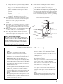 3
3
-
 4
4
-
 5
5
-
 6
6
-
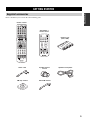 7
7
-
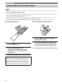 8
8
-
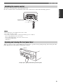 9
9
-
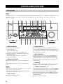 10
10
-
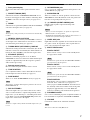 11
11
-
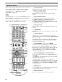 12
12
-
 13
13
-
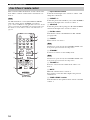 14
14
-
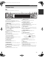 15
15
-
 16
16
-
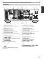 17
17
-
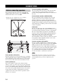 18
18
-
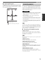 19
19
-
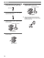 20
20
-
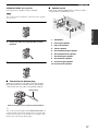 21
21
-
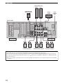 22
22
-
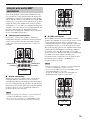 23
23
-
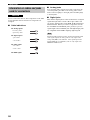 24
24
-
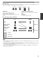 25
25
-
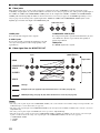 26
26
-
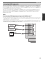 27
27
-
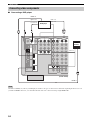 28
28
-
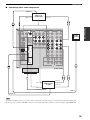 29
29
-
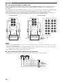 30
30
-
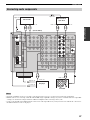 31
31
-
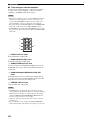 32
32
-
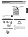 33
33
-
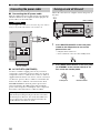 34
34
-
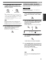 35
35
-
 36
36
-
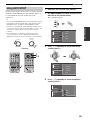 37
37
-
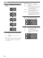 38
38
-
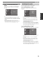 39
39
-
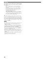 40
40
-
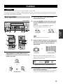 41
41
-
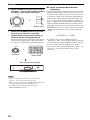 42
42
-
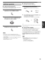 43
43
-
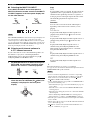 44
44
-
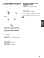 45
45
-
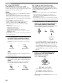 46
46
-
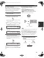 47
47
-
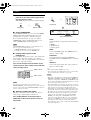 48
48
-
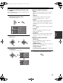 49
49
-
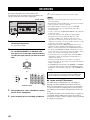 50
50
-
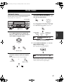 51
51
-
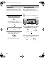 52
52
-
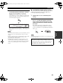 53
53
-
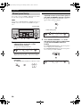 54
54
-
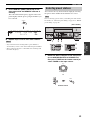 55
55
-
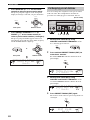 56
56
-
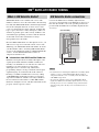 57
57
-
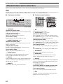 58
58
-
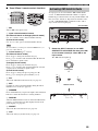 59
59
-
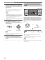 60
60
-
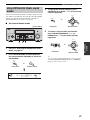 61
61
-
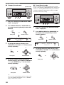 62
62
-
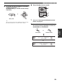 63
63
-
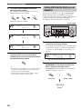 64
64
-
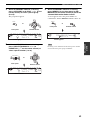 65
65
-
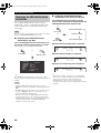 66
66
-
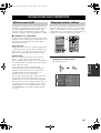 67
67
-
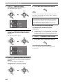 68
68
-
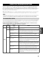 69
69
-
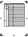 70
70
-
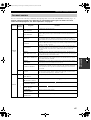 71
71
-
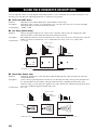 72
72
-
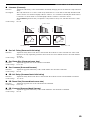 73
73
-
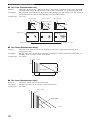 74
74
-
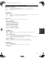 75
75
-
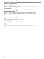 76
76
-
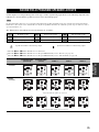 77
77
-
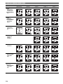 78
78
-
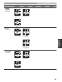 79
79
-
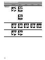 80
80
-
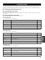 81
81
-
 82
82
-
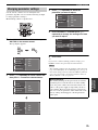 83
83
-
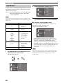 84
84
-
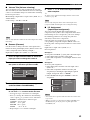 85
85
-
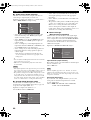 86
86
-
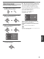 87
87
-
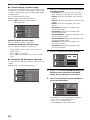 88
88
-
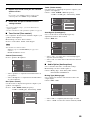 89
89
-
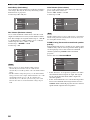 90
90
-
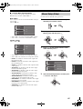 91
91
-
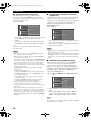 92
92
-
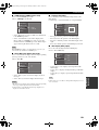 93
93
-
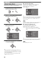 94
94
-
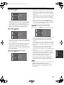 95
95
-
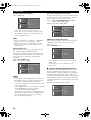 96
96
-
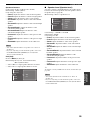 97
97
-
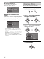 98
98
-
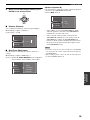 99
99
-
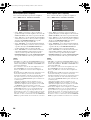 100
100
-
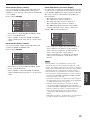 101
101
-
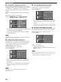 102
102
-
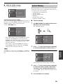 103
103
-
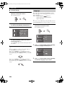 104
104
-
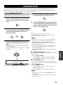 105
105
-
 106
106
-
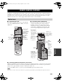 107
107
-
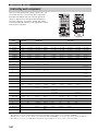 108
108
-
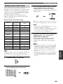 109
109
-
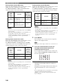 110
110
-
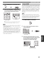 111
111
-
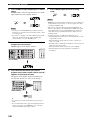 112
112
-
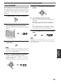 113
113
-
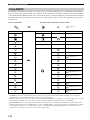 114
114
-
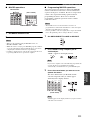 115
115
-
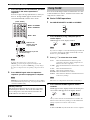 116
116
-
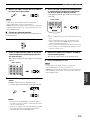 117
117
-
 118
118
-
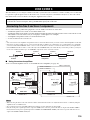 119
119
-
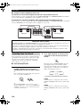 120
120
-
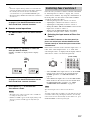 121
121
-
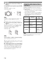 122
122
-
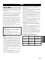 123
123
-
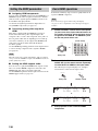 124
124
-
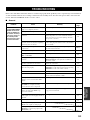 125
125
-
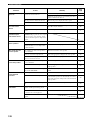 126
126
-
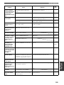 127
127
-
 128
128
-
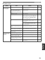 129
129
-
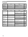 130
130
-
 131
131
-
 132
132
-
 133
133
-
 134
134
-
 135
135
-
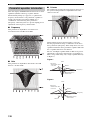 136
136
-
 137
137
-
 138
138
-
 139
139
-
 140
140
-
 141
141
-
 142
142
-
 143
143
-
 144
144


Yamaha RV2600 DTS Manual de usuario
- Categoría
- Receptor
- Tipo
- Manual de usuario
- Este manual también es adecuado para
en otros idiomas
- français: Yamaha RV2600 DTS Manuel utilisateur
- italiano: Yamaha RV2600 DTS Manuale utente
- English: Yamaha RV2600 DTS User manual
- Deutsch: Yamaha RV2600 DTS Benutzerhandbuch
- русский: Yamaha RV2600 DTS Руководство пользователя
- Nederlands: Yamaha RV2600 DTS Handleiding
- português: Yamaha RV2600 DTS Manual do usuário
- dansk: Yamaha RV2600 DTS Brugermanual
- polski: Yamaha RV2600 DTS Instrukcja obsługi
- čeština: Yamaha RV2600 DTS Uživatelský manuál
- svenska: Yamaha RV2600 DTS Användarmanual
- Türkçe: Yamaha RV2600 DTS Kullanım kılavuzu
- suomi: Yamaha RV2600 DTS Ohjekirja
- română: Yamaha RV2600 DTS Manual de utilizare
Artículos relacionados
-
Yamaha RX-V1600 Manual de usuario
-
-
Yamaha RX-V3800 El manual del propietario
-
Yamaha RX-V657 El manual del propietario
-
-
-
Yamaha RX V3900 - AV Network Receiver Manual de usuario
-
-
Yamaha RX-797 El manual del propietario
-
Yamaha RX-V1500 El manual del propietario
Otros documentos
-
TEAC AG-980 El manual del propietario
-
Philips FR985 Manual de usuario
-
-
Kenwood KRF-X9070D El manual del propietario
-
Denon Professional DN-A300M Manual de usuario
-
Logitech Z-5450 Manual de usuario
-
Bose TV Video Accessories AM301726 Manual de usuario
-
Bose OPTIMISEUR VIDEO LIFESTYLE VS-2 El manual del propietario
-
Pioneer A-A6-J Manual de usuario
-
Marantz DH9300 Guía del usuario