Craftsman 536889250 El manual del propietario
- Categoría
- Lanzadores de nieve
- Tipo
- El manual del propietario

] CRRFTSMRN °]
Operator's Manual
Snow Thrower
13 Horsepower
Electric Start
33-inch Dual Stage
Model 536.889250
CAUTION: Before using this product,
read this manual and follow all of its
Safety Rules and Operating Instructions
Manual del usario
Quitanieves
de 33 pulgadas
13 caballos de fuerza (hp)
Biet_pico
Arranque eldctrico
Modelo 536.889250
PRECAUCl6N: Antes de usar este producto,
lea este manual y siga todas las reglas de
seguridad e instrucciones de operaci6n.
Sears, Roebuck and Co., Hoffman Estates, IL 60179 U.S.A.
F-021073L www.sears.com/craftsman

i f:1"|!_ Eo_ [o[o] _ii _ _il_,_
WARRANTY STATEMENT ...... 2
SAFETY RULES ............... 2
INTERNATIONAL SYMBOLS .... 4
ASSEMBLY ................... 6
OPERATION .................. 13
MAINTENANCE ............... 20
SERVICE AND ADJUSTMENT .. 23
STORAGE .................... 32
TROUBLESHOOTING TABLE ... 33
REPAIR PARTS ............... 37
ENGINE REPAIR PARTS ....... 59
SPANISH (ESPAI_IOL) .......... 70
PARTS ORDERING/SERVICE ..
BACK COVER
LIMITED TWO-YEAR WARRANTY ON CRAFTSMAN SNOW THROWER
For two years from the date of purchase, when this Craftsman Snow thrower ismaintained,
lubricated, and tuned up according to the operating and maintenance instructions in the
owner's manual, Sears will repair, free of charge, any defect in material or workmanship.
If thisCraftsman Snow thrower is used for commercial or rental purposes, this warranty ap-
plies for only 90 days from the date of purchase.
This warranty does not cover the following:
• Items which become worn during normal use, such as spark plugs,drive belts and shear
pins.
• Repair necessary because of operator abuse or negligence, including bent crankshafts
and the failure to maintain the equipment according to the instructions contained in the
owner's manual.
WARRANTY SERVICE IS AVAILABLE BY RETURNING THE CRAFTSMAN SNOW
THROWER TO THE NEAREST SEARS SERVICE CENTER IN THE UNITED STATES.
THIS WARRANTY APPLIES ONLY WHILE THIS PRODUCT IS IN USE IN THE UNITED
STATES.
This warranty gives you specific legal rights, and you may also have other rights which may
vary from state to state.
Sears, Roebuck and Co., D817WA, Hoffman Estates. IL 60179
,_ LOOK FOR THIS SYMBOL TO POINT OUT IMPORTANT SAFETY PRECAUTIONS.
IT MEANS--ATTENTION!H BECOME ALERT!H YOUR SAFETY IS INVOLVED.
Engine Exhaust, some of its constituents, and
certain vehicle components contain or emit
chemicals known to the State of California to
cause cancer and birth defects or other repro-
ductive harm.
Battery posts, terminals and related accessories
contain lead and lead compounds, chemicals
known to the State of California to cause cancer
and birth defects or other reproductive harm.
WASH HANDS AFTER HANDLING.
,_ WARNING: Always discon-
nect the spark plug wire
and place it where it cannot
make contact with spark plug to
prevent accidental starting during:
Preparation, Maintenance, or Stor-
age of your snow thrower.
IMPORTANT: Safety standards re-
quire operator presence controls to
minimize the risk of injury. Your snow
thrower is equipped with such controls.
Do not attempt to defeat the function of
the operator presence control under any
circumstances.
F-021073L 2

TRAINING
1. Read this operating and service instruction
manual carefully. Be thoroughly familiar
with the controls and the proper use of the
snow thrower. Know how to stop the snow
thrower and disengage the controls quick-
ly.
2. Never allow children to operate the snow
thrower. Never allow adults to operate the
snow thrower without proper instruction.
3. Keep the area of operation clear of all per-
sons, particularly small children and pets.
4. Exercise caution to avoid slipping or falling
especially when operating in reverse.
PREPARATION
1. Thoroughly inspect the area where the
snow thrower is to be used and remove all
doormats, sleds, boards, wires, and other
foreign objects.
2. Disengage all clutches before starting the
engine (motor).
3. Do not operate the snow thrower without
wearing adequate winter outer garments.
Wear footwear that will improve footing on
slippery surfaces.
4. Handle fuel with care; it is highly flam-
mable.
a. Use an approved fuel container.
b. Never remove fuel tank cap or add fuel
to a running engine (motor) or hot en-
gine (motor).
c. Fill fuel tank outdoors with extreme
care. Never fill fuel tank indoors.
d. Replace fuel cap securely and wipe up
spilled fuel.
e. Never store fuel or snow thrower with
fuel in the tank inside of a building
where fumes may reach an open flame
or spark.
f. Check fuel supply before each use, al-
lowing space for expansion as the heat
of the engine (motor) and/or sun can
cause fuel to expand.
5. For all snow throwers with electric starting
motors use electric starting extension
cords certified CSA/UL Use only with a re-
ceptacle that has been installed in accord-
ance with local inspection authorities.
6. Never attempt to make any adjustments
while the engine (motor) is running (except
when specifically recommended by manu-
facturer).
7. Let engine (motor) and snow thrower ad-
just tooutdoor temperatures before starting
to clear snow.
F-021073L
8.
Always wear safety glasses or eye shields
during operation or while performing an ad-
justment or repair to protect eyes from
foreign objects that may be thrown from the
snow thrower.
OPERATION
1. Do not operate this snow thrower ifyou are
taking drugs or other medication which can
cause drowsiness or affect your ability to
operate this snow thrower.
2. Do not use the snow thrower if you are
mentally or physically unable to operate the
snow thrower safely.
3. Do not put hands or feet near or under ro-
tating parts. Keep clear of the discharge
opening at all times.
4. Exercise extreme caution when operating
on or crossing gravel drives, walks or
roads. Stay alert for hidden hazards or
traffic.
5. After striking a foreign object, stop the en-
gine (motor), remove the wire from the
spark plug, thoroughly inspect snow
thrower for any damage, and repair the
damage before restarting and operating
the snow thrower.
6. If the snow thrower should start to vibrate
abnormally, stop the engine (motor) and
check immediately for the cause. Vibration
is generally a warning of trouble.
7. Stop the engine (motor) whenever you
leave the operating position, before un-
clogging the auger/impeller housing or dis-
charge chute and when making any
repairs, adjustments, or inspections.
8. When cleaning, repairing, or inspecting,
make certain the auger/impeller and all
moving parts have stopped and all controls
are disengaged. Disconnect the spark plug
wire and keep the wire away from the spark
plug to prevent accidental starting.
9. Take all possible precautions when leaving
the snow thrower unattended. Disengage
the auger/ impeller, stop engine (motor),
and remove key.
10. Do not run the engine (motor) indoors, ex-
cept when starting the engine (motor) and
for transporting the snow thrower in or out
of the building. Open the outside doors; ex-
haust fumes are dangerous (containing
CARBON MONOXIDE, an ODORLESS
and DEADLY GAS).
11. Do not clear snow across the face of
slopes. Exercise extreme caution when
changing direction on slopes. Do not at-
tempt to clear steep slopes.
12. Never operate the snow thrower without
proper guards, plates or other safety pro-
tective devices in place.

20.
21.
13.Neveroperatethesnowthrowernearen-
closures,automobiles,windowwells,drop-
offs,andthelikewithoutproperadjustment
ofthesnowdischargeangle.Keepchildren
andpetsaway.
14.Donotoverloadthesnowthrowercapacity
byattemptingtoclearsnowattoofasta
rate.
15.Neveroperatethesnowthrowerathigh
transportspeedsonslipperysurfaces.
Lookbehindandusecarewhenbacking
up.
16.Neverdirectdischargeatbystandersor
allowanyoneinfrontofthesnowthrower.
17.Disengagepowertothecollector/impeller
whensnowthroweristransportedornotin
use.
18. Use only attachments and accessories ap-
proved by the manufacturer of the snow
thrower (such as tire chains, electric start
kits, ect.).
19. Never operate the snow thrower without
good visibility or light. Always be sure of
your footing and keep a firm hold on the
handles. Walk;never run.
Do not over-reach. Keep proper footing
and balance at all times.
Do not attemptto use snow throweron a
roof.
MAINTENANCE AND STORAGE
1. Check shear bolts and other bolts at fre-
quent intervals for proper tightness to be
sure the snow thrower is in safe working
condition.
2. Never store the snow thrower with fuel in
the tank inside a building where ignition
sources are present such as hot water and
space heaters, clothes dryers, and the like.
Allow the engine (motor) to cool before
storing in any enclosure.
3. Always refer to operator's guide instruc-
tions for important details if the snow
thrower is to be stored for an extended
period.
4. Maintain or replace safety and instruction
labels, as necessary.
5. Run the snow thrower a few minutes after
throwing snow to prevent freeze-up of the
auger/impeller.
_ WARNING: This snow thrower isfor use on sidewalks, driveways
and other ground level surfaces.
Caution should be exercised while using on
steep sloping surfaces. DO NOT USE
SNOW THROWER ON SURFACES ABOVE
GROUND LEVEL such as roofs of resi-
dences, garages, porches or other such
structures or buildings.
_o_
IMPORTANT: Many of the following symbols are located on your snow thrower or on litera-
ture supplied with the product. Before you operate the snow thrower, learn and understand
the purpose for each symbol.
CONTROL AND OPERATING
SYMBOLS
Slow Fast
Engine Off Engine Stop
Throttle Primer Button
Electric Start Engine Start
I H
On Choke Off Choke On
Ignition Key Ignition Off
Engine Run
N
Neutral
Ignition On
F-021073L 4

Drive Clutch Forward
Push To Engage Fuel
Electric Starter
Reverse Auger Clutch Auger Collector
Oil
Engage
Fuel Oil Mixture
f
Discharge DOWN Discharge UP Discharge LEFT Discharge RIGHT
Weight Transfer Weight Transfer Transmission
Lift Handle To Depress Pedal
Engage To Disengage
SafetyWarningSymbols
A
DANGER
Thrown Objects.
Keep Bystanders Away.
DANGER
Thrown Objects.
Keep Bystanders Away.
IMPORTANT DANGER
Read Owner's Manual Avoid Injury From
Before Operating Rotating Auger. Keep
This Machine. Hands, Feet And
Clothing Away.
Ignition Key
Insert To Run,
Pull Out To Stop.
WARNING
DANGER
Stop The Engine
Before Unclogging
Discharge Chute!
WARNING
Hot Surface STOP
F-O21073L 5

CONTENTS OF PARTS BAG (ACTUAL SIZE)
1 - Owner's Manual (not shown)
1 - Packet of Fuel Stabilizer (not shown)
1 - Warranty Card (not shown)
*Non-Assembly Parts, found in toolbox located on belt cover
*2- Shear Bolt
1 - Washer
(_ _ _1 Cotter Pin
F_
1 - Shift Lever Knob
(not actual size)
(not actuarl Cord
_t _u size)
1 - Remote Chute
Knob (not actual size)
F-021073L 6

_ ARNING: Always wearsafety glasses or eye shields
while assembling snow
thrower.
TOOLS REQUIRED FOR
ASSEMBLY
1- Knife to cut carton
2 - 1/2 inch wrenches
(or adjustable wrenches)
2 - 9/16 inch wrenches
(or adjustable wrenches)
2 - 3/4 inch wrenches
(or adjustable wrenches)
1- Pliers (to spread cotter pin)
1- Screwdriver
1- Measuring tape or ruler
Figure 1
Figure 1 shows the snow thrower in the
shipping position.
Figure 2 shows the snow thrower com-
pletely assembled.
References to the right or left hand side
of the snow thrower are from the view-
point of the operator's position behind
the unit.
er Drive Lever
Shifter Lever
Traction
Drive Lever
Chute
Deflector
Height
Adjust
Skid
Figure 2
TO REMOVE SNOW THROWER FROM CARTON
1. Locate all parts packed separately
and remove from the carton.
NOTE: Place fuel stabilizer in a
safe place until needed for storage.
2. Remove and discard the packing
material from around the snow
thrower.
3. Cut down all four corners of the car-
ton and lay the panels flat.
4. For shipping purposes, the height
adjust skids are attached to the
pallet. Remove the screw that se-
F-021073L
cures each height adjust skid to
the pallet. See Figure 2.
5. Roll snow thrower off the pallet by
pulling on the lower handle.
CAUTION: DO NOT back over
control cables.
6. Remove all packing material from
the unit.
7. Cut ties securing the clutch control
cable to the lower handle and lay
cable back away from the motor
frame.

TO ASSEMBLE THE HANDLE
1. Cut tie holding shift rod to lower
handle and move shifter to the neu-
tral position.
2. Loosen, but do not remove, the
screws, flatwashers, Iockwashers,
and hex nuts in the upper holes of
the lower handle. See Figure 3.
3. Remove the fasteners from the low-
er holes of the lower handle See
Figure 3.
Right Hand Side /
Of Upper Handle_
u_ Loosen,
but do not
"_ remove
/11 32,,
Flatwasher
5/16" Hex N
5/16"
5/16"Split _ I_,,,_ _.J
Screw
Lockwasher
Figure 3
NOTE: Make sure the cables are not
caught between the upper and lower
handle.
4. Raise the upper handle into operat-
ing position.
NOTE: If the cables have become dis-
connected form the drive levers, rein-
stall the cables as shown in Figure 4.
Lever
"Z" Fitting _'_
Control Cable Figure 4
5. Install the fasteners that were re-
moved in step 3. DO NOT tighten
until all bolts are in place.
6. Tighten all handle bolts.
F-021073L 8

NOTE: If the cables have become dis-
connected, connect cables as shown in
Figure 5.
Traction Drive Cable Auger Drive Cable
Figure 5
Remote Chute Knob
1. Assemble the remote chute knob
onto the lever until snug against the
nut (see Figure 6).
2. Make sure lip on the remote chute
knob is pointed toward the engine.
3. Tighten the nut against the bottom
of the remote chute knob.
Lip
Remote
Chute
Knob
Lever
Figure 6
HOW TO INSTALL
THE SPEED SELECT KNOB
Install the speed select knob to the
speed select lever. See Figure 7.
Speed Select
Knob
Speed Select
Lever
Figure 7
F-021073L 9

How To Install The Speed Control Rod
1. Put the speed select lever to the
NEUTRAL position.
2. Attach the ball joint, located on the
bottom end of the speed control
rod, to the shift yoke assembly.
See Figure 9. The fasteners are at-
tached to the ball joint at the
factory.
3. The length ot the ball joint and
speed control rod have been pre-
adjusted at the factory. If an adjust-
ment is required, loosen the nut.
Remove the fasteners to discon-
nect the ball joint from the shift
yoke assembly. To lengthen or
shorten the speed control rod, turn
the adapter to obtain the correct
length.
4. Make sure the speed select lever
functions correctly. Move the speed
select lever through all speeds.
Speed Select
Lever
Figure 8
ntrol
Shi
Assembly
Fasteners
Ball Joint
Figure 9
How To Assemble The Chute Deflector
1. Remove the carriage bolt. See
Figure 10.
4.
2. Raise the chute deflector into op-
erating position. 5.
3. Fasten chute deflector to flange
with carriage bolt. Make sure to
install with head of carriage bolt on
the inside of the flange.
Fasten with washer and Iocknut.
Tighten Iocknut securely.
NOTE: Make sure all carriage
bolts in flange are tight. DO NOT
OVERTIGHTEN.
Chute
Deflector
Operating Position j._
\
Carriage_
Bolt
F-021073L
Flang_ Washer Nut _
1o
Figure 10

How To Set The Skid Height
The snow thrower is equipped with
height adjustable skids mounted on
the outside of the auger housing. See
Figure 11. To adjust the height of the
skids, see To Adjust Skid Height para-
graph in the Service And Adjustment
section
Hei,
Adjustable Skids
Figure 11
How To Set
The Length Of The Cables
The cables were adjusted at the factory
and no adjustments should be neces-
sary. However, after the handles are put
in the operating position, the cables can
be too tight or too loose. If an adjust-
ment is necessary, see "How To Check
And Adjust The Cables" in the Service
And Adjustment section.
F-021073L 11

How To Set The Drift Cutters
Drift cutters are used to cut a path
through snow deeper than the auger
housing.
1. Loosen the wingnuts that secure
the drift cutters to the auger hous-
ing. See Figure 12.
2. Raise the drift cutters to the de-
sired height.
3. Tighten the wingnuts.
Wingnul
Drift Cutter
_.<
Figure 12
_" CHECKLIST
Before you operate your new snow
thrower, to ensure that you receive the
best performance and satisfaction from
this quality product, please review the
following checklist:
_' All assembly instructions have been
completed.
_' The discharge chute rotates freely.
_' No remaining loose parts in carton.
While learning how to use your snow
thrower, pay extra attention to the fol-
lowing important items:
_' Engine oil is at proper level.
_' Make sure gas tank is filled properly
with clean, fresh, unleaded gasoline.
_' Become familiar with all controls-
their location and function. Operate
controls before starting engine.
F-021073L 12

KNOW YOUR SNOW THROWER
READ THIS OWNER'S MANUAL AND SAFETY RULES BEFORE OPERATING
YOUR SNOW THROWER. Compare the illustrations with your SNOW THROWER
to familiarize yourself with the location of various controls and adjustments. Save
this manual for future reference.
Speed Shifter Lever _ Electric Chute Switch
Auger Drive Lever Traction Drive Lever
Gas Tank Remote Chute Chute
Control Lever Deflector
Choke
Control
Primer
Button
Discharge
Chute
Ignition
Key
Recoil
Starter
Handle
Drift Cutter
Height Adjust
;hear Pin
Scraper Bar Figure 13
Auger Drive Lever- Starts and stops
the auger and impeller (snow gathering
and throwing).
Traction Drive Lever - Propels the
snow thrower forward and in reverse.
Speed Shifter Lever - Selects the for-
ward and reverse speed.
Electric Chute Switch - Changes the
direction of snow throwing through the
discharge chute.
Chute Deflector - Changes the distance
the snow is thrown.
Discharge Chute - Changes the height
and direction the snow is thrown.
Height Adjust Skid - Adjusts the ground
clearance of the auger housing.
Ignition Key - Must be inserted to start
the engine.
Recoil Starter Handle - Starts the en-
gine manually.
F-021073L 13
Choke Control - Used to start a cold
engine.
Primer Button - Injects fuel directly into
the carburetor manifold for fast starts in
cold weather.
Remote Chute Control Lever - Con-
trols the distance the snow is thrown.
Throttle Control - Controls the engine
speed.
Electric Start Button - (ifso equipped)
Usedto startthe engineusingthe 120V elec-
tricstarter.
Shear Pin - Shear pins are designed to
break (to protect the machine) if an ob-
iect becomes lodged in the auger hous-
ing.
Toolbox - spare shear pins and
spacers are located in toolbox.
Drift Cutter -Cuts a path through snow
higher than the auger housing.

Theoperationofanysnowthrowercan
resultinforeignobjectsbeingthrown
intotheeyes,whichcanresultinse-
vereeyedamage.Alwayswearsafety
glassesoreyeshieldswhileoperating
thesnowthrower.
Werecommendstandardsafety
glassesorawidevisionsafetymaskfor
overyourglasses.
_ ARNING: Read Owner's
Manual before operating
machine. Never direct dis-
charge toward bystanders. Stop the
engine before unclogging discharge
chute or auger housing and before
leaving the machine.
TO STOP YOUR
SNOW THROWER
1.
2.
3.
TO CONTROL SNOW DISCHARGE
1. Move the electric chute switch to
set the direction (left to right) of the
snow throwing.
2. Push the remote chute lever for-
ward to discharge the snow down.
Pull the remote chute lever back to
discharge the snow high and far.
HOW TO MOVE
FORWARD AND BACKWARD
To stop throwing snow, release the
auger drive lever. See Figure 14.
To stop the wheels, release the
traction drive lever.
To stop the engine, push the
throttle control lever to off and pull
out the ignition key.
Auger Drive Lever
\
1. To move the snow thrower forward,
engage the traction drive lever
(left hand). As the snow thrower
starts to move forward, push the
shift lever to the desired speed.
Maintain a firm hold on the handles
and guide the snow thrower along
the clearing path. Do not attempt to
push the snow thrower.
2. To move the snow thrower back-
ward, pull the shift lever to the re-
verse position.
TO THROW SNOW
1. Push down the auger driver lever
(right hand). See Figure 14.
2. Release to stop throwing snow.
Shift Lever
Traction Drive Lever
Remote Chute Lever
Figure 14
F-021073L 14

HOW TO USE
THE WHEEL LOCKOUT
Each wheel is secured to the axle with
a lockout pin. See Figure 15. The unit
was shipped with the lockout pin in the
locked position. For ease of maneuver-
ability, disconnect the lockout pin as fol-
lows.
1. Pull the knob out to disengage the
lockout pin.
2. To lock in the disengaged position,
turn the knob 1/4 turn (90 degrees).
Knob
Wheel Lockout
Figure 15
HOW TO USE THE HEATED
GRIPS
_ WARNING: Heated grips are
designed for use when the tem-
perature is below 32 degrees.
Do not turn on electric grips if tempera-
ture is above 32 degrees.
When the temperature falls below 32 de-
grees, use the heated grips to keep your
hands warm. Move the heated grip switch
to the ON position (see Figure 14). It will
take a couple of minutes for the grips to be-
come warm. Because heated grips can be-
come very warm, we recommend that you
wear gloves. If you notice that the grips are
too warm, turn off heated grips.
BEFORE STARTING THE ENGINE
1.
2.
3.
4.
5.
Before you service or start the en-
gine, familiarize yourself with the
snow thrower. Be sure you under-
stand the function and location of all
controls.
Check the tension of clutch cable
before starting the engine. See To
Adjust The Control Cable para-
graph in the Service & Adjust-
ments section of this manual.
Be sure that all fasteners are tight.
Make sure the height adjust skids
are properly adjusted. See To Ad-
just Skid Height paragraph in the
Service & Adjustments section of
this manual.
Check tire pressure (14-17
pounds). Do not exceed maximum
amount of pressure.
CHECK THE OIL:
NOTE: The engine was shipped from
the factory filled with oil. Check the lev-
el of the oil. Add oil as needed.
F-021073L 15
To Add Oil
1. Make sure the unit is level.
NOTE: Do not check the level of the
oil while the engine runs.
2. Remove the oil fill cap/dipstick.
Check the oil.
3. If necessary, add oil until the oil
reaches the FULL mark on the oil fill
cap/dipstick (see Figure 16). Do not
add too much oil.
OII Fill Cap/Dipstick
NOTE: Oil level must be
between Full andAdd mark
Figure 16
4. Tighten the fill cap/dipstick securely
each time you check the oil level.
NOTE: S.A.E. 5W30 motor oil may be
used to make starting easier in areas
where temperature is consistently 20°F.
or lower.

FILL GAS:
The engine is certified to comply with
California and US EPA emission regula-
tions for ULGE (Utility or Lawn and Gar-
den Equipment)engines. ULGE
engines are certified to operate on reg-
ular unleaded gasoline.
_ ARNING: Alcohol blended
fuels (called gasohol or
those using ethanol or
methanol) can attract moisture
which leads to separation and
formation of acids during storage.
Acidic gas can damage the fuel sys-
tem of an engine while in storage.
NOTE: To avoid engine problems, the
fuel system must be emptied before
storage for 30 days or longer. Start the
engine and let it run until the fuel lines
and carburetor are empty. Use fresh
fuel next season. See the Storage sec-
tion in this manual for additional infor-
mation.
Never use engine or carburetor cleaner
products in the fuel tank or permanent
damage may occur.
Fill the fuel tank only with a fresh,
clean, unleaded regular, unleaded pre-
mium, or reformulated automotive gas-
oline. DO NOT use leaded gasoline.
Make sure that the container you pour
the gasoline from is clean and free from
rust or other foreign particles. Never
use gasoline that may be stale from
long periods of storage in the container.
Fuel Tank
Figure 17
_ ARNING: Gasoline is flam-
mable. Always use caution
when handling or storing
gasoline.
• Do not fill fuel tank while snow
thrower is running, when it is hot,
or when snow thrower is in an en-
closed area.
• Keep away from open flame or an
electrical spark and do not smoke
while filling the fuel tank.
• Never fill the tank completely. Fill
the tank to within 1/4"-1/2" from
the top to provide space for ex-
pansion of fuel.
• Always fill fuel tank outdoors and
use a funnel or spout to prevent
spilling.
• Make sure to wipe up any spilled
fuel before stating the engine.
• Store gasoline in a clean, ap-
proved container and keep the
cap in place on the container.
F-021073L 16

HOW TO STOP THE ENGINE
1.
To stop the engine, move the
throttle control lever to the "SLOW"
position, then move to the "STOP"
position (see Figure 18).
T_h_Je Cont_l
re 18
2. Pull out and remove the ON/OFF
key (see Figure 19). Keep the
ON/OFF key in a safe place. The
engine will not start without the
ON/OFF key.
f ( FF Key
I
Figure 19
TO START ENGINE
Be sure that the engine has sufficient
oil. The snow thrower engine is
equipped with a recoil starter. Before
starting the engine, be certain that you
have read the following information.
_ ARNING: The starter is
equipped with a three-wire
power cord and plug and is
designed to operate on 120 volt AC
household current. It must be prop-
erly grounded at all times to avoid
the possibility of electrical shock
which may be injurious to operator.
• Follow all instructions carefully
as set forth in the "To Start En-
gine" section.
• Determine that your house wiring
is a three-wire grounded system.
Ask a licensed electrician if you
are not sure. If your house wire
system is not a three-wire system,
do not use this electric starter un-
der any conditions.
• If your system is grounded and a
three-hole receptacle is not avail-
able at the point your starter will
normally be used, one should be
installed by a licensed electrician.
• When connecting 120 volt AC
"Power Cord", always connect the
cord to the Switch Box on the en-
gine first, then plug the other end
into the three-hole grounded re-
ceptacle. When disconnecting
"Power Cord", always unplug the
end in the three-hole grounded re-
ceptacle first.
How To Start A Cold Engine
1. Be sure auger drive and traction
drive levers are in the disengaged
(RELEASED) position.
2. Turn the rotary choke knob to the
CHOKE position (see Figure 20).
3. Depress the primer button three
times (see Figure 20).
F-021073L 17

Choke Knob
_ure 20
4. Move throttle control to "FAST"
position. Operate the engine with
the throttle control in the "FAST"
position (see Figure 21).
5.
Figure 21
Remove the ON/OFF keys from the
plastic bag. Insert one of the
ON/OFF keys into the key slot (see
Figure 22). Make sure the key
snaps into place. Do not turn the
ON/OFF key. Keep the second ON/
OFF key in a safe place.
ON / OFF Key
f { I
Recoil Starter Handle
7.
Figure 23
(ELECTRIC START) Connect the
power cord to the engine and de-
press the starter button.
Connect
Power Cord
Starter Button
I
Figure24
8. As the engine warms up, move
choke lever to "1/2 choke" position.
When engine runs smoothly, move
choke lever to "No Choke" Posi-
tion.
9. Run engine at full throttle "FAST"
when throwing snow.
Allow the engine to warm up for several
minutes before blowing snow in temper-
atures below 0°E
Figure 22
6. (RECOIL START) Rapidly pull the
starter handle (see Figure 23). Do
not allow the recoil starter handle
to snap back, but allow it to rewind
slowly while keeping a firm hold on
the starter handle.
F-021073L 18
WARM START
If restarting a warm engine after a short
shutdown, leave choke at "OFF" and do
not push the primer button. If the en-
gine fails to start, follow the Cold Start
instructions.
FROZEN STARTER
Ifthe starter is frozen and will not turn
engine:
1. Pull as much rope out of the starter
as possible.

2. Releasethestarterhandleandletit
snapbackagainstthestarter.Re-
peatuntiltheenginestarts.
Tohelppreventpossiblefreeze-upof
recoilstarterandenginecontrols,pro-
ceedasfollowsaftereachsnowremov-
aljob.
1. Withtheenginerunning,pullthe
starterropehardwithacontinuous
fullarmstrokethreeorfourtimes.
Pullingofstarterropewillproducea
loudclatteringsound.Thisisnot
harmfultotheengineorstarter.
2. Withtheenginenotrunning,wipeall
snowandmoisturefromthecarbu-
retorcoverinareaofcontrollevers.
Alsomovethrottlecontrol,choke
control,andstarterhandleseveral
times.
_ ARNING: Never run en-
gine indoors or in enclosed,
poorly ventilated areas. En-
gine exhaust contains CARBON
MONOXIDE, AN ODORLESS AND
DEADLY GAS. Keep hands, feet,
hair and loose clothing away from
any moving parts on engine and
snow thrower.
• The temperature of muffler and
nearby areas may exceed 150°F.
Avoid these areas.
• DO NOT allow children or young
teenagers to operate or be near
snow thrower while it is operat-
ing.
HOW TO REMOVE OBJECTS
FROM AUGER
_ ARNING: Do not attempt
to remove any item that may
become lodged in auger
without taking the following precau-
tions:
• Release auger drive lever.
• Move throttle lever to stop position.
• Remove (do not turn) ignition key.
• Disconnect spark plug wire.
• Do not place your hands in the au-
ger or discharge chute. Use a pry
bar.
SNOW THROWING TIPS
1. For maximum snow thrower efficien-
cy in removing snow, adjust ground
speed, NEVER the throttle. Go
slower in deep, freezing or wet
snow. If the wheels slips, reduce
forward speed. The engine is de-
signed to deliver maximum perfor-
mance at full throttle and should be
run at this power setting at all times.
2. Most efficient snow throwing is ac-
complished when the snow is re-
moved immediately after if falls.
3. For complete snow removal, slightly
overlap each path previously taken.
4. The snow should be discharged
down wind whenever possible.
5. For normal usage, set the skids so
that the scraper bar is 1/8" above
the skids. For extremely hard-
packed snow surfaces, adjust the
F-021073L 19
skids upward so that the scraper
bar touches the ground.
6. On gravel or crushed rock surfaces,
set the skids at 1-1/4" below the
scraper bar. See To Adjust Skid
Height paragraph in the Service &
Adjustments section of this manu-
al. Rocks and gravel must not be
picked up and thrown by the ma-
chine.
7. After the snow throwing job has
been completed, allow the engine to
idle for a few minutes, which will
melt snow and accumulated ice off
the engine.
8. Clean the snow thrower thoroughly
after each use.
9. Remove ice and snow accumulation
and all debris from the entire snow
thrower, and flush with water (if pos-
sible) to remove all salt or other
chemicals. Wipe snow thrower dry.

SERVICERECORDS
Fillin datesasyou Before Every Every Every
completeregular Each 5 10 25 Each Before SERVICE
service. Use Often Hours Hours Hours Season Storage DATES
LubricateAuger Shaft -Vr -Vr
Change Engine Oil !/ !/
Remove Fuel -_
* Adjust after 2 to 4 hours of use.
1-Adjust after First 10 hours and then Every 25 hours of use.
GENERAL RECOMMENDATIONS
The warranty on this snow thrower
does not cover items that have been
subjected to operator abuse or negli-
gence. To receive full value from the
warranty, the operator must maintain
the snow thrower as instructed in this
manual.
Some adjustments will need to be
made periodically to properly maintain
your snow thrower.
AFTER EACH USE
• Run the machine to clear the auger
of snow.
• To prevent freezing of the auger or
controls, remove all snow and slush
from the snow thrower.
• Check for any loose or damaged
parts.
• Tighten any loose fasteners.
• Check and maintain the auger.
• Check controls to make sure they
are functioning properly.
• If any parts are worn or damaged,
replace immediately.
F-021073L 20

PRODUCT SPECIFICATIONS
HORSEPOWER 13 HP
DISPLACEMENT 20.85 cu.in.
GASOLINE 4 quarts
CAPACITY (unleaded)
OIL CAPACITY 5W30
(28oz capacity)
SPARK PLUG: Champion RC12YC
(Gap .030 in.) or
equivalent
VALVECLEARANCE
Intake: 0.004 - 0.006 In.
Exhaust: 0.009 - 0.011 In.
SNOW THROWER
AUGER DRIVE BELT
Adjust the auger drive belt after the first
2 to 4 hours of use, again about mid-
season and twice each season thereaf-
ter (See "Belt Adjustment" in the
Service and Adjustment section).
AUGER SHAFT LUBRICATION
EVERY 10 HOURS
1. LubricatetheZerk fittings (A) everyten
hours with a grease gun.
2. Each time a shear bolt is replaced,
the auger shaft MUST be greased.
See Figure 25. See To Replace Au-
ger Shear Bolt in the Service and
Adjustment section.
A
Figure 25
AUGER GEAR BOX
The auger gear box is lubricated at the
factory and should not require addition-
al lubrication. Iffor some reason the
lubricant should leak out, have auger
gear case checked by a competent re-
pairman.
F-021073L 21

ENGINE
LUBRICATION
Check the crankcase oil level before
starting the engine and after each five
(5) hours of continuous use. Add S.A.E.
5W30 motor oil as needed. Tighten fill
cap/dipstick securely each time you
check the oil level.
Oil Fill Cap/Dipstick _ d
FULL
Figure 26
Change the oil every twenty-five (25)
hours or at least once a year if the
snow thrower is not used for twenty-five
(25) hours.
TO CHANGE ENGINE OIL
1. Position the snow thrower so that
the oil drain plug is at the lowest
point on the engine.
2. Remove the oil drain plug and the
oil fig cap/dipstick. Drain the oil
into a suitable container.
NOTE: The oil will drain more freely
when the engine is warm.
3. After draining all the oil, reinstall the
oil drain plug securely.
4. Fill the engine crankcase with
S.A.E. 5W30 motor oil, pouring
slowly. DO NOT OVERFILL. See
"To Add Oil" in the Operation Sec-
tion.
Oil Drain Plug
Figure 27
SPARK PLUG
Check the spark plug every twenty-five
(25) hours. Replace the spark plug if
the electrodes are pitted or burned or if
the porcelain is cracked.
To access the spark plug, the snow
hood must be removed. See "How To
Remove The Snow Hood" in the Ser-
vice And Adjustment section.
1. Make sure the spark plug is clean.
Clean the spark plug by carefully
scraping the electrodes (do not
sand blast or use a wire brush).
F-021073L
2.
3.
22
Check the spark plug gap with a
feeler gauge and reset gap to 0.30"
if necessary. See Figure 28.
Before installing the spark plug,
coat the threads lightly with oil for
easy removal. Tighten the spark
plug to a torque of 15 foot-pounds.
FeelerGauge
0.030"
Spark Plug
Figure 28

_,_ad_ IP'_'_Im]V-'_n_U_ j _vj_ln Ii
_ ARNING: Always discon-
nect the spark plug wire and
place it where it cannot
make contact with spark plug to pre-
vent accidental starting when mak-
ing any adjustments or repairs.
TO ADJUST SKID HEIGHT
This snow thrower is equipped with two
height adjustment skids, located on
the outside of the auger housing. See
Figure 29.
These skids elevate the front of the
snow thrower.
Mountin_ Nuts
O
Auger =g Height Adjust Skid
Figure29
For normal hard surfaces, such as a
paved driveway or walk, adjust the
skids as follows.
1. Position the snow thrower on a level
surface.
2. Make sure both tires are equally in-
flated. Proper tire pressure is 14 to
17 PSI. See side of tire for maxi-
mum inflation. Do not exceed maxi-
mum sidewall pressure on tire.
3. Place the extra shear bolts supplied
(found in parts bag) under each
end of the scraper bar next to the
adjustable skids.
4. Loosen the mounting nuts that hold
the adjustable skids. To bring the
front of the snow thrower down,
raise the adjustable skids. Tighten
the mounting nuts. See Figure 29.
NOTE: For rocky or uneven surfaces,
raise the front of the snow thrower by
moving the skids down.
_ WARNING: Be certain to
maintain proper ground
clearance for your particular
area to be cleared. Objects such as
gravel, rocks or other debris, if
struck by the impeller, may be
thrown with sufficient force to cause
personal injury, property damage or
damage to the snow thrower.
TO ADJUST SCRAPER BAR
After considerable use, the metal scrap-
er bar will have a definite wear pattern.
The scraper bar in conjunction with the
skids should always be adjusted to al-
low 1/8" between the scraper bar and
the sidewalk or area to be cleaned.
1. Position the snow thrower on a level
surface.
2. Make sure both tires are equally in-
flated. Proper tire pressure is 14 to
17 PSI. See side of tire for maxi-
mum inflation. Do not exceed maxi-
mum sidewall pressure on tire.
3. Loosen the carriage bolts and nuts
securing the scraper bar to the au-
ger housing.
4. Adjust the scraper bar to the proper
position.
5. Tighten the carriage bolts and nuts,
making sure that the scraper bar is
parallel with the working surface.
6. For extended operation, the scraper
bar may be reversed. If the scraper
bar must be replaced due to wear,
remove the carriage bolts and nuts
and install a new scraper bar.
F-021073L 23

HOW TO REMOVE
THE SNOW HOOD
To access the spark plug, the snow
hood must be removed as follows:
1. Remove the choke control knob
(see Figure 30).
2. Remove the ON/OFF key.
3. Remove the four mounting screws.
4. Slowly remove the snow hood (see
Figure 31). Make sure that the prim-
er button hose and the ignition wire
are not disconnected.
5. To install the snow hood, first make
sure that the primer button hose
and the ignition wire are connected.
6. Mount the snow hood to the engine
and secure with the four mounting
screws (see Figure 32).
7. Align the tab on the choke control
knob with the slot in the snow hood
(see Figure 33).
8. Connect the choke control knob
with the choke shaft. Make sure the
choke control knob is properly
installed. If the choke control knob
is not installed correctly, the choke
will not operate.
Choke Control Knob
Screws
Snow Hood
Snow Hood
/
Figure 31
I
Figure 32
Snow Hood
Screws
/
ON/OFF
Key
Figure 30
Figure 33
F-021073L 24

_,_ad_ IP'_'_Im]V-'_n_U_ j _vj_ln Ii
BELT ADJUSTMENT
Traction Drive Belt
After approximately ten hours of opera-
tion, a new belt will stretch and require
an adjustment of the belt tension. Also,
if your snow thrower experiences a loss
of power under heavy load, check the
condition of the traction drive belt. If it is
damaged or loose, replace it (see "How
To Replace The Belts" in this section of
the manual).
1. Disconnect spark plug wire.
2. Unlock both left and right wheel
locks. See "How To Use The Wheel
Lockout" in the Operation section.
3. Remove screw from belt cover.
Remove belt cover (see Figure 34).
Figure 34,
4. Loosen nut on traction idler pulley
and move traction idler pulley to-
wards belt about 1/8 inch (3 mm)
(see Figure 39).
5. Tighten nut.
6. Have someone engage traction
drive clutch. Check tension on belt
(opposite idler pulley). The belt
should deflect about 1/2 inch (12.5
mm) with moderate pressure
(Figure 35). You may have to move
idler pulley more than once to obtain
the correct tension.
F-021073L 25
_ ARNING: DO NOT over
tighten belt. If the belt is too
tight, the drive will not dis-
engage. Before operating, check the
belt tension following the instruc-
tions in step 8.
Traction
Drive
Engine
Pulley
;,.\O 112inch
-,--& _\ (12.5mm)
idler_,,.__.(/¢_ _,_\\fi_ Deflection
Pulley L/_ " ",_
Engaged _1_
_-_ Figure 35
7. Reinstall belt cover.
8. Attach the spark plug wire. Before
operation, check the belt tension as
follows:
a. Unlock both left and right wheel
locks. See "How To Use The
Wheel Lockout" in the Operation
section.
b. Move the shift lever to NEUTRAL
position.
c. DO NOT engage the traction
drive lever.
d. Start the engine.
e. Slowly move the shift lever for-
ward. Watch the axles for rota-
tion. If the axles rotate, the
traction drive belt is too tight.
f. If the belt is too tight, again ad-
just the belt. After each adjust-
ment, check the belt tension
before operating.
9. In correct adjustment, the snow
thrower will not experience a loss of
power under heavy load and the
drive will automatically disengage
when the traction drive lever is re-
leased.

_,_ad_ IP'_'_Im]V-'_n_U_ j _vj_ln Ii
Auger Drive Belt
If your snow blower will not discharge
snow, check the control cable adjust-
ment. If it is correct, then check the
condition of the auger drive belt. If it is
damaged or loose, replace it (see "How
To Replace The Belts" in this section of
the manual).
1. Disconnect spark plug wire.
2. Remove screw from belt cover.
Remove belt cover (see Figure 36).
3.
4.
5.
Loosen nut on auger idler pulley
and move auger idler pulley towards
belt about 1/8 inch (3 mm) (see
Figure 39).
Tighten nut.
Have someone engage auger drive
clutch. Check tension on belt (op-
posite idler pulley). Belt should de-
flect about 1/2 inch (12.5 mm) with
moderate pressure (Figure 37). You
may have to move idler pulley more
than once to obtain the correct ten-
sion.
Auger
Drive
Engine
Pulley
;,.\O 1/2 inch
----3, _\ (12.5mm)
idler_..._..(/¢'_ _,_\\ 11"_ Deflection
Pulley L/_ " ",_
Engaged __
Figure 37
6. Reinstall belt cover.
7.
Whenever belts are adjusted or re-
placed, the cables will need to be
adjusted. (See Cable Adjustment in
this section of the manual).
8. Attach the spark plug wire.
HOW TO REPLACE THE BELTS
The drive belts are of special construc-
tion and must be replaced with original
equipment replacement belts available
from your nearest Sears service center.
Some steps require the assistance of a
second person.
How To Remove the Auger Drive Belt
Ifthe auger drive belt is damaged, the
snow thrower will not discharge snow.
Replace the damaged belt as follows.
1. Disconnect the spark plug wire.
2. Loosen the bolts on each side of
the bottom panel (see Figure 38).
3. Remove the bottom panel.
F-021073L 26

_,_ad_ IP'_'_Im]V-'_n_U_ j _vj_ln Ii
5.
6.
7.
Bolt Bottom
Panel
Auger
Housing
Figure 38
Remove screw from belt cover.
Remove the belt cover (see
Figure 36).
Loosen the auger belt guide. Pull
the auger belt guide away from the
auger drive pulley (see Figure 39).
Pull the idler pulley away from the
auger drive belt.
Remove the old auger drive belt
from the stack pulley and from the
auger drive pulley. Replace the
Traction Drive
Belt Guide
--k
auger drive belt with an original
equipment replacement belt avail-
able from a Sears service center.
8. Install the new auger drive belt
onto the auger drive pulley and
onto the stack pulley.
9. Adjust the auger drive belt. See
"How To Adjust The Auger Drive
Belt" in the Service And Adjustment
section.
10. Adjust the auger belt guide. See
"How To Adjust The Belt Guide" in
the Service And Adjustment section.
11. Install the belt cover. Tighten
screw (See Figure 36).
12. Check the adjustment of the cables.
See "How To Check And Adjust The
Cables" in the Service And Adjust-
ment section.
13. Install the bottom panel (see
Figure 38).
14. Tighten the bolts on each side of
the bottom panel.
15. Connect the spark plug wire.
Traction Drive Belt
Auger Belt Guide
Traction DriveIdler Pulley
\
Auger Idler Pulley
Stack Pulley
Auger Drive Belt
F-021073L 27
Traction
Drive Belt
Traction
Drive Pulley
Auger Drive
Pulley
Figure 39

_,_ad_ IP'_'_Im]V-'_n_U_ j _vj_ln Ii
How To Remove
The Traction Drive Belt
Ifthe snow thrower will not move for-
ward, check the traction drive belt for
wear or damage. If the traction drive
belt is worn or damaged, replace the
belt as follows.
1. Disconnect the spark plug wire.
2.
Remove the auger drive belt. See
"How To Remove The Auger Drive
Belt" in the Service And Adjustment
section.
3. Loosen the traction drive belt
guide(s). Pull the belt guide(s)
away from the traction drive belt.
4. Loosen the nut on the drive idler
pulley (see Figure 39). Move the
pulley the maximum distance away
from the traction drive belt and
then tighten the nut on the pulley.
5. Remove the old traction drive belt
from the smaller stack pulley.
Then, remove the stack pulley and
old traction drive belt. Replace the
traction drive belt with an original
equipment replacement belt avail-
able from a Sears service center.
6. Install the new traction drive belt
onto the traction drive pulley and
onto the engine shaft..
7. Install the stack pulley onto the en-
gine shaft. Then, mount the trac-
tion drive belt onto the smaller
stack pulley. Tighten the stack
pulley securely to the engine shaft.
8.
Adjust the traction drive belt
guide(s). See "Traction Drive Belt
Guide Adjustment" in the Service
And Adjustment section.
9.
Install and adjust the auger drive
belt. See "How To Remove The Au-
ger Drive Belt" in the Service And
Adjustment section.
10. Adjust the auger belt guide. See
"Auger Belt Guide Adjustment" in
the Service And Adjustment section.
11. Install the bottom panel (see
Figure 38).
12. Tighten the bolts on each side of
the bottom panel.
13. Install the belt cover. Tighten
screw (see Figure 36).
14. Check the adjustment of the cables.
See "How To Check And Adjust The
Cables" in the Service And Adjust-
ment section.
15. Connect the spark plug wire.
IMPORTANT: After approximately ten
hours of operation, a new belt will
stretch and require an adjustment of
the belt tension. See "Belt Adjust-
ment" in the Service And Adjustment
section.
F-021073L 28

_,_o] _ I-'I_In]I__n]lll_,_l
AUGER BELT GUIDE
ADJUSTMENT
1. Remove spark plug wire.
2. Have someone engage auger drive.
3. Measure the distance between the
belt guide and auger drive belt.
The distance should be 1/8 inch
(3.175 mm). See Figure 40.
4. If adjustment is necessary, loosen
belt guide mounting bolt. Move belt
guide to the correct position. Tight-
en mounting bolt.
5. Reinstall belt cover.
6. Reconnect spark plug wire.
BeltGuide
..,i"
v 1/8 Inch
Auger idler/_--j,,,-\\'\"_ (3.175mm)
Pulley --"_ _ \\
Engaged ___._.._.
_+__ uigerBelt
Figure 40
TRACTION DRIVE BELT
GUIDE ADJUSTMENT
1. Remove spark plug wire.
2. Have someone engage the traction
drive.
3. Measure the distance between the
two belt guides and traction drive
belt. Set the distance for the two
belt guides as shown in Figure 41.
4. If adjustment is necessary, loosen
belt guide mounting bolt. Move belt
guide to the correct position. Tight-
en mounting bolt.
5. Reinstall belt cover.
6. Reconnect spark plug wire.
1/16 Inch
(1.6 mm)
3/16 Inch
(4.8 mm) Belt Guide
Belt Guide
Traction
Drive Idler Traction
Pulley Drive Belt
Engaged
Figure 41
F-021073L 29

_,_ad_ IP'_'_Im]V-'_n_U_ j _vj_ln Ii
HOW TO CHECK AND
ADJUST THE CABLES
The cables are adjusted at the factory
and no adjustment should be neces-
sary. If the cables have become
stretched or are sagging an adjustment
will be necessary.
Whenever belts are adjusted or re-
placed, the cables will need to be ad-
justed.
To check for correct adjustment, un-
hook "Z" fitting at clutch lever (see
Figure 42).
1. Move clutch lever to the full forward
position (just contacting plastic
bumper). Holding cable tight, note
position of fitting to hole in clutch le-
ver.
"Z" Fitting
either the auger drive cable or the
traction drive cable as necessary
according to the following instruc-
tions.
Auger Drive Cable Adjustment
1. Run the engine until the fuel tank is
empty and the engine stops.
2. Stand the snow thrower up on the
front end of the auger housing.
3. Push cable through spring to ex-
pose the threaded portion of the
cable (see Figure 43).
Square
End
Cable Spring
Locknut
2.
Figure 42
The center of the "Z" fitting should
be between the center and top of
the hole in the clutch lever. Adjust
4.
Figure 43
Hold square end of threaded portion
with pliers and adjust Iocknut in or
out until correct adjustment is
reached. Pull cable back through
spring and connect cable.
F-021073L 30

_,_o]_ r_,_lm]v_,_n_!_U_l_vJ_li
HOW TO REPLACE
THE AUGER SHEAR BOLT
The augers are secured to the auger
shaft with special shear bolts. These
shear bolts are designed to break and
protect the machine if an object be-
comes lodged in the auger housing. Do
not use a harder bolt as the protection
provided by the shear bolt will be lost.
_ ARNING: For safety and to
protect the machine, use
only original equipment
shear bolts.
To replace a broken shear bolt, proceed
as follows. Extra shear bolts were pro-
vided in the assembly parts bag.
1. Move the throttle control to the stop
position. Disengage all controls.
2. Disconnect the spark plug wire.
Make sure all moving parts have
stopped.
3. Align the hole in the auger with the
hole in the auger shaft. Install the
new bolt and nut. See Figure 44.
4. Connect the spark plug wire.
';;- --
u I
Nut --
Figure 44
TO ADJUST THE CARBURETOR
If you think your carburetor needs ad-
justing, contact your nearest Sears Ser-
vice Center. Engine performance
should not be affected at altitudes up to
7,000 feet. For operation at higher
elevations, contact your nearest Sears
Service Center
IMPORTANT: Never tamper with the
engine governor, which is factory set for
proper engine speed. Over-speeding
the engine above the factory high
speed setting can be dangerous. If you
think the engine-governed high speed
needs adjusting, contact your nearest
Sears Service Center, which has the
proper equipment and experience to
make any necessary adjustments. For
the location of the nearest Sears Ser-
vice Center, call Sears Service at
1-800-4-MY-HOME®.
F-021073L 31

_"]ll[O_ _
_ ARNING: Never store your
snow thrower indoors or in
an enclosed, poorly venti-
lated area. If gasoline remains in the
tank, fumes may reach an open
flame, spark or pilot light from a fur-
nace, water heater, clothes dryer,
cigarette, etc.
To prevent damage (if snow thrower is
not used for more than 30 days) follow
the steps below.
SNOW THROWER
1. Thoroughly clean the snow thrower.
2. Lubricate all lubrication points. See
the Maintenance section.
3. Be sure that all nuts, bolts and
screws are securely fastened. In-
spect all visible moving parts for
damage, breakage and wear. Re-
place if necessary.
4. Touch up all rusted or chipped paint
surfaces; sand lightly before paint-
ing.
5. Cover the bare metal parts of the
blower housing auger and the im-
peller with rust preventative, such
as a spray lubricant.
NOTE: A yearly checkup or tune-up by
a Sears service center is a good way of
ensuring that your snow thrower will
provide maximum performance for the
next season.
ENGINE
Gasoline must be removed or treated to
prevent gum deposits from forming in
the fuel tank, filter, hose, and carburetor
during storage. Also, during storage al-
cohol blended gasoline that uses etha-
nol or methanol (sometimes called
gasohol) attracts water. It acts on the
gasoline to form acids which damage
the engine.
1. Run the engine until the fuel tank is
empty and the engine stops.
2. If you do not remove the gasoline,
use fuel stabilizer supplied with unit
or purchase Craftsman Fuel Stabi-
lizer No. 3550. Add fuel stabilizer to
any gasoline left in the tank to mini-
mize gum deposits and acids. If the
fuel tank is almost empty, mix stabi-
lizer with fresh gasoline in a sepa-
rate container and add some to the
fuel tank.
3. Always follow the instructions on the
stabilizer container. After the stabi-
lizer is added to the fuel tank, run
the engine at least ten minutes to
allow the mixture to reach the car-
buretor.
4. Change the engine oil.
5. Lubricate the piston/cylinder area.
First, remove the spark plug and
squirt a few drops of clean engine
oil into the spark plug hole. Next,
cover the spark plug hole with a rag
to absorb oil spray. Then, pull two or
three times on the recoil starter rope
to rotate the engine. Finally, install
the spark plug and attach the spark
plug wire.
OTHER
1. If possible, store your snow thrower
indoors and cover itto give protec-
tion from dust and dirt.
2. If the snow thrower must be stored
outdoors, put the snow thrower on
blocks to raise it off of the ground.
3. Cover the snow thrower with a suit-
able protective cover that does not
retain moisture. Do not use plastic.
IMPORTANT: Never cover snow
thrower while engine and exhaust areas
are stillwarm.
F-021073L 32

Ill
TROUBLE CORRECTION
Difficult starting
CAUSE
Defective spark plug.
Water or dirt in fuel system.
Replace spark plug.
Remove fuel from fuel tank.
Add fresh fuel.
Engine runs erratically Blocked fuel line, empty gas Clean fuel line; check fuel
tank, or stale gasoline supply; add fresh gasoline
Engine stalls Unit running on CHOKE. Set choke lever to OFF
position.
Engine runs erratic; Water or dirt in fuel system. Remove fuel from fuel tank.
Loss of power Add fresh fuel.
Electric Grips do not heat; Blown fuse
Electric Chute does not
rotate
Excessive vibration
Unit fails to propel itself
Loose parts: damaged
impeller
Traction drive belt loose or
damaged.
Check the fuse. Replace the
fuse with a 7.5 amp
automative type fuse. See
the Wiring Harness parts list
page for the location of the
fuse.
Worn or damaged friction
wheel.
Immediately stop engine.
Remove ignition key. Tighten
all fasteners and make all
necessary repairs. If
vibration continues, take the
unit to a Sears service
center.
Replace traction drive belt.
Incorrect adjustment of Adjust traction drive cable.
traction drive cable
Replace friction wheel.
Unit fails to discharge
snow
Auger drive belt loose or
damaged.
Adjust auger drive belt;
replace if damaged.
Auger control cable not Adjust auger control cable.
adjusted correctly.
Shear bolt broken Replace shear bolt
Discharge chute clogged. Stop engine immediately and
disconnect spark plug wire.
Clean discharge chute and
inside of auger housing.
Foreign object lodged in
auger
Stop engine immediately and
disconnect spark plug wire.
Remove object from auger.
F-021073L 33

SEARS, ROEBUCK AND CO.
Federal and California Emission Control Systems Limited Warranty
Small Off-Road Engines
CALIFORNIA & US EPA EMISSION
CONTROL WARRANTY STATEMENT
The U. S. Environmental Protection Agency
("EPA"), the California Air Resources Board
("CARB") and Sears, Roebuck and Co. are
pleased to explain the Federal and California
Emission Control Systems Warranty on your
new small off-road engine. In California, new
1995 and later small off-road engines must be
designed, built and equipped to meet the
State's stringent anti-smog standards. In oth-
er states, new 1997 and later model year en-
gines must be designed, built and equipped, at
the time of sale, to meet the U.S. EPA regula-
tions for small non-road engines. Sears, Roe-
buck and Co. will warrant the emission control
system on your small off-road engine for the
periods of time listed below, provided there
has been no abuse, neglect, unapproved mod-
ification, or improper maintenance of your
small off-road engine.
Your emission control system may include
parts such as the carburetor, ignition system
and exhaust system. Also included may be the
compression release system and other emis-
sion-related assemblies.
Where a warrantable condition exists, Sears,
Roebuck and Co. will repair your small off-
road engine at no cost to you for diagnosis,
parts and labor.
MANUFACTURER'S EMISSION
CONTROL SYSTEM WARRANTY
COVERAGE
Emission control systems on 1995 and later
model year California small off-road engines
are warranted for two years as hereinafter
noted. In other states, 1997 and later model
year engines are also warranted for two years.
If, during such warranty period, any emission-
related part on your engine is defective in ma-
terials or workmanship, the part will be
repaired or replaced by Sears, Roebuck and
Co.
OWNER'S WARRANTY
RESPONSIBILITIES
As the small off-road engine owner, you are
responsible for the performance of the re-
F-021073L
quired maintenance listed in your Owner's
Manual, but Sears, Roebuck and Co. will not
deny warranty solely due to the lack of receipts
or for your failure to provide written evidence
of the performance of all scheduled mainte-
nance.
As the small off-road engine owner, you
should, however, be aware that Sears, Roe-
buck and Co. may deny you warranty cover-
age if your small off-road engine or a part
thereof has failed due to abuse, neglect, im-
proper maintenance or unapproved modifica-
tions.
You are responsible for presenting your small
off-road engine to a Sears, Roebuck and Co.
Authorized Service Outlet as soon as a prob-
lem exists. The warranty repairs should be
completed in a reasonable amount of time, not
to exceed 30 days.
Warranty service can be arranged by contact-
ing either a Sears, Roebuck and Co. Autho-
rized Service Outlet, or by contacting Sears,
Roebuck and Co. at 1-800-473-7247.
34
IMPORTANT NOTE
This warranty statement explains your rights
and obligations under the Emission Control
System Warranty "(ECS Warranty") which is
provided to you by Sears, Roebuck and Co.
pursuant to California law. See also the Sears,
Roebuck and Co. Limited Warranties for
Sears, Roebuck and Co. which is enclosed
therewith on a separate sheet and also is pro-
vided to you by Sears, Roebuck and Co. The
ECS Warranty applies only to the emission
control system of your new engine. To the ex-
tent that there is any conflict in terms between
the ECS Warranty and the Sears, Roebuck
and Co. Warranty, the ECS Warranty shall ap-
ply except in any circumstances in which the
Sears, Roebuck and Co. Warranty may pro-
vide a longer warranty period. Both the ECS
Warranty and the Sears, Roebuck and Co.
Warranty describe important rights and obliga-
tions with respect to your new engine.
Warranty service can only be performed by a
Sears, Roebuck and Co. Authorized Service
Outlet. At the time of requesting warranty ser-
vice, evidence must be presented of the date
of sale to the original purchaser. The purchas-

ershallpayanychargesformakingservice
callsand/orfortransportingtheproductsto
andfromtheplacewheretheinspectionand/
orwarrantyworkisperformed.Thepurchaser
shallberesponsibleforanydamageorlossin-
curredinconnectionwiththetransportationof
anyengineoranypart(s)thereofsubmittedfor
inspectionand/orwarrantywork.
Ifyouhaveanyquestionsregardingyourwar-
rantyrightsandresponsibilities,youshould
contactSears,Roebuckand Co.at
1-800-473-7247.
EMISSION CONTROL SYSTEM
WARRANTY
Emission Control System Warranty ("ECS
Warranty") for 1995 and later model year Cali-
fornia small off-road engines (for other states,
1997 and later model year engines):
A. APPLICABILITY: This warranty shall apply
to 1995 and later model year California small
off-road engines (for other states, 1997 and
later model year engines). The ECS Warranty
Period shall begin on the date the new engine
or equipment is delivered to its original, end-
use purchaser, and shall continue for 24 con-
secutive months thereafter.
B. GENERAL EMISSIONS WARRANTY
COVERAGE: Sears, Roebuck and Co. war-
rants to the original, end-use purchaser of the
new engine or equipment and to each subse-
quent purchaser that each of its small off-road
engines is:
1. Designed, built and equipped so as to con-
form with all applicable regulations adopted by
the Air Resources Board pursuant to its au-
thority in Chapters 1 and 2, Part 5, Division 26
of the Health and Safety Code, and
2. Free from defects in materials and work-
manship which, at any time during the ECS
Warranty Period, will cause a warranted emis-
sions-related part to fail to be identical in all
material respects to the part as described in
the engine manufacturer's application for certi-
fication.
C. The ECS Warranty only pertains to emis-
sions-related parts on your engine, as follows:
1. Any warranted, emissions-related parts
which are not scheduled for replacement as
required maintenance in the Owner's Manual
shall be warranted for the ECS Warranty Peri-
od. If any such part fails during the ECS War-
ranty Period, it shall be repaired or replaced by
F-021073L 35
Sears, Roebuck and Co. according to Subsec-
tion 4 below. Any such part repaired or re-
placed under the ECS Warranty shall be
warranted for any remainder of the ECS War-
ranty Period.
2. Any warranted, emissions-related part
which is scheduled only for regular inspection
as specified in the Owner's Manual shall be
warranted for the ECS Warranty Period. A
statement in such written instructions to the ef-
fect of "repair or replace as necessary", shall
not reduce the ECS Warranty Period. Any
such part repaired or replaced under the ECS
Warranty shall be warranted for the remainder
of the ECS Warranty Period.
3. Any warranted, emissions-related part
which is scheduled for replacement as re-
quired maintenance in the Owner's Manual,
shall be warranted for the period of time prior
to the first scheduled replacement point for
that part. Ifthe part fails prior to the first sched-
uled replacement, the part shall be repaired or
replaced by Sears, Roebuck and Co. accord-
ing to Subsection 4 below. Any such emis-
sions-related part repaired or replaced under
the ECS Warranty, shall be warranted for the
remainder of the ECS Warranty Period prior to
the first scheduled replacement point for such
emissions-related part.
4. Repair or replacement of any warranted,
emissions-related part under this ECS War-
ranty shall be performed at no charge to the
owner at a Sears, Roebuck and Co. Autho-
rized Service Outlet.
5. The owner shall not be charged for diagnos-
tic labor which leads to the determination that
a part covered by the ECS Warranty is in fact
defective, provided that such diagnostic work
is performed at a Sears, Roebuck and Co. Au-
thorized Service Outlet.
6. Sears, Roebuck and Co. shall be liable for
damages to other original engine components
or approved modifications proximately caused
by a failure under warranty of an emission-re-
lated part covered by the ECS Warranty.
7. Throughout the ECS Warranty Period,
Sears, Roebuck and Co. shall maintain a sup-
ply of warranted emission-related parts suffi-
cient to meet the expected demand for such
emission-related parts.
8. Any Sears, Roebuck and Co. authorized
and approved emission-related replacement
part may be used in the performance of any
ECS Warranty maintenance or repair and will
be provided without charge to the owner. Such

useshallnotreduceSears,RoebuckandCo.
ECSWarrantyobligations.
9.Unapprovedadd-onormodifiedpartsmay
notbeusedtomodifyorrepairaSears,Roe-
buckandCo.engine.SuchusevoidsthisECS
Warrantyandshallbesufficientgroundsfor
disallowinganECSWarrantyclaim.Sears,
RoebuckandCo.shallnotbeliablehereunder
forfailuresofanywarrantedpartsofaSears,
RoebuckandCo.enginecausedbytheuseof
suchanunapprovedadd-onormodifiedpart.
EMISSION-RELATED PARTS
INCLUDE THE FOLLOWING:
1. Carburetor Assembly and its Internal Com-
ponents
a) Fuel filter
b) Carburetor gaskets
c) Intake pipe
2. Air Cleaner Assembly
a) Air filter element
3. Ignition System, including:
a) Spark plug
b) Ignition module
c) Flywheel assembly
4. Catalytic Muffler (if so equipped)
a) Muffler gasket (if so equipped)
b) Exhaust manifold (if so equipped)
5. Crankcase Breather Assembly and its
Components
a) Breather connection tube
10/22/99 EPA/CARB
Sears, Roebuck and Co., Hoffman Estates, IL 60179 U.S.A.
F-021073L 36

F-O21073L 37

CRAFTSMAN 33" 13 HP SNOW THROWER 536.889250
ENGINE
19
20
6 22
25-2 24
/
16
25-1 8
18
25-5 25-3 22 \
24
/
25-2
Ref. Drive
Page
Ref. Auc
Housing Page
Key Key
No. Part No. Description No. Part No.
1 6219 CORD, STARTER 19 1501368
2 21A414-0134-E1 ENGINE 20 1501201
-- 1501214 KEY, ENGINE 22 71060
3 002x97 BOLT, CARRIAGE 24 710097
5 028x76 RETAINER, PUSH 25
6 710026 NUT, HEX 5/16-18 25-1 1501062E201
8 1501109 PULLEY, ENGINE 25-2 310169
10 710247 WASHER 25-3 780055
12 71063 WASHER .381D 25-4 1501295E201
14 71015 SCREW 25-5 1501333E201
16 37x127 BELT, HYDRO DR -- 1501214
18 585416 BELT, V 4L -- F-021073L
F-021073L 38
12
/
/
14
Description
GUIDE, BELT
GUIDE, BELT
WASHER
SCREW
FRAME ASSEMBLY
PLATE, ENGINE
SCREW, TAP
SCREW, TAP
FRAME, MOTORBOX
PANEL, BACK- HY
KEY, ENGINE
OWNER'S MANUAL

CRAFTSMAN 33" 13 HP SNOW THROWER 536.889250
FRAME
106
\
105
/
111
169
168
162
160 \
Ref. Auger
Housing Page
145
107
/
112
103
110 148
149
p/
Key
No. Part No.
103 1501369YZ
105 711682
106 761761
107 165X159
108 761675YZ
110 585781
111 711617
112 1501370YZ
122 780055
F-021073L
Key
Description No. Part No.
ASSY, AUGER IDLER 145 165X155
PIN, HAIR 148 50793
PIN, KLIK 3/16" DIA 149 590
SPRING, TENSION 160 1501052
SPRING ATTACHMENT 162 26X306
BOLT, 3/8-16X1.25 166 71067
WASHER, FLAT 168 761187
BRACKET, IDLER 169 760539
SCREW, 5/16-18 X .50
39
Description
SPRING, CLUTCH
PULLEY, IDLER
NUT, JAM 3/8-16
COVER, BELT
SCREW, 1/4-20 X .63
WASHER, FLAT
PAD, FOAM
LID

CRAFTSMAN 33" 13 HP SNOW THROWER 536.889250
DRIVE
Ref. Engine
200
90
/
91
213
212
25-6
650
F-021073L 40

CRAFTSMAN 33" 13 HP SNOW THROWER 536.889250
DRIVE
Key No. Part No. Description
90 1501311E701 COVER, BOTTOM
91 310169 SCREW, 1/4-20 X 0.62
25---6 1501334E201 FRAME, EXTENSION - HYDRO
200 1501496 PLUG, HEYCO
212 1501353 TRANSMISSION, HYDRO
213 021Xll RIVET, BLIND
215 1501366 ARM, CONTROL EXTENSION
225 1501361 BRACKET, DRIVE CABLE
226 71063 WASHER, LOCK
227 71045 NUT, HEX JAM - 3/8-16
229 025X19 SCREW
650 1501365 AXLE, WHEEL
F-021073L 41

CRAFTSMAN 33" 13 HP SNOW THROWER 536.889250
AUGER HOUSING
/
480
482
499
490
491
5OO
527
522
5OO
511
\ \
524
Ref. Gear Case Assy
520
\
525
527
\\
544 540
541
•514
524
510
F-021073L 42

CRAFTSMAN 33" 13 HP SNOW THROWER 536.889250
AUGER HOUSING
Key No. Part No. Description
480 583146 PULLEY, 4L 8.40 OD
482 2001022 KEY, SQUARE 3/16 X 3/4
484 15x112 NUT, 1/2-20
485 1501158 SPACER, FRICTION PULLEY
490 582957 YZ RETAINER, BALL BRNG
491 43846 BEARING, BALL
493 001X92 BOLT, HEX 5/16-18X .50
499 710026 NUT, 5/16-18 HEXWDFLLK
500 1501478E201 HOUSING, ASSY
509 760040 PLUG, CHRISTMAS TREE
510 760661 E701 BLADE, SCRAPER 27"
511 340720 BOLT, 5/16-18X.75
514 710026 NUT, 5/16-18
520 760307E701 AUGER, ASSY, LH
521 760317E701 AUGER, ASSY, RH
522 578647 BOLT
524 71391 NUT, 5/16-18
525 53757 BEARING,FLANGE
527 70984 SCREW, 5/16-18X .75
540 762376E701 SKID, HEIGHT ADJUST
541 340720 BOLT, 5/16-18 X .75
544 710026 NUT, 5/16-18
F-021073L 43

CRAFTSMAN 33" 13 HP SNOW THROWER 536.889250
GEAR CASE
340
352
I HARDWARE TO BE APPLIED
FROM OUTSIDE OF AUGER
HOUSING.
326
320
/ 321
322
/ 323
324
J
327 J
J
330
316
315
312
312
313
J
301
\
304
/
310 _;_
303
300
314
F-021073L 44

CRAFTSMAN 33" 13 HP SNOW THROWER 536.889250
GEAR CASE
Key No. Part No. Description
300 896 CASE, GEAR, RH
301 895 CASE, GEAR, LH
303 910828 SCREW, 5/16-24 x 1.00
304 71100 NUT, 5/16-24
306 780151 SEAL, OIL
310 53749 PLUG, PIPE 0.25-18
311 53743 BEARING, SLEEVE
312 53748 WASHER, FLAT
313 760411 SHAFT, AUGER OUTPUT
314 897 GASKET, GEAR BOX
315 53730 WORM GEAR
316 73905 KEY, WOODRUFF #61
320 53737 RING, QUAD 0.924 ID
321 583126 BEARING, FLANGE
322 48275 WASHER, FLAT
323 50684 BEARING, ROLLER
324 48275 WASHER, FLAT
326 50795 KEY
327 53732 GEAR, WORM
330 53731 BEARING
340 1501148E701 IMPELLER
350 1442 YZ BRACE, GEAR BOX
351 1441 SCREW, 5/16-24 x 1.75
352 71100 NUT, HEX 5/16-24
355 302636 SCREW, 5/16-18 x 1.25
356 71071 WASHER, FLAT
357 71060 WASHER, SPTLK
358 15X144 NUT, REGHEX 5/16-18
-- 333431 10oz TUBE LUBRIPLATE
* (NOT ILLUSTRATED)
F-021073L 45

CRAFTSMAN 33" 13 HP SNOW THROWER 536.889250
DISCHARGE CHUTE
585
584
58O
587
604
600
601
610
609
606
Pop Rivets
611
607
Ref. Auger Housing Page
C3100A
F-021073L 46

CRAFTSMAN 33" 13 HP SNOW THROWER 536.889250
DISCHARGE CHUTE
Key No. Part No. Description
580 761168E701 CHUTE, UPPER W/REMOTE
582 578088 SCREW, 5/16-18 X.75
584 71038 NUT, 5/16-18 NYLOCK
585 578088 SCREW, 5/16-18 X.75
586 6711 PLASTIC WASHER
587 71038 NUT, 5/16-18 NYLOCK
600 761169E701 CHUTE, LOWER W/REMOTE
601 586280 BOLT
602 71071 WASHER, FLAT
603 71038 NUT, 5/16-18 NYLOCK
604 762322 FLAP
606 585214 YZ CHUTE COLLAR
607 340714 BOLT
609 15x145 NUT
610 337227 RETAINER, RING INNER
611 1501476 RETAINER, RING OUTER
F-021073L 47

CRAFTSMAN 33" 13 HP SNOW THROWER 536.889250
HANDLE ASSEMBLY
791
798
739 \
\
790
795
771
803
'_\ 741
764 802
745
724 '
739
762
727 72_
723
759 /
720
t
774
724
!5/
725
756
740
751
753
760
744
Ref. Drive
/ Page
751
Ref. Engine
Page
F-021073L 48

CRAFTSMAN 33" 13 HP SNOW THROWER 536.889250
HANDLE ASSEMBLY
Key Key
No. Part No. Description No. Part No. Description
720 1501381E701 ASSY., HANDLE 762 310169 SCREW 1/4-20X0.63
723 01x129 BOLT 764 1501367 YZ BRKT, CONTROL
724 7288 SCREW 770 1501375YZ BRACKET, SHIFT
725 71072 WASHER, FLAT 771 7288 SCREW
726 71062 WASHER 772 50786 SPRING
727 71044 NUT 773 71072 WASHER, FLAT
728 7289 STOP, PLASTIC 774 71046 NUT, HEX, 3/8-16
739 4049 BUMPER 785 71045 NUT, HEX, 3/8-16
740 1501363 CABLE, DRIVE 787 306689 KNOB, SHIFT
741 1501451 CABLE, AUGER 790 578926E701 ROD, ASSY LH
744 1673 SPRING, CLUTCH 791 578924E701 ROD, ASSY RH
745 15x116 NUT, HEX 795 579002 YZ BRACKET, CAM
750 1501449E701 HANDLE, LOWER 796 002x53 SCREW
751 70984 SCREW 798 71038 NUT, NYLOCK
752 71060 WASHER 799 8417 CAM LOCK
753 1501465 ASSEMBLY, ROD 800 584673 PIN, SPRING PIVOT
759 579860 SPOOL, CABLE 801 73664 NUT, PUSH ON
756 308146 BOOT, CABLE 802 71081 PIN, COTTER
760 71042 NUT, 5/16-24 803 71071 FLATWASHER
F-021073L 49

CRAFTSMAN 33" 13 HP SNOW THROWER 536.889250
REMOTE CONTROL
980
_%_%ef. Control Panel
975
/995
/ 994
975
/
981
Ref. Engine Mount Bolt
/
965
\
973 Ref. Upper Chute
974
968
971
972
/
Ref. Lower Chute
970
969
F-021073L 50

CRAFTSMAN 33" 13 HP SNOW THROWER 536.889250
REMOTE CONTROL
Key No. Part No. Description
965 318468 TENSION SPRING
967 310088 BOLT
968 73787 FLATWASHER
969 15X143 NUT
970 760858 SCREW
971 306447 YZ BRACKET, CABLE CHUTE
972 71391 NUT
973 1001221 TRIM STRIP, GREY
974 760113 TIE, CABLE
975 1501393 ASSY, CHUTE DEF. CONTROL
980 313676 SCREW
981 780220 WIRE FORM, REMOTE CHUTE CABLE
994 71045 NUT
995 306689 KNOB, SHIFT (BLACK)
F-021073L 51

CRAFTSMAN 33" 13 HP SNOW THROWER 536.889250
CONTROL PANEL
794
760
794
Ref.Key# 741
Ref.Key# 790
Ref. Key# 791
/
766
761
Ref. Upper Handle
F-021073L
Key No.
730
731
732
760
761
765
766
767
768
792
794
Part No.
1501358E701
1501357E701
337380
1501399
316042
578866E701
302900
71060
15X144
905531
908913
Description
CLUTCH HANDLE LH
CLUTCH HANDLE RH
GRIP, CLUTCH LEVER
PANEL, CONTROL
SCREW, 10 X .62
BRACKET, PANEL
SCREW, 5/16-18 X 1.75
WASHER, HVSPTLK
NUT, 5/16-18
BOLT, 1/4-20 X .50
NUT, 1/4-20
52

CRAFTSMAN 33" 13 HP SNOW THROWER 536.889250
MOTORIZED CHUTE CONTROL ASSEMBLY
1
12
11
7
8
4
\
\ 11 14
13
Key Key
No. Part No. Description No. Part No. Description
1 1501347 COVER, MOTOR 9 1501430 RING, RETAINER
2 26x263 SCREW 10 1501341 ADAPTER
3 17x185 WASHER 11 018x30 WASHER, SPLIT
4 1501396 BRACE, CHUTE GEAR 12 26x251 SCREW
5 15x143 NUT 13 001x90 BOLT, HEX
7 1501067 GEAR 14 1501340 MOTOR, ELECTRIC
8 032x75 PIN, SPRING
F-O21073L 53

CRAFTSMAN 33" 13 HP SNOW THROWER 536.889250
ELECTRICAL WIRING
4J! 2
1
16 \
Ref. Control
Panel Page
14
\
\
13 6
Ref. Handle
Page
F-021073L 54

CRAFTSMAN 33" 13 HP SNOW THROWER 536.889250
ELECTRICAL WIRING
Key
No. Part No. Description
1 1501352 GRIP, HEATED
2 1501351 WIRE HARNESS, UPPER
3 1501348 SWITCH, CHUTE ROTATION
4 1501349 SWITCH, HEATED GRIP
5 1501350 WIRE HARNESS, LOWER
6 071372 TIE, CABLE
7 FUSE, 7.5 AMP AUTOMOTIVE
8 762343 HEADLIGHT ASSEMBLY
9 578921 BRACKET
10 901736 WASHER, FLAT
11 901696 SCREW #8 X .50
12 1501402 COVER
13 028x79 NUT, PUSH
14 1501401 COVER
15 1501330 FRAME
16 760987 RIVET, 0.125 x 0.23
F-021073L 55

CRAFTSMAN 33" 13 HP SNOW THROWER 536.889250
WHEEL ASSEMBLY
Ref. Frame
655
678
680
682
685
677 683 684
\
686 687
655
\
673
\
671
675
681
652 \
/. 676 682 Ref. Drive 653
Page
677 683
\
/
/
686
687
681 'k
687
684 /
676
682
Key
No.
652
653
654
655
671
673
675
676
677
Part No.
17x184
01x193
15x145
1501114
712120
1501138
1501020
73839
15x145
Key
Description No. Part No.
WASHER 678 239
SCREW, 1/4-20Xl.75 680 1501019
NUT, 1/4-20 681 1501032
BEARING, AXLE 682 2001066
FLATWASHER 683 1501031
BUSHING, WHEEL 684 164X34
TIRE & RIM, RIGHT 685 1501033 YZ
SCREW, 1/4-20X2.25 686 1501034
NUT, 1/4-20 687 32X79
Description
RING, RET
TIRE & RIM, LEFT
DISC, WHEEL
SCREW
HUB, WHEEL LOCK
SPRING
PIN, LOCK
KNOB
PIN
F-021073L 56

CRAFTSMAN 33" 13 HP SNOW THROWER 536.889250
DRIFT CUTTER ASSEMBLY
FROM
RIGHT SIDE OF
282
28
283
Key No. Part No. Description
280 762348E701 DRIFT CUTTER
281 340720 BOLT
282 12021 WASHER
283 711604 WINGNUT
11261 STOP, PLASTIC -RED
F-O21073L 57

CRAFTSMAN 33" 13 HP SNOW THROWER 536.889250
DECALS
Pa_ No.
48x2036
48x2034
48x4075
761078
48x4071
48x4072
48x393
48x358
760983
48x357
Description
DECAL DANGER & FOOT *
DECAL DANGER CHUTE-HAND *
DECAL 13 / 33 CRAFTSMAN *
DECAL DANGER STRIPE *
DECAL, AUGER / HYDRO 13/33 *
DECAL, TRAC / REMOTE CHUTE *
DECAL, SINGLE HAND CONTROL
NAMEPLATE, CRAFTSMAN *
DECAL, TOOL BOX -BELT COVER *
DECAL, WHEEL LOCK
* Not Illustrated
F-021073L 58

4-CYCLE ENGINE MODEL NUMBER 21A414-0134-E1
I 1019LABELK_TI
I 1058 OWNER'S MANUAL ]
,47,t__
287_184_< L
524
552_71
725
718A
741,
24
746
742 _
F-021073L 59

4-CYCLE ENGINE MODEL NUMBER 21A414-0134-E1
1095 VALVE GASKET SET
51A_
868
358 ENGINE GASKET SET
20
51A
51
868 (_
12
1022
F-021073L 60

4-CYCLE ENGINE MODEL NUMBER 21A414-0134-E1
KEY PART KEY PART
NO. NO. DESCRIPTION NO. NO. DESCRIPTION
1 697702 Cylinder Assembly 29 694691 Rod-Connecting
2 495657 Kit-Bushing/Seal 30 694692 Dipper-Connecting
(Magneto Side) Rod
3 _391086 Seal-Oil 32 690976 Screw
(Magneto Side) (Connecting Rod)
7 697690 Gasket-Cylinder Head 46 697239 Camshaft
12 _694953 Gasket-Crankcase 51,A.,694874 Gasket-Intake
15 695757 Plug-Oil Drain 51A,A.,694875 Gasket-Intake
16 696412 Crankshaft 122A°,694876 Spacer-Carburetor
18 696914 Cover-Crankcase 146 690979 Key-Timing
19 495657 Kit-Bushing/Seal 219 693578 Gear-Governor
(PTO Side) 220 691724 Washer
20 _391086 Seal-Oil (Governor Gear)
(PTO Side) 287 691693 Screw
21 281658 Cap-Oil Fill (Dipstick Tube)
22 695174 Screw 358 695438 Gasket Set-Engine
(Crankcase Cover/ 523 695344 Dipstick
Sump) 524 691876 SeaI-O Ring
24 222698 Key-Flywheel (Dipstick Tube)
25 697693 Piston Assembly 525 695343 Tube-Dipstick
(Standard) 552 694674 Bushing-Governor
Note _ Crank
697694 Piston 718 690959 Pin-Locating
Assembly 718A 695178 Pin-Locating
(.010" Oversize) 725 696756 Shield-Heat
697695 Piston 741 691288 Gear-Timing
Assembly 742 692564 Retainer-E Ring
(.020" Oversize) 746 694679 Gear-Idler
697696 Piston 842 691031 SeaI-O Ring
Assembly (Dipstick Tube)
(.030" Ovesize) 847 695342 Dipstick/Tube
26 697692 Ring Set Assembly
(Standard) 868 _A690968 Seal-Valve
Note_ 883 _A695398 Gasket-Exhaust
697697 Ring Set 998 696683 Pipe-Oil
(.010" Oversize) 1019 696745 Kit-Label
697698 Ring Set 1022 _A690971 Gasket-Rocker Cover
(.020" Oversize) 1058 275010 Owner's Manual
697699 Ring Set 1095 695440 Gasket Set-Valve
(.030" Oversize) (Exhaust)
27 690975 Lock-Piston Pin
28 696581 Pin-Piston
F-021073L 61

4-CYCLE ENGINE MODEL NUMBER 21A414-0134-E1
_J 51A_
868
883
51A(
lO8
135
117
369
105
137
F-021073L
1127
62
121 CARBURETOR OVERHAUL KI-I"
127 ©
137
633 @
51A(
977 CARBURETOR GASKET SET
51A(
137 _ 633 @

4-CYCLE ENGINE MODEL NUMBER 21A414-0134-E1
1171
362
1275
1298
383_
337 J
63___
F-O21073L 63

4-CYCLE ENGINE MODEL NUMBER 21A414-0134-E1
KEY PART KEY PART
NO. NO. DESCRIPTION NO. NO. DESCRIPTION
5 697233 Head-Cylinder 127 o690727 Plug-Welch
7 ,A697690 Gasket-Cylinder Head 130 696139 Valve-Throttle
13 690360 Screw 133 694914 Float-Carburetor
(Cylinder Head) 135 696142 Tube-Fuel Transfer
33 499596 Valve-Exhaust 137 o0695426 Gasket-Float Bowl
34 697464 Valve--Intake 192 690063 Adjuster-Rocker Arm
35 694865 Spring-Valve 212 695917 Link-Throttle
(Intake) 337 491055 Plug-Spark
36 694865 Spring-Valve 362 696041 Shield-Spark Plug
(Exhaust) 369 695422 Spring-Float Bowl
40 690964 Retainer-Valve 363 19374 Wrench-Spark Plug
42 499566 Keeper-Valve 633o0690996 Seal-Choke/Throttle
45 690977 Tappet-Valve Shaft
51,A,_,694874 Gasket-Intake 635 710901 Boot-Spark Pug
51A, A,_,694875 Gasket-Intake 796 697890 Screw
95 690718 Screw (Rocker Arm)
(Throttle Valve) 666 _A690968 Seal-Valve
97 696367 Shaft-Throttle 663 _A695398 Gasket-Exhaust
96 o695406 Kit-Idle Speed 977 696147 Gasket Set-Carbure-
104 o694918 Pin-Float Hinge tor
105 o696136 Valve-Float Needle 1022 _A690971 Gasket-Rocker Cover
108 696736 Valve-Choke 1023 696042 Cover-Rocker Arm
109 696735 Shaft-Choke 1026 695177 Rod-Push
117 o696134 Jet-Main 1029 690972 Arm-Rocker
(Standard) 1100 690973 Pivot-Rocker Arm
116 696135 Jet-Main 1171 696754 Stud
(High Altitude) (Rocker Cover)
121 696146 Kit-Carburetor 1275 696757 Nut
Overhaul (Rocker Cover)
122 A,4,694876 Spacer-Carburetor 1296 698111 Nut
125 696737 Carburetor (Heat Shield)
F-021073L 64

4-CYCLE ENGINE MODEL NUMBER 21A414-0134-E1
472
1196
731
1288A 976
1224
1288
11
528
613 _ 613A%
I 1036 EMISSION LABEL
53
1251
1252_
597 45_6 _689
459
58
6O
12"
1211
F-021073L 65

4-CYCLE ENGINE MODEL NUMBER 21A414-0134-E1
727 132
697
23
1005
65
930
356A
455
332
1070
1119
334
F-021073L 66

4-CYCLE ENGINE MODEL NUMBER 21A414-0134-E1
KEY
NO.
11
23
53
55
58
60
65
187
300
305
309
332
333
334
356
356A
455
456
459
472
474
528
597
601
608
613
613A
PART
NO.
696750
695485
696753
696710
693389
695740
695453
698080
696706
690960
698112
694685
715231
691061
696748
696700
697226
692299
281505
696752
695730
696751
691696
95162
696711
695312
696705
KEY PART
DESCRIPTION NO. NO. DESCRIPTION
Tube-Breather (Muffler)
Flywheel 689 691855 Spring-Friction
Stud 697 698113 Screw
(Carburetor) (Starter Motor)
Housing-Rewind 727 697465 Cover-Starter Drive
Starter 731 697399 Hood-Snow
Rope-Starter 732 691097 Screw
(Cut ot Required (Starter Drive Cover)
Length) 883 _A695398 Gasket-Exhaust
Grip-Starter Rope 930 696709 Guard-Rewind
Screw 957 698109 Cap-Fuel
(Rewind Starter) 972 698110 Tank-Fuel
Line-Fuel 976 695750 Primer-Carburetor
(Molded) 1005 694684 Fan-Flywheel
Muffler 1036 697430 Label-Emission
Screw 1070 691058 Screw
(Blower Housing) (Flywheel Fan)
Motor-Starter 1119 691183 Screw
Nut (Alternator)
(Flywheel) 1196 696692 Screw
Armature-Magneto (Snow Hood)
Screw 1210 498144 Pulley/Spring
(Magneto Armature) Assembly
Wire-Stop (Pulley)
Wire-Stop 1211 498144 Pulley/Spring
Cup-Flywheel Assembly
Plate-Pawl Friction (Spring)
PawI-Rachet 1224 696824 Nut
Knob-Choke Shaft (Carburetor Primer)
Alternator 1251 696762 Shield-Snow
Hose-Primer 1252 696763 Screw
Screw (Snow Shield)
(Pawl Friction Plate) 1288 696757 Nut
Clamp-Hose (Snow Hood)
Starter-Rewind 1288A 698111 Nut
Screw (Snow Hood)
(Muffler)
Screw
F-021073L 67

4-CYCLE ENGINE MODEL NUMBER 21A414-0134-E1
281
663A
663
1230
1138
773
271
668
188
505 @
615 _@
621
604
F-021073L 68

4-CYCLE ENGINE MODEL NUMBER 21A414-0134-E1
KEY
NO.
188
209
211
222
227
271
281
410
485
504
505
562
604
PART KEY PART
NO. DESCRIPTION NO. NO.
690877 Screw 615 694676
(Control Bracket)
694867 Spring-Governor 616 694675
695307 Spring-Governor Idle 621 692310
698034 Bracket-Control
694864 Lever-Governor 663 696685
Control
698035 Lever-Control 663A 696704
698081 Panel-Control
695382 Link-Control 668 694257
695755 Knob-Control 773 694258
695383 Washer Set-Friction 892 _A696749
691251 Nut 990 695756
(Governor Control 1138 694255
Lever)
691119 Bolt 1230 696747
(Governor Control
Lever)
696758 Cover-Control
DESCRIPTION
Retainer-Governor
Shaft
Crank-Governor
Switch-Stop
Screw
(Trim Panel)
Screw
(Trim Panel)
Spacer
Retainer
Switch-Key
Key Set
Nut
(Control Bracket)
Stud
(Control Bracket)
F-021073L 69

[_o_i ul=l_lI_Io]
PIEZASDEREPUESTO............ 37
PIEZASDEREPUESTO- MOTOR .... 59
GARANTiA ..................... 70
REGLASDESEGURIDAD .......... 70
SiMBOLOSINTERNACIONALES..... 73
ENSAMBLAJE................... 75
OPERACI(_N.................... 82
MANTENIMIENTO................ 89
SERVICIOY AJUSTES............. 92
ALMACENAMIENTO.............. 101
TABLADELOCALIZACI(_NY
REPARACIONDEAVERIAS..... 102
PEDIDODEPIEZAS/SERVICIO....... 108
GARANT|A LIMITADA DE DOS AltOS PARA EL QUITANIEVES CRAFTSMAN
Durante dos ados a partir de la fecha de compra, siempre que a este quitanieves Craftsman se le
d6 mantenimiento, lubricaci6n y afinamiento de acuerdo con las instrucciones de operaci6n y man-
tenimiento presentadas en elmanual del usuario, Sears reparar& sin cargo alguno, cualquier defec-
to en material y mane de obra.
Si este quitanieves Craftsman es usado con prop6sitos comerciales o de arrendamiento, esta ga-
rantia sera valida solamente pot 90 dias a partir de la fecha de compra.
Esta garantfa no cubre Iosiguiente:
• Elementos de desgaste normal, tales como bujias, correas de transmisi6n y pasadores de segu-
ridad.
• Reparaciones necesarias debido al abuso o negligencia del operador, incluyendo varillas dobla-
dos y otras reparaciones necesarias por falta del mantenimiento a la unidad segOn Io recomen-
dado en las instrucciones contenidas en el manual del propietario.
EL SERVICIO DE GARANTIA SE PUEDE OBTENER LLEVANDO EL QUITANIEVES AL CEN-
TRO DE SERVICIO SEARS MAS CERCANO EN LOS ESTADOS UNIDOS. ESTA GARANT|A ES
VALIDA SOLO CUANDO ESTE PRODUCTO ES USADO EN LOS ESTADOS UNIDOS.
Esta garantia le otorga derechos legales espec[ficos, y asimismo es posible que tenga otros dere-
chos los cuales varian de un estado a otto.
Sears, Roebuck and Co., D817WA, Hoffman Estates, IL 60179
nifica--iiiATENCI6N!tt iiiESTE ALERTAttt Se trata
Preste atenci6n a este simbolo,/e indica precauciones de seguddad importantes. Sig-
de su seguridad.
Las emanaciones de escape producidas por este
motor y ciertos componentes de esta m&quina con-
tienen quimicos reconocidos por el Estado de Cali-
fornia como carcin6genos, tambi_n pueden produ-
cir defectos en los reci_n nacidos o causar otros da-
fios al sistema reproductivo.
Los bornes, terminales y accesorios relacionados
con la bateria contienen plomo y compuestos del
plomo, adem&s de sustancias quimicas que el Esta-
do de California reconoce que estos compuestos
pueden causar c&ncer y defectos como carcin6ge-
nas, adem&s estas sustancias pueden producir da-
fios cong_nitos, a los beb_s y adem&s de otros da-
fios al sistema reproductivo humano. DEBE LAVAR-
SE MUY BIEN LAS MANOS DESPUES DE MANIPU-
LAR ESTOS COMPONENTES.
F-021073L 70
_ DVERTENCIA:
Siempre desconecte
el cable de la bujia y
col6quelo alejado de _sta
para prevenir un arranque
accidental durante la prepa-
raci6n mantenimiento o al-
macenamiento del quitanie-
ves.
IMPORTANTE: Para prevenir
lesiones, las normas de seguri-
dad exigen controles en la unidad
que s61o puedan ser manejados
en presencia del operador. Su
quitanieves est_ equipado con
dichos controles. Por ning0n mo-
tivo intents pasar por alto la fun-
ci6n del control en presencia del
operador.

CAPACITACI(_N
1. Lea con atenci6n las instrucciones en el
manual de operaci6n y servicio. Familiari-
cese completamente con los controles y
el uso apropiado del quitanieves. Apren-
da a detener el quitanieves y a desen-
ganchar r_pidamente los controles.
2. Nunca permita a nifios operar el quita-
nieves. Nunca permita que adultos ope-
ren el quitanieves sin la instrucci6n
apropiada.
3. Mantenga el _rea libre de personas, es-
pecialmente nifios pequefios y mascotas.
4. Tenga mucho cuidado para evitar resba-
Iones o caidas, especialmente cuando
est_ retrocediendo.
PREPARACION
1. Inspeccione completamente el _rea don-
de se usar_ el quitanieves y retire todas
las esteras, trineos, tableros, cables, y
otros objetos extrafios.
2. Desenganche todos los embragues antes
de hacer arrancar el motor.
3. No opere el quitanieves sin vestir pren-
das de invierno adecuadas para trabajar
a la intemperie. Vista calzado que le d_
buena tracci6n sobre superficies resbalo-
sas.
4. Maneje el combustible con cuidado; 6ste
es altamente inflamable.
(a) Use un contenedor aprobado para
combustible.
(b) Nunca quite la tapa del tanque de
combustible ni aSada combustible a
un motor en marcha o a un motor ca-
liente.
(c) Llene el tanque de combustible al ai-
re libre y con mucho cuidado. Nunca
Ilene el tanque en un recinto cerrado.
(d) Vuelva a colocar la tapa del tanque
de combustible de manera segura, y
limpie el combustible derramado.
(e)
Nunca almacene combustible o el
quitanieves con combustible en el
tanque dentro de un edificio donde
los vapores pudiesen alcanzar algu-
na llama abierta o chispas.
(f) Verifique que el quitanieves tenga
suficiente combustible antes de cada
uso, y deje un espacio adicional en el
tanque puesto que el calor del motor
F-021073L 71
ylo del sol hace que el combustible
se expanda.
5. Para todos los quitanieves con motores
de arranque el6ctrico, use cables de ex-
tensi6n con certificaci6n CSAiUL. Use
solamente tomacorrientes que hayan si-
do instalados de acuerdo con los regla-
mentos de inspecci6n locales.
6. Jam_s intente efectuar ning_n ajuste
mientras el motor se encuentra en mar-
cha (excepto cuando el fabricante Io re-
comiende asi especificamente).
7. Permita que el motor y el quitanieves se
ajusten alas temperaturas exteriores an-
tes de comenzar a despejar la nieve.
8. Siempre use galas de seguridad o pro-
tectores para los ojos durante la opera-
ci6n o mientras electra alg_n ajuste o
reparaci6n a la unidad, para proteger sus
ojos de objetos extraRos que pudiesen
ser lanzados por el quitanieves.
OPERACION
1. No opere este quitanieves si est_ toman-
do medicinas que puedan causar somno-
lencia o afectar su habilidad para operar
el quitanieves.
2. No use el quitanieves si por motivos
emocionales o fisicos se le dificulta ma-
nejarlo de forma segura.
3. No coloque las manos o los pies cerca o
debajo de piezas en movimiento. Man-
t6ngase en todo momento a buena dis-
tancia de la abertura del tubo de
descarga.
4. Tenga mucho cuidado al operar el quita-
nieves en o a trav_s de entradas de au-
tos, senderos o caminos de grava.
Mant6ngase alerta de peligros ocultos o
tr_fico.
5.. Si golpea un objeto extrafio, pare el mo-
tor, desconecte el cable de la bujJa, ins-
peccione meticulosamente el quitanieves
por si hubiera alg_n dafio, y rep_relo an-
tes de arrancar el motor y operar el quita-
nieves nuevamente.
6. Si el quitanieves comienza a vibrar de
manera excesiva, pare el motor y revise-
Io inmediatamente para encontrar la cau-
sa. Generalmente, la vibraci6n es una
advertencia de alg_n problema.
7. Pare el motor cuando deje la posici6n de
operaci6n, antes de desobstruir el aloja-
miento de la barrenaipropulsor o el tubo
de descarga, y cuando efect_e cualquier
reparaci6n, ajuste o inspecci6n.
8. Cuando limpie, repare o inspeccione el
quitanieves, aseg_rese de que la barre-

naipropulsorytodaslasparesm6viles
seencuentrendetenidas,yquetodoslos
controlesest_ndesenganchados.Desco-
necteelcabledelabujiaymant_ngalo
alejadodelabujiaparaevitarunarran-
queaccidental.
9. Tometodaslasprecaucionesposiblesal
dejarelquitanievesdesatendido.Desen-
ganchelabarrenaipropulsor,pareelmo-
toryretirelaIlave.
10.Nohagaarrancarelmotorenrecintos
cerrados,exceptoparaarrancarypara
transportarelquitanieveshaciaadentroo
haciaafueradelrecinto.Abralaspuertas
quedanalexterior;losvaporesdeesca-
pesonpeligrosos(contienenMON6XI-
DODECARBONO,unGASINODOROy
LETAL).
11. No use el quitanieves para limpiar _reas
de terreno inclinadas (cuestas, pendien-
tes). Tenga mucho cuidado cuando cam-
bie de direcci6n. No intente limpiar
pendientes muy pronunciadas.
12. Nunca opere el quitanieves sin que los
resguardos, placas u otros dispositivos
de seguridad se encuentren en su lugar.
13. Nunca opere el quitanieves cerca de es-
caparates de vidrio, autom6viles, vidrie-
ras, sitios de cargaidescarga, y similares,
sin el ajuste apropiado del _ngulo de des-
carga de la nieve. Mantenga a los niSos y
las mascotas alejados del _rea que est_
despejando.
14. No sobrecargue la capacidad del quita-
nieves al intentar limpiar la nieve a una
velocidad demasiado r_pida.
15. Nunca opere el quitanieves a altas veloci-
dades de transporte sobre superficies
resbalosas. Mire hacia atr_s y tenga cui-
dado al retroceder.
16. Nunca descargue directamente hacia es-
pectadores ni permita a nadie frente al
quitanieves.
17. Desenganche la fuerza motriz de la ba-
rrenaipropulsor cuando el quitanieves
sea trasportado o no est_ en uso.
18. Utilice Qnicamente aditamentos y acceso-
rios aprobados por el fabricante del quita-
nieves (tales como cadenas para las
ruedas, juegos de arranque el6ctrico,
etc.).
19. Nunca opere el quitanieves sin tener bue-
na visibilidad o iluminaci6n. Aseg_rese
siempre que tiene buena estabilidad, y
sujete con firmeza el mango. Camine;
nunca corra.
20. No trate de alcanzar _reas dificiles. Man-
tenga la estabilidad y el balance en todo
momento.
21. No trate de usar el quitanieves para lim-
piar techos.
MANTENIMIENTO Y
ALMACENAMIENTO
I. Revise los pernos con frecuencia para
asegurar que est6n bien apretados y que
el quitanieves est6 en condiciones segu-
ras de funcionamiento.
2. Nunca guarde el quitanieves con com-
bustible en el tanque dentro de un recinto
donde hubieran fuentes de ignici6n tales
como calentadores de agua y estufas,
secadoras de ropa, y similares. Permita
que el motor se enfrie antes de guardar
el quitanieves en cualquier recinto.
3. Siva a almacenar el quitanieves por un
periodo prolongado, siempre consulte las
instrucciones del manual del operador
donde encontrar_ consejos importantes.
4. Mantenga o reemplace las etiquetas de
seguridad e instrucciones, segQn sea ne-
cesario.
5. Mantenga el quitanieves en marcha unos
cuantos minutos despu6s de despejar la
nieve, para evitar que se congele la ba-
rrenalpropulsor.
_ ADVERTENCIA: Este quitanieves
es para uso en aceras, entradas
de auto y otras superficies de te-
rreno planas. Se debe tener cuidado al
usar el quitanieves en superficies inclina-
das. NO USE EL QUITANIEVES EN SU-
PERFICIES SOBRE EL NIVEL DEL SUELO
tales como techos de residencias, de ga-
rajes, porches u otras estructuras o cons-
trucciones similares.
F-021073L 72

IMPORTANTE: Muchos de estos simbolos est_n colocados en su quitanieves o est_n impresos en
los manuales que vienen con el producto. Antes de operar el quitanieves aprenda y comprenda el
objetivo de cada simbolo.
Simbolos de control y operacibn
Despacio R&pido
Arranque el_ctrico
Arranque de motor
o I
Motor en marcha Motor apagado Apagado Encendido
I',I H N
Ahogador Ahogador
desactivado activado Neutro Acelerador
Bot6n cebador Llave de encendido
G
Ignici6n Ignici6n
desactivada activada
Embrague
de propulsi6n
Colector
de barrena
F-021073L
f
Avance
Enganchar
Embrague
Marcha atr&s de barrena
73
Oprima para accionar
el arranque el_ctrico.
O
Transmisi6n

Simbolos de control y operacibn
Combustible Aceite
Mezcla decombustible
y aceite
Descarga hacia Descarga hacia Descarga hacia la Descarga hacia la
ABAJO ARRIBA IZQUIERDA DERECHA
Transferencia de peso
Levante el mango
para enganchar.
Transferencia de peso
Presione el pedal
para desenganchar.
Llave de encendido
Insertar para marcha,
Retirar para parar.
Simbolos de advertencia de seguridad
PELIGRO
Objetos lanzados.
Mantenga alejados a
los transe_ntes.
PELIGRO
Objetos lanzados.
Mantenga alejados a
los transe_ntes. ADVERTENCIA
IMPORTANTE
Lea el manual del
propietario antes de
operar esta m&quina.
PELIGRO
Evite las lesiones que puede
causar la barrena rotatoria.
Mantenga las manos, los pies y
la ropa fuera de su alcance.
PELIGRO
Pare el motor
antes de desatascar
el tubo de descarga.
ADVERTENCIA
Superficie caliente
F-O21073L
PARE
74

I=l_[,,"_l_.]al_J_
CONTENIDO DE LA BOLSA DE PARTES (TAMANO REAL)
1 - Manual del Propietario (no se muestra)
1 - Paquete de estabilizador de combustible (no se muestra)
1 - Tarjeta de garant[a (no se muestra)
*Las partes que no necesitan ensamblado se encuentran en la caja de herramientas ubicada en la
cubierta de la correa.
*2 - Pernos de seguridad
B©
*2 - Tuercas
_ 1- Arandela
1 - Pasador de
, chaveta
I
1 - EmpuSadura de la
palanca de ajuste de lan-
zamiento de nieve (no en
su tamaSo real)
tamaSo real)
I - EmpuSadura de la
palanca de cambios (no
en su tamaSo real)
encendido
F-O21073L 75

I
_ DVERTENCIA: Siempre use
gafas deseguridad o protecto-
res para los ojos mientras en-
samblael quitanieves.
HERRAMIENTAS NECESARIAS
1- Cuchillo para cortar la caja
2 - Llave de tuercas de 1/2 pig
(o Ilave de tuercas ajustable)
2 - Llave de tuercas de 9/16 pig
(o Ilave de tuercas ajustable)
2 - Llave de tuercas de 3/4 pig
(o Ilave de tuercas ajustable)
1- Alicate (para abrir las patas
del pasador de chaveta)
1- Destomillador
1- Cinta o regla para medir
Figura 45
La Figura 45 muestra el quitanieves en
posici6n de envfo.
La Figura 46 muestra el quitanieves
completamente ensamblado.
La referencia a los lados izquierdo y
derecho del quitanieves se hace desde
la posici6n del operador cuando 6ste se
encuentra detr_s de la unidad.
Palanca de propulsi6n
de la barrena
_ncade cambios
Palanca de
propulsi6n
Deflector
dedescarga
Patines de
ajuste de
altura
Tornill_ Figura 46
C6MO SACAR EL QUlTANIEVES
DE LA CAJA
1. Ubique todas las piezas que vienen
empaquetadas por separado y
s_quelas de la caja.
NOTA: Coloque el estabilizador de
combustible en un lugar seguro
hasta que Io necesite para guardar
la unidad.
2. Quite y deseche el material de
empaque que rodea la unidad.
3. Haga un code de arriba hacia abajo
en cada esquina de la caja y deje
los paneles sobre el suelo.
F-021073L 76
4. Para prop6sitos de envfo, los pa-
tines de ajuste de altura, van suje-
tosa la plataforma de envfo. Saque
el tornillo que sujeta cada patfn a
la plataforma. Vea la Figura 46.
5. Agarre el quitanieves por el mango
inferior y jale para sacarlo de la pla-
taforma. PRECAUCI(_N: NO retro-
ceda sobre los cables de control.
6. Quite el material de empaque de la
unidad.
7. Corte los amarres que sujetan el
cable de control del embrague al
mango inferior, y col6quelos
alejados del bastidor del motor.

I
C6MO ENSAMBLAR EL MANGO
1. Corte los amarres que sujetan la
palanca de cambios al mango
inferior y mueva la palanca a la
posici6n neutro.
2. Afloje pero no quite los tornillos,
arandelas planas, arandelas de
seguridad y tuercas hexagonales
que se encuentran en los agujeros
superiores del mango inferior. Yea
la Figura 47.
3. Retire los sujetadores de los aguje-
ros inferiores del mango inferior.
Vea la Figura 47.
Ladoderecho del ._.
_=! I_f Arandela
Tuerca _ I[El . plana de
hexagonalde II f 11/32pig
Ik/. o.n,,,ode
,,_ _JJ]/5116 pig
Arandela de seguri-
dad (abierta)de
5/16 pig Figura 47
NOTA: Aseg_rese de que los cables no
queden atrapados entre los mangos
superior e inferior.
4. Levante el mango superior a la
posici6n de operaci6n.
NOTA; Si los cables se hart desconec-
tado, con6ctelos como se muestra en la
Figura 48.
Palanca
Conexi6n en "Z"
Cable de control Figura 48
5. Instale los sujetadores que quit6 en
el paso 3. NO los apriete hasta
tener todos los pemos en su lugar.
6. Apriete todos los pemos del mango.
F-021073L 77

I
NOTA: Si los cables se han desconec-
tado, con6ctelos como se muestra en la
Figura 49.
Cable de Cable de propul-
propulsi6n si6n de la barrena
Figura 49
PALANCA DE AJUSTE DE LANZA-
MIENTO DE NIEVE
1.
2.
Monte la empu_adura de la palan-
ca de lanzamiento de nieve en la
palanca basra que quede apretada
contra la tuerca (yea la Figura 50).
Aseg_rese que el reborde de la
empu_adura de la palanca de lan-
zamiento de nieve quede orienta-
do hacia el motor.
3. Apriete la tuerca contra la parte in-
ferior de la empu_adura de la pa-
lanca de lanzamiento de nieve.
Reborde
Tuerca
318pulg. _
//--
Empu5adura de
la palanca de
lanzamiento de
nieve
Palanca
Figura 50
C6MO INSTALAR LA EMPUI_A-
DURA DE LA PALANCA DE VELO-
CIDAD
Instalela empu_adura de la palanca
de velocidad a la palanca develoci-
dad. Yea la Figura51.
_ EmpuRadura
de la palanca
de velocidad
I'_1_ Palanca de
velocidad
Figura 51
F-021073L 78

I
COMO INSTALAR LA VARILLA
DE CONTROL DE VELOCIDAD
1.
2.
Coloque la palanca de velocidad
en la posici6n NEUTRO.
Conecte el junta articulada, ubica-
da en el extremo inferior de la vari-
Ila de control de velocidad al
conjunto de horquilla de cam-
bios. Vea la Figura 53. La f_brica
se encarga de conectar los sujeta-
dores a la junta articulada.
3. El largo de la junta articulada y de
la varilla de control de velocidad
han sido preajustados en la f_brica.
St es necesario ajustarlo, afloje la
tuerca. Retire los sujetadores para
desconectar la junta articulada del
conjunto de horquilla de cam-
bios. Para alargar o acortar el largo
de la varilla de control de veloci-
dad, gire el adaptador para obten-
er el largo correcto.
4. Aseg_rese de que la palanca de
velocidad funcione bien. Mueva la
palanca de velocidad a trav6s de
todas las velocidades.
C
de horquilla
de cambios
Palanca de
Figura 52
Varilla de
control de
velocidad
Junta articulada
Figura 53
COMO ENSAMBLAR EL DEFLECTOR DEL TUBO DE DESCARGA
1. Quite el pemo cabeza de hongo.
Yea la Figura 54. 4.
2. Levante el deflector del tubo de
descarga a la posici6n de opera- 5.
cibn.
3. Monte el deflector del tubo de
descarga en el reborde con los
pernos de cabeza de hongo. Ase-
g_rese de instalar los pernos de
cabeza de hongo con la cabeza en
el parle interior del reborde.
Sujete con las arandelas y las con-
tratuercas.
Apriete firmemente las contratuer-
Gas,
NOTA: Compruebe que los per-
nos de cabeza de hongo en el re-
borde est6n bien apretados.
PERO NO LOS APRIETE DEMA-
SIADO.
F-O21073L 79

I
Deflector
del tubo de
descarga
Pernos de
cabeza de
hongo
Posici6n de operaci6n .Jf_
_ Reborde Arandelas
Figura 54
FIJACION DE LA ALTURA DE
LOS PATINES
El quitanieves tiene patines de altura
ajustable montados en la parte de
atr_s del alojamiento de la barrena.
Para ajustar los patines de altura para dife-
rentes condiciones, consulte "Ajuste de los
patines de altura", en la secci6n de Servi-
cio y Ajustes. Patines de
altura
ajustable
Figura 55
C6MO AJUSTAR EL LARGO DE
LOS CABLES
Puesto que los cables fueron ajustados
en la f_brica, no es necesario que
usted los ajuste. Sin embargo, una vez
que se instalan los mangos en la post-
ci6n de operaci6n, es posible que los
cables queden muy tirantes o muy rio-
jos. Si es necesario ajustarlos, consulte
la secci6n "C6mo revisar y ajustar los
cables" que aparece en la secci6n de
Servicios y Ajustes.
F-021073L 80

I
COMO MONTAR LAS BARRAS DE
CORTE DE ACUMULACION DE NIEVE
Las barras de corte de acumulaci6n se
usan para abrir camino a trav6s de la
nieve cuando la acumulaci6n es m_s
alta que el alojamiento de la barrena.
1. Afioje los sujetadores que afirman
las barras de corte de acumula-
cibn al alojamiento de la barrena.
Vea la Figura 56.
2. Levante las barras de corte de
acumulacibn a la altura deseada.
Barrasde corte
/.7 deacumulaci6n
Sujetadores
3. Apriete los sujetadores.
Figura 56
_" LISTA DE REVISI6N
Antes de usar su nuevo quitanieves, y
para asegurar que obtenga el mejor
rendimiento y la mayor satisfacci6n de
este producto de calidad, por favor ha-
ga un repaso de la siguiente lista de re-
visi6n:
Se ban completado todas las instruc-
clones de ensamblado.
El tubo de descarga gira libremente.
No quedan piezas sueltas en la caja
de cart6n.
AI mismo tiempo que aprende a usar su
quitanieves, preste mucha atenci6n a
los detalles siguientes:
El aceite del motor est_ al nivel ade-
cuado.
Aseg_rese que el tanque de gasolina
est6 Ileno con gasolina limpia, fresca
y sin plomo.
Familiarfcese con todos los contro-
les, su ubicaci6n y funci6n. Opere los
controles antes de hacer arrancar el
motor.
F-021073L 81

CONOZCA SU QUITANIEVES
Lea este manual del propietario y las reglas de seguridad antes de usar su quitanieves. Com-
pare las ilustraciones con su quitanieves para familiarizarse con las posiciones de los diversos
controles y ajustes. Guarde este manual para referencia en el futuro.
Palanca de cambio de velocidades Ajuste el_ctrico para la descarga de nieve
Palanca de propulsi6n de la barrena _ Palanca de propulsi6n
Deflector del con-
Tanque de combustible ducto de descarga
Control de Tapa del de
estrangulaci6n tanque
Bot6n
cebador
Conducto de
descarga
Llave de
ignicidn
Manija de
arranque
manual
Barras de corte de acumulacidn de nieve
Patines de altura ajustable
_=rnosde
seguridad
Barra raspadora Figura 57
Palanca de propulsibn de la barrena - A-
rranca y detiene la barrena y el propulsor (re-
coge y lanza la nieve)
Palanca de propulsi6n de traccibn - Impul-
sa el quitanieves hacia delante o hacia atr_s
Palanca de cambio de velocidades - Se-
lecciona la velocidad de avance y de retroce-
so del quitanieves.
Ajuste el_ctdco para la descarga
de nieve - Cambia la direcci6n de lanza-
miento de la nieve.
Deflector del conducto de descarga - Cam-
bia la distancia del lanzamiento de la nieve.
Conducto de descarga - Cambia la altura y
la direcci6n del lanzamiento de la nieve.
Patines de altura ajustable - Ajustan la dis-
tancia libre entre el terreno y el alojamiento de
la barrena.
Llave de ignicibn - Deber_ ser insertada pa-
ra arrancar el motor.
Manija del arranque manual - Arranca el
motor manualmente.
Control de estrangulacibn - Se usa para
arrancar un motor frio.
F-021073L
Bot6n de cebado - Inyecta el combustible
directamente dentro del carburador o distfibui-
dor para un arranque r_pido en temperaturas
bajas.
Palanca de ajuste de lanzamiento de nieve
- Controla la distancia a la que la nieve es
lanzada.
Control del acelerador - Controla la veloci-
dad del motor.
Bot6n de arranque elL_trico - (el la unidad
Io tiene) Se usa para arrancar el motor usan-
do el arrancador el_ctdco de 120V.
Pernos de seguridad - Pemos disefiados
especialmente para romperse (para proteger
la m_quina) si un objeto se atora en el aloja-
miento de la barrena.
Caja de herramientas -Contiene pasadores
de seguddad y espaciadores de repuesto.
Barras de corte de acumulaci6n de nieve -
Abren un camino a trav_s de la nieve cuanto
la acumulaci6n de la misma es m_s alta que
el alojamiento de la barrena.
82

Laoperaci6ndecualquierquitanievespuede
ocasionarqueobjetosextraSosseanlanza-
doshacialosojos,Iocualpodriaresultaren
lesionesgraves.Usesiempregalasdese-
guridadoprotectoresparalosojosmientras
opereelquitanieves.
Serecomiendanlasgalasdeseguridades-
t_ndarolam_scaradeseguridaddevisi6n
ampliaparausarlasobrelosanteojos.
_ DVERTENCIA: Lea el Manual
del propietario antes de operar
la mbquina. Nunca dirija la des-
carga hacia espectadores. Pare el motor
antes de desobstruir el conducto de des-
carga o el alojamienato de la barrena y
antes de dejar la mbquina.
C(_MO DETENER EL
QUITANIEVES
2.
3.
Para detener el lanzamiento de nieve,
suelte la palanca de propulsi6n de la
barrena (vea la Figura 58).
Para parar las ruedas, suelte la palanca
de propulsi6n.
Para parar el motor, empuje la palanca
de control de aceleraci6n a apagado
(off) y saque la Ilave de ignici6n.
PARA CONTROLAR LA
DESCARGA DE NIEVE
1. Mueva el ajuste el_ctrico para la descar-
ga de nieve para establecer la direcci6n
2.
de lanzamiento de la nieve (hacia la iz-
quierda o hacia la derecha).
Empuje la palanca de ajuste de lanza-
miento de nieve hacia adelante para
lanzar la nieve hacia abajo Jale la pa-
lanca de ajuste de lanzamiento de
nieve hacia atr_s para descargar la nie-
vea buena altura y lejos.
COMO AVANZAR Y
RETROCEDER
1.
Para avanzar el quitanieves hacia ade-
lante, enganche la palanca de propul-
si6n de tracci6n (en el lado izquierdo).
A medida que el quitanieves comienza a
moverse hacia adelante, coloque la pa-
lanca de cambio de velocidades a la ve-
Iocidad deseada. Sujete firmemente los
mangos y guie el quitanieves a Io largo
del camino a despejar. No intente empu-
jarlo.
2. Para mover el quitanieves en retroceso,
mueva la palanca de cambio de veloci-
dades a la posici6n de retroceso.
PARA LANZAR LA NIEVE
1.
Empuje la palanca de propulsi6n de la
barrena hacia abajo (lado derecho) (vea
la Figura 58).
2. S0_ltela para detener el lanzamiento de
nieve.
Palanca de propulsi6n ,Palanca de cambio
de la barrena _. de velocidades
\
Palanca de propulsi6n
F-O21073L
Ajuste el_ctrico para la Ajuste el_ctrico para la
empuSaduras recalentadas descarga de nieve
83
Figura 58

C6MO USAR EL PASADOR DE
ENGANCHE DE LA RUEDA
Las ruedas van aseguradas al eje con un
pasador de enganche. Vea la Figura 59. La
unidad rue enviada con el pasador de en-
ganche en posici6n. Para facilitar la manio-
bra de la unidad, desconecte el pasador de
enganche de la manera siguiente.
1. Jale la perilla para desconectar el pasa-
dor de enganche.
2. Para fijar en la posici6n de desengan-
che, gire la perilla 1/4 de vuelta (90 gra-
dos).
'"#asador de enganche
...... de la rueda
.......':':'rl;i!_;::i!!!_!_;........ Figura 59
C(_MO USAR LAS EMPUNADU-
RAS RECALENTADAS
_ DVERTENCIA: Las em-
puhaduras recalentadas s61o se
deben usar cuando la tem-
peratura caiga por debajo de los 32 gra-
dos, No las active si la temperatura est_
por encima de los 32 grados.
Cuando la temperatura caiga por debajo de
los 32 grados, use las empuhaduras reca-
lentadas para calentar las manos. Mueva el
interruptor de las empu5aduras recalentadas
a la posici6n ON (activada) (vea la
Figura 58). El proceso de recalentamiento
tardar_ unos cuantos minutos. Puesto que
las empuhaduras se ponen bastante calien-
tes, se recomienda el uso de guantes. Si las
empuhaduras se calientan excesivamente,
ap_guelas.
ANTESDEENCENDERELMOTOR
1. Antes de darle servicio o de encender el
motor, familiaricese con el quitanieves.
Aseg_rese de entender la funci6n y la
ubicaci6n de todos los controles.
2. Revise la tensi6n del cable del embra-
gue antes de encender el motor. Con-
suite el p_rrafo C6mo ajustar el cable
de control, en la secci6n de Servicio y
Ajustes de este manual
3. Aseg_rese de que todos los sujetadores
est6n apretados.
4. Aseg_rese de que los patines de altura
ajustable est6n ajustados correctamen-
te. Consulte el p_rrafo Cbmo ajustar la
altura de los patines, en la secci6n de
Servicio y Ajustes de este manual.
5. Revise la presi6n de las ruedas (14- 17
libras). No sobrepase el limite m_:imo
de presi6n para los neum_ticos.
C6MO REVISAR EL ACEITE:
NOTA: El motor rue enviado de la f&brica
con aceite. Revise el nivel de aceite. Aha-
da aceite seg_n sea necesario.
ParaaSadiraceite
1. Aseg_rese de que la unidad se encuen-
tre sobre una superficie nivelada.
F-021073L
2.
3.
NOTA: No revise el nivel de aceite es-
tando el motor en marcha.
Quite la tapaivarilla de nivel de aceite.
Revise el nivel.
Si es necesario, aRada aceite hasta la
linea FULL (lleno) en la tapaivarilla del
nivel (vea la Figura 60). No exceda la
medida.
84
Tapaivarilla del nivel de aceite 4
LL'ENO
El nivel del aceit_
deber_ estar entre la mar-
---q/
ca Ileno y la marca agregar Figura 60
4. Apriete la tapaivarilla del nivel de aceite
en forma segura cada vez que revise el
nivel de aceite.
NOTA: Cuando la temperatura alcance -6,7 `>
C (20'>F) o menos, puede usar aceite del tipo
S.A.E. 5W-30 para facilitar en encendido del
motor.

TIPO DE COMBUSTIBLE
La certificaci6n del motor indica que _ste
cumple con las estipulaciones de las normas
de regulaci6n de emisiones de California y
de la US EPA para motores ULGE (en equi-
po de servicio o para prados yjardines). Los
motores ULGE est_n certificados para fun-
cionar con gasolina regular sin plomo.
_ DVERTENCIA: Los combusti-
bles mezclados con alcohol
(llamados gasohol o aquellos
que usan etanol o metanol) pueden
atraer humedad la cual conduce a la se-
paraci6n y formaci6n de _cidos durante
el almacenamiento. Los gases acidicos
pueden dahar el sistema de combustible
de un motor mientras se encuentra en
almacenamiento.
NOTA: Para evitar problemas del motor, el
sistema de combustible debe vaciarse antes
del almacenamiento durante 30 dias o ma-
yor. Arranque el motor y d_jelo en marcha
hasta que las lineas de combustible y el
carburador est_n vacios. Use gasolina fres-
ca la siguiente temporada.(vea la "lnstruccio-
nes para almacenamiento" para obtener
informaci6n adicional).
Nunca use productos de limpieza de motor o
carburador en el tanque de combustible, de
Io contrario podria causar dafio permanente.
Llenar el tanque _nicamente con gasolina
nueva, limpia, regular sin plomo, s_per sin
plomo, o gasolina automotor reformulada.
NO usa gasolina con plomo. Aseg_rese de
que el recipiente que contiene la gasolina a
utilizar, est_ limpio y sin 6xido u otras
particulas extrafias. Nunca use gasolina
vencida debido a su prolongado almacena-
miento.
Dep6sito
de gasolina
ADVERTENCIA: La gasolina es
inflamable y debe tener mucho
cuidado al manipularla o
alamcenarla.
• No Ilene el tanque de combustible
mientras el quitanieves se encuentre
en marcha, cuando est_ caliente, o
cuando el quitanieves se encuentre
en un _rea cerrada.
• Mantenga la unidad alejada de llamas
abiertas o chispas el_ctricas y no fu-
me mientras Ilena el tanque de com-
bustible.
• Nunca Ilene el tanque completamente,
Llene el tanque hasta dejar entre
1/4-1/2 pulgada de la parte superior
para proporcionar espacio para la ex-
pansi6n del combustible.
• Siempre Ilene el tanque al aire libre y
use un embudo o boquilla para preve-
nir el derrame.
• Aseg_rese de limpiar cualquier com-
bustible derramado antes de arrancar
el motor.
• Almacene la gasolina en un conten-
dot, limpio y aprobado, y mantenga la
tapa puesta y segura en el
contenedor.
Figura 61
F-O21073L 85

PARA APAGAR EL MOTOR
1.
Para parar la marcha del motor,
mueva la palanca de control de
aceleraci6n a la posici6n "LENTO",
luego a la posici6n "PARAR" (vea la
Figura 62).
Control de
Figura 62
2.
Saque la Ilave de ignici6n (vea la
Figura 63). Guarde la Ilave en un
lugar seguro. El motor no arrancar_
sin la Ilave de ignici6n.
f ( ignici6n
I
Figura 63
PARA ENCENDER EL MOTOR
Cerci6rese de que el motor tiene suficiente
aceite. Antes de encender el motor, aseg_re-
se de leer toda la informaci6n siguiente:
,_ ADVERTENCIA: El motor de
arranque est_ equipado con un
cable de alimentaci6n y enchu-
fe de tres paras, disehados para funcio-
nat con corriente domdstica de 120 vol-
tios CA. El cable de alimentaci6n deber&
estar conectado a tierra en todo momen-
to para evitar la posibilidad de una des-
carga el_ctrica que podria lesionar al
operador.
• Siga cuidadosamente todas las ins-
trucciones de la secci6n "Arranque
del motor."
• Verifique que el alambrado el_ctrico
de su casa tenga un sistema de tres
hilos conectado a tierra. Si no est_ se-
guro de esto, pregL_ntele a un electri-
cista profesional. Si su casa no cuen-
ta con un sistema de alambrado el_c-
trico de tres hilos, no use el arranca-
dor el_ctrico bajo ninguna circunstan-
cia.
• Si su sistema est_ conectado a tierra
pero no dispone de un tomacorriente
de tres contactos, en un punto conve-
niente para enchufar su arrancador
el_ctrico, pida a un electricista profe-
sional que le instale uno.
• Para conectar el cable de alimenta-
ci6n de 120 voltios de CA, siempre
conecte primero el cable a la caja del
tomacorriente del motor, luego enchu-
fe el otto extremo en el tomacorriente
de tres contactos conectado a tierra.
AI desconectar el cable de alimenta-
ci6n el_ctrica, siempre desenchufe
primero el extremo en el tomacorrien-
te conectado a tierra.
C6mohacerarrancarel motorenfr|o
Aseg0rese de que las palancas de pro-
pulsi6n de la barrena y de la unidad es-
t_n en la posici6n desenganche
"SUE LTA" (RELEASED).
2. Gire la perilla de estrangulaci6n a la po-
sici6n ESTRANGULAR (vea la
Figura 64).
3. Oprima el bot6n cebador tres veces (vea
la Figura 64).
F-021073L 86
Estrangulador

4.
Mueva el control de aceleraci6n a la po-
sici6n RAPIDO). Opere el motor con el
control de aceleraci6n en la posici6n
"RAPIDO" (vea la Figura 65).
5.
Figura 65
Saque ambas Ilaves de ignici6n de
la bolsa pl_stica. Inserte una de
elias en la ranura de encendido
(vea la Figura 66). Aseg_rese de
que la Ilave encaje bien. No gire la
Ilave de ignici6n. Guarde la se-
gunda Ilave en un lugar seguro.
Llave de ignici6n
r t I
6.
Figura 66
(ARRANQUE MANUAL) Jale la manive-
la de arranque con un movimiento segu-
roy r_pido (vea la Figura 67). No deje
que la inercia del encendido jale la cuer-
da del arranque con violencia. Permita
que vuelva a enrollarse suavemente
mientras sostiene la manivela.
Manija de nque manual
Figura 67
7. (ARRANQUE EL[':CTRICO) Conecte el
cable de alimentaci6n al motor y oprima
el bot6n de arranque.
F-021073L 87
Conecte el
cable de ali-
mentaci6n
Bot6n de
arranque
Figura 68
8. Mientras el motor se va calentando,
mueva la palanca de ahogador a la posi-
ci6n de "1/2 ahogador". Cuando el mo-
tor est6 funcionando uniformemente,
mueva la palanca del ahogador a la po-
sici6n de "No ahogador".
9. Opere el motor a toda velocidad (RAPI-
DO) al remover nieve.
Deje que el motor se caliente por algunos
minutos antes de soplar nieve, en tempera-
turas inferiores a- 18"C (0"F).
ARRANQUE EN CALIENTE
Si est_ arrancando un motor caliente des-
pu6s de un apag6n corto, deje el estrangula-
dor en "APAGADO" (OFF) y no pulse el
bot6n cebo.
ARRANQUE CONGELADO
Si el arrancador est_ congelado y no arranca
el motor:
1. Hale tanta Iongitud de cuerda del arran-
cador como sea posible.
2. Suelte la manija del arrancador y d6jela
enrollarse de nuevo contra el arranca-
dor. Repita hasta que Iogre encender el
motor.
Para ayudar a evitar la posibilidad de conge-
lamiento del arrancador de retroceso y los
controles del motor, proceda de la manera
siguiente despu6s de cada trabajo de remo-
ci6n de nieve.
1. Con el motor en marcha, hale la cuerda
de arranque en6rgicamente con un alar-
gamiento de brazo continuo tres o cua-
tro veces. El halado de la cuerda de
arranque producir_ un sonido de repi-
queteo fuerte. Esto no causa da5o ni al
motor ni al arrancador.
2. Con el motor parado, limpie toda la nie-
ve y humedad de la cubierta del carbu-

radorenel_rsadelaspalancasde
control.Asimismo,mueveelcontrolde
aceleraci6n,controldeestrangulaci6n,y
manijadelarrancadorvariasvecesyde-
jeelestranguladorenlaposici6n,"TO-
TAL"(FULL)ylapalancadeaceleraci6n
ellaposici6n(RAPIDO).
_ ADVERTENCIA: Nunca arran-
que el motor dentro de un re-
cinto cerrado o en &reas con
poca ventilaci6n. Los gases de escape
del motor contienen MON(_XIDO DE
CARBONO, UN GAS INODORO Y MOR-
TAL. Mantenga las manos, los pies, el
pelo y las ropas sueltas alejadas de las
partes en movimiento tanto del motor
como del quitanieves.
• La temperatura del silenciador y de
las piezas alrededor del silenciador
puede exceder los 150'1_. Evite tocar
estas partes.
• NO PERMITA que nihos ni adolescen-
tes operen el quitanieves ni que est_n
cerca cuando est_ funcionando.
C6MO RETIRAR OBJETOS
ATASCADOS DE LA BARRENA
ADVERTENCIA: No intente qui-
tar ning_n objeto que se haya
atorado en la barrena sin tomar
as precauciones siguientes:
- Suelte la palanca de propulsi6n de la ba-
rrena.
- Mueva la palanca de control de acelera-
ciSn a la posiciSn "parar".
- Retire (sin girar) la Ilave de ignici6n.
* Desconecte el cable de la bujia.
* No coloque las manos en la barrena o
canal de descarga. Use una barra de
apalancamiento para sacar el objeto
atascado.
RECOMENDACIONES SOBRE EL
LANZAMIENTO DE NIEVE
Para mayor eficiencia de lanzamiento de
nieve durante la remoci6n de la misma,
ajuste la velocidad en el terreno, NUN-
CA la aceleraci6n. Avance lentamente
en nieve profunda, congelada, o h_me-
da. Si patinan las ruedas, reduzca la ve-
Iocidad de avance. El motor est_
diseSado para brindar un rendimiento
m_ximo bajo aceleraci6n total y debe
ser operado en este valor de potencia
en todo momento.
2. El lanzamiento de nieve es m_s eficente
si la remoci6n de la misma se electra
inmediatamente despu_s de su caida.
3. Para una remoci6n completa de la nieve,
traslape ligeramente cada camino adop-
tado previamente. En nieve profunda,
superponga los barridos entre si para
evitar sobrecargar la m_quina.
4. La nieve deberia ser descargada en la
direcci6n del viento siempre que sea po-
sible.
5. Para uso normal, posicione los patines
de altura ajustable de manera tal que la
barra raspadora se encuentre 118de
F-021073L 88
pulgada sobre los patines. Para superfi-
cies de nieve sumamente compacta,
ajuste los patines hacia arriba de mane-
ra que la barra raspadora haga contacto
con el terreno.
6.
En superficies de grava o roca triturada,
posicione los patines a 1-1/4 pulgadas
por debajo de la barra raspadora (Vea el
p_rrafo "C6mo ajustar la altura de las
correderas de apoyo" en la p_gina 55).
Las rocas y grava no deber_n ser reco-
gidas y lanzadas por la m_quina.
7.
Despu_s de que se haya completado el
lanzamiento de nieve, permita que el
motor se encuentre en reposo por unos
cuantos minutos, Io cual derretir_ la nie-
ve y hielo acumulado del motor.
8. Efect_e una limpieza completa de el qui-
tanieves luego de cada uso.
9.
Remueva la acumulaci6n de hielo y nie-
ve y todo material extraSo heterog6neo
de el quitanieves en su totalidad, y lave
con agua (si fuese posible) para remo-
ver toda sal u otras substancias quimi-
cas. Seque el quitanieves.

REGISTROSDE
SERVIClO
Anotelas fechasame- Antes Cada Cada Cada Cada Antes FECHA
didaque completael de ca- A me- 5 10 25 tempo- de DEL
servicio da uso nudo horas horas horas rada guardar SERVICIO
Lubricaci6n de la
barrena _ _
Cambiar el aceite del
motor _ _
Vaciarel tanque de _f
combustible
¥
* Ajustar despu6s de 2 a 4 horas de operaci6n.
t Ajustar despu6s de las primeras 10 horas de operaci6n; posteriormente, ajustar
cada 25 horas de operaci6n.
RECOMENDACIONES GENERALES
La garantia de este quitanieves no cubre
elementos que han estado sujetos a abuso o
negligencia por parte del operador. Para re-
cibir el valor total de la garantia, el operador
deber_ dar mantenimiento al quitanieves de
acuerdo a las instrucciones contenidas en
este manual.
Ser_ necesario efectuar algunos ajustes pe-
ri6dicamente para mantener su quitanieves
en buenas condiciones de funcionamiento.
DESPUI_S DE CADA USO
• Haga funcionar la unidad para que salga
toda la nieve acumulada en la barrena.
• Para evitar el congelamiento de la
barrena o de los controles, limpie toda la
nieve y el hielo del quitanieves.
• Revise la unidad por si tuviera alguna
pieza suelta o daSada.
• Apriete los sujetadores que est_n
sueltos.
• Revise y d6 mantenimiento a la barrena.
• Revise los controles para asegurarse de
que funcionan correctamente.
• Si encuentra alguna pieza gastada o
daSada, c_mbiela inmediatamente.
F-O21073L 89

ESPECIFICACIONES
CABALLOS DE 13 HP
FUERZA
CILINDRADA 20,85 pulg. c_b.
CAPACIDAD DE 4 cuartos
GASOLINA (sin plomo)
CAPACIDAD DE
ACEITE 28 onzas, 5W30
BUJiA: Champion RC12YC
(entrehierro 0,030
pig.) o su equivalent
HOLGURA DE V,&LVULAS
Entrada: 0,004 - 0,006 pig.
Escape: 0,009 - 0,011 pig.
QUITANIEVES
CORREA DE PROPULSION DE LA
BARRENA
Ajuste la correa de propulsi6n de la barrena
despu6s de las primeras 2 6 4 horas, y nue-
vamente a mitad de la temporada, y dos
veces cada temporada posteriormente,
(Consulte "C6mo ajustar las correas" en
la secci6n de Servicio y Ajustes).
LUBRICACION DEL EJE DE LA
BARRENA - CADA 10 HOP.AS
1.
2.
Lubrique los accesorios Zerk (A) cada
diez horas con una pistola engrasadora.
Cada vez que cambie un perno de segu-
ridad, engrase tambi6n el eje de la barre-
na. Vea la Figura 69. Consulte "C6mo
reemplazar los pernos de seguridad
de la barrena" en la secci6n de Servicio
y Ajustes.
A A
Figura 69
CAJA DE ENGRANAJES DE LA
BARRENA
La caja de engranajes de la barrena se lubri-
ca en la f_brica y no requiere lubricaci6n. Si
por alguna raz6n el lubricante se escapa,
haga revisar esta caja de engranajes en un
centro de servicio autorizado.
F-021073L 90

MOTOR
LUBRICACION
Revise el nivel de aceite en el c_rter del mo-
tor antes de encenderlo y despu_s de cada
cinco (5) horas de uso continuo. Agregue
aceite de motor S.A.E. 5W30 a medida que
sea necesario. Apriete la tapaivarilla
indicadora en forma segura cada vez que
revise el nivel del aceite.
Tapaivarilla indicadora
del nivel de aceite __
LLENO
Figura 70
,_L__ Tap6n de
drenaje del
aceite
Figura 71
Cambie el aceite cada veinticinco (25) horas
de uso, o por Io menos una vez al aSo si el
quitanieves no se usa por veinticinco (25)
horas.
CAMBIO DE ACEITE
1. Coloque el quitanieves de manera tal que
el tap6n de drenaje del aceite sea el pun-
to m_s bajo del motor.
2. Quite el tap6n de drenaje del aceite y la
tapalvarilla indicadora del nivel de
aceite. Drene el aceite en un recipiente
apropiado.
NOTA: El aceite fluir_ mejor si el motor es-
t_ caliente.
3. Una vez que haya sacado todo el aceite,
coloque nuevamente el tap6n de drenaje
en su lugar y apri_telo para que quede
seguro.
4. Llene lentamente el c_rter del motor con
aceite S.A.E. 5W30. NO LO LLENE DE-
MASIADO. Consulte "Para aSadir aceite"
en la secci6n de Operaci6n.
BUJ|A
Revise la bujia cada veinticinco (25) horas.
Reempl_cela si los electrodos est_n picados
o quemados o si la porcelana est_ rajada.
Para sacar la bujia, es necesario retirar la
cubierta protectora de la unidad. Consulte
"C6mo desmontar la cubierta protectora" en
la secci6n de Servicio y Ajustes.
1. Aseg_rese de que la bujia est_ limpia.
Limpiela raspando con mucho cuidado
los electrodos (no use chorro de arena
ni cepillo de alambres).
2. Revise el entrehierro de la bujia usando
una I&mina calibradora y restablezca el
entrehierro a 0,030 pig. si fuera necesa-
rio. Vea la Figura 72.
F-021073L
3. Antes de instalar la bujia, cubra la rosca
con un poco de aceite para que sea m_s
f_cil sacarla, si fuera necesario. Apriete
la bujia a un par de apriete de 15
pie-libra.
L_mina calibradora
0,030pig.
91
Bujia
Figura 72

_ ADVERTENCIA: Para prevenir
el arranque accidental del mo-
tor, siempre desconecte el ca-
ble de la bujia y mant_ngalo alejado de
_sta mientras realiza ajustes o repara-
clones a la unidad.
COMO AJUSTAR LOS PATINES DE
ALTURA
Este quitanieves est_ equipado con dos pati-
nes de ajuste de altura, ubicados en el lado
exterior del alojamiento de la barrena. Vea la
Figura 73.
Estos patines de ajuste de altura elevan la
parte delantera del quitanieves.
Tuercas de montaje
Patin de ajuste
Alojamiento
de la barrena de altura
Figura 73
Para superficies duras normales, tales como
entradas de auto o senderos pavimentados
ajuste los patines de ajuste de altura de la
de la siguiente manera:
1. Ponga el quitanieves en una superficie
nivelada.
2. Compruebe que ambos neum_ticos ten-
gan la misma presi6n de aire. La presi6n
de aire correcta es 14 a 17 PSI. No exe-
da la presi6n m_xima indicada en la cara
lateral del neum_tico.
3. Coloque los pernos de seguridad adicio-
nales (que se encuentran en la bolsa
de partes) debajo de cada extremo de la
barra raspadora junto a los patines de
ajuste de altura.
4. Afloje las tuercas de montaje que sujetan
los patines de ajuste de altura. Para bajar
la parte delantera del quitanieves, suba
los patines. Apriete las tuercas de mon-
taje. Vea la Figura 73.
NOTA: Para las superficies pedregosas o
irregulares, suba la parte delantera del quita-
nieves bajando los patines de ajuste..
_ DVERTENCIA: Aseg_rese de
mantener la altura necesaria
sobre el suelo del _rea que se
va a limpiar. Si el impulsor golpea obje-
tos tales como grava, piedras u otros
desechos, los puede lanzar con sufi-
ciente fuerza como para causar lesio-
nes personales, dahos a la propiedad o
dahos al quitanieves.
AJUSTE DE LA BARRA
RASPADORA
Despu_s de mucho uso, la barra raspadora
met_lica se gastar_. La barra raspadora y
los patines, siempre deben ajustarse de ma-
nera que quede un espacio de 1/8 pig. entre
la barra raspadora y la acera o el _rea que
se va a despejar.
1. Ponga el quitanieves en una superficie
nivelada.
2. Compruebe que ambos neum_ticos tie-
nen la misma presi6n de aire. La presi6n
correcta es de 14 a 17 PSI. No exceda
la presi6n m_xima indicada en la cara
lateral del neum_tico.
3. Afloje las tuercas y pernos de coche que
sujetan la barra raspadora al alojamiento
de la barrena.
4. Ajuste la barra raspadora a la posici6n
correcta.
5. Apriete las tuercas y pernos de coche..
Asegure que la barra raspadora quede
paralela con la acera o el _rea que se va
a despejar.
6. Para que la barra raspadora dure m_s
tiempo, quitela y m6ntela al rev_s. Si de-
be reemplazarla debido al desgaste, qui-
te las tuercas y los pernos de coche e
instale una barra raspadora nueva.
F-O21073L 92

C6MO DESMONTAR LA
CUBIERTA PROTECTORA
Para acceder a la bujfa es necesario
quitar la cubierta protectora:
1. Quite el estrangulador (vea la
Figura 74).
2. Saque la Ilave de ignici6n.
3. Quite los cuatro tornillos de monta-
je.
4. Retire cuidadosamente la cubierta
protectora (vea la Figura 75). Ase-
g_rese de que la manguera del bo-
t6n cebador y el cable de ignici6n
permanezcan conectados.
5. Para instalar la cubierta protector&
aseg_rese de que la manguera del
bot6n cebador y el cable de ignici6n
est6n conectados.
6. Monte la cubierta protectora en el
motor y fijela con los cuatro tornillos
de montaje (vea la Figura 76).
7. Alinee la lengLieta del estrangulador
con la ranura de la cubierta protec-
tora (vea la Figura 77).
8. Conecte el estrangulador a la varilla
del estrangulador. Aseg_rese de
que el estrangulador est6 instalado
correctamente. Si no Io es, el es-
trangulador no funcionar&
Estrangu_ador
Tornillos /
Cubierta
X
/
_rotectora Figura 75
J_
Cubierta protectora Figura 76
Cubierta
protectora Tornillos
/
Llave de
ignici6n
Figura 74
L ** . J_-----_ Estrangu-
engu_ lador
Ranura [__ t
Carburador _
Figura 77
F-O21073L 93

AJUSTE DE LAS CORREAS
Correa de propulsibn
Despu6s de aproximadamente diez ho-
ras de operaci6n, una correa nueva se
estirar_ (aflojar_), por Io que ser_ nece-
sario ajustar la tensi6n de la misma.
Adem_s, si nora una falta de potencia
de su quitanieves durante trabajos pe-
sados, examine la correa de propul-
si6n. Si se encuentra daSada o
aflojada, reempl_cela (consulte "C6mo
reemplazar las correas" en esta sec-
ci6n del Manual).
1. Desconecte el cable de la buj[a.
2. Desconecte los pasadores de engan-
che de ambas ruedas. Consulte "C6-
mo usar el pasador de enganche de
la rueda" en la secci6n de Operaci6n.
3. Quite el tornillo de la cubierta de la
correa. Quite la cubierta de la co-
rrea (Figure 78).
ure 78
4. Afloje la tuerca de la polea gufa de
propulsi6n y mueva esta _ltima hacia
la correa un octavo de pulgada apro-
ximadamente (3 mm) (Figura 83).
5. Apriete la tuerca.
6. Pida a alguien que ponga el embra-
gue de propulsi6n. Compruebe la
tensi6n de la cornea (al lado contrario
de la polea gu[a). La correa deber[a
ceder media pulgada (12,5 mm) con
presi6n moderada (Figure 79). Pue-
de que tenga que mover la polea
gu[a m_s de una vez para conseguir
la tensi6n correcta.
F-021073L 94
_ ADVERTENCIA: NO apriete
excesivamente la correa. Si
est& demasiado apretada la
unidad no se detendr& Antes de
usar la unidad, compruebe la ten-
sibn de la correa seg_n las instruc-
clones del oaso 8.
i _'"x Poleade
--1L-- _, propulsi6n
' .J_,_ 0 del motor
_.-- ',\ /_ 1/2 pig
Polea----'_(!'_ _I';,_ j- (12,5mm)
guia o ff - ",_ Deflecci6n
puesta __ / '"
_ Figure 79
7. Vuelva a poner la cubierta de la
correa.
8. Vuelva a conectar el cable de la bu-
j[a. Antes de operar la unidad, com-
pruebe la tensi6n de la correa:
a. Desconecte los pasadores de en-
ganche de ambas ruedas. Consul-
te "C6mo usar el pasador de
enganche de la rueda" en la sec-
ci6n de Operaci6n.
b. Coloque la palanca de cambios
en la posici6n NEUTRO.
c. NO enganche la palanca de pro-
pulsi6n de la unidad.
d. Arranque el motor.
e. Mueva lentamente la palanca de
cambios hacia adelante. Observe
los ejes. Si giran, la correa de pro-
pulsi6n est_ demasiado apretada.
f. Si la correa est_ demasiado apre-
tad& aj_stela de nuevo. Despu6s
de cada ajuste (y antes de operar
la unidad) compruebe la tensi6n
de la correa.
9. Cuando se haya efectuado un ajuste
correcto, el quitanieves no perder_
potencia durante trabajos pesados y
6ste se detendr_ al soltar la palanca
de propulsi6n.

Correa de propulsibn de la barrena
Si el quitanieves no expulsa la nieve,
compruebe el ajuste del cable. Si es
correcto, compruebe que la correa de
propulsi6n de la barrena est6 en buen
estado. Si est_ estropeada o suelta,
reempl_cela (consulte "C6mo desmon-
tar la correa de propulsi6n de la barre-
ha" en esta misma secci6n del manual).
1. Desconecte el cable de la buj[a.
2. Quite el tornillo de la cubierta de
la correa. Quite la cubierta de la
correa (Figura 80).
Poleade
propulsi6n
- de la
barrena
..\o oo,ooo, o
;\ 1/2 pig.
puesta _
Figura 81
3. Afloje la tuerca de la polea gufa de
la barrena y mueva esta _ltima ha-
cia la correa un octavo de pulgada
aproximadamente (3 ram)
(Figura 83).
4. Apriete la tuerca.
5. Pida a alguien que ponga el embra-
gue de la barrena. Compruebe la
tensi6n de la correa (al lado contra-
rio de la polea gu[a). La correa de-
ber[a ceder media pulgada (12,5
ram) con presi6n moderada
(Figura 81). Puede que tenga que
mover la polea gufa m_s de una
vez para conseguir la tensi6n co-
rrecta.
F-021073L 95
6. Vuelva a poner la cubierta de la
correa.
7. Siempre que ajuste o reemplace las
correas, tambi6n har_ falta ajustar
los cables. (Consulte "C6mo ajustar
los cables" en esta misma secci6n
del manual).
8. Conecte el cable de las buj[as.
C6MO REEMPLAZAR LAS CO-
RREAS
Las correas de propulsi6n son especia-
les y se deben reemplazar con correas
originales del fabricante que podr_ en-
contrar en su tienda Sears m_s cerca-
ha.
Para completar algunos de estos pro-
cedimientos necesitar_ la ayuda de otra
persona.
Cbmo desmontar la correa de propul-
sibn de la barrena
Si la correa de propulsi6n est_ estro-
peada, el quitanieves no expulsar_ la
nieve. Reemplace la correa de la si-
guiente manera.
1. Desconecte el cable de la buj[a.
2. Afloje los pemos a cada lado del
panel inferior (Figura 82).
3. Quite el panel inferior.

Perno Panel
inferior
miento
de la ba-
rrena
Figura 82
4. Quite el tornillo de la cubierta de
la correa. Quite la cubierta
(Figura 80).
5. Afloje la guia de la correa de la
barrena. Separe la guia de la po-
lea de propulsi6n de la barrena
(Figura 83).
6. Separe la polea guia de la correa
de propulsi6n de la barrena.
7. Quite la correa de propulsibn vieja
de la polea doble y de la polea de
la barrena. Instale una correa de
Guia de la correa de
propulsiSn
Polea
Polea guia de la barrena
propulsi6n de la barrena nueva
original de f_brica que haya com-
prado en un centro de servicio
Sears.
8. Instale la correa de propulsi6n de
la barrena nueva en la polea de
propulsi6n yen la polea doble.
9. Ajuste la correa de propulsibn de
la barren& Consulte "C6moajustar
la correa de propulsi6n de la barre-
ha" en la secci6n de Servicio y
Ajustes.
10. Ajuste la guia de la polea de la co-
rrea. Consulte "C6mo ajustar la
gufa de la correa" en la secci6n de
Servicio y Ajustes.
11. Instale la cubierta de la correa.
Apriete el tornillo (Figura 80).
12. Revise los cables. Consulte "C6mo
revisar y ajustar los cables" en la
secci6n de Servicio y Ajustes.
13. Instale el panel inferior (Figura 82).
14. Apriete los pemos a cada lado del
panel inferior.
15. Conecte el cable de la buj[a.
Correa de
Guia de la correa
de la barrena
Polea doble
Correa de propulsi6n
de la barrena
F-021073L 96
Correa de
propulsi6n
Polea de
propulsi6n
Polea de pro-
pulsi6n de la
barrena
Figura 83

Cbmo desmontar la correa de
propulsi6n
Si el quitanieves no se mueve hacia
adelante, aseg0rese de que la correa
de propulsi6n no est_ excesivamente
desgastada o daSada. Si Io est&
reempl_cela de la siguiente manera.
1. Desconecte el cable de la bujfa.
2.
Quite la correa de propulsi6n de la
barrena. Consulte "C6mo desmon-
tar la correa de propulsi6n de la ba-
rrena" en la secci6n de Servicio y
Ajustes.
3. Afloje la gufa(s) de la correa de
propulsi6n. Separe las gu[as de la
correa de propulsi6n.
4.
Afloje la tuerca de la polea guia de
propulsi6n (vea la Figura 83). Se-
pare la polea Io m_s que pueda de
la correa de propulsibn, luego
apriete la tuerca de la polea.
5.
Quite la correa de propulsibn vieja
de la polea doble m_s pequeSa.
Quite la polea doble y la correa de
propulsi6n vieja. Instale una co-
rrea de propulsi6n original de f_-
brica disponible en un centro de
servicio Sears.
6. Instale la nueva correa de propul-
sibn en la polea de propulsibn y
en el eje del motor.
7.
Instale la polea doble en el eje del
motor. A continuaci6n, instale la
correa de propulsibn en la polea
doble m_s pequeSa. Apriete la po-
lea doble de forma que quede fija-
da al eje del motor.
8.
Ajuste la guia de la correa de pro-
pulsibn. Consulte "C6mo ajustar la
gufa de la correa de propulsi6n" en
la secci6n de Servicio y Ajustes.
9.
Instale y ajuste la correa de pro-
pulsi6n de la barrena. Consulte
"C6mo desmontar la correa de pro-
pulsi6n de la barrena" en la secci6n
de Servicio y Ajustes.
10. Ajuste la guia de la correa de la
barrena. Consulte "C6mo ajustar la
gufa de la correa de la barrena" en
la secci6n de Servicio y Ajustes.
11. Instale el panel inferior (Figura 82).
12. Apriete los pemos a ambos lados
del panel inferior.
13. Instale la cubierta de la correa.
Apriete el tornillo (Figura 80).
14. Revise el ajuste de los cables. Con-
suite "C6mo revisar y ajustar los
cables" en la secci6n de Servicio y
Ajustes.
15. Conecte el cable de la buj[a.
IMPORTANTE: Debido a que una co-
rrea nueva se estirar& (aflojar&) con
el uso, ser& necesario ajustar la ten-
si6n despu6s de aproximadamente
diez (10) horas de operaci6n. Con-
suite "Cbmo ajustar las correas" en
la secci6n de Servico y Ajustes.
F-021073L 97

C6MO AJUSTAR LA GUiA DE LA
CORREA DE LA BARRENA
1. Quite el cable de la bujfa.
2. Pida a alguien que ponga el propul-
sor de la barren&
3. Mida la distancia entre la gufa de la
correa y la correa de la barrena.
La distancia debe ser de 1/8 de pul-
gada (3,175 mm). (Figura 84).
4. Si necesita hacer alg_n ajuste, aflo-
je el pemo de montaje de la gufa de
la correa. Ponga la gufa en la posi-
ci6n correcta. Apriete el pemo.
5. Vuelva a instalar la cubierta de la
correa.
6. Vuelve a conectar el cable de la buj[a.
Guia de
(_+.Xjooo oo
Polea _ \'\.,,., 118pig.
guia _ ......._-\\" (3,175mm)
de la ..j' [_ \\
barrena--_t _ \\
(puesta) L_._.._ _-.,,_
V _\ Correade
/" '_ propul-
[ , si6n de la
_ Figura 84
C6MO AJUSTAR LA GUIA DE
LA CORREA DE PROPULSI6N
1. Quite el cable de la bujfa.
2. Pida a alguien que ponga el propul-
sor de la barrena.
3. Mida la distancia entre las dos
guias de correa y la correa de
propulsi6n. Fije la distancia de las
dos guias de correa como se
muestra en la Figura 85.
4. St necesita hacer alg_n ajuste, aflo-
je el pemo de montaje de la gufa de
la correa. Ponga la gufa en la posi-
ci6n correcta. Apriete el perno.
5. Vuelva a instalar la cubierta de la
correa.
6. Vuelva a conectar el cable de la buj[a.
1/16 pulg.
(1,6 mm)
3/16 pul
(4,8 ram) Guia de
la correa
Guia de
la correa
Polea guia
de la barre- Correa de
na (puesta) propulsi6n
Figura 85
F-021073L 98

C6MO REVISAR Y AJUSTAR
LOS CABLES
Los cables se ajustan en la fQbrica y no
deberfa ser necesario ajustados. Si se
se dan de s[ o estQn flojos, aj0stelos.
Siempre que cambie o ajuste las
correas tendrQ que ajustar los cables.
Para asegurarse de que est_n bien
ajustados, suelte el accesorio "Z" en
la palanca de propulsi6n
(Figura 86).
1. Mueva la palanca de propulsi6n to-
do Io que pueda hacia adelante
(basra que toque el tope de plQsti-
co). Sujete bien el cable, observe
la posici6n del accesorio con res-
pecto al agujero en la 3alanca de
propulsi6n.
Accesorio"Z"
pulsi6n de la barrena o el cable de
propulsi6n por tracci6n seg_n sea
necesario, siguiendo las instruccio-
nes a continuaci6n.
Ajuste del cable de propulsi6n de la
barrena
1. Deje el motor en marcha hasta que
el tanque de combustible quede va-
cfo y el motor se pare.
2. Levante el quitanieves con el extre-
mo frontal del alojamiento de la ba-
rrena hacia abajo.
3. Meta el cable por el resorte hasta
exponer la porci6n roscada del ca-
ble (Figura 87).
Extremo cuadrado
\
Resorte
del cable
2.
Figura 86
El centro del accesorlo "Z" debe es-
tar entre el centro y la parle super-
ior del agujero en la palanca de
propulsi6n. Ajuste el cable de pro-
4.
Contratuerca
\_'_ Figura 87
Sujete el extremo cuadrado de la
parte roscada con unos alicates y
ajuste la contratuerca hacia afuera
o hacia adentro hasta conseguir el
ajuste correcto. Vuelva a meter el
cable por el resorte y con6ctelo.
F-021073L 99

C()MO REEMPLAZARLOSPERNOSDE
SEGURIDADDELABARRENA
Las barrenas est_n sujetas al eje de la ba-
rrena con pernos de seguridad especiales.
Estos pernos est_n disefiados para romper-
se y proteger la m_quina en caso de que un
objeto se atasque en el alojamiento de la
barrena. No use pernos duros pues perder_
la protecci6n de los pernos de seguridad.
_ DVERTENCIA: Por razones de
seguridad y para proteger la
m&quina, use solamente pernos
de seguridad originales.
Para cambiar un perno de seguridad roto,
proceda de la siguiente manera. En la bolsa
de partes encontrar_ pernos de seguridad
adicionales.
1. Mueva el control de aceleraci6n a la posi-
ci6n de parada. Desenganche todos los
controles.
2. Desconecte el cable de la bujia. Aseg_-
rese de que todas las piezas m6viles se
hayan detenido.
3. Alinee el agujero de la barrena con el
agujero del eje de la barrena. Instale el
nuevo perno y tuerca. Figura 88.
4. Conecte el cable de la bujia.
I I
Figura 88
AJUSTEDELCARBURADOR
Si piensa que su carburador necesita ser
ajustado, comuniquese con su Centro de
Servicio Sears m_s cercano. El rendimiento
del motor no debe verse afectado en altitu-
des de hasta 2.100 m (7,000 pies). Para
operar este motor en altitudes m_s eleva-
das, comuiquese con su Centro de Servicio
Sears m_s cercano.
IMPORTANTE: Nunca experimente con el
gobernador del motor, el cual est_ configura-
do de f_brica para la velocidad apropiada del
motor. El exceso de velocidad del motor por
encima del ajuste de alta velocidad de f_bri-
ca puede ser peligroso. Si usted cree que la
velocidad alta del gobernador del motor ne-
cesita ser ajustada, comuniquese con su
Centro de Servicio Sears m_s cercano, el
cual tiene el equipo y la experiencia apropia-
da para efectuar los ajustes necesarios.
Para ubicar el Centro de Servicio Sears m_s
cercano, Ilame al departamento de Servicio
de Sears al 1-800-4-MY-HOME@.
F-O21073L 100

_ DVERTENCIA: Nunca guar-
de su quitanieves en am-
bientes interiores o en un
drea cerrada y mal ventilada. Si
queda gasolina en el tanque, los va-
pores podrian alcanzar alguna lla-
ma expuesta, chispa o llama piloto
de una caldera, calentador de
agua, secadora de ropa, cigarrillo,
etc.
Para prevenir el daSo (si el quitanieves
no se usa por m_s 30 dfas) prep_relo
como se indica a continuaci6n.
QUITANIEVES
1. Limpie todo el quitanieves.
2. Lubrique todos los puntos de lubri-
caci6n. Consulte la secci6n de Man-
tenimiento.
3. Aseg_rese de que todas las tuercas,
pemos y tomillos est6n bien apreta-
dos. Inspeccione todas las piezas
m6viles visibles para detectar da-
5os, roturas y desgaste. Haga los
reemplazos necesarios.
4. Retoque todas las superficies oxida-
das o que tengan la pintura saltada;
I[jelas suavemente antes de aplicar
la pintura.
5. Cubra las piezas de metal expuesto
del soplador del alojamiento de la
barrena y del impulsor, con un anti-
corrosivo, tal como un lubricante en
aerosol.
NOTA: Una revisi6n o afinamiento
anual hecho en un Centro de Servicio
Sears es una buena manera de asegu-
rar que su quitanieves le brinde el m_-
ximo rendimiento la siguiente
temporada.
MOTOR
Deber_ sacar la gasolina del tanque o
prepararla para prevenir la formaci6n
de dep6sitos de goma en el tanque, ill-
tro, manguera y carburador durante el
almacenamiento. Adem_s, durante el
almacenamiento, la gasolina mezclada
con alcohol que contiene etanol o me-
tanol (llamada a veces gasohol) atrae
agua, y 6sta actL_asobre la gasolina
formando _cidos que da_an el motor.
1. Deje el motor en marcha hasta que
el tanque quede vac[o y el motor se
pare.
2. Si no quiere sacar la gasolina, use el
estabilizador de combustible provis-
to con la unidad, o compre estabili-
zador de combustible Craftsman
N_m. 3550. ASada el estabilizador
de combustible a cualquier cantidad
de gasolina que permanezca en el
tanque para minimizar los dep6sitos
de goma y _cido. Si el tanque est_
casi vado, mezcle el estabilizador
con gasolina fresca en un recipiente
separado y aSada un poco de esta
mezcla al tanque.
3. Siempre siga las instrucciones del
envase del estabilizador. Luego de
aSadir el estabilizador, encienda el
motor y d_jelo correr por 10 minutos
por Io menos para permitir que la
mezcla alcance el carburador.
4. Cambie el aceite del motor
5. Lubrique el _rea del pist6n/cilindro.
Para hacerlo, saque primero la buj[a
y coloque una gotas de aceite de
motor limpio en el z6calo de la buj[a.
Luego cubra el z6calo con un paso
para absorber el exceso de aceite. A
continuaci6n, jale la manija de arran-
que manual unas dos o tres veces
para hacer girar el motor. Finalmen-
te, reinstale la buj[a y conecte el ca-
ble.
OTRAS INDICACIONES
1. Si fuera posible, guarde su quita-
nieves dentro de un recinto, cubri6n-
dolo para protegerlo del polvo y la
suciedad.
2. Si debe guardar el quitanieves afue-
ra, col6quelo sobre bloques para le-
vantarlo del suelo.
3. Cubra el quitanieves con una cubier-
ta protectora apropiada que no re-
tenga humedad. No use pl_stico.
IMPORTANTE: Nunca cubra el quita-
nieves mientras las _reas del motor y
del escape est6n todavfa calientes.
F-021073L 101

PROBLEMA
Dificultad de
arranque
El motor funciona
err&ticamente
CAUSA
Bujia defectuosa.
Agua o suciedad en el sistema
de combustible.
Linea de combustible bloqueada,
falta de combustible o mezcla de
combustible vieja.
CORRECCION
Reemplace la bujia defectuosa.
Saque el combustible del tanque.
Afiada combustible fresco.
Limpie la linea de combustible; re-
vise la existencia de combustible
en el tanque, agregue gasoUna
fresca si es necesario.
El motor se para Unidad funcionando con Coloque la palanca de
estrangulador activado, estrangulador en la posici6n
DESACTIVADO.
Agua o suciedad en el sistema Saque el combustible del tanque.
de combustible. Afiada combustible fresco.
Fusible fundido
El motor funciona
err&ticamente;
P_rdida de
potencia
Las empuhaduras
recalentadas no se
calientan;
La funcibn de
ajuste el_ctrico del
conducto de
descarga no
funciona
Piezas sueltas; propulsor
daSado.
Correa de propulsi6n floja o
daSada.
Examine el fusible. Reempl_celo
con un fusible de 7,5 amp para
autom6viles. Consulte la p_gina
que incluye la lista de piezas del
conjunto de cableado para ver la
ubicaci6n del fusible.
Rueda de fricci6n gastada o
daSada.
Pare el motor inmediatamente.
Saque la Ilave de encendido.
Apriete todos los sujetadores y
realice todas las reparaciones
necesarias. Si la vibraci6n
continua, Ileva la unidad a su
Centro de Servicio Sears.
Vibracibn excesiva
La unidad no se
puede propulsar a
si misma
La unidad no
descarga la nieve
Reemplace la correa de
propulsi6n.
Ajuste incorrecto del cable de Ajuste cable de propulsi6n.
propulsi6n.
Reemplace la rueda de fricci6n.
Correa de propulsi6n de la Reemplace la correa de
barrena suelta o dafiada, propulsi6n de la barrena.
El cable de control de la barrena Ajuste el cable de control de la
no est_ ajustado correctamente, barrena.
Perno de seguridad roto. Reemplace el perno de
seguridad.
Canal de descarga obstruido Pare el motor inmediatamente y
desconecte el cable de la bujia.
Limpie el canal de descarga y la
parte de adentro del alojamiento
de la barrena.
Objeto extrafio atascado en la
barrena.
Pare el motor inmediatamente y
desconecte el cable de la bujia.
Retire el objeto atascado en la
barrena.
F-O21073L 102

SEARS, ROEBUCK AND CO.
Garantia limitada de cumplimiento con el Sistema Federal
de control de emisiones y con el sistema de control de
emisiones del Estado de California
Motores peque_os para vehiculos todo terreno
CONTROL DE EMISIONES DE
CALIFORNIA Y DE LA AGENCIA DE
PROTECCION AMBIENTAL (EPA) DE
E.U.A. - DECLARACION DE LA
GARANT|A
La Agencia de Protecci6n Ambiental de los
Estados Unidos ('EPA"), el Consejo de Cali-
fornia para los Recursos del Aire ('CARB") y
Sears, Roebuck and Co. tienen el placer de
explicar Io que es la Garantia Federal y de Ca-
lifornia para Sistemas de Control de Emisio-
nes de su nuevo motor pequefio para
vehiculos todo terreno. En California, los mo-
tores pequefios para vehiculos todo terreno
de modelo 1995 y modelos de afios posterio-
res deben ser disefiados, construidos y equi-
pados para cumplir con las estrictas normas
anti contaminaci6n del Estado. En otros esta-
dos, los motores modelo 1997 y modelos de
aSos posteriores deben estar diseSados,
construidos y equipados, al momento de su
venta, para que cumplan con las disposicio-
nes de la EPA acerca de motores pequefios
para vehiculos todo terreno. Sears, Roebuck
and Co., garantizar_ el sistema para el control
de emisiones de su motor pequefio para vehi-
culos todo terreno por los pedodos de tiempo
que se mencionan m_s adelante, siempre y
cuando su motor pequefio para vehiculos todo
terreno no haya sufrido alg_n abuso, negligen-
cia, modificaci6n no aprobada o mantenimien-
to indebido.
Su sistema para el control de emisiones puede
incluir partes como el carburador, el sistema
de encendido y el sistema de escape. Tambi_n
puede incluir el sistema de descompresi6n y
otras unidades relacionadas con las emisio-
nes.
Cuando surja una condici6n protegida por la
garantia, Sears, Roebuck and Co., reparar_
su motor pequefio para vehiculos todo terreno
sin costo alguno para usted por concepto de
diagn6stico, partes y mano de obra.
SISTEMA PAPA EL CONTROL DE
EMISIONES DEL FABRICANTE-
COBERTURA DE LA GARANT|A
Los sistemas para el control de emisiones del
modelo 1995 y modelos de aSos posteriores
de motores pequeSos para vehiculos todo te-
rreno en California est_n garantizados por dos
afios, tal y como se menciona en la presente
garantia. En otros estados, los motores mode-
Io 1997 y modelos de afios posteriores tam-
bi_n est_n garantizados por dos afios. En
caso de que, durante dicho periodo de la ga-
rantia, cualquier pieza del motor, relacionada
con emisiones est_ defectuosa en sus mate-
riales o mano de obra, Sears, Roebuck and
Co., reparar_ o cambiar_ dicha pieza.
RESPONSABILIDADES DEL
PROPIETARIO DE LA GARANT|A
Como propietario del motor pequefio para ve-
hiculos todo terreno usted es responsable de
que se Ileve a cabo el mantenimiento requeri-
do que se menciona en el Manual del usuario,
pero Sears, Roebuck and Co., no negar_ la
garantia _nicamente debido a la falta de un re-
cibo o a que usted no proporcione una prueba
escrita de que se ha Ilevado a cabo el manteni-
miento programado.
No obstante, usted, como propietario del mo-
tor pequefio para vehiculos todo terreno, de-
ber_ estar consciente de que Sears, Roebuck
and Co., le puede negar la cobertura de la ga-
rantia si su motor o alguna parte del mismo ha
fallado debido a abuso, negligencia, manteni-
miento inadecuado o modificaciones no apro-
badas.
Usted es responsable de presentar su motor
pequefio para vehiculos todo terreno en el Ta-
ller de Servicio Autorizado de Sears, Roebuck
and Co., en cuanto surja el problema. Las re-
paraciones bajo la garantia deben Ilevarse a
cabo dentro de un periodo de tiempo razona-
ble que no exceda de 30 dias.
Se puede programar el servicio de garantia
Ilamando al Taller de Servicio Autorizado de
F-021073L 103

Sears, Roebuck and Co., o a Sears, Roebuck
and Co., al 1-800-473-7247 (llamada gratui-
ta en E.U.A.).
NOTA IMPORTANTE
Esta declaraci6n de garantia explica los dere-
chos y las obligaciones que usted tiene de
conformidad con la Garantia del Sistema para
el Control de Emisiones ('Garantia SCE"), la
cual Sears, Roebuck and Co., le proporciona
de conformidad con las leyes de California.
Consulte tambi_n las Garantias Limitadas de
Sears, Roebuck and Co., que se adjuntan a la
Garantia SCE en una hoja aparte y que tam-
bi_n le proporciona Sears, Roebuck and Co.,
La Garantia SCE _nicamente se aplica en el
sistema para el control de emisiones de su
motor nuevo. Hasta el punto en donde no haya
ning_n conflicto en t_rminos entre la Garantia
SCE y la Garantia de Sears, Roebuck and Co.,
la Garantia SCE aplicar_ para cualquier cir-
cunstancia a exoepci6n de aquella en que la
Garantia de Sears, Roebuck and Co., pueda
proporcionar un periodo de garantia m_s lar-
go. La Garantia SCE y la Garantia de Sears,
Roebuck and Co., describen importantes de-
rechos y obligaciones que usted tiene con res-
pecto a su motor nuevo.
S61o se puede Ilevar a cabo el servicio de ga-
rantia en un Taller de Servicio Autorizado de
Sears, Roebuck and Co. AI momento de solici-
tar un servicio de garantia, se debe presentar
una prueba de la fecha de compra por parte
del comprador original. El comprador pagar_
cualquier cargo por concepto de Ilamadas de
servicio ylo transportaci6n de productos des-
de y para el lugar en donde se Ileve a cabo el
trabajo de inspecci6n yio garantia. El compra-
dor ser_ responsable de cualquier dafio o p_r-
dida en el que se incurra con relaci6n a la
transportaci6n de cualquier motor o cualquier
parte del mismo que se presente para inspec-
ci6n yio trabajo de garantia.
Si tiene alguna pregunta con relaci6n a sus de-
rechos y responsabilidades, deber_ Ilamar a
Sears, Roebuck and Co., al 1-800-473-7247.
GARANTIA DEL SISTEMA PAPA EL
CONTROL DE EMISIONES
Garantia del Sistema para el Control de Emi-
siones ("Garantia SCE") de motores peque-
fios para vehiculos todo terreno modelo 1995
y modelos de afios posteriores en California
(para otros estados, motores modelo 1997 y
afios posteriores):
F-021073L 104
A. CAMPO DE APLICACI(_N: Esta garantia
deber_ apUcarse a los motores pequefios para
vehiculos todo terreno modelo 1995 y mode-
los de afios posteriores en California (para
otros estados, motores modelo 1997 y mode-
los de afios posteriores). El Periodo de la Ga-
rantia SCE se iniciar_ en la fecha de entrega
del nuevo motor o equipo al comprador origi-
nal y continuar_ durante los siguientes 24 me-
ses consecutivos.
B. COBERTURA GENERAL DE LA GA-
RANTIA DEL SISTEMA PARA EL CON-
TROL DE EMISIONES: Sears, Roebuck and
Co. garantiza al comprador original del nuevo
motor o equipo y a cada comprador subse-
cuente que su motor pequefio para vehiculos
todo terreno est.:
1. DiseSado, construido y equipado para que
cumpla con todas las disposiciones aplicables
adoptadas por el Consejo para los Recursos
del Aire de conformidad con su autoridad es-
pecificada en los Capitulos I y 2, Parte 5, Divi-
si6n 26 del C6digo de Salud y Seguridad, y
2. Libre de defectos en sus materiales y mano
de obra, Io cual cause en cualquier momento
durante el Periodo de la Garantia SCE, la falla
de una parte relacionada con emisiones y que
est_ bajo la garantia en cuanto a que no sea
id_ntica en sus materiales a la parte descrita
en la solicitud de motor del fabricante para su
oertificaci6n.
C. La Garantia SCE s61o ataSe alas partes de
su motor relacionadas con emisiones de la si-
guiente manera:
1. Cualquier parte relacionada con emisiones
que no se especifique como de cambio, tal y
como se requiere en el mantenimiento especi-
ficado en el Manual del Propietario, deber_ ga-
rantizarse por el Periodo de la Garantia SCE.
Si dicha parte falla durante el Periodo de la Ga-
rantia SCE, Sears, Roebuck and Co. la repa-
rar_ o cambiar_ de acuerdo con la Subsecci6n
4 que se menciona m_s adelante. Cualquier
parte reparada o cambiada de conformidad
con la Garantia SCE deber_ estar garantizada
por el resto del Periodo de la misma.
2. Cualquier parte garantizada y relacionada
con emisiones que est_ especificada s61o pa-
ra inspecciones regulares conforme al Manual
del Propietario deber_ estar garantizada por el
Periodo de la Garantia SCE. Una declaraci6n
en dichas instrucciones por escrito a efecto de
"reparar o cambiar tal y como sea neoesario"
no reducir_ el Periodo de la Garantia SCE. Di-
cha pare reparada o cambiada conforme a la

GarantiaSCEdeber_garantizarseporelresto
delPeriododelamisma.
3.Cualquierpartegarantizadayrelacionada
conemisionesqueseespecifiqueparacam-
bio,deconformidadconelManualdelPropie-
tario,deber_garantizarseporelperiodode
tiempoprevioalprimerpuntodecambiode
esaparte.Silapartefallaantesdelprimer
cambioprogramado,Sears,RoebuckandCo.
reparar_ocambiar_esapartedeacuerdocon
laSubsecci6n4quesemencionam_sadelan-
te.Cualquierparterelacionadaconemisiones
queserepareocambiedeconformidadconla
GarantiaSCEdeber_estargarantizadaporel
restodelPedododelamismaprevioalprimer
puntodecambioprogramadodeesapartere-
lacionadaconemisiones.
4.Lareparaci6noelcambiodecualquierparte
garantizadayrelacionadaconemisionesde
conformidadconestaGarantiaSCEsedebe-
r_Ilevaracabo,sincargoalgunoparaelpro-
pietario,enunTallerAutodzadodeServiciode
Sears,RoebuckandCo.
5.Nosecargar_alpropietarioelcostoportra-
bajodediagn6stico,elcualIlevaaladetermi-
naci6ndequeunapareprotegidaporla
GarantiaSCEsiest_defectuosa,provistoque
dichotrabajodediagn6sticoseIleveacaboen
unTallerAutorizadodeServiciodeSears,
RoebuckandCo.
6.Sears,RoebuckandCo.ser_responsable
dedaSosaotroscomponentesoriginalesdel
motoromodificacionesaprobadasqueproba-
blementeseancausadosporunafallacom-
prendidaen la garantiade unapare
relacionadaconemisionescubiertaporlaGa-
rantiaSCE.
7.DuranteelPeriododelaGarantiaSCE,
Sears,RoebuckandCo.deber_conservarun
suministrodepartesgarantizadasyrelaciona-
dasconemisionesqueseasuficientepara
cumplirlademandaesperadadeesaspares
relacionadasconemisiones.
8.Sepuedeutilizarcualquierpartederepues-
torelacionadaconemisionesautorizaday
aprobadaporSears,RoebuckandCo.para
utilizarseeneldesempefiodecualquierman-
tenimientoocambiodelaGarantiaSCE,la
cualseproporcionar_sincargoalgunoparael
propietario.Dichousonoreducir_lasobliga-
clonesdeSears,RoebuckandCo.conforme
alaGarantiaSCE.
9.Laspartesqueseagreguenomodifiquen
sinaprobaci6nnosepodr_nutilizarparamo-
dificarorepararunmotordeSears,Roebuck
andCo.DichousoanulaestaGarantiaSCEy
conformar_lasbasessuficientespararecha-
zarlademandadeunaGarantiaSCE.Sears,
RoebuckandCo.noser_responsable,con-
formeaestagarantia,porlasfallasdecual-
quierpartegarantizadadeunmotordeSears,
RoebuckandCo.causadasporelusodedi-
chaparteagregadaomodificadasinaproba-
ci6n.
LAS PARTES RELACIONADAS CON
EMISIONES INCLUYEN A I.AS
SIGUIENTES:
1. Unidad del carburador y sus componentes
internos
a) Filtro de combustible
b) Empaques (juntas) del carburador
c) Tubo de entrada
2. Unidad de filtro de aire
a) Elemento del filtro de aire
3. Sistema de encendido, que incluye:
a) Bujia de encendido
b) M6dulo de encendido
c) Ensamblaje del volante
4. Silenciador catalitico (si est_ equipado)
a) Empaque del silenciador (si est_ equipado)
b) Colector de escape (si est_ equipado)
5. Ensamblaje del respiradero del c_rter del ci-
giJefial y sus componentes
a) Tubo de conexi6n del respiradero
10/22/99 EPAiCARB
Sears, Roebuck and Co., Hoffman Estates, IL 60179 U.S.A.
F-021073L 105

F-O21073L 106

F-O21073L 107

Your Home
For repair in your home of all major brand appliances,
lawn and garden equipment, or heating and cooling systems,
no matter who made it, no matter who sold it!
For the replacement parts, accessories and
owner s manuals that you need to do-it-yourself.
For Sears professional installation of home appliances
and items like garage door openers and water heaters.
1-800-4-MY-HOM Efi Anytime, day or night
(1-800-469-4663) (U.S,A, and Canada)
www.sears.com www,sears,ca
Our Home
For repair of carry-in products like vacuums, lawn equipment,
and electronics, call or go on-line for the nearest
Sears Parts and Repair Center.
1-800-488-1222 Anytime, day or night (U.S.A, only)
www.sears.com
To purchase a protection agreement on a product serviced by Sears:
1-800-827-6655 (U.S.A.) 1-800-361-6665 (Canada)
Para pedir servbio de reparaci n
a domicilio, y para ordenar piezas:
1-888-SU-HOGAR sM
(1-888-784--6427)
Au Canada pour service en fran ais:
14'.,00-LE-FOYERMc
(1-800-533-6937)
www.sears.ca
' Sears, Roebuck andCo.
fi Registered Trademark / TMTrademark / sMService Mark of Sears, Roebuck and Co.
fi Marca Registrada / TMMarca de F/_rica / s_ Marca de Servicio de Sears, Roebuck and Co.
k4cMarque de commerce / _[_ Marque dOp3s_ de Sears, Roebuck and Co.
-
 1
1
-
 2
2
-
 3
3
-
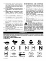 4
4
-
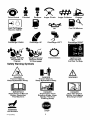 5
5
-
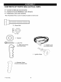 6
6
-
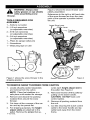 7
7
-
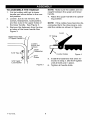 8
8
-
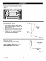 9
9
-
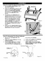 10
10
-
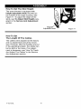 11
11
-
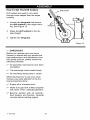 12
12
-
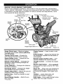 13
13
-
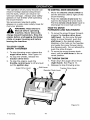 14
14
-
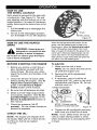 15
15
-
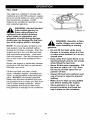 16
16
-
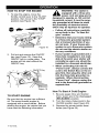 17
17
-
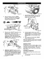 18
18
-
 19
19
-
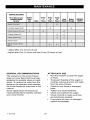 20
20
-
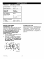 21
21
-
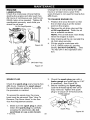 22
22
-
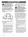 23
23
-
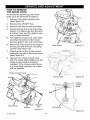 24
24
-
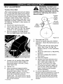 25
25
-
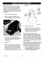 26
26
-
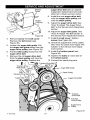 27
27
-
 28
28
-
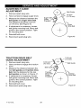 29
29
-
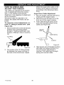 30
30
-
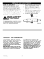 31
31
-
 32
32
-
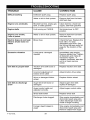 33
33
-
 34
34
-
 35
35
-
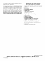 36
36
-
 37
37
-
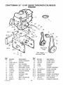 38
38
-
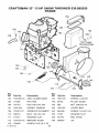 39
39
-
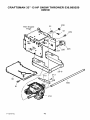 40
40
-
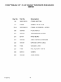 41
41
-
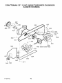 42
42
-
 43
43
-
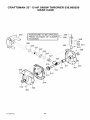 44
44
-
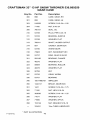 45
45
-
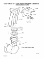 46
46
-
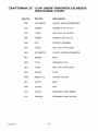 47
47
-
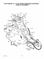 48
48
-
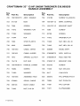 49
49
-
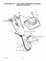 50
50
-
 51
51
-
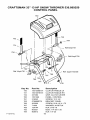 52
52
-
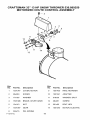 53
53
-
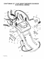 54
54
-
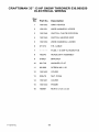 55
55
-
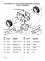 56
56
-
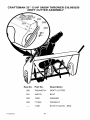 57
57
-
 58
58
-
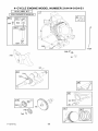 59
59
-
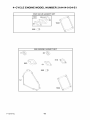 60
60
-
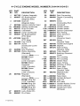 61
61
-
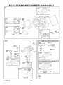 62
62
-
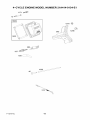 63
63
-
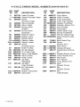 64
64
-
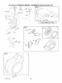 65
65
-
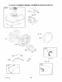 66
66
-
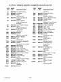 67
67
-
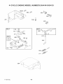 68
68
-
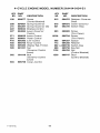 69
69
-
 70
70
-
 71
71
-
 72
72
-
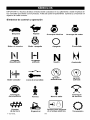 73
73
-
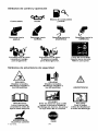 74
74
-
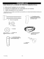 75
75
-
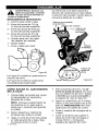 76
76
-
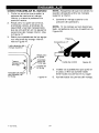 77
77
-
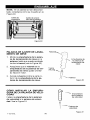 78
78
-
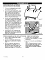 79
79
-
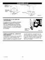 80
80
-
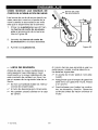 81
81
-
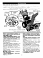 82
82
-
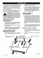 83
83
-
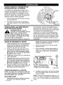 84
84
-
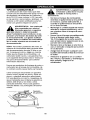 85
85
-
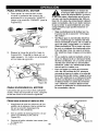 86
86
-
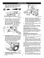 87
87
-
 88
88
-
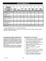 89
89
-
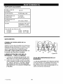 90
90
-
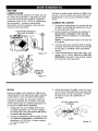 91
91
-
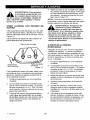 92
92
-
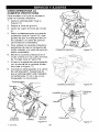 93
93
-
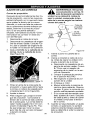 94
94
-
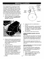 95
95
-
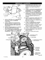 96
96
-
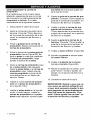 97
97
-
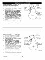 98
98
-
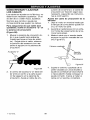 99
99
-
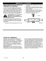 100
100
-
 101
101
-
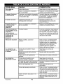 102
102
-
 103
103
-
 104
104
-
 105
105
-
 106
106
-
 107
107
-
 108
108


Craftsman 536889250 El manual del propietario
- Categoría
- Lanzadores de nieve
- Tipo
- El manual del propietario
en otros idiomas
- English: Craftsman 536889250 Owner's manual
Artículos relacionados
-
Craftsman 536.881400 Manual de usuario
-
-
-
-
-
-
-
-
-