Work-pro LW 150 D El manual del propietario
- Tipo
- El manual del propietario


USER MANUAL FOR LW-D LIFTERS 1
IMPORTANT
Carefully read and understand all points and aspects
of this manual. Lifting loads irresponsibly can cause
lethal accidents. Installation of lifting systems and
proper use are only responsibility of the user.
It is recommended to attach this manual with the
tower system used.
In case of doubt, consult the technical department of
Work Lifters.
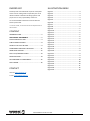
CONTENT
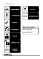
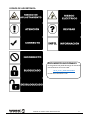
WARNING ICONS ................................................ 2
ADDITIONAL DOCUMENTS ................................ 2
RULES AND SAFETY USE ..................................... 3
PARTS IDENTIFICATION ...................................... 8
HOW TO USE. STEP BY STEP ............................... 9
STANDARDS TAKEN INTO ACCOUNT ................ 11
WIRE DRIVE SYSTEM ........................................ 12
DGUV V17/18 REGULATION. ............................ 13
SPECIFICATIONS ............................................... 14
DECLARATION OF CONFORMITY ...................... 15
DGUV MARK ..................................................... 16
CONTACT
Internet: www.equipson.es
e-mail: support@equipson.es
ILLUSTRATION INDEX
Figure 1 .............................................................. 3
Figure 2 .............................................................. 3
Figure 3 .............................................................. 3
Figure 4 .............................................................. 3
Figure 5 .............................................................. 4
Figure 6 .............................................................. 4
Figure 7 .............................................................. 4
Figure 8 .............................................................. 4
Figure 9 .............................................................. 5
Figure 10 ............................................................ 5
Figure 11 ............................................................ 5
Figure 12 ............................................................ 5
Figure 13 ............................................................ 6
Figure 14 ............................................................ 6
Figure 15 ............................................................ 6
Figure 16 ............................................................ 6
Figure 17 ............................................................ 7
Figure 18 ............................................................ 7
Figure 19 ............................................................ 8
Figure 20 ............................................................ 9
Figure 21 ............................................................ 9
Figure 22 ............................................................ 9
Figure 23 ............................................................ 9
Figure 24 .......................................................... 10
Figure 25 .......................................................... 10
Figure 26 .......................................................... 10
Figure 27 .......................................................... 11
Figure 28 .......................................................... 12
Figure 29 .......................................................... 12


USER MANUAL FOR LW-D LIFTERS 3
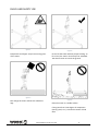
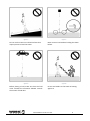
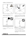
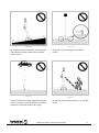
RULES AND SAFETY USE
Figure 1
Keep hands and fingers away from moving parts
of the tower.
Figure 2
Not charge the tower without the stabilizer’s
legs.
Figure 3
Do not lift the tower without proper leveling. To
lift a load, the tower must always be stabilized.
The wheels must not touch the ground.
Figure 4
Place the tower on a stable surface.
If the ground has a low degree of compaction
(earth, gravel, etc..) consult the section of load
data.

USER MANUAL FOR LW-D LIFTERS 4
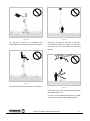
Figure 5
Do not use the tower on inclined surfaces that
require pieces to level the tower.
Figure 6
Before placing a load, make sure that the load
never exceeds the maximum allowed. Consult
the section of load data
Figure 7
Never move a load without leveling the tower
before.
Figure 8
Do not use ladders on the tower or leaning
against it.

USER MANUAL FOR LW-D LIFTERS 5
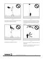
Figure 9
Not grease and lubricate the mechanism of the
winch and the pulleys of the masts.
Figure 10
Not allowed to lift people or animals.
Figure 11
During the rise or descend load process, do not
stand under the load. The load must be secured
to the tower in order to prevent that it cannot
fall down.
Figure 12
Verify that the tower is beyond the reach of
power lines.
The tower is not electrically insulated and can
transmit currents of power lines.

USER MANUAL FOR LW-D LIFTERS 6
On the following table is recommended the
average length between the highest part of the
structure and the power lines.
Voltage
Min. distance
Between phases
Meters
Feet
0 to 230v
1.5
4.92
230v to 400v
2.8
9.19
400v to 50Kv
3.4
11.15
50Kv to 200Kv
4.9
16.08
200Kv to 350Kv
6.5
21.33
350Kv to 500Kv
8.2
26.90
500Kv to 750Kv
11.3
37.07
750Kv to 1000Kv
14.2
46.59
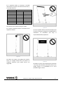
Figure 13
Not use the tower as welding mass.
If necessary, use the grounding placed on the
base.
Figure 14
Not lift a load if there is danger of collision. Take
at least 1.5 meters on any direction to lift the
load safely.
Figure 15
The tower can be used outdoor if the wind speed
is low and If it doesn’t put the installation in risk.
The installation is always under responsibility of
the owner.
Figure 16
Do not use the tower as a support of banners or
another type of decoration with strong wind that
can destabilize the tower and make it falls.

USER MANUAL FOR LW-D LIFTERS 7
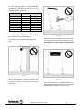
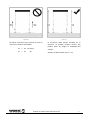
Figure 17
Do not lift structures that require more than
one tower at different speeds.
V1
≠
V2
No lift
V1
=
V2
Ok
Figure 18
The structure must be levelled correctly. If not,
the structure can fall.
Always h1 = h2

USER MANUAL FOR LW-D LIFTERS 8
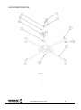
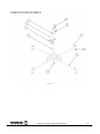
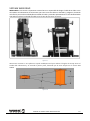
PARTS IDENTIFICATION
Figure 19
1
Bubble level
6
Lock system
2
Winch
7
Level handle
3
Cable
8
Baseplate
4
Wiredrive system
9
Leg
5
Profile
10
Wheel

USER MANUAL FOR LW-D LIFTERS 9
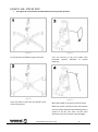
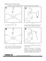
HOW TO USE. STEP BY STEP
• See Figure 26 in this section to understand the security system function.
Figure 20
Fix and secure the stabilizers legs to the base.
Figure 21
Level the tower. Ensure that the wheels never
contact the ground.
Figure 22
Turn the security of the first profile from
horizontal position (blocked) to vertical
(opened).
Figure 23
Move the handle of the winch to lift the tower.
When the section reaches its limit, lock with the
security system and unlock the following security
system to lift the next mast. Do the same
operation until you reach the required height.

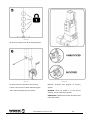
USER MANUAL FOR LW-D LIFTERS 10
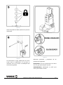
Figure 24
All security systems must be in locked position.
Figure 25
To lower the load: Unlock the first security
system. Turn the winch while maintaining the
other hand unlocking security system.
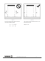
Figure 26
Different positions and purpose of security
system:
BLOCKED: Once the profile is in the correct
position, turn it to block the profile.
UNBLOCKED: Unblock the profile to elevate and
lower the profile.

USER MANUAL FOR LW-D LIFTERS 11
STANDARDS TAKEN INTO ACCOUNT
Figure 27

USER MANUAL FOR LW-D LIFTERS 12
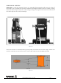
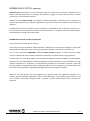
WIRE DRIVE SYSTEM
WIRE DRIVE is a new and important feature. It is responsible for directing the cable across the drum of
the winch in such a manner that it prevents undesired and dangerous cable crosses in the drum, making
easier the cable roll up/unroll process, and avoiding crashing or fraying that could reduce the useful life of
the cable or (in the worst case) its breakage.
Figure 28
Wire Drive consists of a multidirectional grooved pulley that reduces the wire fleet angle between the
winch drum and its entry to the first mast, in order to be compliant with DIN 56950 standard.
Figure 29

USER MANUAL FOR LW-D LIFTERS 13
DGUV V17/18 REGULATION. Explanation
DGUV V17/18 is a norm that regulates the stage and production elements in the entertainment industry.
Lifting equipment and rigging are part of this norm and cover structures and other technical elements.
Adopt DGUV V17/18 is totally voluntary (except in Germany) but its adoption is required by insurance
companies and indeed is becoming a norm in the industry
The application of this norm on lifter towers is vital because, in theaters, stages, etc.., are used to move
loads above artists, technical staff, etc... and in some cases, above viewers, representing a potential risk
of fall.
NORM DGUV V17/18. Fields of application
This standard is oriented in two ways:
On the one hand, lifting towers adopt designs and materials in order to achieve a high degree of safety in
quantities such as supported load, equilibrium, resistance to friction, etc.
Thus, the lifter towers EQUIPSON DGUV V17/18 certified have passed strict controls during design, choice
of materials or load checks and effort.
On the other hand, in order to achieve optimal performance with these units, it is recommended, and a
responsible use of the unit, (meeting basic norms such as obey the maximum load or balance), periodic
maintenance which It must be carried out by expert technicians, checking the condition of the steel cable
and winch, the functioning of the security pins and the folding/unfolding of all sections.
All the above tests are only mandatory in those countries with specific regulations on the matter, applied
through regulations or laws. As manufacturers, we recommend passing all tests in order to prevent
damage and ensure proper operation of lift systems.

USER MANUAL FOR LW-D LIFTERS 14
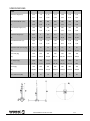
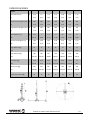
SPECIFICATIONS
Model
LW142D
LW150D
LW155D
LW185D
LW265D
LW290D
LW330D
Minimum Height (m)
a
1,59
1.9
1,72
1,72
1,80
1,84
1,29
(ft)
5,22
6,23
5,64
5,64
5,91
6,04
4,23
Base Folded Width (mm)
b
360
360
360
460
460
460
140
(ft)
1,18
1,18
1,18
1,51
1,51
1,51
0,46
Base Folded Length (mm)
c
360
360
360
460
460
460
140
(ft)
1,18
1,18
1,18
1,51
1,51
1,51
0,46
Maximum Height (m)
d
4,05
5
5,3
5,3
6,5
6,6
3,3
(ft)
13,29
16,40
17,39
17,39
21,33
21,65
10,83
Unfolded diameter (m)
f
1,88
2,06
2,06
2,06
2,52
2,58
1,64
(ft)
6,17
6,76
6,76
6,76
8,27
8,46
5,38
Minimum load capacity (Kg)
25
25
25
25
25
25
25
(Lb)
55,12
55,12
55,12
55,12
55,12
55,12
55,12
Max. load (Kg)
100
100
150
210
220
290
100
(Lb)
220,46
220,46
330,69
462,97
485,02
639,34
220,46
Net weight (Kg)
28,8
32,8
43,4
73,2
93,4
136,8
21
(Lb)
63,49
72,31
95,68
161,38
205,91
301,59
46,3
Winch (Kg)
450
450
350
500
500
900
450
(Lb)
992,08
992,08
771,62
1102,31
1102,31
1984,16
992,08
Noise emissions (dB)
70
70
70
72
72
75
68

USER MANUAL FOR LW-D LIFTERS 15
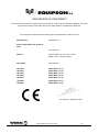
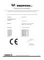
DECLARATION OF CONFORMITY
The tower lifters described complies with all the specific requirements of Directive 2006/42 / EC of the
European Parliament and of the Council of 17 May 2006 on the Machinery Directive.
The tower lifters described meet all the specific requirements in DGUV V17/18
Manufacturer:
EQUIPSON, S.A.
Person responsible of the technical
data:
José Vila Ortiz
Address:
Avda. El Saler, 14 – Pol. Ind. L´Alteró
46460 – Silla – Valencia (Spain)
Description:
Top load lifter
LW 142D
LW 150D
LW 155D
LW 185D
LW 265D
LW 290D
LW 330D
MAX. LOAD: 100 kg
MAX. LOAD: 100 kg
MAX. LOAD: 150 kg
MAX. LOAD: 210 kg
MAX. LOAD: 220 kg
MAX. LOAD: 290 kg
MAX. LOAD: 100 kg
José Vila Ortiz, December 2017

USER MANUAL FOR LW-D LIFTERS 16
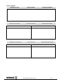
DGUV MARK
NUMERO DE SERIE:
SERIAL NUMBER:
LAUFENDE NUMMER:
Primer test en fábrica
First test in factory.
Erstprüfung im Werk.
Fecha/Date/Datum
Testado por/Tested by/Prüfer
Examen a los cuatro años.
Four years test
UVV Prüfung (alle 4Jahre)
Fecha/Date/Datum
Testado por/Tested by/Prüfer

USER MANUAL FOR LW-D LIFTERS 17
Examen anual a partir
del cuarto año.
Annual test after the fourth
year.
UVV Jährlicher Test nach
dem vierten Jahr.
Fecha/Date/Datum
Testado por/Tested by/Prüfer
Fecha/Date/Datum
Testado por/Tested by/Prüfer
Fecha/Date/Datum
Testado por/Tested by/Prüfer
Fecha/Date/Datum
Testado por/Tested by/Prüfer

MANUAL DE USUARIO PARA TORRES SERIE LW D 1
IMPORTANTE
Leer y comprender de forma precisa todos los puntos
y aspectos de este manual. Elevar cargas de forma
irresponsable puede ocasionar accidentes letales. La
instalación de los sistemas y su correcto uso son sólo
responsabilidad del usuario.
Se recomienda adjuntar este manual junto con el
sistema que se utilice.
En caso de dudas, consultar con el departamento
técnico de EQUIPSON, S.A.
CONTENIDO
ICONOS DE ADVERTENCIA ................................ 2
DOCUMENTOS ADICIONALES ............................ 2
NORMAS Y SEGURIDAD DE USO ........................ 3
IDENTIFICACION DE PARTES .............................. 8
MODO DE USO. PASO A PASO ........................... 9
NORMATIVA TENIDA EN CUENTA .................... 11
SISTEMA WIRE DRIVE ....................................... 12
NORMA DGUV V17/18. .................................... 13
ESPECIFICACIONES ........................................... 14
DECLARACIÓN DE CONFORMIDAD .................. 15
MARCADO DGUV ............................................. 16
CONTACTO
Internet: www.equipson.es
e-mail: support@equipson.es
INDICE DE ILUSTRACIONES
Figura 30 ............................................................ 3
Figura 31 ............................................................ 3
Figura 32 ............................................................ 3
Figura 33 ............................................................ 3
Figura 34 ............................................................ 4
Figura 35 ............................................................ 4
Figura 36 ............................................................ 4
Figura 37 ............................................................ 4
Figura 38 ............................................................ 5
Figura 39 ............................................................ 5
Figura 40 ............................................................ 5
Figura 41 ............................................................ 5
Figura 42 ............................................................ 6
Figura 43 ............................................................ 6
Figura 44 ............................................................ 6
Figura 45 ............................................................ 6
Figura 46 ............................................................ 7
Figura 47 ............................................................ 7
Figura 48 ............................................................ 8
Figura 49 ............................................................ 9
Figura 50 ............................................................ 9
Figura 51 ............................................................ 9
Figura 52 ............................................................ 9
Figura 53 .......................................................... 10
Figura 54 .......................................................... 10
Figura 55 .......................................................... 10
Figura 56 .......................................................... 11
Figura 57 .......................................................... 12
Figura 58 .......................................................... 12


MANUAL DE USUARIO PARA TORRES SERIE LW D 3
NORMAS Y SEGURIDAD DE USO
Figura 30
Mantener las manos y dedos fuera del alcance
de elementos móviles de la torre.
Figura 31
No cargar la torre sin colocar las patas
estabilizadoras.
Figura 32
No elevar la torre sin una correcta nivelación.
Para poder elevar una carga, la torre siempre
deberá estar estabilizada. Las ruedas no deben
tocar el suelo.
Figura 33
Colocar la torre en una superficie estable.
Si el suelo es de bajo grado de compactación
(tierra, gravilla, etc..) consultar en el apartado de
datos de carga.

MANUAL DE USUARIO PARA TORRES SERIE LW D 4
Figura 34
No utilizar la torre en superficies con inclinación
que precisen de tacos o piezas para conseguir
nivelar la torre.
Figura 35
Antes de colocar una carga, asegúrese de que la
carga no excede nunca del máximo permitido.
Consultar el apartado de datos de cargas.
Figura 36
No mover nunca una carga con la torre sin
nivelar.
Figura 37
No usar escaleras encima de la torre, ni apoyada
en ella.

MANUAL DE USUARIO PARA TORRES SERIE LW D 5
Figura 38
No engrasar, ni lubricar el mecanismo del
cabrestante ni las poleas internas de los mástiles.
Figura 39
No autorizada para elevar personas ni animales.
Figura 40
Durante el proceso de elevación o descenso,
evite ponerse debajo de la carga. La carga debe
estar fijada a la torre de manera que no pueda
soltarse.
Figura 41
Comprobar que la torre queda fuera del alcance
de tendidos eléctricos.
La torre no está aislada eléctricamente y puede
transmitir las corrientes del tendido eléctrico.

MANUAL DE USUARIO PARA TORRES SERIE LW D 6
En la siguiente tabla se aconseja la medida
mínima entre la parte más alta de la estructura y
el tendido eléctrico.
Voltaje
Distancia mínima aproximada
Entre fases
Metros
Pies
0 a 230v
1.5
4.92
230v a 400v
2.8
9.19
400v a 50Kv
3.4
11.15
50Kv a 200Kv
4.9
16.08
200Kv a 350Kv
6.5
21.33
350Kv a 500Kv
8.2
26.90
500Kv a 750Kv
11.3
37.07
750Kv a 1000Kv
14.2
46.59
Figura 42
No utilizar la torre como masa para soldar.
En caso de necesidad, utilizar la toma de tierra
alojada en la base.
Figura 43
No elevar una carga si hay peligro de colisión.
Tener un margen mínimo de 1,5 metros en
cualquier dirección para poder elevar con
seguridad.
Figura 44
La torre se podrá utilizar al aire libre siempre que
el viento no ponga en peligro la estabilidad de la
instalación. La instalación está bajo la
responsabilidad del propietario.
Figura 45
No utilizar la torre como soporte para pancartas
u otro tipo de decorados con fuerte viento. Esto
puede afectar a la estabilidad de la torre
pudiendo llegar a volcar.

MANUAL DE USUARIO PARA TORRES SERIE LW D 7
Figura 46
No elevar estructuras que precisen de más de
una torre a distintas velocidades.
V1
≠
V2
No elevar
V1
=
V2
Ok
Figura 47
La estructura debe quedar nivelada, de lo
contrario, se pueden producir fuerzas que
pueden poner en peligro la estabilidad del
sistema.
Siempre se debe cumplir que h1 = h2

MANUAL DE USUARIO PARA TORRES SERIE LW D 8
IDENTIFICACION DE PARTES
Figura 48
1
Nivel de burbuja
6
Sistema de bloqueo
2
Cabestrante
7
Manija del estabilizador
3
Cable
8
Plato del estabilizador
4
Sistema Wiredrive
9
Pata
5
Perfil
10
Rueda

MANUAL DE USUARIO PARA TORRES SERIE LW D 9
MODO DE USO. PASO A PASO
• Ver Figura 55 en esta sección para entender el funcionamiento del sistema de seguridad.
Figura 49
Fijar y asegurar las patas a la base.
Figura 50
Colocar la torre en su posición de trabajo y
nivelar hasta que el nivel de burbuja quede
centrado. Las ruedas no deben tocar el suelo.
Figura 51
Girar el pasador de seguridad del primer tramo
desde la posición bloqueada a desbloqueada
Figura 52
Accionar la manivela del cabrestante para elevar
el primer mástil.
Cuando el tramo llegue a su final de carrera,
bloquear con el sistema de seguridad y
desbloquear el siguiente sistema de seguridad
para elevar el siguiente mástil. Realizar la misma
operación hasta llegar a la altura requerida.

MANUAL DE USUARIO PARA TORRES SERIE LW D 10
Figura 53
Todos los pasadores deben quedar en la posición
de bloqueo.
Figura 54
Para descender la carga, desbloquear el primer
tramo. Girar el cabrestante a la vez que se
mantiene con la otra mano el desbloqueo del
sistema de seguridad.
Figura 55
Diferentes posiciones y propósitos de los
pasadores de seguridad:
BLOQUEADO: Una vez el perfil esté en la altura
correcta, gire para bloquear el perfil.
DESBLOQUEADO: Desbloquee el perfil para
elevar y descender el tramo.

MANUAL DE USUARIO PARA TORRES SERIE LW D 11
NORMATIVA TENIDA EN CUENTA
Figura 56

MANUAL DE USUARIO PARA TORRES SERIE LW D 12
SISTEMA WIRE DRIVE
WIRE DRIVE es una nueva e importante característica. Es responsable de dirigir el cable de un lado a otro
del tambor del cabrestante de tal manera que evita cruces de cable no deseados y peligrosos, haciendo
más fácil el proceso de enrollado/desenrollado del cable y evitando aplastamientos o hilos deshilachados
que podrían reducir la vida útil del cable o (en el peor de los casos) su rotura.
Figura 57
Wire Drive consiste en una polea en espiral multidireccional que reduce el ángulo de esviaje entre el
tambor del cabrestante y su entrada al primer perfil, haciendo que la torre cumpla con la norma DIN
56950.
Figura 58

MANUAL DE USUARIO PARA TORRES SERIE LW D 13
NORMA DGUV V17/18. Explicación
DGUV V17/18 (antes BGVC1) es una norma que regula los elementos de escenario y producción en la
industria del entretenimiento. Los equipos de elevación y rigging son parte de esta norma y cubren
estructuras y otros elementos técnicos.
Adoptar la norma DGUV V17/18 es totalmente voluntaria (excepto en Alemania) pero su adopción se
requiere generalmente por compañías aseguradoras y de hecho se está convirtiendo en una norma en la
industria.
La aplicación de esta norma sobre las torres elevadoras es vital debido a que, en teatros, escenarios, etc.,
se usan para par mover cargas sobre artistas, personal técnico etc., y en algunos casos sobre espectadores,
representando un riesgo potencial de caída.
NORMA DGUV V17/18. Campos de aplicación
Esta norma está orientada de dos maneras:
Por un lado, las torres elevadoras adoptan diseños y materiales con el objeto de conseguir un alto grado
de seguridad en magnitudes tales como carga soportada, equilibrio, resistencia a la fricción, etc.
Así, las torres elevadoras EQUIPSON certificadas DGUV V17/18 aseguran al usuario que han pasado
estrictos controles durante su diseño, elección de materiales o verificaciones de carga y esfuerzo.
Por otro lado, con el fin de conseguir un funcionamiento óptimo con estas unidades, es recomendable,
además de un uso responsable de la unidad (cumpliendo unas normas básicas como son obedecer la carga
máxima soportada o su equilibrio), un mantenimiento periódico el cual debe ser llevado a cabo por
técnicos expertos, comprobando el buen estado del cable de acero y cabrestante, el funcionamiento de
los pasadores de seguridad y el plegado/desplegado del sistema completo de perfiles.
Todos los test mencionados solo son obligatorios en aquellos países con regulación específica en la
materia, aplicada mediante regulaciones o leyes. Como fabricantes, recomendamos pasar todos los test
con el objetivo de prevenir cualquier daño y asegurar un buen funcionamiento de los sistemas de
elevación.

MANUAL DE USUARIO PARA TORRES SERIE LW D 14
ESPECIFICACIONES
Modelo
LW142D
LW150D
LW155D
LW185D
LW265D
LW290D
LW330D
Altura Mínima (m)
a
1,59
1.9
1,72
1,72
1,80
1,84
1,29
(ft)
5,22
6,23
5,64
5,64
5,91
6,04
4,23
Anchura base plegada (mm)
b
360
360
360
460
460
460
140
(ft)
1,18
1,18
1,18
1,51
1,51
1,51
0,46
Longitud base plegada (mm)
b
360
360
360
460
460
460
140
(ft)
1,18
1,18
1,18
1,51
1,51
1,51
0,46
Altura Máxima (m)
d
4,05
5
5,3
5,3
6,5
6,6
3,3
(ft)
13,29
16,40
17,39
17,39
21,33
21,65
10,83
Diámetro Desplegada (m)
f
1,88
2,06
2,06
2,06
2,52
2,58
1,64
(ft)
6,17
6,76
6,76
6,76
8,27
8,46
5,38
Carga Mínima (Kg)
25
25
25
25
25
25
25
(Lb)
55,12
55,12
55,12
55,12
55,12
55,12
55,12
Carga Máxima (Kg)
100
100
150
210
220
290
100
(Lb)
220,46
220,46
330,69
462,97
485,02
639,34
220,46
Peso Neto (Kg)
28,8
32,8
43,4
73,2
93,4
136,8
21
(Lb)
63,49
72,31
95,68
161,38
205,91
301,59
46,3
Cabestrante (Kg)
450
450
350
500
500
900
450
(Lb)
992,08
992,08
771,62
1102,31
1102,31
1984,16
992,08
Emisiones de ruido (dB)
70
70
70
72
72
75
68

MANUAL DE USUARIO PARA TORRES SERIE LW D 15
DECLARACIÓN DE CONFORMIDAD
Las torres elevadoras descritas cumplen con todos los requerimientos específicos en la directiva 2006/42/EC del
Parlamento Europeo y del Consejo de 17 de mayo de 2006 relativo a la Directiva de máquinas.
Las torres elevadoras descritas cumplen con todos los requerimientos específicos en la DGUV V17/18
Fabricante:
EQUIPSON, S.A.
Persona responsible de la
Recopilación:
José Vila Ortiz
Dirección:
Avda. El Saler, 14 – Pol. Ind. L´Alteró
46460 – Silla – Valencia (Spain)
Descripción:
Torres de carga superior
LW 142D /DY
LW 150D /DY
LW 155D /DY
LW 185D /DY
LW 265D /DY
LW 290D /DY
LW 330D
CARGA MÁX.: 100 kg
CARGA MÁX.: 100 kg
CARGA MÁX.: 150 kg
CARGA MÁX.: 210 kg
CARGA MÁX.: 220 kg
CARGA MÁX.: 290 kg
CARGA MÁX.: 100 kg
José Vila Ortiz,
Dicienbre 2017

MANUAL DE USUARIO PARA TORRES SERIE LW D 16
MARCADO DGUV
NUMERO DE SERIE:
SERIAL NUMBER:
LAUFENDE NUMMER:
Primer test en fábrica
First test in factory.
Erstprüfung im Werk.
Fecha/Date/Datum
Testado por/Tested by/Prüfer
Examen a los cuatro años.
Four years test
UVV Prüfung (alle 4Jahre)
Fecha/Date/Datum
Testado por/Tested by/Prüfer

MANUAL DE USUARIO PARA TORRES SERIE LW D 17
Examen anual a partir
del cuarto año.
Annual test after the fourth
year.
UVV Jährlicher Test nach
dem vierten Jahr.
Fecha/Date/Datum
Testado por/Tested by/Prüfer
Fecha/Date/Datum
Testado por/Tested by/Prüfer
Fecha/Date/Datum
Testado por/Tested by/Prüfer
Fecha/Date/Datum
Testado por/Tested by/Prüfer

MANUAL DE USUARIO PARA TORRES SERIE LW D 18
-
 1
1
-
 2
2
-
 3
3
-
 4
4
-
 5
5
-
 6
6
-
 7
7
-
 8
8
-
 9
9
-
 10
10
-
 11
11
-
 12
12
-
 13
13
-
 14
14
-
 15
15
-
 16
16
-
 17
17
-
 18
18
-
 19
19
-
 20
20
-
 21
21
-
 22
22
-
 23
23
-
 24
24
-
 25
25
-
 26
26
-
 27
27
-
 28
28
-
 29
29
-
 30
30
-
 31
31
-
 32
32
-
 33
33
-
 34
34
-
 35
35
-
 36
36


Work-pro LW 150 D El manual del propietario
- Tipo
- El manual del propietario
En otros idiomas
- English: Work-pro LW 150 D Owner's manual
Documentos relacionados

Otros documentos
-
Sony sa ve 100 El manual del propietario
-
 Quadrafire Trekker Series Pellet Insert Manual de usuario
-
DOMUS LINE V17 Radio Receiver for Lighting Control Manual de usuario
-
Fenix ELV-150/5 Instructions Manual
-
-
-
 PRO LIFTS TE-034B ALS Towerlift 125kg Bk Manual de usuario
-
 PROLIFTS VMB HDT-8 Operating Instructions & User Manual
-
Allmand NIGHT-LITE PRO II Manual de usuario
-
Blitz Master Gear S3 1,0 El manual del propietario


