Craftsman 139.53924 El manual del propietario
- Categoría
- Abridor de puerta de garage
- Tipo
- El manual del propietario
Este manual también es adecuado para

Owner's Manual/Manual Del Propietario
ICRRFTSMI:INI
314 HP
GARAGE DOOR OPENER
ABRIDOR DE PUERTA DE COCHERA
For Residential Use Only/Solo para uso residencial
Models/Modelos 139.53924
m
Z
G3
m
I"11
Z_
C3
Read and follow all safety rules
and operating instructions before
first use of this product.
Fasten the manual near the garage
door after installation.
Periodic checks of the opener are
required to ensure safe operation.
Leer y seguir todas las reglas de
seguridad y las instrucciones de
operacion antes de usar este
producto por primera vez.
Guardar este manual cerca de la
puerta de la cochera.
Se deben realizar revisiones
periodicas del abridor de puertas
para asegurar su operacion
segura.
Sears, Roebuck and Co., Hoffman Estates, IL 60179 U.S.A
www.sears.com/craftsman

TABLE OF CONTENTS
Introduction 2- 7
Safety symbol and signal word review ........................ 2
Preparing your garage door ........................................ 3
Tools needed ............................................................... 3
Planning .................................................................. 4-5
Carton inventory .......................................................... 6
Hardware inventory ..................................................... 7
Assembly 8.11
Assemble the rail ..................................................... 8-9
Fasten rail to motor unit and install trolley ................ 10
Attach rail brackets .................................................... 11
Installation 11.26
Installation safety instructions .................................... 11
Determine the header bracket location ..................... 12
Install the header bracket .......................................... 13
Attach the rail to the header bracket ......................... 14
Install the Protector System ®................................ 15-17
Position the opener ................................................... 18
Hang the opener ....................................................... 19
Install the door control and connect wiring ............... 20
Electrical requirements .............................................. 21
Complete the sensor installation ............................... 21
Install the lights ......................................................... 22
Attach the emergency release rope and handle .......22
Fasten the door bracket ....................................... 23-24
Connect door arm to trolley ................................. 25-26
Adjustment Section 27-29
Adjust the travel limits ............................................... 27
Adjust the force ......................................................... 28
Test the safety reversing sensor ............................... 29
Test the Protector System ®........................................ 29
Operation 30-34
Operation safety instructions ..................................... 30
Using your garage door opener ................................ 30
Using the wall-mounted Door Control ....................... 31
The Plug-In Light Control .......................................... 31
To open the door manually ........................................ 31
Care of your garage door opener .............................. 32
Having a problem? .................................................... 33
Diagnostic Chart ........................................................ 34
Programming 35-36
To add or reprogram a hand-held remote control .....35
To erase all codes ..................................................... 35
3-Function Remote Control ....................................... 35
To add or change a Keyless Entry PIN ..................... 36
Repair Parts 37-38
Rail assembly parts ................................................... 37
Installation parts ........................................................ 37
Motor unit assembly parts ......................................... 38
Accessories 39
Warranty 39
Service Numbers Back cover
INTRODUCTION
Safety Symbol
and Signal Word Review
This garage door opener has been designed and tested to offer safe service provided it is installed, operated,
maintained and tested in strict accordance with the instructions and warnings contained in this manual.
Mechanical
Electrical
When you see these Safety Symbols and Signal
Words on the following pages, they will alert you to
the possibility of serious injury or death if you do
not comply with the warnings that accompany them.
The hazard may come from something mechanical
or from electric shock. Read the warnings carefully.
When you see this Signal Word on the following
pages, it will alert you to the possibility of damage to
your garage door and/or the garage door opener if
you do not comply with the cautionary statements
that accompany it. Read them carefully.

Preparing your garage door
Before you begin:
• Disable locks.
• Remove any ropes connected to garage door.
• Complete the following test to make sure your
garage door is balanced and is not sticking or
binding:
1. Lift the door about halfway as shown. Release
the door. If balanced, it should stay in place,
supported entirely by its springs.
2. Raise and lower the door to see if there is any
binding or sticking.
If your door binds, sticks, or is out of balance, call a
trained door systems technician.
To prevent possible SERIOUSINJURYor DEATH:
• ALWAYScall atrained door systems technician if
garage door binds,sticks, or is out of balance.An
unbalancedgaragedoor may not reverse when
required.
• NEVERtry to loosen, move or adjust garage door,door
springs, cables, pulleys, brackets or their hardware,all
of which are under EXTREMEtension.
• DisableALL locks and removeALL ropes connectedto
garage door BEFOREinstalling and operating garage
door opener to avoid entanglement.
To prevent damageto garage door and opener:
• ALWAYSdisable locks BEFOREinstalling and operating
the opener
• ONLYoperategaragedoor opener at 120V,60 Hzto
avoid malfunction and damage
Sectional Door
One-Piece Door
Tools needed
During assembly, installation and adjustment of the
opener, instructions will call for hand tools as
illustrated below.
Stepladder
Level (optional)
Tape Measure
Pencil
Dr_ Wire Cutters
Drill 3/16", 5/16"
and 5/32"
°
O0 S/°2c"_;t/_ 't n,11W!e;,il6" Locking pliers
and 1/4"
Hack Saw
Screwdriver
Adjustable End Wrench

Planning
Identify the type and height of your garage door.
Survey your garage area to see if any of the
conditions below apply to your installation. Additional
materials may be required. You may find it helpful to
refer back to this page and the accompanying
illustrations as you proceed with the installation of
your opener.
Depending on your requirements, there are several
installation steps which may call for materials or
hardware not included in the carton.
• Installation Step 1 - Look at the wall or ceiling
above the garage door. The header bracket must
be securely fastened to structural supports.
• Installation Step 6 - Do you have a finished ceiling
in your garage? If so, a support bracket and
additional fastening hardware may be required.
• Installation Step 4- Depending upon garage
construction, extension brackets or wood blocks
may be needed to install sensors.
• Installation Step 4 - Alternate floor mounting of the
safety reversing sensor will require hardware not
provided.
Do you have an access door in addition to the
garage door? If not, Model 53702 Emergency Key
Release is required. See Accessories page.
Look at the garage door where it meets the floor.
Any gap between the floor and the bottom of the
door must not exceed 1/4" (6 mm). Otherwise, the
safety reversal system may not work properly. See
Adjustment Step 3. Floor or door should be
repaired.
SECTIONAL DOOR INSTALLATIONS
• Do you have a steel, aluminum, fiberglass or glass
panel door? If so, horiFontal and vertical
reinforcement is required (Installation Step 12).
• The opener should be installed above the center of
the door. If there is a torsion spring or center
bearing plate in the way of the header bracket, it
may be installed within 4 feet (1.22 m) to the left or
right of the door center. See Installation Steps 1
and 12.
• If your door is more than 7 feet (2.13 m) high, see
rail extension kits listed on Accessories page.
SECTIONAL DOOR INSTALLATION
Horizontal and vertical reinforcement
is needed for lightweight garage doors
(fiberglass, steel, aluminum, door with
glass panels, etc.). See page 23 for details,
...
....,, Header Wall
Torsion
Spring
Rail
Extension
OR Spring
FINISHED CEILING
jJ
Support bracket & j
fastening hardware
is required.
See page 19.
Motor unit
i
Wall-
mounte
Door
Control
Safety Reversing Sensor
Safety Reversing
Gap between floor Sensor
and bottom of door
must not exceed 1/4" (6 ram).
Access
Door
0
_ader
all
rage
or
CLOSED POSITION
Header Rail Rail Assembly
Bracket Bracket [
Arm
Curved
Door
Door
Arm
Bracket
Emergency
Release
Rope & Handle
4

Planning (Continued)
ONE-PIECE DOOR INSTALLATIONS
• Generally, a one-piece door does not require
reinforcement. If your door is lightweight, refer to
the information relating to sectional doors in
Installation Step 12.
• Depending on your door's construction, you may
need additional mounting hardware for the door
bracket (Step 12).
Without a properly working safety reversal system,
persons (particularly small children) could be
SERIOUSLYINJUREDor KILLEDby a closing garage
door.
• Thegapbetweenthe bottom of the garage door and
the floor MUSTNOTexceed 1/4"(6 mm). Otherwise,
the safety reversal system may not work properly.
• Thefloor or the garage door MUSTbe repairedto
eliminate the gap.
ONE-PIECE DOOR WITHOUT TRACK
FINISHED CEUNG
Support bracket
& fastening
hardware is required.
See page 19.
Safety Reversing Sensor
Rail
- d
f
Safet/ R_v e,_
Sensor
Gap between floor
and bottom of door must not exceed 1/4" (6 ram},
Motor unit
Rail
Bracket
Header
Bracket
Door
Bracket
Garage
Door
CLOSED POSITION
Trolle
Straight Curved
Door Door
Arm Arm
Rail Assembly
Emergency
Release
Rope & Handle
ONE-PIECE DOOR WITH TRACK
Door
ol
Safety
_" Gap between floor Reversing
J_ and bottom of door Sensor
afety must not exceed 1/4" (6 turn).
Reversing Sensor
Garage
Door
CLOSED POSITION
Rail Trolley
curved I
Bracket Door Arm _fl_ Rail Assembly
....... I.... j... I
Dr°Crket Stlraight 1
Door
Arm Emergency Release
Rope & Handle

Carton Inventory
Your garage door opener is packaged in one carton
which contains the motor unit and all parts illustrated
below. Accessories will depend on the model
purchased. If anything is missing, carefully check the
packing material. Hardware for assembly and
installation is shown on the next page. Save the
carton and packing material until installation and
adjustment is complete.
Motion Detecting SECURITY+
Control Panel Three-Function Remote Control
with Visor Clip (2)
Rail Support
Plug-In Braces_
Light Control
©
Sprocket
SECURITY+ Coupling
Keyless Entry
2-Conductor Bell Wire
White & White/Red
Rail
Assembly
Motor Unit with 2 Light Lenses
Header Bracket
Header/Rail
Brackets
Door Bracket
Straight Door
Arm Section
Hanging Bracket
Curved Door
Arm Section
12)Seaf_lyR_ye rsin_
with attached 2-Conductor
White & White/Black Bell Wire
Safety Reversing Sensor
Mounting Bracket (2)
SafetYnLdabels
L terature

Hardware Inventory
Separate all hardware and group as shown below for the assembly and installation procedures.
ASSEMBLY HARDWARE
Bolt Hex Bolt Lock Nut
1/4-20xl-3/4" (8) 1/4'L20x5/8" (4) 1/4'L20x7/16 (12) Sprocket Coupling Sleeve
INSTALLATION HARDWARE
Carriage Bolt
1/4'L20x1/2 '' (2)
Nut 5/16"-18 (6)
Lag Screw
5/16"-9xl-5/8" (2)
Lag Screw
5/16"-18xl -7/8" (2)
Carriage Bolt
5/16'L18x2-1/2" (2)
Wing Nut Ring Handle
1/4'L20 (2) Fastener (3)
Hex Bolt
5/16"-18x7/8" (4)
Screw
6ABxl-1/4 '_(2)
Clevis Pin
5/16"x2-3/4" (1)
Insulated
Lock Washer 5/16" (6) Staples (30)
Dry Wall Anchors (2)
Clevis Pin
5/16"x1" (1)
Screw 6-32x1" (2)
Rope
Clevis Pin
5/16"x1-1/4" (1)

ASSEMBLY STEP 1
Assemble the Rail
To avoid installation difficulties, do not run the
garage door opener until instructed to do so.
1. Turn the opened rail carton upside down and empty
its contents onto a level work surface.
2. Unfold the rails, taking care to avoid kinking the
screw rod joints.
3. Rotate the rail sections so that the flat side is down
and the screw side is up for all three lengths. Keep
it clean and free of debris while you are working.
To prevent INJURYfrom pinching, keephandsand
fingers awayfrom the joints while assemblingthe rail.
Rail
Support
Braces ............
Straight
Door Arm
Extend Remove
End Rails _1,,-,,,, _ Cardboard Packing
Outward - )
Center
Rail
Trolley Rack
Rail Assembly
Carton / _ "_
Remove
Cardboard
Packing
Extend
End Rails
Outward
Rail Assembly
Hardware Bag
Chassis Assembly
Hardware Bag
NOTE: During assembly, avoid pulling the rail section
housing the trolley rack away from the screw rod.
The rack is factory set about 9" (23 cm) from the end
of the screw rod to the center of the rack.
If the plastic liner slides part way out during
assembly, simply push it back in.
Rotate
Sprocket End Rail
Rail
Sprocket
Center Rail
Trolley Rack
Door End Rail

Assemble the Rail (Continued)
4. Beginning with the sprocket end, straighten the
three rail sections so that the screw rod is in a
straight line at the joints. (Avoid handling the joints,
which may have sharp edges.)
5. Carefully slide the pins at the top edge of the rail
into the openings on the adjacent rail. It is
essential that the rail assembly be on a level
surface to achieve proper alignment and to
avoid damage to the pins.
6. Insert two 1/4"-20xl 4/4" bolts through the center
holes of a brace, and place its open length against
the rail at the joint, aligning the holes as shown.
Position another brace on the opposite side of the
rail over the bolts, add 1/4"-20 lock nuts, and hand
tighten. Insert two additional bolts and hand
tighten.
7. Keeping the rail straight and on a level surface,
grasp the screw rods on each side of the
remaining joint and pivot into a straight line.
Repeat steps 5 and 6.
8. With a 7/16" wrench, tighten bolts until snug,
beginning with the center holes. Do NOT
overtighten.
HARDWARE SHOWN ACTUAL SIZE
Bolt Lock Nut
1/4"-20xl-3/4" (8) 1/4"-20
Sprocket End
(Back)
Rail
Support
Brace
Lock
Nuts
Door End
(Front)
Rail Pin
Alignment /
Hole
/
Lock
Nuts
Slide end rail
toward center rail
Rail
Support
Brace
Alignment
Hole
Rail Pin ::
..
Slide end rail
f toward center rail
Center Rail
Bolts
1/4 "-20x 1-3/4"

ASSEMBLY STEP 2
Fasten the Rail To the Motor Unit
and Install the Trolley
• Working on a level surface, align the rail assembly
with the motor unit, as shown.
• Slip the coupling over the rail sprocket.
• Slide the rail through the motor unit bracket until
the coupling fits securely over the motor unit
sprocket.
• Align the two bolt holes in the rail with those in the
motor unit bracket. Insert two 1/4"-20x5/8" hex
bolts and lock nuts. Tighten securely with a 7/16"
socket wrench.
• Slide the trolley onto and along the bottom of the
rail until it snaps firmly in place. Be certain to
install it facing correctly: the trolley release
arm must be horizontal (lock position), with its
arrow pointed away from the motor unit.
HARDWARE SHOWN ACTUAL SIZE
Lock Nut
Hex Bolt 1/4"-20
1/4"-20x5/8"
©
Lock Nuts
1/4"-20
I
Coupling
Rail
Sprocket
Release arm Arrow must point
toward garage door
Motor Unit
Bracket
Motor Unit
Sprocket
Hex Bolts
1/4"-20x5/8"
10

ASSEMBLY STEP 3
Attach the Rail Brackets
• Align rail brackets to end of rail assembly, as
shown.
• Insert two 1/4"-20 x 5/8" hex bolts and lock nuts.
Tighten securely with a 7/16" socket.
You have now finished assembfing your garage
door opener. Please read the following warnings
before proceeding to the installation section.
v
Hex Bolts
1/4"-20x5/8
Rail
J Brackets
Rail
HARDWARE SHOWN ACTUAL SIZE
Lock Nut
Hex Bolt 1/4"-20
1/4"-20x5/8"
©
Lock Nuts
1/4"-20
INSTALLATION
IMPORTANT INSTALLATION INSTRUCTIONS
To reduce the risk of severe injury or death:
1. READAND FOLLOWALL INSTALLATIONWARNINGS
AND INSTRUCTIONS.
2. Install garage door opener only on properly balanced
and lubricated garage door. An improperly balanced
door may not reversewhen required and could result in
SEVEREINJURYor DEATH.
3. All repairsto cables,spring assembliesand other
hardwareMUSTbe madeby a trained door systems
technician BEFOREinstalling opener.
4. Disableall locks and removeall ropesconnectedto
garage door BEFOREinstalling opener to avoid
entanglement.
5. Install garage door opener 7 feet (2.13 m) or more
above floor.
6. Mount emergencyreleasehandle 6 feet (1.83 m) above
floor.
7. NEVERconnect garage door openerto power source
until instructed to do so.
8. NEVERwearwatches, rings or looseclothing while
installing or servicing opener.They could be caught in
garage door or opener mechanisms.
9. Installwall-mounted garage door control:
• within sight of the garage door.
• out of reach of children at minimum height of 5 feet
(1.5 m).
• awayfrom all moving parts of the door.
10. Placeentrapmentwarning label on wall next to garage
door control.
11. Placemanual release/safetyreversetest label in plain
view on inside of garage door.
12. Uponcompletion of installation, test safety reversal
system. Door MUST reverseon contact with a
1-1/2" (3.8 cm) high object (or a 2x4 laid flat) on
the floor.
11

INSTALLATION STEP 1
Determine the Header Bracket
Location
Toprevent possible SERIOUSINJURYor DEATH:
• Headerbracket MUSTbe RIGIDLYfastenedto
structural support on headerwall or ceiling, otherwise
garagedoor might not reversewhen required. DONOT
install headerbracket over drywall.
• Concreteanchors MUSTbe usedif mounting header
bracket or 2x4 into masonry.
• NEVERtry to loosen, move or adjust garagedoor,
springs, cables, pulleys, brackets,or their hardware,
all of which are under EXTREMEtension.
• ALWAYScall a trained door systems technician if
garagedoor binds, sticks, or is out of balance.An
unbalancedgarage door might not reversewhen
required.
Installation procedures vary according to garage door
types. Follow the instructions which apply to your
door.
1. Close the door and mark the inside vertical
centerline of the garage door.
2. Extend the line onto the header wall above the
door.
You can fasten the header bracket within 4 feet
(1.22 m) of the left or right of the door center
only if a torsion spring or center bearing plate
is in the way; or you can attach it to the ceiling
(see page 13) when clearance is minimal. (It
may be mounted on the wall upside down if
necessary, to gain approximately 1/2" (1 cm).
If you need to install the header bracket on a 2x4
(on wall or ceiling), use lag screws (not provided)
to securely fasten the 2x4 to structural supports as
shown here and on page 13.
3. Open your door to the highest point of travel as
shown. Draw an intersecting horizontal line on the
header wall above the high point:
• 3" (7.5 cm) above the high point for sectional
door and one-piece door with track.
• 8" (20 cm) above the high point for one-piece
door without track.
This height will provide travel clearance for the top
edge of the door.
NOTE: If the total number of inches exceeds the
height available in your garage, use the maximum
height possible, or refer to page 13 for ceiling
installation.
Header Wall
Unllnigh_ 2x_
Vertical Centerline
of Garage Door
2x4
/
OPTIONAL
CEILING
MOUNT
FOR
HEADER
BRACKET
Structural
Supports
n r
I Header Wall
_'_, 3" (7.5 cin)Track
// /
/Highest Point
ofTravel
Door
Sectional door with curved track
Header Wall
_'_ 3" (7.5 sin) _ ,
• _ ..... _/racK
_nt
_ of Travel
J
d"
17
One-piece door with horizontal track
_Wall
i 8"(20sin)
Ooor
One-piece door without track:
jamb hardware
Header Wall
', Highest
J_
,, Point
J_
,, of Travel
JF
_F
J_
One-piece door without track:
pivot hardware
12

INSTALLATION STEP 2
Install the Header Bracket
You can attach the header bracket either to the wall
above the garage door, or to the ceiling. Follow the
instructions which will work best for your particular
requirements. Do not install the header bracket
over drywall. If installing into masonry, use
concrete anchors (not provided).
WALL HEADER BRACKET INSTALLATION
• Center the bracket on the vertical centerline with
the bottom edge of the bracket on the horizontal
line as shown (with the arrow pointing toward the
ceiling).
• Mark the vertical set of bracket holes (do not use
the holes designated for ceiling mount). Drill 3/16"
pilot holes and fasten the bracket securely to a
structural support with the hardware provided.
Wall Mounting Holes
Optional
Wall Mounting Holes
Header
= Wall
2x4
Structural j
Support
The nail hole is for
You must use lag screws
to mount the header bracket.
Vertical
•Centerline of
Garage Door
Lag Screws
5/16"x9x1-5/8"
HARDWARE SHOWN ACTUAL SIZE
J J I I I EE
Lag Screw
5/16"-9xl -5/8"
/ f
/
Horizontal
Line / /
f
"l j
Highest Point of
Garage Door Travel
Garage
= Door =
Centerline of
Garage Door
CEILING HEADER BRACKET INSTALLATION
• Extend the vertical centerline onto the ceiling as
shown.
• Center the bracket on the vertical mark, no more
than 6" (15 cm) from the wall. Make sure the arrow
is pointing away from the wall. The bracket can be
mounted flush against the ceiling when clearance
is minimal.
• Mark the side holes. Drill 3/16" pilot holes and
fasten bracket securely to a structural support with
the hardware provided.
Ceiling Mounting Holes
Door
___ - Finished Ceiling -
/ __ t / / _/ / Vertical
_ / _/_tIHeader Centerline
__ Bracket of Garage Door
6" (15 cm)
Maximum -_1
Lag Screws
5/16"-9xl -5/8"
The nail hole is for
positioning only.
You must use lag screws
to mount the header bracket.
nf Qnr_a_ Dnnr
Header Wall
13

Header Wall
Header Bracket
Rail Bracket
INSTALLATION STEP 3
Attach the Rail to the Header
Bracket
• Position the opener on the garage floor below the
header bracket. Use packing material as a
protective base. NOTE: If the door spring is in the
way you'll need help. Have someone hold the
opener securely on a temporary support to allow
the rail to clear the spring.
• Position the rail bracket against the header
bracket.
• Align the bracket holes and join with a clevis pin
5/16"x2-3/4" as shown.
• Insert a ring fastener to secure.
Garage
Door
Rail
Clevis Pin
5/16"x2-3/4"
Ring Fastene_
Header Bracket 0
Rail .......
Bracket
Rail
Opener Carton or
Temporary
Support
HARDWARE SHOWN ACTUAL SIZE
°1
Clevis Pin
5/16"x2-3/4"
0
Ring Fastener
14

INSTALLATION STEP 4
Install The Protector System ®
The safety reversing sensor must be connected
and aligned correctly before the garage door
opener will move in the down direction.
IMPORTANT INFORMATION ABOUT
THE SAFETY REVERSING SENSOR
When properly connected and aligned, the sensor
will detect an obstacle in the path of its electronic
beam. The sending eye (with an amber indicator
light) transmits an invisible light beam to the
receiving eye (with a green indicator light). If an
obstruction breaks the light beam while the door is
closing, the door will stop and reverse to full open
position, and the opener lights will flash 10 times.
The units must be installed inside the garage so that
the sending and receiving eyes face each other
across the door, no more than 6" (15 cm) above the
floor. Either can be installed on the left or right of the
door as long as the sun never shines directly into the
receiving eye lens.
The mounting brackets are designed to clip onto the
track of sectional garage doors without additional
hardware.
• Besure power is not connectedto the garage door
opener BEFOREinstalling the safety reversing sensor
• To prevent SERIOUSINJURYor DEATHfrom a closing
garagedoor:
- Correctly connect and align the safety reversing
sensor This requiredsafety device MUSTNOTbe
disabled.
- Install the safety reversingsensor so beam is NO
HIGHERthan 6" (15 cm) abovegaragefloor
If it is necessary to mount the units on the wall, the
brackets must be securely fastened to a solid
surface such as the wall framing. Extension brackets
(see accessories) are available if needed. If
installing in masonry construction, add a piece of
wood at each location to avoid drilling extra holes in
masonry if repositioning is necessary.
The invisible light beam path must be unobstructed.
No part of the garage door (or door tracks, springs,
hinges, rollers or other hardware) may interrupt the
beam while the door is closing.
Sensor Beam Invisible Light Beam
6" (15 cm) max, Protection Area
above floor
Sensor Beam
6" (15 cm) max,
above floor
Facing the door from inside the garage
15

INSTALLING THE BRACKETS
Be sure power to the opener is disconnected.
Install and align the brackets so the sensors will face
each other across the garage door, with the beam no
higher than 6" (15 cm) above the floor. They may be
installed in one of three ways, as follows.
Garage door track installation (preferred):
• Slip the curved arms over the rounded edge of
each door track, with the curved arms facing the
door. Snap into place against the side of the track.
It should lie flush, with the lip hugging the back
edge of the track, as shown in Figure 1.
If your door track will not support the bracket
securely, wall installation is recommended.
Wall installation (Figure 2 & 3):
• Place the bracket against the wall with curved
arms facing the door. Be sure there is enough
clearance for the sensor beam to be unobstructed.
• If additional depth is needed, an extension bracket
(See Accessories) or wood blocks can be used.
• Use bracket mounting holes as a template to
locate and drill (2) 3/16" diameter pilot holes on
the wall at each side of the door, no higher than 6"
(15 cm) above the floor.
• Attach brackets to wall with lag screws
(Not provided).
• If using extension brackets or wood blocks, adjust
right and left assemblies to the same distance out
from the mounting surface. Make sure all door
hardware obstructions are cleared.
Floor installation (Figure 4):
• Use wood blocks or extension brackets (See
Accessories) to elevate sensor brackets so the
lenses will be no higher than 6" (15 cm) above the
floor.
• Carefully measure and place right and left
assemblies at the same distance out from the wall.
Be sure all door hardware obstructions are
cleared.
• Fasten to the floor with concrete anchors as
shown.
Figure 1
DOOR TRACK MOUNT
I Door
Track
Sensor
Bracket
/
RIGHT SIDE)
Indicator
Light
Figure 2
WALL MOUNT (RIGHT SIDE)
Fasten Wood Block to Wall with
Lag Screws (Not Provided)
Indicator
Lk,ht Sensor
-"- (_r_Bracket
__ (Not Provided)
Lens .....
Figure 3
i
WALL MOUNT (RIGHT SIDE)
Extension
Bracket
(See Accessories)
(Provided with
Extension Bracket)
(Provided with
Extension _.,._4_'"
Bracket)
Lens
Sensor
Bracket
Indicator
Light
Figure 4 FLOOR MOUNT (RIGHT SIDE)
HARDWARE SHOWN ACTUAL SIZE
Carriage Bolt Wing Nut
1/4"-20xl/2" 1/4"-20
Staples
l Attach with
Concrete Anchors
(Not Provided)
Light
Sensor
Bracket
16

MOUNTINGAND WIRING THE SAFETY SENSORS
• Slide a 1/4"-20xl/2" carriage bolt head into the slot
on each sensor. Use wing nuts to fasten sensors
to brackets, with lenses pointing toward each other
across the door. Be sure the lens is not obstructed
by a bracket extension (see Figure 5).
• Finger tighten the wing nuts.
Recommended Wire Routing
1. Using insulated staples, run the wires from both
sensors to the rail at the door header
(see Figure 6).
2. Cross and twist the two wires where they meet
the rail (see Figure 6, Illustration A). Run the wires
inside the channels at the top of the rail, along
each side, to the motor unit. Do not use the lower
(trolley) channels. Use a screwdriver tip to tuck
the wires snugly into the channels.
NOTE: If your access door is near the garage
door, you may choose to install the door control at
this time and run the door control wire along the
rail with the sensor wires. Use one rail channel for
the door control wire and the other channel for
both sensor wires. If you choose this option, follow
instructions 1-3 on page 20 now.
3. Pull wires taut across the top of the chassis and
insert into the opening above the terminal block
(see Figure 6, Illustration B). You will complete the
wiring in Installation Step 7.
Figure 6
Figure 5
CarriageBolt---_
1/4"-20xl/2"
Len!
HARDWARE SHOWN ACTUAL SIZE
Carriage Bolt
1/4"-20xl/2"
Wing Nut
1/4"-20
Staples
Header
-- Wall --
Sensor
Wire
Twist
Wires
Sensor
Wire
Header
Bracket
1. Run wires from sensors
to end of rail at the door
header. Cress & twist here
to help contain wires in
channels on top of rail ,q.
2. Run wires aUong channeUs
to motor unit= Use screwdrive _ Bell Wire
blade to tusk snugly into
channels.
Rail
Channel
B
3. Pull wires taut across
top of chassis and
insert into opening
above terminal block.
Sensor Invisible Light Beam
Protection Area Sensor
17

INSTALLATION STEP 5
Position the Opener
Follow instructions which apply to your door type as
illustrated.
SECTIONAL DOOR OR ONE-PIECE DOOR WITH
TRACK
A 2x4 laid flat is convenient for setting an ideal
door-to-rail distance.
• Raise the opener onto a stepladder. You will need
help at this point if the ladder is not tall enough.
• Open the door all the way and place a 2x4 laid flat
on the top section beneath the rail.
• If the top section or panel hits the trolley when you
raise the door, pull down on the trolley release arm
to disconnect inner and outer sections. Slide the
outer trolley toward the motor unit. The trolley can
remain disconnected until Installation Step 13
is completed.
To prevent damageto garage door, rest garage door
opener rail on 2x4 placedon top section of door.
..............................._
_1 Door 2x4 is used to determine
IIII tl['egli r;e°Ctmm°i_intigng
ENGAGED
ONE-PIECE DOOR WITHOUT TRACK
A 2x4 on its side is convenient for setting an ideal
door-to-rail distance.
• Raise the opener onto a stepladder. You will need
help at this point if the ladder is not tall enough.
• Open the door all the way and place a 2x4 on its
side on the top section of the door beneath the rail.
• The top of the door should be level with the top of
the motor unit. Do not position the opener more
than 3" (7.5 cm) above this point.
Header
2x4 is used to determine
the correct mounting height
from ceiling.
18

INSTALLATION STEP 6
Hang the Opener
Three representative installations are shown. Yours
may be different. Hanging brackets should be angled
(Figure 1) to provide rigid support. On finished
ceilings (Figure 2 and Figure 3), attach a sturdy
metal bracket to structural supports before installing
the opener. This bracket and fastening hardware are
not provided.
1. Measure the distance from each side of the motor
unit to the structural support.
2. Cut both pieces of the hanging bracket to required
lengths.
3. Drill 3/16" pilot holes in the structural supports.
4. Attach one end of each bracket to a support with
5/16"-18xl -7/8" lag screws.
5. Fasten the opener to the hanging brackets with
5/16"-18x7/8" hex bolts, lock washers and nuts.
6. Check to make sure the rail is centered over the
door (or in line with the header bracket if the
bracket is not centered above the door).
7. Remove the 2x4. Operate the door manually. If the
door hits the rail, raise the header bracket.
NOTE: DO NOT connect power to opener at
this time.
To avoid possible SERIOUSINJURYfrom a falling
garage door opener,fasten it SECURELYto structural
supports of the garage.Concreteanchors MUSTbe used
if installing any brackets into masonry.
Figure 1
/ Suppo_s
Measure ',
Distance
Bolt 5/16"-18x7/8"
Nut 5/16"-18
Lag Screws
5/16"-18xl -7/8"
Bolt 5/16"-18x7/8
Lock Washer 5/16"
Nut 5/16"-18
(Not Provided)
Bolt 5/16"-18x7/8"
Lock Washer 5/16"
Nut 5/16"-18
HARDWARE SHOWN ACTUAL SIZE
Lag Screw 5/16"-18xl -7/8"
D© ©
Hex Bolt
5/16"-18x7/8" Nut 5/16"-18 Lock Washer 5/16"
Figure 3
Lag Screws
5/16"-18xl -7/8"
Bolt 5/16"-18x7/8"
Lock Washer 5/16"
Nut 5/16"-18
_ _ _ C_'- _ _ _FINISHED
CEILING
(Not Provided)
Bolt 5/16"-18x7/8"
Lock Washer 5/16"
Nut 5/16"-18
19

INSTALLATION STEP 7
Install the Door Control
Locate door control within sight of door, at a
minimum height of 5 feet (1.52 m) where small
children cannot reach, away from moving parts of
door and door hardware. If installing into drywall, drill
5/32" holes and use the anchors provided. For
pro-wired installations (as in new home construction),
it may be mounted to a single gang box (Figure 2).
1. Strip 7/16" (11 mm) of insulation from one end of
bell wire and connect to the two screw terminals
on back of door control by color: white wire to
2 and white/red wire to the 1.
2. Remove white cover by gently prying at slot in top
of the cover with a small flat head screwdriver.
Fasten with 6ABx1-1/4" self-tapping screws
(drywall installation) or 6-32xl" machine screws
(into gang box) as follows:
• Install bottom screw, allowing 1/8" (3 mm) to
protrude above wall surface.
• Position bottom of door control on screw head
and slide down to secure. Adjust screw for
snug fit.
• Drill and install top screw with care to avoid
cracking plastic housing. Do not overtighten.
• Insert top tabs and snap on cover.
3. (Standard installation only) Run bell wire up wall
and across ceiling to motor unit. Use insulated
staples to secure wire in several places. Do not
pierce wire with a staple, creating a short or open
circuit.
4. Insert all wires through the opening on top of
motor unit above the terminal block on the right
side panel (Figure 3).
5. Strip 7/16" (11 mm) of insulation from each set of
wires. Insert door control wire into quick-connect
terminals by color: white wire to white, white/red
wire to red.
Separate white and white/black wires sufficiently to
connect to the opener quick-connect terminals.
Twist like colored wires together. Insert wires
into quick-connect holes: white to white and
white/black to grey.
NOTE: When connecting multiple door controls to
the opener, twist same color wires together. Insert
wires into quick-connect holes: white to white and
red/white to red.
6. Use tacks or staples to permanently attach
entrapment warning label to wall near door
control, and manual release/safety reverse test
label in a prominent location on inside of
garage door.
NOTE: DO NOT connect the power and operate
the opener at this time. The trolley will travel to
the full open position but will not return to the
close position until the sensor beam is connected
and properly aligned.
20
Toprevent possible SERIOUSINJURYor DEATHfrom
electrocution:
• Be sure power is not connectedBEFOREinstalling door
control.
• ConnectONLYto 24 VOLTlow voltage wires.
Toprevent possible SERIOUSINJURYor DEATHfrom a
closing garagedoor:
• Install door control within sight of garage door, out of
reachof children at a minimum height of 5 feet
(1.52 m), and away from all moving parts of door.
• NEVERpermit children to operateor play with door
control push buttons or remote control transmitters.
•Activatedoor ONLYwhenit canbeseenclearly,isproperly
adjusted,andthereare no obstructionsto door travel.
• ALWAYSkeepgarage door in sight until completely
closed. NEVERpermit anyoneto cross path of closing
garagedoor.
Outside Keylock Accessory Connections
To opener quick-connect terminals: white to white;
white/red to red.
HARDWARE SHOWN ACTUAL SIZE
'''>
Control Console (std installation)
Control Console (pro-wired)
Insulated
Staples
Drywall Anchors
Figure 1
REMOVE & REPLACE COVER
To Replace,
Insert Top
Tabs First / _
Figure 2
PRE-WIRED
INSTALLATION
24 Volt
2-Conductor
Bell Wire in
Gang Box
(BACK VIEW)
Top Mounting
Bell I[_ Hole
Wire _T_J[. Terminal
/I -' .oHFscrows
I1_' I Bottom
Mounting
Hole
Quick-Connect
Terminals.
Lock
Light
To release wire push in )oor Control
tab with screwdriver tip Connections
Strip wire 7/16" (11 mm)
7'18" (11 rnm/ •
White Grey
Figure 3 Wiring to TerminaJ Block
Strip 7/16" (11 mm) of insulation from each wire. Insert
wires through opening on top of motor unit above
terminal block, then into quick-connect terminals.

INSTALLATION STEP 8
Electrical Requirements
To avoid installation difficulties, do not run the
opener at this time.
To reduce the risk of electric shock, your garage door
opener has a grounding type plug with a third
grounding pin. This plug will only fit into a grounding
type outlet. If the plug doesn't fit into the outlet you
have, contact a qualified electrician to install the
proper outlet.
If permanent wiring is required by your local
code, refer to the following procedure.
To make a permanent connection through the 7/8"
hole in the top of the motor unit:
• Remove the motor unit cover screws and set the
cover aside.
• Remove the attached 3-prong cord.
• Connect the black (line) wire to the screw on the
brass terminal; the white (neutral) wire to the
screw on the silver terminal; and the ground wire
to the green ground screw. The opener must be
grounded.
• Reinstall the cover.
To avoid installation difficulties, do not run the
opener at this time.
To prevent possible SERIOUSINJURYor DEATHfrom
electrocution or fire:
• Besure power is not connectedto the opener,and
disconnect power to circuit BEFOREremoving cover to
establish permanent wiring connection.
• Garagedoor installation and wiring MUSTbe in
compliance with all local electrical and building codes.
• NEVERusean extensioncord, 2-wire adapter,or
changeplug in any way to make it fit outlet. Besure
the openeris grounded.
PERMANENT WiRiNG
CONNECTION
Ground Tab
Green
Ground Screw
Black
Ground Wire Wire
White Wire
INSTALLATION STEP 9
Complete the Safety Reversing
Sensor Installation
ALIGNING THE SAFETY SENSORS
• Plug in the opener. The indicator lights in both the
sending and receiving eyes will glow steadily if
wiring connections and alignment are correct.
The sending eye amber indicator light will glow
regardless of alignment or obstruction. If the green
indicator light in the receiving eye is off, dim, or
flickering (and the invisible light beam path is not
obstructed), alignment is required:
• Loosen the sending eye wing nut and readjust,
aiming directly at the receiving eye. Lock in place.
• Loosen the receiving eye wing nut and adjust the
sensor until it receives the sender's beam. When
the green indicator light glows steadily, tighten the
wing nut.
TROUBLESHOOTING THE SAFETY SENSORS
1. If the sending eye indicator light does not glow
steadily after installation, check for:
• Electric power to the opener.
• A short in the white or white/black wires. These
can occur at staples, or at opener connections.
• Incorrect wiring between sensors and opener.
• A broken wire.
2. If the sending eye indicator light glows steadily but
the receiving eye indicator light doesn't:
• Check alignment.
• Check for an open wire to the receiving eye.
3. If the receiving eye indicator light is dim, realign
either sensor.
NOTE: When the invisible beam path is obstructed
or misaligned while the door is closing, the door will
reverse. If the door is already open, it will not close.
The opener lights will flash 10 times. (See page 15.)
21

INSTALLATION STEP 10
Install the Lights
• Press the release tabs on both sides of lens.
Gently rotate lens back and downward until the
lens hinge is in the fully open position. Do not
remove the lens.
• Install up to a 100 watt maximum light bulb in each
socket. The lights will turn ON and remain lit for
approximately 4-1/2 minutes when power is
connected. Then the lights will turn OFR
• Reverse the procedure to close the lens.
• If the bulbs burn out prematurely due to vibration,
replace with a Garage Door Opener bulb.
NOTE: Use only standard light bulbs. The use of
short neck or speciality light bulbs may overheat the
endpanel or light socket.
To prevent possible OVERHEATINGof the endpanel or
light socket:
• DONOTuseshort neck or specialty light bulbs.
• DONOTusehalogen bulbs. UseONLYincandescent.
Release Tab
f-m
100 Watt (Max) _ )
Standard Light Bulb
/
/
/
lOOWatt (Max)
Standard _ k_
Light Bulb
Lens
Hinge
INSTALLATION STEP 1 1
Attach the Emergency Release
Rope and Handle
• Thread one end of the rope through the hole in the
top of the red handle so "NOTICE" reads right side
up as shown. Secure with an overhand knot at
least 1" (2.5 cm) from the end of the rope to
prevent slipping.
• Thread the other end of the rope through the hole
in the release arm of the outer trolley.
• Adjust rope length so the handle is 6 feet (1.83 m)
above the floor. Ensure that the rope and handle
clear the tops of all vehicles to avoid
entanglement. Secure with an overhand knot.
NOTE: If it is necessary to cut the rope, heat seal
the cut end with a match or lighter to prevent
unraveling.
To prevent possible SERIOUSINJURYor DEATHfrom a
failing garage door:
• If possible, useemergencyreleasehandleto
disengagetrolley ONLYwhen garage door is
CLOSED.Weak or broken springs or unbalanced
door could result in an open door failing rapidly
and/or unexpectedly.
• NEVERuseemergencyreleasehandle unlessgarage
doorway is clear of persons and obstructions.
NEVERusehandleto pull door open or closed. If rope
knot becomesuntied, you could fall.
Trolley
_1
I__}.............................................,_ ......................._
Tro,ley
Release Arm ._ ]
_ Overhand
Emergency_ _[,,J Knot
Release Handle _
22

INSTALLATION STEP 12
Fasten the Door Bracket
Follow instructions which apply to your door type
as illustrated below or on the following page.
A horizontal reinforcement brace should be long
enough to be secured to two vertical supports. A
vertical reinforcement brace should cover the
height of the top panel.
The illustration shows one piece of angle iron as the
horizontal brace. For the vertical brace, two pieces of
angle iron are used to create a U-shaped support
(Figure 1). The best solution is to check with your
garage door manufacturer for an opener installation
door reinforcement kit.
NOTE: Many vertical brace installations provide for
direct attachment of the clevis pin and door arm. In
this case you will not need the door bracket; proceed
to Installation Step 12.
SECTIONAL DOORS
• Center the door bracket on the previously marked
vertical centerline used for the header bracket
installation. Note correct UP placement, as
stamped inside the bracket (Figure 2).
• Position the bracket on the face of the door within
the following limits:
A) The top edge of the bracket 2"-4" (5-10 cm)
below the top edge of the door.
B) The top edge of the bracket directly below any
structural support across the top of the door.
Fiberglass,aluminum or lightweight steel garage doors
WILL REQUIREreinforcement BEFOREinstallation of
door bracket. Contactyour door manufacturer for
reinforcement kit.
HARDWARE SHOWN ACTUAL SIZE
Nut 5/16"-18 Lock Washer 5/16"
Carriage Bolt
5/16"-18x2-1/2"
• Mark and drill 5/16" left and right fastening holes.
Secure the bracket as shown in Figure 1 if there is
vertical reinforcement.
If your installation doesn't require vertical
reinforcement but does need top and bottom
fastening holes for the door bracket, fasten as shown
in Figure 2.
Vertical
of Garage
Door
Header Bracket
//
Horizontal and vertical reinforcement
is needed for lightweight garage doors
(fiberglass, aluminum, steel, doors with
glass panel, etc.). (Not Provided)
Vertical
Reinforcement
Vertical
Edge
of Door or
(_einforcement Board
I
Carriage Bolt
5/16"-18x2-1/2
;,,"of Garage
,' Door
UP
Door
Bracket
Lock Washer ; (
i
5/16"
Nut
5/16"-18 ........"
Figure
Door Bracket Figure 2
23

ONE-PIECEDOORS
Please read and comply with the warnings and
reinforcement instructions on the previous page.
They apply to one-piece doors also.
• Center the door bracket on the top of the door, in
line with the header bracket as shown. Mark either
the left and right, or the top and bottom holes.
• Drill 5/16" pilot holes and fasten the bracket with
hardware supplied.
If the door has no exposed framing, drill 3/16" pilot
holes and fasten the bracket with 5/16"x1-1/2" lag
screws (not provided) to the top of the door.
NOTE: The door bracket may be installed on the top
edge of the door if required for your installation.
(Refer to the dotted line optional placement drawing.)
Drill 3/16" pilot holes and substitute 5/16"xl- 1/2" lag
screws (not provided) to fasten the bracket to the
door.
HARDWARE SHOWN ACTUAL SIZE
Nut 5/16"-16 Lock Washer 5/16"
Carriage Bolt
5/16"-18x2-1/2"
Header Wall
2x4
Header
Bracket
Optional
Placement
of Door
Bracket
Door
Bracket
Vertical
Centerline
of Garage
Door
HodzontaU and verticaU
reinforcement is needed for
doors
(fiberglass, aUuminum, steel,
door with gUass paoeU, etc.).
(Not Provided)
5/16"_18 _
Door
Bracket
For a door with no exposed framing,
or for the optional installation, use
5/16"x1-1/2" lag screws (Not Provided)
to fasten door bracket.
_@_ Lock
Washer
' 5/16"
i
Top of Door
Top Edge
of Door
Optional
Placement
Carriage Bolt
5/16"-18x2-1/2"
24

INSTALLATION STEP 13
Connect Door Arm to Trolley
Follow instructions which apply to your door type as
illustrated below and on the following page.
SECTIONAL DOORS ONLY
• Make sure garage door is fully closed. Pull the
emergency release handle to disconnect the outer
trolley from the inner trolley. Slide the outer trolley
back (away from the door) about 2" (5 cm) as
shown in Figures 1,2 and 3.
• Figure 1:
- Fasten straight door arm section to outer trolley
with the 5/16"x1" clevis pin. Secure the
connection with a ring fastener.
- Fasten curved section to the door bracket in the
same way, using the 5/16"x1-1/4" clevis pin.
• Figure 2:
- Bring arm sections together. Find two pairs of
holes that line up and join sections. Select holes
as far apart as possible to increase door arm
rigidity.
• Figure 3, Hole alignment alternative:
- If holes in curved arm are above holes in straight
arm, disconnect straight arm. Cut about 6"
(15 cm) from the solid end. Reconnect to trolley
with cut end down as shown.
- Bring arm sections together.
- Find two pairs of holes that line up and join with
bolts, lock washers and nuts.
• Pull the emergency release handle toward the
opener at a 45 ° angle so that the trolley release
arm is horizontal. Proceed to Adjustment Step 1,
page 27. Trolley will re-engage automatically when
opener is operated.
HARDWARE SHOWN ACTUAL SIZE
©
Nut 5/16"-18
Clevis Pin
5/16"xl" (Trolley)
Lock Washer 5/16" Ring Fastener
el
Clevis Pin Hex Bolt
5/16"x1-1/4" (Door Bracket) 5/16"-18x7/8"
Figure 1
Figure 2
Figure 3
inner Outer
Trolley Trolley
Clevis Pin
5/16"x1"
Emergency
Handle
Curved Door Arm
-- Clevis Pin
5/16"x1-1/4"
....... ..................
_hers/_/ II
\%, ",,,a_lts
\ -- _ , 5/16_, 18x7/8 ,,
I \ Doer Bracket
5J11"/Z/ 11
Nots IYl II
P_--.._-"_g2"_ Bolts
I U
25

ALL ONE-PIECE DOORS
1.Assemble the door arm, Figure 4:
• Fasten the straight and curved door arm sections
together to the longest possible length (with a 2
or 3 hole overlap).
• With the door closed, connect the straight door
arm section to the door bracket with the
5/16"x1-1/4" clevis pin.
• Secure with a ring fastener.
2. Adjustment procedures, Figure 5:
• On one-piece doors, before connecting the door
arm to the trolley, the travel limits must be
adjusted. Limit adjustment screws are located on
the left side panel as shown on page 27. Follow
adjustment procedures below.
• Open door adjustment: decrease UP
travel limit
- Turn the UP limit adjustment screw
counter-clockwise 4 turns.
- Press the Door Control push button. The trolley
will travel to the fully open position.
- Manually raise the door to the open position
(parallel to the floor), and lift the door arm to the
trolley. The arm should touch the trolley just in
back of the door arm connector hole. Refer to
the fully open trolley/door arm positions in the
illustration. If the arm does not extend far
enough, adjust the limit further. One full turn
equals 3" (7.5 cm) of trolley travel.
• Closed door adjustment: decrease DOWN
travel limit
- Turn the DOWN limit adjustment screw
clockwise 4 complete turns.
Figure 5
Inner Trolley Fully Closed
Trolley
Door
Bracket _t_..,.,.,_ Ring
Lock 5/16"-18
Washers ]
5/16" I I _ I
5/1ClevisPin6,,x1-1/4" Ar_""_Straight'J- "_';__ _/\/I
Bolts _ " _2_ _'_'
Figure 4 5/16"-18x7/8_ _rved
Door Arm
- Press the Door Control push button. The trolley
will travel to the fully closed position.
- Manually close the door and lift the door arm to
the trolley. The arm should touch the trolley just
ahead of the door arm connector hole. Refer to
the fully closed trolley/door arm positions in the
illustration. If the arm is behind the connector
hole, adjust the limit further. One full turn equals
3" (7.5 cm) of trolley travel.
3. Connect the door arm to the trolley:
• Close the door and join the curved arm to the
connector hole in the trolley with the remaining
clevis pin. It may be necessary to lift the door
slightly to make the connection.
• Secure with a ring fastener.
• Run the opener through a complete travel cycle.
If the door has a slight "backward" slant in full
open position as shown in the illustration,
decrease the UP limit until the door is parallel
to the floor.
NOTE: When setting the up limit on the following
page, the door should not have a "backward" slant
when fully open as illustrated below. A slight
backward slant will cause unnecessary bucking
and/or jerking operation as the door is being opened
or closed from the fully open position.
Inner Trolley
Open Door
Backward Slant
(Incorrect)
26

ADJUSTMENT STEP 1
Adjust the UP and DOWN Travel
Limits
Limit adjustment settings regulate the points at which
the door will stop when moving up or down.
To operate the opener, press the Door Control push
bar. Run the opener through a complete travel cycle.
• Does the door open and close completely?
• Does the door stay closed and not reverse
unintentionally when fully closed?
If your door passes both of these tests, no limit
adjustments are necessary unless the reversing test
fails (Adjustment Step 3, page 29).
Adjustment procedures are outlined below. Read the
procedures carefully before proceeding to
Adjustment Step 2. Use a screwdriver to make limit
adjustments. Run the opener through a complete
travel cycle after each adjustment.
NOTE: Repeated operation of the opener during
adjustment procedures may cause the motor to
overheat and shut off. Simply wait 15 minutes and
try again.
NOTE: If anything interferes with the door's upward
travel, it will stop. If anything interferes with the
door's downward travel (including binding or
unbalanced doors), it will reverse.
HOW AND WHEN TO ADJUST THE LIMITS
• If the door does not open completely but opens
at least five feet (1.5 m):
Increase up travel. Turn the UP limit adjustment
screw clockwise. One turn equals 3" (7.5 cm) of
travel.
NOTE: Toprevent the trolley from hitting the cover
protection bolt, keep a minimum distance of 2-4"
(5 cm - 10 cm) between the trolley and the bolt.
• If door does not open at least 5 feet (1.5 m):
Adjust the UP (open) force as explained in
Adjustment Step 2.
• If the door does not close completely:
Increase down travel. Turn the down limit
adjustment screw counterclockwise. One turn
equals 3" (7.5 cm) of travel.
If door still won't close completely and the trolley
bumps into the pulley bracket (page 4), try
lengthening the door arm (page 25) and
decreasing the down limit.
• If the opener reverses in fully closed position:
Decrease down travel. Turn the down limit
adjustment screw clockwise. One turn equals 3"
(7.5 cm) of travel.
Without a properly installed safety reversalsystem,
persons (particularly small children) could be
SERIOUSLYINJUREDor KILLEDby a closing garage
door.
• Incorrect adjustment of garage door travel limits will
interfere with proper operation of safety reversal
system.
• If onecontrol (force or travel limits) is adjusted, the
other control may also need adjustment.
• After ANYadjustments are made,the safety reversal
system MUSTbe tested. Door MUSTreverse on
contact with 1-1/2" high (3.8 cm) object (or 2x4 laid
flat) on floor.
Toprevent damageto vehicles, be surefully open door
provides adequateclearance.
Limit
Adjustment
Screws
Adjust
UP Travel
DOWN _ Adjust
DOWN Travel
If the door reverses when closing and there is
no visible interference to travel cycle:
If the opener lights are flashing, the Safety
Reversing Sensors are either not installed,
misaligned, or obstructed. See Troubleshooting,
page 21.
Test the door for binding: Pull the emergency
release handle. Manually open and close the door.
If the door is binding or unbalanced, call for a
trained door systems technician. If the door is
balanced and not binding, adjust the DOWN
(close) force. See Adjustment Step 2.
27

ADJUSTMENT STEP 2
Adjust the Force
Force adjustment controls are located on the left
panel of the motor unit. Force adjustment settings
regulate the amount of power required to open and
close the door.
If the forces are set too light, door travel may be
interrupted by nuisance reversals in the down
direction and stops in the up direction. Weather
conditions can affect the door movement, so
occasional adjustment may be needed.
The maximum force adjustment range is about
3/4 of a complete turn. Do not force controls
beyond that point. Turn force adjustment controls
with a screwdriver.
NOTE: If anything interferes with the door's upward
travel, it will stop. If anything interferes with the
door's downward travel (including binding or
unbalanced doors), it will reverse.
HOW AND WHEN TO ADJUST THE FORCES
1.Test the DOWN (close) force
• Grasp the door bottom when the door is about
halfway through DOWN (close) travel. The door
should reverse. Reversal halfway through down
travel does not guarantee reversal on a 1-1/2"
(3.8 cm) obstruction. See Adjustment Step 3,
page 29. If the door is hard to hold or doesn't
reverse, DECREASE the DOWN (close) force by
turning the control counterclockwise. Make small
adjustments until the door reverses normally.
After each adjustment, run the opener through a
complete cycle.
• If the door reverses during the down (close)
cycle and the opener lights aren't flashing,
INCREASE DOWN (close) force by turning the
control clockwise. Make small adjustments until
the door completes a close cycle. After each
adjustment, run the opener through a complete
travel cycle. Do not increase the force beyond the
minimum amount required to close the door.
2. Test the UP (open) force
• Grasp the door bottom when the door is about
halfway through UP (open) travel. The door
should stop. If the door is hard to hold or
doesn't stop, DECREASE UP (open) force by
turning the control counterclockwise. Make small
adjustments until the door stops easily and opens
fully. After each adjustment, run the opener
through a complete travel cycle.
• If the door doesn't open at least 5 feet (1.5 m),
INCREASE UP (open) force by turning the
control clockwise. Make small adjustments until
door opens completely. Readjust the UP limit if
necessary. After each adjustment, run the opener
through a complete travel cycle.
Without a properly installed safety reversalsystem,
persons (particularly small children) could be
SERIOUSLYINJUREDor KILLEDby a closing garage
door.
• Too muchforce on garage door will interfere with
proper operation of safety reversalsystem.
• NEVERincreaseforce beyond minimum amount
requiredto close garage door.
• NEVERuseforce adjustments to compensate for a
binding or sticking garagedoor.
• If one control (force or travel limits) is adjusted,the
othercontrol may also need adjustment.
• After ANYadjustments are made,the safety reversal
system MUSTbetested• Door MUST reverseon
contact with 1-1/2" high (3.8 cm) object (or 2x4 laid
flat) on floor.
Force Adjustment
Controls
o I 1"I ,
0 0 0 ©
Left Side Panel
Antenna
ADJUSTMENTLABEL
Open Force
Close Force
28

ADJUSTMENT STEP 3
Test the Safety Reversal System
TEST
• With the door fully open, place a 1-1/2" (3.8 cm)
board (or a 2x4 laid flat) on the floor, centered
under the garage door
• Operate the door in the down direction The door
must reverse on striking the obstruction
ADJUST
• If the door stops on the obstruction, it is not
traveling far enough in the down direction.
Increase the DOWN limit by turning the DOWN
limit adjustment screw counterclockwise 1/4 turn.
NOTE: On a sectional door, make sure limit
adjustments do not force the door arm beyond a
straight up and down position. See the illustration
on page 25.
• Repeat the test.
• When the door reverses on the 1-1/2" (3.8 cm)
board, remove the obstruction and run the opener
through 3 or 4 complete travel cycles to test
adjustment.
• If the unit continues to fail the Safety Reverse Test,
call for a trained door systems technician.
IMPORTANT SAFETY CHECK:
Test the Safety Reverse System after:
• Each adjustment of door arm length, limits, or
force controls.
• Any repair to or adjustment of the garage door
(including springs and hardware).
• Any repair to or buckling of the garage floor.
• Any repair to or adjustment of the opener.
Without a properly installed safety reversalsystem,
persons (particularly small children) could be
SERIOUSLYINJUREDor KILLEDby a closing garage
door.
• Safety reversalsystem MUSTbetested every month.
• If one control (force or travel limits) isadjusted, the
other control mayalso needadjustment.
• After ANYadjustments are made,the safety reversal
system MUSTbetested. Door MUSTreverseon
contact with 1-1/2" high (3.8 cm) object (or 2x4 laid
flat) on the floor.
1 1/2 (3 8 cm) board
(or a 2x4 laid flat)
ADJUSTMENT STEP 4
Test The Protector System ®
• Press the remote control push button to open the
door.
• Place the opener carton in the path of the door.
• Press the remote control push button to close the
door. The door will not move more than an inch
(2.5 cm), and the opener lights will flash.
The garage door opener will not close from a remote
if the indicator light in either sensor is off (alerting
you to the fact that the sensor is misaligned or
obstructed).
If the opener closes the door when the safety
reversing sensor is obstructed (and the sensors
are no more than 6" (15 cm) above the floor), call
for a trained door systems technician.
Without a properly installed safety reversing sensor,
persons (particularly small children) could be
SERIOUSLYINJUREDor KILLEDby a closing garage
door.
=_
Safety Reversing Senso, _ Safety Reversing Sensor
29

OPERATION
IMPORTANT SAFETY INSTRUCTIONS
To reduce the risk of severe injury or death:
1. READAND FOLLOWALL WARNINGSAND
INSTRUCTIONS.
2. ALWAYSkeepremote controls out of reach of children.
NEVERpermit children to operate or playwith garage
door control push buttons or remotecontrols.
3. ONLYactivate garagedoor when it can be seenclearly,it
is properly adjusted, and there are no obstructions to
door travel.
4. ALWAYSkeepgarage door in sight until completely
closed. NOONESHOULDCROSSTHE PATHOFTHE
MOVINGDOOR.
5. NOONESHOULDGOUNDERA STOPPED,PARTIALLY
OPENEDDOOR.
6. If possible, useemergency releasehandle to disengage
trolley ONLYwhen garage door is CLOSED.Weakor
brokensprings or unbalanceddoor could result in an
open door failing rapidly and/or unexpectedly.
7. NEVERuse emergencyreleasehandle unlessgarage
doorway is clear of persons and obstructions.
8. NEVERuse handleto pull garage door open or closed. If
rope knot becomes untied, you could fall.
9. If one control (force or travel limits) is adjusted, the
other control may also needadjustment.
10. After ANYadjustments are made,the safety reversal
system MUSTbe tested.
11. Safety reversalsystem MUSTbe tested every month.
Garagedoor must reverseon contact with 1-1/2" high
(3.8 cm) object (or a 2x4 laid flat) on the floor.
12. ALWAYSKEEPGARAGEDOORPROPERLYBALANCED
(see page3). An improperly balanceddoor may not
reversewhen required and could result in SEVERE
INJURYor DEATH.
13. All repairsto cables,spring assemblies and other
hardware, all of which are under EXTREMEtension,
MUSTbe madeby a trained door systems technician.
14. ALWAYSdisconnect electric power to garage door
opener BEFOREmaking any repairs or removing
covers.
1sSAVETHESEINSTRUCTIONS.
Using Your Garage Door Opener
Your Security+ ®opener and hand-held remote
control have been factory-set to a matching code
which changes with each use, randomly accessing
over 100 billion new codes. Your opener will operate
with up to eight Security+ ®remote controls and one
Security+ ®Keyless Entry System. If you purchase a
new remote, or if you wish to deactivate any remote,
follow the instructions in the Programming section.
Activate your opener with any of the following:
• The hand-held Remote Control: Hold the large
push button down until the door starts to move.
• The wall-mounted Door Control: Hold the push
button or bar down until the door starts to move.
• The Keyless Entry (See Accessories): If provided
with your garage door opener, it must be
programmed before use. See Programming.
When the opener is activated (with the safety
reversing sensor correctly installed and aligned)
1. If open, the door will close. If closed, it will open.
2. If closing, the door will reverse.
3. If opening, the door will stop.
4. If the door has been stopped in a partially open
position, it will close.
5. If obstructed while closing, the door will reverse. If
the obstruction interrupts the sensor beam, the
opener lights will blink for five seconds.
6. If obstructed while opening, the door will stop.
7. If fully open, the door will not close when the beam
is broken. The sensor has no effect in the opening
cycle.
If the sensor is not installed, or is misaligned, the
door won't close from a hand-held remote. However,
you can close the door with the Door Control, the
Outdoor Key Switch, or Keyless Entry, if you activate
them until down travel is complete. If you release
them too soon, the door will reverse.
The opener lights will turn on under the following
conditions: when the opener is initially plugged in;
when power is restored after interruption; when the
opener is activated.
They will turn off automatically after 4-1/2 minutes or
provide constant light when the Light feature on the
Motion Detecting Control Console is activated. Bulb
size is 1O0 watts maximum.
Security.I _ light feature: Lights will also turn on
when someone walks through the open garage door.
With a Motion Detecting Control Console, this feature
may be turned off as follows: With the opener lights
off, press and hold the light button for 10 seconds,
until the light goes on, then off again. To restore this
feature, start with the opener lights on, then press
and hold the light button for 10 seconds until the light
goes off, then on again.
30

Using the Wall.Mounted
Door Control
THE MOTION DETECTING CONTROL CONSOLE
Press the lighted push button to
open or close the door. Press Push
Bar
again to reverse the door during
the closing cycle or to stop the Lock
door while it's opening. Button
Light
This door control contains a Button
motion detector that will
automatically turn on the light
when it detects a person entering the garage. This
feature can be easily turned off for extended work
light use.
Light feature
Press the Light button to turn the opener light on or
off. It will not control the opener lights when the door
is in motion. If you turn it on and then activate the
opener, the light will remain on for 4-1/2 minutes.
Press again to turn it off sooner. The 4-1/2 minute
interval can be changed to 1-1/2, 2-1/2, or 3-1/2
minutes as follows: Press and hold the Lock button
until the light blinks (about 10 seconds). A single
blink indicates that the timer is reset to 1-1/2
minutes. Repeat the procedure and the light will blink
twice, resetting the timer to 2-1/2 minutes. Repeat
again for a 3-1/2 minute interval, etc., up to a
maximum of four blinks and 4-1/2 minutes.
When using the opener lights as working lights, we
recommend that you first disable the motion sensor.
See Automatic Light Feature, below.
Automatic Light Feature: The opener light will turn
on automatically when a person enters the garage.
When a person walks in front of the door control, the
light will come on for five minutes, then shut off. This
feature works by detecting body heat and may not
work in temperatures around 100°R
To disable this feature, slide the Detector Switch on
the right side of the door control down (off).
We recommend that you disable the motion sensor
when using the opener lights as working lights.
Otherwise, they will turn off automatically if you are
working beyond the sensors range.
Lock feature
Designed to prevent operation of the door from
hand-held remote controls. However, the door will
open and close from the Door Control, the Outdoor
Key Switch and the Keyless Entry Accessories.
To activate, press and hold the Lock button for 2
seconds. The push button light will flash as long as
the Lock feature is on.
To turn off, press and hold the Lock button again for
2 seconds. The push button light will stop flashing.
The Lock feature will also turn off whenever the
"learn" button on the motor unit panel is activated.
Additional feature when used with the 3-Function
hand-heM remote
To control the opener lights: _-_
In addition to operating the door, you
may program the remote to operate
the lights.
1.With the door closed, press and hold a small
remote button that you want to control the light.
2. Press and hold the Light button on the door
control.
3. While holding the Light button, press and hold the
Lock button on the door control.
4. After the opener lights flash, release all buttons.
THE PLUG-IN LIGHT CONTROL UghtContro_
Actuator
Programming the control
The Plug-In Light Control receiver
needs to learn the hand-held Antenna
remote code. Follow the
instructions below: ....
Learn Learn
Button Indicator Light
1. Plug the light control into a
120VAC polarized outlet. The plug contacts are
designed for polarized outlets only.
2. Press and release the "learn" button on the Plug-
In Light Control. The learn indicator light will glow
steadily for 30 seconds.
3. Within 30 seconds, press and hold the button on
the hand-held remote.
4. Release the remote control push button. Code
setting is now complete.
The remote control push button
must be held down until the
receiver indicator light flashes for
the light control to learn the selecta
remote control's code. push button
31

To Open the Door Manually
To prevent possible SERIOUSINJURYor DEATHfrom a
falling garage door:
• If possible, useemergency releasehandle to
disengagetrolley ONLYwhen garagedoor is
CLOSED.Weakor brokensprings or unbalanced
door could result in an open door falling rapidly
and/or unexpectedly.
• NEVERuse emergencyreleasehandle unlessgarage
doorway is clear of persons and obstructions.
NEVERusehandleto pull door open or closed. If rope
knot becomes untied, you could fall.
DISCONNECT THE TROLLEY:
The door should be fully
closed if possible. Pull down
on the emergency release
handle (so that the trolley
release arm snaps into a
vertical position) and lift the
door manually. The lockout
feature prevents the trolley
from reconnecting
automatically, and the door
can be raised and lowered
manually as often as
necessary.
iZZZZ'_ *
'-_
Trolley
\ Release Arm
(in Manual
Disconnect
Position)
Lockout position
(Manual disconnect)
TO RE-CONNECT THE TROLLEY:
Pull the emergency release
handle toward the opener at
an angle so that the trolley
release arm is horizontal. The
trolley will reconnect on the
next UP or DOWN operation,
either manually or by using
the door control or remote.
(Pull at 45 ° angle)
To reconnect
CARE OF YOUR OPENER
LIMIT AND FORCE ADJUSTMENTS:
Weather conditions may cause
some minor changes in door
operation requiring some re-
adjustments, particularly during
the first year of operation.
Pages 27 and 28 refer to the
limit and force adjustments. Only
a screwdriver is required. Follow
the instructions carefully.
Repeat the safety reverse test
(Adjustment Step 3, page 29)
after any adjustment of limits
or force.
FORCE CONTROLS
U _,lIT CONTROLS
DOW N
MAINTENANCE SCHEDULE
Once a Month
• Manually operate door. If it is unbalanced or
binding, call a trained door systems technician.
• Check to be sure door opens & closes fully. Adjust
limits and/or force if necessary. (See pages 27
and 28)
• Repeat the safety reverse test. Make any
necessary adjustments. (See Adjustment Step 3)
Once a Year
• Oil door rollers, bearings and hinges. The opener
does not require additional lubrication. Do not
grease the door tracks.
THE REMOTE CONTROL BATTERY
Toprevent possible SERIOUSINJURYor DEATH:
• NEVERallow small children near batteries.
• If battery is swallowed, immediately notify doctor.
The lithium battery should
produce power for up to
5 years. To replace battery,
use the visor clip or
screwdriver blade to pry open
the case as shown. Insert
battery positive side up (+).
Dispose of old battery properly.
Open this end
first to avoid/ (..__
crack:ing _ c_<--'<_/-_J'/
hous_
NOTICE:To comply with FCC and or Industry Canada rules (IC), adjustment or
modifications of this receiverand/or transmitter are prohibited, except for changingthe
codesetting or replacingthe battery.THEREARENOOTHERUSERSERVICEABLEPARTS.
Testedto Complywith FCCStandardsFORHOMEOROFFICEUSE.Operationis subjectto
the following two conditions: (1) this device may not cause harmful interference, and
(2) this device must accept any interference received, including interference that may
causeundesiredoperation.
32

HAVING A PROBLEM?
1. My door will not close and the light bulbs blink
on my motor unit: The safety reversing sensor
must be connected and aligned correctly before the
garage door opener will move in the down direction.
• Verify the safety sensors are properly installed,
aligned and free of any obstructions. Refer to
Installation Step 10: Install The Protector
Syster_.
• Check diagnostic LED for flashes on the motor
unit then refer to the Diagnostic Chart on the
following page.
2. My remotes will not activate the door:
• Verify your Premium door control is not blinking. If
it is blinking, deactivate the Lock Mode following
the instructions for Using the Motion Detecting
Control Console.
• Reprogram remotes following the programming
instructions. Refer to Programming.
• If remote will still not activate your door, check
diagnostic LED for flashes on motor unit then
refer to Diagnostic Chart on the following page.
3. My door reverses for no apparent reason:
Repeat safety reverse test after adjustments to
force or travel limits. The need for occasional
adjustment for the force and limit settings is normal.
Weather conditions in particular can affect door
travel.
• Manually check door for balance or any binding
problems.
• Refer to Adjustment Step 2, Adjust the Force.
4. My door reverses for no apparent reason after
fully closing and touching the floor: Repeat
safety reverse test after adjustments to force or
travel limits. The need for occasional adjustment for
the force and limit settings is normal. Weather
conditions in particular can affect door travel.
• Refer to Adjustment Step 1,Adjust the UP and
DOWN Travel Limits. Decrease down travel by
turning down limit adjustment screw clockwise.
Sending Eye Safety Sensor Receiving Eye Safety Sensor
(Amber Indicator Light) (Green Indicator Light)
', /
5. My lights will not turn off when door is open:
• The garage door opener is equipped with a
security light feature. This feature activates the
light on when the safety sensor beam has been
obstructed. Refer to Operation section; Using the
Wall Mounted Door Control Light Feature.
33

Diagnostic Chart
Safety sensors wire open
(broken or disconnected).
OR
Safety sensors wire
shorted or black/white
wire reversed.
Door control or
wire shorted.
Safety Sensors
slightly misaligned
(dim or flashing LED).
Motor overheated or
possible RPM sensor
failure. Unplug to reset.
Motor Circuit Failure.
Replace Receiver
Logic Board.
Your garage door opener is programmed with
self-diagnostic capabilities. The "Learn" button/diagnostic
LED will flash a number of times then pause signifying it
has found a potential issue. Consult Diagnostic Chart below.
'0
"e
'0
Symptom: One or both of the Indicator lights on the safety sensors do
not glow steady.
• Inspect sensor wires for a short (staple in wire), correct wiring polarity
(black/white wires reversed), broken or disconnected wires, replace/attach
as needed.
• Disconnect all wires from back of motor unit.
• Remove sensors from brackets and shorten sensor wires to 1-2 ft (30-60 cm)
from back each of sensor.
• Reattach sending eye to motor unit using shortened wires. If sending eye
indicator light glows steadily, attach the receiving eye.
• Align sensors, if the indicator lights glow replace the wires for the sensors. If
the sensor indicator lights do not light, replace the safety sensors.
Symptom: LED is not fit on door control
• Inspect door control/wires for a short (staple in wire), replace as needed.
• Disconnect wires at door control, touch wires together. If motor unit activates,
replace door control.
• If motor unit does not activate, disconnect door control wires from motor unit.
Momentarily short across red and white terminals with jumper wire. If motor
unit activates, replace door control wires.
Symptom: Sending indicator light glows steadily, receiving indicator light
is dim or flashing.
• Realign receiving eye sensor, clean lens and secure brackets.
• Verify door track is firmly secured to wall and does not move.
0
'0
Symptom: Motor has overheated; the motor unit does not operate
RPM Sensor = Short travel 6-8" (15-20 cm).
• Unplug unit to reset. Try to operate motor unit, check diagnostic code.
• If it is still flashing 5 times and motor unit moves 6-8" (15-20 cm), replace RPM
sensor.
• If motor unit doesn't operate, motor unit is overheated. Wait 30 minutes and
retry. If motor unit still will not operate replace logic board.
Symptom: Motor unit doesn't operate.
• Replace logic board because motor rarely fails.
34

PROGRAMMING
NOTICE: If this Security+_ garage door opener is operated with a non-rolling code transmitter, the technical
measure in the receiver of the garage door opener, which provides security against code-theft devices, will be
circumvented. The owner of the copyright in the garage door opener does not authorize the purchaser or
supplier of the non-rolling code transmitter to circumvent that technical measure,
Your garage door opener has already been programmed at the factory to operate with your hand-held remote
control, The door will open and close when you press the large push button,
Below are instructions for programming your opener to operate with additional Security+ ®remote controls,
To Add or Reprogram a Hand-held Remote Control
USING THE "LEARN" BUTTON USING THE MOTION DETECTING
CONTROL CONSOLE
1. Press and release the "learn"
button on the motor unit, The
learn indicator light will glow
steadily for 30 seconds.
2. Within 30 seconds, press and
hold the button on the hand-held
remote* that you wish to operate
your garage door,
3, Release the button when the
motor unit lights blink. It has
learned the code, If light bulbs are
not installed, two clicks will be
heard,
/
1.Press and hold the button on the
hand-held remote* that you wish
to operate your garage door,
2. While holding the ENTER button,
press and hold the LIGHT button
on the Motion Detecting Control
Console,
3. Continue holding the ENTER and
LIGHT buttons while you press
the push bar on the Motion
Detecting Control Console (all
three buttons are held),
4. Release buttons when the motor
unit lights blink, It has learned the
code, If light bulbs are not
installed, two clicks will be heard,
To Erase All Codes From Motor
Unit Memory
To deactivate any unwanted remote, IL_, II
first erase all codes:
Press and hold the "learn" button on
motor unit until the learn indicator light
goes out (approximately 6 seconds), All
previous codes are now erased. Reprogram each
remote or keyless entry you wish to use,
*3-Function Remotes
If provided with your garage door opener, the large
button is factory programmed to operate it. Additional
buttons on any
Security+ ®3-Function _
remote or compact
remote can be
programmed to operate
other Security÷ ®garage
door openers.
35

To Add, Reprogram or Change a Keyless Entry PIN
NOTE: Your new Keyless Entry must be programmed to operate your garage door opener.
USING THE "LEARN" BUTTON USING THE MOTION DETECTING
CONTROL CONSOLE
1. Press and release the "learn"
button on motor unit. The learn
indicator light will glow steadily for
30 seconds,
2, Within 30 seconds, enter a four
digit personal identification
number (PIN) of your choice on
the keypad. Then press and hold
the ENTER button,
3. Release the button when the
motor unit lights blink. It has
learned the code, If light bulbs are
not installed, two clicks will be
heard,
To change an existing, known PiN
If the existing PIN is known, it may be changed by one
person without using a ladder,
1.Press the four buttons for the present PIN, then
press and hold the # button,
The opener light will blink twice. Release the #
button,
2. Press the new 4-digit PIN you have chosen, then
press Enter,
The motor unit lights will blink once when the PIN has
been learned,
Test by pressing the new PIN, then press Enter. The
door should move,
To set a temporary PIN
You may authorize access by visitors or service people
with a temporary 4-digit PIN. After a programmed
number of hours or number of accesses, this temporary
PIN expires and will no longer open the door, It can be
used to close the door even after it has expired, To set
a temporary PIN:
1,Press the four buttons for your personal entry PIN
(not the last temporary PIN), then press and hold the
button.
The opener light will blink three times, Release the
button,
NOTE: This method requires two people ff the Keyless
Entry is already mounted outside the garage,
1,Enter a four digit personal
identification number (PIN) of your
choice on the keypad, Then press
and hold ENTER,
2, While holding the ENTER button,
press and hold the LIGHT button
on the Motion Detecting
Control Console,
3. Continue holding the ENTER and
LIGHT buttons while you press
the push bar on the Motion
Detecting Control Console
(all three buttons are held),
Release buttons when the motor
unit lights blink, It has learned the
code, If light bulbs are not
installed, two clicks will be heard,
/
36
2. Press the temporary 4-digit PIN you have chosen,
then press Enter.
The opener light will blink four times,
3. To set the number of hours this temporary PIN will
work, press the number of hours (up to 255), then
press _.
OR
3. To set the number of times this temporary PIN will
work, press the number of times (up to 255), then
press #,
The opener light will blink once when the temporary PIN
has been learned,
Test by pressing the four buttons for the temporary PIN,
then press Enter. The door should move, If the
temporary PIN was set to a certain number of openings,
remember that the test has used up one opening,To
clear the temporary password, repeat steps 1-3, setting
the number of hours or times to 0 in step 3,

REPAIR PARTS
Rail Assembly Parts
1 2
3
5
Installation Parts
13
12
/
/'
\
\
4o
1,
%
%
14
15
6
KEY
NO.
1
2
3
4
5
6
7
8
9
10
11
12
13
14
15
16
17
7
KEY PART
NO. NO. DESCRIPTION
1 41A4796 Hardware bag
2 41A4795 Hardware bag (includes
sprocket coupling)
3 12B569-1 Left rail bracket
4 12B569-2 Right rail bracket
5 1C4827-1 Screw drive rail assembly
6 12B560M Rail support braces (4)
7 81C168 Rack
8 41C4677 Complete trolley assembly
9 25C20 Sprocket coupling
10 41A4836 Drive sprocket kit
PART
NO.
41C472-1
29B137
41A5076
10A20
41A2828
41B4494-1
41A5047
41A4353
41A5034
178B35
178B34
12B776
41A5266-1
31D431
31B430
10A2
53786
DESCRIPTION
Motion Detecting Control Console
Visor clip
34unction remote control case
(no circuit board)
3V 2032 Lithium battery (1 required)
Emergency release rope & handle assy.
2-Conductor bell wire: white & white/red
Door bracket w/clevis pin & fastener
Header bracket w/clevis pin & fastener
Safety sensor kit: receiving and sending
eyes with 3' 2-conductor bell wire
attached
Curved door arm section
Straight door arm section
Hanging brackets
Safety sensor bracket
Keyless entry keypad cover
Keyless entry battery cover
9 Volt battery
Plugqn Light Control
NOT SHOWN
41A4675-5 Installation hardware bag (see page 7)
114A2929 Owner's manual
37

Motor Unit Assembly Parts
16
14
3bZ
3c
8b
13
Brown
Wire
\
(Down) LIMIT SWITCH
Contact ASSE_dIBLY
Gear
Center Limit
Contact
(Up)
Contact
Wire
Yellow
Wire
KEY
NO.
1
2
3a
3b
3C
4
5
6
7
8
8a
8b
8c
8d
8e
8f
8g
8h
PART
NO.
31C545
41 B4245
30B530
30B529
41A5637
41A3150
41A5971
4A1344
41 D4671
41A5911
144C82
144C83
20B18
158A69
41C556
41A5916
81B197
41A5913
KEY
DESCRIPTION NO.
Drive shaft cover 9
Line cord 10
Capacitor 56uF 11
Capacitor 40uF 12
Resistor
Terminal block w/screws
End panel w/all labels 13
Light socket 14
Limit switch assembly 15
Motor drive assy complete with: 16
25T motor pulley 17
25T drive pulley
Drive belt
Retainer rings
Isolator bracket spacers
Assy. bracket rear motor mount
Drive shaft limit worm
Assy. bracket front motor mount
PART
NO.
41C4672
41A4837-1
41A6072
41A5483-18
41A5594-2
41C22-1
108D67
41A5910
41D178-1
DESCRIPTION
Screw drive RPM kit
Worm gear and retainer
Wire harness
Receiver logic board
Complete with: logic board,
end panel w/all labels,
light socket
Cover
Drive coupling hub
Light lens
Chassis with rail bracket
End Panel w/all labels
38

ACCESSORIES
139.53702
/
139.53404
139.53589
139.53709
Emergency Key Release:
Required for a garage with NO
access door. Enables homeowner
to open garage door manually from
outside by disengaging trolley.
8 Foot Rail Extension:
To allow an 8 foot door to open
fully.
Support Brackets:
For finished ceilings or where
additional support is required, based
on garage construction. Includes
brackets and fastening hardware.
Door Clearance Brackets:
(For Sectional Doors Only)
Replaces top brackets and rollers on
door to reduce height of door travel.
For use when installing opener in
garage with low headroom clearance.
41A5281
Extension Brackets:
(Available only through Sears
Parts & Service)
(Optional) For safety sensor
installation onto the wall or floor.
139.53786
Plug-In Light Control:
Enables homeowner to turn on a
lamp, television or other appliance
from car, bedside, or anywhere in
the home with a remote.
139.53681
139.53680
139.53684
139.53696
139.53690
SECURITY+ 3-Function Remote
Control:
Includes visor clip.
SECURITY+ Compact
3-Function Remote Control:
With loop for attaching key ring.
SECURITY+ Keyless Entry:
Enables homeowner to operate
garage door opener from outside by
entering a password. Also can add
a temporary password for visitors or
service persons.
Garage Door Monitor:
Security for the largest door of your
home! Tells you if your garage door
is open or closed. Monitors up to 4
garage doors by adding additional
sensor modules.
Garage Door Monitor Sensor:
Additional accessory sensor for
homes with multiple garage doors.
WARRANTY
SEARS WARRANTY
FULL 90-DAY WARRANTY ON GARAGE DOOR OPENER
For 90 days from the date of purchase, Sears will repair this Garage Door Opener, free of charge, if defective in material or workmanship.
LIMITED WARRANTY
From the 91st day until 3 years from the date of purchase, Sears will furnish replacement parts for any defective parts, free of charge.
You pay for labor.
LIMITED WARRANTY ON MOTOR
3/4 HP MOTOR: From the 91st day through 10 years, if the motor on this Garage Door Opener is defective, Sears will furnish a
replacement motor, free of charge. You pay for labor.
LIMITATION ON LIABILITY
SEARS WILL NOT BE LIABLE FOR LOSS OR DAMAGE TO PROPERTY OR ANY INCIDENTAL OR CONSEQUENTIAL LOSS OR
EXPENSE FROM PROPERTY DAMAGE DUE DIRECTLY OR INDIRECTLY TO THE USE OF THIS PRODUCT. Some states do not
allow the exclusion or limitation of incidental or consequential damages, so the above limitation or exclusion may not apply to you.
This warranty does not cover light bulbs or repair parts necessary because of operator abuse or negligence, including the failure to
install, adjust and operate this garage door opener according to instructions contained in the owner's manual.
WARRANTY SERVICE IS AVAILABLE BY CONTACTING THE NEAREST SEARS SERVICE CENTER IN THE UNITED STATES.
This warranty applies only while this product is in use in the United States.
This warranty gives you specific legal rights, and you may also have other rights which vary from state to state.
Sears, Roebuck and Co., Dept. 817WA, Hoffman Estates, IL 60179
39

CONTENIDO
Introducci6n 2-7
Revisi6n de los simbolos y t@minos de seguridad .............. 2
Preparaci6n de la puerta de su cochera .............................. 3
Herramientas necesarias ...................................................... 3
Planificaci6n ...................................................................... 4-5
Inventario de las cajas de cart6n .......................................... 6
Inventario de piezas .............................................................. 7
Montaje 8-11
Montaje del riel .................................................................. 8-9
Fije el riel a la unidad del motor e instale el trole ............... 10
Coloque las mensulas del riel ............................................. 11
Instalaci6n 11.26
Instrucciones importantes para la instalaci6n ..................... 11
Determine d6nde va a instalar
la m6nsula del cabezal ..................................................... 12
Instale la m6nsula del cabezal ........................................... 13
Coloque el riel en la m6nsula del cabezal .......................... 14
Instale la sistema de protecci6n ®................................... 15-17
Coloque el abridor .............................................................. 18
Cuelgue el abridor .............................................................. 19
Instale la unidad de control de la puerta ............................ 20
Requisitos para la instalaci6n el6ctrica .............................. 21
Termine la instalaci6n del sensor del
sistema de reversa de seguridad ..................................... 21
Instale las luces .................................................................. 22
Coloque la cuerda y la manija de emergencia ................... 22
Fije la mensula de la puerta .......................................... 23-24
Conecte el brazo de la puerta al trole ........................... 25-26
Ajustes 27.29
Ajuste el limite del recorrido ............................................... 27
Ajuste la fuerza ................................................................... 28
Pruebe el sistema de retroceso de seguridad .................... 29
Pruebe la sistema de protecci6n ®....................................... 29
Operaci6n 30.34
Instrucciones importantes de seguridad ............................. 30
C6mo usar su abridor de puerta de cochera ...................... 30
C6mo usar la unidad de control de pared .......................... 31
El control de luz de enchufe ............................................... 31
C6mo abrir la puerta manualmente .................................... 32
Mantenimiento de su abridor de puerta de cochera ........... 32
Si tiene algOn problema? .................................................... 33
Tabla de diagnostico ...................................................... 34
C6mo programar el abridor 35-36
C6mo agregar o reprogramar un control
remoto manual .................................................................. 35
Para borrar todos los c6digos de la memoria
de la unidad del motor ...................................................... 35
Controles remotos de 3 funciones ...................................... 35
C6mo agregar, reprogramar o cambiar un
c6digo de entrada sin Ilave ............................................... 36
Accesorios 37
Garantia 37
Nbmeros de Servicio Contra tapa
INTRODUCClON
Revisi6n de los Simbolos y T_rminos
de Seguridad
Este abridor de puerta de cochera ha sido diseSado y probado para un funcionamiento seguro, siempre y cuando se instale,
se pruebe, se opere y se le d6 mantenimiento como se indica en este manual, cumpliendo al pie de la letra con todas las
advertencias e instrucciones generales aqui contenidas.
Mecanica
Electrica
Estas advertencias y/o simbolos de seguridad que
aparecen en este manual le alertara_n de que existe el
riesgo de una lesi6n $eria o de muerte si no se siguen
las instrucciones correspondientes. El peligro puede ser
electrico (electrocuci6n) o meca_nico. Lea las instrucciones
con mucho cuidado.
Cuando vea esta palabra y/o simbolo de seguridad en este
manual, le alertara_de que existe el riesgo de daSar la
puerta de la cochera y/o el abridor si no se siguen las
instrucciones correspondientes. Lea las instrucciones con
mucho cuidado.

Preparaci6n de la puerta de
su cochera
Antes de comenzar:
• Quite los seguros.
• Retire cualquier cuerda o cable que este conectado
a la puerta.
• Haga la siguiente prueba con su puerta para verificar
que este balanceada y que no se atore ni se pandee:
1. Levante la puerta hasta la mitad de su recorrido
como se muestra. Suelte la puerta. Siesta
balanceada, debera mantenerse en esa posicion con
solo el soporte de los resortes.
2. Suba y baje la puerta; observe si se atora con algo o
si se pandea.
Si su puerta se atora o se pandea, o no esta
balanceada Ilame a un tecnico especializado en
sistemas de puertas.
Puerta seccional
Paraevitar una LESIONGRAVEo INCLUSOLA MUERTE:
• SIEMPREIlame a unt_cnico profesional para quele d_
servicio a su puertade cochera si 6sta se atora,se pandeao
est,. desbalanceada.Unapuerta de cocheraque no est_ bien
balanceadapuede que no retroceda como se requiere.
• NUNCAintente aflojar, mover ni ajustar la puerta de su
cochera, los resortes de la puerta, los cables, las poleas, las
m_nsulas ni ]atornilleria, puestodos estos elementos est_n
bajo tensi6n EXTREMA.
• Quite TODOSlos seguros y retire TODASlas cuerdas
conectadasa la puerta de cocheraANTESde instalar y
operar el abridor de lapuerta de cochera paraevitar que
seenreden.
Paraevitar que seda_en el puertay el abridor:
• SIEMPREquite los segurosANTESde instalar y/o de operar
el abridor.
• SOLAMENTEopere el abridor de puerta de cocheracon
corriente de 120V,60Hz con objeto de evitar su real
funcionamiento y que el abridor se dane.
Puerta de una sola pieza
Herramientas necesarias
Durante el montaje, instalaci6n y ajuste del abridor, las
instrucciones le indicaran c6mo usar las herramientas que
aparecen en la siguiente ilustraci6n.
Escalera
Cintade medir
Lapiz
Cortadorade alambre
Taladro Brocasde 3/16, 5/16
y 5/32 depulgada
NO 7/16, 9/16 y 1/4 de pu'lgad'a Pinzas con seguro
Sierrade mano
Destornillador
Llaveinglesa

Planificaci6n
Identifique la altura y el tipo de su puerta de cochera.
Revise el Area de su cochera y observe si alguna de
las siguientes instalaciones corresponden a la suya.
A veces se requieren materiales adicionales, asf que tal
vez sea conveniente tenet esta hoja y las ilustraciones
correspondientes a mano cuando inicie la instalaci6n de su
abridor.
Dependiendo de sus necesidades individuales, es posible
queen algunos casos vaya a necesitar materiales o
herramientas que no se incluyen con este producto.
• Instalacion Paso 1- Observe la pared o el cielo raso
justo por encima de la puerta de la cochera. La mensula
del cabezal debe estar firmemente sujeta a los soportes
de la estructura.
• Instalacion Paso 6 - Si el plafon o cielo raso de su
cochera tiene acabado, es posible que necesite una
mensula de soporte y/o m_.s pemos y tomillerfa para la
instalacion.
• Instalacion Paso 4 - Dependiendo del tipo de
construccion de su cochera, es posible que necesite
mensulas de extensidn o bloques de madera para
instalar los sensores.
• Instalacion Paso 4 - El montaje en el piso del sensor
que activa el sistema de retroceso de seguridad podria
requerir piezas que no se incluyen.
&Hay otra puerta que de acceso a la cochera? Si no es
as[, sera necesario contar con el sistema de Ilave de
emergencia Modelo 53702. Vea la p_.gina de Accesorios.
Observe el punto donde la puerta hace contacto con el
piso. El espacio entre la base de la puerta y el piso no
debe exceder 6 mm (1/4 de pulgada). Si no es as[, se
corre el riesgo de que el sistema de retroceso de
emergencia no funcione correctamente. Vea Ajustes,
Paso 3. Sera necesario reparar ya sea el piso o la
puerta.
INSTALACION CON UNA PUERTA SECCIONAL
• Si tiene una puerta de acero, aluminio, fibra de vidrio o
con paneles de vidrio, necesitar_, refuerzos verticales y
horizontales en la puerta. (Instalacidn, Paso 12.)
• El abridor se debe instalar pot encima del centro de la
puerta, pero si existe algQn resorte de tensidn o placa de
apoyo en el paso de la mensula del cabezal, se puede
instalar hasta a 1.22 m (4 pies) a la derecha o a la
izquierda del centro de la puerta. Vea Instalacidn, Pasos
del 1 a112.
• Si su puerta es de m_.s de 2.13 m (7 pies) de altura, vea
Extensiones de riel en la seccion de Accesorios.
INSTALACl0N CON UNA PUERTA SECClONAL
Losrefuerzosverficalesy hodzontalesson
necesariosparalas puertasde cocherade
materialesmasDianos (fibrade vidrio,acero,
aluminio,o puertascon panelesde vidrio).
Yeala pAgina23, dondeencontrara masdetalles.
Pareddelantera
CIELORASOCONACABADOS
soporiey tomilloso
sujetadores.Vea [apagina19.
Riel
Resortede extension
o resortede torsi6n
Sensordelsistema
de reversade seguridad
El espacioentre la basede
la puertay el pisono debede
exceder6 mm(1/4 de pulg.).
Unidadde
controlde
[apuerta,
instalada
en la pared
Sensordel sietema
de reversade seguridad
Puertade
acceso
Unidaddel motor
EN POSICIONCERRADA
M_neula
deleabezal Riel
M_neula
del riel
Resorte
Mensuh Brazode
de la la puerta
puerta (curvo}
Trole
Cuerday manijad(
sistemade liberaci6r
de emergencia
4

Planificaci6n (continba)
INSTALACION CON PUERTAS DE UNA SOLA PIEZA
• Generalmente una puerta de una sola pieza no requiere
refuerzos adicionales Si usted tiene una puerta de
material liviano y quiere reforzarla, consulte la
informacion respecto a puertas seccionales, contenida
en Instalacion, Paso 12
• Dependiendo del diseSo de su puerta, tal vez necesite
piezas de montaje adicionales para la mensula de la
puerta (Paso 12)
Sinun sistemaderetrocesodeseguridadquefuncione
debidamente,al cerrar la puertade la cochera se corre el
riesgo de que las personas (y en particular los nifios
peque5os) sufran LESIONESGRAVESo INCLUSOLA MUERTE.
• El espacioentre la basede la puerta de la cocheray el piso
NODEBEexceder6 mm (1/4depulgada).Denoserasi,el
sistema de retroceso de seguridad nova a funcionar
debidamente.
• El piso o la puerta de la cochera SEDEBEreparar para
eliminar este espacio.
PUERTA DE UNA SOLA PIEZA
SIN CARRIL
CIELORASOCONACABADOS
Se requieremensula de soporte
ytornillos o sujetadores.
Yea la pagina19.
Pareddelantera
UnidaddeJmotor
Sensordelsistema de
reversade seguridad
Puerta de
acceso
Unidadde controlde lapuerta,
instaladaen la pared
Sensordel sistemade ........ ----- .........
El espacioentre la basede reversade seguridad
la puertayel piso no debede
exceder6 mm(1/4de pulg.)
Mensula
delriel
EN POS_C_0NCERRADA
Riel
M6nsula
delcabezal
Mensula
de la puerta
Trole
Puertade Braze Braze
la cochera de la de la
puerta puerta
(recto) (curve)
del sistemade
liberaci6nde
emergencia
PUERTA DE UNA PIEZA CON CARRIL
Eles )acioentre la basede
t
Sensordelsistemade la puertayel piso no debede
reversade seguridad exceder6 mm(1/4de pulg.)
Puedade
acceso
(
Sensor del
sistema de
reversa de seguddad
Puerta
de la
cochera
EN POSICIONCERRADA
M_nsula Trole
Mensula Brazede la
del oabezal puerta(curve) "_'/ _ Riel
.......F...."" I
M6neula Brazode _
de la la puerta _
puerta (recto) Cuerday manijadel
sistemade liberaci6n
de emergencia

Inventario de las Cajas de Cart6n
Su abridor viene empacado en una caja de carton que
contiene el motor y las piezas que se muestran en la
siguiente ilustracion. Tome nota de que los accesorios
dependeran del modelo que haya comprado. Si falta
alguna pieza, revise con cuidado el material de empaque
ya que en ocasiones las piezas se atoran en el mismo.
Toda la tornilleria y las piezas necesarias para el montaje e
instalaci6n de su puerta se ilustran en la siguiente pagina.
Conserve la caja y los materiales de empaque hasta que la
instalaci6n y el ajuste se hayan terminado.
Consolade control
detecci6n de movimbnto
Controlde Juz
enchufable
Dos cablesconductores
de campana,Blancoy blanco/rojo
SECURITY+
Controlremoto de tresfunciones,
con clipparael visor(2)
Puntabs de1
soportede1rM
(4)
Unidaddelmotor condos lente
@
Trob
M_,neuladelcabezal
Dos sensoresde1sistemade
reversade seguridad(unqo transmbor
yun ojo receptor)conectadosa uncable
de campanade doeconductores,
Blancoy blancoynegro
SECURITY+
Entradasin Ilave
M6nsulaedelcabezal
y delriel
M@eulasparacolgar
M_nsulade la puerta
Dos mensulaede montaje
parael sensordelsbtema de
reversade seguridad
@
Copb de
la polea
Seeci6n recta
del brazo de
la puerta
Secci6ncurva de[
brazede [apuerta
Etiquetasde
seguridady
literatura

Inventario de Piezas
Antes de la instalaci6n, organice todas las piezas en grupos come se muestra en la siguiente ilustracion.
Pemode
1/4-20xl-3/4 pulg,(8)
TORNILLER|A Y PIEZAS PARA EL MONTAJE
@
Pemo hexagonaE Tuercade
de 1/4-20x5/8pulg.(4) 1/4-20x7/16pulg,(12) Manguitodel copb de la poba
TORNILLER|A Y PIEZAS PARA LA INSTALACION
Pernode cochede
1/4-20xl/2 pulg.(2)
Tuerca de ma@osa
1/4-20de pulg,(2)
Tornillo de cabezacuadrada
de 5/16-9xl-5/8 de pulg,(2)
Torni[Iode cabezacuadrada
de 5/16-18xl-7/8 pulg,(2)
Pemo de cochede
5/16-18x2-1/2pulg.(2)
Pasadorde chavetade 5/16x2-3/4 pulg,(1)
© @
Anillosujetador(3) Tuercade
5/16-18pulg(6)
©
Perno hexagonal
de 5/16-18xg/8puLg,(4) ArandeBdeS/16 puLg(6)
Tomillo 6ABx1-1i4pulg.(2)
TaquetesparamurofaBo (2)
ol
Pasadorde chaveta
de 5/16xl pulg.(1)
Manija
Grapas con
materialaislante
(30)
Tornillo de 6/32xl pulg.(2)
Pasadorde chaveta
de 5/16x1-1/4pulg,(1)
Cuerda
o}

MONTAJE, PASO 1
Montaje del riel
No encienda ni use el abridor hasta que Ilegue al
paso de la instalacion correspondiente, de otra
manera corre el riesgo de complicar el proceso de
instalacion.
1. Despues de abrir la caja del riel, p6ngala boca abajo
sobre una superficie de trabajo plana.
2. Desdoble los rieles con cuidado de no golpear la junta
de la varilla de conexion.
3. Voltee las secciones del riel de manera que el lado
piano este hacia abajo y el lado de la varilla este
hacia arriba.
Brazorecto
de la puerta
Puntabs de
soporte --
delriel
ParaevitarQUESEPELLIZQUE,conservelos manosydedos
lejosdelasjuntascuandomonteelreil.
Extenderlosextremos
Quiteel caCf6n
de los rMes hada fuera
de protecd6n
[apoJea _
Rbl
central
Extenderlos
extremesde bs rie[es
hada k_eraB poba
Asientopara
el trob
BoBa con Laspbzas
ysujetadorespara
eJarmadodelrM
Bolsacon laspbzas
ysqetadores para
el armadodelehasis
I
RM con rueda
dentadaaLextremo
NOTA: Durante el montaje del riel nunca mueva ni jale el
asiento para el trole lejos de la varilla de conexidn. El
asiento para el trole sale de la f4brica a 23 cm (9 pulg.)
del extremo de la varilla de conexidn, midiendo hacia el
centro.
Si la cubierta de plastico se sale o se mueve durante el
montaje, simplemente emp4jela para colocarla en su
posicidn correcta.
Voltee
Rielcentral
Rue@ dentada
del riel
Asientopara
el trob
Rie[ de[extremo
de la puerta

Montaje del riel (Continuaci6n)
4. Empezando en el extreme con la rueda dentada,
coloque las tres secciones del riel de manera que la
varilla de conexion este alineada. (Tenga cuidado de no
tocar el extremo de la varilla de conexi6n ya que tiene
orillas afiladas.)
5. Cuidadosamente deslice los pasadores en la orilla
superior de una de las secciones del riel en los orificios
de la secci6n adyacente del riel. Es muy importante
que este paso se realice sobre una superfieie plana,
de otra manera corre el riesgo de que el riel no este
correctamente alineado o que se daSen los
pasadores.
6. Coloque dos de los pernos de 1/4-20xl-3/4 de pulg. a
traves de una de los puntales de soporte, despues,
ponga el puntal con los pemos en los orificios a Io largo
de la conexi6n de las dos secciones del riel. Coloque el
otto puntal de soporte al lade opuesto del riel sobre los
pemos y ponga las tuercas de 1/4-20 de pulg. Apriete a
mane y coloque el resto de los pernos y tuercas.
7. Manteniendo el riel recto y sobre una superficie bien
nivelada, tomar las varillas atomilladas a cada lade de la
union restante y colocar en linea recta. Repetir los
pasos 5 y 6.
8. Con una Ilave de tuercas de 7/16 de pulg. y empezando
al centro, ajuste las tuercas hasta que queden bien
apretadas. NO ajuste demasiado la tuerca.
ESTAS PIEZAS SE MUESTRAN EN SU TAMA_IO NORMAL
IIIuItltltltltltlll}@
Pernode Tuercas
1/4-20xl-3/4 de pulg.(8) de 1/4-20de pulg.
Ladohaciael engranaje
(Extremode la polea)
Lado hacia
la puerta
Puntalde
soportedel riel
Orificiode
alineamiento
Des_zarei tie! IateraIe
hacia eIriet centraI
Tuercas
Pasador
delriel
Puntalde
soportedelriel
Pasador
delriel
Rielcentral
Pemosde
1/4-20xl-3/4 de pulg.
Orificio de
alineamiento

MONTAJE, PASO 2
Fije el riel a la unidad del motor e
instale el trole
• Sobre una superficie plana, alinee el riel ya armado al
motor como se muestra en la siguiente ilustracion
• Deslice el cople sobre la polea del riel
• Deslice el riel a traves de la mensula del motor hasta
que el cople quede bien ajustado sobre la polea del
motor
• Alinee los dos orificios para los pernos del riel con los
correspondientes orificios de la mensula del motor Fije
con los pernos hexagonales de 1/4-20x5/8 pulg y sus
respectivas tuercas Aprietelos con una Ilave de tuercas
de 7/16 de pulg
• Deslice el trole por debajo y a Io largo del riel hasta que
se atore en su lugar Aseg0rese de instalarlo del lado
correcto, el brazo de liberacion del trole debe de
estar horizontal (posicion cerrada), con la flecha
apuntando en la direccion opuesta del motor.
ESTAS PIEZAS SE MUESTRAN EN SU
TAMAI_IO NORMAL
Tuerca de
Pemo hexagonal 1/4-20depulg.
_ pulg. @
Polea
del riel
T/mrcas
de 1/4-20
I
Cople
M_nsula
delmotor
Poleadelmotor
Pemoshexagonales
de 1/4-20x5/8pulg,
Brazodeltrole
puntadoen ]adirecd6n
de ]apuertade laoochera
10

MONTAJE, PASO 3
Coloque las m6nsulas del riel
• Alinee las mensulas con la parte trasera del riel como se
muestra.
• Atornille las mensulas con los pernos hexagonales de
1/4-20x5/8 y las tuercas respectivas. Apriete firmemente
con una Ilave de 7/16 pulg.
Ya termino de armar su abridor de puerta de cochera,
por favor lea las siguientes advertencias antes de
continuar a la Secci6n de instalacion.
Soportes
delriel
Tuercasde 1/4-20pulg.
Pernoshexagonales
de 1/4-20x5/8pulg.
ESTAS PIEZAS SE MUESTRAN
EN SU TAMAI_IO NORMAL
Tuerca de
Pernohexagonal 1/4-20depulg.
INSTALACION
INSTRUCCIONES IMPORTANTES PARA
LA INSTALACION
Para reducir el riesgo de una lesibn grave o
la muerte:
1.LEAY SIGAAL PIEDE LA LETRATODASLAS
INSTRUCCIONESPARALA INSTALACION.
2. Instaleel abridor de puerta de cocheras61osi la puerta de la
cochera est,. debidamentebalanceaday lubricada. Si la puerta
no est&debidamente balanceadaesposible que no retroceda
cuando serequiera, Io que podria ocasionar una LESION
GRAVEo INCLUSOLA MUERTE.
3. Todas las reparaciones de los cables, resortes y otras piezas
las DEBEIlevara cabo un t6cnico especializadoen sistemas
de puertas, ANTESde instalar el abridor.
4. Quite todos los segurosy retire todas las cuerdas conectadas
a la puerta de la cochera ANTESde instalar el abridor para de
evitar que se enreden.
5. Instaleel abridor de lapuerta de cocheraa una distanciade
2.13 m (7 pies) del piso.
6. Monte la manija de liberaci6n de emergenciaa unadistancia
de 1.83 m (6 pies) del piso.
7. NUNCAconecteel abridor de la puertadecocheraauna fuente
de energiael6ctricahastaqueasi seindique.
8. NUNCAIlevepuestos relojes,aoillos ni ropa muy floja
mientras est_ instalando o dando servicio al abridor, pues
podrian atorarse en la puerta de la cochera o enlos
mecanismos del abridor.
9. Instaleel control de pared de la puerta de cochera:
• de maoera que quede a lavista desdela puerta de
la cochera.
• fuera del alcancede los nifios y a unaaltura minima de
5 pies (1.5 m).
• lejos de todas las partes m6viles de la puerta.
10. Coloquelacalcomaniaqueadviertesobreel riesgodeatraparse
cercadelcontrolde lapuertadela cochera,en lapared.
11. Coloque la calcomania que contieoe la prueba de retroceso
de seguridad y liberaci6n de emergencia aplenavista en la
parte interior de la puerta de la cochera.
12. AI coocluir la instalaci6n, pruebe elsistema de retrocesode
seguridad. La puerta DEBEretroceder al entrar en contacto
coo un objeto de 3.8 cm (1-1/2 pulg.) o bien con un pedazo
de maderade 5x10 cm (2x4 pulg.) puesto piano sobre el
piso.
11

I NSTALACI ON, PASO 1 InSTaLaCJ0noPclonAL
LA MSNSULADEL CABEZAL
EN EL CIELORASO
Determine dOnde va a instalar
la MOnsula del Cabezal
CMo raso
sin acabado
Paraevitar una posibleLESIONGRAVEo INCLUSOLA MUERTE:
• La mOnsuladel cabezalDEBEquedar RJGIDAMENTEsujeta
al soporte estructural en la pareddelantera o en el cielo
raso, de no ser asi es posible que la puerta de la cochera no
retroceda cuando se requiera.NO instale la m@sula del
cabezalen muros falsos.
• SeDEBENusar sujetadores para concreto si el montaje de la
mOnsuladel cabezalo del pedazode madera de 5x10 cm
(2x4 pulg.) se haceen mamposteria.
• NUNCAtrate de aflojar, mover ni ajustar la puerta de la
cochera,los resortes, los cables, las poleas,las m@sulas ni
la tornilleria, puestodas estas piezasest_,nbajo unatension
EXTREMA.
• SIEMPREIlamea un t_cnico especializadoen sistemas de
puertas si la puertade cochera se pan@a, seatora o si estA
desbalanceada.Unapuerta de cocheraque no est6
balanceadapuede no retroceder cuando se requiera.
El proceso de instalaci6n varia dependiendo de los
diferentes tipos de puerta de cochera. Siga las
instrucciones que correspondan a su puerta.
1. Cierre la puerta y marque la linea central vertical del
interior de la puerta.
2. Continue marcando esta linea hacia arriba hasta Ilegar
a la pared delantera, por encima de la puerta.
Es poeible instalar la m_nsula del cabezal hasta una
distancia maxima de 1.22 m (4 pies) a cada lado del
centro de la puerta, pero unicamente si un reeorte
de torsion o un placa central de apoyo se encuentra
en el recorrido. Tambien cuando el espacio es
reducido, se puede instalar la mensula en el cielo
raso o plafon de la cochera (vea la pagina 13).
(Asimismo, se puede instalar invertida sobre la
pared si es necesario, esto le dara aproximadamente
1 cm (1/2 pulg.) de espacio).
Si necesita instalar la mensula del cabezal en un
pedazo de madera de 5x10 cm (2x4 pulg.) (ya sea en la
pared o en el techo), use tornillos de cabeza cuadrada o
pijas (no se incluyen) para sujetar el pedazo de madera
a los soportes estructurales, come se indica aqui yen la
pagina 13.
3. Abra la puerta hasta el punto mas alto de su recorrido
come se muestra. Marque una linea horizontal que
intersecte en la pared delantera y adel punto mas alto
del recorrido:
• 7.5 cm (3 pulg.) por encima del punto ma.salto en el
caso de puertas seccionales y puertas de una sola
pieza con riel.
• 20 cm (8 pulg.) per encima del punto ma.s alto en el
caso de puertas de una sola pieza sin riel.
A esta altura, el extreme superior de la puerta tendra.
suficiente espacio para su recorrido.
NOTA: Si el nEimero total de centfmetros excede la
altura disponible en su cochera, use la altura maxima
posible o consulte la pagina 13 para la Instalacidn en el
ciele rase e plafdn.
Pared
delantera
Linea central
verticalde la
puertade garaje Pedazode madera
'\ de 5x10em(2x4 pulg)
Soportesde
la estructura
Pareddelantera
PuertaeeoeionaIconearrii_urvo
_ Pareddelantera
Y
Puerta de una sola pieza con
earriJhorizonta_
Pareddelantera
20 cm(8 puig,}
Puerta
de1recomdo
Tornilleda
del
rnontante
Puerta de una soJa piezasin earriJ:
tomiHeria deI montante
Pareddelantera
20 em(8 puig,)
Pivote
Puerta de una pieza sin car@
torniJieria del pivote
12

INSTALACION, PASO 2
Instale la M6nsula del Cabezal
La mensula del cabezal se puede fijar a la pared justo por
encima de la puerta de la cochera o en el cielo raso. Siga
las instrucciones que sean mas adecuadas para su
cochera. No inetale la mensula del cabezal en un muro
falso. Si va a fijar la mensula del cabezal a ladrillo o
mamposteria, asegt_reee de utilizar sujetadores de
cemento (no se incluyen).
INSTALAClON DE LA MI_NSULA DEL CABEZAL EN LA
PARED DELANTERA
• Coloque la mensula sobre la Ifnea central vertical con el
borde inferior sobre la Ifnea horizontal, come se muestra
en la ilustracion (con la fiecha de la mensula apuntando
hacia el techo).
• Marque los orificios de la mensula que van en Ifnea
vertical. Taladre los orificios con una broca de 3/16 de
pulgada y sujete la mensula al soporte de la estructura
con la tornilleria que se incluye.
ESTAS PIEZAS SE MUESTRAN EN SU
TAMAI_IO REAL
de 5/16 per9xl-5/8 pulgadas
Orificiosparala instalaci6nde pared
Odficiosopcionales
parala instalaci6nen lapared
- Pared -
delantera
Pedazode
maderade
5xlOcm
(2x4pulg.)
Esteorificioes solamente
paramarcar la posici6nde
la mensula.Sedeben de
utilizarlos tornillosde cabeza
cuadradaparasujetarla
mensula.
Lineacentral
vertical
Tornillosde cabeza
cuadradade
5/16xgx1-5/8pulgadas
pue_a
/
/
Linea
/
horizontal / /
f 1/ -- Puerta de lacochera --
Punto mas altodel
recorridode la puerta Linea centralvertical
de la cochera
INSTALACION DE LA M#NSULA DEL CABEZAL EN EL
ClELO RASO
• Extienda la Ifnea central vertical sobre el cielo raso
come se muestra en la ilustracion.
• Coloque la mensula en el centre de la Ifnea a no ma.s
de 15 cm (6 pulg.) de la pared. Cerci6rese de que la
flecha de la mensula apunte hacia el lado opuesto de la
pared. La mensula puede set instalada pegada al cielo
raso cuando el espacio es muy reducido.
• Marque donde va a taladrar los orificios laterales.
Taladre los orificios con una broca de 3/16 de pulgada y
fije la mensula firmemente al soporte de la estructura
con la tornillerfa que se incluye.
-" "" - / - Cielo raeo con aeabados -
_ cabezal Lineacentralvertical
Odficios parala instalacion
en el cielo raso
Maximode 15 cm(6 pulg.)
Resortede Tornillos de cabeza
la puerta cuadradade
5/16xgxl-5/8 pulgadas
Esteorificioes solamentepara
marcarla posicionde lam_nsula.
Sedeben de utilizar lostornillos
de cabezacuadradaparasujetar
la m@suladelcabezal.
la oochera
Pareddelantera
13

/ /
//
/./
//
//
//
//
//
//
//
Pareddelantera
/ Mensoladelcabezal
Pue_ade
la cochera
INSTALACION, PASO 3
Coloque el Riel en la M_nsula
del Cabezal
• Coloque el abridor sobre el piso de la cochera debajo
de la mensula del cabezal Use el material de empaque
come base para protegerlo NOTA: Si el resorte de la
puerta esta obstruyendo, va a necesitar ayuda Otra
persona tendra que sostener el abridor firmemente
sobre un soporte temporal para permitir que el riel
pueda librar el resorte
• Coloque el extremo del riel delantero dentro de la
mensula del cabezal y una ambos elementos con un
pasador de chaveta de 5/16 por 2-3/4 pulg, como se
muestra en la ilustraci6n
• Sujetelos con un anillo sujetador
Anillosujetador
'\\
M_nsuladelcabezal
©
Pasadorde
chavetade
5/16x2-3/4
de pulg.
RM
\l Cajadelabridor
osoportetemporal
ESTAS PIEZAS SE MUESTRAN EN SU TAMANO REAL
Pasadordechavetade
5/16 per 2-3/4pulg.
0
Anillo sujetador
14

INSTALACION, PASO 4
Instale La Sistema de Protecci6n ®
El sensor del sistema de retroceso de seguridad debe
estar instalado y alineado correctamente, antes de que
el abridor de la puerta de cochera mueva la puerta
hacia abajo.
INFORMACION IMPORTANTE CON RESPECTO
AL SENSOR DEL SISTEMA DE RETROCESO
DE SEGURIDAD
Si se instala y se alinea correctamente, el sensor del
sistema de retroceso de seguridad detectara cualquier
obstaculo que se cruce en el recorrido del rayo electr6nico.
El ojo emisor (el que tiene la luz indicadora de color
anaranjado) envfa un rayo electr6nico invisible al ojo
receptor (el que tiene la luz indicadora de color verde).
Si algQn objeto ebstruyera este rayo invisible mientras la
puerta se esta cerrando, la puerta se detendra
automaticamente, retrocedera hasta abrirse per
completo, y la luz del abridor parpadeara diez veces.
Estos sensores se deben instalar en el interior de la
cochera de manera que el ojo emisor y el ojo receptor
esten uno frente al otro a ambos lades de la puerta y a
una distancia maxima de 15 cm (6 pulg.) del piso. Ambos
sensores se pueden instalar en cualquiera de los dos
lades de la puerta, ya sea el derecho o el izquierdo,
siempre y cuando nunca le de el sol directamente a la
lente del ejo receptor.
• Cerci6resedeque la energia el6ctrica no est_ conectada al
abridor de la puerta de la cocheraANTESde instalar el
sensor del sistema de retroceso de seguridad.
• Paraevitar una LESIONGRAVEo INCLUSOLA MUERTE
cuando la puerta de la cochera seest£ cerrando:
- Conectey alinee correctamente el sensor del sistema de
retrocesode seguridad. Este dispositivo de seguridad es
necesarioy NOSEDEBEdesactivar.
- Instale el sensor del sistema de retroceso de seguridad de
manera que el rayo NOESTI_a m_,sde 15 cm (6 pulg.)
del piso.
Las mensulas para la instalaci6n han side disefiadas para
que se sujeten directamente al carril de la puerta, sin la
necesidad de tornillerfa ni piezas adicionales.
Si es necesario instalar las unidades sobre la pared,
aseglirese de que todas las mensulas esten sujetas a una
superficie s61ida, per ejemplo, uno de los soportes de la
pared. Las mensulas de extension estan disponibles, si se
necesitan (vea la seccion de accesorios). Siva a instalar
los sensores sobre ladrillo o mamposteria, use un pedazo
de madera para evitar hacer orificios innecesarios sobre la
mamposteria en caso que necesite cambiarlos de lugar.
El trayecto del rayo elecronico invisible debe estar libre de
cualquier obstrucci6n. Ninguna de las partes de la puerta
(los carriles, resortes, bisagras, rodillos, u otras piezas o
tornilleria) debe interrumpir el rayo cuando la puerta se
este cerrando.
Rayodel sensora
unadistancia maxima
de 15cm (6pulg.)
del piso
Rayodel sensora
unadistancia maxima
de 15cm (6pulg.)
del piso
Areade protecci6ndel
rayoelectr6nicoinvisible
Vista de la puerta desde el interior de la cochera
15

INSTALACION DE LAS MCNSULAS
Aeegurese de que el abridor no eete conectado a la
corriente electrica.
Instaie y alinee ias mensulas de manera que los sensores
esten uno frente al otto en los lados opuestos de la
puerta, a una distancia maxima de 15 cm (6 pulg.) del
piso. Instale las mensuias de una de las tres maneras
siguientes:
Instalacion en el carril de la puerta de la cochera
(recomendada):
• Deslice los brazos curvos sobre ia orilla redondeada de
cada uno de los carriles de la puerta, con los brazos
curvos apuntando hacia ia puerta. Coi6quelos en su
posicion contra el costado del carril. Debe quedar ras,
con el reborde pegado a ia orilla posterior del carril,
como se ilustra en ia Figura 1.
Si el carril de su puerta no soporta ia mensula firmemente,
se recomienda que la instale sobre ia pared.
Instalacion en la pared (Figura 2 y 3):
• Coioque ia mensula contra ia pared con los brazos
curvos apuntando hacia ia puerta. Cerciorese de que
haya suficiente espacio para que el rayo del sensor no
este obstruido.
• Si es necesario tener mas profundidad, puede usar
mensuias de extensidn (Vea Accesorios) o bloques
de madera.
• Use los orificios de montaje de la mensuia para marcar
y taladrar los (2) orificios de 3/16 de puigada de
diametro a cada lado de la puerta a una distancia
maxima de 15 cm (6 puig.) del piso.
• Fije la mensula a la pared con tornillos de cabeza
cuadrada (no se incluyen).
• Si esta usando mensulas de extensidn o bloques de
madera por la falta de espacio, asegQrese de que las
dos unidades queden a la misma distancia de la
superficie de montaje. Asimismo, asegt]rese de
que no haya ninguna obstruccion.
Instalacion en el piso (Figura 4):
• Use bloques de madera o mensulas de extensidn (Yea
Accesorios) para elevar las mensuias de los sensores
de manera que las lentes queden a una distancia
maxima de 15 cm (6 pulg.) del piso.
• Cuidadosamente mida e instale las unidades derecha y
izquierda a la misma distancia con respecto a la pared.
Asegt]rese de que no haya ninguna obstruccidn.
• Fije al piso ias mensuias para los sensores con los
sujetadores para cemento, como se muestra en
la ilustracion.
ESTAS PIEZAS SE MUESTRAN EN SU TAMAI_IO REAL
Pemode coche Tuerca de madposa Grapascon
de 1/4-20xl/2 pulg. 1/4-20pulg. aisiamiento
Figura "_ INSTALAClON ENEL CARRILDE LAPUERTA(LADO DERECHO)
Cardl de
\
" Reborde
I
Mensula
delsensor
Luz
indicadora
Figura2
INSTALAClON ENLA PARED(LADO DERECHO)
Fije el bloquedemaderaa la pared contornillos de
_ eabezaeuadrada(Nose ineluyen)
Luz
indicadora
M@sula
Figura3
INSTALAClONEN LAPARED(LADO DERECHO)
MdnsuJade extensidn
(VeaAccesonos)
(Seinoluyeen el
paquetede Las
m@sulasdeextensidn)
(Se ineluye en
el paquetede
las mensulas _" "
de extensidn)
Lente
Vi@sula
delsensor
indicadora
Figura4 INSTALAClON ENEL PISO(LADO DERECHO)
i Usesujetadores
ott ospora
, (Nose induyen)
Luz
delsensor
16

MONTAJE Y CABLEADO DE LOS SENSORES DEL
SISTEMA DE RETROCESO DE SEGURIDAD
• Deslice la cabeza de un perno de coche de
14-20xl/2 pulgada dentro de la ranura de los sensores.
Use tuercas de mariposa para sujetar los sensores alas
mensulas, con las lentes de cada sensor frente a frente
a ambos lades de la puerta. Cerci6rese de que la
extension de la mensula no obstruya las lentes (vea la
Figura 5).
• Apriete las tuercas de mariposa a mane.
Ruta recomendada para el cableado
1. Usando grapas con aislamiento, corra los cables de los
dos sensores hasta el riel del cabezal de la puerta (vea
la Figura 6).
2. Cruce y tuerza los dos cables cuando Ilegan al riel,
(vea la Figura 6, Ilustraci6n A). Ponga los cables dentro
de la canaleta de la parte superior del riel a Io largo de
ambos lades, hasta que Ileguen al motor. No use la
canaleta de la parte inferior del riel ya que es para el
trole. Con la punta de un desarmador meta bien los
cables dentro de la canaleta.
NOTA: Si la puerta de acceso a su cochera se
encuentra muy cerca de la puerta de la cochera, puede
optar por instalar la unidad de control en este memento
y correr el cableado del control de la puerta a Io largo
del riel, junto con los cables de los senseres. Use una
canaleta del riel para los cables de ambos sensores, y
la otra para los cables de la unidad de control. Si usted
opta per hacer esto, siga ahora las instrucciones
contenidas en la pagina 20, pasos 1al 3.
3. Jale los cables de manera que queden tensos a traves
de la parte superior del chasis y paselos por el orificio
que se encuentra sobre el bloque de terminales
(vea la Figura 6, IlustraciCn B). Terminara el proceso de
cableado cuando Ilegue al paso 7 de la InstalaciCn.
Figura 5
Pernode coche -_'
de 1/4-20xl/2 pub.
ESTAS PIEZAS SE MUESTRAN EN SU TAMAI_IO NORMAL
Pemo de coche
de 1/4-20xl/2 pulg.
Tuercade mariposa
1/4-20pulg.
Grapas
A
Pared
delantera
Cable del
sensor
Tuerza
los caHes
Cable del
se[rso(
Figura 6
I. Corra los cables de Ios eeeeores
haste el extreme de[ riel de!
eabezal de Ia puerta. Cruee y tuerza
los cables en eete
se sa[gan de [a cana[eta de [a parte
superior de[ rieL
2. L[eve los cables haeta [a unidad
del motor a tray,s de ia eaealeta.
Con [a pueta de un deearmador
meta bien be cables
deetro caealeta.
Cablede campana
cabeza[
B
3.Jale los cabiee de maeera que
quedee tenses a trav@ede [a parte
euperior de! _haeis y p&selos per
el orificio que se eecueetra
eobre el b[oque de termieabe.
SeRsor
Areade proteeciCndel
rayo electrCnboinvisible
Sensor
17

INSTALACION, PASO 5
Coloque el Abridor
Siga las instrucciones correspondientes al tipo de puerta
de su cochera, como se muestra en la ilustraci6n.
PUERTA SECClONAL O PUERTA DE UNA SOLA PIEZA
CON CARRIL
Un pedazo de madera de 5x10 cm (2x4 pulg.) le sera. de
ayuda al determinar la distancia ideal entre la puerta
y el riel.
• Ponga el abridor sobre la escalera; si la escalera no es
Io suficientemente alta, va a necesitar ayuda.
• Abra completamente la puerta y coloque el pedazo de
madera de 5x10 cm (2x4 pulg.) en la secci6n superior,
de manera que quede debajo del riel.
• Si el panel superior golpea el trole al levantar la puerta,
tire hacia abajo el braze de liberacion del trole para
desconectar las secciones interna y externa del mismo.
DesNce el trole extemo hacia el motor. El trole puede
permanecer clesconectado hasta el final del Paso 13 de
la secci6n de Instalaci6n.
Paraevitar que la puerta de cocherasufra daSos,apoyeel riel
del abridor dela misma sobre un pedazo de maderade 5x10
cm (2x4 pulg.) colocado en la secci6n superior de la puerta.
/
Puerta Elpedazo demaderalde5x10cm(2x4 pulg)
_11 _e _i_itZa,aaPc_a_etedremie_t_ od.istanoia oorrecta
Brazode
liberaci6n --_
deltrole
CONTECTADO SUELTO
PUERTA DE UNA SOLA PIEZA SIN CARRIL
Coloque un pedazo de madera de 5x10 cm (2x4 pulg.)
sobre su lade de ayuda al determinar la distancia ideal
entre la puerta y el riel.
• Ponga el abridor sobre la escalera; si la escalera no es
Io suficientemente alta, va a necesitar ayuda.
• Abra completamente la puerta y coloque un pedazo de
madera de 5x10 cm (2x4 pulg.) sobre su lado en la
secci6n superior, de manera que quede debajo del riel.
• La parte superior de la puerta debe estar alineada con
la parle superior de la unidad del motor. No instale el
abridor a ma.s de 3 pulg. (7.5 cm) por encima de este
punto.
I I Mensula
I _- _ El pedazo de m!dera de _ _
18

INSTALACION, PASO 6
Cuelgue el Abridor
Aquf se muestran tres ejemplos distintos para la
instalacidn; sin embargo, es posible que su cochera no
concuerde con ninguno de ellos. Las mensulas de soporte
deben estar en a.ngulo (Figura 1), para que proporcionen
un soporte rfgido. En case de tener un cielo raso acabado
(Figura 2 y Figura 3), instale una mensula de metal
resistente en algt]n soporte de la estrucura antes de
instalar el abridor. No se incluye esta mensula ni la
tornilleria.
1. Mida la distancia desde cada lado de la unidad del
motor hasta el soporte de la estructura.
2. Corte las dos partes de las mensulas colgantes a la
medida adecuada.
3. Taladre los orificios de 3/16 de pulgada en los soportes
de la estructura.
4. Fije un extremo de cada mensula al soporte con
tornillos de cabeza cuadrada de 5/16 -18xl-7/8 pulg.
5. Fije el abridor a las mensulas colgantes con pernos
hexagonales de 5/16 -18x7/8 pulg., y sus tuercas y
arandelas correspondientes.
6. Verifique que el abridor este centrado sobre la puerta (o
alineado con la mensula del cabezal, si la mensula no
esta.centrada sobre la puerta).
7. Quite el pedazo de madera de 5x10 cm (2x4 pulg.).
Haga funcionar la puerta manualmente. Si la puerta
golpea el riel, suba la mensula del cabezal.
NOTA: NO conecte el abridor a la fuente de energfa
electrica en este momento.
Paraevitar la posibilidad de una LESIONGRAVEsi se caeel
abridor de la puerta de co@era, suj6telo FIRMEMENTEalos
soportes estructurales de la cochera. Se DEBENusar
sujetadorespara concreto si alguna de las m@sulas seva a
instalar en mamposteria.
Figura 1
la estructura
/
distancia cuadradade
, 5/16-18xl-7/8 pulg.
Pemosde
5/16-18x7/8
Tuercas de
5/16 pulg.
Arandelasde
5/16-18pulg.
Pernosde
5/16-18x7/8pulg.
Tuercasde .......
5/16 pulg.
Arandelasde
5/16-18pulg.
(No se incluyen)
Pernosde
5/16-18x7/8pulg.
Tuercasde 5/16pulg.
Arandelasde 5/16-18pulg.
ESTAS PIEZAS SE MUESTRAN EN SU
TAMAi_IO REAL
Tomillo de cabezacuadrada
de 5/16-18xl-7/8 pulg,
Pemo hexagonal
de 5/16-18x7/8pulg,
Tueroade
5/16-18pulg,
©
Arandelade 5/16pulg,
Figura 3
Tornillos de cabezacuadrada _ _ _ _ _"_'_
de 5/16-18xl-7/8 pulg. _ _ _ -
- _ _ _ _ ClELO RASOCONACABADO
Pernosde
5/16-18x7/8pulg.
Tuercasde
5/16pulg.
Arandelasde
5/16-18pulg.
(No se incluyen)
Pernosde
5/16-18x7/8pulg.
Tuercas de 5/16pulg.
Arandelas de
5/16-18 pulg.
19

INSTALACION, PASO 7
Instale la unidad de control de la puerta
Ubique el control de la puerta de manera que quede a la
vista desde la puerta y a una altura minima de 1.5 m
(5 pies) donde los niSos pequeSos no Io puedan alcanzar y
lejos de las partes mdviles de la puerta y de la tomilleria. Si
se va instalar en un muro falso, taladre dos orificios de 5/32
de pulg. y use los sujetadores que se incluyen. Para una
instalaci6n pre-cableada, (por ejemplo, en una casa en
construccion) los modelos de consola se pueden instalar en
una caja mQItiple est_.ndar (Figura 2).
1. Pole 11 mm (7/16 de pulg.) del extremo del cable de
campana y conectelo alas terminales de tornillo
correspondientes al color del cable en la parte posterior de
la puerta de la unidad de control; blanco a 2 y blanco y
rojo a 1.
2. Con un desarmador abra la tapa por el costado (Figura 1).
Sujete con un tomillo autorroscante de 6ABx1-1/4
pulgadas (instalacion estandar) o con un tomillo para
metales de 6 -32xl pulgadas (dentro de la caja mt_ltiple)
como se indica a continuacidn:
• Perfore e instale el tornillo del fondo, permitiendo que 3
mm (1/8 de pulg.) sobresalga sobre la superficie de la
pared.
• Coloque la parte inferior de la unidad de control de la
puerta sobre la cabeza del tornillo y deslicelo para
sujetarlo, apriete el tomillo.
• Taladre y coloque el tomillo de la parte superior con
precaucidn de no romper la cubierta pl_.stica de la
unidad. No apriete en exceso,
• Inserte las lengQetas superiores y cierre la cubierta.
3. (InstalaciSn estandar solamente) Tienda el cable del
timbre hacia arriba en la pared y atraves del cieloraso a la
unidad del motor. Use grampas aisladas para asegurar el
cable en varios lugares. No perfore el cable con las
grampas, Io que puede crear un cortocircuito o circuito
abierto.
4. Pase todos los cables a traves del orificio de la parte
superior de la unidad del motor pot encima del bloque de
terminales que se encuentra en el panel posterior
(Figura 3).
5. Pole 11 mm (7/16 de pulg.) de aislacidn de cada conjunto
de cables. Inserte el cable de control de la puerta dentro
de los conectores de conexion rapida pot color: cable
blanco a blanco, cable blanco/rojo a rojo.
Separe los cables blancos y blanco/negro suficientemente
para conectar a los terminales de conexion ra.pida del
abridor.Tuerza juntos los cables del mismo color.lnsertar
los cables dentro de los orificios de conexion rapida:
blanco a blanco y blanco/negro a gris.
NOTA: AI conectar controles m#ltiples de la puerta al
abridor tuerza juntos los cables del mismo colo_ Inserte
los cables en los orificios de conexiSn rapida: blanco a
blanco y rojo/blanco a rojo.
6. Use tachuelas o grapas para sujetar
permanentemente la calcomania de advertencia
sobre el riesgo de quedar atrapado; esta calcomania
debe estar en la pared y cerca del control de la
puerta. La calcomania de advertencia de la prueba
de reversa de seguridad y liberacion manual debe
colocarse en un punto prominente del interior de la
puerta de la cochera.
NOTA: NO conecte el abridor a la energfa electrica ni Io
haga funcionar en este momento. El trole hard el recorrido
hasta Ilegar a la posiciSn completamente abierta, pero no
regresara a la posiciSn cerrada hasta que el rayo del
sensor este conectado y alineado debidamente.
2O
Paraevitarla posibilidaddeuna LESIONGRAVEo INCLUSOLA
MUERTEporelectrocuci6n:
• ANTESdeinstalarel control dela puerta,cerci6resede quela
• energiael6ctricano esteconectada.
Conecteel controlSOLOacablesdebajovoltajede24VOLTIOS.
Paraevitarla posibilidaddeuna LESIONgraveeincluso
LAMUERTEcuandola puertadela cocheraseestAcerrando:
Instaleel control dela puertade maneraque quedea lavista
desdela puertadela cochera,fueradelalcancedelos nifiosa una
altura minimade1.52m (5 pies),y alejadodelas partesm6viles
de lapuerta.
NUNCApermitaque los niSoshaganfuncionar ojueguencon los
botonesde control dela puertani con lostransmisoresdecontrol
rernoto.
Hagafuncionar lapuertaSOLOsi lapuedever claramente,si la
puertaestAdebidamenteajustada,y si no nohayninguna
obstrucci6nensu recorrido.
SIEMPREtengaa lavistala puertadela cocherahastaqueest6
completamentecerrada.NUNCApermitaque alguiense atraviese
enel recorridodela puertadela cocheracuandoseest,.cerrando.
ESTAS PIEZAS SE MUESTRAN EN SU TAMAI_IO NORMAL
_ol de
6ABpor 1-1/4 pulg.(instalaci6nestandar)
_ IIIIIIIIIIIIIIIIIIII
Tornilloparala consola de controlde
6-32por 1pulg. (instalacionprecableada)
_ Grapas con
aislamiento
Sujetadoresparamurofalso
I Conexiones para la unidad de control exterior
Conecte alas terminales de conexi6n rapida: el blanco al
blanco; blanco/rojo al rojo.
Figura 1
QUITAR YVOLVERA
PONERLA TAPA
Para voDeraponeda,
Terminalesde
Figura 3 Cabieado al btoque de torminales
de_ motor a ta unidad de controt
Pole 11mm (7/16de pulg.)Insertarlos calesa tray,s de la abertura
en el topede launidaddelmotorsobreel Noqueterminal,y
a continuaci6ndentrodelos terminalesde conexi6nr@ida,

INSTALACION, PASO 8
Requisitos para la Instalaci6n El6ctrica
Para evitar dificultades con la instalacion, no encienda
ni use el abridor en este momento
Para reducir el riesgo de choque electrico, su abridor para
puerta de cochera viene con una clavija de conexi6n a
tierra de tres patas. Esta clavija s61o se puede conectar a
una toma de corriente puesta a tierra y con tres entradas.
Si la clavija no entra en la toma de corriente que usted
tiene, dirfjase a un electricista profesional para que le
instale la toma de corriente correcta.
CORRECQNCORRECTO
Si la reglamentacion local exige que su abridor tenga
cableado permanente, siga los siguientes pasos
Para conectar el abridor a la corriente electrica de forma
permanente a traves del orificio de 7/8 pulg. Iocalizado en
la parte superior del motor:
• Quite los tomillos de la cubierta de la unidad del motor y
deje la cubierta a un lado.
• Quite el cable de tres entradas.
• Conecte el cable negro (Ifnea) al tomillo de la terminal de
cobre, el cable blanco (neutral) al tornillo de la terminal
color plata, y el cable verde (tierra) al tomillo verde de la
puesta a tierra. El abridor debe estar puesto a tierra.
• Vuelva a poner la cubierta en su lugar y atomfllela.
Para evitar dificultades con la instalacion, no encienda
ni use el abridor en este momento.
INSTALACION, PASO 9
Termine la instalaci6n del sensor del
sistema de reversa de seguridad
COMO ALINEAR LOS SENSORES DE SEGURIDAD
• Conecte el abridor; las luces del sensor emisory del
sensor receptor se deben de encender y permanecer
encendidas si todas las conexiones del cableado y la
alineacidn se han hecho correctamente.
La luz a.mbar del sensor que emite el rayo se encendera.
aunque este obstruido o fuera de alineacidn, pero si la luz
verde del sensor receptor del rayo esta. apagada, parpadea
o se ve baja, (y no hay ninguna obstrucci6n en el recorrido
del rayo de luz invisible) sera. necesario alinearlos.
• Afloje la tuerca de mariposa del sensor emisory reajuste
el sensor. Apunte directamente al otro sensory apriete la
tuerca de mariposa.
• Afloje la tuerca de mariposa del sensor receptor del rayo,
y reajuste hasta que reciba el rayo del sensor emisor. Una
vez que la luz verde brille permanentemente, apriete la
tuerca de mariposa.
Paraevitar la posibilidad de una LESIONGRAVEo INCLUSO
LA MUERTEpor electrocuciOno incendio:
• Cerci6resede que el abridor no est_ conectado a la energia
elOctrica,y desconecte la alimentaciOnelOctricaal circuito
ANTESde quitar la cubierta para establecerla conexiOndel
cableadopermanente.
• Tanto la instalaci6n como el cableadode la puertade
cochera DEBENcumplir con todos los cOdigoslocales de
construcciOny elOctricos.
• NUNCAuse una extension ni un adaptador de dos hilos,
tampoco modifique la clavija para poder enchufarla.
Aseg_rese de queel abridor est_ puesto atierra.
CONEXlONCON
CABLEADO RERMANENTE
Leng(ieta
de la tierra
Tornillo verde
de puestaa tierra
Cable
Cable atierra / negro
Cable blanco Cable
negro
DIAGNOSTICO DE FALLAS CON RESPECTO A LOS
SENSORES DEL SlSTEMA DE REVERSA DE SEGURIDAD
1. Si la luz verde del sensor que emite el rayo no permanece
encendida despues de la instalacidn, verifique Io siguiente:
• El suministro de corriente electrica al abridor.
• Que haya un corto circuito en alguno de los cables, ya
sea el banco, o el blanco y negro. Esto ocurre
frecuentemente donde hay alguna grapa.
• Algt]n error en la conexidn de los cables de los sensores
al abridor.
• Algt]n cable roto.
2. Si la luz indicadora del sensor que emite el rayo enciende
y permanece encendida, pero la luz del otro sensor no
enciende:
• Verifique que esten correctamente alineados.
• Verifique que no haya un corto en el cable del sensor
receptor.
3. Si la luz indicadora del sensor receptor esta debil o baja,
verifique la alineaci6n de los sensores.
NOTA: Si la trayectoria del rayo invisible se ve obstruida o
esta fuera de alineaciOn, al tratar de cerrar la puerta esta se
abrira automaticamente. Si la puerta esta abierta,
simplemente no se podra cerrar, y las luces de abridor
parpadearan diez veces. (Vea la pagina 15).
21

INSTALACION, PASO 7
Instale las Luces
• Oprima las lengQetas de liberacion a ambos lados
de la lente. Rote la lente suavemente hacia atras y
hacia abajo hasta que la bisagra quede en la posici6n
totalmente abierta. No quite la lente.
• Instale bombillos de hasta 100 vatios como maximo en
cada portalampara. En cuanto se conecte la
electricidad, las luces se ENCENDERAN y
permaneceran encendidas pot aproximadamente cuatro
minutos y medio; luego las luces se APAGAN.
• Invierta el procedimiento para cerrar la lente.
• Si los bombillos se funden prematuramente debido a la
vibraci6n, use los bombillos para el abridor de puerta
de cochera.
NOTA: S61o utilice bombillos estanda_ El uso de bombillos
de cuello corto o especiales puede sobrecalentar el panel
o la portalampara.
Paraevitar un posible SOBRECALENTAMIENTOdel
portabombillas:
• NOutilice bombillas de cuello cortoni de tipo especial.
• NOutilice bombillas hal6genas.Utilice SOLObombillas
incandescentes.
LengOeta
de liberaci6n
BombilloestAndar
de 100vatios --
(m_iximo)
/
Bisagra
de la lente
INSTALACION, PASO 11
Coloque la cuerda y la manija
de emergencia
• Pase un extremo de la cuerda a traves del orificio que
se encuentra en la parte superior de la manija roja de
manera que la palabra "NOTICE" (aviso) sea legible,
como se indica en la ilustracion. Asegt]rela con un
nudo por Io menos a 2.5 cm (1 pulg.) del extremo de la
cuerda para evitar que se resbale.
• Pase el otro extremo de la cuerda a traves del orificio
del brazo de liberaci6n del trole exterior.
• Ajuste el largo de la cuerda de tal manera que la
manija quede a 1.83 m (6 pies) del piso. Haga un nudo
para asegurafla. Para evitar que la cuerda o la manija
se enganche en algo, asegQrese de que no toquen el
techo de ningt]n vehfculo.
NOTA: Si es necesario cortar la cuerda, queme con un
cerillo o un encendedor el extremo que cortd para sellarla
y evitar que se desenrede.
Paraevitar la posibilidad de una LESIONGRAVEo INCLUSO
LA MUERTEsi la puerta de la cochera secae:
• Deser posible, use la manijade emergencia para soltar el
trole SOLOcuando la puerta de la cocheraest_ CERRADA.
Si los resortes est_ d6bileso rotos, o bien si la puerta
est,. desbalanceada,la puertaabierta podria caerse r_pida
y/o inesperadamente.
• NUNCAusela manija deemergencia a menos que la
entrada a la cochera est6 libre de obstrucciones y no haya
ningunapersona presente.
NUNCAuse la manija paratirar de la puerta para abrifla o
cerrarla.Si el nudo de la cuerda se suelta,usted podria
caerse.
Trole
Brazo
liberacion H '
del trole _ ,, ,
J---"_c _'_ Nudo
Manijadz;"_ _ ....
emergencla _r ""
22

INSTALACION, PASO 12
Fije la M6nsula de la Puerta
Siga las instrucciones que correspondan al tipo de puerta
de cochera que usted tenga, como se muestra en la
ilustracion o en la pagina siguiente
Si usa un puntal horizontal, este debe set Io
suficientemente largo para sujetarlo a dos soportes
verticales. Si usa un puntal vertical, este debe ser
de la altura del panel superior.
La ilustracidn muestra una pieza de hierro en angulo como
puntal horizontal Para el puntal vertical se deben usar dos
piezas de hierro en angulo con objeto de crear un soporte
en "U" (Figura 1) La mejor solucion es ponerse en
contacto con la compahfa fabricante de la puerta de su
cochera e informarse acerca de los juegos de refuerzos de
puertas para la instalacion de un abridor
NOTA: Muchas de las instalaciones con soporte o
puntal vertical toman en cuenta la instalaciSn directa de los
pasadores de chaveta y el brazo de la puerta En este
caso, no necesitara instalar la mensula para la puerta;
proceda al Paso 12
PUERTAS SECClONALES
• Coloque la mensula para la puerta sobre la Ifnea
central vertical que habfa marcado previamente para
la instalaci6n de la mensula del cabezal Asegurese
de que la leyenda "UP" (arriba) este en la posicion
correcta, como estA indicado en la parte interior de
la mensula (Figura 2)
• Coloque la mensula sobre la parte frontal de la puerta,
dentro de los l/mites siguientes:
A) El borde superior de la mensula 5-10 cm (2-4 pulg)
debajo del borde superior de la puerta
Enelcasodepuertasdefibradevidrio,aluminioo acero
ligero,ESNECESARIOcolocarun refuerzoANTESdeinstalar
elmarcodelapuerta.P6ngaseencontactoconelfabricante
desupuertaparaobtenerunkit derefuerzo.
ESTAS PIEZAS SE MUESTRAN EN SU TAMAI_IO REAL
©
de pulgada Arandelade5/16 depulgada
Pernodecochede
5/16-18por 2-1/2pulgada
B) La orilla superior de la mensula debe estar
directamente debajo de algun soporte de la
estructura a Io largo de la parte superior de la puerta
• Marque y taladre dos orificios de 5/16 pulg para los
sujetadores a la derecha y a la izquierda Sujete la
mensula al refuerzo vertical (si este existe), como se
muestra en la Figura 1
Si el tipo de instalacion de su cochera no requiere
refuerzos verticales, pero sf necesita los orificios para
los sujetadores de la mensula, taladre y fijelos como se
muestra en la Figura 2
Ubicacionde
de la puerta
ineacentral
verticalde la
Mensula delcabezal
Si supuerta es de metal, aluminio,
fibra devidrio o con paneles de vidric
siempre son neeesarios refuerzos
vertieales y horizontales,
(No se ineluyen)
Refuerzovertical
Linea central
verticalde la
puertade garaje
Orilla interiorde la
puertao del refuerzo
(_e madera
%
Pernode coche
de5/16-18 pot
2-1/2 pulgadas
M_nsulade
Arandelade
5/16 de pulg.
Tuerca
de 5/16-18
ARRIBA de pulg.
M_nsulade la puerta Figura 2
HAClAARRIBI
Figura 1
23

PUERTAS DE UNA SOLA PIEZA
Lea y respete todas las advertencias e instrucciones
respecto a los refuerzos, contenidas en la pa.gina anterior,
Instalaci6n de puertas seccionales, ya que todos los
refuerzos para su puerta de una sola pieza son
los mismos.
• Coloque la mensula de la puerta en el centro de la parte
superior de la misma, alineada con la m6nsula del
cabezal, segun se indica en la ilustraci6n. Marque ya
sea los orificios derecho e izquierdo o superior y inferior.
• Taladre los orificios piloto de 5/16 pulg. y sujete la
mensula con la tornilleffa que se incluye.
Si la puerta no tiene un marco exterior expuesto, taladre
dos orificios de 3/16 pulg. y sujete la m6nsula a la parte
superior de la puerta con tornillos de cabeza cuadrada de
5/16x1-1/2 pulg. (no se incluyen).
NOTA: La mensula para la puerta puede ser instalada
sobre la orilla superior de la puerta si es necesario para su
instalacidn en particular. (Vea la ilustracidn de colocacidn
opcional, seffalada con la Ifnea punteada). Taladre dos
orificios de 3/16 de pulg. y sujete la mensula a la parte
superior de la puerta con tomillos de cabeza cuadrada de
5/16xl-1/2 pulgadas (no se incluyen).
Pareddelantera
Maderade 5x10cm
(2x4 pulg.)
-- Cielo raso con acabado --
ESTAS PIEZAS SE MUESTRAN EN SU TAMAI_IO REAL
de pulgada Arandelade 5/16de pulgada
Pernode cochede
5/16-18pot 2-1/2 pulgada
Mensuladelcabezal
Colocaci6n
opcional,para
[amensuia
de [apuerta
Linea central
puertade garaje
Si su puertaes de metal, alominio,
fibra devidrio o conpanelesde
siempre sen necesarios
refuerzos vertioales y herizont_les
(No se incluyen.)
JJ_
de 5/16-18
de pulg.
Si supuertano tieneun marcoexterior
expuesto,o en case de quetengaque
recurrira la instalacionopcional,use
tornillosde cabezacuadradade 5/16x1-1/2pulg.
parasujetarla m_nsulade [apuerta(Estos
torniilosno se incluyen.)
...........de 5/16de
pulgada
', Extreme
superiorde la
puerta(interior
de [acochera)
Orillasuperior
de la puerta
Co[ocaci6n
opciona[
Pernode coche
de 5/16-18per
2-1/2 pulg.
24

INSTALACION, PASO 13
Conecte el Brazo de la Puerta al Trole
Siga las instrucciones que correspondan al tipo de puerta
de cochera que usted tenga, come se muestra
a continuaci6n yen la pagina siguiente.
SOLO PARA PUERTAS SECCIONALES
• Cerci6rese de que la puerta de la cochera este
completamente cerrada. Tire de la manija de emergencia
para desconectar el trole exterior del trole interior.
Deslice el trole exterior hacia atra.s (en direcci6n opuesta
a la puerta) per Io menos 5 cm (2 pulg.) come se indica
en las Figuras 1,2 y 3.
• Figura 1:
- Fije la secci6n recta del braze de la puerta al trole
exterior usando un pasador de chaveta de 5/16xl pulg.
Asegure la conexi6n con el anillo sujetador.
- Fije la seccion curva del brazo a la mensula de
la puerta de la misma manera, con un pasador de
chaveta de 5/16 per 1-1/4 pulg.
• Figura 2:
- Junte las dos secciones del braze, Iocalizando dos
pares de orificios que se puedan alinear. Seleccione
dos orificios que esten tan separados como sea
posible para aumentar la rigidez del brazo de la
puerta.
• Figura 3, Opciones para alinear los orificios:
- En case de que los orificios del braze curve no se
puedan alinear con los orificios del braze recto,
desconecte el braze recto y corte aproximadamente
15 cm (6 pulg.) del extremo que no tiene orificios.
Vuelva a conectarlo al trole, con el extreme cortado
hacia abajo, come se muestra.
- Junte las dos secciones de los brazos.
- Localice dos pares de orificios de ambas secciones
que se puedan alinear y t:inalos con tornillos,
arandelas y tuercas.
• Tire de la manija de emergencia hacia el abridor en
un a.ngulo de 45 grades, de manera que el brazo de
liberaci6n del trole este en posicion horizontal. Proceda
a la secci6n de Ajustes, Paso 1, en la pa.gina 27. El trole
volvera, a estar listo automaticamente, cuando se opere
el abridor.
ESTAS PIEZAS SE MUESTRAN EN SU TAMAI_IO REAL
Tuercade Arandelade Anillosujetador ----
5/16-18de pulgada 5/16 depulgada
J Pe
Pasadorde chavetade Pasadorde chavetade hexagonalde
5/16xl pulg.(parael trole) 5/16x1-1/4de puJg.(para 5/16-18x7/8
la m@sulade la puerta) de pulgada
Figura 1
Figura 2
Figura 3
Trole Trole
interior exterior
Pasadorde chaveta
de 5/16xl pulgada
Manija delsistema
de liberad6n de
emergencia
- Pasadorde chaveta
de 5/16x1-1/4pulgada
............ ................
® s/16-18/o/ II
pulgadasLO/ II
muercasde /,,_/ II
P nosde
_""-"_J _..... ",, 5116-18x718
M@mJladela pL_rta
Arandelas
de 5/16-18 /o/ II
Tuernasde pulgad:sL_°_/ II
5/16-18pulgL_---%# I_
25

TODAS LAS PUERTAS DE UNA SOLA PIEZA
1.Arme el brazo de la puerta, Figura 4:
• Sujete las dos secciones de los brazes de la puerta
(recto y curve) a la mayor distancia posible, de
manera que dos o tres de los orificios se sobrepongan
uno al otro.
• Cierre la puerta y fije la seccion recta del braze a la
mensula de la puerta con el pasador de chaveta de
5/16x1-1/4 de pulgada.
• Aseg0relos con un anillo sujetador.
2. Procedimiento de ajuste, Figura 5:
• Si tiene una puerta de una sola pieza, debera ajustar
los limites del recorrido antes de conectar el braze de
la puerta. Los tornillos de ajuste del Ifmite de recorrido
se encuentran en el panel del lade izquierdo, come se
muestra en la ilustracion que aparece en la pagina 27.
Siga el procedimiento de ajuste que aparece a
continuacion.
• Ajuste de la puerta al abrirla: Disminuya el limite
del recorrido HACIA ARRIBA
- Ajuste el tornillo para ajustar el Ifmite del recorrido
HAClAARRIBA, dandole 4 vueltas hacia la izquierda.
- Oprima el bot6n de control de la puerta. El trole
debera, ir hasta la posici6n completamente abierta.
- Abra la puerta manualmente de manera que este
paralela con el piso y suba el brazo de la puerta al
trole. El brazo de la puerta debera tocar el trole justo
en la parte posterior del orificio conector. Consulte la
ilustracion correspondiente al brazo de la puerta y al
trole en su posici6n completamente abierta. Si el
braze no se extiende Io suficiente, ajuste el limite del
recorrido de la puerta; cada vuelta completa del
tornillo equivale a 3 pulg. (7.5 cm) del recorrido del
trole.
• Ajuete de la puerta al cerrarla: Disminuya el limite
del recorrido HACIA ABAJO
- Ajuste el tomillo para ajustar el Ifmite del recorrido
HAClAABAJO, dandole 4 vueltas completas hacia la
derecha.
Figura 5
Anillo sqetador
Tuercade
Arandelade 5/16-18
5/16 de pulgada pulgadas
Pasadorde Brazo recto
chavetade
5/16x1-1/4
de pulgada Pernosde
5/16-18x7/8
Figura 4 de pulgada
Brazo curvo
- Oprima el bot6n de control de la puerta, el trole
debera ir hasta la posicion completamente cerrada.
- Cierre la puerta manualmente y suba el brazo de la
puerta al trole. El brazo de la puerta debera tocar el
trole justo delante del orificio conector del braze de la
puerta. Consulte la ilustracion correspondiente al
brazo de la puerta y al trole en su posici6n
completamente cerrada. Si el braze queda detras del
orificio conector, ajuste el Ifmite del recorrido de la
puerta; cada vuelta completa del tornillo equivale a
3 pulg. (7.5 cm) de recorrido del trole.
3. Conecte el brazo de la puerta al trole:
• Cierre la puerta y sujete el braze curvo al orificio
conector del trole con el t]ltimo pasador de chaveta.
Es posible que necesite levantar un poco la puerta
manualmente para poder hacer esta conexi6n.
• Asegure con un anillo sujetador.
• Opere el abridor durante un ciclo complete del
recorrido. Si la puerta parece estar en cierto a.ngulo
(hacia atras) cuando esta completamente abierta,
come se muestra en la siguiente ilustraci6n, disminuya
el Ifmite del recorrido hacia arriba hasta que la puerta
quede paralela al piso.
NOTA: AI establecer el ffmite hacia arriba come se indica
en la pagina siguiente, la puerta no debe tener una
inclinacidn "hacia atras" cuando este totalmente abierta,
come se ilustra abajo. Una ligera inclinacidn hacia atras
ocasionara que la puerta se pandee innecesariamente y/o
que la operacidn no sea uniforme al abrir o cerrar la puerta
desde la posicidn totalmente abierta.
Puertaabierta
(No esadecuado)
26

AJUSTES, PASO 1
Ajuste el Limite del Recorrido
HACIA ARRIBA y HACIA ABAJO
AI ajustar el Ifmite del recorrido de la puerta, se regula
hasta que punto esta se detendra al abrir y al cerrar.
Para poner en marcha el abridor, optima el boton de
control de la puerta. Haga funcionar el abridor durante
un ciclo completo del recorrido.
• &La puerta se abre y se cierra completamente?
• &La puerta se mantiene cerrada y no retrocede
indebidamente cuando esta completamente cerrada?
Si su puerta pasa estas dos pruebas, no necesitara hacer
mas ajustes al Ifmite del recorrido. Pero si no pasa la
prueba de la retroceso, tendra que ajustar el Ifmite del
recorrido. (Vea Ajustes, Paso 3, en la pagina 29.)
El procedimiento de ajuste se explica a continuaci6n: Lea
el procedimiento con cuidado antes de continuar con el
Paso 2 de la seccion de Ajustes. Use un destomillador
para hacer los ajustes al Ifmite del recorrido. Despues de
Ilevar a cabo un ajuste, haga funcionar el abridor
durante un ciclo completo del recorrido.
NOTA: El abrir y cerrar la puerta varias veces durante el
procedimiento de ajuste puede causar que el abridor se
sobrecaliente y al sobrecalentarse se apagara. Sdlo
espere quince minutos y continue con los ajustes
necesarios.
NOTA: Si algo interfiere con el recorrido de la puerta en su
trayectoria hacia arriba, esta se detendra. Pero si algo la
obstruye en su trayectoria hacia abajo (incluyendo un
posible desnivel o desbalanceo), la puerta retrocedera.
COMO Y CUANDO AJUSTAR LOS L|MITES
• Si la puerta no se abre completamente, pero abre
por Io menos 1.5 m (5 pies):
Aumente el Ifmite del recorrido HACIAARRIBA.
De vuelta al tornillo de ajuste del Ifmite hacia arriba,
girandolo hacia la derecha. Cada vuelta del tomillo
equivale a 3 pulg. (7.5 cm) del recorrido.
NOTA: Para evitar que el trole golpee el perno de la
cubierta de protecciSn, mantenga una distancia mfnima
de 5 a 10 cm (2 a 4 pulg.) entre el trole y el pemo.
• $i la puerta no se abre por Io menos 1.5 m (5 pies):
Ajuste la fuerza del movimiento hacia arriba de la puerta
(abierta), como se indica en el Paso 2 de la seccion
de Ajustes.
• $i la puerta no cierra completamente:
Aumente el Ifmite del recorrido hacia abajo. De vuelta
al tornillo de ajuste del Ifmite del recorrido hacia la
izquierda, (direcci6n opuesta alas manecillas del reloj);
cada vuelta del tornillo equivale a 3 pulg. (7.5 cm) del
recorrido.
Si at]n despues de este ajuste y del trole contra
mensula de la polea del cable (page 4), la puerta
continQa sin cerrar completamente, alargue el brazo de
la puerta (pagina 25) y disminuya el Ifmite del recorrido
hacia abajo.
• $i la puerta retrocede cuando esta en la posicion
completamente cerrada:
Disminuya el l/mite del recorrido hacia abajo. De vuelta
al tornillo de ajuste del Ifmite del recorrido hacia la
27
Si el sistema de retroceso de seguridad no se ha instalado
debidamente,las personas (y los niSospequeSosen
particular) podrian sufrir LESIONESGRAVESo INCLUSOLA
MUERTEcuando se cierra la puerta de la cochera.
• Elajuste incorrecto de los limites del recorrido de la puerta
de la cochera interferir_ con la operaci6n adecuada del
sistema de retroceso de seguridad.
• Si seajusta uno de los controles (limites de la fuerza o del
recorrido), es posible quesea necesarioajustar tambi_n el
otro control.
• Despu_sde Ilevara cabo CUALQUIERajuste, SE DEBE
probar el sistema de retroceso de seguridad. Lapuerta DEBE
retrocederal entrar en contacto con un objeto de3.8 cm
(1-1/2 pulg.) de altura o bien un pedazode madera de 5x10
cm (2x4) acostado en el piso.
Paraevitar que los vehiculos sufran daSos,cerci6rese de que
cuando la puerta est6 completamente abierta haya espacio
suficiente.
Ajustedel recorrido
HACIAARRIBA
DOWN _ Ajustedelrecorrido
HACIAABAJO
derecha (direccion de las manecillas del reloj); cada
vuelta del tornillo equivale a 3 pulg. (7.5 cm) del
recorrido.
$i la puerta retrocede al cerrar y no hay ninguna
interferencia visible en el ciclo del recorrido:
Si la luces del abridor parpadean, esto significa que los
sensores del sistema de retroceso de seguridad no
estan instalados, no estAn alineados correctamente
o hay alguna obstrucci6n. Vea la secci6n de
Diagn6stico de fallas en la pAgina 22.
Pruebe la puerta para verificar que no se doble ni se
pandee. Tire de la manija de liberacion de emergencia,
y abra y cierre la puerta manualmente. Si la puerta se
pandea, Ilame a un tecnico especializado en sistemas
de puertas. Si la puerta no parece estar desbalanceada
ni se pandea, contint]e con el ajuste de la fuerza del
movimiento HACIAABAJO de la puerta (cerrada), como
se indica en el Paso 2 de de la secci6n de Ajustes.

AJUSTES, PASO 2
Ajuste la Fuerza
Los controles para el ajuste de la fuerza del abridor se
encuentran en el panel del lado izquierdo de la unidad del
motor. Estos ajustes controlaran la fuerza que sera.
necesaria para abrir y cerrar la puerta.
Si la fuerza es muy d#bil, es posible que la puerta haga
esos molestos retrocesos al cerrarla (movimiento hacia
abajo) y que se detenga al abrirla (movimiento hacia
arriba). El clima puede afectar el movimiento de la puerta,
asf que es posible que tenga que hacer algunos ajustes
ocasionalmente.
El maximo margen de ajuste de la fuerza es 3/4 de una
vuelta, no trate de forzar el control mas alia de este
punto. Use un destornillador para hacer los ajustes.
NOTA: Si algo interfiere con el recorrido de la puerta en su
trayectoria hacia arriba, #eta se detendra. Pero si algo la
obstruye en su trayectoria hacia abajo (incluyendo un
posible desnivel o desbalanceo), esto activara la retroceso
y la puerta retrocedera.
COMO Y CUANDO AJUSTAR LA FUERZA
DEL ABRIDOR
1. Pruebe la fuerza del recorrido HACIA ABAJO (cerrar)
• Sujete la puerta manualmente agarrandola por la parte
inferior y det#ngala mas o menos a la mitad del
recorrido HACIAABAJO (cerrar); la puerta debera
retroceder. Si la puerta retrocede a la mitad del
recorrido, esto no garantiza que la puerta retrocedera
al toparse con una obstrucciSn de 3.8 cm (1-1/2 pulg).
Dirfjase al Paso 3 de la secciSn de Ajustes, en la
pagina 29. Si es dificil sostener la puerta o bien si
la puerta no retrocede, DISMINUYA la fuerza del
movimiento HACIAABAJO (cerrar), con el control de
ajuste dandole vuelta hacia la izquierda. Haga
pequeSos ajustes hasta que la puerta retroceda
correctamente. Despu#s de Ilevar a cabo un ajuste,
haga funcionar el abridor durante un ciclo completo
del recorrido.
• Si la puerta retrocede automaticamente en la
trayectoria hacia abajo (cerrar), y la luces del
abridor no estan parpadeando, AUMENTE la fuerza
de la trayectoria HACIAABAJO (cerrar) con el control
de ajuste dandole vuelta hacia la derecha. Haga
pequeSos ajustes hasta que la puerta complete un
ciclo de cerrado. Despu#s de Ilevar a cabo el ajuste,
haga funcionar el abridor durante un ciclo completo
del recorrido. No aumente la fuerza mas del mfnimo
necesario para cerrar la puerta.
2. Pruebe la fuerza del recorrido HAClA ARRIBA (abrir)
• Sujete la puerta manualmente agarrandola por la parte
inferior y det#ngala mas o menos a la mitad del
recorrido HACIAARRIBA (abrir); la puerta deber_.
detenerse. Si la puerta no se detiene o es dificil
sostenerla, DISMINUYA la fuerza de la puerta HACIA
ARRIBA con el control de ajuste, dandole vuelta hacia
la izquierda. Haga pequeSos ajustes hasta que la
puerta pare facilmente y abra completamente.
Despu#s de Ilevar a cabo cada ajuste, haga funcionar
el abridor durante un ciclo completo del recorrido.
Si el sistema de retroceso de seguridad no se ha instalado
debidamente,las personas (y los ni_os peque_os en
particular) podrian sufrir LESIONESGRAVESo INCLUSOLA
MUERTEcuando se cierra la puerta de la cochera.
• Si el limite de la fuerza de la puerta de la cocheraes excesivo
interferirA con la operaciOnadecuadadel sistema de
retrocesode seguridad.
• NUNCAaumentela fuerza m_s all_ de la cantidad minima
que se requiera para cerrar la puertade la cochera.
• NUNCAuselos ajustes de lafuerza para compensar si la
puerta de la cochera se pandeao seatora.
• Si seajusta uno de los controles (limites de la fuerza o del
recorrido), es posible quesea necesarioajustar tambi_n el
otro control.
• Despu_sde Ilevara cabo CUALQUIERajuste, SE DEBE
probar el sistema de retroceso de seguridad. Lapuerta DEBE
retrocederal entrar en contacto con un objeto de3.8 cm
(1-1/2 pulg.) de altura (o bien un pedazode madera de 5x10
cm (2x4) acostado enel piso.
Controles parael ajuste
de la fuerzade lapuerta
tl]
© 0
Paneldellado izquierdo
CALCOMANIADE AJUSTES
Lafuerza de abrir La fuerzadecerrar
• Si la puerta no se abre por Io menos 1.5 m (5
pies), AUMENTE la fuerza del RECORRIDO HACIA
ARRIBA (abrir) con el control de ajuste, dandole
vuelta hacia la derecha. Haga pequeSos ajustes hasta
que la puerta abra completamente. Reajuste el Ifmite
del recorrido HACIAARRIBA si es necesario. Despu#s
de Ilevar a cabo cada ajuste, haga funcionar el abridor
durante un ciclo completo del recorrido.
28

AJUSTES, PASO 3
Pruebe el Sistema de Retroceso de
Seguridad
PRUEBA
• Abra completamente la puerta coloque un pedazo de
madera de 38 cm (1-1/2 pulg) (o un pedazo de madera
de 5x10 cm (2x4 pulg) acostado sobre el piso) en el
centro de la puerta de la cochera
• Opere la puerta en la direcci6n hacia abajo La puerta
deber;_ retroceder automaticamente al hacer
contacto con la obstrucci6n
AJUSTE
• Si la puerta se detiene al toparse con la obstruccion
esto significa que el recorride HACIAABAJO (cerrar) no
es suficiente Aumente el Ifmite del recorfido HACIA
ABAJO con el tomille correspondiente haciendolo girar
1/4 de vuelta hacia la izquierda
NOTA: Si su puerta es seccional aseg#rese de que los
ajustes al Ifmite no hagan que el braze de la puerta se
mueva m&s all& de una posiciSn recta hacia arriba y
hacia abajo Vea la ilustraciSn en la p&gina 25
• Repita la prueba
• Si la puerta retrocede automaticamente al hacer
contacto con el pedazo de madera de 38 cm
(1-1/2 pulg) quite la obstrucci6n y abra y cierre la
puerta completamente per Io menos tres o cuatro veces
para verificar que el ajuste sea adecuado
• Si la unidad sigue fallando la prueba del sistema de
reversa de seguridad Ilame a un tecnico en sistemas de
puertas
VERIFICAClON IMPORTANTE DE SEGURIDAD:
Cempruebe el sistema de reversa de segufidad despues
de que:
• Se hagan ajustes al largo del brazo de la puerta los
limites del recorrido o los controles de la fuerza
• Se hagan reparaciones o ajustes a la puerta de la
cochera (incluyendo los resortes y la tornillerfa)
• Se hagan reparaciones al piso de la cochera porque
este desnivelado etc
• Se hagan reparaciones o ajustes al abridor
AJUSTES, PASO 4
Pruebe La Sistema de Protecci6n ®
• Optima el boton de la unidad de control remoto para
abrir la puerta
• Coloque la caja de carton del abridor en la trayectoria
de la puerta
• Optima de nuevo el beton de la unidad de control
remote para cerrar la puerta; esta no se deber& mover
mAs de una pulgada (25 cm) y las luces del abridor
empezaran a parpadear
La puerta no se podra cerrar con ninguno de los controles
remotos si las luces indicadoras de cualquiera de los
sensores estan apagadas (indicandole que los sensores
estan fuera de alineaci6n o que existe alguna obstrucci6n)
Si el abridor cierra la puerta cuando el sensor del
sistema de retroceso de seguridad esta obstruido (y los
sensores no est;_n a m;_s de 15 cm (6 pulg) del piso),
Ilame a un tecnico especializado en sistemas de puertas
29
Si el sistema de retroceso de seguridad no se ha instalado
debidamente, las personas (y los nifios pequefiosen
particular) podrian sufrir LESIONESGRAVESo INCLUSO
LA MUERTEcuando se cierra la puerta de la cochera.
• Elsistema de retroceso de seguridad SE DEBEprobar
cada rues.
• Si seajusta uno de los controles (limites de la fuerza odel
recorrido), esposible que sea necesarioajustar tambi_n el
otro control.
• Despu6sde Ilevar acabo CUALQUIERajuste, SEDEBE
probar el sistemade retroceso de seguridad. La puerta DEBE
retrocederal entrar en contacto con un objeto de 3.8 cm
(1-1/2 pulg) de altura (o bien un pedazode maderade 5x10
cm (2x4) acostado en el piso.
_: _0 de madera de 3 8 cm 1 1/2 u
_1o o,_,PIg.),
(2x4 pulg.) acostado sobre el piso)
Si el sensor de retroceso de seguridad no se ha instalado
debidamente,las personas (y los nifios pequefios en
particular) podrian sufrir LESIONESGRAVESo INCLUSO
LA MUERTEcuando se cierra la puerta de la cochera.
E
Sensordelsistema de
retrocesode seguridad
EZZ
J
Sensordel sistemade
retrocesode seguridad

OPERACION
INSTRUCCIONES IMPORTANTES DE SEGURIDAD
Para reducir el riesgo de lesiones graves o la muerte:
1. LEAYSIGATODASLASADVERTENClASY LAS 9. Si ajustauoodeloscontroles(limitesdela fuerzao del
INSTRUCCIONESDEOPERACION. recorrido),esposiblequeseanecesarioajustartambi6nel
2. SIEMPREconserve los controles remotos fuera del alcance
delos ni_os. NUNCApermita que los ni_os operen o jueguen
coo los botones del control de la puerta de la cochera ni con
los controles remotos.
3. SOLOactive la puerta de la cochera siemprey cuando la
puedaver con claridad, est_ debidamente ajustada y no haya
ningunaobstrucciOn en el recorrido de la puertaal cerrarse.
4. SIEMPREtenga lapuertade lacochera ala vista hastaque
est6completamentecerrada.NADIEDEBEATRAVESAREL
RECORRIDODE LAPUERTACUANDOESTAENMOVIMIENTO.
5. NADIEDEBEPASARPORDEBAJODE LA PUERTASI ESTD,
DETENIDAY PARCIALMENTEABIERTA.
6. De ser posible, use la liberaci6o de emergenciapara soltar el
trole SOLOcuaodo la puerta de la cocbera est_ CERRADA.Si
los resortes est_.nd_biles o rotos, o bieo si la puertaest,,
desbalanceada,puede que la puerta secaiga r_,piday/o
inesperadamentecuando est6 abierta.
7. NUNCAuse la manija de liberaci6n de emergeociaa menos
quela entrada a la cochera est_ libre de obstrucciones y no
hayaninguna personapresente.
8. NUNCAuse la maniiaparatirar de la puertapara abrirla o
cerrarla.Si el nudo dela cuerdase suelta,ustedpodria caerse.
otro control.
10. Despu_sde Ilevara cabo CUALQUIERajuste, SE DEBE
probar el sistema de retroceso de seguridad.
11. El sistema de retroceso de seguridad SEDEBEprobar cada
mes.La puerta DEBEretroceder al eotrar en contacto con
un objeto de 3.8 cm (1-1/2 pulg.) de altura o bien un pedazo
de madera de 5x10 cm (2x4) acostado en el piso.
12. SIEMPREMANTENGALA PUERTADELA COCHERA
DEBIDAMENTEBALANCEADA(vea la p_,gina3). Si la puerta
no est;_debidamente balanceadapodria no retroceder
cuando se requiera,Io que podria ocasionar una LESION
GRAVEo INCLUSOLA MUERTE.
13. Todaslas reparaciones necesariasen los cables, resortes y
otras piezaslas DEBEIlevara cabo un t6cnico especializado
en sistemas de puertas, puestodas estas piezasest_.nbajo
unatensi6n EXTREMA.
14. SIEMPREdesconecteel suministro de energiael6ctrica al
abridor de la puertade la cocheraANTESde Ilevara cabo
cualquier reparaci6no de quitar las cubiertas.
15.CONSERVEESTASINSTRUCCIONES.
C6mo Usar su Abridor de Puerta de
Cochera
Su abridor Security+ ®y el control remoto manual han sido
programados en la fabrica con un codigo coincidente que
cambia cada vez que se usa, accesando al azar mas de
100,000 millones de c6digos nuevos. Su abridor funcionara
hasta con 8 controles remotos Security+ ®y un sistema de
entrada sin Nave Security+ ®.Si compra un control remoto
nuevo, o si desea desactivar algOn control remoto, siga las
instrucciones que aparecen en la seccion sobre Cdmo
programar el abriden
Active su abridor de alguna de las siguientes maneras:
• El Control remote manual: Mantenga oprimido el boton
grande hasta que la puerta se empiece a mover.
• El Control de pared de la puerta: Mantenga oprimido el
bot6n hasta que la puerta se empiece a mover.
• La Entrada sin Ilave (Vea Acceserios): Si su abridor de
puerta de cochera viene con este accesorio, debera
estar programado antes de usarlo. Vea Cdmo programar
el abriden
Una vez activado el abridor (con el sensor de seguridad
de retroceso correctamente instalado y alineado)
1. Si la puerta esta abierta se va a cerrar. Si la puerta esta
cerrada se va a abrir.
2. Si la puerta se esta cerrando va a retroceder.
3. Si la puerta se esta abriendo se va a detener.
4. Si la puerta se ha detenido en un punto parcialmente
abierta, se va a cerrar.
5. Sial cerrarse la puerta se top6 con alguna obstrucci6n,
va a retroceder. Si la obstrucci6n interrumpe el rayo del
sensor, las luces del abridor van a parpadear durante
cinco segundos.
6. Sial abrirse la puerta se top6 con alguna obstrucci6n,
se va a detener.
7. Si la puerta esta completamente abierta, no va a cerrar
si el rayo esta interrumpido. El sensor no tiene ningOn
efecto en el ciclo de apertura.
Si el sensor no se ha instalado o esta desalineado, la
puerta no se cerrara con el control remoto manual. Sin
embargo, la puerta se puede cerrar con el Control de la
puerta, el Interruptor de Nave externo, o la Entrada sin
Ilave, siempre y cuando los active hasta que el recorrido
hacia abajo haya terminado. Si los suelta demasiado
pronto, la puerta va a retrocedera.
Las luces del abridor se encendera.n en los siguientes
casos: Siempre que conecte el abridor inicialmente;
cuando se restaura el suministro de energfa despues de
una interrupci6n; cuando el abridor se activa.
Las luces se apagan automMicamente despues de 4
minutos y 1/2 o se quedan encendidas cuando se activa
Luz en la consola de control de detecci6n con movimiento.
Los bombillas deben ser de 100 vatios maximo.
La funcion de la luz del Security.l_: Las luces se
encenderan tambien si alguien camina por la puerta de la
cochera cuando esta abierta. Si tiene la consola de control
de detecci6n con movimiento, esta funci6n puede
desactivarse como sigue: Con las luces del abridor
apagadas, oprima y mantenga oprimido el boton de la luz
durante 10 segundos hasta que la luz se parpadeo. Para
volver a activar esta funci6n, empiece el procedimiento con
las luces encendidas, luego oprima y mantenga oprimido el
boton de la luz durante 10 segundos hasta que la luz se
parpadeo.
30

C6mo Usar la Unidad de Control
de Pared
LA CONSOLA DE CONTROL DE i •
DETECCION DE MOVIMIENTO '_'\_
Oprima el bot6n iluminado para abrir
o cerrar la puerta. Optima de nuevo -t
para que la puerta retroceda en el
ciclo de cierre o para detener la
puerta cuando se esta abriendo.
Este control de la puerta viene con un detector de
movimiento que automa.ticamente enciende la luz cuando
detecta a una persona entrando a la cochera. Esta funcion
se puede apagar facilmente para usar la luz de trabajo por
ma.s tiempo.
Luz
Optima el bot6n de Luz para encender o apagar la luz del
abridor. Este boton no controla las luces del abridor cuando
la puerta esta en movimiento. Si usted enciende la luz y
luego activa el abridor, la luz permanecera, encendida
durante cuatro minutos y medio. Oprima el bot6n
nuevamente para que la luz se apague antes. El intervalo
de 4 minutos y 1/2 puede cambiarse a 1 minuto y 1/2, 2
minutos y 1/2 o 3 minutos y 1/2, como sigue: Oprima y
mantenga oprimido el boton del seguro (Lock) hasta que la
luz empiece a parpadear (alrededor de 10 segundos). Si
parpadea una vez, esto indica que el medidor de tiempo se
ha fijado a un minuto y medio. Repita el procedimiento y la
luz parpadeara, dos veces, Io que significa que el intervalo
se ha fijado en 2 minutos y 1/2. Repita una vez ma.s si
desea un intervalo de 3 minutos y 1/2, etc., hasta un
ma.ximo de 4 minutos y 1/2, en cuyo caso la luz
parpadeara cuatro veces.
AI usar las luces del abridor como luces de trabajo,
recomendamos que primero inhabilite el detector de
movimiento. Vea la Funcidn de Luz Automatica abajo.
Funcion de LuzAutomatica: La luz del abridor se
enciende automaticamente cuando una persona entra a la
cochera. Cuando una persona pasa caminando frente al
control de la puerta, la luz se enciende, se queda
encendida por cinco minutos y luego se apaga. Esta
caracteristica funciona detectando el calor del cuerpo
humano yes posible que no funcione a temperaturas de
alrededor de 100°F (37.7°C).
Para desactivar esta funcion, deslice hacia abajo el
interruptor del detector para apagarlo; el interruptor se
encuentra al lado derecho del control de la puerta.
Le recomendamos que desactive el sensor de movimiento
cuando vaya a usar las luces del abridor como luces de
trabajo. Si no desconecta el sensor, las luces se apagaran
automaticamente si usted esta trabajando fuera del alcance
de sensor.
Seguro
Esta funcion est,. disefiada para evitar la operaci6n de la
puerta con los controles remotos manuales. No obstante, la
puerta se puede abrir y cerrar con los siguientes
accesorios: el Control de la puerta, el Interruptor de Ilave
externo, y la Entrada sin Ilave.
Para activar esta funci6n, oprima y mantenga oprimido el
bot6n del seguro (Lock) por dos segundos. La luz del boton
va a parpadeara.n mientras este activado el seguro.
Para desactivar la funci6n, oprima y mantenga oprimido el
bot6n del seguro por dos segundos. La luz del boton dejara
de parpadear. La funci6n del seguro tambien se apaga
siempre que el bot6n "aprender" del panel del motor este
activado.
manual de tres funciones
Para controlar las luces del abridor.
Adema.s de la operaci6n de la puerta,
tambien puede programar el control
remoto para el funcionamiento de las
luces.
1.
Funcion adicional cuando se usa con el control remoto
Con la puerta cerrada, oprima y mantenga oprimido un
bot6n pequefio del control remoto que desee usar para
el control de la luz.
2. Optima y mantenga oprimido el boton de Luz del control
de la puerta.
3. Mientras mantiene oprimido el bot6n de Luz, oprima y
mantenga oprimido el boton del seguro (Lock) del
control de la puerta.
4. Despues de que las luces del abridor se enciendan
brevemente, suelte todos los botones.
EL CONTROL DE LUZ DE ENCHUFE
Como programar el control Actuadorde
El receptor de control de luz de controlde luz
enchufe necesita aprender el
codigo de remoto manual. Siga las
instrucciones de abajo: Antena
1. Enchufe el control de luz en un Bot6nj'_
tomacorrientes polarizado de "APRENDER" Luzindicadera
120Vca. Los contactos del (Learn) de aprendizaje
enchufe estan disefiados para
tomacorrientes polarizados solamente.
2. Oprima y suelte el boton de "learn" en el control de luz
de enchufe. La luz indicadora de "learn" brilla
firmemente pot 30 segundos.
3. Dentro de 30 segundos, oprima y mantenga oprimido el
bot6n en el remoto manual.
4. Suelte el bot6n de control remoto. La configuraci6n del
c6digo esta. ahora completa.
Debe mantenerse oprimido el bot6n
de control remoto hasta que
centellee la luz indicadora del
receptor para que el control de luz Seleccionar
aprenda el codigo del control unbot6n
remoto.
31

Cbmo Abrir la Puerta Manualmente
Para evitarla posibilidad de una LESIONGRAVEo INCLUSO
LA MUERTEsi la puertade la cocherase cae:
• De serposible, use la manija de liberaci6n de emergencia
para soltar el trole SOLOcuando la puerta de la cochera
est6 CERRADA.Si los resortes est_,nd6bileso rotos, o
bien si la puertaest_ desbalanceada,la puerta abierta
podria caerse r@ida y/o inesperadamente.
• NUNCAuse la manijade liberaci6n de emergencia a
menos que la entradaa la cochera est6 libre de
obstrucciones y no haya ningunapersona presente.
NUNCAuse la manijapara tirar de la puerta paraabrirla o
cerrarla. Si el nudo de lacuerda se suelta,usted podria caerse.
COMO DESCONECTAR EL TROLE:
La puerta debe estar
completamente cerrada si es
posible. Tire de la manija de
liberaci6n de emergencia (de
manera que el braze de liberaci6n
del trole quede en una posicion
vertical) y levante la puerta
manualmente. La funci6n de
seguro evita que el trole se vuelva
a conectar automaticamente, y la
puerta pueda subirse y bajarse
manualmente con la frecuencia que
sea necesaria.
COMO RECONECTAR EL
TROLE:
Tire de la manija de liberaci6n de
emergencia hacia el abridor en
un _.ngulo que el braze de
liberaci6n del trole quede
horizontal. El trole se reconecta
en la siguiente operaci6n HACIA
ARRIBA o HACIAABAJO, ya
sea manual o mediante el use del
control de la puerta o del control
remote.
Brazode
" liberaci6n
(en la posici6n
de desconexi6n
manual)
Posici6n con el seguro
(desconexi6n manual)
(Abajoy laEsplada)
Para reconectar
MANTENIMIENTO DE SU
ABRIDOR DE PUERTA DE
COCHERA
AJUSTES DE L|MITE Y CONTROLESDEFUERZA
FUERZA:
Las condiciones climatologicas
pueden ocasionar cambios
menores en la operaci6n de la
puerta, los cuales van a requerir
algunos reajustes, en particular CONTROLESDELiMITE
durante el primer abe de
operacion.
En las pa.ginas 27 y 28 se
encuentra la informaci6n sobre los
ajustes de Ifmite y de fuerza. Lo
unico que necesita es un
destornillador. Siga las
instrucciones con cuidado.
Repita la prueba de retroceso de seguridad (Ajustes,
Paso 3, Pagina 29) despues de hacer ajustes a los
limites o la fuerza.
CALENDARIO DE MANTENIMIENTO
Una vez al mes
• Haga funcionar la puerta manualmente. Siesta
desbalanceada o se pandea, Name a un tecnico
especializado en sistemas de puertas.
• Revise para cerciorarse de que la puerta se abra y se
cierre completamente. Ajuste los limites y/o la fuerza de
ser necesario. (Vea las pa.ginas 27 y 28.)
• Repita la prueba de la retroceso de seguridad. Haga los
ajustes necesarios. (Yea Ajustes, Paso 3.)
Una vez al a#o
• Ponga aceite en los rodillos, los cojinetes y las bisagras
de la puerta. El abridor no necesita lubricaci6n adicienal.
No lubrique los carriles de la puerta.
LA BATER|A DEL CONTROL REMOTO
Paraevitar la posibilidad de LESIONESGRAVESo INCLUSO
LA MUERTE:
• NUNCApermita que los niSos pequeSosest6ncercade
las baterias.
• Si alguien setraga unabateria,Nameal m6dicode
inmediato.
La baterfa de litio debe producir
energia durante cinco aSos. Para Abraeste extremo
primeropara
cambiar la bateria use el clip del evitarque J (_
visor o un destornillador para abrir lacaja,._ __,//se/_,_:z_.._ i
la caja, come se indica en la agne__/f'_
ilustracion. Coloque la bateria con
el lado positive hacia arriba (+).
Deseche las baterias viejas de la manera adecuada.
32
AVISO: Para cumplir con las reglas de la FCCy/o de Canada (IC), ajustes o modificaciones de este
receptor y/o emisor estan prohibidos, excepto por el cambio de la graduaci6n del cSdigo o el
reemplazo de la pila. NO HAY OTRAS PIEZAS REPARABLES DEL USUARIO.
Se ha probado para cumplir con las normas de la FCC para USO DEL HOGAR 0 DE LA OFICINA.
La operaci6n esta sujeta alas dos condiciones siguientes:(1) este dispositivo no puede causar
interferencia perjudicial, y (2) este dispositivo debe aceptar cualquier interferencia recibida,
nc uyendo a nter erenc a que puede causar una operac 6n no deseab e.

SI TIENE ALGON PROBLEMA
1. La puerta no cierra y las luces de la unidad del motor
parpadean: El sensor del sistema de retroceso de
seguridad debe estar instalado y alineado correctamente
para que el sistema de apertura de la puerta de la
cochera se mueva en sentido descendente.
• AsegQrese de que los sensores de seguridad esten
instalados y alineados correctamente, y que esten
libres de obstrucciones. Consulte la seccion Instalaci6n,
Paso 10: Instale La Sistema de ProtecciSn ®.
• Compruebe los LED de diagn6stico de la unidad del
motor para ver si parpadean. Luego consulte la tabla
de diagndstico en la siguiente pagina.
2. El control remoto no activa la puerta:
• Compruebe el control puerta de premium para ver si
parpadea En case afirmativo, desactive el mode de
bloqueo segun las instrucciones sobre el use della
Consola de Control Premium
• Vuelva a programar el control remote segt]n las
instruccienes Consulte la secci6n sobre su
programa ciSn
• Si el control remote sigue sin activar la puerta,
compruebe el LED de diagn6stico de la unidad del
motor para vet si parpadea; luego consulte la tabla de
diagndstico en la siguiente pagina
3. La puerta invierte el movimiento sin ninguna razon
aparente: ajuste la fuerza o los limites del recorrido y
repita la prueba de retroceso de seguridad Es normal
tenet que ajustar la fuerza y los limites del recorrido
peri6dicamente Las condiciones atmosfericas pueden
afectar al recorrido de la puerta
• Compruebe manualmente si la puerta tiene problemas
de equilibrado o si queda atascada
• Consulte el apartado Ajustes, Paso 2: Ajuste la fuerza
4. La puerta se cierra completamente, toca el suelo y se
vuelve a abrir, sin ningt_n motivo aparente: ajuste la
fuerza o los limites del recorrido y repita la prueba de
retroceso de seguridad Es normal tener que ajustar la
fuerza y los I[mites del recorrido peri6dicamente Las
condiciones atmosfericas pueden afectar al recorrido de
la puerta
• Consulte el apartado Ajustes, Paso 1:Ajuste los ffmites
del recorrido hacia ARRIBA y hacia ABAJO Reduzca el
recorrido hacia abajo, girando el tornillo de ajuste en
sentido horario
Sensorde seguirdadsensoremisor Sensorde seguirdadsensorrecepto
(Luzindicadora_rmbar)
/
,,
5. Las luces no se apagan cuando la puerta se abre:
• El sistema de apertura de la puerta de la cochera
cuenta con una funci6n de seguridad de luz Esta
funcion activa la luz cuando el haz del sensor estA
ebstruide Consulte la secci6n Operaci6n; Cdmo usar
la unidad de control de puerta, funciSn Luz
33

Tabla de Diagn6stico
El sistema de apertura de la puerta cuenta con una funcidn de
autodiagndstico. El botdn "Aprender"/LED de diagndstico
parpadeara varias veces antes de detenerse, indicando que ha
encontrado un posible problema. Consulte la tabla de diagndstico
a centinuacidn.
El circuito de los sensores
de seguridad esta abierto
(cable roto o desconectado).
0 BIEN
Hay un cortocircuito en el
cable de los sensores de
seguridad, o los cables
blanco y negro estan
invertidos.
El control de la puerta o el
cable tienen un
cortocircuito.
Los sensores de seguridad
estan ligeramente mal
alineados (LED debil o
parpadeante).
El motor se calienta o hay
un posible fallo de RPM.
Desconectelo para
reiniciarlo.
[.tI _ ,_V: !_ ,_VJ] =[*I-It .............
Falla el circuito impreso
del motor. Cambie el circuito
impreso del receptor.
"0 Sfntoma: Una o ambas luces indicadoras de los sensores de seguridad no
permanecen encendidas.
• Inspeccione los cables de los sensores para determinar si presentan un cortocircuito
(grapa en el cable), corrija la polaridad de los cables (cables blanco y negro
invertidos), cables rotos o desconectados, sustituir/conectar segQn proceda.
• Desconecte todos los cables en el dorso de la unidad del motor.
• Quite los sensores de sus soportes y acorte sus cables a 30-60 cm desde la parte
posterior de cada sensor.
• Vuelva a conectar la celula transmisora con la unidad del motor, utilizando los cables
cortos. Si la luz indicadora de la celula transmisora permanece encendida, conecte la
celula receptora.
• Alinee los sensores. Si las luces indicadoras se encienden, sustituya los cables de los
sensores. Si las luces de los sensores no se encienden, sustituya los sensores de
seguridad.
"'_ Sfntoma: El LED del control de la puerta no se enciende.
• Inspeccione la unidad de control de la puerta/cable para ver si tienen un cortocircuito
(grapa clavada en el cable) y sustituya Io que proceda.
• Desconecte los cables de la unidad de control de la puerta y haga puente con los
cables. Si la unidad del motor se activa, sustituya la unidad de control.
• Si el motor no se activa, desconecte del motor los cables de control de la puerta. Con
un cable, haga puente entre los terminales rojo y blanco. Si el motor se activa, cambie
los cables de control de la puerta.
.._ Sfntoma: La luz indicadora de la celula transmisora permanece encendida; la luz
de la celula receptora es debil o parpadea.
• Vuelva a alinear la celula del sensor del receptor, limpie la lente y asegure el soporte.
• Asegurese de que el riel de la puerta este fijado firmemente a la pared y que no se
mueva.
Sfntoma: El motor esta muy caliente; El motor no funciona correctamente
Sensor de RPM = Recorrido corto 15-20 cm (6-8 pulg.).
• Desconecte la unidad para reiniciarla. Intente hacer funcionar el motor, compruebe el
codigo de diagn6stico.
• Si sigue parpadeando 5 veces y el motor se mueve 15-20 cm (6-8 pulg.), cambie el
sensor de RPM.
• Si el motor no funciona, significa que esta muy caliente. Deje pasar 30 minutes y
vuelva a intentarlo. Si el motor sigue sin funcionar, cambie el circuito impreso.
.._ S[ntoma: El motor no funciona.
• Cambie el circuito impreso ya que es raro que falle el motor.
34

COMO PROGRAMAR EL ABRIDOR
AVI$O: Si utiliza este abre puertas de garaje Security,I ._ con un transmisor no dorado de un sistema de cddigos de salto
(cddigo aleatorio), se veran circunvenidas las medidas t#cnicas incorporadas en el receptor del abridor para proteger contra
los aparatos de captura de cddigos. El propietario de los derechos propiedad intelectual del abridor no autoriza ni al
comprador ni al proveedor de un transmisor no dorado de un sistema de cddigos de salto (cddigo aleatorio) a circunvenir
dichas medidas t#cnicas.
Su abridor de puerta de cochera ya viene programado de fabrica para operar con su control remoto manual. La puerta se
abrira y se cerrara cuando oprima el boton grande.
A continuaci6n se proveen las instrucciones para programar su abridor para que opere con controles remotos
Security÷ ®adicionales.
C6mo Agregar o Reprogramar un Control Remoto Manual
COMO USAR EL BOTON LEARN (APRENDER) COMO US AR LA CONSOLA DE CONTROL DE
DETECCION DE MOVIMIENTO
1. Oprima y suelte el bot6n "Aprender"
de la unidad del motor. La luz
indicadora de este boton estara.
encendida por 30 segundos.
2. En los 30 segundos, oprima y
mantenga oprimido el bot6n del
control remoto manual* que desee
usar para su puerta de cochera.
3. Suelte el bot6n cuando las luces de
la unidad del motor empiecen a
parpadear. Ya aprendio el c6digo.
Si no se hart puesto bombillos, se
escuchara.n dos chasquidos.
/
Para Borrar Todos los C6digos de la
Memoria de la Unidad del Motor
Para desactivar cualquier control remote que no desee usar,
antes que nada borre todos los codigos:
Oprima y mantenga oprimido el boton '1 "_""" --"|o)_- a
"Aprender" de la unidad del motor, hasta que
la luz del indicador de Aprender se apague ]
(aproximadamente 6 segundos). Ya estaran /
borrados todos los codigos anteriores. L
Vuelva a programar cada uno de los controles remotos o la
entrada sin lave que desee usar.
1. Oprima y mantenga oprimido el boton
del control remote manual* que
desee usar para la puerta de su
cochera.
2. Mientras mantiene oprimido el bot6n
ENTER, oprima y mantenga oprimido
el boton de la luz (LIGHT) de la
Consola de control de detecci6n de
movimiento.
3. Contint]e oprimiendo los dos botones,
ENTER y LIGHT, mientras oprime
tambien la barra de la Consola de
control de detecci6n de movimiento
(con los tres botones oprimidos).
4. Suelte los botones cuando las luces
de la unidad del motor empiecen a
parpadear. Ya aprendio el c6digo.
Si no se han puesto bombillos, se
escucharan dos chasquidos.
i
f j
*Controles Remotos de 3 Funciones
Si es provisto con su abridor de puerta de la cochera, el
bot6n grande ha sido programado en la fabrica para
operacion de su abridor. Los botones adicionales de
cualquier control remoto de
funciones mt]ltiples
Security÷ ®o de un
minicontrol remoto pueden
programarse para operar
otros abridores de puerta
de cochera Security÷ ®.
35

C6mo Agregar, Reprogramar o Cambiar un C6digo de Entrada sin Llave
NOTA: Su nueva Entrada sin Ilave debe programarse para que opere el abridor de la puerta de su cochera.
COMO USAR EL BOTON LEARN (APRENDER) COMO USAR LA CONSOLA DE CONTROL DE
DETECClON DE MOVIMIENTO
1. Oprima y suelte el bot6n "Aprender"
de la unidad del motor. La luz
indicadora de este boton estara
encendida per 30 segundos.
2. En los 30 segundos, introduzca un
nt]mero de identificaci6n personal
(PIN) que haya elegido, usando el
teclado. Luego oprima y mantenga
oprimido el bot6n ENTER.
3. Suelte el bot6n cuando las luces de
la unidad del motor empiecen a
parpadear. Ya aprendio el c6digo. Si
no ha instalado bombillos, se
escucharan dos chasquidos.
Para cambiar un PIN existente
Si el PIN existente ya es conocido, una persona Io puede
cambiar sin usar una escalera.
1. Optima los cuatro botones que correspondan al PIN
actual, luego oprima y mantenga oprimido el bot6n #.
La luz del abridor parpadeara dos veces. Suelte el
boton #.
2. Optima el nuevo PIN de cuatro dfgitos y luego oprima
Enter.
Las luces de la unidad del motor parpadeara.n una vez
cuando el PIN se haya aprendido.
Pruebe oprimiendo el nuevo PIN, luego oprima Enter.
La puerta debe moverse.
Para poner un PIN temporal
Usted puede autorizar el acceso a sus visitas o a personal
de servicio con un PIN temporal de cuatro dfgitos.
Despues de un determinado nQmero de horas
programadas, o nt]mero de accesos, este PIN temporal
expira y no vuelve a abrir la puerta. Se puede usar para
cerrar la puerta at]n despues de que haya expirado. Haga
Io siguiente para porter un PIN temporal:
1. Optima los cuatro botones correspondientes a su PIN
de entrada personal (no el t]ltimo PIN temporal); luego
oprima y mantenga oprimido el boton _.
La luz del abridor va a parpadear tres veces. Suelte el
boton.
NOTA: Este metodo requiere dos personas si la Entrada
sin Ilave ya esta montada fuera de la cochera.
1. Introduzca un nOmero de
identificaci6n personal (PIN) que
haya elegido, usando el teclado.
Luego oprima y mantenga oprimido
el boton ENTER.
2,
Mientras mantiene oprimido el bot6n
ENTER, oprima y mantenga
oprimido el bot6n de la luz (LIGHT)
de la Consola de control de
deteccion de movimiento.
36
3,
4,
Contint_e oprimiendo los dos
botones, ENTER y LIGHT, mientras
oprime tambien la barra de la
Consola de Consola de control de
deteccion de movimiento (con los
tres botones oprimidos).
Suelte los botones cuando las luces
de la unidad del motor empiecen a
parpadear. Ya aprendi6 el c6digo.
Si no ha instalado bombillos, se
escucharan dos chasquidos.
i
i /
2. Oprima los cuatro dfgitos del PIN temporal que haya
elegido, luego oprima Enter.
La luz del abridor va a parpadeara cuatro veces.
3. Para fijar el nt]mero de horas que el PIN temporal debe
funcionar, oprima el nt_mero de horas (hasta 255), luego
oprima =_.
O
3. Para fijar el nt]mero de veces que el PIN temporal debe
funcionar, oprima el nQmero de veces (hasta 255), luego
oprima #.
La luz del abridor parpadeara una vez cuando el PIN
temporal haya side aprendido.
Pruebe oprimiendo los cuatro botones correspondientes al
PIN temporal, luego oprima Enter. La puerta debe
moverse. Si el PIN temporal se ha fijado para abrir la
puerta un determinado nQmero de veces, recuerde que la
prueba constituye una vez. Para borrar la contraseSa
temporal, repita los pasos del 1 al 3; fijando el nt]mero de
horas o de veces en 0, en el paso 3.

ACCESORIOS
139.53702
/
139.53404
Liberador de la Ilave de emergencia:
Se requiere en las cocheras que NO
tienen puerta de acceso. Permite al due o
de la casa abrir la puerta de la cochera
manualmente desde el exterior,
desconectando el trole.
Extension del riel de 2.40 m (8 pies):
Permite que una puerta de 2.40 m (8 pies)
se abra completamente.
139.53589
139.53709
41A5281
Mensulas de soporte:
Para cielos rases sin acabados o en los
cases en que se necesite soporte
adicional, basado en la construcci6n de la
cochera. Incluye las mensulas y los
sujetadores.
Mensulas para la altura de la puerta:
($61o para puertas seccionales)
Sustituyen alas mensulas superiores y los
rodillos de la puerta para reducir la altura
del recorrido de la puerta. Para usarse
cuando se instala el abridor en una
cochera con peca tolerancia (altura).
Mensulas de extension:
($61o estan disponibles a traves de
Refacciones y Servicio Sears)
(Opcionales) Para la instalaci6n del sensor
de seguridad en la pared o en el piso.
139.53786 Control de luz enchufable:
Permite al dueSo de la casa encender una
la.mpara, la televisi6n, u otro aparato
domestico con el control remote desde el
ceche, la cama, o dondequiera que se
encuentre en la casa.
139.53681
139.53680
139.53684
139.53696
139.53690
D
SECURITY+ Control remote de
3 funciones:
Incluye el clip del visor.
SECURITY+ Control remote compacto
de 3 funciones:
Con lazada para ponerse en el Ilavero.
SECURITY+ Entrada sin Ilave:
Permite al due_o de la casa operar la
puerta de la cochera desde el exterior,
ingresando una contraseha. Tambien
puede agregarse una contraseSa
temporal para visitas o personal de
servicio.
Monitor para la puerta del garaje:
iSeguridad para la puerta mas grande de
su casa! Le dice si la puerta de su garaje
esta abierta o cerrada.
Monitorea hasta 4 puertas de garaje
agregando modules de sensores
adicionales.
Sensor del monitor para la puerta
del garaje:
Sensor accesorio adicional para casas
con multiples puertas de garaje.
GARANTJA
GARANT|A SEARS
EL ABRIDOR DE PUERTA DE COCHERA TIENE UNA GARANTIA COMPLETA DE 90 DIAS
Durante 90 dias a partir de la fecha de cornpra, Sears hara las reparaciones de su abridor de puerta de cochera sin costo para usted si el
abridor tiene defectos en materiales o mano de obra.
GARANTiA LIMITADA
Desde el dia 91 hasta 3 aSos, apartir de la fecha de compra, Sears hara las purtes de repustos para ninguno parte gue tiene defectos, sin
costo. Usted paga la mane de obra.
GARANTiA LIMITADA DEL MOTOR
MOTOR DE 3/4 HP: Desde el dia 91 hasta 10 ahos, si el motor del abridor de puerta de cochera esta defectuoso, Sears proporcionara un
motor de repuesto, sin costo alguno. Usted paga la mane de obra.
LJMITE DE LA RESPONSABILIDAD
SEARS NO SERA RESPONSABLE PeR LAS PERDIDAS O DAI_IOS QUE SUFRA LA PROPIEDAD, NI PeR PERDIDAS O GASTOS
INClDENTALES O CONSECUENTES DERIVADOS DE DANES A LA PROPIEDAD QUE PUDIERAN DIRECTA O INDIRECTAMENTE SER
EL RESULTADO DEL USAR ESTE PRODUCTO. En algunos estados no esta permitido la exclusi6n o I[mite de los dahos incidentales o
consecuentes, de manera que el limite o exclusi6n arriba citado puede no aplicar en su case.
Esta garantia no cubre feces ni piezas de repuesto necesarias cuando este producto se ha tratado indebidamente o con negligencia, incluyendo no Ilevar
a cabo la instalaci6n, ajuste y operaci6n de este abfidor de puerta de cochera de acuerdo alas instrucciones contenidas en el instructive del propietario.
ELSERVICIODE GARANTIAEST,_DISPONIBLECON PONERSEEN CONTACTOCONELCENTRe DESERVICIOSEARSM,_S
CERCANOEN LOSESTADOSUNIDOS.
Esta garantia aplica solamentemientrasesteproducto se este usandoen los EstadosUnidos.
Esta garantia le otorga derechos legales especificos, y ustedpodria tenerotrosderechosquepueden ser diferentesencada estado.
Sears, Roebuck and Co., Dept. 8t7WA, Hoffman Estates, IL 60179
37

Your Home
For repair-in your home-of all major brand appliances,
lawn and garden equipment, or heating and cooling systems,
no matter who made it, no matter who sold it!
For the replacement parts, accessories and
owner's manuals that you need to do-it-yourself.
For Sears professional installation of home appliances
and items like garage door openers and water heaters.
1-800-4-MY-HOME ® (1-800-469-4663)
Call anytime, day or night (U.S.A. and Canada)
www.sears.com www.sears.ca
Our Home
For repair of carry-in items like vacuums, lawn equipment,
and electronics, call or go on-line for the location of your nearest
Sears Parts & Repair Center.
1-800-488-1222
Call anytime, day or night (U.S.A. only)
www.sears.com
To purchase a protection agreement (U.S.A.)
or maintenance agreement (Canada)on a product serviced by Sears:
1-800-827-6655 (U.S.A.) 1-800-361-6665 (Canada)
Para pedir servicio de reparaci6n Au Canada pour service en fran_;ais:
a domicilio, y para ordenar piezas: 1.800.LE.FOYERMC
1-888-SU-HOGAR sM
iiiiiiiiiiiiiiiiii
iiiiiiiiiiiiiiiiii
iiiiiiiiiiiiiiiiii
iiiiiiiiiiiiiiiiii
iiiiiiiiiiiiiiiiii
iiiiiiiiiiiiiiiiii
iiiiiiiiiiiiiiiiii
iiiiiiiiiiiiiiiiii
iiiiiiiiiiiiiiiiii
iiiiiiiiiiiiiiiiii
iiiiiiiiiiiiiiiiii
iiiiiiiiiiiiiiiiii
iiiiiiiiiiiiiiiiiii
iiiiiiiiiiiiiiiiiii
iiiiiiiiiiiiiiiiiii
(1-888-784-6427)
114A2929B
® Registered Trademark / TMTrademark / s_ Service Mark of Sears, Roebuck and Co.
® Marca Registrada / TMMarca de Fabrica / sMMarca de Servicio de Sears, Roebuck and Co.
McMarque de commerce / MDMarque deposee de Sears, Roebuck and Co.
© 2004 Sears, Roebuck and Co.
Printed in Mexico
-
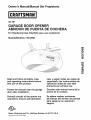 1
1
-
 2
2
-
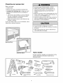 3
3
-
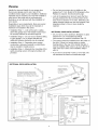 4
4
-
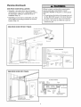 5
5
-
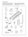 6
6
-
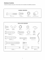 7
7
-
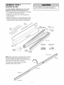 8
8
-
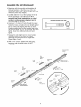 9
9
-
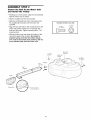 10
10
-
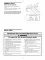 11
11
-
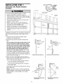 12
12
-
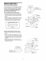 13
13
-
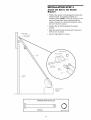 14
14
-
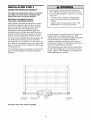 15
15
-
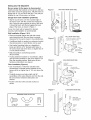 16
16
-
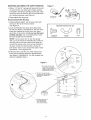 17
17
-
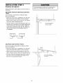 18
18
-
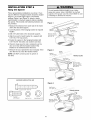 19
19
-
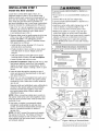 20
20
-
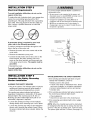 21
21
-
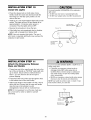 22
22
-
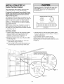 23
23
-
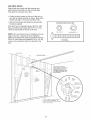 24
24
-
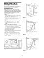 25
25
-
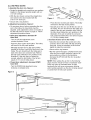 26
26
-
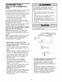 27
27
-
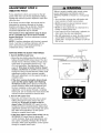 28
28
-
 29
29
-
 30
30
-
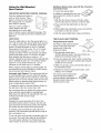 31
31
-
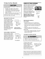 32
32
-
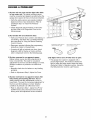 33
33
-
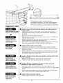 34
34
-
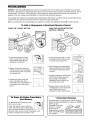 35
35
-
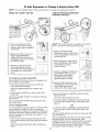 36
36
-
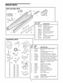 37
37
-
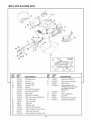 38
38
-
 39
39
-
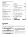 40
40
-
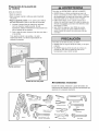 41
41
-
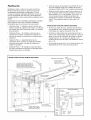 42
42
-
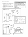 43
43
-
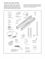 44
44
-
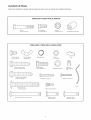 45
45
-
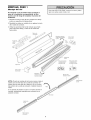 46
46
-
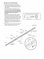 47
47
-
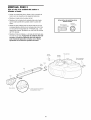 48
48
-
 49
49
-
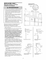 50
50
-
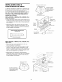 51
51
-
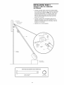 52
52
-
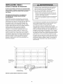 53
53
-
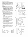 54
54
-
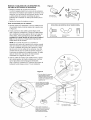 55
55
-
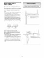 56
56
-
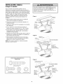 57
57
-
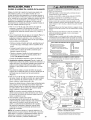 58
58
-
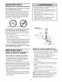 59
59
-
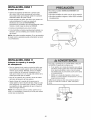 60
60
-
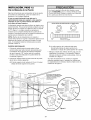 61
61
-
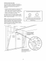 62
62
-
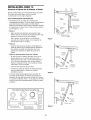 63
63
-
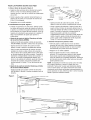 64
64
-
 65
65
-
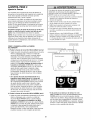 66
66
-
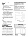 67
67
-
 68
68
-
 69
69
-
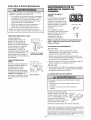 70
70
-
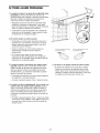 71
71
-
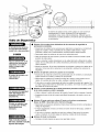 72
72
-
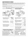 73
73
-
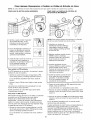 74
74
-
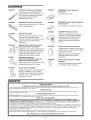 75
75
-
 76
76


Craftsman 139.53924 El manual del propietario
- Categoría
- Abridor de puerta de garage
- Tipo
- El manual del propietario
- Este manual también es adecuado para
en otros idiomas
- English: Craftsman 139.53924 Owner's manual
Artículos relacionados
-
Craftsman 13953927 El manual del propietario
-
Craftsman 139.53992 El manual del propietario
-
-
-
-
-
-
-
-
