
Installation Instructions
Free-Standing Electric Ranges
Questions? CaM1.800.GE.CARES(1.800.432.2737) or visit www.GEApp)iances.com
In Canada, call 1.800.561.3344 or visit www.GEApp)iances.ca
BEFORE YOU BEGIN
Readthese instructions completely and carefully,
" IMPO RTANT -- Save these instructions
for local inspector's use.
" IMPORTANT -- Observe allgoverning
codes and ordinances.
. Note to Installer - Besure to leave these
instructions with consumer.
, Note to consumer - Keep these instructions
for future reference.
. Skill level -Installation of this appliance
requires a qualified installer or electrician.
. Proper installation is the responsibility of the
installer.
• Product failure due to improper installation is
not covered under warranty.
FOR YOUR SAFETY:
Tip-Over Hazard
A child or adult can tip the range and be killed.
Verify the anti-tip bracket has been properly installed
and engaged to the floor or wall.
Engage the range to the anti-tip device by sliding the
foot under the bracket.
Re-engage the anti-tip bracket if the range is moved.
Failure to do so can result in death or serious burns
to children or adults.
If you did not receive an anti-tip bracket with your purchase,
call !.800.626.8774 to receive one at no cost.(In Canada,
call !.800.561.3344.) For installation instructions ofthe bracket,
visit: www.GEAppliances.com. (InCanada, www.GEAppliances.co.)
Anti-Tip Bracket
Kit Included
_,WARNING -- Beforebeginning
the installation,switch poweroffat service
panelandlockthe servicedisconnecting
meansto preventpowerfrombeing
switchedonaccidentally.Whentheservice
disconnectingmeanscannot belocked,
securelyfastena prominentwarning device,
suchasa tag,to the service panel.
MATERIALS YOU MAY NEED
SqueezeConnector (ULListed40 AMP)
(ForConduit 4-Wire Cord 4' long OR
Installations Only} 3-Wire Cord 4' long
TOOLS YOU WILL NEED
Drill with 1/8" Bit Tin Snips
Safety Glasses Tape Measure
Adjustable Wrench Pliers
Level 1/4" Nut Driver
[i] REMOVE PACKAGI NG MATERIALS: Failureto remove packagingmaterials
couldresultindamage tothe appliance.Remove allpackingpartsfrom oven,racks,heating
elementsand drawer.Also,remove protectivefilmand labelson theouterdoor,cooktopand
control panel.
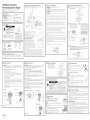
[TI PREPARE THE OPENING (FOR INDOOR USE ONLY)
See illustrations for all rough-in and spacing dimensions. The range may be placed with 0"
clearance (flush) at the back wall and side walls of the cabinet.
+/-_/4"
_ 46"
* GEbranded models Installthe
have control panels outlet box
30 7/8" wide. on either
side of the CL
Electricity to the rangecan be disconnected at the outlet
without moving the range if the outlet is in the preferred
location (remove lower drawer).
NOTE: Use a 4' power cord to prevent interference
with the storage drawer. Power cords 4½ to 6' long may
have to be dressed to allow for proper drawer closing.
MINIMUM DIMENSIONS BETWEEN COOKTOP,
WALLS AND ABOVE THE COOKTOP:
A. Make sure the wall covering, countertop, flooring
and cabinets around the range can withstand
the heat (up to 200°F) generated by the range.
B.Allow 30" minimum clearance between surface units and
bottom of unprotected wood or metal cabinet,
or allow a 24" minimum when bottom of wood or metal
cabinet is protected by no less than 1/4" thick flame
retardant millboard covered with not less than No. 28
MSGsheet metal, (.015'1,.015" thick stainless steel, .024"
aluminum or .020" copper.
NOTEC
A _
B
C
Both
Sides
J
C.This appliance has been approved for 0" minimum spacing to adjacent surfaces above
the cooktop. However, a 6" minimum spacing to surfaces less than 15" above the cooktop
and adjacent cabinets is recommended to reduce exposure to steam, grease splatter and heat.
To reduce the risk of bums or fire when reaching over hot surface elements, cabinet storage
space above the cooktop should be avoided. If cabinet storage space is to be provided above
the cooktop, the risk can be reduced by installing a range hood that projects at least 5" beyond
the front of the cabinets. Cabinets installed above the cooktop must be no deeper than 13".
[TI ELECTRICAL REQUIREMENTS
A WARNING: This appliance must be properly grounded.
WARN I NG: All new constructions, mobile homes, recreational vehicles and installations where
local codes do not allow grounding through neutral, require o 4-conductor UL-listed range cord.
A WARN ING: To prevent fire or shock, do not use an extension cord with this appliance.
A WARN ING: To prevent shock, remove house fuse or open circuit breaker before beginning
installation.
We recommend you have the electrical wiring and hookup of your range connected by a qualified
electrician. After installation, have the electrician show you how to disconnect power from the range.
You must use a single-phase, 120/208 VAC or 120/240 VAC, 60 hertz electrical system. Ifyou connect
to aluminum wiring, properly installed connectors approved for use with aluminum wiring must be
used.
Effective January 1, 1996, the National Electrical Code requires that new construction (not existing)
utilize a 4-conductor connection to an electric range. When installing an electric range
in new construction, mobile home, recreational vehicle, or an area where local codes prohibit
grounding through the neutral conductor, refer to the section on four-conductor branch circuit
connections.
Check with your local utilities for electrical codes which apply in your area. Failure to wire your oven
according to governing codes could result in a hazardous condition. If there are no local codes, your
oven must be wired and fused to meet the National Electrical Code, NFPA No.
70 - latest edition, available from the National Fire Protection Association.
This appliance must be supplied with the proper voltage and frequency, and connected to an
individual, properly grounded, 40 amp (minimum) branch circuit protected by a circuit breaker or time-
delay fuse.
Use only a 3-conductor or a 4-conductor UL-listed range cord. These cords may be provided with ring
terminals on wire and a strain relief device.
A range cord rated at 40 amps with 125/250 minimum volt range is required. A 50 amp range cord
is not recommended but if used, it should be marked for use with nominal 1%< diameter connection
openings. Care should be taken to center the cable and strain relief within the knockout hole to keep
the edge from damaging the cable.
. Because range terminals are not accessible after range is in position, flexible service conduit or cord
must be used.
The rating plate is located on the oven frame or on the side of the drawer frame.
Rating plate
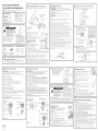
[TI POWER CORD AND CONDUIT INSTALLATION
rA1 Remove wire cover (on the back of range) by removing screws using a 1/4" nut driver.
Do not discard these screws.
2 screws to remove
wire cover
Retaining
tab
Backof range
For power cordand 1" conduit only, remove the LCJ
r=-!
knockout ring (lSA") located on bracket directly
below the terminal block. To remove the
knockout, use a pair of pliers to bend the
knockout ring away from the bracket and
twist until ring is removed.
Terminal
(appearance
may vary)
Knockout
ring in
bracket
For power cord installations only (seethe
next step if using conduit), assemble the
strain relief in the hole. insert the power
cord through the strain relief and tighten.
Mow enough slack to easily attach the
cord terminals to the terminal block. Iftabs
are present at the end of the winged strain
relief, they can be removed for better fit.
NOTE:Do not install the power cord
without a strain relief. The strain relief
bracket MUSTbe installed before
reinstalling the rear range wiring cover.
Strain relief
rG1
Power cord
For 314" conduit installations only, purchase a squeeze connector matching the diameter of your
conduit and assemble it in the hole. Insert the conduit through the squeeze connector and tighten.
Allowenough slackto easilyattach the wires to the terminal block.
NOTE:Do not install the conduit without a squeeze connector. The squeeze connector MUSTbe
installed before reinstalling the rear range wiring cover.
block
F_ 3-WIRE INSTALLATION
A WARN ING: The neutral or ground wire ofthe power cord must be connected to the neutral
terminal located in the center of the terminal block and the ground strap must connect the neutral
terminal to the ground plate. The power leads must be connected to the lower left and the lower right
terminals ofthe terminal block.
DO NOT remove the ground strap connection.
FORPOWER CORD INSTALLATION
A. Remove the 3 lower terminal screws from the terminal block.
B. Insert the 3 terminal screws through each power cord terminal ring and into the lower
terminals of the terminal block. Be certain that the center wire (white/neutral)is connected to
the center lower position of the terminal block.
C.Tighten screws securely into the terminal block.
FOR CONDUIT INSTALLATION
A. Loosenthe 3 lower terminal screws on the terminal block. Strip wire to exposed tip about 5/8" long.
B. Insert the center (white/neutral) wire tip through the bottom center terminal block opening. On
certain models, the wire will needto be inserted through the ground strap opening and then into
the bottom center block opening. Insert the two side bare wire tips into the lower left and the lower
right terminal block openings.
C.Tighten the screws until the wire isfirmly secured (35to 50 inch-lbs.).Do not over-tighten the
screws.
NOTE: ALUMINUM WIRING: Aluminum building wire may be used but it must be rated for the
correct amperage and voltage.
Power Cord
Terminal block
(appearance _----t_
may vary)
Neutral terminal
Ground stra
Ground
plate 4
Power cord --
PROCEEDTO STEP7.
Conduit
Terminal
Conduit _
I 31-i0831-i I
03-12 GE
Printedin Mexico
[_] 4-WIRE INSTALLATION
A WAR NING: Theneutral wire ofthe supply circuit must beconnected tothe neutral terminal located in
the lowercenter oftheterminal block.The power leadsmust beconnected to the lowerleft and the lower
rightterminals ofthe terminal block.Thegrounding lead must be connectedto the frame
of the rangewith the ground plateand the greenground screw.
FOR POWER CORD INSTALLATION
A. Remove the 3 lower terminal screws from the terminal block. Remove the ground screw and ground
plate and retain them. Cutand discard theground strap. DONOTDISCARDANYSCRBA/S.
B. Insertthe oneground screw into the power cordground wire terminal ring,through the ground plate and into
the frame ofthe range.
C. Insertthe 3terminalscrews(removedearlier)through eachpower cord terminal ringand into thelower
terminalsof theterminal block.Becertainthat the centerwire (white/neutral)isconnected to thecenter lower
positionoftheterminal block.Tightenscrewssecurelyinto theterminal block.
FOR CONDUIT INSTALLATION
A. Loosenthe 3 lower terminal screws onthe terminal block. Removethe ground screw and ground plate and
retain them. Cut and discard the ground strap. DONOTDISCARDANYSCREWS.Strip wire to exposed tip
about 5/8" long.
B. Insertthe ground barewire tip between the range frame and the ground plate (removed earlier)and secure
t in placewith the ground screw (removedearlier).Insertthe bare wire (white/neutral)tip through the bottom
center ofthe terminal block opening.Insert thetwo sidebare wire tipsinto the lower left and the lower right
terminal block openings.
C.Tighten the screws untilthe wire isfirmly secured (35to 50inch-lbs.).Do not over-tighten the screws.
NOTE: ALUMINUM WIRING: Aluminum building wire may be used but it must be rated for
the correct amperage and voltage.
Before-Power Cord and Conduit
Ground _ _ "-,
strap Neutral terminal
After-Power Cord
/ ,
Terminal_ '
block l_-_ o Bl
Gcr?Uwnd _
Neutral
_ terminal
__ Ground plate
_- (grounding to
range)
PROCEED TO STEP 7.
After-Conduit
Term na,--
(grounding
block
to range)
Wire
Ground screw "__
171 REPLACE THE WIRE COVER
Replacewire cover on range back
bysliding its left edge under the retaining
tabs and replace the screws removed
earlier. Make sure that no wires are pinched
between cover and range back.
2 screws to remove
wire cover
Retaining
tab
Wire cover
Backof range
FB-I ANTI-TIP DEVICE INSTALLATION
Ti -Over Hazard
• A child or adult ca n tip the range and be killed.
• Verify the anti-tip bracket has been properly installed
and engaged to the floor or wall.
• Engage the ra nge to the anti-tip device by sliding the
foot under the bracket.
• Re-engage the anti-tip bracket if the range is moved.
• Failure to do so can result in death or serious burns
to children or adults.
To reduce the risk of tipping the range, the
range must be secured by o properly installed
anti-tip bracket. See installation instructions
shipped with the bracket for complete details
before attempting to install.
To check if the bracket is installed and
engaged properly, look underneath the range
to see that the rear leveling leg is engaged
in the bracket. On some models, the storage
drawer or kick panel can be removed for
easier inspection. If visual inspection is not
possible,slide the range forward, confirm the anti-tip bracket issecurely attached to the floor or wall, and
slide the range back so the leveling leg isunder the anti-tip bracket. Ifthe range is pulled from the wall for
any reason, always repeat this procedure to verify the range isproperly secured by the anti-tip bracket.
Never completely remove the leveling legs or the range will not be secured to the anti-tip bracket.
[=_ LEVEL THE RANGE
A WARN ING: Nevercompletelyremove thelevelingleg
as the range will not be secured to the anti-tip device properly.
MODELS WITH STORAGE DRAWER ORKICK PANELS
B]
B]
F61
Plug in unit and slide into place. Pull drawer out until it stops.
Lift front of drawer until the stops clear the guide. Remove the drawer.
Install the oven shelves in the oven and position the range where it will be
installed.
Check for levelness by placing a spirit level on one of the oven shelves. Spirit level
Taketwo readings-with the level placed diagonally first
in one direction and then the other.
rE1 The front leveling legs can be adjusted from the bottom and
the rear legs can be adjusted from the top or the bottom.
Use an adjustable wrench to adjust the leveling legs until
the range is level.
[=_ LEVEL THE RANGE (CONT.)
r_ Position cord so that it does not interfere with drawer.
Place drawer rail on guides. Push the drawer in until it stops.
Lift front of drawer and push in until the stops clear
the guides.
D Lower the front of the drawer and push in until it doses.
MODELS WITH BAKING OR WARMING DRAWERS
__ Lower
range
range
rA1 Plug in the unit.
Measure the height of your countertop at the rear of the opening (X).
rcl Adjust two rear leveling legs so that the rear of cooktop is at the same height
as the counter (Y).
r_ Slide unit into place.
r_ install oven shelves in the oven and position the range where it will beinstalled.
r_ Check for levelness by placing a spirit level on one of the oven shelves,
Take two readings-with the level placed diagonally first in one direction
and then the other.
r_ Adjust front leveling legs until the range is level.
FINAL INSTALLATION CHECKLIST
• Check to make sure the circuit breaker isclosed (RESET)or the circuit fuses are replaced.
• Be sure power is in service to the building.
Check that all packing materials and tape have been removed. Thiswill include tape on metal panel under
control knobs (ifapplicable), adhesive tape, wire ties, cardboard and protective plastic. Failure to remove
these materials could result in damage to the appliance once the appliance has been turned on and
surfaces have heated.
Check that the door and drawer are parallel to each other and that both operate smoothly. If they do not,
see the Owner's Manual for proper replacement.
Check to make sure that the rear leveling leg isfully inserted into the Anti-Tip bracket and that the bracket
issecurely installed.
OPERATION CHECKLIST
• Turn on one ofthe surface units to observe that the element glows within 60seconds. Turn the unit
off when glow isdetected. Ifthe glow is not detected within the time limit, recheck the range wiring
connections. Ifchange is required, retest again. Ifno change is required, have building wiring checked for
proper connections and voltage.
Check that the Clock(on models so equipped) display is energized. If o seriesof horizontal red lines appear
in the display, disconnect power immediately. Recheckthe range wiring connections. If change is made to
connections, retest again. If no change is required, have building wiring checked for proper connections
and voltage. It is recommended that the clock be changed if the red lines appear.
Note: Ifthe clock flashes "bAd" and then "LinE"with o loud tone, the neutral connection to the range is
miswired. Check the terminal block connections and/or house wiring to correct.
Besureall range controls are in the OFFposition before leaving the range.

lnstrucciones de instalaci6n
Cocinas elactricas independientes
_Preguntas? Llame a) !.800.GE.CARES(!.800.432.2737) o visite www.GEApp)iances.com
En Canada, Ilame al 1.800.561.3344 o visite www.GEAppliances.ca
ANTES DE COMENZAR
Lea estas instrucdones par completo y con
detenimiento.
" IMPORTANTE -- Guarde estas
instrucciones para el usa de inspectores
locales.
" IMPORTANTE -- Sigatodos
los c6digos y ordenanzas vigentes.
, Nota al instalador - Aseg0rese de dejar estas
instrucciones con el consumidor.
, Nota al consumidor - Conserve estas
instrucdones para referencia futura.
, Nivel de destreza - La instalaci6n de este
aparato debe efectuarla un instalador o
electricista caJificado.
. Elinstalador tiene la responsabilidad
de efectuar una instalad6n adecuada.
• Lagarant[a no cubre lasfolios del producto
debido a una instalaci6n incorrecta.
PARA SU SEGURIDAD
! A D _ A
Riesqo de Caida
• Un ni6o o adulto pueden volcar la cocina y morir.
• Verifique que el soporte anti-volcaduras se haya
instalado y ajustado correctamente al piso o la pared.
• Asegure la estufa al soporte anti-volcaduras deslizando
la pata niveladora debajo del soporte.
• Vuelva a adherir el soporte anti-volcaduras si la estufa
se mueve de lugar.
• Si esto no se hace, se podr6 producir la muerte o
quemaduras graves en ni6os o adultos.
Sino recibi6 un soporte anti volcaduras con su compra,
Ilame al 1.800.62B.8774 para recibir uno sin costa.
(EnCanada, Ilame al !.800.$6!.3344). Para recibir
instrucciones de instalaci6n del soporte, visite:
GEAppliances.com(EnCanada, GEAppliances.ca.).
Kit de soporte
anti volcaduras incluido
,_ ADVERTENCtA -- Antes
de comenzar la instalaci6n, apague el
encendido en el panel de servicio y bloquee
el media de desconexi6n del servicio a fin de
evitar que el encendido se active de forma
accidental. Cuando el media de desconexi6n
del servicio no se pueda bloquear, ajuste
de manera segura un item de advertencia
que est4 bien visible, tal coma una etiqueta,
sabre el panel de servicio.
MATERIALES QUE PUEDE NECESITAR
Conector depresian
(S6topara instalaciones
con conductos
portacables)
(AprobadosparULde40AMP)
Cablede 4abmbres de4'
de largo O Cablede 3alambres
de4' de largo
HERRAMIENTAS NECESARIAS
Perforadora con hojalata
broca de 1/8" Cinta m4trica
Gafas de seguridad Alicates
Llave ajustable Llave de tuercas
Nivel de i/4"
TUeras para
| QUITE LOS MATERIALES DE ENV/O: Noquitarlos materiales
de empaque puede provocar daflos al electrodom#stico. Quite todas las partes de empaque del
homo, bandejas, elementos calentadores y caj6n. Tambian, quite la pelfcula protectora y las
etiquetas de la puerta exterior, estufa, y panel de control.
121 C6MO PREPARARLA ABERTURA(PARAUSOEN INTERIORESSOLAMENTE)
Ver ilustraciones con todas los dimensiones de empotrado y de espacio. Lacocina puede ubicarse con un
espacio de 0" (alineado) sabre la pared trasera y los paredes laterales del gabinete.
I'" 30" j
i
i
Instale la caja de distribuci6n
sabre cualquier lado de
la linea central.
.29_/8 "
36_,J' 46Y_"
+/-Y4"
26"_
z \_.. 46"
* Los modelos de marca GE "_
cuentan con paneles de
control de un ancho
de 30 7/8".
La electricidad hacia la cocina puede desconectarse
desde el tomacorriente sin tener que mover la cocina
si el tomacorriente se encuentra en la posici6n preferida
(quite el caj6n inferior).
NOTA: Utilice un cable de energfa de 4' para evitar una
interferencia con el caj6n de almacenamiento. Los cables
de energia de 4_':'a 6' de largo pueden tenet que cubrirse
para poder cerrar el caj6n correctamente.
DIMENSIONESM/NIMAS ENTRELA ESTUFA,
LAS PAREDESYSOBRELA PARTESUPERIOR
DE LA ESTUFA:
1
B --_ C
NOTAC Ambos
lados
A.Verifique que el revestimiento de las paredes, A -_ _- A "_
el mostrador, el piso y los gabinetes ubicados alrededor
de la cocina puedan soportar el calor
(hasta 200°F) generado par la codna.
B. Deje un espacio de ]0" coma mfnimo entre --
los unidades de superficie y la parte inferior -- _
de gabinetes de madera o de metal sin protecci6n o deje
un minima de 24" cuando la porte inferior del gabinete de madera o metal se encuentre protegida par
cart6n aislante de un grosor no menor a Z/4"y con retardo de llama cubierto con una placa de metal
no menor a NO28 MSG,1.015"),acero inoxidable de un grosor de .015", aluminio de .024" o cobre de
.020".
C. Este aparato ha sido aprobado para un espado mfnimo de 0" respecto de superficies adyacentes
sabre la estufa. Sin embargo, se recomienda un espacio mfnimo de 6" respecto
de superficies menores a lS" sabre la estufa y gabinete adyacente para reducir la exposici6n
al vapor, salpicaduras de grasa y color.
Para reducir el fiesgo de quemaduras o incendios cuando se incline sabre los elementos de superficie
calientes, debe evitarse la instalaci6n de espacios de almacenamiento en gabinetes sabre la estufa. Si
debe contarse con espacio para almacenamiento en gabinetes sabre la estufa, puede reducirse el riesgo
instalando una campana de cocina que sobresalga par Io menos S" mas all@del frente de los gabinetes.
Los gabinetes instalados par encima de la estufa no deben tenet una profundidad mayor a los Z]".
[]_] REQUERIMIENTOS ELECTRICOS
A ADVERTENCIA: Esteelectrodomastico debe tener una correcta conexi6n a tierra.
A ADVERTENCJA: Todas losconstrucciones nuevas, casas rodantes, vehiculos recreativos e
instalaciones don@ losc6digos locales no permiten una conexi6n a tierra atravas de un neutral requieren
un cable para cocina de 4 conductores aprobado par UL.
A ADVERTENCIA: Para seguridad personal, no utilice un cable de extensi6n con este
electrodom4stico.
A ADVERTENCIA: Quite el fusible o abra el interruptor de circuitos antes de comenzar
la instalaci6n.
Recomendamos queun electricista calificado conecte el cableado elactrico y su cocina. Despuas de la
instalaci6n, solicite al electricista que le indique c6mo desconectar la energia
de la cocina.
Usted debe usar un sistema e16ctrico de fase 0nica de 120/208 VAC o 120/240 VAC
de 60 hercios. Si tiene una conexi6n con cableado de aluminio, deben utilizarse conectores
adecuadamente instalados para utilizar con cableado de aluminio.
Vigente desde el :i de enero de :1996,el C6digo Elactrico Nacional requiere que los nuevas
construcciones (no existentes) utilicen una conexi6n de cuatro conductores a una cocina elactrica.
Cuando instale una cocina elactrica en una nueva construcci6n, una casa rodante,
un vehiculo recreativo o undrea donde los c6digos locales prohiben la conexi6n a tierra atravas de un
conductor neutral, consulte la secci6n sabre conexiones en circuito derivado de cuatro conductores.
Consulte a los empresas de servicio p0blico sabre los c6digos elactricos que se aplican en su
area. No realizar el cableado de su homo de acuerdo con los c6digos vigentes puede provocar
una situaci6n peligrosa. Sino existen c6digos locales,su cocina debe contar con cables y fusibles
que cumplan con los requisitos del C6digo El@ctricoNacional, ANSI/NFPANo. 70-01tima edici6n.
Esteelectrodom4stico debe recibir el voltaje y frecuenda adecuados, y debe conectarse
a un circuito derivado individual con adecuada conexi6n a tierra de 40 amperios (mfnimo) protegido
par un intemuptor de circuitos o fusible con retraso.
Utilice s6lo un cable para cocinas de 3 o 4 conductores aprobado par UL.Estos cables pueden contar con
terminales de anillo en alambre y un dispositivo de alivio detensi6n.
Serequiere un cable para cocinas clasificado para 40 amperios con rango de voltios minima de 125/250.
No se recomienda un cable de SOamperios, pero si se utiliza, debe seBalizarse para usarse con aberturas
de conexi6n de un diametro nominal de 1-3/8". Debetenerse cuidado al centrar el cable y elolivia de
tensi6n dentro del orificio de expulsi6n para evitar que el borde daBe el cable.
Dado que las terminales de la cocina no son accesibles despuas de que la cocina se encuentra en su
posici6n, debe utilizarse un portacables o cable de servido flexibles.
La placa de clasificaci6n se encuentra ubicada sabre el armaz6n del homo o sabre el costado del
armaz6n del caj6n.
r_
INSTALACION ENERGIA TENSI6N
DECABLEDE ? DEALIVIO DE
rA1 Quite la tapa del cable (en la porte trasera de la cocina) quitando tornillos mediante
una Ilave de tuercas de :1/4".No elimine esos tomillos.
2 tornillos para quitar la
.LengOetas
de retenci6n
B]
@
Parte trasera de la cocina
Paracable de energia y )ortacables de 1"
solamente, quite el anillo de expulsi6n (1-3/8")
ubicado en el soporte directamente debajo del
bloque terminal. Para quitar el anillo, utilice un
par de alicates para doblar el anillo de expulsi6n
lejos del soporte y gire basra remover el anillo.
Bloque terminal r-!_--_t/_L_-.
(la apariencia ----_{(_{_ )!!@_'Q_t_;::t_
expulsi6n / _ /I
enel Ii IU_ ,._ _: l/
soporte I/
___ o -]
Anillo de
expulsi6n -_----_
quitado
E1
S6t0para instalaciones decable deenergia
(verel pasosiguientesi utilizaunconducto
portacables),instaleel oliviadetensian enel
orificio.Introduzcael cabledeenergb atravas
del aliviodetensi6ny ajuste.Dejeunlargo
suficientepara poderconectar losterminales
decableal bloqueterminal.Sihay leng0etas
al finaldel oliviadetensiancon alas,_stas
puedenquitarse paraun ajustemejor.
NOTA:Noinstaleel cabledeenergiasin un
olivia detensi6n, Elsoporte delolivia de
tensi6nDEBEinstalarseantesdevolvera
colocarla tapa del cableadotrasero dela
cocina.
Alivio de tensi6n
Bloque
terminal
$61opara instalaciones con conducto _ Soporte
portacables, adquiera un conector de presi6n Cable de
que se ajuste al di6metro de su conducto e inst6]elo energfa
en el orificio. Introduzca el conducto a trav6s del
conector de presi6n y ajuste. Deje un largo sufidente para poder pegar loscables al bloque terminal.
NOTA: No instale el conducto sin un conector de presi6n. Elconector de presi6n debe instalarse
antes de volver a colocar la tapa del cableado trasero de la cocina.
_] INSTALACI6N DE TRES (3) ALAMBRES
A ADVERTENCIA: Elcable neutral o a tierra del cable de energia debe estar conectado a la
terminal neutral ubicada en el centro del bloque terminal y la cinta
de conexi6n a tierra debe conectar la terminal neutral a la placa de conexi6n a tierra.
Loscables de energia deben estar conectados a losterminales inferior izquierda e inferior derecha del
bloque terminal.
NO QUITE la cinta de conexi6n a tierra.
PARA INSTALACION DE CABLE DE ENERG/A
A. Quite los ] tornillos inferiores de1bloque terminal.
B. Introduzca los 3 tornillos de terminal a trav6s de coda anillo de terminal de cable
de energia y dentro de las terminales inferiores del bloque terminal. Aseg0rese
de que el alambre central (blanco/neutral) se encuentre conectado a la posici6n
central inferior del bloque terminal.
C. Ajuste bien los tornillos al bloque terminal.
PARA INSTALACI6N DE CONDUCTO PORTACABLES
A. Afloje los ] tornillos inferiores del bloque terminal.
B. Introduzca la punta del cable central pelado (blanco/neutral) a trav4s de la abertura del bloque terminal
central inferior. Enalgunos modelos, el cable tendr6 que introducirse atravas de la abertura de la cinta de
conexi6n atierra y luego a travas de la abertura del bloque central inferior. Introduzca las dos puntas de
cable pelado dentro de losaberturas de bloque terminal izquierda inferior
y derecha inferior.
C. Ajuste los tornillos hasta que el cable quede bien firme (35a S0 pulg-lbs).No ajuste 1astornillos
de m6s porque podrian daflar los cables.
NOTA: CABLEADO DE ALUMINIO: Puede utiFzarse cable de construcci6n de aluminio pero debe
dasificarse para el amperaje y voltaje correctos para poder realizar la conexi6n.
Cable de energia
Bloque terminal
(laapariencia
puede cambiar)
Conducto portacables
terminal
Conducto _ -_ I
portocobles
SIGA CON EL PASO 7.
31-10831-1
05-12 GE
ImpresoenMdxico
[_] INSTALACI6N DE 4 ALAMBRES
A ADVERTENCIA: Elcableneutraldelcircuitodesuministrodebe estarconectadoala terminalneutral
ubicadaenelcentro inferiordelNoque terminal.Loscablesdeenergiadebenestarconectados
alosterminalesinferiorizquierdae inferiorderechadelNoqueterminal.Elcuartocableatierradebeestar
conectadoal marco delacocinacon laplacadeconexi6natierray eltornilloatierra.
PARA INSTALACI6N DE CABLE DE ENERGIA
A. Quite los 3tornillos inferiores del bloque terminal. Quite eltornillo a tierra y la placa de co0exi6n
a tierra y cons6rvelos. Carte y descarte la cinta de conexi6n a tierra. NO ELIMINENINGUNTORNILLO.
B. Introduzca el tornillo de conexi6n a tierra dentro del anillo terminal deconexi6n a tierra del cable
de energia, a travas de la placa de conexi6n a tierra y dentro del marco de la cocina.
C. Introduzca los 3tornillos de terminal (quitados antes) a trav4s de coda anillo determinal de cable de
energia y dentro de losterminales inferiores del bloque terminal. Aseg0rese de que el alambre central
(blanco/neutral) se encuentre conectado a la posici6n central inferior del bloque terminal. Ajuste bien los
tornillos al bloque terminal.
PARA INSTALACI6N DE CONDUCTO PORTACABLES
A.Aflojelostres tornillosinferioresdelbloqueterminal.Quiteeltornillo a tierray la placadeconexi6natierra
y consarvelos.Cartey descartela cintadeconexi6natierra.NOELIHINENINGUNTORNILLO.
B. Introduzcala punta peladadelcableatierraentreel marco delacocinay laplacadeconexi6na tierra(quitada
antes)yaseg0relaensu lugarcon eltornillodeconexi6natierra(quitadoantes).Introduzcalapunta peladadel
cable(blanco/neutral)atravasdelcentro inferiordela aberturadel bloqueterminal.Introduzca
losdospuntasdecable peladodentrodelosaberturasdebloqueterminal izquierdainferiory derechainferior.
C.Ajustelostomilloshastaqueelcablequedebienfirme(35a 50pulg-lbs).Noajustelostornillosdemas porque
podrianda_arloscables.
NOTA: CABLEADODEALUMINIO: Puede utilizarse cable de construcci6n dealuminio pero debe clasificarse
para el amperaje yvoltaje correctos para poder realizar la conexi6n.
Antes-Cable de energia
y conducto portacables
Cinta de
//,-_/MXk conexi6na tierra
Cinta de / _ \ --_
conexlon Terminal neutral
a tierra
SIGA CON EL PASO 7.
Despu6s-Cable de energia
Bloque __4_
terminal
,,B
Tornillo de _
IJtl
Terminal
neutral
laca de conexi6n
a tierra (conexi6n
-- a tierra dela
cocina)
Despu6s-Conducto _ortacables
_....___/_' Platade
conexi6n
BIoque _l a tierra
terminal _ _ (conexi6na tierra de
/
Puntas de ---'-'_'_ /!_ la codna)
loscables _>_
Tornillo de
conexion _"--_
a tierra "[_
[_ REEMPLACE LA TAPA DE LOS CABLES
Reemplacelatapade loscablesde lacocina
deslizandoelladoizquierdobajoloslengLietas
de retenci6ny reemplazandolostornillos
quitadosanteriormente.Verifiqueque
loscablesno hayansufridopellizcos
entre la tapa y la porte trasera de la cocina.
2 tornillos para quitor la
tapc del cable
Parte trasera de la cocina
LengOetas
de retenci6n
F_ INSTALACI6N DE DISPOSITIVO ANTI-VOLCADURAS
Riesqo de Calda
Un ni6o o adulto pueden volcar la cocina y morin
Verifique que el soporte antiwolcaduras se haya
instalado y ajustado correctamente a lpiso o la pared.
Asegure la estufa al soporte anti-volcaduras deslizando
la pata niveladora debajo del soporte.
Vuelva a adherir el soporte antiwolcaduras si la estufa
se mueve de lugar.
Si esto no se hace, se podr6 producir la muerte o
quemaduras graves en niSos o adultos.
inclineconcuidadola cocinahaciaadelante
Afin dereducirelriesgodeindinarla cocina,
#stadeber6estar aseguradacon unsoporteanti
volcadurasLealosinstrucdonesdeinstalacian
queseenviaronconel soporteparaobtenerun
detallecompletoantesdecomenzarlainstalacian
Afin decontrolarqueel soporteest#instalado
y adosadocorrectamente,retireelcajan de
almacenajeolaporteinferiordelanterayobserve
debajodelacocinaque la pataniveladoraest6
adosadaal soporteEnmodelosquenoposeen
uncajandealmacenajeo porteinferiordelantera,
Elsoportedeberfadetenerla cocinadentrodeloscuatropulgadas Denoserasf,el soportedeber6setinstalado
nuevamenteSila cocinaesexpulsadadela paredpar algunarazan,siemprerepitaesteprocedimientoafin deverificar
queest6aseguradodeformacorrectaconunsoporteantivokaduras Nuncaeliminecompletamentelospatas
niveladoras,yaquedeserasila cocinanoestar6 adecuadamenteaseguradapar eldispositivoanti vokaduras
r91 PREPAREPARA NIVEL
A ADVERTENCIA: Nunca quite las paras de nivelad6n par
completo ya que la cocina no quedar6 bien sujeta al dispositivo anti-volcaduras.
MODELOS CON CAJ6NDEALMACENAMIENTO O PANELES
DE PROTECCI6N
N1
Enchufe la unidad y des%ela en su Iugar. Tire del caj6n hacia
fuera hasta que pare.
Nivelde burbuja
de aire
Levante el frente del caj6n hasta que los trabas superen
los guias. Retire el caj6n.
rcl Instale los estontes del homo dentro del electrodom6stico
y coloque la cocina en la ubicaci6n donde se va a instalar.
Controle la nivelaci6n colocando un nivel de burbuja de aire
o una taza, parcialmente Ilena con agua, sabre uno de los estantes del homo. Siutiliza un nivel de
burbuja de aire, haga dos lecturas-con
el nivel ubicado endiagonal primero en una direcci6n y luego en la otto.
r_ Las patas de nivelaci6n frontales pueden ajustarse desde la porte inferior y los patas traseras
pueden ajustarse desde la porte superior o inferior.
Fal
EB
@
rT1
PREPAREPARA NIVEL (CONT.}
Utilice una Ilave abierta o una Ilave ajustable para ajustar los patos
de nivelaci6n hasta que la cocina quede nivelada.
Coloque el riel del caj6n en los guias. Empuje el caj6n hacia
adentro hasta que pare.
Levante el frente del caj6n yempuje hasta que lostrabas superen los
guias.
Bale el frente del caj6n y empuje hacia adentro hasto que cierre.
cocina
MODELOS CON CAJONES DE HORNEADO 0 CALENTADORES
B3
B]
El
@
B]
Enchufe la unidad
Midala altura desu mostradordeencimeraen la porte trasera
de laabertura(×).
Ajuste los dos patas de niveloci6n traseras para que la porte trasera
de la estufa se encuentre a la misma altura del mostrador (Y).
Deslice la unidad en su lugar.
Instale los estontes del horno dentro del electrodom#stico
y coloque la cocina en la ubicaci6n donde se va a instalar.
Controle la nivelaci6n colocando un nivel de burbuja de aire o una taza, pardalmente Ilena con
agua, sabre uno de los estantes del homo. Siutiliza un nivel de burbuja de aire, haga dos
lecturas=con el nivel ubicado en diagonal primero en una direcci6n y Iuego en la otra.
Ajustar las patas de nivelaci6n frontales hasta que la codna quede nivelada.
LISTA DE CONTROL FINAL DE LA INSTALACI6N
• Verifique que el interruptor de circuitos se encuentre cerrado (RESET)o que los fusibles del circuito se
hayan reemplazado.
• Aseg0rese de que se cuente con suministro el_ctrico en el edificio.
• Controle que se haya quitado todo el material de empaque y la cinta. Estoincluye cinta sabre
el panel de metal bajo los perillas de control (si corresponde), cinta adhesiva, ataduras de alambre, cart6n
y plastico protector. Noquitar estos materiales puede provocar da_os al electrodomastico
una vez que el aparato se haya encendido y los superficies se hayan calentado.
• Controle que la puerto y el caj6n se encuentren paralelos y que los dos funcionen correctamente.
Sino es asi, consulte el Manual del propietario para un reemplazo adecuado.
• Controle que la pata de nivelaci6n trasera est6 bien introducida dentro del soporte anti-volcaduras
y que el soporte se encuentre bien instalado.
LISTA DE CONTROL DE FUNCIONAMIENTO
• Accione una de los unidades de superficie para observar que el elemento se encienda dentro
de los60 segundos. Apague la unidad cuando se detecte el encendido. Sino se detecta el encendido dentro
del limite de tiempo, vuelva a verificar losconexiones del cableado de la cocina. Sise requiere un cambio,
vuelva a probar el aparato. Sino se requiere un cambio, haga controlar el cableado
del edificio para verificar conexiones y voltaje adecuados.
• Controle que la pantalla del reloj (enmodelos que Io incluyan) reciba energ[a. Sien la pantalla aparecen una
serie de I[neasrajas horizontales, desconecte la energ[a de inmediato. Vuelva a controlar losconexiones del
cableado de la cocina. Sise efect0a un cambio en losconexiones,
vuelva a probar el aparato. Sino se requiere un cambio, haga controlar el cableado del edificio para
verificar conexiones y voltaje adecuados. Se recomienda cambiar el reloj si aparecen losI[neas rajas.
Nota: Siel reloj destella "bAd" (mala)y luego "LinE"(l[nea)con un sonido alto, la conexi6n neutral
a la cocina tiene una folio. Verifique los conexiones del bloque terminal y/o el cableado dom_stico
para corregirlo.
• Aseg0rese deque loscontroles de la cocina se encuentren en la posici6n OFF(apagado) antes
de alejarse de la cocina.
-
 1
1
-
 2
2


en otros idiomas
Artículos relacionados
Otros documentos
-
GE JB850SP4SS Guía de instalación
-
-
GE Appliances EER2000MCC Guía de instalación
-
Kenmore 362.6278 Manual de usuario
-
-
Kenmore Elite 79041093100 Guía de instalación
-
 Kenmore Elite 79045013101 Guía de instalación
-
 Kenmore Elite 79041059100 Guía de instalación
-
Bosch HDI8054U/01 Guía de instalación
-

