sauder.com
Lateral File
Model 420545
NOTE: THIS INSTRUCTION
BOOKLET CONTAINS IMPORTANT
SAFETY INFORMATION.
PLEASE READ AND KEEP FOR
FUTURE REFERENCE.
Enlish p 1-22
Français p 23-25
Español p 26-28
Lot # 531694 07/26/19
Purchased: __________________
sauder.com
CONTACT US FIRST
BEFORE MAKING ANY RETURNS TO THE STORE.
Share your journey!
sauder.com
CONTACT US FIRST
BEFORE MAKING ANY RETURNS TO THE STORE.
Visit sauder.com/service to order replacement parts, view video assembly tips, or chat with a live rep.
Prefer the phone? Give us a rin at
1-800-523-3987.
Customer Service is available Monday-Friday - 9 a.m. to 5:30 p.m. EST (except holidays)
Get all organized
and stu .

Part Identifi cation
Hardware Identifi cation
Assembly Steps
Français
Español
Safety
Warranty
No. 2 Phillips Screwdriver
Tip Shown Actual Size
Table of Contents Assembly Tools Required
Hammer
Not actual size
Skip the power trip.
This time.
3
4
5-22
23-25
26-28
29-30
31
420545 www.sauder.com/servicePae 2
Tape Measure

å While not all parts are labeled, some of the parts will have a label or an inked letter on the ede
to help distinuish similar parts from each other. Use this part identifi cation to help identify similar parts.
Part Identifi cation
Now you know
our ABCs.
A RIGHT END (1)
B LEFT END (1)
C TOP (1)
D BACK (2)
D32 LEFT DRAWER SIDE (2)
D33 RIGHT DRAWER SIDE (2)
D61 DRAWER BACK (2)
D729 DRAWER BOTTOM (2)
E BRACE (3)
F BASE (1)
G DRAWER FRONT (2)
H TOP MOLDING (1)
I MOLDING (1)
M63
DRAWER BRACE (2)
(Hidden part usin recycled
material. Color may vary.)
420545www.sauder.com/service
Pae 3
A
B
C
D
E
F
G
H
I
D729
D33
D32
D61
M63
E
E
D

Hardware Identifi cation
å Screws are shown actual size. You may receive extra hardware with your unit.
420545 www.sauder.com/servicePae 4
DRAWER FRONT
BRACKET - 4
10G
FILE GLIDE - 4
5B
INTERLOCK TRACK - 1
22G
FILE ROD - 4
9B
FILE BAR - 4
1B
SILVER 3/4" MACHINE SCREW - 4
20S
METAL BRACKET - 3
4G
BLACK 9/16" LARGE HEAD SCREW - 18
1S
BLACK 1-1/4" FLAT HEAD SCREW - 3
7S
BROWN 7/16" LARGE HEAD SCREW - 4
6S
3S
GOLD 5/16" FLAT HEAD SCREW - 16
METAL PIN - 6
1R
20G
DRAWER STOP - 2
12E
TACK GLIDE - 4
29G
SAFETY STOP - 2
FILE BRACKET - 4
12B
HIDDEN CAM - 24
1F
CAM DOWEL - 24
2F
KNOB - 4
69K
30S
BLACK 1-9/16" FLAT HEAD SCREW - 10
(EXTENSION SET SHOWN SEPARATED)
EXTENSION SLIDE - 4
40MC
EXTENSION RAIL - 4
40MA

Step 1
Look for this icon. It means a
video assembly tip is available at
www.sauder.com/service/tips
å
Assemble your unit on a carpeted fl oor or on the empty carton to avoid
scratchin your unit or the fl oor.
å
Push fourteen HIDDEN CAMS (1F) into the ENDS (A and B), BACKS (D), and
DRAWER BRACES (M63). Then, insert the metal end of a CAM DOWEL (2F) into
each HIDDEN CAM.
420545www.sauder.com/service
Pae 5
Insert the metal end of the CAM
DOWEL into the HIDDEN CAM.
Arrow
A
B
D
D
M63
M63
Do not tihten the HIDDEN CAMS in this step.
(14 used)
Arrow
1F
2F

å
Push ten HIDDEN CAMS (1F) into the BRACES (E). Then, insert the
metal end of a CAM DOWEL (2F) into each HIDDEN CAM.
å
NOTE: There will be one BRACE that will only have two HIDDEN
CAMS and CAM DOWELS.
Step 2
Arrow
1F
2F
Do not tihten the HIDDEN CAMS in this step.
Arrow
1F
2F
Do not insert HIDDEN
CAMS and CAM DOWELS
into these two holes.
E
E
E
(10 used)
Arrow
1F
2F
420545 www.sauder.com/servicePae 6

Step Step 3
å
Insert two SAFETY STOPS (29G) into the holes shown in
the RIGHT END (A).
This pin must insert
into the location holes
in the RIGHT END (A).
29G
A
Surface with
HIDDEN CAMS
29G
Ede without
HIDDEN CAMS
Just think. The sooner
you do this, the sooner
you do somethin else.
420545www.sauder.com/service
Pae 7

Step Step 4
Be sure the
interlock track
snaps into each
safety stop.
4.
3.
2.
1.
The interlock system is a safety feature
that prevents more than one drawer
from opening at the same time. Do not
use excessive force to open the drawers.
22G
29G
Tape Measure
å
Diaram 1. Measure 3" from one end of the INTERLOCK TRACK (22G). Position the INTERLOCK TRACK as shown.
å
SAFETY STOP / TRACK ATTACHMENT:
å
Diaram 2. Tilt the fi rst ede of the INTERLOCK TRACK (22G) into the SAFETY STOP (29G).
å
Diaram 3. Rotate the INTERLOCK TRACK and apply force to enae the second ede into the SAFETY STOP.
å
Diaram 4. Repeat the SAFETY STOP / TRACK ATTACHMENT for the next SAFETY STOP while holdin the previously
completed SAFETY STOP in its location hole.
å
Visually check that all INTERLOCK TRACK edes have been enaed into the SAFETY STOP as shown in diaram 3.
Then, remove the INTERLOCK TRACK assembly from the END.
22G
29G
A
22G
29G
Surface with
HIDDEN CAMS
3"
Ede without
HIDDEN CAMS
420545 www.sauder.com/servicePae 8

Step Step 5
å
Insert the INTERLOCK TRACK (22G) with SAFETY STOPS (29G) into the roove in the RIGHT END (A) exactly as shown.
å
Separate the EXTENSION SLIDES (40MC) from the EXTENSION RAILS (40MA) as shown in the upper diaram below.
Be prepared, the parts are reasy.
å
Fasten two EXTENSION RAILS (40MA) to each END (A and B). Use eiht GOLD 5/16" FLAT HEAD SCREWS (3S)
throuh holes #1 and #4.
å
NOTE: For each EXTENSION RAIL, turn a SCREW into the hole shown in the enlared diaram. Then, slide the inner cartride
of the EXTENSION RAIL out to fi nd the other hole that lines up with the hole in the END. Turn a SCREW into this hole.
å
NOTE: The EXTENSION SLIDES will be used later for the DRAWERS.
GOLD 5/16" FLAT HEAD SCREW
(8 used in this step)
3S
Open end
Open end
29G
After fastenin the RAILS to the ENDS, rest the INTERLOCK
TRACK assembly aainst the RAILS. There should be no
more than a 1/16" ap between all ACTUATORS and RAILS.
A
Surface with
HIDDEN CAMS
B
Surface with
HIDDEN CAMS
22G
Finished ede
Finished ede
Push the black lever in and pull the SLIDE from the RAIL.
40MA40MC
1
2
3
4
1
2
3
4
1
2
3
4
1
2
3
4
420545www.sauder.com/service
Pae 9

Step
å
Fasten the BACKS (D) to the LEFT END (B). Tihten four
HIDDEN CAMS.
Step 6
Start Tighten
Arrow
Minimum
190 derees
Caution
Risk of damae or
injury. HIDDEN CAMS
must be completely
tihtened. HIDDEN
CAMS that are not
completely tihtened
may loosen, and parts
may separate. To
completely tihten:
Arrow
Maximum
210 derees
B
Surface with
HIDDEN CAMS
Finished ede
D
D
Surface with
HIDDEN CAMS
Surface with
HIDDEN CAMS
420545 www.sauder.com/servicePae 10

Step Step 7
å
Insert three METAL PINS (1R) into the exact holes shown
in the LEFT END (B).
å
Fasten the BRACES (E) to the LEFT END (B). Tihten
three HIDDEN CAMS.
å
NOTE: Be sure the METAL PINS in the LEFT END insert
into the holes in the BRACES.
å
NOTE: Be sure the BRACE with only two HIDDEN CAMS
and CAM DOWELS is positioned as shown.
1R
Arrow
Minimum
190 derees
Maximum
210 derees
B
E
E
E
Surface with HIDDEN CAMS
Surface with HIDDEN CAMS
Surface with HIDDEN CAMS
Lon ede with
CAM DOWELS
Lon ede
with holes
420545www.sauder.com/service
Pae 11

Step Step 8
Arrow
Minimum
190 derees
Maximum
210 derees
å
Insert three METAL PINS (1R) into the exact holes shown
in the RIGHT END (A).
å
Fasten the RIGHT END (A) to the BACKS (D) and
BRACES (E). Tihten seven HIDDEN CAMS.
å
NOTE: Be sure the METAL PINS in the RIGHT END insert
into the holes in the BRACES.
E
E
E
D
D
A
Surface with
HIDDEN CAMS
1R
Finished ede
420545 www.sauder.com/servicePae 12

Step
å
Fasten the MOLDING (I) to the upper BRACE (E). Tihten
two HIDDEN CAMS.
Step 9
Arrow
Minimum
190 derees
Maximum
210 derees
E
I
Now miht be a
ood time to refresh
your drink.
420545www.sauder.com/service
Pae 13

Step
420545 www.sauder.com/servicePae 14
Step 10
å
Fasten three METAL BRACKETS (4G) to the ENDS (A and B) and BRACE (E). Use three BLACK 9/16" LARGE
HEAD SCREWS (1S).
å
NOTE: Be sure the BRACKETS are even with the edes of the ENDS and BRACE.
å
Fasten the BASE (F) to the BRACE (E). Tihten two HIDDEN CAMS.
å
Then, fasten the BASE (F) to the ENDS (A and B) and BRACE (E). Use three BLACK 9/16" LARGE HEAD SCREWS (1S)
throuh the BRACKETS on the ENDS and BRACE and into the holes in the BASE.
BLACK 9/16" LARGE HEAD SCREW
(6 used in this step)
1S
E
F
Arrow
Minimum
190 derees
Maximum
210 derees
B
A
4G
4G
4G
Curved ede

å
Fasten the TOP (C) to the ENDS (A and B). Tihten four HIDDEN CAMS.
å
Fasten the TOP MOLDING (H) to the TOP (C). Use three BLACK 1-1/4"
FLAT HEAD SCREWS (7S).
å
NOTE: Do not overtihten the SCREWS into the TOP.
å
Usin your hammer, ently tap four TACK GLIDES (12E) into the bottom
edes of the ENDS (A and B) and BASE (F).
å
NOTE: Be sure to tap the TACK GLIDES into the center of the BASE.
Step 11
420545www.sauder.com/service
Pae 15
B
A
F
12E
Tap the TACK GLIDES into
the center of the BASE.
BLACK 1-1/4" FLAT HEAD SCREW
(3 used in this step)
7S

Step 12
420545 www.sauder.com/servicePae 16
VIEW THE T-SLOT BOX VIDEO
1
3
2
4
å
Pull the DRAWER FRONT BRACKETS (10G) apart and slide
them into the rooves in the DRAWER SIDES (D32 and D33).
You may need to ently tap them in with a hammer.
å
NOTE: The DRAWER FRONT BRACKETS are marked “RH” and
“LH” for easy identifi cation.
å
Fasten the DRAWER FRONT (G) to the DRAWER FRONT
BRACKETS (10G). Use four BLACK 9/16" LARGE HEAD SCREWS (1S).
å
Slide the DRAWER BOTTOM (D729) into the
rooves in the DRAWER SIDES (D32 and D33 ) and
DRAWER FRONT (G).
å
Fasten the DRAWER BRACE (M63) to the DRAWER
FRONT (G). Tihten one HIDDEN CAM.
å
Fasten the DRAWER BACK (D61) to the DRAWER
SIDES (D32 and D33) and DRAWER BRACE (M63).
Use fi ve BLACK 1-9/16" FLAT HEAD SCREWS (30S).
å
Repeat this step for the other drawer.
BLACK 9/16" LARGE HEAD SCREW
(8 used in this step)
1S
D33
D729
D61
D32
G
Be sure the DRAWER
BOTTOM inserts into the
DRAWER FRONT roove.
Be sure the
DRAWER
BOTTOM
inserts into
the DRAWER
BACK roove.
With the palm of
your hand, tap
the DRAWER
BOTTOM down
into the roove.
30S
Start each screw a few turns before
completely tihtenin any of them.
BLACK 1-9/16" FLAT HEAD SCREW
(10 used in this step)
Arrow
Minimum
190 derees
Maximum
210 derees
G
Groove
D33
D32
G
M63
M63
D33
D32
Tap down with your
screwdriver and hammer.
Unfi nished surface
Hidden part usin
recycled material.
Color may vary.

Step 13
420545www.sauder.com/service
Pae 17
å
Stand one of the drawers upriht onto the RIGHT
DRAWER SIDE (D33).
å
Fasten one of the EXTENSION SLIDES (40MC) to the LEFT
DRAWER SIDE (D32). Use two GOLD 5/16" FLAT HEAD
SCREWS (3S) throuh holes #1 and #4 in the SLIDE and
into the exact holes shown in the DRAWER SIDE.
GOLD 5/16" FLAT HEAD SCREW
(4 used in this step)
3S
D33
D32
Open end
4
1
2
3
G

Step 14
420545 www.sauder.com/servicePae 18
å
Flip the drawer over onto the LEFT DRAWER SIDE (D32).
å
Diaram 1. Insert the tabs on a DRAWER STOP (20G) into the slots in a EXTENSION SLIDE (40MC). You may need to
insert one tab fi rst, then the other.
å
Diaram 2. Visually check that the DRAWER STOP (20G) is seated in the EXTENSION SLIDE (40MC).
å
Diaram 3. If the DRAWER STOP is not seated, use your hammer to ently tap the SLIDE until the tabs are properly seated
in the slots.
å
Now, fasten this EXTENSION SLIDE (40MC) to the RIGHT DRAWER SIDE (D33). Use two GOLD 5/16" FLAT HEAD SCREWS (3S)
throuh holes #1 and #4 in the SLIDES and into the exact holes shown in the DRAWER SIDE.
å
Repeat Steps 13 and 14 for the other drawer.
4
1
2
3
D32
GOLD 5/16" FLAT HEAD SCREW
(4 used in this step)
3S
D33
20G
These tabs must
insert into the slots.
Slot
1.
2.
D33
3.
20G
20G
Post
Seated
Open end

Step 15
420545www.sauder.com/service
Pae 19
å
Press one of the FILE GLIDES (5B) over the RIGHT DRAWER
SIDE (D33) on one of the drawers. The FILE GLIDES are
necessary to han fi les.
å
Fasten a FILE BRACKET (12B) to the DRAWER FRONT (G).
Use two BLACK 9/16" LARGE HEAD SCREWS (1S).
å
Fasten a FILE BRACKET (12B) to the DRAWER BACK (D61).
Use two BROWN 7/16" LARGE HEAD SCREWS (6S).
å
Repeat this step for the other drawer.
12B
BROWN 7/16" LARGE HEAD SCREW
(4 used for the DRAWER BACKS)
6S
G
BLACK 9/16" LARGE HEAD SCREW
(4 used for the DRAWER FRONTS)
1S
D61
5B
D33
12B

Step 16
420545 www.sauder.com/servicePae 20
å
Slide the FILE RODS (9B) throuh a FILE BAR (1B),
throuh the holes in the FILE BRACKETS (12B), throuh
another FILE BAR (1B), and into the FILE GLIDE (5B) on
the RIGHT DRAWER SIDE (D33).
å
Slide another FILE GLIDE (5B) onto the other end of the
FILE RODS (9B), then press this FILE GLIDE over the
LEFT DRAWER SIDE (D32).
å
Repeat this step for the other drawer.
5B
5B
9B
9B
1B
1B
12B
D32
D33
Use the exact holes shown in
the FILE GLIDES (5B) and FILE
BRACKETS (12B) to insert the
FILE RODS (9B) throuh.
Use these holes.
Use this hole for
the FILE ROD.
Use this hole for
the FILE ROD.
12B

Step 17
420545www.sauder.com/service
Pae 21
å
Fasten two KNOBS (69K) to the DRAWER FRONT (G). Use
two SILVER 3/4" MACHINE SCREWS (20S).
å
Repeat this step for the other drawer.
G
69K
SILVER 3/4" MACHINE SCREW
(4 used in this step)
20S

Step 18
420545 www.sauder.com/servicePae 22
å
Carefully stand your unit upriht.
å
To insert the drawers into your unit, line up the EXTENSION SLIDES
on the drawers with the EXTENSION RAILS on the unit and push the
drawers into the unit until the drawers are fully inserted. The drawers
will push in hard until they are all the way in, then they will slide in and
out easier.
å
NOTE: The DRAWER FRONTS may need adjustments. To adjust the
DRAWER FRONTS, loosen the SCREWS in the DRAWER FRONTS.
Make adjustments and tihten the SCREWS.
å
NOTE: Please read the back paes of the instruction booklet for
important safety information.
å
This completes assembly. Clean with a damp cloth. Wipe dry.
Pro Tip: Lift with your
les. And, you know,
your arms.
50 lbs.
40 lbs.
40 lbs.
And to celebrate, why not share your success story at Walmart.com or

LISTE DE PIÈCES
REFERENCE DESCRIPTION QUANTITÉ
LISTE DE PIÈCES
REFERENCE DESCRIPTION QUANTITÉ
NOUS SOMMES LA POUR VOUS AIDER!
Nous faisons de notre mieux pour nous assurer que votre meuble
arrive dans d’excellentes conditions. Nos représentants du service
Clientèle sont aimables et prêts à vous aider au cas où une pièce
aurait été endommaée ou manquerait (ou si vous aviez besoin
d’aide pour l’assemblae). NE RAMENEZ PAS LE MEUBLE AU
MAGASIN. Au Canada, composez ce numéro d’appel ratuit:
1-800-523-3987
Du lundi au vendredi, de 9 heures du matin à
5:30 heures du soir (horaire Côte Est)
(sauf jours fériés)
Si une pièce a besoin d’être remplacée, la pièce de remplacement
sera envoyée dans les 48 heures. (Sauf week-ends et jours fériés)
Utilisez les instructions d’assemblae en français avec les
schémas étape par étape du manuel d’instruction en anlais.
Chaque étape en français correspond à la même étape
en anlais. La pièce devant être attachée à l’élément est
représentée en ris sur les schémas de chaque étape pour plus
de précision. Comparer la “Liste de pièces” ci-dessous avec
la “PART IDENTIFICATION” du manuel en anlais pour vous
familiariser avec les pièces avant l’assemblae.
REMARQUE : CE MANUEL D’INSTRUCTIONS CONTIENT
D’IMPORTANTES INFORMATIONS RELATIVES À LA SÉCURITÉ.
À LIRE ET CONSERVER POUR TOUTE RÉFÉRENCE FUTURE.
Noter la date d’achat
de cet élément et
conserver le livret pour
future référence. Pour
contacter Sauder en
ce qui concerne cet
élément, faire référence
au numéro de lot et
numéro de modèle en
appelant notre numéro
sans frais.
Lot nº : ____________
Date de
l'achet : ____________
(ENSEMBLE DE GLISSIÈRE ILLUSTRÉ À PART)
40MA GLISSIÈRE D'EXTENSION ................................4
40MC COULISSE D'EXTENSION ................................4
1B TRINGLE POUR DOSSIERS ............................4
5B ARMATURE POUR DOSSIERS .....................4
9B TIGE DE DOSSIER ..................................................4
12B CONSOLE POUR DOSSIERS ........................4
12E PATIN ................................................................................4
1F EXCENTRIQUE ESCAMOTABLE ..............24
2F CHEVILLE D'EXCENTRIQUE .......................24
4G CONSOLE EN MÉTAL .........................................3
10G CONSOLE DE DEVANT DE TIROIR ..........4
20G ARRÊT DE TIROIR ..................................................2
22G RAIL DE VERROUILLAGE ..................................1
29G ARRÊT DE SÉCURITÉ ..........................................2
69K BOUTON ........................................................................4
1R GOUPILLE EN MÉTAL .........................................6
1S VIS TÊTE LARGE 14 mm NOIRE .............18
3S VIS TÊTE PLATE 8 mm DORÉE ...............16
6S VIS TÊTE LARGE 11 mm MARRON ..........4
7S VIS TÊTE PLATE 32 mm NOIRE ................3
20S VIS À MÉTAUX 19 mm ARGENTÉE ..........4
30S VIS TÊTE PLATE 40 mm NOIRE .............10
A EXTRÉMITÉ DROITE ..................................................1
B EXTRÉMITÉ GAUCHE ...............................................1
C DESSUS ...............................................................................1
D ARRIÈRE .............................................................................2
E ENTRETOISE...................................................................3
F BASE ......................................................................................1
G DEVANT DE TIROIR ...................................................2
H MOULURE DE DESSUS ..........................................1
I MOULURE ..........................................................................1
D32 CÔTÉ GAUCHE DE TIROIR .................................2
D33 CÔTÉ DROIT DE TIROIR .......................................2
D61 ARRIÈRE DE TIROIR ..................................................2
D729 FOND DE TIROIR .........................................................2
M63 ENTRETOISE DE TIROIR
(Pièce cachée utilisant des matériaux
recyclés. La couleur peut varier.) ......................2
Classeur latéralModèle 420545
420545www.sauder.com/service
Pae 23

ÉTAPE 5 (SUITE)
REMARQUE : Pour chaque GLISSIÈRE D'EXTENSION, faire tourner
une VIS dans le trou indiqué dans le schéma arandi. Ensuite, enfi ler la
cartouche interne de la GLISSIÈRE D'EXTENSION vers l'extérieur pour
trouver l'autre trou qui est aliné sur le trou dans l'EXTRÉMITÉ. Faire
tourner une VIS dans ce trou.
REMARQUE : Les COULISSES D'EXTENSION seront utilisées
ultérieurement pour les TIROIRS.
ÉTAPE 7
Insérer trois GOUPILLES EN MÉTAL (1R) dans les trous exacts
illustrés dans l'EXTRÉMITÉ GAUCHE (B).
Fixer les ENTRETOISES (E) à l'EXTRÉMITÉ GAUCHE (B). Serrer
trois EXCENTRIQUES ESCAMOTABLES.
REMARQUE : S'assurer de bien insérer les GOUPILLES EN MÉTAL
situées sur l'EXTRÉMITÉ GAUCHE dans les trous dans les ENTRETOISES.
REMARQUE : S’assurer de positionner l'ENTRETOISE avec
seulement deux EXCENTRIQUES ESCAMOTABLES et
CHEVILLES D’EXCENTRIQUE comme l’indique le schéma.
ÉTAPE 8
Insérer trois GOUPILLES EN MÉTAL (1R) dans les trous exacts
illustrés dans l'EXTRÉMITÉ DROITE (A).
Fixer l'EXTRÉMITÉ DROITE (A) aux ARRIÈRES (D) et aux
ENTRETOISES (E). Serrer sept EXCENTRIQUES ESCAMOTABLES.
REMARQUE : S'assurer de bien insérer les GOUPILLES EN MÉTAL
situées sur l'EXTRÉMITÉ DROITE dans les trous dans les ENTRETOISES.
ÉTAPE 5
Enfoncer le RAIL DE VERROUILLAGE (22G) avec les ARRÊTS
DE SÉCURITÉT (29G) dans la rainure de l’EXTRÉMITÉ (A)
exactement comme l'indique le schéma.
Séparer les COULISSES D'EXTENSION (40MC) des GLISSIÈRES
D'EXTENSION (40MA) comme l'indique le schéma ci-dessous
supérieure. Faire attention car les pièces sont raissées.
Fixer deux GLISSIÈRES D'EXTENSION (40MA) à chaque EXTRÉMITÉ (A
et B). Utiliser huit VIS TÊTE PLATE 8 mm DORÉES (3S).
ÉTAPE 4
Schéma 1. À l'aide d'un mètre ruban, déterminer l'endroit à 76 mm
de une extrémité du RAIL DE VERROUILLAGE (22G). Placer le
RAIL DE VERROUILLAGE comme l'indique le schéma.
FIXATION DES ARRÊTS DE SÉCURITÉ/RAILS :
Schéma 2. Incliner le premier chant du RAIL DE VERROUILLAGE (22G)
dans l’ARRÊT DE SÉCURITÉ (29G).
Schéma 3. Faire pivoter le RAIL DE VERROUILLAGE et appliquer
une certaine force pour enclencher le second chant dans l’ARRÊT
DE SÉCURITÉ.
Schéma 4. Répéter la FIXATION DES ARRÊTS DE SÉCURITÉ/
RAILS pour les prochains ARRÊTS DE SÉCURITÉ tout en
maintenant l’ARRÊT DE SÉCURITÉ préalablement assemblé dans
son trou d’emplacement.
Vérifi er visuellement que tous les chants du RAIL DE
VERROUILLAGE sont bien enclenchés dans l’ARRÊT DE
SÉCURITÉ comme l'indique le schéma 3. Retirer ensuite
l'ensemble de RAIL DE VERROUILLAGE de l’EXTRÉMITÉ.
ÉTAPE 3
Insérer deux ARRÊTS DE SÉCURITÉ (29G) dans les trous illustrés
dans l’EXTRÉMITÉ DROITE (A).
ÉTAPE 1
Assembler l'élément sur un sol à moquette ou sur le carton vide
pour éviter d'endommaer l'élément ou le sol.
Enfoncer quatorze EXCENTRIQUES ESCAMOTABLES (1F) dans
les EXTRÉMITÉS (A et B), les ARRIÈRES (D), les ENTRETOISES (E)
et les ENTRETOISES DE TIROIR (M63). Ensuite, insérer l'extrémité
en métal de la CHEVILLE D'EXCENTRIQUE (2F) dans chaque
EXCENTRIQUE ESCAMOTABLE.
420545 www.sauder.com/servicePae 24
ÉTAPE 9
Fixer la MOULURE (I) à l'ENTRETOISE supérieure (E). Serrer deux
EXCENTRIQUES ESCAMOTABLES.
ÉTAPE 10
Fixer trois CONSOLES EN MÉTAL (4G) aux EXTRÉMITÉS (A et B) et à
l'ENTRETOISE (E). Utiliser trois VIS TÊTE LARGE 14 mm NOIRES (1S).
REMARQUE : S'assurer que les CONSOLES sont à fl eur des
chants des EXTRÉMITÉS et de l'ENTRETOISE.
Fixer la BASE (F) à l'ENTRETOISE (E). Serrer deux
EXCENTRIQUES ESCAMOTABLES.
Fixer ensuite la BASE (F) aux EXTRÉMITÉS (A et B) et à l’ENTRETOISE (E).
Utiliser trois VIS TÊTE LARGE 14 mm NOIRES (1S) à travers les CONSOLES
sur les EXTRÉMITÉS et l'ENTRETOISE et dans les trous dans la BASE.
ÉTAPE 6
Fixer les ARRIÈRES (D) à l'EXTRÉMITÉ GAUCHE (B). Serrer quatre
EXCENTRIQUES ESCAMOTABLES.
Attention: Risque des déâts ou blessures. Les Excentriques Escamotables
doivent être serrés à bloc. Les Excentriques Escamotables que ne sont pas
serrées à bloc peuvent desserrer et les pièces peuvent séparer. Pour serrer
à bloc, faire tourner l'excentrique escamotable de 210 derés.
ÉTAPE 2
Enfoncer dix EXCENTRIQUES ESCAMOTABLES (1F) dansles
ENTRETOISES (E). Ensuite, insérer l'extrémité en métal de la
CHEVILLE D'EXCENTRIQUE (2F) dans chaque EXCENTRIQUE
ESCAMOTABLE.
REMARQUE : L'une des ENTRETOISES aura seulement deux
EXCENTRIQUES ESCAMOTABLES et CHEVILLES D'EXCENTRIQUE.

ÉTAPE 14 (SUITE)
Schéma 3. Si l'ARRÊT DE TIROIR n'est pas en place, utiliser un marteau
pour taper léèrement sur la COULISSE jusqu'à ce que les pattes soient
correctement en place dans les fentes.
Maintenant, fi xer cette COULISSE D’EXTENSION (40MC) au CÔTÉ DROIT
DE TIROIR (D33). Utiliser deux VIS TÊTE PLATE 8 mm DORÉES (3S) à
travers les trous n° 1 et n° 4 des les COULISSES et dans les trous exacts
indiqués du CÔTÉ DE TIROIR.
Répéter les étapes 13 et 14 pour l’autre tiroir.
ÉTAPE 16
Enfi ler les GUIDES POUR DOSSIERS (9B) à travers une TRINGLE POUR
DOSSIERS (1B), à travers les trous dans les CONSOLES POUR DOSSIERS
(12B), à travers autre TRINGLE POUR DOSSIERS (1B) et dans le GUIDE
POUR DOSSIERS (5B) située sur le CÔTÉ DROIT DE TIROIR (D33).
Enfi ler une autre ARMATURE POUR DOSSIERS (5B) sur l'autre extrémité des
GUIDES POUR DOSSIERS (9B) et appuyer cette ARMATURE POUR DOSSIERS
sur le CÔTÉ GAUCHE DE TIROIR (D32).
Répéter cette étape pour l'autre tiroir.
ÉTAPE 13
Placer l'un des tiroirs dans sa position verticale sur le CÔTÉ
DROIT DE TIROIR (D33).
Fixer l'une des COULISSES D'EXTENSION (40MC) au CÔTÉ
GAUCHE DE TIROIR (D32). Utiliser deux VIS TÊTE PLATE 8 mm
DORÉES (3S) à travers les trous n° 1 et n° 4 dans la COULISSE et
dans les trous exacts indiqués du CÔTÉ DE TIROIR.
ÉTAPE 12
1 Séparer les CONSOLES DE DEVANT DE TIROIR (10G) et les enfi ler
dans les rainures des CÔTÉS DE TIROIR (D32 et D33). Il est peut-être
nécessaire de les enfoncer délicatement à l'aide d'un marteau.
REMARQUE : Les CONSOLES DE DEVANT DE TIROIR ont
l'inscription "RH" (Droite) et l'inscription "LH" (Gauche) pour
faciliter leur identifi cation.
Fixer le DEVANT DE TIROIR (G) aux CONSOLES DE DEVANT DE
TIROIR (10G). Utiliser quatre VIS TÊTE LARGE 14 mm NOIRES (1S).
2 Enfi ler le FOND DE TIROIR (D729) dans les rainures des
CÔTÉS DE TIROIR (D32 et D33) et du DEVANT DE TIROIR (G).
3 Fixer l'ENTRETOISE DE TIROIR (M63) au DEVANT DE TIROIR (G).
Serrer un EXCENTRIQUE ESCAMOTABLE.
4 Fixer l'ARRIÈRE DE TIROIR (D61) aux CÔTÉS DE TIROIR (D32
et D33) et à l’ENTRETOISE DE TIROIR (M63). Utiliser cinq VIS
TÊTE PLATE 40 mm NOIRES (30S).
Répéter cette étape pour l'autre tiroir.
ÉTAPE 11
Fixer le DESSUS (C) aux EXTRÉMITÉS (A et B). Serrer quatre
EXCENTRIQUES ESCAMOTABLES.
Fixer la MOULURE DE DESSUS (H) au DESSUS (C). Utiliser trois
VIS TÊTE PLATE 32 mm NOIRES (7S).
REMARQUE : Ne pas trop serrer les VIS dans le DESSUS.
À l'aide d'un marteau, enfoncer quatre PATINS (12E) dans les
chants inférieurs des EXTRÉMITÉS (A et B) et de la BASE (F).
REMARQUE : S'assurer de bien enfoncer les PATINS dans le
centre de la BASE.
420545www.sauder.com/service
Pae 25
ÉTAPE 17
Fixer deux POIGNÉES (69K) au DEVANT DE TIROIR (G). Utiliser deux VIS
À MÉTAUX 19 mm ARGENTÉES (20S).
Répéter cette étape pour l'autre tiroir.
ÉTAPE 18
Relever, avec précaution, l'élément dans sa position verticale.
Pour insérer les tiroirs dans l'élément, aliner les COULISSES
D'EXTENSION des tiroirs sur les GLISSIÈRES D'EXTENSION de l'élément
et enfoncer les tiroirs dans l'élément jusqu'à ce que les tiroirs soient
complètement insérés. Les tiroirs o rirent une certaine résistance jusqu'à
ce qu'ils soient complètement insérés dans l'élément, lisserait ensuite
sans di culté.
REMARQUE : Il est peut-être nécessaire d'ajuster les DEVANTS DE
TIROIR. Pour ajuster les DEVANTS DE TIROIR, desserrer les VIS des
DEVANTS DE TIROIR. Ajuster et serrer les VIS.
REMARQUE : Prière de lire les informations importantes sur la sécurité
fi urant sur les paes arrière du manuel d’instructions.
Ceci complète l'assemblae. Nettoyer avec un tissu humide. Essuyer.
ÉTAPE 14
Retourner le tiroir sur le CÔTÉ GAUCHE DE TIROIR (D32).
Schéma 1. Insérer les pattes sur un ARRÊT DE TIROIR (20G) dans
les fentes d’une COULISSE D'EXTENSION (40MC). Il faut peut-être
insérer une patte en premier puis l'autre.
Schéma 2. Vérifi er visuellement que l'ARRÊT DE TIROIR (20G) est
en place dans la COULISSE D'EXTENSION (40MC).
ÉTAPE 15
Appuyer l’une des ARMATURES POUR DOSSIERS (5B) sur le CÔTÉ
DROIT DE TIROIR (D33) de l’un des tiroirs. Les ARMATURES POUR
DOSSIERS sont indispensables pour suspendre les dossiers.
Fixer une CONSOLE POUR DOSSIERS (12B) au DEVANT DE TIROIR (G).
Utiliser deux VIS TÊTE LARGE 14 mm NOIRES (1S).
Fixer une CONSOLE POUR DOSSIERS (12B) à l'ARRIÈRE DE TIROIR (D61).
Utiliser deux VIS TÊTE LARGE 11 mm MARRON (6S).
Répéter cette étape pour l'autre tiroir.

LISTA DE PARTES
ITEM DESCRIPCIÓN CANTIDAD
ESTAMOS AQUI PARA AYUDAR!
Tratamos de aseurar que su mueble llea en condición excelente.
Nuestros representantes de Servicio al Cliente son amables y
listos para ayudarle con servicio rápido y efi ciente si una parte
está defectuosa o ausente (o si necesita ayuda con el ensamblaje).
NO DEVUELVA LA UNIDAD A LA TIENDA. Llame este número sin
caro:
1-800-523-3987
Lunes a viernes, 9:00 a.m. - 5:30 p.m.
Hora ofi cial del Este
(excepto días festivos)
Si requiere un repuesto de una parte, será enviado dentro de
48 horas (excepto los fi nes de semana y días festivos)
Use estas instrucciones de ensamblaje en español junto con las
fi uras paso-a-paso provistas en el folleto inlés. Cada paso
en español corresponde al mismo paso en inlés. Se destacan
las fi uras de cada paso con una tonalidad oscura para mostrar
precisamente cual parte se debe montar a la unidad. Compare
la “Lista de Part” abajo con la “Part Identifi cation” en el folleto en
inlés para familiarizarse con Las partes de ensamblaje.
NOTA: ESTE FOLLETO DE INSTRUCCIONES CONTIENE
INFORMACIÓN IMPORTANTE SOBRE LA SEGURIDAD. POR
FAVOR LEA Y GUÁRDELO PARA REFERENCIA EN EL FUTURO.
LISTA DE PARTES
ITEM DESCRIPCIÓN CANTIDAD
Anote la fecha de
comprar esta unidad y
uarde el folleto para
su referencia futura. Si
necesita ponerse en
contacto con Sauder en
cuanto a esta unidad,
refi érase al número
de lote y al número de
modelo cuando llame a
nuestro número ratis.
No. lote: ____________
Fecha de
compra: ____________
12E TACHUELA DESLIZANTE .....................................4
1F EXCÉNTRICO ESCONDIDO ............................24
2F PASADOR DE EXCÉNTRICO ...........................24
4G SOPORTE DE METAL ..............................................3
10G MÉNSULA DE CARA DE CAJÓN ....................4
20G TOPE DE CAJÓN.........................................................2
22G CARRIL DE UNIÓN ......................................................1
29G TOPE DE SEGURIDAD ............................................2
69K POMO ..................................................................................4
1R ESPIGA DE METAL ....................................................6
1S TORNILLO NEGRO DE CABEZA
GRANDE de 14 mm ................................................18
3S TORNILLO DORADO DE CABEZA
PERDIDA de 8 mm ..................................................16
6S TORNILLO MARRÓN DE CABEZA
GRANDE de 11 mm ....................................................4
7S TORNILLO NEGRO DE CABEZA
PERDIDA de 32 mm .................................................3
20S TORNILLO PLATEADO PARA
METAL de 19 mm........................................................4
30S TORNILLO NEGRO DE CABEZA
PERDIDA de 40 mm ..............................................10
A EXTREMO DERECHO............................................1
B EXTREMO IZQUIERDO ........................................1
C PANEL SUPERIOR....................................................1
D DORSO ............................................................................2
E RIOSTRA ........................................................................3
F BASE ...................................................................................1
G CARA DE CAJÓN ....................................................2
H MOLDURA DE PANEL SUPERIOR ..............1
I MOLDURA SUPERIOR .........................................1
D32 LADO IZQUIERDO DE CAJÓN .....................2
D33 LADO DERECHO DE CAJÓN ........................2
D61 DORSO DE CAJÓN ...............................................2
D729 FONDO DE CAJÓN ...............................................2
M63 RIOSTRA DE CAJÓN
(Parte oculta utilizando material reciclado.
El color puede variar.) ...........................................2
(JUEGO DE EXTENSIÓN SE MUESTRA POR SEPARADO)
40MA RIEL DE EXTENSIÓN.............................................4
40MC CORREDERA DE EXTENSIÓN .......................4
1B BARRA DE ARCHIVERO ....................................4
5B CORRIMIENTO DE ARCHIVERO .................4
9B VARILLA DE ARCHIVERO .................................4
12B MÉNSULA DE ARCHIVERO ............................4
Archivero LateralModelo 420545
420545 www.sauder.com/servicePae 26

PASO 1
Ensamble la unidad sobre un piso alfombrado o sobre el cartón
vacío para evitar rayar la unidad o el piso.
Empuje catorce EXCÉNTRICOS ESCONDIDOS (1F) en los
EXTREMOS (A y B), los DORSOS (D) y las RIOSTRAS DE CAJÓN
(M63). A continuación, inserte el extremo de metal de un PASADOR
DE EXCÉNTRICO (2F) dentro de cada EXCÉNTRICO ESCONDIDO.
PASO 3
Inserte dos TOPES DE SEGURIDAD (29G) dentro de los aujeros
indicados en el EXTREMO DERECHO (A).
PASO 4
Gráfi co 1. Mida 76 mm de un extremo del CARRIL DE UNIÓN (22G).
Coloque el CARRIL DE UNIÓN como se muestra.
SUJECIÓN DE TOPE SEGURIDAD / CARRIL:
Gráfi co 2. Incline el primer borde del CARRIL DE UNIÓN (22G) en
el TOPE DE SEGURIDAD (29G).
Gráfi co 3. Gire el CARRIL DE UNIÓN y presione para introducir el
seundo borde en el TOPE DE SEGURIDAD.
Gráfi co 4. Repita la SUJECIÓN DE TOPE SEGURIDAD / CARRIL para
el próximo TOPE DE SEGURIDAD mientras sostiene el TOPE DE
SEGURIDAD previamente completado en su aujero de ubicación.
Compruebe visualmente que todos los bordes de los CARRILES
DE UNIÓN hayan sido introducidos en el TOPE DE SEGURIDAD
como se muestra en el ráfi co 3. Lueo, retire el ensamble de
CARRILES DE UNIÓN del EXTREMO.
PASO 5
Clave el CARRIL DE UNIÓN (22G) con los TOPES DE
SEGURIDAD (29G) dentro de la ranura del EXTREMO
DERECHO (A) exactamente como se muestra.
Separe las CORREDERAS DE EXTENSIÓN (40MC) de los RIELES
DE EXTENSIÓN (40MA) como se muestra en el diarama
superior mas abajo. Prepárese, las piezas son rasientas.
Fije dos RIELES DE EXTENSIÓN (40MA) a cada EXTREMO (A y B).
Utilice ocho TORNILLOS DORADOS DE CABEZA PERDIDA
de 8 mm (3S).
PASO 9
Fije la MOLDURA (I) a la RIOSTRA superior (E). Apriete dos
EXCÉNTRICOS ESCONDIDOS.
PASO 8
Inserte tres ESPIGAS DE METAL (1R) en los aujeros correspondientes
indicados del EXTREMO DERECHO (A).
Fije el EXTREMO DERECHO (A) a los DORSOS (D) y a las RIOSTRAS (E).
Apriete siete EXCÉNTRICOS ESCONDIDOS.
NOTA: Aseúrese de insertar las ESPIGAS DE METAL del EXTREMO
DERECHO dentro de los aujeros de las RIOSTRAS.
PASO 7
Inserte tres ESPIGAS DE METAL (1R) en los aujeros correspondientes indicados
del EXTREMO IZQUIERDO (B).
Fije las RIOSTRAS (E) al EXTREMO IZQUIERDO (B). Apriete tres EXCÉNTRICOS
ESCONDIDOS.
NOTA: Aseúrese de insertar las ESPIGAS DE METAL del EXTREMO IZQUIERDO
dentro de los aujeros de las RIOSTRAS.
NOTA: Aseúrese de que la RIOSTRA con solamente dos EXCÉNTRICOS
ESCONDIDOS y PASADORES DE EXCÉNTRICO está colocada como se muestra.
PASO 5 (CONTINUACIÓN)
NOTA: Para cada RIEL DE EXTENSIÓN, atornille un TORNILLO dentro
del aujero indicado en el diarama ampliado. A continuación deslice el
cartucho interno del RIEL DE EXTENSIÓN hacia el exterior para encontrar
el otro aujero que se alinea con el aujero del EXTREMO. Atornille un
TORNILLO dentro de este aujero.
NOTA: Las CORREDERAS DE EXTENSIÓN se utilizarán más tarde para
los CAJONES.
420545www.sauder.com/service
Pae 27
PASO 10
Fije tres SOPORTES DE METAL (4G) a los EXTREMOS (A y B) y a la RIOSTRA (E). Utilice
tres TORNILLOS NEGROS DE CABEZA GRANDE de 14 mm (1S).
NOTA: Aseúrese de que los SOPORTES estén nivelados con los bordes
de los EXTREMOS y de la RIOSTRA.
Fije la BASE (F) a la RIOSTRA (E). Apriete dos EXCÉNTRICOS ESCONDIDOS.
A continuación, fi je la BASE (F) a los EXTREMOS (A y B) y a la RIOSTRA (E). Pase tres
TORNILLOS NEGROS DE CABEZA GRANDE de 14 mm (1S) a través de los SOPORTES
sujetados a los EXTREMOS y la RIOSTRA y en los aujeros de la BASE.
PASO 6
Fije los DORSOS (D) al EXTREMO IZQUIERDO (B). Apriete cuatro
EXCÉNTRICOS ESCONDIDOS.
Precaución: Rieso de daños o heridas. Los Excéntricos Escondidos
deben apretarse completamente. Los Excéntricos Escondidos que no se
aprieten completamente se afl ojarán y las partes pueden separarse. Para
apretar completamente, atornille el excéntrico escondido 210 rados.
PASO 2
Empuje diez EXCÉNTRICOS ESCONDIDOS (1F) en las
RIOSTRAS (E) A continuación, inserte el extremo de metal de un
PASADOR DE EXCÉNTRICO (2F) dentro de cada
EXCÉNTRICO ESCONDIDO.
NOTA: Una de las RIOSTRAS sólo tendrá dos EXCÉNTRICOS
ESCONDIDOS y PASADORES DE EXCÉNTRICO.

PASO 14 (CONTINUACIÓN)
Gráfi co 2. Compruebe visualmente que el TOPE DE CAJÓN (20G)
esté asentado en la CORREDERA DE EXTENSIÓN (40MC).
Gráfi co 3. Si el TOPE DE CAJÓN no está asentado, utilice un
martillo para lieramente clave la CORREDERA hasta que las
lenüetas estén asentadas apropiadamente en los encajes.
Ahora, fi je esta CORREDERA DE EXTENSIÓN (40MC) al LADO
DERECHO DE CAJÓN (D33). Inserte dos TORNILLOS DORADOS
DE CABEZA PERDIDA de 8 mm (3S) a través de los aujeros
No. 1 y No. 4 de las CORREDERAS y en los aujeros
correspondientes indicados en el LADO DE CAJÓN.
PASO 16
Deslice las VARILLAS DE ARCHIVERO (9B) a través de una BARRA
DE ARCHIVERO (1B), a través de los aujeros de las MÉNSULAS DE
ARCHIVERO (12B), a través de otra BARRA DE ARCHIVERO (1B) y
dentro del CORRIMIENTO DE ARCHIVERO (5B) sujetada al LADO
DERECHO DE CAJÓN (D33).
Deslice otro CORRIMIENTO DE ARCHIVERO (5B) sobre el otro
extremo de las VARILLAS DE ARCHIVERO (9B) y presione este
CORRIMIENTO DE ARCHIVERO sobre el LADO IZQUIERDO DE
CAJÓN (D32).
Repita este paso para el otro cajón.
PASO 17
Fije dos POMOS (69K) a la CARA DE CAJÓN (G). Utilice dos
TORNILLOS PLATEADOS PARA METAL de 19 mm (20S).
Repita este paso para el otro cajón.
PASO 13
Coloque uno de los cajones en posición vertical sobre el LADO
DERECHO DE CAJÓN (D33).
Fije una de las CORREDERAS DE EXTENSIÓN (40MC) al
LADO IZQUIERDO DE CAJÓN (D32). Inserte dos TORNILLOS
DORADOS DE CABEZA PERDIDA de 8 mm (3S) a través de
los aujeros No. 1 y No. 4 de la CORREDERA y en los aujeros
correspondientes indicados en el LADO DE CAJÓN.
PASO 12
1 Separe las MÉNSULAS DE CARA DE CAJÓN (10G) y deslícelas
dentro de las ranuras de los LADOS DE CAJÓN (D32 y D33). Puede
ser necesario que las clave lieramente adentro con un martillo.
NOTA: Las MÉNSULAS DE CARA DE CAJÓN tienen una
inscripción "RH" (derecha) y una inscripción "LH" (izquierda) para
identifi carlas fácilmente.
Fije la CARA DE CAJÓN (G) a las MÉNSULAS DE CARA DE
CAJÓN (10G). Utilice cuatro TORNILLOS NEGROS DE CABEZA
GRANDE de 14 mm (1S).
2 Deslice el FONDO DE CAJÓN (D729) en las ranuras de los
LADOS DE CAJÓN (D32 y D33) y de la CARA DE CAJÓN (G).
3 Fije la RIOSTRA DE CAJÓN (M63) a la CARA DE CAJÓN (G).
Apriete un EXCÉNTRICO ESCONDIDO.
4 Fije el DORSO DE CAJÓN (D61) a los LADOS DE CAJÓN (D32
y D33) y a la RIOSTRA DE CAJÓN (M63). Utilice cinco TORNILLOS
NEGROS DE CABEZA PERDIDA de 40 mm (30S).
Repita este paso para el otro cajón.
PASO 11
Fije el PANEL SUPERIOR (C) a los EXTREMOS (A y B). Apriete
cuatro EXCÉNTRICOS ESCONDIDOS.
Fije la MOLDURA DE PANEL SUPERIOR (H) al PANEL SUPERIOR (C).
Utilice tres TORNILLOS NEGROS DE CABEZA PERDIDA de 32 mm (7S).
NOTA: No apriete en exceso los TORNILLOS en el PANEL
SUPERIOR.
Con un martillo, suavemente introduzca olpeando cuatro
TACHUELAS DESLIZANTES (12E) en los bordes de la parte
inferior de los EXTREMOS (A y B) y de la BASE (F).
NOTA: Aseúrese de clavar las TACHUELAS DESLIZANTES en el
centro de la BASE.
420545 www.sauder.com/servicePae 28
PASO 18
Cuidadosamente pona la unidad en posición vertical.
Para insertar los cajones dentro de la unidad, alinee las
CORREDERAS DE EXTENSIÓN sujetadas a los cajones con
los RIELES DE EXTENSIÓN sujetados a la unidad y empuje
los cajones dentro de la unidad hasta que los cajones estén
completamente insertados. Los cajones mueven con difi cultad
hasta que se inserten completamente dentro de la unidad,
después deslizarán fácilmente hacia adentro y hacia afuera.
NOTA: Las CARAS DE CAJÓN pueden requerir de ajustes. Para
ajustar las CARAS DE CAJÓN, afl oje los TORNILLOS de las CARAS
DE CAJÓN. Haa los ajustes necesarios y apriete los TORNILLOS.
NOTA: Por favor, lea las páinas de atrás del folleto de
instrucciones en cuanto a importante información de seuridad.
Esto completa el ensamblaje. Limpiar con un trapo húmedo.
Seque con un paño.
PASO 14
Vuelva el cajón al revés sobre el LADO IZQUIERDO DE CAJÓN (D32).
Gráfi co 1. Inserte las lenüetas de un TOPE DE CAJÓN (20G) dentro
de los encajes de una CORREDERA DE EXTENSIÓN (40MC). Puede
que usted necesite insertar una lenüeta primero, y lueo la otra.
PASO 15
Presione uno de los CORRIMIENTOS DE ARCHIVERO (5B) sobre
el LADO DRECHO DE CAJÓN (D33) como se muestra en uno de
los cajones. Los CORRIMIENTOS DE ARCHIVERO son necesarios
para colar los archivos.
Fije una MÉNSULA DE ARCHIVERO (12B) a la CARA DE CAJÓN
(G). Utilice dos TORNILLOS NEGROS DE CABEZA GRANDE
de 14 mm (1S).
Fije una MÉNSULA DE ARCHIVERO (12B) al DORSO DE CAJÓN
(D61). Utilice dos TORNILLOS MARRONES DE CABEZA GRANDE
de 11 mm (6S).
Repita este paso para el otro cajón.

CAUTION
Please use your furniture correctly and safely. Improper use can cause safety hazards,
or damae to your furniture or household items. Carefully read the followin chart.
Look out for: What can happen: How to avoid the problem:
• Overloaded drawers. • Risk of injury.
• Top-heavy furniture can tip over.
• Overloaded drawers can break.
• Never exceed the weiht limits shown in
the instructions.
• Work from bottom to top when loadin
drawers. Place the heavier items in the
lower drawer.
• Improperly movin furniture. • Furniture can tip over or break if
improperly moved.
• Physical injury. Furniture can be very
heavy.
• Unload drawers from top to bottom
before movin the lateral fi le.
• Do not push furniture, especially on a
carpeted fl oor. Have a friend help you lift
the item and set it in place.
• Placin TVs on furniture items that are not
desined to support a television is
hazardous.
• Risk of injury or death. TVs can be very
heavy. Plus the weiht and location of the
picture tube tends to make TVs unbalanced
and prone to tippin forward.
• This product is not desined to support a
television.
ATTENTION
Prière d’utiliser le mobilier à bon escient et avec prudence. Une mauvaise utilisation peut être à l’oriine de risques
d’accident ou peut endommaer le mobilier et les articles ménaers. Lire attentivement le tableau suivant.
À surveiller : Daner éventuel : Solution :
• Tiroirs surcharés. • Risque de blessure.
• Du mobilier mal équilibré risque de se
renverser.
• Des tiroirs surcharés risquerait
de casser.
• Ne jamais excéder les limites de poids
indiquées dans les instructions.
• Pour charer les tiroirs, commencer par
remplir celui du bas pour fi nir par celui du
haut. Placer les objets les plus lourds dans
le tiroir inférieur.
• Déplacement inadéquat d’un mobilier. • Le mobilier risque de se renverser ou de
casser en cas de déplacement inadéquat.
• Blessure physique. Le mobilier peut être
très lourd.
• Décharer les tiroirs en commençant par
celui du haut avant de déplacer le Classeur
Latéral.
• Ne pas pousser le mobilier, surtout sur
la moquette. Se faire aider par une autre
personne pour soulever l’élément et le
mettre en place.
• Il est danereux utiliser un meuble
que n’est pas conçu pour supporter un
téléviseur.
• Risque de blessures raves, voire
mortelles. Les téléviseurs peuvent être très
lourds. De plus, le poids et l’emplacement
du tube imae ont tendance à rendre les
téléviseurs instables et enclins à tomber
vers l’avant.
• Ce produit n’est pas destiné à supporter
un téléviseur.
420545www.sauder.com/service
Pae 29

PRECAUCIÓN
Por favor use el mobiliario correcta y seuramente. El mal uso puede causar riesos de seuridad
o daño a las unidades o artículos domésticos. Cuidadosamente lea la tabla a continuación.
Esté alerto de: Puede ocurrir: Evitar el problema:
• Cajones sobrecarados. • Rieso de lesiones.
• El mobiliario inestable puede volcarse.
• Los cajones sobrecarados pueden
romperse.
• Nunca exceda los límites de peso
indicados en las instrucciones.
• Para carar los cajones trabaje desde
abajo hacia arriba. Coloque los artículos
más pesados en el cajón inferior.
• Mover el mobiliario incorrectamente. • La inclinación o rotura del mobiliario es
posible si se mueve de manera inadecuada.
• Lesión física. El mobiliario puede ser muy
pesado.
• Descarue los cajones desde arriba hacia
abajo antes de mover el archivero lateral.
• No empuje la unidad, especialmente sobre
un piso alfombrado. Pida la ayuda de otra
persona en levantar la unidad y colocarla
en luar.
• Es peliroso colocar los televisores
sobre unidades de mobiliario que no están
diseñadas para soportar un televisor.
• Rieso de lesiones o la muerte. Los
televisores pueden ser muy pesados.
Además, el peso y la ubicación del tubo de
imaen tienden a causar la inestabilidad de
televisores y hacerlos propensos a volcarse
hacia adelante.
• Este producto no está diseñado para
soportar un televisor.
420545 www.sauder.com/servicePae 30

420545www.sauder.com/service
Pae 31
1. Sauder Woodworkin Co. (Sauder®) provee cobertura de arantía limitada al
comprador oriinal de este producto por un período de un año, a partir de la fecha de
compra, contra defectos en los materiales o de mano de obra en los componentes de
muebles Sauder. Como es utilizado en esta Garantía, “defecto” sinifi ca imperfecciones
en los componentes que de manera fundamental afecta la utilidad del producto. Esta
Garantía le permite a usted ciertos derechos leales, y usted también podría poseer
otros derechos adicionales, los cuales varían de estado a estado.
2. No hay cobertura de arantía para defectos o estados que resulten del
incumplimiento en seuir las instrucciones, la información o las advertencias sobre el
ensamblaje del producto; del uso incorrecto o maltrato, del daño intencional, incendio,
inundación, cambio o modifi cación del producto; o de la utilización del producto de
manera contradictoria con el uso para el cual fue fabricado, ni por ninún estado que
resulte del mantenimiento, limpieza o cuidado incorrecto o inadecuado. Tampoco no
hay cobertura de arantía para los productos rentados o para cualesquiera productos
comprados “de uso” o “como está”, en una venta de bienes embarados o en una
venta por salirse del neocio, o comprados a un liquidador.
3. Como un recurso exclusivo bajo esta Garantía, Sauder (sólo a su opción) reparará,
reemplazará o reembolsará el valor de cualquier componente defectuoso de mueble.
Sauder puede requerir una confi rmación independiente de un defecto reclamado y una
prueba de compra. Las piezas de repuesto serán arantizadas solamente por el período
de tiempo que queda de la Garantía oriinal. SAUDER NO TENDRÁ RESPONSABILIDAD
por NINGÚN DAÑO INCIDENTAL O CONSECUENTE DE NINGÚN TIPO y todos dichos
daños SE EXCLUYEN DE ESTA GARANTÍA, tales como pérdida de uso, desensamblaje,
transportación, trabajo o daño a la propiedad en o cerca del producto. Alunos estados
no permiten la exclusión o limitación de daños incidentales o consecuentes, en tales
instancias la limitación o exclusión antes mencionada podría no ser aplicable a usted.
4. Esta Garantía sólo es aplicable a defectos arantizados que primeramente surjan
y se informen a Sauder dentro del período de cobertura de arantía. La Garantía
no puede ser transferida a propietarios o usuarios subsiuientes del producto, y
ésta será inmediatamente invalidada en el caso que el producto sea revendido,
transferido, arrendado o rentado a cualquier tercero u otra persona que no sea el
comprador oriinal.
5. NO HAY OTRA GARANTÍA APLICABLE A ESTE PRODUCTO. Bajo las leyes
de ciertos estados, pueden no haber arantías implícitas de Sauder y se hace
renuncia de responsabilidad de todas las arantías implícitas donde lo permita la
ley, INCLUYENDO CUALQUIER GARANTÍA IMPLÍCITA DE MERCANTIBILIDAD O
DE APTITUD PARA UN PROPÓSITO EN PARTICULAR. EN LA MEDIDA CUALQUIER
GARANTÍA IMPLÍCITA ES APLICABLE, CUALESQUIERA GARANTÍAS IMPLÍCITAS,
INCLUYENDO AQUELLA DE MERCANTIBILIDAD O DE APTITUD PARA UN
PROPÓSITO EN PARTICULAR, SE LIMITAN EN DURACIÓN HASTA LA DURACIÓN
DE ESTA GARANTÍA IMPLÍCITA o hasta el periodo mínimo permitido por la ley,
la que sea más corta. Alunos estados no permiten limitaciones en cuanto a la
duración de una arantía implícita, por eso la limitación arriba citada pueda no ser
aplicable a usted.
6. Para solicitud de información o reclamación de Garantía, por favor, visite nuestro
sitio Web www.sauder.com. Usted también puede contactar a Sauder llamando al
1.800.523.3987. Sauder puede solicitar que las reclamaciones sean presentadas por
escrito a: Sauder Woodworkin Co., 502 Middle Street, Archbold, OH 43502 USA.
Por favor incluya su recibo de venta u otra prueba de compra y una descripción
detallada del defecto del producto.
GARANTÍA LIMITADA DE 1 AÑO
1. Sauder Woodworkin Co. (Sauder®) o re une couverture de arantie limitée à l'acheteur
initial du présent produit pendant une période de un an à compter de la date d'achat
contre tout défaut de matériaux ou de fabrication des composantes de mobilier Sauder.
Le mot « défaut », tel qu’il est utilisé sous les termes de la présente arantie, comprend
les imperfections des pièces qui empêchent substantiellement l’utilisation du produit. La
présente arantie vous donne des droits léaux spécifi ques et il est possible que vous
ayez des droits supplémentaires variant d’État en État ou de province en province.
2. La présente arantie ne saurait couvrir les défauts ou conditions qui surviendraient
à la suite du non respect des instructions, informations ou mises en arde de
montae, d’une mauvaise utilisation ou d’un abus, d’un dommae intentionnel, d’un
incendie, d’une inondation, d’une altération ou modifi cation du produit, d’une utilisation
du produit allant à l’encontre de son usae prévu, ni aucune condition résultant d'une
maintenance, d'un nettoyae ou d'un entretien inappropriés ou inadéquats. De plus,
il n'existe aucune arantie pour les produits loués ou tous les produits achetés «
d'occasion » ou « en l'état », dans le cadre d'une vente aux enchères ou de solde
pour cessation de commerce, ou auprès d'un liquidateur.
3. En tant que recours exclusif en vertu de la présente arantie, Sauder réparera,
remplacera ou rembourser (sur sa seule décision) la valeur de toute composante de
mobilier défectueuse. Sauder peut exier une confi rmation indépendante du défaut
revendiqué ainsi qu'une preuve d'achat. Les pièces de rechane seront aranties
uniquement pendant la période restante de la arantie oriinale. SAUDER NE SERA EN
AUCUN CAS RESPONSABLE de TOUT DOMMAGE ACCESSOIRE OU CONSÉCUTIF
DE TOUTE SORTE et lesdits dommaes sont EXCLUS DE LA PRÉSENTE GARANTIE,
à savoir perte d'utilisation, démontae, transport, main d'œuvre ou dommaes
matériels sur ou à proximité du produit. Certains États ou provinces ne permettant pas
l’exclusion ou la limite aux responsabilités pour dommaes accidentels ou consécutifs,
la limite ou l’exclusion ci -dessus peut ne pas être applicable.
4. La présente arantie ne s'applique qu'aux défauts arantis qui se produisent pour
la première fois et qui sont sinalés à Sauder dans les limites de couverture de la
arantie. La arantie ne peut pas être transférée à des propriétaires ou utilisateurs
subséquents du produit, et sera immédiatement invalidée dans le cas où le produit
est revendu, transféré, loué sous bail ou loué à une tierce partie ou personne autre
que l’acheteur oriinal.
5. IL N'EXISTE AUCUNE AUTRE GARANTIE EN VIGUEUR POUR LE PRÉSENT
PRODUIT. En vertu des lois de certains États ou provinces, il ne peut y avoir
de aranties implicites de la part de Sauder et toutes les aranties implicites,
Y COMPRIS TOUTE GARANTIE IMPLICITE DE COMMERCIABILITÉ OU
D'ADAPTATION À UN USAGE PARTICULIER sont déclinées partout où la
loi l'autorise. DANS LA MESURE OÙ TOUTE GARANTIE IMPLICITE EST
APPLICABLE, TOUTE GARANTIE IMPLICITE, Y COMPRIS TOUTE GARANTIE
DE COMMERCIABILITÉ OU D'ADAPTATION À UN USAGE PARTICULIER, EST
LIMITÉE À LA DURÉE DE LA PRÉSENTE GARANTIE EXPRESSE ou à la période
minimum autorisée par la loi, la période la plus courte étant retenue. Certains États
ne permettant pas que des limites soient imposées quant à la durée d’une arantie
implicite, la limite ci-dessus peut donc ne pas être applicable.
6. Pour toute question concernant la arantie ou toute demande de réclamation,
consulter le site Web www.sauder.com. Il est éalement possible de contacter Sauder
en composant le 1.800.523.3987. Sauder peut exier de soumettre les demandes de
réclamation sous arantie par écrit à : Sauder Woodworkin Co., 502 Middle Street,
Archbold, OH 43502 USA. Veuillez joindre votre ticket de caisse ou toute autre
preuve d’achat ainsi qu’une description spécifi que du défaut de produit.
GARANTIE LIMITÉE DE 1 AN
1. Sauder Woodworkin Co. (Sauder®) provides limited warranty coverae to the
oriinal purchaser of this product for a period of one year from the date of purchase
aainst defects in materials or workmanship of Sauder furniture components.
As used in this Warranty, “defect” means imperfections in components which
substantially impair the utility of the product. This Warranty ives you specifi c leal
rihts, and you may also have other rihts which vary from state to state.
2. There is no warranty coverae for defects or conditions that result from the failure
to follow product assembly instructions, information or warnins, misuse or abuse,
intentional damae, fi re, fl ood, alteration or modifi cation of the product, or use of the
product in a manner inconsistent with its intended use, nor any condition resultin
from incorrect or inadequate maintenance, cleanin, or care. There is also no
warranty coverae for rented products or any products purchased “used” or “as is”, at
a distress or oin-out-of business sale, or from a liquidator.
3. As the exclusive remedy under this Warranty, Sauder will (at its sole option) repair,
replace or refund the value of any defective furniture component. Sauder may require
independent confi rmation of the claimed defect and proof of purchase. Replacement
parts will be warranted for only the remainin period of the oriinal Warranty. SAUDER
SHALL HAVE NO LIABILITY for ANY INCIDENTAL OR CONSEQUENTIAL DAMAGES
OF ANY KIND and all such damaes are EXCLUDED FROM THIS WARRANTY, such
as loss of use, disassembly, transportation, labor or damae to property on or near
the product. Some states do not allow the exclusion or limitation of incidental or
consequential damaes, so the above limitation or exclusion may not apply to you.
4. This Warranty applies only to warranted defects that fi rst arise and are reported to
Sauder within the warranty coverae period. The Warranty cannot be transferred to
subsequent owners or users of the product, and it shall be immediately void in the
event the product is resold, transferred, leased or rented to any third party or person
other than the oriinal purchaser.
5. THERE ARE NO OTHER WARRANTIES APPLICABLE TO THIS PRODUCT. Under
the laws of certain states, there may be no implied warranties from Sauder and all
implied warranties, INCLUDING ANY IMPLIED WARRANTY OF MERCHANTABILITY
OR FITNESS FOR A PARTICULAR PURPOSE are disclaimed where allowed by law.
TO THE EXTENT ANY IMPLIED WARRANTIES ARE APPLICABLE, ANY IMPLIED
WARRANTIES, INCLUDING ANY IMPLIED WARRANTY OF MERCHANTABILITY OR
FITNESS FOR A PARTICULAR PURPOSE, ARE LIMITED IN DURATION TO THE
DURATION OF THIS EXPRESS WARRANTY or the minimum period allowed by law,
whichever is shorter. Some states do not allow limitations on how lon an implied
Warranty lasts, so the above limitation may not apply to you.
6. For Warranty inquiries or claims, please visit our website www.sauder.com. You
can also contact Sauder at 1.800.523.3987. Sauder may require Warranty claims to
be submitted in writin to: Sauder Woodworkin Co., 502 Middle Street, Archbold,
OH 43502 USA. Please include your sales receipt or other proof of purchase and a
specifi c description of the product defect.
1-YEAR LIMITED WARRANTY

General Conformity Certifi cate
1. This certifi cate applies to the Sauder Woodworkin
Product identifi ed by this Instruction Book.
2. This certifi cate applies to compliance of this
product with the CPSC Ban on Lead-Containin
Paint (16 CFR 1303).
3. This product is manufactured by:
Sauder Woodworkin Company
502 Middle St.
Archbold, OH 43502
419-446-2711
4. Date of Manufacture: __________________________
So, how did it go?
Set a world record for speed?
Feelin ood about yourself?
Nice. Get social with it on any of these
quality share sites.
And don’t foret to rate
and review your piece at Walmart.com
in the product detail pae.
If you need assistance please contact customer service at 800-523-3987 Monday-Friday - 9 a.m. to
5:30 p.m. EST (except holidays) or at
sauder.com/service.
Register your new
product online
For immediate service, 24 hours per day, 7 days per
week, to order replacement parts, access assembly tips
and reister your product, visit www.sauder.com/service
Transcripción de documentos
CONTACT US FIRST sauder.com BEFORE MAKING ANY RETURNS TO THE STORE. Visit sauder.com/service to order replacement parts, view video assembly tips, or chat with a live rep. Prefer the phone? Give us a ring at 1-800-523-3987. Customer Service is available Monday-Friday - 9 a.m. to 5:30 p.m. EST (except holidays) Get all organized and stuff. Lateral File NOTE: THIS INSTRUCTION BOOKLET CONTAINS IMPORTANT SAFETY INFORMATION. Model 420545 PLEASE READ AND KEEP FOR FUTURE REFERENCE. English pg 1-22 Français pg 23-25 Español pg 26-28 Share your journey! Lot # 531694 07/26/19 Purchased: __________________ Table of Contents Part Identification Hardware Identification Assembly Steps Assembly Tools Required 3 No. 2 Phillips Screwdriver Tip Shown Actual Size 4 5-22 Hammer Français 23-25 Español 26-28 Safety 29-30 Warranty Not actual size Tape Measure 31 Skip the power trip. This time. Page 2 420545 www.sauder.com/service Now you know our ABCs. Part Identification å While not all parts are labeled, some of the parts will have a label or an inked letter on the edge to help distinguish similar parts from each other. Use this part identification to help identify similar parts. A RIGHT END (1) D33 RIGHT DRAWER SIDE (2) G DRAWER FRONT (2) B LEFT END (1) D61 DRAWER BACK (2) H TOP MOLDING (1) C TOP (1) I MOLDING (1) D BACK (2) D32 D729 DRAWER BOTTOM (2) E LEFT DRAWER SIDE (2) BRACE (3) F M63 BASE (1) DRAWER BRACE (2) (Hidden part using recycled material. Color may vary.) C H D A D E I E E B F D33 D61 D729 D32 G M63 www.sauder.com/service 420545 Page 3 Hardware Identification å Screws are shown actual size. You may receive extra hardware with your unit. (EXTENSION SET SHOWN SEPARATED) 40MA EXTENSION RAIL - 4 9B FILE ROD - 4 12B FILE BRACKET - 4 4G METAL BRACKET - 3 29G SAFETY STOP - 2 40MC EXTENSION SLIDE - 4 10G DRAWER FRONT BRACKET - 4 69K KNOB - 4 1B FILE BAR - 4 12E TACK GLIDE - 4 1F 20G DRAWER STOP - 2 1R 5B FILE GLIDE - 4 HIDDEN CAM - 24 2F CAM DOWEL - 24 22G INTERLOCK TRACK - 1 METAL PIN - 6 1S BLACK 9/16" LARGE HEAD SCREW - 18 3S GOLD 5/16" FLAT HEAD SCREW - 16 6S BROWN 7/16" LARGE HEAD SCREW - 4 7S BLACK 1-1/4" FLAT HEAD SCREW - 3 20S SILVER 3/4" MACHINE SCREW - 4 Page 4 30S BLACK 1-9/16" FLAT HEAD SCREW - 10 420545 www.sauder.com/service Look for this icon. It means a video assembly tip is available at www.sauder.com/service/tips Step 1 å Assemble your unit on a carpeted floor or on the empty carton to avoid scratching your unit or the floor. å Push fourteen HIDDEN CAMS (1F) into the ENDS (A and B), BACKS (D), and DRAWER BRACES (M63). Then, insert the metal end of a CAM DOWEL (2F) into each HIDDEN CAM. Arrow 2F (14 used) 1F D D B Arrow A M63 M63 Insert the metal end of the CAM DOWEL into the HIDDEN CAM. Do not tighten the HIDDEN CAMS in this step. www.sauder.com/service 420545 Page 5 Step 2 å Push ten HIDDEN CAMS (1F) into the BRACES (E). Then, insert the metal end of a CAM DOWEL (2F) into each HIDDEN CAM. å NOTE: There will be one BRACE that will only have two HIDDEN CAMS and CAM DOWELS. Arrow 2F Do not tighten the HIDDEN CAMS in this step. (10 used) 1F Do not insert HIDDEN CAMS and CAM DOWELS into these two holes. E E E Arrow Arrow 1F 1F 2F 2F Page 6 420545 www.sauder.com/service Step 3 å Insert two SAFETY STOPS (29G) into the holes shown in the RIGHT END (A). Just think. The sooner you do this, the sooner you do something else. 29G This pin must insert into the location holes in the RIGHT END (A). 29G A withCAMS e c fa N Sur IDDE H Edge without HIDDEN CAMS www.sauder.com/service 420545 Page 7 Step 4 å å å å å Diagram 1. Measure 3" from one end of the INTERLOCK TRACK (22G). Position the INTERLOCK TRACK as shown. å Visually check that all INTERLOCK TRACK edges have been engaged into the SAFETY STOP as shown in diagram 3. Then, remove the INTERLOCK TRACK assembly from the END. SAFETY STOP / TRACK ATTACHMENT: Diagram 2. Tilt the first edge of the INTERLOCK TRACK (22G) into the SAFETY STOP (29G). Diagram 3. Rotate the INTERLOCK TRACK and apply force to engage the second edge into the SAFETY STOP. Diagram 4. Repeat the SAFETY STOP / TRACK ATTACHMENT for the next SAFETY STOP while holding the previously completed SAFETY STOP in its location hole. The interlock system is a safety feature that prevents more than one drawer from opening at the same time. Do not use excessive force to open the drawers. Be sure the interlock track snaps into each safety stop. 22G 1. 29G 22G " 3 4. A ith S e w CAM c a N f Sur IDDE H Tape Measure 29G Edge without HIDDEN CAMS 22G 2. Page 8 29G 3. 420545 www.sauder.com/service Step 5 å å Insert the INTERLOCK TRACK (22G) with SAFETY STOPS (29G) into the groove in the RIGHT END (A) exactly as shown. å Fasten two EXTENSION RAILS (40MA) to each END (A and B). Use eight GOLD 5/16" FLAT HEAD SCREWS (3S) through holes #1 and #4. å NOTE: For each EXTENSION RAIL, turn a SCREW into the hole shown in the enlarged diagram. Then, slide the inner cartridge of the EXTENSION RAIL out to find the other hole that lines up with the hole in the END. Turn a SCREW into this hole. å NOTE: The EXTENSION SLIDES will be used later for the DRAWERS. Separate the EXTENSION SLIDES (40MC) from the EXTENSION RAILS (40MA) as shown in the upper diagram below. Be prepared, the parts are greasy. 40MC 40MA Push the black lever in and pull the SLIDE from the RAIL. Finished edge Open end 22G 1 2 3 4 3 4 ith S e w CAM c a N f Sur IDDE H 1 2 3 4 2 B 1 A ith S e w CAM c a N f Sur IDDE 2 H 3 4 29G 1 Open end 3S GOLD 5/16" FLAT HEAD SCREW (8 used in this step) www.sauder.com/service Finished edge After fastening the RAILS to the ENDS, rest the INTERLOCK TRACK assembly against the RAILS. There should be no more than a 1/16" gap between all ACTUATORS and RAILS. 420545 Page 9 Step 6 å Fasten the BACKS (D) to the LEFT END (B). Tighten four HIDDEN CAMS. Finished edge B ith e w AMS c a f Sur DEN C D HI D S HID urfac DEN e w CA ith MS D S HID urfac DEN e w CA ith MS Caution Risk of damage or injury. HIDDEN CAMS must be completely tightened. HIDDEN CAMS that are not completely tightened may loosen, and parts may separate. To completely tighten: Page 10 Start Tighten Arrow Maximum 210 degrees Arrow Minimum 190 degrees 420545 www.sauder.com/service Step 7 å Insert three METAL PINS (1R) into the exact holes shown in the LEFT END (B). å Fasten the BRACES (E) to the LEFT END (B). Tighten three HIDDEN CAMS. å NOTE: Be sure the METAL PINS in the LEFT END insert into the holes in the BRACES. å NOTE: Be sure the BRACE with only two HIDDEN CAMS and CAM DOWELS is positioned as shown. Maximum 210 degrees Arrow Minimum 190 degrees 1R B E E Long edge with CAM DOWELS Sur fac ew ith HID DEN CA MS Sur fac ew ith HID DEN CA MS E Long edge with holes www.sauder.com/service Sur fac ew ith HID DEN CA MS 420545 Page 11 Step 8 å Insert three METAL PINS (1R) into the exact holes shown in the RIGHT END (A). å Fasten the RIGHT END (A) to the BACKS (D) and BRACES (E). Tighten seven HIDDEN CAMS. å NOTE: Be sure the METAL PINS in the RIGHT END insert into the holes in the BRACES. Maximum 210 degrees Arrow Minimum 190 degrees Finished edge 1R Sur HIDface w DEN ith CA MS A E E D D E Page 12 420545 www.sauder.com/service Step 9 å Fasten the MOLDING (I) to the upper BRACE (E). Tighten two HIDDEN CAMS. Now might be a good time to refresh your drink. I E Maximum 210 degrees Arrow Minimum 190 degrees www.sauder.com/service 420545 Page 13 Step 10 å Fasten three METAL BRACKETS (4G) to the ENDS (A and B) and BRACE (E). Use three BLACK 9/16" LARGE HEAD SCREWS (1S). å å å NOTE: Be sure the BRACKETS are even with the edges of the ENDS and BRACE. Fasten the BASE (F) to the BRACE (E). Tighten two HIDDEN CAMS. Then, fasten the BASE (F) to the ENDS (A and B) and BRACE (E). Use three BLACK 9/16" LARGE HEAD SCREWS (1S) through the BRACKETS on the ENDS and BRACE and into the holes in the BASE. Curved edge 1S BLACK 9/16" LARGE HEAD SCREW (6 used in this step) F A E B 4G Maximum 210 degrees 4G Arrow 4G Minimum 190 degrees Page 14 420545 www.sauder.com/service Step 11 å å Fasten the TOP (C) to the ENDS (A and B). Tighten four HIDDEN CAMS. å å NOTE: Do not overtighten the SCREWS into the TOP. å NOTE: Be sure to tap the TACK GLIDES into the center of the BASE. Fasten the TOP MOLDING (H) to the TOP (C). Use three BLACK 1-1/4" FLAT HEAD SCREWS (7S). Using your hammer, gently tap four TACK GLIDES (12E) into the bottom edges of the ENDS (A and B) and BASE (F). 7S BLACK 1-1/4" FLAT HEAD SCREW (3 used in this step) Tap the TACK GLIDES into the center of the BASE. A F B 12E www.sauder.com/service 420545 Page 15 Step 12 VIEW THE T-SLOT BOX VIDEO Tap down with your screwdriver and hammer. 1 G 2 With the palm of your hand, tap the DRAWER BOTTOM down into the groove. D32 D729 Unfi nish ed sur D33 fac e Groove D33 1S G D32 BLACK 9/16" LARGE HEAD SCREW (8 used in this step) å Pull the DRAWER FRONT BRACKETS (10G) apart and slide them into the grooves in the DRAWER SIDES (D32 and D33). You may need to gently tap them in with a hammer. å NOTE: The DRAWER FRONT BRACKETS are marked “RH” and “LH” for easy identification. å Fasten the DRAWER FRONT (G) to the DRAWER FRONT BRACKETS (10G). Use four BLACK 9/16" LARGE HEAD SCREWS (1S). 3 Maximum 210 degrees Hidden part using recycled material. Color may vary. Arrow Be sure the DRAWER BOTTOM inserts into the DRAWER FRONT groove. Slide the DRAWER BOTTOM (D729) into the grooves in the DRAWER SIDES (D32 and D33 ) and DRAWER FRONT (G). å 4 Start each screw a few turns before completely tightening any of them. 30S Minimum 190 degrees BLACK 1-9/16" FLAT HEAD SCREW (10 used in this step) D61 M63 D33 M63 D32 G å Fasten the DRAWER BRACE (M63) to the DRAWER FRONT (G). Tighten one HIDDEN CAM. Page 16 Be sure the DRAWER BOTTOM inserts into the DRAWER BACK groove. å Fasten the DRAWER BACK (D61) to the DRAWER SIDES (D32 and D33) and DRAWER BRACE (M63). Use five BLACK 1-9/16" FLAT HEAD SCREWS (30S). å Repeat this step for the other drawer. 420545 www.sauder.com/service Step 13 å Stand one of the drawers upright onto the RIGHT DRAWER SIDE (D33). å Fasten one of the EXTENSION SLIDES (40MC) to the LEFT DRAWER SIDE (D32). Use two GOLD 5/16" FLAT HEAD SCREWS (3S) through holes #1 and #4 in the SLIDE and into the exact holes shown in the DRAWER SIDE. Open end 1 2 4 3S GOLD 5/16" FLAT HEAD SCREW (4 used in this step) 3 D32 G D33 www.sauder.com/service 420545 Page 17 Step 14 å å Flip the drawer over onto the LEFT DRAWER SIDE (D32). å å Diagram 2. Visually check that the DRAWER STOP (20G) is seated in the EXTENSION SLIDE (40MC). å Now, fasten this EXTENSION SLIDE (40MC) to the RIGHT DRAWER SIDE (D33). Use two GOLD 5/16" FLAT HEAD SCREWS (3S) through holes #1 and #4 in the SLIDES and into the exact holes shown in the DRAWER SIDE. å Repeat Steps 13 and 14 for the other drawer. Diagram 1. Insert the tabs on a DRAWER STOP (20G) into the slots in a EXTENSION SLIDE (40MC). You may need to insert one tab first, then the other. Diagram 3. If the DRAWER STOP is not seated, use your hammer to gently tap the SLIDE until the tabs are properly seated in the slots. Slot Open end 1. 1 2 20G 3S 4 GOLD 5/16" FLAT HEAD SCREW (4 used in this step) 3 These tabs must insert into the slots. D33 2. Post D33 20G 20G Seated 3. D32 Page 18 420545 www.sauder.com/service Step 15 å Press one of the FILE GLIDES (5B) over the RIGHT DRAWER SIDE (D33) on one of the drawers. The FILE GLIDES are necessary to hang files. å Fasten a FILE BRACKET (12B) to the DRAWER FRONT (G). Use two BLACK 9/16" LARGE HEAD SCREWS (1S). å Fasten a FILE BRACKET (12B) to the DRAWER BACK (D61). Use two BROWN 7/16" LARGE HEAD SCREWS (6S). å Repeat this step for the other drawer. 12B 6S BROWN 7/16" LARGE HEAD SCREW (4 used for the DRAWER BACKS) D61 5B G D33 12B 1S BLACK 9/16" LARGE HEAD SCREW (4 used for the DRAWER FRONTS) www.sauder.com/service 420545 Page 19 Step 16 å Slide the FILE RODS (9B) through a FILE BAR (1B), through the holes in the FILE BRACKETS (12B), through another FILE BAR (1B), and into the FILE GLIDE (5B) on the RIGHT DRAWER SIDE (D33). å Slide another FILE GLIDE (5B) onto the other end of the FILE RODS (9B), then press this FILE GLIDE over the LEFT DRAWER SIDE (D32). å Repeat this step for the other drawer. Use the exact holes shown in the FILE GLIDES (5B) and FILE BRACKETS (12B) to insert the FILE RODS (9B) through. Use these holes. Use this hole for the FILE ROD. 9B 12B 9B 5B D32 1B 1B 5B D33 12B Use this hole for the FILE ROD. Page 20 420545 www.sauder.com/service Step 17 å Fasten two KNOBS (69K) to the DRAWER FRONT (G). Use two SILVER 3/4" MACHINE SCREWS (20S). å Repeat this step for the other drawer. 20S SILVER 3/4" MACHINE SCREW (4 used in this step) G 69K www.sauder.com/service 420545 Page 21 Step 18 å å Carefully stand your unit upright. å NOTE: The DRAWER FRONTS may need adjustments. To adjust the DRAWER FRONTS, loosen the SCREWS in the DRAWER FRONTS. Make adjustments and tighten the SCREWS. å NOTE: Please read the back pages of the instruction booklet for important safety information. å This completes assembly. Clean with a damp cloth. Wipe dry. To insert the drawers into your unit, line up the EXTENSION SLIDES on the drawers with the EXTENSION RAILS on the unit and push the drawers into the unit until the drawers are fully inserted. The drawers will push in hard until they are all the way in, then they will slide in and out easier. Pro Tip: Lift with your legs. And, you know, your arms. And to celebrate, why not share your success story at Walmart.com or 50 lbs. 40 lbs. 40 lbs. Page 22 420545 www.sauder.com/service Modèle 420545 Classeur latéral Utilisez les instructions d’assemblage en français avec les schémas étape par étape du manuel d’instruction en anglais. Chaque étape en français correspond à la même étape en anglais. La pièce devant être attachée à l’élément est représentée en gris sur les schémas de chaque étape pour plus de précision. Comparer la “Liste de pièces” ci-dessous avec la “PART IDENTIFICATION” du manuel en anglais pour vous familiariser avec les pièces avant l’assemblage. REMARQUE : CE MANUEL D’INSTRUCTIONS CONTIENT D’IMPORTANTES INFORMATIONS RELATIVES À LA SÉCURITÉ. À LIRE ET CONSERVER POUR TOUTE RÉFÉRENCE FUTURE. Noter la date d’achat de cet élément et conserver le livret pour future référence. Pour contacter Sauder en ce qui concerne cet élément, faire référence au numéro de lot et numéro de modèle en appelant notre numéro sans frais. Lot nº : ____________ Date de l'achet : ____________ www.sauder.com/service NOUS SOMMES LA POUR VOUS AIDER! Nous faisons de notre mieux pour nous assurer que votre meuble arrive dans d’excellentes conditions. Nos représentants du service Clientèle sont aimables et prêts à vous aider au cas où une pièce aurait été endommagée ou manquerait (ou si vous aviez besoin d’aide pour l’assemblage). NE RAMENEZ PAS LE MEUBLE AU MAGASIN. Au Canada, composez ce numéro d’appel gratuit: 1-800-523-3987 Du lundi au vendredi, de 9 heures du matin à 5:30 heures du soir (horaire Côte Est) (sauf jours fériés) Si une pièce a besoin d’être remplacée, la pièce de remplacement sera envoyée dans les 48 heures. (Sauf week-ends et jours fériés) LISTE DE PIÈCES REFERENCE DESCRIPTION QUANTITÉ LISTE DE PIÈCES REFERENCE DESCRIPTION QUANTITÉ A EXTRÉMITÉ DROITE ..................................................1 (ENSEMBLE DE GLISSIÈRE ILLUSTRÉ À PART) B EXTRÉMITÉ GAUCHE ...............................................1 40MA GLISSIÈRE D'EXTENSION ................................4 C DESSUS ...............................................................................1 40MC COULISSE D'EXTENSION................................4 D ARRIÈRE .............................................................................2 1B TRINGLE POUR DOSSIERS............................4 E ENTRETOISE...................................................................3 5B ARMATURE POUR DOSSIERS .....................4 F BASE ......................................................................................1 9B TIGE DE DOSSIER..................................................4 G DEVANT DE TIROIR...................................................2 12B CONSOLE POUR DOSSIERS........................4 H MOULURE DE DESSUS ..........................................1 12E PATIN ................................................................................4 I MOULURE ..........................................................................1 1F EXCENTRIQUE ESCAMOTABLE..............24 D32 CÔTÉ GAUCHE DE TIROIR .................................2 2F CHEVILLE D'EXCENTRIQUE .......................24 D33 CÔTÉ DROIT DE TIROIR .......................................2 4G CONSOLE EN MÉTAL .........................................3 D61 ARRIÈRE DE TIROIR ..................................................2 10G CONSOLE DE DEVANT DE TIROIR ..........4 D729 FOND DE TIROIR.........................................................2 20G ARRÊT DE TIROIR ..................................................2 M63 ENTRETOISE DE TIROIR (Pièce cachée utilisant des matériaux recyclés. La couleur peut varier.) ......................2 22G RAIL DE VERROUILLAGE ..................................1 29G ARRÊT DE SÉCURITÉ ..........................................2 69K BOUTON........................................................................4 1R GOUPILLE EN MÉTAL .........................................6 1S VIS TÊTE LARGE 14 mm NOIRE ............. 18 3S VIS TÊTE PLATE 8 mm DORÉE ............... 16 6S VIS TÊTE LARGE 11 mm MARRON ..........4 7S VIS TÊTE PLATE 32 mm NOIRE ................3 20S VIS À MÉTAUX 19 mm ARGENTÉE..........4 30S VIS TÊTE PLATE 40 mm NOIRE .............10 420545 Page 23 ÉTAPE 1 ÉTAPE 5 (SUITE) Assembler l'élément sur un sol à moquette ou sur le carton vide pour éviter d'endommager l'élément ou le sol. Enfoncer quatorze EXCENTRIQUES ESCAMOTABLES (1F) dans les EXTRÉMITÉS (A et B), les ARRIÈRES (D), les ENTRETOISES (E) et les ENTRETOISES DE TIROIR (M63). Ensuite, insérer l'extrémité en métal de la CHEVILLE D'EXCENTRIQUE (2F) dans chaque EXCENTRIQUE ESCAMOTABLE. REMARQUE : Pour chaque GLISSIÈRE D'EXTENSION, faire tourner une VIS dans le trou indiqué dans le schéma agrandi. Ensuite, enfiler la cartouche interne de la GLISSIÈRE D'EXTENSION vers l'extérieur pour trouver l'autre trou qui est aligné sur le trou dans l'EXTRÉMITÉ. Faire tourner une VIS dans ce trou. REMARQUE : Les COULISSES D'EXTENSION seront utilisées ultérieurement pour les TIROIRS. ÉTAPE 6 ÉTAPE 2 Fixer les ARRIÈRES (D) à l'EXTRÉMITÉ GAUCHE (B). Serrer quatre EXCENTRIQUES ESCAMOTABLES. Enfoncer dix EXCENTRIQUES ESCAMOTABLES (1F) dansles ENTRETOISES (E). Ensuite, insérer l'extrémité en métal de la CHEVILLE D'EXCENTRIQUE (2F) dans chaque EXCENTRIQUE ESCAMOTABLE. REMARQUE : L'une des ENTRETOISES aura seulement deux EXCENTRIQUES ESCAMOTABLES et CHEVILLES D'EXCENTRIQUE. Attention: Risque des dégâts ou blessures. Les Excentriques Escamotables doivent être serrés à bloc. Les Excentriques Escamotables que ne sont pas serrées à bloc peuvent desserrer et les pièces peuvent séparer. Pour serrer à bloc, faire tourner l'excentrique escamotable de 210 degrés. ÉTAPE 7 ÉTAPE 3 Insérer deux ARRÊTS DE SÉCURITÉ (29G) dans les trous illustrés dans l’EXTRÉMITÉ DROITE (A). ÉTAPE 4 Schéma 1. À l'aide d'un mètre ruban, déterminer l'endroit à 76 mm de une extrémité du RAIL DE VERROUILLAGE (22G). Placer le RAIL DE VERROUILLAGE comme l'indique le schéma. FIXATION DES ARRÊTS DE SÉCURITÉ/RAILS : Schéma 2. Incliner le premier chant du RAIL DE VERROUILLAGE (22G) dans l’ARRÊT DE SÉCURITÉ (29G). Schéma 3. Faire pivoter le RAIL DE VERROUILLAGE et appliquer une certaine force pour enclencher le second chant dans l’ARRÊT DE SÉCURITÉ. Schéma 4. Répéter la FIXATION DES ARRÊTS DE SÉCURITÉ/ RAILS pour les prochains ARRÊTS DE SÉCURITÉ tout en maintenant l’ARRÊT DE SÉCURITÉ préalablement assemblé dans son trou d’emplacement. Vérifier visuellement que tous les chants du RAIL DE VERROUILLAGE sont bien enclenchés dans l’ARRÊT DE SÉCURITÉ comme l'indique le schéma 3. Retirer ensuite l'ensemble de RAIL DE VERROUILLAGE de l’EXTRÉMITÉ. ÉTAPE 5 Enfoncer le RAIL DE VERROUILLAGE (22G) avec les ARRÊTS DE SÉCURITÉT (29G) dans la rainure de l’EXTRÉMITÉ (A) exactement comme l'indique le schéma. Séparer les COULISSES D'EXTENSION (40MC) des GLISSIÈRES D'EXTENSION (40MA) comme l'indique le schéma ci-dessous supérieure. Faire attention car les pièces sont graissées. Fixer deux GLISSIÈRES D'EXTENSION (40MA) à chaque EXTRÉMITÉ (A et B). Utiliser huit VIS TÊTE PLATE 8 mm DORÉES (3S). Page 24 Insérer trois GOUPILLES EN MÉTAL (1R) dans les trous exacts illustrés dans l'EXTRÉMITÉ GAUCHE (B). Fixer les ENTRETOISES (E) à l'EXTRÉMITÉ GAUCHE (B). Serrer trois EXCENTRIQUES ESCAMOTABLES. REMARQUE : S'assurer de bien insérer les GOUPILLES EN MÉTAL situées sur l'EXTRÉMITÉ GAUCHE dans les trous dans les ENTRETOISES. REMARQUE : S’assurer de positionner l'ENTRETOISE avec seulement deux EXCENTRIQUES ESCAMOTABLES et CHEVILLES D’EXCENTRIQUE comme l’indique le schéma. ÉTAPE 8 Insérer trois GOUPILLES EN MÉTAL (1R) dans les trous exacts illustrés dans l'EXTRÉMITÉ DROITE (A). Fixer l'EXTRÉMITÉ DROITE (A) aux ARRIÈRES (D) et aux ENTRETOISES (E). Serrer sept EXCENTRIQUES ESCAMOTABLES. REMARQUE : S'assurer de bien insérer les GOUPILLES EN MÉTAL situées sur l'EXTRÉMITÉ DROITE dans les trous dans les ENTRETOISES. ÉTAPE 9 Fixer la MOULURE (I) à l'ENTRETOISE supérieure (E). Serrer deux EXCENTRIQUES ESCAMOTABLES. ÉTAPE 10 Fixer trois CONSOLES EN MÉTAL (4G) aux EXTRÉMITÉS (A et B) et à l'ENTRETOISE (E). Utiliser trois VIS TÊTE LARGE 14 mm NOIRES (1S). REMARQUE : S'assurer que les CONSOLES sont à fleur des chants des EXTRÉMITÉS et de l'ENTRETOISE. Fixer la BASE (F) à l'ENTRETOISE (E). Serrer deux EXCENTRIQUES ESCAMOTABLES. Fixer ensuite la BASE (F) aux EXTRÉMITÉS (A et B) et à l’ENTRETOISE (E). Utiliser trois VIS TÊTE LARGE 14 mm NOIRES (1S) à travers les CONSOLES sur les EXTRÉMITÉS et l'ENTRETOISE et dans les trous dans la BASE. 420545 www.sauder.com/service ÉTAPE 11 ÉTAPE 14 (SUITE) Fixer le DESSUS (C) aux EXTRÉMITÉS (A et B). Serrer quatre EXCENTRIQUES ESCAMOTABLES. Fixer la MOULURE DE DESSUS (H) au DESSUS (C). Utiliser trois VIS TÊTE PLATE 32 mm NOIRES (7S). REMARQUE : Ne pas trop serrer les VIS dans le DESSUS. À l'aide d'un marteau, enfoncer quatre PATINS (12E) dans les chants inférieurs des EXTRÉMITÉS (A et B) et de la BASE (F). REMARQUE : S'assurer de bien enfoncer les PATINS dans le centre de la BASE. Schéma 3. Si l'ARRÊT DE TIROIR n'est pas en place, utiliser un marteau pour taper légèrement sur la COULISSE jusqu'à ce que les pattes soient correctement en place dans les fentes. ÉTAPE 12 Appuyer l’une des ARMATURES POUR DOSSIERS (5B) sur le CÔTÉ DROIT DE TIROIR (D33) de l’un des tiroirs. Les ARMATURES POUR DOSSIERS sont indispensables pour suspendre les dossiers. 1 Séparer les CONSOLES DE DEVANT DE TIROIR (10G) et les enfiler dans les rainures des CÔTÉS DE TIROIR (D32 et D33). Il est peut-être nécessaire de les enfoncer délicatement à l'aide d'un marteau. REMARQUE : Les CONSOLES DE DEVANT DE TIROIR ont l'inscription "RH" (Droite) et l'inscription "LH" (Gauche) pour faciliter leur identification. Fixer le DEVANT DE TIROIR (G) aux CONSOLES DE DEVANT DE TIROIR (10G). Utiliser quatre VIS TÊTE LARGE 14 mm NOIRES (1S). 2 Enfiler le FOND DE TIROIR (D729) dans les rainures des CÔTÉS DE TIROIR (D32 et D33) et du DEVANT DE TIROIR (G). 3 Fixer l'ENTRETOISE DE TIROIR (M63) au DEVANT DE TIROIR (G). Serrer un EXCENTRIQUE ESCAMOTABLE. 4 Fixer l'ARRIÈRE DE TIROIR (D61) aux CÔTÉS DE TIROIR (D32 et D33) et à l’ENTRETOISE DE TIROIR (M63). Utiliser cinq VIS TÊTE PLATE 40 mm NOIRES (30S). Répéter cette étape pour l'autre tiroir. Maintenant, fixer cette COULISSE D’EXTENSION (40MC) au CÔTÉ DROIT DE TIROIR (D33). Utiliser deux VIS TÊTE PLATE 8 mm DORÉES (3S) à travers les trous n° 1 et n° 4 des les COULISSES et dans les trous exacts indiqués du CÔTÉ DE TIROIR. Répéter les étapes 13 et 14 pour l’autre tiroir. ÉTAPE 15 Fixer une CONSOLE POUR DOSSIERS (12B) au DEVANT DE TIROIR (G). Utiliser deux VIS TÊTE LARGE 14 mm NOIRES (1S). Fixer une CONSOLE POUR DOSSIERS (12B) à l'ARRIÈRE DE TIROIR (D61). Utiliser deux VIS TÊTE LARGE 11 mm MARRON (6S). Répéter cette étape pour l'autre tiroir. ÉTAPE 16 Enfiler les GUIDES POUR DOSSIERS (9B) à travers une TRINGLE POUR DOSSIERS (1B), à travers les trous dans les CONSOLES POUR DOSSIERS (12B), à travers autre TRINGLE POUR DOSSIERS (1B) et dans le GUIDE POUR DOSSIERS (5B) située sur le CÔTÉ DROIT DE TIROIR (D33). Enfiler une autre ARMATURE POUR DOSSIERS (5B) sur l'autre extrémité des GUIDES POUR DOSSIERS (9B) et appuyer cette ARMATURE POUR DOSSIERS sur le CÔTÉ GAUCHE DE TIROIR (D32). Répéter cette étape pour l'autre tiroir. ÉTAPE 13 Placer l'un des tiroirs dans sa position verticale sur le CÔTÉ DROIT DE TIROIR (D33). Fixer l'une des COULISSES D'EXTENSION (40MC) au CÔTÉ GAUCHE DE TIROIR (D32). Utiliser deux VIS TÊTE PLATE 8 mm DORÉES (3S) à travers les trous n° 1 et n° 4 dans la COULISSE et dans les trous exacts indiqués du CÔTÉ DE TIROIR. ÉTAPE 17 Fixer deux POIGNÉES (69K) au DEVANT DE TIROIR (G). Utiliser deux VIS À MÉTAUX 19 mm ARGENTÉES (20S). Répéter cette étape pour l'autre tiroir. ÉTAPE 18 ÉTAPE 14 Relever, avec précaution, l'élément dans sa position verticale. Retourner le tiroir sur le CÔTÉ GAUCHE DE TIROIR (D32). Schéma 1. Insérer les pattes sur un ARRÊT DE TIROIR (20G) dans les fentes d’une COULISSE D'EXTENSION (40MC). Il faut peut-être insérer une patte en premier puis l'autre. Schéma 2. Vérifier visuellement que l'ARRÊT DE TIROIR (20G) est en place dans la COULISSE D'EXTENSION (40MC). Pour insérer les tiroirs dans l'élément, aligner les COULISSES D'EXTENSION des tiroirs sur les GLISSIÈRES D'EXTENSION de l'élément et enfoncer les tiroirs dans l'élément jusqu'à ce que les tiroirs soient complètement insérés. Les tiroirs offrirent une certaine résistance jusqu'à ce qu'ils soient complètement insérés dans l'élément, glisserait ensuite sans difficulté. REMARQUE : Il est peut-être nécessaire d'ajuster les DEVANTS DE TIROIR. Pour ajuster les DEVANTS DE TIROIR, desserrer les VIS des DEVANTS DE TIROIR. Ajuster et serrer les VIS. REMARQUE : Prière de lire les informations importantes sur la sécurité figurant sur les pages arrière du manuel d’instructions. Ceci complète l'assemblage. Nettoyer avec un tissu humide. Essuyer. www.sauder.com/service 420545 Page 25 Modelo 420545 Archivero Lateral Use estas instrucciones de ensamblaje en español junto con las figuras paso-a-paso provistas en el folleto inglés. Cada paso en español corresponde al mismo paso en inglés. Se destacan las figuras de cada paso con una tonalidad oscura para mostrar precisamente cual parte se debe montar a la unidad. Compare la “Lista de Part” abajo con la “Part Identification” en el folleto en inglés para familiarizarse con Las partes de ensamblaje. ESTAMOS AQUI PARA AYUDAR! Tratamos de asegurar que su mueble llega en condición excelente. Nuestros representantes de Servicio al Cliente son amables y listos para ayudarle con servicio rápido y eficiente si una parte está defectuosa o ausente (o si necesita ayuda con el ensamblaje). NO DEVUELVA LA UNIDAD A LA TIENDA. Llame este número sin cargo: 1-800-523-3987 NOTA: ESTE FOLLETO DE INSTRUCCIONES CONTIENE INFORMACIÓN IMPORTANTE SOBRE LA SEGURIDAD. POR FAVOR LEA Y GUÁRDELO PARA REFERENCIA EN EL FUTURO. Lunes a viernes, 9:00 a.m. - 5:30 p.m. Hora oficial del Este (excepto días festivos) Si requiere un repuesto de una parte, será enviado dentro de 48 horas (excepto los fines de semana y días festivos) Anote la fecha de comprar esta unidad y guarde el folleto para su referencia futura. Si necesita ponerse en contacto con Sauder en cuanto a esta unidad, refiérase al número de lote y al número de modelo cuando llame a nuestro número gratis. LISTA DE PARTES ITEM DESCRIPCIÓN CANTIDAD LISTA DE PARTES ITEM DESCRIPCIÓN CANTIDAD A EXTREMO DERECHO............................................1 12E TACHUELA DESLIZANTE .....................................4 B EXTREMO IZQUIERDO ........................................1 1F EXCÉNTRICO ESCONDIDO ............................24 C PANEL SUPERIOR....................................................1 2F PASADOR DE EXCÉNTRICO...........................24 D DORSO ............................................................................2 4G SOPORTE DE METAL ..............................................3 E RIOSTRA ........................................................................3 10G MÉNSULA DE CARA DE CAJÓN....................4 F BASE...................................................................................1 20G TOPE DE CAJÓN.........................................................2 G CARA DE CAJÓN ....................................................2 22G CARRIL DE UNIÓN ......................................................1 No. lote: ____________ H MOLDURA DE PANEL SUPERIOR ..............1 29G TOPE DE SEGURIDAD ............................................2 Fecha de compra: ____________ I MOLDURA SUPERIOR .........................................1 69K POMO ..................................................................................4 D32 LADO IZQUIERDO DE CAJÓN .....................2 1R ESPIGA DE METAL ....................................................6 D33 LADO DERECHO DE CAJÓN ........................2 D61 DORSO DE CAJÓN ...............................................2 1S TORNILLO NEGRO DE CABEZA GRANDE de 14 mm ................................................ 18 RIOSTRA DE CAJÓN (Parte oculta utilizando material reciclado. El color puede variar.) ...........................................2 3S TORNILLO DORADO DE CABEZA PERDIDA de 8 mm.................................................. 16 6S TORNILLO MARRÓN DE CABEZA GRANDE de 11 mm ....................................................4 (JUEGO DE EXTENSIÓN SE MUESTRA POR SEPARADO) 7S TORNILLO NEGRO DE CABEZA PERDIDA de 32 mm .................................................3 D729 FONDO DE CAJÓN ...............................................2 M63 40MA RIEL DE EXTENSIÓN.............................................4 40MC CORREDERA DE EXTENSIÓN .......................4 Page 26 1B BARRA DE ARCHIVERO ....................................4 5B CORRIMIENTO DE ARCHIVERO .................4 9B VARILLA DE ARCHIVERO.................................4 12B MÉNSULA DE ARCHIVERO ............................4 420545 20S TORNILLO PLATEADO PARA METAL de 19 mm........................................................4 30S TORNILLO NEGRO DE CABEZA PERDIDA de 40 mm ..............................................10 www.sauder.com/service PASO 1 PASO 5 (CONTINUACIÓN) Ensamble la unidad sobre un piso alfombrado o sobre el cartón vacío para evitar rayar la unidad o el piso. Empuje catorce EXCÉNTRICOS ESCONDIDOS (1F) en los EXTREMOS (A y B), los DORSOS (D) y las RIOSTRAS DE CAJÓN (M63). A continuación, inserte el extremo de metal de un PASADOR DE EXCÉNTRICO (2F) dentro de cada EXCÉNTRICO ESCONDIDO. NOTA: Para cada RIEL DE EXTENSIÓN, atornille un TORNILLO dentro del agujero indicado en el diagrama ampliado. A continuación deslice el cartucho interno del RIEL DE EXTENSIÓN hacia el exterior para encontrar el otro agujero que se alinea con el agujero del EXTREMO. Atornille un TORNILLO dentro de este agujero. PASO 2 Empuje diez EXCÉNTRICOS ESCONDIDOS (1F) en las RIOSTRAS (E) A continuación, inserte el extremo de metal de un PASADOR DE EXCÉNTRICO (2F) dentro de cada EXCÉNTRICO ESCONDIDO. NOTA: Una de las RIOSTRAS sólo tendrá dos EXCÉNTRICOS ESCONDIDOS y PASADORES DE EXCÉNTRICO. PASO 3 Inserte dos TOPES DE SEGURIDAD (29G) dentro de los agujeros indicados en el EXTREMO DERECHO (A). PASO 4 Gráfico 1. Mida 76 mm de un extremo del CARRIL DE UNIÓN (22G). Coloque el CARRIL DE UNIÓN como se muestra. SUJECIÓN DE TOPE SEGURIDAD / CARRIL: Gráfico 2. Incline el primer borde del CARRIL DE UNIÓN (22G) en el TOPE DE SEGURIDAD (29G). Gráfico 3. Gire el CARRIL DE UNIÓN y presione para introducir el segundo borde en el TOPE DE SEGURIDAD. Gráfico 4. Repita la SUJECIÓN DE TOPE SEGURIDAD / CARRIL para el próximo TOPE DE SEGURIDAD mientras sostiene el TOPE DE SEGURIDAD previamente completado en su agujero de ubicación. Compruebe visualmente que todos los bordes de los CARRILES DE UNIÓN hayan sido introducidos en el TOPE DE SEGURIDAD como se muestra en el gráfico 3. Luego, retire el ensamble de CARRILES DE UNIÓN del EXTREMO. PASO 5 Clave el CARRIL DE UNIÓN (22G) con los TOPES DE SEGURIDAD (29G) dentro de la ranura del EXTREMO DERECHO (A) exactamente como se muestra. Separe las CORREDERAS DE EXTENSIÓN (40MC) de los RIELES DE EXTENSIÓN (40MA) como se muestra en el diagrama superior mas abajo. Prepárese, las piezas son grasientas. Fije dos RIELES DE EXTENSIÓN (40MA) a cada EXTREMO (A y B). Utilice ocho TORNILLOS DORADOS DE CABEZA PERDIDA de 8 mm (3S). NOTA: Las CORREDERAS DE EXTENSIÓN se utilizarán más tarde para los CAJONES. PASO 6 Fije los DORSOS (D) al EXTREMO IZQUIERDO (B). Apriete cuatro EXCÉNTRICOS ESCONDIDOS. Precaución: Riesgo de daños o heridas. Los Excéntricos Escondidos deben apretarse completamente. Los Excéntricos Escondidos que no se aprieten completamente se aflojarán y las partes pueden separarse. Para apretar completamente, atornille el excéntrico escondido 210 grados. PASO 7 Inserte tres ESPIGAS DE METAL (1R) en los agujeros correspondientes indicados del EXTREMO IZQUIERDO (B). Fije las RIOSTRAS (E) al EXTREMO IZQUIERDO (B). Apriete tres EXCÉNTRICOS ESCONDIDOS. NOTA: Asegúrese de insertar las ESPIGAS DE METAL del EXTREMO IZQUIERDO dentro de los agujeros de las RIOSTRAS. NOTA: Asegúrese de que la RIOSTRA con solamente dos EXCÉNTRICOS ESCONDIDOS y PASADORES DE EXCÉNTRICO está colocada como se muestra. PASO 8 Inserte tres ESPIGAS DE METAL (1R) en los agujeros correspondientes indicados del EXTREMO DERECHO (A). Fije el EXTREMO DERECHO (A) a los DORSOS (D) y a las RIOSTRAS (E). Apriete siete EXCÉNTRICOS ESCONDIDOS. NOTA: Asegúrese de insertar las ESPIGAS DE METAL del EXTREMO DERECHO dentro de los agujeros de las RIOSTRAS. PASO 9 Fije la MOLDURA (I) a la RIOSTRA superior (E). Apriete dos EXCÉNTRICOS ESCONDIDOS. PASO 10 Fije tres SOPORTES DE METAL (4G) a los EXTREMOS (A y B) y a la RIOSTRA (E). Utilice tres TORNILLOS NEGROS DE CABEZA GRANDE de 14 mm (1S). NOTA: Asegúrese de que los SOPORTES estén nivelados con los bordes de los EXTREMOS y de la RIOSTRA. Fije la BASE (F) a la RIOSTRA (E). Apriete dos EXCÉNTRICOS ESCONDIDOS. A continuación, fije la BASE (F) a los EXTREMOS (A y B) y a la RIOSTRA (E). Pase tres TORNILLOS NEGROS DE CABEZA GRANDE de 14 mm (1S) a través de los SOPORTES sujetados a los EXTREMOS y la RIOSTRA y en los agujeros de la BASE. www.sauder.com/service 420545 Page 27 PASO 11 PASO 14 (CONTINUACIÓN) Fije el PANEL SUPERIOR (C) a los EXTREMOS (A y B). Apriete cuatro EXCÉNTRICOS ESCONDIDOS. Fije la MOLDURA DE PANEL SUPERIOR (H) al PANEL SUPERIOR (C). Utilice tres TORNILLOS NEGROS DE CABEZA PERDIDA de 32 mm (7S). NOTA: No apriete en exceso los TORNILLOS en el PANEL SUPERIOR. Con un martillo, suavemente introduzca golpeando cuatro TACHUELAS DESLIZANTES (12E) en los bordes de la parte inferior de los EXTREMOS (A y B) y de la BASE (F). NOTA: Asegúrese de clavar las TACHUELAS DESLIZANTES en el centro de la BASE. Gráfico 2. Compruebe visualmente que el TOPE DE CAJÓN (20G) esté asentado en la CORREDERA DE EXTENSIÓN (40MC). Gráfico 3. Si el TOPE DE CAJÓN no está asentado, utilice un martillo para ligeramente clave la CORREDERA hasta que las lengüetas estén asentadas apropiadamente en los encajes. Ahora, fije esta CORREDERA DE EXTENSIÓN (40MC) al LADO DERECHO DE CAJÓN (D33). Inserte dos TORNILLOS DORADOS DE CABEZA PERDIDA de 8 mm (3S) a través de los agujeros No. 1 y No. 4 de las CORREDERAS y en los agujeros correspondientes indicados en el LADO DE CAJÓN. PASO 12 Presione uno de los CORRIMIENTOS DE ARCHIVERO (5B) sobre el LADO DRECHO DE CAJÓN (D33) como se muestra en uno de los cajones. Los CORRIMIENTOS DE ARCHIVERO son necesarios para colgar los archivos. Fije una MÉNSULA DE ARCHIVERO (12B) a la CARA DE CAJÓN (G). Utilice dos TORNILLOS NEGROS DE CABEZA GRANDE de 14 mm (1S). Fije unalas MÉNSULA DORSO Deslice VARILLASDEDEARCHIVERO ARCHIVERO(12B) (9B) al a través deDE unaCAJÓN BARRA (D61). Utilice dos(1B), TORNILLOS MARRONES GRANDE DE ARCHIVERO a través de los agujerosDE deCABEZA las MÉNSULAS DE de 11 mm (6S). ARCHIVERO (12B), a través de otra BARRA DE ARCHIVERO (1B) y dentro DE cajón. ARCHIVERO (5B) sujetada al LADO Repita del esteCORRIMIENTO paso para el otro DERECHO DE CAJÓN (D33). Deslice otro CORRIMIENTO DE ARCHIVERO (5B) sobre el otro extremo de las VARILLAS DE ARCHIVERO (9B) y presione este CORRIMIENTO DE ARCHIVERO sobre el LADO IZQUIERDO DE CAJÓN (D32). Repita este paso para el otro cajón. PASO 15 1 Separe las MÉNSULAS DE CARA DE CAJÓN (10G) y deslícelas dentro de las ranuras de los LADOS DE CAJÓN (D32 y D33). Puede ser necesario que las clave ligeramente adentro con un martillo. NOTA: Las MÉNSULAS DE CARA DE CAJÓN tienen una inscripción "RH" (derecha) y una inscripción "LH" (izquierda) para identificarlas fácilmente. Fije la CARA DE CAJÓN (G) a las MÉNSULAS DE CARA DE CAJÓN (10G). Utilice cuatro TORNILLOS NEGROS DE CABEZA GRANDE de 14 mm (1S). 2 Deslice el FONDO DE CAJÓN (D729) en las ranuras de los LADOS DE CAJÓN (D32 y D33) y de la CARA DE CAJÓN (G). 3 Fije la RIOSTRA DE CAJÓN (M63) a la CARA DE CAJÓN (G). Apriete un EXCÉNTRICO ESCONDIDO. 4 Fije el DORSO DE CAJÓN (D61) a los LADOS DE CAJÓN (D32 y D33) y a la RIOSTRA DE CAJÓN (M63). Utilice cinco TORNILLOS NEGROS DE CABEZA PERDIDA de 40 mm (30S). Repita este paso para el otro cajón. PASO 16 PASO 17 Fije dos POMOS (69K) a la CARA DE CAJÓN (G). Utilice dos TORNILLOS PLATEADOS PARA METAL de 19 mm (20S). Repita este paso para el otro cajón. PASO 13 Coloque uno de los cajones en posición vertical sobre el LADO DERECHO DE CAJÓN (D33). Fije una de las CORREDERAS DE EXTENSIÓN (40MC) al LADO IZQUIERDO DE CAJÓN (D32). Inserte dos TORNILLOS DORADOS DE CABEZA PERDIDA de 8 mm (3S) a través de los agujeros No. 1 y No. 4 de la CORREDERA y en los agujeros correspondientes indicados en el LADO DE CAJÓN. PASO 18 PASO 14 Vuelva el cajón al revés sobre el LADO IZQUIERDO DE CAJÓN (D32). Gráfico 1. Inserte las lengüetas de un TOPE DE CAJÓN (20G) dentro de los encajes de una CORREDERA DE EXTENSIÓN (40MC). Puede que usted necesite insertar una lengüeta primero, y luego la otra. Page 28 Cuidadosamente ponga la unidad en posición vertical. Para insertar los cajones dentro de la unidad, alinee las CORREDERAS DE EXTENSIÓN sujetadas a los cajones con los RIELES DE EXTENSIÓN sujetados a la unidad y empuje los cajones dentro de la unidad hasta que los cajones estén completamente insertados. Los cajones mueven con dificultad hasta que se inserten completamente dentro de la unidad, después deslizarán fácilmente hacia adentro y hacia afuera. NOTA: Las CARAS DE CAJÓN pueden requerir de ajustes. Para ajustar las CARAS DE CAJÓN, afloje los TORNILLOS de las CARAS DE CAJÓN. Haga los ajustes necesarios y apriete los TORNILLOS. NOTA: Por favor, lea las páginas de atrás del folleto de instrucciones en cuanto a importante información de seguridad. Esto completa el ensamblaje. Limpiar con un trapo húmedo. Seque con un paño. 420545 www.sauder.com/service CAUTION Please use your furniture correctly and safely. Improper use can cause safety hazards, or damage to your furniture or household items. Carefully read the following chart. Look out for: What can happen: How to avoid the problem: • Overloaded drawers. • Risk of injury. • Top-heavy furniture can tip over. • Overloaded drawers can break. • Never exceed the weight limits shown in the instructions. • Work from bottom to top when loading drawers. Place the heavier items in the lower drawer. • Improperly moving furniture. • Furniture can tip over or break if improperly moved. • Physical injury. Furniture can be very heavy. • Unload drawers from top to bottom before moving the lateral file. • Do not push furniture, especially on a carpeted floor. Have a friend help you lift the item and set it in place. • Placing TVs on furniture items that are not • Risk of injury or death. TVs can be very • This product is not designed to support a designed to support a television is heavy. Plus the weight and location of the television. hazardous. picture tube tends to make TVs unbalanced and prone to tipping forward. ATTENTION Prière d’utiliser le mobilier à bon escient et avec prudence. Une mauvaise utilisation peut être à l’origine de risques d’accident ou peut endommager le mobilier et les articles ménagers. Lire attentivement le tableau suivant. À surveiller : Danger éventuel : Solution : • Tiroirs surchargés. • Risque de blessure. • Du mobilier mal équilibré risque de se renverser. • Des tiroirs surchargés risquerait de casser. • Ne jamais excéder les limites de poids indiquées dans les instructions. • Pour charger les tiroirs, commencer par remplir celui du bas pour finir par celui du haut. Placer les objets les plus lourds dans le tiroir inférieur. • Déplacement inadéquat d’un mobilier. • Le mobilier risque de se renverser ou de casser en cas de déplacement inadéquat. • Blessure physique. Le mobilier peut être très lourd. • Décharger les tiroirs en commençant par celui du haut avant de déplacer le Classeur Latéral. • Ne pas pousser le mobilier, surtout sur la moquette. Se faire aider par une autre personne pour soulever l’élément et le mettre en place. • Il est dangereux utiliser un meuble que n’est pas conçu pour supporter un téléviseur. • Risque de blessures graves, voire mortelles. Les téléviseurs peuvent être très lourds. De plus, le poids et l’emplacement du tube image ont tendance à rendre les téléviseurs instables et enclins à tomber vers l’avant. • Ce produit n’est pas destiné à supporter un téléviseur. www.sauder.com/service 420545 Page 29 PRECAUCIÓN Por favor use el mobiliario correcta y seguramente. El mal uso puede causar riesgos de seguridad o daño a las unidades o artículos domésticos. Cuidadosamente lea la tabla a continuación. Esté alerto de: Puede ocurrir: Evitar el problema: • Cajones sobrecargados. • Riesgo de lesiones. • El mobiliario inestable puede volcarse. • Los cajones sobrecargados pueden romperse. • Nunca exceda los límites de peso indicados en las instrucciones. • Para cargar los cajones trabaje desde abajo hacia arriba. Coloque los artículos más pesados en el cajón inferior. • Mover el mobiliario incorrectamente. • La inclinación o rotura del mobiliario es posible si se mueve de manera inadecuada. • Lesión física. El mobiliario puede ser muy pesado. • Descargue los cajones desde arriba hacia abajo antes de mover el archivero lateral. • No empuje la unidad, especialmente sobre un piso alfombrado. Pida la ayuda de otra persona en levantar la unidad y colocarla en lugar. • Es peligroso colocar los televisores sobre unidades de mobiliario que no están diseñadas para soportar un televisor. • Riesgo de lesiones o la muerte. Los televisores pueden ser muy pesados. Además, el peso y la ubicación del tubo de imagen tienden a causar la inestabilidad de televisores y hacerlos propensos a volcarse hacia adelante. • Este producto no está diseñado para soportar un televisor. Page 30 420545 www.sauder.com/service 1-YEAR LIMITED WARRANTY 1. Sauder Woodworking Co. (Sauder®) provides limited warranty coverage to the original purchaser of this product for a period of one year from the date of purchase against defects in materials or workmanship of Sauder furniture components. As used in this Warranty, “defect” means imperfections in components which substantially impair the utility of the product. This Warranty gives you specific legal rights, and you may also have other rights which vary from state to state. 2. There is no warranty coverage for defects or conditions that result from the failure to follow product assembly instructions, information or warnings, misuse or abuse, intentional damage, fire, flood, alteration or modification of the product, or use of the product in a manner inconsistent with its intended use, nor any condition resulting from incorrect or inadequate maintenance, cleaning, or care. There is also no warranty coverage for rented products or any products purchased “used” or “as is”, at a distress or going-out-of business sale, or from a liquidator. 3. As the exclusive remedy under this Warranty, Sauder will (at its sole option) repair, replace or refund the value of any defective furniture component. Sauder may require independent confirmation of the claimed defect and proof of purchase. Replacement parts will be warranted for only the remaining period of the original Warranty. SAUDER SHALL HAVE NO LIABILITY for ANY INCIDENTAL OR CONSEQUENTIAL DAMAGES OF ANY KIND and all such damages are EXCLUDED FROM THIS WARRANTY, such as loss of use, disassembly, transportation, labor or damage to property on or near the product. Some states do not allow the exclusion or limitation of incidental or consequential damages, so the above limitation or exclusion may not apply to you. 4. This Warranty applies only to warranted defects that first arise and are reported to Sauder within the warranty coverage period. The Warranty cannot be transferred to subsequent owners or users of the product, and it shall be immediately void in the event the product is resold, transferred, leased or rented to any third party or person other than the original purchaser. 5. THERE ARE NO OTHER WARRANTIES APPLICABLE TO THIS PRODUCT. Under the laws of certain states, there may be no implied warranties from Sauder and all implied warranties, INCLUDING ANY IMPLIED WARRANTY OF MERCHANTABILITY OR FITNESS FOR A PARTICULAR PURPOSE are disclaimed where allowed by law. TO THE EXTENT ANY IMPLIED WARRANTIES ARE APPLICABLE, ANY IMPLIED WARRANTIES, INCLUDING ANY IMPLIED WARRANTY OF MERCHANTABILITY OR FITNESS FOR A PARTICULAR PURPOSE, ARE LIMITED IN DURATION TO THE DURATION OF THIS EXPRESS WARRANTY or the minimum period allowed by law, whichever is shorter. Some states do not allow limitations on how long an implied Warranty lasts, so the above limitation may not apply to you. 6. For Warranty inquiries or claims, please visit our website www.sauder.com. You can also contact Sauder at 1.800.523.3987. Sauder may require Warranty claims to be submitted in writing to: Sauder Woodworking Co., 502 Middle Street, Archbold, OH 43502 USA. Please include your sales receipt or other proof of purchase and a specific description of the product defect. GARANTIE LIMITÉE DE 1 AN 1. Sauder Woodworking Co. (Sauder®) offre une couverture de garantie limitée à l'acheteur initial du présent produit pendant une période de un an à compter de la date d'achat contre tout défaut de matériaux ou de fabrication des composantes de mobilier Sauder. Le mot « défaut », tel qu’il est utilisé sous les termes de la présente garantie, comprend les imperfections des pièces qui empêchent substantiellement l’utilisation du produit. La présente garantie vous donne des droits légaux spécifiques et il est possible que vous ayez des droits supplémentaires variant d’État en État ou de province en province. 2. La présente garantie ne saurait couvrir les défauts ou conditions qui surviendraient à la suite du non respect des instructions, informations ou mises en garde de montage, d’une mauvaise utilisation ou d’un abus, d’un dommage intentionnel, d’un incendie, d’une inondation, d’une altération ou modification du produit, d’une utilisation du produit allant à l’encontre de son usage prévu, ni aucune condition résultant d'une maintenance, d'un nettoyage ou d'un entretien inappropriés ou inadéquats. De plus, il n'existe aucune garantie pour les produits loués ou tous les produits achetés « d'occasion » ou « en l'état », dans le cadre d'une vente aux enchères ou de solde pour cessation de commerce, ou auprès d'un liquidateur. 3. En tant que recours exclusif en vertu de la présente garantie, Sauder réparera, remplacera ou rembourser (sur sa seule décision) la valeur de toute composante de mobilier défectueuse. Sauder peut exiger une confirmation indépendante du défaut revendiqué ainsi qu'une preuve d'achat. Les pièces de rechange seront garanties uniquement pendant la période restante de la garantie originale. SAUDER NE SERA EN AUCUN CAS RESPONSABLE de TOUT DOMMAGE ACCESSOIRE OU CONSÉCUTIF DE TOUTE SORTE et lesdits dommages sont EXCLUS DE LA PRÉSENTE GARANTIE, à savoir perte d'utilisation, démontage, transport, main d'œuvre ou dommages matériels sur ou à proximité du produit. Certains États ou provinces ne permettant pas l’exclusion ou la limite aux responsabilités pour dommages accidentels ou consécutifs, la limite ou l’exclusion ci -dessus peut ne pas être applicable. 4. La présente garantie ne s'applique qu'aux défauts garantis qui se produisent pour la première fois et qui sont signalés à Sauder dans les limites de couverture de la garantie. La garantie ne peut pas être transférée à des propriétaires ou utilisateurs subséquents du produit, et sera immédiatement invalidée dans le cas où le produit est revendu, transféré, loué sous bail ou loué à une tierce partie ou personne autre que l’acheteur original. 5. IL N'EXISTE AUCUNE AUTRE GARANTIE EN VIGUEUR POUR LE PRÉSENT PRODUIT. En vertu des lois de certains États ou provinces, il ne peut y avoir de garanties implicites de la part de Sauder et toutes les garanties implicites, Y COMPRIS TOUTE GARANTIE IMPLICITE DE COMMERCIABILITÉ OU D'ADAPTATION À UN USAGE PARTICULIER sont déclinées partout où la loi l'autorise. DANS LA MESURE OÙ TOUTE GARANTIE IMPLICITE EST APPLICABLE, TOUTE GARANTIE IMPLICITE, Y COMPRIS TOUTE GARANTIE DE COMMERCIABILITÉ OU D'ADAPTATION À UN USAGE PARTICULIER, EST LIMITÉE À LA DURÉE DE LA PRÉSENTE GARANTIE EXPRESSE ou à la période minimum autorisée par la loi, la période la plus courte étant retenue. Certains États ne permettant pas que des limites soient imposées quant à la durée d’une garantie implicite, la limite ci-dessus peut donc ne pas être applicable. 6. Pour toute question concernant la garantie ou toute demande de réclamation, consulter le site Web www.sauder.com. Il est également possible de contacter Sauder en composant le 1.800.523.3987. Sauder peut exiger de soumettre les demandes de réclamation sous garantie par écrit à : Sauder Woodworking Co., 502 Middle Street, Archbold, OH 43502 USA. Veuillez joindre votre ticket de caisse ou toute autre preuve d’achat ainsi qu’une description spécifique du défaut de produit. GARANTÍA LIMITADA DE 1 AÑO 1. Sauder Woodworking Co. (Sauder®) provee cobertura de garantía limitada al comprador original de este producto por un período de un año, a partir de la fecha de compra, contra defectos en los materiales o de mano de obra en los componentes de muebles Sauder. Como es utilizado en esta Garantía, “defecto” significa imperfecciones en los componentes que de manera fundamental afecta la utilidad del producto. Esta Garantía le permite a usted ciertos derechos legales, y usted también podría poseer otros derechos adicionales, los cuales varían de estado a estado. 2. No hay cobertura de garantía para defectos o estados que resulten del incumplimiento en seguir las instrucciones, la información o las advertencias sobre el ensamblaje del producto; del uso incorrecto o maltrato, del daño intencional, incendio, inundación, cambio o modificación del producto; o de la utilización del producto de manera contradictoria con el uso para el cual fue fabricado, ni por ningún estado que resulte del mantenimiento, limpieza o cuidado incorrecto o inadecuado. Tampoco no hay cobertura de garantía para los productos rentados o para cualesquiera productos comprados “de uso” o “como está”, en una venta de bienes embargados o en una venta por salirse del negocio, o comprados a un liquidador. 3. Como un recurso exclusivo bajo esta Garantía, Sauder (sólo a su opción) reparará, reemplazará o reembolsará el valor de cualquier componente defectuoso de mueble. Sauder puede requerir una confirmación independiente de un defecto reclamado y una prueba de compra. Las piezas de repuesto serán garantizadas solamente por el período de tiempo que queda de la Garantía original. SAUDER NO TENDRÁ RESPONSABILIDAD por NINGÚN DAÑO INCIDENTAL O CONSECUENTE DE NINGÚN TIPO y todos dichos daños SE EXCLUYEN DE ESTA GARANTÍA, tales como pérdida de uso, desensamblaje, transportación, trabajo o daño a la propiedad en o cerca del producto. Algunos estados no permiten la exclusión o limitación de daños incidentales o consecuentes, en tales instancias la limitación o exclusión antes mencionada podría no ser aplicable a usted. www.sauder.com/service 4. Esta Garantía sólo es aplicable a defectos garantizados que primeramente surjan y se informen a Sauder dentro del período de cobertura de garantía. La Garantía no puede ser transferida a propietarios o usuarios subsiguientes del producto, y ésta será inmediatamente invalidada en el caso que el producto sea revendido, transferido, arrendado o rentado a cualquier tercero u otra persona que no sea el comprador original. 5. NO HAY OTRA GARANTÍA APLICABLE A ESTE PRODUCTO. Bajo las leyes de ciertos estados, pueden no haber garantías implícitas de Sauder y se hace renuncia de responsabilidad de todas las garantías implícitas donde lo permita la ley, INCLUYENDO CUALQUIER GARANTÍA IMPLÍCITA DE MERCANTIBILIDAD O DE APTITUD PARA UN PROPÓSITO EN PARTICULAR. EN LA MEDIDA CUALQUIER GARANTÍA IMPLÍCITA ES APLICABLE, CUALESQUIERA GARANTÍAS IMPLÍCITAS, INCLUYENDO AQUELLA DE MERCANTIBILIDAD O DE APTITUD PARA UN PROPÓSITO EN PARTICULAR, SE LIMITAN EN DURACIÓN HASTA LA DURACIÓN DE ESTA GARANTÍA IMPLÍCITA o hasta el periodo mínimo permitido por la ley, la que sea más corta. Algunos estados no permiten limitaciones en cuanto a la duración de una garantía implícita, por eso la limitación arriba citada pueda no ser aplicable a usted. 6. Para solicitud de información o reclamación de Garantía, por favor, visite nuestro sitio Web www.sauder.com. Usted también puede contactar a Sauder llamando al 1.800.523.3987. Sauder puede solicitar que las reclamaciones sean presentadas por escrito a: Sauder Woodworking Co., 502 Middle Street, Archbold, OH 43502 USA. Por favor incluya su recibo de venta u otra prueba de compra y una descripción detallada del defecto del producto. 420545 Page 31 If you need assistance please contact customer service at 800-523-3987 Monday-Friday - 9 a.m. to 5:30 p.m. EST (except holidays) or at sauder.com/service. Register your new product online For immediate service, 24 hours per day, 7 days per week, to order replacement parts, access assembly tips and register your product, visit www.sauder.com/service So, how did it go? Set a world record for speed? Feeling good about yourself? Nice. Get social with it on any of these quality share sites. And don’t forget to rate and review your piece at Walmart.com in the product detail page. General Conformity Certificate 1. This certificate applies to the Sauder Woodworking Product identified by this Instruction Book. 2. This certificate applies to compliance of this product with the CPSC Ban on Lead-Containing Paint (16 CFR 1303). 3. This product is manufactured by: Sauder Woodworking Company 502 Middle St. Archbold, OH 43502 419-446-2711 4. Date of Manufacture: __________________________-
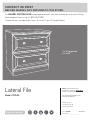 1
1
-
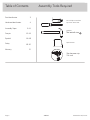 2
2
-
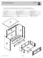 3
3
-
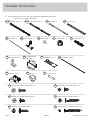 4
4
-
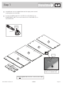 5
5
-
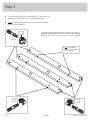 6
6
-
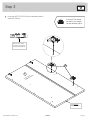 7
7
-
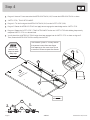 8
8
-
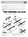 9
9
-
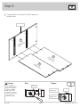 10
10
-
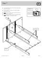 11
11
-
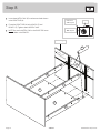 12
12
-
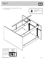 13
13
-
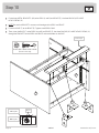 14
14
-
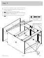 15
15
-
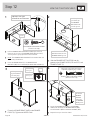 16
16
-
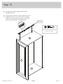 17
17
-
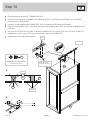 18
18
-
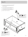 19
19
-
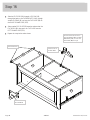 20
20
-
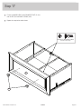 21
21
-
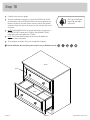 22
22
-
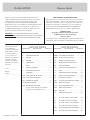 23
23
-
 24
24
-
 25
25
-
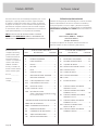 26
26
-
 27
27
-
 28
28
-
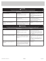 29
29
-
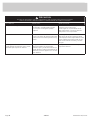 30
30
-
 31
31
-
 32
32


en otros idiomas
- français: Sauder 420545 Mode d'emploi
- English: Sauder 420545 Operating instructions
Artículos relacionados
-
Sauder 414289 Manual de usuario
-
-
-
-
-
-
-
-
-