Generac 1648-0 El manual del propietario
- Categoría
- Generadores de poder
- Tipo
- El manual del propietario

Portable Generator Owner's Manual
Questions? Help is just a moment away!
Call:Generac Generator Helpline - 1-800-270-1408 M-F 8-5 CT
Web: www.generac-por tables.corn
Model No. 1648-0 (4,500WattAC Generator) Manual No. 189264GS Revision5 (I 1/19/2002)

EQUIPMENT
DESCRIPTION
_Read this manual carefully and become familiar
with your generator. Know its applications, its
limitations and any hazards involved.
Thisgenerator isan engine-driven,revolvingfield,alternating
current (AC) generator. It was designedto supply electrical
power for operating compatible electrical lighting,appliances,
tools and motor loads.Thegenerator's revolvingfield is
driven at about 3,600rpm by asingle-cylinderengine.
CAUTION! DO NOT exceed the generator's
wattage/amperage capacity.See"Don't Overload the
Generator" on page I I.
Everyeffort hasbeenmadeto ensurethat informationinthis
manualisaccurateand current However,Generacreserves
the right to change,alter or otherwise improvethe product
and this document at anytime without prior notice.
The EmissionControl Systemfor this generator iswarranted
for standardsset by the EnvironmentalProtection Agency.For
warranty informationrefer to the engineowner's manual.
SAFETY RULES
This is the safety alert symbol. It is used toalert you to potential personal injury hazards.
Obey all safety messages that follow this
symbol to avoid possible injury or death.
The safety alert symbol (_.) isusedwith a signalword
(DANGER, CAUTION,WARNING), a pictorial and/or a
safety messageto alert you to hazards.DANGER indicates
a hazardwhich, ifnot avoided,will result in death or serious
injury.WARNING indicatesa hazardwhich, if not avoided,
couldresult in death or serious injury.CAUTION
indicatesa hazardwhich, ifnot avoided,might result in
minor or moderate injury. CAUTION, when used
without the alert symbol, indicates a situation that could
result in equipment damage.Follow safety messagesto
avoid or reduce the risk of injuryor death.
In the State of California a spark arrester isrequired by lawI
(Section 4442 of the California Public ResourcesCode). I
Other states may havesimilar laws.Federallawsapply on I
federal lands.If you equip the muffler with a spark arrester,
it must be maintained in effective working order.
WARNING
The engine exhaust from this product contains I
chemicals known to the State of California to cause
cancer, b rth defects, or other reproduct ve harm.
DANGER
Operate generator ONLY outdoors.
Keep at least 2 feet of clearance on all sidesof generator for
adequateventilation.
DO NOT operategeneratorinsideanybuildingor enclosure,
includingthe generatorcompartment of arecreationalvehicle(RV).
DANGER
National ElectricCode requires generator to be properly
grounded to an approved earth ground. Call an electrician for
local grounding requirements.
DANGER
When usinggenerator for backup power, notify utility
company.Use approved transfer equipment to isolate
generator from electric utility.
Use aground circuit fault interrupter (GFCI) in any damp or
highly conductive area,such asmetal decking or steel work.
DO NOT touch bare wires or receptacles.
DO NOT use generator with electrical cords which are worn
frayed,bare or otherwise damaged.
DO NOT operate generator in the rain.
DO NOT handle generator or electrical cords while standing
in water, while barefoot, or while handsor feet are wet.
DO NOT allow unqualified persons or children to operate or
service generator.
ENERATOR
WARNING
Disconnect the spark plug wire from the spark plug and place
the wire where it cannot contact spark plug.
/
2

, WARNING
WHEN ADDING FUEL
Turn generator OFF and let it cool at least 2 minutes before
removing gascap.Loosen cap slowly to relieve pressure in tank.
Fill fuel tank outdoors.
DO NOT overfill tank.Allow spacefor fuel expansion.
Keep fuel awayfrom sparks,open flames,pilot lights, heat,and
other ignition sources.
DO NOT light a cigarette or smoke.
NHEN OPERATING EQUIPMENT
DO NOT tip engine or equipment at anglewhich causesfuel
to spill.
'HEN TRANSPORTING OR REPAIRING EQUIPMENT
Transport/repair with fuel tank EMPTYor with fuel shutoff
valve OFF.
Disconnect spark plug wire.
NHEN STORING FUEL OR EQUIPMENT WITH FUEL
IN TANK
Store awayfrom furnaces,stoves, water heaters,clothes
dryers or other appliances that havepilot light or other
ignitionsource becausethey can ignitefuel vapors.
DANGER
DO NOT allow any open flame,spark, heat,or lit cigarette
during andfor several minutes after charging abattery.
Wear protective goggles,rubber apron, and rubber gloves.
, WARNING
DO NOT touch hot surfaces.
Allow equipment to cool before touching.
CAUTION
DO NOT tamper with governedspeed.Generator supplies
correct rated frequency and voltage when running at governed
speed.
DO NOT modify generator in any way.
CAUTION
See"Don't Overload Your Generator" on page I h
Start generator and let engine stabilize before connecting
electrical loads.
Connect electrical loads in OFF position, then turn ON for
operation.
Turn electrical loads OFF and disconnect from generator
before stopping generator.
CAUTION
Use generator only for intended uses.
tf you have questions about intended use,askdealer or
contact Generac.
Operate generator only on levelsurfaces.
DO NOT expose generator to excessive moisture, dust,dirt,
or corrosive vapors.
DO NOT insert any obiects through cooling slots.
tf connected devices overheat, turn them off anddisconnect
them from generaton
Shut off generator if.'
-electrical output is lost;
-equipment sparks,smokes,or emits flames;
-unit vibrates excessively.
/
3

KNOWYOUR GENERATOR
Read this owner's manual and safety rules before operating your generator.
Compare the illustrationswith your generator, to familiarize yourself with the locationsof variouscontrols and
adjustments.Savethis manualfor future reference.
EngineSwitch Recoil Starter
FuelTank
Oil Fill
Air Cleaner
Choke Lever
120/240VoltAC,
30 Amp
Receptacle
Idle Control Switch
Spark Attester Muffler
Minder
Wing Nut
12Volt DC, 10Amp
Receptacle
120Volt AC, 20 Amp
Duplex Receptacles
Circuit
Breakers (AC)
12Volt DC, I0 Amp Receptacle -- Rechargea discharged
12Volt automotive type battery through this receptacle.
120Volt AC, 20 Amp GFCI Duplex Receptacles --
May be usedto supply electrical power for the operation
of 120Volt AC, 20 Amp, single phase,60 Hz electrical,
lighting,appliance,tool and motor loads.
120/240 Volt AC, 30 Amp Locking Receptacle -- May
be usedto supply electrical power for the operation of
120and/or 240Volt AC, 30Amp, singlephase,60 Hz
electrical, lighting, appliance,tool and motor loads.
Air Cleaner -- Uses a dry type filter element to limit the
amount of dirt and dust suckedinto the engine.
Choke Lever -- Usedwhen starting acold engine.
Circuit Breakers (AC) -- Pushto reset circuit breakers
are provided to protect the generator againstelectrical
overload.
FuelTank -- Capacity of seven (7) U.S.gallons.
GroundingWing Nut -- Used for proper grounding of
unit (see page 7).
Maintenance Minder --Alerts you to change the oil and
service the air filter when needed.
Idle Control Switch --The idlecontrolruns the engineat
normal (high)speedswhen there isa loadpresent and runs
the engineat idle (low) speedswhen a load isnot present.
Oil Fill --Add engine oil here.
Recoil Starter-- Used to start the engine.
Engine Switch -- Set this switch to "On" before using
recoil starter. Set switch to "Off" to switch off engine.
Spark Arrester Muffler -- Exhaust muffler lowers
engine noise and is equipped with a spark arrester screen.
/
4

ASSEMBLY
Your generator requires some assembly and isready for
use after it hasbeen properly serviced with the
recommended oil and fuel.
If you have any problems with the assembly of your
generator, please call the generator helpline at
1-800-270-1408.
Remove Generator From Carton
• Set the carton on a rigid fiat surfacewith "This Side Up"
arrows pointing upward.
• Carefully open the top flapsof the shippingcarton.
• Cut down corners at one end of carton from top to
bottom and laythat side of carton down fiat
• Removeall packing material, carton fillers, etc.
• Removethe generator from the shipping carton.
Carton Contents
Check all contents. If anyparts are missingor damaged,call
the generator helpline at 1-800-270-1408.
• The generator
• Generator and engine owner's manuals
• Locking 30Amp plug
• Engineoil
• Wheel kit
Install Wheel Kit
The wheel kit isdesignedto greatly improvethe portability
of your generator.
NOTE: Wheel kit is not intendedfor over-the-road use.
You will need a socket wrench with I/2" or 13mm sockets
and a needle-nose pliers to install this kit.
Refer to Figure I and install the wheel kit as follows:
I. Placethe generator on a hard fiat surface.
2. Standat the engine end of the generator and gently tilt
the generator forward, high enough to placewooden
blocks beneath the cradle.This will allow you to add
the wheels.
Wheel
Axle /
Hex Nut
Support Leg
Vibration
_20mm
Cap Screw /
FlatWasher
Hex Nut
30mm Cap Screw
E-Ring
/
5

3. Slide the axle through the holes in the brackets
provided on the generator cradle.
4. Slide a wheel and fiat washer over the axle.
NOTE: Be sure to installboth wheels with the air
pressure valve on the outboard side.
5. Placethe e-ring onto the groove in the axle.
NOTE: Use retaining pins insteadof e-clip, if applicable.
6. Placeone end of the needle nose pliers on the bottom
of the axle and the other end of the pliers on top of
the e-ring.Seatthe e-ring by pressingthe pliers closed.
7. Repeat step 4 through 6 to secure second wheel
Removethe wooden blocks.
8. Attach the vibration mounts to the support leg with
30mm capscrews,washers and lock nuts.
9. With the wheels on, you can now lift up the handle
end and attach the support leg with 20mm capscrews
and lock nuts.
10. Check eachfastener to ensure it issecure and the
tires are inflated between 15-40 PSI.
BEFORE STARTING THE
ENGINE
Add Oil
CAUTION! Any attempt to crank or start the engine
before it hasbeen properly ftled with the recommended
oil may result in an engine failure.
To fill your engine with oil:
• Place generator on a Jevel surface.
• Follow the oil grade recommendationsand oil fill
instructionsgiven in the engine owner's manual.
NOTE:The generator's revolving field rides on a
prelubricated and sealedbait bearing that requires no
additional lubrication for the life of the bearing.
Add Fuel
_ ARNING! NEVERfillfuel tank indoors. NEVER
flit fuel tank whenengine isrunning or hot.Allow unit
to cool for two minutes before refueling.DO NOT
light a cigarette or smoke when filling the fuel tank.
_ WARNING! DO NOT overfill the fuel tank.
Always allow room for fuel expansion.
• Use regular UNLEADED fuel with the generator
engine.DO NOT usepremium fuel. DO NOT mix oil
with fuel
• Clean areaaround fuel flit cap,remove cap.
• Slowly add unleaded regular fuel to fuel tank. Be careful
not to overfitLAliow about 1.5"of tank spacefor fuel
expansion (Figure2).
Fuel
..... N--N 22Nr
• Install fuel capand wipe up any spilled fuel.
IMPORTANT: It isimportantto prevent gum deposits
from forming in essentialfuel system parts,such asthe
carburetor, fuel filter, fuel hose or tank during storage.Also,
experience indicatesthat alcohol-blended fuels (called
gasohol,ethanol or methanol) can attract moisture, which
leadsto separation and formation of acids during storage.
Acidic fuel can damagethe fuel system of an enginewhile in
storage.
To avoid engine problems, the fuel system should be
emptied before storage of 30 claysor longer.See"Storage"
on page 13.NEVER use engine or carburetor cleaner
products in the fuel tank or permanent damagemay occur.
/
6

GROUNDING THE
G EN ERATO R
The National Electrical Code requires that the frame and
external electrically conductive parts of this generator be
properly connected to an approved earth ground. Local
electrical codes mayalso require proper grounding of the
unit. For that purpose, a GROUNDING WING NUT is
provided on the generator end (Figure 3).
Wing Nut
Generally,connecting a No. 12AWG (American Wire
Gauge) stranded copper wire to the grounding wing nut
and to an earth-driven copper or brass grounding rod
(electrode) provides adequate protection against electrical
shock. Be careful to keepthe grounding wire attached after
connecting the stranded copper wire. However, local codes
may vary widely.Consult with a localelectrician for
grounding requirements in your area.
Properly grounding the generator helps prevent electrical
shock if aground fault condition exists in the generator or
in connected electrical devices,especiallywhen the unit is
equipped with a wheel kit. Proper grounding also helps
dissipate static electricity, which often builds up in
ungrounded devices.
OPERATING THE
G EN ERATO R
A AUTION! Never start or stop the engine with
electrical loadsconnected to the receptaclesAND
with the connected devices turned ON.
Starting the Engine
Disconnect all electrical loadsfrom the generator. Use the
following start instructionsteps by numerical order:
I. Turn the fuel valve to the "On" position (Figure 4).
Fuel Valve is shown
in the "On" position
2.
.
4.
5.
Placethe chokelever in the "Closed" position
(Figure5).
Closed
Setthe engine switch to the "On" position (Figure6).
EngineSwitch
Off
On
Grasp the recoil handle and pull slowly until slight
resistance is felt.Then pull rapidly to start engine.
Move choke lever to "Open" position a short distance
at a time over several seconds in warm weather or
minutes in cold weather. Let engine run smoothly before
each change. Operate with choke in "Open" position.
/
7

NOTE: If engine still fails to start after 3 pulls,check for
proper oil level in crankcase.This unit is equipped with a
low oil device.Seeengine manual.
Refer to the engine owner's manual for more
detailed starting instructions.
Connecting Electrical Loads
• Let enginestabilize and warm up for a few minutes after
starting.
• Plugin and turn on the desired 120and/or 240 VottAC,
single phase,60 Hz electrical loads.
• DO NOT connect 240Vott loads to the 120Volt duplex
receptacles.
• DO NOT connect 3-phase loads to the generator.
• DO NOT connect 50 Hz loadsto the generator.
• DO NOT OVERLOADTHE GENERATOR. See
"Don't Overload the Generator" on page I I.
Stopping the Engine
• Unplug all electrical loads from generator panel
receptacles,NEVER start or stop engine with electrical
devices plugged in and turned ON.
• Let engine run at no-load for several minutes to stabilize
the internal temperatures of engine and generator.
• Movethe engineswitch to "Off' position.
• Movethe fuel valveto the "Off' position.
Operating Automatic Idle Control
This switch isdesignedto greatly improve fuel economy.
When this switch is turned ON, the engine will only
run at its normal high governed engine speed when an
electrical load is connected.When an electrical load is
removed,the enginewill run at a reduced speed.With the
switch off, the enginewill run at the normal high engine
speed.Always have the switch off when starting and
stopping the engine.
Charging a Battery
_ ARNING! Storage batteries give off explosive
hydrogen gaswhile recharging.An explosive mixture
will remain around the battery for a long time after
it hasbeen charged.The slightest spark canignite
the hydrogen and causean explosion, resulting in
blindness or other serious injury.
_ ARNING! DO NOT permit smoking,open
flame,sparks or anyother source of heat around a
battery.Wear protective goggles,rubber apron and
rubber gloves when working around a battery.
Battery electrolyte fluidis an extremely caustic
sulfuric acid solution that can causesevere burns. If
spill occurs flush area with clear water immediately.
Your generator hasthe capability of recharging a discharged
12Volt automotive or utility style storage battery. DO
NOT use the unit to chargeany 6Volt batteries. DO NOT
usethe unit to crank an engine havinga discharged battery.
To recharge 12Volt batteries, proceed as follows:
• Check fluidlevel in all battery cells.If necessary,add
ONLY distilled water to cover separators in battery cells.
DO NOT use tap water.
• If the battery isequipped with vent caps,make sure they
are installed and are tight.
• If necessary,clean battery terminals.
• Connect battery charge cable connector plug to panel
receptacle identified by the words "12-VOLTS D.C".
• Connect battery charge cable clampwith red handle to
the positive (+) battery terminal (Figure7).
12 VOLT D.C.
RECEPTACLE
+
POS NEG
12 VOLT BA'n'ERY
• Connect battery charge cable clampwith black handle
to the negative (-) battery terminal (Figure7).
• Start engine.Let the engine run while battery recharges.
• When battery hascharged,shut down engine
NOTE: Use an automotive hydrometer to test battery state
of chargeand condition. Follow the hydrometer
manufacturer'sinstructions carefully.Generally,abattery is
consideredto be at 1(30°/ostateof chargewhen specificgravity
of its fluid (asmeasuredby hydrometer) is 1.260or higher.
i
8

RECEPTACLES
120/240 Volt AC, 30 Amp, Locking
Receptacle
Use a NEMA LI4-30 plug with this receptacle.Connect a
4-wire cord set rated for 250Volt AC loads at 30 Amps (or
greater) (Figure 8).You can usethe same4-wire cord if you
)lan to run a 120Volt load.
4-WireCord Set
f
(Neutral)
Y (Hot) | X (Hot)
NEMA L14-30 /--_ Ground(Green)
This receptacle powers 120/240Volt AC, 60 Hz,single
phaseloads requiring up to 4,500 watts of power (4.5 kW)
at 30 Amps for 120Volts or 240Volts.The outlet is
protected bya push-to-reset circuit breaker.
_ CAUTION! Although this outlet states it has a
120/240 Volt 30 Amp rating (up to 7,200 watts), the
generator is only rated for 4,500 watts. Powering
loads that exceed the wattage/amperage capacity of
the generator can damage it or cause serious
injuries.
120 Volt AC, 20 Amp, GFCI Duplex
Receptacles
Eachduplex receptacle (Figure 9) isprotected against
overload by a push-to-reset circuit breaker.
•11 I
•11 I
Use each receptacle to operate 120Volt AC, single-phase,
60 Hz electrical loadsrequiring up to 2,400 watts (2.4 kW)
at 20Amps of current. Use cord sets that are rated for
125Volt AC loads at 20Amps (or greater).
Ground Fault Protection
Thisunit isequippedwith a Ground Fault Circuit
Interrupter (GFCI).This device meets applicablefederal,
state and localcodes.
The GFCI protects againstelectrical shock that may be
caused ifyour body becomes a path which electricity
travels to reach ground.This could happenif you touch a
"Live" applianceor wire, or are touching plumbing or other
materials that connect to the ground.
When protected by a GFCI, one may still feel a shock, but
the GFCI should cut current off quickly enough so that a
person in normal health should not suffer anyserious
electrical injury.
_ CAUTION!The GFCI will not protect you
against the following situations: (I) Line-to-line
shocks;(2) Current overloads or line-to-lineshort
circuits.The fuse or circuit breaker at the
distribution panel must provide such protection.
/
9

Testing the GFCI
Test your GFCI outlet every month, asfollows:
• Pushthe black*'Test" button.The red "Reset" button
should pop out, which should allow no power to reach
the outlet. Use a test lamp in eachoutlet to test this.
I[o_ IIP_LV_ilDZeelIJ[!]r_]:i _tI
_ AUTION! Ifthe"Reset" button does not pop
out or the test tamp remains lit when the "Reset"
button ispopped out, do not useany outlets on the
circuit Call a qualified electrician.
• If the GFCI tests good, restore power by pressingthe
"Reset" button firmly until it isfully in place and locksin
that position. If the GFCI outlet does not reset
properly, do not use the outlet _ call a Generac
service center.
• If the GFCI trips by itselfat anytime, reset and test the
outlet. If the reset button does pop out when the
test button is pressed, do not use the outlet. Call
a Generac service center.
12Volt DC, I 0 Amp Receptacle
This receptacle (Figure10) allows you to recharge a 12Volt
automotive or utility style storage battery with the battery
chargecables provided.
This receptacle can not recharge 6Volt batteries and can
not be usedto crank an engine havinga discharged battery.
See"Charging a Battery" on page8 before attempting to
recharge a battery.This outlet isprotected by a l0 Amp self
resetting circuit breaker.
/
10

DON'T OVERLOAD YOUR
G EN ERATO R
Capacity
You must make sure your generator cansupply enough
rated (running) and surge (starting) watts for the itemsyou
will power at the sametime. Follow these simple steps:
I. Select the itemsyou wilt power at the same time.
2. Total the rated (running) watts of these items.Thisis
the amount of power your generator must produce to
keep your itemsrunning. SeeFigure I I.
3. Estimate how many surge (starting) watts you wilt
need.Surge wattage isthe short burst of power
needed to start electric motor-driven tools or
appliancessuch asa circular saw or refrigerator.
Becausenot all motors start at the sametime, total
surge watts can be estimated by addingonly the
item(s)with the highest additional surge watts to the
total rated watts from step 2.
Example:
Tool or Appliance
Window Air
Conditioner
Refrigerator
Deep Freezer
Television
Light (75 Watts)
Rated (Running)
Watts
1200
8O0
50O
50O
75
3075 Total
Running Watts
Total Rated (Running)Watts = 3075
Highest Additional SurgeWatts = 1800
Total Generator Output Required = 4875
Additional Surge
(Starting)Watts
1800
1600
500
1800 Highest
Surge Watts
Power Management
To prolong the life of your generator and attached devices,
it is important to take care when addingelectrical loads to
your generator.There should be nothing connected to the
generator outlets before starting it's engine.The correct
and safeway to managegenerator power isto sequentially
add loads asfollows:
I. With nothing connected to the generator, start the
engine asdescribed in this manual
2. Plugin and turn on the first load,preferably the largest
load you have.
3. Permit the generator output to stabilize (engine runs
smoothly and attached device operates properly).
4. Plug in and turn on the next load.
5. Again,permit the generator to stabilize.
6. Repeat steps 4 and 5 for each additional load.
NEVER add more loads than the generator capacity.Take
specialcare to consider surgeloads in generator capacity,
asdescribed above.
Tool or Appliance
Essentials
Light Bulb - 75 watt
Deep Freezer
SumpPump
Refrigerator/Freezer - 18Cu. Ft.
Water Well Pump- I/3 HP
Heating/Cooling
Window AC - 10,000BTU
Window Fan
FurnaceFanBlower - I/2 HP
Kitchen
Microwave Oven - 1000Watt
Coffee Maker
Electric Stove - SingleElement
Hot Plate
Family Room
DVD/CD Player
VCR
Stereo Receiver
Color Television - 27"
Personal Computer w/I 7" monitor
Other
SecuritySystem
AM/FM Clock Radio
GarageDoor Opener - I/2 HP
Electric Water Heater - 40 Gallon
DIY/Job Site
Quartz Halogen Work Light
Airless Sprayer - I/3 HP
Reciprocating Saw
Electric Drill - I/2 HP
Circular Saw- 7 I/4"
Miter Saw- I0"
Table Planer - 6"
Table Saw/RadialArm Saw- I0"
Air Compressor - I-I/2 HP
Rated*
(Running)
Watts
75
500
8O0
8O0
1000
12O0
3OO
8O0
1000
1500
1500
2500
Additional
Surge
(Starting)
Watts
5O0
1200
1600
20O0
1800
6O0
1300
100
100
450
5o0
8o0
18o
3O0
480 520
40O0
1000
600 1200
960 960
1000 1000
1500 1500
1800 1800
1800 1800
2000 2000
2500 2500
*Wattages listed are approximate only. Check toot or
appliance for actual wattage.
/
II

SPECIFICATIONS
Maximum SurgeWatts ................. 5,625 watts
Continuous Wattage Capacity ........... 4,500 watts
Power Factor .............................. 1.0
Rated Maximum Continuous AC Load Current:
At 120Volts ....................... 37.5Amps
At 240 Volts ....................... 18.7Amps
Phase................................. I-phase
Rated Frequency ....................... 60 Hertz
FuelTank Capacity................... 7 U.S.gallons
ShippingWeight ......................... 164 Ibs.
GENERAL MAINTENANCE
RECOMMENDATIONS
The Owner/Operator is responsible for making sure that
all periodic maintenance tasks are completed on atimely
basis;that all discrepancies are corrected; and that the unit
is kept clean and properly stored. NEVER operate a
damaged or defective generator.
Engine Maintenance
See engineowner's manualfor instructions.
Maintenance Minder
The maintenance minder displaysand records how many
hours your generator has run (up to 9,999.9).It also alerts
you when to changeyour oil and to service your air filter.
The message"CHG OIL" will flash after the first 20 hours
of unit operation.This isto remind you to replace the
'break-in' oil with regular duty oiLThe same messagewill
againflash after intervalsof 100 hours.The maintenance
reminder does not sensethat the oil changehasoccurred -
it merely flashesthe messagefor a two hour period to
permit you to observe the reminder.
Similarly,the message"SVC AIR FILTER" willflashafter
intervalsof 50 hours to remind you to service or change
the air filter element
_ii CAUTION!When working on the generator,
alwaysdisconnect spark plug wire from spark plug
and keepit awayfrom spark plug.
_ii AUTION! Avoid prolonged or repeated skin
contact with used motor oil. Used motor oil has
been shown to causeskin cancer in certain
laboratory animals.Thoroughly wash exposed areas
with soapand water.
KEEPOUT OF REACH OF CHILDREN. DON'T
POLLUTE.CONSERVE RESOURCES.RETURN
USED OIL TO COLLECTION CENTERS.
Generator Maintenance
Generator maintenance consists of keeping the unit clean
and dry. Operate and store the unit in a dean dry
environment where it w{{{ not be exposed to excessive
dust, dirt, moisture or any corrosive vapors. Cooling air
slots in the generator must not become clogged with snow,
leaves or any other foreign material.
NOTE: DO NOT use a garden hose to dean generator.
Water can enter engine fuel system and cause problems. In
addition, if water enters generator through cooling air slots,
some of the water wilt be retained in voids and cracks of
the rotor and stator winding insulation.Water and dirt
buildup on the generator internal windings will eventually
decrease the insulation resistance of these windings.
To Clean the Generator
_ii AUTION! NEVER insertany object or tool
through the air cooling slots, even ifthe engine is
not running.
• Use adamp cloth to wipe exterior surfaces clean.
• A soft bristle brush maybe used to loosen caked on dirt
or oil.
• A vacuum cleaner may be used to pick up loose dirt and
debris.
• Low pressure air (not to exceed 25 psi) may be used to
blow awaydirt. Inspectcooting air slots and opening on
generator.These openings must be kept clean and
unobstructed.
/
12

STO RAG E
The generator should be started at least once every seven
days and allowed to run at least 30 minutes. If this cannot
be done and you must store the unit for more than
30 days,usethe following guidelinesto prepare it for
storage.
Generator Storage
• Clean the generator asoutlined in"To Clean the
Generator"
• Check that cooling air slots andopenings on generator
are open and unobstructed.
_ AUTION! Storage covers canbe flammable.
DO NOT place a storage cover over a hot
generator. Let the unit coot for a sufficient time
before placingthe cover on the unit.
Engine Storage
See engine owner's manualfor instructions.
Other Storage Tips
• To prevent gum from forming in fuel system or on
essential carburetor parts, add fuel stabilizer into fuel
tank and fill with fresh fuel. Run the unit for several
minutes to circulate the additive through the carburetor.
The unit and fuel can then be stored for up to
24 months. Fuel stabilizer can be purchased locally.
• DO NOT store fuel from one season to another unless
it has been treated as described above.
• Replace fuel container if it starts to rust. Rust and/or dirt
in fuel can cause problems if it's used with this unit.
• Store unit in a clean and dry area.
I
13

NOTES
14

TROUBLESHOOTING
Problem
Engine is running, but
no AC output is
available.
Engine runs good but
bogs clown when
loads are connected.
Engine will not start;
or starts and runs
rough.
Cause
I. Circuit breaker isopen.
2. Poor connection or defective cord set.
3. Connected device isbad.
4. Fault ingenerator.
I. Short circuit in a connected load.
2. Generator is overloaded.
3. Enginespeed istoo slow.
4. Shorted generator circuit.
I. Engineswitch set to "Off'.
2. Low oil level.
3. Dirty air cleaner.
4. Out of gasoline.
5. Stalegasoline.
6. Sparkplug wire not connected to
spark plug.
7. Badspark plug.
8. Water in gasoline.
9. Overchoking.
10. Excessivelyrich fuet mixture.
I I. Intake valve stuck open or closed.
12. Enginehaslostcompression.
Solution
I. Resetcircuit breaker.
2. Check and repair.
3. Connect another device that is ingood
condition.
4. Contact Generac service facility.
I. Disconnect shorted electrical load.
2. See"Don't Overload the Generator" on
page II.
3. Contact Honda service facility.
4. Contact Generac service facility.
I. Setswitch to "On".
2. Fill crankcaseto proper level.
3. Cleanor replace air cleaner.
4. Fillfuet tank.
5. Drain gastank and fill with fresh fuel.
6. Connect wire to spark plug.
7. Replacespark plug.
8. Drain gastank; fill with fresh fuel.
9. Setchoke to "Off' position.
10. Contact Honda service facility.
I I. Contact Honda service facility.
12. Contact Honda service facility.
Engine shuts down I. Out of gasoline. I. Fitl fuet tank.
during operation. 2. Fault in engine. 2. Contact Honda service facility.
I. Load istoo high. See "Don't Overload the Generator" on
page II.
Engine lacks power. 2. Dirty air filter. Replace air filter.
3. Engine needs to be serviced. Contact Honda service facility.
I. Choke is opened too soon.
Engine "hunts" or
falters.
2. Carburetor is running too rich or too
lean.
I.
2.
3.
I.
2.
Move choke to halfway position titl engine
runs smoothly.
Contact Honda service facility.
/
15

SCHEMATIC
BATTERY CHARGE
55
L 77 12V PC
HOURMETER/
MAINTENANCE REMINDER
IIA
11
IIA
IIA
66
13 55
RESET
lOA CB
13
IIA
14)
/ff) EXOTATION
FIELD
POWER POWER
ii 22 44
IDLE
CONTROL
TRAN3FORMER
155 156 22 44
IDLE CONTROL
CIRCUIT BOARD
IDLE
SWITCH
22
120/240V
30A 44A
22 22
44A
IIA
I
16

WIRING DIAGRAM
IIA
IlA
IIA
ii
20A CB ]20/240V 30A
IDLE CONTROL
SWITCH
120V 20A
GFCI
12V/IOA DC
0
22
L 22
F 156
13
155 GRY
GR%
IIA
44
55
55
13
13
13 DC CB
t5
55
15
13
156
155 ORY
CRY
I
17

2 ¸
_rs
EXPLODEDVIEW- MAIN UNIT
48
\
\
51
52
\
33
'\
31
42
76
56
72
65
10
61
27 2B
\
\
25
19
37_
11
\
\
3
\\\\\\
1
16
15
17
20
2
_ 6_
66
/
18

2 ¸
_r3
PARTS LIST - MAIN UNIT
Item Part # Qty
I K189252GS I
2 67989GS 8
3 70642GS 2
4 76222GS 2
5 91844JGS I
6 66365GGS I
7 SRV66825DGS I
8 26850GS 2
9 86494GS I
10 67022GS I
II 86307GS 4
12 22695GS I
13 86308CGS 4
14 189127GS I
15 74908GS 4
16 B4871GS I
17 66849GS 2
18 91825GS I
19 84242GS I
20 B4986GS I
21 20566GS I
22 85652GS 2
23 22769GS
24 86292GS
25 189540GS
26 81917GS
27 47480GS
28 96796GS
30 14353621GS
31 38750GS
32 22097GS
33 22473GS
34 BI89434GS
35 42909GS 2
36 22145GS 2
37 22129GS 2
38 45771GS 2
39 78299GS I
40 80270GS I
41 48031CGS 2
Description
CRADLE
NUT
MOUNT, Vibration
SCREW
ASSY,Rotor
HOUSING,Adapter
CARRIER,Rear Bearing
WASHER
SCREW,Wing
GROMMET,Rubber
SCREW
CONNECTOR, 6-pin Male
BOLT,Stator
GROMMET,Bushing,Rubber
SCREW
COVER, Bearing Carrier
SCREW
ASSY,Brush & Bridge Rectifier
GROMMET,Plastic,RBC
DECAL, Ground
DECAL, b800
MOUNT, Vibration
WASHER
SCREW
ASSY,Stator
PIN,Roll
BOLT,Rotor
WASHER
ASSY,Wire, Ground
SCREW
WASHER, Lock
WASHER
COVER, Engine
SCREW
WASHER
WASHER, Lock
NUT
BUSHING, GasTank
VALVE,Fuel
CLAMP,Hose Band
Item Part #
42 30340GS
43 189564GS
44 83465GS
45 78831AGS
46 93826GS
47 B4363GS
48 188333GS
49 B1998AGS
50 92982GS
51 189273GS
52 189272GS
53 189275GS
54 77816GS
55 73054GS
56 189274GS
57 189155GS
58 J189384GS
59 B2153GS
60 22413GS
61 22473GS
62 189377GS
63 189249GS
64 BB3061BGS
65 B1464GS
66 189264GS
67 65787GS
68 43438GS
69 84409GS
70 23762GS
71 189521AGS
72 66849AGS
73 65795GS
74 189454AGS
76 56893GS
77 BI232GS
78 28739AGS
900 NSP
Qty Description
I HOSE,Fuel
I CONNECTOR, Reducer
4 GROMMET,Tank
4 SCREW
I DECAL, Start Instructions
I CAP,Fuel Gauge
I DECAL, Instructions, Fuel Level
I ASSY,Tank,Fuel
(Includes Items 39 & 40)
DECAL, Danger
DECAL, Unit
DECAL, Control Panel
DECAL, Powered By Honda
DECAL, Caution, Hot Muffler
DECAL, FuelShut-Off
DECAL, Starting Instructions
WASHER
HEAT SHIELD,Muffler
SCREW
SCREW
WASHER
NUT,Well
ASSY,Control Panel
(see page21)
BOTTLE,Oil
MANUAL, Engine
MANUAL, Owners
CABLE, Battery Charge
PLUG, 120/240V,30A
SLEEVING,Flexo
WASHER
WIRE, PanelGround
SCREW
RECTIFIER
WIRE, Rectifier
SCREW
CLAMP,Hose
WRAP,Tie
ENGINE
/
19

2 ¸
_r3
EXPLODEDVIEWAND PARTS LIST-WHEEL KIT
3
2
/
4
10'
Item Part # Qty Description
I BB5586GS 2 HANDLE (Includes Item 15)
2 B4966GS 2 WHEEL
3 191267KGS I AXLE
4 191265GS 2 E-RING
5 39287GS 2 SCREW
6 BI89522GS I LEG,Support
7 191413GS 2 MOUNT, Vibe,with Washer
8 42909GS 2 SCREW
9 52858GS 4 NUT, Lock
10 22247GS 2 WASHER
II 39253GS 2 SCREW
12 22145GS 4 WASHER
13 49820GS 2 NUT
14 187104GS 4 WASHER,Nylon
15 B4605GS 2 GRIP
16 B4135GS 2 PIN, with Lanyard
/
20

2 ¸
_rs
EXPLODED VIEW AND PARTS LIST
23
- CONTROL PANEL
/
21
18
17 15
14 _
_19 13
12
11
lO
/
15
Item Part # Qty Description
I BI89250GS I COVER, Lid,Control Panel
2 189251GS I CONTROL PANEL,Back,Plastic
3 82538GS I SWITCH, Rocker
4 90418GS I OUTLET, 12VDC
5 189520GS l0 SCREW
6 82881GS 2 WASHER, Lock
7 189737GS I METER,Hour
8 43182GS 2 WASHER, Lock
9 51714GS 2 NUT
10 75207GS 2 BREAKER,Circuit, 20A
II 23365GS 6 WASHER
12 43437GS I OUTLET, 120/240V,30A
14 /
13
16
5
Item Part # Qty Description
13 38150GS 6 WASHER
14 22264GS 6 WASHER,Lock
15 51715GS 6 NUT
16 80409GS I OUTLET, Duplex, 20A
17 189165GS 2 NUT
18 189367GS I BOARD, Idle Control
19 84028GS I TRANSFORMER,Idle Control
20 87962GS I BREAKER,Circuit, 10A, 12V
21 22694GS I HOUSING, Receptacle
22 82308GS 2 SCREW
23 189502GS I HARNESS,Idle Control
/
21

DESCRIPCI( N DEL EQUIPO
_Lea este manual de manera cuidadosa y
familiaricese con su generador. Conozca sus usos,
sus limitaciones y cualquier peligro relacionado
con el mismo.
Este generador funciona en base a un motor, de campo el_ctrico
giratorio y de corriente alterna (AC). Fue disefiado con la
finalidad de proveer energia el_ctrica para luces el_ctricas,
aparatos, herramientas compatibles y cargas de motor. El campo
giratorio del generador funciona a una velocidad de 3,6000 rpm
usando un motor con un solo cilindro.
|PRECAUCI(_N! NO sobrepase la capacidad de vataje y
amperaie del generador. Revise "No Sobreeargue el Generador"
en la p_gina 3 I.
Se ha hecho cadaesfuerzo posible para asegurarse que la
informaci6n que aparece en este manual esexacta y se encuentra
actualizada.Sin embargo,Generac se reserva el derecho a
cambiar,alterar o de otra manera mejorar, el producto y este
documento en cualquier momento, sin previo aviso.
El Sistema de Control de Emisiones para este generador est_
garantizado para juegos est_ndarespor laAgencia de Protecci6n
Ambiental. Para mayor informaci6n acerca de la garantfa,consulte
con el manualdel propietario del motor.
INSTRUCCIONES DE SEGURIDAD
_ Este es el simbolo de aterta de seguridad. Sirve
para advertir a! usuario de un posible riesgo para
su integridad fisica. Siga todos los mensajes de
seguridad que figuren despu6s de este simbolo
para eqitar lesiones o incluso la muerte.
El simbolo de alerta de seguridad (_.) es usado con una palabra
(PELIGRO, ADVERTENCIA, PRECAUCION), un mensaje por
escrito o una ilustraci6n, para alertarlo acerca de cualquier
situaci6n de peligro que pueda existir. PELIGRO indica un riesgo
el cual, si no se evita, causard la muerte o una herida grave.
ADVEWrENCIA indica un riesgo el cual, si no se evita, puede
causar la muerte o una herida grave. PRECAUCI(_)N indica un
riesgo, el cual, si no se evita, puede causar heridas menores o
moderadas. PRECAUClON, cuando se usa sin el simbolo de
alerta, indica una situaci6n que podria resultar en el dafio del
equipo. Siga los mensajes de seguridad para evitar o reducir los
riesgos de heridas e inclusive la muerte.
En el estado de California es obligatorio, seg0n la ley, el uso de I
apagachispas (Secci6n 4442 del C6digo de Recursos P_blicos de
I
California). Otros estados pueden tener leyes similares. Las leyes
federales se aplican en tierras federales. Si equipa el silenciador
con un apagachispas, este deber_ ser mantenido en buenas
condiciones de trabaio.
I & ADVERTENCIA I
El escape de| motor de este producto contiene u
elementos quimicos reconocidos en el Estado de
California pot producir c_ncer, defectos de nacimiento
otros dafios de tipo reproductivo.
PELIGRO
Opere el generador SOLAMENTE al aire fibre.
Mantenga al menos 2 pies de espacio fibre alrededor del generador,
para la adecuada ventilaci6n.
NO opere el generador dentro de un edificio o lugar cerrado, induyendo
el compartimiento del generador en un vehlculo recreativo o RM
PELIGRO
Los C6digos Nacionales para la Electricidad, requieren clue los
generadores est_n haciendo tierra de una manera aprobada. Elaine a
un electricista para conocer los requisitos locales para hacer tierra.
PELIGRO
Cuando use un generador como poder de energia auxiliar, notifique a
la compafiia de utilidades. Use el equipo de transferencia aprobado
para aislar el generador de otra utilidad el_ctrica.
Use un interruptor para la falla del circuito de tierra (GFCI) en
cualquier _rea bastante h_rneda o que sea altamente conductiva, tales
como terrazas de metal o trabajo hecho con acero.
NO toque los alambres pelados o recept_culos.
NO use un generador con cables el/actricos que est_n malgastados,
rotos, pelados o dafiados de cualquier forma.
NO opere el generador bajo la Iluvia.
NO maneie el generador o cables el_ctricos mientras est_ parado en
agua, descalzo o cuando las manos y los pies est_n moiados.
NO permita que personas descalificadas o nifios operen o sirrah al
generador.
ADVERTENCIA
ENERADOR
Siempre desconecte el alambre de labuila y col0quelo donde no
pueda entrar en contacto con la bujia.
I
22

ADVERTENCIA
CUANDO AI_IADA COMBUSTIBLE
Apague el generador (posici6nOFF) y d_jelo enfriar al menos por
2 minutos antes de remover la tapa de lagasolina.Afloje la tapa
lentamente paradejar que la presi6n salgadel tanque.
Llene el tanque al aire libre.
NO ffenedemasi_do el tanque. Permita a] menos espacio para la
expansi6n del combustible.
Mantenga lagasolina alejadade chispas,ffamasabiertas, pilotos,calory
otras fuentes de ignicibn.
NO encienda un cigarrillo o fume.
:UANDO OPERE EL EQUIPO
• NO inclineel motor o el equipo, de ta[ manera que lagasolina se
pueda derramar.
CUANDO TBANSPORTE O REPABE EL EQUIPO
• Transporte o repare el equipo con e{ tanque de combustib{e vado, o
con la vg[vula para apagarel combustible, apagada(posid6n OFF).
• Desconecte el cable de la buj_a.
CUANDO ALMACENE O GUARDE EL EQUIPO CON
COMBUSTIBLE EN ELTANQUE
Almacene alejado de calderas,estufas,calentadores de agua,secadoras
de ropa u otros aparatos electrodom_sticos que posean pilotos u
otras fuentes de ignici6n, porquee{Ios pueden encender los vapores
de la gasolina.
PELIGRO
NO permita ninguna llamaabierta, chispa,calor, o endenda un
cigarrillo durante y pot varios minutos despu_asde haber recargado la
bater_a.
Llevepuestos[asgafasprotectoras, delantal y guantes de goma.
ADVERTENCIA
NO toque [assuperficies calientes.
Permitaque el equipo se enfrle antes de tocarlo.
PRECAUCION
NO cambie ninguna veloddad determinada. E[generador suminJstra
unafrecuencia y un vo[taje calificado cuando funcionaa unaveloddad
determinada.
NO modifique a[generador en ninguna forma.
PRECAUCION
Vea "No sobrecargue su generador" en [a p_gina31.
Endenda su generador y deje que el motor se estabilice antes de
conectar lascargas e[_ctricas.
Conecte lascargasel_ctricas en la posidbn de apagado (OFF),luego
encienda (ON) para suoperacibn.
Apague (OFF) [as cargasel_ctricas y descon_ctelas del generador
antes de parar el generador.
PRECAUCION
Use el generador solamente con lafina]idadpara e] cualrue dise_ado.
Si usted tiene a[gunapreguntaacerca de [asfinalidadesde uso de[
generador, preg_nte[e a suconcesionario o contacte a Generac.
Opere el gener_dor solamente en superficies nive{adas.
NO exponga al generador a una humedad excesiva,polvo, suciedad o
vapores co rl"osivos,
NO inserte cua{quier objeto a trav_s de lasranuras de enfriamiento.
Si los aparatos conectados se sobrecalientan, ap_gue{osy
descon_cte{os del generation
Apague el generador si:
-Se pierde [asalida e[_ctric_;
-El equipo produce chispas,humo o emite llamas;
-La unidad vibra de una manera excesiva.
mm_mm
23

CONOZCA SU GENERADOR
LEA ESTE MANUAL DEL PROPIETARIOY LAS REGLAS DE SEGURIDAD ANTES DE OPERAR SU GENERADOR.
Compare las ilustraciones con su Generador para familiarizarse con las ubicaciones de los diferentes controles y ajustes. Conserve este
manual para referencias futuras.
tnterruptor del Motor Culatazo el Principio
Tanque de Combustible
Aceite Ilena
Depurador de Aire
Palancadel Cebador
Tomacorrientes con
Dispositivo de
Seguridad de I I
120/240 Voltios AC, II
30 Amp
Interruptor del Control I_
de Marcha en Vacio
Tuerca Mariposa para
Conexi6n aTierra
Tomacorrientes de
12Voltios DC
Aceite Ilena --Agrega motor aceite aqui.
Cortacircuitos (AC) -- Cada tomacorriente posee un
cortacircuito para proteger el generador contra sobrecargas
el_ctricas. Los cortacircuitos son del tipo "oprimir para
reposicionar".
Culatazo el Principio -- Us6 para comenzar motor.
Depurador deAire -- Filtra el aire de entrada a medida que
penetra en el motor.
Interruptor del Control de Mancha enVacio - El control de
marcha en vacio hace funcionar el motor a velocidades normales
(altas) cuando existe una carga presente y hace funcionar el motor
a velocidades de marcha en vacio (baias) cuando no existen cargas
presentes. Esta caracteristica mejora el ahorro de combustible,
prolonga la vida del motor y disminuye el ruido del motor.
Interruptor del Motor -- Deber_ estar en la posici6n "On"
(En) para darle arranque al motor. Col6quelo en la posici6n "Off'
(Apagado) para detener un motor en funcionamiento.
Mantenimiento Minder - Lo pone sobre aviso al cambio el
aceite y atiende al flltro a_reo cuando sea necesario.
Palanca del Cebador -- Us_da cuando se est_ dando arranque
a un motor frio.
Silenciador Apagachispas
Mantenimiento Minder
Cortacircuitos (AC)
Tomacorrientes Doble de
120Voltios AC, 20 Amp
Sileneiador Apagachispas -- El silenciador disminuye el ruido
del motor y est_ equipado con una pantalla apagachispas.
Tanque del Combustible -- El tanque tiene una capacidad de
7 galones americanos de gasolina sin contenido de plomo.
Tomacorrientes de 12Voltios DC - Este tomacorriente le
permite recargar baterlas tipo servicio o automotriz de 12Voltios
o bateria de almacenamiento tipo servicio utilizando los cables
para cargar baterias.
Tomacorriente Dobles de 120VoltiosAC, 20Amp --
Pueden ser utilizados para suministrar alimentaci6n el_ctrica para
el funcionamiento de cargas del motor, herramientas, aparatos
especiales e iluminaci6n el_ctrica de 120Voltios AC a
20 Amperios, monof_sica de 60 Hz.
Tomacorriente con Dispositivo de Seguridad de
120/240 Voltios, 30 Amp -- Puede ser utilizado para suministrar
alimentaci6n el_ctrica para el funcionamiento de cargas del motor,
herramientas, aparatos especiales e iluminaci6n el_ctrica de
120 y/o 240 Voltios AC a 30 Amperios, monof_sica de 60 Hz.
Tuerca Mariposa para Conexi6n aTierra -- Usado para
apropiado moli6 de la unidad (vea p_gina 27).
I
24

MONTAJE
Sugenerador requiere de dertos procedimientos de montaje y
solo estar_ listo para ser utilizado despu_s de haberle
suministrado servicio con el combustible y aceite recomendados.
Si usted tiene problemas con el montaje de su generador,
pot favor Ilame a la linea de ayuda para generadores al
1-800-270-1408.
Para Retirar el Generador de la Caja
Coloque la caja sobre una superficie planay rigida, con las
flechasque dicen "this side up" haciaarriba.
Abra con cuidado lastapas superiores de la cajade envio.
Corte de arriba a abajo las esquinasde uno de los lados de la
caja y coloque ese lado de la caja sobre el suelo.
Retire todo el material de empaque,relleno, etc.
Saque elgenerador de la cajade envto.
Contenido De La Caja
Revisetodo el contenido. Sialguna de las partesno est_ presente
o est_ da_ada,por favor Ilame a la linea de ayudapara
generadores al 1-800-270-1408.
La unidad principal
Manual del propietario
Aceite para motor
Tapones de fijaci6n
Juegode Ilantas
Instale el Juego de Ruedas
Eljuego de ruedas est_ dise_adopara mejorar el transporte del
generador.
NOTA: EsteJuegode Ruedasno hasido dise_ado para ser usado
en la carretera.
Necesitar_ una Ilavede cubos con cubos de /2" o 13mmy unas
pinsasde punta para instalarel juego de ruedas.
Consulte la Figura 12 y instale el juego de ruedas como
se describe a continuaci6n:
I. Coloque el generadorsobre unasuperficie planay dura.
2. P_rese en el extremo del motor del generador e inclineel
generador cuidadosamente haciaadelante, Io suficiente como
para colocar bloques por debajo del armazbn. Esto le
permitir_ colocar lasruedas.
3. Paseel eje atray,s de los oriflcios de las m_nsulasdel
armazbn del generador.
4. Deslice una rueda y arandela en el eje.
NOTA: Aseg_rese de instalarambas ruedas con lav_lvula de aire
hacia el lado de afuera.
5. Coloque el e-ring en la ranura del eje.
Rueda
_e
/
Tuercas
Pata de Soporte
Montajes Antivibratorios
Tornillos
_Tornillos
Tuercas
Arandela
E-Ring
/
25

6. Coloqueunextremodelaspinzasdepuntasdeagujaenla
parteinferior del eie y el otro extremo de laspinzas en la
parte superior del e-ring.Asiente ele-ring cerrando las
pinzas.
7. Repita los pasos 4 por 6 para asegurar la segundarueda.
Remuevalos bloques temporales.
8. lnstale los montajes antivibratorios a la pata de soporte
utilizando dos tornillos prisioneros M8 x 30mm, arandelas
M8 y tuercas de seguridad MS.
9. Con 1asruedas instaladas, ahora puede incEnar el extremo
del generador e instalar la pata de soporte utilizando dos
tornillos prisioneros M8 x 20mm y dos tuercas de seguridad.
10. Verifique que todas las piezasest_n apretadas y las Ilantas
est6n infladascon aire entre 15-40PSI.
ANTES DE DARLE ARRANQUE AL
MOTOR
Agregar Aceite al Motor
CAUTION! Cualquier intento para arancar el motor antes de
haberle proporcionado el mantenimiento apropiado con el aceite
recomendado, podrfa ocasionar la falla del motor.
Coloque la generador sobre una superficie nivelada.
Consulte el manual del propietario del motor para a_adir al
motor el aceite recomendado.
NOTA: El campo giratorio del generador se encuentra en un
coiinete pre-lubricado y sellado que no requiere lubricacibn
adicional por la vida 6til del coiinete.
Agregue Gasolina
_ ADVERTENCIA! NUNCA Ilene el tanque del
combustible en recintos cerrados. NUNCA Ilene el tanque
del combustible cuando el motor est_ en funcionamiento
o caliente.NO encienda cigarrillos o fume cuando est_
Ilenando el tanque del combustible.
_ ADVERTENCIA! NO Ilene excesivamente el tanque
de combustible. Deje suficiente espacio para la expansi6n
del combustible.
Use gasolinaregular SIN CONTENIDO DE PLOMO en
el generador.NO usegasolina premium. NO mezcle aceite
con gasolina.
Limpie el _rea alrededor del Ilenado de gasolina;retire latapa.
Llene lentamente el tanque con gasolinasin contenido de
plomo. Seacuidadoso de no Ilenar excesivamente. Deie
1.5" de espacio en el tanque para que la expansibn del
combustible, como semuestra en esta ilustracibn(Figura 13).
_NNNN_NNNNN_N_N_
Instalela tapa del combustible y limpie cualquier derrame de
gasolina.
IffPORTANTE: Esimportante evitar la formacibn de depbsitos
de goma en las partes esencialesdel sistema de combustible
como en el carburador, filtro del combustible, manguera del
combustible o tanque, durante sualmacenamiento. Los
combustibles mezclados con alcohol (llamados gasohol,etanol o
metanol) pueden atraer la humedad,la cual produce la separacibn
y formacibn de _cidosdurante el almacenamiento. Lagasolina
_cida puede da_ar el sistema de combustible de un motor
durante sualmacenamiento.
Para evitar problemas en el motor, deber_ vaciar el sistema de
combustible antes de perlodos de almacenamiento de 30 dias o
m_s.Vea "Almacenamiento" en la p_gina 33. NUNCA use
productos para limpiar motores o carburadores en el tanque del
combustible; si Io hace ocurrir_n da_os permanentes.
/
26

CONEXION ATIERRA DEL
GENERADOR
El C6digo Nacional de Electricidad exige que el marco y las
partes exteriores del generador conductoras de electricidad,
est_n conectadas atierra adecuadamente.Los c6digos el_ctricos
locales tambi_n pueden exigir que la unidad est_ conectada a
tierra correctamente. Paratal prop6sito, se ha instalado una
tuerca mariposa para conexi6n a tierra en la basedel bastidor
(Rgura 14).
para Conexi6n a
Tierra
Por Io general, la conexi6n de un alambre de cobre trenzado No.
12AWG (AmericanWire Gauge)a la aleta de conexi6n a tierra y
a una barra de conexi6n a tierra de cobre o bronce (electrodo)
proporciona una proteccibn adecuadacontra lasdescargas
el_ctricas. Sin embargo,los c6digos locales pueden variar
substancialmente.Consulte con un electricista local para conocer
los requisitos de conexi6n a tierra de su grea.
La adecuada conexi6n a tierra del generador ayudaa evitar
descargasel_ctricas si se produce alguna fallaa tierra en el
generador o en los dispositivos el_ctricos conectados,
especialmente si el generador se equipa con un juego de la rueda.
Tambi_n ayudaa disipar la electricidad est_tica que, con
frecuencia, segenera en dispositivos sin conexibn a tierra.
OPERANDO EL GENERADOR
_ iPRECAUCI(_N! NUNCA encienda o pare el motor
con las cargasel_ctricas conectadas alos recept_culosY
con los aparatos conectados ENCENDIDOS.
Encienda el Motor
Desconecte todas las cargasel_ctricasdel generador. Use las
siguientes instrucciones para encender,pasopor paso,en orden
num_rico.
I. Gire lav_lvula del combustible a la posicibn "On" (Figura 15).
V_lvula del Combustible
en posici6n"On"
2. Paraencender un motor frto, mueva la palancade la bobina a
la posicibn de "Cerrado" ("Closed") (Figura 16).
Cerrado
3. Pongael interruptor del motor en la posici6n de
"Encendido" ("On") (Figura 17).
Interruptor del Motor
5. Agarre la manilla de retroceso y hale lentamente hasta que
puede sentir un poco de resistencia.Luego hale r_pidamente
para encender el moto_
6. Si la palancade la bobina ha sido movida a la posici6n de
"Cerrado" ("Closed") para comenzar el motor, mu_vala
gradualmente a la posici6n de "Abierto" ("Open"), amedida
que el motor se calienta.
NOTA: Si el motor a_n fallaen encender despu_sde halar tres
veces,verifique el nivel adecuado del aceite en el cig_ehal.Esta
unidad est_ equipada con un Sistema que seapagacuando el
aceite est_ baio.Consulte con el manual del moto_
Consulte con el manual del propietario del motor para
las instrucciones completas de encendido.
/
27

Conexion De Cargas Electricas
Deje que el motor seestabilice y secaliente por unos
minutos despu_sdel arranque.
Conecte y encienda las cargasel_ctricas de 120y/o
240 Voltios AC monof_sicasde 60 Hz que desse.
NO conecte cargas de 240Voltios atomacorrientes de
120Voltios.
NO conecte cargastrif_sicas al generador.
NO conecte cargas de 50 Hz al generador.
NO SOBRECARGUE EL GENERADOR.Vea "No
Sobrecargue el Generador" en la p_gina31.
Parado Del Motor
Desconecte todas lascargas el_ctricas de los tomaco-rrientes
del panel del generador. NUNCA de arranque o detenga el
motor con todos los dispositivosel_ctricos conectados y
encendidos.
Oeje que el motor funcione sincargas por algunos minutos
para estabilizar las temperaturas internas del motor y el
generador.
Muevael interruptordel motor a la posici6nde "Apagado"("Off").
Cierre la v_lvuladel combustible.
FUNCIONAMIENTO DEL
CONTROL AUTOMATICO DE
MARCHA EN VACIO
Esteinterruptor ha sido dise_ado para mejorar el consumo de
combustible. Cuando _ste interruptor sea"Activado", el motor
funcionar_ _nicamente en su alta velocidad de mando normal una
vez seaconectada una carga el_ctrica. Cuando la carga el_ctrica
es retirada, el motor funcionar_ a unavelocidad menor. Si el
interruptor est_ "Desactivado", el motor funcionar_ en alta
velocidad normal. Siempre tenga el interruptor en la
posici6n "Off" (apagado) cuando arranque y detenga el
motor.
PROCEDIMIENTO DE CARGA DE
LA BATERIA
_ ADVERTENCIA! Las batertasde acumuladores
producen gasde hidr6geno explosivo cuandoson
recargadas.Una mezclaexplosiva vaa permanecer
alrededor de la bateria por un pertodo de tiempo
prolongado despu_sde haber sido cargada.Lachispa m_s
peque_a podria encender el gasy causar unaexplosibn. La
explosi6n puede destruir la baterta y causarceguera y
otras lesiones serias.
_ ADVERTENCIA! NO permita que se fume, llamas
abiertas,chispaso cualquierotra fuente de calor
alrededor de la bater{a.Use anteojos de protecc{on,
delantal y guantes de caucho cuando trabaje alrededor de
la baterta. El liquido electrolito de la bateria es una
soluci6n de _cido sulf_rico c_ustico, la cual puede causar
quemaduras severas.Siocurren derrames, limpie
inmediatamenteel _rea con agualimpia.
Sugenerador tiene la capacidadde recargar baterlas descargadas
de acumuladores tipo servicio o automotriz de 12Voltios.NO
utilice la unidad para cargar baterias de 6Voltios. NO use la
unidad para mover motores que tengan la baterla descargada.
Para recargar baterias de 12Voltios, Ileve a cabo los
siguientes procedimientos:
Reviseel nivel del Ifquido en todas lasceldasde la baterta.Si
es necesario,a_adaaguadestilada UNICAMENTE hastacubrir
los separadores de las celdas de la baterta. NO use agua de
grifo.
Sila bateria est_ equipadacon tapas de desfogue,aseg_rese
de que est_n instaladasy apretadas.
Limpie los terminales de la bateria si es necesario.
Conecte el enchufe conector del cable de carga de la baterta
al tomacorrientes del panel identificadocon laspalabras
"I2-VOLTS D.C" ("I2-VOLTIOS D.C").
Conecte el sujetador del cable de carga de la baterla que
tiene la manija roja al terminal positivo (+) de la baterta
(Figura 18).
TOMACORRIENTE DE
12VOLTIOS DC
4-
+ POS{TIVO - NEGATIVO
BATERIA DE 12VOLTIOS
Conecte el sujetador del cable de carga de la baterla que
tiene la manija negra al terminal negativo (-) de la baterta
(Figura 18).
Arranque el motor. Deje que el motor funcione mientras la
baterta serecarga.
/
28

Apague el motor cuando la baterfa se hayacargado.
NOTA: Use un hidr6metro para autom6viles para probar el
estado de carga y condici6n de la baterla. Sigacuidadosamente las
instrucciones del fabricante del hidr6metro. Por Io general,se
considera que una baterfa est_ en un estado de cargadel 100%
cuando lagravedadespecificade su liquido (medido por el
hidr6metro) es de 1.260o mayor.
RECEPTACULOS
120/240 Voltios AC, 30 Amp, Recept_culo
de Seguridad
Use un tap6n NEMA LI4_30 con este recept_culo. Conecte un
juego de cable de 4 alambres, clasificadocomo 250Voltios AC a
30Amps (o mayor) (Figura 19).Usted puede usar el mismo cable
de 4-alambres si planeatrabajar con una carga de 120Voltios.
f
Juegode Cable de 4Alambres
(Neutro)
Y (Cargado) X (Cargado)
NEMA LI4-30
Tierra (Verde)
Esterecept_culo le provee poder a cargasde 120/240Voltios AC,
de 60 Hz, fasesencilla,que requieren hasta 4,500 vatios de
energia (4.5 kW) a 30Amps, para 120Voltios o 240Voltios. La
salida est_ protegida por un corto-circuito de, del tipo "empuje
para reposicionar".
_ PRECAUCI_N! Aunque esta salidatiene una
clasificaci6n de 120/240Voltios 30Amps (hasta
7,200 ratios), elgenerador est_ clasificado solamente para
4,500 ratios. Cargasque pasenla capacidadde amperaje y
vataje del generador pueden daharlo o causaraccidentes
muy serios.
120 Volt AC, 20 Amp, GFCI Recept_culos
Dobles
Cada recept_culo (Figura20) est_ protegido en contra de
sobrecargas por un corto-circuitos de, del tipo "empuje para
reposicionar".
•1 I
•1 I
Use cadarecept_culo para operar 120Voltios AC, de fase sencilla,
de cargas de 60Hz que requieren hasta 2,400 vatios (2.4 kW) a
corrientes de 20 Amps.Use los juegos de cables queson
calificados para cargasde 125Voltios AC, a 20 Amps (o mayores).
Protecci6n en Contra de Fallas El_ctricas
Estaunidadse encuentra equipada conun Interruptor del
Circuito en Caso de FallasEl_ctricas (GFCI). Este aparato cumple
con los c6digos federales, estatales y locales respectivos.
El GFCI protege en contra de descargasel_ctricas que puedan ser
originadas si su cuerpo Ilegaa ser parte conductiva de la
electricidad al hacer tierra. Esto puede pasar si usted toca un
aparato o cable "vivo", o est_tocando una plomeria u otro tipo
de material que est_ conectado a la tierra.
Cuando el GFCI Io proteja, es posible que la persona sienta una
descargael_ctrica, pero el GFCI deberta cortar la corriente
r_pidamente, de tal manera que la persona que seencuentra en
buena salud, no sufra ning6n accidente el_ctrico serio.
iPRECAUCI_N! ElGFCI no Io va aproteger en
_ contra de lassiguientes situaciones:(I) Descargasde Itnea
a linea;(2) Sobrecargasel_ctricas o cortocircuitos de linea
a linea.Elfusible o el cortacircuitos en el panelde
distribuci6ndebergn proveer esaprotecci6n.
/
29

Sometiendo a Prueba el GFCI
Cada mes,someta a prueba el tomacorriente de su GFCI, de la
manera siguiente:
Presione el botbn negro "Test" (de prueba). El botbn rojo
"Reset" (de reposicibn) deberfa saltar,Io cual evitar_ que
ning_n tipo de energia Ilegueal tomacorriente. Use una
I_mpara de prueba en cada tomacorriente para examinarlo.
_ iPRECAUCI_N! Siel bot6n "Reset" no salta o la
I_mparadeprueba permanece encendida cuando el bot6n
rojo "Reset" hasaltado, no use ning_n tomacorriente en
ese circuito el_ctrico. Llamea un electricista profesional.
Si el GFCI pasala prueba y funciona debidamente, conecte la
energia de nuevo,presionando el botbn rojo "Reset"
firmemente, hastaque quede en su lugaradecuado y est_
asegurado en suposicibn. Si el tomacorriente del GFCI
no vuelve a su lugar original, no use el tomacorriente
- Ilame a departmento de servicio Generac.
Siel GFCI salta por sf solo en cualquier momento, pbngalo en
la posicibn original y examine el tomacorriente. Si el bot6n
rojo "Reset" salta cuando el bot6n "Test" ha sido
presionado, no use el tomacorriente. Llame a
departmento de servicio Generac.
Receptgculo de 12 Voltios DC
Esterecept_culo (Figura 21) le permite recargar una bateria de
almacenamiento tipo servicio o automotriz de 12Voltios
utilizando los cables suministrados para cargar baterfas.
Esterecept_culo no puede recargar baterfas de 6Voltios y no se
puede usar para darle arranque a motores que tengan la baterta
descargada.Vealassecciones"Seguridadde la Bateria" y
"Procedimientode Carga de laBaterla" (p_gina28) antes de
intentar recargar la baterla.
/
30

NO SOBRECARGUE EL
GENERADOR
Capacidad
Usted debe asegurarse que sugenerador puedeproveer el
suflciente vataie calificado (cuando est_ funcionando) y de carga
(al encender) para los aparatos a los cuales va a proveer la
energia,al mismo tiempo. Sigaestos pasos:
I. Seleccione los aparatos que recibir_n la energia,al mismo
tiempo.
2. Totalice los ratios calificados (cuando est_funcionando) de
estos aparatos. Esta esla cantidad de energla que su
generador debe producir para mantener eso aparatos
funcionando adecuadamente.Veala Figura 22.
3. Calcule la cantidad de ratios de carga (al encender) que
usted necesitar_. Elvataie de carga esla cantidad minima de
electricidad, necesaria para encender herramientas o
aparatos con motores el_ctricos, tales como, sierras
circulares o refrigeradores. Debido a que no todos los
motores se encienden al mismo momento, el vataje total de
carga se puede estimar al ahadir solamente el(los) aparato(s)
con el vataje adicional m_salto, al total del vataje califlcado,
obtenido en el paso 2.
Ejemplo:
Herramienta o
Aparato El_ctrico
Aire Acondicionado
de Ventana
Refri_erador
Con_elador industrial
Televisi6n
Luz (75 Vatios)
Vatios Califlcados
(cuando est_
funcionando)
1200
800
500
500
75
Total= 3075
Vatiosparafuncionar
VataieTotal Calificado
Vataie de Carga Adicional m_s alto
SalidaTotal Requerida del Generador
Vatios Adicionales de
Carga (al encender)
1800
1600
500
1800 (Vatios de
Carga m_s alto)
:uando est6 funcionando)= 3075
= 1800
= 4875
Control de la Energia
Para prolongar la vida de su generador y los aparatos que est_n
conectados al mismo, es muy importante cuidarlo cuando se le
ahadencargas el6ctricas. Nada deberia estar conectado a los
tomacorrientes del generador antes de que su motor sea
encendido. Laforma correcta y mgs segura para controlar la
energia delgenerador, esla de affadir en secuenciaslascargas,
como sedescribe a continuaci6n:
I. Sin tener nada conectado al generador, encienda el motor de
la manera descrita en este manual.
2. Conecte y encienda la primera carga,preferiblemente la
mayor que usted tenga.
3. Permita que la salidadel generador se estabilice (el motor
funciona suavemente y el aparato conectado al mismo trabaja
adecuadamente).
4. Conecte y encienda la pr6xima carga.
5. De nuevo,permita que el generador se estabilice.
6. Repita los pasos4 y 5 para cada cargaadicional que usted
tenga.
NUNCA affadam_s cargassobre lacapacidaddel generador.Tome
unaatenci6n especialen considerar las cargas de corriente seg_n
capacidaddel generador, como se describe arriba.
Herramienta o Aparato El_'ctrico
Esenciales
Bombilla - 75 vatios
Congelador industrial
Bomba de aguasnegras
Refrigerador / congelador - 18pies
cubicos
Bomba de agua - I/3 HP
Calefacci6n / enfriamiento
Aire Acond, de ventana- I0,000 BTU
Calefactor de caldera - I/2 HP
Cocina
Homo de microondas - 1.000 Vatios
Cafetera
Cocina el_ctrica - Elementosimple
Calientaplatos
Habitaci6n Familiar
Tocador de DVD/CD
VCR
Receptor est_reo
Televisor acolor - 27 pulg.
Computadora personal con monitor
de 17pulg.
Otro$
Sistema de se_uridad
Radio-Reloj AM/FM
Abridor degaraje- I/2 HP
Calentador el_ctrico de agua- 40
galones
Taller
Luz de hal6_eno para trabaiar
Rociador sin aire - 1/3HP
Sierra intercambiable
Taladro el_ctrico - I/2 HP
Sierra circular - 7 ¼ pulg.
Sierra in,fete- I0 pul_.
Mesade planificaciOn - 6 pulg.
Sierra de mesa/ sierra de brazo radial
- I0 pulg.
Compresor de aire - I-I/2 HP HP =
Caballo de fuerza.
Vatios
Calificados*
(cuando est_
funcionando)
75
500
8OO
8OO
1000
1200
8OO
1000
1500
1500
2500
100
100
450
500
800
180
300
480
4000
1000
6OO
96O
1000
1500
1800
1800
2000
Vados
Adicionales
de Carga (al
encender)
500
1200
1600
2000
1800
1300
520
1200
960
I000
1500
1800
1800
2OOO
2500 2500
*El vataie que aparece en la lista es solamente una cantidad
aproximada.Verifique la herramienta o aparato el_ctrico para
obtener el vataie verdadero.
I
31

ESPECIFICAClONES
Potencia M_xima..................... 5,625Vatios (5.6 kW)
Potencia de Sobretensibn .............. 4,500Vatios (4.5 kW)
Voltaje Nominal AC ....................... 120/240Voltios
Corriente MLxima a 120Voltios ............... 37.5Amperios
Corriente MLxima a 240Voltios ............... 18.7Amperios
Frecuencia Nominal ............................... 60Hz
Fase ...................................... Monof_sica
Tanque del Combustible .............. 7 GalonesAmericanos
Peso que Embarca............................... 164Ibs.
RECOMENDACIONES GENERALES
DE MANTENIMIENTO
El propietario / operador es responsable por asegurarse de que
todos los trabaios peribdicos de mantenimiento se Ilevena cabo
adecuadamente;que todos los problemas son resueltos; y que la
unidad se mantiene limpia y adecuadamentealmacenada.NUNCA
opere un generador que est_ da_adoo defectuoso.
Mantenimiento del Motor
Consulteel manualdel propietariodelmotor paralas
instruccionesde c6momanteneradecuadamenteel motor.
Mantenimiento Minder
El recordador de mantenimiento muestra y registra las horas que
ha funcionado su generador (hasta9,999.9).Tambi_n leavisa
cu_ndo debe cambiarle el aceite y hacerle mantenimiento alfiltro
de aire.
Despu_s de lasprimeras 20 horas de funcionamiento de la unidad,
aparecer_ un mensaje en forma intermitente"CHG OIL"
(CAMBiAR ACEITE). Este mensaiees para recordarle al usuario
que debe cambiar el aceite de 'interposici6n'con aceite de
rendimiento regula_El mismo mensa}eaparecer_ cada 100 horas
de intervalo. El recordador de mantenimiento no detecta si se
cambi6 el aceite - s61oanuncia el mensaje en forma intermitente
durante un periodo de dos horas, Io que le permite al usuario
observar el recordatorio.
De igual forma, aparecer_ en forma intermitente el mensaie"SVC
AlP, FILTER"(HACERLE MANTENIMIENTO AL FILTRODE
AIRE) en intervalos de 50 horas, para recordarle al usuario que
debe hacer este mantenimiento o que debe cambiar el filtro de
aire.
_ll PRECAUClON! AI trabajar con el generador,siempredebe desconectar el cable de la bujia de encendido de la
bujtay permanecer alejado de dichabuiia.
_1 PRECAUCI_N! Evite el contacto prolongado o
repetido de piel con aceite usado de motor. El aceite usado
del motor ha sido mostrado al cancer de la piel de la causa
en ciertos animales del laboratorio. Completamente lavado
expuso greas con el jab6n y el agua.
MANTENGA FUERA DEALCANCE DE Nli_OS. NO
CONTAMtNE. CONSERVE los RECURSOS.VUELVA
ACEtTE USADO A la COLECCION CENTRA.
Mantenimiento del Generador
El mantenimiento del generador consiste en conservar la unidad
limpia y seca. Opere 7 almacene la unidad en un ambiente limpio y
seco donde no ser_ expuesta al polvo, suciedad, humedad o
vapores corrosivos. Las ranuras del aire de enfriamiento del
generador no deben estar tapadas con nieve, hojas, o cualquier
otto material extrahos. Revise frecuentemente la limpieza del
generador 7 limpielo cuando est_ con polvo, sucio, con aceite,
humedad, o cuando otras substancias extrahas sean visibles en su
superficie exterior.
NOTA: NO recomendamos el uso de mangueras de iardin para
limpiar el generador. El agua podr{a introducirse en el sistema de
combustible del motor y causar problemas.Adem_s, si el agua se
introduce al generador a tray,s de las ranuras para aire de
enfriamiento, algo del agua quedar_ retenida en los espacios vacios
7 grietas del aislamiento del devanado del estator y rotor. La
acumulaci6n de agua y suciedad en los devanados internos del
generador disminuir_ eventualmente la resistencia del aislamiento
de estos devanados.
Para Limpiar el Generador
_ PRECAUCION! NUNCA inserte ob}etos o
herramientasatray,s de las ranuras de enfriamiento de
aire,inclusosi el motor no est_en funcionamiento.
Utilice un trapo hOmedo para limpiar las superficies
exteriores.
Puede usar un cepillo de cerdas suavespara retirar lasuciedad
endurecida, aceite,etc.
Puede usar una m_quina aspiradora para eliminar suciedad y
residuos sueltos.
Puede usar aire a baja presi6n (que no exceda los 25 psi) para
eliminar la suciedad. Inspeccione las ranuras para aire de
enfriamiento y la apertura del generado_ Estas aperturas
deber_n mantenerse limpias y despejadas.
/
32

ALMACENAMIENTO
Elgenerador deber_ ser encendido al menos una vez cada siete
dfas y deber_ dejarlo funcionar al menos durante 30 minutos. Si
no puede hacer esto y debe almacenar la unidad por rags de
30 dfas, siga las siguientes instrucciones para preparar su unidad
para almacenamiento.
Almacenando el Generador
Limpie el generador como est_ descrito en ("Para Limpiar el
Generador").
Reviseque las ranuras para el aire de enfriamiento y las
aperturas del generador seencuentren abiertas y despejadas.
,_ iPRECAUClON! Lascubiertas para almacenamiento
pueden ser inflamables.No coloque unacubierta encima
de un generador caliente. Deje que la unidad seenfrle Io
suficientemente antes de que le coloque la cubierta.
Almacenando el Motor
Consulte el manual del propietario del motor para las
instruccionesde c6mo preparar adecuadamente el motor para su
almacenamiento.
Otras Sugerencias Para el Almacenando
Para prevenir que seforme unaresina en el sistema de
combustible o en partes esencialesdel carburador, vacie
estabilizadores del combustible, suministrados, en el tanque de
gasolinay Ilene con gasolina fresca.Haga funcionar launidad
por algunos minutos para hacer circular el aditivo atray,s del
carburador. La unidad y el combustible pueden ser
almacenadoshasta por 24 meses.Se puedecomprar mgs
estabilizador del combustible, en su tienda local.
NO almacenegasolina de una estaci6n aotra estaci6n,al
menos que haya sido tratada como se mencion6 antes.
Reemplacela canecade gasolina si comienza a oxidarse. El
6xido y/o lasuciedad en lagasolina le causar_problemas.
Almacene la unidad en un _rea limpia y seca.
/
33

DIAGNOSITICOS DE AVERJAS
Problemo
El motor est_
funcionando pero no
existe salida de AC
disponsible.
El motor funciona bien
sin carga pero "funciona
mal" cuando se le
contectan cargas.
El motor no se
enciende; o se enciende
y funciona real.
El motor se apaga en
pleno funcionamiento.
AI motor le hace falta
potencia.
El motor "no funciona
continuamente" o se
detiene.
Causa
I. Elinterruptor autom_tico de circuito est_
abierto.
2. Conexibn mal o defectuosa deljuego de
cables.
3. El disposidvo conectado est_da_ado.
4. AveHa en elgenerador.
I. Corto circuito en una de lascargasconectadas.
2. Elgenerador est_ sobrecarga.
3. Velocidad del motor esmuy lenta.
4. Circuito delgenerador en corto.
I. lnterruptor Run/Stop poscioando en"Off".
2. Depurador de aire sucio.
3. Singasolina.
4. Gasolinavieja.
5. El cablede la buifa no est_en malaslabuiia.
6. Buiiadefectuosa.
7. Agua en lagasolina.
8. Sobrecebado.
9. Mezcla de combustible excesivamente rica.
10. Lavglvula de corte de combustible.
I I. Lav_lvula de entrada est_ atascadaest_
cerrada.
12. Elmotorhaperdidocompresi6n.
I. Singasolina.
2. Nivel de aceite baio.
I. Lacarga esmuy alta.
2. Filtro de aire sucio.
I. El cebador fue abierto muy r_pidamente.
2. Carburador con mezcla de aire-combusdble
muy rica o muy pobre.
Accion
I. Reposicione el interruptor.
2. Revisey repare.
3. Conecte otro dispositivo que est6 buenas
condiciones.
4. Contacte el Departmento de Servicio
Generac.
I. Desconecte lacarga el6ctrica en corto.
2. Vea"No Sobrerecarque el Generador" en la
p_gina3I.
3. Contacte el Departmento de Servicio
Honda.
4. Contacte el Departmento de Servicio
Generac.
I. Coloque delinterruptor en"On".
2. Limpie o reemplace el depurador de aire.
3. LI6nelo con combustible fresco.
4. Drene eltanque de gasolina;116nelocon
combustible fresco.
5. Conecte el cable ala bujia.
6. Reemplacela bujia.
7. Drene eltanque de gasolina;116nelocon
combustible fresco.
8. Abra por completo el cebador y hagagirar el
motor.
9. Contacte el Departmento de Servicio
Honda.
10. Contacte el Departmento de Servico Honda.
I I. Contacte el Departmento de Servicio
Honda.
12. Contacte el Departmento de Servicio
Honda.
I. Llene eltanque de combustible.
2. Llene de caja del cig_ie_alal nivel correcto.
I. Vea"No Sobrerecarque el Generador" la
p_gina3I.
2. Reemplaceel filtro de aire.
I. Mueva el cebador a la posici6n intermedia
hastaque el motor funcione suavemente.
2. Contacte el Departmento de Servicio
Honda.
I
34

GARANTJA LIMITADA
P(_LIZA DE GARANTiA PARA LOS PROPIETARIOS DE PRODUCTOS PORTATILES GENERAC Efectiva desde el I ro de Octubre, 2001
GARANTIA LIHITADA
"Los productos port,tiles Generac, LLC reparar_ o reemplazarg,sin costo alguno, cualquier parta o partes del equipo que est_n defectuosas en materiales o mano
de obra, o ambos.Los cargos por concepto de transporte en las partessometidas a reparaci6n o reemplazo b_jo esta garantia deben set cubiertos por el
comprador. Estag_rantla es efectiva por un cierto periodo de tiempo y est_ sujeta a lascondidones provistasen la p61iza.Parael servicio de garantia, consiga el
concesionario autorizado mgs cercano en nuestro mapaIocalizador de concesionarios en www_generac-portables.com o Ilame al 1-877-544-0982. NO EXISTE
OTRA GARANTiA EXPRESA.LAS GARANTJA5 IMPL{CITA5, INCLUYENDO AQUELLA5 DE MERCANTIBILIDAD O CAPACIDAD PARA UN PROP_SITO
PARTICULAR, EST_,N LIMITADA5 AL PERIODO DETIEMPO ESPECIFICADO, O HASTA ELL{MITE PERMITIDO POR LA LEY,TODAY CUALQUIER
GARANT{A IMPLiCITA EST'. EXCLUIDA_ RESPONSABILIDAD POR DANOS CONSECUENTES BAJO CUALQUIER Y TODAS LAS GARANT{A5, EST_.N
EXCLUIDAS HASTA EL LiMITE DE EXCLUSI(SN PERMITIDO POR LA LEY.Algunos estados no permiten limitaciones en cu_nto y cudn implicadas,lasgarantias
pueden set y algunosestados no permiten la exclusibn o limitacibn de da_os inddentales o consecuentes, pot Io que las limitaciones y exclusiones arriba
mencionadas,es posible,que no se apliquen a usted. Estagarantia le proporciona derechos legalesespecificos yes posible que usted tenga otros derechos los
cuales puedenvariar de estado aestado y de palsa pals."
PERIODO DE GARANT|A*
PRODUCTOS '_
Generador port_til
(Vdlvula lateral con motor)
Generador port_til
(Motor de v_lvula superior)
Lavador el_ctrico a presibn
Lavador de gasolinaa presibn
PARA USO DEL
CONSUMIDOR
I afio
2 afios(el segundo afio
solamente para las partes)
I afio
I afio
PARA USO COMERCIAL
90 dias
I afio
nin_uno
90 dias
UNIDADES REACONDICIONADAS
POR LA FABRICA
90 dias
90 dias
ninguno
90 dias
* El periodo de garantla comienza en la fecha de compra hecha pot el primer consumidor al detal o usuariocomercial, y continSa por el periodo de tiempo que
aparece en la tabla arriba mencionada."Para uso del consumidor" signiflca,uso residential por un consumidor al detaL"Para uso comercial" significa,todos losotros
casos,incluyendoel uso comercial, paragenerar un ingresoo pot prop6sitos de alquiler. Una vez que el equipo ha sido usado comercialmente, deberia set
considerado como de usocomercial para lasfinalidades de esta garanda. El equipo usado,el equipo de demostracibn y el equipo usadocomo energia primaria en
lugares donde las utilidades p_blicasno estgn garantizados. Los accesorios tales como pistolas, mangueras,varillas y boquillas est_n excluidos de lagarantia del
producto.
** El motor a gasolina y las baterlas para el encendido, est_n garantizados por el fabricante de esos productos.
EL REGISTRO DE LA GARANTJA NO ES NECESARIO PARA OBTENER LA GARANTJA EN LOS EQUIPOS PORTATILES DE GENERAC,
GUARDE SU RECIBO DE COMPRA. SI USTED NO PROVEE LA PRUEBA DE LA FECHA DE LA COMPRA INICIAL, AL HOHENTO EN
QUE SE REQUIERA USAR LA GARANTiA, LA FECHA DE LA FABRICACI6N DEL EQUIPO SERA USADA PARA DETERMINAR EL
PERIODO DE GARANTiA.
Ace_a de la seguridad de su equipo:
Los Productos Por_tiles Generac, reciben lasreparaciones bajo la garantia y le pide disculpas por cualquierinconvenienciacausada.Cualquier Concesionario de
Servicio Autorizado puede Ilevar a c=bo reparaciones baio la garantia. Lamayorla de lasreparaciones baio la garantia son maneiadas normalmente, pero algunas
veces la solicitud del servicio de garantia es posible que no seaapropiada. Pot eiemplo, la garantia no ser& vglida si el dafio al equipo ocurri6 debido al mal uso, falta
de mantenimiento adecuado,maneio,envio, almacenamiento o una instalaci6n inadecuada.5imilarmente, lagarantia es anulada si el n6mero de serial del equipo ha
sido removido o el equipo ha sido alterado o modificado.
Si un cliente no est_ de acuerdo con la decisi6n hecha por el Concesionario de Servicio, se Ilevar&a cabo una investigaci6n para determinar si la garantia se puede
aplicar.Pidaal Concesionario de 5ervicio que entregue todos los hechos que soportan su decisi6n a su Distribuidor, para que _ste los revise.Si el Distribuidor
decide que el reclamo es iusdficado,al cliente se le reembolsar_ completamenta por todos esosarticulos que est_n defectuosos. Paraevitar un malentendido que
pueda ocurrir entre el Concesionario y el cliente, abaio aparecen algunos de las razones pot las cuales el equipo puede fallar,y que lagarantia no cubre:
Oesgaste normal:
Equipo el_ctrico al aire libre,como todos los aparatos mec_nicos, necesita partes, servicioy reemplazo, peri6dicamente,para que funcione bien. Estagarantia
no cubre la reparaci6n cuando el usonormal haacabado con la vida de una parte en particular o del equipo.
Instalacibn y mantenimiento:
Estagarantla no se ap[ica al equipo o parte que ha estado sujeta a unainstalacibninadecuada,que no hayasido autorizada o a cualquier tipo de alteracibn, el
real uso, negligencia,accidentes, sobrecarga,velocidad excesiva, mantenimiento inadecuado,reparaci6n o almacenamiento, que seg6n laopini6n de los Productos
Port'tiles Generac, banafectado desfavorablemente su rendimiento y fiabilidad.Estagarantia tambi_n no cubre el mantenimiento normal tales como ajustes,
limpieza del sistema de combusti6n y la obstrucci6n (debido a materias quimicas,suciedad, carb6n o cal, etc.)
Otras exclusiones:
Tambi_n se encuentran excluidos de est_ garanda,el desgaste de los artlculos tales como,conectadores, medidores de aceite, correas,anillos O, filtros,
empaque de la bomba, etc. las bombas que se haganfuncionar o trabajar sin agua,o daSosy malfuncionamientos que resulten de accidentes, _busos,
modificaciones, altaraciones, un servicio in_decuado,congelamiento o deterioro quimico.
La garantia se encuentra disponible solamente a tray,s de los concesionarios de servicios autorizados pot los Productos Portgtiles Generac,
Esta garantfa no se aplica al servicio proveniente de cualquier otra entidad.
Usted puede ubicar su Concesionario de Servicio Autorizado de los Productos PortAtiles de Generac mgs cercano, en nuestro mapa Iocalizador
de concesionarios en www.generac-portables.com o Ilame al 1-877-544-0982.
Los Productos Port'tiles de Generac est_n fabricados bajo una o m_s de las siguientes patentes: (Otras patentasestgn pendientes)
5902094 5823752 5718255 5890413
Generac Portable Products, LLC
Jefferson,Wisconsin U.S.A.

LIMITED WARRANTY
GENERAC PORTABLE PRODUCTS OWNERWARRANTY POLICY Effective October I, 2001
LIMITED WARRANTY
"Generac Portable Products,LLC will repair or replace,free of charge,any part, or parts of the equipment that are defectivein material or
workmanship or both.Transportation charges on parts submitted for repair or replacement under this Warranty must be borne by purchaser.
This warranty is effective for the time periods and subject to the conditions provided for in this policy.For warranty service, find the nearest
Authorized Service Dealer in our dealer Iocator map at www.generac-portables.com or call 1-877-544-0982.THERE ISNO OTHER EXPRESS
WARRANT'£ IMPLIEDWARRANTIES, INCLUDING THOSE OF MERCHANTABILITY AND FITNESSFORA PARTICULAR PURPOSE,ARE
LIMITED TO THE TIME PERIOD SPECIFIED,OR TO THE EXTENT PERMITTED BY LAW ANY AND ALL IMPLIEDWARRANTIES ARE
EXCLUDED. LIABILITY FOR CONSEQUENTIAL DAMAGES UNDER ANY AND ALL WARRANTIES ARE EXCLUDED TO THE EXTENT
EXCLUSION ISPERMITTED BY LAW. Some states do not allow limitations on how long an impliedwarranty lasts,and some states do not
allow the exclusion or limitation of incidental or consequential damages,so the above limitation and exclusion may not apply to you.This
warranty givesyou specific legal rights andyou mayalso have other rights which vary from state to state and country to country."
WARRANTY PERIOD*
PRODUCTS**
PortableGenerator
(SideValveEngine Powered)
PortableGenerator
(Overhead ValveEnginePowered)
ElectricPowered PressureWasher
GasolinePowered PressureWasher
CONSUMER USE
l year
2 years
(2nd year parts only)
I year
l year
COMMERCIAL USE
90 days
I year
None
90 days
FACTORY RECONDITIONED UNITS
90 days
90 days
None
90 days
*The warranty period beginson the date of purchase by the first retail consumer or commercial end user,and continues for the period of time
stated in the table above. "Consumer use" meanspersonal residential household use by a retail consumer. "Commercial use" means all other uses,
includingusefor commercial, income producing or rental purposes. Once equipment hasbeen usedcommercially, it shall thereafter be considered
to be in commercial usefor purposes of this warranty. Used equipment, demonstration equipment and equipment usedfor prime power in place
of a utility are not warranted.Accessory parts such asguns,hoses,wands and nozzles are excluded from the product warranty.
** The gasoline engine and starting batteries are warranted solely by the manufacturers of those products.
WARRANTY REGISTRATION IS NOT NECESSARYTO OBTAINWARRANTY ON GENERAC PORTABLE PRODUCTS
EQUIPMENT. SAVEYOUR PROOF OF PURCHASE RECEIPT. IFYOU DO NOT PROVIDE PROOF OFTHE INITIAL
PURCHASE DATE ATTHETIME WARRANTY SERVICE IS REQUESTED, THE MANUFACTURING DATE OFTHE
EQUIPMENTWILL BE USEDTO DETERMINE THEWARRANTY PERIOD.
About your equipment warranty:
Generac PortableProducts welcomeswarranty repair and apologizesto you for beinginconvenienced.AnyAuthorized Service Dealer mayperform
warranty repairs.Most warranty repairs are handled routinely, but sometimes requestsfor warranty service may not be appropriate. For example,
warranty would not apply if equipment damageoccurred becauseof misuse,lack of routine maintenance,shipping,handling,warehousing or improper
installation.Similarly,warranty isvoid if the serial number of the equipment hasbeen removed or the equipment hasbeen altered or modified.
If acustomer differs with the decision of the Service Dealer, an investigationwill be made to determine whether the warranty applies.Ask the
Service Dealer to submit all supporting facts to its Distributor for review.If the Distributor decides that the claim isjustified, the customer will be
fully reimbursed for those items that are defective.To avoid misunderstandings that might occur between the customer and the Dealer,listed
below are some of the causes of equipment failure that the warranty does not cover:
Normal wear:
Outdoor Power Equipment,like all mechanical devices,needs periodic parts, service and replacement to perform well.This warranty
does not cover repair when normal use has exhausted the life of a part or the equipment.
Installation and Maintenance:
This warranty does not apply to equipment or parts that havebeen subjected to improper or unauthorizedinstallationor alteration,
misuse,negligence,accident, overloading, overspeeding, improper maintenance, repair or storage so as,in Generac Portable Products'
judgment,to adversely affect its performance and reliablity.This warranty alsodoes not cover normal maintenance such asadjustments,
fuel system cleaning andobstruction (due to chemical,dirt, carbon or lime, etc.).
Other Exclusions:
Also excluded from this warranty are wear items such asquick couplers, oil gauges,belts, o-rings, filters,pump packing,etc., pumps
which havebeen run without water supplied or damageor malfunctions resulting from accidents,abuse,modifications, alterations, or
improper servicing or freezing or chemical deterioration.
Warranty is available only through service dealers authorized by Generac Portable Products.This warranty does not apply to
service by any other entity.
You may locate your nearest Authorized Generac Portable Product Service Dealer in our dealer Iocator map at
www.generac-portables.com or call 1-877-544-0982.
Generac PortableProductsAre Made Under One Or More Of The FollowingPatents:(Other PatentsPending)
5902094 5823752 5718255 5890413
Generac Portable Products, LLC
Jefferson,Wisconsin U.S.A.
-
 1
1
-
 2
2
-
 3
3
-
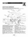 4
4
-
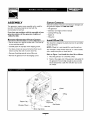 5
5
-
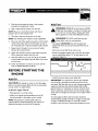 6
6
-
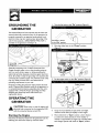 7
7
-
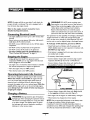 8
8
-
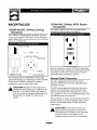 9
9
-
 10
10
-
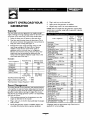 11
11
-
 12
12
-
 13
13
-
 14
14
-
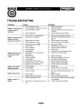 15
15
-
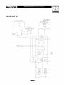 16
16
-
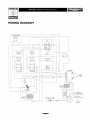 17
17
-
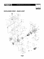 18
18
-
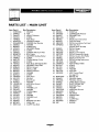 19
19
-
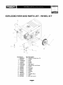 20
20
-
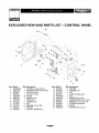 21
21
-
 22
22
-
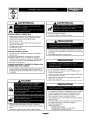 23
23
-
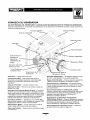 24
24
-
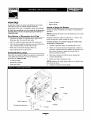 25
25
-
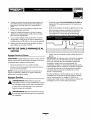 26
26
-
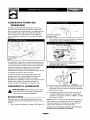 27
27
-
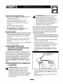 28
28
-
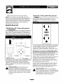 29
29
-
 30
30
-
 31
31
-
 32
32
-
 33
33
-
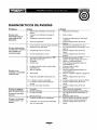 34
34
-
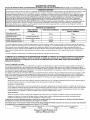 35
35
-
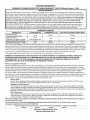 36
36


Generac 1648-0 El manual del propietario
- Categoría
- Generadores de poder
- Tipo
- El manual del propietario
en otros idiomas
- English: Generac 1648-0 Owner's manual
Artículos relacionados
Otros documentos
-
Troybilt 01919 El manual del propietario
-
Briggs & Stratton Elite series 01532-2 El manual del propietario
-
Pulsar PG6580E El manual del propietario
-
-
Briggs & Stratton 1653 El manual del propietario
-
-
-
-
-
Simplicity 01648-0 Manual de usuario