Troybilt 01925 El manual del propietario
- Categoría
- Generadores de poder
- Tipo
- El manual del propietario

O I
I
Owner's Manual / Manual del Propietario
Portable Generator / Generador Port_til
Model / Modelo 01925
,®
IMPORTANT: READ SAFETY RULES AND INSTRUCTIONS CAREFULLY
IMPORTANTE: LEYO LA SEGURIDAD LAS ORDENESY LAS INSTRUCCIONES DETENIDAMENTE
Questions? Preguntas?
Helpline - 1-888-611-6708 M*F8-5 CT
Troy-Bilt_ isaregisteredtrademarkof MTD andisusedunderlicenseto Briggs& StrattonPowerProducts.
Troy-Bilt_ esunamarcaregistradaregistradade MTD yseusaabaiolicenciaa Briggs& StrattonPowerProducts.
BRIGGS & STRATTON POWER PRODUCTS GROUP, LLC
I!!!!U!!UU! EFFERSON,W,SCONS,N,U.S.A.
0 3 Printed in USA ManualNo. 192472GS Revision3 (09/16/2003)

1
Safety Rules
TABLE OF CONTENTS
SafetyRules.................................... 2-4
Know Your Generator ............................. 5
Assembly...................................... 6-7
Operation .................................... 8-13
Maintenance................................. 14-15
Storage........................................ 16
Troubleshooting ................................. 17
Schematic/Wiring Diagram ..................... 18-19
Replacement Parts ............................ 20-24
Notes ......................................... 25
Warranty ................................. Last Page
EQUIPMENT
DESCRIPTION
_Read this manual carefully and become
familiar with your generator. Know its
applications, its limitations and any hazards
involved.
This manualdescribes anengine-driven, revolvingfield,
alternating current (AC) generator designedto supply
electrical power for operating compatible electrical lighting,
appliances,tools andmotor loads.Thegenerator's revolving
field is driven at about 3,600rpm by a single-cylinder engine.
CAUTION! DO NOT exceed the generator's
wattage/amperage capacity.See"Don't Overload
Generator" on page 13.
Everyeffort hasbeenmadeto ensurethat informationinthis
manualisaccurateandcurrent. However,we reserve the
right to change,alter or otherwise improvethe product and
this document at anytime without prior notice.
The EmissionControl Systemfor this generator iswarranted
for standardsset by the EnvironmentalProtection Agency.For
warranty informationrefer to the engineowner's manual.
In the State of California a spark arrester isrequired by lawI
(Section 4442 of the California PublicResourcesCode).
Other states may havesimilar laws.Federallawsapply on
federal lands.If you equip the muffler with a spark arrester,
it must be maintained ineffective working order.
SAFETY RULES
_ his is the safety alert symbol. It is used to
alert you to potential personal injury hazards.
Obey all safety messages that follow this
symbol to avoid possible injury or death.
The safety alert symbol (_.) isused with a signalword
(DANGER, CAUTION,WARNING), a pictorial and/or a
safety messageto alert you to hazards.DANGER indicates
a hazard which, if not avoided,will result in death or serious
injury.WARNING indicatesa hazardwhich,if not avoided,
couldresult in death or serious injury.CAUTION
indicatesa hazardwhich, if not avoided,might result in
minor or moderate injury.CAUTION, when used
without the alert symbol, indicatesa situation that could
result in equipment damage.Follow safety messagesto
avoid or reduce the risk of injuryor death.
WARNING
The engine exhaust from this product contains I
chemicals known to the State of California to cause
cancer, b rth defects, or other reproduct ve harm.
Hazard Symbols and Meanings
Electrocution Electrical Shock Electrical Shock
Toxic Fumes
Explosive Pressure
Explosion Fire
Chemical Burn Hot Surface

Section 1: Safety Rules
DANGER
Operate generator ONLY outdoors.
Keepat least 2 feet of clearance on all sidesof generator for
adequate ventilation.
DO NOT operategenerator insideanybuildingor enclosure,
includingthe generatorcompartmentof arecreationalvehicle(RV).
DANGER
When usinggenerator for backup power, notify utility
company.Use approved transfer equipment to isolate
generator from electric utility.
Use a ground circuit fault interrupter (GFCi) in anydamp or
highly conductive area,such asmetal decking or steel work.
DO NOT touch bare wires or receptacles.
DO NOT use generator with electrical cords which are worn
frayed,bare or otherwise damaged.
DO NOT operate generator in the rain.
DO NOT handle generator or electrical cords while standing
inwater, while barefoot, or while handsor feet are wet.
DO NOT allow unqualified persons or children to operate or
service generator.
DANGER
DO NOT allow any open flame,spark, heat,or lit cigarette
during andfor several minutes after charging abattery.
Wear protective goggles,rubber apron, and rubber gloves.
WARNING
WHEN ADDING FUEL
Turn generator OFF and let it cool at least 2 minutes before
removing gas cap. Loosen cap slowly to relieve pressure in tank_
Fill fuel tank outdoors.
DO NOT overfill tank.Allow space for fuel expansion.
Keep fuel away from sparks, open flames, pilot lights, heat, and
other ignition sources.
DO NOT light a cigarette or smoke.
_HEN OPERATING EQUIPMENT
DO NOT tip engine or equipment at angle which causes fuel
to spill.
This generator is not for use in mobile equipment or marine
applications.
'HEN TRANSPORTING OR REPAIRING EQUIPMENT
Transportlrepair with fuel tank EMPTY.
Disconnect spark plug wire.
_/HEN STORING FUEL OR EQUIPMENT WITH FUEL
IN TANK
Store away from furnaces, stoves, water heaters, clothes
dryers or other appliances that have pilot light or other
ignition source because they can ignite fuel vapors.
I WARNING
This generator does not meet U. S.Coast Guard Regulation
33CFR-183 and should not be used on marine applications.
Failure to use the appropriate U. S.Coast Guard approved
generator could result in bodily injury and/or property
damage.

Section 1: Safety Rules
WARNING
;ENERATOR
Disconnect the spark plug wire from the spark plug and place
the wire where it cannot contact spark plug.
, WARNING
DO NOT touch hot surfaces.
Allow equipment to cool before touching.
CAUTION
DO NOT tamper with governed speed.Generator supplies
correct rated frequency and voltage when running at governed
speed.
DO NOT modify generator in any way.
CAUTION
See"Don't Overload Generator" on page 13.
Start generator and let engine stabilize before connecting
electrical loads.
Connect electrical loads in OFF position, then turn ON for
operation.
Turn electrical loads OFF and disconnect from generator
before stopping generator.
CAUTION
Use generator onlyfor intended uses.
tf you have questions about intended use,askdealer or call
1-888-611-6708.
Operate generator only on levelsurfaces.
DO NOT expose generator to excessive moisture, dust, dirt,
or corrosive vapors.
DO NOT insert anyobjects through cooling slots.
If connected devices overheat, turn them off and disconnect
them from generatoc
Shut off generator if.'
-electrical output is lost;
-equipment sparks,smokes,or emits flames;
-unit vibrates excessively.

Features and Controls
2
KNOWYOUR GENERATOR
Read this owner's manual and safety rules before operating your generator.
Compare this illustrationwith your generator to familiarize yourself with the locationsof variouscontrols and
adjustments.Savethis manualfor future reference.
Oil Fill Cap FuelTank Rocker Switch Circuit
Breaker
Air Cleaner
Circuit Breakers (AC)
SparkArrester Muffler
120Volt AC, 20 Amp
Duplex Receptacles
120/240Volt AC, 30Amp
LockingReceptacle
Choke Lever
DataTag
12Volt DC
Receptacle
Battery
12Volt DC Receptacle -- Use this receptacle with
battery chargecables to chargea 12Volt battery.
120Volt AC, 20 Amp Duplex Receptacles -- Maybe
usedto supplyelectrical power for the operation of 120Volt
AC, 20 Amp,singlephase,60 Hz electrical lighting,appliance,
tool and motor loads.
120/240 Volt AC, 30 Amp Locking Receptacle -- May
be used to supply electrical power for the operation of
120and/or 240 Volt AC, 30Amp, singlephase,60 Hz
electrical lighting,appliance,tool and motor loads.
Air Cleaner -- Usesa dry type filter element and foam
pre-cleaner to limit the amount of dirt and dust sucked
into the engine.
Battery- Located behind plastic cover. 12Volt DC sealed
battery provides power to start the engine.
Choke Lever -- Usedwhen starting a cold engine.
Start Switch
Grounding
Fastener
Circuit Breakers (AC) --The 120VottAC,20A duplex
receptacles are provided with "push to reset" circuit
breakers to protect the generator againstelectrical overload.
DataTag - Provides model, revision andserial number of
generator. Pleasehavethese readily availableif callingfor
assistance.
Fuel Tank -- Capacity of seven (7) U.S.gallons.
Start Switch --Turn to start the engine.
Grounding Fastener -- If required, pleaseconsult a
qualified electrician, electrical inspector,or localagency
havingjurisdiction.
Oil Fill Cap --Add oil to engine here.
Spark Arrester Muffler- Exhaustmuffler lowersengine
noise and isequipped with a spark attester screen.
Rocker Switch Circuit Breaker --The 120/240VoltAC,
30A lockingreceptacleisprovidedwith a rocker switch circuit
breakerto protect thegenerator againstelectricaloverload.
This switch alsocontrols all receptacles.

ASSEMBLY
Your generator requires attachment of the negative battery
cable and is ready for useafter it hasbeen properly
serviced with the recommended oil and fuel.
If you have any problems with the assembly of your
generator, please call the generator helpline at
1-888-61 1-6708.
ll_ _r_;.m_ I_T_I_
Remove Generator From Carton
I. Set carton on a rigid fiat surfacewith "This Side Up"
arrows pointing upward.
2. Carefully open top flapsof shippingcarton.
3. Cut down corners of carton from top to bottom and
laythat side of carton down fiat.
4. Removeall packing material, carton fillers,etc.
5. Roll generator out of shipping carton.
Attach Negative Battery Cable
The sealed battery on the generator isfully chargedand
pre-installed except for the negative (black) battery cable.
You will need a I/2" or 13mm wrench to installthe
negative battery cable.
To install:
I. Cut off tie wrap securing loose end of negative (black)
cable.
2. Attach negative battery cable with 5/16" x 3/4" screw
and lockwasher to the engine block, next to the
starter (Figure I).Tighten securely.
Screw Washer
Positive
battery
cable
Negative
battery
cable

Section 3: Assembly
Attach Handle
You will need two I/2" or 13 mm wrenches to attach the
handle.
I. Attach handleto right side of generator frame (viewing
unit from front), asshown in Figure 2,with a 60 mm
capscrew,flat washers,nylon washers, and locknut.
60ram Capscrew
Nut
_Washer
J and o Braeket
_=_Nylon Washer
M
_ylon Washer
_ \ _ HandleBracket
/y\ _ Washer
60ram Capscrew
HandlePin
NOTE: DO NOT overtighten. Handle must be able to
move up and down freely.
2. Raisehandle and insert handle pin to move generator.
BEFORE STARTING THE
ENGINE
Add Engine Oil and Fuel
• Place generator on a level surface.
CAUTION
• Refer to engine manualfor oil andfuel fill information.
• Damage to equipment resulting from failure to follow this
instructionwill void warranty.
• Refer to engine owner's manualand follow oil and fuel
recommendations and instructions.
_ WARNING
Replace "1-I/2" with "2-I/4" fuel fill level given in engine manual.
Failure to follow this instruction may cause fuel to overexpand
and spill from tank.
NOTE: Check oil often during engine break-in. Refer to
engine owner's manualfor recommendations.
NOTE: The generator assembly rotates on a prelubricated
and sealed ball bearing that requires no additional
lubrication for the life of the bearing.

Operation
USING THE GENERATOR
System Ground
The generator hasa systemground that connects the
generator frame components to the ground terminals on
the AC output receptacles.The systemground is connected
to the AC neutral wire (see"Equipment Description",
earlier in this manual).
Special Requirements
There may be Federalor State Occupational Safetyand
Health Administration (OSHA) regulations,localcodes,or
ordinances that apply to the intendeduseof the generator.
Pleaseconsult a qualified electrician, electrical inspector,or
the localagencyhavingjurisdiction.
• In some areas,generators are required to be registered
with localutilitycompanies.
• If the generator isusedat a construction site,there may
be additional regulations which must be observed.
Connecting to a Building's Electrical
System
Connections for standby power to a buitding's electrical
system must be made by a qualified electrician.The
connection must isolate the generator power from utility
power, and must comply with all applicablelawsand
electrical codes.
DANGER
When usinggenerator for backup power, notifyutility
company.Use approved transfer equipment to isolate
generator from electric utility.
Use a ground fault circuit interrupter (GFCI) in anydamp or
highly conductive area,such asmetal decking or steel work.
DO NOT touch bare wires or receptacles.
DO NOT use generator with electrical cords which are worn
frayed,bare or otherwise damaged.
DO NOT operate generator in the rain.
DO NOT handle generator or electrical cords while standing
inwater, while barefoot, or while handsor feet are wet.
DO NOT allow unqualified persons or children to operate or
service generator.
OPERATING THE
G EN ERATO R
CAUTION
See"Don't Overload Generator" on page 13.
Start generator and let engine stabilize before connecting
electrical loads.
Connect electrical loads in OFF position, then turn ON for
operation.
Turn electrical loads OFF and disconnect from generator
before stopping generator.
IMPORTANT: Always unplug the battery float charger
before starting the generator.
Starting the Engine
Disconnect all electrical loadsfrom the generator. Follow
start instructionsteps in numerical order:
I. Make sure unitison a levelsurface.
IMPORTANT: Failureto start and operate uniton a level
surface will causethe unit not to start or shut down during
operation.
2. Follow start instructionsgiven inengineowner's manual
andturn start switch on generator to "Start" position
(Figure3).To prolong life of starter components,DO
NOT hold starter switch in"Start" position for more
than 15seconds,and pausefor I minute.
NOTE: If engine starts but failsto run, or if unitshuts
down during operation, make sure unit ison a level surface
and check for proper oil levelin crankcase.This unit may be
equipped with a low oil protection device. Seeengine
manual.

Section 4: Operation
Jump Start Procedure
If the generator's starting battery fails,usethe following
instructions to jump start your generator.You can jump
start the generator usingany 12Volt automotive or utility
style storage battery.
I. Unscrew the fuse holder and remove the generator's
l0 Amp in-linefuse (Figure4).Verify the fuse isgood
or replace with a known good fuse.Reinstallfuse in
the fuse holder.
2. Slide the red rubber boot off the generator's battery
terminal and push it onto the red wire, thus
uncovering the POSITIVEbattery terminal.
3. Using standard automotive jumper cables,connect the
RED jumper cableclamp to the generator's POSITIVE
battery terminal (Figure 5).
4. Connect the other RED jumper cable clamp to the
starting battery's POSITIVEbattery terminal.
5. Connect the BLACK jumper cable clamp to the
starting battery's NEGATIVE battery terminal.
6. Connect the other BLACK jumper cable clamp to the
GROUNDING FASTENERon the generator, as shown
in Figure 5.
7. Start the generator asdescribed in"Starting the
Engine"and remove jumper cables in reverse order of
connections.
8. Slide the red rubber boot back onto the generator's
POSITIVEbattery terminal.
If you haveanyquestions, pleasecall the Generator
Helpline at 1-888-611-6708, M-F 8-5 CT.
IMPORTANT: When jump starting, alwayswear proper eye
protection and never leanover battery. Inspectboth
batteries before connecting booster cables.DO NOT jump
start a damagedbattery. Be sure vent capsare tight and level.
Connecting Electrical Loads
• Let engine stabilize and warm up for a few minutes after
starting.
• Plug in and turn on the desired 120 and/or 240 Vott AC,
singlephase,60 Hz electrical loads.
• DO NOT connect 240Volt loads to the 120Volt duplex
receptacles.
• DO NOT connect 3-phase loadsto the generator.
• DO NOT connect 50 Hz loads to the generator.
• DO NOT OVERLOAD GENERATOR. See"Don't
Overload Generator" on page 13.
Stopping the Engine
1. Unplug all electrical loadsfrom generator panel
receptacles.NEVERstart or stop engine with electrical
devicesplugged in and turned ON.
2. Let engine run at no-load for several minutes to
stabilize internal temperatures of engine and generator.
3. Turn start switch to "Stop" position.

Section 4: Operation
Charging a Battery
Your generator hasthe capability of recharging a discharged
12Volt automotive or utility style storage battery. DO
NOT usethe unit to charge any6Vott batteries. DO NOT
use the unit to crank an engine havinga discharged battery.
DANGER
DO NOT allow any open flame,spark, heat,or lit cigarette
during andfor several minutes after charging abattery.
Wear protective goggles,rubber apron, and rubber gloves.
To recharge 12Volt batteries, proceed as follows:
I. Check fluid levelin atl battery cells.If necessary,add
ONLY distilled water to cover separators in battery
cells.DO NOT use tap water.
2. If battery isequipped with vent caps,make sure they
are installedand are tight.
3. If necessary,clean battery terminals.
4. Connect battery chargecable connector plug to panel
receptacle identifiedby the words "12-VOLTS D.C".
5. Connect battery chargecable clamp with red handle
to the positive (+) battery terminal (Figure6).
li_tlrg_=rmrmm_rm
J 12 VOLT D.C.
RECEPTACLE
+
POE NEG
12 VOLT BATTERY
6. Connect battery charge cable clamp with black handle
to the negative (-) battery terminal (Figure 6).
7. Start engine.Let engine run while battery recharges.
8. When battery hascharged,shut down engine
NOTE: Use an automotive hydrometer to test battery state
of chargeand condition. Follow the hydrometer
manufacturer'sinstructionscarefully.Generally,abattery is
consideredto be at 100%stateof chargewhen specificgravity
of itsfluid (asmeasuredby hydrometer) is1.260or higher.
How to Use the Battery Charger
Use battery float charger jack to keep the starting battery
chargedand ready for use. Battery chargingshould be done
in a dry location,such as insideagarage.
1. Plugcharger into unit's "Battery Float Charger" jack,
which islocatednext to starter switch (Figure 7). Ptug
battery charger into a 120Volt AC wall receptacle.
II
J
2. Unplug chargerfrom unitand wall outlet when
generator isbeing started and while in operation.
3. Keep this charger pluggedin when generator isnot in
useto prolong battery life.The charger hasa built in
float equalizer and wilt not overcharge the battery,
evenwhen pluggedin for an extended period of time.
IMPORTANT: See"Battery Maintenance'! on page 15for
additional information.
I

Section 4: Operation
COLD WEATH ER
OPERATION
Under certain weather conditions (temperatures below
40°F [4°C] and a high clew point), your generator may
experience icing of the carburetor and/or the crankcase
breather system.
Build a structure that wilt enclose three sides and top of
generator:
I. Make sure entire muffler-side of generator is exposed.
Note that your generator mayappear different from
that shown in Figure 8.
G EN ERATO R ADAPTER
CORD SET
The generator isequippedwith a25' generator adapter cord
set designedfor a 240Volt,30 Amp grounded neutral circuit
(Figure9).The generator adaptercord set provides a
convenientsupplyof emergencypower into your dwellingso
that your generator can be operated safelyoutside.
J
2. Ensurea minimum of two feet clearancebetween open
side of box and nearest object.
3. Faceexposed end away from wind and elements.
4. Enclosure should hold enough heat created by
generator to prevent problems.
,_ DANGER
The maximum load on each outlet is 20 Amps.The
maximum total load on both yellow wire outlets or both
black wire outlets is 30 Amps.
NOTE: Follow all safety precautions when connecting any
extension cord or device to the generator.
Operate generator ONLY outdoors.
Keep at least 2 feet of clearance on all sides of generator for
adequate ventilation.
DO NOT operate generator inside any building or enclosure,
including the generator compartment of a recreational vehicle (RV).
Remove generator from shelter when temperature is above
40°F [4°C].
t

Section 4: Operation
RECEPTACLES
CAUTION
NEVERattempt to power a device requiring more
amperagethan generator or receptacle can supply.
DO NOT overload the generator. See"Don't Overload
Generator".
12 Volt DC, I0 Amp Receptacle
This receptacle allows you to recharge a 12Volt
automotive or utility style storage battery with the battery
charge cables provided (Figure 10).
IP_ IP_ToT#_[olv_W;T_ _
This receptacle can not recharge 6Volt batteries and can
not be usedto crank an engine havinga discharged battery.
Seethe section "Charging a Battery" (page 10) before
attempting to recharge a battery.
120 Volt AC, 20 Amp, Duplex
Receptacles
Eachduplex receptacle (Figure II) isprotected against
overload by a push-to-reset circuit breaker.
Use each receptacle to operate 120Volt AC, single-phase,
60 Hz electrical loadsrequiring up to 2,400 watts (2.4 kW)
at 20Amps of current. Use cord sets that are rated for
125Volt AC loads at 20Amps (or greater).
120/240 Volt AC, 30 Amp, Locking
Receptacle
Use a NEMA LI4-30 plug with this receptacle. Connect a
4-wire cord set rated for 250Volt AC loads at 30 Amps (or
greater) (Figure 12).Youcan use the same4-wire cord if
you plan to run a 120Volt load.
4-Wire Cord Set
12
Y (Hot) X (Hot)
NEMA L14-30 Ground (Green)
This receptacle powers 120/240Volt AC, 60 Hz, single
phaseloads requiring up to 7,200 watts of power (7.2 kW)
at 30 Amps for 120Volts or 240Volts.The outlet is
protected by a rocker switch circuit breaker.
m

Section 4: Operation
DON'T OVERLOAD
G EN ERATO R
Capacity
You must make sure your generator cansupply enough
rated (running) and surge (starting) watts for the items you
will power at the sametime. Follow these simple steps:
I. Selectthe itemsyou wilt power at the same time.
2. Total the rated (running) watts of these items.Thisis
the amount of power your generator must produce to
keep your itemsrunning. SeeFigure 13.
3. Estimate how many surge (starting) watts you wilt
need.Surge wattage isthe short burst of power
needed to start electric motor-driven tools or
appliancessuch asa circular sawor refrigerator.
Becausenot all motors start at the sametime, total
surge watts can be estimated by addingonly the
item(s)with the highest additional surge watts to the
total rated watts from step 2.
Example:
Tool or Appliance
Window Air
Conditioner
Refrigerator
Deep Freezer
Television
Light (75 Watts)
Rated (Running)
Watts
1200
800
50O
50O
75
3075 Total
Running Watts
Total Rated (Running)Watts = 3075
Highest Additional SurgeWatts = 1800
Total Generator Output Required = 4875
Additional Surge
(Starting) Watts
1800
1600
50O
1800 Highest
SurgeWatts
Power Management
To prolong the life of your generator and attached devices,
it is important to take care when addingelectrical loads to
your generator.There should be nothing connected to the
generator outlets before starting it's engine.The correct
and safeway to managegenerator power is to sequentially
add loads asfollows:
I. With nothing connected to the generator, start the
engine asdescribed in this manual.
2. Plugin and turn on the first load,preferably the largest
load you have.
3. Permit the generator output to stabilize (engine runs
smoothly and attached device operates properly.
4. Plug in and turn on the next load.
5. Again,permit the generator to stabilize.
6. Repeat steps 4 and 5 for each additional load.
NEVER add more loads than the generator capacity.Take
specialcare to consider surgeloads in generator capacity,
asdescribed above.
Tool or Appliance
Essentials
Light Bulb - 75 watt
Deep Freezer
SumpPump
Refrigerator/Freezer - 18Cu. Ft.
Water Well Pump - I/3 HP
Heating/Cooling
Window AC - I0,000 BTU
Window Fan
FurnaceFanBlower - 112HP
Kitchen
Microwave Oven - 1000Watt
Coffee Maker
Electric Stove - SingleElement
Hot Plate
Family Room
DVD/CD Player
VCR
Stereo Receiver
Color Television - 27"
Personal Computer w/I 7" monitor
Other
Security System
AM/FM Clock Radio
GarageDoor Opener - I/2 HP
Electric Water Heater - 40 Gallon
DIY/Job Site
Quartz Halogen Work Light
Airless Sprayer - I/3 HP
Reciprocatin_ Saw
Electric Drill - I/2 HP
Circular Saw- 7 I/4"
Miter Saw- I0"
Table Planer - 6"
Table Saw/RadialArm Saw- I0"
Air Compressor - I-I/2 HP
Rated*
(Running)
Watts
75
500
8O0
8O0
1000
12O0
3OO
8O0
1000
1500
1500
2500
Additional
Surge
(Starting)
Watts
500
1200
1600
20O0
1800
6O0
1300
100
100
450
5o0
8o0
18o
3O0
480 520
40O0
1000
600 1200
960 960
1000 1000
1500 1500
1800 1800
1800 1800
2000 2000
2500 2500
*Wattages listed are approximate only. Check toot or
appliance for actual wattage.
t

5
Maintenance
GENERAL MAINTENANCE
RECOMMENDATIONS
The Owner/Operator is responsible for making sure that
all periodic maintenance tasks are completed on atimely
basis;that all discrepanciesare corrected; and that the unit
is kept clean and properly stored. NEVER operate a
damaged or defective generator.
NOTE: If equipped with inflatabletires, keep the air
pressure at the valuemarked on the tire or within 15and
40 psi.
Engine Maintenance
See engine owner's manual for instructions.
An oil drain tray is provided for your convenience to
change the oil and oil filter. Store tray in a convenient
location for periodic maintenance.
Changing Oil
I. Placethe half moon notch inthe oil drain tray under
the oil drain plug (Figure 14).
2. Placethe oil drain tray foot tab in the slot on the base
of the generator, asshown.
3. Follow the instructionsgiven in the engine owner's
manualfor draining oil.
4. After oil hasdrained, reinstall the oil drain plug.
5. Removethe oil drain tray from under the oil drain plug
and clean up any spilledoil.
Changing Oil Filter
I. Placethe half moon notch in the oil drain tray under
the oil filter (Figure 15).
2. Placethe oil draintray foot tab inthe slot on the base
of the generator, asshown.
3. Follow the instructionsgiven inthe engine owner's
manualfor changingoil filter and adding oil.
4. Remove the oil drain tray from underthe oil filter and
clean up anyspilled oil
CAUTION
Used motor oil has been shown to causeskin cancer in
certain laboratory animals.
Thoroughly wash exposed areaswith soapand water.
KEEPOUT OF REACH OF CHILDREN. DON'T
POLLUTE.CONSERVE RESOURCES.RETURN
USED OIL TO COLLECTION CENTERS.
m

Section 5: Maintenance
Generator Maintenance
Generator maintenance consists of keepingthe unit clean
and dry. Operate and store the unit in a clean dry
environment where itwitt not be exposed to excessive
dust, dirt, moisture or anycorrosive vapors.Cooling air
slots in the generator must not become clogged with snow,
leavesor anyother foreign material.
NOTE: DO NOT usea garden hose to cleangenerator.
Water canenter engine fuel system and cause problems. In
addition, if water enters generator through cooling air slots,
some of the water wilt be retained in voids and cracks of
the rotor and stator winding insulation.Waterand dirt
buildup on the generator internalwindings will eventually
decrease the insulationresistance of these windings.
Battery Maintenance
Other than float charging,asdescribed in"How to Use the
Battery Charger", no maintenance is required for the
battery. Keep the battery and terminals cleanand dry.
IMPORTANT: Battery chargingshould be performed in a
dry location, such asinsidea garage.
Generator Cleaning
• Use a damp cloth to wipe exterior surfacesclean.
CAUTION
DO NOT expose generator to excessive moisture, dust,dirt,
or corrosive vapors.
DO NOT insert any objects through cooling slots.
Data Tag
Data tag informationisvery important ifyou need hetp
from our Customer Service Department or an authorized
servicedealer.
The datatag (Figure 16) is located either on the base
plate of the generator. For future reference,pleasecopy
the model, revision,and serial number of the generator in
the space below.
I I_ Copy Model
_1'v Number Here
MODSL I Copy Revision
RSV NO I Here
SSRIAL I _ Copy Serial
Number Here
AC VOLTS I I
AsAMPsI I
AcwArrsI I
DC VOLTS I I
pc I I
SinglePhase160Hz/3600RPM
Ratedat40°C/ClassFInsulation
• Use a soft bristle brush to loosen caked on dirt or oil.
• Use a vacuum cleaner to pick up loosedirt and debris.
• Use low pressure air (not to exceed 25 psi) to blow away
dirt. Inspect cooling air slots and opening on generator.
These openings must be kept clean and unobstructed.
m

STO RAG E
The generator should be started at least once every seven
claysand allowed to run at least 30 minutes. If this cannot
be done and you must store the unit for more than
30 days,usethe following guidelinesto prepare it for
storage.
Generator Storage
• Clean the generator as outlined in "Generator Cleaning".
• Check that cooling air slots and openings on generator
are open and unobstructed.
WARNING
DO NOT place a storage cover over a hot generator.
Let equipment cool for a sufficient time before placingthe
cover on the equipment.
Engine Storage
See engine owner's manualfor instructions.
Other Storage Tips
• To prevent gum from forming in fuel system or on
essential carburetor parts, add fuel stabilizer into fuel
tank and fill with fresh fuel. Run the unit for several
minutes to circulate the additive through the carburetor.
The unit and fuel can then be stored for up to
24 months. Fuel stabilizer can be purchased locally.
• DO NOT store fuel from one season to another unless
it has been treated as described above.
• Replace fuel container if it starts to rust. Rust and/or dirt
in fuel can cause problems if it's used with this unit.
• Store unit in a clean and dry area.
m

Troubleshooting
7
TROUBLESHOOTING
Problem
No AC output is available, but
generator is running.
Generator runs good at no-load
but "bogs" down" when loads are
connected.
Generator will not start; or starts
and runs rough.
Cause
I. One of the circuit breakers is
open.
2. Fault in generator.
3. Poor connection or defective
cord set.
4. Connected device is bad.
I. Short circuit in a connected load.
2. Generator isoverloaded.
3. Shorted generator circuit.
I. 10Amp in-linefuse isblown.
2. Discharged battery.
3. Failed battery.
4. Low oil level.
I. Out of gasoline.
Generator shuts down during 2. Low oil level.
operation.
Generator lacks power. Load is too high.
Correction
I. Resetcircuit breaker.
2. Contact Authorized service
facility.
3. Check and repair.
4. Connect another device that isin
good condition.
I. Disconnect shorted electrical
load.
2. See "Don't Overload Generator".
3. Contact Authorized service
facility.
I. Replacefuse.
2. Jumpstart generator and/or
charge battery.
3. Replacebattery.
4. Fill crankcaseto proper level or
placegenerator on levelsurface.
I. Fillfuel tank.
2. Fill crankcaseto proper level or
placegenerator on levelsurface.
See "Don't Overload Generator".
m

8
Wiring Diagram and Schematic
SCHEMATIC
3!TR c L
> 1
AUTI ] 10 ANP
RESET
. ,.AMP,_wc _ B_2TTE_
IWITCH _ _ _ppLAURGK iiiiDF r
ENG
IGNITIBN
CB
3OA
2P
P] 2
22
]1
DR2
[20' _
20A
CB2
I]A _ _ lib
25A
1P
IIA
VBLTAGE L
REGULATBR
DPE _ WHITE
2_6
FIELD
PBWER
P] 3
22
WHI]
X (
PBWER
33
DRI
CB3
_22120V20S_ 44B _'_44A25AIp
B BRASS
SCRE_
S SILVER
SCREW
5R GREEN
TLR] SCREW
Y 44A
G ]28/248V
7 30A
PI 4
t

Section 8: Wiring Diagram and Schematic
WIRING DIAGRAM
PB_ NEB
BATTERY
SPARK
PLUG
CARB
FUEL
SHUT BFF
is
J 13B 13C
I

9
Exploded Views and Parts Lists
EXPLODEDVIEW- MAIN UNIT
66
17
58
900
/
68
82
49
D
-48
47
22
21
20
17
16
/
14--
\ 13
72
\
7O
55
/
/
, /
10 11
12
0

Section 9: Exploded Views and Parts Lists
PARTS LIST - MAIN UNIT
Item Part # Description Item Part #
I PI91821GS CRADLE 44 PI91822GS
2 P|93086GS CRADLE,Top 45 49820GS
3 192368GS ASSY,DC Control Panel(seepage23) 46 22145GS
4 193263GS SCREW 47 51730GS
5 |86173GS BUSHING, Snap 48 193288GS
6 31669GS BOLT,Carriage 49 B4135GS
7 26911GS NUT, Nylock 50 87680GS
B 8207 IGS NUT, Lock 51 22473GS
9 192470GS SPRING,Loading,Tank 52 52857GS
10 84966G5 WHEEL 53 193344GS
I I 22247GS WASHER 54 26850GS
12 191265GS E-RING 55 92810GS
13 191267GGS AXLE 56 45757GS
14 !92553GSGS KIT,Vibration Mount Hrdwre (2 sets_ 57 22131GS
15 193320GS STRIP,Foam 58 192251GS
16 193463GS BATTERY,12Vwith Hardware 59 192520GS
17 185939LG5 CABLE, BIk 60 193055GS
18 192940GS CLIP,Retainer,Fuel Hose 6 192997GS
19 189302EGS CABLE,Red 62 48031CGS
20 191815GS COVER, Battery, Billboard 63 189867DGS
21 22769GS WASHER 64 22125GS
22 36701GS SCREW 65 22129GS
23 191190GS CAP,Bolt, Rotor 66 22142GS
24 74908GS SCREW 67 192809GS
25 191029GS COVER,RBC, Plastic 68 392390
26 187365HGS SCREW 69 396903
27 75246GS SCREW 70 B4986GS
28 NSP ASSY,AIternator (see page24) 71 191436GS
29 191793GS ADAPTER, Engine 72 193504
30 193249GS MOUNT,Engine 900 NSP
31 96796GS WASHER
32 193264GS SCREW Items not shown
33 191991GS BOLT 192508GS
34 191990GS BRACKET,Retaining,Panel 191824GS
35 191989GS ROD, Mounting Tank 192472GS
36 191826GS CAP,Fuel Gauge BB3061GS
37 192921GS SHIELD,Fuel Fill 188971GS
38 192277GS ASSY,Control Panel(see page22) 189302FGS
39 555374 SOLENOID/BRACKET A3746GS
40 193345GS ASSY,Tank,7-Gallon, with Labels 193347GS
41 22097GS WASHER, Lock 193346GS
42 22127GS NUT 65787GP
43 192477GS GRIP,Handle MS5246
B4177GS
Description
HANDLE (Includes Item 43)
NUT, Nylok
WASHER
SCREW
WASHER, Nylon
PIN,Handle Release
NUT,Wing
WASHER
NUT, Lock
KIT,PLT,Skid,SRV
WASHER
HARNESS,Ground
SCREW
WASHER
GUARD, Recoil
GROMMET, Rod,Tank
CLAMP,Hose
HOSE,Fuel Overflow
CLAMP,Hose, Band
HOSE,Fuel
SCREW
WASHER, Lock
SCREW
HARNESS,AC
ARRESTOR,Sparkwith Screws
DEFLECTOR,Muffler
DECAL, Ground
DECAL, Caution Hot Muffler
DECAL, Battery Instructions
ENGINE
HARNESS,DC
TRAY,Oil Drain
MANUAL, Owners
OIL, Bottle
CORD, Extension
CABLE, Red,Solenoid to Starter
ASSY,Holder Fuse
KIT,Hardware, Battery Term......
KIT,Decal,01925
CABLE, Battery Charge
MANUAL, Engine
CHARGER, Battery
O

Section 9: Exploded Views and Parts Lists
AC CONTROL PANEL EXPLODED VIEW
6 7
7 \
\
\
\
\
\
\
\\
5
\
& PARTS LIST
16 15
\
\
\
\
17
\
\
\\
14
\\\\\
1
5
\\\\
18
2
Item Part # Description
I 188914GS COVER,Lid, Controt Panel
2 192273BGS CONTROL PANEL,Compact
3 189167GS CLIP,Hinge Pin Retainer
4 189182GS SPRING,Hinge, Pin
5 189166GS PIN, Hinge,Cover, Compact
6 68759GS OUTLET, 120V,20A, Duplex
7 189165GS NUT
8 84198GS CAP,Circuit Breaker
9 75207GS BREAKER,Circuit
10 43437GS OUTLET, 120/240VLocking, 30A
II 189164GS NUT
12 84543CGS SCREW
13 93857GS BAR, Retaining
14 192274GS BOX, Rear Cover
15 82308GS SCREW
16 22694GS HOUSING, Receptacle
17 192241GS SCREW
18 192785GS BREAKER,Circuit
1
10
m

Section 9: Exploded Views and Parts Lists
DC CONTROL PANEL EXPLODED VIEW & PARTS LIST
//
8
/
/
/
/
Item
I
2
3
4
5
6
7
8
9
Part #
192367GS
191015GS
191016GS
192466GS
186133GS
90418GS
192945GS
87962GS
189520GS
Description
PANEL,DC Control
SWITCH, SRS
KNOB, SRSSwitch
ASSY,Jack,Coaxial
CAR Battery Charge
OUTLET, 12VDC,Snap
PLATE,Switch Key
BREAKER,Circuit
SCREW
m

Section 9: Exploded Views and Parts Lists
ALTERNATOR EXPLODED VIEW & PARTS LIST
7
\
9
\
'1
\
2
11
10
Item
I
2
3
4
5
6
7
8
9
10
II
12
13
14
15
Part #
186059GS
192171GS
192186AGS
186060GS
86308KGS
66386GS
66849GS
22694GS
81917GS
19105lAGS
66849CGS
23762GS
65795GS
191653GS
193074GS
Description
ADAPTER, Mounting,Alternator
ROTOR
STATOR
RBC,(with O-Ring p/n 189197GS)
SCREW
ASSY,Holder, Brush
SCREW
RECEPTACLE,6 pin
PIN, Roll
ASSY,Wire, Ground
SCREW
WASHER
RECTIFIER
BOARD, Circuit, System Control
HARNESS,Wire DC Charge
m

Notes
NOTES

1
Reglas de Seguridad
TABLA DE CONTENIDOS
ReglasDe Seguridad................................ 26-28
Conozca Su Generador ................................ 29
Ensamblaje........................................ 30-3I
Funcionamiento .................................... 32-38
Mantenimiento ..................................... 39-40
AImacenamiento ...................................... 4 I
Diagnosticos De Averfas................................ 42
Esquem_tico / Digrama El_ctrico ...................... 18-19
PiezasDe Recambio ................................ 20-24
Garantia ............................................ 43
DESCRIPCI( N DEL EQUIPO
_Lea este manual de manera cuidadosa y
familiaricese con su generador. Conozca sus usos,
sus limitaciones y cualquier peligro relacionado
con el mismo.
Este generador funciona en base a un motor, de campo el_ctrico
giratorio y de corriente alterna (AC). Fue diseffado con la
finalidad de proveer energia el_ctrica para luces el_ctricas,
aparatos, herramientas compatibles y cargas de motor. El campo
giratorio del generador funciona a una velocidad de 3,6000 rpm
usando un motor con un solo cilindro.
iPRECAUCI(_N! NO sobrepasela capacidadde vataiey
amperaie del generador. Revise"No Sobrecargue Generador" en
la p_gina38.
Se ha hecho cadaesfuerzo posible para asegurarse que la
informaci6n que aparece en este manual esexacta y se encuentra
actualizada.Sin embargo,nosotros se reserva el derecho a
cambiar,alterar o de otra manera mejorar, el producto y este
documento en cualquier momento, sin previo aviso.
El Sistema de Control de Emisiones para este generador est_
garantizado para iuegos est_ndarespor laAgencia de Protecci6n
Ambiental. Para mayor informaci6n acerca de la garantfa,consulte
con el manual del propietario del motor.
Enel estado de California es obligatorio, seg_n la ley,el uso de
_pagachispas(Secci6n 4442 del C6digo de Recursos P_blicosde
California). Otros estados pueden tener leyessimilares.Lasleyes
_ederalesse aplican en tierras federales.Si equipa el silenciador
:on un apagachispas,este deber_ ser mantenido en buenas
:ondiciones de trabaio.
REGLAS DE SEGURIDAD
_IL Este es el simbolo de alerta de seguridad. Sirvepara advertir al usuario de un posible riesgo para
su integridad fisica. Siga todos los mensajes de
seguridad que figuren despu_s de este simbolo
para eqitar lesiones o incluso la muerte.
Elsimbolo de alerta de seguridad (_.) esusado con una palabra
(PELIGRO,ADVERTENCIA, PRECAUCI_N), un mensaje por
escrito o una ilustraci6n, para alertarlo acerca de cualquier
situaci6n de peligro que pueda existir. PELIGRO indica un riesgo
el cual,si no se evita,causardla muerte o una heridagrave.
AOVERTENClA indica un riesgo el cual,si no se evita,puede
causar lamuerte o unaherida grave.PRECAUClON indica un
riesgo,el cual,si no seevita, puedecausar heridas menores o
moderadas. PRECAUCION, cuando se usasin el simbolo de
alerta, indica una situaci6n que podria resultar en el daho del
equipo. Sigalos mensajesde seguridad para evitar o reducir los
riesgos de heridas e inclusive la muerte.
I ADVERTENCIA
El escape del motor de este producto contiene
elementos quimicos reconocidos en el Estado de
California pot producir cgncer, defectos de nacimiento u
otros da_os de tipo reproductivo.
Simbolos de Peligro y Signiflcados
Electrocutamiento Descarga El_ctrica Descarga El_ctrica
Gases T6xicos Explosi6n Fuego
_e3
Presi6nExplosiva Quemaduras Qulmica SuperficieCaliente
t

Secci6n 1: Reglas de Seguridad
PELIGRO
Opere el generador SOLAMENTE al aire libre.
Mantenga al menos 2 pies de espado libre alrededor del generador,
para la adecuada ventilaci6n.
NO opere el generador dentro deun edificio o lugarcerrado, incluyendo
el compartimiento del generador en un vehiculo recreativo o R_L
PELIGRO
Cuando use un generador como poder de energla auxiliar, notifique a
la compa_ia de utilidades. Use el equipo de transferencia aprobado
paraaislar el generador de otra utilidad el_ctrica.
Use un interruptor para la faHadef circuito de tierra (GFCI) en
cualquier grea bastante h_meda o que seaaltamente conductiva, tales
como terrazas de metal o trabajo hecho con acero.
NO toque los alambres peladoso receptgculos.
NO use un generador con cablesel_ctricos que est_n malgastados,
rotos, pelados o da_ados de cualquier forma.
NO opere el generador bajo la Lluvia.
NO maneje eJgenerador o cables el_ctricos mientras este parado en
agua,descalzo o cuando lasmanos y los pies est_n mojados.
NO permita que personas descalificadaso ni_os operen o sirvan al
generador.
PELIGRO
NO permita ninguna llama abierta,chispa,calor,o encienda un
cigarrillo durante y por ratios minutos despu_s de haber recargado la
baterla.
Ueve puestos lasgalas protectoras, delantal y guantes de goma.
ADVERTENCIA
CUANDO AI_IADA COMBUSTIBLE
Apague el generador (posici6n OFF) y d_jelo enfriar al menos por
2 minutos antes de remover latapa de lagasolina.Afloie la tapa
lentamente para deiar que la presi0n salgadel tanque.
Llene eltanque al aire libre.
NO Ilene demasiado el tanque. Permita al menos espacio para la
expansion del combustible.
Mantenga lagasolinaaleiada de chispas,llamasabiertas, pilotos, calor y
otras fuentes de igniciOn.
NO encienda un cigarrilloo fume.
:UANDO OPERE EL EQUIPO
NO incline el motor o el equipo, de tal manera que la gasolina se
pueda derrama_
Estegenerador no esapto para el uso en ecluiposmOviles ni en
aplicaciones marinas,
:UANDOTRANSPORTE O REPARE EL EQUIPO
Transporte o repare el equipo con el tanque de combustible vaclo.
Desconecte el cablede la buila.
:UANDO ALMACENE O GUARDE EL EQUIPO CON
COMBUSTIBLE EM ELTANQUE
Almacene aleiado de calderas,estufas,calentadores de agua,sec_doras
de ropa u otros aparatos electrodom_sticos que posean pilotos u
otras fuentes de igniciOn,porque ellos pueden encender los vapores
de la gasolina.
ADVERTENCIA
Estegenerador no cumplela norma 33CFR-183 del cuerpo de
guardacostas de EE.UU. y no debe utilizarse en aplicaciones marinas.
El uso de un generador no homologado por cuerpo de guardacostas
de EE.UU.puede provocar lesionesy daffos materiales.
t

Secci6n 1: Instrucciones de Seguridad
ADVERTENCIA
;ENERADOR
Siempre desconecte el alambre de la bujla y col6quelo donde no
puedaentrar en contacto con la bujla.
ADVERTENCIA
NO toque las superficies calientes.
Permita que el equipo se enfrle antes de tocarlo.
PRECAUCION
NO cambie ninguna velocidad determinada. El generador suministra
una frecuencia y un volt_je calificado cuando funciona a una velocidad
determinada.
NO modifique al generador en ninguna forma.
PRECAUCION
Vea "No sobrecargue generador" en lap_gina 38.
Encienda sugenerador y deje clueel motor se estabilice antes de
conectar lascargas el/actricas.
Conecte lascargasel_ctricas en la posici6n de apagado (OFF),luego
encienda (ON) para su operaci6n.
Apague (OFF) las cargasel_ctricas y descon_ctelas del generador
antes de parar el generador.
PRECAUCION
Use el generador solamente con la finalidad para el cual rue disefiado.
Si usted tiene alguna pregunta acerca de las flnalidades de uso del
generador, preg_ntele a su concesionario o flame 1-888-611-4708,
Opere el generador solamente en superficies niveladas,
NO exponga al generador a una humedad excesiva, polvo, suciedad o
vapores corrosivos,
NO inserte cualquier objeto a trav_s de las ranuras de enfriamiento.
Si los aparatos conectados se sobrecalientan, ap_guelos y
descon_ctelos del generado_
Apague el generador si:
-Se pierde la salida el_ctric_;
-El equipo produce chispas, humo o emite llamas;
-La unidad vibra de una manera excesiva.
I

Caracteristicas ¥ Mandos
2
CONOZCA SU GENERADOR
LEA ESTE MANUAL DEL PROPIETARIOY LAS REGLAS DE SEGURIDAD ANTES DE OPERAR SU GENERADOR.
Compare las ilustraciones con su Generador para familiarizarse con las ubicaciones de los diferentes controles y ajustes. Conserve este
manual para referencias futuras.
Tanque del Combustible Cortacircuitos (AC)
Aceite Llena laTapa Disyuntor basculante
Depurador deAire Tomacorriente Dobles de
120VoLdosAC, 20Amperios
Tomacorriente con
Dispositivo de Seguridad de
Silenciador Apagachispas 120/240Voltios, 30Amperios
Palancadel Cebador
Placa de CaracteHsticas
Tomacorrientes de
12 Voltios DC
Bateria
Aceite Llena laTapa - Agrega aceite al motor aqui.
Bateria - Localizado bajo puerta pl_stica. La bateria sellada de 12V
DC proporciona la energia necesaria para arrancar el motor.
Bot6n de Encendido - Cuando es oprimido, hace que el motor se
encienda.
Cortadrcuitos (AC) -Cada tomacorriente posee un cortacircuito
para proteger el generador contra sobrecargas el6ctricas. Los
cortacircuitos son del tipo "oprimir para reposicionar".
Culatazo el Principio - Us6 para comenzar moto_
Oepurador de Aire - Filtra el aire de entrada a medida que
penetra en el motor.
Disyuntor basculante - La toma con bloqueo de 1201240V CA,
30A dispone de un disyuntor basculante que protege el
generador contra sobrecargas el6ctricas. Este interruptor controla
tambi6n todos recept_culos.
Plata de Caracteristicas -- Proporciona el modelo, revisi6n y
el n6mero de serie de generador.Tenga pot favor estos
prontamente disponible cu_ndo Ilamar para la ayuda.
Palanca del Cebador - Usada cuando se est_ dando arranque a
un motor frto.
Bot6n de Encendido
Tuerca Mariposa para
Conexi6n aTierra
Silenciador Apagaehispas - El silenciador disminuye el ruido
del motor y est_ equipado con una pantalla apagachispas.
Tanque del Combustible - El tanque tiene una capacidad de
7 galones Americanos de gasolina sin contenido de plomo.
Tomacorriente Dobles de 120Voltios AC, 20Amperios -
Pueden set utilizados para suministrar alimentaci6n el_ctrica para
el funcionamiento de cargas del motor, herramientas, aparatos
especiales e iluminaci6n el_ctrica de 120Voltios AC a 20 Amperios,
monof_sica de 60 Hz.
Tomacorriente con Dispositivo de Seguridad de
120/240Voltios, 30 Amperios - Puede ser utilizado para
suministrar alimentaci6n el6ctrica para el funcionamiento de cargas
del motor, herramientas, aparatos especiales e iluminaci6n el6ctrica
de 120 y/o 240 Voltios AC a 30 Amperios, monof_sica de 60 Hz.
Tomacorrientes de 12 Voltios DC - Este tomacorriente le
permite recargar baterias tipo servicio o automotriz de 12Voltios
o baterla de almacenamiento tipo servicio utilizando los cables
para cargar baterias.
Tuerca Mariposa para Conexibn aTierra -- Si requiri6,
consulte con un electricista cualificado, un inspector el6ctrico o el
organismo competente.
t

MONTAJE
Sugenerador requiere de ciertos procedimientos de montaie y
solo estar_ listo para ser utilizado despu_s de haberle
suministrado servicio con el combustible y aceite recomendados.
Si usted tiene problemas con el montaje de su generador,
pot favor Ilame a la linea de ayuda para generadores al
1-888-61 1-6708.
Para Retirar El Generador De La Caja
I. Coloque lacaiasobre unasuperficie planay rigida, con las
flechasque dicen "this side up" hacia arriba.
2. Abra con cuidado lastapas superiores de la caiade envfo.
3. Corte de arriba aabaio lasesquinasde uno de loslados de
la cajay coloque ese lado de la cajasobre el suelo.
4. Retire todo el material de empaque,relleno, etc.
5. Saqueel generador de la cajade envio.
Conecte el Cable Negativo de la Bateria
La baterfa selladaen el generadorestacompletamente cargaday ha
sido pre-instalada,excepto por el cable negativo (negro) de baterfa.
Necesitar_ un Ilavesinglesasde 13mm o I/2" para instalar el
cable negativode la baterla.
Para instalar:
I. Corte el cablecito que est_ aguantando el cable negro, para
poderlo usar.
2. Fijeel cablenegativo de la baterta con el 5/16" x 3/4" tornillo
y cierre arandela al bloque del motor, luego al principio
(Figura 17).Apriete seguramente.
Tornillo Arandela
Cable
Positivo
t

Secci6n 3: Montaje
Fije el Asa
Necesitar6 dos Ilaves inglesas de 13 mm o I/2" para fiiar el asa.
I. Fije el asa al lateral derecho del bastidor del generador (visto
desde la parte delantera de la unidad), como se muestra en la
Figura 18.Para ello utilice un 60 mm tornillo, arandelas,
arandelas de nylon y una tuerca.
Aranclelas 60 mm Tornillo
_erc_
_Arandelas
M
ArandelasdeNylon
ASaPar_ntesis
s
_ 60 mm Tornillo
Asa Pasador
NOTA: NO apriete excesivamente. El asa debe poder subir y
bajar libremente.
2. Suba el asa e inserte su pasador para mover el generador.
ANTES DE DARLE ARRANQUE AL
MOTOR
Agregar Aceite al Motor y Combustible
Coloque la generador sobre una superficie nivelada.
PRECAUCION
• Consulte el manual del propietario de[ motor para aSadir al motor
el aceite y el combustible recomendado_
• Elda_oalalavadoraapresi6n, resultadodeladesatencibnaesta
precaud6n, no ser_ cubierto pot la garantJa.
Co°suite el manual del propietario del motor para a_adir al
motor el aceite y el combustible recomendado.
_ ADVERTENCIA
A pesar de queen ei manual del motor se indicaque el nivel de
Ilenado de combusUble debe ser de 3,8 cm (I,5") por debajo de la
boca de Ilen_do, 116nelosolamente hasrauna altura de 5,7 cm (2,25")
por debajo de laboca de lie°ado.
Encasocontrario, el combustible podrla rebosar dei dep6sito debido
la expansi6n.
NOTA: Verifique el aceite del motor de manera frecuente cuando
_ste se esfuerce demasiado. Co°suite el manual del propietario
del motor para conocer cugles son las recomendaciones al
respecto.
NOTA: El campo giratorio del generador se encuentra en un
coiinete pre-lubricado y sellado que no requiere lubricad6n
adicional por la vida 6til del coiinete.
t

Operaci6n
USO DEL GENERADOR
Tierra del Sistema
El generador dispone de una conexi6n a tierra del sistema que
conecta los componentes del bastidor a los terminales de tierra
de los enchufes hembra de salida de CA. La tierra del sistema
est_ conectada al cable de CA neutro que, a su vez, est_
conectado al bastidor del generador (vea"Descripi6n del
Equipo").
Requisitos Espeeiales
Es posible que haya normas u ordenanzas locales y nacionales en
materia de seguridad e higiene en el trabajo aplicables al uso del
generador. Consulte con un electricista cualiflcado, un inspector
el_ctrico o el organismo competente.
En algunas zonas, es obligatorio registrar los generadores en
las compafiias el_ctricas locales.
Si el generador se utiliza en una obra, puede ser necesario
cumplir normas y requisitos adicionales.
Conexibn al Sistema El_ctrico de un
Edificio
Las conexiones a efectos de alimentaci6n de reserva al sistema
el6ctrico de un edificio deben ser realizadas por un electricista
cualificado. La conexi6n debe aislar la alimentaci6n del generador
de la alimentaci6n de la red p0blica y debe cumplir todas las leyes
€normas el_ctricas vigentes.
PELIGRO
Cuando use un generador como poder de energla auxiliar, notifique a
la compafila de utilidades. Use el equipo de transferencia aprobado
para aislar el generador de otra utilidad el_ctrica.
Use un interruptor para la falla del circuito de tierra (GFCI) en
cualquier grea bastante h6meda o que sea altamente conductiva, tales
como terrazas de metal o trabaio hecho con acero.
NO toque los alambres pelados o receptgculos.
NO use un generador con cables el_ctricos que est_n malgastados,
rotos; pelados o dafiados de cualquier forma.
NO opere el generador bajo la lluvia.
NO maneie el generador o cables el_ctricos mientras est_ parado en
agua, descalzo o cuando las manos y los pies est_n mojados.
NO permita que personas descalificadas o nifios operen o sirvan al
generador.
OPERANDO EL GENERADOR
PRECAUCION
Vea "No sobrecargue generador" en lap_gina 38.
Enciendasu generador y deje clueel motor se estabilice antes de
conectar lascargasel/actricas.
Conecte lascargasel_ctricas en la posici6n de apagado (OFF),luego
encienda (ON) para su operaci6n.
Apague (OFF) las cargasel_ctricas y descon_ctelas del generador
antes de parar el generador.
IMPORTANTE: Desenchufe siempre el cargador de flotaci6n de
la bateria antes de arrancar el generado_
Encienda el Motor
Desconecte todas lascargasel_ctricas del generador. Use las
siguientes instrucciones para encender:
I. Aseg0rese de que la unidad est_ en una superficie plana.
IHPORTANTE: Si launidad no searranca y utiliza en una
superficie plana,se pueden producir problemas de arranque y de
parada durante el funcionamiento.
2. Conforme alas instrucciones que figuran en el manual del
motor y sit_e el interruptor de arranque en la posici6n
"Start" (Arranque) (Figura 19).Para prolongar lavida de los
componentes del sistema de arranque, NO mantengael
interruptor en la posici6n "Start" durante m_s de
15segundos y realice pausasde I minuto entre intentos.
NOTA: Siel motor arranca despu_sde tirar tres vecesdel
arrancador pero no siguefuncionando, o si la unidad se para en
funcionamiento, aseg0resede que la unidad est_ en unasuperficie
planay compruebe que el nivel de aceite del cigLiefiales correcto.
La unidad puede equiparse con un dispositivo de protecci6n de
bajo nivel de aceite.Veamanual de motor.
t

Secci6n 4: Operaci6n
Procedimiento de Arranclue en Puente
Si fa[la la bateria de arranque del generador, sigaestas
instruccionespara arrancarlo en puente. Puede arrancar el
generador utilizando una bateria secundaria o de automocibn de
12voltios.
I. Desatornille el portafusibles y retire el fusible en linea de 10
A del generador (Figura20). Compruebe el estado del fusible
y,si es necesario,sustit_yalo.Vuelva a colocar el fusible en el
portafusibles.
Extraigael recubrimiento aislanteroio del terminal de la
baterfa del generador y deslicelo por el cable rojo para dejar
al descubierto el terminal POSITIVO de la bateria.
Conecte la pinza ROJAde un cablede puente para
automoci6n al terminal POSITIVe de la bateria del
generador (Figura 2 I).
4. Conecte la otra pinza del cablede puente ROJOal terminal
Posmvo de la bateria de arranque.
5. Conecte la otra pinza del cablede puente NEGRO al
terminal NEGATIVO de la bateria de arranque.
6. Conecte la otra pinza del cablede puente NEGRO al
CONECTOR DETIERRA el generador, como se muestra en
la Figura21.
7. Arranque el generador como se describe en "Arranque del
Motor" y retire los cablesde puente en el orden inverso al
de la conexi6n.
8. Deslice el recubrimiento aislante rojo para volver a cubrir el
terminal POStTIVO de labaterfa.
Si tiene alguna pregunta, Ilamea la linea de asistenciat_cnica de
generadores, al 1-888-61 1-6708, de lunes a viernes y de 8:00 a
17:00,horatio central.
IMPORTANTE: Cuando arranque el generador en puente,
utilice proteccibn adecuada para los ojos y nunca se incline sobre
la bateria,lnspeccione ambas baterfas antes de conectar los cables
de puente. No intente arrancar en puente unabaterta que est_
dafiada.Aseg_resede que los tapones de ventilacibn est_n bien
sujetos y nivelados.
Conexion De Cargas Electricas
Deje que el motor se estabilice y secaliente pot unos
minutos despu_s del arranque.
Conecte y encienda lascargas el_ctricas de 120y/o
240Voltios AC monof_sicas de 60 Hz que desse.
NO conecte cargasde 240Voltios a tomacorrientes de
120Voltios.
NO conecte cargastrifgsicas al generador.
NO CONECTE cargasde 50 Hz algenerador.
NO SOBRECARGUE EL GENERADOR.Vea "No
Sobrecargue Generador" en la p_gina 38.
Parado Del Motor
I. Desconectetodas lascargasel_ctricasde los tomacorrientes del
paneldel generador.NUNCA de arranque o detengael motor
con todos losdispositivosel6ctricosconectadosy encendidos.
2. Deie que el motor funcione sin cargaspor algunos minutos
para estabilizar lastemperaturas internasdel motor y el
generador.
3. Sit_e elinterruptor de arranque en la posicibn "Stop" (Parada).
t

Secci6n 4: Operaci6n
Carga de la Bateria
Sugenerador tiene la capacidad de recargar baterlas descargadas
de acumuladores tipo servicio o automotriz de 12Voltios. NO
utilice la unidad para cargar baterias de 6Voltios. NO use la
unidad para mover motores que tengan la baterla descargada.
PELIGRO
NO permita ninguna llama abierta,chispa,calor,o encienda un
cigarrillo durante y por ratios rninutos despu6s de haber recargado la
hateHa.
Lleve puescos lasgalasprotectoras, delantal y guanCesde goma.
2.
3.
4.
Para recargar baterias de 12Voltios, Ileve a cabo los
siguientes procedimientos:
I. Reviseel nivel del liquido en todas lasceldas de la bateria. Si
es necesario,ahadaaguadestilada UNICAMENTE hasta
cubrir los separadores de las celdasde la bateria. NO use
agua de grifo.
Si la baterfa est_ equipada con tapas de desfogue,aseg_rese
de que est_n instaladasy apretadas.
Limpie los terminales de la bateHa si es necesario.
Conecte el enchufe conector del cable de carga de la bateria
al tomacorrientes del panelidentificadocon laspalabras
"12-VOLTS D.C." output.
Conecte el sujetador del cable de carga de la bateria que
tiene la maniia roja al terminal positivo (+) de la bateria
(Figura 22).
TOMACOP.RIENTE DE
[2VOLTIOS DC
POSITIVO NEGATIVO
6. Conecte el sujetador del cable de cargade la bateria que
tiene la manija negra alterminal negativo (-) de la bateria
(Figura22).
7. Arranque el motor. Deje que el motor funcione mientras la
baterta serecarga.
8. Apagueel motor cuando la baterta se hayacargado.
NOTA: Use un hidr6metro para autom6viles para probar el
estado de carga y condici6n de labaterta. Sigacuidadosamente las
instruccionesdel fabricante del hidr6metro. Por Io general, se
considera que unabaterta est_ en un estado de carga del
100%cuando lagravedad espectficade suIfquido (medido por el
hidr6metro) esde 1.260o mayor.
Cargador de Bateria
Si el equipo dispone de 61,utilice el enchufe hembra del cargador
de flotaci6n (cargalenta y continua) de la baterta para mantener la
baterta de arranque cargada y preparada para el uso. Lacarga de
la bateria se debe realizar en un lugar seco,como el interior de
un garaje.
I. Conecte cargador al enchufehembra "Battery Float Charger"
(Cargador de flotaci6n de la baterla) de launidad,que se
encuentra en elinterruptor de arranque (Figura23).Enchufeel
cargador de labaterfa auna toma de pared de 120V CA.
ml
J
2. Desconecte elcargador de launidad y delenchufe de la pared
durante elarranque delgenerador y mientras est6 funcionando.
3. Mantengael cargador enchufado cuando el generador no se
est6 utilizando, para prolongar la vida de la bateria. El
cargador incorporaun ecualizador de flotaci6n que impidela
sobrecarga de la baterta,inclusoaunque est6 enchufado
durante un largo periodo de tiempo.
IMPORTANTE: Paraobtener m_s informaci6nal respecto,
consulte "Mantenimiento de laBaterta" en la p_gina40.
t

Secci6n 4: Operaci6n
OPERACI( N DURANTE UN
CLIMA FRiO
Baio ciertas conclicionesambientales (temperaturas pot debajo de
los 40-_F[4-_C]y un punto alto Dew), sugenerador puede
experimentar congelamiento del carburador y/o el sistemade
respiradero clel cigLiehal.
Construya una estructura que pueclacubrir los tres lados y la
parte superior clelgeneraclor:
I. Aseg_rese que el lacloclelamortiguador del generaclor est_
expuesto.Aqui se muestra una unicladtipica, su uniclad puecle
tener otra apariencia,como se muestra en la Figura 24.
2. Aseg_rese que existe un espacio mfnimo de dos piesentre el
lacloabierto de lacajay el obieto m_s cercano.
3. Coloque la parte abierta fuera clelviento y otros elementos.
4. La cobertura cleberfa aguantarel calor suficiente creaclopor
el generaclor para prevenir problemas.
PELIGRO
Opere el generador SOLAMENTE al aire libre,
Mantenga al menos 2 piesde espaciolibre aIrededor del generador,
para la adecuada ventilaci6n,
NO opere el generador dentro de un ed_cio o lugar cerrado, inciuyendo
el compar_miento de{ generador en un vehlculo recreativo o RV
Retire la proteccibn cuando la temperatura sea superior a
4-_C [40-° F].
t

Secci6n 4: Operaci6n
JUEGO DE CABLES DEL
ADAPTADOR DEL GENERADOR
El generador est_ equipado con unJuegode Cables delAdaptador
del Generador de 25 pies,disefiado para un circuito neutro a
tierra de 240 voltios, 30 Amperios (Figura 25). Eljuego de cables
del adaptador del generador provee un suministro conveniente de
energia para cualquier emergencia en supropiedad, de tal manera
que su generador pueda ser operado seguramente en el exterior.
RECEPTACULOS
Tomacorrientes de 12 Voltios DC
Estetomacorriente le permite recargar una bateria de
almacenamiento tipo servicio o automotriz de 12Voltios
utilizando los cables suministrados para cargar baterfas
(Figura26).
Estatoma no puede recargar baterias de 6 voltios ni utilizarse
para arrancar un motor cuya baterfa est_ descargada.Vealas
seccione "Carga de la Bateria" (p_gina34) antes de intentar
recargar la bateria.
La carga m_xima en cadatomacorriente es de 20 Amperios. La
carga m_xima total tanto en el tomacorriente de cable amarillo
como el tomacorriente de cable negro,esde 30 Amperios.
NOTA: Sigatodas las instruccionesde seguridad cuando conecte
cualquier cable de extensibn o aparato al generado_
t

Secci6n 4: Operaci6n
120 Volt AC, 20 Amp, Recept_culos Dobles
Cada recep_culo (Figura 27) est,i protegido en contra de
sobrecargas por un corto-circuitos de, del tipo "empuje para
reposicionar".
Use cadarecept_culo para operar 120Voltios AC, de fasesencilla,
de cargasde 60Hz que requieren hasta2,400 vatios (2.4 kW) a
corrientes de 20 Amps. Use los iuegos de cables que son
caEificadospara cargas de 125Vo_tiosAC, a20 Amps (o mayores).
120/240 Voltios AC, 30 Amp, Receptgculo
de Seguridad
Use un tap6n NEMA LI4-30 con este recept,iculo. Conecte un
juego de cable de 4 alambres,clasificado como 250Voltios AC a
30Amps (o mayor) (Figura 28). Usted puede usar el mismo cable
de 4-alambres si planea trabaiar con unacarga de 120Voltios.
Juego de Cable de 4Alambres
(Neutro)
Y (Cargado) X (Cargado)
NEMA LI4-30
Tierra (Verde)
Esterecept_culo le provee poder a cargas de 120/240Voltios AC
de 60 Hz fase sencilla,que requieren hasta7.200 vatios de energEa
(7.2 kW) a30 Amps, para 120Voltios o 240Voltios. El enchufe
est_ protegido por un disyuntor basculante.
t

Secci6n 4: Operaci6n
NO SOBRECARGUE EL
GENERADOR
Capacidad
Usted debe asegurarseque sugenerador puede proveer el
suficiente vataje calificado (cuando est_ funcionando) y de carga
(al encender) para los aparatos a los cualesvaa proveer la
energia,al mismo tiempo. Sigaestos pasos:
I. Seleccione los aparatos que recibir_n la energia,al mismo
tiempo.
2. Totalice los ratios calificados (cuando est_ funcionando) de
estos aparatos.Esta esla cantidad de energia que su
generador debe producir para mantener eso aparatos
funcionando adecuadamente.Veala Figura29.
3. Calcule la cantidad de ratios de carga (al encender) que
usted necesitar_.El vataie de carga esla cantidad minima de
electricidad, necesaria para encender herramientas o
aparatos con motores el_ctricos, tales como, sierras
circulates o refrigeradores. Debido a que no todos los
motores se encienden al mismo momento, el vataie total de
carga se puede estimar al afiadir solamente el(los) aparato(s)
con el vataie adicional m_salto, al total del vataie calificado,
obtenido en el paso 2.
Ejemplo:
Herramienta o
Aparato El_ctrico
Aire Acondicionado
de Ven_ana
Refrigerador
Congelador industrial
Televisi6n
Luz (75 Vatios)
Vatios Calificados
(cuando est_
funcionando)
1200
800
500
500
75
Total = 3075
Vatios para funcionar
VatajeTotal Calificado
Vataje de CargaAdicional m_salto
SalidaTotal Requerida del Generador
Vatios Adicionales de
Carga (al encender)
1800
1600
500
1800(Vados de
Carga mgs alto)
cuando est_ _ncionando)= 3075
= 1800
= 4875
Control de la Energia
Para prolongar la vida de su generador y los aparatos que est_n
conectados al mismo, es muy importante cuidarlo cuando se le
afiaden cargasel_ctricas. Nada deberla estar conectado a los
tomacorrientes del generador antes de que su motor sea
encendido. Laforma correcta y m_s segura para controlar la
energia del generador,es la de afiadir en secuenciaslas cargas,
como se describe a continuaci6n:
I. Sin tener nada conectado al generador, encienda el motor de
la manera descrita en este manual.
2. Conecte y encienda la primera carga,preferiblemente la
mayor que usted tenga.
3. Permita que la salidadel generador se estabilice (el motor
funciona suavementey el aparato conectado al mismo
trabaja adecuadamente).
4. Conecte y encienda la pr6xima carga.
5. De nuevo,permita que el generadorse estabilice.
6. Repita los pasos4 y 5 para cada cargaadicional que usted
tenga.
NUNCA afiadamgs cargassobre la capacidaddel generador.
Tome una atenci6n especialen considerar lascargas de corriente
seg6nla capacidaddel generador,como se describe arriba.
Herramienta o Aparato El_ctrico
Esenciales
Bombilla - 75 vatios
Con_elador industrial
Bomba de a_uas ne_ras
Refrigerador / congelador - 18 pies
cObicos
Bomba de agua - 1/3 HP
Calefacci6n / enfriamiento
Aire Acond. de ventana - I0.000 BTU
Ventilador de ventana
Calefactor de caldera - 112 HP
Cocina
Homo de microondas - L000 Vatios
Cafetera
Cocina el_ctrica - Elemento simple
Calientaplatos
Habitaci6n Familiar
Tocador de DVD/CD
VCR
Receptor est_reo
Televisor a color - 27 pul6.
Computadora personal con monitor de
17 pulg,
Otros
Sistema de seguridad
Radio-Relo i AMIFM
Abridor de garaje - I/2 HP
Calentador el_ctrico de agua - 40
galones
Taller
Luz de hal6geno para trabaiar
Rociador sin aire - I/3 HP
Sierra intercambiable
Taladro el_ctrico - I12 HP
Sierra circular - 7 ¼ pulg.
Sierra inglete- I0 pulg.
Mesa de planificaci6n - 6 pulg.
Sierra de mesa / sierra de brazo radial
- I0 pul&
Compresor de aire - I-I12 HP HP =
Caballo de fuerza.
Va_os
Calificados*
(cuando est_
funcionando)
75
5OO
8OO
8OO
I000
1200
3OO
8OO
1000
1500
1500
2500
100
100
450
500
800
180
300
480
4000
1000
600
960
1000
1500
1800
1800
2000
Vatios
Adicionales
de Carga (al
encender)
5OO
1200
1600
2000
1800
600
1300
52O
1200
960
1000
1500
1800
1800
2000
2500 2500
*El vataje que aparece en la lista es solamente una cantidad
aproximada.Verifique la herramienta o aparato el_ctrico para
obtener el vataie verdadero.
I

Mantenimiento
5
RECOMENDACIONES
GENERALES DE
MANTENIMIENTO
El propietario I operador es responsable por asegurarse de que
todos los trabaios peri6dicos de mantenimiento se lleven a cabo
adecuadamente; que todos los problemas son resueltos; y que la
unidad se mantiene limpia y adecuadamente almacenada. NUNCA
opere un generador que est_ daffado o defectuoso.
NOTA: Si la unidad dispone de ruedas inflables, mantenga la
presi6n de aire que se indica en el neum_tico, o entre 15 y 40 psi.
Mantenimiento del Motor
Consulte el manual del propietario del motor para las
instrucciones de c6mo mantener adecuadamente el motor.
La unidad incluye una bandeia de vaciado de aceite que facilita el
cambio del aceite y del filtro.Almac_nela en un lugar adecuado
para utilizarla para el mantenimiento peri6dico.
Cambio del Aceite
I. Situ_ la muesca en forma de media luna de la bandeja de
vaciado de aceite bajo el tap6n de vaciado de aceite (Figura 30).
2.
3.
Inserte la patilla de la bandeja de vaciado de aceite en la
ranura de la base del generador, como se muestra en la
figura.
Para vaciar el aceite, siga las instrucciones del manual del
propietario del motor.
4. Una vez vaciado el aceite, vuelva a colocar el tap6n de
vaciado de aceite.
S. Retire la bandeja de vaciado de aceite de debaio del tap6n y
limpie los restos de aceite.
Cambio del Filtno de Aceite
I. Sit_e la muesca en forma de media luna de la bandeja de
vaciado de aceite baio el filtro de aceite (Figura 3 I).
2. Inserte la patilla de la bandeia de vaciado de aceite en la
ranura de la base del generador, como se muestra en la figura.
3. Siga las instrucciones de cambio del flltro de aceite y de
llenado de aceite que se indican en el manual del propietario
del motor.
4.
Retire la bandeja de vaciado de aceite de debaio del filtro y
limpie los restos de aceite.
PRECAUClON
El aceite usado del motor ha sido mostrado al cancer de la piel de la
causa en ciertos animales del laboratorio.
Completamente lavado expuso dreas con el jab6n y el agua.
_ ANTENGA FUERA DE ALCANCE DE NliCqOS. NO
CONTAMtNE. CONSERVE los RECURSOS.VUELVA
ACEtTE USADO A la COLECCION CENTRA.
t

Secci6n 5: Mantenimiento
Mantenimiento del Generador
El mantenimiento del generador consiste en conservar la unidad
limpia y seca.Opere y almacenela unidad en un ambiente limpio y
seco donde no ser_ expuesta a[ polvo, suciedad,humedad o
vapores corrosives. Lasranuras del aire de enfriamiento del
generador no deben estar tapadascon nieve,hojas,o cualquier
otro material extrahos. Revisefrecuentemente la limpiezadel
generador y limpielocuando est_ con polvo, sucio, con aceite,
humedad,o cuando otras substanciasextrahas seanvisibles en su
superficie exterior.
NOTA: NO recomendamos el use de mangueras de iardin para
limpiar e[generador. El aguapodrfa introducirseen e[ sistema de
combustible del motor y causar problemas.Adem_s, si el aguase
introduceal generador atray,s de lasranuras para aire de
enfriamiento, a[gode[ aguaquedar_ retenida en losespaciosvaries
y grietas del aislamiento del devanado del estator y rotor. La
acumu[acibn de aguay suciedad en losdevanadosinternes de[
generador disminuir_ eventualmente la resistencia del aislamiento
de estos devanados.
Mantenimiento de la Bateria
De otra manera que chorrea un poco cargar,descrito en
"Cargador de Baterfa", la conservacibn ning_n otro serequiere
para labaterfa.
IMPORTANTE: Cargar de baterfa se debe realizar en una
ubicaci6n seca,tal come dentro de un garaje.
Para Limpiar el Generador
Utilice un trapo h_medo para limpiar lassuperficies exteriores.
PRECAUCION
NO exponga aI generador a una humedad excesiva, polvo, sudedad o
v_ores Cot rosJvos.
NO insertecualquierobjecoatray,s de lasranurasde enfriamiento.
Puede usar un cepillo de cerdas suavespara retirar la suciedad
endurecida, aceite, etc.
Puede usar una mgquina aspiradora para eliminar suciedad y
residues sueltos.
Puede usar aire a baja presi6n (que no exceda los 25 psi) para
eliminar la suciedad, tnspeccione las ranuras para aire de
enfriamiento y la apertura del generado_ Estas aperturas
deber_n mantenerse limpias y despejadas.
Placa de Caracterlsticas
Localice la placade caracterlsticasdel generador y copie la
informacibnen el espaciodisponib[e acontinuacibn. Esta
informacibnes fundamental para poder recibir ayudade nuestro
departamento de servicio al cliente o de un distribuidor de
servicio autorizado.
La placade caracterlsticas(Figura 32) puede estar situadaen la
basedel generadonCopie losn6meros de modelo,versibn y
seriedel generador en el espaciodisponible acontinuacibn para
futuras consuitas.
I Copie aqui
el n6mero
MOIDEL [ 1-" de modelo
REVNO l _ Copie aqu,
SEPAL [ ,_ el revisi6n
1 -,B Cople aqun el
AC VOLTS [ ] n_me_o de iserie
AC WATTS [
OC VOLTS [
DC AMPS [ 1
SinglePhase/ 60 Hz/ 3600RPM
Ratedat40=C/ ClassF Insulalien
a

Almacenamiento
6
ALMACENAMIENTO
Elgenerador deber_ ser encendido al menos unavez cada siete
dfas y deber_ dejarlo funcionar al menos durante 30 minutos. Si
no puede hacer esto y debe almacenar launidad por mgsde
30 dfas,sigalas siguientes instruccionespara preparar su unidad
para almacenamiento.
Almacenando el Generador
Limpie el generador como est_ descrito en ("Para Limpiar el
Generador").
Reviseque lasranuras para el aire de enfriamiento y las
aperturas del generador seencuentren abiertas y despejadas.
ADVERTENCIA
NO coloque una cubierta encima de un generador caJiente,
Deje que la unidad se enfrle Io suficientemente antes de que le
coloque la cubierta,
Almacenando el Motor
Consulte el manual del propietario del motor para las
instruccionesde cbmo preparar adecuadamente el motor para su
almacenamiento.
Otras Sugerencias Para el Almacenando
Para prevenir que se forme unaresina en el sistema de
combustible o en partes esencialesdel carburador, vacie
estabilizadores del combustible, suministrados, en e[ tanque de
gasolinay [lenecon gasolina fresca.Haga funcionar [aunidad
por algunos minutos para hacer circular el aditivo atrav6s del
carburador. La unidad y el combustible pueden ser
almacenadoshasta por 24 meses.Se puedecomprar mgs
estabilizador del combustible, en sutienda local
NO almacenegasolina de una estaci6n a otra estacibn,a[
menos que haya sido tratada como se mencion6 antes.
Reemplacela canecade gasolina si comienza aoxidarse. El
bxido y/o [asuciedad en la gaso[ina [e causar_ problemas.
Almacene [a unidad en un _rea [impia y seca.
m

7
Diagnosticos de Averias
DIAGNOSlTICOS DE AVERiAS
Problemo
El motor est& funcionando pero no
existe salida de AC disponsible.
El motor funciona bien sin carga
pero "funciona ma|" cuando se le
contectan cargas.
E| motor no se enciende; o se
enciende y funciona ma|.
Causa
I. El interruptor autom_ico de circuito
est_ abierto.
2. Conexi6n mal o defectuosa del iuego
de cables.
3. El dispositivo conectado est_ dahado.
4. Averia en el generador.
I.
2.
3.
Corto circuito en una de las cargas
conectadss.
Elgeneradorest_ sobrecarga.
Circuito del generador en corto.
I. El fusible en linea de 10A est_
fundido.
2. Baterta descargada.
3. La bateria defectuosa.
4. Nivel de aceite insuficiente.
I. Sin gasolina.
El motor se apaga en pleno 2. Nivel de aceite insuficiente.
funcionamiento.
AI motor le hace falta potencia. La carga es muy alta.
Accion
I. Reposicione el interruptor.
2. Revise y repare.
3. Conecte otro dispositivo que est_
buenascondiciones.
4. Contacte el distribuidor de servicio
autorizado.
I. Desconectela cargael_ctricaen
corto.
2. Vea"No Sobrerecarque Generador".
3. Contacte el distribuidor de servicio
autorizado.
I. Sustituya el fusible.
2. Arranque el generador en puente y/o
cargue 18bsterta.
3. Reemplacebaterta.
4. Lleneel cgrter hastael nivel correcto
o sit6e el generador en una superficie
plana.
I. Lleneeltanque de combustible.
2. Lleneel cgrter hastael nivel correcto
o sit6e el generador en una superficie
plana.
Vea "No Sobrerecarque Generador".
t

POLJTICA PARA EL PROPIETARIO DE EQUIPOSTROY-BILT®
Efectiva desde el Iro de Enero, 2003
GARANTIA LIMITADA
"Troy-BiltO es una marca registrada de MTD bajo licencia de Briggs & Stratton Power Products. Briggs & Stratton Power Products
reparar_ o sustituir_ sin cargo alguno cualquier componente del equipo** que presente defectos de materiales y/o mano de obra. Los
gastos de transporte de las piezas enviadas para reparar o sustituir conforme a los t_rminos de esta garantta corrergn a cargo del
comprador. Esta garantia tiene efecto durante el perfodo indicado y conforme a tas condiciones estipuladas en la misma. Para obtener
servicio en garantia, Iocalice el distribuidor de servicio autorizado m_s prbximo tlamando al 1-888-611-6708. Los distribuidores de
servido autorizado de Briggs & Stratton Power Products son los _nicos que pueden ofrecer servicio en garantfa.
NO EXISTEOTRA GARANTIA EXPRESA.LAS GARANT{AS IMPLiCITAS, tNCLUYENDO AQUELLAS DE MERCANTIBILtDAD O CAPACIDAD
PARA UN PROP_SITO PARTICULAR, ESTAN LIMITADA$ AL PERIODO DETIEMPO ESPECIF[CADO,O HASTA ELLiMITE PERMITIDO POR LA
LEY,TODAY CUALQUIER GARANT{A IMPL{CITA ESTA EXCLUIDA. RESPONSABILIDAD POR DAi_IOS CONSECUENTES BAJO CUALQUIER Y
TODAS LAS GARANT{AS, ESTAN EXCLUIDAS HASTA ELLiMITE DE EXCLUSI(_N PERMITIDO POR LA LEY.Algunos palseso estados no admiten
limitaciones en cuanto a lavigencia de unag_rant{a implicir_ yalgunos no admiten la exclusibn o lirnitacibnde da_os resultantes o derivados. Por Io
tanto, es posible que las limitaciones y exdusiones arriba mendonadas no se apliquen a su caso.Estagarantla [e otorga determinados derechos lega[es
es posible que uscedcuente con otros derechos que pueden variar de unpals a oCro o de un estado a otro."
PERIODO DE GARANTJA*
Equipo**
Lavador a Presibn
Generador Port_til
Para Uso Del Consumidor Para Uso Comerciat
I afio 90 dias
2 afios (el se_undo afio solamente para las partes) I afro
* EIperiodo de garanttacomienza en lafecha de comprahecha por el primer consumidor al detal o usuario comercial, y continua por el
periodo de tiempo que aparece en la tabla arriba meneionada."Para uso del consumidor"significa,uso residencial por unconsumidor al
detal. "Para uso comercial" significa,todos los otros casos,incluyendo el uso comercial, para generar un ingreso o por prop6sitos de
alquile_ Una vez que el equipo hasido usado comercialmente, deberia ser considerado como de uso comercial para lasfinalidades de
esta garantta.
** El motor y las baterias para el encendido, est_n garantizados por el fabricante de esos productos.
EL REGISTRO DE LA GARANTiA NO ES NECESARIO PARA OBTENER LA GARANTiA EN LOS BRIGGS &
STRATTON POWER PRODUCTS. GUARDE SU RECIBO DE COMPRA. SI USTED NO PROVEE LA PRUEBA DE LA
FECHA DE LA COMPRA INICIAL, AL MOMENTO EN QUE SE REQUlERA USAR LA GARANT{A, LA FECHA DE
LA FABRICACI_)N DEL EQUlPO SERA USADA PAPA DETERMINAR EL PERIODO DE GARANT{A.
Acerca de la seguridad de suequipo:
Nosotros reciben lasreparaciones bajo la garanttay le pide disculpas pot cualquier inconvenienciacausada.Cualquier Concesionario de
Servicio Autorizado puede Ilevar a cabo reparaciones baio lagarantia. La mayoria de lasreparaciones bajo lagarantia son manejadas
normalmente, pero algunasvecesla solicitud del servicio de garantta esposible que no seaapropiada.Por ejemplo, la garantta no ser;i
v_lida si el daho al equipo ocurri6 debido al mal uso,falta de mantenimiento adecuado,manejo,envfo,almacenamiento o una instalaci6n
inadecuada.De manera similar, lagarantia quedaanuladasi se ha borrado lafecha de fabricaci6n o el n_mero de serie del equipo o si el
equipo ha sido alterado o modificado. Durante el pertodo de lagarantia, el Comerciante Autorizado del Servicio hace,en es la opcibn, la
reparaci6n o reemplazacualquier parte eso, sobre el examen se encuentran para ser defectuoso bajo el uso y el servicio normales. Esta
garantta no cubrir_ lasreparaciones y el equipo siguientes:
Desgaste normal: Equipo el_ctrico al aire libre,como todos los aparatos mec_nicos,necesita partes, servicio y reemplazo,
peri6dicamente, para que funcione bien. Estagarantia no cubre la reparacibn cuando el uso normal haacabado con lavida de una
parte en particular o del equipo.
Instalacibn y mantenimiento: Estagarantia no se aplica al equipo o parte que haestado sujeta a unainstalaci6ninadecuada,que
no hayasido autorizada o a cualquier tipo de alteraci6n, el real uso, negligencia,accidentes,sobrecarga,velocidad excesiva,
mantenimiento inadecuado,reparaci6n o almacenamiento,en nuestro luicio, han afectado desfavorablemente su rendimiento y
fiabilidad. Estagarantta tambi_n no cubre el mantenimiento normal tales como ajustes,limpieza del sistema de combustibn y la
obstruccibn (debido a materias quimicas,suciedad,carb6n o cat,etc.)
Otras exclusiones: Tambi_n se encuentran excluidos de es_ garantta,el desgastede los articulos tales como, conectadores,
medidores de aceite, correas, anillos O, flltros, empaquede la bomba,etc. lasbombas que sehaganfuncionar o trabajar sin agua,o
dahos y malfuncionamientos que resulten de accidentes,abusos,modificaciones, alteraciones, un servicio inadecuado,congelamiento
o deterioro qutmico. Los accesorios tales como pistolas, mangueras,varillas y boquillas escin excluidos de la garantia del producto.
Tambi_n seexcluye el equipo usado,reacondicionado y destinado a demostraciones; el equipo utilizado como fuente principal de
energia en lugar del servicio de la compahia proveedora de electricidad y el equipo destinado a aplicaciones utilizadas para mantener
la vida.
BRIGGS & STRATTON POWER PRODUCTS GROUP, LLC
JEFFERSON,WISCONSIN, U.S.A.

TROY-BILT®OWNER WARRANTY POLICY Effective January I, 2003
LIMITED WARRANTY
"Troy-Bitt® isa registered trademark of MTD and isused under licenseto Briggs& Stratton Power Products. Briggs& Stratton
Power Products will repair or replace,free of charge,any part, or parts of the equipment** that are defective in material or
workmanship or both.Transportation charges on parts submitted for repair or replacement under this warranty must be borne
by purchaser.This warranty is effective for the time periods and subject to the conditions provided for in this policy.For warranty
service, find your nearestAuthorized service dealer by calling 1-888-611-6708.Warranty service may only be performed by a
Briggs& Stratton Power ProductsAuthorized service dealer.
THERE ISNO OTHER EXPRESSWARRANTY. IMPLIEDWARRANTIES, INCLUDING THOSE OF MERCHANTABILITY AND
FITNESSFORA PARTICULAR PURPOSE,ARELIMITED TO THE TIME PERIOD SPECIFIED,OR TO THE EXTENT PERMITTED
BY LAW.ANY AND ALL IMPLIEDWARRANTIES ARE EXCLUDED. LIABILITY FOR CONSEQUENTIAL DAMAGES UNDER
ANY AND ALLWARRANTIESARE EXCLUDEDTOTHE EXTENT EXCLUSION ISPERMITTED BY LAW. Some countries or
states do not allow limitations on how longan impliedwarranty lasts,and some countries or states do not allow the exclusion or
limitationof incidentalor consequential damages,so the above limitation and exclusion may not applyto you.This warranty gives
you specific legal rights and you may also haveother rights that vary from country to country or state to state."
WARRANTY PERIOD*
Equipment ** Consumer Use Commercial Use
PressureWasher I Year 90 Days
Portable Generator 2Years (2rid year parts only) I Year
*The warranty period beginson the date of purchase by the first retail consumer or commercial end user,and continues for the
period of time stated in the table above."Consumer use" meanspersonal residential household use by a retail consumer.
"Commercial use" meansall other uses,includingusefor commercial, income producing or rental purposes.Once equipment has
been used commercially, it shallthereafter be considered to be in commercial usefor purposes of this warranty.
**The engine and starting batteries are warranted solely by the manufacturers of those products.
WARRANTY REGISTRATION IS NOT NECESSARYTO OBTAIN WARRANTY ON BRIGGS & STRATTON
POWER PRODUCTS EQUIPMENT. SAVEYOUR PROOF OF PURCHASE RECEIPT. IFYOU DO NOT PROVIDE
PROOF OFTHE INITIAL PURCHASE DATE ATTHETIMEWARRANTY SERVICE IS REQUESTED, THE
MANUFACTURING DATE OFTHE EQUIPMENTWILL BE USEDTO DETERMINETHEWARRANTY PERIOD.
About your equipment warranty:
We welcome warranty repair and apologize to you for being inconvenienced.AnyAuthorized service dealer may perform warranty
repairs. Most warranty repairs are handled routinely, but sometimes requests for warranty service may not be appropriate. For
example,warranty service would not apply ifequipment damageoccurred becauseof misuse,lackof routine maintenance,shipping,
handling,warehousing or improper installation.Similarly,the warranty isvoid if the manufacturing date or the serial number on the
equipment hasbeen removed or the equipment has been altered or modified. During the warranty period, the Authorized service
dealer,at its option, will repair or replace any part that, upon examination, isfound to be defective under normal use and service.
This warranty will not cover the following repairs and equipment:
• Normal Wear: Outdoor power equipment, likeall mechanicaldevices,needs periodic parts,service and replacement to
perform well.This warranty does not cover repair when normal use hasexhausted the life of a part or the equipment.
• Installation and Maintenance: This warranty does not apply to equipment or parts that havebeen subjected to improper or
unauthorized installationor alteration and modification, misuse,negligence,accident, overloading, overspeeding,improper
maintenance, repair or storage so as,in our judgment, to adversely affect itsperformance and reliability.This warranty also does
not cover normal maintenance such asadjustments, fuel system cleaningand obstruction (due to chemical,dirt, carbon or lime,
etc.).
• Other Exclusions: Also excluded from this warranty are wear itemssuch as quick couplers, oil gauges,belts, o-rings, filters,
pump packing,etc., pumps which havebeen run without water supplied or damageor malfunctions resulting from accidents,
abuse,modifications, alterations, or improper servicing or freezing or chemical deterioration.Accessory parts such asguns,
hoses,wands and nozzles are excluded from the product warranty.Also excluded isused,reconditioned, and demonstration
equipment; equipment used for prime power in place of utility power and equipment used in life support applications.
BRIGGS & STRATTON POWER PRODUCTS GROUP, LLC
JEFFERSON,WISCONSIN, U.S.A.
-
 1
1
-
 2
2
-
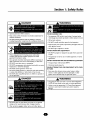 3
3
-
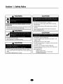 4
4
-
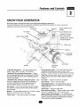 5
5
-
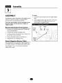 6
6
-
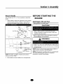 7
7
-
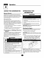 8
8
-
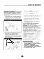 9
9
-
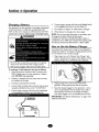 10
10
-
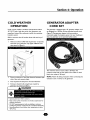 11
11
-
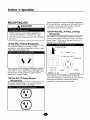 12
12
-
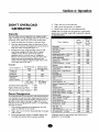 13
13
-
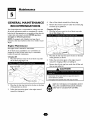 14
14
-
 15
15
-
 16
16
-
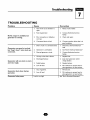 17
17
-
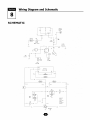 18
18
-
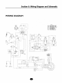 19
19
-
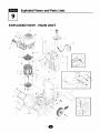 20
20
-
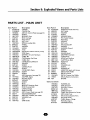 21
21
-
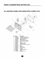 22
22
-
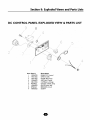 23
23
-
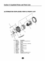 24
24
-
 25
25
-
 26
26
-
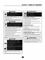 27
27
-
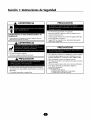 28
28
-
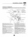 29
29
-
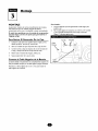 30
30
-
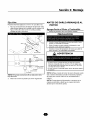 31
31
-
 32
32
-
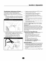 33
33
-
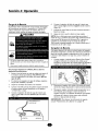 34
34
-
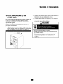 35
35
-
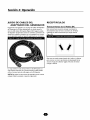 36
36
-
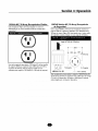 37
37
-
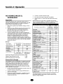 38
38
-
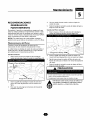 39
39
-
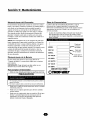 40
40
-
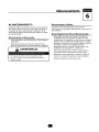 41
41
-
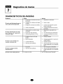 42
42
-
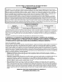 43
43
-
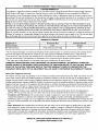 44
44


Troybilt 01925 El manual del propietario
- Categoría
- Generadores de poder
- Tipo
- El manual del propietario
en otros idiomas
- English: Troybilt 01925 Owner's manual
Artículos relacionados
Otros documentos
-
Briggs & Stratton Elite series 01532-2 El manual del propietario
-
Troy-Bilt 01919-1 Manual de usuario
-
Troy-Bilt 01925-0 Manual de usuario
-
-
Generac 1648-0 El manual del propietario
-
-
Briggs & Stratton 1653 El manual del propietario
-
-
-