Troybilt 01919 El manual del propietario
- Categoría
- Generadores de poder
- Tipo
- El manual del propietario
Este manual también es adecuado para

O
m m /
Y
Owner's Manual / Manual del Propietario
Portable Generator / Generador Port_til
Model / Modelo 0 19 19
I®
IMPORTANT: READ SAFETY RULES AND INSTRUCTIONS CAREFULLY
IMPORTANTE: LEYO LA SEGURIDAD LAS ORDENESY LAS INSTRUCCIONES DETENIDAMENTE
Questions? Preguntas?
Helpline - 1-888-611-6708 M-F 8-5 CT
Troy-Bilt® isa registered trademark ofTroy-Bilt, LLC and isusedunder licenseto Briggs& Stratton Power Products.
Troy-Bilt® es una marca registrada deTroy*Bilt, LLC y se usaabajo licenciaa Briggs& Stratton Power Products.
BRIGGS & STRATTON POWER PRODUCTS GROUP, LLC
I!!H!!!!!I ,,FF,RSON,W,SCONS,N,U.S.A.
0 4 Printed in USA ManualNo. 192258GS Revision6 (01/27/2004)

1
Safety Rules
TABLE OF CONTENTS
SafetyRules.................................... 2-4
Know Your Generator ............................. 5
Assembly...................................... 6-7
Operation .................................... 8- I I
Maintenance.................................... 12
Storage........................................ 13
Troubleshooting ................................. 14
Notes .................................... 15& 23
Schematic/Wiring Diagram ..................... 16-17
Replacement Parts............................ 18-22
Warranty ................................. Last Page
EQUIPMENT
DESCRIPTION
_Read this manual carefully and become
familiar with your generator. Know its
applications, its limitations and any hazards
involved.
This manualdescribes anengine-driven, revolving field,
alternating current (AC) generator designedto supply
electrical power for operating compatible electrical lighting,
appliances,tools and motor loads.Thegenerator's revolving
field is driven at about 3,600rpm by a single-cylinder engine.
CAUTION! DO NOT exceed the generator's
wattage/amperage capacity.See"Don't Overload
Generator" on page I I.
Everyeffort hasbeenmadeto ensurethat informationinthis
manualisaccurateand current. However,we reserve the
right to change,alter or otherwise improvethe product and
this document at anytime without prior notice.
The EmissionControl Systemfor this generator iswarranted
for standardsset by the EnvironmentalProtection Agency.For
warranty informationrefer to the engineowner's manual.
In the State of California a spark arrester isrequired by lawI
(Section 4442 of the California PublicResourcesCode).
Other states may havesimilar laws.Federallawsapply on
federal lands.If you equip the muffler with a spark arrester,
it must be maintained ineffective working order.
SAFETY RULES
This is the safety alert symbol. It is used to
alert you to potential personal injury hazards.
Obey all safety messages that follow this
symbol to avoid possible injury or death.
The safety alert symbol (_.) isused with a signalword
(DANGER, CAUTION,WARNING), a pictorial and/or a
safety messageto alert you to hazards.DANGER indicates
a hazard which, if not avoided,will result in death or serious
injury.WARNING indicatesa hazardwhich,if not avoided,
couldresult in death or serious injury.CAUTION
indicatesa hazardwhich, if not avoided,might result in
minor or moderate injury.CAUTION, when used
without the alert symbol, indicatesa situation that could
result in equipment damage.Follow safety messagesto
avoid or reduce the risk of injuryor death.
WARNING
The engine exhaust from this product contains I
chemicals known to the State of California to cause
cancer, b rth defects, or other reproduct ve harm.
Hazard Symbols and Meanings
Electrocution
Electrical Shock
Electrical Shock
Toxic Fumes
,b Q
ExplosivePressure
Explosion Fire
Chemical Burn Hot Surface

Section 1: Safety Rules
DANGER
Operate generator ONLY outdoors.
Keepat least 2 feet of clearance on all sidesof generator for
adequate ventilation.
DO NOT operategenerator insideanybuildingor enclosure,
includingthe generatorcompartmentof a recreationalvehicle(RV).
DANGER
When usinggenerator for backup power, notify utility
company.Use approved transfer equipment to isolate
generator from electric utility.
Use aground circuit fault interrupter (GFCi) in anydamp or
highly conductive area,such asmetal decking or steel work.
DO NOT touch bare wires or receptacles.
DO NOT use generator with electrical cords which are worn
frayed,bare or otherwise damaged.
DO NOT operate generator in the rain.
DO NOT handle generator or electrical cords while standing
inwater, while barefoot, or while handsor feet are wet.
DO NOT allow unqualified persons or children to operate or
service generator.
DANGER
DO NOT allow any open flame,spark, heat,or lit cigarette
during and for several minutes after charging a battery.
Wear protective goggles,rubber apron, and rubber gloves.
, WARNING
WHEN ADDING FUEL
Turn generator OFF and let it cool at least 2 minutes before
removing gas cap. Loosen cap slowly to relieve pressure in tanlc
Fill fuel tank outdoors.
DO NOT overfill tank.Allow space for fuel expansion.
Keep fuel away from sparks, open flames, pilot lights, heat, and
other ignition sources.
DO NOT light a cigarette or smoke.
eVHEN OPERATING EQUIPMENT
DO NOT tip engine or equipment at angle which causes fuel
to spill.
This generator is not for use in mobile equipment or marine
applications.
'HEN TRANSPORTING OR REPAIRING EQUIPMENT
Transportlrepair with fuel tank EMPTY or with fuel shutoff
valve OrE
Disconnect spark plug wire.
_HEN STORING FUEL OR EQUIPMENT WITH FUEL
IN TANK
Store away from furnaces, stoves, water heaters, clothes
dryers or other appliances that have pilot light or other
ignition source because they can ignite fuel vapors.
, WARNING
Thisgenerator does not meet U. S.Coast Guard Regulation
33CFR-183 and should not be used on marine applications.
Failure to use the appropriate U. S.Coast Guard approved
generator could result in bodily injury and/or property
damage.

Section 1: Safety Rules
WARNING
;ENERATOR
Disconnect the spark plug wire from the spark plug and place
the wire where it cannot contact spark plug.
, WARNING
DO NOT touch hot surfaces.
Allow equipment to cool before touching.
CAUTION
DO NOT tamper with governed speed.Generator supplies
correct rated frequency and voltage when running at governed
speed.
DO NOT modify generator in any way.
CAUTION
See"Don't Overload Generator" on page I I.
Start generator and let engine stabilize before connecting
electrical loads.
Connect electrical loads in OFF position, then turn ON for
operation.
Turn electrical loads OFF and disconnect from generator
before stopping generator.
CAUTION
Use generator onlyfor intended uses.
tf you havequestions about intended use,askdealer or call
1-888-611-6708.
Operate generator only on levelsurfaces.
DO NOT expose generator to excessive moisture, dust, dirt,
or corrosive vapors.
DO NOT insert anyobjects through cooling slots.
If connected devices overheat, turn them off and disconnect
them from generatoc
Shut off generator if.'
-electrical output is lost;
-equipment sparks,smokes,or emits flames;
-unit vibrates excessively.

Features and Controls
2
KNOWYOUR GENERATOR
Read this owner's manual and safety rules before operating your generator.
Compare this illustrationwith your generator to familiarize yourself with the locationsof variouscontrols and
adjustments.Savethis manualfor future reference.
DataTag
FuelTank
SparkArrester Muffler
Choke Lever
Air Cleaner
Circuit
Breakers (AC)
120/240Volt AC,
30 Amp
Receptacle
Recoil Starter
Grounding Fastener
Rocker Switch
(on engine shroud)
120Volt AC, 20 Amp, Duplex Receptacles -- May be
usedto supply electrical power for the operation of
120Volt AC, 20 Amp, singlephase,60 Hz electrical, lighting,
appliance,toot and motor loads.
120/240 Volt AC, 30 Amp Locking Receptacle -- May
be usedto supply electrical power for the operation of
120and/or 240Volt AC, 30Amp, singlephase,60 Hz
electrical, lighting,appliance,tool and motor loads.
Air Cleaner -- Uses a dry type filter element to limit the
amount of dirt and dust suckedinto the engine.
Choke Lever -- Used when starting a cold engine.
Circuit Breakers (AC) -- Pushto resetcircuit breakersare
provided to protect the generator againstelectricaloverload.
120Volt AC, 20 Amp
Duplex Receptacles
Oil Fill
DataTag -- Provides model, revision and serial number of
generator. Please have these readily available when calling
for assistance.
Fuel Tank -- Capacity of five (5) U.S.gallons.
Grounding Fastener -- If required, pleaseconsult a
qualified electrician, electrical inspector, or local agency
havingjurisdiction.
Oil Fill --Add engine oil here.
Recoil starter -- Used to start the engine.
Rocker Switch -- Set this switch to "On" before using
recoil starter. Set switch to "Off" to switch off engine.
Spark Arrester Muffler -- Exhaust muffler lowers
engine noise and isequipped with a spark arrester screen.

ASSEMBLY
Your generator requires some assembly and isready for
use after it hasbeen properly serviced with the
recommended oil and fuel.
If you have any problems with the assembly of your
generator, please call the generator helpline at
1-888-61 1-6708.
Remove Generator From Carton
I. Set carton on a rigid fiat surfacewith "This Side Up"
arrows pointing upward.
2. Carefully open top flapsof shippingcarton.
3. Cut down corners at one end of carton from top to
bottom and laythat side of carton down fiat
4. Removeall packing material, carton fillers, etc.
5. Removegenerator from shippingcarton.
Install Wheel Kit
The wheel kit isdesignedto greatly improvethe portability
of your generator.
NOTE: Wheel kit is not intendedfor over-the-road use.
You will need a socket wrench with I/2" or 13mm sockets
and a needle-nose pliers to install this kit.
I. Placebottom of generator cradle on afiat, even
surface.Temporarily place unit on blocks to ease
assembly.
2. Slide axle through both axle mounting brackets on
cradle frame, as shown in Figure I.
3. Slide a wheel over axle.
NOTE: Be sure to install both wheels with the air
pressure valveon the outboard side.
4. Placee-ring onto groove in axle.You may add the fiat
washer if desired.
NOTE: Use retaining pins insteadof e-clip, ifapplicable.
Cap Screw
\
\
\
Hex Nut
/
/
HandleAssembly
Support Leg
Hex Nut _
Cap Screw
Axle
J
Wheel
/
E-Ring
Flat Washer

Section 3: Assembly
5. Placeone end of needlenose pliers on bottom of axle
and other end of pliers on top of e-ring. Seate-ring by
pressing pliers closed.
6. Repeat step 3 through 5 to secure second wheel.
8. To aid support leg assembly,rest generator on cradle,
engine end down.Attach support leg with two
M8x 16mmcap screws and two locking hex nuts as
shown.
9. Use two 13 mm wrenches to tighten leg hardware.
Rest generator on wheels and support leg.
10. Center handle bracket on generator frame at support
leg end of cradle, as shown.
I I. Attach handle bracket with two M8 x 45mm cap
screws and two locking hex nuts.
12. Check that all fasteners are tight and the tires are
inflated to value marked on tire or within 15 and
40 psi.
BEFORE STARTING THE
ENGINE
Add Engine Oil and Fuel
• Place generator on a level surface.
CAUTION
• Refer to engine manualfor oil andfuel fill information.
• Damage to equipment resulting from failure to follow this
instruction will void warranty.
• Refer to engine owner's manualand follow oil and fuel
recommendations and instructions.
NOTE: Check oil often during engine break-in. Refer to
engine owner's manualfor recommendations.
NOTE: The generator assembly rotates on a prelubricated
and sealed ballbearing that requires no additional
lubrication for the life of the bearing.

Operation
USING THE GENERATOR
System Ground
The generator hasa systemground that connects the
generator frame components to the ground terminals on
the AC output receptacles.The systemground is connected
to the AC neutral wire (see"Equipment Description",
earlier in this manual).
Special Requirements
There may be Federalor State Occupational Safetyand
Health Administration (OSHA) regulations,localcodes,or
ordinances that apply to the intendeduseof the generator.
Pleaseconsult a qualified electrician, electrical inspector,or
the localagencyhavingjurisdiction.
• In some areas,generators are required to be registered
with localutilitycompanies.
• If the generator isusedat a construction site,there may
be additional regulations which must be observed.
Connecting to a Building's Electrical
System
Connections for standby power to abuitding's electrical
system must be made by a qualified electrician.The
connection must isolate the generator power from utility
power, and must comply with all applicablelawsand
electrical codes.
DANGER
When usinggenerator for backup power, notifyutility
company.Use approved transfer equipment to isolate
generator from electric utility.
Use aground fault circuit interrupter (GFCI) in anydamp or
highly conductive area,such asmetal decking or steel work.
DO NOT touch bare wires or receptacles.
DO NOT use generator with electrical cords which are worn
frayed,bare or otherwise damaged.
DO NOT operate generator in the rain.
DO NOT handle generator or electrical cords while standing
inwater, while barefoot, or while handsor feet are wet.
DO NOT allow unqualified persons or children to operate or
service generator.
OPERATING THE
G EN ERATO R
CAUTION
See"Don't Overload Generator" on page I I.
Start generator and let engine stabilize before connecting
electrical loads.
Connect electrical loads in OFF position, then turn ON for
operation.
Turn electrical loads OFF and disconnect from generator
before stopping generator.
Starting the Engine
Disconnect all electrical loadsfrom the generator. Use the
following start instructions:
I. Make sure unit is on a levelsurface.
IMPORTANT: Failureto start and operate unit on a level
surface will causethe unit not to start or shut down during
operation.
2. Turn fuel valve to "On" position (Figure 2).
3. Start engine according to instructions given in engine
owner's manual.
NOTE: If engine starts but fails to run, or if unit shuts
down during operation, make sure unit is on a level surface
and check for proper oil level in crankcase.This unit may be
equipped with a low oil protection device. See engine
manual.
Connecting Electrical Loads
• Let engine stabilize andwarm upfor a few minutes after
starting.
• Plugin and turn on the desired 120 and/or 240 VottAC,
singlephase,60 Hz electrical loads.

Section 4: Operation
• DO NOT connect 240Vott loads to the 120Volt duplex
receptacles.
• DO NOT connect 3-phase loads to the generator.
• DO NOT connect 50 Hz loadsto the generator.
• DO NOT OVERLOAD GENERATOR. See"Don't
Overload Generator" on page I I.
Stopping the Engine
I. Unplug all electrical loads from generator panel
receptacles.NEVER start or stop engine with electrical
devices plugged in and turned ON.
2. Let engine run at no-load for several minutes to
stabilize internal temperatures of engine and generator.
3. Turn engine off according to engine owner's manual.
4. Move fuel valve to "Off" position.
RECEPTACLES
,_ CAUTION
NEVERattempt to power a device requiring more
amperagethan generator or receptacle cansupply.
DO NOT overload the generator. See"Don't Overload
Generator".
_m iP_dg_W. J m pm
120/240 Volt AC, 30 Amp, Locking
Receptacle
Use a NEMA LI4-30 plug with this receptacle.Connect a
4-wire cord set rated for 250Volt AC loads at 30 Amps (or
greater) (Figure 3).You can usethe same 4-wire cord if you
plan to run a 120Volt load.
Y (Hot) X (Hot)
NEMA LI4-30
Ground (Green)
This receptacle powers 120/240Volt AC, 60 Hz, single
phaseloads requiring up to 6,000 watts of power (6.0 kW)
at 30 Amps for 120Volts or 240Volts.The outlet is
protected by a push-to-reset circuit breaker.
120 Volt AC, 20 Amp, Duplex
Receptacles
Each duplex receptacle (Figure 4) is protected against
overload by a push-to-reset circuit breaker.
Use each receptacle to operate 120Volt AC, single-phase,
60 Hz electrical loads requiring up to 2,400 watts (2.4 kW)
at 20Amps of current. Use cord sets that are rated for
125Volt AC loads at 20Amps (or greater).

Section 4: Operation
G EN ERATO R ADAPTER
CORD SET
The generator isequippedwith a25' generator adaptercord
set designedfor a 240Volt, 30Amp groundedneutral circuit
(Figure5).The generator adaptercord set provides a
convenientsupplyof emergencypower into your dwelling so
that your generator canbe operated safelyoutside.
COLD WEATH ER
OPERATION
Under certain weather conditions (temperatures below
40°F [4°C] and a high dew point), your generator may
experience icing of the carburetor and/or the crankcase
breather system.
Build a structure that wilt enclose three sides and the top
of the generator:
I. Make sure entire muffler-side of generator is exposed.
Note that your generator may appear different from
that shown in Figure6.
The maximum load on each outlet is 20 Amps.The
maximum total load on both yellow wire outlets or black
wire outlets is 30 Amps.
NOTE: Follow all safety precautions when connecting any
extension cord or device to the generator.
Wind
2. Ensure a minimum of two feet clearance between open
side of box and nearest object.
3. Face exposed end away from wind and elements.
4. Enclosure should hold enough heat created by
generator to prevent problems.
,_ DANGER
Operate generator ONLY outdoors.
Keep at least 2 feet of clearance on all sidesof generator for
adequateventilation.
DO NOT operategenerator insideanybuildingor enclosure,
includingthe generatorcompartment of arecreationalvehicle(RV).
Remove generator from shelter when temperature is above
40°F [4°C].
m

Section 4: Operation
DON'T OVERLOAD
G EN ERATO R
Capacity
You must make sure your generator cansupply enough
rated (running) and surge (starting) watts for the items you
will power at the sametime. Follow these simple steps:
I. Selectthe itemsyou wilt power at the same time.
2. Total the rated (running) watts of these items.Thisis
the amount of power your generator must produce to
keep your itemsrunning. SeeFigure 7.
3. Estimate how many surge (starting) watts you wilt
need.Surge wattage isthe short burst of power
needed to start electric motor-driven tools or
appliancessuch asa circular saw or refrigerator.
Becausenot all motors start at the sametime, total
surge watts can be estimated by addingonly the
item(s)with the highestadditional surge watts to the
total rated watts from step 2.
Example:
Tool or Appliance
Window Air
Conditioner
Refrigerator
Deep Freezer
Television
Light (75 Watts)
Rated (Running)
Watts
1200
800
50O
50O
75
3075 Total
Running Watts
Total Rated (Running)Watts = 3075
Highest Additional SurgeWatts = 1800
Total Generator Output Required = 4875
Additional Surge
(Starting) Watts
1800
1600
50O
1800 Highest
SurgeWatts
Power Management
To prolong the life of your generator and attached devices,
it is important to take care when addingelectrical loads to
your generator.There should be nothing connected to the
generator outlets before starting it's engine.The correct
and safeway to managegenerator power is to sequentially
add loads asfollows:
I. With nothing connected to the generator, start the
engine asdescribed in this manual.
2. Plugin and turn on the first load,preferably the largest
load you have.
3. Permit the generator output to stabilize (engine runs
smoothly and attached device operates properly.
4. Plug in and turn on the next load.
5. Again,permit the generator to stabilize.
6. Repeat steps 4 and 5 for each additional load.
NEVER addmore loads than the generator capacity.Take
specialcare to consider surgeloads in generator capacity,
asdescribed above.
Tool or Appliance
Essentials
Light Bulb - 75 watt
Deep Freezer
SumpPump
Refrigerator/Freezer - 18Cu. Ft.
Water Well Pump - I/3 HP
Heating/Cooling
Window AC - I0,000 BTU
Window Fan
FurnaceFanBlower - 112HP
Kitchen
Microwave Oven - 1000Watt
Coffee Maker
Electric Stove - SingleElement
Hot Plate
Family Room
DVD/CD Player
VCR
Stereo Receiver
Color Television - 27"
Personal Computer w/I 7" monitor
Other
Security System
AM/FM Clock Radio
GarageDoor Opener - I/2 HP
Electric Water Heater - 40 Gallon
DIY/Job Site
Quartz Halogen Work Light
Airless Sprayer - I/3 HP
Reciprocatin_ Saw
Electric Drill - I/2 HP
Circular Saw- 7 I/4"
Miter Saw- I0"
Table Planer - 6"
Table Saw/RadialArm Saw- I0"
Air Compressor - I-I/2 HP
Rated*
(Running)
Watts
75
500
8O0
8O0
1000
12O0
3OO
8O0
1000
1500
1500
2500
Additional
Surge
(Starting)
Watts
500
1200
1600
20O0
1800
6O0
1300
100
100
450
5o0
8o0
18o
3O0
480 520
40O0
1000
600 1200
960 960
1000 1000
1500 1500
1800 1800
1800 1800
2000 2000
2500 2500
*Wattages listed are approximate only. Check toot or
appliance for actual wattage.
t

5
Maintenance
GENERAL MAINTENANCE
RECOMMENDATIONS
The Owner/Operator is responsible for making sure that
alt periodic maintenance tasks are completed on atimely
basis;that all discrepancies are corrected; and that the unit
is kept dean and properly stored. NEVER operate a
damaged or defective generator.
Engine Maintenance
See engineowner's manualfor instructions.
CAUTION
Used motor oil hasbeen shown to cause skin cancer in
certain laboratory animals.
Thoroughly wash exposed areas with soap andwater.
KEEPOUT OF REACH OF CHILDREN. DON'T
POLLUTE.CONSERVERESOURCES.RETURN
USED OIL TO COLLECTION CENTERS.
Generator Maintenance
Generator maintenance consists of keeping the unit clean
and dry. Operate and store the unit in a dean dry
environment where it wJ{{ not be exposed to excessive
dust, dirt, moisture or any corrosive vapors. Cooting air
slots in the generator must not become clogged with snow,
leaves or any other foreign material.
NOTE: DO NOT usea garden hose to dean generator.
Water can enter engine fuel system and cause problems. In
addition, if water enters generator through cooling air slots,
some of the water will be retained in voids and cracks of
the rotor and stator winding insulation.Water and dirt
buildup on the generator internal windings will eventually
decrease the insulation resistance of these windings.
Generator Cleaning
• Use a damp cloth to wipe exterior surfacesclean.
• Use a soft bristle brush to loosen caked on dirt or oiL
• Use a vacuum cleaner to pick up loose dirt and debris.
• Use low pressure air (not to exceed 25 psi) to blow
awaydirt. Inspect cooling air slots and opening on
generator.These openings must be kept dean and
unobstructed.
CAUTION
DO NOT expose generator to excessive moisture, dust, dirt,
or corrosive vapors.
DO NOT insertany objects through cooling slots.
Data Tag
Datatag informationisvery importantif you need helpfrom
our Customer ServiceDepartment or anauthorized service
dealer.
• The data tag(Figure8) islocated either on the heatshield
or engine support on the muffler sideof the generator.
For future reference,pleasecopy the model, revision,and
serial number of the generator inthe spacebelow.
I
MODEL
REV NO
SERL'_L
AC VOLTS
AC AMPS
AC WATTS
DS VOLTS
DC AMPS
Single Phase/60Hz/3600RPM
Ratedat40=C/ClassFinsulation
1
],_......NCO py Model
umber Here
_,, Copy Revision
1_ Here
Copy Serial
Number Here
1
]
]
]
O Bl£1r
m

STO RAG E
The generator should be started at least once every seven
claysand allowed to run at least 30 minutes. If this cannot
be done and you must store the unit for more than
30 days,usethe following guidelinesto prepare it for
storage.
Generator Storage
• Clean the generator as outlined in "Generator Cleaning".
• Check that cooling air slots and openings on generator
are open and unobstructed.
WARNING
DO NOT place a storage cover over a hot generator.
Let equipment cool for a sufficient time before placing the
cover on the equipment.
Engine Storage
See engine owner's manualfor instructions.
Other Storage Tips
• To prevent gum from forming in fuel system or on
essential carburetor parts, add fuel stabilizer into fuel
tank and fill with fresh fuel. Run the unit for several
minutes to circulate the additive through the carburetor.
The unit and fuel can then be stored for up to
24 months. Fuel stabilizer can be purchased locally.
• DO NOT store fuel from one season to another unless
it has been treated as described above.
• Replace fuel container if it starts to rust. Rust and/or dirt
in fuel can cause problems if it's used with this unit.
• Store unit in a clean and dry area.
I

7
Troubleshooting
TROUBLESHOOTING
Problem
NoAC output is available,
but engine is running.
Cause
I. Circuit breaker is open.
2. Poor connection or defective cord set.
3. Connected device is bad.
Solution
I.
2.
3.
4. Fault in generator. 4.
I. Short circuit in a connected load. I.
When loads are 2. Generator isoverloaded. 2.
connected, engine runs
good but bogs down. 3. Engine speed istoo slow. 3.
4. Shorted generator circuit. 4.
Engine shuts down during Out of gasoline. Fill fuel tank.
operation.
Engine lacks power. Load is too high. See "Don't Overload Generator".
Reset circuit breaker.
Check and repair.
Connect another devicethat isin
good condition.
Contact Authorized Service Facility.
Disconnect shorted electrical toad.
See"Don't Overload Generator".
Contact Authorized Service Facility.
Contact Authorized Service Facility.
m

Notes
NOTES

8
Wiring Diagram and Schematic
SCHEMATIC
BRIDGE
RECTIFIER
BLUE (2)
RED (6)
(4)
EXCITATION
FIELD
BLUE _E£ BLACK GRAY
BLUE RED BLAOK
22> <33>
GRAY
(44)
c
]BI
"OA c.
22)
BLUE 1
I1A
RED
"2
RED
22
BLUE
(IIA)
BLUE
(IIA)
120V/20A
BLUE
(IIA)
120/240V/SOA
(22>
GRAY
(44A)
m

Section 8: Wiring Diagram and Schematic
WIRING DIAGRAM
CIRCUIT
BREAKER 1
44_
i-4 l,°,,,°v
44A _ BOA
82
IlA
33
BI× LU[] B_
B[]NNEBT[]R
H[]UBING
CIRCUIT
BREAKER 8
llA
44A
I1A
IlA
4L
180V
80A
°
_ llA °
°_
88
I TAB k/UST N
SIX LUG (REsD)
(11>
÷ NI]TE: P[]SITIVE BRUSH IS CL[]SEBT T[] BEARING
B/
RED 18)
(6)
I80V
SOA
BLACK
(33)
CUST[]MER
GROUND LUG
m

9
Exploded Views and Parts Lists
EXPLOD ED VI EW -
46
HAIN UNIT
45
900
\
54
76
2O
-27
2O
51
m

Section 9: Exploded Views and Parts Lists
PARTS LIST - MAIN UNIT
Item Part # Description
I B189444GS CRADLE
2 194150GS KIT,Vibration, Mount
4 190220GS HOUSING, EngineAdapter
5 NSP ASSY,AIternator (see page20_
6 194151GS KIT,Hrdwr Mounting Adapter
8 96796GS WASHER
I0 190274BGS SCREW
II 187365FGS SCREW
14 189009GS BRACKET,Muffler
15 695398 GASKET,Exhaust
16 66476GS SCREW,w/LockWshr
17 189008GS MUFFLER
18 60706GS SCREW
19 83083GS SCREEN,SparkArrest
20 193646GS KIT,Grounding Hardware
23 194153GS KIT,Vibration Mount
24 192794GS SHIELD,Heat
25 B4986GS DECAL, Ground, Green
26 74908GS SCREW
27 14353621GS WIRE, Ground
30 56893GS SCREW
31 191436GS DECAL, Hot Muffler
33 191435GS DECAL, Shut-Off, Fuel
34 186347GS COVER,Bearing Carrier
35 194397GS KIT,Fuel Hose, Formed w/Clamps
37 192376GS SCREW
38 189164GS NUT
39 194398GS KIT,FuelTank Hardware
41 192980GS KIT,VaNe,FuelTank
43 B4363GS CAP,FuelGauge
44 193668GS ASSY,Tank,Fuel (includes Items 48,49,45 & 4 I)
45 189235GS DECAL, Start Instructions
46 190355GS ASSY,Control Panel(see page21)
48 188333GS DECAL, Gas Fill
49 92982GS DECAL, Danger
55 84346GS SCREW
900 NSP ENGINE
Parts Not Illustrated
MS5242 MANUAL, Engine
192258GS MANUAL, Owners
BB3061GS BOTTLE,Oil
188971GS CORD, Extension, 120/240,30A
193667GS KIT,Decals
m

Section 9: Exploded Views and Parts Lists
ALTERNATOR EXPLODED VIEW AND PARTS LIST
4
\
B
7
8
10
Item Part # Description
I 186059GS ADAPTER, Mounting,Alternator
2 190032GS ROTOR
3 190079AGS STATOR
4 186060GS RBC,with O-Ring (p/n 189197GS)
5 86308HGS SCREW
6 91825GS ASSY,Holder, Rectifier/Brush
7 66849GS SCREW
8 22694GS RECEPTACLE,6 pin
9 81917GS PIN,Roll
10 193428AGS ASSY,Wire, Ground
13 190356GS HARNESS,Wire, Power
O

Section 9: Exploded Views and Parts Lists
CONTROL PANEL EXPLODED VIEWAND PARTS LIST
16 15
5
6 7 7
\\.°
17
2
11
10
Item
I
2
3
4
5
6
7
8
9
I0
II
12
13
14
15
16
17
Part #
188914GS
188889GS
189167GS
189182GS
189166GS
68759GS
18916SGS
84198GS
75207GS
43437GS
189164GS
84543CGS
93857GS
188890GS
82308GS
22694GS
192241GS
Description
COVER,Lid,Control Panel
CONTROL PANEL,Compact
CLIP,Hinge Pin Retainer
SPRING,Hinge, Pin
PIN,Hinge, Cover, Compact
OUTLET, 120V,20A, Duplex
NUT
CAP,Breaker,Circuit
BREAKER,Circuit
OUTLET, 120/240V Locking,30A
NUT
SCREW
BAR, Retaining
COVER,Back,Control Panel
SCREW
HOUSING, Receptacle
SCREW
t

Section 9: Exploded Views and Parts Lists
WHEEL KIT EXPLODEDVIEWAND PARTS LIST
\
5
Item Part # Description
I 189715GS ASSY,Handle
2 B1764GS LEG,Mounting
3 52858GS NUT, Lock
4 39287GS SCREW
5 191267HGS AXLE
6 B4966GS WHEEL
7 191265GS E-RING
8 22247GS WASHER
9 42907GS SCREW
m

Notes
NOTES

1
Reglas de Seguridad
TABLA DE CONTENIDOS
ReglasDe Seguridad ................................ 24-26
Conozca Su Generador ................................ 27
Ensamblaje........................................ 28-29
Funcionamiento .................................... 30-33
Mantenimiento ....................................... 34
AImacenamiento ...................................... 35
Diagnosticos De Averfas................................ 36
Notas ............................................ 37-38
Esquem_tico / Digrama El_ctrico ...................... 16-17
PiezasDe Recambio ................................ 18-22
Garantia ............................................ 39
DESCRIPCION DEL EQUIPO
_Lea este manual de manera cuidadosa y
familiaricese con su generador. Conozca sus usos,
sus limitaciones y cualquier peligro relacionado
con el mismo.
Este generador funciona en base a un motor, de campo el_ctrico
giratorio y de corriente alterna (AC). Fue diseffado con la
finalidad de proveer energia el_ctrica para luces el_ctricas,
aparatos, herramientas compatibles y cargas de motor. El campo
giratorio del generador funciona a una velocidad de 3,6000 rpm
usando un motor con un solo cilindro.
|PRECAUCI_N! NO sobrepase la capacidadde vataje y
amperaie del generador. Revise"No Sobrecargue el Generador"
en la p_gina33.
Se ha hecho cadaesfuerzo posible para asegurarse que la
informaci6n que aparece en este manual es exacta y se encuentra
actualizada.Sin embargo,nosotros se reserva el derecho a
cambiar,alterar o de otra manera mejorar, el producto y este
documento en cualquier momento, sin previo aviso.
El Sistema de Control de Emisiones para este generador est_
garantizado para iuegos est_ndarespor laAgencia de Protecci6n
Ambiental. Para mayor informaci6n acerca de la garantfa,consulte
con el manual del propietario del motor.
Enel estado de California es obligatorio, seg0n la ley,el uso de
_pagachispas(Secci6n 4442 del C6digo de Recursos P0blicos de
California). Otros estados pueden tener leyessimilares.Lasleyes
:ederalesse aplican en tierras federales.Si equipa el silenciador
:on un apagachispas,este deber_ ser mantenido en buenas
:ondicionesde trabaio.
REGLAS DE SEGURIDAD
_k Este es el simbolo de alerta de seguridad. Sirvepara advertir al usuario de un posible riesgo para
su integridad fisica. Siga todos los mensajes de
seguridad que figuren despu_s de este simbolo
para eqitar lesiones o incluso la muerte.
Elsimbolo de alerta de seguridad (_.) esusado con una palabra
(PELIGRO,ADVERTENCIA, PRECAUCION), un mensaje por
escrito o una ilustraci6n, para alertarlo acerca de cualquier
situaci6n de peligro que pueda existir. PEUGRO indica un riesgo
el cual,si no se evita,causar_ la muerte o una herida grave.
AOVERTENClA indica un riesgo el cual,si no se evita,puede
causar lamuerte o una herida grave. PRECAUCI_N indica un
riesgo,el cual,si no seevita, puedecausar heridas menores o
moderadas. PRECAUCI_)N, cuando se usasin el simbolo de
alerta, indica una situaci6n que podria resultar en el daho del
equipo. Sigalos mensajesde seguridad para evitar o reducir los
riesgos de heridas e inclusive la muerte.
I ADVERTENCIA
El escape del motor de este producto contiene
elementos quimicos reconocidos en el Estado de
California pot producir cgncer, defectos de nacimiento u
otros da_os de tipo reproductivo.
Simbolos de Peligro y Signiflcados
Electrocutamiento Descarga El_ctrica Descarga El_ctrica
Gases T6xicos
Explosi6n Fuego
Presi6nExplosiva Quemaduras Qulmica SuperficieCaliente
t

Secci6n 1: Reglas de Seguridad
PELIGRO
Opere el generador SOLAMENTE al aire libre.
Mantenga al menos 2 pies de espaciolibre alrededor del generador,
para la adecuadaventilaci6n.
NO opere el generador dentro deun edificio o lugar cerrado, incluyendo
el compardmiento del generador en un vehiculo recreativo o RM
PELIGRO
Cuando use un generador como poder de energla auxiliar, notifique a
la compa_iade utilidades. Use el equipo de transferencia aprobado
paraaislar el generador de otra utilidad el_ctrica.
Use un interruptor para lafalla del circuito de tierra (GFCI) en
cualquier _rea bastante h6meda o que seaaltamente conducdva, tales
como terrazas de metal o trabajo hecho con acero.
NO toque los alambres pelados o receptgculos.
NO use un generador con cablesel6ctricos que est6n malgastados,
rotos, pelados o da_ados de cualquier forma.
NO opere el generador bajo la Iluvia.
NO maneie el generador o cables el6ctricos mientras est6 parado en
agua,descalzo o cuando lasmanos y los pies est6n mojados.
NO permita que personas descalitlcadaso ni_os operen o sirvan al
generador.
PELIGRO
NO permita ninguna llama abierta,chispa,calor,o encienda un
cigarri]lo durante y por ratios minutos despuas de haber recargado la
bateria.
Lleve puestos lasgalasprotectoras, delantal y guantes de goma.
ADVERTENCIA
CUANDO AI_IADA COMBUSTIBLE
Apague el generador (posicibn OFF) y d_jelo enfriar al menos por
2 minutos antes de remover la tapa de la gasolina.Afloje la tapa
lentamente para dejar que la presi6n salgadel tanque.
Llene el tanque al aire libre.
NO Ilene demasiado el tanque. Permita al menos espacio para la
expansi6n del combustible.
Mantenga la gasolinaalejada de chispas,llamasabiertas, pilotos, calory
otras fuentes de ignici6n.
NO encienda un cigarrilloo fume.
"UANDO OPERE EL EQUIPO
NO inclineel motor o el equipo, de tal manera que la gasolina se
pueda derrama_
Estegenerador no es apto para el uso en equipos m6viles ni en
aplicadones marinas,
:UANDOTRANSPORTE O REPARE EL EQUIPO
Transporte o repare el equipo con el tanque de combustible vaclo,o
con la v_Ivula para apagarel combustible,apagada(posici6n OFF).
Desconecte el cable de la buila.
"UANDO ALMACENE O GUARDE EL EQUIPO CON
COMBUSTIBLE EN ELTANQUE
Almacene aleiado de calderas,estufas, calentadores de agua,secadoras
de ropa u otros aparatos electrodom_sticos que posean pilotos u
otras fuentes de ignici6n, porque ellos puedenencender los vapores
de la gasolina.
ADVERTENCIA
Estegenerador no cumple la norma 33CFR-183 del cuerpo de
guardacostas de EE.UU. y no debe utilizarse en aplicadones marinas.
El uso de un generador no homologado por cuerpo de guardacostas
de EE.UU.puede provocar lesionesy daSos materiales.
t

Secci6n 1: Instrucciones de Seguridad
ADVERTENCIA
;ENERADOR
Siempre desconecte el alambre de la bujla y col6quelo donde no
puedaentrar en contacto con la bujla.
ADVERTENCIA
NO toque las superficies calientes.
Permita que el equipo se enfrle antes de tocarlo.
PRECAUCION
NO cambie ninguna velocidad determinada. El generador suministra
una frecuencia y un volt_je calificado cuando funciona a una velocidad
determinada.
NO modifique al generador en ninguna forma.
PRECAUCION
Vea "No sobrecargue su generador" en la p_gina33.
Encienda sugenerador y deje que el motor se estabilice antes de
conectar lascargas el/actricas.
Conecte lascargasel_ctricas en la posici6n de apagado (OFF),luego
encienda (ON) para su operaci6n.
Apague (OFF) las cargasel_ctricas y descon_ctelas del generador
antes de parar el generador.
PRECAUCION
Use el generador solamente con la finalidad para el cual rue diseffado.
Si usted tiene alguna pregunta acerca de las flnalidades de uso del
generador, preg_ntele a su concesionario o flame 1-888-611-4708,
Opere el generador solamente en superficies niveladas,
NO exponga al generador a una humedad excesiva, polvo, suciedad o
vapores corrosivos,
NO inserte cualquier objeto a trav_s de las ranuras de enfriamiento.
Si los aparatos conectados se sobrecalientan, ap_guelos y
descon_ctelos del generado_
Apague el generador si:
-Se pierde la salida el_ctrica;
-El equipo produce chispas, humo o emite llamas;
-La unidad vibra de una manera excesiva.
I

Caracteristicas ¥ Mandos
2
CONOZCA SU GENERADOR
LEA ESTE MANUAL DEL PROPIETARIOY LAS REGLAS DE SEGURIDAD ANTES DE OPERAR SU GENERADOR.
Compare las ilustraciones con su Generador para familiarizarse con las ubicaciones de los diferentes controles y ajustes. Conserve este
manual para referencias futuras.
Etiqueta de Datos
Tanquede Combustible
Silenciador
Apagachispas
Palancadel Cebador
Cortacircuitos
Depurador de
Aire
Tomacorrientes con
Dispositivo de
Seguridad de
1201240 Voltios AC,
30 Amp
Culatazo el Principio
Tuerca Mariposa
para Conexi6n
aTierra
lnterruptor
B_lancln
Cortacircuitos (AC) -- Cada tomacorriente posee un cortacircuito
para proteger el generador contra sobrecargas el_ctricas. Los
cortacircuitos son del tipo "oprimir para reposicionar".
Culatazo el Principio -- Us6 para comenzar motor.
Depurador deAire -- Filtra el aire de entrada a medida que
penetra en el motor.
Etiqueta de Datos -- Proporciona el modelo, revisi6n y el
n6mero de serie de generador.Tenga por favor estos prontamente
disponible cugndo llamar para la ayuda.
Interruptor Balancin -- Deber_ estar en la posici6n "On" (En)
para darle arranque al moton Col6quelo en la posici6n "Off'
(Apagado) para detener un motor en funcionamiento.
Palanca del Cebador -- Us_da cuando se est6 dando arranque
a un motor frio.
Sileneiador Apagachispas -- El silenciador disminuye el ruido
del motor y est_ equipado con una pantalla apagachispas.
Tomacorrientes Doble de
120Voltios AC, 20 Amp
Tanque del Combustible -- El tanque tiene una capacidad de
5 galones americanos de gasolina sin contenido de plomo.
Tomacorriente Dobles de 120VoltiosAC, 20Amp --
Pueden ser utilizados para suministrar alimentaci6n el_ctrica para
el funcionamiento de cargas del motor, herramientas, aparatos
especiales e iluminaci6n el_ctrica de 120Voltios AC a
20 Amperios, monof_sica de 60 Hz.
Tomacorriente con Dispositivo de Seguridad de
1201240 Voltios, 30 Amp -- Puede ser utilizado para
suministrar alimentaci6n el_ctrica para el funcionamiento de
cargas del motor, herramientas, aparatos especiales e iluminaci6n
el6ctrica de 120 y/o 240 Voltios AC a 30 Amperios, monof&sica de
60 Hz.
Tuerca Mariposa para Conexi6n aTierra-- Si requiri6,
consulte con un electricista cualificado, un inspector el_ctrico o el
organismo competente.
t

MONTAJE
Sugenerador requiere de ciertos procedimientos de montaie y
solo estar_ listo para ser utilizado despu_sde haber[e
suministrado servicio con el combustible y aceite recomendados.
Si usted tiene problemas con el montaje de su generador,
pot favor Ilame a la linea de ayuda para generadores al
1-888-61 1-6708.
Para Retirar El Generador De La Caja
Co[oque [acaja sobre una superficie p[anay rigida, con [as
flechasque dicen"this side up" haciaarriba.
Abra con cuidado lastapas superiores de [acaiade envio.
Corte de arriba a abajo las esquinasde uno de los lados de la
caja y coloque ese lado de [acaja sobre e[ suelo.
Retire todo e[ material de empaque,rel[eno, etc.
Saque el generador de la caiade envfo.
Instale el Juego de Ruedas
E[iuego de ruedas est_ disefiadopara mejorar el transporte de[
generador.
NOTA: EsteJuegode Ruedasno hasido disefiadopara ser usado
en la carretera.
Necesitar6 una liavede cubos con cubos de V2"o 13ramy unas
pinsasde punta para insta[arel juego de ruedas.
I. Co[oque e[ fondo de [acamilla de[ generador en una
superficie p[ana.Temporalmente, co[oque la unidad en
bioques para ensamblarla f_cilmente.
2. Desiice el eje a trav_s de ambos soportes de montaje, en el
marco de la camilla,como semuestra en la Figura9.
3. Desiice una rueda en el eie.
NOTA: Aseg_rese de instalarambas ruedas con la v_lvula de aire
hacia el lado de afuera.
4. Co[oque e[ e-ring en la ranura deleje.
Tornil[os
\
\
\,
TLlercE
/
Manilla
Tuercas_
Torni[Ios
Eje
/
Rueda
Arande[a
/
%
/
E-Ring
t

Secci6n 3: Montaje
5. Coloque un extremo de las pinzas de puntas de agujaen la
parte inferior del eje y el otro extremo de las pinzas en la
parte superior del e-ring.Asiente el e-ring cerrando las
pinzas.
6. Repita los pasos 3 por 5 para asegurar la segundarueda.
7. Remuevalos bloques temporales.
8. Para ayudaral ensamblaje de la pata de apoyo, haga
descansar elgenerador en la camilla con la parte del motor
hacia abajo.Anexe la patade apoyo con dos tornillos M8 x
16mm y dos tuercas de seguridad, como se muestra en la
figura.
9. Use dos Ilavesde 13mm para apretar las piezas.Ahora haga
descansar elgenerador en las ruedasy pata de apoyo.
I0. Coloque el soporte de la manilla en el centro del marco del
generador al extremo de la patade apoyo,como se muestra.
I I. Anexe el soporte de la manillacon dos tornillos M8 x 45mm
y dos tuercas de seguridad.
12. Verifique quetodas las piezasest_napretadasy las Ilantasest_n
infladasal valor marcb en la Ilantao dentro de 15y 40 psi.
ANTES DE DARLE ARRANQUE AL
MOTOR
Agregar Aceite al Motor y Gasolina
Coloque lagenerador sobre una superficie nivelada.
PRECAUCION
• Consulte el manual del propiet_rio del motor par_ a_adir_l motor
el aceite y el combustible recomendado
• El da_o a la lavadora a presibn, resultado de la desatenci6n a
esta precauci6n, no ser_ cubierto por la garantta.
Consulte el manual del propietario del motor para a_adiral
motor el aceite y el combustible recomendado.
NOTA: Verifique el aceite del motor de manera
frecuente cuando _ste se esfuerce demasiado. Consulte el
manual del propietario del motor para conocer cugles
son las recomendaciones al respecto.
NOTA: El campo giratorio del generador seencuentra en un
cojinete pre-lubricado y sellado que no requiere lubricacibn
adicional por la vida _til delcojinete.
t

Operaci6n
USO DEL GENERADOR OPERANDO EL GENERADOR
Tierra del Sistema
El generador dispone de una conexi6n a tierra del sistema que
conecta los componentes del bastidor a los terminales de tierra
de los enchufes hembra de salida de CA. La tierra del sistema est_
conectada al cable de CA neutro que,a su vez,est_ conectado al
bastidor del generador (vea"Descripi6n del Equipo").
Requisitos Especiates
Esposible que hayanormas u ordenanzas localesy nacionales en
materia de seguridad e higiene en el trabajo aplicables al uso del
generador. Consulte con un electricista cualificado,un inspector
el_ctrico o el organismo competente.
Enalgunaszonas,es obligatorio registrar los generadores en
las compafitasel_ctricas locales.
Si el generador seutiliza en una obra, puede ser necesario
cumplir normas y requisitos adicionales.
Conexibn al Sistema El_ctrico de un
Edificio
Las conexiones a efectos de alimentaci6n de reserva al sistema
el_ctrico de un edificio deben ser realizadaspor un electricista
cualificado. La conexi6n debe aislar la alimentaci6n del generador
de la alimentaci6n de la red pfiblica y debe cumplir todas las leyes
' normas el_ctricas vigentes.
PELIGRO
Cuando use un generador como poder de energla auxiliar, notifique a
la compafila de utilidades. Use el equipo de transferencia aprobado
para aislar el generador de otra utilidad el6ctrica.
Use un interruptor pzra la falla del circuito de tierra (GFCI) en
cualquier grea bastante h0meda o que sea altamente conductiva, tales
como terrazas de metal o trabaio hecho con acero.
NO toque los alambres pelados o receptgculos.
NO use un generador con cables el_ctricos que est_n malgastados,
rotos, pelados o dafiados de ¢ualquier forma.
NO opere el generador bajo la lluvia.
NO maneie el generador o cables el_ctricos mientras este parado en
agua, descalzo o cuando las manos y los pies est6n mojados.
NO permita que personas descalificadas o nifios operen o sirvan al
generador.
PRECAUCION
Vea "No sobrecargue generador" en la p_gina 33.
Enciendasu generador y deje clueel motor se estabilice antes de
conectar lascargas el_ctricas.
Conecte lascargasel_ctricas en la posici6n de apagado (OFF),luego
encienda (ON) para su operaci6n.
Apague (OFF) las cargaselactricas y descon_ctelas del generador
antes de parar el generador.
Encienda el Motor
Desconecte todas las cargasel_ctricas del generador.Use las
siguientes instrucciones para encender:
I. Aseg0rese de que la unidad est_ en una superficie plana.
IMPORTANTE: Si launidad no se arranca y utiliza en una
superficie plana,se pueden producir problemas de arranque y de
parada durante el funcionamiento.
2. Gire la v_lvula del combustible a la posici6n "On" (Figura 10).
3. Pongaen marcha el motor tal y como se explica en el manual
del propietario del motor.
NOTA: Si el motor arranca despu_s de tirar tres veces del
arrancador pero no siguefuncionando, o si la unidad separa en
funcionamiento, aseg0rese de que la unidad est_ en unasuperficie
planay compruebe que el nivel de aceite del cigLiefialescorrecto.
La unidad puede equiparse con un dispositivo de protecci6n de
bajo nivel de aceite.
Conexion De Cargas Electricas
Deje que el motor se estabilice y secaliente pot unos
minutos despu_s del arranque.
Conecte y encienda lascargas el_ctricas de 120ylo
240Voltios AC monof_sicas de 60 Hz que desse.
NO conecte cargasde 240Voltios a tomacorrientes de
120Voltios.
NO conecte cargastrif_sicas al generador.
t

Secci6n 4: Operaci6n
NO CONECTE cargasde 50 Hz al generador.
NO SOBRECARGUE EL GENERADOR.Vea "No
Sobrecargueel Generador" en la p_gina33.
Parado Del Motor
1. Desconecte todas las cargasel_ctricas de los tomaco-
rrientes del panel del generador. NUNCA de arranque o
detenga el motor con todos los dispositivos el_ctricos
conectados y encendidos.
2. Oe}e que el motor funcione sin cargaspor algunos minutos
para estabilizar las temperaturas internasdel motor y el
generador.
3. Pare el motor tal y como se explica en el manual del
propietario del motor.
4. Cierre lav_ilvuladel combustible.
RECEPTACULOS
PRECAUCION
NUNCA intente suministrarcorriente a un dispositivo de arnperaje
superior al que puede suministrar el generador o el enchufe hembra.
NO sobrecargue el generador. Consulte el apartado"No Sobrecargue
Generador'.
120/240 Voltios AC, 30 Amp, Recept_culo
de Seguridad
Use un tap6n NEMA LI4-30 con este recept_culo. Conecte un
juego de cable de 4 alambres, clasificado como 250Voltios AC a
30Amps (o mayor) (Figura I I). Usted puede usar el mismo cable
de 4-alambres si planeatrabajar con una carga de 120Voltios.
Juego de Cable de 4Alambres
(Neutro)
Y (Cargado) X (Cargado)
NEMA L14-30 Tierra (Verde)
Este recept_culo le provee poder a cargas de 120/240Voltios AC,
de 60 Hz, fasesencilla,que requieren hasta5,500 vatios de
energia (5.5 kW) a 30Amps, para 120Voltios o 240Voltios. La
salidaest_ protegida por un corto-circuito de, del tipo "empuie
para reposicionar".
120 Volt AC, 20 Amp, Recept_culos Dobles
Cada recept_culo (Figura 12)est_ protegido en contra de
sobrecargas por un corto-circuitos de, del tipo "empuie para
reposicionar".
Use cada recept_culo para operar 120Voltios AC, de fase sencilla,
de cargas de 60Hz que requieren hasta 2,400 vatios (2.4 kW) a
corrientes de 20 Amps.Use los iuegos de cables que son
calificados para cargasde 125Voltios AC, a 20 Amps (o mayores).
t

Secci6n 4: Operaci6n
JUEGO DE CABLES DEL
ADAPTADOR DEL GENERADOR
El generador est_ equipado con un Juegode Cables del Adaptador
del Generador de 25 pies,dise_ado para un circuito neutro a
tierra de 240 voltios, 30 Amperios (Figura 13).Eljuego de cables
del adaptador del generador provee un suministro conveniente de
energia para cualquier emergencia en su propiedad, de tal manera
que su generador pueda ser operado seguramente en el exterior.
La carga m_xima en cada tomacorriente esde 20Amperios. La
carga m_xima total tanto en el tomacorriente de cable amarillo
como el tomacorriente de cable negro, esde 30 Amperios.
NOTA: Sigatodas las instruccionesde seguridad cuando conecte
cualquier cable de extensibn o aparato al generador.
OPERACI( N DURANTE UN
CLIMA FRiO
Baio ciertas condiciones ambientales (temperaturas pot debajo de
los 40-_F[4-_C]y un punto alto Dew), su generador puede
experimentar congelamiento del carburador y/o el sistema de
respiradero del cigLiehaL
Construya unaestructura que pueda cubrir los tres lados y la
parte superior del generador:
L Aseg_rese que el lado del amortiguador del generador est_
expuesto.Aqui se muestra unaunidad tipica, su unidad puede
tener otra apariencia, como se muestra en la Figura 14.
Viento _
2. Aseg6rese que existe un espacio mtnimo de dos pies entre el
lado abierto de la caja y el obieto mis cercano.
3. Coloque la parte abierta fuera del viento y otros elementos.
4. La cobertura deberta aguantar el calor suficiente creado por
el generador para prevenir problemas.
PELIGRO
Opere elgener_dor SOLAMENTE alaire libre.
Mantenga al menos 2 piesde espacio librealredeclor del generaclor,
para la _decuadaventilaci6n.
NO opere el generador dentro de un ed_cio o lugar cerrado, incluyendo
el compartimiento del generador en un vehlculo recreativo o RM
Retire la proteccibn cuando la temperatura sea superior a
4`0C [40-_F].
t

Secci6n 4: Operaci6n
NO SOBRECARGUE GENERADOR
Capacidad
Usted debe asegurarseque sugenerador puedeproveer el
suficiente vataje calificado (cuando est_ funcionando) y de carga
(al encender) para los aparatos a los cualesvaa proveer la
energia,al mismo tiempo. Sigaestos pasos:
I. Seleccione los aparatos que recibir_n la energia,al mismo
tiempo.
2. Totalice los ratios calificados (cuando est_ funcionando) de
estos aparatos. Esta esla cantidad de energia que su
generador debe producir para mantener eso aparatos
funcionando adecuadamente.Veala Figura15.
3. Calcule la cantidad de ratios de carga (al encender) que
usted necesitar_.El vataie de carga esla cantidad minima de
electricidad, necesaria para encender herramientas o
aparatos con motores el_ctricos, tales como, sierras
circulates o refrigeradores. Debido aque no todos los
motores se encienden al mismo momento, el vataje total de
carga se puede estimar al aSadir solamente el(los) aparato(s)
con el vataje adicional m_salto, al total del vataie calificado,
obtenido en el paso2.
Ejemplo:
Herramienta o
Aparato El_ctrico
Aire Acondicionado
de Ven_ana
Refrigerador
Congelador industrial
Televisi6n
Luz (75 Vatios)
Vatios Calificados
(cuandoest_
funcionando)
1200
VatajeTotal Calificado
Vataje de CargaAdicional m_salto
SalidaTotal Requerida del Generador
Vatios Adicionales de
Carga (al encender)
1800
800
500
500
75
Total = 3075
Vatios para funcionar
cuando est_ funcionando)
1600
500
1800(V_ios de
Cargamgsalto)
= 3075
= 1800
= 4875
Control de la Energia
Para prolongar la vida de su generador y los aparatos que est_n
conectados al mismo, es muy importante cuidarlo cuando se le
aSadencargasel_ctricas. Nada deberla estar conectado a los
tomacorrientes del generador antes de que su motor sea
encendido. Laforma correcta y m_s segura para controlar la
energia del generador,es la de aSadir en secuenciaslas cargas,
como se describe a continuaci6n:
I. Sin tener nada conectado al generador, encienda el motor de
la manera descrita en este manual.
2. Conecte y encienda la primera carga,preferiblemente la
mayor que usted tenga.
3. Permita que la salidadel generador seestabilice (el motor
funciona suavementey el aparato conectado al mismo
trabaja adecuadamente).
4. Conecte y encienda la pr6xima carga.
5. De nuevo,permita que el generadorse estabilice.
6. Repita los pasos4 y 5 para cada cargaadicional que usted
tenga.
NUNCA aSadamgs cargassobre la capacidaddel generador.
Tome una atenci6n especialen considerar lascargas de corriente
seg6nla capacidaddel generador,como se describe arriba.
Herramienta o Aparato El_ctrico
Esenciales
Bombilla - 75 vatios
Con_elador industrial
Bomba de a_uas ne_ras
Refrigerador I congelador - 18 pies
c_bicos
Bomba de agua - I/3 HP
Calefaccibn / enfriamiento
Aire Acond. de ventana - I0.000 BTU
Ventilador de ventana
Calefactor de caldera - 112 HP
Cocina
Homo de microondas - L000 Vatios
Cafetera
Cocina el_ctrica - Elemento simple
Calientaplatos
HabitatiOn Familiar
Tocador de DVD/CD
VCR
Receptor est_reo
Televisor a color - 27 pulg.
Computadora personal con monitor de
17 pulg.
Otros
Sistema de seguridad
Radio-Relo i AM/FM
Abridor de garaje - I/2 HP
Calentador ei_ctrico de agua - 40
galones
Taller
Luz de halbgeno para trabaiar
Rociador sin aire - I/3 HP
Sierra intercambiable
Taladro el_ctrico - I12 HP
Sierra circular - 7 ¼ pul_.
Sierra inglete- I0 pulg.
Mesa de planificaci6n - 6 pul_.
Sierra de mesa / sierra de brazo radial
- I0 pul&
Compresor de aire - l-I12 HP HP =
Caballo de fuerza.
Vados
Calificados*
(cuando est_
funcionando)
75
5OO
8OO
8OO
I000
1200
3OO
8OO
1000
1500
1500
2500
_00
_00
450
500
800
_80
300
480
4000
1000
600
960
1000
1500
1800
1800
2000
Vatios
Adicionales
de Carga (al
encender)
5OO
1200
1600
2000
1800
600
1300
52O
1200
960
1000
1500
1800
1800
2000
2500 2500
*El vataje que aparece en la lista es solamente una cantidad
aproximada.Verifique la herramienta o aparato el_ctrico para
obtener el vataie verdadero.
I

5
Mantenimiento
RECOMENDACIONES
GENERALES DE
MANTENIMIENTO
El propietario I operador es responsable por asegurarse de que
todos los trabajos peri6dicos de mantenimiento se lleven a cabo
adecuadamente; que todos los problemas son resueltos; y que la
unidad se mantiene limpia y adecuadamente almacenada. NUNCA
opere un generador que est_ dafiado o defectuoso.
Mantenimiento del Motor
Consulte el manual del propietario del motor para las
instrucciones de c6mo mantener adecuadamente el motor.
PRECAUCION
El aceite usado del motor ha sido mostrado al cancer de la piel de la
causa en ciertos animales del laboratorio.
Completamente lavado expuso _reas con el jab6n y el agua.
_ ANTENGA FUERA DE ALCANCE DE NIi_IOS. NO
CONTAMINE. CONSERVE los RECURSOS.VUELVA
ACEtTE USADO A la COLECCION CENTRA.
Mantenimiento del Generador
El mantenimiento del generador consiste en conservar la unidad
limpia y sec_ Opere y almacene la unidad en un ambiente limpio y
seco donde no ser_ expuesta al polvo, suciedad, humedad o vapores
corrosivos. Las ranuras del aire de enfriamiento del generador no
deben estar tapadas con nieve, hojas, o cualquier otto material
extrafios. Revise frecuentemente la limpieza del generador y limpielo
cuando est_ con polvo, sucio, con aceite, humedad, o cuando otras
substancias extrafias sean visibles en su superficie exterior.
NOTA; NO recomendamos el uso de mangueras de jardln para
limpiar el generador. El agua podria introducirse en el sistema de
combustible del motor y causar problemas.Adem_s, si el agua se
introduce al generador a tray,s de las ranuras para aire de
enfriamiento, algo del agua quedar_ retenida en los espacios
vaclos y grietas del aislamiento del devanado del estator y rotor.
La acumulaci6n de agua y suciedad en los devanados internos del
generador disminuir_ eventualmente la resistencia del aislamiento
de estos devanados.
Para Limpiar el Generador
Utilice un trapo h6medo para limpiar las superficies exteriores.
Puede usar un cepillo de cerdas suaves para retirar la
suciedad endurecida, aceite, etc.
Puede usar una mgquina aspiradora para eliminar suciedad y
residuos sueltos.
Puede usar aire a baja presi6n (que no exceda los 25 psi) para
eliminar la suciedad. Inspeccione las ranuras para aire de
enfriamiento y la apertura del generadon Estas aperturas
deber_n mantenerse limpias y despejadas.
PRECAUCION
NO exponga al generador a una humedad excesiva, polvo, suciedad o
vspores corrosivos_
NO inserte cualquier objeto a tray,s de las ranuras de enfriamiento.
Eticlueta de Datos
Localice la etiqueta de datos del generador y copie la informaci6n
en el espacio disponible a continuaci6n. Esta informaci6n es
fundamental para poder recibir ayuda de nuestro departamento
de servicio al cliente o de un distribuidor de servicio autorizado.
La etiqueta de datos (Figura 16), que contiene los nameros de
modelo, revisi6n y de serie, est_ situada en la protecci6n
t_rmica o apoyo del motor del lateral del silenciador del
generador. Copie los n6meros de modelo, revisi6n y de serie
del generador en el espacio disponible a continuaci6n para
futuras consultas.
I [ Copie aqui
el n6mero
I_ODEL [ _ de modelo
RLmV NO [ _ Copie aqui
el revisi6n
SERIAL [ '_ Copie aqui el
AC VOLT8 [ I n6mero de serie
AC AMPS [ I
AC WATTS [ I
DC VOLTS [
DC AMPS [ I
SinglePhase 160 Hz / 3800RPM
o
Ratedat 40 C / Class F I_ula_on
O __ -_e!_lT
I

Almacenamiento
6
ALMACENAMIENTO
E[generador deber_ ser encendido al menos unavez cada siete
dfas y deber_ dejarlo funcionar al menos durante 30 minutos. Si
no puede hacer esto y debe aimacenar la unidad por mgsde
30 dfas,sigalas siguientes instruccionespara preparar su unidad
para almacenamiento.
Almacenando el Generador
Limpie el generador como est_ descrito en ("Para Limpiar el
Generador").
Reviseque las ranuras para el aire de enfriamiento y las
aperturas del generador seencuentren abiertas y despejadas.
ADVERTENCIA
NO co[oque una cubierta encima de un generador caliente.
Deje que la unidad se enfrle Io suficientemente antes de que le
coloque la cubierta,
Almacenando el Motor
Consulte e[ manual del propietariodel motor para las
instruccionesde cbmo preparar adecuadamente el motor para su
aimacenamiento.
Otras Sugerencias Para el Almacenando
Para prevenir que seforme unaresina en el sistema de
combustible o en partes esencialesdelcarburador, vacie
estabilizadores del combustible, suministrados, en e[ tanque de
gasolinay [lene con gasolina fresca.Haga funcionar [aunidad
por algunos minutos para hacer circular el aditivo a trav6s del
carburador. La unidad y el combustible pueden ser
almacenadoshasta por 24 meses.Se puedecomprar mgs
estabilizador del combustible, en sutienda local
NO almacenegasolina de una estaci6n aotra estacibn,a[
menos que hayasido tratada como se mencion6 antes.
Reemplacela canecade gasolina si comienza aoxidarse. El
bxido y/o [asuciedad en la gaso[ina [e causar_ problemas.
Almacene [a unidad en un _rea [impia y seca.
t

7
Diagnosticos de Averias
DIAGNOSlTICOS DE AVERiAS
Problemo
No hay corriente alterna,
pero el motor funciona.
Cuando las cargas est_n
conectadas, el motor
funciona correctamente
pero se ahoga.
Causa
I. El interruptor autom_tico de circuito est_
abierto.
2. Conexi6n real o defectuosa del juego de
cables.
3. El dispositivo conectado est_ daffado.
4. Averia en el generador.
I.
2.
3.
4.
Corto circuito en una de las cargas
conectadas.
El generador est_ sobrecarga.
Velocidad del motor es muy lenta.
Circuito del generador en corto.
Action
I. Reposicione el interruptor.
2. Revisey repare.
3. Conecte otto dispositivo que est_ buenas
condiciones.
4. P6ngase en contacto con el servicio t_cnico
autorizado.
I. Desconecte la carga el_ctrica en corto.
2. Vea"No Sobrerecarque Generador".
3. P6ngaseen contacto con el servicio t_cnico
autorizado.
4. P6ngaseen contacto con el servicio t_cnico
autorizado.
El motor se apaga en Sin gasolina. Llene el tanque de combustible.
pleno funcionamiento.
La carga es muy alta. Vea "No Sobrerecarque el Generador".
AI motor le hace falta
potencia.
t

Notas
NOTAS

Notas
NOTAS

POLJTICA PARA EL PROPIETARIO DE EQUIPOSTROY-BILT®
Efectiva desde el Iro de Enero, 2003
GARANTIA LIMITADA
"Troy-BiltO es una marca registrada de MTD bajo licencia de Briggs & Stratton Power Products. Briggs & Stratton Power Products
reparar_ o sustituir_ sin cargo alguno cualquier componente del equipo** que presente defectos de materiales y/o mano de obra. Los
gastos de transporte de las piezas enviadas para reparar o sustituir conforme a los t_rminos de esta garantta corrergn a cargo del
comprador. Esta garantia tiene efecto durante el perfodo indicado y conforme a tas condiciones estipuladas en la misma. Para obtener
servicio en garantia, Iocalice el distribuidor de servicio autorizado m_s prbximo tlamando al 1-888-611-6708. Los distribuidores de
servido autorizado de Briggs & Stratton Power Products son los _nicos que pueden ofrecer servicio en garantfa.
NO EXISTEOTRA GARANTIA EXPRESA.LAS GARANT{AS IMPLiCITAS, tNCLUYENDO AQUELLAS DE MERCANTIBILtDAD O CAPACIDAD
PARA UN PROP_SITO PARTICULAR, ESTAN LIMITADA$ AL PERIODO DETIEMPO ESPECIF[CADO,O HASTA EL LiMITE PERMITIDO POR LA
LEY,TODAY CUALQUIER GARANT{A IMPL{CITA ESTA EXCLUIDA. RESPONSABILIDAD POR DAi_IOS CONSECUENTES BAJO CUALQUIER Y
TODAS LAS GARANT{AS, ESTAN EXCLUIDAS HASTA EL LiMITE DE EXCLUSI(_N PERMITIDO POR LA LEY.Algunos palseso estados no admiten
limitaciones en cuanto a la vigencia de unag_rant{a implicir_ y algunos no admiten la exclusibn o lirnitacibnde da_os resultantes o derivados. Por Io
tanto, es posible que las limitaciones y exdusiones arriba mendonadas no se apliquen a su caso.Estagarantla [e otorga determinados derechos lega[es
es posible que uscedcuente con otros derechos que pueden variar de un pals a oCro o de un estado a otro."
PERIODO DE GARANTJA*
Equipo**
Lavador a Presibn
Generador Port_til
Para Uso Del Consumidor Para Uso Comerciat
I afio 90 dias
2 afios (el se_undo afio solamente para las partes) I afro
* EI periodo de garanttacomienza en lafecha de comprahecha por el primer consumidor al detal o usuario comercial, y continua por el
periodo de tiempo que aparece en la tabla arriba meneionada."Para uso del consumidor"significa,uso residencial por unconsumidor al
detal. "Para uso comercial" significa,todos los otros casos,incluyendo el uso comercial, para generar un ingreso o por prop6sitos de
alquile_ Una vez que el equipo hasido usado comercialmente, deberia ser considerado como de uso comercial para lasfinalidades de
esta garantta.
** El motor y las baterias para el encendido, est_n garantizados por el fabricante de esos productos.
EL REGISTRO DE LA GARANTiA NO ES NECESARIO PARA OBTENER LA GARANTiA EN LOS BRIGGS &
STRATTON POWER PRODUCTS. GUARDE SU RECIBO DE COMPRA. SI USTED NO PROVEE LA PRUEBA DE LA
FECHA DE LA COMPRA INICIAL, AL MOMENTO EN QUE SE REQUlERA USAR LA GARANT{A, LA FECHA DE
LA FABRICACI_)N DEL EQUlPO SERA USADA PAPA DETERMINAR EL PERIODO DE GARANT{A.
Acerca de la seguridad de suequipo:
Nosotros reciben las reparaciones bajo la garanttay le pide disculpas pot cualquier inconvenienciacausada.Cualquier Concesionario de
Servicio Autorizado puede Ilevar a cabo reparaciones baio la garantia. La mayoria de las reparaciones bajo la garantia son manejadas
normalmente, pero algunasvecesla solicitud del servicio de garantta esposible que no seaapropiada.Por ejemplo, la garanttano ser;i
v_lida si el daho al equipo ocurri6 debido al mal uso,falta de mantenimiento adecuado,manejo,envfo,almacenamiento o una instalaci6n
inadecuada.De manera similar, lagarantia queda anuladasi se ha borrado lafecha de fabricaci6n o el n_mero de serie del equipo o si el
equipo ha sido alterado o modificado. Durante el pertodo de lagarantia, el Comerciante Autorizado del Servicio hace,en es la opcibn, la
reparaci6n o reemplaza cualquier parte eso, sobre el examen se encuentran para ser defectuoso bajo el uso y el servicio normales. Esta
garantta no cubrir_ las reparaciones y el equipo siguientes:
Desgaste normal: Equipo el_ctrico al aire libre, como todos los aparatos mec_nicos,necesita partes, servicio y reemplazo,
peri6dicamente, para que funcione bien. Estagarantia no cubre la reparacibn cuando el uso normal haacabado con la vida de una
parte en particular o del equipo.
Instalacibn y mantenimiento: Estagarantia no seaplica al equipo o parte que haestado sujeta a unainstalaci6ninadecuada,que
no hayasido autorizada o a cualquier tipo de alteraci6n, el real uso, negligencia,accidentes,sobrecarga,velocidad excesiva,
mantenimiento inadecuado,reparaci6n o almacenamiento,en nuestro luicio, han afectado desfavorablemente su rendimiento y
fiabilidad. Estagarantta tambi_n no cubre el mantenimiento normal tales como ajustes,limpieza del sistema de combustibn y la
obstruccibn (debido a materias quimicas,suciedad,carb6n o cat,etc.)
Otras exclusiones: Tambi_n se encuentran excluidos de es_ garantta,el desgastede los articulos tales como, conectadores,
medidores de aceite, correas, anillos O, flltros, empaquede la bomba,etc. las bombas que sehaganfuncionar o trabajar sin agua,o
dahos y malfuncionamientos que resulten de accidentes,abusos,modificaciones, alteraciones, un servicio inadecuado,congelamiento
o deterioro qutmico. Los accesorios tales como pistolas,mangueras,varillas y boquillas escin excluidos de la garantia del producto.
Tambi_n se excluye el equipo usado,reacondicionado y destinado a demostraciones; el equipo utilizado como fuente principal de
energia en lugar del servicio de la compahia proveedora de electricidad y el equipo destinado a aplicaciones utilizadas para mantener
la vida.
BRIGGS & STRATTON POWER PRODUCTS GROUP, LLC
JEFFERSON,WISCONSIN, U.S.A.

TROY-BILT®OWNER WARRANTY POLICY Effective January I, 2003
LIMITED WARRANTY
"Troy-Bitt® isa registered trademark of MTD and isused under license to Briggs& Stratton Power Products. Briggs& Stratton
Power Products will repair or replace,free of charge,any part, or parts of the equipment** that aredefective in material or
workmanship or both.Transportation charges on parts submitted for repair or replacement under this warranty must be borne
by purchaser.This warranty is effective for the time periods and subject to the conditions provided for in this policy.For warranty
service, find your nearestAuthorized service dealer by calling 1-888-611-6708.Warranty service may only be performed by a
Briggs& Stratton Power ProductsAuthorized service dealer.
THERE ISNO OTHER EXPRESSWARRANTY. IMPLIEDWARRANTIES, INCLUDING THOSE OF MERCHANTABILITY AND
FITNESSFORA PARTICULAR PURPOSE,ARELIMITED TO THE TIME PERIOD SPECIFIED,OR TO THE EXTENT PERMITTED
BY LAW.ANY AND ALL IMPLIEDWARRANTIES ARE EXCLUDED. LIABILITY FOR CONSEQUENTIAL DAMAGES UNDER
ANY AND ALLWARRANTIESARE EXCLUDEDTOTHE EXTENT EXCLUSION ISPERMITTED BY LAW. Some countries or
states do not allow limitations on how longan impliedwarranty lasts,and some countries or states do not allow the exclusion or
limitationof incidentalor consequential damages,so the above limitation and exclusion may not applyto you.This warranty gives
you specific legal rights and you may also haveother rights that vary from country to country or state to state."
WARRANTY PERIOD*
Equipment ** Consumer Use Commercial Use
PressureWasher I Year 90 Days
Portable Generator 2Years (2rid year parts only) I Year
*The warranty period beginson the date of purchase by the first retail consumer or commercial end user,and continues for the
period of time stated in the table above."Consumer use" meanspersonal residential household use by a retail consumer.
"Commercial use" meansall other uses,includingusefor commercial, income producing or rental purposes.Once equipment has
been used commercially, it shallthereafter be considered to be in commercial usefor purposes of this warranty.
**The engine and starting batteries are warranted solely by the manufacturers of those products.
WARRANTY REGISTRATION IS NOT NECESSARYTO OBTAIN WARRANTY ON BRIGGS & STRATTON
POWER PRODUCTS EQUIPMENT. SAVEYOUR PROOF OF PURCHASE RECEIPT. IFYOU DO NOT PROVIDE
PROOF OFTHE INITIAL PURCHASE DATE ATTHETIMEWARRANTY SERVICE IS REQUESTED, THE
MANUFACTURING DATE OFTHE EQUIPMENTWILL BE USEDTO DETERMINETHEWARRANTY PERIOD.
About your equipment warranty:
We welcome warranty repair and apologize to you for being inconvenienced.AnyAuthorized service dealer may perform warranty
repairs. Most warranty repairs are handled routinely, but sometimes requests for warranty service may not be appropriate. For
example,warranty service would not apply ifequipment damageoccurred becauseof misuse,lackof routine maintenance,shipping,
handling,warehousing or improper installation.Similarly,the warranty isvoid if the manufacturing date or the serial number on the
equipment hasbeen removed or the equipment has been altered or modified. During the warranty period, the Authorized service
dealer,at its option, will repair or replace any part that, upon examination, isfound to be defective under normal use and service.
This warranty will not cover the following repairs and equipment:
• Normal Wear: Outdoor power equipment, likeall mechanicaldevices,needs periodic parts,service and replacement to
perform well.This warranty does not cover repair when normal use hasexhausted the life of a part or the equipment.
• Installation and Maintenance: This warranty does not apply to equipment or parts that havebeen subjected to improper or
unauthorized installationor alteration and modification, misuse,negligence,accident, overloading,overspeeding,improper
maintenance, repair or storage so as,in our judgment, to adversely affect itsperformance and reliability.This warranty also does
not cover normal maintenance such asadjustments, fuel system cleaningand obstruction (due to chemical,dirt, carbon or lime,
etc.).
• Other Exclusions: Also excluded from this warranty are wear itemssuch as quick couplers, oil gauges,belts, o-rings, filters,
pump packing,etc., pumps which havebeen run without water supplied or damageor malfunctions resulting from accidents,
abuse,modifications, alterations, or improper servicing or freezing or chemical deterioration.Accessory parts such asguns,
hoses,wands and nozzles are excluded from the product warranty.Also excluded isused,reconditioned, and demonstration
equipment; equipment used for prime power in place of utility power and equipment used in life support applications.
BRIGGS & STRATTON POWER PRODUCTS GROUP, LLC
JEFFERSON,WISCONSIN, U.S.A.
-
 1
1
-
 2
2
-
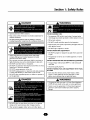 3
3
-
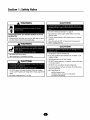 4
4
-
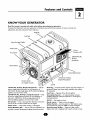 5
5
-
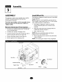 6
6
-
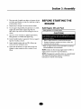 7
7
-
 8
8
-
 9
9
-
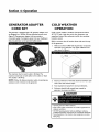 10
10
-
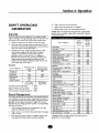 11
11
-
 12
12
-
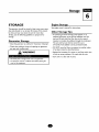 13
13
-
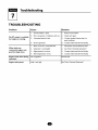 14
14
-
 15
15
-
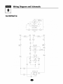 16
16
-
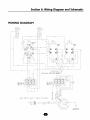 17
17
-
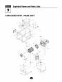 18
18
-
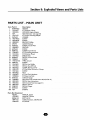 19
19
-
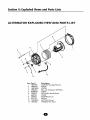 20
20
-
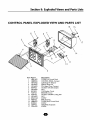 21
21
-
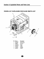 22
22
-
 23
23
-
 24
24
-
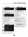 25
25
-
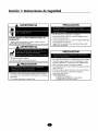 26
26
-
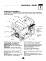 27
27
-
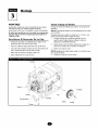 28
28
-
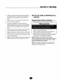 29
29
-
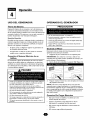 30
30
-
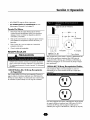 31
31
-
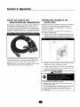 32
32
-
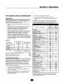 33
33
-
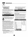 34
34
-
 35
35
-
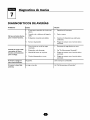 36
36
-
 37
37
-
 38
38
-
 39
39
-
 40
40


Troybilt 01919 El manual del propietario
- Categoría
- Generadores de poder
- Tipo
- El manual del propietario
- Este manual también es adecuado para
En otros idiomas
- English: Troybilt 01919 Owner's manual
Documentos relacionados
Otros documentos
-
Generac 1648-0 El manual del propietario
-
Troy-Bilt 01919-1 Manual de usuario
-
Briggs & Stratton 1365GN El manual del propietario
-
-
-
-
Briggs & Stratton 1653 El manual del propietario
-
-
Generac 1649-0 El manual del propietario
-