
PREPARATION/PREPARACIÓN
Before beginning installation of product, make sure all parts are present.
Compare parts with package contents list and hardware contents list. If any part
is missing or damaged, do not attempt to assemble, install or operate the product.
Contact customer service for replacement parts.
ESTIMATED ASSEMBLY TIME: 40 - 60 MINUTES
TOOLS NEEDED FOR NEW INSTALLATION:
• Pencil • Chisel • Tape Measure • Hammer • Phillips Screwdriver
• 1 in. and 1/8 in. Drill Bits • 2-1/8 in. Hole Boring Bit • Power Drill
• 2 in. 6d Common Nail
Antes de comenzar a instalar el producto, asegúrese de tener todas las piezas.
Compare las piezas con la lista del contenido del paquete y la de los aditamentos.
No intente ensamblar, instalar ni usar el producto si falta alguna pieza o si éstas
están dañadas.
Póngase en contacto con el Departamento de Servicio al Cliente para obtener
piezas de repuesto.
TIEMPO ESTIMADO DE ENSAMBLAJE: 40 A 60 MINUTOS.
HERRAMIENTAS NECESARIAS PARA UNA INSTALACIÓN NUEVA::
• Lápiz • Cincel • Cinta métrica • Martillo • Destornillador Phillips
• Brocas para taladro de 1” y 1/8” • Broca de precisión de 2-1/8”
• Taladro eléctrico • Clavos comunes de 2” 6d
WARNING/ADVERTENCIA
IF DRILLING IS REQUIRED, you should read and thoroughly
understand all steps prior to drilling.
Please drill holes from both sides to avoid splintering of the door face.
IF HOLES ARE ALREADY DRILLED IN YOUR DOOR, install latches
and begin at step 2.
SI SE DEBE TALADRAR, debe leer y comprender completamente todos los
pasos antes de proceder.
Taladre orificios desde ambos lados para evitar astillar el frente de la puerta.
SI YA HAY ORIFICIOS TALADRADOS EN SU PUERTA, instale los pestillos
y comience en el paso 2.
SAFETY INFORMATION/INFORMACIÓN DE SEGURIDAD
Please read and understand this entire manual before attempting to assemble,
operate or install the product.
Lea y comprenda completamente este manual antes de intentar ensamblar,
usar o instalar el producto.
!
!
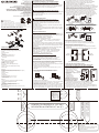
PACKAGE CONTENTS/CONTENIDO DEL PAQUETE
HARDWARE CONTENTS/ADITAMENTOS
2-3/4 in. (70 mm)
7 cm (2-3/4”)
2-3/8 in. (60 mm)
6 cm (2-3/8”)
BEFORE PROCEEDING/ANTES DE PROCEDER
Make sure backset of lock is same as backset of your door.
(Latch backset adjustment only needs to be made if your door needs
a 2-3/4 in. backset. Otherwise NO ADJUSTMENT is necessary.)
If an adjustable latch is to be used, please adjust the backset to fit your
door as shown below.
Asegúrese de que el seguro de la cerradura es el mismo que el de la puerta.
(Sólo se debe ajustar el seguro del pestillo si la puerta necesita un seguro
de 2-3/4”. De lo contrario NO ES necesario AJUSTARLO).
Si se utilizará un pestillo ajustable, ajuste el seguro de manera que se adapte
a la puerta como se muestra a continuación.
A. TUBULAR LOCK LATCH ADJUSTMENT
ADJUSTABLE LATCH FOR 2-3/8 in. (60 mm) AND 2-3/4 in. (70 mm)
BACKSET
A. AJUSTE DEL PESTILLO DE LA CERRADURA TUBULAR
PESTILLO AJUSTABLE PARA SEGUROS DE 6 cm (2-3/8”)
Y 7 cm (2-3/4”)
Hinges
Bisagras
Left hand door
Puerta hacia la izquierda
Right hand door
Puerta hacia la derecha
Hinges
Bisagras
Exterior
Exterior
C. DETERMINE HANDING OF YOUR DOOR
Stand at exterior side and face the door.
1. Your door is a left hand door if hinges are installed at your left hand.
2. Your door is a right hand door if hinges are installed at your right hand.
C. DETERMINE LA COLOCACIÓN DE LA PUERTA
Coloque en el exterior enfrentando la puerta.
1. La puerta está orientada hacia la izquierda si las bisagras están instaladas
a la izquierda.
2. La puerta está hacia la derecha si las bisagras están instaladas a la derecha.
3. Use a Phillips screwdriver on the cross section of the latch and turn
clockwise until the arrow faces to your right and it is ready to be installed.
Installation illustrations are shown with KEYED ONE SIDE models.
B. AJUSTE DEL PESTILLO DE LA CERRADURA
Conversión del seguro preajustado de fábrica de 6 cm (2-3/8”) a 7 cm (2-3/4”):
1. Mientras observa el pestillo donde está marcado ”ARRIBA” use un destornillador
Phillips en la sección con la cruz del pestillo y gírelo en dirección contraria a las
manecillas del reloj hasta que la flecha apunte a su izquierda.
2. Mientras sostiene el pestillo (verá 2-3/8” en una ranura del pestillo), gire la
sección del pestillo con la cruz en 45 grados y jale hacia atrás, luego, gírela de
vuelta hacia su posición original (ahora verá 2-3/4” en la misma ranura).
3. Use un destornillador Phillips en la sección de la cruz del pestillo y gire en
dirección de las manecillas del reloj hasta que la flecha apunte a su derecha
y esté lista para instalarse. Las ilustraciones de la instalación se muestran con
modelos DE UN LADO CON LLAVE.
90˚
2
U
2³⁄�
UP
2-3/4 in. (70 mm)
7 cm (2-3/4”)
Latch rear part (frame)
Parte posterior del pestillo (marco)
90˚
UP
2
2
³⁄�
UP
2-3/8 in. (60 mm)
6 cm (2-3/8”)
1.
Twist the rear part (frame) back
Gire la parte posterior del pestillo (marco) de vuelta
Twist 45º
Gire en 45º
Pull back
Jale hacia atrás
2.
3.
Note: Please install two locks respectively
according to the installation instruction sheets
attached inside.
Nota: Instale dos cerraduras respectivamente,
de acuerdo con la hoja de instrucciones
adjunta en el interior.
1-3/4 in. 1-9/16 in. 1-3/8 in.
4,5 cm 4 cm 3,5 cm
45 40 35
1-3/4 in. 1-9/16 in. 1-3/8 in.
4,5 cm 4 cm 3,5 cm
45 40 35
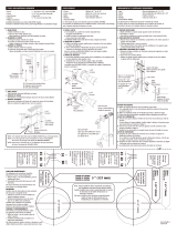
Drill 1 in. (25 mm)
hole at center of
door edge.
Taladre un orificio
de 2,5 cm (1”) al
centro del borde
de la puerta.
Fit here on door edge
Fije aquí en el borde
de la puerta
Hole for deadbolt
Orificio para
cerradura con
pestillo
CENTER TO CENTER 5 in. (127 mm)
DE CENTRO A CENTRO 12,7 cm (5”)
Hole for lockset
Orificio para
cerradura
ø2-1/8 in. (54 mm)
ø 5,4 cm (2-1/8”)
ø2-1/8 in. (54 mm)
ø 5,4 cm (2-1/8”)
Backset 2-3/8 in. (60 mm)
Seguro de 6 cm (2-3/8”)
Backset 2-3/4 in. (70 mm)
Seguro de 7 cm (2-3/4”)
BCD-0000H19 10/06-01
2-31/64 in. (63 mm) Mounting Screws (2)
Thumbturn Assembly (Single Cylinder Deadbolt)
Latch
Outside Cylinder
Key (2)
Faceplate
3/4 in. (19 mm) Latch Screws (2)
2 in. (51 mm) Strike Screws (2)
Strike Plate
Key (2) (Only included in Entry Knob)
Outside Knob/Lever Assembly
Latch
Inside Knob/Lever Assembly
1-5/16 in. (33 mm) Mounting Screws (2)
Faceplate
3/4 in. (19 mm) Latch/Strike Plate Screws (4)
Strike Plate
DEADBOLT
A.
B.
C.
D.
E.
F.
G.
H.
I.
KNOB
J.
K.
L.
N.
M.
O.
P.
Q.
Tornillos de montaje (2) de 6,3 cm (2-31/64”)
Ensamble de cierre manual (cerradura con cilindro simple)
Pestillo
Cilindro exterior
Llave (2)
Placa frontal
Tornillos para pestillo (2) 1,9 cm (3/4”)
Tornillos del cerrojo (2) de 5,1 cm (2”)
Placa del cerrojo
Llaves (2) (sólo se incluyen en la perilla de entrada)
Ensamble de perilla/palanca exterior
Pestillo
Ensamble de perilla/palanca interior
Tornillos de montaje (2) de 3,3 cm (1-5/16”)
Placa frontal
Tornillos del pestillo/placa del cerrojo (4) de 1,9 cm (3/4”)
Placa del cerrojo
PESTILLO
A.
B.
C.
D.
E.
F.
G.
H.
I.
PERILLA
J.
K.
L.
N.
M.
O.
P.
Q.
ITEM/ARTÍCULO #
0117980/0117995/0117988
0280294/0279793/0279722
0037039/0332609/0332607
0332601/0332605
0353289/0354824/0354825/0354822/0354823
KEYED ENTRY+SINGLE CYLINDER DEADBOLT
COMBINATION ENTRY LOCKSET
ENTRADA CON LLAVE + CERRADURA CON CILINDRO SIMPLE
JUEGO DE CERRADURA DE COMBINACIÓN DE ENTRADA
MODEL/MODELO #
BS7L1/BS8L1/BS6L1
BFX7L1/BS7L1D/BS6L1D
BFX2L1/M6X2L1B/M6X7L1B
MAX2L1B/MAX7L1B
BS6L1D/BS7L1D/BS8L1D/BFX2L1D/BFX7L1D
A. MARK DOOR WITH TEMPLATE (AT BOTTOM OF THIS PAGE)
1. Use TEMPLATE to mark centerline on door for knob/lever about
36 in. (914 mm) above the floor.
2. Mark centerline on door for
deadbolt about 5 in. (127 mm)
above the centerline
of knob/lever.
3. Stand so door swings
towards you.
Align template on
centerline and fold
template as shown.
A. MARQUE LA PUERTA CON
LA PLANTILLA (EN LA PARTE
INFERIOR DE ESTA PÁGINA)
1. Use la PLANTILLA para marcar la línea central en la puerta, para la
perilla/palanca a aproximadamente 91,4 cm (36”) por sobre el piso.
2. Marque la línea central en la puerta para la cerradura con pestillo,
aproximadamente 12,7 cm (5”) por sobre la línea central de la perilla/palanca.
3. Colóquese de manera que la puerta se abra hacia usted. Alinee la plantilla en
la línea del centro y doble la plantilla como se muestra.
OR
O
2.
Centerline
Línea del centro
Template
Plantilla
1.
1. DOOR DRILLING FOR NEW INSTALLATION
1. TALADRADO DE LA PUERTA PARA UNA NUEVA INSTALACIÓN
B. DEADBOLT LATCH ADJUSTMENT
Converting factory pre-set 2-3/8 in. (60 mm) to a 2-3/4 in. (70 mm) backset:
1. While looking at the latch where it is marked
"UP", use a Phillips
screwdriver on the cross section of the latch and turn it ”counter-clockwise”
until the arrow faces to your left.
2. Holding the latch (you will see 2-3/8 in. in a notch on the latch), twist the
section of the latch with the cross 45 degrees and pull it back. Then twist it
back to the original position (you will now see 2-3/4 in. in the same notch).
Call customer service at 1-877-4GATEHS,
8:30 a.m. - 5:30 p.m., EST, Monday - Friday.
Llame al Departamento de Servicio al Cliente
al 1-877-4GATEHS, de lunes a viernes de
8:30 a.m. a 5:30 p.m., hora estándar del Este.
Questions/¿Preguntas?
ATTACH YOUR RECEIPT HERE
ADJUNTE SU RECIBO AQUÍ
Serial Number/Número de serie _______________
Purchase Date/Fecha de compra
______________
REPLACEMENT PARTS LIST & TROUBLESHOOTING
LISTA DE PIEZAS DE REPUESTO y SOLUCIÓN DE PROBLEMAS
For replacement parts & troubleshooting, call customer service at
1-877-4GATEHS, 8:30 a.m. - 5:30 p.m., EST, Monday - Friday.
Para obtener piezas de repuesto e información sobre solución de problemas,
llame al Departamento de Servicio al Cliente al 1-877-4GATEHS, de lunes
a viernes de 8:30 a.m. a 5:30 p.m., hora estándar del Este.
A
B
C
D
E
F
G
H
I
N
M
L
O
Q
P
K
J

WARRANTY/GARANTÍA
Limited Lifetime Warranty
The Manufacturer extends a Limited Lifetime Mechanical and Finish Warranty to the original “User” of this Product against defects in materials and workmanship as long as the User occupies the residential premises upon which the Product was
originally installed. Upon return of a defective Product to the Manufacturer, the Manufacturer shall either replace, repair or refund the purchase price in exchange for the Product.
This warranty does not cover abused or misused Products or those Products used in commercial applications.
No other warranties, express or implied are made with respect to the Product including but not limited to any implied warranty of merchantability or fitness for a particular purpose.
The Manufacturer DOES NOT authorize any person to create for it any obligation or liability in connection with the Product.
The Manufacturer maximum liability hereunder limited to the purchase price of the Product, and in no event shall the company be liable for any consequential, indirect, incidental or special damages of any nature arising from the sale or use of this
Product, whether in contract, tort, strict liability or otherwise.
( For warranty service, please call 1-877-4GATEHS, 8:30 a.m. - 5:30 p.m. EST, Monday through Friday )
Note: Should the Product be considered a consumer product it may be covered by the Magnusson Moss Federal Warranty Act, please be advised that: (1) Some states do not allow limitations or incidental consequential damages on how long an
implied warranty lasts so that the above limitations may not fully apply: and (2) This warranty gives specific legal rights and a User may have other rights which may vary from state to state.
Garantía limitada de por vida
El fabricante extiende una garantía limitada de por vida, mecánica y del acabado, al “usuario” original de este producto, contra defectos de fabricación en el material y en la mano de obra mientras el usuario ocupe las instalaciones residenciales
en las que se instaló originalmente el producto. Cuando se devuelve un producto defectuoso al fabricante, éste deberá reemplazar, reparar o reembolsar el precio de compra a cambio del producto.
Esta garantía no cubre productos que hayan sufrido abuso o mal uso ni aquellos productos usados en aplicaciones comerciales.
No se otorgan otras garantías, expresas o implícitas, con respecto al producto, incluida, entre otras, cualquier garantía implícita de comerciabilidad o idoneidad para cualquier propósito determinado.
El fabricante NO autoriza a ninguna persona para crear una obligación o responsabilidad en conexión con el producto.
La máxima responsabilidad del fabricante según la presente se limita al precio de compra del producto y en ningún caso la empresa será responsable de ningún daño resultante, indirecto, accidental o especial de ninguna naturaleza causado
por la venta o uso de este producto, ya sea contractual, extracontractual, en estricta responsabilidad o de otra manera.
( Para servicio de garanía, llame al 1-877-4GATEHS, de lunes a viernes de 8:30 a.m. a 5:30 p.m., hora estándar del Este )
Nota: Si el producto se considera de consumo, es posible que esté cubierto por la ley federal de garantías Magnuson-Moss, por lo que debe tener presente que: (1) Algunos estados no permiten limitaciones ni daños resultantes accidentales
en cuanto a la duración de una garantía implícita, de modo que las limitaciones anteriores pueden no aplicarse completamente; y (2) esta garantía otorga derechos legales específicos y el usuario podría tener también otros derechos que varían
según el estado.
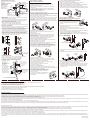
C. INSTALL EXTERIOR CYLINDER
1. Press exterior cylinder against exterior surface of the door making
certain the torque blade is properly inserted in the latch cross drive.
Note: The exterior cylinder has no visible screws.
2. The two hidden, threaded screw holes in the exterior cylinder
must line up with the two latch holes.
3. The lock is positioned correctly when vertical and
the "key teeth" are facing UP.
C. INSTALE EL CILINDRO EXTERIOR
1. Presione el cilindro exterior contra la superficie exterior de la puerta,
asegurándose de que la cuchilla de torsión esté adecuadamente insertada
en el accionamiento en cruz del pestillo.
Nota: El cilindro exterior no tiene tornillos visibles.
2. Los dos orificios ocultos y roscados para tornillos en
el cilindro exterior deben alinearse con los dos
orificios del pestillo.
3. La cerradura está colocada correctamente cuando
la vertical y los “dientes de la llave” apuntan
hacia ARRIBA.
1. 2.
2.
1 in.
2,5 cm
(25 mm)
1 in.
2,5 cm
(25 mm)
3.
4.
Faceplate
Placa frontal
Outline
Contorno
Chisel 1/8 in. (3 mm) deep
Cincel de 0,3 cm (1/8”)
de profundidad
D. PREPARE DOOR JAMB
1. Drill a 1 in. (25 mm) hole, 1-1/8 in. (28 mm) deep in the door jamb.
2. Use strike plate as a pattern for mortise and pilot holes.
3. Chisel 1/8 in. (3 mm) deep. Strike plate should fit flush.
D. PREPARE EL MARCO INTERIOR PARA PUERTA
1. Taladre un orificio de
2,5 cm (1”),
de 2,8 cm (1-1/8”)
de profundidad, en el
marco interior
para puerta.
2. Use la placa del
cerrojo como diseño
para la mortaja
y los orificios guía.
3. Cincel de 0,3 cm (1/8”)
de profundidad.
La placa del cerrojo
debe encajar al ras.
1 in. (25 mm) hole
1-1/8 in. (28 mm) deep
Orificio de 2,5 cm (1”)
2,8 cm (1-1/8”) de
profundidad
Outline
Contorno
1.
2.
3.
Chisel 1/16 in. (2 mm) deep
Cincel de 0,2 cm (1/16”) de profundidad
1 in. (25 mm) hole
1-1/8 in. (28 mm) deep
Orificio de 2,5 cm (1”)
2,8 cm (1-1/8”) de
profundidad
A. INSTALL EXTERIOR KNOB/LEVER
1. Press exterior knob/lever against exterior surface of the door
making certain the stems are positioned horizontally so they go
through holes in the latch case.
Note: The exterior knob/lever has no visible screws. If the door lock
has a key hole.
2. For knobset, make sure that the key hole is in a vertical position
and the "key teeth" are facing up;
3. For leverset, make sure that the key hole is in a horizontal position
and the "key teeth" are facing the lever.
A. INSTALE LA PERILLA/PALANCA EXTERIOR
1. Presione la perilla/palanca exterior contra la superficie exterior de la puerta,
asegurándose de que los vástagos estén en posición horizontal, de manera
que pasen por los orificios de la caja del pestillo.
Nota: La perilla/palanca exterior no tiene tornillos visibles. Si la cerradura
para puerta tiene un ojo de la cerradura.
2. En el caso del conjunto de perilla, asegúrese de que el ojo de la cerradura
se encuentra en posición vertical y que los “dientes de la llave” apuntan
hacia arriba.
3. En el caso del conjunto de palanca, asegúrese de que se encuentre en
posición horizontal y que los “dientes de la llave” apuntan hacia la palanca.
C. DRILL HOLES
1. Drill a 2-1/8 in. (54 mm) and a 2-1/8 in. (54 mm) hole on the door face
from both sides to avoid wood splitting.
2. Use a 2 in. (51 mm) 6d common nail and press it from inside the holes
through the pilot hole to mark centerlines on jamb exactly opposite
center of knob/lever/deadbolt latch hole.
3. Drill a 1 in. (25 mm) hole in the door edge for the latch.
4. Use faceplate as a pattern for mortise and pilot holes.
Chisel 1/8 in. (3 mm) deep. Faceplate should fit flush.
5. Install as shown for appropriate latch type. Ensure bevel faces door jamb.
C. TALADRE LOS ORIFICIOS
1. Taladre un orificio de 5,4 cm (2-1/8”) y a 5,4 cm (2-1/8”) en la superficie
de la puerta, desde ambos lados para evitar astillar la madera.
2. Use un clavo común de 2” (5,1 cm) 6d y presiónelo desde el interior
de los orificios, a través del orificio piloto, para marcar las líneas centrales
en los marcos interiores para puertas, en los centros exactamente
opuestos de los orificios de la perilla/palanca/pestillo de la cerradura.
3. Taladre un orificio de 2,5 cm (1”) en el borde de la puerta para el pestillo.
4. Use la placa frontal como diseño para la mortaja y los orificios guía.
Cincel de 0,3 cm (1/8”) de profundidad. La placa frontal debe encajar al ras.
5. Instale como se muestra para el tipo adecuado de pestillo. Asegúrese de
que el bisel enfrente el marco interior para puerta.
1.
2-1/8 in.
5,4 cm
(54 mm)
2-1/8 in.
5,4 cm
(54 mm)
2. INSTALLATION OF LOCKSET
2. INSTALACIÓN DE CERRADURAS
B. INSTALL INTERIOR KNOB/LEVER
1. Install interior knob/lever by placing on spindle and aligning screw
holes with stems.
2. Push flush against the door.
Tighten screw near the door edge first, then tighten the other side
until lockset is firm.
Note: To have the proper leveling of lock knob/levers and to avoid
sagging after installation, check knob/lever fit and orientation prior
to installing and securely tightening the mounting screws.
B. INSTALE LA PERILLA/PALANCA INTERIOR
1. Instale la perilla/palanca interior colocándola en el eje y alineando los
orificios de los tornillos con los vástagos.
2. Empuje hasta dejarla al ras de la puerta.
Primero, apriete el tornillo que está cerca del borde de la puerta, luego
apriete el del otro lado hasta que el cerrojo quede firme.
Nota: Para lograr un apalancamiento adecuado de la perilla/palanca
de la cerradura y así evitar el aflojamiento después de la instalación,
se sugiere revisar el ajuste y la orientación de la perilla/palanca, antes
de instalar y apretar firmemente los tornillos de montaje.
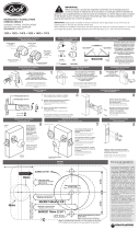
3. HOW TO CHANGE LEVER HANDING
3. CÓMO CAMBIAR LA COLOCACIÓN DE LA PALANCA
A. Insert key to unlock outside lever.
Rotate key to horizontal position and withdraw.
A. Inserte la llave para desbloquear la palanca exterior.
Gire la llave hasta dejarla en posición horizontal
y retírela.
Pick-up pin
Pasador captador
Knob catch hole
Orificio de cierre de la perilla
Knob catch hole
Orificio de cierre de la perilla
Spindle
Eje
Hole on lever
Orificio de la palanca
Cylinder
Cilindro
Cylinder
Cilindro
Spindle
Eje
Pull
Tirador
Pull
Tirador
C. If cylinder is also removed from spindle, please insert it securely back into
the spindle.
C. Si también retira el cilindro del eje, vuelva a insertarlo firmemente en éste.
D. Swap levers. Place lever over spindle, align punched hole on the
lever shank with knob catch hole on the rose and press until secure and
full engagement between lever and spindle is reached.
D. Intercambie las palancas. Coloque la palanca sobre el eje, alinee los orificios
taladrados del vástago de la palanca con el orificio de cierre de la perilla en
la elevación y presione hasta que quede fijo y entre completamente entre
la palanca y el eje.
B. Insert pick-up pin into knob catch hole on the outside rose and pull
outside lever off spindle.
Repeat the same on the inside to remove inside lever.
(Note: Pick-up pin may need to be removed from knob catch hole as
you pull lever off.)
B. Inserte un pasador captador en el orificio de cierre de la perilla en la elevación
exterior y jale la palanca exterior hasta extraerla del eje.
Repita el mismo procedimiento en el interior para retirar la palanca interior.
(Nota: Es posible que deba retirar el pasador captador del orificio de cierre de
la perilla al extraer la palanca.)
B. MARK AND DRILL PILOT HOLES
Select backset. Mark and drill pilot holes
as shown.
B. MARQUE Y TALADRE
AGUJEROS GUÍA
Elija los seguros.
Marque y taladre los
agujeros piloto
como se muestra.
Backset
Seguro
2-1/8 in.
5,4 cm
(54 mm)
1 in.
2,5 cm
(25 mm)
Drill 1/8 in. (3 mm)
pilot hole
Taladre orificios
guía de 0,3 cm
(1/8”)
Drill 1/8 in. (3 mm)
pilot hole
Taladre orificios
guía de 0,3 cm (1/8”)
Centerline
Línea del centro
D. INSTALL INTERIOR THUMBTURN AND COVERPLATE
1. Slide interior coverplate onto torque blade.
2. Insert two mounting machine screws through holes in coverplate to
engage threaded holes of exterior cylinder and tighten.
D. INSTALE EL CIERRE MANUAL Y LA PLACA DE CUBIERTA INTERIORES
1. Deslice la placa de cubierta interior sobre la cuchilla de torsión.
2. Inserte dos tornillos de montaje para metales a través de los orificios de la placa
de cubierta para que entren en los orificios roscados del cilindro exterior y apriete.
Printed in Taiwan
Impreso en Taiwán
CARE AND MAINTENANCE/CUIDADO Y MANTENIMIENTO
THE FOLLOWING CARE INSTRUCTIONS SHOULD BE FOLLOWED TO ENSURE A LONG LASTING FINISH:
1. Remove locks, or do not install locks, prior to painting your door.
2. Periodically clean with mild soap and a soft cloth only.
Do not use abrasives or harsh chemicals and avoid sharp objects.
SE DEBEN SEGUIR LAS SIGUIENTES INSTRUCCIONES DE CUIDADO PARA ASEGURAR UN ACABADO DURADERO:
1. Retire todas las cerraduras o no las instale antes de pintar la puerta.
2. Limpie periódicamente sólo con jabón y un paño suave.
No use agentes químicos abrasivos y evite los objetos afilados.
-
 1
1
-
 2
2


Gatehouse BFX2L2 Guía de instalación
- Tipo
- Guía de instalación
- Este manual también es adecuado para
en otros idiomas
- English: Gatehouse BFX2L2 Installation guide
Artículos relacionados
Otros documentos
-
 Gate House G27D01 Guía de instalación
-
Defiant B87L2 Guía de instalación
-
Schlage Accents FA360/FA362/FA393 Guía de instalación
-
-
-
 Faultless MYEX2L1B-F Guía de instalación
-
 Lock 13CE El manual del propietario
-
LARSON LARSON Certified Storm Door Revere Mortise Handle Set (Aged Bronze) Manual de usuario
-
-


