
Art.-Nr. 3044826_201403 Änderungen vorbehalten
Wolf GmbH · Postfach 1380 · 84048 Mainburg · Tel. 08751/74-0 · Fax 08751/741600 · Internet: www.wolf-heiztechnik.de
DE
ES
GB
Wartungsanleitung
Gasbrennwertgeräte
CGB-(K)-11/20/24, CGS-20/160, CGS-24/200,
CGW-11/100 CGW-20/120, CGW-24/140,
CGI-20/120, TGC-20/24, TGS-20/160
Seite 2 -18
Manual de mantenimiento
Caldera de condensacion a gas
CGB-(K)-11/20/24, CGS-20/160, CGS-24/200,
CGW-11/100 CGW-20/120, CGW-24/140,
CGI-20/120, TGC-20/24, TGS-20/160
Página 19 - 36
Service Manual
Gas condensing boilers
CGB-(K)-11/20/24, CGS-20/160, CGS-24/200,
CGW-11/100 CGW-20/120, CGW-24/140,
CGI-20/120, TGC-20/24, TGS-20/160
Page 37 - 54

2
3044826_201403
Wartungsanleitung
Inhaltsverzeichnis ................................................................................. Seite
Sicherheitshinweise ......................................................................................................3
Wartungsablauf ...................................................................................................... 4-16
Liste benötigter Teile ...................................................................................................17
Übersicht der Arbeitsschritte mit Wartungsprotokoll ...................................................18

3
3044826_201403
Wartungsanleitung
Sicherheitshinweise
In dieser Beschreibung werden die folgenden Symbole
und Hinweiszeichen verwendet. Diese wichtigen Anwei-
sungen betreffen den Personenschutz und die technische
Betriebssicherheit.
„Sicherheitshinweis“ kennzeichnet Anweisun-
gen, die genau einzuhalten sind, um Gefährdung
oder Verletzung von Personen zu vermeiden
und Beschädigungen am Gerät zu verhindern.
Gefahr durch elektrische Spannung an elektri-
schen Bauteilen!
Achtung: Vor Abnahme der Verkleidung Be-
triebsschalter ausschalten.
Greifen Sie niemals bei eingeschaltetem Be-
triebsschalter an elektrische Bauteile und
Kontakte! Es besteht die Gefahr eines Strom-
schlages mit Gesundheitsgefährdung oder
Todesfolge.
An Anschlussklemmen liegt auch bei ausge-
schalteten Betriebsschalter Spannung an.
„Hinweis“ kennzeichnet technische Anweisun-
gen, die zu beachten sind, um Schäden und
Funktionsstörungen am Gerät zu verhindern.
Achtung
Bild: Klemmkasten:
Gefahr durch elektrische Spannung
Bild: Zündtrafo, Hochspannungs-Zündelektrode, Brennkam-
mer
Gefahr durch elektrische Spannung, Gefahr von Verbrennung
durch heiße Bauteile
Allgemeine Hinweise
Alle Wartungsarbeiten dürfen nur von einem Fach-
handwerker durchgeführt werden.
Jährliche Wartung sowie die ausschließliche Ver-
wendung von Original Wolf-Ersatzteilen sind für ei-
nen störungsfreien Betrieb und lange Lebensdauer
Ihres Gerätes von entscheidender Bedeutung.
Wir empfehlen daher einen Wartungsvertrag mit
Ihrer Fachhandwerkerrma abzuschließen.
Bild: Gaskombiventil
Gefahr durch elektrische Spannung, Gefahr von Vergiftung
und Explosion durch ausströmendes Gas
Bild: Gasanschluss: Gefahr von Vergiftung und Explosions-
gefahr durch ausströmendes Gas

4
3044826_201403
Wartungsanleitung
- Den Verkleidungsdeckel mit dem linken und rechten Drehrie-
gel entriegeln. Verkleidungsdeckel unten lösen und oben
aushängen.
An den Netzanschlussklemmen des Gerätes liegt
auch bei ausgeschaltetem Betriebsschalter elektri-
sche Spannung an.
- Anlage spannungsfrei machen.
- Regelungsdeckel nach unten klappen.
Therme am Betriebsschalter ausschalten.
Gaskugelhahn schließen.
Drehriegel

5
3044826_201403
Wartungsanleitung
- Brennkammer anheben.
- Sicherungsklammer herausziehen.
- Steuerleitungsschlauch von der Mischkammer abziehen.
Verbrennungsgefahr
Verschiedene Bauteile können sehr heiß sein. Abkühlen lassen
oder Handschuhe anziehen.
- Verschraubung Gasanschluss öffnen.
- Schiebestücke mit Silikonspray einsprühen.

6
3044826_201403
Wartungsanleitung
- Reinigungsbehälter anbringen.
- Brennkammer ausschwenken.
- Stecker am Gasgebläse lösen.
- Stecker von Ionisationselektrode und Zündelektrode
abziehen.

7
3044826_201403
Wartungsanleitung
Sichtkontrolle Brennerdichtung
Brennerdichtung mit Wolf-Silikonfett einfetten ggf. ersetzen
und einfetten.
- Brennkammertopf herausdrehen und nach unten heraus-
nehmen.
- Brennkammerdeckel nach oben abnehmen.
- Haltelaschen öffnen.

8
3044826_201403
Wartungsanleitung
- Bei Wasserverlust Vordruck vom Ausdehnungsgefäß prüfen,
ggf. auf 0,75 bar erhöhen. Heizkreis muss drucklos sein.
- Kondensatwanne reinigen.
- Wärmetauscher mit Bürste reinigen.
Bei Ausführung mit beschichtetem Wärmetau-
scher nur mit Kunststoffbürste reinigen.

9
3044826_201403
Wartungsanleitung
- Brennkammerdichtung oben und unten ersetzen, mit
Silikonfett einfetten.
- Brennkammersitz einfetten.
- Überwachungselektrode ersetzen
Zündelektrode prüfen, ggf. ersetzen
Sichtkontrolle Isolierung
ersetzen, falls gebrochen

10
3044826_201403
Wartungsanleitung
- Brennkammerdeckel wieder auf Brennkammer setzen und
mit Haltelaschen befestigen.
Zusammenbau
- Brennkammertopf einbauen
- Stecker am Gasgebläse wieder anbringen.
- Stecker von Ionisationselektrode und Zündelektrode wieder
aufstecken.
Achtung

11
3044826_201403
Wartungsanleitung
- Brennkammereinheit einschwenken.
- Brennkammer nach unten in die Kondensatwanne
drücken.
Sicherungsklammer befestigen.
- Gasdrosselblende prüfen.
Geräteleistung Gasart Gasdrosselblende
11 kW E/H Grün 430
17 20 523
LL Gelb 660
17 20 521
20 kW E/H Orange 580
17 20 532
LL keine
Flüssiggas Grün 430
17 20 523
24 kW E/H Weiß 780
17 20 522
LL keine
Flüssiggas Rot 510
17 20 520

12
3044826_201403
Wartungsanleitung
- Luft-/Abgasführung kontrollieren.
- Reinigungsbehälter entfernen.
- Kaltwassersieb reinigen. (nur Kombigerät)
- Kaltwasser absperren.
Bild: Kombigerät
Siphon kontrollieren
Ggf. reinigen und neu füllen.
Auf festen Sitz prüfen,
Abgasaustritt verhindern.

13
3044826_201403
Wartungsanleitung
Bild: Rückschlagventil
- Wenn Warmwasserleistung zu gering, Rückschlagventil
entkalken.
CGWCGS
- Wenn Warmwasserleistung zu gering,
Warmwasserwärmetauscher entkalken.
- Kaltwasserhahn wieder öffnen.
Schutzanode prüfen (nur bei CGS)
- Kaltwasser-Hahn absperren.
-
Abdeckung entfernen und Schutzanode herausschrauben.
- Bei hoher Beanspruchung Schutzanode ersetzen.
Schutzanode
Handlochdeckel ausbauen (nur bei CGW)
- Verrohrung abbauen
- Mutter vom Bügel Handlochdeckel abschrauben; Bügel
abnehmen
- Handlochdeckel herausnehmen
- Zusammenbau in umgekehrter Reihenfolge
Achtung
- Dichtung des Handlochdeckels muss bei Zusammenbau
erneuert werden
- Anzugsdrehmoment der Mutter für den Bügel Handloch-
deckel 55-60 Nm

14
3044826_201403
Wartungsanleitung
Abschluss der Arbeiten
Gasstrecke und Hydraulik auf Dichtheit
kontrollieren.
- Verkleidung anbringen.
Abgasmessung
Im Schornsteinfegerbetrieb durchführen,
Werte in Wartungsprotokoll eintragen.
Bei Bedarf CO
2
-Wert neu einstellen.
(siehe Seite 15-16)
Zuluft-Prüfung durchführen
Wenn CO
2
> 0,2% LAF auf Dichtigkeit prüfen.
Probelauf
- Sicherungen einschalten.
- Gaskugelhahn öffnen.
- Gerät einschalten.
- Programmwahlschalter auf Schornsteinfegerbetrieb stel-
len.
Stellung Schornsteinfegerbetrieb
Bild: Gesamtansicht Regelung

15
3044826_201403
Wartungsanleitung
- Schornsteinfegerbetrieb beenden durch Drehen des Tem-
peraturwahlschalters zurück in Ausgangsstellung.
- rechts drehen - CO
2
Gehalt wird niedriger
- links drehen - CO
2
-Gehalt wird höher
Gasdurchuss-
schraube
Bild: Gaskombiventil
Einstellung Gas-Luftverbund
Die Einstellarbeiten müssen in nachfolgend be-
schriebener Reihenfolge durchgeführt werden. Das
Gaskombiventil ist werksseitig bereits auf die Gas-
art gemäß Typenschild eingestellt. Eine Einstellung
am Gaskombiventil darf nur nach der Umrüstung
auf eine andere Gasart vorgenommen werden.
Achtung
A) CO
2
-Einstellung bei oberer Belastung
(Schornsteinfegerbetrieb)
- Regelungsdeckel nach unten klappen.
Den Verkleidungsdeckel mit dem linken und rechten Drehrie-
gel entriegeln. Verkleidungsdeckel unten lösen und oben
aushängen.
- Schraube aus der linken Messöffnung “Abgas” entfernen.
- Messsonde des CO
2
-Messgerätes in die Messöffnung “Ab-
gas” einführen.
- Temperaturwahlschalter in Stellung Schornsteinfeger
drehen. (Leuchtring zur Statusanzeige blinkt in gelber
Farbe).
- Bei Vollast den CO
2
-Gehalt messen und mit den Werten in
untenstehender Tabelle vergleichen.
- Bei Bedarf die Regelung herausschwenken und den CO
2
-
Gehalt mit der Gasdurchussschraube am Gaskombiventil
gemäß Tabelle korrigieren.
Gerät offen
bei oberer Belastung
Erdgas E/H/L
8,8% ± 0,2%
Flüssiggas B/P
9,9% ± 0,3%
Bild: Abgasmessung bei geöffnetem Gerät
Messöffnung „Abgas“
Bild: Drehriegel öffnen
Drehriegel

16
3044826_201403
Wartungsanleitung
- Die Therme durch Drücken der “Entstörtaste” erneut star-
ten.
- Ca. 20 Sekunden nach dem Brennerstart den CO
2
-Gehalt
mit dem CO
2
-Messgerät kontrollieren und ggf. mit Nullpunkt-
schraube gemäß Tabelle nachjustieren. Diese Einstellung
muss innerhalb von 120 Sek. nach dem Brennerstart erfol-
gen. Evtl. durch Drücken der “Entstörtaste” die Startphase
zur Einstellung wiederholen.
- rechts drehen - CO
2
höher!
- links drehen - CO
2
niedriger!
B) CO
2
-Einstellung bei unterer Belastung (Softstart)
Bild: Gaskombiventil
Nullpunktschraube
- Gerät außer Betrieb nehmen und die Messöffnungen und
Schlauchanschlussnippel wieder verschließen und auf
Dichheit kontrollieren.
D) Abschluss der Einstellarbeiten
C) Überprüfen der CO
2
-Einstellung
- Nach Abschluss der Arbeiten Verkleidungsdeckel montieren
und die CO
2
-Werte bei geschlossenem Gerät überprüfen.
Bei Erstinbetriebnahme kann die CO-Emission für
einige Stunden bis 200 ppm erreichen, da Binde-
mittel aus der Isolierung verbrennen.
Beachten Sie bei der CO
2
-Einstellung die CO-
Emission. Ist der CO-Wert bei richtigem CO
2
-Wert
>200ppm, ist das Gaskombiventil nicht richtig
eingestellt. Gehen Sie wie folgt vor:
- Nullpunktschraube ganz hineindrehen
- Nullpunktschraube 3 Umdrehungen bei Erdgas, 2 Umdre-
hungen bei Flüssiggas öffnen.
- Einstellvorgang ab Abschnitt A) wiederholen.
- Bei richtiger Einstellung muss die Therme auf die CO
2
-Werte
gemäß nebenstehender Tabelle eingestellt sein.
Achtung
Gerät offen
bei unterer Belastung
Erdgas E/H/L
8,8% ± 0,2%
Flüssiggas B/P
10,8% ± 0,5%
Gerät geschlossen
bei unterer Belastung
Erdgas E/H/L
9,0% ± 0,2%
Flüssiggas B/P
11,1% ± 0,5%
Gerät geschlossen
bei oberer Belastung
Erdgas E/H/L
9,0% ± 0,2%
Flüssiggas B/P
10,1% ± 0,3%
Bild: Abgasmessung bei geschlossenem Gerät
Messöffnung „Abgas“

17
3044826_201403
Wartungsanleitung
Für die Wartung wird benötigt:
1 Wartungsset Art.-Nr. 86 03 017
1 Reinigungsset Art.-Nr. 86 03 194
1 Messgerät für BImSch-Messung
Regelungszubehör prüfen
Bild: AWTBild: BM
- Busverbindung muss im Display zu sehen sein.
Busverbindung
Wir empfehlen, die folgenden Teile beim Serviceeinsatz mitzuführen:
1 Isolierung BK-Oberteil Art.-Nr. 86 03 041
1 Abgastemperaturwächter Art.-Nr. 86 10 798
1 Dichtungsset Abgasrohr Art.-Nr. 86 03 056
1 Fett-Silikon 10 Gramm Tube Art.-Nr. 86 02 264
1 Silikonspray Art.-Nr. 35 01 566
1 Temperaturfühler Vorlauf Art.-Nr. 27 41 058
1 Brennkammertopf komplet 80mm Art.-Nr. 26 51 807
1 Schutzanode für emaillierten Speicher Art.-Nr. 24 45 128
1 Temperaturwächter-Brennkammerdeckel Art.-Nr. 86 10 011

18
3044826_201403
Wartungsanleitung
Nr. Arbeitsschritt Protokollpunkt Protokollpunkt Protokollpunkt
1 Gerät ausschalten, Notschalter aus
2 Gaszufuhr schließen,
3 Verkleidung und Brennraumgehäuse abnehmen
4 Elektrische Verbindungen an Ventilator, Fühlern und Elektroden abziehen
5 Brennkammerdeckel nach oben abnehmen
6 Brenner bei Bedarf reinigen O O O
7 Heizwasserwärmetauscher reinigen O O O
8 Kondensatwanne reinigen O O O
9 Mischkammer bei Bedarf reinigen O O O
10 Isolierung Brennkammer auf Beschädigung prüfen O O O
11 Dichtungen kontrollieren, bei Bedarf wechseln und
mit Silkonfett einschmieren
O O O
12 Falls Neutralisation vorhanden, Granulat nachfüllen O O O
13 Bei emailliertem Speicher, Schutzanode alle 2 Jahre kontrollieren O O O
14 Gerät zusammenbauen
15 Siphon reinigen, füllen, montieren und auf festen Sitz achten O O O
16 Warmwasserwärmetauscher bei Bedarf entkalken O O O
17 Warmwassersieb reinigen O O O
18 Ausdehnungsgefäß prüfen, bei Wasserverlust O O O
19 Gaszufuhr öffnen, Gerät einschalten
20 Dichtheitskontrolle Gas O O O
21 Dichtheitskontrolle Abgassystem O O O
22 Zündung prüfen O O O
23 Zusammenspiel mit Regelungszubehör prüfen O O O
24 Abgasmessung bei Kaminkehrerbetrieb O O O
25 Abgastemperatur brutto °C °C °C
26 Ansauglufttemperatur °C °C °C
27 Abgastemperatur netto °C °C °C
28 Kohlendioxidgehalt (CO
2
) % % %
29 oder Sauerstoffgehalt (O
2
) % % %
30 Kohlenmonoxydgehalt (CO) % % %
31 Abgasverlust % % %
Wartung bestätigen (Firmenstempel, Unterschrift)
Übersicht der Arbeitsschritte mit Wartungsprotokoll

Art.-Nr. 3044826_201403 Änderungen vorbehalten
Wolf GmbH · Postfach 1380 · 84048 Mainburg · Tel. 08751/74-0 · Fax 08751/741600 · Internet: www.wolf-heiztechnik.de
Wolf Ibérica S.A. · Avenida de la Astronomia 2 · 28830 San Fernando de Henares (Madrid) · Tel. 91/6611853 · Fax 91/6610398
ES
Manual de mantenimiento
Caldera de condensacion a gas
CGB-(K)-11/20/24, CGS-20/160, CGS-24/200,
CGW-11/100 CGW-20/120, CGW-24/140,
CGI-20/120, TGC-20/24, TGS-20/160

20
3044826_201403
Manual de mantenimiento
Índice ................................................................................................... Página
Advertencias de seguridad .........................................................................................21
Desarrollo del mantenimiento ............................................................................... 22-34
Lista de piezas necesarias .........................................................................................35
Vista general de los pasos, con acta de mantenimiento ............................................36

21
3044826_201403
Manual de mantenimiento
Advertencias de seguridad
En esta descripción se utilizan los símbolos y las señales
de advertencia siguientes. Son instrucciones importantes
que afectan a la seguridad de las personas y del funcio-
namiento.
Las „advertencias de seguridad“son instruccio-
nes que deben respetarse siempre para evitar
peligros, lesiones personales y desperfectos
de la caldera.
Peligro por componentes eléctricos bajo ten-
sión.
Atención: desconectar el interruptor principal
antes de desmontar el revestimiento.
No tocar nunca los componentes y contactos
eléctricos con el interruptor principal conecta-
do. De lo contrario, existe peligro de descarga
eléctrica con riesgos para la salud e incluso
muerte.
Los bornes de conexión están bajo tensión in-
cluso cuando se ha desconectado el interruptor
principal.
„Advertencia“ que identica instrucciones téc-
nicas que deben respetarse para evitar daños y
fallos de la caldera.
Atención
Figura: Caja de bornes:
Peligro por tensión eléctrica
Figura: transformador de ignición, electrodo de encendido de
alta tensión, cámara de combustión
Peligro: tensión eléctrica. Peligro de quemaduras en compo-
nentes muy calientes
Instrucciones generales
Los trabajos de mantenimiento son competencia
exclusiva de un técnico.
El mantenimiento periódico y el uso exclusivo de re-
cambios originales Wolf inuyen de modo decisivo
en el funcionamiento y la vida útil del aparato.
Por consiguiente, recomendamos suscribir un
contrato de mantenimiento con la empresa in-
staladora.
Figura: Válvula multigás
Peligro por tensión eléctrica, peligro de intoxicación y de ex-
plosión por escape de gas
Figura: Conexión de gas: peligro de intoxicación y de explo-
sión por escape de gas

22
3044826_201403
Manual de mantenimiento
- Desbloquear el pestillo izquierdo y derecho de la cubierta
de revestimiento. Soltar la parte inferior de la tapa de reve-
stimiento y descolgar la parte superior.
Los bornes de puesta a red del aparato están
bajo tensión aunque se desconecte el interruptor
principal.
- Desconectar la tensión de la instalación.
- Abatir la tapa de la regulación.
Desconectar el interruptor principal de la caldera.
Cerrar la llave de gas.
Pestillo giratorio

23
3044826_201403
Manual de mantenimiento
- Levantar la cámara de combustión.
- Sacar la pinza de seguridad.
- Desconectar la manguera de distribución de la cámara de
mezcla.
Peligro de quemaduras
Varios componentes pueden estar muy calientes. Es preciso
dejarlos enfriar o ponerse guantes.
- Abrir el racor de la conexión de gas.
- Para piezas correderas utilizar el spray de silicona.

24
3044826_201403
Manual de mantenimiento
- Colocar el depósito de limpieza.
- Girar hacia fuera la cámara de combustión.
- Desenchufar la clavija del ventilador de gas.
- Desenchufar la clavija del electrodo de ionización y del
electrodo de encendido.

25
3044826_201403
Manual de mantenimiento
Control visual junta del quemador
Engrasar o bien cambiar y engrasar la junta del quemador con
grasa de silicona Wolf.
- Desenroscar el crisol de la cámara y sacarlo por abajo.
- Levantar la tapa de la cámara de combustión.
- Abrir las bridas de sujeción.

26
3044826_201403
Manual de mantenimiento
- Si hay pérdidas de agua, comprobar la presión inicial del
depósito de expansión y aumentarlo en su caso a 0,75 bar.
El circuito de calefacción no debe tener presión.
- Limpiar la cubeta de condensado.
- Limpiar el intercambiador de calor con un cepillo.
Si el intercambiador de calor es de acero inoxi-
dable no usar cepillos metalicos.

27
3044826_201403
Manual de mantenimiento
- Cambiar la junta superior e inferior de la cámara de com-
bustión y engrasarla con grasa de silicona.
- Engrasar el asiento de la cámara de combustión.
- Cambiar el electrodo de control
Comprobar el electrodo de encendido y cambiarlo si es
preciso
Control visual Aislamiento
Cambiarlo si está roto

28
3044826_201403
Manual de mantenimiento
- Colocar nuevamente la tapa de la cámara de combustión y
jarla con las bridas de sujeción.
Ensamblaje
- Montar crisol de la cámara de combustión
- Montar la clavija del ventilador de gas.
- Enchufar la clavija del electrodo de ionización y del electrodo
de encendido.
Atención

29
3044826_201403
Manual de mantenimiento
- Girar hacia dentro la unidad de cámara de combustión.
- Encajar la cámara de combustión en la cubeta de conden-
sados situada debajo.
Fijar la pinza de seguridad.
- Comprobar estrangulador de gas.
Potencia del
aparato
Clase de gas Estrangulador de
gas
20 kW H Naranja 580
17 20 532
Gas licuado Verde 430
17 20 523
24 kW H Blanco 780
17 20 522
Gas licuado Rojo 510
17 20 520

30
3044826_201403
Manual de mantenimiento
- Comprobar el conducto de aire/escape.
- Desmontar el depósito de limpieza.
- Limpiar el ltro de agua fría.
- Cerrar el agua fría.
Caldera mixta
Comprobar el sifón
Si es preciso limpiarlo y llenarlo.
Vericar el asiento,
evitar la salida de gases de escape.

31
3044826_201403
Manual de mantenimiento
- Si el rendimiento de agua caliente es demasiado bajo, de-
scalcicar el intercambiador de calor de agua caliente y la
válvula de retención.
- Abrir el grifo de agua fría.
Comprobar ánodo protector (sólo para CGS)
- Cerrar el grifo de agua fría.
- Quitar la cubierta y desenroscar el ánodo protector.
- Cambiar el ánodo si está muy desgastado.
Ánodo protector
Figura: Válvula de retención
CGWCGS
- Si la producción de ACS se queda corta, desincrustar (por
cal) la válvula antiretorno
Desmontaje brida de registro (sólo para CGW)
- Desmontar tuberías
- Desenroscar tuerca del estribo para desmontaje de la brida
de registro
- Quitar brida de registro
- Montaje de forma viceversa al desmontaje
Atención
- Al montar la brida de registro es necesario sustituir la junta
de la brida
- El par de apriete de la tuerca del estribo en la brida de
registro es de 55-60 Nm

32
3044826_201403
Manual de mantenimiento
Finalización de los trabajos de ajuste
Desconectar el aparato, cerrar los orificios de
medición y racores de conexión de mangueras y
comprobar la estanquidad.
- Montar el revestimiento.
Prueba de funcionamiento
- Conectar los fusibles.
- Abrir la llave de gas.
- Conectar el aparato.
- Situar el selector de programas en modo de inspección.
Análisis de gases de escape
En su caso, ajustar un nuevo valor de CO
2
.
(véase página siguiente)
Comprobar el aire de entrada
Si CO
2
> 0,2%, comprobar hermeticidad de la
LAF.
Posición „Modo de inspección“

33
3044826_201403
Manual de mantenimiento
- Finalizar el modo de inspección retornando el selector de
temperatura a la posición inic
- giro a la derecha - contenido de CO2 disminuye
- giro a la izquierda - contenido de CO2 aumenta
Tornillo de cau-
dal de gas
Figura: Válvula multigás
Ajuste de la mezcla aire/gas
Los trabajos de ajuste deberán realizarse en el
orden descrito a continuación. La válvula multigás
se ha ajustado en fábrica para la clase de gas es-
pecicada en la placa de características. El ajuste
de la válvula se modicará exclusivamente si se ha
cambiado a otra clase de gas.
Atención
A) Ajuste de CO
2
con carga superior (modo de inspec-
ción)
- Abatir la tapa de la regulación.
Desbloquear el pestillo izquierdo y derecho de la tapa frontal.
Desencajar la parte inferior del revestimiento y descolgar la
parte superior.
- Desenroscar completamente el tornillo del oricio de medi-
ción izquierdo „Escape“.
- Introducir la sonda del analizador de CO
2
en el oricio de
medición „Escape“.
- Girar el selector de temperatura a la posición deshollinador
(parpadeo amarillo del anillo luminoso de la indicación
de estado).
- Medir el contenido de CO
2
a plena carga y compararlo con
los valores de la tabla inferior.
- Si es preciso, sacar la regulación y ajustar el contenido de
CO
2
al valor de la tabla girando el tornillo de caudal de gas
situado en la válvula multigás.
Con caldera
abierta y potencia máx.
Gas natural H
8,8% ± 0,2%
B / P
9,9% ± 0,3%
Figura: Abrir el pestillo giratorio.
Pestillo giratorio
Figura: Análisis de gases de escape con el aparato cerrado
Oricio de medición
„Escape“

34
3044826_201403
Manual de mantenimiento
- Arrancar de nuevo la caldera pulsando el „botón de desblo-
queo“.
- Aproximadamente 20 segundos después de arrancar el
quemador, controlar el contenido de CO2 con el analizador
y ajustarlo eventualmente mediante el tornillo de punto cero
según los valores de la tabla. El ajuste ha de realizarse dentro
de los 120 segundos siguientes al arranque del quemador.
Repetir eventualmente la fase de arranque para el ajuste
pulsando el „botón de desbloqueo“
- giro a la derecha: aumentar CO
2
- giro a la izquierda: reducir CO
2
Ajuste de CO2 con carga inferior (arranque suave)
Figura: Válvula multigás
Tornillo de punto cero
- Desconectar el aparato, cerrar los oricios de medición y
racores de conexión de mangueras y comprobar la estan-
quidad.
D) Finalización de los trabajos de ajuste
C) Comprobar el ajuste de CO
2
- Después de nalizar los trabajos, montar la tapa de re-
vestimiento y vericar los valores de CO
2
con el aparato
cerrado.
En la primera puesta en marcha, la emisión
de CO puede alcanzar 200 ppm durante unas
horas debido a que se queman aglutinantes del
aislamiento.
Controle la emisión de CO al ajustar el CO
2
.
Si el valor de CO
2
es correcto pero el de CO
es > 200 ppm, signica que la válvula multigás
no está bien austada. Procédase de la forma
siguiente:
- Enroscar completamente el tornillo de punto cero
- Abrir el tonrillo 3 vueltas para gas natural, 2 vueltas para
gas licuado.
- Repetir la operación de ajuste a partir del apartado A).
- Si el ajuste es correcto, la calera deberá estar ajustada en
los valores de CO
2
señalados en la tabla contigua.
Atención
Con caldera
abierta y potencia mín.
Gas natural H
8,8% ± 0,2%
B/P
10,8% ± 0,5%
Con caldera cerrada y potencia mín.
Gas natural H
9,0% ± 0,2%
B/P
11,1% ± 0,5%
Con caldera cerrada y potencia máx.
Gas natural H
9,0% ± 0,2%
B/P
10,1% ± 0,3%
Figura: Análisis de gases de escape con el aparato cerrado
Oricio de medición
„Escape“

35
3044826_201403
Manual de mantenimiento
Para el mantenimiento se precisa lo siguiente:
1 Kit de mantenimiento Ref. 86 03 017
1 Kit de limpieza Ref. 86 03 194
1 Analizador para medición según BImSch (regl. fed. de protección atmosférica)
Comprobar accesorios de la
regulación
Figura: AWTFigura: BM
- La conexión de bus ha de aparecer en la pantalla.
Conexión de bus
Para trabajos de servicio recomendamos tener preparadas las piezas siguientes:
1 Aislamiento parte superior cámara de combustión Ref. 86 03 041
1 Monitor de temperatura de gases de combustión Ref. 86 10 798
1 Tubo de escape Junta Ref. 86 03 056
1 Grasa de silicona, tubo de 10 gramos Ref. 86 02 264
1 Spray de silicona Ref. 35 01 566
1 Sensor de temperatura de entrada Ref. 27 41 058
1 Combustion orinal Ref. 26 51 807
1 Ánodo protector para acumulador esmaltado Ref.. 24 45 128
1 Cubierta de la cámara del monitor de temperatura de combustión Ref. 86 10 011

36
3044826_201403
Manual de mantenimiento
1 Desconectar el aparato, interruptor de emergencia Off
2 Cerrar la toma de gas,
3 Desmontar revestimiento y caja de la cámara de combustión
4 Desenchufar las conexiones eléctricas de ventilador, sensores y electrodos
5 Levantar la tapa de la cámara de combustión
6 Limpiar el quemador si es preciso O O
7 Limpiar el intercambiador de calor de agua de calefacción O O
8 Limpiar la cubeta de condensados O O
9 Limpiar la cámara de mezcla si es preciso O O
10 Comprobar si está dañado el aislamiento de la cámara de combustión O O
11 Controlar las juntas; si es preciso, cambiar y engrasar con grasa de silicona O O
12 Si se dispone de neutralización, rellenar granulado O O
13 En acumuladores esmaltados, controlar el ánodo protector cada 2 años O O
14 Ensamblar el aparato
15 Limpiar, llenar y montar el sifón y comprobar que el asiento es rme O O
16 En su caso, descalcicar el intercambiador de calor de agua caliente O O
17 Descalcicar, si es preciso, la válvula de retención de ACS O O
18 Limpiar la criba de agua caliente O O
19 Comprobar el depósito de expansión si se constatan pérdidas de agua O O
20 Abrir la toma de gas, conectar el aparato
21 Control de estanquidad Gas O O
22 Control de estanquidad Sistema de escape O O
23 Comprobar encendido O O
24 Comprobar interacción con los accesorios de la regulación O O
25 Medición de gases de escape en modo de inspección O O
26 Temperatura de escape bruta °C °C
27 Temperatura aire aspirado °C °C
28 Temperatura de escape neta °C °C
29 Contenido de dióxido de carbono (CO
2
) % %
30 o contenido de oxígeno (O
2
) % %
31 Contenido en monóxido de carbono (CO) % %
32 Pérdida de gases de escape % %
Conrmar mantenimiento (sello de empresa, rma)
Fecha
Vista general de los pasos, con acta de mantenimiento
Nº Fase de trabajo Punto del acta Punto del acta

Art.-Nr. 3044826_201403 Änderungen vorbehalten
Wolf GmbH · Postfach 1380 · 84048 Mainburg · Tel. 08751/74-0 · Fax 08751/741600 · Internet: www.wolf-heiztechnik.de
GB
Service Manual
Gas condensing boilers
CGB-(K)-11/20/24, CGS-20/160, CGS-24/200,
CGW-11/100 CGW-20/120, CGW-24/140,
CGI-20/120, TGC-20/24, TGS-20/160

38
3044826_201403
Service Manual
Table of Contents .................................................................................. Page
Safety Instructions ......................................................................................................39
Service Procedure .............................................................................................. 40 - 52
List of required parts ...................................................................................................53
Overview of worksteps with service log ......................................................................54

39
3044826_201403
Service Manual
Safety instructions
The following symbols are used in conjunction with these
important instructions concerning personal safety as well
as operational reliability.
„Safety instructions“ are instructions with
which you must comply exactly, to prevent
injury and material losses.
Danger through ‚live‘ electrical components.
Please note: Switch OFF the ON/OFF switch
before removing the casing.
Never touch electrical components or contacts
when the ON/OFF switch is in the ON position.
This brings a risk of electrocution, which may
result in injury or death.
The main supply terminals are ‚live‘ even when
the ON/OFF switch is in the OFF position.
This indicates technical instructions which you
must observe to prevent material losses and
boiler malfunctions.
NB
Fig.: Terminal box:
Danger from electric power
Fig.: Ignition transformer, high voltage ignition electrode,
combustion chamber
Danger through ‚live‘ electrical components; danger through
hot components
General notes
Maintenance work must only be carried out by a
qualied heating contractor.
Annal maintenance and the exclusive use of original
Wolf spare parts are necessary preconditions for
trouble-free operation and a long service life.
We therefore recommend you arrange a mainte-
nance contract with a local heating contractor.
Fig.: Gas combination valve
Risk of electrical shock, risk of poisoning and explosion from
escaping gas
Fig.: Gas connection: Escaping gas may cause poisoning or
the risk of explosion

40
3044826_201403
Service Manual
- Unlock the casing lid with the l.h. and r.h. rotating locks.
Release the lower part of the casing lid and unhook at the
top.
The mains terminals are ‚live‘ even when the ON/
OFF switch has been switched OFF.
- Disconnect the system from the power supply.
- Pivot the control unit lid down.
Switch OFF the boiler at the ON/OFF switch.
Close the gas shut-off valve.
rotating lock

41
3044826_201403
Service Manual
- Lift the combustion chamber.
- Pull out the locking clip.
- Pull the control hose off the mixing chamber.
Danger of burning
Several components may be hot. Let these cool down or wear
gloves.
- Crack open the gas supply connection.
- Spray silicone lubricant on sleeves.

42
3044826_201403
Service Manual
- Fit the cleaning tray.
- Pivot the combustion chamber out.
- Pull the plug off the gas fan.
- Pull the plugs off the ionisation and the ignition electrodes.

43
3044826_201403
Service Manual
Visual burner gasket check
Lubricate the burner gasket with Wolf silicone grease or replace
and lubricate.
- Rotate the combustion chamber pot and remove down-
wards.
- Remove the combustion chamber lid upwards.
- Open the retaining tabs.

44
3044826_201403
Service Manual
- When you notice a loss of water, check the expansion vessel
inlet pressure and increase it, if required, to 0.75 bar. The
heating circuit must be at zero pressure.
- Clean the condensate pan.
- Clean the heat exchanger with a brush.
Versions with coated heat exchanger must
only be cleaned with a plastic brush.

45
3044826_201403
Service Manual
- Replace the upper and lower combustion chamber gasket;
lubricate the new gaskets with silicone grease.
- Lubricate the combustion chamber seat.
- Replace the monitoring electrode.
Check and replace the ignition electrode, if necessary.
Visual insulation check
replace, if broken

46
3044826_201403
Service Manual
- Replace the combustion chamber lid on the combustion
chamber and secure with locking tabs.
Assembly
- Install the combustion chamber pot.
- Push the plug back onto the gas fan.
- Push the plugs back onto the ionisation and the ignition
electrodes.
NB

47
3044826_201403
Service Manual
- Pivot the combustion chamber unit back into place.
- Push the combustion chamber down into the condensate
pan.
Secure the locking clip.
- Check the gas restrictor.
* only CGB
Boiler output Gas type Gas restrictor
11 kW * E/H Green 430
17 20 523
20 kW E/H Orange 580
17 20 532
LPG Green 430
17 20 523
24 kW E/H White 780
17 20 522
LPG Red 510
17 20 520

48
3044826_201403
Service Manual
- Check the balanced ue system.
- Remove the cleaning container.
- Clean the cold water strainer.
- Shut off the cold water supply.
Checking the siphon
If required, clean and re-ll.
Check for tight t,
prevent ue gas from escaping.

49
3044826_201403
Service Manual
Fig.: Non-return valve
- If DHW output is too low descale the non-return valve.
CGWCGS
- If the DHW output is too low, descale the DHW heat ex-
changer and the non-return valve.
- Reopen the cold water tap.
Check sacricial anode (CGS only)
- Shut off cold water valve.
-
Take off cover and unscrew sacricial anode.
- In case of considerable wear replace anode.
sacrical anode
Remove access trap cover (CGW only)
- Disassemble pipework
- Unscrew nut from clamp of access trap cover, remove
clamp
- Take of access trap cover
- Reassemble in reverse order
NB
- Replace sealing of access trap cover prior to reassembly
- Tightening torque of nut for the clamp of the access trap
cover is 55-60 Nm.

50
3044826_201403
Service Manual
Test run
Completing the adjustments
- Reset the MCBs.
- pen the gas tap.
- Switch ON the boiler.
- Set the program selector to emissions test mode.
- Switch the boiler OFF and close the test ports and hose
nipples; check for leaks.
- Fit the casing.
Flue gas test
Re-adjust the CO
2
content, if required
(see next page)
Carrying out a ventilation test
Check LAF for soundness, if the CO
2
value >
0.2%.
Emissions test mode position

51
3044826_201403
Service Manual
- Terminate the emissions test mode by turning the tempera-
ture selector back into its original position.
- Turn clockwise - lower CO
2
content
- Turn anti-clockwise - higher CO
2
content
Gas ow adju-
sting screw
Fig.: Gas combination valve
Adjusting the gas:air mixture
Carry out the adjustments in the following sequence:
At the factory, the gas combination valve has been
adjusted for the gas type stated on the type plate.
Only adjust the gas combination valve after the
system has been changed to a different gas type.
NB
A) CO
2
adjustment at the upper load
(emissions test mode)
- Pivot the control unit lid down.
Unlock the casing lid with the l.h. and r.h. rotating locks.
Release the lower part of the casing lid and unhook at the
top.
- Remove the screw from the l.h. „Flue gas“ test port.
- Insert the test probe of the CO
2
test equipment into the „Flue
gas“ test port.
- Turn the temperature selector to the emissions test position,
(illuminated status display ring ashes yellow).
- Check the CO
2
content at full load, and compare the actual
value with those in the table below.
- Pivot the control unit out and correct the CO
2
content with
the gas ow adjusting screw on the gas combination valve
(in accordance with the table).
boiler open
at upper load
Natural gas H
8,8% ± 0,2%
LPG P
9,9% ± 0,3%
Fig.: Open the rotating locks
rotating lock
Fig.: Flue gas test with an open boiler
„Flue gas“ test port

52
3044826_201403
Service Manual
- Restart the boiler by pressing the „Reset button“.
- Check and correct (if required) the CO
2
content approx. 20
s after burner start with the CO
2
meter, by ne adjusting
the zero point adjusting screw in accordance with the table
below. Make this adjustment within 120 s after burner start.
If necessary, repeat the start phase for setting purposes by
pressing the „Reset button“.
- Turn clockwise - higher CO
2
content.
- Turn anti-clockwise - lower CO
2
content.
B) CO
2
adjustment at the lower load (soft start)
Fig.: Gas combination valve
Zero point adju-
sting screw
- Switch the boiler OFF and close the test ports and hose
nipple; check for leaks.
D) Completing the adjustments
C) Checking the CO
2
adjustment
- After completing the work, ret the casing lid and check the
CO
2
value with the boiler closed.
During the initial start-up, the EC emissions can reach
200 ppm for the rst hours, as binding agents from
the insulation combust.
Observe the CO emissions whilst making CO
2
ad-
justments. The gas combination valve is incorrectly
adjusted, if the CO value lies >200ppm, when the
CO
2
value is correct. In that case, take the following
steps::
- Fully insert the zero point adjusting screw
- open the zero point adjusting screw 3 revolutions for natural
gas, and 2 revolutions for LPG.
- Repeat the adjusting process from section A).
- The boiler is correctly adjusted, when the CO
2
value corre-
sponds with those in the adjacent table.
NB
CGB / CGB-K boiler open
at lower load
Natural gas H
8,8% ± 0,2%
LPG P
10,8% ± 0,5%
CGB / CGB-K boiler closed
at lower load
Natural gas H
9,0% ± 0,2%
LPG P
11,1% ± 0,5%
CGB / CGB-K boiler closed
at upper load
Natural gas H
9,0% ± 0,2%
LPG P
10,1% ± 0,3%
Fig.: Flue gas test with a closed boiler
Test port „Flue gas“

53
3044826_201403
Service Manual
Maintenance requires the following:
1 Maintenance set CGB-11/20/24 Art.-Nr. 86 03 017
1 Cleaning set Art.-Nr. 86 03 194
1 Test equipment for BImSchV test [Germany]
Checking control accessories
Fig.: AWTFig.: BM
- The display must show BUS connection .
BUS connection
We recommend you have the following as part of your service kit:
1 Insulation CC top part Art.-Nr. 86 03 041
1 Flue gas temperature monitor Art.-Nr. 86 10 798
1 Gasket exhaust pipe Art.-Nr. 86 03 056
1 Silicone grease 10 g tube Art.-Nr. 86 02 264
1 Silicone lubricant Art.-Nr. 35 01 566
1 Flow temperature sensor Art.-Nr. 27 41 058
1 combustion chamber pot Art.-Nr. 26 51 807
1 Protective anode for enamelled cylinder Art.-Nr. 24 45 128
1 Temperature monitor combustion chamber cover Art.-Nr. 86 10 011

54
3044826_201403
Service Manual
1 Switch OFF the boiler, switch OFF the emergency stop switch
2 Close the gas supply valve,
3 Remove the casing and the combustion chamber housing
4 Pull the electrical connections off fan, sensors and electrodes
5 Remove the combustion chamber lid upwards
6 Clean the burner, if required O O
7 Clean the heating water heat exchanger O O
8 Clean the condensate pan O O
9 Clean the mixing chamber, if required O O
10 Rell granulate, if a neutralising system is installed O O
11 Rell granulate, if a neutralising system is installed O O
12 Rell granulate, if a neutralising system is installed O O
13 Check the protective anode every two years on enamelled cylinders. O O
14 Assemble the equipment
15 Clean and ll the siphon, install and check for tight t O O
16 Descale the DHW heat exchanger, if required O O
17 Clean the DHW strainer O O
18 Check the expansion vessel in case of water loss O O
19 Open the gas supply valve and start the boiler
20 Gas soundness test O O
21 Flue gas soundness test O O
22 Check the ignition O O
23 Check the interaction with control accessories O O
24 Flue gas test in emissions test mode O O
25 Gross ue gas temperature °C °C
26 Ventilation air temperature °C °C
27 Net ue gas temperature °C °C
28 Carbon dioxide content (CO
2
) % %
29 or oxygen content (O
2
) % %
30 Carbon monoxide content (CO) % %
31 Flue gas loss % %
Conrm maintenance (company stamp, signature)
Date
Overview of the steps to be taken and the maintenance report
No. Step Report item Report item

55
3044826_201403

Wolf GmbH · Postfach 1380 · 84048 Mainburg · Tel. 08751/74-0 · Fax 08751/741600 · Internet: www.wolf-heiztechnik.de
Transcripción de documentos
DE Wartungsanleitung Gasbrennwertgeräte CGB-(K)-11/20/24, CGS-20/160, CGS-24/200, CGW-11/100 CGW-20/120, CGW-24/140, CGI-20/120, TGC-20/24, TGS-20/160 Seite 2 -18 ES Manual de mantenimiento Caldera de condensacion a gas CGB-(K)-11/20/24, CGS-20/160, CGS-24/200, CGW-11/100 CGW-20/120, CGW-24/140, CGI-20/120, TGC-20/24, TGS-20/160 Página 19 - 36 GB Service Manual Gas condensing boilers CGB-(K)-11/20/24, CGS-20/160, CGS-24/200, CGW-11/100 CGW-20/120, CGW-24/140, CGI-20/120, TGC-20/24, TGS-20/160 Page 37 - 54 Wolf GmbH · Postfach 1380 · 84048 Mainburg · Tel. 08751/74-0 · Fax 08751/741600 · Internet: www.wolf-heiztechnik.de Art.-Nr. 3044826_201403 Änderungen vorbehalten Wartungsanleitung Inhaltsverzeichnis.................................................................................. Seite Sicherheitshinweise.......................................................................................................3 Wartungsablauf....................................................................................................... 4-16 Liste benötigter Teile....................................................................................................17 Übersicht der Arbeitsschritte mit Wartungsprotokoll....................................................18 2 3044826_201403 Wartungsanleitung Sicherheitshinweise In dieser Beschreibung werden die folgenden Symbole und Hinweiszeichen verwendet. Diese wichtigen Anweisungen betreffen den Personenschutz und die technische Betriebssicherheit. „Sicherheitshinweis“ kennzeichnet Anweisungen, die genau einzuhalten sind, um Gefährdung oder Verletzung von Personen zu vermeiden und Beschädigungen am Gerät zu verhindern. Gefahr durch elektrische Spannung an elektrischen Bauteilen! Achtung: Vor Abnahme der Verkleidung Betriebsschalter ausschalten. Bild: Klemmkasten: Gefahr durch elektrische Spannung Greifen Sie niemals bei eingeschaltetem Betriebsschalter an elektrische Bauteile und Kontakte! Es besteht die Gefahr eines Stromschlages mit Gesundheitsgefährdung oder Todesfolge. An Anschlussklemmen liegt auch bei ausgeschalteten Betriebsschalter Spannung an. Achtung „Hinweis“ kennzeichnet technische Anweisungen, die zu beachten sind, um Schäden und Funktionsstörungen am Gerät zu verhindern. Bild: Zündtrafo, Hochspannungs-Zündelektrode, Brennkammer Gefahr durch elektrische Spannung, Gefahr von Verbrennung durch heiße Bauteile Allgemeine Hinweise Bild: Gaskombiventil Gefahr durch elektrische Spannung, Gefahr von Vergiftung und Explosion durch ausströmendes Gas Alle Wartungsarbeiten dürfen nur von einem Fachhandwerker durchgeführt werden. Jährliche Wartung sowie die ausschließliche Verwendung von Original Wolf-Ersatzteilen sind für einen störungsfreien Betrieb und lange Lebensdauer Ihres Gerätes von entscheidender Bedeutung. Wir empfehlen daher einen Wartungsvertrag mit Ihrer Fachhandwerkerfirma abzuschließen. Bild: Gasanschluss: Gefahr von Vergiftung und Explosionsgefahr durch ausströmendes Gas 3044826_201403 3 Wartungsanleitung - Regelungsdeckel nach unten klappen. Therme am Betriebsschalter ausschalten. An den Netzanschlussklemmen des Gerätes liegt auch bei ausgeschaltetem Betriebsschalter elektrische Spannung an. - Anlage spannungsfrei machen. Gaskugelhahn schließen. - Den Verkleidungsdeckel mit dem linken und rechten Drehriegel entriegeln. Verkleidungsdeckel unten lösen und oben aushängen. Drehriegel 4 3044826_201403 Wartungsanleitung Verbrennungsgefahr Verschiedene Bauteile können sehr heiß sein. Abkühlen lassen oder Handschuhe anziehen. - Steuerleitungsschlauch von der Mischkammer abziehen. - Verschraubung Gasanschluss öffnen. - Schiebestücke mit Silikonspray einsprühen. - Sicherungsklammer herausziehen. - Brennkammer anheben. 3044826_201403 5 Wartungsanleitung - Reinigungsbehälter anbringen. - Brennkammer ausschwenken. - Stecker am Gasgebläse lösen. - Stecker von Ionisationselektrode und Zündelektrode abziehen. 6 3044826_201403 Wartungsanleitung - Haltelaschen öffnen. - Brennkammerdeckel nach oben abnehmen. - Brennkammertopf herausdrehen und nach unten herausnehmen. Sichtkontrolle Brennerdichtung Brennerdichtung mit Wolf-Silikonfett einfetten ggf. ersetzen und einfetten. 3044826_201403 7 Wartungsanleitung - Wärmetauscher mit Bürste reinigen. Bei Ausführung mit beschichtetem Wärmetauscher nur mit Kunststoffbürste reinigen. - Kondensatwanne reinigen. - Bei Wasserverlust Vordruck vom Ausdehnungsgefäß prüfen, ggf. auf 0,75 bar erhöhen. Heizkreis muss drucklos sein. 8 3044826_201403 Wartungsanleitung - Brennkammerdichtung oben und unten ersetzen, mit Silikonfett einfetten. - Brennkammersitz einfetten. - Überwachungselektrode ersetzen Zündelektrode prüfen, ggf. ersetzen Sichtkontrolle Isolierung ersetzen, falls gebrochen 3044826_201403 9 Wartungsanleitung Zusammenbau - Brennkammerdeckel wieder auf Brennkammer setzen und mit Haltelaschen befestigen. Achtung - Brennkammertopf einbauen - Stecker von Ionisationselektrode und Zündelektrode wieder aufstecken. - Stecker am Gasgebläse wieder anbringen. 10 3044826_201403 Wartungsanleitung - Brennkammereinheit einschwenken. - Brennkammer nach unten in die Kondensatwanne drücken. Sicherungsklammer befestigen. - Gasdrosselblende prüfen. Geräteleistung Gasart Gasdrosselblende 11 kW E/H Grün 430 17 20 523 LL Gelb 660 17 20 521 E/H Orange 580 17 20 532 20 kW 24 kW 3044826_201403 LL keine Flüssiggas Grün 430 17 20 523 E/H Weiß 780 17 20 522 LL keine Flüssiggas Rot 510 17 20 520 11 Wartungsanleitung - Reinigungsbehälter entfernen. - Luft-/Abgasführung kontrollieren. Siphon kontrollieren Ggf. reinigen und neu füllen. Auf festen Sitz prüfen, Abgasaustritt verhindern. - Kaltwasser absperren. Bild: Kombigerät - Kaltwassersieb reinigen. (nur Kombigerät) 12 3044826_201403 Wartungsanleitung - Wenn Warmwasserleistung zu gering, Warmwasserwärmetauscher entkalken. - Kaltwasserhahn wieder öffnen. - Wenn Warmwasserleistung zu gering, Rückschlagventil entkalken. CGS CGW Bild: Rückschlagventil Schutzanode prüfen (nur bei CGS) - Kaltwasser-Hahn absperren. - Abdeckung entfernen und Schutzanode herausschrauben. - Bei hoher Beanspruchung Schutzanode ersetzen. Schutzanode Handlochdeckel ausbauen (nur bei CGW) - Verrohrung abbauen - Mutter vom Bügel Handlochdeckel abschrauben; Bügel abnehmen - Handlochdeckel herausnehmen - Zusammenbau in umgekehrter Reihenfolge Achtung - Dichtung des Handlochdeckels muss bei Zusammenbau erneuert werden - Anzugsdrehmoment der Mutter für den Bügel Handlochdeckel 55-60 Nm 3044826_201403 13 Wartungsanleitung Abschluss der Arbeiten Gasstrecke und Hydraulik auf Dichtheit kontrollieren. - Verkleidung anbringen. Probelauf - Sicherungen einschalten. Gaskugelhahn öffnen. Gerät einschalten. Programmwahlschalter auf Schornsteinfegerbetrieb stellen. Stellung Schornsteinfegerbetrieb Bild: Gesamtansicht Regelung Zuluft-Prüfung durchführen Wenn CO2 > 0,2% LAF auf Dichtigkeit prüfen. Abgasmessung Im Schornsteinfegerbetrieb durchführen, Werte in Wartungsprotokoll eintragen. Bei Bedarf CO2-Wert neu einstellen. (siehe Seite 15-16) 14 3044826_201403 Wartungsanleitung Einstellung Gas-Luftverbund Achtung Die Einstellarbeiten müssen in nachfolgend beschriebener Reihenfolge durchgeführt werden. Das Gaskombiventil ist werksseitig bereits auf die Gasart gemäß Typenschild eingestellt. Eine Einstellung am Gaskombiventil darf nur nach der Umrüstung auf eine andere Gasart vorgenommen werden. A) CO2-Einstellung bei oberer Belastung (Schornsteinfegerbetrieb) Drehriegel - Regelungsdeckel nach unten klappen. Den Verkleidungsdeckel mit dem linken und rechten Drehriegel entriegeln. Verkleidungsdeckel unten lösen und oben aushängen. - Schraube aus der linken Messöffnung “Abgas” entfernen. Bild: Drehriegel öffnen - Messsonde des CO2-Messgerätes in die Messöffnung “Abgas” einführen. - Temperaturwahlschalter in Stellung Schornsteinfeger drehen. (Leuchtring zur Statusanzeige blinkt in gelber Farbe). Gasdurchflussschraube - Bei Vollast den CO2-Gehalt messen und mit den Werten in untenstehender Tabelle vergleichen. - Bei Bedarf die Regelung herausschwenken und den CO2Gehalt mit der Gasdurchflussschraube am Gaskombiventil gemäß Tabelle korrigieren. - rechts drehen - links drehen - CO2 Gehalt wird niedriger CO2-Gehalt wird höher Gerät offen bei oberer Belastung Erdgas E/H/L 8,8% ± 0,2% Messöffnung „Abgas“ Flüssiggas B/P 9,9% ± 0,3% - Schornsteinfegerbetrieb beenden durch Drehen des Temperaturwahlschalters zurück in Ausgangsstellung. 3044826_201403 Bild: Gaskombiventil Bild: Abgasmessung bei geöffnetem Gerät 15 Wartungsanleitung B) CO2-Einstellung bei unterer Belastung (Softstart) - Die Therme durch Drücken der “Entstörtaste” erneut starten. Nullpunktschraube - Ca. 20 Sekunden nach dem Brennerstart den CO2-Gehalt mit dem CO2-Messgerät kontrollieren und ggf. mit Nullpunktschraube gemäß Tabelle nachjustieren. Diese Einstellung muss innerhalb von 120 Sek. nach dem Brennerstart erfolgen. Evtl. durch Drücken der “Entstörtaste” die Startphase zur Einstellung wiederholen. - rechts drehen - CO2 höher! - links drehen - CO2 niedriger! Bild: Gaskombiventil Gerät offen bei unterer Belastung Erdgas E/H/L 8,8% ± 0,2% Flüssiggas B/P 10,8% ± 0,5% C) Überprüfen der CO2-Einstellung - Nach Abschluss der Arbeiten Verkleidungsdeckel montieren und die CO2-Werte bei geschlossenem Gerät überprüfen. Messöffnung „Abgas“ Achtung Bei Erstinbetriebnahme kann die CO-Emission für einige Stunden bis 200 ppm erreichen, da Bindemittel aus der Isolierung verbrennen. Beachten Sie bei der CO2-Einstellung die COEmission. Ist der CO-Wert bei richtigem CO2-Wert >200ppm, ist das Gaskombiventil nicht richtig eingestellt. Gehen Sie wie folgt vor: Bild: Abgasmessung bei geschlossenem Gerät - Nullpunktschraube ganz hineindrehen - Nullpunktschraube 3 Umdrehungen bei Erdgas, 2 Umdrehungen bei Flüssiggas öffnen. - Einstellvorgang ab Abschnitt A) wiederholen. - Bei richtiger Einstellung muss die Therme auf die CO2-Werte gemäß nebenstehender Tabelle eingestellt sein. Gerät geschlossen bei oberer Belastung Erdgas E/H/L 9,0% ± 0,2% Flüssiggas B/P 10,1% ± 0,3% D) Abschluss der Einstellarbeiten - Gerät außer Betrieb nehmen und die Messöffnungen und Schlauchanschlussnippel wieder verschließen und auf Dichheit kontrollieren. 16 Gerät geschlossen bei unterer Belastung Erdgas E/H/L 9,0% ± 0,2% Flüssiggas B/P 11,1% ± 0,5% 3044826_201403 Wartungsanleitung Regelungszubehör prüfen Bild: BM - Busverbindung Bild: AWT muss im Display zu sehen sein. Busverbindung Für die Wartung wird benötigt: 1 Wartungsset Art.-Nr. 86 03 017 1 Reinigungsset Art.-Nr. 86 03 194 1 Messgerät für BImSch-Messung Wir empfehlen, die folgenden Teile beim Serviceeinsatz mitzuführen: 1 Isolierung BK-Oberteil Art.-Nr. 86 03 041 1 Abgastemperaturwächter Art.-Nr. 86 10 798 1 Dichtungsset Abgasrohr Art.-Nr. 86 03 056 1 Fett-Silikon Art.-Nr. 86 02 264 1 Silikonspray Art.-Nr. 35 01 566 1 Temperaturfühler Vorlauf Art.-Nr. 27 41 058 1 Brennkammertopf komplet 80mm Art.-Nr. 26 51 807 1 Schutzanode für emaillierten Speicher Art.-Nr. 24 45 128 1 Temperaturwächter-Brennkammerdeckel Art.-Nr. 86 10 011 3044826_201403 10 Gramm Tube 17 Wartungsanleitung Übersicht der Arbeitsschritte mit Wartungsprotokoll Nr. Arbeitsschritt Protokollpunkt Protokollpunkt Protokollpunkt 1 Gerät ausschalten, Notschalter aus 2 Gaszufuhr schließen, 3 Verkleidung und Brennraumgehäuse abnehmen 4 Elektrische Verbindungen an Ventilator, Fühlern und Elektroden abziehen 5 Brennkammerdeckel nach oben abnehmen 6 Brenner bei Bedarf reinigen O O O 7 Heizwasserwärmetauscher reinigen O O O 8 Kondensatwanne reinigen O O O 9 Mischkammer bei Bedarf reinigen O O O 10 Isolierung Brennkammer auf Beschädigung prüfen O O O 11 Dichtungen kontrollieren, bei Bedarf wechseln und mit Silkonfett einschmieren O O O 12 Falls Neutralisation vorhanden, Granulat nachfüllen O O O 13 Bei emailliertem Speicher, Schutzanode alle 2 Jahre kontrollieren O O O 14 Gerät zusammenbauen 15 Siphon reinigen, füllen, montieren und auf festen Sitz achten O O O 16 Warmwasserwärmetauscher bei Bedarf entkalken O O O 17 Warmwassersieb reinigen O O O 18 Ausdehnungsgefäß prüfen, bei Wasserverlust O O O 19 Gaszufuhr öffnen, Gerät einschalten 20 Dichtheitskontrolle Gas O O O 21 Dichtheitskontrolle Abgassystem O O O 22 Zündung prüfen O O O 23 Zusammenspiel mit Regelungszubehör prüfen O O O 24 Abgasmessung bei Kaminkehrerbetrieb O O O 25 Abgastemperatur brutto °C °C °C 26 Ansauglufttemperatur °C °C °C 27 Abgastemperatur netto °C °C °C 28 Kohlendioxidgehalt (CO2) % % % 29 oder Sauerstoffgehalt (O2) % % % 30 Kohlenmonoxydgehalt (CO) % % % 31 Abgasverlust % % % Wartung bestätigen (Firmenstempel, Unterschrift) 18 3044826_201403 ES Manual de mantenimiento Caldera de condensacion a gas CGB-(K)-11/20/24, CGS-20/160, CGS-24/200, CGW-11/100 CGW-20/120, CGW-24/140, CGI-20/120, TGC-20/24, TGS-20/160 Wolf GmbH · Postfach 1380 · 84048 Mainburg · Tel. 08751/74-0 · Fax 08751/741600 · Internet: www.wolf-heiztechnik.de Wolf Ibérica S.A. · Avenida de la Astronomia 2 · 28830 San Fernando de Henares (Madrid) · Tel. 91/6611853 · Fax 91/6610398 Art.-Nr. 3044826_201403 Änderungen vorbehalten Manual de mantenimiento Índice.................................................................................................... Página Advertencias de seguridad..........................................................................................21 Desarrollo del mantenimiento................................................................................ 22-34 Lista de piezas necesarias..........................................................................................35 Vista general de los pasos, con acta de mantenimiento.............................................36 20 3044826_201403 Manual de mantenimiento Advertencias de seguridad En esta descripción se utilizan los símbolos y las señales de advertencia siguientes. Son instrucciones importantes que afectan a la seguridad de las personas y del funcionamiento. Las „advertencias de seguridad“son instrucciones que deben respetarse siempre para evitar peligros, lesiones personales y desperfectos de la caldera. Peligro por componentes eléctricos bajo tensión. Atención: desconectar el interruptor principal antes de desmontar el revestimiento. Figura: Caja de bornes: Peligro por tensión eléctrica No tocar nunca los componentes y contactos eléctricos con el interruptor principal conectado. De lo contrario, existe peligro de descarga eléctrica con riesgos para la salud e incluso muerte. Los bornes de conexión están bajo tensión incluso cuando se ha desconectado el interruptor principal. Atención „Advertencia“ que identifica instrucciones técnicas que deben respetarse para evitar daños y fallos de la caldera. Figura: transformador de ignición, electrodo de encendido de alta tensión, cámara de combustión Peligro: tensión eléctrica. Peligro de quemaduras en componentes muy calientes Instrucciones generales Figura: Válvula multigás Peligro por tensión eléctrica, peligro de intoxicación y de explosión por escape de gas Los trabajos de mantenimiento son competencia exclusiva de un técnico. El mantenimiento periódico y el uso exclusivo de recambios originales Wolf influyen de modo decisivo en el funcionamiento y la vida útil del aparato. Por consiguiente, recomendamos suscribir un contrato de mantenimiento con la empresa instaladora. Figura: Conexión de gas: peligro de intoxicación y de explosión por escape de gas 3044826_201403 21 Manual de mantenimiento - Abatir la tapa de la regulación. Desconectar el interruptor principal de la caldera. Los bornes de puesta a red del aparato están bajo tensión aunque se desconecte el interruptor principal. - Desconectar la tensión de la instalación. Cerrar la llave de gas. - Desbloquear el pestillo izquierdo y derecho de la cubierta de revestimiento. Soltar la parte inferior de la tapa de revestimiento y descolgar la parte superior. Pestillo giratorio 22 3044826_201403 Manual de mantenimiento Peligro de quemaduras Varios componentes pueden estar muy calientes. Es preciso dejarlos enfriar o ponerse guantes. - Desconectar la manguera de distribución de la cámara de mezcla. - Abrir el racor de la conexión de gas. - Para piezas correderas utilizar el spray de silicona. - Sacar la pinza de seguridad. - Levantar la cámara de combustión. 3044826_201403 23 Manual de mantenimiento - Colocar el depósito de limpieza. - Girar hacia fuera la cámara de combustión. - Desenchufar la clavija del ventilador de gas. - Desenchufar la clavija del electrodo de ionización y del electrodo de encendido. 24 3044826_201403 Manual de mantenimiento - Abrir las bridas de sujeción. - Levantar la tapa de la cámara de combustión. - Desenroscar el crisol de la cámara y sacarlo por abajo. Control visual junta del quemador Engrasar o bien cambiar y engrasar la junta del quemador con grasa de silicona Wolf. 3044826_201403 25 Manual de mantenimiento - Limpiar el intercambiador de calor con un cepillo. Si el intercambiador de calor es de acero inoxidable no usar cepillos metalicos. - Limpiar la cubeta de condensado. - Si hay pérdidas de agua, comprobar la presión inicial del depósito de expansión y aumentarlo en su caso a 0,75 bar. El circuito de calefacción no debe tener presión. 26 3044826_201403 Manual de mantenimiento - Cambiar la junta superior e inferior de la cámara de combustión y engrasarla con grasa de silicona. - Engrasar el asiento de la cámara de combustión. - Cambiar el electrodo de control Comprobar el electrodo de encendido y cambiarlo si es preciso Control visual Aislamiento Cambiarlo si está roto 3044826_201403 27 Manual de mantenimiento Ensamblaje - Colocar nuevamente la tapa de la cámara de combustión y fijarla con las bridas de sujeción. Atención - Montar crisol de la cámara de combustión - Enchufar la clavija del electrodo de ionización y del electrodo de encendido. - Montar la clavija del ventilador de gas. 28 3044826_201403 Manual de mantenimiento - Girar hacia dentro la unidad de cámara de combustión. - Encajar la cámara de combustión en la cubeta de condensados situada debajo. Fijar la pinza de seguridad. - Comprobar estrangulador de gas. Potencia del aparato Clase de gas Estrangulador de gas 20 kW H Naranja 580 17 20 532 Gas licuado Verde 430 17 20 523 H Blanco 780 17 20 522 Gas licuado Rojo 510 17 20 520 24 kW 3044826_201403 29 Manual de mantenimiento - Desmontar el depósito de limpieza. - Comprobar el conducto de aire/escape. Comprobar el sifón Si es preciso limpiarlo y llenarlo. Verificar el asiento, evitar la salida de gases de escape. - Cerrar el agua fría. Caldera mixta - Limpiar el filtro de agua fría. 30 3044826_201403 Manual de mantenimiento - Si el rendimiento de agua caliente es demasiado bajo, descalcificar el intercambiador de calor de agua caliente y la válvula de retención. - Abrir el grifo de agua fría. - Si la producción de ACS se queda corta, desincrustar (por cal) la válvula antiretorno CGS CGW Figura: Válvula de retención Comprobar ánodo protector (sólo para CGS) - Cerrar el grifo de agua fría. - Quitar la cubierta y desenroscar el ánodo protector. - Cambiar el ánodo si está muy desgastado. Ánodo protector Desmontaje brida de registro (sólo para CGW) - Desmontar tuberías - Desenroscar tuerca del estribo para desmontaje de la brida de registro - Quitar brida de registro - Montaje de forma viceversa al desmontaje Atención - Al montar la brida de registro es necesario sustituir la junta de la brida - El par de apriete de la tuerca del estribo en la brida de registro es de 55-60 Nm 3044826_201403 31 Manual de mantenimiento Finalización de los trabajos de ajuste Desconectar el aparato, cerrar los orificios de medición y racores de conexión de mangueras y comprobar la estanquidad. - Montar el revestimiento. Prueba de funcionamiento - Conectar los fusibles. Abrir la llave de gas. Conectar el aparato. Situar el selector de programas en modo de inspección. Posición „Modo de inspección“ Comprobar el aire de entrada Si CO2 > 0,2%, comprobar hermeticidad de la LAF. Análisis de gases de escape En su caso, ajustar un nuevo valor de CO2. (véase página siguiente) 32 3044826_201403 Manual de mantenimiento Ajuste de la mezcla aire/gas Atención Los trabajos de ajuste deberán realizarse en el orden descrito a continuación. La válvula multigás se ha ajustado en fábrica para la clase de gas especificada en la placa de características. El ajuste de la válvula se modificará exclusivamente si se ha cambiado a otra clase de gas. A) Ajuste de CO2 con carga superior (modo de inspección) Pestillo giratorio - Abatir la tapa de la regulación. Desbloquear el pestillo izquierdo y derecho de la tapa frontal. Desencajar la parte inferior del revestimiento y descolgar la parte superior. - Desenroscar completamente el tornillo del orificio de medición izquierdo „Escape“. Figura: Abrir el pestillo giratorio. - Introducir la sonda del analizador de CO2 en el orificio de medición „Escape“. - Girar el selector de temperatura a la posición deshollinador (parpadeo amarillo del anillo luminoso de la indicación de estado). Tornillo de caudal de gas - Medir el contenido de CO2 a plena carga y compararlo con los valores de la tabla inferior. - Si es preciso, sacar la regulación y ajustar el contenido de CO2 al valor de la tabla girando el tornillo de caudal de gas situado en la válvula multigás. - giro a la derecha - contenido de CO2 disminuye - giro a la izquierda - contenido de CO2 aumenta Con caldera abierta y potencia máx. Gas natural H 8,8% ± 0,2% B/P 9,9% ± 0,3% Figura: Válvula multigás Orificio de medición „Escape“ - Finalizar el modo de inspección retornando el selector de temperatura a la posición inic Figura: Análisis de gases de escape con el aparato cerrado 3044826_201403 33 Manual de mantenimiento Ajuste de CO2 con carga inferior (arranque suave) - Arrancar de nuevo la caldera pulsando el „botón de desbloqueo“. Tornillo de punto cero - Aproximadamente 20 segundos después de arrancar el quemador, controlar el contenido de CO2 con el analizador y ajustarlo eventualmente mediante el tornillo de punto cero según los valores de la tabla. El ajuste ha de realizarse dentro de los 120 segundos siguientes al arranque del quemador. Repetir eventualmente la fase de arranque para el ajuste pulsando el „botón de desbloqueo“ - giro a la derecha: aumentar CO2 - giro a la izquierda: reducir CO2 Figura: Válvula multigás Con caldera abierta y potencia mín. Gas natural H 8,8% ± 0,2% B/P 10,8% ± 0,5% C) Comprobar el ajuste de CO2 - Después de finalizar los trabajos, montar la tapa de revestimiento y verificar los valores de CO2 con el aparato cerrado. Atención En la primera puesta en marcha, la emisión de CO puede alcanzar 200 ppm durante unas horas debido a que se queman aglutinantes del aislamiento. Controle la emisión de CO al ajustar el CO2. Si el valor de CO2 es correcto pero el de CO es > 200 ppm, significa que la válvula multigás no está bien austada. Procédase de la forma siguiente: Orificio de medición „Escape“ Figura: Análisis de gases de escape con el aparato cerrado - Enroscar completamente el tornillo de punto cero - Abrir el tonrillo 3 vueltas para gas natural, 2 vueltas para gas licuado. - Repetir la operación de ajuste a partir del apartado A). - Si el ajuste es correcto, la calera deberá estar ajustada en los valores de CO2 señalados en la tabla contigua. Con caldera cerrada y potencia máx. Gas natural H 9,0% ± 0,2% B/P 10,1% ± 0,3% D) Finalización de los trabajos de ajuste - Desconectar el aparato, cerrar los orificios de medición y racores de conexión de mangueras y comprobar la estanquidad. 34 Con caldera cerrada y potencia mín. Gas natural H 9,0% ± 0,2% B/P 11,1% ± 0,5% 3044826_201403 Manual de mantenimiento Comprobar accesorios de la regulación Figura: BM - La conexión de bus Figura: AWT ha de aparecer en la pantalla. Conexión de bus Para el mantenimiento se precisa lo siguiente: 1 Kit de mantenimiento Ref. 86 03 017 1 Kit de limpieza Ref. 86 03 194 1 Analizador para medición según BImSch (regl. fed. de protección atmosférica) Para trabajos de servicio recomendamos tener preparadas las piezas siguientes: 1 Aislamiento parte superior cámara de combustión Ref. 86 03 041 1 Monitor de temperatura de gases de combustión Ref. 86 10 798 1 Tubo de escape Junta Ref. 86 03 056 1 Grasa de silicona, Ref. 86 02 264 1 Spray de silicona Ref. 35 01 566 1 Sensor de temperatura de entrada Ref. 27 41 058 1 Combustion orinal Ref. 26 51 807 1 Ánodo protector para acumulador esmaltado Ref.. 24 45 128 1 Cubierta de la cámara del monitor de temperatura de combustión Ref. 86 10 011 3044826_201403 tubo de 10 gramos 35 Manual de mantenimiento Vista general de los pasos, con acta de mantenimiento Nº Fase de trabajo Punto del acta Punto del acta 1 Desconectar el aparato, interruptor de emergencia Off 2 Cerrar la toma de gas, 3 Desmontar revestimiento y caja de la cámara de combustión 4 Desenchufar las conexiones eléctricas de ventilador, sensores y electrodos 5 Levantar la tapa de la cámara de combustión 6 Limpiar el quemador si es preciso O O 7 Limpiar el intercambiador de calor de agua de calefacción O O 8 Limpiar la cubeta de condensados O O 9 Limpiar la cámara de mezcla si es preciso O O 10 Comprobar si está dañado el aislamiento de la cámara de combustión O O 11 Controlar las juntas; si es preciso, cambiar y engrasar con grasa de silicona O O 12 Si se dispone de neutralización, rellenar granulado O O 13 En acumuladores esmaltados, controlar el ánodo protector cada 2 años O O 14 Ensamblar el aparato 15 Limpiar, llenar y montar el sifón y comprobar que el asiento es firme O O 16 En su caso, descalcificar el intercambiador de calor de agua caliente O O 17 Descalcificar, si es preciso, la válvula de retención de ACS O O 18 Limpiar la criba de agua caliente O O 19 Comprobar el depósito de expansión si se constatan pérdidas de agua O O 20 Abrir la toma de gas, conectar el aparato 21 Control de estanquidad Gas O O 22 Control de estanquidad Sistema de escape O O 23 Comprobar encendido O O 24 Comprobar interacción con los accesorios de la regulación O O 25 Medición de gases de escape en modo de inspección O O 26 Temperatura de escape bruta °C °C 27 Temperatura aire aspirado °C °C 28 Temperatura de escape neta °C °C 29 Contenido de dióxido de carbono (CO2) % % 30 o contenido de oxígeno (O2) % % 31 Contenido en monóxido de carbono (CO) % % 32 Pérdida de gases de escape % % Confirmar mantenimiento (sello de empresa, firma) Fecha 36 3044826_201403 GB Service Manual Gas condensing boilers CGB-(K)-11/20/24, CGS-20/160, CGS-24/200, CGW-11/100 CGW-20/120, CGW-24/140, CGI-20/120, TGC-20/24, TGS-20/160 Wolf GmbH · Postfach 1380 · 84048 Mainburg · Tel. 08751/74-0 · Fax 08751/741600 · Internet: www.wolf-heiztechnik.de Art.-Nr. 3044826_201403 Änderungen vorbehalten Service Manual Table of Contents................................................................................... Page Safety Instructions.......................................................................................................39 Service Procedure............................................................................................... 40 - 52 List of required parts....................................................................................................53 Overview of worksteps with service log.......................................................................54 38 3044826_201403 Service Manual Safety instructions The following symbols are used in conjunction with these important instructions concerning personal safety as well as operational reliability. „Safety instructions“ are instructions with which you must comply exactly, to prevent injury and material losses. Danger through ‚live‘ electrical components. Please note: Switch OFF the ON/OFF switch before removing the casing. Never touch electrical components or contacts when the ON/OFF switch is in the ON position. This brings a risk of electrocution, which may result in injury or death. Fig.: Terminal box: Danger from electric power The main supply terminals are ‚live‘ even when the ON/OFF switch is in the OFF position. NB This indicates technical instructions which you must observe to prevent material losses and boiler malfunctions. Fig.: Ignition transformer, high voltage ignition electrode, combustion chamber Danger through ‚live‘ electrical components; danger through hot components General notes Fig.: Gas combination valve Risk of electrical shock, risk of poisoning and explosion from escaping gas Maintenance work must only be carried out by a qualified heating contractor. Annal maintenance and the exclusive use of original Wolf spare parts are necessary preconditions for trouble-free operation and a long service life. We therefore recommend you arrange a maintenance contract with a local heating contractor. Fig.: Gas connection: Escaping gas may cause poisoning or the risk of explosion 3044826_201403 39 Service Manual - Pivot the control unit lid down. Switch OFF the boiler at the ON/OFF switch. The mains terminals are ‚live‘ even when the ON/ OFF switch has been switched OFF. - Disconnect the system from the power supply. Close the gas shut-off valve. - Unlock the casing lid with the l.h. and r.h. rotating locks. Release the lower part of the casing lid and unhook at the top. rotating lock 40 3044826_201403 Service Manual Danger of burning Several components may be hot. Let these cool down or wear gloves. - Pull the control hose off the mixing chamber. - Crack open the gas supply connection. - Spray silicone lubricant on sleeves. - Pull out the locking clip. - Lift the combustion chamber. 3044826_201403 41 Service Manual - Fit the cleaning tray. - Pivot the combustion chamber out. - Pull the plug off the gas fan. - Pull the plugs off the ionisation and the ignition electrodes. 42 3044826_201403 Service Manual - Open the retaining tabs. - Remove the combustion chamber lid upwards. - Rotate the combustion chamber pot and remove downwards. Visual burner gasket check Lubricate the burner gasket with Wolf silicone grease or replace and lubricate. 3044826_201403 43 Service Manual - Clean the heat exchanger with a brush. Versions with coated heat exchanger must only be cleaned with a plastic brush. - Clean the condensate pan. - When you notice a loss of water, check the expansion vessel inlet pressure and increase it, if required, to 0.75 bar. The heating circuit must be at zero pressure. 44 3044826_201403 Service Manual - Replace the upper and lower combustion chamber gasket; lubricate the new gaskets with silicone grease. - Lubricate the combustion chamber seat. - Replace the monitoring electrode. Check and replace the ignition electrode, if necessary. Visual insulation check replace, if broken 3044826_201403 45 Service Manual Assembly - Replace the combustion chamber lid on the combustion chamber and secure with locking tabs. NB - Install the combustion chamber pot. - Push the plugs back onto the ionisation and the ignition electrodes. - Push the plug back onto the gas fan. 46 3044826_201403 Service Manual - Pivot the combustion chamber unit back into place. - Push the combustion chamber down into the condensate pan. Secure the locking clip. - Check the gas restrictor. Boiler output Gas type Gas restrictor 11 kW * E/H Green 430 17 20 523 20 kW E/H Orange 580 17 20 532 LPG Green 430 17 20 523 E/H White 780 17 20 522 LPG Red 510 17 20 520 24 kW * only CGB 3044826_201403 47 Service Manual - Remove the cleaning container. - Check the balanced flue system. Checking the siphon If required, clean and re-fill. Check for tight fit, prevent flue gas from escaping. - Shut off the cold water supply. - Clean the cold water strainer. 48 3044826_201403 Service Manual - If the DHW output is too low, descale the DHW heat exchanger and the non-return valve. - Reopen the cold water tap. - If DHW output is too low descale the non-return valve. CGS CGW Fig.: Non-return valve Check sacrificial anode (CGS only) - Shut off cold water valve. - Take off cover and unscrew sacrificial anode. - In case of considerable wear replace anode. sacrifical anode Remove access trap cover (CGW only) - Disassemble pipework - Unscrew nut from clamp of access trap cover, remove clamp - Take of access trap cover - Reassemble in reverse order NB - Replace sealing of access trap cover prior to reassembly - Tightening torque of nut for the clamp of the access trap cover is 55-60 Nm. 3044826_201403 49 Service Manual Completing the adjustments - Switch the boiler OFF and close the test ports and hose nipples; check for leaks. - Fit the casing. Test run - Reset the MCBs. pen the gas tap. Switch ON the boiler. Set the program selector to emissions test mode. Emissions test mode position Carrying out a ventilation test Check LAF for soundness, if the CO2 value > 0.2%. Flue gas test Re-adjust the CO2 content, if required (see next page) 50 3044826_201403 Service Manual Adjusting the gas:air mixture NB Carry out the adjustments in the following sequence: At the factory, the gas combination valve has been adjusted for the gas type stated on the type plate. Only adjust the gas combination valve after the system has been changed to a different gas type. A) CO2 adjustment at the upper load (emissions test mode) - Pivot the control unit lid down. Unlock the casing lid with the l.h. and r.h. rotating locks. Release the lower part of the casing lid and unhook at the top. - Remove the screw from the l.h. „Flue gas“ test port. - Insert the test probe of the CO2 test equipment into the „Flue gas“ test port. rotating lock Fig.: Open the rotating locks - Turn the temperature selector to the emissions test position, (illuminated status display ring flashes yellow). - Check the CO2 content at full load, and compare the actual value with those in the table below. Gas flow adjusting screw - Pivot the control unit out and correct the CO2 content with the gas flow adjusting screw on the gas combination valve (in accordance with the table). - Turn clockwise - lower CO2 content - Turn anti-clockwise - higher CO2 content Fig.: Gas combination valve boiler open at upper load Natural gas H 8,8% ± 0,2% LPG P 9,9% ± 0,3% „Flue gas“ test port - Terminate the emissions test mode by turning the temperature selector back into its original position. Fig.: Flue gas test with an open boiler 3044826_201403 51 Service Manual B) CO2 adjustment at the lower load (soft start) - Restart the boiler by pressing the „Reset button“. - Check and correct (if required) the CO2 content approx. 20 s after burner start with the CO2 meter, by fine adjusting the zero point adjusting screw in accordance with the table below. Make this adjustment within 120 s after burner start. If necessary, repeat the start phase for setting purposes by pressing the „Reset button“. Zero point adjusting screw - Turn clockwise - higher CO2content. - Turn anti-clockwise - lower CO2content. Fig.: Gas combination valve CGB / CGB-K boiler open at lower load Natural gas H 8,8% ± 0,2% LPG P 10,8% ± 0,5% C) Checking the CO2 adjustment - After completing the work, refit the casing lid and check the CO2 value with the boiler closed. NB Test port „Flue gas“ During the initial start-up, the EC emissions can reach 200 ppm for the first hours, as binding agents from the insulation combust. Observe the CO emissions whilst making CO2 adjustments. The gas combination valve is incorrectly adjusted, if the CO value lies >200ppm, when the CO2 value is correct. In that case, take the following steps:: Fig.: Flue gas test with a closed boiler - Fully insert the zero point adjusting screw - open the zero point adjusting screw 3 revolutions for natural gas, and 2 revolutions for LPG. - Repeat the adjusting process from section A). - The boiler is correctly adjusted, when the CO2 value corresponds with those in the adjacent table. CGB / CGB-K boiler closed at upper load Natural gas H 9,0% ± 0,2% LPG P 10,1% ± 0,3% D) Completing the adjustments - Switch the boiler OFF and close the test ports and hose nipple; check for leaks. CGB / CGB-K boiler closed at lower load Natural gas H 9,0% ± 0,2% 52 LPG P 11,1% ± 0,5% 3044826_201403 Service Manual Checking control accessories Fig.: BM - The display must show BUS connection Fig.: AWT . BUS connection Maintenance requires the following: 1 Maintenance set CGB-11/20/24 Art.-Nr. 86 03 017 1 Cleaning set Art.-Nr. 86 03 194 1 Test equipment for BImSchV test [Germany] We recommend you have the following as part of your service kit: 1 Insulation CC top part Art.-Nr. 86 03 041 1 Flue gas temperature monitor Art.-Nr. 86 10 798 1 Gasket exhaust pipe Art.-Nr. 86 03 056 1 Silicone grease Art.-Nr. 86 02 264 1 Silicone lubricant Art.-Nr. 35 01 566 1 Flow temperature sensor Art.-Nr. 27 41 058 1 combustion chamber pot Art.-Nr. 26 51 807 1 Protective anode for enamelled cylinder Art.-Nr. 24 45 128 1 Temperature monitor combustion chamber cover Art.-Nr. 86 10 011 3044826_201403 10 g tube 53 Service Manual Overview of the steps to be taken and the maintenance report No. Step Report item Report item 1 Switch OFF the boiler, switch OFF the emergency stop switch 2 Close the gas supply valve, 3 Remove the casing and the combustion chamber housing 4 Pull the electrical connections off fan, sensors and electrodes 5 Remove the combustion chamber lid upwards 6 Clean the burner, if required O O 7 Clean the heating water heat exchanger O O 8 Clean the condensate pan O O 9 Clean the mixing chamber, if required O O 10 Refill granulate, if a neutralising system is installed O O 11 Refill granulate, if a neutralising system is installed O O 12 Refill granulate, if a neutralising system is installed O O 13 Check the protective anode every two years on enamelled cylinders. O O 14 Assemble the equipment 15 Clean and fill the siphon, install and check for tight fit O O 16 Descale the DHW heat exchanger, if required O O 17 Clean the DHW strainer O O 18 Check the expansion vessel in case of water loss O O 19 Open the gas supply valve and start the boiler 20 Gas soundness test O O 21 Flue gas soundness test O O 22 Check the ignition O O 23 Check the interaction with control accessories O O 24 Flue gas test in emissions test mode O O 25 Gross flue gas temperature °C °C 26 Ventilation air temperature °C °C 27 Net flue gas temperature °C °C 28 Carbon dioxide content (CO2) % % 29 or oxygen content (O2) % % 30 Carbon monoxide content (CO) % % 31 Flue gas loss % % Confirm maintenance (company stamp, signature) Date 54 3044826_201403 3044826_201403 55 Wolf GmbH · Postfach 1380 · 84048 Mainburg · Tel. 08751/74-0 · Fax 08751/741600 · Internet: www.wolf-heiztechnik.de-
 1
1
-
 2
2
-
 3
3
-
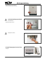 4
4
-
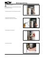 5
5
-
 6
6
-
 7
7
-
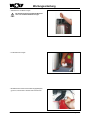 8
8
-
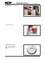 9
9
-
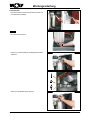 10
10
-
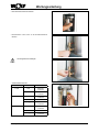 11
11
-
 12
12
-
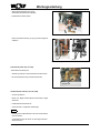 13
13
-
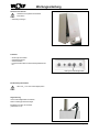 14
14
-
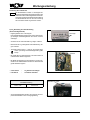 15
15
-
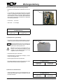 16
16
-
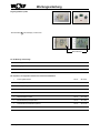 17
17
-
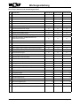 18
18
-
 19
19
-
 20
20
-
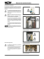 21
21
-
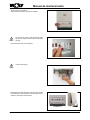 22
22
-
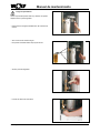 23
23
-
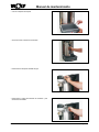 24
24
-
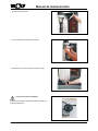 25
25
-
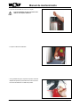 26
26
-
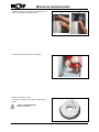 27
27
-
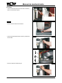 28
28
-
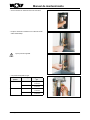 29
29
-
 30
30
-
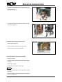 31
31
-
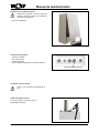 32
32
-
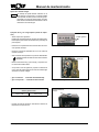 33
33
-
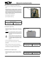 34
34
-
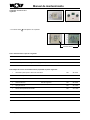 35
35
-
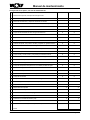 36
36
-
 37
37
-
 38
38
-
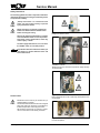 39
39
-
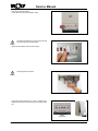 40
40
-
 41
41
-
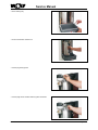 42
42
-
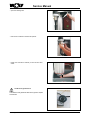 43
43
-
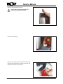 44
44
-
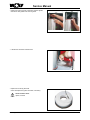 45
45
-
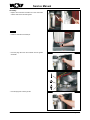 46
46
-
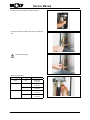 47
47
-
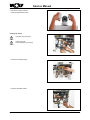 48
48
-
 49
49
-
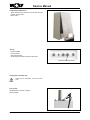 50
50
-
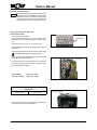 51
51
-
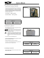 52
52
-
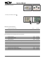 53
53
-
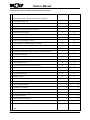 54
54
-
 55
55
-
 56
56


en otros idiomas
- English: Wolf CGB-20 User manual
- Deutsch: Wolf CGB-20 Benutzerhandbuch
Artículos relacionados
-
Wolf TGC-24 Manual de usuario
-
Wolf CGB-100 Instructions Manual
-
Wolf CGS-2R Instructions Manual
-
-
-
-
-
-
Otros documentos
-
GOK Filler valve Instrucciones de operación
-
Teka CGW LUX 60 4G AI AL CI Manual de usuario
-
-
Modine CGs Technical Manual
-
 ECOFLAM MAX GAS 500 PR Operating Instructions Manual
-
Nilfisk-ALTO Patio Heater Range Manual de usuario
-
BALTUR TBL 130P DACA Manual User Instructions
