
CGS
CO2 COOLERS
MANUALE TECNICO
Aeroevaporatori a soffitto
BETRIEBSANLEITUNG
Deckenluftverdampfer
TECHNICAL MANUAL
Ceiling unit coolers
MANUAL TECNICO
Aeroevaporadores de techo
MANUEL TECHNIQUE
Evaporateurs plafonniers
ТЕХНИЧЕСКОЕ РУКОВОДСТВО
отолочные воздухоохладители


CGS
Indice
- Avvertenze
. . . . . . . . . . . . . . . . . . . . . . . . . . . . . . . . . . . . . . . . . . . . . . . . . . . . . . . . . . . . . . . . . . . . . . . . . . . . . . . . . . . . . . . . . . .2
- Ispezione - Trasporto
. . . . . . . . . . . . . . . . . . . . . . . . . . . . . . . . . . . . . . . . . . . . . . . . . . . . . . . . . . . . . . . . . . . . . . . . . . . . . .2
- Condizioni da verificare per una corretta messa in opera
. . . . . . . . . . . . . . . . . . . . . . . . . . . . . .2
- Manutenzione generale
. . . . . . . . . . . . . . . . . . . . . . . . . . . . . . . . . . . . . . . . . . . . . . . . . . . . . . . . . . . . . . . . . . . . . . . . . .2
- Pericoli
. . . . . . . . . . . . . . . . . . . . . . . . . . . . . . . . . . . . . . . . . . . . . . . . . . . . . . . . . . . . . . . . . . . . . . . . . . . . . . . . . . . . . . . . . . . . . . . . .2
- Norme di riferimento
. . . . . . . . . . . . . . . . . . . . . . . . . . . . . . . . . . . . . . . . . . . . . . . . . . . . . . . . . . . . . . . . . . . . . . . . . . . . . .2
- Avvertenze per una corretta installazione
. . . . . . . . . . . . . . . . . . . . . . . . . . . . . . . . . . . . . . . . . . . . . . . . . .3
- Caratteristiche costruttive e dimensionali
. . . . . . . . . . . . . . . . . . . . . . . . . . . . . . . . . . . . . . . . . . . . . . . . . . .3
- Suggerimenti per un corretto accesso all’apparecchio
. . . . . . . . . . . . . . . . . . . . . . . . . . . . . . . . .6
- Schema di collegamento dei motoventilatori
. . . . . . . . . . . . . . . . . . . . . . . . . . . . . . . . . . . . . . . . . . . . . . .7
- Schema di collegamento e potenze delle
resistenze elettriche
. . . . . . . . . . . . . . . . . . . . . . . . . . . . . . . . . . . . . . . . . . . . . . . . . . . . . . . . . . . . . . . . . . . . . . . . . . . . . . .9
- Garanzie
. . . . . . . . . . . . . . . . . . . . . . . . . . . . . . . . . . . . . . . . . . . . . . . . . . . . . . . . . . . . . . . . . . . . . . . . . . . . . . . . . . . . . . . . . . . .57
Index
- Hinweise
. . . . . . . . . . . . . . . . . . . . . . . . . . . . . . . . . . . . . . . . . . . . . . . . . . . . . . . . . . . . . . . . . . . . . . . . . . . . . . . . . . . . . . . . . . . .11
- Kontrolle - Transport
. . . . . . . . . . . . . . . . . . . . . . . . . . . . . . . . . . . . . . . . . . . . . . . . . . . . . . . . . . . . . . . . . . . . . . . . . . . . .11
- Hinweise für eine korrekte Inbetriebnahme
. . . . . . . . . . . . . . . . . . . . . . . . . . . . . . . . . . . . . . . . . . . . . . .11
- Allgemeine Wartung
. . . . . . . . . . . . . . . . . . . . . . . . . . . . . . . . . . . . . . . . . . . . . . . . . . . . . . . . . . . . . . . . . . . . . . . . . . . . .11
- Gefahren
. . . . . . . . . . . . . . . . . . . . . . . . . . . . . . . . . . . . . . . . . . . . . . . . . . . . . . . . . . . . . . . . . . . . . . . . . . . . . . . . . . . . . . . . . . . .11
- Bezugsnormen
. . . . . . . . . . . . . . . . . . . . . . . . . . . . . . . . . . . . . . . . . . . . . . . . . . . . . . . . . . . . . . . . . . . . . . . . . . . . . . . . . . . .11
- Hinweise für eine korrekte Aufstellung
. . . . . . . . . . . . . . . . . . . . . . . . . . . . . . . . . . . . . . . . . . . . . . . . . . . . .12
- Konstruktionseigenschaften und Abmessungen
. . . . . . . . . . . . . . . . . . . . . . . . . . . . . . . . . . . . . . . .12
- Ratschläge für einen korrekten Zugang zum Gerät
. . . . . . . . . . . . . . . . . . . . . . . . . . . . . . . . . . . .15
- Anschlußplan der Motorventilatoren
. . . . . . . . . . . . . . . . . . . . . . . . . . . . . . . . . . . . . . . . . . . . . . . . . . . . . . . .16
- Anschlußplan und Leistungen der Heizstäbe
. . . . . . . . . . . . . . . . . . . . . . . . . . . . . . . . . . . . . . . . . . . .18
- Gewährleistung
. . . . . . . . . . . . . . . . . . . . . . . . . . . . . . . . . . . . . . . . . . . . . . . . . . . . . . . . . . . . . . . . . . . . . . . . . . . . . . . . . . .57
Index
- Important
. . . . . . . . . . . . . . . . . . . . . . . . . . . . . . . . . . . . . . . . . . . . . . . . . . . . . . . . . . . . . . . . . . . . . . . . . . . . . . . . . . . . . . . . . . . .20
- Inspection - Transport
. . . . . . . . . . . . . . . . . . . . . . . . . . . . . . . . . . . . . . . . . . . . . . . . . . . . . . . . . . . . . . . . . . . . . . . . . . .20
- For a proper installation
. . . . . . . . . . . . . . . . . . . . . . . . . . . . . . . . . . . . . . . . . . . . . . . . . . . . . . . . . . . . . . . . . . . . . . . .20
- General maintenance
. . . . . . . . . . . . . . . . . . . . . . . . . . . . . . . . . . . . . . . . . . . . . . . . . . . . . . . . . . . . . . . . . . . . . . . . . . .20
- Hazards / Risks
. . . . . . . . . . . . . . . . . . . . . . . . . . . . . . . . . . . . . . . . . . . . . . . . . . . . . . . . . . . . . . . . . . . . . . . . . . . . . . . . . . .20
- Reference standards
. . . . . . . . . . . . . . . . . . . . . . . . . . . . . . . . . . . . . . . . . . . . . . . . . . . . . . . . . . . . . . . . . . . . . . . . . . . .20
- Instructions for a correct installation
. . . . . . . . . . . . . . . . . . . . . . . . . . . . . . . . . . . . . . . . . . . . . . . . . . . . . . . .21
- Manufacturing and dimensional features
. . . . . . . . . . . . . . . . . . . . . . . . . . . . . . . . . . . . . . . . . . . . . . . . . .21
- Recommendations for a proper access to model
. . . . . . . . . . . . . . . . . . . . . . . . . . . . . . . . . . . . . . .24
- Fan motor connection scheme
. . . . . . . . . . . . . . . . . . . . . . . . . . . . . . . . . . . . . . . . . . . . . . . . . . . . . . . . . . . . . . .25
- Electric heater connection schemes and electric power
. . . . . . . . . . . . . . . . . . . . . . . . . . . . . .27
- Warranty
. . . . . . . . . . . . . . . . . . . . . . . . . . . . . . . . . . . . . . . . . . . . . . . . . . . . . . . . . . . . . . . . . . . . . . . . . . . . . . . . . . . . . . . . . . . .57
Indice
- Advertencias
. . . . . . . . . . . . . . . . . . . . . . . . . . . . . . . . . . . . . . . . . . . . . . . . . . . . . . . . . . . . . . . . . . . . . . . . . . . . . . . . . . . . . . .29
- Inspección - Transporte
. . . . . . . . . . . . . . . . . . . . . . . . . . . . . . . . . . . . . . . . . . . . . . . . . . . . . . . . . . . . . . . . . . . . . . . . .29
- Condiciones a verificar para una correcta puesta en marcha
. . . . . . . . . . . . . . . . . . . . . . .29
- Manutención general
. . . . . . . . . . . . . . . . . . . . . . . . . . . . . . . . . . . . . . . . . . . . . . . . . . . . . . . . . . . . . . . . . . . . . . . . . . . .29
- Peligros
. . . . . . . . . . . . . . . . . . . . . . . . . . . . . . . . . . . . . . . . . . . . . . . . . . . . . . . . . . . . . . . . . . . . . . . . . . . . . . . . . . . . . . . . . . . . . .29
- Normas de referencia
. . . . . . . . . . . . . . . . . . . . . . . . . . . . . . . . . . . . . . . . . . . . . . . . . . . . . . . . . . . . . . . . . . . . . . . . . . .29
- Advertencias para una correcta instalación
. . . . . . . . . . . . . . . . . . . . . . . . . . . . . . . . . . . . . . . . . . . . . .30
- Características constructivas y dimensionales
. . . . . . . . . . . . . . . . . . . . . . . . . . . . . . . . . . . . . . . . . .30
- Sugerencias para un correcto acceso al aparato
. . . . . . . . . . . . . . . . . . . . . . . . . . . . . . . . . . . . . . .33
- Esquema de conexión motoventiladores
. . . . . . . . . . . . . . . . . . . . . . . . . . . . . . . . . . . . . . . . . . . . . . . . . .34
- Esquema de conexión y potencia
de las resistencias eléctricas
. . . . . . . . . . . . . . . . . . . . . . . . . . . . . . . . . . . . . . . . . . . . . . . . . . . . . . . . . . . . . . . . .36
- Garantias
. . . . . . . . . . . . . . . . . . . . . . . . . . . . . . . . . . . . . . . . . . . . . . . . . . . . . . . . . . . . . . . . . . . . . . . . . . . . . . . . . . . . . . . . . . .57
Index
- Attention
. . . . . . . . . . . . . . . . . . . . . . . . . . . . . . . . . . . . . . . . . . . . . . . . . . . . . . . . . . . . . . . . . . . . . . . . . . . . . . . . . . . . . . . . . . . . .38
- Inspection - Transport
. . . . . . . . . . . . . . . . . . . . . . . . . . . . . . . . . . . . . . . . . . . . . . . . . . . . . . . . . . . . . . . . . . . . . . . . . . .38
- Conditions à vérifier pour une mise en marche correcte
. . . . . . . . . . . . . . . . . . . . . . . . . . . . .38
- Entretien général
. . . . . . . . . . . . . . . . . . . . . . . . . . . . . . . . . . . . . . . . . . . . . . . . . . . . . . . . . . . . . . . . . . . . . . . . . . . . . . . . .38
- Dangers
. . . . . . . . . . . . . . . . . . . . . . . . . . . . . . . . . . . . . . . . . . . . . . . . . . . . . . . . . . . . . . . . . . . . . . . . . . . . . . . . . . . . . . . . . . . . .38
- Normes de référence
. . . . . . . . . . . . . . . . . . . . . . . . . . . . . . . . . . . . . . . . . . . . . . . . . . . . . . . . . . . . . . . . . . . . . . . . . . . .38
- Instructions pour une installation correcte
. . . . . . . . . . . . . . . . . . . . . . . . . . . . . . . . . . . . . . . . . . . . . . . .39
- Caractéristiques constructives et
dimensionnelles
. . . . . . . . . . . . . . . . . . . . . . . . . . . . . . . . . . . . . . . . . . . . . . . . . . . . . . . . . . . . . . . . . . . . . . . . . . . . . . . . . . .39
- Suggestions pour un accès correct à l’appareil
. . . . . . . . . . . . . . . . . . . . . . . . . . . . . . . . . . . . . . . . .42
- Schéma de connexion motoventilateurs
. . . . . . . . . . . . . . . . . . . . . . . . . . . . . . . . . . . . . . . . . . . . . . . . . . .43
- Schéma de connexion et puissances
des résistances électriques
. . . . . . . . . . . . . . . . . . . . . . . . . . . . . . . . . . . . . . . . . . . . . . . . . . . . . . . . . . . . . . . . . . .45
- Garantie
. . . . . . . . . . . . . . . . . . . . . . . . . . . . . . . . . . . . . . . . . . . . . . . . . . . . . . . . . . . . . . . . . . . . . . . . . . . . . . . . . . . . . . . . . . . . .57
Указатель
- еры предосторожности
. . . . . . . . . . . . . . . . . . . . . . . . . . . . . . . . . . . . . . . . . . . . . . . . . . . . . . . . . . . . . . . . . . .47
- Осмотр - ранспортировка
. . . . . . . . . . . . . . . . . . . . . . . . . . . . . . . . . . . . . . . . . . . . . . . . . . . . . . . . . . . . . . . . .47
- одлежащие проверке условия для правильного
ввода в эксплуатацию
. . . . . . . . . . . . . . . . . . . . . . . . . . . . . . . . . . . . . . . . . . . . . . . . . . . . . . . . . . . . . . . . . . . . . . . .47
- Общее техобслуживание
. . . . . . . . . . . . . . . . . . . . . . . . . . . . . . . . . . . . . . . . . . . . . . . . . . . . . . . . . . . . . . . . . . .47
- Опасность
. . . . . . . . . . . . . . . . . . . . . . . . . . . . . . . . . . . . . . . . . . . . . . . . . . . . . . . . . . . . . . . . . . . . . . . . . . . . . . . . . . . . . . . . .47
- ормативная документация
. . . . . . . . . . . . . . . . . . . . . . . . . . . . . . . . . . . . . . . . . . . . . . . . . . . . . . . . . . . . . . .47
- еры предосторожности для правильной установки
. . . . . . . . . . . . . . . . . . . . . . . . . . .48
- онструктивные и габаритные характеристики
. . . . . . . . . . . . . . . . . . . . . . . . . . . . . . . . . . . .48
- екомендации по правильному доступу к аппарату
. . . . . . . . . . . . . . . . . . . . . . . . . . . . . .51
- хема подключения электровентиляторов
. . . . . . . . . . . . . . . . . . . . . . . . . . . . . . . . . . . . . . . . . .52
- хема подключения и мощностей электрических Эов
. . . . . . . . . . . . . . . . . . . . . .54
- арантии
. . . . . . . . . . . . . . . . . . . . . . . . . . . . . . . . . . . . . . . . . . . . . . . . . . . . . . . . . . . . . . . . . . . . . . . . . . . . . . . . . . . . . . . . . . .57
Index

2
www.modine.com
Attenzione
Prima di effettuare qualsiasi intervento di manutenzione, accertarsi che l’ali-
mentazione elettrica sia scollegata dalla fonte principale: le parti elettriche
potrebbero essere collegate ad un controllo automatico.
Avvertenze
1. Conservare questo manuale tecnico per tutto il periodo di vita del modello.
2. Leggere con attenzione il manuale prima dell’installazione e prima di qualsia-
si operazione sul modello.
3. Impiegare il modello esclusivamente per lo scopo per cui é stato progettato:
l’uso improprio esonera il costruttore da qualsiasi responsabilità.
4. Ogni operazione diversa da quella indicata in questo manuale deve essere
preventivamente concordata col costruttore. La mancata osservanza annulla
la garanzia.
5. Questo manuale rispecchia lo stato della tecnica al momento della commer-
cializzazione del prodotto, pertanto non può essere considerato inadeguato
nel caso in cui l'evoluzione dei metodi progettuali e costruttivi richiedano l'ag-
giornamento dei dati espressi.
6. È responsabilità dell'installatore/progettista dell’impianto il rispetto delle
disposizioni e delle normative in vigore e valutarne la sicurezza, prima di
metterlo in servizio.
7. Tutte le operazioni descritte in questo manuale devono essere eseguite da
personale autorizzato e qualificato, in possesso della formazione e delle
competenze necessarie in conformità con la EN 378. Per nessuna operazio-
ne sono ammesse persone sotto l’effetto di droghe, alcool, medicinali che
pregiudicano la prontezza di riflessi. I lavori sono consentiti solo se è stato
dato un ordine in proposito.
8. La progettazione, costruzione e conduzione dell’impianto frigorifero dove
verrà installata l’unità devono seguire le prescrizioni e criteri indicati dalla
norma EN 378
9. Le prescrizioni e requisiti di sicurezza nell’utilizzo dei fluidi refrigeranti appar-
tenenti ai gruppi A1, A2L devono essere in accordo a quanto previsto dalla
norma EN 378 e dalle schede di sicurezza relative a ciascun fluido utilizzato.
10. Predisporre e pianificare misure in caso di emergenza sull’impianto, ad
esempio installare un sistema di segnalazione guasti, onde evitare danni a
persone e cose.
Ispezione - Trasporto
1. Al ricevimento del modello controllare immediatamente il suo stato; contesta-
re subito alla compagnia di trasporto qualsiasi eventuale danno.
2. Durante il trasporto evitare di esercitare pressioni improprie sull’imballaggio,
che va mantenuto comunque sempre nella posizione indicata sullo stesso.
3. Disimballare il modello il più vicino possibile al luogo di installazione. Una
volta disimballato, evitare urti ai componenti.
4. Durante l’installazione e la movimentazione del modello utilizzare appositi
guanti protettivi per evitare di ferirsi con le parti taglienti (es. alette) del
modello.
Condizioni da verificare per una
corretta messa in opera
1. Verificare la tenuta delle strutture di sostegno rispetto al peso dell’apparec-
chio.
2. Verificare che il modello venga installato orizzontalmente.
3. Assicurare un volume libero adeguato (circa il 30% del volume interno della
cella) per una corretta circolazione dell’aria in aspirazione e scarico.
Particolari condizioni di installazione o funzionamento quali celle basse, tra-
vature a soffitto, stoccaggi eccessivi, impedimenti al getto e/o all’aspirazio-
ne dell’aria, formazione impropria di brina dovuta ad eccessiva immissione
di umidità nella cella, possono influenzare negativamente le prestazioni
dichiarate e creare difettosità nei modelli.
I modelli standard possono non essere adatti ad operare in tunnel o celle di
abbattimento/surgelamento rapido.
4. I modelli sono equipaggiati con motoventilatori assiali, quindi non adatti ad
essere canalizzati o comunque a sopportare prevalenze statiche aggiuntive.
5. Verificare che le condizioni di funzionamento (temperature e pressioni) siano
conformi a quelle di progetto.
6. Prestare particolare cura in fase di collegamento affinchè non si deformino i
capillari e non si modifichi la posizione del distributore.
7. In caso di più modelli installati a breve distanza l’uno dall’altro, evitare sbrina-
menti alternati.
8. Installare sugli scarichi condensa gli opportuni sifoni e verificarne l'efficacia in
tutte le temperature di utilizzo.
9. Evitare l'installazione degli aeroevaporatori vicino alle porte delle celle.
10. Collocare la sonda di temperatura per il fine sbrinamento nelle zone più fred-
de degli scambiatori, ovvero quelle zone che tendono a ghiacciarsi maggior-
mente (al termine del ciclo non deve rimanere ghiaccio sui modelli). La posi-
zione di questo dispositivo non può essere definita a priori, in quanto varia in
relazione al tipo di cella e al tipo di impianto.
11. Verificare che la linea elettrica di alimentazione sia adeguata alle caratteristi-
che elettriche dell’apparecchio.
12. Assicurarsi che tutti i collegamenti elettrici siano in accordo con le norme
vigenti.
13. Le unità sono predisposte per il collegamento elettrico a terra.
L’installattore e/o il conduttore dell’unità sono tenuti a garantire la presenza di
un efficiente collegamento alla terra di protezione contro i contatti elettrici
indiretti.
A richiesta i modelli possono essere forniti con scambiatori, sbrinamenti e
motoventilatori diversi dallo standard.
Le resistenze elettriche impiegate per l’eventuale sbrinamento sono alloggia-
te in scatola di derivazione in materiale termoplastico (protezione contro il
contatto elettrico diretto di classe II) aventi grado di protezione IP 54.
14. Ad installazione completata rimuovere la pellicola protettiva che ricopre il
modello.
15. L’accessibilità al modello, per qualsiasi tipo di intervento, deve essere riserva-
ta al personale qualificato alla conduzione dell’impianto, secondo le norme
vigenti.
Manutenzione generale
1. Verificare periodicamente i fissaggi, le connessioni elettriche e i collegamenti
all’impianto frigorifero.
2. Provvedere alla pulizia periodica dell’apparecchio, per evitare accumuli di
sostanze nocive. Si consiglia l’utilizzo di normale acqua saponata, evitando
solventi, agenti aggressivi, abrasivi o a base di ammoniaca.
3. In caso di sostituzioni di resistenze elettriche prestare particolare attenzione
nelle fasi di installazione per evitare danni alle vulcanizzazioni; ripristinare
correttamente i collegamenti e i sistemi di fissaggio esistenti per evitare movi-
menti delle stesse durante il funzionamento.
Tali operazioni dovranno essere effettuate da personale esperto e qualificato.
Pericoli
1. Pericolo di elettrocuzione. Il modello è provvisto di
elettroventilatori e resistestenze elettriche di sbrinamento. La
tensione di alimentazione è di 400V AC. Utilizzare sistemi di
sicurezza elettrica previsti dalla normativa vigente.
2. Pericolo di ustione. Le resistenze elettriche di sbrinamento
possono raggiungere temperature superficiali di 350°C.
3. Pericolo di taglio. Lo scambiatore di calore è costituito da alette
con bordi taglienti e la carrozzeria da parti in lamiera.
4. Pericolo parti in movimento. Il modello è provvisto di
elettroventilatori dotati di griglia di protezione esterna.
5. Pericolo di schiacciamento. Il modello può pesare oltre 70 kg.
Norme di riferimento
- DIRETTIVA MACCHINE 2006/42/EC
- DIRETTIVA BASSA TENSIONE 2014/35/UE
- DIRETTIVA COMP. ELETTROMAGNETICA 2014/30/UE
- DIRETTIVA PED 2014/68/UE
- DIRETTIVA ERP 2009/125/EC

435
32
34
190 50 120 min.
C
B
=
A
=
65
13
6,5
6,5
22
40
6
27
3
www.modine.com
Italiano
Avvertenze per una corretta installazione
Distanza minima laterale dalla parete lato resistenze - Distanza minima dalla parete lato motore
In fase di installazione rispettare la quota minima di 120 mm
dalla parete lato motore per una buona accessibilità all’ap-
parecchio.
In fase di installazione dei modelli EDP (sbrinamento elettrico potenziato) rispettare
la quota minima B + 250 mm per poter togliere e inserire le resistenze.
Modelli standard: A = 150 mm
Modelli EDP: A = B + 250 mm
Caratteristiche costruttive e dimensionali
Particolare
di fissaggio
Modelli con ventola ø 200 mm
Modello CGS ø 200 mm 11EH3 11AH3 12EH3 12AH3 12LH3 12MH3 13EH3 13AH3 13MH3 14MH3
11EL4 11AL4 12EL4 12AL4 12LL4 12ML4 13EL4 13AL4 13ML4 14ML4
Dimensioni A 411 411 611 611 611 861 1111 1111 1111 1461
(mm) B 271 271 471 471 471 721 971 971 971 1321
C 120 120 120 120 170 170 120 120 170 170
Attacchi scambiatore In
(mm) 10 10 10 10 10 10 10 10 10 10
Out
(mm) 12 12 12 12 12 12 12 12 12 12
Attacco scarico
GAS 1/2 1/2 1/2 1/2 1/2 1/2 1/2 1/2 1/2 1/2
Peso Netto (modelli ED)
kg 4,3 4,9 7,1 7,7 10,7 13,8 11,1 12,1 17 23
Particolare del posizionamento resistenze modello con ventola ø 200 mm
Sgocciolatoio
(solo su versione L4)
Resistenza
Molla fermaresistenza

4
www.modine.com
Caratteristiche costruttive e dimensionali
Modelli con ventola ø 250 mm
Modello CGS ø 250 mm 21GH4 22GH4 23GH4 24GH4
21EH4 22EH4 23EH4 24EH4
21GL7 22GL7 --
21EL7 22EL7 23EL7 24EL7
21FL7 22FL7 23FL7 24FL7
Dimensioni A 739 1189 1639 2089
(mm) B 475 925 1375 1825
C 451 901 1351 1801
In (mm) 12 12 12 12
Out (mm) 12 12 12 12
Attacco scarico GAS 11 1 1
Peso netto (max) kg 13 21 28 36
Attacchi scambiatore
RBA
RBA
RSB
RBB
RBA
Resistenza elettrica di alta potenza nello scambiatore
RBB
Resistenza elettrica di bassa potenza nello scambiatore
(opzionale versioni EDP)
RSB
Resistenza elettrica di bassa potenza nello sgocciolatoio
Particolare del posizionamento resistenze modello con ventola ø 250 mm
CGS passo alette 4 mm
CGS passo alette 7 mm
620
25,5 569
553
25,5
9
629
277
A
132B132
41
162,5
160
C
132
25,5
76
245
12233
32
r 597
45
35

A
X
Y
B
CD
114 114
161
881
820
787
534 227
775
43
8
4
30
10
15
22,5
56
10
30
4
17,5
= =
Particolare di fissaggio “F” Particolare di fissaggio “G”
Semiasola 10x20
Semiasola 22x10
5
www.modine.com
Italiano
Particolare del posizionamento resistenze modello con ventola ø 315 mm
RBA
RSA
RSA
RBB
RBA
RBA
Resistenza elettrica di alta potenza nelle
batteria
RSA
Resistenza elettrica sullo sgocciolatoio
interno
RBB
Resistenza elettrica di bassa potenza nella
batteria
CGS passo alette 4 mm CGS passo alette 7 mm
Caratteristiche costruttive e dimensionali
Modelli con ventola ø 315 mm
Fissare le staffe al soffitto tramite le semiasole dei sup-
porti “X” e “Y” con gli interassi di fissaggio riportati nel-
la tabella dimensionale.
Modello CGS ø 315 mm 31AH4 32AH4 33AH4 34AH4
31BL7 32BL7 33BL7 34BL7
Dimensioni A 810 1360 1910 2460
(mm) B 582 1132 1682 2232
C/ / 565 1115
D/ / 1117 1117
In (mm) 12 12 12 12
Out (mm) 12 12 16 16
Attacco scarico GAS 11 1 1
Peso netto (max) kg 19 31 48 65
Attacchi scambiatore

6
www.modine.com
A
B
C
D
E
Accesso
1. Smontare il tubo di scarico condensa e posizionarlo in modo che non crei
intralcio al movimento del convogliatore.
2. Svitare le viti “A” e “B” che fissano il convogliatore alla struttura ed
accompagnarlo fino alla posizione rappresentata in figura.
3. Svitare le viti “C” e rimuovere i coperchi laterali.
4. Al fine di intervenire sulla resistenza posta sotto lo scambiatore, rimuovere
lo sgocciolatoio fissato con le viti “E”.
5. Per accedere alla scatola di derivazione delle resistenze (modelli ED e
EDP), rimuovere le viti autofilettanti “D” che fissano il coperchio frontale di
destra.
6. Per accedere rapidamente al lato collettori dello scambiatore, rimuovere le
viti autofilettanti “D” che fissano il coperchio frontale di sinistra.
Riposizionamento
1. Ricollocare lo sgocciolatoio fissandolo con le viti “E”.
2. Riposizionare i coperchi frontali fissandoli con le viti “D”.
3. Rimontare i coperchi laterali utilizzando le viti “C”.
4. Richiudere il convogliatore assicurandosi che i coperchi laterali siano interni
allo stesso, quindi fissarlo con le viti “A” e “B”.
5. Rimontare il tubo di scarico condensa.
Coperchio
laterale
Coperchio
frontale
Sgocciolatoio
Convogliatore
Accesso
1. Smontare il tubo di scarico condensa e posizionarlo in modo che non crei
intralcio al movimento del convogliatore.
2. Svitare le viti di fissaggio “A” del convogliatore allo sgocciolatoio interno;
svitare le viti di fissaggio “B” alle fianchette, togliere il deflettore, ed accom-
pagnare il convogliatore fino alla posizione rappresentata in figura.
3. Allentare le viti autofilettanti “C”, senza toglierle completamente.
4. Svitare le viti autofilettanti “D”, quindi sfilare il coperchio laterale.
Riposizionamento
1. Ricollocare il coperchio laterale e fissarlo mediante le viti “C” e “D”.
2. Riportare il convogliatore in posizione, avendo cura che i coperchi laterali
siano interni allo stesso, quindi fissarlo con le viti “B”.
3. Inserire il deflettore, quindi avvitare le viti di fissaggio “A” allo sgocciolatoio
interno.
4. Rimontare il tubo di scarico condensa.
Supporti
posteriori
Sgocciolatoio
Interno
Deflettore
Coperchio
laterale
Fianchetta
Supporti
anteriori
Convogliatore
Modelli con ventola ø 315 mm
Modelli con ventola ø 250 mm
Modelli con ventola ø 200 mm
Suggerimenti per un corretto accesso all’apparecchio
Accesso
1. Smontare il tubo di scarico condensa in modo che non si crei intralcio al
movimento del convogliatore.
2. Allentare le viti zigrinate di serraggio “F” e svitare le viti di fissaggio “C” del
convogliatore.
3. Accompagnare il convogliatore fino alla posizione rappresentata in figura.
Riposizionamento
1. Portare in posizione il convogliatore, avendo cura che la carenatura rimanga
all’interno dello stesso, serrare le viti zigrinate “F” e fissarlo mediante le
viti “C”.
2. Rimontare il tubo di scarico condensa.
Carenatura
Convogliatore
Resistenza
Molla fermaresistenza

7
www.modine.com
Italiano
Schema di collegamento e assorbimento dei motoventilatori (modelli L4)
Modelli con ventola ø 200 mm Alimentazione: 230V/1/50Hz
M = motoventilatori
R = resistenza di sbrinamento
L1 = marrone
N1 = blu
L2-N2 = nero
= giallo/verde
L1-N1 = linea di alimentazione dei motoventilatori 230V/1/50-60Hz
L2-N2 = linea di alimentazione delle resistenze elettriche 230V/1/50-60Hz
Attenzione
I motori sono dotati di termocontatti di protezione interni a riarmo
automatico.
Prima di utilizzare sistemi di regolazione del numero di giri dei motori verificare
la compatibilità con i motori stessi, sistemi non compatibili possono generare
rumorosità e danneggiamenti; il costruttore non si assume responsabilità alcu-
na sulle prestazioni dei modelli equipaggiati con sistemi di regolazione.
Attenzione
È d’obbligo l’applicazione di opportuni sistemi di protezione termica sulle
linee di alimentazione.
Provvedere periodicamente alla verifica delle funzionalità della resistenza
per evitare accumuli dannosi di ghiaccio sui modelli.
Il costruttore non risponde in alcun modo di difettosità create da malfunziona-
menti non rilevati.
Modello CGS ø 200 mm 11EH3 11AH3 12EH3 12AH3 12LH3 12MH3 13EH3 13AH3 13MH3 14MH3
11EL4 11AL4 12EL4 12AL4 12LL4 12ML4 13EL4 13AL4 13ML4 14ML4
Motoventilatori
n° x Ø mm 1x200 1x200 2x200 2x200 2x200 2x200 3x200 3x200 3x200 4x200
Assorbimento A 0,35 0,35 0,7 0,7 0,7 0,7 1,05 1,05 1,05 1,4
motoventilatori W 53 53 106 106 106 106 159 159 159 212
Assorbimento resistenze W 480 480 650 680 680 850 1080 1200 1200 1600

8
www.modine.com
Schema di collegamento dei motoventilatori
P.E.
L
N
Scatola derivazione
motori
Scatola derivazione
resistenze
Connessione cavi rapida
L = Marrone o Grigio N = Blu
= Giallo / Verde
Modelli con ventola ø 250 mm Alimentazione: 230V/1/50-60Hz
Modelli con ventola ø 315 mm Alimentazione: 230V/1/50-60Hz
Motore n. 2/3/4 Motore n. 1 Scatola derivazione
P.E. = Connessione di terra carrozzeria
Attenzione
I motori sono dotati di termocontatti di protezione interni a riarmo automatico.
Prima di utilizzare sistemi di regolazione del numero di giri dei motori verificare la
compatibilità con i motori stessi, sistemi non compatibili possono generare rumoro-
sità e danneggiamenti; il costruttore non si assume responsabilità alcuna sulle pre-
stazioni dei modelli equipaggiati con sistemi di regolazione.
Modello CGS ø 250 mm 21GH4 22GH4 23GH4 24GH4
21EH4 22EH4 23EH4 24EH4
21GL7 22GL7 --
21EL7 22EL7 23EL7 24EL7
21FL7 22FL7 23FL7 24FL7
Motoventilatori
n° x Ø mm 1 x 250 2 x 250 3 x 250 4 x 250
Assorbimento A 0,68 1,36 2,04 2,72
motoventilatori
W 95 190 285 380
Motore n. 2 (eventuale) Motore n. 1
L = Marrone N = Blu
= Giallo / Verde
Motore n. 2 (eventuale) Motore n. 1 Scatola di derivazione
Giallo/verde
Blu
Nero
Marrone
Giallo/verde
Blu
Nero
Marrone
Attenzione
I motori sono dotati di termocontatti di
protezione interni a riarmo automatico.
Prima di utilizzare sistemi di regolazione
del numero di giri dei motori verificare la
compatibilità con i motori stessi, sistemi
non compatibili possono generare rumo-
rosità e danneggiamenti; il costruttore
non si assume responsabilità alcuna sulle
prestazioni dei modelli equipaggiati con
sistemi di regolazione.
Modello CGS 31AH4 32AH4 33AH4 34AH4
31BL7 32BL7 33BL7 34BL7
Motoventilatori n. x ø mm 1 x 315 2 x 315 3 x 315 4 x 315
Frequenza Hz 50 60 50 60 50 60 50 60
Assorbimento W 96 130 192 260 288 390 384 520
A 0,43 0,58 0,86 1,16 1,29 1,74 1,72 2,32
RPM 1340 1490 1340 1490 1340 1490 1340 1490
Scatola di derivazione

9
www.modine.com
Italiano
RBA1
L
N
N
RBA1
L
P.E.
N
L
RBB1
RBA1
RSB
L
N
N
RBB1
RBA1
RSB
P.E.
RBA1
RSB
L
N
N
RBA1
RSB
P.E.
N
L
L
N
L
L
RBA1 - Resistenza di alta potenza nella batteria
RBB1 - Resistenze di bassa potenza nella batteria
RSB - Resistenza di bassa potenza sullo sgocciolatoio interno
Versione standard
Versione standard Versione EDP
(opzionale)
Scatola derivazione resistenze (interna)
Scatola derivazione resistenze (interna) Scatola derivazione resistenze (interna)
Modello CGS 21GH4 22GH4 23GH4 24GH4
ø 250 mm 21EH4 22EH4 23EH4 24EH4
Potenza totale (W) 450 900 1330 1750
Modello CGS 21GL7 22GL7 --
ø 250 mm 21EL7 22EL7 23EL7 24EL7
21FL7 22FL7 23FL7 24FL7
Potenza totale (W) 675 1350 1995 2625
Versioni EDP (W) 900 1800 2660 3500
Modello con ventola da ø 250 mm - passo alette 4 mm Alimentazione 230V/1/50Hz
Modello con ventola da ø 250 mm - passo alette 7 mm Alimentazione 230V/1/50Hz
RBA1 - Resistenze di alta potenza nella batteria
Attenzione
È d’obbligo l’applicazione di opportuni
sistemi di protezione termica sulle linee
di alimentazione.
Provvedere periodicamente alla verifica
delle funzionalità di tutte le resistenze
per evitare accumuli dannosi di ghiaccio
sui modelli.
Il costruttore non risponde in alcun modo
di difettosità create da malfunzionamenti
non rilevati.
P.E. = Connessione di terra corazza resistenze
P.E. = Connessione di terra corazza resistenze
Schemi di collegamento e potenze delle resistenze elettriche

10
www.modine.com
Schemi di collegamento e potenze delle resistenze elettriche
PE
PE
PE
RSA
RSA
RSA
RSA
RSA
RSA
COLLEGAMENTO 400V/3/50 Hz COLLEGAMENTO 230V/3/50 Hz COLLEGAMENTO 230V/1/50 Hz
(predisposto) (da predisporre) (da predisporre)
Modello CGS 31AH4 32AH4 33AH4 34AH4
Potenza totale (W) 1500 2700 4200 5400
Modello con ventola da ø 315 mm - passo alette 4 mm
RBA1 / RBA2 - Resistenze di alta potenza nella batteria
RSA - Resistenza di alta potenza sullo sgocciolatoio interno
Attenzione
È d’obbligo l’applicazione di opportuni sistemi di protezione termica sulle linee di
alimentazione.
Provvedere periodicamente alla verifica delle funzionalità di tutte le resistenze
per evitare accumuli dannosi di ghiaccio sui modelli.
Il costruttore non risponde in alcun modo di difettosità create da malfunzionamenti
non rilevati.
RBA - Resistenza di alta potenza nella batteria
RBB1 / RBB2 - Resistenze di bassa potenza nella batteria
RSA - Resistenza di alta potenza sullo sgocciolatoio interno
COLLEGAMENTO 400V/3/50 Hz COLLEGAMENTO 230V/3/50 Hz COLLEGAMENTO 230V/1/50 Hz
(predisposto) (da predisporre) (da predisporre)
Modello con ventola da ø 315 mm - passo alette 7 mm
Modello CGS 31BL7 32BL7 33BL7 34BL7
Potenza totale (W) 1500 2700 4200 5400
Attenzione
È d’obbligo l’applicazione di opportuni sistemi di protezione termica sulle linee di
alimentazione.
Provvedere periodicamente alla verifica delle funzionalità di tutte le resistenze
per evitare accumuli dannosi di ghiaccio sui modelli.
Il costruttore non risponde in alcun modo di difettosità create da malfunzionamenti
non rilevati.

11
www.modine.com
Deutsch
Achtung
Versichern Sie sich vor jeder Wartung, daß die Stromzuführung vom
Hauptnetz getrennt ist; die elektrischen Teile könnten automatisch anlaufen.
Hinweise
1. Diese Betriebsanleitung während der ganzen Lebensdauer des Geräts auf-
bewahren.
2. Vor Inbetriebnahme des Geräts und vor jedem Eingriff aufmerksam die
Betriebsanleitung durchlesen.
3. Das Gerät nur für den Zweck einsetzen, wofür es entworfen worden ist; unsa-
chgemäße Anwendung befreit den Hersteller von jeder Verantwortung.
4. Jeder andere Vorgang als der in dieser Anleitung beschriebene muss vorher
mit dem Hersteller vereinbart werden. Die Nichtbeachtung führt zum
Erlöschen der Garantie.
5. Dieses Handbuch entspricht dem Stand der Technik zum Zeitpunkt der
Vermarktung des Produkts und kann daher nicht als unzureichend ange-
sehen werden, wenn die Entwicklung der Planungs- und
Konstruktionsmethoden eine Aktualisierung der ausgedrückten Daten erfor-
dert.
6. Es liegt in der Verantwortung des Installateurs/Planers des Systems, die gel-
tenden Bestimmungen und Vorschriften einzuhalten und die Sicherheit des
Systems vor dessen Inbetriebnahme zu beurteilen.
7. Alle in dieser Anleitung beschriebenen Vorgänge müssen von autorisiertem
und qualifiziertem Personal mit den erforderlichen Ausbildungen und
Kompetenzen gemäß EN 378 durchgeführt werden. Für keinen Vorgang sind
Personen unter dem Einfluss von Drogen, Alkohol, Medikamenten, die die
Reaktionsfähigkeit beeinträchtigen, zugelassen. Die Arbeiten sind nur nach
deren vorheriger Beauftragung zulässig.
8. Die Planung, der Bau und der Betrieb der Kühlanlage, in der die Einheit
installiert werden soll, müssen den Anforderungen und Kriterien der Norm
EN 378 entsprechen
9. Die Bestimmungen und Sicherheitsanforderungen für die Verwendung von
Kältemitteln der Gruppen A1, A2L müssen den Angaben der EN 378 und der
Sicherheitsdatenblätter für jedes verwendete Fluid entsprechen.
10. Es müssen Notfallmaßnahmen an der Anlage vorbereitet und geplant wer-
den, z.B. die Installation einer Störmeldeanlage, um Personen- und
Sachschäden zu vermeiden.
Kontrolle - Transport
1. Bei Erhalt des Geräts sofort den Zustand kontrollieren; jeglichen eventuellen
Schaden sofort dem Spediteur beanstanden.
2. Während des Transports unnötigen Druck auf die Verpackung vermeiden.
3. Während der Montage und des Positionierens des Geräts geeignete
Schutzhandschuhe benutzen, um eine Verletzungsgefahr durch scharfe
Stellen am Gerät zu vermeiden.
4. Während der Montage und des Positionierens des Geräts geeignete
Schutzhandschuhe benutzen, um eine Verletzungsgefahr durch scharfe
Stellen (z.B. Lamellen) zu vermeiden.
Hinweise für eine korrekte Inbetriebnahme
1. Die Tragfähigkeit der Strukturen bezüglich des Gerätegewichts überprüfen.
2. Das Modell muß horizontal eingebaut werden.
3. Für eine einwandfreie Luftzirkulation muß genügend Freiraum vorhanden
sein (ungefähr 30% des Innenvolumens der Zelle).
Besondere Einbau- oder Betriebsbedingungen, wie niedrige Kühlzellen,
Deckenträger, übermäßige Lagerung, Behinderungen des Luftstroms
und/oder der Luftansaugung, übermäßige Reifbildung durch zu hohe
Feuchtigkeit in der Kühlzelle können die angegebenen Leistungen negativ
beeinflussen und Schäden an den Geräten hervorrufen.
Die Standardmodelle können für die Anwendung in Schnellabkühlungs- oder
Schockräumen nicht geeignet sein.
4. Die Modelle sind mit Axialmotorventilatoren ausgestattet und daher nicht
kanalisierbar oder jedenfalls keine weiteren Druckverluste verkraften.
5. Die Betriebsbedingungen (Temperaturen und Drucke) müssen dem Projekt
entsprechen.
6. Das Anschließen muß sorgfältig erfolgen, um das Verformen eventueller
Kapillarrohre und das Verlagern des Verteilers zu verhindern.
7. Bei nah aneinander installierten Geräten abwechselnde Abtauungen vermei-
den.
8. An den Tauwasserabflüssen die passenden Siphone installieren und die
Wirksamkeit bei allen Anwendungstemperaturen überprüfen.
9. Die Installation der Luftverdampfer in der Nähe der Zellentüren vermeiden.
10. Die Temperaturfühler für das Ende der Abtauung in den kältesten Zonen der
Wärmeaustauscher anbringen, beziehungsweise in den Zonen, wo die
Tendenz zur Eisbildung am größten ist (am Ende der Abtauung darf kein Eis
an den Modellen bleiben). Die Lage dieser kann nicht vorherbestimmt wer-
den, da sie sich je nach Typ der Zelle und der Anlage verändert.
11. Die Stromzuleitung muß den elektrischen Daten des Geräts angepaßt sein.
12. Alle Anschlüsse müssen den gültigen elektrischen Normen entsprechen.
13. Die Einheiten sind für den elektrischen Erdungsanschluss vorgesehen. Der
Installationsfachmann bzw. Betreiber der Einheit muss einen funktionstüchti-
gen Anschluss an den Erdungsschutzleiter gegen indirekte Stromkontakte
gewährleisten. Die elektrischen Widerstände für das Abtausystem sind in
einer Verteilerdose aus thermoplastischem Material untergebracht mit
Schutzgrad IP 54. Auf Bestellung können die Modelle mit nicht stan-
dardmäßigen Wärmetauschern, Abtausystemen und Lüfteraggregaten gelie-
fert werden.
14. Nach beendeter Installation den am Gerät befindlichen Schutzfilm entfernen.
15. Der Zugang zum Gerät für jeden Eingriff muß dem für die Anlage qualifizier-
ten Personal gemäß den gültigen Normen vorbehalten sein.
Allgemeine Wartung
1. Regelmäßige Überprüfung der Befestigungen der elektrischen Anschlüsse.
Kältemittelanschlüsse auf Dichtheit prüfen.
2. Regelmäßige Reinigung des Geräts mit normalem Seifenwasser, um das
Anhäufen von schädlichen Substanzen zu verhindern. Keine Lösungsmittel
und aggressive oder ammoniakhaltige Reibepulver verwenden.
3. Beim eventuellen Auswechseln von elektrischen Heizstäben besonders acht-
geben, um während der Installation Schäden an der Vulkanisierung zu ver-
meiden; die Anschlüsse und die bestehenden Befestigungssysteme wieder
korrekt herstellen, um zu vermeiden, daß sie sich während des Betriebs
bewegen.
Die Wartung darf nur von qualifizierten Personal vorgenommen werden.
Gefahren
1. Stromschlaggefahr. Das Gerät ist mit Motorventilatoren und
elektrischen Abtauheizungen versehen. Die Stromspannung ist
400 V AC. Elektrische Sicherheitssysteme gemäß den
geltenden Normen anwenden.
2. Verbrennungsgefahr. Die elektrischen Abtauheizungen können
Oberflächentemperaturen von 350° C erreichen.
3. Schnittgefahr. Der Wärmeaustauscher besteht aus Lamellen mit
scharfen Kanten und das Gehäuse besteht aus Blechteilen.
4. Gefahr durch sich bewegende Teile. Das Gerät ist mit
Motorventilatoren mit äußerem Schutzgitter versehen.
5. Quetschgefahr. Das Gerät kann über 70 kg wiegen.
Bezugsnormen
- MASCHINEN - RICHTLINIE 2006/42/EC
- NIEDERSPANNUNG - RICHTLINIE 2014/35/UE
- RICHTLINIE ELEKTROMAGNETISCHE KOMP. 2014/30/UE
- PED RICHTLINIE 2014/68/UE
- ERP RICHTLINIE 2009/125/EC

12
www.modine.com
435
32
34
190 50 120 min.
C
B
=
A
=
65
13
6,5
6,5
22
40
6
27
Konstruktionseigenschaften und Abmessungen
Einzelheit
der Befestigung
Modell mit Flügeldurchmesser ø 200 mm
Modell CGS ø 200 mm 11EH3 11AH3 12EH3 12AH3 12LH3 12MH3 13EH3 13AH3 13MH3 14MH3
11EL4 11AL4 12EL4 12AL4 12LL4 12ML4 13EL4 13AL4 13ML4 14ML4
Abmessungen A 411 411 611 611 611 861 1111 1111 1111 1461
(mm) B 271 271 471 471 471 721 971 971 971 1321
C 120 120 120 120 170 170 120 120 170 170
Innere In
(mm) 10 10 10 10 10 10 10 10 10 10
Batterieanschlüsse Out
(mm) 12 12 12 12 12 12 12 12 12 12
Tauwasserabfluß Ø
(GAS) 1/2 1/2 1/2 1/2 1/2 1/2 1/2 1/2 1/2 1/2
Nettogewicht
(ED Ausführung) kg 4,3 4,9 7,1 7,7 10,7 13,8 11,1 12,1 17 23
Einzelheit der Heizstäbebefestigung Modell mit Flügeldurchmesser ø 200 mm
Mindestabstand von der Wand zum Ein- und Ausbau der Heizstäbe
Mindestabstand von der Wand Motorenseite
Hinweise für eine korrekte Aufstellung
Für eine gute Zugänglichkeit muß der Mindestabstand von 120
mm von der Wand auf der Motorenseite bei der Montage ein-
gehalten werden.
Während der Montage der EDP Modelle (verstärkte elektrische Abtauung) das
Mindestmass B + 250 mm beachten, um die Heizstäbe herausnehmen und
hineingeben zu können.
Modell standard: A = 150 mm
Modell EDP: A = B + 250 mm
Tropfwanne
(nur in L4 Ausführung)
Heizstab
Heizstabbefestigungsfeder

620
25,5 569
553
25,5
9
629
277
A
132B132
41
162,5
160
C
132
25,5
76
245
12233
32
r 597
45
35
13
www.modine.com
Deutsch
Einzelheit der Heizstäbebefestigung Modell mit Flügeldurchmesser ø 250 mm
RBA
RBA
RSB
RBB
RBA
Hochleistungsheizstab im Wärmeaustauscher
RBB
Niederleistungsheizstab im Wärmeaustauscher (Option
Modell EDP)
RSB
Niederleistungsheizstab in der inneren Tropfwanne
CGS Lamellenabstand 4 mm
CGS Lamellenabstand 7 mm
Konstruktionseigenschaften und Abmessungen
Modell mit Flügeldurchmesser ø 250 mm
Modell CGS ø 250 mm 21GH4 22GH4 23GH4 24GH4
21EH4 22EH4 23EH4 24EH4
21GL7 22GL7 --
21EL7 22EL7 23EL7 24EL7
21FL7 22FL7 23FL7 24FL7
Abmessungen A 739 1189 1639 2089
(mm) B 475 925 1375 1825
C 451 901 1351 1801
In (mm) 12 12 12 12
Out (mm) 12 12 12 12
Tauwasserabfluß GAS 11 1 1
Nettogewicht (max)
kg 13 21 28 36
Batterie Anschlüsse

A
X
Y
B
CD
114 114
161
881
820
787
534 227
775
43
8
4
30
10
15
22,5
56
10
30
4
17,5
= =
Einzelheit der “F” Befestigung Einzelheit der “G” Befestigung
Halblangloch 10x20
Halblangloch 22x10
14
www.modine.com
Einzelheit der Heizstäbebefestigung Modell mit Flügeldurchmesser ø 315 mm
RBA
RSA
RSA
RBB
RBA
RBA
Hochleistungsheizstab im
Wärmeaustauscher
RSA
Elektrischer Heizstab in der inneren
Tropfwanne
RBB
Niederleistungsheizstab im
Wärmeaustauscher
CGS Lamellenabstand 4 mm CGS Lamellenabstand 7 mm
Konstruktionseigenschaften und Abmessungen
Modell mit Flügeldurchmesser ø 315 mm
Die Halterungen mit dem Halblangloch der Halterun-
gen “X”, der Bohrung der Halterungen “Y” und der in
der seitlichen Abmessungstabelle angegebenen Be-
festigungsabständen an die Decke befestigen.
Modell CGS ø 315 mm 31AH4 32AH4 33AH4 34AH4
31BL7 32BL7 33BL7 34BL7
Abmessungen A 810 1360 1910 2460
(mm) B 582 1132 1682 2232
C/ / 565 1115
D/ / 1117 1117
In (mm) 12 12 12 12
Out (mm) 12 12 16 16
Tauwasserabfluß GAS 11 1 1
Nettogewicht (max) kg 19 31 48 65
AInnere
Batterieanschlüsse

A
B
C
D
E
Modell mit Flügeldurchmesser ø 250 mm
Ausbau
1. Tauwasserabflußrohr so demontieren, daß das Bewegen des Lüfterblechs
nicht behindert wird.
2. Die Schrauben „A“ und „B“, mit denen das Lüfterblech am Gehäuse befe-
stigt ist, losschrauben und das Lüfterblech wie aufgezeichnet positionieren.
3. Die Schrauben „C“ losschrauben und die seitlichen Abdeckungen abneh-
men.
4. Um zu dem unter dem Wärmeaustauscher gelegenen Heizstab zu gelan-
gen, die mit den Schrauben „E“ befestigte Tropfwanne abnehmen.
5. Um zu der Abzweigdose der Heizstäbe (Modelle ED und EDP) zu gelangen,
die selbstbohrenden Schrauben „D“, mit denen die rechte vordere Abdeckung
befestigt ist, losschrauben.
6. Um schnell an die Sammlerseite des Wärmeaustauschers zu gelangen, die
selbstbohrenden Schrauben „D“, mit denen die linke vordere Abdeckung
befestigt ist, entfernen.
Zusammenbau
1. Die Tropfwanne mit den Schrauben „E“ befestigen.
2. Die vorderen Abdeckungen mit den Schrauben „D“ befestigen.
3. Die seitlichen Abdeckungen mit den Schrauben „C“ montieren.
4. Das Lüfterblech wieder zumachen und so positionieren, dass die seitlichen
Abdeckungen innen sind und mit den Schrauben „A“ und „B“ befestigen.
5. Tauwasserabfluss montieren.
Hintere Halterungen
Vordere
Abdeckung
Innere
Tropfwanne
Lüfterblech
15
www.modine.com
Deutsch
Modell mit Flügeldurchmesser ø 200 mm
Ausbau
1. Tauwasserabflußrohr so demontieren, daß das Bewegen des Lüfterblechs
nicht behindert wird.
2. Die Rändelschrauben “F” lockern und die Befestigungsschrauben “C” vom
Lüfterblech losschrauben.
3. Das Lüfterblech wie aufgezeichnet positionieren.
Zusammenbau
1. Das Lüfterblech so positionieren, daß das Gehäuse innen ist, die
Rändelschrauben “F” anziehen und mit den Schrauben “C” befestigen.
2. Tauwasserabflußrohr montieren.
Gehäuse
Lüfterblech
Heizstab
Heizstabbefestigungsfeder
Ausbau
1. Tauwasserabflußrohr so demontieren, daß das Bewegen des Lüfterblechs
nicht behindert wird.
2. Befestigungsschrauben “A” des Lüfterblechs von der inneren Tropfwanne
losschrauben, Befestigungsschrauben “B” von der Seitenwand losschrau-
ben, Deflektor abnehmen und das Lüfterblech wie aufgezeichnet positionie-
ren.
3. Die selbstbohrenden Schrauben “C” lockern, ohne sie jedoch ganz abzu-
schrauben.
4. Die selbstbohrenden Schrauben “D” losschrauben und die seitliche
Abdeckung abnehmen.
Zusammenbau
1. Den seitlichen Deckel mit den Schrauben “C” und “D” befestigen.
2. Das Lüfterblech so positionieren, daß die seitlichen Abdeckungen innen
sind und mit den Schrauben “B” befestigen.
3. Den Deflektor mit den Befestigungsschrauben “A” an die innere Tropfwanne
anschrauben.
4. Tauwasserabflußrohr montieren.
Modell mit Flügeldurchmesser ø 315 mm
Ratschläge für einen korrekten Zugang zum Gerät
Hintere
Halterungen
Innere
Tropfwanne
Deflektor
Seitliche Abdeckung
Seiten-
wand
Vordere
Halterungen
Lüfterblech

Anschlußplan der Motorventilatoren (Modell L4)
Modell mit Flügeldurchmesser ø 200 mm Stromaufnahme: 230V/1/50Hz
M = Motorventilatoren
R = Heizstab
L1 = braun
N1 = blau
L2-N2 = schwarz
= gelb/grün
L1-N1 = Stromspannung der Motorventilatoren 230V/1/50-60Hz
L2-N2 = Stromspannung der Heizstäbe 230V/1/50-60Hz
Modell CGS ø 200 mm 11EH3 11AH3 12EH3 12AH3 12LH3 12MH3 13EH3 13AH3 13MH3 14MH3
11EL4 11AL4 12EL4 12AL4 12LL4 12ML4 13EL4 13AL4 13ML4 14ML4
Motorventilatoren n° x Ø mm 1x200 1x200 2x200 2x200 2x200 2x200 3x200 3x200 3x200 4x200
Stromaufnahme A 0,35 0,35 0,7 0,7 0,7 0,7 1,05 1,05 1,05 1,4
Motorventilatoren W 53 53 106 106 106 106 159 159 159 212
Stromaufnahme Heizstäbe W 480 480 650 680 680 850 1080 1200 1200 1600
16
www.modine.com
Achtung
Die Motoren sind mit automatisch wiederaufrüstbaren Temperaturwächtern
ausgestattet.
Vor Anwendung von Drehzahlreglern die Eignung für die Motoren überprü-
fen; nicht verträgliche Systeme können Lärm und Schäden am Motor hervor-
rufen; der Hersteller lehnt jede Verantwortung für mit Drehzahlreglern ausge-
stattete Geräte ab.
Achtung
Es müssen geeignete thermische Schutzsysteme angewendet werden.
Regelmäßig die Funktionstüchtigkeit des Heizstabes überprüfen, um schäd-
liche Eisbildung an den Geräten zu vermeiden.
Der Hersteller ist auf keinen Fall für durch nicht bemerkten schlechten
Betrieb hervorgerufene Mängel verantwortlich.

17
www.modine.com
Deutsch
Anschlußplan der Motorventilatoren
P.E.
L
N
Abzweigdose
Motoren
Abzweigdose
Heizstäben
Steckeranschluss
L = Braun oder grau N = Blau
= Gelb / Grün
Modell mit Flügeldurchmesser ø 250 mm Stromaufnahme: 230V/1/50-60Hz
Modell mit Flügeldurchmesser ø 315 mm Stromaufnahme: 230V/1/50-60Hz
Motor N. 2/3/4 Motor N. 1 Abzweigdose
P.E. = Erdanschluss Gehäuse
Achtung
die Motoren sind mit automatisch wiederaufrüstbaren Temperaturwächtern
ausgestattet.
Vor Anwendung von Drehzahlreglern die Eignung für die Motoren überprüfen;
nicht verträgliche Systeme können Lärm und Schäden am Motor hervorrufen;
der Hersteller lehnt jede Verantwortung für mit Drehzahlreglern ausgestattete
Geräte ab.
Modell CGS ø 250 mm 21GH4 22GH4 23GH4 24GH4
21EH4 22EH4 23EH4 24EH4
21GL7 22GL7 --
21EL7 22EL7 23EL7 24EL7
21FL7 22FL7 23FL7 24FL7
Motoren 1 x 250 2 x 250 3 x 250 4 x 250
Stromaufnahme A 0,68 1,36 2,04 2,72
Motoren
W 95 190 285 380
Motor n. 2 (eventuell) Motor n. 1
L = braun N = blau
= gelb/grün
Motor n. 2 (eventuell) Motor n. 1 Abzweigdose
Gelb/grün
Blau
Schwarz
Braun
Gelb/grün
Blau
Schwarz
Braun
Achtung
die Motoren sind mit automatisch wiede-
raufrüstbaren Temperaturwächtern au-
sgestattet.
Vor Anwendung von Drehzahlreglern die
Eignung für die Motoren überprüfen; nicht
verträgliche Systeme können Lärm und
Schäden am Motor hervorrufen; der Herz-
teller lehnt jede Verantwortung für mit
Drehzahlreglern ausgestattete Geräte ab.
Modell GSE ø 315 mm 31AH4 32AH4 33AH4 34AH4
31BL7 32BL7 33BL7 34BL7
Motoventilatoren n. x ø mm 1 x 315 2 x 315 3 x 315 4 x 315
Elektrische Frequenz Hz 50 60 50 60 50 60 50 60
Stromaufnahme W 96 130 192 260 288 390 384 520
Motorventilatoren A 0,43 0,58 0,86 1,16 1,29 1,74 1,72 2,32
RPM 1340 1490 1340 1490 1340 1490 1340 1490
Abzweigdose

18
www.modine.com
RBA1
L
N
N
RBA1
L
P.E.
N
L
RBB1
RBA1
RSB
L
N
N
RBB1
RBA1
RSB
P.E.
RBA1
RSB
L
N
N
RBA1
RSB
P.E.
N
L
L
N
L
L
Anschlußplan und Leistungen der Heizstäbe
RBA1 - Hochleistungsheizstab im Wärmeaustauscher
RBB1 - Niederleistungsheizstab im Wärmeaustauscher
RSB - Hochleistungsheizstab in der inneren Tropfwanne
Ausführung
standard
Ausführung
standard
Ausführung EDP
(vorzubereiten)
Abzweigdose Heizstäbe (innerhalb)
Abzweigdose Heizstäbe (innerhalb) Abzweigdose Heizstäbe (innerhalb)
Modell CGS 21GH4 22GH4 23GH4 24GH4
ø 250 mm 21EH4 22EH4 23EH4 24EH4
Gesamtleistung (W) 450 900 1330 1750
Modell CGS 21GL7 22GL7 --
ø 250 mm 21EL7 22EL7 23EL7 24EL7
21FL7 22FL7 23FL7 24FL7
Gesamtleistung (W) 675 1350 1995 2625
Ausführung EDP (W) 900 1800 2660 3500
Modell mit Flügeldurchmesser ø 315 mm - Lamellenabstand 4 mm Stromaufnahme 230V/1/50Hz
Modell mit Flügeldurchmesser ø 315 mm - Lamellenabstand 7 mm Stromaufnahme 230V/1/50Hz
RBA1 - Hochleistungsheizstab im Wärmeaustauscher
Achtung
Es müssen geeignete thermische
Schutzsysteme angewendet werden.
Regelmäßig die Funktionstüchtigkeit aller
Heizstäbe überprüfen, um schädliche
Eisbildung an den Geräten zu vermeiden.
Der Hersteller ist auf keinen Fall für durch
nicht bemerkten schlechten Betrieb hervor-
gerufene Mängel verantwortlich.
P.E. = Erdanschluss Schutzhülle Heizstäbe
P.E. = Erdanschluss Schutzhülle Heizstäbe

19
www.modine.com
Deutsch
Anschlußplan und Leistungen der Heizstäbe
Modell CGS ø 315 mm 31AH4 32AH4 33AH4 34AH4
Gesamtleistung (W) 1500 2700 4200 5400
Modell mit Flügeldurchmesser ø 315 mm - Lamellenabstand 4 mm Stromaufnahme 230V/1/50Hz
Modell mit Flügeldurchmesser ø 315 mm - Lamellenabstand 7 mm Stromaufnahme 230V/1/50Hz
Modell CGS ø 315 mm 31BL7 32BL7 33BL7 34BL7
Gesamtleistung (W) 1500 2700 4200 5400
PE
PE
PE
RSA
RSA
RSA
RSA
RSA
RSA
RBA - Hochleistungsheizstab im Wärmeaustauscher
RBB1 / RBB2 - Niederleistungsheizstab im Wärmeaustauscher
RSA - Hochleistungsheizstab in der inneren Tropfwanne
ANSCHLUß 400V/3/50 Hz ANSCHLUß 230V/3/50 Hz ANSCHLUß 230V/1/50 Hz
(standard) (vorzubereiten) (vorzubereiten)
ANSCHLUß 400V/3/50 Hz ANSCHLUß 230V/3/50 Hz ANSCHLUß 230V/1/50 Hz
(standard) (vorzubereiten) (vorzubereiten)
RBA1 / RBA2 - Hochleistungsheizstab im Wärmeaustauscher
RSA - Hochleistungsheizstab in der inneren Tropfwanne
Achtung
Es müssen geeignete thermische Schutzsysteme angewendet werden.
Regelmäßig die Funktionstüchtigkeit aller Heizstäbe überprüfen, um schädliche
Eisbildung an den Geräten zu vermeiden.
Der Herzteller ist auf keinen Fall für durch nicht bemerkten schlechten Betrieb hervor-
gerufene Mängel verantwortlich.

20
www.modine.com
Caution
Before carrying out maintenance on unit, make sure that the electric feed is
disconnected from main power source: the electric parts may be connected to
an automatic control system.
Important
1. Keep this manual for the lifespan of model.
2. Read technical manual carefully before installation and prior to any interven-
tion on model.
3. Use model exclusively for the purpose for which it has been designed; misuse
exempts manufacturer from any responsibility.
4. Any operation other than that indicated in this manual must be previously
agreed with the manufacturer. Non-compliance will void the warranty.
5. This manual reflects the state of the art at the time of marketing of the product
and therefore cannot be regarded as inappropriate in the case that evolution of
the design and construction methods require updating of the data expressed.
6. It is the responsibility of the installer/designer of the system to comply with the
current regulations and legislation and to assess its safety before putting it into
service.
7. All of the operations described in this manual must be performed by authorised
and qualified personnel, with the training and skills required by the EN 378
standard. No operation can be carried out by people under the influence of
drugs, alcohol or medicine that may affect the promptness of their reflexes.
Jobs are allowed only if an order has been given.
8. The design, construction and operation of the refrigeration system where the
unit will be installed must comply with the requirements and criteria indicated in
the EN 378 standard.
9. The safety requirements for the use of coolants belonging to groups A1 and
A2L must comply with the provisions of the EN 378 standard and of the safety
data sheets of each fluid used.
10. Prepare and plan measures in the event of an emergency on the system; for
example, install a fault warning system to prevent damage to people and pro-
perty.
Inspection - Transport
1. Upon delivery immediately examine condition of model; should damages be
detected promptly notify forwarder.
2. During transport of model it is necessary to avoid pressure on packaging and
it must be kept in upright position as indicated on package.
3. Unpack model as close as possible to installation site. When packaging is
removed from model, care must be exercised in order to avoid damage to
parts.
4. In order to avoid injury from the model's sharp edges (e.g. fins) during instal-
lation and positioning of model use of special protective gloves is recommen-
ded.
For a proper installation
1. Verify structural bearing of ceiling in relation to the weight of the unit.
2. Verify that the unit is installed horizontally.
3. Ensure an adequate free space (approx. 30% of the inner room volume)
to allow a proper intake and exhaust air circulation.
Particular conditions of installation or operation such as low or beamed
rooms, overstorage, obstructed intake and exhaust air circulation and
improper ice build-up due to excessive entry of humidity in room may nega-
tively affect the stated performance and may cause defects.
Standard models may not be suitable for blast freezer and chill room appli-
cation.
4. The models are equipped with axial fan motors, therefore not suitable for duct
ventilation systems and cannot sustain extra static air pressure drops.
5. Verify that the operating conditions (temperatures and pressures) are in
accordance to those of project.
6. Care must be exercised during the connecting phase in order to avoid possi-
ble distortion of the capillary tubes and shifting of the distributor.
7. In the case of more than one model installed at close range it is advisable to
avoid alternate defrostings.
8. Fit the appropriate siphons on the condensate drain connections and assess
their efficiency in all working temperatures.
9. Avoid installation of the units next to the cold-room doors.
10. Place the end of defrost temperature feeler in the coldest areas of the coil,
i.e. the areas that tend to freeze more (at the end of the cycle the unit should
be completely ice-free).
The position of this device cannot be defined in advance, because it varies in
accordance to the type cold room and type of installation.
11. Verify that the electrical feed network is in accordance to the electrical featu-
res of model.
12. Ensure that all the electric wiring is in compliance with the standards in force.
13. The units are predisposed for ground wiring connection.
The unit installer and/or plant operator must ensure the presence of an effi-
cient earthing connection to protect against indirect electric contacts.
The electric heating elements eventually used for defrosting are housed in
junction boxes made of thermoplastic material, with protection rating IP 54.
Upon request, models can be supplied with coils, defrosting units and fan
motors different from the standard ones.
14. The protective film is to be removed from model upon completion of installa-
tion.
15. Access to model, for any type of intervention, is reserved to qualified person-
nel as per regulations in force.
General Maintenance
1. Periodically inspect fastenings, electrical connections and connections to
cooling installation.
2. It is necessary to arrange periodical cleaning of unit in order to avoid deposits
of toxic substances. Use of mild detergent is recommended; avoid use of sol-
vents, aggressive, abrasive or ammonia-based agents.
3. When replacing electric heaters take particular care during installation in
order to avoid damage to the vulcanization; correctly reset wiring and existing
fastening systems to avoid possible movement during operation.
The above-mentioned operations are to be carried out by qualified person-
nel only.
Hazards / Risks
1. Electric shock. The model is equipped with fan motors and
electric defrost heaters. The supply voltage is 400 V AC. It is
important to use electrical safety systems that are in
compliance to the regulations in force.
2. Burns. The surface of the electric defrost heaters can reach the
temperature of 350 ° C.
3. Cuts. The heat exchanger is made with fins with sharp edges
and the casing is made of sheet metal parts.
4. Parts in motion. The model is equipped with fan motors fitted
with external protection.
5. Crushing. The weight of unit may exceed 70 kg.
Reference standards
- MACHINES DIRECTIVE 2006/42/EC
- LOW-VOLTAGE DIRECTIVE 2014/35/UE
- ELECTROMAGNETIC COMPATIBILITY DIR. 2014/30/UE
- PED DIRECTIVE 2014/68/UE
- ERP DIRECTIVE 2009/125/EC

21
www.modine.com
English
435
32
34
190 50 120 min.
C
B
=
A
=
65
13
6,5
6,5
22
40
6
27
Instructions for a correct installation
Minimum distance from wall on heater side - Minimum distance from wall on fan motor side
During the installation phase observe the minimun distance
of 120 mm from wall on fan motor side to allow proper
access to the unit.
During installation of EDP models (enhanced electric heaters) it is necessary
to respect minimum dimension B + 250 mm to facilitate removal and replace-
ment of heaters.
Standard model: A = 150 mm
EDP Model: A = B + 250 mm
Manufacturing and dimensional features
Fastening
detail
Model with ø 200 mm fan motor
CGS Model ø 200 mm 11EH3 11AH3 12EH3 12AH3 12LH3 12MH3 13EH3 13AH3 13MH3 14MH3
11EL4 11AL4 12EL4 12AL4 12LL4 12ML4 13EL4 13AL4 13ML4 14ML4
Dimensions A 411 411 611 611 611 861 1111 1111 1111 1461
(mm) B 271 271 471 471 471 721 971 971 971 1321
C 120 120 120 120 170 170 120 120 170 170
Inner coil connections In
(mm) 10 10 10 10 10 10 10 10 10 10
Out
(mm) 12 12 12 12 12 12 12 12 12 12
Drain connection GAS 1/2 1/2 1/2 1/2 1/2 1/2 1/2 1/2 1/2 1/2
Net weight (ED versions) kg 4,3 4,9 7,1 7,7 10,7 13,8 11,1 12,1 17 23
Positioning of electric heaters model with ø 200 mm fan motors
Inner drip tray
(for L4 series only)
Heater
Heater clip

22
www.modine.com
Manufacturing and dimensional features
Model with ø 250 mm fan motor
CGS Model ø 250 mm 21GH4 22GH4 23GH4 24GH4
21EH4 22EH4 23EH4 24EH4
21GL7 22GL7 --
21EL7 22EL7 23EL7 24EL7
21FL7 22FL7 23FL7 24FL7
Dimensions A 739 1189 1639 2089
(mm) B 475 925 1375 1825
C 451 901 1351 1801
In (mm) 12 12 12 12
Out (mm) 12 12 12 12
Drain connections GAS 11 1 1
Net weight (max)
kg 13 21 28 36
Coil connections
RBA
RBA
RSB
RBB
RBA
High power electric heater in coil
RBB
Low power electric heater in coil
(option EDP version)
RSB
Low power electric heater in drip tray
Positioning of electric heaters model with ø 250 mm fan motors
CGS fin spacing 4 mm
CGS fin spacing 7 mm
620
25,5 569
553
25,5
9
629
277
A
132B132
41
162,5
160
C
132
25,5
76
245
12233
32
r 597
45
35

A
X
Y
B
CD
114 114
161
881
820
787
534 227
775
43
8
4
30
10
15
22,5
56
10
30
4
17,5
==
Fastening detail “F” Fastening detail “G”
Open slot 10x20
Open slot 22x10
23
www.modine.com
English
Manufacturing and dimensional features
Model with ø 315 mm fan motor
Secure brackets to ceiling with open slot of support
bracket “X” and hole of support bracket “Y” and faste-
ning center distances stated in table.
CGS Model ø 315 mm 31AH4 32AH4 33AH4 34AH4
31BL7 32BL7 33BL7 34BL7
Dimensions A 810 1360 1910 2460
(mm) B 582 1132 1682 2232
C/ / 565 1115
D/ / 1117 1117
In (mm) 12 12 12 12
Out (mm) 12 12 16 16
Drain connections GAS 11 1 1
Net weight (max) kg 19 31 48 65
Coil connections
RBA
RSA
RSA
RBB
RBA
RBA
High power electric heater in coil
RSA
Electric heater on inner drip tray
RBB
Low power electric heater in coil
CGS fin spacing 4 mm CGS fin spacing 7 mm
Positioning of electric heaters model with ø 315 mm fan motors

24
www.modine.com
A
B
C
D
E
Access
1. Disconnect drain connection and ensure that it does not hamper with the
handling of the fan shroud.
2. Unfasten screws “A” and “B” that secure the fan shroud to the casing and
carefully bring the fan shroud to the position shown in drawing.
3. Unfasten screws “C” and remove side panels.
4. To reach the heater positioned under the coil, remove drip tray secured with
screws “E”.
5. In order open the heater terminal box (models ED and EDP), remove the
self-threaded screws “D” that fasten the right-hand side front cover.
6. For quick access to header side of coil, remove self-threaded screws “D”
that fasten the left-hand side front cover.
Remounting
1. Refasten drip tray with screws “E”.
2. Place front covers back and fasten them with screws “D”.
3. Refasten side panels with screws “C”
4. When closing the fan shroud it is necessary position the side panels inside,
subsequently fasten it with screws “A” and “B”.
5. Reconnect condensate drain connection.
Access
1. Disconnect drain connection and ensure that it does not hamper with the
handling of the fan shroud.
2. Loosen and remove fastening screws “A” of fan shroud to inner drip tray;
loosen and remove fastening screws “B” from inner side panel, remove baf-
fle and bring fan shroud to the position shown in drawing.
3. Loosen the self threading screws “D”, without removing completely.
4. Loosen and remove self threading screws “D”, then remove side panel.
Remounting
1. Reposition side panel and fasten with screws “C” and “D”.
2. Return fan shroud to its original position ensuring that the side panels are
inside and fasten with screws “B”.
3. Reposition baffle and fasten screws “A” to the inner drip tray.
4. Reconnect drain connection.
Model with ø 315 mm fan motors
Model with ø 250 mm fan motors
Recommendations for a proper access to model
Side
panel
Frontal
cover
Inner drip tray
Fan shroud
Rear brackets
Inner drip tray
Baffle
Side panel
Inner side
panel
Front
brackets
Fan shroud
Model with ø 200 mm fan motors
Access
1. Disconnect condensate drain connection so that it does not hamper with
opening/closing of fan shroud.
2. Loosen knurled fastening screws “F” and unscrew the fastening screws “C”
of the fan shroud.
3. Bring fan shroud to the position shown in drawing.
Remounting
1. Position fan shroud ensuring that the casing is inside, tighten knurled screws
“F” and fasten with screws “C”.
2. Reconnect the condensate drain connection.
Casing
Fan shroud
Electric heater
Heater clip

25
www.modine.com
English
Fan motors and electric defrost heater connection scheme and absorption data (L4 models)
Model with ø 200 mm fan motors 230V/1/50Hz Feed
M = fan motor
R = defrost heater
L1 = brown
N1 = blue
L2-N2 = black
= green/yellow
L1-N1 = 230V/1/50-60Hz fan motor electric feed line
L2-N2 = 230V/1/50-60Hz electric heater feed line
CGS Model ø 200 mm 11EH3 11AH3 12EH3 12AH3 12LH3 12MH3 13EH3 13AH3 13MH3 14MH3
11EL4 11AL4 12EL4 12AL4 12LL4 12ML4 13EL4 13AL4 13ML4 14ML4
Fan motors
n° x Ø mm 1x200 1x200 2x200 2x200 2x200 2x200 3x200 3x200 3x200 4x200
Fan motors A 0,35 0,35 0,7 0,7 0,7 0,7 1,05 1,05 1,05 1,4
absorption W 53 53 106 106 106 106 159 159 159 212
Heater absorption W 480 480 650 680 680 850 1080 1200 1200 1600
Important
The motors are equipped with inner thermal protection with automatic
reconnection.
Before using motor speed control systems verify the compatibility with the
motors.
Non compatible systems may damage motors or increase noise level; the
manufacturer will not be responsible for model performance with speed con-
trol systems.
Important
Application of adequate thermal control systems on feeder lines is manda-
tory.
Performance of the electric heater must be periodically controlled to avoid
damage due to ice build-up.
The manufacturer is not liable in any way for defects caused by non detec-
ted malfunctions.

26
www.modine.com
Fan motor connection scheme
P.E.
L
N
Fan motors terminal box
(internal)
Heaters terminal
box
Quick cable connections
L = Brown or grey N = Blue
= Yellow/Green
Model with ø 250 mm fan motors 230V/1/50-60Hz Feed
Model with ø 315 mm fan motors 230V/1/50-60Hz Feed
Motor n. 2/3/4 Motor n. 1 Terminal box
P.E. = Casework earth connection
Important
The motors are equipped with inner thermal protection with automatic reconnec-
tion.
Before using motor speed control systems verify the compatibility with the motors;
Non compatible systems may damage motors or increase noise level; the manufac-
turer will not be responsible for model performance with speed control systems.
CGS Model ø 250 mm 21GH4 22GH4 23GH4 24GH4
21EH4 22EH4 23EH4 24EH4
21GL7 22GL7 --
21EL7 22EL7 23EL7 24EL7
21FL7 22FL7 23FL7 24FL7
Fan motors 1 x 250 2 x 250 3 x 250 4 x 250
Fan motors A 0,68 1,36 2,04 2,72
absorption
W 95 190 285 380
Motor No. 2 (eventual) Motor No. 1
L = brown N = blue
= green/yellow
Motor No. 2 (eventual) Motor n. 1 Terminal box
Green/yellow
Blue
Black
Brown
Green/yellow
Blue
Black
Brown
Important
The motors are equipped with inner
thermal protection with automatic recon-
nection.
Before using motor speed control
systems verify the compatibility with the
motors;
Non compatible systems may damage
motors or increase noise level; the manu-
facturer will not be responsible for model
performance with speed control systems.
Model GSE ø 315 mm 31AH4 32AH4 33AH4 34AH4
31BL7 32BL7 33BL7 34BL7
Fan motors n. x ø mm 1 x 315 2 x 315 3 x 315 4 x 315
Electrical frequency Hz 50 60 50 60 50 60 50 60
Electrical input W 96 130 192 260 288 390 384 520
A 0,43 0,58 0,86 1,16 1,29 1,74 1,72 2,32
RPM 1340 1490 1340 1490 1340 1490 1340 1490
Terminal box

27
www.modine.com
English
CGS Model 21GH4 22GH4 23GH4 24GH4
ø 250 mm 21EH4 22EH4 23EH4 24EH4
Total power (W) 450 900 1330 1750
CGS Model 21GL7 22GL7 --
ø 250 mm 21EL7 22EL7 23EL7 24EL7
21FL7 22FL7 23FL7 24FL7
Total power (W) 675 1350 1995 2625
EDP versions (W) 900 1800 2660 3500
Model with ø 250 mm fan motors - 4 mm fin spacing 230V/1/50-60Hz Feed
Model with ø 250 mm fan motors - 7 mm fin spacing 230V/1/50-60Hz Feed
Electric heater connection schemes and electric power
RBA1
L
N
N
RBA1
L
P.E.
N
L
RBB1
RBA1
RSB
L
N
N
RBB1
RBA1
RSB
P.E.
RBA1
RSB
L
N
N
RBA1
RSB
P.E.
N
L
L
N
L
L
RBA1 - High power electric heater in coil
RBB1 - Lower power electric heaters in coil
RSB - High power electric heater on inner drip tray
Standard version
Standard version EDP version
(optional)
Heaters Terminal box (internal)
Heaters Terminal box (internal) Heaters Terminal box (internal)
RBA1 - High power electric heaters in coil
Important
Application of adequate thermal control
systems on feeder lines is mandatory.
Performance of all electric heaters must
be periodically controlled to avoid dama-
ge due to ice build-up.
The manufacturer is not liable in any
way for defects caused by non detected
malfunctions.
Important
Application of adequate thermal control
systems on feeder lines is mandatory.
Performance of all electric heaters must
be periodically controlled to avoid dama-
ge due to ice build-up.
The manufacturer is not liable in any
way for defects caused by non detected
malfunctions.
P.E. = Heater sheath earth connection
P.E. = Heater sheath earth connection

28
www.modine.com
Electric heater connection schemes and electric power
CGS Model ø 315 mm 31AH4 32AH4 33AH4 34AH4
Total power (W) 1500 2700 4200 5400
Model with ø 315 mm fan motors - 4 mm fin spacing 230V/1/50-60Hz Feed
Model with ø 315 mm fan motors - 7 mm fin spacing 230V/1/50-60Hz Feed
CGS Model ø 315 mm 31BL7 32BL7 33BL7 34BL7
Total power (W) 1500 2700 4200 5400
PE
PE
PE
RSA
RSA
RSA
RSA
RSA
RSA
RBA - High power electric heater in coil
RBB1 / RBB2 - Lower power electric heaters in coil
RSA - High power electric heater on inner drip tray
400V/3/50 Hz CONNECTION 230V/3/50 Hz CONNECTION 230V/1/50 Hz CONNECTION
(preset) (to set) (to set)
400V/3/50 Hz CONNECTION 230V/3/50 Hz CONNECTION 230V/1/50 Hz CONNECTION
(preset) (to set) (to set)
RBA1 / RBA2 - High power electric heaters in coil
RSA - High power electric heater on inner drip tray
Important
Application of adequate thermal control systems on feeder lines is mandatory.
Performance of all electric heaters must be periodically controlled to avoid dama-
ge due to ice build-up.
The manufacturer is not liable in any way for defects caused by non detected mal-
functions.
Important
Application of adequate thermal control systems on feeder lines is mandatory.
Performance of all electric heaters must be periodically controlled to avoid dama-
ge due to ice build-up.
The manufacturer is not liable in any way for defects caused by non detected mal-
functions.

29
www.modine.com
Español
Atención
Antes de efectuar cualquier intervención de manutención, comprobar que la
alimentación eléctrica ha sido desconectada de la fuente principal: los moto-
res y resistencias pueden ser conectados en un control automático.
Advertencias
1. Conservar el presente manual técnico, mientras la unidad esté en funciona-
miento.
2. Leer con atención el manual antes de instalar la unidad y antes de cualquier
intervención en la misma.
3. Utilizar la unidad exclusivamente para las aplicaciones que ha sido proyec-
tada. La utilización no adecuada libera el constructor de cualquier respon-
sabilidad.
4. Toda operación diversa de la indicada en este manual debe ser preventiva-
mente acordada con el fabricante. El incumplimiento anula la garantía.
5. Este manual refleja el estado de la técnica utilizada al momento de la comer-
cialización del producto, por lo tanto no se puede considerar inadecuado en
caso que la evolución de los métodos de diseño y fabricación requieran la
actualización de los datos expresados.
6. Es responsabilidad del instalador/diseñador de la instalación el cumplimiento
de las disposiciones y de las normativas en vigor y evaluar la seguridad,
antes de colocarla en funcionamiento.
7. Todas las operaciones descritas en este manual deben ser realizadas por
personal autorizado y cualificado, con posesión de la formación y de las
competencias necesarias de acuerdo con la EN 378. Para ninguna opera-
ción están admitidas personas bajo el efecto de drogas, alcohol, medicinas
que perjudican la prontitud de los reflejos. Los trabajos están permitidos solo
si ha sido dada una orden al respecto.
8. El diseño, fabricación y conducción de la instalación frigorífica donde será
instalada la unidad deben seguir las prescripciones y criterios indicados por
la norma EN 378
9. Las prescripciones y requisitos de seguridad en el uso de los fluidos refrige-
rantes pertenecientes a los grupos A1, A2L deben estar de acuerdo a cuanto
previsto por la norma EN 378 y por las tarjetas de seguridad relativas a cada
fluido utilizado.
10. Predisponer y planificar medidas en caso de emergencia en la instalación,
por ejemplo, instalar un sistema de indicación de averías, con el fin de evitar
daños a personas y cosas.
Inspección - Transporte
1. En fase de recepción del modelo, controlar de inmediato su estado; notificar
enseguida cualquier daño a la compañía de trasporte.
2. Durante el transporte no es correcto presionar el embalaje imprópiamente,
este se tendrá que mantener siempre en al posición indicada en el mismo.
3. Desembalar la unidad cerca del lugar de la instalación. Una vez desembala-
da, evitar cualquier golpe en los componentes.
4. Durante la instalación y el desplazamiento de la unidad, utilizar guantes de
protección adecuados para evitar heridas con las partes afiladas de la uni-
dad (ej. aletas).
Condiciones a verificar
para una correcta puesta en marcha
1. Verificar la capacidad de la estructura de sujeción con respecto al peso del aparato.
2. Verificar que el modelo sea instalado horizontalmente.
3. Asegurar un volumen libre adecuado (cerca del 30% del volumen interno de
la cámara) para una correcta circulación del aire, tanto en aspiración como
en descarga.
Particulares condiciones de instalación o funcionamiento como cámaras de
altura reducida, vigas en techo, stock excesivo, impedimiento a la salida o a
la aspiración del aire, formación imprópia de escarcha debido a excesiva
introducción de húmedad en la cámara, pueden influenciar negativamente
los rendimientos declarados de las unidades y generar defectos y proble-
mas. Los modelos estandard no se pueden utilizar en tuneles o cámaras de
surgelación o congelamiento rápido.
4. Los modelos son provistos de motores axíales, no aptos para ser canaliza-
dos o, en cada caso, a soportar presiones estáticas fuera de lo normal.
5. Verificar que las condiciones de funcionamiento (temperatura y presión)
sean conformes a las que figuran en el proyecto.
6. Prestar especial cuidado en la fase de conexión con el fin de que no se
deformen los tubos capilares y no se modifique la posición del distribuidor.
7. En caso de varios modelos instalados a poca distancia uno del otro, evitar
los desescarches alternos.
8. Instalar en los desagues el sifón necesarío y verificar su funcionamiento en
todas las temperaturas de utilización.
9. Evitar la instalación de los aeroevaporadores cerca de las puertas de las
cámaras.
10. Colocar la sonda de temperatura de final de desescarche en la parte más fría
de los intercambiadores o sea en la parte del intercambiador donde se depo-
sita mayormente el hielo (al final del ciclo no tiene que quedarse hielo en los
modelos). La posición de este dispositivo no se puede determinar antes por-
que puede cambiar en función del tipo de cámara y del tipo de instalación.
11. Verificar que la línea eléctrica de alimentación sea la adecuada a las carac-
terísticas eléctricas de la unidad.
12. Asegurarse que todas las conexiones eléctricas sean de acuerdo con las
normas vigentes.
13. Las unidades están preparadas para la conexión eléctrica a tierra. El instalador
y/o el usuario de la unidad tienen que garantizar la presencia de una conexión
a tierra eficiente y protegida contra los contactos eléctricos indirectos. Las resi-
stencias eventualmente empleadas para el desescarche se encuentran aloja-
das en una caja de derivación de material termoplástico y presentan un grado
de protección IP 54. A partir de la solicitud del cliente, pueden suministrarse
con intercambiadores, dispositivos de desescarche y motoventiladores diferen-
tes de los estándares.
14. Después de haber instalado la unidad quitar la película de plástico de protec-
ción de la misma.
14. La accesibilidad al aparato, por cualquier tipo de intervención, debe ser
reservada al personal cualificado, responsable de la instalación, según las
normas vigentes.
Manutención general
1. Verificar periodicamente las fijaciones, las conexiones eléctricas y también
las conexiones de la instalación frigorífica.
2. Proceder a la limpieza periódica del aparato, para evitar acumulaciones de
sustancias nocivas. Se aconseja el utilizo de agua normal con jabón, evitan-
do disolventes o agentes agresivos, abrasivos o con amoniaco.
3. En el caso de sustitución de las resistencias eléctricas, tener especial cuida-
do en la fase de montaje para evitar dañar las partes vulcanizadas; restable-
cer correctamente las conexiones y los sistemas de sujección existentes
para evitar vibraciones de las resistencias durante el funcionamiento.
Todas estas operaciones deben ser realizadas por personal especializado y
cualificado.
Peligros
1. Peligro de electrocución. El modelo está provisto de
electroventiladores y resistencias eléctricas de desescarche.
La tensión de alimentación es de 400V AC. Utilizar sistemas de
seguridad eléctrica previstos por la normativa vigente.
2. Peligro de gestión. Las resistencias eléctricas de desescarche
pueden alcanzar temperaturas superficiales de 350 °C.
3. Peligro de cortarse. Los intercambiadores de calor son
constituidos de aletas con bordes afilados y carrozado con
partes de laminado.
4. Peligros para las partes en movimiento. El modelo está provisto
de electroventiladores dotados de rejilla de protección externa.
5. Peligro de aplastamiento. El modelo puede pesar más de 70 kg.
Normas de referencia
- DIRECTIVA MAQUINAS 2006/42/EC
- DIRECTIVA BAJA TENSION 2014/35/UE
- DIRECTIVA COMP. ELECTROMAGNETICA 2014/30/UE
- DIRECTIVA PED 2014/68/UE
- DIRECTIVA ERP 2009/125/EC

30
www.modine.com
435
32
34
190 50 120 min.
C
B
=
A
=
65
13
6,5
6,5
22
40
6
27
Características constructivas y dimensionales
Detalle de fijación
Modelos con helice ø 200 mm
Modelo CGS ø 200 mm 11EH3 11AH3 12EH3 12AH3 12LH3 12MH3 13EH3 13AH3 13MH3 14MH3
11EL4 11AL4 12EL4 12AL4 12LL4 12ML4 13EL4 13AL4 13ML4 14ML4
Dimensiones A 411 411 611 611 611 861 1111 1111 1111 1461
(mm) B 271 271 471 471 471 721 971 971 971 1321
C 120 120 120 120 170 170 120 120 170 170
Conexiones In
(mm) 10 10 10 10 10 10 10 10 10 10
internas bateria Out
(mm) 12 12 12 12 12 12 12 12 12 12
Conexión desagüe Ø
(GAS) 1/2 1/2 1/2 1/2 1/2 1/2 1/2 1/2 1/2 1/2
Peso neto (versiones ED)
kg 4,3 4,9 7,1 7,7 10,7 13,8 11,1 12,1 17 23
Detalle de la posición de las resistencias modelos con helice ø 200 mm
Distancia mínima lateral de la pared lado resistencias - Distancia mínima de la pared lado de los motores
Advertencias para una correcta instalación
En el proceso de montaje respetar la medida mínima de 120
mm de la pared lado motor para tener un buen acceso al
aparato.q
En fase de instalación de los modelos EDP (desescarche eléctrico potenciado)
respetar la cota mínima B+250 mm. para poder sacar y colocar las resistencias.
Modelos standard: A = 150 mm
Modelos EDP: A = B + 250 mm
Bandeja desagüe
(solo versión L4)
Resistencia
Muelle resistencia

31
www.modine.com
Español
Caracteristicas constructivas y dimensionales
Modelos con helice ø 250 mm
Modelo CGS ø 250 mm 21GH4 22GH4 23GH4 24GH4
21EH4 22EH4 23EH4 24EH4
21GL7 22GL7 --
21EL7 22EL7 23EL7 24EL7
21FL7 22FL7 23FL7 24FL7
Dimensiones A 739 1189 1639 2089
(mm) B 475 925 1375 1825
C 451 901 1351 1801
In (mm) 12 12 12 12
Out (mm) 12 12 12 12
Conexión desagüe GAS 11 1 1
Peso neto (max)
kg 13 21 28 36
Conexiones
intercambiador
RBA
RBA
RSB
RBB
RBA
Resistencia eléctrica de alta potencia en la batería
RBB
Resistencia eléctrica de baja potencia en la batería (optional
versiones EDP)
RSB
Resistencia eléctrica en la bandeja de desagüe
CGS paso entre las aletas 4 mm
CGS paso entre las aletas 7 mm
Detalle de la posición de las resistencias modelos con helice ø 250 mm
620
25,5 569
553
25,5
9
629
277
A
132B132
41
162,5
160
C
132
25,5
76
245
12233
32
r 597
45
35

A
X
Y
B
CD
114 114
161
881
820
787
534 227
775
43
8
4
30
10
15
22,5
56
10
30
4
17,5
= =
Detalle de fijación “F” Detalle de fijación “G”
Semiagujero 10x20
Semiagujero 22x10
32
www.modine.com
Modelos con helice ø 315 mm
Fijar la unidad al techo mediante el soporte “X” y el
soporte “Y” de acuerdo con las medidas de fijación
indicadas en la tabla.
Modelo CGS ø 315 mm 31AH4 32AH4 33AH4 34AH4
31BL7 32BL7 33BL7 34BL7
Dimensiones A 810 1360 1910 2460
(mm) B 582 1132 1682 2232
C/ / 565 1115
D/ / 1117 1117
In (mm) 12 12 12 12
Out (mm) 12 12 16 16
Conexión desagüe GAS 11 1 1
Peso neto (max) kg 19 31 48 65
Conexiones
intercambiador
RBA
RSA
RSA
RBB
RBA
RBA
Resistencia eléctrica de alta potencia en la
batería
RSA
Resistencia eléctrica en la bandeja de desagüe
interna
RBB
Resistencia eléctrica de baja potencia en la
batería
CGS paso entre las aletas 4 mm CGS paso entre las aletas 7 mm
Caracteristicas constructivas y dimensionales
Detalle de la posición de las resistencias modelos con helice ø 315 mm

Modelos con helice ø 200 mm
Sujerencias para un correcto acceso al aparato
Acceso
1. Desmontar el tubo de desagüe de modo que no cree problemas en el movi-
miento del envolvente.
2. Desenroscar el tornillo de cierre “F” sacar el tornillo de fijación “C” del envol-
vente.
3. Acompañar el envolvente hasta la posición representada en la figura.
Montaje
1. Poner en posición el envolvente, con cuidado que los laterales queden en el
interior del mismo, atornillar el tornillo “F” fijarlo mediante el tornillo “C”.
2. Montar nuevamente el racor desagüe.
Carcasa
Envolvente
Resistencia
Muelle soporte
resistencia
A
B
C
D
E
Acceso
1. Desmontar el tubo de desagüe y posicionarlo de modo que no cause pro-
blemas al movimiento de la plancha envolvente.
2. Desmontar los tornillos « A » y « B » de fijación del envolvente a la estructura y
colocarlo hasta la posición representada en el diseño.
3. Desenroscar los tornillos “C” y desmontar las tapas laterales.
4. Para intervenciones en la resistencia colocada debajo del intercambiador,
sacar la bandeja desagüe interna fijada con los tornillos “E”.
5. Para acceder a la caja de derivación de las resistencias (modelos ED y
EDP), desenroscar los tornillos autoroscantes “D” que fijan la tapa lateral
derecha.
6. Para el acceso rápido al lado colectores del intercambiador, desmontar los
tornillos autoroscantes “D” que fijan la tapa frontal izquierda.
Montaje
1. Colocar la bandeja desagüe interna y fijarla con los tornillos “E”.
2. Colocar nuevamente las tapas frontales y fijarlas con los tornillos “D”.
3. Montar nuevamente las tapas laterales utilizando los tornillos “D”.
4. Colocar el envolvente en posición, teniendo cuidado que los laterales estén den-
tro del mismo y fijarlo con los tornillos “A” y “B”.
5. Montar nuevamente el tubo de desagüe.
Acceso
1. Desmontar el tubo de desagüe y posicionarlo de modo que no cause pro-
blemas al movimiento de la plancha envolvente.
2. Desmontar los tornillos de fijación “A” del envolvente a la bandeja de
desagüe interno, desmontar los tornillos de fijación “B” a los laterales,
sacar el deflector, y acompañar el envolvente hasta la posición representa-
da en la figura.
3. Desenroscar los tornillos autoroscantes “D”, sin sacarlos completamente.
4. Desmontar los tornillos autoroscantes “E”, hasta poder sacar la tapa lateral.
Montaje
1. Colocar la tapa lateral y fijarla mediante los tornillos “C” y “D”.
2. Colocar el envolvente en posición, teniendo cuidado que los laterales sean
dentro del mismo, y fijarlo con los tornillos “B”.
3. Colocar el deflector y montar los tornillos de fijación “A” a la bandeja inter-
na.
4. Montar nuevamente el tubo de desagüe.
Modelos con helice ø 315 mm
Modelos con helice ø 250 mm
Tapa lateral
Tapa frontal
Bandeja
desagüe
Envolvente
Soporte
Posterior
Bandeja
desagüe interna
Deflector
Tapa lateral
Lateral
Soporte
anterior
Envolvente
33
www.modine.com
Español

34
www.modine.com
Esquema de conexión motoventiladores (Modelos L4)
Modelos con helice ø 200 mm Alimentación: 230V/1/50Hz
M = motoventilador
R = resistencia de desescarche
L1 = marrón
N1 = azul
L2-N2 = negro
= amarillo/verde
L1-N1 = línea de alimentación del motoventilador 230V/1/50-60Hz
L2-N2 = línea de alimentación de las resistencias electricas 230V/1/50-60Hz
Modelo CGS ø 200 mm 11EH3 11AH3 12EH3 12AH3 12LH3 12MH3 13EH3 13AH3 13MH3 14MH3
11EL4 11AL4 12EL4 12AL4 12LL4 12ML4 13EL4 13AL4 13ML4 14ML4
Motoventilador n° x Ø mm 1x200 1x200 2x200 2x200 2x200 2x200 3x200 3x200 3x200 4x200
Consumo motoventilador A 0,35 0,35 0,7 0,7 0,7 0,7 1,05 1,05 1,05 1,4
W 53 53 106 106 106 106 159 159 159 212
Consumo resistencias W 480 480 650 680 680 850 1080 1200 1200 1600
Atención
Los motores van provistos de termocontactos de protección internos con
rearme automático;
antes de utilizar sistemas de regulación del número de vueltas de los moto-
res, verificar si son compatibles con los motores.
Sistemas no compatibles pueden causar rumorosidad y dañar los mismos;
el fabricante no responde de los rendimiento de los modelos provistos de
sistemas de regulación.
Atención
Es obligatorio montar sistemas de protección térmica en las líneas de ali-
mentación.
Comprobar periódicamente la funcionabilidad de la resistencia para evitar
acumulaciones peligrosas de hielo en las unidades.
El fabricante no responde en ningun caso de problemas causados por fucio-
namientos defectuosos no detectados.

35
www.modine.com
Español
Esquema de conexión motoventiladores
P.E.
L
N
Caja de conexión
motores
Caja de conexión
resistencias
Conexión rápida cables
L = Marrón o Gris N = Azul
= Amarillo / Verde
Modelos con helice ø 250 mm Alimentación: 230V/1/50-60Hz
Motor N. 2/3/4 Motor N. 1
Caja de conexión
P.E. = Conexión de tierra carrocería
Atención
Es obligatorio montar sistemas de protección térmica en las líneas de alimentación.
Comprobar periódicamente la funcionabilidad de todas las resistencias para evitar
acumulaciones peligrosas de hielo en las unidades. El fabricante no responde en
ningun caso de problemas causados por fucionamientos defectuosos no detectados.
Modelo CGS ø 250 mm 21GH4 22GH4 23GH4 24GH4
21EH4 22EH4 23EH4 24EH4
21GL7 22GL7 --
21EL7 22EL7 23EL7 24EL7
21FL7 22FL7 23FL7 24FL7
Motoventilador 1 x 250 2 x 250 3 x 250 4 x 250
Consumo A 0,68 1,36 2,04 2,72
Motorventilador W 95 190 285 380
Motor n. 2 (eventual) Motor n. 1
L = marrón N = azul
= amarillo/verde
Motor n. 2 (eventual) Motor n. 1 Caja de conexión
Alimentación: 230V/1/50-60Hz
Amarillo/verde
Azul
Negro
Marron
Amarillo/verde
Azul
Negro
Marron
Atención
Es obligatorio montar sistemas de protec-
ción térmica en las líneas de alimentación.
Comprobar periódicamente la funcionabi-
lidad de todas las resistencias para evitar
acumulaciones peligrosas de hielo en las
unidades. El fabricante no responde en
ningun caso de problemas causados por
fucionamientos defectuosos no detecta-
dos.
Modelo GSE 31AH4 32AH4 33AH4 34AH4
31BL7 32BL7 33BL7 34BL7
Motoventilador n. x ø mm 1 x 315 2 x 315 3 x 315 4 x 315
Frecuencia eléctrica Hz 50 60 50 60 50 60 50 60
Consumo W 96 130 192 260 288 390 384 520
Motorventilador A 0,43 0,58 0,86 1,16 1,29 1,74 1,72 2,32
RPM 1340 1490 1340 1490 1340 1490 1340 1490
Caja de conexión

36
www.modine.com
Modelo CGS 21GH4 22GH4 23GH4 24GH4
ø 250 mm 21EH4 22EH4 23EH4 24EH4
Potencia total (W) 450 900 1330 1750
Modello CGS 21GL7 22GL7 --
ø 250 mm 21EL7 22EL7 23EL7 24EL7
21FL7 22FL7 23FL7 24FL7
Potencia total (W) 675 1350 1995 2625
Versiones EDP (W) 900 1800 2660 3500
Modelos con helice ø 250 mm - paso aleta 4 mm Alimentación: 230V/1/50-60Hz
Modelos con helice ø 250 mm - paso aleta 7 mm Alimentación: 230V/1/50-60Hz
Esquema de conexión y potencia de las resistencias eléctricas
RBA1
L
N
N
RBA1
L
P.E.
N
L
RBB1
RBA1
RSB
L
N
N
RBB1
RBA1
RSB
P.E.
RBA1
RSB
L
N
N
RBA1
RSB
P.E.
N
L
L
N
L
L
RBA1 - Resistencia de alta potencia en la batería
RBB1 - Resistencia de baja potencia en la batería
RSB - Resistencia de alta potencia en la bandeja desagüe interna
Version standard
Version standard Version EDP
(optional)
Caja de derivacción resistencias (interna)
Caja derivacción resistencias (interna) Caja derivacción resistencias (interna)
RBA1 - Resistencias de alta potencia en la batería
P.E. = Conexión de tierra protección resistencias
P.E. = Conexión de tierra protección resistencias
Atención
Es obligatorio montar sistemas de pro-
tección térmica en las líneas de alimen-
tación. Comprobar periódicamente la
funcionabilidad de todas las resistencias
para evitar acumulaciones peligrosas de
hielo en las unidades. El fabricante no
responde en ningun caso de problemas
causados por fucionamientos defectuo-
sos no detectados.

37
www.modine.com
Español
Esquema de conexión y potencia de las resistencias eléctricas
Modelo CGS ø 315 mm 31AH4 32AH4 33AH4 34AH4
Potencia total (W) 1500 2700 4200 5400
Modelo con helice ø 315 mm - paso aleta 4 mm Alimentación: 230V/1/50-60Hz
Modelo con helice ø 315 mm - paso aleta 7 mm Alimentación: 230V/1/50-60Hz
Modelo CGS ø 315 mm 31BL7 32BL7 33BL7 34BL7
Potencia total (W) 1500 2700 4200 5400
PE
PE
PE
RSA
RSA
RSA
RSA
RSA
RSA
RBA - Resistencia de alta potencia en la batería
RBB1 / RBB2 - Resistencia de baja potencia en la batería
RSA - Resistencia de alta potencia en la bandeja desagüe interna
CONEXION 400V/3/50 Hz CONEXION 230V/3/50 Hz CONEXION 230V/1/50 Hz
(Conectado de fábrica) (Posible - Ver sistema) (Posible - Ver sistema)
CONEXION 400V/3/50 Hz CONEXION 230V/3/50 Hz CONEXION 230V/1/50 Hz
(Conectado de fábrica) (Posible - Ver sistema) (Posible - Ver sistema)
RBA1 / RBA2 - Resistencias de alta potencia en la batería
RSA - Resistencia de alta potencia en la bandeja desagüe interna
Atención
Es obligatorio montar sistemas de protección térmica en las líneas de alimenta-
ción. Comprobar periódicamente la funcionabilidad de todas las resistencias
para evitar acumulaciones peligrosas de hielo en las unidades. El fabricante no
responde en ningun caso de problemas causados por fucionamientos defectuo-
sos no detectados.

38
www.modine.com
Attention
Avant d’effectuer toute intervention d’entretien, vérifier que l’alimentation élec-
trique soit déconnectée de la source principale: les parties électriques pour-
raient être reliées à des contrôles automatiques.
Attention
1. Conserver ce manuel technique pendant toute la période de vie du modèle.
2. Lire avec attention le manuel avant l'installation et avant toute intervention sur
le modèle.
3. Employer le modèle exclusivement dans le but pour lequel il a été projeté; l'u-
tilisation impropre libère le constucteur de toute responsabilité.
4. Toute opération différente de celle indiquée dans de manuel doit être préala-
blement convenue avec le fabricant. Le non-respect annule la garantie.
5. Ce manuel reflète l'état de la technique au moment de la commercialisation
du produit ; il ne peut par conséquent pas être considéré comme inadéquat si
l'évolution des méthodes de conception et de construction requiert la mise à
jour des données exprimées.
6. L'installateur/concepteur de l'installation est responsable du respect des
dispositions et des normes en vigueur et de l'évaluation de la sécurité, avant
de le mettre en service.
7. Toutes les opérations décrites dans ce manuel doivent être réalisées par un
personnel autorisé et qualifié, ayant une formation et les compétences
nécessaires conformément à la norme EN 378. Aucune opération ne pourra
être réalisée par une personne sous l’effet de drogues, d’alcool, de médica-
ments, qui compromettent la promptitude des réactions. Les travaux sont
autorisés uniquement si un ordre a été donné à ce propos.
8. La conception, la construction et la commande du système frigorifique où l'u-
nité sera installée, doivent suivre les prescriptions et les critères indiquées
par la norme EN 378
9. Les prescriptions et les exigences de sécurité pour l’utilisation des fluides
réfrigérants appartenant aux groupes A1, A2L doivent être conformes à ce
que prévoient la norme EN 378 et les fiches de sécurité relatives à chaque
fluide utilisé.
10. Préparer et planifier des mesures en cas d’urgence sur le système, comme
par exemple l’installation d’un système de signalisation des pannes, afin d'é-
viter toute blessure aux personnes et tout dommage aux objets.
Inspection - Transport
1. A réception du modèle, contrôler immédiatement son état; contester de suite
à la compagnie de transport tout dommage éventuel.
2. Pendant le transport, éviter d'exercer des pressions exagérées sur l'emballa-
ge, qui doit toujours être maintenu dans la position indiquée sur celui-ci.
3. Déballer le modèle le plus près possible du lieu d'installation. Après déballage,
faire attention à ne pas heurter les composants.
4 Pendant l'installation et la manutention du modèle, utiliser des gants de pro-
tection spéciaux pour éviter toute blessure avec les parties coupantes (par
ex. ailettes) du modèle.
Conditions à vérifier
pour une mise en marche correcte
1. Vérifier la charge admissible des structures de support par rapport au poids
de l’appareil.
2. Vérifier que le modèle soit installé horizontalement.
3. Pour une circulation correcte de l’air en aspiration et en refoulement, il faut
disposer d’un volume adapté (30% environ du volume interne de la cham-
bre).
Des conditions d'installation ou de fonctionnement particulières telles que
chambres froides basses, poutrages plafonniers, stockages excessifs,
empêchements au jet et/ou à l'aspiration de l'air, formation impropre de
givre due à une introduction excessive d'humidité dans la chambre froide,
peuvent influencer de façon négative les prestations déclarées et créer des
défectuosités dans les modèles.
Les modèles standard peuvent être adaptés à fonctionner dans des tunnels
ou chambres de surgélation rapide.
4. Les modèles sont équipés de motoventilateurs axiaux, par conséquent non
adaptés à une canalisation ou à supporter des pressions statiques addition-
nelles.
5. Vérifier que les conditions de fonctionnement (températures et pressions)
soient conformes à celles du projet.
6. Effectuer les branchements avec beaucoup de soin afin que les éventuels
capillaires ne se déforment pas et que la position du distributeur ne change
pas.
7. Dans le cas d'installation de plusieurs modèles très près l'un de l'autre, éviter
les dégivrages alternés.
8. Installer les siphons sur les goulots de déchargement condensat et en vérifier
l'efficacité à toutes les températures d'utilisation.
9. Eviter l'installation à proximité des portes des chambres froides.
10. Positionner la sonde de température pour la fin de dégivrage dans les zones
les plus froides des échangeurs, c'est à dire dans les zones qui risquent de
givrer le plus (à la fin du cycle, il ne doit pas rester de glace sur les modèles).
La position de ce dispositif ne peut être définie à priori, vu qu'elle change en
fonction du type de chambre et du type d'installation.
11. Vérifier que la ligne électrique d'alimentation soit adaptée aux caractéristi-
ques électriques de l'appareil.
12. S'assurer que tous les branchements électriques soient en accord avec les
normes en vigueur.
13. Les unités sont prédisposées pour le branchement électrique à terre.
L’installateur et/ou le responsable de l’unité doivent garantir la présence d'un
branchement à terre, efficace comme protection contre les contacts électri-
ques indirects.Sur demande, les modèles peuvent être fournis avec échan-
geurs, dégivrages et moto-ventilateurs différents du standard.Les résistances
électriques utilisées pour l'éventuel dégivrage se trouvent dans la boîte de
dérivation en matériel thermo-plastique (protection contre le contact électri-
que direct de classe II) ayant degré de protection IP 54.
14. Après installation, enlever la pellicule de protection qui recouvre le modèle.
15. L'accessibilité au modèle, pour tout type d'intervention, doit être réservée au
personnel qualifié à la gestion de l'installation, selon les normes en vigueur.
Entretien général
1. Vérifier périodiquement les fixations, les connexions électriques et les bran-
chements à l'installation frigorifique.
2. Nettoyer régulièrement l'appareil pour éviter l'accumulation de substances
nocives. La simple utilisation d'eau et de savon est conseillée, en évitant les
solvants, agents agressifs, abrasifs ou à base d'ammoniac.
3. Dans le cas de substitution de résistances électriques, faire très attention en
phase d'installation afin d'éviter tout dommage aux vulcanisations; rétablir
correctement les branchements et les systèmes de fixation existants afin d'é-
viter les mouvements de celles-ci pendant le fonctionnement.
Ces opérations devront être effectuées par du personnel expert et qualifié.
Dangers
1. Danger d’électrocution. Le modèle est pourvu
d’électroventilateurs et de résistances électriques de dégivrage.
La tension d’alimentation est de 400V AC. Utiliser des systèmes
de sécurité électrique prévus par les normes en vigueur.
2. Danger de brûlures. Les résistances électriques de dégivrage
peuvent atteindre des températures superficielles de 350°C.
3. Danger de coupures. L’échangeur de chaleur est constitué
d’ailettes à bords coupants et la carrosserie de parties en tôle.
4. Danger de parties en mouvement. Le modèle est pourvu
d’électroventilateurs dotés de grille de protection externe.
5. Danger d’écrasement. Le modèle peut peser plus de 70 kg.
Normes de référence
- DIRECTIVE MACHINES 2006/42/EC
- DIRECTIVE BASSE TENSION 2014/35/UE
- DIRECTIVE COMP. ELECTROMAGNETIQUE 2014/30/UE
- DIRECTIVE PED 2014/68/UE
- DIRECTIVE ERP 2009/125/EC

39
www.modine.com
Français
Instructions pour une installation correcte
Distance latérale minimum de la paroi côté résistances - Distance minimum de la paroi côté moteur
Pour un accès facile à l’appareil, respecter la distance min.
de la paroi de 120 mm côté moteur lors de l’installation.
Pendant la phase d'installation des modèles EDP (dégivrage électrique
renforcé), respecter la cote minimum B + 250 mm afin de pouvoir enlever et
insérer les résistances.
Modèle standard: A = 150 mm
Modèle EDP: A = B + 250 mm
435
32
34
190 50 120 min.
C
B
=
A
=
65
13
6,5
6,5
22
40
6
27
Caractéristiques constructives et dimensionnelles
Détail de fixage
Modèles avec hélice ø 200 mm
Modèle CGS ø 200 mm 11EH3 11AH3 12EH3 12AH3 12LH3 12MH3 13EH3 13AH3 13MH3 14MH3
11EL4 11AL4 12EL4 12AL4 12LL4 12ML4 13EL4 13AL4 13ML4 14ML4
Dimensions A 411 411 611 611 611 861 1111 1111 1111 1461
(mm) B 271 271 471 471 471 721 971 971 971 1321
C 120 120 120 120 170 170 120 120 170 170
Raccords internes In
(mm) 10 10 10 10 10 10 10 10 10 10
batterie Out
(mm) 12 12 12 12 12 12 12 12 12 12
Raccord d’ecoulement GAS 1/2 1/2 1/2 1/2 1/2 1/2 1/2 1/2 1/2 1/2
Poids net (max) kg 4,3 4,9 7,1 7,7 10,7 13,8 11,1 12,1 17 23
Détail de positionnement résistances modèles avec hélice ø 250 mm
Egouttoir (uniquement pour la version L4)
Résistance
Clip fixation résistance

40
www.modine.com
Caractéristiques constructives et dimensionnelles
Modèles avec hélice ø 250 mm
Modèle CGS ø 250 mm 21GH4 22GH4 23GH4 24GH4
21EH4 22EH4 23EH4 24EH4
21GL7 22GL7 --
21EL7 22EL7 23EL7 24EL7
21FL7 22FL7 23FL7 24FL7
Dimensions A 739 1189 1639 2089
(mm) B 475 925 1375 1825
C 451 901 1351 1801
In (mm) 12 12 12 12
Out (mm) 12 12 12 12
Raccord d’ecoulement GAS 11 1 1
Poids net (max)
kg 13 21 28 36
Raccords internes
batterie
RBA
RBA
RSB
RBB
RBA
Résistance électrique de haute puissance dans la batterie
RBB
Résistance électrique de basse puissance dans la batterie
(optionnel versions EDP)
RSB
Résistance électrique sur l’égouttoir
CGS pas entre les ailettes 4 mm
CGS pas entre les ailettes 7 mm
Détail de positionnement résistances modèles avec hélice ø 250 mm
620
25,5 569
553
25,5
9
629
277
A
132B132
41
162,5
160
C
132
25,5
76
245
12233
32
r 597
45
35

A
X
Y
B
CD
114 114
161
881
820
787
534 227
775
43
8
4
30
10
15
22,5
56
10
30
4
17,5
= =
Détail de fixage “F” Détail de fixage “G”
Encoche 10x20
Encoche 22x10
41
www.modine.com
Français
Détail de positionnement résistances modèles avec hélice ø 315 mm
Caractéristiques constructives et dimensionnelles
RBA
RSA
RSA
RBB
RBA
RBA
Résistance électrique de haute puissance dans
la batterie
RSA
Résistance électrique sur l’égouttoir interne
RBB
Résistance électrique de basse puissance
dans la batterie
CGS pas entre les ailettes 4 mm CGS pas entre les ailettes 7 mm
Modèles avec hélice ø 315 mm
Fixer les tirants au plafond en tenant compte de
l’encoche du support “X”, du trou du support “Y” et
des entraxes de fixage indiqués dans le tableau.
Modèle CGS ø 315 mm 31AH4 32AH4 33AH4 34AH4
31BL7 32BL7 33BL7 34BL7
Dimensions A 810 1360 1910 2460
(mm) B 582 1132 1682 2232
C/ / 565 1115
D/ / 1117 1117
In (mm) 12 12 12 12
Out (mm) 12 12 16 16
Raccord d’ecoulement GAS 11 1 1
Poids net (max) kg 19 31 48 65
Raccords internes
batterie

A
B
C
D
E
Accès
1. Démonter le tube d’écoulement et le positionner de façon à ne pas gêner le
mouvement du carénage de ventilation.
2. Dévisser les vis “A” et “B” qui fixent le carénage de ventilation à la structure
et accompagner ce dernier jusqu'à la position représentée sur la figure.
3. Dévisser les vis “C” et enlever les couvercles latéraux.
4. Afin d'intervenir sur la résistance positionnée sous l'échangeur, enlever l'é-
gouttoir fixé avec les vis “E”.
5. Pour accéder à la boîte de dérivation des résistances (modèles ED et
EDP), enlever les vis autofiletées “D” qui fixent le couvercle frontal de droi-
te.
6. Pour accéder rapidement au côté collecteurs de l'échangeur, enlever les vis
autofiletées “D” qui fixent le couvercle frontal de gauche.
Remontage
1. Repositionner l'égouttoir en le fixant avec les vis “E”.
2. Repositionner les couvercles frontaux en les fixant avec les vis “D”.
3. Remonter les couvercles latéraux en utilisant les vis “C”.
4. Refermer le carénage de ventilation en s'assurant que les couvercles laté-
raux soient à l'intérieur de celui-ci et le fixer avec les vis “A” et “B”.
5. Remonter le tube de déchargement condensat.
Modèles avec hélice ø 250 mm
Couvercle
latéral
Couvercle
frontal
Egouttoir
Carénage
de ventilation
Modèles avec hélice ø 200 mm
Accès
1. Démonter le tube de déchargement du condensat pour ne pas gêner le
mouvement du carénage.
2. Dévisser en partie les vis de serrage moletées “F” et dévisser complètement
les vis de fixage “C” du carénage.
3. Accompagner le carénage jusqu’à la position représentée sur la figure.
Remontage
1. Mettre en position le carénage en faisant attention à ce que les plaques
latérales restent à l’intérieur de celui-ci, serrer les vis moletées “F” et fixer le
carénage grâce aux vis “C”.
2. Remonter le tube de déchargement du condensat.
Plaques latérales
Carénage
Résistance
Clip fixation résistance
42
www.modine.com
Accès
1. Démonter le tube d’écoulement et le positionner de façon à ne pas gêner le
mouvement du carénage de ventilation.
2. Desserrer les vis “A” qui fixent le carénage à l’égouttoir interne: desserrer
les vis de fixation “B” des flasques, enlever le déflecteur et positionner le
carénage de ventilation comme indiqué à côté.
3. Desserrer les vis à tôle “C” sans les enlever complètement.
4. Desserrer les vis à tôle “D” et extraire le couvercle latéral.
Remontage
1. Replacer le couvercle latéral et le fixer avec les vis “C” et “D”.
2. Replacer le carénage de ventilation en faisant attention à ce que les cou-
vercles latéraux soient internes à celui-ci, puis le fixer avec les vis “B”.
3. Introduire le déflecteur et visser les vis de fixation à l’égouttoir interne “A”.
4. Remonter le tube d’écoulement.
Modèles avec hélice ø 315 mm
Suggestions pour un accès correct à l’appareil
Supports
posterieurs
Egouttoir
interne
Déflecteur
Couvercle
Latéral
Flasque
Supports
antérieurs
Carénage
de ventilation

43
www.modine.com
Français
Schéma de connexion motoventilateurs (Modèles L4)
Modèles avec hélice ø 200 mm Alimentation: 230V/1/50Hz
Modèle CGS ø 200 mm 11EH3 11AH3 12EH3 12AH3 12LH3 12MH3 13EH3 13AH3 13MH3 14MH3
11EL4 11AL4 12EL4 12AL4 12LL4 12ML4 13EL4 13AL4 13ML4 14ML4
Motoventilateurs
n° x Ø mm 1x200 1x200 2x200 2x200 2x200 2x200 3x200 3x200 3x200 4x200
Absorption A 0,35 0,35 0,7 0,7 0,7 0,7 1,05 1,05 1,05 1,4
motoventilateurs W 53 53 106 106 106 106 159 159 159 212
Absorption des résistances W 480 480 650 680 680 850 1080 1200 1200 1600
M = motoventilateurs
R = résistance de dégivrage
L1 = marron
N1 = bleu
L2-N2 = noir
= jaune/vert
L1-N1 = ligne d’alimentation des motoventilateurs 230V/1/50-60Hz
L2-N2 = ligne d’alimentation des résistances électriques 230V/1/50-60Hz
Attention
Les moteurs sont dotés de thermocontacts de protection internes à réen-
clenchement automatique.
Avant d'utiliser des systèmes de réglage du nombre de tours des moteurs,
vérifier la compatibilité avec ces mêmes moteurs; des systèmes non compa-
tibles peuvent générer des nuisances sonores ou des dommages aux
moteurs mêmes.
Le fabricant n'assume aucune responsabilité sur les prestations des modè-
les équipés avec systèmes de réglage.
Attention
Il est obligatoire d'appliquer d'opportuns systèmes de protection thermique
sur les lignes d'alimentation.
Vérifier périodiquement les fonctionnalités de la résistance pour éviter l'ac-
cumulation dommageable de glace sur les modèles.
Le fabricant ne répond en aucune manière des défectuosités générées par
des mauvais fonctionnements non relevés.

44
www.modine.com
Schéma de connexion motoventilateurs
P.E.
L
N
Boîte de dérivation
motoventilateurs
Boîte de dérivation
résistances
Connexion câbles rapide
L = Marron o gris N = Blu
= Jaune / Vert
Modèles avec hélice ø 250 mm Alimentation: 230V/1/50-60Hz
Modèles avec hélice ø 315 mm Alimentation: 230V/1/50-60Hz
Moteur n. 2/3/4 Moteur n. 1 Boîte de dérivation
P.E. = Connexion de terre carrosserie
Attention
Les moteurs sont dotés de thermocontacts de protection internes à réenclenche-
ment automatique.
Avant d'utiliser des systèmes de réglage du nombre de tours des moteurs, véri-
fier la compatibilité avec ces mêmes moteurs; des systèmes non compatibles
peuvent générer des nuisances sonores ou des dommages aux moteurs mêmes;
el fabricant n'assume aucune responsabilité sur les prestations des modèles
équipés avec des systèmes de réglage.
Modèle CGS ø 250 mm 21GH4 22GH4 23GH4 24GH4
21EH4 22EH4 23EH4 24EH4
21GL7 22GL7 --
21EL7 22EL7 23EL7 24EL7
21FL7 22FL7 23FL7 24FL7
Motoventilateurs 1 x 250 2 x 250 3 x 250 4 x 250
Absorption A 0,68 1,36 2,04 2,72
motoventilateurs
W 95 190 285 380
Moteur n. 2 (éventuel) Moteur n. 1
L = marron N = bleu
= jaune/vert
Moteur n. 2 (éventuel) Moteur n. 1 Boîte de dérivation
Jaune/vert
Bleu
Noir
Marron
Jaune/vert
Bleu
Noir
Marron
Attention
Les moteurs sont dotés de thermocon-
tacts de protection internes à réenclen-
chement automatique.
Avant d'utiliser des systèmes de réglage du
nombre de tours des moteurs, vérifier la
compatibilité avec ces mêmes moteurs;
des systèmes non compatibles peuvent
générer des nuisances sonores ou des
dommages aux moteurs mêmes; le fabri-
cant n'assume aucune responsabilité sur
les prestations des modèles équipés avec
systèmes de réglage.
Modèle GSE ø 315 mm 31AH4 32AH4 33AH4 34AH4
31BL7 32BL7 33BL7 34BL7
Motoventilateurs n. x ø mm 1 x 315 2 x 315 3 x 315 4 x 315
Fréquence électrique Hz 50 60 50 60 50 60 50 60
Absorption motoventilateurs W 96 130 192 260 288 390 384 520
A 0,43 0,58 0,86 1,16 1,29 1,74 1,72 2,32
RPM 1340 1490 1340 1490 1340 1490 1340 1490
Boîte de dérivation

45
www.modine.com
Français
Modèle CGS 21GH4 22GH4 23GH4 24GH4
ø 250 mm 21EH4 22EH4 23EH4 24EH4
Puissance totale (W) 450 900 1330 1750
Modèle CGS 21GL7 22GL7 --
ø 250 mm 21EL7 22EL7 23EL7 24EL7
21FL7 22FL7 23FL7 24FL7
Puissance totale (W) 675 1350 1995 2625
Versions EDP (W) 900 1800 2660 3500
Modèle avec hélice ø 250 mm - pas entre les ailettes de 4 mm Alimentation 230V/1/50Hz
Modèle avec hélice ø 250 mm - pas entre les ailettes de 7 mm Alimentation 230V/1/50Hz
Schéma de connexion et puissance des résistances électriques
RBA1
L
N
N
RBA1
L
P.E.
N
L
RBB1
RBA1
RSB
L
N
N
RBB1
RBA1
RSB
P.E.
RBA1
RSB
L
N
N
RBA1
RSB
P.E.
N
L
L
N
L
L
RBA1 - Résistance de haute puissance dans la batterie
RBB1 - Résistance de basse puissance dans la batterie
RSB - Résistance de haute puissance sur l’égouttoir interne
Version standard
Version standard Version EDP
(option)
Boîte dérivation résistances (intérieur)
Boîte dérivation résistances (intérieur) Boîte dérivation résistances (intérieur)
RBA1 - Résistance de haute puissance dans la batterie
Attention
Il est obligatoire d'appliquer d'opportuns
systèmes de protection thermique sur
les lignes d'alimentation. Vérifier périodi-
quement les fonctionnalités de toutes
les résistances pour éviter l'accumula-
tion dommageable de glace sur les
modèles. El fabricant ne répond en
aucune manière des défectuosités
générées par des mauvais fonctionne-
ments non relevés.
P.E. = Connexion de terre cuirasse résistances
P.E. = Connexion de terre cuirasse résistances

46
www.modine.com
Schéma de connexion et puissance des résistances électriques
Modèle CGS ø 315 mm 31AH4 32AH4 33AH4 34AH4
Puissance totale (W) 1500 2700 4200 5400
Modèle avec hélice ø 315 mm - pas entre les ailettes de 4 mm Alimentation 230V/1/50Hz
Modèle avec hélice ø 315 mm - pas entre les ailettes de 7 mm Alimentation 230V/1/50Hz
Modèle CGS ø 315 mm 31BL7 32BL7 33BL7 34BL7
Puissance totale (W) 1500 2700 4200 5400
PE
PE
PE
RSA
RSA
RSA
RSA
RSA
RSA
RBA - Résistance de haute puissance dans la batterie
RBB1 / RBB2 - Résistance de basse puissance dans la batterie
RSA - Résistance de haute puissance sur l’égouttoir interne
CONNEXION 400V/3/50 Hz CONNEXION 230V/3/50 Hz CONNEXION 230V/1/50 Hz
(prédisposée) (à prédisposer) (à prédisposer)
CONNEXION 400V/3/50 Hz CONNEXION 230V/3/50 Hz CONNEXION 230V/1/50 Hz
(prédisposée) (à prédisposer) (à prédisposer)
RBA1 / RBA2 - Résistance de haute puissance dans la batterie
RSA - Résistance de haute puissance sur l’égouttoir interne
Attention
Il est obligatoire d'appliquer d'opportuns systèmes de protection thermique sur
les lignes d'alimentation. Vérifier périodiquement les fonctionnalités de toutes les
résistances pour éviter l'accumulation dommageable de glace sur les modèles.
Le fabricant ne répond en aucune manière des défectuosités générées par des
mauvais fonctionnements non relevés.

Опасность
1. Опасность поражения электрическим током. зделие обо-
рудовано электровентиляторами и электрическими
Эами оттайки. апряжение питания- 400 (переменный
ток). ользуйтесь системами электробезопасности, пред-
усмотренными действующим законодательством.
2. Опасность ожога. оверхность электрических Эов
оттайки может достигать температуры 350°.
3. Опасность пореза. еплообменник состоит из ребер с
острыми кромками и корпуса, детали которого выполнены
из металлического листа.
4. Опасность, связанная с подвижными органами. зделие
оборудовано электровентиляторами с внешней защитной
решеткой.
5. Опасность раздавливания. ес одного аппарата может
превышать 70 кг.
Нормативная документация
- А О АО ООУОА 2006/42/EC
- А О ООЬО ООУОА 2014/35/UE
- А О ЭОАО ОО 2014/30/UE
- А О ООУОА,
АОАЮ О А 2014/68/UE
- А О ООУОА,
ОУ ОЯЮ ЭЮ 2009/125/EC
47
www.modine.com
Внимание
еред выполнением любого техобслуживания убедитесь в том, что
основной источник обесточен: электрические детали могут быть под-
ключены к автоматическому устройству управления.
Меры предосторожности
1. анное техническое руководство следует хранить в течение всего
срока службы изделия.
2. нимательно ознакомьтесь с данным руководством перед установкой
и выполнением любой операции на изделии.
3.
спользуйте изделие исключительно в целях, для которых оно было раз-
работано: использование не по назначению освобождает изготовителя от
какой бы то ни было ответственности.
4.
юбые операции, отличающиеся от перечисленных в данном руководстве,
должны предварительно согласовываться с изготовителем.
есоблюдение этого требования аннулирует гарантию.
5.
астоящее руководство отражает технический уровень на момент прода-
жи продукта, и поэтому не может считаться несоответствующим в слу-
чаях, когда развитие проектных и конструкторских решений требуют
обновления соответствующих данных.
6.
онтажники/проектировщики установки несут ответственность за провер-
ку соответствия действующим нормам и требованиям перед вводом
устройства в эксплуатацию.
7.
се операции, описанные в данном руководстве должны выполняться пер-
соналом, имеющим соответствующую квалификацию и допуск, получив-
шим подготовку и необходимые знания, согласно стандарту EN 378.
апрещаются любые действия на установке лицам, находящимся под воз-
действием наркотиков, алкоголя или лекарств, которые негативно влияют
на быстроту рефлекторных реакций. ыполнение работ допускается толь-
ко при получении соответствующего распоряжения.
8.
роектирование, изготовление и управление холодильной установкой, в
составе которой монтируется данное устройство, должны соответство-
вать требованиям и критериям стандарта EN 378
9.
редписания и требования техники безопасности при эксплуатации хлада-
гентов групп A1 и A2L должны соответствовать стандарту EN 378 и пас-
портам безопасности каждого используемого хладагента.
10.
еобходимо разработать и запланировать соответствующие меры на слу-
чай аварийной ситуации на установке, например, систему сигнализации о
неисправностях, с тем чтобы избежать ущерба людям и имуществу.
Осмотр - Транспортировка
1. ри получении изделия немедленно проверьте его состояние; при
обнаружении любых возможных повреждений незамедлительно изве-
стите об этом транспортную компанию.
2. о время транспортировки не подвергайте чрезмерному нажим упа-
ковку, которая должна всегда находиться в положении, обозначенном
непосредственно на самой упаковке.
3. аспаковывайте изделие как можно ближе к месту его установки.
осле распаковки оберегайте компоненты от ударов.
4. о избежание порезов об острые края (например, ребра) аппарата, во
время установки и перемещения изделия пользуйтесь специальными
защитными перчатками.
Подлежащие проверке условия для пра-
вильного ввода в эксплуатацию
1. роверьте прочность опорных конструкций, которые должны выдер-
живать вес аппарата.
2. Убедитесь в том, что изделие установлено горизонтально.
3. Обеспечьте наличие достаточного свободного объёма (примерно 30%
от внутреннего объёма камеры) для правильной циркуляции впускного
и выпускного воздуха.
Особые условия установки или работы, например, низкие камеры,
балочные потолочные перекрытия, чрезмерные складские загрузки,
препятствия на пути потока и/или на линии аспирации воздуха, ано-
мальное образование инея по причине повышенной влажности в
камере, могут отрицательно повлиять на заявленные эксплуатацион-
ные характеристики и привести к дефектам аппаратов.
Стандартные модели могут быть не адаптированы для работы в тун-
нелях или в камерах шоковой заморозки/скороморозильных камерах.
4.
одели оснащены осевыми электровентиляторами, поэтому они непригод-
ны в качестве канальных версий или, в любом случае, для выдерживания
дополнительного статического напора.
5. ледите за тем, чтобы условия работы (температура и давление) соот-
ветствовали проектным.
6. а стадии подключения внимательно следите за тем, чтобы капилляры
не деформировались, а положение распределителя не изменялось.
7. случае использования нескольких моделей, установленных на неболь-
шом расстоянии друг от друга, избегайте чередующейся оттайки.
8. Установите на сливах конденсата соответствующие сифоны и проверьте
их эффективность при всех рабочих температурах.
9.
е устанавливайте воздухоохладители рядом с дверьми камер.
10.
омещайте температурный зонд окончания оттайки в наиболее холодные
зоны теплообменников, т.е., в зоны, которые, как правило, подвержены наи-
большему замерзанию (по окончании цикла на изделии не должен оставать-
ся лед). асположение этого устройства не может быть определено заранее,
так как оно варьируется в зависимости от типа камер и от типа установки.
11. Убедитесь в том, что линия электропитания имеет те же электриче-
ские характеристики, что и аппарат.
12. Убедитесь в том, что все электрические соединения соответствуют
действующим нормам.
13. локи предназначены для электрического подключения с заземлением.
Установщик и/или оператор блока обязаны обеспечить наличие эффектив-
ного заземления, предохраняющего от электрического контакта в виде
косвенного прикосновения.
о запросу модели могут поставляться с нестан-
дартными теплообменниками, системами оттайки и электровентиляторами.
спользуемые для размораживания Эы находятся в распределитель-
ной коробке из термопластичного материала (защита от электрического
контакта в виде прямого прикосновения) и имеют степень защиты I 54.
14. о завершении установки удалите защитную пленку, покрывающую изделие.
15. огласно требованиям действующего законодательства доступ к изде-
лию для проведения любых работ должен быть открыт только для квали-
фицированного персонала, осуществляющего эксплуатацию установки.
Общее техобслуживание
1. ериодически проверяйте крепления, электрические соединения и
соединения с холодильной установкой.
2. роводите периодическую очистку аппарата во избежание скопления
вредных веществ. екомендуется пользоваться обычной водой с
мылом, избегая растворителей, агрессивных, абразивных веществ или
аммиачных средств.
3. случае замены Эов будьте особенно внимательны на стадии их уста-
новки с тем, чтобы избежать повреждения подвергнутых вулканизации
частей; восстановите в первоначальном виде существующие соединения
и системы крепления во избежание их смещения во время работы.
Означенные операции должны выполняться квалифицированным и
опытным персоналом.
Русский язык

48
www.modine.com
Меры предосторожности для правильной установки
Минимальное боковое расстояние от стены со стороны ТЭНов - Минимальное расстояние от стены со стороны двигателя
ля беспрепятственного доступа к аппарату, на этапе уста-
новки оставьте со стороны двигателя свободное расстояние
от стены, составляющее минимум 120 мм.
а этапе установки моделей EDP (электрическая оттайка усиленной
мощности) соблюдайте минимальное расстояние B + 250 мм, необходи-
мое для демонтажа и установки Эов.
тандартные модели: A = 150 мм
одели EDP: A = B + 250 мм
435
32
34
190 50 120 min.
C
B
=
A
=
65
13
6,5
6,5
22
40
6
27
Конструктивные и габаритные характеристики
Фрагмент крепежа
Модели с вентилятором ø 200 мм
Модель CGS ø 200 мм 11EH3 11AH3 12EH3 12AH3 12LH3 12MH3 13EH3 13AH3 13MH3 14MH3
11EL4 11AL4 12EL4 12AL4 12LL4 12ML4 13EL4 13AL4 13ML4 14ML4
азмеры A 411 411 611 611 611 861 1111 1111 1111 1461
(mm) B 271 271 471 471 471 721 971 971 971 1321
C 120 120 120 120 170 170 120 120 170 170
репления нутри (mm) 10 10 10 10 10 10 10 10 10 10
теплообменника наружи (mm) 12 12 12 12 12 12 12 12 12 12
репление слива А 1/2 1/2 1/2 1/2 1/2 1/2 1/2 1/2 1/2 1/2
ес нетто (макс.) kg 4,3 4,9 7,1 7,7 10,7 13,8 11,1 12,1 17 23
Детальное изображение расположения ТЭНов на модели с вентилятором Ø 200 мм
аплеуловитель
(только для версии L4)
Э
ружина фиксации Эов

49
www.modine.com
Русский язык
RBA
RBA
RSB
RBB
RBA
Электрический Э высокой мощности в
теплообменнике
RBB
Электрический Э низкой мощности в
теплообменнике
(опция для версий EDP)
RSB
Электрический Э низкой мощности в
каплеуловителе
CGS шаг ребра 4 мм CGS шаг ребра 7 мм
Конструктивные и габаритные характеристики
Модели с вентилятором ø 250 мм
Модель CGS ø 250 мм 21GH4 22GH4 23GH4 24GH4
21EH4 22EH4 23EH4 24EH4
21GL7 22GL7 --
21EL7 22EL7 23EL7 24EL7
21FL7 22FL7 23FL7 24FL7
азмеры A 739 1189 1639 2089
(мм) B 475 925 1375 1825
C 451 901 1351 1801
нутри
(мм) 12 12 12 12
наружи
(мм) 12 12 12 12
репление слива
А 11 1 1
ес нетто (макс.)
кг 13 21 28 36
репления
теплообменника
Детальное изображение расположения ТЭНов на модели с вентилятором ø 250 мм
620
25,5 569
553
25,5
9
629
277
A
132B132
41
162,5
160
C
132
25,5
76
245
12233
32
r 597
45
35

A
X
Y
B
CD
114 114
161
881
820
787
534 227
775
43
8
4
30
10
15
22,5
56
10
30
4
17,5
==
Фрагмент крепежа «F» Фрагмент крепежа «G»
олупроушина 10x20
олупроушина 22x10
50
www.modine.com
Модели с вентилятором ø 315 мм
акрепите скобы на потолке при помощи полу-
проушины кронштейнов «X» и отверстия крон-
штейнов «Y», при этом соблюдайте расстояния
между точками крепления, приведенные на раз-
мещенной сбоку размерной таблице.
Модель CGS ø 315 мм 31AH4 32AH4 33AH4 34AH4
31BL7 32BL7 33BL7 34BL7
азмеры A 810 1360 1910 2460
(мм) B 582 1132 1682 2232
C/ / 565 1115
D/ / 1117 1117
нутри
(мм) 12 12 12 12
наружи
(мм) 12 12 16 16
репление слива
А 11 1 1
ес нетто (макс.)
кг 19 31 48 65
репления
теплообменника
Конструктивные и габаритные характеристики
RBA
RSA
RSA
RBB
RBA
RBA
Электрический Э высокой мощности в
батарее
RSA
Электрический Э на внутреннем
каплеуловителе
RBB
Электрический Э низкой мощности в
батарее
CGS шаг ребра 4 мм CGS шаг ребра 7 мм
Детальное изображение расположения ТЭНов на модели с вентилятором ø 315 мм

Модели с вентилятором ø 200 мм
Доступ
1. Отвинтите трубу для отвода конденсата, чтобы можно было беспре-
пятственно сдвинуть воздухонаправляющую пластину.
2. Ослабьте крепежные винты с накаткой «F» и завинтите винты «C»
крепления воздухонаправляющей пластины.
3. риведите воздухонаправляющую пластину в положение, указанное
на рисунке.
Установка на прежнее место
1. ридайте воздухонаправляющей пластине нужной положение, при
этом проследите за тем, чтобы корпус остался внутри пластины, затя-
ните винты с накаткой «F» и зафиксируйте ее винтами «C».
2. Установите на прежнее место трубу для отвода конденсата.
орпус
оздухонаправля
ющая пластина
Э
ружина фиксации
Эов
A
B
C
D
E
Доступ
1. Отвинтите трубу для отвода конденсата и разместите ее таким обра-
зом, чтобы можно было беспрепятственно сдвинуть воздухонаправ-
ляющую пластину.
2. Отвинтите винты «A» и «B», крепящие воздухонаправляющую пла-
стину к корпусу, и приведите ее в положение, указанное на рисунке.
3. Отвинтите винты «C» и снимите боковые крышки.
4.
ля проведения работ на Эе, расположенном под теплообменником,
демонтируйте каплеуловитель, закрепленный винтами «E».
5. тобы получить доступ к распределительной коробке Эов (модели
ED и EDP), удалите самонарезающие винты «D», которые крепят
фронтальную крышку с правой стороны.
6. ля быстрого доступа к стороне коллекторов теплообменника, удали-
те самонарезающие винты «D», которые крепят фронтальную крыш-
ку с левой стороны.
Установка на прежнее место
1. ерните каплеуловитель на прежнее место и закрепите его винтами
«E».
2. Установите фронтальные крышки на прежнее место и закрепите их
винтами «D».
3. ри помощи винтов «C» установите боковые крышки на прежнее
место.
4. новь закройте воздухонаправляющую пластину и убедитесь в том,
что боковые крышки располагаются внутри нее, а затем закрепите
пластину винтами «A» и «B».
5.
Установите на прежнее место трубу для отвода конденсата.
оковая крышка
ронтальная
крышка
аплеуловитель
оздухо-
направляющая
пластина
Доступ
1. Отвинтите трубу для отвода конденсата и разместите ее таким обра-
зом, чтобы можно было беспрепятственно сдвинуть воздухонаправ-
ляющую пластину.
2. Отвинтите винты «A», которые крепят воздухонаправляющую пла-
стину к внутреннему каплеуловителю; отвинтите винты «B», обес-
печивающие крепеж к боковинам; демонтируйте дефлектор и приве-
дите воздухонаправляющую пластину в положение, указанное на
рисунке.
3. Ослабьте самонарезающие винты «C», но не снимайте их полностью.
4. Отвинтите самонарезащающие винты «D», а затем снимите бококую
крышку.
Установка на прежнее место
1. ерните на прежнее место боковую крышку и закрепите ее винтами
«C» и «D».
2. ерните воздухонаправляющую пластину в прежнее положение и
убедитесь в том, что боковые крышки располагаются внутри нее, а
затем закрепите пластину винтами «B».
3. ставьте дефлектор, а затем завинтите винты «A», обеспечивающие
крепление к внутреннему каплеуловителю.
4. Установите на прежнее место трубу для отвода конденсата.
ыльные кронштейны
нутренний
каплеуловитель
ефлектор
оковая крышка
оковина
ронтальные
кронштейны
оздухо-
направляющая
пластина
Модели с вентилятором ø 315 мм
Модели с вентилятором ø 250 мм
Рекомендации по правильному доступу к аппарату
51
www.modine.com
Русский язык

52
www.modine.com
Схема подключения электровентиляторов (Модель L4)
Модели с вентилятором ø 200 мм Питание: 230 В/1/50 Гц
M = электровентиляторы
R = Э оттайки
L1 = коричневый
N1 = синий
L2-N2 = черный
= желтый/зеленый
L1-N1 = линия питания электровентиляторов 230 /1/50-60 ц
L2-N2 = линия электрических Эов 230 /1/50-60 ц
Модель CGS ø 200 mm 11EH3 11AH3 12EH3 12AH3 12LH3 12MH3 13EH3 13AH3 13MH3 14MH3
11EL4 11AL4 12EL4 12AL4 12LL4 12ML4 13EL4 13AL4 13ML4 14ML4
Электровентиляторы кол-во x ø мм 1x200 1x200 2x200 2x200 2x200 2x200 3x200 3x200 3x200 4x200
отребление тока A 0,35 0,35 0,7 0,7 0,7 0,7 1,05 1,05 1,05 1,4
электровентиляторами W 53 53 106 106 106 106 159 159 159 212
отребление тока Эами W 480 480 650 680 680 850 1080 1200 1200 1600
Внимание
вигатели оснащены встроенными термоконтактами тепловой защи-
ты с автоматической перезагрузкой.
еред тем, как воспользоваться системой регулирования числа оборо-
тов двигателей, проверьте ее совместимость с самими двигателями:
несовместимые системы могут создавать шумы и вызывать поврежде-
ния; изготовитель не несет никакой ответственности за рабочие харак-
теристики моделей, оборудованных системами регулирования.
Внимание
спользование соответствующих систем тепловой защиты на линиях
питания является обязательным.
ля предотвращения опасного обледенения аппаратов периодиче-
ски проверяйте исправную работу всех Эов.
зготовитель не несет никакой ответственности за дефекты, возникшие
вследствие невыявленных аномалий.

53
www.modine.com
Русский язык
Схема подключения электровентиляторов
P.E.
L
N
аспределительная коробка
двигателей
аспределительная
коробкаЭов
ыстрый коннектор кабелей
L = оричневый или ерый
N = иний
= елтый / еленый
Модели с вентилятором ø 250 мм Питание: 230 В/1/50-60 Гц
Модели с вентилятором ø 315 мм Питание: 230 В/1/50-60 Гц
ол-во двигателей 2/3/4 ол-во двигателей 1 аспределительная коробка
P.E. = одключение корпуса к заземлению
Внимание
вигатели оснащены встроенными термоконтактами тепловой защи-
ты с автоматической перезагрузкой.
еред тем, как воспользоваться системой регулирования числа оборо-
тов двигателей, проверьте ее совместимость с самими двигателями:
несовместимые системы могут создавать шумы и вызывать поврежде-
ния; изготовитель не несет никакой ответственности за рабочие харак-
теристики моделей, оборудованных системами регулирования.
ол-во двигателей 2 ол-во двигателей 1
(возможно)
L = оричневый N = иний
= елтый / еленый
елтый/зеленый
иний
ерный
оричневый
елтый/зеленый
иний
ерный
оричневый
Внимание
вигатели оснащены встроенными
термоконтактами тепловой защи-
ты с автоматической перезагруз-
кой.
еред тем, как воспользоваться
системой регулирования числа обо-
ротов двигателей, проверьте ее
совместимость с самими двигателя-
ми: несовместимые системы могут
создавать шумы и вызывать
повреждения; изготовитель не
несет никакой ответственности за
рабочие характеристики моделей,
оборудованных системами регули-
рования.
Модель GSE 31AH4 32AH4 33AH4 34AH4
31BL7 32BL7 33BL7 34BL7
Электровентиляторы кол-во x ø мм
1 x 315 2 x 315 3 x 315 4 x 315
астота ц 50 60 50 60 50 60 50 60
отребление т 96 130 192 260 288 390 384 520
A 0,43 0,58 0,86 1,16 1,29 1,74 1,72 2,32
Oб/мин 1340 1490 1340 1490 1340 1490 1340 1490
аспределительная коробка
Модель CGS ø 250 мм 21GH4 22GH4 23GH4 24GH4
21EH4 22EH4 23EH4 24EH4
21GL7 22GL7 --
21EL7 22EL7 23EL7 24EL7
21FL7 22FL7 23FL7 24FL7
Электровентиляторы 1 x 250 2 x 250 3 x 250 4 x 250
отребление A 0,68 1,36 2,04 2,72
электровентиляторы
т 95 190 285 380
ол-во двигателей 2 (возможно) ол-во двигателей 1 аспределительная коробка

54
www.modine.com
RBA1
L
N
N
RBA1
L
P.E.
N
L
RBB1
RBA1
RSB
L
N
N
RBB1
RBA1
RSB
P.E.
RBA1
RSB
L
N
N
RBA1
RSB
P.E.
N
L
L
N
L
L
RBA1 - Э высокой мощности в батарее
RBB1 - Эы низкой мощности в батарее
RSB - Эы низкой мощности на внутреннем каплеуловителе
тандартная версия
тандартная версия ерсия EDP
(опция)
аспределительная коробка Эов (внутренняя)
аспределительная коробка Эов (внутренняя) аспределительная коробка Эов (внутренняя)
Модель CGS 21GH4 22GH4 23GH4 24GH4
ø 250 мм 21EH4 22EH4 23EH4 24EH4
Общая мощность (т) 450 900 1330 1750
Модель CGS 21GL7 22GL7 --
ø 250 мм 21EL7 22EL7 23EL7 24EL7
21FL7 22FL7 23FL7 24FL7
Общая мощность (т) 675 1350 1995 2625
ерсии EDP (т) 900 1800 2660 3500
Модель с вентилятором ø 250 мм - шаг ребра 4 мм Питание 230 В/1/50 Гц
Модель с вентилятором ø 250 мм - шаг ребра 7 мм Питание 230 В/1/50 Гц
RBA1 - Эы высокой мощности в батарее
Внимание
спользование соответствующих
систем тепловой защиты на линиях
питания является обязательным.
ля предотвращения опасного обле-
денения аппаратов периодически
проверяйте исправную работу всех
Эов.
зготовитель не несет никакой ответ-
ственности за дефекты, возникшие
вследствие невыявленных аномалий.
P.E. = одключение корпуса Эов к заземлению
P.E. = одключение корпуса Эов к заземлению
Схемы подключения и мощностей электрических ТЭНов

55
www.modine.com
Русский язык
Схемы подключения и мощностей электрических ТЭНов
PE
PE
PE
RSA
RSA
RSA
RSA
RSA
RSA
RBA1 - Э высокой мощности в батарее
RBB1 / RBB2 - Эы низкой мощности в батарее
RSA - Э высокой мощности на внутреннем каплеуловителе
О 400 /3/50 ц О 230 3/3/50 ц О 230 3/1/50 ц
(готово к использованию) (необходима предварительная подготовка) (необходима предварительная подготовка)
О 400 /3/50 ц О 230 3/3/50 ц О 230 3/1/50 ц
(готово к использованию) (необходима предварительная подготовка) (необходима предварительная подготовка)
Модель CGS ø 315 мм 31AH4 32AH4 33AH4 34AH4
Общая мощность (т)
1500 2700 4200 5400
Модель с вентилятором ø 315 мм - шаг ребра 4 мм Питание 230 В/1/50 Гц
Модель с вентилятором 315 мм - шаг ребра 7 мм Питание 230 В/1/50 Гц
RBA1 / RBA2 - Эы высокой мощности в батарее
RSA - Э высокой мощности на внутреннем каплеуловителе
Модель CGS ø 315 мм 31BL7 32BL7 33BL7 34BL7
Общая мощность (т) 1500 2700 4200 5400
Внимание
спользование соответствующих систем тепловой защиты на линиях
питания является обязательным.
ля предотвращения опасного обледенения аппаратов периодически
проверяйте исправную работу всех Эов.
зготовитель не несет никакой ответственности за дефекты, возникшие
вследствие невыявленных аномалий.

Данный продукт cоответствует требованиям
“О безопасности оборудования, работающего под избыточным давлением”
Регистрационный номер декларации о соответствии ЕАЭС N RU Д-IТ.Кд01.В. О1908/19
Дата регистрации декларации о соответствии 24.04.2019
декларация о соответствии действительна с даты регистрации ио 23.04.2024 включительно
Изготовитель: Modine CIS Italy S.r.l.
Адрес: Via Giulio Locatelli, 22 / 33050 Pocenia (Udine) / Italy
Тел. +39 0432 772 001
Факс +39 0432 779 594
This product complies with “The safety of the equipment operating under high pressure”
Registration number of the Declaration of Conformity ЕАЭС N RU Д-IТ.Кд01.В. О1908/19
Registration date of Declaration of Conformity 24.04.2019
Declaration of Conformity is valid until the 23.04.2024 included
Manufacturer: Modine CIS Italy S.r.l.
Address: Via Giulio Locatelli, 22 / 33050 Pocenia (Udine) / Italy
Tel. +39 0432 772 001
Fax +39 0432 779 594

57
www.modine.com
Garanzie
Tutte le informazioni tecniche presenti in questa edizione sono basate su prove che riteniamo ampie e attendibili, ma che non possono essere riferite a tutta la casistica dei possibili impieghi.Pertanto, l’acquirente deve accertare l’idoneità del prodotto all’uso
per il quale intende destinarlo, assumendo ogni responsabilità derivante dall’utilizzo dello stesso. La società venditrice, su richiesta dell’acquirente, si renderà disponibile fornendo tutte le informazioni utili per il migliore utilizzo dei suoi prodotti. Tutti i nostri
modelli sono garantiti per due anni dalla data di fatturazione degli stessi; si prega di contattare la sede legale di Modine CIS Italy S.r.l. per un maggior approfondimento. Sono ad ogni modo escluse da ogni forma di garanzia le avarie occasionali quali quelle
dovute al trasposto, le manomissioni da parte di personale non autorizzato, l’utilizzo non corretto e le errate installazioni a cui vengano sottoposti i prodotti.
La costante ricerca svolta dai nostri laboratori per garantire prodotti sempre migliori e innovativi potrebbe causare la modifica dei dati qui contenuti. Sarà dunque compito dell’utilizzatore mantenersi aggiornato sulla loro validità.
Nessuna parte di questa pubblicazione può essere riprodotta o imitata senza autorizzazione. Decliniamo ogni responsabilità per eventuali errori di stampa o omissioni e ci riserviamo il diritto di apportare senza preavviso e in qualsiasi momento le modifiche
che riterremo opportune.
Gewährleistung
Alle technischen Informationen in dieser Ausgabe basieren auf Tests, die wir für weit gefächert und zuverlässig halten, aber nicht alle möglichen Anwendungen einbeziehen können. Daher muss der Käufer die Eignung des Produkts für den Zweck, für den
es bestimmt ist, überprüfen, und die gesamte Verantwortung für die Verwendung derselben übernehmen. Der Verkäufer steht auf Anfrage des Käufers zur Verfügung, alle nützlichen Informationen für die beste Anwendung seiner Produkte zu erteilen. Alle
unsere Produkte sind für zwei Jahre ab dem Rechnungsdatum der Produkte garantiert; für weitere Informationen konsultieren das Rechtsbüro von Modine CIS Italy S.r.l. Von jeder Form der Garantie ausgeschlossen sind auf alle Fälle eventuelle
Beschädigungen durch den Transport, Manipulationen durch nicht autorisiertes Personal, nicht korrekter Gebrauch und fehlerhafte Installationen.
Durch die ständige Forschung unserer Labors, um immer bessere und innovativere Produkte zu garantieren, kann es zur Änderung der hier beinhaltenden Daten kommen, es ist daher Aufgabe des Benutzers sich über die Gültigkeit auf dem Laufenden zu
halten.
Kein Teil dieser Veröffentlichung darf ohne Genehmigung wiedergegeben oder nachgeahmt werden, wir lehnen jede Verantwortung für eventuelle Druck- oder Schreibfehler ab und behalten uns das Recht vor, jederzeit und ohne vorherige Benachrichtigung
Änderungen vorzunehmen, die wir für zweckmäßig halten.
Warranty
All technical information in this edition is based on tests carried out, which we deem exhaustive and reliable but which cannot be referred to all records of possible applications. Therefore, the purchaser must ascertain product suitability with regard to its
intended use, undertaking all responsibility arising from its said use. Upon request by the purchaser, the seller shall be available to supply all useful information in order to use his products better. All our models have a two-year warranty with effect from the
date of the said invoice. Please refer to the Legal Office of Modine CIS Italy S.r.l for more in-depth information. However, occasional failures such as those due to transport, tampering by unauthorised personnel, incorrect use and incorrect installation, which
the products are subjected to, are all excluded from any form of warranty.
As a result of continuing research and design by our technical laboratories, aimed at offering top quality and innovative products, the information given in this guide may be subject to modification at any time without prior notice; it is up to the user to keep up
to date on all possible modifications.
No part of this publication may be reproduced or duplicated without prior permission; we decline any responsibility for possible mistakes or omissions, and we reserve the right to make amendments deemed necessary, without prior notice and at any time.
Garantias
Todas las informaciones técnicas presentes en esta edición se basan en pruebas que consideramos extensas y fiables, pero que no pueden tomarse como referencia para toda la variedad de posibles aplicaciones. Por lo tanto, el comprador debe comprobar
la compatibilidad del producto con el uso para el que pretende destinarlo, asumiendo toda la responsabilidad derivada del uso del mismo. El vendedor estará a disposición del comprador para cualquier información útil que pueda servir para el mejor uso
posible de sus productos. Todos nuestros modelos cuentan con una garantía de dos años desde la fecha de facturación de los mismos. Para más información, se ruega consultar la Oficina Legal de Modine CIS Italy S.r.l. Quedan excluidas de cualquier
forma posible de garantía las averías fortuitas que puedan sufrir los productos, como las debidas al transporte, a la manipulación por parte de personal no autorizado, a un uso no adecuado y a una instalación incorrecta.
En nuestros laboratorios se trabaja sin interrupción para garantizar la mejora y la inovación de los productos. Esto podría causar la modificación de algunos de los datos de esta guía. Por lo tanto, aconsejamos al usuario averiguar siempre la actualización
y validez de los mismos.
Está prohibido imitar o reproducir el contenido del presente sin previa autorización. Declinamos cualquier responsabilidad por errores de impresión o de transcripción y omisiones y nos reservamos el derecho de aportar en cualquier momento, sin aviso, los
cambios que se estime oportuno.
Garantie
Toutes les informations techniques présentes dans cette édition sont basées sur des essais que nous considérons complets et fiables, mais qui ne peuvent pas se référer à tous les cas possibles d’emploi. C’est pourquoi, l’acheteur doit vérifier la conformité
du produit à l’usage auquel il souhaite le destiner, en se chargeant de toute responsabilité découlant de l’utilisation de celui-ci. Le vendeur, à la demande de l’acheteur, restera à disposition en fournissant toutes les informations utiles pour assurer une
utilisation optimale de ses produits. Tous nos modèles sont garantis pendant deux ans à compter de la date de facturation de ceux-ci; veuillez consulter le Bureau Juridique de Modine CIS Italy S.r.l. pour obtenir plus de détails. Sont quoi qu’il en soit exclues
de toute forme de garantie: les pannes occasionnelles telles que celles dues au transport, les altérations de la part d’un personnel non autorisé, l’utilisation incorrecte et les mauvaises installations auxquelles les produits sont soumis.
La recherche constante de nos laboratoires visant à garantir des produits toujours meilleurs et innovants pourrait causer la modification des données contenues ici. Il incombera à l’utilisateur de se tenir informé sur leur validité.
Aucune partie de cette publication ne peut être reproduite ou imitée sans autorisation. Nous déclinons toute responsabilité pour d’éventuelles erreurs d’impression ou omissions et nous réservons le droit d’apporter sans préavis et à tout moment les
modifications que nous retiendrons opportunes.
Гарантия
ся техническая информация, представленная в настоящем издании, основана на опыте изготовителя, который он считает богатым и исчерпывающим, но который может не отвечать всем возможным целям применения. оэтому
пользователь должен убедиться, что изделие подходит для предназначенных целей, и принять всю ответственность для эксплуатации прибора. омпания-продавец, по заявке покупателя предоставляет всю необходимую информацию
для улучшения эксплуатации собственных изделий се наши модели покрываются гарантией сроком на два года с даты выставления счета-фактуры; мы рекомендуем вам обратиться в Modine CIS Italy S.r.l. Legal Office. арантией в любом
случае не покрывается ремонт, выполненный при повреждениях в результате перевозки, разборках, выполненных неуполномоченным персоналом, неправильным применением и установке, которым подвергается изделие.
В связи с непрерывными исследованиями и разработками, нацеленными на совершенствование нашей продукции, информация, представленная в данной публикации, в любой момент может быть изменена без уведомления. Следить за
такими изменениями – задача заказчика.
Никакая часть данной публикации не может быть воспроизведена или скопирована без предварительно полученного разрешения. Мы не несем ответственности за возможные ошибки и пропуски и сохраняем право вносить необходимые
исправления в любое время без уведомления.

CGSM1904A02P_M
MN263495
Manufacturer:
Modine CIS Italy S.r.l.
33050 Pocenia - Udine - Italy
Via Giulio Locatelli, 22
Tel.: +39 0432.772.001
Fax: +39 0432.779.594
-
 1
1
-
 2
2
-
 3
3
-
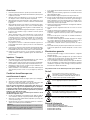 4
4
-
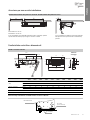 5
5
-
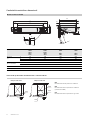 6
6
-
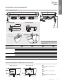 7
7
-
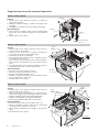 8
8
-
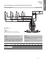 9
9
-
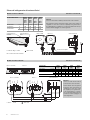 10
10
-
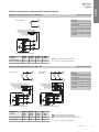 11
11
-
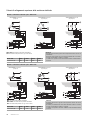 12
12
-
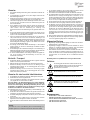 13
13
-
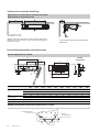 14
14
-
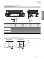 15
15
-
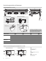 16
16
-
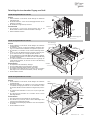 17
17
-
 18
18
-
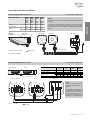 19
19
-
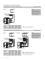 20
20
-
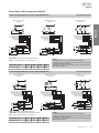 21
21
-
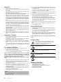 22
22
-
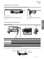 23
23
-
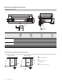 24
24
-
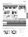 25
25
-
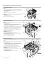 26
26
-
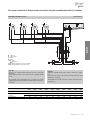 27
27
-
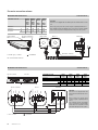 28
28
-
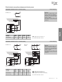 29
29
-
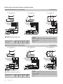 30
30
-
 31
31
-
 32
32
-
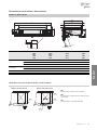 33
33
-
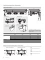 34
34
-
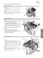 35
35
-
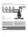 36
36
-
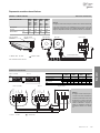 37
37
-
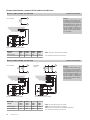 38
38
-
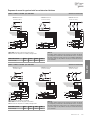 39
39
-
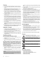 40
40
-
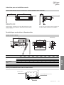 41
41
-
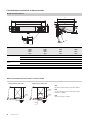 42
42
-
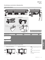 43
43
-
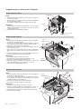 44
44
-
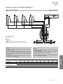 45
45
-
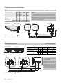 46
46
-
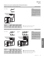 47
47
-
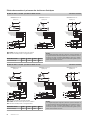 48
48
-
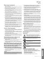 49
49
-
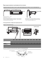 50
50
-
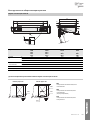 51
51
-
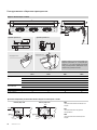 52
52
-
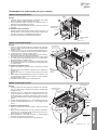 53
53
-
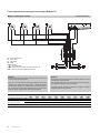 54
54
-
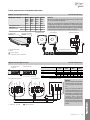 55
55
-
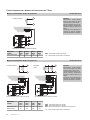 56
56
-
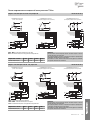 57
57
-
 58
58
-
 59
59
-
 60
60


