
FTE
MANUALE TECNICO
Aeroevaporatori a soffitto
TECHNICAL MANUAL
Ceiling unit coolers
BETRIEBSANLEITUNG
Deckenluftverdampfer
MANUAL TECNICO
Aeroevaporadores de techo
MANUEL TECHNIQUE
Evaporateurs plafonniers
ТЕХНИЧЕСКОЕ РУКОВОДСТВО
Потолочные воздухоохладители


FTE
Indice
- Avvertenze . . . . . . . . . . . . . . . . . . . . . . . . . . . . . . . . . . . . . . . . . . . . . . . . . . . . . . . . .2
- Applicazioni
. . . . . . . . . . . . . . . . . . . . . . . . . . . . . . . . . . . . . . . . . . . . . . . . . . . . . . .2
- Ispezione, trasporto e movimentazione
. . . . . . . . . . . . . . . . . . . . . . .2
- Installazione e messa in opera
. . . . . . . . . . . . . . . . . . . . . . . . . . . . . . . . .2
- Manutenzione generale e controllo
. . . . . . . . . . . . . . . . . . . . . . . . . . . .4
- Caratteristiche tecniche
. . . . . . . . . . . . . . . . . . . . . . . . . . . . . . . . . . . . . . . . .4
- Pericoli
. . . . . . . . . . . . . . . . . . . . . . . . . . . . . . . . . . . . . . . . . . . . . . . . . . . . . . . . . . . . .4
- Norme di riferimento
. . . . . . . . . . . . . . . . . . . . . . . . . . . . . . . . . . . . . . . . . . . .4
- Caratteristiche dimensionali
. . . . . . . . . . . . . . . . . . . . . . . . . . . . . . . . . . . .5
- Caratteristiche tecniche
. . . . . . . . . . . . . . . . . . . . . . . . . . . . . . . . . . . . . . . . .7
- Schemi di collegamento
e assorbimento dei motoventilatori
. . . . . . . . . . . . . . . . . . . . . . . . . . . .7
- Schemi di collegamento
e potenze delle resistenze elettriche
. . . . . . . . . . . . . . . . . . . . . . . . . .8
- Garanzie
. . . . . . . . . . . . . . . . . . . . . . . . . . . . . . . . . . . . . . . . . . . . . . . . . . . . . . . . . .51
Index
- Important . . . . . . . . . . . . . . . . . . . . . . . . . . . . . . . . . . . . . . . . . . . . . . . . . . . . . . . .10
- Applications
. . . . . . . . . . . . . . . . . . . . . . . . . . . . . . . . . . . . . . . . . . . . . . . . . . . . .10
- Inspection, transportation, handling
. . . . . . . . . . . . . . . . . . . . . . . .10
- Installation and set-up
. . . . . . . . . . . . . . . . . . . . . . . . . . . . . . . . . . . . . . . . .10
- General maintenance & control
. . . . . . . . . . . . . . . . . . . . . . . . . . . . . .11
- Technical features
. . . . . . . . . . . . . . . . . . . . . . . . . . . . . . . . . . . . . . . . . . . . . .12
- Hazards / Risks
. . . . . . . . . . . . . . . . . . . . . . . . . . . . . . . . . . . . . . . . . . . . . . . . .12
- Reference standards
. . . . . . . . . . . . . . . . . . . . . . . . . . . . . . . . . . . . . . . . . . .12
- Dimensional features
. . . . . . . . . . . . . . . . . . . . . . . . . . . . . . . . . . . . . . . . . .13
- Technical features
. . . . . . . . . . . . . . . . . . . . . . . . . . . . . . . . . . . . . . . . . . . . . .15
- Connection scheme and fan motor absorption
. . . . . . . . . . . . .15
- Electric heater connection scheme
and electric power
. . . . . . . . . . . . . . . . . . . . . . . . . . . . . . . . . . . . . . . . . . . . . .16
- Warranty
. . . . . . . . . . . . . . . . . . . . . . . . . . . . . . . . . . . . . . . . . . . . . . . . . . . . . . . . . .51
Index
- Hinweise . . . . . . . . . . . . . . . . . . . . . . . . . . . . . . . . . . . . . . . . . . . . . . . . . . . . . . . . .18
- Anwendungen
. . . . . . . . . . . . . . . . . . . . . . . . . . . . . . . . . . . . . . . . . . . . . . . . . . .18
- Kontrolle - Transport - Psitionieren
. . . . . . . . . . . . . . . . . . . . . . . . . .18
- Aufstellung und Inbetriebnahme
. . . . . . . . . . . . . . . . . . . . . . . . . . . . .18
- Allgemeine Wartung und Kontrolle
. . . . . . . . . . . . . . . . . . . . . . . . . .19
- Technische Eigenschaften
. . . . . . . . . . . . . . . . . . . . . . . . . . . . . . . . . . . .20
- Gefahren
. . . . . . . . . . . . . . . . . . . . . . . . . . . . . . . . . . . . . . . . . . . . . . . . . . . . . . . . .20
- Bezugsnormen
. . . . . . . . . . . . . . . . . . . . . . . . . . . . . . . . . . . . . . . . . . . . . . . . . .20
- Dimensionale Eigenschaften
. . . . . . . . . . . . . . . . . . . . . . . . . . . . . . . . . .21
- Technische Eigenschaften
. . . . . . . . . . . . . . . . . . . . . . . . . . . . . . . . . . . .23
- Anschlußplan und Stromaufnahme
der Motorventilatoren
. . . . . . . . . . . . . . . . . . . . . . . . . . . . . . . . . . . . . . . . . .23
- Anschlußplan und Leistungen der Heizstäbe
. . . . . . . . . . . . . .24
- Gewährleistung
. . . . . . . . . . . . . . . . . . . . . . . . . . . . . . . . . . . . . . . . . . . . . . . . . .51
Indice
- Advertencias . . . . . . . . . . . . . . . . . . . . . . . . . . . . . . . . . . . . . . . . . . . . . . . . . . . . .26
- Aplicaciones
. . . . . . . . . . . . . . . . . . . . . . . . . . . . . . . . . . . . . . . . . . . . . . . . . . . . .26
- Inspección transporte y manejo
. . . . . . . . . . . . . . . . . . . . . . . . . . . . . .26
- Instalación y puesta en marcha
. . . . . . . . . . . . . . . . . . . . . . . . . . . . . .26
- Mantenimiento general y control
. . . . . . . . . . . . . . . . . . . . . . . . . . . . .27
- Características técnicas
. . . . . . . . . . . . . . . . . . . . . . . . . . . . . . . . . . . . . . .28
- Peligros
. . . . . . . . . . . . . . . . . . . . . . . . . . . . . . . . . . . . . . . . . . . . . . . . . . . . . . . . . . .28
- Normas de referencia
. . . . . . . . . . . . . . . . . . . . . . . . . . . . . . . . . . . . . . . . . .28
- Características dimensionales
. . . . . . . . . . . . . . . . . . . . . . . . . . . . . . . .29
- Características técnicas
. . . . . . . . . . . . . . . . . . . . . . . . . . . . . . . . . . . . . . .31
- Esquema de conexión
y absorción motoventiladores
. . . . . . . . . . . . . . . . . . . . . . . . . . . . . . . . .31
- Esquema de conexión y potencia
de las resistencias eléctricas
. . . . . . . . . . . . . . . . . . . . . . . . . . . . . . . . .32
- Garantías
. . . . . . . . . . . . . . . . . . . . . . . . . . . . . . . . . . . . . . . . . . . . . . . . . . . . . . . . .51
Index
- Attention . . . . . . . . . . . . . . . . . . . . . . . . . . . . . . . . . . . . . . . . . . . . . . . . . . . . . . . . .34
- Applications
. . . . . . . . . . . . . . . . . . . . . . . . . . . . . . . . . . . . . . . . . . . . . . . . . . . . .34
- Inspection, transport et déplacement
. . . . . . . . . . . . . . . . . . . . . . .34
- Installation et mise en marche
. . . . . . . . . . . . . . . . . . . . . . . . . . . . . . .34
- Entretien général et contrôle
. . . . . . . . . . . . . . . . . . . . . . . . . . . . . . . . .35
- Caractéristiques techniques
. . . . . . . . . . . . . . . . . . . . . . . . . . . . . . . . . .36
- Dangers
. . . . . . . . . . . . . . . . . . . . . . . . . . . . . . . . . . . . . . . . . . . . . . . . . . . . . . . . . .36
- Normes de référence
. . . . . . . . . . . . . . . . . . . . . . . . . . . . . . . . . . . . . . . . . . .36
- Caractéristiques dimensionnelles
. . . . . . . . . . . . . . . . . . . . . . . . . . . .37
- Caractéristiques techniques
. . . . . . . . . . . . . . . . . . . . . . . . . . . . . . . . . .39
- Schéma de connexion
et absorptions motoventilateurs
. . . . . . . . . . . . . . . . . . . . . . . . . . . . . .39
- Schéma de connexion et puissances
des résistances électriques
. . . . . . . . . . . . . . . . . . . . . . . . . . . . . . . . . . .40
- Garantie
. . . . . . . . . . . . . . . . . . . . . . . . . . . . . . . . . . . . . . . . . . . . . . . . . . . . . . . . . .51
Указатель
- Меры предосторожности . . . . . . . . . . . . . . . . . . . . . . . . . . . . . . . . . . . . . . 42
- Область применения
. . . . . . . . . . . . . . . . . . . . . . . . . . . . . . . . . . . . . . . . . . . . 42
- Осмотр, транспортировк а и перемещение
. . . . . . . . . . . . . 42
- Установка и пуск в эксплуатацию
. . . . . . . . . . . . . . . . . . . . . . . . . 42
- Общее техобслуживание и контроль
. . . . . . . . . . . . . . . . . . . . . 44
- Технические характеристики
. . . . . . . . . . . . . . . . . . . . . . . . . . . . . . . . 44
- Опасность
. . . . . . . . . . . . . . . . . . . . . . . . . . . . . . . . . . . . . . . . . . . . . . . . . . . . . . . . . . . 44
- Нормативная документация
. . . . . . . . . . . . . . . . . . . . . . . . . . . . . . . . . 44
- Габаритные характеристики
. . . . . . . . . . . . . . . . . . . . . . . . . . . . . . . . . 45
- Технические характеристики
. . . . . . . . . . . . . . . . . . . . . . . . . . . . . . . . 47
- Схемы подключения и потребления
электровентиляторов
. . . . . . . . . . . . . . . . . . . . . . . . . . . . . . . . . . . . . . . . . . 47
- Схемы подключения и мощностей
электрических ТЭНов
. . . . . . . . . . . . . . . . . . . . . . . . . . . . . . . . . . . . . . . . . . 48
- Гарантии
. . . . . . . . . . . . . . . . . . . . . . . . . . . . . . . . . . . . . . . . . . . . . . . . . . . . . . . . . . . . . .51
Index

2
www.modine.com
Avvertenze
1. Questo manuale è parte integrante del modello e come
tale deve essere conservato per tutto il periodo di vita
dello stesso.
2. Leggere attentamente le istruzioni contenute prima di
qualsiasi operazione sul modello, in caso di dubbio
rispetto a quanto riportato contattare il costruttore.
3. Il modello descritto in questo manuale non è utilizza-
bile così come fornito ma è un componente per
impianti di refrigerazione e deve essere messo in opera
solo da operatori qualificati (vedi anche installazione e
messa in opera).
Applicazioni
1. Il modello deve essere utilizzato esclusivamente per lo
scopo indicato: l’uso diverso da quanto prescritto è da
considerarsi improprio ed esonera il costruttore da
qualsiasi responsabilità.
2. La gamma FTE trova impiego in celle frigorifere e
magazzini refrigerati specificatamente studiati per la
conservazione di frutta e verdura.
3. Il modello standard è equipaggiato con motoventilato-
ri assiali prementi non adatti a sopportare prevalenza
statica aggiuntiva.
Ispezione, trasporto e movimentazione
1. Al ricevimento del modello controllare immediatamen-
te il suo stato di integrità; contestare subito alla com-
pagnia di trasporto qualsiasi eventuale danno.
L’imballaggio viene fabbricato conformemente al
modello, ad adeguati mezzi di trasporto e movimenta-
zione.
2. Durante il trasporto e la movimentazione fare attenzio-
ne a non inclinare il modello. Pericolo di ribaltamento.
3. Durante il trasporto e la movimentazione del modello
imballato, evitare sollecitazioni non conformi e impro-
prie sull’imballaggio, attenersi a tutte le indicazioni
illustrate e mantenere il modello sempre nella posizio-
ne indicata (Fig. 1).
4. Durante il trasporto e la movimentazione del modello
imballato, utilizzare apposite protezioni per evitare di
ferirsi con le parti dell’imballaggio (es. chiodi, tavole,
cartone) e del modello (es. alette, carrozzeria).
5. Durante la movimentazione del modello disimballato,
utilizzare apposite protezioni per evitare di ferirsi con
le parti taglienti (es. alette, carrozzeria).
6. Disimballare il modello il più vicino possibile al luogo
di installazione (vedi anche installazione e messa in
opera). Il modello non deve essere trasportato privo
dell’imballaggio originale.
Installazione e messa in opera
1. L’installazione e la messa in opera del modello deve
essere eseguita da operatori qualificati.
2. Verificare la corretta tenuta delle strutture di supporto
e dei relativi punti di fissaggio in relazione al peso ed
alla forma del modello (vedi tabella caratteristiche tec-
niche).
3. Fissare il modello agli appositi sostegni, rispettando le
quote minime prescritte secondo gli schemi indicati
(vedi Fig. 3 e tabella caratteristiche dimensionali).
4. Il modello non è progettato per fungere da supporto ad
altri componenti dell’impianto.
Fig. 1 - Ispezione, trasporto e movimentazione
a) Rimuovere il coperchio
b) Rimuovere le sezioni laterali
c) Installare il deflettore lato uscita aria
5. Assicurare un volume libero adeguato per una corretta
circolazione dell’aria nell’ambiente conformemente
alla tipologia di cella (es. scaffali, bins, ecc.). Non
ostruire l’aspirazione dei motoventilatori e la mandata
dello scambiatore. Errate zone di posizionamento,
dimensioni di celle inadeguate, travature a soffitto,
stoccaggi eccessivi, formazione impropria di brina
(dovuta ad eccessiva immissione di umidità nella cella
ed a sbrinamenti inadeguati), possono influenzare
negativamente le prestazioni dichiarate e provocare
difettosità o rottura del modello.
6. Per permettere la sostituzione delle resistenze nei
modelli con sbrinamento elettrico, assicurare uno spa-
zio di intervento adeguato o eventualmente realizzare
dei pannelli rimovibili.
7. Evitare l'installazione degli aeroevaporatori vicino alle
porte delle celle.
8. In caso di più modelli installati non si devono effet-
tuare sbrinamenti alternati che sono causa comune di
formazione anomala di brina sugli scambiatori.

3
www.modine.com
Italiano
ze (cicli di sbrinamento). Eventuali sonde di tempera-
tura non devono interrompere il ciclo di sbrinamento,
ma come dispositivo di sicurezza solo una eventuale
sovratemperatura.
Se altrimenti si utilizzano sonde di temperatura di fine
sbrinamento, devono essere collocate nelle zone più
fredde dello scambiatore (zone con maggior formazio-
ne di brina) e a distanza dalle resistenze.
18. L’accessibilità al modello installato, per qualsiasi tipo
di intervento, deve essere riservata a personale esper-
to e qualificato alla conduzione dell’impianto, secondo
le norme vigenti.
19. Installare sugli scarichi condensa i sifoni e verificarne
l'efficacia in tutte le temperature di utilizzo.
9. Ad installazione completata rimuovere la pellicola pro-
tettiva che ricopre il modello.
10. Verificare che la linea elettrica di alimentazione sia
conforme alle caratteristiche del modello.
11. Prima di collegare il modello verificare che siano stati
utilizzati i dispositivi di sezionamento ed interruzione
della rete di alimentazione, di protezione contro la scos-
sa elettrica, di protezione dell’equipaggiamento e quan-
t’altro previsto dalla normativa vigente. Se è richiesto il
cablaggio, il modello viene fornito con scatole di deriva-
zione per l’alimentazione dei motoventilatori e con sca-
tole di derivazione per l’alimentazione delle resistenze
se è richiesto lo sbrinamento elettrico.
12. Le unità sono predisposte per il collegamento elettrico
a terra. L’installatore e/o il conduttore dell’unità sono
tenuti a garantire la presenza di un efficiente collega-
mento alla terra di protezione contro i contatti elettrici
indiretti.
13. Se vengono utilizzati dispositivi di regolazione del
numero di giri dei motoventilatori verificarne la com-
patibilità, dispositivi non compatibili possono generare
rumorosità e danneggiamenti ai motoventilatori; il
costruttore non garantisce le prestazioni indicate per
modelli equipaggiati con dispositivi di regolazione.
14. Verificare che la linea frigorigena sia adeguata alla
tipologia del modello. Prestare particolare attenzione
in fase di collegamento del circuito refrigerante affin-
ché non si deformino i capillari e non si modifichi la
posizione del distributore.
15. Verificare che le condizioni di funzionamento (umidità,
temperature e pressioni) siano conformi a quelle del
modello.
16. Verificare che a conclusione di ogni ciclo di sbrina-
mento elettrico o hot-gas il pacco alettato risulti puli-
to. Accumuli di brina tendono a trasformarsi in ghiac-
cio di difficile pulizia che può provocare la rottura dello
scambiatore.
17. Per i modelli con sbrinamento elettrico, in funzione
della tipologia di cella, definire correttamente il tempo
ed il numero di accensioni/spegnimenti delle resisten-
(A)
(A) In fase di installazione rispettare la quota minima per un
buon funzionamento del motore:
- Ø 350 mm la quota minima è 450 mm.
- Ø 400 mm la quota minima è 600 mm.
- Ø 450 mm la quota minima è 700 mm.
- Ø 500 mm la quota minima è 800 mm.
Fig. 3 - Distanza minima dalla parete lato aspirazione
Fig. 2 - Installazione a soffitto
16x22 mm
Ad installazione avvenuta
rimuovere i piedini per la
movimentazione
Lato
uscita aria
Sollevare
con il pallet fornito

4
www.modine.com
Manutenzione generale e controllo
1. Il modello è costituito da uno scambiatore di calore a
fascio tubiero in rame ed alettatura in alluminio, da
una carrozzeria in lamiera di alluminio-magnesio, da
elettroventilatori dotati di termocontatti interni. Nei
modelli con sbrinamento elettrico, sono inserite nello
scambiatore e fissate agli sgocciolatoi resistenze coraz-
zate in acciaio inossidabile con terminali vulcanizzati
e dispositivi di blocco che ne evitano lo scorrimento.
2. Prima di effettuare qualsiasi intervento di manutenzio-
ne accertarsi che l’alimentazione elettrica del modello
sia stata sezionata: le parti elettriche potrebbero esse-
re collegate a controlli automatici. Tutte le operazioni
di manutenzione devono essere effettuate da persona-
le esperto e qualificato.
3. Verificare periodicamente i fissaggi del modello, le
connessioni elettriche e i collegamenti all’impianto fri-
gorigeno.
4. Provvedere alla pulizia periodica della carrozzeria uti-
lizzando soluzioni acquose di alcool etilico diluito al
50% o eventualmente dell’acqua saponata con pH
neutro. Non utilizzare solventi, soluzioni acide, basi-
che o contenenti ammoniaca ed evitare l’utilizzo di
abrasivi in genere.
5. Provvedere alla pulizia periodica del pacco alettato uti-
lizzando soluzioni acquose di alcool etilico diluito al
50% o eventualmente dell’acqua ossigenata se è
richiesto un maggior effetto igienizzante. Non utilizza-
re soluzioni contenenti cloro o ammoniaca. Utilizzare
eventualmente dell’acqua saponata con pH neutro su
residui grassi risciacquando accuratamente.
6. Controllare l’efficacia dello sbrinamento. Per i modelli
con sbrinamento elettrico, verificare periodicamente la
funzionalità di tutte le resistenze. Il costruttore non
risponde in alcun modo di difettosità e danni creati da
malfunzionamenti non rilevati (es. dannosi accumuli di
ghiaccio).
7. Provvedere alla sostituzione delle resistenze elettriche
non funzionanti. Prestare particolare attenzione nelle
fasi di installazione per evitare danni alle vulcanizza-
zioni; ripristinare correttamente i collegamenti (vedi
schemi allegati) ed i sistemi di fissaggio esistenti per
evitare movimenti delle stesse durante il funzionamen-
to.
8. I periodi di verifica e manutenzione sono dipendenti
dalla tipologia di cella, pertanto da definirsi da perso-
nale esperto e qualificato.
9. Per qualsiasi operazione sul modello, non descritta su
questo manuale, contattare il costruttore.
Caratteristiche tecniche
- Passo 7,0 mm.
- Capacità: da 12,5 a 59,9 kW.
- Portata d’aria: da 7930 a 43030 m
3
/h.
- temperatura di funzionamento min/max: –25/+40 °C.
Pericoli
1. Pericolo di elettrocuzione. Il modello è
provvisto di elettroventilatori e resistestenze
elettriche di sbrinamento. La tensione di
alimentazione è di 400V AC. Utilizzare sistemi
di sicurezza elettrica previsti dalla normativa
vigente.
2. Pericolo di ustione. Le resistenze elettriche di
sbrinamento possono raggiungere
temperature superficiali di 350°C.
3. Pericolo di taglio. Lo scambiatore di calore è
costituito da alette con bordi taglienti e la
carrozzeria da parti in lamiera.
4. Pericolo parti in movimento. Il modello è
provvisto di elettroventilatori dotati di griglia di
protezione esterna.
5. Pericolo di schiacciamento. Il modello può
pesare oltre 270 kg.
Norme di riferimento
- DIRETTIVA MACCHINE 2006/42/EC
- DIRETTIVA BASSA TENSIONE 2014/35/UE
- DIRETTIVA COMP. ELETTROMAGNETICA 2014/30/UE
- DIRETTIVA PED 2014/68/UE
- DIRETTIVA ERP 2009/125/EC

5
www.modine.com
Italiano
A
177
EE
F
==13 13
307
1004 450
647
600
547
177
577
Brackets position
B
B B
B C B
B 2C B
B 3C B
B 2C 2C B
A
CB177B177
647
600
547
185
1039 600
604
632
E E
F
==13 13
307
Modello FTE 403A07 404A07 405A7 406A07
Dimensioni
mm A 2674 3424 4174 4924
B 785 785 785 785
C 750 (2x) 750 (3x) 750 (4x) 750
E 1344 848 1035 1223
F-1728 2103 2478
Modello FTE 353A07 354A07 355A07 356A07 357A07 358A07
Dimensioni
mm A 2224 2824 3424 4024 4624 5224
B 1870 1235 1235 1235 1235 1235
C - - 600 1200 1800 1200
E 1119 1419 848 998 1148 1298
F --1728 2028 2328 2628
Caratteristiche dimensionali
FTE Ø 350 mm
FTE Ø 400 mm

6
www.modine.com
A
CB177
904
989 700
704
732
647
600
547
185
B177
E E
F
= =13 13
307
A
704
732
B
E13 13
307
EF
CCCB177 177
1004
747
700
647 185
1039 800
Modello FTE 453A07 454A07 455A07 456A07
Dimensioni
mm A 3274 4224 5174 6124
B 985 (2x) 985 (3x) 985 (4x) 985
C 950 950 950 950
E 816 1048 1285 1523
F 1655 2128 2603 3073
Modello FTE 505A07 506A7
Dimensioni
mm A 5424 6424
B 1035 1035
C 1000 (4x) 1000
E 1355 1598
F 2728 3228
FTE Ø 450 mm
FTE Ø 500 mm
Caratteristiche dimensionali

7
www.modine.com
Italiano
Modello FTE
Capacità nominale
kW
Portata aria m
3
/h
Freccia aria m
Superficie interna m
2
Superficie esterna m
2
Attacchi scambiatore In tube (mm)
Out (mm)
Motoventilatori n° x Ø mm
Assorbimento motoventilatori A
Potenza nominale W
Capacità circuito dm
3
Sbrinamento elettrico W
Attacco scarico Ø (GAS)
1) Peso netto kg
Modello FTE
Capacità nominale
kW
Portata aria m
3
/h
Freccia aria m
Superficie interna m
2
Superficie esterna m
2
Attacchi scambiatore In tube (mm)
Out (mm)
Motoventilatori n° x Ø mm
Assorbimento motov. A
Potenza nominale W
Capacità circuito dm
3
Sbrinamento elettrico W
Attacco scarico Ø (GAS)
1) Peso netto kg
Caratteristiche tecniche
353A07 354A07 355A07 356A07 357A07 358A07 403A07 404A07
12,5 16,4 21,4 25,6 29,2 32,3 16,3 22,5
7930 10580 13200 15860 18510 21150 10760 14350
19 22 25 27 28 30 22 24
8,6 11,4 14,3 17,2 20 22,9 11,8 15,7
65 86,8 108 130 152 174 90 119
22 22 28 28 28 28 22 28
35 35 42 42 42 42 35 42
3 x 350 4 x 350 5 x 350 6 x 350 7 x 350 8 x 350 3 x 400 4 x 400
2,88 3,84 4,8 5,76 6,72 7,68 2,04 2,72
555 740 925 1110 1295 1480 810 1080
22 29,3 36,7 44 51,3 58,7 30,1 40,1
5940 7920 9900 11880 13860 15840 7380 9840
1x 3/4 1x 3/4 2x 3/4 2x 3/4 2x 3/4 2x 3/4 1x 1 1/4 2x 1 1/4
160 200 240 280 320 360 200 255
405A7 406A07 453A07 454A07 455A07 456A07 505A07 506A7
28,6 33,4 27,6 36,5 45,8 52,3 48,1 59,9
17930 21500 17040 22720 28400 34080 35900 43030
28 31 27 31 35 38 40 44
19,7 23,6 17,6 23,5 29,3 35,2 31 37,1
149 179 134 178 223 267 235 282
28 28 35 35 35 35 35 35
42 42 54 54 54 54 54 54
5 x 400 6 x 400 3 x 450 4 x 450 5 x 450 6 x 450 5 x 500 6 x 500
3,4 4,08 7,08 9,44 11,8 14,16 8,5 10,2
1350 1620 1470 1960 2450 2940 3850 4620
50,2 60,2 44,7 59,6 74,5 89,4 75 93
12300 14760 9360 12480 15600 18720 16500 19800
2x 1 1/4 2x 1 1/4 2x 1 1/4 2x 1 1/4 2x 1 1/4 2x 1 1/4 2x 1 1/4 2x 1 1/4
310 365 270 340 415 490 510 600
1) Il peso è riferito ai modelli con sbrinamento elettrico ED.
Schema di collegamento e assorbimento dei motoventilatori
L
U1
U2
Z
N PE
TB TB Z2
N L PE
Z1 U2 U1
PE
TB TB W2
L2 L1 L3
U1 U2 V1 V2
U1 Z U2
NL
PE
TOP TOP
W1
FTE Ø 350 mm
~1 230V 50 Hz
U1 - Blu
Z - Marrone
U2 - Nero
PE - Giallo/Verde
L
U1
U2
Z
N PE
TB TB Z2
NLPE
Z1 U2 U1
PE
TB TB W2
L2 L1 L3
U1 U2 V1 V2
U1 Z U2
NL
PE
TOP TOP
W1
FTE Ø 400 mm
~1 230V 50 Hz
U1 - Marrone
U2 - Blu
Z1 - Nero
Z2 - Arancio
TB - Bianco
Attenzione
Seguire rigorosamente gli schemi elettrici riportati per evitare il danneggiamento del motore.
Prima di utilizzare sistemi di regolazione del numero di giri dei motori verificare la compatibilità con i motori stessi, sistemi non com-
patibili possono generare rumorosità e danneggiamenti; il costruttore non si assume responsabilità alcuna sulle prestazioni dei
modelli equipaggiati con sistemi di regolazione.
Termocontatti di protezione interni (TB, TOP)
I termocontatti sono elementi di azionamento dipendenti dalla temperatura, che vengono inseriti, isolati, negli avvolgimenti dei moto-
ri; essi aprono un contatto elettrico quando viene superata la temperatura permanente massima ammissibile.
I termocontatti devono essere collegati ai circuiti di comando dei contattori di modo che in caso di disturbi non si abbia una reinser-
zione automatica.
I motori Ø 350 mm sono dotati di termocontatti di protezione interni a riarmo automatico.

8
www.modine.com
Schema di collegamento e assorbimento dei motoventilatori
L
U1
U2
Z
N PE
TB TB Z2
N L PE
Z1 U2 U1
PE
TB TB W2
L2 L1 L3
U1 U2 V1 V2
U1 Z U2
NL
PE
TOP TOP
W1
FTE Ø 450 mm
~1 230V 50 Hz
L
U1
U2
Z
N PE
TB TB Z2
NLPE
Z1 U2 U1
PE
TB TB W2
L2 L1
L3
U1 U2 V1
V2
U1 Z U2
NL
PE
TOP TOP
W1
FTE Ø 500 mm
~3 400V ∆/Y 50 Hz
U1 - Blu
Z - Marrone
U2 - Nero
PE - Giallo\Verde
TOP - Grigio
U1 - Marrone
V1 - Blu
W1 - Nero
U2 - Rosso
V2 - Grigio
W2 - Arancio
TB - Bianco
V
1
W
1
W
1
V
1
V
1
U
1
U
1
V
2
V
2
U
2
U
2
W
2
W
2
2
RBB1
RBA1
R
N
S
T
RBA2
V
U
1
2
RSA1
U
U
1
2
RSA2
U
V
1
2
RBA3
V
W
1
2
RBA1
W
V
1
2
RBB2
V
RBA2
W
1
2
W
RSA1
RBA3
RBB1
RBB2
RSA2
W
1
W
1
W
1
V
1
V
1
U
1
U
1
V
2
V
2
U
2
U
2
W
2
W
2
2
RBB1
RBB1
R
N
S
T
RBB2
RBA1
W
V
1
2
RBB3
V
U
1
2
RSA1
U
U
1
2
RSA2
U
W
1
2
RBA1
W
V
1
2
RBA2
V
W
1
2
RBB2
W
RBB4
V
1
2
V
RSA1
RBA2
RBB3
RBB4
RSA2
FTE Ø 350 - 400 mm
Schemi di collegamento e potenze delle resistenze elettriche
Attenzione
È d’obbligo l’applicazione di opportuni sistemi di protezione termica sulle linee di alimentazione.
Provvedere periodicamente alla verifica delle funzionalità di tutte le resistenze per evitare accumuli dannosi di ghiaccio sui modelli.
Il costruttore non risponde in alcun modo di difettosità create da malfunzionamenti non rilevati.
Modello FTE
Motoventilatori
n° x Ø mm
RBA - RSA W
RBB W
353A07 354A07 355A07 356A07 357A07 358A07 403A07 404A07 405A7 406A07
3 x 350 4 x 350 5 x 350 6 x 350 7 x 350 8 x 350 3 x 400 4 x 400 5 x 400 6 x 400
990 1320 1650 1980 2310 2640 1230 1640 2050 2460
495 660 825 990 1155 1320 615 820 1025 1230
RBA - Resistenza elettrica di alta potenza nella batteria.
RBB - Resistenza elettrica di bassa potenza nella batteria.
RSA - Resistenza elettrica sullo sgocciolatoio interno.
Attenzione
Seguire rigorosamente gli schemi elettrici riportati per evitare il danneggiamento del motore.
Prima di utilizzare sistemi di regolazione del numero di giri dei motori verificare la compatibilità con i motori stessi, sistemi non com-
patibili possono generare rumorosità e danneggiamenti; il costruttore non si assume responsabilità alcuna sulle prestazioni dei
modelli equipaggiati con sistemi di regolazione.
Termocontatti di protezione interni (TB, TOP)
I termocontatti sono elementi di azionamento dipendenti dalla temperatura, che vengono inseriti, isolati, negli avvolgimenti dei moto-
ri; essi aprono un contatto elettrico quando viene superata la temperatura permanente massima ammissibile.
I termocontatti devono essere collegati ai circuiti di comando dei contattori di modo che in caso di disturbi non si abbia una reinser-
zione automatica.
I motori Ø 350 mm sono dotati di termocontatti di protezione interni a riarmo automatico.

9
www.modine.com
Italiano
V
1
W
1
W
1
V
1
V
1
U
1
U
1
V
2
V
2
U
2
U
2
W
2
W
2
2
RBB1
RBA1
R
N
S
T
RBA2
V
U
1
2
RSA1
U
U
1
2
RSA2
U
V
1
2
RBA3
V
W
1
2
RBA1
W
V
1
2
RBB2
V
RBA2
W
1
2
W
RSA1
RBA3
RBB1
RBB2
RSA2
W
1
W
1
W
1
V
1
V
1
U
1
U
1
V
2
V
2
U
2
U
2
W
2
W
2
2
RBB1
RBB1
R
N
S
T
RBB2
RBA1
W
V
1
2
RBB3
V
U
1
2
RSA1
U
U
1
2
RSA2
U
W
1
2
RBA1
W
V
1
2
RBA2
V
W
1
2
RBB2
W
RBB4
V
1
2
V
RSA1
RBA2
RBB3
RBB4
RSA2
FTE Ø 450 - 500 mm
Schemi di collegamento e potenze delle resistenze elettriche
Attenzione
È d’obbligo l’applicazione di opportuni sistemi di protezione termica sulle linee di alimentazione.
Provvedere periodicamente alla verifica delle funzionalità di tutte le resistenze per evitare accumuli dannosi di ghiaccio sui modelli.
Il costruttore non risponde in alcun modo di difettosità create da malfunzionamenti non rilevati.
Modello FTE
Motoventilatori
n° x Ø mm
RBA - RSA W
RBB W
453A07 454A07 455A07 456A07 505A07 506A7
3 x 450 4 x 450 5 x 450 6 x 450 5 x 500 6 x 500
1560 2080 2600 3120 2750 3300
780 1040 1300 1560 1375 1650
RBA - Resistenza elettrica di alta potenza nella batteria.
RBB - Resistenza elettrica di bassa potenza nella batteria.
RSA - Resistenza elettrica sullo sgocciolatoio interno.

10
www.modine.com
Hinweise
1. Als Bestandteil des Modells ist die Betriebsanleitung wäh-
rend der ganzen Lebensdauer des Luftverdampfers aufzu-
bewahren.
2. Vor jedem Eingriff die Betriebsanleitung aufmerksam durch-
lesen, im Zweifelfalle mit dem Hersteller Kontakt aufneh-
men.
3. Das in dieser Betriebsanleitung beschriebene Gerät ist nicht
im gelieferten Zustand einsetzbar, sondern ist ein
Bestandteil von Kältetechnikanlagen und die
Inbetriebnahme darf nur von qualifiziertem Personal vorge-
nommen werden (siehe auch Aufstellung und
Inbetriebnahme).
Anwendungen
1. Das Gerät ausschließlich zu dem angegebenen Zweck ver-
wenden: eine von den Vorgaben abweichende Anwendung
ist als unsachgemäß zu verstehen, und befreit den
Hersteller von jeder Verantwortung.
2. Die Produktpalette FTE wird in Kühlzellen und gekühlten
Lagerräumen eingesetzt, die speziell für Obst und Gemüse
eingerichtet wurden.
3. Die STD Modelle sind mit Axialmotorventilatoren ausgestattet
und daher nicht kanalisierbar oder jedenfalls keine weiteren
Druckverluste verkraften.
Kontrolle – Transport – Positionieren
1. Bei Erhalt des Geräts sofort den Integritätszustand kontrol-
lieren; jeglichen eventuellen Schaden sofort dem Spediteur
beanstanden. Die Verpackung ist dem Gerät, den
Transportmitteln, und dem Positionieren angepasst.
2. Während des Transports und Positionierens ist zu beachten,
dass das Gerät nicht schräg gestellt wird, da dieses umkip-
pen könnte.
3. Während des Transports und Positionierens des verpack-
ten Geräts ist unnötiger Druck auf die Verpackung zu ver-
meiden, alle beschriebenen Hinweise sind einzuhalten und
das Gerät ist immer in der angegebenen Position zu halten
(Fig. 1).
4. Während des Transports und Positionierens des verpackten
Geräts muss man sich entsprechend schützen, um die
Verletzungsgefahr durch Bestandteile der Verpackung (z.B.
Nägel, Holzbrette, Kartone) und die des Geräts (z.B.
Lamellen, Gehäuse) zu vermeiden.
5. Während des Positionierens des ausgepackten Geräts
muss man sich entsprechend schützen, um die
Verletzungsgefahr durch scharfe Stellen (z.B. Lamellen,
Gehäuse) zu vermeiden.
6. Das Gerät ist so nahe wie möglich der Montagestelle aus-
zupacken (siehe auch Aufstellung und Inbetriebnahme).
Das Gerät darf nur in seiner Originalverpackung transpor-
tiert werden.
Aufstellung und Inbetriebnahme
1. Die Aufstellung und Inbetriebnahme des Geräts darf nur von
qualifiziertem Personal durchgeführt werden.
2. Die Tragfähigkeit der Strukturen und der entsprechenden
Befestigungsstellen bezüglich des Gerätegewichts und der
Geräteform überprüfen (siehe Tabelle technische
Eigenschaften).
3. Das Gerät ausschließlich an den dafür bestimmten
Halterungen befestigen, wobei die vorgegebenen
Mindestabmessungen laut den aufgeführten Schemen ein-
zuhalten sind (siehe Tabelle dimensionale Eigenschaften).
4. Das Gerät wurde nicht als Stütze anderer
Anlagenkomponenten entworfen.
5. Für eine einwandfreie Luftzirkulation im Raum muss genü-
gend Freiraum entsprechend dem Kühlzellentyp (z.B.
Tablettwagen, Luftkanalisierung, etc.) vorhanden sein. Die
Fig. 1 - Kontrolle – Transport – Positionieren
a) Abdeckung entfernen
b) Entfernen Sie Seitenteile
c) Montieren Sie den Deflektor am Luftaustrittsseite
Ansaugung der Motorventilatoren und den Luftstrom zum
Wärmeaustauscher nicht verstopfen. Fehlerhafte
Einbaulagen, ungeeignete Dimensionen der Kühlzellen,
Deckenträger, übermäßige Lagerung, überhöhte
Reifbildung durch zu hohe Feuchtigkeit in der Kühlzelle oder
durch ungeeignete Abtauung können zu Behinderungen der
Luftansaugung und/oder Luftaustritts des
Wärmeaustauschers führen und dadurch die angegebenen
Leistungen negativ beeinflussen und auch Schäden am
Gerät hervorrufen.
6. Um den Ersatz der Heizst.be in den Ger.ten mit elektrischer
Abtauung zu erm.glichen, ist ein angemessener Raum für
jeden Eingriff vorzusehen oder sind eventuell abnehmbare
Paneele anzubringen.
7. Die Installation der Luftverdampfer in der Nähe der Zellentüren
vermeiden.
8. Nach beendeter Installation den am Gerät befindlichen
Schutzfilm entfernen.
9. Die Stromzuleitung muss den Eigenschaften des Geräts
angepasst sein.
10. Vor dem Anschließen des Gerätes muss überprüft werden,
dass die Vorrichtungen zur Trenn- und Netzschaltung, zum

11
www.modine.com
Allgemeine Wartung und Kontrolle
1. Das Gerät besteht aus einem Wärmeaustauscher mit
Rohrbündel aus Kupfer und Berippung aus Aluminium, aus
einem Aluminium-Magnesium Gehäuse, aus mit inneren
Temperaturwächtern versehenen Ventilatormotoren. Bei
den Geräten mit elektrischer Abtauung sind Heizstäbe aus
Edelstahl mit vulkanisierten Endverschlüssen im
Wärmeaustauscher eingeführt und an den Tropfwannen mit
Befestigungsvorrichtungen fixiert, die das Bewegen vermei-
den.
2. Vor jeglichem Wartungseingriff ist sicherzustellen, dass die
Stromzuführung vom Hauptnetz getrennt ist: die elektri-
schen Teile könnten automatisch anlaufen. Alle
Wartungseingriffe müssen von qualifiziertem Personal
durchgeführt werden.
Schutz vor Stromschlägen, zum Schutz der Ausrüstung und
sonstiger Vorgaben gemäß den gültigen Normen angewen-
det wurden. Wenn die Verkabelung vorgesehen ist, wird das
Gerät mit Abzweigdosen für den Anschluss von
Ventilatormotoren geliefert und mit Abzweigdosen für den
Anschluss der Heizstäbe bei elektrischer Abtauung.
11. Wenn Vorrichtungen für die Drehzahlregelung der
Ventilatormotoren verwendet werden, muss ihre
Kompatibilität überprüft werden, unkompatible
Vorrichtungen können Geräusche entwickeln und die
Ventilatormotoren beschädigen; der Hersteller garantiert die
angegebenen Leistungsangaben für die mit Drehzahlregler
ausgestatteten Geräte nicht.
12. 12. Die Einheiten sind für den elektrischen
Erdungsanschluss vorgesehen. Der Installationsfachmann
bzw. Betreiber der Einheit muss einen funktionstüchtigen
Anschluss an den Erdungsschutzleiter gegen indirekte
Stromkontakte gewährleisten.
13. Die Betriebsbedingungen (Feuchtigkeit, Temperaturen und
Drucke) müssen dem Gerät entsprechen.
14. Am Ende jeder elektrischen Abtau- oder
Heißgasabtauphase muss das Lamellenpaket sauber sein.
Anhäufungen von Reif können zur Eisbildung schwieriger
Entfernung führen, die den Wärmeaustauscher beschädi-
gen kann.
15. Für die Geräte mit elektrischer Abtauung ist die Zeit und
die Anzahl von Ein- und Ausschaltung der Heizstäbe
(Abtauphasen) je nach Kühlzellentyp korrekt zu bestim-
men. Eventuelle Temperaturfühler sollen nicht die korrekte
Abtauphase, sondern nur eine eventuelle Übererwärmung
unterbrechen, die Temperaturfühler sind
Schutzvorrichtungen und dienen nicht zur Regelung der
Abtauung. Wenn man Temperaturfühler am Ende der
Abtauung anwendet, müssen diese an den kältesten
Zonen des Wärmeaustauschers (wo die Reifbildung am
größten ist) und entfernt von den Heizstäben angebracht
werden.
16. Für jeden Eingriff muss der Zugang zu dem installierten
Gerät dem für die Anlage qualifizierten Personal gemäß den
gültigen Normen vorbehalten sein.
17. An den Kondensabflußrohren die Siphone montieren und
die Wirksamkeit bei allen Betriebstemperaturen überprüfen.
(A)
(A) Für einen optimalen Betrieb des Motors den
Mindestabstand bei der Montage einhalten.
- Ø 350 mm das Minimum ist 450 mm.
- Ø 400 das Minimum ist 600 mm.
- Ø 450 mm das Minimum ist 700 mm.
- Ø 500 mm das Minimum ist 800 mm.
Fig. 3 - Mindestabstand von der Wand, Ansaugseite
Fig. 2 - Deckenmontage
16x22 mm
Nach der Installation
entfernen Sie die Füße
Seite
Luftaustritt
Heben Sie mit
die mitgelieferte Pallet
Deutsch

12
www.modine.com
3. Regelmäßige Überprüfung der Befestigungen der elektri-
schen Anschlüsse. Kältemittelanschlüsse auf Dichtheit prü-
fen.
4. Regelmäßige Reinigung des Gehäuses mit wässrigen
Lösungen aus mit 50% verdünntem Äthylalkohol oder even-
tuell mit Seifenwasser mit neutralem pH-Wert. Keine
Lösungsmittel, keine sauren, basischen oder ammoniakhal-
tigen Lösungen, und keine Reibepulver im allgemeinen ver-
wenden.
5. Regelmäßige Reinigung des Lamellenpakets mit wässrigen
Lösungen aus mit 50% verdünntem Äthylalkohol oder even-
tuell mit Wasserstoffperoxid, wenn eine höhere hygienische
Wirkung erforderlich ist. Keine chlor- oder ammoniakhalti-
gen Lösungen verwenden. Fetthaltige Rückstände eventuell
mit Seifenwasser mit neutralem pH-Wert behandeln und
sorgfältig abspülen.
6. Die Wirksamkeit der Abtauung kontrollieren. Für die
Geräte mit elektrischer Abtauung ist die
Funktionsfähigkeit aller Heizstäbe regelmäßig zu überprü-
fen. Der Hersteller ist keinesfalls für Mängel und Schäden
verantwortlich, die aus nicht festgestellten
Funktionsstörungen entstehen (z.B. schädliche
Eisanhäufungen).
7. Nicht funktionierende elektrische Heizstäbe müssen ausge-
tauscht werden. Während der Installationsphasen ist darauf
zu achten, dass Schäden an den Vulkanisierungen vermie-
den werden; die Anschlüsse (siehe beiliegende Schemen)
und die bestehenden Befestigungssysteme müssen korrekt
wiederhergestellt werden, damit Bewegungen der Heizstäbe
vermieden werden.
8. Da die Prüf- und Wartungszeiten vom Kühlzellentyp abhän-
gen, dürfen diese nur von qualifiziertem Personal bestimmt
werden.
9. Für jeden Eingriff am Modell, der nicht in dieser
Betriebsanleitung beschrieben ist, den Hersteller kontak-
tieren.
Technische Eigenschaften
- Leistuing: von 12,5 zu 59,5 kW
- Luftmenge: von 7930 zu 43030 m3/h
- Betriebstemperatur: min/max: –25/+40 °C.
Gefahren
1. Stromschlaggefahr. Das Gerät ist mit
Motorventilatoren und elektrischen
Abtauheizungen versehen. Die
Stromspannung ist 400 V AC. Elektrische
Sicherheitssysteme gemäß den geltenden
Normen anwenden.
2. Verbrennungsgefahr. Die elektrischen
Abtauheizungen können
Oberflächentemperaturen von 350° C errei-
chen.
3. Schnittgefahr. Der Wärmeaustauscher besteht
aus Lamellen mit scharfen Kanten und das
Gehäuse besteht aus Blechteilen.
4. Gefahr durch sich bewegende Teile. Das Gerät
ist mit Motorventilatoren mit äußerem
Schutzgitter versehen.
5. Quetschgefahr. Das Gerät kann über 270 kg
wiegen.
Bezugsnormen
- MASCHINEN - RICHTLINIE 2006/42/EC
- NIEDERSPANNUNG - RICHTLINIE 2014/35/UE
- RICHTLINIE ELEKTROMAGNETISCHE KOMP. 2014/30/UE
- PED RICHTLINIE 2014/68/UE
- ERP RICHTLINIE 2009/125/EC

13
www.modine.com
A
177
EE
F
==13 13
307
1004 450
647
600
547
177
577
Brackets position
B
B B
B C B
B 2C B
B 3C B
B 2C 2C B
A
CB177B177
647
600
547
185
1039 600
604
632
E E
F
==13 13
307
Modell FTE 403A07 404A07 405A7 406A07
Abmessungen
mm A 2674 3424 4174 4924
B 785 785 785 785
C 750 (2x) 750 (3x) 750 (4x) 750
E 1344 848 1035 1223
F-1728 2103 2478
Modell FTE 353A07 354A07 355A07 356A07 357A07 358A07
Abmessungen
mm A 2224 2824 3424 4024 4624 5224
B 1870 1235 1235 1235 1235 1235
C - - 600 1200 1800 1200
E 1119 1419 848 998 1148 1298
F --1728 2028 2328 2628
Dimensionale Eigenschaften
FTE Ø 350 mm
FTE Ø 400 mm
Deutsch

14
www.modine.com
A
CB177
904
989 700
704
732
647
600
547
185
B177
E E
F
= =13 13
307
A
704
732
B
E13 13
307
EF
CCCB177 177
1004
747
700
647 185
1039 800
Modell FTE 453A07 454A07 455A07 456A07
Abmessungen
mm A 3274 4224 5174 6124
B 985 (2x) 985 (3x) 985 (4x) 985
C 950 950 950 950
E 816 1048 1285 1523
F 1655 2128 2603 3073
Modell FTE 505A07 506A7
Abmessungen
mm A 5424 6424
B 1035 1035
C 1000 (4x) 1000
E 1355 1598
F 2728 3228
FTE Ø 450 mm
FTE Ø 500 mm
Dimensionale Eigenschaften

15
www.modine.com
Modell FTE
Nennleistung
kW
Luftmenge m
3
/h
Wurfweite m
Innenoberfläche m
2
Außenoberfläche m
2
Batterieanschlüsse In tube (mm)
Out (mm)
Ventilatormotoren n° x Ø mm
Stromaufn. Motoren A
Nennleistung W
Rohrinhalt dm
3
Elektrische Abtauung W
Tauwasserabfluß Ø (GAS)
Nettogewicht kg
Modell FTE
Nennleistung
kW
Luftmenge m
3
/h
Wurfweite m
Innenoberfläche m
2
Außenoberfläche m
2
Batterieanschlüsse In tube (mm)
Out (mm)
Ventilatormotoren n° x Ø mm
Stromaufn. Motoren A
Nennleistung W
Rohrinhalt dm
3
Elektrische Abtauung W
Tauwasserabfluß Ø (GAS)
Nettogewicht kg
Technische Eigenschaften
353A07 354A07 355A07 356A07 357A07 358A07 403A07 404A07
12,5 16,4 21,4 25,6 29,2 32,3 16,3 22,5
7930 10580 13200 15860 18510 21150 10760 14350
19 22 25 27 28 30 22 24
8,6 11,4 14,3 17,2 20 22,9 11,8 15,7
65 86,8 108 130 152 174 90 119
22 22 28 28 28 28 22 28
35 35 42 42 42 42 35 42
3 x 350 4 x 350 5 x 350 6 x 350 7 x 350 8 x 350 3 x 400 4 x 400
2,88 3,84 4,8 5,76 6,72 7,68 2,04 2,72
555 740 925 1110 1295 1480 810 1080
22 29,3 36,7 44 51,3 58,7 30,1 40,1
5940 7920 9900 11880 13860 15840 7380 9840
1x 3/4 1x 3/4 2x 3/4 2x 3/4 2x 3/4 2x 3/4 1x 1 1/4 2x 1 1/4
160 200 240 280 320 360 200 255
405A7 406A07 453A07 454A07 455A07 456A07 505A07 506A7
28,6 33,4 27,6 36,5 45,8 52,3 48,1 59,9
17930 21500 17040 22720 28400 34080 35900 43030
28 31 27 31 35 38 40 44
19,7 23,6 17,6 23,5 29,3 35,2 31 37,1
149 179 134 178 223 267 235 282
28 28 35 35 35 35 35 35
42 42 54 54 54 54 54 54
5 x 400 6 x 400 3 x 450 4 x 450 5 x 450 6 x 450 5 x 500 6 x 500
3,4 4,08 7,08 9,44 11,8 14,16 8,5 10,2
1350 1620 1470 1960 2450 2940 3850 4620
50,2 60,2 44,7 59,6 74,5 89,4 75 93
12300 14760 9360 12480 15600 18720 16500 19800
2x 1 1/4 2x 1 1/4 2x 1 1/4 2x 1 1/4 2x 1 1/4 2x 1 1/4 2x 1 1/4 2x 1 1/4
310 365 270 340 415 490 510 600
1) Das Gewicht bezieht sich auf die Modelle mit elektrischer Abtauung ED.
Anschlußplan und Stromaufnahme der Motorventilatoren
L
U1
U2
Z
N PE
TB TB Z2
N L PE
Z1 U2 U1
PE
TB TB W2
L2 L1 L3
U1 U2 V1 V2
U1 Z U2
NL
PE
TOP TOP
W1
FTE Ø 350 mm
~1 230V 50 Hz
U1 - Hellblau
Z - Braun
U2 - Schwarz
PE - Gelb/grün
L
U1
U2
Z
N PE
TB TB Z2
NLPE
Z1 U2 U1
PE
TB TB W2
L2 L1 L3
U1 U2 V1 V2
U1 Z U2
NL
PE
TOP TOP
W1
FTE Ø 400 mm
~1 230V 50 Hz
U1 - Braun
U2 - Hellblau
Z1 - Schwarz
Z2 - Orange
TB - Weiß
Achtung
die Motoren sind mit automatisch wiederaufrüstbaren Temperaturwächtern ausgestattet.
Vor Anwendung von Drehzahlreglern die Eignung für die Motoren überprüfen; nicht verträgliche Systeme können Lärm und
Schäden am Motor hervorrufen; der Hersteller lehnt jede Verantwortung für mit Drehzahlreglern ausgestattete Geräte ab.
Innere Schutztemperaturwächter (TB, TOP)
Die Temperaturwächter sind temperaturunabhängige Schaltelemente, die in die Wicklungen der Motoren isoliert ein-
gebettet werden; sie öffnen einen elektrischen Kontakt, sobald die höchstzulässige Dauertemperatur überschritten
wird.Die Temperaturwächter sind so in den Steuerstromkreis von Schützen einzufügen, daß im Störungsfalle keine
selbsttätige Wiedereinschaltung erfolgt.
Die Motoren sind mit Ø 350 mm Temperaturwächtern ausgestattet.
Deutsch

16
www.modine.com
Anschlußplan und Stromaufnahme der Motorventilatoren
L
U1
U2
Z
N PE
TB TB Z2
N L PE
Z1 U2 U1
PE
TB TB W2
L2 L1 L3
U1 U2 V1 V2
U1 Z U2
NL
PE
TOP TOP
W1
FTE Ø 450 mm
~1 230V 50 Hz
L
U1
U2
Z
N PE
TB TB Z2
NLPE
Z1 U2 U1
PE
TB TB W2
L2 L1
L3
U1 U2 V1
V2
U1 Z U2
NL
PE
TOP TOP
W1
FTE Ø 500 mm
~3 400V ∆/Y 50 Hz
U1 - Hellblau
Z - Braun
U2 - Schwarz
PE - Gelb/grün
TOP - Grau
U1 - Braun
V1 - Hellblau
W1 - Schwarz
U2 - Rote
V2 - Grau
W2 - Orange
TB - Weiß
V
1
W
1
W
1
V
1
V
1
U
1
U
1
V
2
V
2
U
2
U
2
W
2
W
2
2
RBB1
RBA1
R
N
S
T
RBA2
V
U
1
2
RSA1
U
U
1
2
RSA2
U
V
1
2
RBA3
V
W
1
2
RBA1
W
V
1
2
RBB2
V
RBA2
W
1
2
W
RSA1
RBA3
RBB1
RBB2
RSA2
W
1
W
1
W
1
V
1
V
1
U
1
U
1
V
2
V
2
U
2
U
2
W
2
W
2
2
RBB1
RBB1
R
N
S
T
RBB2
RBA1
W
V
1
2
RBB3
V
U
1
2
RSA1
U
U
1
2
RSA2
U
W
1
2
RBA1
W
V
1
2
RBA2
V
W
1
2
RBB2
W
RBB4
V
1
2
V
RSA1
RBA2
RBB3
RBB4
RSA2
FTE Ø 350 - 400 mm
Anschlußplan und Leistungen der Heizstäbe
Achtung
Es müssen geeignete thermische Schutzsysteme angewendet werden.
Regelmäßig die Funktionstüchtigkeit aller Heizstäbe überprüfen, um schädliche Eisbildung an den Geräten zu vermeiden.
Der Hersteller ist auf keinen Fall für durch nicht bemerkten schlechten Betrieb hervorgerufene Mängel verantwortlich.
Modell FTE
Motorventilatoren
n° x Ø mm
RBA - RSA W
RBB W
353A07 354A07 355A07 356A07 357A07 358A07 403A07 404A07 405A7 406A07
3 x 350 4 x 350 5 x 350 6 x 350 7 x 350 8 x 350 3 x 400 4 x 400 5 x 400 6 x 400
990 1320 1650 1980 2310 2640 1230 1640 2050 2460
495 660 825 990 1155 1320 615 820 1025 1230
RBA - Hochleistungsheizstab im Wärmeaustauscher.
RBB - Niederleistungsheizstab im Wärmeaustauscher.
RSA - Elektrischer Heizstab in der inneren Tropfwanne.
Achtung
die Motoren sind mit automatisch wiederaufrüstbaren Temperaturwächtern ausgestattet.
Vor Anwendung von Drehzahlreglern die Eignung für die Motoren überprüfen; nicht verträgliche Systeme können Lärm und
Schäden am Motor hervorrufen; der Hersteller lehnt jede Verantwortung für mit Drehzahlreglern ausgestattete Geräte ab.
Innere Schutztemperaturwächter (TB, TOP)
Die Temperaturwächter sind temperaturunabhängige Schaltelemente, die in die Wicklungen der Motoren isoliert ein-
gebettet werden; sie öffnen einen elektrischen Kontakt, sobald die höchstzulässige Dauertemperatur überschritten
wird.Die Temperaturwächter sind so in den Steuerstromkreis von Schützen einzufügen, daß im Störungsfalle keine
selbsttätige Wiedereinschaltung erfolgt.
Die Motoren sind mit Ø 350 mm Temperaturwächtern ausgestattet.

17
www.modine.com
V
1
W
1
W
1
V
1
V
1
U
1
U
1
V
2
V
2
U
2
U
2
W
2
W
2
2
RBB1
RBA1
R
N
S
T
RBA2
V
U
1
2
RSA1
U
U
1
2
RSA2
U
V
1
2
RBA3
V
W
1
2
RBA1
W
V
1
2
RBB2
V
RBA2
W
1
2
W
RSA1
RBA3
RBB1
RBB2
RSA2
W
1
W
1
W
1
V
1
V
1
U
1
U
1
V
2
V
2
U
2
U
2
W
2
W
2
2
RBB1
RBB1
R
N
S
T
RBB2
RBA1
W
V
1
2
RBB3
V
U
1
2
RSA1
U
U
1
2
RSA2
U
W
1
2
RBA1
W
V
1
2
RBA2
V
W
1
2
RBB2
W
RBB4
V
1
2
V
RSA1
RBA2
RBB3
RBB4
RSA2
FTE Ø 450 - 500 mm
Anschlußplan und Leistungen der Heizstäbe
Achtung
Es müssen geeignete thermische Schutzsysteme angewendet werden.
Regelmäßig die Funktionstüchtigkeit aller Heizstäbe überprüfen, um schädliche Eisbildung an den Geräten zu vermeiden.
Der Hersteller ist auf keinen Fall für durch nicht bemerkten schlechten Betrieb hervorgerufene Mängel verantwortlich.
Modell FTE
Motorventilatoren
n° x Ø mm
RBA - RSA W
RBB W
453A07 454A07 455A07 456A07 505A07 506A7
3 x 450 4 x 450 5 x 450 6 x 450 5 x 500 6 x 500
1560 2080 2600 3120 2750 3300
780 1040 1300 1560 1375 1650
RBA - Hochleistungsheizstab im Wärmeaustauscher.
RBB - Niederleistungsheizstab im Wärmeaustauscher.
RSA - Elektrischer Heizstab in der inneren Tropfwanne.
Deutsch

18
www.modine.com
Important
1. This manual is an integral part of the SRE and as such
must be kept for the entire lifespan of the unit.
2. Carefully read the instructions before installation and prior
to any intervention on the model, in case of doubt contact
the manufacturer.
3. The model described in this manual cannot be used as
supplied as it is a component for refrigeration systems and
must be installed by qualified personnel only (see also
Installation and Set-up).
Applications
1. The model should be used exclusively for the purpose for
which it has been designed: misuse will exempt the manu-
facturer from any responsibility.
2. The FTE range has been designed for installations in cold
rooms and refrigerated storerooms specifically for the pre-
servation of fruit and vegetables.
3. The STD models are equipped with axial fan motors, the-
refore not suitable for duct ventilation systems and cannot
sustain extra static air pressure drops.
Inspection, transportation, handling
1. Upon reception the condition of model must immediately
be visually inspected; should damages be detected it is
necessary to promptly notify the transport company. The
packaging is designed and manufactured in accordance
to: type of model, adequate means of transport and hand-
ling.
2. Care must be exercised during transportation and hand-
ling as to avoid tilting the model as it may fall over.
3. During transportation and handling of packed model it is
necessary to avoid the application of excessive and impro-
per pressure on the package, strictly respect the marked
instructions and always keep the model in the position
shown (see Fig. 1).
4. During transportation and handling of packaged model,
use appropriate protective gear in order to avoid injury
with the parts of the packaging (e.g. nails, wooden
boards, cardboard) and model (e.g. fins, casing).
5. During handling of the unpacked model, use appropriate
protective wear in order to avoid injury with the unit’s
sharp edges (e.g. fins, casing).
6. Unpack the unit as close as possible to the installation site
(see Installation and Set-up sections of this manual). The
unit should not be transported without its original packa-
ging.
Installation and set-up
1. The installation and set-up of the unit must be carried out
by qualified personnel.
2. Ensure that the structural support and the relevant fixing
points can carry the weight and accommodate shape of
the unit (see Fig. 3 table with technical features).
3. Secure unit to the apposite support brackets, by respec-
ting the minimum allowances as illustrated in the schemes
(see table with dimensional features).
4. The model is not designed to be used as a support for
other components.
5. Ensure an adequate free space around unit to allow proper
air circulation in accordance with the type of storage area
(e.g. presence of trolleys, air ductwork, etc.). Do not
obstruct the fan motor air intake and the air exhaust of the
coil. Incorrect installation location, inadequate room size,
beamed ceilings, over storage, ice/frost build-up (due to
excessive moisture entering the cold room and/or inade-
quate defrosting) may obstruct intake and/or exhaust air cir-
culation, which can have a negative effect on stated perfor-
mance and may cause damage to the unit.
Fig. 1 - Inspection, transportation, handling
a) Remove cover
b) Remove side panels
c) Install the deflector on air outlet side
6. Consider an appropriate clearance area or predispose
removable access panels to facilitate access for the repla-
cement of electric heaters.
7. Avoid installation of the units next to the cold-room doors.
8. When installation is complete remove the protective film
from model.
9. Verify that the electrical power supply line is in complian-
ce to the electrical features of model.
10. In compliance to the laws in force, before connecting the
unit it is necessary to ensure that the electrical supply is
isolated and secured from accidental reconnection as to
protect against electric shock, to safeguard the equipment
and other. Should cabling be required, the model can be
supplied with junction boxes for the power supply of the
motors and junction boxes for the power supply of the
heaters the latter if electric defrost is required.
11. If devices for the regulation of revolutions of the fan
motors are used, it is important to assess compatibility, as
non-compatible devices may generate noise and damage
the fan motors. The manufacturer does not guarantee the
published performance for models that are equipped with
regulation devices.
12. The units are predisposed for ground wiring connection.
The unit installer and/or plant operator must ensure the
presence of an efficient earthing connection to protect
against indirect electric contacts.tion of the distributor is
not modified.

19
www.modine.com
gent, soapy water, on greasy residues then rinse tho-
roughly.
6. Check the efficacy of defrost. For models with electric
defrost, periodically verify the working condition of all hea-
ters. The manufacturer is in no way liable for defects and
damage caused by undetected malfunctions (e.g. damage
due to ice build-up).
7. See to the replacement of malfunctioning electrical hea-
ters. It is important to pay particular attention during instal-
lation as to avoid damaging the heaters; carefully recon-
nect the heaters (see attached schemes) and fasten them
in order to prevent dislodgment during operation.
8. The testing and maintenance periods depend on the type
of cold room, therefore these must be determined by qua-
lified and experienced personnel.
9. For all other operations, not illustrated in this manual, con-
tact the manufacturer.
13. Verify that the operating conditions (humidity, temperature
and pressure) are in accordance to those of model.
14. Ensure that at the end of each electric or hot gas defrost
cycle the finned pack of the coil is clean. Frost build-up
tends to transform into ice, which is difficult to remove and
may cause the breakage of the heat exchanger.
15. For the models with electric defrost, in accordance to the
type of cold room, appropriately define the timing and the
number of heater ignitions (defrost cycles). Should tempe-
rature probes be used they must not interrupt the correct
defrost cycle, but be used only as a safety device in case
of possible overheating. If end of defrost cycle temperatu-
re probes are used they must be placed in the coolest
areas of the heat exchanger (areas in which frost/ice build-
up is possible) and far from the heaters.
16. Access to the installed model, for service and/or mainte-
nance, must be carried out by qualified and experienced
personnel in compliance to the regulations in force.
17. Install siphons on the drain connections and check effi-
cacy in all operation temperatures.
General maintenance & control
1. The unit consists of a finned pack heat exchanger with
copper tube and aluminium fins, aluminium-magnesium
casing, fan motors equipped with internal thermo-con-
tacts. For models with electrical defrost, the shielded,
stainless-steel, vulcanized heater rods are placed and
secured in the heat exchangers and in the drip trays.
2. Before performing any maintenance make sure that elec-
tric feed is disconnected from the main power source: as
the electrical parts may be connected to an automatic
control system. All maintenance operations must be car-
ried out by qualified and experienced personnel.
3. Periodically inspect fastenings, electrical connections and
connections to refrigerant installation.
4. It is necessary to periodically arrange the cleaning of the
unit’s casing with a 50%-50% solution of diluted ethyl alco-
hol and water or a mild detergent. Do not use solvents,
aggressive, abrasive or ammonia-based solutions.
5. It is also necessary to periodically arrange cleaning of the
finned pack - use an aqueous solution with 50% diluted
ethyl alcohol or eventually with some peroxide should
greater cleanliness/sanitation be required. Do not use
solutions containing ammonia or chlorine. Use mild deter-
(A)
(A) During the installation phase observe the minimun dis-
tance as to allow proper functioning of motor.
- Ø 350 mm the minimum distance is 450 mm.
- Ø 400 mm the minimum distance is 600 mm.
- Ø 450 mm the minimum distance is 700 mm.
- Ø 500 mm the minimum distance is 800 mm.
Fig. 3 - Minimum distance from wall on suction side
Fig. 2 - Ceiling installation
16x22 mm
After installation
remove handling feet
Air outlet
Lift with supplied pallet
English

20
www.modine.com
Technical features
- Fin spacing 7,0 mm
- Capacity range: from 12,5 to 59,9 kW
- Air flow rate: from 7930 to 43030 m
3
/h
- Operating temperature: from –25 to 40 °C
Hazards / Risks
1. Electric shock. The model is equipped with fan
motors and electric defrost heaters. The
supply voltage is 400 V AC. It is important to
use electrical safety systems that are in com-
pliance to the regulations in force.
2. Burns. The surface of the electric defrost hea-
ters can reach the temperature of 350 ° C.
3. Cuts. The heat exchanger is made with fins
with sharp edges and the casing is made of
sheet metal parts.
4. Parts in motion. The model is equipped with
fan motors fitted with external protection.
5. Crushing. The weight of unit may exceed 270 kg.
Reference standards
- MACHINES DIRECTIVE 2006/42/EC
- LOW-VOLTAGE DIRECTIVE 2014/35/UE
- ELECTROMAGNETIC COMPATIBILITY DIR. 2014/30/UE
- PED DIRECTIVE 2014/68/UE
- ERP DIRECTIVE 2009/125/EC

21
www.modine.com
A
177
EE
F
==13 13
307
1004 450
647
600
547
177
577
Brackets position
B
B B
B C B
B 2C B
B 3C B
B 2C 2C B
A
CB177B177
647
600
547
185
1039 600
604
632
E E
F
==13 13
307
Model FTE 403A07 404A07 405A7 406A07
Dimensions
mm A 2674 3424 4174 4924
B 785 785 785 785
C 750 (2x) 750 (3x) 750 (4x) 750
E 1344 848 1035 1223
F-1728 2103 2478
Model FTE 353A07 354A07 355A07 356A07 357A07 358A07
Dimensions
mm A 2224 2824 3424 4024 4624 5224
B 1870 1235 1235 1235 1235 1235
C - - 600 1200 1800 1200
E 1119 1419 848 998 1148 1298
F --1728 2028 2328 2628
Dimensional features
FTE Ø 350 mm
FTE Ø 400 mm
English

22
www.modine.com
A
CB177
904
989 700
704
732
647
600
547
185
B177
E E
F
= =13 13
307
A
704
732
B
E13 13
307
EF
CCCB177 177
1004
747
700
647 185
1039 800
Model FTE 453A07 454A07 455A07 456A07
Dimensions
mm A 3274 4224 5174 6124
B 985 (2x) 985 (3x) 985 (4x) 985
C 950 950 950 950
E 816 1048 1285 1523
F 1655 2128 2603 3073
Model FTE 505A07 506A7
Dimensions
mm A 5424 6424
B 1035 1035
C 1000 (4x) 1000
E 1355 1598
F 2728 3228
FTE Ø 450 mm
FTE Ø 500 mm
Dimensional features

23
www.modine.com
Model FTE
Nominal capacity
kW
Air flow m
3
/h
Air throw m
Internal surface m
2
External surface m
2
Coil connections In tube (mm)
Out (mm)
Fan motors n° x Ø mm
Fan motors absorption A
Nominal power W
Circuit capacity dm
3
Electric defrost W
Drain connection Ø (GAS)
1) Net weight kg
Model FTE
Nominal capacity
kW
Air flow m
3
/h
Air throw m
Internal surface m
2
External surface m
2
Coil connections In tube (mm)
Out (mm)
Fan motors n° x Ø mm
Fan motors absorption A
Nominal power W
Circuit capacity dm
3
Electric defrost W
Drain connection Ø (GAS)
1) Net weight kg
Technical features
353A07 354A07 355A07 356A07 357A07 358A07 403A07 404A07
12,5 16,4 21,4 25,6 29,2 32,3 16,3 22,5
7930 10580 13200 15860 18510 21150 10760 14350
19 22 25 27 28 30 22 24
8,6 11,4 14,3 17,2 20 22,9 11,8 15,7
65 86,8 108 130 152 174 90 119
22 22 28 28 28 28 22 28
35 35 42 42 42 42 35 42
3 x 350 4 x 350 5 x 350 6 x 350 7 x 350 8 x 350 3 x 400 4 x 400
2,88 3,84 4,8 5,76 6,72 7,68 2,04 2,72
555 740 925 1110 1295 1480 810 1080
22 29,3 36,7 44 51,3 58,7 30,1 40,1
5940 7920 9900 11880 13860 15840 7380 9840
1x 3/4 1x 3/4 2x 3/4 2x 3/4 2x 3/4 2x 3/4 1x 1 1/4 2x 1 1/4
160 200 240 280 320 360 200 255
405A7 406A07 453A07 454A07 455A07 456A07 505A07 506A7
28,6 33,4 27,6 36,5 45,8 52,3 48,1 59,9
17930 21500 17040 22720 28400 34080 35900 43030
28 31 27 31 35 38 40 44
19,7 23,6 17,6 23,5 29,3 35,2 31 37,1
149 179 134 178 223 267 235 282
28 28 35 35 35 35 35 35
42 42 54 54 54 54 54 54
5 x 400 6 x 400 3 x 450 4 x 450 5 x 450 6 x 450 5 x 500 6 x 500
3,4 4,08 7,08 9,44 11,8 14,16 8,5 10,2
1350 1620 1470 1960 2450 2940 3850 4620
50,2 60,2 44,7 59,6 74,5 89,4 75 93
12300 14760 9360 12480 15600 18720 16500 19800
2x 1 1/4 2x 1 1/4 2x 1 1/4 2x 1 1/4 2x 1 1/4 2x 1 1/4 2x 1 1/4 2x 1 1/4
310 365 270 340 415 490 510 600
1) The weight refers to models with ED electric defrost.
Connection scheme and fan motor absorption
L
U1
U2
Z
N PE
TB TB Z2
N L PE
Z1 U2 U1
PE
TB TB W2
L2 L1 L3
U1 U2 V1 V2
U1 Z U2
NL
PE
TOP TOP
W1
FTE Ø 350 mm
~1 230V 50 Hz
U1 - Light blue
Z - Brownd
U2 - Black
PE - Yellow/Green
L
U1
U2
Z
N PE
TB TB Z2
NLPE
Z1 U2 U1
PE
TB TB W2
L2 L1 L3
U1 U2 V1 V2
U1 Z U2
NL
PE
TOP TOP
W1
FTE Ø 400 mm
~1 230V 50 Hz
U1 - Brown
U2 - Light blue
Z1 - Black
Z2 - Orange
TB - White
Caution
Application of adequate thermal control systems on feeder lines is mandatory.
Performance of all electric heaters must be periodically controlled to avoid damage due to ice build-up.
The manufacturer is not liable in any way for defects caused by non detected malfunctions.
Inner thermal protection with automatic reconnection (TB, TOP)
The motors are equipped with inner thermal protection with automatic reconnection.
Before using motor speed control systems verify the compatibility with the motors;
Non compatible systems may damage motors or increase noise level;
the manufacturer will not be responsible for model performance with speed control systems.
The motors Ø 350 mm are equipped with inner thermal protection with automatic reconnection.
English

24
www.modine.com
Connection scheme and fan motor absorption
L
U1
U2
Z
N PE
TB TB Z2
N L PE
Z1 U2 U1
PE
TB TB W2
L2 L1 L3
U1 U2 V1 V2
U1 Z U2
NL
PE
TOP TOP
W1
FTE Ø 450 mm
~1 230V 50 Hz
L
U1
U2
Z
N PE
TB TB Z2
NLPE
Z1 U2 U1
PE
TB TB W2
L2 L1
L3
U1 U2 V1
V2
U1 Z U2
NL
PE
TOP TOP
W1
FTE Ø 500 mm
~3 400V ∆/Y 50 Hz
U1 - Light blue
Z - Brown
U2 - Black
PE - Yellow/Green
TOP - Grey
U1 - Brown
V1 - Light blue
W1 - Black
U2 - Red
V2 - Grey
W2 - Orange
TB - White
V
1
W
1
W
1
V
1
V
1
U
1
U
1
V
2
V
2
U
2
U
2
W
2
W
2
2
RBB1
RBA1
R
N
S
T
RBA2
V
U
1
2
RSA1
U
U
1
2
RSA2
U
V
1
2
RBA3
V
W
1
2
RBA1
W
V
1
2
RBB2
V
RBA2
W
1
2
W
RSA1
RBA3
RBB1
RBB2
RSA2
W
1
W
1
W
1
V
1
V
1
U
1
U
1
V
2
V
2
U
2
U
2
W
2
W
2
2
RBB1
RBB1
R
N
S
T
RBB2
RBA1
W
V
1
2
RBB3
V
U
1
2
RSA1
U
U
1
2
RSA2
U
W
1
2
RBA1
W
V
1
2
RBA2
V
W
1
2
RBB2
W
RBB4
V
1
2
V
RSA1
RBA2
RBB3
RBB4
RSA2
FTE Ø 350 - 400 mm
Electric heater connection schemes and electric power
Caution
Application of adequate thermal control systems on feeder lines is mandatory.
Performance of all electric heaters must be periodically controlled to avoid damage due to ice build-up.
The manufacturer is not liable in any way for defects caused by non detected malfunctions.
Model FTE
Fan motors
n° x Ø mm
RBA - RSA W
RBB W
353A07 354A07 355A07 356A07 357A07 358A07 403A07 404A07 405A7 406A07
3 x 350 4 x 350 5 x 350 6 x 350 7 x 350 8 x 350 3 x 400 4 x 400 5 x 400 6 x 400
990 1320 1650 1980 2310 2640 1230 1640 2050 2460
495 660 825 990 1155 1320 615 820 1025 1230
RBA - High power electric heater in coil.
RBB - Low power electric heaters in coil.
RSA - High power electric heater on inner drip tray.
Caution
Application of adequate thermal control systems on feeder lines is mandatory.
Performance of all electric heaters must be periodically controlled to avoid damage due to ice build-up.
The manufacturer is not liable in any way for defects caused by non detected malfunctions.
Inner thermal protection with automatic reconnection (TB, TOP)
The motors are equipped with inner thermal protection with automatic reconnection.
Before using motor speed control systems verify the compatibility with the motors;
Non compatible systems may damage motors or increase noise level;
the manufacturer will not be responsible for model performance with speed control systems.
The motors Ø 350 mm are equipped with inner thermal protection with automatic reconnection.

25
www.modine.com
V
1
W
1
W
1
V
1
V
1
U
1
U
1
V
2
V
2
U
2
U
2
W
2
W
2
2
RBB1
RBA1
R
N
S
T
RBA2
V
U
1
2
RSA1
U
U
1
2
RSA2
U
V
1
2
RBA3
V
W
1
2
RBA1
W
V
1
2
RBB2
V
RBA2
W
1
2
W
RSA1
RBA3
RBB1
RBB2
RSA2
W
1
W
1
W
1
V
1
V
1
U
1
U
1
V
2
V
2
U
2
U
2
W
2
W
2
2
RBB1
RBB1
R
N
S
T
RBB2
RBA1
W
V
1
2
RBB3
V
U
1
2
RSA1
U
U
1
2
RSA2
U
W
1
2
RBA1
W
V
1
2
RBA2
V
W
1
2
RBB2
W
RBB4
V
1
2
V
RSA1
RBA2
RBB3
RBB4
RSA2
FTE Ø 450 - 500 mm
Electric heater connection schemes and electric power
Caution
Application of adequate thermal control systems on feeder lines is mandatory.
Performance of all electric heaters must be periodically controlled to avoid damage due to ice build-up.
The manufacturer is not liable in any way for defects caused by non detected malfunctions.
Model FTE
Fan motors
n° x Ø mm
RBA - RSA W
RBB W
453A07 454A07 455A07 456A07 505A07 506A7
3 x 450 4 x 450 5 x 450 6 x 450 5 x 500 6 x 500
1560 2080 2600 3120 2750 3300
780 1040 1300 1560 1375 1650
RBA - High power electric heater in coil.
RBB - Low power electric heaters in coil.
RSA - High power electric heater on inner drip tray.
English

26
www.modine.com
Advertencias
1. El presente manual se considera parte del modelo y por
esta razón se debe conservar mientras el modelo esté en
funcionamiento.
2. Leer con atención las instrucciones del manual antes de
cualquier intervención en el modelo. Cualquier duda con-
tactar con el constructor.
3. El modelo descrito en este manual no se puede utilizar
autonomamente considerando que se trata de un compo-
nente para instalaciones de refrigeración y tiene que ser
puesto en marcha sólo por instaladores cualificados (ver
también instalación y puesta en marcha).
Aplicaciones
1. El modelo tiene que ser utilizado exclusivamente para las
aplicaciones para las cuales ha sido proyectado. La utili-
zación no adecuada libera el constructor de cualquier
responsabilidad.
2. La gama FTE se emplea en cámaras frigoríficas y alma-
cenes refrigerados específicamente estudiados para la
conservación de fruta y verdura.
3. Los modelos estandard son provistos de motores axía-
les, no aptos para ser canalizados o, en cada caso, a
soportar presiones estáticas fuera de lo normal.
Inspección transporte y manejo
1. En fase de recepción del modelo controlar de inmediato su
estado; notificar enseguida a la compañía de transporte
cualquier daño. El embalaje tiene que ser fabricado confor-
me al modelo, a los adecuados medios de transporte y
movimentación.
2. Durante el transporte y el desplazamiento asegurarse de
no inclinar el modelo el cual podría volcarse.
3. Durante el transporte y el desplazamiento (el manejo) del
modelo embalado, evitar maniobras no conformes e
impropias en el embalaje. Seguir todas las indicaciones
ilustradas y mantener siempre el modelo en la posición
indicada en el embalaje (Fig. 01)
4. Durante el transporte y el desplazamiento del modelo
embalado utilizar las proteciones adecuadas para evitar
heridas con las partes del embalaje (ej. Clavos, tablas,
cartón) y del modelo (ej. Aletas, carcasa)
5. Durante el desplazamiento del modelo desembalado, uti-
lizar las proteciones adecuadas para no herirse con las
partes afiladas del modelo (ej. Aletas, carcasa).
6. Desembalar el modelo lo más cerca posible del lugar de
la instalación (ver también instalación y puesta en mar-
cha). El modelo no se debe transportar sin el embalaje
original.
Instalación y puesta en marcha
1. La instalación y puesta en marcha del modelo debe de ser
realizada por instaladores cualificados.
2. Verificar siempre la solidéz de las estructuras de soporte y
los respectivos puntos de anclaje en relación a la forma del
modelo (ver tabla de características técnicas).
3. Anclar el modelo a los soportes adecuados, respetando
las cotas mínimas señaladas según los esquemas indica-
dos (ver Fig. 01 y tabla de características dimensionales).
4. El modelo no ha sido proyectado como soporte para otros
componentes de la instalación.
5. Asegurar un volumen libre adecuado para una correcta
circolación del aire en el ambiente según la tipología de la
cámara (p.ej. estantes, bins, etc.). No obstruir la aspira-
ción de los motoventiladores y/o el caudal del aire. Esto
puede causar efectos negativos con respecto a las pre-
staciones declaradas y provocar la rotura del modelo.
Fig. 1 - Inspección transporte y manejo
a) Quitar la tapa
b) Quitar las secciones laterales
c) Instalar el deflector lado salida aire
6. Para permitir la substitución de las resistencias en los
modelos con desescarche eléctrico, asegurar un espacio
adecuado para la intervención o realizar paneles móviles.
7. Evitar la instalación de los aeroevaporadores cerca de las
puertas de las cámaras.
8. Después de haber instalado la unidad quitar la película de
plastico de protección de la misma.
9. Verificar que la línea eléctrica de alimentación sea confor-
me a las características eléctricas de la unidad.
10. Antes de conectar el modelo verificar que se hayan utili-
zado dispositivos de seccionamiento e interrupción de la
red de alimentacción, de protección contra choque eléc-
trico, de protección del equipo y lo que está previsto por
la normativa vigente. Si se pide el modelo cableado, el
mismo se suministra completo de cajas de derivación
para la alimentación de los motores y con cajas de deri-
vación para la alimentación de las resistencias si se piden
con desescarche eléctrico.
11. Si se utilizan dispositivos para la regulación del número de
vueltas de los motores averiguar si son compatibles.
Dispositivos no compatibles pueden generar ruido y dañar

27
www.modine.com
vos de bloqueo que evitan el desplazamiento.
2. Antes de efectuar cuaquier intervención de mantenimien-
to asegurar que la alimentación eléctrica del modelo sea
seccionada: las partes eléctricas podrían ser conectadas
a controles automáticos.
Todas las operaciones de mantenimiento deben de ser
efectuadas por personal experto y cualificado.
3. Controlar periódicamente los anclajes del modelo, las
conexiones eléctricas y las conexiones a la instalación fri-
gorífica.
4. Dotar a la limpieza periódica de la carrocería de aluminio,
utilizando soluciones acuosas de alcohol etílico diluido al
50% o eventualmente agua con jabón con PH neutro. No
utilizar disolventes, soluciones ácidas, básicas o que con-
tengan amoniaco y evitar la utilización de elementos abra-
sivos en general.
los motores. El constructor no puede garantizar las presta-
ciones indicadas en los modelos equipados con dispositi-
vos de regulación.
12. Las unidades están preparadas para la conexión eléctrica
a tierra. El instalador y/o el usuario de la unidad tienen que
garantizar la presencia de una conexión a tierra eficiente y
protegida contra los contactos eléctricos indirectos.
13. Averiguar que las condiciones de funcionamiento (hume-
dad, temperatura y presión) sean conformes con las del
modelo.
14. Averiguar que a conclusión de cada ciclo de desescarche
eléctrico o gas caliente el paquete aleteado se haya lim-
piado completamente. Acúmulos de humedad pueden
transformarse en hielo y debido a la dificíl limpieza cau-
sar la rotura del intercambiador.
15. Para los modelos con desescarche eléctrico incluido,
según la tipología de la cámara, definir correctamente el
tiempo y el número de paro y marcha de las resistencias
(ciclos de desescarche). Eventuales sondas de tempera-
tura no deben de interrumpir el ciclo de desescarche,
sino son un dispositivo de seguridad para una eventual
sobretemperatura. En el caso de que se utilizen sondas
de temperatura al final del desescarche, estas tienen que
ser colocadas en las zonas más frías del paquete aletea-
do (zonas donde hay mayor formación de escarcha) y
lejano de las resistencias.
16. El acceso al modelo instalado, para cualquier tipo de
intervención, debe de ser reservada a personal experto y
cualificado para la conducción de la instalación, según las
normatívas vigentes.
17. Instalar sifónes en las conexiones desagues y averiguar
el buen funcionamiento de todas las temperaturas de uti-
lizo.
Mantenimiento general y control
1. El modelo se compone por un intercambiador de calor a
paquete aleteado con tubos de cobre y aletas de alumi-
nio, por una carcasa de chapa de aluminio al magnesio,
de electroventiladores dotados de termocontactos inter-
nos. En los modelos con desescarche électrico, son
incluidas en el intercambiadores y fijadas a las bandejas
resistencias acorazadas de acero inoxidable y dispositi-
(A)
(A) En el proceso de montaje respetar la medida mínima para
un buen funcionamiento del motor.
- Ø 350 mm medida mínima 450 mm.
- Ø 400 mm medida mínima 600 mm.
- Ø 450 mm medida mínima 700 mm.
- Ø 500 mm medida mínima 800 mm.
Fig. 3 - Distance minimum de la paroi côté aspiration
Fig. 2 - Instalación en el techo
16x22 mm
Después de la instalación
quitar los pies
Salida
aire
Levantar través el pallet
suministrado
Español

28
www.modine.com
5. Limpiar periodicamente el paquete aleteado utilizando
soluciones acuosas de alcohol etílico diluido al 50% o
eventualmente agua oxigenada si se pide un mayor efec-
to de higiene. No utilizar soluciones que contengan cloro
o amoniaco. Utilizar agua con jabón con PH neutro para
residuos de grasa con cuidado.
6. Controlar el buen funcionamiento del desescarche. Para
los modelos con desescarche eléctrico, averiguar periodi-
camente el funcionamiento de todas las resistencias. El
constructor no responde de los defectos y daños causa-
dos por el mal funcionamiento no detectado. (ej: acumu-
laciones de hielo).
7. Prever la substitución de las resistencias eléctricas que
no funcionen. Prestar especial atención en la fase de
instalación para evitar daños al vulcanizado de las
mismas, restablecer correctamente las conexiones (ver
esquema adjunto) y los sistemas de anclaje existentes
para evitar movimientos de las mismas, durante el funcio-
namiento.
8. Los tiempos de verifica y mantenimiento son indepen-
dientes de la tipología de la cámara, por lo tanto se tiene
que hacer por personal experto y cualificado.
9. Para cualquier tipo de intervención en el modelo, no indi-
cada en este manual, contactar con el constructor.
Características técnicas
- Paso aletas 7,0 mm
- Capacidad: de 12,5 a 59,9 kW
- Caudal del aire: de 7930 a 43030 m
3
/h
- Presión estática exterior: de 50 a 150 Pa
- Temperatura de ejercicio: de –25 a 40 °C
- Caudal de salida del aire: min. 3 m/s aprox.
Peligros
1. Peligro de electrocución. El modelo está provi-
sto de electroventiladores y resistencias eléc-
tricas de desescarche. La tensión de alimenta-
ción es de 400V AC. Utilizar sistemas de segu-
ridad eléctrica previstos por la normativa
vigente.
2. Peligro de gestión. Las resistencias eléctricas
de desescarche pueden alcanzar temperatu-
ras superficiales de 350 °C.
3. Peligro de cortarse. Los intercambiadores de
calor son constituidos de aletas con bordes
afilados y carrozado con partes de laminado.
4. Peligros para las partes en movimiento. El
modelo está provisto de electroventiladores
dotados de rejilla de protección externa.
5. Peligro de aplastamiento. El modelo puede
pesar más de 270 kg.
Normas de referencia
- DIRECTIVA MáQUINAS 2006/42/EC
- DIRECTIVA BAj A TENSIó N 2014/35/UE
- DIRECTIVA COMP. ELECTROMAGNé TICA 2014/30/UE
- DIRECTIVA PED 2014/68/UE
- DIRECTIVA ERP 2009/125/EC

29
www.modine.com
A
177
EE
F
==13 13
307
1004 450
647
600
547
177
577
Brackets position
B
B B
B C B
B 2C B
B 3C B
B 2C 2C B
A
CB177B177
647
600
547
185
1039 600
604
632
E E
F
==13 13
307
Modelo FTE 403A07 404A07 405A7 406A07
Dimensiones
mm A 2674 3424 4174 4924
B 785 785 785 785
C 750 (2x) 750 (3x) 750 (4x) 750
E 1344 848 1035 1223
F-1728 2103 2478
Modelo FTE 353A07 354A07 355A07 356A07 357A07 358A07
Dimensiones
mm A 2224 2824 3424 4024 4624 5224
B 1870 1235 1235 1235 1235 1235
C - - 600 1200 1800 1200
E 1119 1419 848 998 1148 1298
F --1728 2028 2328 2628
Características dimensionales
FTE Ø 350 mm
FTE Ø 400 mm
Español

30
www.modine.com
A
CB177
904
989 700
704
732
647
600
547
185
B177
E E
F
= =13 13
307
A
704
732
B
E13 13
307
EF
CCCB177 177
1004
747
700
647 185
1039 800
Modelo FTE 453A07 454A07 455A07 456A07
Dimensiones
mm A 3274 4224 5174 6124
B 985 (2x) 985 (3x) 985 (4x) 985
C 950 950 950 950
E 816 1048 1285 1523
F 1655 2128 2603 3073
Modelo FTE 505A07 506A7
Dimensiones
mm A 5424 6424
B 1035 1035
C 1000 (4x) 1000
E 1355 1598
F 2728 3228
FTE Ø 450 mm
FTE Ø 500 mm
Características dimensionales

31
www.modine.com
Modelo FTE
Capacidad nominal
kW
Caudal de aire m
3
/h
Flecha de aire m
Superficie interna m
2
Superficie externa m
2
Conex. intercamb. In tube (mm)
Out (mm)
Motoventiladores n° x Ø mm
Intensidad absorb. motov. A
Capacidad nominal W
Capacidad circuito dm
3
Desescarche eléctrico W
Conexión desagüe Ø (GAS)
1) Peso neto kg
Características técnicas
353A07 354A07 355A07 356A07 357A07 358A07 403A07 404A07
12,5 16,4 21,4 25,6 29,2 32,3 16,3 22,5
7930 10580 13200 15860 18510 21150 10760 14350
19 22 25 27 28 30 22 24
8,6 11,4 14,3 17,2 20 22,9 11,8 15,7
65 86,8 108 130 152 174 90 119
22 22 28 28 28 28 22 28
35 35 42 42 42 42 35 42
3 x 350 4 x 350 5 x 350 6 x 350 7 x 350 8 x 350 3 x 400 4 x 400
2,88 3,84 4,8 5,76 6,72 7,68 2,04 2,72
555 740 925 1110 1295 1480 810 1080
22 29,3 36,7 44 51,3 58,7 30,1 40,1
5940 7920 9900 11880 13860 15840 7380 9840
1x 3/4 1x 3/4 2x 3/4 2x 3/4 2x 3/4 2x 3/4 1x 1 1/4 2x 1 1/4
160 200 240 280 320 360 200 255
405A7 406A07 453A07 454A07 455A07 456A07 505A07 506A7
28,6 33,4 27,6 36,5 45,8 52,3 48,1 59,9
17930 21500 17040 22720 28400 34080 35900 43030
28 31 27 31 35 38 40 44
19,7 23,6 17,6 23,5 29,3 35,2 31 37,1
149 179 134 178 223 267 235 282
28 28 35 35 35 35 35 35
42 42 54 54 54 54 54 54
5 x 400 6 x 400 3 x 450 4 x 450 5 x 450 6 x 450 5 x 500 6 x 500
3,4 4,08 7,08 9,44 11,8 14,16 8,5 10,2
1350 1620 1470 1960 2450 2940 3850 4620
50,2 60,2 44,7 59,6 74,5 89,4 75 93
12300 14760 9360 12480 15600 18720 16500 19800
2x 1 1/4 2x 1 1/4 2x 1 1/4 2x 1 1/4 2x 1 1/4 2x 1 1/4 2x 1 1/4 2x 1 1/4
310 365 270 340 415 490 510 600
1) El peso hace referencia a los modelos con desescarche eléctrico ED.
Esquema de connexión y absorcíon motoventiladores
L
U1
U2
Z
N PE
TB TB Z2
N L PE
Z1 U2 U1
PE
TB TB W2
L2 L1 L3
U1 U2 V1 V2
U1 Z U2
NL
PE
TOP TOP
W1
FTE Ø 350 mm
~1 230V 50 Hz
U1 - Azul
Z - Marrón
U2 - Negro
PE - Amarillo/Verde
L
U1
U2
Z
N PE
TB TB Z2
NLPE
Z1 U2 U1
PE
TB TB W2
L2 L1 L3
U1 U2 V1 V2
U1 Z U2
NL
PE
TOP TOP
W1
FTE Ø 400 mm
~1 230V 50 Hz
U1 - Marrón
U2 - Azul
Z1 - Negro
Z2 - Naranja
TB - Blanco
Atención
Los motores van provistos de termocontactos de protección internos con rearme automático.
Antes de utilizar sistemas de regulación del número de vueltas de los motores, verificar si son compatibles con los motores;
sistemas no compatibles pueden causar rumorosidad y dañar los mismos; el fabricante no responde de los rendimiento de
los modelos provistos de sistemas de regulación.
Termocontactos de protección internos (TB, TOP)
Los termocontactos son elementos de acción dependientes de la temperatura que vienen colocados aislados, en el envolvente de
los motores. Los termocontactos se accionan por contacto eléctrico, cuando la temperatura supera la máxima admisible.
Los termocontactos deben ser conexionados al circuito de mando de los contactores de modo que, en caso de problemas, no exista
un rearme automático.
Los motoventiladoresi Ø 350 mm llevan termocontactos.
Español

32
www.modine.com
Esquema de connexión y absorcíon motoventiladores
L
U1
U2
Z
N PE
TB TB Z2
N L PE
Z1 U2 U1
PE
TB TB W2
L2 L1 L3
U1 U2 V1 V2
U1 Z U2
NL
PE
TOP TOP
W1
FTE Ø 450 mm
~1 230V 50 Hz
L
U1
U2
Z
N PE
TB TB Z2
NLPE
Z1 U2 U1
PE
TB TB W2
L2 L1
L3
U1 U2 V1
V2
U1 Z U2
NL
PE
TOP TOP
W1
FTE Ø 500 mm
~3 400V ∆/Y 50 Hz
U1 - Azul
Z - Marrón
U2 - Negro
PE - Amarillo\Verde
TOP - Gris
U1 - Marrón
V1 - Azul
W1 - Negro
U2 - Rojo
V2 - Gris
W2 - Naranja
TB - Blanco
V
1
W
1
W
1
V
1
V
1
U
1
U
1
V
2
V
2
U
2
U
2
W
2
W
2
2
RBB1
RBA1
R
N
S
T
RBA2
V
U
1
2
RSA1
U
U
1
2
RSA2
U
V
1
2
RBA3
V
W
1
2
RBA1
W
V
1
2
RBB2
V
RBA2
W
1
2
W
RSA1
RBA3
RBB1
RBB2
RSA2
W
1
W
1
W
1
V
1
V
1
U
1
U
1
V
2
V
2
U
2
U
2
W
2
W
2
2
RBB1
RBB1
R
N
S
T
RBB2
RBA1
W
V
1
2
RBB3
V
U
1
2
RSA1
U
U
1
2
RSA2
U
W
1
2
RBA1
W
V
1
2
RBA2
V
W
1
2
RBB2
W
RBB4
V
1
2
V
RSA1
RBA2
RBB3
RBB4
RSA2
FTE Ø 350 - 400 mm
Esquema de conexión y potencia de las resistencias eléctricas
Atención
Es obligatorio montar sistemas de protección térmica en las líneas de alimentación. Comprobar periódicamente la funcio-
nabilidad de todas las resistencias para evitar acumulaciones peligrosas de hielo en las unidades. El constructor no
responde en ningun caso de problemas causados por fucionamientos defectuosos no detectados.
Modelo FTE
Motoventiladores
n° x Ø mm
RBA - RSA W
RBB W
353A07 354A07 355A07 356A07 357A07 358A07 403A07 404A07 405A7 406A07
3 x 350 4 x 350 5 x 350 6 x 350 7 x 350 8 x 350 3 x 400 4 x 400 5 x 400 6 x 400
990 1320 1650 1980 2310 2640 1230 1640 2050 2460
495 660 825 990 1155 1320 615 820 1025 1230
RBA - Resistencia de alta potencia en la bateria.
RBB - Resistencia de baja potencia en la bateria.
RSA - sistencia de alta potencia
en la bandeja desagüe interna.
Atención
Los motores van provistos de termocontactos de protección internos con rearme automático.
Antes de utilizar sistemas de regulación del número de vueltas de los motores, verificar si son compatibles con los motores;
sistemas no compatibles pueden causar rumorosidad y dañar los mismos; el fabricante no responde de los rendimiento de
los modelos provistos de sistemas de regulación.
Termocontactos de protección internos (TB, TOP)
Los termocontactos son elementos de acción dependientes de la temperatura que vienen colocados aislados, en el envolvente de
los motores. Los termocontactos se accionan por contacto eléctrico, cuando la temperatura supera la máxima admisible.
Los termocontactos deben ser conexionados al circuito de mando de los contactores de modo que, en caso de problemas, no exista
un rearme automático.
Los motoventiladoresi Ø 350 mm llevan termocontactos.

33
www.modine.com
V
1
W
1
W
1
V
1
V
1
U
1
U
1
V
2
V
2
U
2
U
2
W
2
W
2
2
RBB1
RBA1
R
N
S
T
RBA2
V
U
1
2
RSA1
U
U
1
2
RSA2
U
V
1
2
RBA3
V
W
1
2
RBA1
W
V
1
2
RBB2
V
RBA2
W
1
2
W
RSA1
RBA3
RBB1
RBB2
RSA2
W
1
W
1
W
1
V
1
V
1
U
1
U
1
V
2
V
2
U
2
U
2
W
2
W
2
2
RBB1
RBB1
R
N
S
T
RBB2
RBA1
W
V
1
2
RBB3
V
U
1
2
RSA1
U
U
1
2
RSA2
U
W
1
2
RBA1
W
V
1
2
RBA2
V
W
1
2
RBB2
W
RBB4
V
1
2
V
RSA1
RBA2
RBB3
RBB4
RSA2
FTE Ø 450 - 500 mm
Esquema de conexión y potencia de las resistencias eléctricas
Atención
Es obligatorio montar sistemas de protección térmica en las líneas de alimentación. Comprobar periódicamente la funcio-
nabilidad de todas las resistencias para evitar acumulaciones peligrosas de hielo en las unidades. El constructor no
responde en ningun caso de problemas causados por fucionamientos defectuosos no detectados.
Modelo FTE
Motoventiladores
n° x Ø mm
RBA - RSA W
RBB W
453A07 454A07 455A07 456A07 505A07 506A7
3 x 450 4 x 450 5 x 450 6 x 450 5 x 500 6 x 500
1560 2080 2600 3120 2750 3300
780 1040 1300 1560 1375 1650
RBA - Resistencia de alta potencia en la bateria.
RBB - Resistencia de baja potencia en la bateria.
RSA - sistencia de alta potencia
en la bandeja desagüe interna.
Español

34
www.modine.com
Attention
1. Ce manuel fait partie du modèle et, en tant que tel, il doit
être conservé pendant toute la durée de vie du modèle.
2. Lire attentivement les instructions avant toute intervention
sur le modèle. En cas de doute, contacter le constructeur.
3. Le modèle décrit dans ce manuel n’est pas utilisable tel
quel mais est un composant pour les installations de réfri-
gération et doit être mis en marche uniquement par des
opérateurs qualifiés (voir également paragr. Installation et
Mise en marche).
Applications
1. Le modèle doit être utilisé exclusivement dans le but indi-
qué: toute utilisation différente est considérée impropre et
libère le constructeur de toute responsabilité.
2. La gamme FTE est utilisée dans les chambres froides et
entrepôts réfrigérés spécifiquement conçus pour la con-
servation des fruits et légumes.
3. Les modèles sont équipés de motoventilateurs axiaux, par
conséquent non adaptés à une canalisation ou à suppor-
ter des pressions statiques additionnelles.
Inspection, transport et déplacement
1. A réception du modèle, contrôler immédiatement son état;
contester de suite à la compagnie de transport tout dom-
mage éventuel. L’emballage est réalisé conformément au
modèle, aux moyens de transport et aux déplacements
nécessaires.
2. Pendant le transport et déplacement, faire attention à ne
pas incliner le modèle qui pourrait se renverser.
3. Pendant le transport et déplacement du modèle emballé,
éviter les contraintes non conformes et impropres sur
l’emballage; suivre toutes les indications illustrées et
maintenir le modèle toujours dans la position indiquée
(Fig. 1).
4. Pendant le transport et déplacement du modèle emballé,
utiliser des protections spéciales pour éviter toute blessu-
re avec les parties de l’emballage (ex. clous, planches,
carton) et du modèle (ex. ailettes, carrosserie).
5. Pendant le déplacement du modèle désemballé, utiliser
des protections spéciales pour éviter toute blessure avec
les parties coupantes (ex. ailettes, carrosserie).
6. Désemballer le modèle le plus près possible du lieu d’in-
stallation (voir égal. Installation et Mise en marche). Le
modèle ne doit pas être transporté sans l’emballage origi-
nal.
Installation et mise en marche
1. L’installation et la mise en marche du modèle doivent être
effectuées par des opérateurs qualifiés.
2. Vérifier la résistance des structures de support et des points
de fixations prévus par rapport au poids et à la forme du
modèle (voir table caractéristiques techniques).
3. Fixer le modèle aux supports prévus en respectant les
cotes minimum nécessaires selon les schémas indiqués
(voir Fig. 3 et table caractéristiques dimensionnelles).
4. Le modèle n’a pas été conçu pour servir de support à
d’autres composants de l’installation.
5. Garantir un volume libre suffisant pour une correcte circula-
tion de l’air dans le milieu ambiant conformément à la typo-
logie de chambre froide (Ex. Les étagères, bins, etc.). Ne
pas boucher l’aspiration des motoventilateurs ni le jet d’air
de l’échangeur. Des zones de positionnement incorrectes,
dimensions de chambres froides inadaptées, poutrages
plafonniers, stockages excessifs, formation impropre de
givre (causée par une introduction excessive d'humidité
dans la chambre froide, dégivrages inadéquats), peuvent
Fig. 1 - Inspection, transport et déplacement
a) Enlever le couvercle
b) Enlever les panneaux latéraux
c) Installez le déflecteur sur le côté de sortie d'air
générer des empêchements à l’aspiration et/ou jet de l’air
avec effets négatifs sur les prestations déclarées et provo-
quer également la rupture du modèle.
6. 6. Pour permettre le remplacement des résistances dans les
modèles avec dégivrage électrique, garantir un espace d’in-
tervention suffisant ou éventuellement réaliser des pan-
neaux amovibles.
7. Eviter l'installation à proximité des portes des chambres froi-
des.
8. Une fois l’installation terminée, enlever la pellicule de pro-
tection qui recouvre le modèle.
9. Vérifier que la ligne électrique d’alimentation soit confor-
me aux caractéristiques du modèle.
10. Avant de brancher le modèle, vérifier que les dispositifs de
sectionnement et d’interruption du réseau d’alimentation,
de protection contre les secousses électriques, de protec-
tion des équipements et autres prévus par les normes en
vigueur aient été utilisés. Si le câblage est demandé, le
modèle est fourni avec boîtes de dérivation pour l’alimen-
tation des motoventilateurs et boîtes de dérivation pour
l’alimentation des résistances, si le dégivrage électrique
est demandé.

35
www.modine.com
Entretien général et contrôle
1. Le modèle est constitué d’un échangeur de chaleur à fai-
sceau de tubes en cuivre et ailetage en aluminium, d’une
carrosserie en tôle d’aluminium-magnésium, d’électroven-
tilateurs dotés de thermocontacts internes. Dans le cas de
modèles avec dégivrage électrique, sont insérées dans
l’échangeur et fixées aux égouttoirs des résistances cui-
rassées en acier inoxydable avec terminaisons vulcani-
sées et dispositifs de blocage qui en évitent le mouve-
ment.
2. Avant d’effectuer toute intervention d’entretien, s’assurer
que l’alimentation électrique du modèle ait été sectionnée:
les parties électriques pourraient être branchées à des
contrôles automatiques. Toutes les opérations d’entretien
doivent être effectuées par du personnel expert et qualifié.
3. Vérifier périodiquement les points de fixation du modèle, les
connexions électriques et les branchements à l’installation fri-
gorigène.
11. Si des dispositifs de régulation du nombre de tours des
motoventilateurs sont utilisés, en vérifier la compatibilité;
des dispositifs non compatibles peuvent générer des nui-
sances sonores et des dommages aux motoventilateurs.
Le constructeur ne garantit pas les prestations indiquées
pour les modèles équipés avec des dispositifs de régula-
tion.
12. Les unités sont prédisposées pour le branchement électri-
que à terre.L’installateur et/ou le responsable de l’unité doi-
vent garantir la présence d'un branchement à terre, effica-
ce comme protection contre les contacts électriques indi-
rects.
13. Vérifier que les conditions de fonctionnement (humidité,
températures et pressions) soient conformes à celles du
modèle.
14. S’assurer qu’à la fin de chaque cycle de dégivrage élec-
trique ou hot-gas, le paquet aileté soit propre.
L’accumulation de givre a tendance à se transformer en
glace difficile à nettoyer, ce qui peut provoquer la rupture
de l’échangeur.
15. Pour les modèles avec dégivrage électrique, selon la
typologie de chambre froide, définir correctement le temps
et le nombre d’allumages/coupures des résistances
(cycles de dégivrage). Les sondes de température ne doi-
vent pas interrompre le cycle correct de dégivrage mais
seulement une éventuelle température excessive. Les
éventuelles sondes de température ne doivent pas inter-
rompre le cycle de dégivrage mais, en tant que dispositif
de sécurité, seulement une éventuelle température exces-
sive. Si, par contre, sont utilisées des sondes de tempé-
rature de fin dégivrage, celles-ci doivent être positionnées
dans les zones les plus froides de l'échangeur (zones à
majeure formation de givre) et loin de résistances.
16. L’accessibilité au modèle installé, pour tout type d’inter-
vention, doit être réservée à du personnel expert et quali-
fié à la conduction de l’installation, selon les normes en
vigueur.
17. Installeur les siphons sur le raccords de déchargement
condensat et en vérifier l’efficacité à toutes les températu-
res d’utilisation.
(A)
(A) Pour un bon fonctionnement du moteur,
lors de l’installation, respecter la cote min.
- Ø 350 mm la cote min. est 450 mm.
- Ø 400 mm la cote min. est 600 mm.
- Ø 450 mm la cote min. est 700 mm.
- Ø 500 mm la cote min. est 800 mm.
Fig. 3 - Distance minimum de la paroi côté aspiration
Fig. 2 - Installation au plafond
16x22 mm
Après l'installation
retirer les pieds
côté sortie
d'air
Levée par la palette fournie
Français

36
www.modine.com
4. Nettoyer périodiquement la carrosserie en utilisant des
solutions aqueuses d’alcool éthylique dilué à 50% ou
éventuellement de l’eau savonneuse à pH neutre. Ne pas
utiliser de solvants, solutions acides, basiques ou conte-
nant de l’ammoniaque et éviter l’utilisation d’abrasifs en
général.
5. Nettoyer périodiquement le paquet aileté en utilisant des
solutions aqueuses d’alcool éthylique dilué à 50% ou
éventuellement de l’eau oxygénée si un effet hygiénisant
majeur est demandé. Ne pas utiliser de solutions conte-
nant du chlore ou de l’ammoniaque. Utiliser éventuelle-
ment de l’eau savonneuse avec PH neutre sur résidus
gras et rinçer soigneusement.
6. Contrôler l’efficacité du dégivrage. Pour les modèles
avec dégivrage électrique, vérifier périodiquement la
fonctionnalité de toutes les résistances. Le constructeur
ne répond en aucun cas de défectuosités et dommages
générés par de mauvais fonctionnements non relevés
(ex. accumulations de glace nocifs).
7. Remplacer les résistances électriques qui ne fonctionnent
pas. Faire particulièrement attention en phase d’installa-
tion afin d’éviter des dommages aux vulcanisations; réta-
blir correctement les branchements (voir schémas joints)
et les systèmes de fixation existants afin d’éviter que les
résistances ne bougent pendant les fonctionnement.
8. Les périodes de vérification et d’entretien dépendent de la
typologie de chambre froide et doivent donc être définies
par du personnel expert et qualifié.
9. Pour toute intervention sur le modèle non décrites dans ce
manuel, contacter le constructeur.
Caractéristiques techniques
- Pas d’ailettes 7,0 mm
- Capacité: de 12,5 à 59,9 kW
- Débit d’air: de 7930 à 43030 m
3
/h
- Température d’exercice: de –25 à 40 °C
Dangers
1. Danger d’électrocution. Le modèle est pourvu
d’électroventilateurs et de résistances électri-
ques de dégivrage. La tension d’alimentation
est de 400V AC. Utiliser des systèmes de
sécurité électrique prévus par les normes en
vigueur.
2. Danger de brûlures. Les résistances électri-
ques de dégivrage peuvent atteindre des tem-
pératures superficielles de 350°C.
3. Danger de coupures. L’échangeur de chaleur
est constitué d’ailettes à bords coupants et la
carrosserie de parties en tôle.
4. Danger de parties en mouvement. Le modèle
est pourvu d’électroventilateurs dotés de grille
de protection externe.
5. Danger d’écrasement. Le modèle peut peser
plus de 270 kg.
Normes de référence
- DIRECTIVE MACHINES 2006/42/EC
- DIRECTIVE BASSE TENSION 2014/35/UE
- DIRECTIVE COMP. ELECTROMAGNETIQUE 2014/30/UE
- DIRECTIVE PED 2014/68/UE
- DIRECTIVE ERP 2009/125/EC

37
www.modine.com
A
177
EE
F
==13 13
307
1004 450
647
600
547
177
577
Brackets position
B
B B
B C B
B 2C B
B 3C B
B 2C 2C B
A
CB177B177
647
600
547
185
1039 600
604
632
E E
F
==13 13
307
Modèlo FTE 403A07 404A07 405A7 406A07
Dimensions
mm A 2674 3424 4174 4924
B 785 785 785 785
C 750 (2x) 750 (3x) 750 (4x) 750
E 1344 848 1035 1223
F-1728 2103 2478
Modèle FTE 353A07 354A07 355A07 356A07 357A07 358A07
Dimensions
mm A 2224 2824 3424 4024 4624 5224
B 1870 1235 1235 1235 1235 1235
C - - 600 1200 1800 1200
E 1119 1419 848 998 1148 1298
F --1728 2028 2328 2628
Caractéristiques dimensionnelles
FTE Ø 350 mm
FTE Ø 400 mm
Français

38
www.modine.com
A
CB177
904
989 700
704
732
647
600
547
185
B177
E E
F
= =13 13
307
A
704
732
B
E13 13
307
EF
CCCB177 177
1004
747
700
647 185
1039 800
Modèlo FTE 453A07 454A07 455A07 456A07
Dimensions
mm A 3274 4224 5174 6124
B 985 (2x) 985 (3x) 985 (4x) 985
C 950 950 950 950
E 816 1048 1285 1523
F 1655 2128 2603 3073
Modèle FTE 505A07 506A7
Dimensions
mm A 5424 6424
B 1035 1035
C 1000 (4x) 1000
E 1355 1598
F 2728 3228
FTE Ø 450 mm
FTE Ø 500 mm
Caractéristiques dimensionnelles

39
www.modine.com
Modèle FTE
Capacité nominale
kW
Débit d’air m
3
/h
Flèche d’air m
Surface intérieure m
2
Surface extérieure m
2
Raccords échangeur In tube (mm)
Out (mm)
Motoventilateurs n° x Ø mm
Absorption motov. A
Puissance nominale W
Capacité circuit dm
3
Dégivrage électrique W
Goulot déchargement Ø (GAS)
1) Poids net kg
Caractéristiques techniques
353A07 354A07 355A07 356A07 357A07 358A07 403A07 404A07
12,5 16,4 21,4 25,6 29,2 32,3 16,3 22,5
7930 10580 13200 15860 18510 21150 10760 14350
19 22 25 27 28 30 22 24
8,6 11,4 14,3 17,2 20 22,9 11,8 15,7
65 86,8 108 130 152 174 90 119
22 22 28 28 28 28 22 28
35 35 42 42 42 42 35 42
3 x 350 4 x 350 5 x 350 6 x 350 7 x 350 8 x 350 3 x 400 4 x 400
2,88 3,84 4,8 5,76 6,72 7,68 2,04 2,72
555 740 925 1110 1295 1480 810 1080
22 29,3 36,7 44 51,3 58,7 30,1 40,1
5940 7920 9900 11880 13860 15840 7380 9840
1x 3/4 1x 3/4 2x 3/4 2x 3/4 2x 3/4 2x 3/4 1x 1 1/4 2x 1 1/4
160 200 240 280 320 360 200 255
405A7 406A07 453A07 454A07 455A07 456A07 505A07 506A7
28,6 33,4 27,6 36,5 45,8 52,3 48,1 59,9
17930 21500 17040 22720 28400 34080 35900 43030
28 31 27 31 35 38 40 44
19,7 23,6 17,6 23,5 29,3 35,2 31 37,1
149 179 134 178 223 267 235 282
28 28 35 35 35 35 35 35
42 42 54 54 54 54 54 54
5 x 400 6 x 400 3 x 450 4 x 450 5 x 450 6 x 450 5 x 500 6 x 500
3,4 4,08 7,08 9,44 11,8 14,16 8,5 10,2
1350 1620 1470 1960 2450 2940 3850 4620
50,2 60,2 44,7 59,6 74,5 89,4 75 93
12300 14760 9360 12480 15600 18720 16500 19800
2x 1 1/4 2x 1 1/4 2x 1 1/4 2x 1 1/4 2x 1 1/4 2x 1 1/4 2x 1 1/4 2x 1 1/4
310 365 270 340 415 490 510 600
1) Le poids fait référence aux modèles avec dégivrage électrique ED.
Schéma de connexion et absorptions motoventiateurs
L
U1
U2
Z
N PE
TB TB Z2
N L PE
Z1 U2 U1
PE
TB TB W2
L2 L1 L3
U1 U2 V1 V2
U1 Z U2
NL
PE
TOP TOP
W1
FTE Ø 350 mm
~1 230V 50 Hz
U1 - Bleu
Z - Marron
U2 - Noir
PE - j aune/Vert
L
U1
U2
Z
N PE
TB TB Z2
NLPE
Z1 U2 U1
PE
TB TB W2
L2 L1 L3
U1 U2 V1 V2
U1 Z U2
NL
PE
TOP TOP
W1
FTE Ø 400 mm
~1 230V 50 Hz
U1 - Marron
U2 - Bleu
Z1 - Noir
Z2 - Orange
TB - Blanc
Attention
Les moteurs sont dotés de thermocontacts de protection internes à réenclenchement automatique.
Avant d'utiliser des systèmes de réglage du nombre de tours des moteurs, vérifier la compatibilité avec ces mêmes moteurs;
des systèmes non compatibles peuvent générer des nuisances sonores ou des dommages aux moteurs mêmes; le fabricant
n'assume aucune responsabilité sur les prestations des modèles équipés avec systèmes de réglage.
Thermocontacts de protection internes
Les thermocontacts sont des éléments de coupure sensibles à la température, noyés dans le bobinage des moteurs. Ils
ouvrent un contact électrique dès que la température maximale admissible est atteinte
Pour éviter un réenclenchement intempestif en cas de panne, nous préconisons de raccorder les thermocontacts dans le cir-
cuit de commande.
Les moteurs Ø 350 mm sont dotés de thermocontacts.
Français

40
www.modine.com
Schéma de connexion et absorptions motoventiateurs
L
U1
U2
Z
N PE
TB TB Z2
N L PE
Z1 U2 U1
PE
TB TB W2
L2 L1 L3
U1 U2 V1 V2
U1 Z U2
NL
PE
TOP TOP
W1
FTE Ø 450 mm
~1 230V 50 Hz
L
U1
U2
Z
N PE
TB TB Z2
NLPE
Z1 U2 U1
PE
TB TB W2
L2 L1
L3
U1 U2 V1
V2
U1 Z U2
NL
PE
TOP TOP
W1
FTE Ø 500 mm
~3 400V ∆/Y 50 Hz
U1 - Bleu
Z - Marron
U2 - Noir
PE - j aune\Vert
TOP - Gris
U1 - Marron
V1 - Bleu
W1 - Noir
U2 - Rouge
V2 - Gris
W2 - Orange
TB - Blanc
V
1
W
1
W
1
V
1
V
1
U
1
U
1
V
2
V
2
U
2
U
2
W
2
W
2
2
RBB1
RBA1
R
N
S
T
RBA2
V
U
1
2
RSA1
U
U
1
2
RSA2
U
V
1
2
RBA3
V
W
1
2
RBA1
W
V
1
2
RBB2
V
RBA2
W
1
2
W
RSA1
RBA3
RBB1
RBB2
RSA2
W
1
W
1
W
1
V
1
V
1
U
1
U
1
V
2
V
2
U
2
U
2
W
2
W
2
2
RBB1
RBB1
R
N
S
T
RBB2
RBA1
W
V
1
2
RBB3
V
U
1
2
RSA1
U
U
1
2
RSA2
U
W
1
2
RBA1
W
V
1
2
RBA2
V
W
1
2
RBB2
W
RBB4
V
1
2
V
RSA1
RBA2
RBB3
RBB4
RSA2
FTE Ø 350 - 400 mm
Schéma de connexion et puissances des résistances électriques
Attention
Il est obligatoire d'appliquer d'opportuns systèmes de protection thermique sur les lignes d'alimentation. Vérifier périodi-
quement les fonctionnalités de toutes les résistances pour éviter l'accumulation dommageable de glace sur les modèles.
Le fabricant ne répond en aucune manière des défectuosités générées par des mauvais fonctionnements non relevés.
Modèle FTE
Motoventilateurs
n° x Ø mm
RBA - RSA W
RBB W
353A07 354A07 355A07 356A07 357A07 358A07 403A07 404A07 405A7 406A07
3 x 350 4 x 350 5 x 350 6 x 350 7 x 350 8 x 350 3 x 400 4 x 400 5 x 400 6 x 400
990 1320 1650 1980 2310 2640 1230 1640 2050 2460
495 660 825 990 1155 1320 615 820 1025 1230
RBA - Résistance de haute puissance dans la batterie.
RBB - Résistance de basse puissance dans la batterie.
RSA - Résistance de haute puissance sur l’égouttoir interne.
Attention
Les moteurs sont dotés de thermocontacts de protection internes à réenclenchement automatique.
Avant d'utiliser des systèmes de réglage du nombre de tours des moteurs, vérifier la compatibilité avec ces mêmes moteurs;
des systèmes non compatibles peuvent générer des nuisances sonores ou des dommages aux moteurs mêmes; le fabricant
n'assume aucune responsabilité sur les prestations des modèles équipés avec systèmes de réglage.
Thermocontacts de protection internes
Les thermocontacts sont des éléments de coupure sensibles à la température, noyés dans le bobinage des moteurs. Ils
ouvrent un contact électrique dès que la température maximale admissible est atteinte
Pour éviter un réenclenchement intempestif en cas de panne, nous préconisons de raccorder les thermocontacts dans le cir-
cuit de commande.
Les moteurs Ø 350 mm sont dotés de thermocontacts.

41
www.modine.com
V
1
W
1
W
1
V
1
V
1
U
1
U
1
V
2
V
2
U
2
U
2
W
2
W
2
2
RBB1
RBA1
R
N
S
T
RBA2
V
U
1
2
RSA1
U
U
1
2
RSA2
U
V
1
2
RBA3
V
W
1
2
RBA1
W
V
1
2
RBB2
V
RBA2
W
1
2
W
RSA1
RBA3
RBB1
RBB2
RSA2
W
1
W
1
W
1
V
1
V
1
U
1
U
1
V
2
V
2
U
2
U
2
W
2
W
2
2
RBB1
RBB1
R
N
S
T
RBB2
RBA1
W
V
1
2
RBB3
V
U
1
2
RSA1
U
U
1
2
RSA2
U
W
1
2
RBA1
W
V
1
2
RBA2
V
W
1
2
RBB2
W
RBB4
V
1
2
V
RSA1
RBA2
RBB3
RBB4
RSA2
FTE Ø 450 - 500 mm
Schéma de connexion et puissances des résistances électriques
Attention
Il est obligatoire d'appliquer d'opportuns systèmes de protection thermique sur les lignes d'alimentation. Vérifier périodi-
quement les fonctionnalités de toutes les résistances pour éviter l'accumulation dommageable de glace sur les modèles.
Le fabricant ne répond en aucune manière des défectuosités générées par des mauvais fonctionnements non relevés.
Modèle FTE
Motoventilateurs
n° x Ø mm
RBA - RSA W
RBB W
453A07 454A07 455A07 456A07 505A07 506A7
3 x 450 4 x 450 5 x 450 6 x 450 5 x 500 6 x 500
1560 2080 2600 3120 2750 3300
780 1040 1300 1560 1375 1650
RBA - Résistance de haute puissance dans la batterie.
RBB - Résistance de basse puissance dans la batterie.
RSA - Résistance de haute puissance sur l’égouttoir interne.
Français

42
www.modine.com
Меры предосторожности
1. Данное руководство является неотъемлемой частью
изделия и должно сохраняться на протяжении всего
срока службы аппарата.
2. Перед выполнением любых работ на аппарате вни-
мательно ознакомьтесь с приведенными здесь
инструкциями, при возникновении сомнений обрати-
тесь к изготовителю.
3. Модель, которой посвящено данное рук оводство, не
мож ет эк сплуатироваться самостоятельно: она
является одним из компонентов холодильной уста-
новк и и должна вводиться в эксплуатацию только
квалифицированными мастерами.
Область применения
1.
Изделие должно использоваться исключительно в
указанных целях: иное применение считается исполь-
зованием не по назначению и освобождает изготови-
теля от какой бы то ни было ответственности.
2. Линейка изделий FTE предназначена для эксплуата-
ции в холодильных камерах и на складах, предна-
значенных для хранения овощей и фруктов.
3. Стандартная модель комплектуется осевыми элек-
тровентиляторами, не способными выдерж ивать
дополнительный статическ ий напор.
Осмотр, транспортировка и
перемещение
1. При получении изделия немедленно проверьте его
целостность; при обнаружении любых возможных
повреждений незамедлительно известите об этом
транспортную компанию. Упаковк а подбирается в
соответствии с моделью, средствами транспорти-
ровк и и перемещения.
2. Не наклоняйте аппарат во время транспортировки и
перемещения. Опасность опрокидывания.
3. Во время транспортировк и и перемещения упако-
ванного изделия не подвергайте упаковку неадек-
ватной и чрезмерной нагрузке; соблюдайте все при-
веденные ук азания и держите аппарат тольк о в
положении, ук азанном на рисунке (Рис. 1).
4. Во время транспортировк и и перемещения упако-
ванного изделия пользуйтесь специальными сред-
ствами защиты, чтобы не пораниться о края упак ов-
ки (например, гвозди, доск и, к артон) и о сам аппа-
рат (например, ребра, корпус).
5. Во избежание порезов об острые края (например,
ребра, корпус) аппарата, во время перемещения упа-
к ованного изделия пользуйтесь специальными
защитными перчатками.
6. Распаковывайте изделие как можно ближе к месту
его установки (также см. раздел Установк а и пуск в
эксплуатацию). Запрещается перевозить изделие
без оригинальной упаковки.
Установка и пуск в эксплуатацию
1. Установка и пуск аппарата в эксплуатацию должны
осуществляться квалифицированными мастерами.
2. Проверьте несущую способность опорных к онструк-
ций и соответствующих точек крепления, которая
должна соответствовать весу и форме изделия (см.
таблицу с техническ ими характеристиками).
3.
Зафик сируйте аппарат на специальных опорах,
соблюдая минимальные предписываемые расстояния
в соответствии с вышеозначенными схемами (см. Рис.
3 и таблицу с габаритными характеристик ами).
4. Изделие не предназначено для использования в
качестве опоры для других компонентов установки.
Рис. 1 - Осмотр, транспортировка и перемещение
a) Снимите крышку
b) Снимите боковые секции
c) Установите дефлектор со стороны выхода воздуха
5. Обеспечьте наличие достаточного свободного объе-
ма для правильной циркуляции воздуха в помещении
в соответствии с типом камеры (например, стелла-
жи, складские лари и т.п.) Не создавайте препят-
ствий для аспирации, осуществляемой электровен-
тиляторами, и для притока к теплообменник у.
Неправильно выбранные для установк и места,
неподходящие габариты камер, балочные потолоч-
ные перекрытия, чрезмерные ск ладские загрузки,
аномальное образование инея (по причине повышен-
ной влажности в камере и неправильной оттайки)
могут отрицательно повлиять за заявленные экс-
плуатационные характеристики, стать причиной ано-
мальной работы или вывести изделие из строя.
6. Для замены ТЭНов на моделях с автоматической
оттайкой необходимо предусмотреть достаточное
свободное место для осуществления работ либо вос-
пользоваться съемными панелями.
7. Не устанавливайте воздухоохладители рядом с
дверьми камер.
8. При использовании нескольких аппаратов запреща-
ется осуществлять чередующуюся оттайку, которая
часто ведет к аномальному образованию инея на
теплообменник ах.

43
www.modine.com
Русский язык
43
www.modine.com
Если используются температурные зонды окончания
оттайки, то их необходимо помещать в самые холод-
ные зоны теплообменник а (подверженные наиболь-
шему образованию инея), на определенном расстоя-
нии от ТЭНов.
18. Согласно требованиям действующего законода-
тельства доступ к аппарату для проведения
любых работ должен быть отк рыт только для
опытного и квалифицированного персонала, осу-
ществляющего эксплуатацию установки.
19. Установите на сливах конденсата соответствую-
щие сифоны и проверьте их эффективность при
всех рабочих температурах.
9. По завершении установки удалите защитную пленку,
покрывающую изделие.
10.
Убедитесь в том, что линия электропитания имеет те
же электрические характеристики, что и сам аппарат.
11. Перед подключением аппарата к сети электропита-
ния убедитесь в наличии устройств отсекания и
отключения от электросети, устройств защиты от
поражения электрическим током, устройств защиты
оборудования и прочих приспособлений, предусмот-
ренных действующим законодательством. При
необходимости к абельного подключения изделие
поставляется с распределительными коробками для
электропитания вентиляторов, при необходимости
элек трической оттайк и - с распределительными
коробками для электропитания ТЭНов.
12. Блоки предназначены для элек трическ ого под-
ключения с заземлением. Установщик и/или опера-
тор блок а обязаны обеспечить наличие эффектив-
ного заземления, предохраняющего от электриче-
ского контакта в виде к освенного прикосновения.
13. Перед тем, к ак воспользоваться системой регулиро-
вания числа оборотов двигателей, проверьте ее
совместимость с самими двигателями: несовмести-
мые системы могут создавать шумы и вызывать
повреждения электровентиляторов; изготовитель не
несет ответственности за рабочие характеристики
моделей, оборудованных системами регулирования.
14. Убедитесь в том, что хладагент соответствует типу
модели. На стадии подключения внимательно сле-
дите за тем, чтобы капилляры не деформировались,
а положение распределителя не изменялось.
15. Следите за тем, чтобы условия работы (температура
и давление) соответствовали проек тным.
16. По окончании к аждого цик ла электрической оттайки
либо оттайки горячим газом проверяйте чистоту
пакета теплообменника. Скопление инея может пре-
вратиться в сложно удаляемый лед, который спосо-
бен вывести из строя теплообменник.
17. Для моделей с электрическ ой оттайкой необходимо
правильно, в соответствии с типом камеры, опреде-
лить время и количество включений/отключений
ТЭНов (цик лы оттайки). Температурные зонды (если
установлены) не должны прерывать цик л оттайк и:
их необходимо использовать в качестве предохрани-
тельных устройств на случай перегрева.
(A)
(A) На стадии установки соблюдайте минимальное расстоя-
ние с тем, чтобы обеспечить исправную работу двигателя:
- Ø 350 мм: минимальное расстояние составляет 450 мм
- Ø 400 мм: минимальное расстояние составляет 600 мм
- Ø 450 мм: минимальное расстояние составляет 700 мм
- Ø 500 мм: минимальное расстояние составляет 800 мм
Рис. 3 - Минимальное расстояние от стены со
стороны всасывания
Рис. 2 - Потолочная установка
16x22 мм
По окончании установки
удалите опорные ножки,
использованные при перемещении
Сторона
выхода
воздуха
Поднятие осуществляйте
вместе с прилагаемым
поддоном

44
www.modine.com
Общее техобслуживание и контроль
1. Аппарат состоит из теплообменника с медным труб-
ным пучком и алюминиевыми ребрами, к орпуса из
листа, выполненного из алюминиево-магниевого
сплава, и электровентиляторов с внутренними тер-
моконтактами. На моделях с электрическ ой оттай-
кой имеются бронированные ТЭНы из нержавеющей
стали с вулканизированными выводами, которые
устанавливаются в теплообменнике и крепятся к
каплеулавливателям, а также блокираторы, препят-
ствующие скольжению выводов.
2. Перед выполнением любого техобслуживания убе-
дитесь в том, что подача электропитания к аппарату
отключена: элек трическ ие детали могут быть под-
ключены к автоматическому устройству управления.
Все операции по техобслуживанию должны выпол-
няться квалифицированным и опытным персоналом.
3. Периодическ и проверяйте к репления, элек триче-
ские соединения и соединения с холодильной уста-
новк ой.
4. Периодически очищайте корпус раствором воды с
50% этилового спирта либо водой с мылом, имею-
щим нейтральный pH. Запрещается пользоваться
растворителями, к ислотными, щелочными раствора-
ми либо содержащими аммиак средствами, а также
абразивными веществами в целом.
5. Периодически очищайте пакет теплообменник а рас-
твором воды с 50% этилового спирта либо переки-
сью водорода - для особой гигиеничности.
Запрещается пользоваться хлор- или аммиак содер-
жащими растворами. Чтобы отмыть жирные следы,
пользуйтесь водой с мылом, имеющим нейтральный
pH; тщательно ополосните вымытые поверхности.
6. Проверьте эффективность оттайки. На моделях с
электрическ ой оттайкой периодически проверяйте
исправность всех ТЭНов. Изготовитель не несет
никакой ответственности за дефекты, возникшие
вследствие невыявленных аномалий (например,
опасных скоплений льда).
7. Заменяйте вышедшие из строя элек трическ ие
ТЭНы. Будьте особенно внимательны на стадии
установк и с тем, чтобы избежать повреждения под-
вергнутых вулканизации частей; восстановите в пер-
воначальном виде существующие соединения (см.
прилагаемые схемы) и системы крепления во избе-
жание их смещения во время работы.
8. Частота проверок и техобслуживания зависит от
типа камеры, поэтому они должны определяться
опытными и квалифицированными мастерами.
9. Перед выполнением любой операции, не указанной в
данном руководстве, свяжитесь с изготовителем.
Технические характеристики
- Шаг 7,0 мм.
- Мощность: от 12,5 до 59,9 кВт.
- Производительность: от 7930 до 43030 м
3
/ч
- мин./макс. рабочая температура: –25/+40°C.
Опасность
1. Опасность поражения электрическ им
током. Изделие оборудовано электровен-
тиляторами и электрическими ТЭНами
оттайки. Напряжение питания- 400 В
(переменный ток). Пользуйтесь системами
электробезопасности, предусмотренными
действующим законодательством.
2. Опасность ожога. Поверхность
электрическ их ТЭНов оттайки может
достигать температуры 350°С.
3. Опасность пореза. Теплообменник
состоит из ребер с острыми кромками и
корпуса, детали к оторого выполнены из
металлического листа.
4. Опасность, связанная с подвижными
органами. Изделие оборудовано
электровентиляторами с внешней
защитной решеткой.
5. Опасность раздавливания. Вес одного
аппарата может превышать 270 к г.
Нормативная документация
- ДИРЕКТИВА О МАШИННОМ ОБОРУДОВАНИИ 2006/42/EC
- ДИРЕКТИВА О НИЗКОВОЛЬТНОМ ОБОРУДОВАНИИ 2014/35/UE
- ДИРЕКТИВА О ЭЛЕКТРОМАГНИТНОЙ СОВМЕСТИМОСТИ 2014/30/UE
- ДИРЕКТИВА ОБ ОБОРУДОВАНИИ,
РАБОТАЮЩЕМ ПОД ДАВЛЕНИЕМ 2014/68/UE
- ДИРЕКТИВА ОБ ОБОРУДОВАНИИ,
ПРОДУКТы ПОТРЕБЛяЮЩИЕ ЭНЕРГИЮ 2009/125/EC

45
www.modine.com
Русский язык
45
www.modine.com
A
177
EE
F
==13 13
307
1004 450
647
600
547
177
577
Brackets position
B
B B
B C B
B 2C B
B 3C B
B 2C 2C B
A
CB177B177
647
600
547
185
1039 600
604
632
E E
F
==13 13
307
Модель FTE 403A07 404A07 405A7 406A07
Размеры
мм A 2674 3424 4174 4924
B 785 785 785 785
C 750 (2x) 750 (3x) 750 (4x) 750
E 1344 848 1035 1223
F-1728 2103 2478
Модель FTE 353A07 354A07 355A07 356A07 357A07 358A07
Размеры
мм A 2224 2824 3424 4024 4624 5224
B 1870 1235 1235 1235 1235 1235
C - - 600 1200 1800 1200
E 1119 1419 848 998 1148 1298
F --1728 2028 2328 2628
Габаритные характеристики
FTE Ø 350 мм
FTE Ø 400 мм

46
www.modine.com
A
CB177
904
989 700
704
732
647
600
547
185
B177
E E
F
= =13 13
307
A
704
732
B
E13 13
307
EF
CCCB177 177
1004
747
700
647 185
1039 800
Модель FTE 453A07 454A07 455A07 456A07
Размеры
мм A 3274 4224 5174 6124
B 985 (2x) 985 (3x) 985 (4x) 985
C 950 950 950 950
E 816 1048 1285 1523
F 1655 2128 2603 3073
Модель FTE 505A07 506A7
Размеры
мм A 5424 6424
B 1035 1035
C 1000 (4x) 1000
E 1355 1598
F 2728 3228
FTE Ø 450 мм
FTE Ø 500 мм
Габаритные характеристики

47
www.modine.com
Русский язык
47
www.modine.com
Модель FTE
Номинальная мощность
кВт
Производительность м
3
/ч
Воздушная стрелка м
Внутренняя поверхность м
2
Наружная поверхность м
2
Крепления теплообменника В трубе (мм)
Снаружи (мм)
Электровентиляторы кол-во x Ø мм
Потребление тока электровентиляторамиA
Номинальная мощность кВт
Емкость к онтура дм
3
Электрическая оттайк а кВт
Крепление слива Ø (ГАЗ)
1) Вес нетто кг
Модель FTE
Номинальная мощность
кВт
Производительность м
3
/ч
Воздушная стрелка м
Внутренняя поверхность м
2
Наружная поверхность м
2
Крепления теплообменника В трубе (мм)
Снаружи (мм)
Электровентиляторы кол-во x Ø мм
Потребление тока электровент. A
Номинальная мощность кВт
Емкость к онтура дм
3
Электрическая оттайк а кВт
Крепление слива Ø (ГАЗ)
1) Вес нетто кг
Технические характеристики
353A07 354A07 355A07 356A07 357A07 358A07 403A07 404A07
12,5 16,4 21,4 25,6 29,2 32,3 16,3 22,5
7930 10580 13200 15860 18510 21150 10760 14350
19 22 25 27 28 30 22 24
8,6 11,4 14,3 17,2 20 22,9 11,8 15,7
65 86,8 108 130 152 174 90 119
22 22 28 28 28 28 22 28
35 35 42 42 42 42 35 42
3 x 350 4 x 350 5 x 350 6 x 350 7 x 350 8 x 350 3 x 400 4 x 400
2,88 3,84 4,8 5,76 6,72 7,68 2,04 2,72
555 740 925 1110 1295 1480 810 1080
22 29,3 36,7 44 51,3 58,7 30,1 40,1
5940 7920 9900 11880 13860 15840 7380 9840
1x 3/4 1x 3/4 2x 3/4 2x 3/4 2x 3/4 2x 3/4 1x 1 1/4 2x 1 1/4
160 200 240 280 320 360 200 255
405A7 406A07 453A07 454A07 455A07 456A07 505A07 506A7
28,6 33,4 27,6 36,5 45,8 52,3 48,1 59,9
17930 21500 17040 22720 28400 34080 35900 43030
28 31 27 31 35 38 40 44
19,7 23,6 17,6 23,5 29,3 35,2 31 37,1
149 179 134 178 223 267 235 282
28 28 35 35 35 35 35 35
42 42 54 54 54 54 54 54
5 x 400 6 x 400 3 x 450 4 x 450 5 x 450 6 x 450 5 x 500 6 x 500
3,4 4,08 7,08 9,44 11,8 14,16 8,5 10,2
1350 1620 1470 1960 2450 2940 3850 4620
50,2 60,2 44,7 59,6 74,5 89,4 75 93
12300 14760 9360 12480 15600 18720 16500 19800
2x 1 1/4 2x 1 1/4 2x 1 1/4 2x 1 1/4 2x 1 1/4 2x 1 1/4 2x 1 1/4 2x 1 1/4
310 365 270 340 415 490 510 600
1) Вес относится к моделям с электрической оттайкой ED.
Схема подключения и потребления электровентиляторов
L
U1
U2
Z
N PE
TB TB Z2
N L PE
Z1 U2 U1
PE
TB TB W2
L2 L1 L3
U1 U2 V1 V2
U1 Z U2
NL
PE
TOP TOP
W1
FTE Ø 350 мм
~1 230 В 50 Гц
U1 - Синий
Z - Коричневый
U2 - Черный
PE - Желтый/Зеленый
L
U1
U2
Z
N PE
TB TB Z2
NLPE
Z1 U2 U1
PE
TB TB W2
L2 L1 L3
U1 U2 V1 V2
U1 Z U2
NL
PE
TOP TOP
W1
FTE Ø 400 мм
~1 230 В 50 Гц
U1 - Коричневый
U2 - Синий
Z1 - Черный
Z2 - Оранжевый
TB - Белый
Внимание
Во избежание повреждения двигателя строго придерживайтесь приведенных электрических схем.
Перед тем, как воспользоваться системой регулирования числа оборотов двигателей, проверьте ее совместимость с
самими двигателями: несовместимые системы могут создавать шумы и вызывать повреждения; изготовитель не несет
никакой ответственности за рабочие характеристики моделей, оборудованных системами регулирования.
Термоконтакты внутренней защиты (ТВ, ТОР)
Термоконтакты являются элементами привода, зависящими от температуры, которые, в изолированном виде, входят в
состав обмотки двигателей; они размыкают электрический контакт при превышении допустимой максимальной посто-
янной температуры.
Термоконтакты подключаются к цепи управления контакторов таким образом, чтобы избежать их автоматического сра-
батывания при возникновении помех.
Двигатели Ø 350 мм оснащены встроенными защитными термоконтактами с автоматической перезагрузкой.

48
www.modine.com
Схема подключения и потребления электровентиляторов
L
U1
U2
Z
N PE
TB TB Z2
N L PE
Z1 U2 U1
PE
TB TB W2
L2 L1 L3
U1 U2 V1 V2
U1 Z U2
NL
PE
TOP TOP
W1
FTE Ø 450 мм
~1 230 В 50 Гц
L
U1
U2
Z
N PE
TB TB Z2
NLPE
Z1 U2 U1
PE
TB TB W2
L2 L1
L3
U1 U2 V1
V2
U1 Z U2
NL
PE
TOP TOP
W1
FTE Ø 500 мм
~3 400 В ∆/Y 50 Гц
U1 - Синий
Z - Коричневый
U2 - Черный
PE - Желтый\Зеленый
TOP - Серый
U1 - Коричневый
V1 - Синий
W1 - Черный
U2 - Красный
V2 - Серый
W2 - Оранжевый
TB - Белый
V
1
W
1
W
1
V
1
V
1
U
1
U
1
V
2
V
2
U
2
U
2
W
2
W
2
2
RBB1
RBA1
R
N
S
T
RBA2
V
U
1
2
RSA1
U
U
1
2
RSA2
U
V
1
2
RBA3
V
W
1
2
RBA1
W
V
1
2
RBB2
V
RBA2
W
1
2
W
RSA1
RBA3
RBB1
RBB2
RSA2
W
1
W
1
W
1
V
1
V
1
U
1
U
1
V
2
V
2
U
2
U
2
W
2
W
2
2
RBB1
RBB1
R
N
S
T
RBB2
RBA1
W
V
1
2
RBB3
V
U
1
2
RSA1
U
U
1
2
RSA2
U
W
1
2
RBA1
W
V
1
2
RBA2
V
W
1
2
RBB2
W
RBB4
V
1
2
V
RSA1
RBA2
RBB3
RBB4
RSA2
FTE Ø 350 - 400 мм
Схемы подключения и мощностей электрических ТЭНов
Внимание
Использование соответствующих систем тепловой защиты на линиях питания является обязательным.
Для предотвращения опасного обледенения аппаратов периодически проверяйте исправную работу всех ТЭНов.
Изготовитель не несет никакой ответственности за дефекты, возникшие вследствие невыявленных аномалий.
Модель FTE
Электровентиляторы
кол-во x Ø мм
RBA - RSA кВт
RBB кВт
353A07 354A07 355A07 356A07 357A07 358A07 403A07 404A07 405A7 406A07
3 x 350 4 x 350 5 x 350 6 x 350 7 x 350 8 x 350 3 x 400 4 x 400 5 x 400 6 x 400
990 1320 1650 1980 2310 2640 1230 1640 2050 2460
495 660 825 990 1155 1320 615 820 1025 1230
RBA - Электрический ТЭН высокой мощности в батарее.
RBB - Электрический ТЭН низк ой мощности в батарее.
RSА - Электрический ТЭН на внутреннем каплеуловителе.
Внимание
Во избежание повреждения двигателя строго придерживайтесь приведенных электрических схем.
Перед тем, как воспользоваться системой регулирования числа оборотов двигателей, проверьте ее совместимость с
самими двигателями: несовместимые системы могут создавать шумы и вызывать повреждения; изготовитель не несет
никакой ответственности за рабочие характеристики моделей, оборудованных системами регулирования.
Термоконтакты внутренней защиты (ТВ, ТОР)
Термоконтакты являются элементами привода, зависящими от температуры, которые, в изолированном виде, входят в
состав обмотки двигателей; они размыкают электрический контакт при превышении допустимой максимальной посто-
янной температуры.
Термоконтакты подключаются к цепи управления контакторов таким образом, чтобы избежать их автоматического сра-
батывания при возникновении помех.
Двигатели Ø 350 мм оснащены встроенными защитными термоконтактами с автоматической перезагрузкой.

49
www.modine.com
Русский язык
49
www.modine.com
V
1
W
1
W
1
V
1
V
1
U
1
U
1
V
2
V
2
U
2
U
2
W
2
W
2
2
RBB1
RBA1
R
N
S
T
RBA2
V
U
1
2
RSA1
U
U
1
2
RSA2
U
V
1
2
RBA3
V
W
1
2
RBA1
W
V
1
2
RBB2
V
RBA2
W
1
2
W
RSA1
RBA3
RBB1
RBB2
RSA2
W
1
W
1
W
1
V
1
V
1
U
1
U
1
V
2
V
2
U
2
U
2
W
2
W
2
2
RBB1
RBB1
R
N
S
T
RBB2
RBA1
W
V
1
2
RBB3
V
U
1
2
RSA1
U
U
1
2
RSA2
U
W
1
2
RBA1
W
V
1
2
RBA2
V
W
1
2
RBB2
W
RBB4
V
1
2
V
RSA1
RBA2
RBB3
RBB4
RSA2
FTE Ø 450 - 500 мм
Схемы подключения и мощностей электрических ТЭНов
Внимание
Использование соответствующих систем тепловой защиты на линиях питания является обязательным.
Для предотвращения опасного обледенения аппаратов периодически проверяйте исправную работу всех ТЭНов.
Изготовитель не несет никакой ответственности за дефекты, возникшие вследствие невыявленных аномалий.
Модель FTE
Электровентиляторы
кол-во x Ø мм
RBA - RSA кВт
RBB кВт
453A07 454A07 455A07 456A07 505A07 506A7
3 x 450 4 x 450 5 x 450 6 x 450 5 x 500 6 x 500
1560 2080 2600 3120 2750 3300
780 1040 1300 1560 1375 1650
RBA - Электрический ТЭН высокой мощности в батарее.
RBB - Электрический ТЭН низк ой мощности в батарее.
RSА - Электрический ТЭН на внутреннем каплеуловителе.

Данный продукт cоответствует требованиям
“О безопасности оборудования, работающего под избыточным давлением”
Регистрационный номер декларации о соответствии TC N° RU C-IT.МO10.В.О3011
Дата регистрации декларации о соответствии 16.01.2018
декларация о соответствии действительна с даты регистрации ио 15.01.2023 включительно
Изготовитель: Modine CIS Italy S.r.l.
Адрес: Via Giulio Locatelli, 22 / 33050 Pocenia (Udine) / Italy
Тел. +39 0432 772 001
Факс +39 0432 779 594
This product complies with “The safety of the equipment operating under high pressure”
Registration number of the Declaration of Conformity TC N° RU C-IT.МO10.В.О3011
Registration date of Declaration of Conformity 16.01.2018
Declaration of Conformity is valid until the 15.01.2023 included
Manufacturer: Modine CIS Italy S.r.l.
Address: Via Giulio Locatelli, 22 / 33050 Pocenia (Udine) / Italy
Tel. +39 0432 772 001
Fax +39 0432 779 594

51
www.modine.com
Garanzie
Tutte le informazioni tecniche presenti in questa edizione sono basate su prove che riteniamo ampie e attendibili, ma che non possono essere riferite a tutta la casistica dei possibili impieghi.Pertanto, l’acquirente
deve accertare l’idoneità del prodotto all’uso per il quale intende destinarlo, assumendo ogni responsabilità derivante dall’utilizzo dello stesso. La società venditrice, su richiesta dell’acquirente, si renderà disponibile
fornendo tutte le informazioni utili per il migliore utilizzo dei suoi prodotti. Tutti i nostri modelli sono garantiti per due anni dalla data di fatturazione degli stessi; si prega di contattare la sede legale di Modine
CIS Italy S.r.l. per un maggior approfondimento. Sono ad ogni modo escluse da ogni forma di garanzia le avarie occasionali quali quelle dovute al trasposto, le manomissioni da parte di personale non autorizzato,
l’utilizzo non corretto e le errate installazioni a cui vengano sottoposti i prodotti.
La costante ricerca svolta dai nostri laboratori per garantire prodotti sempre migliori e innovativi potrebbe causare la modifica dei dati qui contenuti. Sarà dunque compito dell’utilizzatore mantenersi aggiornato
sulla loro validità.
Nessuna parte di questa pubblicazione può essere riprodotta o imitata senza autorizzazione. Decliniamo ogni responsabilità per eventuali errori di stampa o omissioni e ci riserviamo il diritto di apportare senza
preavviso e in qualsiasi momento le modifiche che riterremo opportune.
Gewährleistung
Alle technischen Informationen in dieser Ausgabe basieren auf Tests, die wir für weit gefächert und zuverlässig halten, aber nicht alle möglichen Anwendungen einbeziehen können. Daher muss der Käufer die
Eignung des Produkts für den Zweck, für den es bestimmt ist, überprüfen, und die gesamte Verantwortung für die Verwendung derselben übernehmen. Der Verkäufer steht auf Anfrage des Käufers zur Verfügung,
alle nützlichen Informationen für die beste Anwendung seiner Produkte zu erteilen. Alle unsere Produkte sind für zwei Jahre ab dem Rechnungsdatum der Produkte garantiert; für weitere Informationen konsultieren
das Rechtsbüro von Modine CIS Italy S.r.l. Von jeder Form der Garantie ausgeschlossen sind auf alle Fälle eventuelle Beschädigungen durch den Transport, Manipulationen durch nicht autorisiertes Personal, nicht
korrekter Gebrauch und fehlerhafte Installationen.
Durch die ständige Forschung unserer Labors, um immer bessere und innovativere Produkte zu garantieren, kann es zur Änderung der hier beinhaltenden Daten kommen, es ist daher Aufgabe des Benutzers sich
über die Gültigkeit auf dem Laufenden zu halten.
Kein Teil dieser Veröffentlichung darf ohne Genehmigung wiedergegeben oder nachgeahmt werden, wir lehnen jede Verantwortung für eventuelle Druck- oder Schreibfehler ab und behalten uns das Recht vor,
jederzeit und ohne vorherige Benachrichtigung Änderungen vorzunehmen, die wir für zweckmäßig halten.
Warranty
All technical information in this edition is based on tests carried out, which we deem exhaustive and reliable but which cannot be referred to all records of possible applications. Therefore, the purchaser must
ascertain product suitability with regard to its intended use, undertaking all responsibility arising from its said use. Upon request by the purchaser, the seller shall be available to supply all useful information in
order to use his products better. All our models have a two-year warranty with effect from the date of the said invoice. Please refer to the Legal Office of Modine CIS Italy S.r.l for more in-depth information. However,
occasional failures such as those due to transport, tampering by unauthorised personnel, incorrect use and incorrect installation, which the products are subjected to, are all excluded from any form of warranty.
As a result of continuing research and design by our technical laboratories, aimed at offering top quality and innovative products, the information given in this guide may be subject to modification at any time
without prior notice; it is up to the user to keep up to date on all possible modifications.
No part of this publication may be reproduced or duplicated without prior permission; we decline any responsibility for possible mistakes or omissions, and we reserve the right to make amendments deemed
necessary, without prior notice and at any time.
Garantias
Todas las informaciones técnicas presentes en esta edición se basan en pruebas que consideramos extensas y fiables, pero que no pueden tomarse como referencia para toda la variedad de posibles aplicaciones.
Por lo tanto, el comprador debe comprobar la compatibilidad del producto con el uso para el que pretende destinarlo, asumiendo toda la responsabilidad derivada del uso del mismo. El vendedor estará a disposición
del comprador para cualquier información útil que pueda servir para el mejor uso posible de sus productos. Todos nuestros modelos cuentan con una garantía de dos años desde la fecha de facturación de los
mismos. Para más información, se ruega consultar la Oficina Legal de Modine CIS Italy S.r.l. Quedan excluidas de cualquier forma posible de garantía las averías fortuitas que puedan sufrir los productos, como
las debidas al transporte, a la manipulación por parte de personal no autorizado, a un uso no adecuado y a una instalación incorrecta.
En nuestros laboratorios se trabaja sin interrupción para garantizar la mejora y la inovación de los productos. Esto podría causar la modificación de algunos de los datos de esta guía. Por lo tanto, aconsejamos al
usuario averiguar siempre la actualización y validez de los mismos.
Está prohibido imitar o reproducir el contenido del presente sin previa autorización. Declinamos cualquier responsabilidad por errores de impresión o de transcripción y omisiones y nos reservamos el derecho de
aportar en cualquier momento, sin aviso, los cambios que se estime oportuno.
Garantie
Toutes les informations techniques présentes dans cette édition sont basées sur des essais que nous considérons complets et fiables, mais qui ne peuvent pas se référer à tous les cas possibles d’emploi. C’est
pourquoi, l’acheteur doit vérifier la conformité du produit à l’usage auquel il souhaite le destiner, en se chargeant de toute responsabilité découlant de l’utilisation de celui-ci. Le vendeur, à la demande de l’acheteur,
restera à disposition en fournissant toutes les informations utiles pour assurer une utilisation optimale de ses produits. Tous nos modèles sont garantis pendant deux ans à compter de la date de facturation de
ceux-ci; veuillez consulter le Bureau Juridique de Modine CIS Italy S.r.l. pour obtenir plus de détails. Sont quoi qu’il en soit exclues de toute forme de garantie: les pannes occasionnelles telles que celles dues au
transport, les altérations de la part d’un personnel non autorisé, l’utilisation incorrecte et les mauvaises installations auxquelles les produits sont soumis.
La recherche constante de nos laboratoires visant à garantir des produits toujours meilleurs et innovants pourrait causer la modification des données contenues ici. Il incombera à l’utilisateur de se tenir informé
sur leur validité.
Aucune partie de cette publication ne peut être reproduite ou imitée sans autorisation. Nous déclinons toute responsabilité pour d’éventuelles erreurs d’impression ou omissions et nous réservons le droit d’apporter
sans préavis et à tout moment les modifications que nous retiendrons opportunes.
Гарантия
Вся техническая информация, представленная в настоящем издании, основана на опыте изготовителя, к оторый он считает богатым и исчерпывающим, но который может не отвечать всем
возможным целям применения. Поэтому пользователь должен убедиться, что изделие подходит для предназначенных целей, и принять всю ответственность для эксплуатации прибора.
Компания-продавец, по заявк е пок упателя предоставляет всю необходимую информацию для улучшения эксплуатации собственных изделий Все наши модели пок рываются гарантией сроком
на два года с даты выставления счета-фактуры; мы рекомендуем вам обратиться в Modine CIS Italy S.r.l. Legal Office. Гарантией в любом случае не покрывается ремонт, выполненный при
повреж дениях в результате перевозк и, разборках, выполненных неуполномоченным персоналом, неправильным применением и установке, к оторым подвергается изделие.
В связи с непрерывными исследованиями и разработками, нацеленными на совершенствование нашей продукции, информация, представленная в данной публикации, в любой момент мож ет
быть изменена без уведомления. Следить за такими изменениями – задача заказчика.
Никакая часть данной публикации не мож ет быть воспроизведена или скопирована без предварительно полученного разрешения. Мы не несем ответственности за возмож ные ошибки и
пропуски и сохраняем право вносить необходимые исправления в любое время без уведомления.


FTEM1801A04P_M
MN263438
Manufacturer:
Modine CIS Italy S.r.l.
33050 Pocenia - Udine - Italy
Via Giulio Locatelli, 22
Tel.: +39 0432.772.001
Fax: +39 0432.779.594
-
 1
1
-
 2
2
-
 3
3
-
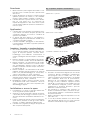 4
4
-
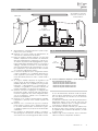 5
5
-
 6
6
-
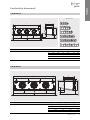 7
7
-
 8
8
-
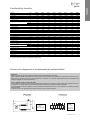 9
9
-
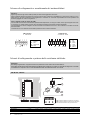 10
10
-
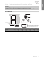 11
11
-
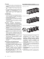 12
12
-
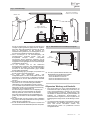 13
13
-
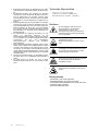 14
14
-
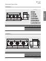 15
15
-
 16
16
-
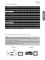 17
17
-
 18
18
-
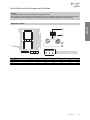 19
19
-
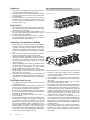 20
20
-
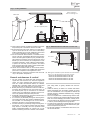 21
21
-
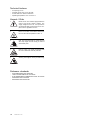 22
22
-
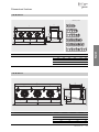 23
23
-
 24
24
-
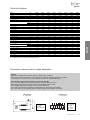 25
25
-
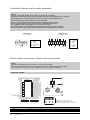 26
26
-
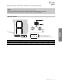 27
27
-
 28
28
-
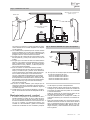 29
29
-
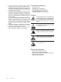 30
30
-
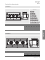 31
31
-
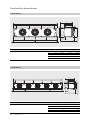 32
32
-
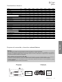 33
33
-
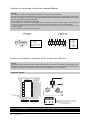 34
34
-
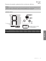 35
35
-
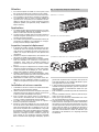 36
36
-
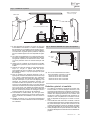 37
37
-
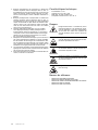 38
38
-
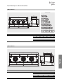 39
39
-
 40
40
-
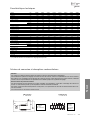 41
41
-
 42
42
-
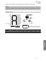 43
43
-
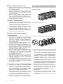 44
44
-
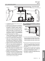 45
45
-
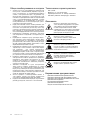 46
46
-
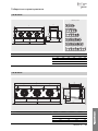 47
47
-
 48
48
-
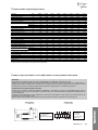 49
49
-
 50
50
-
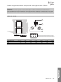 51
51
-
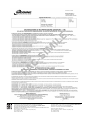 52
52
-
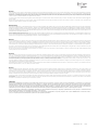 53
53
-
 54
54
-
 55
55
-
 56
56


En otros idiomas
- français: Modine FTE
- italiano: Modine FTE
Documentos relacionados
-
Modine EP Technical Manual
-
Modine CDD Technical Manual
-
-
-
-
-
-
Modine Manufacturing ECO VCC814 Technical Manual
-
-
