
CDD
CO2 COOLERS
MANUALE TECNICO
Aeroevaporatori a soffitto
BETRIEBSANLEITUNG
Deckenluftverdampfer
TECHNICAL MANUAL
Ceiling unit coolers
MANUAL TECNICO
Aeroevaporadores de techo
MANUEL TECHNIQUE
Evaporateurs plafonniers
ТЕХНИЧЕСКОЕ РУКОВОДСТВО
Потолочные воздухоохладители


1
www.modine.com
CDD
Indice
- Avvertenze
. . . . . . . . . . . . . . . . . . . . . . . . . . . . . . . . . . . . . . . . . . . . . . . . . . . . . . . . . . . . . . . . . . . . . . .2
- Ispezione - Trasporto
. . . . . . . . . . . . . . . . . . . . . . . . . . . . . . . . . . . . . . . . . . . . . . . . . . . . . . . . . .2
- Condizioni da verificare per una corretta
messa in opera
. . . . . . . . . . . . . . . . . . . . . . . . . . . . . . . . . . . . . . . . . . . . . . . . . . . . . . . . . . . . . . . . . .2
- Manutenzione generale
. . . . . . . . . . . . . . . . . . . . . . . . . . . . . . . . . . . . . . . . . . . . . . . . . . . . . .2
- Pericoli
. . . . . . . . . . . . . . . . . . . . . . . . . . . . . . . . . . . . . . . . . . . . . . . . . . . . . . . . . . . . . . . . . . . . . . . . . . . . .2
- Norme di riferimento
. . . . . . . . . . . . . . . . . . . . . . . . . . . . . . . . . . . . . . . . . . . . . . . . . . . . . . . . . . .2
- Avvertenze per una corretta installazione
. . . . . . . . . . . . . . . . . . . . . . . . . . . . . . .3
- Caratteristiche costruttive e dimensionali
. . . . . . . . . . . . . . . . . . . . . . . . . . . . . . .4
- Suggerimenti per un corretto accesso all’apparecchio
. . . . . . . . . . . . . .6
- Schema di collegamento e assorbimento dei motoventilatori
. . . . .7
- Schema di collegamento e potenze delle
resistenze elettriche
. . . . . . . . . . . . . . . . . . . . . . . . . . . . . . . . . . . . . . . . . . . . . . . . . . . . . . . . . . .8
- Garanzie
. . . . . . . . . . . . . . . . . . . . . . . . . . . . . . . . . . . . . . . . . . . . . . . . . . . . . . . . . . . . . . . . . . . . . . . . .57
Index
- Hinweise
. . . . . . . . . . . . . . . . . . . . . . . . . . . . . . . . . . . . . . . . . . . . . . . . . . . . . . . . . . . . . . . . . . . . . . . . .11
- Kontrolle - Transport
. . . . . . . . . . . . . . . . . . . . . . . . . . . . . . . . . . . . . . . . . . . . . . . . . . . . . . . . .11
- Hinweise für eine korrekte Inbetriebnahme
. . . . . . . . . . . . . . . . . . . . . . . . . . .11
- Allgemeine Wartung
. . . . . . . . . . . . . . . . . . . . . . . . . . . . . . . . . . . . . . . . . . . . . . . . . . . . . . . . . .11
- Gefahren
. . . . . . . . . . . . . . . . . . . . . . . . . . . . . . . . . . . . . . . . . . . . . . . . . . . . . . . . . . . . . . . . . . . . . . . .11
- Bezugsnormen
. . . . . . . . . . . . . . . . . . . . . . . . . . . . . . . . . . . . . . . . . . . . . . . . . . . . . . . . . . . . . . . .11
- Hinweise für eine korrekte Aufstellung
. . . . . . . . . . . . . . . . . . . . . . . . . . . . . . . . .12
- Konstruktionseigenschaften und Abmessungen
. . . . . . . . . . . . . . . . . . . .13
- Ratschläge für einen korrekten Zugang zum Gerät
. . . . . . . . . . . . . . . .15
- Anschlußplan und Stromaufnahme der Motorventilatoren
. . . . . . .16
- Anschlußplan und Leistungen der Heizstäbe
. . . . . . . . . . . . . . . . . . . . . . . .17
- Gewährleistung
. . . . . . . . . . . . . . . . . . . . . . . . . . . . . . . . . . . . . . . . . . . . . . . . . . . . . . . . . . . . . . . .57
Index
- Important
. . . . . . . . . . . . . . . . . . . . . . . . . . . . . . . . . . . . . . . . . . . . . . . . . . . . . . . . . . . . . . . . . . . . . . . .20
- Inspection - Transport
. . . . . . . . . . . . . . . . . . . . . . . . . . . . . . . . . . . . . . . . . . . . . . . . . . . . . . .20
- For a proper installation
. . . . . . . . . . . . . . . . . . . . . . . . . . . . . . . . . . . . . . . . . . . . . . . . . . . . .20
- General maintenance
. . . . . . . . . . . . . . . . . . . . . . . . . . . . . . . . . . . . . . . . . . . . . . . . . . . . . . .20
- Hazards / Risks
. . . . . . . . . . . . . . . . . . . . . . . . . . . . . . . . . . . . . . . . . . . . . . . . . . . . . . . . . . . . . . .20
- Reference standards
. . . . . . . . . . . . . . . . . . . . . . . . . . . . . . . . . . . . . . . . . . . . . . . . . . . . . . . .20
- Instructions for a correct installation
. . . . . . . . . . . . . . . . . . . . . . . . . . . . . . . . . . . . .21
- Manufacturing and dimensional features
. . . . . . . . . . . . . . . . . . . . . . . . . . . . . .22
- Proper access to model
. . . . . . . . . . . . . . . . . . . . . . . . . . . . . . . . . . . . . . . . . . . . . . . . . . . . .24
- Connection scheme and fan motor absorption
. . . . . . . . . . . . . . . . . . . . . .25
- Electric heater connection schemes and electric power
. . . . . . . . . .26
- Warranty
. . . . . . . . . . . . . . . . . . . . . . . . . . . . . . . . . . . . . . . . . . . . . . . . . . . . . . . . . . . . . . . . . . . . . . . . .57
Indice
- Advertencias . . . . . . . . . . . . . . . . . . . . . . . . . . . . . . . . . . . . . . . . . . . . . . . . . . . . . . . . . . . . . . . . . . .29
- Inspección - Transporte
. . . . . . . . . . . . . . . . . . . . . . . . . . . . . . . . . . . . . . . . . . . . . . . . . . . . .29
- Condiciones a verificar para una correcta
puesta en marcha
. . . . . . . . . . . . . . . . . . . . . . . . . . . . . . . . . . . . . . . . . . . . . . . . . . . . . . . . . . . .29
- Manutención general
. . . . . . . . . . . . . . . . . . . . . . . . . . . . . . . . . . . . . . . . . . . . . . . . . . . . . . . .29
- Peligros
. . . . . . . . . . . . . . . . . . . . . . . . . . . . . . . . . . . . . . . . . . . . . . . . . . . . . . . . . . . . . . . . . . . . . . . . . .29
- Normas de referencia
. . . . . . . . . . . . . . . . . . . . . . . . . . . . . . . . . . . . . . . . . . . . . . . . . . . . . . .29
- Advertencias para una correcta instalación
. . . . . . . . . . . . . . . . . . . . . . . . . . .30
- Características constructivas y dimensionales
. . . . . . . . . . . . . . . . . . . . . .31
- Sugerencias para un correcto acceso al aparato
. . . . . . . . . . . . . . . . . . .33
- Esquema de conexión y absorción de los motoventiladores
. . . .34
- Esquema de conexión y potencia
de las resistencias eléctricas
. . . . . . . . . . . . . . . . . . . . . . . . . . . . . . . . . . . . . . . . . . . . . .35
- Garantias
. . . . . . . . . . . . . . . . . . . . . . . . . . . . . . . . . . . . . . . . . . . . . . . . . . . . . . . . . . . . . . . . . . . . . . . .57
Index
- Attention
. . . . . . . . . . . . . . . . . . . . . . . . . . . . . . . . . . . . . . . . . . . . . . . . . . . . . . . . . . . . . . . . . . . . . . . . .38
- Inspection - Transport
. . . . . . . . . . . . . . . . . . . . . . . . . . . . . . . . . . . . . . . . . . . . . . . . . . . . . . .38
- Conditions à vérifier pour une mise en marche correcte
. . . . . . . . . .38
- Entretien général
. . . . . . . . . . . . . . . . . . . . . . . . . . . . . . . . . . . . . . . . . . . . . . . . . . . . . . . . . . . . . .38
- Dangers
. . . . . . . . . . . . . . . . . . . . . . . . . . . . . . . . . . . . . . . . . . . . . . . . . . . . . . . . . . . . . . . . . . . . . . . . .38
- Normes de référence
. . . . . . . . . . . . . . . . . . . . . . . . . . . . . . . . . . . . . . . . . . . . . . . . . . . . . . . .38
- Instructions pour une installation correcte
. . . . . . . . . . . . . . . . . . . . . . . . . . . . .39
- Caractéristiques constructives et dimensionnelles
. . . . . . . . . . . . . . . . .40
- Suggestions pour un accès correct à l’appareil
. . . . . . . . . . . . . . . . . . . . . .42
- Schéma de connexion et absorption des motoventilateurs
. . . . . .43
- Schéma de connexion et puissances
des résistances électriques
. . . . . . . . . . . . . . . . . . . . . . . . . . . . . . . . . . . . . . . . . . . . . . . .44
- Garantie
. . . . . . . . . . . . . . . . . . . . . . . . . . . . . . . . . . . . . . . . . . . . . . . . . . . . . . . . . . . . . . . . . . . . . . . . .57
Указатель
- Меры предосторожности
. . . . . . . . . . . . . . . . . . . . . . . . . . . . . . . . . . . . . . . . . . . . .47
- Осмотр - Транспортировка
. . . . . . . . . . . . . . . . . . . . . . . . . . . . . . . . . . . . . . . . . . .47
- Подлежащие проверке условия для правильного
ввода в эксплуатацию
. . . . . . . . . . . . . . . . . . . . . . . . . . . . . . . . . . . . . . . . . . . . . . . . .47
- Общее техобслуживание
. . . . . . . . . . . . . . . . . . . . . . . . . . . . . . . . . . . . . . . . . . . . . .47
- Опасность
. . . . . . . . . . . . . . . . . . . . . . . . . . . . . . . . . . . . . . . . . . . . . . . . . . . . . . . . . . . . . . . . . .47
- Нормативная документация
. . . . . . . . . . . . . . . . . . . . . . . . . . . . . . . . . . . . . . . . .47
- Меры предосторожности для правильной установки
. . . . . .48
- Конструктивные и габаритные характеристики
. . . . . . . . . . . . . .49
- Рекомендации по правильному доступу к аппарату
. . . . . . . .51
- Схема подключения и потребления
электровентиляторов
. . . . . . . . . . . . . . . . . . . . . . . . . . . . . . . . . . . . . . . . . . . . . . . . . .52
- Схема подключения и мощностей
электрических ТЭНов
. . . . . . . . . . . . . . . . . . . . . . . . . . . . . . . . . . . . . . . . . . . . . . . . . .53
- Гарантии
. . . . . . . . . . . . . . . . . . . . . . . . . . . . . . . . . . . . . . . . . . . . . . . . . . . . . . . . . . . . . . . . . . . .57
Index

2
www.modine.com
Attenzione
Prima di effettuare qualsiasi intervento di manutenzione, accertarsi che l’alimentazione elettrica sia scollegata dalla fonte principale: le
parti elettriche potrebbero essere collegate ad un controllo automatico.
Avvertenze
1. Conservare questo manuale tecnico per tutto il periodo di vita
del modello.
2. Leggere con attenzione il manuale prima dell’installazione e
prima di qualsiasi operazione sul modello.
3. Impiegare il modello esclusivamente per lo scopo per cui é
stato progettato: l’uso improprio esonera il costruttore da qual-
siasi responsabilità.
Ispezione - Trasporto
1. Al ricevimento del modello controllare immediatamente il suo
stato; contestare subito alla compagnia di trasporto qualsiasi
eventuale danno.
2. Durante il trasporto evitare di esercitare pressioni improprie
sull’imballaggio, che va mantenuto comunque sempre nella
posizione indicata sullo stesso.
3. Disimballare il modello il più vicino possibile al luogo di installa-
zione. Una volta disimballato, evitare urti ai componenti.
4. Durante l’installazione e la movimentazione del modello utiliz-
zare appositi guanti protettivi per evitare di ferirsi con le parti
taglienti (es. alette) del modello.
Condizioni da verificare per una
corretta messa in opera
1. Verificare la tenuta delle strutture di sostegno rispetto al peso
dell’apparecchio.
2. Verificare che il modello venga installato orizzontalmente.
3. Assicurare un volume libero adeguato (circa il 30% del volume
interno della cella) per una corretta circolazione dell’aria in
aspirazione e scarico.
Particolari condizioni di installazione o funzionamento quali
celle basse, travature a soffitto, stoccaggi eccessivi, impedi-
menti al getto e/o all’aspirazione dell’aria, formazione impro-
pria di brina dovuta ad eccessiva immissione di umidità nella
cella, possono influenzare negativamente le prestazioni
dichiarate e creare difettosità nei modelli.
I modelli standard possono non essere adatti ad operare in
tunnel o celle di abbattimento/surgelamento rapido.
4. I modelli sono equipaggiati con motoventilatori assiali, quindi
non adatti ad essere canalizzati o comunque a sopportare pre-
valenze statiche aggiuntive.
5. Verificare che le condizioni di funzionamento (temperature e
pressioni) siano conformi a quelle di progetto.
6. Prestare particolare cura in fase di collegamento affinchè non si
deformino i capillari e non si modifichi la posizione del distributore.
7. In caso di più modelli installati a breve distanza l’uno dall’altro,
evitare sbrinamenti alternati.
8. Installare sugli scarichi condensa gli opportuni sifoni e verificar-
ne l'efficacia in tutte le temperature di utilizzo.
9. Evitare l'installazione degli aeroevaporatori vicino alle porte
delle celle.
10. Collocare la sonda di temperatura per il fine sbrinamento nelle
zone più fredde degli scambiatori, ovvero quelle zone che ten-
dono a ghiacciarsi maggiormente (al termine del ciclo non deve
rimanere ghiaccio sui modelli). La posizione di questo dispositi-
vo non può essere definita a priori, in quanto varia in relazione
al tipo di cella e al tipo di impianto.
11. Verificare che la linea elettrica di alimentazione sia adeguata
alle caratteristiche elettriche dell’apparecchio.
12. Assicurarsi che tutti i collegamenti elettrici siano in accordo con
le norme vigenti.
13. Le unità sono predisposte per il collegamento elettrico a terra.
L’installattore e/o il conduttore dell’unità sono tenuti a garantire
la presenza di un efficiente collegamento alla terra di protezio-
ne contro i contatti elettrici indiretti.
A richiesta i modelli possono essere forniti con scambiatori,
sbrinamenti e motoventilatori diversi dallo standard.
Le resistenze elettriche impiegate per l’eventuale sbrinamento
sono alloggiate in scatola di derivazione in materiale termopla-
stico (protezione contro il contatto elettrico diretto di classe II)
aventi grado di protezione IP 54.
14. Ad installazione completata rimuovere la pellicola protettiva
che ricopre il modello.
15. L’accessibilità al modello, per qualsiasi tipo di intervento, deve
essere riservata al personale qualificato alla conduzione del-
l’impianto, secondo le norme vigenti.
Manutenzione generale
1. Verificare periodicamente i fissaggi, le connessioni elettriche e i
collegamenti all’impianto frigorifero.
2. Provvedere alla pulizia periodica dell’apparecchio, per evitare
accumuli di sostanze nocive. Si consiglia l’utilizzo di normale
acqua saponata, evitando solventi, agenti aggressivi, abrasivi o
a base di ammoniaca.
3. In caso di sostituzioni di resistenze elettriche prestare particola-
re attenzione nelle fasi di installazione per evitare danni alle
vulcanizzazioni; ripristinare correttamente i collegamenti e i
sistemi di fissaggio esistenti per evitare movimenti delle stesse
durante il funzionamento.
Tali operazioni dovranno essere effettuate da personale
esperto e qualificato.
Pericoli
1. Pericolo di elettrocuzione. Il modello è provvisto
di elettroventilatori e resistestenze elettriche di
sbrinamento. La tensione di alimentazione è di
400V AC. Utilizzare sistemi di sicurezza elettrica
previsti dalla normativa vigente.
2. Pericolo di ustione. Le resistenze elettriche di
sbrinamento possono raggiungere temperature
superficiali di 350°C.
3. Pericolo di taglio. Lo scambiatore di calore è
costituito da alette con bordi taglienti e la
carrozzeria da parti in lamiera.
4. Pericolo parti in movimento. Il modello è provvisto
di elettroventilatori dotati di griglia di protezione
esterna.
5. Pericolo di schiacciamento. Il modello può pesare
oltre 500 kg.
Norme di riferimento
- DIRETTIVA MACCHINE 2006/42/EC
- DIRETTIVA BASSA TENSIONE 2014/35/UE
- DIRETTIVA COMP. ELETTROMAGNETICA 2014/30/UE
- DIRETTIVA PED 2014/68/UE
- DIRETTIVA ERP 2009/125/EC

3
www.modine.com
Italiano
0.6 m
5 : 8 m
2 : 4 m
Avvertenze per una corretta installazione
Modelli con ventola ø 230 mm - Distanze consigliate
Modelli con ventola ø 450 e 560 mm - Distanze consigliate
Nel caso di installazione di più aeroevaporatori nella medesima
cella frigorifera o sala di climatizzazione rispettare le distanze
riportate nel disegno.
1. Togliere il coperchio dell’imballo prima di sollevare il modello.
2. Predisporre i tiranti sul soffitto.
3. Sollevare il gruppo modello-imballo fino ad appoggiarlo al sof-
fitto.
4. Avvitare fino in fondo i dadi “A” sui tiranti di fissaggio.
5. Togliere le viti di sicurezza “B” e calare l’imballo vuoto.
6. Serrare i dadi “A” di fissaggio dell’apparecchio al soffitto.
Istruzioni per l’installazione a soffitto
Imballo
Tirante
Imballo
Coperchio imballo
Staffa
Apparecchio
Distanza minima laterale dalla parete lato resistenze
Distanza consigliata dalle pareti lato uscita aria
In fase di installazione rispettare la quota minima B + 300 mm per poter
togliere/inserire le resistenze.
In fase di installazione si consiglia di rispettare la quota minima “Y”
per garantire una buona circolazione dell’aria:
motoventilatori ø = 450 mm: Y = 700 mm;
motoventilatori ø = 560 mm: Y = 900 mm.

4
www.modine.com
Modelli con ventola ø 230 mm
Caratteristiche costruttive e dimensionali
Modello CDD ø 230 mm 21E49 22E49 22A49 23A49 24A49 25A49
Dimensioni A 430 730 730 1030 1330 1630
(mm)
B 320 620 620 920 1220 1520
C 172 185 185 185 185 185
D 30 30 30 30 35 35
Attacchi interni batteria In tube 10 10 10 10 10 10
(mm)
Out tube 10 10 10 10 10 10
Attacco scarico ø GAS 1/2” 1/2” 1/2” 1/2” 1” 1”
Peso netto (max) kg 9 13 15 21 27 33
Modelli con ventola ø 230 mm - Particolare di posizionamento resistenza
Particolare di fissaggio “F”
Resistenze
Molla fermaresistenze
Sgocciolatoio interno

5
www.modine.com
Italiano
F
F
Caratteristiche costruttive e dimensionali
Modello CDD ø 450/560 mm 41A04 41B04 42A04 42B04 43A04 43B04 52A04 52B04 53A04 53B04 54A04 54B04
41A07 41B07 42A07 42B07 43A07 43B07 52A07 52B07 53A07 53B07 54A07 54B07
41A10 41B10 42A10 42B10 43A10 43B10 52A10 52B10 53A10 53B10 54A10 54B10
Dimensioni A 1300 2150 3000 2760 3860 4960
(mm)
B 814 1664 2514 2164 3264 4364
C/ / 1700 1100 2 x 1100 3 x 1100
D/ / 814 1064 1064 1064
E 406 410 415 538 543 550
F 400 400 400 530 530 530
G 85 85 85 90 90 90
H 243 243 243 298 298 298
L 1594 1594 1594 1809 1809 1809
M 1449 1449 1449 1664 1664 1664
N 1290 1290 1290 1505 1505 1505
P 280 280 280 280 280 280
Q 490 490 490 680 680 680
R 695 695 695 835 835 835
Attacchi interni batteria In tube 12 - 12,7 12 - 12,7 12 - 16 12 - 16 - 22 16 - 22 16 - 22
(mm)
Out tube 12 - 12,7 16 22 22 - 28 22 - 28 28
Attacco scarico ø GAS 2 x 1” 2 x 1” 2 x 1” 2 x 2” 2 x 2” 2 x 2”
Peso netto (max) kg 83 151 215 261 387 520
Particolare
di fissaggio “F”
Modelli con ventola ø 450 e 560 mm

6
www.modine.com
Modelli con ventola ø 450 e 560 mm
Suggerimenti per un corretto accesso all’apparecchio
Modelli con ventola ø 230 mm
Accesso
1. Smontare il tubo di scarico condensa in modo che non si crei
intralcio al movimento del convogliatore.
2. Svitare le viti di fissaggio “A” del convogliatore (in alcuni
modelli le viti sono presenti anche dal lato cerniere)
3. Accompagnare il convogliatore fino alla posizione rappresen-
tata in figura.
4. Al fine di intervenire anche sulle resistenze poste sotto la bat-
teria, togliere gli sgocciolatoi interni svitando le viti autofilettan-
ti “B”; le resistenze sono fissate al pacco per mezzo delle
molle “C” come da schema riportato nella pagina precedente.
Riposizionamento
1. Riposizionare gli sgocciolatoi avvitando le viti “B”.
2. Portare in posizione il convogliatore e fissarlo mediante le
viti “A”.
3. Rimontare il tubo di scarico condensa.
Sostegni
Resistenza
Sgocciolatoio
interno
Scatola collegamento resistenze
Scatola
collegamento
motori
Convogliatore
Accesso
1. Smontare i tubi di scarico condensa e posizionarli in modo che
non creino intralcio al movimento delle vaschette.
2. Svitare i pomelli di fissaggio “A” per aprire le vaschette;
accompagnarle lentamente fino alla posizione rappresentata
in figura.
Importante:
prima di effettuare l’apertura delle vaschette accertarsi che
siano libere da eventuali residui di ghiaccio.
3. Svitare i pomelli “B” per aprire i coperchi laterali.
4. Svitare le viti “C” per rimuovere i motori; se necessario rimuo-
vere anche i convogliatori svitando le viti “D”.
Riposizionamento
1. Fissare i convogliatori mediante le viti “D” e i motori mediante
le viti “C”.
2. Chiudere i coperchi laterali mediante i pomelli “B”.
3. Rimettere le vaschette in posizione serrando i pomelli “A”.
4. Rimontare i tubi di scarico condensa.
Coperchi laterali
Sostegni
Vaschetta
Convogliatore

7
www.modine.com
Italiano
Modello CDD ø 230 mm 21E49 22E49 22A49 23A49 24A49 25A49
Motoventilatori N° x ø mm 1 x 230 2 x 230 2 x 230 3 x 230 4 x 230 5 x 230
Assorbimento A 0,35 0,70 0,70 1,05 1,40 1,75
W 53 106 106 159 212 265
Schema di collegamento e assorbimento dei motoventilatori
M = motoventilatori
L1 = marrone
N1= blu
= giallo/verde
L1-N1 = linea di alimentazione dei motoventilatori
Scatola collegamento motori
Attenzione
I motori sono dotati di termocontatti di protezione interni a riar-
mo automatico.
Prima di utilizzare sistemi di regolazione del numero di giri dei
motori verificare la compatibilità con i motori stessi, sistemi non
compatibili possono generare rumorosità e danneggiamenti; il
costruttore non si assume responsabilità alcuna sulle prestazioni
dei modelli equipaggiati con sistemi di regolazione.
Modelli con ventola ø 230 mm Alimentazione 230V/1/50-60Hz
Modelli con ventola ø 450 e 560 mm
Modello CDD ø 450 e 560 mm 41A04 41B04 42A04 42B04 43A04 43B04 52A04 52B04 53A04 53B07 54A04 54B04
41A07 41B07 42A07 42B07 43A07 43B07 52A07 52B07 53A07 53B07 54A07 54B07
41A10 41B10 42A10 42B10 43A10 43B10 52A10 52B10 53A10 53B10 54A10 54B10
Motoventilatori n.x ø mm 1x450 2x450 3x450 2x560 3x560 4x560
A 0,79 1,58 2,37 3,3 4,95 6,6
W 430 860 1290 1680 2520 3360
A 0,53 1,06 1,59 2,1 3,15 4,2
W 330 660 990 1280 1920 2560
(*) Termocontatti di protezione interni
I termocontatti sono elementi di azionamento dipendenti dalla temperatu-
ra che vengono inseriti, isolati, negli avvolgimenti dei motori; essi aprono
un contatto elettrico quando viene superata la temperatura permanente
massima ammissibile.
I termocontatti devono essere collegati ai circuiti di comando dei con-
tatori di modo che in caso di disturbi non si abbia una reinserzione
automatica.
400 V/50 Hz Trifase
collegamento
q
Alta velocità
400 V/50 Hz Trifase
collegamento Y
Bassa velocità
Arancio
Marrone
Rosso
Blu
Grigio
Nero
Giallo / vede
Arancio
Marrone
Rosso
Blu
Grigio
Nero
Giallo / vede
Assorbimenti
Alta velocità (
q
)
Bassa velocità (Y)
Attenzione
Seguire rigorosamente gli schemi elettrici riportati per evitare il
danneggiamento del motore.
Prima di utilizzare sistemi di regolazione del numero di giri dei
motori verificare la compatibilità con i motori stessi, sistemi non
compatibili possono generare rumorosità e danneggiamenti; il
costruttore. non si assume responsabilità alcuna sulle prestazioni
dei modelli equipaggiati con sistemi di regolazione.

8
www.modine.com
Scatola collegamento resistenze
Attenzione
È d’obbligo l’applicazione di opportuni sistemi di protezione
termica sulle linee di alimentazione.
Provvedere periodicamente alla verifica delle funzionalità di
tutte le resistenze per evitare accumuli dannosi di ghiaccio sui
modelli.
Il costruttore non risponde in alcun modo di difettosità create da
malfunzionamenti non rilevati.
Schemi di collegamento e potenze delle resistenze elettriche
Modelli con ventola ø 230 mm Alimentazione 230V/1/50-60Hz
R = resistenza di sbrinamento
L2-N2 = nero
= giallo/verde
L2-N2 = linea di alimentazione delle resistenze elettriche
Modello CDD ø 230 mm 21E49 22E49 22A49 23A49 24A49 25A49
Potenza totale (W) 800 1600 1600 2400 3000 3600

9
www.modine.com
Italiano
Schemi di collegamento e potenze delle resistenze elettriche
Collegamento 400V/3/50 Hz
(predisposto).
RBA1 / RBA2 / RBA3 / RBA4 - Resistenze di alta potenza nella batteria.
RSA1 / RSA2 - Resistenze di alta potenza sullo sgocciolatoio.
Modello con ventola ø 450 mm
Collegamento 230V3/50 Hz
Si ottiene modificando la disposizione delle barrette in morsettiera.
Modelli CDD ø 450 mm 41A04 42A04 43A04
41A07 42A07 43A07
41A10 42A10 43A10
Potenza totale (W) 5040 10200 15000
Modello con ventola ø 450 mm
Collegamento 400V/3/50 Hz
(predisposto).
RBA1 / RBA2 - Resistenze di alta potenza nella batteria.
RBB1 / RBB2 / RBB3 / RBB4 - Resistenze di bassa potenza nella batteria.
RSA1 / RSA2 - Resistenze di alta potenza sullo sgocciolatoio.
Collegamento 230V3/50 Hz
Si ottiene modificando la disposizione delle barrette in morsettiera.
Modelli CDD ø 450 mm 41B04 42B04 43B04
41B07 42B07 43B07
41B10 42B10 43B10
Potenza totale (W) 5040 10200 15000
Attenzione
È d’obbligo l’applicazione di
opportuni sistemi di protezione
termica sulle linee di alimenta-
zione.
Provvedere periodicamente
alla verifica delle funzionalità di
tutte le resistenze per evitare
accumuli dannosi di ghiaccio
sui modelli.
Il costruttore non risponde in
alcun modo di difettosità create
da malfunzionamenti non rile-
vati.

10
www.modine.com
Schemi di collegamento e potenze delle resistenze elettriche
Collegamento 400V/3/50 Hz
(predisposto).
RBA1 / RBA2 / RBA3 / RBA4 - Resistenze di alta potenza nella batteria.
RBB1 / RBB2 - Resistenze di bassa potenza nella batteria.
RSB1 / RSB2 - Resistenze di bassa potenza sullo sgocciolatoio.
RBM1 / RBM2 - Resistenze di media potenza nella batteria.
Modello con ventola ø 560 mm
Collegamento 230V3/50 Hz
Si ottiene modificando la disposizione delle barrette in morsettiera.
Modelli CDD ø 560 mm 52A04 53A04 54A04
52A07 53A07 54A07
52A10 53A10 54A10
Potenza totale (W) 16050 24000 32250
Modello con ventola ø 560 mm
Collegamento 400V/3/50 Hz
(predisposto).
RBA1 / RBA2 / RBA3 / RBA4 / RBA5 / RBA6 - Resistenze di alta potenza
nella batteria.
RBB1 / RBB2 / RBB3 / RBB4 - Resistenze di bassa potenza nella batteria.
RSB1 / RSB2 - Resistenze di bassa potenza sullo sgocciolatoio.
Collegamento 230V3/50 Hz
Si ottiene modificando la disposizione delle barrette in morsettiera.
Modelli CDD ø 560 mm 52B04 53B04 54B04
52B07 53B07 54B07
52B10 53B10 54B10
Potenza totale (W) 19260 28800 38700
Attenzione
È d’obbligo l’applicazione di
opportuni sistemi di protezione
termica sulle linee di alimenta-
zione.
Provvedere periodicamente
alla verifica delle funzionalità di
tutte le resistenze per evitare
accumuli dannosi di ghiaccio
sui modelli.
Il costruttore non risponde in
alcun modo di difettosità create
da malfunzionamenti non rile-
vati.

11
www.modine.com
Deutsch
Achtung
Versichern Sie sich vor jeder Wartung, daß die Stromzuführung vom Hauptnetz getrennt ist; die elektrischen Teile könnten automatisch
anlaufen.
Hinweise
1. Diese Betriebsanleitung während der ganzen Lebensdauer des
Geräts aufbewahren.
2. Vor Inbetriebnahme des Geräts und vor jedem Eingriff auf-
merksam die Betriebsanleitung durchlesen.
3. Das Gerät nur für den Zweck einsetzen, wofür es entworfen
worden ist; unsachgemäße Anwendung befreit den Hersteller
von jeder Verantwortung.
Kontrolle - Transport
1. Bei Erhalt des Geräts sofort den Zustand kontrollieren; jegli-
chen eventuellen Schaden sofort dem Spediteur beanstanden.
2. Während des Transports unnötigen Druck auf die Verpackung
vermeiden.
3. Während der Montage und des Positionierens des Geräts geei-
gnete Schutzhandschuhe benutzen, um eine Verletzungsgefahr
durch scharfe Stellen am Gerät zu vermeiden.
4. Während der Montage und des Positionierens des Geräts
geeignete Schutzhandschuhe benutzen, um eine
Verletzungsgefahr durch scharfe Stellen (z.B. Lamellen) zu
vermeiden.
Hinweise für eine korrekte
Inbetriebnahme
1. Die Tragfähigkeit der Strukturen bezüglich des Gerätegewichts
überprüfen.
2. Das Modell muß horizontal eingebaut werden.
3. Für eine einwandfreie Luftzirkulation muß genügend Freiraum
vorhanden sein (ungefähr 30% des Innenvolumens der Zelle).
Besondere Einbau- oder Betriebsbedingungen, wie niedrige
Kühlzellen, Deckenträger, übermäßige Lagerung,
Behinderungen des Luftstroms und/oder der Luftansaugung,
übermäßige Reifbildung durch zu hohe Feuchtigkeit in der
Kühlzelle können die angegebenen Leistungen negativ beein-
flussen und Schäden an den Geräten hervorrufen.
Die Standardmodelle können für die Anwendung in
Schnellabkühlungs- oder Schockräumen nicht geeignet sein.
4. Die Modelle sind mit Axialmotorventilatoren ausgestattet und
daher nicht kanalisierbar oder jedenfalls keine weiteren
Druckverluste verkraften.
5. Die Betriebsbedingungen (Temperaturen und Drucke) müssen
dem Projekt entsprechen.
6. Das Anschließen muß sorgfältig erfolgen, um das Verformen
eventueller Kapillarrohre und das Verlagern des Verteilers zu
verhindern.
7. Bei nah aneinander installierten Geräten abwechselnde
Abtauungen vermeiden.
8. An den Tauwasserabflüssen die passenden Siphone installie-
ren und die Wirksamkeit bei allen Anwendungstemperaturen
überprüfen.
9. Die Installation der Luftverdampfer in der Nähe der Zellentüren
vermeiden.
10. Die Temperaturfühler für das Ende der Abtauung in den kälte-
sten Zonen der Wärmeaustauscher anbringen, beziehungswei-
se in den Zonen, wo die Tendenz zur Eisbildung am größten ist
(am Ende der Abtauung darf kein Eis an den Modellen blei-
ben). Die Lage dieser kann nicht vorherbestimmt werden, da
sie sich je nach Typ der Zelle und der Anlage verändert.
11. Die Stromzuleitung muß den elektrischen Daten des Geräts
angepaßt sein.
12. Alle Anschlüsse müssen den gültigen elektrischen Normen ent-
sprechen.
13. Die Einheiten sind für den elektrischen Erdungsanschluss vor-
gesehen. Der Installationsfachmann bzw. Betreiber der Einheit
muss einen funktionstüchtigen Anschluss an den
Erdungsschutzleiter gegen indirekte Stromkontakte gewährlei-
sten. Die elektrischen Widerstände für das Abtausystem sind in
einer Verteilerdose aus thermoplastischem Material unterge-
bracht mit Schutzgrad IP 54. Auf Bestellung können die
Modelle mit nicht standardmäßigen Wärmetauschern,
Abtausystemen und Lüfteraggregaten geliefert werden.
14. Nach beendeter Installation den am Gerät befindlichen
Schutzfilm entfernen.
15. Der Zugang zum Gerät für jeden Eingriff muß dem für die
Anlage qualifizierten Personal gemäß den gültigen Normen
vorbehalten sein.
Allgemeine Wartung
1. Regelmäßige Überprüfung der Befestigungen der elektrischen
Anschlüsse. Kältemittelanschlüsse auf Dichtheit prüfen.
2. Regelmäßige Reinigung des Geräts mit normalem
Seifenwasser, um das Anhäufen von schädlichen Substanzen
zu verhindern. Keine Lösungsmittel und aggressive oder
ammoniakhaltige Reibepulver verwenden.
3. Beim eventuellen Auswechseln von elektrischen Heizstäben
besonders achtgeben, um während der Installation Schäden an
der Vulkanisierung zu vermeiden; die Anschlüsse und die
bestehenden Befestigungssysteme wieder korrekt herstellen,
um zu vermeiden, daß sie sich während des Betriebs bewegen.
Die Wartung darf nur von qualifizierten Personal vorgenom-
men werden.
Gefahren
1. Stromschlaggefahr. Das Gerät ist mit
Motorventilatoren und elektrischen
Abtauheizungen versehen. Die Stromspannung
ist 400 V AC. Elektrische Sicherheitssysteme
gemäß den geltenden Normen anwenden.
2. Verbrennungsgefahr. Die elektrischen
Abtauheizungen können
Oberflächentemperaturen von 350° C erreichen.
3. Schnittgefahr. Der Wärmeaustauscher besteht
aus Lamellen mit scharfen Kanten und das
Gehäuse besteht aus Blechteilen.
4. Gefahr durch sich bewegende Teile. Das Gerät ist
mit Motorventilatoren mit äußerem Schutzgitter
versehen.
5. Quetschgefahr. Das Gerät kann über 500 kg
wiegen.
Bezugsnormen
- MASCHINEN - RICHTLINIE 2006/42/EC
- NIEDERSPANNUNG - RICHTLINIE 2014/35/UE
- RICHTLINIE ELEKTROMAGNETISCHE KOMP. 2014/30/UE
- PED RICHTLINIE 2014/68/UE
- ERP RICHTLINIE 2009/125/EC

12
www.modine.com
0.6 m
5 : 8 m
2 : 4 m
Hinweise für eine korrekte Aufstellung
Modell mit Flügeldurchmesser ø 230 mm - Empfohlene Abstände
Modell mit Flügeldurchmesser ø 450 und 560 mm - Empfohlene Abstände
Bei mehr Luftverdampfern in einer Kühlzelle oder in einem
Klimatisierungsraum die auf der Zeichnung eingetragenen Abstände
einhalten.
1. Vor dem Heben des Modells Verpackungsdeckel abnehmen.
2. Befestigungsschrauben an der Decke vorbereiten.
3. Gerät mit der Verpackung an die Decke heben.
4. Die Muttern “A” an die Befestigungsschrauben fest anziehen.
5. Die Sicherheitsschrauben “B” abnehmen und die leere
Verpackung herunterziehen.
6. Die Befestigungsmuttern “A” des Geräts an die Decke fest
anziehen.
Anweisungen für Wandmontage
Verdampfer
Mindestabstand von der Wand, Heizstabseite
Empfohlener Abstand von der Wand auf der Luftaustrittsseite
Zum seitlichen Ein- und Ausbau der Heizstäbe muß bei der
Geräteinstallation das Mindestmaß B + 300 mm eingehalten werden.
Für eine gute Luftzirkulation den Mindestabstand "Y" bei der Montage
einhalten:
Motorventilatoren ø = 450 mm: Y = 700 mm;
Motorventilatoren ø = 560 mm: Y = 900 mm.
Verpackung
Befestigungs-
schraube
Verpackung
Verpackungsdeckel
Halterung

13
www.modine.com
Deutsch
Modell mit Flügeldurchmesser ø 230 mm
Konstruktionseigenschaften und Abmessungen
Modello CDD ø 230 mm 21E49 22E49 22A49 23A49 24A49 25A49
Abmessungen A 430 730 730 1030 1330 1630
(mm)
B 320 620 620 920 1220 1520
C 172 185 185 185 185 185
D 30 30 30 30 35 35
Innere Batterieanschlüsse In tube 10 10 10 10 10 10
(mm)
Out tube 10 10 10 10 10 10
Tauwasserabfluß ø GAS 1/2” 1/2” 1/2” 1/2” 1” 1”
Nettogewicht (max) kg 9 13 15 21 27 33
Modell mit Flügeldurchmesser ø 230 mm - Einzelheit der Heizstabbefestigung
Einzelheit der “F” Befestigung
Heizstäbe
Heizstabbefestigungsfedern
Innere Tropfwanne

14
www.modine.com
F
F
Konstruktionseigenschaften und Abmessungen
Einzelheit der “F”
Befestigung
Modell mit Flügeldurchmesser ø 450 und 560 mm
Modell CDD ø 450/560 mm 41A04 41B04 42A04 42B04 43A04 43B04 52A04 52B04 53A04 53B04 54A04 54B04
41A07 41B07 42A07 42B07 43A07 43B07 52A07 52B07 53A07 53B07 54A07 54B07
41A10 41B10 42A10 42B10 43A10 43B10 52A10 52B10 53A10 53B10 54A10 54B10
Abmessungen A 1300 2150 3000 2760 3860 4960
(mm)
B 814 1664 2514 2164 3264 4364
C/ / 1700 1100 2 x 1100 3 x 1100
D/ / 814 1064 1064 1064
E 406 410 415 538 543 550
F 400 400 400 530 530 530
G 85 85 85 90 90 90
H 243 243 243 298 298 298
L 1594 1594 1594 1809 1809 1809
M 1449 1449 1449 1664 1664 1664
N 1290 1290 1290 1505 1505 1505
P 280 280 280 280 280 280
Q 490 490 490 680 680 680
R 695 695 695 835 835 835
Batterieanschlüsse In tube 12 - 12,7 12 - 12,7 12 - 16 12 - 16 - 22 16 - 22 16 - 22
(mm)
Out tube 12 - 12,7 16 22 22 - 28 22 - 28 28
Tauwasserabfluß ø GAS 2 x 1” 2 x 1” 2 x 1” 2 x 2” 2 x 2” 2 x 2”
Gewicht (max) kg 83 151 215 261 387 520

15
www.modine.com
Deutsch
Modell mit Flügeldurchmesser ø 450 e 560 mm
Ratschläge für einen korrekten Zugang zum Gerät
Modell mit Flügeldurchmesser ø 230 mm
Ausbau
1. Tauwasserabflußrohr so demontieren, daß das Bewegen des
Lüfterblechs nicht behindert wird.
2. Die Befestigungsschrauben “A” vom Lüfterblech losschrauben
(bei einigen Modellen gibt es auch auf der Scharnierblechseite
Schrauben).
3. Das Lüfterblech wie aufgezeichnet positionieren.
4. Um zu den unter dem Wärmetauscher gelegenen
Heizstäben zu gelangen, die selbstbohrenden Schrauben
“B” losschrauben und die inneren Tropfwannen abnehmen;
die Heizstäbe sind am Paket durch die Federn “C” befestigt,
wie auf der Skizze auf der vorhergehenden Seite aufgeführt.
Zusammenbau
1. Die Tropfwannen positionieren und mit den Schrauben “B”
festschrauben.
2. Das Lüfterblech positionieren und mit den Schrauben “A”
befestigen.
3. Tauwasserabflußrohr montieren.
Halterungen
Heizstab
Innere
Tropfwanne
Abzweigdose Heizstäbe
Abzweigdose
Motoren
Lüfterblech
Ausbau
1. Tauwasserablußrohre so demontieren, daß das Bewegen der
Tropfwannen nicht behindert wird.
2. Um die Tropfwannen zu öffnen, die Be-festigungsdrehschrauben
"A" losschrauben und langsam wie aufgezeichnet positionieren.
Wichtig:
vor dem Öffnen der Tropfwannen sicher-stellen, daß keine
eventuellen Eisrück-stände vorhanden sind.
3. Um die seitlichen Abdeckungen abzunehmen, die
Drehschrauben "B" losschrauben.
4. Um die Motoren auszubauen, die Schrau-ben "C" losschrau-
ben und wenn nötig, die Schrauben "D" losschrauben, um
auch die Lüfterbleche abzunehmen.
Zusammenbau
1. Die Lüfterbleche mit den Schrauben "D" und die Motoren mit
den Schrauben "C" befestigen.
2. Die seitlichen Abdeckungen mit den Drehschrauben "B" befestigen.
3. Die Tropfwannen positionieren und mit den Drehschrauben
"A" anziehen.
4. Tauwasserabflußrohre montieren.
Seitliche Abdeckung
Halterungen
Tropfwanne
Lüfterblech

16
www.modine.com
Modell CDD ø 230 mm 21E49 22E49 22A49 23A49 24A49 25A49
Motorventilatoren N° x ø mm 1 x 230 2 x 230 2 x 230 3 x 230 4 x 230 5 x 230
Stromaufnahme A 0,35 0,70 0,70 1,05 1,40 1,75
Motorventilatoren W 53 106 106 159 212 265
Anschlußplan der Heizstäbe und der Motorventilatoren
M = Motorventilatoren
L1 = braun
N1= blau
= gelb/grün
L2-N2 = Stromspannung der Heizstäbe 230V/1/50-60Hz
Abzweigdose Motoren
Achtung
Die Motoren sind mit automatisch wiederaufrüstbaren
Temperaturwächtern ausgestattet.
Vor Anwendung von Drehzahlreglern die Eignung für die
Motoren überprüfen;
nicht verträgliche Systeme können Lärm und Schäden am
Motor hervorrufen; der Hersteller lehnt jede Verantwortung für
mit Drehzahlreglern ausgestattete Geräte ab.
Modell mit Flügeldurchmesser ø 230 mm Stromaufnahme 230V/1/50-60Hz
Modell mit Flügeldurchmesser ø 450 und 560 mm
Modell CDD ø 450 e 560 mm 41A04 41B04 42A04 42B04 43A04 43B04 52A04 52B04 53A04 53B07 54A04 54B04
41A07 41B07 42A07 42B07 43A07 43B07 52A07 52B07 53A07 53B07 54A07 54B07
41A10 41B10 42A10 42B10 43A10 43B10 52A10 52B10 53A10 53B10 54A10 54B10
Motorventilatoren n.x ø mm 1x450 2x450 3x450 2x560 3x560 4x560
A 0,79 1,58 2,37 3,3 4,95 6,6
W 430 860 1290 1680 2520 3360
A 0,53 1,06 1,59 2,1 3,15 4,2
W 330 660 990 1280 1920 2560
(*) Innere Schutztemperaturwächter
Die Temperaturwächter sind temperaturunabhängige
Schaltelemente, die in die Wicklungen der Motoren isoliert einge-
bettet werden; sie öffnen einen elektrischen Kontakt, sobald die
höchstzulässige Dauertemperatur überschritten wird. Die
Temperaturwächter sind so in den Steuerstromkreis von
Schützen einzufügen, daß im Störungsfalle keine selbst-tätige
Wiedereinschaltung erfolgt.
Orange
Braun
Rot
Hellblau
Grau
Schwarz
Gelb / grün
Orange
Braun
Rot
Hellblau
Grau
Schwarz
Gelb / grün
Stromaufnahme
Hohe
Geschwindigkeit
(
q
)
Niedrige
Geschwindigkeit
(Y)
Achtung
Um Schäden am Motor zu vermeiden, ist genau nach dem auf-
geführten Anschlußplan vorzugehen.
Vor Anwendung von Drehzahlreglern die Eignung für die Motoren
überprüfen, nicht verträgliche Systeme können Lärm und Schäden
am Motor hervorrufen; der Hersteller lehnt jede Verantwortung für
mit Drehzahlreglern ausgestattete Geräte ab.
400 V/50 Hz Drehstrom
q
Anschluß
Hohe Geschwindigkeit
400 V/50 Hz Drehstrom
Y Anschluß
Niedrige Geschwindigkeit

17
www.modine.com
Deutsch
Abzweigdose Heizstäbe
Achtung
Es müssen geeignete thermische Schutzsysteme angewendet
werden.
Regelmäßig die Funktionstüchtigkeit aller Heizstäbe überprü-
fen, um schädliche Eisbildung an den Geräten zu vermeiden.
Der Hersteller ist auf keinen Fall für durch nicht bemerkten
schlechten Betrieb hervorgerufene Mängel verantwortlich.
Anschlußplan und Leistungen der Heizstäbe
Modell mit Flügeldurchmesser ø 230 mm Stromaufnahme 230V/1/50-60Hz
R = Heizstab
L2-N2 = schwarz
= gelb/grün
L2-N2 = Stromspannung der Heizstäbe 230V/1/50-60Hz
Modell CDD ø 230 mm 21E49 22E49 22A49 23A49 24A49 25A49
Stromaufnahme Heizstäbe (W) 800 1600 1600 2400 3000 3600

18
www.modine.com
Anschlußplan und Leistungen der Heizstäbe
Anschluß 400V/3/50 Hz
(standard).
RBA1 / RBA2 / RBA3 / RBA4 - Hochleistungsheizstäbe im
Wärmeaustauscher.
RSA1 / RSA2 - Niederleistungsheizstäbe in der Tropfwanne.
Modell mit Flügeldurchmesser 450 mm
Anschluß 230V3/50 Hz
Durch Änderung der Anordnung der Schaltstangen im Klemmenkasten.
Modell CDD ø 450 mm 41A04 42A04 43A04
41A07 42A07 43A07
41A10 42A10 43A10
Gesamtleistung (W) 5040 10200 15000
Modell mit Flügeldurchmesser 450 mm
Anschluß 400V/3/50 Hz
(standard).
RBA1 / RBA2 - Hochleistungsheizstäbe im Wärmeaustauscher.
RBB1 / RBB2 / RBB3 / RBB4 - Niederleistungsheizstäbe im
Wärmeaustauscher.
RSA1 / RSA2 - Niederleistungsheizstäbe in der Tropfwanne.
Anschluß 230V3/50 Hz
Durch Änderung der Anordnung der Schaltstangen im Klemmenkasten.
Modell CDD ø 450 mm 41B04 42B04 43B04
41B07 42B07 43B07
41B10 42B10 43B10
Gesamtleistung (W) 5040 10200 15000
Achtung
Es müssen geeignete thermi-
sche Schutzsysteme angewen-
det werden.
Regelmäßig die Funktionstüch-
tigkeit aller Heizstäbe überprü-
fen, um schädliche Eisbildung an
den Geräten zu vermeiden.
Der Hersteller ist auf keinen
Fall für durch nicht bemerkten
schlechten Betrieb hervorge-
rufene Mängel verantwortlich.

19
www.modine.com
Deutsch
Anschlußplan und Leistungen der Heizstäbe
Anschluß 400V/3/50 Hz
(standard).
RBA1 / RBA2 / RBA3 / RBA4 - Hochleistungsheizstäbe im Wärmeaustauscher.
RBB1 / RBB2 - Niederleistungsheizstäbe im Wärmeaustauscher.
RSB1 / RSB2 - Niederleistungsheizstäbe in der Tropfwanne.
RBM1 / RBM2 - Mittelleistungsheizstäbe im Wärmeaustauscher.
Modell mit Flügeldurchmesser 560 mm
Anschluß 230V3/50 Hz
Durch Änderung der Anordnung der Schaltstangen im Klemmenkasten.
Modell CDD ø 560 mm 52A04 53A04 54A04
52A07 53A07 54A07
52A10 53A10 54A10
Gesamtleistung (W) 16050 24000 32250
Modell mit Flügeldurchmesser 560 mm
Anschluß 400V/3/50 Hz
(standard).
RBA1 / RBA2 / RBA3 / RBA4 / RBA5 / RBA6 - Hochleistungsheizstäbe
im Wärmeaustauscher.
RBB1 / RBB2 / RBB3 / RBB4 - Niederleistungsheizstäbe im Wärmeaustauscher.
RSB1 / RSB2 - Niederleistungsheizstäbe in der Tropfwanne.
Anschluß 230V3/50 Hz
Durch Änderung der Anordnung der Schaltstangen im Klemmenkasten.
Modell CDD ø 560 mm 52B04 53B04 54B04
52B07 53B07 54B07
52B10 53B10 54B10
Gesamtleistung (W) 19260 28800 38700
Achtung
Es müssen geeignete thermi-
sche Schutzsysteme angewen-
det werden.
Regelmäßig die Funktionstüch-
tigkeit aller Heizstäbe überprü-
fen, um schädliche Eisbildung an
den Geräten zu vermeiden.
Der Hersteller ist auf keinen
Fall für durch nicht bemerkten
schlechten Betrieb hervorge-
rufene Mängel verantwortlich.

20
www.modine.com
Caution
Before carrying out maintenance on unit, make sure that the electric feed is disconnected from main power source: the electric parts
may be connected to an automatic control system.
Important
1. Keep this manual for the lifespan of model.
2. Read technical manual carefully before installation and prior to
any intervention on model.
3. Use model exclusively for the purpose for which it has been
designed; misuse exempts manufacturer from any responsibility.
Inspection - Transport
1. Upon delivery immediately examine condition of model; should
damages be detected promptly notify forwarder.
2. During transport of model it is necessary to avoid pressure on
packaging and it must be kept in upright position as indicated
on package.
3. Unpack model as close as possible to installation site. When
packaging is removed from model, care must be exercised in
order to avoid damage to parts.
4. In order to avoid injury from the model's sharp edges (e.g. fins)
during installation and positioning of model use of special pro-
tective gloves is recommended.
For a proper installation
1. Verify structural bearing of ceiling in relation to the weight of
the unit.
2. Verify that the unit is installed horizontally.
3. Ensure an adequate free space (approx. 30% of the inner
room volume) to allow a proper intake and exhaust air circu-
lation.
Particular conditions of installation or operation such as low
or beamed rooms, overstorage, obstructed intake and exhau-
st air circulation and improper ice build-up due to excessive
entry of humidity in room may negatively affect the stated
performance and may cause defects.
Standard models may not be suitable for blast freezer and
chill room application.
4. The models are equipped with axial fan motors, therefore not
suitable for duct ventilation systems and cannot sustain extra
static air pressure drops.
5. Verify that the operating conditions (temperatures and pressu-
res) are in accordance to those of project.
6. Care must be exercised during the connecting phase in order
to avoid possible distortion of the capillary tubes and shifting of
the distributor.
7. In the case of more than one model installed at close range it is
advisable to avoid alternate defrostings.
8. Fit the appropriate siphons on the condensate drain connec-
tions and assess their efficiency in all working temperatures.
9. Avoid installation of the units next to the cold-room doors.
10. Place the end of defrost temperature feeler in the coldest areas
of the coil, i.e. the areas that tend to freeze more (at the end of
the cycle the unit should be completely ice-free).
The position of this device cannot be defined in advance,
because it varies in accordance to the type cold room and type
of installation.
11. Verify that the electrical feed network is in accordance to the
electrical features of model.
12. Ensure that all the electric wiring is in compliance with the stan-
dards in force.
13. The units are predisposed for ground wiring connection.
The unit installer and/or plant operator must ensure the presen-
ce of an efficient earthing connection to protect against indirect
electric contacts.
The electric heating elements eventually used for defrosting
are housed in junction boxes made of thermoplastic material,
with protection rating IP 54.
Upon request, models can be supplied with coils, defrosting
units and fan motors different from the standard ones.
14. The protective film is to be removed from model upon comple-
tion of installation.
15. Access to model, for any type of intervention, is reserved to
qualified personnel as per regulations in force.
General Maintenance
1. Periodically inspect fastenings, electrical connections and con-
nections to cooling installation.
2. It is necessary to arrange periodical cleaning of unit in order to
avoid deposits of toxic substances. Use of mild detergent is
recommended; avoid use of solvents, aggressive, abrasive or
ammonia-based agents.
3. When replacing electric heaters take particular care during
installation in order to avoid damage to the vulcanization; cor-
rectly reset wiring and existing fastening systems to avoid pos-
sible movement during operation.
The above-mentioned operations are to be carried out by qua-
lified personnel only.
Hazards / Risks
1. Electric shock. The model is equipped with fan
motors and electric defrost heaters. The supply
voltage is 400 V AC. It is important to use
electrical safety systems that are in compliance to
the regulations in force.
2. Burns. The surface of the electric defrost heaters
can reach the temperature of 350 ° C.
3. Cuts. The heat exchanger is made with fins with
sharp edges and the casing is made of sheet
metal parts.
4. Parts in motion. The model is equipped with fan
motors fitted with external protection.
5. Crushing. The weight of unit may exceed 500 kg.
Reference standards
- MACHINES DIRECTIVE 2006/42/EC
- LOW-VOLTAGE DIRECTIVE 2014/35/UE
- ELECTROMAGNETIC COMPATIBILITY DIR. 2014/30/UE
- PED DIRECTIVE 2014/68/UE
- ERP DIRECTIVE 2009/125/EC

21
www.modine.com
English
Model with ø 450 and 560 mm fan motor - Recommended distances
1. Remove package lid before lifting unit to ceiling.
2. Set fastening rods to ceiling.
3. Lift packaged unit to ceiling.
4. Tighten screws “A” to fastening rods.
5. Unfasten and remove safety screws “B” and slip off empty packaging.
6. Tighten fastening screws “A” of unit to ceiling.
Instructions for ceiling installationMinimum distance from wall on heater side
Recommended distance from wall on air side
During the installation phase observe the minimum dimension B + 300
as to allow an adequate space for the removal and fitting of heaters.
During the installation phase observe the minimum “Y” distance to
allow proper air circulation:
ø=450 mm fan motors: Y=700 mm;
ø=560 mm fan motors: Y=900 mm.
Package
Fastening
rod
Packaged unit
Package lid
Support
bracket
Unit
Instructions for a correct installation
0.6 m
5 : 8 m
2 : 4 m
Model with ø 230 mm fan motor - Recommended distances
For the installation of more than one unit in the same cold or air-
conditioned room it is necessary to observe the dimensions indi-
cated in drawing.

22
www.modine.com
Model with ø 230 mm fan motor
Manufacturing and dimensional features
CDD model ø 230 mm 21E49 22E49 22A49 23A49 24A49 25A49
Dimensions A 430 730 730 1030 1330 1630
(mm)
B 320 620 620 920 1220 1520
C 172 185 185 185 185 185
D 30 30 30 30 35 35
Coil inner connections In tube 10 10 10 10 10 10
(mm)
Out tube 10 10 10 10 10 10
Drain connection ø GAS 1/2” 1/2” 1/2” 1/2” 1” 1”
Net weight (max) kg 9 13 15 21 27 33
Model with ø 230 mm fan motor - Positioning detail of electric heaters
Fastening detail “F”
Heaters
Heater clips
Inner drip tray

23
www.modine.com
English
F
F
Manufacturing and dimensional features
Fastening
detail “F”
Model with ø 450 and 560 mm fan motor
CDD Model ø 450/560 mm 41A04 41B04 42A04 42B04 43A04 43B04 52A04 52B04 53A04 53B04 54A04 54B04
41A07 41B07 42A07 42B07 43A07 43B07 52A07 52B07 53A07 53B07 54A07 54B07
41A10 41B10 42A10 42B10 43A10 43B10 52A10 52B10 53A10 53B10 54A10 54B10
Dimensions A 1300 2150 3000 2760 3860 4960
(mm)
B 814 1664 2514 2164 3264 4364
C/ / 1700 1100 2 x 1100 3 x 1100
D/ / 814 1064 1064 1064
E 406 410 415 538 543 550
F 400 400 400 530 530 530
G 85 85 85 90 90 90
H 243 243 243 298 298 298
L 1594 1594 1594 1809 1809 1809
M 1449 1449 1449 1664 1664 1664
N 1290 1290 1290 1505 1505 1505
P 280 280 280 280 280 280
Q 490 490 490 680 680 680
R 695 695 695 835 835 835
Coil connections In tube 12 - 12,7 12 - 12,7 12 - 16 12 - 16 - 22 16 - 22 16 - 22
(mm)
Out tube 12 - 12,7 16 22 22 - 28 22 - 28 28
Drain connection ø GAS 2 x 1” 2 x 1” 2 x 1” 2 x 2” 2 x 2” 2 x 2”
Net weight (max) kg 83 151 215 261 387 520

24
www.modine.com
Model with ø 450 and 560 mm fan motor
Proper acces to model
Model with ø 230 mm fan motor
Access
1. Disconnect condensate drain connection as to avoid hampe-
ring with fan shroud.
2. Loosen and remove fastening screws “A” of fan shroud (note
that some models have fastening screws on the hinge side).
3. Bring fan shroud to the position shown in drawing.
4. To reach heaters located under coil, remove the inner drip
trays by unfastening the self-threading screws “B”; the hea-
ters are fastened with clips “C” as per drawing in previous
page.
Remounting
1. Reposition the drip trays by fastening screws “B”.
2. Reposition the fan shroud and fasten with screws “A”.
3. Reconnect condensate drain connection.
Support brackets
Electric heater
Inner drip tray
Heater junction box
Motor
junction
box
Fan shroud
Access
1. Dismantle drain connections and position to avoid hampering
with the drip trays.
2. Unfasten fastening knobs “A”; slowly position drip trays as
shown in drawing.
Important:
before opening drip trays check if they are free from ice
build-up.
3. To open side panels unfasten knobs “B”.
4. To remove motors unfasten screws “C”; if necessary to unfa-
sten screws “D” to remove fan shrouds.
Remounting
1. Fasten the fan shrouds with screws “D” and the motors with
screws “C”.
2. Close side panels with knobs “B”.
3. Reposition the drip trays by clamping knobs “A”.
4. Reconnect the drain connection.
Side panel
Brackets
Drip tray
Fan shroud

25
www.modine.com
English
Model CDD ø 230 mm 21E49 22E49 22A49 23A49 24A49 25A49
Fan motors N° x ø mm 1 x 230 2 x 230 2 x 230 3 x 230 4 x 230 5 x 230
Fan motors absorption A 0,35 0,70 0,70 1,05 1,40 1,75
W 53 106 106 159 212 265
Connection scheme and fan motor absorption
M = fan motor
L1 = brown
N1= blue
= green/yellow
L1-N1 = 230V/1/50-60Hz fan motor electric feed line
Heater junction box
Important
The motors are equipped with inner thermal protection with
automatic reconnection.
Before using motor speed control systems verify the compati-
bility with the motors.
Non compatible systems may damage motors or increase
noise level; the manufacturer will not be responsible for model
performance with speed control systems.
Model with ø 230 mm fan motors 230V/1/50-60Hz Feed
Model with ø 450 and 560 mm fan motor
CDD Model ø 450 e 560 mm 41A04 41B04 42A04 42B04 43A04 43B04 52A04 52B04 53A04 53B07 54A04 54B04
41A07 41B07 42A07 42B07 43A07 43B07 52A07 52B07 53A07 53B07 54A07 54B07
41A10 41B10 42A10 42B10 43A10 43B10 52A10 52B10 53A10 53B10 54A10 54B10
Fan motors n.x ø mm 1x450 2x450 3x450 2x560 3x560 4x560
A 0,79 1,58 2,37 3,3 4,95 6,6
W 430 860 1290 1680 2520 3360
A 0,53 1,06 1,59 2,1 3,15 4,2
W 330 660 990 1280 1920 2560
(*) Inner protection thermal contacts
The thermal contacts are temperature sensing, insulated switching ele-
ments built directly into the windings of the motors. They interrupt an
electrical contact when maximum admissable sustained temperature has
been reached.
The thermal contacts must be connected to the control circuit of the
mains contractor to prevent automatic reconnection of the motor in the
event of a fault.
400 V/50 Hz
Three-phase
q
connection
High speed
400 V/50 Hz
Three-phase
Y connection
Low speed
Orange
Brown
Red
Light blue
Grey
Black
Green/yellow
Orange
Brown
Red
Light blue
Grey
Black
Green/yellow
Absorption
High speed (
q
)
Low speed (Y)
Caution
To avoid possible motor damage strictly follow the electric sche-
mes shown.
Before using motor speed control systems verify the compatibility
with the motors; non compatible systems may damage motors or
increase noise level; the manufacturer will not be responsible for
model performance with speed control systems.

26
www.modine.com
Heater junction box
Important
Application of adequate thermal control systems on feeder
lines is mandatory.
Performance of all electric heaters must be periodically con-
trolled to avoid damage due to ice build-up.
The manufacturer is not liable in any way for defects caused
by non detected malfunctions.
Electric heater connection schemes and electric power
Model with ø 230 mm fan motors 230V/1/50-60Hz Feed
M = fan motor
L2-N2 = black
= green/yellow
L2-N2 = 230V/1/50-60Hz electric heater feed line
CDD Model ø 230 mm 21E49 22E49 22A49 23A49 24A49 25A49
Total power (W) 800 1600 1600 2400 3000 3600

27
www.modine.com
English
Electric heater connection schemes and electric power
400V/3/50 Hz connection
(preset).
RBA1 / RBA2 / RBA3 / RBA4 - High power electric heaters in coil.
RSA1 / RSA2 - Low power electric heaters on drip tray.
Model with ø 450 mm fan motor
230V/3/50 Hz connection
Obtainable by modifying the jumper layout in the terminal block.
CDD Model ø 450 mm 41A04 42A04 43A04
41A07 42A07 43A07
41A10 42A10 43A10
Total power (W) 5040 10200 15000
Model with ø 450 mm fan motor
400V/3/50 Hz connection
(preset).
RBA1 / RBA2 - High power electric heaters in coil.
RBB1 / RBB2 / RBB3 / RBB4 - Low power electric heaters in coil.
RSA1 / RSA2 - High power electric heaters on drip tray.
230V/3/50 Hz connection
Obtainable by modifying the jumper layout in the terminal block.
CDD Model ø 450 mm 41B04 42B04 43B04
41B07 42B07 43B07
41B10 42B10 43B10
Total power (W) 5040 10200 15000
Caution
Application of adequate thermal
control systems on feeder lines
is mandatory.
Performance of all electric hea-
ters must be periodically control-
led to avoid damage due to ice
build-up. The manufacturer is
not liable in any way for defects
caused by non detected mal-
functions.
Caution
Application of adequate thermal
control systems on feeder lines
is mandatory.
Performance of all electric hea-
ters must be periodically control-
led to avoid damage due to ice
build-up. The manufacturer is
not liable in any way for defects
caused by non detected mal-
functions.

28
www.modine.com
Electric heater connection schemes and electric power
400V/3/50 Hz connection
(preset).
RBA1 / RBA2 / RBA3 / RBA4 - High power electric heaters in coil.
RBB1 / RBB2 - Low power electric heaters in coil.
RSB1 / RSB2 - High power electric heaters on drip tray.
RBM1 / RBM2 - Medium power electric heaters in coil.
Model with ø 560 mm fan motor
230V/3/50 Hz connection
Obtainable by modifying the jumper layout in the terminal block.
CDD Model ø 560 mm 52A04 53A04 54A04
52A07 53A07 54A07
52A10 53A10 54A10
Total power (W) 16050 24000 32250
Model with ø 560 mm fan motor
400V/3/50 Hz connection
(preset).
RBA1 / RBA2 / RBA3 / RBA4 / RBA5 / RBA6 - High power electric heaters
in coil.
RBB1 / RBB2 / RBB3 / RBB4 - Low power electric heaters in coil.
RSB1 / RSB2 - Low power electric heaters on drip tray.
230V/3/50 Hz connection
Obtainable by modifying the jumper layout in the terminal block.
CDD Model ø 560 mm 52B04 53B04 54B04
52B07 53B07 54B07
52B10 53B10 54B10
Total power (W) 19260 28800 38700
Caution
Application of adequate thermal
control systems on feeder lines
is mandatory.
Performance of all electric hea-
ters must be periodically control-
led to avoid damage due to ice
build-up. The manufacturer is
not liable in any way for defects
caused by non detected mal-
functions.
Caution
Application of adequate thermal
control systems on feeder lines
is mandatory.
Performance of all electric hea-
ters must be periodically control-
led to avoid damage due to ice
build-up. The manufacturer is
not liable in any way for defects
caused by non detected mal-
functions.

29
www.modine.com
Español
Atención
Antes de efectuar cualquier intervención de manutención, comprobar que la alimentación eléctrica ha sido desconectada de la fuente
principal: los motores y resistencias pueden ser conectados en un control automático.
Advertencias
1. Conservar el presente manual técnico, mientras la unidad esté
en funcionamiento.
2. Leer con atención el manual antes de instalar la unidad y antes
de cualquier intervención en la misma.
3. Utilizar la unidad exclusivamente para las aplicaciones que ha
sido proyectada. La utilización no adecuada libera el construc-
tor de cualquier responsabilidad.
Inspección - Transporte
1. En fase de recepción del modelo, controlar de inmediato su esta-
do; notificar enseguida cualquier daño a la compañía de trasporte.
2. Durante el transporte no es correcto presionar el embalaje
imprópiamente, este se tendrá que mantener siempre en al
posición indicada en el mismo.
3. Desembalar la unidad cerca del lugar de la instalación. Una
vez desembalada, evitar cualquier golpe en los componentes.
4. Durante la instalación y el desplazamiento de la unidad, utilizar
guantes de protección adecuados para evitar heridas con las
partes afiladas de la unidad (ej. aletas).
Condiciones a verificar
para una correcta puesta en marcha
1. Verificar la capacidad de la estructura de sujeción con respecto
al peso del aparato.
2. Verificar que el modelo sea instalado horizontalmente.
3. Asegurar un volumen libre adecuado (cerca del 30% del volu-
men interno de la cámara) para una correcta circulación del
aire, tanto en aspiración como en descarga.
Particulares condiciones de instalación o funcionamiento
como cámaras de altura reducida, vigas en techo, stock exce-
sivo, impedimiento a la salida o a la aspiración del aire, forma-
ción imprópia de escarcha debido a excesiva introducción de
húmedad en la cámara, pueden influenciar negativamente los
rendimientos declarados de las unidades y generar defectos y
problemas. Los modelos estandard no se pueden utilizar en
tuneles o cámaras de surgelación o congelamiento rápido.
4. Los modelos son provistos de motores axíales, no aptos para
ser canalizados o, en cada caso, a soportar presiones estáti-
cas fuera de lo normal.
5. Verificar que las condiciones de funcionamiento (temperatura y
presión) sean conformes a las que figuran en el proyecto.
6. Prestar especial cuidado en la fase de conexión con el fin de
que no se deformen los tubos capilares y no se modifique la
posición del distribuidor.
7. En caso de varios modelos instalados a poca distancia uno del
otro, evitar los desescarches alternos.
8. Instalar en los desagues el sifón necesarío y verificar su fun-
cionamiento en todas las temperaturas de utilización.
9. Evitar la instalación de los aeroevaporadores cerca de las
puertas de las cámaras.
10. Colocar la sonda de temperatura de final de desescarche en la
parte más fría de los intercambiadores o sea en la parte del
intercambiador donde se deposita mayormente el hielo (al final
del ciclo no tiene que quedarse hielo en los modelos).
La posición de este dispositivo no se puede determinar antes
porque puede cambiar en función del tipo de cámara y del tipo
de instalación.
11. Verificar que la línea eléctrica de alimentación sea la adecuada
a las características eléctricas de la unidad.
12. Asegurarse que todas las conexiones eléctricas sean de
acuerdo con las normas vigentes.
13. Las unidades están preparadas para la conexión eléctrica a tier-
ra. El instalador y/o el usuario de la unidad tienen que garantizar
la presencia de una conexión a tierra eficiente y protegida contra
los contactos eléctricos indirectos. Las resistencias eventual-
mente empleadas para el desescarche se encuentran alojadas
en una caja de derivación de material termoplástico y presentan
un grado de protección IP 54. A partir de la solicitud del cliente,
pueden suministrarse con intercambiadores, dispositivos de
desescarche y motoventiladores diferentes de los estándares.
14. Después de haber instalado la unidad quitar la película de plá-
stico de protección de la misma.
14. La accesibilidad al aparato, por cualquier tipo de intervención,
debe ser reservada al personal cualificado, responsable de la
instalación, según las normas vigentes.
Manutención general
1. Verificar periodicamente las fijaciones, las conexiones eléctri-
cas y también las conexiones de la instalación frigorífica.
2. Proceder a la limpieza periódica del aparato, para evitar acu-
mulaciones de sustancias nocivas. Se aconseja el utilizo de
agua normal con jabón, evitando disolventes o agentes agresi-
vos, abrasivos o con amoniaco.
3. En el caso de sustitución de las resistencias eléctricas, tener
especial cuidado en la fase de montaje para evitar dañar las
partes vulcanizadas; restablecer correctamente las conexiones
y los sistemas de sujección existentes para evitar vibraciones
de las resistencias durante el funcionamiento.
Todas estas operaciones deben ser realizadas por personal
especializado y cualificado.
Peligros
1. Peligro de electrocución. El modelo está provisto
de electroventiladores y resistencias eléctricas de
desescarche. La tensión de alimentación es de
400V AC. Utilizar sistemas de seguridad eléctrica
previstos por la normativa vigente.
2. Peligro de gestión. Las resistencias eléctricas de
desescarche pueden alcanzar temperaturas
superficiales de 350 °C.
3. Peligro de cortarse. Los intercambiadores de
calor son constituidos de aletas con bordes
afilados y carrozado con partes de laminado.
4. Peligros para las partes en movimiento. El
modelo está provisto de electroventiladores
dotados de rejilla de protección externa.
5. Peligro de aplastamiento. El modelo puede pesar
más de 500 kg.
Normas de referencia
- DIRECTIVA MAQUINAS 2006/42/EC
- DIRECTIVA BAJA TENSION 2014/35/UE
- DIRECTIVA COMP. ELECTROMAGNETICA 2014/30/UE
- DIRECTIVA PED 2014/68/UE
- DIRECTIVA ERP 2009/125/EC

30
www.modine.com
0.6 m
5 : 8 m
2 : 4 m
Advertencias para una correcta installación
Modelo con helice ø 230 mm - Distancias aconsejadas
Modelo con helice ø 450 y 560 mm - Distancias aconsejadas
En el caso de una instalación de muchos aeroevaporadores en la
misma cámara frigorífica o sala de climatización, respetar las
medidas indicadas.
Instrucciones para la instalación en el techoDistancia minima lateral de la pared lado resistencias
Distancia minima de la pared lado salida del aire
En el proceso de montaje respetar la medida mínima B + 300 mm para
poder sacar/entrar las resistencias.
En el proceso de montaje respetar la medida mínima “Y” para garan-
tizar una buena circulación del aire:
motoventiladores ø = 450 mm: Y = 700 mm;
motoventiladores ø = 560 mm: Y = 900 mm.
1 Desmontar la tapa superior del embalaje antes de mover la unidad.
2 Preparar los tirantes de sujección en el techo.
3 Elevar la unidad embalada hasta apoyarla en el techo.
4 Roscar las tuercas “A” hasta el fondo, en los tirantes de fijación.
5 Desenroscar los tornillos de seguridad “B” y bajar el embalaje vacío
6 Apretar al máximo las tuercas “A” de fijación de la unidad al techo.
Embalaje
Tirante
Embalaje
Tapa embalaje
Soporte
Aparato

31
www.modine.com
Español
Modelo con helice ø 230 mm
Características constructivas y dimensionales
Modelo CDD ø 230 mm 21E49 22E49 22A49 23A49 24A49 25A49
Dimensiones A 430 730 730 1030 1330 1630
(mm)
B 320 620 620 920 1220 1520
C 172 185 185 185 185 185
D 30 30 30 30 35 35
Conexiones internas bateria In tube 10 10 10 10 10 10
(mm)
Out tube 10 10 10 10 10 10
Conexión desagüe ø GAS 1/2” 1/2” 1/2” 1/2” 1” 1”
Peso neto (max) kg 9 13 15 21 27 33
Modelo con helice ø 230 mm - Posición de las resistencias eléctricas
Detalle de fijación “F”
Resistencias
Clips resistencias
Bandeja desagüe interna

32
www.modine.com
F
F
Caracteristicas constructivas y dimensionales
Detalle
de fijación “F”
Modelos con helice ø 450 y 560 mm
Modelo CDD ø 450/560 mm 41A04 41B04 42A04 42B04 43A04 43B04 52A04 52B04 53A04 53B04 54A04 54B04
41A07 41B07 42A07 42B07 43A07 43B07 52A07 52B07 53A07 53B07 54A07 54B07
41A10 41B10 42A10 42B10 43A10 43B10 52A10 52B10 53A10 53B10 54A10 54B10
Dimensiones A 1300 2150 3000 2760 3860 4960
(mm)
B 814 1664 2514 2164 3264 4364
C/ / 1700 1100 2 x 1100 3 x 1100
D/ / 814 1064 1064 1064
E 406 410 415 538 543 550
F 400 400 400 530 530 530
G 85 85 85 90 90 90
H 243 243 243 298 298 298
L 1594 1594 1594 1809 1809 1809
M 1449 1449 1449 1664 1664 1664
N 1290 1290 1290 1505 1505 1505
P 280 280 280 280 280 280
Q 490 490 490 680 680 680
R 695 695 695 835 835 835
Conexiones internas In tube 12 - 12,7 12 - 12,7 12 - 16 12 - 16 - 22 16 - 22 16 - 22
(mm)
Out tube 12 - 12,7 16 22 22 - 28 22 - 28 28
Conexión desagüe ø GAS 2 x 1” 2 x 1” 2 x 1” 2 x 2” 2 x 2” 2 x 2”
Peso neto (max) kg 83 151 215 261 387 520

33
www.modine.com
Español
Modelos con helice ø 450 y 560 mm
Sugerencias para un correcto acceso al aparato
Modelos con helice ø 230 mm
Acceso
1. Desmontar el tubo de desagüe en modo que no cree obstacu-
lo al movimiento de la plancha del motor o motores.
2. Desmotar el tornillo de fijacion “A” de la plancha motores (en
algún modelo los tornillos también se encuentran en el lado
de las bisagras).
3. Acompañar la plancha motores hasta la posición representa-
da en la figura.
4. Con el fin de intervenir también sobre las resistencias coloca-
das debajo de la batería, sacar la bandeja de desagüe inter-
na, desmontando los tornillos autoroscantes “B”, las resisten-
cias son fijadas al paquete aleteado por medio del clip “C”
como en el esquema indicado en la página anterior.
Montaje del aparato
1. Colocar de nuevo la bandeja de desagüe en el paquete ale-
teado roscando los tornillos “B”.
2. Llevar a la posición correcta la plancha motores y fijarla
mediante el tornillo “A”.
3. Volver a montar el tubo de desagüe.
Soportes
Resistencia
Bandeja
desagüe interna
Caja conexión resistencias
Caja
conexión
motores
Plancha motores
Acceso
1. Aflojar el tubo de desagüe y posicionarlo de manera que no
cree problemas en el movimiento de la bandeja.
2. Desenroscar los pomos de fijacion “A” para abrir la bandeja,
llevandola hasta la posición representada en la figura.
Importante:
antes de abrir la bandeja asegurarse de que esté libre de
eventuales residuos de hielo.
3. Desenroscar los pomos “B” para abrir las tapas laterales.
4. Desmontar los tornillos “C” para desmontar los motores; si es
necesario desmontar el envolvente, destornillando los tornillos “D”.
Montar nuevamente la unidad
1. Fijar el envolvente mediante el tornillo “D” y los motores
mediante los tornillos “C”.
2. Fijar las tapas laterales mediante los pomos “B”.
3. Colocar la bandeja en posición, apretando los pomos “A”.
4. Montar los tubos de desagüe en su posición correcta.
Tapa lateral
Soportes
Bandeja
Envolvente

34
www.modine.com
Modelo CDD ø 230 mm 21E49 22E49 22A49 23A49 24A49 25A49
Motoventilatdor N° x ø mm 1 x 230 2 x 230 2 x 230 3 x 230 4 x 230 5 x 230
Consumo motoventilador A 0,35 0,70 0,70 1,05 1,40 1,75
W 53 106 106 159 212 265
Esquema de conexión y absorción de los motoventiladores
M = motoventilador
L1 = marron
N1= azul
= amarillo/verde
L1-N1 = línea de alimentación del motoventilador 230V/1/50-60Hz
Caja conexión resistencias
Atención
Los motores van provistos de termocontactos de protección
internos con rearme automático;
antes de utilizar sistemas de regulación del número de vueltas
de los motores, verificar si son compatibles con los motores.
Sistemas no compatibles pueden causar rumorosidad y dañar
los mismos; el fabricante no responde de los rendimiento de
los modelos provistos de sistemas de regulación.
Modelos con helice ø 230 mm Alimentacíon 230V/1/50-60Hz
Modelos con helice ø 450 y 560 mm
Modelo CDD ø 450 e 560 mm 41A04 41B04 42A04 42B04 43A04 43B04 52A04 52B04 53A04 53B07 54A04 54B04
41A07 41B07 42A07 42B07 43A07 43B07 52A07 52B07 53A07 53B07 54A07 54B07
41A10 41B10 42A10 42B10 43A10 43B10 52A10 52B10 53A10 53B10 54A10 54B10
Motoventiladores n.x ø mm 1x450 2x450 3x450 2x560 3x560 4x560
A 0,79 1,58 2,37 3,3 4,95 6,6
W 430 860 1290 1680 2520 3360
A 0,53 1,06 1,59 2,1 3,15 4,2
W 330 660 990 1280 1920 2560
(*) Termocontatti di protezione interni
I termocontatti sono elementi di azionamento dipendenti dalla temperatu-
ra che vengono inseriti, isolati, negli avvolgimenti dei motori; essi aprono
un contatto elettrico quando viene superata la temperatura permanente
massima ammissibile.
I termocontatti devono essere collegati ai circuiti di comando dei con-
tatori di modo che in caso di disturbi non si abbia una reinserzione
automatica.
400 V/50 Hz Trifásico
conexión
q
Alta velocidad
400 V/50 Hz Trifásico
conexión Y
Baja velocidad
Naranja
Marrón
Rojo
Azul
Gris
Negro
Verde / amarillo
Naranja
Marrón
Rojo
Azul
Gris
Negro
Verde / amarillo
Absorción
Alta velocidad (
q
)
Baja velocidad (Y)
Attenzione
Seguire rigorosamente gli schemi elettrici riportati per evitare il
danneggiamento del motore.
Prima di utilizzare sistemi di regolazione del numero di giri dei
motori verificare la compatibilità con i motori stessi, sistemi non
compatibili possono generare rumorosità e danneggiamenti; il
costruttore. non si assume responsabilità alcuna sulle prestazioni
dei modelli equipaggiati con sistemi di regolazione.

35
www.modine.com
Español
Caja conexión resistencias
Atención
Es obligatorio montar sistemas de protección térmica en las
líneas de alimentación.
Comprobar periódicamente la funcionabilidad de todas las
resistencias para evitar acumulaciones peligrosas de hielo en
las unidades.
El fabricante no responde en ningun caso de problemas cau-
sados por fucionamientos defectuosos no detectados.
Esquema de conexión y potencia de las resistencias eléctricas
Modelos con helice ø 230 mm Alimentación 230V/1/50-60Hz
R = resistencia de desescarche
L2-N2 = negro
= amarillo/verde
L2-N2 = línea de alimentación de las resistencias eléctricas
Modelo CDD ø 230 mm 21E49 22E49 22A49 23A49 24A49 25A49
Potencia total (W) 800 1600 1600 2400 3000 3600

36
www.modine.com
Esquema de conexión y potencia de las resistencias eléctricas
Conexión 400V/3/50 Hz
(conectado de fábrica).
RBA1 / RBA2 / RBA3 / RBA4 - Resistencias de alta potencia en la bateria.
RSA1 / RSA2 - Resistencias de alta potencia en la bandeja desagüe.
Modelo con helice ø 450 mm
Conexión 230V3/50 Hz
Se obtiene modificando la colocación de las barritas de las conexiones
Modelo CDD ø 450 mm 41A04 42A04 43A04
41A07 42A07 43A07
41A10 42A10 43A10
Potencia total (W) 5040 10200 15000
Modelo con helice ø 450 mm
Conexión 400V/3/50 Hz
(conectado de fábrica).
RBA1 / RBA2 - Resistencias de alta potencia en la bateria.
RBB1 / RBB2 / RBB3 / RBB4 - Resistencias de baja potencia en la bateria.
RSA1 / RSA2 - Resistencias de alta potencia en la bandeja desagüe.
Conexión 230V3/50 Hz
Se obtiene modificando la colocación de las barritas de las conexiones
Modelo CDD ø 450 mm 41B04 42B04 43B04
41B07 42B07 43B07
41B10 42B10 43B10
Potencia total (W) 5040 10200 15000
Atención
Es obligatorio montar sistemas
de protección térmica en las
líneas de alimentación.
Comprobar periódicamente la
funcionabilidad de todas las resi-
stencias para evitar acumulacio-
nes peligrosas de hielo en las
unidades. El fabricante no
responde en ningun caso de pro-
blemas causados por fuciona-
mientos defectuosos no detecta-
dos.

37
www.modine.com
Español
Esquema de conexión y potencia de las resistencias eléctricas
Conexión 400V/3/50 Hz
(conectado de fábrica).
RBA1 / RBA2 / RBA3 / RBA4 - Resistencias de alta potencia en la bateria.
RBB1 / RBB2 - Resistencias de baja potencia en la bateria.
RSB1 / RSB2 - Resistencias de alta potencia en la bandeja desagüe.
RBM1 / RBM2 - Resistencias de media potencia en la bateria.
Modelo con helice ø 560 mm
Conexión 230V3/50 Hz
Se obtiene modificando la colocación de las barritas de las conexiones
Modelo CDD ø 560 mm 52A04 53A04 54A04
52A07 53A07 54A07
52A10 53A10 54A10
Potencia total (W) 16050 24000 32250
Modelo con helice ø 560 mm
Conexión 400V/3/50 Hz
(conectado de fábrica).
RBA1 / RBA2 / RBA3 / RBA4 / RBA5 / RBA6 - Resistencias de alta
potencia en la bateria.
RBB1 / RBB2 / RBB3 / RBB4 - Resistencias de baja potencia en la bateria.
RSB1 / RSB2 - Resistencias de baja potencia en la bandeja desagüe.
Conexión 230V3/50 Hz
Se obtiene modificando la colocación de las barritas de las conexiones
Modelo CDD ø 560 mm 52B04 53B04 54B04
52B07 53B07 54B07
52B10 53B10 54B10
Potencia total (W) 19260 28800 38700
Atención
Es obligatorio montar sistemas
de protección térmica en las
líneas de alimentación.
Comprobar periódicamente la
funcionabilidad de todas las resi-
stencias para evitar acumulacio-
nes peligrosas de hielo en las
unidades. El fabricante no
responde en ningun caso de pro-
blemas causados por fuciona-
mientos defectuosos no detecta-
dos.

38
www.modine.com
Attention
Avant d’effectuer toute intervention d’entretien, vérifier que l’alimentation électrique soit déconnectée de la source principale: les parties
électriques pourraient être reliées à des contrôles automatiques.
Attention
1. Conserver ce manuel technique pendant toute la période de
vie du modèle.
2. Lire avec attention le manuel avant l'installation et avant toute
intervention sur le modèle.
3. Employer le modèle exclusivement dans le but pour lequel il a
été projeté; l'utilisation impropre libère le constucteur de toute
responsabilité.
Inspection - Transport
1. A réception du modèle, contrôler immédiatement son état; con-
tester de suite à la compagnie de transport tout dommage
éventuel.
2. Pendant le transport, éviter d'exercer des pressions exagérées
sur l'emballage, qui doit toujours être maintenu dans la position
indiquée sur celui-ci.
3. Déballer le modèle le plus près possible du lieu d'installation.
Après déballage, faire attention à ne pas heurter les composants.
4 Pendant l'installation et la manutention du modèle, utiliser des
gants de protection spéciaux pour éviter toute blessure avec
les parties coupantes (par ex. ailettes) du modèle.
Conditions à vérifier
pour une mise en marche correcte
1. Vérifier la charge admissible des structures de support par rap-
port au poids de l’appareil.
2. Vérifier que le modèle soit installé horizontalement.
3. Pour une circulation correcte de l’air en aspiration et en refou-
lement, il faut disposer d’un volume adapté (30% environ du
volume interne de la chambre).
Des conditions d'installation ou de fonctionnement particuliè-
res telles que chambres froides basses, poutrages plafon-
niers, stockages excessifs, empêchements au jet et/ou à l'a-
spiration de l'air, formation impropre de givre due à une intro-
duction excessive d'humidité dans la chambre froide, peuvent
influencer de façon négative les prestations déclarées et créer
des défectuosités dans les modèles.
Les modèles standard peuvent être adaptés à fonctionner
dans des tunnels ou chambres de surgélation rapide.
4. Les modèles sont équipés de motoventilateurs axiaux, par con-
séquent non adaptés à une canalisation ou à supporter des
pressions statiques additionnelles.
5. Vérifier que les conditions de fonctionnement (températures et
pressions) soient conformes à celles du projet.
6. Effectuer les branchements avec beaucoup de soin afin que
les éventuels capillaires ne se déforment pas et que la position
du distributeur ne change pas.
7. Dans le cas d'installation de plusieurs modèles très près l'un de
l'autre, éviter les dégivrages alternés.
8. Installer les siphons sur les goulots de déchargement condensat
et en vérifier l'efficacité à toutes les températures d'utilisation.
9. Eviter l'installation à proximité des portes des chambres froides.
10. Positionner la sonde de température pour la fin de dégivrage
dans les zones les plus froides des échangeurs, c'est à dire
dans les zones qui risquent de givrer le plus (à la fin du cycle, il
ne doit pas rester de glace sur les modèles). La position de ce
dispositif ne peut être définie à priori, vu qu'elle change en
fonction du type de chambre et du type d'installation.
11. Vérifier que la ligne électrique d'alimentation soit adaptée aux
caractéristiques électriques de l'appareil.
12. S'assurer que tous les branchements électriques soient en
accord avec les normes en vigueur.
13. Les unités sont prédisposées pour le branchement électrique à
terre.L’installateur et/ou le responsable de l’unité doivent
garantir la présence d'un branchement à terre, efficace comme
protection contre les contacts électriques indirects.Sur deman-
de, les modèles peuvent être fournis avec échangeurs, dégi-
vrages et moto-ventilateurs différents du standard.Les résistan-
ces électriques utilisées pour l'éventuel dégivrage se trouvent
dans la boîte de dérivation en matériel thermo-plastique (pro-
tection contre le contact électrique direct de classe II) ayant
degré de protection IP 54.
14. Après installation, enlever la pellicule de protection qui recou-
vre le modèle.
15. L'accessibilité au modèle, pour tout type d'intervention, doit
être réservée au personnel qualifié à la gestion de l'installation,
selon les normes en vigueur.
Entretien général
1. Verificare periodicamente i fissaggi, le connessioni elettriche e i
collegamenti all’impianto frigorifero.
2. Provvedere alla pulizia periodica dell’apparecchio, per evitare
accumuli di sostanze nocive. Si consiglia l’utilizzo di normale
acqua saponata, evitando solventi, agenti aggressivi, abrasivi o
a base di ammoniaca.
3. In caso di sostituzioni di resistenze elettriche prestare particola-
re attenzione nelle fasi di installazione per evitare danni alle
vulcanizzazioni; ripristinare correttamente i collegamenti e i
sistemi di fissaggio esistenti per evitare movimenti delle stesse
durante il funzionamento.
Ces opérations devront être effectuées par du personnel
expert et qualifié.
Dangers
1. Danger d’électrocution. Le modèle est pourvu
d’électroventilateurs et de résistances électriques
de dégivrage. La tension d’alimentation est de
400V AC. Utiliser des systèmes de sécurité
électrique prévus par les normes en vigueur.
2. Danger de brûlures. Les résistances électriques
de dégivrage peuvent atteindre des températures
superficielles de 350°C.
3. Danger de coupures. L’échangeur de chaleur est
constitué d’ailettes à bords coupants et la
carrosserie de parties en tôle.
4. Danger de parties en mouvement. Le modèle est
pourvu d’électroventilateurs dotés de grille de
protection externe.
5. Danger d’écrasement. Le modèle peut peser plus
de 500 kg.
Normes de référence
- DIRECTIVE MACHINES 2006/42/EC
- DIRECTIVE BASSE TENSION 2014/35/UE
- DIRECTIVE COMP. ELECTROMAGNETIQUE 2014/30/UE
- DIRECTIVE PED 2014/68/UE
- DIRECTIVE ERP 2009/125/EC

39
www.modine.com
Français
0.6 m
5 : 8 m
2 : 4 m
Instructions pour une installation correcte
Modèle avec hélice ø 230 mm - Distances conseillées
Modèle avec hélice ø 450 et 560 mm - Distances conseillées
Dans le cas d’installation de plusieurs évaporateurs ventilés dans
la même chambre froide ou salle de climatisation, respecter les
distances indiquées dans le plan ci-dessous.
1. Enlever le couvercle de l’emballage avant de soulever le modèle.
2. Disposer les tirants au plafond.
3. Soulever l’ens. modèle-emballage jusqu’à l’appuyer au
plafond.
4. Visser à fond les boulons “A” sur les tirants de fixage.
5. Enlever les vis de sécurité “B” et descendre l’emballage vide.
6. Serrer les boulons “A” de fixage de l’appareil au plafond.
Instructions pour l’installation au plafond
Distance latérale minimum de la paroi côté résistances
Distance minimum de la paroi côté aspiration
Lors de l’installation, respecter la cote min. B + 250 mm, afin de
pouvoir enlever/installer latéralement les résistances.
Au moment de l’installation, respecter la cote minimale “Y” pour
garantir une bonne circulation de l’air:
motoventilateurs ø = 450 mm: Y = 700 mm;
motoventilateurs ø = 560 mm: Y = 900 mm.
Emballage
Tirant
Emballage
Couvercle emballage
Cale
Appareil

40
www.modine.com
Modèle avec hélice ø 230 mm
Caractéristiques constructives et dimensionnelles
Modèle CDD ø 230 mm 21E49 22E49 22A49 23A49 24A49 25A49
Dimensions A 430 730 730 1030 1330 1630
(mm)
B 320 620 620 920 1220 1520
C 172 185 185 185 185 185
D 30 30 30 30 35 35
Raccords internas batterie In tube 10 10 10 10 10 10
(mm)
Out tube 10 10 10 10 10 10
Raccord d’écoulement ø GAS 1/2” 1/2” 1/2” 1/2” 1” 1”
Poids net (max) kg 9 13 15 21 27 33
Modèle avec hélice ø 230 mm - Détail de positionnement résistance
Détail de fixage “F”
Résistances
Clips résistances
Egouttoir interne

41
www.modine.com
Français
F
F
Caractéristiques constructives et dimensionnelles
Particolare
di fissaggio “F”
Modèle avec hélice ø 450 et 560 mm
Modèle CDD ø 450/560 mm 41A04 41B04 42A04 42B04 43A04 43B04 52A04 52B04 53A04 53B04 54A04 54B04
41A07 41B07 42A07 42B07 43A07 43B07 52A07 52B07 53A07 53B07 54A07 54B07
41A10 41B10 42A10 42B10 43A10 43B10 52A10 52B10 53A10 53B10 54A10 54B10
Dimensions A 1300 2150 3000 2760 3860 4960
(mm)
B 814 1664 2514 2164 3264 4364
C/ / 1700 1100 2 x 1100 3 x 1100
D/ / 814 1064 1064 1064
E 406 410 415 538 543 550
F 400 400 400 530 530 530
G 85 85 85 90 90 90
H 243 243 243 298 298 298
L 1594 1594 1594 1809 1809 1809
M 1449 1449 1449 1664 1664 1664
N 1290 1290 1290 1505 1505 1505
P 280 280 280 280 280 280
Q 490 490 490 680 680 680
R 695 695 695 835 835 835
Raccords batterie In tube 12 - 12,7 12 - 12,7 12 - 16 12 - 16 - 22 16 - 22 16 - 22
(mm)
Out tube 12 - 12,7 16 22 22 - 28 22 - 28 28
Raccord d’encoulement ø GAS 2 x 1” 2 x 1” 2 x 1” 2 x 2” 2 x 2” 2 x 2”
Poids net (max) kg 83 151 215 261 387 520

42
www.modine.com
Modèle avec hélice ø 450 et 560 mm
Suggestions pour un accès correct à l’appareil
Modèle avec hélice ø 230 mm
Accès
1. Démonter le tube de déchargement condensat afin de ne pas
gêner le mouvement du carénage de ventilation.
2. Démonter les vis de fixage “A” du carénage de ventilation (sur
certains modèles, les vis sont également présentes du côté
charnières).
3. Accompagner le carénage de ventilation jusqu’à la position
indiquée sur le schéma.
4. Afin d’intervenir également sur les résistances qui se trou-
vent sous la batterie, enlever les égouttoirs internes en
dévissant les vis à tôle “B”; les résistances sont fixées au
paquet aileté grâce aux clips “C”, comme indiqué sur le
schéma de la page précédente.
Repositionnement
1. Repositionner les égouttoirs en vissant les vis “B”.
2. Mettre en position le carénage de ventilation et le fixer grâce
aux vis “A”.
3. Remonter le tube de déchargement condensat.
Supports
Résistance
Egouttoir interne
Boîte connexion résistances
Boîte connexion
moteurs
Carénage de ventilation
Accès
1. Démonter les tubes de déchargement condensat et les posi-
tionner de façon à ce qu’ils n’empêchent pas le mouvement
des égouttoirs.
2. Dévisser les poignées de fixation pour ouvrir les égouttoirs,
les accompagner lentement jusqu’à la position représentée
sur la figure.
Important:
avant d’ouvrir les égouttoirs, s’assurer qu’ils soient libres
d’éventuels résidus de glace.
3. Dévisser les poignées “B” pour ouvrir les couvercles latéraux.
4. Dévisser les vis “C” pour enlever les moteurs. Si nécessaire,
enlever également les carénages de ventilation en dévissant
les vis “D”.
Repositionnement
1. Fixer les carénages de ventilation grâce aux vis “D” et les
moteurs grâce aux vis “C”.
2. Fermer les couvercles latéraux grâce aux poignées “B”.
3. Remettre les égouttoirs en position en serrant les poignées “A”.
4. Remonter les tubes de déchargement condensat.
Couvercle latéral
Soutiens
Bac
Carénage de
ventilation

43
www.modine.com
Français
Modèle avec hélice ø 450 et 560 mm
Modèle CDD ø 450 e 560 mm 41A04 41B04 42A04 42B04 43A04 43B04 52A04 52B04 53A04 53B07 54A04 54B04
41A07 41B07 42A07 42B07 43A07 43B07 52A07 52B07 53A07 53B07 54A07 54B07
41A10 41B10 42A10 42B10 43A10 43B10 52A10 52B10 53A10 53B10 54A10 54B10
Motoventilateurs n.x ø mm 1x450 2x450 3x450 2x560 3x560 4x560
A 0,79 1,58 2,37 3,3 4,95 6,6
W 430 860 1290 1680 2520 3360
A 0,53 1,06 1,59 2,1 3,15 4,2
W 330 660 990 1280 1920 2560
(*) Thermocontacts de protection internes
Les thermocontacts sont des éléments de coupure sensibles à la tempé-
rature, noyés dans le bobinage des moteurs. Ils ouvrent un contact élec-
trique dès que la température maximale admissible est atteinte.
Pour éviter un réenclenchement intempestif en cas de panne, nous pré-
conisons de raccorder les thermocontacts dans le circuit de commande.
400 V/50 Hz Triphase
connexion
q
Haute vitesse
400 V/50 Hz Triphase
connexionY
Basse vitesse
Orange
Marron
Rouge
Bleu
Gris
Noir
Jaune / vert
Orange
Marron
Rouge
Bleu
Gris
Noir
Jaune / vert
Absorption
Haute vitesse (
q
)
Basse vitesse (Y)
Attention
Suivre rigoureusement les schémas électriques reportés pour
éviter d’endommager le moteur.
Avant d'utiliser des systèmes de réglage du nombre de tours
des moteurs, vérifier la compatibilité avec ces mêmes moteurs;
des systèmes non compatibles peuvent générer des nuisances
sonores ou des dommages aux moteurs mêmes; Le fabricant
n'assume aucune responsabilité sur les prestations des modè-
les équipés avec systèmes de réglage.
Modèle CDD ø 230 mm 21E49 22E49 22A49 23A49 24A49 25A49
Motoventilateurs N° x ø mm 1 x 230 2 x 230 2 x 230 3 x 230 4 x 230 5 x 230
Absorption motoventilateurs A 0,35 0,70 0,70 1,05 1,40 1,75
W 53 106 106 159 212 265
Schéma de connexion et absorption des motoventilateurs
M = motoventilateurs
L1 = marron
N1= bleu
= jaune/vert
L1-N1 = ligne d’alimentation des motoventilateurs
Boîte connexion résistances
Attention
Les moteurs sont dotés de thermocontacts de protection inter-
nes à réenclenchement automatique.
Avant d'utiliser des systèmes de réglage du nombre de tours
des moteurs, vérifier la compatibilité avec ces mêmes
moteurs; des systèmes non compatibles peuvent générer des
nuisances sonores ou des dommages aux moteurs mêmes.
Le fabricant n'assume aucune responsabilité sur les presta-
tions des modèles équipés avec systèmes de réglage.
Modèle avec hélice ø 230 mm Alimentation 230V/1/50-60Hz

44
www.modine.com
Boîte connexion résistances
Attention
Il est obligatoire d'appliquer d'opportuns systèmes de protec-
tion thermique sur les lignes d'alimentation.
Vérifier périodiquement les fonctionnalités de toutes les rési-
stances pour éviter l'accumulation dommageable de glace sur
les modèles.
Le fabricant ne répond en aucune manière des défectuosités
générées par des mauvais fonctionnements non relevés.
Schéma de connexion et puissances des résistances électriques
Modèle avec hélice ø 230 mm Alimentation 230V/1/50-60Hz
R = resistenza di sbrinamento
L2-N2 = nero
= giallo/verde
L2-N2 = linea di alimentazione delle resistenze elettriche
Modèle CDD ø 230 mm 21E49 22E49 22A49 23A49 24A49 25A49
Puissance totale (W) 800 1600 1600 2400 3000 3600

45
www.modine.com
Français
Schéma de connexion et puissances des résistances électriques
Connexion 400V/3/50 Hz
(prédisposée).
RBA1 / RBA2 / RBA3 / RBA4 - Résistances de haute puissance dans la batterie.
RSA1 / RSA2 - Résistances de basse puissance sur l’égouttoir.
Modèle avec hélice ø 450 mm
Connexion 230V3/50 Hz
Obtenue en modifiant la disposition des barrettes de connexion.
Modèle CDD ø 450 mm 41A04 42A04 43A04
41A07 42A07 43A07
41A10 42A10 43A10
Puissance totale (W) 5040 10200 15000
Modèle avec hélice ø 450 mm
Connexion 400V/3/50 Hz
(prédisposée).
RBA1 / RBA2/ RBA3/ RBA4 - Résistances de haute puissance dans la batterie
RBB1/ RBB2 - Résistances de basse puissance dans la batterie
RSB1/ RSB2 - Résistances de basse puissance sur l’égouttoir
Connexion 230V/3/50 Hz
Obtenue en modifiant la disposition des barrettes de connexion.
Modèle CDD ø 450 mm 41B04 42B04 43B04
41B07 42B07 43B07
41B10 42B10 43B10
Puissance totale (W) 5040 10200 15000
Attention
Il est obligatoire d'appliquer d'op-
portuns systèmes de protection
thermique sur les lignes d'alimen-
tation. Vérifier périodiquement les
fonctionnalités de toutes les rési-
stances pour éviter l'accumulation
dommageable de glace sur les
modèles. Le fabricant ne répond
en aucune manière des défectuo-
sités générées par des mauvais
fonctionnements non relevés.

46
www.modine.com
Schéma de connexion et puissances des résistances électriques
Connexion 400V/3/50 Hz
(prédisposée).
RBA1 / RBA2 / RBA3 / RBA4 - Résistances de haute puissance dans la batterie.
RBB1 / RBB2 - Résistances de basse puissance dans la batterie.
RSB1 / RSB2 - Résistances de basse puissance sur l’égouttoir.
RBM1 / RBM2 - Résistances de puissance moyenne dans la batterie.
Modèle avec hélice ø 560 mm
Connexion 230V3/50 Hz
Obtenue en modifiant la disposition des barrettes de connexion.
Modèle CDD ø 560 mm 52A04 53A04 54A04
52A07 53A07 54A07
52A10 53A10 54A10
Puissance totale (W) 16050 24000 32250
Modèle avec hélice ø 560 mm
Connexion 400V/3/50 Hz
(prédisposée).
RBA1 / RBA2 / RBA3 / RBA4 / RBA5 / RBA6 - Résistances de haute puis-
sance dans la batterie.
RBB1 / RBB2 / RBB3 / RBB4 - Résistances de basse puissance dans la batterie.
RSB1 / RSB2 - Résistances de basse puissance sur l’égouttoir.
Connexion 230V3/50 Hz
Obtenue en modifiant la disposition des barrettes de connexion.
Modèle CDD ø 560 mm 52B04 53B04 54B04
52B07 53B07 54B07
52B10 53B10 54B10
Puissance totale (W) 19260 28800 38700
Attention
Il est obligatoire d'appliquer d'op-
portuns systèmes de protection
thermique sur les lignes d'alimen-
tation. Vérifier périodiquement les
fonctionnalités de toutes les rési-
stances pour éviter l'accumulation
dommageable de glace sur les
modèles. Le fabricant ne répond
en aucune manière des défectuo-
sités générées par des mauvais
fonctionnements non relevés.

47
www.modine.com
Внимание
Перед выполнением любого техобслуживания убедитесь в том, что основной источник обесточен: электрические детали
могут быть подключены к автоматическому устройству управления.
Меры предосторожности
1. Данное техническое руководство следует хранить в течение
всего срока службы изделия.
2. Внимательно ознакомьтесь с данным руководством перед
установкой и выполнением любой операции на изделии.
3. Используйте изделие исключительно в целях, для которых оно
было разработано: использование не по назначению освобож-
дает изготовителя от какой бы то ни было ответственности.
Осмотр - Транспортировка
1. При получении изделия немедленно проверьте его состояние;
при обнаружении любых возможных повреждений незамед-
лительно известите об этом транспортную компанию.
2. Во время транспортировки не подвергайте чрезмерному
нажим упаковку, которая должна всегда находиться в поло-
жении, обозначенном непосредственно на самой упаковке.
3. Распаковывайте изделие как можно ближе к месту его уста-
новки. После распаковки оберегайте компоненты от ударов.
4. Во избежание порезов об острые края (например, ребра)
аппарата, во время установки и перемещения изделия поль-
зуйтесь специальными защитными перчатками.
Подлежащие проверке условия для
правильного ввода в эксплуатацию
1. Проверьте прочность опорных конструкций, которые должны
выдерживать вес аппарата.
2. Убедитесь в том, что изделие установлено горизонтально.
3. Обеспечьте наличие достаточного свободного объёма (при-
мерно 30% от внутреннего объёма камеры) для правильной
циркуляции впускного и выпускного воздуха.
Особые условия установки или работы, например, низкие
камеры, балочные потолочные перекрытия, чрезмерные
складские загрузки, препятствия на пути потока и/или на
линии аспирации воздуха, аномальное образование инея по
причине повышенной влажности в камере, могут отрицатель-
но повлиять на заявленные эксплуатационные характери-
стики и привести к дефектам аппаратов.
Стандартные модели могут быть не адаптированы для рабо-
ты в туннелях или в камерах шоковой заморозки/ скоромо-
розильных камерах.
4. Модели оснащены осевыми электровентиляторами, поэтому
они непригодны в качестве канальных версий или, в любом слу-
чае, для выдерживания дополнительного статического напора.
5. Следите за тем, чтобы условия работы (температура и давле-
ние) соответствовали проектным.
6. На стадии подключения внимательно следите за тем, чтобы
капилляры не деформировались, а положение распределителя
не изменялось.
7. В случае использования нескольких моделей, установленных
на небольшом расстоянии друг от друга, избегайте чередую-
щейся оттайки.
8. Установите на сливах конденсата соответствующие сифоны и
проверьте их эффективность при всех рабочих температурах.
9. Не устанавливайте воздухоохладители рядом с дверьми
камер.
10. Помещайте температурный зонд окончания оттайки в наибо-
лее холодные зоны теплообменников, т.е., в зоны, которые,
как правило, подвержены наибольшему замерзанию (по
окончании цикла на изделии не должен оставаться лед).
Расположение этого устройства не может быть определено
заранее, так как оно варьируется в зависимости от типа
камер и от типа установки.
11. Убедитесь в том, что линия электропитания имеет те же
электрические характеристики, что и прибор.
12. Убедитесь в том, что все электрические соединения соответ-
ствуют действующим нормам.
13. Блоки предназначены для электрического подключения с
заземлением.
Установщик и/или оператор блока обязаны обеспечить нали-
чие эффективного заземления, предохраняющего от электри-
ческого контакта в виде косвенного прикосновения.
По запросу модели могут поставляться с нестандартными теп-
лообменниками, системами оттайки и электровентиляторами.
Используемые для размораживания ТЭНы находятся в рас-
пределительной коробке из термопластичного материала
(защита от электрического контакта в виде прямого прикос-
новения) и имеют степень защиты 1Р 54.
14. По завершении установки удалите защитную пленку, покры-
вающую изделие.
15. Согласно требованиям действующего законодательства
доступ к изделию для проведения любых работ должен быть
открыт только для квалифицированного персонала, осу-
ществляющего эксплуатацию установки.
Общее техобслуживание
1. Периодически проверяйте крепления, электрические соеди-
нения и соединения с холодильной установкой.
2. Проводите периодическую очистку аппарата во избежание
скопления вредных веществ. Рекомендуется пользоваться
обычной водой с мылом, избегая растворителей, агрессив-
ных, абразивных веществ или аммиачных средств.
3. В случае замены ТЭНов будьте особенно внимательны на
стадии их установки с тем, чтобы избежать повреждения
подвергнутых вулканизации частей; восстановите в первона-
чальном виде существующие соединения и системы крепле-
ния во избежание их смещения во время работы.
Означенные операции должны выполняться квалифициро-
ванным и опытным персоналом.
Опасность
1. Опасность поражения электрическим током.
Изделие оборудовано электровентиляторами и
электрическими ТЭНами оттайки. Напряжение
питания- 400 В (переменный ток). Пользуйтесь
системами электробезопасности, предусмотрен-
ными действующим законодательством.
2. Опасность ожога. Поверхность электрических
ТЭНов оттайки может достигать температуры
350°С.
3. Опасность пореза. Теплообменник состоит из
ребер с острыми кромками и корпуса, детали
которого выполнены из металлического листа.
4. Опасность, связанная с подвижными органами.
Изделие оборудовано электровентиляторами с
внешней защитной решеткой.
5. Опасность раздавливания. Вес одного аппарата
может превышать 500 кг.
Нормативная документация
- ДИРЕКТИВА О МАШИННОМ ОБОРУДОВАНИИ 2006/42/EC
- ДИРЕКТИВА О НИЗКОВОЛЬТНОМ ОБОРУДОВАНИИ 2014/35/UE
- ДИРЕКТИВА О ЭЛЕКТРОМАГНИТНОЙ СОВМЕСТИМОСТИ 2014/30/UE
- ДИРЕКТИВА ОБ ОБОРУДОВАНИИ,
РАБОТАЮЩЕМ ПОД ДАВЛЕНИЕМ 2014/68/UE
- ДИРЕКТИВА ОБ ОБОРУДОВАНИИ,
ПРОДУКТы ПОТРЕБЛяЮЩИЕ ЭНЕРГИЮ 2009/125/EC
Русский язык

48
www.modine.com
0.6 m
5 : 8 m
2 : 4 m
Меры предосторожности для правильной установки
Модели с вентилятором ø 230 мм - Рекомендуемые расстояния
Модели с вентилятором ø 450 и 560 мм - Рекомендуемые расстояния
Если в одной и той же холодильной камере или зале с
системой климатизации устанавливается несколько возду-
хоохладителей, соблюдайте указанные на чертеже расстоя-
ния.
1. Перед тем, как поднять изделие, снимите крышку упа-
ковки.
2. Подготовьте анкерные тяги на потолке.
3. Поднимайте узел изделие-упаковка до тех пор, пока оно
не упрется в потолок.
4. До отказа завинтите гайки «A» на анкерных тягах.
5. Удалите предохранительные винты «B» и опустите вниз
пустую упаковку.
6. Зафиксируйте гайки «A», чтобы закрепить аппарат на
потолке.
Инструкции по потолочной установке
Упаковка
Анкерная тяга
Упаковка
Крышка упаковки
Скоба
Аппарат
Минимальное боковое расстояние от стены со
стороны ТЭНов
Рекомендуемое расстояние от стенок со стороны
выхода воздуха
На этапе установки соблюдайте минимальное расстояние B +
300 мм, необходимое для демонтажа/установки ТЭНов.
На стадии установки рекомендуется соблюдать минимальное
расстояние «Y» с тем, чтобы обеспечить хорошую циркуляцию
воздуха:
электровентиляторы ø = 450 мм: Y = 700 мм;
электровентиляторы ø = 560 мм: Y = 900 мм.

49
www.modine.com
Русский язык
Модели с вентилятором ø 230 мм
Конструктивные и габаритные характеристики
Модель CDD ø 230 мм 21E49 22E49 22A49 23A49 24A49 25A49
Размеры A 430 730 730 1030 1330 1630
(мм)
B 320 620 620 920 1220 1520
C 172 185 185 185 185 185
D 30 30 30 30 35 35
Внутренние крепления батареи
В трубе 10 10 10 10 10 10
(мм)
Вне трубы 10 10 10 10 10 10
Крепление слива ø ГАЗ 1/2” 1/2” 1/2” 1/2” 1” 1”
Вес нетто (макс.) кг 9 13 15 21 27 33
Модели с вентилятором ø 230 мм - Детальные изображения с расположением электрического ТЭНа
Фрагмент крепежа «F»
ТЭНы
Пружина, фиксирующая ТЭНы
Внутренний каплеуловитель

50
www.modine.com
F
F
Конструктивные и габаритные характеристики
Модель CDD ø 450/560 мм 41A04 41B04 42A04 42B04 43A04 43B04 52A04 52B04 53A04 53B04 54A04 54B04
41A07 41B07 42A07 42B07 43A07 43B07 52A07 52B07 53A07 53B07 54A07 54B07
41A10 41B10 42A10 42B10 43A10 43B10 52A10 52B10 53A10 53B10 54A10 54B10
Размеры A 1300 2150 3000 2760 3860 4960
(мм)
B 814 1664 2514 2164 3264 4364
C/ / 1700 1100 2 x 1100 3 x 1100
D/ / 814 1064 1064 1064
E 406 410 415 538 543 550
F 400 400 400 530 530 530
G 85 85 85 90 90 90
H 243 243 243 298 298 298
L 1594 1594 1594 1809 1809 1809
M 1449 1449 1449 1664 1664 1664
N 1290 1290 1290 1505 1505 1505
P 280 280 280 280 280 280
Q 490 490 490 680 680 680
R 695 695 695 835 835 835
Внутренние крепления В трубе 12 - 12,7 12 - 12,7 12 - 16 12 - 16 - 22 16 - 22 16 - 22
батареи (мм)
Вне трубы 12 - 12,7 16 22 22 - 28 22 - 28 28
Крепление слива ø ГАЗ 2 x 1” 2 x 1” 2 x 1” 2 x 2” 2 x 2” 2 x 2”
Вес нетто (макс.) кг 83 151 215 261 387 520
Фрагмент
крепежа «F»
Модели с вентилятором ø 450 мм и 560 мм

51
www.modine.com
Русский язык
Модели с вентилятором ø 450 мм и 560 мм
Рекомендации по правильному доступу к аппарату
Модели с вентилятором ø 230 мм
Доступ
1. Отвинтите трубу для отвода конденсата, чтобы можно было
беспрепятственно сдвинуть воздухонаправляющую пластину.
2. Отвинтите крепежные винты «A» воздухонаправляющей
пластины (в некоторых моделях винты присутствуют и со
стороны шарнирных соединений)
3. Приведите воздухонаправляющую пластину в положение,
указанное на рисунке.
4. Для выполнения работ и на ТЭНах, расположенных под бата-
реей, снимите внутренние каплеуловители, отвинтив самона-
резающие винты «B»; ТЭНы крепятся к пакету пластин при
помощи пружин «C» - см. схему, приведенную на предыду-
щей странице.
Установка на прежнее место
1.
Верните на прежнее место каплеуловители, завинтив винты «B».
2. Верните в прежнее положение воздухонаправляющую пла-
стину и зафиксируйте ее винтами «A».
3. Установите на прежнее место трубу для отвода конденсата.
Кронштейны
ТЭН
Внутренний
каплеулови-
тель
Соединительная коробка ТЭНов
Соединительная
коробка
двигателей
Воздухонаправля
ющая пластина
Доступ
1. Демонтируйте трубы для отвода конденсата, чтобы они не
препятствовали перемещению поддонов.
2. Чтобы открыть поддоны, отвинтите круглые ручки-фиксато-
ры «A»; медленно приведите их в положение, указанное на
рисунке.
Важно:
перед тем, как открыть поддоны, убедитесь в отсутствии
возможных следов льда внутри них.
3. Чтобы открыть боковые крышки, отвинтите круглые ручки
«B».
4. Чтобы демонтировать двигатели, отвинтите винты «C»; при
необходимости, снимите и воздухонаправляющие пластины,
отвинтив винты «D».
Установка на прежнее место
1. Закрепите воздухонаправляющие пластины при помощи вин-
тов «D», двигатели - при помощи винтов «C».
2. Закройте боковые крышки при помощи круглых ручек «B».
3. Верните поддоны на прежнее место и затяните круглые
ручки «A».
4. Установите на прежнее место трубы для отвода конденсата.
Боковые крышки
Кронштейны
Поддон
Воздухонаправля
ющая пластина

52
www.modine.com
Модель CDD ø 230 мм 21E49 22E49 22A49 23A49 24A49 25A49
Электровентиляторы кол-во x ø мм 1 x 230 2 x 230 2 x 230 3 x 230 4 x 230 5 x 230
Потребление A 0,35 0,70 0,70 1,05 1,40 1,75
Вт 53 106 106 159 212 265
Схема подключения и потребления электровентиляторов
M = электровентиляторы
L1 = коричневый
N1= синий
= желтый/зеленый
L1-N1 = линия питания электровентиляторов
Соединительная коробка
двигателей
Внимание
Двигатели оснащены встроенными термоконтактами тепло-
вой защиты с автоматической перезагрузкой.
Перед тем, как воспользоваться системой регулирования
числа оборотов двигателей, проверьте ее совместимость с
самими двигателями: несовместимые системы могут создавать
шумы и вызывать повреждения; изготовитель не несет ника-
кой ответственности за рабочие характеристики моделей, обо-
рудованных системами регулирования.
Модели с вентилятором ø 230 мм Питание 230 В/1/50-60 Гц

53
www.modine.com
Русский язык
Соединительная коробка ТЭНов
Внимание
Использование соответствующих систем тепловой защиты
на линиях питания является обязательным.
Для предотвращения опасного обледенения аппаратов
периодически проверяйте исправную работу всех ТЭНов.
Изготовитель не несет никакой ответственности за дефекты,
возникшие вследствие невыявленных аномалий.
Схема подключения электровентиляторов
Модели с вентилятором ø 450 мм и 560 мм
Модель CDD ø 450 и 560 мм 41A04 41B04 42A04 42B04 43A04 43B04 52A04 52B04 53A04 53B07 54A04 54B04
41A07 41B07 42A07 42B07 43A07 43B07 52A07 52B07 53A07 53B07 54A07 54B07
41A10 41B10 42A10 42B10 43A10 43B10 52A10 52B10 53A10 53B10 54A10 54B10
Электровентиляторы кол-во x ø мм 1x450 2x450 3x450 2x560 3x560 4x560
A 0,79 1,58 2,37 3,3 4,95 6,6
Вт 430 860 1290 1680 2520 3360
A 0,53 1,06 1,59 2,1 3,15 4,2
Вт 330 660 990 1280 1920 2560
(*) Термоконтакты внутренней защиты
Термоконтакты являются элементами привода, зависящими от
температуры, которые, в изолированном виде, входят в состав
обмотки двигателей; они размыкают электрический контакт при
превышении допустимой максимальной постоянной температуры.
Термоконтакты подключаются к цепи управления контакторов
таким образом, чтобы избежать их автоматического срабатыва-
ния при возникновении помех.
400 В/50 Гц трехфазное
соединение
q
Высокая скорость
400 В/50 Гц трехфазное
соединение Y
Низкая скорость
Оранжевый
Коричневый
Красный
Синий
Серый
Черный
Желтый/зеленый
Оранжевый
Коричневый
Красный
Синий
Серый
Черный
Желтый/зеленый
Потребление
Высокая скорость
(
q
)
Низкая скорость
(Y)
Внимание
Во избежание повреждения двигателя строго придерживай-
тесь приведенных электрических схем.
Перед тем, как воспользоваться системой регулирования числа
оборотов двигателей, проверьте ее совместимость с самими дви-
гателями: несовместимые системы могут создавать шумы и
вызывать повреждения; изготовитель не несет никакой ответ-
ственности за рабочие характеристики моделей, оборудованных
системами регулирования.
Схемы подключения и мощностей электрических ТЭНов
Модели с вентилятором ø 230 мм Питание 230 В/1/50-60 Гц
R = ТЭН оттайки
L2-N2 = черный
= желтый/зеленый
L2-N2 = линия питания электрических ТЭНов
Модель CDD ø 230 мм 21E49 22E49 22A49 23A49 24A49 25A49
Общая мощность (Вт) 800 1600 1600 2400. 3000 3600

54
www.modine.com
Схемы подключения и мощностей электрических ТЭНов
Соединение 400В/3/50 Гц
(готово к использованию).
RBA1 / RBA2 / RBA3 / RBA4 - ТЭНы высокой мощности в батарее.
RSA1 / RSA2 - ТЭНы высокой мощности на каплеуловителе.
Модели с вентилятором ø 450 мм
Соединение 230В3/50 Гц
Чтобы получить данное соединение, необходимо изменить рас-
положение перемычек в клеммнике.
Модель CDD ø 450 мм 41A04 42A04 43A04
41A07 42A07 43A07
41A10 42A10 43A10
Общая мощность (Вт) 5040 10200 15000
Модели с вентилятором ø 450 мм
Соединение 400В/3/50 Гц
(готово к использованию).
RBA1 / RBA2 - ТЭНы высокой мощности в батарее.
RBB1 / RBB2 / RBB3 / RBB4 - ТЭНы низкой мощности в батарее.
RSA1 / RSA2 - ТЭНы высокой мощности на каплеуловителе.
Соединение 230В3/50 Гц
Чтобы получить данное соединение, необходимо изменить рас-
положение перемычек в клеммнике.
Модель CDD ø 450 мм 41B04 42B04 43B04
41B07 42B07 43B07
41B10 42B10 43B10
Общая мощность (Вт) 5040 10200 15000
Внимание
Использование соответствую-
щих систем тепловой защиты
на линиях питания является
обязательным.
Для предотвращения опасного
обледенения аппаратов перио-
дически проверяйте исправ-
ную работу всех ТЭНов.
Изготовитель не несет никакой
ответственности за дефекты,
возникшие вследствие невы-
явленных аномалий.

55
www.modine.com
Русский язык
Схемы подключения и мощностей электрических ТЭНов
Соединение 400В/3/50 Гц
(готово к использованию).
RBA1 / RBA2 / RBA3 / RBA4 - ТЭНы высокой мощности в батарее.
RBB1 / RBB2 - ТЭНы низкой мощности в батарее.
RSB1 / RSB2 - ТЭНы низкой мощности на каплеуловителе.
RBM1 / RBM2 - ТЭНы средней мощности в батарее.
Модели с вентилятором ø 560 мм
Соединение 230В3/50 Гц
Чтобы получить данное соединение, необходимо изменить рас-
положение перемычек в клеммнике.
Модель CDD ø 560 мм 52A04 53A04 54A04
52A07 53A07 54A07
52A10 53A10 54A10
Общая мощность (Вт) 16050 24000 32250
Модели с вентилятором ø 560 мм
Соединение 400В/3/50 Гц
(готово к использованию).
RBA1 / RBA2 / RBA3 / RBA4 / RBA5 / RBA6 - ТЭНы высокой мощности в батарее.
RBB1 / RBB2 / RBB3 / RBB4 - ТЭНы низкой мощности в батарее.
RSB1 / RSB2 - ТЭНы низкой мощности на каплеуловителе.
Соединение 230В3/50 Гц
Чтобы получить данное соединение, необходимо изменить рас-
положение перемычек в клеммнике.
Модель CDD ø 560 мм 52B04 53B04 54B04
52B07 53B07 54B07
52B10 53B10 54B10
Общая мощность (Вт) 19260 28800 38700
Внимание
Использование соответствую-
щих систем тепловой защиты
на линиях питания является
обязательным.
Для предотвращения опасного
обледенения аппаратов перио-
дически проверяйте исправ-
ную работу всех ТЭНов.
Изготовитель не несет никакой
ответственности за дефекты,
возникшие вследствие невы-
явленных аномалий.

Данный продукт cоответствует требованиям
“О безопасности оборудования, работающего под избыточным давлением”
Регистрационный номер декларации о соответствии TC N° RU Д-IT.МO1062.В.О4631
Дата регистрации декларации о соответствии 16.01.2018
декларация о соответствии действительна с даты регистрации ио 15.01.2023 включительно
Изготовитель: Modine CIS Italy S.r.l.
Адрес: Via Giulio Locatelli, 22 / 33050 Pocenia (Udine) / Italy
Тел. +39 0432 772 001
Факс +39 0432 779 594
This product complies with “The safety of the equipment operating under high pressure”
Registration number of the Declaration of Conformity TC N° RU Д-IT.МO1062.В.О4631
Registration date of Declaration of Conformity 16.01.2018
Declaration of Conformity is valid until the 15.01.2023 included
Manufacturer: Modine CIS Italy S.r.l.
Address: Via Giulio Locatelli, 22 / 33050 Pocenia (Udine) / Italy
Tel. +39 0432 772 001
Fax +39 0432 779 594

57
www.modine.com
Garanzie
Tutte le informazioni tecniche presenti in questa edizione sono basate su prove che riteniamo ampie e attendibili, ma che non possono essere riferite a tutta la casistica dei possibili impieghi.Pertanto, l’acquirente
deve accertare l’idoneità del prodotto all’uso per il quale intende destinarlo, assumendo ogni responsabilità derivante dall’utilizzo dello stesso. La società venditrice, su richiesta dell’acquirente, si renderà disponibile
fornendo tutte le informazioni utili per il migliore utilizzo dei suoi prodotti. Tutti i nostri modelli sono garantiti per due anni dalla data di fatturazione degli stessi; si prega di contattare la sede legale di Modine
CIS Italy S.r.l. per un maggior approfondimento. Sono ad ogni modo escluse da ogni forma di garanzia le avarie occasionali quali quelle dovute al trasposto, le manomissioni da parte di personale non autorizzato,
l’utilizzo non corretto e le errate installazioni a cui vengano sottoposti i prodotti.
La costante ricerca svolta dai nostri laboratori per garantire prodotti sempre migliori e innovativi potrebbe causare la modifica dei dati qui contenuti. Sarà dunque compito dell’utilizzatore mantenersi aggiornato
sulla loro validità.
Nessuna parte di questa pubblicazione può essere riprodotta o imitata senza autorizzazione. Decliniamo ogni responsabilità per eventuali errori di stampa o omissioni e ci riserviamo il diritto di apportare senza
preavviso e in qualsiasi momento le modifiche che riterremo opportune.
Gewährleistung
Alle technischen Informationen in dieser Ausgabe basieren auf Tests, die wir für weit gefächert und zuverlässig halten, aber nicht alle möglichen Anwendungen einbeziehen können. Daher muss der Käufer die
Eignung des Produkts für den Zweck, für den es bestimmt ist, überprüfen, und die gesamte Verantwortung für die Verwendung derselben übernehmen. Der Verkäufer steht auf Anfrage des Käufers zur Verfügung,
alle nützlichen Informationen für die beste Anwendung seiner Produkte zu erteilen. Alle unsere Produkte sind für zwei Jahre ab dem Rechnungsdatum der Produkte garantiert; für weitere Informationen konsultieren
das Rechtsbüro von Modine CIS Italy S.r.l. Von jeder Form der Garantie ausgeschlossen sind auf alle Fälle eventuelle Beschädigungen durch den Transport, Manipulationen durch nicht autorisiertes Personal, nicht
korrekter Gebrauch und fehlerhafte Installationen.
Durch die ständige Forschung unserer Labors, um immer bessere und innovativere Produkte zu garantieren, kann es zur Änderung der hier beinhaltenden Daten kommen, es ist daher Aufgabe des Benutzers sich
über die Gültigkeit auf dem Laufenden zu halten.
Kein Teil dieser Veröffentlichung darf ohne Genehmigung wiedergegeben oder nachgeahmt werden, wir lehnen jede Verantwortung für eventuelle Druck- oder Schreibfehler ab und behalten uns das Recht vor,
jederzeit und ohne vorherige Benachrichtigung Änderungen vorzunehmen, die wir für zweckmäßig halten.
Warranty
All technical information in this edition is based on tests carried out, which we deem exhaustive and reliable but which cannot be referred to all records of possible applications. Therefore, the purchaser must
ascertain product suitability with regard to its intended use, undertaking all responsibility arising from its said use. Upon request by the purchaser, the seller shall be available to supply all useful information in
order to use his products better. All our models have a two-year warranty with effect from the date of the said invoice. Please refer to the Legal Office of Modine CIS Italy S.r.l for more in-depth information. However,
occasional failures such as those due to transport, tampering by unauthorised personnel, incorrect use and incorrect installation, which the products are subjected to, are all excluded from any form of warranty.
As a result of continuing research and design by our technical laboratories, aimed at offering top quality and innovative products, the information given in this guide may be subject to modification at any time
without prior notice; it is up to the user to keep up to date on all possible modifications.
No part of this publication may be reproduced or duplicated without prior permission; we decline any responsibility for possible mistakes or omissions, and we reserve the right to make amendments deemed
necessary, without prior notice and at any time.
Garantias
Todas las informaciones técnicas presentes en esta edición se basan en pruebas que consideramos extensas y fiables, pero que no pueden tomarse como referencia para toda la variedad de posibles aplicaciones.
Por lo tanto, el comprador debe comprobar la compatibilidad del producto con el uso para el que pretende destinarlo, asumiendo toda la responsabilidad derivada del uso del mismo. El vendedor estará a disposición
del comprador para cualquier información útil que pueda servir para el mejor uso posible de sus productos. Todos nuestros modelos cuentan con una garantía de dos años desde la fecha de facturación de los
mismos. Para más información, se ruega consultar la Oficina Legal de Modine CIS Italy S.r.l. Quedan excluidas de cualquier forma posible de garantía las averías fortuitas que puedan sufrir los productos, como
las debidas al transporte, a la manipulación por parte de personal no autorizado, a un uso no adecuado y a una instalación incorrecta.
En nuestros laboratorios se trabaja sin interrupción para garantizar la mejora y la inovación de los productos. Esto podría causar la modificación de algunos de los datos de esta guía. Por lo tanto, aconsejamos al
usuario averiguar siempre la actualización y validez de los mismos.
Está prohibido imitar o reproducir el contenido del presente sin previa autorización. Declinamos cualquier responsabilidad por errores de impresión o de transcripción y omisiones y nos reservamos el derecho de
aportar en cualquier momento, sin aviso, los cambios que se estime oportuno.
Garantie
Toutes les informations techniques présentes dans cette édition sont basées sur des essais que nous considérons complets et fiables, mais qui ne peuvent pas se référer à tous les cas possibles d’emploi. C’est
pourquoi, l’acheteur doit vérifier la conformité du produit à l’usage auquel il souhaite le destiner, en se chargeant de toute responsabilité découlant de l’utilisation de celui-ci. Le vendeur, à la demande de l’acheteur,
restera à disposition en fournissant toutes les informations utiles pour assurer une utilisation optimale de ses produits. Tous nos modèles sont garantis pendant deux ans à compter de la date de facturation de
ceux-ci; veuillez consulter le Bureau Juridique de Modine CIS Italy S.r.l. pour obtenir plus de détails. Sont quoi qu’il en soit exclues de toute forme de garantie: les pannes occasionnelles telles que celles dues au
transport, les altérations de la part d’un personnel non autorisé, l’utilisation incorrecte et les mauvaises installations auxquelles les produits sont soumis.
La recherche constante de nos laboratoires visant à garantir des produits toujours meilleurs et innovants pourrait causer la modification des données contenues ici. Il incombera à l’utilisateur de se tenir informé
sur leur validité.
Aucune partie de cette publication ne peut être reproduite ou imitée sans autorisation. Nous déclinons toute responsabilité pour d’éventuelles erreurs d’impression ou omissions et nous réservons le droit d’apporter
sans préavis et à tout moment les modifications que nous retiendrons opportunes.
Гарантия
Вся техническая информация, представленная в настоящем издании, основана на опыте изготовителя, который он считает богатым и исчерпывающим, но который может не отвечать всем
возможным целям применения. Поэтому пользователь должен убедиться, что изделие подходит для предназначенных целей, и принять всю ответственность для эксплуатации прибора.
Компания-продавец, по заявке покупателя предоставляет всю необходимую информацию для улучшения эксплуатации собственных изделий Все наши модели покрываются гарантией сроком
на два года с даты выставления счета-фактуры; мы рекомендуем вам обратиться в Modine CIS Italy S.r.l. Legal Office. Гарантией в любом случае не покрывается ремонт, выполненный при
повреждениях в результате перевозки, разборках, выполненных неуполномоченным персоналом, неправильным применением и установке, которым подвергается изделие.
В связи с непрерывными исследованиями и разработками, нацеленными на совершенствование нашей продукции, информация, представленная в данной публикации, в любой момент может
быть изменена без уведомления. Следить за такими изменениями – задача заказчика.
Никакая часть данной публикации не может быть воспроизведена или скопирована без предварительно полученного разрешения. Мы не несем ответственности за возможные ошибки и
пропуски и сохраняем право вносить необходимые исправления в любое время без уведомления.

CDDM1801A08P_M
MN263455
Manufacturer:
Modine CIS Italy S.r.l.
33050 Pocenia - Udine - Italy
Via Giulio Locatelli, 22
Tel.: +39 0432.772.001
Fax: +39 0432.779.594
-
 1
1
-
 2
2
-
 3
3
-
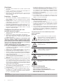 4
4
-
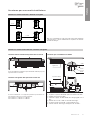 5
5
-
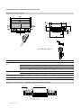 6
6
-
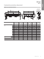 7
7
-
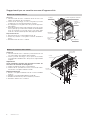 8
8
-
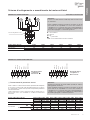 9
9
-
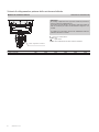 10
10
-
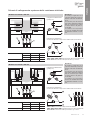 11
11
-
 12
12
-
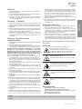 13
13
-
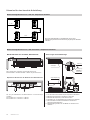 14
14
-
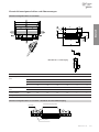 15
15
-
 16
16
-
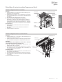 17
17
-
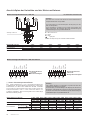 18
18
-
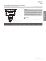 19
19
-
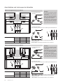 20
20
-
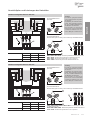 21
21
-
 22
22
-
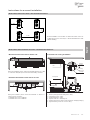 23
23
-
 24
24
-
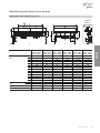 25
25
-
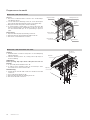 26
26
-
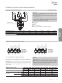 27
27
-
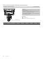 28
28
-
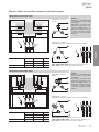 29
29
-
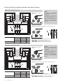 30
30
-
 31
31
-
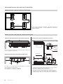 32
32
-
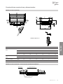 33
33
-
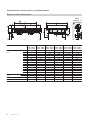 34
34
-
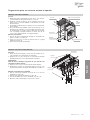 35
35
-
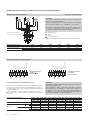 36
36
-
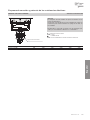 37
37
-
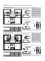 38
38
-
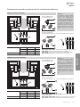 39
39
-
 40
40
-
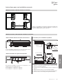 41
41
-
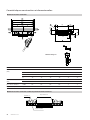 42
42
-
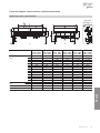 43
43
-
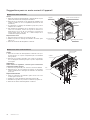 44
44
-
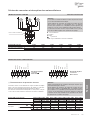 45
45
-
 46
46
-
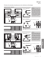 47
47
-
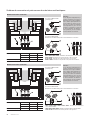 48
48
-
 49
49
-
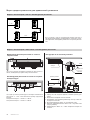 50
50
-
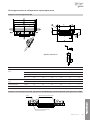 51
51
-
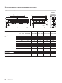 52
52
-
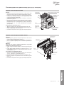 53
53
-
 54
54
-
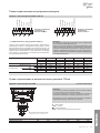 55
55
-
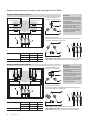 56
56
-
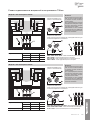 57
57
-
 58
58
-
 59
59
-
 60
60


