
IDE
MANUALE TECNICO
Aeroevaporatori a soffitto
serie industriale a doppio flusso
BETRIEBSANLEITUNG
Doppeltausblasende
Industrieverdampfer
TECHNICAL MANUAL
Dual discharge industrial range
ceiling unit coolers
MANUAL TECNICO
Aeroevaporadores de techo
serie industrial doble flujo
MANUEL TECHNIQUE
Evaporateurs plafonniers
série industrielle double flux
ТЕХНИЧЕСКОЕ РУКОВОДСТВО
Потолочные воздухоохладители
промышленная серия с двойным потоком

Indice
- Avvertenze
. . . . . . . . . . . . . . . . . . . . . . . . . . . . . . . . . . . . . . . . . . . . . . . . . . . . . . . . . . . . . . . . . . . .1
- Ispezione - Trasporto
. . . . . . . . . . . . . . . . . . . . . . . . . . . . . . . . . . . . . . . . . . . . . . . . . . . . . . .1
- Condizioni da verificare per una corretta
messa in opera
. . . . . . . . . . . . . . . . . . . . . . . . . . . . . . . . . . . . . . . . . . . . . . . . . . . . . . . . . . . . . . .1
- Manutenzione generale
. . . . . . . . . . . . . . . . . . . . . . . . . . . . . . . . . . . . . . . . . . . . . . . . . . . .1
- Avvertenze per una corretta installazione
. . . . . . . . . . . . . . . . . . . . . . . . . . . .1
- Caratteristiche costruttive e dimensionali
. . . . . . . . . . . . . . . . . . . . . . . . . . . . .2
- Suggerimenti per un corretto accesso
all’apparecchio
. . . . . . . . . . . . . . . . . . . . . . . . . . . . . . . . . . . . . . . . . . . . . . . . . . . . . . . . . . . . . . .3
- Schema di collegamento e assorbimento
dei motoventilatori
. . . . . . . . . . . . . . . . . . . . . . . . . . . . . . . . . . . . . . . . . . . . . . . . . . . . . . . . . . .3
- Schema di collegamento e potenze
delle resistenze elettriche
. . . . . . . . . . . . . . . . . . . . . . . . . . . . . . . . . . . . . . . . . . . . .4 - 5
Index
- Hinweise für eine korrekte Inbetriebnahme
. . . . . . . . . . . . . . . . . . . . . . . . . .6
- Allgemeine Wartung
. . . . . . . . . . . . . . . . . . . . . . . . . . . . . . . . . . . . . . . . . . . . . . . . . . . . . . . .6
- Hinweise für eine korrekte Aufstellung
. . . . . . . . . . . . . . . . . . . . . . . . . . . . . . . .6
- Konstruktionseigenschaften
und Abmessungen
. . . . . . . . . . . . . . . . . . . . . . . . . . . . . . . . . . . . . . . . . . . . . . . . . . . . . . . . . .7
- Ratschläge für einen korrekten Zugang
zum Gerät
. . . . . . . . . . . . . . . . . . . . . . . . . . . . . . . . . . . . . . . . . . . . . . . . . . . . . . . . . . . . . . . . . . . . .8
- Anschlußplan und Stromaufnahme der
Motorventilatoren
. . . . . . . . . . . . . . . . . . . . . . . . . . . . . . . . . . . . . . . . . . . . . . . . . . . . . . . . . . . .8
- Anschlußplan und Leistungen der Heizstäbe
. . . . . . . . . . . . . . . . . . .9 -10
Index
- For a correct installation
. . . . . . . . . . . . . . . . . . . . . . . . . . . . . . . . . . . . . . . . . . . . . . . . .11
- Routine maintenance
. . . . . . . . . . . . . . . . . . . . . . . . . . . . . . . . . . . . . . . . . . . . . . . . . . . . .11
- Instructions for a correct installation
. . . . . . . . . . . . . . . . . . . . . . . . . . . . . . . . . .11
- Manufacturing and dimensional features
. . . . . . . . . . . . . . . . . . . . . . . . . . .12
- Proper access to model
. . . . . . . . . . . . . . . . . . . . . . . . . . . . . . . . . . . . . . . . . . . . . . . . . .13
- Connection scheme and fan motor absorption
. . . . . . . . . . . . . . . . . . . .13
- Electric heater connection schemes
and electric power
. . . . . . . . . . . . . . . . . . . . . . . . . . . . . . . . . . . . . . . . . . . . . . . . . . .14 - 15
Indice
- Condiciones a verificar para una correcta
puesta en marcha
. . . . . . . . . . . . . . . . . . . . . . . . . . . . . . . . . . . . . . . . . . . . . . . . . . . . . . . . .16
- Manutención general
. . . . . . . . . . . . . . . . . . . . . . . . . . . . . . . . . . . . . . . . . . . . . . . . . . . . .16
- Advertencias para una correcta instalación
. . . . . . . . . . . . . . . . . . . . . . . .16
- Caracteristicas constructivas y
dimensionales
. . . . . . . . . . . . . . . . . . . . . . . . . . . . . . . . . . . . . . . . . . . . . . . . . . . . . . . . . . . . . .17
- Sujerencias para un correcto acceso
al aparato
. . . . . . . . . . . . . . . . . . . . . . . . . . . . . . . . . . . . . . . . . . . . . . . . . . . . . . . . . . . . . . . . . . . .18
- Esquema de conexión y absorción
motoventiladores
. . . . . . . . . . . . . . . . . . . . . . . . . . . . . . . . . . . . . . . . . . . . . . . . . . . . . . . . . . .18
- Esquema de conexión y potencia
de las resistencias eléctricas
. . . . . . . . . . . . . . . . . . . . . . . . . . . . . . . . . . . . .19 - 20
Index
- Conditions à vérifier pour une installation
correcte
. . . . . . . . . . . . . . . . . . . . . . . . . . . . . . . . . . . . . . . . . . . . . . . . . . . . . . . . . . . . . . . . . . . . . . .21
- Entretien général
. . . . . . . . . . . . . . . . . . . . . . . . . . . . . . . . . . . . . . . . . . . . . . . . . . . . . . . . . . .21
- Instructions pour une installation correcte
. . . . . . . . . . . . . . . . . . . . . . . . . .21
- Caractéristiques constructives
et dimensionnelles
. . . . . . . . . . . . . . . . . . . . . . . . . . . . . . . . . . . . . . . . . . . . . . . . . . . . . . . .22
- Suggestions pour un accès correct à l’appareil
. . . . . . . . . . . . . . . . . . .23
- Schéma de connexion et absorptions
motoventiateurs
. . . . . . . . . . . . . . . . . . . . . . . . . . . . . . . . . . . . . . . . . . . . . . . . . . . . . . . . . . . .23
- Schéma de connexion et puissances
des résistances électriques
. . . . . . . . . . . . . . . . . . . . . . . . . . . . . . . . . . . . . . .24 - 25
Содержание
- Меры предосторожности
. . . . . . . . . . . . . . . . . . . . . . . . . . . . . . . . . . . . . . . . . . . . .26
- Осмотр - Транспортировка
. . . . . . . . . . . . . . . . . . . . . . . . . . . . . . . . . . . . . . . . . . .26
- Условия для выполнения корректного
ввода в эксплуатацию
. . . . . . . . . . . . . . . . . . . . . . . . . . . . . . . . . . . . . . . . . . . . . . . . .26
- Общее техобслуживание
. . . . . . . . . . . . . . . . . . . . . . . . . . . . . . . . . . . . . . . . . . . . . .26
- Меры предосторожности
для корректной установки
. . . . . . . . . . . . . . . . . . . . . . . . . . . . . . . . . . . . . . . . . . .26
- Конструктивные
и пространственные характеристики
. . . . . . . . . . . . . . . . . . . . . . . . . . . .27
- Рекомендации по корректному доступу к аппарату
. . . . . . . .28
- Схема подключения
и потребления мотовентиляторов
. . . . . . . . . . . . . . . . . . . . . . . . . . . . . . . . .28
- Схема подключений и мощностей
электрических ТЭНов
. . . . . . . . . . . . . . . . . . . . . . . . . . . . . . . . . . . . . . . . . . . .29 - 30
Index

Italiano
1
www.modine.com
Avvertenze
per una corretta installazione
1. Togliere il coperchio dell’imballo prima di sollevare il modello.
2. Predisporre i tiranti sul soffitto.
3. Sollevare il gruppo modello-imballo fino ad appoggiarlo al sof-
fitto.
4. Avvitare fino in fondo i dadi “A” sui tiranti di fissaggio.
5. Togliere le viti di sicurezza “B” e calare l’imballo vuoto.
6. Serrare i dadi “A” di fissaggio dell’apparecchio al soffitto.
Istruzioni per l’installazione a soffitto
Imballo
Tirante
Imballo
Coperchio imballo
Staffa
Apparecchio
Avvertenze
1. Conservare questo manuale tecnico per tutto il periodo di vita
del modello.
2. Leggere con attenzione il manuale prima dell’installazione e
prima di qualsiasi operazione sul modello.
3. Impiegare il modello esclusivamente per lo scopo per cui é
stato progettato: l’uso improprio esonera il costruttore da qual-
siasi responsabilità.
Ispezione - Trasporto
1. Al ricevimento del modello controllare immediatamente il suo
stato; contestare subito alla compagnia di trasporto qualsiasi
eventuale danno.
2. Durante il trasporto evitare di esercitare pressioni improprie
sull’imballaggio, che va mantenuto comunque sempre nella
posizione indicata sullo stesso.
3. Disimballare il modello il più vicino possibile al luogo di instal-
lazione. Una volta disimballato, evitare urti ai componenti.
4. Durante l’installazione e la movimentazione del modello utiliz-
zare appositi guanti protettivi per evitare di ferirsi con le parti
taglienti (es. alette) del modello.
Condizioni da verificare
per una corretta messa in opera
1. Verificare la tenuta delle strutture di sostegno rispetto al peso
dell’apparecchio.
2. Verificare che il modello venga installato orizzontalmente.
3. Assicurare un volume libero adeguato (circa il 30% del volume
interno della cella) per una corretta circolazione dell’aria in
aspirazione e scarico.
Particolari condizioni di installazione o funzionamento quali
celle basse, travature a soffitto, stoccaggi eccessivi, impedi-
menti al getto e/o all’aspirazione dell’aria, formazione impro-
pria di brina dovuta ad eccessiva immissione di umidità
nella cella, possono influenzare negativamente le prestazioni
dichiarate e creare difettosità nei modelli.
I modelli standard possono non essere adatti ad operare in
tunnel o celle di abbattimento/surgelamento rapido.
4. I modelli sono equipaggiati con motoventilatori assiali, quindi
non adatti ad essere canalizzati o comunque a sopportare
prevalenze statiche aggiuntive.
5. Verificare che le condizioni di funzionamento (temperature e
pressioni) siano conformi a quelle di progetto.
6. Prestare particolare cura in fase di collegamento affinchè non
si deformino i capillari e non si modifichi la posizione del distri-
butore.
7. In caso di più modelli installati a breve distanza l’uno dall’altro,
evitare sbrinamenti alternati.
8. Installare sugli scarichi condensa gli opportuni sifoni e verifi-
carne l'efficacia in tutte le temperature di utilizzo.
9. Evitare l'installazione degli aeroevaporatori vicino alle porte
delle celle.
10.Collocare la sonda di temperatura per il fine sbrinamento nelle
zone più fredde degli scambiatori, ovvero quelle zone che ten-
dono a ghiacciarsi maggiormente (al termine del ciclo non
deve rimanere ghiaccio sui modelli).
La posizione di questo dispositivo non può essere definita a
priori, in quanto varia in relazione al tipo di cella e al tipo di
impianto.
11.Verificare che la linea elettrica di alimentazione sia adeguata
alle caratteristiche elettriche dell’apparecchio.
12.Assicurarsi che tutti i collegamenti elettrici siano in accordo
con le norme vigenti.
13.Ad installazione completata rimuovere la pellicola protettiva
che ricopre il modello.
14.L’accessibilità al modello, per qualsiasi tipo di intervento, deve
essere riservata al personale qualificato alla conduzione del-
l’impianto, secondo le norme vigenti.
Manutenzione generale
1. Verificare periodicamente i fissaggi, le connessioni elettriche e
i collegamenti all’impianto frigorifero.
2. Provvedere alla pulizia periodica dell’apparecchio, per evitare
accumuli di sostanze nocive. Si consiglia l’utilizzo di normale
acqua saponata, evitando solventi, agenti aggressivi, abrasivi
o a base di ammoniaca.
3. In caso di sostituzioni di resistenze elettriche prestare partico-
lare attenzione nelle fasi di installazione per evitare danni alle
vulcanizzazioni; ripristinare correttamente i collegamenti e i
sistemi di fissaggio esistenti per evitare movimenti delle stes-
se durante il funzionamento.
Tali operazioni dovranno essere effettuate da personale
esperto e qualificato.
Attenzione
Prima di effettuare qualsiasi intervento di manutenzione,
accertarsi che l’alimentazione elettrica sia scollegata dalla
fonte principale: le parti elettriche potrebbero essere collegate
ad un controllo automatico.

2
www.modine.com
X
X
Caratteristiche costruttive e dimensionali
Modello IDE 41A04 41B04 42A04 42B04 43A04 43B04 52A04 52B04 53A04 53B07 54A04 54B04
41A07 41B07 42A07 42B07 43A07 43B07 52A07 52B07 53A07 53B07 54A07 54B07
41A10 41B10 42A10 42B10 43A10 43B10 52A10 52B10 53A10 53B10 54A10 54B10
Dimensioni A 1300 2150 3000 2760 3860 4960
(mm) B 814 1664 2514 2164 3264 4364
C/ / 1700 1100 2 x 1100 3 x 1100
D/ / 814 1064 1064 1064
E 406 410 415 538 543 550
F 400 400 400 530 530 530
G 85 85 85 90 90 90
H 243 243 243 298 298 298
L 1594 1594 1594 1809 1809 1809
M 1449 1449 1449 1664 1664 1664
N 1290 1290 1290 1505 1505 1505
P 280 280 280 280 280 280
Q 490 490 490 680 680 680
R 695 695 695 835 835 835
Attacchi interni batteria entrata 16 22 28 28 35 35
(mm) uscita 35 42 42 54 54 70
Attacco scarico 2 x 1” GAS 2 x 1” GAS 2 x 1” GAS 2 x 2” GAS 2 x 2” GAS 2 x 2” GAS
Peso (kg) 80 145 206 250 370 498
Impiegare valvola termostatica con equalizzatore di pressione esterno.
Distanza minima laterale dalla parete lato resistenze
Distanza consigliata dalle pareti lato uscita aria
In fase di installazione rispettare la quota minima B + 300 mm per poter
togliere/inserire le resistenze.
In fase di installazione si consiglia di rispettare la quota minima “Y”
per garantire una buona circolazione dell’aria:
motoventilatori ø = 450 mm: Y = 700 mm;
motoventilatori ø = 560 mm: Y = 900 mm.

Italiano
3
www.modine.com
Modello IDE 41A04 41B04 42A04 42B04 43A04 43B04 52A04 52B04 53A04 53B07 54A04 54B04
41A07 41B07 42A07 42B07 43A07 43B07 52A07 52B07 53A07 53B07 54A07 54B07
41A10 41B10 42A10 42B10 43A10 43B10 52A10 52B10 53A10 53B10 54A10 54B10
Motoventilatori n.x ø mm 1x450 2x450 3x450 2x560 3x560 4x560
A 0,79 1,58 2,37 3,3 4,95 6,6
W 430 860 1290 1680 2520 3360
A 0,53 1,06 1,59 2,1 3,15 4,2
W 330 660 990 1280 1920 2560
Suggerimenti per un corretto accesso all’apparecchio
Accesso
1. Smontare i tubi di scarico condensa e posi-
zionarli in modo che non creino intralcio al
movimento delle vaschette.
2. Svitare i pomelli di fissaggio “A” per aprire le
vaschette; accompagnarle lentamente fino
alla posizione rappresentata in figura.
Importante:
prima di effettuare l’apertura delle vaschette
accertarsi che siano libere da eventuali resi-
dui di ghiaccio.
3. Svitare i pomelli “B” per aprire i coperchi late-
rali.
4. Svitare le viti “C” per rimuovere i motori; se
necessario rimuovere anche i convogliatori
svitando le viti “D”.
Riposizionamento
1. Fissare i convogliatori mediante le viti “D” e i
motori mediante le viti “C”.
2. Chiudere i coperchi laterali mediante i
pomelli “B”.
3. Rimettere le vaschette in posizione serrando
i pomelli “A”.
4. Rimontare i tubi di scarico condensa.
Schema di collegamento e assorbimento dei motoventilatori
(*) Termocontatti di protezione interni
I termocontatti sono elementi di azionamento dipendenti dalla temperatu-
ra che vengono inseriti, isolati, negli avvolgimenti dei motori; essi aprono
un contatto elettrico quando viene superata la temperatura permanente
massima ammissibile.
I termocontatti devono essere collegati ai circuiti di comando dei con-
tatori di modo che in caso di disturbi non si abbia una reinserzione
automatica.
400 V/50 Hz Trifase
collegamento
q
Alta velocità
400 V/50 Hz Trifase
collegamento Y
Bassa velocità
Coperchi laterali
Sostegni
Vaschetta
Convogliatore
Arancio
Marrone
Rosso
Blu
Grigio
Nero
Giallo / vede
Arancio
Marrone
Rosso
Blu
Grigio
Nero
Giallo / vede
Assorbimenti
Alta velocità (∆)
Bassa velocità (Y)
Attenzione
Seguire rigorosamente gli schemi elettrici riportati per evitare il
danneggiamento del motore.
Prima di utilizzare sistemi di regolazione del numero di giri dei
motori verificare la compatibilità con i motori stessi, sistemi non
compatibili possono generare rumorosità e danneggiamenti; il
costruttore. non si assume responsabilità alcuna sulle prestazioni
dei modelli equipaggiati con sistemi di regolazione.

4
www.modine.com
Schemi di collegamento e potenze delle resistenze elettriche
Collegamento 400V/3/50 Hz
(predisposto).
RBA1 / RBA2 / RBA3 / RBA4 - Resistenze di alta potenza nella batteria.
RSA1 / RSA2 - Resistenze di alta potenza sullo sgocciolatoio.
Modello con ventola ø 450 mm
Collegamento 230V3/50 Hz
Si ottiene modificando la disposizione delle barrette in morsettiera.
Modelli IDE ø 450 41A04 42A04 43A04
41A07 42A07 43A07
41A10 42A10 43A10
Potenza totale (W) 5040 10200 15000
Modello con ventola ø 450 mm
Collegamento 400V/3/50 Hz
(predisposto).
RBA1 / RBA2 - Resistenze di alta potenza nella batteria.
RBB1 / RBB2 / RBB3 / RBB4 - Resistenze di bassa potenza nella batteria.
RSA1 / RSA2 - Resistenze di alta potenza sullo sgocciolatoio.
Collegamento 230V3/50 Hz
Si ottiene modificando la disposizione delle barrette in morsettiera.
Modelli IDE ø 450 41B04 42B04 43B04
41B07 42B07 43B07
41B10 42B10 43B10
Potenza totale (W) 5040 10200 15000
Attenzione
È d’obbligo l’applicazione di
opportuni sistemi di protezione
termica sulle linee di alimenta-
zione.
Provvedere periodicamente
alla verifica delle funzionalità di
tutte le resistenze per evitare
accumuli dannosi di ghiaccio
sui modelli.
Il costruttore non risponde in
alcun modo di difettosità create
da malfunzionamenti non rile-
vati.

Italiano
5
www.modine.com
Schemi di collegamento e potenze delle resistenze elettriche
Collegamento 400V/3/50 Hz
(predisposto).
RBA1 / RBA2 / RBA3 / RBA4 - Resistenze di alta potenza nella batteria.
RBB1 / RBB2 - Resistenze di bassa potenza nella batteria.
RSB1 / RSB2 - Resistenze di bassa potenza sullo sgocciolatoio.
RBM1 / RBM2 - Resistenze di media potenza nella batteria.
Modello con ventola ø 560 mm
Collegamento 230V3/50 Hz
Si ottiene modificando la disposizione delle barrette in morsettiera.
Modelli IDE ø 560 52A04 53A04 54A04
52A07 53A07 54A07
52A10 53A10 54A10
Potenza totale (W) 16050 24000 32250
Modello con ventola ø 560 mm
Collegamento 400V/3/50 Hz
(predisposto).
RBA1 / RBA2 / RBA3 / RBA4 / RBA5 / RBA6 - Resistenze di alta potenza
nella batteria.
RBB1 / RBB2 / RBB3 / RBB4 - Resistenze di bassa potenza nella batteria.
RSB1 / RSB2 - Resistenze di bassa potenza sullo sgocciolatoio.
Collegamento 230V3/50 Hz
Si ottiene modificando la disposizione delle barrette in morsettiera.
Modelli IDE ø 560 52B04 53B04 54B04
52B07 53B07 54B07
52B10 53B10 54B10
Potenza totale (W) 19260 28800 38700
Attenzione
È d’obbligo l’applicazione di
opportuni sistemi di protezione
termica sulle linee di alimenta-
zione.
Provvedere periodicamente
alla verifica delle funzionalità di
tutte le resistenze per evitare
accumuli dannosi di ghiaccio
sui modelli.
Il costruttore non risponde in
alcun modo di difettosità create
da malfunzionamenti non rile-
vati.

6
www.modine.com
Hinweise für eine korrekte Aufstellung
1. Vor dem Heben des Modells Verpackungsdeckel abnehmen.
2. Befestigungsschrauben an der Decke vorbereiten.
3. Gerät mit der Verpackung an die Decke heben.
4. Die Muttern “A” an die Befestigungsschrauben fest anziehen.
5. Die Sicherheitsschrauben “B” abnehmen und die leere
Verpackung herunterziehen.
6. Die Befestigungsmuttern “A” des Geräts an die Decke fest
anziehen.
Anweisungen für Wandmontage
Verpackung
Befestigungs-
schraube
Verpackung
Verpackungsdeckel
Halterung
Verdampfer
Hinweise
1. Diese Betriebsanleitung während der ganzen Lebensdauer
des Geräts aufbewahren.
2. Vor Inbetriebnahme des Geräts und vor jedem Eingriff auf-
merksam die Betriebsanleitung durchlesen.
3. Das Gerät nur für den Zweck einsetzen, wofür es entworfen
worden ist; unsachgemäße Anwendung befreit den Hersteller
von jeder Verantwortung.
Kontrolle - Transport
1. Bei Erhalt des Geräts sofort den Zustand kontrollieren; jegli-
chen eventuellen Schaden sofort dem Spediteur beanstanden.
2. Während des Transports unnötigen Druck auf die Verpackung
vermeiden.
3. Während der Montage und des Positionierens des Geräts
geeignete Schutzhandschuhe benutzen, um eine
Verletzungsgefahr durch scharfe Stellen am Gerät zu vermei-
den.
4. Während der Montage und des Positionierens des Geräts
geeignete Schutzhandschuhe benutzen, um eine
Verletzungsgefahr durch scharfe Stellen (z.B. Lamellen) zu
vermeiden.
Hinweise für eine korrekte
Inbetriebnahme
1. Die Tragfähigkeit der Strukturen bezüglich des
Gerätegewichts überprüfen.
2. Das Modell muß horizontal eingebaut werden.
3. Für eine einwandfreie Luftzirkulation muß genügend Freiraum
vorhanden sein (ungefähr 30% des Innenvolumens der Zelle).
Besondere Einbau- oder Betriebsbedingungen, wie niedrige
Kühlzellen, Deckenträger, übermäßige Lagerung,
Behinderungen des Luftstroms und/oder der Luftansaugung,
übermäßige Reifbildung durch zu hohe Feuchtigkeit in der
Kühlzelle können die angegebenen Leistungen negativ
beeinflussen und Schäden an den Geräten hervorrufen.
Die Standardmodelle können für die Anwendung in
Schnellabkühlungs- oder Schockräumen nicht geeignet sein.
4. Die Modelle sind mit Axialmotorventilatoren ausgestattet und
daher nicht kanalisierbar oder jedenfalls keine weiteren
Druckverluste verkraften.
5. Die Betriebsbedingungen (Temperaturen und Drucke) müssen
dem Projekt entsprechen.
6. Das Anschließen muß sorgfältig erfolgen, um das Verformen
eventueller Kapillarrohre und das Verlagern des Verteilers zu
verhindern.
7. Bei nah aneinander installierten Geräten abwechselnde
Abtauungen vermeiden.
8. An den Tauwasserabflüssen die passenden Siphone installie-
ren und die Wirksamkeit bei allen Anwendungstemperaturen
überprüfen.
9. Die Installation der Luftverdampfer in der Nähe der
Zellentüren vermeiden.
10.Die Temperaturfühler für das Ende der Abtauung in den kälte-
sten Zonen der Wärmeaustauscher anbringen, beziehung-
sweise in den Zonen, wo die Tendenz zur Eisbildung am größ-
ten ist (am Ende der Abtauung darf kein Eis an den Modellen
bleiben). Die Lage dieser kann nicht vorherbestimmt werden,
da sie sich je nach Typ der Zelle und der Anlage verändert.
11.Die Stromzuleitung muß den elektrischen Daten des Geräts
angepaßt sein.
12.Alle Anschlüsse müssen den gültigen elektrischen Normen
entsprechen.
13.Nach beendeter Installation den am Gerät befindlichen
Achtung
Versichern Sie sich vor jeder Wartung, daß die
Stromzuführung vom Hauptnetz getrennt ist; die elektrischen
Teile könnten automatisch anlaufen.
Schutzfilm entfernen.
14.Der Zugang zum Gerät für jeden Eingriff muß dem für die
Anlage qualifizierten Personal gemäß den gültigen Normen
vorbehalten sein.
Allgemeine Wartung
1. Regelmäßige Überprüfung der Befestigungen der elektrischen
Anschlüsse. Kältemittelanschlüsse auf Dichtheit prüfen.
2. Regelmäßige Reinigung des Geräts mit normalem
Seifenwasser, um das Anhäufen von schädlichen Substanzen
zu verhindern. Keine Lösungsmittel und aggressive oder
ammoniakhaltige Reibepulver verwenden.
3. Beim eventuellen Auswechseln von elektrischen Heizstäben
besonders achtgeben, um während der Installation Schäden
an der Vulkanisierung zu vermeiden; die Anschlüsse und die
bestehenden Befestigungssysteme wieder korrekt herstellen,
um zu vermeiden, daß sie sich während des Betriebs bewe-
gen.
Die Wartung darf nur von qualifizierten Personal vorgenom-
men werden.

Deutsch
7
www.modine.com
X
X
Konstruktionseigenschaften und Abmessungen
Modell IDE 41A04 41B04 42A04 42B04 43A04 43B04 52A04 52B04 53A04 53B07 54A04 54B04
41A07 41B07 42A07 42B07 43A07 43B07 52A07 52B07 53A07 53B07 54A07 54B07
41A10 41B10 42A10 42B10 43A10 43B10 52A10 52B10 53A10 53B10 54A10 54B10
Abmessungen A 1300 2150 3000 2760 3860 4960
(mm) B 814 1664 2514 2164 3264 4364
C/ / 1700 1100 2 x 1100 3 x 1100
D/ / 814 1064 1064 1064
E 406 410 415 538 543 550
F 400 400 400 530 530 530
G 85 85 85 90 90 90
H 243 243 243 298 298 298
L 1594 1594 1594 1809 1809 1809
M 1449 1449 1449 1664 1664 1664
N 1290 1290 1290 1505 1505 1505
P 280 280 280 280 280 280
Q 490 490 490 680 680 680
R 695 695 695 835 835 835
Batterieanschlüsse Eintritt 16 22 28 28 35 35
(mm) Austritt 35 42 42 54 54 70
Tauwasserabfluß 2 x 1” GAS 2 x 1” GAS 2 x 1” GAS 2 x 2” GAS 2 x 2” GAS 2 x 2” GAS
Gewicht (kg) 80 145 206 250 370 498
Thermostatisches Ventil mit Aussendruck-Kompensator anwenden.
Mindestabstand von der Wand, Heizstabseite
Empfohlener Abstand von der Wand auf der Luftaustrittsseite
Zum seitlichen Ein- und Ausbau der Heizstäbe muß bei der
Geräteinstallation das Mindestmaß B + 300 mm eingehalten werden.
Für eine gute Luftzirkulation den Mindestabstand "Y" bei der Montage
einhalten:
Motorventilatoren ø = 450 mm: Y = 700 mm;
Motorventilatoren ø = 560 mm: Y = 900 mm.

8
www.modine.com
Modell IDE 41A04 41B04 42A04 42B04 43A04 43B04 52A04 52B04 53A04 53B07 54A04 54B04
41A07 41B07 42A07 42B07 43A07 43B07 52A07 52B07 53A07 53B07 54A07 54B07
41A10 41B10 42A10 42B10 43A10 43B10 52A10 52B10 53A10 53B10 54A10 54B10
Motorventilatoren n.x ø mm 1x450 2x450 3x450 2x560 3x560 4x560
A 0,79 1,58 2,37 3,3 4,95 6,6
W 430 860 1290 1680 2520 3360
A 0,53 1,06 1,59 2,1 3,15 4,2
W 330 660 990 1280 1920 2560
Ratschläge für einen korrekten Zugang zum Gerät
Ausbau
1. Tauwasserablußrohre so demontieren, daß
das Bewegen der Tropfwannen nicht behin-
dert wird.
2. Um die Tropfwannen zu öffnen, die Be-festi-
gungsdrehschrauben "A" losschrauben und
langsam wie aufgezeichnet positionieren.
Wichtig:
vor dem Öffnen der Tropfwannen sicher-
stellen, daß keine eventuellen Eisrück-stän-
de vorhanden sind.
3. Um die seitlichen Abdeckungen abzuneh-
men, die Drehschrauben "B" losschrauben.
4. Um die Motoren auszubauen, die Schrau-
ben "C" losschrauben und wenn nötig, die
Schrauben "D" losschrauben, um auch die
Lüfterbleche abzunehmen.
Zusammenbau
1. Die Lüfterbleche mit den Schrauben "D" und
die Motoren mit den Schrauben "C" befesti-
gen.
2. Die seitlichen Abdeckungen mit den
Drehschrauben "B" befestigen.
3. Die Tropfwannen positionieren und mit den
Drehschrauben "A" anziehen.
4. Tauwasserabflußrohre montieren.
Anschlußplan und Stromaufnahme der Motorventilatoren
(*) Innere Schutztemperaturwächter
Die Temperaturwächter sind temperaturunabhängige
Schaltelemente, die in die Wicklungen der Motoren isoliert einge-
bettet werden; sie öffnen einen elektrischen Kontakt, sobald die
höchstzulässige Dauertemperatur überschritten wird. Die
Temperaturwächter sind so in den Steuerstromkreis von
Schützen einzufügen, daß im Störungsfalle keine selbst-tätige
Wiedereinschaltung erfolgt.
400 V/50 Hz Drehstrom
q
Anschluß
Hohe Geschwindigkeit
400 V/50 Hz Drehstrom
Y Anschluß
Niedrige Geschwindigkeit
Seitliche Abdeckung
Halterungen
Tropfwanne
Lüfterblech
Orange
Braun
Rot
Hellblau
Grau
Schwarz
Gelb / grün
Orange
Braun
Rot
Hellblau
Grau
Schwarz
Gelb / grün
Stromaufnahme
Hohe Geschwindigkeit (∆)
Niedrige Geschwindigkeit (Y)
Achtung
Um Schäden am Motor zu vermeiden, ist genau nach dem auf-
geführten Anschlußplan vorzugehen.
Vor Anwendung von Drehzahlreglern die Eignung für die Motoren
überprüfen, nicht verträgliche Systeme können Lärm und Schäden
am Motor hervorrufen; der Hersteller lehnt jede Verantwortung für
mit Drehzahlreglern ausgestattete Geräte ab.

Deutsch
9
www.modine.com
Anschlußplan und Leistungen der Heizstäbe
Anschluß 400V/3/50 Hz
(standard).
RBA1 / RBA2 / RBA3 / RBA4 - Hochleistungsheizstäbe im
Wärmeaustauscher.
RSA1 / RSA2 - Niederleistungsheizstäbe in der Tropfwanne.
Modell mit Flügeldurchmesser 450 mm
Anschluß 230V3/50 Hz
Durch Änderung der Anordnung der Schaltstangen im Klemmenkasten.
Modell IDE ø 450 41A04 42A04 43A04
41A07 42A07 43A07
41A10 42A10 43A10
Gesamtleistung (W) 5040 10200 15000
Modell mit Flügeldurchmesser 450 mm
Anschluß 400V/3/50 Hz
(standard).
RBA1 / RBA2 - Hochleistungsheizstäbe im Wärmeaustauscher.
RBB1 / RBB2 / RBB3 / RBB4 - Niederleistungsheizstäbe im
Wärmeaustauscher.
RSA1 / RSA2 - Niederleistungsheizstäbe in der Tropfwanne.
Anschluß 230V3/50 Hz
Durch Änderung der Anordnung der Schaltstangen im Klemmenkasten.
Modell IDE ø 450 41B04 42B04 43B04
41B07 42B07 43B07
41B10 42B10 43B10
Gesamtleistung (W) 5040 10200 15000
Achtung
Es müssen geeignete thermi-
sche Schutzsysteme angewen-
det werden.
Regelmäßig die Funktionstüch-
tigkeit aller Heizstäbe überprü-
fen, um schädliche Eisbildung an
den Geräten zu vermeiden.
Der Hersteller ist auf keinen
Fall für durch nicht bemerkten
schlechten Betrieb hervorge-
rufene Mängel verantwortlich.

10
www.modine.com
Anschlußplan und Leistungen der Heizstäbe
Anschluß 400V/3/50 Hz
(standard).
RBA1 / RBA2 / RBA3 / RBA4 - Hochleistungsheizstäbe im Wärmeaustauscher.
RBB1 / RBB2 - Niederleistungsheizstäbe im Wärmeaustauscher.
RSB1 / RSB2 - Niederleistungsheizstäbe in der Tropfwanne.
RBM1 / RBM2 - Mittelleistungsheizstäbe im Wärmeaustauscher.
Modell mit Flügeldurchmesser 560 mm
Anschluß 230V3/50 Hz
Durch Änderung der Anordnung der Schaltstangen im Klemmenkasten.
Modell IDE ø 560 52A04 53A04 54A04
52A07 53A07 54A07
52A10 53A10 54A10
Gesamtleistung (W) 16050 24000 32250
Modell mit Flügeldurchmesser 560 mm
Anschluß 400V/3/50 Hz
(standard).
RBA1 / RBA2 / RBA3 / RBA4 / RBA5 / RBA6 - Hochleistungsheizstäbe
im Wärmeaustauscher.
RBB1 / RBB2 / RBB3 / RBB4 - Niederleistungsheizstäbe im Wärmeaustauscher.
RSB1 / RSB2 - Niederleistungsheizstäbe in der Tropfwanne.
Anschluß 230V3/50 Hz
Durch Änderung der Anordnung der Schaltstangen im Klemmenkasten.
Modell IDE ø 560 52B04 53B04 54B04
52B07 53B07 54B07
52B10 53B10 54B10
Gesamtleistung (W) 19260 28800 38700
Achtung
Es müssen geeignete thermi-
sche Schutzsysteme angewen-
det werden.
Regelmäßig die Funktionstüch-
tigkeit aller Heizstäbe überprü-
fen, um schädliche Eisbildung an
den Geräten zu vermeiden.
Der Hersteller ist auf keinen
Fall für durch nicht bemerkten
schlechten Betrieb hervorge-
rufene Mängel verantwortlich.

English
11
www.modine.com
Instructions for a correct installation
1. Remove package lid before lifting unit to ceiling.
2. Set fastening rods to ceiling.
3. Lift packaged unit to ceiling.
4. Tighten screws “A” to fastening rods.
5. Unfasten and remove safety screws “B” and slip off empty packaging.
6. Tighten fastening screws “A” of unit to ceiling.
Instructions for ceiling installation
Package
Fastening
rod
Packaged unit
Package lid
Support
bracket
Unit
Important
1. Keep this manual for the lifespan of model.
2. Read technical manual carefully before installation and prior to
any intervention on model.
3. Use model exclusively for the purpose for which it has been
designed; misuse exempts manufacturer from any responsibility.
Inspection - Transport
1. Upon delivery immediately examine condition of model; should
damages be detected promptly notify forwarder.
2. During transport of model it is necessary to avoid pressure on
packaging and it must be kept in upright position as indicated
on package.
3. Unpack model as close as possible to installation site. When
packaging is removed from model, care must be exercised in
order to avoid damage to parts.
4. In order to avoid injury from the model's sharp edges (e.g.
fins) during installation and positioning of model use of special
protective gloves is recommended.
For a proper installation
1. Verify structural bearing of ceiling in relation to the weight of
the unit.
2. Verify that the unit is installed horizontally.
3. Ensure an adequate free space (approx. 30% of the inner
room volume) to allow a proper intake and exhaust air circula-
tion.
Particular conditions of installation or operation such as low
or beamed rooms, overstorage, obstructed intake and
exhaust air circulation and improper ice build-up due to
excessive entry of humidity in room may negatively affect
the stated performance and may cause defects.
Standard models may not be suitable for blast freezer and
chill room application.
4. The models are equipped with axial fan motors, therefore not
suitable for duct ventilation systems and cannot sustain extra
static air pressure drops.
5. Verify that the operating conditions (temperatures and pressu-
res) are in accordance to those of project.
6. Care must be exercised during the connecting phase in order
to avoid possible distortion of the capillary tubes and shifting
of the distributor.
7. In the case of more than one model installed at close range it
is advisable to avoid alternate defrostings.
8. Fit the appropriate siphons on the condensate drain con-
nections and assess their efficiency in all working tempe-
ratures.
9. Avoid installation of the units next to the cold-room doors.
10.Place the end of defrost temperature feeler in the coldest
areas of the coil, i.e. the areas that tend to freeze more (at
the end of the cycle the unit should be completely ice-free).
The position of this device cannot be defined in advance,
because it varies in accordance to the type cold room and
type of installation.
11.Verify that the electrical feed network is in accordance to the
electrical features of model.
12.Ensure that all the electric wiring is in compliance with the
standards in force.
13.The protective film is to be removed from model upon comple-
tion of installation.
14.Access to model, for any type of intervention, is reserved to
qualified personnel as per regulations in force.
General Maintenance
1. Periodically inspect fastenings, electrical connections and con-
nections to cooling installation.
2. It is necessary to arrange periodical cleaning of unit in order to
avoid deposits of toxic substances. Use of mild detergent is
recommended; avoid use of solvents, aggressive, abrasive or
ammonia-based agents.
3. When replacing electric heaters take particular care during
installation in order to avoid damage to the vulcanization; cor-
rectly reset wiring and existing fastening systems to avoid pos-
sible movement during operation.
The above-mentioned operations are to be carried out by
qualified personnel only.
Caution
before carrying out maintenance on unit, make sure that the
electric feed is disconnected from main power source: the
electric parts may be connected to an automatic control
system.

12
www.modine.com
X
X
Manufacturing and dimensional features
IDE model 41A04 41B04 42A04 42B04 43A04 43B04 52A04 52B04 53A04 53B07 54A04 54B04
41A07 41B07 42A07 42B07 43A07 43B07 52A07 52B07 53A07 53B07 54A07 54B07
41A10 41B10 42A10 42B10 43A10 43B10 52A10 52B10 53A10 53B10 54A10 54B10
Dimensions A 1300 2150 3000 2760 3860 4960
(mm) B 814 1664 2514 2164 3264 4364
C/ / 1700 1100 2 x 1100 3 x 1100
D/ / 814 1064 1064 1064
E 406 410 415 538 543 550
F 400 400 400 530 530 530
G 85 85 85 90 90 90
H 243 243 243 298 298 298
L 1594 1594 1594 1809 1809 1809
M 1449 1449 1449 1664 1664 1664
N 1290 1290 1290 1505 1505 1505
P 280 280 280 280 280 280
Q 490 490 490 680 680 680
R 695 695 695 835 835 835
Coil connections Inlet 16 22 28 28 35 35
(mm) Outlet 35 42 42 54 54 70
Drain connections 2 x 1” GAS 2 x 1” GAS 2 x 1” GAS 2 x 2” GAS 2 x 2” GAS 2 x 2” GAS
Weight (kg) 80 145 206 250 370 498
Use thermostatic valve with external pressure equalizer.
Minimum distance from wall on heater side
Recommended distance from wall on air side
During the installation phase observe the minimum dimension B + 300
as to allow an adequate space for the removal and fitting of heaters.
During the installation phase observe the minimum “Y” distance to
allow proper air circulation:
ø=450 mm fan motors: Y=700 mm;
ø=560 mm fan motors: Y=900 mm.

English
13
www.modine.com
IDE Model 41A04 41B04 42A04 42B04 43A04 43B04 52A04 52B04 53A04 53B07 54A04 54B04
41A07 41B07 42A07 42B07 43A07 43B07 52A07 52B07 53A07 53B07 54A07 54B07
41A10 41B10 42A10 42B10 43A10 43B10 52A10 52B10 53A10 53B10 54A10 54B10
Fan motors n.x ø mm 1x450 2x450 3x450 2x560 3x560 4x560
A 0,79 1,58 2,37 3,3 4,95 6,6
W 430 860 1290 1680 2520 3360
A 0,53 1,06 1,59 2,1 3,15 4,2
W 330 660 990 1280 1920 2560
Proper access to model
Access
1. Dismantle drain connections and position to
avoid hampering with the drip trays.
2. Unfasten fastening knobs “A”; slowly position
drip trays as shown in drawing.
Important:
before opening drip trays check if they are
free from ice build-up.
3. To open side panels unfasten knobs “B”.
4. To remove motors unfasten screws “C”; if
necessary to unfasten screws “D” to remove
fan shrouds.
Remounting
1. Fasten the fan shrouds with screws “D” and
the motors with screws “C”.
2. Close side panels with knobs “B”.
3. Reposition the drip trays by clamping knobs
“A”.
4. Reconnect the drain connection.
Connection scheme and fan motor absorption
(*) Inner protection thermal contacts
The thermal contacts are temperature sensing, insulated switching ele-
ments built directly into the windings of the motors. They interrupt an
electrical contact when maximum admissable sustained temperature has
been reached.
The thermal contacts must be connected to the control circuit of the
mains contractor to prevent automatic reconnection of the motor in the
event of a fault.
400 V/50 Hz
Three-phase
q
connection
High speed
400 V/50 Hz
Three-phase
Y connection
Low speed
Side panel
Brackets
Drip tray
Fan shroud
Orange
Brown
Red
Light blue
Grey
Black
Green/yellow
Orange
Brown
Red
Light blue
Grey
Black
Green/yellow
Absorption
High speed (∆)
Low speed (Y)
Caution
To avoid possible motor damage strictly follow the electric sche-
mes shown.
Before using motor speed control systems verify the compatibility
with the motors; non compatible systems may damage motors or
increase noise level; the manufacturer will not be responsible for
model performance with speed control systems.

14
www.modine.com
Electric heater connection schemes and electric power
400V/3/50 Hz connection
(preset).
RBA1 / RBA2 / RBA3 / RBA4 - High power electric heaters in coil.
RSA1 / RSA2 - Low power electric heaters on drip tray.
Model with ø 450 mm fan motor
230V/3/50 Hz connection
Obtainable by modifying the jumper layout in the terminal block.
IDE model ø 450 41A04 42A04 43A04
41A07 42A07 43A07
41A10 42A10 43A10
Total power (W) 5040 10200 15000
Model with ø 450 mm fan motor
400V/3/50 Hz connection
(preset).
RBA1 / RBA2 - High power electric heaters in coil.
RBB1 / RBB2 / RBB3 / RBB4 - Low power electric heaters in coil.
RSA1 / RSA2 - High power electric heaters on drip tray.
230V/3/50 Hz connection
Obtainable by modifying the jumper layout in the terminal block.
IDE model ø 450 41B04 42B04 43B04
41B07 42B07 43B07
41B10 42B10 43B10
Total power (W) 5040 10200 15000
Caution
Application of adequate thermal
control systems on feeder lines
is mandatory.
Performance of all electric hea-
ters must be periodically control-
led to avoid damage due to ice
build-up. The manufacturer is
not liable in any way for defects
caused by non detected mal-
functions.
Caution
Application of adequate thermal
control systems on feeder lines
is mandatory.
Performance of all electric hea-
ters must be periodically control-
led to avoid damage due to ice
build-up. The manufacturer is
not liable in any way for defects
caused by non detected mal-
functions.

English
15
www.modine.com
Electric heater connection schemes and electric power
400V/3/50 Hz connection
(preset).
RBA1 / RBA2 / RBA3 / RBA4 - High power electric heaters in coil.
RBB1 / RBB2 - Low power electric heaters in coil.
RSB1 / RSB2 - High power electric heaters on drip tray.
RBM1 / RBM2 - Medium power electric heaters in coil.
Model with ø 560 mm fan motor
230V/3/50 Hz connection
Obtainable by modifying the jumper layout in the terminal block.
IDE model ø 560 52A04 53A04 54A04
52A07 53A07 54A07
52A10 53A10 54A10
Total power (W) 16050 24000 32250
Model with ø 560 mm fan motor
400V/3/50 Hz connection
(preset).
RBA1 / RBA2 / RBA3 / RBA4 / RBA5 / RBA6 - High power electric heaters
in coil.
RBB1 / RBB2 / RBB3 / RBB4 - Low power electric heaters in coil.
RSB1 / RSB2 - Low power electric heaters on drip tray.
230V/3/50 Hz connection
Obtainable by modifying the jumper layout in the terminal block.
IDE model ø 560 52B04 53B04 54B04
52B07 53B07 54B07
52B10 53B10 54B10
Total power (W) 19260 28800 38700
Caution
Application of adequate thermal
control systems on feeder lines
is mandatory.
Performance of all electric hea-
ters must be periodically control-
led to avoid damage due to ice
build-up. The manufacturer is
not liable in any way for defects
caused by non detected mal-
functions.
Caution
Application of adequate thermal
control systems on feeder lines
is mandatory.
Performance of all electric hea-
ters must be periodically control-
led to avoid damage due to ice
build-up. The manufacturer is
not liable in any way for defects
caused by non detected mal-
functions.

16
www.modine.com
Advertencias
para una correcta installación
1 Desmontar la tapa superior del embalaje antes de mover la unidad.
2 Preparar los tirantes de sujección en el techo.
3 Elevar la unidad embalada hasta apoyarla en el techo.
4 Roscar las tuercas “A” hasta el fondo, en los tirantes de fijación.
5 Desenroscar los tornillos de seguridad “B” y bajar el embalaje vacío
6 Apretar al máximo las tuercas “A” de fijación de la unidad al techo.
Instrucciones para la instalación en el techo
Embalaje
Tirante
Embalaje
Tapa embalaje
Soporte
Aparato
Advertencias
1. Conservar el presente manual técnico, mientras la unidad esté en
funcionamiento.
2. Leer con atención el manual antes de instalar la unidad y antes de
cualquier intervención en la misma.
3. Utilizar la unidad exclusivamente para las aplicaciones que ha
sido proyectada. La utilización no adecuada libera el constructor
de cualquier responsabilidad.
Inspección - Transporte
1. En fase de recepción del modelo, controlar de inmediato su esta-
do; notificar enseguida cualquier daño a la compañía de trasporte.
2. Durante el transporte no es correcto presionar el embalaje impró-
piamente, este se tendrá que mantener siempre en al posición
indicada en el mismo.
3. Desembalar la unidad cerca del lugar de la instalación. Una vez
desembalada, evitar cualquier golpe en los componentes.
4. Durante la instalación y el desplazamiento de la unidad, utilizar
guantes de protección adecuados para evitar heridas con las par-
tes afiladas de la unidad (ej. aletas).
Condiciones a verificar
para una correcta puesta en marcha
1. Verificar la capacidad de la estructura de sujeción con respecto al
peso del aparato.
2. Verificar que el modelo sea instalado horizontalmente.
3. Asegurar un volumen libre adecuado (cerca del 30% del volumen
interno de la cámara) para una correcta circulación del aire, tanto
en aspiración como en descarga.
Particulares condiciones de instalación o funcionamiento como
cámaras de altura reducida, vigas en techo, stock excesivo,
impedimiento a la salida o a la aspiración del aire, formación
imprópia de escarcha debido a excesiva introducción de húme-
dad en la cámara, pueden influenciar negativamente los rendi-
mientos declarados de las unidades y generar defectos y pro-
blemas.
Los modelos estandard no se pueden utilizar en tuneles o
cámaras de surgelación o congelamiento rápido.
4. Los modelos son provistos de motores axíales, no aptos para
ser canalizados o, en cada caso, a soportar presiones estáti-
cas fuera de lo normal.
5. Verificar que las condiciones de funcionamiento (temperatura
y presión) sean conformes a las que figuran en el proyecto.
6. Prestar especial cuidado en la fase de conexión con el fin de
que no se deformen los tubos capilares y no se modifique la
posición del distribuidor.
7. En caso de varios modelos instalados a poca distancia uno del
otro, evitar los desescarches alternos.
8. Instalar en los desagues el sifón necesarío y verificar su fun-
cionamiento en todas las temperaturas de utilización.
9. Evitar la instalación de los aeroevaporadores cerca de las
puertas de las cámaras.
10.Colocar la sonda de temperatura de final de desescarche en
la parte más fría de los intercambiadores o sea en la parte del
intercambiador donde se deposita mayormente el hielo (al
final del ciclo no tiene que quedarse hielo en los modelos)
La posición de este dispositivo no se puede determinar antes
porque puede cambiar en función del tipo de cámara y del tipo
de instalación.
11.Verificar que la línea eléctrica de alimentación sea la adecua-
da a las características eléctricas de la unidad.
12.Asegurarse que todas las conexiones eléctricas sean de
acuerdo con las normas vigentes.
13.Después de haber instalado la unidad quitar la película de plá-
stico de protección de la misma.
14.La accesibilidad al aparato, por cualquier tipo de intervención,
debe ser reservada al personal cualificado, responsable de la
instalación, según las normas vigentes.
Atención
Antes de efectuar cualquier intervención de manutención,
comprobar que la alimentación eléctrica ha sido desconectada
de la fuente principal: los motores y resistencias pueden ser
conectados en un control automático.
Manutención general
1. Verificar periodicamente las fijaciones, las conexiones eléctricas y
también las conexiones de la instalación frigorífica.
2. Proceder a la limpieza periódica del aparato, para evitar acumula-
ciones de sustancias nocivas. Se aconseja el utilizo de agua nor-
mal con jabón, evitando disolventes o agentes agresivos, abrasi-
vos o con amoniaco.
3. En el caso de sustitución de las resistencias eléctricas, tener
especial cuidado en la fase de montaje para evitar dañar las par-
tes vulcanizadas; restablecer correctamente las conexiones y los
sistemas de sujección existentes para evitar vibraciones de las
resistencias durante el funcionamiento.
Todas estas operaciones deben ser realizadas por personal
especializado y cualificado.

Español
17
www.modine.com
X
X
Caracteristicas constructivas y dimensionales
Modelos IDE 41A04 41B04 42A04 42B04 43A04 43B04 52A04 52B04 53A04 53B07 54A04 54B04
41A07 41B07 42A07 42B07 43A07 43B07 52A07 52B07 53A07 53B07 54A07 54B07
41A10 41B10 42A10 42B10 43A10 43B10 52A10 52B10 53A10 53B10 54A10 54B10
Dimensiones A 1300 2150 3000 2760 3860 4960
(mm) B 814 1664 2514 2164 3264 4364
C/ / 1700 1100 2 x 1100 3 x 1100
D/ / 814 1064 1064 1064
E 406 410 415 538 543 550
F 400 400 400 530 530 530
G 85 85 85 90 90 90
H 243 243 243 298 298 298
L 1594 1594 1594 1809 1809 1809
M 1449 1449 1449 1664 1664 1664
N 1290 1290 1290 1505 1505 1505
P 280 280 280 280 280 280
Q 490 490 490 680 680 680
R 695 695 695 835 835 835
Conexiones internas Entrada 16 22 28 28 35 35
(mm) Salida 35 42 42 54 54 70
Conexiones desagüe 2 x 1” GAS 2 x 1” GAS 2 x 1” GAS 2 x 2” GAS 2 x 2” GAS 2 x 2” GAS
Peso (kg) 80 145 206 250 370 498
Emplear válvula de expansión con equilibrador de presión externo.
Distancia minima lateral de la pared lado resistencias
Distancia minima de la pared lado salida del aire
En el proceso de montaje respetar la medida mínima B + 300 mm para
poder sacar/entrar las resistencias.
En el proceso de montaje respetar la medida mínima “Y” para garan-
tizar una buena circulación del aire:
motoventiladores ø = 450 mm: Y = 700 mm;
motoventiladores ø = 560 mm: Y = 900 mm.

18
www.modine.com
Modelo IDE 41A04 41B04 42A04 42B04 43A04 43B04 52A04 52B04 53A04 53B07 54A04 54B04
41A07 41B07 42A07 42B07 43A07 43B07 52A07 52B07 53A07 53B07 54A07 54B07
41A10 41B10 42A10 42B10 43A10 43B10 52A10 52B10 53A10 53B10 54A10 54B10
Motoventiladores n.x ø mm 1x450 2x450 3x450 2x560 3x560 4x560
A 0,79 1,58 2,37 3,3 4,95 6,6
W 430 860 1290 1680 2520 3360
A 0,53 1,06 1,59 2,1 3,15 4,2
W 330 660 990 1280 1920 2560
Sujerencias para un correcto acceso al aparato
Acceso
1. Aflojar el tubo de desagüe y posicionarlo de
manera que no cree problemas en el movi-
miento de la bandeja.
2. Desenroscar los pomos de fijacion “A” para
abrir la bandeja, llevandola hasta la posición
representada en la figura.
Importante:
antes de abrir la bandeja asegurarse de que
esté libre de eventuales residuos de hielo.
3. Desenroscar los pomos “B” para abrir las
tapas laterales.
4. Desmontar los tornillos “C” para desmontar
los motores; si es necesario desmontar el
envolvente, destornillando los tornillos “D”.
Montar nuevamente la unidad
1. Fijar el envolvente mediante el tornillo “D” y
los motores mediante los tornillos “C”.
2. Fijar las tapas laterales mediante los pomos
“B”.
3. Colocar la bandeja en posición, apretando
los pomos “A”.
4. Montar los tubos de desagüe en su posición
correcta.
Esquema de conexión y absorción motoventiladores
(*) Termocontactos de protección interna
Los termocontactos son elementos de acción dependientes de la tem-
peratura, que vienen conectados, aislados, en el debanado del motor.
Los termocontactos producen un contacto eléctrico cuando se supe-
ra la temperatura permanente máxima admisibile.
Los termocontactos deben ser conexionados al circuito de mando de
los contadores de modo que en caso de problemas no exista un rear-
me automático.
400 V/50 Hz Trifásico
conexión
q
Alta velocidad
400 V/50 Hz Trifásico
conexión Y
Baja velocidad
Tapa lateral
Soportes
Bandeja
Envolvente
Naranja
Marrón
Rojo
Azul
Gris
Negro
Verde / amarillo
Naranja
Marrón
Rojo
Azul
Gris
Negro
Verde / amarillo
Absorción
Alta velocidad (∆)
Baja velocidad (Y)
Atención
Seguir rigurosamente los esquemas eléctricos para evitar los
posibles daños a los motores.
Antes de utilizar sistemas de regulación del número de vueltas de
los motores, verificar si son compatibles con los motores; sistemas
no compatibles pueden causar rumorosidad y dañar los mismos; el
fabricante no responde de los rendimiento de los modelos provi-
stos de sistemas de regulación.

Español
19
www.modine.com
Esquema de conexión y potencia de las resistencias eléctricas
Conexión 400V/3/50 Hz
(conectado de fábrica).
RBA1 / RBA2 / RBA3 / RBA4 - Resistencias de alta potencia en la bateria.
RSA1 / RSA2 - Resistencias de alta potencia en la bandeja desagüe.
Modelo con helice ø 450 mm
Conexión 230V3/50 Hz
Se obtiene modificando la colocación de las barritas de las conexiones
Modelos IDE ø 450 41A04 42A04 43A04
41A07 42A07 43A07
41A10 42A10 43A10
Potencia total (W) 5040 10200 15000
Modelo con helice ø 450 mm
Conexión 400V/3/50 Hz
(conectado de fábrica).
RBA1 / RBA2 - Resistencias de alta potencia en la bateria.
RBB1 / RBB2 / RBB3 / RBB4 - Resistencias de baja potencia en la bateria.
RSA1 / RSA2 - Resistencias de alta potencia en la bandeja desagüe.
Conexión 230V3/50 Hz
Se obtiene modificando la colocación de las barritas de las conexiones
Modelos IDE ø 450 41B04 42B04 43B04
41B07 42B07 43B07
41B10 42B10 43B10
Potencia total (W) 5040 10200 15000
Atención
Es obligatorio montar sistemas
de protección térmica en las
líneas de alimentación.
Comprobar periódicamente la
funcionabilidad de todas las resi-
stencias para evitar acumulacio-
nes peligrosas de hielo en las
unidades. El fabricante no
responde en ningun caso de pro-
blemas causados por fuciona-
mientos defectuosos no detecta-
dos.

20
www.modine.com
Esquema de conexión y potencia de las resistencias eléctricas
Conexión 400V/3/50 Hz
(conectado de fábrica).
RBA1 / RBA2 / RBA3 / RBA4 - Resistencias de alta potencia en la bateria.
RBB1 / RBB2 - Resistencias de baja potencia en la bateria.
RSB1 / RSB2 - Resistencias de alta potencia en la bandeja desagüe.
RBM1 / RBM2 - Resistencias de media potencia en la bateria.
Modelo con helice ø 560 mm
Conexión 230V3/50 Hz
Se obtiene modificando la colocación de las barritas de las conexiones
Modelos IDE ø 560 52A04 53A04 54A04
52A07 53A07 54A07
52A10 53A10 54A10
Potencia total (W) 16050 24000 32250
Modelo con helice ø 560 mm
Conexión 400V/3/50 Hz
(conectado de fábrica).
RBA1 / RBA2 / RBA3 / RBA4 / RBA5 / RBA6 - Resistencias de alta
potencia en la bateria.
RBB1 / RBB2 / RBB3 / RBB4 - Resistencias de baja potencia en la bateria.
RSB1 / RSB2 - Resistencias de baja potencia en la bandeja desagüe.
Conexión 230V3/50 Hz
Se obtiene modificando la colocación de las barritas de las conexiones
Modelos IDE ø 560 52B04 53B04 54B04
52B07 53B07 54B07
52B10 53B10 54B10
Potencia total (W) 19260 28800 38700
Atención
Es obligatorio montar sistemas
de protección térmica en las
líneas de alimentación.
Comprobar periódicamente la
funcionabilidad de todas las resi-
stencias para evitar acumulacio-
nes peligrosas de hielo en las
unidades. El fabricante no
responde en ningun caso de pro-
blemas causados por fuciona-
mientos defectuosos no detecta-
dos.

Français
21
www.modine.com
Instructions
pour une installation correcte
1. Enlever le couvercle de l’emballage avant de soulever le modèle.
2. Disposer les tirants au plafond.
3. Soulever l’ens. modèle-emballage jusqu’à l’appuyer au plafond.
4. Visser à fond les boulons “A” sur les tirants de fixage.
5. Enlever les vis de sécurité “B” et descendre l’emballage vide.
6. Serrer les boulons “A” de fixage de l’appareil au plafond.
Instructions pour l’installation au plafond
Emballage
Tirant
Emballage
Couvercle emballage
Cale
Appareil
Attention
1. Conserver ce manuel technique pendant toute la période de
vie du modèle.
2. Lire avec attention le manuel avant l'installation et avant toute
intervention sur le modèle.
3. Employer le modèle exclusivement dans le but pour lequel il a
été projeté; l'utilisation impropre libère le constucteur de toute
responsabilité.
Inspection - Transport
1. A réception du modèle, contrôler immédiatement son état;
contester de suite à la compagnie de transport tout dommage
éventuel.
2. Pendant le transport, éviter d'exercer des pressions
exagérées sur l'emballage, qui doit toujours être maintenu
dans la position indiquée sur celui-ci.
3. Déballer le modèle le plus près possible du lieu d'installation.
Après déballage, faire attention à ne pas heurter les compo-
sants.
4 Pendant l'installation et la manutention du modèle, utiliser des
gants de protection spéciaux pour éviter toute blessure avec
les parties coupantes (par ex. ailettes) du modèle.
Conditions à vérifier
pour une mise en marche correcte
1. Vérifier la charge admissible des structures de support par
rapport au poids de l’appareil.
2. Vérifier que le modèle soit installé horizontalement.
3. Pour une circulation correcte de l’air en aspiration et en refou-
lement, il faut disposer d’un volume adapté (30% environ du
volume interne de la chambre).
Des conditions d'installation ou de fonctionnement particu-
lières telles que chambres froides basses, poutrages plafon-
niers, stockages excessifs, empêchements au jet et/ou à l'a-
spiration de l'air, formation impropre de givre due à une
introduction excessive d'humidité dans la chambre froide,
peuvent influencer de façon négative les prestations
déclarées et créer des défectuosités dans les modèles.
Les modèles standard peuvent être adaptés à fonctionner
dans des tunnels ou chambres de surgélation rapide.
4. Les modèles sont équipés de motoventilateurs axiaux, par
conséquent non adaptés à une canalisation ou à supporter
des pressions statiques additionnelles.
5. Vérifier que les conditions de fonctionnement (températures et
pressions) soient conformes à celles du projet.
6. Effectuer les branchements avec beaucoup de soin afin que
les éventuels capillaires ne se déforment pas et que la posi-
tion du distributeur ne change pas.
7. Dans le cas d'installation de plusieurs modèles très près l'un
de l'autre, éviter les dégivrages alternés.
8. Instalar en los desagues el sifón necesarío y verificar su fun-
cionamiento en todas las temperaturas de utilización.
9. Evitar la instalación de los aeroevaporadores cerca de las
puertas de las cámaras.
10.Colocar la sonda de temperatura de final de desescarche en
la parte más fría de los intercambiadores o sea en la parte del
intercambiador donde se deposita mayormente el hielo (al
final del ciclo no tiene que quedarse hielo en los modelos)
La posición de este dispositivo no se puede determinar antes
porque puede cambiar en función del tipo de cámara y del tipo
de instalación.
11.Vérifier que la ligne électrique d'alimentation soit adaptée aux
caractéristiques électriques de l'appareil.
12.S'assurer que tous les branchements électriques soient en
accord avec les normes en vigueur.
13.Après installation, enlever la pellicule de protection qui recouvre
le modèle.
14.L'accessibilité au modèle, pour tout type d'intervention, doit
être réservée au personnel qualifié à la gestion de l'installa-
tion, selon les normes en vigueur.
Entretien général
1. Vérifier périodiquement les fixations, les connexions électri-
ques et les branchements à l'installation frigorifique.
2. Nettoyer régulièrement l'appareil pour éviter l'accumulation de
substances nocives. La simple utilisation d'eau et de savon
est conseillée, en évitant les solvants, agents agressifs, abra-
sifs ou à base d'ammoniac.
3. Dans le cas de substitution de résistances électriques, faire
très attention en phase d'installation afin d'éviter tout domma-
ge aux vulcanisations; rétablir correctement les branchements
et les systèmes de fixation existants afin d'éviter les mouve-
ments de celles-ci pendant le fonctionnement.
Ces opérations devront être effectuées par du personnel
expert et qualifié.
Attention:
avant d’effectuer toute intervention d’entretien, vérifier que l’a-
limentation électrique soit déconnectée de la source principa-
le: les parties électriques pourraient être reliées à des contrô-
les automatiques.

22
www.modine.com
X
X
Caractéristiques constructives et dimensionnelles
Modèle IDE 41A04 41B04 42A04 42B04 43A04 43B04 52A04 52B04 53A04 53B07 54A04 54B04
41A07 41B07 42A07 42B07 43A07 43B07 52A07 52B07 53A07 53B07 54A07 54B07
41A10 41B10 42A10 42B10 43A10 43B10 52A10 52B10 53A10 53B10 54A10 54B10
Dimensions A 1300 2150 3000 2760 3860 4960
(mm) B 814 1664 2514 2164 3264 4364
C/ / 1700 1100 2 x 1100 3 x 1100
D/ / 814 1064 1064 1064
E 406 410 415 538 543 550
F 400 400 400 530 530 530
G 85 85 85 90 90 90
H 243 243 243 298 298 298
L 1594 1594 1594 1809 1809 1809
M 1449 1449 1449 1664 1664 1664
N 1290 1290 1290 1505 1505 1505
P 280 280 280 280 280 280
Q 490 490 490 680 680 680
R 695 695 695 835 835 835
Raccords batterie Entrée 16 22 28 28 35 35
(mm) Sortie 35 42 42 54 54 70
Raccord d’encoulement 2 x 1” GAS 2 x 1” GAS 2 x 1” GAS 2 x 2” GAS 2 x 2” GAS 2 x 2” GAS
Poids (kg) 80 145 206 250 370 498
Utiliser valve thermostatique avec égalisateur de pression externe.
Distance latérale minimum de la paroi côté résistances
Distance minimum de la paroi côté aspiration
Lors de l’installation, respecter la cote min. B + 250 mm, afin de
pouvoir enlever/installer latéralement les résistances.
Au moment de l’installation, respecter la cote minimale “Y” pour
garantir une bonne circulation de l’air:
motoventilateurs ø = 450 mm: Y = 700 mm;
motoventilateurs ø = 560 mm: Y = 900 mm.

Français
23
www.modine.com
Modèle IDE 41A04 41B04 42A04 42B04 43A04 43B04 52A04 52B04 53A04 53B07 54A04 54B04
41A07 41B07 42A07 42B07 43A07 43B07 52A07 52B07 53A07 53B07 54A07 54B07
41A10 41B10 42A10 42B10 43A10 43B10 52A10 52B10 53A10 53B10 54A10 54B10
Motoventilateurs n.x ø mm 1x450 2x450 3x450 2x560 3x560 4x560
A 0,79 1,58 2,37 3,3 4,95 6,6
W 430 860 1290 1680 2520 3360
A 0,53 1,06 1,59 2,1 3,15 4,2
W 330 660 990 1280 1920 2560
Suggestions pour un accès correct à l’appareil
Accès
1. Démonter les tubes de déchargement con-
densat et les positionner de façon à ce qu’ils
n’empêchent pas le mouvement des égout-
toirs.
2. Dévisser les poignées de fixation pour ouvrir
les égouttoirs, les accompagner lentement
jusqu’à la position représentée sur la figure.
Important:
avant d’ouvrir les égouttoirs, s’assurer qu’ils
soient libres d’éventuels résidus de glace.
3. Dévisser les poignées “B” pour ouvrir les
couvercles latéraux.
4. Dévisser les vis “C” pour enlever les
moteurs. Si nécessaire, enlever également
les carénages de ventilation en dévissant les
vis “D”.
Repositionnement
1. Fixer les carénages de ventilation grâce aux
vis “D” et les moteurs grâce aux vis “C”.
2. Fermer les couvercles latéraux grâce aux
poignées “B”.
3. Remettre les égouttoirs en position en ser-
rant les poignées “A”.
4. Remonter les tubes de déchargement con-
densat.
Schéma de connexion et absorptions motoventilateurs
(*) Thermocontacts de protection internes
Les thermocontacts sont des éléments de coupure sensibles à la tempé-
rature, noyés dans le bobinage des moteurs. Ils ouvrent un contact élec-
trique dès que la température maximale admissible est atteinte.
Pour éviter un réenclenchement intempestif en cas de panne, nous pré-
conisons de raccorder les thermocontacts dans le circuit de commande.
400 V/50 Hz Triphase
connexion
q
Haute vitesse
400 V/50 Hz Triphase
connexionY
Basse vitesse
Couvercle latéral
Soutiens
Bac
Carénage de
ventilation
Orange
Marron
Rouge
Bleu
Gris
Noir
Jaune / vert
Orange
Marron
Rouge
Bleu
Gris
Noir
Jaune / vert
Absorption
Haute vitesse (∆)
Basse vitesse (Y)
Attention
Suivre rigoureusement les schémas électriques reportés pour
éviter d’endommager le moteur.
Avant d'utiliser des systèmes de réglage du nombre de tours
des moteurs, vérifier la compatibilité avec ces mêmes moteurs;
des systèmes non compatibles peuvent générer des nuisances
sonores ou des dommages aux moteurs mêmes; Le fabricant
n'assume aucune responsabilité sur les prestations des modè-
les équipés avec systèmes de réglage.

24
www.modine.com
Schéma de connexion et puissances des résistances électriques
Connexion 400V/3/50 Hz
(prédisposée).
RBA1 / RBA2 / RBA3 / RBA4 - Résistances de haute puissance dans la batterie.
RSA1 / RSA2 - Résistances de basse puissance sur l’égouttoir.
Modèle avec hélice ø 450 mm
Connexion 230V3/50 Hz
Obtenue en modifiant la disposition des barrettes de connexion.
Modèle IDE ø 450 41A04 42A04 43A04
41A07 42A07 43A07
41A10 42A10 43A10
Puissance totale (W) 5040 10200 15000
Modèle avec hélice ø 450 mm
Connexion 400V/3/50 Hz
(prédisposée).
RBA1 / RBA2/ RBA3/ RBA4 - Résistances de haute puissance dans la batterie
RBB1/ RBB2 - Résistances de basse puissance dans la batterie
RSB1/ RSB2 - Résistances de basse puissance sur l’égouttoir
Connexion 230V/3/50 Hz
Obtenue en modifiant la disposition des barrettes de connexion.
Modèle IDE ø 450 41B04 42B04 43B04
41B07 42B07 43B07
41B10 42B10 43B10
Puissance totale (W) 5040 10200 15000
Attention
Il est obligatoire d'appliquer d'op-
portuns systèmes de protection
thermique sur les lignes d'alimen-
tation. Vérifier périodiquement les
fonctionnalités de toutes les rési-
stances pour éviter l'accumulation
dommageable de glace sur les
modèles. Le fabricant ne répond
en aucune manière des défectuo-
sités générées par des mauvais
fonctionnements non relevés.

Français
25
www.modine.com
Schéma de connexion et puissances des résistances électriques
Connexion 400V/3/50 Hz
(prédisposée).
RBA1 / RBA2 / RBA3 / RBA4 - Résistances de haute puissance dans la batterie.
RBB1 / RBB2 - Résistances de basse puissance dans la batterie.
RSB1 / RSB2 - Résistances de basse puissance sur l’égouttoir.
RBM1 / RBM2 - Résistances de puissance moyenne dans la batterie.
Modèle avec hélice ø 560 mm
Connexion 230V3/50 Hz
Obtenue en modifiant la disposition des barrettes de connexion.
Modèle IDE ø 560 52A04 53A04 54A04
52A07 53A07 54A07
52A10 53A10 54A10
Puissance totale (W) 16050 24000 32250
Modèle avec hélice ø 560 mm
Connexion 400V/3/50 Hz
(prédisposée).
RBA1 / RBA2 / RBA3 / RBA4 / RBA5 / RBA6 - Résistances de haute puis-
sance dans la batterie.
RBB1 / RBB2 / RBB3 / RBB4 - Résistances de basse puissance dans la batterie.
RSB1 / RSB2 - Résistances de basse puissance sur l’égouttoir.
Connexion 230V3/50 Hz
Obtenue en modifiant la disposition des barrettes de connexion.
Modèle IDE ø 560 52B04 53B04 54B04
52B07 53B07 54B07
52B10 53B10 54B10
Puissance totale (W) 19260 28800 38700
Attention
Il est obligatoire d'appliquer d'op-
portuns systèmes de protection
thermique sur les lignes d'alimen-
tation. Vérifier périodiquement les
fonctionnalités de toutes les rési-
stances pour éviter l'accumulation
dommageable de glace sur les
modèles. Le fabricant ne répond
en aucune manière des défectuo-
sités générées par des mauvais
fonctionnements non relevés.

26
www.modine.com
Меры предосторожности
для корректной установки
1. Снять крышку упаковки перед тем, как поднять модель.
2. Подготовить тяги на потолке.
3. Поднять блок модели-упаковки до упора в потолок
4. Завинтить до упора гайки “А” на крепёжных тягах.
5. Снять крепёжные болты “В” и опустить вниз пустую упа-
ковку.
6. Затянуть крепёжные гайки “А” прибора на потолке.
Инструкции для установки на потолок
Упаковка
Тяга
Упаковка
Крышка упаковки
Скоба
Агрегат
Меры предосторожности
1. Храните это техническое Руководство в течение всего
срока службы изделия.
2. Прочтите внимательно Руководство перед установкой и
перед выполнением любой операции на изделии.
3. Используйте изделие исключительно в целях, для которых
оно было разработано: ненадлежащее пользование осво-
бождает изготовителя от всякой ответственности.
Осмотр - Транспортировка
1. При получении изделия немедленно проверьте его состоя-
ние; сразу же уведомите транспортную компанию о воз-
можном ущербе.
2. Во время транспортировки, во избежание неправильного
давления на упаковку, она должна всегда находиться в
положении, показанном на ней самой.
3. Распаковывайте изделие как можно ближе к месту его
установки. Во избежание воздействия на компоненты
после распаковки избегайте толчков.
4. Во время установки и перемещения изделия во избежание
ранений острыми краями (например, ребра) модели, поль-
зуйтесь соответствующими защитными перчатками.
Условия для выполнения
корректного ввода в эксплуатацию
1. Проверьте герметичность опорных конструкций по отно-
шению к весу прибора.
2. Убедитесь, что изделие установлено горизонтально.
3. Обеспечьте достаточный свободный объём (примерно 30%
от внутреннего объёма камеры) для корректной циркуля-
ции впускного и выпускного воздуха.
Особые условия установки или работы в низких камерах,
балочных потолочных перекрытиях, чрезмерных склад-
ских загрузках, препятствий на пути потока и/или на аспи-
рации воздуха, неправильное образование инея по причи-
не повышенной влажности в камере, могут отрицательно
повлиять на заявленные эксплуатационные характери-
стики и привести к дефектам изделия.
Стандартные модели не могут быть адаптированы для
работы в туннелях или скороморозильных камерах с
интенсивным движением воздуха.
4. Модели оснащены осевыми мотовентиляторами, непригод-
ными для использования в каналах или, в любом случае,
выдерживания дополнительного статического напора.
5. Проверяйте, чтобы условия работы (температура и давле-
ние) соответствовали проектным.
6. При выполнении фазы подключений старайтесь не дефор-
мировались капилляры и не изменять положение распре-
делителя.
7. В случае использования нескольких моделей, установлен-
ных на небольшом расстоянии друг от друга, избегайте
цикличности оттайки.
8. Установите на отводах конденсата соответствующие
сифоны и проверьте их эффективность при всех рабочих
температурах.
9. Избегайте установки воздухоохладителей рядом с дверь-
ми камер.
10. Поместите зонд температуры в более холодные зоны теп-
лообменников, т.е. , те в зонах, которые, как правило,
замерзают большей частью(в конце цикла лед не должен
присутствовать на изделии).
Расположение этого устройства не может быть определе-
но заранее, так как оно изменяется в зависимости от типа
камер и от типа установки.
11. Убедитесь, что электрическая линия питания имеет одни и
те же электрические характеристики, что и прибор.
12. Убедитесь в том, что все электрические соединения соот-
ветствуют с действующими нормами.
13. После завершения установки удалите защитную пленку,
покрывающую изделие.
14. Доступ к изделию для любого типа вмешательства в соот-
ветствии с действующими нормами должен быть осу-
ществлен только квалифицированным персоналом для
ведения монтажа.
Общее техобслуживание
1. Убедитесь в том, чтобы используемые жидкости и добав-
ки были совместимы с материалами, используемыми для
изготовления изделия.
2. Проводите периодическую очистку во избежание скопле-
ния вредных веществ. Рекомендуем пользоваться обыч-
ным водным раствором с мылом, избегая растворители,
агрессивные, абразивные агенты или агенты на основе
аммиака.
3. В случае замены электрических нагревателей во время
установки во избежание повреждения вулканизации обра-
щайте особое внимание на корректное восстановление
соединений и систем крепления во избежание их смеще-
ния во время работы.
Эти операции должны выполняться квалифицированным
и опытным персоналом.
Внимание
Перед выполнением любой операции техобслуживания
убедитесь в том, чтобы электрическое питание было
отключено от основного источника: токоведущие части
могут быть подключены к устройству автоматического
контроля.

Русский язык
27
www.modine.com
X
X
Конструктивные и габаритные характеристики
Модель IDE 41A04 41B04 42A04 42B04 43A04 43B04 52A04 52B04 53A04 53B07 54A04 54B04
41A07 41B07 42A07 42B07 43A07 43B07 52A07 52B07 53A07 53B07 54A07 54B07
41A10 41B10 42A10 42B10 43A10 43B10 52A10 52B10 53A10 53B10 54A10 54B10
Размеры A 1300 2150 3000 2760 3860 4960
(mm) B 814 1664 2514 2164 3264 4364
C/ / 1700 1100 2 x 1100 3 x 1100
D/ / 814 1064 1064 1064
E 406 410 415 538 543 550
F 400 400 400 530 530 530
G 85 85 85 90 90 90
H 243 243 243 298 298 298
L 1594 1594 1594 1809 1809 1809
M 1449 1449 1449 1664 1664 1664
N 1290 1290 1290 1505 1505 1505
P 280 280 280 280 280 280
Q 490 490 490 680 680 680
R 695 695 695 835 835 835
Подсоединения Вход 16 22 28 28 35 35
теплообменника (mm) Выход 35 42 42 54 54 70
Подсоединение выпуска 2 x 1” GAS 2 x 1” GAS 2 x 1” GAS 2 x 2” GAS 2 x 2” GAS 2 x 2” GAS
Чистый вес кг 80 145 206 250 370 498
Используйте термостатический клапан с внешним уравнителем давления
Минимальное расстояние от стены
сторона нагревательных элементов
Минимальное расстояние от стены
сторона всасывания
Соблюдайте минимальное расстояние
B+300 мм при монтаже.
При установке рекомендуется соблюдать минимальное рас-
стояние “Y” чтобы обеспечить хорошую циркуляцию воздуха:
мотовентиляторы ø = 450 мм: Y = 700 мм;
мотовентиляторы ø = 560 мм: Y = 900 мм.

28
www.modine.com
Модель IDE 41A04 41B04 42A04 42B04 43A04 43B04 52A04 52B04 53A04 53B07 54A04 54B04
41A07 41B07 42A07 42B07 43A07 43B07 52A07 52B07 53A07 53B07 54A07 54B07
41A10 41B10 42A10 42B10 43A10 43B10 52A10 52B10 53A10 53B10 54A10 54B10
Мотовентиляторы n.x ø mm 1x450 2x450 3x450 2x560 3x560 4x560
A 0,79 1,58 2,37 3,3 4,95 6,6
W 430 860 1290 1680 2520 3360
A 0,53 1,06 1,59 2,1 3,15 4,2
W 330 660 990 1280 1920 2560
Рекомендации по корректному доступу к аппарату
Доступ
1. Демонтировать сливные трубы конденса-
та, так, чтобы они не мешали при переме-
щении лотков.
2. Отвинтить крепёжные болты “А” чтобы
открыть лотки, медленно довести их до
положения, представленного на иллюст-
рации.
Важно:
перед тем, как открыть лотки, проверить,
что в них накопления льда.
3. Отвинтить рукоятки “В”, чтобы открыть
боковые крышки.
4. Отвинтить винты “C” чтобы снять двига-
тели; при необходимости, снять направ-
ляющие каналы, для этого снять болты
“D”.
Повторное позиционирование
1. Закрепить направляющие трубы “D” и
двигатели с помощью болтов “C”.
2. Закрыть боковые крышки с помощью
рукояток “В”.
3. Установить на место лотки, затягивая
рукоятки “А”.
4. Установить на место сливные трубы кон-
денсата.
Схема подключения и потребления мотовентиляторов
( * ) Термоконтакты внутренней защиты
Термоконтакты имеют элементы привода, зависящие от
температуры, которые включаются и изолируются обмоткой
двигателя; они открывают электрический контакт, когда
температура превысит постоянную максимально допусти-
мую температуру. Термоконтакты должны быть подключе-
ны к цепи управления контакторами таким образом, что в
случае нарушения не будут иметь автоматического сброса.
Высокая скорость
Подключение
q
400 В/3/50 Гц
Высокая скорость
Подключение Y
400 В/3/50 Гц
Боковые крышки
Опоры
Лоток
Направляющая труба
Оранжевый
Коричневый
Красный
Синий
Серый
Чёрный
Жёлтый
зелёный
Оранжевый
Коричневый
Красный
Синий
Серый
Чёрный
Жёлтый
зелёный
Потребление
Высокая скорость (∆)
Низкая скорость (Y)
Внимание
Во избежание повреждения двигателя строго соблюдайте
электрические схемы.
Перед использованием системы регулирования числа обо-
ротов двигателей проверьте совместимость с самими дви-
гателями, несовместимые системы могут создавать шумы и
повреждения; компания производитель не несет никакой
ответственности по производительности моделей, осна-
щенных системами управления.

Русский язык
29
www.modine.com
Схема подключений и мощностей электрических ТЭНов
ПОДКЛЮЧЕНИЕ 400V/3/50 Hz
(подготовлено)
RBA1 / RBA2 / RBA3 / RBA4 - Нагревательные элементы высокой
мощности в аккумуляторе.
RSA1 / RSA2 - Электрические нагревательные элементы высокой
мощности на внутреннем жёлобе
Модель с крыльчаткой ø 450 мм
ПОДКЛЮЧЕНИЕ 230V/1/50 Hz
Схемы подключения и мощность для нагревательных элементов
Модель IDE ø 450 41A04 42A04 43A04
41A07 42A07 43A07
41A10 42A10 43A10
Общая мощность (Вт) 5040 10200 15000
Модель с крыльчаткой ø 450 мм
ПОДКЛЮЧЕНИЕ 400V/3/50 Hz
(подготовлено)
RBA1 / RBA2 - Нагревательные элементы высокой мощности в аккумуляторе.
RBB1 / RBB2 / RBB3 / RBB4 - Нагревательные элементы низкой мощности в
аккумуляторе.
RSA1 / RSA2 - Электрические нагревательные элементы высокой
мощности на внутреннем жёлобе
ПОДКЛЮЧЕНИЕ 230V/1/50 Hz
Схемы подключения и мощность для нагревательных элементов
Модель IDE ø 450 41B04 42B04 43B04
41B07 42B07 43B07
41B10 42B10 43B10
Общая мощность (Вт) 5040 10200 15000
Внимание
Использование соответствую-
щих систем тепловой защиты от
линий питания является обяза-
тельным.
Для предотвращения вредных
скоплений льда на изделиях
проводите периодические про-
верки функциональности всех
нагревательных
элементов.Компания произво-
дитель не несёт никакой ответ-
ственности за дефекты, приво-
дящие к невыявленным неис-
правностям.

30
www.modine.com
Схема подключений и мощностей электрических ТЭНов
ПОДКЛЮЧЕНИЕ 400V/3/50 Hz
(подготовлено)
RBA1 / RBA2 / RBA3 / RBA4
Нагревательные элементы высокой мощности в аккумуляторе.
RBB1 / RBB2 -Нагревательные элементы низкой мощности в аккумуляторе.
RSB1 / RSB2 -Нагревательные элементы низкой мощности в спускном желобке.
RBM1 / RBM2 - Нагревательные элементы средней мощности в аккумуляторе.
Модель с крыльчаткой ø 560 мм
ПОДКЛЮЧЕНИЕ 230V/1/50 Hz
Схемы подключения и мощность для нагревательных элементов
Модель IDE ø 560 52A04 53A04 54A04
52A07 53A07 54A07
52A10 53A10 54A10
Общая мощность (Вт) 16050 24000 32250
Модель с крыльчаткой ø 560 мм
ПОДКЛЮЧЕНИЕ 400V/3/50 Hz
(подготовлено)
RBA1 / RBA2 / RBA3 / RBA4 / RBA5 / RBA6
Нагревательные элементы высокой мощности в аккумуляторе.
RBB1 / RBB2 / RBB3 / RBB4 - Нагревательные элементы низкой
мощности в аккумуляторе.
RSB1 / RSB2 -Нагревательные элементы низкой мощности в спускном желобке.
ПОДКЛЮЧЕНИЕ 230V/1/50 Hz
Схемы подключения и мощность для нагревательных элементов
Модель IDE ø 560 52B04 53B04 54B04
52B07 53B07 54B07
52B10 53B10 54B10
Общая мощность (Вт) 19260 28800 38700
Внимание
Использование соответствую-
щих систем тепловой защиты от
линий питания является обяза-
тельным.
Для предотвращения вредных
скоплений льда на изделиях
проводите периодические про-
верки функциональности всех
нагревательных
элементов.Компания произво-
дитель не несёт никакой ответ-
ственности за дефекты, приво-
дящие к невыявленным неис-
правностям.

Данный продукт cоответствует требованиям
“О безопасности оборудования, работающего под избыточным давлением”
Регистрационный номер декларации о соответствии TC N° RU Д-IT.МO1062.В.О4631
Дата регистрации декларации о соответствии 16.01.2018
декларация о соответствии действительна с даты регистрации ио 15.01.2023 включительно
Изготовитель: Modine CIS Italy S.r.l.
Адрес: Via Giulio Locatelli, 22 / 33050 Pocenia (Udine) / Italy
Тел. +39 0432 772 001
Факс +39 0432 779 594
This product complies with “The safety of the equipment operating under high pressure”
Registration number of the Declaration of Conformity TC N° RU Д-IT.МO1062.В.О4631
Registration date of Declaration of Conformity 16.01.2018
Declaration of Conformity is valid until the 15.01.2023 included
Manufacturer: Modine CIS Italy S.r.l.
Address: Via Giulio Locatelli, 22 / 33050 Pocenia (Udine) / Italy
Tel. +39 0432 772 001
Fax +39 0432 779 594

32
www.modine.com
Garanzie
Tutte le informazioni tecniche presenti in questa edizione sono basate su prove che riteniamo ampie e attendibili, ma che non possono essere riferite a tutta la casistica dei possibili impieghi.Pertanto, l’acquirente
deve accertare l’idoneità del prodotto all’uso per il quale intende destinarlo, assumendo ogni responsabilità derivante dall’utilizzo dello stesso. La società venditrice, su richiesta dell’acquirente, si renderà disponibile
fornendo tutte le informazioni utili per il migliore utilizzo dei suoi prodotti. Tutti i nostri modelli sono garantiti per due anni dalla data di fatturazione degli stessi; si prega di contattare la sede legale di Modine
CIS Italy S.r.l. per un maggior approfondimento. Sono ad ogni modo escluse da ogni forma di garanzia le avarie occasionali quali quelle dovute al trasposto, le manomissioni da parte di personale non autorizzato,
l’utilizzo non corretto e le errate installazioni a cui vengano sottoposti i prodotti.
La costante ricerca svolta dai nostri laboratori per garantire prodotti sempre migliori e innovativi potrebbe causare la modifica dei dati qui contenuti. Sarà dunque compito dell’utilizzatore mantenersi aggiornato
sulla loro validità.
Nessuna parte di questa pubblicazione può essere riprodotta o imitata senza autorizzazione. Decliniamo ogni responsabilità per eventuali errori di stampa o omissioni e ci riserviamo il diritto di apportare senza
preavviso e in qualsiasi momento le modifiche che riterremo opportune.
Gewährleistung
Alle technischen Informationen in dieser Ausgabe basieren auf Tests, die wir für weit gefächert und zuverlässig halten, aber nicht alle möglichen Anwendungen einbeziehen können. Daher muss der Käufer die
Eignung des Produkts für den Zweck, für den es bestimmt ist, überprüfen, und die gesamte Verantwortung für die Verwendung derselben übernehmen. Der Verkäufer steht auf Anfrage des Käufers zur Verfügung,
alle nützlichen Informationen für die beste Anwendung seiner Produkte zu erteilen. Alle unsere Produkte sind für zwei Jahre ab dem Rechnungsdatum der Produkte garantiert; für weitere Informationen konsultieren
das Rechtsbüro von Modine CIS Italy S.r.l. Von jeder Form der Garantie ausgeschlossen sind auf alle Fälle eventuelle Beschädigungen durch den Transport, Manipulationen durch nicht autorisiertes Personal, nicht
korrekter Gebrauch und fehlerhafte Installationen.
Durch die ständige Forschung unserer Labors, um immer bessere und innovativere Produkte zu garantieren, kann es zur Änderung der hier beinhaltenden Daten kommen, es ist daher Aufgabe des Benutzers sich
über die Gültigkeit auf dem Laufenden zu halten.
Kein Teil dieser Veröffentlichung darf ohne Genehmigung wiedergegeben oder nachgeahmt werden, wir lehnen jede Verantwortung für eventuelle Druck- oder Schreibfehler ab und behalten uns das Recht vor,
jederzeit und ohne vorherige Benachrichtigung Änderungen vorzunehmen, die wir für zweckmäßig halten.
Warranty
All technical information in this edition is based on tests carried out, which we deem exhaustive and reliable but which cannot be referred to all records of possible applications. Therefore, the purchaser must
ascertain product suitability with regard to its intended use, undertaking all responsibility arising from its said use. Upon request by the purchaser, the seller shall be available to supply all useful information in
order to use his products better. All our models have a two-year warranty with effect from the date of the said invoice. Please refer to the Legal Office of Modine CIS Italy S.r.l for more in-depth information.
However, occasional failures such as those due to transport, tampering by unauthorised personnel, incorrect use and incorrect installation, which the products are subjected to, are all excluded from any form of
warranty.
As a result of continuing research and design by our technical laboratories, aimed at offering top quality and innovative products, the information given in this guide may be subject to modification at any time
without prior notice; it is up to the user to keep up to date on all possible modifications.
No part of this publication may be reproduced or duplicated without prior permission; we decline any responsibility for possible mistakes or omissions, and we reserve the right to make amendments deemed
necessary, without prior notice and at any time.
Garantias
Todas las informaciones técnicas presentes en esta edición se basan en pruebas que consideramos extensas y fiables, pero que no pueden tomarse como referencia para toda la variedad de posibles aplicaciones.
Por lo tanto, el comprador debe comprobar la compatibilidad del producto con el uso para el que pretende destinarlo, asumiendo toda la responsabilidad derivada del uso del mismo. El vendedor estará a disposición
del comprador para cualquier información útil que pueda servir para el mejor uso posible de sus productos. Todos nuestros modelos cuentan con una garantía de dos años desde la fecha de facturación de los
mismos. Para más información, se ruega consultar la Oficina Legal de Modine CIS Italy S.r.l. Quedan excluidas de cualquier forma posible de garantía las averías fortuitas que puedan sufrir los productos, como
las debidas al transporte, a la manipulación por parte de personal no autorizado, a un uso no adecuado y a una instalación incorrecta.
En nuestros laboratorios se trabaja sin interrupción para garantizar la mejora y la inovación de los productos. Esto podría causar la modificación de algunos de los datos de esta guía. Por lo tanto, aconsejamos al
usuario averiguar siempre la actualización y validez de los mismos.
Está prohibido imitar o reproducir el contenido del presente sin previa autorización. Declinamos cualquier responsabilidad por errores de impresión o de transcripción y omisiones y nos reservamos el derecho de
aportar en cualquier momento, sin aviso, los cambios que se estime oportuno.
Garantie
Toutes les informations techniques présentes dans cette édition sont basées sur des essais que nous considérons complets et fiables, mais qui ne peuvent pas se référer à tous les cas possibles d’emploi. C’est
pourquoi, l’acheteur doit vérifier la conformité du produit à l’usage auquel il souhaite le destiner, en se chargeant de toute responsabilité découlant de l’utilisation de celui-ci. Le vendeur, à la demande de l’acheteur,
restera à disposition en fournissant toutes les informations utiles pour assurer une utilisation optimale de ses produits. Tous nos modèles sont garantis pendant deux ans à compter de la date de facturation de
ceux-ci; veuillez consulter le Bureau Juridique de Modine CIS Italy S.r.l. pour obtenir plus de détails. Sont quoi qu’il en soit exclues de toute forme de garantie: les pannes occasionnelles telles que celles dues
au transport, les altérations de la part d’un personnel non autorisé, l’utilisation incorrecte et les mauvaises installations auxquelles les produits sont soumis.
La recherche constante de nos laboratoires visant à garantir des produits toujours meilleurs et innovants pourrait causer la modification des données contenues ici. Il incombera à l’utilisateur de se tenir informé
sur leur validité.
Aucune partie de cette publication ne peut être reproduite ou imitée sans autorisation. Nous déclinons toute responsabilité pour d’éventuelles erreurs d’impression ou omissions et nous réservons le droit d’apporter
sans préavis et à tout moment les modifications que nous retiendrons opportunes.
Гарантия
Вся техническая информация, представленная в настоящем издании, основана на опыте изготовителя, который он считает богатым и исчерпывающим, но который может не отвечать всем
возможным целям применения. Поэтому пользователь должен убедиться, что изделие подходит для предназначенных целей, и принять всю ответственность для эксплуатации прибора.
Компания-продавец, по заявке покупателя предоставляет всю необходимую информацию для улучшения эксплуатации собственных изделий Все наши модели покрываются гарантией сроком
на два года с даты выставления счета-фактуры; мы рекомендуем вам обратиться в Modine CIS Italy S.r.l. Legal Office. Гарантией в любом случае не покрывается ремонт, выполненный при
повреждениях в результате перевозки, разборках, выполненных неуполномоченным персоналом, неправильным применением и установке, которым подвергается изделие.
В связи с непрерывными исследованиями и разработками, нацеленными на совершенствование нашей продукции, информация, представленная в данной публикации, в любой момент может
быть изменена без уведомления. Следить за такими изменениями – задача заказчика.
Никакая часть данной публикации не может быть воспроизведена или скопирована без предварительно полученного разрешения. Мы не несем ответственности за возможные ошибки и
пропуски и сохраняем право вносить необходимые исправления в любое время без уведомления.

33
www.modine.com

IDEM1711A08P_M
MN263420
Manufacturer:
Modine CIS Italy S.r.l.
33050 Pocenia - Udine - Italy
Via Giulio Locatelli, 22
Tel.: +39 0432.772.001
Fax: +39 0432.779.594
-
 1
1
-
 2
2
-
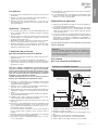 3
3
-
 4
4
-
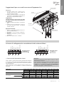 5
5
-
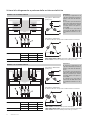 6
6
-
 7
7
-
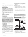 8
8
-
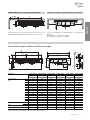 9
9
-
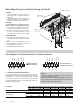 10
10
-
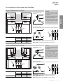 11
11
-
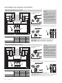 12
12
-
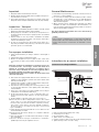 13
13
-
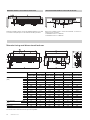 14
14
-
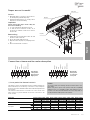 15
15
-
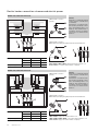 16
16
-
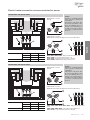 17
17
-
 18
18
-
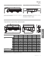 19
19
-
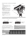 20
20
-
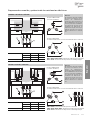 21
21
-
 22
22
-
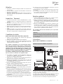 23
23
-
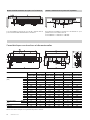 24
24
-
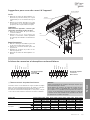 25
25
-
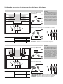 26
26
-
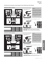 27
27
-
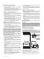 28
28
-
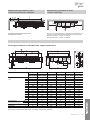 29
29
-
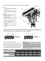 30
30
-
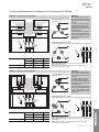 31
31
-
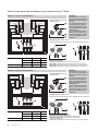 32
32
-
 33
33
-
 34
34
-
 35
35
-
 36
36


Modine IDE Technical Manual
- Tipo
- Technical Manual
- Este manual también es adecuado para
en otros idiomas
- français: Modine IDE
- italiano: Modine IDE