Panasonic TC-22LH1 El manual del propietario
- Tipo
- El manual del propietario

PanasoniC °
} _ _ !_ L !i_! _ :_; _ _: __
:_ ! • _ _!!_il ;i!!i_ !i!! i¸I
LCD TV
Operating Instructions
Model No. TC-22LH1
For assistance, please call : 1-800-211-PANA (7262)
or visit us at www.panasonic.com (U.S.A)
For assistance, please call : 787-750-4300
or visit us at www.panasonic.com (Puerto Rico
For assistance, please call : 1-800-561-5505
or visit us at www.panasonic.ca (Canada)
Before connecting, operating or adjusting this product, please read these instructions completely.
Please keep this manual for future reference.
English
TQBC0633-1

Important Safety Instructions
CAUTION
,_ The lightning flash with arrow ,_
head within atriangle isintended
to tell the user that parts inside
the product are a risk of electric
shock to persons.
The exclamation point within a
triangle is intended to tell the
user that important operating
and servicing instructions ere in
the papers with the appliance.
• Note to CATV System Installer: This reminder is provided to direct the CATV system installer's
attention to Article 820-40 of the NEC that provides guidelines for proper grounding and, in particular,
specifies that the cable ground shall be connected to the grounding system of the building,as close to the
point of cable entry as practical.
• Important Safety Instructions for LCD TV
1) Read these instructions.
All the safety and operating instructions should be read before the appliance is operated.
2) Keep these instructions.
The safety and operating instructions should be retained for future reference.
3) Heed all warnings.
All wamings on the appliance and in the operating instructionsshould be adhered to.
4) Follow all instructions.
All operating and use instructions should be followed.
5) Do not use this apparatus near water.
For exampte, near a bathtub, wash bowl, kitchen sink, or laundry tub, in a wet basement, or near a
swimming pool, and the like.
6) Clean only with dry cloth.
Do not use liquidcleaners or aerosol cleaners. Use a dry cloth for cleaning.
7) Do not block any ventilationopenings. Install in accordance withthe manufacturer's instructions.
Slots and Openings in the cabinet are provided for ventilation and to ensure reliable operation ofthe
product and to protect it from overheating. The openings should never be blocked by placing the
product on a bed, sofa, rug, or other similar surface.
8) Do not install near any heat sources such as radiators, heat registers, stoves, or other apparatus
(including amplifiers) that produce heat.
This product should not be placed in a built-in installation such as a bookcase or rack unless proper
ventilation is provided or the manufacturer's instructionshave been adhered to.
9) Protect the power cord from being walked on or pinched particularlyat plugs, convenience receptacles,
and the point where they exit from the apparatus.
10) Only use attachments / accessories specified by the Manufacturer.
11) Use only with the cart, stand, tripod, bracket, or table specified bythe manufacturer, or sold with the
apparatus. When a cart is used, use caution when moving the cart/ apparatus combination to avoid
injuryfrom tip-over.
Quick stops, excessive force, and uneven surfaces may cause the appliance and cart
combination to overturn. _1_'_
12) Unplug this apparatus during lightning storms or when unused for long periods of time.
This will prevent damage to the product due to lightning and power-line surges.
13) Refer allservicing to qualified service personnel. Servicing is requiredwhen the apparatus hasbeen damaged in
any way,such as power-supply cord or plug is damaged, liquid has been spilled or objects have fallen into the
apparatus, the apparatus has been exposed to rain ormoisture, does notoperate normally, or has been dropped.
14) To prevent electric shock, ensure the grounding pin on the AC cord power plug is securely connected.
2

Important Safety Instructions
15) If an outside antenna is connected to the
television equipment, be sure theantenna system
is grounded so as to provide some protection
against voltage surges and built up static
charges. In the U.S. Selection 810-21 of the
National Electrical Code provides information
with respect to proper grounding of the mast and
supporting structure, grounding of the lead-in wire
to an antenna discharge unit, size of grounding
conductors, location of antenna discharge unit,
connection to grounding electrodes, and
requirements for the grounding electrode.
16) An outside antenna system should not be located
in the vicinity of overhead power lines or other
EXAMPLE OFANTENNA
GROUNDING AS PER (NEC)
NATIONAL ELECTRICAL _._
CODE
L EQUIPMENT_ _ J_
ANTENNA
LEAD-IN WIRE
_ ANTENNA
•,-- DISCHARGE UNIT
(NECSECTION810-20)
_'J GROUNDINGCONDUCTORS
(NECSECTION810-21)
GROUND CLAMPS
_-- POWERSERVlCEGROUNDING
ELECTRODESYSTEM
(NECART250, PARTH)
electric light or power circuits, or where it can fall into such power lines or circuits. When installing an
outside antenna system extreme care should be taken to keep from touching such power lines or circuits
as contact with them might be fatal.
17) Unplug this LCD TV from the wall outlet, and refer servicing to qualified service personnel under the
following conditions:
a. When the power cord or plug is damaged or frayed.
b. If liquid has been spilled into the LCD TV.
c. If the LCD TV has been exposed to rain or water.
d. If the LCD TV does not operate normally by following the operating instructions.
Adjust only those controls that are covered by the operating instructions as improper adjustment of other
controls may result in damage and will often require extensive work by a qualified technician to restore
the LCD TV to normal operation.
e. If the LCD TV has been dropped or the cabinet has been damaged.
f. When the LCD TV exhibits a distinct change in performance - this indicates a need for service.
18) When replacement parts are required, be sure the service technician uses replacement parts specified by
the manufacturer that have the same characteristics as the original part. Unauthorized substitutions may
result in fire, electric shock, or other hazards.
19) WARNING: TO REDUCE THE RISK OF FIRE OR ELECTRIC SHOCK, DO NOT EXPOSE THIS
APPARATUS TO RAIN OR MOISTURE.
DO NOT PLACE LIQUID CONTAINERS (FLOWER VASES, CUPS, COSMETICS, ETC.) ABOVE THE
SET. (INCLUDING ON SHELVES ABOVE, ETC.)
20) CAUTION: TO PREVENT ELECTRIC SHOCK DO NOT USE THIS PLUG WITH A RECEPTACLE OR
OTHER OUTLET UNLESS THE BLADES CAN BE FULLY INSERTED TO PREVENT BLADE EXPOSURE.
NOTE: • This equipment is designed to operate in the U.S.A. and other countries where the broadcasting
system and AC house current is exactly the same as in the U.S.A.
• The marking or retained image on the LCD panel resulting from fixed image use is not an operating
defect and as such is not covered by Warranty. This product is not designed to display fixed image
patterns for extended periods of time.
• Important Information Regarding Use of Video Games, Computers, Captions or Other Fixed Image Displays.
The extended useof fixed image programmaterial can cause a permanent "shadowimage"on the LCD panel.
This background image is viewable on normal programs in the form of a stationary fixed image. This type of
irreversibleLCD panel deteriorationcan be limitedby observingthe followingsteps:
A. Reduce the bdghtness/contrast setting to a minimum viewing level.
B, Do not display the fixed image for extended periods of time.
C. Turn the power off when not in actual use.
• Thisproduct utilizestin-lead solder,and hasa fluorescent lampcontaining a small amountof memury. Disposal
ofthese materials may be regulated in your community due to environmental considerations. Fordisposal or
recyclinginformationplease contact your localauthorities,or the ElectronicsIndustriesAlliance:www.eiae.orq.
3

Dear Panasonic Customer
Welcome to the Panasonic family of customers.
We hope that you will have many years of enjoyment from yotlr izew LCD TV.
To obtain maximum benefit from your set, please read these instructions before
making any adjustments, and retain them for future reference.
Retain your purchase receipt, and record the model number and serial number
of your set in the space provided on the rear cover of these instructions.
For assistance, please call : 1-800-211-PANA (7262)
or visit us at www.panasonic.com (U.S.A)
For assistance, please call • 787-750-4300
or visit us at www.panasonic.com (Puerto Rico)
For assistance, please call : 1-800-561-5505
or visit us at www.panasonic.ca (Canada)
I Federal Communication Commission Information I
This equipment has been tested and found to comply with the limits for a TV Broadcast Receiver, pursuant
to Part 15 of the FCC Rules. These limits are designed to provide reasonable protection against harmful
interference in a residential installation. This equipment generates, uses and can radiate radio frequency
energy and, if not installed and used in accordance with the instructions, may cause harmful interference to
radio communications. However, there is no guarantee that interference will not occur in a particular
installation. If this equipment does cause or receive interference, which can be determined by turning
equipment off and on, the user is encouraged to try to correct the interference by one er more of the
following measures:
Reorient or relocate the TV antenna.
Increase the separation between TV and other equipment.
Connect TV into separate outlet from other equipment.
Consult the dealer or an experienced radio/TV technician for help.
FCC Caution: Pursuant to 47CFR, Part 15.21 of the FCC rules, any changes or modifications not expressly
approved by the party responsible for compliance could void the user's authority to operate this equipment.
_ HDMI, the HDMI logo and High-Definition Multimedia Interface
are trademarks or registered trademarks of HDMI Licensing LLC.
HIGH-DEFINITION MULTIMEDIA INTERFACE
4

Table of Contents
Important Safety Instructions .............................. 2
Installation ............................................................. 6
SUPPLIED ACCESSORIES ................................ 6
Remote control battery installation ...................... 7
Maintenance .......................................................... 7
Connections .......................................................... 8
ConnectingtheAntennaCableto theAntennaTerminal.... 8
Antenna cover removal and fitting ....................... 8
Antenna / Cable Connection ................................ 8
Cable cover removal and fitting ......................... 10
How to connect the input terminals ................... 10
How to connect the HDMI Terminal ................... 12
Power ON/OFF ................................................... 13
Connecting the Plug to the Wall Outlet .............. 13
How to Turn the Power On ................................ 13
Location of Controls ........................................... 14
Illuminated Remote Control ............................... 14
Flow Chart of MENU ............................................ 16
Tuning channels
(Automatic channel programming) ............. 18
Tuning channels
(Manual channel programming) ................... 19
ASPECT Controls ................................................ 20
Picture Adjustments ........................................... 21
Position / Size Adjustment ................................. 23
Audio Adjustments ............................................. 24
Lock Feature ........................................................ 25
Closed Captions .................................................. 29
Customizing the VIDEO INPUT labels ............... 30
OTHER ADJUST .................................................. 30
I
Operating peripheral equipment
using the remote control ........................... 31
Programming The Illuminated
Remote Control Using Access Codes .......... 31
Programming Without A Code
(When the code is not known) ...................... 32
infrared Codes Index ......................................... 33
IMode Operational Key Chart ............................ 35
--Manual de instrucciones [ Resumen ] --
Preparacion .................................................. 36
Instalaci6n de las pilas en el control remoto .... 36
Conexibn ....................................................... 37
C0nexiondelcabledeantenaalterminaldeentradadeRF. 37
Desmontajeeinstalaci6ndelacubiefladela antena.........37
Conexi6n de antena / cable ........................... 37
Para quitar y colocar la cubierta del cable ..... 38
Como conectar el termino del entrada/salida .... 38
Conexi6n/desconexibn de la alimentaci6n ... 39
Conexi6n de la clavija a latoma de corriente ... 39
C6mo conectar la alimentaci6n ...................... 39
Ubicacion de los controles ......................... 40
Control remoto iluminado ............................... 40
Organigrama de ment_s de televisibn ........ 42
Sintonizacibn de canales
(Programaci6nautomdtica de canales) ..... 44
Sintonizacion de canales
(Programaci6n manual de canales) ...... 45
Troubleshooting .................................................. 46
Specifications ...................................................... 47
5

I Installation
I
Receiver Location
Locateforcomfortableviewing.Avoidplacingwheresunlightor otherbrightlight(includingreflections)willfallon thescreen.
Use ofsome typesof fluorescentlightingcan reduceremotecontroltransmitterrange.
Adequateventilationis essentialtopreventinternalcomponentfailure.Keepawayfrom areasofexcessiveheator moisture.
Optional External Equipment
The Video/Audio connection between components can be made with shielded video and audio cables. For
best performance, antenna cables should utilize 75 ohm coaxial shielded wire. Cables are available from
your dealer or electronic supply store.
Before you purchase any cables, be sure you know what type of output and input connectors your various
components require. Also determine the length of cable you'll need.
For optimum quality picture
When the LCD is exposed to light from outdoors or lighting fixtures, high-contrast pictures may not bedisplayed
clearly. Turn off florescent lamps near the LCD and place in a location not exposed to outdoor light.
Row to use the LCD stand
Adjust the stand to your desired angle. The stand angle can be adjusted between 5 ° front to 15 ° back.
SUPPLIED ACCESSORIES
Check the accessories before installations.
• Operating Instruction book • Remote Control Transmitter
tllatl=le_
E
• Batteries for the Remote
Control Transmitter
• Warranty Card
• AC Adaptor & AC Cord • Coaxial Antenna Plug
o
6

Installation
Remote control battery installation
Replacing batteries
Replace batteries by following the steps below:
Requires two AA batteries.
1. Open the battery cover.
\
2. Install the batteries as shown
in the battery compartment.
(Polarity + or- must match the
markings in the compartment).
JJ2 -.Two AA size
3. Replace the cover.
/_ Precaution on battery use
Incorrect installation can cause battery leakage and corrosion that will damage the remote control
transmitter.
Observe the following precautions:
1. Always use new batteries when replacing the old set.
2. Do not attempt to charge, short-circuit, disassemble, heat or burn used batteries.
3. Battery replacement is necessary when remote control acts sporadically or stops operating this unit.
Notes:
• Do not drop, apply shock to or step on the remote control.
• Do not spill water on the remote control.
• Do not place objects between the remote control and remote control receiver.
• Do not use remote controls for other equipment at the same time.
• If the TV does not operate even when operating the remote control from a close range, it is time to
replace the batteries.
Refer to the label on back of the remote control for directions on replacing batteries.
I Maintenance
To clean this unit, wipe with a soft, dry cloth.
If the surfaces are extremely dirty, use a soft cloth dipped in a soap and
water solution or a weak detergent solution.
• Use eyeglass cleaner to remove stubborn dirt from the LCD.
• Never use alcohol, paint thinner or benzine to clean this unit.
• Before using a chemically treated cloth, read the instructions that came
with the cloth carefully.
CAUTION :
If water or similar substances get inside the monitor via the liquid crystal panel surface, a malfunction may result.
7

I Connections
Connecting the Antenna Cable to the Antenna Terminal
Antenna Connection - For proper reception of VHF/UHF channels, an external antenna is required. For best
reception an outdoor antenna is recommended. Antenna Mode must be set to TV.
VHF Antenna
UHF Antenna
J
Ca4
Antenna Terminal
(ANT or VHF/UHF)
Coaxial Antenna Plug
Antenna cover removal and fitting
•Hook
(_ Removal
1.Push up hooks and pull the cover slightly towards yourself to
disengage the claws (at 4 points)•
2.Slowly pull out in the downward direction•
(_ Fitting
1,Insert the claws (at 4 points) at the bottom end.
2.Push ituntil hook is locked.
Note:
To avoid interference appearing on the screen, do not bundle the antenna wire and AC adapter wire together.
Antenna / Cable Connection
Incoming 75 Ohm Cable from Home Antenna / Cable Company
F-TypeAntennaAdapter (supplied)
ANT (VHF/UHF) __
onthe BackoftheTV
Cable Connection- Forreceptionof cablechannels (01 * 125) connectthe cablesuppliedby yourlocalcable company•
Antenna Mode must be set to CABLE•(Refer to Antenna Mode section.)
Note:
Certain cable systems offset some channels to reduce interference or have Premium (scrambled) channels. A cable
converter box is required for proper reception. Check with your local Cablecompany for its compatibility requirements.
8

Connections
I Antenna Connection (Cable Box, no VCR) 1
Use this configuration when connecting the TV to a cable TV system using a Cable Box.
ANTENNA TERMINAL
(ANT or VHF/UHF)
ON THE BACK OF
THE TV
CABLE BOX
[,, ,J
-I
[
.......... I
i Connect the cable from the Output
terminal on the back of the Cable
f
Box to the ANTENNA terminal on
the back of the TV.
TERMINALS ON THE BACK OF
THE CABLE BOX
Incoming Cable from
Antenna or Cable TV
System
I Antenna (Cable Box, VCR)
Connection and
Use this configuration when connecting the "IV to a cable TV system using a Cable Box and VCR,
l,
CABLE BOX
ANTENNATERMINAL
(ANT or VHF/UHF)
ON THE BACK OF
THE TV
Connect the cable from the
Output terminal on the back
of the Cable Box to the
Antenna Input terminal on
the back of the VCR.
I
Connect the
cable from the
Antenna Output
terminal on the
back of the VCR
to the Antenna
terminal (ANT or
VHF/UHF) on the
back of the TV,
TERMINALS ON THE BACK OF
THE CABLE BOX
--I
Connect the cable from the
antenna or cable system to the
Input terminal on the back of the
CABLE BOX.
VCR
4/ TOVCR {_O r[' ._J]o 4
Incoming Cable from
Antenna or Cable TV
System
_)INPUT r_ OUTPUT
V
(_OUTPUT _QG_
SVIDEO VIDEO L-i_UI_3-R
Note:
When the antenna cable is connected to the TV antenna terminal via a cable box or VCR, set the TV
channel to CH3 or CH4, cable. This does not apply when signal is input from VIDEO INPUT.
9

Connections
Cable cover removal and fitting
FittingRemoval
I
1. Disengage the claws at
the uppermost end.
2. Slowly pull out in the
upward direction.
1. Insert the claws (at 2
points) at the bottom.
2. Push in the TOP.
Note:
Dependingonthetypeofcableuseditmaynotbe possibletoclosethecover,Insuchcasesthecabtemaybe routed
throughthe antennacover,
How to connect the input/output terminals
Connect camcorder and video game console.
i
INPUT
COMPONENTVIDEO
o o
00 ÷
GO÷
CAMCORDER
VIDEO GAME CONSOLE
(Optional)
t
S-VIDEO cable
VIDEO cable
t t t
10

Connections
Connect VCR and other peripheral equipment
INPUT
212
COMPONENT VIDEO
INPUT
1 2
®@
VIDEO VIDEO
$$
©©
AUDIO AUDIO
®®
4
@
@
@
@
@
@
@
@
____ ,super-VRSVOR,
0 .0000(30
[]
[]
®® ®®® @
Audio Audio Video S Video
L IN R L OUT R OUT OUT
$ ,!, $ $ $ _-
S-VIDEO
cable
VIDEO
AUDIO
l_ ;innectionexample
INPUT1connection
or
INPUT2 connection.
\
Connect the
S-VIDEO or
VIDEO
Terminal
®
Connection example
component VIDEO
INPUT1 connection
or
component VIDEO
INPUT2 connection.
(DVD/STB)
o ,,0(30 (30
% []
_3
COMPONENT VIDEO OUT A_io
L OUT R
Y Pb Pr
®®®®®
,I,
VIDEO
AUDIO
Notes:
eWhen connecting video cables, priority is given to the S-Video cable when the S-Video input terminal
and the video input terminal are connected at the same time.
OThe volume control output of the LCD TV will be fixed.(SOUND,ADJUST, VOLUME UP/DOWN and
SURROUND ON/OFF are not functional for output signals from the AUDIO OUT terminals.)"
11

I How to connect the HDMI Terminal
I
HDMI _1(HDMI : High Definition Multimedia Interface) isthe first all digital consumer electronics A/V interface
that supports uncompressed standard. One jack supports both video and audio information.
This HDMI '_`_input can be connected to an EIA/CEA-861/861B `_2compliant consumer electronic device,
such as a Set Top Box or DVD player equipped with HDMI or DVI output connection.
By inputting a High-bandwidth Digital Content Protection (HDCP) high-definition picture source to the HDMI
terminal of this television, high-definition pictures can be displayed on the screen in their digital form.
Audio Cable
(not included) y _j
I f
I If the external device has DVI output only, use a HDMI-DVl
conversion cable .3 to connect to the HDMI jack on the LCD.
Also, connect the Audio out signal from the external device.
(Set Top Box or DVD player) to the AUDIO IN'_4jacks beside
the HDMI input.
HDMI Cable (not included)
HDMI or DVI
signal out
I
Set Top Box
DVD player
......................... s
Applicable VIDEO Signal
This model support following format.
Please adjust the format of connecting equipment.
No. of dots (H x V)
1080i
480P
480i
Vertical scanning frequency(Hz)
1,920 x 1,080i 59.94/60
720 x 480P 59.94/60
640 x 480P 59.94/60
720(1,440) x 480i 59.94/60
This input terminal is not intended for use with computers.
AUDIO signal (L.PCM)
When the digital sound signal is included at connecting HDMI equipment, L.PCM sound is available.
Sampling frequency
48KHz / 44.1KHz / 32 KHz
Notes:
(1) This HDMI connector is Type A.
(2) If you cannot display the picture because your Digital Set Top Box does not have a Digital OUT terminal
Output setting, use the component Video input (or the S video Input or Video Input). In this case the picture
will be displayed as an analog signal.
_-1. HDMI, the HDMI logo and High-Definition Multimedia Interface are trademarks or registered trademarks
of HDMI Licensing LLC.
:_-2.EINCEA-861/861B profiles compliance covers profiles for transmission of uncompressed digital video
including high bandwidth digital content protection.
:_-3.HDMI-DVI conversion cable part no. (TY-SCH03DH):available on Panasonic Website (USA only)
(www.panasonic.com)
¢-4.AUDIO-IN, Please refer to page 24. (HDMI-IN)
12

Power ON / OFF
Connecting the Plug to the Wall Outlet
Note:
The TV's power cord must first be plugged intothe wall outlet.
How to Turn the Power On
Main POWER switch
l__
'_POWER /VIDE0 VOLUME C+HANNEL 1
V
I
SAPC)
RETURN
MENU EXIT
0 C)
Press the Main POWER switch on the top of TV to turn
the set on.
POWER-ON: Green
When the set is on or in standby mode press the Main
POWER switch on the TV to turn the set off.
POWER-OFF: No light
Example: The screen below is displayed for a while after
the TV is turned on. (setting condition is an
example.)
ZOOM
CH 6
F_
SAP
MONO
_ Press the POWER button on the remote
control to turn the TV off: Red (standby)
Press the POWER button on the remote
control to turn the TV on: Green
Note:
The TV willstill consume some power as long as the power
cord is stillplugged into the wall outlet.
13

I Location of Controls I
Illuminated Remote Control
Power button ,-
Press to turn the TV ON or OFF.
Note: The TV's power cord must first be plugged into the walt outlet and
then turned on at the POWER switch (standby mode).
Mode Selection buttons
VCR Mode Selection for Remote
Control
Digital Broadcasting Satellite for Remote
Control / Cable TV Mode Selection for
Remote Control
TV Mode Selection for _ _ _
Remote Control
---- Digital Video Disc Mode
Selection for Remote Control
R-TUNER-TUNE button '
L.) Switches to previously viewed channel or video mode.
Operation of other Device
VCR VCR REW/FF
CABLE/DBS
DVD Skip Search REW/FF
PLAY
PLAY
Pause
Pause
STOP
STOP
on s
Device
VCR
CABLE/DBS
DVD
VCR RECORD TV/VCR Switch VCRCH up/down
-- STB--ASPECT PAGE up/down
-- Open / Close Slow/+/-
ASPECTASPECT button
_)R Change of screen size (See page 20).
r JUST-_-_ ZOOM _ FULL _ NORMAL_
14

Location of Controls
S, hu.on --1
Selects Audio mode (See page 24).
STEREO _ SAP -_ MONO
Changes to the next channel up
Moves cursor upward during menu mode,
O O
RECALL MUTE GUIDE
0 0 0 0
t
® ®®
® ® ®--
® ® ®
nEW pLAY FF
PAUSE STOP REC
&SPECT
TVNCR VCRIDBSCH
Moves cursor to
the left during
menu mode.
Displays menu
Press to access
TV, DTV, DBS or
DVD menus.
Changes to the next
channel down
Moves cursor downward
during menu mode.
Moves cursor to
the right during
menu mode.
Return
to previous
MENU or EXIT
from menu.
The input mode changes each
time this button is pressed.
I
TVNIDEO RECALL
C) C>
Press this button to mute the
sound, press again to cancel the
mute
I
MUTE GUIDE
O O GUIDE button
U___ for DBS.
Press to display the current system status, for example, Aspect
mode, Channel number, Stereo mode, Picture menu, TV/VIDEO,
Power save, Off timer and Color system.
Direct program number
selection buttons
SLEEPPROG dash button / SLEEP TIMER button
P(_ Program dash channel numbers for DTV and DBS,
Sleep timer (MINUTES)
_-_0---* 3o--* 6o-_- 9o
7
[
15

I FIow Chart of MENU
I
All adjustments and setting functions available in this set can be made using the menu buttons.
The menu screen is composed of 2 menus: the ADJUST menu and the SET UP menu.
Press to display MENU
screen, press again to
clear.
PICTURE
ru PICTURE ADJUST
[_E] POSITION / SIZE
AUDIO
J_ AUDIO ADJUST
O VOL
0
EXIT
O
TV/VIDEO RECALL MUTE GUIDE
0 0 0 0
®® ®
®® ®
® ® ®
SLEEP
R-TUNE PROG
o ® ®
Please refer to the On Screen Help
An On Screen Help box is displayed whenever a menu is displayed
on the "IV. This Help box indicates which keys onthe remote control
are used to navigate the menu shown. See above for descriptions
of button functions.
ON SCREEN HELP
'Instruction' box LANGUAGE
MENU selection
PICTURE
PICTURE ADJUST !
POSITION / SIZE I
AUDIO
J_ AUDIO ADJUST
or
I_) LANGUAGE t
_E] PROGRAM OH
_1 LOCK I
CLOSED CAPTION I
INPUT LABEL
"_ OTHER ADJUST
I I
SET UP
lid LANGUAGE I [
!_3PROGRAM CH I
LOCK I
rd_CLOSEDCAPTIONI <_
I;=_INPUTLABEL 1
"_ OTHER ADJUST I
16

Flow Chart of MENU
Press to select the desired MENU (ADJUST or SET UP).
Press to select each item.
Press to display each adjustment screen.
Proceed to the adjustment.
• To return to previous screen :
RETURN
EXIT
G- Press to return.
• To end adjustments :
MENU
Q - Press to exit from the MENU screen.
This returns the set to the normal viewing condition.
Press to display each
adjustment screen.
OK
,©
RETURN
Press the RETURN
button to return to
previous screen.
TO PICTURE ADJUST
menu
PICTURE
(See page 21)
TO LANGUAGE
TO PROGRAM
CHANNELS
TO AUDIO ADJUST
menu
(See page 24)
TO LOCK
selection screen
Press to display each Allows you to select the
adjustment screen, language used for On
O K Screen Displays.
j Q [_> r ENGLISH'='_'FRAN_;AIS"I
i. "-ESPAI_IOL'-- J
RETURN TO CLOSED
[ ] CAPTION
Press the RETURN
button to return to
previous screen.
(See page 29)
(See page 18,19)
TO OTHER ADJUST
screen
VIDEO NR
3D Y/C
COLOR MATRIX
POWER SAVE
(See page 30)
BLOCK PROGRAMS
CHANGE SE]-i-ING
ENTER CODE FIRST
(See page 25)
TO INPUT LABEL
selection screen
(See page 30)
17

I Tuningchannels(Automatic channel programming) I
Automatically scans all TV channels and stores them in memory.
Turn the Power on and press the TV/VIDEO button to display the TV channel.
Press the MENU button to display the MENU screen and select SET UE
Press to select PROGRAM CH.
Press to display the PROGRAM
CHANNELS screen.
Press to select MODE.
Press to select TV or CABLE.
SET UP
LANGUAGE J
PROGRAM CH I
I_ LOCK I
CLOSED CAPTION I
r-_ INPUT LABEL I
"_ OTHER ADJUST I
Press to select AUTO PROGRAM.
Press to display the confirmation
screen.
5
Press to select YES.
__ Press to select NO.
Press to run AUTO PROGRAM.
MENU
Channels will automatically advance until all channels have been
scanned. Channel numbers with a video signal present will be stored
in the Channel Scan Memory.
Press to exit from the MENU screen.
This returns the set to the normal viewing condition.
Notes:
• When buttons are pressed with AUTO PROGRAM running, the TV set will return to normal viewing.
(Channels searched up to this point are added.)
• After AUTO PROGRAM is finished, the lowest channel number added will be received.
• When there are no receivable channels, channel 69 is displayed for TV and channel 125 is displayed
for cable TV.
18

I Tuning channels (Manual channel programming)
Use this setting when changing setting of receiving channels or changing the channel display.
I
Turn the TV on and select the broadcast channel. Follow the steps on the previous page to display the I
PROGRAM CHANNELS screen.
I
1
Press to select MANUAL PROGRAM.
Press to display the MANUAL
PROGRAM screen.
Adding or deleting channels
Press to select channel
(or number keys).
3
Press to add channels to memory (Channel
number turns blue).
Press to delete channels from memory
(Channel number turns yellow).
Repeat steps 2 and 3 to continue adding or deleting channels.
MENU
C
Press to exit from the MENU screen.
This returns the set to the normal viewing condition.
19

I ASPECT Controls
I
The color monitor will allow you to enjoy viewing the picture at its maximum size, including wide screen
cinema format picture.
o ® ®
REW PLAY FF
F---qr_-I r_l
PAUSE STOP REC
nn r--_ rr_
VCR_I)BS CH
ASPECT
TV/VCR
O
ASPECT button
The aspect mode changes each time the ASPECT button
is pressed.
F-. JUST-_ ZOOM _ FULL _ NORMAL_
Note:
When a 1080i signal is being received, the mode is set to
FULL, and aspect switching is not possible.
NORMAL
JUST
ZOOM
FULL
I-- 4 _1 I,._.-t 6_
3 °]-,4a !
o oi [
4 _1 I-._16_
o o[
Normal mode will display a 4:3 picture
at its standard 4:3 size.
JUST mode will display a 4:3 picture
at its maximum size but with aspect
correction applied to the sides of the
screen so that elongation is only
apparent at the left and right edges of
the screen. The size of the picture will
depend on the original signal.
ZOOM mode magnifies the central
section of the picture.
FULL will display the picture at its
maximum size but with slight
elongation.
2O

I Picture Adjustments
Press the MENU button to display the
MENU screen and select ADJUST.
__ _ Press to select
PICTURE
ADJUST.
ADJUST
PICTURE
PICTURE ADJUST I
L_] POSITION / SIZE I
AUDIO
AUDIO ADJUST J
Press to display the PICTURE
ADJUST screen.
Press to select the menu to adjust.
Select the desired level by looking at
the picture behind the menu.
NORMAL is displayed at default.
AI PICTURE
PIC MODE
PICTURE MODE is stored for TV, VIDEO1, VIDEO2, COMPONENT1,
COMPONENT2 and HDMI individually.
_- STANDARD_ CINEMA"_,'- VIVID
I
MODE Function
STANDARD Displays standard image.
CINEMA Ideal for watching movies in a dark room.
VIVID Displays a clear screen with contrast of light and dark.
BACK LIGHT, PICTURE, BRIGHTNESS, COLOR, TINT, SHARPNESS, AI PICTURE, COLOR TEMP
You can change the level of each Item (BACK LIGHT, PICTURE, BRIGHTNESS, COLOR, TINT,
SHARPNESS, AI PICTURE and COLOR TEMP) for each MENU (STANDARD, CINEMA, and VIVID )
according to your personal preference,
Item Function
BACK LIGHT Luminance of the back light is adjusted.
PICTURE Selects proper brightness and density for the room.
BRIGHTNESS Adjusts for easier viewing of dark pictures such as night scenes.
COLOR Adjusts the level of color.
TINT Adjusts for flesh tone color.
SHARPNESS Adjusts the degree of sharpness.
AI PICTURE Displays black and white colors more clearly when turned ON.
COLOR TEMP Increase or decrease WARM (red) and COOL (blue) colors to suit personal
preference.
• To reset to standard setting :
Press to select
NORMALIZE.
Press OK.
21

Picture Adjustments
3
ADVANCED ADJUST
Press to select PIC MODE.
Select STANDARD or CINEMA.
PICTURE
Press down to PAGE 2 and select
ADVANCED ADJUST.
Press to select ADVANCED
ADJUST ON.
Press to go to NEXT PAGE.
ADVANCED ADJUST will be shown.
MPEG NR
Press to select the menu to adjust.
Select the desired level by looking at
the picture behind the menu.
NORMAL is displayed at default.
Item Function
BLACKEXTENSION Contrast level will be improved.
WHITE CHAR CORR It makes white characters brighter.
MPEG NR Noise unique to DVD, STB etc will be reduced.
22

Position / Size Adjustment
This function will adjust the picture position / size for easy viewing.
Press MENU button to display MENU screen
and select adjust.
J
Press to select POSITION/SIZE.
Press to display POSITION/SIZE control.
ADJUST
PICTURE
PICTURE ADJUST I
[] POSITION / SIZE J
AUDIO
I_ AUDIO ADJUST J
2 [Picture Position Adjustment ]
Itwill work for "ZOOM" mode only.
@
Press to move picture vertically for the best view.
[ Picture Size Adjustment ]
I,f
Itwill work for "NORMAL" and "JUST" mode only,
_ Press to select.
size 1: reduced black bar.
size 2: widened black bar.
-- Size1
Size2
• To return to previous screen :
RETURN
EXIT
G-- Press to return.
• To reset to standard setting : o=._
Press OK.
23

I Audio Adjustments
Press the MENU button to display the MENU screen and select ADJUST.
Press to select AUDIO ADJUST.
Press to display the AUDIO ADJUST
screen.
ADJUST
PICTURE
[_ PICTURE ADJUST [
POSITION / SIZE I
AUDIO
AUDIO ADJUST I
I
2
Press to select the menu to adjust.
Select the desired level by listening
to the sound.
NORMAL is displayed at default.
MODE
[--_ AUTO_ STANDARD_ DYNAMIC
MODE
AUTO
STANDARD
DYNAMIC
Function
Automatically adjusts quiet sound
and loudsound for easeof listening.
Emits the original sound.
Gives contrast to sound.
BASS, TREBLE, BALANCE, SURROUND
You can change the level of each Item ( BASS,
TREBLE, BALANCE and SURROUND ) for each
MODE (AUTO, STANDARD and DYNAMIC )
according to your personal preference.
Item Function
BASS Adjusts low sounds
TREBLE Adjusts high sounds
BALANCE Adjusts left and right volume
SURROUND Toenjoy a concert hall effect,
turn SURROUND to ON when a
stereo signal isavailable.
Selecting STEREO/SAP/MONO
STEREO _ SAP _ MONO
Note:
Red display : With signal
White display : No signal
White display : MONO
MODE Function
STEREO Two c.hannel Audio reception.
Second Audio Programming
SAP ( typically used for bilingual audio ).
MONO Use when stereo signal is weak.
HDMI IN
Perform input switching of analog audio input (for DVI) and digital audio input (for HDMI) when using
the HDMI terminal.
_'- AUTO_ DIGITAL 4---,-- ANALOG
AUTO Set use of analog audio input when digital audio signal is not available.
DIGITAL Forces use of digital audio input signal transmitted via the HDMI terminal.
ANALOG Forces use of analog audio input signal transmitted via separate RCA terminals.
24

I Lock Feature
I
In the United States, the V-CHIP consists of two rating systems, which are MPAA
(MOTION PICTURE) and TV PARENTAL GUIDELINES. Its function is to block programs
by the rating data in the XDS data packets sent from broadcasting stations. The user
can select which rating programs should be blocked by the LOCK MENU options.
0 0 0 0
Looo®i
®®®1
Press the MENU button to display the MENU screen and select SET UP.
Press to select LOCK.
Press to display the
LOCK screen.
Input code
Enter any 4-digit number as a password.
These numbers will be needed when
deactivating the LOCK function.
While entering a code, by pressing the
up _ or down _ buttons you can
input a new code again.
After entering your secret code for the first time, the onscreen
display will change to CHANGE CODE. And you can change the
Input code.
Note: Use a code that is easy to remember and record it in a
safe place.
Selecting broadcasts to lock.
Press to select BLOCK PROGRAMS.
Pressto select U.S MOVIES, U.S. TV
PROGRAMS, CANADIAN ENGLISH
or CANADIAN FRENCH.
U.S. MOVIES "_" U.S.TV PROGRAMS "=-'-_]
ADIAN ENGLISH"=_"CANADIAN FRENCH_
Press to select STATUS.
Press to select ON or OFF.
Press to select CHANGE SETTING.
Press to display the next screen.
STATUS
25

Lock Feature
for U,S.TV PROGRAM to lock
Press to select VIEW NR PROGRAMS?.
Press to select NO or YES.
NO : Cannot view programs with NR signals.
YES : Can view programs with NR signal.
OK
Press to select SEr-FING.
Press to select BASIC or DETAILED.
_" BASIC-.=-_ DETAILED "_
3
Press to select rating.
BASIC: Change the selected title.
DETAILED :The cursor selecting the title
can be moved to select options
displayed on the right.
Press to lock or unlock the rating.
Lock: Red
Unlock : Green
_:[][][][]
Locking and unlocking
• When a title field is selected, all ratings below this rating are selected.
• When options within an option field are selected, ratings below this rating within the same field are
selected.
• Ratings displayed in green are unlocked and those displayed in red are blocked programs.
1. Ratings for children: These ratings are divided into ranks as follows.
I _[_-_'_1 TV-Y7-FV J
[TV-Y71 I FV
2. Ratings for teenagers: These ratings can be created out of these major categories to form vadous
combinations. These combinations are described in the below diagram. Ratings for all ages are on
top and ratings for adults are on the bottom.
1
• To return to previous screen :
• To end adjustments :
RETURN
EXIT
G Press to return.
MENU
O
Press to exit from the MENU screen.
This returns the set to the normal viewing condition.
26

Lock Feature
for U.S.MOVIES to lock
OK
Press to select VIEW NR PROGRAMS?.
Press to select NO or YES.
NO : Cannot view programs with NR signals.
YES : Can view programs with NR signal.
OK
Press to select rating.
Press to lock or unlock the rating.
Lock: Red
Unlock : Green
Rating
G : General audience
PG : Parental guidance suggested
PG-13 : Parental guidance needed
under 13 years otd
R : Restricted
NC17 : No one under 17 is admitted
X : Pornography
for CANADIAN ENGLISH / CANADIAN FRENCH to lock
Press to select VIEW E PROGRAMS?.
Press to select NO or YES.
Press to select rating.
Press to lock or unlock the rating,
Lock: Red
Unlock : Green
I
m
m
27

Lock Feature
CANADIAN ENGLISH RATINGS CHART
Exempt - Exempt programming includes:news, sports, documentaries and other information
E programming, talk shows, music videos, andvariety programming.
C Programming intended for children under age 8. No offensive language, nudity or sexual
content.
C8+ Programming generally considered acceptable for children 8 years and over. No profanity,
nudity or sexual content.
G General programming, suitable for all audiences.
PG Parental Guidance suggested. Some material may not be suitable for children.
Programming contains themes or content which may not be suitable for viewers under
14+ the age of 14. Parents are strongly cautioned to exercise discretion in permitting viewing
by pre-teens and early teens.
18+ years old. Programming restricted to adults. Contains constant violence or
18+ scenes of extreme violence.
CANADIAN FRENCH RATINGS CHART
E Exempt - Exempt programming.
General - Programming intended for audience of all ages. Contains no violence, or
G
the violence content is minimal or is depicted appropriately.
8+ General - Not recommended for young children. Programming intended for a broad
8 ANS+
audience but contains light or occasional violence. Adult supervision recommended.
Programming may not be suitable for children under the age of 13 - Contains either a
13ANS+ few violent scenes or one or more sufficiently violent scenes to affect them. Adult
supervision strongly suggested.
16ANS+ Programming may not be suitable for children under the age of 16 - Contains frequent
scenes of violence or intense violence.
18+ years old. Programming restricted to adults. Contains constant violence or
18ANS+
scenes of extreme violence.
RETURN
EXIT
• To return to previous screen : (_-
Press to return.
• To end adjustments :
MENU
_-- Press to exit from the MENU screen.
This returns the set to the normal viewing condition.
28

Closed Captions
I
This unit has a built in decoder that provides a visual depiction of the audio portion
of a television program in the form of written words across the screen (white or
colored letters on a black background). It allows the viewer to read the dialogue of
a television program or other information.
1
2
Press the MENU button to display the MENU screen and select SET UP.
Press to select CLOSED CAPTION.
Press to display the CLOSED
CAPTION screen.
SET UP
[Ik_ LANGUAGE
I_ PROG_MCH
I1_1 LOCK
CLOSED CAPTION
I_::::_iNPUT LABEL
I'_ OTHER ADJUST
[_ ON MUTE
Activates the On-Screen Closed Caption feature, when the MUTE button on the Remote Control is
pressed. To deactivate, press the MUTE button again.
Note:
This feature functions when the Closed Caption Mode is in the "OFF" position.
The program being viewed must be broadcast with Closed Caption.
Press to select [_ ON MUTE.
Press to select from the following:
_---_NO (OFF)'_'_'" C1''--'_ C2"_
3 MODE
Activates the On-Screen Closed Caption feature. When activated this feature will remain on until
OFF is selected in this menu.
Press to select _ MODE.
f __
o_-_ -o_-"_ I_ Press to select from the following:
€ CAPTION OFF -
• CAPTION C1 -
• CAPTION C2 -
Recommended mode when Closed Caption is not being used.
For video related information that can be displayed (up to 4 lines of scriptstrategically
placed on the television screen so that it does not obstruct relevant parts of the picture).
Another mode used for video related information.
• To return to previous screen :
• To end adjustments :
RETURN
EXIT
(_-- Press to return.
MENU
(_-- Press to exit from the MENU screen..
This returns the set to the normal viewing condition.
29

I Customizing the VIDEO INPUT labels I
Display for each VIDEO INPUT can be changed to match with the connected device
(VCR, DVD Player etc.).
Press the MENU button to display the MENU screen and select SET UP.
r
Press to select INPUT LABEL.
Pressto display the INPUT LABEL screen.
Press to select the VIDEO INPUT.
E_ COMPON ENT1 ,_-_b COMPONENT2 -_-]
HE)MI '_-_ VlDEO2 ,.w,------_Vl DEO1
Press to change the INPUT LABEL.
Each INPUT LABEL has the following choices.
IOID LANGUAGE I
II_ PROGRAM CH I
l t:i LOCK I
tr_ CLOSED CAPTION I
INPUT LABEL .--.I
I'_ OTHER ADJUST I
HDMI
F COMPONENTI(COMPONENT2, VIDEO1,VIDEO2or HDMI).--_ VC R
-[BLANK]= --DTV: =DVD" m'_'_AME _"_
OTHER ADJUST
1
Pressthe MENU button to display the MENU screen and select SET UE
Press to select OTHER ADJUST.
Press to access OTHER ADJUST.
Press to select the item that you would
like to change.
Press to select desired condition.
VIDEO NR
Reduce video noise in the picture.
Selection condition: ON4._.__OFF
3D Y/C FILTER
Minimizes noise and cross color in the picture.
Not available for COMPONENT VIDEO.
Selection condition: ON..,_--.._OFF
SET UP
I_ LANGUAGE I
If_ PROGRAM CH I
Ia LOCK I
I_a CLOSED CAPTION I
[_:::_INPUT LABEL _1
°_ OTHER ADJUST I
VIDEO NR
3D Y/C
COLOR MATRIX
POWER SAVE
li]'Jll!
COLOR MATRIX
Displays input signals (480p signals) in a natural color.
Automatically adjusts color parameters for HD (high definition) and SD (standard definition).
Selection condition: SD _ HD
POWER SAVE
The POWER SAVE will be suitable for watching at night and power consumption will be reduced.
selection condition: STANDARD--SAVING
I
3O

I OperatingperipheralequipmentusingtheremotecontrolI
ProgrammingTheIlluminatedRemoteControlUsingAccessCodes
The Universal Remote Control can be programmed to operate many manufacturers' components, using the
component function buttons for TV, VCR, DBS/CABLE or DVD. Follow the procedures for programming
your Remote Control with or without a code for the component.
Determine the manufacturer of the component and look in the table for the code.
Confirm that the external component is plugged in and operating.
Turn the component off.
Press POWER and OK together, for at least 5 seconds.
After 5 seconds, all the illuminated mode keys will begin to flash.
Release the POWER and OK keys.
Press the mode key.
The mode key will illuminate steadily, all others will go out.
5
6
®®®1
Enter the 3-digit component code using the Remote Control numeric
keypad.
Press the Remote Control to test the component. If the
procedure is successful, the component will turn on.
Default Modes For Remote Control
TV
VCR
DBS/CBL
DVD
TV (Panasonic Only)
VCR (Preset)
DBS (Preset), CABLE (Preset)
DVD (Preset)
Panasonic TV Codes
Panasonic VCR Codes
Panasonic DBS Codes
Panasonic DVD Codes
Helpfui Hints: UnsuCCessful _ .....
If the component does not operate with the Remote Control, repeat the procedure using
another code. (Some brands have multiple codes).
If an incorrect code is entered, or if the procedure takes longer than 30 seconds,the
programming will fail.
31

Operating peripheral equipment using the remote control
ProgrammingWithoutACode(Whenthecodeisnotknown)
This procedure searches all codes and is called the "sequence method."
32
]VNID_O RECALL MUTE GUIDE
0 0 0 0
I® ® ®1
I®®®1
R_ pLAy FF
PAUSE STOP REC
nn c_n r'_
ASPECT
TVNCR VC_$CH
1
_ 2 Turn the component off.
6
Confirm that the external component is plugged in and on.
Press POWER and OK together,
for at least 5 seconds.
After 5 seconds, allthe illuminated
mode keys will begin toflash.
Release the POWER and OK key.
Press the mode key.
The mode key will illuminate
steadily, all others will go out.
Press to move forward to the next
code, or to move backward.
Press the Remote Control _ to test the component. If the
procedure was successful, the component will turn on.
Note:
Repeat the above steps until the component code isfound. It may
take many attempts before the correct code isfound.
7
After the code isfound, press OK to
store the code.
Note:
The step and set mode willstart from the current device (not the
beginning of the list, except for the first time).

Operating peripheral equipment using the remote control
Infrared Codes Index
The remote control is capable of operating many brands of peripheral equipment. Refer to pages 31 and 32
for programming procedures.
Note: The remote control memory is limited and therefore some models may not operate. The remote
control is not designed to control all features available in all models.
Note: After entering the proper infrared code, press the desired Mode Selection Button on the remote control.
Refer to pages 14 and 31 - 32 for details on operating peripheral equipment using the remote control.
Helpful Hint: Write down the code numbers for your components in the space provided below. This will serve as a
handy reference whenever you need to reprogram your remote control.
CABLE _ VCR DBS
Other Component Other Component Other Component
- [o]7t;FJI
m
;odes for VCR
Admiral
Aiwa
Akai
Audio Dynamic
Bell &Howell
Broksonic
Canon
Citizen
Craig
Curtis Mathes
Daewoo
DBX
Dimensia
Emerson
Fisher
Funai
GE
Goldstar
Gradiente
Hitachi
InstantReplay
Jensen
JVC
Kenwood
LXI
Magnavox
Marantz
Marta
Memorex
MGA
Minolta
Mitsubishi
Multiteeh
NEC
Olympic
Optimus
335
332
314,315,316, 329
311,339
305,313
320,326
323,325
306
305,306,329
324, 345
301,324,343
310,311,339
345
303, 319, 320, 325, 326,343
305,307,308,309,313
320,326,334
324,333, 345
306
334
300,323,345
323, 324
339
310, 311,334, 339
306, 310,311,339
300,305,306,307,308,309
323, 324, 331
310, 311,339
306
309, 324
338, 340, 341,347, 348
300, 345
338, 340, 341,347, 348
304,347
310, 311,334,339
323,324
306,321,328,335
Odon
Panasonic
J.C.Penney
Pentax
Philco
Philips
Pioneer
Proscan
Quasar
Radio Shack
RCA
Realistic
Samsung
Sansui
Sanyo
Scott
Sears
Sharp
Shintom
Signature 2000
Singer
Sony
Sylvania
Ta_hiro
Tatung
Teac
Technics
Teknika
Toshiba
VectorResearch
Wards
Yamaha
Zenith
320, 326
321,322, 323, 324
300, 305, 310, 311,324,
339, 345
300, 311,345
320, 323, 324, 326, 331,343
323, 324, 331
323
300, 301,302, 323, 324,
331,333, 345, 346
321,322, 323, 324
305, 309, 324, 333, 336, 340
300, 301,302, 323, 324,
331,333, 345, 346
305, 309, 324, 336, 340
302, 304, 333
320, 326, 339, 352
305, 369, 313
301,302, 304, 309, 320,
326, 338, 340, 347, 348
300, 305, 306, 307, 308
335, 336
317
335
;317
i328, 329, 330
323, 324, 331
306
310, 311,339
310, 311,339
321,322, 323, 324
324
301,346
311
306, 309, 335, 336, 344
305, 310, 311,339
306, 344
Codes for Personal Video Recorders
100
101
102
33

Operating peripheral equipment using the remote control
Codes for DVD
_ I Ferguson
JVC
Mitsubishi
Nordmende
Panasonic
Philips
Pioneer
RCA
100
101
t09
105
101
100
103
102
101
Saba 101
Samsung 110
Sharp 108
Sony 104
Technics 1O0
Thomson 101
Toshiba 103
Yamaha 100
Zenith 107
Codes for Cable Box
ABC
Archer
Cableview
Citizen
Curtis
Diamond
Eagle
Eastem
GC Brand
Gemini
General
InstrumenVJerrold
Hamlin
Hitachi
Macom
Magnavox
Memorex
Movietime
Oak
Panasonic
Philips
Pioneer
Pulsar
124
125,132
105,132
105,122
112,113
124,125,132
129
134
108,132
122
111,119,120,121,122,
123,
124,125,126,127
112,118,140,141,142,
145
103,124
103,104,105
133
130
105,132
102,137,139
109,110,1!4
106,107,128,129,130
101,116
105,132
Poser
RCA
Realistic
Regal
Regency
Rembrandt
Samsung
Scien_cAtlanta
Slmark 101,
Sprucer 105,
Stargate 105,
Teleview 101,
Texscan 144
Tocom 135
Toshiba 104
Unika 125,
Universal 122,
Videoway 106
Viewstar 129,
Zenith 100,
Zenith/Drae 100
Satellite
132
115
132
112, 118, 140, 141,142,
145
134
105, 132, 137
105
111,112, 113
105
110
132
105
132
132
130
117
Codes for DBS
Dish Network
(Echostar)
Echo Star
Express VU
G.E.
G.I.
(GeneralInstrument)
Gradiente
Hitachi
HNS (Hughes)
105,115,116
105
105,115
106
108
114
103, 111, 112
103
Panasonic
Philips
Primestar
Proscan
RCA
Sony
Star Choice
Toshiba
Uniden
102
104
101,102
108
106,109,110,113
106,109,110,113
107
103,108
100
101,102
34

Operating peripheral equipment using the remote control
Mode Operational Key Chart
This chart defines which keys are operational after programming (if needed), while in the selected remote
control mode TV, DTV, CABLE, DBS, VCR, DVD ...etc.
SAP
0
MUTE
0
TV/_,'IDEO
O
2__'I:]HI_ ,v,[+]i] =IR
POWER
TV MUTE
TV INPUT SW
CABLECHANNEl.
UP/DOWN
ENTER
CABLE VOL + / -
mill :_._LV,[e]m]a
POWER
STBAUDIOTRACK
STB MUTE
"IV INPUT SW
STBNAVIGATION
UP/DOWN
STB ACTION
STB NAVIGATION
RIGHT/LEFT
STB MENU
_ I;m,v,[+]m]_
POWER
SAP ON/OFF
MUTE
TV INPUT SW
CHANNEL
UP/DOWN
ACTION
VOL+/-
MENU
DISPLAY
EXIT
mu, i[_;B,v,[+]m]=_
POWER
TV MUTE
TV INPUT SW
TV CHANNEL
UP/DOWN
TV ACTION
TV VOLUME +/-
MENU
RECALL ONSCREEN VCR
(_) - - DISPLAY
O - STB EXIT -
GUIDE
(_ - STB GUIDE -
Select Channel
Select Channel Select Channel
0©0
®®®
0®®
W
Select Channel
li]Yjt] _',{i]I]_| J_,Yt+l.|
POWER
TV MUTE
TV INPUT SW
,NEXT/PREVIOUS
CHAPTER
NEXT/PREVIOUS
CHAPTER
TV VOLUME +/-
R-TUNE PREVIOUS CHAN
0 OR VIDEO MODE iCABLEPREVIOUS STB PREVIOUS - -
SLEEP
PmOG STB PROGRAM/
(_) SLEEP - DASH - -
REW FF SKIP SEARCH
[-_ [_ - - VCR REW/FF <<REW/>>FF
PLAY
I_ - - - PLAY PLAY
PAUSE
- - - PAUSE PAUSE
STOP
- - - STOP STOP
REC
r_ - - - VCR RECORD -
ASPECT
TV/VCR
0 ASPECT - STBASPECT TVNCR SWITCH OPEN/CLOSE
vc_c_sc. VCR CHANNEL
(_ - - PAGE UP/DOWN UP/DOWN SLOW +/-
35

Manuel de instrucciones [Resumen]
Estimado cliente de Panasonic
Bienvenido a la familia de clientes de Panasonic.
Esperamos sinceramente que disfrute durante inuchos a_os de su nuevo televisor
LCD.
Para obtener el mc'tximo beneficio de su aparato, lea estas instrucciones antes
de hacer cualquier ajuste, y gu6rdelas para poder utilizarlas como referencia
en el futuro.
Guarde tambi_n el recibo de su compra, y anote el n_mero del modelo y el
n_mero de serie de su aparato en el espacio provisto en la cubierta posterior de
estas instrucciones.
I Preparacibn
I
Instalacibn de las pilas en el control remoto
Cambio de las pilas
Cambie las pilas siguiendo los pasos indicados mds abajo:
Se necesitan dos pilas AA.
1. Abra la cubierta de las pilas. 2. Instalelas pilascomose muestraene[ 3. Vuelva a colocar la cubierta.
compartirnientode laspilas.
(l_aspolaridades+ y- debera ncoincidir
con tas marcas correspondientesdel
compartimiento).
Dos pilas
_'_. tamafioAA
/_ Precauciones relacionadas con la utilizacibn de las pilas
La instalaci6n incorrecta de las pilas puede causar fugas en las mismas que podrian estropear el
transmisor de mando a distancia.
Tome las precauciones siguientes:
1. Utilice siempre pilas nuevas cuando reemplace las viejas.
2. No intente cargar, cortocircuitar,desarmar, calentar o quemar las pilas usadas.
3. Las pilas deberdn cambiarse cuando el mando a distancia funcione esporadicamente o no pueda
controlar esta unidad.
36

Conexibn
I
Conexi6ndelcabledeantenaalterminaldeentradadeRF
Conexi6n de antena - Para recibir correctamente los canales de VHF/UHF se requiere una antena externa.
Para obtener la mejor recepcion se recomienda utilizar una antena para exteriores.
El modo de antena debe ajustarse a TV.
Antena de VHF Antena de UHF
Cable coaxia! ._
de 75 ohmios
de antena
(ANT o VHF/UHF)
_ lavija de antena
coaxial
Desmontaje e instalacibn de la cubierta de la antena
Q
Ganchos
(_ Desmontaje
1.Empuje los ganchos hacia arriba y tire ligeramente de la
cubierta hacia usted mismo para soltar las garras (en 4
puntos).
2.Saque lentamente la cubierta hacia abajo.
(_ Instalacibn
1.1nserte las garras (en 4 puntos) en el extremo de la parte
superior.
2.Empuje la cubierta hasta que !os ganchos hagan un ruido
seco.
Nota:
Para evitar que aparezcan interferenciasen la panta!la, nojunte el cable de la antena y el cable del adaptador
de CA.
Conexidn de antena / cable
Cable entrante de 75 ohmios procedente de la antena del hogadcompa6ia de televisi6n por cable
Conexi6n de cable - Para recibir loscanales
de televisibn por cable (01 - 125) conecte el
cable suministrado por su compafi_'a de
televisi6n por cable. El modo de antena debe
ajustarse a CABLE. (Consulte la seccibn
Modo de la antena.)
Adaptador de antenatipo F (nosuministrado)
ANT(VHF/UHF) _)_
en laparte posteriordeltelevisor
Nota:
Ciertossistemasdetelevisi6nporcableneutralizanalgunoscanalespara reducirintefferenciaso tienencanalesespeciales
(codificados).Pararecibircorrectamenteestoscanales se necesitaun sintonizadorde conversibnde televisi6nporcable.
P6ngaseen contacto consu compafiia de televisi6n porcable para conocer losrequerimientosde compatibilidad.
37

Conexion
Para quitar y colocar la cubierta del cable
Para quitarla
®
1.Suelte los ganchos del
extremo mAs alto.
2.Sa,quela lentamente hacia
arriba.
Para colocarla
1.Inserte los ganchos (en 2 puntos)
en el extremo mas bajo.
2.Empujela hacia adentro en el
extremo m_.s alto.
Nota:
Dependiendo del tipo de cable utilizado, tal vez no sea posible cerrar la cubierta. En tales casos, el cable
podra instalarse a trav_s de la cubierta de ta antena.
Como conectar el t_rmino del entrada/salida
Reproducci6n en una videograbadora o en otro equipo perif_rico
cable S-VIDEO
VIDEO
AUDIO
cable S-VIDEO
cable VIDEO
Estereof6nico
] •
VideograbadoraSuper-VHS
Video camara
JUEGO DE VIDEO
DVD/STB
AUDIO
Notas,
OCuando se conecten cables de video, y cuando se encuentren hechas conexiones al mismo tiempo al
terminal de entrada de S-video y al terminal de entrada de video, se dar_. prioridad al cable de S-video.
eel control de salida de sonido es fijo (SONIDO, AJUSTE, VOLUMEN subir/abajo Y Ambiente conexi6n/
desconexi6n son no funciona para el terminal de Audio Out).
38

Conexibnldesconexibn de la alimentacibn ]
Conexibn de la clavija a la toma de corriente
Nota:
El televisor y el adaptador de CA consumir&n algo de energ{a siempre que el cable de alimentacion est_
conectado a la toma de corriente.
Cbmo conectar la alimentacibn
Interruptor POWER principal
V
t , i•
|=_']gl[=lt,]=I_
F
I
RETURN
MENU EXIT
0 0
Presione el interruptor POWER principal del televisor para
encenderlo.
POWER-ON: Verde
Cuando el aparato este en el modo de alimentaci6n
conectada o en espera, pulse el interruptor POWER
principal del televisor para apagarlo.
POWER OFF: Apagado
Ejemplo:La pantalla de abajo se visualiza durante un rato
despues de encenderse el televisor. (La condici6n de ajuste
es un ejemplo.)
ZOOM Canal 6
SPA
MONO
_ Pulse e!bot6n POWER del mandoa distancia
para apagar el televisor: Rojo (espera)
Pulse el bot6n POWER del mando a distancia
para encender el televisor:Verde
Nota:
El cable de la alimentaci6n del televisor deber_
enchufarse primero al tomacorriente, y el televisor
encenderse luego con el interruptor POWER (modo de
espera).
39

I Ubicacibn de los controles
I
Control remoto iluminado
Botbn de la alimentaci6n
P_lselo para encender o apagar el televisor.
Nota: El cable de la alimentacion del televisor deber_, enchufarse primero
al tomacorriente, y el televisor encenderse luego con el interruptor
POWER (modo de espera).
Botones de selecci6n de modo
Seleccion del modo de --
videograbadora para el
control remoto
Sat_lite de emision digital para el control
remote
Selecci6n del modo de televisi6n por
cable para el control remoto
Selecci6n del modo de _ _ _
televisor para el control
remoto
'_ elecci6n del modo de disco
de vfdeo digital para el
control remoto
R-TUNEBoton R-TUNE
(,_ Cambia al canal o modo de vfdeo anterior.
Funcionamiento de otro dispositivo
Videograbadora
CABLE/DBS
DVD
Rebobinado/avance rapido
de videof)rabadora
Busqueda con salto en
rebobinado/avance r_pido
Reproducci6n
Reproducci6n
Pausa
Pausa
Parada
Parada
_Botones I
Apara_
Videograbadora Grabaci0ndevide0grabad0ra
CABLFJDBS
DVD
Conmutaci6n de
:televisorNideoqrabadora
ASPECTO de STB
Abertura/cierre
Subida/ba ada de canal
para vid_ oqrabadora
UP/DOWN de P_.gina
Lentamente/+/-
ASPECTBot6n ASPECT
TVNCR
(_ Cambia el tamaSo de la pantalla (consulte la pdgina 20).
_- JUSTIFICADO _ ACERCAMIENTO _ COMPLETO _ NORMAL_]
4O

Ubicacion de los controles
3 G
TVNIDEO RECALL MUTE GUIDE
0 0 0 0
BotGn SAP
Selecciona el modo de audio.
y ESTEREO _ SPA _ MONO --1
Cambia al siguiente canal superior
Mueve el cursor hacia arriba durante el modo
del men_.
Mueve el cursor
hacia la izquierda
durante el modo del
mene.
Presione para
acceder a los
men_s DTV, DBS
o DVD.
Mueve el cursor
hacia la derecha
durante el modo
del menQ,
-Presione para
votver MENU
anterior o salir de
MENU.
Cambia al siguiente canal
inferior
Mueve el cursor hacia abajo
durante el modo del menU.
® ® ®
® ®®
® ® ®
El modo de entrada cambia
cada vez que se presiona
este botGn. I
TV/VlDEO RECALL
O O
I
-
REW PLAY FF Presione para visualizar la hera, el canal, el cronometrados de
_ _ _ apagado y otras opciones.
_ [-_ @ -- Botonesdeseleccibndirectade
_.SPECT ndmeros de programas
TVNCR VCR/DBS CH
_ { O (_ (_ /-- SLEEP Bot6n PROG raya/Bot6n Ternporizador de cancelado
PROG
_iG (_) Programa nl3meros de canales para DTV y DBS.
Temporizador de cancelado (Minutos)
[--_ 0 "_ 30 _ 60 -_ 90 7
Presione este boton para silenciar
el sonido, y pi31selode nuevo para
cancelar el silenciamiento.
I
MUTE GUIDE
(_ (_ BotGn GUIDE
L__ para DBS.
41

I Organigrama de mends de televisi6n
Utilizando los botones del menu se pueden hacer todos los ajustes y configuraciones que este aparato es
capaz de realizar. La pantalla de menQ est'. compuesta de 2 menus, el menQ Ajuste y el menu Configu.
PQIselo para visualizar la
pantalla MENU, y pulselo
de nuevo para cancelada.
I
SAP
O
vo,O
EXIT
TVNIDEO RECALL G_
®®®
® ® ®
® ®®
SLEEP
R-TUNE PROG
o ® ®
Consulte la ayuda en pantalla
El cuadro de ayuda en pantalla se visualiza siempre que aparece
un menu en la pantalla. Este cuadro de ayuda indica que teclas
del mando a distancia se utilizan para desplazarse pot el men_
mostrado. Consulte m_.sarriba las descripciones de las funciones
de los botones.
Cuadro de instrucciones
de ayuda en pantalla
Seleccion de MEN0
IO Idiema
_3 Pr_. Oanales
a Bio_ueo I
I_ Subtitulos
[:::= Por_a Titulos
"3o Otto AiuSte I
I I
Configu.
Idioma I I
_E3 Prowl.Canales I
_1 Bloqueo I
G Subfltulos
1:= Ponga Tltulos I !
"_ OtroAjuste I
[
42

Organigrama de mends de television
Pulse para seleccionar el MEN0 deseado (Ajuste o Configu).
Pulse para seleccionar cada elemento.
Pulse para visualizar cada pantalla de ajuste.
Prosiga con el ajuste.
RETURN
EXIT
• Para volver a la pantalla antedor :Q Pulse para volver.
• Para finalizar el ajuste :
MENU
0
Pulseparasalirdela pantallaMENU.
Estohacequeel aparatovuelvaa la condici6ndevisi6nnormal.
Pulse para visualizar cada
pantalla de ajuste.
OK
,©
RETURN
1 5{ ]
Pulse el bot6n
RETURN para volver
ala pantalla antenor.
Men[_
Ajuste Imagen
Luz de Arras
Normalizar
(consulte la pagina 21)
Men=3
Ajuste Sonido
(consulte la pa.gina 24)
Menl3 Idioma
Men0 Pantalla de selecci6n
Prog.Canales Bloqueo
Pulse para visualizar
cada pantalla de Le permite seleccionar el
ajuste, idiomaseleccionadoen las
O K visualizacionesen pantalla.
] 0 [_> E-_SEH_FcR'/_N(_AISG
RETURN
Pantalla e ajuste
] _ I ] Subtftulos
Pulse el bot6n
RETURN para volver
a la pantalla anterior.
I_ ISi
I[SOl'Jll
(consulte la pagina 28)
(consulte la pdgina 18,19)
MenLi
Otro Ajuste
REDUC DE RUIDO
Filtro 3D
Matriz Color
ECON ENERGIA
(consulte la p_igina 30)
P,og
INGRESAR CLAVE
consulte la p_.gina 25)
Menu
Ponga Tftulos
(consulte la p&gina 30)
43

I
Sint0nizacibndecanales(Pr0gramacibnaut0maticadecanales)I
Explora autom_ticamente todos los canales de TV y los almacena en la memoria.
Conecte la alimentacion y pulse el bot6n TV/VIDEO para visualizar el canal de televisi6n.
2
Pulse el boton MENU para visualizar la pantalla MENU y seleccione
Configu.
Pulse para seleccionar Prog. Canales.
oK Pulse para visualizar la pantalla
Prog. Canales.
Pulse para seleccionar MODO.
Pulse para seleccionar TV o CABLE.
Configu.
Idioma I
I_ Pro_. Canales I
a Bloqueo I
Subt{tuios I
Pon_aTltulos I
"_ OtroAjuste I
Pulse para seleccionarPROGRAMAAUTO.
Pulse para visualizar la pantalla de
confirmacion.
5
Pulse para seleccionar Si.
Pulse para seleccionar No.
Pulse para ejecutar PROGRAMAAUTO.
MENU
O
Los canales avanzar_n automaticamente hasta que todos hayan side
explorados. Los nt_meros de canales con una videosefial se
almacenar_,n en la memoria de exploraci6n de canales.
Pulse para salir de la pantalla MENU.
Esto hace que el aparato vuelva a la condici6n de visi6n
normal.
Notas:
• Cuande se pulsen botones mientras se ejecute PROGRAMAAUTO, el televisor volver_, al modo de visibn
normal. (Los canales encontrados hasta este punto se a_adir_.n.)
• Despu@s de terminar PROGRAMA AUTO, se recibira, el canal con el numero ma.s bajo que haya sido
a5adido.
• Cuando no haya canales que puedan ser recibidos se visualizar,_ el canal 69 (canal 125 para la televisi6n
por cable).
44

t Sintonizacibndecanales(Programaci6nmanualdecanales)I
Utilice este ajuste cuando cambie ajustes de los canales de recepci6n o cuando
cambie la visualizaci6n de los canales.
Encienda el televisor y seleccione el canal de emision. Siga los pasos de la ps.gina anterior para I
visualizar la pantalla Prog. Canales.
I
Pulsepa_ seleccionarPROGRAMA
MANUAL.
Pulseparavisualizarlapantalla
PROGRAMA MANUAL.
Adicion o borrado de canales
Pulse para seleccionar canal
(o teclas de numeros).
3
4
Pulse para afladir canales a la memoria
(el nQmero del canal se pone de color azul).
Pulse para borrar canales de la memoria
(el nt_mero del canal se pone de color
amarillo).
Repita los pasos 2 y 3 para continuar afiadiendo o borrando canales.
MENU
O
Pulse para salir de la pantalla MENU.
Esto hace que el aparato vuelva a la cendici6n de visi6n
normal.
45

I Troubleshooting
I
Before requesting service for this LCD TV, check the chart below for a possible cause of the problem you
are experiencing. Some simple checks or a minor adjustment on your part may eliminate the problem and
restore proper operation. If you are in doubt about some of the check points, or if the remedies indicated in
the chart do not solve the problem, consult your dealer for instructions.
Symptom Cause and remedy pag_
Power supply does not go • Is power supply plug unplugged from the outlet?
on • If power will not go on with the remote control, is the power supply of the TV "Off"? 12
Remote control cannot be • Is battery exhausted, or is battery polarity wrong? 7
operated • Isthe remote control receiver illuminated with strong light from a fluorescent lampetc.?
• Are you using the special-purpose remote control for this equipment? (The unit
will not operate with another remote control.)
Image shakes, or image is • Isthere deterioration, breakage or disconnection of the antenna or antenna wire?
unclear • Is the antenna wire connected correctly? 8, 9
There are spots on the ° Is the system affected (by radio wave interference or induced electromagnetic
picture, or the screen waves) by external sources (automobiles or trains, high-voltage wires, neon,
shakes motors, magnetized steel frame, or iron rain shutters, etc.)?
,-,Turn off the power supply, and try changing the equipment setup location. If
that has no effect, separate magnet-proofing will be required.
The image appears doubled • Is the antenna direction shifted?
or tripled ° Are reflected electromagnetic waves being received from mountains or buildings?
A color pattern appears, or ° Is the equipment being affected by another TV (electromagnetic interference)?
colors disappear ,,,,Changing the TV setup location may lead to improvement.
The channel number ° Has the RECALL button been pressed?
disappears from the screen _ Press the "RECALL button" again.
If the system is switched to external input and there is no external signal video, -
the number will disappear.
When the image is net stable, • This occurs when the signal driving the liquid crystal is lost, and is not a
the screen turns completely malfunction. 15
white for a moment
Thescreengoesdarkmomentarily •The screen is darkened for a moment to conceal noise generated when changing
whenthe channelischanged, channels.
The TV makes a hissing • If the screen and audio are not abnormal, this sound is caused by slight
noise occasionally expansion and contraction of the cabinet due to changes in room temperature. -
It has no effect on performance.
The screen display shakes • When input is switched to "video input", this may occur if there is no signal at
with video input the video/audio input terminal.
A black band appears ° This is due to noise generated when changing channels.
momentarily when selecting 10, 11
channels with video
Both edges of the screen, or • They may appear bent due to the received channel or some DVD software.
columns or window frames, This is not a malfunction.
appear bent
The image from the connected •Are p_ugs securely inserted into each terminal?
equipment does not appear --Securely insert plugs all the way. 10,11
The main unit is hot to the I • The main unit radiates heat, so some parts of the console reach a high
touch temperature. This is not a problem for performance or quality.
• Set up at a location with good ventilation.
Do not cover the ventilation holes of the console with a tablecloth, etc., and do
not place on top of other equipment (like a video deck).
Poor Video • Check HDMI cable is connected securely.
H (Example: Snow noise, no • Turn the power supply of the TV set and connected equipment ON/OFF
picture, picture runs, etc.) • Check compatibility of connected signal. Change settings of connected
D equipment to make signal compatible. 12
M • Is the input source from the equipment that is EIA/CEA-861/861B compliant
consumer electric device?
I Poor Audio • Set audio of connected equipment to L.PCM.
• Check setting of HDMt INPUT under AUDIO ADJUST. 24
• If the problem with the digital audio connection persists, change to an analog
audio connection.
46

I Specifications
I
Power Source AC 120 V, 60 Hz
Average use : 92W
Power Consumption Stand-by condition : 1.3 W
TV set DC 15V, 1.6 A max.
LCD 559 mm (22-inch), 16 : 9 aspect ratio LCD panel
487.7 mm (19.20 ") (W) x 274.3 mm (10.80 ") x
Screen Size
559.5 mm (22.03 ") (DIAGONAL)
Channel Capability VHF-12 : UHF-56 : Cable-125
Sound
Speakers
Full-range
Woofer
I Headphones
FEATURES
Operating Conditions
Connection Terminals
INPUT
COMPONENT
VIDEO INPUT
OUTPUT
HDMI
Dimensions ( W x Hx D )
Including TV Stand
TV Set Only
Mass (Weight)
3W + 3W + 5W (10 %THD)
4 cm, 2 pcs
_5cm, 2pcs
M3 (3.5 mm) Jack x 1
CLOSED CAPTION
V-Chip
Temperature : 41 °F - 95 °F (5 °C - 35 °C)
Humidity : 5 % - 90 % RH (non-condensing)
VIDEO (RCA PIN Type x 1) x 2
S-VIDEO (MINI DIN 4pin × 1) x 2
AUDIO L-R (RCA PIN Type x 2) x 2
Yx2
PB/PRX2
AUDIO L-R (RCA PIN Type x 2) x 2
AUDIO L-R (RCA PIN Type x 2)x 1
AUDIO L-R (RCA PIN Type x 2)x 1
1.0 Vp-p (75 _)
Y :1 Vp-p(75_). C:0.286Vp-p(75Q)
0.5 Vrms
1.0Vp-p (including synchronization)
_+0.35Vp-p
0.5 Vrms
0.5 Vrms
HDMI TYPE A Connector x 1
586 mm (23.07") x 427.5 mm (16.83 ") x 255 mm (10,04 ")
586 mm (23.07 ") x 387.2 mm (15.25 ") x 91.3 (3.59 " mm)
9.5 kg (20.9 lb.) NET
Note:
Design and Specifications are subjectto change without notice.Weight and Dimensions shownare approximate.
47

Customer' Record
The model number and serial number of this product can be found on its rear panel. You should
note this serial number in the space provided below and retain this book, plus your purchase
receipt, as a permanent record of your purchase to aid in identification in the event of theft or
loss, and for Warranty Service purposes.
Model Number
Serial Number
Panasonic Consumer Electronics
Company, Division of Matsushita
Electric Corporation of America
One Panasonic Way Secaucus
New Jersey 07094
Panasonic Sales Company,
Division of Matsushita Electric
of Puerto Rico Inc, ("PSC")
Ave. 65 de Infanteria, Km 9.5
San Gabriel Industrial Park,
Carolina, Puerto Rico 00985
Panasonic Canada Inc.
5770 Ambler Drive
Mississauga, Ontario
L4W 2T3
© Matsushita Electric Industrial Co., Ltd. Printedin USA
MBS0703S0
-
 1
1
-
 2
2
-
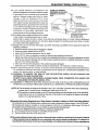 3
3
-
 4
4
-
 5
5
-
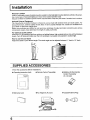 6
6
-
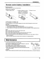 7
7
-
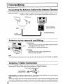 8
8
-
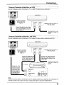 9
9
-
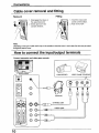 10
10
-
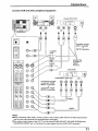 11
11
-
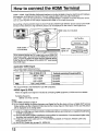 12
12
-
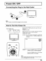 13
13
-
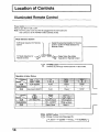 14
14
-
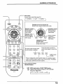 15
15
-
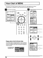 16
16
-
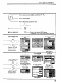 17
17
-
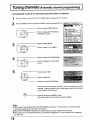 18
18
-
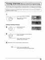 19
19
-
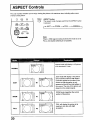 20
20
-
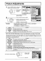 21
21
-
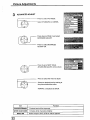 22
22
-
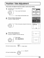 23
23
-
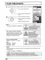 24
24
-
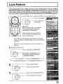 25
25
-
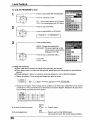 26
26
-
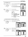 27
27
-
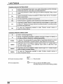 28
28
-
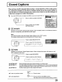 29
29
-
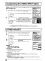 30
30
-
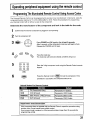 31
31
-
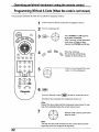 32
32
-
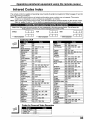 33
33
-
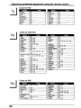 34
34
-
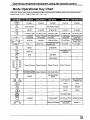 35
35
-
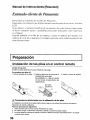 36
36
-
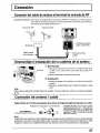 37
37
-
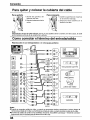 38
38
-
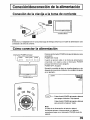 39
39
-
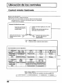 40
40
-
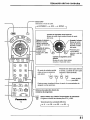 41
41
-
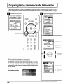 42
42
-
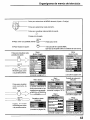 43
43
-
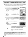 44
44
-
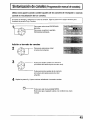 45
45
-
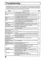 46
46
-
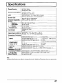 47
47
-
 48
48


Panasonic TC-22LH1 El manual del propietario
- Tipo
- El manual del propietario
En otros idiomas
- English: Panasonic TC-22LH1 Owner's manual
Documentos relacionados
-
Panasonic TC32LH1 Instrucciones de operación
-
-
-
Panasonic TC32LX20 Instrucciones de operación
-
-
-
Panasonic TC-32LX70 El manual del propietario
-
-
-