Yamaha 01V96i Manual de usuario
- Categoría
- Equipo de música suplementario
- Tipo
- Manual de usuario
Este manual también es adecuado para

Reference Manual
How to Use This
Reference Manual
The 01V96i Reference Manual (this document) allows you to
search for terms and take advantage of links in the text.
Searching for terms
To search for a term, use the search function of the software
you’re using to view this document.
If you’re using Adobe Reader, enter the term in the search box
and press the <Enter> key of your computer keyboard to
search for occurrences of that term.
Displaying the next/previous
view
If you’re using Adobe Reader, you can jump to the previous/
next view in your viewing history. This is a convenient way to
jump back to the previous page after you’ve used a link to
jump to a different page.
Using the Function Tree
A function tree for the 01V96i is provided on page 4 and fol-
lowing. You can use this to quickly find the explanatory page
you want.
Note: The latest version of Adobe Reader can be downloaded
from the following URL.
http://www.adobe.com/products/reader.html
Note:
• If the Previous View / Next View buttons are not shown in the
toolbar, you can hold down your computer keyboard’s <Alt>
key and use the <←><→> keys to jump to the previous or next
view.
• For details on using other PDF-viewing software, refer to the
owner’s manual of the software you’re using.

2 Contents
01V96i—Reference Manual
Contents
How to Use This Reference Manual ............................................... 1
Contents of the Owner’s Manual (Booklet) .......... 3
Function Tree .......................................................... 4
Control Surface & Rear Panel ................................. 6
Control Surface .................................................................................. 6
Rear Panel ......................................................................................... 10
Analog I/O & Digital I/O ...................................... 12
Analog Inputs & Outputs ............................................................... 12
Digital Inputs & Outputs ................................................................ 13
Converting Sampling Rates of Signals Received at I/O Card
Inputs ................................................................................. 14
Monitoring Digital Input Channel Status .................................... 14
Dithering Digital Outputs .............................................................. 15
Setting the Transfer Format for Higher Sampling Rates ........... 16
Input Channels ...................................................... 17
About Input Channels .................................................................... 17
Setting the Input Channels from the Display .............................. 18
Setting the Input Channels from the Control Surface ............... 25
Pairing Input Channels ................................................................... 26
Naming Input Channels ................................................................. 28
Bus Outs ................................................................ 29
About Stereo Out ............................................................................. 29
Bus Out 1–8 ...................................................................................... 29
Setting the Stereo Out and Bus Out 1–8 from the Display ........ 30
Setting the Stereo Out and Bus Out 1–8 from the Control
Surface ............................................................................... 33
Pairing Buses or Aux Sends ........................................................... 33
Attenuating Output Signals ........................................................... 34
Naming the Stereo Out and Bus Outs .......................................... 35
Aux Outs ................................................................ 36
Aux Out 1–8 ..................................................................................... 36
Setting Aux Out 1–8 from the Display ......................................... 36
Setting Aux Out 1–8 from the Control Surface ........................... 38
Setting Aux Send Levels .................................................................. 38
Viewing Aux Send Settings for Multiple Channels .................... 40
Panning Aux Sends ......................................................................... 41
Copying Channel Fader Positions to Aux Sends ........................ 42
Input & Output Patching ..................................... 43
Input Patching ................................................................................. 43
Output Patching .............................................................................. 44
Patching Direct Outs ....................................................................... 46
Insert Patching ................................................................................. 47
Monitoring ............................................................ 49
Monitor ............................................................................................. 49
Monitor and Solo Setup .................................................................. 49
Using the Monitor ........................................................................... 50
Using the Solo Function ................................................................. 51
Surround Pan ........................................................ 52
About Surround Pan ....................................................................... 52
Setting Up and Selecting Surround Pan Modes .......................... 53
Surround Panning ........................................................................... 56
Grouping Channels & Linking Parameters .......... 59
Grouping & Linking ........................................................................ 59
Using Fader Groups and Mute Groups ........................................ 59
Using Fader Group Master ............................................................ 61
Using Mute Group Master ............................................................. 62
Linking EQ and Compressor Parameters .................................... 62
Internal Effects ..................................................... 64
About the Internal Effects .............................................................. 64
Using Effects Processors via Aux Sends ....................................... 64
Inserting the Internal Effects into Channels ................................ 65
Editing Effects .................................................................................. 66
About Add-On Effects .................................................................... 67
About Plug-Ins ................................................................................. 67
Scene Memories ................................................... 68
About Scene Memories ................................................................... 68
What is Stored in a Scene? .............................................................. 68
About Scene Numbers .................................................................... 68
Storing and Recalling Scenes .......................................................... 69
Auto Scene Memory Update .......................................................... 70
Fading Scenes ................................................................................... 71
Recalling Scenes Safely .................................................................... 72
Sorting Scenes ................................................................................... 72
Copying and Pasting a Scene (Global Paste) ............................... 73
Libraries ................................................................ 74
About the Libraries .......................................................................... 74
General Library Operation ............................................................. 74
Using Libraries ................................................................................. 75
Remote Control .................................................... 83
About Remote Function ................................................................. 83
Pro Tools Remote Layer ................................................................. 83
Nuendo/Cubase Remote Layer ...................................................... 93
Other DAW Remote Layer ............................................................. 94
MIDI Remote Layer ......................................................................... 94
Machine Control Function ............................................................. 98
MIDI .................................................................... 100
MIDI & the 01V96i ........................................................................ 100
MIDI Port Setup ............................................................................ 101
Assigning Scenes to Program Changes for Remote Recall ...... 103
Assigning Parameters to Control Changes for Real-time Control
.. 104
Controlling Parameters by Using Parameter Changes ............. 106
Transmitting Parameter Settings via MIDI (Bulk Dump) ....... 107
Other Functions ................................................. 109
Setting Preferences ......................................................................... 109
Creating a Custom Layer by Combining Channels
(User Assignable Layer) ................................................. 110
Cascading Consoles ....................................................................... 111
Checking the Battery and the System Version .......................... 113
Calibrating the Faders ................................................................... 113
Index ................................................................... 115
Appendix: Parameter Lists .............................. 119
USER DEFINED KEYS ................................................................. 119
USER DEFINED KEYS Initial Assignments ............................. 121
Input Patch Parameters ................................................................ 121
Initial Input Patch Settings ........................................................... 123
Output Patch Parameters ............................................................. 125
Initial Output Patch Settings ........................................................ 127
User Defined Remote Layer Initial Bank Settings ..................... 128
Effects Parameters ......................................................................... 132
Effects and tempo synchronization ............................................. 146
Preset EQ Parameters .................................................................... 147
Preset Gate Parameters (fs = 44.1 kHz) ...................................... 148
Preset Compressor Parameters (fs = 44.1 kHz) ......................... 149
Dynamics Parameters ................................................................... 151
Appendix: MIDI ............................................... 156
Scene Memory to Program Change Table ................................. 156
Initial Parameter to Control Change Table ............................... 157
MIDI Data Format ......................................................................... 173
MIDI Implementation Chart ........... End of Manual

Contents of the Owner’s Manual (Booklet) 3
01V96i—Reference Manual
Contents of the Owner’s Manual (Booklet)
Contents of the
Owner’s Manual
(Booklet)
The contents of the separate Owner’s Manual booklet are as
follows.
PRECAUTIONS
Welcome
Package Contents
About the included discs
About the included DAW software
About the utility software
Firmware updates
About this Owner’s Manual
Conventions Used in this Manual
Control Surface & Rear Panel
Control Surface
Rear Panel
Installing an Optional Card
Operating Basics
About the Display
Selecting Display Pages
Display Interface
Selecting Layers
Selecting Channels
Selecting Fader Modes
Metering
Connections and Setup
Connections
Wordclock Connections and Settings
Input and Output Patching
Tutorial
Input and Output Patching
Setting the Input Levels
Pairing Channels
Setting the Routing
EQ’ing the Input Signals
Using the EQ Library
Compressing the Input Signals
Using the Internal Effects
Recording to DAW Software via the USB Port
Adjusting the Monitor Levels from the DAW
Using Scene Memories
Changing the Channel Names
Creating a Custom Layer by Combining Channels
(User Assignable Layer)
Using the Oscillator
Using the User Defined Keys
Using Operation Lock
Initializing
Troubleshooting
Error messages
Contents of the Reference Manual
Specifications
General Spec
Libraries
Analog Input Spec
Analog Output Specs
Digital Input Spec
Digital Output Spec
I/O SLOT Spec
MIDI/USB/WORD CLOCK I/O Spec
Dimensions
Options
Rack Mounting the 01V96i Using RK1 Rack Mount Kit
Index
01V96i Block Diagram
01V96i Level Diagram

4 Function Tree
01V96i—Reference Manual
Function Tree
DISPLAY ACCESS
Page numbers in parentheses ( ) are the page numbers of the
Owner’s Manual (booklet).
BUTTON FUNCTION PAGE NAME LINK
SCENE
SCENE SCENE MEMORY 68
IN FADE INPUT FADE TIME 71
OUT FADE OUTPUT FADE TIME 71
RCL SAFE RECALL SAFE 72
SORT SORT 72
PASTE SRC
GLOBAL PASTE SOURCE CH
SELECT
73
PASTE DST
GLOBAL PASTE
DESTINATION SCENE
73
DIO/SETUP
WORD CLOCK WORD CLOCK SELECT 14
FORMAT
HIGHER SAMPLE RATE
DATA TRANSFER FORMAT
14
15
16
PREFER1 PREFERENCES 1 109
PREFER2 PREFERENCES 2 110
MIDI/HOST MIDI/TO HOST SETUP 100
MONITOR MONITOR 49
REMOTE REMOTE 85
MACHINE MACHINE CONTROL 98
SURR BUS SURROUND BAS SETUP 54
CASCADE
CASCADE IN
ATTENUATION
112
OUTPUT ATT
OUTPUT PORT
ATTENUATOR
34
MIDI
SETUP MIDI SETUP 101
PGM ASGN
PROGRAM CHANGE
ASSIGN TABLE
102
CTL ASGN
CONTROL CHANGE
ASSIGN TABLE
104
BULK BULK DUMP 107
UTILITY
OSCILLATOR OSCILLATOR (45)
CH STATUS
CHANNEL STATUS
MONITOR
14
BATTERY BATTERY CHECK 113
USER DEF USER DEFINED KEY ASSIGN 119
LOCK OPERATION LOCK (47)
/INSERT/
DELAY
PHASE PHASE 18
INSERT INSERT 47
DLY 1-16 INPUT CH1-16 DELAY 18
DLY17-32 INPUT CH17-32 DELAY 18
OUT DLY OUTPUT DELAY 30
PAN/
ROUTING
PAN PAN 22
ROUT1-16 INPUT CH1-16 ROUTING 22
ROUT17-STI
INPUT CH17-32
ROUTING/ST IN
22
BUS TO ST BUS TO STEREO 31
SURR MODE SURROUND MODE 53
CH EDIT
SELECTED CHANNEL
SURROUND EDIT
56
SURR1-16 INPUT CH1-16 SURROUND 58
SURR17-32
INPUT CH17-32
SURROUND
58
SURR ST IN STEREO INPUT SURROUND 58
PAIR/
GROUP
INPUT INPUT PAIR 27
OUTPUT OUTPUT PAIR 33
IN FADER INPUT FADER GROUP 59
IN MUTE INPUT MUTE GROUP 59
OUT FADER OUTPUT FADER GROUP 59
OUT MUTE OUTPUT MUTE GROUP 60
IN EQ INPUT EQUALIZER LINK 62
OUT EQ OUTPUT EQUALIZER LINK 62
IN COMP INPUT COMP LINK 63
OUT COMP OUTPUT COMP LINK 63
IN MASTER
INPUT FADER GROUP
MASTER
61
OUT MASTER
OUTPUT FADER GROUP
MASTER
61
PATCH
IN PATCH INPUT PATCH 43
INPUT INS INPUT INSERT IN PATCH 48
EFFECT
EFFECT INPUT/OUTPUT
PATCH
64
CASCADE IN CASCADE IN PATCH 111
IN NAME INPUT CHANNEL NAME 28
IN LIB INPUT PATCH LIBRARY 75
OUT PATCH SLOT OUTPUT PATCH 44
USB OUT USB OUT PATCH 45
OUTPUT INS OUTPUT INSERT IN PATCH 48
DIRECT OUT DIRECT OUT DESTINATION 46
2TR OUT 2TR OUT DIGITAL PATCH 45
OUT NAME OUTPUT CHANNEL NAME 35
OUT LIB OUTPUT PATCH LIBRARY 76
DYNAMICS
GATE EDIT GATE EDIT 19
GATE LIB GATE LIBRARY 79
COMP EDIT COMP EDIT 20
COMP LIB COMP LIBRARY 79
EQ
EQ EDIT EQUALIZER EDIT 21
EQ LIBRARY EQUALIZER LIBRARY 81
IN ATT INPUT ATTENUATOR 20
OUT ATT OUTPUT ATTENUATOR 30
EFFECT
FX1 EDIT FX1 EDIT 66
FX2 EDIT FX2 EDIT 66
FX3 EDIT FX3 EDIT 66
FX4 EDIT FX4 EDIT 66
FX1 LIB FX1 LIBRARY 76
FX2 LIB FX2 LIBRARY 76
FX3 LIB FX3 LIBRARY 76
FX4 LIB FX4 LIBRARY 76
P-IN EDIT
PLUG-IN EFFECT CARD
EDIT
67
VIEW
PARAMETER PARAMETER VIEW
23
31
37
FADER FADER VIEW
24
32
38
LIBRARY CHANNEL LIBRARY 75
1-16 AUX INPUT CH1-16 AUX VIEW 40
17-STI AUX
INPUT CH17-ST IN AUX
VIEW
40
BUTTON FUNCTION PAGE NAME LINK

Function Tree 5
01V96i—Reference Manual
Function Tree
FADER MODE
LAYER
BUTTON FUNCTION PAGE NAME LINK
AUX1–
AUX8
SEND AUX1–AUX8 SEND 38
PAN AUX1–AUX8 PAN 41
VIEW1-16 INPUT CH1-16 AUX VIEW 40
VIEW17-STI
INPUT CH17-ST IN AUX
VIEW
40
HOME
(METER)
CH1-32 CH1-32 METER 8
ST IN ST IN METER 8
MASTER MASTER METER 8
EFFECT
EFFECT1-4 INPUT/OUTPUT
METER
8
STEREO STEREO METER 8
POSITION METER POSITION 8
BUTTON FUNCTION PAGE NAME LINK
1-16
8
17-32
8
MASTER
8
REMOTE
USER DEFINED 94
ProTools 83
Nuendo 93
Cubase 93
General DAW 94
USER
ASSIGNABLE
LAYER
110

6 Control Surface & Rear Panel
01V96i—Reference Manual
Control Surface & Rear Panel
Control Surface
SOLO SOLO
ON ON
SOLO
ON
SOLO
ON
SOLO
ON
SOLO
ON
SOLO
ON
SOLO
ON
SOLO
ON
SOLO
ON
SOLO
ON
SOLO
ON
SOLO
ON
SOLO
ON
SOLO
ON
SOLO
ON
SOLO
ON
SOLO
ONON
PEAK
SIGNAL
PEAK
SIGNAL
PEAK
SIGNAL
PEAK
SIGNAL
PEAK
SIGNAL
PEAK
SIGNAL
PEAK
SIGNAL
PEAK
SIGNAL
PEAK
SIGNAL
PEAK
SIGNAL
PEAK
SIGNAL
PEAK
SIGNAL
PEAK
SIGNAL
PEAK
SIGNAL
1-16 17-32 MASTER REMOTE
LAYER
SEL SEL SEL SEL SEL SEL SEL SEL SEL SEL SEL SEL SEL SEL SEL SEL SEL SELSEL
ST IN
ENTER
STEREO
DEC INC
SOLO CLEAR
RECALL
STORE
SCENE MEMORY
PHONES
MONITOR
OUT
MONITOR
2TR IN
CH15
/
16
2TR IN
LEVEL
PHONES
LEVEL
0
10
0
10
+4
-26
GAIN
+4
-26
GAIN
+4
-26
GAIN
GAIN
+4
-26
GAIN
20dB
-16
-60
GAIN
20dB
-16
-60
GAIN
20dB20dB20dB20dB20dB20dB20dB20dB20dB20dB
-16
-60
GAIN
-16
-60
GAIN
-16
-60
GAIN
-16
-60
GAIN
-16
-60
GAIN
-16
-60
GAIN
-16
-60
GAIN
-16
-60
GAIN
-16
-60
GAIN
-16
-60
PA D
FADER MODE
DISPLAY ACCESS
AUX 1
AUX 1 AUX 2 AUX 3 AUX 4 AUX 5 AUX 6 AUX 7 AUX 8 BUS 1 BUS 2 BUS 3 BUS 4 BUS 5 BUS 6 BUS 7 BUS 8
AUX 2 AUX 3 AUX 4
AUX 8AUX 7AUX 6AUX 5
HOME (METER)
DYNAMICS
EQ EFFECT VIEW
PATCH
UTILITYMIDISCENE
DIO/SETUP
/ INSERT/
DELAY
PAN/
ROUTING
PAIR/
GROUP
A
B
A
B
A
B
A
B
A
B
A
B
A
B
A
B
A
B
A
B
A
B
A
B
16
1513
121110987643215
14
INSERT I
/
O INSERT I
/
O INSERT I
/
O INSERT I
/
O INSERT I
/
O INSERT I
/
O INSERT I
/
O INSERT I
/
O INSERT I
/
O INSERT I
/
O INSERT I
/
O INSERT I
/
O
L
R
IN OUT
2TR
-10dBV (UNBAL)
PHANTOM +48V
CH9-12CH5-8CH1-4
INPUT
(BAL)
INSERT
OUT IN
(UNBAL)
ST IN 1 ST IN 2
USER DEFINED
KEYS
12
34
56
78
55
5
+10
5
1010
10
1515
15
2020
20
303030
30
4040
40
5050
50
6060
7070
20
30
40
40
50
50
60
70
00
5
10
15
20
0
0
5
+10
5
10
15
30
20
30
40
40
50
50
60
70
20
30
40
40
50
50
60
70
20
30
40
40
50
50
60
70
20
30
40
40
50
50
60
70
20
30
40
40
50
50
60
70
15
0
5
10
15
20
0
5
+10
5
10
0
30
15
5
10
15
20
0
5
+10
5
10
0
30
15
5
10
15
20
0
5
+10
5
10
0
30
15
5
10
15
20
0
5
+10
5
10
0
30
15
20
30
40
40
50
50
60
70
30
15
20
30
40
40
20
30
40
20
30
40
20
30
40
50
50505050
20
30
40
50
20
30
40
50
60
70
40
50
60
70
40
50
60
70
40
50
60
70
40
50
60
70
40
50
60
70
40
50
60
70
40
50
60
70
30
15
5
10
15
20
0
5
+10
5
10
0
5
10
15
20
0
5
+10
5
10
0
5
10
15
20
0
30
5
10
15
20
0
30
5
10
15
20
0
30
5
10
15
20
0
30
5
10
15
20
0
303030
5
10
15
20
0
5
10
15
20
0
5
10
15
20
0
5
+10
5
10
0
15
5
+10
5
10
0
15
5
+10
5
10
0
15
5
+10
5
10
0
15
20
30
40
50
15 15
20
30
40
50
15
5
+10
5
10
0
5
+10
5
10
0
5
+10
5
10
0
5
+10
5
10
0
123456
123456
7
8 9 10 11 12
7
8 9 10 11 12
13 14 15 16
13 14 15 16
32313029282726252423222120191817
STEREO
13 14 15 16
OVER
0
-3
-6
-9
-12
-15
-18
-24
-30
-36
-48
HIGH
HIGH-MID
LOW-MID
LOW
Q
FREQUENCY
GAIN
AD Input Section (p. 7)
SELECTED
CHANNEL
Section (p. 9)
Monitor Out
& Head-
phones Sec-
tion (p. 7)
SOLO Section
(p. 9)
Channel Strip Section (p. 7) STEREO Section (p. 8) USER DEFINED KEYS
Section (p. 9)
Data Entry
Section (p. 9)
LAYER Section
(p. 8)
SCENE MEMORY Section (p. 9)
Display Section
(p. 9)
DISPLAY ACCESS
Section (p. 8)
ST IN Section
(p. 8)
FADER MODE
Section (p. 8)
Note: For details on the function of each item, refer to “Control Surface & Rear Panel” in the Owner’s Manual.

Control Surface 7
01V96i—Reference Manual
Control Surface & Rear Panel
AD Input Section
1 INPUT connectors A/B
2 INPUT connectors 13–16
3 INSERT I/O connectors
4 PAD switches
5 GAIN controls
6 PEAK indicators
7 SIGNAL indicators
8 AD15/16 selector
Monitor Out & Headphones
Section
1 2TR IN/OUT connectors
2 Monitor Source selector
3 MONITOR LEVEL control
4 PHONES LEVEL control
5 PHONES jack
Channel Strip Section
1 [SEL] buttons
2 [SOLO] buttons
3 [ON] buttons
4 Channel faders
PEAK
SIGNAL
PEAK
SIGNAL
PEAK
SIGNAL
PEAK
SIGNAL
PEAK
SIGNAL
PEAK
SIGNAL
PEAK
SIGNAL
PEAK
SIGNAL
PEAK
SIGNAL
PEAK
SIGNAL
PEAK
SIGNAL
CH15
/
16
2TR IN
+4
-26
GAIN
+4
-26
GAIN
+4
-26
GAIN
GAIN
+4
-26
GAIN
20dB
-16
-60
GAIN
20dB
-16
-60
GAIN
20dB20dB20dB20dB20dB20dB20dB
-16
-60
GAIN
-16
-60
GAIN
-16
-60
GAIN
-16
-60
GAIN
-16
-60
GAIN
-16
-60
GAIN
-16
-60
PAD
A
B
A
B
A
B
A
B
A
B
A
B
A
B
A
B
A
B
16
1513
121110943215
14
INSERT I
/
O INSERT I
/
O INSERT I
/
O INSERT I
/
O INSERT I
/
O INSERT I
/
O INSERT I
/
O INSERT I
/
O INSERT I
/
O
CH1-4
INPUT
(BAL)
INSERT
OUT IN
(UNBAL)
13 14 15 16
1
3
4
5
6
7
8
2
PHONES
MONITOR
OUT
MONITOR
2TR IN
LEVEL
PHONES
LEVEL
0
10
0
10
L
R
IN OUT
2TR
-10dBV
(UNBAL)
PHANTOM +48V
CH9-12CH5-8
1
2
3
4
5
SOLO
ON
SEL
AUX 1
40
50
60
70
30
5
10
15
20
0
20
30
40
50
15
5
+10
5
10
0
1
1
17
1
2
3
4

8 Control Surface & Rear Panel
01V96i—Reference Manual
STEREO Section
1 [SEL] button
2 [ON] button
3 [STEREO] fader
ST IN Section
1 [ST IN] button
2 [SEL] buttons
3 [SOLO] buttons
4 [ON] buttons
5 Level controls
FADER MODE Section
1 [AUX 1]–[AUX 8] buttons
2 [HOME] button
DISPLAY ACCESS Section
1 [SCENE] button
2 [DIO/SETUP] button
3 [MIDI] button
4 [UTILITY] button
5 [ /INSERT/DELAY] button
6 [PAN/ROUTING] button
7 [PAIR/GROUP] button
8 [PATCH] button
9 [DYNAMICS] button
0 [EQ] button
A [EFFECT] button
B [VIEW] button
LAYER Section
1 [1–16]/[17–32] buttons
2 [MASTER] button
3 [REMOTE] button
ON
SEL
5
10
15
20
30
40
50
60
70
0
STEREO
1
2
3
SOLO
ON
SOLO
ON
SEL SEL
ST IN
ST IN 1 ST IN 2
1
2
3
4
5
FADER MODE
AUX
1
AUX
2
AUX
3
AUX
4
AUX
8
AUX
7
AUX
6
AUX
5
HOME (METER)
1
2
Tip: The ST IN section is not affected by the layer settings.
DISPLAY ACCESS
DYNAMICS
EQ EFFECT VIEW
PATCH
UTILITYMIDISCENE
DIO/SETUP
/ INSERT/
DELAY
PAN/
ROUTING
PAIR/
GROUP
1 2 3
9
0 A B
4
5
6
8
7
UTILITYMIDISCENE
DIO/SETUP
1-16 17-32 MASTER REMOTE
LAYER
1 2 3

Control Surface 9
01V96i—Reference Manual
Control Surface & Rear Panel
Display Section
1 Display
2 Stereo meters
3 Contrast control
4 [F1]–[F4] buttons
5 Left Tab Scroll [ ] button
6 Right Tab Scroll [ ] button
SELECTED CHANNEL Section
1 [PAN] control
2 [HIGH] button
3 [HIGH-MID] button
4 [LOW-MID] button
5 [LOW] button
6 [Q] control
7 [FREQUENCY] con-
trol
8 [GAIN] control
SCENE MEMORY Section
1 [STORE] button
2 Scene Up [ ] / Down [ ] buttons
3 [RECALL] button
USER DEFINED KEYS
Section
1 [1]–[8] buttons
Data Entry Section
1 Parameter wheel
2 [ENTER] button
3 [DEC] & [INC] buttons
4 Left, Right, Up, Down ([ ]/[ ]/[ ]/[ ]) cur-
sor buttons
SOLO Section
1 [SOLO] indicator
2 [CLEAR] button
STEREO
OVER
0
-3
-6
-9
-12
-15
-18
-24
-30
-36
-48
4
1
5
2
3
6
Tab Scroll arrow
HIGH
HIGH-MID
LOW-MID
LOW
Q
FREQUENCY
GAIN
2
3
4
5
6
1
7
8
RECALL
STORE
SCENE MEMORY
2
13
USER DEFINED
KEYS
12
34
56
78
1
ENTER
DEC INC
2
3
1
4
SOLO CLEAR
1 2

10 Control Surface & Rear Panel
01V96i—Reference Manual
Rear Panel
PHANTOM +48V
1 CH1–4 ON/OFF switch
2 CH5–8 ON/OFF switch
3 CH9–12 ON/OFF switch
AD Output Section
1 MONITOR OUT connectors L/R
2 OMNI OUT connectors 1–4
3 STEREO OUT connectors L/R
Digital I/O Section
1 WORD CLOCK OUT connector
2 WORD CLOCK IN connector
3 ADAT IN/OUT connectors
4 2TR OUT DIGITAL COAXIAL
5 2TR IN DIGITAL COAXIAL
MIDI/USB Section
1 MIDI IN/THRU/OUT ports
2 TO HOST USB port
PHANTOM +48V (p. 10)
Power Section (p. 11)
AD Output Section
(p. 10)
SLOT Section (p. 11)
MIDI/USB Section
(p. 10)
Digital I/O Section
(p. 10)
321
321
42153
21

Rear Panel 11
01V96i—Reference Manual
Control Surface & Rear Panel
SLOT Section
1 SLOT
Power Section
1 POWER ON/OFF switch
2 AC IN connector
1
21

12 Analog I/O & Digital I/O
01V96i—Reference Manual
Analog I/O &
Digital I/O
This chapter describes the 01V96i’s analog and digital
input/output connectors as well as the basic operations
involving the digital I/Os.
Analog Inputs & Outputs
Input Section
The 01V96i’s top panel features input connectors, which
enable you to connect microphone and line-level sources.
• INPUT connectors A 1–12
These balanced TRS-type
phone connectors accept
line-level and microphone sig-
nals. The nominal input range is
–60 dB through +4 dB. The phantom [+48V] switches on
the rear panel turn on or off the +48V phantom power
feed to these inputs.
• INPUT connectors B 1–12
These balanced TRS-type con-
nectors accept line-level and
microphone signals. The nominal input range is –60 dB
through +4 dB.
You cannot use same-numbered INPUT A and INPUT B
connectors simultaneously. (For example, you cannot use
INPUT A-2 and INPUT B-2 at the same time.) If you
connect cables to A and B connectors of the same num-
ber, only the signal from INPUT B is effective (e.g., B-2
takes priority over A-2).
•INPUT connectors 13–16
These balanced TRS-type phone con-
nectors accept line-level signals. When
the AD 15/16 source selector is turned
on (pushed in), signals from INPUT 15
and 16 are ignored. Instead, signals from
the 2TR IN connector will be routed to AD Input Chan-
nels 15 and 16.
• INSERT I/O connectors
These TRS-type phone connectors
are used to insert external devices,
such as effects processors, into AD Input Channels.
•Phantom Power
Inputs 1 through
12 feature switch-
able +48V phantom powering for use with con-
denser-type microphones and direct boxes. The phantom
[+48V] switches on the rear panel turn on or off the +48V
phantom power feed to the corresponding inputs.
•PAD switches
Inputs 1 through 12 feature pad
switches, which attenuate input
signals by 20 dB. These switches
are effective on both INPUT A and B signals.
•GAIN controls
Inputs 1 through 16 feature
rotary gain controls that adjust
input sensitivity. Input sensitivity
for INPUT connectors 1–12
ranges from –16 dB to –60 dB when the Pad is off, and
from +4 dB to –40 dB when the Pad is on. Input sensitiv-
ity for INPUT connectors 13–16 ranges from +4 dB to
–26 dB.
•PEAK & SIGNAL Indicators
The SIGNAL indicator lights up
when the input signal level at
INPUTs 1–16 exceeds –34 dB.
The PEAK indicator lights up when the input signal level
is 3 dB below clipping.
•2TR IN connectors
These unbalanced RCA phono connec-
tors accept line-level signals from
devices such as CD players.
When the AD 15/16 source selector is
turned on (pushed in), signals input at
these conductors are routed to AD
Inputs 15 and 16. When the Monitor source selector is
turned on (pushed in), you can monitor these signals
from the MONITOR OUT connectors.
Tip: You can patch signals input from the INPUT connectors
to any Input Channels. (See page 43 for information on
patching input signals to Input Channels.)
AA
21
BB
INPUT
(BAL)
16
1513
14
INSERT I
/
O INSERT I
/
O
INSERT
OUT IN
(UNBAL)
20dB
PAD
20dB
GAIN
-16
-60
PEAK
SIGNAL
GAIN
L
R
IN OUT
2TR
-10dBV
(UNBAL)

Digital Inputs & Outputs 13
01V96i—Reference Manual
Analog I/O & Digital I/O
Output Section
The 01V96i top and rear panels feature output connectors
that enable you to connect a monitoring system, effects pro-
cessors and other line-level devices.
• MONITOR OUT connectors L/R
These balanced TRS-type phone con-
nectors output monitoring signals or
input signals routed from the 2TR IN
connectors. The nominal output level
is +4 dB.
Use the Monitor source selector in the Monitor Out &
Headphones section to select the signal output from these
connectors.
•OMNI OUT connectors 1–4
These balanced
TRS-type phone con-
nectors output any Bus
Outs or Input Channel
Direct Outs. The nomi-
nal output level is +4 dB.
• STEREO OUT connectors L/R
These balanced XLR-3-32-type
connectors output the Stereo Out
signals. The nominal output level
is +4 dB.
•2TR OUT connectors
These unbalanced RCA phono con-
nectors output line-level signals to a
connected recorder or other external
device. These connectors always out-
put the Stereo Out signals.
Digital Inputs & Outputs
The 01V96i rear panel features digital input and output con-
nectors that enable you to connect external digital devices.
Any signal path can be patched to these digital inputs and
outputs.
You can also add analog and digital I/Os by installing an
optional I/O card in the slot.
Digital I/O Connectors
•2TR IN DIGITAL connector
2TR IN DIGITAL is an RCA phono connector
and accepts consumer format (IEC 60958)
digital audio. You can patch digital signals
input at this connector to any Input Channel
(page 43).
• 2TR OUT DIGITAL connector
This RCA phono connector outputs con-
sumer format (IEC 60958) digital audio. You
can patch any Bus outs or Input channel
Direct Outs to this output (page 45).
•ADAT IN connector
This TOSLINK connector accepts 8-channel ADAT opti-
cal format signals, which can be patched to any Input
Channel (page 43).
• ADAT OUT connector
This TOSLINK connector outputs an 8-channel ADAT
optical format signal. You can patch any Bus Outs or
Input Channel Direct outs to this output (page 44).
SLOT
This slot allows you to install an optional mini-YGDAI
(Yamaha General Digital Audio Interface) I/O card. This card
offers AD/DA conversion, and various analog I/O options
and digital I/O interfaces in all the popular digital audio inter-
connect formats, including AES/EBU, ADAT, and Tascam.
You can patch signals input at these card connectors to any
Input Channels or Insert Ins (see page 43).
You can patch the card outputs to Bus Outs or Input Channel
Direct Outs (see page 46).
For details on the mini-YGDAI I/O cards that are currently
usable, refer to “I/O Slot Specifications” in the Owner’s Man-
ual.
For the latest information about mini-YGDAI I/O cards, refer
to the Yamaha Professional Audio website.
http://www.yamahaproaudio.com/
Tip: Any signal path can be patched to the OMNI OUT con-
nectors. (See page 44 for more information on patching sig-
nals to the OMNI OUT connectors.)
L
R
IN OUT
2TR
-10dBV
(UNBAL)

14 Analog I/O & Digital I/O
01V96i—Reference Manual
Converting Sampling
Rates of Signals Received
at I/O Card Inputs
An optional MY8-AE96S Digital I/O card features sampling
rate converters, so you can easily convert the sampling fre-
quency of digital inputs to the current 01V96i sampling rate.
1. Press the DISPLAY ACCESS [DIO/SETUP] but-
ton repeatedly until the DIO/Setup | Format
page appears.
Use the buttons in the SRC sections to turn the sampling
rate converters on and off. You can turn the sampling rate
converters of the digital I/O card on or off in pairs (odd &
even channels, in this order).
2. Use the cursor buttons to move the cursor to
any two-channel button in the SRC sections,
then press [ENTER].
The sampling rate converter for the selected 2-channel
input turns on or off. When on, the sampling rate of the
received digital audio is converted to the 01V96i’s current
sampling rate.
Monitoring Digital Input
Channel Status
You can view and monitor the Channel Status (sampling rate,
emphasis, etc.) of digital audio signals connected to the 2TR
Digital Inputs and Slot Inputs as follows.
1. Press the DISPLAY ACCESS [UTILITY] button,
then press the [F2] button.
The Utility | CH Status page appears.
On this page, use the following buttons to select a slot or
connector for which you want to view the channel status.
1 2TR IN
This button enables you to view the Channel Status of
input signals connected to the 2TR Digital Inputs.
2 SLOT
These buttons enable you to view the Channel Status of
each two adjacent (odd and even, in this order) channel
signals connected to the digital I/O card installed in the
slot.
2. Move the cursor to the desired input or slot
button, then press [ENTER].
Channel Status information for the selected input is dis-
played. However, if a mini-YGDAI I/O card other than
AES/EBU format is installed, Channel Status information
will be grayed out. Channel Status information includes
the following items:
3 FS
Indicates the sampling rate. If no signal is being input, or
if the incoming wordclock is not synching to the internal
clock, “Unlock” appears.
4 EMPHASIS
Indicates the Emphasis on/off status.
5 CATEGORY
Indicates the status of “Category Code Bit” included in
the IEC958 Part 2 (S/PDIF-Consumer) format. This
parameter can display the following values:
Tip: The FS box on the Word Clock page displays the sam-
pling frequency at which the 01V96i is currently operating.
Note: The sampling rate converter is available only on the
Yamaha MY8-AE96S Digital I/O card. If you have installed
another type of I/O card in the slot, or if no card is installed
in the 01V96i, the buttons in the SRC sections are disabled.
1
2
3
4
5
6

Dithering Digital Outputs 15
01V96i—Reference Manual
Analog I/O & Digital I/O
6 COPY
Indicates the status of copy protection information
included in the IEC958 Part2 (S/PDIF-Consumer) for-
mat signals. “OK” appears if copying is allowed. “Pro-
hibit” appears if copy-protected.
3. If you select the SLOT
button for a slot that
has an MY16-AE card installed, use the 01–08
and 09–16 buttons located in the lower-right
corner of the screen to select a channel group
you wish to display.
Dithering Digital Outputs
When digital audio is transferred to lower-resolution systems,
truncated bits may generate unpleasant noise. To cancel the
audible effect of this noise, a small complement of noise is
intentionally added to the digital outputs. This process is
called “dithering.”
On the 01V96i, you can dither the 2TR Digital Outputs and
Slot Outputs. For example, you can apply dithering to the
01V96i stereo mix data and record to a 16-bit digital recorder.
1. Press the DISPLAY ACCESS [DIO/SETUP] but-
ton repeatedly until the DIO/Setup | Format
page appears.
The dithering settings are displayed at the bottom of the
page.
2. Move the cursor to the output or channel to
which you want to apply dithering, then
rotate the Parameter wheel or press the
[INC]/[DEC] buttons to select the value that
matches the resolution of the receiving
device.
Parameter value Description
General Temporarily used
Laser Optical Laser optical device
D/D Conv
Digital - Digital converter and
signal processing device
Magnetic
Magnetic tape device and mag-
netic disk device
D.Broadcast Digital broadcast reception
Instruments
Musical instrument, micro-
phone, and sources that gener-
ate string signals
A/D Conv
A/D converter (without copy-
right information)
A/D Conv with (C)
A/D converter (with copyright
information)
Solid Memory Solid memory device
Experimental Experimental device
Unknown Unknown
Note: “AES/EBU” appears in the Category row when you are
monitoring IEC958 Part 3 (AES/EBU-Professional) format
signals (that do not include Category Code Bit).
Note:
• You cannot apply dithering to outputs or channels that are
set to “OFF.”
• Dithering is effective only when the resolution of the
receiving device is lower than that of the 01V96i.
Tip: To copy the currently-selected setting to all channels,
double-click the [ENTER] button. The copy confirmation
window is displayed.

16 Analog I/O & Digital I/O
01V96i—Reference Manual
Setting the Transfer
Format for Higher
Sampling Rates
To operate the 01V96i at higher sampling frequencies
(88.2 kHz or 96 kHz) and transfer digital audio signals to and
from connected external devices, you must set the data trans-
fer format in accordance with the sampling frequencies sup-
ported by the external devices.
1. Press the DISPLAY ACCESS [DIO/SETUP] but-
ton repeatedly until the DIO/Setup | Word
Clock page appears.
2. Select INT88.2k or INT96k as the wordclock
source.
3. Press the DISPLAY ACCESS [DIO/SETUP] but-
ton repeatedly until the DIO/Setup | Format
page appears.
4. Use the cursor buttons to move the cursor to
an IN/OUT parameter field (
1), then rotate
the Parameter wheel or press the [INC]/[DEC]
buttons to set the data transfer format.
The IN/OUT parameters are used to set one of the follow-
ing data transfer formats for each slot input and output.
• DOUBLE CHANNEL
In Double Channel mode, digital audio data is received
and transmitted as mono signals at a sampling rate that is
exactly half (44.1/48 kHz) the current higher sampling
rate. Data is handled by two channels. This is useful when
you want to transfer data between the 01V96i operating at
a higher sampling rate and an external digital device that
supports 44.1/48 kHz.
•DOUBLE SPEED
In Double Speed mode, digital audio data is received and
transmitted at the current high sampling rate (i.e.,
88.2 kHz or 96 kHz). Select this mode if the devices that
support the higher sampling rates transmit or receive
data.
•SINGLE
In Single mode, digital audio data is received and trans-
mitted at a sampling rate that is half (44.1/48 kHz) the
current higher sampling rate of the 01V96i. For example,
this is useful when you want to receive 44.1 kHz digital
signals from an external digital device while the 01V96i is
operating at 88.2 kHz.
Note: When the 01V96i operates at a high sampling rate
(88.2 kHz or 96 kHz), only two internal effects processors are
available.
Note: Double Channel mode reduces the total number of
inputs or outputs on the corresponding slot. The even-num-
bered channels are disabled.
1
Note: You can select this setting only for slots in which a dig-
ital I/O card that inputs/outputs double-speed digital audio
data (e.g., MY8-AE96, MY8-AE96S) is installed.
Note: You cannot select this setting for slots in which a digital
I/O card that inputs/outputs double-speed digital audio data
(e.g., MY8-AE96, MY8-AE96S) is installed.
Tip: The parameter fields display “–” if the slot contains no
I/O card or if an AD/DA card or other I/O card that does not
allow you to set the transfer format has been installed.

Input Channels 17
01V96i—Reference Manual
Input Channels
Input Channels
This chapter describes how to adjust the 01V96i’s Input
Channel parameters.
About Input Channels
The input Channel section enables you to adjust the level and
tone of the signals input to the 01V96i (and the signals output
from the internal Effects processors 1–4), and route the sig-
nals to Buses 1–8, the Stereo Bus, and Aux Sends 1–8. There
are two types of Input Channels, each featuring slightly differ-
ent functions: monaural Input Channels 1–32 and stereo ST
IN Channels 1–4.
Input Channels 1–32
Each of these monaural Input Channels features a phase
effect, gate, compressor, attenuator, and EQ for signal pro-
cessing. The following diagram illustrates the Input Channel
1–32 signal flow.
Input Channels 1–32 feature the following parameters:
• (Phase)
This section switches the phase of input signals.
•GATE
This dynamics processor can be used as a gate or for
ducking.
•COMP (Compressor)
This dynamics processor can be used as compressor,
expander or limiter. The compressor can be pre-EQ,
pre-fader, or post-fader.
•ATT (Attenuator)
This section enables you to attenuate or amplify the level
of signals that will be input to the EQ. The attenuator
enables you to prevent post-EQ signals from clipping and
to correct signal levels that are too low.
• 4 BAND EQ (4-band equalizer)
This parametric EQ features four bands (high, high-mid,
low-mid, and low).
• INPUT DELAY (Input delay)
This section enables you to delay input signals. You can
use this delay to fine-tune the timing between channels,
or as a delay effect with feedback.
• ON (On/Off)
This section enables you to turn the channel on or off.
The channel is muted with the Off setting.
•LEVEL
This section enables you to adjust the input level of the
Input Channel signal.
•PAN
This section enables you to adjust the pan setting of the
signals routed from the Input Channels to the Stereo Bus.
You can also apply the pan setting to a pair of Bus chan-
nels.
• AUX (Aux Send level)
This section enables you to adjust the level of signals
routed to Aux Sends 1–8. The signals can be routed to
Aux Sends from either the pre-fader or post-fader posi-
tion.
•INSERT
This section enables you to patch input signals to external
devices via the on-board I/O connectors or I/O card, or
insert the internal effect processors. You can patch any
inputs, outputs, or I/O card channels. (Note that this is
different from the INSERT I/O connectors in the AD
Input section.)
• METER
This section enables you to switch the metering position
of the signal levels that are displayed in the Meter page.
For more information on selecting the metering position,
refer to “Viewing the Level Meters” in the Owner’s Man-
ual (booklet).
ST IN Channels 1–4
These stereo channels enable you to process stereo signals
using the phase effect, attenuator, and EQ. The following dia-
gram illustrates the ST IN Channel 1–4 signal flow.
ST IN Channels 1–4 feature the following parameters:
• (Phase)
•ATT (Attenuator)
• 4 BAND EQ (4-band equalizer)
• ON (On/Off)
•LEVEL
•PAN
• AUX (Aux Send level)
• METER
For more information on each parameter, refer to the preced-
ing section Input Channel 1–32.
INPUT PATCH
Tip: You can store these channel parameter settings in the Chan-
nel library. You can also store the Gate, Compressor, and EQ
parameter settings to the corresponding libraries.
INPUT PATCH

18 Input Channels
01V96i—Reference Manual
Setting the Input
Channels from the
Display
To set the Input Channel parameters, you can either move the
cursor to the desired parameter on the display and change the
value, or operate the desired button or control on the top
panel to directly change the setting.
This section explains how to set the parameters via the dis-
play.
Switching the Signal Phase
To switch the phase of each Input Channel, press the
[ /INSERT/DELAY] button repeatedly until the following
/INS/DLY | Phase page appears.
Move the cursor to the NOR/REV button of the channel for
which you want to change the phase, then press the [ENTER]
or [INC]/[DEC] buttons to change the setting.
1 NOR/REV
These buttons switch the corresponding Input Channel
phase. NOR buttons indicate normal phase, and REV
buttons indicate reversed phase.
2 GLOBAL
The GLOBAL NOR/REV buttons allow you to set the
phase for all Input Channels simultaneously.
Delaying Input Channels
To set the delay for each channel, press the
[ /INSERT/DELAY] button repeatedly until the page listed
below that contains the desired channels appears.
• DLY 1-16 page
This page enables you to set the Delay function for Input
Channels 1–16.
• DLY 17-32 page
This page enables you to set the Delay function for Input
Channels 17–32.
The parameters on these two pages (and the procedure for
setting them) are the same.
1 DELAY SCALE
The following buttons determine the units of the delay
value shown below the msec value.
• meter ........................Units are set to meters.
• feet ............................Units are set to feet.
• sample......................Units are set to samples.
• beat ...........................Units are set to beats.
• frame........................Units are set to timecode frames.
2 GANG button
When this button is turned on (highlighted), the delay
time for each channel in a channel pair can be set simul-
taneously. When this option is turned off, the delay time
can be set for each channel in a channel pair individually.
3 Channel section
You can set individual delay parameters here. The delay
parameters include the following items:
•ON/OFF
This button switches the corresponding channel delay on
or off.
•msec
This parameter sets the delay time in milliseconds.
• meter/feet/sample/beat/frame
The delay time can be set using units of meters, feet, sam-
ples, beats, or frames, which you select by using the
DELAY SCALE buttons.
Tip:
• The name of the currently-selected channel is indicated in the
upper-right corner of the screen.
• You can set the phase separately for each of the ST IN Channels
or for each channel in a channel pair. If you selected the desired
ST IN Channel using the corresponding [SEL] button, pressing
the same [SEL] button repeatedly will toggle between channels
L and R.
1
2
213

Setting the Input Channels from the Display 19
01V96i—Reference Manual
Input Channels
•MIX
This parameter sets the mix balance of dry (Input Chan-
nel) and wet (delayed) signals.
•FB.GAIN
This parameter sets the amount of delay feedback.
Gating Input Channels
To set the Input Channel gates, use the [SEL] buttons to select
the desired Input Channel, then press the DISPLAY ACCESS
[DYNAMICS] button, then press the [F1] button. The
Dynamics | Gate Edit page appears.
1 KEYIN SOURCE
Select one of the following buttons to determine the trig-
ger source for the currently-selected Input Channel’s gate.
• SELF......................... The selected channel’s own input sig-
nal is the trigger source.
• CHANNEL ............. Another Channel’s input signal is the
trigger source. Select the desired
channel in the parameter box below
the CHANNEL button.
• AUX ......................... An Aux Send signal is the trigger
source. Select the desired bus in the
parameter box below the AUX but-
ton.
2 STEREO LINK
This parameter’s ON/OFF button enables you to pair
gates for stereo operation even when the Input Channels
are not paired.
3 CURVE
This area displays the current gate curve.
4 TYPE
This area displays the current gate type (GATE or DUCK-
ING).
5 Meters
These meters indicate the levels of the post-gate signals
and the amount of gain reduction.
6 ON/OFF
The ON/OFF button turns the currently-selected Input
Channel’s gate on or off.
7 PARAMETER
These controls enable you to set the gate parameters. (See
page 148 for more information on the parameters.)
Tip:
• This function is unavailable for the ST IN Channels.
• The delay time range depends on the sampling rate at which
the 01V96i is operating.
• If you select the DELAY SCALE meter or feet button, the dis-
tance value can be converted to the delay time based on sonic
speeds (about 343.59 m/sec at 20 degrees Celsius). This option
is useful if you wish to correct the timing difference between
two sound sources that are far apart.
• If you select the DELAY SCALE beat button, a parameter box
for setting a note that represents the beat and a parameter box
for a tempo (BPM) setting appear below the DELAY SCALE
parameter. Setting the note and BPM settings in these param-
eter boxes enables you to set a delay time that synchronizes to
the song tempo.
3 4 521
76
Note: You cannot change the gate type on this page. To
change the gate type, recall a program that uses the desired
gate type from the Gate library.
Tip:
• This function is unavailable for the ST IN Channels.
• You can store the gate settings in the Gate library, which
features preset programs that can be used for various
applications (see page 79).

20 Input Channels
01V96i—Reference Manual
Compressing Input Channels
To set the Input Channel compressors, use the [SEL] buttons
to select the desired Input Channel, then press the DISPLAY
ACCESS [DYNAMICS] button, then press the [F3] button to
display the Dynamics | Comp Edit page.
1 POSITION
Use the Parameter wheel, or the [INC]/[DEC] buttons to
select the position of the compressor within the channel
from the following options:
• PRE EQ....................Immediately before EQ (default)
• PRE FADER ...........Immediately before the fader
• POST FADER ........Immediately after the fader
2 STEREO LINK
This ON/OFF button enables you to pair compressors for
stereo operation even when channels are not paired.
3 CURVE
This area displays the current compressor curve.
4 TYPE
This field indicates the compressor type used by the cur-
rently-selected channel’s compressor
(COMP/EXPAND/COMP (H)/COMP (S)).
5 Meters
These meters indicate the levels of the post-compressor
signals and the amount of gain reduction.
6 ON/OFF
The ON/OFF button turns the currently-selected Input
Channel’s compressor on or off.
7 PARAMETER section
These controls enable you to set the compressor parame-
ters. (See page 149 for more information on the parame-
ters of each compressor type.)
Attenuating Input Channels
To set the attenuator for each Input Channel, press the DIS-
PLAY ACCESS [EQ] button, then press the [F3] button to
display the EQ | In Att page.
Move the cursor to the knob for the desired Input Channel,
then rotate the Parameter wheel to set the amount of attenua-
tion in the range of –96 dB to +12 dB.
Note: You cannot change the Compressor type on this page.
To change the compressor type, recall a program that uses the
desired compressor type from the compressor library.
Tip:
• This function is unavailable for the ST IN Channels.
• You can store the compressor settings in the compressor
library, which features preset programs that can be used
for various applications (see page 80).
3 4 521
76
Tip: You can also set the attenuation amount (in dB) for the cur-
rently-selected channel on the EQ | EQ Edit page.

Setting the Input Channels from the Display 21
01V96i—Reference Manual
Input Channels
EQ’ing Input Channels
The 01V96i’s Input Channels feature 4-band (LOW,
LOW-MID, HIGH-MID, HIGH) parametric EQ. The
LOW-MID and HIGH-MID bands are a peaking type of EQ.
The LOW and HIGH bands can be set to shelving, peaking,
or HPF and LPF respectively.
1. Press the [SEL] button of the channel for
which you want to adjust EQ.
2. Press the DISPLAY ACCEESS [EQ] button, then
press the [F1] button to display the EQ | EQ
Edit page.
The parameters on this page are described below:
1 EQ ON
The ON/OFF button turns the currently-selected Input
Channel’s EQ on or off. You can press the [ENTER] but-
ton to turn the EQ on or off as long as the cursor is located
on any parameter other than TYPE.
2 TYPE
Selects the type of EQ. TYPE I is the EQ type used on leg-
acy Yamaha 02R series digital mixing consoles. The
TYPE II algorithm minimizes the interference between
bands.
3 ATT
Determines the amount of pre-EQ signal attenuation in
dB. It is the same Attenuator parameter that appears on
the EQ | ATT In page.
4 CURVE
This area displays the current EQ curve.
5 Meters
These meters indicate the post-EQ signal levels of the
currently-selected Input Channel and its available pair
partner.
6 LOW, L-MID, H-MID, HIGH sections
These sections contain the Q, Frequency (F), and Gain
(G) parameters for the four bands. These parameter val-
ues range as follows:
3. Move the cursor to the desired parameter,
then rotate the Parameter wheel to change
the value.
6
51 2 3 4
Parameter LOW
LOW-
MID
HIGH-
MID
HIGH
Q
HPF, 10.0
to 0.10
(41 steps),
L.SHELF
10.0 to 0.10
(41 steps)
LPF, 10.0
to 0.10
(41 steps),
H.SHELF
Frequency
21.2 Hz to 20.0 kHz
(120 steps per 1/12 octave)
Gain
–18.0 dB to +18.0 dB (0.1 dB steps)
1
1. The LOW and HIGH GAIN controls function as filter
on/off controls when Q is set to HPF or LPF respec-
tively.
Tip:
• The LOW-band EQ functions as a high-pass filter when
the Q parameter in the LOW section is set to HPF. It func-
tions as a shelving-type EQ when the Q parameter is set
to L.SHELF.
• The HIGH-band EQ functions as a low-pass filter when
the Q parameter in the HIGH section is set to LPF. It func-
tions as a shelving-type EQ when the Q parameter is set
to H.SHELF.
Tip:
• The EQ settings for the ST IN Channels L & R are linked
to each other.
• You can also press the buttons in the SELECTED CHAN-
NEL section to select the desired band and use the rotary
controls to directly edit the Q, F, and G parameters (see
page 25).
• You can store the EQ settings in the EQ library, which fea-
tures preset programs that can be used for various appli-
cations (see page 147).

22 Input Channels
01V96i—Reference Manual
Panning Input Channels
Input Channels can be panned in the range of L63 through
CENTER to R63. To pan each channel, press the
[PAN/ROUTING] button repeatedly until the Pan/Route |
Pan page appears.
Move the cursor to the desired Pan control, then rotate the
Parameter wheel to set the value.
1 Pan controls
These knobs adjust the channel pan settings.
Press the [ENTER] button to reset the currently-selected
Pan control to center.
2 MODE
The MODE parameter determines how paired Input
Channels are panned. There are three Pan modes as fol-
lows:
• INDIVIDUAL
In Individual mode, paired Input Chan-
nel pan controls operate independently.
•GANG
In Gang mode, paired Input Channel
pan controls operate in unison, main-
taining the current pan range.
•INV GANG
In Inverse Gang mode, paired Input
Channel pan controls operate in unison
but move in opposite directions.
Routing Input Channels
You can route each Input Channel to the Stereo Bus, Bus 1–8,
or its own Direct Out. With the default setting, signals are
routed only to the Stereo Bus. However, you can patch signals
to a single or multiple destinations, if necessary.
1. Press the DISPLAY ACCESS [PAN/ROUTING]
button repeatedly until the page listed below
that contains the desired channels appears.
•ROUT1-16 page
This page enables you to change the routing for Input
Channels 1–16.
•ROUT17-ST1 page
This page enables you to change the routing for Input
Channels 17–32 and ST IN Channels 1–4.
The parameters on these two pages (and the procedure for
setting them) are the same.
1 PAN buttons
These buttons determine whether the channel’s Pan set-
ting is applied to the Bus outs. In surround mode, they
also determine whether the Surround Pan setting is
applied to the Bus Outs.
2 Bus buttons 1–8
These buttons route the currently-selected Input Channel
to the Bus Outs. If the 01V96i is in Surround mode, the
button indicators change as follows, depending on the
selected Surround mode:
L=Left, R=Right, C=Center, S=Surround, Ls=Left Sur-
round
Rs=Right Surround, E=Low Frequency Effect, Bs=Back
Surround
The above table shows the default assignment. The actual
assignment may vary, depending on the settings on the
DIO/Setup | Surround Bus Setup page.
Tip:
• You can adjust the pan setting for the ST IN Channels L/R sep-
arately.
• You can also adjust the pan setting for the Input Channels using
the PAN control in the SELECTED CHANNEL section.
• Surround Pan is available when the 01V96i is in Surround
mode. See page 52 for more information on Surround Pan.
2
1
Bus buttons 12345678
Surround mode: 3-1 LRCS5678
Surround mode: 5.1 LRLsRsCE78
Surround mode: 6.1 LRLsRsCBsE8
576
1
3
4
8
2

Setting the Input Channels from the Display 23
01V96i—Reference Manual
Input Channels
3 S
When this button is turned on, the currently-selected
Input Channel is routed to the Stereo Bus.
4 D
When this button is turned on, the currently-selected
Input Channel is routed to its Direct Out. See page 46 for
more information on the Direct Out.
5 ALL STEREO
This button turns on the S button for all channels on the
page.
6 ALL BUS
This button turns on the Bus buttons 1–8 for all channels
on the page.
7 ALL CLEAR
This button clears all routing assignments on the page.
8 SURROUND MODE
This field displays the current Surround mode.
Viewing Input Channel Settings
You can view and adjust parameter settings for the cur-
rently-selected Input Channel on the View | Parameter or
Fader pages.
■ Viewing the Gate, Compressor, and
EQ Settings
To display the View | Parameter page for a specific Input
Channel, use the corresponding [SEL] button to select the
desired channel, then press the DISPLAY ACCESS [VIEW]
button repeatedly.
Move the cursor to a parameter you wish to change, then
rotate the Parameter wheel or press the [INC]/[DEC] buttons
or [ENTER] button to modify the setting.
The following parameters are available (sections marked with
an asterisk (*) are unavailable for the ST IN Channels).
1 GATE section (*)
This section enables you to turn the gate-type dynamics
processor on or off and set the parameters. (See page 19
for more information.)
2 COMP section (*)
This section enables you to turn the compressor-type
dynamics processor on or off and set the parameters. (See
page 20 for more information.)
3 INSERT section (*)
This section enables you to turn the Insert on or off and
patch the Insert In and Out. (See page 47 for more infor-
mation.)
4 EQ section
This section enables you to set various EQ parameters.
(See page 21 for more information.)
5 Meters
These meters indicate the signal levels of the cur-
rently-selected Input Channel and its available pair part-
ner.
6 (Phase) section
You can reverse the signal phase of the currently-selected
Input Channel. (See page 18 for more information.)
Tip: The routings of the ST IN Channels L/R are linked. The D
button is unavailable for the ST IN Channels.
2
1
3 54 6
8
7

24 Input Channels
01V96i—Reference Manual
7 DELAY section (*)
This section enables you to set the currently-selected
channel’s Delay function. (See page 18 for more informa-
tion.)
8 PAIR section (*)
This section indicates whether or not channels are paired.
The heart icon ( ) is in one piece when channels are
paired. The heart icon is broken ( ) when channels are
not paired. (See page 26 for more information.)
■ Viewing the Pan, Fader, and Aux
Send Level Settings
To display the View | Fader page of a certain Input Channel,
use the corresponding [SEL] button to select the desired
channel, then press the DISPLAY ACCESS [VIEW] button
repeatedly.
Move the cursor to a parameter you wish to change, then
rotate the Parameter wheel or press the [INC]/[DEC] buttons
to modify the setting.
1 PAN/ON/Fader section
•PAN control
This control adjusts the currently-selected Input Chan-
nel’s Pan parameter.
Press the [ENTER] button to reset the Pan control to
Center.
• ON/OFF button
This button turns on or off the currently-selected Input
Channel.
•Fader
This parameter sets the fader position of the cur-
rently-selected Input Channel. The fader knob is high-
lighted when the fader is set to 0.0 dB.
Press the [ENTER] button to reset the Fader to 0.0 dB.
2 SURROUND PAN section
• SURROUND PAN
The Surround pan parameters for the currently-selected
Input Channel are displayed only when a Surround mode
is selected. See page 52 for more information on Sur-
round pan.
3 BUS ROUTING/FOLLOW PAN section
•BUS ROUTING
This section enables you to select a destination Bus for the
selected channel. When the D button is turned on, the
channel signal is patched to the Direct Out selected in the
parameter box below the button. (The D button is
unavailable for the ST IN Channels.)
• FOLLOW PAN
This button determines whether the Input Channel’s Pan
setting is applied to the paired Bus Outs (Follow Pan
function). When the button is turned off, the Follow Pan
function is disabled and an identical signal is sent to the
paired Bus Outs. In surround mode, it also determines
whether the Surround Pan setting is applied to the Bus
Outs.
4 AUX section
•AUX
These controls set the currently-selected Input Channel’s
Aux Send 1–8 levels and positions. (See page 36 for more
information on Aux Sends.)
5 Meter section
•Meters
These meters indicate the levels of the currently-selected
Input Channel.
• PRE EQ/PRE FADER/POST FADER
The metering position is displayed below the meters.
6 GROUP section
• FADER/MUTE/EQ/COMP
These buttons indicate which Fader, Mute, EQ, or Comp
group, if any, the currently-selected Input Channel is in. If
the channel is in a group, the group number appears. If
the channel is not in a group, “—” appears. (The compres-
sor is unavailable for the ST IN Channels.)
321 4 5
6

Setting the Input Channels from the Control Surface 25
01V96i—Reference Manual
Input Channels
Setting the Input
Channels from the
Control Surface
You can use the faders, [SEL] buttons, and various buttons
and controls in the SELECTED CHANNEL section on the
top panel to directly control most parameters for Input Chan-
nels.
Setting Input Channel Levels
and Panning the Channels
■ Input Channels 1–32
1. Press the LAYER [1–16] or [17–32] button to
select a layer.
2. Press the [SEL] button of the channel for
which you want to adjust the input level
and/or pan settings.
3. Use the faders to set the Input Channel levels.
4. Rotate the SELECTED CHANNEL [PAN] con-
trol to adjust the pan settings.
When you rotate the [PAN] control, the Pan/Route | Pan
page is displayed automatically.
■ ST IN Channels 1–4
1. Use the ST IN [ST IN] button to select the
desired ST IN Channels.
The indicators next to the [ST IN] button display the ST
IN Channels currently selected for control by the ST IN
section.
2. Press the [SEL] button for the channel for
which you want to adjust the level and/or pan
settings.
3. Rotate the level control of the desired chan-
nel to set the level.
You can always view the
current channel level at the
top of the display.
4. Rotate the SELECTED CHANNEL [PAN] con-
trol to adjust the pan setting.
The pan setting can be applied to
either ST IN channel L or R. To
switch between channels L and R
for the pan setting, press the same
[SEL] button repeatedly. (The
channel currently being controlled is indicated in the
upper-left corner of the display.)
EQ’ing Input Channels
1. Press the [SEL] button or move the fader for
the channel you wish to control.
2. To control EQ for the currently-selected chan-
nel, press one of the following buttons to
select the band you wish to adjust:
• [HIGH] button...... HIGH band
• [H-MID] button ... HIGH-MID band
• [L-MID] button .... LOW-MID band
• [LOW] button ....... LOW band
3. Use the SELECTED CHANNEL [Q], [FRE-
QUENCY], and [GAIN] controls to adjust the
Q, frequency, and gain of the band selected
in Step 2.
When the Auto EQUALIZER Display (page 109) check
box is on, the 01V96i displays the EQ/EQ Edit page.

26 Input Channels
01V96i—Reference Manual
If the check box is off, the parameter value currently
being adjusted pops up.
See page 21 for more information on EQ.
Pairing Input Channels
On the 01V96i, you can pair adjacent odd-even Input Chan-
nels or counterpart channels on Layer 1 and Layer 2 that share
the same physical fader. Faders and most parameters of paired
channels are linked for stereo operation. Paired channels’
linked parameters and non-linked parameters (that are avail-
able for independent control) are listed below:
* You can set this parameter for each channel indepen-
dently if the GANG button is turned off on the
/INS/DLY | DLY page.
** You can set this parameter for each channel indepen-
dently on the EQ | ATT page, but the paired channel set-
tings are linked on the EQ | Edit and View pages.
To pair channels, or to cancel channel pairs, you can use the
[SEL] buttons on the top panel or access the Pair/Grup pages.
Tip:
• Pressing and holding down the button selected in Step 2 resets
the corresponding band gain.
• Pressing the SELECTED CHANNEL [HIGH] and [LOW]
buttons simultaneously resets the Q, frequency and gain for
each band.
Linked parameters Non-linked parameters
[SEL] buttons Input patches
Faders Insert patches
Channel on/off Output patches
Insert on/off Comp insert position
Solo on/off Phase
Solo Safe Delay on/off
Aux on/off Delay time
*
Aux Send level Delay feedback
Aux Sends as Pre or Post Delay mix
Gate Routing
Comp settings Pan, Follow Pan
EQ settings Surround pan
Fader group Aux Send pan
Mute group Balance
Fade time Attenuators
**
Recall Safe
Note: You cannot pair an ST IN channel 1–4 with an Input Chan-
nel.

Pairing Input Channels 27
01V96i—Reference Manual
Input Channels
■ Pairing Channels by Using the
[SEL] Buttons
1. While pressing and holding down the [SEL]
button for one of the channels you wish to
pair, press the [SEL] button for the adjacent
channel. (The paired channel numbers
should be odd and even in this order).
2. When the Pair Confirmation check box is on
(see page 109), the Channel Pairing window
appears.
3. Move the cursor to the desired button in the
Channel Pairing window, then press [ENTER].
The following buttons are available in this window:
•CANCEL
Cancels the operation.
•CH x ➔ y
Copies the odd channel parameter values to the even
channel.
•CH y ➔ x
Copies the even channel parameter values to the odd
channel.
• RESET BOTH
Resets both channel parameters to the default settings
(same as when Channel memory #01 is recalled).
Move the cursor to the desired button, then press
[ENTER] to confirm the pair.
■ Pairing Input Channels Using the
Display
1. Press the [PAIR/GROUP] button repeatedly
until the Pair/Grup | Input page appears.
The parameters on this page are described below:
1 PAIR MODE
Determines how channels are paired.
2 STEREO/MONO x2 buttons
These buttons turn pairs on or off.
2. Move the cursor to the PAIR MODE parameter
field (
1), then select the HORIZONTAL or
VERTICAL button.
The function of each mode is described below:
•HORIZONTAL
This button pairs adjacent odd-even channels (default).
• VERTICAL
This button pairs counterpart channels on Layer 1 and
Layer 2 that share the same physical fader (e.g., CH1 &
CH17, CH16 & CH32, etc.). This mode is useful when
you wish to use one fader to control both stereo channels.
When you switch the Pair Mode, the combinations of
channel numbers displayed on the page also change.
3. Move the cursor to the desired channel’s
MONOx2 button (
2), then press [ENTER].
The channels are paired.
Note: You can pair only channels that are adjacent, odd-even
(in this order) channels. Pressing the [SEL] button for a
non-adjacent channel will be ignored. You cannot create or
cancel a pair of vertical partners.
Tip: Pressing and holding down the first [SEL] button of the
paired channels and pressing the second [SEL] button cancels
the pair.
Note:
• When Pair mode is switched, only the channel numbers
change. The mix parameters of the paired partners do not
change.
• For example, if you change Pair mode from Horizontal to
Vertical, the Input Channel “2” indication changes to
Input Channel “17.” However, its parameters do not
change. (If Channels 1 and 2 have been paired, switching
the mode will pair Channels 1 and 17.)
21

28 Input Channels
01V96i—Reference Manual
4. To cancel a pair, move the cursor to the
desired channel’s STEREO button, then press
[ENTER].
Naming Input Channels
By default, Input Channels are named CH1, CH2, etc. You
can change these names if desired. For example, it may be
helpful for mixdown if you name a particular Input Channel
with the type of musical instrument connected to the corre-
sponding input jack.
1. Press the DISPLAY ACCESS [PATCH] button
repeatedly until the Patch | IN Name page
appears.
You can specify Short names in the center column (1)
and Long (full) names in the right column (
2).
When the Name Input Auto Copy check box (
3) is on,
the first four characters of a newly-entered Long name are
automatically copied to the Short name. On the other
hand, a newly-entered Short name is automatically added
to the beginning of the Long name.
You can reset all channel names to their default names by
moving the cursor to the INITIALIZE button, then press-
ing [ENTER].
2. Move the cursor to a name you wish to
change, then press [ENTER].
The Title Edit window appears, enabling you to enter a
name.
3. Edit the name, move the cursor to the OK but-
ton, then press [ENTER].
The new name is now effective.
Tip: You can also create or cancel a pair of Output Channels
in the same way on the Pair/Grup | Output page (see
page 33).
Tip: The edited name is stored in the Input Patch library.
13 2

Bus Outs 29
01V96i—Reference Manual
Bus Outs
Bus Outs
This chapter describes how to adjust the 01V96i’s Stereo Out
and Bus Out 1–8 parameters.
About Stereo Out
The Stereo Out section receives Input Channel and Bus Out
1–8 signals, mixes them into two channels, processes them
using on-board EQ, compressor, etc., then routes them to the
STEREO OUT and 2TR OUT connectors. The following dia-
gram illustrates the Stereo Out signal flow.
•INSERT
This section enables you to route the Stereo Out signals to
external devices via the on-board connectors or I/O card,
or insert internal effects processors.
•ATT (Attenuator)
This section enables you to attenuate or amplify the level
of signals to be input to the EQ. The attenuator prevents
post-EQ signals from clipping or corrects signal levels
that are too low.
• 4 BAND EQ (4-band equalizer)
This parametric EQ features four bands (HIGH,
HIGH-MID, LOW-MID, and LOW).
•COMP (Compressor)
This dynamics processor can be used as compressor,
expander, or limiter. The processor can be located
pre-EQ, pre-[STEREO] fader, or post-[STEREO] fader.
• ON (On/Off)
This button turns the Stereo Out on or off.
•LEVEL
The [STEREO] fader adjusts the Stereo Out output levels.
•Balance
This section enables you to adjust the level balance
between the L and R channels of the Stereo Out.
•OUTPUT DELAY (Output delay)
This section delays the output signals. It is mainly used to
fine-tune the signal timing.
• METER
This section enables you to switch the metering position
of signal levels that are displayed on the Meter page or by
the stereo meter to the right of the screen.
For more information on selecting the metering position,
refer to “Viewing the Level Meters” in the Owner’s Man-
ual (booklet).
Bus Out 1–8
The Bus Out 1–8 section mixes signals routed from Input
Channels to the specified buses, processes them using
on-board EQ, compressor, etc., then routes them to the spec-
ified output connectors or I/O card.
The following diagram illustrates the Bus Out signal flow.
•INSERT
•ATT (Attenuator)
• 4 BAND EQ (4-band equalizer)
•COMP (Compressor)
• ON (On/Off)
•LEVEL
•OUTPUT DELAY (Output delay)
• METER
The parameters and sections listed above are identical to
those for the Stereo Out. For more information, refer to
the explanation of the Stereo Out.
•Bus to Stereo
Bus Out 1–8 signals are also routed to the Stereo Bus. In
addition to the ON, LEVEL, and other parameters, you
can also set the Send Level, On/Off, Pan, and other
parameters.
OUTPUT PATCH
OUTPUT
DELAY
METER
ATT
4BAND
EQ
INSERT
INSERT
LEVEL
ON
COMP
METER
(Gain Reduction)
BAL
INSERT
Same as stereo master L
METER
METER
(Out Meter)
STEREO L
STEREO R
[STEREO OUT]
L
R
(+4dBu)
L
R
(-10dBV)
DA
DA
[2TR OUT]
Note: You can also patch the Stereo Out signals to other output
connectors or the I/O card by using the Patch | Out Patch pages.
Tip:
• You can also pair adjacent odd-even buses for stereo operation
(see page 33).
• By default, Slot channels 1–8 and 9–16 and ADAT OUT chan-
nels 1–8 are patched to the Bus Out 1–8 outputs. However, you
can change this patching on the Patch | Out Patch page (see
page 44).
OUTPUT PATCH
OUTPUT
DELAY
METER
ATT
4BAND
EQ
INSERT
INSERT
LEVEL
ON
COMP
METER
(Gain Reduction)
INSERT
METER
METER
(Out Meter)
STEREO L
STEREO R
BUS1
BUS2
BUS3
BUS4
BUS5
BUS6
BUS7
BUS8
PAN
BUS to STEREO
LEVEL
ON
BUS 1(...8)

30 Bus Outs
01V96i—Reference Manual
Setting the Stereo Out
and Bus Out 1–8 from the
Display
To set the Stereo Out and Bus Out 1–8 parameters, you can
either move the cursor to the desired parameter on the display
and change the value, or operate the desired button or control
on the top panel.
This section explains how to set the parameters on the display.
Attenuating the Stereo Out and
Bus Out
To attenuate the Stereo Out and Bus Out signals, press the
DISPLAY ACCESS [EQ] button, then press the [F4] button to
display the EQ | Out Att page. On this page, you can attenuate
the Bus Out 1–8, Aux Out 1–8, and Stereo Out signals.
The parameters on this page (and the procedure for setting
them) are the same as for Input Channels (see page 20).
Delaying the Stereo Out and
Bus Outs
To delay the Stereo Out and Bus Out 1–8 signals, press the
[ /INSERT/DELAY] button repeatedly until the
/INS/DLY | Out Dly page appears.
The parameters on this page (and the procedure for setting
them) are the same as for Input Channels, except that this
page does not include the MIX/FB.GAIN parameters (see
page 18).
Compressing the Stereo Out
and Bus Outs
To set the Stereo Out and Bus Out 1–8 compressors, press the
[DYNAMICS] button, then the [F3] button to display the
Dynamics | Comp Edit page, and use the [SEL] buttons to
select the Stereo Out or Bus Out 1–8.
The parameters on this page (and the procedure for setting
them) are the same as for Input Channels (see page 20).
Tip: Refer to “Input & Output Patching” on page 43 for more
information on how to set inserts.
Tip: You can also display the Out Dly page by pressing the
[ /INSERT/DELAY] button once, then press the [SEL] button
to select the Stereo Out or Bus Out 1–8.

Setting the Stereo Out and Bus Out 1–8 from the Display 31
01V96i—Reference Manual
Bus Outs
EQ’ing the Stereo Out and Bus
Outs
To set the EQ for the Stereo Out and Bus Out 1–8 EQ, press
the DISPLAY ACCESS [EQ] button, then press the [F1] but-
ton to display the EQ | EQ Edit page, and use the [SEL] but-
tons to select the Stereo Out or Bus Out 1–8.
The parameters on this page (and the procedure for setting
them) are the same as for Input Channels (see page 21). Note
that the Stereo Out does not feature the STEREO LINK
parameter.
Routing Bus Out 1–8 Signals to
the Stereo Bus
You can patch Bus Out 1–8 signals to Outputs and Slot, as well
as to the Stereo Bus. You can adjust the level and pan settings
of the signals routed to the Stereo Bus for each bus. This is
convenient when you wish to use Bus Outs (1–8) as a Group
Bus.
To patch the Bus Out 1–8 signals to the Stereo Bus, press the
DISPLAY ACCESS [PAN/ROUTING] button repeatedly to
display the Pan/Route | Bus to St page.
Move the cursor to the desired parameter you wish to change,
then rotate the Parameter wheel or press the [INC]/[DEC]
buttons to modify the setting.
1 TO ST PAN
These controls pan the Bus Out 1–8 signals between the
left and right Stereo Out buses.
2 TO ST ON/OFF
These buttons turn on and off the Bus Out 1–8 to the Ste-
reo Bus routing.
3 TO ST Faders
These faders set the Bus Out 1–8 to Stereo Bus levels.
Viewing the Stereo Out and Bus
Out Settings
You can view and adjust parameter settings for the cur-
rently-selected Stereo Out or Bus Out on the View | Parameter
and Fader pages.
■ Viewing the Compressor and EQ
Settings
To display the View | Parameter page, use the corresponding
[SEL] button to select the desired bus, then press the DIS-
PLAY ACCESS [VIEW] button, then press the [F1] button.
The parameters on this page (and the procedure for setting
them) are the same as for Input Channels, except for the fol-
lowing items:
• The Stereo Out and Bus Out 1–8 Parameter pages do not
contain the Gate and Phase parameters.
• The Stereo Out Parameter page does not contain the Pair
parameter.
1
2
3

32 Bus Outs
01V96i—Reference Manual
■ Viewing Faders and Other
Parameters
To display the View | Fader page, use the corresponding [SEL]
button to select the desired bus, then press the DISPLAY
ACCESS [VIEW] button, then press the [F2] button.
The Fader page layouts for Stereo Out and Bus Out 1–8 are
slightly different.
Stereo Out Fader page
1 BAL
This control adjusts the level balance between the L and R
channels of the Stereo Out.
2 ON/OFF
This button turns the Stereo Out on or off, and links with
the [ON] button in the STEREO section.
3 Fader
This fader adjusts the Stereo Out output levels, and links
with the [STEREO] fader. The fader knob is highlighted
when the fader is set to 0.0 dB.
Bus Out (1–8) Fader page
1 BUS ON/OFF
This button turns the currently-selected Bus Out (1–8)
on or off, and links with the [ON] (9–16) button in the
Master layer.
2 BUS Fader
This fader sets the currently-selected Bus Out (1–8) level,
and links with the fader (9–16) in the Master layer. The
fader knob is highlighted when the fader is set to 0.0 dB.
3 TO ST PAN
This control sets the Bus Out to Stereo Out Pan position
for the currently-selected Bus Out (1–8).
4 TO ST ON/OFF
This button turns on or off the Bus Out to Stereo Out sig-
nal for the currently-selected Bus Out (1–8).
5 TO ST Fader
This fader sets the Bus Out to Stereo Out signal level for
the currently-selected Bus Out (1–8).
1
3
2
Tip: The TO ST PAN, ON/OFF, and TO ST Fader parameters
also appear on the Pan/Route | Bus to St page.
12 435

Setting the Stereo Out and Bus Out 1–8 from the Control Surface 33
01V96i—Reference Manual
Bus Outs
Setting the Stereo Out
and Bus Out 1–8 from the
Control Surface
You can use the faders, [SEL] buttons, and various buttons
and controls in the SELECTED CHANNEL section on the
top panel to directly control certain parameters for the Stereo
Out and Bus Out 1–8.
Setting the Levels
Move the [STEREO] fader to adjust the Stereo Out levels.
Press the [ON] button in the STEREO section to turn the Ste-
reo Out on or off.
To set Bus Out 1–8 levels, press the [MASTER] button in the
LAYER section to select the Master layer, then move faders
9–16. At this time, you can turn Bus Out 1–8 on or off using
the [ON] 9–16 buttons.
EQ’ing and Balancing the Stereo
Out and Bus Outs
1. Press the [SEL] button of the bus to which you
want to apply EQ or set the level balance.
2. To adjust the EQ of the currently-selected bus,
select the desired band by pressing one of the
following buttons in the SELECTED CHANNEL
section:
• [HIGH] button...... HIGH band
• [H-MID] button ... HIGH-MID band
• [L-MID] button .... LOW-MID band
• [LOW] button ....... LOW band
3. Use the [Q], [FREQUENCY], and [GAIN] con-
trols to adjust the Q, frequency, and gain of
the band selected in Step 2.
See page 21 for more information on EQ.
4. To adjust the Stereo Out Balance parameter,
use the [PAN] control in the SELECTED CHAN-
NEL section.
Pairing Buses or Aux
Sends
You can pair adjacent odd-even (in this order) buses or Aux
Sends for stereo operation. Paired bus and Aux Send linked
parameters and non-linked parameters (that are available for
independent controls) are listed below:
** You can set this parameter for each channel indepen-
dently if the GANG button is turned off on the
/INS/DLY | DLY page.
*** You can set this parameter for each channel indepen-
dently on the EQ | ATT page, but the paired channel set-
tings are linked on the EQ | Edit and View pages.
Parameters marked with an asterisk * are available only for
Bus Out 1–8.
1. Press the DISPLAY ACCESS [PAIR/GROUP]
button repeatedly until the Pair/Grup | Out-
put page appears.
The parameters on this page are described below.
1 STEREO/MONOx2
These buttons turn Bus or Aux Send pairs on or off.
Note: If you select Aux Out 1–8 or Bus Out 1–8, the [PAN] control
is disabled.
Linked parameters Non-linked parameters
[SEL] buttons Output Patching
Fader Insert Patching
Channel on/off Delay on/off
Insert on/off Delay time
**
Solo on/off Bus to Stereo Pan
*
Comp settings Attenuators
***
Comp insert position
EQ settings
Fader group
Mute group
Fade time
Recall safe
Bus to Stereo on/off
*
Bus to Stereo fader
*
12

34 Bus Outs
01V96i—Reference Manual
2 F.S
This button determines whether Aux Sends follow the
Input Channel Surround Pan when the 01V96i is in any
Surround mode other than “Stereo.” When this button is
turned on, Aux Sends follow the Input Channel Surround
Pan. This is useful for feeding Surround signals to exter-
nal Surround effects processors.
2. Move the cursor to the MONOx2 button for
the desired Bus or Aux Send, then press
[ENTER].
The buses or Aux Sends are paired.
3. To cancel a pair, move the cursor to the STE-
REO button for the desired Bus or Aux Send,
then press [ENTER].
Attenuating Output
Signals
To attenuate the 01V96i’s output signals, display the EQ | Out
Att page and adjust the Stereo Out and Bus Out 1–8 attenua-
tors individually.
If necessary, you can also select Output and I/O card channels
and specify the amount of attenuation. This technique is con-
venient when you want to attenuate output signals quickly,
regardless of the source signal patching.
1. Press the DISPLAY ACCESS [DIO/SETUP] but-
ton repeatedly until the DIO/Setup | Output
Att page appears.
2. Move the cursor in the left column (1), then
scroll the list up or down using the Parameter
wheel to select the desired output or slot
channel for which you want to adjust attenu-
ation.
The following outputs and slot channels can be selected:
• STEREO OUT L/R ................ STEREO OUT L & R
channels
• MONITOR OUT L/R............MONITOR OUT L & R
channels
• OMNI OUT 1–4 .....................OMNI OUT connectors
1–4
• SLOT OUT 1–1 through 1–16
..................... Slot channels 1–16
• ADAT OUT 1–8 ..................... ADAT OUT channels 1–8
• 2TR OUT DIGITAL L/R...... 2TR OUT DIGITAL L & R
channels
3. Move the cursor to the parameter value in the
right column (
2), then rotate the Parameter
wheel or press the [INC]/[DEC] buttons to set
the amount of attenuation.
The amount of attenuation can be set from 0 dB to –9 dB.
Tip: To reset the attenuation amount of all Output Channels
to 0 dB, move the cursor to the INITIALIZE button, then
press [ENTER].
12

Naming the Stereo Out and Bus Outs 35
01V96i—Reference Manual
Bus Outs
Naming the Stereo Out
and Bus Outs
You can change the default Bus names (BUS1, AUX4, STE-
REO, etc.). It may be convenient to name the buses “Monitor
Out” or “Effect Send,” for example, so that you can easily iden-
tify the signal type.
1. Press the DISPLAY ACCESS [PATCH] button
repeatedly until the Patch | Out Name page
appears.
You can specify Short names in the center column (1)
and Long (full) names in the right column (
2).
When the Name Input Auto Copy check box (
3) is on,
the first four characters of a newly-entered Long name are
automatically copied to the Short name. On the other
hand, a newly-entered Short name is automatically added
to the beginning of the Long name.
You can reset all bus names to their default names by
moving the cursor to the INITIALIZE button, then press-
ing [ENTER].
2. Move the cursor to a name you wish to
change, then press [ENTER].
The Title Edit window appears, which enables you to edit
the name.
3. Edit the name, move the cursor to the OK but-
ton, then press [ENTER].
The new name is now effective.
Tip: The edited name is stored in the Output Patch library.
3
1 2

36 Aux Outs
01V96i—Reference Manual
Aux Outs
This chapter describes how to control Aux Out 1–8.
Aux Out 1–8
The Aux Out 1–8 section mixes signals routed from the Input
Channels to the corresponding Aux Sends, processes them
using on-board EQ, compressor, etc., then routes them to the
specified internal effects processors, output connectors or I/O
card connectors.
The 01V96i features eight Aux Sends, which can be used to
send signals to the internal and external effects processors
and monitors.
The following diagram illustrates the Aux Out 1–8 signal
flow.
•INSERT
• ATT (Attenuator)
• 4 BAND EQ (4-band equalizer)
•COMP (Compressor)
• ON (On/Off)
•LEVEL
• OUTPUT DELAY (Output delay)
• METER
These parameters are the same as the Stereo Out and Bus Out
1–8 (see page 29).
Setting Aux Out 1–8 from
the Display
To set Aux Out 1–8 parameters, you can either move the cur-
sor to the desired parameter on the screen and change the
value, or operate the desired button or control on the top
panel.
This section explains how to set the parameters on the screen.
Attenuating Aux Outs
To attenuate Aux Out 1–8 signals, press the [EQ] button, then
press the [F4] button to display the EQ | Out Att page.
The parameters on this page (and the procedure for setting
them) are the same as for Input Channels (see page 20).
Tip: You can also pair adjacent odd-even Aux Sends (in this
order) for stereo Aux operation.
Note: With the default setting, Aux Out 1–4 are patched to OMNI
OUT connectors 1–4 and to internal Effects processors 1–4. How-
ever, you can change this patching on the Patch | Output page.
OUTPUT PATCH
OUTPUT
DELAY
METER
ATT
4BAND
EQ
INSERT
INSERT
LEVEL
ON
COMP
METER
(Gain Reduction)
INSERT
METER
METER
(Out Meter)
AUX 1(...8)
AUX 1
AUX 8
Tip: Refer to “Input & Output Patching” on page 43 for more
information on how to set inserts.

Setting Aux Out 1–8 from the Display 37
01V96i—Reference Manual
Aux Outs
Delaying Aux Outs
To delay Aux Out 1–8 signals, press the DISPLAY ACCESS
[ /INSERT/DELAY] button repeatedly until the
/INS/DLY | Out Dly page appears.
The parameters on this page (and the procedure for setting
them) are the same as for Input Channels, except that this
page does not include the MIX/FB.GAIN parameters (see
page 18).
Comp settings
To set the Aux Out 1–8 compressors, press the DISPLAY
ACCESS [DYNAMICS] button, then press the [F3] button to
display the Dynamics | Comp Edit page, then select the
desired Aux Out 1–8 by using the corresponding [SEL] but-
tons.
The parameters on this page (and the procedure for setting
them) are the same as for Input Channels (see page 20).
EQ settings
To set the EQ for Aux Out 1–8, press the DISPLAY ACCESS
[EQ] button, then press the [F1] button to display the EQ | EQ
Edit page, then use the [SEL] buttons to select Aux Out 1–8.
The parameters on this page (and the procedure for setting
them) are the same as for Input Channels (see page 21).
Viewing Aux Out Settings
You can view and adjust the parameter settings for the cur-
rently-selected Aux Out on the View | Parameter and Fader
pages.
■ Viewing the Compressor and EQ
Settings
To display the View | Parameter page, use the corresponding
[SEL] button to select the desired Aux Out (1–8), then press
the DISPLAY ACCESS [VIEW] button, then press the [F1]
button.
The parameters on this page (and the procedure for setting
them) are the same as for Input Channels, except that this
page does not include the Gate and Phase parameters (see
page 23).
Tip: You can also display the Out Dly page if you select the desired
Aux Out (1–8) by pressing the corresponding [SEL] button while
the DLY-related parameters are indicated on the page.

38 Aux Outs
01V96i—Reference Manual
■ Viewing Faders and On/Off
Parameters
To display the View | Fader page, use the corresponding [SEL]
button to select the desired Aux Out (1–8), then press the DIS-
PLAY ACCESS [VIEW] button, then press the [F2] button.
•ON/OFF
This button turns the currently-selected Aux Out (1–8)
on or off. It links with the corresponding [ON] (1–8) but-
ton in the Master layer.
•Fader
This fader sets the currently-selected Aux Out (1–8) level.
It links with the corresponding fader (1–8) in the Master
layer. The fader knob is highlighted when the fader is set
to 0.0 dB.
Setting Aux Out 1–8 from
the Control Surface
You can use the faders, [SEL] buttons, and various buttons
and controls in the SELECTED CHANNEL section on the
top panel to directly control certain parameters for Aux Out
1–8.
Setting Levels
To set Aux Out 1–8 levels, press the [MASTER] button in the
LAYER section to select the Master layer, then move faders
1–8. At this time, you can turn Aux Out 1–8 on or off using
the corresponding [ON] 1–8 buttons.
EQ settings
To control Aux Out 1–8 EQ parameters, select the desired
Aux Out (1–8) using the corresponding [SEL] button or fader,
then use the buttons and controls in the SELECTED CHAN-
NEL section. The parameters on this page (and the procedure
for setting them) are the same as for Input Channels (see
page 21).
Setting Aux Send Levels
You can adjust the level of signals routed from Input Channels
to the corresponding Aux Out (1–8).
Setting Send Levels from the
Display
You can view multiple channels’ Aux Send levels on the screen
and adjust them individually.
1. Press the FADER MODE [AUX 1]–[AUX 8] but-
tons to select the Aux.
2. Make sure that the 01V96i displays the Aux |
Send page.
This page enables you to adjust the level of the signals
routed from each Input Channel to the Aux selected in
Step 1.
If the Send page is not displayed, repeatedly press the but-
ton that you pressed in Step 1 until the Send page appears.
• Aux Send rotary controls
These controls adjust the Aux Send level of the Input
Channels. The current numeric levels appear below the
rotary controls.
•PRE/POST
These buttons enable you to specify the Aux signal source
points. The PRE buttons send pre-fader signals, and the
POST buttons send post-fader signals.
•MODE
Aux Sends have two operating modes that determine how
signals are sent: Fixed (Aux Send levels are fixed); and
Variable (Aux Send levels are variable).
•GLOBAL
The GLOBAL PRE and POST buttons enable you to set
all Input Channels for the selected Aux to pre-fader or
post-fader simultaneously.
•PRE POINT
The PRE POINT PRE ON and POST ON buttons enable
you to set the pre-fader channels to pre-on (before the
[ON] button) or post-on (after the [ON] button).

Setting Aux Send Levels 39
01V96i—Reference Manual
Aux Outs
3. Move the cursor to the FIXED or VARIABLE
button in the MODE section for the cur-
rently-selected Aux Send to select a mode.
•Fixed Mode
In this mode, Aux Send levels are fixed at nominal
(0.0 dB). Also, channel ON/OFF buttons appear instead
of the Send level rotary controls and PRE/POST buttons.
•Variable Mode
In this mode, Aux Send levels are variable and the signal
source point can be either pre-fader or post-fader. Chan-
nel Send level rotary controls and PRE/POST buttons
appear on the screen.
4. If you switched to Fixed mode in Step 3, the
ON/OFF buttons turn each Input Channel on
or off for the currently-selected Aux Send.
5. If you switched to Variable mode in Step 3,
the PRE/POST buttons and Send level rotary
controls enable you to adjust the signal
source points and Send levels.
You can turn each Input Channel on or off for the cur-
rently-selected Aux Send even in Variable mode. To do
this, move the cursor to the desired Send level control,
then press [ENTER]. (The rotary controls for Off chan-
nels are grayed out.)
Note: In Fixed mode, Aux Send ON/OFF buttons appear
instead of the Aux Send rotary controls, PRE/POST buttons,
GLOBAL PRE/POST buttons, and PRE POINT PRE
ON/POST ON. These ON/OFF buttons turn on or off each
Input Channel for the currently-selected Aux Send.
Tip: You can select Variable or Fixed mode individually for
each of the eight Aux.
Note:
• In Fixed mode, all ON/OFF buttons are turned OFF.
• When you switch to Variable mode, the signal source
points are set to post-fader (PRE/POST buttons are set to
POST), and Send level rotary controls are reset to –
.
Note: In Fixed mode, the Aux On/Off parameters for paired
Input Channels are not linked to each other.
Tip:
• In Variable mode, Aux Send levels, Aux On/Off, and
Pre/Post parameters for paired Input Channels are linked
to each other.
• GLOBAL PRE/POST buttons enable you to set all Input
Channels simultaneously (including those not displayed
on the current page) to pre-fader or post-fader.

40 Aux Outs
01V96i—Reference Manual
Viewing Aux Send
Settings for Multiple
Channels
You can view and set parameters for all Aux Send 1–8, includ-
ing setting levels and Pre/Post parameters.
This is convenient when you wish to visually check all Aux
Send settings or simultaneously adjust the levels of certain
channels routed to Aux 1–8.
1. Press one of the FADER MODE [AUX 1]–[AUX
8] buttons repeatedly until the page listed
below that contains the desired channels
appears.
• View1-16 page
This page displays the Aux Send levels of Input Channels
1–16.
•View17-STI page
This page displays the Aux Send levels of Input Channels
17–32 and ST IN Channels 1–4.
These pages display the source Input channels and the
corresponding Aux Sends in a matrix. The parameters on
these two pages (and the procedure for setting them) are
the same.
1 DISPLAY
Use the following buttons to display the desired parame-
ters.
• LEVEL......................Select the LEVEL button to display
Send level bar graphs for Input
Channels routed to Aux 1–8.
• PRE/POST..............Select the PRE/POST button to dis-
play signal source points for Input
Channels routed to Aux 1–8.
2 FIX/VARI
These buttons indicate the Aux mode (Fixed or Variable)
for Aux Out 1–8 and are only for display purposes.
Note:
• Do not raise the level of the Aux Sends (patched to the
effects processor) on the effects return channels.
• For example, by default, Aux 1 is routed to the input of the
internal Effects processor 1, and L and R of ST IN Channel
1 are patched to the processor’s output. Under these con-
ditions, if you raise the level of the send signals from ST IN
Channel 1 to Aux 1, the signals are returned to ST IN
Channel 1, creating a signal loop and possibly damaging
your speakers.
1
3
2

Panning Aux Sends 41
01V96i—Reference Manual
Aux Outs
3 LEVEL
This field displays in dB the level of the Aux Send cur-
rently-selected by the cursor.
2. Move the cursor to either the DISPLAY LEVEL
or PRE/POST button, then press [ENTER] to
display the Level or Pre/Post parameters.
3. If you selected the PRE/POST button in Step
2, move the cursor to the desired Input Chan-
nel and Aux intersection, then press the
[ENTER] button to change the signal source
point.
4. If you selected the LEVEL button in Step 2,
move the cursor to the desired Input Channel
and Aux intersection, then edit the Send level
or turn the currently-selected AUX Send on or
off.
Rotate the Parameter wheel or press the [INC]/[DEC]
buttons to set the Send level, then press the [ENTER] but-
ton to turn the currently-selected Aux Send on or off.
One of the following indicators appears, depending on
the current Aux mode.
• Aux Sends in Fixed mode
A “FIX” indicator appears for On Aux Sends, and a dot
“.” appears for Off Aux Sends.
• Aux Sends in Variable mode
The current Send levels are displayed by the bar graphs. If
the level is set to nominal (0.0 dB), “N” appears in the bar.
The bars for Aux Sends that are turned off are high-
lighted.
Panning Aux Sends
You can pair adjacent odd-even (in this order) Aux Sends for
stereo operation. This enables you to pan signals from Input
Channels to paired Aux Sends.
1. Pair the desired two Aux Sends. (See page 33
for more information on pairing channels.)
2. Use the FADER MODE [AUX 1]–[AUX 8] but-
tons to select one of the paired Aux Sends.
3. Repeatedly press the button you pressed in
Step 2 to display the Aux | Pan page.
1 Aux pan controls
These controls adjust the pan setting of signals routed
from Input Channels to paired Aux buses.
2 MODE
The MODE parameter determines how paired Input
Channels are panned.
3 INPUT PAN LINK
When this parameter is turned on, Aux Sends follow the
Input Channel Pan.
4. Move the cursor to the Aux pan control of the
desired Input Channel, the rotate the Param-
eter wheel to set the pan value.
5. If necessary, move the cursor to the MODE
parameter box, then rotate the Parameter
wheel to select INDIVIDUAL, GANG, or INV
GANG, then press [ENTER].
If the INPUT PAN LINK ON/OFF button is turned off,
this Mode setting is independent of the Mode parameter
on the Pan page. (See page 22 for more information on
Mode options.)
Note: You can switch between Pre and Post only for Aux
Sends that are set to Variable mode. The “FIX” indication
appears for Aux Sends that are set to Fixed mode, and you
cannot switch Pre/Post.
321

42 Aux Outs
01V96i—Reference Manual
6. To link the Input Channel Pan setting with the
Aux Send Pan setting, move the cursor to the
INPUT PAN LINK ON/OFF button, then press
[ENTER].
The pan positions on the Pan page are copied to the Aux
pan setting, and the pan controls on both pages are
linked.
Copying Channel Fader
Positions to Aux Sends
While Aux Sends are in Variable mode, you can copy all Input
Channel fader positions on one layer to the corresponding
Aux Sends.
This is convenient when you wish to send to the musicians
monitor signals that have the same balance setting as the Ste-
reo Out signals.
1. Press and hold down the copy source layer
(LAYER [1–16] or [17–32]) button.
2. Press one of the FADER MODE
[AUX 1]–[AUX 8] buttons to select the
desired Aux Send copy destination.
The confirmation window for the Copy operation
appears.
3. To execute the Copy operation, move the cur-
sor to the YES button, then press [ENTER].
To cancel the Copy operation, move the cursor to the NO
button, then press [ENTER].
Tip:
• If paired Aux Sends are in Variable mode, the Aux Send
levels, Aux On/Off, and Pre/Post parameters for paired
Input Channels are linked to each other.
• If paired Aux Sends are in Fixed mode, the Aux On/Off
parameters for paired Input Channels are not linked to
each other.
Note: If you release the button in the LAYER section before
you proceed to Step 2, you will be unable to complete the Copy
operation.
Tip: If the copy destination Input Channel has been paired
with a vertical partner in another Layer, the fader position
will be copied to the partner’s Aux Send.

Input & Output Patching 43
01V96i—Reference Manual
Input & Output Patching
Input & Output
Patching
This chapter describes how to patch (assign) signal paths
within the 01V96i to its inputs, outputs, and slot channels
Input Patching
Signals input at INPUT connectors 1–16, ADAT IN connec-
tor, 2TR IN DIGITAL connectors, and Slot I/O card are
patched to Input Channels for use.
Patch example:
By default, the Input Channels are patched as follows:
You can change these patches, if you desire.
Input Patching
Follow the steps below to change the Input Patch.
1. Press the DISPLAY ACCESS [PATCH] button
repeatedly until the Patch | In Patch page
appears.
Inputs, ADAT IN channels, TO HOST USB channels, and
slot channels that are currently assigned to Input Chan-
nels are shown in the parameter boxes (
1) below the
channel numbers. The parameter indicators are
explained below:
2. Move the cursor to an input patch parameter
you wish to change, then rotate the Parame-
ter wheel or press the [INC]/[DEC] buttons to
modify the patching.
The long name of the currently-selected channel is indi-
cated in the upper-right corner of the screen (
1). Below
the channel name is the long name of the selected input
channel (
2). (See page 28 for information on changing
channel names.)
Input Channels Input connectors and Slot channels
1–16 INPUT connectors 1–16
17–24 ADAT IN Input Channels 1–8
25–32 Slot Channels 1–8
ST IN Channels
1–4
Internal Effects Processor 1–4 Outputs
1–2
Input Patching
INPUT connector 1
INPUT connector 2
INPUT connector 3
INPUT connector 4
INPUT connector 5
INPUT connector 6
INPUT connector 7
INPUT connector 8
Input Channel 1
Input Channel 2
Input Channel 3
Input Channel 4
Input Channel 5
Input Channel 6
Input Channel 7
Input Channel 8
Parameter value Description
– No assignment
AD1–AD16 INPUT connectors 1–16
ADAT1–ADAT8 ADAT IN Input Channels 1–8
SL-01–SL-16 Slot Channels 1–16
FX1-1 & FX1-2
Outputs 1 & 2 of Internal Effects
Processor 1
FX2-1 & FX2-2
Outputs 1 & 2 of Internal Effects
Processor 2
FX3-1 & FX3-2
Outputs 1 & 2 of Internal Effects
Processor 3
FX4-1 & FX4-2
Outputs 1 & 2 of Internal Effects
Processor 4
2TD-L & 2TD-R 2TR DIGITAL IN (L/R)
USB1–USB16
TO HOST USB port input channels
1–16
1
1
2

44 Input & Output Patching
01V96i—Reference Manual
3. Press [ENTER] to confirm the change.
Output Patching
The 01V96i’s Stereo Out, Bus Out 1–8, Aux Out 1–8 signals
can be patched to any outputs, ADAT OUT output channels,
and slot output channels.
Patch example:
By default, the following signal paths are patched to outputs,
ADAT OUT output channels, and slot output channels:
You can change these patches, if you desire. The procedure for
patching signals to output varies depending on the output
connectors and slots.
Changing the Signal Path to the
ADAT OUT Connector, Slot, or
OMNI OUT connectors
Follow the steps below to change the signal path patched to
the ADAT OUT connector, the optional mini-YGDAI card
installed in the slot, or the OMNI OUT connectors.
1. Press the DISPLAY ACCESS [PATCH] button
repeatedly until the Patch | Out Patch page
appears.
Each parameter box displays the currently-patched signal
path.
1 SLOT 1–16
These parameter boxes set the routing of Slot Channel
1–16 signals.
2 ADAT 1–8
These parameter boxes set the routing of ADAT OUT
connector output channel 1–8 signals.
3 OMNI 1–4
These parameter boxes set the routing of OMNI OUT
connector 1–4 signals.
The parameter indicators are explained below:
2. Move the cursor to a patch parameter you
wish to change, then rotate the Parameter
wheel or press the [INC]/[DEC] buttons to
modify the patching.
Tip:
• You can patch an input signal to multiple Input Channels.
• You can store the Input Patch settings to the Input Patch library.
Refer to “Libraries” on page 74 for more information.
Output connectors and slot channels Signal flow
ADAT OUT output channels 1–8 Bus Outs 1–8
Slot Channels 1–8 Bus Outs 1–8
Slot Channels 9–16 Bus Outs 1–8
OMNI OUT connectors 1–4 Aux Outs 1–4
2TR OUT DIGITAL (L) Stereo Out L
2TR OUT DIGITAL (R) Stereo Out R
Tip:
• You can patch a signal to multiple outputs.
• You can store the Output Patch settings to the Output Patch
library. Refer to “Libraries” on page 74 for more information.
Output Patching
Aux Out 1
Aux Out 2
Aux Out 3
Aux Out 4
Aux Out 5
Aux Out 6
Aux Out 7
Aux Out 8
OMNI Out connector 1
OMNI Out connector 2
OMNI Out connector 3
OMNI Out connector 4
OMNI Out connector 1
OMNI Out connector 2
OMNI Out connector 3
OMNI Out connector 4
Parameter value Description
– No assignment
BUS1–BUS8 Bus Out 1–8 signal
AUX1–AUX8 Aux Out 1–8 signal
ST L/R Stereo Out signal
INS CH1–INS CH32
Input Channel 1–32 Insert
Out
INS BUS1–INS BUS8 Bus Out 1–8 Insert Out
INS AUX1–INS AUX8 Aux Out 1–8 Insert Out
INS ST-L/ST-R Stereo Out Insert Out
CAS BUS1–BUS8 Bus 1–8 Cascade Outs
CAS AUX1–AUX8 Aux Bus 1–8 Cascade Outs
CAS ST-L/ST-R Stereo Bus Cascade Outs
CASSOLOL/CASSOLOR Solo Bus Cascade Outs
1
2
3

Output Patching 45
01V96i—Reference Manual
Input & Output Patching
3. Press [ENTER] to confirm the change.
Patching the USB Outputs
By default, the following output signals are assigned to USB
OUT.
If you want to change or verify this patching, proceed as fol-
lows.
1. Press the DISPLAY ACCESS [PATCH] button
repeatedly until the Patch | USB Out page
appears.
The parameter boxes underneath each number indicate
the currently-assigned signal routing. The meaning of
these indicators are explained below.
2. Move the cursor to a parameter box, and use
the Parameter wheel (or [INC]/[DEC]) to
modify the patching.
3. Press [ENTER] to confirm the change.
Patching the 2TR Digital
Outputs
Follow the steps below to change the signal path patched to
the 2TR OUT DIGITAL connector.
1. Press the DISPLAY ACCESS [PATCH] button
repeatedly until the Patch | 2TR Out page
appears.
Signals assigned on the Out Patch page can also be
assigned on this page.
2. Move the cursor to a patch parameter you
wish to change, then rotate the Parameter
wheel or press the [INC]/[DEC] buttons to
modify the patching.
3. Press [ENTER] to confirm the change.
Tip: You can store the Output Patch settings to the Output Patch
library. Refer to “Libraries” on page 74 for more information.
Outputs Signals
USB OUT1–8 Bus Out 1–8 signals
USB OUT9–16 Bus Out 1–8 signals
Parameter value Description
– No assignment
BUS1–BUS8 Bus Out 1–8 signals
AUX1–AUX8 Aux Out 1–8 signals
ST L/R Stereo Out signals
INS CH1–INS CH32
Input Channels 1–32 Insert
Outs
INS BUS1–INS BUS8 Bus Out 1–8 Insert Outs
INS AUX1–INS AUX8 Aux Out 1–8 Insert Outs
INS ST-L/ST-R Stereo Out Insert Outs

46 Input & Output Patching
01V96i—Reference Manual
Patching Direct Outs
Input Channel 1–32 signals can be directly patched to any
outputs or slot outputs, as well as Bus Out 1–8 and Stereo Out.
This patching is convenient when you want to record the
input signal of each Input Channel to an individual track on a
connected DAW.
1. Press the DISPLAY ACCESS [PATCH] button
repeatedly until the Patch | Direct Out page
appears.
The parameters on this page are described below.
1 1–32
These boxes indicate the Direct Out destination (outputs,
ADAT OUT output channels, and slot output channels)
for Input Channels 1–32.
2 DIRECT OUT
Determines the Direct Out signal source position from
the following three options:
• PRE EQ....................Immediately before Input Channel
EQ
• PRE FADER ...........Immediately before Input Channel
fader
• POST FADER ........Immediately after Input Channel
fader
2. Move the cursor to a patch parameter (1–32)
you want to change, then rotate the Param-
eter wheel or press the [INC]/[DEC] buttons
to select the destination.
If necessary, specify the signal source position using the
DIRECT OUT parameter.
3. Press [ENTER] to confirm the change.
4. Press the DISPLAY ACCESS [PAN/ROUTING]
button repeatedly until one of the following
pages containing the channels you want to
patch to the Direct Out appears.
• Rout1-16 page........This page enables you to change the
Input Channel 1–16 routings.
• Rout17-STI page...This page enables you to change the
Input Channels 17–32 and ST IN
Channel 1–4 routings.
5. Move the cursor to the D button for the chan-
nel you want to patch to the Direct Out, then
press [ENTER].
The Direct Out patching is now effective, and the signals
are routed to the assigned outputs, ADAT OUT channels,
or slot output channels.
Note: If you select a destination that is already used by an
Output Patch setting and turn on the Direct Out, the Output
Patch setting will be disabled. To restore the Output Patch set-
ting, select another Direct Out destination or turn off the
Direct Out.
21
Tip: Refer to page 22 for more information on these pages.

Insert Patching 47
01V96i—Reference Manual
Input & Output Patching
Insert Patching
The 01V96i’s Input Channels and Output Channels (Stereo
Out, Bus Out 1–8, Aux Out 1–8) feature independent Insert
Ins and Outs. Inputs, outputs, ADAT connector channels, slot
channels, and internal effects processor inputs and outputs
can be patched to the Output Channel Insert Ins and Outs. In
this way, you can send the signals to external effects proces-
sors for processing, or insert internal effects.
Individual Insert Patching
You can patch the 01V96i’s inputs, outputs, ADAT connector
channels, slot channels, and effects processor inputs and out-
puts to the Insert Ins and Outs. The same procedure applies
to both Input Channels and Output Channels.
1. Press the [SEL] button of an Input Channel or
Output Channel for Insert patching.
2. Press the [ /INSERT/DELAY] button repeat-
edly until the /INS/DLY | Insert page
appears.
This page contains the following parameters:
1 POSITION
This parameter determines the insert position of the
Insert patch or compressor. The insert position is indi-
cated by highlighted COMP or INSERT buttons.
2 INSERT section
•ON/OFF
This button turns the Insert on or off.
•OUT
This parameter enables you to select outputs, ADAT
OUT channels, slot output channels, or internal effects
inputs as the Insert Out destination.
•IN
This parameter enables you to select inputs, ADAT IN
channels, slot input channels, or internal effects outputs
as the Insert In source.
3 COMP section
•ON/OFF
This button turns the compressor on or off.
•ORDER
This parameter determines the order of Insert patch and
compressor when they are inserted at the same signal
path point. With the “COMP → INS” setting, signals pass
through the compressor first, then the Insert. With the
“INS → COMP” setting, signals pass through the Insert
first, then the compressor.
3. Move the cursor to the OUT parameter box,
then rotate the Parameter wheel or press the
[INC]/[DEC] buttons to select the desired out-
puts, slot channels, or internal effects inputs
to be patched to Insert Out.
The parameter indicators are explained below:
4. Press [ENTER] to confirm the change.
If you move the cursor to another parameter box or dis-
play another page before you press the [ENTER] button,
all settings on this page will be cancelled.
Effects
Input Output
Output connector Input connector
Insert Out Insert In
Channel
1
23
Parameter values Description
– No assignment
ADAT 1–ADAT 8 ADAT OUT Output Channels 1–8
SL-01–SL-16 Slot Channels 1–16
OMNI1–OMNI4 OMNI OUT connectors 1–4
2TD-L/2TD-R 2TR OUT DIGITAL (L/R)
FX1-1/FX1-2
Inputs 1 & 2 of Internal Effects
Processor 1
FX2-1/FX2-2
Inputs 1 & 2 of Internal Effects
Processor 2
FX3-1/FX3-2
Inputs 1 & 2 of Internal Effects
Processor 3
FX4-1/FX4-2
Inputs 1 & 2 of Internal Effects
Processor 4
USB1–USB16
TO HOST USB port output chan-
nels 1–16

48 Input & Output Patching
01V96i—Reference Manual
5. Move the cursor to the desired IN parameter
box, then rotate the Parameter wheel or
press the [INC]/[DEC] buttons to select the
inputs, ADAT IN channels, or slot input chan-
nels to be patched to the Insert In.
Refer to the explanation regarding the Input Patch for
more information on the parameter values (see page 43).
6. Press [ENTER] to confirm the change.
7. To enable the specified Insert patch, move
the cursor to the ON/OFF button in the
INSERT section, and press [ENTER] to turn it
on or off.
Viewing and Changing Insert In
Patch
You can view and also change the items patched to the Insert
Ins of all Input Channels (or all Output Channels). This is
useful when you wish to find out if multiple channels have the
same patch.
1. To view the Input Channels’ Insert Ins, press
the [PATCH] button repeatedly until the
Patch | Input Ins page appears.
This page displays Input Channels 1–32 Insert In Patches.
2. Move the cursor to a channel patch parame-
ter box you wish to change, then rotate the
Parameter wheel or press the [INC]/[DEC]
buttons to modify the patching.
3. Press [ENTER] to confirm the change.
4. To view the Output Channels’ Insert Ins, press
the [PATCH] button repeatedly until the
Patch | Output Ins page appears.
5. Move the cursor to a channel patch parame-
ter box you wish to change, then rotate the
Parameter wheel or press the [INC]/[DEC]
buttons to modify the patching.
6. Press [ENTER] to confirm the change.
Tip: Move the cursor to an empty OUT or IN parameter box
and press the [ENTER] button. The Patch Select window
appears. Rotate the Parameter wheel or press the cursor but-
tons to select an item to be patched, then press [ENTER].
Move the cursor to the YES button, then press [ENTER]. The
selected item is now patched.

Monitoring 49
01V96i—Reference Manual
Monitoring
Monitoring
This chapter explains how to set up monitoring and use the
Solo function on the 01V96i.
Monitor
The 01V96i features the stereo signal path to feed the moni-
tors. The monitoring signal source is patched to MONITOR
OUT connectors L & R and the PHONES connector.
The following diagram illustrates the monitoring signal flow.
•SOLO bus
This special bus routes soloed Input Channels to the
Monitor outputs, bypassing Bus 1–8 and the Stereo Bus.
•OUTPUT SOLO
This section routes soloed Output Channels (Aux Out
1–8, Bus Out 1–8) to the Monitor outputs.
• MONITOR TRIM
This section adjusts the monitoring signal level in the dig-
ital domain.
• MONITOR OUT LEVEL
Use the MONITOR [MONITOR OUT] control on the
top panel to adjust the monitoring signal level in the ana-
log domain.
• MONITOR/2TR IN
As a monitoring signal, you can select either the 01V96i
internal signals or 2TR IN digital inputs.
•PHONES
The Monitor signal is also fed to the PHONES jack. You
can set the level independently.
Monitor and Solo Setup
For monitoring and solo setup, press the DISPLAY ACCESS
[DIO/SETUP] button repeatedly until the DIO/Setup | Mon-
itor page appears.
This page contains the following parameters:
1 SOLO
This parameter turns the Solo function on or off. By
default, it is set to Enabled.
2 MODE
This parameter determines how the Solo function works.
There are two options. The setting affects only Input
Channels.
•RECORDING
In Recording Solo mode, soloed Input Channel signals
are fed to the Solo bus and output via the Monitor out-
puts. Other buses (Stereo bus and Bus 1–8) are unaffected
by this mode.
•MIXDOWN
In Mixdown Solo mode, soloed Input Channel signals are
fed to the Stereo bus and output via the Monitor outputs.
Unsoloed Input Channels are not fed to the Stereo bus
while the Solo function is enabled.
Note: Input and Output Channels cannot be solo-monitored
simultaneously. The solo function for the most-recently
soloed channels is enabled.
SOLO LOGIC
MONO
BUS1-8
AUX1-8
8
8
OUTPUT SOLO
SOLO TRIM
SOLO R
SOLO L
SOLO L
SOLO R
STEREO L
STEREO R
MONITOR TRIM
[PHONES]
PHONES
LEVEL
[MONITOR OUT]
L
R
MONITOR OUT
LEVEL
DA
DA
[2TR IN]
RCA
L
R
MONITOR
/2TR IN
Tip:
• Recording Solo mode i s c onveni ent when yo u w ish to mon -
itor certain Input Channels while recording, since the Ste-
reo bus and Bus 1–8 signals are unaffected.
• Mixdown Solo mode is useful when you wish to mute
unsoloed Input Channels and feed soloed Input Channel
signals to the Stereo bus during mixdown.
8 97
3 42165

50 Monitoring
01V96i—Reference Manual
3 SEL MODE
This parameter determines how the Input Channels will
be soloed when you press the [SOLO] button of each
Channel. There are two options.
•MIX SOLO
In Mix Solo mode, any number of channels can be soloed
simultaneously.
•LAST SOLO
In Last Solo mode, only one channel can be soloed at a
time by pressing the [SOLO] button. The Solo function
that was previously enabled for channels is automatically
cancelled.
4 LISTEN
This parameter determines the source of the Input Chan-
nel Solo signal: Pre Fader or Post Pan. When Pre Fader is
selected, turning on the PAN button below the Pre Fader
option will solo the channel with the pan position speci-
fied by the Pan setting even if the source precedes the
fader. This parameter is effective only in Recording Solo
mode.
5 SOLO TRIM
This parameter enables you to trim the level of the Solo
signal in the range of –96 dB to +12 dB.
6 FADER/SOLO RELEASE
If this check box is checked, you can unsolo the channels
by raising the channel faders that were at the level of –
when the Solo function was turned on. If the faders were
set to higher than –, the channels cannot be soloed. This
setting is not effective in Mixdown Solo mode and for
Output Channels.
7 SOLO SAFE CHANNEL
For Mixdown Solo mode, Input Channels can be config-
ured individually so that they are not muted when other
Input Channels are soloed (Solo Safe function). Signals
from Input Channels with the SOLO SAFE CHANNEL
button turned on are always fed to the Stereo bus, regard-
less of the channels’ Solo function status. You can clear all
Solo Safe settings by turning on the ALL CLEAR button.
8 MONITOR TRIM
This parameter enables you to trim the level of the mon-
itoring signal in the range of –96 dB to +12 dB.
9 MONO
This button switches the Monitor signal into mono.
Using the Monitor
1. Connect a monitoring system to the MONI-
TOR OUT connectors.
To monitor the signal via headphones, connect head-
phones to the PHONES jack.
2. Press the Monitor Source selector in the
MONITOR section to select the monitoring
signal source.
To monitor the 01V96i’s internal signals, turn off the
selector (the button should be raised). To monitor the sig-
nals at the 2TR IN connectors, turn on the selector (the
button should be pushed in).
3. Adjust the monitoring level using the MONI-
TOR [MONITOR LEVEL] control while playing
the sound sources.
To adjust the level of the monitoring signal via head-
phones, turn the [PHONES LEVEL] control.
Note: When you check the FADER/SOLO RELEASE check
box, the Solo setting is temporarily cancelled.
Tip: For example, if you set the internal effects processor’s
return signal to Solo Safe, you can monitor the soloed “pro-
cessed (or wet)” signals.
PHONES
MONITOR
OUT
MONITOR
2TR IN
LEVEL
PHONES
LEVEL
0
10
0
10

Using the Solo Function 51
01V96i—Reference Manual
Monitoring
Using the Solo Function
You can solo and monitor Input Channels, Aux Out 1–8, and
Bus Out 1–8 using the [SOLO] buttons on the top panel.
1. Press the [DIO/SETUP] button repeatedly
until the DIO/Setup | Monitor page appears.
2. Set the SOLO parameter to On.
Set other parameters on the page, if necessary.
3. To solo and monitor Input Channels, press
the corresponding LAYER button to select a
Layer that contains the desired channels,
then press the channel [SOLO] buttons.
The channel [SOLO] button indicators and the SOLO
[SOLO] indicator light up. Only the soloed Input Chan-
nel signals are fed to the Monitor outputs.
4. To solo and monitor Output Channels, press
the LAYER [MASTER] button, then press the
channel [SOLO] buttons.
Input and Output Channels (Aux Out 1–8, Bus Out 1–8)
cannot be solo-monitored simultaneously. For example, if
you solo an Input Channel, then solo an Output Channel,
the first solo channel is cancelled.
If you solo an Output Channel first, then solo an Input
Channel, canceling the Input Channel’s solo will activate
the Output Channel’s solo.
5. You can unsolo all soloed channels by press-
ing all illuminated channel [SOLO] buttons.
The button indicators turn off. You can also unsolo all
soloed channels by pressing the SOLO [CLEAR] button.
Tip: If the SEL MODE parameter is set to Mix Solo on the
DIO/Setup | Monitor page, you can solo multiple Channels
simultaneously.

52 Surround Pan
01V96i—Reference Manual
Surround Pan
This chapter describes surround panning, which determines
how Input Channel signals are panned within and across the
stereo field.
About Surround Pan
The Surround Pan function places a sound image within a
two-dimensional field using a multi-channel playback sys-
tem, and pans the image to the front, rear, left, and right in
relation to the listening position. To pan the stereo image, you
can use the Parameter wheel, or [INC]/[DEC] buttons.
If each channel’s follow pan (see page 24) is turned off, you
can route the signals to the corresponding Bus Outs regard-
less of the Surround Pan setting. This is convenient when you
wish to assign the surround source or surround effect returns
to the Buses.
If “Nominal Pan” (see page 109) in the Prefer1 page is
checked, the level of the Input Channels that are panned hard
left or right will be used as the nominal level. If the check box
is not checked, the nominal level will be +3 dB.
You can also store the surround pan settings in a Scene. In
addition to a normal Stereo mode, the 01V96i features the fol-
lowing three Surround modes:
•3-1
This mode uses four channels that include front left, front
right, front center, and rear.
•5.1
This mode uses six channels that include front left, front
right, rear left, rear right, front center, and subwoofer.
•6.1
This mode uses seven channels that include six channels
of 5.1 mode plus rear center.
When you select one of these Surround modes, each surround channel signal is output as the Bus Out signal specified on the
DIO/Setup | Surr Bus page (see page 54).
The following table shows the factory-default Surround Channel to Bus Out assignment in each Surround mode.
Front L Front RCenter
Surround
Subwoofer
Rear L Rear R
Front L Front RCenter
Subwoofer
Rear L Rear RRear center
Front L Front RCenter
Surround Mode BUS1 BUS2 BUS3 BUS4 BUS5 BUS6 BUS7
3-1
LRCS
———
Front left Front right Center Surround
5.1
LRLsRsCLFE
—
Front left Front right Rear left Rear right Center Subwoofer
6.1
L R Ls Rs C Bs LFE
Front left Front right Rear left Rear right Center Rear center Subwoofer
Tip: You can set the surround pan either independently of normal panpots or in unison with them.

Setting Up and Selecting Surround Pan Modes 53
01V96i—Reference Manual
Surround Pan
Setting Up and Selecting
Surround Pan Modes
To configure the surround environment, select 3-1, 5.1, or 6.1
Surround mode on the 01V96i and connect a DAW or
multi-channel monitoring system to the 01V96i.
1. Press the DISPLAY ACCESS [PAN/ROUTING]
button repeatedly until the Pan/Route | Surr
Mode page appears.
1 SURROUND MODE
This parameter enables you to select a Surround mode by
using the following buttons. The button that is turned on
(highlighted) indicates the currently-selected Surround
mode.
• STEREO.................. The 01V96i uses normal stereo
mode (default).
• 3-1............................. Selects 3-1 Surround mode.
• 5.1 ............................. Selects 5.1 Surround mode.
• 6.1 ............................. Selects 6.1 Surround mode.
2 PAN/SURR LINK
When this button is turned on, Input Channel panpots
and stereo surround panning are linked.
3
Press this button to display the Surr/Bus Setup page,
which enables you to change the Surround Channel to
Bus Out assignment.
2. Move the cursor to the Surround mode but-
ton you want to use.
When you move the cursor to one of these buttons,
speaker icons appear, indicating a typical listening posi-
tion and the Surround Channel to Bus Out configuration.
•3-1 Surround
•5.1 Surround
•6.1 Surround
3. Press the [ENTER] button.
The confirmation window for changing the Surround
mode appears.
4. Move the cursor to the YES button, then press
[ENTER].
The 01V96i enters the selected Surround mode.
5. To link the Input Channel Pan setting with the
stereo surround panning, move the cursor to
the PAN/SURR LINK button, then press
[ENTER].
When the PAN/SURR LINK button is turned on, adjust-
ing the Input Channel pan settings will also change the
stereo surround panning accordingly, and vice versa.
6. To change the Surround Channel to Bus Out
assignment, move the cursor to the
SURR/BUS SETUP button, then press [ENTER].
1 2
3

54 Surround Pan
01V96i—Reference Manual
The DIO/Setup | Surr Bus page appears.
1 BUS1–BUS8
These parameters select channels to be assigned to the
Bus Outs in 3-1, 5.1, and 6.1 Surround modes.
2 INIT
These buttons reset the channel assignment to the default
setting.
3 Surround LR to Stereo
When this check box is on, the left and right front signals
of the surround channels are output from the STEREO
L/R connectors.
7. To change the assignment, move the cursor
to the desired Bus parameter, rotate the
Parameter wheel to select a channel, then
press [ENTER].
The channels are swapped between the selected Bus and
the Bus to which the channel assigned to the selected Bus
was assigned previously.
8. Depending on the selected Surround mode
or applications, patch the Bus Out signals to
the outputs, ADAT OUT channels, or slot out-
put channels. Connect a playback device or
MTR to the output connectors.
■ Surround Pan Recording
To record surround pan movement to a DAW, patch the corresponding bus outs to the TO HOST USB port’s output channels, send-
ing them to the DAW’s tracks.
The following diagram illustrates an example of recording each channel’s signal into a DAW when using 5.1 Surround mode.
23 1
Tip:
• Pressing the DISPLAY ACCESS [SETUP] button repeat-
edly also displays the Surr Bus page.
• Available Bus Outs vary depending on the Surround
mode. For example, in 3-1 Surround mode, Bus Outs 1–4
are available. In 5.1 Surround mode, Bus Outs 1–6 are
available, and in 6.1 Surround mode, Bus Outs 1–7 are
available.
BUS1 (L)
BUS2 (R)
BUS3 (Ls)
BUS4 (Rs)
BUS5 (C)
BUS6 (LFE)
SURROUND
PAN
LFE LEVEL
SURROUND
PAN
LFE LEVEL
SURROUND
PAN
LFE LEVEL
01V96i
Input Channel 2
DAW
USB
USB 1
USB 2
USB 3
USB 4
USB 5
USB 6
Track 1
Track 2
Track 3
Track 4
Track 5
Track 6
Input Channel 1
Input Channel 3

Setting Up and Selecting Surround Pan Modes 55
01V96i—Reference Manual
Surround Pan
■ Surround Pan Monitoring
To monitor surround pan movement, patch the Bus Outs to the analog outputs, to which a monitoring system is connected.
The following diagram illustrates an example in which Bus Out 1/2 (left and right front channel) signals are output from the STE-
REO OUT L/R connectors and Bus Out 3–6 signals are output from the OMNI OUT 1–4 connectors in 5.1 Surround mode.
Tip: To output left and right front signals of the surround channels from the STEREO OUT L/R connectors, turn on the Surround LR to Stereo
checkbox on the Surr Bus page.
BUS1 (L)
BUS2 (R)
BUS3 (Ls)
BUS4 (Rs)
BUS5 (C)
BUS6 (LFE)
SURROUND
PAN
LFE LEVEL
SURROUND
PAN
LFE LEVEL
SURROUND
PAN
LFE LEVEL
STEREO OUT L
Front L Front R
Rear L Rear R
Center
Subwoofer
01V96i
STEREO OUT R
OMNI OUT 1
OMNI OUT 2
OMNI OUT 3
OMNI OUT 4
Multi-channel
amplifier
Front L
Front R
Rear L
Rear R
Center
Subwoofer
Input Channel 2
Input Channel 1
Input Channel 3

56 Surround Pan
01V96i—Reference Manual
Surround Panning
You can set the surround pan parameters for each Input
Channel.
1. Make sure that the 01V96i is in any Surround
mode except Stereo, then press the [SEL] but-
ton of the channel for which you want to set
surround pan.
2. Press the DISPLAY ACCESS [PAN/ROUTING]
button repeatedly until the Pan/Route | Ch
Edit page appears.
The Ch Edit page displays the selected Input Channel,
and its surround pan setting and available pair partner.
The following display page is an example in 6.1 Surround
mode.
The following parameters are available on this page:
1 Surround pan graph
This graph indicates the pan positions in a two-dimen-
sional field, with the listening position in the center. A
small diamond ( ) indicates the current surround pan
position. You can move the current surround pan posi-
tion ( ) directly to one of the speaker icons by select-
ing its icon, then pressing [ENTER].
2 Trajectory patterns
These buttons represent seven trajectory patterns that
determine how the surround pan moves when you oper-
ate the Parameter wheel or the [INC]/[DEC] buttons.
3 FAST
Turning on this button increases the speed of sound
images panned via the Parameter wheel.
4 Trajectory pattern parameters
These parameters fine-tune the surround pan trajectory
pattern.
• WIDTH ............This parameter sets the left-to-right
width of the selected trajectory pat-
tern.
• DEPTH .............This parameter sets the front-to-rear
width of the selected trajectory pat-
tern.
• OFFSET ............This parameter offsets the
left-to-right direction of the selected
trajectory pattern.
• OFFSET ............This parameter offsets the
front-to-rear direction of the
selected trajectory pattern.
5 LFE
This parameter control sets the level of the LFE (Low Fre-
quency Effects) Channel signal routed to the subwoofer,
and appears only in 5.1 and 6.1 Surround modes.
6 F/R
In 6.1 Surround mode, F and R parameter controls
appear. The F parameter control determines how the
Front Center signal is fed to the Left and Right channels,
and the R parameter control determines how the rear sur-
round signal is fed to the Left and Right surround chan-
nels.
6 DIV
This parameter control, instead of the F/R parameter
control, appears in 3-1 or 5.1 Surround mode, and deter-
mines how the Center signal is fed to the Left, Right, and
Center channels. It is expressed as a percentage ranging
from 0 to 100%. When you set the parameter to 100, the
Center signal is fed to only the Center channel. When you
set the parameter to 0, the Center signal is fed to only the
Left and Right channels. When you set the parameter to
50, the Center signal is fed equally to the Left, Right, and
Center channels.
7 LINK
This button is available only in 6.1 Surround mode. When
you turn on this button, the F and R controls are set to the
same value, and linked together.
8 ST LINK
Turning on this button links the surround pan parame-
ters of two Input Channels that are currently displayed on
the page (Stereo Link function). You can link the sur-
round pan parameters of two channels regardless of
whether they are paired.
9 PATTERN
When Input Channels are linked by the Stereo Link func-
tion, the seven patterns selectable here determine how the
linked surround pan moves via the Parameter wheel and
the [INC]/[DEC] buttons.
123
54 6 97 8

Surround Panning 57
01V96i—Reference Manual
Surround Pan
3. Select one of seven trajectory patterns by
turning on the corresponding trajectory pat-
tern button.
The following patterns are available:
• ......The sound image moves between left and right.
• ......The sound image moves between front and rear.
• ......The sound image moves from front left to rear
right. With this pattern, you can also fine-tune
the trajectory by using the WIDTH, DEPTH,
OFFSET ( ), and OFFSET ( ) parameters.
• ......The sound image moves from front right to rear
left. With this pattern, you can also fine-tune the
trajectory using the WIDTH, DEPTH, OFFSET
( ), and OFFSET ( ) parameters.
• ......The sound image moves between left and right
while tracing an arc. With this pattern, you can
also fine-tune the radius and shape of the arc
using the WIDTH, DEPTH, OFFSET ( ), and
OFFSET ( ) parameters.
• ......The sound image moves between front and rear
while tracing an arc. With this pattern, you can
also fine-tune the radius and shape of the arc
using the WIDTH, DEPTH, OFFSET ( ), and
OFFSET ( ) parameters.
• ......The sound image moves while tracing a circle or
oval. With this pattern, you can also fine-tune the
radius and shape of the circle or oval using the
WIDTH, DEPTH, OFFSET ( ), and OFFSET
( ) parameters.
4. If necessary, fine-tune the trajectory by edit-
ing the WIDTH, DEPTH, OFFSET ( ), and
OFFSET ( ) parameter values.
5. To move the sound image, move the cursor to
anywhere outside the parameter boxes, then
rotate the Parameter wheel.
The sound image of the selected channel moves along the
selected trajectory pattern.
6. To link the surround pan settings of two chan-
nels displayed on the page, turn on the ST
LINK button.
Use the PATTERN parameter box below the ST LINK
button to specify how you want the linked surround pan
to move.
The following table shows how the sound images on two
linked channels move when different trajectory patterns
and stereo link patterns are combined. A solid line indi-
cates the movement of the selected channel, and a dot-
ted line indicates the movement of the linked partner.
40 5636 40
40 5636 40
36 36 36 12 8 8 44 16 20 16
36 36 36 12 8 8 44 16 20 16
40 48 44 44 20 32 28 56 32 24
40 48 44 44 20 32 28 56 32 24
Tip: You can also adjust the front and rear or left and right
movement, the trajectory pattern and other parameters from
an external MIDI device by assigning the surround param-
eters to MIDI Control Changes (see page 104).
44 48 32 24 24 24 60 40 52 40
Tra jector y
Patterns

58 Surround Pan
01V96i—Reference Manual
7. To list multiple-channel surround pan set-
tings, press the [PAN/ROUTING] button
repeatedly until the Pan/Route | Surr1-16,
Surr17-32, or Surr ST IN page appears.
These pages display and enable you to edit the surround
pan settings for 16 channels.
1 Surround pan graphs
These graphs display the trajectory patterns and the cur-
rent pan positions for the Input Channels.
2 parameter box
This parameter box enables you to move the surround
pan setting of the selected channel left and right.
3 parameter box
This parameter box enables you to move the surround
pan setting of the selected channel front and rear.
8. To move the sound image of each channel on
these pages, move the cursor to the desired
channel, then rotate the Parameter wheel.
The pan setting of the channel changes along the trajec-
tory pattern. Press [ENTER] to display the cur-
rently-selected channel’s CH Edit page.
2
3
1

Grouping Channels & Linking Parameters 59
01V96i—Reference Manual
Grouping Channels & Linking Parameters
Grouping
Channels &
Linking
Parameters
This chapter describes how to group faders or [ON] buttons
for multiple channels and link the EQ or compressor param-
eters for simultaneous operation.
Grouping & Linking
On the 01V96i, you can group faders or [ON] buttons for
multiple Input Channels (Input Channels 1–32, ST IN Chan-
nels 1–4) or multiple Output Channels (Bus Outs 1–8, Aux
Outs 1–8, Stereo Out) and link the EQ or compressor param-
eters.
The following elements can be grouped or linked within
Input Channels or Output Channels.
• Fader group
Input Channel or Output Channel faders (or level con-
trols) can be grouped. There are eight Input Channel
Fader groups and four Output Channel Fader groups.
When channel faders or level controls are grouped, oper-
ating any one of them enables you to control the level of
the other grouped faders or level controls while maintain-
ing the relative level differences.
Also, the 01V96i features a Fader Group Master function
that enables you to control the level of all grouped chan-
nels using the Group Master level while maintaining the
relative level balance between channels.
•Mute group
Input Channel or Output Channel [ON] buttons can be
grouped. There are eight Input Channel mute groups and
four Output Channel mute groups. When channel [ON]
buttons are grouped, pressing any one of them turns the
[ON] buttons for all the grouped channels on or off. A
mute group can include On channels and Off channels at
the same time, which turn off or on respectively when
you press any one of the grouped [ON] buttons.
Also, the 01V96i features a Mute Group Master function
that enables you to mute grouped channels using the
Master Mute buttons.
•EQ Link
Input or Output Channel EQ parameters can be linked.
There are four EQ links for Input Channels and Output
Channels respectively.
All channels in an EQ link share the same EQ parameter
settings. When you change an EQ parameter value for
one of the linked channels, the change is applied to all
other linked channels.
•Compressor Link
Input or Output Channel compressor parameters can be
linked. There are four compressor links for Input Chan-
nels and Output Channels respectively.
All channels in a compressor link share the same com-
pressor parameter settings. When you change a compres-
sor parameter value for one of the linked channels, the
change is applied to all other linked channels.
Using Fader Groups and
Mute Groups
Follow the steps below to group faders or [ON] buttons for
Input Channels or Output Channels.
1. Press the DISPLAY ACCESS [PAIR/GROUP]
button repeatedly until one of the pages that
contains the desired group and channels
appears.
•In Fader page
This page enables you to set Fader groups (A–H) for
Input Channels 1–32 and ST IN Channels 1–4.
•Out Fader page
This page enables you to set Fader groups (Q–T) for Bus
Outs (1–8), Aux Outs (1–8) and Stereo Out.
•In Mute page
This page enables you to set Mute groups (I–P) for Input
Channels 1–32 and ST IN Channels 1–4 respectively.
Tip: Compressor Link is not available for the ST IN Chan-
nels, since they do not feature compressors.
In Fader page

60 Grouping Channels & Linking Parameters
01V96i—Reference Manual
•Out Mute page
This page enables you to set Mute groups (U–X) for Bus
Outs (1–8), Aux Outs (1–8) and Stereo Out.
2. Press the up ( ) or down ( ) button to select
a group.
3. Press the [SEL] button for a channel you wish
to add to the group.
The selected channel is marked with “ ” and the chan-
nel is added to the group.
4. In the same way, press the [SEL] button for
other channels you wish to add to the group.
The relative level of the faders for the grouped channels is
determined by the position of the faders when the chan-
nels were added to the group.
The On/Off status of the grouped channels is determined
by the [ON] button status when the channels were added
to the group.
5. To turn a group on or off, move the corre-
sponding button in the ENABLE column, then
press [ENTER].
When the group Enable button is turned off, the corre-
sponding group is temporarily cancelled.
6. To use a fader group, operate one of the fad-
ers or level controls for the grouped channels.
7. To use a mute group, press one of the [ON]
buttons for the grouped channels.
All channels in the group switch their on/off status.
Tip:
• If you add one channel from a pair to a group, the pair
partner is automatically added to the group.
• You can also select a channel on another layer by switching
layers.
In Mute page
Example: Input Channels 1–4, 7, 8, and 15, 16 have
been added to Fader group C.
Note:
• If you wish to change the relative level balance between the
grouped channels while this page is displayed, first turn off
the Enable button or remove the channels for which you
want to change the level from the group.
• If other pages are displayed, press and hold down the [SEL]
button for the desired channels to temporarily remove
them from the group, then change the level balance.
Note:
• While a mute group is enabled, you cannot turn a subset
of the grouped channels on or off.
• If you wish to turn a subset of the grouped channels on or
off, first turn off the Enable button, or remove the channels
you wish to turn on or off from the group.

Using Fader Group Master 61
01V96i—Reference Manual
Grouping Channels & Linking Parameters
Using Fader Group Master
The
01V96i
features a Fader Group Master function that
enables you to control the level of all channels using the Group
Master level while maintaining the relative balance between
channels, much like a VCA group on an analog mixing console.
While this function is enabled, channel fader operation does
not affect channel levels in the corresponding Fader group.
1. After you perform Step 5 in “Using Fader
Groups and Mute Groups” on page 59, use
the cursor buttons to select the INPUT FADER
MASTER check box or the OUTPUT FADER
MASTER check box, then press [ENTER] to
turn on the Fader Group Master function.
2. When the Fader Master check box is checked,
you can set channel levels of the Fader groups
in the Master column.
When the Master column is selected, repeatedly pressing
the [ENTER] button turns the Fader group on and off.
You can also make these settings in the In Master page or
Out Master page, as shown below.
3. Press the DISPLAY ACCESS [GROUP] button
repeatedly until the Group | In Master or
Group | Out Master page appears.
4. Use the cursor buttons to select parameters,
then use the Parameter wheel, [INC]/[DEC]
buttons, or [ENTER] button to set the param-
eters.
• INPUT/OUTPUT FADER MASTER
When this check box is checked, you can set the master
levels for the Fader groups. The resultant Channel level
equals the corresponding Channel fader level plus the
Group Master level.
• ALL NOMINAL
This button resets the master levels for all Fader groups to
nominal.
•ON/OFF
This turns each Input Fader group on or off. This func-
tion works like a VCA mute on an analog mixing console.
•Faders
These faders adjust the master levels of the Fader groups.
Fader knobs are highlighted when faders are set to 0.0 dB.
Press the [ENTER] button to set the currently-selected
fader to 0.0 dB.
You can also control the parameters from the channel
strips on the control surface as described below by using
the User Assignable Layer of the Remote Layers. See
page 110 for information on the User Assignable Layer.
• [SEL] buttons
These buttons move the cursor on the In Master page or
Out Master page.
• [SOLO] buttons
These buttons turn the Solo function of each Fader group
on and off. You can monitor all the channels in each Fader
group.
• Channel Faders
The channel faders enable you to set the master level for
each Fader group.

62 Grouping Channels & Linking Parameters
01V96i—Reference Manual
Using Mute Group Master
In addition to the Mute Group function that links the opera-
tion of channel [ON] buttons, the 01V96i features a Mute
Group Master function that enables you to mute grouped
channels using the Master Mute buttons in a manner similar
to using a mute group on an analog mixing console. While
this function is enabled, the [ON] buttons for grouped chan-
nels will not be linked.
1. After you perform Step 5 in “Using Fader
Groups and Mute Groups” on page 59, use
the cursor buttons to select the INPUT MUTE
MASTER check box or OUTPUT MUTE MAS-
TER check box, then press [ENTER] to turn on
the Mute Group Master function.
2. When the Mute Master check box is checked,
use the group MASTER MUTE buttons to
mute or unmute the groups.
If channels are muted via the Mute Master function, the
channel [ON] button indicators flash. It is useful if you
assign the MASTER MUTE buttons to USER DEFINED
KEYS buttons.
Linking EQ and
Compressor Parameters
Follow the steps below to link EQ or compressor parameters
for Input Channels or Output Channels. This function
enables you to set EQ or compressor parameters for multiple
channels to the same values simultaneously.
1. Press the DISPLAY ACCESS [PAIR/GROUP]
button repeatedly until one of the following
pages appears.
•In EQ page
This page enables you to set EQ links (a–d) for Input
Channels 1–32 and ST IN Channels 1–4.
•Out EQ page
This page enables you to set EQ links (e–h) for Bus Outs
(1–8), Aux Outs (1–8) and Stereo Out.

Linking EQ and Compressor Parameters 63
01V96i—Reference Manual
Grouping Channels & Linking Parameters
•In Comp page
This page enables you to set Compressor links (i–l) for
Input Channels 1–32.
•Out Comp page
This page enables you to set Compressor links (m–p) for
Bus Outs (1–8), Aux Outs (1–8) and Stereo Out.
2. Press the up ( ) or down ( ) cursor button
to select a link to which you want to add chan-
nels.
3. Press the [SEL] button for a channel you wish
to add to the EQ or Compressor link.
The selected channel is marked with “ ” and the chan-
nel is added to the link.
4. In the same way, press the [SEL] button for
other channels you wish to add to the link.
The EQ or compressor settings for the first channel added
to the link are applied to all subsequently-added chan-
nels.
5. After all desired channels are added to the
link, edit the EQ or compressor parameters
for one of the linked channels.
The edits for the EQ or compressor parameters are
applied to the rest of the linked channels.
Tip:
• If you add one channel from a pair to a link, the pair part-
ner is automatically added to the link.
• You can also select a channel on another layer by switching
layers.
Example: Input Channels 1–4, 7, 8, 12 and 14
have been added to EQ link b.

64 Internal Effects
01V96i—Reference Manual
Internal Effects
This chapter describes how to use the 01V96i’s internal effects
processors.
About the Internal Effects
The 01V96i features four internal multi-effects processors.
These effects processors offer numerous types of effects,
including reverbs, delays, modulation-based effects, and
combination effects designed especially for use with sur-
round sound.
Processor inputs and outputs can be patched to various
sources. For example, effects processor inputs can be fed from
the Aux Sends and output to ST IN Channels (effects
send/return). Effects processors can also be inserted into
Input Channels, Bus Outs, Aux Outs, or the Stereo Out.
Effects processors 1 through 4 create 1-in/2-out or
2-in/2-out effects.
The 01V96i also features the Effects library, which contains 56
preset programs (including Add-On Effects) and 72 user pro-
grams.
Using Effects Processors
via Aux Sends
You can use effects processors via Aux Sends by patching
effects processor inputs to Aux Outs, and effects processor
outputs to ST IN Channels.
1. Recall an effect program you wish to use.
Refer to page 76 for more information on recalling effect
programs.
2. Press the DISPLAY ACCESS [PATCH] button
repeatedly until the Patch | Effect page
appears.
This page enables you to patch all inputs and outputs of
Effects processors 1–4.
This page contains the following parameters:
1 IN
These parameter boxes select the signals to be fed to the
effects processors.
2 OUT
These parameter boxes select the destination of the sig-
nals output from the effects processors.
3 button
This button recalls the FX1 Edit–FX4 Edit pages, which
enable you to adjust the effect parameters.
Note: When the 01V96i operates at a high sampling frequency
(88.2 kHz or 96 kHz), you can use only Effects processors 1 and 2.
INPUT PATCH
AUX1-8
INSERT OUT
FX1 SEND
1-2
FX2 SEND
1-2
FX3 SEND
1-2
FX4 SEND
1-2
EFFECT 1
INPUT
OUTPUT
1
2
1
2
EFFECT 2
INPUT
OUTPUT
1
2
1
2
EFFECT 3
INPUT
OUTPUT
1
2
1
2
EFFECT 4
INPUT
OUTPUT
1
2
1
2
SELECT
1 3 2

Inserting the Internal Effects into Channels 65
01V96i—Reference Manual
Internal Effects
3. To select a signal to be input to the effects
processor, move the cursor to the desired In
parameter box, select a signal from the fol-
lowing options, then press [ENTER].
• – ................................ No assignment
• AUX1–8 .................. Aux Sends 1–8
• INS CH1–32........... Input Channel 1–32 Insert Out
• INS BUS1–8........... Bus 1–8 Insert Out
• INS AUX1–8.......... Aux Send 1–8 Insert Out
• INS ST-L/R............. Stereo Out Insert Out
To use the internal effects processors via Aux Sends,
select Aux 1–8 (in most cases).
You can patch a different signal to the other input of
2-in/2-out effect programs.
4. To patch a signal output from the effects pro-
cessor, move the cursor to the desired OUT
parameter box, select the signal destination
from the following options, then press
[ENTER].
• – ...............................................No assignment
• CH1–32..................................Input Channels 1–32
• ST IN 1L–ST IN 4R.............ST IN Channels 1L–4R
• INS CH1–32..........................Input Channel Insert In
• INS BUS1–8..........................Bus 1–8 Insert In
• INS AUX1–8.........................Aux 1–8 Insert In
• INS ST-L & INS ST-R.........Stereo Bus Insert In
To use the internal effects processors via Aux Sends,
select CH 1–32 or ST IN 1–4 (in most cases). The chan-
nels you assign here will become the effects return chan-
nels.
You can patch a different channel to the other output of a
1-in/2-out or 2-in/2-out effect program to create stereo
effects.
5. Adjust the level of Aux Sends patched to the
effects processor.
Refer to “Aux Outs” on page 36 for information on setting
the Aux Sends.
6. Adjust the level, pan, and EQ of the Input
Channels patched to the effect outputs.
Inserting the Internal
Effects into Channels
You can insert the internal effects into certain Input Channels
or Output Channels (Bus 1–8, Aux Bus 1–8, or the Stereo
Bus).
1. Select an internal Effects processor (1–4),
then recall the desired effect programs.
2. Press the [SEL] button of the Input Channel
or Output Channel into which you want to
insert the selected effects.
3. Press the DISPLAY ACCESS
[ /INSERT/DELAY] button repeatedly until
the /Ins/Dly | Insert page appears.
Tip:
• You can patch a signal to multiple effect inputs.
• Move the cursor to an IN parameter box and press the
[ENTER] button. The Patch Select window appears. This
window enables you to select the input source quickly.
Tip:
• If you select an ST IN Channel as the destination, you can
patch the L and R channel signals separately.
• You can also use the Patch Select window to set the OUT
parameter boxes, as explained in Step 3.
• The number of inputs available for each effect varies
depending on the type of effect programs initially recalled.
Note: You cannot select a channel as the destination of mul-
tiple effect signals. If you select a channel that is already
selected in another OUT parameter box, that OUT parame-
ter box switches its indicator to “–” (not assigned).
Note: Do not raise the level of the Aux Sends (patched to the
effects processor’s input) on the effects return channels. Oth-
erwise, the signal will return to the same channel, creating a
signal loop and possibly damaging your speakers.
Tip: Use the Master layer fader to adjust the final Aux Send
output level. At this time, you can view the level on the Meter
| Master page.
Tip: To mix the effects sound returned via the Aux sends with
the original dry sound, set the effect’s MIX BALANCE
parameter to 100% (only the effects sound will be output).
Note:
• You cannot use Insert In and Out for ST IN Channels.
• If effects are inserted in channels, you cannot use those effects
via Aux Sends or insert them into other channels.
Tip: Repeatedly pressing the STEREO [SEL] button toggles
between the left and right Stereo Bus channels.

66 Internal Effects
01V96i—Reference Manual
4. Select the effect insertion position using the
INSERT button in the POSITION section.
5. Move the cursor to the OUT parameter box
in the INSERT section, then select the inputs
of the effects processor selected in Step 1.
• FX1-1 & FX1-2 ......Inputs 1 & 2 of Internal Effects Pro-
cessor 1
• FX2-1 & FX2-2 ......Inputs 1 & 2 of Internal Effects Pro-
cessor 2
• FX3-1 & FX3-2 ......Inputs 1 & 2 of Internal Effects Pro-
cessor 3
• FX4-1 & FX4-2 ......Inputs 1 & 2 of Internal Effects Pro-
cessor 4
6. Press [ENTER] to confirm the setting.
7. Move the cursor to the IN parameter box in
the INSERT section, select the outputs of the
effects processor selected in Step 1, then
press [ENTER] to confirm the setting.
8. Move the cursor to the ON/OFF button in the
INSERT section, then press [ENTER] to turn on
the button.
Effect insertion is now enabled.
Editing Effects
To edit effect programs recalled to the internal Effects proces-
sors 1–4, press the DISPLAY ACCESS [EFFECT] button
repeatedly until the Edit page for the effects processor you
wish to edit appears.
Effects processors 1–4 correspond to the following pages:
• Effects Processor 1 ............. FX1 Edit page
• Effects Processor 2 ............. FX2 Edit page
• Effects Processor 3 ............. FX3 Edit page
• Effects Processor 4 ............. FX4 Edit page
These Edit pages contain the following effect parameters.
1 EFFECT NAME
This parameter displays the name of the effect program
currently used by the effects processor.
2 TYPE
This parameter displays the type of effect program cur-
rently used by the effects processor. The I/O configura-
tion of the effect program is displayed below this
parameter.
3 button
Move the cursor to this parameter, then press [ENTER] to
display the Library page for the selected effects processor.
4 button
Move the cursor to this button, then press [ENTER] to
display the Patch | Effect page, which enables you to
assign signals to the inputs and outputs of Effects proces-
sors 1–4.
5 MIX BALANCE
This parameter knob enables you to set the balance
between wet and dry signals. When the parameter is set
to 0%, only the dry signal is heard. When set to 100%,
only the wet signal is heard. Turn on the BYPASS button
to bypass the currently-selected effects processor.
6 TEMPO
This section enables you to set the tempo and interval of
the selected effects, and displays certain parameters only
when certain effect types are selected. Use the parameter
control on the left side of this section to adjust the value
between 25 BPM and 300 BPM. When the MIDI CLK
Tip:
• After inserting effects to channels, adjust the MIX BAL-
ANCE parameter for the effects, according to the purpose
and effects type.
• Move the cursor to an empty IN or OUT parameter box
and press the [ENTER] button. The Patch Select window
appears, which enables you to quickly select available sig-
nal paths.
1243 7
5
6

About Add-On Effects 67
01V96i—Reference Manual
Internal Effects
button is on, the 01V96i updates the TEMPO data
(BPM) based on the MIDI Clock information received at
the MIDI IN port. You can also specify the tempo by
moving the cursor to the TAP TEMPO button and dou-
ble-clicking the [ENTER] button. The 01V96i calculates
the tempo based on the time interval between your two
taps (clicks) on the [ENTER] button.
7 Meters
These meters indicate the input or output levels of the
currently-selected effects processor. Select the IN button
or OUT button to display the input levels or output levels
respectively.
Move the cursor to a parameter you wish to change, and
rotate the Parameter wheel or press the [INC]/[DEC]
buttons to adjust the setting. You can store the edited set-
tings as a new program in the Effects library (see
page 76).
About Add-On Effects
The 01V96i comes with pre-installed Add-On Effects created
with VCM technology to faithfully simulate analog circuits
using digital processing. Add-On Effects will be stored in and
recalled from preset #45 and the subsequent preset programs.
You can also store edited effects in user program #57 and the
subsequent user programs.
About Plug-Ins
If you installed a mini-YGDAI card that supports the Effects
function into Slot, you can use plug-in effects in addition to
the internal effects processors.
You can patch Bus signals or channel insert outs to the plug-in
input. The plug-in output can be patched to Input Channels
or channel insert ins.
To use the plug-in effects, press the [EFFECT] button repeat-
edly until the Effect | P-In Edit page appears.
For details on using plug-ins, refer to the owner’s manual that
came with the plug-in card.
Tip: If the Freeze effect is selected, the TEMPO section dis-
plays the record and playback buttons for using the effect, the
recording data condition, and a progress bar that indicates
the current status.
Tip: You can also view the input and output levels of the
effects processors on the Meter | Effect 1–4 pages.
Note: You cannot change the effects type on this page. To
change the effects type, recall a program that uses the desired
effects type from the Effects library.

68 Scene Memories
01V96i—Reference Manual
Scene Memories
This chapter describes Scene memories, which store 01V96i
mix and effects settings.
About Scene Memories
Scene memories enable you to store a snapshot of 01V96i
channel mix settings and internal effects processor settings as
a “Scene” in a special memory area.
There are 99 Scene memories, and you can recall any Scene
using the display pages or the controls on the top panel.
What is Stored in a
Scene?
The following parameter settings are stored in a Scene:
About Scene Numbers
Scene memories are numbered with #U or from #00 through
#99. You can store Scenes in Scene memories #01–99. When
you recall a Scene, the Scene memory number appears at the
top of the display page.
Scene memory #00 is a special read-only memory that
contains the default settings of all mix parameters. To
reset all mix parameters on the 01V96i to their initial or
default values, recall Scene memory #0.
Also, the Initial Data Nominal check box on the Setup |
Prefer1 page (see page 109) enables you to specify whether
Input Channel faders are set to either 0 dB or – dB when
Scene memory #0 is recalled.
Scene memory “Ud” is a special read-only memory that
contains the mix settings in effect immediately before the
most recently recalled or stored Scene. To undo or redo
Scene memory recall and store operations, recall Scene mem-
ory #U.
When you adjust parameters after recalling a Scene, the Edit
indicators appear (“EDIT” at the top of the display), indicat-
ing that the mix settings no longer match those of the Scene
that was most recently recalled. The contents of the Edit Buf-
fer (where the current mix settings are stored) are retained
while the 01V96i is turned off. This allows the 01V96i to
restore the edited mix settings when you turn on the power.
Tip:
• You can recall Scenes by transmitting Program Changes from
external MIDI devices (see page 103).
• You can back up Scene memories to external MIDI devices by
using MIDI Bulk Dump (see page 107).
Scene Parameters
Mix parameters
All channel faders (and level controls)
Channel to Aux Out 1–8 Send levels
Aux Out 1–8 & Bus Out 1–8 levels
All channel [ON] button settings
All channel Phase settings
All channel Attenuator settings
All channel Delay settings (excluding
ST IN Channels)
All channel Compressor settings
(excluding ST IN Channels)
Input channel Gate settings (exclud-
ing ST IN Channels)
All channel EQ settings
All channel Pan settings
All channel routings
Fader groups, Mute groups, Fader
group Masters, Mute group Masters,
EQ links, and Compressor links
All channel pair settings
Effects
parameters
Effect programs recalled for Effects
processors 1–4 and their parameter
settings
Remote Layer
Fader and [ON] button status (only
when Remote Control Target is set to
USER DEFINED)
Scene settings Scene titles and Fade Time settings
Input Patching
Currently-selected Input Patch library
number
Output Patching
Currently-selected Output Patch
library number
Note:
• Scenes take a snapshot of Input and Output Patch library num-
bers that are in use at the time the Scene is stored, but exclude
current (edited) Input and Output patching.
• If you do not store the edited Input and Output patching to the
libraries, recalling a Scene may change the current patching.
The contents of recalled Scene
memory #2 match the current
settings on the 01V96i, and
the Edit indicator remains off.
The parameters of recalled
Scene memory #2 were edited.
Therefore, the Edit indicators
appear, indicating that the cur-
rent settings on the 01V96i do
not match Scene memory #2.
Display
Edit indicator

Storing and Recalling Scenes 69
01V96i—Reference Manual
Scene Memories
Storing and Recalling
Scenes
You can store and recall Scenes by pressing the buttons on the
top panel or using the dedicated Scene memory page on the
display.
Storing and Recalling Scenes
Using the SCENE MEMORY
Buttons
You can use the SCENE MEMORY buttons to store and recall
Scenes.
1. Adjust the mix parameters on the 01V96i to
the conditions you wish to store as a Scene.
2. Press the SCENE MEMORY Up [ ] or Down
[ ] buttons to select a Scene memory num-
ber.
If you select a Scene memory other than the cur-
rently-recalled Scene, its number flashes at the to of the
display.
Scene memories #U (“Ud”) and #0 (“00”) are special
read-only memories, to which you cannot store Scenes.
Also, you cannot store Scenes to write-protected Scene
memories.
3. Press the SCENE MEMORY [STORE] button.
The Title Edit window appears, which enables you to
name the Scene to be stored.
4. Enter the title, move the cursor to the OK but-
ton, then press [ENTER].
The Title Edit window closes and the current Scene is
stored to the selected Scene memory.
5. To recall a Scene, press the SCENE MEMORY
Up [ ] or Down [ ] buttons to select a Scene
memory number, then press the SCENE
MEMORY [RECALL] button.
Storing and Recalling Scenes
Using the Scene Memory Page
On the Scene Memory page, you can store, recall, write-pro-
tect, delete, and edit the titles of Scenes.
1. Adjust the mix parameters on the 01V96i to
the conditions you wish to store as a Scene.
2. Press the DISPLAY ACCESS [SCENE] button
repeatedly until the Scene | Scene page
appears.
3. Rotate the Parameter wheel or press the
[INC]/[DEC] buttons to select a Scene mem-
ory, move the cursor to one of the following
buttons, then press [ENTER].
1 TITLE EDIT
Select this button to display the Title Edit window, which
enables you to edit a selected Scene title.
2 RECALL
This button recalls the contents of the selected Scene
memory.
3 STORE
This button stores the current Scene to the selected Scene
memory. By default, a confirmation window appears
before you store the Scene.
4 CLEAR
This button deletes the contents of the selected Scene
memory.
5 PROTECT ON/OFF
This button switches on and off the write-protection of
the contents of the selected Scene memory. A padlock
icon ( ) appears next to the title of a Scene memory that
is write-protected.
6 Library list
Scene memories 01–99 are listed in the library memory
title list. The titles of stored Scenes are indicated in the
title column. The message “No Data!” appears in the title
column of empty library memories. The selected mem-
ory appears inside the dotted box between the and
marks.
Note:
•
When you store Scenes, make sure that there are no settings in
the Edit Buffer that you do not want to store. Make sure that no
settings, especially faders, have been adjusted unintentionally.
• If you are not sure of the Edit Buffer’s contents, recall the last
Scene, make the adjustments you want, then store the Scene.
You may wish to store the current Scene to an unused Scene
memory, just in case.
Tip: You can disable this window by turning the Store Con-
firmation parameter to Off on the DIO/Setup | Prefer1 page
(see page 109). In this case, the stored Scene will hve the same
name as the one recalled most-recently.
Tip: If you turn the Recall Confirmation parameter to On on
the DIO/Setup | Prefer1 page, a Scene recall confirmation
window for Scene recalls appears before the Scene is recalled
(see page 109).
1
2
3
4
5
7
6 8

70 Scene Memories
01V96i—Reference Manual
7 PATCH LINK INPUT
This indicates the Input Patch library number that is
linked to each scene. When you store a scene, the number
of the input patch that was most recently recalled or
stored will automatically be linked with that scene. When
you recall that scene, this library number will also be
automatically recalled. You can also move the cursor to
the parameter boxes and change the library numbers.
8 PATCH LINK OUTPUT
This indicates the Output Patch library number that is
linked to each scene. When you store a scene, the number
of the output patch that was most recently recalled or
stored will automatically be linked with that scene. When
you recall that scene, this library number will also be
automatically recalled. You can also move the cursor to
the parameter boxes and change the library numbers.
Auto Scene Memory
Update
If the Scene MEM Auto Update check box on the Setup |
Prefer1 page (see page 109) is turned on, parameter edits are
stored automatically in a Shadow memory, which is available
for each Scene. This is called the Auto Update function.
If the Auto Update function is enabled, parameter edits made
after the Scene was recalled are stored in the Scene’s Shadow
memory. When you again recall the Scene, the contents of the
Original and Shadow memories are recalled alternately.
Therefore, even after you recall the Original Scene mem-
ory, you can recall the edited version from Shadow mem-
ory to restore the most recent edits.
If the “EDIT” indicator appears at the top of the display, the
edited version from Shadow memory has been recalled.
If a Shadow memory is recalled, the edited version is stored
when you store the Scene. (The contents of the Original and
Shadow memories then become identical.)
Display
Edit indicator
Original Scene
Shadow memory

Fading Scenes 71
01V96i—Reference Manual
Scene Memories
Fading Scenes
You can specify the time it takes the Input and Output Chan-
nel faders (or level controls) to move to their new positions
when a Scene is recalled. This is called Fade Time, and it can
be set for each channel in the range of 00.0 through 30.0 sec-
onds (in 0.1 second steps). You can set the Fade Time for each
Scene individually or for all Scenes globally.
Fading Input Channels
To set the Fade Time for Input Channels 1–32 and ST IN
Channels 1–4, press the DISPLAY ACCESS [SCENE] button
repeatedly until the Scene | In Fade page appears. Move the
cursor to the desired channel parameter box, then rotate the
Parameter wheel or press the [INC]/[DEC] buttons to modify
the Fade Time setting.
1 Global Fade Time
When this check box is checked, a Scene is recalled using
the currently-specified Fade Time. (The Fade Time set-
ting stored in the recalled Scene is temporarily ignored.)
This check box setting works in unison with the Out Fade
page.
2 ALL INPUT CLEAR
This button resets all channel Fade Times on the page to
00.0 second.
3 INPUT CH1–32/ST IN 1–4
These parameters enable you to set the Fade Time for
each Input Channel in the range of 00.0 through 30.0 sec-
onds. The Fade Time setting for one channel in a pair
works in unison with its partner.
Fading Output Channels
To set the Fade Time for the Output Channels (Stereo Out,
Bus Outs 1–8, Aux Outs 1–8), press the DISPLAY ACCESS
[SCENE] button repeatedly until the Scene | Out Fade page
appears.
The basic operation is the same as on the In Fade page.
1 BUS1–8
These parameters enable you to set the Fade Time for
each Bus Out (1–8) in the range of 00.0 through 30.0 sec-
onds.
2 AUX1–8
These parameters enable you to set the Fade Time for Aux
Outs 1–8.
3 STEREO
This parameter enables you to set the Fade Time for the
Stereo Out.
4 INPUT MASTER A–H
These parameters enable you to set the Fade Time for
Input Fader Group Master A–H.
5 OUTPUT MASTER Q–T
These parameters enable you to set the Fade Time for
Output Fader Group Master Q–T.
Tip:
• If you operate a fader while fading channels, the fader’s Fade
Time setting is temporarily ignored.
• You can copy the currently-selected Input Channel Fade Time
to all Input Channels by double-clicking the [ENTER] button
to display a window for copying. This is convenient when you
wish to set the Fade Time for all channels simultaneously.
1 23
Tip: You can copy the currently-selected Output Channel Fade
Time setting to all Output Channels by double-clicking the
[ENTER] button.
3
2
5
4
1

72 Scene Memories
01V96i—Reference Manual
Recalling Scenes Safely
When a Scene is recalled, all mix parameters are set accord-
ingly. However, in some situations, you can retain the cur-
rent settings of certain parameters on certain channels by
using the Recall Safe function. You can set the Recall Safe
function parameters for each Scene individually or for all
Scenes globally.
To set the Recall Safe function, press the DISPLAY ACCESS
[SCENE] button repeatedly until the Scene | Rcl Safe page
appears.
1 Global Recall Safe
When this check box is checked, Recall Safe settings
stored in Scene memories are ignored and the current set-
tings are retained.
2 SAFE
This parameter enables or disables the Recall Safe func-
tion.
3 MODE
The following MODE buttons determine which Safe
channel parameters will remain unaffected by Scene
recalls. The MODE buttons correspond to the following
parameters:
• ALL ...........................All parameters
• FADER .....................Channel faders (or level controls)
• ON.............................Channel On/Off parameters
• PA N ..........................Channel Pan parameters, Stereo Out
balance
• EQ .............................Channel EQ parameters
• COMP......................Channel Comp parameters
• GATE........................Channel Gate parameters
• AUX ..........................Channel Aux Send levels, Pre/Post
• AUX ON ..................Aux Send On/Off parameters
• DELAY.....................Channel Delay parameters
• ROUTING ..............Channel Routing parameters
4 RECALL SAFE CHANNEL section
This section enables you to select which channels will
remain unaffected by Scene recalls, including Input
Channels 1–32, ST IN Channels 1–4, Bus Outs 1–8, Aux
Outs 1–8, Stereo Out, internal effects, USER DEFINED
Remote layers, and plug-in effects. The Recall Safe func-
tion is effective on channels and functions for which the
buttons are turned on.
Sorting Scenes
You can sort Scenes in Scene memories.
1. Press the DISPLAY ACCESS [SCENE] button
repeatedly until the Scene | Sort page
appears.
2. Move the cursor to the SOURCE list (1) in the
left column, then rotate the Parameter wheel
or press the [INC]/[DEC] buttons to select the
Scene memory you wish to move.
3. Move the cursor to the DESTINATION list (2)
in the right column, then rotate the Parame-
ter wheel or press the [INC]/[DEC] buttons to
select the position to which you want to move
the source Scene memory.
4. Press [ENTER] to move the source Scene
memory to the specified destination.
The Scene memory numbers are updated accordingly.
Tip: The ALL button is mutually exclusive of the other but-
tons.
1 42
3
1 2

Copying and Pasting a Scene (Global Paste) 73
01V96i—Reference Manual
Scene Memories
Copying and Pasting a
Scene (Global Paste)
Any channel or parameter settings for the current scene can
be copied and pasted into one or more scenes. This function
is useful when you want to apply edited parameter settings in
the current scene to other scenes.
1. Press the DISPLAY ACCESS [SCENE] button
repeatedly until the Paste SRC page appears.
2. Use the cursor buttons, [SEL] buttons, or
Parameter wheel to select the channel cate-
gory, then use the [ENTER] button or the
[INC]/[DEC] buttons to select the copy source
channel.
The number of the source channel is highlighted.
You can also select Group Masters, internal Effects, and a
User Defined Remote layer as copy sources.
3. Use the cursor buttons or Parameter wheel to
select the copy source parameter, then press
the [ENTER] button.
4. Press the DISPLAY ACCESS [SCENE] button
repeatedly until the Paste DST page appears.
5. Use the Parameter wheel or [INC]/[DEC] but-
tons to select the destination scene(s).
Scenes specified between FROM and TO (inclusive)
become the paste destination. You can paste up to 10
scenes at a time.
6. Use the cursor buttons to select the PASTE
button, then use the [ENTER] button to paste
the settings.
You cannot paste the settings to write-protected scenes.
To restore the previous settings that existed before the
paste operation, click the UNDO button, then press
[ENTER] button. However, if the settings in the scene are
changed after the paste operation (such as by saving,
clearing, or sorting the scene, or receiving scene data via
MIDI Bulk Dump), the UNDO function is disabled. Also,
note that you will not be able to undo the operation after
you turn off the power to the console.

74 Libraries
01V96i—Reference Manual
Libraries
This chapter describes the 01V96i’s various libraries.
About the Libraries
The 01V96i features seven libraries that enable you to store
Channel, Input Patch, Output Patch, Effects, and other data.
You can also quickly recall this data from the libraries to
restore previous parameter values.
The 01V96i offers the following libraries:
• Channel Library
•Input Patch Library
• Output Patch Library
•Effects Library
•Gate Library
•Compressor Library
•EQ Library
General Library Operation
Most library functions are the same for each library.
1. Use the buttons on the top panel to locate the
desired library pages.
The procedure for locating library pages varies depend-
ing on the library. Refer to the latter part of this chapter
for more information on how to display the desired
library page.
The example below assumes you have located the Input
Patch library page.
The library memory title list is displayed in the middle of
the page. The message “No Data!” appears in the title col-
umn of empty library memories.
An “ ” icon is displayed next to the name of read-only
preset memories. You cannot store, clear, or edit the titles
of these memories.
Memories #0 and #U are special read-only memories.
Recall memory #0 to reset the parameter settings to their
initial values. Recall #U to undo memory recall and store
operations.
2. Rotate the Parameter wheel or press the
[INC]/[DEC] buttons to select the desired
memory.
The selected memory appears inside the dotted box.
3. Move the cursor to one of the following func-
tion buttons, then press [ENTER].
1 TITLE EDIT
This button displays the Title Edit window, which enables
you to edit the title of the selected memory. Move the cur-
sor to the OK button, then press [ENTER] to confirm the
edited title. Refer to “Title Edit Window” in the Owner’s
Manual (booklet) for more information on entering char-
acters.
2 RECALL
This button recalls the contents of the selected library
memory. If you turn on the Recall Confirmation param-
eter on the DIO/Setup | Prefer1 page, the 01V96i displays
a memory recall confirmation window.
3 STORE
This button stores the settings to the selected memory.
Before you store the settings, you can enter or edit the title
using the Title Edit window.
You can disable the Title Edit window by turning off the
Store Confirmation parameter on the DIO/Setup |
Prefer1 page. If you bypass the Edit Title window, the
name “New Data” will be used as a title for the Scene
memory.
4 CLEAR
This button deletes the contents of the selected memory.
After you press [ENTER], the 01V96i displays a confir-
mation window. To execute the delete operation, move
the cursor to the YES button in the confirmation window,
then press [ENTER].
Tip:
• You can store library data to a computer hard disk using the
included Studio Manager software. Be sure to back up your
important data.
• You can also store library data to an external MIDI device,
such as a MIDI data filer, by using MIDI Bulk Dump (see
page 107).
1
2
3
4
Note: If you select a memory that already contains settings
and execute the delete operation, the settings will be lost.
Make sure that you do not accidentally delete important set-
tings.

Using Libraries 75
01V96i—Reference Manual
Libraries
Using Libraries
Channel Library
Channel library enables you to store and recall Input Channel
and Output Channel parameter settings. The library contains
two preset memories and 127 user (readable & writable)
memories.
You can recall only the settings for the currently-selected
channels from the Channel library. For example, you cannot
recall Input Channel 1–32 settings to ST IN Channels 1–4,
Bus Outs 1–8, Aux Outs 1–8, or Stereo Out, with the excep-
tion that memories #0 and #1 can be recalled to any channels.
Follow the steps below to use the Channel library.
1. Press the DISPLAY ACCESS [VIEW] button
repeatedly until the View | Library page
appears.
1 SEL CH
This parameter indicates the currently-selected channel.
2 CURRENT CONFIGURATION section
If the currently-selected channel is an Input Channel
(1–32) or ST IN Channels (1–4), its Surround mode and
Aux configuration information is displayed here.
3 Level meters
These meters indicate the levels of the currently-selected
channel and the available partner.
4 STORED FROM
This parameter indicates the channel for which the set-
tings were originally stored in the selected library mem-
ory. If the currently-selected library memory contains
Input Channel 1–32 and ST IN Channels 1–4 settings, its
Surround mode and Aux pairing information are also
displayed below this parameter.
2. Use the LAYER buttons to select layers, then
press the [SEL] buttons to select channels.
For details on the Store and Recall functions, see “General
Library Operation” on page 74.
If the selected memory’s channel type does not match the
type of the destination channel, an alarm mark ( ) and
the word “CONFLICT” appear next to the STORED
FROM parameter. These alarms indicate that you tried to
recall unrecallable channel settings to the cur-
rently-selected channel.
The alarm indicators also appear when the Surround
mode, Aux pair, and other non-channel parameter set-
tings originally stored in the memory do not match those
for the destination channel. However, if the channel type
of the memory and that of the destination channel match,
you can recall the settings even with the alarm indicators
displayed. (For unmatched parameter settings, the
01V96i will use the settings in the memory that is to be
recalled.)
The following preset memories are available for the
Channel library.
Input Patch Library
The Input Patch library enables you to store and recall all
Input Patch settings. The library contains one preset memory
and 32 user (readable & writable) memories.
To access the Input Patch library, press the DISPLAY ACCESS
[PATCH] button repeatedly until the Patch | IN LIB page
appears. For details on storing and recalling memories, see
“General Library Operation” on page 74.
Input Patch preset memory #0 contains the following settings:
12
3
4
No. Preset Name Description
0 Reset (– dB)
This preset memory resets all
parameters of the cur-
rently-selected channel to their
initial values and sets the chan-
nel fader level to (– dB).
1 Reset (0 dB)
This preset memory resets all
parameters of the cur-
rently-selected channel to their
initial values and sets the chan-
nel fader level to 0 dB (i.e.,
nominal).
Input Channels 1–16 INPUT connectors 1–16
Input Channels 17–24 ADAT IN Channels 1–8
Input Channels 25–32 Slot Channels 1–8
ST IN Channels 1–4
Internal Effects Processor 1–4
Outputs 1 & 2

76 Libraries
01V96i—Reference Manual
Output Patch Library
The Output Patch library enables you to store and recall all
Output Patch settings. The library contains one preset mem-
ory and 32 user (readable & writable) memories.
To access the Output Patch library, press the DISPLAY
ACCESS [PATCH] button repeatedly until the Patch | Out
LIB page appears.
For details on storing and recalling memories, see “General
Library Operation” on page 74.
The Output Patch preset memory #0 contains the following
settings:
Effects Library
The Effects library enables you to store and recall Effects pro-
cessor 1–4 programs. The library contains 56 preset programs
(including Add-On Effects) and 72 user (readable & writable)
programs.
To store and recall settings to and from the library, you must
locate the corresponding Effects processor’s page.
To access the Effects library, press the DISPLAY ACCESS
[EFFECT] button repeatedly until the library page for the
desired Effects processor appears.
Each Effects processor features the library pages listed below:
• Internal Effects Processor 1 Library ...FX1 Lib page
• Internal Effects Processor 2 Library ...FX2 Lib page
• Internal Effects Processor 3 Library ...FX3 Lib page
• Internal Effects Processor 4 Library ...FX4 Lib page
1 EFFECT NAME
This parameter displays the name of the Effects program
currently selected by the Effects processor.
2 TYPE
This parameter displays the effects type currently used by
the Effects processor. The number of input and output
channels for the currently-used effects appears below the
TYPE parameter.
3
Move the cursor to this button, then press [ENTER] to
display the Effect | FX1 Edit, FX2 Edit, FX3 Edit, or FX4
Edit page to adjust the Effects parameters.
4
Move the cursor to this button, then press [ENTER] to
display the In Patch | Effect page to assign the input and
output signals of Effects processors 1–4.
5 Level meters
These meters indicate the input or output levels of the
currently-selected Effects processor. Select the IN button
or OUT button to display the input levels or output levels
respectively.
Slot output channels 1–8 Bus Outs 1–8
Slot output channels 9–16 Bus Outs 1–8
ADAT OUT channels 1–8 Bus Outs 1–8
OMNI OUT connectors 1–4 Aux Outs 1–4
Note: The Effects library is shared by Effects processors 1–4. How-
ever, only Effects processors 1 and 2 enable the recall of Effect 19
“HQ Pitch” and Effect 42 “Freeze.”
1243 5

Using Libraries 77
01V96i—Reference Manual
Libraries
For details on storing and recalling programs, see “General Library Operation” on page 74.
The following tables list the preset effects programs in the Effects library:
•Reverbs
•Delays
• Modulation-based Effects
•Guitar Effects
•Dynamic Effects
No. Preset Name Type Description
1 Reverb Hall REVERB HALL Concert hall reverberation simulation with gate
2 Reverb Room REVERB ROOM Room reverberation simulation with gate
3 Reverb Stage REVERB STAGE Reverb designed for vocals, with gate
4 Reverb Plate REVERB PLATE Plate reverb simulation with gate
5 Early Ref. EARLY REF. Early reflections without the subsequent reverb
6 Gate Reverb GATE REVERB Gated early reflections
7 Reverse Gate REVERSE GATE Gated reverse early reflections
No. Preset Name Type Description
8 Mono Delay MONO DELAY Simple mono delay
9 Stereo Delay STEREO DELAY Simple stereo delay
10 Mod.delay MOD.DELAY Simple repeat delay with modulation
11 Delay LCR DELAY LCR 3-tap (left, center, right) delay
12 Echo ECHO Stereo delay with crossed left/right feedback
No. Preset Name Type Description
13 Chorus CHORUS Chorus
14 Flange FLANGE Flanger
15 Symphonic SYMPHONIC
Proprietary Yamaha effect that produces a richer and more complex modu-
lation than normal chorus
16 Phaser PHASER 16-stage stereo phase shifter
17 Auto Pan AUTO PAN Auto-panner
18 TREMOLO TREMOLO Tremolo
19 HQ.Pitch HQ.PITCH
Mono pitch shifter, producing stable results (Available for internal effects 1
and 2.)
20 Dual Pitch DUAL PITCH Stereo pitch shifter
21 Rotary ROTARY Rotary speaker simulation
22 Ring Mod. RING MOD. Ring modulator
23 Mod.Filter MOD.FILTER Modulated filter
No. Preset Name Type Description
24 Distortion DISTORTION Distortion
25 Amp Simulate AMP SIMULATE Guitar amp simulation
No. Preset Name Type Description
26 Dyna.Filter DYNA.FILTER Dynamically controlled filter
27 Dyna.Flange DYNA.FLANGE Dynamically controlled flanger
28 Dyna.Phaser DYNA.PHASER Dynamically controlled phase shifter

78 Libraries
01V96i—Reference Manual
• Combination Effects
•Others
• Add-On Effects
No. Preset Name Type Description
29 Rev+Chorus REV+CHORUS Reverb and chorus in parallel
30 Rev->Chorus REV->CHORUS Reverb and chorus in series
31 Rev+Flange REV+FLANGE Reverb and flanger in parallel
32 Rev->Flange REV->FLANGE Reverb and flanger in series
33 Rev+Sympho. REV+SYMPHO. Reverb and symphonic in parallel
34 Rev->Sympho. REV->SYMPHO. Reverb and symphonic in series
35 Rev->Pan REV->PAN Reverb and auto-pan in series
36 Delay+ER. DELAY+ER. Delay and early reflections in parallel
37 Delay->ER. DELAY->ER. Delay and early reflections in series
38 Delay+Rev DELAY+REV Delay and reverb in parallel
39 Delay->Rev DELAY->REV Delay and reverb in series
40 Dist->Delay DIST->DELAY Distortion and delay in series
No. Preset Name Type Description
41 Multi.Filter MULTI.FILTER 3-band parallel filter (24 dB/octave)
42 Freeze FREEZE Simple sampler (Available for internal effects 1 and 2.)
43 Stereo Reverb ST REVERB Stereo reverb
44 M.Band Dyna. M.BAND DYNA. 3-band dynamics processor
No. Preset Name Type Description
45 Comp276 COMP276
This emulates the characteristics of an analog compressor that has become a
standard in recording studios.
46 Comp276S COMP276S This is a stereo model of Comp276.
47 Comp260 COMP260
This emulates the characteristics of a compressor/limiter of the mid-1970s
that has now become a standard for live sound reinforcement.
48 Comp260S COMP260S This is a stereo model of Comp260.
49 Equalizer601 EQUALIZER601 This emulates the characteristics of an analog equalizer of the 1970s.
50 OpenDeck OPENDECK
This is a mastering effect that emulates the tape compression produced by
two open-reel tape recorders, a recording deck and a reproduction deck.
51 REV-X Hall REV-X HALL
REV-X reverb provides a high-density, richly reverberant sound quality, with
smooth decay, spaciousness and depth that enhance the original sound.
Three types are available: hall, room, and plate.
52 REV-X Room REV-X ROOM
53 REV-X Plate REV-X PLATE
54 Max100 MAX100
This emulates a vintage phaser effect that was manufactured only during the
second half of the 1970s.
55 Vintage Phaser VNTG PHASER
Rather than limiting itself to reproducing any particular model, this phaser
offers an extremely high level of freedom in creating phaser sounds.
56 Dual Phaser DUAL PHASER This phaser emulates a vintage effect manufactured during the mid-1970s.

Using Libraries 79
01V96i—Reference Manual
Libraries
Gate Library
The Gate library enables you to store and recall Input Channel
gate settings. The library contains four preset memories and
124 user (readable & writable) memories.
Follow the steps below to use the Gate library.
1. Press the DISPLAY ACCESS [DYNAMICS] but-
ton, then press the [F2] button.
The Dynamics | Gate Lib page appears.
1 CURRENT TYPE
This parameter displays the currently-selected channel
gate type (Gate or Ducking).
2 CURRENT CURVE
This graph displays the current channel gate curve.
3 GR meters
These meters indicate the amount of gain reduction being
applied by the gate, and the post-gate levels of the cur-
rently-selected channel and its available pair partner.
4 Type & Curve section
The type (Gate or Ducking) and curve of the cur-
rently-selected memory is displayed here.
2. Use the LAYER buttons to select layers, then
press the [SEL] buttons to select channels.
You can now store the selected channel gate settings or
recall the gate library memories to channels. For details
on storing and recalling memories, see “General Library
Operation” on page 74.
The following table lists the preset memories in the Gate
library:
Compressor Library
This library enables you to store and recall settings for the
compressors on Input Channels, Bus Outs 1–8, Aux Outs 1–8,
and Stereo Out. The library contains 36 preset memories and
92 user (readable & writable) memories.
Follow the steps below to use the Compressor library.
1. Press the DISPLAY ACCESS [DYNAMICS] but-
ton, then press the [F4] button.
The Dynamics | Comp Lib page appears.
1 CURRENT TYPE
This parameter displays the currently-selected channel
comp type (Compressor, Expander, Compander Soft,
Compander Hard).
2 CURRENT CURVE
This graph displays the current compressor curve.
3 GR meters
These meters indicate the amount of gain reduction being
applied by the compressor, and the post-comp levels of
the currently-selected channel and its available pair part-
ner.
4 Type & Curve section
The type and curve of the currently-selected memory is
displayed here.
2. Use the LAYER buttons to select layers, then
press the [SEL] buttons to select channels.
You can now store the selected channel comp settings and
recall the compressor library memories to channels. For
details on storing and recalling memories, see “General
Library Operation” on page 74. Since ST IN Channels do
not feature compressors, if you select an ST IN Channel,
the message “Stereo in has no Comp!” appears on the dis-
play.
Tip: If you selected an ST IN Channel (1–4), Aux Out (1–8),
Bus Out (1–8), or Stereo Out that does not feature a gate, the
01V96i indicates “XXX has no Gate!” (in which XXX repre-
sents a channel name).
No. Preset Name Type Description
1 Gate GATE Gate template
2 Ducking DUCKING Ducking template
3 A. Dr. BD GATE
Gate preset for use with
acoustic bass drums
4 A. Dr. SN GATE
Gate preset for use with
acoustic snare drums
1 3 42
1 3 42

80 Libraries
01V96i—Reference Manual
The following table lists the preset memories in the Compressor library:
No. Preset Name Type Description
1 Comp COMP
Compressor for reducing the overall volume level. Use it on the stereo output during
mixdown, or with paired Input or Output Channels.
2 Expand EXPAND Expander template.
3 Compander (H) COMPAND-H Hard-kneed compressor template.
4 Compander (S) COMPAND-S Soft-kneed compressor template.
5 A. Dr. BD COMP Compressor for use with acoustic bass drum.
6 A. Dr. BD COMPAND-H Hard-kneed compander for use with acoustic bass drum.
7 A. Dr. SN COMP Compressor for use with acoustic snare drum.
8 A. Dr. SN EXPAND Expander for use with acoustic snare drum.
9 A. Dr. SN COMPAND-S Soft-kneed compander for use with acoustic snare drum.
10 A. Dr. Tom EXPAND
Expander for use with acoustic tom toms, which automatically reduces the volume
when the tom toms are not played, improving mic separation.
11 A. Dr. OverTop COMPAND-S
Soft-kneed compander for emphasizing the attack and ambience of cymbals recorded
with overhead mics. It automatically reduces the volume when the cymbals are not
played, improving mic separation.
12 E. B. Finger COMP Compressor for leveling the attack and volume of a finger-picked electric bass guitar.
13 E. B. Slap COMP Compressor for leveling the attack and volume of a slapped electric bass guitar.
14 Syn. Bass COMP Compressor for controlling or emphasizing the level of a synth bass.
15 Piano1 COMP Compressor for brightening the tonal color of a piano.
16 Piano2 COMP A variation on preset 15, using a deep threshold to change the overall attack and level.
17 E. Guitar COMP
Compressor for electric guitar “cutting” or arpeggio-style backing. The sound color
can be varied by playing different styles.
18 A. Guitar COMP Compressor for acoustic guitar “stroke” or arpeggio-style backing.
19 Strings1 COMP Compressor for use with strings.
20 Strings2 COMP A variation on preset 19, intended for violas or cellos.
21 Strings3 COMP
A variation on preset 20, intended for string instruments with a very low range, such as
cellos or contrabass.
22 BrassSection COMP Compressor for brass sounds with a fast and strong attack.
23 Syn. Pad COMP
Compressor for musical instruments that feature gentle sounds which, depending on
the tones, could diffuse, such as synth pad. Intended to prevent diffusion of the sound.
24 SamplingPerc COMPAND-S Compressor for making sampled percussion sound like real acoustic percussion.
25 Sampling BD
COMP A variation on preset 24, intended for sampled bass drum sounds.
26 Sampling SN COMP A variation on preset 25, intended for sampled snare drum sounds.
27 Hip Comp COMPAND-S A variation on preset 26, intended for sampled loops and phrases.
28 Solo Vocal1 COMP Compressor for use with main vocals.
29 Solo Vocal2 COMP A variation on preset 28.
30 Chorus COMP A variation on preset 28, intended for choruses.
31 Click Erase EXPAND
Expander for removing a click track that may bleed through from a musician’s head-
phones.
32 Announcer COMPAND-H Hard-kneed compander for reducing the level of the music when an announcer speaks.
33 Limiter1 COMPAND-S A soft-kneed compander with a slow release.
34 Limiter2 COMP A “peak-stop” compressor.
35 Total Comp1 COMP
Compressor for reducing the overall volume level. Use it on the stereo output during
mixdown, or with paired Input or Output Channels.
36 Total Comp2 COMP A variation on preset 35, but with more compression.

Using Libraries 81
01V96i—Reference Manual
Libraries
EQ Library
This library enables you to store and recall EQ settings for
Input Channels, Bus Outs 1–8, Aux Outs 1–8, and Stereo Out.
The library contains 40 preset memories and 160 user (read-
able & writable) memories.
Follow the steps below to use the EQ library.
1. Press the DISPLAY ACCESS [EQ] button, then
press the [F2] button.
The EQ | EQ Library page appears.
1 CURRENT TYPE
This parameter displays the currently-selected channel
EQ type (TYPE I or II).
2 CURRENT CURVE
This graph displays the current EQ curve.
3 Level meters
These meters indicate the post-EQ levels of the cur-
rently-selected channel and its available pair partner.
4 Type & Curve section
The type and curve of the currently-selected EQ program
are displayed here.
2. Use the LAYER buttons to select layers, then
press the [SEL] buttons to select channels.
You can now store the selected channel EQ settings or
recall the EQ library memories to channels. For details on
storing and recalling memories, see “General Library
Operation” on page 74.
The following table lists the preset memories in the EQ
library:
1 3 42
No. Preset Name Description
1 Bass Drum 1 Emphasizes the low range of a bass drum and the attack created by the beater.
2 Bass Drum 2 Creates a peak around 80 Hz, producing a tight, stiff sound.
3 Snare Drum 1 Emphasizes “snappy” and rimshot sounds.
4 Snare Drum 2 Emphasizes various ranges for that classic rock snare drum sound.
5 Tom-tom 1 Emphasizes the attack of tom-toms, and creates a long, “leathery” decay.
6 Cymbal Emphasizes the attack of crash cymbals, extending the “sparkling” decay.
7 High Hat Use on a tight high-hat, emphasizing the mid to high range.
8 Percussion
Emphasizes attack and adds clarity to the high-range of instruments, such as shakers, cabasas, and con-
gas.
9 E. Bass 1 Produces a tight electric bass sound by cutting very low frequencies.
10 E. Bass 2 Unlike preset 9, this preset emphasizes the low range of an electric bass.
11 Syn. Bass 1 Use on a synth bass with emphasized low range.
12 Syn. Bass 2 Emphasizes the attack that is peculiar to synth bass.
13 Piano 1 Makes pianos sound brighter.
14 Piano 2 Used in conjunction with a compressor, this preset emphasizes the attack and low range of pianos.
15 E. G. Clean Use for line-level recording of an electric or semi-acoustic guitar to get a slightly harder sound.
16 E. G. Crunch 1 Adjusts the tonal quality of a slightly distorted guitar sound.
17 E. G. Crunch 2 A variation on preset 16.
18 E. G. Dist. 1 Makes a heavily distorted guitar sound clearer.
19 E. G. Dist. 2 A variation on preset 18.
20 A. G. Stroke 1 Emphasizes the bright tones of acoustic guitars.
21 A. G. Stroke 2 A variation on preset 20. You can also use it with an acoustic-electric nylon string guitar.
22 A. G. Arpeg. 1 Ideal for arpeggio playing on acoustic guitars.
23 A. G. Arpeg. 2 A variation on preset 22.
24 Brass Sec.
Use with trumpets, trombones, or saxes. When used with a single instrument, try adjusting the HIGH
or HIGH-MID frequency.
25 Male Vocal 1
An EQ template for male vocals. Try adjusting the HIGH or HIGH-MID parameters according to the
voice quality.

82 Libraries
01V96i—Reference Manual
26 Male Vocal 2 A variation on preset 25.
27 Female Vo. 1
An EQ template for female vocals. Try adjusting the HIGH or HIGH-MID parameters according to the
voice quality.
28 Female Vo. 2 A variation on preset 27.
29 Chorus&Harmo An EQ template for brightening choruses.
30 Total EQ 1 Use on a stereo mix during mixdown. Sounds even better when used with a compressor.
31 Total EQ 2 A variation on preset 30.
32 Total EQ 3 A variation on preset 30. Can also be used with paired Input or Output Channels.
33 Bass Drum 3 A variation on preset 1, with low and mid range reduced.
34 Snare Drum 3 A variation on preset 3, creating a thicker sound.
35 Tom-tom 2 A variation on preset 5, emphasizing the mid and high ranges.
36 Piano 3 A variation on preset 13.
37 Piano Low Emphasizes the low range of pianos recorded in stereo.
38 Piano High Emphasizes the high range of pianos recorded in stereo.
39 Fine-EQ Cass Add clarity when recording to or from cassette tape.
40 Narrator Ideal for recording narration.
No. Preset Name Description

Remote Control 83
01V96i—Reference Manual
Remote Control
Remote Control
This chapter describes the Remote function, which enables
you to control external equipment directly from the 01V96i
top panel.
About Remote Function
The 01V96i’s Remote function enables you to control external
DAW (Digital Audio Workstation) equipment, MIDI devices,
etc.
There are two types of Remote functions (Remote and
Machine Control):
■ REMOTE (Remote Layer)
To use these types of Remote functions, you must connect the
01V96i to a target device via USB or an optional
MY16-mLAN card installed in the slot, and operate the faders
and [ON] buttons on the top panel to control the external
device remotely.
You can specify a target device and parameter values on the
DIO/Setup | Remote page. This layer is enabled when you
turn on the LAYER [REMOTE] button. During Remote oper-
ation, the controls on the top panel enable you to control the
external device. (You cannot adjust the 01V96i’s parameters
unless you select a different layer.)
You can assign functions of a target device to the controls on
the top panel of the 01V96i by using Remote layer. The fol-
lowing targets are available for remote control:
•ProTools
You can remotely control Digidesign Pro Tools.
•Nuendo
You can remotely control Steinberg Nuendo.
•Cubase
You can remotely control Steinberg Cubase.
• General DAW
You can remotely control DAW software that supports
the protocol used by Pro Tools.
•User Defined
You can also assign MIDI messages to the faders or [ON]
buttons to remotely control a connected MIDI device,
such as a synthesizer.
•User Assignable Layer
You can combine the 01V96i channels to create a custom
layer. (See Owner’s Manual for more information on this
function.)
■ Machine Control
By using MIDI Machine Control commands and the
DIO/Setup | Machine page, you can control an external
recording machine that is connected to the 01V96i MIDI
port, USB port, or optional MY16-mLAN card installed in
the slot.
Pro Tools Remote Layer
The 01V96i features Remote Layer target especially designed
for controlling Pro Tools.
Connections and Configuring
Pro Tools
Follow the steps below to connect the 01V96i to your com-
puter via the USB port so that you can control Pro Tools from
the 01V96i.
■ Configuring Windows Computers
1. Download the Yamaha Steinberg USB Driver
from the following URL.
http://www.yamahaproaudio.com/
2. Install the driver in your computer as
described in the installation guide included in
the downloaded file.
3. Connect the 01V96i TO HOST USB port to a
USB port on your PC using a USB cable.
4. Make the necessary settings in Pro Tools.
Refer to the Pro Tools Owner’s Manual for more informa-
tion about Pro Tools settings.
Tip: To control external devices from the 01V96i, you can also use
the User Defined buttons. Refer to “Other Functions” on page 109
for more information.
Note: You cannot control Pro Tools via MIDI connections. Be sure
to connect your computer via the USB or an optional
MY16-mLAN card installed in the 01V96i slot.

84 Remote Control
01V96i—Reference Manual
■ Configuring Macintosh Computers
1. Download the Yamaha Steinberg USB Driver
from the following URL.
http://www.yamahaproaudio.com/
2. Install the driver in your computer as
described in the installation guide included in
the downloaded file.
3. Connect the 01V96i TO HOST USB port to a
USB port on your Mac using a USB cable.
4. Make sure that the 01V96i is powered-on.
5. Launch Pro Tools.
6. Choose Peripherals from the Setups menu to
open the Peripherals window.
7. Double-click the MIDI Controllers tab.
8. Refer to the screen below to set the Type,
Receive From, Send To, and #Ch’s parame-
ters.
The 01V96i can emulate up to two MIDI controllers.
9. When you finish setting the parameters, close
the window.
Configuring the 01V96i
Follow the steps below to set up the 01V96i so that you can
remotely control Pro Tools from the 01V96i Remote Layer.
1. Press the DISPLAY ACCESS [DIO/SETUP] but-
ton repeatedly until the DIO/Setup |
MIDI/Host page appears.
2. Move the cursor to the first DAW parameter
box in the SPECIAL FUNCTIONS section, then
rotate the Parameter wheel to select USB as
the port.
3. Press [ENTER] to confirm the setting.
4. Move the cursor to the adjacent parameter
box (on the right), then rotate the Parameter
wheel to specify the port ID.
Tip: To control Pro Tools remotely, you need one port for
every eight audio channels.
Note: If you select an incorrect port, you will be unable to use
the Remote function. Be sure to match the port ID with that
specified in the Peripherals window in Pro Tools.

Pro Tools Remote Layer 85
01V96i—Reference Manual
Remote Control
5. Press the DISPLAY ACCESS [DIO/SETUP] but-
ton repeatedly until the DIO/Setup | Remote
page appears.
6. Select ProTools (as the target device) for the
Target parameter (
1) located in the
upper-right corner of the page.
By default, the Remote layer target is set to ProTools. If
another target has been selected, rotate the Parameter
wheel to select ProTools.
7. Press the LAYER [REMOTE] button.
The Remote Layer is now available for control, enabling
you to remotely control Pro Tools.
Display
While the Pro Tools layer is selected, you can use the
[F2]–[F4] buttons as well as the left and right [ ]/[ ] Tab
Scroll buttons to select display modes. You can select the fol-
lowing display modes using these buttons:
■ Insert Display mode ( [F2] button)
Press the [F2] button to select Insert Display mode. In this
mode, you can assign and edit plug-ins.
1 TARGET
This parameter enables you to select the remote control
target device.
2 COUNTER
This counter indicates the current position. This counter
works in unison with the timecode counter on Pro Tools.
The display format of the counter is specified in Pro
Tools. The following three check boxes in the COUNTER
section indicate the currently-selected format.
•TIME CODE
Pro Tools timecode format is set to “Time Code.”
• FEET
Pro Tools timecode format is set to “Feet:Frames.”
•BEATS
Pro Tools timecode format is set to “Bars:Beats.”
• If no check boxes are selected
Pro Tools timecode format is set to “Minutes:Seconds” or
“Samples.”
3 SELECT ASSIGN
This parameter indicates the current parameter, which
can be adjusted via the parameter controls on the page.
For example, Pan, PanR, SndA, SndB, SndC, SndD, or
SndE (see page 87).
4 P.WHEEL MODE
This parameter indicates the function currently assigned
to the Parameter wheel (see page 87).
Note: When the Pro Tools Remote layer is selected, the
01V96i’s top panel faders and other channel buttons are
available for remote control. To control the 01V96i, you need
to select an Input Channel Layer or the Master Layer.
1
12 34
5

86 Remote Control
01V96i—Reference Manual
5 INSERT ASSIGN/EDIT section
This section enables you to insert plug-ins into Pro Tools
channels and adjust plug-in settings. Use the left and right
[ ]/[ ] Tab Scroll buttons to change the parameters
displayed in this section.
•ASSIGN
Turn on this button to insert plug-ins into Pro Tools
channels. (If you are using the TDM system, you can also
assign outboard effects processors.)
•COMPARE
You can compare your edits with the original settings by
turning on this button. This button works in unison with
the Compare button in the Pro Tools Inserts and Sends
windows.
•BYPASS
Turning on this button bypasses the plug-ins (see
page 92).
• INSERT/PARAM
Switching this button to INSERT enables you to assign
plug-ins using four rotary controls on the page. Switching
this button to PARAM enables you to adjust the plug-in
parameters using the four rotary controls (see page 91).
• Information box
This box displays plug-in parameter names, values, alarm
messages from Pro Tools, etc.
•Rotary controls 1–4
These controls enable you to select plug-ins or adjust the
selected plug-in parameters.
■ Channel Display mode ( [F3]
button)
Press the [F3] button to select this display mode, in which the
parameter controls for tracks 1–16 are displayed.
• Parameter controls 1–16
Channel parameter controls, such as channel 1–16 pan-
pots, Send A–E send levels, etc. are displayed.
■ Meter Display mode ( [F4] button)
Press the [F4] button to select this display mode, in which the
level meters for tracks 1–16 are displayed.
•Channels 1–16
The channel 1–16 levels or Send levels are displayed.

Pro Tools Remote Layer 87
01V96i—Reference Manual
Remote Control
Control Surface Operation
When the Pro Tools Remote layer is selected, the 01V96i con-
trols on the top panel engage the following functions:
■ Channel Strip section
• [SEL] buttons
These buttons select Pro Tools channels, inserts, and
Automation mode.
• [SOLO] buttons
These buttons solo Pro Tools channels. The button indi-
cators for the soloed channels light up.
•[ON] buttons
These buttons mute Pro Tools channels.
•Faders
The faders set Pro Tools channel levels, including the
audio tracks, MIDI tracks, master fader, Aux Ins, etc. If 16
or fewer channels are displayed in Pro Tools, faders are
assigned starting from the left-most channel.
■ FADER MODE Section
• [AUX 1]–[AUX 5] buttons
These buttons select Sends A–E so that you can adjust the
corresponding Pro Tools channel send level.
•[AUX 6] button
Press and hold down this button and press the desired
[SEL] button to reset the corresponding channel fader
level.
Move the cursor to the parameter control on the display,
then press and hold down this button and press [ENTER]
to reset the corresponding channel panpot to center.
While you are holding down the [AUX 6] button, the
SELECT ASSIGN parameter indicates “DFLT.”
•[AUX 7] button
When this button is turned on, you can adjust the selected
channel panpot using the SELECTED CHANNEL [PAN]
control. If you turn on this button while a Channel Dis-
play mode page is selected, you can adjust each channel
panpot using parameter controls 1–16.
To adjust the stereo channel panpots, press this button
repeatedly to toggle between L and R channels.
•[AUX 8] button
Use this button along with the desired [SEL] button to
assign a plug-in to the corresponding Pro Tools channel
(see page 90).
• [HOME] button
This button turns Flip mode (see page 90) on or off. Flip
mode enables you to adjust the Aux Send parameters
using the faders, [ON] buttons, and the [PAN] control.
■ DISPLAY ACCESS section
• [PAIR/GROUP] button
Press this button while a Channel Display mode or Meter
Display mode page is selected to display a Group ID to
which each channel belongs.
• [EFFECT] button
Press this button to display or hide the Insert window in
Pro Tools.
■ Display section
•[F1] button
Press this button to reset the Clipping and Peak Hold
indicators on Meter Display mode pages.
•Tab Scroll buttons ([ ]/[ ])
These buttons switch the INSERT ASSIGN/EDIT param-
eter settings on Insert Display mode pages.
■ Data Entry section
• [ENTER] button
This button switches the on/off status of the buttons on
the display.
• Left, Right, Up, Down ([ ]/[ ]/[ ]/[ ]) cursor
buttons
These buttons move the cursor on the display.
• [INC] & [DEC] buttons
The [INC] button works the same as the Enter key on
your computer keyboard. The [DEC] button works the
same as the Esc key on your computer keyboard.
• Parameter wheel
The Parameter wheel enables you to adjust the cur-
rently-selected parameter, or execute the shuttle and
scrub operation. By default, it adjusts the value of the cur-
rently-selected parameter (The P.WHEEL MODE
parameter indicates “Prm.”).
■ USER DEFINED KEYS section
• [1]–[8] buttons
You can assign one of 194 parameters to each of these but-
tons. In particular, if you assign any of 54 Remote Control
parameters to these buttons, you can operate the trans-
port section and select various Pro Tools modes from the
01V96i top panel. For more information on assigning
functions to keys, refer to “Using the User Defined Keys”
in the Owner’s Manual (separate booklet).
Parameter Function
DAW REC
Places Pro Tools in Record Enabled
mode. The button indicator flashes
while the transport section is
stopped. The indicator lights up
when recording starts.
DAW PLAY
Starts playback from the current cur-
sor position.
DAW STOP Stops playback and recording.
DAW FF Fast forwards the cursor position.

88 Remote Control
01V96i—Reference Manual
DAW REW Fast rewinds the cursor position.
DAW SHUTTLE Switches the Wheel mode to Shuttle.
DAW SCRUB
Switches the Wheel mode to Scrub
(Jog).
DAW AUDITION
You can audition the pre-roll,
post-roll, in-point area, or out-point
area by holding down the button to
which this function is assigned and
pressing a button to which DAW
PRE, DAW POST, DAW IN, or DAW
OUT is assigned.
DAW PRE
Plays back from the pre-roll point up
to the beginning of the selected
area.
DAW IN
Plays back from the beginning of the
selected area for a duration specified
as the pre-roll.
DAW OUT
Plays back to the end of the selected
area for a duration specified as the
post-roll.
DAW POST
Plays back from the end of the
selected area for a duration specified
as the post-roll.
DAW RTZ
Moves the playback cursor to the
beginning of the session.
DAW END
Moves the playback cursor to the
end of the session.
DAW ONLINE Toggles between on-line and off-line.
DAW LOOP Toggles Loop Playback on and off.
DAW
QUICKPUNCH
Toggles QuickPunch on and off.
DAW AUTO FADER
Correspond to the Automation Over-
write (Auto Enable) functions.
DAW AUTO MUTE
DAW AUTO PAN
DAW AUTO SEND
DAW AUTO
PLUGIN
DAW AUTO
SENDMUTE
DAW AUTO READ
Select Automation modes.
DAW AUTO
TOUCH
DAW AUTO LATCH
DAW AUTO WRITE
DAW AUTO TRIM
DAW AUTO OFF
DAW AUTO
SUSPEND
Cancels Automation recording and
playback for all channels. When
Automation is interrupted, the LED
flashes, and channel strip controls
maintain the current settings.
DAW AUTO
STATUS
Displays the channel Automation
mode (Read, Tch, Ltch, Wrt, or Off).
The mode setting appears at the bot-
tom of each channel on a Channel or
Meter Display page when you press
and hold the button to which this
function is assigned.
Parameter Function
DAW GROUP
STATUS
Displays a Group ID (to which each
channel belongs) below each chan-
nel number on a Channel or Meter
Display page (in all caps for a main
group and in lowercase letters for a
sub-group).
DAW MONI
STATUS
Pressing the key (to which this func-
tion is assigned) enables you to view
the current monitoring mode and
the channel strip type.
DAW CREATE
GROUP
Pressing the key (to which this func-
tion is assigned) enables you to exe-
cute the function specified in the
menu of the Pro Tools Group list.
DAW SUSPEND
GROUP
Suspends all mix groups temporarily.
Press the button again to undo sus-
pension.
DAW WIN
TRANSPORT
Shows or hides the Transport win-
dow.
DAW WIN INSERT Shows or hides the Insert window.
DAW WIN
MIX/EDIT
Toggles between the Mix window
and Edit window. (Both windows are
not displayed at the same time.)
DAW WIN
MEM-LOC
Shows or hides the Memory Loca-
tions window.
DAW WIN STATUS Shows or hides the Status window.
DAW UNDO
Executes the Edit menu’s Undo/Redo
command.
DAW SAVE
Executes the Edit menu’s Save com-
mand.
DAW EDIT MODE
Pressing the button (to which this
function is assigned) repeatedly
selects Shuffle, Slip, Spot, or Grid
edit mode in this order.
DAW EDIT TOOL
Pressing the button (to which this
function is assigned) repeatedly
selects one of seven edit tools
(Zoomer, Trimmer, Selector, Grab-
ber, Smart Tool, Scrubber, and Pen-
cil, in this order).
DAW SHIFT/ADD Functions in the same way as Macin-
tosh keyboard keys (Shift, Option,
Control, and Alt). Pressing one of the
buttons (to which these functions
are assigned) along with another
button enables you to execute vari-
ous commands.
DAW OPTION/ALL
DAW
CTRL/CLUCH
DAW ALT/FINE
DAW BANK + Executes the Bank Swap operation.
Pressing the button (to which this
function is assigned) switches the
entire 16-channel bank.
DAW BANK –
DAW Channel + Executes the Channel Scroll opera-
tion. Pressing the buttons (to which
these functions are assigned) enables
you to scroll channels horizontally.
DAW Channel –
Parameter Function

Pro Tools Remote Layer 89
01V96i—Reference Manual
Remote Control
Selecting Channels
To select a single Pro Tools channel, press the [SEL] button
that corresponds to the desired channel.
To select multiple Pro Tools channels simultaneously, while
holding down one [SEL] button, press the [SEL] buttons of
the other channels you wish to add. Press the [SEL] buttons
again to cancel the selection.
Setting Channel Levels
1. Make sure that the FADER MODE [HOME]
button indicator is lit steadily.
If the indicator is flashing, press the [HOME] button to
turn on the button indicator.
2. Operate the faders to set channel levels.
Press and hold down the [AUX 6] button and press the
desired [SEL] button to reset the corresponding channel
fader level.
Muting Channels
To mute Pro Tools channels, press the [ON] buttons. The
[ON] button indicators of muted channels turn off. Grouped
channels are muted together.
Press the [ON] buttons again to unmute channels. The [ON]
button indicators of unmuted channels light up.
There are two mute modes in Pro Tools: Implicit mute and
Explicit mute. You can check the mute mode by viewing the
[ON] button indicators.
• Implicit mute
This is a forced mute mode in which the channels are
muted because other channels are soloed. In this mode,
the [ON] button indicators flash.
•Explicit mute
In this mode, the channels are turned off manually. In this
mode, the [ON] button indicators turn off.
Panning Channels
You can adjust the Pro Tools channel pan settings.
1. Press the FADER MODE [AUX 7] button.
The button indicator lights up.
2. Press the [F3] button to select Channel Dis-
play mode.
On a Channel Display mode page, parameter controls
1–16 indicate the pan settings.
3. Press the [SEL] button of the channel for
which you want to adjust the pan setting.
To adjust the stereo channel panpots, press the STEREO
[SEL] button, then press the [AUX 7] button to select the
L or R channel. Pressing the [AUX 7] button repeatedly
toggles between the left and right channels. When the left
channel is selected, the [AUX 7] button indicator lights
up and the SELECT ASSIGN parameter on the display
indicates “Pan.” When the right channel is selected, the
[AUX 7] button indicator flashes and the SELECT
ASSIGN parameter indicates “PanR.”
4. Adjust the selected channel panpot using the
SELECTED CHANNEL [PAN] control.
5. To reset the corresponding channel panpot
to center, move the cursor to the parameter
control on the display, then press and hold
down the [AUX 6] button and press [ENTER].
You can reset the pan settings only when the [AUX 7] but-
ton indicator is lit steadily.
DAW REC/RDY 1
Pressing the buttons (to which these
functions are assigned) places the
corresponding channel strips in
Record Ready mode. At this time,
the indicator of the button you
pressed flashes. It lights up when
recording starts.
DAW REC/RDY 2
DAW REC/RDY 3
DAW REC/RDY 4
DAW REC/RDY 5
DAW REC/RDY 6
DAW REC/RDY 7
DAW REC/RDY 8
DAW REC/RDY 9
DAW REC/RDY 10
DAW REC/RDY 11
DAW REC/RDY 12
DAW REC/RDY 13
DAW REC/RDY 14
DAW REC/RDY 15
DAW REC/RDY 16
DAW REC/
RDY ALL
If no channel strips are in Record
Enabled mode, pressing the button
(to which this function is assigned)
places all channel strips in Record
Enabled mode. The button indicator
flashes if any channel strip in any
bank is in Record Enabled mode.
Pressing the button while the button
indicator is flashing cancels Record
Enabled mode for all channel strips.
Parameter Function
Note: Before you adjust monaural channel panpots, first be
sure the [AUX 7] button indicator is illuminated steadily. If
the indicator is flashing, operating the [PAN] control will be
ineffective.

90 Remote Control
01V96i—Reference Manual
Soloing Channels
To solo Pro Tools channels, press the [SOLO] buttons of the
desired channels. Grouped channels are soloed together, and
other channels are muted.
Press the [SOLO] buttons again to unsolo the channels.
Configuring Sends A–E as Pre or
Post
You can set Pro Tools channels for the selected Sends (A–E)
to pre or post.
1. Press the [F3] button to select Channel Dis-
play mode.
2. Press the FADER MODE [AUX 1]–[AUX 5] but-
tons to select the desired Sends (A–E).
3. To toggle between pre and post, move the
cursor to the parameter control on the dis-
play, then press [ENTER].
Pressing [ENTER] repeatedly toggles between pre and
post.
Setting Send Levels
You can adjust Pro Tools Send (A–E) send levels as follows.
1. Press the [F3] button to select Channel Dis-
play mode.
2. Press the AUX SELECT [AUX 1]–[AUX 5] but-
tons to select the desired Sends (A–E).
3. Move the cursor to the parameter control of
the channel for which you want to adjust the
Send level, then rotate the Parameter wheel.
You can set Send levels by operating the faders if faders,
[ON] buttons, and the [PAN] control are in Flip mode.
Refer to “Flip Mode” for more information.
Muting Sends A–E
You can mute Sends by pressing the [ON] buttons if faders,
[ON] buttons, and the [PAN] control are in Flip mode. Refer
to “Flip Mode” for more information.
Panning Sends A–E
You can pan channel signals sent to stereo Aux Sends by rotat-
ing the SELECTED CHANNEL [PAN] control if faders, [ON]
buttons, and the [PAN] control are in Flip mode. Refer to the
next section for more information.
Flip Mode
In Flip mode, you can use the faders, [ON] buttons, and the
[PAN] control to control send levels, pre/post positions, and
mute settings as shown in the following table.
1. Press the FADER MODE [HOME] button
repeatedly so that the button indicator
flashes.
The SELECT ASSIGN parameter on the display indicates
“FLIP.”
2. Press the FADER MODE [AUX 1]–[AUX 5] but-
tons to select the desired Aux Sends (A–E).
The button indicator of the selected send lights up.
3. Use the faders, [ON] buttons, and the [PAN]
control to control the currently-selected Aux
send.
For stereo Aux input channels, you can set the left and
right panpots individually. To do this, press the FADER
MODE [AUX 7] button repeatedly. When the button
indicator is lit continuously, you can set the left panpot.
When the button indicator is flashing, you can set the
right panpot.
Assigning Plug-ins to Pro Tools
Channels
You can assign plug-ins to five inserts available for Pro Tools
channel strips as follows.
1. Press the [F2] button to select Insert Display
mode.
2. Press the FADER MODE [AUX 8] button.
The [AUX 8] button indicator flashes. You can now select
a channel to which you want to insert plug-ins.
3. Press the [SEL] button of each desired chan-
nel.
4. Make sure that the INSERT/PARAM button
(
1) is selected in the INSERT ASSIGN/EDIT
section.
Control Normal mode Flip Mode
Faders Channel level AUX Send level
[ON] buttons Channel mute AUX Send mute
[PAN] control Channel pan AUX Send pan

Pro Tools Remote Layer 91
01V96i—Reference Manual
Remote Control
If the PARAM button is selected instead, move the cursor
to the button, then press [ENTER] to select INSERT.
5. Move the cursor to the ASSIGN button (2),
then press [ENTER] to turn on the button.
You can now select plug-ins. If you press another chan-
nel’s [SEL] button after you turn on the ASSIGN button,
the button turns off. If you wish to assign plug-ins to
other channels, turn on the ASSIGN button again.
6. Move the cursor to one of the four parameter
controls, then rotate the Parameter wheel to
select a plug-in.
By default, the parameter controls enable you to select
plug-ins to be assigned to channel inserts #1–#4. To
assign a plug-in to insert #5, press the Tab Scroll button
[ ] to change the indication in the INSERT
ASSIGN/EDIT section.
If you are using the TDM system, you can also assign out-
board effects processors.
7. Press [ENTER] to confirm the assignment.
Repeat Steps 6 and 7 to assign more plug-ins to other
insert positions in the channel strip.
8. In the same way, assign plug-ins to other
channels.
9. When you finish assigning plug-ins, press the
[AUX 8] button.
The button indicator turns off.
Editing Plug-ins
You can edit plug-ins inserted in the channel strips as follows:
1. Press the [F2] button to select Insert Display
mode.
2. Press the corresponding [SEL] button to
select the channel that was assigned the
plug-in you want to edit.
3. In the INSERT ASSIGN/EDIT section, move
the cursor to the parameter control (Insert
1–4) that was assigned the parameter you
want to edit.
4. Press [ENTER] to display the parameters.
In the INSERT ASSIGN/EDIT section, the PARAM but-
ton is automatically selected and the Information box
indicates the selected plug-in parameters.
You can now use parameter controls 1–4 and the
[ENTER] button to adjust the parameters.
5. Use the Tab Scroll buttons to display the
parameter value you wish to change.
Most plug-ins feature five or more parameters. To edit the
fifth or subsequent parameters, use the Tab Scroll buttons
to display the desired parameters and their values in the
INSERT ASSIGN/EDIT section. The current page num-
ber and the plug-in name appear for a moment immedi-
ately after you press the Tab Scroll buttons.
12
Note: To adjust a plug-in assigned to insert #5, press the Tab
Scroll button [ ] to change the parameter indication in the
INSERT ASSIGN/EDIT section, then select a parameter con-
trol.

92 Remote Control
01V96i—Reference Manual
6. Move the cursor to a parameter control, then
rotate the Parameter wheel or press the
[ENTER] button to adjust the value.
One or two parameters are assigned to a single parameter
control. To turn the parameter setting on or off, press
[ENTER]. To modify the parameter variable, rotate the
Parameter wheel.
7. When you finish adjusting the parameters,
move the cursor to the INSERT/PARAM but-
ton, then press [ENTER] to switch it to INSERT.
Bypassing Plug-ins
You can bypass plug-ins assigned to Pro Tools channels.
Before bypassing plug-ins, you must press the corresponding
[SEL] button to select a channel to which the plug-ins have
been assigned, then press the [F2] button to select Insert Dis-
play mode.
To bypass plug-ins, display the parameters of the plug-in you
wish to bypass in the INSERT ASSIGN/EDIT section, then
turn on the BYPASS button.
Scrub & Shuttle
By assigning the DAW SCRUB parameter to one of the User
Defined buttons [1]–[8], you can scrub Pro Tools tracks back
and forth by turning the Parameter wheel. By assigning the
DAW SHUTTLE parameter to one of the User Defined but-
tons [1]–[8], you can shuttle back and forth by turning the
Parameter wheel.
1. Assign the DAW SCRUB or DAW SHUTTLE
parameter to one of the User Defined buttons
[1]–[8].
Before assigning parameters to these buttons, you must
switch layers to cancel the Remote function. For more
information on assigning the user defined keys, refer to
“Using the User Defined Keys” in the Owner’s Manual
(separate booklet).
2. Press the LAYER [REMOTE] button to enable
remote control of Pro Tools.
3. Make sure that Pro Tools is stopped.
4. Press the User Defined button to which you
assigned the DAW SCRUB or DAW SHUTTLE
parameter in Step 1.
You can now use the Scrub or Shuttle function.
5. Rotate the Parameter wheel.
Rotate the Parameter wheel clockwise to scrub or shuttle
forwards. Turn it counterclockwise to scrub or shuttle
backwards.
The minimum scrub playback step varies depending on
the zoom setting in the Pro Tools Edit window.
6. To cancel the Scrub or Shuttle function, press
the User Defined button or DAW SHUTTLE to
which you assigned the DAW SCRUB param-
eter in Step 1.
Alternatively, you can cancel the Scrub or Shuttle func-
tion by pressing the User Defined button to which the
DAW STOP parameter is assigned. The Scrub function is
automatically cancelled if you commence playback or fast
forward.
Note: The Scrub/Shuttle operation might be stopped unex-
pectedly by Pro Tools. Therefore, whenever you use the Scrub
or Shuttle function, make sure that the P.WHEEL MODE
parameter indicates “SCRUB” or “SHUTTLE.” You can check
the Scrub/Shuttle function status by viewing the correspond-
ing User Defined button indicator.

Nuendo/Cubase Remote Layer 93
01V96i—Reference Manual
Remote Control
Automation
If you assign a parameter that controls Pro Tools Automation
mode (such as DAW Auto Read, DAW Auto Touch, etc.) to
one of the User Defined buttons, you can control the Automa-
tion settings for each channel by using that User Defined but-
ton. For more information on assigning functions to the user
defined keys, refer to “Using the User Defined Keys” in the
Owner’s Manual (separate booklet).
Press the STEREO OUT channel [SEL] button. The button
indicator lights up, and the Channel 1–16 [SEL] buttons
become available for the Automation mode setting.
Press the desired channel [SEL] buttons while pressing the
programmed User Defined button to switch the correspond-
ing channels’ Automation settings.
While the channel [SEL] buttons are available for the Auto-
mation mode setting, pressing the [SEL] buttons will cause
the Fader Touch or Untouch command to be transmitted to
Pro Tools. This is useful for Automation punch in and out
recording.
Depending on the currently-selected Automation mode, the
channel [SEL] button indicators operate as follows:
Nuendo/Cubase Remote
Layer
You can remotely control Nuendo and Cubase using the
Remote Layer.
■ Configuring Computers
1. Download the Yamaha Steinberg USB Driver
from the following URL, and install the driver
as described in the included installation
guide.
http://www.yamahaproaudio.com/
2. Use a USB cable to connect the 01V96i.
3. Make sure that the 01V96i is powered-on.
4. Launch Nuendo/Cubase, select the Device
Setup menu, and set up Nuendo/Cubase so
that the 01V96i can communicate with the
software.
Refer to the Nuendo/Cubase User’s Manual for more
information on setting up the software.
■ Configuring the 01V96i
1. Refer to page 84 to configure the DIO/Setup
| MIDI/HOST page.
2. Press the LAYER [REMOTE] button to set the
TARGET parameter to Nuendo/Cubase.
You can now remotely control Nuendo/Cubase using the
Remote Layer.
Note: Operating a fader also causes the Fader Touch command
to be transmitted. Also, whenever the transport mode changes
(such as Play and Stop), the Fader Untouch command is trans-
mitted.
User Defined Keys
Function
Pro Tools
Automation
Mode
[SEL] Button
Indicators
DAW AUTO WRITE Auto write
Flashing red
(Record Ready)
Red (Recording)
DAW AUTO TOUTCH Auto touch
DAW AUTO LATCH Auto latch
DAW AUTO READ Auto read
Illuminated
steadily
DAW AUTO OFF Auto off Off

94 Remote Control
01V96i—Reference Manual
Other DAW Remote Layer
You can remotely control DAW software that supports the
Pro Tools protocol.
■ Configuring Computers
1. Download the Yamaha Steinberg USB Driver
from the following URL, and install the driver
as described in the included installation
guide.
http://www.yamahaproaudio.com/
2. Launch and set up the DAW software so that
the 01V96i communicates with the software.
Refer to the DAW software’s user’s manual for more infor-
mation on setting up the software.
■ Configuring the 01V96i
1. Refer to page 84 to configure the DIO/Setup
| MIDI/HOST page.
2. Use a USB cable to connect the 01V96i.
3. Press the LAYER [REMOTE] button to set the
TARGET parameter to General DAW.
You can now remotely control the DAW software using
the Remote Layer.
MIDI Remote Layer
If you select USER DEFINED as the target for the Remote
Layer, you can remotely control the parameters of external
MIDI devices (such as synthesizers and tone generators) by
operating the channel [ON] buttons, and faders to output var-
ious MIDI messages. (This is called MIDI Remote function.)
You can store MIDI messages assigned to the channel con-
trols in four banks. When the 01V96i is shipped from the fac-
tory, it includes MIDI settings in these banks, which you can
quickly recall to use the MIDI Remote function.
If necessary, you can also assign other MIDI messages to the
faders or [ON] buttons to remotely control the parameters of
a connected MIDI device.
Using the MIDI Remote
Function
This section describes how to recall and use the factory-preset
MIDI Remote settings stored in the banks.
By default, the 01V96i’s four MIDI Remote banks (Banks
1–4) contain the following MIDI messages.
1. Connect the 01V96i’s MIDI OUT port to the
MIDI IN port of the MIDI device.
Bank Usage
Control Function
[ON]
buttons
Faders
1
Panning and setting GM
sound levels
—Volume
2
Setting GM sound effect
send levels
—Effect Send
3 Setting XG sound levels — Volume
4
Adjusting mute, and levels
for Cubase series mixer
Mute Volume
REC
SONG SCENE
MUSIC
PRODUCTION
SYNTHESIZER
Integrated
Sampling
Sequencer
Real-timeExternalControl
Surface
Modular
SynthesisPlug-in
System
SOLO SOLO
ON ON
SOLO
ON
SOLO
ON
SOLO
ON
SOLO
ON
SOLO
ON
SOLO
ON
SOLO
ON
SOLO
ON
SOLO
ON
SOLO
ON
SOLO
ON
SOLO
ON
SOLO
ON
SOLO
ON
SOLO
ON
SOLO
ONON
PEAK
SIGNAL
PEAK
SIGNAL
PEAK
SIGNAL
PEAK
SIGNAL
PEAK
SIGNAL
PEAK
SIGNAL
PEAK
SIGNAL
PEAK
SIGNAL
PEAK
SIGNAL
PEAK
SIGNAL
PEAK
SIGNAL
PEAK
SIGNAL
PEAK
SIGNAL
PEAK
SIGNAL
1-16 17-32 MASTER REMOTE
LAYER
SEL SEL SEL SEL SEL SEL SEL SEL SEL SEL SEL SEL SEL SEL SEL SEL SEL SELSEL
ST IN
ENTER
STEREO
DEC INC
SOLO CLEAR
RECALL
STORE
SCENE MEMORY
PHONES
MONITOR
OUT
MONITOR
2TR IN
CH15
/
16
2TR IN
LEVEL
PHONES
LEVEL
0
10
0
10
+4
-26
GAIN
+4
-26
GAIN
+4
-26
GAIN
GAIN
+4
-26
GAIN
20dB
-16 -60
GAIN
20dB
-16 -60
GAIN
20dB20dB20dB20dB20dB20dB20dB20dB20dB20dB
-16 -60
GAIN
-16 -60
GAIN
-16 -60
GAIN
-16 -60
GAIN
-16 -60
GAIN
-16 -60
GAIN
-16 -60
GAIN
-16 -60
GAIN
-16 -60
GAIN
-16 -60
PAD
FADER MODE
DISPLAY ACCESS
AUX 1
AUX 1 AUX 2 AUX 3 AUX 4 AUX 5 AUX 6 AUX 7 AUX 8 BUS 1 BUS 2 BUS 3 BUS 4 BUS 5 BUS 6 BUS 7 BUS 8
AUX 2 AU X 3 AUX 4
AUX 8AUX 7AUX 6AUX 5
HOME (METER)
DYNAMICS
EQ EFFECT VIEW
PATCH
UTILITYMIDISCENE
DIO/SETUP
/ INSERT/
DELAY
PAN/
ROUTING
PAIR/
GROUP
A
B
A
B
A
B
A
B
A
B
A
B
A
B
A
B
A
B
A
B
A
B
A
B
16
1513
121110987643215
14
INSERT I
/
OINSERT I
/
OINSERT I
/
OINSERT I
/
OINSERT I
/
OINSERT I
/
OINSERT I
/
OINSERT I
/
OINSERT I
/
OINSERT I
/
OINSERT I
/
OINSERT I
/
O
L
R
IN OUT
2TR
-10dBV (UNBAL)
PHANTOM +48V
CH9-12CH5-8CH1-4
INPUT
(BAL)
INSERT
OUTIN
(UNBAL)
ST IN 1 ST IN 2
USER DEFINED
KEYS
12
34
56
78
55
5
+10
5
1010
10
1515
15
2020
20
303030
30
4040
40
5050
50
6060
7070
20
30
40
40
50
50
60
70
00
5
10
15
20
0
0
5
+10
5
10
15
30
20
30
40
40
50
50
60
70
20
30
40
40
50
50
60
70
20
30
40
40
50
50
60
70
20
30
40
40
50
50
60
70
20
30
40
40
50
50
60
70
15
0
5
10
15
20
0
5
+10
5
10
0
30
15
5
10
15
20
0
5
+10
5
10
0
30
15
5
10
15
20
0
5
+10
5
10
0
30
15
5
10
15
20
0
5
+10
5
10
0
30
15
20
30
40
40
50
50
60
70
30
15
20
30
40
40
20
30
40
20
30
40
20
30
40
50
50505050
20
30
40
50
20
30
40
50
60
70
40
50
60
70
40
50
60
70
40
50
60
70
40
50
60
70
40
50
60
70
40
50
60
70
40
50
60
70
30
15
5
10
15
20
0
5
+10
5
10
0
5
10
15
20
0
5
+10
5
10
0
5
10
15
20
0
30
5
10
15
20
0
30
5
10
15
20
0
30
5
10
15
20
0
30
5
10
15
20
0
303030
5
10
15
20
0
5
10
15
20
0
5
10
15
20
0
5
+10
5
10
0
15
5
+10
5
10
0
15
5
+10
5
10
0
15
5
+10
5
10
0
15
20
30
40
50
15 15
20
30
40
50
15
5
+10
5
10
0
5
+10
5
10
0
5
+10
5
10
0
5
+10
5
10
0
123456
123456
7
8 9 10 11 12
7
8 9 10 11 12
13 14 15 16
13 14 15 16
32313029282726252423222120191817
STEREO
13 14 15 16
OVER
0
-3
-6
-9
-12
-15
-18
-24
-30
-36
-48
HIGH
HIGH-MID
LOW-MID
LOW
Q
FREQUENCY
GAIN
MIDI OUT
Synthesizer
MIDI IN

MIDI Remote Layer 95
01V96i—Reference Manual
Remote Control
2. Press the DISPLAY ACCESS [DIO/SETUP] but-
ton repeatedly until the DIO/Setup |
MIDI/Host page appears.
3. Move the cursor to the REMOTE parameter
box (
1) in the SPECIAL FUNCTIONS section,
rotate the Parameter wheel to select MIDI,
then press [ENTER].
If the MIDI port is already in use, a window confirming
the assignment change appears. Move the cursor to the
YES button, then press [ENTER].
4. Press the DISPLAY ACCESS [DIO/SETUP] but-
ton repeatedly until the DIO/Setup | Remote
page appears.
5. Move the cursor to the TARGET parameter
box, rotate the Parameter wheel to select
USER DEFINED, then press [ENTER].
The confirmation window for changing the setting
appears. Move the cursor to the YES button, then press
[ENTER]. The display changes as follows:
1 TRANSMIT ENABLE/DISABLE
This button switches the MIDI Remote function between
enable and disable.
2 INITIALIZE
This button resets the settings stored in the bank selected
by the BANK parameter their default settings.
3 BANK
This parameter enables you to select one of four banks.
4 ID, SHORT, LONG
These parameters display the channel names. The ID
parameter displays the channel ID (RM01–RM16) for the
currently-controlled MIDI device.
5 ON section
This section displays the type of MIDI messages (in hexa-
decimal or alphabet) assigned to the [ON] buttons for the
currently-selected channels (RM01–RM16).
• L ATCH/UNL ATCH
This button toggles between Latch and Unlatch for [ON]
button operation.
•LEARN
When you turn on this button, MIDI messages received
at the MIDI IN port are assigned to the DATA parameter
boxes.
•DATA parameter boxes
These boxes display the type of MIDI messages (in hexa-
decimal or alphabets) assigned to the [ON] button).
6 FADER section
This section displays the type of MIDI messages (in hexa-
decimal or alphabet) assigned to the faders for the cur-
rently-selected channels (RM01–RM16).
6. Move the cursor to the desired bank button
(BANK parameter buttons 1–4), then press
[ENTER].
7. Press the LAYER [REMOTE] button to select
Remote layer.
You can now use the MIDI Remote function.
8. Use the faders and [ON] buttons to control
the MIDI device.
Tip: If the REMOTE parameter box is grayed out, proceed to
Steps 4 and 5 to set the TARGET parameter, then return to
Steps 2 and 3.
1
214
5
6
3

96 Remote Control
01V96i—Reference Manual
Assigning MIDI Messages to
Channel Controls
You can quickly use the MIDI Remote function if you use the
factory presets in the banks. However, you can also assign the
desired MIDI messages to the faders or [ON] buttons.
This section describes how to assign MIDI messages to the
channel controls, using the example of assigning Hold
On/Off messages (Control Change #64; Values 127 & 0) to the
Channel 1 [ON] button.
1. Connect the 01V96i’s MIDI IN port to the
MIDI OUT port of a MIDI keyboard to which
a Hold On/Off controllable foot switch is con-
nected. Enable the MIDI Remote function on
the 01V96i.
2. Press the DISPLAY ACCESS [DIO/SETUP] but-
ton repeatedly until the DIO/Setup | Remote
page appears, then set the TARGET parame-
ter to USER DEFINED.
You can now use the MIDI Remote function. Refer to the
previous section for more information on using the MIDI
Remote function.
3. Move the cursor to the desired bank button
(BANK parameter buttons 1–4), then press
[ENTER].
4. Press the [SEL] buttons for the desired chan-
nels.
Currently-assigned MIDI messages appear in the ON and
FADER sections.
5. Move the cursor to the LEARN button in the
ON section, then press [ENTER].
MIDI messages received at the MIDI IN port of the
01V96i will be assigned to the DATA parameter boxes in
the ON section.
6. Press and hold down the MIDI keyboard foot
switch.
The MIDI Hold On message is assigned in the DATA
parameter box.
MIDI messages are described below:
•00–7F
MIDI messages are expressed in hexadecimal.
•END
This message indicates the end of MIDI messages. Subse-
quent messages assigned in the DATA parameter boxes
will be ignored.
•–
This message indicates that no messages are assigned to
the DATA parameter boxes.
7. While continuing to hold down the foot
switch, turn off the LEARN button.
8. Move the cursor to the third parameter box
(“7F” in this example), then rotate the Param-
eter wheel to change the value to SW.
“SW” is a variable that changes depending on the [ON]
button’s on/off status. You can use the following variables
in MIDI messages.
•SW
This variable is selectable only in the DATA parameter
boxes of the ON section. When the [ON] buttons are
turned on, “7F” (127 in decimal) is output. When the
[ON] buttons are turned off, “00” (0 in decimal) is output.
•FAD
This variable is selectable only in the DATA parameter
boxes of the FADER section. When you operate the fad-
ers, continuously changing values in the range of 00 to 7F
(0–127 in decimal) are output.
Tip: You can also choose the desired channels using the ID,
SHORT, and LONG parameters.
SOLO SOLO
ON ON
SOLO
ON
SOLO
ON
SOLO
ON
SOLO
ON
SOLO
ON
SOLO
ON
SOLO
ON
SOLO
ON
SOLO
ON
SOLO
ON
SOLO
ON
SOLO
ON
SOLO
ON
SOLO
ON
SOLO
ON
SOLO
ONON
PEAK
SIGNAL
PEAK
SIGNAL
PEAK
SIGNAL
PEAK
SIGNAL
PEAK
SIGNAL
PEAK
SIGNAL
PEAK
SIGNAL
PEAK
SIGNAL
PEAK
SIGNAL
PEAK
SIGNAL
PEAK
SIGNAL
PEAK
SIGNAL
PEAK
SIGNAL
PEAK
SIGNAL
1-16 17-32 MASTER REMOTE
LAYER
SEL SEL SEL SEL SEL SEL SEL SEL SEL SEL SEL SEL SEL SEL SEL SEL SEL SELSEL
ST IN
ENTER
STEREO
DEC INC
SOLO CLEAR
RECALL
STORE
SCENE MEMORY
PHONES
MONITOR
OUT
MONITOR
2TR IN
CH15
/
16
2TR IN
LEVEL
PHONES
LEVEL
0
10
0
10
+4
-26
GAIN
+4
-26
GAIN
+4
-26
GAIN
GAIN
+4
-26
GAIN
20dB
-16 -60
GAIN
20dB
-16 -60
GAIN
20dB20dB20dB20dB20dB20dB20dB20dB20dB20dB
-16 -60
GAIN
-16 -60
GAIN
-16 -60
GAIN
-16 -60
GAIN
-16 -60
GAIN
-16 -60
GAIN
-16 -60
GAIN
-16 -60
GAIN
-16 -60
GAIN
-16 -60
PAD
FADER MODE
DISPLAY ACCESS
AUX 1
AUX 1 AUX 2 AUX 3 AUX 4 AUX 5 AUX 6 AUX 7 AUX 8 BUS 1 BUS 2 BUS 3 BUS 4 BUS 5 BUS 6 BUS 7 BUS 8
AUX 2 AU X 3 AUX 4
AUX 8AUX 7AU X 6AUX 5
HOME (METER)
DYNAMICS
EQ EFFECT VIEW
PATCH
UTILITYMIDISCENE
DIO/SETUP
/ INSERT/
DELAY
PAN/
ROUTING
PAIR/
GROUP
A
B
A
B
A
B
A
B
A
B
A
B
A
B
A
B
A
B
A
B
A
B
A
B
16
1513
121110987643215
14
INSERT I
/
OINSERT I
/
OINSERT I
/
OINSERT I
/
OINSERT I
/
OINSERT I
/
OINSERT I
/
OINSERT I
/
OINSERT I
/
OINSERT I
/
OINSERT I
/
OINSERT I
/
O
L
R
IN OUT
2TR
-10dBV (UNBAL)
PHANTOM +48V
CH9-12CH5-8CH1-4
INPUT
(BAL)
INSERT
OUTIN
(UNBAL)
ST IN 1 ST IN 2
USER DEFINED
KEYS
12
34
56
78
55
5
+10
5
1010
10
1515
15
2020
20
303030
30
4040
40
5050
50
6060
7070
20
30
40
40
50
50
60
70
00
5
10
15
20
0
0
5
+10
5
10
15
30
20
30
40
40
50
50
60
70
20
30
40
40
50
50
60
70
20
30
40
40
50
50
60
70
20
30
40
40
50
50
60
70
20
30
40
40
50
50
60
70
15
0
5
10
15
20
0
5
+10
5
10
0
30
15
5
10
15
20
0
5
+10
5
10
0
30
15
5
10
15
20
0
5
+10
5
10
0
30
15
5
10
15
20
0
5
+10
5
10
0
30
15
20
30
40
40
50
50
60
70
30
15
20
30
40
40
20
30
40
20
30
40
20
30
40
50
50505050
20
30
40
50
20
30
40
50
60
70
40
50
60
70
40
50
60
70
40
50
60
70
40
50
60
70
40
50
60
70
40
50
60
70
40
50
60
70
30
15
5
10
15
20
0
5
+10
5
10
0
5
10
15
20
0
5
+10
5
10
0
5
10
15
20
0
30
5
10
15
20
0
30
5
10
15
20
0
30
5
10
15
20
0
30
5
10
15
20
0
303030
5
10
15
20
0
5
10
15
20
0
5
10
15
20
0
5
+10
5
10
0
15
5
+10
5
10
0
15
5
+10
5
10
0
15
5
+10
5
10
0
15
20
30
40
50
15 15
20
30
40
50
15
5
+10
5
10
0
5
+10
5
10
0
5
+10
5
10
0
5
+10
5
10
0
123456
123456
7
8 9 10 11 12
7
8 9 10 11 12
13 14 15 16
13 14 15 16
32313029282726252423222120191817
STEREO
13 14 15 16
OVER
0
-3
-6
-9
-12
-15
-18
-24
-30
-36
-48
HIGH
HIGH-MID
LOW-MID
LOW
Q
FREQUENCY
GAIN
MIDI OUT
MIDI keyboard
MIDI INMIDI OUT
MIDI IN
Foot switch
Tip: When you click the LEARN button to assign MIDI mes-
sages, the 01V96i automatically recognizes the end of the
messages and assigns END and “–.”

MIDI Remote Layer 97
01V96i—Reference Manual
Remote Control
9. Move the cursor to the LATCH/UNLATCH but-
ton, then press [ENTER] to select LATCH or
UNLATCH depending on how you want the
[ON] buttons to function.
• LATCH.................... Pressing the [ON] buttons repeat-
edly transmits alternating On and
Off messages.
• UNLATCH............. Pressing and holding down the [ON]
buttons transmits On messages, and
releasing the [ON] buttons transmits
Off messages.
■ When “SW” is assigned:
•LATCH
•UNLATCH
■ When “SW” is not assigned:
•UNLATCH
10.
To change the channel name, move the cur-
sor to the ID LONG parameter box, then press
[ENTER] to display the Title Edit window.
For more information on entering names, refer to “Title
Edit Window” in the Owner’s Manual (separate booklet).
Tip: If “SW” is not assigned in the DATA parameter boxes of
the ON section, the current MIDI messages are output.
Note: Be sure to set one of the DATA parameter boxes of the
FADER section to “FAD.” If no “FAD” is assigned, fader oper-
ation is ignored.
Tip: Refer to the diagrams below for information on how the
[ON] buttons behave when Latch or Unlatch is selected.
Off Illuminated Off
MIDI data transmission
(SW=7F)
MIDI data transmission
(SW=00)
Off Off
MIDI data
transmission
(SW=7F)
MIDI data
transmission
(SW=00)
Illuminated
Tip: In most situations, select Unlatch if SW is not assigned.
Tip:
• Move the cursor to the INITIALIZE button, then press
[ENTER]. A window is displayed that enables you to reset
the parameter settings in the currently-selected bank.
• You can also assign MIDI messages to the parameter boxes
manually without using the LEARN button.
MIDI data transmission
Off OffIlluminated

98 Remote Control
01V96i—Reference Manual
Machine Control Function
The 01V96i can control the transport functions and select
tracks on external recording machines that support MMC by
transmitting commands via the MIDI OUT port or USB port.
1. Refer to the diagram below for information
on connecting the 01V96i to an external
device.
2. Press the DISPLAY ACCESS [DIO/SETUP] but-
ton repeatedly until the DIO/Setup |
MIDI/Host page appears.
3. Move the cursor to the PORT parameter box
in the MACHINE CONTROL section (
1), then
rotate the Parameter wheel to select the
MMC destination.
The following ports and slot are available as the MMC
destination.
• MIDI .................MIDI port
• USB....................USB port
• SLOT .................Slot with an MY16-mLAN (mLAN card)
installed
If USB is selected, move the cursor to the adjacent param-
eter box (on the right), and select one of eight ports.
4. Move the cursor to the DEVICE ID parameter
box, then rotate the Parameter wheel to set
the 01V96i MMC Device ID to the same ID
number as the external device.
MMC commands are effective on devices that use the
same Device ID. Therefore, the MMC Device ID needs to
match the ID of the devices you wish to control.
5. Press the DISPLAY ACCESS [DIO/SETUP] but-
ton repeatedly until the DIO/Setup | Machine
page appears.
This page contains the following parameters:
1 LOCATE/TIME section
This section enables you to set the locate points.
• LOCATE 1–8..........These buttons locate the positions
(specified by the TIME values) on
external machines.
• RTZ...........................This Return To Zero button locates
the zero timecode position on exter-
nal machines.
• TIME........................Locate points are specified in
hour/minute/second/frame format.
• CAPTURE ..............These buttons capture the current
position on external machines and
import the information into the
TIME column.
2 TRACK ARMING section
This section controls the tracks on external machines.
• 1–24 buttons...........These buttons turn external tracks
1–24 on or off, and set or cancel their
Record Ready mode.
• ALL CLEAR............Turning on this button switches all
buttons (1–24) simultaneously.
Note: Controllable parameters vary depending on the connected
devices. Refer to the User’s Manual for the external device for
more information on controllable parameters.
SOLO SOLO
ON ON
SOLO
ON
SOLO
ON
SOLO
ON
SOLO
ON
SOLO
ON
SOLO
ON
SOLO
ON
SOLO
ON
SOLO
ON
SOLO
ON
SOLO
ON
SOLO
ON
SOLO
ON
SOLO
ON
SOLO
ON
SOLO
ONON
PEAK
SIGNAL
PEAK
SIGNAL
PEAK
SIGNAL
PEAK
SIGNAL
PEAK
SIGNAL
PEAK
SIGNAL
PEAK
SIGNAL
PEAK
SIGNAL
PEAK
SIGNAL
PEAK
SIGNAL
PEAK
SIGNAL
PEAK
SIGNAL
PEAK
SIGNAL
PEAK
SIGNAL
1-16 17-32 MASTER REMOTE
LAYER
SEL SEL SEL SEL SEL SEL SEL SEL SEL SEL SEL SEL SEL SEL SEL SEL SEL SELSEL
ST IN
ENTER
STEREO
DEC INC
SOLO CLEAR
RECALL
STORE
SCENE MEMORY
PHONES
MONITOR
OUT
MONITOR
2TR IN
CH15
/
16
2TR IN
LEVEL
PHONES
LEVEL
0
10
0
10
+4
-26
GAIN
+4
-26
GAIN
+4
-26
GAIN
GAIN
+4
-26
GAIN
20dB
-16 -60
GAIN
20dB
-16 -60
GAIN
20dB20dB20dB20dB20dB20dB20dB20dB20dB20dB
-16 -60
GAIN
-16 -60
GAIN
-16 -60
GAIN
-16 -60
GAIN
-16 -60
GAIN
-16 -60
GAIN
-16 -60
GAIN
-16 -60
GAIN
-16 -60
GAIN
-16 -60
PAD
FADER MODE
DISPLAY ACCESS
AUX 1
AUX 1 AUX 2 AUX 3 AUX 4 AUX 5 AUX 6 AUX 7 AUX 8 BUS 1 BUS 2 BUS 3 BUS 4 BUS 5 BUS 6 BUS 7 BUS 8
AUX 2 AU X 3 AUX 4
AUX 8AUX 7AU X 6AUX 5
HOME (METER)
DYNAMICS
EQ EFFECT VIEW
PATCH
UTILITYMIDISCENE
DIO/SETUP
/ INSERT/
DELAY
PAN/
ROUTING
PAIR/
GROUP
A
B
A
B
A
B
A
B
A
B
A
B
A
B
A
B
A
B
A
B
A
B
A
B
16
1513
121110987643215
14
INSERT I
/
OINSERT I
/
OINSERT I
/
OINSERT I
/
OINSERT I
/
OINSERT I
/
OINSERT I
/
OINSERT I
/
OINSERT I
/
OINSERT I
/
OINSERT I
/
OINSERT I
/
O
L
R
IN OUT
2TR
-10dBV (UNBAL)
PHANTOM +48V
CH9-12CH5-8CH1-4
INPUT
(BAL)
INSERT
OUTIN
(UNBAL)
ST IN 1 ST IN 2
USER DEFINED
KEYS
12
34
56
78
55
5
+10
5
1010
10
1515
15
2020
20
303030
30
4040
40
5050
50
6060
7070
20
30
40
40
50
50
60
70
00
5
10
15
20
0
0
5
+10
5
10
15
30
20
30
40
40
50
50
60
70
20
30
40
40
50
50
60
70
20
30
40
40
50
50
60
70
20
30
40
40
50
50
60
70
20
30
40
40
50
50
60
70
15
0
5
10
15
20
0
5
+10
5
10
0
30
15
5
10
15
20
0
5
+10
5
10
0
30
15
5
10
15
20
0
5
+10
5
10
0
30
15
5
10
15
20
0
5
+10
5
10
0
30
15
20
30
40
40
50
50
60
70
30
15
20
30
40
40
20
30
40
20
30
40
20
30
40
50
50505050
20
30
40
50
20
30
40
50
60
70
40
50
60
70
40
50
60
70
40
50
60
70
40
50
60
70
40
50
60
70
40
50
60
70
40
50
60
70
30
15
5
10
15
20
0
5
+10
5
10
0
5
10
15
20
0
5
+10
5
10
0
5
10
15
20
0
30
5
10
15
20
0
30
5
10
15
20
0
30
5
10
15
20
0
30
5
10
15
20
0
303030
5
10
15
20
0
5
10
15
20
0
5
10
15
20
0
5
+10
5
10
0
15
5
+10
5
10
0
15
5
+10
5
10
0
15
5
+10
5
10
0
15
20
30
40
50
15 15
20
30
40
50
15
5
+10
5
10
0
5
+10
5
10
0
5
+10
5
10
0
5
+10
5
10
0
123456
123456
7
8 9 10 11 12
7
8 9 10 11 12
13 14 15 16
13 14 15 16
32313029282726252423222120191817
STEREO
13 14 15 16
OVER
0
-3
-6
-9
-12
-15
-18
-24
-30
-36
-48
HIGH
HIGH-MID
LOW-MID
LOW
Q
FREQUENCY
GAIN
MIDI OUT
MMC-supported
machine
MIDI INMIDI IN MIDI OUT
1
12
43

Machine Control Function 99
01V96i—Reference Manual
Remote Control
3 TRANSPORT section
This section enables you to control the transport func-
tions on external machines.
• REW......................... This button starts rewind on external
machines.
• FF.............................. This button starts fast forward on
external machines.
• STOP........................ This button stops external machines.
• PLAY........................ This button starts playback on exter-
nal machines.
• REC .......................... This button is used in conjunction
with the PLAY button to start
recording on external machines.
4 FRAMES
This parameter selects the timecode frame rate from 24,
25, 30D (drop frame), and 30.
6. To control the transport functions, move the
cursor to the desired button in the TRANS-
PORT section, then press [ENTER].
7. If you desire, move the cursor to the buttons
and parameters in the LOCATE/TIME section
and the TRACK ARMING section, then press
the [ENTER] button or rotate the Parameter
wheel to control the transport functions on
external machines.
Tip: You can also use the programmed User Defined buttons
to control Machine Control functions. For more information
on assigning functions to the user defined keys, refer to “Using
the User Defined Keys” in the Owner’s Manual (separate
booklet).

100 MIDI
01V96i—Reference Manual
MIDI
This chapter describes the 01V96i’s MIDI-related functions.
MIDI & the 01V96i
Using Control Changes, Program Changes, and other MIDI
messages enables you to recall Scenes and edit parameters on
the 01V96i, and store 01V96i internal data on external MIDI
devices.
The 01V96i supports the following MIDI messages. Each of
these MIDI messages can be individually turned on or off for
transmission and reception.
• Program Changes
If you assign the 01V96i’s Scenes to Program Change
numbers, the 01V96i transmits Program Changes when it
recalls Scenes. Also, the 01V96i will switch Scenes when
it receives Program Changes.
•Control Changes
If you assign the 01V96i’s parameters to Control Change
numbers, the 01V96i transmits the assigned Control
Changes when the parameter values change. Also, the
01V96i changes certain parameter values when it receives
the corresponding Control Changes.
• System Exclusive Messages
The 01V96i transmits System Exclusive Parameter
Changes in real-time when the parameter values change.
Also, the 01V96i notifies certain parameter values when
it receives assigned Parameter Changes.
• MMC (MIDI Machine Control)
MMC is used for external machine control.
• MIDI Note On/Off
These messages are used to adjust the Freeze effect.
• Bulk Dump Messages
These messages enable you to store the 01V96i’s internal
data to a sequencer or MIDI filer. When the 01V96i
receives these messages, they overwrite the 01V96i data
The 01V96i features the following interface for transmitting
and receiving MIDI data.
• MIDI IN/THRU/OUT ports
These ports transmit and receive MIDI data to and from
standard MIDI devices. Each port is a single port inter-
face that transmits and receives single-port data (16 chan-
nels x 1 ports). The MIDI THRU port outputs MIDI
messages received at the MIDI IN port without modifica-
tion (as is).
•USB port
This port is used to connect a computer and transfer
MIDI messages. This is a multiport interface that trans-
mits and receives up to eight-port data (16 channels x 8
ports). In order to connect the 01V96i via USB to a com-
puter, the appropriate driver software must be installed in
the computer. You can download this software from the
Yamaha Pro Audio website.
http://www.yamahaproaudio.com/
For more information about installation and setup, refer
to the above website and to the installation guide
included with the program you downloaded.
•SLOT
If an optional “MY16-mLAN” I/O card is installed in the
slot, MIDI data transfer to and from an external MIDI
device is available via the MY16-mLAN card.
Note: If the computer is turned on but the USB MIDI appli-
cation has not been launched, 01V96i performance may be
slow. In this case, cancel the assignment of the USB port as
the MIDI message transmission port.

MIDI Port Setup 101
01V96i—Reference Manual
MIDI
MIDI Port Setup
Selecting a Port for MIDI
Message Transfer
To configure MIDI ports for MIDI message transfer, press the
DISPLAY ACCESS [DIO/SETUP] button repeatedly until the
DIO/Setup | MIDI/Host page appears. This page enables you
to set MIDI message input and output.
The following parameters are available on this page:
1 GENERAL section
This section enables you to select ports that transmit and
receive MIDI messages, such as Program Changes and
Control Changes.
•Rx PORT
This parameter specifies a port for general MIDI data
reception. In the left parameter box, select MIDI, USB, or
SLOT. If you select USB or SLOT, specify the port number
(1–8) in the right parameter box.
•Tx PORT
This parameter specifies a port for general MIDI data
transmission. The available ports are the same as for the
Rx PORT parameter.
2 MIDI THRU section
These parameters enable you to route incoming MIDI
data from one port or slot to another without changes.
Select a port for reception in the first parameter box, and
select a port for transmission in the next parameter box
(located to the right of the arrow). If you select USB or
SLOT, specify the port number in the small parameter
box adjacent to the port parameter box.
3 MACHINE CONTROL section
This section enables you to select a remote control
method and a remote control port to control external
devices that support MMC.
•PORT
Select MIDI, USB, or SLOT for MMC command transfer.
If you select USB or SLOT, specify the port number in the
right parameter box.
• DEVICE ID
Specify the 01V96i’s MMC Device ID. MMC Device IDs
identify connected devices, enabling recognition during
MMC transmission and reception.
4 SPECIAL FUNCTIONS section
This section enables you to specify ports for various spe-
cial functions.
•Studio Manager
In the left parameter box, select MIDI, USB or SLOT as
the port used by the included Studio Manager software.
In the two small parameter boxes on the right, specify a
port number (if you selected USB), and an ID number.
•DAW
Select USB or SLOT as a port for use with a DAW. Specify
in the right parameter box a port number pair (1–2, 3–4,
5–6, 7–8).
•REMOTE
This parameter indicates the target currently selected for
Remote Layer. If the target is set to “USER DEFINED,”
you can select a MIDI message destination port.
•CASCADE LINK
This parameter determines whether MIDI messages are
transmitted between two cascaded 01V96is. If you select
MIDI, MIDI messages will be transferred between two
cascaded units. If you select “–,” no MIDI messages are
transferred.
The TRANSMIT and REQUEST buttons are used to syn-
chronize all parameters that are cascade-linked. The
TRANSMIT button synchronizes the connected 01V96i’s
parameters to your primary 01V96i’s parameters. The
REQUEST button synchronizes your 01V96i parameters
to the connected 01V96i’s parameters.
41
3
2

102 MIDI
01V96i—Reference Manual
Selecting MIDI Messages for
Transmission and Reception
You can select MIDI messages to be transmitted or received at
a specified port.
To do so, press the DISPLAY ACCESS [MIDI] button, then
press the [F1] button to display the MIDI | Setup page.
Select MIDI channels for transmission and reception in the
CHANNEL row, and turn the transmission and reception of
each MIDI message on or off using the buttons in the param-
eter rows from PROGRAM CHANGE to OTHER COM-
MANDS.
1 CHANNEL
This parameter row enables you to specify MIDI Chan-
nels for MIDI message transmission and reception. The
following parameters are available in this row:
• Tx ..............................This parameter box specifies a MIDI
Transmit Channel.
• Rx ..............................This parameter box specifies a MIDI
Receive Channel.
2 PROGRAM CHANGE
This parameter row enables or disables transmission and
reception of Program Changes.
• Tx ON/OFF ............Transmission of Program Change
messages is enabled or disabled.
• Rx ON/OFF ............Reception of Program Change mes-
sages is enabled or disabled.
• OMNI ON/OFF.....When this button is turned on, Pro-
gram Changes on all MIDI Channels
are received regardless of the
CHANNEL row settings.
• ECHO ON/OFF.....This button determines whether
Program Change messages received
at the MIDI IN port are echoed
through to the MIDI OUT port.
3 CONTROL CHANGE
This parameter row enables or disables transmission and
reception of Control Changes.
• Tx ON/OFF ............Transmission of Control Change
messages is enabled or disabled.
• Rx ON/OFF ............Reception of Control Change mes-
sages is enabled or disabled.
• ECHO ON/OFF.....This button determines whether
Control Change messages received
at the MIDI IN port are echoed
through to the MIDI OUT port.
4 PARAMETER CHANGE
This parameter row enables or disables transmission and
reception of Parameter Changes.
• Tx ON/OFF ............Transmission of Parameter Change
messages is enabled or disabled.
• Rx ON/OFF
............Reception of Parameter Change mes-
sages is enabled or disabled.
• ECHO ON/OFF.....This button determines whether
Parameter Change messages
received at the MIDI IN port are
echoed through to the MIDI OUT
port.
5 BULK
This parameter row enables or disables reception of Bulk
Dump data.
• Rx ON/OFF ............Reception of Bulk Dump data is
enabled or disabled.
6 OTHER COMMANDS
• ECHO ON/OFF.....This button determines whether
other MIDI messages received at the
MIDI IN port are echoed through to
the MIDI OUT port.
7 Fader Resolution
This parameter specifies the resolution of the value out-
put when you operate the 01V96i’s faders. To transfer
fader value data between two cascaded 01V96is, or to
record the 01V96i operation to or play it back from a
sequencer, select the HIGH button. When the LOW but-
ton is selected, the fader resolution switches to 256 steps.
1
2
3
4
5
6
7

Assigning Scenes to Program Changes for Remote Recall 103
01V96i—Reference Manual
MIDI
Assigning Scenes to
Program Changes for
Remote Recall
You can assign 01V96i Scenes to MIDI Program Changes for
remote recall. When you recall a Scene on the 01V96i, the
unit transmits the assigned Program Change to the connected
MIDI device. When the 01V96i receives a Program Change,
the assigned Scene is recalled.
Initially, Scenes 1 through 99 are assigned sequentially to Pro-
gram Changes 1 through 99, and Scene #0 is assigned to Pro-
gram Change #100, although you can change these
assignments.
1. Press the DISPLAY ACCESS [DIO/SETUP] but-
ton repeatedly until the DIO/Setup |
MIDI/Host page appears, then specify ports
for transmission and reception of MIDI mes-
sages (see page 101).
2. Make connections using the ports selected in
Step 1 so that the 01V96i can transfer MIDI
messages to and from the external device.
3. Press the DISPLAY ACCESS [MIDI] button,
then press the [F2] button.
The MIDI | Pgm Asgn page appears.
4. Move the cursor to a parameter box in the
PGM CHG column, and rotate the Parameter
wheel or press the [INC]/[DEC] buttons to
select the Program Change numbers to which
you want to assign Scenes.
5. Press the cursor button [ ] to move the cur-
sor to a parameter box in the SCENE
NO./TITLE column, then rotate the Parame-
ter wheel or press the [INC]/[DEC] buttons to
select Scenes.
6. Press the DISPLAY ACCESS [MIDI] button,
then press the [F1] button to display the MIDI
| Setup page, then specify the MIDI Transmit
and Receive Channels.
7. Turn on the PROGRAM CHANGE Tx ON/OFF
and Rx ON/OFF buttons.
Now, when the 01V96i receives the Program Changes on
the specified MIDI Channels, the corresponding Scenes
are recalled. Also, when you switch Scenes on the 01V96i,
the 01V96i transmits the Program Changes on the speci-
fied MIDI Channels.
Tip: You can store a Scene to Program Change assignment table
to an external device by using MIDI Bulk Dump or the Studio
Manager software.
Tip:
• If you assign a Scene to multiple Program Changes, the
Program Change with the lowest number becomes effec-
tive.
• You can initialize the Scene to Program Change assign-
ment table by moving the cursor to the INITIALIZE but-
ton, then pressing [ENTER].

104 MIDI
01V96i—Reference Manual
Assigning Parameters to
Control Changes for
Real-time Control
You can assign 01V96i parameters to MIDI Control Changes
for real-time control. When the 01V96i receives a Control
Change, the assigned 01V96i parameter is set accordingly.
Also, when you adjust a parameter on the 01V96i, the 01V96i
transmits the assigned Control Change message.
1. Press the DISPLAY ACCESS [DIO/SETUP] but-
ton repeatedly until the DIO/Setup |
MIDI/Host page appears, then specify ports
for transmission and reception of MIDI mes-
sages (see page 101).
2. Make connections using the ports selected in
Step 1 so that the 01V96i can transfer MIDI
messages to and from the external device.
3. Press the DISPLAY ACCESS [MIDI] button,
then press the [F3] button.
The MIDI | Ctl Asgn page appears. This page enables you
to assign 01V96i parameters to Control Changes.
4. Move the cursor to the MODE parameter’s
TABLE button (
1), then press [ENTER].
The MODE parameter determines which MIDI messages
are transmitted when 01V96i parameters are adjusted.
The following options are available for the MODE
parameter:
•TABLE
MIDI Control Change messages are transmitted in accor-
dance with the assignments on this page.
• NRPN
The assignments on the Ctl Asgn page are ignored, and
predefined NRPNs (Non Registered Parameter Num-
bers) are transmitted for remote control.
5. If you turned on the TABLE button in Step 4,
move the cursor to a parameter box in the No.
(CH) column, then rotate the Parameter
wheel or press the [INC]/[DEC] buttons to
select the MIDI channels and Control
Changes to which you want to assign param-
eters.
You can assign parameters to up to 16-channel Control
Changes on the Ctl Asgn page, regardless of the MIDI
Channels currently selected for transmission and recep-
tion.
Skip Steps 5 and 6 if you turned on the NRPN button in
Step 4.
6. Select parameters in the parameter boxes in
the three PARAMETER columns.
Select a parameter group in the parameter box in the first
PARAMETER column, and specify the desired values in
the parameter boxes in the second and third PARAME-
TER columns.
The following parameters and values are available:
Tip: You can store a Parameter to Control Change assignment
table to an external device by using MIDI Bulk Dump or the Stu-
dio Manager software.
Tip: See page 157 for information on the default Parameter
to Control Change assignments.
1
Tip: NRPNs are special MIDI messages that combine three
different Control Changes. They enable you to control many
parameters on a single MIDI Channel.
HIGH MID LOW
NO ASSIGN ——
FADER H
CHANNEL INPUT1–32/ST IN1–4
MASTER BUS1–8/AUX1–8/STEREO
AUX1 SEND
INPUT1–32/ST IN1–4
AUX2 SEND
AUX3 SEND
AUX4 SEND
AUX5 SEND
AUX6 SEND
AUX7 SEND
AUX8 SEND
BUS TO ST BUS1–8
FADER L
CHANNEL INPUT1–32/ST IN1–4
MASTER BUS1–8/AUX1–8/STEREO
AUX1 SEND
INPUT1–32/ST IN1–4
AUX2 SEND
AUX3 SEND
AUX4 SEND
AUX5 SEND
AUX6 SEND
AUX7 SEND
AUX8 SEND
BUS TO ST BUS1–8

Assigning Parameters to Control Changes for Real-time Control 105
01V96i—Reference Manual
MIDI
ON
CHANNEL INPUT1–32/ST IN1–4
MASTER BUS1–8/AUX1–8/STEREO
AUX1 SEND
INPUT1–32/ST IN1–4
AUX2 SEND
AUX3 SEND
AUX4 SEND
AUX5 SEND
AUX6 SEND
AUX7 SEND
AUX8 SEND
BUS TO ST BUS1–8
PHASE CHANNEL INPUT1–32/ST IN1L–4R
INSERT ON
CHANNEL INPUT1–32
MASTER BUS1–8/AUX1–8/STEREO
PRE/POST
AUX1 SEND
INPUT1–32/ST IN1–4
AUX2 SEND
AUX3 SEND
AUX4 SEND
AUX5 SEND
AUX6 SEND
AUX7 SEND
AUX8 SEND
IN DELAY
ON
INPUT1–32
TIME HIGH
TIME MID
TIME LOW
MIX HIGH
MIX LOW
FB GAIN H
FB GAIN L
OUT DELAY
ON
BUS1–8/AUX1–8/STEREO L,R
TIME HIGH
TIME MID
TIME LOW
EQ
ON
INPUT1–32/ST IN
1–4/BUS1–8/AUX1–8/
STEREO
Q LOW
F LOW
G LOW H
G LOW L
Q LO-MID
F LO-MID
G LO-MID H
G LO-MID L
Q HI-MID
F HI-MID
G HI-MID H
G HI-MID L
Q HIGH
F HIGH
G HIGH H
G HIGH L
ATT H
ATT L
HPF ON
LPF ON
HIGH MID LOW
GATE
ON
INPUT1–32
ATTACK
THRESH H
THRESH L
RANGE
HOLD H
HOLD L
DECAY H
DECAY L
COMP
ON
INPUT1–32/BUS1–8/AUX1–8
/STEREO
ATTACK
THRESH H
THRESH L
RELEASE H
RELEASE L
RATIO
GAIN H
GAIN L
KNEE
PAN
CHANNEL
INPUT1–32/ST IN1L–4R
AUX1–2
AUX3–4
AUX5–6
AUX7–8
BUS TO ST BUS1–8
BALANCE MASTER STEREO
SURROUND
LFE H
INPUT1–32/ST IN1L–4R
LFE L
DIV (F)
DIV R
LR
FR
WIDTH
DEPTH
OFS LR
OFS FR
EFFECT
BYPASS
EFFECT1–4
MIX
PARAM1 H
PARAM1 L
:
PARAM32 H
PARAM32 L
HIGH MID LOW

106 MIDI
01V96i—Reference Manual
Parameters that feature a setting range of more than 128
steps (such as Fader and Delay Time parameters) require
two or more Control Change messages to specify the val-
ues.
For example, if you wish to control Fader parameters on
certain channels using Control Changes, you must assign
the same channel to two Control Change numbers, and
select “FADER H” and “FADER L” for the Control
Changes in the parameter boxes in the first PARAME-
TER column.
If you wish to control Delay Time parameters on certain
channels using Control Changes, you must assign the
same channel Delay parameter to three Control Change
numbers, and select “TIME LOW,” “TIME MID,” and
“TIME HIGH” for the Control Changes in the parameter
boxes in the second (middle) PARAMETER column.
7. Press the DISPLAY ACCESS [MIDI] button,
then press the [F1] button to display the MIDI
| Setup page, then specify MIDI Transmit and
Receive Channels.
8. Turn on the CONTROL CHANGE Tx ON/OFF
and Rx ON/OFF buttons.
01V96i parameters will now be set accordingly when the
01V96i receives corresponding Control Changes. Also,
when you adjust parameters on the 01V96i, the 01V96i
will transmit corresponding Control Changes.
Controlling Parameters
by Using Parameter
Changes
You can control 01V96i parameters in real time by using
Parameter Change messages that are System Exclusive mes-
sages, instead of using MIDI Control Changes.
See “MIDI Data Format” at the end of this Manual for
detailed information on available Parameter Changes.
1. Press the DISPLAY ACCESS [DIO/SETUP] but-
ton repeatedly until the DIO/Setup |
MIDI/Host page appears, then specify ports
for transmission and reception of MIDI mes-
sages (see page 101).
2. Make connections using the ports selected in
Step 1 so that the 01V96i can transmit and
receive MIDI messages to and from the exter-
nal device.
3. Press the DISPLAY ACCESS [MIDI] button,
then press the [F1] button to display the MIDI
| Setup page, then turn off the Tx and Rx
ON/OFF buttons in the PARAMETER CHANGE
row.
The 01V96i will now set certain parameter values when it
receives corresponding Parameter Changes. Also, when
you adjust certain parameters on the 01V96i, it transmits
corresponding Parameter Changes.
Note: Parameters that feature a setting range in excess of 128
steps require an appropriate combination of range parame-
ters for successful MIDI Control Change.
Tip: You can initialize the Parameter to Control Change
assignment table by moving the cursor to the INITIALIZE
button, then pressing [ENTER].
Note: Before controlling parameters using Control Changes,
make sure that both Tx and Rx ON/OFF buttons in the
PARAMETER CHANGE row on the MIDI | Setup page are
turned off.
Note: Before controlling parameters using Parameter
Changes, make sure that both Tx and Rx ON/OFF buttons
in the CONTROL CHANGE row are turned off.

Transmitting Parameter Settings via MIDI (Bulk Dump) 107
01V96i—Reference Manual
MIDI
Transmitting Parameter
Settings via MIDI (Bulk
Dump)
You can back up data stored in the 01V96i, such as libraries
and Scenes, to an external MIDI device by using MIDI Bulk
Dump. In this way, you can later restore previous 01V96i set-
tings by transmitting this MIDI data back to the 01V96i.
1. Press the DISPLAY ACCESS [DIO/SETUP] but-
ton repeatedly until the DIO/Setup |
MIDI/Host page appears, then specify ports
for transmission and reception of MIDI mes-
sages (see page 101).
2. Make connections using the ports selected in
Step 1 so that the 01V96i can transmit and
receive MIDI messages to and from the exter-
nal device.
3. Press the DISPLAY ACCESS [MIDI] button,
then press the [F4] button.
The MIDI | Bulk page appears.
The page includes the following parameters:
1 CATEGORY section
This section enables you to select data for transmission
and reception.
2 REQUEST
Move the cursor to this button, then press [ENTER] to
transmit messages from the 01V96i that request a second
01V96i (connected to the first 01V96i) to transmit the
data specified in the CATEGORY section. This button is
used primarily when two 01V96is are connected in cas-
cade.
3 TRANSMIT
Move the cursor to this button, then press [ENTER] to
transmit data specified in the CATEGORY section to an
external MIDI device.
4 INTERVAL
This parameter specifies the interval between data pack-
ets during bulk transmission in 50 millisecond steps. If
the external device drops part of the bulk data, increase
this parameter value.
4. In the CATEGORY section, move the cursor to
the button of the data type you want to trans-
mit, then press [ENTER].
The following options are available:
•ALL
This button selects all data available for bulk dump. When
this button is turned on, all other buttons in this section
are turned off.
•SCENEMEM
This button selects Scene memories. You can select
Scenes you wish to transmit in the parameter box next to
the button.
•LIBRARY
This button selects libraries. You can select the type of
library in the TYPE parameter box (next to the button),
then specify the library number in the parameter box on
the right.
•BANK
This parameter enables you to select the User Defined
Key banks (KEYS UDEF), User Defined Remote Layer
banks (RMT UDEF), or User Assignable Layer banks
(USR LAYER) for bulk dump. You can select one of these
three types in the parameter box next to the button, and
select the banks in the parameter box on the right.
•SETUPMEM
This button selects the 01V96i setup data (i.e., system set-
tings).
• PGM TABLE
This button selects the MIDI | Pgm Asgn page settings.
• CTL TABLE
This button selects the MIDI | Ctl Asgn page settings.
•PLUG-IN
This button selects the settings of an optional card
installed in the slot.
Note: Some of the data transmitted from the 01V96i to the
sequence software may occasionally drop out during Bulk Dump
transmission. To avoid this, we recommend that you use the Stu-
dio Manager software to store 01V96i data to an external device.
1 23
4
Note: Data selected by the SETUPMEM button includes
MIDI transmission and reception port settings and message
set ting s. Afte r you store to an ex terna l d evice bul k dump data
that has its reception disabled, if the 01V96i later starts to
receive this particular data, 01V96i bulk dump reception will
be turned off immediately, and the 01V96i will be unable to
receive subsequent data. Therefore, before you store the data
selected by the SETUPMEM button using Bulk Dump, be
sure to enable bulk data transmission and reception.

108 MIDI
01V96i—Reference Manual
5. If necessary, move the cursor to the parame-
ter box next to the selected button, then
rotate the Parameter wheel or press the
[INC]/[DEC] buttons to select the desired
bulk dump data.
6. To start transmitting bulk data, move the cur-
sor to the TRANSMIT button, then press
[ENTER].
Bulk Dump is executed. During the operation, the Bulk
Dump window appears, indicating the current bulk
dump status. To abort the bulk dump operation, move the
cursor to the CANCEL button in the window, then press
[ENTER].
7. To receive bulk data, press the DISPLAY
ACCESS [MIDI] button again to display the
MIDI | Setup page, then turn on the Rx
ON/OFF button in the BULK row.
Now, when the 01V96i receives bulk data, the corre-
sponding internal data is updated.
Tip: If you selected [ALL] in the parameter box, all data
selected by the corresponding button is transmitted as bulk
dump data.
Tip: To transmit bulk dump request messages, move the cur-
sor to the REQUEST button, then press [ENTER]. If you set
up the 01V96i so that it will transmit and receive MIDI mes-
sages to and from another 01V96i, the other 01V96i will
respond to the bulk dump request and transmit the bulk
dump data to the 01V96i you are operating.
Note: Bulk data can be transmitted and received between the
01V96i and the 01V96V2 / 01V96VCM. Compatibility
depends on the type of data, as follows.
Data that can be transmitted and received between the
01V96i and the 01V96V2 / 01V96VCM in either direction
SCENE MEM:
EQ LIBRARY:
GATE LIBRARY:
COMP LIBRARY:
CHANNEL LIBRARY:
EFFECT LIBRARY:
BANK:
SETUP MEMORY:
PGM TABLE:
CTL TABLE:
Data that can be only be transmitted by the 01V96V2 /
01V96VCM and received by the 01V96i (and not in the other
direction)
INPUT PATCH LIBRARY:
OUTPUT PATCH LIBRARY:

Other Functions 109
01V96i—Reference Manual
Other Functions
Other Functions
This chapter describes the 01V96i’s miscellaneous functions.
Setting Preferences
You can change the default settings and environmental set-
tings of the 01V96i by using the DIO/Setup | Prefer1 and
Prefer2 pages. To locate one of the Preferences page, press the
DISPLAY ACCESS [DIO/SETUP] button repeatedly.
Prefer1 page
This page enables you to set the 01V96i so that when you
press a button on the top panel, the 01V96i displays the cor-
responding display page, and shows or hides confirmation
and alarm messages.
This page contains the following parameters. (These parame-
ters are explained in the order from the top of the left column
to the bottom of the right column.)
•Auto PAN Display
If this check box is on, the Pan/Route pages appear auto-
matically when you operate the [PAN] control in the
SELECTED CHANNEL section. In Stereo Surround
mode, operating the [PAN] control enables you to adjust
the left and right Pan setting. Otherwise, it enables you to
adjust the Surround Pan settings.
• Auto EQUALIZER Display
If this check box is on, the EQ | EQ Edit page appears
automatically when you press an EQ-related button in the
SELECTED CHANNEL section.
• Auto SOLO Display
If this check box is on, the DIO/Setup | Monitor page
appears automatically when you solo an Input Channel.
•Auto WORD CLOCK Display
If this check box is on, the DIO/Setup | Word Clock page
appears automatically if the currently-selected external
wordclock source fails.
• Auto Channel Select
If this check box is on, you can select a channel by moving
the corresponding fader, or by turning on the corre-
sponding channel [SOLO] or [ON] button.
•Store Confirmation
If this check box is on, the Title Edit window to input a
Scene or library memory name appears when you store a
Scene or library memory.
•Recall Confirmation
If this check box is on, a confirmation window appears
when you recall a Scene or library memory.
•Patch Confirmation
If this check box is on, a confirmation message appears
when you edit the Input and Output Patches.
• Pair Confirmation
If this check box is on, a confirmation message appears
when you create or cancel a pair.
•Nominal Pan
If this check box is checked, and when Input Channel sig-
nals are panned hard left or hard right, the signals on the
left/odd channels and right/even channels will be at the
nominal level. If this check box is not checked, these sig-
nals will be boosted by 3 dB. (When the signals are
panned to center, they will be at the nominal level.) In
Surround mode, the same thing applies when any Sur-
roound pan channel is panned hard left or right.
•Fast Meter Fall Time
If this check box is on, the level meters fall more quickly.
•DIO Warning
If this check box is on, a warning message appears when
any errors are detected in digital audio signals received at
the Slot or 2TR Digital Inputs.
•MIDI Warning
If this check box is on, a warning message appears when
any errors are detected in the incoming MIDI messages.
• Initial Data Nominal
If this check box is on, Input Channel faders and ST IN
Channel level controls are set to nominal (0 dB) when
you recall Scene #0. (If this check box is off, they are set to
–.)
• Scene MEM Auto Update
If this check box is on, you can use the Scene Memory
Auto Update function (see page 70).
•Cascade COMM Link
If this check box is on, various functions and parameters
are linked between cascaded 01V96is (See page 111 for
more information on cascade connection). When the
check box is off, only the Solo function is linked.
•Auto Direct Out On
If this check box is on and you change the channel Direct
Out destination from “–” to any other output, the channel
Direct Out is automatically enabled. If you change the
channel Direct Out destination from an output to “–,” the
channel Direct Out is automatically disabled.

110 Other Functions
01V96i—Reference Manual
• Routing ST Pair Link
When this check box is checked, paired channels’ routing
to the Stereo Bus will be linked.
Prefer2 page
The Prefer2 page enables you to name the channel indicated
on the display, and adjust the display brightness.
This page contains the following parameters:
1 Channel ID/Channel
This parameter selects a style for the displayed channel. If
the Channel ID check box is selected, the Channel ID
appears (e.g., CH1, CH16, AUX1). If the Channel Short
Name check box is on, the Channel Short name appears.
2 Channel Copy Parameter
This parameter selects the channel parameters to be cop-
ied when you assign the Channel Copy function to one of
the User Defined buttons. You can select multiple
options.
• ALL ...........................This button selects all parameters
that can be copied. When you turn
on this button, all other options are
cancelled.
• FADER .....................Copies the fader values.
• ON.............................Copies the on/off status of the [ON]
buttons.
• PA N ..........................Copies the pan settings.
• SURR........................Copies the surround pan settings.
• AUX ..........................Copies the Aux Send levels.
• AUX ON ..................Copies the on/off status of the Chan-
nel to Aux signals.
• EQ .............................Copies the EQ parameter values.
3 Display Brightness
This parameter sets the brightness of the LED indicators
in the range of 1 through 4.
Creating a Custom Layer
by Combining Channels
(User Assignable Layer)
If you set the Remote Layer target to “USER ASSIGNABLE,”
you can create a custom layer by combining any 01V96i chan-
nels (excluding the Stereo Out). This custom layer is called
“User Assignable layer.”
1. Press the DISPLAY ACCESS [DIO/SETUP] but-
ton repeatedly until the DIO/Setup| Remote
page appears.
2. Set the TARGET parameter to USER ASSIGN-
ABLE, then press [ENTER].
A confirmation window appears.
3. Move the cursor to the YES button, then press
[ENTER].
The 01V96i displays the page shown below.
4. Select the channels you wish to assign to the
User Assignable layer using the 1–16 param-
eter boxes (
1).
You can store up to four 16-channel setups in four banks
by switching Banks 1–4 via the BANK 1–4 buttons. If you
press[ENTER] before selecting the channels to assign,
you will still be able to select the channels you wish to
assign in the User CH Select window.
5. Use the LAYER [REMOTE] button to assign or
recall the User Assignable layer.
You can use the faders and [ON] buttons to control the
assigned channels.
1
2
3
Tip: You can reset the assignment to default by moving the
cursor to the CLEAR button and pressing [ENTER].
1

Cascading Consoles 111
01V96i—Reference Manual
Other Functions
Cascading Consoles
The 01V96i features a Cascade Bus that enables cascade con-
nection. You can connect two 01V96is in cascade using the
digital inputs and outputs, or the OMNI IN and OMNI OUT
connectors. In this way, two consoles work just like one big
console, integrating each unit’s Buses 1–8, Aux Sends 1–8,
Stereo Bus, and Solo Bus.
The following functions are linked between two cascaded
01V96is via the MIDI IN and OUT ports.
• Display page selection
•Solo function
•Fader Mode
• Metering Position
• Peak Hold On/Off
• Meter Fast Fall on/off
• Scene Store, Recall, and Title Edit
The following paragraphs explain how to make a cascade
connection using two 01V96is and the inputs and outputs of
the digital I/O card installed in the slot of each 01V96i.
1. Install digital I/O cards into the slot on each
of two 01V96is.
2. Connect two 01V96is as follows:
• Connect the digital I/O card output on the transmitting
01V96i (slave) to the digital I/O card input on the receiv-
ing 01V96i (master).
• Connect the ADAT IN connector on the master unit to
the ADAT OUT connector on the slave unit.
• Connect the MIDI IN port on the master unit to the
MIDI OUT port on the slave unit using a MIDI cable.
• Connect the MIDI OUT port on the master unit to the
MIDI IN port on the slave unit using a MIDI cable.
3. On the slave unit, press the DISPLAY ACCESS
[PATCH] button repeatedly until the Patch |
Out Patch page appears.
4. Assign the Bus signals to the channels that are
used for the cascade connection.
The following signals are available:
The following display page is an example of integrating
Bus 1–8, Aux Send 1–4, Stereo Bus, and Solo Bus signals
via the ADAT IN and OUT connectors and two 8-chan-
nel digital I/O cards (such as MY8-AT).
5. On the master unit, press the DISPLAY
ACCESS [PATCH] button repeatedly until the
Patch | Cascade In page appears.
6. Select the Input Channels on the master unit
to which the Bus signals are input from the
Slave unit.
The following display page is an example of receiving the
slave unit’s Bus 1–8, Aux Send 1–4, Stereo Bus, and Solo
Tip:
• To link functions and parameters (excluding the Solo func-
tion), turn on the Cascade COMM Link check box on the Setup
| Prefer1 page (see page 109).
• The Solo function is always linked regardless of the status of the
Cascade COMM Link check box.
SOLO SOLO
ON ON
SOLO
ON
SOLO
ON
SOLO
ON
SOLO
ON
SOLO
ON
SOLO
ON
SOLO
ON
SOLO
ON
SOLO
ON
SOLO
ON
SOLO
ON
SOLO
ON
SOLO
ON
SOLO
ON
SOLO
ON
SOLO
ONON
PEAK
SIGNAL
PEAK
SIGNAL
PEAK
SIGNAL
PEAK
SIGNAL
PEAK
SIGNAL
PEAK
SIGNAL
PEAK
SIGNAL
PEAK
SIGNAL
PEAK
SIGNAL
PEAK
SIGNAL
PEAK
SIGNAL
PEAK
SIGNAL
PEAK
SIGNAL
PEAK
SIGNAL
1-16 17-32 MASTER REMOTE
LAYER
SEL SEL SEL SEL SEL SEL SEL SEL SEL SEL SEL SEL SEL SEL SEL SEL SEL SELSEL
ST IN
ENTER
STEREO
DEC INC
SOLO CLEAR
RECALL
STORE
SCENE MEMORY
PHONES
MONITOR
OUT
MONITOR
2TR IN
CH15
/
16
2TR IN
LEVEL
PHONES
LEVEL
0
10
0
10
+4
-26
GAIN
+4
-26
GAIN
+4
-26
GAIN
GAIN
+4
-26
GAIN
20dB
-16 -60
GAIN
20dB
-16 -60
GAIN
20dB20dB20dB20dB20dB20dB20dB20dB20dB20dB
-16 -60
GAIN
-16 -60
GAIN
-16 -60
GAIN
-16 -60
GAIN
-16 -60
GAIN
-16 -60
GAIN
-16 -60
GAIN
-16 -60
GAIN
-16 -60
GAIN
-16 -60
PAD
FADER MODE
DISPLAY ACCESS
AUX
1
AUX
1
AUX
2
AUX
3
AUX
4
AUX
5
AUX
6
AUX
7
AUX
8
BUS
1
BUS
2
BUS
3
BUS
4
BUS
5
BUS
6
BUS
7
BUS
8
AUX
2
AUX
3
AUX
4
AUX
8
AUX
7
AUX
6
AUX
5
HOME (METER)
DYNAMICS
EQ EFFECT VIEW
PATCH
UTILITYMIDISCENE
DIO/SETUP
/ INSERT/
DELAY
PAN/
ROUTING
PAIR/
GROUP
A
B
A
B
A
B
A
B
A
B
A
B
A
B
A
B
A
B
A
B
A
B
A
B
16
1513
121110987643215
14
INSERT I
/
O INSERT I
/
O INSERT I
/
O INSERT I
/
O INSERT I
/
O INSERT I
/
O INSERT I
/
O INSERT I
/
O INSERT I
/
OINSERT I
/
OINSERT I
/
OINSERT I
/
O
L
R
IN OUT
2TR
-10dBV
(UNBAL)
PHANTOM +48V
CH9-12CH5-8CH1-4
INPUT
(BAL)
INSERT
OUTIN
(UNBAL)
ST IN 1 ST IN 2
USER DEFINED
KEYS
12
34
56
78
55
5
+10
5
1010
10
1515
15
2020
20
303030
30
4040
40
5050
50
6060
7070
20
30
40
40
50
50
60
70
00
5
10
15
20
0
0
5
+10
5
10
15
30
20
30
40
40
50
50
60
70
20
30
40
40
50
50
60
70
20
30
40
40
50
50
60
70
20
30
40
40
50
50
60
70
20
30
40
40
50
50
60
70
15
0
5
10
15
20
0
5
+10
5
10
0
30
15
5
10
15
20
0
5
+10
5
10
0
30
15
5
10
15
20
0
5
+10
5
10
0
30
15
5
10
15
20
0
5
+10
5
10
0
30
15
20
30
40
40
50
50
60
70
30
15
20
30
40
40
20
30
40
20
30
40
20
30
40
50
50505050
20
30
40
50
20
30
40
50
60
70
40
50
60
70
40
50
60
70
40
50
60
70
40
50
60
70
40
50
60
70
40
50
60
70
40
50
60
70
30
15
5
10
15
20
0
5
+10
5
10
0
5
10
15
20
0
5
+10
5
10
0
5
10
15
20
0
30
5
10
15
20
0
30
5
10
15
20
0
30
5
10
15
20
0
30
5
10
15
20
0
303030
5
10
15
20
0
5
10
15
20
0
5
10
15
20
0
5
+10
5
10
0
15
5
+10
5
10
0
15
5
+10
5
10
0
15
5
+10
5
10
0
15
20
30
40
50
15 15
20
30
40
50
15
5
+10
5
10
0
5
+10
5
10
0
5
+10
5
10
0
5
+10
5
10
0
123456
123456
7
8 9 10 11 12
7
8 9 10 11 12
13 14 15 16
13 14 15 16
32313029282726252423222120191817
STEREO
13 14 15 16
OVER
0
-3
-6
-9
-12
-15
-18
-24
-30
-36
-48
HIGH
HIGH-MID
LOW-MID
LOW
Q
FREQUENCY
GAIN
SOLO SOLO
ON ON
SOLO
ON
SOLO
ON
SOLO
ON
SOLO
ON
SOLO
ON
SOLO
ON
SOLO
ON
SOLO
ON
SOLO
ON
SOLO
ON
SOLO
ON
SOLO
ON
SOLO
ON
SOLO
ON
SOLO
ON
SOLO
ONON
PEAK
SIGNAL
PEAK
SIGNAL
PEAK
SIGNAL
PEAK
SIGNAL
PEAK
SIGNAL
PEAK
SIGNAL
PEAK
SIGNAL
PEAK
SIGNAL
PEAK
SIGNAL
PEAK
SIGNAL
PEAK
SIGNAL
PEAK
SIGNAL
PEAK
SIGNAL
PEAK
SIGNAL
1-16 17-32 MASTER REMOTE
LAYER
SEL SEL SEL SEL SEL SEL SEL SEL SEL SEL SEL SEL SEL SEL SEL SEL SEL SELSEL
ST IN
ENTER
STEREO
DEC INC
SOLO CLEAR
RECALL
STORE
SCENE MEMORY
PHONES
MONITOR
OUT
MONITOR
2TR IN
CH15
/
16
2TR IN
LEVEL
PHONES
LEVEL
0
10
0
10
+4
-26
GAIN
+4
-26
GAIN
+4
-26
GAIN
GAIN
+4
-26
GAIN
20dB
-16 -60
GAIN
20dB
-16 -60
GAIN
20dB20dB20dB20dB20dB20dB20dB20dB20dB20dB
-16 -60
GAIN
-16 -60
GAIN
-16 -60
GAIN
-16 -60
GAIN
-16 -60
GAIN
-16 -60
GAIN
-16 -60
GAIN
-16 -60
GAIN
-16 -60
GAIN
-16 -60
PAD
FADER MODE
DISPLAY ACCESS
AUX
1
AUX
1
AUX
2
AUX
3
AUX
4
AUX
5
AUX
6
AUX
7
AUX
8
BUS
1
BUS
2
BUS
3
BUS
4
BUS
5
BUS
6
BUS
7
BUS
8
AUX
2
AUX
3
AUX
4
AUX
8
AUX
7
AUX
6
AUX
5
HOME (METER)
DYNAMICS
EQ EFFECT VIEW
PATCH
UTILITYMIDISCENE
DIO/SETUP
/ INSERT/
DELAY
PAN/
ROUTING
PAIR/
GROUP
A
B
A
B
A
B
A
B
A
B
A
B
A
B
A
B
A
B
A
B
A
B
A
B
16
1513
121110987643215
14
INSERT I
/
O INSERT I
/
OINSERT I
/
O INSERT I
/
OINSERT I
/
O INSERT I
/
O INSERT I
/
O INSERT I
/
O INSERT I
/
OINSERT I
/
OINSERT I
/
OINSERT I
/
O
L
R
IN OUT
2TR
-10dBV
(UNBAL)
PHANTOM +48V
CH9-12CH5-8CH1-4
INPUT
(BAL)
INSERT
OUTIN
(UNBAL)
ST IN 1 ST IN 2
USER DEFINED
KEYS
12
34
56
78
55
5
+10
5
1010
10
1515
15
2020
20
303030
30
4040
40
5050
50
6060
7070
20
30
40
40
50
50
60
70
00
5
10
15
20
0
0
5
+10
5
10
15
30
20
30
40
40
50
50
60
70
20
30
40
40
50
50
60
70
20
30
40
40
50
50
60
70
20
30
40
40
50
50
60
70
20
30
40
40
50
50
60
70
15
0
5
10
15
20
0
5
+10
5
10
0
30
15
5
10
15
20
0
5
+10
5
10
0
30
15
5
10
15
20
0
5
+10
5
10
0
30
15
5
10
15
20
0
5
+10
5
10
0
30
15
20
30
40
40
50
50
60
70
30
15
20
30
40
40
20
30
40
20
30
40
20
30
40
50
50505050
20
30
40
50
20
30
40
50
60
70
40
50
60
70
40
50
60
70
40
50
60
70
40
50
60
70
40
50
60
70
40
50
60
70
40
50
60
70
30
15
5
10
15
20
0
5
+10
5
10
0
5
10
15
20
0
5
+10
5
10
0
5
10
15
20
0
30
5
10
15
20
0
30
5
10
15
20
0
30
5
10
15
20
0
30
5
10
15
20
0
303030
5
10
15
20
0
5
10
15
20
0
5
10
15
20
0
5
+10
5
10
0
15
5
+10
5
10
0
15
5
+10
5
10
0
15
5
+10
5
10
0
15
20
30
40
50
15 15
20
30
40
50
15
5
+10
5
10
0
5
+10
5
10
0
5
+10
5
10
0
5
+10
5
10
0
123456
123456
7
8 9 10 11 12
7
8 9 10 11 12
13 14 15 16
13 14 15 16
32313029282726252423222120191817
STEREO
13 14 15 16
OVER
0
-3
-6
-9
-12
-15
-18
-24
-30
-36
-48
HIGH
HIGH-MID
LOW-MID
LOW
Q
FREQUENCY
GAIN
MY8-AT
etc.
SLOT
MY8-AT
etc.
SLOT
01V96i (Slave) 01V96i (Master)
OUT IN
ADAT
OUT
connector
MIDI
IN/OUT
connector
ADAT
IN
connector
MIDI
IN/OUT
connector
Options Description
CAS BUS1–BUS8 Bus 1–8 Cascade Outs
CAS AUX1–AUX8 Aux Bus 1–8 Cascade Outs
CAS ST-L, CAS ST-R
Stereo Bus L & R Cascade
Outs
CASSOLOL, CASSOLOR
Solo Bus L & R Cascade
Outs
Tip: Patching may vary depending on the type and number
of buses used for the cascade connection.
Note: Since the number of channels available on the digital
I/O card is limited, only Aux Sends 1–4 are cascaded in this
example. Using a 16-channel digital I/O card (such as
MY16-AT) enables you to cascade all buses.

112 Other Functions
01V96i—Reference Manual
Bus signals via the ADAT IN and OUT connectors and
two 8-channel digital I/O cards (such as MY8-AT).
7. On the master unit, press the DISPLAY
ACCESS [DIO/SETUP] button repeatedly until
the DIO/Setup | Cascade page appears, then
adjust the Attenuators using the parameter
controls.
The DIO/Setup | Cascade page enables you to adjust the
level of signals input to the Cascade Bus using the dedi-
cated attenuators. You can also turn the Cascade Buses on
or off using the buttons below the parameter controls.
8. Press the DISPLAY ACCESS [DIO/SETUP] but-
ton repeatedly to display the DIO/Setup |
MIDI/Host page, then set the Cascade Link
parameter to “MIDI.”
9. Repeat Step 8 for the master unit.
After Steps 8 and 9, the slave unit will be able to transmit
and receive MIDI messages.
10.
To match the parameters of both 01V96is,
locate the DIO/Setup | MIDI/Host page on
the copy source unit.
Move the cursor to the TRANSMIT button for
the SYNC parameter, then press [ENTER].
Parameters for cascade link (page 111) will be copied to
the other 01V96i via the REMOTE connector. If you
select the REQUEST button instead of the TRANSMIT
button for the SYNC parameter, you can reverse the copy
direction.
At this point, Bus 1–8, Aux 1–4, and the Stereo Bus on
both 01V96is are integrated, and the data is output via
Bus Outs 1–8, Aux Outs 1–4, and the Stereo Out on the
master unit. If you solo channels on one of the 01V96is,
you can monitor the soloed signals via the Monitor out-
puts.
Note: Be sure to patch the slave Bus signals to the same Buses
on the master unit. Incorrect patching will result in an incor-
rect cascade connection.

Checking the Battery and the System Version 113
01V96i—Reference Manual
Other Functions
Checking the Battery and
the System Version
The Utility | Battery page enables you to check the condition
of the internal memory-backup battery and the system ver-
sion number. To locate this page, press the DISPLAY ACCESS
[UTILITY] button repeatedly.
1 Status
If the Status is “Okay,” the battery has sufficient voltage for
operation. If the Status is “Voltage Low!,” ask your
Yamaha dealer or authorized Yamaha service center to
replace the battery as soon as possible. Failure to replace
a low battery may result in data loss.
2 Ver X.XX (X.XX represents the version number.)
This indicator identifies the system version number.
Check the current system version number before you
update the firmware.
Visit the following website to check the latest system ver-
sion number:
http://www.yamahaproaudio.com/
Calibrating the Faders
The 01V96i motorized fader positions may shift over time
depending on the operating conditions and environment.
You can correct the shifted faders using the Calibration func-
tion.
1. Make sure that the power to the 01V96i is
turned off.
2. Press and hold down the [ENTER] button,
then turn on the POWER ON/OFF switch.
After a while, the following calibration window appears.
3. Make sure that “1 FADER MOVE & FADER
POSITION” is selected, then press [ENTER].
To adjust only the motor fader movement, use the cursor
buttons to select “2 FADER MOVE ONLY,” then press
[ENTER].
To adjust only the fader position, use the cursor buttons
to select “3 FADER POSITION ONLY,” then press
[ENTER]. Proceed to Step 5.
To cancel the calibration operation, use the cursor but-
tons to select “4 QUIT,” then press [ENTER]. The 01V96i
starts in normal mode.
4. The calibration operation begins, adjusting
the motor fader movement, and the 01V96i
displays a message that indicates the calibra-
tion operation is in progress.
The calibration operation takes about two minutes. DO
NOT touch the faders during the operation.
Note: Do not attempt to replace the battery yourself as a mal-
function may occur.
1
2

114 Other Functions
01V96i—Reference Manual
5. When the calibration operation is complete,
the 01V96i displays a window in which you
can select faders for position adjustment.
If you selected “2 FADER MOVE ONLY” in Step 3, the
fader adjustment is complete. The 01V96i starts in nor-
mal mode.
6. Use the channel [SEL] buttons to select faders
for which you wish to calibrate the position,
then press [ENTER].
The selected channel [SEL] button indicators flash.
(When you press [ENTER], they light up steadily.) At the
beginning, all [SEL] buttons are flashing. However, if an
error occurs and the unit is trying calibration again, only
the [SEL] button indicator of a problematic fader flashes.
7. Follow the instruction in the window to set
the position of the selected faders to –, then
press [ENTER].
8. Set the position of the selected faders to the
level instructed in the window, then press
[ENTER]. Set faders 1–16 to –15, and Stereo
fader to –30.
9. Set the position of the selected faders to the
level instructed in the window, then press
[ENTER]. Set faders 1–16 to 0, and Stereo
fader to any position.
10.
Set the position of the selected faders to the
level instructed in the window, then press
[ENTER]. Set faders 1–16 to +10, and Stereo
fader to 0.
If there is no problem with the calibration result, this con-
cludes the calibration operation. The 01V96i will start in
normal mode.
11.
If there is any problem with the calibration
result, the 01V96i displays the following win-
dow.
Also, the channel [SEL] button indicator of a problematic
fader flashes.
Use the cursor buttons to select one of the following three
options, then press [ENTER].
•CONTINUE
While the [SEL] button indicator of a problematic fader is
flashing, the calibration process returns to Step 5.
• START FROM THE BEGINNING
The calibration process returns to Step 2.
•QUIT ANYWAY
The 01V96i cancels the calibration operation and starts in
normal mode. The standard setting will be applied to
problematic faders.
If this window appears after you try the calibration pro-
cess several times, consult your nearest Yamaha dealer.
If the calibration data has some problems, the 01V96i dis-
plays the following window when it starts up. In this case,
calibrate the position of the faders specified in the win-
dow.

Index 115
01V96i—Reference Manual
Index
Index
Symbols
/INS/DLY | DLY 1-16 page ............18
/INS/DLY | DLY 17-32 page
.........18
/INS/DLY | Insert page ............ 47, 65
/INS/DLY | Out Dly page
........ 30, 37
/INS/DLY | Phase page ...................18
/INSERT/DELAY button .................8
+48V ON/OFF switches
.......................10
Numerics
1–16/17–32 buttons ................................ 8
1–8 buttons ...............................................9
2TR IN connectors ............................7, 12
2TR IN DIGITAL COAXIAL
.............10
2TR IN DIGITAL connector ..............13
2TR OUT connectors .......................7, 13
2TR OUT DIGITAL COAXIAL
........10
2TR OUT DIGITAL connector ..........13
A
AC IN connector ...................................11
AD input ...................................................7
AD output section
.................................10
AD15/16 selector .....................................7
ADAT IN/OUT connector ........... 10, 13
Add-On Effects
......................................67
AMP SIMULATE ...............................136
Analog inputs & outputs ......................12
Assigne
Control changes
...........................104
MIDI messages ...............................96
Program changes
..........................103
Remote Layer ..................................83
USER DEFINED KEYS ................87
Attenuator
.................................20, 30, 36
Output signals .................................34
Auto Channel Select preference .......109
Auto Direct Out On preference
........109
Auto EQUALIZER Display preference
..................................................109
AUTO PAN
.........................................135
Auto PAN Display preference ..........109
Auto SOLO Display preference ........109
Auto update function
...........................70
Auto WORD CLOCK Display
preference ...............................109
AUX 1–AUX 8 buttons
..........................8
Aux outs ..................................................36
Aux send mode
.........................38, 39, 41
Aux sends ...............................................38
Attenuating .....................................36
Comp settings
.................................37
Copying channel fader positions
............................................42
Delaying
...........................................37
EQ settings ............................... 37, 38
Fixed mode ......................................39
Panning
............................................41
Setting from the control surface
.............................................38
Setting from the display
.........36, 38
Setting levels ....................................38
Variable mode .................................39
Viewing settings
..............................37
Viewing settings for multiple
channels .............................40
Aux1 | View1-16 page
...........................40
Aux1 | View17-STI page .......................40
B
Balancing .................................................33
Battery
................................................... 113
Bulk dump ........................................... 107
Messages ....................................... 100
Bus out
.....................................................29
Attenuating ......................................30
Compressing ...................................30
Delaying
...........................................30
EQ’ing ...............................................31
EQ’ing and Balancing ....................33
Naming
............................................35
Pairing ..............................................33
Routing signals to the stereo bus
.............................................31
Setting from the control surface
.............................................33
Setting from the display
................30
Setting the levels .............................33
Viewing the settings .......................31
BUS1–BUS8
............................................54
C
Cascade COMM Link preference .... 109
Cascading consoles ............................. 111
Cascade page ................................ 112
SYNC parameter
......................... 112
CATEGORY ...........................................14
CH1–4 ON/OFF switch .......................10
CH5–8 ON/OFF switch
.......................10
CH9–12 ON/OFF switch .....................10
Channel Copy Parameter preference
................................................. 110
Channel faders .........................................7
Channel ID/Channel preference ...... 110
Channel library
......................................75
Channel strip section ..............................7
CHORUS ............................................. 134
CLEAR button
.........................................9
Comp260/Comp260S ........................ 142
Compressor library ...............................79
Preset
................................................80
Compressors ............................. 20, 30, 37
Compressor link
.............................59
Linking .............................................62
Contrast control .......................................9
Control changes
..........................100, 104
Control surface .........................................6
AD input section ..............................7
Channel strip section
.......................7
Data entry section .............................9
DISPLAY ACCESS section .............8
Display section
................................. 9
FADER MODE section .................. 8
LAYER section
................................. 8
Monitor out & Headphones section
.............................................. 7
SCENE MEMORY section
............. 9
SELECTED CHANNEL section ... 9
SOLO section .................................... 9
ST IN section
.................................... 8
STEREO section ............................... 8
USER DEFINED KEYS section
..... 9
Control Surface & Rear Panel ............... 6
COPY ......................................................15
Cursor buttons
......................................... 9
D
Data entry section ................................... 9
DAW .......................................................93
Nuendo/Cubase .............................93
Other
................................................94
Pro tools ...........................................83
Remote .............................................83
DEC & INC buttons
............................... 9
Delay ...........................................18, 30, 37
DELAY SCALE .............................. 18
FB.GAIN
.........................................19
DELAY LCR ........................................133
DELAY SCALE .....................................18
DELAY+ER.
.........................................139
DELAY+REV ......................................140
DELAY->ER. .......................................139
DELAY->REV
.....................................140
Digital I/O section ................................. 10
Digital inputs & outputs ......................13
DIO Warning preference
...................109
DIO/Setup | Cascade page .................112
DIO/Setup | Format page ..............15, 16
DIO/Setup | Insert page
.......................85
DIO/Setup | Machine page
.................. 98
DIO/Setup | Meter page .......................86
DIO/Setup | MIDI/Host page
.............................84
, 98, 101, 112
DIO/Setup | Monitor page ..................49
DIO/Setup | Output Att page
..............34
DIO/Setup | Prefer1 page ..................109
DIO/Setup | Prefer2 page ..................109
DIO/Setup | Remote page
.....85, 95, 110
DIO/Setup | Surr Bus page .................. 54
DIO/Setup | Word Clock page ...........14
DIO/SETUP button
................................ 8
Direct outs ..............................................46
Display ...................................................... 9
DISPLAY ACCESS section
................... 8
Display Brightness preference ..........110
Display section
......................................... 9
DIST->DELAY ....................................140
DISTORTION .....................................136
Dithering
................................................15
DIV ..........................................................56
DOUBLE CHANNEL ..........................16
DOUBLE SPEED
..................................16
Dual Phaser ..........................................145
DUAL PITCH .....................................135

116 Index
01V96i—Reference Manual
DYNA. FILTER .................................. 136
DYNA. FLANGE ................................ 136
DYNA. PHASER
................................ 137
Dynamics | Comp Edit page .. 20, 30, 37
Dynamics | Comp Lib page ................. 79
Dynamics | Gate Edit page
.................. 19
Dynamics | Gate Lib page ................... 79
DYNAMICS button ................................8
E
EARLY REF. ........................................ 132
ECHO ................................................... 134
Effect | FX1 Edit page ........................... 66
Effect | FX1 Lib page
............................ 76
Effect | FX2 Edit page ........................... 66
Effect | FX2 Lib page ............................ 76
Effect | FX3 Edit page
........................... 66
Effect | FX3 Lib page ............................ 76
Effect | FX4 Edit page ........................... 66
Effect | FX4 Lib page
............................ 76
Effect | P-In Edit page .......................... 67
EFFECT button ........................................8
Effects
Bypass
.............................................. 66
Internal effects ................................ 64
parameter tables
........................... 132
Plug-ins ........................................... 67
Effects library ......................................... 76
Preset
............................................... 77
programs ......................................... 77
EMPHASIS ............................................ 14
ENTER button
.........................................9
EQ ..................................21, 31, 33, 37, 38
frequency ........................................ 21
gain
................................................... 21
Q ....................................................... 21
EQ | EQ Edit page .................... 21, 31, 37
EQ | EQ Library page
........................... 81
EQ | Out Att page
...........................30, 36
EQ button .................................................8
EQ library
............................................... 81
Preset ............................................... 81
EQ link .................................................... 59
Equalizer601
........................................ 143
F
F/R ........................................................... 56
F1–F4 buttons ..........................................9
Fader groups .......................................... 59
FADER MODE section
..........................8
Fading ..................................................... 71
ALL CLEAR ................................... 71
AUX1–8
.......................................... 71
BUS1–8 ............................................ 71
Global fade time
............................. 71
INPUT CH1–32 ............................. 71
ST IN 1–4 ........................................ 71
STEREO
.......................................... 71
FAST ....................................................... 56
Fast Meter Fall Time preference ...... 109
FB.GAIN
................................................ 19
Fixed mode ......................................39, 41
FLANGE .............................................. 134
FREQUENCY control
............................ 9
FS .............................................................14
G
GAIN controls .............................. 7, 9, 12
GANG
.....................................................22
Gate library .............................................79
GATE REVERB
...................................132
Gates ........................................................19
KEYIN SOURCE ...........................19
Global Paste
............................................73
Group ......................................................59
Fader groups ...................................59
Mute groups
....................................59
H
HIGH button ........................................... 9
Higher sampling rates ..........................16
HIGH-MID button ................................. 9
HOME button
......................................... 8
HORIZONTAL .....................................27
HQ. PITCH ..........................................135
I
INDIVIDUAL .......................................22
INIT
.........................................................54
Initial Data Nominal preference .......109
Input channels .......................................17
Attenuating
.....................................20
Compressing ...................................20
Delaying ...........................................18
EQ
.....................................................25
EQ’ing ..............................................21
Gating ..............................................19
Levels
................................................25
Naming ............................................28
Pairing ..............................................26
Panning
..................................... 22, 25
Routing ............................................22
Setting from the control surface .. 25
Setting from the display
................18
Switching the signal phase ............18
Viewing the settings
......................23
INPUT connectors
............................7, 12
Input patch .............................................43
Initial settings ...............................123
Parameters
....................................121
Input patch library ................................75
Input section ..........................................12
Input sensitivity
GAIN controls
.................................. 7
INSERT I/O connectors ...................7, 12
Insert in
...................................................48
Insert patching .......................................47
Internal effects
Aux sends
........................................64
Editing ..............................................66
Effects processors 1–4
...................64
Inserting into channels .................65
Meters ..............................................67
MIX BALANCE
.............................66
TEMPO ...........................................66
INV GANG ............................................22
K
KEYIN SOURCE ...................................19
L
LAST SOLO ............................................50
LATCH
....................................................97
LAYER section .........................................8
Layers
Initial bank settings
..................... 128
LEARN button .......................................96
Level controls
...........................................8
Levels ................................................33, 38
LFE ...........................................................56
Libraries
...................................................74
Channel library ...............................75
Compressor library ........................79
Effects library
..................................76
EQ library ........................................81
Gate library ......................................79
General operation
..........................74
Input patch library .........................75
Output patch library ......................76
Link
..........................................................59
Compressors ...................................62
EQ .....................................................62
LOW button
.............................................9
LOW-MID button ...................................9
M
M.BAND DYNA. ............................... 142
Machine control ....................................98
MASTER button
......................................8
Max 100 ................................................ 144
Meters
Stereo meters
.....................................9
MIDI ...............................................84, 100
Bulk dump .................................... 107
Bulk dump messages
.................. 100
Control changes ........................... 104
Data format .................................. 173
FADER H/L
.................................. 106
Initial parameter to control
change table
................... 157
MIDI IN/THRU/OUT ports
.....................................10
, 100
MIDI note on/off ......................... 100
Parameter changes
...................... 106
Parameters .................................... 104
Program changes ......................... 103
Scene memory to program
change table
................... 156
Setup
.............................................. 101
SLOT ............................................. 100
System exclusive messages ......... 100
Transmission and Reception
..... 102
USB port ....................................... 100
MIDI | Bulk page ................................ 107
MIDI | Ctl Asgn page
......................... 104
MIDI | Pgm Asgn page ...................... 103
MIDI | Setup page .............................. 102
MIDI button
.............................................8
MIDI IN/THRU/OUT ports ...............10
MIDI machine control ...................... 100

Index 117
01V96i—Reference Manual
Index
MIDI remote ..........................................94
Banks ................................................94
LATCH
............................................97
LEARN button ...............................96
MIDI messages ...............................96
TARGET parameter
......................95
UNLATCH .....................................97
MIDI Warning preference ................109
MIDI/USB Section
................................10
MIX SOLO .............................................50
MIXDOWN
...........................................49
MMC .............................................. 98, 100
MOD. DELAY .....................................133
MOD. FILTER
.....................................136
MONITOR LEVEL control ...................7
Monitor out & Headphones section
......................................................7
MONITOR OUT connectors ...... 10, 13
Monitor Source selector .........................7
Monitoring
.............................................49
Digital input channel status .........14
LAST SOLO ....................................50
MIX SOLO
......................................50
MIXDOWN ....................................49
MONO .............................................50
RECORDING
.................................49
Solo function ...................................51
Solo safe function ...........................50
Solo setup
........................................49
MONO ....................................................50
MONO DELAY ...................................132
MULTI FILTER
...................................141
Mute groups ...........................................59
Muting .....................................................89
N
Naming ............................................ 28, 35
Nominal Pan preference
....................109
Nuendo
...................................................83
Nuendo/Cubase .....................................93
O
OMNI OUT connectors ............... 10, 13
ON buttons
...........................................7, 8
OpenDeck .............................................143
Other functions ...................................109
Preferences
....................................109
Output patch ..........................................44
Initial settings ...............................127
Parameters
.....................................125
Output patch library .............................76
Output section .......................................13
P
PAD switches .....................................7, 12
Pair Confirmation preference ...........109
PAIR/GROUP button ............................8
Pair/Grup | In Comp page
...................63
Pair/Grup | In EQ page ........................62
Pair/Grup | In Fader page ....................59
Pair/Grup | In Mute page
....................59
Pair/Grup | Input page .........................27
Pair/Grup | Out Comp page ................63
Pair/Grup | Out EQ page ......................62
Pair/Grup | Out Fader page .................59
Pair/Grup | Out Mute page
..................60
Pair/Grup | Output page ......................33
Pairing ..............................................26, 33
HORIZONTAL
..............................27
Using the display ............................27
Using the SEL buttons ...................27
VERTICAL
......................................27
PAN control .............................................9
Pan/Route | Bus To St page
..................31
Pan/Route | Ch Edit page .....................56
Pan/Route | Pan page ............................25
Pan/Route | ROUT1-16 page
..............22
Pan/Route | ROUT17-ST1 page ..........22
Pan/Route | Surr ST IN page ...............58
Pan/Route | Surr1-16 page
...................58
Pan/Route | Surr17-32 page .................58
PAN/ROUTING button ........................8
Pan/Surr | Surr Mode page
..................53
PAN/SURR LINK ..................................53
Panning ............................................22, 41
F.S
......................................................34
FOLLOW PAN ...............................24
GANG ..............................................22
INDIVIDUAL
.................................22
INV GANG .....................................22
PAN buttons ...................................22
Parameter changes
............................. 106
Parameter lists ..................................... 119
Parameter wheel ......................................9
Patch | 2TR Out page
............................45
Patch | Cascade In page ..................... 111
Patch | Direct Out page ........................46
Patch | Effect page
..................................64
Patch | IN LIB page ...............................75
Patch | IN Name page ...........................28
Patch | In Patch page
.............................43
Patch | Insert In page ............................48
Patch | Out LIB page .............................76
Patch | Out Name page
.........................35
Patch | Out Patch page .................44, 111
Patch | USB OUT page .........................45
PATCH button
.................................8, 43
Patch Confirmation preference ........ 109
Patching ...................................................43
2TR digital outputs
........................45
ADAT OUT connector .................44
Direct outs .......................................46
Input patching
................................43
Insert in ............................................48
Insert patching ................................47
OMNI OUT connector
.................44
Output patching .............................44
TO HOST USB channels
..............43
PEAK indicators ...............................7, 12
PHANTOM +48V .................................10
Phantom Power
.....................................12
CH1–4 ON/OFF switch ................10
CH5–8 ON/OFF switch ................10
CH9–12 ON/OFF switch
..............10
Phase ........................................................18
PHASER ............................................... 135
PHONES jack ....................................7, 49
PHONES LEVEL control ...................... 7
PLUG-IN
..............................................107
Plug-ins ...................................................90
POWER ON/OFF switch ....................11
Power section
.........................................11
Prefer1 page .........................................109
Prefer2 page .........................................110
Preferences
...........................................109
Pro tools ............................................83, 89
Automation
.....................................93
Channel display mode .................. 86
Channel levels .................................89
Control surface operation
............87
Explicit mute ...................................89
Flip mode ........................................90
Implicit mute
..................................89
Insert display mode .......................85
Meter display mode .......................86
MIDI
................................................84
Muting .............................................90
Panning ......................................89, 90
Plug-ins
............................................90
Pre or Post .......................................90
Scrub & Shuttle ..............................92
Selecting
...........................................89
Send levels .......................................90
Soloing .............................................90
Program changes
........................ 100, 103
PROTECT button ................................. 69
Q
Q control .................................................. 9
Q, EQ .......................................................21
R
Rear Panel
PHANTOM +48V
......................... 10
Rear panel ...............................................10
AD output section ......................... 10
Digital I/O section
.........................10
MIDI/USB Section ........................10
Power section
.................................11
SLOT section
..................................11
RECALL button ...................................... 9
Recall Confirmation preference .......109
Recall safe function
...............................72
RECORDING ........................................49
Remote ....................................................83
FRAMES
..........................................99
Insert display mode .......................85
LOCATE/TIME section ............... 98
Machine control
.......................83, 98
MACHINE CONTROL section
............................................98
MIDI messages ...............................96
MIDI remote ..................................94
Nuendo
............................................83
ProTools ..........................................83
REMOTE .........................................83
Target parameter
...........................85
TRACK ARMING section ...........98
TRANSPORT section ................... 99

118 Index
01V96i—Reference Manual
REMOTE button ..............................8, 83
Remote Layer
Nuendo/Cubase
............................. 93
Pro tools .......................................... 83
RESET BOTH ....................................... 27
REV+CHORUS
.................................. 137
REV+FLANGE ................................... 137
REV+SYMPHO. ................................. 138
REV->CHORUS
................................. 137
REV->FLANGE .................................. 138
REV->PAN
.......................................... 138
REV->SYMPHO. ................................ 138
REVERB HALL ................................... 132
REVERB PLATE
................................. 132
REVERB ROOM ................................ 132
REVERB STAGE ................................ 132
REVERSE GATE
................................ 132
REV-X .................................................. 144
RING MOD. ........................................ 136
ROTARY
.............................................. 136
Routing ................................................... 22
Routing ST Pair Link preference ..... 110
S
Sampling rates ....................................... 14
DOUBLE CHANNEL
.................. 16
DOUBLE SPEED ........................... 16
Setting the higher sampling rates
............................................ 16
SINGLE ........................................... 16
SRC sections ................................... 14
Scene | In Fade page
............................. 71
Scene | Out Fade page .......................... 71
Scene | Rcl Safe page ............................. 72
Scene | Scene page
................................ 69
Scene | Sort page ................................... 72
SCENE button ..........................................8
Scene MEM Auto Update preference
................................................. 109
Scene memories .................................... 68
Auto update function
................... 70
Edit indicators ................................ 68
Fading .............................................. 71
PROTECT button
......................... 69
Recall safe function ....................... 72
Scene numbers ............................... 68
Shadow memory
............................ 70
Sorting ............................................. 72
Storing & Recalling ....................... 69
Using the Scene Memory Page
... 69
What is stored ................................ 68
Scene memory #00 ............................... 68
Scene memory #Ud
.............................. 68
SCENE MEMORY section .....................9
Scene numbers
...................................... 68
Scene up/down buttons ..........................9
SEL buttons .......................................... 7, 8
SELECTED CHANNEL section
...........9
Setting levels .......................................... 38
Shadow memory ................................... 70
SIGNAL indicators
...........................7, 12
SINGLE .................................................. 16
SLOT ........................................ 11, 13, 100
SLOT section
..........................................11
Solo ..........................................................49
LAST SOLO
....................................50
LISTEN ............................................50
MIX SOLO ......................................50
MIXDOWN
....................................49
RECORDING .................................49
SOLO ...............................................49
Solo function
...................................51
SOLO SAFE CHANNEL ..............50
Solo safe function
...........................50
SOLO TRIM ...................................50
SOLO buttons ......................................7, 8
SOLO indicator
....................................... 9
SOLO section ........................................... 9
SRC sections ...........................................14
ST IN button
............................................8
ST IN section ........................................... 8
STEREO DELAY ................................133
STEREO fader
.......................................... 8
Stereo meters ............................................ 9
Stereo out ................................................29
Attenuating
.....................................30
Compressing ...................................30
Delaying ...........................................30
EQ’ing
..............................................31
EQ’ing and Balancing ...................33
Naming ............................................35
Pairing
..............................................33
Setting from the control surface
............................................33
Setting from the display
................30
Setting the levels .............................33
Viewing the settings ......................31
STEREO OUT connectors
........... 10, 13
STEREO section ...................................... 8
STORE button ......................................... 9
Store Confirmation preference
.........109
Storing and Recalling ...........................69
Surround .................................................52
BUS1–BUS8
....................................54
DIV ...................................................56
F.S .....................................................34
F/R
....................................................56
FAST ................................................56
INIT ..................................................54
LFE
...................................................56
LINK ................................................56
Pan graph ........................................56
PAN/SURR LINK
..........................53
Panning ............................................56
PATTERN .......................................56
Setting up and Selecting
................53
ST LINK ..........................................56
SURROUND MODE
............. 23, 53
Trajectory patterns ........................56
SURROUND MODE ...........................53
Surround modes
............................. 52, 53
Factory-default ...............................52
SYMPHONIC ......................................134
SYNC parameter
.................................112
System exclusive messages ................100
System version .....................................113
T
Tab scroll buttons ....................................9
Target parameter
...................................85
TO HOST USB port ..............................10
Trajectory patterns ................................57
TREMOLO
.......................................... 135
U
UNLATCH .............................................97
USB ..........................................................10
USB port
....................................... 100
USB OUT page ......................................45
User assignable layer .......................... 110
USER DEFINED KEYS
..........................9
Initial assignments ...................... 121
Utility | Battery page .......................... 113
Utility | CH Status page
........................14
UTILITY button ......................................8
V
Variable mode .................................39, 41
VERTICAL .............................................27
View | Fader page
.................... 24, 32, 38
View | Library page ...............................75
View | Parameter page ............ 23, 31, 37
VIEW button
............................................8
Vintage Phaser .................................... 144
W
Window
Changing the surround mode ......53
Channel Pairing
..............................27
Copy operation ...............................42
WORD CLOCK IN connector ............10
WORD CLOCK OUT connector
.......10

USER DEFINED KEYS 119
Appendix: Parameter Lists
01V96i—Reference Manual
Appendix: Parameter Lists
USER DEFINED KEYS
#Function Display
0 No Assign No Assign
1 Scene MEM. Recall +1 Scene +1 Recall
2 Scene MEM. Recall –1 Scene –1 Recall
3 Scene MEM. Recall No. XX Scene XX Recall
4 Effect-1 Lib. Recall +1 Fx1 Lib+1 Recall
5 Effect-1 Lib. Recall –1 Fx1 Lib–1 Recall
6 Effect-1 Lib. Recall No.XX Fx1 LibXXX RCL.
7 Effect-2 Lib. Recall +1 Fx2 Lib+1 Recall
8 Effect-2 Lib. Recall –1 Fx2 Lib–1 Recall
9 Effect-2 Lib. Recall No.XX Fx2 LibXXX RCL.
10 Effect-3 Lib. Recall +1 Fx3 Lib+1 Recall
11 Effect-3 Lib. Recall –1 Fx3 Lib–1 Recall
12 Effect-3 Lib. Recall No.XX Fx3 LibXXX RCL.
13 Effect-4 Lib. Recall +1 Fx4 Lib+1 Recall
14 Effect-4 Lib. Recall –1 Fx4 Lib–1 Recall
15 Effect-4 Lib. Recall No.XX Fx4 LibXXX RCL.
16 Effect-1 Bypass On/Off Fx1 Bypass
17 Effect-2 Bypass On/Off Fx2 Bypass
18 Effect-3 Bypass On/Off Fx3 Bypass
19 Effect-4 Bypass On/Off Fx4 Bypass
20 Channel Lib. Recall +1 CH Lib+1 Recall
21 Channel Lib. Recall –1 CH Lib–1 Recall
22 Channel Lib. Recall No. XX CH LibXXX Recall
23 GATE Lib. Recall +1 Gate Lib+1 RCL.
24 GATE Lib. Recall –1 Gate Lib–1 RCL.
25 GATE Lib. Recall No. XX Gate LibXXX RCL.
26 COMP Lib. Recall +1 Comp Lib+1 RCL.
27 COMP Lib. Recall –1 Comp Lib–1 RCL.
28 COMP Lib. Recall No. XX Comp LibXXX RCL.
29 EQ Lib. Recall +1 EQ Lib+1 Recall
30 EQ Lib. Recall –1 EQ Lib–1 Recall
31 EQ Lib. Recall No. XX EQ LibXXX Recall
32 Input Patch Lib. Recall +1 IN Patch Lib+1
33 Input Patch Lib. Recall –1 IN Patch Lib–1
34 Input Patch Lib. Recall No. XX IN Patch LibXX
35 Output Patch Lib. Recall +1 Out Patch Lib+1
36 Output Patch Lib. Recall –1 Out Patch Lib–1
37 Output Patch Lib. Recall No. XX Out Patch LibXX
38 Input Fader Group Enable A IN Fader Group A
39 Input Fader Group Enable B IN Fader Group B
40 Input Fader Group Enable C IN Fader Group C
41 Input Fader Group Enable D IN Fader Group D
42 Input Fader Group Enable E IN Fader Group E
43 Input Fader Group Enable F IN Fader Group F
44 Input Fader Group EnableG IN Fader Group G
45 Input Fader Group Enable H IN Fader Group H
46 Input MUTE Group Enable I IN Mute Group I
47 Input MUTE Group Enable J IN Mute Group J
48 Input MUTE Group Enable K IN Mute Group K
49 Input MUTE Group Enable L IN Mute Group L
50 Input MUTE Group Enable M IN Mute Group M
51 Input MUTE Group Enable N IN Mute Group N
52 Input MUTE Group Enable O IN Mute Group O
53 Input MUTE Group Enable P IN Mute Group P
54 Output Fader Group Enable Q OutFader Group Q
55 Output Fader Group Enable R OutFader Group R
56 Output Fader Group Enable S OutFader Group S
57 Output Fader Group Enable T OutFader Group T
58 Output MUTE Group Enable U Out Mute Group U
59 Output MUTE Group Enable V Out Mute Group V
60 Output MUTE Group Enable W Out Mute Group W
61 Output MUTE Group Enable X Out Mute Group X
62 Input Fader Group Assign X IN Fader Assign X
63 Input Mute Group Assign X IN Mute Assign X
64 Input EQ Group Assign X IN EQ Assign x
65 Input COMP Group Assign X IN COMP Assign x
66 Output Fader Group Assign X OutFader Assign X
67 Output Mute Group Assign X Out Mute Assign X
68 Output EQ Group Assign X Out EQ Assign x
69 Output COMP Group Assign X Out COMP Assign x
70 Input Mute Group Master X In Mute Master X
71 Output MUTE Group Master X Out Mute Master X
72 PEAK HOLD On/Off Peak Hold
73 OSCILLATOR On/Off OSC ON/OFF
74 SOLO Enable SOLO ENABLE
75
FADER/SOLO RELEASE Mode
On/Off
FaderSolo RELEASE
76 Control Room Monitor MONO C-R MONO
77 Pan / Surround Link PAN/SURR LINK
78 Channel Name ID/Short CH ID/Short
79 Channel Copy Channel Copy
80 Channel Paste Channel Paste
81 Display Back Display Back
82 Display Forward Display Forward
83 UDEF KEYS BANK +1 UDEF KEYS BANK+1
84 UDEF KEYS BANK –1 UDEF KEYS BANK–1
85 UDEF KEYS BANK X UDEF KEYS BANK x
86 REMOTE USER DEFINE BANK +1 RMT UDEF BANK+1
87 REMOTE USER DEFINE BANK –1 RMT UDEF BANK–1
88 REMOTE USER DEFINE BANK X RMT UDEF BANK X
89 REMOTE USER ASS LAYER BANK +1 USR LAYER BANK+1
90 REMOTE USER ASS LAYER BANK –1 USR LAYER BANK–1
91 REMOTE USER ASS LAYER BANK X USR LAYER BANK X
92 MIDI NOTE No.XX MIDI NOTE XXX
93 MIDI Program change No.XX MIDI PGM XXX
94 MIDI Control Change No.XX MIDI CC XXX
95 Machine REC Machine REC
96 Machine PLAY Machine PLAY
97 Machine STOP Machine STOP
98 Machine FF Machine FF
99 Machine REW Machine REW
100 Machine SHUTTLE Machine SHUTTLE
101 Machine SCRUB Machine SCRUB
102 Machine LOCATE X Machine LOCATE X
103 Machine Set LOCATE X Machine Capture X
104 Machine RTZ Machine RTZ
# Function Display

120 Appendix: Parameter Lists
01V96i—Reference Manual
105 Machine Set RTZ Machine Set RTZ
106 Track Arming 1 Track Arming 1
107 Track Arming 2 Track Arming 2
108 Track Arming 3 Track Arming 3
109 Track Arming 4 Track Arming 4
110 Track Arming 5 Track Arming 5
111 Track Arming 6 Track Arming 6
112 Track Arming 7 Track Arming 7
113 Track Arming 8 Track Arming 8
114 Track Arming 9 Track Arming 9
115 Track Arming 10 Track Arming 10
116 Track Arming 11 Track Arming 11
117 Track Arming 12 Track Arming 12
118 Track Arming 13 Track Arming 13
119 Track Arming 14 Track Arming 14
120 Track Arming 15 Track Arming 15
121 Track Arming 16 Track Arming 16
122 Track Arming 17 Track Arming 17
123 Track Arming 18 Track Arming 18
124 Track Arming 19 Track Arming 19
125 Track Arming 20 Track Arming 20
126 Track Arming 21 Track Arming 21
127 Track Arming 22 Track Arming 22
128 Track Arming 23 Track Arming 23
129 Track Arming 24 Track Arming 24
130 Track Arming All Clear Track Arming CLR
131 DAW REC DAW REC
132 DAW PLAY DAW PLAY
133 DAW STOP DAW STOP
134 DAW FF DAW FF
135 DAW REW DAW REW
136 DAW SHUTTLE DAW SHUTTLE
137 DAW SCRUB DAW SCRUB
138 DAW AUDITION DAW AUDITION
139 DAW PRE DAW PRE
140 DAW IN DAW IN
141 DAW OUT DAW OUT
142 DAW POST DAW POST
143 DAW RTZ DAW RTZ
144 DAW END DAW END
145 DAW ONLINE DAW ONLINE
146 DAW LOOP DAW LOOP
147 DAW QUICKPUNCH DAW QUICKPUNCH
148 DAW GROUP STATUS DAW GROUP STATUS
149 DAW AUTO FADER DAW AUTO FADER
150 DAW AUTO MUTE DAW AUTO MUTE
151 DAW AUTO PAN DAW AUTO PAN
152 DAW AUTO SEND DAW AUTO SEND
153 DAW AUTO PLUGIN DAW AUTO PLUGIN
154 DAW AUTO SEND MUTE DAW AUTO SENDMUTE
155 DAW AUTO READ DAW AUTO READ
156 DAW AUTO TOUCH DAW AUTO TOUCH
157 DAW AUTO LATCH DAW AUTO LATCH
158 DAW AUTO WRITE DAW AUTO WRITE
159 DAW AUTO TRIM DAW AUTO TRIM
160 DAW AUTO OFF DAW AUTO OFF
161 DAW AUTO SUSPEND DAW AUTO SUSPEND
162 DAW AUTO STATUS DAW AUTO STATUS
163 DAW MONITOR STATUS DAW MONI STATUS
# Function Display
164 DAW CREATE GROUP DAW CREATE GROUP
165 DAW SUSPEND GROUP DAW SUSPEND GRP
166 DAW WINDOW TRANSPORT DAW WIN TRANSPORT
167 DAW WINDOW INSERT DAW WIN INSERT
168 DAW WINDOW MIX/EDIT DAW WIN MIX/EDIT
169 DAW WINDOW MEM-LOC DAW WIN MEM-LOC
170 DAW WINDOW STATUS DAW WIN STATUS
171 DAW Shortcut UNDO DAW UNDO
172 DAW Shortcut SAVE DAW SAVE
173 DAW Shortcut EDIT MODE DAW EDIT MODE
174 DAW Shortcut EDIT TOOL DAW EDIT TOOL
175 DAW Shortcut SHIFT/ADD DAW SHIFT/ADD
176 DAW Shortcut OPTION/ALL DAW OPTION/ALL
177 DAW Shortcut CTRL/CLUCH DAW CTRL/CLUCH
178 DAW Shortcut ALT/FINE DAW ALT/FINE
179 DAW BANK + DAW BANK +
180 DAW BANK – DAW BANK –
181 DAW Channel + DAW Channel +
182 DAW Channel – DAW Channel –
183 DAW REC/RDY X DAW REC/RDY X
184 DAW REC/RDY ALL DAW REC/RDY ALL
185
Studio Manager Window Control
Close
SM CTRL Close
186
Studio Manager Window Control
Close All
SM CTRL Close All
187
Studio Manager Window Control
Selected Channel
SM CTRL Sel Ch
188
Studio Manager Window Control
Library
SM CTRL Library
189
Studio Manager Window Control
Patch Editor
SM CTRL Patch
190
Studio Manager Window Control
Surround Editor
SM CTRL Surround
191
Studio Manager Window Control
Effect Editor
SM CTRL Effect
192
Studio Manager Window Control
Meter
SM CTRL Meter
193
Studio Manager Window Control
Layer
SM CTRL Layer
194
Studio Manager Window Control
Master
SM CTRL Master
# Function Display

USER DEFINED KEYS Initial Assignments 121
Appendix: Parameter Lists
01V96i—Reference Manual
USER DEFINED KEYS Initial Assignments
Input Patch Parameters
BANK A BANK B BANK C BANK D BANK E BANK F BANK G BANK H
TITLE Scene Recall
Group
Enable
DAW 1 DAW 2
Machine
Control
Program
Change
Special
Function
No Assign
1
Scene 1 Recall
IN Fader
Group A
UDEF BANK D UDEF BANK C
Machine
SHUTTLE
MIDI PGM 1 Display Back No Assign
2
Scene 2 Recall
IN Mute
Group I
DAW WIN
MIX/EDIT
DAW
OPTION/ALL
Machine
SCRUB
MIDI PGM 2
Display
Forward
No Assign
3
Scene 3 Recall
IN Fader
Group B
DAW BANK –
DAW AUTO
READ
Machine RTZ MIDI PGM 3
Channel
Copy
No Assign
4
Scene 4 Recall
IN Mute
Group J
DAW BANK +
DAW AUTO
TOUCH
Machine REC MIDI PGM 4
Channel
Paste
No Assign
5
Scene 5 Recall
IN Fader
Group C
DAW
SHUTTLE
DAW AUTO
LATCH
Machine
STOP
MIDI PGM 5 No Assign No Assign
6
Scene 6 Recall
IN Mute
Group K
DAW SCRUB
DAW AUTO
WRITE
Machine
PLAY
MIDI PGM 6 No Assign No Assign
7
Scene 7 Recall
IN Fader
Group D
DAW STOP
DAW AUTO
TRIM
Machine
REW
MIDI PGM 7 No Assign No Assign
8
Scene 8 Recall
IN Mute
Group L
DAW PLAY
DAW AUTO
OFF
Machine FF MIDI PGM 8 No Assign No Assign
INPUT INSERT IN EFFECT IN CASCADE
Port ID Description Port ID Description Port ID Description Port ID Description
– NONE – NONE – NONE – NONE
AD1 AD IN 1 AD1 AD IN 1 AUX1 AUX1 ADAT1 ADAT1 IN
AD2 AD IN 2 AD2 AD IN 2 AUX2 AUX2 ADAT2 ADAT2 IN
AD3 AD IN 3 AD3 AD IN 3 AUX3 AUX3 ADAT3 ADAT3 IN
AD4 AD IN 4 AD4 AD IN 4 AUX4 AUX4 ADAT4 ADAT4 IN
AD5 AD IN 5 AD5 AD IN 5 AUX5 AUX5 ADAT5 ADAT5 IN
AD6 AD IN 6 AD6 AD IN 6 AUX6 AUX6 ADAT6 ADAT6 IN
AD7 AD IN 7 AD7 AD IN 7 AUX7 AUX7 ADAT7 ADAT7 IN
AD8 AD IN 8 AD8 AD IN 8 AUX8 AUX8 ADAT8 ADAT8 IN
AD9 AD IN 9 AD9 AD IN 9 INS CH1 InsertOut-CH1 SL-01 Slot CH1 IN
AD10 AD IN 10 AD10 AD IN 10 INS CH2 InsertOut-CH2 SL-02 Slot CH2 IN
AD11 AD IN 11 AD11 AD IN 11 INS CH3 InsertOut-CH3 SL-03 Slot CH3 IN
AD12 AD IN 12 AD12 AD IN 12 INS CH4 InsertOut-CH4 SL-04 Slot CH4 IN
AD13 AD IN 13 AD13 AD IN 13 INS CH5 InsertOut-CH5 SL-05 Slot CH5 IN
AD14 AD IN 14 AD14 AD IN 14 INS CH6 InsertOut-CH6 SL-06 Slot CH6 IN
AD15 AD IN 15 AD15 AD IN 15 INS CH7 InsertOut-CH7 SL-07 Slot CH7 IN
AD16 AD IN 16 AD16 AD IN 16 INS CH8 InsertOut-CH8 SL-08 Slot CH8 IN
ADAT1 ADAT1 IN ADAT1 ADAT1 IN INS CH9 InsertOut-CH9 SL-09 Slot CH9 IN
ADAT2 ADAT2 IN ADAT2 ADAT2 IN INS CH10 InsertOut-CH10 SL-10 Slot CH10 IN
ADAT3 ADAT3 IN ADAT3 ADAT3 IN INS CH11 InsertOut-CH11 SL-11 Slot CH11 IN
ADAT4 ADAT4 IN ADAT4 ADAT4 IN INS CH12 InsertOut-CH12 SL-12 Slot CH12 IN
ADAT5 ADAT5 IN ADAT5 ADAT5 IN INS CH13 InsertOut-CH13 SL-13 Slot CH13 IN
ADAT6 ADAT6 IN ADAT6 ADAT6 IN INS CH14 InsertOut-CH14 SL-14 Slot CH14 IN
ADAT7 ADAT7 IN ADAT7 ADAT7 IN INS CH15 InsertOut-CH15 SL-15 Slot CH15 IN
ADAT8 ADAT8 IN ADAT8 ADAT8 IN INS CH16 InsertOut-CH16 SL-16 Slot CH16 IN
SL-01 Slot CH1 IN SL-01 Slot CH1 IN INS CH17 InsertOut-CH17 AD1 AD IN 1
SL-02 Slot CH2 IN SL-02 Slot CH2 IN INS CH18 InsertOut-CH18 AD2 AD IN 2
SL-03 Slot CH3 IN SL-03 Slot CH3 IN INS CH19 InsertOut-CH19 AD3 AD IN 3
SL-04 Slot CH4 IN SL-04 Slot CH4 IN INS CH20 InsertOut-CH20 AD4 AD IN 4

122 Appendix: Parameter Lists
01V96i—Reference Manual
SL-05 Slot CH5 IN SL-05 Slot CH5 IN INS CH21 InsertOut-CH21 AD5 AD IN 5
SL-06 Slot CH6 IN SL-06 Slot CH6 IN INS CH22 InsertOut-CH22 AD6 AD IN 6
SL-07 Slot CH7 IN SL-07 Slot CH7 IN INS CH23 InsertOut-CH23 AD7 AD IN 7
SL-08 Slot CH8 IN SL-08 Slot CH8 IN INS CH24 InsertOut-CH24 AD8 AD IN 8
SL-09 Slot CH9 IN SL-09 Slot CH9 IN INS CH25 InsertOut-CH25 AD9 AD IN 9
SL-10 Slot CH10 IN SL-10 Slot CH10 IN INS CH26 InsertOut-CH26 AD10 AD IN 10
SL-11 Slot CH11 IN SL-11 Slot CH11 IN INS CH27 InsertOut-CH27 AD11 AD IN 11
SL-12 Slot CH12 IN SL-12 Slot CH12 IN INS CH28 InsertOut-CH28 AD12 AD IN 12
SL-13 Slot CH13 IN SL-13 Slot CH13 IN INS CH29 InsertOut-CH29 AD13 AD IN 13
SL-14 Slot CH14 IN SL-14 Slot CH14 IN INS CH30 InsertOut-CH30 AD14 AD IN 14
SL-15 Slot CH15 IN SL-15 Slot CH15 IN INS CH31 InsertOut-CH31 AD15 AD IN 15
SL-16 Slot CH16 IN SL-16 Slot CH16 IN INS CH32 InsertOut-CH32 AD16 AD IN 16
USB1 USB CH1 IN USB1 USB CH1 IN INS BUS1 InsertOut-BUS1 2TD-L 2TR IN Dig. L
USB2 USB CH2 IN USB2 USB CH2 IN INS BUS2 InsertOut-BUS2 2TD-R 2TR IN Dig. R
USB3 USB CH3 IN USB3 USB CH3 IN INS BUS3 InsertOut-BUS3
USB4 USB CH4 IN USB4 USB CH4 IN INS BUS4 InsertOut-BUS4
USB5 USB CH5 IN USB5 USB CH5 IN INS BUS5 InsertOut-BUS5
USB6 USB CH6 IN USB6 USB CH6 IN INS BUS6 InsertOut-BUS6
USB7 USB CH7 IN USB7 USB CH7 IN INS BUS7 InsertOut-BUS7
USB8 USB CH8 IN USB8 USB CH8 IN INS BUS8 InsertOut-BUS8
USB9 USB CH9 IN USB9 USB CH9 IN INS AUX1 InsertOut-AUX1
USB10 USB CH10 IN USB10 USB CH10 IN INS AUX2 InsertOut-AUX2
USB11 USB CH11 IN USB11 USB CH11 IN INS AUX3 InsertOut-AUX3
USB12 USB CH12 IN USB12 USB CH12 IN INS AUX4 InsertOut-AUX4
USB13 USB CH13 IN USB13 USB CH13 IN INS AUX5 InsertOut-AUX5
USB14 USB CH14 IN USB14 USB CH14 IN INS AUX6 InsertOut-AUX6
USB15 USB CH15 IN USB15 USB CH15 IN INS AUX7 InsertOut-AUX7
USB16 USB CH16 IN USB16 USB CH16 IN INS AUX8 InsertOut-AUX8
FX1-1 Effect1 OUT 1 FX1-1 Effect1 OUT 1 INS ST-L InsertOut-ST-L
FX1-2 Effect1 OUT 2 FX1-2 Effect1 OUT 2 INS ST-R InsertOut-ST-R
FX2-1 Effect2 OUT 1 FX2-1 Effect2 OUT 1
FX2-2 Effect2 OUT 2 FX2-2 Effect2 OUT 2
FX3-1 Effect3 OUT 1 FX3-1 Effect3 OUT 1
FX3-2 Effect3 OUT 2 FX3-2 Effect3 OUT 2
FX4-1 Effect4 OUT 1 FX4-1 Effect4 OUT 1
FX4-2 Effect4 OUT 2 FX4-2 Effect4 OUT 2
2TD-L 2TR IN Dig. L 2TD-L 2TR IN Dig. L
2TD-R 2TR IN Dig. R 2TD-R 2TR IN Dig. R
INPUT INSERT IN EFFECT IN CASCADE
Port ID Description Port ID Description Port ID Description Port ID Description

Initial Input Patch Settings 123
Appendix: Parameter Lists
01V96i—Reference Manual
Initial Input Patch Settings
CHANNEL EFFECT IN PATCH
CASCADE IN PATCH
EFFECT TYPE
1AD1
2AD2
3AD3
4AD4
5AD5
6AD6
7AD7
8AD8
9AD9
10 AD10
11 AD11
12 AD12
13 AD13
14 AD14
15 AD15
16 AD16
17 ADAT1
18 ADAT2
19 ADAT3
20 ADAT4
21 ADAT5
22 ADAT6
23 ADAT7
24 ADAT8
25 S-1
26 S-2
27 S-3
28 S-4
29 S-5
30 S-6
31 S-7
32 S-8
STI1L FX1-1
STI1R FX1-2
STI2L FX2-1
STI2R FX2-2
STI3L FX3-1
STI3R FX3-2
STI4L FX4-1
STI4R FX4-2
1-1 AUX1
1-2 NONE
2-1 AUX2
2-2 NONE
3-1 AUX3
3-2 NONE
4-1 AUX4
4-2 NONE
BUS1 NONE
BUS2 NONE
BUS3 NONE
BUS4 NONE
BUS5 NONE
BUS6 NONE
BUS7 NONE
BUS8 NONE
AUX1 NONE
AUX2 NONE
AUX3 NONE
AUX4 NONE
AUX5 NONE
AUX6 NONE
AUX7 NONE
AUX8 NONE
ST L NONE
ST R NONE
SOLO L NONE
SOLO R NONE
EFFECT1 REVERB HALL
EFFECT2 REVERB ROOM
EFFECT3 REVERB STAGE
EFFECT4 REVERB PLATE
(mono input)

124 Appendix: Parameter Lists
01V96i—Reference Manual
CHANNEL NAME
CHANNEL ID SHORT LONG
CH1 CH1 CH1 CH1
CH2 CH2 CH2 CH2
CH3 CH3 CH3 CH3
CH4 CH4 CH4 CH4
CH5 CH5 CH5 CH5
CH6 CH6 CH6 CH6
CH7 CH7 CH7 CH7
CH8 CH8 CH8 CH8
CH9 CH9 CH9 CH9
CH10 CH10 CH10 CH10
CH11 CH11 CH11 CH11
CH12 CH12 CH12 CH12
CH13 CH13 CH13 CH13
CH14 CH14 CH14 CH14
CH15 CH15 CH15 CH15
CH16 CH16 CH16 CH16
CH17 CH17 CH17 CH17
CH18 CH18 CH18 CH18
CH19 CH19 CH19 CH19
CH20 CH20 CH20 CH20
CH21 CH21 CH21 CH21
CH22 CH22 CH22 CH22
CH23 CH23 CH23 CH23
CH24 CH24 CH24 CH24
CH25 CH25 CH25 CH25
CH26 CH26 CH26 CH26
CH27 CH27 CH27 CH27
CH28 CH28 CH28 CH28
CH29 CH29 CH29 CH29
CH30 CH30 CH30 CH30
CH31 CH31 CH31 CH31
CH32 CH32 CH32 CH32
ST IN1 STI1 STI1 STEREO IN1
ST IN2 STI2 STI2 STEREO IN2
ST IN3 STI3 STI3 STEREO IN3
ST IN4 STI4 STI4 STEREO IN4

Output Patch Parameters 125
Appendix: Parameter Lists
01V96i—Reference Manual
Output Patch Parameters
SLOT, ADAT, OMNI,
2TR OUT Digital
INSERT IN DIRECT OUT USB OUT
Source Description Source Description Source Description Source Description
– NONE – NONE – NONE – NONE
BUS1 BUS1 AD1 AD IN 1 ADAT1 ADAT1 OUT BUS1 BUS1
BUS2 BUS2 AD2 AD IN 2 ADAT2 ADAT2 OUT BUS2 BUS2
BUS3 BUS3 AD3 AD IN 3 ADAT3 ADAT3 OUT BUS3 BUS3
BUS4 BUS4 AD4 AD IN 4 ADAT4 ADAT4 OUT BUS4 BUS4
BUS5 BUS5 AD5 AD IN 5 ADAT5 ADAT5 OUT BUS5 BUS5
BUS6 BUS6 AD6 AD IN 6 ADAT6 ADAT6 OUT BUS6 BUS6
BUS7 BUS7 AD7 AD IN 7 ADAT7 ADAT7 OUT BUS7 BUS7
BUS8 BUS8 AD8 AD IN 8 ADAT8 ADAT8 OUT BUS8 BUS8
AUX1 AUX1 AD9 AD IN 9 SL-01 Slot CH1 OUT AUX1 AUX1
AUX2 AUX2 AD10 AD IN 10 SL-02 Slot CH2 OUT AUX2 AUX2
AUX3 AUX3 AD11 AD IN 11 SL-03 Slot CH3 OUT AUX3 AUX3
AUX4 AUX4 AD12 AD IN 12 SL-04 Slot CH4 OUT AUX4 AUX4
AUX5 AUX5 AD13 AD IN 13 SL-05 Slot CH5 OUT AUX5 AUX5
AUX6 AUX6 AD14 AD IN 14 SL-06 Slot CH6 OUT AUX6 AUX6
AUX7 AUX7 AD15 AD IN 15 SL-07 Slot CH7 OUT AUX7 AUX7
AUX8 AUX8 AD16 AD IN 16 SL-08 Slot CH8 OUT AUX8 AUX8
ST L STEREO L ADAT1 ADAT1 IN SL-09 Slot CH9 OUT ST L STEREO L
ST R STEREO R ADAT2 ADAT2 IN SL-10 Slot CH10 OUT ST R STEREO R
INS CH1 InsertOut-CH1 ADAT3 ADAT3 IN SL-11 Slot CH11 OUT INS CH1 InsertOut-CH1
INS CH2 InsertOut-CH2 ADAT4 ADAT4 IN SL-12 Slot CH12 OUT INS CH2 InsertOut-CH2
INS CH3 InsertOut-CH3 ADAT5 ADAT5 IN SL-13 Slot CH13 OUT INS CH3 InsertOut-CH3
INS CH4 InsertOut-CH4 ADAT6 ADAT6 IN SL-14 Slot CH14 OUT INS CH4 InsertOut-CH4
INS CH5 InsertOut-CH5 ADAT7 ADAT7 IN SL-15 Slot CH15 OUT INS CH5 InsertOut-CH5
INS CH6 InsertOut-CH6 ADAT8 ADAT8 IN SL-16 Slot CH16 OUT INS CH6 InsertOut-CH6
INS CH7 InsertOut-CH7 SL-01 Slot CH1 IN USB1 USB CH1 OUT INS CH7 InsertOut-CH7
INS CH8 InsertOut-CH8 SL-02 Slot CH2 IN USB2 USB CH2 OUT INS CH8 InsertOut-CH8
INS CH9 InsertOut-CH9 SL-03 Slot CH3 IN USB3 USB CH3 OUT INS CH9 InsertOut-CH9
INS CH10 InsertOut-CH10 SL-04 Slot CH4 IN USB4 USB CH4 OUT INS CH10 InsertOut-CH10
INS CH11 InsertOut-CH11 SL-05 Slot CH5 IN USB5 USB CH5 OUT INS CH11 InsertOut-CH11
INS CH12 InsertOut-CH12 SL-06 Slot CH6 IN USB6 USB CH6 OUT INS CH12 InsertOut-CH12
INS CH13 InsertOut-CH13 SL-07 Slot CH7 IN USB7 USB CH7 OUT INS CH13 InsertOut-CH13
INS CH14 InsertOut-CH14 SL-08 Slot CH8 IN USB8 USB CH8 OUT INS CH14 InsertOut-CH14
INS CH15 InsertOut-CH15 SL-09 Slot CH9 IN USB9 USB CH9 OUT INS CH15 InsertOut-CH15
INS CH16 InsertOut-CH16 SL-10 Slot CH10 IN USB10 USB CH10 OUT INS CH16 InsertOut-CH16
INS CH17 InsertOut-CH17 SL-11 Slot CH11 IN USB11 USB CH11 OUT INS CH17 InsertOut-CH17
INS CH18 InsertOut-CH18 SL-12 Slot CH12 IN USB12 USB CH12 OUT INS CH18 InsertOut-CH18
INS CH19 InsertOut-CH19 SL-13 Slot CH13 IN USB13 USB CH13 OUT INS CH19 InsertOut-CH19
INS CH20 InsertOut-CH20 SL-14 Slot CH14 IN USB14 USB CH14 OUT INS CH20 InsertOut-CH20
INS CH21 InsertOut-CH21 SL-15 Slot CH15 IN USB15 USB CH15 OUT INS CH21 InsertOut-CH21
INS CH22 InsertOut-CH22 SL-16 Slot CH16 IN USB16 USB CH16 OUT INS CH22 InsertOut-CH22
INS CH23 InsertOut-CH23 USB1 USB CH1 IN OMNI1 OMNI OUT 1 INS CH23 InsertOut-CH23
INS CH24 InsertOut-CH24 USB2 USB CH2 IN OMNI2 OMNI OUT 2 INS CH24 InsertOut-CH24
INS CH25 InsertOut-CH25 USB3 USB CH3 IN OMNI3 OMNI OUT 3 INS CH25 InsertOut-CH25
INS CH26 InsertOut-CH26 USB4 USB CH4 IN OMNI4 OMNI OUT 4 INS CH26 InsertOut-CH26
INS CH27 InsertOut-CH27 USB5 USB CH5 IN 2TD-L 2TR OUT Dig. L INS CH27 InsertOut-CH27
INS CH28 InsertOut-CH28 USB6 USB CH6 IN 2TD-R 2TR OUT Dig. R INS CH28 InsertOut-CH28
INS CH29 InsertOut-CH29 USB7 USB CH7 IN — — INS CH29 InsertOut-CH29
INS CH30 InsertOut-CH30 USB8 USB CH8 IN — — INS CH30 InsertOut-CH30
INS CH31 InsertOut-CH31 USB9 USB CH9 IN — — INS CH31 InsertOut-CH31
INS CH32 InsertOut-CH32 USB10 USB CH10 IN — — INS CH32 InsertOut-CH32

126 Appendix: Parameter Lists
01V96i—Reference Manual
INS BUS1 InsertOut-BUS1 USB11 USB CH11 IN — — INS BUS1 InsertOut-BUS1
INS BUS2 InsertOut-BUS2 USB12 USB CH12 IN — — INS BUS2 InsertOut-BUS2
INS BUS3 InsertOut-BUS3 USB13 USB CH13 IN — — INS BUS3 InsertOut-BUS3
INS BUS4 InsertOut-BUS4 USB14 USB CH14 IN — — INS BUS4 InsertOut-BUS4
INS BUS5 InsertOut-BUS5 USB15 USB CH15 IN — — INS BUS5 InsertOut-BUS5
INS BUS6 InsertOut-BUS6 USB16 USB CH16 IN — — INS BUS6 InsertOut-BUS6
INS BUS7 InsertOut-BUS7 FX1-1 Effect1 OUT 1 — — INS BUS7 InsertOut-BUS7
INS BUS8 InsertOut-BUS8 FX1-2 Effect1 OUT 2 — — INS BUS8 InsertOut-BUS8
INS AUX1 InsertOut-AUX1 FX2-1 Effect2 OUT 1 — — INS AUX1 InsertOut-AUX1
INS AUX2 InsertOut-AUX2 FX2-2 Effect2 OUT 2 — — INS AUX2 InsertOut-AUX2
INS AUX3 InsertOut-AUX3 FX3-1 Effect3 OUT 1 — — INS AUX3 InsertOut-AUX3
INS AUX4 InsertOut-AUX4 FX3-2 Effect3 OUT 2 — — INS AUX4 InsertOut-AUX4
INS AUX5 InsertOut-AUX5 FX4-1 Effect4 OUT 1 — — INS AUX5 InsertOut-AUX5
INS AUX6 InsertOut-AUX6 FX4-2 Effect4 OUT 2 — — INS AUX6 InsertOut-AUX6
INS AUX7 InsertOut-AUX7 2TD-L 2TR IN Dig. L — — INS AUX7 InsertOut-AUX7
INS AUX8 InsertOut-AUX8 2TD-R 2TR IN Dig. R — — INS AUX8 InsertOut-AUX8
INS ST-LInsertOut-STL————INS ST-LInsertOut-ST-L
INS ST-RInsertOut-STR————INS ST-RInsertOut-ST-R
CAS BUS1Cascade Out Bus1———— — —
CAS BUS2Cascade Out Bus2———— — —
CAS BUS3Cascade Out Bus3———— — —
CAS BUS4Cascade Out Bus4———— — —
CAS BUS5Cascade Out Bus5———— — —
CAS BUS6Cascade Out Bus6———— — —
CAS BUS7Cascade Out Bus7———— — —
CAS BUS8Cascade Out Bus8———— — —
CAS AUX1Cascade Out Aux1———— — —
CAS AUX2Cascade Out Aux2———— — —
CAS AUX3Cascade Out Aux3———— — —
CAS AUX4Cascade Out Aux4———— — —
CAS AUX5Cascade Out Aux5———— — —
CAS AUX6Cascade Out Aux6———— — —
CAS AUX7Cascade Out Aux7———— — —
CAS AUX8Cascade Out Aux8———— — —
CAS ST-LCascade STEREO-L———— — —
CAS ST-RCascade STEREO-R———— — —
CASSOLOLCascade SOLO L———— — —
CASSOLOR
Cascade SOLO R———— — —
SLOT, ADAT, OMNI,
2TR OUT Digital
INSERT IN DIRECT OUT USB OUT
Source Description Source Description Source Description Source Description

Initial Output Patch Settings 127
Appendix: Parameter Lists
01V96i—Reference Manual
Initial Output Patch Settings
SLOT
ADAT OUT
OMNI OUT
DIRECT OUT
2TR OUT Digital
CHANNEL NAME
USB
SLOT1-1 BUS1
SLOT1-2 BUS2
SLOT1-3 BUS3
SLOT1-4 BUS4
SLOT1-5 BUS5
SLOT1-6 BUS6
SLOT1-7 BUS7
SLOT1-8 BUS8
SLOT1-9 BUS1
SLOT1-10 BUS2
SLOT1-11 BUS3
SLOT1-12 BUS4
SLOT1-13 BUS5
SLOT1-14 BUS6
SLOT1-15 BUS7
SLOT1-16 BUS8
1BUS1
2BUS2
3BUS3
4BUS4
5BUS5
6BUS6
7BUS7
8BUS8
1AUX1
2AUX2
3AUX3
4AUX4
1ADAT1
2ADAT2
3ADAT3
4ADAT4
5ADAT5
6ADAT6
7ADAT7
8ADAT8
9SLOT-1
10 SLOT-2
11 SLOT-3
12 SLOT-4
13 SLOT-5
14 SLOT-6
15 SLOT-7
16 SLOT-8
17 NONE
18 NONE
19 NONE
20 NONE
21 NONE
22 NONE
23 NONE
24 NONE
25 NONE
26 NONE
27 NONE
28 NONE
29 NONE
30 NONE
31 NONE
32 NONE
1L ST L
1R ST R
CHANNEL ID SHORT LONG
AUX1 AUX1 AUX1 AUX1
AUX2 AUX2 AUX2 AUX2
AUX3 AUX3 AUX3 AUX3
AUX4 AUX4 AUX4 AUX4
AUX5 AUX5 AUX5 AUX5
AUX6 AUX6 AUX6 AUX6
AUX7 AUX7 AUX7 AUX7
AUX8 AUX8 AUX8 AUX8
BUS1 BUS1 BUS1 BUS1
BUS2 BUS2 BUS2 BUS2
BUS3 BUS3 BUS3 BUS3
BUS4 BUS4 BUS4 BUS4
BUS5 BUS5 BUS5 BUS5
BUS6 BUS6 BUS6 BUS6
BUS7 BUS7 BUS7 BUS7
BUS8 BUS8 BUS8 BUS8
STEREO ST ST STEREO
1BUS1
2BUS2
3BUS3
4BUS4
5BUS5
6BUS6
7BUS7
8BUS8
9BUS1
10 BUS2
11 BUS3
12 BUS4
13 BUS5
14 BUS6
15 BUS7
16 BUS8

128 Appendix: Parameter Lists
01V96i—Reference Manual
User Defined Remote Layer Initial Bank Settings
Bank 1 (GM Vol & Pan)
ID
Name
Controller
Data Format
Short Long 12345678910111213141516
RM01 GM01 GM-CH01 VOL&PAN
ON END–––––––––––––––
FADER B007FADEND––––––––––––
RM02 GM02 GM-CH02 VOL&PAN
ON END–––––––––––––––
FADER B107FADEND––––––––––––
RM03 GM03 GM-CH03 VOL&PAN
ON END–––––––––––––––
FADER B207FADEND––––––––––––
RM04 GM04 GM-CH04 VOL&PAN
ON END–––––––––––––––
FADER B307FADEND––––––––––––
RM05 GM05 GM-CH05 VOL&PAN
ON END–––––––––––––––
FADER B407FADEND––––––––––––
RM06 GM06 GM-CH06 VOL&PAN
ON END–––––––––––––––
FADER B507FADEND––––––––––––
RM07 GM07 GM-CH07 VOL&PAN
ON END–––––––––––––––
FADER B607FADEND––––––––––––
RM08 GM08 GM-CH08 VOL&PAN
ON END–––––––––––––––
FADER B707FADEND––––––––––––
RM09 GM09 GM-CH09 VOL&PAN
ON END–––––––––––––––
FADER B807FADEND––––––––––––
RM10 GM10 GM-CH10 VOL&PAN
ON END–––––––––––––––
FADER B907FADEND––––––––––––
RM11 GM11 GM-CH11 VOL&PAN
ON END–––––––––––––––
FADER BA07FADEND––––––––––––
RM12 GM12 GM-CH12 VOL&PAN
ON END–––––––––––––––
FADER BB07FADEND––––––––––––
RM13 GM13 GM-CH13 VOL&PAN
ON END–––––––––––––––
FADER BC07FADEND––––––––––––
RM14 GM14 GM-CH14 VOL&PAN
ON END–––––––––––––––
FADER BD07FADEND––––––––––––
RM15 GM15 GM-CH15 VOL&PAN
ON END–––––––––––––––
FADER BE07FADEND––––––––––––
RM16 GM16 GM-CH16 VOL&PAN
ON END–––––––––––––––
FADER BF07FADEND––––––––––––

User Defined Remote Layer Initial Bank Settings 129
Appendix: Parameter Lists
01V96i—Reference Manual
Bank 2 (GM Vol & Effect 1)
ID
Name
Controller
Data Format
Short Long 12345678910111213141516
RM01 GM01 GM-CH01 VOL&EFF1
ON END–––––––––––––––
FADER B007FADEND––––––––––––
RM02 GM02 GM-CH02 VOL&EFF1
ON END–––––––––––––––
FADER B107FADEND––––––––––––
RM03 GM03 GM-CH03 VOL&EFF1
ON END–––––––––––––––
FADER B207FADEND––––––––––––
RM04 GM04 GM-CH04 VOL&EFF1
ON END–––––––––––––––
FADER B307FADEND––––––––––––
RM05 GM05 GM-CH05 VOL&EFF1
ON END–––––––––––––––
FADER B407FADEND––––––––––––
RM06 GM06 GM-CH06 VOL&EFF1
ON END–––––––––––––––
FADER B507FADEND––––––––––––
RM07 GM07 GM-CH07 VOL&EFF1
ON END–––––––––––––––
FADER B607FADEND––––––––––––
RM08 GM08 GM-CH08 VOL&EFF1
ON END–––––––––––––––
FADER B707FADEND––––––––––––
RM09 GM09 GM-CH09 VOL&EFF1
ON END–––––––––––––––
FADER B807FADEND––––––––––––
RM10 GM10 GM-CH10 VOL&EFF1
ON END–––––––––––––––
FADER B907FADEND––––––––––––
RM11 GM11 GM-CH11 VOL&EFF1
ON END–––––––––––––––
FADER BA07FADEND––––––––––––
RM12 GM12 GM-CH12 VOL&EFF1
ON END–––––––––––––––
FADER BB07FADEND––––––––––––
RM13 GM13 GM-CH13 VOL&EFF1
ON END–––––––––––––––
FADER BC07FADEND––––––––––––
RM14 GM14 GM-CH14 VOL&EFF1
ON END–––––––––––––––
FADER BD07FADEND––––––––––––
RM15 GM15 GM-CH15 VOL&EFF1
ON END–––––––––––––––
FADER BE07FADEND––––––––––––
RM16 GM16 GM-CH16 VOL&EFF1
ON END–––––––––––––––
FADER BF07FADEND––––––––––––

130 Appendix: Parameter Lists
01V96i—Reference Manual
Bank 3 (XG Vol & Pan)
ID
Name
Controller
Data Format
Short Long 12345678910111213141516
RM01 XG01 XG-CH01 VOL&PAN
ON END–––––––––––––––
FADER F0 43104C08000BFADF7END– – – – – –
RM02 XG02 XG-CH02 VOL&PAN
ON END–––––––––––––––
FADER F0 43104C08010BFADF7END– – – – – –
RM03 XG03 XG-CH03 VOL&PAN
ON END–––––––––––––––
FADER F0 43104C08020BFADF7END– – – – – –
RM04 XG04 XG-CH04 VOL&PAN
ON END–––––––––––––––
FADER F0 43104C08030BFADF7END– – – – – –
RM05 XG05 XG-CH05 VOL&PAN
ON END–––––––––––––––
FADER F0 43104C08040BFADF7END– – – – – –
RM06 XG06 XG-CH06 VOL&PAN
ON END–––––––––––––––
FADER F0 43104C08050BFADF7END– – – – – –
RM07 XG07 XG-CH07 VOL&PAN
ON END–––––––––––––––
FADER F0 43104C08060BFADF7END– – – – – –
RM08 XG08 XG-CH08 VOL&PAN
ON END–––––––––––––––
FADER F0 43104C08070BFADF7END– – – – – –
RM09 XG09 XG-CH09 VOL&PAN
ON END–––––––––––––––
FADER F0 43104C08080BFADF7END– – – – – –
RM10 XG10 XG-CH10 VOL&PAN
ON END–––––––––––––––
FADER F0 43104C08090BFADF7END– – – – – –
RM11 XG11 XG-CH11 VOL&PAN
ON END–––––––––––––––
FADER F0 43104C080A0BFADF7END– – – – – –
RM12 XG12 XG-CH12 VOL&PAN
ON END–––––––––––––––
FADER F0 43104C080B0BFADF7END– – – – – –
RM13 XG13 XG-CH13 VOL&PAN
ON END–––––––––––––––
FADER F0 43104C080C0BFADF7END– – – – – –
RM14 XG14 XG-CH14 VOL&PAN
ON END–––––––––––––––
FADER F0 43104C080D0BFADF7END– – – – – –
RM15 XG15 XG-CH15 VOL&PAN
ON END–––––––––––––––
FADER F0 43104C080E0BFADF7END– – – – – –
RM16 XG16 XG-CH16 VOL&PAN
ON END–––––––––––––––
FADER F0 43104C080F0BFADF7END– – – – – –

User Defined Remote Layer Initial Bank Settings 131
Appendix: Parameter Lists
01V96i—Reference Manual
Bank 4 (Nuendo VST Mixer)
ID
Name
Controller
Data Format
Short Long 12345678910111213141516
RM01 CH1 VST MIXER CH1
ON B040SWEND––––––––––––
FADER B007FADEND––––––––––––
RM02 CH2 VST MIXER CH2
ON B140SWEND––––––––––––
FADER B107FADEND––––––––––––
RM03 CH3 VST MIXER CH3
ON B240SWEND––––––––––––
FADER B207FADEND––––––––––––
RM04 CH4 VST MIXER CH4
ON B340SWEND––––––––––––
FADER B307FADEND––––––––––––
RM05 CH5 VST MIXER CH5
ON B440SWEND––––––––––––
FADER B407FADEND––––––––––––
RM06 CH6 VST MIXER CH6
ON B540SWEND––––––––––––
FADER B507FADEND––––––––––––
RM07 CH7 VST MIXER CH7
ON B640SWEND––––––––––––
FADER B607FADEND––––––––––––
RM08 CH8 VST MIXER CH8
ON B740SWEND––––––––––––
FADER B707FADEND––––––––––––
RM09 CH9 VST MIXER CH9
ON B840SWEND––––––––––––
FADER B807FADEND––––––––––––
RM10 CH10 VST MIXER CH10
ON B940SWEND––––––––––––
FADER B907FADEND––––––––––––
RM11 CH11 VST MIXER CH11
ON BA40SWEND––––––––––––
FADER BA07FADEND––––––––––––
RM12 CH12 VST MIXER CH12
ON BB40SWEND––––––––––––
FADER BB07FADEND––––––––––––
RM13 CH13 VST MIXER CH13
ON BC40SWEND––––––––––––
FADER BC07FADEND––––––––––––
RM14 CH14 VST MIXER CH14
ON BD40SWEND––––––––––––
FADER BD07FADEND––––––––––––
RM15 CH15 VST MIXER CH15
ON BE40SWEND––––––––––––
FADER BE07FADEND––––––––––––
RM16 CH16 VST MIXER CH16
ON BF40SWEND––––––––––––
FADER BF07FADEND––––––––––––

132 Appendix: Parameter Lists
01V96i—Reference Manual
Effects Parameters
REVERB HALL, REVERB ROOM,
REVERB STAGE, REVERB PLATE
One input, two output hall, room, stage, and plate
reverb simulations, all with gates.
EARLY REF.
One input, two output early reflections.
GATE REVERB, REVERSE GATE
One input, two output early reflections with gate,
and early reflections with reverse gate.
MONO DELAY
One input, two output basic repeat delay.
Parameter Range Description
REV TIME 0.3–99.0 s Reverb time
INI. DLY 0.0–500.0 ms Initial delay before reverb begins
HI. RATIO 0.1–1.0 High-frequency reverb time ratio
LO. RATIO 0.1–2.4 Low-frequency reverb time ratio
DIFF. 0–10
Reverb diffusion (left–right
reverb spread)
DENSITY 0–100% Reverb density
E/R DLY 0.0–100.0 ms
Delay between early reflections
and reverb
E/R BAL. 0–100%
Balance of early reflections and
reverb (0% = all reverb, 100% =
all early reflections)
HPF
THRU,
21.2 Hz–8.00 kHz
High-pass filter cutoff frequency
LPF
50.0 Hz–16.0 kHz,
THRU
Low-pass filter cutoff frequency
GATE LVL OFF, –60 to 0 dB Level at which gate kicks in
ATTACK 0–120 ms Gate opening speed
HOLD
1
1. 0.02 ms–2.13 s (fs=44.1 kHz), 0.02 ms–1.96 s (fs=48 kHz),
0.01 ms–1.06 s (fs=88.2 kHz), 0.01 ms–981 ms (fs=96 kHz)
Gate open time
DECAY
2
2. 6 ms–46.0 s (fs=44.1 kHz), 5 ms–42.3 s (fs=48 kHz), 3 ms–23.0 s
(fs=88.2 kHz), 3 ms–21.1 s (fs=96 kHz)
Gate closing speed
Parameter Range Description
TYPE
S-Hall, L-Hall, Ran-
dom, Revers, Plate,
Spring
Type of early reflection simula-
tion
ROOMSIZE 0.1–20.0 Reflection spacing
LIVENESS 0–10
Early reflections decay character-
istics (0 = dead, 10 = live)
INI. DLY 0.0–500.0 ms Initial delay before reverb begins
DIFF. 0–10
Reflection diffusion (left–right
reflection spread)
DENSITY 0–100% Reflection density
ER NUM. 1–19 Number of early reflections
FB.GAIN –99 to +99% Feedback gain
HI. RATIO 0.1–1.0 High-frequency feedback ratio
HPF
THRU,
21.2 Hz–8.00 kHz
High-pass filter cutoff frequency
LPF
50.0 Hz–16.0 kHz,
THRU
Low-pass filter cutoff frequency
Parameter Range Description
TYPE Type-A, Type-B
Type of early reflection simula-
tion
ROOMSIZE 0.1–20.0 Reflection spacing
LIVENESS 0–10
Early reflections decay character-
istics (0 = dead, 10 = live)
INI. DLY 0.0–500.0 ms Initial delay before reverb begins
DIFF. 0–10
Reflection diffusion (left–right
reflection spread)
DENSITY 0–100% Reflection density
HI. RATIO 0.1–1.0 High-frequency feedback ratio
ER NUM. 1–19 Number of early reflections
FB.GAIN –99 to +99% Feedback gain
HPF
THRU,
21.2 Hz–8.00 kHz
High-pass filter cutoff frequency
LPF
50.0 Hz–16.0 kHz,
THRU
Low-pass filter cutoff frequency
Parameter Range Description
DELAY 0.0–2730.0 ms Delay time
FB. GAIN –99 to +99%
Feedback gain (plus values for
normal-phase feedback, minus
values for reverse-phase feed-
back)
HI. RATIO 0.1–1.0 High-frequency feedback ratio
HPF
THRU,
21.2 Hz–8.00 kHz
High-pass filter cutoff frequency
LPF
50.0 Hz–16.0 kHz,
THRU
Low-pass filter cutoff frequency
SYNC OFF, ON Tempo parameter sync on/off
NOTE
1
1.
(Max. value depends on tempo setting)
Used in conjunction with TEMPO
to determine DELAY

Effects Parameters 133
Appendix: Parameter Lists
01V96i—Reference Manual
STEREO DELAY
Two input, two output basic stereo delay.
MOD. DELAY
One input, two output basic repeat delay with mod-
ulation.
DELAY LCR
One input, two output 3-tap delay (left, center, right).
Parameter
Range Description
DELAY L 0.0–1350.0 ms Left channel delay time
DELAY R 0.0–1350.0 ms Right channel delay time
FB. G L –99 to +99%
Left channel feedback (plus val-
ues for normal-phase feedback,
minus values for reverse-phase
feedback)
FB. G R –99 to +99%
Right channel feedback (plus val-
ues for normal-phase feedback,
minus values for reverse-phase
feedback)
HI. RATIO 0.1–1.0 High-frequency feedback ratio
HPF
THRU,
21.2 Hz–8.00 kHz
High-pass filter cutoff frequency
LPF
50.0 Hz–16.0 kHz,
THRU
Low-pass filter cutoff frequency
SYNC OFF, ON Tempo parameter sync on/off
NOTE L
1
1.
(Maximum value depends on the tempo setting)
Used in conjunction with TEMPO
to determine left channel DELAY
NOTE R
1
Used in conjunction with TEMPO
to determine right channel
DELAY
Parameter Range Description
DELAY 0.0–2725.0 ms Delay time
FB. GAIN –99 to +99%
Feedback gain (plus values for
normal-phase feedback, minus
values for reverse-phase feed-
back)
HI. RATIO 0.1–1.0 High-frequency feedback ratio
FREQ. 0.05–40.00 Hz Modulation speed
DEPTH 0–100% Modulation depth
WAVE Sine, Tri Modulation waveform
HPF
THRU,
21.2 Hz–8.00 kHz
High-pass filter cutoff frequency
LPF
50.0 Hz–16.0 kHz,
THRU
Low-pass filter cutoff frequency
SYNC OFF, ON Tempo parameter sync on/off
DLY.NOTE
1
1.
(Maximum value depends on the tempo setting)
Used in conjunction with
TEMPO to determine DELAY
MOD.NOTE
2
2.
Used in conjunction with
TEMPO to determine FREQ.
Parameter
Range Description
DELAY L 0.0–2730.0 ms Left channel delay time
DELAY C 0.0–2730.0 ms Center channel delay time
DELAY R 0.0–2730.0 ms Right channel delay time
FB. DLY 0.0–2730.0 ms Feedback delay time
LEVEL L –100 to +100% Left channel delay level
LEVEL C –100 to +100% Center channel delay level
LEVEL R –100 to +100% Right channel delay level
FB. GAIN –99 to +99%
Feedback gain (plus values for
normal-phase feedback, minus
values for reverse-phase feed-
back)
HI. RATIO 0.1–1.0 High-frequency feedback ratio
HPF
THRU,
21.2 Hz–8.00 kHz
High-pass filter cutoff frequency
LPF
50.0 Hz–16.0 kHz,
THRU
Low-pass filter cutoff frequency
SYNC OFF, ON Tempo parameter sync on/off
NOTE L
1
1.
(Maximum value depends on the tempo setting)
Used in conjunction with TEMPO
to determine DELAY L
NOTE C
1
Used in conjunction with TEMPO
to determine DELAY C
NOTE R
1
Used in conjunction with TEMPO
to determine DELAY R
NOTE FB
1
Used in conjunction with TEMPO
to determine FB. DLY

134 Appendix: Parameter Lists
01V96i—Reference Manual
ECHO
Two input, two output stereo delay with crossed
feedback loop.
CHORUS
Two input, two output chorus effect.
FLANGE
Two input, two output flange effect.
SYMPHONIC
Two input, two output symphonic effect.
Parameter Range Description
DELAY L 0.0–1350.0 ms Left channel delay time
DELAY R 0.0–1350.0 ms Right channel delay time
FB.DLY L 0.0–1350.0 ms Left channel feedback delay time
FB.DLY R 0.0–1350.0 ms
Right channel feedback delay
time
FB. G L –99 to +99%
Left channel feedback gain (plus
values for normal-phase feed-
back, minus values for
reverse-phase feedback)
FB. G R –99 to +99%
Right channel feedback gain
(plus values for normal-phase
feedback, minus values for
reverse-phase feedback)
L->R FBG –99 to +99%
Left to right channel feedback
gain (plus values for nor-
mal-phase feedback, minus val-
ues for reverse-phase feedback)
R->L FBG –99 to +99%
Right to left channel feedback
gain (plus values for nor-
mal-phase feedback, minus val-
ues for reverse-phase feedback)
HI. RATIO 0.1–1.0 High-frequency feedback ratio
HPF
THRU,
21.2 Hz–8.00 kHz
High-pass filter cutoff frequency
LPF
50.0 Hz–16.0 kHz,
THRU
Low-pass filter cutoff frequency
SYNC OFF, ON Tempo parameter sync on/off
NOTE L
1
1.
(Maximum value depends on the tempo setting)
Used in conjunction with TEMPO
to determine DELAY L
NOTE R
1
Used in conjunction with TEMPO
to determine DELAY R
NOTE FBL
1
Used in conjunction with TEMPO
to determine FB.DLY L
NOTE FBR
1
Used in conjunction with TEMPO
to determine FB.DLY R
Parameter Range Description
FREQ. 0.05–40.00 Hz Modulation speed
AM DEPTH 0–100% Amplitude modulation depth
PM DEPTH 0–100% Pitch modulation depth
MOD. DLY 0.0–500.0 ms Modulation delay time
WAVE Sine, Tri Modulation waveform
LSH F 21.2 Hz–8.00 kHz Low shelving filter frequency
LSH G –12.0 to +12.0 dB Low shelving filter gain
EQ F 100 Hz–8.00 kHz EQ (peaking type) frequency
EQ G –12.0 to +12.0 dB EQ (peaking type) gain
EQ Q 10.0–0.10 EQ (peaking type) bandwidth
HSH F 50.0 Hz–16.0 kHz High shelving filter frequency
HSH G –12.0 to +12.0 dB High shelving filter gain
SYNC OFF, ON Tempo parameter sync on/off
NOTE
1
1.
Used in conjunction with TEMPO
to determine FREQ.
Parameter Range Description
FREQ. 0.05–40.00 Hz Modulation speed
DEPTH 0–100% Modulation depth
MOD. DLY 0.0–500.0 ms Modulation delay time
FB. GAIN –99 to +99%
Feedback gain (plus values for
normal-phase feedback, minus
values for reverse-phase feed-
back)
WAVE Sine, Tri Modulation waveform
LSH F 21.2 Hz–8.00 kHz Low shelving filter frequency
LSH G –12.0 to +12.0 dB Low shelving filter gain
EQ F 100 Hz–8.00 kHz EQ (peaking type) frequency
EQ G –12.0 to +12.0 dB EQ (peaking type) gain
EQ Q 10.0–0.10 EQ (peaking type) bandwidth
HSH F 50.0 Hz–16.0 kHz High shelving filter frequency
HSH G –12.0 to +12.0 dB High shelving filter gain
SYNC OFF, ON Tempo parameter sync on/off
NOTE
1
1.
Used in conjunction with TEMPO
to determine FREQ.
Parameter Range Description
FREQ. 0.05–40.00 Hz Modulation speed
DEPTH 0–100% Modulation depth
MOD. DLY 0.0–500.0 ms Modulation delay time
WAVE Sine, Tri Modulation waveform
LSH F 21.2 Hz–8.00 kHz Low shelving filter frequency
LSH G –12.0 to +12.0 dB Low shelving filter gain
EQ F 100 Hz–8.00 kHz EQ (peaking type) frequency
EQ G –12.0 to +12.0 dB EQ (peaking type) gain
EQ Q 10.0–0.10 EQ (peaking type) bandwidth
HSH F 50.0 Hz–16.0 kHz High shelving filter frequency
HSH G –12.0 to +12.0 dB High shelving filter gain
SYNC OFF, ON Tempo parameter sync on/off
NOTE
1
1.
Used in conjunction with TEMPO
to determine FREQ.

Effects Parameters 135
Appendix: Parameter Lists
01V96i—Reference Manual
PHASER
Two input, two output 16-stage phaser.
AUTO PAN
Two input, two output autopanner.
TREMOLO
Two input, two output tremolo effect.
HQ. PITCH
One input, two output high-quality pitch shifter
(Available for internal effects 1 and 2.).
DUAL PITCH
Two input, two output pitch shifter.
Parameter Range Description
FREQ. 0.05–40.00 Hz Modulation speed
DEPTH 0–100% Modulation depth
FB. GAIN –99 to +99%
Feedback gain (plus values for
normal-phase feedback, minus
values for reverse-phase feed-
back)
OFFSET 0–100
Lowest phase-shifted frequency
offset
PHASE
0.00–354.38
degrees
Left and right modulation phase
balance
STAGE
2, 4, 6, 8, 10, 12,
14, 16
Number of phase shift stages
LSH F 21.2 Hz–8.00 kHz Low shelving filter frequency
LSH G –12.0 to +12.0 dB Low shelving filter gain
HSH F 50.0 Hz–16.0 kHz High shelving filter frequency
HSH G –12.0 to +12.0 dB High shelving filter gain
SYNC OFF, ON Tempo parameter sync on/off
NOTE
1
1.
Used in conjunction with TEMPO
to determine FREQ.
Parameter Range Description
FREQ. 0.05–40.00 Hz Modulation speed
DEPTH 0–100% Modulation depth
DIR.
1
1. L<->R, L—>R, L<—R, Turn L, Turn R
Panning direction
WAVE Sine, Tri, Square Modulation waveform
LSH F 21.2 Hz–8.00 kHz Low shelving filter frequency
LSH G –12.0 to +12.0 dB Low shelving filter gain
EQ F 100 Hz–8.00 kHz EQ (peaking type) frequency
EQ G –12.0 to +12.0 dB EQ (peaking type) gain
EQ Q 10.0–0.10 EQ (peaking type) bandwidth
HSH F 50.0 Hz–16.0 kHz High shelving filter frequency
HSH G –12.0 to +12.0 dB High shelving filter gain
SYNC OFF, ON Tempo parameter sync on/off
NOTE
2
2.
Used in conjunction with TEMPO
to determine FREQ.
Parameter Range Description
FREQ. 0.05–40.00 Hz Modulation speed
DEPTH 0–100% Modulation depth
WAVE Sine, Tri, Square Modulation waveform
LSH F 21.2 Hz–8.00 kHz Low shelving filter frequency
LSH G –12.0 to +12.0 dB Low shelving filter gain
EQ F 100 Hz–8.00 kHz EQ (peaking type) frequency
EQ G –12.0 to +12.0 dB EQ (peaking type) gain
EQ Q 10.0–0.10 EQ (peaking type) bandwidth
HSH F 50.0 Hz–16.0 kHz High shelving filter frequency
HSH G –12.0 to +12.0 dB High shelving filter gain
SYNC OFF, ON Tempo parameter sync on/off
NOTE
1
1.
Used in conjunction with TEMPO
to determine FREQ.
Parameter Range Description
PITCH
–12 to +12 semi-
tones
Pitch shift
FINE –50 to +50 cents Pitch shift fine
DELAY 0.0–1000.0 ms Delay time
FB. GAIN –99 to +99%
Feedback gain (plus values for
normal-phase feedback, minus
values for reverse-phase feed-
back)
MODE 1–10 Pitch shift precision
SYNC OFF, ON Tempo parameter sync on/off
NOTE
1
1.
(Maximum value depends on the tempo setting)
Used in conjunction with TEMPO
to determine DELAY
Parameter Range Description
PITCH 1
–24 to +24 semi-
tones
Channel #1 pitch shift
FINE 1 –50 to +50 cents Channel #1 pitch shift fine
LEVEL 1 –100 to +100%
Channel #1 level (plus values for
normal phase, minus values for
reverse phase)
PAN 1 L63 to R63 Channel #1 pan
DELAY 1 0.0–1000.0 ms Channel #1 delay time
FB. G 1 –99 to +99%
Channel #1 feedback gain (plus
values for normal-phase feed-
back, minus values for
reverse-phase feedback)
PITCH 2
–24 to +24 semi-
tones
Channel #2 pitch shift
FINE 2 –50 to +50 cents Channel #2 pitch shift fine
LEVEL 2 –100 to +100%
Channel #2 level (plus values for
normal phase, minus values for
reverse phase)
PAN 2 L63 to R63 Channel #2 pan
DELAY 2 0.0–1000.0 ms Channel #2 delay time
FB. G 2 –99 to +99%
Channel #2 feedback gain (plus
values for normal-phase feed-
back, minus values for
reverse-phase feedback)
MODE 1–10 Pitch shift precision
SYNC OFF, ON Tempo parameter sync on/off
NOTE 1
1
1.
(Maximum value depends on the tempo setting)
Used in conjunction with TEMPO
to determine Channel #1 delay
NOTE 2
1
Used in conjunction with TEMPO
to determine Channel #2 delay

136 Appendix: Parameter Lists
01V96i—Reference Manual
ROTARY
One input, two output rotary speaker simulator.
RING MOD.
Two input, two output ring modulator.
MOD. FILTER
Two input, two output modulation filter.
DISTORTION
One input, two output distortion effect.
AMP SIMULATE
One input, two output guitar amp simulator.
DYNA. FILTER
Two input, two output dynamically controlled filter.
DYNA. FLANGE
Two input, two output dynamically controlled
flanger.
Parameter Range Description
ROTATE STOP, START Rotation stop, start
SPEED SLOW, FAST
Rotation speed (see SLOW and
FAST parameters)
SLOW 0.05–10.00 Hz SLOW rotation speed
FAST 0.05–10.00 Hz FAST rotation speed
DRIVE 0–100 Overdrive level
ACCEL 0–10 Acceleration at speed changes
LOW 0–100 Low-frequency filter
HIGH 0–100 High-frequency filter
Parameter Range Description
SOURCE OSC, SELF
Modulation source: oscillator or
input signal
OSC FREQ 0.0–5000.0 Hz Oscillator frequency
FM FREQ. 0.05–40.00 Hz
Oscillator frequency modulation
speed
FM DEPTH 0–100%
Oscillator frequency modulation
depth
SYNC OFF, ON Tempo parameter sync on/off
NOTE FM
1
1.
Used in conjunction with TEMPO
to determine FM FREQ.
Parameter Range Description
FREQ. 0.05–40.00 Hz Modulation speed
DEPTH 0–100% Modulation depth
PHASE
0.00–354.38
degrees
Left-channel modulation and
right-channel modulation phase
difference
TYPE LPF, HPF, BPF
Filter type: low pass, high pass,
band pass
OFFSET 0–100 Filter frequency offset
RESO. 0–20 Filter resonance
LEVEL 0–100 Output level
SYNC OFF, ON Tempo parameter sync on/off
NOTE
1
1.
Used in conjunction with TEMPO
to determine FREQ.
Parameter Range Description
DST TYPE
DST1, DST2,
OVD1, OVD2,
CRUNCH
Distortion type (DST = distor-
tion, OVD = overdrive)
DRIVE 0–100 Distortion drive
MASTER 0–100 Master volume
TONE –10 to +10 Tone
N. GATE 0–20 Noise reduction
Parameter Range Description
AMP TYPE
1
1. STK-M1, STK-M2, THRASH, MIDBST, CMB-PG, CMB-VR,
CMB-DX, CMB-TW, MINI, FLAT
Guitar amp simulation type
DST TYPE
DST1, DST2,
OVD1, OVD2,
CRUNCH
Distortion type (DST = distor-
tion, OVD = overdrive)
DRIVE 0–100 Distortion drive
MASTER 0–100 Master volume
BASS 0–100 Bass tone control
MIDDLE 0–100 Middle tone control
TREBLE 0–100 High tone control
CAB DEP 0–100%
Speaker cabinet simulation
depth
EQ F 100–8.00 kHz Parametric equalizer frequency
EQ G –12.0 to +12.0 dB Parametric equalizer gain
EQ Q 10.0–0.10 Parametric equalizer bandwidth
N. GATE 0–20 Noise reduction
Parameter Range Description
SOURCE INPUT, MIDI
Control source: input signal or
MIDI Note On velocity
SENSE 0–100 Sensitivity
DIR. UP, DOWN
Upward or downward fre-
quency change
DECAY
1
1. 6 ms–46.0 s (fs=44.1 kHz), 5 ms–42.3 s (fs=48 kHz), 3 ms–23.0 s
(fs=88.2 kHz), 3 ms–21.1 s (fs=96 kHz)
Filter frequency change decay
speed
TYPE LP F, H P F, B PF F i lt er ty p e
OFFSET 0–100 Filter frequency offset
RESO. 0–20 Filter resonance
LEVEL 0–100 Output Level
Parameter Range Description
SOURCE INPUT, MIDI
Control source: input signal or
MIDI Note On velocity
SENSE 0–100 Sensitivity
DIR. UP, DOWN
Upward or downward fre-
quency change
DECAY
1
1. 6 ms–46.0 s (fs=44.1 kHz), 5 ms–42.3 s (fs=48 kHz), 3 ms–23.0 s
(fs=88.2 kHz), 3 ms–21.1 s (fs=96 kHz)
Decay speed
OFFSET 0–100 Delay time offset
FB.GAIN –99 to +99%
Feedback gain (plus values for
normal-phase feedback, minus
values for reverse-phase feed-
back)
LSH F 21.2 Hz–8.00 kHz Low shelving filter frequency
LSH G –12.0 to +12.0 dB Low shelving filter gain
EQ F 100 Hz–8.00 kHz EQ (peaking type) frequency
EQ G –12.0 to +12.0 dB EQ (peaking type) gain
EQ Q 10.0–0.10 EQ (peaking type) bandwidth
HSH F 50.0 Hz–16.0 kHz High shelving filter frequency
HSH G –12.0 to +12.0 dB High shelving filter gain

Effects Parameters 137
Appendix: Parameter Lists
01V96i—Reference Manual
DYNA. PHASER
Two input, two output dynamically controlled
phaser.
REV+CHORUS
One input, two output reverb and chorus effects in
parallel.
REV->CHORUS
One input, two output reverb and chorus effects in
series.
REV+FLANGE
One input, two output reverb and flanger effects in
parallel.
Parameter Range Description
SOURCE INPUT, MIDI
Control source: input signal or
MIDI Note On velocity
SENSE 0–100 Sensitivity
DIR. UP, DOWN
Upward or downward fre-
quency change
DECAY
1
1. 6 ms–46.0 s (fs=44.1 kHz), 5 ms–42.3 s (fs=48 kHz), 3 ms–23.0 s
(fs=88.2 kHz), 3 ms–21.1 s (fs=96 kHz)
Decay speed
OFFSET 0–100
Lowest phase-shifted frequency
offset
FB.GAIN –99 to +99%
Feedback gain (plus values for
normal-phase feedback, minus
values for reverse-phase feed-
back)
STAGE
2, 4, 6, 8, 10, 12,
14, 16
Number of phase shift stages
LSH F 21.2 Hz–8.00 kHz Low shelving filter frequency
LSH G –12.0 to +12.0 dB Low shelving filter gain
HSH F 50.0 Hz–16.0 kHz High shelving filter frequency
HSH G –12.0 to +12.0 dB High shelving filter gain
Parameter Range Description
REV TIME 0.3–99.0 s Reverb time
INI. DLY 0.0–500.0 ms Initial delay before reverb begins
HI. RATIO 0.1–1.0 High-frequency reverb time ratio
DIFF. 0–10 Spread
DENSITY 0–100% Reverb density
HPF
THRU,
21.2 Hz–8.00 kHz
High-pass filter cutoff frequency
LPF
50.0 Hz–16.0 kHz,
THRU
Low-pass filter cutoff frequency
REV/CHO 0–100%
Reverb and chorus balance (0%
= all reverb, 100% = all chorus)
FREQ. 0.05–40.00 Hz Modulation speed
AM DEPTH 0–100% Amplitude modulation depth
PM DEPTH 0–100% Pitch modulation depth
MOD. DLY 0.0–500.0 ms Modulation delay time
WAVE Sine, Tri Modulation waveform
SYNC OFF, ON Tempo parameter sync on/off
NOTE
1
1.
Used in conjunction with TEMPO
to determine FREQ.
Parameter Range Description
REV TIME 0.3–99.0 s Reverb time
INI. DLY 0.0–500.0 ms Initial delay before reverb begins
HI. RATIO 0.1–1.0 High-frequency reverb time ratio
DIFF. 0–10 Spread
DENSITY 0–100% Reverb density
HPF
THRU,
21.2 Hz–8.00 kHz
High-pass filter cutoff frequency
LPF
50.0 Hz–16.0 kHz,
THRU
Low-pass filter cutoff frequency
REV.BAL 0–100%
Reverb and chorused reverb bal-
ance (0% = all chorused reverb,
100% = all reverb)
FREQ. 0.05–40.00 Hz Modulation speed
AM DEPTH 0–100% Amplitude modulation depth
PM DEPTH 0–100% Pitch modulation depth
MOD. DLY 0.0–500.0 ms Modulation delay time
WAVE Sine, Tri Modulation waveform
SYNC OFF, ON Tempo parameter sync on/off
NOTE
1
1.
Used in conjunction with TEMPO
to determine FREQ.
Parameter Range Description
REV TIME 0.3–99.0 s Reverb time
INI. DLY 0.0–500.0 ms Initial delay before reverb begins
HI. RATIO 0.1–1.0 High-frequency reverb time ratio
DIFF. 0–10 Spread
DENSITY 0–100% Reverb density
HPF
THRU,
21.2 Hz–8.00 kHz
High-pass filter cutoff frequency
LPF
50.0 Hz–16.0 kHz,
THRU
Low-pass filter cutoff frequency
REV/FLG 0–100%
Reverb and flange balance (0% =
all reverb, 100% = all flange)
FREQ. 0.05–40.00 Hz Modulation speed
DEPTH 0–100% Modulation depth
MOD. DLY 0.0–500.0 ms Modulation delay time
FB. GAIN –99 to +99%
Feedback gain (plus values for
normal-phase feedback, minus
values for reverse-phase feed-
back)
WAVE Sine, Tri Modulation waveform
SYNC OFF, ON Tempo parameter sync on/off
NOTE
1
1.
Used in conjunction with TEMPO
to determine FREQ.

138 Appendix: Parameter Lists
01V96i—Reference Manual
REV->FLANGE
One input, two output reverb and flanger effects in
series.
REV+SYMPHO.
One input, two output reverb and symphonic effects
in parallel.
REV->SYMPHO.
One input, two output reverb and symphonic effects
in series.
REV->PAN
One input, two output reverb and autopan effects in
parallel.
Parameter Range Description
REV TIME 0.3–99.0 s Reverb time
INI. DLY 0.0–500.0 ms Initial delay before reverb begins
HI. RATIO 0.1–1.0 High-frequency reverb time ratio
DIFF. 0–10 Spread
DENSITY 0–100% Reverb density
HPF
THRU,
21.2 Hz–8.00 kHz
High-pass filter cutoff frequency
LPF
50.0 Hz–16.0 kHz,
THRU
Low-pass filter cutoff frequency
REV.BAL 0–100%
Reverb and flanged reverb bal-
ance (0% = all flanged reverb,
100% = all reverb)
FREQ. 0.05–40.00 Hz Modulation speed
DEPTH 0–100% Modulation depth
MOD. DLY 0.0–500.0 ms Modulation delay time
FB. GAIN –99 to +99%
Feedback gain (plus values for
normal-phase feedback, minus
values for reverse-phase feed-
back)
WAVE Sine, Tri Modulation waveform
SYNC OFF, ON Tempo parameter sync on/off
NOTE
1
1.
Used in conjunction with TEMPO
to determine FREQ.
Parameter Range Description
REV TIME 0.3–99.0 s Reverb time
INI. DLY 0.0–500.0 ms Initial delay before reverb begins
HI. RATIO 0.1–1.0 High-frequency reverb time ratio
DIFF. 0–10 Spread
DENSITY 0–100% Reverb density
HPF
THRU,
21.2 Hz–8.00 kHz
High-pass filter cutoff frequency
LPF
50.0 Hz–16.0 kHz,
THRU
Low-pass filter cutoff frequency
REV/SYM 0–100%
Reverb and symphonic balance
(0% = all reverb, 100% = all
symphonic)
FREQ. 0.05–40.00 Hz Modulation speed
DEPTH 0–100% Modulation depth
MOD. DLY 0.0–500.0 ms Modulation delay time
WAVE Sine, Tri Modulation waveform
SYNC OFF, ON Tempo parameter sync on/off
NOTE
1
1.
Used in conjunction with TEMPO
to determine FREQ.
Parameter Range Description
REV TIME 0.3–99.0 s Reverb time
INI. DLY 0.0–500.0 ms Initial delay before reverb begins
HI. RATIO 0.1–1.0 High-frequency reverb time ratio
DIFF. 0–10 Spread
DENSITY 0–100% Reverb density
HPF
THRU,
21.2 Hz–8.00 kHz
High-pass filter cutoff frequency
LPF
50.0 Hz–16.0 kHz,
THRU
Low-pass filter cutoff frequency
REV.BAL 0–100%
Reverb and symphonic reverb
balance (0% = all symphonic
reverb, 100% = all reverb)
FREQ. 0.05–40.00 Hz Modulation speed
DEPTH 0–100% Modulation depth
MOD. DLY 0.0–500.0 ms Modulation delay time
WAVE Sine, Tri Modulation waveform
SYNC OFF, ON Tempo parameter sync on/off
NOTE
1
1.
Used in conjunction with TEMPO
to determine FREQ.
Parameter Range Description
REV TIME 0.3–99.0 s Reverb time
INI. DLY 0.0–500.0 ms Initial delay before reverb begins
HI. RATIO 0.1–1.0 High-frequency reverb time ratio
DIFF. 0–10 Spread
DENSITY 0–100% Reverb density
HPF
THRU,
21.2 Hz–8.00 kHz
High-pass filter cutoff frequency
LPF
50.0 Hz–16.0 kHz,
THRU
Low-pass filter cutoff frequency
REV.BAL 0–100%
Reverb and panned reverb bal-
ance (0% = all panned reverb,
100% = all reverb)
FREQ. 0.05–40.00 Hz Modulation speed
DEPTH 0–100% Modulation depth
DIR.
1
1. L<–>R, L–>R, L<–R, Turn L, Turn R
Panning direction
WAVE Sine, Tri, Square Modulation waveform
SYNC OFF, ON Tempo parameter sync on/off
NOTE
2
2.
Used in conjunction with TEMPO
to determine FREQ.

Effects Parameters 139
Appendix: Parameter Lists
01V96i—Reference Manual
DELAY+ER.
One input, two output delay and early reflections
effects in parallel.
DELAY->ER.
One input, two output delay and early reflections
effects in series.
Parameter Range Description
DELAY L 0.0–1000.0 ms Left channel delay time
DELAY R 0.0–1000.0 ms Right channel delay time
FB. DLY 0.0–1000.0 ms Feedback delay time
FB. GAIN –99 to +99%
Feedback gain (plus values for
normal-phase feedback, minus
values for reverse-phase feed-
back)
HI. RATIO 0.1–1.0 High-frequency feedback ratio
HPF
THRU,
21.2 Hz–8.00 kHz
High-pass filter cutoff frequency
LPF
50.0 Hz–16.0 kHz,
THRU
Low-pass filter cutoff frequency
DLY/ER 0–100%
Delay and early reflections bal-
ance (0% = all delay, 100% = all
early reflections)
TYPE
S-Hall, L-Hall, Ran-
dom, Revers, Plate,
Spring
Type of early reflection simula-
tion
ROOMSIZE 0.1–20.0 Reflection spacing
LIVENESS 0–10
Early reflections decay character-
istics (0 = dead, 10 = live)
INI. DLY 0.0–500.0 ms Initial delay before reverb begins
DIFF. 0–10 Spread
DENSITY 0–100% Reverb density
ER NUM. 1–19 Number of early reflections
SYNC OFF, ON Tempo parameter sync on/off
NOTE L
1
1.
(Maximum value depends on the tempo setting)
Used in conjunction with TEMPO
to determine left channel DELAY
L
NOTE R
1
Used in conjunction with TEMPO
to determine right channel
DELAY R
NOTE FB
1
Used in conjunction with TEMPO
to determine FB. DLY
Parameter Range Description
DELAY L 0.0–1000.0 ms Left channel delay time
DELAY R 0.0–1000.0 ms Right channel delay time
FB. DLY 0.0–1000.0 ms Feedback delay time
FB. GAIN –99 to +99%
Feedback gain (plus values for
normal-phase feedback, minus
values for reverse-phase feed-
back)
HI. RATIO 0.1–1.0 High-frequency feedback ratio
HPF
THRU,
21.2 Hz–8.00 kHz
High-pass filter cutoff frequency
LPF
50.0 Hz–16.0 kHz,
THRU
Low-pass filter cutoff frequency
DLY.BAL 0–100%
Delay and early reflected delay
balance (0% = all early reflected
delay, 100% = all delay)
TYPE
S-Hall, L-Hall, Ran-
dom, Revers, Plate,
Spring
Type of early reflection simula-
tion
ROOMSIZE 0.1–20.0 Reflection spacing
LIVENESS 0–10
Early reflections decay character-
istics (0 = dead, 10 = live)
INI. DLY 0.0–500.0 ms Initial delay before reverb begins
DIFF. 0–10 Spread
DENSITY 0–100% Reverb density
ER NUM. 1–19 Number of early reflections
SYNC OFF, ON Tempo parameter sync on/off
NOTE L
1
1.
(Maximum value depends on the tempo setting)
Used in conjunction with TEMPO
to determine left channel DELAY
L
NOTE R
1
Used in conjunction with TEMPO
to determine right channel
DELAY R
NOTE FB
1
Used in conjunction with TEMPO
to determine FB. DLY

140 Appendix: Parameter Lists
01V96i—Reference Manual
DELAY+REV
One input, two output delay and reverb effects in
parallel.
DELAY->REV
One input, two output delay and reverb effects in
series.
DIST->DELAY
One input, two output distortion and delay effects in
series.
Parameter Range Description
DELAY L 0.0–1000.0 ms Left channel delay time
DELAY R 0.0–1000.0 ms Right channel delay time
FB. DLY 0.0–1000.0 ms Feedback delay time
FB. GAIN –99 to +99%
Feedback gain (plus values for
normal-phase feedback, minus
values for reverse-phase feed-
back)
DELAY HI 0.1–1.0
Delay high-frequency feedback
ratio
HPF
THRU,
21.2 Hz–8.00 kHz
High-pass filter cutoff frequency
LPF
50.0 Hz–16.0 kHz,
THRU
Low-pass filter cutoff frequency
DLY.BAL 0–100%
Delay and reverb balance (0% =
all delay, 100% = all reverb)
REV TIME 0.3–99.0 s Reverb time
INI. DLY 0.0–500.0 ms Initial delay before reverb begins
REV HI 0.1–1.0 High-frequency reverb time ratio
DIFF. 0–10 Spread
DENSITY 0–100% Reverb density
SYNC OFF, ON Tempo parameter sync on/off
NOTE L
1
1.
(Maximum value depends on the tempo setting)
Used in conjunction with TEMPO
to determine left channel DELAY
L
NOTE R
1
Used in conjunction with TEMPO
to determine right channel
DELAY R
NOTE FB
1
Used in conjunction with TEMPO
to determine FB. DLY
Parameter Range Description
DELAY L 0.0–1000.0 ms Left channel delay time
DELAY R 0.0–1000.0 ms Right channel delay time
FB. DLY 0.0–1000.0 ms Feedback delay time
FB. GAIN –99 to +99%
Feedback gain (plus values for
normal-phase feedback, minus
values for reverse-phase feed-
back)
DELAY HI 0.1–1.0
Delay high-frequency feedback
ratio
HPF
THRU,
21.2 Hz–8.00 kHz
High-pass filter cutoff frequency
LPF
50.0 Hz–16.0 kHz,
THRU
Low-pass filter cutoff frequency
DLY.BAL 0–100%
Delay and delayed reverb bal-
ance (0% = all delayed reverb,
100% = all delay)
REV TIME 0.3–99.0 s Reverb time
INI. DLY 0.0–500.0 ms Initial delay before reverb begins
REV HI 0.1–1.0 High-frequency reverb time ratio
DIFF. 0–10 Spread
DENSITY 0–100% Reverb density
SYNC OFF, ON Tempo parameter sync on/off
NOTE L
1
1.
(Maximum value depends on the tempo setting)
Used in conjunction with TEMPO
to determine left channel DELAY
L
NOTE R *1
Used in conjunction with TEMPO
to determine right channel
DELAY R
NOTE FB *1
Used in conjunction with TEMPO
to determine FB. DLY
Parameter Range Description
DST TYPE
DST1, DST2,
OVD1, OVD2,
CRUNCH
Distortion type (DST = distor-
tion, OVD = overdrive)
DRIVE 0–100 Distortion drive
MASTER 0–100 Master volume
TONE –10 to +10 Tone control
N. GATE 0–20 Noise reduction
DELAY 0.0–2725.0 ms Delay time
FB. GAIN –99 to +99%
Feedback gain (plus values for
normal-phase feedback, minus
values for reverse-phase feed-
back)
HI. RATIO 0.1–1.0 High-frequency feedback ratio
FREQ. 0.05–40.00 Hz Modulation speed
DEPTH 0–100% Modulation depth
DLY.BAL 0–100%
Distortion and delay balance
(0% = all distortion, 100% = all
delayed distortion)
SYNC OFF, ON Tempo parameter sync on/off
DLY.NOTE
1
1.
(Maximum value depends on the tempo setting)
Used in conjunction with TEMPO
to determine DELAY
MOD.NOT
E
2
2.
Used in conjunction with TEMPO
to determine FREQ.

Effects Parameters 141
Appendix: Parameter Lists
01V96i—Reference Manual
MULTI FILTER
Two input, two output 3-band multi-filter
(24 dB/octave).
FREEZE
One input, one output basic sampler (Available for
internal effects 1 and 2.).
Parameter Range Description
TYPE 1 H P F, L P F, B PF
Filter 1 type: high pass, low pass,
band pass
TYPE 2 H P F, L P F, B PF
Filter 2 type: high pass, low pass,
band pass
TYPE 3 H P F, L P F, B PF
Filter 3 type: high pass, low pass,
band pass
FREQ. 1 28.0 Hz–16.0 kHz Filter 1 frequency
FREQ. 2 28.0 Hz–16.0 kHz Filter 2 frequency
FREQ. 3 28.0 Hz–16.0 kHz Filter 3 frequency
LEVEL 1 0–100 Filter 1 level
LEVEL 2 0–100 Filter 2 level
LEVEL 3 0–100 Filter 3 level
RESO. 1 0–20 Filter 1 resonance
RESO. 2 0–20 Filter 2 resonance
RESO. 3 0–20 Filter 3 resonance
Parameter Range Description
REC MODE MANUAL, INPUT
In MANUAL mode, recording is
started by pressing the REC and
PLAY buttons. In INPUT mode,
Record-Ready mode is engaged
by pressing the REC button, and
actual recording is triggered by
the input signal
REC DLY
–1000 to
+1000 ms
Recording delay. For plus values,
recording starts after the trigger
is received. For minus values,
recording starts before the trig-
ger is received
TRG LVL –60 to 0 dB
Input trigger level (i.e., the signal
level required to trigger record-
ing or playback)
TRG MASK 0–1000 ms
Once playback has been trig-
gered, subsequent triggers are
ignored for the duration of the
TRG MASK time
PLY MODE
MOMENT,
CONTI., INPUT
In MOMENT mode, the sample
plays only while the that the
PLAY button is pressed. In CONT
mode, playback continues once
the PLAY button has been
pressed. The number of times
the sample plays is set using the
LOOP NUM parameter. In INPUT
mode, playback is triggered by
the input signal
START
1
1. 0.0~2970.5 ms (fs=44.1 kHz), 0.0~2729.2 ms (fs=48 kHz),
0.0~2970.5 ms (fs=88.2 kHz), 0.0~2729.2 ms (fs=96 kHz)
Playback start point in millisec-
onds
END
1
Playback end point in millisec-
onds
LOOP
1
Loop start point in milliseconds
LOOP
NUM
0–100
Number of times the sample
plays
START
[SAMPLE]
2
2. 0~131000 (fs=44.1 kHz, 48 kHz), 0~262000 (fs=88.2 kHz,
96 kHz)
Playback start point in samples
END
[SAMPLE]
2
Playback end point in samples
LOOP
[SAMPLE]
2
Loop start point in samples
PITCH
–12 to +12
semitones
Playback pitch shift
FINE –50 to +50 cents Playback pitch shift fine
MIDI TRG OFF, C1–C6, ALL
PLAY button can be triggered by
using MIDI Note on/off mes-
sages

142 Appendix: Parameter Lists
01V96i—Reference Manual
ST REVERB
Two input, two output stereo reverb.
M.BAND DYNA.
Two input, two output 3-band dynamics processor,
with individual solo and gain reduction metering for
each band.
Comp276/Comp276S
This emulates the characteristics of an analog com-
pressor that has become a standard item in recording
studios. It thickens the sound, and is particularly
suitable for drum and bass sounds. Comp276 lets
you control two monaural channels independently.
Comp276S links the L/R channel parameters for
control.
Comp260/Comp260S
This emulates the characteristics of a compres-
sor/limiter of the mid-1970s that has now become a
standard item for live sound reinforcement.
Comp260 lets you control two monaural channels
independently. Comb260S links the L/R channel
parameters for control.
Parameter Range Description
REV TIME 0.3–99.0 s Reverb time
REV TYPE
Hall, Room, Stage,
Plate
Reverb type
INI. DLY 0.0–100.0 ms Initial delay before reverb begins
HI. RATIO 0.1–1.0 High-frequency reverb time ratio
LO. RATIO 0.1–2.4 Low-frequency reverb time ratio
DIFF. 0–10
Reverb diffusion (left–right
reverb spread)
DENSITY 0–100% Reverb density
E/R BAL. 0–100%
Balance of early reflections and
reverb (0% = all reverb, 100% =
all early reflections)
HPF
THRU,
21.2 Hz–8.00 kHz
High-pass filter cutoff frequency
LPF
50.0 Hz–16.0 kHz,
THRU
Low-pass filter cutoff frequency
Parameter Range Description
LOW GAIN –96.0 to +12.0 dB Low band level
MID GAIN –96.0 to +12.0 dB Mid band level
HI. GAIN –96.0 to +12.0 dB High band level
PRESENCE –10 to +10
For positive values, the threshold
of the high band is lowered and
the threshold of the low band is
increased. For negative values,
the opposite will occur. When set
to 0, all three bands are affected
the same
CMP. THRE 24.0 to 0.0 dB Compressor threshold
CMP. RAT 1:1 to 20:1 Compressor ratio
CMP. ATK 0–120 ms Compressor attack
CMP. REL
1
Compressor release time
CMP. KNEE 0–5 Compressor knee
LOOKUP 0.0–100.0 ms Lookup delay
CMP. BYP OFF, ON Compressor bypass
L–M XOVR 21.2 Hz–8.00 kHz Low/mid crossover frequency
M–H XOVR 21.2 Hz–8.00 kHz Mid/high crossover frequency
SLOPE –6 to –12 dB Filter slope
CEILING
–6.0 to 0.0 dB,
OFF
Specifies the maximum output
level
EXP. THRE –54.0 to –24.0 dB Expander threshold
EXP. RAT 1:1 to :1 Expander ratio
EXP. REL
1
1. 6 ms–46.0 s (fs=44.1 kHz), 5 ms–42.3 s (fs=48 kHz), 3 ms–23.0 s
(fs=88.2 kHz), 3 ms–21.1 s (fs=96 kHz)
Expander release time
EXP. BYP OFF, ON Expander bypass
LIM. THRE –12.0 to 0.0 dB Limiter threshold
LIM. ATK 0–120 ms Limiter attack
LIM. REL
1
Limiter release time
LIM. BYP OFF, ON Limiter bypass
LIM. KNEE 0–5 Limiter knee
SOLO LOW OFF, ON
If this is on, only the low-fre-
quency band will be output
SOLO MID OFF, ON
If this is on, only the mid-fre-
quency band will be output
SOLO
HIGH
OFF, ON
If this is on, only the high-fre-
quency band will be output
Parameter Range Description
INPUT –180 to 0 dB Adjusts the input level
OUTPUT –180 to 0 dB Adjusts the output gain
ATTACK 0.022 to 50.40ms Adjusts the attack time
RELEASE 10.88 to 544.22ms Adjusts the release time
RATIO
2:1, 4:1, 8:1, 12:1,
20:1
Adjusts the ratio
MAKE UP ON, OFF
If this is on, the output gain will
automatically be compensated
to make up for gain reduction
applied by the compressor
SIDE HPF ON, OFF
If this is on, the compressor
effect in the low-frequency
range will be reduced, thus
boosting the low-frequency out-
put
GR meter ON, OFF
This shows the amount of gain
reduction when the compressor
is operating
Parameter Range Description
THRE. –60.0 to 0.0 dB Adjusts the threshold
ATTACK 0.010 to 80.00 ms Adjusts the attack time
RELEASE 6.2 to 999.0 ms Adjusts the release time
RATIO 1.0 to Adjusts the ratio
KNEE
SOFT, MEDIUM,
HARD
Adjusts the knee
ST LINK ON, OFF
If this is on, CH1 and CH2 will be
stereo-linked
OUTPUT –20.0 to 40.0 dB Adjusts the output gain
GR meter
This shows the amount of gain
reduction when the compressor
is operating
Level
meter
This shows the effect’s input
level or output level. Use the
METER: [IN][OUT] switches to
choose which level is shown

Effects Parameters 143
Appendix: Parameter Lists
01V96i—Reference Manual
Equalizer601
This emulates the characteristics of an analog equal-
izer of the 1970s. By reproducing the distortion that
is typical of analog circuits, it adds drive to the
sound.
OpenDeck
This emulates the tape compression produced by
two open-reel tape recorders (a recording deck and a
reproduction deck). You can change the tonal char-
acter by adjusting various elements, such as the deck
type, tape quality, and playback speed.
Parameter Range Description
TYPE DRIVE, CLEAN Switches the equalizer type
INPUT –18.0 to +18.0 dB Adjusts the input gain
OUTPUT –18.0 to +18.0 dB Adjusts the output gain
Level
meter
This shows the effect’s input
level or output level. Use the
METER: [IN][OUT] switches to
choose which level is shown
Q/TYPE
LO: LSH-1, LSH-2,
HPF-1, HPF-2
MID1–4:
0.50–16.00
HI: LPF-1, LPF-2,
HSH-1, HSH-2
These parameters control the
shape of the frequency response
curve for each filter band.
For the MID 1–4 bands you can
specify the sharpness (Q) of the
frequency response curve.
For the LO and HI bands, you
can select one of four filter types
F
fs=44.1/48 kHz:
16.0–20.0 kHz,
fs=88.2/96 kHz:
16.0 Hz–40.0 kHz
(HI TYPE=HSH-1 or
HSH-2: HI Band=
1.0–40 kHz)
These specify the center fre-
quency of the filter
G –18.0 to +18.0 dB
These specify the gain of the fil-
ter
SW ON, OFF
These switch each filter band
on/off
Frequency
response
curve
This displays the total frequency
response curve for all bands
FLAT
This resets the gain of all bands
to 0 dB
Parameter Range Description
REC DEC
Swss70, Swss78,
Swss85, Amer70
Selects the type of recording
deck
REC LVL –96.0 to +18.0dB
Adjusts the input level of the
recording deck. As you raise the
level, tape compression is gener-
ated, narrowing the dynamic
range and distorting the sound
REC HI –6.0 to +6.0dB
Adjusts the high range gain of
the recording deck
REC BIAS –1.00 to +1.00
Adjusts the bias of the recording
deck
MAKEUP ON, OFF
If this is on, operating the
recording deck’s level
([RECORD]/[REC LVL] knob) will
cause the reproduction deck’s
level ([REPRODUCE]/[REPR LVL]
knob) to move in tandem, main-
taining a fixed output level This
allows you to change the
amount of distortion without
changing the output level
REPR
DECK
Swss70, Swss78,
Swss85, Amer70
Selects the type of reproduction
deck
REPR LVL –96.0 to +18.0 dB
Adjusts the output level of the
reproduction deck
REPR HI –6.0 to +6.0 dB
Adjusts the high range gain of
the reproduction deck
REPR LO –6.0 to +6.0 dB
Adjusts the low range gain of the
reproduction deck
TP SPEED 15 ips, 30 ips Selects the tape speed
TP KIND New, Old Selects the type of tape

144 Appendix: Parameter Lists
01V96i—Reference Manual
REV-X Hall, REV-X Room, REV-X Plate
This is a 2-in/2-out reverb algorithm. It provides
rich, high-density reverberation with a smooth
decay, and depth and spaciousness that will enhance
the original sound. You can choose one of three pro-
grams to suit the venue and your needs: REV-X Hall,
REV-X Room, and REV-X Plate.
Max 100
This is a 1-in/1-out phaser that emulates a vintage
effect that was manufactured only during the late
1970s.
Vintage Phaser
This is a 1-in/1-out phaser that offers an extremely
high level of freedom in creating phaser sounds,
without limiting itself to emulating any particular
model.
Parameter Range Description
REV TIME 0.32–32.14s
Specifies the duration of time
until the reverberation decays to
silence. Higher values produce
longer reverberation
INI.DLY 0.0–125.0ms
Specifies the time delay from
when the original sound is input
until reverberation begins.
Higher values produce a longer
delay before reverberation
begins
DECAY 0–53
Specifies the shape of the rever-
beration’s envelope. This value
will affect the characteristics of
the reverberation
ROOMSIZE 0–28
Specifies the size of the space.
Higher values simulate a broader
space. This value is linked with
the Reverb Time. Changing this
value will also change the Reverb
Time
DIFF. 0–10
Specifies the density and diffu-
sion of the reverberation. Higher
values will increase the density
and strengthen the sense of spa-
ciousness
HPF Thru–8.00 kHz
This is a filter that cuts the
low-frequency range of the
reverberation. The region below
the frequency specified here will
be cut. This filter does not affect
the original sound
LPF 1.00 kHz–Thru
This is a filter that cuts the
high-frequency range of the
reverberation. The region above
the frequency specified here will
be cut. This filter does not affect
the original sound
HI.RATIO 0.1–1.0
Adjusts the decay time of the
high-frequency reverberation.
This specifies the high-fre-
quency decay time as a propor-
tion of the Reverb Time
LO.RATIO 0.1–1.4
Adjusts the decay time of the
low-frequency reverberation.
This specifies the low-frequency
decay time as a proportion of
the Reverb Time
LO.FREQ. 22.0 Hz–18.0 kHz
Specifies the frequency on which
Lo Ratio is based. The region
below this frequency will be
affected by the Lo Ratio
Level
meter
Use the METER: [IN] [OUT]
switches to choose whether the
input level or output level will be
shown
MIX 0–100%
Adjusts the balance between the
original sound and the effect
sound.
Only the original sound will be
output if this value is 0%, and
only the effect sound will be out-
put if this value is 100%
Parameter Range Description
MODE 1, 2, 3, 4
Switches the sound quality
(tone). There are four types
available, each with differences
in modulation amplitude and in
the amount of feedback
SPEED
SYNC,
0.100–10.000 Hz
Adjusts the rate of modulation
Parameter Range Description
SPEED SYNC, 0.1–10.0 Hz Adjusts the rate of modulation
MANUAL 0.00–10.00
Adjusts the center frequency of
modulation
DEPTH 0.00–10.00 Adjusts the depth of modulation
FEEDBACK 0.00–10.00 Adjusts the amount of feedback
COLOR 0.00–10.00
This parameter is available for
certain combinations of MODE
and STAGE. It allows you to
fine-tune the tonal character
MODE 1, 2
Selects the type of circuit config-
uration being modeled. This will
affect the tonal character
STAGE 4, 6, 8, 10
Specifies the number of stages in
the circuit being modeled. This
will affect the tonal character

Effects Parameters 145
Appendix: Parameter Lists
01V96i—Reference Manual
Dual Phaser
This is a 2-in/2-out phaser that emulates a vintage
phaser manufactured during the mid-1970s.
Parameter Range Description
RATE 1
SYNC,
0.067–20.000 Hz
Adjusts the modulation rate of
LFO1
SHAPE 1 Sine, Square Selects the waveform of LFO1
RATE 2
SYNC,
0.111–20.000 Hz
Adjusts the modulation rate of
LFO2
SHAPE 2 Sine, Square Selects the waveform of LFO2
DEPTH
(A/B)
1.00–10.00 Adjusts the depth of modulation
FB (A/B) 0.00–10.00 Adjusts the amount of feedback
SW (A/B) ON, OFF
Switches the phaser circuit
on/off
SWEEP B LFO1, LFO2 Selects the LFO for Phaser B
SYNC B NORM, REV
Selects the LFO phase for Phaser
B
IN MODE 1, 2, 3, 4
Specifies the way in which the
two phasers are connected.
1: After mixing the stereo input,
the sound processed by Phaser A
is output from the left channel,
and the sound processed by
Phaser B is output from the right
channel.
2: After mixing the stereo input,
the sound processed by Phaser A
is output from the left channel,
and the sound processed by
Phaser A and then additionally
processed by Phaser B is output
from the right channel.
3: After mixing the stereo input,
the sound processed by Phaser A
and then additionally processed
by Phaser B is output from both
the left and right channels.
4: The left input channel is pro-
cessed by Phaser A and output
from the left channel, and the
right input channel is processed
by Phaser B and output from the
right channel.

146 Appendix: Parameter Lists
01V96i—Reference Manual
Effects and tempo
synchronization
Some of the 01V96i’s effects allow you to synchronize the
effect with the tempo. There are two such types of effect;
delay-type effects and modulation-type effects. For
delay-type effects, the delay time will change according to the
tempo. For modulation-type effects, the frequency of the
modulation signal will change according to the tempo.
• Parameters related to tempo synchronization
The following five parameters are related to tempo syn-
chronization.
1) SYNC 2) NOTE 3) TEMPO 4) DELAY 5) FREQ.
SYNC: ............................. This is the on/off switch for tempo
synchronization.
NOTE and TEMPO: .... These are the basic parameters for
tempo synchronization.
DELAY and FREQ.: ...... DELAY is the delay time, and
FREQ. is the frequency of the
modulation signal. These directly
affect the way in which the effect
sound will change. DELAY is rele-
vant only for delay-type effects,
and FREQ. is relevant only for
modulation-type effects.
• How the parameters are related
Tempo synchronization uses TEMPO and NOTE to calcu-
late a value that will be the basis for the tempo, and contin-
ues making adjustments so that this tempo basis stays
essentially the same as the DELAY (or FREQ.). This means
that when TEMPO, NOTE, and DELAY (or FREQ.) are
synchronized, and you change any of these values, the
other parameters will be re-set in order to maintain the cor-
rect relationship. The parameters that are re-set and the cal-
culation method(*a) used are as follows.
If you turn SYNC on NOTE will be set
If you edit DELAY (or FREQ.) NOTE will be set
In this case, the NOTE value is calculated as follows.
NOTE = DELAY (or FREQ.)/(4 x (60/TEMPO))
If you edit NOTE DELAY (or FREQ.) will be set
In this case, the DELAY (or FREQ.) value is calculated as
follows.
DELAY (or FREQ.) = NOTE x 4 x (60/TEMPO)
If you edit TEMPO DELAY (or FREQ.) will be set
In this case, the DELAY (or FREQ.) value is calculated as
follows.
DELAY (or FREQ.) = original DELAY (or FREQ.) x
(previous TEMPO/new TEMPO)
Example 1: When SYNC=ON, DELAY=250 ms,
TEMPO=120, you change NOTE from 8th note to
quarter note
DELAY= new NOTE x 4 x (60/TEMPO)
= (1/4) x 4 x (60/120)
= 0.5 (sec)
= 500 ms
Thus, the DELAY will change from 250 ms to 500 ms.
Example 2: When SYNC=ON, DELAY=250 ms,
NOTE=8th note, you change TEMPO from 120 to 121
DELAY= original DELAY x (previous TEMPO/
new TEMPO)
= 250 x (120/121)
= 247.9 (ms)
Thus, the TEMPO will change from 250 ms to 247.9 ms.
*a: Rounded values are used for the calculation results.
• Ranges of the NOTE and TEMPO values
The ranges of the NOTE and TEMPO values are limited by
the ranges of the DELAY or FREQ. values. You cannot set
NOTE or TEMPO values that would cause DELAY or
FREQ. to exceed their maximum possible values when syn-
chronized to tempo. This limitation also applies even when
SYNC is OFF.
• Special characteristics of the TEMPO parameter
The TEMPO parameter has the following characteristics
that are unlike other parameters.
• It is a common value shared by all effects
• You cannot stored it to or recall it from the Effects
Library. (You can store it to and recall it from a Scene.)
This means that the TEMPO value may not necessarily be
the same when an effect is recalled as when that effect was
stored. Here is an example.
Store the effect: TEMPO=120 Change TEMPO to 60
Recall the effect: TEMPO=60
Normally when you change the TEMPO, the DELAY (or
FREQ.) will be re-set accordingly. However if the DELAY
(or FREQ.) were changed, the effect would sound differ-
ently when recalled than when it was stored. To prevent the
effect from changing in this way between store and recall,
the 01V96i does not update the DELAY (or FREQ.) value
when an effect is recalled, even if the TEMPO is no longer
the same as when that effect was stored.
* The NOTE parameter is calculated based on the following values.
= 1/48
= 2/1
= 1/16= 1/24 = 1/12
= 3/4= 3/16 = 1/2
= 3/32 = 1/6
= 1/4
= 1/8
= 1/1= 3/8

Preset EQ Parameters 147
Appendix: Parameter Lists
01V96i—Reference Manual
Preset EQ Parameters
# Title
Parameter
LOW L-MID H-MID HIGH
01
Bass Drum
1
PEAKING PEAKING PEAKING H.SHELF
G
+3.5 dB –3.5 dB 0.0 dB +4.0 dB
F
100 Hz 265 Hz 1.06 kHz 5.30 kHz
Q
1.2100.9—
02
Bass Drum
2
PEAKING PEAKING PEAKING LPF
G
+8.0 dB –7.0 dB +6.0 dB ON
F
80 Hz 400 Hz 2.50 kHz 12.5 kHz
Q
1.4 4.5 2.2 —
03
Snare
Drum 1
PEAKING PEAKING PEAKING H.SHELF
G
–0.5 dB 0.0 dB +3.0 dB +4.5 dB
F
132 Hz 1.00 kHz 3.15 kHz 5.00 kHz
Q
1.2 4.5 0.11 —
04
Snare
Drum 2
L.SHELF PEAKING PEAKING PEAKING
G
+1.5 dB –8.5 dB +2.5 dB +4.0 dB
F
180 Hz 335 Hz 2.36 kHz 4.00 kHz
Q
—100.70.1
05
Tom-tom 1
PEAKING PEAKING PEAKING PEAKING
G
+2.0 dB –7.5 dB +2.0 dB +1.0 dB
F
212 Hz 670 Hz 4.50 kHz 6.30 kHz
Q
1.4101.20.28
06
Cymbal
L.SHELF PEAKING PEAKING H.SHELF
G
–2.0 dB 0.0 dB 0.0 dB +3.0 dB
F
106 Hz 425 Hz 1.06 kHz 13.2 kHz
Q
—80.9—
07
High Hat
L.SHELF PEAKING PEAKING H.SHELF
G
–4.0 dB –2.5 dB +1.0 dB +0.5 dB
F
95 Hz 425 Hz 2.80 kHz 7.50 kHz
Q
—0.5 1 —
08
Percussion
L.SHELF PEAKING PEAKING H.SHELF
G
–4.5 dB 0.0 dB +2.0 dB 0.0 dB
F
100 Hz 400 Hz 2.80 kHz 17.0 kHz
Q
—4.50.56—
09
E. Bass 1
L.SHELF PEAKING PEAKING H.SHELF
G
–7.5 dB +4.5 dB +2.5 dB 0.0 dB
F
35.5 Hz 112 Hz 2.00 kHz 4.00 kHz
Q
—54.5—
10
E. Bass 2
PEAKING PEAKING PEAKING H.SHELF
G
+3.0 dB 0.0 dB +2.5 dB +0.5 dB
F
112 Hz 112 Hz 2.24 kHz 4.00 kHz
Q
0.1 5 6.3 —
11
Syn. Bass 1
PEAKING PEAKING PEAKING H.SHELF
G
+3.5 dB +8.5 dB 0.0 dB 0.0 dB
F
85 Hz 950 Hz 4.00 kHz 12.5 kHz
Q
0.1 8 4.5 —
12
Syn. Bass 2
PEAKING PEAKING PEAKING H.SHELF
G
+2.5 dB 0.0 dB +1.5 dB 0.0 dB
F
125 Hz 180 Hz 1.12 kHz 12.5 kHz
Q
1.6 8 2.2 —
13
Piano 1
L.SHELF PEAKING PEAKING H.SHELF
G
–6.0 dB 0.0 dB +2.0 dB +4.0 dB
F
95 Hz 950 Hz 3.15 kHz 7.50 kHz
Q
—80.9—
14
Piano 2
PEAKING PEAKING PEAKING H.SHELF
G
+3.5 dB –8.5 dB +1.5 dB +3.0 dB
F
224 Hz 600 Hz 3.15 kHz 5.30 kHz
Q
5.6100.7—
15
E. G. Clean
PEAKING PEAKING PEAKING H.SHELF
G
+2.0 dB –5.5 dB +0.5 dB +2.5 dB
F
265 Hz 400 Hz 1.32 kHz 4.50 kHz
Q
0.18 10 6.3 —
16
E. G.
Crunch 1
PEAKING PEAKING PEAKING PEAKING
G
+4.5 dB 0.0 dB +4.0 dB +2.0 dB
F
140 Hz 1.00 kHz 1.90 kHz 5.60 kHz
Q
84.50.639
17
E. G.
Crunch 2
PEAKING PEAKING PEAKING H.SHELF
G
+2.5 dB +1.5 dB +2.5 dB 0.0 dB
F
125 Hz 450 Hz 3.35 kHz 19.0 kHz
Q
80.40.16—
18
E. G. Dist. 1
L.SHELF PEAKING PEAKING H.SHELF
G
+5.0 dB 0.0 dB +3.5 dB 0.0 dB
F
355 Hz 950 Hz 3.35 kHz 12.5 kHz
Q
—910—
19
E. G. Dist. 2
L.SHELF PEAKING PEAKING H.SHELF
G
+6.0 dB –8.5 dB +4.5 dB +4.0 dB
F
315 Hz 1.06 kHz 4.25 kHz 12.5 kHz
Q
—10 4 —
20
A. G.
Stroke 1
PEAKING PEAKING PEAKING H.SHELF
G
–2.0 dB 0.0 dB +1.0 dB +4.0 dB
F
106 Hz 1.00 kHz 1.90 kHz 5.30 kHz
Q
0.9 4.5 3.5 —
21
A. G.
Stroke 2
L.SHELF PEAKING PEAKING H.SHELF
G
–3.5 dB –2.0 dB 0.0 dB +2.0 dB
F
300 Hz 750 Hz 2.00 kHz 3.55 kHz
Q
—94.5—
22
A. G.
Arpeg. 1
L.SHELF PEAKING PEAKING PEAKING
G
–0.5 dB 0.0 dB 0.0 dB +2.0 dB
F
224 Hz 1.00 kHz 4.00 kHz 6.70 kHz
Q
— 4.5 4.5 0.12
23
A. G.
Arpeg. 2
L.SHELF PEAKING PEAKING H.SHELF
G
0.0 dB –5.5 dB 0.0 dB +4.0 dB
F
180 Hz 355 Hz 4.00 kHz 4.25 kHz
Q
—74.5—
24
Brass Sec.
PEAKING PEAKING PEAKING PEAKING
G
–2.0 dB –1.0 dB +1.5 dB +3.0 dB
F
90 Hz 850 Hz 2.12 kHz 4.50 kHz
Q
2.820.77
25
Male Vocal
1
PEAKING PEAKING PEAKING PEAKING
G
–0.5 dB 0.0 dB +2.0 dB +3.5 dB
F
190 Hz 1.00 kHz 2.00 kHz 6.70 kHz
Q
0.11 4.5 0.56 0.11
26
Male Vocal
2
PEAKING PEAKING PEAKING H.SHELF
G
+2.0 dB –5.0 dB –2.5 dB +4.0 dB
F
170 Hz 236 Hz 2.65 kHz 6.70 kHz
Q
0.11 10 5.6 —
27
Female Vo.
1
PEAKING PEAKING PEAKING PEAKING
G
–1.0 dB +1.0 dB +1.5 dB +2.0 dB
F
118 Hz 400 Hz 2.65 kHz 6.00 kHz
Q
0.18 0.45 0.56 0.14
# Title
Parameter
LOW L-MID H-MID HIGH

148 Appendix: Parameter Lists
01V96i—Reference Manual
Preset Gate Parameters
(fs = 44.1 kHz)
28
Female Vo.
2
L.SHELF PEAKING PEAKING H.SHELF
G
–7.0 dB +1.5 dB +1.5 dB +2.5 dB
F
112 Hz 335 Hz 2.00 kHz 6.70 kHz
Q
— 0.16 0.2 —
29
Chorus &
Harmo
PEAKING PEAKING PEAKING PEAKING
G
–2.0 dB –1.0 dB +1.5 dB +3.0 dB
F
90 Hz 850 Hz 2.12 kHz 4.50 kHz
Q
2.8 2 0.7 7
30
Total EQ 1
PEAKING PEAKING PEAKING H.SHELF
G
–0.5 dB 0.0 dB +3.0 dB +6.5 dB
F
95 Hz 950 Hz 2.12 kHz 16.0 kHz
Q
72.25.6—
31
Total EQ 2
PEAKING PEAKING PEAKING H.SHELF
G
+4.0 dB +1.5 dB +2.0 dB +6.0 dB
F
95 Hz 750 Hz 1.80 kHz 18.0 kHz
Q
72.85.6—
32
Total EQ 3
L.SHELF PEAKING PEAKING H.SHELF
G
+1.5 dB +0.5 dB +2.0 dB +4.0 dB
F
67 Hz 850 Hz 1.90 kHz 15.0 kHz
Q
— 0.28 0.7 —
33
Bass Drum
3
PEAKING PEAKING PEAKING PEAKING
G
+3.5 dB –10.0 dB +3.5 dB 0.0 dB
F
118 Hz 315 Hz 4.25 kHz 20.0 kHz
Q
2100.40.4
34
Snare
Drum 3
L.SHELF PEAKING PEAKING PEAKING
G
0.0 dB +2.0 dB +3.5 dB 0.0 dB
F
224 Hz 560 Hz 4.25 kHz 4.00 kHz
Q
— 4.5 2.8 0.1
35
Tom-tom 2
L.SHELF PEAKING PEAKING H.SHELF
G
–9.0 dB +1.5 dB +2.0 dB 0.0 dB
F
90 Hz 212 Hz 5.30 kHz 17.0 kHz
Q
—4.51.2—
36
Piano 3
PEAKING PEAKING PEAKING H.SHELF
G
+4.5 dB –13.0 dB +4.5 dB +2.5 dB
F
100 Hz 475 Hz 2.36 kHz 10.0 kHz
Q
8109—
37
Piano Low
PEAKING PEAKING PEAKING H.SHELF
G
–5.5 dB +1.5 dB +6.0 dB 0.0 dB
F
190 Hz 400 Hz 6.70 kHz 12.5 kHz
Q
10 6.3 2.2 —
38
Piano High
PEAKING PEAKING PEAKING PEAKING
G
–5.5 dB +1.5 dB +5.0 dB +3.0 dB
F
190 Hz 400 Hz 6.70 kHz 5.60 kHz
Q
10 6.3 2.2 0.1
39
Fine-EQ
Cass
L.SHELF PEAKING PEAKING H.SHELF
G
–1.5 dB 0.0 dB +1.0 dB +3.0 dB
F
75 Hz 1.00 kHz 4.00 kHz 12.5 kHz
Q
—4.51.8—
40
Narrator
PEAKING PEAKING PEAKING H.SHELF
G
–4.0 dB –1.0 dB +2.0 dB 0.0 dB
F
106 Hz 710 Hz 2.50 kHz 10.0 kHz
Q
4 7 0.63 —
#Title
Parameter
LOW L-MID H-MID HIGH
#Title Type ParameterValue
1
Gate GATE
Threshold (dB) –26
Range (dB) –56
Attack (ms) 0
Hold (ms) 2.56
Decay (ms) 331
2
Ducking DUCKING
Threshold (dB) –19
Range (dB) –22
Attack (ms) 93
Hold (ms) 1.20 S
Decay (ms) 6.32 S
3
A. Dr. BD GATE
Threshold (dB) –11
Range (dB) –53
Attack (ms) 0
Hold (ms) 1.93
Decay (ms) 400
4
A. Dr. SN GATE
Threshold (dB) –8
Range (dB) –23
Attack (ms) 1
Hold (ms) 0.63
Decay (ms) 238

Preset Compressor Parameters (fs = 44.1 kHz) 149
Appendix: Parameter Lists
01V96i—Reference Manual
Preset Compressor
Parameters
(fs = 44.1 kHz)
#Title Type ParameterValue
1
Comp COMP
Threshold (dB) –8
Ratio ( :1) 2.5
Attack (ms) 60
Out gain (dB) 0.0
Knee 2
Release (ms) 250
2
Expand EXPAND
Threshold (dB) –23
Ratio ( :1) 1.7
Attack (ms) 1
Out gain (dB) 3.5
Knee 2
Release (ms) 70
3
Compander
(H)
COMPAND-H
Threshold (dB) –10
Ratio ( :1) 3.5
Attack (ms) 1
Out gain (dB) 0.0
Width (dB) 6
Release (ms) 250
4
Compander
(S)
COMPAND-S
Threshold (dB) –8
Ratio ( :1) 4
Attack (ms) 25
Out gain (dB) 0.0
Width (dB) 24
Release (ms) 180
5
A. Dr. BD COMP
Threshold (dB) –24
Ratio ( :1) 3
Attack (ms) 9
Out gain (dB) 5.5
Knee 2
Release (ms) 58
6
A. Dr. BD COMPAND-H
Threshold (dB) –11
Ratio ( :1) 3.5
Attack (ms) 1
Out gain (dB) –1.5
Width (dB) 7
Release (ms) 192
7
A. Dr. SN COMP
Threshold (dB) –17
Ratio ( :1) 2.5
Attack (ms) 8
Out gain (dB) 3.5
Knee 2
Release (ms) 12
8
A. Dr. SN EXPAND
Threshold (dB) –23
Ratio ( :1) 2
Attack (ms) 0
Out gain (dB) 0.5
Knee 2
Release (ms) 151
9
A. Dr. SN COMPAND-S
Threshold (dB) –8
Ratio ( :1) 1.7
Attack (ms) 11
Out gain (dB) 0.0
Width (dB) 10
Release (ms) 128
10
A. Dr. Tom EXPAND
Threshold (dB) –20
Ratio ( :1) 2
Attack (ms) 2
Out gain (dB) 5.0
Knee 2
Release (ms) 749
11
A. Dr. OverTop COMPAND-S
Threshold (dB) –24
Ratio ( :1) 2
Attack (ms) 38
Out gain (dB) –3.5
Width (dB) 54
Release (ms) 842
12
E. B. Finger COMP
Threshold (dB) –12
Ratio ( :1) 2
Attack (ms) 15
Out gain (dB) 4.5
Knee 2
Release (ms) 470
13
E. B. Slap COMP
Threshold (dB) –12
Ratio ( :1) 1.7
Attack (ms) 6
Out gain (dB) 4.0
Knee hard
Release (ms) 133
14
Syn. Bass COMP
Threshold (dB) –10
Ratio ( :1) 3.5
Attack (ms) 9
Out gain (dB) 3.0
Knee hard
Release (ms) 250
15
Piano1 COMP
Threshold (dB) –9
Ratio ( :1) 2.5
Attack (ms) 17
Out gain (dB) 1.0
Knee hard
Release (ms) 238
16
Piano2 COMP
Threshold (dB) –18
Ratio ( :1) 3.5
Attack (ms) 7
Out gain (dB) 6.0
Knee 2
Release (ms) 174
17
E. Guitar COMP
Threshold (dB) –8
Ratio ( :1) 3.5
Attack (ms) 7
Out gain (dB) 2.5
Knee 4
Release (ms) 261
18
A. Guitar COMP
Threshold (dB) –10
Ratio ( :1) 2.5
Attack (ms) 5
Out gain (dB) 1.5
Knee 2
Release (ms) 238
19
Strings1 COMP
Threshold (dB) –11
Ratio ( :1) 2
Attack (ms) 33
Out gain (dB) 1.5
Knee 2
Release (ms) 749
# Title Type Parameter Value

150 Appendix: Parameter Lists
01V96i—Reference Manual
20
Strings2 COMP
Threshold (dB) –12
Ratio ( :1) 1.5
Attack (ms) 93
Out gain (dB) 1.5
Knee 4
Release (ms) 1.35 S
21
Strings3 COMP
Threshold (dB) –17
Ratio ( :1) 1.5
Attack (ms) 76
Out gain (dB) 2.5
Knee 2
Release (ms) 186
22
BrassSection COMP
Threshold (dB) –18
Ratio ( :1) 1.7
Attack (ms) 18
Out gain (dB) 4.0
Knee 1
Release (ms) 226
23
Syn. Pad COMP
Threshold (dB) –13
Ratio ( :1) 2
Attack (ms) 58
Out gain (dB) 2.0
Knee 1
Release (ms) 238
24
SamplingPerc COMPAND-S
Threshold (dB) –18
Ratio ( :1) 1.7
Attack (ms) 8
Out gain (dB) –2.5
Width (dB) 18
Release (ms) 238
25
Sampling BD COMP
Threshold (dB) –14
Ratio ( :1) 2
Attack (ms) 2
Out gain (dB) 3.5
Knee 4
Release (ms) 35
26
Sampling SN COMP
Threshold (dB) –18
Ratio ( :1) 4
Attack (ms) 8
Out gain (dB) 8.0
Knee hard
Release (ms) 354
27
Hip Comp COMPAND-S
Threshold (dB) –23
Ratio ( :1) 20
Attack (ms) 15
Out gain (dB) 0.0
Width (dB) 15
Release (ms) 163
28
Solo Vocal1 COMP
Threshold (dB) –20
Ratio ( :1) 2.5
Attack (ms) 31
Out gain (dB) 2.0
Knee 1
Release (ms) 342
29
Solo Vocal2 COMP
Threshold (dB) –8
Ratio ( :1) 2.5
Attack (ms) 26
Out gain (dB) 1.5
Knee 3
Release (ms) 331
#Title Type ParameterValue
30
Chorus COMP
Threshold (dB) –9
Ratio ( :1) 1.7
Attack (ms) 39
Out gain (dB) 2.5
Knee 2
Release (ms) 226
31
Click Erase EXPAND
Threshold (dB) –33
Ratio ( :1) 2
Attack (ms) 1
Out gain (dB) 2.0
Knee 2
Release (ms) 284
32
Announcer COMPAND-H
Threshold (dB) –14
Ratio ( :1) 2.5
Attack (ms) 1
Out gain (dB) –2.5
Width (dB) 18
Release (ms) 180
33
Limiter1 COMPAND-S
Threshold (dB) –9
Ratio ( :1) 3
Attack (ms) 20
Out gain (dB) –3.0
Width (dB) 90
Release (ms) 3.90 s
34
Limiter2 COMP
Threshold (dB) 0
Ratio ( :1)
Attack (ms) 0
Out gain (dB) 0.0
Knee hard
Release (ms) 319
35
Total Comp1 COMP
Threshold (dB) –18
Ratio ( :1) 3.5
Attack (ms) 94
Out gain (dB) 2.5
Knee hard
Release (ms) 447
36
Total Comp2 COMP
Threshold (dB) –16
Ratio ( :1) 6
Attack (ms) 11
Out gain (dB) 6.0
Knee 1
Release (ms) 180
#Title Type ParameterValue

Dynamics Parameters 151
Appendix: Parameter Lists
01V96i—Reference Manual
Dynamics Parameters
The dynamics effects for each channel strip include a Gate section (only for Input Channels)
and a Comp section. The Gate section includes Gate and Ducking types. The Comp section
includes Compressor, Expander, Compander Hard (COMP. (H)), and Compander Soft
(COMP. (S)) types.
GATE Section (Only for Input Channels)
GATE
A gate attenuates signals below a set THRESHOLD level by a specified amount (RANGE).
Parameter Range Description
THRESHOLD (dB) –54.0 to 0.0 (541 points)
This determines the level at which the gate effect is
applied.
RANGE (dB) –70 to 0 (71 points)
This determines the amount of attenuation when
the gate closes.
ATTACK (ms) 0–120 (121 points)
This determines how fast the gate opens when the
signal exceeds the threshold level.
HOLD (ms)
44.1kHz: 0.02 ms – 2.13 sec
48kHz: 0.02 ms – 1.96 sec
88.2kHz: 0.01 ms – 1.06 sec
96kHz: 0.01 ms – 981 ms
(160 points)
This determines how long the gate stays open
once the trigger signal has fallen below the thresh-
old.
DECAY (ms)
44.1kHz: 6 ms – 46.0 sec
48kHz: 5 ms – 42.3 sec
88.2kHz: 3 ms – 23.0 sec
96kHz: 3 ms – 21.1 sec
(160 points)
This determines how fast the gate closes once the
hold time has expired. The value is expressed as
the duration required for the level to change by
6dB.
Input Level Time Time
Output Level
Input Level
Output Level
I/O Characteristics Time Series Analysis
RANGE
THRESHOLD
THRESHOLD
RANGE
Input Signal Output Signal
ATTACK DECAY
HOLD

152 Appendix: Parameter Lists
01V96i—Reference Manual
DUCKING
Ducking is commonly used for voice-over applications in which the background music
level is reduced automatically when an announcer speaks. When the KEY IN source signal
level exceeds the specified THRESHOLD, the output level is attenuated by a specified
amount (RANGE).
Parameter Range Description
THRESHOLD (dB) –54.0 to 0.0 (541 points)
This determines the level of trigger signal (KEY IN)
required to activate ducking.
RANGE (dB) –70 to 0 (71 points)
This determines the amount of attenuation when
ducking is activated.
ATTACK (ms) 0–120 (121 points)
This determines how soon the signal is ducked
once the ducker has been triggered.
HOLD (ms)
44.1kHz: 0.02 ms – 2.13 sec
48kHz: 0.02 ms – 1.96 sec
88.2kHz: 0.01 ms – 1.06 sec
96kHz: 0.01 ms – 981 ms
(160 points)
This determines how long ducking remains active
once the trigger signal has fallen below the
THRESHOLD level.
DECAY (ms)
44.1kHz: 6 ms – 46.0 sec
48kHz: 5 ms – 42.3 sec
88.2kHz: 3 ms – 23.0 sec
96kHz: 3 ms – 21.1 sec
(160 points)
This determines how soon the ducker returns to its
normal gain once the trigger signal level drops
below the threshold. The value is expressed as the
duration required for the level to change by 6 dB.
Input Level Time Time
Output Level
Input Level
Output Level
I/O Characteristics Time Series Analysis
RANGE
THRESHOLD
THRESHOLD
RANGE
Input Signal Output Signal
ATTACK DECAY
HOLD

Dynamics Parameters 153
Appendix: Parameter Lists
01V96i—Reference Manual
COMP Section
COMP
The COMP processor attenuates signals above a specified THRESHOLD by a specified
RATIO. The COMP processor can also be used as a limiter, which, with a RATIO of :1,
reduces the level to the threshold. This means that the limiter’s output level never actually
exceeds the threshold.
Parameter Range Description
THRESHOLD (dB) –54.0 to 0.0 (541 points)
This determines the level of input signal required to
trigger the compressor.
RATIO
1.0:1, 1.1:1, 1.3:1, 1.5:1,
1.7:1, 2.0:1, 2.5:1, 3.0:1,
3.5:1, 4.0:1, 5.0:1, 6.0:1,
8.0:1, 10:1, 20:1, :1
(16 points)
This determines the amount of compression, that
is, the change in output signal level relative to
change in input signal level.
ATTACK (ms) 0–120 (121 points)
This determines how soon the signal will be com-
pressed once the compressor has been triggered.
RELEASE (ms)
44.1kHz: 6 ms – 46.0 sec
48kHz: 5 ms – 42.3 sec
88.2kHz: 3 ms – 23.0 sec
96kHz: 3 ms – 21.1 sec
(160 points)
This determines how soon the compressor returns
to its normal gain once the trigger signal level
drops below the threshold. The value is expressed
as the duration required for the level to change by
6dB.
OUT GAIN (dB) 0.0 to +18.0 (180 points) This sets the compressor’s output signal level.
KNEE Hard, 1–5 (6 points)
This determines how compression is applied at the
threshold. For higher knee settings, compression is
applied gradually as the signal exceeds the speci-
fied threshold, creating a more natural sound.
Input Level Time Time
Output Level
Input Level
Output Level
Time Series Analysis (RATIO=:1)
RATIO
THRESHOLD
THRESHOLD
Input signal Output Signal
ATTACK RELEASE
I/O Characteristics
(KNEE=hard, OUT GAIN=0.0dB)

154 Appendix: Parameter Lists
01V96i—Reference Manual
EXPAND
An expander attenuates signals below a specified THRESHOLD by a specified RATIO.
Parameter Range Description
THRESHOLD (dB) –54.0 to 0.0 (541 points)
This determines the level of input signal required to
trigger the expander.
RATIO
1.0:1, 1.1:1, 1.3:1, 1.5:1,
1.7:1, 2.0:1, 2.5:1, 3.0:1,
3.5:1, 4.0:1, 5.0:1, 6.0:1,
8.0:1, 10:1, 20:1, :1
(16 points)
This determines the amount of expansion.
ATTACK (ms) 0–120 (121 points)
This determines how soon the expander returns to
its normal gain once the trigger signal level exceeds
the threshold.
RELEASE (ms)
44.1kHz: 6 ms – 46.0 sec
48kHz: 5 ms – 42.3 sec
88.2kHz: 3 ms – 23.0 sec
96kHz: 3 ms – 21.1 sec
(160 points)
This determines how soon the signal is expanded
once the signal level drops below the threshold.
The value is expressed as the duration required for
the level to change by 6 dB.
OUT GAIN (dB) 0.0 to +18.0 (180 points) This sets the expander’s output signal level.
KNEE Hard, 1–5 (6 points)
This determines how expansion is applied at the
threshold. For higher knee settings, expansion is
applied gradually as the signal falls below the speci-
fied threshold, creating a more natural sound.
Input Level Time Time
Output Level
Input Level
Output Level
I/O Characteristics
(KNEE=hard, OUT GAIN=0.0dB)
Time Series Analysis (RATIO=:1)
RATIO
THRESHOLD
THRESHOLD
Input Signal Output Signal
ATTACK RELEASE

Dynamics Parameters 155
Appendix: Parameter Lists
01V96i—Reference Manual
COMPANDER HARD (H)
COMPANDER SOFT (S)
The hard and soft companders combine the effects of the compressor, expander and limiter.
The companders function differently at the following levels:
1 0 dB and higher ...................................... Functions as a limiter.
2 Exceeding the threshold........................ Functions as a compressor.
3 Below the threshold and width............ Functions as an expander.
The hard compander has an expansion ratio of 5:1, while the soft compander has an expan-
sion ratio of 1.5:1. The expander is essentially turned off when the width is set to maximum.
The compressor has a fixed knee setting of 2.
* The gain is automatically adjusted according to the ratio and threshold values, and can
be increased by up to 18 dB.
* The OUT GAIN parameter enables you to compensate for the overall level change
caused by the compression and expansion processes.
Parameter Range Description
THRESHOLD (dB) –54.0 to 0.0 (541 points)
This determines the level at which compression is
applied.
RATIO
1.0:1, 1.1:1, 1.3:1, 1.5:1,
1.7:1, 2.0:1, 2.5:1, 3.0:1,
3.5:1, 4.0:1, 5.0:1, 6.0:1,
8.0:1, 10:1, 20:1, (15 points)
This determines the amount of compression.
ATTACK (ms) 0–120 (121 points)
This determines how soon the signal is com-
pressed or expanded once the compander has
been triggered.
RELEASE (ms)
44.1kHz: 6 ms – 46.0 sec
48kHz: 5 ms – 42.3 sec
88.2kHz: 3 ms – 23.0 sec
96kHz: 3 ms – 21.1 sec
(160 points)
This determines how soon the compressor or
expander returns to the normal gain once the
trigger signal level drops below or exceeds the
threshold respectively. The value is expressed as
the duration required for the level to change by
6dB.
OUT GAIN (dB) –18.0 to 0.0 (180 points) This sets the compander’s output signal level.
WIDTH (dB) 0–90 (91 points)
This determines how far below the threshold
expansion will be applied. The expander is acti-
vated when the level drops below the threshold
and width.
0dB
Input Level
Output Level
THRESHOLD
WIDTH

156 Appendix: MIDI
01V96i—Reference Manual
Appendix: MIDI
Scene Memory to Program Change Table
Program
Change #
Initial
Scene #
User
Scene #
Program
Change #
Initial
Scene #
User
Scene #
Program
Change#
Initial
Scene #
User
Scene #
10144448787
20245458888
30346468989
40447479090
50548489191
60649499292
70750509393
80851519494
90952529595
10 10 53 53 96 96
11 11 54 54 97 97
12 12 55 55 98 98
13 13 56 56 99 99
14 14 57 57 100 00
15 15 58 58 101 —
16 16 59 59 102 —
17 17 60 60 103 —
18 18 61 61 104 —
19 19 62 62 105 —
20 20 63 63 106 —
21 21 64 64 107 —
22 22 65 65 108 —
23 23 66 66 109 —
24 24 67 67 110 —
25 25 68 68 111 —
26 26 69 69 112 —
27 27 70 70 113 —
28 28 71 71 114 —
29 29 72 72 115 —
30 30 73 73 116 —
31 31 74 74 117 —
32 32 75 75 118 —
33 33 76 76 119 —
34 34 77 77 120 —
35 35 78 78 121 —
36 36 79 79 122 —
37 37 80 80 123 —
38 38 81 81 124 —
39 39 82 82 125 —
40 40 83 83 126 —
41 41 84 84 127 —
42 42 85 85 128 —
43 43 86 86

Initial Parameter to Control Change Table 157
01V96i—Reference Manual
Appendix: MIDI
Initial Parameter to Control Change Table
CHANNEL1
# High Mid Low
0 NO ASSIGN
1 FADER H CHANNEL INPUT1
2 FADER H CHANNEL INPUT2
3 FADER H CHANNEL INPUT3
4 FADER H CHANNEL INPUT4
5 FADER H CHANNEL INPUT5
6 FADER H CHANNEL INPUT6
7 FADER H CHANNEL INPUT7
8 FADER H CHANNEL INPUT8
9 FADER H CHANNEL INPUT9
10 FADER H CHANNEL INPUT10
11 FADER H CHANNEL INPUT11
12 FADER H CHANNEL INPUT12
13 FADER H CHANNEL INPUT13
14 FADER H CHANNEL INPUT14
15 FADER H CHANNEL INPUT15
16 FADER H CHANNEL INPUT16
17 FADER H CHANNEL INPUT17
18 FADER H CHANNEL INPUT18
19 FADER H CHANNEL INPUT19
20 FADER H CHANNEL INPUT20
21 FADER H CHANNEL INPUT21
22 FADER H CHANNEL INPUT22
23 FADER H CHANNEL INPUT23
24 FADER H CHANNEL INPUT24
25 NO ASSIGN
26 NO ASSIGN
27 NO ASSIGN
28 NO ASSIGN
29 NO ASSIGN
30 FADER H MASTER STEREO
31 NO ASSIGN
32 NO ASSIGN
33 FADER L CHANNEL INPUT1
34 FADER L CHANNEL INPUT2
35 FADER L CHANNEL INPUT3
36 FADER L CHANNEL INPUT4
37 FADER L CHANNEL INPUT5
38 FADER L CHANNEL INPUT6
39 FADER L CHANNEL INPUT7
40 FADER L CHANNEL INPUT8
41 FADER L CHANNEL INPUT9
42 FADER L CHANNEL INPUT10
43 FADER L CHANNEL INPUT11
44 FADER L CHANNEL INPUT12
45 FADER L CHANNEL INPUT13
46 FADER L CHANNEL INPUT14
47 FADER L CHANNEL INPUT15
48 FADER L CHANNEL INPUT16
49 FADER L CHANNEL INPUT17
50 FADER L CHANNEL INPUT18
51 FADER L CHANNEL INPUT19
52 FADER L CHANNEL INPUT20
53 FADER L CHANNEL INPUT21
54 FADER L CHANNEL INPUT22
55 FADER L CHANNEL INPUT23
56 FADER L CHANNEL INPUT24
57 NO ASSIGN
58 NO ASSIGN
59 NO ASSIGN
60 NO ASSIGN
61 NO ASSIGN
62 FADER L MASTER STEREO
63 NO ASSIGN
64 ON CHANNEL INPUT1
65 ON CHANNEL INPUT2
66 ON CHANNEL INPUT3
67 ON CHANNEL INPUT4
68 ON CHANNEL INPUT5
69 ON CHANNEL INPUT6
70 ON CHANNEL INPUT7
71 ON CHANNEL INPUT8
72 ON CHANNEL INPUT9
73 ON CHANNEL INPUT10
74 ON CHANNEL INPUT11
75 ON CHANNEL INPUT12
76 ON CHANNEL INPUT13
77 ON CHANNEL INPUT14
78 ON CHANNEL INPUT15
79 ON CHANNEL INPUT16
80 ON CHANNEL INPUT17
81 ON CHANNEL INPUT18
82 ON CHANNEL INPUT19
83 ON CHANNEL INPUT20
84 ON CHANNEL INPUT21
85 ON CHANNEL INPUT22
86 ON CHANNEL INPUT23
87 ON CHANNEL INPUT24
88 NO ASSIGN
89 PAN CHANNEL INPUT1
90 PAN CHANNEL INPUT2
91 PAN CHANNEL INPUT3
92 PAN CHANNEL INPUT4
93 PAN CHANNEL INPUT5
94 PAN CHANNEL INPUT6
95 PAN CHANNEL INPUT7
102 PAN CHANNEL INPUT8
103 PAN CHANNEL INPUT9
104 PAN CHANNEL INPUT10
105 PAN CHANNEL INPUT11
106 PAN CHANNEL INPUT12
107 PAN CHANNEL INPUT13
108 PAN CHANNEL INPUT14
109 PAN CHANNEL INPUT15
110 PAN CHANNEL INPUT16
111 PAN CHANNEL INPUT17
112 PAN CHANNEL INPUT18
113 PAN CHANNEL INPUT19
114 PAN CHANNEL INPUT20
115 PAN CHANNEL INPUT21
116 PAN CHANNEL INPUT22
117 PAN CHANNEL INPUT23
118 PAN CHANNEL INPUT24
119 NO ASSIGN
# High Mid Low

158 Appendix: MIDI
01V96i—Reference Manual
CHANNEL2
#High Mid Low
0 NO ASSIGN
1 FADER H CHANNEL INPUT25
2 FADER H CHANNEL INPUT26
3 FADER H CHANNEL INPUT27
4 FADER H CHANNEL INPUT28
5 FADER H CHANNEL INPUT29
6 FADER H CHANNEL INPUT30
7 FADER H CHANNEL INPUT31
8 FADER H CHANNEL INPUT32
9 FADER H CHANNEL ST-IN1
10 FADER H CHANNEL ST-IN2
11 FADER H CHANNEL ST-IN3
12 FADER H CHANNEL ST-IN4
13 FADER H MASTER BUS1
14 FADER H MASTER BUS2
15 FADER H MASTER BUS3
16 FADER H MASTER BUS4
17 FADER H MASTER BUS5
18 FADER H MASTER BUS6
19 FADER H MASTER BUS7
20 FADER H MASTER BUS8
21 FADER H MASTER AUX1
22 FADER H MASTER AUX2
23 FADER H MASTER AUX3
24 FADER H MASTER AUX4
25 FADER H MASTER AUX5
26 FADER H MASTER AUX6
27 FADER H MASTER AUX7
28 FADER H MASTER AUX8
29 NO ASSIGN
30 ON MASTER STEREO
31 NO ASSIGN
32 NO ASSIGN
33 FADER L CHANNEL INPUT25
34 FADER L CHANNEL INPUT26
35 FADER L CHANNEL INPUT27
36 FADER L CHANNEL INPUT28
37 FADER L CHANNEL INPUT29
38 FADER L CHANNEL INPUT30
39 FADER L CHANNEL INPUT31
40 FADER L CHANNEL INPUT32
41 FADER L CHANNEL ST-IN1
42 FADER L CHANNEL ST-IN2
43 FADER L CHANNEL ST-IN3
44 FADER L CHANNEL ST-IN4
45 FADER L MASTER BUS1
46 FADER L MASTER BUS2
47 FADER L MASTER BUS3
48 FADER L MASTER BUS4
49 FADER L MASTER BUS5
50 FADER L MASTER BUS6
51 FADER L MASTER BUS7
52 FADER L MASTER BUS8
53 FADER L MASTER AUX1
54 FADER L MASTER AUX2
55 FADER L MASTER AUX3
56 FADER L MASTER AUX4
57 FADER L MASTER AUX5
58 FADER L MASTER AUX6
59 FADER L MASTER AUX7
60 FADER L MASTER AUX8
61 NO ASSIGN
62 BALANCE MASTER STEREO
63 NO ASSIGN
64 ON CHANNEL INPUT25
65 ON CHANNEL INPUT26
66 ON CHANNEL INPUT27
67 ON CHANNEL INPUT28
68 ON CHANNEL INPUT29
69 ON CHANNEL INPUT30
70 ON CHANNEL INPUT31
71 ON CHANNEL INPUT32
72 ON CHANNEL ST-IN1
73 ON CHANNEL ST-IN2
74 ON CHANNEL ST-IN3
75 ON CHANNEL ST-IN4
76 ON MASTER BUS1
77 ON MASTER BUS2
78 ON MASTER BUS3
79 ON MASTER BUS4
80 ON MASTER BUS5
81 ON MASTER BUS6
82 ON MASTER BUS7
83 ON MASTER BUS8
84 NO ASSIGN
85 NO ASSIGN
86 NO ASSIGN
87 NO ASSIGN
88 NO ASSIGN
89 PAN CHANNEL INPUT25
90 PAN CHANNEL INPUT26
91 PAN CHANNEL INPUT27
92 PAN CHANNEL INPUT28
93 PAN CHANNEL INPUT29
94 PAN CHANNEL INPUT30
95 PAN CHANNEL INPUT31
102 PAN CHANNEL INPUT32
103 PAN CHANNEL ST-IN1L
104 PAN CHANNEL ST-IN1R
105 PAN CHANNEL ST-IN2L
106 PAN CHANNEL ST-IN2R
107 PAN CHANNEL ST-IN3L
108 PAN CHANNEL ST-IN3R
109 PAN CHANNEL ST-IN4L
110 PAN CHANNEL ST-IN4R
111 ON MASTER AUX1
112 ON MASTER AUX2
113 ON MASTER AUX3
114 ON MASTER AUX4
115 ON MASTER AUX5
116 ON MASTER AUX6
117 ON MASTER AUX7
118 ON MASTER AUX8
119 NO ASSIGN
# High Mid Low

Initial Parameter to Control Change Table 159
01V96i—Reference Manual
Appendix: MIDI
CHANNEL3
# High Mid Low
0 NO ASSIGN
1EQ G LOW H INPUT1
2EQ G LOW H INPUT2
3EQ G LOW H INPUT3
4EQ G LOW H INPUT4
5EQ G LOW H INPUT5
6EQ G LOW H INPUT6
7EQ G LOW H INPUT7
8EQ G LOW H INPUT8
9EQ G LOW H INPUT9
10 EQ G LOW H INPUT10
11 EQ G LOW H INPUT11
12 EQ G LOW H INPUT12
13 EQ G LOW H INPUT13
14 EQ G LOW H INPUT14
15 EQ G LOW H INPUT15
16 EQ G LOW H INPUT16
17 EQ G LOW H INPUT17
18 EQ G LOW H INPUT18
19 EQ G LOW H INPUT19
20 EQ G LOW H INPUT20
21 EQ G LOW H INPUT21
22 EQ G LOW H INPUT22
23 EQ G LOW H INPUT23
24 EQ G LOW H INPUT24
25 NO ASSIGN
26 NO ASSIGN
27 NO ASSIGN
28 NO ASSIGN
29 NO ASSIGN
30 NO ASSIGN
31 NO ASSIGN
32 NO ASSIGN
33 EQ G LOW L INPUT1
34 EQ G LOW L INPUT2
35 EQ G LOW L INPUT3
36 EQ G LOW L INPUT4
37 EQ G LOW L INPUT5
38 EQ G LOW L INPUT6
39 EQ G LOW L INPUT7
40 EQ G LOW L INPUT8
41 EQ G LOW L INPUT9
42 EQ G LOW L INPUT10
43 EQ G LOW L INPUT11
44 EQ G LOW L INPUT12
45 EQ G LOW L INPUT13
46 EQ G LOW L INPUT14
47 EQ G LOW L INPUT15
48 EQ G LOW L INPUT16
49 EQ G LOW L INPUT17
50 EQ G LOW L INPUT18
51 EQ G LOW L INPUT19
52 EQ G LOW L INPUT20
53 EQ G LOW L INPUT21
54 EQ G LOW L INPUT22
55 EQ G LOW L INPUT23
56 EQ G LOW L INPUT24
57 NO ASSIGN
58 NO ASSIGN
59 NO ASSIGN
60 NO ASSIGN
61 NO ASSIGN
62 NO ASSIGN
63 NO ASSIGN
64 EQ F LOW INPUT1
65 EQ F LOW INPUT2
66 EQ F LOW INPUT3
67 EQ F LOW INPUT4
68 EQ F LOW INPUT5
69 EQ F LOW INPUT6
70 EQ F LOW INPUT7
71 EQ F LOW INPUT8
72 EQ F LOW INPUT9
73 EQ F LOW INPUT10
74 EQ F LOW INPUT11
75 EQ F LOW INPUT12
76 EQ F LOW INPUT13
77 EQ F LOW INPUT14
78 EQ F LOW INPUT15
79 EQ F LOW INPUT16
80 EQ F LOW INPUT17
81 EQ F LOW INPUT18
82 EQ F LOW INPUT19
83 EQ F LOW INPUT20
84 EQ F LOW INPUT21
85 EQ F LOW INPUT22
86 EQ F LOW INPUT23
87 EQ F LOW INPUT24
88 NO ASSIGN
89 EQ Q LOW INPUT1
90 EQ Q LOW INPUT2
91 EQ Q LOW INPUT3
92 EQ Q LOW INPUT4
93 EQ Q LOW INPUT5
94 EQ Q LOW INPUT6
95 EQ Q LOW INPUT7
102 EQ Q LOW INPUT8
103 EQ Q LOW INPUT9
104 EQ Q LOW INPUT10
105 EQ Q LOW INPUT11
106 EQ Q LOW INPUT12
107 EQ Q LOW INPUT13
108 EQ Q LOW INPUT14
109 EQ Q LOW INPUT15
110 EQ Q LOW INPUT16
111 EQ Q LOW INPUT17
112 EQ Q LOW INPUT18
113 EQ Q LOW INPUT19
114 EQ Q LOW INPUT20
115 EQ Q LOW INPUT21
116 EQ Q LOW INPUT22
117 EQ Q LOW INPUT23
118 EQ Q LOW INPUT24
119 NO ASSIGN
# High Mid Low

160 Appendix: MIDI
01V96i—Reference Manual
CHANNEL4
#High Mid Low
0 NO ASSIGN
1EQ G LOW H INPUT25
2EQ G LOW H INPUT26
3EQ G LOW H INPUT27
4EQ G LOW H INPUT28
5EQ G LOW H INPUT29
6EQ G LOW H INPUT30
7EQ G LOW H INPUT31
8EQ G LOW H INPUT32
9EQ G LOW H ST-IN1
10 EQ G LOW H ST-IN2
11 EQ G LOW H ST-IN3
12 EQ G LOW H ST-IN4
13 NO ASSIGN
14 NO ASSIGN
15 NO ASSIGN
16 NO ASSIGN
17 NO ASSIGN
18 NO ASSIGN
19 NO ASSIGN
20 NO ASSIGN
21 NO ASSIGN
22 NO ASSIGN
23 NO ASSIGN
24 NO ASSIGN
25 NO ASSIGN
26 NO ASSIGN
27 NO ASSIGN
28 NO ASSIGN
29 NO ASSIGN
30 NO ASSIGN
31 NO ASSIGN
32 NO ASSIGN
33 EQ G LOW L INPUT25
34 EQ G LOW L INPUT26
35 EQ G LOW L INPUT27
36 EQ G LOW L INPUT28
37 EQ G LOW L INPUT29
38 EQ G LOW L INPUT30
39 EQ G LOW L INPUT31
40 EQ G LOW L INPUT32
41 EQ G LOW L ST-IN1
42 EQ G LOW L ST-IN2
43 EQ G LOW L ST-IN3
44 EQ G LOW L ST-IN4
45 NO ASSIGN
46 NO ASSIGN
47 NO ASSIGN
48 NO ASSIGN
49 NO ASSIGN
50 NO ASSIGN
51 NO ASSIGN
52 NO ASSIGN
53 NO ASSIGN
54 NO ASSIGN
55 NO ASSIGN
56 NO ASSIGN
57 NO ASSIGN
58 NO ASSIGN
59 NO ASSIGN
60 NO ASSIGN
61 NO ASSIGN
62 NO ASSIGN
63 NO ASSIGN
64 EQ F LOW INPUT25
65 EQ F LOW INPUT26
66 EQ F LOW INPUT27
67 EQ F LOW INPUT28
68 EQ F LOW INPUT29
69 EQ F LOW INPUT30
70 EQ F LOW INPUT31
71 EQ F LOW INPUT32
72 EQ F LOW ST-IN1
73 EQ F LOW ST-IN2
74 EQ F LOW ST-IN3
75 EQ F LOW ST-IN4
76 NO ASSIGN
77 NO ASSIGN
78 NO ASSIGN
79 NO ASSIGN
80 NO ASSIGN
81 NO ASSIGN
82 NO ASSIGN
83 NO ASSIGN
84 NO ASSIGN
85 NO ASSIGN
86 NO ASSIGN
87 NO ASSIGN
88 NO ASSIGN
89 EQ Q LOW INPUT25
90 EQ Q LOW INPUT26
91 EQ Q LOW INPUT27
92 EQ Q LOW INPUT28
93 EQ Q LOW INPUT29
94 EQ Q LOW INPUT30
95 EQ Q LOW INPUT31
102 EQ Q LOW INPUT32
103 EQ Q LOW ST-IN1
104 EQ Q LOW ST-IN2
105 EQ Q LOW ST-IN3
106 EQ Q LOW ST-IN4
107 NO ASSIGN
108 NO ASSIGN
109 NO ASSIGN
110 NO ASSIGN
111 NO ASSIGN
112 NO ASSIGN
113 NO ASSIGN
114 NO ASSIGN
115 NO ASSIGN
116 NO ASSIGN
117 NO ASSIGN
118 NO ASSIGN
119 NO ASSIGN
# High Mid Low

Initial Parameter to Control Change Table 161
01V96i—Reference Manual
Appendix: MIDI
CHANNEL5
# High Mid Low
0 NO ASSIGN
1EQ G LO-MID H INPUT1
2EQ G LO-MID H INPUT2
3EQ G LO-MID H INPUT3
4EQ G LO-MID H INPUT4
5EQ G LO-MID H INPUT5
6EQ G LO-MID H INPUT6
7EQ G LO-MID H INPUT7
8EQ G LO-MID H INPUT8
9EQ G LO-MID H INPUT9
10 EQ G LO-MID H INPUT10
11 EQ G LO-MID H INPUT11
12 EQ G LO-MID H INPUT12
13 EQ G LO-MID H INPUT13
14 EQ G LO-MID H INPUT14
15 EQ G LO-MID H INPUT15
16 EQ G LO-MID H INPUT16
17 EQ G LO-MID H INPUT17
18 EQ G LO-MID H INPUT18
19 EQ G LO-MID H INPUT19
20 EQ G LO-MID H INPUT20
21 EQ G LO-MID H INPUT21
22 EQ G LO-MID H INPUT22
23 EQ G LO-MID H INPUT23
24 EQ G LO-MID H INPUT24
25 NO ASSIGN
26 NO ASSIGN
27 NO ASSIGN
28 NO ASSIGN
29 NO ASSIGN
30 NO ASSIGN
31 NO ASSIGN
32 NO ASSIGN
33 EQ G LO-MID L INPUT1
34 EQ G LO-MID L INPUT2
35 EQ G LO-MID L INPUT3
36 EQ G LO-MID L INPUT4
37 EQ G LO-MID L INPUT5
38 EQ G LO-MID L INPUT6
39 EQ G LO-MID L INPUT7
40 EQ G LO-MID L INPUT8
41 EQ G LO-MID L INPUT9
42 EQ G LO-MID L INPUT10
43 EQ G LO-MID L INPUT11
44 EQ G LO-MID L INPUT12
45 EQ G LO-MID L INPUT13
46 EQ G LO-MID L INPUT14
47 EQ G LO-MID L INPUT15
48 EQ G LO-MID L INPUT16
49 EQ G LO-MID L INPUT17
50 EQ G LO-MID L INPUT18
51 EQ G LO-MID L INPUT19
52 EQ G LO-MID L INPUT20
53 EQ G LO-MID L INPUT21
54 EQ G LO-MID L INPUT22
55 EQ G LO-MID L INPUT23
56 EQ G LO-MID L INPUT24
57 NO ASSIGN
58 NO ASSIGN
59 NO ASSIGN
60 NO ASSIGN
61 NO ASSIGN
62 NO ASSIGN
63 NO ASSIGN
64 EQ F LO-MID INPUT1
65 EQ F LO-MID INPUT2
66 EQ F LO-MID INPUT3
67 EQ F LO-MID INPUT4
68 EQ F LO-MID INPUT5
69 EQ F LO-MID INPUT6
70 EQ F LO-MID INPUT7
71 EQ F LO-MID INPUT8
72 EQ F LO-MID INPUT9
73 EQ F LO-MID INPUT10
74 EQ F LO-MID INPUT11
75 EQ F LO-MID INPUT12
76 EQ F LO-MID INPUT13
77 EQ F LO-MID INPUT14
78 EQ F LO-MID INPUT15
79 EQ F LO-MID INPUT16
80 EQ F LO-MID INPUT17
81 EQ F LO-MID INPUT18
82 EQ F LO-MID INPUT19
83 EQ F LO-MID INPUT20
84 EQ F LO-MID INPUT21
85 EQ F LO-MID INPUT22
86 EQ F LO-MID INPUT23
87 EQ F LO-MID INPUT24
88 NO ASSIGN
89 EQ Q LO-MID INPUT1
90 EQ Q LO-MID INPUT2
91 EQ Q LO-MID INPUT3
92 EQ Q LO-MID INPUT4
93 EQ Q LO-MID INPUT5
94 EQ Q LO-MID INPUT6
95 EQ Q LO-MID INPUT7
102 EQ Q LO-MID INPUT8
103 EQ Q LO-MID INPUT9
104 EQ Q LO-MID INPUT10
105 EQ Q LO-MID INPUT11
106 EQ Q LO-MID INPUT12
107 EQ Q LO-MID INPUT13
108 EQ Q LO-MID INPUT14
109 EQ Q LO-MID INPUT15
110 EQ Q LO-MID INPUT16
111 EQ Q LO-MID INPUT17
112 EQ Q LO-MID INPUT18
113 EQ Q LO-MID INPUT19
114 EQ Q LO-MID INPUT20
115 EQ Q LO-MID INPUT21
116 EQ Q LO-MID INPUT22
117 EQ Q LO-MID INPUT23
118 EQ Q LO-MID INPUT24
119 NO ASSIGN
# High Mid Low

162 Appendix: MIDI
01V96i—Reference Manual
CHANNEL6
#High Mid Low
0 NO ASSIGN
1EQ G LO-MID H INPUT25
2EQ G LO-MID H INPUT26
3EQ G LO-MID H INPUT27
4EQ G LO-MID H INPUT28
5EQ G LO-MID H INPUT29
6EQ G LO-MID H INPUT30
7EQ G LO-MID H INPUT31
8EQ G LO-MID H INPUT32
9EQ G LO-MID H ST-IN1
10 EQ G LO-MID H ST-IN2
11 EQ G LO-MID H ST-IN3
12 EQ G LO-MID H ST-IN4
13 NO ASSIGN
14 NO ASSIGN
15 NO ASSIGN
16 NO ASSIGN
17 NO ASSIGN
18 NO ASSIGN
19 NO ASSIGN
20 NO ASSIGN
21 NO ASSIGN
22 NO ASSIGN
23 NO ASSIGN
24 NO ASSIGN
25 NO ASSIGN
26 NO ASSIGN
27 NO ASSIGN
28 NO ASSIGN
29 NO ASSIGN
30 NO ASSIGN
31 NO ASSIGN
32 NO ASSIGN
33 EQ G LO-MID L INPUT25
34 EQ G LO-MID L INPUT26
35 EQ G LO-MID L INPUT27
36 EQ G LO-MID L INPUT28
37 EQ G LO-MID L INPUT29
38 EQ G LO-MID L INPUT30
39 EQ G LO-MID L INPUT31
40 EQ G LO-MID L INPUT32
41 EQ G LO-MID L ST-IN1
42 EQ G LO-MID L ST-IN2
43 EQ G LO-MID L ST-IN3
44 EQ G LO-MID L ST-IN4
45 NO ASSIGN
46 NO ASSIGN
47 NO ASSIGN
48 NO ASSIGN
49 NO ASSIGN
50 NO ASSIGN
51 NO ASSIGN
52 NO ASSIGN
53 NO ASSIGN
54 NO ASSIGN
55 NO ASSIGN
56 NO ASSIGN
57 NO ASSIGN
58 NO ASSIGN
59 NO ASSIGN
60 NO ASSIGN
61 NO ASSIGN
62 NO ASSIGN
63 NO ASSIGN
64 EQ F LO-MID INPUT25
65 EQ F LO-MID INPUT26
66 EQ F LO-MID INPUT27
67 EQ F LO-MID INPUT28
68 EQ F LO-MID INPUT29
69 EQ F LO-MID INPUT30
70 EQ F LO-MID INPUT31
71 EQ F LO-MID INPUT32
72 EQ F LO-MID ST-IN1
73 EQ F LO-MID ST-IN2
74 EQ F LO-MID ST-IN3
75 EQ F LO-MID ST-IN4
76 NO ASSIGN
77 NO ASSIGN
78 NO ASSIGN
79 NO ASSIGN
80 NO ASSIGN
81 NO ASSIGN
82 NO ASSIGN
83 NO ASSIGN
84 NO ASSIGN
85 NO ASSIGN
86 NO ASSIGN
87 NO ASSIGN
88 NO ASSIGN
89 EQ Q LO-MID INPUT25
90 EQ Q LO-MID INPUT26
91 EQ Q LO-MID INPUT27
92 EQ Q LO-MID INPUT28
93 EQ Q LO-MID INPUT29
94 EQ Q LO-MID INPUT30
95 EQ Q LO-MID INPUT31
102 EQ Q LO-MID INPUT32
103 EQ Q LO-MID ST-IN1
104 EQ Q LO-MID ST-IN2
105 EQ Q LO-MID ST-IN3
106 EQ Q LO-MID ST-IN4
107 NO ASSIGN
108 NO ASSIGN
109 NO ASSIGN
110 NO ASSIGN
111 NO ASSIGN
112 NO ASSIGN
113 NO ASSIGN
114 NO ASSIGN
115 NO ASSIGN
116 NO ASSIGN
117 NO ASSIGN
118 NO ASSIGN
119 NO ASSIGN
# High Mid Low

Initial Parameter to Control Change Table 163
01V96i—Reference Manual
Appendix: MIDI
CHANNEL7
# High Mid Low
0 NO ASSIGN
1EQ G HI-MID H INPUT1
2EQ G HI-MID H INPUT2
3EQ G HI-MID H INPUT3
4EQ G HI-MID H INPUT4
5EQ G HI-MID H INPUT5
6EQ G HI-MID H INPUT6
7EQ G HI-MID H INPUT7
8EQ G HI-MID H INPUT8
9EQ G HI-MID H INPUT9
10 EQ G HI-MID H INPUT10
11 EQ G HI-MID H INPUT11
12 EQ G HI-MID H INPUT12
13 EQ G HI-MID H INPUT13
14 EQ G HI-MID H INPUT14
15 EQ G HI-MID H INPUT15
16 EQ G HI-MID H INPUT16
17 EQ G HI-MID H INPUT17
18 EQ G HI-MID H INPUT18
19 EQ G HI-MID H INPUT19
20 EQ G HI-MID H INPUT20
21 EQ G HI-MID H INPUT21
22 EQ G HI-MID H INPUT22
23 EQ G HI-MID H INPUT23
24 EQ G HI-MID H INPUT24
25 NO ASSIGN
26 NO ASSIGN
27 NO ASSIGN
28 NO ASSIGN
29 NO ASSIGN
30 NO ASSIGN
31 NO ASSIGN
32 NO ASSIGN
33 EQ G HI-MID L INPUT1
34 EQ G HI-MID L INPUT2
35 EQ G HI-MID L INPUT3
36 EQ G HI-MID L INPUT4
37 EQ G HI-MID L INPUT5
38 EQ G HI-MID L INPUT6
39 EQ G HI-MID L INPUT7
40 EQ G HI-MID L INPUT8
41 EQ G HI-MID L INPUT9
42 EQ G HI-MID L INPUT10
43 EQ G HI-MID L INPUT11
44 EQ G HI-MID L INPUT12
45 EQ G HI-MID L INPUT13
46 EQ G HI-MID L INPUT14
47 EQ G HI-MID L INPUT15
48 EQ G HI-MID L INPUT16
49 EQ G HI-MID L INPUT17
50 EQ G HI-MID L INPUT18
51 EQ G HI-MID L INPUT19
52 EQ G HI-MID L INPUT20
53 EQ G HI-MID L INPUT21
54 EQ G HI-MID L INPUT22
55 EQ G HI-MID L INPUT23
56 EQ G HI-MID L INPUT24
57 NO ASSIGN
58 NO ASSIGN
59 NO ASSIGN
60 NO ASSIGN
61 NO ASSIGN
62 NO ASSIGN
63 NO ASSIGN
64 EQ F HI-MID INPUT1
65 EQ F HI-MID INPUT2
66 EQ F HI-MID INPUT3
67 EQ F HI-MID INPUT4
68 EQ F HI-MID INPUT5
69 EQ F HI-MID INPUT6
70 EQ F HI-MID INPUT7
71 EQ F HI-MID INPUT8
72 EQ F HI-MID INPUT9
73 EQ F HI-MID INPUT10
74 EQ F HI-MID INPUT11
75 EQ F HI-MID INPUT12
76 EQ F HI-MID INPUT13
77 EQ F HI-MID INPUT14
78 EQ F HI-MID INPUT15
79 EQ F HI-MID INPUT16
80 EQ F HI-MID INPUT17
81 EQ F HI-MID INPUT18
82 EQ F HI-MID INPUT19
83 EQ F HI-MID INPUT20
84 EQ F HI-MID INPUT21
85 EQ F HI-MID INPUT22
86 EQ F HI-MID INPUT23
87 EQ F HI-MID INPUT24
88 NO ASSIGN
89 EQ Q HI-MID INPUT1
90 EQ Q HI-MID INPUT2
91 EQ Q HI-MID INPUT3
92 EQ Q HI-MID INPUT4
93 EQ Q HI-MID INPUT5
94 EQ Q HI-MID INPUT6
95 EQ Q HI-MID INPUT7
102 EQ Q HI-MID INPUT8
103 EQ Q HI-MID INPUT9
104 EQ Q HI-MID INPUT10
105 EQ Q HI-MID INPUT11
106 EQ Q HI-MID INPUT12
107 EQ Q HI-MID INPUT13
108 EQ Q HI-MID INPUT14
109 EQ Q HI-MID INPUT15
110 EQ Q HI-MID INPUT16
111 EQ Q HI-MID INPUT17
112 EQ Q HI-MID INPUT18
113 EQ Q HI-MID INPUT19
114 EQ Q HI-MID INPUT20
115 EQ Q HI-MID INPUT21
116 EQ Q HI-MID INPUT22
117 EQ Q HI-MID INPUT23
118 EQ Q HI-MID INPUT24
119 NO ASSIGN
# High Mid Low

164 Appendix: MIDI
01V96i—Reference Manual
CHANNEL8
#High Mid Low
0 NO ASSIGN
1EQ G HI-MID H INPUT25
2EQ G HI-MID H INPUT26
3EQ G HI-MID H INPUT27
4EQ G HI-MID H INPUT28
5EQ G HI-MID H INPUT29
6EQ G HI-MID H INPUT30
7EQ G HI-MID H INPUT31
8EQ G HI-MID H INPUT32
9EQ G HI-MID H ST-IN1
10 EQ G HI-MID H ST-IN2
11 EQ G HI-MID H ST-IN3
12 EQ G HI-MID H ST-IN4
13 NO ASSIGN
14 NO ASSIGN
15 NO ASSIGN
16 NO ASSIGN
17 NO ASSIGN
18 NO ASSIGN
19 NO ASSIGN
20 NO ASSIGN
21 NO ASSIGN
22 NO ASSIGN
23 NO ASSIGN
24 NO ASSIGN
25 NO ASSIGN
26 NO ASSIGN
27 NO ASSIGN
28 NO ASSIGN
29 NO ASSIGN
30 NO ASSIGN
31 NO ASSIGN
32 NO ASSIGN
33 EQ G HI-MID L INPUT25
34 EQ G HI-MID L INPUT26
35 EQ G HI-MID L INPUT27
36 EQ G HI-MID L INPUT28
37 EQ G HI-MID L INPUT29
38 EQ G HI-MID L INPUT30
39 EQ G HI-MID L INPUT31
40 EQ G HI-MID L INPUT32
41 EQ G HI-MID L ST-IN1
42 EQ G HI-MID L ST-IN2
43 EQ G HI-MID L ST-IN3
44 EQ G HI-MID L ST-IN4
45 NO ASSIGN
46 NO ASSIGN
47 NO ASSIGN
48 NO ASSIGN
49 NO ASSIGN
50 NO ASSIGN
51 NO ASSIGN
52 NO ASSIGN
53 NO ASSIGN
54 NO ASSIGN
55 NO ASSIGN
56 NO ASSIGN
57 NO ASSIGN
58 NO ASSIGN
59 NO ASSIGN
60 NO ASSIGN
61 NO ASSIGN
62 NO ASSIGN
63 NO ASSIGN
64 EQ F HI-MID INPUT25
65 EQ F HI-MID INPUT26
66 EQ F HI-MID INPUT27
67 EQ F HI-MID INPUT28
68 EQ F HI-MID INPUT29
69 EQ F HI-MID INPUT30
70 EQ F HI-MID INPUT31
71 EQ F HI-MID INPUT32
72 EQ F HI-MID ST-IN1
73 EQ F HI-MID ST-IN2
74 EQ F HI-MID ST-IN3
75 EQ F HI-MID ST-IN4
76 NO ASSIGN
77 NO ASSIGN
78 NO ASSIGN
79 NO ASSIGN
80 NO ASSIGN
81 NO ASSIGN
82 NO ASSIGN
83 NO ASSIGN
84 NO ASSIGN
85 NO ASSIGN
86 NO ASSIGN
87 NO ASSIGN
88 NO ASSIGN
89 EQ Q HI-MID INPUT25
90 EQ Q HI-MID INPUT26
91 EQ Q HI-MID INPUT27
92 EQ Q HI-MID INPUT28
93 EQ Q HI-MID INPUT29
94 EQ Q HI-MID INPUT30
95 EQ Q HI-MID INPUT31
102 EQ Q HI-MID INPUT32
103 EQ Q HI-MID ST-IN1
104 EQ Q HI-MID ST-IN2
105 EQ Q HI-MID ST-IN3
106 EQ Q HI-MID ST-IN4
107 NO ASSIGN
108 NO ASSIGN
109 NO ASSIGN
110 NO ASSIGN
111 NO ASSIGN
112 NO ASSIGN
113 NO ASSIGN
114 NO ASSIGN
115 NO ASSIGN
116 NO ASSIGN
117 NO ASSIGN
118 NO ASSIGN
119 NO ASSIGN
# High Mid Low

Initial Parameter to Control Change Table 165
01V96i—Reference Manual
Appendix: MIDI
CHANNEL9
# High Mid Low
0 NO ASSIGN
1EQ G HIGH H INPUT1
2EQ G HIGH H INPUT2
3EQ G HIGH H INPUT3
4EQ G HIGH H INPUT4
5EQ G HIGH H INPUT5
6EQ G HIGH H INPUT6
7EQ G HIGH H INPUT7
8EQ G HIGH H INPUT8
9EQ G HIGH H INPUT9
10 EQ G HIGH H INPUT10
11 EQ G HIGH H INPUT11
12 EQ G HIGH H INPUT12
13 EQ G HIGH H INPUT13
14 EQ G HIGH H INPUT14
15 EQ G HIGH H INPUT15
16 EQ G HIGH H INPUT16
17 EQ G HIGH H INPUT17
18 EQ G HIGH H INPUT18
19 EQ G HIGH H INPUT19
20 EQ G HIGH H INPUT20
21 EQ G HIGH H INPUT21
22 EQ G HIGH H INPUT22
23 EQ G HIGH H INPUT23
24 EQ G HIGH H INPUT24
25 NO ASSIGN
26 NO ASSIGN
27 NO ASSIGN
28 NO ASSIGN
29 NO ASSIGN
30 NO ASSIGN
31 NO ASSIGN
32 NO ASSIGN
33 EQ G HIGH L INPUT1
34 EQ G HIGH L INPUT2
35 EQ G HIGH L INPUT3
36 EQ G HIGH L INPUT4
37 EQ G HIGH L INPUT5
38 EQ G HIGH L INPUT6
39 EQ G HIGH L INPUT7
40 EQ G HIGH L INPUT8
41 EQ G HIGH L INPUT9
42 EQ G HIGH L INPUT10
43 EQ G HIGH L INPUT11
44 EQ G HIGH L INPUT12
45 EQ G HIGH L INPUT13
46 EQ G HIGH L INPUT14
47 EQ G HIGH L INPUT15
48 EQ G HIGH L INPUT16
49 EQ G HIGH L INPUT17
50 EQ G HIGH L INPUT18
51 EQ G HIGH L INPUT19
52 EQ G HIGH L INPUT20
53 EQ G HIGH L INPUT21
54 EQ G HIGH L INPUT22
55 EQ G HIGH L INPUT23
56 EQ G HIGH L INPUT24
57 NO ASSIGN
58 NO ASSIGN
59 NO ASSIGN
60 NO ASSIGN
61 NO ASSIGN
62 NO ASSIGN
63 NO ASSIGN
64 EQ F HIGH INPUT1
65 EQ F HIGH INPUT2
66 EQ F HIGH INPUT3
67 EQ F HIGH INPUT4
68 EQ F HIGH INPUT5
69 EQ F HIGH INPUT6
70 EQ F HIGH INPUT7
71 EQ F HIGH INPUT8
72 EQ F HIGH INPUT9
73 EQ F HIGH INPUT10
74 EQ F HIGH INPUT11
75 EQ F HIGH INPUT12
76 EQ F HIGH INPUT13
77 EQ F HIGH INPUT14
78 EQ F HIGH INPUT15
79 EQ F HIGH INPUT16
80 EQ F HIGH INPUT17
81 EQ F HIGH INPUT18
82 EQ F HIGH INPUT19
83 EQ F HIGH INPUT20
84 EQ F HIGH INPUT21
85 EQ F HIGH INPUT22
86 EQ F HIGH INPUT23
87 EQ F HIGH INPUT24
88 NO ASSIGN
89 EQ Q HIGH INPUT1
90 EQ Q HIGH INPUT2
91 EQ Q HIGH INPUT3
92 EQ Q HIGH INPUT4
93 EQ Q HIGH INPUT5
94 EQ Q HIGH INPUT6
95 EQ Q HIGH INPUT7
102 EQ Q HIGH INPUT8
103 EQ Q HIGH INPUT9
104 EQ Q HIGH INPUT10
105 EQ Q HIGH INPUT11
106 EQ Q HIGH INPUT12
107 EQ Q HIGH INPUT13
108 EQ Q HIGH INPUT14
109 EQ Q HIGH INPUT15
110 EQ Q HIGH INPUT16
111 EQ Q HIGH INPUT17
112 EQ Q HIGH INPUT18
113 EQ Q HIGH INPUT19
114 EQ Q HIGH INPUT20
115 EQ Q HIGH INPUT21
116 EQ Q HIGH INPUT22
117 EQ Q HIGH INPUT23
118 EQ Q HIGH INPUT24
119 NO ASSIGN
# High Mid Low

166 Appendix: MIDI
01V96i—Reference Manual
CHANNEL10
#High Mid Low
0 NO ASSIGN
1EQ G HIGH H INPUT25
2EQ G HIGH H INPUT26
3EQ G HIGH H INPUT27
4EQ G HIGH H INPUT28
5EQ G HIGH H INPUT29
6EQ G HIGH H INPUT30
7EQ G HIGH H INPUT31
8EQ G HIGH H INPUT32
9EQ G HIGH H ST-IN1
10 EQ G HIGH H ST-IN2
11 EQ G HIGH H ST-IN3
12 EQ G HIGH H ST-IN4
13 NO ASSIGN
14 NO ASSIGN
15 NO ASSIGN
16 NO ASSIGN
17 NO ASSIGN
18 NO ASSIGN
19 NO ASSIGN
20 NO ASSIGN
21 NO ASSIGN
22 NO ASSIGN
23 NO ASSIGN
24 NO ASSIGN
25 NO ASSIGN
26 NO ASSIGN
27 NO ASSIGN
28 NO ASSIGN
29 NO ASSIGN
30 NO ASSIGN
31 NO ASSIGN
32 NO ASSIGN
33 EQ G HIGH L INPUT25
34 EQ G HIGH L INPUT26
35 EQ G HIGH L INPUT27
36 EQ G HIGH L INPUT28
37 EQ G HIGH L INPUT29
38 EQ G HIGH L INPUT30
39 EQ G HIGH L INPUT31
40 EQ G HIGH L INPUT32
41 EQ G HIGH L ST-IN1
42 EQ G HIGH L ST-IN2
43 EQ G HIGH L ST-IN3
44 EQ G HIGH L ST-IN4
45 NO ASSIGN
46 NO ASSIGN
47 NO ASSIGN
48 NO ASSIGN
49 NO ASSIGN
50 NO ASSIGN
51 NO ASSIGN
52 NO ASSIGN
53 NO ASSIGN
54 NO ASSIGN
55 NO ASSIGN
56 NO ASSIGN
57 NO ASSIGN
58 NO ASSIGN
59 NO ASSIGN
60 NO ASSIGN
61 NO ASSIGN
62 NO ASSIGN
63 NO ASSIGN
64 EQ F HIGH INPUT25
65 EQ F HIGH INPUT26
66 EQ F HIGH INPUT27
67 EQ F HIGH INPUT28
68 EQ F HIGH INPUT29
69 EQ F HIGH INPUT30
70 EQ F HIGH INPUT31
71 EQ F HIGH INPUT32
72 EQ F HIGH ST-IN1
73 EQ F HIGH ST-IN2
74 EQ F HIGH ST-IN3
75 EQ F HIGH ST-IN4
76 NO ASSIGN
77 NO ASSIGN
78 NO ASSIGN
79 NO ASSIGN
80 NO ASSIGN
81 NO ASSIGN
82 NO ASSIGN
83 NO ASSIGN
84 NO ASSIGN
85 NO ASSIGN
86 NO ASSIGN
87 NO ASSIGN
88 NO ASSIGN
89 EQ Q HIGH INPUT25
90 EQ Q HIGH INPUT26
91 EQ Q HIGH INPUT27
92 EQ Q HIGH INPUT28
93 EQ Q HIGH INPUT29
94 EQ Q HIGH INPUT30
95 EQ Q HIGH INPUT31
102 EQ Q HIGH INPUT32
103 EQ Q HIGH ST-IN1
104 EQ Q HIGH ST-IN2
105 EQ Q HIGH ST-IN3
106 EQ Q HIGH ST-IN4
107 NO ASSIGN
108 NO ASSIGN
109 NO ASSIGN
110 NO ASSIGN
111 NO ASSIGN
112 NO ASSIGN
113 NO ASSIGN
114 NO ASSIGN
115 NO ASSIGN
116 NO ASSIGN
117 NO ASSIGN
118 NO ASSIGN
119 NO ASSIGN
# High Mid Low

Initial Parameter to Control Change Table 167
01V96i—Reference Manual
Appendix: MIDI
CHANNEL11
# High Mid Low
0 NO ASSIGN
1EQ ATT H INPUT1
2EQ ATT H INPUT2
3EQ ATT H INPUT3
4EQ ATT H INPUT4
5EQ ATT H INPUT5
6EQ ATT H INPUT6
7EQ ATT H INPUT7
8EQ ATT H INPUT8
9EQ ATT H INPUT9
10 EQ ATT H INPUT10
11 EQ ATT H INPUT11
12 EQ ATT H INPUT12
13 EQ ATT H INPUT13
14 EQ ATT H INPUT14
15 EQ ATT H INPUT15
16 EQ ATT H INPUT16
17 EQ ATT H INPUT17
18 EQ ATT H INPUT18
19 EQ ATT H INPUT19
20 EQ ATT H INPUT20
21 EQ ATT H INPUT21
22 EQ ATT H INPUT22
23 EQ ATT H INPUT23
24 EQ ATT H INPUT24
25 NO ASSIGN
26 NO ASSIGN
27 NO ASSIGN
28 NO ASSIGN
29 NO ASSIGN
30 NO ASSIGN
31 NO ASSIGN
32 NO ASSIGN
33 EQ ATT L INPUT1
34 EQ ATT L INPUT2
35 EQ ATT L INPUT3
36 EQ ATT L INPUT4
37 EQ ATT L INPUT5
38 EQ ATT L INPUT6
39 EQ ATT L INPUT7
40 EQ ATT L INPUT8
41 EQ ATT L INPUT9
42 EQ ATT L INPUT10
43 EQ ATT L INPUT11
44 EQ ATT L INPUT12
45 EQ ATT L INPUT13
46 EQ ATT L INPUT14
47 EQ ATT L INPUT15
48 EQ ATT L INPUT16
49 EQ ATT L INPUT17
50 EQ ATT L INPUT18
51 EQ ATT L INPUT19
52 EQ ATT L INPUT20
53 EQ ATT L INPUT21
54 EQ ATT L INPUT22
55 EQ ATT L INPUT23
56 EQ ATT L INPUT24
57 NO ASSIGN
58 NO ASSIGN
59 NO ASSIGN
60 NO ASSIGN
61 NO ASSIGN
62 NO ASSIGN
63 NO ASSIGN
64 EQ HPF ON INPUT1
65 EQ HPF ON INPUT2
66 EQ HPF ON INPUT3
67 EQ HPF ON INPUT4
68 EQ HPF ON INPUT5
69 EQ HPF ON INPUT6
70 EQ HPF ON INPUT7
71 EQ HPF ON INPUT8
72 EQ HPF ON INPUT9
73 EQ HPF ON INPUT10
74 EQ HPF ON INPUT11
75 EQ HPF ON INPUT12
76 EQ HPF ON INPUT13
77 EQ HPF ON INPUT14
78 EQ HPF ON INPUT15
79 EQ HPF ON INPUT16
80 EQ HPF ON INPUT17
81 EQ HPF ON INPUT18
82 EQ HPF ON INPUT19
83 EQ HPF ON INPUT20
84 EQ HPF ON INPUT21
85 EQ HPF ON INPUT22
86 EQ HPF ON INPUT23
87 EQ HPF ON INPUT24
88 NO ASSIGN
89 EQ LPF ON INPUT1
90 EQ LPF ON INPUT2
91 EQ LPF ON INPUT3
92 EQ LPF ON INPUT4
93 EQ LPF ON INPUT5
94 EQ LPF ON INPUT6
95 EQ LPF ON INPUT7
102 EQ LPF ON INPUT8
103 EQ LPF ON INPUT9
104 EQ LPF ON INPUT10
105 EQ LPF ON INPUT11
106 EQ LPF ON INPUT12
107 EQ LPF ON INPUT13
108 EQ LPF ON INPUT14
109 EQ LPF ON INPUT15
110 EQ LPF ON INPUT16
111 EQ LPF ON INPUT17
112 EQ LPF ON INPUT18
113 EQ LPF ON INPUT19
114 EQ LPF ON INPUT20
115 EQ LPF ON INPUT21
116 EQ LPF ON INPUT22
117 EQ LPF ON INPUT23
118 EQ LPF ON INPUT24
119 NO ASSIGN
# High Mid Low

168 Appendix: MIDI
01V96i—Reference Manual
CHANNEL12
#High Mid Low
0 NO ASSIGN
1 EQ ATT H INPUT25
2 EQ ATT H INPUT26
3 EQ ATT H INPUT27
4 EQ ATT H INPUT28
5 EQ ATT H INPUT29
6 EQ ATT H INPUT30
7 EQ ATT H INPUT31
8 EQ ATT H INPUT32
9 EQ ATT H ST-IN1L
10 EQ ATT H ST-IN1R
11 EQ ATT H ST-IN2L
12 EQ ATT H ST-IN2R
13 EQ ATT H ST-IN3L
14 EQ ATT H ST-IN3R
15 EQ ATT H ST-IN4L
16 EQ ATT H ST-IN4R
17 NO ASSIGN
18 NO ASSIGN
19 NO ASSIGN
20 NO ASSIGN
21 NO ASSIGN
22 NO ASSIGN
23 NO ASSIGN
24 NO ASSIGN
25 NO ASSIGN
26 NO ASSIGN
27 NO ASSIGN
28 NO ASSIGN
29 NO ASSIGN
30 NO ASSIGN
31 NO ASSIGN
32 NO ASSIGN
33 EQ ATT L INPUT25
34 EQ ATT L INPUT26
35 EQ ATT L INPUT27
36 EQ ATT L INPUT28
37 EQ ATT L INPUT29
38 EQ ATT L INPUT30
39 EQ ATT L INPUT31
40 EQ ATT L INPUT32
41 EQ ATT L ST-IN1L
42 EQ ATT L ST-IN1R
43 EQ ATT L ST-IN2L
44 EQ ATT L ST-IN2R
45 EQ ATT L ST-IN3L
46 EQ ATT L ST-IN3R
47 EQ ATT L ST-IN4L
48 EQ ATT L ST-IN4R
49 NO ASSIGN
50 NO ASSIGN
51 NO ASSIGN
52 NO ASSIGN
53 NO ASSIGN
54 NO ASSIGN
55 NO ASSIGN
56 NO ASSIGN
57 NO ASSIGN
58 NO ASSIGN
59 NO ASSIGN
60 NO ASSIGN
61 NO ASSIGN
62 NO ASSIGN
63 NO ASSIGN
64 EQ HPF ON INPUT25
65 EQ HPF ON INPUT26
66 EQ HPF ON INPUT27
67 EQ HPF ON INPUT28
68 EQ HPF ON INPUT29
69 EQ HPF ON INPUT30
70 EQ HPF ON INPUT31
71 EQ HPF ON INPUT32
72 EQ HPF ON ST-IN1
73 EQ HPF ON ST-IN2
74 EQ HPF ON ST-IN3
75 EQ HPF ON ST-IN4
76 NO ASSIGN
77 NO ASSIGN
78 NO ASSIGN
79 NO ASSIGN
80 NO ASSIGN
81 NO ASSIGN
82 NO ASSIGN
83 NO ASSIGN
84 NO ASSIGN
85 NO ASSIGN
86 NO ASSIGN
87 NO ASSIGN
88 NO ASSIGN
89 EQ LPF ON INPUT25
90 EQ LPF ON INPUT26
91 EQ LPF ON INPUT27
92 EQ LPF ON INPUT28
93 EQ LPF ON INPUT29
94 EQ LPF ON INPUT30
95 EQ LPF ON INPUT31
102 EQ LPF ON INPUT32
103 EQ LPF ON ST-IN1
104 EQ LPF ON ST-IN2
105 EQ LPF ON ST-IN3
106 EQ LPF ON ST-IN4
107 NO ASSIGN
108 NO ASSIGN
109 NO ASSIGN
110 NO ASSIGN
111 NO ASSIGN
112 NO ASSIGN
113 NO ASSIGN
114 NO ASSIGN
115 NO ASSIGN
116 NO ASSIGN
117 NO ASSIGN
118 NO ASSIGN
119 NO ASSIGN
# High Mid Low

Initial Parameter to Control Change Table 169
01V96i—Reference Manual
Appendix: MIDI
CHANNEL13
# High Mid Low
0 NO ASSIGN
1 SURROUND LFE H INPUT1
2 SURROUND LFE H INPUT2
3 SURROUND LFE H INPUT3
4 SURROUND LFE H INPUT4
5 SURROUND LFE H INPUT5
6 SURROUND LFE H INPUT6
7 SURROUND LFE H INPUT7
8 SURROUND LFE H INPUT8
9 SURROUND LFE H INPUT9
10 SURROUND LFE H INPUT10
11 SURROUND LFE H INPUT11
12 SURROUND LFE H INPUT12
13 SURROUND LFE H INPUT13
14 SURROUND LFE H INPUT14
15 SURROUND LFE H INPUT15
16 SURROUND LFE H INPUT16
17 SURROUND LFE H INPUT17
18 SURROUND LFE H INPUT18
19 SURROUND LFE H INPUT19
20 SURROUND LFE H INPUT20
21 SURROUND LFE H INPUT21
22 SURROUND LFE H INPUT22
23 SURROUND LFE H INPUT23
24 SURROUND LFE H INPUT24
25 NO ASSIGN
26 NO ASSIGN
27 NO ASSIGN
28 NO ASSIGN
29 NO ASSIGN
30 NO ASSIGN
31 NO ASSIGN
32 NO ASSIGN
33 SURROUND LFE L INPUT1
34 SURROUND LFE L INPUT2
35 SURROUND LFE L INPUT3
36 SURROUND LFE L INPUT4
37 SURROUND LFE L INPUT5
38 SURROUND LFE L INPUT6
39 SURROUND LFE L INPUT7
40 SURROUND LFE L INPUT8
41 SURROUND LFE L INPUT9
42 SURROUND LFE L INPUT10
43 SURROUND LFE L INPUT11
44 SURROUND LFE L INPUT12
45 SURROUND LFE L INPUT13
46 SURROUND LFE L INPUT14
47 SURROUND LFE L INPUT15
48 SURROUND LFE L INPUT16
49 SURROUND LFE L INPUT17
50 SURROUND LFE L INPUT18
51 SURROUND LFE L INPUT19
52 SURROUND LFE L INPUT20
53 SURROUND LFE L INPUT21
54 SURROUND LFE L INPUT22
55 SURROUND LFE L INPUT23
56 SURROUND LFE L INPUT24
57 NO ASSIGN
58 NO ASSIGN
59 NO ASSIGN
60 NO ASSIGN
61 NO ASSIGN
62 NO ASSIGN
63 NO ASSIGN
64 SURROUND DIV F INPUT1
65 SURROUND DIV F INPUT2
66 SURROUND DIV F INPUT3
67 SURROUND DIV F INPUT4
68 SURROUND DIV F INPUT5
69 SURROUND DIV F INPUT6
70 SURROUND DIV F INPUT7
71 SURROUND DIV F INPUT8
72 SURROUND DIV F INPUT9
73 SURROUND DIV F INPUT10
74 SURROUND DIV F INPUT11
75 SURROUND DIV F INPUT12
76 SURROUND DIV F INPUT13
77 SURROUND DIV F INPUT14
78 SURROUND DIV F INPUT15
79 SURROUND DIV F INPUT16
80 SURROUND DIV F INPUT17
81 SURROUND DIV F INPUT18
82 SURROUND DIV F INPUT19
83 SURROUND DIV F INPUT20
84 SURROUND DIV F INPUT21
85 SURROUND DIV F INPUT22
86 SURROUND DIV F INPUT23
87 SURROUND DIV F INPUT24
88 NO ASSIGN
89 EQ ON INPUT1
90 EQ ON INPUT2
91 EQ ON INPUT3
92 EQ ON INPUT4
93 EQ ON INPUT5
94 EQ ON INPUT6
95 EQ ON INPUT7
102 EQ ON INPUT8
103 EQ ON INPUT9
104 EQ ON INPUT10
105 EQ ON INPUT11
106 EQ ON INPUT12
107 EQ ON INPUT13
108 EQ ON INPUT14
109 EQ ON INPUT15
110 EQ ON INPUT16
111 EQ ON INPUT17
112 EQ ON INPUT18
113 EQ ON INPUT19
114 EQ ON INPUT20
115 EQ ON INPUT21
116 EQ ON INPUT22
117 EQ ON INPUT23
118 EQ ON INPUT24
119 NO ASSIGN
# High Mid Low

170 Appendix: MIDI
01V96i—Reference Manual
CHANNEL14
#High Mid Low
0 NO ASSIGN
1 SURROUND LFE H INPUT25
2 SURROUND LFE H INPUT26
3 SURROUND LFE H INPUT27
4 SURROUND LFE H INPUT28
5 SURROUND LFE H INPUT29
6 SURROUND LFE H INPUT30
7 SURROUND LFE H INPUT31
8 SURROUND LFE H INPUT32
9 SURROUND LFE H ST-IN1L
10 SURROUND LFE H ST-IN1R
11 SURROUND LFE H ST-IN2L
12 SURROUND LFE H ST-IN2R
13 SURROUND LFE H ST-IN3L
14 SURROUND LFE H ST-IN3R
15 SURROUND LFE H ST-IN4L
16 SURROUND LFE H ST-IN4R
17 NO ASSIGN
18 NO ASSIGN
19 NO ASSIGN
20 NO ASSIGN
21 NO ASSIGN
22 NO ASSIGN
23 NO ASSIGN
24 NO ASSIGN
25 NO ASSIGN
26 NO ASSIGN
27 NO ASSIGN
28 NO ASSIGN
29 NO ASSIGN
30 NO ASSIGN
31 NO ASSIGN
32 NO ASSIGN
33 SURROUND LFE L INPUT25
34 SURROUND LFE L INPUT26
35 SURROUND LFE L INPUT27
36 SURROUND LFE L INPUT28
37 SURROUND LFE L INPUT29
38 SURROUND LFE L INPUT30
39 SURROUND LFE L INPUT31
40 SURROUND LFE L INPUT32
41 SURROUND LFE L ST-IN1L
42 SURROUND LFE L ST-IN1R
43 SURROUND LFE L ST-IN2L
44 SURROUND LFE L ST-IN2R
45 SURROUND LFE L ST-IN3L
46 SURROUND LFE L ST-IN3R
47 SURROUND LFE L ST-IN4L
48 SURROUND LFE L ST-IN4R
49 NO ASSIGN
50 NO ASSIGN
51 NO ASSIGN
52 NO ASSIGN
53 NO ASSIGN
54 NO ASSIGN
55 NO ASSIGN
56 NO ASSIGN
57 NO ASSIGN
58 NO ASSIGN
59 NO ASSIGN
60 NO ASSIGN
61 NO ASSIGN
62 NO ASSIGN
63 NO ASSIGN
64 SURROUND DIV F INPUT25
65 SURROUND DIV F INPUT26
66 SURROUND DIV F INPUT27
67 SURROUND DIV F INPUT28
68 SURROUND DIV F INPUT29
69 SURROUND DIV F INPUT30
70 SURROUND DIV F INPUT31
71 SURROUND DIV F INPUT32
72 SURROUND DIV F ST-IN1L
73 SURROUND DIV F ST-IN1R
74 SURROUND DIV F ST-IN2L
75 SURROUND DIV F ST-IN2R
76 SURROUND DIV F ST-IN3L
77 SURROUND DIV F ST-IN3R
78 SURROUND DIV F ST-IN4L
79 SURROUND DIV F ST-IN4R
80 NO ASSIGN
81 NO ASSIGN
82 NO ASSIGN
83 NO ASSIGN
84 NO ASSIGN
85 NO ASSIGN
86 NO ASSIGN
87 NO ASSIGN
88 NO ASSIGN
89 EQ ON INPUT25
90 EQ ON INPUT26
91 EQ ON INPUT27
92 EQ ON INPUT28
93 EQ ON INPUT29
94 EQ ON INPUT30
95 EQ ON INPUT31
102 EQ ON INPUT32
103 EQ ON ST-IN1
104 EQ ON ST-IN2
105 EQ ON ST-IN3
106 EQ ON ST-IN4
107 NO ASSIGN
108 NO ASSIGN
109 NO ASSIGN
110 NO ASSIGN
111 NO ASSIGN
112 NO ASSIGN
113 NO ASSIGN
114 NO ASSIGN
115 NO ASSIGN
116 NO ASSIGN
117 NO ASSIGN
118 NO ASSIGN
119 NO ASSIGN
# High Mid Low

Initial Parameter to Control Change Table 171
01V96i—Reference Manual
Appendix: MIDI
CHANNEL15
# High Mid Low
0 NO ASSIGN
1 SURROUND LR INPUT1
2 SURROUND LR INPUT2
3 SURROUND LR INPUT3
4 SURROUND LR INPUT4
5 SURROUND LR INPUT5
6 SURROUND LR INPUT6
7 SURROUND LR INPUT7
8 SURROUND LR INPUT8
9 SURROUND LR INPUT9
10 SURROUND LR INPUT10
11 SURROUND LR INPUT11
12 SURROUND LR INPUT12
13 SURROUND LR INPUT13
14 SURROUND LR INPUT14
15 SURROUND LR INPUT15
16 SURROUND LR INPUT16
17 SURROUND LR INPUT17
18 SURROUND LR INPUT18
19 SURROUND LR INPUT19
20 SURROUND LR INPUT20
21 SURROUND LR INPUT21
22 SURROUND LR INPUT22
23 SURROUND LR INPUT23
24 SURROUND LR INPUT24
25 NO ASSIGN
26 NO ASSIGN
27 NO ASSIGN
28 NO ASSIGN
29 NO ASSIGN
30 NO ASSIGN
31 NO ASSIGN
32 NO ASSIGN
33 SURROUND FR INPUT1
34 SURROUND FR INPUT2
35 SURROUND FR INPUT3
36 SURROUND FR INPUT4
37 SURROUND FR INPUT5
38 SURROUND FR INPUT6
39 SURROUND FR INPUT7
40 SURROUND FR INPUT8
41 SURROUND FR INPUT9
42 SURROUND FR INPUT10
43 SURROUND FR INPUT11
44 SURROUND FR INPUT12
45 SURROUND FR INPUT13
46 SURROUND FR INPUT14
47 SURROUND FR INPUT15
48 SURROUND FR INPUT16
49 SURROUND FR INPUT17
50 SURROUND FR INPUT18
51 SURROUND FR INPUT19
52 SURROUND FR INPUT20
53 SURROUND FR INPUT21
54 SURROUND FR INPUT22
55 SURROUND FR INPUT23
56 SURROUND FR INPUT24
57 NO ASSIGN
58 NO ASSIGN
59 NO ASSIGN
60 NO ASSIGN
61 NO ASSIGN
62 NO ASSIGN
63 NO ASSIGN
64 SURROUND WIDTH INPUT1
65 SURROUND WIDTH INPUT2
66 SURROUND WIDTH INPUT3
67 SURROUND WIDTH INPUT4
68 SURROUND WIDTH INPUT5
69 SURROUND WIDTH INPUT6
70 SURROUND WIDTH INPUT7
71 SURROUND WIDTH INPUT8
72 SURROUND WIDTH INPUT9
73 SURROUND WIDTH INPUT10
74 SURROUND WIDTH INPUT11
75 SURROUND WIDTH INPUT12
76 SURROUND WIDTH INPUT13
77 SURROUND WIDTH INPUT14
78 SURROUND WIDTH INPUT15
79 SURROUND WIDTH INPUT16
80 SURROUND WIDTH INPUT17
81 SURROUND WIDTH INPUT18
82 SURROUND WIDTH INPUT19
83 SURROUND WIDTH INPUT20
84 SURROUND WIDTH INPUT21
85 SURROUND WIDTH INPUT22
86 SURROUND WIDTH INPUT23
87 SURROUND WIDTH INPUT24
88 NO ASSIGN
89 SURROUND DEPTH INPUT1
90 SURROUND DEPTH INPUT2
91 SURROUND DEPTH INPUT3
92 SURROUND DEPTH INPUT4
93 SURROUND DEPTH INPUT5
94 SURROUND DEPTH INPUT6
95 SURROUND DEPTH INPUT7
102 SURROUND DEPTH INPUT8
103 SURROUND DEPTH INPUT9
104 SURROUND DEPTH INPUT10
105 SURROUND DEPTH INPUT11
106 SURROUND DEPTH INPUT12
107 SURROUND DEPTH INPUT13
108 SURROUND DEPTH INPUT14
109 SURROUND DEPTH INPUT15
110 SURROUND DEPTH INPUT16
111 SURROUND DEPTH INPUT17
112 SURROUND DEPTH INPUT18
113 SURROUND DEPTH INPUT19
114 SURROUND DEPTH INPUT20
115 SURROUND DEPTH INPUT21
116 SURROUND DEPTH INPUT22
117 SURROUND DEPTH INPUT23
118 SURROUND DEPTH INPUT24
119 NO ASSIGN
# High Mid Low

172 Appendix: MIDI
01V96i—Reference Manual
CHANNEL16
#High Mid Low
0 NO ASSIGN
1 SURROUND LR INPUT25
2 SURROUND LR INPUT26
3 SURROUND LR INPUT27
4 SURROUND LR INPUT28
5 SURROUND LR INPUT29
6 SURROUND LR INPUT30
7 SURROUND LR INPUT31
8 SURROUND LR INPUT32
9 SURROUND LR ST-IN1L
10 SURROUND LR ST-IN1R
11 SURROUND LR ST-IN2L
12 SURROUND LR ST-IN2R
13 SURROUND LR ST-IN3L
14 SURROUND LR ST-IN3R
15 SURROUND LR ST-IN4L
16 SURROUND LR ST-IN4R
17 NO ASSIGN
18 NO ASSIGN
19 NO ASSIGN
20 NO ASSIGN
21 NO ASSIGN
22 NO ASSIGN
23 NO ASSIGN
24 NO ASSIGN
25 NO ASSIGN
26 NO ASSIGN
27 NO ASSIGN
28 NO ASSIGN
29 NO ASSIGN
30 NO ASSIGN
31 NO ASSIGN
32 NO ASSIGN
33 SURROUND FR INPUT25
34 SURROUND FR INPUT26
35 SURROUND FR INPUT27
36 SURROUND FR INPUT28
37 SURROUND FR INPUT29
38 SURROUND FR INPUT30
39 SURROUND FR INPUT31
40 SURROUND FR INPUT32
41 SURROUND FR ST-IN1L
42 SURROUND FR ST-IN1R
43 SURROUND FR ST-IN2L
44 SURROUND FR ST-IN2R
45 SURROUND FR ST-IN3L
46 SURROUND FR ST-IN3R
47 SURROUND FR ST-IN4L
48 SURROUND FR ST-IN4R
49 NO ASSIGN
50 NO ASSIGN
51 NO ASSIGN
52 NO ASSIGN
53 NO ASSIGN
54 NO ASSIGN
55 NO ASSIGN
56 NO ASSIGN
57 NO ASSIGN
58 NO ASSIGN
59 NO ASSIGN
60 NO ASSIGN
61 NO ASSIGN
62 NO ASSIGN
63 NO ASSIGN
64 SURROUND WIDTH INPUT25
65 SURROUND WIDTH INPUT26
66 SURROUND WIDTH INPUT27
67 SURROUND WIDTH INPUT28
68 SURROUND WIDTH INPUT29
69 SURROUND WIDTH INPUT30
70 SURROUND WIDTH INPUT31
71 SURROUND WIDTH INPUT32
72 SURROUND WIDTH ST-IN1L
73 SURROUND WIDTH ST-IN1R
74 SURROUND WIDTH ST-IN2L
75 SURROUND WIDTH ST-IN2R
76 SURROUND WIDTH ST-IN3L
77 SURROUND WIDTH ST-IN3R
78 SURROUND WIDTH ST-IN4L
79 SURROUND WIDTH ST-IN4R
80 NO ASSIGN
81 NO ASSIGN
82 NO ASSIGN
83 NO ASSIGN
84 NO ASSIGN
85 NO ASSIGN
86 NO ASSIGN
87 NO ASSIGN
88 NO ASSIGN
89 SURROUND DEPTH INPUT25
90 SURROUND DEPTH INPUT26
91 SURROUND DEPTH INPUT27
92 SURROUND DEPTH INPUT28
93 SURROUND DEPTH INPUT29
94 SURROUND DEPTH INPUT30
95 SURROUND DEPTH INPUT31
102 SURROUND DEPTH INPUT32
103 SURROUND DEPTH ST-IN1L
104 SURROUND DEPTH ST-IN1R
105 SURROUND DEPTH ST-IN2L
106 SURROUND DEPTH ST-IN2R
107 SURROUND DEPTH ST-IN3L
108 SURROUND DEPTH ST-IN3R
109 SURROUND DEPTH ST-IN4L
110 SURROUND DEPTH ST-IN4R
111 NO ASSIGN
112 NO ASSIGN
113 NO ASSIGN
114 NO ASSIGN
115 NO ASSIGN
116 NO ASSIGN
117 NO ASSIGN
118 NO ASSIGN
119 NO ASSIGN
# High Mid Low

MIDI Data Format 173
01V96i—Reference Manual
Appendix: MIDI
MIDI Data Format
1. DATA FORMAT
1.1 CHANNEL MESSAGE
1.2 SYSTEM COMMON MESSAGE
1.3 SYSTEM REALTIME MESSAGE
1.4 EXCLUSIVE MESSAGE
1.4.1 Real Time System Exclusive
1.4.2 System Exclusive Message
1.4.2.1 Bulk Dump
The following data types of bulk dump are used on the 01V96i.
1.4.2.2 PARAMTER CHANGE
The following data types of parameter change are used by the 01V96i.
* ‘tx’ indicates that the data can be transmitted from the 01V96i, and
‘rx’ indicates that the data can be received by the 01V96i.
2. Format Details
2.1 NOTE OFF (8n)
Reception
If [OTHER ECHO] is ON, these message are echoed from MIDI OUT.
If the [Rx CH] matches, these messages are received and used to control effects.
2.2 NOTE ON (9n)
Reception
If [OTHER ECHO] is ON, these messages are echoed from MIDI OUT.
If the [Rx CH] matches, these messages are received and used to control effects.
2.3 CONTROL CHANGE (Bn)
Reception
If [Control Change ECHO] is ON, these messages are echoed from MIDI OUT.
If [TABLE] is selected, these message are received if [Control Change Rx] is ON,
and will control parameters according to the [Control assign table] settings.
The parameters that can be set are defined in the Control Change Assign Pa-
rameter List.
If [NRPN] is selected, these messages are received if [Control Change Rx] is ON
and the [Rx CH] matches, and will control the parameter that is specified by the
four messages NRPN control number (62h, 63h) and Data Entry control num-
ber (06h, 26h). Parameter settings are defined in the Control Change Assign Pa-
rameter List.
Transmission
If [TABLE] is selected, operating a parameter specified in the [Control assign
table] will cause these messages to be transmitted if [Control Change Tx] is ON.
The parameters that can be specified are defined in the Control Change Assign
Parameter List.
If [NRPN] is selected, operating a specified parameter will cause data to be
transmitted on the [Tx CH] if [Control Change Tx] is ON, using the four mes-
sages NRPN control number (62h, 63h) and Data Entry control number (06h,
26h). Parameter settings are defined in the Control Change Assign Parameter
List.
This data cannot be transmitted via control change to Studio Manager since
there is no guarantee that the contents of the tables will match. (Parameter
Change messages will always be used.)
Command rx/tx function
8n NOTE OFF rx Control the internal effects
9n NOTE ON rx Control the internal effects
Bn CONTROL CHANGE rx/tx Control parameters
Cn PROGRAM CHANGE rx/tx Switch scene memories
Command rx/tx function
F1 MIDI TIME CODE QUARTER
FRAME
rx MTC
Command rx/tx function
F8 TIMING CLOCK rx MIDI clock
FE ACTIVE SENSING rx Check MIDI cable connections
FF RESET rx Clear running status
Command rx/tx function
F0 7F dd 06 … F7 MMC
COMMAND
tx MMC command
F0 7F dd 07 … F7 MMC RESPONSE rx MMC response
F0 7F dd 01 … F7 MIDI TIME CODE rx MTC full message
Command rx/tx function
F0 43 0n 7E … F7 BULK DUMP
DATA
rx/tx
BULK DUMP DATA
F0 43 2n 7E … F7 BULK DUMP
REQUEST
rx/tx
BULK DUMP REQUEST
Data name tx/rx function
‘m’ tx/rx Scene Memory & Request
(compressed data)
‘S’ tx/rx Setup Memory & Request
‘L’ tx/rx User defined MIDI remote &
Request
‘V’ tx/rx User defined keys & Request
‘U’ tx/rx User assignable layer & Request
‘C’ tx/rx Control change table & Request
‘P’ tx/rx Program change table & Request
‘Q’ tx/rx Equalizer library & Request
‘Y’ tx/rx Compressor library & Request
‘G’ tx/rx Gate library & Request
‘E’ tx/rx Effect library & Request
‘H’ tx/rx Channel library & Request
‘R’ tx/rx Input patch library & Request
‘O’ tx/rx Output patch library & Request
‘N’ tx/rx Plug-in Effect Card Data & Request
Command rx/tx function
F0 43 1n 3E 0D … F7 RARAMETER
CHANGE
rx/tx 01V96i-specific parameter change
F0 43 3n 3E 0D … F7 PARAMETER
REQUEST
rx/tx 01V96i-specific parameter change
F0 43 1n 3E 7F … F7 PARAMETER
CHANGE
rx/tx General purpose digital mixer
parameter change
F0 43 3n 3E 7F … F7 PARAMETER
REQUEST
rx/tx General purpose digital mixer
parameter request
Type (HEX) tx/rx function
1 (01) tx/rx Edit buffer
2 (02) tx/rx Patch data
3 (03) tx/rx Setup data
4 (04) tx/rx Backup data
16 (10) tx/rx Function (recall, store, title, clear)
17 (11) rx Function (pair, copy)
18 (12) rx Function (effect)
19 (13) tx/rx Sort table
20 (14) tx/rx Function (attribute, link)
32 (20) rx Key remote
33 (21) tx/rx Remote meter
34 (22) tx/rx Remote time counter
STATUS 1000nnnn 8n
Note off message
DATA 0nnnnnnn nn
Note number
0vvvvvvv vv
Velocity(ignored)
STATUS 1001nnnn 9n
Note on message
DATA 0nnnnnnn nn
Note number
0vvvvvvv vv
Velocity(1-127:on, 0:off)

174 Appendix: MIDI
01V96i—Reference Manual
If [TABLE] is selected
If [NRPN] is selected
*1) The second and subsequent STATUS need not be added during
transmission. Reception must be implemented so that reception oc-
curs whether or not STATUS is present.
2.4 PROGRAM CHANGE (Cn)
Reception
If [Program Change ECHO] is ON, these messages are echoed from MIDI
OUT.
If [Program Change RX] is ON and the [Rx CH] matches, these messages will
be received. However if [OMNI] is ON, they will be received regardless of the
channel. When a message is received, a Scene Memory will be recalled accord-
ing to the settings of the [Program Change Table].
Transmission
If [Program Change TX] is ON, this message is transmitted according to the set-
tings of the [Program Change Table] on the [Tx CH] channel when a scene
memory is recalled.
If the recalled scene has been assigned to more than one program number, the
lowest-numbered program number will be transmitted. Transmission to Studio
Manager using Program Change messages will not be performed since there is
no guarantee that the contents of the tables will match. (Parameter Changes will
always be used.)
2.5 TIMING CLOCK (F8)
Reception
It is used to control effects. This message is transmitted 24 times per quarter
note.
2.6 ACTIVE SENSING (FE)
Reception
Once this message has been received, the failure to receive any message for an
interval of 400 ms or longer will cause MIDI transmission to be initialized, such
as by clearing the Running Status.
2.7 SYSTEM RESET (FF)
Reception
When this message is received, MIDI communications will be cleared, e.g., by
clearing the Running Status.
2.8 SYSTEM EXCLUSIVE MESSAGE (F0)
2.8.1 MIDI MACHINE CONTROL (MMC)
These messages are transmitted when the Machine Control section of the
01V96i is operated. For details, refer to the MMC specification.
2.8.2 BULK DUMP
This message sends or receives the contents of various memories stored within
the 01V96i.
The basic format is as follows.
For DUMP DATA
F0 43 0n 7E cc cc <Model ID> tt mm mm [Data …] cs F7
For DUMP REQUEST
F0 43 2n 7E <Model ID> tt mm mm F7
A unique header (Model ID) is used to determine whether the device is a
01V96i.
CHECK SUM is obtained by adding the bytes that follow BYTE COUNT
(LOW) and end before CHECK SUM, taking the binary compliment of this
sum, and then setting bit 7 to 0.
CHECK SUM = (-sum)&0x7F
Reception
This message is received if [Bulk RX] is ON and the [Rx CH] matches the device
number included in the SUB STATUS.
When a bulk dump is received, it is immediately written into the specified
memory.
When a bulk dump request is received, a bulk dump is immediately transmit-
ted.
Transmission
This message is transmitted on the [Tx CH] by key operations in the
[MIDI]-[BULK DUMP] screen.
A bulk dump is transmitted on the [Rx CH] in response to a bulk dump request.
The data area is handled by converting seven words of 8-bit data into eight
words of 7-bit data.
Conversion from actual data into bulk data
d[0~6]: actual data
b[0~7]: bulk data
b[0] = 0;
for( I=0; I<7; I++){
if( d[I]&0x80){
b[0] |= 1<<(6-I);
}
b[I+1] = d[I]&0x7F;
}
Restoration from bulk data into actual data
d[0~6]: actual data
b[0~7]: bulk data
for( I=0; I<7; I++){
b[0] <<= 1;
d[I] = b[I+1]+(0x80&b[0]);
}
2.8.2.1 Scene memory bulk dump format (compress)
The 01V96i can transmit and receive scene memories in compressed form.
STATUS 1011nnnn Bn
Control change
DATA 0nnnnnnn nn
Control number (0-95, 102-119)
0vvvvvvv vv
Control Value (0-127)
STATUS 1011nnnn Bn
Control change
DATA 01100010 62
NRPN LSB
0vvvvvvv vv
LSB of parameter number
STATUS 1011nnnn Bn
Control change *1
DATA 01100011 63
NRPN MSB
0vvvvvvv vv
MSB of parameter number
STATUS 1011nnnn Bn
Control change *1
DATA 00000110 06
MSB of data entry
0vvvvvvv vv
MSB of parameter data
STATUS 1011nnnn Bn
Control change *1
DATA 00100110 26
LSB of data entry
0vvvvvvv vv
LSB of parameter data
STATUS 1100nnnn Cn
Program change
DATA 0nnnnnnn nn
Program number (0-127)
STATUS 11111000 F8
Timing clock
STATUS 11111110 FE
Active sensing
STATUS 11111111 FF
System reset
n
Device Number
cc cc
DATA COUNT (the number of bytes that
follow this, ending before the checksum)
4C 4D 20 20 38 43 39 33
Model ID
tt
DATA TYPE
mm mm
DATA NUMBER
cs
CHECK SUM
STATUS 11110000 F0
System exclusive message
ID No. 01000011 43
Manufacture’s ID number (YAMAHA)
SUB STATUS 0000nnnn 0n
n=0-15 (Device number=MIDI Channel)
FORMAT No. 01111110 7E
Universal bulk dump
COUNT HIGH 0ccccccc ch
data count = ch * 128 + cl
COUNT LOW 0ccccccc cl
01001100 4C
‘L’
01001101 4D
‘M’
00100000 20
‘ ’
00100000 20
‘ ’
00111000 38
‘8’
01000011 43
‘C’
00111001 39
‘9’
00110011 33
‘3’
DATA NAME 01101101 6D
‘m’
0mmmmmmm mh
m=0-99, 256, 8192(Scene0-99, EDIT
BUFFER, UNDO)

MIDI Data Format 175
01V96i—Reference Manual
Appendix: MIDI
2.8.2.2 Scene memory bulk dump request format
(compress)
The second and third bytes of the DATA NAME indicate the scene number that
is being requested. If this is 256, the data of the Edit Buffer will be bulk-dumped.
If this is 8192, the data of the Undo Buffer will be bulk-dumped.
2.8.2.3 Setup memory bulk dump format
Of the setup memory of the 01V96i, this bulk-dumps data other than the User
Define MIDI Remote, User Defined Keys, User Assignable Layer, Control
Change Table, and Program Change Table.
2.8.2.4 Setup memory bulk dump request format
2.8.2.5 User Defined MIDI Remote bulk dump format
The second and third bytes of the DATA NAME indicate the bank number.
Be aware that the state of the transmission destination will (in some cases)
change if the same bank is being used.
2.8.2.6 User Defined MIDI Remote bulk dump request
format
The second and third bytes of the DATA NAME indicate the bank number.
2.8.2.7 User Defined Keys bulk dump format
The second and third bytes of the DATA NAME indicate the bank number.
Be aware that the state of the transmission destination will (in some cases)
change if the same bank is being used.
0mmmmmmm ml
Receive is effective 1-99, 256, 8192
BLOCK INFO. 0ttttttt tt
total block number(minimum number is 0)
0bbbbbbb bb
current block number(0-total block number)
DATA 0ddddddd ds
Scene data of block[bb]
::
0ddddddd de
CHECK SUM 0eeeeeee ee
ee=(Invert(‘L’+…+de)+1)&0x7F
EOX 11110111 F7
End of exclusive
STATUS 11110000 F0
System exclusive message
ID No. 01000011 43
Manufacture’s ID number (YAMAHA)
SUB STATUS 0010nnnn 2n
n=0-15 (Device number=MIDI Channel)
FORMAT No. 01111110 7E
Universal bulk dump
01001100 4C
‘L’
01001101 4D
‘M’
00100000 20
‘ ’
00100000 20
‘ ’
00111000 38
‘8’
01000011 43
‘C’
00111001 39
‘9’
00110011 33
‘3’
DATA NAME 01101101 6D
‘m’
0mmmmmmm mh
m=0-99, 256, 8192(Scene0-99, EDIT
BUFFER, UNDO)
0mmmmmmm ml
EOX 11110111 F7
End of exclusive
STATUS 11110000 F0
System exclusive message
ID No. 01000011 43
Manufacture’s ID number (YAMAHA)
SUB STATUS 0000nnnn 0n
n=0-15 (Device number=MIDI Channel)
FORMAT No. 01111110 7E
Universal bulk dump
COUNT HIGH 0ccccccc ch
data count = ch * 128 + cl
COUNT LOW 0ccccccc cl
01001100 4C
‘L’
01001101 4D
‘M’
00100000 20
‘ ’
00100000 20
‘ ’
00111000 38
‘8’
01000011 43
‘C’
00111001 39
‘9’
00110011 33
‘3’
DATA NAME 01010011 53
‘S’
00000010 02
00000000 00
No.256 = Current
BLOCK INFO. 0ttttttt tt
total block number(minimum number is 0)
0bbbbbbb bb
current block number(0-total block number)
DATA 0ddddddd ds
Setup data of block[bb]
::
0ddddddd de
CHECK SUM 0eeeeeee ee
ee=(Invert(‘L’+…+de)+1)&0x7F
EOX 11110111 F7
End of exclusive
STATUS 11110000 F0
System exclusive message
ID No. 01000011 43
Manufacture’s ID number (YAMAHA)
SUB STATUS 0010nnnn 2n
n=0-15 (Device number=MIDI Channel)
FORMAT No. 01111110 7E
Universal bulk dump
01001100 4C
‘L’
01001101 4D
‘M’
00100000 20
‘ ’
00100000 20
‘ ’
00111000 38
‘8’
01000011 43
‘C’
00111001 39
‘9’
00110011 33
‘3’
DATA NAME 01010011 53
‘S’
00000010 02
00000000 00
No.256 = Current
EOX 11110111 F7
End of exclusive
STATUS 11110000 F0
System exclusive message
ID No. 01000011 43
Manufacture’s ID number (YAMAHA)
SUB STATUS 0000nnnn 0n
n=0-15 (Device number=MIDI Channel)
FORMAT No. 01111110 7E
Universal bulk dump
COUNT HIGH 0ccccccc ch
data count = ch * 128 + cl
COUNT LOW 0ccccccc cl
01001100 4C
‘L’
01001101 4D
‘M’
00100000 20
‘ ’
00100000 20
‘ ’
00111000 38
‘8’
01000011 43
‘C’
00111001 39
‘9’
00110011 33
‘3’
DATA NAME 01001100 4C
‘L’
00000000 00
0bbbbbbb bb
b=0-3(bank no.1-4)
BLOCK INFO. 0ttttttt tt
total block number(minimum number is 0)
0bbbbbbb bb
current block number(0-total block number)
DATA 0ddddddd ds
User define layer data of block[bb]
::
0ddddddd de
CHECK SUM 0eeeeeee ee
ee=(Invert(‘L’+…+de)+1)&0x7F
EOX 11110111 F7
End of exclusive
STATUS 11110000 F0
System exclusive message
ID No. 01000011 43
Manufacture’s ID number (YAMAHA)
SUB STATUS 0010nnnn 2n
n=0-15 (Device number=MIDI Channel)
FORMAT No. 01111110 7E
Universal bulk dump
01001100 4C
‘L’
01001101 4D
‘M’
00100000 20
‘ ’
00100000 20
‘ ’
00111000 38
‘8’
01000011 43
‘C’
00111001 39
‘9’
00110011 33
‘3’
DATA NAME 01001100 4C
‘L’
00000000 00
0bbbbbbb bb
b=0-3(bank no.1-4)
EOX 11110111 F7
End of exclusive
STATUS 11110000 F0
System exclusive message
ID No. 01000011 43
Manufacture’s ID number (YAMAHA)
SUB STATUS 0000nnnn 0n
n=0-15 (Device number=MIDI Channel)
FORMAT No. 01111110 7E
Universal bulk dump
COUNT HIGH 0ccccccc ch
data count = ch * 128 + cl
COUNT LOW 0ccccccc cl
01001100 4C
‘L’
01001101 4D
‘M’

176 Appendix: MIDI
01V96i—Reference Manual
2.8.2.8 User Defined Keys bulk dump request format
The second and third bytes of the DATA NAME indicate the bank number.
2.8.2.9 User Assignable Layer bulk dump format
The second and third bytes of the DATA NAME indicate the bank number.
Be aware that the state of the transmission destination will (in some cases)
change if the same bank is being used.
2.8.2.10 User Assignable Layer bulk dump request format
The second and third bytes of the DATA NAME indicate the bank number.
2.8.2.11 Control change table bulk dump format
2.8.2.12 Control change table bulk dump request format
00100000 20
‘ ’
00100000 20
‘ ’
00111000 38
‘8’
01000011 43
‘C’
00111001 39
‘9’
00110011 33
‘3’
DATA NAME 01010110 56
‘V’
00000000 00
0bbbbbbb bb
b=0-7(bank no.A-H)
BLOCK INFO. 0ttttttt tt
total block number(minimum number is 0)
0bbbbbbb bb
current block number(0-total block number)
DATA 0ddddddd ds
User define key data of block[bb]
::
0ddddddd de
CHECK SUM 0eeeeeee ee
ee=(Invert(‘L’+…+de)+1)&0x7F
EOX 11110111 F7
End of exclusive
STATUS 11110000 F0
System exclusive message
ID No. 01000011 43
Manufacture’s ID number (YAMAHA)
SUB STATUS 0010nnnn 2n
n=0-15 (Device number=MIDI Channel)
FORMAT No. 01111110 7E
Universal bulk dump
01001100 4C
‘L’
01001101 4D
‘M’
00100000 20
‘ ’
00100000 20
‘ ’
00111000 38
‘8’
01000011 43
‘C’
00111001 39
‘9’
00110011 33
‘3’
DATA NAME 01010110 56
‘V’
00000000 00
0bbbbbbb bb
b=0-7(bank no.A-H)
EOX 11110111 F7
End of exclusive
STATUS 11110000 F0
System exclusive message
ID No. 01000011 43
Manufacture’s ID number (YAMAHA)
SUB STATUS 0000nnnn 0n
n=0-15 (Device number=MIDI Channel)
FORMAT No. 01111110 7E
Universal bulk dump
COUNT HIGH 0ccccccc ch
data count = ch * 128 + cl
COUNT LOW 0ccccccc cl
01001100 4C
‘L’
01001101 4D
‘M’
00100000 20
‘ ’
00100000 20
‘ ’
00111000 38
‘8’
01000011 43
‘C’
00111001 39
‘9’
00110011 33
‘3’
DATA NAME 01010101 55
‘U’
00000000 00
0bbbbbbb bb
b=0-3(bank no.1-4)
BLOCK INFO. 0ttttttt tt
total block number(minimum number is 0)
0bbbbbbb bb
current block number(0-total block number)
DATA 0ddddddd ds
User assignable layer data of block[bb]
::
0ddddddd de
CHECK SUM 0eeeeeee ee
ee=(Invert(‘L’+…+de)+1)&0x7F
EOX 11110111 F7
End of exclusive
STATUS 11110000 F0
System exclusive message
ID No. 01000011 43
Manufacture’s ID number (YAMAHA)
SUB STATUS 0010nnnn 2n
n=0-15 (Device number=MIDI Channel)
FORMAT No. 01111110 7E
Universal bulk dump
01001100 4C
‘L’
01001101 4D
‘M’
00100000 20
‘ ’
00100000 20
‘ ’
00111000 38
‘8’
01000011 43
‘C’
00111001 39
‘9’
00110011 33
‘3’
DATA NAME 01010101 55
‘U’
00000000 00
0bbbbbbb bb
b=0-3(bank no.1-4)
EOX 11110111 F7
End of exclusive
STATUS 11110000 F0
System exclusive message
ID No. 01000011 43
Manufacture’s ID number (YAMAHA)
SUB STATUS 0000nnnn 0n
n=0-15 (Device number=MIDI Channel)
FORMAT No. 01111110 7E
Universal bulk dump
COUNT HIGH 0ccccccc ch
data count = ch * 128 + cl
COUNT LOW 0ccccccc cl
01001100 4C
‘L’
01001101 4D
‘M’
00100000 20
‘ ’
00100000 20
‘ ’
00111000 38
‘8’
01000011 43
‘C’
00111001 39
‘9’
00110011 33
‘3’
DATA NAME 01000011 43
‘C’
00000010 02
00000000 00
No.256 = Current
BLOCK INFO. 0ttttttt tt
total block number(minimum number is 0)
0bbbbbbb bb
current block number(0-total block number)
DATA 0ddddddd ds
Control change table data of block[bb]
::
0ddddddd de
CHECK SUM 0eeeeeee ee
ee=(Invert(‘L’+…+de)+1)&0x7F
EOX 11110111 F7
End of exclusive
STATUS 11110000 F0
System exclusive message
ID No. 01000011 43
Manufacture’s ID number (YAMAHA)
SUB STATUS 0010nnnn 2n
n=0-15 (Device number=MIDI Channel)
FORMAT No. 01111110 7E
Universal bulk dump
01001100 4C
‘L’
01001101 4D
‘M’
00100000 20
‘ ’
00100000 20
‘ ’
00111000 38
‘8’
01000011 43
‘C’
00111001 39
‘9’
00110011 33
‘3’
DATA NAME 01000011 43
‘C’
00000010 02
00000000 00
No.256 = Current
EOX 11110111 F7
End of exclusive

MIDI Data Format 177
01V96i—Reference Manual
Appendix: MIDI
2.8.2.13 Program change table bulk dump format
2.8.2.14 Program change table bulk dump request format
2.8.2.15 Equalizer library bulk dump format
The second and third bytes of the DATA NAME indicate the bank number.
0:Library no.1 – 199:Library no.200,
256:CH1 – 287:CH32, 288:STEREO 1L – 295:STEREO 4R, 384:BUS1 –
391:BUS8, 512:AUX1 – 519:AUX8, 768:STEREO, 8192:UNDO
256 and following are data for the corresponding channel of the edit buffer.
For reception by the 01V96i, only the user area is valid. (40-199, 256-)
2.8.2.16 Equalizer library bulk dump request format
The second and third bytes of the DATA NAME indicate the bank number. (See
above)
2.8.2.17 Compressor library bulk dump format
The second and third bytes of the DATA NAME indicate the bank number.
0:Library no.1 – 127:Library no.128,
256:CH1 – 287:CH32, 384:BUS1 – 391:BUS8, 512:AUX1 – 519:AUX8,
768:STEREO, 8192:UNDO
256 and following are data for the corresponding channel of the edit buffer.
For reception by the 01V96i, only the user area is valid. (36-127, 256-)
STATUS 11110000 F0
System exclusive message
ID No. 01000011 43
Manufacture’s ID number (YAMAHA)
SUB STATUS 0000nnnn 0n
n=0-15 (Device number=MIDI Channel)
FORMAT No. 01111110 7E
Universal bulk dump
COUNT HIGH 0ccccccc ch
data count = ch * 128 + cl
COUNT LOW 0ccccccc cl
01001100 4C
‘L’
01001101 4D
‘M’
00100000 20
‘ ’
00100000 20
‘ ’
00111000 38
‘8’
01000011 43
‘C’
00111001 39
‘9’
00110011 33
‘3’
DATA NAME 01010000 50
‘P’
00000010 02
00000000 00
No.256 = Current
BLOCK INFO. 0ttttttt tt
total block number(minimum number is 0)
0bbbbbbb bb
current block number(0-total block number)
DATA 0ddddddd ds
Program change table data of block[bb]
::
0ddddddd de
CHECK SUM 0eeeeeee ee
ee=(Invert(‘L’+…+de)+1)&0x7F
EOX 11110111 F7
End of exclusive
STATUS 11110000 F0
System exclusive message
ID No. 01000011 43
Manufacture’s ID number (YAMAHA)
SUB STATUS 0010nnnn 2n
n=0-15 (Device number=MIDI Channel)
FORMAT No. 01111110 7E
Universal bulk dump
01001100 4C
‘L’
01001101 4D
‘M’
00100000 20
‘ ’
00100000 20
‘ ’
00111000 38
‘8’
01000011 43
‘C’
00111001 39
‘9’
00110011 33
‘3’
DATA NAME 01010000 50
‘P’
00000010 02
00000000 00
No.256 = Current
EOX 11110111 F7
End of exclusive
STATUS 11110000 F0
System exclusive message
ID No. 01000011 43
Manufacture’s ID number (YAMAHA)
SUB STATUS 0000nnnn 0n
n=0-15 (Device number=MIDI Channel)
FORMAT No. 01111110 7E
Universal bulk dump
COUNT HIGH 0ccccccc ch
data count = ch * 128 + cl
COUNT LOW 0ccccccc cl
01001100 4C
‘L’
01001101 4D
‘M’
00100000 20
‘ ’
00100000 20
‘ ’
00111000 38
‘8’
01000011 43
‘C’
00111001 39
‘9’
00110011 33
‘3’
DATA NAME 01010001 51
‘Q’
0mmmmmmm mh
0-199(EQ Library no.1-200),
0mmmmmmm ml
256-(Channel current data)
BLOCK INFO. 0ttttttt tt
total block number(minimum number is 0)
0bbbbbbb bb
current block number(0-total block number)
DATA 0ddddddd ds
EQ Library data of block[bb]
::
0ddddddd de
CHECK SUM 0eeeeeee ee
ee=(Invert(‘L’+…+de)+1)&0x7F
EOX 11110111 F7
End of exclusive
STATUS 11110000 F0
System exclusive message
ID No. 01000011 43
Manufacture’s ID number (YAMAHA)
SUB STATUS 0010nnnn 2n
n=0-15 (Device number=MIDI Channel)
FORMAT No. 01111110 7E
Universal bulk dump
01001100 4C
‘L’
01001101 4D
‘M’
00100000 20
‘ ’
00100000 20
‘ ’
00111000 38
‘8’
01000011 43
‘C’
00111001 39
‘9’
00110011 33
‘3’
DATA NAME 01010001 51
‘Q’
0mmmmmmm mh
0-199(EQ Library no.1-200),
0mmmmmmm ml
256-(Channel current data)
EOX 11110111 F7
End of exclusive
STATUS 11110000 F0
System exclusive message
ID No. 01000011 43
Manufacture’s ID number (YAMAHA)
SUB STATUS 0000nnnn 0n
n=0-15 (Device number=MIDI Channel)
FORMAT No. 01111110 7E
Universal bulk dump
COUNT HIGH 0ccccccc ch
data count = ch * 128 + cl
COUNT LOW 0ccccccc cl
01001100 4C
‘L’
01001101 4D
‘M’
00100000 20
‘ ’
00100000 20
‘ ’
00111000 38
‘8’
01000011 43
‘C’
00111001 39
‘9’
00110011 33
‘3’
DATA NAME 01011001 59
‘Y’
0mmmmmmm mh
0-127(COMP Library no.1-128),
0mmmmmmm ml
256-(Channel current data)
BLOCK INFO. 0ttttttt tt
total block number(minimum number is 0)
0bbbbbbb bb
current block number(0-total block number)
DATA 0ddddddd ds
COMP Library data of block[bb]
::
0ddddddd de
CHECK SUM 0eeeeeee ee
ee=(Invert(‘L’+…+de)+1)&0x7F
EOX 11110111 F7
End of exclusive

178 Appendix: MIDI
01V96i—Reference Manual
2.8.2.18 Compressor library bulk dump request format
The second and third bytes of the DATA NAME indicate the bank number. (See
above)
2.8.2.19 Gate library bulk dump format
The second and third bytes of the DATA NAME indicate the bank number.
0:Library no.1 – 127:Library no.128, 256:CH1 – 287:CH32, 8192:UNDO
256 and following are data for the corresponding channel of the edit buffer.
For reception by the 01V96i, only the user area is valid. (4-127, 256-)
2.8.2.20 Gate library bulk dump request format
The second and third bytes of the DATA NAME indicate the bank number. (See
above)
2.8.2.21 Effect library bulk dump format
The second and third bytes of the DATA NAME indicate the bank number.
0:Library no.1 – 127:Library no.128, 256:EFFECT1 – 259:EFFECT4, 8192:UN-
DO
256-259 are the data for the corresponding area of the edit buffer.
For reception by the 01V96i, only the user area is valid. (xx-127, 256-259, 8192)
(xx varies with the firmware version.)
2.8.2.22 Effect library bulk dump request format
The second and third bytes of the DATA NAME indicate the bank number. (See
above)
2.8.2.23 Channel library bulk dump format
The second and third bytes of the DATA NAME indicate the bank number.
0:Library no.0 – 128:Library no.128,
256:CH1 – 287:CH32, 288:STEREO 1L – 295:STEREO 4R, 384:BUS1 –
391:BUS8, 512:AUX1 – 519:AUX8, 768:STEREO, 8192:UNDO
256 and following are data for the corresponding channel of the edit buffer.
For reception by the 01V96i, only the user area is valid. (2-128, 256-)
STATUS 11110000 F0
System exclusive message
ID No. 01000011 43
Manufacture’s ID number (YAMAHA)
SUB STATUS 0010nnnn 2n
n=0-15 (Device number=MIDI Channel)
FORMAT No. 01111110 7E
Universal bulk dump
01001100 4C
‘L’
01001101 4D
‘M’
00100000 20
‘ ’
00100000 20
‘ ’
00111000 38
‘8’
01000011 43
‘C’
00111001 39
‘9’
00110011 33
‘3’
DATA NAME 01011001 59
‘Y’
0mmmmmmm mh
0-127(COMP Library no.1-128),
0mmmmmmm ml
256-(Channel current data)
EOX 11110111 F7
End of exclusive
STATUS 11110000 F0
System exclusive message
ID No. 01000011 43
Manufacture’s ID number (YAMAHA)
SUB STATUS 0000nnnn 0n
n=0-15 (Device number=MIDI Channel)
FORMAT No. 01111110 7E
Universal bulk dump
COUNT HIGH 0ccccccc ch
data count = ch * 128 + cl
COUNT LOW 0ccccccc cl
01001100 4C
‘L’
01001101 4D
‘M’
00100000 20
‘ ’
00100000 20
‘ ’
00111000 38
‘8’
01000011 43
‘C’
00111001 39
‘9’
00110011 33
‘3’
DATA NAME 01000111 47
‘G’
0mmmmmmm mh
0-127(GATE Library no.1-128),
0mmmmmmm ml
256-351(Channel current data)
BLOCK INFO. 0ttttttt tt
total block number(minimum number is 0)
0bbbbbbb bb
current block number(0-total block number)
DATA 0ddddddd ds
GATE Library data of block[bb]
::
0ddddddd de
CHECK SUM 0eeeeeee ee
ee=(Invert(‘L’+…+de)+1)&0x7F
EOX 11110111 F7
End of exclusive
STATUS 11110000 F0
System exclusive message
ID No. 01000011 43
Manufacture’s ID number (YAMAHA)
SUB STATUS 0010nnnn 2n
n=0-15 (Device number=MIDI Channel)
FORMAT No. 01111110 7E
Universal bulk dump
01001100 4C
‘L’
01001101 4D
‘M’
00100000 20
‘ ’
00100000 20
‘ ’
00111000 38
‘8’
01000011 43
‘C’
00111001 39
‘9’
00110011 33
‘3’
DATA NAME 01000111 47
‘G’
0mmmmmmm mh
0-127(GATE Library no.1-128),
0mmmmmmm ml
256-351(Channel current data)
EOX 11110111 F7
End of exclusive
STATUS 11110000 F0
System exclusive message
ID No. 01000011 43
Manufacture’s ID number (YAMAHA)
SUB STATUS 0000nnnn 0n
n=0-15 (Device number=MIDI Channel)
FORMAT No. 01111110 7E
Universal bulk dump
COUNT HIGH 0ccccccc ch
data count = ch * 128 + cl
COUNT LOW 0ccccccc cl
01001100 4C
‘L’
01001101 4D
‘M’
00100000 20
‘ ’
00100000 20
‘ ’
00111000 38
‘8’
01000011 43
‘C’
00111001 39
‘9’
00110011 33
‘3’
DATA NAME 01000101 45
‘E’
0mmmmmmm mh
0-127(Effect Library no.1-128),
0mmmmmmm ml
256-259(Effect1-4 current)
BLOCK INFO. 0ttttttt tt
total block number(minimum number is 0)
0bbbbbbb bb
current block number(0-total block number)
DATA 0ddddddd ds
Effect Library data of block[bb]
::
0ddddddd de
CHECK SUM 0eeeeeee ee
ee=(Invert(‘L’+…+de)+1)&0x7F
EOX 11110111 F7
End of exclusive
STATUS 11110000 F0
System exclusive message
ID No. 01000011 43
Manufacture’s ID number (YAMAHA)
SUB STATUS 0010nnnn 2n
n=0-15 (Device number=MIDI Channel)
FORMAT No. 01111110 7E
Universal bulk dump
01001100 4C
‘L’
01001101 4D
‘M’
00100000 20
‘ ’
00100000 20
‘ ’
00111000 38
‘8’
01000011 43
‘C’
00111001 39
‘9’
00110011 33
‘3’
DATA NAME 01000101 45
‘E’
0mmmmmmm mh
0-127(Effect Library no.1-128),
0mmmmmmm ml
256-259(Effect1-4 current)
EOX 11110111 F7
End of exclusive
STATUS 11110000 F0
System exclusive message
ID No. 01000011 43
Manufacture’s ID number (YAMAHA)
SUB STATUS 0000nnnn 0n
n=0-15 (Device number=MIDI Channel)
FORMAT No. 01111110 7E
Universal bulk dump
COUNT HIGH 0ccccccc ch
data count = ch * 128 + cl
COUNT LOW 0ccccccc cl
01001100 4C
‘L’
01001101 4D
‘M’
00100000 20
‘ ’
00100000 20
‘ ’
00111000 38
‘8’

MIDI Data Format 179
01V96i—Reference Manual
Appendix: MIDI
2.8.2.24 Channel library bulk dump request format
The second and third bytes of the DATA NAME indicate the bank number. (See
above)
2.8.2.25 Input patch library bulk dump format
The second and third bytes of the DATA NAME indicate the bank number.
0:Library no.0 – 32:Library no.32, 256:current input patch data, 8192:UNDO
For reception by the 01V96i, only the user area is valid. (1-32, 256, 8192)
2.8.2.26 Input patch library bulk dump request format
The second and third bytes of the DATA NAME indicate the bank number. (See
above)
2.8.2.27 Output patch library bulk dump format
The second and third bytes of the DATA NAME indicate the bank number.
0:Library no.0 – 32:Library no.32, 256:current output patch data, 8192:UNDO
For reception by the 01V96i, only the user area is valid. (1-32, 256)
2.8.2.28 Output patch library bulk dump request format
The second and third bytes of the DATA NAME indicate the bank number. (See
above)
01000011 43
‘C’
00111001 39
‘9’
00110011 33
‘3’
DATA NAME 01001000 48
‘H’
0mmmmmmm mh
0-128(Channel Library no.0-128),
0mmmmmmm ml
256-(Current data)
BLOCK INFO. 0ttttttt tt
total block number(minimum number is 0)
0bbbbbbb bb
current block number(0-total block number)
DATA 0ddddddd ds
Channel Library data of block[bb]
::
0ddddddd de
CHECK SUM 0eeeeeee ee
ee=(Invert(‘L’+…+de)+1)&0x7F
EOX 11110111 F7
End of exclusive
STATUS 11110000 F0
System exclusive message
ID No. 01000011 43
Manufacture’s ID number (YAMAHA)
SUB STATUS 0010nnnn 2n
n=0-15 (Device number=MIDI Channel)
FORMAT No. 01111110 7E
Universal bulk dump
01001100 4C
‘L’
01001101 4D
‘M’
00100000 20
‘ ’
00100000 20
‘ ’
00111000 38
‘8’
01000011 43
‘C’
00111001 39
‘9’
00110011 33
‘3’
DATA NAME 01001000 48
‘H’
0mmmmmmm mh
0-128(Channel Library no.0-128),
0mmmmmmm ml
256-(Current data)
EOX 11110111 F7
End of exclusive
STATUS 11110000 F0
System exclusive message
ID No. 01000011 43
Manufacture’s ID number (YAMAHA)
SUB STATUS 0000nnnn 0n
n=0-15 (Device number=MIDI Channel)
FORMAT No. 01111110 7E
Universal bulk dump
COUNT HIGH 0ccccccc ch
data count = ch * 128 + cl
COUNT LOW 0ccccccc cl
01001100 4C
‘L’
01001101 4D
‘M’
00100000 20
‘ ’
00100000 20
‘ ’
00111000 38
‘8’
01000011 43
‘C’
00111001 39
‘9’
00110011 33
‘3’
DATA NAME 01010010 52
‘R’
0mmmmmmm mh
0-32(Input patch Library no.0-32),
0mmmmmmm ml
256(Current data)
BLOCK INFO. 0ttttttt tt
total block number(minimum number is 0)
0bbbbbbb bb
current block number(0-total block number)
DATA 0ddddddd ds
Input patch Library data of block[bb]
::
0ddddddd de
CHECK SUM 0eeeeeee ee
ee=(Invert(‘L’+…+de)+1)&0x7F
EOX 11110111 F7
End of exclusive
STATUS 11110000 F0
System exclusive message
ID No. 01000011 43
Manufacture’s ID number (YAMAHA)
SUB STATUS 0010nnnn 2n
n=0-15 (Device number=MIDI Channel)
FORMAT No. 01111110 7E
Universal bulk dump
01001100 4C
‘L’
01001101 4D
‘M’
00100000 20
‘ ’
00100000 20
‘ ’
00111000 38
‘8’
01000011 43
‘C’
00111001 39
‘9’
00110011 33
‘3’
DATA NAME 01010010 52
‘R’
0mmmmmmm mh
0-32(Input patch Library no.0-32),
0mmmmmmm ml
256(Current data)
EOX 11110111 F7
End of exclusive
STATUS 11110000 F0
System exclusive message
ID No. 01000011 43
Manufacture’s ID number (YAMAHA)
SUB STATUS 0000nnnn 0n
n=0-15 (Device number=MIDI Channel)
FORMAT No. 01111110 7E
Universal bulk dump
COUNT HIGH 0ccccccc ch
data count = ch * 128 + cl
COUNT LOW 0ccccccc cl
01001100 4C
‘L’
01001101 4D
‘M’
00100000 20
‘ ’
00100000 20
‘ ’
00111000 38
‘8’
01000011 43
‘C’
00111001 39
‘9’
00110011 33
‘3’
DATA NAME 01001111 4F
‘O’
0mmmmmmm mh
0-32(Output patch Library no.0-32),
0mmmmmmm ml
256(Current data)
BLOCK INFO. 0ttttttt tt
total block number(minimum number is 0)
0bbbbbbb bb
current block number(0-total block number)
DATA 0ddddddd ds
Output patch Library data of block[bb]
::
0ddddddd de
CHECK SUM 0eeeeeee ee
ee=(Invert(‘L’+…+de)+1)&0x7F
EOX 11110111 F7
End of exclusive
STATUS 11110000 F0
System exclusive message
ID No. 01000011 43
Manufacture’s ID number (YAMAHA)
SUB STATUS 0010nnnn 2n
n=0-15 (Device number=MIDI Channel)
FORMAT No. 01111110 7E
Universal bulk dump
01001100 4C
‘L’
01001101 4D
‘M’
00100000 20
‘ ’
00100000 20
‘ ’
00111000 38
‘8’
01000011 43
‘C’
00111001 39
‘9’
00110011 33
‘3’
DATA NAME 01001111 4F
‘O’
0mmmmmmm mh
0-32(Output patch Library no.0-32),
0mmmmmmm ml
256(Current data)
EOX 11110111 F7
End of exclusive

180 Appendix: MIDI
01V96i—Reference Manual
2.8.2.29 Plug-in effect card bulk dump format
The second byte of the DATA NAME indicates the slot number.
0:SLOT 1
The data is not received if the Developer ID and Product ID are different than
the card that is installed in the slot.
The data is not transmitted if a valid plug-in effect card is not installed.
2.8.2.30 Plug-in effect card bulk dump request format
The second and third bytes of the DATA NAME indicate the slot number. (See
above)
2.8.3 PARAMETER CHANGE
2.8.3.1 Basic behavior
Reception
If [Parameter change ECHO] is ON, these messages are echoed.
If [Parameter change RX] is ON and the [Rx CH] matches the Device Number
included in the SUB STATUS, these messages are received. A specific parameter
is controlled when a Parameter Change is received. When a Parameter Request
is received, the current value of the specified parameter will be transmitted as a
Parameter Change with the Device Number set to [Rx CH].
Transmission
If [Parameter change TX] is ON and you operate a parameter for which Control
Change transmission is not enabled, a parameter change will be transmitted
with [Tx CH] as the Device Number.
As a response to a Parameter Request, a parameter change will be transmitted
with [Rx CH] as the Device Number.
2.8.3.1.1 Parameter change basic format
*) For parameters with a data size of 2 or more, data for that size will be
transmitted.
2.8.3.1.2 Parameter Change basic format (Universal
format)
*) For parameters with a data size of 2 or more, data for that size will be
transmitted.
2.8.3.1.3 Parameter request basic format
2.8.3.1.4 Parameter request basic format (Universal
format)
STATUS 11110000 F0
System exclusive message
ID No. 01000011 43
Manufacture’s ID number (YAMAHA)
SUB STATUS 0000nnnn 0n
n=0-15 (Device number=MIDI Channel)
FORMAT No. 01111110 7E
Universal bulk dump
COUNT HIGH 0ccccccc ch
data count = ch * 128 + cl
COUNT LOW 0ccccccc cl
01001100 4C
‘L’
01001101 4D
‘M’
00100000 20
‘ ’
00100000 20
‘ ’
00111000 38
‘8’
01000011 43
‘C’
00111001 39
‘9’
00110011 33
‘3’
DATA NAME 01001110 4E
‘N’
0mmmmmmm mh
m=0(SLOT 1)
0mmmmmmm ml
BLOCK INFO. 0bbbbbbb bh
current block number(0-total block number)
0bbbbbbb bl
0ttttttt th
total block number(minimum number is 0)
0ttttttt tl
0000iiii 0i
Developer id (High)
0000iiii 0i
Developer id (Low)
0000jjjj 0j
Product id (High)
0000jjjj 0j
Product id (Low)
DATA 0ddddddd ds
Plug-in Effect card memory data of block[bb]
::
0ddddddd de
CHECK SUM 0eeeeeee ee
ee=(Invert(‘L’+…+de)+1)&0x7F
EOX 11110111 F7
End of exclusive
STATUS 11110000 F0
System exclusive message
ID No. 01000011 43
Manufacture’s ID number (YAMAHA)
SUB STATUS 0010nnnn 2n
n=0-15 (Device number=MIDI Channel)
FORMAT No. 01111110 7E
Universal bulk dump
01001100 4C
‘L’
01001101 4D
‘M’
00100000 20
‘ ’
00100000 20
‘ ’
00111000 38
‘8’
01000011 43
‘C’
00111001 39
‘9’
00110011 33
‘3’
DATA NAME 01001110 4E
‘N’
0mmmmmmm mh
m=0(SLOT 1)
0mmmmmmm ml
EOX 11110111 F7
End of exclusive
STATUS 11110000 F0
System exclusive message
ID No. 01000011 43
Manufacture’s ID number (YAMAHA)
SUB STATUS 0001nnnn 1n
n=0-15 (Device number=MIDI Channel)
GROUP ID 00111110 3E
MODEL ID (digital mixer)
MODEL ID 00011010 1A
01V96i
ADDRESS 0ttttttt tt
Data type
0eeeeeee ee
Element no.
(If ‘ee’ is 0, ‘ee’ is expanded to two bytes)
0ppppppp pp
Parameter no.
0ccccccc cc
Channel no.
DATA *) 0ddddddd dd
data
::
EOX 11110111 F7
End of exclusive
STATUS 11110000 F0
System exclusive message
ID No. 01000011 43
Manufacture’s ID number (YAMAHA)
SUB STATUS 0001nnnn 1n
n=0-15 (Device number=MIDI Channel)
GROUP ID 00111110 3E
MODEL ID (digital mixer)
MODEL ID 01111111 7F
Universal
ADDRESS 0ttttttt tt
Data type
0eeeeeee ee
Element no.
(If ‘ee’ is 0, ‘ee’ is expanded to two bytes)
0ppppppp pp
Parameter no.
0ccccccc cc
Channel no.
DATA *) 0ddddddd dd
data
::
EOX 11110111 F7
End of exclusive
STATUS 11110000 F0
System exclusive message
ID No. 01000011 43
Manufacture’s ID number (YAMAHA)
SUB STATUS 0011nnnn 3n
n=0-15 (Device number=MIDI Channel)
GROUP ID 00111110 3E
MODEL ID (digital mixer)
MODEL ID 00011010 1A
01V96i
ADDRESS 0ttttttt tt
Data type
0eeeeeee ee
Element no.
(If ‘ee’ is 0, ‘ee’ is expanded to two bytes)
0ppppppp pp
Parameter no.
0ccccccc cc
Channel no.
EOX 11110111 F7
End of exclusive
STATUS 11110000 F0
System exclusive message
ID No. 01000011 43
Manufacture’s ID number (YAMAHA)
SUB STATUS 0011nnnn 3n
n=0-15 (Device number=MIDI Channel)
GROUP ID 00111110 3E
MODEL ID (digital mixer)
MODEL ID 01111111 7F
Universal
ADDRESS 0ttttttt tt
Data type
0eeeeeee ee
Element no.
(If ‘ee’ is 0, ‘ee’ is expanded to two bytes)
0ppppppp pp
Parameter no.
0ccccccc cc
Channel no.
EOX 11110111 F7
End of exclusive

MIDI Data Format 181
01V96i—Reference Manual
Appendix: MIDI
2.8.3.1.5 Parameter Address
Consult your dealer for parameter address details.
2.8.3.2 Parameter change (Edit buffer)
2.8.3.3 Parameter request (Edit buffer)
2.8.3.4 Parameter change (Patch data)
2.8.3.5 Parameter request (Patch data)
2.8.3.6 Parameter change (Setup memory)
2.8.3.7 Parameter request (Setup memory)
2.8.3.8 Parameter change (Backup memory)
2.8.3.9 Parameter request (Backup memory)
2.8.3.10 Parameter change (Function call: Library store /
recall)
Reception
When this is received, the specified memory/library will be stored/recalled. If
this is received from Studio Manager or Cascade Link, the operation will be ex-
ecuted, and then the result of execution will be transmitted as a Parameter Re-
sponse.
Transmission
If [Parameter change Tx] is ON, and you store or recall a memory/library for
which Program Change transmission is not valid, this message will be transmit-
ted with the Device Number set to the [Tx CH].
STATUS 11110000 F0
System exclusive message
ID No. 01000011 43
Manufacture’s ID number (YAMAHA)
SUB STATUS 0001nnnn 1n
n=0-15 (Device number=MIDI Channel)
GROUP ID 00111110 3E
MODEL ID (digital mixer)
MODEL ID 01111111 7F
Universal
ADDRESS 00000001 01
Edit Buffer
0eeeeeee ee
Element no.
(If ‘ee’ is 0, ‘ee’ is expanded to two bytes)
0ppppppp pp
Parameter no.
0ccccccc cc
Channel no.
DATA 0ddddddd dd
data
::
EOX 11110111 F7
End of exclusive
STATUS 11110000 F0
System exclusive message
ID No. 01000011 43
Manufacture’s ID number (YAMAHA)
SUB STATUS 0011nnnn 3n
n=0-15 (Device number=MIDI Channel)
GROUP ID 00111110 3E
MODEL ID (digital mixer)
MODEL ID 01111111 7F
Universal
ADDRESS 00000001 01
Edit Buffer
0eeeeeee ee
Element no.
(If ‘ee’ is 0, ‘ee’ is expanded to two bytes)
0ppppppp pp
Parameter no.
0ccccccc cc
Channel no.
EOX 11110111 F7
End of exclusive
STATUS 11110000 F0
System exclusive message
ID No. 01000011 43
Manufacture’s ID number (YAMAHA)
SUB STATUS 0001nnnn 1n
n=0-15 (Device number=MIDI Channel)
GROUP ID 00111110 3E
MODEL ID (digital mixer)
MODEL ID 00011010 1A
01V96i
ADDRESS 00000010 02
Patch data
0eeeeeee ee
Element no.
(If ‘ee’ is 0, ‘ee’ is expanded to two bytes)
0ppppppp pp
Parameter no.
0ccccccc cc
Channel no.
DATA 0ddddddd dd
data
::
EOX 11110111 F7
End of exclusive
STATUS 11110000 F0
System exclusive message
ID No. 01000011 43
Manufacture’s ID number (YAMAHA)
SUB STATUS 0011nnnn 3n
n=0-15 (Device number=MIDI Channel)
GROUP ID 00111110 3E
MODEL ID (digital mixer)
MODEL ID 00011010 1A
01V96i
ADDRESS 00000010 02
Patch data
0eeeeeee ee
Element no.
(If ‘ee’ is 0, ‘ee’ is expanded to two bytes)
0ppppppp pp
Parameter no.
0ccccccc cc
Channel no.
EOX 11110111 F7
End of exclusive
STATUS 11110000 F0
System exclusive message
ID No. 01000011 43
Manufacture’s ID number (YAMAHA)
SUB STATUS 0001nnnn 1n
n=0-15 (Device number=MIDI Channel)
GROUP ID 00111110 3E
MODEL ID (digital mixer)
MODEL ID 00011010 1A
01V96i
ADDRESS 00000011 03
Setup data
0eeeeeee ee
Element no.
(If ‘ee’ is 0, ‘ee’ is expanded to two bytes)
0ppppppp pp
Parameter no.
0ccccccc cc
Channel no.
DATA 0ddddddd dd
data
::
EOX 11110111 F7
End of exclusive
STATUS 11110000 F0
System exclusive message
ID No. 01000011 43
Manufacture’s ID number (YAMAHA)
SUB STATUS 0011nnnn 3n
n=0-15 (Device number=MIDI Channel)
GROUP ID 00111110 3E
MODEL ID (digital mixer)
MODEL ID 00011010 1A
01V96i
ADDRESS 00000011 03
Setup data
0eeeeeee ee
Element no.
(If ‘ee’ is 0, ‘ee’ is expanded to two bytes)
0ppppppp pp
Parameter no.
0ccccccc cc
Channel no.
EOX 11110111 F7
End of exclusive
STATUS 11110000 F0
System exclusive message
ID No. 01000011 43
Manufacture’s ID number (YAMAHA)
SUB STATUS 0001nnnn 1n
n=0-15 (Device number=MIDI Channel)
GROUP ID 00111110 3E
MODEL ID (digital mixer)
MODEL ID 00011010 1A
01V96i
ADDRESS 00000100 04
Backup data
0eeeeeee ee
Element no.
(If ‘ee’ is 0, ‘ee’ is expanded to two bytes)
0ppppppp pp
Parameter no.
0ccccccc cc
Channel no.
DATA 0ddddddd dd
data
::
EOX 11110111 F7
End of exclusive
STATUS 11110000 F0
System exclusive message
ID No. 01000011 43
Manufacture’s ID number (YAMAHA)
SUB STATUS 0011nnnn 3n
n=0-15 (Device number=MIDI Channel)
GROUP ID 00111110 3E
MODEL ID (digital mixer)
MODEL ID 00011010 1A
01V96i
ADDRESS 00000100 04
Backup data
0eeeeeee ee
Element no.
(If ‘ee’ is 0, ‘ee’ is expanded to two bytes)
0ppppppp pp
Parameter no.
0ccccccc cc
Channel no.
EOX 11110111 F7
End of exclusive
STATUS 11110000 F0
System exclusive message
ID No. 01000011 43
Manufacture’s ID number (YAMAHA)
SUB STATUS 0001nnnn 1n
n=0-15 (Device number=MIDI Channel)
GROUP ID 00111110 3E
MODEL ID (digital mixer)
MODEL ID 01111111 7F
Universal
ADDRESS 00010000 10
Function call
00ffffff ff
function
0mmmmmmm mh
number High
0mmmmmmm ml
number Low
DATA 0ccccccc ch
channel High
0ccccccc cl
channel Low
EOX 11110111 F7
End of exclusive

182 Appendix: MIDI
01V96i—Reference Manual
*1) 0:CH1 – 31:CH32, 32:ST-IN1L - 39:ST-IN4R, 128:BUS1 – 135:BUS8,
256:AUX1 – 263:AUX8, 512:STEREO
Use 256 if the recall destination or store source is a single data item.
Effect is 0:Effect 1–3:Effect 4
If the store destination is 16383 (0x3FFF), this indicates that the li-
brary data has been changed by a external cause (such as bulk re-
ception)
(only transmitted by the 01V96i)
*2) Varies with the firmware version.
2.8.3.11 Parameter change (Function call: title)
Reception
When this is received, the title of the specified memory/library will be changed.
If this is received from Studio Manager or Cascade Link, the operation will be
executed, and then the result of execution will be transmitted as a parameter re-
sponse.
Transmission
In response to a request, this is transmitted with the device number set to the
[Tx CH].
When the title is changed on the 01V96i, this message will be transmitted with
the device number set to [Tx CH].
*1) Varies with the firmware version.
2.8.3.12 Parameter request (Function call: title)
Reception
When this is received, a parameter change will be transmitted with the device
number set to [Rx CH].
Refer to the above table for the Functions and Numbers.
2.8.3.13 Parameter change (Function call: Scene/Library
Clear)
Reception
When this is received, the specified memory/library will be cleared. If this is re-
ceived from Studio Manager or Cascade Link, the operation will be executed,
and then the result of execution will be transmitted as a parameter response.
Transmission
When a memory or library is cleared on the 01V96i, this message will be trans-
mitted with the device number set to [Tx CH].
*1) Varies with the firmware version.
2.8.3.14 Parameter change (Function call: attribute)
Reception
This is received if [Parameter change RX] is ON and the [Rx CH] matches the
device number included in the SUB STATUS. This is echoed if [Parameter
change ECHO] is ON.
When this is received, the attribute of the specified memory/library will be
changed.
Transmission
In response to a request, a Parameter Change message will be transmitted on the
[Rx CH].
If [Parameter change ECHO] is ON, this message will be retransmitted without
change.
2.8.3.15 Parameter request (Function call: attribute)
Reception
This is received if [Parameter change RX] is ON and the [Rx CH] matches the
device number included in the SUB STATUS. This is echoed if [Parameter
change ECHO] is ON.
When this is received, a Parameter Change message will be transmitted on the
[Rx CH].
function number channel*1) tx/rx
SCENE RECALL 0x00 0-99, 8192 256 tx/rx
EQ LIB RECALL 0x01 1-200, 8192 0-513 tx/rx
GATE LIB RECALL 0x02 1-128, 8192 0-95 tx/rx
COMP LIB RECALL 0x03 1-128, 8192 0-513 tx/rx
EFF LIB RECALL 0x04 1-128, 8192 0-3 tx/rx
CHANNEL LIB RECALL 0x06 0-128, 8192 0-513 tx/rx
INPATCH LIB RECALL 0x07 0-32, 8192 256 tx/rx
OUTPATCH LIB RECALL 0x08 0-32, 8192 256 tx/rx
SCENE STORE 0x20 1-99 256, 16383 tx/rx
EQ LIB STORE 0x21 41-200 0-513, 16383 tx/rx
GATE LIB STORE 0x22 5-128 0-31, 16383 tx/rx
COMP LIB STORE 0x23 37-128 0-513, 16383 tx/rx
EFF LIB STORE 0x24 xx(*2)-128 0-3, 16383 tx/rx
CHANNEL LIB STORE 0x26 1-128 0-513, 16383 tx/rx
INPATCH LIB STORE 0x27 1-32 256, 16383 tx/rx
OUTPATCH LIB STORE 0x28 1-32 256, 16383 tx/rx
STATUS 11110000 F0
System exclusive message
ID No. 01000011 43
Manufacture’s ID number (YAMAHA)
SUB STATUS 0001nnnn 1n
n=0-15 (Device number=MIDI Channel)
GROUP ID 00111110 3E
MODEL ID (digital mixer)
MODEL ID 01111111 7F
Universal
ADDRESS 00010000 10
Function call
0100ffff 4f
title
0mmmmmmm mh
number High
0mmmmmmm ml
number Low
DATA 0ddddddd dd
title 1
::
:
0ddddddd dd
title x(depend on the library)
EOX 11110111 F7
End of exclusive
function number size
SCENE LIB TITLE 0x40 0-99,256(0:response only) 16
EQ LIB TITLE 0x41 1-200(1-40:response only) 16
GATE LIB TITLE 0x42 1-128(1-4:response only) 16
COMP LIB TITLE 0x43 1-128(1-36:response only) 16
EFF LIB TITLE 0x44 1-128(1-xx(*1):response only) 16
CHANNEL LIB TITLE 0x46 0-128(0:response only) 16
INPATCH LIB TITLE 0x47 0-32(0:response only) 16
OUTPATCH LIB TITLE 0x48 0-32(0:response only) 16
STATUS 11110000 F0
System exclusive message
ID No. 01000011 43
Manufacture’s ID number (YAMAHA)
SUB STATUS 0011nnnn 3n
n=0-15 (Device number=MIDI Channel)
GROUP ID 00111110 3E
MODEL ID (digital mixer)
MODEL ID 01111111 7F
Universal
ADDRESS 00010000 10
Function call
0100ffff 4f
title
0mmmmmmm mh
number High
0mmmmmmm ml
number Low
EOX 11110111 F7
End of exclusive
STATUS 11110000 F0
System exclusive message
ID No. 01000011 43
Manufacture’s ID number (YAMAHA)
SUB STATUS 0001nnnn 1n
n=0-15 (Device number=MIDI Channel)
GROUP ID 00111110 3E
MODEL ID (digital mixer)
MODEL ID 01111111 7F
Universal
ADDRESS 00010000 10
Function call
0110ffff 6f
clear function
0mmmmmmm mh
number High
0mmmmmmm ml
number Low
EOX 11110111 F7
End of exclusive
function number
SCENE LIB CLEAR 0x60 1-99
EQ LIB CLEAR 0x61 41-200
GATE LIB CLEAR 0x62 5-128
COMP LIB CLEAR 0x63 37-128
EFF LIB CLEAR 0x64 xx-128 (*1)
CHANNEL LIB CLEAR 0x66 1-128
INPATCH LIB CLEAR 0x67 1-32
OUTPATCH LIB CLEAR 0x68 1-32
STATUS 11110000 F0
System exclusive message
ID No. 01000011 43
Manufacture’s ID number (YAMAHA)
SUB STATUS 0001nnnn 1n
n=0-15 (Device number=MIDI Channel)
GROUP ID 00111110 3E
MODEL ID (digital mixer)
MODEL ID 01111111 7F
Universal
ADDRESS 00010100 14
Function call
0000ffff 0f
attribute
0mmmmmmm mh
number High
0mmmmmmm ml
number Low
DATA 0ttttttt tt
attribute(protect:0x0001, normal:0x0000)
0ttttttt tt
EOX 11110111 F7
End of exclusive
function number
SCENE LIB ATTRIBUTE 0x00 0-99(0:response only)

MIDI Data Format 183
01V96i—Reference Manual
Appendix: MIDI
Refer to the above table for the Functions and Numbers.
2.8.3.16 Parameter change (Function call: link)
Reception
This is received if [Parameter change RX] is ON and the [Rx CH] matches the
device number included in the SUB STATUS. This is echoed if [Parameter
change ECHO] is ON.
When this is received, the patch link data of the specified scene will be modified.
Transmission
In response to a request, a Parameter Change message will be transmitted on the
[Rx CH].
If [Parameter change ECHO] is ON, this message will be retransmitted without
change.
2.8.3.17 Parameter request (Function call: link)
Reception
This is received if [Parameter change RX] is ON and the [Rx CH] matches the
device number included in the SUB STATUS. This is echoed if [Parameter
change ECHO] is ON.
When this is received, a Parameter Change message will be transmitted on the
[Rx CH].
Refer to the above table for the Functions and Numbers.
2.8.3.18 Parameter change (Function call: pair, copy)
Reception
This is received if [Parameter change RX] is ON and the [Rx CH] matches the
device number included in the SUB STATUS. This is echoed if [Parameter
change ECHO] is ON.
When this is received, pairing will be enabled/disabled for the specified channel.
*1) 0:CH1 – 31:CH32, 128:BUS1 – 135:BUS8, 256:AUX1 – 263:AUX8,
512:STEREO
Effect is 0:Effect 1–3:Effect 4
• In the case of PAIR, you must specify channels for which pairing is pos-
sible.
• In the case of PAIR ON with COPY, you must specify Source Channel
as the copy source, and Destination Channel as the copy destination.
2.8.3.19 Parameter change (Function call Event: Effect )
Reception
This is received if [Parameter change RX] is ON and the [Rx CH] matches the
device number included in the SUB STATUS.
This is echoed if [Parameter change ECHO] is ON.
When this is received, the corresponding effect’s function activates (depending
on the effect type).
• This does not activate when the effect type is different.
2.8.3.20 Parameter change (Sort Table)
When scene memory sort is executed on the 01V96i, the memory sort table will
be transmitted to Studio Manager.
Studio Manager will sort the memories according to this data.
If Studio Manager performs a scene memory sort, it will transmit this data to
the 01V96i.
8-7 conversion is performed on the data area in the same way as for bulk.
STATUS 11110000 F0
System exclusive message
ID No. 01000011 43
Manufacture’s ID number (YAMAHA)
SUB STATUS 0011nnnn 3n
n=0-15 (Device number=MIDI Channel)
GROUP ID 00111110 3E
MODEL ID (digital mixer)
MODEL ID 01111111 7F
Universal
ADDRESS 00010100 14
Function call
0000ffff 0f
attribute
0mmmmmmm mh
number High
0mmmmmmm ml
number Low
EOX 11110111 F7
End of exclusive
STATUS 11110000 F0
System exclusive message
ID No. 01000011 43
Manufacture’s ID number (YAMAHA)
SUB STATUS 0001nnnn 1n
n=0-15 (Device number=MIDI Channel)
GROUP ID 00111110 3E
MODEL ID (digital mixer)
MODEL ID 01111111 7F
Universal
ADDRESS 00010100 14
Function call
0010ffff 2f
link
0mmmmmmm mh
number High
0mmmmmmm ml
number Low
DATA 0iiiiiii ih
inpatch
0iiiiiii il
0ooooooo oh
outpatch
0ooooooo ol
EOX 11110111 F7
End of exclusive
function number
SCENE LIB LINK 0x20 0-99(0:response only)
STATUS 11110000 F0
System exclusive message
ID No. 01000011 43
Manufacture’s ID number (YAMAHA)
SUB STATUS 0011nnnn 3n
n=0-15 (Device number=MIDI Channel)
GROUP ID 00111110 3E
MODEL ID (digital mixer)
MODEL ID 01111111 7F
Universal
ADDRESS 00010100 14
Function call
0010ffff 2f
link
0mmmmmmm mh
number High
0mmmmmmm ml
number Low
EOX 11110111 F7
End of exclusive
STATUS 11110000 F0
System exclusive message
ID No. 01000011 43
Manufacture’s ID number (YAMAHA)
SUB STATUS 0001nnnn 1n
n=0-15 (Device number=MIDI Channel)
GROUP ID 00111110 3E
MODEL ID (digital mixer)
MODEL ID 01111111 7F
Universal
ADDRESS 00010001 11
Function call Pair
0000ffff 0f
function
0sssssss sh
Source channel H
0sssssss sl
Source channel L
DATA 0ddddddd dh
Destination channel H
0ddddddd dl
Destination channel L
EOX 11110111 F7
End of exclusive
function channel
PAIR ON with COPY 0x00 *1)
PAIR ON with RESET BOTH 0x01 *1)
PAIR OFF 0x02 *1)
STATUS 11110000 F0
System exclusive message
ID No. 01000011 43
Manufacture’s ID number (YAMAHA)
SUB STATUS 0001nnnn 1n
n=0-15 (Device number=MIDI Channel)
GROUP ID 00111110 3E
MODEL ID (digital mixer)
MODEL ID 01111111 7F
Universal
ADDRESS 00010010 12
Function call Effect Event
0000ffff 0f
function
00000000 00
0ppppppp pp
Release:0, Press:1
DATA 00000000 00
0eeeeeee ee
Effect number (0:Effect1 - 3:Effect4)
EOX 11110111 F7
End of exclusive
function channel
Freeze Play button 0x00 0:Effect1-3:Effect4
Freeze Record button 0x01 0:Effect1-3:Effect4
STATUS 11110000 F0
System exclusive message
ID No. 01000011 43
Manufacture’s ID number (YAMAHA)
SUB STATUS 0001nnnn 1n
n=0-15 (Device number=MIDI Channel)
GROUP ID 00111110 3E
MODEL ID (digital mixer)
MODEL ID 00011010 1A
01V96i
ADDRESS 00010011 13
Library sort table
0000ffff 0f
Library type
DATA 0ddddddd ds
Data
::
0ddddddd de
Data
EOX 11110111 F7
End of exclusive

184 Appendix: MIDI
01V96i—Reference Manual
2.8.3.21 Parameter request (Sort Table)
When the 01V96i receives this data, it will transmit Sort Table Data.
2.8.3.22 Parameter change (Key remote)
Reception
This is received if [Parameter change RX] is ON and the [Rx CH] matches the
device number included in the SUB STATUS.
This is echoed if [Parameter change ECHO] is ON.
When this is received, the same processing that is executed when the key spec-
ified by Address is pressed (released).
Transmission
If [Parameter Change ECHO] is ON, this message is retransmitted without
change.
2.8.3.23 Parameter change (Remote Meter)
When transmission is enabled by receiving a Request of Remote meter, the
specified meter information is transmitted every 50 msec for 10 seconds. When
you want to transmit meter information continuously, a Request must be trans-
mitted continuously within every 10 seconds.
Reception
This is echoed if [Parameter change ECHO] is ON.
Transmission
When transmission has been enabled by a Request, the parameter specified by
Address will be transmitted on the [Rx CH] channel at 50 msec intervals for a
duration of 10 seconds.
Transmission will be disabled if the power is turned off and on again, or if the
PORT setting is changed.
If [Parameter Change ECHO] is ON, this message is retransmitted without
change.
* Meter data uses the unmodified DECAY value of the DSP. The inter-
pretation of the data will depend on the parameter.
2.8.3.24 Parameter request (Remote Meter)
Reception
This is received if [Parameter change RX] is ON and the [Rx CH] matches the
device number included in the SUB STATUS. This is echoed if [Parameter
change ECHO] is ON.
When this is received, data of the specified address is transmitted on the [Rx
CH] at intervals of 50 msec as a rule (although this may not be the case if the
port is being used by other communication), for a period of 10 seconds.
If Address UL= 0x7F is received, transmission of all meter data will be halted
immediately. (disable)
Transmission
If [Parameter Change ECHO] is ON, this message is retransmitted without
change.
2.8.3.25 Parameter change (Remote Time Counter)
When transmission is enabled by receiving a Request of Remote Time Counter,
the Time Counter data is transmitted every 50 msec for 10 seconds. When you
want to transmit Counter information continuously, a Request must be trans-
mitted within every 10 seconds.
Reception
This is echoed if [Parameter change ECHO] is ON.
Transmission
When transmission is enabled by receiving a Request, the Time Counter infor-
mation is transmitted on [RxCH] channel every 50 msec for 10 seconds.
Transmission will be disabled if the power is turned off and on again, or if the
PORT setting is changed.
If [Parameter Change ECHO] is ON, this message is retransmitted without
change.
2.8.3.26 Parameter request (Remote Time Counter)
Reception
This is received if [Parameter change RX] is ON and the [Rx CH] matches the
device number included in the SUB STATUS. This is echoed if [Parameter
change ECHO] is ON.
When this is received, the Time Counter information is transmitted on the [Rx
CH] channel every 50 msec for 10 seconds.
When the second byte of Address is received on 0x7F, data transmission will be
halted immediately. (disable)
Transmission
If [Parameter Change ECHO] is ON, this message is retransmitted without
change.
STATUS 11110000 F0
System exclusive message
ID No. 01000011 43
Manufacture’s ID number (YAMAHA)
SUB STATUS 0011nnnn 3n
n=0-15 (Device number=MIDI Channel)
GROUP ID 00111110 3E
MODEL ID (digital mixer)
MODEL ID 00011010 1A
01V96i
ADDRESS 00010011 13
Library sort table
0000ffff 0f
Library type
EOX 11110111 F7
End of exclusive
STATUS 11110000 F0
System exclusive message
ID No. 01000011 43
Manufacture’s ID number (YAMAHA)
SUB STATUS 0001nnnn 1n
n=0-15 (Device number=MIDI Channel)
GROUP ID 00111110 3E
MODEL ID (digital mixer)
MODEL ID 00011010 1A
01V96i
ADDRESS 00100000 20
Key remote
0kkkkkkk kk
Key address H
0kkkkkkk kk
Key address M
0kkkkkkk kk
Key address L
DATA 0ppppppp pp
Release:0, Press:1
EOX 11110111 F7
End of exclusive
STATUS 11110000 F0
System exclusive message
ID No. 01000011 43
Manufacture’s ID number (YAMAHA)
SUB STATUS 0001nnnn 1n
n=0-15 (Device number=MIDI Channel)
GROUP ID 00111110 3E
MODEL ID (digital mixer)
MODEL ID 00011010 1A
01V96i
ADDRESS 00100001 21
Remote meter
0mmmmmmm mm
ADDRESS UL
0mmmmmmm mm
ADDRESS LU
0mmmmmmm mm
ADDRESS LL
DATA 0ddddddd dd
Data1 H
0ddddddd dd
Data1 L
::
EOX 11110111 F7
End of exclusive
STATUS 11110000 F0
System exclusive message
ID No. 01000011 43
Manufacture’s ID number (YAMAHA)
SUB STATUS 0011nnnn 3n
n=0-15 (Device number=MIDI Channel)
GROUP ID 00111110 3E
MODEL ID (digital mixer)
MODEL ID 00011010 1A
01V96i
ADDRESS 00100001 21
Remote meter
0mmmmmmm mm
ADDRESS UL
0mmmmmmm mm
ADDRESS LU
0mmmmmmm mm
ADDRESS LL
0ccccccc ch
Count H
0ccccccc cl
Count L
EOX 11110111 F7
End of exclusive
STATUS 11110000 F0
System exclusive message
ID No. 01000011 43
Manufacture’s ID number (YAMAHA)
SUB STATUS 0001nnnn 1n
n=0-15 (Device number=MIDI Channel)
GROUP ID 00111110 3E
MODEL ID (digital mixer)
MODEL ID 00011010 1A
01V96i
ADDRESS 00100010 22
Remote Time counter
0000tttt 0t
0:Time code, 1:Measure.Beat.Clock
0ddddddd dd
Hour / Measure H
0ddddddd dd
Minute / Measure L
DATA 0ddddddd dd
Second / Beat
0ddddddd dd
Frame / Clock
EOX 11110111 F7
End of exclusive
STATUS 11110000 F0
System exclusive message
ID No. 01000011 43
Manufacture’s ID number (YAMAHA)
SUB STATUS 0011nnnn 3n
n=0-15 (Device number=MIDI Channel)
GROUP ID 00111110 3E
MODEL ID (digital mixer)
MODEL ID 00011010 1A
01V96i
ADDRESS 00100010 22
Remote Time counter
0ddddddd dd
0:Transmission request,
0x7F:Transmission stop request
EOX 11110111 F7
End of exclusive

YAMAHA [Digital Mixing Console-Internal Parameters] Date: 26 Aug. 2011
Model: 01V96i
MIDI Implementation Chart
Version: 1.0
Function... Transmitted Recognized Remarks
Basic
Channel
Default
Changed
1–16
1–16
1–16
1–16
Memorized
Mode
Default
Messages
Altered
X
X
**************
OMNI off/OMNI on
X
X
Memorized
Note
Number
True Voice
X
**************
0–127
X
Velocity
Note On
Note Off
X
X
O
O
Effect Control
After
Key’s
Ch’s
X
X
X
X
Pitch Bend X X
Control
Change
0-95,102-119 O O Assignable
Prog
Change :True#
0–127
**************
0–127
0–99
Assignable
System Exclusive O O *1
System
Common
:Song Pos
:Song Sel
:Tune
X
X
X
X
X
X
System
Real Time
:Clock
:Commands
X
X
O
X
Effect Control
Aux
Messages
:Local ON/OFF
:All Notes OFF
:Active Sense
:Reset
X
X
X
X
X
X
O
O
Notes
MTC quarter frame message is recognized.
*1: Bulk Dump/Request, Parameter Change/Request, and MMC.
For MIDI Remote, ALL messages can be transmitted.
Mode 1: OMNI ON, POLY
Mode 3: OMNI OFF, POLY
Mode 2: OMNI ON, MONO
Mode 4: OMNI OFF, MONO
O: Yes
X: No

110IP-A0
Yamaha Manual Library
http://www.yamaha.co.jp/manual/
Yamaha Pro Audio Global Web Site
http://www.yamahaproaudio.com/
© 2011 Yamaha Corporation
C.S.G., Pro Audio Division
Transcripción de documentos
Reference Manual How to Use This Reference Manual The 01V96i Reference Manual (this document) allows you to search for terms and take advantage of links in the text. Searching for terms To search for a term, use the search function of the software you’re using to view this document. If you’re using Adobe Reader, enter the term in the search box and press the <Enter> key of your computer keyboard to search for occurrences of that term. Note: The latest version of Adobe Reader can be downloaded from the following URL. http://www.adobe.com/products/reader.html Displaying the next/previous view If you’re using Adobe Reader, you can jump to the previous/ next view in your viewing history. This is a convenient way to jump back to the previous page after you’ve used a link to jump to a different page. Note: • If the Previous View / Next View buttons are not shown in the toolbar, you can hold down your computer keyboard’s <Alt> key and use the <←><→> keys to jump to the previous or next view. • For details on using other PDF-viewing software, refer to the owner’s manual of the software you’re using. Using the Function Tree A function tree for the 01V96i is provided on page 4 and following. You can use this to quickly find the explanatory page you want. 2 Contents Contents How to Use This Reference Manual ............................................... 1 Contents of the Owner’s Manual (Booklet) .......... 3 Function Tree .......................................................... 4 Control Surface & Rear Panel ................................. 6 Control Surface .................................................................................. 6 Rear Panel ......................................................................................... 10 Analog I/O & Digital I/O ...................................... 12 Analog Inputs & Outputs ............................................................... 12 Digital Inputs & Outputs ................................................................ 13 Converting Sampling Rates of Signals Received at I/O Card Inputs ................................................................................. 14 Monitoring Digital Input Channel Status .................................... 14 Dithering Digital Outputs .............................................................. 15 Setting the Transfer Format for Higher Sampling Rates ........... 16 Input Channels ...................................................... 17 About Input Channels .................................................................... 17 Setting the Input Channels from the Display .............................. 18 Setting the Input Channels from the Control Surface ............... 25 Pairing Input Channels ................................................................... 26 Naming Input Channels ................................................................. 28 Bus Outs ................................................................ 29 About Stereo Out ............................................................................. 29 Bus Out 1–8 ...................................................................................... 29 Setting the Stereo Out and Bus Out 1–8 from the Display ........ 30 Setting the Stereo Out and Bus Out 1–8 from the Control Surface ............................................................................... 33 Pairing Buses or Aux Sends ........................................................... 33 Attenuating Output Signals ........................................................... 34 Naming the Stereo Out and Bus Outs .......................................... 35 Aux Outs ................................................................ 36 Aux Out 1–8 ..................................................................................... 36 Setting Aux Out 1–8 from the Display ......................................... 36 Setting Aux Out 1–8 from the Control Surface ........................... 38 Setting Aux Send Levels .................................................................. 38 Viewing Aux Send Settings for Multiple Channels .................... 40 Panning Aux Sends ......................................................................... 41 Copying Channel Fader Positions to Aux Sends ........................ 42 Input & Output Patching ..................................... 43 Input Patching ................................................................................. 43 Output Patching .............................................................................. 44 Patching Direct Outs ....................................................................... 46 Insert Patching ................................................................................. 47 Monitoring ............................................................ 49 Monitor ............................................................................................. 49 Monitor and Solo Setup .................................................................. 49 Using the Monitor ........................................................................... 50 Using the Solo Function ................................................................. 51 Surround Pan ........................................................ 52 About Surround Pan ....................................................................... 52 Setting Up and Selecting Surround Pan Modes .......................... 53 Surround Panning ........................................................................... 56 Grouping Channels & Linking Parameters .......... 59 Grouping & Linking ........................................................................ 59 Using Fader Groups and Mute Groups ........................................ 59 Using Fader Group Master ............................................................ 61 Using Mute Group Master ............................................................. 62 Linking EQ and Compressor Parameters .................................... 62 01V96i—Reference Manual Internal Effects ..................................................... 64 About the Internal Effects .............................................................. 64 Using Effects Processors via Aux Sends ....................................... 64 Inserting the Internal Effects into Channels ................................ 65 Editing Effects .................................................................................. 66 About Add-On Effects .................................................................... 67 About Plug-Ins ................................................................................. 67 Scene Memories ................................................... 68 About Scene Memories ................................................................... 68 What is Stored in a Scene? .............................................................. 68 About Scene Numbers .................................................................... 68 Storing and Recalling Scenes .......................................................... 69 Auto Scene Memory Update .......................................................... 70 Fading Scenes ................................................................................... 71 Recalling Scenes Safely .................................................................... 72 Sorting Scenes ................................................................................... 72 Copying and Pasting a Scene (Global Paste) ............................... 73 Libraries ................................................................ 74 About the Libraries .......................................................................... 74 General Library Operation ............................................................. 74 Using Libraries ................................................................................. 75 Remote Control .................................................... 83 About Remote Function ................................................................. 83 Pro Tools Remote Layer ................................................................. 83 Nuendo/Cubase Remote Layer ...................................................... 93 Other DAW Remote Layer ............................................................. 94 MIDI Remote Layer ......................................................................... 94 Machine Control Function ............................................................. 98 MIDI .................................................................... 100 MIDI & the 01V96i ........................................................................ 100 MIDI Port Setup ............................................................................ 101 Assigning Scenes to Program Changes for Remote Recall ...... 103 Assigning Parameters to Control Changes for Real-time Control .. 104 Controlling Parameters by Using Parameter Changes ............. 106 Transmitting Parameter Settings via MIDI (Bulk Dump) ....... 107 Other Functions ................................................. 109 Setting Preferences ......................................................................... 109 Creating a Custom Layer by Combining Channels (User Assignable Layer) ................................................. 110 Cascading Consoles ....................................................................... 111 Checking the Battery and the System Version .......................... 113 Calibrating the Faders ................................................................... 113 Index ................................................................... 115 Appendix: Parameter Lists .............................. 119 USER DEFINED KEYS ................................................................. 119 USER DEFINED KEYS Initial Assignments ............................. 121 Input Patch Parameters ................................................................ 121 Initial Input Patch Settings ........................................................... 123 Output Patch Parameters ............................................................. 125 Initial Output Patch Settings ........................................................ 127 User Defined Remote Layer Initial Bank Settings ..................... 128 Effects Parameters ......................................................................... 132 Effects and tempo synchronization ............................................. 146 Preset EQ Parameters .................................................................... 147 Preset Gate Parameters (fs = 44.1 kHz) ...................................... 148 Preset Compressor Parameters (fs = 44.1 kHz) ......................... 149 Dynamics Parameters ................................................................... 151 Appendix: MIDI ............................................... 156 Scene Memory to Program Change Table ................................. 156 Initial Parameter to Control Change Table ............................... 157 MIDI Data Format ......................................................................... 173 MIDI Implementation Chart ........... End of Manual Contents of the Owner’s Manual (Booklet) The contents of the separate Owner’s Manual booklet are as follows. PRECAUTIONS Welcome Package Contents About the included discs About the included DAW software About the utility software Firmware updates About this Owner’s Manual Conventions Used in this Manual Control Surface & Rear Panel Control Surface Rear Panel Installing an Optional Card Troubleshooting Error messages Contents of the Reference Manual Specifications General Spec Libraries Analog Input Spec Analog Output Specs Digital Input Spec Digital Output Spec I/O SLOT Spec MIDI/USB/WORD CLOCK I/O Spec Dimensions Options Rack Mounting the 01V96i Using RK1 Rack Mount Kit Index 01V96i Block Diagram 01V96i Level Diagram Operating Basics About the Display Selecting Display Pages Display Interface Selecting Layers Selecting Channels Selecting Fader Modes Metering Connections and Setup Connections Wordclock Connections and Settings Input and Output Patching Tutorial Input and Output Patching Setting the Input Levels Pairing Channels Setting the Routing EQ’ing the Input Signals Using the EQ Library Compressing the Input Signals Using the Internal Effects Recording to DAW Software via the USB Port Adjusting the Monitor Levels from the DAW Using Scene Memories Changing the Channel Names Creating a Custom Layer by Combining Channels (User Assignable Layer) Using the Oscillator Using the User Defined Keys Using Operation Lock Initializing 01V96i—Reference Manual Contents of the Owner’s Manual (Booklet) Contents of the Owner’s Manual (Booklet) 3 4 Function Tree Function Tree BUTTON DISPLAY ACCESS Page numbers in parentheses ( ) are the page numbers of the Owner’s Manual (booklet). BUTTON SCENE FUNCTION DELAY PAN/ ROUTING 27 OUTPUT OUTPUT PAIR 33 IN FADER INPUT FADER GROUP 59 IN MUTE INPUT MUTE GROUP 59 OUT FADER OUTPUT FADER GROUP 59 OUT MUTE OUTPUT MUTE GROUP 60 IN EQ INPUT EQUALIZER LINK 62 OUT EQ OUTPUT EQUALIZER LINK 62 IN COMP INPUT COMP LINK 63 OUT COMP OUTPUT COMP LINK 63 IN MASTER INPUT FADER GROUP MASTER 61 OUT MASTER OUTPUT FADER GROUP MASTER 61 IN PATCH INPUT PATCH 43 INPUT INS INPUT INSERT IN PATCH 48 64 68 IN FADE INPUT FADE TIME 71 OUT FADE OUTPUT FADE TIME 71 RCL SAFE RECALL SAFE 72 SORT SORT 72 PASTE SRC GLOBAL PASTE SOURCE CH SELECT 73 EFFECT PASTE DST GLOBAL PASTE DESTINATION SCENE EFFECT INPUT/OUTPUT PATCH 73 CASCADE IN CASCADE IN PATCH 111 WORD CLOCK WORD CLOCK SELECT 14 IN NAME INPUT CHANNEL NAME 28 HIGHER SAMPLE RATE DATA TRANSFER FORMAT 14 15 16 IN LIB INPUT PATCH LIBRARY 75 OUT PATCH SLOT OUTPUT PATCH 44 USB OUT USB OUT PATCH 45 OUTPUT INS OUTPUT INSERT IN PATCH 48 DIRECT OUT DIRECT OUT DESTINATION 46 2TR OUT 2TR OUT DIGITAL PATCH 45 OUT NAME OUTPUT CHANNEL NAME 35 OUT LIB OUTPUT PATCH LIBRARY 76 GATE EDIT GATE EDIT 19 GATE LIB GATE LIBRARY 79 COMP EDIT COMP EDIT 20 COMP LIB COMP LIBRARY 79 EQ EDIT EQUALIZER EDIT 21 EQ LIBRARY EQUALIZER LIBRARY 81 IN ATT INPUT ATTENUATOR 20 OUT ATT OUTPUT ATTENUATOR 30 FX1 EDIT FX1 EDIT 66 FX2 EDIT FX2 EDIT 66 FX3 EDIT FX3 EDIT 66 FX4 EDIT FX4 EDIT 66 FX1 LIB FX1 LIBRARY 76 PREFER1 PREFERENCES 1 109 PREFER2 PREFERENCES 2 110 MIDI/HOST MIDI/TO HOST SETUP 100 MONITOR MONITOR 49 REMOTE REMOTE 85 MACHINE MACHINE CONTROL 98 SURR BUS SURROUND BAS SETUP 54 CASCADE CASCADE IN ATTENUATION 112 OUTPUT ATT OUTPUT PORT ATTENUATOR 34 SETUP MIDI SETUP 101 PGM ASGN PROGRAM CHANGE ASSIGN TABLE 102 CTL ASGN CONTROL CHANGE ASSIGN TABLE 104 BULK BULK DUMP 107 OSCILLATOR /INSERT/ LINK SCENE MEMORY MIDI UTILITY LINK PAGE NAME INPUT PAIR SCENE FORMAT DIO/SETUP PAGE NAME PAIR/ GROUP FUNCTION INPUT OSCILLATOR PATCH DYNAMICS EQ (45) CH STATUS CHANNEL STATUS MONITOR 14 BATTERY BATTERY CHECK 113 FX2 LIB FX2 LIBRARY 76 USER DEF USER DEFINED KEY ASSIGN 119 FX3 LIB FX3 LIBRARY 76 LOCK OPERATION LOCK (47) FX4 LIB FX4 LIBRARY 76 PHASE PHASE 18 P-IN EDIT 67 INSERT INSERT 47 PLUG-IN EFFECT CARD EDIT DLY 1-16 INPUT CH1-16 DELAY 18 PARAMETER PARAMETER VIEW DLY17-32 INPUT CH17-32 DELAY 18 23 31 37 OUT DLY OUTPUT DELAY 30 PAN PAN 22 FADER FADER VIEW ROUT1-16 INPUT CH1-16 ROUTING 22 24 32 38 INPUT CH17-32 ROUTING/ST IN LIBRARY CHANNEL LIBRARY 75 ROUT17-STI 22 1-16 AUX INPUT CH1-16 AUX VIEW 40 17-STI AUX INPUT CH17-ST IN AUX VIEW 40 EFFECT BUS TO ST BUS TO STEREO 31 SURR MODE SURROUND MODE 53 CH EDIT SELECTED CHANNEL SURROUND EDIT 56 SURR1-16 INPUT CH1-16 SURROUND 58 SURR17-32 INPUT CH17-32 SURROUND 58 SURR ST IN STEREO INPUT SURROUND 58 01V96i—Reference Manual VIEW Function Tree 5 BUTTON AUX1– AUX8 HOME (METER) FUNCTION PAGE NAME Function Tree FADER MODE LINK SEND AUX1–AUX8 SEND 38 PAN AUX1–AUX8 PAN 41 VIEW1-16 INPUT CH1-16 AUX VIEW 40 VIEW17-STI INPUT CH17-ST IN AUX VIEW 40 CH1-32 CH1-32 METER 8 ST IN ST IN METER 8 MASTER MASTER METER 8 EFFECT EFFECT1-4 INPUT/OUTPUT METER 8 STEREO STEREO METER 8 POSITION METER POSITION 8 LAYER BUTTON FUNCTION PAGE NAME LINK 1-16 8 17-32 8 8 MASTER REMOTE USER DEFINED 94 ProTools 83 Nuendo 93 Cubase 93 General DAW 94 USER ASSIGNABLE LAYER 110 01V96i—Reference Manual 6 Control Surface & Rear Panel Control Surface & Rear Panel Control Surface AD Input Section (p. 7) DISPLAY ACCESS Section (p. 8) SCENE MEMORY Section (p. 9) CH1-4 1 2 3 4 5 6 7 8 9 10 11 CH5-8 12 13 15 14 16 CH9-12 PHANTOM +48V L A A B A B A B A B A B A B A B A B A B A B A B R B IN INPUT OUT 2TR (BAL) -10dBV (UNBAL) PHONES INSERT OUT IN (UNBAL) INSERT I/O INSERT I/O INSERT I/O INSERT I/O INSERT I/O INSERT I/O INSERT I/O INSERT I/O INSERT I/O INSERT I/O INSERT I/O INSERT I/O 20dB 20dB 20dB 20dB 20dB 20dB 20dB 20dB 20dB 20dB 20dB 20dB CH15/16 2TR IN MONITOR 2TR IN PAD +4 GAIN -26 +4 GAIN -26 0 LEVEL 10 MONITOR OUT -60 -16 -60 -16 -60 -16 -60 -16 -60 -16 -60 -16 -60 -16 -60 -16 -60 -16 -60 -16 -60 -16 GAIN GAIN GAIN GAIN GAIN GAIN GAIN GAIN GAIN GAIN GAIN PEAK SIGNAL PEAK SIGNAL PEAK SIGNAL PEAK SIGNAL PEAK SIGNAL PEAK SIGNAL PEAK SIGNAL PEAK SIGNAL PEAK SIGNAL PEAK SIGNAL PEAK SIGNAL PEAK SIGNAL DISPLAY ACCESS FADER MODE Section (p. 8) DIO/SETUP SCENE +4 GAIN -26 -60 -16 GAIN 13 0 LEVEL +4 GAIN -26 PEAK 14 15 SIGNAL PEAK 16 SIGNAL SCENE MEMORY MIDI UTILITY STORE SOLO RECALL SOLO Section (p. 9) CLEAR OVER PAN/ / INSERT/ ROUTING DELAY 10 PHONES Monitor Out & Headphones Section (p. 7) PAIR/ GROUP PATCH EFFECT VIEW 0 -3 -6 EQ DYNAMICS Display Section (p. 9) FADER MODE AUX 1 AUX 2 AUX 3 AUX 4 DEC INC -9 -12 -15 -18 Data Entry Section (p. 9) -24 -30 -36 HIGH Q -48 STEREO AUX 5 AUX 6 AUX 7 AUX 8 HIGH-MID FREQUENCY SELECTED CHANNEL Section (p. 9) HOME (METER) LOW-MID LAYER LAYER Section (p. 8) ENTER 1-16 17-32 LOW GAIN MASTER REMOTE ST IN SEL SEL SEL SEL SEL SEL SEL SEL SEL SEL SEL SEL SEL SEL SEL SEL SOLO SOLO SOLO SOLO SOLO SOLO SOLO SOLO SOLO SOLO SOLO SOLO SOLO SOLO SOLO SOLO ON ON ON ON ON ON ON ON ON ON ON ON ON ON ON ON 1 2 3 4 5 6 7 8 9 10 11 12 13 14 15 16 5 5 10 5 15 10 5 15 20 10 10 10 5 15 20 10 5 10 5 15 20 10 5 15 20 10 5 15 20 10 5 15 20 10 5 15 20 10 5 15 20 10 5 15 20 10 5 15 5 15 20 10 5 15 20 10 5 15 ON 5 10 10 5 15 5 20 10 15 15 20 20 30 15 30 15 30 15 30 15 30 15 30 15 30 15 30 15 30 15 30 15 30 15 30 15 30 15 30 15 30 15 30 30 20 40 20 40 20 40 20 40 20 40 20 40 20 40 20 40 20 40 20 40 20 40 20 40 20 40 20 40 20 40 20 40 40 30 50 30 60 40 70 50 50 30 60 40 70 50 50 30 60 40 70 50 50 30 60 40 70 50 50 30 60 40 70 50 50 30 60 40 70 50 50 30 60 40 70 50 50 30 60 40 70 50 50 30 60 40 70 50 50 30 60 40 70 50 50 30 60 40 70 50 50 30 60 40 70 50 50 30 60 40 70 50 50 30 60 40 70 50 50 30 60 40 70 50 50 50 60 70 60 70 50 1 2 3 4 5 6 7 8 9 10 11 12 13 14 15 18 19 20 21 22 23 24 25 26 27 28 29 30 31 32 AUX 2 AUX 3 AUX 4 AUX 5 AUX 6 AUX 7 AUX 8 BUS 1 BUS 2 BUS 3 BUS 4 BUS 5 BUS 6 BUS 7 BUS 8 1 2 3 4 5 6 7 8 ST IN Section (p. 8) STEREO STEREO Section (p. 8) Note: For details on the function of each item, refer to “Control Surface & Rear Panel” in the Owner’s Manual. 01V96i—Reference Manual USER DEFINED KEYS 16 17 AUX 1 Channel Strip Section (p. 7) ON ST IN 2 0 5 15 40 ON ST IN 1 0 10 20 10 20 10 SEL SOLO 0 10 10 SEL SOLO 5 5 0 0 10 0 +10 5 5 5 0 10 20 10 5 5 0 10 0 +10 0 +10 5 5 0 10 0 +10 5 5 0 10 0 +10 5 5 0 10 0 +10 5 5 0 10 0 +10 5 5 0 10 0 +10 5 5 0 0 0 0 0 0 5 0 +10 5 5 5 5 0 +10 0 +10 0 +10 5 5 5 5 0 +10 0 +10 0 +10 +10 SEL USER DEFINED KEYS Section (p. 9) 7 Control Surface CH1-4 1 2 3 4 5 9 10 11 12 13 15 14 16 1 A A A A A A A A A B B B B B B B B B 2 INPUT (BAL) INSERT 3 8 OUT IN (UNBAL) 4 INSERT I/O INSERT I/O INSERT I/O INSERT I/O INSERT I/O INSERT I/O INSERT I/O INSERT I/O INSERT I/O 20dB 20dB 20dB 20dB 20dB 20dB 20dB 20dB 20dB CH15/16 2TR IN PAD 5 6 7 -60 -16 -60 -16 -60 -16 -60 -16 -60 -16 -60 -16 -60 -16 -60 -16 -60 -16 GAIN GAIN GAIN GAIN GAIN GAIN GAIN GAIN GAIN PEAK SIGNAL PEAK SIGNAL PEAK SIGNAL PEAK SIGNAL PEAK SIGNAL PEAK SIGNAL PEAK SIGNAL PEAK SIGNAL PEAK SIGNAL 13 +4 GAIN -26 +4 GAIN -26 +4 GAIN -26 +4 GAIN -26 PEAK 14 15 SIGNAL PEAK 16 SIGNAL 1 INPUT connectors A/B 2 INPUT connectors 13–16 3 INSERT I/O connectors 4 PAD switches 5 GAIN controls 6 PEAK indicators 7 SIGNAL indicators 8 AD15/16 selector Monitor Out & Headphones Section CH5-8 CH9-12 PHANTOM +48V L 1 Channel Strip Section 1 [SEL] buttons 2 [SOLO] buttons 3 [ON] buttons 4 Channel faders 1 SEL 2 SOLO 3 ON 1 R IN 5 OUT 2TR -10dBV (UNBAL) PHONES 2 +10 MONITOR 2TR IN 5 3 4 0 LEVEL 10 MONITOR OUT 0 5 0 LEVEL 0 10 10 5 15 PHONES 1 2TR IN/OUT connectors 2 Monitor Source selector 3 MONITOR LEVEL control 4 PHONES LEVEL control 5 PHONES jack 10 20 15 30 20 40 30 50 40 60 70 50 4 1 17 AUX 1 01V96i—Reference Manual Control Surface & Rear Panel AD Input Section 8 Control Surface & Rear Panel STEREO Section DISPLAY ACCESS Section 1 SEL 1 [SEL] button 2 [ON] button 3 [STEREO] fader 1 2 3 4 2 DISPLAY ACCESS ON 6 5 SCENE DIO/SETUP PAN/ / INSERT/ ROUTING DELAY MIDI UTILITY PAIR/ GROUP PATCH EFFECT VIEW 7 8 0 DYNAMICS 5 EQ 10 9 0 A B 15 20 30 40 50 60 70 3 STEREO ST IN Section 1 ST IN 1 [ST IN] button 2 [SEL] buttons 3 [SOLO] buttons 4 [ON] buttons 5 Level controls 1 [SCENE] button 2 [DIO/SETUP] button 3 [MIDI] button 4 [UTILITY] button 5 [ /INSERT/DELAY] button 6 [PAN/ROUTING] button 7 [PAIR/GROUP] button 8 [PATCH] button 9 [DYNAMICS] button 0 [EQ] button A [EFFECT] button B [VIEW] button 2 SEL SEL SOLO SOLO ON ON 3 4 ST IN 1 LAYER Section ST IN 2 1 [1–16]/[17–32] buttons 2 [MASTER] button 3 [REMOTE] button 5 LAYER 1-16 17-32 1 MASTER REMOTE 2 3 Tip: The ST IN section is not affected by the layer settings. FADER MODE Section 1 [AUX 1]–[AUX 8] buttons 2 [HOME] button 1 FADER MODE AUX 1 AUX 2 AUX 3 AUX 4 AUX 5 AUX 6 AUX 7 AUX 8 2 HOME (METER) 01V96i—Reference Manual 9 Control Surface SCENE MEMORY Section Control Surface & Rear Panel Display Section SCENE MEMORY OVER STORE RECALL 0 -3 -6 -9 -12 -15 2 1 -18 1 3 2 -24 -30 -36 -48 STEREO 3 5 4 6 1 [STORE] button 2 Scene Up [ ] / Down [ ] buttons 3 [RECALL] button USER DEFINED KEYS Section 1 Display 2 Stereo meters 3 Contrast control 4 [F1]–[F4] buttons 5 Left Tab Scroll [ ] button 6 Right Tab Scroll [ ] button 1 [1]–[8] buttons SELECTED CHANNEL Section 8 2 3 4 5 6 7 8 Data Entry Section 1 3 trol [GAIN] control 1 1 Tab Scroll arrow 1 [PAN] control 1 2 [HIGH] button 3 [HIGH-MID] button 4 [LOW-MID] button 6 5 [LOW] button 6 [Q] control 7 7 [FREQUENCY] con- USER DEFINED KEYS DEC INC 4 2 Q HIGH 3 2 ENTER HIGH-MID 4 FREQUENCY LOW-MID 5 8 GAIN LOW 1 Parameter wheel 2 [ENTER] button 3 [DEC] & [INC] buttons 4 Left, Right, Up, Down ([ ]/[ ]/[ ]/[ ]) cur- sor buttons SOLO Section SOLO 1 [SOLO] indicator 2 [CLEAR] button CLEAR 1 2 01V96i—Reference Manual 10 Control Surface & Rear Panel Rear Panel PHANTOM +48V (p. 10) AD Output Section (p. 10) Power Section (p. 11) MIDI/USB Section (p. 10) SLOT Section (p. 11) PHANTOM +48V 3 Digital I/O Section (p. 10) 2 Digital I/O Section 1 1 CH1–4 ON/OFF switch 2 CH5–8 ON/OFF switch 3 CH9–12 ON/OFF switch 1 2 3 4 1 WORD CLOCK OUT connector 2 WORD CLOCK IN connector 3 ADAT IN/OUT connectors 4 2TR OUT DIGITAL COAXIAL 5 2TR IN DIGITAL COAXIAL AD Output Section MIDI/USB Section 1 2 3 1 MONITOR OUT connectors L/R 2 OMNI OUT connectors 1–4 3 STEREO OUT connectors L/R 1 1 MIDI IN/THRU/OUT ports 2 TO HOST USB port 01V96i—Reference Manual 2 5 Rear Panel 11 Control Surface & Rear Panel SLOT Section 1 SLOT 1 Power Section 1 POWER ON/OFF switch 2 AC IN connector 1 2 01V96i—Reference Manual 12 Analog I/O & Digital I/O Analog I/O & Digital I/O This chapter describes the 01V96i’s analog and digital input/output connectors as well as the basic operations involving the digital I/Os. Analog Inputs & Outputs Input Section The 01V96i’s top panel features input connectors, which enable you to connect microphone and line-level sources. • INPUT connectors A 1–12 1 2 These balanced TRS-type phone connectors accept A A line-level and microphone signals. The nominal input range is –60 dB through +4 dB. The phantom [+48V] switches on the rear panel turn on or off the +48V phantom power feed to these inputs. • INPUT connectors B 1–12 B B These balanced TRS-type con- INPUT nectors accept line-level and microphone signals. The nominal input range is –60 dB through +4 dB. You cannot use same-numbered INPUT A and INPUT B connectors simultaneously. (For example, you cannot use INPUT A-2 and INPUT B-2 at the same time.) If you connect cables to A and B connectors of the same number, only the signal from INPUT B is effective (e.g., B-2 takes priority over A-2). (BAL) • INPUT connectors 13–16 13 15 These balanced TRS-type phone connectors accept line-level signals. When 14 16 the AD 15/16 source selector is turned on (pushed in), signals from INPUT 15 and 16 are ignored. Instead, signals from the 2TR IN connector will be routed to AD Input Channels 15 and 16. Tip: You can patch signals input from the INPUT connectors to any Input Channels. (See page 43 for information on patching input signals to Input Channels.) • INSERT I/O connectors These TRS-type phone connectors INSERT I/O INSERT I/O are used to insert external devices, such as effects processors, into AD Input Channels. INSERT OUT IN (UNBAL) 01V96i—Reference Manual • Phantom Power Inputs 1 through 12 feature switchable +48V phantom powering for use with condenser-type microphones and direct boxes. The phantom [+48V] switches on the rear panel turn on or off the +48V phantom power feed to the corresponding inputs. • PAD switches PAD Inputs 1 through 12 feature pad switches, which attenuate input signals by 20 dB. These switches are effective on both INPUT A and B signals. 20dB 20dB • GAIN controls Inputs 1 through 16 feature rotary gain controls that adjust -60 -16 input sensitivity. Input sensitivity GAIN for INPUT connectors 1–12 ranges from –16 dB to –60 dB when the Pad is off, and from +4 dB to –40 dB when the Pad is on. Input sensitivity for INPUT connectors 13–16 ranges from +4 dB to –26 dB. GAIN • PEAK & SIGNAL Indicators PEAK The SIGNAL indicator lights up SIGNAL when the input signal level at INPUTs 1–16 exceeds –34 dB. The PEAK indicator lights up when the input signal level is 3 dB below clipping. • 2TR IN connectors L These unbalanced RCA phono connectors accept line-level signals from R devices such as CD players. IN OUT When the AD 15/16 source selector is 2TR -10dBV (UNBAL) turned on (pushed in), signals input at these conductors are routed to AD Inputs 15 and 16. When the Monitor source selector is turned on (pushed in), you can monitor these signals from the MONITOR OUT connectors. Digital Inputs & Outputs The 01V96i top and rear panels feature output connectors that enable you to connect a monitoring system, effects processors and other line-level devices. • MONITOR OUT connectors L/R These balanced TRS-type phone connectors output monitoring signals or input signals routed from the 2TR IN connectors. The nominal output level is +4 dB. Use the Monitor source selector in the Monitor Out & Headphones section to select the signal output from these connectors. • OMNI OUT connectors 1–4 These balanced TRS-type phone connectors output any Bus Outs or Input Channel Direct Outs. The nominal output level is +4 dB. Tip: Any signal path can be patched to the OMNI OUT connectors. (See page 44 for more information on patching signals to the OMNI OUT connectors.) • STEREO OUT connectors L/R These balanced XLR-3-32-type connectors output the Stereo Out signals. The nominal output level is +4 dB. The 01V96i rear panel features digital input and output connectors that enable you to connect external digital devices. Any signal path can be patched to these digital inputs and outputs. You can also add analog and digital I/Os by installing an optional I/O card in the slot. Digital I/O Connectors • 2TR IN DIGITAL connector 2TR IN DIGITAL is an RCA phono connector and accepts consumer format (IEC 60958) digital audio. You can patch digital signals input at this connector to any Input Channel (page 43). • 2TR OUT DIGITAL connector This RCA phono connector outputs consumer format (IEC 60958) digital audio. You can patch any Bus outs or Input channel Direct Outs to this output (page 45). • ADAT IN connector This TOSLINK connector accepts 8-channel ADAT optical format signals, which can be patched to any Input Channel (page 43). • ADAT OUT connector This TOSLINK connector outputs an 8-channel ADAT optical format signal. You can patch any Bus Outs or Input Channel Direct outs to this output (page 44). L R IN OUT 2TR -10dBV (UNBAL) SLOT This slot allows you to install an optional mini-YGDAI (Yamaha General Digital Audio Interface) I/O card. This card offers AD/DA conversion, and various analog I/O options and digital I/O interfaces in all the popular digital audio interconnect formats, including AES/EBU, ADAT, and Tascam. You can patch signals input at these card connectors to any Input Channels or Insert Ins (see page 43). You can patch the card outputs to Bus Outs or Input Channel Direct Outs (see page 46). For details on the mini-YGDAI I/O cards that are currently usable, refer to “I/O Slot Specifications” in the Owner’s Manual. For the latest information about mini-YGDAI I/O cards, refer to the Yamaha Professional Audio website. http://www.yamahaproaudio.com/ 01V96i—Reference Manual Analog I/O & Digital I/O Digital Inputs & Outputs Output Section • 2TR OUT connectors These unbalanced RCA phono connectors output line-level signals to a connected recorder or other external device. These connectors always output the Stereo Out signals. 13 14 Analog I/O & Digital I/O Converting Sampling Rates of Signals Received at I/O Card Inputs An optional MY8-AE96S Digital I/O card features sampling rate converters, so you can easily convert the sampling frequency of digital inputs to the current 01V96i sampling rate. Monitoring Digital Input Channel Status You can view and monitor the Channel Status (sampling rate, emphasis, etc.) of digital audio signals connected to the 2TR Digital Inputs and Slot Inputs as follows. 1. Press the DISPLAY ACCESS [UTILITY] button, then press the [F2] button. 1. Press the DISPLAY ACCESS [DIO/SETUP] but- The Utility | CH Status page appears. ton repeatedly until the DIO/Setup | Format page appears. Use the buttons in the SRC sections to turn the sampling rate converters on and off. You can turn the sampling rate converters of the digital I/O card on or off in pairs (odd & even channels, in this order). 1 2 3 4 5 6 On this page, use the following buttons to select a slot or connector for which you want to view the channel status. 1 2TR IN This button enables you to view the Channel Status of input signals connected to the 2TR Digital Inputs. Tip: The FS box on the Word Clock page displays the sampling frequency at which the 01V96i is currently operating. Note: The sampling rate converter is available only on the Yamaha MY8-AE96S Digital I/O card. If you have installed another type of I/O card in the slot, or if no card is installed in the 01V96i, the buttons in the SRC sections are disabled. 2. Use the cursor buttons to move the cursor to any two-channel button in the SRC sections, then press [ENTER]. The sampling rate converter for the selected 2-channel input turns on or off. When on, the sampling rate of the received digital audio is converted to the 01V96i’s current sampling rate. 2 SLOT These buttons enable you to view the Channel Status of each two adjacent (odd and even, in this order) channel signals connected to the digital I/O card installed in the slot. 2. Move the cursor to the desired input or slot button, then press [ENTER]. Channel Status information for the selected input is displayed. However, if a mini-YGDAI I/O card other than AES/EBU format is installed, Channel Status information will be grayed out. Channel Status information includes the following items: 3 FS Indicates the sampling rate. If no signal is being input, or if the incoming wordclock is not synching to the internal clock, “Unlock” appears. 4 EMPHASIS Indicates the Emphasis on/off status. 5 CATEGORY Indicates the status of “Category Code Bit” included in the IEC958 Part 2 (S/PDIF-Consumer) format. This parameter can display the following values: 01V96i—Reference Manual Dithering Digital Outputs Description Temporarily used Laser Optical Laser optical device D/D Conv Digital - Digital converter and signal processing device Magnetic Magnetic tape device and magnetic disk device D.Broadcast Digital broadcast reception Instruments Musical instrument, microphone, and sources that generate string signals A/D Conv A/D converter (without copyright information) A/D converter (with copyright A/D Conv with (C) information) Solid Memory Solid memory device Experimental Experimental device Unknown Unknown Dithering Digital Outputs When digital audio is transferred to lower-resolution systems, truncated bits may generate unpleasant noise. To cancel the audible effect of this noise, a small complement of noise is intentionally added to the digital outputs. This process is called “dithering.” On the 01V96i, you can dither the 2TR Digital Outputs and Slot Outputs. For example, you can apply dithering to the 01V96i stereo mix data and record to a 16-bit digital recorder. 1. Press the DISPLAY ACCESS [DIO/SETUP] button repeatedly until the DIO/Setup | Format page appears. The dithering settings are displayed at the bottom of the page. Note: “AES/EBU” appears in the Category row when you are monitoring IEC958 Part 3 (AES/EBU-Professional) format signals (that do not include Category Code Bit). 6 COPY Indicates the status of copy protection information included in the IEC958 Part2 (S/PDIF-Consumer) format signals. “OK” appears if copying is allowed. “Prohibit” appears if copy-protected. 3. If you select the SLOT button for a slot that has an MY16-AE card installed, use the 01–08 and 09–16 buttons located in the lower-right corner of the screen to select a channel group you wish to display. 2. Move the cursor to the output or channel to which you want to apply dithering, then rotate the Parameter wheel or press the [INC]/[DEC] buttons to select the value that matches the resolution of the receiving device. Note: • You cannot apply dithering to outputs or channels that are set to “OFF.” • Dithering is effective only when the resolution of the receiving device is lower than that of the 01V96i. Tip: To copy the currently-selected setting to all channels, double-click the [ENTER] button. The copy confirmation window is displayed. 01V96i—Reference Manual Analog I/O & Digital I/O Parameter value General 15 16 Analog I/O & Digital I/O Setting the Transfer Format for Higher Sampling Rates To operate the 01V96i at higher sampling frequencies (88.2 kHz or 96 kHz) and transfer digital audio signals to and from connected external devices, you must set the data transfer format in accordance with the sampling frequencies supported by the external devices. 1. Press the DISPLAY ACCESS [DIO/SETUP] button repeatedly until the DIO/Setup | Word Clock page appears. 2. Select INT88.2k or INT96k as the wordclock source. Note: When the 01V96i operates at a high sampling rate (88.2 kHz or 96 kHz), only two internal effects processors are available. 3. Press the DISPLAY ACCESS [DIO/SETUP] button repeatedly until the DIO/Setup | Format page appears. 1 4. Use the cursor buttons to move the cursor to an IN/OUT parameter field (1), then rotate the Parameter wheel or press the [INC]/[DEC] buttons to set the data transfer format. The IN/OUT parameters are used to set one of the following data transfer formats for each slot input and output. • DOUBLE CHANNEL In Double Channel mode, digital audio data is received and transmitted as mono signals at a sampling rate that is exactly half (44.1/48 kHz) the current higher sampling rate. Data is handled by two channels. This is useful when you want to transfer data between the 01V96i operating at a higher sampling rate and an external digital device that supports 44.1/48 kHz. Note: Double Channel mode reduces the total number of inputs or outputs on the corresponding slot. The even-numbered channels are disabled. 01V96i—Reference Manual • DOUBLE SPEED In Double Speed mode, digital audio data is received and transmitted at the current high sampling rate (i.e., 88.2 kHz or 96 kHz). Select this mode if the devices that support the higher sampling rates transmit or receive data. Note: You can select this setting only for slots in which a digital I/O card that inputs/outputs double-speed digital audio data (e.g., MY8-AE96, MY8-AE96S) is installed. • SINGLE In Single mode, digital audio data is received and transmitted at a sampling rate that is half (44.1/48 kHz) the current higher sampling rate of the 01V96i. For example, this is useful when you want to receive 44.1 kHz digital signals from an external digital device while the 01V96i is operating at 88.2 kHz. Note: You cannot select this setting for slots in which a digital I/O card that inputs/outputs double-speed digital audio data (e.g., MY8-AE96, MY8-AE96S) is installed. Tip: The parameter fields display “–” if the slot contains no I/O card or if an AD/DA card or other I/O card that does not allow you to set the transfer format has been installed. Input Channels 17 • LEVEL This section enables you to adjust the input level of the Input Channel signal. This chapter describes how to adjust the 01V96i’s Input Channel parameters. • PAN This section enables you to adjust the pan setting of the signals routed from the Input Channels to the Stereo Bus. You can also apply the pan setting to a pair of Bus channels. About Input Channels The input Channel section enables you to adjust the level and tone of the signals input to the 01V96i (and the signals output from the internal Effects processors 1–4), and route the signals to Buses 1–8, the Stereo Bus, and Aux Sends 1–8. There are two types of Input Channels, each featuring slightly different functions: monaural Input Channels 1–32 and stereo ST IN Channels 1–4. Input Channels 1–32 INPUT PATCH Each of these monaural Input Channels features a phase effect, gate, compressor, attenuator, and EQ for signal processing. The following diagram illustrates the Input Channel 1–32 signal flow. • AUX (Aux Send level) This section enables you to adjust the level of signals routed to Aux Sends 1–8. The signals can be routed to Aux Sends from either the pre-fader or post-fader position. • INSERT This section enables you to patch input signals to external devices via the on-board I/O connectors or I/O card, or insert the internal effect processors. You can patch any inputs, outputs, or I/O card channels. (Note that this is different from the INSERT I/O connectors in the AD Input section.) • METER This section enables you to switch the metering position of the signal levels that are displayed in the Meter page. For more information on selecting the metering position, refer to “Viewing the Level Meters” in the Owner’s Manual (booklet). ST IN Channels 1–4 • (Phase) This section switches the phase of input signals. • GATE This dynamics processor can be used as a gate or for ducking. • COMP (Compressor) This dynamics processor can be used as compressor, expander or limiter. The compressor can be pre-EQ, pre-fader, or post-fader. • ATT (Attenuator) This section enables you to attenuate or amplify the level of signals that will be input to the EQ. The attenuator enables you to prevent post-EQ signals from clipping and to correct signal levels that are too low. • 4 BAND EQ (4-band equalizer) This parametric EQ features four bands (high, high-mid, low-mid, and low). • INPUT DELAY (Input delay) This section enables you to delay input signals. You can use this delay to fine-tune the timing between channels, or as a delay effect with feedback. • ON (On/Off) This section enables you to turn the channel on or off. The channel is muted with the Off setting. These stereo channels enable you to process stereo signals using the phase effect, attenuator, and EQ. The following diagram illustrates the ST IN Channel 1–4 signal flow. INPUT PATCH Input Channels 1–32 feature the following parameters: ST IN Channels 1–4 feature the following parameters: • • • • • • • • (Phase) ATT (Attenuator) 4 BAND EQ (4-band equalizer) ON (On/Off) LEVEL PAN AUX (Aux Send level) METER For more information on each parameter, refer to the preceding section Input Channel 1–32. Tip: You can store these channel parameter settings in the Channel library. You can also store the Gate, Compressor, and EQ parameter settings to the corresponding libraries. 01V96i—Reference Manual Input Channels Input Channels 18 Input Channels Setting the Input Channels from the Display Delaying Input Channels To set the delay for each channel, press the [ /INSERT/DELAY] button repeatedly until the page listed below that contains the desired channels appears. To set the Input Channel parameters, you can either move the cursor to the desired parameter on the display and change the value, or operate the desired button or control on the top panel to directly change the setting. This section explains how to set the parameters via the display. • DLY 1-16 page This page enables you to set the Delay function for Input Channels 1–16. • DLY 17-32 page This page enables you to set the Delay function for Input Channels 17–32. The parameters on these two pages (and the procedure for setting them) are the same. Switching the Signal Phase To switch the phase of each Input Channel, press the [ /INSERT/DELAY] button repeatedly until the following /INS/DLY | Phase page appears. Move the cursor to the NOR/REV button of the channel for which you want to change the phase, then press the [ENTER] or [INC]/[DEC] buttons to change the setting. 31 2 1 DELAY SCALE 2 1 1 NOR/REV These buttons switch the corresponding Input Channel phase. NOR buttons indicate normal phase, and REV buttons indicate reversed phase. 2 GLOBAL The GLOBAL NOR/REV buttons allow you to set the phase for all Input Channels simultaneously. Tip: • The name of the currently-selected channel is indicated in the upper-right corner of the screen. • You can set the phase separately for each of the ST IN Channels or for each channel in a channel pair. If you selected the desired ST IN Channel using the corresponding [SEL] button, pressing the same [SEL] button repeatedly will toggle between channels L and R. • • • • • The following buttons determine the units of the delay value shown below the msec value. meter ........................Units are set to meters. feet ............................Units are set to feet. sample......................Units are set to samples. beat ...........................Units are set to beats. frame........................Units are set to timecode frames. 2 GANG button When this button is turned on (highlighted), the delay time for each channel in a channel pair can be set simultaneously. When this option is turned off, the delay time can be set for each channel in a channel pair individually. 3 Channel section You can set individual delay parameters here. The delay parameters include the following items: • ON/OFF This button switches the corresponding channel delay on or off. • msec This parameter sets the delay time in milliseconds. • meter/feet/sample/beat/frame The delay time can be set using units of meters, feet, samples, beats, or frames, which you select by using the DELAY SCALE buttons. 01V96i—Reference Manual Setting the Input Channels from the Display • FB.GAIN This parameter sets the amount of delay feedback. Tip: • This function is unavailable for the ST IN Channels. • The delay time range depends on the sampling rate at which the 01V96i is operating. • If you select the DELAY SCALE meter or feet button, the distance value can be converted to the delay time based on sonic speeds (about 343.59 m/sec at 20 degrees Celsius). This option is useful if you wish to correct the timing difference between two sound sources that are far apart. • If you select the DELAY SCALE beat button, a parameter box for setting a note that represents the beat and a parameter box for a tempo (BPM) setting appear below the DELAY SCALE parameter. Setting the note and BPM settings in these parameter boxes enables you to set a delay time that synchronizes to the song tempo. 2 STEREO LINK This parameter’s ON/OFF button enables you to pair gates for stereo operation even when the Input Channels are not paired. 3 CURVE This area displays the current gate curve. 4 TYPE This area displays the current gate type (GATE or DUCKING). Note: You cannot change the gate type on this page. To change the gate type, recall a program that uses the desired gate type from the Gate library. 5 Meters These meters indicate the levels of the post-gate signals and the amount of gain reduction. 6 ON/OFF The ON/OFF button turns the currently-selected Input Channel’s gate on or off. 7 PARAMETER These controls enable you to set the gate parameters. (See page 148 for more information on the parameters.) Gating Input Channels To set the Input Channel gates, use the [SEL] buttons to select the desired Input Channel, then press the DISPLAY ACCESS [DYNAMICS] button, then press the [F1] button. The Dynamics | Gate Edit page appears. 1 2 6 3 4 5 Tip: • This function is unavailable for the ST IN Channels. • You can store the gate settings in the Gate library, which features preset programs that can be used for various applications (see page 79). 7 1 KEYIN SOURCE Select one of the following buttons to determine the trigger source for the currently-selected Input Channel’s gate. • SELF......................... The selected channel’s own input signal is the trigger source. • CHANNEL ............. Another Channel’s input signal is the trigger source. Select the desired channel in the parameter box below the CHANNEL button. • AUX ......................... An Aux Send signal is the trigger source. Select the desired bus in the parameter box below the AUX button. 01V96i—Reference Manual Input Channels • MIX This parameter sets the mix balance of dry (Input Channel) and wet (delayed) signals. 19 20 Input Channels Compressing Input Channels Attenuating Input Channels To set the Input Channel compressors, use the [SEL] buttons to select the desired Input Channel, then press the DISPLAY ACCESS [DYNAMICS] button, then press the [F3] button to display the Dynamics | Comp Edit page. To set the attenuator for each Input Channel, press the DISPLAY ACCESS [EQ] button, then press the [F3] button to display the EQ | In Att page. 1 2 6 3 4 5 7 1 POSITION Use the Parameter wheel, or the [INC]/[DEC] buttons to select the position of the compressor within the channel from the following options: • PRE EQ....................Immediately before EQ (default) • PRE FADER ...........Immediately before the fader • POST FADER ........Immediately after the fader 2 STEREO LINK This ON/OFF button enables you to pair compressors for stereo operation even when channels are not paired. 3 CURVE This area displays the current compressor curve. 4 TYPE This field indicates the compressor type used by the currently-selected channel’s compressor (COMP/EXPAND/COMP (H)/COMP (S)). Note: You cannot change the Compressor type on this page. To change the compressor type, recall a program that uses the desired compressor type from the compressor library. 5 Meters These meters indicate the levels of the post-compressor signals and the amount of gain reduction. 6 ON/OFF The ON/OFF button turns the currently-selected Input Channel’s compressor on or off. 7 PARAMETER section These controls enable you to set the compressor parameters. (See page 149 for more information on the parameters of each compressor type.) Tip: • This function is unavailable for the ST IN Channels. • You can store the compressor settings in the compressor library, which features preset programs that can be used for various applications (see page 80). 01V96i—Reference Manual Move the cursor to the knob for the desired Input Channel, then rotate the Parameter wheel to set the amount of attenuation in the range of –96 dB to +12 dB. Tip: You can also set the attenuation amount (in dB) for the currently-selected channel on the EQ | EQ Edit page. 21 Setting the Input Channels from the Display The 01V96i’s Input Channels feature 4-band (LOW, LOW-MID, HIGH-MID, HIGH) parametric EQ. The LOW-MID and HIGH-MID bands are a peaking type of EQ. The LOW and HIGH bands can be set to shelving, peaking, or HPF and LPF respectively. 1. Press the [SEL] button of the channel for These sections contain the Q, Frequency (F), and Gain (G) parameters for the four bands. These parameter values range as follows: Parameter Q which you want to adjust EQ. 2. Press the DISPLAY ACCEESS [EQ] button, then press the [F1] button to display the EQ | EQ Edit page. 1 2 3 4 5 Frequency Gain LOW LOW- HIGHMID MID HIGH HPF, 10.0 to 0.10 (41 steps), L.SHELF 10.0 to 0.10 (41 steps) LPF, 10.0 to 0.10 (41 steps), H.SHELF 21.2 Hz to 20.0 kHz (120 steps per 1/12 octave) –18.0 dB to +18.0 dB (0.1 dB steps)1 1. The LOW and HIGH GAIN controls function as filter on/off controls when Q is set to HPF or LPF respectively. Tip: • The LOW-band EQ functions as a high-pass filter when the Q parameter in the LOW section is set to HPF. It functions as a shelving-type EQ when the Q parameter is set to L.SHELF. • The HIGH-band EQ functions as a low-pass filter when the Q parameter in the HIGH section is set to LPF. It functions as a shelving-type EQ when the Q parameter is set to H.SHELF. 3. Move the cursor to the desired parameter, then rotate the Parameter wheel to change the value. 6 The parameters on this page are described below: 1 EQ ON The ON/OFF button turns the currently-selected Input Channel’s EQ on or off. You can press the [ENTER] button to turn the EQ on or off as long as the cursor is located on any parameter other than TYPE. 2 TYPE Tip: • The EQ settings for the ST IN Channels L & R are linked to each other. • You can also press the buttons in the SELECTED CHANNEL section to select the desired band and use the rotary controls to directly edit the Q, F, and G parameters (see page 25). • You can store the EQ settings in the EQ library, which features preset programs that can be used for various applications (see page 147). Selects the type of EQ. TYPE I is the EQ type used on legacy Yamaha 02R series digital mixing consoles. The TYPE II algorithm minimizes the interference between bands. 3 ATT Determines the amount of pre-EQ signal attenuation in dB. It is the same Attenuator parameter that appears on the EQ | ATT In page. 4 CURVE This area displays the current EQ curve. 5 Meters These meters indicate the post-EQ signal levels of the currently-selected Input Channel and its available pair partner. 01V96i—Reference Manual Input Channels 6 LOW, L-MID, H-MID, HIGH sections EQ’ing Input Channels 22 Input Channels Panning Input Channels Routing Input Channels Input Channels can be panned in the range of L63 through CENTER to R63. To pan each channel, press the [PAN/ROUTING] button repeatedly until the Pan/Route | Pan page appears. You can route each Input Channel to the Stereo Bus, Bus 1–8, or its own Direct Out. With the default setting, signals are routed only to the Stereo Bus. However, you can patch signals to a single or multiple destinations, if necessary. 1 2 1. Press the DISPLAY ACCESS [PAN/ROUTING] button repeatedly until the page listed below that contains the desired channels appears. • ROUT1-16 page This page enables you to change the routing for Input Channels 1–16. • ROUT17-ST1 page This page enables you to change the routing for Input Channels 17–32 and ST IN Channels 1–4. The parameters on these two pages (and the procedure for setting them) are the same. 5 Move the cursor to the desired Pan control, then rotate the Parameter wheel to set the value. 1 Pan controls These knobs adjust the channel pan settings. Press the [ENTER] button to reset the currently-selected Pan control to center. 67 1 2 3 4 2 MODE The MODE parameter determines how paired Input Channels are panned. There are three Pan modes as follows: • INDIVIDUAL In Individual mode, paired Input Channel pan controls operate independently. • GANG In Gang mode, paired Input Channel pan controls operate in unison, maintaining the current pan range. • INV GANG In Inverse Gang mode, paired Input Channel pan controls operate in unison but move in opposite directions. Tip: • You can adjust the pan setting for the ST IN Channels L/R separately. • You can also adjust the pan setting for the Input Channels using the PAN control in the SELECTED CHANNEL section. • Surround Pan is available when the 01V96i is in Surround mode. See page 52 for more information on Surround Pan. 8 1 PAN buttons These buttons determine whether the channel’s Pan setting is applied to the Bus outs. In surround mode, they also determine whether the Surround Pan setting is applied to the Bus Outs. 2 Bus buttons 1–8 These buttons route the currently-selected Input Channel to the Bus Outs. If the 01V96i is in Surround mode, the button indicators change as follows, depending on the selected Surround mode: Bus buttons 1 2 3 4 Surround mode: 3-1 L Surround mode: 5.1 L Surround mode: 6.1 L 5 6 7 8 R C R S 5 6 7 8 Ls Rs C E 7 R Ls Rs 8 C Bs E 8 L=Left, R=Right, C=Center, S=Surround, Ls=Left Surround Rs=Right Surround, E=Low Frequency Effect, Bs=Back Surround The above table shows the default assignment. The actual assignment may vary, depending on the settings on the DIO/Setup | Surround Bus Setup page. 01V96i—Reference Manual Setting the Input Channels from the Display When this button is turned on, the currently-selected Input Channel is routed to the Stereo Bus. 4D When this button is turned on, the currently-selected Input Channel is routed to its Direct Out. See page 46 for more information on the Direct Out. 5 ALL STEREO This button turns on the S button for all channels on the page. 6 ALL BUS This button turns on the Bus buttons 1–8 for all channels on the page. 7 ALL CLEAR This button clears all routing assignments on the page. Viewing Input Channel Settings You can view and adjust parameter settings for the currently-selected Input Channel on the View | Parameter or Fader pages. ■ Viewing the Gate, Compressor, and EQ Settings To display the View | Parameter page for a specific Input Channel, use the corresponding [SEL] button to select the desired channel, then press the DISPLAY ACCESS [VIEW] button repeatedly. Move the cursor to a parameter you wish to change, then rotate the Parameter wheel or press the [INC]/[DEC] buttons or [ENTER] button to modify the setting. 4 3 8 SURROUND MODE 6 5 This field displays the current Surround mode. Tip: The routings of the ST IN Channels L/R are linked. The D button is unavailable for the ST IN Channels. 1 2 7 8 The following parameters are available (sections marked with an asterisk (*) are unavailable for the ST IN Channels). 1 GATE section (*) This section enables you to turn the gate-type dynamics processor on or off and set the parameters. (See page 19 for more information.) 2 COMP section (*) This section enables you to turn the compressor-type dynamics processor on or off and set the parameters. (See page 20 for more information.) 3 INSERT section (*) This section enables you to turn the Insert on or off and patch the Insert In and Out. (See page 47 for more information.) 4 EQ section This section enables you to set various EQ parameters. (See page 21 for more information.) 5 Meters These meters indicate the signal levels of the currently-selected Input Channel and its available pair partner. 6 (Phase) section You can reverse the signal phase of the currently-selected Input Channel. (See page 18 for more information.) 01V96i—Reference Manual Input Channels 3S 23 24 Input Channels 7 DELAY section (*) 3 BUS ROUTING/FOLLOW PAN section This section enables you to set the currently-selected channel’s Delay function. (See page 18 for more information.) 8 PAIR section (*) This section indicates whether or not channels are paired. The heart icon ( ) is in one piece when channels are paired. The heart icon is broken ( ) when channels are not paired. (See page 26 for more information.) ■ Viewing the Pan, Fader, and Aux Send Level Settings To display the View | Fader page of a certain Input Channel, use the corresponding [SEL] button to select the desired channel, then press the DISPLAY ACCESS [VIEW] button repeatedly. Move the cursor to a parameter you wish to change, then rotate the Parameter wheel or press the [INC]/[DEC] buttons to modify the setting. 1 2 3 4 5 • BUS ROUTING This section enables you to select a destination Bus for the selected channel. When the D button is turned on, the channel signal is patched to the Direct Out selected in the parameter box below the button. (The D button is unavailable for the ST IN Channels.) • FOLLOW PAN This button determines whether the Input Channel’s Pan setting is applied to the paired Bus Outs (Follow Pan function). When the button is turned off, the Follow Pan function is disabled and an identical signal is sent to the paired Bus Outs. In surround mode, it also determines whether the Surround Pan setting is applied to the Bus Outs. 4 AUX section • AUX These controls set the currently-selected Input Channel’s Aux Send 1–8 levels and positions. (See page 36 for more information on Aux Sends.) 5 Meter section • Meters These meters indicate the levels of the currently-selected Input Channel. • PRE EQ/PRE FADER/POST FADER The metering position is displayed below the meters. 6 GROUP section 6 1 PAN/ON/Fader section • PAN control This control adjusts the currently-selected Input Channel’s Pan parameter. Press the [ENTER] button to reset the Pan control to Center. • ON/OFF button This button turns on or off the currently-selected Input Channel. • Fader This parameter sets the fader position of the currently-selected Input Channel. The fader knob is highlighted when the fader is set to 0.0 dB. Press the [ENTER] button to reset the Fader to 0.0 dB. 2 SURROUND PAN section • SURROUND PAN The Surround pan parameters for the currently-selected Input Channel are displayed only when a Surround mode is selected. See page 52 for more information on Surround pan. 01V96i—Reference Manual • FADER/MUTE/EQ/COMP These buttons indicate which Fader, Mute, EQ, or Comp group, if any, the currently-selected Input Channel is in. If the channel is in a group, the group number appears. If the channel is not in a group, “—” appears. (The compressor is unavailable for the ST IN Channels.) Setting the Input Channels from the Control Surface 25 3. Rotate the level control of the desired chan- You can use the faders, [SEL] buttons, and various buttons and controls in the SELECTED CHANNEL section on the top panel to directly control most parameters for Input Channels. 4. Rotate the SELECTED CHANNEL [PAN] con- nel to set the level. You can always view the current channel level at the top of the display. trol to adjust the pan setting. The pan setting can be applied to either ST IN channel L or R. To switch between channels L and R for the pan setting, press the same [SEL] button repeatedly. (The channel currently being controlled is indicated in the upper-left corner of the display.) Setting Input Channel Levels and Panning the Channels ■ Input Channels 1–32 1. Press the LAYER [1–16] or [17–32] button to select a layer. EQ’ing Input Channels 1. Press the [SEL] button or move the fader for the channel you wish to control. 2. Press the [SEL] button of the channel for which you want to adjust the input level and/or pan settings. 3. Use the faders to set the Input Channel levels. 4. Rotate the SELECTED CHANNEL [PAN] control to adjust the pan settings. When you rotate the [PAN] control, the Pan/Route | Pan page is displayed automatically. 2. To control EQ for the currently-selected channel, press one of the following buttons to select the band you wish to adjust: • • • • [HIGH] button...... HIGH band [H-MID] button ... HIGH-MID band [L-MID] button .... LOW-MID band [LOW] button ....... LOW band 3. Use the SELECTED CHANNEL [Q], [FREQUENCY], and [GAIN] controls to adjust the Q, frequency, and gain of the band selected in Step 2. When the Auto EQUALIZER Display (page 109) check box is on, the 01V96i displays the EQ/EQ Edit page. ■ ST IN Channels 1–4 1. Use the ST IN [ST IN] button to select the desired ST IN Channels. The indicators next to the [ST IN] button display the ST IN Channels currently selected for control by the ST IN section. 2. Press the [SEL] button for the channel for which you want to adjust the level and/or pan settings. 01V96i—Reference Manual Input Channels Setting the Input Channels from the Control Surface 26 Input Channels If the check box is off, the parameter value currently being adjusted pops up. See page 21 for more information on EQ. Pairing Input Channels On the 01V96i, you can pair adjacent odd-even Input Channels or counterpart channels on Layer 1 and Layer 2 that share the same physical fader. Faders and most parameters of paired channels are linked for stereo operation. Paired channels’ linked parameters and non-linked parameters (that are available for independent control) are listed below: Linked parameters [SEL] buttons Tip: • Pressing and holding down the button selected in Step 2 resets the corresponding band gain. • Pressing the SELECTED CHANNEL [HIGH] and [LOW] buttons simultaneously resets the Q, frequency and gain for each band. Non-linked parameters Input patches Faders Insert patches Channel on/off Output patches Insert on/off Comp insert position Solo on/off Phase Solo Safe Delay on/off Aux on/off Delay time* Aux Send level Delay feedback Aux Sends as Pre or Post Delay mix Gate Routing Comp settings Pan, Follow Pan EQ settings Surround pan Fader group Aux Send pan Mute group Balance Fade time Attenuators** Recall Safe * You can set this parameter for each channel independently if the GANG button is turned off on the /INS/DLY | DLY page. ** You can set this parameter for each channel independently on the EQ | ATT page, but the paired channel settings are linked on the EQ | Edit and View pages. Note: You cannot pair an ST IN channel 1–4 with an Input Channel. To pair channels, or to cancel channel pairs, you can use the [SEL] buttons on the top panel or access the Pair/Grup pages. 01V96i—Reference Manual Pairing Input Channels 27 ■ Pairing Input Channels Using the Display 1. While pressing and holding down the [SEL] 1. Press the [PAIR/GROUP] button repeatedly button for one of the channels you wish to pair, press the [SEL] button for the adjacent channel. (The paired channel numbers should be odd and even in this order). until the Pair/Grup | Input page appears. 2 1 2. When the Pair Confirmation check box is on (see page 109), the Channel Pairing window appears. The parameters on this page are described below: Note: You can pair only channels that are adjacent, odd-even (in this order) channels. Pressing the [SEL] button for a non-adjacent channel will be ignored. You cannot create or cancel a pair of vertical partners. 3. Move the cursor to the desired button in the Channel Pairing window, then press [ENTER]. The following buttons are available in this window: • CANCEL Cancels the operation. • CH x ➔ y Copies the odd channel parameter values to the even channel. • CH y ➔ x Copies the even channel parameter values to the odd channel. • RESET BOTH Resets both channel parameters to the default settings (same as when Channel memory #01 is recalled). Move the cursor to the desired button, then press [ENTER] to confirm the pair. Tip: Pressing and holding down the first [SEL] button of the paired channels and pressing the second [SEL] button cancels the pair. 1 PAIR MODE Determines how channels are paired. 2 STEREO/MONO x2 buttons These buttons turn pairs on or off. 2. Move the cursor to the PAIR MODE parameter field (1), then select the HORIZONTAL or VERTICAL button. The function of each mode is described below: • HORIZONTAL This button pairs adjacent odd-even channels (default). • VERTICAL This button pairs counterpart channels on Layer 1 and Layer 2 that share the same physical fader (e.g., CH1 & CH17, CH16 & CH32, etc.). This mode is useful when you wish to use one fader to control both stereo channels. When you switch the Pair Mode, the combinations of channel numbers displayed on the page also change. Note: • When Pair mode is switched, only the channel numbers change. The mix parameters of the paired partners do not change. • For example, if you change Pair mode from Horizontal to Vertical, the Input Channel “2” indication changes to Input Channel “17.” However, its parameters do not change. (If Channels 1 and 2 have been paired, switching the mode will pair Channels 1 and 17.) 3. Move the cursor to the desired channel’s MONOx2 button (2), then press [ENTER]. The channels are paired. 01V96i—Reference Manual Input Channels ■ Pairing Channels by Using the [SEL] Buttons 28 Input Channels 4. To cancel a pair, move the cursor to the desired channel’s STEREO button, then press [ENTER]. Tip: You can also create or cancel a pair of Output Channels in the same way on the Pair/Grup | Output page (see page 33). Naming Input Channels By default, Input Channels are named CH1, CH2, etc. You can change these names if desired. For example, it may be helpful for mixdown if you name a particular Input Channel with the type of musical instrument connected to the corresponding input jack. 1. Press the DISPLAY ACCESS [PATCH] button repeatedly until the Patch | IN Name page appears. 1 3 2 You can specify Short names in the center column (1) and Long (full) names in the right column (2). When the Name Input Auto Copy check box (3) is on, the first four characters of a newly-entered Long name are automatically copied to the Short name. On the other hand, a newly-entered Short name is automatically added to the beginning of the Long name. You can reset all channel names to their default names by moving the cursor to the INITIALIZE button, then pressing [ENTER]. 2. Move the cursor to a name you wish to change, then press [ENTER]. The Title Edit window appears, enabling you to enter a name. 3. Edit the name, move the cursor to the OK button, then press [ENTER]. The new name is now effective. Tip: The edited name is stored in the Input Patch library. 01V96i—Reference Manual 29 Bus Outs This chapter describes how to adjust the 01V96i’s Stereo Out and Bus Out 1–8 parameters. Note: You can also patch the Stereo Out signals to other output connectors or the I/O card by using the Patch | Out Patch pages. About Stereo Out The Stereo Out section receives Input Channel and Bus Out 1–8 signals, mixes them into two channels, processes them using on-board EQ, compressor, etc., then routes them to the STEREO OUT and 2TR OUT connectors. The following diagram illustrates the Stereo Out signal flow. (Gain Reduction) METER (Out Meter) METER STEREO L STEREO R COMP INSERT ATT METER INSERT OUTPUT DELAY 4BAND EQ L (-10dBV) [2TR OUT] R METER INSERT ON LEVEL BAL • METER This section enables you to switch the metering position of signal levels that are displayed on the Meter page or by the stereo meter to the right of the screen. For more information on selecting the metering position, refer to “Viewing the Level Meters” in the Owner’s Manual (booklet). DA L (+4dBu) DA R Bus Out 1–8 The Bus Out 1–8 section mixes signals routed from Input Channels to the specified buses, processes them using on-board EQ, compressor, etc., then routes them to the specified output connectors or I/O card. The following diagram illustrates the Bus Out signal flow. [STEREO OUT] (Gain Reduction) METER STEREO L STEREO R BUS1 BUS2 BUS3 BUS4 BUS5 BUS6 BUS7 BUS8 OUTPUT PATCH INSERT ATT • INSERT This section enables you to route the Stereo Out signals to external devices via the on-board connectors or I/O card, or insert internal effects processors. • ATT (Attenuator) This section enables you to attenuate or amplify the level of signals to be input to the EQ. The attenuator prevents post-EQ signals from clipping or corrects signal levels that are too low. • 4 BAND EQ (4-band equalizer) This parametric EQ features four bands (HIGH, HIGH-MID, LOW-MID, and LOW). • COMP (Compressor) This dynamics processor can be used as compressor, expander, or limiter. The processor can be located pre-EQ, pre-[STEREO] fader, or post-[STEREO] fader. • ON (On/Off) This button turns the Stereo Out on or off. • LEVEL The [STEREO] fader adjusts the Stereo Out output levels. • Balance This section enables you to adjust the level balance between the L and R channels of the Stereo Out. • OUTPUT DELAY (Output delay) This section delays the output signals. It is mainly used to fine-tune the signal timing. (Out Meter) METER COMP METER INSERT BUS 1(...8) OUTPUT DELAY ON PAN • • • • • • • • METER INSERT ON LEVEL 4BAND EQ LEVEL BUS to STEREO OUTPUT PATCH Same as stereo master L INSERT ATT (Attenuator) 4 BAND EQ (4-band equalizer) COMP (Compressor) ON (On/Off) LEVEL OUTPUT DELAY (Output delay) METER The parameters and sections listed above are identical to those for the Stereo Out. For more information, refer to the explanation of the Stereo Out. • Bus to Stereo Bus Out 1–8 signals are also routed to the Stereo Bus. In addition to the ON, LEVEL, and other parameters, you can also set the Send Level, On/Off, Pan, and other parameters. Tip: • You can also pair adjacent odd-even buses for stereo operation (see page 33). • By default, Slot channels 1–8 and 9–16 and ADAT OUT channels 1–8 are patched to the Bus Out 1–8 outputs. However, you can change this patching on the Patch | Out Patch page (see page 44). 01V96i—Reference Manual Bus Outs Bus Outs 30 Bus Outs Setting the Stereo Out and Bus Out 1–8 from the Display To set the Stereo Out and Bus Out 1–8 parameters, you can either move the cursor to the desired parameter on the display and change the value, or operate the desired button or control on the top panel. This section explains how to set the parameters on the display. Delaying the Stereo Out and Bus Outs To delay the Stereo Out and Bus Out 1–8 signals, press the [ /INSERT/DELAY] button repeatedly until the /INS/DLY | Out Dly page appears. Tip: Refer to “Input & Output Patching” on page 43 for more information on how to set inserts. Attenuating the Stereo Out and Bus Out To attenuate the Stereo Out and Bus Out signals, press the DISPLAY ACCESS [EQ] button, then press the [F4] button to display the EQ | Out Att page. On this page, you can attenuate the Bus Out 1–8, Aux Out 1–8, and Stereo Out signals. The parameters on this page (and the procedure for setting them) are the same as for Input Channels, except that this page does not include the MIX/FB.GAIN parameters (see page 18). Tip: You can also display the Out Dly page by pressing the [ /INSERT/DELAY] button once, then press the [SEL] button to select the Stereo Out or Bus Out 1–8. Compressing the Stereo Out and Bus Outs The parameters on this page (and the procedure for setting them) are the same as for Input Channels (see page 20). To set the Stereo Out and Bus Out 1–8 compressors, press the [DYNAMICS] button, then the [F3] button to display the Dynamics | Comp Edit page, and use the [SEL] buttons to select the Stereo Out or Bus Out 1–8. The parameters on this page (and the procedure for setting them) are the same as for Input Channels (see page 20). 01V96i—Reference Manual Setting the Stereo Out and Bus Out 1–8 from the Display 2 TO ST ON/OFF To set the EQ for the Stereo Out and Bus Out 1–8 EQ, press the DISPLAY ACCESS [EQ] button, then press the [F1] button to display the EQ | EQ Edit page, and use the [SEL] buttons to select the Stereo Out or Bus Out 1–8. 3 TO ST Faders These buttons turn on and off the Bus Out 1–8 to the Stereo Bus routing. These faders set the Bus Out 1–8 to Stereo Bus levels. Viewing the Stereo Out and Bus Out Settings You can view and adjust parameter settings for the currently-selected Stereo Out or Bus Out on the View | Parameter and Fader pages. ■ Viewing the Compressor and EQ Settings To display the View | Parameter page, use the corresponding [SEL] button to select the desired bus, then press the DISPLAY ACCESS [VIEW] button, then press the [F1] button. The parameters on this page (and the procedure for setting them) are the same as for Input Channels (see page 21). Note that the Stereo Out does not feature the STEREO LINK parameter. Routing Bus Out 1–8 Signals to the Stereo Bus You can patch Bus Out 1–8 signals to Outputs and Slot, as well as to the Stereo Bus. You can adjust the level and pan settings of the signals routed to the Stereo Bus for each bus. This is convenient when you wish to use Bus Outs (1–8) as a Group Bus. To patch the Bus Out 1–8 signals to the Stereo Bus, press the DISPLAY ACCESS [PAN/ROUTING] button repeatedly to display the Pan/Route | Bus to St page. The parameters on this page (and the procedure for setting them) are the same as for Input Channels, except for the following items: • The Stereo Out and Bus Out 1–8 Parameter pages do not contain the Gate and Phase parameters. • The Stereo Out Parameter page does not contain the Pair parameter. 1 2 3 Move the cursor to the desired parameter you wish to change, then rotate the Parameter wheel or press the [INC]/[DEC] buttons to modify the setting. 1 TO ST PAN These controls pan the Bus Out 1–8 signals between the left and right Stereo Out buses. 01V96i—Reference Manual Bus Outs EQ’ing the Stereo Out and Bus Outs 31 32 Bus Outs ■ Viewing Faders and Other Parameters Bus Out (1–8) Fader page 12 3 45 To display the View | Fader page, use the corresponding [SEL] button to select the desired bus, then press the DISPLAY ACCESS [VIEW] button, then press the [F2] button. The Fader page layouts for Stereo Out and Bus Out 1–8 are slightly different. Stereo Out Fader page 12 1 BUS ON/OFF This button turns the currently-selected Bus Out (1–8) on or off, and links with the [ON] (9–16) button in the Master layer. 2 BUS Fader 3 This fader sets the currently-selected Bus Out (1–8) level, and links with the fader (9–16) in the Master layer. The fader knob is highlighted when the fader is set to 0.0 dB. 3 TO ST PAN 1 BAL This control adjusts the level balance between the L and R channels of the Stereo Out. 2 ON/OFF This button turns the Stereo Out on or off, and links with the [ON] button in the STEREO section. 3 Fader This fader adjusts the Stereo Out output levels, and links with the [STEREO] fader. The fader knob is highlighted when the fader is set to 0.0 dB. 01V96i—Reference Manual This control sets the Bus Out to Stereo Out Pan position for the currently-selected Bus Out (1–8). 4 TO ST ON/OFF This button turns on or off the Bus Out to Stereo Out signal for the currently-selected Bus Out (1–8). 5 TO ST Fader This fader sets the Bus Out to Stereo Out signal level for the currently-selected Bus Out (1–8). Tip: The TO ST PAN, ON/OFF, and TO ST Fader parameters also appear on the Pan/Route | Bus to St page. Setting the Stereo Out and Bus Out 1–8 from the Control Surface You can use the faders, [SEL] buttons, and various buttons and controls in the SELECTED CHANNEL section on the top panel to directly control certain parameters for the Stereo Out and Bus Out 1–8. Setting the Levels Move the [STEREO] fader to adjust the Stereo Out levels. Press the [ON] button in the STEREO section to turn the Stereo Out on or off. To set Bus Out 1–8 levels, press the [MASTER] button in the LAYER section to select the Master layer, then move faders 9–16. At this time, you can turn Bus Out 1–8 on or off using the [ON] 9–16 buttons. Pairing Buses or Aux Sends You can pair adjacent odd-even (in this order) buses or Aux Sends for stereo operation. Paired bus and Aux Send linked parameters and non-linked parameters (that are available for independent controls) are listed below: Linked parameters Non-linked parameters [SEL] buttons Output Patching Fader Insert Patching Channel on/off Delay on/off Insert on/off Delay time** Solo on/off Bus to Stereo Pan* Comp settings Attenuators*** Comp insert position EQ settings Fader group Mute group Fade time EQ’ing and Balancing the Stereo Out and Bus Outs Recall safe 1. Press the [SEL] button of the bus to which you ** You can set this parameter for each channel independently if the GANG button is turned off on the /INS/DLY | DLY page. *** You can set this parameter for each channel independently on the EQ | ATT page, but the paired channel settings are linked on the EQ | Edit and View pages. want to apply EQ or set the level balance. 2. To adjust the EQ of the currently-selected bus, select the desired band by pressing one of the following buttons in the SELECTED CHANNEL section: • • • • [HIGH] button...... HIGH band [H-MID] button ... HIGH-MID band [L-MID] button .... LOW-MID band [LOW] button ....... LOW band 3. Use the [Q], [FREQUENCY], and [GAIN] controls to adjust the Q, frequency, and gain of the band selected in Step 2. Bus to Stereo on/off* Bus to Stereo fader* Parameters marked with an asterisk * are available only for Bus Out 1–8. 1. Press the DISPLAY ACCESS [PAIR/GROUP] button repeatedly until the Pair/Grup | Output page appears. 21 See page 21 for more information on EQ. 4. To adjust the Stereo Out Balance parameter, use the [PAN] control in the SELECTED CHANNEL section. Note: If you select Aux Out 1–8 or Bus Out 1–8, the [PAN] control is disabled. The parameters on this page are described below. 1 STEREO/MONOx2 These buttons turn Bus or Aux Send pairs on or off. 01V96i—Reference Manual Bus Outs Setting the Stereo Out and Bus Out 1–8 from the Control Surface 33 34 Bus Outs 2 F.S This button determines whether Aux Sends follow the Input Channel Surround Pan when the 01V96i is in any Surround mode other than “Stereo.” When this button is turned on, Aux Sends follow the Input Channel Surround Pan. This is useful for feeding Surround signals to external Surround effects processors. 2. Move the cursor to the MONOx2 button for the desired Bus or Aux Send, then press [ENTER]. Attenuating Output Signals To attenuate the 01V96i’s output signals, display the EQ | Out Att page and adjust the Stereo Out and Bus Out 1–8 attenuators individually. If necessary, you can also select Output and I/O card channels and specify the amount of attenuation. This technique is convenient when you want to attenuate output signals quickly, regardless of the source signal patching. The buses or Aux Sends are paired. 3. To cancel a pair, move the cursor to the STEREO button for the desired Bus or Aux Send, then press [ENTER]. 1. Press the DISPLAY ACCESS [DIO/SETUP] button repeatedly until the DIO/Setup | Output Att page appears. 1 2 2. Move the cursor in the left column (1), then scroll the list up or down using the Parameter wheel to select the desired output or slot channel for which you want to adjust attenuation. The following outputs and slot channels can be selected: • STEREO OUT L/R ................ STEREO OUT L & R channels • MONITOR OUT L/R............ MONITOR OUT L & R channels • OMNI OUT 1–4 ..................... OMNI OUT connectors 1–4 • SLOT OUT 1–1 through 1–16 ..................... Slot channels 1–16 • ADAT OUT 1–8 ..................... ADAT OUT channels 1–8 • 2TR OUT DIGITAL L/R...... 2TR OUT DIGITAL L & R channels 3. Move the cursor to the parameter value in the right column (2), then rotate the Parameter wheel or press the [INC]/[DEC] buttons to set the amount of attenuation. The amount of attenuation can be set from 0 dB to –9 dB. Tip: To reset the attenuation amount of all Output Channels to 0 dB, move the cursor to the INITIALIZE button, then press [ENTER]. 01V96i—Reference Manual Naming the Stereo Out and Bus Outs 35 Bus Outs Naming the Stereo Out and Bus Outs You can change the default Bus names (BUS1, AUX4, STEREO, etc.). It may be convenient to name the buses “Monitor Out” or “Effect Send,” for example, so that you can easily identify the signal type. 1. Press the DISPLAY ACCESS [PATCH] button repeatedly until the Patch | Out Name page appears. 3 1 2 You can specify Short names in the center column (1) and Long (full) names in the right column (2). When the Name Input Auto Copy check box (3) is on, the first four characters of a newly-entered Long name are automatically copied to the Short name. On the other hand, a newly-entered Short name is automatically added to the beginning of the Long name. You can reset all bus names to their default names by moving the cursor to the INITIALIZE button, then pressing [ENTER]. 2. Move the cursor to a name you wish to change, then press [ENTER]. The Title Edit window appears, which enables you to edit the name. 3. Edit the name, move the cursor to the OK button, then press [ENTER]. The new name is now effective. Tip: The edited name is stored in the Output Patch library. 01V96i—Reference Manual 36 Aux Outs Aux Outs Setting Aux Out 1–8 from the Display This chapter describes how to control Aux Out 1–8. To set Aux Out 1–8 parameters, you can either move the cursor to the desired parameter on the screen and change the value, or operate the desired button or control on the top panel. This section explains how to set the parameters on the screen. Aux Out 1–8 The Aux Out 1–8 section mixes signals routed from the Input Channels to the corresponding Aux Sends, processes them using on-board EQ, compressor, etc., then routes them to the specified internal effects processors, output connectors or I/O card connectors. The 01V96i features eight Aux Sends, which can be used to send signals to the internal and external effects processors and monitors. Tip: Refer to “Input & Output Patching” on page 43 for more information on how to set inserts. Attenuating Aux Outs To attenuate Aux Out 1–8 signals, press the [EQ] button, then press the [F4] button to display the EQ | Out Att page. The following diagram illustrates the Aux Out 1–8 signal flow. (Gain Reduction) (Out Meter) METER METER INSERT ATT • • • • • • • • METER INSERT METER INSERT ON LEVEL 4BAND EQ OUTPUT DELAY AUX 1(...8) OUTPUT PATCH AUX 8 AUX 1 COMP INSERT ATT (Attenuator) 4 BAND EQ (4-band equalizer) COMP (Compressor) ON (On/Off) LEVEL OUTPUT DELAY (Output delay) METER These parameters are the same as the Stereo Out and Bus Out 1–8 (see page 29). Tip: You can also pair adjacent odd-even Aux Sends (in this order) for stereo Aux operation. Note: With the default setting, Aux Out 1–4 are patched to OMNI OUT connectors 1–4 and to internal Effects processors 1–4. However, you can change this patching on the Patch | Output page. 01V96i—Reference Manual The parameters on this page (and the procedure for setting them) are the same as for Input Channels (see page 20). Setting Aux Out 1–8 from the Display 37 EQ settings To delay Aux Out 1–8 signals, press the DISPLAY ACCESS [ /INSERT/DELAY] button repeatedly until the /INS/DLY | Out Dly page appears. To set the EQ for Aux Out 1–8, press the DISPLAY ACCESS [EQ] button, then press the [F1] button to display the EQ | EQ Edit page, then use the [SEL] buttons to select Aux Out 1–8. The parameters on this page (and the procedure for setting them) are the same as for Input Channels, except that this page does not include the MIX/FB.GAIN parameters (see page 18). The parameters on this page (and the procedure for setting them) are the same as for Input Channels (see page 21). Tip: You can also display the Out Dly page if you select the desired Aux Out (1–8) by pressing the corresponding [SEL] button while the DLY-related parameters are indicated on the page. Comp settings To set the Aux Out 1–8 compressors, press the DISPLAY ACCESS [DYNAMICS] button, then press the [F3] button to display the Dynamics | Comp Edit page, then select the desired Aux Out 1–8 by using the corresponding [SEL] buttons. The parameters on this page (and the procedure for setting them) are the same as for Input Channels (see page 20). Viewing Aux Out Settings You can view and adjust the parameter settings for the currently-selected Aux Out on the View | Parameter and Fader pages. ■ Viewing the Compressor and EQ Settings To display the View | Parameter page, use the corresponding [SEL] button to select the desired Aux Out (1–8), then press the DISPLAY ACCESS [VIEW] button, then press the [F1] button. The parameters on this page (and the procedure for setting them) are the same as for Input Channels, except that this page does not include the Gate and Phase parameters (see page 23). 01V96i—Reference Manual Aux Outs Delaying Aux Outs 38 Aux Outs ■ Viewing Faders and On/Off Parameters To display the View | Fader page, use the corresponding [SEL] button to select the desired Aux Out (1–8), then press the DISPLAY ACCESS [VIEW] button, then press the [F2] button. Setting Aux Send Levels You can adjust the level of signals routed from Input Channels to the corresponding Aux Out (1–8). Setting Send Levels from the Display You can view multiple channels’ Aux Send levels on the screen and adjust them individually. 1. Press the FADER MODE [AUX 1]–[AUX 8] buttons to select the Aux. 2. Make sure that the 01V96i displays the Aux | Send page. • ON/OFF This button turns the currently-selected Aux Out (1–8) on or off. It links with the corresponding [ON] (1–8) button in the Master layer. This page enables you to adjust the level of the signals routed from each Input Channel to the Aux selected in Step 1. If the Send page is not displayed, repeatedly press the button that you pressed in Step 1 until the Send page appears. • Fader This fader sets the currently-selected Aux Out (1–8) level. It links with the corresponding fader (1–8) in the Master layer. The fader knob is highlighted when the fader is set to 0.0 dB. Setting Aux Out 1–8 from the Control Surface You can use the faders, [SEL] buttons, and various buttons and controls in the SELECTED CHANNEL section on the top panel to directly control certain parameters for Aux Out 1–8. Setting Levels To set Aux Out 1–8 levels, press the [MASTER] button in the LAYER section to select the Master layer, then move faders 1–8. At this time, you can turn Aux Out 1–8 on or off using the corresponding [ON] 1–8 buttons. EQ settings To control Aux Out 1–8 EQ parameters, select the desired Aux Out (1–8) using the corresponding [SEL] button or fader, then use the buttons and controls in the SELECTED CHANNEL section. The parameters on this page (and the procedure for setting them) are the same as for Input Channels (see page 21). 01V96i—Reference Manual • Aux Send rotary controls These controls adjust the Aux Send level of the Input Channels. The current numeric levels appear below the rotary controls. • PRE/POST These buttons enable you to specify the Aux signal source points. The PRE buttons send pre-fader signals, and the POST buttons send post-fader signals. • MODE Aux Sends have two operating modes that determine how signals are sent: Fixed (Aux Send levels are fixed); and Variable (Aux Send levels are variable). • GLOBAL The GLOBAL PRE and POST buttons enable you to set all Input Channels for the selected Aux to pre-fader or post-fader simultaneously. • PRE POINT The PRE POINT PRE ON and POST ON buttons enable you to set the pre-fader channels to pre-on (before the [ON] button) or post-on (after the [ON] button). Setting Aux Send Levels 4. If you switched to Fixed mode in Step 3, the ON/OFF buttons turn each Input Channel on or off for the currently-selected Aux Send. 3. Move the cursor to the FIXED or VARIABLE button in the MODE section for the currently-selected Aux Send to select a mode. • Fixed Mode In this mode, Aux Send levels are fixed at nominal (0.0 dB). Also, channel ON/OFF buttons appear instead of the Send level rotary controls and PRE/POST buttons. Note: In Fixed mode, the Aux On/Off parameters for paired Input Channels are not linked to each other. 5. If you switched to Variable mode in Step 3, the PRE/POST buttons and Send level rotary controls enable you to adjust the signal source points and Send levels. • Variable Mode In this mode, Aux Send levels are variable and the signal source point can be either pre-fader or post-fader. Channel Send level rotary controls and PRE/POST buttons appear on the screen. You can turn each Input Channel on or off for the currently-selected Aux Send even in Variable mode. To do this, move the cursor to the desired Send level control, then press [ENTER]. (The rotary controls for Off channels are grayed out.) Tip: You can select Variable or Fixed mode individually for each of the eight Aux. Tip: • In Variable mode, Aux Send levels, Aux On/Off, and Pre/Post parameters for paired Input Channels are linked to each other. • GLOBAL PRE/POST buttons enable you to set all Input Channels simultaneously (including those not displayed on the current page) to pre-fader or post-fader. Note: • In Fixed mode, all ON/OFF buttons are turned OFF. • When you switch to Variable mode, the signal source points are set to post-fader (PRE/POST buttons are set to POST), and Send level rotary controls are reset to –. 01V96i—Reference Manual Aux Outs Note: In Fixed mode, Aux Send ON/OFF buttons appear instead of the Aux Send rotary controls, PRE/POST buttons, GLOBAL PRE/POST buttons, and PRE POINT PRE ON/POST ON. These ON/OFF buttons turn on or off each Input Channel for the currently-selected Aux Send. 39 40 Aux Outs Note: • Do not raise the level of the Aux Sends (patched to the effects processor) on the effects return channels. • For example, by default, Aux 1 is routed to the input of the internal Effects processor 1, and L and R of ST IN Channel 1 are patched to the processor’s output. Under these conditions, if you raise the level of the send signals from ST IN Channel 1 to Aux 1, the signals are returned to ST IN Channel 1, creating a signal loop and possibly damaging your speakers. Viewing Aux Send Settings for Multiple Channels You can view and set parameters for all Aux Send 1–8, including setting levels and Pre/Post parameters. This is convenient when you wish to visually check all Aux Send settings or simultaneously adjust the levels of certain channels routed to Aux 1–8. 1. Press one of the FADER MODE [AUX 1]–[AUX 8] buttons repeatedly until the page listed below that contains the desired channels appears. • View1-16 page This page displays the Aux Send levels of Input Channels 1–16. • View17-STI page This page displays the Aux Send levels of Input Channels 17–32 and ST IN Channels 1–4. These pages display the source Input channels and the corresponding Aux Sends in a matrix. The parameters on these two pages (and the procedure for setting them) are the same. 2 1 3 1 DISPLAY Use the following buttons to display the desired parameters. • LEVEL......................Select the LEVEL button to display Send level bar graphs for Input Channels routed to Aux 1–8. • PRE/POST ..............Select the PRE/POST button to display signal source points for Input Channels routed to Aux 1–8. 2 FIX/VARI These buttons indicate the Aux mode (Fixed or Variable) for Aux Out 1–8 and are only for display purposes. 01V96i—Reference Manual Panning Aux Sends This field displays in dB the level of the Aux Send currently-selected by the cursor. 2. Move the cursor to either the DISPLAY LEVEL or PRE/POST button, then press [ENTER] to display the Level or Pre/Post parameters. 3. If you selected the PRE/POST button in Step 2, move the cursor to the desired Input Channel and Aux intersection, then press the [ENTER] button to change the signal source point. Panning Aux Sends You can pair adjacent odd-even (in this order) Aux Sends for stereo operation. This enables you to pan signals from Input Channels to paired Aux Sends. 1. Pair the desired two Aux Sends. (See page 33 for more information on pairing channels.) 2. Use the FADER MODE [AUX 1]–[AUX 8] buttons to select one of the paired Aux Sends. 3. Repeatedly press the button you pressed in Step 2 to display the Aux | Pan page. 1 2 3 Note: You can switch between Pre and Post only for Aux Sends that are set to Variable mode. The “FIX” indication appears for Aux Sends that are set to Fixed mode, and you cannot switch Pre/Post. 4. If you selected the LEVEL button in Step 2, move the cursor to the desired Input Channel and Aux intersection, then edit the Send level or turn the currently-selected AUX Send on or off. Rotate the Parameter wheel or press the [INC]/[DEC] buttons to set the Send level, then press the [ENTER] button to turn the currently-selected Aux Send on or off. One of the following indicators appears, depending on the current Aux mode. • Aux Sends in Fixed mode A “FIX” indicator appears for On Aux Sends, and a dot “ .” appears for Off Aux Sends. 1 Aux pan controls These controls adjust the pan setting of signals routed from Input Channels to paired Aux buses. 2 MODE The MODE parameter determines how paired Input Channels are panned. 3 INPUT PAN LINK When this parameter is turned on, Aux Sends follow the Input Channel Pan. 4. Move the cursor to the Aux pan control of the • Aux Sends in Variable mode The current Send levels are displayed by the bar graphs. If the level is set to nominal (0.0 dB), “N” appears in the bar. The bars for Aux Sends that are turned off are highlighted. desired Input Channel, the rotate the Parameter wheel to set the pan value. 5. If necessary, move the cursor to the MODE parameter box, then rotate the Parameter wheel to select INDIVIDUAL, GANG, or INV GANG, then press [ENTER]. If the INPUT PAN LINK ON/OFF button is turned off, this Mode setting is independent of the Mode parameter on the Pan page. (See page 22 for more information on Mode options.) 01V96i—Reference Manual Aux Outs 3 LEVEL 41 42 Aux Outs 6. To link the Input Channel Pan setting with the Aux Send Pan setting, move the cursor to the INPUT PAN LINK ON/OFF button, then press [ENTER]. The pan positions on the Pan page are copied to the Aux pan setting, and the pan controls on both pages are linked. Tip: • If paired Aux Sends are in Variable mode, the Aux Send levels, Aux On/Off, and Pre/Post parameters for paired Input Channels are linked to each other. • If paired Aux Sends are in Fixed mode, the Aux On/Off parameters for paired Input Channels are not linked to each other. Copying Channel Fader Positions to Aux Sends While Aux Sends are in Variable mode, you can copy all Input Channel fader positions on one layer to the corresponding Aux Sends. This is convenient when you wish to send to the musicians monitor signals that have the same balance setting as the Stereo Out signals. 1. Press and hold down the copy source layer (LAYER [1–16] or [17–32]) button. Note: If you release the button in the LAYER section before you proceed to Step 2, you will be unable to complete the Copy operation. 2. Press one of the FADER MODE [AUX 1]–[AUX 8] buttons to select the desired Aux Send copy destination. The confirmation window for the Copy operation appears. 3. To execute the Copy operation, move the cursor to the YES button, then press [ENTER]. To cancel the Copy operation, move the cursor to the NO button, then press [ENTER]. Tip: If the copy destination Input Channel has been paired with a vertical partner in another Layer, the fader position will be copied to the partner’s Aux Send. 01V96i—Reference Manual Input & Output Patching This chapter describes how to patch (assign) signal paths within the 01V96i to its inputs, outputs, and slot channels Input Patching Follow the steps below to change the Input Patch. 1. Press the DISPLAY ACCESS [PATCH] button repeatedly until the Patch | In Patch page appears. Input Patching Signals input at INPUT connectors 1–16, ADAT IN connector, 2TR IN DIGITAL connectors, and Slot I/O card are patched to Input Channels for use. Patch example: Input Patching INPUT connector 1 Input Channel 1 INPUT connector 2 Input Channel 2 INPUT connector 3 Input Channel 3 INPUT connector 4 Input Channel 4 INPUT connector 5 Input Channel 5 INPUT connector 6 Input Channel 6 INPUT connector 7 Input Channel 7 INPUT connector 8 Input Channel 8 By default, the Input Channels are patched as follows: Input Channels Input connectors and Slot channels 1 Inputs, ADAT IN channels, TO HOST USB channels, and slot channels that are currently assigned to Input Channels are shown in the parameter boxes (1) below the channel numbers. The parameter indicators are explained below: Parameter value Description – No assignment AD1–AD16 INPUT connectors 1–16 ADAT1–ADAT8 ADAT IN Input Channels 1–8 SL-01–SL-16 Slot Channels 1–16 FX1-1 & FX1-2 Outputs 1 & 2 of Internal Effects Processor 1 FX2-1 & FX2-2 Outputs 1 & 2 of Internal Effects Processor 2 1–16 INPUT connectors 1–16 17–24 ADAT IN Input Channels 1–8 25–32 Slot Channels 1–8 FX3-1 & FX3-2 ST IN Channels 1–4 Internal Effects Processor 1–4 Outputs 1–2 Outputs 1 & 2 of Internal Effects Processor 3 FX4-1 & FX4-2 Outputs 1 & 2 of Internal Effects Processor 4 2TD-L & 2TD-R 2TR DIGITAL IN (L/R) USB1–USB16 TO HOST USB port input channels 1–16 You can change these patches, if you desire. 2. Move the cursor to an input patch parameter you wish to change, then rotate the Parameter wheel or press the [INC]/[DEC] buttons to modify the patching. 1 2 The long name of the currently-selected channel is indicated in the upper-right corner of the screen (1). Below the channel name is the long name of the selected input channel (2). (See page 28 for information on changing channel names.) 01V96i—Reference Manual Input & Output Patching Input & Output Patching 43 44 Input & Output Patching 3. Press [ENTER] to confirm the change. Tip: • You can patch an input signal to multiple Input Channels. • You can store the Input Patch settings to the Input Patch library. Refer to “Libraries” on page 74 for more information. Output Patching Changing the Signal Path to the ADAT OUT Connector, Slot, or OMNI OUT connectors Follow the steps below to change the signal path patched to the ADAT OUT connector, the optional mini-YGDAI card installed in the slot, or the OMNI OUT connectors. 1. Press the DISPLAY ACCESS [PATCH] button The 01V96i’s Stereo Out, Bus Out 1–8, Aux Out 1–8 signals can be patched to any outputs, ADAT OUT output channels, and slot output channels. repeatedly until the Patch | Out Patch page appears. Each parameter box displays the currently-patched signal path. Patch example: Output Patching Aux Out 1 OMNI Out connector 1 Aux Out 2 OMNI Out connector 2 Aux Out 3 OMNI Out connector 3 Aux Out 4 OMNI Out connector 4 Aux Out 5 OMNI Out connector 1 Aux Out 6 OMNI Out connector 2 Aux Out 7 OMNI Out connector 3 Aux Out 8 OMNI Out connector 4 1 2 3 1 SLOT 1–16 By default, the following signal paths are patched to outputs, ADAT OUT output channels, and slot output channels: Output connectors and slot channels Signal flow ADAT OUT output channels 1–8 Bus Outs 1–8 Slot Channels 1–8 Bus Outs 1–8 Slot Channels 9–16 Bus Outs 1–8 OMNI OUT connectors 1–4 Aux Outs 1–4 2TR OUT DIGITAL (L) Stereo Out L 2TR OUT DIGITAL (R) Stereo Out R Tip: • You can patch a signal to multiple outputs. • You can store the Output Patch settings to the Output Patch library. Refer to “Libraries” on page 74 for more information. You can change these patches, if you desire. The procedure for patching signals to output varies depending on the output connectors and slots. These parameter boxes set the routing of Slot Channel 1–16 signals. 2 ADAT 1–8 These parameter boxes set the routing of ADAT OUT connector output channel 1–8 signals. 3 OMNI 1–4 These parameter boxes set the routing of OMNI OUT connector 1–4 signals. The parameter indicators are explained below: Parameter value Description – No assignment BUS1–BUS8 Bus Out 1–8 signal AUX1–AUX8 Aux Out 1–8 signal ST L/R Stereo Out signal INS CH1–INS CH32 Input Channel 1–32 Insert Out INS BUS1–INS BUS8 Bus Out 1–8 Insert Out INS AUX1–INS AUX8 Aux Out 1–8 Insert Out INS ST-L/ST-R Stereo Out Insert Out CAS BUS1–BUS8 Bus 1–8 Cascade Outs CAS AUX1–AUX8 Aux Bus 1–8 Cascade Outs CAS ST-L/ST-R Stereo Bus Cascade Outs CASSOLOL/CASSOLOR Solo Bus Cascade Outs 2. Move the cursor to a patch parameter you wish to change, then rotate the Parameter wheel or press the [INC]/[DEC] buttons to modify the patching. 01V96i—Reference Manual Output Patching Tip: You can store the Output Patch settings to the Output Patch library. Refer to “Libraries” on page 74 for more information. Patching the 2TR Digital Outputs Follow the steps below to change the signal path patched to the 2TR OUT DIGITAL connector. Patching the USB Outputs By default, the following output signals are assigned to USB OUT. Outputs 1. Press the DISPLAY ACCESS [PATCH] button repeatedly until the Patch | 2TR Out page appears. Signals USB OUT1–8 Bus Out 1–8 signals USB OUT9–16 Bus Out 1–8 signals If you want to change or verify this patching, proceed as follows. 1. Press the DISPLAY ACCESS [PATCH] button repeatedly until the Patch | USB Out page appears. Signals assigned on the Out Patch page can also be assigned on this page. 2. Move the cursor to a patch parameter you wish to change, then rotate the Parameter wheel or press the [INC]/[DEC] buttons to modify the patching. 3. Press [ENTER] to confirm the change. The parameter boxes underneath each number indicate the currently-assigned signal routing. The meaning of these indicators are explained below. Parameter value Description – No assignment BUS1–BUS8 Bus Out 1–8 signals AUX1–AUX8 Aux Out 1–8 signals ST L/R Stereo Out signals INS CH1–INS CH32 Input Channels 1–32 Insert Outs INS BUS1–INS BUS8 Bus Out 1–8 Insert Outs INS AUX1–INS AUX8 Aux Out 1–8 Insert Outs INS ST-L/ST-R Stereo Out Insert Outs 2. Move the cursor to a parameter box, and use the Parameter wheel (or [INC]/[DEC]) to modify the patching. 3. Press [ENTER] to confirm the change. 01V96i—Reference Manual Input & Output Patching 3. Press [ENTER] to confirm the change. 45 46 Input & Output Patching Patching Direct Outs Input Channel 1–32 signals can be directly patched to any outputs or slot outputs, as well as Bus Out 1–8 and Stereo Out. This patching is convenient when you want to record the input signal of each Input Channel to an individual track on a connected DAW. 1. Press the DISPLAY ACCESS [PATCH] button repeatedly until the Patch | Direct Out page appears. 4. Press the DISPLAY ACCESS [PAN/ROUTING] button repeatedly until one of the following pages containing the channels you want to patch to the Direct Out appears. • Rout1-16 page........This page enables you to change the Input Channel 1–16 routings. • Rout17-STI page...This page enables you to change the Input Channels 17–32 and ST IN Channel 1–4 routings. Tip: Refer to page 22 for more information on these pages. 5. Move the cursor to the D button for the channel you want to patch to the Direct Out, then press [ENTER]. The Direct Out patching is now effective, and the signals are routed to the assigned outputs, ADAT OUT channels, or slot output channels. 1 2 The parameters on this page are described below. 1 1–32 These boxes indicate the Direct Out destination (outputs, ADAT OUT output channels, and slot output channels) for Input Channels 1–32. 2 DIRECT OUT Determines the Direct Out signal source position from the following three options: • PRE EQ....................Immediately before Input Channel EQ • PRE FADER ...........Immediately before Input Channel fader • POST FADER ........Immediately after Input Channel fader 2. Move the cursor to a patch parameter (1–32) you want to change, then rotate the Parameter wheel or press the [INC]/[DEC] buttons to select the destination. If necessary, specify the signal source position using the DIRECT OUT parameter. 3. Press [ENTER] to confirm the change. Note: If you select a destination that is already used by an Output Patch setting and turn on the Direct Out, the Output Patch setting will be disabled. To restore the Output Patch setting, select another Direct Out destination or turn off the Direct Out. 01V96i—Reference Manual Insert Patching This page contains the following parameters: 1 POSITION The 01V96i’s Input Channels and Output Channels (Stereo Out, Bus Out 1–8, Aux Out 1–8) feature independent Insert Ins and Outs. Inputs, outputs, ADAT connector channels, slot channels, and internal effects processor inputs and outputs can be patched to the Output Channel Insert Ins and Outs. In this way, you can send the signals to external effects processors for processing, or insert internal effects. Individual Insert Patching You can patch the 01V96i’s inputs, outputs, ADAT connector channels, slot channels, and effects processor inputs and outputs to the Insert Ins and Outs. The same procedure applies to both Input Channels and Output Channels. Effects This parameter determines the insert position of the Insert patch or compressor. The insert position is indicated by highlighted COMP or INSERT buttons. 2 INSERT section • ON/OFF This button turns the Insert on or off. • OUT This parameter enables you to select outputs, ADAT OUT channels, slot output channels, or internal effects inputs as the Insert Out destination. • IN This parameter enables you to select inputs, ADAT IN channels, slot input channels, or internal effects outputs as the Insert In source. 3 COMP section Input Output Output connector • ON/OFF This button turns the compressor on or off. Input connector Insert Out Insert In • ORDER This parameter determines the order of Insert patch and compressor when they are inserted at the same signal path point. With the “COMP → INS” setting, signals pass through the compressor first, then the Insert. With the “INS → COMP” setting, signals pass through the Insert first, then the compressor. 3. Move the cursor to the OUT parameter box, Channel 1. Press the [SEL] button of an Input Channel or Output Channel for Insert patching. 2. Press the [ /INSERT/DELAY] button repeatedly until the /INS/DLY | Insert page appears. 1 then rotate the Parameter wheel or press the [INC]/[DEC] buttons to select the desired outputs, slot channels, or internal effects inputs to be patched to Insert Out. The parameter indicators are explained below: Parameter values Description – No assignment ADAT 1–ADAT 8 ADAT OUT Output Channels 1–8 SL-01–SL-16 Slot Channels 1–16 OMNI1–OMNI4 OMNI OUT connectors 1–4 2TD-L/2TD-R 2TR OUT DIGITAL (L/R) FX1-1/FX1-2 Inputs 1 & 2 of Internal Effects Processor 1 FX2-1/FX2-2 Inputs 1 & 2 of Internal Effects Processor 2 FX3-1/FX3-2 Inputs 1 & 2 of Internal Effects Processor 3 FX4-1/FX4-2 Inputs 1 & 2 of Internal Effects Processor 4 USB1–USB16 TO HOST USB port output channels 1–16 4. Press [ENTER] to confirm the change. 2 3 If you move the cursor to another parameter box or display another page before you press the [ENTER] button, all settings on this page will be cancelled. 01V96i—Reference Manual Input & Output Patching Insert Patching 47 48 Input & Output Patching 5. Move the cursor to the desired IN parameter box, then rotate the Parameter wheel or press the [INC]/[DEC] buttons to select the inputs, ADAT IN channels, or slot input channels to be patched to the Insert In. Refer to the explanation regarding the Input Patch for more information on the parameter values (see page 43). 6. Press [ENTER] to confirm the change. Tip: Move the cursor to an empty OUT or IN parameter box and press the [ENTER] button. The Patch Select window appears. Rotate the Parameter wheel or press the cursor buttons to select an item to be patched, then press [ENTER]. Move the cursor to the YES button, then press [ENTER]. The selected item is now patched. Viewing and Changing Insert In Patch You can view and also change the items patched to the Insert Ins of all Input Channels (or all Output Channels). This is useful when you wish to find out if multiple channels have the same patch. 1. To view the Input Channels’ Insert Ins, press the [PATCH] button repeatedly until the Patch | Input Ins page appears. This page displays Input Channels 1–32 Insert In Patches. 7. To enable the specified Insert patch, move the cursor to the ON/OFF button in the INSERT section, and press [ENTER] to turn it on or off. 2. Move the cursor to a channel patch parameter box you wish to change, then rotate the Parameter wheel or press the [INC]/[DEC] buttons to modify the patching. 3. Press [ENTER] to confirm the change. 4. To view the Output Channels’ Insert Ins, press the [PATCH] button repeatedly until the Patch | Output Ins page appears. 5. Move the cursor to a channel patch parameter box you wish to change, then rotate the Parameter wheel or press the [INC]/[DEC] buttons to modify the patching. 6. Press [ENTER] to confirm the change. 01V96i—Reference Manual 49 Monitoring Monitor and Solo Setup This chapter explains how to set up monitoring and use the Solo function on the 01V96i. For monitoring and solo setup, press the DISPLAY ACCESS [DIO/SETUP] button repeatedly until the DIO/Setup | Monitor page appears. 5 1 6 2 3 4 Monitor STEREO L STEREO R SOLO L SOLO R The 01V96i features the stereo signal path to feed the monitors. The monitoring signal source is patched to MONITOR OUT connectors L & R and the PHONES connector. The following diagram illustrates the monitoring signal flow. SOLO TRIM SOLO L SOLO R [2TR IN] L RCA R 8 8 MONITOR /2TR IN MONITOR TRIM MONO SOLO LOGIC OUTPUT SOLO BUS1-8 AUX1-8 MONITOR OUT LEVEL DA L [MONITOR OUT] DA R PHONES LEVEL [PHONES] 7 • SOLO bus This special bus routes soloed Input Channels to the Monitor outputs, bypassing Bus 1–8 and the Stereo Bus. • OUTPUT SOLO This section routes soloed Output Channels (Aux Out 1–8, Bus Out 1–8) to the Monitor outputs. Note: Input and Output Channels cannot be solo-monitored simultaneously. The solo function for the most-recently soloed channels is enabled. • MONITOR TRIM This section adjusts the monitoring signal level in the digital domain. • MONITOR OUT LEVEL Use the MONITOR [MONITOR OUT] control on the top panel to adjust the monitoring signal level in the analog domain. • MONITOR/2TR IN As a monitoring signal, you can select either the 01V96i internal signals or 2TR IN digital inputs. • PHONES The Monitor signal is also fed to the PHONES jack. You can set the level independently. 8 9 This page contains the following parameters: 1 SOLO This parameter turns the Solo function on or off. By default, it is set to Enabled. 2 MODE This parameter determines how the Solo function works. There are two options. The setting affects only Input Channels. • RECORDING In Recording Solo mode, soloed Input Channel signals are fed to the Solo bus and output via the Monitor outputs. Other buses (Stereo bus and Bus 1–8) are unaffected by this mode. • MIXDOWN In Mixdown Solo mode, soloed Input Channel signals are fed to the Stereo bus and output via the Monitor outputs. Unsoloed Input Channels are not fed to the Stereo bus while the Solo function is enabled. Tip: • Recording Solo mode is convenient when you wish to monitor certain Input Channels while recording, since the Stereo bus and Bus 1–8 signals are unaffected. • Mixdown Solo mode is useful when you wish to mute unsoloed Input Channels and feed soloed Input Channel signals to the Stereo bus during mixdown. 01V96i—Reference Manual Monitoring Monitoring 50 Monitoring 3 SEL MODE This parameter determines how the Input Channels will be soloed when you press the [SOLO] button of each Channel. There are two options. • MIX SOLO In Mix Solo mode, any number of channels can be soloed simultaneously. • LAST SOLO In Last Solo mode, only one channel can be soloed at a time by pressing the [SOLO] button. The Solo function that was previously enabled for channels is automatically cancelled. Using the Monitor 1. Connect a monitoring system to the MONITOR OUT connectors. To monitor the signal via headphones, connect headphones to the PHONES jack. 2. Press the Monitor Source selector in the MONITOR section to select the monitoring signal source. PHONES 4 LISTEN This parameter determines the source of the Input Channel Solo signal: Pre Fader or Post Pan. When Pre Fader is selected, turning on the PAN button below the Pre Fader option will solo the channel with the pan position specified by the Pan setting even if the source precedes the fader. This parameter is effective only in Recording Solo mode. 5 SOLO TRIM This parameter enables you to trim the level of the Solo signal in the range of –96 dB to +12 dB. 6 FADER/SOLO RELEASE If this check box is checked, you can unsolo the channels by raising the channel faders that were at the level of – when the Solo function was turned on. If the faders were set to higher than –, the channels cannot be soloed. This setting is not effective in Mixdown Solo mode and for Output Channels. Note: When you check the FADER/SOLO RELEASE check box, the Solo setting is temporarily cancelled. 7 SOLO SAFE CHANNEL For Mixdown Solo mode, Input Channels can be configured individually so that they are not muted when other Input Channels are soloed (Solo Safe function). Signals from Input Channels with the SOLO SAFE CHANNEL button turned on are always fed to the Stereo bus, regardless of the channels’ Solo function status. You can clear all Solo Safe settings by turning on the ALL CLEAR button. Tip: For example, if you set the internal effects processor’s return signal to Solo Safe, you can monitor the soloed “processed (or wet)” signals. 8 MONITOR TRIM This parameter enables you to trim the level of the monitoring signal in the range of –96 dB to +12 dB. 9 MONO This button switches the Monitor signal into mono. 01V96i—Reference Manual MONITOR 2TR IN 0 LEVEL 10 MONITOR OUT 0 LEVEL 10 PHONES To monitor the 01V96i’s internal signals, turn off the selector (the button should be raised). To monitor the signals at the 2TR IN connectors, turn on the selector (the button should be pushed in). 3. Adjust the monitoring level using the MONITOR [MONITOR LEVEL] control while playing the sound sources. To adjust the level of the monitoring signal via headphones, turn the [PHONES LEVEL] control. Using the Solo Function 51 Monitoring Using the Solo Function You can solo and monitor Input Channels, Aux Out 1–8, and Bus Out 1–8 using the [SOLO] buttons on the top panel. 1. Press the [DIO/SETUP] button repeatedly until the DIO/Setup | Monitor page appears. 2. Set the SOLO parameter to On. Set other parameters on the page, if necessary. 3. To solo and monitor Input Channels, press the corresponding LAYER button to select a Layer that contains the desired channels, then press the channel [SOLO] buttons. The channel [SOLO] button indicators and the SOLO [SOLO] indicator light up. Only the soloed Input Channel signals are fed to the Monitor outputs. Tip: If the SEL MODE parameter is set to Mix Solo on the DIO/Setup | Monitor page, you can solo multiple Channels simultaneously. 4. To solo and monitor Output Channels, press the LAYER [MASTER] button, then press the channel [SOLO] buttons. Input and Output Channels (Aux Out 1–8, Bus Out 1–8) cannot be solo-monitored simultaneously. For example, if you solo an Input Channel, then solo an Output Channel, the first solo channel is cancelled. If you solo an Output Channel first, then solo an Input Channel, canceling the Input Channel’s solo will activate the Output Channel’s solo. 5. You can unsolo all soloed channels by pressing all illuminated channel [SOLO] buttons. The button indicators turn off. You can also unsolo all soloed channels by pressing the SOLO [CLEAR] button. 01V96i—Reference Manual 52 Surround Pan Surround Pan • 5.1 This mode uses six channels that include front left, front right, rear left, rear right, front center, and subwoofer. Subwoofer This chapter describes surround panning, which determines how Input Channel signals are panned within and across the stereo field. Front L Center Front R About Surround Pan The Surround Pan function places a sound image within a two-dimensional field using a multi-channel playback system, and pans the image to the front, rear, left, and right in relation to the listening position. To pan the stereo image, you can use the Parameter wheel, or [INC]/[DEC] buttons. If each channel’s follow pan (see page 24) is turned off, you can route the signals to the corresponding Bus Outs regardless of the Surround Pan setting. This is convenient when you wish to assign the surround source or surround effect returns to the Buses. If “Nominal Pan” (see page 109) in the Prefer1 page is checked, the level of the Input Channels that are panned hard left or right will be used as the nominal level. If the check box is not checked, the nominal level will be +3 dB. You can also store the surround pan settings in a Scene. In addition to a normal Stereo mode, the 01V96i features the following three Surround modes: Rear L Rear R • 6.1 This mode uses seven channels that include six channels of 5.1 mode plus rear center. Subwoofer Front L Center Front R Rear L Rear center Rear R • 3-1 This mode uses four channels that include front left, front right, front center, and rear. Front L Center Front R Surround When you select one of these Surround modes, each surround channel signal is output as the Bus Out signal specified on the DIO/Setup | Surr Bus page (see page 54). The following table shows the factory-default Surround Channel to Bus Out assignment in each Surround mode. Surround Mode 3-1 5.1 6.1 BUS1 BUS2 BUS3 BUS4 L R C S Front left Front right Center Surround BUS5 BUS6 BUS7 — — — L R Ls Rs C LFE Front left Front right Rear left Rear right Center Subwoofer — L R Ls Rs C Bs LFE Front left Front right Rear left Rear right Center Rear center Subwoofer Tip: You can set the surround pan either independently of normal panpots or in unison with them. 01V96i—Reference Manual Setting Up and Selecting Surround Pan Modes • 3-1 Surround Surround Pan Setting Up and Selecting Surround Pan Modes 53 To configure the surround environment, select 3-1, 5.1, or 6.1 Surround mode on the 01V96i and connect a DAW or multi-channel monitoring system to the 01V96i. 1. Press the DISPLAY ACCESS [PAN/ROUTING] button repeatedly until the Pan/Route | Surr Mode page appears. 1 • 5.1 Surround 2 • 6.1 Surround 3 1 SURROUND MODE • • • • This parameter enables you to select a Surround mode by using the following buttons. The button that is turned on (highlighted) indicates the currently-selected Surround mode. STEREO.................. The 01V96i uses normal stereo mode (default). 3-1............................. Selects 3-1 Surround mode. 5.1 ............................. Selects 5.1 Surround mode. 6.1 ............................. Selects 6.1 Surround mode. 3. Press the [ENTER] button. The confirmation window for changing the Surround mode appears. 2 PAN/SURR LINK When this button is turned on, Input Channel panpots and stereo surround panning are linked. 3 Press this button to display the Surr/Bus Setup page, which enables you to change the Surround Channel to Bus Out assignment. 4. Move the cursor to the YES button, then press [ENTER]. The 01V96i enters the selected Surround mode. 2. Move the cursor to the Surround mode button you want to use. When you move the cursor to one of these buttons, speaker icons appear, indicating a typical listening position and the Surround Channel to Bus Out configuration. 5. To link the Input Channel Pan setting with the stereo surround panning, move the cursor to the PAN/SURR LINK button, then press [ENTER]. When the PAN/SURR LINK button is turned on, adjusting the Input Channel pan settings will also change the stereo surround panning accordingly, and vice versa. 6. To change the Surround Channel to Bus Out assignment, move the cursor to the SURR/BUS SETUP button, then press [ENTER]. 01V96i—Reference Manual 54 Surround Pan 3 Surround LR to Stereo The DIO/Setup | Surr Bus page appears. 3 1 When this check box is on, the left and right front signals of the surround channels are output from the STEREO L/R connectors. 2 7. To change the assignment, move the cursor to the desired Bus parameter, rotate the Parameter wheel to select a channel, then press [ENTER]. The channels are swapped between the selected Bus and the Bus to which the channel assigned to the selected Bus was assigned previously. Tip: • Pressing the DISPLAY ACCESS [SETUP] button repeatedly also displays the Surr Bus page. • Available Bus Outs vary depending on the Surround mode. For example, in 3-1 Surround mode, Bus Outs 1–4 are available. In 5.1 Surround mode, Bus Outs 1–6 are available, and in 6.1 Surround mode, Bus Outs 1–7 are available. 1 BUS1–BUS8 These parameters select channels to be assigned to the Bus Outs in 3-1, 5.1, and 6.1 Surround modes. 8. Depending on the selected Surround mode 2 INIT or applications, patch the Bus Out signals to the outputs, ADAT OUT channels, or slot output channels. Connect a playback device or MTR to the output connectors. These buttons reset the channel assignment to the default setting. ■ Surround Pan Recording To record surround pan movement to a DAW, patch the corresponding bus outs to the TO HOST USB port’s output channels, sending them to the DAW’s tracks. The following diagram illustrates an example of recording each channel’s signal into a DAW when using 5.1 Surround mode. SURROUND PAN Input Channel 1 BUS1 (L) BUS2 (R) BUS3 (Ls) BUS4 (Rs) BUS5 (C) BUS6 (LFE) 01V96i LFE LEVEL SURROUND PAN Input Channel 2 LFE LEVEL SURROUND PAN Input Channel 3 LFE LEVEL USB USB 1 USB 2 USB 3 USB 4 USB 5 USB 6 01V96i—Reference Manual Track 1 Track 2 Track 3 Track 4 Track 5 Track 6 DAW Setting Up and Selecting Surround Pan Modes 55 To monitor surround pan movement, patch the Bus Outs to the analog outputs, to which a monitoring system is connected. The following diagram illustrates an example in which Bus Out 1/2 (left and right front channel) signals are output from the STEREO OUT L/R connectors and Bus Out 3–6 signals are output from the OMNI OUT 1–4 connectors in 5.1 Surround mode. SURROUND PAN Input Channel 1 BUS1 (L) BUS2 (R) BUS3 (Ls) BUS4 (Rs) BUS5 (C) BUS6 (LFE) 01V96i Subwoofer LFE LEVEL SURROUND PAN Input Channel 2 Front L Center Front R LFE LEVEL SURROUND PAN Input Channel 3 LFE LEVEL STEREO OUT L STEREO OUT R OMNI OUT 1 OMNI OUT 2 OMNI OUT 3 OMNI OUT 4 Front L Front R Rear L Rear R Multi-channel amplifier Center Subwoofer Rear L Rear R Tip: To output left and right front signals of the surround channels from the STEREO OUT L/R connectors, turn on the Surround LR to Stereo checkbox on the Surr Bus page. 01V96i—Reference Manual Surround Pan ■ Surround Pan Monitoring 56 Surround Pan Surround Panning • OFFSET You can set the surround pan parameters for each Input Channel. ............This parameter offsets the left-to-right direction of the selected trajectory pattern. • OFFSET ............This parameter offsets the front-to-rear direction of the selected trajectory pattern. 1. Make sure that the 01V96i is in any Surround mode except Stereo, then press the [SEL] button of the channel for which you want to set surround pan. 2. Press the DISPLAY ACCESS [PAN/ROUTING] button repeatedly until the Pan/Route | Ch Edit page appears. The Ch Edit page displays the selected Input Channel, and its surround pan setting and available pair partner. The following display page is an example in 6.1 Surround mode. 2 3 1 5 LFE This parameter control sets the level of the LFE (Low Frequency Effects) Channel signal routed to the subwoofer, and appears only in 5.1 and 6.1 Surround modes. 6 F/R In 6.1 Surround mode, F and R parameter controls appear. The F parameter control determines how the Front Center signal is fed to the Left and Right channels, and the R parameter control determines how the rear surround signal is fed to the Left and Right surround channels. 6 DIV This parameter control, instead of the F/R parameter control, appears in 3-1 or 5.1 Surround mode, and determines how the Center signal is fed to the Left, Right, and Center channels. It is expressed as a percentage ranging from 0 to 100%. When you set the parameter to 100, the Center signal is fed to only the Center channel. When you set the parameter to 0, the Center signal is fed to only the Left and Right channels. When you set the parameter to 50, the Center signal is fed equally to the Left, Right, and Center channels. 7 LINK This button is available only in 6.1 Surround mode. When you turn on this button, the F and R controls are set to the same value, and linked together. 4 5 6 7 98 The following parameters are available on this page: 1 Surround pan graph This graph indicates the pan positions in a two-dimensional field, with the listening position in the center. A small diamond ( ) indicates the current surround pan position. You can move the current surround pan position ( ) directly to one of the speaker icons by selecting its icon, then pressing [ENTER]. 2 Trajectory patterns These buttons represent seven trajectory patterns that determine how the surround pan moves when you operate the Parameter wheel or the [INC]/[DEC] buttons. 3 FAST Turning on this button increases the speed of sound images panned via the Parameter wheel. 4 Trajectory pattern parameters These parameters fine-tune the surround pan trajectory pattern. • WIDTH ............This parameter sets the left-to-right width of the selected trajectory pattern. • DEPTH .............This parameter sets the front-to-rear width of the selected trajectory pattern. 01V96i—Reference Manual 8 ST LINK Turning on this button links the surround pan parameters of two Input Channels that are currently displayed on the page (Stereo Link function). You can link the surround pan parameters of two channels regardless of whether they are paired. 9 PATTERN When Input Channels are linked by the Stereo Link function, the seven patterns selectable here determine how the linked surround pan moves via the Parameter wheel and the [INC]/[DEC] buttons. 57 Surround Panning • ......The sound image moves while tracing a circle or oval. With this pattern, you can also fine-tune the radius and shape of the circle or oval using the WIDTH, DEPTH, OFFSET ( ), and OFFSET ( ) parameters. turning on the corresponding trajectory pattern button. The following patterns are available: • ......The sound image moves between left and right. 44 36 • 40 40 56 48 32 24 24 24 60 40 52 40 4. If necessary, fine-tune the trajectory by editing the WIDTH, DEPTH, OFFSET ( OFFSET ( ) parameter values. ......The sound image moves between front and rear. ), and 5. To move the sound image, move the cursor to anywhere outside the parameter boxes, then rotate the Parameter wheel. 36 • 40 40 The sound image of the selected channel moves along the selected trajectory pattern. 56 ......The sound image moves from front left to rear right. With this pattern, you can also fine-tune the trajectory by using the WIDTH, DEPTH, OFFSET ( ), and OFFSET ( ) parameters. Tip: You can also adjust the front and rear or left and right movement, the trajectory pattern and other parameters from an external MIDI device by assigning the surround parameters to MIDI Control Changes (see page 104). 6. To link the surround pan settings of two chan36 • 36 36 12 8 8 44 16 20 nels displayed on the page, turn on the ST LINK button. 16 Use the PATTERN parameter box below the ST LINK button to specify how you want the linked surround pan to move. The following table shows how the sound images on two linked channels move when different trajectory patterns and stereo link patterns are combined. A solid line indicates the movement of the selected channel, and a dotted line indicates the movement of the linked partner. ......The sound image moves from front right to rear left. With this pattern, you can also fine-tune the trajectory using the WIDTH, DEPTH, OFFSET ( ), and OFFSET ( ) parameters. Trajectory 36 • 36 36 12 8 8 44 16 20 16 Patterns ......The sound image moves between left and right while tracing an arc. With this pattern, you can also fine-tune the radius and shape of the arc using the WIDTH, DEPTH, OFFSET ( ), and OFFSET ( ) parameters. 40 • 48 44 44 20 32 28 56 32 24 ......The sound image moves between front and rear while tracing an arc. With this pattern, you can also fine-tune the radius and shape of the arc using the WIDTH, DEPTH, OFFSET ( ), and OFFSET ( ) parameters. 40 48 44 44 20 32 28 56 32 24 01V96i—Reference Manual Surround Pan 3. Select one of seven trajectory patterns by 58 Surround Pan 7. To list multiple-channel surround pan settings, press the [PAN/ROUTING] button repeatedly until the Pan/Route | Surr1-16, Surr17-32, or Surr ST IN page appears. These pages display and enable you to edit the surround pan settings for 16 channels. 1 2 3 1 Surround pan graphs These graphs display the trajectory patterns and the current pan positions for the Input Channels. 2 parameter box This parameter box enables you to move the surround pan setting of the selected channel left and right. 3 parameter box This parameter box enables you to move the surround pan setting of the selected channel front and rear. 8. To move the sound image of each channel on these pages, move the cursor to the desired channel, then rotate the Parameter wheel. The pan setting of the channel changes along the trajectory pattern. Press [ENTER] to display the currently-selected channel’s CH Edit page. 01V96i—Reference Manual Grouping Channels & Linking Parameters This chapter describes how to group faders or [ON] buttons for multiple channels and link the EQ or compressor parameters for simultaneous operation. Grouping & Linking On the 01V96i, you can group faders or [ON] buttons for multiple Input Channels (Input Channels 1–32, ST IN Channels 1–4) or multiple Output Channels (Bus Outs 1–8, Aux Outs 1–8, Stereo Out) and link the EQ or compressor parameters. The following elements can be grouped or linked within Input Channels or Output Channels. • Fader group Input Channel or Output Channel faders (or level controls) can be grouped. There are eight Input Channel Fader groups and four Output Channel Fader groups. When channel faders or level controls are grouped, operating any one of them enables you to control the level of the other grouped faders or level controls while maintaining the relative level differences. Also, the 01V96i features a Fader Group Master function that enables you to control the level of all grouped channels using the Group Master level while maintaining the relative level balance between channels. • Mute group Input Channel or Output Channel [ON] buttons can be grouped. There are eight Input Channel mute groups and four Output Channel mute groups. When channel [ON] buttons are grouped, pressing any one of them turns the [ON] buttons for all the grouped channels on or off. A mute group can include On channels and Off channels at the same time, which turn off or on respectively when you press any one of the grouped [ON] buttons. Also, the 01V96i features a Mute Group Master function that enables you to mute grouped channels using the Master Mute buttons. • EQ Link Input or Output Channel EQ parameters can be linked. There are four EQ links for Input Channels and Output Channels respectively. All channels in an EQ link share the same EQ parameter settings. When you change an EQ parameter value for one of the linked channels, the change is applied to all other linked channels. • Compressor Link Input or Output Channel compressor parameters can be linked. There are four compressor links for Input Channels and Output Channels respectively. All channels in a compressor link share the same compressor parameter settings. When you change a compressor parameter value for one of the linked channels, the change is applied to all other linked channels. Tip: Compressor Link is not available for the ST IN Channels, since they do not feature compressors. Using Fader Groups and Mute Groups Follow the steps below to group faders or [ON] buttons for Input Channels or Output Channels. 1. Press the DISPLAY ACCESS [PAIR/GROUP] button repeatedly until one of the pages that contains the desired group and channels appears. • In Fader page This page enables you to set Fader groups (A–H) for Input Channels 1–32 and ST IN Channels 1–4. • Out Fader page This page enables you to set Fader groups (Q–T) for Bus Outs (1–8), Aux Outs (1–8) and Stereo Out. In Fader page • In Mute page This page enables you to set Mute groups (I–P) for Input Channels 1–32 and ST IN Channels 1–4 respectively. 01V96i—Reference Manual Grouping Channels & Linking Parameters Grouping Channels & Linking Parameters 59 60 Grouping Channels & Linking Parameters • Out Mute page This page enables you to set Mute groups (U–X) for Bus Outs (1–8), Aux Outs (1–8) and Stereo Out. 5. To turn a group on or off, move the corresponding button in the ENABLE column, then press [ENTER]. When the group Enable button is turned off, the corresponding group is temporarily cancelled. In Mute page 6. To use a fader group, operate one of the faders or level controls for the grouped channels. Note: • If you wish to change the relative level balance between the grouped channels while this page is displayed, first turn off the Enable button or remove the channels for which you want to change the level from the group. • If other pages are displayed, press and hold down the [SEL] button for the desired channels to temporarily remove them from the group, then change the level balance. 7. To use a mute group, press one of the [ON] buttons for the grouped channels. 2. Press the up ( ) or down ( ) button to select a group. Note: • While a mute group is enabled, you cannot turn a subset of the grouped channels on or off. • If you wish to turn a subset of the grouped channels on or off, first turn off the Enable button, or remove the channels you wish to turn on or off from the group. 3. Press the [SEL] button for a channel you wish to add to the group. The selected channel is marked with “ nel is added to the group. ” and the chan- Example: Input Channels 1–4, 7, 8, and 15, 16 have been added to Fader group C. Tip: • If you add one channel from a pair to a group, the pair partner is automatically added to the group. • You can also select a channel on another layer by switching layers. 4. In the same way, press the [SEL] button for other channels you wish to add to the group. The relative level of the faders for the grouped channels is determined by the position of the faders when the channels were added to the group. The On/Off status of the grouped channels is determined by the [ON] button status when the channels were added to the group. 01V96i—Reference Manual All channels in the group switch their on/off status. Using Fader Group Master The 01V96i features a Fader Group Master function that enables you to control the level of all channels using the Group Master level while maintaining the relative balance between channels, much like a VCA group on an analog mixing console. While this function is enabled, channel fader operation does not affect channel levels in the corresponding Fader group. 1. After you perform Step 5 in “Using Fader Groups and Mute Groups” on page 59, use the cursor buttons to select the INPUT FADER MASTER check box or the OUTPUT FADER MASTER check box, then press [ENTER] to turn on the Fader Group Master function. 4. Use the cursor buttons to select parameters, then use the Parameter wheel, [INC]/[DEC] buttons, or [ENTER] button to set the parameters. • INPUT/OUTPUT FADER MASTER When this check box is checked, you can set the master levels for the Fader groups. The resultant Channel level equals the corresponding Channel fader level plus the Group Master level. • ALL NOMINAL This button resets the master levels for all Fader groups to nominal. • ON/OFF This turns each Input Fader group on or off. This function works like a VCA mute on an analog mixing console. • Faders These faders adjust the master levels of the Fader groups. Fader knobs are highlighted when faders are set to 0.0 dB. Press the [ENTER] button to set the currently-selected fader to 0.0 dB. You can also control the parameters from the channel strips on the control surface as described below by using the User Assignable Layer of the Remote Layers. See page 110 for information on the User Assignable Layer. • [SEL] buttons These buttons move the cursor on the In Master page or Out Master page. 2. When the Fader Master check box is checked, you can set channel levels of the Fader groups in the Master column. When the Master column is selected, repeatedly pressing the [ENTER] button turns the Fader group on and off. You can also make these settings in the In Master page or Out Master page, as shown below. • [SOLO] buttons These buttons turn the Solo function of each Fader group on and off. You can monitor all the channels in each Fader group. • Channel Faders The channel faders enable you to set the master level for each Fader group. 3. Press the DISPLAY ACCESS [GROUP] button repeatedly until the Group | In Master or Group | Out Master page appears. 01V96i—Reference Manual Grouping Channels & Linking Parameters Using Fader Group Master 61 62 Grouping Channels & Linking Parameters Using Mute Group Master In addition to the Mute Group function that links the operation of channel [ON] buttons, the 01V96i features a Mute Group Master function that enables you to mute grouped channels using the Master Mute buttons in a manner similar to using a mute group on an analog mixing console. While this function is enabled, the [ON] buttons for grouped channels will not be linked. 1. After you perform Step 5 in “Using Fader Groups and Mute Groups” on page 59, use the cursor buttons to select the INPUT MUTE MASTER check box or OUTPUT MUTE MASTER check box, then press [ENTER] to turn on the Mute Group Master function. 2. When the Mute Master check box is checked, use the group MASTER MUTE buttons to mute or unmute the groups. If channels are muted via the Mute Master function, the channel [ON] button indicators flash. It is useful if you assign the MASTER MUTE buttons to USER DEFINED KEYS buttons. 01V96i—Reference Manual Linking EQ and Compressor Parameters Follow the steps below to link EQ or compressor parameters for Input Channels or Output Channels. This function enables you to set EQ or compressor parameters for multiple channels to the same values simultaneously. 1. Press the DISPLAY ACCESS [PAIR/GROUP] button repeatedly until one of the following pages appears. • In EQ page This page enables you to set EQ links (a–d) for Input Channels 1–32 and ST IN Channels 1–4. • Out EQ page This page enables you to set EQ links (e–h) for Bus Outs (1–8), Aux Outs (1–8) and Stereo Out. Linking EQ and Compressor Parameters 2. Press the up ( ) or down ( ) cursor button to select a link to which you want to add channels. 3. Press the [SEL] button for a channel you wish to add to the EQ or Compressor link. The selected channel is marked with “ nel is added to the link. • Out Comp page This page enables you to set Compressor links (m–p) for Bus Outs (1–8), Aux Outs (1–8) and Stereo Out. ” and the chan- Example: Input Channels 1–4, 7, 8, 12 and 14 have been added to EQ link b. Tip: • If you add one channel from a pair to a link, the pair partner is automatically added to the link. • You can also select a channel on another layer by switching layers. 4. In the same way, press the [SEL] button for other channels you wish to add to the link. The EQ or compressor settings for the first channel added to the link are applied to all subsequently-added channels. 5. After all desired channels are added to the link, edit the EQ or compressor parameters for one of the linked channels. The edits for the EQ or compressor parameters are applied to the rest of the linked channels. 01V96i—Reference Manual Grouping Channels & Linking Parameters • In Comp page This page enables you to set Compressor links (i–l) for Input Channels 1–32. 63 64 Internal Effects Internal Effects Using Effects Processors via Aux Sends This chapter describes how to use the 01V96i’s internal effects processors. You can use effects processors via Aux Sends by patching effects processor inputs to Aux Outs, and effects processor outputs to ST IN Channels. About the Internal Effects 1. Recall an effect program you wish to use. The 01V96i features four internal multi-effects processors. These effects processors offer numerous types of effects, including reverbs, delays, modulation-based effects, and combination effects designed especially for use with surround sound. 2. Press the DISPLAY ACCESS [PATCH] button Refer to page 76 for more information on recalling effect programs. repeatedly until the Patch | Effect page appears. This page enables you to patch all inputs and outputs of Effects processors 1–4. Note: When the 01V96i operates at a high sampling frequency (88.2 kHz or 96 kHz), you can use only Effects processors 1 and 2. 1 OUTPUT EFFECT 2 OUTPUT 1 2 EFFECT 3 OUTPUT 1 2 EFFECT 4 OUTPUT 1 2 SELECT INSERT OUT 3 2 INPUT PATCH INPUT 1 2 INPUT 1 2 1 2 INPUT FX2 SEND 1-2 1 2 EFFECT 1 INPUT FX1 SEND 1-2 1 2 FX3 SEND 1-2 AUX1-8 FX4 SEND 1-2 Processor inputs and outputs can be patched to various sources. For example, effects processor inputs can be fed from the Aux Sends and output to ST IN Channels (effects send/return). Effects processors can also be inserted into Input Channels, Bus Outs, Aux Outs, or the Stereo Out. Effects processors 1 through 4 create 1-in/2-out or 2-in/2-out effects. This page contains the following parameters: The 01V96i also features the Effects library, which contains 56 preset programs (including Add-On Effects) and 72 user programs. 1 IN These parameter boxes select the signals to be fed to the effects processors. 2 OUT These parameter boxes select the destination of the signals output from the effects processors. 3 01V96i—Reference Manual button This button recalls the FX1 Edit–FX4 Edit pages, which enable you to adjust the effect parameters. Inserting the Internal Effects into Channels processor, move the cursor to the desired In parameter box, select a signal from the following options, then press [ENTER]. • • • • • • – ................................ No assignment AUX1–8 .................. Aux Sends 1–8 INS CH1–32........... Input Channel 1–32 Insert Out INS BUS1–8........... Bus 1–8 Insert Out INS AUX1–8 .......... Aux Send 1–8 Insert Out INS ST-L/R............. Stereo Out Insert Out To use the internal effects processors via Aux Sends, select Aux 1–8 (in most cases). You can patch a different signal to the other input of 2-in/2-out effect programs. Tip: • You can patch a signal to multiple effect inputs. • Move the cursor to an IN parameter box and press the [ENTER] button. The Patch Select window appears. This window enables you to select the input source quickly. 4. To patch a signal output from the effects processor, move the cursor to the desired OUT parameter box, select the signal destination from the following options, then press [ENTER]. • • • • • • • – ...............................................No assignment CH1–32..................................Input Channels 1–32 ST IN 1L–ST IN 4R.............ST IN Channels 1L–4R INS CH1–32..........................Input Channel Insert In INS BUS1–8..........................Bus 1–8 Insert In INS AUX1–8 .........................Aux 1–8 Insert In INS ST-L & INS ST-R.........Stereo Bus Insert In 5. Adjust the level of Aux Sends patched to the effects processor. Refer to “Aux Outs” on page 36 for information on setting the Aux Sends. Note: Do not raise the level of the Aux Sends (patched to the effects processor’s input) on the effects return channels. Otherwise, the signal will return to the same channel, creating a signal loop and possibly damaging your speakers. Tip: Use the Master layer fader to adjust the final Aux Send output level. At this time, you can view the level on the Meter | Master page. 6. Adjust the level, pan, and EQ of the Input Channels patched to the effect outputs. Tip: To mix the effects sound returned via the Aux sends with the original dry sound, set the effect’s MIX BALANCE parameter to 100% (only the effects sound will be output). Inserting the Internal Effects into Channels You can insert the internal effects into certain Input Channels or Output Channels (Bus 1–8, Aux Bus 1–8, or the Stereo Bus). Note: • You cannot use Insert In and Out for ST IN Channels. • If effects are inserted in channels, you cannot use those effects via Aux Sends or insert them into other channels. 1. Select an internal Effects processor (1–4), To use the internal effects processors via Aux Sends, select CH 1–32 or ST IN 1–4 (in most cases). The channels you assign here will become the effects return channels. You can patch a different channel to the other output of a 1-in/2-out or 2-in/2-out effect program to create stereo effects. Tip: • If you select an ST IN Channel as the destination, you can patch the L and R channel signals separately. • You can also use the Patch Select window to set the OUT parameter boxes, as explained in Step 3. • The number of inputs available for each effect varies depending on the type of effect programs initially recalled. then recall the desired effect programs. 2. Press the [SEL] button of the Input Channel or Output Channel into which you want to insert the selected effects. Tip: Repeatedly pressing the STEREO [SEL] button toggles between the left and right Stereo Bus channels. 3. Press the DISPLAY ACCESS [ /INSERT/DELAY] button repeatedly until the /Ins/Dly | Insert page appears. Note: You cannot select a channel as the destination of multiple effect signals. If you select a channel that is already selected in another OUT parameter box, that OUT parameter box switches its indicator to “–” (not assigned). 01V96i—Reference Manual Internal Effects 3. To select a signal to be input to the effects 65 66 Internal Effects 4. Select the effect insertion position using the INSERT button in the POSITION section. 5. Move the cursor to the OUT parameter box in the INSERT section, then select the inputs of the effects processor selected in Step 1. • FX1-1 & FX1-2 ......Inputs 1 & 2 of Internal Effects Processor 1 • FX2-1 & FX2-2 ......Inputs 1 & 2 of Internal Effects Processor 2 • FX3-1 & FX3-2 ......Inputs 1 & 2 of Internal Effects Processor 3 • FX4-1 & FX4-2 ......Inputs 1 & 2 of Internal Effects Processor 4 6. Press [ENTER] to confirm the setting. Editing Effects To edit effect programs recalled to the internal Effects processors 1–4, press the DISPLAY ACCESS [EFFECT] button repeatedly until the Edit page for the effects processor you wish to edit appears. Effects processors 1–4 correspond to the following pages: • Effects Processor 1 ............. FX1 Edit page • Effects Processor 2 ............. FX2 Edit page • Effects Processor 3 ............. FX3 Edit page • Effects Processor 4 ............. FX4 Edit page These Edit pages contain the following effect parameters. 3 124 7 7. Move the cursor to the IN parameter box in the INSERT section, select the outputs of the effects processor selected in Step 1, then press [ENTER] to confirm the setting. 8. Move the cursor to the ON/OFF button in the INSERT section, then press [ENTER] to turn on the button. Effect insertion is now enabled. Tip: • After inserting effects to channels, adjust the MIX BALANCE parameter for the effects, according to the purpose and effects type. • Move the cursor to an empty IN or OUT parameter box and press the [ENTER] button. The Patch Select window appears, which enables you to quickly select available signal paths. 5 6 1 EFFECT NAME This parameter displays the name of the effect program currently used by the effects processor. 2 TYPE This parameter displays the type of effect program currently used by the effects processor. The I/O configuration of the effect program is displayed below this parameter. 3 button Move the cursor to this parameter, then press [ENTER] to display the Library page for the selected effects processor. 4 button Move the cursor to this button, then press [ENTER] to display the Patch | Effect page, which enables you to assign signals to the inputs and outputs of Effects processors 1–4. 5 MIX BALANCE This parameter knob enables you to set the balance between wet and dry signals. When the parameter is set to 0%, only the dry signal is heard. When set to 100%, only the wet signal is heard. Turn on the BYPASS button to bypass the currently-selected effects processor. 6 TEMPO This section enables you to set the tempo and interval of the selected effects, and displays certain parameters only when certain effect types are selected. Use the parameter control on the left side of this section to adjust the value between 25 BPM and 300 BPM. When the MIDI CLK 01V96i—Reference Manual About Add-On Effects Tip: If the Freeze effect is selected, the TEMPO section displays the record and playback buttons for using the effect, the recording data condition, and a progress bar that indicates the current status. 7 Meters About Plug-Ins If you installed a mini-YGDAI card that supports the Effects function into Slot, you can use plug-in effects in addition to the internal effects processors. You can patch Bus signals or channel insert outs to the plug-in input. The plug-in output can be patched to Input Channels or channel insert ins. To use the plug-in effects, press the [EFFECT] button repeatedly until the Effect | P-In Edit page appears. For details on using plug-ins, refer to the owner’s manual that came with the plug-in card. These meters indicate the input or output levels of the currently-selected effects processor. Select the IN button or OUT button to display the input levels or output levels respectively. Tip: You can also view the input and output levels of the effects processors on the Meter | Effect 1–4 pages. Move the cursor to a parameter you wish to change, and rotate the Parameter wheel or press the [INC]/[DEC] buttons to adjust the setting. You can store the edited settings as a new program in the Effects library (see page 76). Note: You cannot change the effects type on this page. To change the effects type, recall a program that uses the desired effects type from the Effects library. About Add-On Effects The 01V96i comes with pre-installed Add-On Effects created with VCM technology to faithfully simulate analog circuits using digital processing. Add-On Effects will be stored in and recalled from preset #45 and the subsequent preset programs. You can also store edited effects in user program #57 and the subsequent user programs. 01V96i—Reference Manual Internal Effects button is on, the 01V96i updates the TEMPO data (BPM) based on the MIDI Clock information received at the MIDI IN port. You can also specify the tempo by moving the cursor to the TAP TEMPO button and double-clicking the [ENTER] button. The 01V96i calculates the tempo based on the time interval between your two taps (clicks) on the [ENTER] button. 67 68 Scene Memories Scene Memories This chapter describes Scene memories, which store 01V96i mix and effects settings. Note: • Scenes take a snapshot of Input and Output Patch library numbers that are in use at the time the Scene is stored, but exclude current (edited) Input and Output patching. • If you do not store the edited Input and Output patching to the libraries, recalling a Scene may change the current patching. About Scene Memories About Scene Numbers Scene memories enable you to store a snapshot of 01V96i channel mix settings and internal effects processor settings as a “Scene” in a special memory area. There are 99 Scene memories, and you can recall any Scene using the display pages or the controls on the top panel. Scene memories are numbered with #U or from #00 through #99. You can store Scenes in Scene memories #01–99. When you recall a Scene, the Scene memory number appears at the top of the display page. Scene memory #00 is a special read-only memory that contains the default settings of all mix parameters. To reset all mix parameters on the 01V96i to their initial or default values, recall Scene memory #0. Also, the Initial Data Nominal check box on the Setup | Prefer1 page (see page 109) enables you to specify whether Input Channel faders are set to either 0 dB or – dB when Scene memory #0 is recalled. Scene memory “Ud” is a special read-only memory that contains the mix settings in effect immediately before the most recently recalled or stored Scene. To undo or redo Scene memory recall and store operations, recall Scene memory #U. When you adjust parameters after recalling a Scene, the Edit indicators appear (“EDIT” at the top of the display), indicating that the mix settings no longer match those of the Scene that was most recently recalled. The contents of the Edit Buffer (where the current mix settings are stored) are retained while the 01V96i is turned off. This allows the 01V96i to restore the edited mix settings when you turn on the power. Tip: • You can recall Scenes by transmitting Program Changes from external MIDI devices (see page 103). • You can back up Scene memories to external MIDI devices by using MIDI Bulk Dump (see page 107). What is Stored in a Scene? The following parameter settings are stored in a Scene: Scene Parameters All channel faders (and level controls) Channel to Aux Out 1–8 Send levels Aux Out 1–8 & Bus Out 1–8 levels All channel [ON] button settings All channel Phase settings The contents of recalled Scene memory #2 match the current settings on the 01V96i, and the Edit indicator remains off. All channel Attenuator settings All channel Delay settings (excluding ST IN Channels) Mix parameters All channel Compressor settings (excluding ST IN Channels) Display Input channel Gate settings (excluding ST IN Channels) All channel EQ settings All channel Pan settings All channel routings Fader groups, Mute groups, Fader group Masters, Mute group Masters, EQ links, and Compressor links All channel pair settings Effects parameters Effect programs recalled for Effects processors 1–4 and their parameter settings Remote Layer Fader and [ON] button status (only when Remote Control Target is set to USER DEFINED) Scene settings Scene titles and Fade Time settings Input Patching Currently-selected Input Patch library number Output Patching Currently-selected Output Patch library number 01V96i—Reference Manual Edit indicator The parameters of recalled Scene memory #2 were edited. Therefore, the Edit indicators appear, indicating that the current settings on the 01V96i do not match Scene memory #2. Storing and Recalling Scenes You can store and recall Scenes by pressing the buttons on the top panel or using the dedicated Scene memory page on the display. Note: • When you store Scenes, make sure that there are no settings in the Edit Buffer that you do not want to store. Make sure that no settings, especially faders, have been adjusted unintentionally. • If you are not sure of the Edit Buffer’s contents, recall the last Scene, make the adjustments you want, then store the Scene. You may wish to store the current Scene to an unused Scene memory, just in case. Storing and Recalling Scenes Using the Scene Memory Page On the Scene Memory page, you can store, recall, write-protect, delete, and edit the titles of Scenes. 1. Adjust the mix parameters on the 01V96i to the conditions you wish to store as a Scene. 2. Press the DISPLAY ACCESS [SCENE] button repeatedly until the Scene | Scene page appears. Storing and Recalling Scenes Using the SCENE MEMORY Buttons 1 You can use the SCENE MEMORY buttons to store and recall Scenes. 4 1. Adjust the mix parameters on the 01V96i to 2 3 5 the conditions you wish to store as a Scene. 6 2. Press the SCENE MEMORY Up [ ] or Down [ ] buttons to select a Scene memory number. If you select a Scene memory other than the currently-recalled Scene, its number flashes at the to of the display. Scene memories #U (“Ud”) and #0 (“00”) are special read-only memories, to which you cannot store Scenes. Also, you cannot store Scenes to write-protected Scene memories. 3. Press the SCENE MEMORY [STORE] button. The Title Edit window appears, which enables you to name the Scene to be stored. Tip: You can disable this window by turning the Store Confirmation parameter to Off on the DIO/Setup | Prefer1 page (see page 109). In this case, the stored Scene will hve the same name as the one recalled most-recently. 4. Enter the title, move the cursor to the OK button, then press [ENTER]. The Title Edit window closes and the current Scene is stored to the selected Scene memory. 5. To recall a Scene, press the SCENE MEMORY Up [ ] or Down [ ] buttons to select a Scene memory number, then press the SCENE MEMORY [RECALL] button. Tip: If you turn the Recall Confirmation parameter to On on the DIO/Setup | Prefer1 page, a Scene recall confirmation window for Scene recalls appears before the Scene is recalled (see page 109). 7 8 3. Rotate the Parameter wheel or press the [INC]/[DEC] buttons to select a Scene memory, move the cursor to one of the following buttons, then press [ENTER]. 1 TITLE EDIT Select this button to display the Title Edit window, which enables you to edit a selected Scene title. 2 RECALL This button recalls the contents of the selected Scene memory. 3 STORE This button stores the current Scene to the selected Scene memory. By default, a confirmation window appears before you store the Scene. 4 CLEAR This button deletes the contents of the selected Scene memory. 5 PROTECT ON/OFF This button switches on and off the write-protection of the contents of the selected Scene memory. A padlock icon ( ) appears next to the title of a Scene memory that is write-protected. 6 Library list Scene memories 01–99 are listed in the library memory title list. The titles of stored Scenes are indicated in the title column. The message “No Data!” appears in the title column of empty library memories. The selected memory appears inside the dotted box between the and marks. 01V96i—Reference Manual Scene Memories Storing and Recalling Scenes 69 70 Scene Memories 7 PATCH LINK INPUT This indicates the Input Patch library number that is linked to each scene. When you store a scene, the number of the input patch that was most recently recalled or stored will automatically be linked with that scene. When you recall that scene, this library number will also be automatically recalled. You can also move the cursor to the parameter boxes and change the library numbers. 8 PATCH LINK OUTPUT This indicates the Output Patch library number that is linked to each scene. When you store a scene, the number of the output patch that was most recently recalled or stored will automatically be linked with that scene. When you recall that scene, this library number will also be automatically recalled. You can also move the cursor to the parameter boxes and change the library numbers. Auto Scene Memory Update If the Scene MEM Auto Update check box on the Setup | Prefer1 page (see page 109) is turned on, parameter edits are stored automatically in a Shadow memory, which is available for each Scene. This is called the Auto Update function. If the Auto Update function is enabled, parameter edits made after the Scene was recalled are stored in the Scene’s Shadow memory. When you again recall the Scene, the contents of the Original and Shadow memories are recalled alternately. Therefore, even after you recall the Original Scene memory, you can recall the edited version from Shadow memory to restore the most recent edits. If the “EDIT” indicator appears at the top of the display, the edited version from Shadow memory has been recalled. Original Scene Display Shadow memory Edit indicator If a Shadow memory is recalled, the edited version is stored when you store the Scene. (The contents of the Original and Shadow memories then become identical.) 01V96i—Reference Manual Fading Scenes Fading Output Channels You can specify the time it takes the Input and Output Channel faders (or level controls) to move to their new positions when a Scene is recalled. This is called Fade Time, and it can be set for each channel in the range of 00.0 through 30.0 seconds (in 0.1 second steps). You can set the Fade Time for each Scene individually or for all Scenes globally. Fading Input Channels To set the Fade Time for Input Channels 1–32 and ST IN Channels 1–4, press the DISPLAY ACCESS [SCENE] button repeatedly until the Scene | In Fade page appears. Move the cursor to the desired channel parameter box, then rotate the Parameter wheel or press the [INC]/[DEC] buttons to modify the Fade Time setting. 1 3 To set the Fade Time for the Output Channels (Stereo Out, Bus Outs 1–8, Aux Outs 1–8), press the DISPLAY ACCESS [SCENE] button repeatedly until the Scene | Out Fade page appears. The basic operation is the same as on the In Fade page. 1 2 3 4 5 2 1 BUS1–8 These parameters enable you to set the Fade Time for each Bus Out (1–8) in the range of 00.0 through 30.0 seconds. 2 AUX1–8 These parameters enable you to set the Fade Time for Aux Outs 1–8. 3 STEREO This parameter enables you to set the Fade Time for the Stereo Out. 4 INPUT MASTER A–H 1 Global Fade Time When this check box is checked, a Scene is recalled using the currently-specified Fade Time. (The Fade Time setting stored in the recalled Scene is temporarily ignored.) This check box setting works in unison with the Out Fade page. 2 ALL INPUT CLEAR This button resets all channel Fade Times on the page to 00.0 second. These parameters enable you to set the Fade Time for Input Fader Group Master A–H. 5 OUTPUT MASTER Q–T These parameters enable you to set the Fade Time for Output Fader Group Master Q–T. Tip: You can copy the currently-selected Output Channel Fade Time setting to all Output Channels by double-clicking the [ENTER] button. 3 INPUT CH1–32/ST IN 1–4 These parameters enable you to set the Fade Time for each Input Channel in the range of 00.0 through 30.0 seconds. The Fade Time setting for one channel in a pair works in unison with its partner. Tip: • If you operate a fader while fading channels, the fader’s Fade Time setting is temporarily ignored. • You can copy the currently-selected Input Channel Fade Time to all Input Channels by double-clicking the [ENTER] button to display a window for copying. This is convenient when you wish to set the Fade Time for all channels simultaneously. 01V96i—Reference Manual Scene Memories Fading Scenes 71 72 Scene Memories Recalling Scenes Safely When a Scene is recalled, all mix parameters are set accordingly. However, in some situations, you can retain the current settings of certain parameters on certain channels by using the Recall Safe function. You can set the Recall Safe function parameters for each Scene individually or for all Scenes globally. To set the Recall Safe function, press the DISPLAY ACCESS [SCENE] button repeatedly until the Scene | Rcl Safe page appears. 2 1 4 4 RECALL SAFE CHANNEL section This section enables you to select which channels will remain unaffected by Scene recalls, including Input Channels 1–32, ST IN Channels 1–4, Bus Outs 1–8, Aux Outs 1–8, Stereo Out, internal effects, USER DEFINED Remote layers, and plug-in effects. The Recall Safe function is effective on channels and functions for which the buttons are turned on. Sorting Scenes You can sort Scenes in Scene memories. 1. Press the DISPLAY ACCESS [SCENE] button repeatedly until the Scene | Sort page appears. 1 2 3 1 Global Recall Safe When this check box is checked, Recall Safe settings stored in Scene memories are ignored and the current settings are retained. 2 SAFE This parameter enables or disables the Recall Safe function. 3 MODE • • • • • • • • • • • The following MODE buttons determine which Safe channel parameters will remain unaffected by Scene recalls. The MODE buttons correspond to the following parameters: ALL ...........................All parameters FADER.....................Channel faders (or level controls) ON.............................Channel On/Off parameters PAN ..........................Channel Pan parameters, Stereo Out balance EQ .............................Channel EQ parameters COMP......................Channel Comp parameters GATE........................Channel Gate parameters AUX..........................Channel Aux Send levels, Pre/Post AUX ON ..................Aux Send On/Off parameters DELAY.....................Channel Delay parameters ROUTING ..............Channel Routing parameters Tip: The ALL button is mutually exclusive of the other buttons. 01V96i—Reference Manual 2. Move the cursor to the SOURCE list (1) in the left column, then rotate the Parameter wheel or press the [INC]/[DEC] buttons to select the Scene memory you wish to move. 3. Move the cursor to the DESTINATION list (2) in the right column, then rotate the Parameter wheel or press the [INC]/[DEC] buttons to select the position to which you want to move the source Scene memory. 4. Press [ENTER] to move the source Scene memory to the specified destination. The Scene memory numbers are updated accordingly. Copying and Pasting a Scene (Global Paste) Any channel or parameter settings for the current scene can be copied and pasted into one or more scenes. This function is useful when you want to apply edited parameter settings in the current scene to other scenes. 1. Press the DISPLAY ACCESS [SCENE] button repeatedly until the Paste SRC page appears. 5. Use the Parameter wheel or [INC]/[DEC] buttons to select the destination scene(s). Scenes specified between FROM and TO (inclusive) become the paste destination. You can paste up to 10 scenes at a time. 6. Use the cursor buttons to select the PASTE button, then use the [ENTER] button to paste the settings. You cannot paste the settings to write-protected scenes. To restore the previous settings that existed before the paste operation, click the UNDO button, then press [ENTER] button. However, if the settings in the scene are changed after the paste operation (such as by saving, clearing, or sorting the scene, or receiving scene data via MIDI Bulk Dump), the UNDO function is disabled. Also, note that you will not be able to undo the operation after you turn off the power to the console. 2. Use the cursor buttons, [SEL] buttons, or Parameter wheel to select the channel category, then use the [ENTER] button or the [INC]/[DEC] buttons to select the copy source channel. The number of the source channel is highlighted. You can also select Group Masters, internal Effects, and a User Defined Remote layer as copy sources. 3. Use the cursor buttons or Parameter wheel to select the copy source parameter, then press the [ENTER] button. 4. Press the DISPLAY ACCESS [SCENE] button repeatedly until the Paste DST page appears. 01V96i—Reference Manual Scene Memories Copying and Pasting a Scene (Global Paste) 73 74 Libraries Libraries This chapter describes the 01V96i’s various libraries. About the Libraries The 01V96i features seven libraries that enable you to store Channel, Input Patch, Output Patch, Effects, and other data. You can also quickly recall this data from the libraries to restore previous parameter values. The 01V96i offers the following libraries: • Channel Library • Input Patch Library • Output Patch Library • Effects Library • Gate Library • Compressor Library • EQ Library Tip: • You can store library data to a computer hard disk using the included Studio Manager software. Be sure to back up your important data. • You can also store library data to an external MIDI device, such as a MIDI data filer, by using MIDI Bulk Dump (see page 107). General Library Operation Most library functions are the same for each library. 1. Use the buttons on the top panel to locate the desired library pages. The procedure for locating library pages varies depending on the library. Refer to the latter part of this chapter for more information on how to display the desired library page. The example below assumes you have located the Input Patch library page. 1 2 3 4 The library memory title list is displayed in the middle of the page. The message “No Data!” appears in the title column of empty library memories. 01V96i—Reference Manual An “ ” icon is displayed next to the name of read-only preset memories. You cannot store, clear, or edit the titles of these memories. Memories #0 and #U are special read-only memories. Recall memory #0 to reset the parameter settings to their initial values. Recall #U to undo memory recall and store operations. 2. Rotate the Parameter wheel or press the [INC]/[DEC] buttons to select the desired memory. The selected memory appears inside the dotted box. 3. Move the cursor to one of the following function buttons, then press [ENTER]. 1 TITLE EDIT This button displays the Title Edit window, which enables you to edit the title of the selected memory. Move the cursor to the OK button, then press [ENTER] to confirm the edited title. Refer to “Title Edit Window” in the Owner’s Manual (booklet) for more information on entering characters. 2 RECALL This button recalls the contents of the selected library memory. If you turn on the Recall Confirmation parameter on the DIO/Setup | Prefer1 page, the 01V96i displays a memory recall confirmation window. 3 STORE This button stores the settings to the selected memory. Before you store the settings, you can enter or edit the title using the Title Edit window. You can disable the Title Edit window by turning off the Store Confirmation parameter on the DIO/Setup | Prefer1 page. If you bypass the Edit Title window, the name “New Data” will be used as a title for the Scene memory. 4 CLEAR This button deletes the contents of the selected memory. After you press [ENTER], the 01V96i displays a confirmation window. To execute the delete operation, move the cursor to the YES button in the confirmation window, then press [ENTER]. Note: If you select a memory that already contains settings and execute the delete operation, the settings will be lost. Make sure that you do not accidentally delete important settings. Using Libraries Channel Library Channel library enables you to store and recall Input Channel and Output Channel parameter settings. The library contains two preset memories and 127 user (readable & writable) memories. You can recall only the settings for the currently-selected channels from the Channel library. For example, you cannot recall Input Channel 1–32 settings to ST IN Channels 1–4, Bus Outs 1–8, Aux Outs 1–8, or Stereo Out, with the exception that memories #0 and #1 can be recalled to any channels. Follow the steps below to use the Channel library. 1. Press the DISPLAY ACCESS [VIEW] button repeatedly until the View | Library page appears. 1 2 3 If the selected memory’s channel type does not match the type of the destination channel, an alarm mark ( ) and the word “CONFLICT” appear next to the STORED FROM parameter. These alarms indicate that you tried to recall unrecallable channel settings to the currently-selected channel. The alarm indicators also appear when the Surround mode, Aux pair, and other non-channel parameter settings originally stored in the memory do not match those for the destination channel. However, if the channel type of the memory and that of the destination channel match, you can recall the settings even with the alarm indicators displayed. (For unmatched parameter settings, the 01V96i will use the settings in the memory that is to be recalled.) The following preset memories are available for the Channel library. No. Preset Name Description 0 This preset memory resets all parameters of the curReset (– dB) rently-selected channel to their initial values and sets the channel fader level to (– dB). 1 This preset memory resets all parameters of the currently-selected channel to their initial values and sets the channel fader level to 0 dB (i.e., nominal). Reset (0 dB) Input Patch Library 4 1 SEL CH The Input Patch library enables you to store and recall all Input Patch settings. The library contains one preset memory and 32 user (readable & writable) memories. To access the Input Patch library, press the DISPLAY ACCESS [PATCH] button repeatedly until the Patch | IN LIB page appears. For details on storing and recalling memories, see “General Library Operation” on page 74. This parameter indicates the currently-selected channel. 2 CURRENT CONFIGURATION section If the currently-selected channel is an Input Channel (1–32) or ST IN Channels (1–4), its Surround mode and Aux configuration information is displayed here. 3 Level meters These meters indicate the levels of the currently-selected channel and the available partner. 4 STORED FROM This parameter indicates the channel for which the settings were originally stored in the selected library memory. If the currently-selected library memory contains Input Channel 1–32 and ST IN Channels 1–4 settings, its Surround mode and Aux pairing information are also displayed below this parameter. Input Patch preset memory #0 contains the following settings: 2. Use the LAYER buttons to select layers, then press the [SEL] buttons to select channels. For details on the Store and Recall functions, see “General Library Operation” on page 74. Input Channels 1–16 INPUT connectors 1–16 Input Channels 17–24 ADAT IN Channels 1–8 Input Channels 25–32 Slot Channels 1–8 ST IN Channels 1–4 Internal Effects Processor 1–4 Outputs 1 & 2 01V96i—Reference Manual Libraries Using Libraries 75 76 Libraries Output Patch Library Effects Library The Output Patch library enables you to store and recall all Output Patch settings. The library contains one preset memory and 32 user (readable & writable) memories. To access the Output Patch library, press the DISPLAY ACCESS [PATCH] button repeatedly until the Patch | Out LIB page appears. For details on storing and recalling memories, see “General Library Operation” on page 74. The Effects library enables you to store and recall Effects processor 1–4 programs. The library contains 56 preset programs (including Add-On Effects) and 72 user (readable & writable) programs. Note: The Effects library is shared by Effects processors 1–4. However, only Effects processors 1 and 2 enable the recall of Effect 19 “HQ Pitch” and Effect 42 “Freeze.” To store and recall settings to and from the library, you must locate the corresponding Effects processor’s page. To access the Effects library, press the DISPLAY ACCESS [EFFECT] button repeatedly until the library page for the desired Effects processor appears. Each Effects processor features the library pages listed below: • Internal Effects Processor 1 Library ... FX1 Lib page • Internal Effects Processor 2 Library ... FX2 Lib page • Internal Effects Processor 3 Library ... FX3 Lib page • Internal Effects Processor 4 Library ... FX4 Lib page 3 124 5 The Output Patch preset memory #0 contains the following settings: Slot output channels 1–8 Bus Outs 1–8 Slot output channels 9–16 Bus Outs 1–8 ADAT OUT channels 1–8 Bus Outs 1–8 OMNI OUT connectors 1–4 Aux Outs 1–4 1 EFFECT NAME This parameter displays the name of the Effects program currently selected by the Effects processor. 2 TYPE This parameter displays the effects type currently used by the Effects processor. The number of input and output channels for the currently-used effects appears below the TYPE parameter. 3 Move the cursor to this button, then press [ENTER] to display the Effect | FX1 Edit, FX2 Edit, FX3 Edit, or FX4 Edit page to adjust the Effects parameters. 4 Move the cursor to this button, then press [ENTER] to display the In Patch | Effect page to assign the input and output signals of Effects processors 1–4. 5 Level meters These meters indicate the input or output levels of the currently-selected Effects processor. Select the IN button or OUT button to display the input levels or output levels respectively. 01V96i—Reference Manual Using Libraries 77 Libraries For details on storing and recalling programs, see “General Library Operation” on page 74. The following tables list the preset effects programs in the Effects library: • Reverbs No. Preset Name Type Description 1 Reverb Hall REVERB HALL Concert hall reverberation simulation with gate 2 Reverb Room REVERB ROOM Room reverberation simulation with gate 3 Reverb Stage REVERB STAGE Reverb designed for vocals, with gate 4 Reverb Plate REVERB PLATE Plate reverb simulation with gate 5 Early Ref. EARLY REF. Early reflections without the subsequent reverb 6 Gate Reverb GATE REVERB Gated early reflections 7 Reverse Gate REVERSE GATE Gated reverse early reflections • Delays No. Preset Name Type Description 8 Mono Delay MONO DELAY Simple mono delay Simple stereo delay 9 Stereo Delay STEREO DELAY 10 Mod.delay MOD.DELAY Simple repeat delay with modulation 11 Delay LCR DELAY LCR 3-tap (left, center, right) delay 12 Echo ECHO Stereo delay with crossed left/right feedback • Modulation-based Effects No. Preset Name Type Description 13 Chorus CHORUS Chorus 14 Flange FLANGE Flanger 15 Symphonic SYMPHONIC Proprietary Yamaha effect that produces a richer and more complex modulation than normal chorus 16 Phaser PHASER 16-stage stereo phase shifter 17 Auto Pan AUTO PAN Auto-panner 18 TREMOLO TREMOLO Tremolo 19 HQ.Pitch HQ.PITCH Mono pitch shifter, producing stable results (Available for internal effects 1 and 2.) 20 Dual Pitch DUAL PITCH Stereo pitch shifter 21 Rotary ROTARY Rotary speaker simulation 22 Ring Mod. RING MOD. Ring modulator 23 Mod.Filter MOD.FILTER Modulated filter • Guitar Effects No. Preset Name Type Description 24 Distortion DISTORTION Distortion 25 Amp Simulate AMP SIMULATE Guitar amp simulation • Dynamic Effects No. Preset Name Type Description 26 Dyna.Filter DYNA.FILTER 27 Dyna.Flange DYNA.FLANGE Dynamically controlled filter Dynamically controlled flanger 28 Dyna.Phaser DYNA.PHASER Dynamically controlled phase shifter 01V96i—Reference Manual 78 Libraries • Combination Effects No. Preset Name Type Description 29 Rev+Chorus REV+CHORUS Reverb and chorus in parallel 30 Rev->Chorus REV->CHORUS Reverb and chorus in series 31 Rev+Flange REV+FLANGE Reverb and flanger in parallel 32 Rev->Flange REV->FLANGE Reverb and flanger in series 33 Rev+Sympho. REV+SYMPHO. Reverb and symphonic in parallel 34 Rev->Sympho. REV->SYMPHO. Reverb and symphonic in series 35 Rev->Pan REV->PAN Reverb and auto-pan in series 36 Delay+ER. DELAY+ER. Delay and early reflections in parallel 37 Delay->ER. DELAY->ER. Delay and early reflections in series 38 Delay+Rev DELAY+REV Delay and reverb in parallel 39 Delay->Rev DELAY->REV Delay and reverb in series 40 Dist->Delay DIST->DELAY Distortion and delay in series • Others No. Preset Name Type Description 41 Multi.Filter MULTI.FILTER 3-band parallel filter (24 dB/octave) 42 Freeze FREEZE Simple sampler (Available for internal effects 1 and 2.) 43 Stereo Reverb ST REVERB Stereo reverb 44 M.Band Dyna. M.BAND DYNA. 3-band dynamics processor • Add-On Effects No. Preset Name Type Description 45 Comp276 COMP276 This emulates the characteristics of an analog compressor that has become a standard in recording studios. 46 Comp276S COMP276S This is a stereo model of Comp276. 47 Comp260 COMP260 This emulates the characteristics of a compressor/limiter of the mid-1970s that has now become a standard for live sound reinforcement. 48 Comp260S COMP260S This is a stereo model of Comp260. 49 Equalizer601 EQUALIZER601 This emulates the characteristics of an analog equalizer of the 1970s. 50 OpenDeck OPENDECK This is a mastering effect that emulates the tape compression produced by two open-reel tape recorders, a recording deck and a reproduction deck. 51 REV-X Hall REV-X HALL 52 REV-X Room REV-X ROOM 53 REV-X Plate REV-X PLATE 54 Max100 MAX100 This emulates a vintage phaser effect that was manufactured only during the second half of the 1970s. 55 Vintage Phaser VNTG PHASER Rather than limiting itself to reproducing any particular model, this phaser offers an extremely high level of freedom in creating phaser sounds. 56 Dual Phaser DUAL PHASER This phaser emulates a vintage effect manufactured during the mid-1970s. 01V96i—Reference Manual REV-X reverb provides a high-density, richly reverberant sound quality, with smooth decay, spaciousness and depth that enhance the original sound. Three types are available: hall, room, and plate. Using Libraries 79 Compressor Library The Gate library enables you to store and recall Input Channel gate settings. The library contains four preset memories and 124 user (readable & writable) memories. Follow the steps below to use the Gate library. This library enables you to store and recall settings for the compressors on Input Channels, Bus Outs 1–8, Aux Outs 1–8, and Stereo Out. The library contains 36 preset memories and 92 user (readable & writable) memories. Follow the steps below to use the Compressor library. 1. Press the DISPLAY ACCESS [DYNAMICS] button, then press the [F2] button. 1 2 1. Press the DISPLAY ACCESS [DYNAMICS] button, then press the [F4] button. The Dynamics | Gate Lib page appears. 3 4 The Dynamics | Comp Lib page appears. 1 2 3 4 1 CURRENT TYPE This parameter displays the currently-selected channel gate type (Gate or Ducking). 2 CURRENT CURVE This graph displays the current channel gate curve. 3 GR meters These meters indicate the amount of gain reduction being applied by the gate, and the post-gate levels of the currently-selected channel and its available pair partner. 4 Type & Curve section The type (Gate or Ducking) and curve of the currently-selected memory is displayed here. Tip: If you selected an ST IN Channel (1–4), Aux Out (1–8), Bus Out (1–8), or Stereo Out that does not feature a gate, the 01V96i indicates “XXX has no Gate!” (in which XXX represents a channel name). 2. Use the LAYER buttons to select layers, then press the [SEL] buttons to select channels. You can now store the selected channel gate settings or recall the gate library memories to channels. For details on storing and recalling memories, see “General Library Operation” on page 74. The following table lists the preset memories in the Gate library: No. Preset Name Type 1 CURRENT TYPE This parameter displays the currently-selected channel comp type (Compressor, Expander, Compander Soft, Compander Hard). 2 CURRENT CURVE This graph displays the current compressor curve. 3 GR meters These meters indicate the amount of gain reduction being applied by the compressor, and the post-comp levels of the currently-selected channel and its available pair partner. 4 Type & Curve section The type and curve of the currently-selected memory is displayed here. 2. Use the LAYER buttons to select layers, then press the [SEL] buttons to select channels. You can now store the selected channel comp settings and recall the compressor library memories to channels. For details on storing and recalling memories, see “General Library Operation” on page 74. Since ST IN Channels do not feature compressors, if you select an ST IN Channel, the message “Stereo in has no Comp!” appears on the display. Description 1 Gate GATE Gate template 2 Ducking DUCKING Ducking template 3 A. Dr. BD GATE Gate preset for use with acoustic bass drums 4 A. Dr. SN GATE Gate preset for use with acoustic snare drums 01V96i—Reference Manual Libraries Gate Library 80 Libraries The following table lists the preset memories in the Compressor library: No. Preset Name Type Description 1 Comp COMP Compressor for reducing the overall volume level. Use it on the stereo output during mixdown, or with paired Input or Output Channels. 2 Expand EXPAND Expander template. 3 Compander (H) COMPAND-H 4 Compander (S) COMPAND-S Soft-kneed compressor template. 5 A. Dr. BD COMP Compressor for use with acoustic bass drum. 6 A. Dr. BD COMPAND-H Hard-kneed compander for use with acoustic bass drum. 7 A. Dr. SN COMP Compressor for use with acoustic snare drum. 8 A. Dr. SN EXPAND Expander for use with acoustic snare drum. 9 A. Dr. SN COMPAND-S Soft-kneed compander for use with acoustic snare drum. Hard-kneed compressor template. 10 A. Dr. Tom EXPAND Expander for use with acoustic tom toms, which automatically reduces the volume when the tom toms are not played, improving mic separation. 11 A. Dr. OverTop COMPAND-S Soft-kneed compander for emphasizing the attack and ambience of cymbals recorded with overhead mics. It automatically reduces the volume when the cymbals are not played, improving mic separation. 12 E. B. Finger COMP Compressor for leveling the attack and volume of a finger-picked electric bass guitar. 13 E. B. Slap COMP Compressor for leveling the attack and volume of a slapped electric bass guitar. 14 Syn. Bass COMP Compressor for controlling or emphasizing the level of a synth bass. 15 Piano1 COMP Compressor for brightening the tonal color of a piano. 16 Piano2 COMP A variation on preset 15, using a deep threshold to change the overall attack and level. 17 E. Guitar COMP Compressor for electric guitar “cutting” or arpeggio-style backing. The sound color can be varied by playing different styles. 18 A. Guitar COMP Compressor for acoustic guitar “stroke” or arpeggio-style backing. 19 Strings1 COMP Compressor for use with strings. 20 Strings2 COMP A variation on preset 19, intended for violas or cellos. 21 Strings3 COMP A variation on preset 20, intended for string instruments with a very low range, such as cellos or contrabass. 22 BrassSection COMP Compressor for brass sounds with a fast and strong attack. 23 Syn. Pad COMP Compressor for musical instruments that feature gentle sounds which, depending on the tones, could diffuse, such as synth pad. Intended to prevent diffusion of the sound. 24 SamplingPerc COMPAND-S Compressor for making sampled percussion sound like real acoustic percussion. 25 Sampling BD COMP A variation on preset 24, intended for sampled bass drum sounds. 26 Sampling SN COMP A variation on preset 25, intended for sampled snare drum sounds. 27 Hip Comp COMPAND-S A variation on preset 26, intended for sampled loops and phrases. 28 Solo Vocal1 COMP Compressor for use with main vocals. 29 Solo Vocal2 COMP A variation on preset 28. 30 Chorus COMP A variation on preset 28, intended for choruses. 31 Click Erase EXPAND Expander for removing a click track that may bleed through from a musician’s headphones. 32 Announcer COMPAND-H Hard-kneed compander for reducing the level of the music when an announcer speaks. 33 Limiter1 COMPAND-S A soft-kneed compander with a slow release. 34 Limiter2 COMP A “peak-stop” compressor. 35 Total Comp1 COMP Compressor for reducing the overall volume level. Use it on the stereo output during mixdown, or with paired Input or Output Channels. 36 Total Comp2 COMP A variation on preset 35, but with more compression. 01V96i—Reference Manual Using Libraries This library enables you to store and recall EQ settings for Input Channels, Bus Outs 1–8, Aux Outs 1–8, and Stereo Out. The library contains 40 preset memories and 160 user (readable & writable) memories. Follow the steps below to use the EQ library. This parameter displays the currently-selected channel EQ type (TYPE I or II). 2 CURRENT CURVE This graph displays the current EQ curve. 3 Level meters These meters indicate the post-EQ levels of the currently-selected channel and its available pair partner. 1. Press the DISPLAY ACCESS [EQ] button, then press the [F2] button. 4 Type & Curve section The EQ | EQ Library page appears. 2 3 The type and curve of the currently-selected EQ program are displayed here. 4 2. Use the LAYER buttons to select layers, then press the [SEL] buttons to select channels. You can now store the selected channel EQ settings or recall the EQ library memories to channels. For details on storing and recalling memories, see “General Library Operation” on page 74. The following table lists the preset memories in the EQ library: No. Preset Name Description 1 Bass Drum 1 Emphasizes the low range of a bass drum and the attack created by the beater. 2 Bass Drum 2 Creates a peak around 80 Hz, producing a tight, stiff sound. 3 Snare Drum 1 Emphasizes “snappy” and rimshot sounds. 4 Snare Drum 2 Emphasizes various ranges for that classic rock snare drum sound. 5 Tom-tom 1 Emphasizes the attack of tom-toms, and creates a long, “leathery” decay. 6 Cymbal Emphasizes the attack of crash cymbals, extending the “sparkling” decay. 7 High Hat Use on a tight high-hat, emphasizing the mid to high range. 8 Percussion Emphasizes attack and adds clarity to the high-range of instruments, such as shakers, cabasas, and congas. 9 E. Bass 1 Produces a tight electric bass sound by cutting very low frequencies. 10 E. Bass 2 Unlike preset 9, this preset emphasizes the low range of an electric bass. 11 Syn. Bass 1 Use on a synth bass with emphasized low range. 12 Syn. Bass 2 Emphasizes the attack that is peculiar to synth bass. 13 Piano 1 Makes pianos sound brighter. 14 Piano 2 Used in conjunction with a compressor, this preset emphasizes the attack and low range of pianos. 15 E. G. Clean Use for line-level recording of an electric or semi-acoustic guitar to get a slightly harder sound. 16 E. G. Crunch 1 Adjusts the tonal quality of a slightly distorted guitar sound. 17 E. G. Crunch 2 A variation on preset 16. 18 E. G. Dist. 1 Makes a heavily distorted guitar sound clearer. 19 E. G. Dist. 2 A variation on preset 18. 20 A. G. Stroke 1 Emphasizes the bright tones of acoustic guitars. 21 A. G. Stroke 2 A variation on preset 20. You can also use it with an acoustic-electric nylon string guitar. 22 A. G. Arpeg. 1 Ideal for arpeggio playing on acoustic guitars. 23 A. G. Arpeg. 2 A variation on preset 22. 24 Brass Sec. Use with trumpets, trombones, or saxes. When used with a single instrument, try adjusting the HIGH or HIGH-MID frequency. 25 Male Vocal 1 An EQ template for male vocals. Try adjusting the HIGH or HIGH-MID parameters according to the voice quality. 01V96i—Reference Manual Libraries 1 CURRENT TYPE EQ Library 1 81 82 No. Libraries Preset Name Description 26 Male Vocal 2 A variation on preset 25. 27 Female Vo. 1 An EQ template for female vocals. Try adjusting the HIGH or HIGH-MID parameters according to the voice quality. 28 Female Vo. 2 A variation on preset 27. 29 Chorus&Harmo An EQ template for brightening choruses. 30 Total EQ 1 Use on a stereo mix during mixdown. Sounds even better when used with a compressor. 31 Total EQ 2 A variation on preset 30. 32 Total EQ 3 A variation on preset 30. Can also be used with paired Input or Output Channels. 33 Bass Drum 3 A variation on preset 1, with low and mid range reduced. 34 Snare Drum 3 A variation on preset 3, creating a thicker sound. 35 Tom-tom 2 A variation on preset 5, emphasizing the mid and high ranges. 36 Piano 3 A variation on preset 13. 37 Piano Low Emphasizes the low range of pianos recorded in stereo. 38 Piano High Emphasizes the high range of pianos recorded in stereo. 39 Fine-EQ Cass Add clarity when recording to or from cassette tape. 40 Narrator Ideal for recording narration. 01V96i—Reference Manual Remote Control This chapter describes the Remote function, which enables you to control external equipment directly from the 01V96i top panel. About Remote Function The 01V96i’s Remote function enables you to control external DAW (Digital Audio Workstation) equipment, MIDI devices, etc. There are two types of Remote functions (Remote and Machine Control): ■ Machine Control By using MIDI Machine Control commands and the DIO/Setup | Machine page, you can control an external recording machine that is connected to the 01V96i MIDI port, USB port, or optional MY16-mLAN card installed in the slot. Tip: To control external devices from the 01V96i, you can also use the User Defined buttons. Refer to “Other Functions” on page 109 for more information. Pro Tools Remote Layer The 01V96i features Remote Layer target especially designed for controlling Pro Tools. ■ REMOTE (Remote Layer) To use these types of Remote functions, you must connect the 01V96i to a target device via USB or an optional MY16-mLAN card installed in the slot, and operate the faders and [ON] buttons on the top panel to control the external device remotely. You can specify a target device and parameter values on the DIO/Setup | Remote page. This layer is enabled when you turn on the LAYER [REMOTE] button. During Remote operation, the controls on the top panel enable you to control the external device. (You cannot adjust the 01V96i’s parameters unless you select a different layer.) You can assign functions of a target device to the controls on the top panel of the 01V96i by using Remote layer. The following targets are available for remote control: • ProTools You can remotely control Digidesign Pro Tools. • Nuendo You can remotely control Steinberg Nuendo. • Cubase You can remotely control Steinberg Cubase. • General DAW You can remotely control DAW software that supports the protocol used by Pro Tools. • User Defined You can also assign MIDI messages to the faders or [ON] buttons to remotely control a connected MIDI device, such as a synthesizer. Connections and Configuring Pro Tools Follow the steps below to connect the 01V96i to your computer via the USB port so that you can control Pro Tools from the 01V96i. Note: You cannot control Pro Tools via MIDI connections. Be sure to connect your computer via the USB or an optional MY16-mLAN card installed in the 01V96i slot. ■ Configuring Windows Computers 1. Download the Yamaha Steinberg USB Driver from the following URL. http://www.yamahaproaudio.com/ 2. Install the driver in your computer as described in the installation guide included in the downloaded file. 3. Connect the 01V96i TO HOST USB port to a USB port on your PC using a USB cable. 4. Make the necessary settings in Pro Tools. Refer to the Pro Tools Owner’s Manual for more information about Pro Tools settings. • User Assignable Layer You can combine the 01V96i channels to create a custom layer. (See Owner’s Manual for more information on this function.) 01V96i—Reference Manual Remote Control Remote Control 83 84 Remote Control ■ Configuring Macintosh Computers Configuring the 01V96i 1. Download the Yamaha Steinberg USB Driver Follow the steps below to set up the 01V96i so that you can remotely control Pro Tools from the 01V96i Remote Layer. from the following URL. http://www.yamahaproaudio.com/ 2. Install the driver in your computer as described in the installation guide included in the downloaded file. 1. Press the DISPLAY ACCESS [DIO/SETUP] button repeatedly until the DIO/Setup | MIDI/Host page appears. 3. Connect the 01V96i TO HOST USB port to a USB port on your Mac using a USB cable. 4. Make sure that the 01V96i is powered-on. 5. Launch Pro Tools. 6. Choose Peripherals from the Setups menu to open the Peripherals window. 7. Double-click the MIDI Controllers tab. 8. Refer to the screen below to set the Type, Receive From, Send To, and #Ch’s parameters. The 01V96i can emulate up to two MIDI controllers. 2. Move the cursor to the first DAW parameter box in the SPECIAL FUNCTIONS section, then rotate the Parameter wheel to select USB as the port. 3. Press [ENTER] to confirm the setting. 4. Move the cursor to the adjacent parameter box (on the right), then rotate the Parameter wheel to specify the port ID. Tip: To control Pro Tools remotely, you need one port for every eight audio channels. 9. When you finish setting the parameters, close the window. 01V96i—Reference Manual Note: If you select an incorrect port, you will be unable to use the Remote function. Be sure to match the port ID with that specified in the Peripherals window in Pro Tools. Pro Tools Remote Layer ton repeatedly until the DIO/Setup | Remote page appears. 1 Display While the Pro Tools layer is selected, you can use the [F2]–[F4] buttons as well as the left and right [ ]/[ ] Tab Scroll buttons to select display modes. You can select the following display modes using these buttons: ■ Insert Display mode ( [F2] button) Press the [F2] button to select Insert Display mode. In this mode, you can assign and edit plug-ins. 21 34 6. Select ProTools (as the target device) for the Target parameter (1) located in the upper-right corner of the page. By default, the Remote layer target is set to ProTools. If another target has been selected, rotate the Parameter wheel to select ProTools. 7. Press the LAYER [REMOTE] button. The Remote Layer is now available for control, enabling you to remotely control Pro Tools. 5 1 TARGET This parameter enables you to select the remote control target device. 2 COUNTER This counter indicates the current position. This counter works in unison with the timecode counter on Pro Tools. The display format of the counter is specified in Pro Tools. The following three check boxes in the COUNTER section indicate the currently-selected format. • TIME CODE Pro Tools timecode format is set to “Time Code.” • FEET Pro Tools timecode format is set to “Feet:Frames.” Note: When the Pro Tools Remote layer is selected, the 01V96i’s top panel faders and other channel buttons are available for remote control. To control the 01V96i, you need to select an Input Channel Layer or the Master Layer. • BEATS Pro Tools timecode format is set to “Bars:Beats.” • If no check boxes are selected Pro Tools timecode format is set to “Minutes:Seconds” or “Samples.” 3 SELECT ASSIGN This parameter indicates the current parameter, which can be adjusted via the parameter controls on the page. For example, Pan, PanR, SndA, SndB, SndC, SndD, or SndE (see page 87). 4 P.WHEEL MODE This parameter indicates the function currently assigned to the Parameter wheel (see page 87). 01V96i—Reference Manual Remote Control 5. Press the DISPLAY ACCESS [DIO/SETUP] but- 85 86 Remote Control 5 INSERT ASSIGN/EDIT section This section enables you to insert plug-ins into Pro Tools channels and adjust plug-in settings. Use the left and right [ ]/[ ] Tab Scroll buttons to change the parameters displayed in this section. ■ Channel Display mode ( [F3] button) Press the [F3] button to select this display mode, in which the parameter controls for tracks 1–16 are displayed. • ASSIGN Turn on this button to insert plug-ins into Pro Tools channels. (If you are using the TDM system, you can also assign outboard effects processors.) • COMPARE You can compare your edits with the original settings by turning on this button. This button works in unison with the Compare button in the Pro Tools Inserts and Sends windows. • BYPASS Turning on this button bypasses the plug-ins (see page 92). • INSERT/PARAM Switching this button to INSERT enables you to assign plug-ins using four rotary controls on the page. Switching this button to PARAM enables you to adjust the plug-in parameters using the four rotary controls (see page 91). • Parameter controls 1–16 Channel parameter controls, such as channel 1–16 panpots, Send A–E send levels, etc. are displayed. ■ Meter Display mode ( [F4] button) Press the [F4] button to select this display mode, in which the level meters for tracks 1–16 are displayed. • Information box This box displays plug-in parameter names, values, alarm messages from Pro Tools, etc. • Rotary controls 1–4 These controls enable you to select plug-ins or adjust the selected plug-in parameters. • Channels 1–16 The channel 1–16 levels or Send levels are displayed. 01V96i—Reference Manual Pro Tools Remote Layer When the Pro Tools Remote layer is selected, the 01V96i controls on the top panel engage the following functions: ■ Channel Strip section • [SEL] buttons These buttons select Pro Tools channels, inserts, and Automation mode. • [SOLO] buttons These buttons solo Pro Tools channels. The button indicators for the soloed channels light up. • [ON] buttons These buttons mute Pro Tools channels. • Faders The faders set Pro Tools channel levels, including the audio tracks, MIDI tracks, master fader, Aux Ins, etc. If 16 or fewer channels are displayed in Pro Tools, faders are assigned starting from the left-most channel. ■ FADER MODE Section • [AUX 1]–[AUX 5] buttons These buttons select Sends A–E so that you can adjust the corresponding Pro Tools channel send level. • [AUX 6] button Press and hold down this button and press the desired [SEL] button to reset the corresponding channel fader level. Move the cursor to the parameter control on the display, then press and hold down this button and press [ENTER] to reset the corresponding channel panpot to center. While you are holding down the [AUX 6] button, the SELECT ASSIGN parameter indicates “DFLT.” • [AUX 7] button When this button is turned on, you can adjust the selected channel panpot using the SELECTED CHANNEL [PAN] control. If you turn on this button while a Channel Display mode page is selected, you can adjust each channel panpot using parameter controls 1–16. To adjust the stereo channel panpots, press this button repeatedly to toggle between L and R channels. • [AUX 8] button Use this button along with the desired [SEL] button to assign a plug-in to the corresponding Pro Tools channel (see page 90). • [HOME] button This button turns Flip mode (see page 90) on or off. Flip mode enables you to adjust the Aux Send parameters using the faders, [ON] buttons, and the [PAN] control. ■ DISPLAY ACCESS section • [PAIR/GROUP] button Press this button while a Channel Display mode or Meter Display mode page is selected to display a Group ID to which each channel belongs. • [EFFECT] button Press this button to display or hide the Insert window in Pro Tools. ■ Display section • [F1] button Press this button to reset the Clipping and Peak Hold indicators on Meter Display mode pages. • Tab Scroll buttons ([ ]/[ ]) These buttons switch the INSERT ASSIGN/EDIT parameter settings on Insert Display mode pages. ■ Data Entry section • [ENTER] button This button switches the on/off status of the buttons on the display. • Left, Right, Up, Down ([ ]/[ ]/[ ]/[ ]) cursor buttons These buttons move the cursor on the display. • [INC] & [DEC] buttons The [INC] button works the same as the Enter key on your computer keyboard. The [DEC] button works the same as the Esc key on your computer keyboard. • Parameter wheel The Parameter wheel enables you to adjust the currently-selected parameter, or execute the shuttle and scrub operation. By default, it adjusts the value of the currently-selected parameter (The P.WHEEL MODE parameter indicates “Prm.”). ■ USER DEFINED KEYS section • [1]–[8] buttons You can assign one of 194 parameters to each of these buttons. In particular, if you assign any of 54 Remote Control parameters to these buttons, you can operate the transport section and select various Pro Tools modes from the 01V96i top panel. For more information on assigning functions to keys, refer to “Using the User Defined Keys” in the Owner’s Manual (separate booklet). Parameter Function DAW REC Places Pro Tools in Record Enabled mode. The button indicator flashes while the transport section is stopped. The indicator lights up when recording starts. DAW PLAY Starts playback from the current cursor position. DAW STOP Stops playback and recording. DAW FF Fast forwards the cursor position. 01V96i—Reference Manual Remote Control Control Surface Operation 87 88 Remote Control Parameter Function DAW REW Fast rewinds the cursor position. DAW SHUTTLE Switches the Wheel mode to Shuttle. DAW SCRUB Switches the Wheel mode to Scrub (Jog). DAW AUDITION You can audition the pre-roll, post-roll, in-point area, or out-point area by holding down the button to which this function is assigned and pressing a button to which DAW PRE, DAW POST, DAW IN, or DAW OUT is assigned. Parameter Function DAW GROUP STATUS Displays a Group ID (to which each channel belongs) below each channel number on a Channel or Meter Display page (in all caps for a main group and in lowercase letters for a sub-group). DAW MONI STATUS Pressing the key (to which this function is assigned) enables you to view the current monitoring mode and the channel strip type. DAW CREATE GROUP Pressing the key (to which this function is assigned) enables you to execute the function specified in the menu of the Pro Tools Group list. DAW SUSPEND GROUP Suspends all mix groups temporarily. Press the button again to undo suspension. DAW WIN TRANSPORT Shows or hides the Transport window. DAW WIN INSERT Shows or hides the Insert window. DAW PRE Plays back from the pre-roll point up to the beginning of the selected area. DAW IN Plays back from the beginning of the selected area for a duration specified as the pre-roll. DAW OUT Plays back to the end of the selected area for a duration specified as the post-roll. DAW POST Plays back from the end of the selected area for a duration specified as the post-roll. DAW WIN MIX/EDIT Toggles between the Mix window and Edit window. (Both windows are not displayed at the same time.) DAW RTZ Moves the playback cursor to the beginning of the session. DAW WIN MEM-LOC Shows or hides the Memory Locations window. DAW END Moves the playback cursor to the end of the session. DAW WIN STATUS Shows or hides the Status window. DAW ONLINE Toggles between on-line and off-line. DAW LOOP Toggles Loop Playback on and off. DAW QUICKPUNCH Toggles QuickPunch on and off. DAW AUTO FADER DAW UNDO Executes the Edit menu’s Undo/Redo command. DAW SAVE Executes the Edit menu’s Save command. DAW EDIT MODE Pressing the button (to which this function is assigned) repeatedly selects Shuffle, Slip, Spot, or Grid edit mode in this order. DAW EDIT TOOL Pressing the button (to which this function is assigned) repeatedly selects one of seven edit tools (Zoomer, Trimmer, Selector, Grabber, Smart Tool, Scrubber, and Pencil, in this order). DAW AUTO MUTE DAW AUTO PAN DAW AUTO SEND DAW AUTO PLUGIN Correspond to the Automation Overwrite (Auto Enable) functions. DAW AUTO SENDMUTE DAW SHIFT/ADD DAW AUTO READ DAW AUTO TOUCH DAW AUTO LATCH Select Automation modes. DAW AUTO WRITE Functions in the same way as MacinDAW OPTION/ALL tosh keyboard keys (Shift, Option, Control, and Alt). Pressing one of the DAW buttons (to which these functions CTRL/CLUCH are assigned) along with another button enables you to execute variDAW ALT/FINE ous commands. DAW BANK + DAW AUTO TRIM DAW BANK – DAW AUTO OFF DAW AUTO SUSPEND Cancels Automation recording and playback for all channels. When Automation is interrupted, the LED flashes, and channel strip controls maintain the current settings. DAW AUTO STATUS Displays the channel Automation mode (Read, Tch, Ltch, Wrt, or Off). The mode setting appears at the bottom of each channel on a Channel or Meter Display page when you press and hold the button to which this function is assigned. 01V96i—Reference Manual DAW Channel + DAW Channel – Executes the Bank Swap operation. Pressing the button (to which this function is assigned) switches the entire 16-channel bank. Executes the Channel Scroll operation. Pressing the buttons (to which these functions are assigned) enables you to scroll channels horizontally. Pro Tools Remote Layer Function DAW REC/RDY 2 DAW REC/RDY 3 DAW REC/RDY 4 DAW REC/RDY 5 DAW REC/RDY 6 DAW REC/RDY 7 DAW REC/RDY 8 DAW REC/RDY 9 DAW REC/RDY 10 DAW REC/RDY 11 Pressing the buttons (to which these functions are assigned) places the corresponding channel strips in Record Ready mode. At this time, the indicator of the button you pressed flashes. It lights up when recording starts. DAW REC/RDY 12 Muting Channels To mute Pro Tools channels, press the [ON] buttons. The [ON] button indicators of muted channels turn off. Grouped channels are muted together. Press the [ON] buttons again to unmute channels. The [ON] button indicators of unmuted channels light up. There are two mute modes in Pro Tools: Implicit mute and Explicit mute. You can check the mute mode by viewing the [ON] button indicators. • Implicit mute This is a forced mute mode in which the channels are muted because other channels are soloed. In this mode, the [ON] button indicators flash. • Explicit mute In this mode, the channels are turned off manually. In this mode, the [ON] button indicators turn off. DAW REC/RDY 13 DAW REC/RDY 14 DAW REC/RDY 15 DAW REC/RDY 16 DAW REC/ RDY ALL If no channel strips are in Record Enabled mode, pressing the button (to which this function is assigned) places all channel strips in Record Enabled mode. The button indicator flashes if any channel strip in any bank is in Record Enabled mode. Pressing the button while the button indicator is flashing cancels Record Enabled mode for all channel strips. Panning Channels You can adjust the Pro Tools channel pan settings. 1. Press the FADER MODE [AUX 7] button. The button indicator lights up. 2. Press the [F3] button to select Channel Display mode. Selecting Channels To select a single Pro Tools channel, press the [SEL] button that corresponds to the desired channel. To select multiple Pro Tools channels simultaneously, while holding down one [SEL] button, press the [SEL] buttons of the other channels you wish to add. Press the [SEL] buttons again to cancel the selection. Setting Channel Levels 1. Make sure that the FADER MODE [HOME] button indicator is lit steadily. If the indicator is flashing, press the [HOME] button to turn on the button indicator. 2. Operate the faders to set channel levels. Press and hold down the [AUX 6] button and press the desired [SEL] button to reset the corresponding channel fader level. On a Channel Display mode page, parameter controls 1–16 indicate the pan settings. 3. Press the [SEL] button of the channel for which you want to adjust the pan setting. To adjust the stereo channel panpots, press the STEREO [SEL] button, then press the [AUX 7] button to select the L or R channel. Pressing the [AUX 7] button repeatedly toggles between the left and right channels. When the left channel is selected, the [AUX 7] button indicator lights up and the SELECT ASSIGN parameter on the display indicates “Pan.” When the right channel is selected, the [AUX 7] button indicator flashes and the SELECT ASSIGN parameter indicates “PanR.” Note: Before you adjust monaural channel panpots, first be sure the [AUX 7] button indicator is illuminated steadily. If the indicator is flashing, operating the [PAN] control will be ineffective. 4. Adjust the selected channel panpot using the SELECTED CHANNEL [PAN] control. 5. To reset the corresponding channel panpot to center, move the cursor to the parameter control on the display, then press and hold down the [AUX 6] button and press [ENTER]. You can reset the pan settings only when the [AUX 7] button indicator is lit steadily. 01V96i—Reference Manual Remote Control Parameter DAW REC/RDY 1 89 90 Remote Control Soloing Channels Flip Mode To solo Pro Tools channels, press the [SOLO] buttons of the desired channels. Grouped channels are soloed together, and other channels are muted. Press the [SOLO] buttons again to unsolo the channels. In Flip mode, you can use the faders, [ON] buttons, and the [PAN] control to control send levels, pre/post positions, and mute settings as shown in the following table. Configuring Sends A–E as Pre or Post You can set Pro Tools channels for the selected Sends (A–E) to pre or post. 1. Press the [F3] button to select Channel Display mode. 2. Press the FADER MODE [AUX 1]–[AUX 5] buttons to select the desired Sends (A–E). Control Normal mode Flip Mode Faders Channel level AUX Send level [ON] buttons Channel mute AUX Send mute [PAN] control Channel pan AUX Send pan 1. Press the FADER MODE [HOME] button repeatedly so that the button indicator flashes. The SELECT ASSIGN parameter on the display indicates “FLIP.” 2. Press the FADER MODE [AUX 1]–[AUX 5] buttons to select the desired Aux Sends (A–E). The button indicator of the selected send lights up. 3. To toggle between pre and post, move the cursor to the parameter control on the display, then press [ENTER]. Pressing [ENTER] repeatedly toggles between pre and post. Setting Send Levels You can adjust Pro Tools Send (A–E) send levels as follows. 1. Press the [F3] button to select Channel Display mode. 2. Press the AUX SELECT [AUX 1]–[AUX 5] buttons to select the desired Sends (A–E). 3. Move the cursor to the parameter control of the channel for which you want to adjust the Send level, then rotate the Parameter wheel. You can set Send levels by operating the faders if faders, [ON] buttons, and the [PAN] control are in Flip mode. Refer to “Flip Mode” for more information. Muting Sends A–E You can mute Sends by pressing the [ON] buttons if faders, [ON] buttons, and the [PAN] control are in Flip mode. Refer to “Flip Mode” for more information. Panning Sends A–E You can pan channel signals sent to stereo Aux Sends by rotating the SELECTED CHANNEL [PAN] control if faders, [ON] buttons, and the [PAN] control are in Flip mode. Refer to the next section for more information. 01V96i—Reference Manual 3. Use the faders, [ON] buttons, and the [PAN] control to control the currently-selected Aux send. For stereo Aux input channels, you can set the left and right panpots individually. To do this, press the FADER MODE [AUX 7] button repeatedly. When the button indicator is lit continuously, you can set the left panpot. When the button indicator is flashing, you can set the right panpot. Assigning Plug-ins to Pro Tools Channels You can assign plug-ins to five inserts available for Pro Tools channel strips as follows. 1. Press the [F2] button to select Insert Display mode. 2. Press the FADER MODE [AUX 8] button. The [AUX 8] button indicator flashes. You can now select a channel to which you want to insert plug-ins. 3. Press the [SEL] button of each desired channel. 4. Make sure that the INSERT/PARAM button (1) is selected in the INSERT ASSIGN/EDIT section. Pro Tools Remote Layer 2 1 Editing Plug-ins You can edit plug-ins inserted in the channel strips as follows: 1. Press the [F2] button to select Insert Display mode. 2. Press the corresponding [SEL] button to select the channel that was assigned the plug-in you want to edit. 3. In the INSERT ASSIGN/EDIT section, move 5. Move the cursor to the ASSIGN button (2), then press [ENTER] to turn on the button. You can now select plug-ins. If you press another channel’s [SEL] button after you turn on the ASSIGN button, the button turns off. If you wish to assign plug-ins to other channels, turn on the ASSIGN button again. the cursor to the parameter control (Insert 1–4) that was assigned the parameter you want to edit. Note: To adjust a plug-in assigned to insert #5, press the Tab Scroll button [ ] to change the parameter indication in the INSERT ASSIGN/EDIT section, then select a parameter control. 6. Move the cursor to one of the four parameter controls, then rotate the Parameter wheel to select a plug-in. By default, the parameter controls enable you to select plug-ins to be assigned to channel inserts #1–#4. To assign a plug-in to insert #5, press the Tab Scroll button [ ] to change the indication in the INSERT ASSIGN/EDIT section. If you are using the TDM system, you can also assign outboard effects processors. 4. Press [ENTER] to display the parameters. In the INSERT ASSIGN/EDIT section, the PARAM button is automatically selected and the Information box indicates the selected plug-in parameters. You can now use parameter controls 1–4 and the [ENTER] button to adjust the parameters. 7. Press [ENTER] to confirm the assignment. Repeat Steps 6 and 7 to assign more plug-ins to other insert positions in the channel strip. 8. In the same way, assign plug-ins to other channels. 9. When you finish assigning plug-ins, press the [AUX 8] button. 5. Use the Tab Scroll buttons to display the parameter value you wish to change. Most plug-ins feature five or more parameters. To edit the fifth or subsequent parameters, use the Tab Scroll buttons to display the desired parameters and their values in the INSERT ASSIGN/EDIT section. The current page number and the plug-in name appear for a moment immediately after you press the Tab Scroll buttons. The button indicator turns off. 01V96i—Reference Manual Remote Control If the PARAM button is selected instead, move the cursor to the button, then press [ENTER] to select INSERT. 91 92 Remote Control 6. Move the cursor to a parameter control, then rotate the Parameter wheel or press the [ENTER] button to adjust the value. One or two parameters are assigned to a single parameter control. To turn the parameter setting on or off, press [ENTER]. To modify the parameter variable, rotate the Parameter wheel. Scrub & Shuttle By assigning the DAW SCRUB parameter to one of the User Defined buttons [1]–[8], you can scrub Pro Tools tracks back and forth by turning the Parameter wheel. By assigning the DAW SHUTTLE parameter to one of the User Defined buttons [1]–[8], you can shuttle back and forth by turning the Parameter wheel. 1. Assign the DAW SCRUB or DAW SHUTTLE parameter to one of the User Defined buttons [1]–[8]. Before assigning parameters to these buttons, you must switch layers to cancel the Remote function. For more information on assigning the user defined keys, refer to “Using the User Defined Keys” in the Owner’s Manual (separate booklet). 7. When you finish adjusting the parameters, move the cursor to the INSERT/PARAM button, then press [ENTER] to switch it to INSERT. 2. Press the LAYER [REMOTE] button to enable remote control of Pro Tools. 3. Make sure that Pro Tools is stopped. Bypassing Plug-ins You can bypass plug-ins assigned to Pro Tools channels. Before bypassing plug-ins, you must press the corresponding [SEL] button to select a channel to which the plug-ins have been assigned, then press the [F2] button to select Insert Display mode. To bypass plug-ins, display the parameters of the plug-in you wish to bypass in the INSERT ASSIGN/EDIT section, then turn on the BYPASS button. 4. Press the User Defined button to which you assigned the DAW SCRUB or DAW SHUTTLE parameter in Step 1. You can now use the Scrub or Shuttle function. 5. Rotate the Parameter wheel. Rotate the Parameter wheel clockwise to scrub or shuttle forwards. Turn it counterclockwise to scrub or shuttle backwards. The minimum scrub playback step varies depending on the zoom setting in the Pro Tools Edit window. 6. To cancel the Scrub or Shuttle function, press the User Defined button or DAW SHUTTLE to which you assigned the DAW SCRUB parameter in Step 1. Alternatively, you can cancel the Scrub or Shuttle function by pressing the User Defined button to which the DAW STOP parameter is assigned. The Scrub function is automatically cancelled if you commence playback or fast forward. Note: The Scrub/Shuttle operation might be stopped unexpectedly by Pro Tools. Therefore, whenever you use the Scrub or Shuttle function, make sure that the P.WHEEL MODE parameter indicates “SCRUB” or “SHUTTLE.” You can check the Scrub/Shuttle function status by viewing the corresponding User Defined button indicator. 01V96i—Reference Manual Nuendo/Cubase Remote Layer If you assign a parameter that controls Pro Tools Automation mode (such as DAW Auto Read, DAW Auto Touch, etc.) to one of the User Defined buttons, you can control the Automation settings for each channel by using that User Defined button. For more information on assigning functions to the user defined keys, refer to “Using the User Defined Keys” in the Owner’s Manual (separate booklet). Press the STEREO OUT channel [SEL] button. The button indicator lights up, and the Channel 1–16 [SEL] buttons become available for the Automation mode setting. Press the desired channel [SEL] buttons while pressing the programmed User Defined button to switch the corresponding channels’ Automation settings. While the channel [SEL] buttons are available for the Automation mode setting, pressing the [SEL] buttons will cause the Fader Touch or Untouch command to be transmitted to Pro Tools. This is useful for Automation punch in and out recording. Note: Operating a fader also causes the Fader Touch command to be transmitted. Also, whenever the transport mode changes (such as Play and Stop), the Fader Untouch command is transmitted. Depending on the currently-selected Automation mode, the channel [SEL] button indicators operate as follows: User Defined Keys Function Pro Tools Automation Mode DAW AUTO WRITE Auto write DAW AUTO TOUTCH Auto touch DAW AUTO LATCH Auto latch DAW AUTO READ DAW AUTO OFF Auto read Auto off [SEL] Button Indicators Nuendo/Cubase Remote Layer You can remotely control Nuendo and Cubase using the Remote Layer. ■ Configuring Computers 1. Download the Yamaha Steinberg USB Driver from the following URL, and install the driver as described in the included installation guide. http://www.yamahaproaudio.com/ 2. Use a USB cable to connect the 01V96i. 3. Make sure that the 01V96i is powered-on. 4. Launch Nuendo/Cubase, select the Device Setup menu, and set up Nuendo/Cubase so that the 01V96i can communicate with the software. Refer to the Nuendo/Cubase User’s Manual for more information on setting up the software. ■ Configuring the 01V96i 1. Refer to page 84 to configure the DIO/Setup Flashing red (Record Ready) Red (Recording) Illuminated steadily Off | MIDI/HOST page. 2. Press the LAYER [REMOTE] button to set the TARGET parameter to Nuendo/Cubase. You can now remotely control Nuendo/Cubase using the Remote Layer. 01V96i—Reference Manual Remote Control Automation 93 94 Remote Control Other DAW Remote Layer MIDI Remote Layer You can remotely control DAW software that supports the Pro Tools protocol. If you select USER DEFINED as the target for the Remote Layer, you can remotely control the parameters of external MIDI devices (such as synthesizers and tone generators) by operating the channel [ON] buttons, and faders to output various MIDI messages. (This is called MIDI Remote function.) You can store MIDI messages assigned to the channel controls in four banks. When the 01V96i is shipped from the factory, it includes MIDI settings in these banks, which you can quickly recall to use the MIDI Remote function. If necessary, you can also assign other MIDI messages to the faders or [ON] buttons to remotely control the parameters of a connected MIDI device. ■ Configuring Computers 1. Download the Yamaha Steinberg USB Driver from the following URL, and install the driver as described in the included installation guide. http://www.yamahaproaudio.com/ 2. Launch and set up the DAW software so that the 01V96i communicates with the software. Refer to the DAW software’s user’s manual for more information on setting up the software. ■ Configuring the 01V96i 1. Refer to page 84 to configure the DIO/Setup | MIDI/HOST page. 2. Use a USB cable to connect the 01V96i. Using the MIDI Remote Function This section describes how to recall and use the factory-preset MIDI Remote settings stored in the banks. By default, the 01V96i’s four MIDI Remote banks (Banks 1–4) contain the following MIDI messages. Control Function Bank Usage 3. Press the LAYER [REMOTE] button to set the [ON] buttons Faders TARGET parameter to General DAW. 1 Panning and setting GM sound levels — Volume You can now remotely control the DAW software using the Remote Layer. 2 Setting GM sound effect send levels — Effect Send 3 Setting XG sound levels — Volume 4 Adjusting mute, and levels for Cubase series mixer Mute Volume 1. Connect the 01V96i’s MIDI OUT port to the MIDI IN port of the MIDI device. MIDI IN MUSIC PRODUCTION SYNTHESIZER Integrated Sampling Sequencer Real-time External Control Sur face Modular Synthesis Plug-in System SONG SCENE REC MIDI OUT Synthesizer CH1-4 1 2 3 4 5 6 7 8 9 10 11 CH5-8 12 13 15 CH9-12 PHANTOM +48V L A A A A A A A A A A A A B B B B B B B B B B B B 14 16 R IN INPUT OUT 2TR (BAL) -10dBV (UNBAL) PHONES INSERT OUT IN (UNBAL) INSERT I/O INSERT I/O INSERT I/O INSERT I/O INSERT I/O INSERT I/O INSERT I/O INSERT I/O INSERT I/O INSERT I/O INSERT I/O INSERT I/O 20dB 20dB 20dB 20dB 20dB 20dB 20dB 20dB 20dB 20dB 20dB 20dB CH15/16 2TR IN MONITOR 2TR IN PAD +4 GAIN -26 +4 GAIN -26 0 LEVEL 10 MONITOR OUT -16 -60 -16 -60 -16 -60 -16 -60 -16 -60 -16 -60 -16 -60 -16 -60 -16 -60 -16 -60 -16 -60 GAIN GAIN GAIN GAIN GAIN GAIN GAIN GAIN GAIN GAIN PEAK SIGNAL PEAK SIGNAL PEAK SIGNAL PEAK SIGNAL PEAK SIGNAL PEAK SIGNAL PEAK SIGNAL PEAK SIGNAL PEAK SIGNAL PEAK SIGNAL PEAK SIGNAL DISPLAY ACCESS DIO/SETUP SCENE -16 +4 GAIN -26 -60 GAIN GAIN PEAK SIGNAL 13 0 LEVEL +4 GAIN -26 PEAK 14 15 SIGNAL PEAK 16 SIGNAL SCENE MEMORY MIDI UTILITY PAIR/ GROUP PATCH STORE RECALL SOLO CLEAR OVER PAN/ / INSERT/ ROUTING DELAY 0 -3 -6 EQ DYNAMICS EFFECT DEC INC -9 VIEW -12 FADER MODE -15 -18 -24 -30 AUX 1 AUX 2 AUX 3 AUX 4 AUX 7 AUX 8 -36 HIGH Q -48 STEREO AUX 5 AUX 6 HIGH-MID FREQUENCY HOME (METER) LOW-MID LAYER ENTER 1-16 17-32 ST IN SEL SEL SEL SEL SEL SEL SEL SEL SEL SEL SEL SEL SEL SEL SEL SEL SOLO SOLO SOLO SOLO SOLO SOLO SOLO SOLO SOLO SOLO SOLO SOLO SOLO SOLO SOLO SOLO ON ON ON ON ON ON ON ON ON ON ON ON ON ON ON ON 1 2 3 4 5 6 7 8 9 10 11 12 13 14 15 16 +10 0 +10 5 0 +10 5 0 5 0 +10 5 5 5 0 5 5 5 5 15 5 15 0 +10 5 15 15 15 15 0 10 5 10 5 15 5 15 15 20 10 20 10 20 10 20 10 20 10 20 10 20 10 20 10 20 20 30 15 30 15 30 15 30 15 30 15 30 15 30 15 30 15 30 15 30 15 30 15 30 15 30 15 30 15 30 15 30 30 20 40 20 40 20 40 20 40 20 40 20 40 20 40 20 40 20 40 20 40 20 40 20 40 20 40 20 40 20 40 20 40 30 50 30 60 40 70 50 50 30 60 40 70 50 50 30 60 40 70 50 50 30 60 40 70 50 50 30 60 40 70 50 50 30 60 40 70 50 50 30 60 40 70 50 50 30 60 40 70 50 50 30 60 40 70 50 50 30 60 40 70 50 50 30 60 40 70 50 50 30 60 40 70 50 50 30 60 40 70 50 50 30 60 40 70 50 50 30 60 40 70 50 50 50 60 70 60 70 40 50 1 15 15 2 15 20 10 3 4 15 5 15 6 15 7 15 8 9 20 10 20 10 20 10 20 10 10 11 12 13 20 10 14 ON ST IN 2 0 5 10 15 20 10 SEL SOLO ON ST IN 1 10 15 SEL SOLO ON 0 10 5 SEL 5 5 0 0 10 5 0 +10 5 5 5 0 10 5 0 +10 5 5 0 10 5 0 +10 5 5 0 10 10 10 0 +10 5 5 0 0 10 0 +10 5 5 5 0 10 0 +10 5 5 5 0 10 0 +10 0 +10 5 5 0 10 5 0 +10 5 5 0 10 5 0 +10 5 5 0 10 10 5 0 +10 5 5 5 0 01V96i—Reference Manual LOW GAIN MASTER REMOTE 15 40 16 17 18 19 20 21 22 23 24 25 26 27 28 29 30 31 32 AUX 1 AUX 2 AUX 3 AUX 4 AUX 5 AUX 6 AUX 7 AUX 8 BUS 1 BUS 2 BUS 3 BUS 4 BUS 5 BUS 6 BUS 7 BUS 8 STEREO 10 PHONES USER DEFINED KEYS 1 2 3 4 5 6 7 8 MIDI Remote Layer ton repeatedly until the DIO/Setup | MIDI/Host page appears. 1 TRANSMIT ENABLE/DISABLE This button switches the MIDI Remote function between enable and disable. 2 INITIALIZE 1 This button resets the settings stored in the bank selected by the BANK parameter their default settings. 3 BANK This parameter enables you to select one of four banks. 4 ID, SHORT, LONG These parameters display the channel names. The ID parameter displays the channel ID (RM01–RM16) for the currently-controlled MIDI device. 5 ON section This section displays the type of MIDI messages (in hexadecimal or alphabet) assigned to the [ON] buttons for the currently-selected channels (RM01–RM16). 3. Move the cursor to the REMOTE parameter box (1) in the SPECIAL FUNCTIONS section, rotate the Parameter wheel to select MIDI, then press [ENTER]. If the MIDI port is already in use, a window confirming the assignment change appears. Move the cursor to the YES button, then press [ENTER]. Tip: If the REMOTE parameter box is grayed out, proceed to Steps 4 and 5 to set the TARGET parameter, then return to Steps 2 and 3. 4. Press the DISPLAY ACCESS [DIO/SETUP] button repeatedly until the DIO/Setup | Remote page appears. 5. Move the cursor to the TARGET parameter box, rotate the Parameter wheel to select USER DEFINED, then press [ENTER]. The confirmation window for changing the setting appears. Move the cursor to the YES button, then press [ENTER]. The display changes as follows: 4 1 2 3 • LATCH/UNLATCH This button toggles between Latch and Unlatch for [ON] button operation. • LEARN When you turn on this button, MIDI messages received at the MIDI IN port are assigned to the DATA parameter boxes. • DATA parameter boxes These boxes display the type of MIDI messages (in hexadecimal or alphabets) assigned to the [ON] button). 6 FADER section This section displays the type of MIDI messages (in hexadecimal or alphabet) assigned to the faders for the currently-selected channels (RM01–RM16). 6. Move the cursor to the desired bank button (BANK parameter buttons 1–4), then press [ENTER]. 7. Press the LAYER [REMOTE] button to select Remote layer. You can now use the MIDI Remote function. 8. Use the faders and [ON] buttons to control the MIDI device. 5 6 01V96i—Reference Manual Remote Control 2. Press the DISPLAY ACCESS [DIO/SETUP] but- 95 96 Remote Control Assigning MIDI Messages to Channel Controls You can quickly use the MIDI Remote function if you use the factory presets in the banks. However, you can also assign the desired MIDI messages to the faders or [ON] buttons. This section describes how to assign MIDI messages to the channel controls, using the example of assigning Hold On/Off messages (Control Change #64; Values 127 & 0) to the Channel 1 [ON] button. 5. Move the cursor to the LEARN button in the ON section, then press [ENTER]. MIDI messages received at the MIDI IN port of the 01V96i will be assigned to the DATA parameter boxes in the ON section. 6. Press and hold down the MIDI keyboard foot switch. The MIDI Hold On message is assigned in the DATA parameter box. 1. Connect the 01V96i’s MIDI IN port to the MIDI OUT port of a MIDI keyboard to which a Hold On/Off controllable foot switch is connected. Enable the MIDI Remote function on the 01V96i. MIDI messages are described below: MIDI OUT MIDI IN MIDI keyboard MIDI OUT MIDI IN CH1-4 1 2 3 4 5 6 7 8 9 10 11 CH5-8 12 13 15 14 16 A A A A A A A A A A A B B B B B B B B B B B B R IN OUT 2TR (BAL) -10dBV (UNBAL) PHONES INSERT OUT IN (UNBAL) INSERT I/O INSERT I/O INSERT I/O INSERT I/O INSERT I/O INSERT I/O INSERT I/O INSERT I/O INSERT I/O INSERT I/O INSERT I/O CH15/16 2TR IN INSERT I/O MONITOR 2TR IN PAD 20dB 20dB 20dB 20dB 20dB 20dB 20dB 20dB 20dB 20dB 20dB 20dB +4 GAIN -26 +4 GAIN -26 +4 GAIN -26 +4 GAIN -26 0 LEVEL 10 MONITOR OUT -16 -60 -16 -60 -16 -60 -16 -60 -16 -60 -16 -60 -16 -60 -16 -60 -16 -60 -16 -60 -16 -60 -16 -60 GAIN GAIN GAIN GAIN GAIN GAIN GAIN GAIN GAIN GAIN GAIN GAIN PEAK SIGNAL PEAK SIGNAL PEAK SIGNAL PEAK SIGNAL PEAK SIGNAL PEAK SIGNAL PEAK SIGNAL PEAK SIGNAL PEAK SIGNAL PEAK SIGNAL PEAK SIGNAL PEAK SIGNAL DISPLAY ACCESS DIO/SETUP SCENE 13 PEAK 14 15 SIGNAL 0 LEVEL 10 PHONES PEAK 16 SIGNAL SCENE MEMORY MIDI UTILITY PAIR/ GROUP PATCH EFFECT VIEW STORE RECALL SOLO CLEAR OVER PAN/ / INSERT/ ROUTING DELAY 0 -3 -6 EQ DYNAMICS DEC INC -9 -12 FADER MODE -15 -18 -24 -30 AUX 1 AUX 2 AUX 3 AUX 4 AUX 5 AUX 6 AUX 7 AUX 8 -36 HIGH Q -48 STEREO HIGH-MID Foot switch FREQUENCY HOME (METER) LOW-MID LAYER ENTER 1-16 17-32 LOW GAIN MASTER REMOTE ST IN SEL SEL SEL SEL SEL SEL SEL SEL SEL SEL SEL SEL SEL SEL SEL SEL SOLO SOLO SOLO SOLO SOLO SOLO SOLO SOLO SOLO SOLO SOLO SOLO SOLO SOLO SOLO SOLO ON ON 1 +10 ON 2 0 +10 5 15 15 15 15 15 10 5 15 15 20 10 15 15 15 15 10 5 10 0 5 5 10 10 15 15 20 10 20 10 20 20 30 15 10 10 5 15 5 15 5 15 30 15 30 15 30 15 30 15 30 15 30 15 30 15 30 15 30 15 30 15 30 15 30 15 30 15 30 15 30 15 30 20 40 20 40 20 40 20 40 20 40 20 40 20 40 20 40 20 40 20 40 20 40 20 40 20 40 20 40 20 40 20 40 30 50 30 60 40 70 50 50 30 60 40 70 50 50 30 60 40 70 50 50 30 60 40 70 50 50 30 60 40 70 50 50 30 60 40 70 50 50 30 60 40 70 50 50 30 60 40 70 50 50 30 60 40 70 50 50 30 60 40 70 50 50 30 60 40 70 50 50 30 60 40 70 50 50 30 60 40 70 50 50 30 60 40 70 50 50 30 60 40 70 50 50 50 60 70 60 70 40 50 1 2 3 4 5 6 7 8 9 10 11 12 13 14 SEL SOLO ON ON ST IN 1 0 0 20 10 5 SEL SOLO ST IN 2 Tip: When you click the LEARN button to assign MIDI messages, the 01V96i automatically recognizes the end of the messages and assigns END and “–.” 7. While continuing to hold down the foot 5 5 0 20 10 15 20 10 ON 16 0 +10 5 5 0 SEL ON 15 0 +10 5 5 0 10 5 20 10 ON 14 0 +10 5 5 0 10 5 20 10 ON 13 0 +10 5 5 0 10 5 20 10 ON 12 0 +10 5 5 0 10 5 20 10 ON 11 0 +10 5 5 0 10 5 20 10 ON 10 0 +10 5 5 0 20 10 ON 9 0 +10 5 5 0 10 5 ON 8 0 +10 5 5 0 10 5 20 10 ON 7 0 +10 5 5 0 10 5 20 10 ON 6 0 +10 5 5 0 10 5 20 10 ON 5 0 +10 5 5 0 10 5 ON 4 0 +10 5 5 0 10 ON 3 0 +10 5 5 0 • END This message indicates the end of MIDI messages. Subsequent messages assigned in the DATA parameter boxes will be ignored. • – This message indicates that no messages are assigned to the DATA parameter boxes. CH9-12 PHANTOM +48V L A INPUT • 00–7F MIDI messages are expressed in hexadecimal. 15 40 USER DEFINED KEYS 1 2 3 4 5 6 7 8 16 17 18 19 20 21 22 23 24 25 26 27 28 29 30 31 32 AUX 1 AUX 2 AUX 3 AUX 4 AUX 5 AUX 6 AUX 7 AUX 8 BUS 1 BUS 2 BUS 3 BUS 4 BUS 5 BUS 6 BUS 7 BUS 8 STEREO switch, turn off the LEARN button. 8. Move the cursor to the third parameter box (“7F” in this example), then rotate the Parameter wheel to change the value to SW. 2. Press the DISPLAY ACCESS [DIO/SETUP] button repeatedly until the DIO/Setup | Remote page appears, then set the TARGET parameter to USER DEFINED. You can now use the MIDI Remote function. Refer to the previous section for more information on using the MIDI Remote function. 3. Move the cursor to the desired bank button (BANK parameter buttons 1–4), then press [ENTER]. 4. Press the [SEL] buttons for the desired channels. Currently-assigned MIDI messages appear in the ON and FADER sections. Tip: You can also choose the desired channels using the ID, SHORT, and LONG parameters. 01V96i—Reference Manual “SW” is a variable that changes depending on the [ON] button’s on/off status. You can use the following variables in MIDI messages. • SW This variable is selectable only in the DATA parameter boxes of the ON section. When the [ON] buttons are turned on, “7F” (127 in decimal) is output. When the [ON] buttons are turned off, “00” (0 in decimal) is output. • FAD This variable is selectable only in the DATA parameter boxes of the FADER section. When you operate the faders, continuously changing values in the range of 00 to 7F (0–127 in decimal) are output. MIDI Remote Layer Note: Be sure to set one of the DATA parameter boxes of the FADER section to “FAD.” If no “FAD” is assigned, fader operation is ignored. ■ When “SW” is not assigned: • UNLATCH MIDI data transmission Off Illuminated Off 9. Move the cursor to the LATCH/UNLATCH button, then press [ENTER] to select LATCH or UNLATCH depending on how you want the [ON] buttons to function. • LATCH.................... Pressing the [ON] buttons repeatedly transmits alternating On and Off messages. • UNLATCH............. Pressing and holding down the [ON] buttons transmits On messages, and releasing the [ON] buttons transmits Off messages. Tip: Refer to the diagrams below for information on how the [ON] buttons behave when Latch or Unlatch is selected. ■ When “SW” is assigned: • LATCH MIDI data transmission (SW=7F) Off MIDI data transmission (SW=00) Illuminated Tip: In most situations, select Unlatch if SW is not assigned. 10. To change the channel name, move the cursor to the ID LONG parameter box, then press [ENTER] to display the Title Edit window. For more information on entering names, refer to “Title Edit Window” in the Owner’s Manual (separate booklet). Tip: • Move the cursor to the INITIALIZE button, then press [ENTER]. A window is displayed that enables you to reset the parameter settings in the currently-selected bank. • You can also assign MIDI messages to the parameter boxes manually without using the LEARN button. Off • UNLATCH MIDI data transmission (SW=7F) Off Illuminated MIDI data transmission (SW=00) Off 01V96i—Reference Manual Remote Control Tip: If “SW” is not assigned in the DATA parameter boxes of the ON section, the current MIDI messages are output. 97 98 Remote Control Machine Control Function The 01V96i can control the transport functions and select tracks on external recording machines that support MMC by transmitting commands via the MIDI OUT port or USB port. Note: Controllable parameters vary depending on the connected devices. Refer to the User’s Manual for the external device for more information on controllable parameters. 1. Refer to the diagram below for information on connecting the 01V96i to an external device. • MIDI .................MIDI port • USB....................USB port • SLOT .................Slot with an MY16-mLAN (mLAN card) installed If USB is selected, move the cursor to the adjacent parameter box (on the right), and select one of eight ports. 4. Move the cursor to the DEVICE ID parameter box, then rotate the Parameter wheel to set the 01V96i MMC Device ID to the same ID number as the external device. MMC commands are effective on devices that use the same Device ID. Therefore, the MMC Device ID needs to match the ID of the devices you wish to control. 5. Press the DISPLAY ACCESS [DIO/SETUP] butMIDI OUT MIDI IN CH1-4 1 2 3 4 5 6 7 8 9 10 11 MIDI OUT CH5-8 12 13 15 MIDI IN CH9-12 PHANTOM +48V L A A A A A A A A A A A A B B B B B B B B B B B B 14 16 R IN INPUT ton repeatedly until the DIO/Setup | Machine page appears. OUT 2TR (BAL) -10dBV (UNBAL) PHONES INSERT OUT IN (UNBAL) INSERT I/O INSERT I/O INSERT I/O INSERT I/O INSERT I/O INSERT I/O INSERT I/O INSERT I/O INSERT I/O INSERT I/O INSERT I/O INSERT I/O 20dB 20dB 20dB 20dB 20dB 20dB 20dB 20dB 20dB 20dB 20dB 20dB CH15/16 2TR IN MONITOR 2TR IN PAD +4 GAIN -26 +4 GAIN -26 0 LEVEL 10 MONITOR OUT -16 -60 -16 -60 -16 -60 -16 -60 -16 -60 -16 -60 -16 -60 -16 -60 -16 -60 -16 -60 -16 -60 GAIN GAIN GAIN GAIN GAIN GAIN GAIN GAIN GAIN GAIN PEAK SIGNAL PEAK SIGNAL PEAK SIGNAL PEAK SIGNAL PEAK SIGNAL PEAK SIGNAL PEAK SIGNAL PEAK SIGNAL PEAK SIGNAL PEAK SIGNAL PEAK SIGNAL DISPLAY ACCESS DIO/SETUP SCENE -16 +4 GAIN -26 -60 GAIN GAIN PEAK SIGNAL 13 0 LEVEL +4 GAIN -26 PEAK 14 15 SIGNAL PEAK 16 SIGNAL SCENE MEMORY MIDI UTILITY PAIR/ GROUP PATCH STORE RECALL SOLO 10 PHONES MMC-supported machine 2 1 CLEAR OVER PAN/ / INSERT/ ROUTING DELAY 0 -3 -6 EQ DYNAMICS EFFECT DEC INC -9 VIEW -12 FADER MODE -15 -18 -24 -30 AUX 1 AUX 2 AUX 3 AUX 4 -36 HIGH Q -48 STEREO AUX 5 AUX 6 AUX 7 AUX 8 HIGH-MID FREQUENCY HOME (METER) LOW-MID LAYER ENTER 1-16 17-32 LOW GAIN MASTER REMOTE ST IN SEL SEL SEL SEL SEL SEL SEL SEL SEL SEL SEL SEL SEL SEL SEL SEL SOLO SOLO SOLO SOLO SOLO SOLO SOLO SOLO SOLO SOLO SOLO SOLO SOLO SOLO SOLO SOLO ON ON ON ON ON ON ON ON ON ON ON ON ON ON ON ON 1 2 3 4 5 6 7 8 9 10 11 12 13 14 15 16 +10 0 +10 5 0 +10 5 0 0 5 0 5 0 10 0 10 0 +10 5 0 0 +10 5 5 5 0 10 0 0 5 5 0 10 10 10 10 15 15 20 10 20 10 20 10 20 10 20 10 20 10 20 10 20 10 20 20 30 15 30 15 30 15 30 15 30 15 30 15 30 15 30 15 30 15 30 15 30 15 30 15 30 15 30 15 30 15 30 30 20 40 20 40 20 40 20 40 20 40 20 40 20 40 20 40 20 40 20 40 20 40 20 40 20 40 20 40 20 40 20 40 40 30 50 30 60 40 70 50 50 30 60 40 70 50 50 30 60 40 70 50 50 30 60 40 70 50 50 30 60 40 70 50 50 30 60 40 70 50 50 30 60 40 70 50 50 30 60 40 70 50 50 30 60 40 70 50 50 30 60 40 70 50 50 30 60 40 70 50 50 30 60 40 70 50 50 30 60 40 70 50 50 30 60 40 70 50 50 30 60 40 70 50 50 50 60 70 60 70 5 15 5 15 20 10 40 50 1 5 15 20 10 2 5 15 20 10 3 4 5 15 5 5 15 6 5 15 7 5 15 5 15 20 10 8 5 15 20 10 9 5 15 10 5 15 20 10 20 10 11 12 5 15 13 5 15 14 SEL SOLO ON ON ST IN 1 15 10 SEL SOLO ON ST IN 2 5 5 0 10 0 +10 5 5 0 10 10 0 +10 5 5 5 0 10 0 +10 5 5 5 0 10 0 +10 0 +10 5 5 0 10 0 +10 5 5 0 10 0 +10 5 5 0 10 0 +10 5 5 0 10 0 +10 5 5 5 10 0 +10 0 +10 5 5 SEL 5 15 15 5 USER DEFINED KEYS 1 2 3 4 5 6 7 8 16 17 18 19 20 21 22 23 24 25 26 27 28 29 30 31 32 AUX 1 AUX 2 AUX 3 AUX 4 AUX 5 AUX 6 AUX 7 AUX 8 BUS 1 BUS 2 BUS 3 BUS 4 BUS 5 BUS 6 BUS 7 BUS 8 STEREO 2. Press the DISPLAY ACCESS [DIO/SETUP] button repeatedly until the DIO/Setup | MIDI/Host page appears. 4 3 This page contains the following parameters: 1 LOCATE/TIME section 1 3. Move the cursor to the PORT parameter box in the MACHINE CONTROL section (1), then rotate the Parameter wheel to select the MMC destination. The following ports and slot are available as the MMC destination. 01V96i—Reference Manual This section enables you to set the locate points. • LOCATE 1–8..........These buttons locate the positions (specified by the TIME values) on external machines. • RTZ...........................This Return To Zero button locates the zero timecode position on external machines. • TIME........................Locate points are specified in hour/minute/second/frame format. • CAPTURE ..............These buttons capture the current position on external machines and import the information into the TIME column. 2 TRACK ARMING section This section controls the tracks on external machines. • 1–24 buttons...........These buttons turn external tracks 1–24 on or off, and set or cancel their Record Ready mode. • ALL CLEAR............Turning on this button switches all buttons (1–24) simultaneously. Machine Control Function 99 • • • • • Remote Control 3 TRANSPORT section This section enables you to control the transport functions on external machines. REW......................... This button starts rewind on external machines. FF.............................. This button starts fast forward on external machines. STOP........................ This button stops external machines. PLAY........................ This button starts playback on external machines. REC .......................... This button is used in conjunction with the PLAY button to start recording on external machines. 4 FRAMES This parameter selects the timecode frame rate from 24, 25, 30D (drop frame), and 30. 6. To control the transport functions, move the cursor to the desired button in the TRANSPORT section, then press [ENTER]. 7. If you desire, move the cursor to the buttons and parameters in the LOCATE/TIME section and the TRACK ARMING section, then press the [ENTER] button or rotate the Parameter wheel to control the transport functions on external machines. Tip: You can also use the programmed User Defined buttons to control Machine Control functions. For more information on assigning functions to the user defined keys, refer to “Using the User Defined Keys” in the Owner’s Manual (separate booklet). 01V96i—Reference Manual 100 MIDI MIDI This chapter describes the 01V96i’s MIDI-related functions. MIDI & the 01V96i Using Control Changes, Program Changes, and other MIDI messages enables you to recall Scenes and edit parameters on the 01V96i, and store 01V96i internal data on external MIDI devices. The 01V96i supports the following MIDI messages. Each of these MIDI messages can be individually turned on or off for transmission and reception. • Program Changes If you assign the 01V96i’s Scenes to Program Change numbers, the 01V96i transmits Program Changes when it recalls Scenes. Also, the 01V96i will switch Scenes when it receives Program Changes. • Control Changes If you assign the 01V96i’s parameters to Control Change numbers, the 01V96i transmits the assigned Control Changes when the parameter values change. Also, the 01V96i changes certain parameter values when it receives the corresponding Control Changes. • System Exclusive Messages The 01V96i transmits System Exclusive Parameter Changes in real-time when the parameter values change. Also, the 01V96i notifies certain parameter values when it receives assigned Parameter Changes. • MMC (MIDI Machine Control) MMC is used for external machine control. • MIDI Note On/Off These messages are used to adjust the Freeze effect. • Bulk Dump Messages These messages enable you to store the 01V96i’s internal data to a sequencer or MIDI filer. When the 01V96i receives these messages, they overwrite the 01V96i data 01V96i—Reference Manual The 01V96i features the following interface for transmitting and receiving MIDI data. • MIDI IN/THRU/OUT ports These ports transmit and receive MIDI data to and from standard MIDI devices. Each port is a single port interface that transmits and receives single-port data (16 channels x 1 ports). The MIDI THRU port outputs MIDI messages received at the MIDI IN port without modification (as is). • USB port This port is used to connect a computer and transfer MIDI messages. This is a multiport interface that transmits and receives up to eight-port data (16 channels x 8 ports). In order to connect the 01V96i via USB to a computer, the appropriate driver software must be installed in the computer. You can download this software from the Yamaha Pro Audio website. http://www.yamahaproaudio.com/ For more information about installation and setup, refer to the above website and to the installation guide included with the program you downloaded. Note: If the computer is turned on but the USB MIDI application has not been launched, 01V96i performance may be slow. In this case, cancel the assignment of the USB port as the MIDI message transmission port. • SLOT If an optional “MY16-mLAN” I/O card is installed in the slot, MIDI data transfer to and from an external MIDI device is available via the MY16-mLAN card. MIDI Port Setup This section enables you to select a remote control method and a remote control port to control external devices that support MMC. Selecting a Port for MIDI Message Transfer To configure MIDI ports for MIDI message transfer, press the DISPLAY ACCESS [DIO/SETUP] button repeatedly until the DIO/Setup | MIDI/Host page appears. This page enables you to set MIDI message input and output. 4 • PORT Select MIDI, USB, or SLOT for MMC command transfer. If you select USB or SLOT, specify the port number in the right parameter box. • DEVICE ID Specify the 01V96i’s MMC Device ID. MMC Device IDs identify connected devices, enabling recognition during MMC transmission and reception. 4 SPECIAL FUNCTIONS section This section enables you to specify ports for various special functions. • Studio Manager In the left parameter box, select MIDI, USB or SLOT as the port used by the included Studio Manager software. In the two small parameter boxes on the right, specify a port number (if you selected USB), and an ID number. • DAW Select USB or SLOT as a port for use with a DAW. Specify in the right parameter box a port number pair (1–2, 3–4, 5–6, 7–8). 2 3 The following parameters are available on this page: 1 GENERAL section This section enables you to select ports that transmit and receive MIDI messages, such as Program Changes and Control Changes. • Rx PORT This parameter specifies a port for general MIDI data reception. In the left parameter box, select MIDI, USB, or SLOT. If you select USB or SLOT, specify the port number (1–8) in the right parameter box. • Tx PORT This parameter specifies a port for general MIDI data transmission. The available ports are the same as for the Rx PORT parameter. • REMOTE This parameter indicates the target currently selected for Remote Layer. If the target is set to “USER DEFINED,” you can select a MIDI message destination port. • CASCADE LINK This parameter determines whether MIDI messages are transmitted between two cascaded 01V96is. If you select MIDI, MIDI messages will be transferred between two cascaded units. If you select “–,” no MIDI messages are transferred. The TRANSMIT and REQUEST buttons are used to synchronize all parameters that are cascade-linked. The TRANSMIT button synchronizes the connected 01V96i’s parameters to your primary 01V96i’s parameters. The REQUEST button synchronizes your 01V96i parameters to the connected 01V96i’s parameters. 2 MIDI THRU section These parameters enable you to route incoming MIDI data from one port or slot to another without changes. Select a port for reception in the first parameter box, and select a port for transmission in the next parameter box (located to the right of the arrow). If you select USB or SLOT, specify the port number in the small parameter box adjacent to the port parameter box. 01V96i—Reference Manual MIDI 3 MACHINE CONTROL section MIDI Port Setup 1 101 102 MIDI Selecting MIDI Messages for Transmission and Reception You can select MIDI messages to be transmitted or received at a specified port. To do so, press the DISPLAY ACCESS [MIDI] button, then press the [F1] button to display the MIDI | Setup page. 1 2 3 4 5 6 This parameter row enables or disables reception of Bulk Dump data. • Rx ON/OFF ............Reception of Bulk Dump data is enabled or disabled. 6 OTHER COMMANDS • ECHO ON/OFF.....This button determines whether other MIDI messages received at the MIDI IN port are echoed through to the MIDI OUT port. Select MIDI channels for transmission and reception in the CHANNEL row, and turn the transmission and reception of each MIDI message on or off using the buttons in the parameter rows from PROGRAM CHANGE to OTHER COMMANDS. 1 CHANNEL This parameter row enables you to specify MIDI Channels for MIDI message transmission and reception. The following parameters are available in this row: • Tx ..............................This parameter box specifies a MIDI Transmit Channel. • Rx ..............................This parameter box specifies a MIDI Receive Channel. 2 PROGRAM CHANGE • • • This parameter row enables or disables transmission and reception of Parameter Changes. • Tx ON/OFF ............Transmission of Parameter Change messages is enabled or disabled. • Rx ON/OFF ............Reception of Parameter Change messages is enabled or disabled. • ECHO ON/OFF.....This button determines whether Parameter Change messages received at the MIDI IN port are echoed through to the MIDI OUT port. 5 BULK 7 • 4 PARAMETER CHANGE This parameter row enables or disables transmission and reception of Program Changes. Tx ON/OFF ............Transmission of Program Change messages is enabled or disabled. Rx ON/OFF ............Reception of Program Change messages is enabled or disabled. OMNI ON/OFF.....When this button is turned on, Program Changes on all MIDI Channels are received regardless of the CHANNEL row settings. ECHO ON/OFF.....This button determines whether Program Change messages received at the MIDI IN port are echoed through to the MIDI OUT port. 3 CONTROL CHANGE This parameter row enables or disables transmission and reception of Control Changes. • Tx ON/OFF ............Transmission of Control Change messages is enabled or disabled. • Rx ON/OFF ............Reception of Control Change messages is enabled or disabled. • ECHO ON/OFF.....This button determines whether Control Change messages received at the MIDI IN port are echoed through to the MIDI OUT port. 01V96i—Reference Manual 7 Fader Resolution This parameter specifies the resolution of the value output when you operate the 01V96i’s faders. To transfer fader value data between two cascaded 01V96is, or to record the 01V96i operation to or play it back from a sequencer, select the HIGH button. When the LOW button is selected, the fader resolution switches to 256 steps. Assigning Scenes to Program Changes for Remote Recall You can assign 01V96i Scenes to MIDI Program Changes for remote recall. When you recall a Scene on the 01V96i, the unit transmits the assigned Program Change to the connected MIDI device. When the 01V96i receives a Program Change, the assigned Scene is recalled. Initially, Scenes 1 through 99 are assigned sequentially to Program Changes 1 through 99, and Scene #0 is assigned to Program Change #100, although you can change these assignments. Tip: You can store a Scene to Program Change assignment table to an external device by using MIDI Bulk Dump or the Studio Manager software. 1. Press the DISPLAY ACCESS [DIO/SETUP] button repeatedly until the DIO/Setup | MIDI/Host page appears, then specify ports for transmission and reception of MIDI messages (see page 101). 2. Make connections using the ports selected in 5. Press the cursor button [ ] to move the cursor to a parameter box in the SCENE NO./TITLE column, then rotate the Parameter wheel or press the [INC]/[DEC] buttons to select Scenes. Tip: • If you assign a Scene to multiple Program Changes, the Program Change with the lowest number becomes effective. • You can initialize the Scene to Program Change assignment table by moving the cursor to the INITIALIZE button, then pressing [ENTER]. 6. Press the DISPLAY ACCESS [MIDI] button, then press the [F1] button to display the MIDI | Setup page, then specify the MIDI Transmit and Receive Channels. 7. Turn on the PROGRAM CHANGE Tx ON/OFF and Rx ON/OFF buttons. Now, when the 01V96i receives the Program Changes on the specified MIDI Channels, the corresponding Scenes are recalled. Also, when you switch Scenes on the 01V96i, the 01V96i transmits the Program Changes on the specified MIDI Channels. Step 1 so that the 01V96i can transfer MIDI messages to and from the external device. 3. Press the DISPLAY ACCESS [MIDI] button, then press the [F2] button. The MIDI | Pgm Asgn page appears. 4. Move the cursor to a parameter box in the PGM CHG column, and rotate the Parameter wheel or press the [INC]/[DEC] buttons to select the Program Change numbers to which you want to assign Scenes. 01V96i—Reference Manual MIDI Assigning Scenes to Program Changes for Remote Recall 103 104 MIDI Assigning Parameters to Control Changes for Real-time Control You can assign 01V96i parameters to MIDI Control Changes for real-time control. When the 01V96i receives a Control Change, the assigned 01V96i parameter is set accordingly. Also, when you adjust a parameter on the 01V96i, the 01V96i transmits the assigned Control Change message. Tip: You can store a Parameter to Control Change assignment table to an external device by using MIDI Bulk Dump or the Studio Manager software. 1. Press the DISPLAY ACCESS [DIO/SETUP] button repeatedly until the DIO/Setup | MIDI/Host page appears, then specify ports for transmission and reception of MIDI messages (see page 101). 2. Make connections using the ports selected in Step 1 so that the 01V96i can transfer MIDI messages to and from the external device. 3. Press the DISPLAY ACCESS [MIDI] button, then press the [F3] button. The MIDI | Ctl Asgn page appears. This page enables you to assign 01V96i parameters to Control Changes. 1 • NRPN The assignments on the Ctl Asgn page are ignored, and predefined NRPNs (Non Registered Parameter Numbers) are transmitted for remote control. Tip: NRPNs are special MIDI messages that combine three different Control Changes. They enable you to control many parameters on a single MIDI Channel. 5. If you turned on the TABLE button in Step 4, move the cursor to a parameter box in the No. (CH) column, then rotate the Parameter wheel or press the [INC]/[DEC] buttons to select the MIDI channels and Control Changes to which you want to assign parameters. You can assign parameters to up to 16-channel Control Changes on the Ctl Asgn page, regardless of the MIDI Channels currently selected for transmission and reception. Skip Steps 5 and 6 if you turned on the NRPN button in Step 4. 6. Select parameters in the parameter boxes in the three PARAMETER columns. Select a parameter group in the parameter box in the first PARAMETER column, and specify the desired values in the parameter boxes in the second and third PARAMETER columns. The following parameters and values are available: HIGH NO ASSIGN MID LOW — — CHANNEL INPUT1–32/ST IN1–4 MASTER BUS1–8/AUX1–8/STEREO AUX1 SEND AUX2 SEND AUX3 SEND FADER H AUX4 SEND AUX5 SEND INPUT1–32/ST IN1–4 AUX6 SEND AUX7 SEND AUX8 SEND Tip: See page 157 for information on the default Parameter to Control Change assignments. 4. Move the cursor to the MODE parameter’s TABLE button (1), then press [ENTER]. The MODE parameter determines which MIDI messages are transmitted when 01V96i parameters are adjusted. The following options are available for the MODE parameter: • TABLE MIDI Control Change messages are transmitted in accordance with the assignments on this page. 01V96i—Reference Manual BUS TO ST BUS1–8 CHANNEL INPUT1–32/ST IN1–4 MASTER BUS1–8/AUX1–8/STEREO AUX1 SEND AUX2 SEND AUX3 SEND FADER L AUX4 SEND AUX5 SEND INPUT1–32/ST IN1–4 AUX6 SEND AUX7 SEND AUX8 SEND BUS TO ST BUS1–8 Assigning Parameters to Control Changes for Real-time Control MID LOW HIGH INPUT1–32/ST IN1–4 ON MASTER BUS1–8/AUX1–8/STEREO ATTACK THRESH L AUX2 SEND GATE AUX3 SEND AUX4 SEND AUX5 SEND INSERT ON DECAY H AUX7 SEND DECAY L ON BUS TO ST BUS1–8 ATTACK CHANNEL INPUT1–32/ST IN1L–4R THRESH H CHANNEL INPUT1–32 THRESH L MASTER BUS1–8/AUX1–8/STEREO GAIN H AUX5 SEND INPUT1–32/BUS1–8/AUX1–8 /STEREO GAIN L INPUT1–32/ST IN1–4 KNEE AUX6 SEND CHANNEL AUX7 SEND AUX1–2 PAN AUX3–4 INPUT1–32/ST IN1L–4R AUX5–6 TIME HIGH AUX7–8 TIME MID BUS TO ST BUS1–8 MASTER STEREO TIME LOW MIX HIGH INPUT1–32 BALANCE LFE H MIX LOW LFE L FB GAIN H DIV (F) FB GAIN L DIV R ON TIME HIGH TIME MID SURROUND BUS1–8/AUX1–8/STEREO L,R LR FR DEPTH ON OFS LR Q LOW OFS FR F LOW BYPASS G LOW H MIX PARAM1 H EFFECT Q LO-MID PARAM1 L G LO-MID H PARAM32 H G LO-MID L PARAM32 L F HI-MID G HI-MID H EFFECT1–4 : F LO-MID Q HI-MID INPUT1–32/ST IN1L–4R WIDTH TIME LOW G LOW L EQ RELEASE L RATIO ON OUT DELAY RELEASE H AUX3 SEND AUX8 SEND IN DELAY COMP AUX2 SEND AUX4 SEND INPUT1–32 HOLD L AUX6 SEND AUX1 SEND PRE/POST RANGE HOLD H INPUT1–32/ST IN1–4 AUX8 SEND PHASE LOW THRESH H AUX1 SEND ON MID CHANNEL INPUT1–32/ST IN 1–4/BUS1–8/AUX1–8/ STEREO G HI-MID L Q HIGH F HIGH G HIGH H G HIGH L ATT H ATT L HPF ON LPF ON 01V96i—Reference Manual MIDI HIGH 105 106 MIDI Parameters that feature a setting range of more than 128 steps (such as Fader and Delay Time parameters) require two or more Control Change messages to specify the values. For example, if you wish to control Fader parameters on certain channels using Control Changes, you must assign the same channel to two Control Change numbers, and select “FADER H” and “FADER L” for the Control Changes in the parameter boxes in the first PARAMETER column. Controlling Parameters by Using Parameter Changes You can control 01V96i parameters in real time by using Parameter Change messages that are System Exclusive messages, instead of using MIDI Control Changes. See “MIDI Data Format” at the end of this Manual for detailed information on available Parameter Changes. 1. Press the DISPLAY ACCESS [DIO/SETUP] butIf you wish to control Delay Time parameters on certain channels using Control Changes, you must assign the same channel Delay parameter to three Control Change numbers, and select “TIME LOW,” “TIME MID,” and “TIME HIGH” for the Control Changes in the parameter boxes in the second (middle) PARAMETER column. ton repeatedly until the DIO/Setup | MIDI/Host page appears, then specify ports for transmission and reception of MIDI messages (see page 101). 2. Make connections using the ports selected in Step 1 so that the 01V96i can transmit and receive MIDI messages to and from the external device. 3. Press the DISPLAY ACCESS [MIDI] button, Note: Parameters that feature a setting range in excess of 128 steps require an appropriate combination of range parameters for successful MIDI Control Change. then press the [F1] button to display the MIDI | Setup page, then turn off the Tx and Rx ON/OFF buttons in the PARAMETER CHANGE row. Tip: You can initialize the Parameter to Control Change assignment table by moving the cursor to the INITIALIZE button, then pressing [ENTER]. The 01V96i will now set certain parameter values when it receives corresponding Parameter Changes. Also, when you adjust certain parameters on the 01V96i, it transmits corresponding Parameter Changes. 7. Press the DISPLAY ACCESS [MIDI] button, then press the [F1] button to display the MIDI | Setup page, then specify MIDI Transmit and Receive Channels. 8. Turn on the CONTROL CHANGE Tx ON/OFF and Rx ON/OFF buttons. 01V96i parameters will now be set accordingly when the 01V96i receives corresponding Control Changes. Also, when you adjust parameters on the 01V96i, the 01V96i will transmit corresponding Control Changes. Note: Before controlling parameters using Control Changes, make sure that both Tx and Rx ON/OFF buttons in the PARAMETER CHANGE row on the MIDI | Setup page are turned off. 01V96i—Reference Manual Note: Before controlling parameters using Parameter Changes, make sure that both Tx and Rx ON/OFF buttons in the CONTROL CHANGE row are turned off. Transmitting Parameter Settings via MIDI (Bulk Dump) You can back up data stored in the 01V96i, such as libraries and Scenes, to an external MIDI device by using MIDI Bulk Dump. In this way, you can later restore previous 01V96i settings by transmitting this MIDI data back to the 01V96i. Note: Some of the data transmitted from the 01V96i to the sequence software may occasionally drop out during Bulk Dump transmission. To avoid this, we recommend that you use the Studio Manager software to store 01V96i data to an external device. 1. Press the DISPLAY ACCESS [DIO/SETUP] button repeatedly until the DIO/Setup | MIDI/Host page appears, then specify ports for transmission and reception of MIDI messages (see page 101). 2. Make connections using the ports selected in Step 1 so that the 01V96i can transmit and receive MIDI messages to and from the external device. 3. Press the DISPLAY ACCESS [MIDI] button, then press the [F4] button. The MIDI | Bulk page appears. 1 3 2 3 TRANSMIT Move the cursor to this button, then press [ENTER] to transmit data specified in the CATEGORY section to an external MIDI device. 4 INTERVAL This parameter specifies the interval between data packets during bulk transmission in 50 millisecond steps. If the external device drops part of the bulk data, increase this parameter value. 4. In the CATEGORY section, move the cursor to the button of the data type you want to transmit, then press [ENTER]. The following options are available: • ALL This button selects all data available for bulk dump. When this button is turned on, all other buttons in this section are turned off. • SCENEMEM This button selects Scene memories. You can select Scenes you wish to transmit in the parameter box next to the button. • LIBRARY This button selects libraries. You can select the type of library in the TYPE parameter box (next to the button), then specify the library number in the parameter box on the right. • BANK This parameter enables you to select the User Defined Key banks (KEYS UDEF), User Defined Remote Layer banks (RMT UDEF), or User Assignable Layer banks (USR LAYER) for bulk dump. You can select one of these three types in the parameter box next to the button, and select the banks in the parameter box on the right. • SETUPMEM This button selects the 01V96i setup data (i.e., system settings). • PGM TABLE This button selects the MIDI | Pgm Asgn page settings. • CTL TABLE This button selects the MIDI | Ctl Asgn page settings. 4 The page includes the following parameters: 1 CATEGORY section This section enables you to select data for transmission and reception. 2 REQUEST Move the cursor to this button, then press [ENTER] to transmit messages from the 01V96i that request a second 01V96i (connected to the first 01V96i) to transmit the data specified in the CATEGORY section. This button is used primarily when two 01V96is are connected in cascade. • PLUG-IN This button selects the settings of an optional card installed in the slot. Note: Data selected by the SETUPMEM button includes MIDI transmission and reception port settings and message settings. After you store to an external device bulk dump data that has its reception disabled, if the 01V96i later starts to receive this particular data, 01V96i bulk dump reception will be turned off immediately, and the 01V96i will be unable to receive subsequent data. Therefore, before you store the data selected by the SETUPMEM button using Bulk Dump, be sure to enable bulk data transmission and reception. 01V96i—Reference Manual MIDI Transmitting Parameter Settings via MIDI (Bulk Dump) 107 108 MIDI 5. If necessary, move the cursor to the parameter box next to the selected button, then rotate the Parameter wheel or press the [INC]/[DEC] buttons to select the desired bulk dump data. Tip: If you selected [ALL] in the parameter box, all data selected by the corresponding button is transmitted as bulk dump data. 6. To start transmitting bulk data, move the cursor to the TRANSMIT button, then press [ENTER]. Bulk Dump is executed. During the operation, the Bulk Dump window appears, indicating the current bulk dump status. To abort the bulk dump operation, move the cursor to the CANCEL button in the window, then press [ENTER]. Tip: To transmit bulk dump request messages, move the cursor to the REQUEST button, then press [ENTER]. If you set up the 01V96i so that it will transmit and receive MIDI messages to and from another 01V96i, the other 01V96i will respond to the bulk dump request and transmit the bulk dump data to the 01V96i you are operating. 7. To receive bulk data, press the DISPLAY ACCESS [MIDI] button again to display the MIDI | Setup page, then turn on the Rx ON/OFF button in the BULK row. Now, when the 01V96i receives bulk data, the corresponding internal data is updated. Note: Bulk data can be transmitted and received between the 01V96i and the 01V96V2 / 01V96VCM. Compatibility depends on the type of data, as follows. Data that can be transmitted and received between the 01V96i and the 01V96V2 / 01V96VCM in either direction SCENE MEM: EQ LIBRARY: GATE LIBRARY: COMP LIBRARY: CHANNEL LIBRARY: EFFECT LIBRARY: BANK: SETUP MEMORY: PGM TABLE: CTL TABLE: Data that can be only be transmitted by the 01V96V2 / 01V96VCM and received by the 01V96i (and not in the other direction) INPUT PATCH LIBRARY: OUTPUT PATCH LIBRARY: 01V96i—Reference Manual Other Functions This chapter describes the 01V96i’s miscellaneous functions. Setting Preferences You can change the default settings and environmental settings of the 01V96i by using the DIO/Setup | Prefer1 and Prefer2 pages. To locate one of the Preferences page, press the DISPLAY ACCESS [DIO/SETUP] button repeatedly. Prefer1 page This page enables you to set the 01V96i so that when you press a button on the top panel, the 01V96i displays the corresponding display page, and shows or hides confirmation and alarm messages. • Auto Channel Select If this check box is on, you can select a channel by moving the corresponding fader, or by turning on the corresponding channel [SOLO] or [ON] button. • Store Confirmation If this check box is on, the Title Edit window to input a Scene or library memory name appears when you store a Scene or library memory. • Recall Confirmation If this check box is on, a confirmation window appears when you recall a Scene or library memory. • Patch Confirmation If this check box is on, a confirmation message appears when you edit the Input and Output Patches. • Pair Confirmation If this check box is on, a confirmation message appears when you create or cancel a pair. • Nominal Pan If this check box is checked, and when Input Channel signals are panned hard left or hard right, the signals on the left/odd channels and right/even channels will be at the nominal level. If this check box is not checked, these signals will be boosted by 3 dB. (When the signals are panned to center, they will be at the nominal level.) In Surround mode, the same thing applies when any Surroound pan channel is panned hard left or right. • Fast Meter Fall Time If this check box is on, the level meters fall more quickly. • DIO Warning If this check box is on, a warning message appears when any errors are detected in digital audio signals received at the Slot or 2TR Digital Inputs. This page contains the following parameters. (These parameters are explained in the order from the top of the left column to the bottom of the right column.) • Auto PAN Display If this check box is on, the Pan/Route pages appear automatically when you operate the [PAN] control in the SELECTED CHANNEL section. In Stereo Surround mode, operating the [PAN] control enables you to adjust the left and right Pan setting. Otherwise, it enables you to adjust the Surround Pan settings. • Auto EQUALIZER Display If this check box is on, the EQ | EQ Edit page appears automatically when you press an EQ-related button in the SELECTED CHANNEL section. • Auto SOLO Display If this check box is on, the DIO/Setup | Monitor page appears automatically when you solo an Input Channel. • Auto WORD CLOCK Display If this check box is on, the DIO/Setup | Word Clock page appears automatically if the currently-selected external wordclock source fails. • MIDI Warning If this check box is on, a warning message appears when any errors are detected in the incoming MIDI messages. • Initial Data Nominal If this check box is on, Input Channel faders and ST IN Channel level controls are set to nominal (0 dB) when you recall Scene #0. (If this check box is off, they are set to –.) • Scene MEM Auto Update If this check box is on, you can use the Scene Memory Auto Update function (see page 70). • Cascade COMM Link If this check box is on, various functions and parameters are linked between cascaded 01V96is (See page 111 for more information on cascade connection). When the check box is off, only the Solo function is linked. • Auto Direct Out On If this check box is on and you change the channel Direct Out destination from “–” to any other output, the channel Direct Out is automatically enabled. If you change the channel Direct Out destination from an output to “–,” the channel Direct Out is automatically disabled. 01V96i—Reference Manual Other Functions Other Functions 109 110 Other Functions • Routing ST Pair Link When this check box is checked, paired channels’ routing to the Stereo Bus will be linked. Prefer2 page The Prefer2 page enables you to name the channel indicated on the display, and adjust the display brightness. Creating a Custom Layer by Combining Channels (User Assignable Layer) If you set the Remote Layer target to “USER ASSIGNABLE,” you can create a custom layer by combining any 01V96i channels (excluding the Stereo Out). This custom layer is called “User Assignable layer.” 1. Press the DISPLAY ACCESS [DIO/SETUP] button repeatedly until the DIO/Setup| Remote page appears. 1 2. Set the TARGET parameter to USER ASSIGNABLE, then press [ENTER]. 2 A confirmation window appears. 3. Move the cursor to the YES button, then press 3 [ENTER]. The 01V96i displays the page shown below. This page contains the following parameters: 1 Channel ID/Channel This parameter selects a style for the displayed channel. If the Channel ID check box is selected, the Channel ID appears (e.g., CH1, CH16, AUX1). If the Channel Short Name check box is on, the Channel Short name appears. 2 Channel Copy Parameter • • • • • • • • This parameter selects the channel parameters to be copied when you assign the Channel Copy function to one of the User Defined buttons. You can select multiple options. ALL ...........................This button selects all parameters that can be copied. When you turn on this button, all other options are cancelled. FADER.....................Copies the fader values. ON.............................Copies the on/off status of the [ON] buttons. PAN ..........................Copies the pan settings. SURR........................Copies the surround pan settings. AUX..........................Copies the Aux Send levels. AUX ON ..................Copies the on/off status of the Channel to Aux signals. EQ .............................Copies the EQ parameter values. 1 4. Select the channels you wish to assign to the User Assignable layer using the 1–16 parameter boxes (1). You can store up to four 16-channel setups in four banks by switching Banks 1–4 via the BANK 1–4 buttons. If you press[ENTER] before selecting the channels to assign, you will still be able to select the channels you wish to assign in the User CH Select window. Tip: You can reset the assignment to default by moving the cursor to the CLEAR button and pressing [ENTER]. 3 Display Brightness This parameter sets the brightness of the LED indicators in the range of 1 through 4. 5. Use the LAYER [REMOTE] button to assign or recall the User Assignable layer. You can use the faders and [ON] buttons to control the assigned channels. 01V96i—Reference Manual Cascading Consoles 111 The 01V96i features a Cascade Bus that enables cascade connection. You can connect two 01V96is in cascade using the digital inputs and outputs, or the OMNI IN and OMNI OUT connectors. In this way, two consoles work just like one big console, integrating each unit’s Buses 1–8, Aux Sends 1–8, Stereo Bus, and Solo Bus. The following functions are linked between two cascaded 01V96is via the MIDI IN and OUT ports. • Display page selection • Solo function • Fader Mode • Metering Position • Peak Hold On/Off • Meter Fast Fall on/off • Scene Store, Recall, and Title Edit Tip: • To link functions and parameters (excluding the Solo function), turn on the Cascade COMM Link check box on the Setup | Prefer1 page (see page 109). • The Solo function is always linked regardless of the status of the Cascade COMM Link check box. [PATCH] button repeatedly until the Patch | Out Patch page appears. 4. Assign the Bus signals to the channels that are used for the cascade connection. The following signals are available: Options Description CAS BUS1–BUS8 Bus 1–8 Cascade Outs CAS AUX1–AUX8 Aux Bus 1–8 Cascade Outs CAS ST-L, CAS ST-R Stereo Bus L & R Cascade Outs CASSOLOL, CASSOLOR Solo Bus L & R Cascade Outs The following display page is an example of integrating Bus 1–8, Aux Send 1–4, Stereo Bus, and Solo Bus signals via the ADAT IN and OUT connectors and two 8-channel digital I/O cards (such as MY8-AT). The following paragraphs explain how to make a cascade connection using two 01V96is and the inputs and outputs of the digital I/O card installed in the slot of each 01V96i. 1. Install digital I/O cards into the slot on each of two 01V96is. 2. Connect two 01V96is as follows: • Connect the digital I/O card output on the transmitting 01V96i (slave) to the digital I/O card input on the receiving 01V96i (master). • Connect the ADAT IN connector on the master unit to the ADAT OUT connector on the slave unit. • Connect the MIDI IN port on the master unit to the MIDI OUT port on the slave unit using a MIDI cable. • Connect the MIDI OUT port on the master unit to the MIDI IN port on the slave unit using a MIDI cable. Tip: Patching may vary depending on the type and number of buses used for the cascade connection. Note: Since the number of channels available on the digital I/O card is limited, only Aux Sends 1–4 are cascaded in this example. Using a 16-channel digital I/O card (such as MY16-AT) enables you to cascade all buses. 5. On the master unit, press the DISPLAY ACCESS [PATCH] button repeatedly until the Patch | Cascade In page appears. OUT IN MY8-AT etc. ADAT OUT connector SLOT MIDI IN/OUT connector CH1-4 1 2 3 4 5 6 7 8 9 10 11 MY8-AT etc. CH5-8 12 13 15 ADAT IN connector SLOT CH9-12 MIDI IN/OUT connector CH1-4 1 PHANTOM +48V 2 3 4 5 6 7 8 9 10 11 CH5-8 12 13 15 CH9-12 PHANTOM +48V L A A B A B A B A B A B A B A B A B A B A B A B 14 L A 16 A A A A A A A A A A 14 R B B IN INPUT A OUT B B B B B B B B B B 16 R IN OUT 2TR (BAL) -10dBV (UNBAL) -10dBV (UNBAL) PHONES PHONES INSERT OUT IN (UNBAL) INSERT I/O INSERT I/O INSERT I/O INSERT I/O INSERT I/O INSERT I/O INSERT I/O INSERT I/O INSERT I/O INSERT I/O INSERT I/O INSERT I/O 20dB 20dB 20dB 20dB 20dB 20dB 20dB 20dB 20dB 20dB 20dB 20dB CH15/16 2TR IN MONITOR 2TR IN PAD INSERT I/O INSERT I/O INSERT I/O INSERT I/O INSERT I/O INSERT I/O INSERT I/O INSERT I/O INSERT I/O INSERT I/O INSERT I/O INSERT I/O 20dB 20dB 20dB 20dB 20dB 20dB 20dB 20dB 20dB 20dB 20dB 20dB CH15/16 2TR IN MONITOR 2TR IN PAD +4 GAIN -26 +4 GAIN -26 0 LEVEL 10 MONITOR OUT -16 -60 -16 -60 -16 -60 -16 -60 -16 -60 -16 -60 -16 -60 -16 -60 -16 -60 -16 -60 -16 -60 -16 GAIN GAIN GAIN GAIN GAIN GAIN GAIN GAIN GAIN GAIN GAIN PEAK SIGNAL PEAK SIGNAL PEAK SIGNAL PEAK SIGNAL PEAK SIGNAL PEAK SIGNAL PEAK SIGNAL PEAK SIGNAL PEAK SIGNAL PEAK SIGNAL PEAK SIGNAL PEAK SIGNAL DISPLAY ACCESS DIO/SETUP SCENE +4 GAIN -26 -60 GAIN 13 0 LEVEL -16 PEAK 16 SIGNAL -60 MIDI UTILITY PAIR/ GROUP PATCH -16 -60 -16 -60 -16 -60 -16 -60 -16 -60 -16 -60 -16 -60 -16 -60 STORE RECALL SOLO GAIN GAIN GAIN GAIN GAIN GAIN PEAK SIGNAL PEAK SIGNAL PEAK SIGNAL PEAK SIGNAL PEAK SIGNAL PEAK SIGNAL PEAK SIGNAL DIO/SETUP MIDI UTILITY PAIR/ GROUP PATCH STORE RECALL DEC AUX 5 HIGH-MID -36 HIGH Q AUX 6 AUX 7 AUX 8 HIGH-MID FREQUENCY HOME (METER) LOW-MID LOW-MID LAYER ENTER ENTER LOW GAIN SEL SEL SEL SEL SEL SEL SEL SEL SEL SEL SEL SOLO SOLO SOLO SOLO SOLO SOLO SOLO SOLO SOLO SOLO SOLO SOLO SOLO SOLO SOLO SOLO ON ON ON ON ON ON ON ON ON ON ON ON ON ON ON ON 1 2 3 4 5 6 7 8 9 10 11 12 13 14 15 16 0 +10 0 +10 5 0 15 0 +10 5 0 15 5 15 0 +10 5 0 15 5 15 5 15 5 15 0 0 5 15 5 15 5 15 5 5 5 5 5 5 15 ON 0 5 10 5 15 5 15 15 20 10 20 10 20 10 20 10 20 10 20 10 20 10 20 10 20 20 30 15 30 15 30 15 30 15 30 15 30 15 30 15 30 15 30 15 30 15 30 15 30 15 30 15 30 15 30 15 30 30 20 40 20 40 20 40 20 40 20 40 20 40 20 40 20 40 20 40 20 40 20 40 20 40 20 40 20 40 20 40 20 40 30 50 30 60 40 70 50 50 30 60 40 70 50 50 30 60 40 70 50 50 30 60 40 70 50 50 30 60 40 70 50 50 30 60 40 70 50 50 30 60 40 70 50 50 30 60 40 70 50 50 30 60 40 70 50 50 30 60 40 70 50 50 30 60 40 70 50 50 30 60 40 70 50 50 30 60 40 70 50 50 30 60 40 70 50 50 30 60 40 70 50 50 50 60 70 60 70 1 20 10 20 10 2 3 4 5 6 7 8 9 15 20 10 20 10 20 10 10 15 20 10 11 12 15 13 14 15 40 16 17 18 19 20 21 22 23 24 25 26 27 28 29 30 31 32 AUX 1 AUX 2 AUX 3 AUX 4 AUX 5 AUX 6 AUX 7 AUX 8 BUS 1 BUS 2 BUS 3 BUS 4 BUS 5 BUS 6 BUS 7 BUS 8 SEL SEL SEL SEL SEL SEL SEL SEL SEL SEL SEL SEL SEL SEL SEL SOLO SOLO SOLO SOLO SOLO SOLO SOLO SOLO SOLO SOLO SOLO SOLO SOLO SOLO SOLO SOLO SOLO SOLO ON ON ON ON ON ON ON ON ON ON ON ON ON ON ON ON ON ON 1 2 3 4 5 6 7 8 9 10 11 12 13 14 15 16 ST IN 2 +10 0 +10 01V96i (Slave) 0 +10 5 0 0 2 3 4 5 6 7 8 15 5 15 0 +10 5 0 15 5 15 0 +10 5 0 5 15 5 15 15 5 15 5 15 5 15 5 5 5 5 15 0 10 5 10 5 15 5 15 15 20 10 20 10 20 10 20 10 20 10 20 10 20 10 20 10 20 20 30 15 30 15 30 15 30 15 30 15 30 15 30 15 30 15 30 15 30 15 30 15 30 15 30 15 30 15 30 15 30 30 40 20 40 20 40 20 40 20 40 20 40 20 40 20 40 20 40 20 40 20 40 20 40 20 40 20 40 20 40 20 40 30 50 30 60 40 70 50 50 30 60 40 70 50 50 30 60 40 70 50 50 30 60 40 70 50 50 30 60 40 70 50 50 30 60 40 70 50 50 30 60 40 70 50 50 30 60 40 70 50 50 30 60 40 70 50 50 30 60 40 70 50 50 30 60 40 70 50 50 30 60 40 70 50 50 30 60 40 70 50 50 30 60 40 70 50 50 30 60 40 70 50 50 50 60 70 60 70 20 10 20 10 20 10 50 2 3 4 5 6 7 8 9 15 20 10 20 10 20 10 10 15 20 10 11 12 15 13 14 ON ST IN 2 0 5 10 20 40 SEL SOLO ON ST IN 1 15 10 SEL SOLO ON 0 10 5 SEL 5 5 0 0 10 10 0 +10 5 5 5 0 0 10 0 +10 0 +10 5 5 5 0 10 10 0 +10 5 5 5 0 0 10 0 +10 0 +10 5 5 5 0 10 5 0 +10 5 5 5 0 10 10 0 +10 0 +10 5 5 5 0 10 10 5 0 +10 5 5 5 0 10 10 5 1 0 +10 5 5 5 USER DEFINED KEYS 1 STEREO ST IN SEL 0 5 10 LOW GAIN MASTER REMOTE SEL 5 10 15 20 10 17-32 SEL ST IN 1 0 10 10 SEL 5 5 0 0 0 10 0 +10 5 5 5 5 0 10 0 +10 0 +10 0 +10 5 5 0 10 10 10 0 +10 5 5 5 5 0 10 0 +10 5 5 5 5 0 10 0 +10 0 +10 0 +10 5 5 0 10 10 5 0 +10 5 5 5 0 10 10 5 0 +10 5 5 5 5 10 1-16 ST IN SEL 50 CLEAR -15 FREQUENCY SEL 40 SOLO INC -12 AUX 4 STEREO AUX 8 MASTER REMOTE SEL 5 The following display page is an example of receiving the slave unit’s Bus 1–8, Aux Send 1–4, Stereo Bus, and Solo -9 VIEW AUX 3 STEREO 17-32 SEL 10 10 0 -6 AUX 2 -48 LAYER 5 LEVEL PEAK 16 SIGNAL -30 SEL 0 0 PHONES +4 GAIN -26 PEAK 14 15 SIGNAL -24 AUX 1 HIGH Q HOME (METER) +10 13 -18 -36 -48 AUX 7 10 -3 EFFECT FADER MODE -30 AUX 6 LEVEL OVER EQ DYNAMICS -15 -24 1-16 0 SCENE MEMORY -18 AUX 5 +4 GAIN -26 -60 GAIN PEAK SIGNAL SCENE CLEAR -16 GAIN PEAK SIGNAL INC -12 AUX 4 -60 GAIN PEAK SIGNAL PAN/ / INSERT/ ROUTING DELAY DEC -9 VIEW AUX 3 -16 GAIN PEAK SIGNAL DISPLAY ACCESS 0 -6 EFFECT -60 GAIN PEAK SIGNAL -3 EQ AUX 2 -16 GAIN SCENE MEMORY FADER MODE AUX 1 +4 GAIN -26 MONITOR OUT OVER PAN/ / INSERT/ ROUTING DELAY DYNAMICS +4 GAIN -26 PHONES +4 GAIN -26 PEAK 14 15 SIGNAL 10 to which the Bus signals are input from the Slave unit. B INPUT 2TR (BAL) INSERT OUT IN (UNBAL) 6. Select the Input Channels on the master unit 15 40 USER DEFINED KEYS 1 2 3 4 5 6 7 8 16 17 18 19 20 21 22 23 24 25 26 27 28 29 30 31 32 AUX 1 AUX 2 AUX 3 AUX 4 AUX 5 AUX 6 AUX 7 AUX 8 BUS 1 BUS 2 BUS 3 BUS 4 BUS 5 BUS 6 BUS 7 BUS 8 STEREO 01V96i (Master) 01V96i—Reference Manual Other Functions 3. On the slave unit, press the DISPLAY ACCESS Cascading Consoles 112 Other Functions Bus signals via the ADAT IN and OUT connectors and two 8-channel digital I/O cards (such as MY8-AT). 8. Press the DISPLAY ACCESS [DIO/SETUP] button repeatedly to display the DIO/Setup | MIDI/Host page, then set the Cascade Link parameter to “MIDI.” 9. Repeat Step 8 for the master unit. After Steps 8 and 9, the slave unit will be able to transmit and receive MIDI messages. Note: Be sure to patch the slave Bus signals to the same Buses on the master unit. Incorrect patching will result in an incorrect cascade connection. 7. On the master unit, press the DISPLAY ACCESS [DIO/SETUP] button repeatedly until the DIO/Setup | Cascade page appears, then adjust the Attenuators using the parameter controls. 10. To match the parameters of both 01V96is, locate the DIO/Setup | MIDI/Host page on the copy source unit. Move the cursor to the TRANSMIT button for the SYNC parameter, then press [ENTER]. The DIO/Setup | Cascade page enables you to adjust the level of signals input to the Cascade Bus using the dedicated attenuators. You can also turn the Cascade Buses on or off using the buttons below the parameter controls. Parameters for cascade link (page 111) will be copied to the other 01V96i via the REMOTE connector. If you select the REQUEST button instead of the TRANSMIT button for the SYNC parameter, you can reverse the copy direction. At this point, Bus 1–8, Aux 1–4, and the Stereo Bus on both 01V96is are integrated, and the data is output via Bus Outs 1–8, Aux Outs 1–4, and the Stereo Out on the master unit. If you solo channels on one of the 01V96is, you can monitor the soloed signals via the Monitor outputs. 01V96i—Reference Manual Checking the Battery and the System Version The Utility | Battery page enables you to check the condition of the internal memory-backup battery and the system version number. To locate this page, press the DISPLAY ACCESS [UTILITY] button repeatedly. Calibrating the Faders The 01V96i motorized fader positions may shift over time depending on the operating conditions and environment. You can correct the shifted faders using the Calibration function. 1. Make sure that the power to the 01V96i is turned off. 1 2. Press and hold down the [ENTER] button, then turn on the POWER ON/OFF switch. After a while, the following calibration window appears. 2 1 Status If the Status is “Okay,” the battery has sufficient voltage for operation. If the Status is “Voltage Low!,” ask your Yamaha dealer or authorized Yamaha service center to replace the battery as soon as possible. Failure to replace a low battery may result in data loss. Note: Do not attempt to replace the battery yourself as a malfunction may occur. 2 Ver X.XX (X.XX represents the version number.) This indicator identifies the system version number. Check the current system version number before you update the firmware. Visit the following website to check the latest system version number: http://www.yamahaproaudio.com/ 3. Make sure that “1 FADER MOVE & FADER POSITION” is selected, then press [ENTER]. To adjust only the motor fader movement, use the cursor buttons to select “2 FADER MOVE ONLY,” then press [ENTER]. To adjust only the fader position, use the cursor buttons to select “3 FADER POSITION ONLY,” then press [ENTER]. Proceed to Step 5. To cancel the calibration operation, use the cursor buttons to select “4 QUIT,” then press [ENTER]. The 01V96i starts in normal mode. 4. The calibration operation begins, adjusting the motor fader movement, and the 01V96i displays a message that indicates the calibration operation is in progress. The calibration operation takes about two minutes. DO NOT touch the faders during the operation. 01V96i—Reference Manual Other Functions Checking the Battery and the System Version 113 114 Other Functions 5. When the calibration operation is complete, 11. If there is any problem with the calibration the 01V96i displays a window in which you can select faders for position adjustment. result, the 01V96i displays the following window. If you selected “2 FADER MOVE ONLY” in Step 3, the fader adjustment is complete. The 01V96i starts in normal mode. Also, the channel [SEL] button indicator of a problematic fader flashes. 6. Use the channel [SEL] buttons to select faders for which you wish to calibrate the position, then press [ENTER]. The selected channel [SEL] button indicators flash. (When you press [ENTER], they light up steadily.) At the beginning, all [SEL] buttons are flashing. However, if an error occurs and the unit is trying calibration again, only the [SEL] button indicator of a problematic fader flashes. 7. Follow the instruction in the window to set the position of the selected faders to –, then press [ENTER]. 8. Set the position of the selected faders to the level instructed in the window, then press [ENTER]. Set faders 1–16 to –15, and Stereo fader to –30. 9. Set the position of the selected faders to the level instructed in the window, then press [ENTER]. Set faders 1–16 to 0, and Stereo fader to any position. 10. Set the position of the selected faders to the level instructed in the window, then press [ENTER]. Set faders 1–16 to +10, and Stereo fader to 0. If there is no problem with the calibration result, this concludes the calibration operation. The 01V96i will start in normal mode. 01V96i—Reference Manual Use the cursor buttons to select one of the following three options, then press [ENTER]. • CONTINUE While the [SEL] button indicator of a problematic fader is flashing, the calibration process returns to Step 5. • START FROM THE BEGINNING The calibration process returns to Step 2. • QUIT ANYWAY The 01V96i cancels the calibration operation and starts in normal mode. The standard setting will be applied to problematic faders. If this window appears after you try the calibration process several times, consult your nearest Yamaha dealer. If the calibration data has some problems, the 01V96i displays the following window when it starts up. In this case, calibrate the position of the faders specified in the window. Index Symbols /INS/DLY | DLY 1-16 page ............18 /INS/DLY | DLY 17-32 page .........18 /INS/DLY | Insert page ............ 47, 65 /INS/DLY | Out Dly page ........ 30, 37 /INS/DLY | Phase page ...................18 /INSERT/DELAY button ................. 8 +48V ON/OFF switches .......................10 Numerics 1–16/17–32 buttons ................................ 8 1–8 buttons ............................................... 9 2TR IN connectors ............................7, 12 2TR IN DIGITAL COAXIAL .............10 2TR IN DIGITAL connector ..............13 2TR OUT connectors .......................7, 13 2TR OUT DIGITAL COAXIAL ........10 2TR OUT DIGITAL connector ..........13 A AC IN connector ...................................11 AD input ................................................... 7 AD output section .................................10 AD15/16 selector ..................................... 7 ADAT IN/OUT connector ........... 10, 13 Add-On Effects ......................................67 AMP SIMULATE ...............................136 Analog inputs & outputs ......................12 Assigne Control changes ...........................104 MIDI messages ...............................96 Program changes ..........................103 Remote Layer ..................................83 USER DEFINED KEYS ................87 Attenuator .................................20, 30, 36 Output signals .................................34 Auto Channel Select preference .......109 Auto Direct Out On preference ........109 Auto EQUALIZER Display preference ..................................................109 AUTO PAN .........................................135 Auto PAN Display preference ..........109 Auto SOLO Display preference ........109 Auto update function ...........................70 Auto WORD CLOCK Display preference ...............................109 AUX 1–AUX 8 buttons .......................... 8 Aux outs ..................................................36 Aux send mode .........................38, 39, 41 Aux sends ...............................................38 Attenuating .....................................36 Comp settings .................................37 Copying channel fader positions ............................................42 Delaying ...........................................37 EQ settings ............................... 37, 38 Fixed mode ......................................39 Panning ............................................41 Setting from the control surface .............................................38 Setting from the display .........36, 38 Setting levels ....................................38 Variable mode .................................39 Viewing settings ..............................37 Viewing settings for multiple channels .............................40 Aux1 | View1-16 page ...........................40 Aux1 | View17-STI page .......................40 B Balancing .................................................33 Battery ................................................... 113 Bulk dump ........................................... 107 Messages ....................................... 100 Bus out .....................................................29 Attenuating ......................................30 Compressing ...................................30 Delaying ...........................................30 EQ’ing ...............................................31 EQ’ing and Balancing ....................33 Naming ............................................35 Pairing ..............................................33 Routing signals to the stereo bus .............................................31 Setting from the control surface .............................................33 Setting from the display ................30 Setting the levels .............................33 Viewing the settings .......................31 BUS1–BUS8 ............................................54 C Cascade COMM Link preference .... 109 Cascading consoles ............................. 111 Cascade page ................................ 112 SYNC parameter ......................... 112 CATEGORY ...........................................14 CH1–4 ON/OFF switch .......................10 CH5–8 ON/OFF switch .......................10 CH9–12 ON/OFF switch .....................10 Channel Copy Parameter preference ................................................. 110 Channel faders .........................................7 Channel ID/Channel preference ...... 110 Channel library ......................................75 Channel strip section ..............................7 CHORUS ............................................. 134 CLEAR button .........................................9 Comp260/Comp260S ........................ 142 Compressor library ...............................79 Preset ................................................80 Compressors ............................. 20, 30, 37 Compressor link .............................59 Linking .............................................62 Contrast control .......................................9 Control changes ..........................100, 104 Control surface .........................................6 AD input section ..............................7 Channel strip section .......................7 Data entry section .............................9 DISPLAY ACCESS section .............8 Display section ................................. 9 FADER MODE section .................. 8 LAYER section ................................. 8 Monitor out & Headphones section .............................................. 7 SCENE MEMORY section ............. 9 SELECTED CHANNEL section ... 9 SOLO section .................................... 9 ST IN section .................................... 8 STEREO section ............................... 8 USER DEFINED KEYS section ..... 9 Control Surface & Rear Panel ............... 6 COPY ...................................................... 15 Cursor buttons ......................................... 9 D Data entry section ................................... 9 DAW ....................................................... 93 Nuendo/Cubase ............................. 93 Other ................................................ 94 Pro tools ........................................... 83 Remote ............................................. 83 DEC & INC buttons ............................... 9 Delay ...........................................18, 30, 37 DELAY SCALE .............................. 18 FB.GAIN ......................................... 19 DELAY LCR ........................................133 DELAY SCALE ..................................... 18 DELAY+ER. .........................................139 DELAY+REV ......................................140 DELAY->ER. .......................................139 DELAY->REV .....................................140 Digital I/O section ................................. 10 Digital inputs & outputs ...................... 13 DIO Warning preference ...................109 DIO/Setup | Cascade page .................112 DIO/Setup | Format page ..............15, 16 DIO/Setup | Insert page ....................... 85 DIO/Setup | Machine page .................. 98 DIO/Setup | Meter page ....................... 86 DIO/Setup | MIDI/Host page ............................. 84, 98, 101, 112 DIO/Setup | Monitor page .................. 49 DIO/Setup | Output Att page .............. 34 DIO/Setup | Prefer1 page ..................109 DIO/Setup | Prefer2 page ..................109 DIO/Setup | Remote page .....85, 95, 110 DIO/Setup | Surr Bus page .................. 54 DIO/Setup | Word Clock page ........... 14 DIO/SETUP button ................................ 8 Direct outs .............................................. 46 Display ...................................................... 9 DISPLAY ACCESS section ................... 8 Display Brightness preference ..........110 Display section ......................................... 9 DIST->DELAY ....................................140 DISTORTION .....................................136 Dithering ................................................ 15 DIV .......................................................... 56 DOUBLE CHANNEL .......................... 16 DOUBLE SPEED .................................. 16 Dual Phaser ..........................................145 DUAL PITCH .....................................135 01V96i—Reference Manual Index Index 115 116 Index DYNA. FILTER .................................. 136 DYNA. FLANGE ................................ 136 DYNA. PHASER ................................ 137 Dynamics | Comp Edit page .. 20, 30, 37 Dynamics | Comp Lib page ................. 79 Dynamics | Gate Edit page .................. 19 Dynamics | Gate Lib page ................... 79 DYNAMICS button ................................8 E EARLY REF. ........................................ 132 ECHO ................................................... 134 Effect | FX1 Edit page ........................... 66 Effect | FX1 Lib page ............................ 76 Effect | FX2 Edit page ........................... 66 Effect | FX2 Lib page ............................ 76 Effect | FX3 Edit page ........................... 66 Effect | FX3 Lib page ............................ 76 Effect | FX4 Edit page ........................... 66 Effect | FX4 Lib page ............................ 76 Effect | P-In Edit page .......................... 67 EFFECT button ........................................8 Effects Bypass .............................................. 66 Internal effects ................................ 64 parameter tables ........................... 132 Plug-ins ........................................... 67 Effects library ......................................... 76 Preset ............................................... 77 programs ......................................... 77 EMPHASIS ............................................ 14 ENTER button .........................................9 EQ .................................. 21, 31, 33, 37, 38 frequency ........................................ 21 gain ................................................... 21 Q ....................................................... 21 EQ | EQ Edit page .................... 21, 31, 37 EQ | EQ Library page ........................... 81 EQ | Out Att page ...........................30, 36 EQ button .................................................8 EQ library ............................................... 81 Preset ............................................... 81 EQ link .................................................... 59 Equalizer601 ........................................ 143 F F/R ........................................................... 56 F1–F4 buttons ..........................................9 Fader groups .......................................... 59 FADER MODE section ..........................8 Fading ..................................................... 71 ALL CLEAR ................................... 71 AUX1–8 .......................................... 71 BUS1–8 ............................................ 71 Global fade time ............................. 71 INPUT CH1–32 ............................. 71 ST IN 1–4 ........................................ 71 STEREO .......................................... 71 FAST ....................................................... 56 Fast Meter Fall Time preference ...... 109 FB.GAIN ................................................ 19 Fixed mode ......................................39, 41 FLANGE .............................................. 134 01V96i—Reference Manual FREQUENCY control ............................ 9 FS ............................................................. 14 G GAIN controls .............................. 7, 9, 12 GANG ..................................................... 22 Gate library ............................................. 79 GATE REVERB ...................................132 Gates ........................................................ 19 KEYIN SOURCE ........................... 19 Global Paste ............................................ 73 Group ...................................................... 59 Fader groups ................................... 59 Mute groups .................................... 59 H HIGH button ........................................... 9 Higher sampling rates .......................... 16 HIGH-MID button ................................. 9 HOME button ......................................... 8 HORIZONTAL ..................................... 27 HQ. PITCH ..........................................135 I INDIVIDUAL ....................................... 22 INIT ......................................................... 54 Initial Data Nominal preference .......109 Input channels ....................................... 17 Attenuating ..................................... 20 Compressing ................................... 20 Delaying ........................................... 18 EQ ..................................................... 25 EQ’ing .............................................. 21 Gating .............................................. 19 Levels ................................................ 25 Naming ............................................ 28 Pairing .............................................. 26 Panning ..................................... 22, 25 Routing ............................................ 22 Setting from the control surface .. 25 Setting from the display ................ 18 Switching the signal phase ............ 18 Viewing the settings ...................... 23 INPUT connectors ............................7, 12 Input patch ............................................. 43 Initial settings ...............................123 Parameters ....................................121 Input patch library ................................ 75 Input section .......................................... 12 Input sensitivity GAIN controls .................................. 7 INSERT I/O connectors ...................7, 12 Insert in ................................................... 48 Insert patching ....................................... 47 Internal effects Aux sends ........................................ 64 Editing .............................................. 66 Effects processors 1–4 ................... 64 Inserting into channels ................. 65 Meters .............................................. 67 MIX BALANCE ............................. 66 TEMPO ........................................... 66 INV GANG ............................................ 22 K KEYIN SOURCE ...................................19 L LAST SOLO ............................................50 LATCH ....................................................97 LAYER section .........................................8 Layers Initial bank settings ..................... 128 LEARN button .......................................96 Level controls ...........................................8 Levels ................................................ 33, 38 LFE ...........................................................56 Libraries ...................................................74 Channel library ...............................75 Compressor library ........................79 Effects library ..................................76 EQ library ........................................81 Gate library ......................................79 General operation ..........................74 Input patch library .........................75 Output patch library ......................76 Link ..........................................................59 Compressors ...................................62 EQ .....................................................62 LOW button .............................................9 LOW-MID button ...................................9 M M.BAND DYNA. ............................... 142 Machine control ....................................98 MASTER button ......................................8 Max 100 ................................................ 144 Meters Stereo meters .....................................9 MIDI ...............................................84, 100 Bulk dump .................................... 107 Bulk dump messages .................. 100 Control changes ........................... 104 Data format .................................. 173 FADER H/L .................................. 106 Initial parameter to control change table ................... 157 MIDI IN/THRU/OUT ports .....................................10, 100 MIDI note on/off ......................... 100 Parameter changes ...................... 106 Parameters .................................... 104 Program changes ......................... 103 Scene memory to program change table ................... 156 Setup .............................................. 101 SLOT ............................................. 100 System exclusive messages ......... 100 Transmission and Reception ..... 102 USB port ....................................... 100 MIDI | Bulk page ................................ 107 MIDI | Ctl Asgn page ......................... 104 MIDI | Pgm Asgn page ...................... 103 MIDI | Setup page .............................. 102 MIDI button .............................................8 MIDI IN/THRU/OUT ports ...............10 MIDI machine control ...................... 100 Index N Naming ............................................ 28, 35 Nominal Pan preference ....................109 Nuendo ...................................................83 Nuendo/Cubase .....................................93 O OMNI OUT connectors ............... 10, 13 ON buttons ...........................................7, 8 OpenDeck .............................................143 Other functions ...................................109 Preferences ....................................109 Output patch ..........................................44 Initial settings ...............................127 Parameters .....................................125 Output patch library .............................76 Output section .......................................13 P PAD switches .....................................7, 12 Pair Confirmation preference ...........109 PAIR/GROUP button ............................ 8 Pair/Grup | In Comp page ...................63 Pair/Grup | In EQ page ........................62 Pair/Grup | In Fader page ....................59 Pair/Grup | In Mute page ....................59 Pair/Grup | Input page .........................27 Pair/Grup | Out Comp page ................63 Pair/Grup | Out EQ page ......................62 Pair/Grup | Out Fader page .................59 Pair/Grup | Out Mute page ..................60 Pair/Grup | Output page ......................33 Pairing ..............................................26, 33 HORIZONTAL ..............................27 Using the display ............................27 Using the SEL buttons ...................27 VERTICAL ......................................27 PAN control .............................................9 Pan/Route | Bus To St page ..................31 Pan/Route | Ch Edit page .....................56 Pan/Route | Pan page ............................25 Pan/Route | ROUT1-16 page ..............22 Pan/Route | ROUT17-ST1 page ..........22 Pan/Route | Surr ST IN page ...............58 Pan/Route | Surr1-16 page ...................58 Pan/Route | Surr17-32 page .................58 PAN/ROUTING button ........................8 Pan/Surr | Surr Mode page ..................53 PAN/SURR LINK ..................................53 Panning ............................................22, 41 F.S ......................................................34 FOLLOW PAN ...............................24 GANG ..............................................22 INDIVIDUAL .................................22 INV GANG .....................................22 PAN buttons ...................................22 Parameter changes ............................. 106 Parameter lists ..................................... 119 Parameter wheel ......................................9 Patch | 2TR Out page ............................45 Patch | Cascade In page ..................... 111 Patch | Direct Out page ........................46 Patch | Effect page ..................................64 Patch | IN LIB page ...............................75 Patch | IN Name page ...........................28 Patch | In Patch page .............................43 Patch | Insert In page ............................48 Patch | Out LIB page .............................76 Patch | Out Name page .........................35 Patch | Out Patch page .................44, 111 Patch | USB OUT page .........................45 PATCH button ................................. 8, 43 Patch Confirmation preference ........ 109 Patching ...................................................43 2TR digital outputs ........................45 ADAT OUT connector .................44 Direct outs .......................................46 Input patching ................................43 Insert in ............................................48 Insert patching ................................47 OMNI OUT connector .................44 Output patching .............................44 TO HOST USB channels ..............43 PEAK indicators ............................... 7, 12 PHANTOM +48V .................................10 Phantom Power .....................................12 CH1–4 ON/OFF switch ................10 CH5–8 ON/OFF switch ................10 CH9–12 ON/OFF switch ..............10 Phase ........................................................18 PHASER ............................................... 135 PHONES jack ....................................7, 49 PHONES LEVEL control ...................... 7 PLUG-IN ..............................................107 Plug-ins ................................................... 90 POWER ON/OFF switch .................... 11 Power section ......................................... 11 Prefer1 page .........................................109 Prefer2 page .........................................110 Preferences ...........................................109 Pro tools ............................................83, 89 Automation ..................................... 93 Channel display mode .................. 86 Channel levels ................................. 89 Control surface operation ............ 87 Explicit mute ................................... 89 Flip mode ........................................ 90 Implicit mute .................................. 89 Insert display mode ....................... 85 Meter display mode ....................... 86 MIDI ................................................ 84 Muting ............................................. 90 Panning ......................................89, 90 Plug-ins ............................................ 90 Pre or Post ....................................... 90 Scrub & Shuttle .............................. 92 Selecting ........................................... 89 Send levels ....................................... 90 Soloing ............................................. 90 Program changes ........................ 100, 103 PROTECT button ................................. 69 Q Q control .................................................. 9 Q, EQ ....................................................... 21 R Rear Panel PHANTOM +48V ......................... 10 Rear panel ............................................... 10 AD output section ......................... 10 Digital I/O section ......................... 10 MIDI/USB Section ........................ 10 Power section ................................. 11 SLOT section .................................. 11 RECALL button ...................................... 9 Recall Confirmation preference .......109 Recall safe function ............................... 72 RECORDING ........................................ 49 Remote .................................................... 83 FRAMES .......................................... 99 Insert display mode ....................... 85 LOCATE/TIME section ............... 98 Machine control .......................83, 98 MACHINE CONTROL section ............................................ 98 MIDI messages ............................... 96 MIDI remote .................................. 94 Nuendo ............................................ 83 ProTools .......................................... 83 REMOTE ......................................... 83 Target parameter ........................... 85 TRACK ARMING section ........... 98 TRANSPORT section ................... 99 01V96i—Reference Manual Index MIDI remote ..........................................94 Banks ................................................94 LATCH ............................................97 LEARN button ...............................96 MIDI messages ...............................96 TARGET parameter ......................95 UNLATCH .....................................97 MIDI Warning preference ................109 MIDI/USB Section ................................10 MIX SOLO .............................................50 MIXDOWN ...........................................49 MMC .............................................. 98, 100 MOD. DELAY .....................................133 MOD. FILTER .....................................136 MONITOR LEVEL control ................... 7 Monitor out & Headphones section ...................................................... 7 MONITOR OUT connectors ...... 10, 13 Monitor Source selector ......................... 7 Monitoring .............................................49 Digital input channel status .........14 LAST SOLO ....................................50 MIX SOLO ......................................50 MIXDOWN ....................................49 MONO .............................................50 RECORDING .................................49 Solo function ...................................51 Solo safe function ...........................50 Solo setup ........................................49 MONO ....................................................50 MONO DELAY ...................................132 MULTI FILTER ...................................141 Mute groups ...........................................59 Muting .....................................................89 117 118 Index REMOTE button .............................. 8, 83 Remote Layer Nuendo/Cubase ............................. 93 Pro tools .......................................... 83 RESET BOTH ....................................... 27 REV+CHORUS .................................. 137 REV+FLANGE ................................... 137 REV+SYMPHO. ................................. 138 REV->CHORUS ................................. 137 REV->FLANGE .................................. 138 REV->PAN .......................................... 138 REV->SYMPHO. ................................ 138 REVERB HALL ................................... 132 REVERB PLATE ................................. 132 REVERB ROOM ................................ 132 REVERB STAGE ................................ 132 REVERSE GATE ................................ 132 REV-X .................................................. 144 RING MOD. ........................................ 136 ROTARY .............................................. 136 Routing ................................................... 22 Routing ST Pair Link preference ..... 110 S Sampling rates ....................................... 14 DOUBLE CHANNEL .................. 16 DOUBLE SPEED ........................... 16 Setting the higher sampling rates ............................................ 16 SINGLE ........................................... 16 SRC sections ................................... 14 Scene | In Fade page ............................. 71 Scene | Out Fade page .......................... 71 Scene | Rcl Safe page ............................. 72 Scene | Scene page ................................ 69 Scene | Sort page ................................... 72 SCENE button ..........................................8 Scene MEM Auto Update preference ................................................. 109 Scene memories .................................... 68 Auto update function ................... 70 Edit indicators ................................ 68 Fading .............................................. 71 PROTECT button ......................... 69 Recall safe function ....................... 72 Scene numbers ............................... 68 Shadow memory ............................ 70 Sorting ............................................. 72 Storing & Recalling ....................... 69 Using the Scene Memory Page ... 69 What is stored ................................ 68 Scene memory #00 ............................... 68 Scene memory #Ud .............................. 68 SCENE MEMORY section .....................9 Scene numbers ...................................... 68 Scene up/down buttons ..........................9 SEL buttons .......................................... 7, 8 SELECTED CHANNEL section ...........9 Setting levels .......................................... 38 Shadow memory ................................... 70 SIGNAL indicators ........................... 7, 12 SINGLE .................................................. 16 SLOT ........................................ 11, 13, 100 01V96i—Reference Manual SLOT section .......................................... 11 Solo .......................................................... 49 LAST SOLO .................................... 50 LISTEN ............................................ 50 MIX SOLO ...................................... 50 MIXDOWN .................................... 49 RECORDING ................................. 49 SOLO ............................................... 49 Solo function ................................... 51 SOLO SAFE CHANNEL .............. 50 Solo safe function ........................... 50 SOLO TRIM ................................... 50 SOLO buttons ......................................7, 8 SOLO indicator ....................................... 9 SOLO section ........................................... 9 SRC sections ........................................... 14 ST IN button ............................................ 8 ST IN section ........................................... 8 STEREO DELAY ................................133 STEREO fader .......................................... 8 Stereo meters ............................................ 9 Stereo out ................................................ 29 Attenuating ..................................... 30 Compressing ................................... 30 Delaying ........................................... 30 EQ’ing .............................................. 31 EQ’ing and Balancing ................... 33 Naming ............................................ 35 Pairing .............................................. 33 Setting from the control surface ............................................ 33 Setting from the display ................ 30 Setting the levels ............................. 33 Viewing the settings ...................... 31 STEREO OUT connectors ........... 10, 13 STEREO section ...................................... 8 STORE button ......................................... 9 Store Confirmation preference .........109 Storing and Recalling ........................... 69 Surround ................................................. 52 BUS1–BUS8 .................................... 54 DIV ................................................... 56 F.S ..................................................... 34 F/R .................................................... 56 FAST ................................................ 56 INIT .................................................. 54 LFE ................................................... 56 LINK ................................................ 56 Pan graph ........................................ 56 PAN/SURR LINK .......................... 53 Panning ............................................ 56 PATTERN ....................................... 56 Setting up and Selecting ................ 53 ST LINK .......................................... 56 SURROUND MODE ............. 23, 53 Trajectory patterns ........................ 56 SURROUND MODE ........................... 53 Surround modes ............................. 52, 53 Factory-default ............................... 52 SYMPHONIC ......................................134 SYNC parameter .................................112 System exclusive messages ................100 System version .....................................113 T Tab scroll buttons ....................................9 Target parameter ...................................85 TO HOST USB port ..............................10 Trajectory patterns ................................57 TREMOLO .......................................... 135 U UNLATCH .............................................97 USB ..........................................................10 USB port ....................................... 100 USB OUT page ......................................45 User assignable layer .......................... 110 USER DEFINED KEYS ..........................9 Initial assignments ...................... 121 Utility | Battery page .......................... 113 Utility | CH Status page ........................14 UTILITY button ......................................8 V Variable mode ................................. 39, 41 VERTICAL .............................................27 View | Fader page .................... 24, 32, 38 View | Library page ...............................75 View | Parameter page ............ 23, 31, 37 VIEW button ............................................8 Vintage Phaser .................................... 144 W Window Changing the surround mode ......53 Channel Pairing ..............................27 Copy operation ...............................42 WORD CLOCK IN connector ............10 WORD CLOCK OUT connector .......10 USER DEFINED KEYS 119 USER DEFINED KEYS # 52 # Function Display Function Display Input MUTE Group Enable O IN Mute Group O 53 Input MUTE Group Enable P IN Mute Group P Output Fader Group Enable Q OutFader Group Q 0 No Assign No Assign 54 1 Scene MEM. Recall +1 Scene +1 Recall 55 Output Fader Group Enable R OutFader Group R 2 Scene MEM. Recall –1 Scene –1 Recall 56 Output Fader Group Enable S OutFader Group S 3 Scene MEM. Recall No. XX Scene XX Recall 57 Output Fader Group Enable T OutFader Group T Fx1 Lib+1 Recall 58 Output MUTE Group Enable U Out Mute Group U Fx1 Lib–1 Recall 59 Output MUTE Group Enable V Out Mute Group V Output MUTE Group Enable W Out Mute Group W 4 5 Effect-1 Lib. Recall +1 Effect-1 Lib. Recall –1 6 Effect-1 Lib. Recall No.XX Fx1 LibXXX RCL. 60 7 Effect-2 Lib. Recall +1 Fx2 Lib+1 Recall 61 Output MUTE Group Enable X Out Mute Group X Input Fader Group Assign X IN Fader Assign X 8 Effect-2 Lib. Recall –1 Fx2 Lib–1 Recall 62 9 Effect-2 Lib. Recall No.XX Fx2 LibXXX RCL. 63 Input Mute Group Assign X IN Mute Assign X 10 Effect-3 Lib. Recall +1 Fx3 Lib+1 Recall 64 Input EQ Group Assign X IN EQ Assign x 11 Effect-3 Lib. Recall –1 Fx3 Lib–1 Recall 65 Input COMP Group Assign X IN COMP Assign x Output Fader Group Assign X OutFader Assign X 12 Effect-3 Lib. Recall No.XX Fx3 LibXXX RCL. 66 13 Effect-4 Lib. Recall +1 Fx4 Lib+1 Recall 67 Output Mute Group Assign X Out Mute Assign X Output EQ Group Assign X Out EQ Assign x 14 Effect-4 Lib. Recall –1 Fx4 Lib–1 Recall 68 15 Effect-4 Lib. Recall No.XX Fx4 LibXXX RCL. 69 Output COMP Group Assign X Out COMP Assign x Input Mute Group Master X In Mute Master X Out Mute Master X 16 Effect-1 Bypass On/Off Fx1 Bypass 70 17 Effect-2 Bypass On/Off Fx2 Bypass 71 Output MUTE Group Master X 18 Effect-3 Bypass On/Off Fx3 Bypass 72 PEAK HOLD On/Off Peak Hold 19 Effect-4 Bypass On/Off Fx4 Bypass 73 OSCILLATOR On/Off OSC ON/OFF 20 Channel Lib. Recall +1 CH Lib+1 Recall 74 SOLO Enable SOLO ENABLE 75 FADER/SOLO RELEASE Mode On/Off FaderSolo RELEASE 76 Control Room Monitor MONO C-R MONO 77 Pan / Surround Link PAN/SURR LINK 21 Channel Lib. Recall –1 CH Lib–1 Recall 22 Channel Lib. Recall No. XX CH LibXXX Recall 23 GATE Lib. Recall +1 Gate Lib+1 RCL. 24 GATE Lib. Recall –1 Gate Lib–1 RCL. 25 GATE Lib. Recall No. XX Gate LibXXX RCL. 26 COMP Lib. Recall +1 Comp Lib+1 RCL. 27 COMP Lib. Recall –1 Comp Lib–1 RCL. 28 COMP Lib. Recall No. XX Comp LibXXX RCL. 29 EQ Lib. Recall +1 EQ Lib+1 Recall 30 EQ Lib. Recall –1 EQ Lib–1 Recall 31 EQ Lib. Recall No. XX EQ LibXXX Recall 32 Input Patch Lib. Recall +1 IN Patch Lib+1 33 Input Patch Lib. Recall –1 IN Patch Lib–1 34 Input Patch Lib. Recall No. XX IN Patch LibXX 35 Output Patch Lib. Recall +1 Out Patch Lib+1 36 Output Patch Lib. Recall –1 Out Patch Lib–1 37 Output Patch Lib. Recall No. XX Out Patch LibXX 38 Input Fader Group Enable A IN Fader Group A 39 Input Fader Group Enable B IN Fader Group B 40 Input Fader Group Enable C IN Fader Group C 41 Input Fader Group Enable D IN Fader Group D 42 Input Fader Group Enable E IN Fader Group E 43 Input Fader Group Enable F IN Fader Group F 44 Input Fader Group EnableG IN Fader Group G 45 Input Fader Group Enable H IN Fader Group H 46 Input MUTE Group Enable I IN Mute Group I 47 Input MUTE Group Enable J IN Mute Group J 48 Input MUTE Group Enable K IN Mute Group K 49 Input MUTE Group Enable L IN Mute Group L 50 Input MUTE Group Enable M IN Mute Group M 51 Input MUTE Group Enable N IN Mute Group N 78 Channel Name ID/Short CH ID/Short 79 Channel Copy Channel Copy 80 Channel Paste Channel Paste 81 Display Back Display Back 82 Display Forward Display Forward 83 UDEF KEYS BANK +1 UDEF KEYS BANK+1 84 UDEF KEYS BANK –1 UDEF KEYS BANK–1 85 UDEF KEYS BANK X UDEF KEYS BANK x 86 REMOTE USER DEFINE BANK +1 RMT UDEF BANK+1 87 REMOTE USER DEFINE BANK –1 RMT UDEF BANK–1 88 REMOTE USER DEFINE BANK X RMT UDEF BANK X 89 REMOTE USER ASS LAYER BANK +1 USR LAYER BANK+1 90 REMOTE USER ASS LAYER BANK –1 USR LAYER BANK–1 91 REMOTE USER ASS LAYER BANK X USR LAYER BANK X 92 MIDI NOTE No.XX MIDI NOTE XXX 93 MIDI Program change No.XX MIDI PGM XXX 94 MIDI Control Change No.XX MIDI CC XXX 95 Machine REC Machine REC 96 Machine PLAY Machine PLAY 97 Machine STOP Machine STOP 98 Machine FF Machine FF 99 Machine REW Machine REW 100 Machine SHUTTLE Machine SHUTTLE 101 Machine SCRUB Machine SCRUB 102 Machine LOCATE X Machine LOCATE X 103 Machine Set LOCATE X Machine Capture X 104 Machine RTZ Machine RTZ 01V96i—Reference Manual Appendix: Parameter Lists Appendix: Parameter Lists 120 Appendix: Parameter Lists # Function Display # Function Display 105 Machine Set RTZ Machine Set RTZ 164 DAW CREATE GROUP DAW CREATE GROUP 106 Track Arming 1 Track Arming 1 165 DAW SUSPEND GROUP DAW SUSPEND GRP 107 Track Arming 2 Track Arming 2 166 DAW WINDOW TRANSPORT DAW WIN TRANSPORT 108 Track Arming 3 Track Arming 3 167 DAW WINDOW INSERT DAW WIN INSERT 109 Track Arming 4 Track Arming 4 168 DAW WINDOW MIX/EDIT DAW WIN MIX/EDIT 110 Track Arming 5 Track Arming 5 169 DAW WINDOW MEM-LOC DAW WIN MEM-LOC 111 Track Arming 6 Track Arming 6 170 DAW WINDOW STATUS DAW WIN STATUS 112 Track Arming 7 Track Arming 7 171 DAW Shortcut UNDO DAW UNDO 113 Track Arming 8 Track Arming 8 172 DAW Shortcut SAVE DAW SAVE 114 Track Arming 9 Track Arming 9 173 DAW Shortcut EDIT MODE DAW EDIT MODE 115 Track Arming 10 Track Arming 10 174 DAW Shortcut EDIT TOOL DAW EDIT TOOL 116 Track Arming 11 Track Arming 11 175 DAW Shortcut SHIFT/ADD DAW SHIFT/ADD 117 Track Arming 12 Track Arming 12 176 DAW Shortcut OPTION/ALL DAW OPTION/ALL 118 Track Arming 13 Track Arming 13 177 DAW Shortcut CTRL/CLUCH DAW CTRL/CLUCH 119 Track Arming 14 Track Arming 14 178 DAW Shortcut ALT/FINE DAW ALT/FINE 120 Track Arming 15 Track Arming 15 179 DAW BANK + DAW BANK + 121 Track Arming 16 Track Arming 16 180 DAW BANK – DAW BANK – 122 Track Arming 17 Track Arming 17 181 DAW Channel + DAW Channel + 123 Track Arming 18 Track Arming 18 182 DAW Channel – DAW Channel – 124 Track Arming 19 Track Arming 19 183 DAW REC/RDY X DAW REC/RDY X 125 Track Arming 20 Track Arming 20 184 DAW REC/RDY ALL DAW REC/RDY ALL 126 Track Arming 21 Track Arming 21 185 SM CTRL Close 127 Track Arming 22 Track Arming 22 Studio Manager Window Control Close 128 Track Arming 23 Track Arming 23 186 Studio Manager Window Control Close All SM CTRL Close All 129 Track Arming 24 Track Arming 24 130 Track Arming All Clear Track Arming CLR 187 Studio Manager Window Control Selected Channel SM CTRL Sel Ch 131 DAW REC DAW REC 132 DAW PLAY DAW PLAY 188 Studio Manager Window Control Library SM CTRL Library 133 DAW STOP DAW STOP 189 SM CTRL Patch 134 DAW FF DAW FF Studio Manager Window Control Patch Editor 135 DAW REW DAW REW 190 Studio Manager Window Control Surround Editor SM CTRL Surround 136 DAW SHUTTLE DAW SHUTTLE 137 DAW SCRUB DAW SCRUB 191 Studio Manager Window Control Effect Editor SM CTRL Effect 138 DAW AUDITION DAW AUDITION 192 DAW PRE DAW PRE Studio Manager Window Control Meter SM CTRL Meter 139 140 DAW IN DAW IN 193 Studio Manager Window Control Layer SM CTRL Layer 141 DAW OUT DAW OUT 142 DAW POST DAW POST 194 Studio Manager Window Control Master SM CTRL Master 143 DAW RTZ DAW RTZ 144 DAW END DAW END 145 DAW ONLINE DAW ONLINE 146 DAW LOOP DAW LOOP 147 DAW QUICKPUNCH DAW QUICKPUNCH 148 DAW GROUP STATUS DAW GROUP STATUS 149 DAW AUTO FADER DAW AUTO FADER 150 DAW AUTO MUTE DAW AUTO MUTE 151 DAW AUTO PAN DAW AUTO PAN 152 DAW AUTO SEND DAW AUTO SEND 153 DAW AUTO PLUGIN DAW AUTO PLUGIN 154 DAW AUTO SEND MUTE DAW AUTO SENDMUTE 155 DAW AUTO READ DAW AUTO READ 156 DAW AUTO TOUCH DAW AUTO TOUCH 157 DAW AUTO LATCH DAW AUTO LATCH 158 DAW AUTO WRITE DAW AUTO WRITE 159 DAW AUTO TRIM DAW AUTO TRIM 160 DAW AUTO OFF DAW AUTO OFF 161 DAW AUTO SUSPEND DAW AUTO SUSPEND 162 DAW AUTO STATUS DAW AUTO STATUS 163 DAW MONITOR STATUS DAW MONI STATUS 01V96i—Reference Manual 121 USER DEFINED KEYS Initial Assignments BANK A BANK B BANK C BANK D BANK E BANK F BANK G BANK H TITLE Scene Recall Group Enable DAW 1 DAW 2 Machine Control Program Change Special Function No Assign 1 Scene 1 Recall IN Fader Group A UDEF BANK D UDEF BANK C Machine SHUTTLE MIDI PGM 1 Display Back No Assign 2 Scene 2 Recall IN Mute Group I DAW WIN MIX/EDIT DAW OPTION/ALL Machine SCRUB MIDI PGM 2 Display Forward No Assign 3 Scene 3 Recall IN Fader Group B DAW BANK – DAW AUTO READ Machine RTZ MIDI PGM 3 Channel Copy No Assign 4 Scene 4 Recall IN Mute Group J DAW BANK + DAW AUTO TOUCH Machine REC MIDI PGM 4 Channel Paste No Assign 5 Scene 5 Recall IN Fader Group C DAW SHUTTLE DAW AUTO LATCH Machine STOP MIDI PGM 5 No Assign No Assign 6 Scene 6 Recall IN Mute Group K DAW SCRUB DAW AUTO WRITE Machine PLAY MIDI PGM 6 No Assign No Assign 7 Scene 7 Recall IN Fader Group D DAW STOP DAW AUTO TRIM Machine REW MIDI PGM 7 No Assign No Assign 8 Scene 8 Recall IN Mute Group L DAW PLAY DAW AUTO OFF Machine FF MIDI PGM 8 No Assign No Assign Input Patch Parameters INPUT Port ID INSERT IN Description Port ID EFFECT IN Description Port ID CASCADE Description Port ID Description – NONE – NONE – NONE – NONE AD1 AD IN 1 AD1 AD IN 1 AUX1 AUX1 ADAT1 ADAT1 IN AD2 AD IN 2 AD2 AD IN 2 AUX2 AUX2 ADAT2 ADAT2 IN AD3 AD IN 3 AD3 AD IN 3 AUX3 AUX3 ADAT3 ADAT3 IN AD4 AD IN 4 AD4 AD IN 4 AUX4 AUX4 ADAT4 ADAT4 IN AD5 AD IN 5 AD5 AD IN 5 AUX5 AUX5 ADAT5 ADAT5 IN AD6 AD IN 6 AD6 AD IN 6 AUX6 AUX6 ADAT6 ADAT6 IN AD7 AD IN 7 AD7 AD IN 7 AUX7 AUX7 ADAT7 ADAT7 IN AD8 AD IN 8 AD8 AD IN 8 AUX8 AUX8 ADAT8 ADAT8 IN AD9 AD IN 9 AD9 AD IN 9 INS CH1 InsertOut-CH1 SL-01 Slot CH1 IN AD10 AD IN 10 AD10 AD IN 10 INS CH2 InsertOut-CH2 SL-02 Slot CH2 IN AD11 AD IN 11 AD11 AD IN 11 INS CH3 InsertOut-CH3 SL-03 Slot CH3 IN AD12 AD IN 12 AD12 AD IN 12 INS CH4 InsertOut-CH4 SL-04 Slot CH4 IN AD13 AD IN 13 AD13 AD IN 13 INS CH5 InsertOut-CH5 SL-05 Slot CH5 IN AD14 AD IN 14 AD14 AD IN 14 INS CH6 InsertOut-CH6 SL-06 Slot CH6 IN AD15 AD IN 15 AD15 AD IN 15 INS CH7 InsertOut-CH7 SL-07 Slot CH7 IN AD16 AD IN 16 AD16 AD IN 16 INS CH8 InsertOut-CH8 SL-08 Slot CH8 IN ADAT1 ADAT1 IN ADAT1 ADAT1 IN INS CH9 InsertOut-CH9 SL-09 Slot CH9 IN ADAT2 ADAT2 IN ADAT2 ADAT2 IN INS CH10 InsertOut-CH10 SL-10 Slot CH10 IN ADAT3 ADAT3 IN ADAT3 ADAT3 IN INS CH11 InsertOut-CH11 SL-11 Slot CH11 IN ADAT4 ADAT4 IN ADAT4 ADAT4 IN INS CH12 InsertOut-CH12 SL-12 Slot CH12 IN ADAT5 ADAT5 IN ADAT5 ADAT5 IN INS CH13 InsertOut-CH13 SL-13 Slot CH13 IN ADAT6 ADAT6 IN ADAT6 ADAT6 IN INS CH14 InsertOut-CH14 SL-14 Slot CH14 IN ADAT7 ADAT7 IN ADAT7 ADAT7 IN INS CH15 InsertOut-CH15 SL-15 Slot CH15 IN ADAT8 ADAT8 IN ADAT8 ADAT8 IN INS CH16 InsertOut-CH16 SL-16 Slot CH16 IN SL-01 Slot CH1 IN SL-01 Slot CH1 IN INS CH17 InsertOut-CH17 AD1 AD IN 1 SL-02 Slot CH2 IN SL-02 Slot CH2 IN INS CH18 InsertOut-CH18 AD2 AD IN 2 SL-03 Slot CH3 IN SL-03 Slot CH3 IN INS CH19 InsertOut-CH19 AD3 AD IN 3 SL-04 Slot CH4 IN SL-04 Slot CH4 IN INS CH20 InsertOut-CH20 AD4 AD IN 4 01V96i—Reference Manual Appendix: Parameter Lists USER DEFINED KEYS Initial Assignments 122 Appendix: Parameter Lists INPUT Port ID Description INSERT IN Port ID Description EFFECT IN Port ID Description CASCADE Port ID Description SL-05 Slot CH5 IN SL-05 Slot CH5 IN INS CH21 InsertOut-CH21 AD5 AD IN 5 SL-06 Slot CH6 IN SL-06 Slot CH6 IN INS CH22 InsertOut-CH22 AD6 AD IN 6 SL-07 Slot CH7 IN SL-07 Slot CH7 IN INS CH23 InsertOut-CH23 AD7 AD IN 7 SL-08 Slot CH8 IN SL-08 Slot CH8 IN INS CH24 InsertOut-CH24 AD8 AD IN 8 SL-09 Slot CH9 IN SL-09 Slot CH9 IN INS CH25 InsertOut-CH25 AD9 AD IN 9 SL-10 Slot CH10 IN SL-10 Slot CH10 IN INS CH26 InsertOut-CH26 AD10 AD IN 10 SL-11 Slot CH11 IN SL-11 Slot CH11 IN INS CH27 InsertOut-CH27 AD11 AD IN 11 SL-12 Slot CH12 IN SL-12 Slot CH12 IN INS CH28 InsertOut-CH28 AD12 AD IN 12 SL-13 Slot CH13 IN SL-13 Slot CH13 IN INS CH29 InsertOut-CH29 AD13 AD IN 13 SL-14 Slot CH14 IN SL-14 Slot CH14 IN INS CH30 InsertOut-CH30 AD14 AD IN 14 SL-15 Slot CH15 IN SL-15 Slot CH15 IN INS CH31 InsertOut-CH31 AD15 AD IN 15 SL-16 Slot CH16 IN SL-16 Slot CH16 IN INS CH32 InsertOut-CH32 AD16 AD IN 16 USB1 USB CH1 IN USB1 USB CH1 IN INS BUS1 InsertOut-BUS1 2TD-L 2TR IN Dig. L USB2 USB CH2 IN USB2 USB CH2 IN INS BUS2 InsertOut-BUS2 2TD-R 2TR IN Dig. R USB3 USB CH3 IN USB3 USB CH3 IN INS BUS3 InsertOut-BUS3 USB4 USB CH4 IN USB4 USB CH4 IN INS BUS4 InsertOut-BUS4 USB5 USB CH5 IN USB5 USB CH5 IN INS BUS5 InsertOut-BUS5 USB6 USB CH6 IN USB6 USB CH6 IN INS BUS6 InsertOut-BUS6 USB7 USB CH7 IN USB7 USB CH7 IN INS BUS7 InsertOut-BUS7 USB8 USB CH8 IN USB8 USB CH8 IN INS BUS8 InsertOut-BUS8 USB9 USB CH9 IN USB9 USB CH9 IN INS AUX1 InsertOut-AUX1 USB10 USB CH10 IN USB10 USB CH10 IN INS AUX2 InsertOut-AUX2 USB11 USB CH11 IN USB11 USB CH11 IN INS AUX3 InsertOut-AUX3 USB12 USB CH12 IN USB12 USB CH12 IN INS AUX4 InsertOut-AUX4 USB13 USB CH13 IN USB13 USB CH13 IN INS AUX5 InsertOut-AUX5 USB14 USB CH14 IN USB14 USB CH14 IN INS AUX6 InsertOut-AUX6 USB15 USB CH15 IN USB15 USB CH15 IN INS AUX7 InsertOut-AUX7 USB16 USB CH16 IN USB16 USB CH16 IN INS AUX8 InsertOut-AUX8 FX1-1 Effect1 OUT 1 FX1-1 Effect1 OUT 1 INS ST-L InsertOut-ST-L FX1-2 Effect1 OUT 2 FX1-2 Effect1 OUT 2 INS ST-R InsertOut-ST-R FX2-1 Effect2 OUT 1 FX2-1 Effect2 OUT 1 FX2-2 Effect2 OUT 2 FX2-2 Effect2 OUT 2 FX3-1 Effect3 OUT 1 FX3-1 Effect3 OUT 1 FX3-2 Effect3 OUT 2 FX3-2 Effect3 OUT 2 FX4-1 Effect4 OUT 1 FX4-1 Effect4 OUT 1 FX4-2 Effect4 OUT 2 FX4-2 Effect4 OUT 2 2TD-L 2TR IN Dig. L 2TD-L 2TR IN Dig. L 2TD-R 2TR IN Dig. R 2TD-R 2TR IN Dig. R 01V96i—Reference Manual Initial Input Patch Settings 123 CHANNEL Appendix: Parameter Lists Initial Input Patch Settings EFFECT IN PATCH 1 AD1 1-1 2 AD2 1-2 AUX1 NONE 3 AD3 2-1 AUX2 4 AD4 2-2 NONE 5 AD5 3-1 AUX3 6 AD6 3-2 NONE 7 AD7 4-1 AUX4 8 AD8 4-2 NONE 9 AD9 10 AD10 11 AD11 12 AD12 13 AD13 14 AD14 15 AD15 16 AD16 17 ADAT1 18 ADAT2 19 ADAT3 20 ADAT4 21 ADAT5 22 ADAT6 23 ADAT7 24 ADAT8 25 S-1 26 S-2 27 S-3 28 S-4 29 S-5 30 S-6 31 S-7 32 S-8 STI1L FX1-1 EFFECT1 REVERB HALL STI1R FX1-2 EFFECT2 REVERB ROOM STI2L FX2-1 EFFECT3 REVERB STAGE STI2R FX2-2 EFFECT4 REVERB PLATE STI3L FX3-1 STI3R FX3-2 STI4L FX4-1 STI4R FX4-2 CASCADE IN PATCH BUS1 NONE BUS2 NONE BUS3 NONE BUS4 NONE BUS5 NONE BUS6 NONE BUS7 NONE BUS8 NONE AUX1 NONE AUX2 NONE AUX3 NONE AUX4 NONE AUX5 NONE AUX6 NONE AUX7 NONE AUX8 NONE ST L NONE ST R NONE SOLO L NONE SOLO R NONE EFFECT TYPE (mono input) 01V96i—Reference Manual 124 Appendix: Parameter Lists CHANNEL NAME CHANNEL ID SHORT LONG CH1 CH1 CH1 CH1 CH2 CH2 CH2 CH2 CH3 CH3 CH3 CH3 CH4 CH4 CH4 CH4 CH5 CH5 CH5 CH5 CH6 CH6 CH6 CH6 CH7 CH7 CH7 CH7 CH8 CH8 CH8 CH8 CH9 CH9 CH9 CH9 CH10 CH10 CH10 CH10 CH11 CH11 CH11 CH11 CH12 CH12 CH12 CH12 CH13 CH13 CH13 CH13 CH14 CH14 CH14 CH14 CH15 CH15 CH15 CH15 CH16 CH16 CH16 CH16 CH17 CH17 CH17 CH17 CH18 CH18 CH18 CH18 CH19 CH19 CH19 CH19 CH20 CH20 CH20 CH20 CH21 CH21 CH21 CH21 CH22 CH22 CH22 CH22 CH23 CH23 CH23 CH23 CH24 CH24 CH24 CH24 CH25 CH25 CH25 CH25 CH26 CH26 CH26 CH26 CH27 CH27 CH27 CH27 CH28 CH28 CH28 CH28 CH29 CH29 CH29 CH29 CH30 CH30 CH30 CH30 CH31 CH31 CH31 CH31 CH32 CH32 CH32 CH32 ST IN1 STI1 STI1 STEREO IN1 ST IN2 STI2 STI2 STEREO IN2 ST IN3 STI3 STI3 STEREO IN3 ST IN4 STI4 STI4 STEREO IN4 01V96i—Reference Manual Output Patch Parameters 125 SLOT, ADAT, OMNI, 2TR OUT Digital Source Description INSERT IN Source Description DIRECT OUT Source USB OUT Description Source Description – NONE – NONE – NONE – NONE BUS1 BUS1 AD1 AD IN 1 ADAT1 ADAT1 OUT BUS1 BUS1 BUS2 BUS2 AD2 AD IN 2 ADAT2 ADAT2 OUT BUS2 BUS2 BUS3 BUS3 AD3 AD IN 3 ADAT3 ADAT3 OUT BUS3 BUS3 BUS4 BUS4 AD4 AD IN 4 ADAT4 ADAT4 OUT BUS4 BUS4 BUS5 BUS5 AD5 AD IN 5 ADAT5 ADAT5 OUT BUS5 BUS5 BUS6 BUS6 AD6 AD IN 6 ADAT6 ADAT6 OUT BUS6 BUS6 BUS7 BUS7 AD7 AD IN 7 ADAT7 ADAT7 OUT BUS7 BUS7 BUS8 BUS8 AD8 AD IN 8 ADAT8 ADAT8 OUT BUS8 BUS8 AUX1 AUX1 AD9 AD IN 9 SL-01 Slot CH1 OUT AUX1 AUX1 AUX2 AUX2 AD10 AD IN 10 SL-02 Slot CH2 OUT AUX2 AUX2 AUX3 AUX3 AD11 AD IN 11 SL-03 Slot CH3 OUT AUX3 AUX3 AUX4 AUX4 AD12 AD IN 12 SL-04 Slot CH4 OUT AUX4 AUX4 AUX5 AUX5 AD13 AD IN 13 SL-05 Slot CH5 OUT AUX5 AUX5 AUX6 AUX6 AD14 AD IN 14 SL-06 Slot CH6 OUT AUX6 AUX6 AUX7 AUX7 AD15 AD IN 15 SL-07 Slot CH7 OUT AUX7 AUX7 AUX8 AUX8 AD16 AD IN 16 SL-08 Slot CH8 OUT AUX8 AUX8 ST L STEREO L ADAT1 ADAT1 IN SL-09 Slot CH9 OUT ST L STEREO L ST R STEREO R ADAT2 ADAT2 IN SL-10 Slot CH10 OUT ST R STEREO R INS CH1 InsertOut-CH1 ADAT3 ADAT3 IN SL-11 Slot CH11 OUT INS CH1 InsertOut-CH1 INS CH2 InsertOut-CH2 ADAT4 ADAT4 IN SL-12 Slot CH12 OUT INS CH2 InsertOut-CH2 INS CH3 InsertOut-CH3 ADAT5 ADAT5 IN SL-13 Slot CH13 OUT INS CH3 InsertOut-CH3 INS CH4 InsertOut-CH4 ADAT6 ADAT6 IN SL-14 Slot CH14 OUT INS CH4 InsertOut-CH4 INS CH5 InsertOut-CH5 ADAT7 ADAT7 IN SL-15 Slot CH15 OUT INS CH5 InsertOut-CH5 INS CH6 InsertOut-CH6 ADAT8 ADAT8 IN SL-16 Slot CH16 OUT INS CH6 InsertOut-CH6 INS CH7 InsertOut-CH7 SL-01 Slot CH1 IN USB1 USB CH1 OUT INS CH7 InsertOut-CH7 INS CH8 InsertOut-CH8 SL-02 Slot CH2 IN USB2 USB CH2 OUT INS CH8 InsertOut-CH8 INS CH9 InsertOut-CH9 SL-03 Slot CH3 IN USB3 USB CH3 OUT INS CH9 InsertOut-CH9 INS CH10 InsertOut-CH10 SL-04 Slot CH4 IN USB4 USB CH4 OUT INS CH10 InsertOut-CH10 INS CH11 InsertOut-CH11 SL-05 Slot CH5 IN USB5 USB CH5 OUT INS CH11 InsertOut-CH11 INS CH12 InsertOut-CH12 SL-06 Slot CH6 IN USB6 USB CH6 OUT INS CH12 InsertOut-CH12 INS CH13 InsertOut-CH13 SL-07 Slot CH7 IN USB7 USB CH7 OUT INS CH13 InsertOut-CH13 INS CH14 InsertOut-CH14 SL-08 Slot CH8 IN USB8 USB CH8 OUT INS CH14 InsertOut-CH14 INS CH15 InsertOut-CH15 SL-09 Slot CH9 IN USB9 USB CH9 OUT INS CH15 InsertOut-CH15 INS CH16 InsertOut-CH16 SL-10 Slot CH10 IN USB10 USB CH10 OUT INS CH16 InsertOut-CH16 INS CH17 InsertOut-CH17 SL-11 Slot CH11 IN USB11 USB CH11 OUT INS CH17 InsertOut-CH17 INS CH18 InsertOut-CH18 SL-12 Slot CH12 IN USB12 USB CH12 OUT INS CH18 InsertOut-CH18 INS CH19 InsertOut-CH19 SL-13 Slot CH13 IN USB13 USB CH13 OUT INS CH19 InsertOut-CH19 INS CH20 InsertOut-CH20 SL-14 Slot CH14 IN USB14 USB CH14 OUT INS CH20 InsertOut-CH20 INS CH21 InsertOut-CH21 SL-15 Slot CH15 IN USB15 USB CH15 OUT INS CH21 InsertOut-CH21 INS CH22 InsertOut-CH22 SL-16 Slot CH16 IN USB16 USB CH16 OUT INS CH22 InsertOut-CH22 INS CH23 InsertOut-CH23 USB1 USB CH1 IN OMNI1 OMNI OUT 1 INS CH23 InsertOut-CH23 INS CH24 InsertOut-CH24 USB2 USB CH2 IN OMNI2 OMNI OUT 2 INS CH24 InsertOut-CH24 INS CH25 InsertOut-CH25 USB3 USB CH3 IN OMNI3 OMNI OUT 3 INS CH25 InsertOut-CH25 INS CH26 InsertOut-CH26 USB4 USB CH4 IN OMNI4 OMNI OUT 4 INS CH26 InsertOut-CH26 INS CH27 InsertOut-CH27 USB5 USB CH5 IN 2TD-L 2TR OUT Dig. L INS CH27 InsertOut-CH27 2TD-R 2TR OUT Dig. R INS CH28 InsertOut-CH28 USB6 USB CH6 IN INS CH28 InsertOut-CH28 INS CH29 InsertOut-CH29 USB7 USB CH7 IN — — INS CH29 InsertOut-CH29 INS CH30 InsertOut-CH30 USB8 USB CH8 IN — — INS CH30 InsertOut-CH30 INS CH31 InsertOut-CH31 USB9 USB CH9 IN — — INS CH31 InsertOut-CH31 INS CH32 InsertOut-CH32 USB10 USB CH10 IN — — INS CH32 InsertOut-CH32 01V96i—Reference Manual Appendix: Parameter Lists Output Patch Parameters 126 Appendix: Parameter Lists SLOT, ADAT, OMNI, 2TR OUT Digital INSERT IN Source Description Source Description INS BUS1 InsertOut-BUS1 USB11 INS BUS2 InsertOut-BUS2 USB12 INS BUS3 InsertOut-BUS3 INS BUS4 Description USB CH11 IN — USB CH12 IN — USB13 USB CH13 IN InsertOut-BUS4 USB14 INS BUS5 InsertOut-BUS5 INS BUS6 USB OUT Source Description — INS BUS1 InsertOut-BUS1 — INS BUS2 InsertOut-BUS2 — — INS BUS3 InsertOut-BUS3 USB CH14 IN — — INS BUS4 InsertOut-BUS4 USB15 USB CH15 IN — — INS BUS5 InsertOut-BUS5 InsertOut-BUS6 USB16 USB CH16 IN — — INS BUS6 InsertOut-BUS6 INS BUS7 InsertOut-BUS7 FX1-1 Effect1 OUT 1 — — INS BUS7 InsertOut-BUS7 INS BUS8 InsertOut-BUS8 FX1-2 Effect1 OUT 2 — — INS BUS8 InsertOut-BUS8 INS AUX1 InsertOut-AUX1 FX2-1 Effect2 OUT 1 — — INS AUX1 InsertOut-AUX1 INS AUX2 InsertOut-AUX2 FX2-2 Effect2 OUT 2 — — INS AUX2 InsertOut-AUX2 INS AUX3 InsertOut-AUX3 FX3-1 Effect3 OUT 1 — — INS AUX3 InsertOut-AUX3 INS AUX4 InsertOut-AUX4 FX3-2 Effect3 OUT 2 — — INS AUX4 InsertOut-AUX4 INS AUX5 InsertOut-AUX5 FX4-1 Effect4 OUT 1 — — INS AUX5 InsertOut-AUX5 INS AUX6 InsertOut-AUX6 FX4-2 Effect4 OUT 2 — — INS AUX6 InsertOut-AUX6 INS AUX7 InsertOut-AUX7 2TD-L 2TR IN Dig. L — — INS AUX7 InsertOut-AUX7 INS AUX8 InsertOut-AUX8 2TD-R 2TR IN Dig. R — — INS AUX8 InsertOut-AUX8 INS ST-L InsertOut-STL — — — — INS ST-L InsertOut-ST-L INS ST-R InsertOut-STR — — — — INS ST-R InsertOut-ST-R CAS BUS1 Cascade Out Bus1 — — — — — — CAS BUS2 Cascade Out Bus2 — — — — — — CAS BUS3 Cascade Out Bus3 — — — — — — CAS BUS4 Cascade Out Bus4 — — — — — — CAS BUS5 Cascade Out Bus5 — — — — — — CAS BUS6 Cascade Out Bus6 — — — — — — CAS BUS7 Cascade Out Bus7 — — — — — — CAS BUS8 Cascade Out Bus8 — — — — — — CAS AUX1 Cascade Out Aux1 — — — — — — CAS AUX2 Cascade Out Aux2 — — — — — — CAS AUX3 Cascade Out Aux3 — — — — — — CAS AUX4 Cascade Out Aux4 — — — — — — CAS AUX5 Cascade Out Aux5 — — — — — — CAS AUX6 Cascade Out Aux6 — — — — — — CAS AUX7 Cascade Out Aux7 — — — — — — CAS AUX8 Cascade Out Aux8 — — — — — — CAS ST-L Cascade STEREO-L — — — — — — CAS ST-R Cascade STEREO-R — — — — — — CASSOLOL Cascade SOLO L — — — — — — CASSOLOR Cascade SOLO R — — — — — — 01V96i—Reference Manual Source DIRECT OUT Initial Output Patch Settings 127 SLOT SLOT1-1 SLOT1-2 SLOT1-3 SLOT1-4 SLOT1-5 SLOT1-6 SLOT1-7 SLOT1-8 SLOT1-9 SLOT1-10 SLOT1-11 SLOT1-12 SLOT1-13 SLOT1-14 SLOT1-15 SLOT1-16 BUS1 BUS2 BUS3 BUS4 BUS5 BUS6 BUS7 BUS8 BUS1 BUS2 BUS3 BUS4 BUS5 BUS6 BUS7 BUS8 21 22 23 24 25 26 27 28 29 30 31 32 Appendix: Parameter Lists Initial Output Patch Settings NONE NONE NONE NONE NONE NONE NONE NONE NONE NONE NONE NONE 2TR OUT Digital 1L 1R ST L ST R CHANNEL NAME ADAT OUT 1 2 3 4 5 6 7 8 CHANNEL ID BUS1 BUS2 BUS3 BUS4 BUS5 BUS6 BUS7 BUS8 OMNI OUT 1 2 3 4 AUX1 AUX2 AUX3 AUX4 DIRECT OUT 1 2 3 4 5 6 7 8 9 10 11 12 13 14 15 16 17 18 19 20 ADAT1 ADAT2 ADAT3 ADAT4 ADAT5 ADAT6 ADAT7 ADAT8 SLOT-1 SLOT-2 SLOT-3 SLOT-4 SLOT-5 SLOT-6 SLOT-7 SLOT-8 NONE NONE NONE NONE AUX1 AUX2 AUX3 AUX4 AUX5 AUX6 AUX7 AUX8 BUS1 BUS2 BUS3 BUS4 BUS5 BUS6 BUS7 BUS8 STEREO AUX1 AUX2 AUX3 AUX4 AUX5 AUX6 AUX7 AUX8 BUS1 BUS2 BUS3 BUS4 BUS5 BUS6 BUS7 BUS8 ST SHORT AUX1 AUX2 AUX3 AUX4 AUX5 AUX6 AUX7 AUX8 BUS1 BUS2 BUS3 BUS4 BUS5 BUS6 BUS7 BUS8 ST LONG AUX1 AUX2 AUX3 AUX4 AUX5 AUX6 AUX7 AUX8 BUS1 BUS2 BUS3 BUS4 BUS5 BUS6 BUS7 BUS8 STEREO USB 1 2 3 4 5 6 7 8 9 10 11 12 13 14 15 16 BUS1 BUS2 BUS3 BUS4 BUS5 BUS6 BUS7 BUS8 BUS1 BUS2 BUS3 BUS4 BUS5 BUS6 BUS7 BUS8 01V96i—Reference Manual 128 Appendix: Parameter Lists User Defined Remote Layer Initial Bank Settings Bank 1 (GM Vol & Pan) ID Name Short Long RM01 GM01 GM-CH01 VOL&PAN RM02 GM02 GM-CH02 VOL&PAN RM03 GM03 GM-CH03 VOL&PAN RM04 GM04 GM-CH04 VOL&PAN RM05 GM05 GM-CH05 VOL&PAN RM06 GM06 GM-CH06 VOL&PAN RM07 GM07 GM-CH07 VOL&PAN RM08 GM08 GM-CH08 VOL&PAN RM09 GM09 GM-CH09 VOL&PAN RM10 GM10 GM-CH10 VOL&PAN RM11 GM11 GM-CH11 VOL&PAN RM12 GM12 GM-CH12 VOL&PAN RM13 GM13 GM-CH13 VOL&PAN RM14 GM14 GM-CH14 VOL&PAN RM15 GM15 GM-CH15 VOL&PAN RM16 GM16 GM-CH16 VOL&PAN 01V96i—Reference Manual Controller Data Format 1 2 3 4 5 6 7 8 9 10 11 12 13 14 15 16 ON END – – – – – – – – – – – – – – – FADER B0 – – – – – – – – – – – – ON END – – – – – – – – – – – – FADER B1 ON END FADER B2 ON END FADER B3 ON END FADER B4 ON END FADER B5 ON END FADER B6 ON END FADER B7 ON END FADER B8 ON END FADER B9 ON END FADER BA ON END FADER BB ON END FADER BC ON END FADER BD ON END FADER BE ON END FADER BF 07 – 07 – 07 – 07 – 07 – 07 – 07 – 07 – 07 – 07 – 07 – 07 – 07 – 07 – 07 – 07 FAD END – – FAD END – – FAD END – – FAD END – – FAD END – – FAD END – – FAD END – – FAD END – – FAD END – – FAD END – – FAD END – – FAD END – – FAD END – – FAD END – – FAD END – – FAD END – – – – – – – – – – – – – – – – – – – – – – – – – – – – – – – – – – – – – – – – – – – – – – – – – – – – – – – – – – – – – – – – – – – – – – – – – – – – – – – – – – – – – – – – – – – – – – – – – – – – – – – – – – – – – – – – – – – – – – – – – – – – – – – – – – – – – – – – – – – – – – – – – – – – – – – – – – – – – – – – – – – – – – – – – – – – – – – – – – – – – – – – – – – – – – – – – – – – – – – – – – – – – – – – – – – – – – – – – – – – – – – – – – – – – – – – – – – – – – – – – – – – – – – – – – – – – – – – – – – – – – – – – – – – – – – – – – – – – – – – – – – – – – – – – – – – – – – – – – – – – – – – – – – – – – – – – – – – – – – – – – – – – – – – – – – – – – – – – – – – – – – – – – – – 129 User Defined Remote Layer Initial Bank Settings ID Name Short Long RM01 GM01 GM-CH01 VOL&EFF1 RM02 GM02 GM-CH02 VOL&EFF1 RM03 GM03 GM-CH03 VOL&EFF1 RM04 GM04 GM-CH04 VOL&EFF1 RM05 GM05 GM-CH05 VOL&EFF1 RM06 GM06 GM-CH06 VOL&EFF1 RM07 GM07 GM-CH07 VOL&EFF1 RM08 GM08 GM-CH08 VOL&EFF1 RM09 GM09 GM-CH09 VOL&EFF1 RM10 GM10 GM-CH10 VOL&EFF1 RM11 GM11 GM-CH11 VOL&EFF1 RM12 GM12 GM-CH12 VOL&EFF1 RM13 GM13 GM-CH13 VOL&EFF1 RM14 GM14 GM-CH14 VOL&EFF1 RM15 GM15 GM-CH15 VOL&EFF1 RM16 GM16 GM-CH16 VOL&EFF1 Controller Data Format 1 2 3 4 5 6 7 8 9 10 11 12 13 14 15 16 ON END – – – – – – – – – – – – – – – FADER B0 – – – – – – – – – – – – ON END – – – – – – – – – – – – FADER B1 ON END FADER B2 ON END FADER B3 ON END FADER B4 ON END FADER B5 ON END FADER B6 ON END FADER B7 ON END FADER B8 ON END FADER B9 ON END FADER BA ON END FADER BB ON END FADER BC ON END FADER BD ON END FADER BE ON END FADER BF 07 – 07 – 07 – 07 – 07 – 07 – 07 – 07 – 07 – 07 – 07 – 07 – 07 – 07 – 07 – 07 FAD END – – FAD END – – FAD END – – FAD END – – FAD END – – FAD END – – FAD END – – FAD END – – FAD END – – FAD END – – FAD END – – FAD END – – FAD END – – FAD END – – FAD END – – FAD END – – – – – – – – – – – – – – – – – – – – – – – – – – – – – – – – – – – – – – – – – – – – – – – – – – – – – – – – – – – – – – – – – – – – – – – – – – – – – – – – – – – – – – – – – – – – – – – – – – – – – – – – – – – – – – – – – – – – – – – – – – – – – – – – – – – – – – – – – – – – – – – – – – – – – – – – – – – – – – – – – – – – – – – – – – – – – – – – – – – – – – – – – – – – – – – – – – – – – – – – – – – – – – – – – – – – – – – – – – – – – – – – – – – – – – – – – – – – – – – – – – – – – – – – – – – – – – – – – – – – – – – – – – – – – – – – – – – – – – – – – – – – – – – – – – – – – – – – – – – – – – – – – – – – – – – – – – – – – – – – – – – – – – – – – – – – – – – – – – – – – – – – – – – – 01V96i—Reference Manual Appendix: Parameter Lists Bank 2 (GM Vol & Effect 1) 130 Appendix: Parameter Lists Bank 3 (XG Vol & Pan) ID Name Short RM01 XG01 RM02 XG02 RM03 XG03 RM04 XG04 RM05 XG05 RM06 XG06 RM07 XG07 RM08 XG08 RM09 XG09 RM10 XG10 RM11 XG11 RM12 XG12 RM13 XG13 RM14 XG14 RM15 XG15 RM16 XG16 Long XG-CH01 VOL&PAN XG-CH02 VOL&PAN XG-CH03 VOL&PAN XG-CH04 VOL&PAN XG-CH05 VOL&PAN XG-CH06 VOL&PAN XG-CH07 VOL&PAN XG-CH08 VOL&PAN XG-CH09 VOL&PAN XG-CH10 VOL&PAN XG-CH11 VOL&PAN XG-CH12 VOL&PAN XG-CH13 VOL&PAN XG-CH14 VOL&PAN XG-CH15 VOL&PAN XG-CH16 VOL&PAN 01V96i—Reference Manual Controller Data Format 1 2 3 4 5 6 7 8 9 10 11 12 13 14 15 16 ON END – – – – – – – – – – – – – – – FADER F0 43 10 4C 08 00 0B END – – – – – – ON END – – – – – – – – – – – – – 43 10 4C 08 01 0B – – – – – – 43 10 4C 08 02 0B – – – – – – 43 10 4C 08 03 0B – – – – – – 43 10 4C 08 04 0B – – – – – – 43 10 4C 08 05 0B – – – – – – 43 10 4C 08 06 0B – – – – – – 43 10 4C 08 07 0B – – – – – – 43 10 4C 08 08 0B – – – – – – 43 10 4C 08 09 0B – – – – – – 43 10 4C 08 0A 0B – – – – – – 43 10 4C 08 0B 0B – – – – – – 43 10 4C 08 0C 0B – – – – – – 43 10 4C 08 0D 0B – – – – – – 43 10 4C 08 0E 0B – – – – – – 43 10 4C 08 0F 0B FADER F0 ON END FADER F0 ON END FADER F0 ON END FADER F0 ON END FADER F0 ON END FADER F0 ON END FADER F0 ON END FADER F0 ON END FADER F0 ON END FADER F0 ON END FADER F0 ON END FADER F0 ON END FADER F0 ON END FADER F0 ON END FADER F0 FAD F7 – – FAD F7 – – FAD F7 – – FAD F7 – – FAD F7 – – FAD F7 – – FAD F7 – – FAD F7 – – FAD F7 – – FAD F7 – – FAD F7 – – FAD F7 – – FAD F7 – – FAD F7 – – FAD F7 – – FAD F7 END – – – – – – – – – – – – – END – – – – – – – – – – – – – END – – – – – – – – – – – – – END – – – – – – – – – – – – – END – – – – – – – – – – – – – END – – – – – – – – – – – – – END – – – – – – – – – – – – – END – – – – – – – – – – – – – END – – – – – – – – – – – – – END – – – – – – – – – – – – – END – – – – – – – – – – – – – END – – – – – – – – – – – – – END – – – – – – – – – – – – – END – – – – – – – – – – – – – END – – – – – – 131 User Defined Remote Layer Initial Bank Settings ID Name Short RM01 CH1 RM02 CH2 RM03 CH3 RM04 CH4 RM05 CH5 RM06 CH6 RM07 CH7 RM08 CH8 RM09 CH9 RM10 CH10 RM11 CH11 RM12 CH12 RM13 CH13 RM14 CH14 RM15 CH15 RM16 CH16 Long VST MIXER CH1 VST MIXER CH2 VST MIXER CH3 VST MIXER CH4 VST MIXER CH5 VST MIXER CH6 VST MIXER CH7 VST MIXER CH8 VST MIXER CH9 VST MIXER CH10 VST MIXER CH11 VST MIXER CH12 VST MIXER CH13 VST MIXER CH14 VST MIXER CH15 VST MIXER CH16 Controller Data Format 1 2 3 4 5 6 7 ON B0 40 SW 8 9 10 11 12 13 14 15 16 END – – – – – – – – – – – FADER B0 – 07 FAD END – – – – – – – – – – – ON B1 – 40 SW – – – – – – – – – – – – END FADER B1 07 FAD END – – – – – – – – – – – – ON B2 40 SW – – – – – – – – – – – – END FADER B2 07 FAD END – – – – – – – – – – – – ON B3 40 SW – – – – – – – – – – – – END FADER B3 07 FAD END – – – – – – – – – – – – ON B4 40 SW – – – – – – – – – – – – END FADER B4 07 FAD END – – – – – – – – – – – – ON B5 40 SW – – – – – – – – – – – – END FADER B5 07 FAD END – – – – – – – – – – – – ON B6 40 SW – – – – – – – – – – – – END FADER B6 07 FAD END – – – – – – – – – – – – ON B7 40 SW – – – – – – – – – – – – END FADER B7 07 FAD END – – – – – – – – – – – – ON B8 40 SW – – – – – – – – – – – – END FADER B8 07 FAD END – – – – – – – – – – – – ON B9 40 SW – – – – – – – – – – – – END FADER B9 07 FAD END – – – – – – – – – – – – ON BA 40 SW – – – – – – – – – – – – END FADER BA 07 FAD END – – – – – – – – – – – – ON BB 40 SW – – – – – – – – – – – – END FADER BB 07 FAD END – – – – – – – – – – – – ON BC 40 SW – – – – – – – – – – – – END FADER BC 07 FAD END – – – – – – – – – – – – ON BD 40 SW – – – – – – – – – – – – END FADER BD 07 FAD END – – – – – – – – – – – – ON BE 40 SW – – – – – – – – – – – – END FADER BE 07 FAD END – – – – – – – – – – – – ON BF 40 SW END – – – – – – – – – – – – FADER BF 07 FAD END – – – – – – – – – – – – 01V96i—Reference Manual Appendix: Parameter Lists Bank 4 (Nuendo VST Mixer) 132 Appendix: Parameter Lists Effects Parameters GATE REVERB, REVERSE GATE REVERB HALL, REVERB ROOM, REVERB STAGE, REVERB PLATE One input, two output hall, room, stage, and plate reverb simulations, all with gates. Parameter Range Description One input, two output early reflections with gate, and early reflections with reverse gate. Parameter TYPE Range Type-A, Type-B Description Type of early reflection simulation ROOMSIZE 0.1–20.0 Reflection spacing LIVENESS 0–10 Early reflections decay characteristics (0 = dead, 10 = live) INI. DLY 0.0–500.0 ms Initial delay before reverb begins Reflection diffusion (left–right reflection spread) REV TIME 0.3–99.0 s Reverb time INI. DLY 0.0–500.0 ms Initial delay before reverb begins HI. RATIO 0.1–1.0 High-frequency reverb time ratio DIFF. 0–10 LO. RATIO 0.1–2.4 Low-frequency reverb time ratio DENSITY 0–100% Reflection density DIFF. 0–10 Reverb diffusion (left–right reverb spread) HI. RATIO 0.1–1.0 High-frequency feedback ratio DENSITY 0–100% Reverb density ER NUM. 1–19 Number of early reflections –99 to +99% Feedback gain E/R DLY 0.0–100.0 ms Delay between early reflections and reverb FB.GAIN HPF THRU, 21.2 Hz–8.00 kHz High-pass filter cutoff frequency E/R BAL. 0–100% Balance of early reflections and reverb (0% = all reverb, 100% = all early reflections) LPF 50.0 Hz–16.0 kHz, THRU Low-pass filter cutoff frequency HPF THRU, 21.2 Hz–8.00 kHz High-pass filter cutoff frequency MONO DELAY LPF 50.0 Hz–16.0 kHz, THRU Low-pass filter cutoff frequency One input, two output basic repeat delay. GATE LVL OFF, –60 to 0 dB Level at which gate kicks in Parameter ATTACK 0–120 ms Gate opening speed DELAY 0.0–2730.0 ms Delay time HOLD 1 Gate open time DECAY 2 Gate closing speed FB. GAIN –99 to +99% Feedback gain (plus values for normal-phase feedback, minus values for reverse-phase feedback) HI. RATIO 0.1–1.0 High-frequency feedback ratio HPF THRU, 21.2 Hz–8.00 kHz High-pass filter cutoff frequency LPF 50.0 Hz–16.0 kHz, THRU Low-pass filter cutoff frequency 1. 0.02 ms–2.13 s (fs=44.1 kHz), 0.02 ms–1.96 s (fs=48 kHz), 0.01 ms–1.06 s (fs=88.2 kHz), 0.01 ms–981 ms (fs=96 kHz) 2. 6 ms–46.0 s (fs=44.1 kHz), 5 ms–42.3 s (fs=48 kHz), 3 ms–23.0 s (fs=88.2 kHz), 3 ms–21.1 s (fs=96 kHz) EARLY REF. One input, two output early reflections. Parameter TYPE Range S-Hall, L-Hall, Random, Revers, Plate, Spring Description SYNC OFF, ON Tempo parameter sync on/off NOTE 1 Used in conjunction with TEMPO to determine DELAY Description 1. Type of early reflection simulation ROOMSIZE 0.1–20.0 Reflection spacing LIVENESS 0–10 Early reflections decay characteristics (0 = dead, 10 = live) INI. DLY 0.0–500.0 ms Initial delay before reverb begins DIFF. 0–10 Reflection diffusion (left–right reflection spread) DENSITY 0–100% Reflection density ER NUM. 1–19 Number of early reflections FB.GAIN –99 to +99% Feedback gain HI. RATIO 0.1–1.0 High-frequency feedback ratio HPF THRU, 21.2 Hz–8.00 kHz High-pass filter cutoff frequency LPF 50.0 Hz–16.0 kHz, THRU Low-pass filter cutoff frequency 01V96i—Reference Manual Range (Max. value depends on tempo setting) Effects Parameters 133 DELAY LCR Two input, two output basic stereo delay. One input, two output 3-tap delay (left, center, right). Range Parameter DELAY L 0.0–1350.0 ms DELAY R FB. G L FB. G R Description Description DELAY L 0.0–2730.0 ms Left channel delay time 0.0–1350.0 ms Right channel delay time DELAY C 0.0–2730.0 ms Center channel delay time DELAY R 0.0–2730.0 ms Right channel delay time –99 to +99% Left channel feedback (plus values for normal-phase feedback, minus values for reverse-phase feedback) FB. DLY 0.0–2730.0 ms Feedback delay time LEVEL L –100 to +100% Left channel delay level LEVEL C –100 to +100% Center channel delay level –99 to +99% Right channel feedback (plus values for normal-phase feedback, minus values for reverse-phase feedback) LEVEL R –100 to +100% Right channel delay level FB. GAIN –99 to +99% Feedback gain (plus values for normal-phase feedback, minus values for reverse-phase feedback) HI. RATIO 0.1–1.0 High-frequency feedback ratio HPF THRU, 21.2 Hz–8.00 kHz High-pass filter cutoff frequency LPF 50.0 Hz–16.0 kHz, THRU Low-pass filter cutoff frequency SYNC OFF, ON Tempo parameter sync on/off NOTE L 1 Used in conjunction with TEMPO to determine DELAY L NOTE C 1 Used in conjunction with TEMPO to determine DELAY C NOTE R 1 Used in conjunction with TEMPO to determine DELAY R NOTE FB 1 Used in conjunction with TEMPO to determine FB. DLY HI. RATIO 0.1–1.0 High-frequency feedback ratio HPF THRU, 21.2 Hz–8.00 kHz High-pass filter cutoff frequency LPF 50.0 Hz–16.0 kHz, THRU Low-pass filter cutoff frequency SYNC OFF, ON Tempo parameter sync on/off NOTE L 1 Used in conjunction with TEMPO to determine left channel DELAY 1 Used in conjunction with TEMPO to determine right channel DELAY NOTE R Range Parameter Left channel delay time 1. (Maximum value depends on the tempo setting) MOD. DELAY One input, two output basic repeat delay with modulation. Parameter Range 1. (Maximum value depends on the tempo setting) Description DELAY 0.0–2725.0 ms Delay time FB. GAIN –99 to +99% Feedback gain (plus values for normal-phase feedback, minus values for reverse-phase feedback) HI. RATIO 0.1–1.0 High-frequency feedback ratio FREQ. 0.05–40.00 Hz Modulation speed DEPTH 0–100% Modulation depth WAVE Sine, Tri Modulation waveform HPF THRU, 21.2 Hz–8.00 kHz High-pass filter cutoff frequency LPF 50.0 Hz–16.0 kHz, THRU Low-pass filter cutoff frequency SYNC OFF, ON Tempo parameter sync on/off DLY.NOTE 1 Used in conjunction with TEMPO to determine DELAY MOD.NOTE 2 Used in conjunction with TEMPO to determine FREQ. 1. (Maximum value depends on the tempo setting) 2. 01V96i—Reference Manual Appendix: Parameter Lists STEREO DELAY 134 Appendix: Parameter Lists ECHO FLANGE Two input, two output stereo delay with crossed feedback loop. Two input, two output flange effect. Parameter DELAY L Range 0.0–1350.0 ms Parameter Range Description FREQ. 0.05–40.00 Hz Left channel delay time DEPTH 0–100% Modulation depth MOD. DLY 0.0–500.0 ms Modulation delay time Feedback gain (plus values for normal-phase feedback, minus values for reverse-phase feedback) Description Modulation speed DELAY R 0.0–1350.0 ms Right channel delay time FB.DLY L 0.0–1350.0 ms Left channel feedback delay time FB.DLY R 0.0–1350.0 ms Right channel feedback delay time FB. GAIN –99 to +99% Sine, Tri Modulation waveform –99 to +99% Left channel feedback gain (plus values for normal-phase feedback, minus values for reverse-phase feedback) WAVE FB. G L LSH F 21.2 Hz–8.00 kHz Low shelving filter frequency LSH G –12.0 to +12.0 dB Low shelving filter gain EQ F 100 Hz–8.00 kHz EQ (peaking type) frequency –99 to +99% Right channel feedback gain (plus values for normal-phase feedback, minus values for reverse-phase feedback) EQ G –12.0 to +12.0 dB EQ (peaking type) gain EQ Q 10.0–0.10 EQ (peaking type) bandwidth HSH F 50.0 Hz–16.0 kHz High shelving filter frequency –99 to +99% Left to right channel feedback gain (plus values for normal-phase feedback, minus values for reverse-phase feedback) HSH G –12.0 to +12.0 dB High shelving filter gain SYNC OFF, ON Tempo parameter sync on/off Right to left channel feedback gain (plus values for normal-phase feedback, minus values for reverse-phase feedback) NOTE 1 Used in conjunction with TEMPO to determine FREQ. FB. G R L->R FBG R->L FBG –99 to +99% 1. HI. RATIO 0.1–1.0 High-frequency feedback ratio HPF THRU, 21.2 Hz–8.00 kHz High-pass filter cutoff frequency LPF 50.0 Hz–16.0 kHz, THRU Low-pass filter cutoff frequency SYNC OFF, ON Tempo parameter sync on/off FREQ. 0.05–40.00 Hz NOTE L 1 Used in conjunction with TEMPO to determine DELAY L DEPTH 0–100% Modulation depth 0.0–500.0 ms Modulation delay time 1 Used in conjunction with TEMPO to determine DELAY R MOD. DLY WAVE Sine, Tri Modulation waveform LSH F 21.2 Hz–8.00 kHz Low shelving filter frequency 1 Used in conjunction with TEMPO to determine FB.DLY L LSH G –12.0 to +12.0 dB Low shelving filter gain 1 Used in conjunction with TEMPO to determine FB.DLY R EQ F 100 Hz–8.00 kHz EQ (peaking type) frequency EQ G –12.0 to +12.0 dB EQ (peaking type) gain EQ Q 10.0–0.10 EQ (peaking type) bandwidth HSH F 50.0 Hz–16.0 kHz High shelving filter frequency HSH G –12.0 to +12.0 dB High shelving filter gain SYNC OFF, ON Tempo parameter sync on/off NOTE 1 Used in conjunction with TEMPO to determine FREQ. NOTE R NOTE FBL NOTE FBR 1. (Maximum value depends on the tempo setting) CHORUS Two input, two output chorus effect. Parameter FREQ. Range 0.05–40.00 Hz Description Modulation speed AM DEPTH 0–100% Amplitude modulation depth PM DEPTH 0–100% Pitch modulation depth MOD. DLY 0.0–500.0 ms Modulation delay time WAVE Sine, Tri Modulation waveform LSH F 21.2 Hz–8.00 kHz Low shelving filter frequency LSH G –12.0 to +12.0 dB Low shelving filter gain EQ F 100 Hz–8.00 kHz EQ (peaking type) frequency EQ G –12.0 to +12.0 dB EQ (peaking type) gain EQ Q 10.0–0.10 EQ (peaking type) bandwidth HSH F 50.0 Hz–16.0 kHz High shelving filter frequency HSH G –12.0 to +12.0 dB High shelving filter gain SYNC OFF, ON Tempo parameter sync on/off NOTE 1 Used in conjunction with TEMPO to determine FREQ. 1. 01V96i—Reference Manual SYMPHONIC Two input, two output symphonic effect. Parameter 1. Range Description Modulation speed Effects Parameters 135 HQ. PITCH Two input, two output 16-stage phaser. One input, two output high-quality pitch shifter (Available for internal effects 1 and 2.). Parameter Range Description FREQ. 0.05–40.00 Hz Modulation speed DEPTH 0–100% Modulation depth –99 to +99% Feedback gain (plus values for normal-phase feedback, minus values for reverse-phase feedback) FB. GAIN Parameter Range Description PITCH –12 to +12 semitones FINE –50 to +50 cents Pitch shift fine DELAY 0.0–1000.0 ms Delay time FB. GAIN –99 to +99% Feedback gain (plus values for normal-phase feedback, minus values for reverse-phase feedback) Pitch shift OFFSET 0–100 Lowest phase-shifted frequency offset PHASE 0.00–354.38 degrees Left and right modulation phase balance 2, 4, 6, 8, 10, 12, 14, 16 MODE 1–10 Pitch shift precision STAGE Number of phase shift stages SYNC OFF, ON Tempo parameter sync on/off LSH F 21.2 Hz–8.00 kHz Low shelving filter frequency NOTE 1 LSH G –12.0 to +12.0 dB Low shelving filter gain Used in conjunction with TEMPO to determine DELAY HSH F 50.0 Hz–16.0 kHz High shelving filter frequency HSH G –12.0 to +12.0 dB High shelving filter gain SYNC OFF, ON Tempo parameter sync on/off NOTE 1 Used in conjunction with TEMPO to determine FREQ. 1. 1. (Maximum value depends on the tempo setting) DUAL PITCH Two input, two output pitch shifter. Parameter Range Description AUTO PAN PITCH 1 –24 to +24 semitones Two input, two output autopanner. FINE 1 –50 to +50 cents Channel #1 pitch shift fine LEVEL 1 –100 to +100% Channel #1 level (plus values for normal phase, minus values for reverse phase) PAN 1 L63 to R63 Channel #1 pan DELAY 1 0.0–1000.0 ms Channel #1 delay time FB. G 1 –99 to +99% Channel #1 feedback gain (plus values for normal-phase feedback, minus values for reverse-phase feedback) PITCH 2 –24 to +24 semitones Channel #2 pitch shift FINE 2 –50 to +50 cents Channel #2 pitch shift fine LEVEL 2 –100 to +100% Channel #2 level (plus values for normal phase, minus values for reverse phase) Channel #2 pan Parameter FREQ. Range Description Channel #1 pitch shift 0.05–40.00 Hz Modulation speed DEPTH 0–100% Modulation depth DIR. 1 Panning direction WAVE Sine, Tri, Square Modulation waveform LSH F 21.2 Hz–8.00 kHz Low shelving filter frequency LSH G –12.0 to +12.0 dB Low shelving filter gain EQ F 100 Hz–8.00 kHz EQ (peaking type) frequency EQ G –12.0 to +12.0 dB EQ (peaking type) gain EQ Q 10.0–0.10 EQ (peaking type) bandwidth HSH F 50.0 Hz–16.0 kHz High shelving filter frequency HSH G –12.0 to +12.0 dB High shelving filter gain SYNC OFF, ON Tempo parameter sync on/off PAN 2 L63 to R63 Used in conjunction with TEMPO to determine FREQ. DELAY 2 0.0–1000.0 ms Channel #2 delay time FB. G 2 –99 to +99% Channel #2 feedback gain (plus values for normal-phase feedback, minus values for reverse-phase feedback) MODE 1–10 Pitch shift precision TREMOLO SYNC OFF, ON Tempo parameter sync on/off Two input, two output tremolo effect. NOTE 1 1 Used in conjunction with TEMPO to determine Channel #1 delay NOTE 2 1 Used in conjunction with TEMPO to determine Channel #2 delay NOTE 1. 2 L<->R, L—>R, L<—R, Turn L, Turn R 2. Parameter Range Description FREQ. 0.05–40.00 Hz Modulation speed DEPTH 0–100% Modulation depth WAVE Sine, Tri, Square Modulation waveform LSH F 21.2 Hz–8.00 kHz Low shelving filter frequency LSH G –12.0 to +12.0 dB Low shelving filter gain EQ F 100 Hz–8.00 kHz EQ (peaking type) frequency EQ G –12.0 to +12.0 dB EQ (peaking type) gain EQ Q 10.0–0.10 EQ (peaking type) bandwidth HSH F 50.0 Hz–16.0 kHz High shelving filter frequency HSH G –12.0 to +12.0 dB High shelving filter gain SYNC OFF, ON Tempo parameter sync on/off NOTE 1 Used in conjunction with TEMPO to determine FREQ. 1. (Maximum value depends on the tempo setting) 1. 01V96i—Reference Manual Appendix: Parameter Lists PHASER 136 Appendix: Parameter Lists ROTARY AMP SIMULATE One input, two output rotary speaker simulator. One input, two output guitar amp simulator. Parameter Range Description Parameter Range Description ROTATE STOP, START Rotation stop, start AMP TYPE 1 Guitar amp simulation type SPEED SLOW, FAST Rotation speed (see SLOW and FAST parameters) DST TYPE SLOW 0.05–10.00 Hz SLOW rotation speed DST1, DST2, OVD1, OVD2, CRUNCH Distortion type (DST = distortion, OVD = overdrive) FAST 0.05–10.00 Hz FAST rotation speed DRIVE 0–100 Distortion drive DRIVE 0–100 Overdrive level MASTER 0–100 Master volume ACCEL 0–10 Acceleration at speed changes BASS 0–100 Bass tone control LOW 0–100 Low-frequency filter MIDDLE 0–100 Middle tone control HIGH 0–100 High-frequency filter TREBLE 0–100 High tone control CAB DEP 0–100% Speaker cabinet simulation depth EQ F 100–8.00 kHz Parametric equalizer frequency EQ G –12.0 to +12.0 dB Parametric equalizer gain EQ Q 10.0–0.10 Parametric equalizer bandwidth N. GATE 0–20 Noise reduction RING MOD. Two input, two output ring modulator. Parameter Range Description SOURCE OSC, SELF Modulation source: oscillator or input signal OSC FREQ 0.0–5000.0 Hz Oscillator frequency FM FREQ. 0.05–40.00 Hz Oscillator frequency modulation speed FM DEPTH 0–100% Oscillator frequency modulation depth SYNC OFF, ON Tempo parameter sync on/off NOTE FM 1 Used in conjunction with TEMPO to determine FM FREQ. 1. STK-M1, STK-M2, THRASH, MIDBST, CMB-PG, CMB-VR, CMB-DX, CMB-TW, MINI, FLAT DYNA. FILTER Two input, two output dynamically controlled filter. Parameter Range Description SOURCE INPUT, MIDI Control source: input signal or MIDI Note On velocity SENSE 0–100 Sensitivity MOD. FILTER DIR. UP, DOWN Upward or downward frequency change Two input, two output modulation filter. DECAY 1 Filter frequency change decay speed 1. TYPE LPF, HPF, BPF Filter type FREQ. 0.05–40.00 Hz Modulation speed OFFSET 0–100 Filter frequency offset DEPTH 0–100% Modulation depth RESO. 0–20 Filter resonance 0.00–354.38 degrees LEVEL 0–100 Output Level PHASE Left-channel modulation and right-channel modulation phase difference TYPE LPF, HPF, BPF Filter type: low pass, high pass, band pass OFFSET 0–100 Filter frequency offset DYNA. FLANGE RESO. 0–20 Filter resonance LEVEL 0–100 Output level Two input, two output dynamically controlled flanger. Parameter Range Description SYNC OFF, ON Tempo parameter sync on/off NOTE 1 Used in conjunction with TEMPO to determine FREQ. 1. 6 ms–46.0 s (fs=44.1 kHz), 5 ms–42.3 s (fs=48 kHz), 3 ms–23.0 s (fs=88.2 kHz), 3 ms–21.1 s (fs=96 kHz) Parameter Range Description SOURCE INPUT, MIDI Control source: input signal or MIDI Note On velocity SENSE 0–100 Sensitivity DISTORTION DIR. UP, DOWN Upward or downward frequency change One input, two output distortion effect. DECAY 1 Decay speed OFFSET 0–100 Delay time offset Feedback gain (plus values for normal-phase feedback, minus values for reverse-phase feedback) 1. Parameter Range DST TYPE DST1, DST2, OVD1, OVD2, CRUNCH DRIVE MASTER Description Distortion type (DST = distortion, OVD = overdrive) FB.GAIN –99 to +99% 0–100 Distortion drive LSH F 21.2 Hz–8.00 kHz Low shelving filter frequency 0–100 Master volume LSH G –12.0 to +12.0 dB Low shelving filter gain TONE –10 to +10 Tone EQ F 100 Hz–8.00 kHz EQ (peaking type) frequency N. GATE 0–20 Noise reduction EQ G –12.0 to +12.0 dB EQ (peaking type) gain EQ Q 10.0–0.10 EQ (peaking type) bandwidth HSH F 50.0 Hz–16.0 kHz High shelving filter frequency HSH G –12.0 to +12.0 dB High shelving filter gain 1. 01V96i—Reference Manual 6 ms–46.0 s (fs=44.1 kHz), 5 ms–42.3 s (fs=48 kHz), 3 ms–23.0 s (fs=88.2 kHz), 3 ms–21.1 s (fs=96 kHz) Effects Parameters 137 REV->CHORUS Two input, two output dynamically controlled phaser. One input, two output reverb and chorus effects in series. Parameter Range Description Parameter Range Description SOURCE INPUT, MIDI Control source: input signal or MIDI Note On velocity REV TIME 0.3–99.0 s Reverb time INI. DLY 0.0–500.0 ms Initial delay before reverb begins SENSE 0–100 Sensitivity HI. RATIO 0.1–1.0 High-frequency reverb time ratio DIR. UP, DOWN Upward or downward frequency change DIFF. 0–10 Spread DENSITY 0–100% Reverb density DECAY 1 Decay speed OFFSET 0–100 Lowest phase-shifted frequency offset HPF THRU, 21.2 Hz–8.00 kHz High-pass filter cutoff frequency Feedback gain (plus values for normal-phase feedback, minus values for reverse-phase feedback) LPF 50.0 Hz–16.0 kHz, THRU Low-pass filter cutoff frequency REV.BAL 0–100% Reverb and chorused reverb balance (0% = all chorused reverb, 100% = all reverb) Number of phase shift stages FREQ. 0.05–40.00 Hz FB.GAIN STAGE –99 to +99% 2, 4, 6, 8, 10, 12, 14, 16 LSH F 21.2 Hz–8.00 kHz Low shelving filter frequency LSH G –12.0 to +12.0 dB Low shelving filter gain HSH F HSH G 1. 50.0 Hz–16.0 kHz –12.0 to +12.0 dB High shelving filter frequency High shelving filter gain 6 ms–46.0 s (fs=44.1 kHz), 5 ms–42.3 s (fs=48 kHz), 3 ms–23.0 s (fs=88.2 kHz), 3 ms–21.1 s (fs=96 kHz) One input, two output reverb and chorus effects in parallel. Range Description REV TIME 0.3–99.0 s Reverb time INI. DLY 0.0–500.0 ms Initial delay before reverb begins HI. RATIO 0.1–1.0 High-frequency reverb time ratio DIFF. 0–10 Spread DENSITY 0–100% Amplitude modulation depth PM DEPTH 0–100% Pitch modulation depth MOD. DLY 0.0–500.0 ms Modulation delay time WAVE Sine, Tri Modulation waveform SYNC OFF, ON Tempo parameter sync on/off NOTE 1 Used in conjunction with TEMPO to determine FREQ. 1. REV+CHORUS Parameter Modulation speed AM DEPTH 0–100% Reverb density REV+FLANGE One input, two output reverb and flanger effects in parallel. Parameter Range Description REV TIME 0.3–99.0 s Reverb time INI. DLY 0.0–500.0 ms Initial delay before reverb begins HI. RATIO 0.1–1.0 High-frequency reverb time ratio DIFF. 0–10 Spread HPF THRU, 21.2 Hz–8.00 kHz High-pass filter cutoff frequency DENSITY 0–100% Reverb density LPF 50.0 Hz–16.0 kHz, THRU Low-pass filter cutoff frequency HPF THRU, 21.2 Hz–8.00 kHz High-pass filter cutoff frequency REV/CHO 0–100% Reverb and chorus balance (0% = all reverb, 100% = all chorus) LPF 50.0 Hz–16.0 kHz, THRU Low-pass filter cutoff frequency FREQ. 0.05–40.00 Hz Modulation speed REV/FLG 0–100% Reverb and flange balance (0% = all reverb, 100% = all flange) FREQ. 0.05–40.00 Hz Modulation speed DEPTH 0–100% Modulation depth MOD. DLY 0.0–500.0 ms Modulation delay time FB. GAIN –99 to +99% Feedback gain (plus values for normal-phase feedback, minus values for reverse-phase feedback) WAVE Sine, Tri Modulation waveform SYNC OFF, ON Tempo parameter sync on/off NOTE 1 Used in conjunction with TEMPO to determine FREQ. AM DEPTH 0–100% Amplitude modulation depth PM DEPTH 0–100% Pitch modulation depth MOD. DLY 0.0–500.0 ms Modulation delay time WAVE Sine, Tri Modulation waveform SYNC OFF, ON Tempo parameter sync on/off NOTE 1 Used in conjunction with TEMPO to determine FREQ. 1. 1. 01V96i—Reference Manual Appendix: Parameter Lists DYNA. PHASER 138 Appendix: Parameter Lists REV->FLANGE REV->SYMPHO. One input, two output reverb and flanger effects in series. One input, two output reverb and symphonic effects in series. Parameter Range Description Parameter Range Description REV TIME 0.3–99.0 s Reverb time REV TIME 0.3–99.0 s Reverb time INI. DLY 0.0–500.0 ms Initial delay before reverb begins INI. DLY 0.0–500.0 ms Initial delay before reverb begins HI. RATIO 0.1–1.0 High-frequency reverb time ratio HI. RATIO 0.1–1.0 High-frequency reverb time ratio DIFF. 0–10 Spread DIFF. 0–10 Spread DENSITY 0–100% Reverb density DENSITY 0–100% Reverb density HPF THRU, 21.2 Hz–8.00 kHz High-pass filter cutoff frequency HPF THRU, 21.2 Hz–8.00 kHz High-pass filter cutoff frequency LPF 50.0 Hz–16.0 kHz, THRU Low-pass filter cutoff frequency LPF 50.0 Hz–16.0 kHz, THRU Low-pass filter cutoff frequency REV.BAL 0–100% Reverb and flanged reverb balance (0% = all flanged reverb, 100% = all reverb) REV.BAL 0–100% Reverb and symphonic reverb balance (0% = all symphonic reverb, 100% = all reverb) FREQ. 0.05–40.00 Hz Modulation speed FREQ. 0.05–40.00 Hz Modulation speed DEPTH 0–100% Modulation depth DEPTH 0–100% Modulation depth MOD. DLY 0.0–500.0 ms Modulation delay time MOD. DLY 0.0–500.0 ms Modulation delay time Sine, Tri Modulation waveform –99 to +99% Feedback gain (plus values for normal-phase feedback, minus values for reverse-phase feedback) WAVE FB. GAIN SYNC OFF, ON Tempo parameter sync on/off NOTE 1 Used in conjunction with TEMPO to determine FREQ. WAVE Sine, Tri SYNC OFF, ON Tempo parameter sync on/off 1 Used in conjunction with TEMPO to determine FREQ. NOTE Modulation waveform 1. REV->PAN One input, two output reverb and autopan effects in parallel. REV+SYMPHO. One input, two output reverb and symphonic effects in parallel. Parameter 1. Range Description Parameter Range Description REV TIME 0.3–99.0 s Reverb time INI. DLY 0.0–500.0 ms Initial delay before reverb begins HI. RATIO 0.1–1.0 High-frequency reverb time ratio 0–10 Spread REV TIME 0.3–99.0 s Reverb time DIFF. INI. DLY 0.0–500.0 ms Initial delay before reverb begins DENSITY 0–100% Reverb density HI. RATIO 0.1–1.0 High-frequency reverb time ratio HPF 0–10 Spread THRU, 21.2 Hz–8.00 kHz High-pass filter cutoff frequency DIFF. DENSITY 0–100% Reverb density LPF 50.0 Hz–16.0 kHz, THRU Low-pass filter cutoff frequency HPF THRU, 21.2 Hz–8.00 kHz High-pass filter cutoff frequency REV.BAL 0–100% 50.0 Hz–16.0 kHz, THRU Low-pass filter cutoff frequency Reverb and panned reverb balance (0% = all panned reverb, 100% = all reverb) FREQ. 0.05–40.00 Hz Modulation speed 0–100% Reverb and symphonic balance (0% = all reverb, 100% = all symphonic) DEPTH 0–100% Modulation depth DIR. 1 Panning direction LPF REV/SYM FREQ. 0.05–40.00 Hz Modulation speed WAVE Sine, Tri, Square Modulation waveform DEPTH 0–100% Modulation depth SYNC OFF, ON Tempo parameter sync on/off MOD. DLY 0.0–500.0 ms Modulation delay time NOTE 2 WAVE Sine, Tri Modulation waveform Used in conjunction with TEMPO to determine FREQ. SYNC OFF, ON Tempo parameter sync on/off 1. NOTE 1 Used in conjunction with TEMPO to determine FREQ. 2. 1. 01V96i—Reference Manual L<–>R, L–>R, L<–R, Turn L, Turn R Effects Parameters 139 DELAY->ER. One input, two output delay and early reflections effects in parallel. One input, two output delay and early reflections effects in series. Parameter Range DELAY L 0.0–1000.0 ms DELAY R FB. DLY Description Parameter Range Description Left channel delay time DELAY L 0.0–1000.0 ms 0.0–1000.0 ms Right channel delay time DELAY R 0.0–1000.0 ms Right channel delay time 0.0–1000.0 ms Feedback delay time FB. DLY 0.0–1000.0 ms Feedback delay time FB. GAIN –99 to +99% Feedback gain (plus values for normal-phase feedback, minus values for reverse-phase feedback) FB. GAIN –99 to +99% Feedback gain (plus values for normal-phase feedback, minus values for reverse-phase feedback) HI. RATIO 0.1–1.0 High-frequency feedback ratio HI. RATIO 0.1–1.0 High-frequency feedback ratio HPF THRU, 21.2 Hz–8.00 kHz HPF THRU, 21.2 Hz–8.00 kHz High-pass filter cutoff frequency LPF 50.0 Hz–16.0 kHz, THRU Low-pass filter cutoff frequency LPF 50.0 Hz–16.0 kHz, THRU Low-pass filter cutoff frequency DLY/ER 0–100% Delay and early reflections balance (0% = all delay, 100% = all early reflections) DLY.BAL 0–100% Delay and early reflected delay balance (0% = all early reflected delay, 100% = all delay) TYPE S-Hall, L-Hall, Random, Revers, Plate, Spring Type of early reflection simulation TYPE S-Hall, L-Hall, Random, Revers, Plate, Spring Type of early reflection simulation ROOMSIZE 0.1–20.0 Reflection spacing ROOMSIZE 0.1–20.0 Reflection spacing LIVENESS 0–10 Early reflections decay characteristics (0 = dead, 10 = live) LIVENESS 0–10 Early reflections decay characteristics (0 = dead, 10 = live) INI. DLY 0.0–500.0 ms Initial delay before reverb begins INI. DLY 0.0–500.0 ms Initial delay before reverb begins DIFF. 0–10 Spread DIFF. 0–10 Spread DENSITY 0–100% Reverb density DENSITY 0–100% Reverb density ER NUM. 1–19 Number of early reflections ER NUM. 1–19 Number of early reflections SYNC OFF, ON Tempo parameter sync on/off SYNC OFF, ON Tempo parameter sync on/off NOTE L 1 Used in conjunction with TEMPO to determine left channel DELAY L NOTE L 1 Used in conjunction with TEMPO to determine left channel DELAY L NOTE R 1 Used in conjunction with TEMPO to determine right channel DELAY R NOTE R 1 Used in conjunction with TEMPO to determine right channel DELAY R NOTE FB 1 Used in conjunction with TEMPO to determine FB. DLY NOTE FB 1 Used in conjunction with TEMPO to determine FB. DLY High-pass filter cutoff frequency 1. Left channel delay time 1. (Maximum value depends on the tempo setting) (Maximum value depends on the tempo setting) 01V96i—Reference Manual Appendix: Parameter Lists DELAY+ER. 140 Appendix: Parameter Lists DELAY+REV DELAY->REV One input, two output delay and reverb effects in parallel. One input, two output delay and reverb effects in series. Parameter Range Description Parameter Range Description DELAY L 0.0–1000.0 ms Left channel delay time DELAY L 0.0–1000.0 ms Left channel delay time DELAY R 0.0–1000.0 ms Right channel delay time DELAY R 0.0–1000.0 ms Right channel delay time FB. DLY 0.0–1000.0 ms Feedback delay time FB. DLY 0.0–1000.0 ms Feedback delay time FB. GAIN –99 to +99% Feedback gain (plus values for normal-phase feedback, minus values for reverse-phase feedback) FB. GAIN –99 to +99% Feedback gain (plus values for normal-phase feedback, minus values for reverse-phase feedback) DELAY HI 0.1–1.0 Delay high-frequency feedback ratio DELAY HI 0.1–1.0 Delay high-frequency feedback ratio HPF THRU, 21.2 Hz–8.00 kHz High-pass filter cutoff frequency HPF THRU, 21.2 Hz–8.00 kHz High-pass filter cutoff frequency LPF 50.0 Hz–16.0 kHz, THRU Low-pass filter cutoff frequency LPF 50.0 Hz–16.0 kHz, THRU Low-pass filter cutoff frequency DLY.BAL 0–100% Delay and reverb balance (0% = all delay, 100% = all reverb) DLY.BAL 0–100% REV TIME 0.3–99.0 s Reverb time Delay and delayed reverb balance (0% = all delayed reverb, 100% = all delay) INI. DLY 0.0–500.0 ms Initial delay before reverb begins REV TIME 0.3–99.0 s Reverb time REV HI 0.1–1.0 High-frequency reverb time ratio INI. DLY 0.0–500.0 ms Initial delay before reverb begins DIFF. 0–10 Spread REV HI 0.1–1.0 High-frequency reverb time ratio Reverb density DIFF. 0–10 Spread OFF, ON Tempo parameter sync on/off DENSITY 0–100% Reverb density SYNC OFF, ON Tempo parameter sync on/off 1 Used in conjunction with TEMPO to determine left channel DELAY L NOTE L 1 1 Used in conjunction with TEMPO to determine right channel DELAY R Used in conjunction with TEMPO to determine left channel DELAY L NOTE R *1 Used in conjunction with TEMPO to determine right channel DELAY R NOTE FB *1 Used in conjunction with TEMPO to determine FB. DLY DENSITY SYNC NOTE L NOTE R NOTE FB 0–100% 1 Used in conjunction with TEMPO to determine FB. DLY 1. (Maximum value depends on the tempo setting) 1. (Maximum value depends on the tempo setting) DIST->DELAY One input, two output distortion and delay effects in series. Parameter Range Description DST TYPE DST1, DST2, OVD1, OVD2, CRUNCH DRIVE 0–100 Distortion drive MASTER 0–100 Master volume TONE –10 to +10 Tone control N. GATE 0–20 Noise reduction DELAY 0.0–2725.0 ms Delay time FB. GAIN –99 to +99% Feedback gain (plus values for normal-phase feedback, minus values for reverse-phase feedback) HI. RATIO 0.1–1.0 High-frequency feedback ratio FREQ. 0.05–40.00 Hz Modulation speed DEPTH 0–100% Modulation depth DLY.BAL 0–100% Distortion and delay balance (0% = all distortion, 100% = all delayed distortion) SYNC OFF, ON Tempo parameter sync on/off DLY.NOTE 1 Used in conjunction with TEMPO to determine DELAY MOD.NOT E 2 Used in conjunction with TEMPO to determine FREQ. Distortion type (DST = distortion, OVD = overdrive) 1. (Maximum value depends on the tempo setting) 2. 01V96i—Reference Manual Effects Parameters 141 FREEZE Two input, two output 3-band multi-filter (24 dB/octave). One input, one output basic sampler (Available for internal effects 1 and 2.). Parameter Range Description TYPE 1 HPF, LPF, BPF Filter 1 type: high pass, low pass, band pass TYPE 2 HPF, LPF, BPF Filter 2 type: high pass, low pass, band pass TYPE 3 HPF, LPF, BPF Filter 3 type: high pass, low pass, band pass FREQ. 1 28.0 Hz–16.0 kHz Filter 1 frequency FREQ. 2 28.0 Hz–16.0 kHz Filter 2 frequency FREQ. 3 28.0 Hz–16.0 kHz Filter 3 frequency LEVEL 1 0–100 Filter 1 level LEVEL 2 0–100 Filter 2 level LEVEL 3 0–100 Filter 3 level RESO. 1 0–20 Filter 1 resonance RESO. 2 0–20 Filter 2 resonance RESO. 3 0–20 Filter 3 resonance Parameter Range REC MODE MANUAL, INPUT Description In MANUAL mode, recording is started by pressing the REC and PLAY buttons. In INPUT mode, Record-Ready mode is engaged by pressing the REC button, and actual recording is triggered by the input signal REC DLY –1000 to +1000 ms Recording delay. For plus values, recording starts after the trigger is received. For minus values, recording starts before the trigger is received TRG LVL –60 to 0 dB Input trigger level (i.e., the signal level required to trigger recording or playback) TRG MASK 0–1000 ms Once playback has been triggered, subsequent triggers are ignored for the duration of the TRG MASK time PLY MODE MOMENT, CONTI., INPUT In MOMENT mode, the sample plays only while the that the PLAY button is pressed. In CONT mode, playback continues once the PLAY button has been pressed. The number of times the sample plays is set using the LOOP NUM parameter. In INPUT mode, playback is triggered by the input signal START 1 Playback start point in milliseconds END 1 Playback end point in milliseconds LOOP 1 Loop start point in milliseconds LOOP NUM 0–100 Number of times the sample plays START [SAMPLE] 2 Playback start point in samples END [SAMPLE] 2 Playback end point in samples LOOP [SAMPLE] 2 Loop start point in samples PITCH –12 to +12 semitones Playback pitch shift FINE –50 to +50 cents Playback pitch shift fine OFF, C1–C6, ALL PLAY button can be triggered by using MIDI Note on/off messages MIDI TRG 1. 0.0~2970.5 ms (fs=44.1 kHz), 0.0~2729.2 ms (fs=48 kHz), 0.0~2970.5 ms (fs=88.2 kHz), 0.0~2729.2 ms (fs=96 kHz) 2. 0~131000 (fs=44.1 kHz, 48 kHz), 0~262000 (fs=88.2 kHz, 96 kHz) 01V96i—Reference Manual Appendix: Parameter Lists MULTI FILTER 142 Appendix: Parameter Lists ST REVERB Comp276/Comp276S Two input, two output stereo reverb. This emulates the characteristics of an analog compressor that has become a standard item in recording studios. It thickens the sound, and is particularly suitable for drum and bass sounds. Comp276 lets you control two monaural channels independently. Comp276S links the L/R channel parameters for control. Parameter Range Description REV TIME 0.3–99.0 s Reverb time REV TYPE Hall, Room, Stage, Plate Reverb type Initial delay before reverb begins INI. DLY 0.0–100.0 ms HI. RATIO 0.1–1.0 High-frequency reverb time ratio LO. RATIO 0.1–2.4 Low-frequency reverb time ratio DIFF. 0–10 Reverb diffusion (left–right reverb spread) DENSITY E/R BAL. 0–100% Reverb density 0–100% Balance of early reflections and reverb (0% = all reverb, 100% = all early reflections) HPF THRU, 21.2 Hz–8.00 kHz High-pass filter cutoff frequency LPF 50.0 Hz–16.0 kHz, THRU Low-pass filter cutoff frequency Range Description INPUT Parameter –180 to 0 dB Adjusts the input level OUTPUT –180 to 0 dB Adjusts the output gain ATTACK 0.022 to 50.40ms Adjusts the attack time RELEASE 10.88 to 544.22ms Adjusts the release time RATIO 2:1, 4:1, 8:1, 12:1, 20:1 Adjusts the ratio MAKE UP ON, OFF If this is on, the output gain will automatically be compensated to make up for gain reduction applied by the compressor SIDE HPF ON, OFF If this is on, the compressor effect in the low-frequency range will be reduced, thus boosting the low-frequency output GR meter ON, OFF This shows the amount of gain reduction when the compressor is operating M.BAND DYNA. Two input, two output 3-band dynamics processor, with individual solo and gain reduction metering for each band. Parameter Range Description LOW GAIN –96.0 to +12.0 dB Low band level MID GAIN –96.0 to +12.0 dB Mid band level HI. GAIN –96.0 to +12.0 dB High band level –10 to +10 For positive values, the threshold of the high band is lowered and the threshold of the low band is increased. For negative values, the opposite will occur. When set to 0, all three bands are affected the same PRESENCE Comp260/Comp260S This emulates the characteristics of a compressor/limiter of the mid-1970s that has now become a standard item for live sound reinforcement. Comp260 lets you control two monaural channels independently. Comb260S links the L/R channel parameters for control. CMP. THRE 24.0 to 0.0 dB Compressor threshold CMP. RAT 1:1 to 20:1 Compressor ratio CMP. ATK 0–120 ms Compressor attack Parameter –60.0 to 0.0 dB Adjusts the threshold Range Description Compressor release time THRE. CMP. KNEE 0–5 Compressor knee ATTACK 0.010 to 80.00 ms Adjusts the attack time LOOKUP 0.0–100.0 ms Lookup delay RELEASE 6.2 to 999.0 ms Adjusts the release time CMP. BYP OFF, ON Compressor bypass RATIO 1.0 to Adjusts the ratio KNEE SOFT, MEDIUM, HARD Adjusts the knee CMP. REL L–M XOVR 1 21.2 Hz–8.00 kHz Low/mid crossover frequency M–H XOVR 21.2 Hz–8.00 kHz Mid/high crossover frequency SLOPE –6 to –12 dB Filter slope ST LINK ON, OFF If this is on, CH1 and CH2 will be stereo-linked CEILING –6.0 to 0.0 dB, OFF Specifies the maximum output level OUTPUT –20.0 to 40.0 dB Adjusts the output gain EXP. THRE –54.0 to –24.0 dB Expander threshold EXP. RAT 1:1 to :1 GR meter Expander ratio This shows the amount of gain reduction when the compressor is operating EXP. REL 1 Expander release time EXP. BYP OFF, ON Expander bypass Level meter LIM. THRE –12.0 to 0.0 dB Limiter threshold This shows the effect’s input level or output level. Use the METER: [IN][OUT] switches to choose which level is shown LIM. ATK 0–120 ms Limiter attack LIM. REL 1 Limiter release time LIM. BYP OFF, ON Limiter bypass LIM. KNEE 0–5 Limiter knee SOLO LOW OFF, ON If this is on, only the low-frequency band will be output SOLO MID OFF, ON If this is on, only the mid-frequency band will be output SOLO HIGH OFF, ON If this is on, only the high-frequency band will be output 1. 6 ms–46.0 s (fs=44.1 kHz), 5 ms–42.3 s (fs=48 kHz), 3 ms–23.0 s (fs=88.2 kHz), 3 ms–21.1 s (fs=96 kHz) 01V96i—Reference Manual Effects Parameters 143 OpenDeck This emulates the characteristics of an analog equalizer of the 1970s. By reproducing the distortion that is typical of analog circuits, it adds drive to the sound. This emulates the tape compression produced by two open-reel tape recorders (a recording deck and a reproduction deck). You can change the tonal character by adjusting various elements, such as the deck type, tape quality, and playback speed. Parameter Range Description TYPE DRIVE, CLEAN Switches the equalizer type INPUT –18.0 to +18.0 dB Adjusts the input gain OUTPUT –18.0 to +18.0 dB Adjusts the output gain This shows the effect’s input level or output level. Use the METER: [IN][OUT] switches to choose which level is shown Level meter Parameter Range Description Swss70, Swss78, Swss85, Amer70 Selects the type of recording deck REC LVL –96.0 to +18.0dB Adjusts the input level of the recording deck. As you raise the level, tape compression is generated, narrowing the dynamic range and distorting the sound REC HI –6.0 to +6.0dB Adjusts the high range gain of the recording deck REC BIAS –1.00 to +1.00 Adjusts the bias of the recording deck MAKEUP ON, OFF If this is on, operating the recording deck’s level ([RECORD]/[REC LVL] knob) will cause the reproduction deck’s level ([REPRODUCE]/[REPR LVL] knob) to move in tandem, maintaining a fixed output level This allows you to change the amount of distortion without changing the output level REC DEC LO: LSH-1, LSH-2, HPF-1, HPF-2 MID1–4: 0.50–16.00 HI: LPF-1, LPF-2, HSH-1, HSH-2 These parameters control the shape of the frequency response curve for each filter band. For the MID 1–4 bands you can specify the sharpness (Q) of the frequency response curve. For the LO and HI bands, you can select one of four filter types F fs=44.1/48 kHz: 16.0–20.0 kHz, fs=88.2/96 kHz: 16.0 Hz–40.0 kHz (HI TYPE=HSH-1 or HSH-2: HI Band= 1.0–40 kHz) These specify the center frequency of the filter G –18.0 to +18.0 dB These specify the gain of the filter REPR DECK Swss70, Swss78, Swss85, Amer70 Selects the type of reproduction deck SW ON, OFF These switch each filter band on/off REPR LVL –96.0 to +18.0 dB Adjusts the output level of the reproduction deck Frequency response curve This displays the total frequency response curve for all bands REPR HI –6.0 to +6.0 dB Adjusts the high range gain of the reproduction deck FLAT This resets the gain of all bands to 0 dB REPR LO –6.0 to +6.0 dB Adjusts the low range gain of the reproduction deck TP SPEED 15 ips, 30 ips Selects the tape speed TP KIND New, Old Selects the type of tape Q/TYPE 01V96i—Reference Manual Appendix: Parameter Lists Equalizer601 144 Appendix: Parameter Lists REV-X Hall, REV-X Room, REV-X Plate Max 100 This is a 2-in/2-out reverb algorithm. It provides rich, high-density reverberation with a smooth decay, and depth and spaciousness that will enhance the original sound. You can choose one of three programs to suit the venue and your needs: REV-X Hall, REV-X Room, and REV-X Plate. This is a 1-in/1-out phaser that emulates a vintage effect that was manufactured only during the late 1970s. Parameter Range Specifies the duration of time until the reverberation decays to silence. Higher values produce longer reverberation INI.DLY 0.0–125.0ms Specifies the time delay from when the original sound is input until reverberation begins. Higher values produce a longer delay before reverberation begins DECAY 0–53 Specifies the shape of the reverberation’s envelope. This value will affect the characteristics of the reverberation ROOMSIZE 0–28 Specifies the size of the space. Higher values simulate a broader space. This value is linked with the Reverb Time. Changing this value will also change the Reverb Time 0–10 Specifies the density and diffusion of the reverberation. Higher values will increase the density and strengthen the sense of spaciousness Thru–8.00 kHz This is a filter that cuts the low-frequency range of the reverberation. The region below the frequency specified here will be cut. This filter does not affect the original sound 1.00 kHz–Thru This is a filter that cuts the high-frequency range of the reverberation. The region above the frequency specified here will be cut. This filter does not affect the original sound 0.1–1.0 Adjusts the decay time of the high-frequency reverberation. This specifies the high-frequency decay time as a proportion of the Reverb Time LO.RATIO 0.1–1.4 Adjusts the decay time of the low-frequency reverberation. This specifies the low-frequency decay time as a proportion of the Reverb Time LO.FREQ. 22.0 Hz–18.0 kHz Specifies the frequency on which Lo Ratio is based. The region below this frequency will be affected by the Lo Ratio DIFF. HPF LPF HI.RATIO Level meter Use the METER: [IN] [OUT] switches to choose whether the input level or output level will be shown MIX Adjusts the balance between the original sound and the effect sound. Only the original sound will be output if this value is 0%, and only the effect sound will be output if this value is 100% 0–100% 01V96i—Reference Manual Range Description MODE 1, 2, 3, 4 Switches the sound quality (tone). There are four types available, each with differences in modulation amplitude and in the amount of feedback SPEED SYNC, 0.100–10.000 Hz Adjusts the rate of modulation Description 0.32–32.14s REV TIME Parameter Vintage Phaser This is a 1-in/1-out phaser that offers an extremely high level of freedom in creating phaser sounds, without limiting itself to emulating any particular model. Parameter Range Description SPEED SYNC, 0.1–10.0 Hz Adjusts the rate of modulation MANUAL 0.00–10.00 DEPTH 0.00–10.00 Adjusts the depth of modulation FEEDBACK 0.00–10.00 Adjusts the amount of feedback COLOR 0.00–10.00 This parameter is available for certain combinations of MODE and STAGE. It allows you to fine-tune the tonal character MODE 1, 2 Selects the type of circuit configuration being modeled. This will affect the tonal character STAGE 4, 6, 8, 10 Specifies the number of stages in the circuit being modeled. This will affect the tonal character Adjusts the center frequency of modulation Effects Parameters 145 Appendix: Parameter Lists Dual Phaser This is a 2-in/2-out phaser that emulates a vintage phaser manufactured during the mid-1970s. Parameter Range Description RATE 1 SYNC, 0.067–20.000 Hz Adjusts the modulation rate of LFO1 SHAPE 1 Sine, Square Selects the waveform of LFO1 RATE 2 SYNC, 0.111–20.000 Hz Adjusts the modulation rate of LFO2 SHAPE 2 Sine, Square Selects the waveform of LFO2 DEPTH (A/B) 1.00–10.00 Adjusts the depth of modulation FB (A/B) 0.00–10.00 Adjusts the amount of feedback SW (A/B) ON, OFF Switches the phaser circuit on/off SWEEP B LFO1, LFO2 Selects the LFO for Phaser B SYNC B NORM, REV Selects the LFO phase for Phaser B 1, 2, 3, 4 Specifies the way in which the two phasers are connected. 1: After mixing the stereo input, the sound processed by Phaser A is output from the left channel, and the sound processed by Phaser B is output from the right channel. 2: After mixing the stereo input, the sound processed by Phaser A is output from the left channel, and the sound processed by Phaser A and then additionally processed by Phaser B is output from the right channel. 3: After mixing the stereo input, the sound processed by Phaser A and then additionally processed by Phaser B is output from both the left and right channels. 4: The left input channel is processed by Phaser A and output from the left channel, and the right input channel is processed by Phaser B and output from the right channel. IN MODE 01V96i—Reference Manual 146 Appendix: Parameter Lists Effects and tempo synchronization Example 1: When SYNC=ON, DELAY=250 ms, TEMPO=120, you change NOTE from 8th note to quarter note DELAY= new NOTE x 4 x (60/TEMPO) = (1/4) x 4 x (60/120) = 0.5 (sec) = 500 ms Thus, the DELAY will change from 250 ms to 500 ms. Some of the 01V96i’s effects allow you to synchronize the effect with the tempo. There are two such types of effect; delay-type effects and modulation-type effects. For delay-type effects, the delay time will change according to the tempo. For modulation-type effects, the frequency of the modulation signal will change according to the tempo. • Parameters related to tempo synchronization The following five parameters are related to tempo synchronization. 1) SYNC 2) NOTE 3) TEMPO 4) DELAY 5) FREQ. SYNC: ............................. This is the on/off switch for tempo synchronization. NOTE and TEMPO: .... These are the basic parameters for tempo synchronization. DELAY and FREQ.: ...... DELAY is the delay time, and FREQ. is the frequency of the modulation signal. These directly affect the way in which the effect sound will change. DELAY is relevant only for delay-type effects, and FREQ. is relevant only for modulation-type effects. • How the parameters are related Tempo synchronization uses TEMPO and NOTE to calculate a value that will be the basis for the tempo, and continues making adjustments so that this tempo basis stays essentially the same as the DELAY (or FREQ.). This means that when TEMPO, NOTE, and DELAY (or FREQ.) are synchronized, and you change any of these values, the other parameters will be re-set in order to maintain the correct relationship. The parameters that are re-set and the calculation method(*a) used are as follows. Example 2: When SYNC=ON, DELAY=250 ms, NOTE=8th note, you change TEMPO from 120 to 121 DELAY= original DELAY x (previous TEMPO/ new TEMPO) = 250 x (120/121) = 247.9 (ms) Thus, the TEMPO will change from 250 ms to 247.9 ms. *a: Rounded values are used for the calculation results. • Ranges of the NOTE and TEMPO values The ranges of the NOTE and TEMPO values are limited by the ranges of the DELAY or FREQ. values. You cannot set NOTE or TEMPO values that would cause DELAY or FREQ. to exceed their maximum possible values when synchronized to tempo. This limitation also applies even when SYNC is OFF. • Special characteristics of the TEMPO parameter The TEMPO parameter has the following characteristics that are unlike other parameters. • It is a common value shared by all effects • You cannot stored it to or recall it from the Effects Library. (You can store it to and recall it from a Scene.) This means that the TEMPO value may not necessarily be the same when an effect is recalled as when that effect was stored. Here is an example. Store the effect: TEMPO=120 Change TEMPO to 60 Recall the effect: TEMPO=60 Normally when you change the TEMPO, the DELAY (or FREQ.) will be re-set accordingly. However if the DELAY (or FREQ.) were changed, the effect would sound differently when recalled than when it was stored. To prevent the effect from changing in this way between store and recall, the 01V96i does not update the DELAY (or FREQ.) value when an effect is recalled, even if the TEMPO is no longer the same as when that effect was stored. If you turn SYNC on NOTE will be set If you edit DELAY (or FREQ.) NOTE will be set In this case, the NOTE value is calculated as follows. NOTE = DELAY (or FREQ.)/(4 x (60/TEMPO)) If you edit NOTE DELAY (or FREQ.) will be set In this case, the DELAY (or FREQ.) value is calculated as follows. DELAY (or FREQ.) = NOTE x 4 x (60/TEMPO) If you edit TEMPO DELAY (or FREQ.) will be set In this case, the DELAY (or FREQ.) value is calculated as follows. DELAY (or FREQ.) = original DELAY (or FREQ.) x (previous TEMPO/new TEMPO) * The NOTE parameter is calculated based on the following values. = 1/48 = 1/24 = 1/16 = 1/12 = 3/32 = 1/8 = 1/6 = 3/16 = 1/4 = 3/8 = 1/2 = 3/4 = 1/1 = 2/1 01V96i—Reference Manual Preset EQ Parameters # LOW L-MID H-MID HIGH PEAKING PEAKING PEAKING H.SHELF G +3.5 dB –3.5 dB 0.0 dB +4.0 dB F 100 Hz 265 Hz 1.06 kHz 5.30 kHz Q 02 Bass Drum 2 1.2 10 0.9 — PEAKING PEAKING PEAKING LPF G +8.0 dB –7.0 dB +6.0 dB ON F 80 Hz 400 Hz 2.50 kHz 12.5 kHz Q 03 Snare Drum 1 0.0 dB +3.0 dB +4.5 dB 1.00 kHz 3.15 kHz 5.00 kHz 1.2 4.5 0.11 — L.SHELF PEAKING PEAKING PEAKING G +1.5 dB –8.5 dB +2.5 dB +4.0 dB F 180 Hz 335 Hz 2.36 kHz 4.00 kHz — 10 0.7 0.1 PEAKING PEAKING PEAKING PEAKING G +2.0 dB –7.5 dB +2.0 dB +1.0 dB F 212 Hz 670 Hz 4.50 kHz 6.30 kHz 0.0 dB 0.0 dB +3.0 dB 425 Hz 1.06 kHz 13.2 kHz — 8 0.9 — L.SHELF PEAKING PEAKING H.SHELF G –4.0 dB –2.5 dB +1.0 dB +0.5 dB F 95 Hz 425 Hz 2.80 kHz 7.50 kHz 0.5 1 — PEAKING PEAKING H.SHELF –4.5 dB 0.0 dB +2.0 dB 0.0 dB F 100 Hz 400 Hz 2.80 kHz 17.0 kHz — 4.5 0.56 — L.SHELF PEAKING PEAKING H.SHELF G –7.5 dB +4.5 dB +2.5 dB 0.0 dB F 35.5 Hz 112 Hz 2.00 kHz 4.00 kHz — 5 4.5 — PEAKING PEAKING PEAKING H.SHELF G +3.0 dB 0.0 dB +2.5 dB +0.5 dB F 112 Hz 112 Hz 2.24 kHz 4.00 kHz 0.1 5 6.3 — PEAKING PEAKING PEAKING H.SHELF G +3.5 dB +8.5 dB 0.0 dB 0.0 dB F 85 Hz 950 Hz 4.00 kHz 12.5 kHz 0.1 8 4.5 — PEAKING PEAKING PEAKING H.SHELF G +2.5 dB 0.0 dB +1.5 dB 0.0 dB F 125 Hz 180 Hz 1.12 kHz 12.5 kHz Q 13 Piano 1 — L.SHELF G Q 12 Syn. Bass 2 0.28 H.SHELF 106 Hz Q 11 Syn. Bass 1 1.2 PEAKING –2.0 dB Q 10 E. Bass 2 10 PEAKING F Q 09 E. Bass 1 1.4 L.SHELF G Q 08 Percussion — H.SHELF 132 Hz Q 07 High Hat 2.2 PEAKING –0.5 dB Q 06 Cymbal 4.5 PEAKING F Q 05 Tom-tom 1 1.4 PEAKING G Q 04 Snare Drum 2 Parameter Title LOW L-MID H-MID HIGH PEAKING PEAKING PEAKING H.SHELF G +3.5 dB –8.5 dB +1.5 dB +3.0 dB F 224 Hz 600 Hz 3.15 kHz 5.30 kHz Parameter Title 01 Bass Drum 1 # 1.6 8 2.2 — L.SHELF PEAKING PEAKING H.SHELF G –6.0 dB 0.0 dB +2.0 dB +4.0 dB F 95 Hz 950 Hz 3.15 kHz 7.50 kHz Q — 8 0.9 — 14 Piano 2 Q 15 E. G. Clean 5.6 10 0.7 — PEAKING PEAKING PEAKING H.SHELF G +2.0 dB –5.5 dB +0.5 dB +2.5 dB F 265 Hz 400 Hz 1.32 kHz 4.50 kHz Q 16 E. G. Crunch 1 0.0 dB +4.0 dB +2.0 dB 140 Hz 1.00 kHz 1.90 kHz 5.60 kHz 8 4.5 0.63 9 PEAKING PEAKING PEAKING H.SHELF G +2.5 dB +1.5 dB +2.5 dB 0.0 dB F 125 Hz 450 Hz 3.35 kHz 19.0 kHz 0.0 dB +3.5 dB 0.0 dB 950 Hz 3.35 kHz 12.5 kHz — H.SHELF –8.5 dB +4.5 dB +4.0 dB 315 Hz 1.06 kHz 4.25 kHz 12.5 kHz — 10 4 — PEAKING PEAKING PEAKING H.SHELF G –2.0 dB 0.0 dB +1.0 dB +4.0 dB F 106 Hz 1.00 kHz 1.90 kHz 5.30 kHz 0.9 4.5 3.5 — L.SHELF PEAKING PEAKING H.SHELF G –3.5 dB –2.0 dB 0.0 dB +2.0 dB F 300 Hz 750 Hz 2.00 kHz 3.55 kHz — 9 4.5 — L.SHELF PEAKING PEAKING PEAKING G –0.5 dB 0.0 dB 0.0 dB +2.0 dB F 224 Hz 1.00 kHz 4.00 kHz 6.70 kHz — 4.5 4.5 0.12 L.SHELF PEAKING PEAKING H.SHELF G 0.0 dB –5.5 dB 0.0 dB +4.0 dB F 180 Hz 355 Hz 4.00 kHz 4.25 kHz — 7 4.5 — PEAKING PEAKING PEAKING PEAKING G –2.0 dB –1.0 dB +1.5 dB +3.0 dB F 90 Hz 850 Hz 2.12 kHz 4.50 kHz 2.8 2 0.7 7 PEAKING PEAKING PEAKING PEAKING G –0.5 dB 0.0 dB +2.0 dB +3.5 dB F 190 Hz 1.00 kHz 2.00 kHz 6.70 kHz 0.11 4.5 0.56 0.11 PEAKING PEAKING PEAKING H.SHELF G +2.0 dB –5.0 dB –2.5 dB +4.0 dB F 170 Hz 236 Hz 2.65 kHz 6.70 kHz Q 27 Female Vo. 1 10 PEAKING +6.0 dB Q 26 Male Vocal 2 9 PEAKING F Q 25 Male Vocal 1 — L.SHELF G Q 24 Brass Sec. — H.SHELF 355 Hz Q 23 A. G. Arpeg. 2 0.16 PEAKING +5.0 dB Q 22 A. G. Arpeg. 1 0.4 PEAKING F Q 21 A. G. Stroke 2 8 L.SHELF G Q 20 A. G. Stroke 1 — PEAKING +4.5 dB Q 19 E. G. Dist. 2 6.3 PEAKING F Q 18 E. G. Dist. 1 10 PEAKING G Q 17 E. G. Crunch 2 0.18 PEAKING 0.11 10 5.6 — PEAKING PEAKING PEAKING PEAKING G –1.0 dB +1.0 dB +1.5 dB +2.0 dB F 118 Hz 400 Hz 2.65 kHz 6.00 kHz Q 0.18 0.45 0.56 0.14 01V96i—Reference Manual Appendix: Parameter Lists Preset EQ Parameters 147 148 # 28 Appendix: Parameter Lists Parameter Title Female Vo. 2 29 Chorus & Harmo LOW L-MID H-MID HIGH L.SHELF PEAKING PEAKING H.SHELF G –7.0 dB +1.5 dB +1.5 dB +2.5 dB F 112 Hz 335 Hz 2.00 kHz 6.70 kHz Q — 0.16 0.2 — PEAKING PEAKING PEAKING PEAKING G –2.0 dB –1.0 dB +1.5 dB +3.0 dB F 90 Hz 850 Hz 2.12 kHz 4.50 kHz Q 30 Total EQ 1 31 Total EQ 2 2.8 2 0.7 7 PEAKING PEAKING PEAKING H.SHELF G –0.5 dB 0.0 dB +3.0 dB +6.5 dB F 95 Hz 950 Hz 2.12 kHz 16.0 kHz Q 7 2.2 5.6 — PEAKING PEAKING PEAKING H.SHELF G +4.0 dB +1.5 dB +2.0 dB +6.0 dB F 95 Hz 750 Hz 1.80 kHz 18.0 kHz Q 7 2.8 5.6 — L.SHELF 32 Total EQ 3 +1.5 dB +0.5 dB +2.0 dB +4.0 dB 67 Hz 850 Hz 1.90 kHz 15.0 kHz — 0.28 0.7 — PEAKING PEAKING PEAKING PEAKING G +3.5 dB –10.0 dB +3.5 dB 0.0 dB F 118 Hz 315 Hz 4.25 kHz 20.0 kHz 2 10 0.4 0.4 L.SHELF PEAKING PEAKING PEAKING G 0.0 dB +2.0 dB +3.5 dB 0.0 dB F 224 Hz 560 Hz 4.25 kHz 4.00 kHz Q 35 Tom-tom 2 — 4.5 2.8 0.1 L.SHELF PEAKING PEAKING H.SHELF G –9.0 dB +1.5 dB +2.0 dB 0.0 dB F 90 Hz 212 Hz 5.30 kHz 17.0 kHz Q 36 Piano 3 — 4.5 1.2 — PEAKING PEAKING PEAKING H.SHELF G +4.5 dB –13.0 dB +4.5 dB +2.5 dB F 100 Hz 475 Hz 2.36 kHz 10.0 kHz Q 37 Piano Low 8 10 9 — PEAKING PEAKING PEAKING H.SHELF G –5.5 dB +1.5 dB +6.0 dB 0.0 dB F 190 Hz 400 Hz 6.70 kHz 12.5 kHz Q 38 Piano High 10 6.3 2.2 — PEAKING PEAKING PEAKING PEAKING G –5.5 dB +1.5 dB +5.0 dB +3.0 dB F 190 Hz 400 Hz 6.70 kHz 5.60 kHz Q 39 Fine-EQ Cass 40 Narrator 10 6.3 2.2 0.1 L.SHELF PEAKING PEAKING H.SHELF G –1.5 dB 0.0 dB +1.0 dB +3.0 dB F 75 Hz 1.00 kHz 4.00 kHz 12.5 kHz Q — 4.5 1.8 — PEAKING PEAKING PEAKING H.SHELF G –4.0 dB –1.0 dB +2.0 dB 0.0 dB F 106 Hz 710 Hz 2.50 kHz 10.0 kHz Q 4 7 0.63 — 01V96i—Reference Manual (fs = 44.1 kHz) # 1 2 3 Title Gate Ducking A. Dr. BD Type GATE DUCKING GATE H.SHELF F Q 34 Snare Drum 3 PEAKING G Q 33 Bass Drum 3 PEAKING Preset Gate Parameters 4 A. Dr. SN GATE Parameter Value Threshold (dB) –26 Range (dB) –56 Attack (ms) 0 Hold (ms) 2.56 Decay (ms) 331 Threshold (dB) –19 Range (dB) –22 Attack (ms) 93 Hold (ms) 1.20 S Decay (ms) 6.32 S Threshold (dB) –11 Range (dB) –53 Attack (ms) 0 Hold (ms) 1.93 Decay (ms) 400 Threshold (dB) –8 Range (dB) –23 Attack (ms) 1 Hold (ms) 0.63 Decay (ms) 238 Preset Compressor Parameters (fs = 44.1 kHz) # 1 Title Comp Type COMP Parameter 3 Expand Compander (H) EXPAND COMPAND-H 5 6 A. Dr. BD A. Dr. BD COMPAND-S COMP COMPAND-H A. Dr. SN COMP A. Dr. SN EXPAND COMPAND-S EXPAND 2 Out gain (dB) 5.0 749 Attack (ms) 60 Threshold (dB) –24 Out gain (dB) 0.0 Ratio ( :1) 2 2 Attack (ms) 38 11 A. Dr. OverTop COMPAND-S 2 Release (ms) 250 Threshold (dB) –23 Width (dB) 54 Ratio ( :1) 1.7 Release (ms) 842 Threshold (dB) –12 Attack (ms) Out gain (dB) 1 Out gain (dB) –3.5 3.5 Ratio ( :1) 2 Knee 2 Attack (ms) 15 Release (ms) 70 Out gain (dB) 4.5 Threshold (dB) –10 Knee Ratio ( :1) 3.5 Release (ms) 470 Attack (ms) Out gain (dB) 12 E. B. Finger COMP 1 2 Threshold (dB) –12 0.0 Ratio ( :1) 1.7 6 Attack (ms) 250 13 E. B. Slap COMP Out gain (dB) 6 4.0 Threshold (dB) –8 Knee hard Ratio ( :1) 4 Release (ms) 133 Attack (ms) 25 Threshold (dB) –10 Out gain (dB) 0.0 Ratio ( :1) 3.5 Width (dB) 24 Attack (ms) Release (ms) 180 Threshold (dB) –24 14 Syn. Bass COMP Out gain (dB) 9 3.0 Knee hard Ratio ( :1) 3 Release (ms) 250 Attack (ms) 9 Threshold (dB) –9 Ratio ( :1) 2.5 Out gain (dB) 5.5 Knee 2 Release (ms) 58 Threshold (dB) –11 Knee hard Ratio ( :1) 3.5 Release (ms) 238 Attack (ms) 1 Threshold (dB) –18 –1.5 Ratio ( :1) 3.5 7 Attack (ms) Out gain (dB) 15 16 Piano1 Piano2 COMP COMP Attack (ms) 17 Out gain (dB) 1.0 Release (ms) 192 Threshold (dB) –17 Knee Ratio ( :1) 2.5 Release (ms) Attack (ms) Out gain (dB) 8 3.5 Knee 2 Release (ms) 12 Threshold (dB) –23 Attack (ms) Out gain (dB) Release (ms) A. Dr. SN A. Dr. Tom 2 Attack (ms) Release (ms) Knee 9 10 –20 Ratio ( :1) 2.5 Ratio ( :1) 8 Value Value Ratio ( :1) Width (dB) 7 Parameter Threshold (dB) Knee Release (ms) 4 Type –8 Width (dB) Compander (S) Title Threshold (dB) Knee 2 # 17 E. Guitar COMP Out gain (dB) 7 6.0 2 174 Threshold (dB) –8 Ratio ( :1) 3.5 Attack (ms) Out gain (dB) Knee 7 2.5 4 2 Release (ms) 261 0 Threshold (dB) –10 0.5 Ratio ( :1) 2.5 2 Attack (ms) 151 18 A. Guitar COMP Out gain (dB) 5 1.5 Threshold (dB) –8 Knee Ratio ( :1) 1.7 Release (ms) 238 Attack (ms) 11 Threshold (dB) –11 Out gain (dB) 0.0 Ratio ( :1) 2 Width (dB) 10 Attack (ms) 33 Release (ms) 128 Out gain (dB) 1.5 19 Strings1 COMP Knee Release (ms) 2 2 749 01V96i—Reference Manual Appendix: Parameter Lists Preset Compressor Parameters (fs = 44.1 kHz) 149 150 # 20 Appendix: Parameter Lists Title Strings2 Type COMP Parameter COMP BrassSection COMP Syn. Pad COMP 25 26 27 28 SamplingPerc Sampling BD Sampling SN Hip Comp Solo Vocal1 COMPAND-S COMP COMP COMPAND-S COMP –9 1.7 Attack (ms) 93 Out gain (dB) 1.5 COMP COMP 4 Attack (ms) 39 Out gain (dB) 2.5 Knee 1.35 S 2 Release (ms) 226 –33 –17 Threshold (dB) 1.5 Ratio ( :1) 2 Attack (ms) 76 Attack (ms) 1 Out gain (dB) 2.5 31 Click Erase EXPAND 2 Out gain (dB) Knee 2.0 2 Release (ms) 186 Release (ms) 284 Threshold (dB) –18 Threshold (dB) –14 Ratio ( :1) 1.7 Ratio ( :1) 2.5 Attack (ms) 18 Attack (ms) Out gain (dB) 4.0 32 Announcer COMPAND-H 1 Out gain (dB) 1 –2.5 Width (dB) 18 Release (ms) 226 Release (ms) 180 Threshold (dB) –13 Threshold (dB) –9 Ratio ( :1) 2 Ratio ( :1) 3 Attack (ms) 58 Attack (ms) 20 Out gain (dB) 2.0 33 Limiter1 COMPAND-S 1 Out gain (dB) Width (dB) –3.0 90 Release (ms) 238 Release (ms) Threshold (dB) –18 Threshold (dB) 0 Ratio ( :1) 1.7 Ratio ( :1) Attack (ms) Out gain (dB) 8 –2.5 34 Limiter2 COMP Attack (ms) 3.90 s 0 Out gain (dB) 0.0 Width (dB) 18 Knee hard Release (ms) 238 Release (ms) 319 Threshold (dB) –14 Threshold (dB) –18 3.5 Ratio ( :1) 2 Ratio ( :1) Attack (ms) 2 Attack (ms) 94 Out gain (dB) 2.5 Out gain (dB) 3.5 35 Total Comp1 COMP Knee 4 Knee hard Release (ms) 35 Release (ms) 447 Threshold (dB) –18 Threshold (dB) –16 Ratio ( :1) 4 Ratio ( :1) 6 Attack (ms) 8 Attack (ms) 11 Out gain (dB) 6.0 36 Total Comp2 COMP Out gain (dB) 8.0 Knee hard Knee Release (ms) 354 Release (ms) Threshold (dB) –23 Ratio ( :1) 20 Attack (ms) 15 Out gain (dB) 0.0 Width (dB) 15 Release (ms) 163 Threshold (dB) –20 Ratio ( :1) 2.5 Attack (ms) 31 Out gain (dB) 2.0 1 342 Threshold (dB) –8 Ratio ( :1) 2.5 Attack (ms) 26 Out gain (dB) 1.5 Knee Release (ms) 01V96i—Reference Manual Chorus Ratio ( :1) Release (ms) Solo Vocal2 30 Threshold (dB) Knee 29 Value Ratio ( :1) Knee 24 Parameter 1.5 Knee 23 Type Ratio ( :1) Knee 22 Title Threshold (dB) Release (ms) Strings3 # –12 Knee 21 Value Threshold (dB) 3 331 1 180 151 Dynamics Parameters The dynamics effects for each channel strip include a Gate section (only for Input Channels) and a Comp section. The Gate section includes Gate and Ducking types. The Comp section includes Compressor, Expander, Compander Hard (COMP. (H)), and Compander Soft (COMP. (S)) types. GATE Section (Only for Input Channels) GATE A gate attenuates signals below a set THRESHOLD level by a specified amount (RANGE). Parameter Range Description THRESHOLD (dB) –54.0 to 0.0 (541 points) This determines the level at which the gate effect is applied. RANGE (dB) –70 to 0 (71 points) This determines the amount of attenuation when the gate closes. ATTACK (ms) 0–120 (121 points) This determines how fast the gate opens when the signal exceeds the threshold level. HOLD (ms) 44.1kHz: 0.02 ms – 2.13 sec 48kHz: 0.02 ms – 1.96 sec 88.2kHz: 0.01 ms – 1.06 sec 96kHz: 0.01 ms – 981 ms (160 points) This determines how long the gate stays open once the trigger signal has fallen below the threshold. DECAY (ms) 44.1kHz: 6 ms – 46.0 sec 48kHz: 5 ms – 42.3 sec 88.2kHz: 3 ms – 23.0 sec 96kHz: 3 ms – 21.1 sec (160 points) This determines how fast the gate closes once the hold time has expired. The value is expressed as the duration required for the level to change by 6 dB. I/O Characteristics Time Series Analysis Output Signal THRESHOLD Output Level Input Level Output Level Input Signal ATTACK HOLD DECAY THRESHOLD RANGE RANGE Input Level Time Time 01V96i—Reference Manual Appendix: Parameter Lists Dynamics Parameters 152 Appendix: Parameter Lists DUCKING Ducking is commonly used for voice-over applications in which the background music level is reduced automatically when an announcer speaks. When the KEY IN source signal level exceeds the specified THRESHOLD, the output level is attenuated by a specified amount (RANGE). Parameter Range Description THRESHOLD (dB) –54.0 to 0.0 (541 points) This determines the level of trigger signal (KEY IN) required to activate ducking. RANGE (dB) –70 to 0 (71 points) This determines the amount of attenuation when ducking is activated. ATTACK (ms) 0–120 (121 points) This determines how soon the signal is ducked once the ducker has been triggered. HOLD (ms) 44.1kHz: 0.02 ms – 2.13 sec This determines how long ducking remains active 48kHz: 0.02 ms – 1.96 sec 88.2kHz: 0.01 ms – 1.06 sec once the trigger signal has fallen below the THRESHOLD level. 96kHz: 0.01 ms – 981 ms (160 points) DECAY (ms) 44.1kHz: 6 ms – 46.0 sec 48kHz: 5 ms – 42.3 sec 88.2kHz: 3 ms – 23.0 sec 96kHz: 3 ms – 21.1 sec (160 points) I/O Characteristics This determines how soon the ducker returns to its normal gain once the trigger signal level drops below the threshold. The value is expressed as the duration required for the level to change by 6 dB. Time Series Analysis Output Level Output Signal Input Level Output Level Input Signal THRESHOLD ATTACK HOLD DECAY THRESHOLD RANGE RANGE Input Level 01V96i—Reference Manual Time Time Dynamics Parameters 153 COMP The COMP processor attenuates signals above a specified THRESHOLD by a specified RATIO. The COMP processor can also be used as a limiter, which, with a RATIO of :1, reduces the level to the threshold. This means that the limiter’s output level never actually exceeds the threshold. Parameter Range Description THRESHOLD (dB) –54.0 to 0.0 (541 points) This determines the level of input signal required to trigger the compressor. RATIO 1.0:1, 1.1:1, 1.3:1, 1.5:1, 1.7:1, 2.0:1, 2.5:1, 3.0:1, 3.5:1, 4.0:1, 5.0:1, 6.0:1, 8.0:1, 10:1, 20:1, :1 (16 points) This determines the amount of compression, that is, the change in output signal level relative to change in input signal level. ATTACK (ms) 0–120 (121 points) This determines how soon the signal will be compressed once the compressor has been triggered. RELEASE (ms) 44.1kHz: 6 ms – 46.0 sec 48kHz: 5 ms – 42.3 sec 88.2kHz: 3 ms – 23.0 sec 96kHz: 3 ms – 21.1 sec (160 points) This determines how soon the compressor returns to its normal gain once the trigger signal level drops below the threshold. The value is expressed as the duration required for the level to change by 6 dB. OUT GAIN (dB) 0.0 to +18.0 (180 points) This sets the compressor’s output signal level. KNEE Hard, 1–5 (6 points) This determines how compression is applied at the threshold. For higher knee settings, compression is applied gradually as the signal exceeds the specified threshold, creating a more natural sound. I/O Characteristics (KNEE=hard, OUT GAIN=0.0dB) Time Series Analysis (RATIO=:1) RATIO Output Level THRESHOLD Output Signal Input Level Output Level Input signal ATTACK RELEASE THRESHOLD Input Level Time Time 01V96i—Reference Manual Appendix: Parameter Lists COMP Section 154 Appendix: Parameter Lists EXPAND An expander attenuates signals below a specified THRESHOLD by a specified RATIO. Parameter Range Description THRESHOLD (dB) –54.0 to 0.0 (541 points) This determines the level of input signal required to trigger the expander. RATIO 1.0:1, 1.1:1, 1.3:1, 1.5:1, 1.7:1, 2.0:1, 2.5:1, 3.0:1, 3.5:1, 4.0:1, 5.0:1, 6.0:1, 8.0:1, 10:1, 20:1, :1 (16 points) This determines the amount of expansion. ATTACK (ms) 0–120 (121 points) This determines how soon the expander returns to its normal gain once the trigger signal level exceeds the threshold. RELEASE (ms) 44.1kHz: 6 ms – 46.0 sec 48kHz: 5 ms – 42.3 sec 88.2kHz: 3 ms – 23.0 sec 96kHz: 3 ms – 21.1 sec (160 points) This determines how soon the signal is expanded once the signal level drops below the threshold. The value is expressed as the duration required for the level to change by 6 dB. OUT GAIN (dB) 0.0 to +18.0 (180 points) This sets the expander’s output signal level. Hard, 1–5 (6 points) This determines how expansion is applied at the threshold. For higher knee settings, expansion is applied gradually as the signal falls below the specified threshold, creating a more natural sound. KNEE I/O Characteristics (KNEE=hard, OUT GAIN=0.0dB) Time Series Analysis (RATIO=:1) Output Level THRESHOLD Output Signal Input Level Output Level Input Signal ATTACK RELEASE THRESHOLD RATIO 01V96i—Reference Manual Input Level Time Time Dynamics Parameters 155 Output Level THRESHOLD 0dB Input Level WIDTH The companders function differently at the following levels: 1 0 dB and higher ...................................... Functions as a limiter. 2 Exceeding the threshold........................ Functions as a compressor. 3 Below the threshold and width ............ Functions as an expander. The hard compander has an expansion ratio of 5:1, while the soft compander has an expansion ratio of 1.5:1. The expander is essentially turned off when the width is set to maximum. The compressor has a fixed knee setting of 2. * The gain is automatically adjusted according to the ratio and threshold values, and can be increased by up to 18 dB. * The OUT GAIN parameter enables you to compensate for the overall level change caused by the compression and expansion processes. Parameter Range Description THRESHOLD (dB) –54.0 to 0.0 (541 points) This determines the level at which compression is applied. RATIO 1.0:1, 1.1:1, 1.3:1, 1.5:1, 1.7:1, 2.0:1, 2.5:1, 3.0:1, 3.5:1, 4.0:1, 5.0:1, 6.0:1, 8.0:1, 10:1, 20:1, (15 points) This determines the amount of compression. ATTACK (ms) 0–120 (121 points) This determines how soon the signal is compressed or expanded once the compander has been triggered. RELEASE (ms) 44.1kHz: 6 ms – 46.0 sec 48kHz: 5 ms – 42.3 sec 88.2kHz: 3 ms – 23.0 sec 96kHz: 3 ms – 21.1 sec (160 points) This determines how soon the compressor or expander returns to the normal gain once the trigger signal level drops below or exceeds the threshold respectively. The value is expressed as the duration required for the level to change by 6 dB. OUT GAIN (dB) –18.0 to 0.0 (180 points) This sets the compander’s output signal level. 0–90 (91 points) This determines how far below the threshold expansion will be applied. The expander is activated when the level drops below the threshold and width. WIDTH (dB) 01V96i—Reference Manual Appendix: Parameter Lists COMPANDER HARD (H) COMPANDER SOFT (S) The hard and soft companders combine the effects of the compressor, expander and limiter. 156 Appendix: MIDI Appendix: MIDI Scene Memory to Program Change Table Program Change # Initial Scene # 1 2 Program Change # Initial Scene # Program Change# Initial Scene # 01 44 02 45 44 87 87 45 88 3 03 88 46 46 89 89 4 5 04 47 47 90 90 05 48 48 91 91 6 06 49 49 92 92 7 07 50 50 93 93 8 08 51 51 94 94 9 09 52 52 95 95 10 10 53 53 96 96 11 11 54 54 97 97 12 12 55 55 98 98 13 13 56 56 99 99 14 14 57 57 100 00 15 15 58 58 101 — 16 16 59 59 102 — 17 17 60 60 103 — 18 18 61 61 104 — 19 19 62 62 105 — 20 20 63 63 106 — 21 21 64 64 107 — 22 22 65 65 108 — 23 23 66 66 109 — 24 24 67 67 110 — 25 25 68 68 111 — 26 26 69 69 112 — 27 27 70 70 113 — 28 28 71 71 114 — 29 29 72 72 115 — 30 30 73 73 116 — 31 31 74 74 117 — 32 32 75 75 118 — 33 33 76 76 119 — 34 34 77 77 120 — 35 35 78 78 121 — 36 36 79 79 122 — 37 37 80 80 123 — 38 38 81 81 124 — 39 39 82 82 125 — 40 40 83 83 126 — 41 41 84 84 127 — 42 42 85 85 128 — 43 43 86 86 01V96i—Reference Manual User Scene # User Scene # User Scene # Initial Parameter to Control Change Table 157 CHANNEL1 # 0 1 2 3 4 5 6 7 8 9 10 11 12 13 14 15 16 17 18 19 20 21 22 23 24 25 26 27 28 29 30 31 32 33 34 35 36 37 38 39 40 41 42 43 44 45 46 47 48 49 50 51 52 53 54 55 56 High NO ASSIGN FADER H FADER H FADER H FADER H FADER H FADER H FADER H FADER H FADER H FADER H FADER H FADER H FADER H FADER H FADER H FADER H FADER H FADER H FADER H FADER H FADER H FADER H FADER H FADER H NO ASSIGN NO ASSIGN NO ASSIGN NO ASSIGN NO ASSIGN FADER H NO ASSIGN NO ASSIGN FADER L FADER L FADER L FADER L FADER L FADER L FADER L FADER L FADER L FADER L FADER L FADER L FADER L FADER L FADER L FADER L FADER L FADER L FADER L FADER L FADER L FADER L FADER L FADER L Mid Low CHANNEL CHANNEL CHANNEL CHANNEL CHANNEL CHANNEL CHANNEL CHANNEL CHANNEL CHANNEL CHANNEL CHANNEL CHANNEL CHANNEL CHANNEL CHANNEL CHANNEL CHANNEL CHANNEL CHANNEL CHANNEL CHANNEL CHANNEL CHANNEL INPUT1 INPUT2 INPUT3 INPUT4 INPUT5 INPUT6 INPUT7 INPUT8 INPUT9 INPUT10 INPUT11 INPUT12 INPUT13 INPUT14 INPUT15 INPUT16 INPUT17 INPUT18 INPUT19 INPUT20 INPUT21 INPUT22 INPUT23 INPUT24 MASTER STEREO CHANNEL CHANNEL CHANNEL CHANNEL CHANNEL CHANNEL CHANNEL CHANNEL CHANNEL CHANNEL CHANNEL CHANNEL CHANNEL CHANNEL CHANNEL CHANNEL CHANNEL CHANNEL CHANNEL CHANNEL CHANNEL CHANNEL CHANNEL CHANNEL INPUT1 INPUT2 INPUT3 INPUT4 INPUT5 INPUT6 INPUT7 INPUT8 INPUT9 INPUT10 INPUT11 INPUT12 INPUT13 INPUT14 INPUT15 INPUT16 INPUT17 INPUT18 INPUT19 INPUT20 INPUT21 INPUT22 INPUT23 INPUT24 # 57 58 59 60 61 62 63 64 65 66 67 68 69 70 71 72 73 74 75 76 77 78 79 80 81 82 83 84 85 86 87 88 89 90 91 92 93 94 95 102 103 104 105 106 107 108 109 110 111 112 113 114 115 116 117 118 119 High NO ASSIGN NO ASSIGN NO ASSIGN NO ASSIGN NO ASSIGN FADER L NO ASSIGN ON ON ON ON ON ON ON ON ON ON ON ON ON ON ON ON ON ON ON ON ON ON ON ON NO ASSIGN PAN PAN PAN PAN PAN PAN PAN PAN PAN PAN PAN PAN PAN PAN PAN PAN PAN PAN PAN PAN PAN PAN PAN PAN NO ASSIGN Mid Low MASTER STEREO CHANNEL CHANNEL CHANNEL CHANNEL CHANNEL CHANNEL CHANNEL CHANNEL CHANNEL CHANNEL CHANNEL CHANNEL CHANNEL CHANNEL CHANNEL CHANNEL CHANNEL CHANNEL CHANNEL CHANNEL CHANNEL CHANNEL CHANNEL CHANNEL INPUT1 INPUT2 INPUT3 INPUT4 INPUT5 INPUT6 INPUT7 INPUT8 INPUT9 INPUT10 INPUT11 INPUT12 INPUT13 INPUT14 INPUT15 INPUT16 INPUT17 INPUT18 INPUT19 INPUT20 INPUT21 INPUT22 INPUT23 INPUT24 CHANNEL CHANNEL CHANNEL CHANNEL CHANNEL CHANNEL CHANNEL CHANNEL CHANNEL CHANNEL CHANNEL CHANNEL CHANNEL CHANNEL CHANNEL CHANNEL CHANNEL CHANNEL CHANNEL CHANNEL CHANNEL CHANNEL CHANNEL CHANNEL INPUT1 INPUT2 INPUT3 INPUT4 INPUT5 INPUT6 INPUT7 INPUT8 INPUT9 INPUT10 INPUT11 INPUT12 INPUT13 INPUT14 INPUT15 INPUT16 INPUT17 INPUT18 INPUT19 INPUT20 INPUT21 INPUT22 INPUT23 INPUT24 01V96i—Reference Manual Appendix: MIDI Initial Parameter to Control Change Table 158 Appendix: MIDI CHANNEL2 # 0 1 2 3 4 5 6 7 8 9 10 11 12 13 14 15 16 17 18 19 20 21 22 23 24 25 26 27 28 29 30 31 32 33 34 35 36 37 38 39 40 41 42 43 44 45 46 47 48 49 50 51 52 53 54 55 56 57 58 High NO ASSIGN FADER H FADER H FADER H FADER H FADER H FADER H FADER H FADER H FADER H FADER H FADER H FADER H FADER H FADER H FADER H FADER H FADER H FADER H FADER H FADER H FADER H FADER H FADER H FADER H FADER H FADER H FADER H FADER H NO ASSIGN ON NO ASSIGN NO ASSIGN FADER L FADER L FADER L FADER L FADER L FADER L FADER L FADER L FADER L FADER L FADER L FADER L FADER L FADER L FADER L FADER L FADER L FADER L FADER L FADER L FADER L FADER L FADER L FADER L FADER L FADER L Mid Low CHANNEL CHANNEL CHANNEL CHANNEL CHANNEL CHANNEL CHANNEL CHANNEL CHANNEL CHANNEL CHANNEL CHANNEL MASTER MASTER MASTER MASTER MASTER MASTER MASTER MASTER MASTER MASTER MASTER MASTER MASTER MASTER MASTER MASTER INPUT25 INPUT26 INPUT27 INPUT28 INPUT29 INPUT30 INPUT31 INPUT32 ST-IN1 ST-IN2 ST-IN3 ST-IN4 BUS1 BUS2 BUS3 BUS4 BUS5 BUS6 BUS7 BUS8 AUX1 AUX2 AUX3 AUX4 AUX5 AUX6 AUX7 AUX8 MASTER STEREO CHANNEL CHANNEL CHANNEL CHANNEL CHANNEL CHANNEL CHANNEL CHANNEL CHANNEL CHANNEL CHANNEL CHANNEL MASTER MASTER MASTER MASTER MASTER MASTER MASTER MASTER MASTER MASTER MASTER MASTER MASTER MASTER INPUT25 INPUT26 INPUT27 INPUT28 INPUT29 INPUT30 INPUT31 INPUT32 ST-IN1 ST-IN2 ST-IN3 ST-IN4 BUS1 BUS2 BUS3 BUS4 BUS5 BUS6 BUS7 BUS8 AUX1 AUX2 AUX3 AUX4 AUX5 AUX6 01V96i—Reference Manual # 59 60 61 62 63 64 65 66 67 68 69 70 71 72 73 74 75 76 77 78 79 80 81 82 83 84 85 86 87 88 89 90 91 92 93 94 95 102 103 104 105 106 107 108 109 110 111 112 113 114 115 116 117 118 119 High FADER L FADER L NO ASSIGN BALANCE NO ASSIGN ON ON ON ON ON ON ON ON ON ON ON ON ON ON ON ON ON ON ON ON NO ASSIGN NO ASSIGN NO ASSIGN NO ASSIGN NO ASSIGN PAN PAN PAN PAN PAN PAN PAN PAN PAN PAN PAN PAN PAN PAN PAN PAN ON ON ON ON ON ON ON ON NO ASSIGN Mid Low MASTER MASTER AUX7 AUX8 MASTER STEREO CHANNEL CHANNEL CHANNEL CHANNEL CHANNEL CHANNEL CHANNEL CHANNEL CHANNEL CHANNEL CHANNEL CHANNEL MASTER MASTER MASTER MASTER MASTER MASTER MASTER MASTER INPUT25 INPUT26 INPUT27 INPUT28 INPUT29 INPUT30 INPUT31 INPUT32 ST-IN1 ST-IN2 ST-IN3 ST-IN4 BUS1 BUS2 BUS3 BUS4 BUS5 BUS6 BUS7 BUS8 CHANNEL CHANNEL CHANNEL CHANNEL CHANNEL CHANNEL CHANNEL CHANNEL CHANNEL CHANNEL CHANNEL CHANNEL CHANNEL CHANNEL CHANNEL CHANNEL MASTER MASTER MASTER MASTER MASTER MASTER MASTER MASTER INPUT25 INPUT26 INPUT27 INPUT28 INPUT29 INPUT30 INPUT31 INPUT32 ST-IN1L ST-IN1R ST-IN2L ST-IN2R ST-IN3L ST-IN3R ST-IN4L ST-IN4R AUX1 AUX2 AUX3 AUX4 AUX5 AUX6 AUX7 AUX8 Initial Parameter to Control Change Table 159 # 0 1 2 3 4 5 6 7 8 9 10 11 12 13 14 15 16 17 18 19 20 21 22 23 24 25 26 27 28 29 30 31 32 33 34 35 36 37 38 39 40 41 42 43 44 45 46 47 48 49 50 51 52 53 54 55 56 57 58 High NO ASSIGN EQ EQ EQ EQ EQ EQ EQ EQ EQ EQ EQ EQ EQ EQ EQ EQ EQ EQ EQ EQ EQ EQ EQ EQ NO ASSIGN NO ASSIGN NO ASSIGN NO ASSIGN NO ASSIGN NO ASSIGN NO ASSIGN NO ASSIGN EQ EQ EQ EQ EQ EQ EQ EQ EQ EQ EQ EQ EQ EQ EQ EQ EQ EQ EQ EQ EQ EQ EQ EQ NO ASSIGN NO ASSIGN Mid G LOW H G LOW H G LOW H G LOW H G LOW H G LOW H G LOW H G LOW H G LOW H G LOW H G LOW H G LOW H G LOW H G LOW H G LOW H G LOW H G LOW H G LOW H G LOW H G LOW H G LOW H G LOW H G LOW H G LOW H G LOW L G LOW L G LOW L G LOW L G LOW L G LOW L G LOW L G LOW L G LOW L G LOW L G LOW L G LOW L G LOW L G LOW L G LOW L G LOW L G LOW L G LOW L G LOW L G LOW L G LOW L G LOW L G LOW L G LOW L Low INPUT1 INPUT2 INPUT3 INPUT4 INPUT5 INPUT6 INPUT7 INPUT8 INPUT9 INPUT10 INPUT11 INPUT12 INPUT13 INPUT14 INPUT15 INPUT16 INPUT17 INPUT18 INPUT19 INPUT20 INPUT21 INPUT22 INPUT23 INPUT24 INPUT1 INPUT2 INPUT3 INPUT4 INPUT5 INPUT6 INPUT7 INPUT8 INPUT9 INPUT10 INPUT11 INPUT12 INPUT13 INPUT14 INPUT15 INPUT16 INPUT17 INPUT18 INPUT19 INPUT20 INPUT21 INPUT22 INPUT23 INPUT24 # 59 60 61 62 63 64 65 66 67 68 69 70 71 72 73 74 75 76 77 78 79 80 81 82 83 84 85 86 87 88 89 90 91 92 93 94 95 102 103 104 105 106 107 108 109 110 111 112 113 114 115 116 117 118 119 High NO ASSIGN NO ASSIGN NO ASSIGN NO ASSIGN NO ASSIGN EQ EQ EQ EQ EQ EQ EQ EQ EQ EQ EQ EQ EQ EQ EQ EQ EQ EQ EQ EQ EQ EQ EQ EQ NO ASSIGN EQ EQ EQ EQ EQ EQ EQ EQ EQ EQ EQ EQ EQ EQ EQ EQ EQ EQ EQ EQ EQ EQ EQ EQ NO ASSIGN Mid Low F LOW F LOW F LOW F LOW F LOW F LOW F LOW F LOW F LOW F LOW F LOW F LOW F LOW F LOW F LOW F LOW F LOW F LOW F LOW F LOW F LOW F LOW F LOW F LOW INPUT1 INPUT2 INPUT3 INPUT4 INPUT5 INPUT6 INPUT7 INPUT8 INPUT9 INPUT10 INPUT11 INPUT12 INPUT13 INPUT14 INPUT15 INPUT16 INPUT17 INPUT18 INPUT19 INPUT20 INPUT21 INPUT22 INPUT23 INPUT24 Q LOW Q LOW Q LOW Q LOW Q LOW Q LOW Q LOW Q LOW Q LOW Q LOW Q LOW Q LOW Q LOW Q LOW Q LOW Q LOW Q LOW Q LOW Q LOW Q LOW Q LOW Q LOW Q LOW Q LOW INPUT1 INPUT2 INPUT3 INPUT4 INPUT5 INPUT6 INPUT7 INPUT8 INPUT9 INPUT10 INPUT11 INPUT12 INPUT13 INPUT14 INPUT15 INPUT16 INPUT17 INPUT18 INPUT19 INPUT20 INPUT21 INPUT22 INPUT23 INPUT24 01V96i—Reference Manual Appendix: MIDI CHANNEL3 160 Appendix: MIDI CHANNEL4 # 0 1 2 3 4 5 6 7 8 9 10 11 12 13 14 15 16 17 18 19 20 21 22 23 24 25 26 27 28 29 30 31 32 33 34 35 36 37 38 39 40 41 42 43 44 45 46 47 48 49 50 51 52 53 54 55 56 57 58 High NO ASSIGN EQ EQ EQ EQ EQ EQ EQ EQ EQ EQ EQ EQ NO ASSIGN NO ASSIGN NO ASSIGN NO ASSIGN NO ASSIGN NO ASSIGN NO ASSIGN NO ASSIGN NO ASSIGN NO ASSIGN NO ASSIGN NO ASSIGN NO ASSIGN NO ASSIGN NO ASSIGN NO ASSIGN NO ASSIGN NO ASSIGN NO ASSIGN NO ASSIGN EQ EQ EQ EQ EQ EQ EQ EQ EQ EQ EQ EQ NO ASSIGN NO ASSIGN NO ASSIGN NO ASSIGN NO ASSIGN NO ASSIGN NO ASSIGN NO ASSIGN NO ASSIGN NO ASSIGN NO ASSIGN NO ASSIGN NO ASSIGN NO ASSIGN Mid G LOW H G LOW H G LOW H G LOW H G LOW H G LOW H G LOW H G LOW H G LOW H G LOW H G LOW H G LOW H G LOW L G LOW L G LOW L G LOW L G LOW L G LOW L G LOW L G LOW L G LOW L G LOW L G LOW L G LOW L 01V96i—Reference Manual Low INPUT25 INPUT26 INPUT27 INPUT28 INPUT29 INPUT30 INPUT31 INPUT32 ST-IN1 ST-IN2 ST-IN3 ST-IN4 INPUT25 INPUT26 INPUT27 INPUT28 INPUT29 INPUT30 INPUT31 INPUT32 ST-IN1 ST-IN2 ST-IN3 ST-IN4 # 59 60 61 62 63 64 65 66 67 68 69 70 71 72 73 74 75 76 77 78 79 80 81 82 83 84 85 86 87 88 89 90 91 92 93 94 95 102 103 104 105 106 107 108 109 110 111 112 113 114 115 116 117 118 119 High NO ASSIGN NO ASSIGN NO ASSIGN NO ASSIGN NO ASSIGN EQ EQ EQ EQ EQ EQ EQ EQ EQ EQ EQ EQ NO ASSIGN NO ASSIGN NO ASSIGN NO ASSIGN NO ASSIGN NO ASSIGN NO ASSIGN NO ASSIGN NO ASSIGN NO ASSIGN NO ASSIGN NO ASSIGN NO ASSIGN EQ EQ EQ EQ EQ EQ EQ EQ EQ EQ EQ EQ NO ASSIGN NO ASSIGN NO ASSIGN NO ASSIGN NO ASSIGN NO ASSIGN NO ASSIGN NO ASSIGN NO ASSIGN NO ASSIGN NO ASSIGN NO ASSIGN NO ASSIGN Mid Low F LOW F LOW F LOW F LOW F LOW F LOW F LOW F LOW F LOW F LOW F LOW F LOW INPUT25 INPUT26 INPUT27 INPUT28 INPUT29 INPUT30 INPUT31 INPUT32 ST-IN1 ST-IN2 ST-IN3 ST-IN4 Q LOW Q LOW Q LOW Q LOW Q LOW Q LOW Q LOW Q LOW Q LOW Q LOW Q LOW Q LOW INPUT25 INPUT26 INPUT27 INPUT28 INPUT29 INPUT30 INPUT31 INPUT32 ST-IN1 ST-IN2 ST-IN3 ST-IN4 Initial Parameter to Control Change Table 161 # 0 1 2 3 4 5 6 7 8 9 10 11 12 13 14 15 16 17 18 19 20 21 22 23 24 25 26 27 28 29 30 31 32 33 34 35 36 37 38 39 40 41 42 43 44 45 46 47 48 49 50 51 52 53 54 55 56 57 58 High NO ASSIGN EQ EQ EQ EQ EQ EQ EQ EQ EQ EQ EQ EQ EQ EQ EQ EQ EQ EQ EQ EQ EQ EQ EQ EQ NO ASSIGN NO ASSIGN NO ASSIGN NO ASSIGN NO ASSIGN NO ASSIGN NO ASSIGN NO ASSIGN EQ EQ EQ EQ EQ EQ EQ EQ EQ EQ EQ EQ EQ EQ EQ EQ EQ EQ EQ EQ EQ EQ EQ EQ NO ASSIGN NO ASSIGN Mid G LO-MID H G LO-MID H G LO-MID H G LO-MID H G LO-MID H G LO-MID H G LO-MID H G LO-MID H G LO-MID H G LO-MID H G LO-MID H G LO-MID H G LO-MID H G LO-MID H G LO-MID H G LO-MID H G LO-MID H G LO-MID H G LO-MID H G LO-MID H G LO-MID H G LO-MID H G LO-MID H G LO-MID H G LO-MID L G LO-MID L G LO-MID L G LO-MID L G LO-MID L G LO-MID L G LO-MID L G LO-MID L G LO-MID L G LO-MID L G LO-MID L G LO-MID L G LO-MID L G LO-MID L G LO-MID L G LO-MID L G LO-MID L G LO-MID L G LO-MID L G LO-MID L G LO-MID L G LO-MID L G LO-MID L G LO-MID L Low INPUT1 INPUT2 INPUT3 INPUT4 INPUT5 INPUT6 INPUT7 INPUT8 INPUT9 INPUT10 INPUT11 INPUT12 INPUT13 INPUT14 INPUT15 INPUT16 INPUT17 INPUT18 INPUT19 INPUT20 INPUT21 INPUT22 INPUT23 INPUT24 INPUT1 INPUT2 INPUT3 INPUT4 INPUT5 INPUT6 INPUT7 INPUT8 INPUT9 INPUT10 INPUT11 INPUT12 INPUT13 INPUT14 INPUT15 INPUT16 INPUT17 INPUT18 INPUT19 INPUT20 INPUT21 INPUT22 INPUT23 INPUT24 # 59 60 61 62 63 64 65 66 67 68 69 70 71 72 73 74 75 76 77 78 79 80 81 82 83 84 85 86 87 88 89 90 91 92 93 94 95 102 103 104 105 106 107 108 109 110 111 112 113 114 115 116 117 118 119 High NO ASSIGN NO ASSIGN NO ASSIGN NO ASSIGN NO ASSIGN EQ EQ EQ EQ EQ EQ EQ EQ EQ EQ EQ EQ EQ EQ EQ EQ EQ EQ EQ EQ EQ EQ EQ EQ NO ASSIGN EQ EQ EQ EQ EQ EQ EQ EQ EQ EQ EQ EQ EQ EQ EQ EQ EQ EQ EQ EQ EQ EQ EQ EQ NO ASSIGN Mid Low F LO-MID F LO-MID F LO-MID F LO-MID F LO-MID F LO-MID F LO-MID F LO-MID F LO-MID F LO-MID F LO-MID F LO-MID F LO-MID F LO-MID F LO-MID F LO-MID F LO-MID F LO-MID F LO-MID F LO-MID F LO-MID F LO-MID F LO-MID F LO-MID INPUT1 INPUT2 INPUT3 INPUT4 INPUT5 INPUT6 INPUT7 INPUT8 INPUT9 INPUT10 INPUT11 INPUT12 INPUT13 INPUT14 INPUT15 INPUT16 INPUT17 INPUT18 INPUT19 INPUT20 INPUT21 INPUT22 INPUT23 INPUT24 Q LO-MID Q LO-MID Q LO-MID Q LO-MID Q LO-MID Q LO-MID Q LO-MID Q LO-MID Q LO-MID Q LO-MID Q LO-MID Q LO-MID Q LO-MID Q LO-MID Q LO-MID Q LO-MID Q LO-MID Q LO-MID Q LO-MID Q LO-MID Q LO-MID Q LO-MID Q LO-MID Q LO-MID INPUT1 INPUT2 INPUT3 INPUT4 INPUT5 INPUT6 INPUT7 INPUT8 INPUT9 INPUT10 INPUT11 INPUT12 INPUT13 INPUT14 INPUT15 INPUT16 INPUT17 INPUT18 INPUT19 INPUT20 INPUT21 INPUT22 INPUT23 INPUT24 01V96i—Reference Manual Appendix: MIDI CHANNEL5 162 Appendix: MIDI CHANNEL6 # 0 1 2 3 4 5 6 7 8 9 10 11 12 13 14 15 16 17 18 19 20 21 22 23 24 25 26 27 28 29 30 31 32 33 34 35 36 37 38 39 40 41 42 43 44 45 46 47 48 49 50 51 52 53 54 55 56 57 58 High NO ASSIGN EQ EQ EQ EQ EQ EQ EQ EQ EQ EQ EQ EQ NO ASSIGN NO ASSIGN NO ASSIGN NO ASSIGN NO ASSIGN NO ASSIGN NO ASSIGN NO ASSIGN NO ASSIGN NO ASSIGN NO ASSIGN NO ASSIGN NO ASSIGN NO ASSIGN NO ASSIGN NO ASSIGN NO ASSIGN NO ASSIGN NO ASSIGN NO ASSIGN EQ EQ EQ EQ EQ EQ EQ EQ EQ EQ EQ EQ NO ASSIGN NO ASSIGN NO ASSIGN NO ASSIGN NO ASSIGN NO ASSIGN NO ASSIGN NO ASSIGN NO ASSIGN NO ASSIGN NO ASSIGN NO ASSIGN NO ASSIGN NO ASSIGN Mid G LO-MID H G LO-MID H G LO-MID H G LO-MID H G LO-MID H G LO-MID H G LO-MID H G LO-MID H G LO-MID H G LO-MID H G LO-MID H G LO-MID H G LO-MID L G LO-MID L G LO-MID L G LO-MID L G LO-MID L G LO-MID L G LO-MID L G LO-MID L G LO-MID L G LO-MID L G LO-MID L G LO-MID L 01V96i—Reference Manual Low INPUT25 INPUT26 INPUT27 INPUT28 INPUT29 INPUT30 INPUT31 INPUT32 ST-IN1 ST-IN2 ST-IN3 ST-IN4 INPUT25 INPUT26 INPUT27 INPUT28 INPUT29 INPUT30 INPUT31 INPUT32 ST-IN1 ST-IN2 ST-IN3 ST-IN4 # 59 60 61 62 63 64 65 66 67 68 69 70 71 72 73 74 75 76 77 78 79 80 81 82 83 84 85 86 87 88 89 90 91 92 93 94 95 102 103 104 105 106 107 108 109 110 111 112 113 114 115 116 117 118 119 High NO ASSIGN NO ASSIGN NO ASSIGN NO ASSIGN NO ASSIGN EQ EQ EQ EQ EQ EQ EQ EQ EQ EQ EQ EQ NO ASSIGN NO ASSIGN NO ASSIGN NO ASSIGN NO ASSIGN NO ASSIGN NO ASSIGN NO ASSIGN NO ASSIGN NO ASSIGN NO ASSIGN NO ASSIGN NO ASSIGN EQ EQ EQ EQ EQ EQ EQ EQ EQ EQ EQ EQ NO ASSIGN NO ASSIGN NO ASSIGN NO ASSIGN NO ASSIGN NO ASSIGN NO ASSIGN NO ASSIGN NO ASSIGN NO ASSIGN NO ASSIGN NO ASSIGN NO ASSIGN Mid Low F LO-MID F LO-MID F LO-MID F LO-MID F LO-MID F LO-MID F LO-MID F LO-MID F LO-MID F LO-MID F LO-MID F LO-MID INPUT25 INPUT26 INPUT27 INPUT28 INPUT29 INPUT30 INPUT31 INPUT32 ST-IN1 ST-IN2 ST-IN3 ST-IN4 Q LO-MID Q LO-MID Q LO-MID Q LO-MID Q LO-MID Q LO-MID Q LO-MID Q LO-MID Q LO-MID Q LO-MID Q LO-MID Q LO-MID INPUT25 INPUT26 INPUT27 INPUT28 INPUT29 INPUT30 INPUT31 INPUT32 ST-IN1 ST-IN2 ST-IN3 ST-IN4 Initial Parameter to Control Change Table 163 # 0 1 2 3 4 5 6 7 8 9 10 11 12 13 14 15 16 17 18 19 20 21 22 23 24 25 26 27 28 29 30 31 32 33 34 35 36 37 38 39 40 41 42 43 44 45 46 47 48 49 50 51 52 53 54 55 56 57 58 High NO ASSIGN EQ EQ EQ EQ EQ EQ EQ EQ EQ EQ EQ EQ EQ EQ EQ EQ EQ EQ EQ EQ EQ EQ EQ EQ NO ASSIGN NO ASSIGN NO ASSIGN NO ASSIGN NO ASSIGN NO ASSIGN NO ASSIGN NO ASSIGN EQ EQ EQ EQ EQ EQ EQ EQ EQ EQ EQ EQ EQ EQ EQ EQ EQ EQ EQ EQ EQ EQ EQ EQ NO ASSIGN NO ASSIGN Mid G HI-MID H G HI-MID H G HI-MID H G HI-MID H G HI-MID H G HI-MID H G HI-MID H G HI-MID H G HI-MID H G HI-MID H G HI-MID H G HI-MID H G HI-MID H G HI-MID H G HI-MID H G HI-MID H G HI-MID H G HI-MID H G HI-MID H G HI-MID H G HI-MID H G HI-MID H G HI-MID H G HI-MID H G HI-MID L G HI-MID L G HI-MID L G HI-MID L G HI-MID L G HI-MID L G HI-MID L G HI-MID L G HI-MID L G HI-MID L G HI-MID L G HI-MID L G HI-MID L G HI-MID L G HI-MID L G HI-MID L G HI-MID L G HI-MID L G HI-MID L G HI-MID L G HI-MID L G HI-MID L G HI-MID L G HI-MID L Low INPUT1 INPUT2 INPUT3 INPUT4 INPUT5 INPUT6 INPUT7 INPUT8 INPUT9 INPUT10 INPUT11 INPUT12 INPUT13 INPUT14 INPUT15 INPUT16 INPUT17 INPUT18 INPUT19 INPUT20 INPUT21 INPUT22 INPUT23 INPUT24 INPUT1 INPUT2 INPUT3 INPUT4 INPUT5 INPUT6 INPUT7 INPUT8 INPUT9 INPUT10 INPUT11 INPUT12 INPUT13 INPUT14 INPUT15 INPUT16 INPUT17 INPUT18 INPUT19 INPUT20 INPUT21 INPUT22 INPUT23 INPUT24 # 59 60 61 62 63 64 65 66 67 68 69 70 71 72 73 74 75 76 77 78 79 80 81 82 83 84 85 86 87 88 89 90 91 92 93 94 95 102 103 104 105 106 107 108 109 110 111 112 113 114 115 116 117 118 119 High NO ASSIGN NO ASSIGN NO ASSIGN NO ASSIGN NO ASSIGN EQ EQ EQ EQ EQ EQ EQ EQ EQ EQ EQ EQ EQ EQ EQ EQ EQ EQ EQ EQ EQ EQ EQ EQ NO ASSIGN EQ EQ EQ EQ EQ EQ EQ EQ EQ EQ EQ EQ EQ EQ EQ EQ EQ EQ EQ EQ EQ EQ EQ EQ NO ASSIGN Mid Low F HI-MID F HI-MID F HI-MID F HI-MID F HI-MID F HI-MID F HI-MID F HI-MID F HI-MID F HI-MID F HI-MID F HI-MID F HI-MID F HI-MID F HI-MID F HI-MID F HI-MID F HI-MID F HI-MID F HI-MID F HI-MID F HI-MID F HI-MID F HI-MID INPUT1 INPUT2 INPUT3 INPUT4 INPUT5 INPUT6 INPUT7 INPUT8 INPUT9 INPUT10 INPUT11 INPUT12 INPUT13 INPUT14 INPUT15 INPUT16 INPUT17 INPUT18 INPUT19 INPUT20 INPUT21 INPUT22 INPUT23 INPUT24 Q HI-MID Q HI-MID Q HI-MID Q HI-MID Q HI-MID Q HI-MID Q HI-MID Q HI-MID Q HI-MID Q HI-MID Q HI-MID Q HI-MID Q HI-MID Q HI-MID Q HI-MID Q HI-MID Q HI-MID Q HI-MID Q HI-MID Q HI-MID Q HI-MID Q HI-MID Q HI-MID Q HI-MID INPUT1 INPUT2 INPUT3 INPUT4 INPUT5 INPUT6 INPUT7 INPUT8 INPUT9 INPUT10 INPUT11 INPUT12 INPUT13 INPUT14 INPUT15 INPUT16 INPUT17 INPUT18 INPUT19 INPUT20 INPUT21 INPUT22 INPUT23 INPUT24 01V96i—Reference Manual Appendix: MIDI CHANNEL7 164 Appendix: MIDI CHANNEL8 # 0 1 2 3 4 5 6 7 8 9 10 11 12 13 14 15 16 17 18 19 20 21 22 23 24 25 26 27 28 29 30 31 32 33 34 35 36 37 38 39 40 41 42 43 44 45 46 47 48 49 50 51 52 53 54 55 56 57 58 High NO ASSIGN EQ EQ EQ EQ EQ EQ EQ EQ EQ EQ EQ EQ NO ASSIGN NO ASSIGN NO ASSIGN NO ASSIGN NO ASSIGN NO ASSIGN NO ASSIGN NO ASSIGN NO ASSIGN NO ASSIGN NO ASSIGN NO ASSIGN NO ASSIGN NO ASSIGN NO ASSIGN NO ASSIGN NO ASSIGN NO ASSIGN NO ASSIGN NO ASSIGN EQ EQ EQ EQ EQ EQ EQ EQ EQ EQ EQ EQ NO ASSIGN NO ASSIGN NO ASSIGN NO ASSIGN NO ASSIGN NO ASSIGN NO ASSIGN NO ASSIGN NO ASSIGN NO ASSIGN NO ASSIGN NO ASSIGN NO ASSIGN NO ASSIGN Mid G HI-MID H G HI-MID H G HI-MID H G HI-MID H G HI-MID H G HI-MID H G HI-MID H G HI-MID H G HI-MID H G HI-MID H G HI-MID H G HI-MID H G HI-MID L G HI-MID L G HI-MID L G HI-MID L G HI-MID L G HI-MID L G HI-MID L G HI-MID L G HI-MID L G HI-MID L G HI-MID L G HI-MID L 01V96i—Reference Manual Low INPUT25 INPUT26 INPUT27 INPUT28 INPUT29 INPUT30 INPUT31 INPUT32 ST-IN1 ST-IN2 ST-IN3 ST-IN4 INPUT25 INPUT26 INPUT27 INPUT28 INPUT29 INPUT30 INPUT31 INPUT32 ST-IN1 ST-IN2 ST-IN3 ST-IN4 # 59 60 61 62 63 64 65 66 67 68 69 70 71 72 73 74 75 76 77 78 79 80 81 82 83 84 85 86 87 88 89 90 91 92 93 94 95 102 103 104 105 106 107 108 109 110 111 112 113 114 115 116 117 118 119 High NO ASSIGN NO ASSIGN NO ASSIGN NO ASSIGN NO ASSIGN EQ EQ EQ EQ EQ EQ EQ EQ EQ EQ EQ EQ NO ASSIGN NO ASSIGN NO ASSIGN NO ASSIGN NO ASSIGN NO ASSIGN NO ASSIGN NO ASSIGN NO ASSIGN NO ASSIGN NO ASSIGN NO ASSIGN NO ASSIGN EQ EQ EQ EQ EQ EQ EQ EQ EQ EQ EQ EQ NO ASSIGN NO ASSIGN NO ASSIGN NO ASSIGN NO ASSIGN NO ASSIGN NO ASSIGN NO ASSIGN NO ASSIGN NO ASSIGN NO ASSIGN NO ASSIGN NO ASSIGN Mid Low F HI-MID F HI-MID F HI-MID F HI-MID F HI-MID F HI-MID F HI-MID F HI-MID F HI-MID F HI-MID F HI-MID F HI-MID INPUT25 INPUT26 INPUT27 INPUT28 INPUT29 INPUT30 INPUT31 INPUT32 ST-IN1 ST-IN2 ST-IN3 ST-IN4 Q HI-MID Q HI-MID Q HI-MID Q HI-MID Q HI-MID Q HI-MID Q HI-MID Q HI-MID Q HI-MID Q HI-MID Q HI-MID Q HI-MID INPUT25 INPUT26 INPUT27 INPUT28 INPUT29 INPUT30 INPUT31 INPUT32 ST-IN1 ST-IN2 ST-IN3 ST-IN4 Initial Parameter to Control Change Table 165 # 0 1 2 3 4 5 6 7 8 9 10 11 12 13 14 15 16 17 18 19 20 21 22 23 24 25 26 27 28 29 30 31 32 33 34 35 36 37 38 39 40 41 42 43 44 45 46 47 48 49 50 51 52 53 54 55 56 57 58 High NO ASSIGN EQ EQ EQ EQ EQ EQ EQ EQ EQ EQ EQ EQ EQ EQ EQ EQ EQ EQ EQ EQ EQ EQ EQ EQ NO ASSIGN NO ASSIGN NO ASSIGN NO ASSIGN NO ASSIGN NO ASSIGN NO ASSIGN NO ASSIGN EQ EQ EQ EQ EQ EQ EQ EQ EQ EQ EQ EQ EQ EQ EQ EQ EQ EQ EQ EQ EQ EQ EQ EQ NO ASSIGN NO ASSIGN Mid G HIGH H G HIGH H G HIGH H G HIGH H G HIGH H G HIGH H G HIGH H G HIGH H G HIGH H G HIGH H G HIGH H G HIGH H G HIGH H G HIGH H G HIGH H G HIGH H G HIGH H G HIGH H G HIGH H G HIGH H G HIGH H G HIGH H G HIGH H G HIGH H G HIGH L G HIGH L G HIGH L G HIGH L G HIGH L G HIGH L G HIGH L G HIGH L G HIGH L G HIGH L G HIGH L G HIGH L G HIGH L G HIGH L G HIGH L G HIGH L G HIGH L G HIGH L G HIGH L G HIGH L G HIGH L G HIGH L G HIGH L G HIGH L Low INPUT1 INPUT2 INPUT3 INPUT4 INPUT5 INPUT6 INPUT7 INPUT8 INPUT9 INPUT10 INPUT11 INPUT12 INPUT13 INPUT14 INPUT15 INPUT16 INPUT17 INPUT18 INPUT19 INPUT20 INPUT21 INPUT22 INPUT23 INPUT24 INPUT1 INPUT2 INPUT3 INPUT4 INPUT5 INPUT6 INPUT7 INPUT8 INPUT9 INPUT10 INPUT11 INPUT12 INPUT13 INPUT14 INPUT15 INPUT16 INPUT17 INPUT18 INPUT19 INPUT20 INPUT21 INPUT22 INPUT23 INPUT24 # 59 60 61 62 63 64 65 66 67 68 69 70 71 72 73 74 75 76 77 78 79 80 81 82 83 84 85 86 87 88 89 90 91 92 93 94 95 102 103 104 105 106 107 108 109 110 111 112 113 114 115 116 117 118 119 High NO ASSIGN NO ASSIGN NO ASSIGN NO ASSIGN NO ASSIGN EQ EQ EQ EQ EQ EQ EQ EQ EQ EQ EQ EQ EQ EQ EQ EQ EQ EQ EQ EQ EQ EQ EQ EQ NO ASSIGN EQ EQ EQ EQ EQ EQ EQ EQ EQ EQ EQ EQ EQ EQ EQ EQ EQ EQ EQ EQ EQ EQ EQ EQ NO ASSIGN Mid Low F HIGH F HIGH F HIGH F HIGH F HIGH F HIGH F HIGH F HIGH F HIGH F HIGH F HIGH F HIGH F HIGH F HIGH F HIGH F HIGH F HIGH F HIGH F HIGH F HIGH F HIGH F HIGH F HIGH F HIGH INPUT1 INPUT2 INPUT3 INPUT4 INPUT5 INPUT6 INPUT7 INPUT8 INPUT9 INPUT10 INPUT11 INPUT12 INPUT13 INPUT14 INPUT15 INPUT16 INPUT17 INPUT18 INPUT19 INPUT20 INPUT21 INPUT22 INPUT23 INPUT24 Q HIGH Q HIGH Q HIGH Q HIGH Q HIGH Q HIGH Q HIGH Q HIGH Q HIGH Q HIGH Q HIGH Q HIGH Q HIGH Q HIGH Q HIGH Q HIGH Q HIGH Q HIGH Q HIGH Q HIGH Q HIGH Q HIGH Q HIGH Q HIGH INPUT1 INPUT2 INPUT3 INPUT4 INPUT5 INPUT6 INPUT7 INPUT8 INPUT9 INPUT10 INPUT11 INPUT12 INPUT13 INPUT14 INPUT15 INPUT16 INPUT17 INPUT18 INPUT19 INPUT20 INPUT21 INPUT22 INPUT23 INPUT24 01V96i—Reference Manual Appendix: MIDI CHANNEL9 166 Appendix: MIDI CHANNEL10 # 0 1 2 3 4 5 6 7 8 9 10 11 12 13 14 15 16 17 18 19 20 21 22 23 24 25 26 27 28 29 30 31 32 33 34 35 36 37 38 39 40 41 42 43 44 45 46 47 48 49 50 51 52 53 54 55 56 57 58 High NO ASSIGN EQ EQ EQ EQ EQ EQ EQ EQ EQ EQ EQ EQ NO ASSIGN NO ASSIGN NO ASSIGN NO ASSIGN NO ASSIGN NO ASSIGN NO ASSIGN NO ASSIGN NO ASSIGN NO ASSIGN NO ASSIGN NO ASSIGN NO ASSIGN NO ASSIGN NO ASSIGN NO ASSIGN NO ASSIGN NO ASSIGN NO ASSIGN NO ASSIGN EQ EQ EQ EQ EQ EQ EQ EQ EQ EQ EQ EQ NO ASSIGN NO ASSIGN NO ASSIGN NO ASSIGN NO ASSIGN NO ASSIGN NO ASSIGN NO ASSIGN NO ASSIGN NO ASSIGN NO ASSIGN NO ASSIGN NO ASSIGN NO ASSIGN Mid G HIGH H G HIGH H G HIGH H G HIGH H G HIGH H G HIGH H G HIGH H G HIGH H G HIGH H G HIGH H G HIGH H G HIGH H G HIGH L G HIGH L G HIGH L G HIGH L G HIGH L G HIGH L G HIGH L G HIGH L G HIGH L G HIGH L G HIGH L G HIGH L 01V96i—Reference Manual Low INPUT25 INPUT26 INPUT27 INPUT28 INPUT29 INPUT30 INPUT31 INPUT32 ST-IN1 ST-IN2 ST-IN3 ST-IN4 INPUT25 INPUT26 INPUT27 INPUT28 INPUT29 INPUT30 INPUT31 INPUT32 ST-IN1 ST-IN2 ST-IN3 ST-IN4 # 59 60 61 62 63 64 65 66 67 68 69 70 71 72 73 74 75 76 77 78 79 80 81 82 83 84 85 86 87 88 89 90 91 92 93 94 95 102 103 104 105 106 107 108 109 110 111 112 113 114 115 116 117 118 119 High NO ASSIGN NO ASSIGN NO ASSIGN NO ASSIGN NO ASSIGN EQ EQ EQ EQ EQ EQ EQ EQ EQ EQ EQ EQ NO ASSIGN NO ASSIGN NO ASSIGN NO ASSIGN NO ASSIGN NO ASSIGN NO ASSIGN NO ASSIGN NO ASSIGN NO ASSIGN NO ASSIGN NO ASSIGN NO ASSIGN EQ EQ EQ EQ EQ EQ EQ EQ EQ EQ EQ EQ NO ASSIGN NO ASSIGN NO ASSIGN NO ASSIGN NO ASSIGN NO ASSIGN NO ASSIGN NO ASSIGN NO ASSIGN NO ASSIGN NO ASSIGN NO ASSIGN NO ASSIGN Mid Low F HIGH F HIGH F HIGH F HIGH F HIGH F HIGH F HIGH F HIGH F HIGH F HIGH F HIGH F HIGH INPUT25 INPUT26 INPUT27 INPUT28 INPUT29 INPUT30 INPUT31 INPUT32 ST-IN1 ST-IN2 ST-IN3 ST-IN4 Q HIGH Q HIGH Q HIGH Q HIGH Q HIGH Q HIGH Q HIGH Q HIGH Q HIGH Q HIGH Q HIGH Q HIGH INPUT25 INPUT26 INPUT27 INPUT28 INPUT29 INPUT30 INPUT31 INPUT32 ST-IN1 ST-IN2 ST-IN3 ST-IN4 Initial Parameter to Control Change Table 167 # 0 1 2 3 4 5 6 7 8 9 10 11 12 13 14 15 16 17 18 19 20 21 22 23 24 25 26 27 28 29 30 31 32 33 34 35 36 37 38 39 40 41 42 43 44 45 46 47 48 49 50 51 52 53 54 55 56 57 58 High NO ASSIGN EQ EQ EQ EQ EQ EQ EQ EQ EQ EQ EQ EQ EQ EQ EQ EQ EQ EQ EQ EQ EQ EQ EQ EQ NO ASSIGN NO ASSIGN NO ASSIGN NO ASSIGN NO ASSIGN NO ASSIGN NO ASSIGN NO ASSIGN EQ EQ EQ EQ EQ EQ EQ EQ EQ EQ EQ EQ EQ EQ EQ EQ EQ EQ EQ EQ EQ EQ EQ EQ NO ASSIGN NO ASSIGN Mid ATT H ATT H ATT H ATT H ATT H ATT H ATT H ATT H ATT H ATT H ATT H ATT H ATT H ATT H ATT H ATT H ATT H ATT H ATT H ATT H ATT H ATT H ATT H ATT H ATT L ATT L ATT L ATT L ATT L ATT L ATT L ATT L ATT L ATT L ATT L ATT L ATT L ATT L ATT L ATT L ATT L ATT L ATT L ATT L ATT L ATT L ATT L ATT L Low INPUT1 INPUT2 INPUT3 INPUT4 INPUT5 INPUT6 INPUT7 INPUT8 INPUT9 INPUT10 INPUT11 INPUT12 INPUT13 INPUT14 INPUT15 INPUT16 INPUT17 INPUT18 INPUT19 INPUT20 INPUT21 INPUT22 INPUT23 INPUT24 INPUT1 INPUT2 INPUT3 INPUT4 INPUT5 INPUT6 INPUT7 INPUT8 INPUT9 INPUT10 INPUT11 INPUT12 INPUT13 INPUT14 INPUT15 INPUT16 INPUT17 INPUT18 INPUT19 INPUT20 INPUT21 INPUT22 INPUT23 INPUT24 # 59 60 61 62 63 64 65 66 67 68 69 70 71 72 73 74 75 76 77 78 79 80 81 82 83 84 85 86 87 88 89 90 91 92 93 94 95 102 103 104 105 106 107 108 109 110 111 112 113 114 115 116 117 118 119 High NO ASSIGN NO ASSIGN NO ASSIGN NO ASSIGN NO ASSIGN EQ EQ EQ EQ EQ EQ EQ EQ EQ EQ EQ EQ EQ EQ EQ EQ EQ EQ EQ EQ EQ EQ EQ EQ NO ASSIGN EQ EQ EQ EQ EQ EQ EQ EQ EQ EQ EQ EQ EQ EQ EQ EQ EQ EQ EQ EQ EQ EQ EQ EQ NO ASSIGN Mid Low HPF ON HPF ON HPF ON HPF ON HPF ON HPF ON HPF ON HPF ON HPF ON HPF ON HPF ON HPF ON HPF ON HPF ON HPF ON HPF ON HPF ON HPF ON HPF ON HPF ON HPF ON HPF ON HPF ON HPF ON INPUT1 INPUT2 INPUT3 INPUT4 INPUT5 INPUT6 INPUT7 INPUT8 INPUT9 INPUT10 INPUT11 INPUT12 INPUT13 INPUT14 INPUT15 INPUT16 INPUT17 INPUT18 INPUT19 INPUT20 INPUT21 INPUT22 INPUT23 INPUT24 LPF ON LPF ON LPF ON LPF ON LPF ON LPF ON LPF ON LPF ON LPF ON LPF ON LPF ON LPF ON LPF ON LPF ON LPF ON LPF ON LPF ON LPF ON LPF ON LPF ON LPF ON LPF ON LPF ON LPF ON INPUT1 INPUT2 INPUT3 INPUT4 INPUT5 INPUT6 INPUT7 INPUT8 INPUT9 INPUT10 INPUT11 INPUT12 INPUT13 INPUT14 INPUT15 INPUT16 INPUT17 INPUT18 INPUT19 INPUT20 INPUT21 INPUT22 INPUT23 INPUT24 01V96i—Reference Manual Appendix: MIDI CHANNEL11 168 Appendix: MIDI CHANNEL12 # 0 1 2 3 4 5 6 7 8 9 10 11 12 13 14 15 16 17 18 19 20 21 22 23 24 25 26 27 28 29 30 31 32 33 34 35 36 37 38 39 40 41 42 43 44 45 46 47 48 49 50 51 52 53 54 55 56 57 58 High NO ASSIGN EQ EQ EQ EQ EQ EQ EQ EQ EQ EQ EQ EQ EQ EQ EQ EQ NO ASSIGN NO ASSIGN NO ASSIGN NO ASSIGN NO ASSIGN NO ASSIGN NO ASSIGN NO ASSIGN NO ASSIGN NO ASSIGN NO ASSIGN NO ASSIGN NO ASSIGN NO ASSIGN NO ASSIGN NO ASSIGN EQ EQ EQ EQ EQ EQ EQ EQ EQ EQ EQ EQ EQ EQ EQ EQ NO ASSIGN NO ASSIGN NO ASSIGN NO ASSIGN NO ASSIGN NO ASSIGN NO ASSIGN NO ASSIGN NO ASSIGN NO ASSIGN Mid ATT H ATT H ATT H ATT H ATT H ATT H ATT H ATT H ATT H ATT H ATT H ATT H ATT H ATT H ATT H ATT H ATT L ATT L ATT L ATT L ATT L ATT L ATT L ATT L ATT L ATT L ATT L ATT L ATT L ATT L ATT L ATT L 01V96i—Reference Manual Low INPUT25 INPUT26 INPUT27 INPUT28 INPUT29 INPUT30 INPUT31 INPUT32 ST-IN1L ST-IN1R ST-IN2L ST-IN2R ST-IN3L ST-IN3R ST-IN4L ST-IN4R INPUT25 INPUT26 INPUT27 INPUT28 INPUT29 INPUT30 INPUT31 INPUT32 ST-IN1L ST-IN1R ST-IN2L ST-IN2R ST-IN3L ST-IN3R ST-IN4L ST-IN4R # 59 60 61 62 63 64 65 66 67 68 69 70 71 72 73 74 75 76 77 78 79 80 81 82 83 84 85 86 87 88 89 90 91 92 93 94 95 102 103 104 105 106 107 108 109 110 111 112 113 114 115 116 117 118 119 High NO ASSIGN NO ASSIGN NO ASSIGN NO ASSIGN NO ASSIGN EQ EQ EQ EQ EQ EQ EQ EQ EQ EQ EQ EQ NO ASSIGN NO ASSIGN NO ASSIGN NO ASSIGN NO ASSIGN NO ASSIGN NO ASSIGN NO ASSIGN NO ASSIGN NO ASSIGN NO ASSIGN NO ASSIGN NO ASSIGN EQ EQ EQ EQ EQ EQ EQ EQ EQ EQ EQ EQ NO ASSIGN NO ASSIGN NO ASSIGN NO ASSIGN NO ASSIGN NO ASSIGN NO ASSIGN NO ASSIGN NO ASSIGN NO ASSIGN NO ASSIGN NO ASSIGN NO ASSIGN Mid Low HPF ON HPF ON HPF ON HPF ON HPF ON HPF ON HPF ON HPF ON HPF ON HPF ON HPF ON HPF ON INPUT25 INPUT26 INPUT27 INPUT28 INPUT29 INPUT30 INPUT31 INPUT32 ST-IN1 ST-IN2 ST-IN3 ST-IN4 LPF ON LPF ON LPF ON LPF ON LPF ON LPF ON LPF ON LPF ON LPF ON LPF ON LPF ON LPF ON INPUT25 INPUT26 INPUT27 INPUT28 INPUT29 INPUT30 INPUT31 INPUT32 ST-IN1 ST-IN2 ST-IN3 ST-IN4 Initial Parameter to Control Change Table 169 # 0 1 2 3 4 5 6 7 8 9 10 11 12 13 14 15 16 17 18 19 20 21 22 23 24 25 26 27 28 29 30 31 32 33 34 35 36 37 38 39 40 41 42 43 44 45 46 47 48 49 50 51 52 53 54 55 56 57 58 High NO ASSIGN SURROUND SURROUND SURROUND SURROUND SURROUND SURROUND SURROUND SURROUND SURROUND SURROUND SURROUND SURROUND SURROUND SURROUND SURROUND SURROUND SURROUND SURROUND SURROUND SURROUND SURROUND SURROUND SURROUND SURROUND NO ASSIGN NO ASSIGN NO ASSIGN NO ASSIGN NO ASSIGN NO ASSIGN NO ASSIGN NO ASSIGN SURROUND SURROUND SURROUND SURROUND SURROUND SURROUND SURROUND SURROUND SURROUND SURROUND SURROUND SURROUND SURROUND SURROUND SURROUND SURROUND SURROUND SURROUND SURROUND SURROUND SURROUND SURROUND SURROUND SURROUND NO ASSIGN NO ASSIGN Mid LFE H LFE H LFE H LFE H LFE H LFE H LFE H LFE H LFE H LFE H LFE H LFE H LFE H LFE H LFE H LFE H LFE H LFE H LFE H LFE H LFE H LFE H LFE H LFE H LFE L LFE L LFE L LFE L LFE L LFE L LFE L LFE L LFE L LFE L LFE L LFE L LFE L LFE L LFE L LFE L LFE L LFE L LFE L LFE L LFE L LFE L LFE L LFE L Low INPUT1 INPUT2 INPUT3 INPUT4 INPUT5 INPUT6 INPUT7 INPUT8 INPUT9 INPUT10 INPUT11 INPUT12 INPUT13 INPUT14 INPUT15 INPUT16 INPUT17 INPUT18 INPUT19 INPUT20 INPUT21 INPUT22 INPUT23 INPUT24 INPUT1 INPUT2 INPUT3 INPUT4 INPUT5 INPUT6 INPUT7 INPUT8 INPUT9 INPUT10 INPUT11 INPUT12 INPUT13 INPUT14 INPUT15 INPUT16 INPUT17 INPUT18 INPUT19 INPUT20 INPUT21 INPUT22 INPUT23 INPUT24 # 59 60 61 62 63 64 65 66 67 68 69 70 71 72 73 74 75 76 77 78 79 80 81 82 83 84 85 86 87 88 89 90 91 92 93 94 95 102 103 104 105 106 107 108 109 110 111 112 113 114 115 116 117 118 119 High NO ASSIGN NO ASSIGN NO ASSIGN NO ASSIGN NO ASSIGN SURROUND SURROUND SURROUND SURROUND SURROUND SURROUND SURROUND SURROUND SURROUND SURROUND SURROUND SURROUND SURROUND SURROUND SURROUND SURROUND SURROUND SURROUND SURROUND SURROUND SURROUND SURROUND SURROUND SURROUND NO ASSIGN EQ EQ EQ EQ EQ EQ EQ EQ EQ EQ EQ EQ EQ EQ EQ EQ EQ EQ EQ EQ EQ EQ EQ EQ NO ASSIGN Mid Low DIV F DIV F DIV F DIV F DIV F DIV F DIV F DIV F DIV F DIV F DIV F DIV F DIV F DIV F DIV F DIV F DIV F DIV F DIV F DIV F DIV F DIV F DIV F DIV F INPUT1 INPUT2 INPUT3 INPUT4 INPUT5 INPUT6 INPUT7 INPUT8 INPUT9 INPUT10 INPUT11 INPUT12 INPUT13 INPUT14 INPUT15 INPUT16 INPUT17 INPUT18 INPUT19 INPUT20 INPUT21 INPUT22 INPUT23 INPUT24 ON ON ON ON ON ON ON ON ON ON ON ON ON ON ON ON ON ON ON ON ON ON ON ON INPUT1 INPUT2 INPUT3 INPUT4 INPUT5 INPUT6 INPUT7 INPUT8 INPUT9 INPUT10 INPUT11 INPUT12 INPUT13 INPUT14 INPUT15 INPUT16 INPUT17 INPUT18 INPUT19 INPUT20 INPUT21 INPUT22 INPUT23 INPUT24 01V96i—Reference Manual Appendix: MIDI CHANNEL13 170 Appendix: MIDI CHANNEL14 # 0 1 2 3 4 5 6 7 8 9 10 11 12 13 14 15 16 17 18 19 20 21 22 23 24 25 26 27 28 29 30 31 32 33 34 35 36 37 38 39 40 41 42 43 44 45 46 47 48 49 50 51 52 53 54 55 56 57 58 High NO ASSIGN SURROUND SURROUND SURROUND SURROUND SURROUND SURROUND SURROUND SURROUND SURROUND SURROUND SURROUND SURROUND SURROUND SURROUND SURROUND SURROUND NO ASSIGN NO ASSIGN NO ASSIGN NO ASSIGN NO ASSIGN NO ASSIGN NO ASSIGN NO ASSIGN NO ASSIGN NO ASSIGN NO ASSIGN NO ASSIGN NO ASSIGN NO ASSIGN NO ASSIGN NO ASSIGN SURROUND SURROUND SURROUND SURROUND SURROUND SURROUND SURROUND SURROUND SURROUND SURROUND SURROUND SURROUND SURROUND SURROUND SURROUND SURROUND NO ASSIGN NO ASSIGN NO ASSIGN NO ASSIGN NO ASSIGN NO ASSIGN NO ASSIGN NO ASSIGN NO ASSIGN NO ASSIGN Mid LFE H LFE H LFE H LFE H LFE H LFE H LFE H LFE H LFE H LFE H LFE H LFE H LFE H LFE H LFE H LFE H LFE L LFE L LFE L LFE L LFE L LFE L LFE L LFE L LFE L LFE L LFE L LFE L LFE L LFE L LFE L LFE L 01V96i—Reference Manual Low INPUT25 INPUT26 INPUT27 INPUT28 INPUT29 INPUT30 INPUT31 INPUT32 ST-IN1L ST-IN1R ST-IN2L ST-IN2R ST-IN3L ST-IN3R ST-IN4L ST-IN4R INPUT25 INPUT26 INPUT27 INPUT28 INPUT29 INPUT30 INPUT31 INPUT32 ST-IN1L ST-IN1R ST-IN2L ST-IN2R ST-IN3L ST-IN3R ST-IN4L ST-IN4R # 59 60 61 62 63 64 65 66 67 68 69 70 71 72 73 74 75 76 77 78 79 80 81 82 83 84 85 86 87 88 89 90 91 92 93 94 95 102 103 104 105 106 107 108 109 110 111 112 113 114 115 116 117 118 119 High NO ASSIGN NO ASSIGN NO ASSIGN NO ASSIGN NO ASSIGN SURROUND SURROUND SURROUND SURROUND SURROUND SURROUND SURROUND SURROUND SURROUND SURROUND SURROUND SURROUND SURROUND SURROUND SURROUND SURROUND NO ASSIGN NO ASSIGN NO ASSIGN NO ASSIGN NO ASSIGN NO ASSIGN NO ASSIGN NO ASSIGN NO ASSIGN EQ EQ EQ EQ EQ EQ EQ EQ EQ EQ EQ EQ NO ASSIGN NO ASSIGN NO ASSIGN NO ASSIGN NO ASSIGN NO ASSIGN NO ASSIGN NO ASSIGN NO ASSIGN NO ASSIGN NO ASSIGN NO ASSIGN NO ASSIGN Mid Low DIV F DIV F DIV F DIV F DIV F DIV F DIV F DIV F DIV F DIV F DIV F DIV F DIV F DIV F DIV F DIV F INPUT25 INPUT26 INPUT27 INPUT28 INPUT29 INPUT30 INPUT31 INPUT32 ST-IN1L ST-IN1R ST-IN2L ST-IN2R ST-IN3L ST-IN3R ST-IN4L ST-IN4R ON ON ON ON ON ON ON ON ON ON ON ON INPUT25 INPUT26 INPUT27 INPUT28 INPUT29 INPUT30 INPUT31 INPUT32 ST-IN1 ST-IN2 ST-IN3 ST-IN4 Initial Parameter to Control Change Table 171 # 0 1 2 3 4 5 6 7 8 9 10 11 12 13 14 15 16 17 18 19 20 21 22 23 24 25 26 27 28 29 30 31 32 33 34 35 36 37 38 39 40 41 42 43 44 45 46 47 48 49 50 51 52 53 54 55 56 57 58 High NO ASSIGN SURROUND SURROUND SURROUND SURROUND SURROUND SURROUND SURROUND SURROUND SURROUND SURROUND SURROUND SURROUND SURROUND SURROUND SURROUND SURROUND SURROUND SURROUND SURROUND SURROUND SURROUND SURROUND SURROUND SURROUND NO ASSIGN NO ASSIGN NO ASSIGN NO ASSIGN NO ASSIGN NO ASSIGN NO ASSIGN NO ASSIGN SURROUND SURROUND SURROUND SURROUND SURROUND SURROUND SURROUND SURROUND SURROUND SURROUND SURROUND SURROUND SURROUND SURROUND SURROUND SURROUND SURROUND SURROUND SURROUND SURROUND SURROUND SURROUND SURROUND SURROUND NO ASSIGN NO ASSIGN Mid LR LR LR LR LR LR LR LR LR LR LR LR LR LR LR LR LR LR LR LR LR LR LR LR FR FR FR FR FR FR FR FR FR FR FR FR FR FR FR FR FR FR FR FR FR FR FR FR Low INPUT1 INPUT2 INPUT3 INPUT4 INPUT5 INPUT6 INPUT7 INPUT8 INPUT9 INPUT10 INPUT11 INPUT12 INPUT13 INPUT14 INPUT15 INPUT16 INPUT17 INPUT18 INPUT19 INPUT20 INPUT21 INPUT22 INPUT23 INPUT24 INPUT1 INPUT2 INPUT3 INPUT4 INPUT5 INPUT6 INPUT7 INPUT8 INPUT9 INPUT10 INPUT11 INPUT12 INPUT13 INPUT14 INPUT15 INPUT16 INPUT17 INPUT18 INPUT19 INPUT20 INPUT21 INPUT22 INPUT23 INPUT24 # 59 60 61 62 63 64 65 66 67 68 69 70 71 72 73 74 75 76 77 78 79 80 81 82 83 84 85 86 87 88 89 90 91 92 93 94 95 102 103 104 105 106 107 108 109 110 111 112 113 114 115 116 117 118 119 High NO ASSIGN NO ASSIGN NO ASSIGN NO ASSIGN NO ASSIGN SURROUND SURROUND SURROUND SURROUND SURROUND SURROUND SURROUND SURROUND SURROUND SURROUND SURROUND SURROUND SURROUND SURROUND SURROUND SURROUND SURROUND SURROUND SURROUND SURROUND SURROUND SURROUND SURROUND SURROUND NO ASSIGN SURROUND SURROUND SURROUND SURROUND SURROUND SURROUND SURROUND SURROUND SURROUND SURROUND SURROUND SURROUND SURROUND SURROUND SURROUND SURROUND SURROUND SURROUND SURROUND SURROUND SURROUND SURROUND SURROUND SURROUND NO ASSIGN Mid Low WIDTH WIDTH WIDTH WIDTH WIDTH WIDTH WIDTH WIDTH WIDTH WIDTH WIDTH WIDTH WIDTH WIDTH WIDTH WIDTH WIDTH WIDTH WIDTH WIDTH WIDTH WIDTH WIDTH WIDTH INPUT1 INPUT2 INPUT3 INPUT4 INPUT5 INPUT6 INPUT7 INPUT8 INPUT9 INPUT10 INPUT11 INPUT12 INPUT13 INPUT14 INPUT15 INPUT16 INPUT17 INPUT18 INPUT19 INPUT20 INPUT21 INPUT22 INPUT23 INPUT24 DEPTH DEPTH DEPTH DEPTH DEPTH DEPTH DEPTH DEPTH DEPTH DEPTH DEPTH DEPTH DEPTH DEPTH DEPTH DEPTH DEPTH DEPTH DEPTH DEPTH DEPTH DEPTH DEPTH DEPTH INPUT1 INPUT2 INPUT3 INPUT4 INPUT5 INPUT6 INPUT7 INPUT8 INPUT9 INPUT10 INPUT11 INPUT12 INPUT13 INPUT14 INPUT15 INPUT16 INPUT17 INPUT18 INPUT19 INPUT20 INPUT21 INPUT22 INPUT23 INPUT24 01V96i—Reference Manual Appendix: MIDI CHANNEL15 172 Appendix: MIDI CHANNEL16 # 0 1 2 3 4 5 6 7 8 9 10 11 12 13 14 15 16 17 18 19 20 21 22 23 24 25 26 27 28 29 30 31 32 33 34 35 36 37 38 39 40 41 42 43 44 45 46 47 48 49 50 51 52 53 54 55 56 57 58 High NO ASSIGN SURROUND SURROUND SURROUND SURROUND SURROUND SURROUND SURROUND SURROUND SURROUND SURROUND SURROUND SURROUND SURROUND SURROUND SURROUND SURROUND NO ASSIGN NO ASSIGN NO ASSIGN NO ASSIGN NO ASSIGN NO ASSIGN NO ASSIGN NO ASSIGN NO ASSIGN NO ASSIGN NO ASSIGN NO ASSIGN NO ASSIGN NO ASSIGN NO ASSIGN NO ASSIGN SURROUND SURROUND SURROUND SURROUND SURROUND SURROUND SURROUND SURROUND SURROUND SURROUND SURROUND SURROUND SURROUND SURROUND SURROUND SURROUND NO ASSIGN NO ASSIGN NO ASSIGN NO ASSIGN NO ASSIGN NO ASSIGN NO ASSIGN NO ASSIGN NO ASSIGN NO ASSIGN Mid LR LR LR LR LR LR LR LR LR LR LR LR LR LR LR LR FR FR FR FR FR FR FR FR FR FR FR FR FR FR FR FR 01V96i—Reference Manual Low INPUT25 INPUT26 INPUT27 INPUT28 INPUT29 INPUT30 INPUT31 INPUT32 ST-IN1L ST-IN1R ST-IN2L ST-IN2R ST-IN3L ST-IN3R ST-IN4L ST-IN4R INPUT25 INPUT26 INPUT27 INPUT28 INPUT29 INPUT30 INPUT31 INPUT32 ST-IN1L ST-IN1R ST-IN2L ST-IN2R ST-IN3L ST-IN3R ST-IN4L ST-IN4R # 59 60 61 62 63 64 65 66 67 68 69 70 71 72 73 74 75 76 77 78 79 80 81 82 83 84 85 86 87 88 89 90 91 92 93 94 95 102 103 104 105 106 107 108 109 110 111 112 113 114 115 116 117 118 119 High NO ASSIGN NO ASSIGN NO ASSIGN NO ASSIGN NO ASSIGN SURROUND SURROUND SURROUND SURROUND SURROUND SURROUND SURROUND SURROUND SURROUND SURROUND SURROUND SURROUND SURROUND SURROUND SURROUND SURROUND NO ASSIGN NO ASSIGN NO ASSIGN NO ASSIGN NO ASSIGN NO ASSIGN NO ASSIGN NO ASSIGN NO ASSIGN SURROUND SURROUND SURROUND SURROUND SURROUND SURROUND SURROUND SURROUND SURROUND SURROUND SURROUND SURROUND SURROUND SURROUND SURROUND SURROUND NO ASSIGN NO ASSIGN NO ASSIGN NO ASSIGN NO ASSIGN NO ASSIGN NO ASSIGN NO ASSIGN NO ASSIGN Mid Low WIDTH WIDTH WIDTH WIDTH WIDTH WIDTH WIDTH WIDTH WIDTH WIDTH WIDTH WIDTH WIDTH WIDTH WIDTH WIDTH INPUT25 INPUT26 INPUT27 INPUT28 INPUT29 INPUT30 INPUT31 INPUT32 ST-IN1L ST-IN1R ST-IN2L ST-IN2R ST-IN3L ST-IN3R ST-IN4L ST-IN4R DEPTH DEPTH DEPTH DEPTH DEPTH DEPTH DEPTH DEPTH DEPTH DEPTH DEPTH DEPTH DEPTH DEPTH DEPTH DEPTH INPUT25 INPUT26 INPUT27 INPUT28 INPUT29 INPUT30 INPUT31 INPUT32 ST-IN1L ST-IN1R ST-IN2L ST-IN2R ST-IN3L ST-IN3R ST-IN4L ST-IN4R 173 MIDI Data Format 1. DATA FORMAT The following data types of parameter change are used by the 01V96i. Type (HEX) 1.1 CHANNEL MESSAGE Command 8n NOTE OFF rx/tx rx function Control the internal effects 9n NOTE ON Bn CONTROL CHANGE Cn PROGRAM CHANGE rx rx/tx rx/tx Control the internal effects Control parameters Switch scene memories 1.2 SYSTEM COMMON MESSAGE Command F1 MIDI TIME CODE QUARTER FRAME rx/tx rx function MTC 1.3 SYSTEM REALTIME MESSAGE Command F8 TIMING CLOCK FE ACTIVE SENSING FF RESET rx/tx rx rx rx function MIDI clock Check MIDI cable connections Clear running status 1.4.1 Real Time System Exclusive function MMC command MMC response MTC full message 1.4.2.1 Bulk Dump rx/tx function BULK DUMP DATA rx/tx ‘m’ tx/rx tx/rx ‘S’ ‘L’ tx/rx tx/rx ‘V’ ‘U’ ‘C’ ‘P’ ‘Q’ ‘Y’ ‘G’ ‘E’ ‘H’ ‘R’ ‘O’ ‘N’ tx/rx tx/rx tx/rx tx/rx tx/rx tx/rx tx/rx tx/rx tx/rx tx/rx tx/rx tx/rx function Scene Memory & Request (compressed data) Setup Memory & Request User defined MIDI remote & Request User defined keys & Request User assignable layer & Request Control change table & Request Program change table & Request Equalizer library & Request Compressor library & Request Gate library & Request Effect library & Request Channel library & Request Input patch library & Request Output patch library & Request Plug-in Effect Card Data & Request 1.4.2.2 PARAMTER CHANGE Command F0 43 1n 3E 0D … F7 RARAMETER CHANGE F0 43 3n 3E 0D … F7 PARAMETER REQUEST F0 43 1n 3E 7F … F7 PARAMETER CHANGE F0 43 3n 3E 7F … F7 PARAMETER REQUEST * ‘tx’ indicates that the data can be transmitted from the 01V96i, and ‘rx’ indicates that the data can be received by the 01V96i. 2. Format Details 2.1 NOTE OFF (8n) STATUS DATA 1000nnnn 8n Note off message 0nnnnnnn nn Note number 0vvvvvvv vv Velocity(ignored) 2.2 NOTE ON (9n) STATUS DATA 1001nnnn 9n Note on message 0nnnnnnn nn Note number 0vvvvvvv vv Velocity(1-127:on, 0:off) BULK DUMP REQUEST rx/tx The following data types of bulk dump are used on the 01V96i. Data name function Edit buffer Patch data Setup data Backup data Function (recall, store, title, clear) Function (pair, copy) Function (effect) Sort table Function (attribute, link) Key remote Remote meter Remote time counter Reception If [OTHER ECHO] is ON, these messages are echoed from MIDI OUT. If the [Rx CH] matches, these messages are received and used to control effects. 1.4.2 System Exclusive Message Command F0 43 0n 7E … F7 BULK DUMP DATA F0 43 2n 7E … F7 BULK DUMP REQUEST tx/rx tx/rx tx/rx tx/rx tx/rx tx/rx rx rx tx/rx tx/rx rx tx/rx tx/rx Reception If [OTHER ECHO] is ON, these message are echoed from MIDI OUT. If the [Rx CH] matches, these messages are received and used to control effects. 1.4 EXCLUSIVE MESSAGE Command rx/tx F0 7F dd 06 … F7 MMC tx COMMAND F0 7F dd 07 … F7 MMC RESPONSE rx F0 7F dd 01 … F7 MIDI TIME CODE rx 1 (01) 2 (02) 3 (03) 4 (04) 16 (10) 17 (11) 18 (12) 19 (13) 20 (14) 32 (20) 33 (21) 34 (22) rx/tx rx/tx function 01V96i-specific parameter change rx/tx 01V96i-specific parameter change rx/tx General purpose digital mixer parameter change General purpose digital mixer parameter request rx/tx 2.3 CONTROL CHANGE (Bn) Reception If [Control Change ECHO] is ON, these messages are echoed from MIDI OUT. If [TABLE] is selected, these message are received if [Control Change Rx] is ON, and will control parameters according to the [Control assign table] settings. The parameters that can be set are defined in the Control Change Assign Parameter List. If [NRPN] is selected, these messages are received if [Control Change Rx] is ON and the [Rx CH] matches, and will control the parameter that is specified by the four messages NRPN control number (62h, 63h) and Data Entry control number (06h, 26h). Parameter settings are defined in the Control Change Assign Parameter List. Transmission If [TABLE] is selected, operating a parameter specified in the [Control assign table] will cause these messages to be transmitted if [Control Change Tx] is ON. The parameters that can be specified are defined in the Control Change Assign Parameter List. If [NRPN] is selected, operating a specified parameter will cause data to be transmitted on the [Tx CH] if [Control Change Tx] is ON, using the four messages NRPN control number (62h, 63h) and Data Entry control number (06h, 26h). Parameter settings are defined in the Control Change Assign Parameter List. This data cannot be transmitted via control change to Studio Manager since there is no guarantee that the contents of the tables will match. (Parameter Change messages will always be used.) 01V96i—Reference Manual Appendix: MIDI MIDI Data Format 174 Appendix: MIDI If [TABLE] is selected STATUS DATA 2.8.2 BULK DUMP 1011nnnn Bn Control change 0nnnnnnn nn Control number (0-95, 102-119) 0vvvvvvv vv Control Value (0-127) For DUMP DATA F0 43 0n 7E cc cc <Model ID> tt mm mm [Data …] cs F7 If [NRPN] is selected STATUS DATA STATUS DATA STATUS DATA STATUS DATA 1011nnnn 01100010 0vvvvvvv 1011nnnn 01100011 0vvvvvvv 1011nnnn 00000110 0vvvvvvv 1011nnnn 00100110 0vvvvvvv Bn 62 vv Bn 63 vv Bn 06 vv Bn 26 vv Control change For DUMP REQUEST F0 43 2n 7E <Model ID> tt mm mm F7 NRPN LSB LSB of parameter number NRPN MSB MSB of parameter number MSB of data entry MSB of parameter data Control change *1 LSB of data entry LSB of parameter data (Cn) Reception If [Program Change ECHO] is ON, these messages are echoed from MIDI OUT. If [Program Change RX] is ON and the [Rx CH] matches, these messages will be received. However if [OMNI] is ON, they will be received regardless of the channel. When a message is received, a Scene Memory will be recalled according to the settings of the [Program Change Table]. Transmission If [Program Change TX] is ON, this message is transmitted according to the settings of the [Program Change Table] on the [Tx CH] channel when a scene memory is recalled. If the recalled scene has been assigned to more than one program number, the lowest-numbered program number will be transmitted. Transmission to Studio Manager using Program Change messages will not be performed since there is no guarantee that the contents of the tables will match. (Parameter Changes will always be used.) 1100nnnn Cn Program change 0nnnnnnn nn Program number (0-127) 2.5 TIMING CLOCK (F8) Reception It is used to control effects. This message is transmitted 24 times per quarter note. STATUS 11111000 F8 Timing clock 2.6 ACTIVE SENSING (FE) Reception Once this message has been received, the failure to receive any message for an interval of 400 ms or longer will cause MIDI transmission to be initialized, such as by clearing the Running Status. STATUS 11111110 FE Active sensing 2.7 SYSTEM RESET (FF) Reception When this message is received, MIDI communications will be cleared, e.g., by clearing the Running Status. STATUS 2.8.1 MIDI MACHINE CONTROL DATA NUMBER CHECK SUM Reception This message is received if [Bulk RX] is ON and the [Rx CH] matches the device number included in the SUB STATUS. When a bulk dump is received, it is immediately written into the specified memory. When a bulk dump request is received, a bulk dump is immediately transmitted. Transmission This message is transmitted on the [Tx CH] by key operations in the [MIDI]-[BULK DUMP] screen. A bulk dump is transmitted on the [Rx CH] in response to a bulk dump request. The data area is handled by converting seven words of 8-bit data into eight words of 7-bit data. Conversion from actual data into bulk data d[0~6]: actual data b[0~7]: bulk data b[0] = 0; for( I=0; I<7; I++){ if( d[I]&0x80){ b[0] |= 1<<(6-I); } b[I+1] = d[I]&0x7F; } Restoration from bulk data into actual data d[0~6]: actual data b[0~7]: bulk data for( I=0; I<7; I++){ b[0] <<= 1; d[I] = b[I+1]+(0x80&b[0]); } 2.8.2.1 Scene memory bulk dump format (compress) The 01V96i can transmit and receive scene memories in compressed form. STATUS ID No. SUB STATUS FORMAT No. COUNT HIGH COUNT LOW (F0) (MMC) These messages are transmitted when the Machine Control section of the 01V96i is operated. For details, refer to the MMC specification. DATA NAME 01V96i—Reference Manual DATA TYPE A unique header (Model ID) is used to determine whether the device is a 01V96i. CHECK SUM is obtained by adding the bytes that follow BYTE COUNT (LOW) and end before CHECK SUM, taking the binary compliment of this sum, and then setting bit 7 to 0. CHECK SUM = (-sum)&0x7F 11111111 FF System reset 2.8 SYSTEM EXCLUSIVE MESSAGE DATA COUNT (the number of bytes that follow this, ending before the checksum) Model ID 4C 4D 20 20 38 43 39 33 tt mm mm cs Control change *1 2.4 PROGRAM CHANGE Device Number n cc cc Control change *1 *1) The second and subsequent STATUS need not be added during transmission. Reception must be implemented so that reception occurs whether or not STATUS is present. STATUS DATA This message sends or receives the contents of various memories stored within the 01V96i. The basic format is as follows. 11110000 01000011 0000nnnn 01111110 0ccccccc 0ccccccc 01001100 01001101 00100000 00100000 00111000 01000011 00111001 00110011 01101101 0mmmmmmm F0 43 0n 7E ch cl 4C 4D 20 20 38 43 39 33 6D mh System exclusive message Manufacture’s ID number (YAMAHA) n=0-15 (Device number=MIDI Channel) Universal bulk dump data count = ch * 128 + cl ‘L’ ‘M’ ‘’ ‘’ ‘8’ ‘C’ ‘9’ ‘3’ ‘m’ m=0-99, 256, 8192(Scene0-99, EDIT BUFFER, UNDO) MIDI Data Format ml tt bb ds : de ee F7 Receive is effective 1-99, 256, 8192 total block number(minimum number is 0) current block number(0-total block number) Scene data of block[bb] DATA NAME ee=(Invert(‘L’+…+de)+1)&0x7F End of exclusive 2.8.2.2 Scene memory bulk dump request format (compress) The second and third bytes of the DATA NAME indicate the scene number that is being requested. If this is 256, the data of the Edit Buffer will be bulk-dumped. If this is 8192, the data of the Undo Buffer will be bulk-dumped. STATUS ID No. SUB STATUS FORMAT No. DATA NAME EOX 11110000 01000011 0010nnnn 01111110 01001100 01001101 00100000 00100000 00111000 01000011 00111001 00110011 01101101 0mmmmmmm F0 43 2n 7E 4C 4D 20 20 38 43 39 33 6D mh System exclusive message Manufacture’s ID number (YAMAHA) n=0-15 (Device number=MIDI Channel) Universal bulk dump ‘L’ ‘M’ ‘’ ‘’ ‘8’ ‘C’ ‘9’ ‘3’ ‘m’ m=0-99, 256, 8192(Scene0-99, EDIT BUFFER, UNDO) 0mmmmmmm ml 11110111 F7 End of exclusive 2.8.2.3 Setup memory bulk dump format Of the setup memory of the 01V96i, this bulk-dumps data other than the User Define MIDI Remote, User Defined Keys, User Assignable Layer, Control Change Table, and Program Change Table. STATUS ID No. SUB STATUS FORMAT No. COUNT HIGH COUNT LOW 11110000 01000011 0000nnnn 01111110 0ccccccc 0ccccccc 01001100 01001101 00100000 00100000 00111000 01000011 00111001 00110011 DATA NAME 01010011 00000010 00000000 BLOCK INFO. 0ttttttt 0bbbbbbb DATA 0ddddddd : 0ddddddd CHECK SUM 0eeeeeee EOX 11110111 F0 43 0n 7E ch cl 4C 4D 20 20 38 43 39 33 53 02 00 tt bb ds : de ee F7 System exclusive message Manufacture’s ID number (YAMAHA) n=0-15 (Device number=MIDI Channel) Universal bulk dump data count = ch * 128 + cl ‘L’ ‘M’ ‘’ ‘’ 11110000 01000011 0010nnnn 01111110 01001100 01001101 00100000 00100000 F0 43 2n 7E 4C 4D 20 20 STATUS ID No. SUB STATUS FORMAT No. COUNT HIGH COUNT LOW 11110000 01000011 0000nnnn 01111110 0ccccccc 0ccccccc 01001100 01001101 00100000 00100000 00111000 01000011 00111001 00110011 DATA NAME 01001100 00000000 0bbbbbbb BLOCK INFO. 0ttttttt 0bbbbbbb DATA 0ddddddd : 0ddddddd CHECK SUM 0eeeeeee EOX 11110111 STATUS ID No. SUB STATUS FORMAT No. ‘S’ No.256 = Current total block number(minimum number is 0) DATA NAME Setup data of block[bb] EOX System exclusive message Manufacture’s ID number (YAMAHA) n=0-15 (Device number=MIDI Channel) Universal bulk dump ‘L’ ‘M’ ‘’ ‘’ ‘9’ ‘3’ ‘S’ No.256 = Current End of exclusive F0 43 0n 7E ch cl 4C 4D 20 20 38 43 39 33 4C 00 bb tt bb ds : de ee F7 System exclusive message Manufacture’s ID number (YAMAHA) n=0-15 (Device number=MIDI Channel) Universal bulk dump data count = ch * 128 + cl ‘L’ ‘M’ ‘’ ‘’ ‘8’ ‘C’ ‘9’ ‘3’ ‘L’ b=0-3(bank no.1-4) total block number(minimum number is 0) current block number(0-total block number) User define layer data of block[bb] ee=(Invert(‘L’+…+de)+1)&0x7F End of exclusive The second and third bytes of the DATA NAME indicate the bank number. ‘3’ End of exclusive ‘C’ 2.8.2.6 User Defined MIDI Remote bulk dump request format ‘9’ ee=(Invert(‘L’+…+de)+1)&0x7F ‘8’ 2.8.2.5 User Defined MIDI Remote bulk dump format ‘C’ current block number(0-total block number) 38 43 39 33 53 02 00 F7 The second and third bytes of the DATA NAME indicate the bank number. Be aware that the state of the transmission destination will (in some cases) change if the same bank is being used. ‘8’ 2.8.2.4 Setup memory bulk dump request format STATUS ID No. SUB STATUS FORMAT No. EOX 00111000 01000011 00111001 00110011 01010011 00000010 00000000 11110111 11110000 01000011 0010nnnn 01111110 01001100 01001101 00100000 00100000 00111000 01000011 00111001 00110011 01001100 00000000 0bbbbbbb 11110111 F0 43 2n 7E 4C 4D 20 20 38 43 39 33 4C 00 bb F7 System exclusive message Manufacture’s ID number (YAMAHA) n=0-15 (Device number=MIDI Channel) Universal bulk dump ‘L’ ‘M’ ‘’ ‘’ ‘8’ ‘C’ ‘9’ ‘3’ ‘L’ b=0-3(bank no.1-4) End of exclusive 2.8.2.7 User Defined Keys bulk dump format The second and third bytes of the DATA NAME indicate the bank number. Be aware that the state of the transmission destination will (in some cases) change if the same bank is being used. STATUS ID No. SUB STATUS FORMAT No. COUNT HIGH COUNT LOW 11110000 01000011 0000nnnn 01111110 0ccccccc 0ccccccc 01001100 01001101 F0 43 0n 7E ch cl 4C 4D System exclusive message Manufacture’s ID number (YAMAHA) n=0-15 (Device number=MIDI Channel) Universal bulk dump data count = ch * 128 + cl ‘L’ ‘M’ 01V96i—Reference Manual Appendix: MIDI 0mmmmmmm BLOCK INFO. 0ttttttt 0bbbbbbb DATA 0ddddddd : 0ddddddd CHECK SUM 0eeeeeee EOX 11110111 175 176 Appendix: MIDI 00100000 00100000 00111000 01000011 00111001 00110011 DATA NAME 01010110 00000000 0bbbbbbb BLOCK INFO. 0ttttttt 0bbbbbbb DATA 0ddddddd : 0ddddddd CHECK SUM 0eeeeeee EOX 11110111 20 20 38 43 39 33 56 00 bb tt bb ds : de ee F7 ‘’ 2.8.2.10 User Assignable Layer bulk dump request format ‘’ The second and third bytes of the DATA NAME indicate the bank number. ‘8’ STATUS ID No. SUB STATUS FORMAT No. ‘C’ ‘9’ ‘3’ ‘V’ b=0-7(bank no.A-H) total block number(minimum number is 0) current block number(0-total block number) User define key data of block[bb] ee=(Invert(‘L’+…+de)+1)&0x7F End of exclusive 2.8.2.8 User Defined Keys bulk dump request format The second and third bytes of the DATA NAME indicate the bank number. STATUS ID No. SUB STATUS FORMAT No. DATA NAME EOX 11110000 01000011 0010nnnn 01111110 01001100 01001101 00100000 00100000 00111000 01000011 00111001 00110011 01010110 00000000 0bbbbbbb 11110111 F0 43 2n 7E 4C 4D 20 20 38 43 39 33 56 00 bb F7 System exclusive message Manufacture’s ID number (YAMAHA) n=0-15 (Device number=MIDI Channel) Universal bulk dump ‘L’ ‘M’ ‘’ ‘’ ‘8’ ‘C’ ‘9’ ‘3’ ‘V’ b=0-7(bank no.A-H) End of exclusive 2.8.2.9 User Assignable Layer bulk dump format The second and third bytes of the DATA NAME indicate the bank number. Be aware that the state of the transmission destination will (in some cases) change if the same bank is being used. STATUS ID No. SUB STATUS FORMAT No. COUNT HIGH COUNT LOW 11110000 01000011 0000nnnn 01111110 0ccccccc 0ccccccc 01001100 01001101 00100000 00100000 00111000 01000011 00111001 00110011 DATA NAME 01010101 00000000 0bbbbbbb BLOCK INFO. 0ttttttt 0bbbbbbb DATA 0ddddddd : 0ddddddd CHECK SUM 0eeeeeee EOX 11110111 F0 43 0n 7E ch cl 4C 4D 20 20 38 43 39 33 55 00 bb tt bb ds : de ee F7 01V96i—Reference Manual DATA NAME System exclusive message Manufacture’s ID number (YAMAHA) n=0-15 (Device number=MIDI Channel) Universal bulk dump data count = ch * 128 + cl EOX 11110000 01000011 0010nnnn 01111110 01001100 01001101 00100000 00100000 00111000 01000011 00111001 00110011 01010101 00000000 0bbbbbbb 11110111 F0 43 2n 7E 4C 4D 20 20 38 43 39 33 55 00 bb F7 System exclusive message Manufacture’s ID number (YAMAHA) n=0-15 (Device number=MIDI Channel) Universal bulk dump ‘L’ ‘M’ ‘’ ‘’ ‘8’ ‘C’ ‘9’ ‘3’ ‘U’ b=0-3(bank no.1-4) End of exclusive 2.8.2.11 Control change table bulk dump format STATUS ID No. SUB STATUS FORMAT No. COUNT HIGH COUNT LOW 11110000 01000011 0000nnnn 01111110 0ccccccc 0ccccccc 01001100 01001101 00100000 00100000 00111000 01000011 00111001 00110011 DATA NAME 01000011 00000010 00000000 BLOCK INFO. 0ttttttt 0bbbbbbb DATA 0ddddddd : 0ddddddd CHECK SUM 0eeeeeee EOX 11110111 F0 43 0n 7E ch cl 4C 4D 20 20 38 43 39 33 43 02 00 tt bb ds : de ee F7 System exclusive message Manufacture’s ID number (YAMAHA) n=0-15 (Device number=MIDI Channel) Universal bulk dump data count = ch * 128 + cl ‘L’ ‘M’ ‘’ ‘’ ‘8’ ‘C’ ‘9’ ‘3’ ‘C’ No.256 = Current total block number(minimum number is 0) current block number(0-total block number) Control change table data of block[bb] ee=(Invert(‘L’+…+de)+1)&0x7F End of exclusive 2.8.2.12 Control change table bulk dump request format ‘L’ ‘M’ ‘’ ‘’ ‘8’ STATUS ID No. SUB STATUS FORMAT No. ‘C’ ‘9’ ‘3’ ‘U’ b=0-3(bank no.1-4) total block number(minimum number is 0) current block number(0-total block number) DATA NAME User assignable layer data of block[bb] EOX ee=(Invert(‘L’+…+de)+1)&0x7F End of exclusive 11110000 01000011 0010nnnn 01111110 01001100 01001101 00100000 00100000 00111000 01000011 00111001 00110011 01000011 00000010 00000000 11110111 F0 43 2n 7E 4C 4D 20 20 38 43 39 33 43 02 00 F7 System exclusive message Manufacture’s ID number (YAMAHA) n=0-15 (Device number=MIDI Channel) Universal bulk dump ‘L’ ‘M’ ‘’ ‘’ ‘8’ ‘C’ ‘9’ ‘3’ ‘C’ No.256 = Current End of exclusive MIDI Data Format STATUS ID No. SUB STATUS FORMAT No. COUNT HIGH COUNT LOW 11110000 01000011 0000nnnn 01111110 0ccccccc 0ccccccc 01001100 01001101 00100000 00100000 00111000 01000011 00111001 00110011 DATA NAME 01010000 00000010 00000000 BLOCK INFO. 0ttttttt 0bbbbbbb DATA 0ddddddd : 0ddddddd CHECK SUM 0eeeeeee EOX 11110111 F0 43 0n 7E ch cl 4C 4D 20 20 38 43 39 33 50 02 00 tt bb ds : de ee F7 System exclusive message DATA Manufacture’s ID number (YAMAHA) n=0-15 (Device number=MIDI Channel) Universal bulk dump data count = ch * 128 + cl ‘L’ ‘M’ ‘’ ‘’ ‘8’ ‘C’ ‘9’ CHECK SUM EOX DATA NAME EOX 11110000 01000011 0010nnnn 01111110 01001100 01001101 00100000 00100000 00111000 01000011 00111001 00110011 01010000 00000010 00000000 11110111 F0 43 2n 7E 4C 4D 20 20 38 43 39 33 50 02 00 F7 STATUS ID No. SUB STATUS FORMAT No. ‘P’ No.256 = Current total block number(minimum number is 0) current block number(0-total block number) Program change table data of block[bb] DATA NAME ee=(Invert(‘L’+…+de)+1)&0x7F End of exclusive System exclusive message Manufacture’s ID number (YAMAHA) n=0-15 (Device number=MIDI Channel) Universal bulk dump ‘L’ ‘M’ ‘’ ‘’ ‘8’ ‘C’ ‘9’ ‘3’ ‘P’ No.256 = Current End of exclusive 2.8.2.15 Equalizer library bulk dump format The second and third bytes of the DATA NAME indicate the bank number. 0:Library no.1 – 199:Library no.200, 256:CH1 – 287:CH32, 288:STEREO 1L – 295:STEREO 4R, 384:BUS1 – 391:BUS8, 512:AUX1 – 519:AUX8, 768:STEREO, 8192:UNDO 256 and following are data for the corresponding channel of the edit buffer. For reception by the 01V96i, only the user area is valid. (40-199, 256-) STATUS ID No. SUB STATUS FORMAT No. COUNT HIGH COUNT LOW 11110000 01000011 0000nnnn 01111110 0ccccccc 0ccccccc 01001100 01001101 00100000 00100000 00111000 01000011 00111001 00110011 DATA NAME 01010001 0mmmmmmm 0mmmmmmm BLOCK INFO. 0ttttttt F0 43 0n 7E ch cl 4C 4D 20 20 38 43 39 33 51 mh ml tt System exclusive message Manufacture’s ID number (YAMAHA) n=0-15 (Device number=MIDI Channel) Universal bulk dump data count = ch * 128 + cl ‘L’ current block number(0-total block number) EQ Library data of block[bb] ee=(Invert(‘L’+…+de)+1)&0x7F End of exclusive The second and third bytes of the DATA NAME indicate the bank number. (See above) EOX STATUS ID No. SUB STATUS FORMAT No. bb ds : de ee F7 2.8.2.16 Equalizer library bulk dump request format ‘3’ 2.8.2.14 Program change table bulk dump request format 0bbbbbbb 0ddddddd : 0ddddddd 0eeeeeee 11110111 11110000 01000011 0010nnnn 01111110 01001100 01001101 00100000 00100000 00111000 01000011 00111001 00110011 01010001 0mmmmmmm 0mmmmmmm 11110111 F0 43 2n 7E 4C 4D 20 20 38 43 39 33 51 mh ml F7 System exclusive message Manufacture’s ID number (YAMAHA) n=0-15 (Device number=MIDI Channel) Universal bulk dump ‘L’ ‘M’ ‘’ ‘’ ‘8’ ‘C’ ‘9’ ‘3’ ‘Q’ 0-199(EQ Library no.1-200), 256-(Channel current data) End of exclusive 2.8.2.17 Compressor library bulk dump format The second and third bytes of the DATA NAME indicate the bank number. 0:Library no.1 – 127:Library no.128, 256:CH1 – 287:CH32, 384:BUS1 – 391:BUS8, 512:AUX1 – 519:AUX8, 768:STEREO, 8192:UNDO 256 and following are data for the corresponding channel of the edit buffer. For reception by the 01V96i, only the user area is valid. (36-127, 256-) STATUS ID No. SUB STATUS FORMAT No. COUNT HIGH COUNT LOW 11110000 01000011 0000nnnn 01111110 0ccccccc 0ccccccc 01001100 01001101 00100000 00100000 00111000 01000011 00111001 00110011 DATA NAME 01011001 0mmmmmmm 0mmmmmmm BLOCK INFO. 0ttttttt 0bbbbbbb DATA 0ddddddd : 0ddddddd CHECK SUM 0eeeeeee EOX 11110111 F0 43 0n 7E ch cl 4C 4D 20 20 38 43 39 33 59 mh ml tt bb ds : de ee F7 System exclusive message Manufacture’s ID number (YAMAHA) n=0-15 (Device number=MIDI Channel) Universal bulk dump data count = ch * 128 + cl ‘L’ ‘M’ ‘’ ‘’ ‘8’ ‘C’ ‘9’ ‘3’ ‘Y’ 0-127(COMP Library no.1-128), 256-(Channel current data) total block number(minimum number is 0) current block number(0-total block number) COMP Library data of block[bb] ee=(Invert(‘L’+…+de)+1)&0x7F End of exclusive ‘M’ ‘’ ‘’ ‘8’ ‘C’ ‘9’ ‘3’ ‘Q’ 0-199(EQ Library no.1-200), 256-(Channel current data) total block number(minimum number is 0) 01V96i—Reference Manual Appendix: MIDI 2.8.2.13 Program change table bulk dump format 177 178 Appendix: MIDI 2.8.2.18 Compressor library bulk dump request format 2.8.2.21 Effect library bulk dump format The second and third bytes of the DATA NAME indicate the bank number. (See above) The second and third bytes of the DATA NAME indicate the bank number. 0:Library no.1 – 127:Library no.128, 256:EFFECT1 – 259:EFFECT4, 8192:UNDO 256-259 are the data for the corresponding area of the edit buffer. For reception by the 01V96i, only the user area is valid. (xx-127, 256-259, 8192) (xx varies with the firmware version.) STATUS ID No. SUB STATUS FORMAT No. DATA NAME EOX 11110000 01000011 0010nnnn 01111110 01001100 01001101 00100000 00100000 00111000 01000011 00111001 00110011 01011001 0mmmmmmm 0mmmmmmm 11110111 F0 43 2n 7E 4C 4D 20 20 38 43 39 33 59 mh ml F7 System exclusive message Manufacture’s ID number (YAMAHA) n=0-15 (Device number=MIDI Channel) Universal bulk dump ‘L’ ‘M’ ‘’ ‘’ ‘8’ ‘C’ ‘9’ ‘3’ ‘Y’ 0-127(COMP Library no.1-128), 256-(Channel current data) End of exclusive 2.8.2.19 Gate library bulk dump format The second and third bytes of the DATA NAME indicate the bank number. 0:Library no.1 – 127:Library no.128, 256:CH1 – 287:CH32, 8192:UNDO 256 and following are data for the corresponding channel of the edit buffer. For reception by the 01V96i, only the user area is valid. (4-127, 256-) STATUS ID No. SUB STATUS FORMAT No. COUNT HIGH COUNT LOW 11110000 01000011 0000nnnn 01111110 0ccccccc 0ccccccc 01001100 01001101 00100000 00100000 00111000 01000011 00111001 00110011 DATA NAME 01000111 0mmmmmmm 0mmmmmmm BLOCK INFO. 0ttttttt 0bbbbbbb DATA 0ddddddd : 0ddddddd CHECK SUM 0eeeeeee EOX 11110111 F0 43 0n 7E ch cl 4C 4D 20 20 38 43 39 33 47 mh ml tt bb ds : de ee F7 System exclusive message Manufacture’s ID number (YAMAHA) n=0-15 (Device number=MIDI Channel) Universal bulk dump data count = ch * 128 + cl ‘L’ ‘M’ ‘’ ‘’ ‘8’ ‘C’ ‘9’ ‘3’ STATUS ID No. SUB STATUS FORMAT No. COUNT HIGH COUNT LOW 11110000 01000011 0000nnnn 01111110 0ccccccc 0ccccccc 01001100 01001101 00100000 00100000 00111000 01000011 00111001 00110011 DATA NAME 01000101 0mmmmmmm 0mmmmmmm BLOCK INFO. 0ttttttt 0bbbbbbb DATA 0ddddddd : 0ddddddd CHECK SUM 0eeeeeee EOX 11110111 System exclusive message Manufacture’s ID number (YAMAHA) n=0-15 (Device number=MIDI Channel) Universal bulk dump data count = ch * 128 + cl ‘L’ ‘M’ ‘’ ‘’ ‘8’ ‘C’ ‘9’ ‘3’ ‘E’ 0-127(Effect Library no.1-128), 256-259(Effect1-4 current) total block number(minimum number is 0) current block number(0-total block number) Effect Library data of block[bb] ee=(Invert(‘L’+…+de)+1)&0x7F End of exclusive 2.8.2.22 Effect library bulk dump request format The second and third bytes of the DATA NAME indicate the bank number. (See above) STATUS ID No. SUB STATUS FORMAT No. ‘G’ 0-127(GATE Library no.1-128), 256-351(Channel current data) total block number(minimum number is 0) current block number(0-total block number) GATE Library data of block[bb] ee=(Invert(‘L’+…+de)+1)&0x7F F0 43 0n 7E ch cl 4C 4D 20 20 38 43 39 33 45 mh ml tt bb ds : de ee F7 DATA NAME End of exclusive 11110000 01000011 0010nnnn 01111110 01001100 01001101 00100000 00100000 00111000 01000011 00111001 00110011 01000101 0mmmmmmm 0mmmmmmm 11110111 F0 43 2n 7E 4C 4D 20 20 38 43 39 33 45 mh ml F7 System exclusive message Manufacture’s ID number (YAMAHA) n=0-15 (Device number=MIDI Channel) Universal bulk dump ‘L’ ‘M’ ‘’ ‘’ ‘8’ ‘C’ ‘9’ ‘3’ ‘E’ 0-127(Effect Library no.1-128), 256-259(Effect1-4 current) 2.8.2.20 Gate library bulk dump request format EOX The second and third bytes of the DATA NAME indicate the bank number. (See above) 2.8.2.23 Channel library bulk dump format STATUS ID No. SUB STATUS FORMAT No. DATA NAME EOX 11110000 01000011 0010nnnn 01111110 01001100 01001101 00100000 00100000 00111000 01000011 00111001 00110011 01000111 0mmmmmmm 0mmmmmmm 11110111 F0 43 2n 7E 4C 4D 20 20 38 43 39 33 47 mh ml F7 01V96i—Reference Manual System exclusive message Manufacture’s ID number (YAMAHA) n=0-15 (Device number=MIDI Channel) Universal bulk dump ‘L’ ‘M’ ‘’ ‘’ ‘8’ ‘C’ ‘9’ ‘3’ ‘G’ 0-127(GATE Library no.1-128), 256-351(Channel current data) End of exclusive End of exclusive The second and third bytes of the DATA NAME indicate the bank number. 0:Library no.0 – 128:Library no.128, 256:CH1 – 287:CH32, 288:STEREO 1L – 295:STEREO 4R, 384:BUS1 – 391:BUS8, 512:AUX1 – 519:AUX8, 768:STEREO, 8192:UNDO 256 and following are data for the corresponding channel of the edit buffer. For reception by the 01V96i, only the user area is valid. (2-128, 256-) STATUS ID No. SUB STATUS FORMAT No. COUNT HIGH COUNT LOW 11110000 01000011 0000nnnn 01111110 0ccccccc 0ccccccc 01001100 01001101 00100000 00100000 00111000 F0 43 0n 7E ch cl 4C 4D 20 20 38 System exclusive message Manufacture’s ID number (YAMAHA) n=0-15 (Device number=MIDI Channel) Universal bulk dump data count = ch * 128 + cl ‘L’ ‘M’ ‘’ ‘’ ‘8’ MIDI Data Format 43 39 33 48 mh ml tt bb ds : de ee F7 ‘C’ 2.8.2.26 Input patch library bulk dump request format ‘9’ The second and third bytes of the DATA NAME indicate the bank number. (See above) ‘3’ ‘H’ 0-128(Channel Library no.0-128), 256-(Current data) total block number(minimum number is 0) STATUS ID No. SUB STATUS FORMAT No. current block number(0-total block number) Channel Library data of block[bb] ee=(Invert(‘L’+…+de)+1)&0x7F End of exclusive 2.8.2.24 Channel library bulk dump request format The second and third bytes of the DATA NAME indicate the bank number. (See above) STATUS ID No. SUB STATUS FORMAT No. DATA NAME EOX 11110000 01000011 0010nnnn 01111110 01001100 01001101 00100000 00100000 00111000 01000011 00111001 00110011 01001000 0mmmmmmm 0mmmmmmm 11110111 F0 43 2n 7E 4C 4D 20 20 38 43 39 33 48 mh ml F7 System exclusive message Manufacture’s ID number (YAMAHA) F0 43 0n 7E ch cl 4C 4D 20 20 38 43 39 33 52 mh ml tt bb ds : de ee F7 System exclusive message Manufacture’s ID number (YAMAHA) n=0-15 (Device number=MIDI Channel) Universal bulk dump ‘L’ ‘M’ ‘’ ‘’ ‘8’ ‘C’ ‘9’ ‘3’ ‘R’ 0-32(Input patch Library no.0-32), 256(Current data) End of exclusive Universal bulk dump 2.8.2.27 Output patch library bulk dump format ‘L’ The second and third bytes of the DATA NAME indicate the bank number. 0:Library no.0 – 32:Library no.32, 256:current output patch data, 8192:UNDO For reception by the 01V96i, only the user area is valid. (1-32, 256) ‘M’ ‘’ ‘’ ‘8’ ‘C’ ‘9’ ‘3’ ‘H’ 0-128(Channel Library no.0-128), 256-(Current data) End of exclusive The second and third bytes of the DATA NAME indicate the bank number. 0:Library no.0 – 32:Library no.32, 256:current input patch data, 8192:UNDO For reception by the 01V96i, only the user area is valid. (1-32, 256, 8192) 11110000 01000011 0000nnnn 01111110 0ccccccc 0ccccccc 01001100 01001101 00100000 00100000 00111000 01000011 00111001 00110011 DATA NAME 01010010 0mmmmmmm 0mmmmmmm BLOCK INFO. 0ttttttt 0bbbbbbb DATA 0ddddddd : 0ddddddd CHECK SUM 0eeeeeee EOX 11110111 EOX F0 43 2n 7E 4C 4D 20 20 38 43 39 33 52 mh ml F7 n=0-15 (Device number=MIDI Channel) 2.8.2.25 Input patch library bulk dump format STATUS ID No. SUB STATUS FORMAT No. COUNT HIGH COUNT LOW DATA NAME 11110000 01000011 0010nnnn 01111110 01001100 01001101 00100000 00100000 00111000 01000011 00111001 00110011 01010010 0mmmmmmm 0mmmmmmm 11110111 System exclusive message Manufacture’s ID number (YAMAHA) n=0-15 (Device number=MIDI Channel) Universal bulk dump data count = ch * 128 + cl ‘L’ ‘M’ ‘’ ‘’ STATUS ID No. SUB STATUS FORMAT No. COUNT HIGH COUNT LOW 11110000 01000011 0000nnnn 01111110 0ccccccc 0ccccccc 01001100 01001101 00100000 00100000 00111000 01000011 00111001 00110011 DATA NAME 01001111 0mmmmmmm 0mmmmmmm BLOCK INFO. 0ttttttt 0bbbbbbb DATA 0ddddddd : 0ddddddd CHECK SUM 0eeeeeee EOX 11110111 F0 43 0n 7E ch cl 4C 4D 20 20 38 43 39 33 4F mh ml tt bb ds : de ee F7 System exclusive message Manufacture’s ID number (YAMAHA) n=0-15 (Device number=MIDI Channel) Universal bulk dump data count = ch * 128 + cl ‘L’ ‘M’ ‘’ ‘’ ‘8’ ‘C’ ‘9’ ‘3’ ‘O’ 0-32(Output patch Library no.0-32), 256(Current data) total block number(minimum number is 0) current block number(0-total block number) Output patch Library data of block[bb] ee=(Invert(‘L’+…+de)+1)&0x7F End of exclusive ‘8’ ‘C’ 2.8.2.28 Output patch library bulk dump request format ‘9’ The second and third bytes of the DATA NAME indicate the bank number. (See above) ‘3’ ‘R’ 0-32(Input patch Library no.0-32), 256(Current data) total block number(minimum number is 0) STATUS ID No. SUB STATUS FORMAT No. current block number(0-total block number) Input patch Library data of block[bb] ee=(Invert(‘L’+…+de)+1)&0x7F End of exclusive DATA NAME EOX 11110000 01000011 0010nnnn 01111110 01001100 01001101 00100000 00100000 00111000 01000011 00111001 00110011 01001111 0mmmmmmm 0mmmmmmm 11110111 F0 43 2n 7E 4C 4D 20 20 38 43 39 33 4F mh ml F7 System exclusive message Manufacture’s ID number (YAMAHA) n=0-15 (Device number=MIDI Channel) Universal bulk dump ‘L’ ‘M’ ‘’ ‘’ ‘8’ ‘C’ ‘9’ ‘3’ ‘O’ 0-32(Output patch Library no.0-32), 256(Current data) End of exclusive 01V96i—Reference Manual Appendix: MIDI 01000011 00111001 00110011 DATA NAME 01001000 0mmmmmmm 0mmmmmmm BLOCK INFO. 0ttttttt 0bbbbbbb DATA 0ddddddd : 0ddddddd CHECK SUM 0eeeeeee EOX 11110111 179 180 Appendix: MIDI 2.8.2.29 Plug-in effect card bulk dump format The second byte of the DATA NAME indicates the slot number. 0:SLOT 1 The data is not received if the Developer ID and Product ID are different than the card that is installed in the slot. The data is not transmitted if a valid plug-in effect card is not installed. STATUS ID No. SUB STATUS FORMAT No. COUNT HIGH COUNT LOW 11110000 01000011 0000nnnn 01111110 0ccccccc 0ccccccc 01001100 01001101 00100000 00100000 00111000 01000011 00111001 00110011 DATA NAME 01001110 0mmmmmmm 0mmmmmmm BLOCK INFO. 0bbbbbbb 0bbbbbbb 0ttttttt 0ttttttt 0000iiii 0000iiii 0000jjjj 0000jjjj DATA 0ddddddd : 0ddddddd CHECK SUM 0eeeeeee EOX 11110111 F0 43 0n 7E ch cl 4C 4D 20 20 38 43 39 33 4E mh ml bh bl th tl 0i 0i 0j 0j ds : de ee F7 System exclusive message n=0-15 (Device number=MIDI Channel) Universal bulk dump data count = ch * 128 + cl ‘L’ ‘M’ DATA NAME EOX F0 43 2n 7E 4C 4D 20 20 38 43 39 33 4E mh ml F7 ‘8’ ‘C’ DATA *) ‘9’ ‘3’ System exclusive message 11110000 01000011 0001nnnn 00111110 00011010 0ttttttt 0eeeeeee F0 43 1n 3E 1A tt ee 0ccccccc 0ddddddd : 11110111 cc Channel no. dd data : F7 End of exclusive Manufacture’s ID number (YAMAHA) n=0-15 (Device number=MIDI Channel) MODEL ID (digital mixer) 01V96i Data type Element no. (If ‘ee’ is 0, ‘ee’ is expanded to two bytes) 0ppppppp pp Parameter no. ‘’ EOX ‘N’ m=0(SLOT 1) current block number(0-total block number) total block number(minimum number is 0) Developer id (High) Developer id (Low) Product id (High) Product id (Low) Plug-in Effect card memory data of block[bb] *) For parameters with a data size of 2 or more, data for that size will be transmitted. 2.8.3.1.2 Parameter Change basic format (Universal format) STATUS ID No. SUB STATUS GROUP ID MODEL ID ADDRESS ee=(Invert(‘L’+…+de)+1)&0x7F End of exclusive DATA *) EOX 11110000 01000011 0001nnnn 00111110 01111111 0ttttttt 0eeeeeee F0 43 1n 3E 7F tt ee System exclusive message 0ppppppp 0ccccccc 0ddddddd : 11110111 pp cc dd : F7 Parameter no. Manufacture’s ID number (YAMAHA) n=0-15 (Device number=MIDI Channel) MODEL ID (digital mixer) Universal Data type Element no. (If ‘ee’ is 0, ‘ee’ is expanded to two bytes) Channel no. data End of exclusive *) For parameters with a data size of 2 or more, data for that size will be transmitted. System exclusive message Manufacture’s ID number (YAMAHA) n=0-15 (Device number=MIDI Channel) Universal bulk dump ‘L’ ‘M’ ‘’ ‘’ 2.8.3.1.3 Parameter request basic format STATUS ID No. SUB STATUS GROUP ID MODEL ID ADDRESS ‘8’ 11110000 01000011 0011nnnn 00111110 00011010 0ttttttt 0eeeeeee F0 43 3n 3E 1A tt ee ‘C’ ‘9’ ‘3’ ‘N’ m=0(SLOT 1) End of exclusive 2.8.3 PARAMETER CHANGE 2.8.3.1 Basic behavior Reception If [Parameter change ECHO] is ON, these messages are echoed. If [Parameter change RX] is ON and the [Rx CH] matches the Device Number included in the SUB STATUS, these messages are received. A specific parameter is controlled when a Parameter Change is received. When a Parameter Request is received, the current value of the specified parameter will be transmitted as a Parameter Change with the Device Number set to [Rx CH]. 01V96i—Reference Manual STATUS ID No. SUB STATUS GROUP ID MODEL ID ADDRESS ‘’ The second and third bytes of the DATA NAME indicate the slot number. (See above) 11110000 01000011 0010nnnn 01111110 01001100 01001101 00100000 00100000 00111000 01000011 00111001 00110011 01001110 0mmmmmmm 0mmmmmmm 11110111 2.8.3.1.1 Parameter change basic format Manufacture’s ID number (YAMAHA) 2.8.2.30 Plug-in effect card bulk dump request format STATUS ID No. SUB STATUS FORMAT No. Transmission If [Parameter change TX] is ON and you operate a parameter for which Control Change transmission is not enabled, a parameter change will be transmitted with [Tx CH] as the Device Number. As a response to a Parameter Request, a parameter change will be transmitted with [Rx CH] as the Device Number. EOX System exclusive message Manufacture’s ID number (YAMAHA) n=0-15 (Device number=MIDI Channel) MODEL ID (digital mixer) 01V96i Data type Element no. (If ‘ee’ is 0, ‘ee’ is expanded to two bytes) 0ppppppp pp Parameter no. 0ccccccc cc Channel no. 11110111 F7 End of exclusive 2.8.3.1.4 Parameter request basic format (Universal format) STATUS ID No. SUB STATUS GROUP ID MODEL ID ADDRESS 11110000 01000011 0011nnnn 00111110 01111111 0ttttttt 0eeeeeee F0 43 3n 3E 7F tt ee System exclusive message Manufacture’s ID number (YAMAHA) n=0-15 (Device number=MIDI Channel) MODEL ID (digital mixer) Universal Data type Element no. (If ‘ee’ is 0, ‘ee’ is expanded to two bytes) 0ppppppp pp Parameter no. EOX 0ccccccc cc Channel no. 11110111 F7 End of exclusive MIDI Data Format Consult your dealer for parameter address details. 2.8.3.2 Parameter change STATUS ID No. SUB STATUS GROUP ID MODEL ID ADDRESS EOX (Edit buffer) System exclusive message 11110000 01000011 0001nnnn 00111110 01111111 00000001 0eeeeeee F0 43 1n 3E 7F 01 ee 0ccccccc 0ddddddd : 11110111 cc Channel no. dd data : F7 End of exclusive Manufacture’s ID number (YAMAHA) n=0-15 (Device number=MIDI Channel) MODEL ID (digital mixer) Universal Edit Buffer 2.8.3.7 Parameter request STATUS ID No. SUB STATUS GROUP ID MODEL ID ADDRESS Element no. (If ‘ee’ is 0, ‘ee’ is expanded to two bytes) 0ppppppp pp Parameter no. DATA EOX 2.8.3.3 Parameter request STATUS ID No. SUB STATUS GROUP ID MODEL ID ADDRESS EOX 11110000 01000011 0011nnnn 00111110 01111111 00000001 0eeeeeee F0 43 3n 3E 7F 01 ee (Edit buffer) System exclusive message Manufacture’s ID number (YAMAHA) n=0-15 (Device number=MIDI Channel) MODEL ID (digital mixer) STATUS ID No. SUB STATUS GROUP ID MODEL ID ADDRESS EOX DATA 0ccccccc cc Channel no. 11110111 F7 End of exclusive EOX (Patch data) System exclusive message 0ccccccc 0ddddddd : 11110111 cc Channel no. dd data : F7 End of exclusive Manufacture’s ID number (YAMAHA) n=0-15 (Device number=MIDI Channel) MODEL ID (digital mixer) 01V96i Patch data EOX 2.8.3.5 Parameter request STATUS ID No. SUB STATUS GROUP ID MODEL ID ADDRESS 11110000 01000011 0011nnnn 00111110 00011010 00000010 0eeeeeee F0 43 3n 3E 1A 02 ee (Patch data) System exclusive message Manufacture’s ID number (YAMAHA) n=0-15 (Device number=MIDI Channel) MODEL ID (digital mixer) 01V96i Patch data Element no. (If ‘ee’ is 0, ‘ee’ is expanded to two bytes) 0ppppppp pp Parameter no. EOX 0ccccccc cc Channel no. 11110111 F7 End of exclusive 2.8.3.6 Parameter change STATUS ID No. SUB STATUS GROUP ID MODEL ID ADDRESS 11110000 01000011 0001nnnn 00111110 00011010 00000011 0eeeeeee F0 43 1n 3E 1A 03 ee (Setup memory) System exclusive message DATA EOX MODEL ID (digital mixer) 01V96i Setup data 0ccccccc cc Channel no. 11110111 F7 End of exclusive (Backup memory) System exclusive message 11110000 01000011 0001nnnn 00111110 00011010 00000100 0eeeeeee F0 43 1n 3E 1A 04 ee 0ccccccc 0ddddddd : 11110111 cc Channel no. dd data : F7 End of exclusive Manufacture’s ID number (YAMAHA) n=0-15 (Device number=MIDI Channel) MODEL ID (digital mixer) 01V96i Backup data 11110000 01000011 0011nnnn 00111110 00011010 00000100 0eeeeeee F0 43 3n 3E 1A 04 ee (Backup memory) System exclusive message Manufacture’s ID number (YAMAHA) n=0-15 (Device number=MIDI Channel) MODEL ID (digital mixer) 01V96i Backup data 0ccccccc cc Channel no. 11110111 F7 End of exclusive 2.8.3.10 Parameter change (Function call: Library store / recall) Reception When this is received, the specified memory/library will be stored/recalled. If this is received from Studio Manager or Cascade Link, the operation will be executed, and then the result of execution will be transmitted as a Parameter Response. Transmission If [Parameter change Tx] is ON, and you store or recall a memory/library for which Program Change transmission is not valid, this message will be transmitted with the Device Number set to the [Tx CH]. STATUS ID No. SUB STATUS GROUP ID MODEL ID ADDRESS n=0-15 (Device number=MIDI Channel) MODEL ID (digital mixer) DATA Setup data Element no. (If ‘ee’ is 0, ‘ee’ is expanded to two bytes) 0ppppppp pp Parameter no. n=0-15 (Device number=MIDI Channel) Element no. (If ‘ee’ is 0, ‘ee’ is expanded to two bytes) 0ppppppp pp Parameter no. Manufacture’s ID number (YAMAHA) 01V96i Manufacture’s ID number (YAMAHA) 2.8.3.9 Parameter request STATUS ID No. SUB STATUS GROUP ID MODEL ID ADDRESS Element no. (If ‘ee’ is 0, ‘ee’ is expanded to two bytes) 0ppppppp pp Parameter no. DATA (Setup memory) System exclusive message Element no. (If ‘ee’ is 0, ‘ee’ is expanded to two bytes) 0ppppppp pp Parameter no. Element no. (If ‘ee’ is 0, ‘ee’ is expanded to two bytes) 0ppppppp pp Parameter no. F0 43 1n 3E 1A 02 ee F0 43 3n 3E 1A 03 ee 2.8.3.8 Parameter change STATUS ID No. SUB STATUS GROUP ID MODEL ID ADDRESS Edit Buffer 11110000 01000011 0001nnnn 00111110 00011010 00000010 0eeeeeee 11110000 01000011 0011nnnn 00111110 00011010 00000011 0eeeeeee Element no. (If ‘ee’ is 0, ‘ee’ is expanded to two bytes) 0ppppppp pp Parameter no. Universal 2.8.3.4 Parameter change : : 11110111 F7 End of exclusive EOX 11110000 01000011 0001nnnn 00111110 01111111 00010000 00ffffff 0mmmmmmm 0mmmmmmm 0ccccccc 0ccccccc 11110111 F0 43 1n 3E 7F 10 ff mh ml ch cl F7 System exclusive message Manufacture’s ID number (YAMAHA) n=0-15 (Device number=MIDI Channel) MODEL ID (digital mixer) Universal Function call function number High number Low channel High channel Low End of exclusive 0ccccccc cc Channel no. 0ddddddd dd data 01V96i—Reference Manual Appendix: MIDI 2.8.3.1.5 Parameter Address 181 182 Appendix: MIDI function SCENE RECALL EQ LIB RECALL GATE LIB RECALL COMP LIB RECALL EFF LIB RECALL CHANNEL LIB RECALL INPATCH LIB RECALL OUTPATCH LIB RECALL 0x00 0x01 0x02 0x03 0x04 0x06 0x07 0x08 number 0-99, 8192 1-200, 8192 1-128, 8192 1-128, 8192 1-128, 8192 0-128, 8192 0-32, 8192 0-32, 8192 channel*1) 256 0-513 0-95 0-513 0-3 0-513 256 256 tx/rx tx/rx tx/rx tx/rx tx/rx tx/rx tx/rx tx/rx tx/rx SCENE STORE EQ LIB STORE GATE LIB STORE COMP LIB STORE EFF LIB STORE CHANNEL LIB STORE INPATCH LIB STORE OUTPATCH LIB STORE 0x20 0x21 0x22 0x23 0x24 0x26 0x27 0x28 1-99 41-200 5-128 37-128 xx(*2)-128 1-128 1-32 1-32 256, 16383 tx/rx 0-513, 16383 tx/rx 0-31, 16383 tx/rx 0-513, 16383 tx/rx 0-3, 16383 tx/rx 0-513, 16383 tx/rx 256, 16383 tx/rx 256, 16383 tx/rx *1) 0:CH1 – 31:CH32, 32:ST-IN1L - 39:ST-IN4R, 128:BUS1 – 135:BUS8, 256:AUX1 – 263:AUX8, 512:STEREO Use 256 if the recall destination or store source is a single data item. Effect is 0:Effect 1–3:Effect 4 If the store destination is 16383 (0x3FFF), this indicates that the library data has been changed by a external cause (such as bulk reception) (only transmitted by the 01V96i) *2) Varies with the firmware version. 2.8.3.11 Parameter change (Function call: title) Reception When this is received, the title of the specified memory/library will be changed. If this is received from Studio Manager or Cascade Link, the operation will be executed, and then the result of execution will be transmitted as a parameter response. Transmission In response to a request, this is transmitted with the device number set to the [Tx CH]. When the title is changed on the 01V96i, this message will be transmitted with the device number set to [Tx CH]. STATUS ID No. SUB STATUS GROUP ID MODEL ID ADDRESS DATA EOX 11110000 01000011 0001nnnn 00111110 01111111 00010000 0100ffff 0mmmmmmm 0mmmmmmm 0ddddddd : 0ddddddd 11110111 function SCENE LIB TITLE EQ LIB TITLE GATE LIB TITLE COMP LIB TITLE EFF LIB TITLE CHANNEL LIB TITLE INPATCH LIB TITLE OUTPATCH LIB TITLE F0 43 1n 3E 7F 10 4f mh ml dd : dd F7 Manufacture’s ID number (YAMAHA) n=0-15 (Device number=MIDI Channel) MODEL ID (digital mixer) Universal Function call title number High title 1 : title x(depend on the library) End of exclusive size 16 16 16 16 16 16 16 16 (Function call: title) Reception When this is received, a parameter change will be transmitted with the device number set to [Rx CH]. Refer to the above table for the Functions and Numbers. STATUS ID No. SUB STATUS GROUP ID MODEL ID 11110000 01000011 0011nnnn 00111110 01111111 F0 43 3n 3E 7F 01V96i—Reference Manual System exclusive message Manufacture’s ID number (YAMAHA) n=0-15 (Device number=MIDI Channel) MODEL ID (digital mixer) Universal Function call title number High number Low End of exclusive 2.8.3.13 Parameter change (Function call: Scene/Library Clear) Reception When this is received, the specified memory/library will be cleared. If this is received from Studio Manager or Cascade Link, the operation will be executed, and then the result of execution will be transmitted as a parameter response. Transmission When a memory or library is cleared on the 01V96i, this message will be transmitted with the device number set to [Tx CH]. STATUS ID No. SUB STATUS GROUP ID MODEL ID ADDRESS EOX 11110000 01000011 0001nnnn 00111110 01111111 00010000 0110ffff 0mmmmmmm 0mmmmmmm 11110111 function SCENE LIB CLEAR EQ LIB CLEAR GATE LIB CLEAR COMP LIB CLEAR EFF LIB CLEAR CHANNEL LIB CLEAR INPATCH LIB CLEAR OUTPATCH LIB CLEAR F0 43 1n 3E 7F 10 6f mh ml F7 0x60 0x61 0x62 0x63 0x64 0x66 0x67 0x68 System exclusive message Manufacture’s ID number (YAMAHA) n=0-15 (Device number=MIDI Channel) MODEL ID (digital mixer) Universal Function call clear function number High number Low End of exclusive number 1-99 41-200 5-128 37-128 xx-128 (*1) 1-128 1-32 1-32 *1) Varies with the firmware version. Reception This is received if [Parameter change RX] is ON and the [Rx CH] matches the device number included in the SUB STATUS. This is echoed if [Parameter change ECHO] is ON. When this is received, the attribute of the specified memory/library will be changed. STATUS ID No. SUB STATUS GROUP ID MODEL ID ADDRESS DATA *1) Varies with the firmware version. 2.8.3.12 Parameter request 10 4f mh ml F7 Transmission In response to a request, a Parameter Change message will be transmitted on the [Rx CH]. If [Parameter change ECHO] is ON, this message will be retransmitted without change. number Low number 0-99,256(0:response only) 1-200(1-40:response only) 1-128(1-4:response only) 1-128(1-36:response only) 1-128(1-xx(*1):response only) 0-128(0:response only) 0-32(0:response only) 0-32(0:response only) EOX 00010000 0100ffff 0mmmmmmm 0mmmmmmm 11110111 2.8.3.14 Parameter change (Function call: attribute) System exclusive message 0x40 0x41 0x42 0x43 0x44 0x46 0x47 0x48 ADDRESS EOX 11110000 01000011 0001nnnn 00111110 01111111 00010100 0000ffff 0mmmmmmm 0mmmmmmm 0ttttttt 0ttttttt 11110111 function SCENE LIB ATTRIBUTE F0 43 1n 3E 7F 14 0f mh ml tt tt F7 0x00 System exclusive message Manufacture’s ID number (YAMAHA) n=0-15 (Device number=MIDI Channel) MODEL ID (digital mixer) Universal Function call attribute number High number Low attribute(protect:0x0001, normal:0x0000) End of exclusive number 0-99(0:response only) 2.8.3.15 Parameter request (Function call: attribute) Reception This is received if [Parameter change RX] is ON and the [Rx CH] matches the device number included in the SUB STATUS. This is echoed if [Parameter change ECHO] is ON. When this is received, a Parameter Change message will be transmitted on the [Rx CH]. MIDI Data Format STATUS ID No. SUB STATUS GROUP ID MODEL ID ADDRESS EOX 11110000 01000011 0011nnnn 00111110 01111111 00010100 0000ffff 0mmmmmmm 0mmmmmmm 11110111 F0 43 3n 3E 7F 14 0f mh ml F7 System exclusive message Manufacture’s ID number (YAMAHA) n=0-15 (Device number=MIDI Channel) MODEL ID (digital mixer) DATA Universal Function call EOX attribute number High number Low End of exclusive 2.8.3.16 Parameter change (Function call: link) Reception This is received if [Parameter change RX] is ON and the [Rx CH] matches the device number included in the SUB STATUS. This is echoed if [Parameter change ECHO] is ON. When this is received, the patch link data of the specified scene will be modified. Transmission In response to a request, a Parameter Change message will be transmitted on the [Rx CH]. If [Parameter change ECHO] is ON, this message will be retransmitted without change. STATUS ID No. SUB STATUS GROUP ID MODEL ID ADDRESS DATA EOX 11110000 01000011 0001nnnn 00111110 01111111 00010100 0010ffff 0mmmmmmm 0mmmmmmm 0iiiiiii 0iiiiiii 0ooooooo 0ooooooo 11110111 F0 43 1n 3E 7F 14 2f mh ml ih il oh ol F7 MODEL ID ADDRESS System exclusive message Manufacture’s ID number (YAMAHA) n=0-15 (Device number=MIDI Channel) MODEL ID (digital mixer) Universal Function call link number High number Low STATUS ID No. SUB STATUS GROUP ID MODEL ID ADDRESS End of exclusive (Function call: link) Reception This is received if [Parameter change RX] is ON and the [Rx CH] matches the device number included in the SUB STATUS. This is echoed if [Parameter change ECHO] is ON. When this is received, a Parameter Change message will be transmitted on the [Rx CH]. Refer to the above table for the Functions and Numbers. STATUS ID No. SUB STATUS GROUP ID MODEL ID ADDRESS EOX 11110000 01000011 0011nnnn 00111110 01111111 00010100 0010ffff 0mmmmmmm 0mmmmmmm 11110111 F0 43 3n 3E 7F 14 2f mh ml F7 System exclusive message Manufacture’s ID number (YAMAHA) n=0-15 (Device number=MIDI Channel) MODEL ID (digital mixer) Universal Function call link Source channel H Source channel L Destination channel H Destination channel L End of exclusive channel 0x00 0x01 0x02 11110000 01000011 0001nnnn 00111110 01111111 00010010 0000ffff 00000000 0ppppppp 00000000 0eeeeeee 11110111 function Freeze Play button Freeze Record button *1) *1) *1) F0 43 1n 3E 7F 12 0f 00 pp 00 ee F7 0x00 0x01 System exclusive message Manufacture’s ID number (YAMAHA) n=0-15 (Device number=MIDI Channel) MODEL ID (digital mixer) Universal Function call Effect Event function Release:0, Press:1 Effect number (0:Effect1 - 3:Effect4) End of exclusive channel 0:Effect1-3:Effect4 0:Effect1-3:Effect4 • This does not activate when the effect type is different. 2.8.3.20 Parameter change (Sort Table) When scene memory sort is executed on the 01V96i, the memory sort table will be transmitted to Studio Manager. Studio Manager will sort the memories according to this data. If Studio Manager performs a scene memory sort, it will transmit this data to the 01V96i. STATUS ID No. SUB STATUS GROUP ID MODEL ID ADDRESS number High number Low function Reception This is received if [Parameter change RX] is ON and the [Rx CH] matches the device number included in the SUB STATUS. This is echoed if [Parameter change ECHO] is ON. When this is received, the corresponding effect’s function activates (depending on the effect type). DATA 2.8.3.17 Parameter request Function call Pair 2.8.3.19 Parameter change (Function call Event: Effect ) outpatch 0x20 Universal *1) 0:CH1 – 31:CH32, 128:BUS1 – 135:BUS8, 256:AUX1 – 263:AUX8, 512:STEREO Effect is 0:Effect 1–3:Effect 4 • In the case of PAIR, you must specify channels for which pairing is possible. • In the case of PAIR ON with COPY, you must specify Source Channel as the copy source, and Destination Channel as the copy destination. inpatch number 0-99(0:response only) 7F 11 0f sh sl dh dl F7 function PAIR ON with COPY PAIR ON with RESET BOTH PAIR OFF EOX function SCENE LIB LINK 01111111 00010001 0000ffff 0sssssss 0sssssss 0ddddddd 0ddddddd 11110111 Appendix: MIDI Refer to the above table for the Functions and Numbers. 183 DATA End of exclusive 11110000 01000011 0001nnnn 00111110 00011010 00010011 0000ffff 0ddddddd : 0ddddddd 11110111 F0 43 1n 3E 1A 13 0f ds : de F7 System exclusive message Manufacture’s ID number (YAMAHA) n=0-15 (Device number=MIDI Channel) MODEL ID (digital mixer) 01V96i Library sort table Library type Data Data End of exclusive 2.8.3.18 Parameter change (Function call: pair, copy) EOX Reception This is received if [Parameter change RX] is ON and the [Rx CH] matches the device number included in the SUB STATUS. This is echoed if [Parameter change ECHO] is ON. When this is received, pairing will be enabled/disabled for the specified channel. 8-7 conversion is performed on the data area in the same way as for bulk. STATUS ID No. SUB STATUS GROUP ID 11110000 01000011 0001nnnn 00111110 F0 43 1n 3E System exclusive message Manufacture’s ID number (YAMAHA) n=0-15 (Device number=MIDI Channel) MODEL ID (digital mixer) 01V96i—Reference Manual 184 Appendix: MIDI 2.8.3.21 Parameter request (Sort Table) When the 01V96i receives this data, it will transmit Sort Table Data. STATUS ID No. SUB STATUS GROUP ID MODEL ID ADDRESS EOX 11110000 01000011 0011nnnn 00111110 00011010 00010011 0000ffff 11110111 F0 43 3n 3E 1A 13 0f F7 System exclusive message Manufacture’s ID number (YAMAHA) n=0-15 (Device number=MIDI Channel) MODEL ID (digital mixer) 01V96i Library sort table Library type End of exclusive 2.8.3.22 Parameter change (Key remote) CH] at intervals of 50 msec as a rule (although this may not be the case if the port is being used by other communication), for a period of 10 seconds. If Address UL= 0x7F is received, transmission of all meter data will be halted immediately. (disable) Transmission If [Parameter Change ECHO] is ON, this message is retransmitted without change. STATUS ID No. SUB STATUS GROUP ID MODEL ID ADDRESS Reception This is received if [Parameter change RX] is ON and the [Rx CH] matches the device number included in the SUB STATUS. This is echoed if [Parameter change ECHO] is ON. When this is received, the same processing that is executed when the key specified by Address is pressed (released). Transmission If [Parameter Change ECHO] is ON, this message is retransmitted without change. STATUS ID No. SUB STATUS GROUP ID MODEL ID ADDRESS DATA EOX 11110000 01000011 0001nnnn 00111110 00011010 00100000 0kkkkkkk 0kkkkkkk 0kkkkkkk 0ppppppp 11110111 F0 43 1n 3E 1A 20 kk kk kk pp F7 System exclusive message Manufacture’s ID number (YAMAHA) n=0-15 (Device number=MIDI Channel) MODEL ID (digital mixer) 01V96i Key remote Key address H Key address M Key address L Release:0, Press:1 End of exclusive 2.8.3.23 Parameter change (Remote Meter) When transmission is enabled by receiving a Request of Remote meter, the specified meter information is transmitted every 50 msec for 10 seconds. When you want to transmit meter information continuously, a Request must be transmitted continuously within every 10 seconds. Reception This is echoed if [Parameter change ECHO] is ON. Transmission When transmission has been enabled by a Request, the parameter specified by Address will be transmitted on the [Rx CH] channel at 50 msec intervals for a duration of 10 seconds. Transmission will be disabled if the power is turned off and on again, or if the PORT setting is changed. If [Parameter Change ECHO] is ON, this message is retransmitted without change. STATUS ID No. SUB STATUS GROUP ID MODEL ID ADDRESS DATA EOX 11110000 01000011 0001nnnn 00111110 00011010 00100001 0mmmmmmm 0mmmmmmm 0mmmmmmm 0ddddddd 0ddddddd : 11110111 F0 43 1n 3E 1A 21 mm mm mm dd dd : F7 System exclusive message Manufacture’s ID number (YAMAHA) n=0-15 (Device number=MIDI Channel) MODEL ID (digital mixer) 01V96i Remote meter ADDRESS UL ADDRESS LU Data1 H Data1 L End of exclusive * Meter data uses the unmodified DECAY value of the DSP. The interpretation of the data will depend on the parameter. (Remote Meter) Reception This is received if [Parameter change RX] is ON and the [Rx CH] matches the device number included in the SUB STATUS. This is echoed if [Parameter change ECHO] is ON. When this is received, data of the specified address is transmitted on the [Rx 01V96i—Reference Manual F0 43 3n 3E 1A 21 mm mm mm ch cl F7 System exclusive message Manufacture’s ID number (YAMAHA) n=0-15 (Device number=MIDI Channel) MODEL ID (digital mixer) 01V96i Remote meter ADDRESS UL ADDRESS LU ADDRESS LL Count H Count L End of exclusive 2.8.3.25 Parameter change (Remote Time Counter) When transmission is enabled by receiving a Request of Remote Time Counter, the Time Counter data is transmitted every 50 msec for 10 seconds. When you want to transmit Counter information continuously, a Request must be transmitted within every 10 seconds. Reception This is echoed if [Parameter change ECHO] is ON. Transmission When transmission is enabled by receiving a Request, the Time Counter information is transmitted on [RxCH] channel every 50 msec for 10 seconds. Transmission will be disabled if the power is turned off and on again, or if the PORT setting is changed. If [Parameter Change ECHO] is ON, this message is retransmitted without change. STATUS ID No. SUB STATUS GROUP ID MODEL ID ADDRESS DATA EOX 11110000 01000011 0001nnnn 00111110 00011010 00100010 0000tttt 0ddddddd 0ddddddd 0ddddddd 0ddddddd 11110111 F0 43 1n 3E 1A 22 0t dd dd dd dd F7 System exclusive message Manufacture’s ID number (YAMAHA) n=0-15 (Device number=MIDI Channel) MODEL ID (digital mixer) 01V96i Remote Time counter 0:Time code, 1:Measure.Beat.Clock Hour / Measure H Minute / Measure L Second / Beat Frame / Clock End of exclusive 2.8.3.26 Parameter request (Remote Time Counter) Reception This is received if [Parameter change RX] is ON and the [Rx CH] matches the device number included in the SUB STATUS. This is echoed if [Parameter change ECHO] is ON. When this is received, the Time Counter information is transmitted on the [Rx CH] channel every 50 msec for 10 seconds. When the second byte of Address is received on 0x7F, data transmission will be halted immediately. (disable) Transmission If [Parameter Change ECHO] is ON, this message is retransmitted without change. ADDRESS LL 2.8.3.24 Parameter request EOX 11110000 01000011 0011nnnn 00111110 00011010 00100001 0mmmmmmm 0mmmmmmm 0mmmmmmm 0ccccccc 0ccccccc 11110111 STATUS ID No. SUB STATUS GROUP ID MODEL ID ADDRESS EOX 11110000 01000011 0011nnnn 00111110 00011010 00100010 0ddddddd F0 43 3n 3E 1A 22 dd System exclusive message Manufacture’s ID number (YAMAHA) n=0-15 (Device number=MIDI Channel) MODEL ID (digital mixer) 01V96i Remote Time counter 0:Transmission request, 0x7F:Transmission stop request 11110111 F7 End of exclusive YAMAHA [Digital Mixing Console-Internal Parameters] Model: 01V96i Function... Date: 26 Aug. 2011 MIDI Implementation Chart Version: 1.0 Transmitted Recognized Remarks 1–16 1–16 1–16 1–16 Memorized Memorized Basic Channel Default Changed Mode Default Messages Altered X X ************** OMNI off/OMNI on X X Note Number True Voice X ************** 0–127 X Velocity Note On Note Off X X O O After Key’s Ch’s X X X X X X O O Assignable 0–127 ************** 0–127 0–99 Assignable O O *1 Pitch Bend Control Change Prog Change 0-95,102-119 :True# System Exclusive System Common :Song Pos :Song Sel :Tune X X X X X X System Real Time :Clock :Commands X X O X Aux Messages :Local ON/OFF :All Notes OFF :Active Sense :Reset X X X X X X O O Effect Control Effect Control Notes MTC quarter frame message is recognized. *1: Bulk Dump/Request, Parameter Change/Request, and MMC. For MIDI Remote, ALL messages can be transmitted. Mode 1: OMNI ON, POLY Mode 3: OMNI OFF, POLY Mode 2: OMNI ON, MONO Mode 4: OMNI OFF, MONO O: Yes X: No Yamaha Pro Audio Global Web Site http://www.yamahaproaudio.com/ Yamaha Manual Library http://www.yamaha.co.jp/manual/ C.S.G., Pro Audio Division © 2011 Yamaha Corporation 110IP-A0-
 1
1
-
 2
2
-
 3
3
-
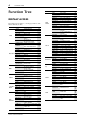 4
4
-
 5
5
-
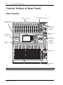 6
6
-
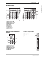 7
7
-
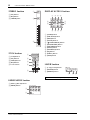 8
8
-
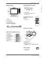 9
9
-
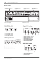 10
10
-
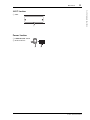 11
11
-
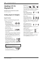 12
12
-
 13
13
-
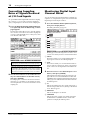 14
14
-
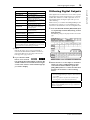 15
15
-
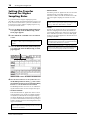 16
16
-
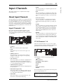 17
17
-
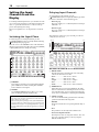 18
18
-
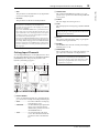 19
19
-
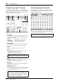 20
20
-
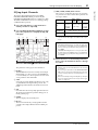 21
21
-
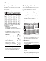 22
22
-
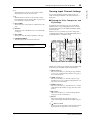 23
23
-
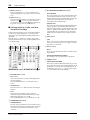 24
24
-
 25
25
-
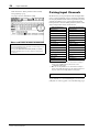 26
26
-
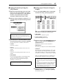 27
27
-
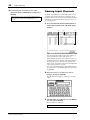 28
28
-
 29
29
-
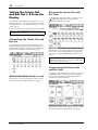 30
30
-
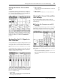 31
31
-
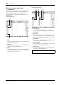 32
32
-
 33
33
-
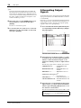 34
34
-
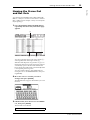 35
35
-
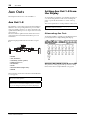 36
36
-
 37
37
-
 38
38
-
 39
39
-
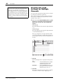 40
40
-
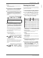 41
41
-
 42
42
-
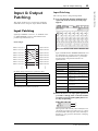 43
43
-
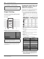 44
44
-
 45
45
-
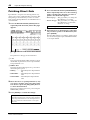 46
46
-
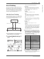 47
47
-
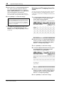 48
48
-
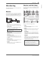 49
49
-
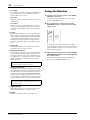 50
50
-
 51
51
-
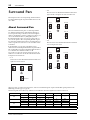 52
52
-
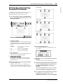 53
53
-
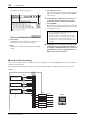 54
54
-
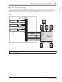 55
55
-
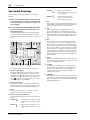 56
56
-
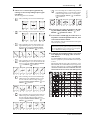 57
57
-
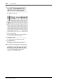 58
58
-
 59
59
-
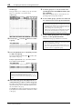 60
60
-
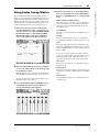 61
61
-
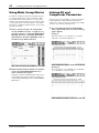 62
62
-
 63
63
-
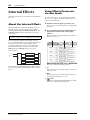 64
64
-
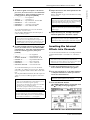 65
65
-
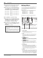 66
66
-
 67
67
-
 68
68
-
 69
69
-
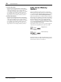 70
70
-
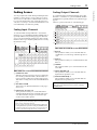 71
71
-
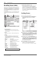 72
72
-
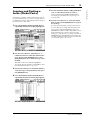 73
73
-
 74
74
-
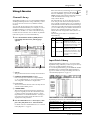 75
75
-
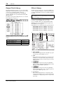 76
76
-
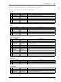 77
77
-
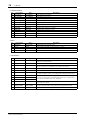 78
78
-
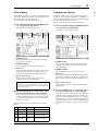 79
79
-
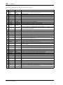 80
80
-
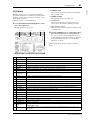 81
81
-
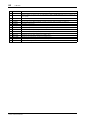 82
82
-
 83
83
-
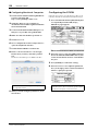 84
84
-
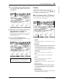 85
85
-
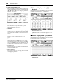 86
86
-
 87
87
-
 88
88
-
 89
89
-
 90
90
-
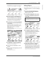 91
91
-
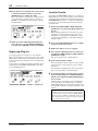 92
92
-
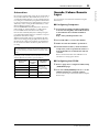 93
93
-
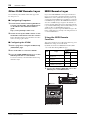 94
94
-
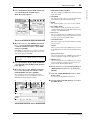 95
95
-
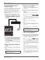 96
96
-
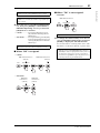 97
97
-
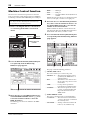 98
98
-
 99
99
-
 100
100
-
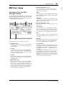 101
101
-
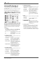 102
102
-
 103
103
-
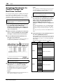 104
104
-
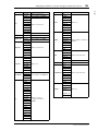 105
105
-
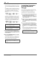 106
106
-
 107
107
-
 108
108
-
 109
109
-
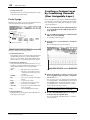 110
110
-
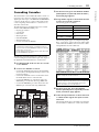 111
111
-
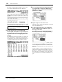 112
112
-
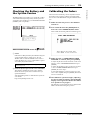 113
113
-
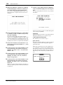 114
114
-
 115
115
-
 116
116
-
 117
117
-
 118
118
-
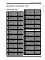 119
119
-
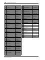 120
120
-
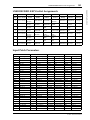 121
121
-
 122
122
-
 123
123
-
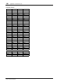 124
124
-
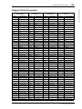 125
125
-
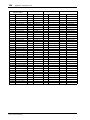 126
126
-
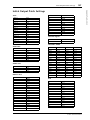 127
127
-
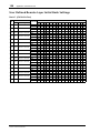 128
128
-
 129
129
-
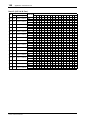 130
130
-
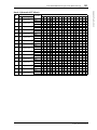 131
131
-
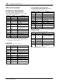 132
132
-
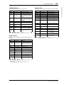 133
133
-
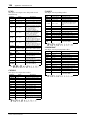 134
134
-
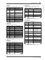 135
135
-
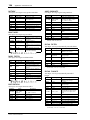 136
136
-
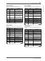 137
137
-
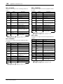 138
138
-
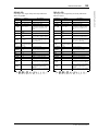 139
139
-
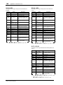 140
140
-
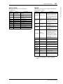 141
141
-
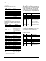 142
142
-
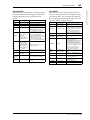 143
143
-
 144
144
-
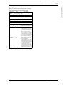 145
145
-
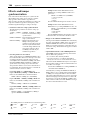 146
146
-
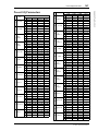 147
147
-
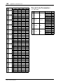 148
148
-
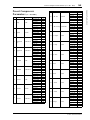 149
149
-
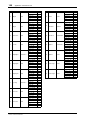 150
150
-
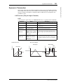 151
151
-
 152
152
-
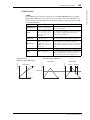 153
153
-
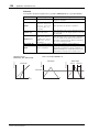 154
154
-
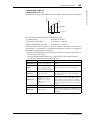 155
155
-
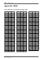 156
156
-
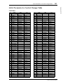 157
157
-
 158
158
-
 159
159
-
 160
160
-
 161
161
-
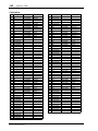 162
162
-
 163
163
-
 164
164
-
 165
165
-
 166
166
-
 167
167
-
 168
168
-
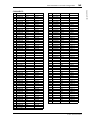 169
169
-
 170
170
-
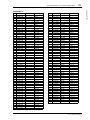 171
171
-
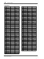 172
172
-
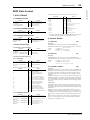 173
173
-
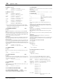 174
174
-
 175
175
-
 176
176
-
 177
177
-
 178
178
-
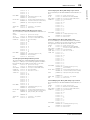 179
179
-
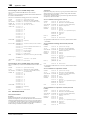 180
180
-
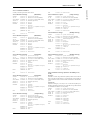 181
181
-
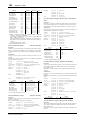 182
182
-
 183
183
-
 184
184
-
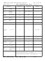 185
185
-
 186
186


Yamaha 01V96i Manual de usuario
- Categoría
- Equipo de música suplementario
- Tipo
- Manual de usuario
- Este manual también es adecuado para
En otros idiomas
- français: Yamaha 01V96i Manuel utilisateur
- italiano: Yamaha 01V96i Manuale utente
- English: Yamaha 01V96i User manual
- Deutsch: Yamaha 01V96i Benutzerhandbuch
- русский: Yamaha 01V96i Руководство пользователя
- Nederlands: Yamaha 01V96i Handleiding
- português: Yamaha 01V96i Manual do usuário
- dansk: Yamaha 01V96i Brugermanual
- polski: Yamaha 01V96i Instrukcja obsługi
- čeština: Yamaha 01V96i Uživatelský manuál
- svenska: Yamaha 01V96i Användarmanual
- Türkçe: Yamaha 01V96i Kullanım kılavuzu
- suomi: Yamaha 01V96i Ohjekirja
- română: Yamaha 01V96i Manual de utilizare
Documentos relacionados
-
Yamaha V96i El manual del propietario
-
-
-
-
Yamaha V96i Guía del usuario
-
-
Yamaha DM2000 El manual del propietario
-
-
-
Otros documentos
-
Sharp 8M-B120C guía de instalación rápida
-
-
Sharp CP-LS100 High Performance Portable Speaker Manual de usuario
-
Alesis BASSFIRE 60 Manual de usuario
-
Sigma R500T EOX Remote 500 Smart Control Center Manual de usuario
-
Universal Remote Control TOTAL CONTROL FX-1 El manual del propietario
-
Sigma EOX REMOTE 500 E-Bike Manual de usuario
-
Sigma EOX View 1300 Guía del usuario
-
Ashdown Engineering MF 484 2.N Manual de usuario
-
Blackmagic Ultimatte Manual de usuario