dbx 240 El manual del propietario
- Categoría
- Ecualizadores de audio
- Tipo
- El manual del propietario
Este manual también es adecuado para

User Manual/Manual de Instrucciones
Complete Equalization & Loudspeaker Management System
Completo sistema de ecualización y gestión de altavoces
240
241
®
®

WARNING FOR YOUR PROTECTION
PLEASE READ THE FOLLOWING:
KEEP THESE INSTRUCTIONS.
HEED ALL WARNINGS.
FOLLOW ALL INSTRUCTIONS.
CLEAN ONLY WITH A DAMP CLOTH.
DO NOT BLOCK ANY OF THE VENTILATION OPENINGS. INSTALL IN ACCORDANCE WITH
THE MANUFACTURERS INSTRUCTIONS.
DO NOT INSTALL NEAR ANY HEAT SOURCES SUCH AS RADIATORS, HEAT REGISTERS,
STOVES; OR OTHER APPARATUS (INCLUDING AMPLIFIERS) THAT PRODUCE HEAT.
ONLY USE ATTACHMENTS/ACCESSORIES SPECIFIED BY THE MANUFACTURER.
UNPLUG THIS APPARATUS DURING LIGHTNING STORMS OR WHEN UNUSED FOR LONG
PERIODS OF TIME.
WATER AND MOISTURE: Appliance should not be used near water (e.g. near a bathtub,
washbowl, kitchen sink, laundry tub, in a wet basement, or near a swimming pool, etc).
Care should be taken so that objects do not fall and liquids are not spilled into the enclosure
through openings.
POWER SOURCES: The appliance should be connected to a power supply only of the type
described in the operating instructions or as marked on the appliance.
GROUNDING OR POLARIZATION: Precautions should be taken so that the grounding or
polarization means of an appliance is not defeated.
POWER CORD PROTECTION: Power supply cords should be routed so that they are not likely
to be walked on or pinched by items placed upon or against them, paying particular attention
to cords at plugs, convenience receptacles, and the point where they exit from the appliance.
SERVICING: To reduce the risk of fire or electric shock, the user should not attempt to
service the appliance beyond that described in the operating instructions. All other
servicing should be referred to qualified service personnel.
FOR UNITS EQUIPPED WITH EXTERNALLY ACCESSIBLE FUSE RECEPTACLE: Replace
fuse with same type and rating only.
MULTIPLE-INPUT VOLTAGE: This equipment may require the use of a different line cord,
attachment plug, or both, depending on the available power source at installation. Connect this
equipment only to the power source indicated on the equipment rear panel. To reduce the risk
of fire or electric shock, refer servicing to qualified service personnel or equivalent.
POWER ON / OFF SWITCH: The Power Switch used in this piece of equipment DOES NOT
break the connection from the Mains.
AVISO PARA SU PROTECCION
LEA LO SIGUIENTE:
CONSERVE ESTAS INSTRUCCIONES.
TENGA EN CUANTA TODAS LAS ADVERTENCIAS QUE LE HACEMOS.
SIGA TODAS LAS INSTRUCCIONES.
LIMPIE EL APARATO SOLO CON UN TRAPO LIGERAMENTE HUMEDO.
NO TAPE NINGUNA DE LAS MUESCAS DE VENTILACION. INSTALE EL APARATO DE
ACUERDO A LAS INSTRUCCIONES DEL FABRICANTE.
NO COLOQUE EL APARATO CERCA DE NINGUNA FUENTE DE CALOR COMO
RADIADORES, CALENTADORES, ESTUFAS U OTROS APARATOS (INCLUIDOS
AMPLIFICADORES) QUE PRODUZCAN CALOR.
USE SOLO LOS ACCESORIOS ESPECIFICADOS POR EL FABRICANTE.
DESCONECTE EL APARATO DURANTE LAS TORMENTAS ELECTRICAS O SI NO LO VA A
USAR DURANTE BASTANTE TIEMPO.
AGUA Y HUMEDAD: No utilice los aparatos cerca del agua (p.ej. cerca de una bañera,
fregadero, lavabo, lavadora, en un sótano húmedo o cerca de una piscina, etc.). Evite que se
introduzca ningún objeto o líquido dentro de la carcasa a través de las aberturas.
FUENTES DE ALIMENTACION: El aparato debe ser conectado a una fuente de alimentación
sólo del tipo descrito en las instrucciones o en el propio aparato.
TIERRA Y POLARIZACION: Ha de tomar precauciones para que la toma a tierra o
polarización de un aparato nunca sea anulada.
PROTECCION DEL CABLE DE ALIMENTACION: Coloque los cables de alimentación de
modo que resulte difícil el que puedan quedar aplastados por elementos colocados encima
o junto a ellos o que puedan ser pisados, especialmente los cables conectados a enchufes,
los propios enchufes y el punto en el que salen del aparato.
REPARACION: Para evitar incendios o descargas eléctricas, no intente reparar el aparato
más allá de lo descrito en las instrucciones de funcionamiento. Cualquier otra reparación
debe ser realizadas por un servicio técnico autorizado.
PARA UNIDADES EQUIPADAS CON FUSIBLE ACCESIBLE DESDE EL EXTERIOR: Sustituya
el fusible solo por otro del mismo tipo y valor.
VOLTAJE DE ENTRADA MULTIPLE: Este equipo puede necesitar el uso de un cable de
alimentación o enchufe diferente, o ambos, dependiendo de la fuente de la salida de
corriente disponible en la instalación. Conecte este equipo sólo a la fuente de alimentación
indicada en el panel trasero del equipo. Para prevenir incendios o descargas eléctrica, dirija
cualquier reparación a un servicio técnico autorizado.
INTERRUPTOR DE ENCENDIDO: El interruptor de encendido de este aparato NO ROMPE la
conexión con la salida de corriente.
SAFETY INSTRUCTIONS
NOTICE FOR CUSTOMERS IF YOUR UNIT IS EQUIPPED WITH A POWER CORD.
WARNING: THIS APPLIANCE MUST BE EARTHED.
The cores in the mains lead are coloured in accordance with the following code:
GREEN and YELLOW - Earth BLUE - Neutral BROWN - Live
As colours of the cores in the mains lead of this appliance may not correspond with the coloured
markings identifying the terminals in your plug, proceed as follows:
• The core which is coloured green and yellow must be connected to the terminal in the plug marked
with the letter E, or with the earth symbol, or coloured green, or green and yellow.
• The core which is coloured blue must be connected to the terminal marked N or coloured black.
• The core which is coloured brown must be connected to the terminal marked L or coloured red.
This equipment may require the use of a different line cord, attachment plug, or both, depending on the
available power source at installation. If the attachment plug needs to be changed, refer servicing to
qualified service personnel who should refer to the table below. The green/yellow wire shall be
connected directly to the units chassis.
WARNING: If the ground is defeated, certain fault conditions in the unit or in the system to which it is
connected can result in full line voltage between chassis and earth ground. Severe injury or death can
then result if the chassis and earth ground are touched simultaneously.
INSTRUCCIONES DE SEGURIDAD
AVISO PARA LOS USUARIOS SI LA UNIDAD ESTA EQUIPADA CON UN CABLE DE ALIMENTACION.
AVISO: ESTE APARATO DEBE SER CONECTADO A UNA TOMA DE TIERRA.
Los cables de alimentación vienen indicados con el siguiente código de color:
VERDE y AMARILLO - Tierra AZUL - Neutro MARRON - Fase
Dado que los colores de los hilos del cable de alimentación de este aparato puede que no coincidan
con los colores que identifican los hilos de su enchufe, siga los siguientes pasos:
• El hilo de color verde y amarillo ha de ser conectado al hilo del enchufe marcado con la letra E o con
el símbolo de tierra, o de color verde, o verde y amarillo.
• El hilo de color azul ha de ser conectado al hilo marcado con la letra N o de color negro.
• El hilo de color marrón ha de ser conectado al hilo marcado con la letra L o de color rojo.
Este equipo puede necesitar el uso de un cable de alimentación o un enchufe diferente, o ambos,
dependiendo de la fuente de alimentación disponible en la instalación. Si en algún momento necesita
cambiar el enchufe, vaya a un servicio técnico cualificado, quienes deberán consultar la siguiente tabla.
Conecte el hilo verde/amarillo directamente a la carcasa de la unidad.
AVISO: Si la toma de tierra es anulada, determinadas averías de la unidad o del sistema al que esté
conectado podrán producir un voltaje de línea completa entre la carcasa y el suelo. Si toca la carcasa
y el suelo simultáneamente corre el riesgo de que esto pueda producirle graves daños o incluso la
muerte.
LIVE/FASE
E
NEUTRAL/NEUTRO
EARTH GND/
TIERRA
CONDUCTOR/
CONDUCTOR
L
N
BROWN/MARRON
BLUE/AZUL
GREEN/YEL/
VERDE/AMARILLO
BLACK/NEGRO
Normal/Normal Alt/Alternativa
WIRE COLOR/COLOR DEL HILO
WHITE/BLANCO
GREEN/VERDE
The symbols shown above are internationally accepted symbols that warn of potential hazards with
electrical products. The lightning flash with arrowpoint in an equilateral triangle means that there are
dangerous voltages present within the unit. The exclamation point in an equilateral triangle indicates
that it is necessary for the user to refer to the owner’s manual.
These symbols warn that there are no user serviceable parts inside the unit. Do not open the unit. Do
not attempt to service the unit yourself. Refer all servicing to qualified personnel. Opening the chassis
for any reason will void the manufacturer’s warranty. Do not get the unit wet. If liquid is spilled on the
unit, shut it off immediately and take it to a dealer for service. Disconnect the unit during storms to
prevent damage.
Los símbolos de arriba están aceptados internacionalmente y quieren advertirle de los peligros
potenciales de los aparatos eléctricos. El rayo dentro del triángulo equilátero advierte de la presencia
de voltajes peligrosos dentro de la unidad. El signo de exclamación en el triángulo equilátero significa
que es necesario que el usuario lea el manual de instrucciones.
Estos símbolos le advierten que no hay piezas reparables por el usuario dentro de la unidad. No abra
la unidad. No intente reparar la unidad usted mismo. Dirija cualquier reparación a personal cualificado.
El abrir la carcasa por cualquier razón anulará la garantía del fabricante. No moje la unidad. Si se
derraman líquidos sobre la unidad, apáguela inmediatamente y llévela a un servicio técnico para
reparación. Desconecte la unidad durante las tormentas para evitar daños.
CAUTION
ATTENTION: RISQUE DE CHOC ELECTRIQUE - NE PAS OUVRIR
WARNING: TO REDUCE THE RISK OF FIRE OR ELECTRIC
SHOCK DO NOT EXPOSE THIS EQUIPMENT TO RAIN OR MOISTURE
RISK OF ELECTRIC SHOCK
DO NOT OPEN
IMPORTANT SAFETY INSTRUCTIONS
INSTRUCCIONES IMPORTANTES DE SEGURIDAD

U.K. MAINS PLUG WARNING
A molded mains plug that has been cut off from the cord is
unsafe. Discard the mains plug at a suitable disposal facility.
NEVER UNDER ANY CIRCUMSTANCES SHOULD YOU INSERT
A DAMAGED OR CUT MAINS PLUG INTO A 13 AMP POWER
SOCKET. Do not use the mains plug without the fuse cover in
place. Replacement fuse covers can be obtained from your
local retailer. Replacement fuses are 13 amps and MUST be
ASTA approved to BS1362.
ADVERTENCIA PARA LOS USUARIOS DEL REINO
UNIDO
Un enchufe de alimentación que haya sido cortado del cable
es inseguro. Nunca utilice cables montados de esta forma por
medio de distintos enchufes y cables no originales. BAJO
NINGUNA CIRCUNSTANCIA INTRODUZCA UN CONECTOR O
CABLE DAÑADO O CORTADO EN UN ENCHUFE DE 13
AMPERIOS. No use el conector de alimentación sin la tapa del
fusible en su lugar. Puede adquirir tapas de fusible de
recambio en su tienda de electricidad más próxima. Los
fusibles son de 13 amperios y DEBEN de estar aprobados por
la ASTA a BS1362.
LITHIUM BATTERY
WARNING
CAUTION!
This product may contain a lithium battery.There is danger of
explosion if the battery is incorrectly replaced. Replace only
with an Eveready CR 2032 or equivalent. Make sure the
battery is installed with the correct polarity. Discard used
batteries according to manufacturer’s instructions.
ADVARSEL!
Lithiumbatteri - Eksplosjonsfare.Ved utskifting benyttes kun
batteri som anbefalt av apparatfabrikanten. Brukt batteri
returneres apparatleverandøren.
ADVARSEL!
Lithiumbatteri - Eksplosionsfare ved fejlagtig håndtering.
Udskiftning må kun ske med batteri av samme fabrikat og
type. Levér det brugte batteri tilbage til leverandøren.
VAROITUS!
Paristo voi räjähtää, jos se on virheellisesti asennettu.Vaihda
paristo ainoastaan laitevalmistajan suosittelemaan tyyppin.
Hävitä käytetty paristo valmistajan ohjeiden mukaisesti.
VARNING!
Explosionsfara vid felaktigt batteribyte.Använd samma
batterityp eller en ekvivalent typ som rekommenderas av
apparattillverkaren. Kassera använt batteri enligt fabrikantens
instruktion.
IMPORTANT SAFETY INSTRUCTIONS
INSTRUCCIONES IMPORTANTES DE SEGURIDAD
ELECTROMAGNETIC
COMPATIBILITY
This unit conforms to the Product Specifications noted on the
Declaration of Conformity.Operation is subject to the following two
conditions:
• this device may not cause harmful interference, and
• this device must accept any interference received, including
interference that may cause undesired operation.
Operation of this unit within significant electromagnetic fields should be
avoided.
• use only shielded interconnecting cables.
COMPATIBILIDAD
ELECTROMAGNETICA
Esta unidad cumple las Especificaciones de Producto indicadas en la
Declaración de Conformidad. Su funcionamiento está sujeto a las dos
condiciones siguientes:
• este aparato no puede causar interferencias dañinas, y
• este aparato debe aceptar cualquier interferencia recibida,
incluyendo interferencias que puedan provocar un funcionamiento
no deseado.
Evite el funcionamiento de esta unidad dentro de campos
electromagnéticos potentes.
• use sólo cables de interconexión blindados.
DECLARATION OF
CONFORMITY
Manufacturer’s Name: dbx Professional Products
Manufacturer’s Address: 8760 S. Sandy Parkway
Sandy, Utah 84070, USA
declares that the product:
Product name: dbx DriveRack™ 240 and 241
Note: product may be suffixed by the letters EU.
Product option: None
conforms to the following Product Specifications:
Safety: EN 60065 (1993)
IEC65 (1985) with
Amendments 1,2,3
CAN/CSA E65-94
EMC: EN 55013 (1990)
EN 55020 (1991)
Supplementary Information:
The product herewith complies with the
requirements of the Low Voltage Directive
73/23/EEC and the EMC Directive 89/336/EEC as
amended by Directive 93/68/EEC.
dbx Professional Products
Vice-President of Engineering
8760 S. Sandy Parkway
Sandy, Utah 84070, USA
February 8, 2001
European Contact: Your Local dbx Sales and Service Office or
Harman Music Group
8760 South Sandy Parkway Sandy, Utah 84070
USA
PH: (801) 566-8800 FX: (801) 568-7583
CONFORMIDAD
Nombre del fabricante: dbx Professional Products
Dirección del fabricante: 8760 S. Sandy Parkway
Sandy, Utah 84070, USA
Declara que el producto:
Nombre del producto: dbx DriveRack™ 240 and 241
Nota: product may be suffixed by the letters EU.
Opción del producto: None
Cumple las siguientes Especificaciones de Producto:
Seguridad: EN 60065 (1993)
IEC65 (1985) with
Amendments 1,2,3
CAN/CSA E65-94
EMC: EN 55013 (1990)
EN 55020 (1991)
Información complementaria:
El producto cumple con los requisitos de la
Directiva de Baja Tensión 73/23/EEC y la
Directiva EMC 89/336/EEC enmendada por la
Directiva 93/68/EEC.
dbx Professional Products
Vicepresidente técnico
8760 S. Sandy Parkway
Sandy, Utah 84070, USA
February 8, 2001
Contacto en Europa: Su vendedor local dbx y servicio técnico oficial o
Harman Music Group
8760 South Sandy Parkway Sandy, Utah 84070
USA
Tfno
: (801) 566-8800 FX: (801) 568-7583

Ta b le of Contents/Indice
DriveRack
™
Introduction/Introducción
0.1 Defining the 240/241DriveRack™/Definición del Sistema 240/241DriveRack™..ii
0.2 Service Contact Info/Información de contacto para reparaciones ..iii
0.3 Warranty/Garantía ...............................................................................iv
0.4 Quick Start/Arranque rápido...............................................................v
Section 1 - Getting Started/Sección 1 - Inicio
1.1 Rear Panel Connections (240)/Conexiones del panel trasero (240) 2
1.2 Front Panel (240)/Panel frontal (240) ...............................................2
1.3 Rear Panel Connections (241)/Conexiones del panel trasero (241) 3
1.4 Front Panel (241)/Panel frontal (241) ...............................................4
Section 2 - Editing Functions/Sección 2 - Funciones de Edición
2.1 Basic Navigation Modes/Modos básicos de navegación...................6
2.2 Button Array Overview/Disposición de los botones.........................6
2.3 Navigating the Pre-EQ Section/Navegación por la sección pre-ecualizador.8
2.4 Navigating the Post-EQ Section/Navegación por la sección post-ecualizador.8
2.5 Navigating the Xover Sections/Navegación por las secciones de crossover.9
2.6 Navigating the Delay Section/Navegación por la sección de retardo ..........9
2.7 Navigating the Dynamics Section/Navegación por la sección de dinamismo10
2.8 Navigating the I/O Section/Navegación por la sección de E/S......10
2.9 Navigating the Utility Section/Navegación por la sección de utilidades10
Section 3 - Configuring the DriveRack/Sección 3 - Configuración del DriveRack
3.1 Program Definition/Definición de programa ...................................12
3.2 Navigating Factory Programs/Navegación por los programas de fábrica...12
3.3 Editing Factory Programs/Edición de los programas de fábrica ....13
3.4 Saving Factory Program Changes/Almacenamiento de los cambios sobre
los programas de fábrica .................................................................................14
3.5 Creating a User Configuration/Creación de una configuración de usuario 15
3.6 Saving Configuration Changes/Almacenamiento de cambios de configuración18
Section 4 - Detailed Parameters/Sección 4 - Parámetros detallados
4.1 Input Routing/Direccionamiento de entrada ...................................20
4.2. Pre-Crossover EQ/Pre-Crossover (ecualización).................................................................20
4.3 Delay (Pre-Crossover)/Retardo (Pre-Crossover) ..............................21
4.4 Crossover (XOVER)/Crossovers (XOVER)........................................22
4.5 Post-Crossover Parametric EQ/Ecualizador paramétrico post-crossover.....26
4.6 Compressor/Limiter (Dynamics)/Compresor / limitador (dinamismo)26
4.7 Speaker Alignment Delay/Retardo de alineación de altavoces ......28
4.8 OutputRouting/Salida.........................................................................28
Section 5 - Utilities/Sección 5 - Utilidades
5.1 Security Levels/Niveles de seguridad ...............................................30
5.2 Security Passwords/Contraseña de seguridad..................................31
5.3 Entering Security Password/Introducción de la contraseña de seguridad ..31
5.4 Program Change/Program list/Lista de programas / cambio de programa32
5.5 Contrast Adjustment/Ajuste de contraste..........................................33
5.6 Power-up (Mutes/Saved)/Encendido (anulación / grabación) .......34
5.7 Load Stored/Carga almacenada.........................................................34
5.8 Switch Closure option/Opción de cierre de interruptor .................35
Section 6 - DriveWare™ GUI/Sección 6 - DriveWare™ GUI
6.1 PC GUI Installation/Instalación GUI.................................................38
System Requirements/Requisitos del sistema.........................................38
Install/Instalación .....................................................................................38
Basic operation/Funcionamiento básico.................................................38
Cable specs/Especificaciones de los cables ...........................................40
Section 7 - Application Guide/Sección 7 - Guía de aplicación
7.1 2-Way FOH/FOH de dos vías ...........................................................42
7.2 2x4 Delay Cabinets/Recintos 2x4 con retardo.................................43
7.3 L-C-R w/Sub/Izquierdo-central-derecho + subwoofer ....................44
7.4 Multi-Zone Controller/Controlador multizonas................................45
7.5 Time Delay/Retardo de tiempo ........................................................46
7.6 Programmable Insert/Inserción programable...................................47
7.7 Single Room Multi-Zone/Multizonas en sala única .........................48
Appendix/Apéndices
A.1 Factory Reset/Reinicialización a los valores de fábrica ..................50
A.2 Power up Quick Key Options/Opciones de teclas rápidas para el encendido 50
A.3 Flash Downloads/Volcados rápidos .................................................51
A.4 Program List/Lista de programas......................................................51
A.5 Specifications/Especificaciones.........................................................52
A.6 Crossover Diagrams/Diagramas de crossover .................................55
A.7 Gain Level Jumpers/Puentes de nivel de ganacia ..........................56
A.8 Input and Output Section Diagrams/Diagramas de sección de entrada y salida57
®
DriveRack™ User Manual/ Manual de Instrucciones
Table of Contents/Table of Contents

INTRO
CUSTOMER SERVICE INFO
Defining the DriveRack
WARRANTY INFO
INTRO
INFORMACION DE CONTACTO
PARA REPARACIONES
Definición del DriveRack
GARANTIA
®
INTRODUCTION/INTRODUCCION
DriveRack
™
Section i/Sección i

Introduction/Introducción
®
DriveRack™ User Manual/Manual de Instrucciones
ii
DriveRack
™
Congratulations on your purchase of the dbx 240/241DriveRack™
Complete Equalization and Loudspeaker Management System! For over 25
years, dbx has been the industry leader in dynamics processing. With the
introduction of the DriveRack™, dbx Professional Products has redefined
the standard by which all other loudspeaker management systems will be
based.
This manual will be your guide to understanding the full functionality of
the powerful 240 and 241 DriveRack™ units. By combining the different
components, the configuration possibilities are limitless. After you have
become familiar with the unit, we encourage you to experiment and find
the most effective and efficient way to run your system by utilizing the
powerful processing of the DriveRack™.
The dbx 240/241 DriveRack™ is the most effective way to manage all
aspects of post mixer processing and signal routing. The 240/241
DriveRack essentially becomes the only device that you will need
between the mixer and the power amps. The following are just some of
the features of the 240 and 241 DriveRack™ units.
240 DriveRack™ features:
• 2 Inputs and 4 Outputs
• Fully functional user interface
• Balanced XLR and Euroblock Connectors
• 31-band graphic or 9-band parametric equalizer on every input
• Multiple Crossover Configurations including Butterworth,
Bessel or Linkwitz-Riley filter topologies
• Loudspeaker Cluster and Transducer Alignment Delays
• 4-band Parametric EQ Post crossover per output. Selectable
shelves or bell curves. 1/12 octave centers, Q selectable from
0.20 to 16.
• dbx
®
Compression/Limiting
• Multi-level Security System
• Patented dbx
®
TYPE IV
®
Analog to Digital Conversion System
• PC DriveWare Interface
• Remote Switch Closure Interface
241 DriveRack™ features:
• 2 Inputs and 4 Outputs
• Balanced XLR and Euroblock Connectors
• 31-band graphic or 9-band parametric equalizer on every input
• Multiple Crossover Configurations including Butterworth,
Bessel or Linkwitz-Riley filter topologies
• Loudspeaker Cluster and Transducer Alignment Delays
• 4-band Parametric EQ Post crossover per output. Selectable
shelves or bell curves. 1/12 octave centers, Q selectable from
0.20 to 16.
¡Felicidades por la compra del sistema completo de ecualización y gestión
de altavoces dbx DriveRack™ 240/241! Desde hace 25 años, dbx ha sido
la empresa líder en el campo del procesado dinámico. Con la
presentación del DriveRack™, dbx Professional Products ha redefinido el
standard de referencia para los sistemas de gestión de altavoces.
Este manual le ayudará a comprender toda la funcionalidad de las
potentes unidades 240 y 241 DriveRack™. Combinando los distintos
componentes, las posibilidades de configuración son infinitas. Una vez
que se haya familiarizado con la unidad, le recomendamos que haga sus
propias pruebas y encuentre la forma más efectiva y directa de hacer
funcionar su sistema utilizando el potente procesado del DriveRack™.
El dbx DriveRack™ es la forma más eficaz de gestionar todos los aspectos
del procesado post-mezcla y del direccionamiento de señal. El DriveRack
240/241 se convierte esencialmente en el único aparato que necesitará
entre la mesa de mezclas y sus etapas de potencia. A continuación le
indicamos algunas de las funciones de las unidades DriveRack™ 240 y 241.
Características del 240 DriveRack™ :
• 2 entradas and 4 salidas
• Interface de usuario completamente funcional
• Conectores XLR y Euroblock balanceados
• Ecualizador gráfico de 31bandas o paramétrico de 9 bandas en
cada entrada
• Múltiples configuraciones de crossover incluyendo tipologías
de filtro Butterworth, Bessel o Linkwitz-Riley
• Retardos de alineación de transductor y bloque central de altavoces
• EQ paramétrico de 4 bandas post-crossover por salida. Curvas
de estantería o de tipo campana seleccionables con centros en
1/12 de octava, Q seleccionable desde 0.20 a 16
• Compresor/Limitador dbx
®
• Sistema de seguridad multinivel
• Sistema de conversión analógico a digital TYPE IV™ patentado por dbx
• Interface DriveWare PC
• Interface de cierre de interruptor a distancia
Características del 241 DriveRack™:
• 2 entradas and 4 salidas
• Conectores XLR y euroblock balanceados
• Ecualizador gráfico de 31bandas o paramétrico de 9 bandas en
cada entrada
• Múltiples configuraciones de crossover incluyendo tipologías
de filtro Butterworth, Bessel o Linkwitz-Riley
• Retardos de alineación de transductor y bloque central de
altavoces
• EQ paramétrico de 4 bandas post-crossover por salida. Curvas
de estantería o de tipo campana seleccionables con centros en
1/12 de octava, Q seleccionable desde 0.20 a 16
INTRODUCTION
0.1 Defining the 240/241 DriveRack™ System 0.1 0.1 Definición del Sistema DriveRack™ 240/241
INTRODUCCION
Section i/Sección i

®
Introduction/Introducción
DriveRack
™
DriveRack™ User Manual/Manual de Instrucciones
• dbx
®
Compression/Limiting
• Multi-level Security System
• Patented dbx
®
TYPE IV
™
Analog to Digital Conversion System
• PC DriveWare Interface
• Remote Switch Closure Interface
By including every form of processing necessary to drive the signal from
the mixer to the power amp, the 240/241 DriveRack™ allows you to
eliminate all other processing devices that are normally found in large and
cumbersome traditional drive rack systems of the past.
The 240/241 DriveRack™ Loud Speaker Management System includes two
balanced XLR and Euroblock inputs, as well as four balanced XLR and
Euroblock output connectors, which can be routed for any configuration.
The 241 DriveRack™ features the identical processing power of the 240
DriveRack, but only offers limited editing functionality from the front
panel.
If you require technical support, contact dbx Customer Service. Be
prepared to accurately describe the problem. Know the serial number of
your unit - this is printed on a sticker attached to the top panel. If you
have not already taken the time to fill out your warranty registration card
and send it in, please do so now.
Before you return a product to the factory for service, we recommend you
refer to the manual. Make sure you have correctly followed installation
steps and operation procedures. If you are still unable to solve a problem,
contact our Customer Service Department at (801) 568-7660 for
consultation. If you need to return a product to the factory for service,
you MUST contact Customer Service to obtain a Return Authorization
Number.
No returned products will be accepted at the factory without a Return
Authorization Number.
Please refer to the Warranty information on the following page, which
extends to the first end-user. After expiration of the warranty, a
reasonable charge will be made for parts, labor, and packing if you
choose to use the factory service facility. In all cases, you are responsible
for transportation charges to the factory. dbx will pay return shipping if
the unit is still under warranty.
Use the original packing material if it is available. Mark the package with
the name of the shipper and with these words in red: DELICATE
INSTRUMENT, FRAGILE! Insure the package properly. Ship prepaid, not
collect. Do not ship parcel post.
• Compresor/Limitador dbx
®
• Sistema de seguridad multinivel
• Sistema de conversión analógico a digital TYPE IV™ patentado por dbx
• Interface DriveWare PC
• Interface de cierre de interruptor a distancia
Al incluir todas las formas de procesado necesarias para el control de la
señal desde el mezclador hasta la etapa de potencia, los DriveRack™
240/241 le permiten prescindir del resto de unidades de procesado que
se encontraban normalmente en uno de esos gigantescos e incómodos
sistemas de unidades de control en rack tradicionales hace algunos años.
El sistema de gestión de altavoces DriveRack™ 240/241 incluye dos
entradas balanceadas XLR y euroblock, así como cuatro salidas
balanceadas XLR y euroblock, que pueden ser direccionadas en cualquier
configuración. El DriveRack™ 241 disponen del mismo potencial de
procesado que el del 240, pero le ofrece unas funciones de edición algo
más limitadas desde su panel frontal.
Si necesita asistencia técnica, contacte con el Servicio de Atención al
Cliente dbx. Esté preparado para describir con precisión el problema.
Debe saber el número de serie de su unidad – está impreso en una
pegatina colocada en el panel trasero. Si todavía no ha rellenado su tarjeta
de registro de garantía y no la ha enviado, hágalo ahora.
Antes de devolver un aparato a fábrica para su reparación, le
recomendamos que consulte este manual. Asegúrese de haber seguido
correctamente los pasos de instalación y los procesos operativos. Si aun
así es incapaz de solucionar el problema, contacte con nuestro
Departamento de Servicio de Atención al Cliente en el (801) 568-7660. Si
necesita devolver un aparato a fábrica para su reparación, DEBERA
contactar con nuestro Servicio de Atención al Cliente para que le asignen
un Número de autorización de devolución.
En fábrica no aceptaremos ningún aparato sin su correspondiente número
de autorización de devolución.
Consulte la garantía siguiente, que cubre al primer usuario final. Tras el
vencimiento de esta garantía, en cualquier reparación que hagamos en
fábrica tendremos que cobrarle las piezas, mano de obra y el embalaje.
Sea cual sea el caso, deberá enviar el aparato a fábrica a portes pagados.
dbx se lo devolverá también a portes pagados si la unidad está todavía
en garantía.
Utilice el embalaje original siempre que sea posible. Marque el embalaje
con el nombre del transportista y con estas palabras en rojo:
INSTRUMENTO DELICADO ¡FRAGIL!. Es recomendable que contrate un
seguro de transporte. Envíe el paquete a portes pagados, no debidos. No
lo envíe por correo.
iii
0.2 Service Contact Info 0.2 Información de contacto para reparaciones
Section i/Sección i

Introduction/Introducción
®
DriveRack™ User Manual/Manual de Instrucciones
iv
DriveRack
™
This warranty is valid only for the original purchaser and only in the
United States.
1. The warranty registration card that accompanies this product must be
mailed within 30 days after purchase date to validate this warranty.
Proof-of-purchase is considered to be the burden of the consumer.
2. dbx warrants this product, when bought and used solely within the
U.S., to be free from defects in materials and workmanship under
normal use and service.
3. dbx liability under this warranty is limited to repairing or, at our
discretion, replacing defective materials that show evidence of defect,
provided the product is returned to dbx WITH RETURN
AUTHORIZATION from the factory, where all parts and labor will be
covered up to a period of two years. A Return Authorization number
must be obtained from dbx by telephone. The company shall not be
liable for any consequential damage as a result of the product's use in
any circuit or assembly.
4. dbx reserves the right to make changes in design or make additions to
or improvements upon this product without incurring any obligation to
install the same additions or improvements on products previously
manufactured.
5. The foregoing is in lieu of all other warranties, expressed or implied,
and dbx neither assumes nor authorizes any person to assume on its
behalf any obligation or liability in connection with the sale of this
product. In no event shall dbx or its dealers be liable for special or
consequential damages or from any delay in the performance of this
warranty due to causes beyond their control.
Todos los aparatos dbx son fabricados con el máximo cuidado. Las
condiciones de la garantía varían desde el momento en que los
distribuidores son distintos en cada país.
Si necesita cualquier información relacionada con las condiciones de la
garantía en su país, le rogamos que se ponga en contacto con su
distribuidor o comercio local
dbx es una marca registrada.
NOTA: La información contenida en este manual está sujeta a cambios en
cualquier momento sin previo aviso. Algunas de las informaciones
contenidas en este manual pueden incluso ser inexactadas debido a
modificaciones no documentadas en el aparato o en el sistema operativo
desde el momento de finalizar esta versión del manual. La información
contenida en este manual de instrucciones sustituye a la de versiones
anteriores.
0.3 Warranty 0.3 Garantía
Section i/Sección i

®
For those of you that wish to jump right in, the following information has
been provided to act as a quick start guide for optimizing performance of
the 240/241 DriveRack units.
Signal Path Block Diagram
The following diagram shows the logical and intuitive signal path of the
input, effect modules, and output of the 240 and 241 DriveRack units.
• When setting up the 240/241 DriveRack™, make connections
as follows:
•Make connections prior to powering the unit up.
• Connect the output from the sending device (mixer) to any
one of the two XLR or Euroblock input shown below. Note:
XLR and Euroblock connectors are wired in parallel.
• Make output connections from any one of the four output
XLR or Euroblock connectors shown below to the input of
the selected power amp.
• If application requires, make switch closure connections.
The DriveRack can power up with the outputs muted, this will
help ensure that damage can not be done to the speakers or
other subsequent equipment.
Para aquellos de ustedes que quieran empezar a usar ya su unidad,
hemos incluido la siguiente información para que le sirva como una guía
de arranque rápido de cara a optimizar el rendimiento de las unidades
DriveRack 240/241.
Diagrama de bloques de la ruta de señal
El diagrama siguiente le muestra la ruta de señal lógica e intuitiva de la
entrada, módulos de efectos y salida de las unidades DriveRack 240 y 241.
• Cuando esté ajustando el DriveRack‰ 240/241, haga las
conexiones de la forma que le indicamos a continuación
•Haga las conexiones antes de encender la unidad
• Conecte la salida de la unidad de envío de señal (mesa de
mezclas) a cualquiera de las dos entradas XLR o euroblock
que le mostramos abajo. Nota: Los conectores XLR y
euroblock están conectados en paralelo.
• Realice las conexiones de salida desde cualquiera de los
cuatro conectores de salida XLR o euroblock que mostramos
abajo a la entrada de la etapa de potencia que quiera.
• Si su aplicación lo requiere, realice las conexiones de cierre
de interruptor
Puede encender la unidad DriveRack con las salidas anuladas,
lo cual le ayudará a evitar que no se dañen los altavoces u
otros aparatos que vayan detrás.
Introduction/Introducción
Section i/Sección i
DriveRack
™
DriveRack™ User Manual/Manual de Instrucciones
v
0.4 Quick Start 0.4 Arranque rápido
Input
Mixer
Input
Mixer
GEQ/
PEQ
GEQ/
PEQ
Pre
Delay
Pre
Delay
PEQ
Meters
Inputs
1
2
Outputs
1
2
3
4
Gain/
Phase
Gain/
Phase
Gain/
Phase
Gain/
Phase
Crossover
PEQ
PEQ
PEQ
DYN
Comp/
Limit
DYN
Comp/
Limit
DYN
Comp/
Limit
DYN
Comp/
Limit
DELAY
DELAY
DELAY
DELAY
Meters
Limiter
Limiter
Limiter
Limiter

Introduction/Introducción
®
DriveRack™ User Manual/Manual de Instrucciones
vi
Section i/Sección i
DriveRack
™
Front Panel Navigation of the 240
DriveRack
• Once all of the connections have been made and the unit is
powered up you can navigate through the entire signal path
of the 240 DriveRack from the front panel of the unit. The
display provides you with a clear and concise overview of
each aspect of the signal path from the input to the output
section.
The features of the front panel of the 240 DriveRack are as
follows from left to right. LCD Display- all operational
information of the DriveRack is displayed here. The display
will also notify the user if any internal clipping is taking place
within the unit. The following messages will appear: CLIP:
Pre Xover (clipping prior to the crossover section), CLIP:
Post Xover (clipping past the crossover section), and CLIP:
Pre/Post (clipping in both sections).
Data Wheel - The data wheel is used to scroll through the
program menu of the 240 DriveRack™. The Data Wheel is also
used to perform editing functions to effects and utility menu
features. Button Array - Operational editing is done using this
12 button array. A complete description of each button’s
functionality is listed on the following page. Input meters-
These two 6-segment LED meters monitor the input level of
the 240 DriveRack directly after the input mixer. Output
meters - These four 6-segment meters monitor the output
levels of the 240 DriveRack directly after the output gain stage.
Mute buttons - These four mute buttons are used to instantly
mute the output signal of the selected channel.
Front Panel Navigation of the 241
DriveRack
• Once all of the rear panel connections have been made, you
can make your front or rear panel connections from the 241
to a PC. Due to its limited design, most operations
performed on the unit must be done through the use of the
included DriveWare™ GUI. The front panel controls of the
241 allow you to scroll through the program menu and load
the selected program. Clip note: In the event that there is
internal clipping within the signal path of the 241, “CL”
(indicating clipping) will briefly appear in the 7-segment
display.
Navegación con el panel frontal del
DriveRack 240
• Una vez que haya realizado todas las conexiones y haya
encendido la unidad, puede realizar retoques por la ruta de
señal completa del DriveRack 240 desde el panel frontal de
la unidad. La pantalla le irá facilitando información clara y
concisa de cada uno de los aspectos de esta ruta de señal
desde la sección de entrada a la de salida.
Las funciones del panel frontal del DriveRack 240 son las
siguientes (de izquierda a derecha). Pantalla LCD – aquí
aparece toda la información operativa del DriveRack. La
pantalla también le advertirá al usuario si se produce cualquier
saturación interna dentro de la unidad. Aparecerán los
mensajes siguientes: CLIP: Pre Xover (saturación antes de la
sección de separación de señales o crossover), CLIP: Post
Xover (saturación después de la sección de crossover) y
CLIP: Pre/Post (saturación en ambas secciones).
Rueda de datos – la rueda de datos se usa para ir pasando a
través del menú de programa del DriveRack™ 240. La rueda
de datos se usa también para realizar funciones de edición
sobre los efectos y funciones del menú de utilidades. Matriz
de botones – Las funciones de edición se realizan usando esta
matriz de 12 botones. En las páginas siguientes le daremos
una descripción detallada de las funciones de cada botón.
Medidores de entrada – Estos dos medidores de seis
segmentos luminosos le visualizan el nivel de entrada del
DriveRack 240 directamente tras el mezclador de entrada.
Medidores de salida – Estos cuatro medidores de seis
segmentos luminosos le visualizan los niveles de salida del
DriveRack 240 directamente después de la fase de ganancia de
salida. Botones Mute o de anulación – Estos cuatro botones
de anulación se usan para anular de forma instantánea la señal
de salida del canal elegido.
Navegación con el panel frontal del
DriveRack 241
• Una vez que haya realizado todas las conexiones del panel trasero,
puede realizar todas las conexiones entre el panel frontal o trasero
del 240 y un PC. Debido a su limitado diseño, la mayor parte de las
operaciones realizadas por esta unidad deben ser hechas usando el
DriveWare‰ GUI incluido. Los controles del panel frontal del 240 le
permiten ir pasando a través del menú de programa y cargar el
programa elegido. Nota acerca de las saturaciones: en caso de que
se produzca una saturación interna dentro de la ruta de señal del
241, en la pantalla de siete segmentos aparecerá brevemente la
indicación “CL” (para indicar saturación).

®
Getting Started/Inicio
Section 1/Sección 1
DriveRack
™

Getting Started/Inicio
®
DriveRack™ User Manual/Manual de Instrucciones
2
Section 1/Sección 1
DriveRack
™
IEC Power Cord Receptacle
The 240 comes with an universal power supply that will accept voltages
ranging from 100V-240V at frequencies from 50Hz-60Hz. An IEC cord is
included.
Switch Closure Connection
This Euroblock-type connector is used to interface the 240 with wall-
mount zone control system switches. For more information regarding the
switch closure connection and its applications, please see the Utilities
sections.
PC Connection
This DB-9 type connection is used to send and receive information to and
from the GUI interface.
Outputs 1-4
The output section of the 240 DriveRack™ offers four electronically
balanced XLR and two Euroblock connectors. Note: The XLRs are wired
in parallel with the Euroblock connectors.
Inputs 1-2
The input section of the 240 DriveRack™ offers two electronically
balanced XLR and Euroblock connectors. Note: Do not use both input
types (XLR and Euroblock) simultaneously.
Ground Lift Switch
The ground lift switch lifts the pin 1 chassis ground of both input XLR
connectors as well as the chassis ground connector of the euroblock input
connector.
LCD Display
The backlit LCD display of the 240 DriveRack™ provides the user with all
of the vital processing information of the DriveRack™ including: signal
routing, configuration modes and effect block editing. The display will
also notify the user if any internal clipping is taking place within the unit.
The following messages will appear: CLIP: Pre Xover (clipping prior to
the crossover section), CLIP: Post Xover (clipping past the crossover
section), and CLIP: Pre/Post (clipping in both sections).
Data Wheel
The data wheel of the 240 DriveRack™ is used to scroll through the
program menu and edit parameters values. Pressing the Data wheel will
allow you to instantly move to other parameters.
Conector de cable de alimentación IEC
El 240 viene con una fuente de alimentación Internacional que admite un
rango de voltajes comprendido entre los 100 y 240 V a frecuencias desde
50 hasta 60 Hz. Se incluye un cable IEC.
Conexión de cierre de interruptor
Este conector de tipo euroblock se usa para interconectar el 240 con un
sistema de interruptores de control montados en una pared. Para una
mayor información acerca de esta conexión de cierre o bloqueo de los
interruptores y sus aplicaciones, vea la sección de utilidades.
Conexión PC
Esta conexión tipo DB-9 se usa para enviar y recibir información a y
desde la interconexión gráfica de usuario o GUI.
Salidas 1-4
La sección de salida del DriveRack™ 240 le ofrece cuatro conectores XLR
balanceados electrónicamente y dos conectores de tipo euroblock. Nota:
Los XLR están conectados en paralelo con los euroblock.
Entradas 1-2
La sección de entrada del DriveRack™ 240 le ofrece dos conectores XLR
balanceados electrónicamente y dos conectores de tipo euroblock. Nota:
No use ambos tipos de conectores (XLR y euroblock) simultáneamente.
Interruptor de anulación de tierra
Este interruptor desconecta la toma de tierra de chasis de la punta 1 en
ambos conectores de entrada XLR así como el conector a tierra del chasis
del conector de entrada euroblock.
Pantalla LCD
La gran pantalla LCD del DriveRack™ 240 le proporciona al usuario toda
la información fundamental sobre el procesado efectuado por el
DriveRack™, incluyendo: el direccionamiento de señal, los modos de
configuración y la edición de bloques de efectos. La pantalla también le
advertirá al usuario si se produce cualquier saturación interna dentro de
la unidad. Aparecerán los mensajes siguientes: CLIP: Pre Xover
(saturación antes de la sección de separación de señales o crossover),
CLIP: Post Xover (saturación después de la sección de crossover) y
CLIP: Pre/Post (saturación en ambas secciones).
Rueda de datos
La rueda de datos del DriveRack™ 240 se usa para ir pasando por el menú
de programa y editar los valores de los parámetros. La pulsación de la
rueda de datos le permitirá pasar de forma instantánea a otros
parámetros.
1.1 Rear Panel Connections (240)
1.2 Front Panel (240)
1.1 Conexiones del panel de trasero (240
)
1.2 Panel delantero (240)

®
Function Buttons
The function buttons of the 240 DriveRack™ allow direct access to all
editing and navigating functions of the 240 DriveRack™.
Input Meters
The 240 DriveRack™ provides the user with two independent six segment
Lightpipe™ input meters that range from -30 to +22dBu. Note: These
meters are calibrated for the +22dBu setting of the internal gain jumpers.
These meters monitor the signal level right after the input mixer module.
Threshold Meters
The threshold meters indicate that the threshold level has been exceeded
within the dynamics section (compressor/limiter), and gain reduction may
be taking place within the specific output channel.
Output Meters
The 240 DriveRack™ provides the user with four independent six-
segment Lightpipe™ output meters that range from -30 to +22dBu. Note:
These meters are calibrated for the +22dBu setting of the gain jumpers.
Output Mutes
The four output mute buttons are used for independently muting each
output of the 240 DriveRack™.
Power Switch
Turns the 240 DriveRack™ on and off. Note: dbx Professional Products
recommends that power amplifiers connected to the DriveRack™, should
be powered down prior to cycling the power on the DriveRack™.
IEC Power Cord Receptacle
The 240 comes with an universal power supply that will accept voltages
ranging from 100V-240V at frequencies from 50Hz-60Hz. An IEC cord is
included.
Switch Closure Connection
This Euroblock-type connector is used to interface the 240 with wall-
mount zone control system switches. For more information regarding the
switch closure connection and its applications, please see the Utilities
sections.
PC Connection
This DB-9 type connection is used to send and receive information to and
from the computer running the DriveWare™ software.
Botones de función
Los botones de función del DriveRack™ 240 permiten el acceso directo a
todas las funciones de edición y navegación del DriveRack™ 240.
Medidores de entrada
El DriveRack™ 240 ofrece al usuario dos medidores independientes de
entrada de 6 segmentos Lightpipe™ que varían entre –30 y +22 dBu. Nota:
Estos medidores están calibrados para un ajuste de +22 dBu de los
puentes de ganancia. Estos medidores monitorizan el nivel de señal justo
después del módulo de mezclador de entrada.
Meditores de umbral
Los medidores de umbral indican que el nivel de umbral ha sido
sobrepasado en la sección de dinamismo (compresor / limitador) y que
se está produciendo una reducción de ganancia dentro del canal de salida
específico.
Meditores de salida
El DriveRack™ 240 le ofrece al usuario cuatro medidores de entrada
independientes Lightpipe™ de 6 segmentos que varían entre –30 y +22
dBu. Nota: Estos medidores están calibrados para un ajuste de +22dBu de
los puentes de ganancia.
Anulaciones de salida
Los cuatro botones de anulación de salida sirven para anular de forma
independiente cada una de las cuatro salidas del DriveRack™ 240.
Interruptor de encendido
Enciende y apaga el DriveRack™ 240. Nota: en dbx Professional Products
le recomendamos que apague las etapas de potencia conectadas al
DriveRack™ antes de encender / apagar el DriveRack™.
Conector de cable de alimentación IEC
El 241 viene con una fuente de alimentación Internacional que admite
voltajes comprendidos entre 100 y 240 V a frecuencias que van desde 50
hasta 60 Hz. Se incluye un cable IEC.
Conexión de cierre de interruptor
Este conector de tipo euroblock se usa para interconectar el 240 con un
sistema de interruptores de control montados en una pared. Para una
mayor información acerca de esta conexión de cierre o bloqueo de los
interruptores y sus aplicaciones, vea la sección de utilidades.
Conexión PC
Esta conexión tipo DB-9 se usa para enviar y recibir información a y
desde un ordenador que use el programa DriveWare™.
Getting Started/Inicio
Section 1/Sección 1
DriveRack
™
DriveRack™ User Manual/Manual de Instrucciones
3
1.3 Rear Panel Connections (241) 1.3 Conexiones del panel trasero (241)

®
DriveRack™ User Manual/Manual de Instrucciones
4
Section 1/Sección 1
Outputs 1-4
The output section of the 240 DriveRack™ offers four electronically
balanced XLR and two Euroblock connectors. Note: The XLRs are wired
in parallel with the Euroblock connectors.
Inputs 1-2
The input section of the 240 DriveRack™ offers two electronically
balanced XLR and Euroblock connectors. Note: The XLR connectors are
wired in parallel with the Euroblock. Note: Do not use both input types
(XLR and Euroblock) simultaneously.
Ground Lift Switch
The ground lift switch lifts the pin 1 chassis ground of both XLR
connectors as well as the chassis ground connector of the euroblock input
connector.
PC Connection
This DB-9 type connection is used to send and receive information to and
from the computer running the DriveWare™ software. Note: this
connection is parallel with the DB-9 connection on the rear panel.
Program Up and Down
These program up and down buttons are used to scroll through the
program menu of the 241.
Program Display
This program display is used to indicate the currently selected program of
the 241.
Clip note: In the event that there is internal clipping within the signal
path of the 241, “CL” (indicating clipping) will briefly appear.
Load Button
The load button is used to load the currently selected program number
which is flashing in the program display.
Salidas 1-4
La sección de salida del DriveRack™ 241 le ofrece cuatro conectores XLR
balanceados electrónicamente y dos conectores de tipo euroblock. Nota:
Los XLR están conectados en paralelo con los euroblock.
Entradas 1-2
La sección de entrada del DriveRack™ 241 le ofrece dos conectores XLR
balanceados electrónicamente y dos conectores de tipo euroblock. Nota:
No use ambos tipos de conectores (XLR y euroblock) simultáneamente.
Interruptor de anulación de tierra
Este interruptor desconecta la toma de tierra de chasis de la punta 1 en
ambos conectores de entrada XLR así como el conector a tierra del chasis
del conector de entrada euroblock.
Conexión PC
Esta conexión tipo DB-9 se usa para enviar y recibir información a y
desde un ordenador que use el programa DriveWare™. Nota: Esta toma
está conectada en paralelo con la salida DB-9 del panel trasero.
Programa Arriba y Abajo
Estos botones sirven para desplazarse por el menú de programa del 241.
Pantalla de programa
Esta pantalla le muestra el programa elegido en ese momento en el 241.
Nota acerca de las saturaciones: En el caso de que se produjese una
saturación interna en la ruta de señal del 241, en esta pantalla aparecerá
brevemente “CL” (indicando que hay saturación).
Botón de carga (Load)
Este botón se usa para cargar el número de programa elegido en ese
momento cuyo número está parpadeando en la pantalla de programas.
Getting Started/Inicio
DriveRack
™
1.4 Front Panel (241) 1.4 Panel delantero (241)

EDITING
FUNCTIONS
FUNCIONES DE EDICIÓN
®
Editing Functions/Funciones
de edición
Section 2/Sección 2
DriveRack
™

Editing Functions/Funciones de Edición
®
6
Section 2/Sección 2
DriveRack
™
The 240 DriveRack™ has been carefully designed and engineered to
ensure that all aspects of operation are intuitive and logical. Simply
stated, the 240 DriveRack™ operating system was designed with user’s
best interest in mind. Editing the 240 DriveRack™ can be done by
utilizing key functions and tools. This section will provide you with
detailed information on all of the tools used to optimize the editing
performance of your 240 DriveRack™ via the front panel.
Navigational aspects of the 240 DriveRack™ are clear, concise and more
important: flexible. The DriveRack™ provides you with essentially three
different modes of navigation when performing program edits. 1. FX
buttons - This array of 12 FX buttons is your primary mode of directly
accessing any effect module. 2. NEXTPG & PREVPG page buttons -
Successive presses of the NEXTPG or PREVPG page buttons will move
the user from one page to the next in an effect block. 3. Data Wheel -
The Data Wheel is used to move through the program menu of the 240
DriveRack. The Data wheel is also used to change the values of the
selected parameter by simply rotating the wheel. Pressing the Data wheel
will toggle between the available parameters on any selected page of the
currently selected effect module.
The following will provide you with detailed information for accurate
navigation of the FX button section of the 240 DriveRack™. Each diagram
indicates the functionality of each FX button and its ability to guide the
user through each operational menu.
El DriveRack™ 240 ha sido cuidadosamente diseñado y fabricado para
garantizar que todos los aspectos de funcionamiento sean intuitivos y
lógicos. En pocas palabras, el sistema operativo del DriveRack™ 240 fue
creado pensando en el usuario. La edición con el DriveRack™ 240 puede
llevarse a cabo utilizando teclas de función y herramientas. Esta sección
le ofrecerá una información detallada de todas las herramientas usadas
para optimizar el rendimiento del proceso de edición con su DriveRack™
240 a través de su panel frontal.
Los aspectos de navegación del DriveRack™ 240 son claros, concisos y lo
que es más importante: flexibles. El DriveRack™ le ofrece básicamente
tres modos de navegación diferentes para realizar las ediciones en los
programas. 1. Botones FX – Esta matriz de 12 botones de efectos es el
modo principal de acceder a cualquier módulo de efectos. 2. Botones de
página NEXTPG y PREVPG – La pulsación de estos botones le
permitirá acceder respectivamente a la página siguiente o a la anterior en
un bloque de efectos. 3. Rueda de datos – La rueda de datos se usa para
ir pasando a través del menú de programa del DriveRack 240. Esta rueda
de datos se usa también para cambiar los valores del parámetro elegido
sencillamente girando la rueda. La pulsación sobre esta rueda hará que
vaya saltando entre los parámetros disponibles en la página elegida del
módulo de efectos activo en ese momento.
En los párrafos siguientes encontrará información detallada para el
manejo preciso de la sección de botones de efectos del DriveRack™ 240.
Cada uno de los diagramas le indica la función de los distintos botones y
la forma en que estos guían al usuario a través de cada menú operativo.
EditingFunctions
DriveRack™ User Manual/Manual de Instrucciones
2.1 Basic Navigation Modes
2.2 FX Button Array Overview
Funciones de Edición
2.1 Modos básicos de navegación
2.2 Distribución de los botones de efectos

®
PREVIOUS PAGE - Moves to the previous page in the
currently selected effect menu.
NEXT PAGE - Moves to the next page in the currently
selected effect menu.
XOVER - Selects the Crossover menu. Successive presses
will toggle between the various crossovers.
PRE-EQ - Selects the Pre-EQ effect menu. This is the EQ
section located prior to the crossover section. Successive presses
will rotate through the various pre crossover EQ modules.
CHANNEL - When you are in edit mode of a selected effect
module page, successive press of the channel button will
automatically move you to the same parameter of the same effect
in the next channel.
DELAY - Selects the DELAY effect menu. Successive presses
will toggle between the various delay modules.
DYNAMICS - Selects the Compressor/Limiter effect menu.
Successive presses will move through the dynamics modules.
POST-EQ - Selects the Post-EQ effect menu. This is the EQ
section after the crossover section. Successive presses will move
through the various EQ modules located within any one of the
four output paths.
PROGRAM/CONFIG - This button will load a selected
program, loads the Program mode, enters the Configuration edit
mode when pressed and held or will return you to main menu
from any subsection within the unit.
STORE - The STORE button is used to store program edits.
UTILITY - Selects the Utility edit menu of the 240 DriveRack.
1/O - Selects the various input and output modules used in the
currently selected program The I/O button also provides access
to the output Phase adjustments. Successive presses of this
button will toggle between the two inputs and four outputs of
the 240.
PREVIOUS PAGE - Le traslada a la página anterior del
menú de efectos activo en ese momento.
NEXT PAGE - Hace que vaya a la página siguiente del
menú de efectos activo en ese momento.
XOVER - Selecciona el menú Crossover. Las pulsaciones sucesivas
de este botón le desplazarán a través de los distintos crossovers.
PRE-EQ - Elige el menú de efectos de pre-ecualización. Esta es la
sección de EQ que se encuentra antes de la sección crossover. Las
pulsaciones sucesivas de este botón le desplazarán de forma cíclica por
los distintos módulos de pre-ecualización.
CHANNEL - Cuando esté en el modo de edición de una
página de módulo de efectos determinada, las pulsaciones sucesivas
sobre este botón harán que vaya pasando de forma automática al
mismo parámetro del mismo efecto pero del canal siguiente.
DELAY - Elige el menú de efectos Retardo. Las pulsaciones
sucesivas de este botón harán que pase por los distintos
módulos de retardo.
DYNAMICS - Selecciona el menú de efectos Compresor /
limitador. Las pulsaciones sucesivas de este botón le harán
avanzar a lo largo de los distintos módulos de dinamismo.
POST-EQ - Elige el menú de efectos de post-ecualización. Esta
es la sección de EQ que se encuentra detrás de la sección crossover.
Las pulsaciones sucesivas de este botón le desplazarán de forma cíclica
por los distintos módulos de post-ecualización
PROGRAM/CONFIG - Este botón cargará un programa
seleccionado, activará el modo de programa, accederá al modo de
edición de configuración si lo mantiene pulsado o hará que
vuelva al menú principal desde cualquier subsección de la unidad.
STORE - El botón STORE se usa para almacenar las ediciones
realizadas en los programas.
UTILITY - Selecciona el menú de edición de Utilidades del
DriveRack 240.
1/O - Elige los distintos módulos de entrada y salida usados en el
programa elegido en ese momento. Este botón I/O también le da
acceso a los ajustes de fase de salida. Las pulsaciones sucesivas de
este botón hará que vaya pasando por las dos entradas y cuatro
salidas del 240.
Editing Functions/Funciones de Edición
Section 2/Sección 2
DriveRack
™
7
DriveRack™ User Manual/Manual de Instrucciones
2.2 FX Button Array Overview
(cont) Botones de efectos (continuación)

Editing Functions/Funciones de Edición
®
8
Section 2/Sección 2
DriveRack
™
DriveRack™ User Manual/Manual de Instrucciones
2.3 Navigating the Pre-crossover EQ Section
2.4 Navigating the Post-crossover EQ Section
2.3 Navegación por las secciones del ecualizador
The EQ button
toggles through
the EQs used in
each channel of
the selected
program
menu.
PEQ
GEQ
or
To edit the parameters of the EQs used in a selected program, simply use the following procedure. From program mode,
press the Pre-EQ button to reach the EQ module to be edited. Once you have reached the desired EQ,
Successive presses of the Pre-EQ button will move through each channel (input).
Navigate through the Pages of the selected EQ section by depressing "Next Page" or "Prev Page" successively until arriving at the desired Page.
GEQ On/Off
Flatten/Restore
Pre-EQ
Pre-EQ
Frequency
Gain
PEQ On/Off
Flatten/Restore
Band 1 Freq
Gain
Slope
Band 2 Freq
Gain
Q
Band 3 Freq
Gain
Q
Band 4 Freq
Gain
Q
Band 5 Freq
Gain
Q
Band 6 Freq
Gain
Q
Band 7 Freq
Gain
Q
Band 9 Freq
Slope
Level
Band 8 Freq
Gain
Q
Band 9 Freq
Gain
Slope
Successive presses of the Data wheel will select
effect parameters within the currently selected page.
Para editar los parámetros de los ecualizadores usados en un programa seleccionado, simplemente haga lo siguiente: desde el modo de Programa,
pulse el botón pre-EQ para desplazarse hasta el módulo de ecualizador a editar. Una vez que haya llegado
hasta el ecualizador deseado, las pulsaciones sucesivas del botón pre-EQ harán que vaya pasando a través de cada uno de los canales (entrada).
Desplácese por las páginas de la sección EQ elegida pulsando “Next Page” o “Prev Page” hasta llegar a la página deseada.
El botón EQ hace
que vaya pasando
a través de los
ecualizadores
usados en cada
canal del menú
de programa
seleccionado.
Las pulsaciones sucesivas sobre la rueda de datos harán que elija
los parámetros de efectos dentro de la página elegida en ese momento.
2.4 Navegación por las secciones del ecualizador
The EQ button
toggles through
the EQs used in
each channel of
the selected
program
menu.
PEQ
To edit the parameters of the EQs used in a selected program, simply use the following procedure. From program mode,
press the Post-EQ button to EQ module to be edited. Once you have reached the desired EQ,
Successive presses of the Post EQ button will move through each channel (output).
Navigate through the Pages of the selected EQ section by depressing "Next Page" or "Prev Page" successively until arriving at the desired Page.
Post EQ
PEQ On/Off
Flatten/Restore
Band 1 Freq
Gain
Q/Slope
Type-
L-Bell/H-Bell, L-Bell/H-Shelf,
L-Shelf/H-Bell, L-Shelf/H-Shelf,
Band 2 Freq
Gain
Q
Band 3 Freq
Gain
Q
Band 4 Freq
Gain
Q/Slope
Successive presses of the Data wheel will select
effect parameters within the currently selected page.
Para editar los parámetros de los ecualizadores usados en un programa seleccionado, simplemente haga lo siguiente: desde el modo de Programa,
pulse el botón post-EQ para desplazarse hasta el módulo de ecualizador a editar. Una vez que haya llegado
hasta el ecualizador deseado, las pulsaciones sucesivas del botón post-EQ harán que vaya pasando a través de cada uno de los canales (salida).
Desplácese por las páginas de la sección EQ elegida pulsando “Next Page” o “Prev Page” hasta llegar a la página deseada.
El botón EQ hace
que vaya pasando
a través de
los ecualizadores
usados en cada
canal del menú
de programa
seleccionado.
Las pulsaciones sucesivas sobre la rueda de datos harán que elija
los parámetros de efectos dentro de la página elegida en ese momento.

®
Editing Functions/Funciones de Edición
Section 2/Sección 2
DriveRack
™
9
DriveRack™ User Manual/Manual de Instrucciones
2.5 Navigating the XOVER Sections
2.6 Navigating the Delay Section
2.5 Navegación por las secciones X-OVER
2.6 Navegación por la sección de retardo
The X-OVER button
toggles through
the Crossover
modules used in
each channel of
the selected
program.
Crossovers - 1X2...2X4
Type (BS,BW,L-R)
Frequency
Slope
High
To edit the parameters of the Crossover used in a selected program, simply use the following procedure. From program mode,
press the X-OVER button. Once you have reached the Crossover module, Navigate through the Pages of the selected Crossover
module by pressing the "Next Page" or "Prev Page" buttons successively until arriving at the desired Page.
Type (BS,BW,L-R)
Frequency
Slope
High
Type (BS,BW,L-R)
Frequency
Slope
High Mid
Type (BS,BW,L-R)
Frequency
Slope
High Mid
Type (BS,BW,L-R)
Frequency
Slope
Low Mid
Type (BS,BW,L-R)
Frequency
Slope
Low Mid
Type (BS,BW,L-R)
Frequency
Slope
Low
Type (BS,BW,L-R)
Frequency
Slope
Low
Crossovers - 2X4 Dual
Type (BS,BW,L-R)
Frequency
Slope
High
Type (BS,BW,L-R)
Frequency
Slope
High
Type (BS,BW,L-R)
Frequency
Slope
Sub
Type (BS,BW,L-R)
Frequency
Slope
Sub
Type (BS,BW,L-R)
Frequency
Slope
SSub
Type (BS,BW,L-R)
Frequency
Slope
S Sub
Wires/Cables - 1X1, 1X2,1X3,1X4
Filters/Filtros - 1X1, 1X2,1X3,1X4
Filter Type:
Wire, Low Pass,
High Pass, Band Pass
Type (BS,BW,L-R)
Frequency
Slope
Type (BS,BW,L-R)
Frequency
Slope
Successive presses of the Data wheel will select
effect parameters within the currently selected page.
Para editar los parámetros de crossover usados en un programa seleccionado, simplemente siga el siguiente procedimiento.
Desde el modo de Programa, pulse el botón X-OVER. Una vez que haya llegado hasta el módulo de Crossover,
desplácese por las páginas del módulo Crossover elegido pulsando “Next Page” o “Prev Page” hasta llegar a la página deseada.
El botón X-OVER
hace que vaya
pasando a través
de los módulos
de Crossover
usados en cada
canal del menú de
programa seleccionado.
Las pulsaciones sucesivas sobre la rueda de datos harán que elija
los parámetros de efectos dentro de la página elegida en ese momento..
The DELAY button
toggles through
the Delay
modules used in
each channel of
the selected
program.
DLY
DLY
Speaker Alignment Delay (Post X-OVER)
To edit the parameters of the Delay and Speaker Alignment Delay used in a selected program, simply use the following procedure.
From program mode, press the DELAY button to move to Delay module to be edited. Navigate through the Pages of the selected Delay
module by depressing the "Next Page" or "Prev Page" buttons successively until arriving at the desired Page.
Delay On/Off
Length
Type
DELAY
DELAY
Delay On/Off
Length
Type
Successive presses of the Data wheel will select
effect parameters within the currently selected page.
Para editar los parámetros de Retardo y Retardo de alineación de altavoces usados en un programa seleccionado, simplemente haga lo siguiente:
desde el modo de Programa, pulse el botón DELAY para desplazarse hasta el módulo de retardo a editar.
Muévase por las distintas páginas del módulo de retardo elegido pulsando los botones “Next Page” o “Prev Page” hasta llegar a la página deseada.
El botón DELAY
hace que vaya
pasando a través
de los módulos
de Retardo usados
en cada canal del
menú de programa
seleccionado.
Las pulsaciones sucesivas sobre la rueda de datos harán que elija
los parámetros de efectos dentro de la página elegida en ese momento.
Retardo de alineamiento de altavoces (post X-OVER)

Editing Functions/Funciones de Edición
®
10
Section 2/Sección 2
DriveRack
™
DriveRack™ User Manual/Manual de Instrucciones
2.7 Navigating the Dynamics Section
2.8 Navigating the I/O Section
2.9 Navigating the Utility Section
2.7 Navegación por la sección de dinamismo
Navegación por la sección de Entrada y Salida
The DYNAMICS button
toggles through
the Dynamics
modules used in
each channel of
the selected
program.
DYNAMICS
Dynamics On/Off
Compressor/Limiter
Over Easy Off, 1-10
DYNAMICS
Compressor
Threshold
Ratio
Gain
Limiter
Threshold
PeakStop+ 1-6
Dynamics (Compressor/Limiter)/Dinamismo (Compresor / limitador)
To edit the parameters of the Dynamics module used in a selected program, simply use the following procedure. From program mode,
press the X-OVER button to move to the Dynamics module. Once you have reached the Crossover module,
successive presses of DYNAMICS button will move through each channel that utilizes a Dynamics module. Navigate through the Pages of the
selected Dynamics module by pressing the "Next Page" or "Prev Page" buttons successively until you arrive at the desired Page.
Successive presses of the Data wheel will select
effect parameters within the currently selected page.
Para editar los parámetros del módulo de Dinamismo usados en un programa seleccionado, simplemente haga lo siguiente: desde el modo de Programa,
pulse el botón DYNAMICS para desplazarse hasta el módulo de Dinamismo. Una vez que haya llegado hasta el módulo de dinamismo,
las sucesivas pulsaciones del botón DYNAMICS harán que vaya pasando por cada canal que utilice un módulo de dinamismo.
Muévase por las distintas páginas del módulo elegido pulsando los botones “Next Page” o “Prev Page” hasta llegar a la página deseada.
El botón DYNAMICS
hace que vaya
pasando a través
de los módulos
de Dinamismo usados
en cada canal del menú
de programa seleccionado.
Las pulsaciones sucesivas sobre la rueda de datos harán que elija
los parámetros de efectos dentro de la página elegida en ese momento.
The I/O button
toggles through
the Input and
Output modules used
in each channel of
the selected
program.
I/O
I/O
MGain - -∞ to 20.0dB
Ch1 - -∞ to 20.0dB
Ch2 - -∞ to 20.0dB
I/O
I/O
Adjust On/Off
Gain - -∞ to 20.0dB
Phase - -360 to 0
Input Channels 1-2
Output Channels 1-4/Canales de salida 1-4
To edit the parameters of the Input and Ouptuts used in a selected program, simply use the following procedure. From program mode,
either press the I/O button. Successive presses will move through each of the Input and Output editing modules.
Pressing the Data Wheel will select the effect parameter to be edited.
Successive presses of the Data wheel will select
effect parameters within the currently selected page.
Para editar los parámetros de las Entradas y Salidas usados en un programa seleccionado, simplemente haga lo siguiente:
desde el modo de Programa, pulse el botón I/O. Las pulsaciones sucesivas harán que vaya pasando por cada uno de los módulos de edición Input y Output.
La pulsación sobre la rueda de datos elegirá el parámetro de efectos a ser editado.
El botón I/O
hace que vaya
pasando por los
módulos de entrada
y salida usados en
cada canal del
programa seleccionado.
Las pulsaciones sucesivas sobre la rueda de datos harán que elija
los parámetros de efectos dentro de la página elegida en ese momento.
/Canales de entrada 1-2
Navegación por la sección de utilidades
Navigate through the Pages by pressing the "Next Page" or "Prev Page" buttons successively until arriving at the desired Page.
Pressing the Data Wheel will select the parameter to be edited.
Limiter
Security
Program Change
Limiter
1 Edit Med
2 Edit High
Limiter
Set Clearance
High
Limiter
Prg Chg Normal
List Size
Limiter
Index 0
Program 5
Limiter
Contrast 53%
PUP Mute All
Limiter
Latch
Definition
Limiter
Load Stored
Limiter
Switch Closure 1-4
Moment/Latch
Function - Program Up/Down or Mute
Successive presses of the Data wheel will select
effect parameters within the currently selected page.
Desplácese por las distintas páginas pulsando los botones “Next Page” o “Prev Page” hasta llegar a la página deseada.
La pulsación sobre la rueda de datos elegirá el parámetro de efectos a ser editado.
Las pulsaciones sucesivas sobre la rueda de datos harán que elija
los parámetros de efectos dentro de la página elegida en ese momento.

CONFIGURATION
FUNCTIONS
FUNCIONES DE
CONFIGURACION
®
SOFTWARE/SOFTWARE
Section 3/Sección 3
DriveRack
™

Configuring the DriveRack™/Configuración del DriveRack™
®
12
Section 3/Sección 3
DriveRack
™
DriveRack™ User Manual/Manual de Instrucciones
The Configuring section of the 240 and 241 DriveRack™ units will be your
key to successful navigation of the configuration functions of the
DriveRack™. The following information provides, descriptions about
program functions and in depth configuration options of the 240 and 241
DriveRack™ units.
The first step in understanding the thorough programming capabilities of
the DriveRack™ is to understand the elements involved that combined,
define a complete “program.” Within an individual program, there are
several levels of editing that make up the complete program. When
initially entering a program, you will be at the “program” mode level.
This level supplies the user with current program information such as:
current signal path, effect usage, and program name. From this point, the
240 or 241 DriveRack™ units give you the option of entering subsequent
levels of operation that are dedicated to program editing. These levels
include Configuration mode and Effect Edit mode. The key element to
remember is that all of these components combined, make up the
conventional “program”, and that they are all unique to each individual
program. The Utility menu mode is accessed via the utility menu, and is
not part of a single program.
From the factory, the 240 and 241 DriveRack™ units are shipped with 20
factory programs that utilize carefully constructed routing configurations
that have been designed to accommodate virtually any sound
reinforcement and installation application. The factory programs offer a
clear an concise explanatory title to help you up and running in a timely
manner. These programs can also be used as templates or starting points
for the user to create custom programs.
Selecting Programs:
The quickest mode for getting up and running with the DriveRack™ is to
simply use any one of the factory programs that are available in the box.
To select a factory program, (from program mode), use the Data Wheel
to scroll through the various factory programs. This is an ideal method
of selection, as each factory program is selected, the display will clearly
indicate the title that is directly related to a specific application. Once a
program is selected, press the PROGRAM/CONFIG button to load the
program. The display will appear something like this:
La sección de Configuración de las unidades DriveRack™ 240 y 241 será
su punto de partida para el correcto acceso a las funciones de
configuración del DriveRack™. La siguiente información ofrece
descripciones acerca de las funciones de programa y de las opciones de
configuración más avanzadas de las unidades DriveRack™ 240 y 241.
El primer paso para comprender las complejas posibilidades de
programación del DriveRack™ es entender los elementos implicados que
combinados definen un “programa” completo. Dentro de un programa
individual, hay varios niveles de edición que constituyen un programa
completo. Inicialmente cuando acceda a un programa, estará en el nivel
modo “programa”. Este nivel ofrece al usuario información del programa
actual como: ruta de señal actual, uso de efectos y nombre de programa.
A partir de este punto, las unidades DriveRack™ 240 y 241 le dan la
opción de entrar en los siguientes niveles de funcionamiento que están
dedicados a la edición de programas. Los niveles incluyen: modo de
Configuración y modo de Edición de efectos. El elemento clave a recordar
es que todos estos componentes juntos constituyen en “programa”
convencional y que todos son distintos en cada programa individual. Al
modo de menú de utilidades se accede a través del menú de utilidades,
y no son parte del programa.
Las unidades DriveRack™ 240 y 241 vienen equipadas de fábrica con 20
programas que utilizan configuraciones de direccionamiento
cuidadosamente construidas diseñadas para dar cabida a prácticamente
cualquier aplicación de refuerzo de sonido e instalación. Los programas
de fábrica le ofrecen un título explicatorio conciso y claro para hacer que
los pueda usar en el mínimo tiempo posible. También puede usar estos
programas como plantillas o puntos de inicio para configurar sus propios
programas de usuario.
Selección de programas:
El modo más rápido para empezar a funcionar con el DriveRack™ es
simplemente usar cualquiera de los programas de fábrica que están
disponibles en la unidad. Para elegir un programa de fábrica, (desde el
modo de programa), use la Rueda de datos para desplazarse por los
distintos programas de fábrica. Este es un método de selección ideal
porque cuando se desplace a cada programa de fábrica, la pantalla le
indicará claramente el título que está directamente relacionado con una
aplicación concreta. Una vez que haya seleccionado un programa, pulse
el botón PROGRAM/CONFIG para cargarlo. La pantalla mostrará algo
como esto:
3.1 Program Definition
3.2 Navigating Factory Programs
3.1 Definición de programa
3.2 Navegación por los programas de fábrica
User Program 1
2Way w/ GEq

®
Configuring the DriveRack™/Configuración del DriveRack™
Section 3/Sección 3
DriveRack
™
13
DriveRack™ User Manual/Manual de Instrucciones
Navigation Modes
Once you have selected a program that utilizes a configuration that
accommodates your application, the DriveRack™ offers instant access to
edit effect types within the selected configuration.
To instantly
access an effect module, simply press the corresponding
button in the button array for the desired module. The following buttons
will access the following modules: PRE-EQ = PEQ or GEQ modules
prior to the crossover section. X-OVER = Crossover(s) and filters,
DELAY = Delay and Driver Alignment Delay (successive presses will you
move through each input and output which utilizes the Delay type
module). DYNAMICS = Compressor/Limiter (successive presses will
move you through each output compressor module. POST EQ = PEQ
modules after the crossover section).
Once you have reached the module that you wish to edit, simply use the
PREV PG and NEXT PG buttons to move through the pages within the
module. The DATA wheel is used to edit parameter values. The
following illustration shows an example of the Dynamics module in edit
mode:
Note that the underscore indicates the currently selected parameter for
editing. To select parameters to edit from the current page, simply press
the DATA wheel until the underscore is under the parameter that you
wish to edit.
Modos de navegación
Una vez que haya elegido un programa que utilice una configuración
adecuada para su aplicación, el DriveRack™ le ofrece distintos modos de
navegación para acceder y editar los tipos de efectos dentro de la
configuración elegida.
Para acceder de forma instantánea
a un módulo de efectos, simplemente
pulse el botón correspondiente para el módulo deseado en la matriz de
botones. Los siguientes botones accederán a los módulos indicados a
continuación: PRE-EQ = módulos PEQ ó GEQ antes de la sección de
separación de señales o crossover. X-OVER = Crossover(s) y filtros,
DELAY = Retardo y Retardo de alineación de cabezal (las pulsaciones
sucesivas harán que vaya pasando por cada entrada y salida que utilice
el módulo de tipo Retardo). DYNAMICS = Compresor / limitador (las
pulsaciones sucesivas harán que vaya pasando por cada salida de módulo
compresor). POST-EQ = módulos PEQ detrás de la sección de crossover.
Una vez que haya localizado el módulo que desee editar, simplemente
use los botones PREV PG y NEXT PG para moverse por las páginas
dentro del módulo. La rueda DATA se usa para editar los valores de los
parámetros. La ilustración siguiente muestra un ejemplo del módulo de
dinamismo en el modo de edición:
Observe que la parte subrayada indica el parámetro elegido en este
momento para su edición. Para elegir parámetro para su edición en la
página activa, simplemente pulse la rueda DATA hasta que la parte
subrayada quede debajo del parámetro que quiera editar.
3.3 Editing Factory Programs 3.3 Edición de los programas de fábrica
User Program 1
2Way w/ GEq

Configuring the DriveRack™/Configuración del DriveRack™
®
14
Section 3/Sección 3
DriveRack
™
DriveRack™ User Manual/Manual de Instrucciones
Once you are satisfied with the changes that have been made to a factory
or user program, the DriveRack™ allows you to save these changes to the
program as a custom USER program by simply pressing the STORE
button and the display will appear something like this:
• Rotating the DATA wheel will change the icons on the currently
selected position.
• Pressing the DATA wheel will toggle between upper and lowercase
letters, numbers or symbols.
• Use the PREV PG and NEXT PG button to move icon positions.
• Once the desired title has been written, press the STORE button again
and the display will now appear something like this:
• If you wish to replace an existing program, press the 1/Pre-EQ button
and the unit will ask you which program you wish to replace. Rotate
the DATA wheel to select the program to be replaced and press the
STORE button and the existing program will be replaced with the
new program.
• If you wish to store the program as a new program, press the 2/Post
EQ button and the unit will ask you which program will precede the
program. Simply rotate the DATA wheel to select the preceding
program.
• Once either method has been selected, press the STORE button once
again, and all edits will be saved.
The 240 DriveRack will store up to 50 user programs in addition to the 20
factory programs. Note: Factory programs cannot be over-written.
Selecting “REPLACE OLD” will move the program index to a user
program.
Una vez que esté satisfecho con los cambios que haya realizado al
programa de fábrica o de usuario, el DriveRack™ le permitirá guardar
estos cambios del programa en la forma de un programa personal de
usuario simplemente pulsando el botón STORE, momento en el que la
pantalla mostrará algo como esto:
• El giro de la rueda DATA cambiará los iconos de la posición elegida
en ese momento.
• La pulsación de la rueda DATA hará que cambie entre las letras
mayúsculas y minúsculas, los números o los símbolos.
• Use el botón PREV PG y NEXT PG para desplazar la posición del
icono.
• Una vez que esté satisfecho con el nombre que haya elegido pulse de
nuevo el botón STORE y la pantalla mostrará algo como esto:
• Si desea reemplazar un programa de usuario ya existente, pulse el
mando 1/Pre-EQ y la unidad le preguntará qué programa quiere
sustituir; Gire la rueda DATA para elegir el programa de usuario a
sustituir y pulse le botón STORE de nuevo, tras lo cual el programa
será reemplazado por el nuevo.
• Para guardar un programa como un nuevo programa de usuario, pulse
el botón 2/Post EQ y la unidad le pedirá que elija el programa que irá
delante del que va a almacenar. Simplemente gire la rueda DATA para
elegir el programa anterior.
• Una vez que haya elegido el método que quiera, pulse de nuevo el
botón STORE, tras lo cual sus ediciones serán guardadas.
El DriveRack 240 puede almacenar 50 programas de usuario además de
los 20 programas de fábrica. Nota: Los programas de fábrica no pueden
ser sobregrabados. El elegir “REPLACE OLD” desplazará el índice del
programa a un programa de usuario.
3.4 Saving Factory Programs Changes
3.4
Almacenamiento de los cambios de los programas de fábrica
NAME:
2Way w/ PEq/GEq
1 Replace Old
2 Store New

®
Configuring the DriveRack™/Configuración del DriveRack™
Section 3/Sección 3
DriveRack
™
15
DriveRack™ User Manual/Manual de Instrucciones
User Configuration creation is an ideal feature available in the
DriveRack™ line. Even with the versatility of the Factory configurations
within the DriveRack™, there may be an application that requires a
unique “custom” program configuration. The DriveRack™ gives you the
ability to create a custom routing configuration by selecting and
modifying the modules including: Inputs, pre-crossover EQ, Pre-Delay,
Crossovers, Post-crossover Parametric EQ, Dynamics, Post Delay, Output
Gain and Phase. The following information contain a standard block
diagram of the signal path in the 240 and 241 DriveRack units which can
be used as a reference map, as well as step-by-step instructions for
creating custom user configurations.
240/241 Signal Pat
• From Program mode, press and hold the PROGRAM/CONFIG
button until the display briefly reads:
CONFIGURATION
• At this point, you will be entered into configuration mode at
the Pre-Crossover EQ section, and the display will now
appear as follows:
Note: If you wish to abort the configuration at any
time, simply press the PROGRAM button. Edits
will not be saved and you will be returned to the
last saved program.
• Note that the underscore indicates the currently selected
parameter for editing. To select parameters to edit from the
current page, simply press the DATA wheel until the
underscore is under the module that you wish to edit.
From this page, you can either select the 31-Band Graphic
(GEQ) or the 9-Band Parametric (PEQ).
La creación de una configuración de usuario es una función ideal
disponible en la línea DriveRack™. Incluso contando con la versatilidad
de las configuraciones de Fábrica incluidas en el DriveRack™, puede que
se encuentre con aplicaciones que requieran un programa
“personalizado” diferente. El DriveRack™ le ofrece la posibilidad de crear
una configuración de direccionamientos personalizada seleccionando y
modificando los módulos, incluyendo entre sus opciones: entradas,
ecualizador pre-crossover, pre-retardo, crossover, EQ paramétrico post-
crossover, dinamismo, post-retardo, ganancia de salida y fase. La
información siguiente le muestra un diagrama de bloques standard de la
ruta de señal de las unidades DriveRack 240 y 241 que puede usar como
un mapa de referencia, así como instrucciones paso-a-paso para la
creación de sus propias configuraciones de usuario personalizadas.
Ruta de señal 240/241
• Desde el modo Programa, mantenga pulsado el botón
PROGRAM/CONFIG hasta que la pantalla muestre brevemente:
CONFIGURATION
• En este punto, habrá accedido al modo de configuración en
la sección EQ pre-crossover, y la pantalla tendrá ahora un
aspecto similar al siguiente:
Nota: Si quiere salir de la configuración en
cualquier momento, simplemente pulse el botón
PROGRAM. Las ediciones no serán almacenadas
y volverá al último programa almacenado.
• Tenga en cuenta que la parte subrayada indica el
parámetro elegido en este momento para su edición. Para
elegir parámetro para su edición en la página activa,
simplemente pulse la rueda DATA hasta que la parte
subrayada quede debajo del parámetro que quiera editar.
Desde esta página, puede elegir el ecualizador gráfico de 31
bandas (GEQ) o el paramétrico de 9 bandas (PEQ).
3.5 Creating a User Configuration 3.5 Creación de una configuración de usuario
Input
Mixer
Input
Mixer
GEQ/
PEQ
GEQ/
PEQ
Pre
Delay
Pre
Delay
PEQ
Meters
Inputs
1
2
Outputs
1
2
3
4
Gain/
Phase
Gain/
Phase
Gain/
Phase
Gain/
Phase
Crossover
PEQ
PEQ
PEQ
DYN
Comp/
Limit
DYN
Comp/
Limit
DYN
Comp/
Limit
DYN
Comp/
Limit
DELAY
DELAY
DELAY
DELAY
Meters
Limiter
Limiter
Limiter
Limiter
In1 GEQ Linked

Configuring the DriveRack™/Configuración del DriveRack™
®
16
Section 3/Sección 3
DriveRack
™
Pressing the DATA wheel will move you to the Linked module
selection. When effect modules are linked, any changes that you make
to any parameter, will be made to the same effect in the other linked
channels. For example, if a change is made to the delay time in the
linked post crossover delay module, the change will take place in all
other linked(up to four) output channel delay modules.
• Once you are satisfied with your selections on this page,
press the NEXT PAGE button which will move you to the
next page, which will appears as follows:
• Leaving the setting at Linked will apply the same Delay
parameter values to both delay modules that are used in in
the pre-crossover position. Switching to Unlinked (rotate
Data wheel) will keep DELAY inputs separate.
• Once you are satisfied with your selections on this page,
press the NEXT PAGE button which will move you to the
next page, which will appears as follows:
• Rotate the DATA wheel to select the appropriate crossover
module. Note that only valid crossover combinations will
be made available.
• If you have selected a crossover with effects, press the
NEXT PAGE button which will move you to the next
page, which will appear as follows:
Note: If you have however, selected a crossover which has no
effects, the 240/241 will automatically move to the
output routing section.
• At this point, you can use the DATA wheel to select either:
Unlink ALL, Link ALL, or Custom. Selecting “Custom” will
allow you to custom edit the post-Crossover effects links
including: PEQ, DYN (compressor/limiter), or Post
crossover Delay.
These modules can be accessed and edited by pressing the
NEXT PG button, and then pressing (to select) and
rotating (to change values), the DATA wheel.
La pulsación de la rueda DATA hará que vaya a la selección del
módulo enlazado. Cuando los módulos de efectos están enlazados,
cualquier cambio que haga en cualquiera de los parámetros producirá
el mismo efecto en el resto de canales enlazados. Por ejemplo, si realiza
un cambio en el tiempo de retardo del módulo de retardo post-
crossover enlazado, el cambio se realizará en el resto de módulos de
retardo de canales de salida enlazados (hasta cuatro).
• Una vez que esté satisfecho con sus elecciones en esta
página, pulse el botón NEXT PAGE para pasar a la página
siguiente, que tendrá un aspecto similar al siguiente:
• Si deja el valor como Linked hará que se apliquen los mismos
valores del parámetro de retardo a todos los módulos de
retardo que se estén usando en la posición pre-crossover. Si
cambia el valor a Unlinked (girando la rueda Data), los
RETARDOS de entrada se mantendrán separados.
• Una vez que esté satisfecho con sus elecciones en esta
página, pulse el botón NEXT PAGE para pasar a la página
siguiente, que tendrá un aspecto similar al siguiente:
• Gire la rueda DATA para elegir el módulo de crossover
adecuado. Tenga en cuenta que sólo podrá realizar
combinaciones de crossover válidas.
• Si ha elegido un crossover con efectos, pulse el botón
NEXT PAGE para pasar a la página siguiente, que tendrá
un aspecto similar a este:
Nota: Si, sin embargo, ha elegido un crossover que no tiene
efectos, el 240/241 cambiará automáticamente a la
sección de direccionamiento de salida.
• En este punto, puede usar la rueda DATA para elegir entre:
Unlink ALL (desenlazar todos), Link ALL (enlazar todos) o
Custom (personalizado). Si elige el valor “Custom” podrá
personalizar los enlaces de efectos post-crossover
incluyendo: PEQ, DYN (compresor/limitador) o retardo
post-crossover.
Puede acceder y editar estos módulos pulsando el botón
NEXT PG, y después pulsando (para elegir) y girando
(para cambiar los valores) la rueda DATA.
DriveRack™ User Manual/Manual de Instrucciones
In1 DLY Linked
Xover1 No FX
Xover2 No FX
Post effects:
Unlink All

®
Configuring the DriveRack™/Configuración del DriveRack™
Section 3/Sección 3
DriveRack
™
17
• If Custom Post-effects linking is selected, depending on the
current configuration, you will be allowed to link post
effects to specific outputs. The following illustration shows
the post effects linking, utilizing a 2X4 crossover:
• Pressing the DATA wheel will move the cursor to the
parameter to be edited, and rotating the DATA wheel will
either Link (L) or Unlink (U) the effect to the selected
outputs
• Once you have edited and moved through the three post
crossover effect modules, the next display will appear as
follows:
Note on linking dynamics- Linked compressors
share a common RMS (or signal) detector so that a
high range on one linked channel will cause gain
reduction on all of the linked channels.
Once you have edited and moved through the
three post crossover effect modules, the next
display will appear as follows:
• If you select Standard output routing, pressing the DATA
wheel take you directly to the load page. If however, you
choose to not select standard output routing, the next page
will appear as follows:
• Now you can proceed to route any digital output
to any analog output. This means that the digital
output signal can be routed to any one of the 4
physical outputs.
Output routing selections can be made by
pressing (to select output 1-4)) the DATA wheel
and rotating the DATA wheel (to change analog
outputs).
• Once your output routing has been selected,
press the NEXT PG button and the display will
appear as follows:
• Si a elegido el enlace de post-efectos personalizado o
Custom, dependiendo de la configuración activa, podrá
enlazar post efectos a salidas específicas. La ilustración
siguiente le muestra en enlace de post efectos, usando un
crossover 2x4:
• La pulsación de la rueda DATA hará que el cursor vaya al
parámetro a ser editado, mientras que el giro de esta rueda
enlazará (L) o desenlazará (U) el efecto a las salidas
escogidas
• Una vez que haya realizado la edición y se haya
desplazado por los tres módulos de efectos post crossover,
aparecerá la pantalla siguiente:
Nota acerca del enlace de dinamismo – los
compresores enlazados comparten un detector RMS
(o de señal) común de tal forma que un alto rango
en un canal enlazado producirá una reducción de
ganancia en todos los canales enlazados.
Una vez que haya editado los datos y haya pasado
a traves de los tres modulos de efectos post
crossover, la siguiente pagina tendra este aspecto:
• Si elige un direccionamiento de salida Standard, la pulsación
de la rueda DATA hará que vaya directamente a la página de
carga. Sin embargo, si decide no elegir un direccionamiento de
tipo standard, aparecerá la pantalla siguiente:
• En esta página puede dirigir cualquier salida
digital a cualquier salida analógica. Esto implica
que la señal de salida digital puede ser dirigida a
cualquiera de las cuatro salidas físicas.
Las selecciones de direccionamiento de salida
puede ser realizadas pulsando (para elegir las
salidas 1-4) la rueda DATA y girando esta misma
rueda (para cambiar las salidas analógicas)..
• Una vez que haya elegido el direccionamiento de
salida que quiera, pulse el botón NEXT PG y la
pantalla pasará a la siguiente:
DriveRack™ User Manual/Manual de Instrucciones
PEQ U 1-2
PEQ U 3-4
Standard output
routing? Yes
Out1 1 Out2 2
Out3 3 Out4 4

Configuring the DriveRack™/Configuración del DriveRack™
®
18
Section 3/Sección 3
DriveRack
™
• Upon pressing the DATA wheel, your new
custom configuration will be loaded into the
currently selected program. You must save the
program to retain configuration changes before
moving to the next program, or turning the
power off.
Once changes have been made to the current Configuration, changes can
be saved by pressing the STORE button and the display will appear like
this:
At this point, enter the new name for your configuration. Please see
section 3.4 for naming information. IF you wish to abort at this point,
simply press the PROGRAM/CONFIG button.
• Al pulsar la rueda DATA, su nueva configuración
personalizada será cargada en el programa
elegido en ese momento. Deberá almacenar el
programa para mantener los cambios de
configuración antes de pasar a otro programa o
apagar la unidad.
Una vez realizados los cambios sobre la configuración actual, podrá
almacenar estas modificaciones con solo pulsar el botón STORE; la
pantalla mostrará lo siguiente:
En este punto, introduzca el nuevo nombre para su configuración. Vea la
sección 3.4 para saber lo necesario sobre el proceso de nombrado. Si
quiere anular todo en este punto, simplemente pulse el botón
PROGRAM/CONFIG.
DriveRack™ User Manual/Manual de Instrucciones
3.6 Saving Configuration Changes 3.6 Almacenamiento de cambios de configuración
Press DATA
wheel to load
NAME:
2Way w/ PEq/GEq

DETAILED
PARAMETERS
PARAMETROS
DETALLADOS
®
PARAMETERS/PARAMETROS
Section 4/Sección 4
DriveRack
™

Detailed Parameters/Parametros Detallados
®
20
DriveRack
™
DriveRack™ User Manual/Manual de Instrucciones
Section 4/Sección 4
The DriveRack™ units (240 and 241) offer complete editing flexibility, by
offering in-depth control over every parameter within each effect module.
The following section will provide you with descriptions and explanations
of all parameters within the DriveRack™ units.
The signal routing begins at the INPUT ROUTING block of the
DriveRack™ units. The input is configured as a mixer. These parameters
are user adjustable on all programs. Please see section A.9 of the
Appendix section for a complete input signal routing diagram.
Input
This parameter is used to select the input channel. Notice that both
channel 1 and channel 2 are available for editing when the input
module is selected.
Level -Inf to 20dB
This parameter is used to adjust the level for the selected channel.
Master level -Inf to 20dB
This parameter is used to control the overall output level of the mixed
input signals.
The 240 and 241 DriveRack™ Pre-Crossover EQ sections may be
configured as a single 31 band graphic or 9 band parametric. For more
information on these configuration options, please see section 3.5B.
4.2.1 - 31 BAND GRAPHIC EQ (G)
EQ On/Off
Turns the GEQ on and off.
Flatten/Restore
This parameter either flattens the GEQ or restores the GEQ to the last
saved shape. The DriveRack unit allows you to leave the EQ edit window
and return without losing the edited EQ settings.
Frequency (F) 20Hz to 20kHz
This parameter allows you to select any one the 31 available frequencies.
Gain (G) -12 to +12 dB
This parameter allows you to adjust the level of any one of the 31 bands
of the GEQ in .5 dB increments.
4.2.2 - PARAMETRIC EQ (P)
EQ On/Off
Turns the PEQ on and off.
Type Const Q
Const Q operates similar to an analog graphic EQ where the Q is constant
regardless of cut or boost.
Las unidades DriveRack™ (240 y 241) le ofrecen una total flexibilidad de
edición, permitiéndole un control completo de cada uno de los
parámetros dentro de cada módulo de efectos. En la sección siguiente le
ofrecemos descripciones y explicaciones de todos los parámetros que
puede encontrar en las unidades DriveRack™.
El direccionamiento de señal empieza en el bloque INPUT ROUTING de las
unidades DriveRack™. La entrada puede ser configurada como un router de
señal o un mezclador. Estos parámetros son ajustables por el usuario en
todos los programas. Vaya a la sección A.9 del Apéndice si quiere ver un
diagrama completo del direccionamiento de la señal de entrada.
Entrada
Este parámetro se usa para seleccionar el canal de entrada. Tenga en
cuenta que cuando elija el módulo de entrada tendrá disponibles para
su edición tanto el canal 1 como el 2.
Nivel -Infinito hasta 20 dB
Este parámetro se usa para ajustar el nivel del canal elegido.
Nivel principal -Infinito hasta 20 dB
This parameter is used to control the overall output level of the mixed
input signals.
Las secciones de ecualización del DriveRack™ 240 y 241 pueden ser
configuradas como un ecualizador gráfico de 31 bandas sencillo o uno
paramétrico de 9 bandas. Para más información sobre estas opciones de
configuración, vea la sección 3.5B.
4.2.1 - ECUALIZADOR GRÁFICO DE 31 BANDAS (G)
EQ On/Off
Activa y desactiva el GEQ
Plano / Restaurar
Este parámetro ajusta a plano el GEQ o restaura el GEQ a la última forma
almacenada. La unidad DriveRack le permite salir de la ventana de
edición de EQ y volver a ella sin perder los ajustes EQ editados.
Frecuencia (F) 20 Hz hasta 20 kHz
Este parámetro le permite elegir cualquiera de las 31 frecuencias
disponibles.
Ganancia –12 hasta +12 dB
Este parámetro le permite ajustar el nivel de cualquiera de las 31 bandas
del GEQ en incrementos de .5dB
4.2.2 - ECUALIZADOR PARAMETRICO (P)
EQ On/Off
Activa y desactiva el PEQ.
Tipo Const Q
Const Q funciona de forma similar a un ecualizador gráfico analógico en
el que Q es constante independientemente del corte o realce.
4.1 Input Routing
4.2 Pre-Crossover (EQ)
4.1 Direccionamiento de entrada
4.2 Pre-Crossover (ecualizador)

®
Detailed Parameters/Parametros Detallados
Section 4/Sección 4
DriveRack
™
21
DriveRack™ User Manual/Manual de Instrucciones
The following figure shows the constant Q parametric filter.
Flatten/Restore
This parameter either flattens or restores all bands to the last saved
settings.
Band 1 Frequency 20 to 20kHz (Low Shelf)
Selects the frequency of the low pass shelf parametric EQ.
Slope 1 3-12dB/Octave
Sets the slope of the low shelf parametric EQ.
Level 1 -12 to 12 dB
Sets the overall gain of the shelf EQ.
Band (2-8) Frequency 20 to 20k
Selects the frequency of the selected band of the parametric EQ.
Q (2-8) 0.20 to 16.0
Adjusts the Q of the selected band of the parametric EQ.
Level (2-8) -12 to 12dB
Sets the overall level of the selected parametric EQ frequency.
Band 9 Frequency 20 to 20k (High Shelf)
Selects the frequency of the high shelf parametric EQ.
Slope 9 3-12dB/Octave
Sets the slope of the high shelf parametric EQ.
Level 9 -12 to 12dB
Sets the overall gain of the high shelf parametric EQ.
Each input channel of the 240 and 241 DriveRack™ units offer a room
channel delay effect. The channel delay effect can be used to
compensate signal delay, which results from distance separation of
loudspeakers.
Delay On/Off
Turns the delay on and off.
La siguiente figura muestra el filtro paramétrico de Q constante.
Plano / Restaurar
Este parámetro ajusta a plano o restaura todas las bandas a la última
forma almacenada.
Frecuencia de la banda 1 20 Hz hasta 2 0kHz
(estantería grave)
Selecciona la frecuencia del ecualizador paramétrico de estante pasabajos.
Pendiente 1 3-12 dB/Octava
Ajusta la pendiente del ecualizador paramétrico de estantería baja.
Nivel 1 -12 hasta 12 dB
Ajusta la ganancia general del ecualizador de estantería.
Frecuencia de las bandas (2-8) 20 Hz hasta 20 kHz
Elige la frecuencia de la banda seleccionada del ecualizador paramétrico.
Q (2-8) 0.20 hasta 16.0
Ajusta la Q de la banda seleccionada del ecualizador paramétrico.
Nivel (2-8) -12 hasta 12 dB
Ajusta la ganancia general para la frecuencia seleccionada del ecualizador
paramétrico.
Frecuencia de la banda 9 20 hasta 20k (estantería de
agudos)
Selecciona la frecuencia del ecualizador paramétrico de estantería de agudos.
Pendiente 9 3-12 dB/Octava
Ajusta la pendiente del ecualizador paramétrico de estantería de agudos.
Nivel 9 -12 hasta 12 dB
Ajusta la ganancia general del ecualizador de estantería de agudos.
Cada canal de entrada de las unidades DriveRack™ 240 y 241 le ofrece
un efecto de retardo de canal de sala. El efecto de retardo de canal puede
ser usado para compensar la pérdida de retardo de señal, que se produce
por la separación física de los altavoces.
Retardo On/Off
Activa y desactiva el retardo.
4.3 Pre Crossover Delay (DLY) 4.3 Retardo pre Crossover Delay (DLY)

Detailed Parameters/Parametros Detallados
®
22
DriveRack
™
DriveRack™ User Manual/Manual de Instrucciones
Section 4/Sección 4
Units - MilliSeconds, Feet or Meters
Selects the unit of measurement for the delay.
Length
Selects the amount of delay. Delay length will correspond directly with
the selected unit of measurement. Max Delay lengths are: 1.0 second,
1127 feet or 343 meters.
Adjustments are in approximately 20 micro-second increments. Note:
When using a 2x4 crossover, the predelay for the subs is taken from
channel 1.
To accommodate any audio application, the 240 and 241 DriveRack™
units offer numerous crossover options. There are three main types of
configurations found in the crossover section. They are: Wires, Filters and
Crossovers. The Wire modules simply route the signal to the appropriate
output with no processing. The filter module allows the user to select a
Wire and a high or low band pass filter with adjustable frequency and
slope. The Dual filter is a case that splits the signal with the same filter
on each output channel. The Crossover options are grouped into 2, 3 or
4 band categories. Each Crossover gives control of 1, 2 or 3 crossover
points respectively. A crossover point is where the Lowpass and
Highpass filter meet. The user may control the Lowpass edge, or
Highpass edge. The Crossover type allows selection of Butterworth,
Bessel or Linkwitz-Riley filter types with roll-off or slopes of 6-
24dB/Octave (Butterworth and Bessel) or 12-24dB/Octave (Linkwitz-
Riley). In traditional analog Crossovers using Linkwitz-Riley filters, the
low and high frequencies and slopes are set equal. Within the Crossover
menu, the following parameters are available with various Crossovers.
A complete diagram of each crossover used in the 240 and 241
DriveRack™ units can be found in section A.7 of the Appendix.
4.4.1 MONO, DUALTRI AND QUAD FILTERS
Filter Type - Wire, Lowpass, Highpass and Bandpass
Selects the desired filter type.
Lowpass - 20Hz to 20kHz, or Out
Selects the desired Lowpass crossover frequency, or allows you to
completely remove the rolloff point.
Highpass - 20Hz to 20kHz, or Out
Selects the desired Lowpass crossover frequency, or allows you to
completely remove the rolloff point.
Low Slope - 6-24dB/Octave (filter type dependent)
Sets the Lowpass slope of the crossover filter.
High Slope - 6-24dB/Octave
Sets the Highpass slope of the crossover filter.
Type - Butterworth (BW), Bessel (BS) and Linkwitz-
Riley(L-R)
Selects the desired crossover filter type.
Unidades - Milisegundos, Mies o Metros
Elige la unidad de medida del retardo.
Longitud
Elige la cantidad de retardo. La longitud del retardo se corresponderá
directamente con la unidad de medida elegida. Las longitudes de retardo
máximas son: 1.0 segundos, 1127 pies o 343 metros.
Los ajustes pueden ser realizados en incrementos de aproximadamente 20
microsegundos cada uno. Nota: Cuando esté usando un crossover 2x4, el
pre-retardo para los subs viene del canal 1.
Para adaptarse a cualquier aplicación de audio, las unidades DriveRack™
disponen de diversas opciones de crossover o separadores de
frecuencias. Hay tres tipos principales de configuraciones que se
encuentran en la sección de crossover. Son: wires, filters y crossovers. Los
módulos wires (cables) simplemente dirigen la señal a la salida adecuada
sin procesarla. El módulo filter (filtro) permite que el usuario elija un
“cable” y un filtro pasa-alto o pasabajos con frecuencia y pendiente
ajustables. El filtro dual es un caso que divide la señal con un filtro en
cada canal. Las opciones de crossover están agrupadas en 2, 3 o 4
categorías de bandas. Cada crossover da control de 1, 2 ó 3 puntos de
crossover respectivamente. Un punto de crossover es el lugar en el que
coinciden los filtros pasabajos y pasa-altos. El usuario puede controlar el
extremo pasabajos, o el extremo pasa-altos. El tipo de crossover permite
la selección de filtros de tipos Butterworth, Bessel o Linkwitz-Riley con
supresiones o pendientes de 6-24 dB/octava (Butterworth y Bessel) o 12-
24 dB/Octava (Linkwitz-Riley). En los crossover analógicos tradicionales
que usan filtros Linkwitz-Riley, las frecuencias graves y agudas y las
pendientes son ajustadas al mismo valor. Con el menú Crossover, dispone
de los siguientes parámetros con los distintos crossovers.
En la sección A.7 del Apéndice puede encontrar un diagrama completo
de cada crossover usado en las unidades DriveRack™ 240 y 241.
4.4.1 FILTROS MONO, DUAL,TRIY QUAD
Tipo de filtro - Cable, Pasabajos, Pasa-altos, Pasabanda
Elige el tipo deseado de filtro.
Pasabajos - 20 Hz a 20 kHz, o Fuera
Elige la frecuencia de crossover pasabajo deseada, o le permite eliminar
completamente el punto de supresión.
Pasa-altos - 20 Hz a 20 kHz, o Fuera
Elige la frecuencia de crossover pasa-altos deseada, o le permite eliminar
completamente el punto de supresión.
Pendiente graves - 6-24 dB/Octava (depende del tipo
de filtro)
Ajusta la pendiente pasabajo del filtro crossover.
Pendiente agudos - 6-24 dB/Octava
Ajusta la pendiente pasa-altos del filtro crossover.
Tipo - Butterworth (BW), Bessel (BS) and Linkwitz-
Riley(L-R)
Elige el tipo de filtro de crossover que quiera.
4.4 CROSSOVER (XOVER) 4.4 CROSSOVER (XOVER)

®
Detailed Parameters/Parametros Detallados
Section 4/Sección 4
DriveRack
™
23
DriveRack™ User Manual/Manual de Instrucciones
4.4.2 LINKED STEREO FIL
TER
Filter Type 1 - Wire, Lowpass, Highpass and Bandpass
Selects the desired filter type.
Lowpass 1 - 20Hz to 20kHz
Selects the desired Lowpass crossover frequency.
Highpass 1 - 20Hz to 20kHz
Selects the desired Highpass crossover frequency.
Low Slope 1 - 6-24dB/Octave (filter type dependent)
Sets the Lowpass slope of the crossover filter.
High Slope 1 - 6-24dB/Octave
Sets the High pass slope of the crossover filter.
Type - Butterworth (BW), Bessel (BS) and Linkwitz-
Riley(L-R)
Selects the desired crossover filter type.
4.4.3 2-BAND CROSSOVERS - 1X2, 2X4
Low Frequency rolloff 1 - 20Hz to 20kHz
Selects the desired Lowpass crossover frequency.
High Frequency rolloff 1 - 20Hz to 20kHz
Selects the desired Highpass crossover frequency.
Type 1 - Butterworth (BW), Bessel (BS) and Linkwitz-
Riley(L-R)
Selects the desired crossover filter type.
Low Slope 1 - 6-24dB/Octave (BW, Bessel)
12-48dB/Octave (L-R)
Sets the Lowpass slope of the crossover filter.
High Slope 1 - 6-24dB/Octave (BW, Bessel)
12-48dB/Octave (L-R)
Sets the Highpass slope of the crossover filter.
Low Frequency rolloff 2 - 20Hz to 20kHz
Selects the desired Lowpass crossover frequency.
High Frequency rolloff 2 - 20Hz to 20kHz
Selects the desired Highpass crossover frequency.
Type 2 - Butterworth (BW), Bessel (BS) and Linkwitz-
Riley(L-R)
Selects the desired crossover filter type.
Low Slope 2 - 6-24dB/Octave (BW, Bessel)
12-48dB/Octave (L-R)
Sets the Lowpass slope of the crossover filter.
High Slope 2 - 6-24dB/Octave (BW, Bessel)
12-48dB/Octave (L-R)
Sets the Highpass slope of the crossover filter.
4.4.2 FILTRO STEREO ENLAZADO
Tipo de filtro 1 - Cable, Pasabajo, Pasa-altos, Pasabanda
Elige el tipo de filtro deseado.
Pasabajo 1 - 20 Hz a 20 kHz
Elige la frecuencia de crossover pasabajo deseada.
Pasa-altos 1 - 20 Hz a 20 kHz
Elige la frecuencia de crossover pasa-altos deseada.
Pendiente graves 1 - 6-24 dB/Octava (depende del
tipo de filtro)
Ajusta la pendiente pasabajo del filtro crossover.
Pendiente agudos 1 - 6-24 dB/Octava
Ajusta la pendiente pasa-altos del filtro crossover.
Tipo - Butterworth (BW), Bessel (BS) and Linkwitz-
Riley(L-R)
Elige el tipo de filtro de crossover que quiera.
4.4.3 CROSSOVERS DE 2 BANDAS - 1X2, 2X4
Frecuencia supresión graves 1 - 20 Hz hasta 20 kHz
Elige la frecuencia de crossover de pasabajos deseada.
Frecuencia supresión agudos 1 - 20 Hz hasta 20 kHz
Elige la frecuencia de crossover de pasa-altos deseada.
Tipo 1 - Butterworth (BW), Bessel (BS) and Linkwitz-
Riley(L-R)
Elige el tipo de filtro crossover deseado.
Pendiente graves 1 - 6-24 dB/Octava (BW, Bessel)
12-48 dB/Octava (L-R)
Ajusta la pendiente de pasabajo del filtro crossover.
Pendiente agudos 1 - 6-24 dB/Octava (BW, Bessel)
12-48 dB/Octava (L-R)
Ajusta la pendiente de pasa-alto del filtro crossover
Frecuencia supresión graves 2 - 20 Hz hasta 20 kHz
Elige la frecuencia de crossover de pasabajos deseada.
Frecuencia supresión agudos 2 - 20 Hz hasta 20 kHz
Elige la frecuencia de crossover de pasa-altos deseada.
Tipo 2 - Butterworth (BW), Bessel (BS) and Linkwitz-
Riley(L-R)
Elige el tipo de filtro crossover deseado.
Pendiente graves 2 - 6-24 dB/Octava (BW, Bessel)
12-48 dB/Octava(L-R)
Ajusta la pendiente de pasabajo del filtro crossover.
Pendiente agudos 2 - 6-24 dB/Octava (BW, Bessel)
12-48 dB/Octava (L-R)
Ajusta la pendiente de pasa-alto del filtro crossover.

Detailed Parameters/Parametros Detallados
®
24
DriveRack
™
DriveRack™ User Manual/Manual de Instrucciones
Section 4/Sección 4
4.4.4 3-BAND CROSSOVERS - 1X3
Low Frequency rolloff 1 - 20Hz to 20kHz
Selects the desired Lowpass crossover frequency.
High Frequency rolloff 1 - 20Hz to 20kHz
Selects the desired Highpass crossover frequency.
Type 1 - Butterworth (BW), Bessel and Linkwitz-
Riley(L-R)
Selects the desired cross-over filter type.
Low Slope 1 - 6-24dB/Octave (BW, Bessel)
12-24dB/Octave (L-R)
Sets the slope of the crossover filter.
High Slope 1 - 6-24dB/Octave (BW, Bessel)
12-24dB/Octave (L-R)
Sets the Highpass slope of the crossover filter.
Low Frequency rolloff 2 - 20Hz to 20kHz
Selects the desired Lowpass crossover frequency.
High Frequency rolloff 2 - 20Hz to 20kHz
Selects the desired Highpass crossover frequency.
Type 2 - Butterworth (BW), Bessel (BS) and Linkwitz-
Riley(L-R)
Selects the desired crossover filter type.
Low Slope 2 - 6-24dB/Octave (BW, Bessel)
12-24dB/Octave (L-R)
Sets the Lowpass slope of the crossover filter.
High Slope 2 - 6-24dB/Octave (BW, Bessel)
12-24dB/Octave (L-R)
Sets the Highpass slope of the crossover filter.
Low Frequency rolloff 3 - 20Hz to 20kHz
Selects the desired Lowpass crossover frequency.
High Frequency rolloff 3 - 20Hz to 20kHz
Selects the desired Highpass crossover frequency.
Type 3 - Butterworth (BW), Bessel (BS) and Linkwitz-
Riley(L-R)
Selects the desired crossover filter type.
Low Slope 3 - 6-24dB/Octave (BW, Bessel)
12-24dB/Octave (L-R)
Sets the Lowpass slope of the crossover filter.
High Slope 3 - 6-24dB/Octave (BW, Bessel)
12-24dB/Octave (L-R)
Sets the Highpass slope of the crossover filter.
4.4.5 4-BAND CROSSOVERS - 1X4
Low Frequency rolloff 1 - 20Hz to 20kHz
Selects the desired Lowpass crossover frequency.
4.4.4 CROSSOVERS DE 3 BANDAS - 1X3
Frecuencia supresión graves 1 - 20 Hz hasta 20 kHz
Elige la frecuencia de crossover de pasabajos deseada.
Frecuencia supresión agudos 1 - 20 Hz hasta 20 kHz
Elige la frecuencia de crossover de pasa-altos deseada.
Tipo 1 - Butterworth (BW), Bessel and Linkwitz-
Riley(L-R)
Elige el tipo de filtro crossover deseado.
Pendiente graves 1 - 6-24 dB/Octava (BW, Bessel)
12-24 dB/Octava (L-R)
Ajusta la pendiente de pasabajo del filtro crossover.
Pendiente agudos 1 - 6-24 dB/Octava (BW, Bessel)
12-24 dB/Octava (L-R)
Ajusta la pendiente de pasa-alto del filtro crossover.
Frecuencia supresión graves 2 - 20 Hz hasta 20 kHz
Elige la frecuencia de crossover de pasabajos deseada.
Frecuencia supresión agudos 2 - 20 Hz hasta 20 kHz
Elige la frecuencia de crossover de pasa-altos deseada..
Tipo 2 - Butterworth (BW), Bessel (BS) and Linkwitz-
Riley(L-R)
Elige el tipo de filtro crossover deseado.
Pendiente graves 2 - 6-24 dB/Octava (BW, Bessel)
12-24 dB/Octava (L-R)
Ajusta la pendiente de pasabajo del filtro crossover.
Pendiente agudos 2 - 6-24 dB/Octava (BW, Bessel)
12-24 dB/Octava (L-R)
Ajusta la pendiente de pasa-alto del filtro crossover.
Frecuencia supresión graves 3 - 20 Hz hasta 20 kHz
Elige la frecuencia de crossover de pasabajos deseada.
Frecuencia supresión graves 3 - 20 Hz hasta 20 kHz
Elige la frecuencia de crossover de pasa-altos deseada.
Tipo 3 - Butterworth (BW), Bessel (BS) and Linkwitz-
Riley(L-R)
Elige el tipo de filtro crossover deseado.
Pendiente graves 3 - 6-24 dB/Octava (BW, Bessel)
12-24 dB/Octava (L-R)
Ajusta la pendiente de pasabajo del filtro crossover.
Pendiente agudos 3 - 6-24 dB/Octava (BW, Bessel)
12-24 dB/Octava (L-R)
Ajusta la pendiente de pasa-alto del filtro crossover.
4.4.5 CROSSOVERS DE 4 BANDAS - 1X4
Frecuencia supresión gravesf 1 - 20 Hz hasta 20 kHz
Elige la frecuencia de crossover de pasabajos deseada.

®
Detailed Parameters/Parametros Detallados
Section 4/Sección 4
DriveRack
™
25
DriveRack™ User Manual/Manual de Instrucciones
High Frequency rolloff 1 - 20Hz to 20kHz
Selects the desired Highpass crossover frequency.
Type 1 - Butterworth (BW), Bessel and Linkwitz-
Riley(L-R)
Selects the desired crossover filter type.
Low Slope 1 - 6-24dB/Octave (BW, Bessel)
12-24dB/Octave (L-R)
Sets the Lowpass slope of the crossover filter.
High Slope 1 - 6-24dB/Octave (BW, Bessel)
12-24dB/Octave (L-R)
Sets the Highpass slope of the crossover filter.
Low Frequency 2 - 20Hz to 20kHz
Selects the desired Lowpass crossover frequency.
High Frequency 2 - 20Hz to 20kHz
Selects the desired Highpass crossover frequency.
Type 2 - Butterworth (BW), Bessel and Linkwitz-
Riley(L-R)
Selects the desired crossover filter type.
Low Slope 2 - 6-24dB/Octave (BW, Bessel)
12-48dB/Octave (L-R)
Sets the Lowpass slope of the crossover filter.
High Slope 2 - 6-24dB/Octave (BW, Bessel)
12-48dB/Octave (L-R)
Sets the Highpass slope of the crossover filter.
Low Frequency rolloff 3 - 20Hz to 20kHz
Selects the desired Lowpass crossover frequency.
High Frequency rolloff 3 - 20Hz to 20kHz
Selects the desired Highpass crossover frequency.
Type 3 - Butterworth (BW), Bessel and Linkwitz-
Riley(L-R)
Selects the desired crossover filter type.
Low Slope 3 - 6-24dB/Octave (BW, Bessel)
12-24dB/Octave (L-R)
Sets the Lowpass slope of the crossover filter.
High Slope 3 - 6-24dB/Octave (BW, Bessel)
12-24dB/Octave (L-R)
Sets the Highpass slope of the crossover filter.
Low Frequency rolloff 4 - 20Hz to 20kHz
Selects the desired Lowpass crossover frequency.
High Frequency rolloff 4 - 20Hz to 20kHz
Selects the desired Highpass crossover frequency.
Frecuencia supresión agudos 1 - 20 Hz hasta 20 kHz
Elige la frecuencia de crossover de pasa-altos deseada.
Tipo 1 - Butterworth (BW), Bessel and Linkwitz-
Riley(L-R)
Elige el tipo de filtro crossover deseado.
Pendiente graves 1 - 6-24 dB/Octava (BW, Bessel)
12-24 dB/Octava (L-R)
Ajusta la pendiente de pasabajo del filtro crossover.
Pendiente agudos 1 - 6-24 dB/Octava (BW, Bessel)
12-24 dB/Octava (L-R)
Ajusta la pendiente de pasa-alto del filtro crossover.
Frecuencia supresión graves 2 - 20 Hz hasta 20 kHz
Elige la frecuencia de crossover de pasabajos deseada.
Frecuencia supresión agudos 2 - 20 Hz hasta 20 kHz
Elige la frecuencia de crossover de pasa-altos deseada.
Tipo 2 - Butterworth (BW), Bessel and Linkwitz-
Riley(L-R)
SElige el tipo de filtro crossover deseado.
Pendiente graves 2 - 6-24 dB/Octava (BW, Bessel)
12-48 dB/Octava (L-R)
Ajusta la pendiente de pasabajo del filtro crossover.
Pendiente agudos 2 - 6-24 dB/Octava (BW, Bessel)
12-48 dB/Octava (L-R)
Ajusta la pendiente de pasa-alto del filtro crossover.
Frecuencia supresión graves 3 - 20 Hz hasta 20 kHz
Elige la frecuencia de crossover de pasabajos deseada.
Frecuencia supresión agudos 3 - 20 Hz hasta 20 kHz
Elige la frecuencia de crossover de pasa-altos deseada.
Tipo 3 - Butterworth (BW), Bessel and Linkwitz-
Riley(L-R)
Elige el tipo de filtro crossover deseado.
Pendiente graves 3 - 6-24 dB/Octava (BW, Bessel)
12-24 dB/Octava (L-R)
Ajusta la pendiente de pasabajo del filtro crossover.
Pendiente agudos 3 - 6-24 dB/Octava (BW, Bessel)
12-24 dB/Octava (L-R)
Ajusta la pendiente de pasa-alto del filtro crossover.
Frecuencia supresión graves 4 - 20 Hz hasta 20 kHz
Elige la frecuencia de crossover de pasabajos deseada.
Frecuencia supresión agudos 4 - 20 Hz hasta 20 kHz
Elige la frecuencia de crossover de pasa-altos deseada.

Detailed Parameters/Parametros Detallados
®
26
DriveRack
™
DriveRack™ User Manual/Manual de Instrucciones
Section 4/Sección 4
Type 4 - Butterworth (BW), Bessel (BS) and Linkwitz-
Riley(L-R)
Selects the desired crossover filter type.
Low Slope 4 - 6-24dB/Octave (BW, Bessel)
12-24dB/Octave (L-R)
Sets the Lowpass slope of the crossover filter.
High Slope 4 - 6-24dB/Octave (BW, Bessel)
12-24dB/Octave (L-R)
Sets the Highpass slope of the crossover filter.
In addition to the pre-crossover EQ options within the signal path, the 240
and 241 DriveRack™ units also offer a 4-band parametric EQ after the
crossover section. The parameters for the Post-crossover EQ are as
follows and are user adjustable:
PEQ On/Off (per crossover band)
Turns the PEQ band on and off per XOVER band.
The following figure shows the constant Q parametric filter.
Flatten/Restore
This parameter either flattens the PEQ or restores the PEQ to its original
shape.
Type
This parameter selects the PEQ type. Types include: 1. L-Bell/H-Bell 2.
L-Bell/H-Shelf 3. L-Shelf/H-Bell and L-Shelf/H-Shelf.
Band (1-4) Frequency 20 to 20k
Selects the frequency of the selected band of the parametric EQ.
Q/S (1,4) 0.2 to 16.0 (bell) or 3 to 12 (shelf)
Adjusts the Q/S of the selected band of the parametric EQ. This
parameter is only used in outputs 1 and 4.
Q (2-3) 0.20 to 16dB
Sets the Q for outputs 2 and 3.
The 240 and 241 DriveRack™ units also offer compressing or limiting
capabilities. Furthermore, within the configuration menu, compression or
limiting can be assigned to similar bands (ie: highs with highs or lows
with lows). The parameters for the Compressor/Limiter are as follows
and are user adjustable:
Tipo 4 - Butterworth (BW), Bessel (BS) and Linkwitz-
Riley(L-R)
Elige el tipo de filtro crossover deseado.
Pendiente gaves 4 - 6-24 dB/Octava (BW, Bessel)
12-24 dB/Octava (L-R)
Ajusta la pendiente de pasabajo del filtro crossover.
Pendiente agudos 4 - 6-24 dB/Octava (BW, Bessel)
12-24 dB/Octava (L-R)
Ajusta la pendiente de pasa-alto del filtro crossover.
Además de las opciones de ecualización pre-crossover dentro de la ruta de
señal, las unidades DriveRack™ 240 y 241 también le ofrecen un ecualizador
paramétrico de 4 bandas tras la sección crossover. Los parámetros del filtro
Post-crossover son los siguientes y son ajustables por el usuario:
PEQ On/Off (por banda de crossover)
Activa y desactiva el PEQ de banda para cada banda XOVER.
El gráfico siguiente le muestra un filtro paramétrico de Q constante:
Plano/Restaurar
Este parámetro ajusta a plano o restaura el PEQ a su forma original.
Tipo
Este parámetro elige el tipo de PEQ. Los tipos incluyen: 1. L-Bell/H-Bell 2. L-Bell/H-
Shelf 3. L-Shelf/H-Bell y L-Shelf/H-Shelf (L = graves, H = agudos, Bell =campana,
Shelf = estantería)
frecuencia de la banda 1-4 20 hasta 20k
Elige la frecuencia de la banda seleccionada del ecualizador paramétrico.
Q/S (1,4) 0.2 a 16.0 (campana) o 3 a 12 (estantería)
Ajusta el Q/S de la banda elegida del EQ paramétrico. Este parámetro se
usa solo en las salidas 1 y 4.
Q (2-3) 0.20 hasta 16 dB
Ajusta la Q para las salidas 2 y 3.
Las unidades DriveRack™ 240 y 241 también le ofrecen funciones de
compresión o limitación. Es más, dentro del menú de configuración, la
compresión o limitación puede ser asignada a bandas similares (es decir:
agudos con agudos o graves con graves). Los parámetros para el
Compresor / limitador son los siguientes, siendo ajustables todos ellos por
el usuario:
4.5 Post-CROSSOVER PEQ (EQ)
4.6 Compressor/Limiter (DYN)
4.5 ECUALIZADOR Post-CROSSOVER (PEQ)
4.6 Compresor / limitador (DYN)

®
Detailed Parameters/Parametros Detallados
Section 4/Sección 4
DriveRack
™
27
DriveRack™ User Manual/Manual de Instrucciones
Dynamics On/Off
Turns the compressor/limiter module on and off.
Dynamics Select Compressor/Limiter
When set to “comp,” the compressor is active. When set to “Lim,” the
limiter is active.
OverEasy Off to 10
There are ten levels of OverEasy® that can be used for the limiters. The
point when the compressor starts to compress is the "knee." When the
compressor starts to reduce the level of a signal abruptly right as it passes
over the threshold this is called "hard knee" compression. OverEasy®
(soft knee as it is sometimes called) is when the volume of the sound is
compressed gradually. OverEasy® compression starts to compress before
the level of the signal reaches the threshold and reaches full compression
after the level has gone above the threshold. This OverEasy®
compression, by its very nature sounds much smoother and more natural
and will be used for most applications. When it is gentle (natural
sounding or light) compression that you are looking for, the compressor
offers VariKnee™. VariKnee™ gives you ten levels of OverEasy®
compression to choose from (1 being almost hard knee and 10 being the
most OverEasy®). This lets you choose the exact knee that is needed for
the dynamic effect you are looking for.
Threshold -40 to +20dBu
Threshold is the signal level at which the 240 and 241 DriveRack™ units
start to compress the signal. If the level is set to -10dBu, than any signal
larger than -10dBu is compressed while any signal that has a level that is
lower than -10dBu is left at the same signal level. Light compression is
where only the loudest parts of the signal go over the threshold. Very
heavy compression can be achieved by setting the threshold low enough
that almost the entire signal content is over the threshold. For most signals
the most natural compression is achieved when most of the signal content
remains just below the threshold and only the peaks cross the threshold.
Peakstop+ On/Off and 1-6
This parameter turns the peakstop limiting on and off. Peakstop+ is only
in effect when the ratio is set to INF:1 (Limiter). PeakStop+ is only
available when the limiter is selected.
PeakStop+ involves a two-stage process of dynamic limiting. The first
stage of PeakStop+ is the Instantaneous Transient Clamp™ which clamps
the signal with a soft logarithmic clamp function. This logarithmic
function ensures that the signal will not exceed the level set by the
PeakStop+™ LEVEL control by more than 2dB typically, and that it will
not introduce harsh artifacts. The second stage is a unique program limiter
featuring Intelligent Predictive Limiting™. Its function is to monitor the
input signal and intelligently predict the amount of gain reduction needed
to keep the output signal below the ceiling set by the Instantaneous
Transient Clamp™. Note that since the PeakStop+™ limiter is a fail-safe
limiter, it must come after the OUTPUT GAIN control.
Dynamics On/Off
Activa y desactiva el módulo compresor / limitador
Dynamics Select Compressor/Limiter
Cuando lo ajusta a “comp”, el compresor está activo. Cuando lo ajuste a
“Lim”, estará activo el limitador.
OverEasy Off hasta 10
Hay diez niveles de OverEasy® que se pueden usar con los limitadores.
El punto en el que el compresor empieza a comprimir es el “codo”. Al
modo en el que el compresor empieza a reducir el nivel de una señal de
forma abrupta justo cuando pasa por encima del umbral se le llama
compresión de “codo duro”. El modo OverEasy® (o de “codo suave”
como se le suele llamar a veces) es cuando el volumen del sonido es
comprimido de forma gradual. La compresión OverEasy® comienza antes
de que el nivel de la señal alcance el umbral, llegando hasta la
compresión completa después de que el nivel haya sobrepasado el
umbral. Esta compresión OverEasy®, por su propia naturaleza, produce
un sonido mucho más suave y natural y será la que utilizará en la mayoría
de aplicaciones. Cuando lo que busque sea una compresión suave
(sonido natural o ligero), el compresor le ofrece la opción VariKnee™.
Este VariKnee™ le ofrece diez niveles de compresión OverEasy® entre los
que elegir (el valor 1 es casi de “codo duro” mientras que el 10 es casi
OverEasy®). Esto le permite elegir el tipo de codo o punto de inflexión
exacto que necesite para el efecto de dinamismo que está buscando.
Umbral -40 hasta +20 dBu
El umbral es el nivel de señal en el que las unidades DriveRack™ 240 y
241 comienzan a comprimir la señal. Si el nivel es ajustado a –10 dBu,
entonces cualquier señal mayor de –10 dBu será comprimida mientras
que cualquier señal que tenga un nivel inferior a –10 dBu permanecerá
con el mismo nivel de señal. La compresión ligera es aquella en la que
sólo las partes más fuertes de la señal pasan por encima del umbral. Se
puede conseguir una compresión muy fuerte ajustando el umbral lo
suficientemente bajo como para que casi todo el contenido de la señal
esté por encima del umbral. Para la mayoría de señales la compresión
más natural se obtiene cuando la mayor parte del contenido de la señal
permanece justo por debajo del umbral y sólo los picos lo sobrepasan.
Tope de picos+ On/Off y 1-6
Este parámetro activa y desactiva el limitador con tope de picos. Esta
opción es el único efecto disponible cuando la relación o ratio es fijado
a INF:1 (limitador).
El Peakstop+ implica un proceso de limitación dinámica de dos fases. La
primera fase de este Peakstop+ la Sujeción instantánea de transitorios‰
que se ocupa de “sujetar” la señal con una suave función logarítmica de
tipo abrazadera. Esta función logarítmica asegura que la señal no
sobrepasará el nivel ajustado por el control Peakstop+‰ LEVEL en más
de 2 dB de forma típica, y que a la vez no se introducirá ningún tipo de
ruido. La segunda fase es una función de limitador de programa
realmente única llamada Limitación de anticipación inteligente‰. Esta
función se ocupa de monitorizar la señal de entrada y predecir de forma
inteligente la cantidad de reducción de ganancia necesaria para mantener
la señal de salida por debajo del techo ajustado en la fase anterior. Tenga
en cuenta que dado que el limitador Peakstop+‰ es un limitador seguro,
debe ir detrás del control OUTPUT GAIN de ganancia de salida.

Detailed Parameters/Parametros Detallados
®
28
DriveRack
™
DriveRack™ User Manual/Manual de Instrucciones
Section 4/Sección 4
Ratio 1.0 to Inf:1
Ratio is the amount the 240 and 241 DriveRack™ units reduce the signal
level of the sound that is above the threshold. A 2:1 ratio means that if
the incoming signal is 2dB over the threshold the 240 and 241
DriveRack™ units will compress the signal, and outputs a signal that only
goes 1dB over the threshold. For light compression choose a lower ratio,
while a heavy compression requires a higher ratio. A setting of Inf:1 sets
the compressor act as a limiter.
Gain -20 to +20dB
This parameter is used to compensate for the gain lost during
compression. By using heavy compression on a signal and then boosting
the signal with the output gain, the user can create a signal that sounds
much louder than it actually is.
The 240 and 241 DriveRack™ units also offer a speaker alignment delay
which is located after the crossover section. This delay is ideal to use for
compensating signal delay that occurs between speaker driver
components such as speaker clusters or between internal speaker
components such as high frequency, mid frequency and low frequency
drivers within a speaker cabinet.
Delay On/Off
Turns the Speaker Alignment delay on and off.
Units - MS (milliseconds), Feet or Meters
Selects the unit of measurement for the delay.
Length
Sets the amount of Speaker Alignment delay time. Delay times include:
Seconds- 0-365.32 ms, Feet- 0-411.72 and Meters - 0.0-125.31. Fine
adjustments are made in 10 microsecond increments.
The output section 240 and 241DriveRack™ units provide the user with
the ability to control output levels of the unit and adjust phase
compensation of loudspeakers within the signal path. The parameters for
the Phase Compensation effect are as follows and are user adjustable.
Please refer to section A.9 of the Appendix for a complete output signal
routing diagram.
Output Adjust On/Off
This parameter is used to turn the selected output level and shift
parameters on or off. When level/shift is off, level is set to 0dB and phase
shift is 0
0
.
Gain -Inf to 20.0dB
This parameter is used to set the overall output level of the selected
output.
Phase Off, 0 to -360
0
Sets the amount of phase within the selected output path. The phase is
referenced to the upper frequency of the selected output crossover band.
Ratio 1.0 hasta Inf:1
El Ratio o relación es la cantidad en que las unidades DriveRack™
reducen el nivel de señal del sonido que está por encima del umbral. Una
relación 2:1 significa que si la señal entrante está 2 dB por encima del
umbral, las unidades DriveRack™ 240 y 241 comprimirán la señal, y
emitirán una señal con sólo 1dB por encima del umbral. Para una
compresión ligera elija un ratio menor, mientras que las compresiones
fuertes obligarán a valores altos. Un ajuste Inf:1 hace que el compresor
actúe como un limitador.
Gain -20 hasta +20 dB
Este parámetro se usa para compensar la ganancia perdida durante la
compresión. Usando una compresión fuerte en una señal y después
realzándola con la ganancia de salida, el usuario puede crear una señal
que suene mucho más fuerte de lo que realmente era.
Las unidades DriveRack™ 240 y 241 también disponen de un retardo de
alineación de altavoces situado tras la sección de crossover. Este retardo
es ideal para su uso en la compensación del retardo de señal que se
produce entre las distintas unidades que forman un bloque de recintos o
entre los componentes internos de los recintos acústicos como las
trompetas, altavoces y subwoofers que se encuentran dentro de la caja o
recinto.
Retardo On/Off
Activa y desactiva el retardo de alineación de altavoces.
Unidades - MS (milisegundos), Pies o Metros
Selects the unit of measurement for the delay.
Longitud
Elige la cantidad de tiempo de retardo de alineación de altavoces.
Segundos: 0-365.32ms, Pies: 0-411.72 y Metros: 0.0-125.31. Los ajustes más
precisos se realizan en incrementos de 10 microsegundos.
La sección de salida de las unidades DriveRack™ 240 y 241 le ofrecen al
usuario la capacidad de controlar los niveles de salida de la unidad y
ajustar la compensación de fase de altavoces dentro de la ruta de señal.
Los parámetros para el efecto de compensación de fase son los que le
indicamos a continuación, siendo todos ajustables por el usuario. Vaya a
la sección A.9 del apéndice para ver un completo diagrama de ruta de
señal de salida.
Ajuste de salida On/Off
Este parámetro se usa para activar o desactivar los parámetros de cambio
y el nivel de salida elegido. Cuando el nivel / cambio está en off, el nivel
es ajustado a 0 dB y el cambio de fase es 0º.
Ganancia -Infinito a 20.0 dB
Este parámetro se usa para ajustar el nivel de salida global de la salida
elegida.
Fase Off, 0 a -360
0
Ajusta la cantidad de fase dentro de la ruta de salida elegida. La fase toma
su referencia de la frecuencia superior de la banda de crossover de salida
elegida.
4.7 Speaker Alignment Delay (DLY)
4.8 Output Routing
4.7 Retardo de alineación de altavoces (DLY)
4.8 Direccionamiento de salida

UTILITIES SECTION
SECCION DE UTILIDADES
®
Utilities/Utilidades
Section 5/Sección 5
DriveRack
™

Utilities/Utilidades
®
30
Section 5/Sección 5
DriveRack
™
®
DriveRack™ User Manual/Manual de Instrucciones
The Utility section of the 240 and 241 DriveRack™ units, contains many
important functions. The Utility section gives you the ability to perform
several key operational functions to the DriveRack™ including: Security
settings, Power-up features, Program list organization and Display contrast
settings. Use this section of the manual to make yourself familiar with all
aspects of the Utility menu of the DriveRack™ system.
To protect all detailed parameter editing and configuration modification
settings of your DriveRack™ unit, the Utility menu of the DriveRack™
system includes a complete security system set-up. This security system
allows you to set security access to every module, with security levels that
vary from low to high. By providing different levels of access, this
ensures limited access to different users. This security system also allows
you to create unique passwords which will limit/prevent any other users
from access to the system. The following information is provided to help
you set all security parameters.
• Prior to setting security passwords you will access the security menu by
pressing the UTILITY button and use the PREV PG and NEXT PG
buttons to move to the first page of security/password pages of the
Utility section. The display will appear as follows:
• Note that the underscore indicates the currently selected parameter for
editing. To select parameters to edit from the current page, simply
press the DATA wheel until the underscore is under the parameter that
you wish to edit.
• Once the parameter to edit has been selected, rotate the DATA wheel
to edit parameter values.
• When the module type is selected, rotating the DATA wheel is used to
select modules and functions which are available for selecting security
levels. Items include: Program changes, Program list, Mutes, Store,
Inputs, Pre EQ, Pre Delay, Crossover, Post EQ, Dynamics, Post Delay
and Outputs.
• The security level (High, Med or Low) type is selected by rotating the
DATA wheel, which is used to select either the High, Medium or Low
level of security for the currently selected module or function.
La sección de utilidades de las unidades DriveRack™ 240 y 241 contiene
muchas funciones importantes. Esta sección pone en sus manos varias
funciones operativas clave para el sistema DriveRack™ incluyendo:
ajustes de seguridad, funciones de encendido, programación MIDI,
organización de las listas de programas y ajustes de contraste de pantalla.
Use esta sección del manual para familiarizarse con todos los aspectos del
menú de utilidades del sistema DriveRack™.
Para proteger todos los ajustes modificados en los parámetros de edición
y en la configuración de su unidad DriveRack™, el menú de utilidades de
los sistemas DriveRack™ incluye un ajuste o sistema completo de
seguridad. Este sistema de seguridad le permite fijar un valor de clave
seguridad necesaria para acceder a cada módulo, con niveles de
seguridad que varían desde bajo hasta alto. Estos sistemas de seguridad
también le permiten crear contraseñas diferentes que limitarán / evitarán
que cualquier otro usuario acceda al sistema. Le incluimos la siguiente
información para ayudarle a configurar todos los parámetros de
seguridad.
• Antes de configurar las contraseñas de seguridad deberá acceder al
menú de seguridad pulsando el botón UTILITY y usando los botones
PREV PG y NEXT PG para desplazarse a la primera página de las
páginas de seguridad / contraseñas de la sección de utilidades. Una vez
allí, las pantallas aparecerán del siguiente modo:
• Tenga en cuenta que el subrayado indica el parámetro elegido en ese
momento para su edición. Para elegir el parámetro a editar en la página
activa, simplemente pulse la rueda DATA hasta que el subrayado
quede debajo del parámetro que quiera editar.
• Una vez que haya elegido el parámetro a editar, gire el dial DATA para
editar los valores de los parámetros.
• Cuando haya elegido el tipo de módulo, puede usar el giro de la rueda
DATA para elegir los módulos y las funciones que están disponibles
para la elección de niveles de seguridad. Los elementos incluidos son:
cambios de programa, listado de programas, almacenamiento,
anulación, red, entradas, pre-ecualización, pre-retardo, crossover, post-
ecualización, dinamismo, post-retardo y salidas.
• El tipo de nivel de seguridad (alto, medio o bajo) se elige girando el
dial DATA.
5.1 Security Levels 5.1 Niveles de seguridad
Security
Prog Chg LOW

®
Utilities/Utilidades
Section 5/Sección 5
DriveRack
™
31
®
DriveRack™ User Manual/Manual de Instrucciones
Once security levels have been assigned to the various modules and
functions, you can now proceed to set your operating security
password. This Password (High or Med) will prevent any unwanted
users from manipulating operating parameters and functions of
modules within the DriveRack™ units.
• To set the password, move to the page of the Utility menu that
appears as follows:
• To create a security password for either the High or Med, press the
PRE-EQ/1 (MED) or POST-EQ/2 (HIGH) button. Once the
desired level to edit has been selected, the display will appear as
follows:
• Rotating the DATA wheel will change the icons on the
currently selected position.
• Pressing the DATA wheel will toggle between upper and
lowercase letters, number and symbols.
• Use the PREV PG and NEXT PG button to move icon
positions.
• Once the desired title has been written, press the STORE
button and the display will now briefly read:
PASSWORD CHANGED
• You will now need to set the security level (high, Med or
Low) clearance before returning to program mode.
Since the security system has three levels (high, med and low), there can
be three different levels of users accessing the unit. The high security
password user can change/lockout all modules and users, while the
medium security password user has access to limited modules and
functions and the user with low access will not have access to any
modules with security settings with a security clearance high or medium.
The following information walks you through the procedure for entering
your password.
Una vez asignados los niveles de seguridad a los distintos módulos
y funciones, es el momento de configurar su contraseña de
seguridad operativa. Esta contraseña (Alta o Media) le permitirá
evitar que usuarios no deseados manipulen los parámetros
operativos y las funciones de los módulos dentro de las unidades
DriveRack™.
• Para establecer la contraseña, vaya a la página del menú utilidades
siguiente:
• Para crear una contraseña de seguridad de nivel Alto o Medio,
pulse o gire el botón PRE-EQ/1 (MED) o POST-EQ/2 (HIGH).
Una vez que haya elegido el nivel que quiera editar, la pantalla
tendrá un aspecto similar al siguiente:
• El giro de la rueda DATA cambiará los iconos en la posición
elegida en ese momento.
• La pulsación de la rueda DATA hará que cambie entre las
letras mayúsculas y minúsculas, números y símbolos.
• Use el botón PREV PG y NEXT PG para desplazarse por
las posiciones de los iconos.
• Una vez que esté satisfecho con su contraseña de seguridad,
simplemente pulse STORE y en la pantalla se leerá
brevemente: PASSWORD CHANGED
• A partir de ahora deberá ajustar la autorización del nivel de
seguridad (alta, media o baja) antes de volver al modo de
programa.
Dado que el sistema de seguridad tiene tres niveles (alto, medio, bajo),
puede haber tres niveles diferentes de usuarios que accedan a la unidad.
El usuario de contraseña de seguridad alta puede cambiar / bloquear
todos los módulos y usuarios, mientras que el usuario de contraseña
media tiene acceso limitado a los módulos y funciones y el usuario con
acceso inferior no tendrá acceso a ningún módulo con ajustes de
seguridad con un permiso de seguridad superior. La información
siguiente le guía a través del proceso de introducción de contraseñas.
5.2 Security Passwords
5.3 Entering Security Password
5.2 Contraseñas de seguridad
5.3 Introducción de la contraseña de seguridad
1 Edit Med
2 Edit High
High Password:
SRV

Utilities/Utilidades
®
32
Section 5/Sección 5
DriveRack
™
®
DriveRack™ User Manual/Manual de Instrucciones
• From Program mode, press the UTILITY button
and move to the security page that appears as
follows:
• If you wish to change the security level clearance
at this point, rotate the DATA wheel to select
either the Medium or High level of clearance and
the screen will appear as follows:
• Pressing the I/O 3 button will bring you to the
following screen, which will ask you for your
password:
• Once you have entered your security password,
simply press the STORE button to store the
password and the clearance level will be changed.
To abort this procedure at any time, simply press
PROGRAM/CONFIG button.
• Press the PROGRAM/CONFIG button to return
to normal operation.
• After a user with medium or high clearance has
completed any edit changes, he or she must
remember to set the security level back to low for
normal use.
The 240 and 241 DriveRack™ units allow you to set the unit to either
scroll through programs in a sequential manner, or create custom program
lists from within the Utility menu. This list makes it convenient for
accessing and grouping selected programs The program list cannot be
changed if the security level is set to lockout access to the program list.
The procedure for setting up the program list is as follows.
• Desde el modo de programa, pulse el botón
UTILITY y desplácese a la página de seguridad
con un aspecto similar al siguiente:
• En este punto, si quiere cambiar la autorización
de nivel de seguridad, gire la rueda DATA para
elegir el nivel de autorización medio o alto y la
pantalla pasará a tener el siguiente aspecto:
• La pulsación del botón I/O 3 hará que pase a la
siguiente pantalla, que le pedirá que introduzca la
contraseña:
• Una vez que haya introducido su contraseña de
seguridad, simplemente pulse el botón STORE
para almacenar esa contraseña y el nivel de
autorización cambiará. Para anular este proceso de
introducción en cualquier momento, simplemente
pulse el botón PROGRAM/CONFIG.
• Pulse el botón PROGRAM/CONFIG para volver
a la modo operativo normal.
• Después de que un usuario con nivel de
autorización media o alta haya completado un
cambio o edición, deberá tener en cuenta que
tiene que ajustar el nivel de seguridad de nuevo a
bajo para el uso normal.
Con las unidades DriveRack™ 240 y 241 tiene la posibilidad de navegar
por los distintos programas de forma secuencial, o crear listas de
programas personalizadas desde dentro del menú de utilidades. Esta lista
es muy útil para acceder y agrupar programas que seleccione. La lista de
programas no puede ser modificada si el nivel de seguridad está ajustado
a bloqueo del acceso a la lista de programas. El proceso para configurar
la lista de programas es el siguiente.
5.4 Program Change/Program List 5.4 Lista de programas / cambio de programa
Set Clearance
Low
Set Clearance
High 3 to chg
Enter Password:

®
Utilities/Utilidades
Section 5/Sección 5
DriveRack
™
33
®
DriveRack™ User Manual/Manual de Instrucciones
From Program mode, press the UTILITY button and use the PREV PG
and NEXT PG buttons to move to the page that appears something like
this:
• Note that the underscore indicates the currently selected
parameter for editing. To select parameters to edit from the
current page, simply press the DATA wheel until the
underscore is under the parameter that you wish to edit.
• The unit is set to default to program change normal mode,
so simply rotate the DATA wheel to select; ProgList, and
then press the DATA wheel to select List size.
• Once this has been selected, rotate the DATA wheel to set
the desired list size. Once the desired mode and size have
been selected, press the NEXT PG button and the display
will appear as follows:
• The index number is the position of the selected program
in the list. To change the index number (when it is
selected), simply rotate the DATA wheel.
• To set the program number that will correspond with the
index number, press the DATA wheel. once this is
selected, rotate the DATA wheel to select the desired
program number.
• Once your program list has been built, press the
PROGRAM/CONFIG button to exit.
Note: Factory programs cannot be written over or lost. The
“Replace Old” function will only allow you to replace a
user program.
Since venues and applications vary, the 240 and 241 DriveRack™ units
provide you with the option of changing the contrast of the custom
display. To make any adjustments to the display contrast, press the
UTILITY button and use the NEXTPG or PREVPG button to move to
the page that appears as follows:
Desde el modo de programa, pulse el botón UTILITY y use los botones
PREV PG y NEXT PG para desplazarse hasta la página que tiene el
aspecto siguiente:
• Tenga en cuenta que el subrayado indica el parámetro
elegido en ese momento para su edición. Para elegir el
parámetro a editar en la página activa, simplemente pulse
la rueda DATA hasta que el subrayado quede debajo del
parámetro que quiera editar.
• La unidad queda por defecto en el modo de cambio de
programa normal, por lo que no tiene más que girar la
rueda DATA para elegir; ProgList (lista de programas) y
después pulsar la rueda DATA para elegir el tamaño de
esta lista.
• Una vez que haya elegido esto, gire la rueda DATA para
ajustar el tamaño deseado para la lista. Una vez que haya
elegido el modo y el tamaño preferido, pulse el botón
NEXT PG para que la pantalla tenga este aspecto:
• El número del índice es la posición del programa elegido
en la lista. Para cambiar este índice (cuando está
seleccionado) simplemente gire la rueda DATA.
• Para ajustar el número de programa que se corresponderá
con ese número de índice, pulse la rueda DATA. Una vez
que lo haya elegido, gire la rueda DATA para elegir el
número de programa que quiera.
• Una vez que haya creado la lista de programa personalizada,
pulse el botón PROGRAM/CONFIG para salir.
Nota: No puede grabar encima de los programas de fábrica,
por lo que no se pueden perder. La función “Replace
Old” solo le permitirá sustituir un programa de usuario.
Como los entornos de trabajo y las aplicaciones varían, las unidades
DriveRack™ 240 y 241 le ofrecen una función para cambiar el contraste
de su gran pantalla. Para realizar cualquier ajuste del contraste de la
pantalla, pulse el botón UTILITY y use el botón NEXTPG o PREVPG
para desplazarse a la página siguiente:
5.5 Contrast Adjustment 5.5 Ajsute de contraste
Prg Chg Normal
List Size 6
Index 1
Program 1

Utilities/Utilidades
®
34
Section 5/Sección 5
DriveRack
™
®
• Select the Contrast adjustment by pressing the
DATA wheel until the contrast percentage is
selected. Once the contrast has been selected,
proceed to rotate the DATA wheel until the
desired contrast has been established. To exit,
simply press the PROGRAM/CONFIG button.
Contrast adjust ranges from 0 to 100%.
Within the Utility menu, you have the option of changing the set up so
that when the DriveRack™ units are powered up, the output mutes will
either power up all muted, or as they were set prior to the unit shutting
down. To change the PUP Mute setup, use the following procedure.
• From Program mode, press the UTILITY button
and use the PREV PG and NEXT PG button to
move to the page that appears as follows:
• Select the PUP mute adjustment by pressing the
DATA wheel until the PUP mute is selected. Once
the PUP Mute has been selected, proceed to rotate
the DATA wheel until the desired mute setting
(All, Saved or SyS Mute) is selected. All= All
outputs muted on powerup, Saved= Outputs
mutes on previous power down and SYS Mute=
the unit powers up all muted, but can be unmuted
by using a remote switch closure program as a
“mute all” program. To exit, simply press the
PROGRAM/CONFIG button.
The Utility menu of the 240/241 DriveRack also offers the option of
setting the Load stored feature to either on or off. The following explains
the difference between Load On and Load OFF settings.
LOAD On: After cycling the power (or power failure), the unit will
automatically load a program from the program table. No unstored edits
will be saved.
LOAD OFF: After cycling the power (or power failure), the unit will
automatically reload a configuration exactly as it was prior to powering
down. This includes any adjustments made to any effect modules
including: delays, EQs... etc.
• Elija el ajuste de contraste pulsando la rueda
DATA hasta que quede seleccionado el porcentaje
de contraste. Una vez que haya elegido el
contraste, vaya girando el mando DATA hasta que
haya ajustado el contraste que quiera. Para salir de
aquí, simplemente pulse el botón
PROGRAM/CONFIG. El ajuste de contraste varía
de 0 a 100%.
Dentro del menú de utilidades, tiene la opción de cambiar la
configuración de modo que cuando encienda las unidades DriveRack™,
el sistema de anulación de las salidas esté conectado o quede en el valor
que tenía antes de apagar el sistema. Para cambiar esta función, use el
siguiente procedimiento.
• Desde el modo de programa, pulse el botón
UTILITY y use el botón PREV PG y NEXT
PGhasta que la pantalla tenga este aspecto:
• Elija el ajuste de anulación PUP pulsando la rueda
DATA hasta que aparezca este ajuste. Una vez que
tenga esta opción en la pantalla, vaya girando la
rueda DATA hasta que haya elegido el valor que
quiera (All, Saved o Sys Mute). All = todas las
salidas quedan anuladas durante el encendido,
Saved = las anulaciones de las salidas quedan con
el mismo valor que tenían la última vez que apagó
la unidad y Sys Mute = la unidad se enciende con
todo anulado, pero puede ser activado usando un
programa de interruptor remoto de tipo “anulación
total”. Para salir, simplemente pulse el botón
PROGRAM/CONFIG.
El menú de utilidades del DriveRack 240/241 también ofrece la opción de
configurar la función de almacenamiento de carga a On o a Off. Los
párrafos siguientes le explican la diferencia entre tener esta función
activada o desactivada.
LOAD On: Después de apagar y encender la unidad (o de un fallo en la
alimentación), el aparato cargará automáticamente un programa de la
tabla de programas. No será guardada ninguna edición no almacenada.
LOAD OFF: Después de apagar y encender la unidad (o de un fallo en la
alimentación), el aparato volverá a cargar automáticamente una
configuración exacta a la que tenía antes de apagar la unidad o del corte
de alimentación. Esto incluye cualquier ajuste hecho en cualquiera de los
módulos de efectos incluyendo: retardos, EQ, .... etc.
DriveRack™ User Manual/Manual de Instrucciones
5.6 PUP MUTE (Power Up Mutes On/Saved)
5.7 Load Stored
5.6 PUP MUTE (anulaciones activadas / almacenado)
5.7 Almacenamiento de carga
Contrast 53%
PUP Mute ALL
Contrast 53%
PUP Mute ALL

®
Utilities/Utilidades
Section 5/Sección 5
DriveRack
™
35
®
DriveRack™ User Manual/Manual de Instrucciones
To access and edit the Load Stored option of the unit, use the following
procedure.
• From Program mode, press the UTILITY button
and use the PREV PG and NEXT PG button to
move to the page that appears as follows:
• Rotate the DATA wheel to select either On or Off..
The Switch closure function is a feature available in the 240/241
DriveRack units. This feature allows control of key functions, such as
muting and program changes from a wall mounted switch. The following
information and application provides you with all of the information
necessary to utilize this powerful tool.
Note: Switch closure options can only be edited when security
clearance is high. Additionally, switch closure setups on the
241 can only be performed through the DriveWare software.
To setup the switch closure option from within the 240, the procedure is
as follows:
• From Program mode, press the UTILITY button
and use the PREV PG and NEXT PG button to
move to the page that appears as follows:
• Note that the underscore indicates the currently selected
parameter for editing. To select parameters to edit from the
current page, simply press the DATA wheel until the
underscore is under the parameter that you wish to edit.
• Once the parameter to edit has been selected,
rotate the DATA wheel to edit parameter values.
• If Switch closure is currently selected, you have
the option of selecting closures 1-4 to assign
functionality by simply rotating the DATA wheel.
• Once a switch port has been selected (1-4), you
will assign the type of switch (momentary or
latching) to be wired to a designated port. A latch
type switch is similar to a light switch with two
positions (on/off). A momentary switch typically
is a push button switch which sends a closed or
on signal only when it is being pressed.
Para acceder a esta opción y poder editarla, use el proceso siguiente:
• Desde el modo de programa, pulse el botón
UTILITY y use el botón PREV PG y NEXT PG
hasta que la pantalla tenga este aspecto:
• Gire la rueda DATA para elegir el valor On u Off.
Esta opción es una nueva función disponible en las unidades DriveRack
240/241. Esta función permite el control de cualquier tecla, como las de
anulación y cambio de programa desde un interruptor instalado en una
pared o similares. A continuación le incluimos toda la información
necesaria para utilizar esta potente función.
Nota: Las opciones de interruptor remoto solo pueden ser editadas
cuando el nivel de seguridad es alto. De forma adicional, los
ajustes de interruptor remoto del 241 solo pueden ser
realizados desde el programa DriveWare.
Para configurar la opción de interruptores remotos del 240, el proceso es
el siguiente:
• Desde el modo de programa, pulse el botón
UTILITY y use el botón PREV PG y NEXT PG
hasta que la pantalla tenga este aspecto:
• Observe que el subrayado indica el parámetro elegido en ese
momento para su edición. Para elegir los parámetros a editar en la
página activa, simplemente pulse la rueda DATA hasta que el
subrayado quede bajo el parámetro que quiera editar.
• Una vez que haya elegido el parámetro a editar,
gire la rueda DATA para editar los valores de los
parámetros.
• Si el sistema de interruptores remotos está elegido
en ese momento, tiene la opción de elegir los
bloques de disparo 1-4 para asignarles funciones
con simplemente girar la rueda DATA.
• Una vez que haya elegido un puerto de interruptor (1-
4), tendrá que asignarle el tipo de interruptor
(momentáneo o de bloqueo) que vaya a conectar al
puerto indicado. Un interruptor de tipo bloqueo es
similar a un interruptor de la luz que tiene dos posiciones
(encendido / apagado)positions (on/off). El ejemplo
típico de interruptor de tipo momentáneo es un botón
de pulsación de tipo timbre que envía una señal de
cerrado o activado solo cuando se mantiene pulsado.
5.8 Switch closure option 5.8 Opción de interruptor remoto
Load Stored On
Switch Closure 1
Moment Ignore

Utilities/Utilidades
®
36
Section 5/Sección 5
DriveRack
™
®
DriveRack™ User Manual/Manual de Instrucciones
• There are several options for assigning functionality to these
selected switches and are as follows: SYSTEM MUTE:
Mutes or unmutes all outputs with sequential presses.
PROGRAM UP: Advances up and loads one program at a
time each time it is pressed. Multiple presses will
automatically move to program specified by the number of
presses. PROGRAM DOWN: Moves up and loads one
program at a time each time it is pressed. Multiple presses
will automatically move to program specified by the number
of presses PROGRAM NUMBER: The assigned program
number will load when switch is pressed. IGNORE: Unit
will not respond to keypress.
• If you are utilizing the Latch feature of the unit, press the
NEXT PG button to move to the next page which will
appear something like this:
• Once you have selected the program that you wish to add
latching functionality to, press the DATA wheel until Latch is
selected for editing. You can move through the options
available for latch set up (ie: OFF On OFF On) indicates that
when connected to a toggle switch (such as a light switch),
the program will be turned on/off respectively. Off= open
switch. There are 16 different combinations that can be
selected using 4 switches.
The diagram on the following page indicates the 16
different combinations for latching program setups.
• Hay varias opciones para la asignación de funciones a estos
interruptores: SYSTEM MUTE: Activa o desactiva la
anulación de todas las salidas con pulsaciones en secuencia.
PROGRAM UP: hace que los programas avancen y sean
cargados de uno en uno con cada pulsación. Las pulsaciones
múltiples harán que se desplace al programa especificado
por el número de pulsaciones. PROGRAM DOWN: hace
que los programas disminuyan y sean cargados de uno en
uno con cada pulsación. Las pulsaciones múltiples harán que
se desplace al programa especificado por el número de
pulsaciones. PROGRAM NUMBER: El número de
programa asignado será cargado cuando pulse el interruptor.
IGNORE: La unidad no responderá a las pulsaciones de las
teclas.
• Si está usando la función de bloqueo de la unidad, pulse el
botón NEXT PG para ir a la siguiente página, que tendrá un
aspecto similar al siguiente:
• Una vez que haya elegido el programa al que quiera
asignarle la función de bloqueo, pulse la rueda DATA hasta
que tenga el parámetro Latch elegido para su edición. Puede
ir pasando a través de las opciones disponibles para esta
función de bloqueo (p.e.: OFF On OFF On) que indican que
cuando conecte esta función a un interruptor de tipo on/off
(como un interruptor de la luz) el programa será activado o
desactivado, respectivamente. Off=interruptor abierto. Hay
16 combinaciones diferentes que puede elegir usando los 4
interruptores.
El diagrama siguiente indica las 16 combinaciones
posibles para la configuración de programa de
bloqueo.
Latch: 0 Prg 14
Off Off Off Off
Latching Combinations
0000 - ejemplo: Programa 1 1001
1=Switch Closed 0=Switch open
0001
sw.
1
sw.
2
sw.
3
sw.
4
1001
0010 1010
0011 1011
0100 1100
0101 1101
0111 1111 - ejemplo: Programa 16
1000
Note: If Switch 2 is selected as a latch, Switch 1 will automatically be set as a latch.
The same affect will apply to Switches 1, 2 and 3 when switches 3 and 4
are selected respectively.
Combinaciones para bloqueo
Interruptor cerrado
Interruptor
abierto
Nota: Si elige el interruptor 2 como de tipo bloqueo, el interruptor 1 será activado
automáticamente también como del mismo tipo. El mismo efecto se aplicará a los interruptores 1,
2 y 3, respectivamente, cuando los interruptores 3 y 4 sean seleccionados como de tipo bloqueo.
Euro Block
Connector
Switch Closure Connection Diagram 240/241
1
Switch/Interruptor 1
Switch/Interruptor 2
2
3
4
5
6
Switch/Interruptor 3
Switch/Interruptor 4
Diagrama de conexión de interruptor remoto
del 240/241
Conector tipo
euroblock

DriveWare
GUI
GUI DriveWare
®
Section 6/Sección 6
DriveRack
™

GUI Install/Instalación GUI
®
38
Section 6/Sección 6
DriveRack
™
DriveRack™ User Manual/Manual de Instrucciones
To make operation of the DriveWare™ units even more convenient, dbx
professional products includes the DriveRack™ PC GUI software with
every unit shipped. The GUI interface will allow you to control all
aspects of the DriveRack™ units.
The following section contains some basic information regarding the
utilization of the DriveWare™ software including: install, system
requirements, cable specifications and basic operation.
SYSTEM REQUIREMENTS
Min. system- 166mhz PC processor - 16 bit color monitor - 32 meg
RAM - Windows™ 95 OS R2 or newer - Windows™ NT 4.0 or newer -
Baud rate (fixed) 38.4 kbaud
Note- COMM port setting must be consistent. This means that when the
GUI is in use, any other device that uses the RS232 COMM port must be
turned off.
INSTALL
• Install the DriveRack™ GUI interface from either the dbx Professional
Products website at: www.dbxpro.com or from the CD ROM onto
your your PC or laptop.
• Once the software is downloaded or CD is loaded, simply double
click on the file named: DriveRack™ setup.
• The application will proceed to ask you where you want the
program installed.
• Once the software installation has been completed, it is
recommended that you restart your computer.
• Make all network device connections prior to running the GUI
interface.
The following information offers basic operation information of the
DriveRack™ GUI interface
BASIC OPERATION
Once the unit has been connected, boot up the GUI Interface by
double-clicking on the application icon. When the program opens, the
first view you will see will be the UNIT view if the unit is not
connected to the PC. This view has icon representations of the unit
being used. Simply double-click on the unit to access and edit.
If the unit is connected to the PC, the program will boot up with a
block diagram of the unit. To edit modules, simply double-click on the
desired module block.
• To adjust the utility menu, Right-Click-hold on the top bar of the
window to pull down the utility menu.
Para facilitar el funcionamiento con las unidades DriveRack™, dbx
Professional Products incluye con cada unidad un programa de software
DriveRack™ PC GUI. El interface GUI le permitirá controlar todos los
aspectos de las unidades DriveRack™.
Esta sección le ofrece información básica acerca del uso del programa
DriveWare™ incluyendo: instalación, requisitos del sistema,
especificaciones del cable y funcionamiento básico.
REQUISITOS DEL SISTEMA
Sistema mínimo – Procesador PC 166 MHz – monitor color de 16 bits –
32 MB de RAM – Windows™ 95 OS R2 o posterior – Windows™ NT 4.0
o posterior – Velocidad en baudios (fija) 38.4 Kbaudios
Nota – La configuración del puerto COMM ha de ser constante. Esto
quiere decir que cuando la GUI esté en uso, cualquier otra unidad que
use el puerto COMM RS232 deberá estar desactivada.
INSTALACION
• Instale el interface DriveRack™ GUI o bien bajándoselo desde la
página web de dbx Professional Products en www.dbxpro.com o
con el CD ROM que incluimos en su PC o portátil.
• Una vez que haya descargado el software o haya introducido el CD,
simplemente haga doble clic en el archivo llamado: DriveRack™
setup.
• La aplicación le preguntará dónde quiere instalar el programa.
• Una vez completada la instalación del software, recomendamos que
reinicie su ordenador.
• Haga todas las conexiones de la red antes de poner en marcha el
interface GUI.
En los párrafos siguientes le ofrecemos información básica acerca del
funcionamiento del interface DriveRack™ GUI.
FUNCIONAMIENTO BASICO
Una vez que estén conectadas todas las unidades, ponga en marcha el
interface GUI haciendo doble clic en el icono de la aplicación. Cuando
se abra el programa, la primera vista que aparecerá será la vista UNIT
si la unidad no está conectada al PC. Esta vista tiene representaciones
en forma de iconos de la unidad que esté usando. Simplemente haga
doble clic en la unidad a la que quiera acceder y editar.
Si la unidad está conectada a su ordenador, el programa arrancará con
una vista de diagrama de bloques de la unidad. Para editar los módulos,
simplemente haga doble clic sobre el módulo que quiera editar.
• Para ajustar el menú de utilidades, haga clic con el botón derecho del
ratón y manténgalo pulsado sobre la barra superior de la ventana
para desplegar el menú de utilidades.
6.1 PC GUI Installation 6.1 Instalación del interface gráfico de usuario de PC

®
The utility menus will appear as follows:
• To customize the mode of operation to best suit your needs, it is
recommended that at this point, you set your desired preferences in
the preference folder, which can be accessed in the file menu and
will appear as follows:
Los menús de utilidades aparecerán del siguiente modo:
• Para personalizar el modo operativo y adecuarlo a sus necesidades,
recomendamos que en este punto ajuste su preferencias en la carpeta
preferences, a la que se puede acceder desde el menú File y que
aparecerá del siguiente modo:
GUI Install/Instalación GUI
Section 6/Sección 6
DriveRack
™
39
DriveRack™ User Manual/Manual de Instrucciones

GUI Install/Instalación GUI
®
40
Section 6/Sección 6
DriveRack
™
DriveRack™ User Manual/Manual de Instrucciones
Note: The Baud rate must be set to 38400.
GUI Recommended Cable Specifications:
PC GUI Interface - DB-9 female-to-female nul modem cable. (10 feet)
Nota: La velocidad en baudios debe ser fijada a 38400.
Especificaciones de cable recomendadas para GUI:
Interface GUI de PC - cable de módem nul hembra-hembra de tipo
DB-9 (3 metros).

APPLICATION
GUIDE
GUÍA DE APLICACIÓN
®
Section 7/Sección 7
DriveRack
™

Application Guide/Guía de aplicación
®
42
Section 7/Sección 7
DriveRack
™
This Application guide section is provided to offer suggested installation
applications of the DriveRack™ units that will allow you to optimize peak
performance of the units. Note that the six included applications
represent the extensive flexibility of the DriveRack™ units. These
applications can be used verbatim, or as sample reference guide
templates for designing countless audio applications.
Hardware
Note
Make sure that all outputs are muted on the DriveRack™ prior
to adding power to any devices in the signal path (pre and
post DriveRack™).
1. Connect the outputs from the mixer to the inputs of the
DriveRack™.
2. Connect the outputs of the DriveRack™ and run to the selected
speaker amplifier.
3. Making sure that all outputs are muted, apply power to the mixer
and amplifiers.
Software
1. From Program mode, select factory program #21 (2Way w/GEQ) as
a template.
2. Once the program has been chosen, press the PROGRAM/CONFIG
button to load the program.
Incluimos esta guía de aplicación para que conozca las sugerencias de
aplicaciones de instalación para las unidades DriveRack™ que le
permitirán optimizar a tope el rendimiento de las unidades. Tenga en
cuenta que las siete aplicaciones que incluimos aquí quieren representar
toda la flexibilidad de las unidades DriveRack™. Puede usar estos
ejemplos de aplicaciones tal como los describimos o simplemente como
una guía de referencia para diseñar sus propias aplicaciones audio.
Hardware
Nota
Asegúrese de que todas las salidas están anuladas en el
DriveRack™ antes de encender cualquier unidad de la ruta de
señal (pre y post DriveRack™).
1. Conecte las salidas del mezclador a las entradas del DriveRack™.
2. Conecte las salidas del DriveRack™ al sistema de amplificación de
altavoces elegido.
3. Asegurándose antes de que todas las salidas están anuladas,
encienda el mezclador y los amplificadores.
Software
1. Desde el modo de Programa, elija el programa de fábrica 21 (2Way
w/GEQ) como plantilla.
2. Una vez que haya escogido el programa anterior, pulse el botón
PROGRAM/CONFIG para cargarlo.
DriveRack™ User Manual/Manual de Instrucciones
7.1 2-Way Front of House 7.1 2-Recintos directos de dos vías

®
Hardware
Note
Make sure that all outputs are muted on the DriveRack™ prior
to adding power to any devices in the signal path (pre and
post DriveRack™).
1. Connect the outputs from the mixer to the inputs of the
DriveRack™.
2. Connect the outputs of the DriveRack™ and run to the selected
speaker amplifier.
3. Making sure that all outputs are muted, apply power to the mixer
and amplifiers.
Software
1. From Program mode, select factory program #22 (LR w/Delay) as a
template.
2. Once the program has been chosen, press the PROGRAM/CONFIG
button to load the program.
3. Please see sections 3 and 4 (configuring and detailed parameter) for
more information on setting up and editing crossover points.
Notes: Each output of the crossover is a fully adjustable band pass filter.
These filters will need to be adjusted differently depending on signal.
Example:
Speech Only: Adjust the Low shelves to 120Hz to eliminate
thumping. Adjust the high shelves to 10kHz
to eliminate preamp noise.
Hardware
Nota
Asegúrese de que todas las salidas están anuladas en el
DriveRack™ antes de encender cualquier unidad de la ruta de
señal (pre y post DriveRack™).
1. Conecte las salidas del mezclador a las entradas del DriveRack™.
2. Conecte las salidas del DriveRack™ al sistema de amplificación de
altavoces elegido.
3. Asegurándose antes de que todas las salidas estén anuladas,
encienda el mezclador y los amplificadores.
Software
1. Desde el modo de Programa, elija el programa de fábrica 22 (LR
w/Delay) como plantilla.
2. Una vez que haya escogido el programa anterior, pulse el botón
PROGRAM/CONFIG para cargarlo.
3. Vea las secciones 3 y 4 (configuración y detalles de los parámetros)
para una mayor información acerca de la configuración y edición de
los puntos de separación de frecuencia o crossover.
Nota: Cada salida del crossover es un filtro pasabanda totalmente
ajustable. Este filtros deberán ser ajustados de forma distinta dependiendo
de la señal.
Ejemplo:
Solo para conversación hablada: Ajuste los estantes de
graves a 120 Hz para eliminar los ruidos de frecuencias muy graves.
Ajuste los estantes de agudos a 10 kHz para eliminar el ruido del
preamplificador.
Application Guide/Guía de aplicación
Section 7/Sección 7
DriveRack
™
43
DriveRack™ User Manual/Manual de Instrucciones
7.2- 2X4 Delay Cabinets 7.2- Recintos 2x4 con retardo
FOH
Delay Cabs
Recintos con retardo
240
or/o
241

Application Guide/Guía de aplicación
®
44
Section 7/Sección 7
DriveRack
™
Hardware
Note
Make sure that all outputs are muted on the DriveRack™ prior
to adding power to any devices in the signal path (pre and
post DriveRack™).
1. Connect the outputs from the mixer to the inputs of the
DriveRack™.
2. Connect the outputs of the DriveRack™ and run to the selected
speaker amplifier.
3. Making sure that all outputs are muted, apply power to the mixer
and amplifiers.
Software
1. From Program mode, select factory program #23 (Mono LCR w/Sub)
as a template.
2. Once the program has been chosen, press the PROGRAM/CONFIG
button to load the program.
3. Please see sections 3 and 4 (configuring and detailed parameter) for
more information on setting up and editing crossover points.
Notes: This configuration can be easily be edited to function in a LCR
w/Surround rear application by changing the sub lowpass
filter to a full range band pass and adjusting the Low Rolloff
of the Left and Right outputs.
Hardware
Nota
Asegúrese de que todas las salidas están anuladas en el
DriveRack™ antes de encender cualquier unidad de la ruta de
señal (pre y post DriveRack™).
1. Conecte las salidas del mezclador a las entradas del DriveRack™.
2. Conecte las salidas del DriveRack™ al sistema de amplificación de
altavoces elegido.
3. Asegurándose antes de que todas las salidas estén anuladas,
encienda el mezclador y los amplificadores.
Software
1. Desde el modo de Programa, elija el programa de fábrica 23 (Mono
LCR w/Sub) como plantilla.
2. Una vez que haya escogido el programa anterior, pulse el botón
PROGRAM/CONFIG para cargarlo.
3. Vea las secciones 3 y 4 (configuración y detalles de los parámetros)
para una mayor información acerca de la configuración y edición de
los puntos de separación de frecuencia o crossover.
Nota: Esta configuración puede ser editada fácilmente para
funcionar en una aplicación I+C+D con altavoz trasero
surround cambiando el filtro pasabajo del subwoofer por un
pasabanda de rango completo y ajustando el punto de
supresión de graves de las salidas izquierda y derecha.
DriveRack™ User Manual/Manual de Instrucciones
7.3 L-C-R w/Sub 7.3 Izquierdo-central-derecho con subwoofer

®
Application Guide/Guía de aplicación
Section 7/Sección 7
DriveRack
™
45
DriveRack™ User Manual/Manual de Instrucciones
ZONE/ZONE 1
ZONE/ZONE 2
ZONE/ZONA 3
ZONE/ZONA
4
Remote Switch
Interruptor remoto
1
240
or/o
241
7.4- Multi-Zone Controller
Hardware
Note
Make sure that all outputs are muted on the DriveRack™ prior
to adding power to any devices in the signal path (pre and
post DriveRack™).
1. Connect the outputs from the mixer to the inputs of the
DriveRack™.
2. Connect the outputs of the DriveRack™ and run to the selected
speaker amplifier.
3. Making sure that all outputs are muted, apply power to the mixer
and amplifiers.
4. Make connections from switch closure output on the 240/241 to the
wall-mount control switches.
Software
1. Select a program (ie: Factory 24- Zones with filter) that uses a 1X4
(with filters) crossover configuration.
2. Store four separate copies of this preset, with names such as Zone 1-4.
3. Adust the EQ, Time alignment delay, and limiter for each preset Zone.
4. Now modify each of the four presets in the following manner: Preset
1 has Zone 1 on and Zone 2-4 muted, Preset 2 has Zone 1 and 2 on
and Zone 3-4 muted, and preset 3 with with Zones 1-3 on and Zone
4 muted.
5. Now select remote switch 1 to select Zone 1/ preset 1, Remote
switch 2 to select Zones 1+2, Remote switch 3 to select Zones 1-3
and Remote switch 4 to select Zones 1-4
Hardware
Nota
Asegúrese de que todas las salidas están anuladas en el
DriveRack™ antes de encender cualquier unidad de la ruta
de señal (pre y post DriveRack™).
1. Conecte las salidas del mezclador a las entradas del DriveRack™.
2. Conecte las salidas del DriveRack™ al sistema de amplificación de
altavoces elegido.
3. Asegurándose antes de que todas las salidas estén anuladas,
encienda el mezclador y los amplificadores.
4. Realice las conexiones entre la salida del interruptor remoto del
240/241 y los interruptores de control de pared.
Software
1. Elija un programa (p.e. el programa de fábrica 24 – Zonas con filtro)
que use una configuración de crossover 1x4 (con filtros).
2. Almacene cuatro copias separadas de este preset, con nombres del
tipo Zona 1 - 4.
3. Ajuste el EQ, retardo de alineamiento de tiempo y limitador para
cada zona prefijada.
4. Modifique después cada uno de los cuatro presets de la siguiente
forma: El preset 1 debe tener la zona 1 activada y las zonas 2-4
anuladas, el preset 2 debe tener la zona 1 y 2 activada y las zonas 3-
4 anuladas y el preset 3 deberá tener activas las zonas 1-3 con la
zona 4 anulada.
5. Ahora elija el interruptor remoto 1 para que escoja la zona 1/preset
1, el interruptor remoto 2 para que escoja las zonas 1+2, el
interruptor remoto 3 para que elija las zonas 1-3 y el interruptor
remoto 4 para que elija las zonas 1-4.
7.4- Controlador multizona
Remote Switch
Interruptor remoto
2
Remote Switch
Interruptor remoto
3
Remote Switch
Interruptor remoto
4

Application Guide/Guía de aplicación
®
46
Section 7/Sección 7
DriveRack
™
DriveRack™ User Manual/Manual de Instrucciones
7.5 Time Delay (Delay Stacks) 7.5 Retardo de tiempo (torres con retardo)
Cajas acústicas
FOH
Retardo
torre 1
Retardo
torre 2
Retardo
torre 3
240
or/o
241
Note Make sure that all outputs are muted on the DriveRack™ prior
to adding power to any devices in the signal path (pre and
post DriveRack™).
1. Connect the outputs from the mixer to the inputs of the
DriveRack™.
2. Connect the outputs of the DriveRack™ and run to the selected
speaker amplifier.
3. Making sure that all outputs are muted, apply power to the mixer
and amplifiers.
Software
1. From Program mode, select factory program #27 (Delay Speakers) as
a template.
2. From program mode, calculate and edit each time delay through all
four outputs of the unit.
FOH= Input 1 pre-delay time Stack 1= Input 1 pre-delay time + Output
1 post delay time Stack 2= Input 2 pre-delay time and Stack 3= Input 2
pre-delay time + Output 4 post delay time
Nota Asegúrese de que todas las salidas están anuladas en el
DriveRack™ antes de encender cualquier unidad de la ruta de
señal (pre y post DriveRack™).
1. Conecte las salidas del mezclador a las entradas del DriveRack™.
2. Conecte las salidas del DriveRack™ al sistema de amplificación de
altavoces elegido.
3. Asegurándose antes de que todas las salidas estén anuladas,
encienda el mezclador y los amplificadores.
Software
1. Desde el modo de Programa, elija el programa de fábrica 27 (Delay
Speakers) como plantilla.
2. Desde el modo de programa, calcule y edite cada uno de los
retardos de tiempo para las cuatro salidas de la unidad.
FOH = tiempo pre-retardo entrada 1 Torre 1 = tiempo de pre-retardo
entrada 1 + tiempo de post-retardo salida 1 Torre 2 = tiempo de pre-
retardo entrada 2 y Torre 3 = tiempo de pre-retardo entrada 2 + tiempo
de post-retardo salida 4

®
Application Guide/Guía de aplicación
Section 7/Sección 7
DriveRack
™
47
DriveRack™ User Manual/Manual de Instrucciones
7.6- Programmable Insert EQ 7.6- Ecualizador de inserción programable
Note Make sure that all outputs are muted on the DriveRack™ prior
to adding power to any devices in the signal path (pre and
post DriveRack™).
1. Connect the send of the channel or output to the input of the 240/241.
2. Connect the output of the 240/241 to the return of the mixer..
3. Making sure that all outputs are muted, apply power to the mixer
and amplifiers.
Software
1. From Program mode, select factory program 28 or 29 as a template.
2. From program mode, edit EQs, Compressors/Limiters to the specific
application requirements.
Nota Asegúrese de que todas las salidas están anuladas en el
DriveRack™ antes de encender cualquier unidad de la ruta de
señal (pre y post DriveRack™).
1. Conecte el envío del canal o salida a las entradas del DriveRack™
240/241.
2. Conecte las salidas del 240/241 al retorno de la mesa de mezclas.
3. Asegurándose antes de que todas las salidas estén anuladas, encienda el
mezclador y los amplificadores.
Software
1. Desde el modo de Programa, elija el programa de fábrica 28 ó 29
como plantilla.
2. Desde el modo de programa, edite los ecualizadores, compresores y
limitadores a las necesidades específicas de la aplicación.

Zone/Zona
1
Zone/Zona
2
Application Guide/Guía de aplicación
Section 7/Sección 7
DriveRack
™
®
48
DriveRack™ User Manual/Manual de Instrucciones
7.7- Single Room Multi-Zone 7.7- Multizona en una única sala
Hardware
Note
Make sure that all outputs are muted on the DriveRack™ prior
to adding power to any devices in the signal path (pre and
post DriveRack™).
1. Connect the outputs from the mixer to the inputs of the
DriveRack™.
2. Connect the outputs of the DriveRack™ and run to the selected
speaker amplifier.
3. Making sure that all outputs are muted, apply power to the mixer
and amplifiers.
4. Make connections from switch closure output on the 240/241 to the
wall-mount control switches (optional).
Software
1. Select a program that uses a 1X4 (with filters) crossover
configuration.
2. Store three separate copies of this preset, with names such as Zone 1-4.
3. Adust the EQ, Time alignment delay, and limiter for each preset Zone.
Note:Speakers near the stage can be EQ’d differently to eliminate
feedback. Speakers located in the Hall can use a flatter EQ with a time
delay.
Hardware
Nota
Asegúrese de que todas las salidas están anuladas en el
DriveRack™ antes de encender cualquier unidad de la ruta de
señal (pre y post DriveRack™).
1. Conecte las salidas del mezclador a las entradas del DriveRack™.
2. Conecte las salidas del DriveRack™ al sistema de amplificación de
altavoces elegido.
3. Asegurándose antes de que todas las salidas estén anuladas,
encienda el mezclador y los amplificadores.
4. Realice las conexiones desde la salida de interruptor remoto del
240/241 a los interruptores de control de pared (opcionales).
Software
1. Elija un programa que use una configuración de crossover 1x4 (con
filtros).
2. Almacene tres copias separadas de este preset, con nombres del tipo
Zona 1 - 4.
3. Ajuste el EQ, retardo de alineamiento de tiempo y limitador para
cada zona prefijada.
Nota: Los recintos acústicos cercanos al escenario pueden ser ecualizados
de forma distinta para eliminar la realimentación. Los altavoces que estén
situados por los otros lugares de la sala pueden usar una ecualización
plana con un retardo de tiempo.

®
Appendix/Apéndices
DriveRack
™

®
DriveRack™ User Manual/Manual de Instrucciones
50
Appendix A/Apéndices A
DriveRack
™
In the event that a reset is required, the 240/241 DriveRack™ units offer you
the option of performing a “Soft” or “Hard” reset. The Soft Reset resets all
operating parameters except user programs. The Hard Reset Procedure will
reset all programmable information back to the factory defaults.
240 Factory ("Hard") Reset
• Press and Hold the STORE button on power-up until the following
message appears:
"! HARD RESET?"
• Pressing the PREV PAGE button will start a Factory Reset (All User
Programs will become copies of the Factory Programs, all Utility
settings will be defaulted, and all Security settings will be defaulted)
Pressing the PROGRAM button will abort the Factory Reset sequence
and the unit will reset normally.
240 Factory ("Soft") Reset.
Press and Hold the POST-EQ button at power-up until the following
message appears:
"! SOFT RESET?"
• Pressing the PREVPAGE button will start a System Reset (All Utility
settings will be defaulted.)
• Pressing the PROGRAM button will abort the System Reset sequence
and the unit will reset normally.
241 Factory ("Hard") Reset
• Press and hold the PROGRAM DOWN button on power-up until
the following message appears in the 7-Seg Display:
"HD"
• Pressing the PROGRAM DOWN button will start a Factory Reset
(All User Programs will become copies of the Factory Programs, all Utility
settings will be defaulted, and all Security settings will be defaulted)
Pressing any other button will abort the Factory Reset sequence and the
unit will reset normally.
241 Factory ("Soft") Reset.
• Press and Hold the PROGRAM UP button on power-up until the
following message appears in the 7-Seg Display:
"ST "
• Pressing the PROGRAM UP button will start a System Reset (All
Utility settings will be defaulted.)
Pressing any other button will abort the System Reset sequence and the
unit will reset normally.
The DriveRack™ units offer several “Quick Key” options for initial
power up and are as follow:
240 Power-Up Output Mute
Press and hold any of the mute buttons at power-up. All of the outputs
will be muted when the program loads.
240 Change Initial Program Number
Press and hold PROGRAM button at power-up until the following
message appears:
Chg Restart Prog Number
Press the PROGRAM button again when the selection is complete.
Normal resetting will continue.
241 Power Up Quick Key options
PROGRAM CHANGE - Press and hold LOAD button on power-up:
goes to program power up change mode.
FLASH SCREEN - Press and hold LOAD and UP buttons on power up:
goes to flash screen.
Para el caso de que sea necesaria una reinicialización, las unidades
DriveRack™ 240/241 le ofrecen la posibilidad de realizar una reinicialización
“suave” o “dura”. La reinicialización suave restaura todos los datos excepto los
programas de usuario. El proceso de reinicialización dura restaurará todos los
datos programables de nuevo a los valores que vienen de fábrica por defecto.
Reinicialización (“dura”) a valores de fábrica del 240
• Mantenga pulsado el botón STORE mientras enciende la unidad
hasta que aparezca el siguiente mensaje:
"! HARD RESET?"
• Al pulsar el botón PREV PAGE iniciará un reset a los valores de fábrica
(todos los programas de usuario se convertirán en copias de los programas
de fábrica, todos lo ajustes de las utilidades pasarán a sus valores por
defecto y todos los ajustes de seguridad pasarán a sus valores por defecto).
La pulsación del botón PROGRAMcancelará la secuencia de
reinicialización y hará que la unidad se reinicie con normalidad.
Reinicialización (“blanda”) a valores de fábrica del 240
Mantenga pulsado el botón POST-EQ durante el encendido hasta que
aparezca el siguiente mensaje:
"! SOFT RESET?"
• Al pulsar el botón PREVPAGE se producirá una reinicialización del sistema
(todos los valores de las utilidades pasarán a sus valores por defecto).
• La pulsación del botón PROGRAM cancelará la secuencia de reinicia-
lización del sistema y hará que la unidad se reinicie con normalidad.
Reinicialización (“dura”) a valores de fábrica del 241
• Mantenga pulsado el botón PROGRAM UP al encender la unidad
hasta que aparezca el siguiente mensaje en la pantalla de 7 segmentos:
"HD"
• Cuando pulse el botón PROGRAM UP iniciará un reset a los valores de
fábrica (todos los programas de usuario se convertirán en copias de los
programas de fábrica, todos los ajustes de las utilidades pasarán a sus valores
por defecto y todos los ajustes de seguridad pasarán a sus valores por defecto).
La pulsación de cualquier otro botón cancelará la secuencia de
reinicialización y hará que la unidad se reinicie con normalidad.
Reinicialización (“blanda”) a valores de fábrica del 241
• Mantenga pulsado el botón PROGRAM UP durante el encendido hasta
que aparezca el siguiente mensaje en la pantalla de 7 segmentos:
"ST "
• Al pulsar el botón PROGRAM UP se producirá una reinicialización de
sistema (todos los valores de las utilidades pasarán a sus valores por defecto).
La pulsación de cualquier otro botón cancelará la secuencia de
reinicialización de sistema y hará que la unidad se reinicie con normalidad.
Las unidades DriveRack™ ofrecen varias opciones de “teclas rápidas”
que actuarán en el encendido inicial; son las siguientes:
Anulación de salida durante el encendido del 240
Mantenga pulsado cualquiera de los botones de anulación durante el
encendido. Todas las salidas estarán anuladas cuando cargue el programa.
Cambio de número de programa inicial del 240
Mantenga pulsado PROGRAM durante el encendido hasta que
aparezca el siguiente mensaje:
Chg Restart Prog Number
Pulse de nuevo el botón PROGRAM cuando haya terminado la
selección. La reinicialización normal continuará.
Opciones de teclas rápidas en el encendido del 241
CAMBIO DE PROGRAMA - Mantenga pulsado el botón LOAD durante el
encendido; esto hace que vaya al modo de cambio de programa en el encendido.
PANTALLA FLASH - Mantenga pulsados los botones LOAD y UP
durante el encendido; esto hace que vaya a la pantalla flash.
A.1 Factory Reset
A.2 Power Up Quick Key Options
A.1 Reset a valores de fábrica
A.2 Opciones de teclas rápidas en el encendido

®
The 240 and 241 DriveRack™ units have the ability to update their
operating systems (OS) with the latest version available via the Internet.
In order to perform a flash download your PC must be able to
receive/transmit information through the RS-232 connector. The Flash
download procedure is as follows:
1. Connect the RS 232 output from your PC to the RS 232 port of the
DriveRack™.
2. Access the World Wide Web.
3. Go to www.dbxpro.com to access the latest OS version.
4. Download the latest OS version and all attached software.
5. Follow the detailed instructions from the website.
Start Flash Download Session (Front Panel 240)
• Press and hold the PREV PAGE button on power-up until the
following message appears:
"WAITING FOR FLASH DOWNLOAD"
At this point, follow the flash download instructions to perform a flash
download. It is always recommended that a sof preset be performed
after a flash download.
Start Flash Download Session (Front Panel 241)
Press and hold the UP and LOAD buttons on power-up until the
following message appears:
"FL"
• At this point follow the flash download instructions to perform a
flash download.
U1)2Way w/GEQ F1) 2Way w/GEQ
U2) LR w/Delay F2) LR w/Delay
U3) Mono LCR w/Sub F3) Mono LCR w/Sub
U4) Zones with filter F4) Zones with filter
U5) LR w/Dual Sub F5) LR w/Dual Sub
U6) Bi-Amp Monitors F6) Bi-Amp Monitors
U7) Delay Speakers F7) Delay Speakers
U8) 2 Channel GEQ F8) 2 Channel GEQ
U9) 2 Channel PEQ F9) 2 Channel PEQ
U10) LR w/Sub & Aux F10) LR w/Sub & Aux
U11) Array 4890-91 F11) Array 4890-91
U12) Array 4892-45S F12) Array 4892-45S
U13) HLA 12 & 6 F13) HLA 12 & 6
U14) HLA 6 & 4 F14) HLA 6 & 4
U15) SP 215-9 F15) SP 215-9
U16) SP 222 F16) SP 222
U17) SR 4731X w/Sub F17) SR 4731X w/Sub
U18) SR 4732X w/Sub F18) SR 4732X w/Sub
U19) VS 3215-6 F19) VS 3215-6
U20) VS 3215-9 F20) VS 3215-9
Las unidades DriveRack™ tienen la posibilidad de actualizar sus sistemas
operativos (OS) con la última versión disponible a través de Internet. Para
poder realizar una descarga rápida, su PC debe ser capaz de recibir /
transmitir información a través de los conectores RS-232 o MIDI. El
proceso de descarga rápida es el siguiente:
1. Conecte la salida RS 2332 o MIDI de su PC a la entrada RS 232 o
MIDI del DriveRack™.
2. Acceda a Internet
3. Vaya a la dirección www.dbxpro.com para tener acceso a la última
versión del OS.
4. Descargue la última versión y todo el software adjunto.
5. Siga las instrucciones detalladas que aparecen en la página web.
Inicio de sesión de descarga rápida (panel frontal del 240)
• Mantenga pulsado el botón PREV PAGE durante el encendido hasta
que aparezca el siguiente mensaje:
"WAITING FOR FLASH DOWNLOAD"
En este punto, siga las instrucciones de descarga rápida para realizar
una descarga rápida. Después de una descarga flash le recomendamos
que realice una reinicialización suave.
Inicio de sesión de descarga rápida (panel frontal del 241)
Mantenga pulsado los botones UP y LOAD durante el encendido hasta
que aparezca el siguiente mensaje:
"FL"
• En este punto, siga las instrucciones de descarga rápida para realizar
una descarga rápida.
U1)2Way w/GEQ F1) 2Way w/GEQ
U2) LR w/Delay F2) LR w/Delay
U3) Mono LCR w/Sub F3) Mono LCR w/Sub
U4) Zones with filter F4) Zones with filter
U5) LR w/Dual Sub F5) LR w/Dual Sub
U6) Bi-Amp Monitors F6) Bi-Amp Monitors
U7) Delay Speakers F7) Delay Speakers
U8) 2 Channel GEQ F8) 2 Channel GEQ
U9) 2 Channel PEQ F9) 2 Channel PEQ
U10) LR w/Sub & Aux F10) LR w/Sub & Aux
U11) Array 4890-91 F11) Array 4890-91
U12) Array 4892-45S F12) Array 4892-45S
U13) HLA 12 & 6 F13) HLA 12 & 6
U14) HLA 6 & 4 F14) HLA 6 & 4
U15) SP 215-9 F15) SP 215-9
U16) SP 222 F16) SP 22
U17) SR 4731X w/Sub F17) SR 4731X w/Sub
U18) SR 4732X w/Sub F18) SR 4732X w/Sub
U19) VS 3215-6 F19) VS 3215-6
U20) VS 3215-9 F20) VS 3215-9
Appendix A/Apéndices A
DriveRack
™
DriveRack™ User Manual/Manual de Instrucciones
51
A.3 Flash Downloads
A.4 Program List
A.3 Descargas rápidas
A.4 Listado de programas

®
DriveRack™ User Manual/Manual de Instrucciones
52
Appendix A/Apéndices A
DriveRack
™
Specifications ( 240 DriveRack™)
Inputs
Number of Inputs: 2
Connectors: XLR, Euroblock
Type: Electronically balanced/RF filtered
Impedance: >40kΩ
Maximum Input Level: Hardware selectable for +30, +22, +14, dBu
CMRR: >40dB typical, >55dB at 1kHz
Outputs
Number of Outputs: 4
Connectors: XLR, Euroblock
Type: Electronically balanced, RF filtered
Impedance: 30Ω
Max Output Level: +25.5dBu into 1kΩ
+22dBu into 600Ω
System Performance
Type: dbx Type IV™ Conversion System
Dynamic Range line: >105dB unweighted, 108dB A-weighted
Type IV™ dynamic range: 120dB with transient material,
A-weighted, 22kHz BW
118dB with transient material,
unweighted, 22kHz BW
112 dB typical with program material,
A-weighted, 22kHz BW
Sample Rate: 48kHz
Word length: 24 bits
Latency: 74.9 samples typical
THD + Noise: 0.005% typical at +4dBu, 1kHz, 0dB
input gain
Frequency Response: 20Hz- 20kHz, +/-0.5dB
Interchannel Crosstalk: <-100dB at 1kHz
Functions:
Pre EQ
Type: One 31-band Graphic EQ per input
channel, or
9 band Parametric EQ per input channel
Both inputs linkable
Range: +/-12dB range
Pre Delay
Length: 1.0 seconds/channel
Both inputs linkable
Crossover
Type: Wire(1x1, 1x2, 1x3, 1x4) Filter (1x1,
1x2, 1x3, 1x4),
Crossovers: 1x2, 1x3, 1x4, 2x3, 2x4,
2x4(Dual Band)
Filter Type: Butterworth, Bessel, or Linkwitz-Riley
Slope: 6, 12, 18 or 24dB/octave for Butterworth
or Bessel filters
12 or 24dB/octave for Linkwitz-Riley filters
Post EQ
Type: Parametric
Number: 4 EQ bands per output channel
Range: +/-12dB range
Especificaciones técnicas ( 240 DriveRack™)
Entradas
Número de entradas: 2
Conectores: XLR, Euroblock
Tipo: Electronically balanced/RF filtered
Impedancia: >40kΩ
Máximo nivel de entrada: Elegible vía +30, +22, +14dBu
CMRR: >40dB típica, >55dB a 1kHz
Salidas
Número de salidas: 4
Conectores: XLR, Euroblock
Tipo: Balanceada electrónicamente / Filtrada RF
Impedancia: 30Ω
Máx. nivel de salida: +25.5dBu a 1kΩ
+22dBu a 600Ω
Rendimiento del sistema
Tipo: sistema de conversión dbx Type IV™
Línea de rango dinámico: >105dB sin medición, 108 dB medición A
Rango dinámico Type IV™: 120dB con transitorios,
Medición A, 22kHz de ancho de banda
118dB con transitorios,
Sin medición, 22kHz de ancho de banda
112dB típico con material de programa,
Medición A, 22kHz de ancho de banda
Velocidad de muestreo: 48kHz
Longitud Word: 24 bits
Latencia: 74.9 muestreos típico
THD + ruido: 0.005% típico a +4dBu, 1kHz, 0dB de
ganancia de entrada
Respuesta de frecuencia: 20Hz- 20kHz, +/-0.5dB
Cruce de canal interno: <-100dB a 1kHz
Funciones:
Pre ecualizador
Tipo: Un ecualizador gráfico de 31 bandas por
canal de entrada, o
Ecualizador paramétrico de 9 bandas por
canal de entrada
Rango: +/-12dB de rango
Pre retardo
Duración: 1.0 segundo/canal
Ambas entradas son enlazables
Crossover
Tipo: Wire(1x1, 1x2, 1x3, 1x4) Filter (1x1,
1x2, 1x3, 1x4),
Crossovers: 1x2, 1x3, 1x4, 2x3, 2x4,
2x4(banda dual)
Tipo de filtro: Butterworth, Bessel, o Linkwitz-Riley
Pendiente: 6, 12, 18 o 24dB/octava par filtros
Butterworth o Bessel
12 o 24dB/octava para filtros Linkwitz-Riley
Post ecualizador
Tipo: Paramétrico
Número: 4 bandas de ecualización por canal de salida
Rango: +/-12dB de rango
A.5 Specifications A.5 Especificaciones técnicas

®
All 4 channels are linkable
Dynamics
Type: Compressor/Limiter with PeakStopPlus™
Attack/Release: Program Dependent
Linking: All 4 parameters are linkable
Post Delay (Driver Alignment)
Length: 365.32ms per output channel
All 4 parameters are linkable
Phase Compensation
Number: One per output channel
Amount: 0-360 degrees phase shift
Miscellaneous
Output
GUI: RS-232 interface for computer display
and configuration
ROM Upgrade: Flash upgradeable through RS-232
Power Requirements
Watts: 100-240V - 50/60Hz
35 Watts
Dimensions
Dimensions: Height- 1.75” X Width- 19” X Depth 7.90”
Weight 8lbs.
Shipping Weight: 9.5lbs.
Specifications ( 241 DriveRack™)
Inputs
Number of Inputs: 2
Connectors: XLR, Euroblock
Type: Electronically balanced/RF filtered
Impedance: >40kΩ
Maximum Input Level: Hardware selectable for +30, +22, +14, dBu
CMRR: >40dB typical, >55dB at 1kHz
Outputs
Number of Outputs: 4
Connectors: XLR, Euroblock
Type: Electronically balanced, RF filtered
Impedance: 30Ω
Max Output Level: +25.5dBu into 1kΩ
+22dBu into 600Ω
System Performance
Type: dbx Type IV™ Conversion System
Dynamic Range line: >105dB unweighted, 108dB A-weighted
Type IV™ dynamic range: 120dB with transient material,
A-weighted, 22kHz BW
118dB with transient material,
unweighted, 22kHz BW
112dB typical with program material,
A-weighted, 22kHz BW
Sample Rate: 48kHz
Los cuatro canales son enlazables
Dinamismo
Tipo: Compresor / limitador con PeakStopPlus™
Ataque/salida: Dependiente del programa
Enlace: Los cuatro parámetros son enlazables
Post retardo (alineación de altavoces)
Duración: 365.32ms por canal de salida
All 4 parameters are linkable
Compensación de fase
Número: Una por canal de salida
Cantidad: Cambio de fase de 0-360 grados
Miscelánea
Salida
GUI: Interface RS-232 para visualización y edición en PC
Actualización ROM: Actualizable a través de RS-232
Alimentación
Voltaje: 100-240V - 50/60Hz
35 watios
Dimensiones
Dimensiones: Alto – 4.45cm X Ancho – 48.26cm X
Profundo – 20cm
Peso 4Kg
Peso embalado: 4.75Kg
Especificaciones técnicas (DriveRack™ 241)
Entradas
Número de entradas: 2
Conectores: XLR, Euroblock
Tipo: Balanceada electrónicamente / Filtrada RF
Impedancia: >40kΩ
Máximo nivel de entrada: Elegible vía hardware a +30, +22, +14dBu
CMRR: >40dB típica, >55dB a 1kHz
Salidas
Número de salidas: 4
Conectores: XLR, Euroblock
Tipo: Balanceada electrónicamente / Filtrada RF
Impedancia: 30Ω
Máx. nivel de salida: +25.5dBu a 1kW
+22dBu a 600W
Rendimiento del sistema
Tipo: sistema de conversión dbx Type IV™
Línea de rango dinámico: >105dB sin medición, 108dB medición A
Rango dinámico Type IV™: 120dB con transitorios,
Medición A, 22kHz de ancho de banda
118dB con transitorios,
Sin medición, 22kHz de ancho de banda
112dB típico con material de programa
Medición A, 22kHz de ancho de banda
Velocidad de muestros: 48kHz
Appendix A/Apéndices A
DriveRack
™
DriveRack™ User Manual /Manual de Instrucciones
53

®
DriveRack™ User Manual/Manual de Instrucciones
54
Appendix A/Apéndices A
DriveRack
™
Word length: 24 bits
Latency: 74.9 samples typical
THD + Noise: 0.005% typical at +4dBu, 1kHz, 0dB
input gain
Frequency Response: 20Hz- 20kHz, +/-0.5dB
Interchannel Crosstalk: <-100dB at 1kHz
Functions:
Pre EQ
Type: One 31-band Graphic EQ per input
channel, or
9 band Parametric EQ per input channel
Both inputs linkable
Range: +/-12dB range
Pre Delay
Length: 1.0 seconds/channel
Both inputs linkable
Crossover
Type: Wire(1x1, 1x2, 1x3, 1x4) Filter (1x1,
1x2, 1x3, 1x4),
Crossovers: 1x2, 1x3, 1x4, 2x3, 2x4,
2x4(Dual Band)
Filter Type: Butterworth, Bessel, or Linkwitz-Riley
Slope: 6, 12, 18 or 24dB/octave for Butterworth
or Bessel filters
12 or 24dB/octave for Linkwitz-Riley filters
Post EQ
Type: Parametric
Number: 4 EQ bands per output channel
Range: +/-12dB range
All 4 channels are linkable
Dynamics
Type: Compressor/Limiter with PeakStopPlus™
Attack/Release: Program Dependent
Linking: All 4 parameters are linkable
Post Delay (Driver Alignment)
Length: 365.32ms per output channel
All 4 parameters are linkable
Phase Compensation
Number: One per output channel
Amount: 0-360 degrees phase shift
Miscellaneous
Output
GUI: RS-232 interface for computer display
and configuration
ROM Upgrade: Flash upgradeable through RS-232
Power Requirements
Watts: 100-240V - 50/60Hz
35 Watts
Dimensions
Dimensions: Height- 1.75” X Width- 19” X Depth 7.90”
Weight 8lbs.
Shipping Weight: 9.5lbs.
Longitud word: 24 bits
Latencia: 74.9 muestreos típico
THD + ruido: 0.005% típico a +4dBu, 1kHz, 0dB de
ganancia de entrada
Respuesta de frecuencia: 20Hz- 20kHz, +/-0.5dB
Cruce de canal interno: <-100dB a 1kHz
Funciones:
Pre ecualizador
Tipo: Un ecualizador gráfico de 31 bandas por
canal de entrada, o
Ecualizador paramétrico de 9 bandas por
canal de entrada
Ambas entradas son enlazables
Rango: +/-12dB rango
Pre retardo
Duración: 1.0 segundo/canal
Ambas entradas son enlazables
Crossover
Tipo: Wire(1x1, 1x2, 1x3, 1x4) Filter (1x1,
1x2, 1x3, 1x4),
Crossovers: 1x2, 1x3, 1x4, 2x3, 2x4,
2x4(banda dual)
Tipo de filtro: Butterworth, Bessel, o Linkwitz-Riley
Pendiente: 6, 12, 18 ó 24dB/octava para filtros
Butterworth o Bessel
12 ó 24dB/octava para filtros Linkwitz-Riley
Post ecualizador
Tipo: Paramétrico
Número: 4 bandas de ecualización por canal de salida
Rango: +/-12dB de rango
Los cuatro canales son enlazables
Dinamismo
Tipo: Compresor / limitador con PeakStopPlus™
Ataque / salida: Dependiente del programa
Enlace: Los cuatro parámetros son enlazables
Post retardo (alineación de altavoces)
Duración: 365.32ms por canal de salida
Los cuatro parámetros son enlazables
Compensación de fase
Número: Una por canal de salida
Cantidad: Cambio de fase de 0-360 grados
Miscelánea
Salida
GUI: Interface RS-232 para visualización y
edición en PC
Actualización ROM: Actualizable a través de RS-232
Alimentación
Voltaje: 100-240V - 50/60Hz
35 watios
Dimensiones
Dimensiones: Alto – 4.45cm X Ancho – 48.26cm X
Profundo – 20cm
Peso 4Kg
Peso embalado: 4.75Kg

®
Wire/Caldeado:
1x1
1x2
1x3
1x4
Linked/Enlazado
1x1
1x2
1x3
1x4
2X3(2-band/2-bandas)
BP
H
BP
BP
H
+
Sub
L
R
L
R
L
R
Filters/Filtros:
2X4(2-band/2-bandas)
BP
H
BP
BP
H
L
BP
L
+
2X4 w/sub (3-band/3-bandas
BP
H
BP
BP
H
Sub
BP
Sub-Sub
BP
BP BP BP
1x2
1x3
1x4
Crossovers/
Crossover:
BP
BP
BP
BP
BP
BP
BP
BP
BP
2x2
BP
BP
Appendix A/Apéndices A
DriveRack
™
DriveRack™ User Manual/Manual de Instrucciones
55
A.6 Crossover Diagrams A.6 Diagramas de crossover

®
DriveRack™ User Manual/Manual de Instrucciones
56
Appendix A/Apéndices A
DriveRack
™
A.7 Gain Level Jumpers A.7 Puentes de nivel de ganancia
CAUTION: These servicing instructions are for use by qualified service personnel only. To reduce the risk of
electric shock, do not perform any servicing other than that contained in the operating instructions unless you
are qualified to do so. Refer all servicing to qualified service personnel. Disconnect mains power before
servicing.
PRECAUCION: Estas instrucciones de reparación son sólo para su uso por personal técnico cualificado. Para
reducir el riesgo de descargas eléctricas, no realice ninguna reparación aparte de las específicamente incluidas
en estas instrucciones de funcionamiento a menos que esté cualificado para ello. Dirija cualquier reparación a
personal técnico cualificado. Desconecte la corriente antes de cualquier reparación.
240/241 Main Board
Output Jumpers
Puentes de salida
Input Jumpers
Puentes de entrada
+22dBu
Ch1
+30dBu
+14dBu
+22dBu
Ch2
+30dBu
+14dBu
+22dBu
Ch1
+30dBu
+14dBu
+22dBu
Ch2
+30dBu
+14dBu
+22dBu
Ch3
+30dBu
+14dBu
+22dBu
Ch4
+30dBu
+14dBu
Placa base del 240/241
The 240 and 241 DriveRack™ units offer you the option of changing the
input gain level settings. There are 3 hardware configurable gain settings.
They are: +14 dBu, +22 dBu and +30 dBu. For these cases, use the
following procedure to change the gain level settings. Please be advised
however, that once the gain level has been changed from the factory
settings, the output meters will no longer be calibrated correctly.
To change the gain level, move the jumpers to the pins that are marked
with the desired gain setting
1) First, make sure that the unit has been shut off and unplugged prior to
opening the unit.
2) Ground yourself prior to opening the DriveRack™ chassis to prevent
ESD damage.
3) Open the chassis by removing five screws on each side of the chassis
and the top two center screws on the rear panel, as well as the top
center allen screw located on the front panel
4) Locate the jumper block shown in the illustration below:
5) Set the jumpers to the desired input and output gain settings.
6) Once the desired settings have been made, replace the chassis lid.
Las unidades DriveRack™ 240 y 241le ofrecen la posibilidad de cambiar
los ajustes del nivel de ganancia de entrada. Hay tres valores de ganancia
configurables en hardware. Son: +14 dBu, +22 dBu y +30 dBu. Para estos
casos, use el siguiente procedimiento para cambiar los valores de nivel de
ganancia. No obstante, tenga en cuenta que una vez que haya modificado
el nivel de ganancia con respecto a los valores de fábrica, los medidores
de salida ya no estarán calibrados correctamente.
Para cambiar el nivel de ganancia, cambie la posición de los puentes a
las puntas marcadas con el valor de ganancia deseado.
1) Primero, asegúrese de que la unidad está apagada y desconectada de
la corriente antes de abrirla
2) Conéctese usted mismo a tierra antes de abrir la carcasa del
DriveRack™ para evitar posibles daños por electricidad estática.
3) Abra la carcasa quitando los cinco tornillos que hay a cada lado de la
caja y los dos tornillos que hay en la parte superior central del panel
trasero, así como el tornillo allen de la parte superior central del panel
frontal.
4) Localice el bloque de puentes mostrado en la ilustración inferior.
5) Cambie los puentes a los valores de entrada y salida deseados.
6) Una vez realizados los cambios deseados, vuelva a colocar la carcasa.

®
1-4
Input 1 Gain
DSP
Limiter Level Detect
Detección de nivel de limitador
DSP Input 1
Euroblock
DSP Input 2
XLR 1
XLR 2
Euroblock
Input 2 Gain
Master
Level
Nivel
Master
Entrada DSP 1
Master
Level
Nivel
Master
Input Meter
Medidor de entrada
Entrada DSP 2
OUTPUT DIAGRAM (repeat for each XLR OUTPUT)
INPUT DIAGRAM
DIAGRAMA DE ENTRADA
DIAGRAMA DE SALIDA (repetido para cada SALIDA XLR)
Phase Shift
Cambio de fase
Level/
Shift
Off
Cambio/
nivel
On/Off
Level
Nivel
Mute
Anulación
Output Meter
Medidor de salida
Output/Salida
Output Routing
config
Configuración de
direccionamiento
de salida
DSP
Channel/
Canal DSP
Input Meter
Medidor de entrada
Ganancia
de entrada 1
Ganancia
de entrada 2
Input 1 Gain
Ganancia
de entrada 1
Input 2 Gain
Ganancia
de entrada 2
Appendix A/Apéndices A
DriveRack
™
DriveRack™ User Manual/Manual de Instrucciones
57
A.8 Input and Output Diagrams A.8 Diagramas de entrada y de salida

®
DriveRack™ User Manual/Manual de Instrucciones
58
Appendix A/Apéndices A
DriveRack
™
USER NOTES: NOTAS DEL USUARIO:

8760 South Sandy
Parkway • Sandy, Utah
84070
Phone: (801) 568-7660
Fax (801) 568-7662
Int’l Fax: (801) 568-7583
Questions or comments?
E-mail us at:
customer@dbxpro.com
or visit our World Wide
Web home page at:
www.dbxpro.com
8760 South Sandy
Parkway • Sandy, Utah
84070
Te léfono: (801) 568-7660
Fax (801) 568-7662
Fax internacional: (801)
568-7583
¿Tiene alguna pregunta o
comentario?
Envíenos un correo
electrónico a:
customer@dbxpro.com
o visite nuestra página
web en Web home page
at: www.dbxpro.com
A Harman International Company
18-6386-A
®
-
 1
1
-
 2
2
-
 3
3
-
 4
4
-
 5
5
-
 6
6
-
 7
7
-
 8
8
-
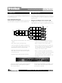 9
9
-
 10
10
-
 11
11
-
 12
12
-
 13
13
-
 14
14
-
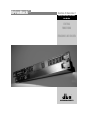 15
15
-
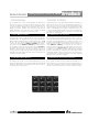 16
16
-
 17
17
-
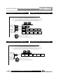 18
18
-
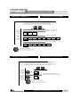 19
19
-
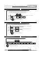 20
20
-
 21
21
-
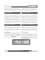 22
22
-
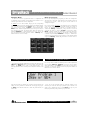 23
23
-
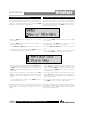 24
24
-
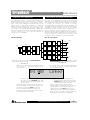 25
25
-
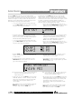 26
26
-
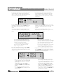 27
27
-
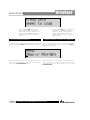 28
28
-
 29
29
-
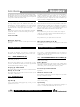 30
30
-
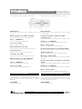 31
31
-
 32
32
-
 33
33
-
 34
34
-
 35
35
-
 36
36
-
 37
37
-
 38
38
-
 39
39
-
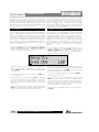 40
40
-
 41
41
-
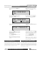 42
42
-
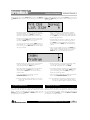 43
43
-
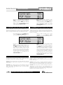 44
44
-
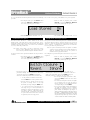 45
45
-
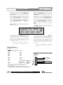 46
46
-
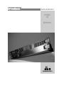 47
47
-
 48
48
-
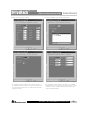 49
49
-
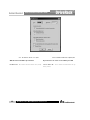 50
50
-
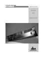 51
51
-
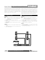 52
52
-
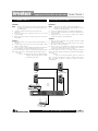 53
53
-
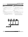 54
54
-
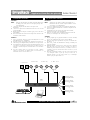 55
55
-
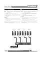 56
56
-
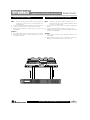 57
57
-
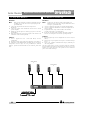 58
58
-
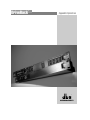 59
59
-
 60
60
-
 61
61
-
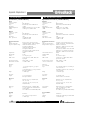 62
62
-
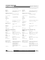 63
63
-
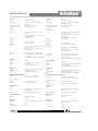 64
64
-
 65
65
-
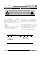 66
66
-
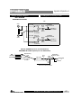 67
67
-
 68
68
-
 69
69


dbx 240 El manual del propietario
- Categoría
- Ecualizadores de audio
- Tipo
- El manual del propietario
- Este manual también es adecuado para
en otros idiomas
- English: dbx 240 Owner's manual
Artículos relacionados
-
dbx DriveRack PA El manual del propietario
-
dbx DriveRack 260 El manual del propietario
-
-
dbx 1046 El manual del propietario
-
-
-
-
dbx DriveRack PA2 El manual del propietario
-
-
Otros documentos
-
Ashly XR 1OO1 Manual de usuario
-
TC Electronic XO24 El manual del propietario
-
Electro-Voice Dx38 El manual del propietario
-
DAS DSP-2040 Manual de usuario
-
Work-pro MX 61 Manual de usuario
-
 dbx Pro 166XL Manual de usuario
-
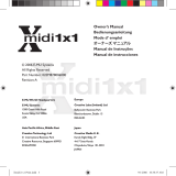 E-Mu Xmidi 1x1 El manual del propietario
-
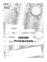 BSS Audio FDS-355 OMNIDRIVE El manual del propietario
-
Optimus UAP88 Ficha de datos
-
DAP Audio D2084 Manual de usuario


