Peavey 16FX Instrucciones de operación
- Categoría
- Mezcladores de audio
- Tipo
- Instrucciones de operación
Este manual también es adecuado para

www.peavey.com
FX
™
Mixer Series
16, 24 and 32 Channel • Four-Bus Mixing Consoles
Operating
Manual

2
Intended to alert the user to the presence of uninsulated “dangerous voltage” within the product’s
enclosure that may be of sufficient magnitude to constitute a risk of electric shock to persons.
Intended to alert the user of the presence of important operating and maintenance (servicing)
instructions in the literature accompanying the product.
CAUTION: Risk of electrical shock — DO NOT OPEN!
CAUTION: To reduce the risk of electric shock, do not remove cover. No user serviceable parts inside.
Refer servicing to qualified service personnel.
WARNING: To prevent electrical shock or fire hazard, this apparatus should not be exposed to rain or
moisture‚ and objects filled with liquids‚ such as vases‚ should not be placed on this apparatus. Before
using this apparatus‚ read the operating guide for further warnings.
Este símbolo tiene el propósito, de alertar al usuario de la presencia de “(voltaje) peligroso” sin
aislamiento dentro de la caja del producto y que puede tener una magnitud suficiente como para
constituir riesgo de descarga eléctrica.
Este símbolo tiene el propósito de alertar al usario de la presencia de instruccones importantes sobre la
operación y mantenimiento en la información que viene con el producto.
PRECAUCION: Riesgo de descarga eléctrica ¡NO ABRIR!
PRECAUCION: Para disminuír el riesgo de descarga eléctrica, no abra la cubierta. No hay piezas útiles
dentro. Deje todo mantenimiento en manos del personal técnico cualificado.
ADVERTENCIA: Para prevenir choque electrico o riesgo de incendios, este aparato no se debe exponer a
la lluvia o a la humedad. Los objetos llenos de liquidos, como los floreros, no se deben colocar encima
de este aparato. Antes de usar este aparato, lea la guia de funcionamiento para otras advertencias.
Ce symbole est utilisé dans ce manuel pour indiquer à l’utilisateur la présence d’une tension dangereuse
pouvant être d’amplitude suffisante pour constituer un risque de choc électrique.
Ce symbole est utilisé dans ce manuel pour indiquer à l’utilisateur qu’il ou qu’elle trouvera d’importantes
instructions concernant l’utilisation et l’entretien de l’appareil dans le paragraphe signalé.
ATTENTION: Risques de choc électrique — NE PAS OUVRIR!
ATTENTION: Afin de réduire le risque de choc électrique, ne pas enlever le couvercle. Il ne se trouve
à l’intérieur aucune pièce pouvant être reparée par l’utilisateur. Confiez I’entretien et la réparation de
l’appareil à un réparateur Peavey agréé.
AVIS: Dans le but de reduire les risques d’incendie ou de decharge electrique, cet appareil ne doit
pas etre expose a la pluie ou a l’humidite et aucun objet rempli de liquide, tel qu’un vase, ne doit
etre pose sur celui-ci. Avant d’utiliser de cet appareil, lisez attentivement le guide fonctionnant pour
avertissements supplémentaires.

3
Dieses Symbol soll den Anwender vor nicht isolierten „gefährlichen Spannungen“ innerhalb des Gehäuse
warnen, die hoch genug sind, um einen Stromschlag zu erzeugen.
Dieses Symbol soll den Anwender auf wichtige Bedienungs- und Wartungs- bzw.
Instandhaltungsanweisungen in den Begleitunterlagen zum Produkt aufmerksam machen.
VORSICHT: Stromschlaggefahr – NICHT ÖFFNEN!
VORSICHT: Gehäuse nicht öffnen, um Stromschläge zu vermeiden. Das Gerät enthält keine Teile, die vom
Anwender gewartet werden können. Wartungsarbeiten nur von qualifiziertem Fachpersonal durchführen
lassen.
WARNUNG: Gerät vor Regen oder Feuchtigkeit schützen, um Stromschläge und Brandgefahren zu
vermeiden. Keine mit Flüssigkeiten gefüllten Gegenstände, wie etwa Vasen, auf das Gerät stellen. Vor
Gebrauch des Geräts alle weiteren Warnhinweise in dieser Bedienungsanleitung lesen.
Avverte l’utente della presenza di “tensione pericolosa” non isolata all’interno dell’involucro del
prodotto, la cui entità può essere sufficiente a costituire rischio di folgorazione per le persone.
Avverte l’utente della presenza di importanti istruzioni sull’uso e la manutenzione (assistenza) nella
documentazione allegata al prodotto.
ATTENZIONE: rischio di folgorazione — NON APRIRE!
ATTENZIONE: per ridurre il rischio di folgorazione, non rimuovere il coperchio. All’interno non vi sono
componenti riparabili dall’utente. Per l’assistenza, rivolgersi al personale qualificato.
AVVERTENZA: al fine di evitare il rischio di folgorazione o incendio, questo apparecchio non deve essere
esposto a pioggia o umidità e su di esso non dovranno essere collocati oggetti contenenti liquidi‚ come
vasi‚ ecc. Prima di utilizzare questo apparecchio, leggere la guida per l’utente.
3

4
3
*.1035"/54"'&5:*/4536$5*0/4
8"3/*/(8IFOVTJOHFMFDUSJDBMQSPEVDUTCBTJDDBVUJPOTTIPVMEBMXBZTCFGPMMPXFEJODMVEJOHUIFGPMMPXJOH
3FBEUIFTFJOTUSVDUJPOT
,FFQUIFTFJOTUSVDUJPOT
)FFEBMMXBSOJOHT
'PMMPXBMMJOTUSVDUJPOT
%POPUVTFUIJTBQQBSBUVTOFBSXBUFS
$MFBOPOMZXJUIBESZDMPUI
%POPUCMPDLBOZPGUIFWFOUJMBUJPOPQFOJOHT*OTUBMMJOBDDPSEBODFXJUINBOVGBDUVSFSµTJOTUSVDUJPOT
%POPUJOTUBMMOFBSBOZIFBUTPVSDFTTVDIBTSBEJBUPSTIFBUSFHJTUFSTTUPWFTPSPUIFSBQQBSBUVTJODMVEJOHBNQMJGJFSTUIBU
QSPEVDFIFBU
%POPUEFGFBUUIFTBGFUZQVSQPTFPGUIFQPMBSJ[FEPSHSPVOEJOHUZQFQMVH"QPMBSJ[FEQMVHIBTUXPCMBEFTXJUIPOFXJEFSUIBO
UIFPUIFS"HSPVOEJOHUZQFQMVHIBTUXPCMBEFTBOEBUIJSEHSPVOEJOHQMVH5IFXJEFCMBEFPSUIJSEQSPOHJTQSPWJEFEGPSZPVS
TBGFUZ*GUIFQSPWJEFEQMVHEPFTOPUGJUJOUPZPVSPVUMFUDPOTVMUBOFMFDUSJDJBOGPSSFQMBDFNFOUPGUIFPCTPMFUFPVUMFU
1SPUFDUUIFQPXFSDPSEGSPNCFJOHXBMLFEPOPSQJODIFEQBSUJDVMBSMZBUQMVHTDPOWFOJFODFSFDFQUBDMFTBOEUIFQPJOUUIFZFYJU
GSPNUIFBQQBSBUVT
0OMZVTFBUUBDINFOUTBDDFTTPSJFTQSPWJEFECZUIFNBOVGBDUVSFS
6TFPOMZXJUIBDBSUTUBOEUSJQPECSBDLFUPSUBCMFTQFDJGJFECZUIFNBOVGBDUVSFSPSTPMEXJUIUIFBQQBSBUVT8IFOBDBSUJT
VTFEVTFDBVUJPOXIFONPWJOHUIFDBSUBQQBSBUVTDPNCJOBUJPOUPBWPJEJOKVSZGSPNUJQPWFS
6OQMVHUIJTBQQBSBUVTEVSJOHMJHIUOJOHTUPSNTPSXIFOVOVTFEGPSMPOHQFSJPETPGUJNF
3FGFSBMMTFSWJDJOHUPRVBMJGJFETFSWJDFQFSTPOOFM4FSWJDJOHJTSFRVJSFEXIFOUIFBQQBSBUVTIBTCFFOEBNBHFEJOBOZXBZTVDI
BTQPXFSTVQQMZDPSEPSQMVHJTEBNBHFEMJRVJEIBTCFFOTQJMMFEPSPCKFDUTIBWFGBMMFOJOUPUIFBQQBSBUVTUIFBQQBSBUVTIBT
CFFOFYQPTFEUPSBJOPSNPJTUVSFEPFTOPUPQFSBUFOPSNBMMZPSIBTCFFOESPQQFE
/FWFSCSFBLPGGUIFHSPVOEQJO8SJUFGPSPVSGSFFCPPLMFU²4IPDL)B[BSEBOE(SPVOEJOH³$POOFDUPOMZUPBQPXFSTVQQMZPGUIF
UZQFNBSLFEPOUIFVOJUBEKBDFOUUPUIFQPXFSTVQQMZDPSE
*GUIJTQSPEVDUJTUPCFNPVOUFEJOBOFRVJQNFOUSBDLSFBSTVQQPSUTIPVMECFQSPWJEFE
/PUFGPS6,POMZ*GUIFDPMPSTPGUIFXJSFTJOUIFNBJOTMFBEPGUIJTVOJUEPOPUDPSSFTQPOEXJUIUIFUFSNJOBMTJOZPVSQMVHÂ
QSPDFFEBTGPMMPXT
B5IFXJSFUIBUJTDPMPSFEHSFFOBOEZFMMPXNVTUCFDPOOFDUFEUPUIFUFSNJOBMUIBUJTNBSLFECZUIFMFUUFS&ÂUIFFBSUITZNCPMÂ
DPMPSFEHSFFOPSDPMPSFEHSFFOBOEZFMMPX
C5IFXJSFUIBUJTDPMPSFECMVFNVTUCFDPOOFDUFEUPUIFUFSNJOBMUIBUJTNBSLFEXJUIUIFMFUUFS/PSUIFDPMPSCMBDL
D5IFXJSFUIBUJTDPMPSFECSPXONVTUCFDPOOFDUFEUPUIFUFSNJOBMUIBUJTNBSLFEXJUIUIFMFUUFS-PSUIFDPMPSSFE
5IJTFMFDUSJDBMBQQBSBUVTTIPVMEOPUCFFYQPTFEUPESJQQJOHPSTQMBTIJOHBOEDBSFTIPVMECFUBLFOOPUUPQMBDFPCKFDUT
DPOUBJOJOHMJRVJETTVDIBTWBTFTVQPOUIFBQQBSBUVT
5IFPOPGGTXJUDIJOUIJTVOJUEPFTOPUCSFBLCPUITJEFTPGUIFQSJNBSZNBJOT)B[BSEPVTFOFSHZDBOCFQSFTFOUJOTJEFUIF
DIBTTJTXIFOUIFPOPGGTXJUDIJTJOUIFPGGQPTJUJPO5IFNBJOTQMVHPSBQQMJBODFDPVQMFSJTVTFEBTUIFEJTDPOOFDUEFWJDFUIF
EJTDPOOFDUEFWJDFTIBMMSFNBJOSFBEJMZPQFSBCMF
&YQPTVSFUPFYUSFNFMZIJHIOPJTFMFWFMTNBZDBVTFBQFSNBOFOUIFBSJOHMPTT*OEJWJEVBMTWBSZDPOTJEFSBCMZJOTVTDFQUJCJMJUZUP
OPJTFJOEVDFEIFBSJOHMPTTCVUOFBSMZFWFSZPOFXJMMMPTFTPNFIFBSJOHJGFYQPTFEUPTVGGJDJFOUMZJOUFOTFOPJTFGPSBTVGGJDJFOU
UJNF5IF64(PWFSONFOUµT0DDVQBUJPOBM4BGFUZBOE)FBMUI"ENJOJTUSBUJPO04)"IBTTQFDJGJFEUIFGPMMPXJOHQFSNJTTJCMF
OPJTFMFWFMFYQPTVSFT
%VSBUJPO1FS%BZ*O)PVST 4PVOE-FWFME#"4MPX3FTQPOTF
º
º
ºPSMFTT
"DDPSEJOHUP04)"BOZFYQPTVSFJOFYDFTTPGUIFBCPWFQFSNJTTJCMFMJNJUTDPVMESFTVMUJOTPNFIFBSJOHMPTT&BSQMVHTPSQSPUFDUPSTUP
UIFFBSDBOBMTPSPWFSUIFFBSTNVTUCFXPSOXIFOPQFSBUJOHUIJTBNQMJGJDBUJPOTZTUFNJOPSEFSUPQSFWFOUBQFSNBOFOUIFBSJOHMPTTJG
FYQPTVSFJTJOFYDFTTPGUIFMJNJUTBTTFUGPSUIBCPWF5PFOTVSFBHBJOTUQPUFOUJBMMZEBOHFSPVTFYQPTVSFUPIJHITPVOEQSFTTVSFMFWFMTJUJT
SFDPNNFOEFEUIBUBMMQFSTPOTFYQPTFEUPFRVJQNFOUDBQBCMFPGQSPEVDJOHIJHITPVOEQSFTTVSFMFWFMTTVDIBTUIJTBNQMJGJDBUJPOTZTUFNCF
QSPUFDUFECZIFBSJOHQSPUFDUPSTXIJMFUIJTVOJUJTJOPQFSBUJPO
4"7&5)&4&*/4536$5*0/4

5
Instrucciones Importantes Para Su Seguridad
CUIDADO:
Cuando use productos electrónicos, debe tomar precauciones básicas, incluyendo las siguientes:
1. Lea estas instrucciones.
2. Guarde estas instrucciones.
3. Haga caso de todos los consejos.
4. Siga todas las instrucciones.
5. No usar este aparato cerca del agua.
6. Limpiar solamente con una tela seca.
7. No bloquear ninguna de las salidas de ventilación. Instalar de acuerdo a las instrucciones del fabricante.
8. No instalar cerca de ninguna fuente de calor como radiadores, estufas, hornos u otros aparatos (incluyendo
amplificadores) que produzcan calor.
9. No retire la patilla protectora del enchufe polarizado o de tipo “a Tierra”. Un enchufe polarizado tiene dos puntas, una
de ellas más ancha que la otra. Un enchufe de tipo “a Tierra” tiene dos puntas y una tercera “a Tierra”. La punta ancha
(la tercera ) se proporciona para su seguridad. Si el enchufe proporcionado no encaja en su enchufe de red, consulte a
un electricista para que reemplace su enchufe obsoleto.
10. Proteja el cable de alimentación para que no sea pisado o pinchado, particularmente en los enchufes, huecos, y los
puntos que salen del aparato.
11. Usar solamente añadidos/accesorios proporcionados por el fabricante.
12. Usar solamente un carro, pie, trípode, o soporte especificado por el fabricante, o vendido junto al aparato. Cuando se
use un carro, tenga cuidado al mover el conjunto carro/aparato para evitar que se dañe en un vuelco. No suspenda
esta caja de ninguna manera.
13. Desenchufe este aparato durante tormentas o cuando no sea usado durante largos periodos de tiempo.
14. Para cualquier reparación, acuda a personal de servicio cualificado. Se requieren reparaciones cuando el aparato ha
sido dañado de alguna manera, como cuando el cable de alimentación o el enchufe se han dañado, algún líquido ha
sido derramado o algún objeto ha caído dentro del aparato, el aparato ha sido expuesto a la lluvia o la humedad, no
funciona de manera normal, o ha sufrido una caída.
15. Nunca retire la patilla de Tierra.Escríbanos para obtener nuestro folleto gratuito “Shock Hazard and Grounding”
(“Peligro de Electrocución y Toma a Tierra”). Conecte el aparato sólo a una fuente de alimentación del tipo marcado al
lado del cable de alimentación.
16. Si este producto va a ser enracado con más equipo, use algún tipo de apoyo trasero.
17. Nota para el Reino Unido solamente: Si los colores de los cables en el enchufe principal de esta unidad no
corresponden con los terminales en su enchufe‚ proceda de la siguiente manera:
a) El cable de color verde y azul debe ser conectado al terminal que está marcado con la letra E‚ el símbolo de Tierra
(earth)‚ coloreado en verde o en verde y amarillo.
b) El cable coloreado en azul debe ser conectado al terminal que está marcado con la letra N o el color negro.
c) El cable coloreado en marrón debe ser conectado al terminal que está marcado con la letra L o el color rojo.
18. Este aparato eléctrico no debe ser sometido a ningún tipo de goteo o salpicadura y se debe tener cuidado para no
poner objetos que contengan líquidos, como vasos, sobre el aparato.
19. El interruptor de en/lejos en esta unidad no rompe ambos lados de la red primaria. La energía peligrosa puede ser
presente dentro del chasis cuando el interruptor de en/lejos está en el de la posición. El tapón de la red o el acoplador
del aparato son utilizados como el desconecta dispositivo, el desconecta dispositivo se quedará fácilmente operable.
20. La exposición a altos niveles de ruido puede causar una pérdida permanente en la audición. La susceptibilidad a la
pérdida de audición provocada por el ruido varía según la persona, pero casi todo el mundo perderá algo de audición
si se expone a un nivel de ruido suficientemente intenso durante un tiempo determinado. El Departamento para la
Salud y para la Seguridad del Gobierno de los Estados Unidos (OSHA) ha especificado las siguientes exposiciones al
ruido permisibles:
Duración por Día en Horas Nivel de Sonido dBA, Respuesta Lenta
8 90
6 92
4 95
3 97
2 100
1 1⁄2 102
1 105
1⁄2 110
1⁄4 or less 115
De acuerdo al OSHA, cualquier exposición que exceda los límites arriba indicados puede producir algún tipo de pérdida en la
audición. Protectores para los canales auditivos o tapones para los oídos deben ser usados cuando se opere con este sistema de
sonido para prevenir una pérdida permanente en la audición, si la exposición excede los límites indicados más arriba. Para prote-
gerse de una exposición a altos niveles de sonido potencialmente peligrosa, se recomienda que todas las personas expuestas a
equipamiento capaz de producir altos niveles de presión sonora, tales como este sistema de amplificación, se encuentren protegi-
das por protectores auditivos mientras esta unidad esté operando.
¡GUARDE ESTAS INSTRUCCIONES!

6
5
*/4536$5*0/4*.1035"/5&4%&4&$63*5&
"55&/5*0/-µVUJMJTBUJPOEFUPVUBQQBSFJMnMFDUSJRVFEPJUpUSFTPVNJTFBVYQSFDBVUJPOTEµVTBHFJODMVBOU
-JSFDFTJOTUSVDUJPOT
(BSEF[DFNBOVFMQPVSEFGVUVSFTSnGnSFODFT
1SnUF[BUUFOUJPOBVYNFTTBHFTEFQSnDBVUJPOTEFDFNBOVFM
4VJWF[DFTJOTUSVDUJPOT
/µVUJMJTF[QBTDFUUFVOJUnQSPDIFEFQMBOTEµFBV
/µVUJMJTF[RVµVOUJTTVTFDQPVSMFOFUUPZBHFEFWPUSFVOJUn
/µPCTUSVF[QBTMFTTZTUoNFTEFSFGSPJEJTTFNFOUEFWPUSFVOJUnFUJOTUBMMF[WPUSFVOJUnFOGPODUJPOEFTJOTUSVDUJPOTEFDFNBOVFM
/FQPTJUJPOOF[QBTWPUSFVOJUnhQSPYJNJUnEFUPVUFTPVSDFEFDIBMFVS
$POOFDUF[UPVKPVSTWPUSFVOJUnTVSVOFBMJNFOUBUJPONVOJFEFQSJTFEFUFSSFVUJMJTBOUMFDPSEPOEµBMJNFOUBUJPOGPVSOJ
1SPUnHF[MFTDPOOFDUFVSTEFWPUSFVOJUnFUQPTJUJPOOF[MFTDBCMBHFTQPVSnWJUFSUPVUFTEnDPOOFYJPOTBDDJEFOUFMMFT
/µVUJMJTF[RVFEFTGJYBUJPOTBQQSPVWnFTQBSMFGBCSJRVBOU
-PSTEFMµVUJMTBUJPOTVSQJFEPVQPMFEFTVQQPSUBTTVSF[EBOTMFDBTEFEnQMBDFNFOUEFMµFOTFNCMFFODFJOUFTVQQPSUEFQSnWFOJS
UPVUCBTDVMFNFOUJOUFNQFTUJGEFDFMVJDJ
*MFTUDPOTFJMMnEFEnDPOOFDUFSEVTFDUFVSWPUSFVOJUnFODBTEµPSBHFPVEFEVSnFQSPMPOHnFTBOTVUJMJTBUJPO
4FVMVOUFDIOJDJFOBHSnnQBSMFGBCSJRVBOUFTUhNpNFEFSnQBSFSDPOUSyMFSWPUSFVOJUn$FMMFDJEPJUpUSFDPOUSyMnFTJFMMFBTVCJU
EFTEPNNBHFTEFNBOJQVMBUJPOEµVUJMJTBUJPOPVEFTUPDLBHFIVNJEJUn©
/FEnDPOOFDUF[KBNBJTMBQSJTFEFUFSSFEFWPUSFVOJUn
4JWPUSFVOJUnFTUEFTUJOnFBFUSFNPOUnF
FOSBDLEFTTVQQPSUTBSSJFSFEPJWFOUFUSFVUJMJTFT
/PUFQPVSMFT3PZBVNFT6OJT4JMFTDPVMFVSTEFDPOOFDUFVSTEVDBCMFEµBMJNFOUBUJPOOFDPSSFTQPOEQBTBVHVJEFEFMBQSJTF
TFDUFVSQSPDnEF[DPNNFTVJU
B-FDPOOFDUFVSWFSUFUKBVOFEPJUpUSFDPOOFDUSFSBVUFSNJOBMOPUn&JOEJRVBOUMBQSJTFEFUFSSFPVDPSSFTQPOEBOUBVYDPVMFVST
WFSUFPVWFSUFFUKBVOFEVHVJEF
C-FDPOOFDUFVS#MFVEPJUpUSFDPOOFDUSFSBVUFSNJOBMOPUn/DPSSFTQPOEOBUhMBDPVMFVSOPJSFEVHVJEF
D-FDPOOFDUFVSNBSSPOEPJUpUSFDPOOFDUSFSBVUFSNJOBMOPUn-DPSSFTQPOEBOUhMBDPVMFVSSPVHFEVHVJEF
$FUnRVJQFNFOUnMFDUSJRVFOFEPJUFOBVDVODBTpUSFFODPOUBDUBWFDVORVFMDPORVFMJRVJEFFUBVDVOPCKFUDPOUFOBOUVOMJRVJEF
WBTFPVBVUSFOFEFWSBJUpUSFQPTnTVSDFMVJDJ
-JOUFSSVQUFSPOPGGEBOTDFUUFVOJUnOFDBTTFQBTMFTEFVYDyUnTEVQSJNBJSFQSJODJQBM-nOFSHJFIBTBSEFVTFQFVUpUSF
QSFnTFOUFEBOTDIiTTJTRVBOEMJOUFSSVQUFSPOPGGFTUEBOTMFEFMBQPTJUJPO-FCPVDIPOQSJODJQBMPVBUFMBHFEBQQBSFJMFTU
VUJMJTnDPNNFMFEnCSBODIFSMBQQBSFJMSFTUFSBGBDJMFNFOUPQnSBCMF
6OFFYQPTJUJPOhEFIBVUTOJWFBVYTPOPSFTQFVUDPOEVJSFhEFTEPNNBHFTEFMµnDPVUFJSSnWFSTJCMFT-BTVTDFQUJCJMJUnBVCSVJU
WBSJFDPOTJEnSBCMFNFOUEµVOJOEJWJEVhMµBVUSFNBJTVOFMBSHFNBKPSJUnEFMB
QPQVMBUJPOFYQnSJFODFSBVOFQFSUFEFMµnDPVUFBQSoT
VOFFYQPTJUJPOhVOFGPSUFQVJTTBODFTPOPSFQPVSVOFEVSnFQSPMPOHnF-µPSHBOJTNFEFMBTBOUnBNnSJDBJOF04)"BQSPEVJUMF
HVJEFDJEFTTPVTFOSBQQPSUhMBQFSUFPDDBTJPOOnF
%VSnFQBS+PVSIFVSFT /JWFBVTPOPSFNPZFOE#"
º
º
ºPVJOGnSJFVS
%µBQSoTMFTnUVEFTNFOnFTQBSMF04)"UPVUFFYQPTJUJPOBVEFMhEFTMJNJUFTEnDSJUFTDFEFTTVTFOUSBJOFSBEFTQFSUFTEFMµnDPVUFDIF[MB
QMVQBSUEFTTVKFUT-FQPSUEFTZTUoNFEFQSPUFDUJPODBTRVFPSFJMFUUFEFGJMUSBHF©EPJUpUSFPCTFSWnMPSTEFMµPQnSBUJPODFUUFVOJUnPVEFT
EPNNBHFTJSSnWFSTJCMFTQFVWFOUpUSFPDDBTJPOOnT-FQPSUEFDFTTZTUoNFTEPJUpUSFPCTFSWnQBSUPVUFTQFSTPOOFTTVTDFQUJCMFTEµpUSFFYQP
TnFThEFTDPOEJUJPOTBVEFMhEFTMJNJUFTEnDSJUFTDJEFTTVT
("3%&;$&4*/4536$5*0/4
5

7
4
8*$)5*(&4*$)&3)&*54)*/8&*4&
"$)56/(#FJN&JOTBU[WPO&MFLUSPHFSjUFONTTFOVBHSVOEMFHFOEF7PSTJDIUTNBOBINFOCFGPMHUXFSEFO
-FTFO4JFTJDIEJFTF"OXFJTVOHFOEVSDI
#FXBISFO4JFEJFTF"OXFJTVOHFOBVG
#FBDIUFO4JFBMMF8BSOVOHFO
#FGPMHFO4JFBMMF"OXFJTVOHFO
4FU[FO4JFEJFTFT(FSjUOJDIUJOEFS/jIFWPO8BTTFSFJO
3FJOJHFO4JFFTOVSNJUFJOFNUSPDLFOFO5VDI
#MPDLJFSFO4JFLFJOFEFS-GUVOHTzGGOVOHFO'ISFO4JFEJF*OTUBMMBUJPOHFNjEFO"OXFJTVOHFOEFT)FSTUFMMFSTEVSDI
*OTUBMMJFSFO4JFEBT(FSjUOJDIUOFCFO8jSNFRVFMMFOXJF)FJ[VOHFO)FJ[HFSjUFOeGFOPEFSBOEFSFO(FSjUFOBVDI7FSTUjSLFSO
EJF8jSNFFS[FVHFO
#FFJOUSjDIUJHFO4JFOJDIUEJF4JDIFSIFJUTXJSLVOHEFTHFQPMUFO4UFDLFSTC[XEFT&SEVOHTTUFDLFST&JOHFQPMUFS4UFDLFSXFJTU
[XFJ4UJGUFBVGWPOEFOFOFJOFSCSFJUFSJTUBMTEFSBOEFSF&JO&SEVOHTTUFDLFSXFJTU[XFJ4UJGUFVOEFJOFOESJUUFO&SEVOHTTUJGUBVG
%FSCSFJUF4UJGUC[XEFSESJUUF4UJGUEJFOU*ISFS4JDIFSIFJU4PMMUFEFSCFJMJFHFOEF4UFDLFSOJDIUJO*ISF4UFDLEPTFQBTTFOXFOEFO
4JFTJDICJUUFBOFJOFO&MFLUSJLFSVNEJFVOHFFJHOFUF4UFDLEPTFBVTUBVTDIFO[VMBTTFO
4DIU[FO4JFEBT/FU[LBCFMTPEBTTOJFNBOEEBSBVGUSJUUPEFSFTHFLOJDLUXJSEJOTCFTPOEFSFBO4UFDLFSOPEFS#VDITFOVOE
JISFO"VTUSJUUTTUFMMFOBVTEFN(FSjU
7FSXFOEFO4JFOVSEJFWPN)FSTUFMMFSFSIjMUMJDIFO;VCFIzSHFSjUFPEFS;VCFIzSUFJMF
7FSXFOEFO4JFOVSFJOFO8BHFO4UBUJW%SFJGV5SjHFSPEFS5JTDIEFSEFO"OHBCFOEFT)FSTUFMMFSTFOUTQSJDIUPEFS[VTBNNFO
NJUEFN(FSjUWFSLBVGUXVSEF8JSEFJO8BHFOWFSXFOEFUCFXFHFO
4JFEFO8BHFONJUEFNEBSBVGCFGJOEMJDIFO(FSjUCFTPOEFST
WPSTJDIUJHEBNJUFSOJDIUVNLJQQUVOENzHMJDIFSXFJTFKFNBOEWFSMFU[UXJSE
5SFOOFO4JFEBT(FSjUXjISFOEFJOFT(FXJUUFSTPEFSXjISFOEMjOHFSFS;FJUSjVNFJOEFOFOFTOJDIUCFOVU[UXJSEWPOEFS
4USPNWFSTPSHVOH
-BTTFO4JFTjNUMJDIF8BSUVOHTBSCFJUFOWPORVBMJGJ[JFSUFO,VOEFOEJFOTUUFDIOJLFSOEVSDIGISFO&JOF8BSUVOHJTUFSGPSEFSMJDI
XFOOEBT(FSjUJOJSHFOEFJOFS"SUCFTDIjEJHUXVSEFFUXBXFOOEBT/FU[LBCFMPEFSEFS/FU[TUFDLFSCFTDIjEJHUXVSEFO
'MTTJHLFJUPEFS(FHFOTUjOEFJOEBT(FSjUHFMBOHUTJOEEBT(FSjU3FHFOPEFS'FVDIUJHLFJUBVTHFTFU[UXVSEFOJDIUOPSNBM
BSCFJUFUPEFSIFSVOUFSHFGBMMFOJTU
%FS&SEVOHTTUJGUEBSGOJFFOUGFSOUXFSEFO"VG8VOTDITFOEFOXJS*IOFOHFSOFVOTFSFLPTUFOMPTF#SPTDISFÃ4IPDL)B[BSEBOE
(SPVOEJOH²(FGBISEVSDIFMFLUSJTDIFO4DIMBHVOE&SEVOH[V4DIMJFFO4JFOVSBOEJF4USPNWFSTPSHVOHEFS"SUBOEJFBN
(FSjUOFCFOEFN/FU[LBCFMBOHFHFCFOJTU
8FOOEJFTFT1SPEVLUJOFJO(FSjUF3BDLFJOHFCBVUXFSEFOTPMMNVTTFJOF7FSTPSHVOHCFSEJF3DLTFJUFFJOHFSJDIUFUXFSEFO
)JOXFJT°/VSGS(SPCSJUBOOJFO4PMMUFEJF'BSCFEFS%SjIUFJOEFS/FU[MFJUVOHEJFTFT(FSjUTOJDIUNJUEFO,MFNNFOJO*ISFN
4UFDLFSCFSFJOTUJNNFOHFIFO4JFGPMHFOEFSNBFOWPS
B%FSHSOHFMCF%SBIUNVTTBOEJFNJU&4ZNCPMGS&SEFNBSLJFSUFC[XHSOFPEFSHSOHFMCF,MFNNFBOHFTDIMPTTFO
XFSEFO
C%FSCMBVF%SBIUNVTTBOEJFNJU
/NBSLJFSUFC[XTDIXBS[F,MFNNFBOHFTDIMPTTFOXFSEFO
D%FSCSBVOF%SBIUNVTTBOEJFNJU-NBSLJFSUFC[XSPUF,MFNNFBOHFTDIMPTTFOXFSEFO
%JFTFT(FSjUEBSGOJDIUVOHFTDIU[U8BTTFSUSPQGFOVOE8BTTFSTQSJU[FSOBVTHFTFU[UXFSEFOVOEFTNVTTEBSBVGHFBDIUFU
XFSEFOEBTTLFJOFNJU'MTTJHLFJUFOHFGMMUF(FHFOTUjOEFXJF[##MVNFOWBTFOBVGEFN(FSjUBCHFTUFMMUXFSEFO
%FS/FU[TDIBMUFSJOEJFTFS&JOIFJUCSJDIUCFJEF4FJUFOWPOEFOQSJNjSFO)BVQMFJUVOHFOOJDIU(FSGjISMJDIF&OFSHJFLBOO
BOXFTFOEJOOFSIBMCEFT$IBTTJTTFJOXFOOIFS/FU[TDIBMUFSJNBC1PJTUJPOJTU%JF)BVQUMFJUVOHFOTUzQTFMO[VPEFS
(FSjULVQQMVOHJTUCFOVU[UXjISFOEEBT7PSSJDIUVOHBCTDIBMUFUEBTTDIBMUFU7PSSJDIUVOHXJSECMFJCFOTPHMFJDIIBOUJFSCBSBC
#FMBTUVOHEVSDIFYUSFNIPIF-jSNQFHFMLBOO[VEBVFSIBGUFN(FIzSWFSMVTUGISFO%JF"OGjMMJHLFJUGSEVSDI-jSNCFEJOHUFO
(FIzSWFSMVTUJTUWPO.FOTDI[V.FOTDIWFSTDIJFEFOEBT(FIzSXJSEKFEPDICFJKFEFNJOHFXJTTFN.BFHFTDIjEJHUEFSCFS
FJOFOCFTUJNNUFO;FJUSBVNBVTSFJDIFOETUBSLFN-jSNBVTHFTFU[UJTU%JF64"SCFJUTTDIVU[CFIzSEF0DDVQBUJPOBMBOE)FBMUI
"ENJOJTUSBUJPO04)"IBUEJFGPMHFOEFO[VMjTTJHFO1FHFMGS-jSNCFMBTUVOHGFTUHFMFHU
%BVFSQSP5BHJO4UVOEFO (FSjVTDIQFHFME#"MBOHTBNF3FBLUJPO
º
º
ºPEFSXFOJHFS
-BVU04)"LBOOKFEF#FMBTUVOHCFSEFOPCFOTUFIFOEFO[VMjTTJHFO(SFO[XFSUFO[VFJOFNHFXJTTFO(FIzSWFSMVTUGISFO4PMMUFEJF#FMBTUVOH
EJFPCFOTUFIFOEFO(SFO[XFSUF
CFSTUFJHFONTTFOCFJN#FUSJFCEJFTFT7FSTUjSLVOHTTZTUFNT0ISFOTUPQGFOPEFS4DIVU[WPSSJDIUVOHFO
JN(FIzSHBOHPEFSCFSEFO0ISFOHFUSBHFOXFSEFOVNFJOFOEBVFSIBGUFO(FIzSWFSMVTU[VWFSIJOEFSO6NTJDIWPSFJOFSNzHMJDIFSXFJTF
HFGjISMJDIFO#FMBTUVOHEVSDIIPIF4DIBMMESVDLQFHFM[VTDIU[FOXJSEBMMFO1FSTPOFOFNQGPIMFOEJFNJU(FSjUFOBSCFJUFOEJFXJFEJFTFT
7FSTUjSLVOHTTZTUFNIPIF4DIBMMESVDLQFHFMFS[FVHFOLzOOFOCFJN#FUSJFCEJFTFT(FSjUTFJOFO(FIzSTDIVU[[VUSBHFO
#&8")3&/4*&%*&4&4*$)&3)&*54)*/8&*4&"6'
4

8
Note importanti sulla sicurezza
AVVERTENZA: Quando si usano prodotti elettrici, seguire sempre le precauzioni fondamentali, incluso quanto riportato di seguito.
1. Leggere le presenti istruzioni.
2. Conservare le presenti istruzioni.
3. Attenersi a tutte le avvertenze.
4. Seguire tutte le istruzioni.
5. Non usare questo apparecchio in prossimità dell’acqua.
6. Pulire solo con un panno asciutto.
7. Non ostruire le aperture di ventilazione. Installare conformemente alle istruzioni del produttore.
8. Non installare in prossimità di fonti di calore come radiatori, termoregolatori, stufe o altri apparecchi (inclusi
amplificatori) che producono calore.
9. Non vanificare la funzione di sicurezza della spina polarizzata o della spina con collegamento di terra. Una spina
polarizzata presenta due lamelle, una più larga dell’altra. Una spina con collegamento di terra presenta due lamelle e
un terzo spinotto di terra. La lamella larga o terzo polo è stato previsto ai fini della sicurezza. Se la spina fornita non
è adatta alla presa del proprio impianto elettrico, rivolgersi a un elettricista per sostituire la presa obsoleta.
10. Proteggere il cavo di alimentazione affinché non venga calpestato o sottoposto a sollecitazioni, in particolare in
prossimità di spine, prese e del punto in cui esce dall’apparecchio.
11. Usare solo accessori forniti dal produttore.
12. Usare solo con carrelli, supporti, treppiedi, staffe o tavoli specificati dal produttore o venduti insieme all’apparecchio.
Se si usa un carrello, prestare attenzione quando si sposta la combinazione carrello/apparecchio al fine di evitare
lesioni derivanti dal ribaltamento.
13. Scollegare questo apparecchio in caso di temporale o se si prevede di non utilizzarli per periodi prolungati.
14. Per tutti gli interventi di assistenza, rivolgersi al personale qualificato. Interventi di assistenza saranno necessari
se l’apparecchio ha subito danni, come nel caso di danni al cavo di alimentazione, caduta di liquidi od oggetti
solidi all’interno dell’apparecchio, esposizione dell’apparecchio a pioggia o umidità, malfunzionamento o caduta
dell’apparecchio.
15. Non rimuovere lo spinotto di terra. Richiedere per iscritto il nostro opuscolo gratuito “Shock Hazard and
Grounding (Rischio di scosse elettriche e collegamento di terra.)” Collegare solo ad alimentazione del tipo indicato
sull’apparecchio vicino al cavo di alimentazione.
16. Per il montaggio in rack, prevedere un supporto posteriore.
17. Nota (solo per GB): se i colori dei conduttori del cavo di rete elettrica di questo apparecchio non corrispondono ai
terminali della spina, procedere come segue:
a) il cavo verde e giallo deve essere collegato al terminale marcato con la lettera E‚ il simbolo del collegamento di
terra‚ di colore verde o giallo-verde
b) il cavo blu deve essere collegato al terminale marcato con la lettera N oppure di colore nero
c) il cavo marrone deve essere collegato al terminale marcato con la lettera L oppure di colore rosso.
18. Questo apparecchio elettrico non deve essere esposto a gocciolamento o a spruzzi e sopra di esso non si devono
collocare oggetti contenenti liquidi, come vasi.
19. L’interruttore on/off di questo apparecchio non deve sezionare entrambi i lati dell’alimentazione di rete principale.
Quando l’interruttore si trova in posizione OFF, è possibile che all’interno dello chassis sia presente un’energia
pericolosa. La spina o il connettore di rete viene utilizzato come dispositivo di scollegamento, che dovrà restare
facilmente accessibile.
20. L’esposizione a livelli di emissione acustica molto elevati può causare la perdita permanente dell’udito. La predisposizione
alla perdita dell’udito indotta da emissioni acustiche varia notevolmente da soggetto a soggetto, ma quasi chiunque
può subire danni all’udito se ci si espone a emissione acustica di una certa intensità per un certo periodo di tempo.
L’OSHA (Occupational Safety and Health Administration, Dipartimento del governo statunitense per la tutela della salute
occupazione) ha emanato una specifica con i seguenti livelli ammissibili di esposizione a emissioni acustiche:
Durata giornaliera espressa in ore Livello di pressione sonora in dBA, risposta “lento”
8 90
6 92
4 95
3 97
2 100
1 1⁄2 102
1 105
1⁄2 110
1⁄4 o inferiore 115
Secondo l’OSHA, qualsiasi esposizione superiore ai limiti consentiti di cui sopra può causare la perdita, anche parziale, delle
facoltà uditive. Quando si usa questo impianto di amplificazione, indossare tappi o dispositivi di protezione del condotto uditivo, al
fine di evitare una perdita permanente dell’udito, qualora l’esposizione superi i limiti sopra indicati. Per prevenire i potenziali rischi
dell’esposizione a livelli elevati di pressione sonora, si consiglia di indossare dispositivi di protezione dell’udito a tutte le persone
esposte ad apparecchiature suscettibili di produrre livelli elevati di pressione sonora, come questo apparecchio quando è in funzione.
CONSERVARE LE PRESENTI ISTRUZIONI!

9
16FX
™
, 24FX
™
and 32FX
™
4-Bus Console Mixer
Congratulations on purchasing the Peavey 16FX
™
, 24FX
™
or 32FX
™
four-bus console mixer. The Peavey 16FX
™
, 24FX
™
and
32FX
™
are studio-quality mixing consoles designed to meet diverse needs. These consoles feature Peavey-exclusive technology
that enhances live studio reproduction as well as project studio recording, making them perfect for every venue. FX
™
Series mix-
ers also feature built-in DSP effects that are useful in real-world recording and sound reinforcement, while parameter controls
allow you to tailor each effect to meet your needs.
Please read this guide carefully to ensure your personal safety as well as the safety of your equipment.
FEATURES:
• Silencer™ mic preamps with current-source dual feedback design
• 12 XLR mic inputs on 16FX, 20 XLR mic inputs on 24FX, 28 XLR mic inputs on 32FX
• Two stereo channels with direct-to-L/R assignment capability
• Three-band channel EQ on all input channels
• Sweepable mid-frequency control on all mono input channels
• 75 Hz low-cut filter on all mono input channels
• Inserts on all mono channels
• Four-bus design with direct group outputs and L/R assignment
• Four monitor sends per channel, pre-fader
• Two effects sends per channel, post-fader
• Pan and PFL on each channel
• Clip LEDs for the entire signal path for clipping
• Signal presence LEDs on every input, group and return
• Mute switches with LED indicator on every input, group and return channel
• 48-volt phantom power switch
• Dual DSP engines for output processing, dual effects and digital I/O
• Output processing includes EQ, Delay and Compressor/Limiter
• Large LCD graphics user interface
• Dual USB ports
• Direct streaming of audio to and from your computer
• Built-in MP3 compression, direct recording and playback via USB removable data storage device
• Media inputs with level control assignable to L/R mix
• Headphone output with level control
• Two 12V BNC lamp jacks (24FX and 32FX mixers only)
ENGLISH

Gain
This control establishes the nominal operating level for the channel. The input
gain can be adjusted over a wide range (0 dB – 60 dB) to compensate for soft
voices or very loud drums. To maximize the signal-to-noise ratio, the gain should
be set to the proper level, with the Channel Fader (13) set to 0. It can be set by
pressing the PFL Switch (12) and adjusting for 0 dB on the output meter. If the
clip LED comes on and remains lit, reduce the gain.
Lo Cut
The low-cut lter has a corner frequency of 75 Hz. When engaged‚ it can improve
clarity by removing low frequencies that make a mix sound muddy. This lter
reduces handling and stage noise, breathing noise, and unwanted low frequency
energy that can rob your sound system of power. Engaging this switch will
remove those frequencies from the system and restore power where needed. We
recommend engaging it for all channels except those with the lowest bass tones
such as Bass guitar and Kick drum.
Hi EQ
This shelving type tone control adjusts treble frequency levels (±15 dB at 10 KHz),
resulting in less noise or more brilliance.
Mid EQ
This active tone control is a bandpass (peak/notch) type that varies mid-frequen-
cy response by ±15 dB in a range from 100 Hz to 5 kHz. The center frequency is
controlled by the Mid Freq (5) control.
Mid Freq
This control determines the center frequency of the Mid EQ (4) control. Center
frequency for the bandpass lter can be set from 100 Hz to 5 kHz.
Low EQ
This shelving-type tone control adjusts bass frequency levels (±15 dB at 70 Hz),
adding depth to thin signals or clarity to overly thick signals.
Caution: Excessive low frequency boost causes increased power consumption
and increases the possibility of speaker damage.
AUX 1-4 Sends
These controls send the channel’s pre-fader, post-EQ signal to each of four aux
buses. These buses are normally used for monitor sends or for feeding a sepa-
rate mix to external equipment. There are internal jumpers that can be switched
to change the send point to pre-EQ. Unity gain is at the center detent position
with up to 10 dB of gain in the fully clockwise position.
AUX 5-6/EFX 1-2 Sends
These controls send the channel’s post-fader signal to each of two aux (effects)
buses. These buses are normally used for effects sends or for feeding the inter-
nal effects processors. Unity gain is at the center detent position with up to 10
dB of gain in the fully clockwise position.
10
Front Panel
1
2
3
4
7
5
6
8
MONO INPUT CHANNELS
2
3
4
1
6
5
8
7
9
10
11
12
13

Pan
This control determines the signal’s position with respect to the assigned L/R and Group 1–4 buses.
Rotating the control counterclockwise increases the amount of signal sent to L and odd-numbered
groups; rotating clockwise increases the amount sent to R and even-numbered groups. For example,
with the channel Bus Assign switch (10) in the 1/2 position, rotating the control counterclockwise
increases the amount of signal sent to Group 1, while rotating clockwise increases the amount sent to
Group 2. The C position sends equal amounts to each.
1/2, 3/4, L/R Bus Assign Switches
These post-fader switches determine where the channel signal is being sent. For example, to send a
signal to Groups 1 & 2, depress the 1/2 button. The PAN control (9) determines the signal level that is
sent to each signal bus.
Mute Switch/Mute-Clip LED
This switch mutes all Aux, Group and L/R sends from the corresponding channel. This switch is
equipped with a red LED that will illuminate when the channel is muted. When the MUTE button is out,
the LED functions as a Clip indicator that will illuminate at 2 dB below clipping. Muting the channel does
not prevent the PFL signal from being sent to the PFL/AFL mix when the PFL Switch (12) is in.
PFL Switch/Signal-PFL LED
This switch connects the channel’s pre-fader signal to the PFL/AFL mix. When the PFL button is in, the
channel’s signal can be monitored through the headphones and/or on the PFL/AFL display. A yellow
LED in the Master section will blink to indicate that the signal on the Master LED display and at the
headphone output is PFL. Selecting PFL allows the operator to monitor a channel even with the channel
muted, and is especially useful for cuing CDs/tapes. When the PFL button is out, the yellow channel LED
will function as a signal presence indicator (-30 dBu).
Channel Fader
This control varies the signal level from -∞ to +10 dB and sends the signal from the channel to the L/R
and Group buses and to the Effects Sends. The optimum setting is the ø (unity gain) position.
11
Front Panel
9
10
11
13
12

12
Mic Gain
This control establishes the nominal operating level for the mic input (XLR) of
the channel. The mic gain can be adjusted over a wide range (0 dB – 60 dB) to
compensate for soft voices or very loud drums. To maximize the signal-to-noise
ratio, the gain should be set to the proper level, with the Channel Fader (13) set
to ø. The mic gain can be set by pressing the PFL button (12) and adjusting for
ø dB on the output meter. If the clip LED comes on and remains lit, reduce the
gain.
Stereo Gain
This control establishes the nominal operating level for the stereo line inputs
(1/4" jacks) of the channel. The Stereo Gain can be adjusted over a sufcient
range (-∞ to +20 dB) to accommodate almost any input level. It operates in
conjunction with the L/R–CH Switch (16) to route the stereo signal directly to
the L/R buses or through the channel strip.
L/R–CH Switch
This switch establishes the routing of the stereo line input (1/4" jacks) signal.
When the switch is out, the stereo line input signal is routed directly to the L/R
buses, bypassing the channel strip. In this mode, the mic input (XLR) signal is routed through the
channel. When the switch is in, the stereo line input signal is routed through the channel and the mic
input signal is disconnected. The signal level is controlled via the Stereo Gain control (15).
Input Select Stereo-USB Switch
This switch selects the input signal that will feed the stereo line input of the second stereo channel.
When the switch is out, the signal from the stereo line inputs is routed to the Stereo Gain control (15).
When the switch is in, the signal from the device connected to either USB port (60-61) is routed to the
Stereo Gain control (15).
Mid EQ
In the Stereo Input channels, this active tone control is a bandpass (peak/notch) type that varies
mid-frequency response by ±15 dB at a center frequency of 850 Hz.
Auxiliary Masters 1-4
This control sets the output level of the AUX 1-4 mixes and is adjustable from -∞ to +10 dB.
Auxiliary Masters 5-6
This control sets the output level of the various AUX 5-6 mixes and is adjustable from -∞ to +10 dB.
These signals are also sent to the EFX1 and EFX2 internal effects processors, respectively.
AFL Switch/AFL-Clip LED
This switch directs the post-fader (AFL) signal to the Headphone output (37) and activates the PFL/
AFL LED display. An adjacent red LED illuminates to signify this selection. If AFL is not selected, the LED
functions as a Clip indicator. Selecting AFL allows monitoring of AUX Masters with the full PFL/AFL Level
Display as well as allowing the operator to hear the output.
Front Panel
14
19
16
17
18
21
20
15
STEREO INPUT CHANNELS
Stereo Input Channels
ONLY
14
2
17
16
15
3
18
6
MASTER SECTION

13
Phantom Power Switch
This switch applies +48 VDC voltage
to the input XLR connectors to power
condenser microphones requiring phan-
tom power. This switch is recessed into
the console and requires a small “tool”
such as a pencil or pen tip to activate. A
regular low impedance dynamic mic such
as the PVM™ 22 will not be harmed. The
Line inputs (49&50) are not connected
to the +48 V supply and are safe for bal-
anced or unbalanced inputs. An adjacent
LED illuminates when Phantom Power is
activated.
Caution:
If phantom power is used, do not
connect unbalanced dynamic micro-
phones or other devices to the XLR
inputs. (Some wireless receivers may be
damaged. Consult their manuals.)
Note:
Make sure the Master Level Faders (40)
are completely down when switching on
the phantom power and when connect-
ing microphones to the Mic inputs to
prevent pops from affecting the loud-
speakers.
Left, Right, Bus Assign Switches
These post-fader switches determine
where the Group mix signal is being sent.
For example, if each individual drum mic
is assigned to Group 1, depressing the
Left button will send the drum mix to the
Left bus and to the Left Out (54) on the
rear panel.
Mute Switch/Mute-Clip LED
This switch mutes its respective Group
send from the Group channel. This switch
is equipped with a red LED that will il-
luminate when the Group is muted. When
the Mute button is out, the LED functions
as a Clip indicator that will illuminate at 2
dB below clipping.
44
19
30
20
21
22
23
24
25
26
47
45
46
38
39
29
41
40
32
31
42
36
35
34
27
37
33
28
43
Front Panel
22
24
23

AFL Switch/Signal-AFL LED
This switch connects the Group’s post-fader signal to the PFL/AFL mix. When the AFL button is in, the
Group’s signal can be monitored through the headphones and/or on the PFL/AFL display. A yellow LED
in the Master section will blink to indicate that the signal on the Master LED display and the Headphone
Output is the PFL/AFL mix. When the AFL button is out, the yellow group LED will blink as an indication
of signal presence (-30 dBu).
Group Fader
This control varies the signal level from -∞ to +10 dB and sends the signal from the Group to the Left
and/or Right buses and to the Group Output jacks (53). The optimum setting is the ø (unity gain)
position.
TO AUX 1 & TO AUX 2 Controls
These controls determine the level of the respective Effects Return signal that is sent to the respective
AUX bus, allowing musicians/singers to hear internal and/or external effects in their monitors.
NOTE: Due to the creation of an electronic feedback loop, do not use AUX Sends 1 or 2 as the path to
external equipment that is to be sent back to the corresponding AUX mix (1 or 2).
BAL
This control determines the placement of the Effects Return signal's position with respect to the as-
signed L/R and Group 1-4 buses. Rotating the control counterclockwise (L) sends more signal to the
LEFT output and odd-numbered GROUPS; rotating clockwise (R) sends more signal to the RIGHT output
and even-numbered GROUPS. The C position sends equal amounts to each.
EFX LEVEL Control
This control determines the level of the Effects Return signal being sent to its assigned buses. It func-
tions similarly to the Channel Faders (13).
1/2, 3/4, L/R Bus Assign Switches
Like the channel assign switches, these buttons determine the bus assignment of the Effects Return
signal. They determine where the signal is being sent.
Mute Switch/Mute-Clip LED
This switch mutes its respective Effects Return from being sent to the buses. This switch is equipped
with a red LED that will illuminate when the Effects is muted. When the Mute button is out, the LED func-
tions as a Clip indicator that will illuminate at 2 dB below clipping.
AFL Switch/Signal-AFL LED
This switch connects the Effects Return post-fader signal to the PFL/AFL mix. When the AFL button is in,
the Effects Return signal can be monitored through the headphones and/or on the PFL/AFL display. A
yellow LED in the Master section will blink to indicate that the signal on the Master LED display and the
Headphone Output is the PFL/AFL mix. When the AFL button is out, the yellow Effects Return LED will
blink as an indication of signal presence (-30 dBu).
Effects 2 Patch Switch
This switch determines whether the Effects 2 processor will be used in the Return 2 or will be patched
to an Input Channel or Group insert point. This switch can also be used to perform the bypass function.
When the effects processor is assigned to the EFX 2 Return, the I/O jack (56) is bypassed. Similarly,
when the effects processor is being patched externally, only the external Stereo Return jacks (57) are
used to return a signal.
14
Front Panel
26
27
29
28
30
32
31
33
25

15
Front Panel
Media In Level Control
Controls the level of the Media Input signal from the RCA jacks (58) to the Left and Right buses when the
L/R switch (35) is in.
Media In L/R Switch
Routes the Media Input signal to the Left and Right buses.
Record Out Control
Controls the Record Output level of the pre-fader Left and Right main output signal to the RCA jacks (59).
Regardless of the position of the L/R–Media Switch (39), when any PFL/AFL switch on the mixer is
activated, this display indicates the signal level being sent to the PFL/AFL bus. The PFL/AFL indicator
ashes if either mode (PFL or AFL) is selected.
Headphone Output Jack
The Headphone Output is a 1⁄4” TRS (Tip= Left; Ring = Right; Sleeve = Ground) jack. The signal sent to
this output is normally the Left/Right mix. When the L/R–Media Switch (39) is engaged, the Media Input
signal is selected and is monitored through headphones. An activated PFL or AFL button (indicated by a
yellow ashing LED) switches the headphone output jack monitor to the selcted signal.
Headphone Level
This control sets the Headphone Output level. To avoid damage to your hearing‚ make sure to turn the
control fully counterclockwise before using headphones. Slowly turn the knob clockwise until you reach
a comfortable listening level. Normally, the signal in the headphones is the Left/Right signal. If the
L/R–Media Switch (39) is engaged‚ the Media Input signal is selected and monitored through
headphones. An activated PFL or AFL button (indicated by a yellow ashing LED) switches the head-
phone level monitoring to the selcted signal.
L/R–Media Switch
This switch selects the signal that is monitored by the headphones. When out, the Main Left/Right post-
fader signal is monitored. When in, the Media Input post-fader signal is monitored.
Master Level Faders
The Master Faders control the levels sent to the Main Left/Right outputs (54). Best results are obtained
when these controls are set near the 0 point.
Left/Right – PFL/AFL Level Displays
These indicators graphically display the level of the signal selected by the L/R–Media Switch (38). When
the switch is in, these indicators show the level of the post-fader level of the Media Input. When the
switch is out, these indicators show the level of the Main Left and Right outputs. Signal is sampled at
the summing amp and post-master faders to monitor clipping throughout the Left/Right section. The
Clip LED indicator will illuminate when any level in the signal chain approaches (-2 dB) clipping.
NOTE: Clip LED can illuminate before the rest of the array indicating the summing amp reaches clipping.
Power LED
This LED indicates that AC power is supplied to the unit‚ the power switch is on, and the unit is function-
ing properly.
Lamp 12Vdc (24FX™ and 32FX™ mixers only)
These outputs are designed to power gooseneck lamps such as the Peavey ML-1.
38
39
37
40
41
42
43
35
36
34

16
Page Select Switches (A-B-C)
Use these three switches to select the desired digital processor page that is shown in the LCD
Graphics User interface (47) and controlled by the encoders (45) and the soft switches (46).
Software Encoders
These encoders allow you to edit the selected parameters as indicated on the LCD (47).
Software Switches
These switches select the functions that are indicated on the LCD (47).
LCD
The Liquid Crystal Display reveals all of the menus available for editing.
This is a brief overview of the digital processing capabilities of your new FX™ mixer. While you can
expect incredible results following this guide, mastering the art of digital processing will be achieved
through experimentation. Keep in mind that until you conrm your changes by pressing "save", no
alterations have been made to the presets. Peavey engineers programmed your mixer with a variety of
the most commonly used presets, which are ready to use right out of the box. However, your FX mixer
will only reach its full digital processing potential through your acquired expertise. Review the process
below and begin exploring the digital mixing world beyond factory presets.
44A Effects Screen
When you power up your FX Mixer, the Peavey logo will briey appear on the LCD (47). In a few seconds,
once the mixer software is fully loaded, the effects screen will appear on the LCD (47). Your FX Mixer fea-
tures a variety of commonly used factory presets and plenty of user-dened, customizable presets. Each
preset effect may contain 1-3 effects. The split screen display (EFX 1 and EFX 2) contains information
for the current, active presets. The two active presets shown on the LCD (47) are independent and can
be assigned to any channel(s) using EFX 1-2 Sends (8) . The screen displays the preset number (effects
1-99), the title for that individual effect (Church Choir, for example), and which effects are included in
that preset (compressor, reverb, delay, etc.). To change the preset for EFX 1 or EFX 2, use the correspond-
ing Software Encoder knob (45) . When you reach
the desired preset, you will be prompted to select
the new preset by pressing the Effects switch (44).
An asterisk will appear beside any preset number
that has been edited but not saved. Once a new
preset has been selected, you may return to the
previous preset by pressing the software encoder
(Recall). To edit a preset, press the software switch
labeled Edit and follow the on-screen directions,
which allow individual parameter changes. For
example, you may wish to increase the bass and
decrease the amount of reverb on the "Joe's Bar"
preset(preset 37). The “lib” (library) is a helpful place to start. Peavey has pre-programmed your FX
mixer with a library of commonly used effects settings (Delay, Reverb, Deesser, etc.). You may choose to
use the library effect as programmed or tweak the parameters to your own personal preference.
Cathedral
Tube Hard
Bypass
34
user 34
Small Room
DW Expdr 4:1
Flange Hvy
11
Factory 11
Recall
Recall
Edit 34
Edit 11
*
Front Panel
DIGITAL PROCESSOR
44
45
46
47
DIGITAL PROCESSING ARENA

17
IMPORTANT: When a signal passes through a digital
effects processor, a short delay results. When this
same signal returns to the mixer and combines with
the main output, the small delay difference results in
a comb lter. (Short changing delays are the basis of
wah-wah effects.) To prevent the comb-lter effect,
increase the delay time simply by including an effect
block such as reverb or delay.
Note that many effects like compressor, limiter, gate,
chorus, etc., do not work well when used alone on
an effects send. Fortunately, the EFX 2 Patch Jack
(56) can be patched directly into an Insert (48) on any channel or subgroup (Group Inserts (54)). Press
the EFX 2 Patch Switch (33) to activate the patch. In this conguration, comb ltering is eliminated be-
cause the only signal path is through the processor.
If you make a mistake, you do not have to start over. The “undo” button will revert the last change to its
original setting, much like the undo command in a word processor. To make further renements to any
user-dened preset, you have two choices: press the "back" button and start completely over, or simply
use the soft knobs (45-46) to return to the individual effect within a preset. Remember, factory presets
cannot be altered by the user. If you choose to adjust or build on a factory preset (which we encourage
you to do), your saved settings will be automatically directed to the next, unused, customized preset.
WARNING: When user-dened, customizable presets are saved, they will automatically replace the
current settings for that preset UNLESS you assign a new preset number. If you overwrite the originally
saved preset settings, the old settings are no longer retrievable.
QUICK TIP: From anywhere within the digital arena, you can return to the main effects screen simply by
pressing the Effects Button (44A).
44B Output Processing
Pressing the Output Processing button (44B) allows
users to adjust the main (L-R) signal output from
the FX™ mixer, in your choice of stereo output, dual
mono output, or subwoofer output modes. Users
can create and save presets for all three effects com-
bined. Your mixer is also equipped with one “neu-
tral” preset, allowing an unadjusted (zero) starting
place for creating a new preset.
By default, the stereo output menu appears when the Output Processing button (44B) is pressed. If you
prefer to work in dual-mono-output or
subwoofer mode, return to the main output processing screen by pressing the “mode” soft knob choice.
Stereo Output Mode
The stereo output option features four customizable output effects: Feedback Ferret®, EQ, Delay, and
Limiter. To edit an effect, press the Soft Encoder button (45) and then enter the edit mode using Soft
Switches (46). To save a new preset (save current) or to use a previously saved setting (load saved),
enter the “lib” (library) mode using the soft knobs (45-46).
Remember, in stereo mode these parameter adjustments are made to both the left and right channels
equally.
OUTPUT PROCESSING
EDIT
TYPE
MODE
FB
EQ
DLY
LIM
EFX 1 user 34
None
None
None
EDIT
SAVE
TYPE
BACK
DIGITAL PROCESSING ARENA

18
DIGITAL PROCESSING ARENA
Dual Mono Output Mode
The dual mono output mode functions exactly like the stereo mode except that parameters may be
adjusted independently for left and right channels. To save a new preset (save current) or to use a previ-
ously saved setting (load saved), enter the “lib” (library) mode using the soft knobs (45-46).
Subwoofer Output Mode
This mode features an internal crossover lter that allows you to adjust parameters of frequency levels
(high frequencies feed to the left channel and low frequencies feed to the right). To save a new preset
(save current) or to use a previously saved setting (load saved), enter the “lib” (library) mode using the
soft knobs (45-46).
44C Digital I/O
Pressing the Digital I/O (44C) allows user access to the utility or USB menu options.
Utility Menu Options
Entering the utility function allows users to adjust
screen contrast, assign two levels of user acces-
sibility (security), change or access password, or
restore the unit to the original factory presets.
To accommodate lighting, LCD (47) viewing may be
adjusted simply by entering the "view angle"
option from the main utility screen using soft
knobs (45-46) to make all adjustments.
To accommodate varying users, your FX™ mixer is equipped with a two-level security system. The main
mixer operator user controls who can do what with the digital effects board, granting passwords to
people for specic processing rights such as disabling effects edit, disabling output edit, etc. Security
settings can be adjusted simply by entering the security choice option from the main utility screen using
the soft knobs (45-46) to make all adjustments.
MASTER USER TIP: Peavey highly recommends that you set a security password. Allowing someone
else to operate your unsecured FX mixer grants that user complete access to change all of your settings.
Security passwords protect the time you spent to get your presets just right while allowing you to safely
provide digital processing access for even the most inexperienced users.
In the event you wish to change your password, press the "change password" button from the main
Digital I/O menu (44C), and follow on-screen directions.
IMPORTANT: Write and store your password in a safe place. No one other than you should have access
to this password; loss of your password could result in your inability to change settings.
CAUTION: Restoring the factory settings option resets your mixer’s presets, reformatting factory presets
and erasing all other user presets. (This option is handy when your venue has permanently changed and
all-new presets are required.) Once conrmed, the presets are not retrievable and will be permanently
lost. Should you select this option in error, a warning screen allows you to cancel the procedure.
USB Menu Options
Entering the USB function allows users to play or record .mp3, .aiff and .wav les using a USB drive (pur-
chased separately).

19
This feature is perfect for playing a pre-recorded musical piece through assigned channels of your mixer.
USB drives also allow you to record specic segments of your work or an entire gig up to the amount of
free memory available on your USB drive. After connecting a USB drive to the USB port (60), enter the
USB menu. Follow on-screen instructions to select les available for playback or to name les for
recording, again using soft knobs (45-46) to make all selections.
Firmware Updates
To install a rmware update, hold down the left Software Encoder (45) while powering up your mixer.
Follow on-screen prompts to complete your process. Necessary les can be downloaded from the In-
ternet and installed using your computer or an optional USB drive. If the installation is successful, your
mixer will automatically restart. If unsuccessful, or to exit the update mode, press the power button to
restart.
CONNECTIONS
Inserts
These jacks are
1/4” Tip/Ring/Sleeve
(TRS) connectors
that allow external
signal processors to
be inserted into the
Input Channel sig-
nal path. Tip=Send;
Ring=Return;
Sleeve=Ground. One of
the on-board
effects processors can
be patched to any chan-
nel with an Insert.
Line (1/4”) Inputs
These jacks are 1/4”
balanced (TRS) high-
impedance inputs. The
tip is the positive input
and should be used for unbalanced inputs. It has 20 dB less gain than the XLR input and does not have
phantom power available. The Mic and Line inputs should not be used simultaneously.
Mic (XLR) Inputs
XLR balanced inputs optimized for a microphone or other low impedance source. Pin 2 is the positive
input. Because of the wide range of gain adjustment, signal levels up to +14 dBu can be accommodated.
Stereo (1/4”) Inputs
These 1/4” unbalanced inputs work as a stereo line input using both jacks or as a mono input if the con-
nection is made to the L/Mono input only.
Group Inserts
These jacks are 1/4” TRS connectors that allow external signal processors to be inserted into the Group
signal path. Tip=Send; Ring=Return; Sleeve=Ground. One of the on-board effects processors can be
patched to any Group Insert.
48
49
50
51
52
53
54
56
57
58 59
55
60 61
49
50
51
52
Rear Panel
48
DIGITAL PROCESSING ARENA

20
Group Outputs
These Group Outputs feature 1/4” TRS balanced jacks and provide output signal from the Groups. The
output level is set by the Group Level faders (26).
Left/Right Outputs
The Left/Right Outputs feature two 1⁄4” TRS Z-balanced jacks and two fully balanced XLR outputs. The
1⁄4” outputs can be used with Tip‚ Ring, Sleeve (TRS) balanced or Tip, Sleeve (TS) unbalanced connec-
tors. The output level is set by the Master Level faders (40). Both outputs can be used simultaneously.
AUX 1 - 6 Outputs
These AUX Outputs feature 1/4” TRS balanced jacks and provide signal from the Auxiliary Outputs. The
output level is set by the AUX Level controls (19, 20).
Effects 2 Patch Jack
This 1/4” TRS jack allows the internal Effects 2 processor to be patched to an Input or Group Insert or
to an external device. The tip carries the input (return) signal to the compressor and the ring carries the
output (send).
EFX 2 Return Jacks
These 1/4” high-impedance balanced inputs can be used as stereo or individual returns. Designed for
effects return, they can also be used as additional stereo inputs. The L/Mono input provides signal to
both inputs if no connector is attached to the Right jack. The tip is the positive input for both balanced
and unbalanced use.
Media In Jacks
The Media Input jacks are set up for a +4 dBu input from a stereo audio media source. The signal feeds
the Media In level control (34).
Record Output Jacks
The output jacks can provide a +4 dBu output signal to a stereo recording device. The output level is
controlled by the Record Output level control (36).
USB Memory Connector
Use this A-type USB connector to plug in a removable data storage device to read or write MP3-
formatted les.
USB Computer Connector
Use this B-type USB connector to connect with a computer.
Rear Panel
57
58
56
59
60
61
53
54
55

21
Power Switch
Pressing the power switch supplies power to the unit.
Removable Power Cord
This receptacle is for the IEC line cord (included) that pro-
vides AC power to the unit. Connect the line cord to this
connector and to a properly grounded AC supply. Damage
to the equipment may occur if an improper line voltage is
used (see voltage marking on unit).
Never remove or cut the ground pin of the line cord plug. The console is supplied with a properly rated
line cord. If lost or damaged, replace this cord with one of the proper rating.
NOTE FOR UK ONLY:
If the colors of the wires in the mains lead of this unit do not correspond with the colored markings iden-
tifying terminals in your plug, proceed as follows: (1) The wire that is colored green and yellow must be
connected to the terminal marked by the letter E, or by the Earth symbol, or colored green or green and
yellow. (2) The wire that is colored blue must be connected to the terminal that is marked with the letter
N, or colored black. (3) The wire that is colored brown must be connected to the terminal that is marked
with the letter L or colored red.
Line Fuse (16FX™ mixer only)
The fuse is located within the cap of the fuse holder. If the fuse fails, THE FUSE MUST BE REPLACED
WITH THE SAME TYPE AND VALUE IN ORDER TO AVOID DAMAGE TO THE EQUIPMENT AND TO PREVENT
VOIDING THE WARRANTY. If the mixer repeatedly blows the fuse, it should be taken to a qualied service
center for repair.
WARNING: The fuse should only be replaced when the power cord has been disconnected from its
power source!
Rear Panel
63
64
62
62
63
64

22
FX
™
Series Specications
Inputs
Function Input Z
(Ohms min)
Input Gain
Setting Min* Nominal** Max
Bal/
Unbal
Connector
Microphone
(150 Ohms)
2.2k
Max Gain
(60 dB)
Min Gain
(0 dB)
-76 dBu
-16 dBu
-56 dBu
+4 dBu
-40 dBu
+20 dBu
Bal
XLR Pin 1 Gnd
Pin 2 (+)
Pin 3 (-)
Line
(10 k Ohms)
20k
Max Gain
(40 dB)
Min Gain
(-20 dB)
-56 dBu
+4 dBu
-36 dBu
+24 dBu
-20 dBu
+40 dBu
Bal
1/4" TRS;
Tip (+)
Ring (-)
Sleeve Ground
Stereo Line
(direct to L/R)
10k
Max Gain
(20 dB)
Nominal Gain
(0dB)
-26 dBu
-6 dBu
-16 dBu
+4 dBu
+2 dBu
+22 dBu
Unbal 1/4" TS;
Tip (+)
Sleeve Ground
Stereo Line
(via channel)
10k
Max Gain
(20 dB)
Nom Gain
(0dB)
-36 dBu
-16 dBu
-16 dBu
+4 dBu
+2 dBu
+22 dBu
Unbal 1/4" TS;
Tip (+)
Sleeve Ground
Channel and
Group Insert
Return
22k
N/A
(0dB) -16 dBu +4 dBu +22 dBu Unbal
1/4" TRS; Tip (send)
Ring (return)
Sleeve Ground
EFX2 Return 20k
Max Gain
(10 dB)
Nom gain
(0dB)
-16 dBu
-6 dBu
-6 dBu
+4 dBu
+12 dBu
+22 dBu
Bal
1/4" TRS; Tip (+)
Ring (-)
Sleeve Ground
Media In 10k
Max Gain
(10dB)
Nom Gain
(0db)
-16 dBu
-6 dBu
-6 dBu
+4 dBu
+10 dBu
+20 dBu
Unbal
RCA Jacks
Input Levels
0 dBu=0.775 V (RMS)
* Min Input Level (sensitivity) is the smallest signal that will produce nominal output (+4 dBu) with channel and
master faders set for maximum gain.
** Nominal settings are dened as all controls set at 0 dB (or 50% rotation for rotary controls) for nominal output.
Microphone gain control is as specied.

23
16FX
™
,
24FX
™
and 32FX
™
Specifications
Outputs
Function Min Load
Z (Ω) Nominal Max
Bal/
Unbal
Connector
Master Left/Right 600
+4 dBu
+4 dBu
+22 dBu
+22 dBu
Bal
XLR Pin 1 Gnd
Pin 2 (+), Pin 3 (-)
1/4" TRS; Tip (+), Ring (-)
Sleeve Ground
Groups 1-4 and
Aux 1-6
600 +4 dBu +22 dBu Bal 1/4" TRS: Tip (+), Ring (-)
Sleeve Ground
Record Out 2k +4 dBu +22 dBu Unbal RCA Jacks
Channel and Group
Insert Send
600 +4 dBu +22 dBu Unbal 1/4" TRS; Tip (send), Ring (return)
Sleeve Ground
Headphone 8 +4 dBu +22 dBu Unbal 1/4" TRS; Tip (left), Ring (right)
Sleeve Ground
Output Levels
0 dBu=0.775 V (RMS)
Gain
Mic Input Gain Adjustment Range: 0 dB to +60 dB
Mic Input to Left/Right Balanced Output 80 dB (max gain)
Line Input Gain Range: -20 dB to +40 dB
Line Input to Left/Right Balanced Output 60 dB (max gain)
Stereo Line Input Gain Range: -∞ to +20 dB
Stereo Line Input to Left/Right Balanced Output +30 dB direct to L/R output - +40 dB via channel
(max gain)
Total Harmonic Distortion & Noise
0.01% 20 Hz to 20 kHz Mic to Left/Right Output (22 Hz to 22 kHz BW)
0.005% Mic Pre-amp (22 Hz to 22 kHz BW)
Frequency Response
Mic Input to Left/Right Output 20 Hz to 20 kHz 0 dB/-1 dB
Hum and Noise
Output Residual Noise S/N Ratio (Ref: +4dBu) Test Conditions
Master Left/Right -100 dBu
-82 dBu
-80 dBu
104 dB
86 dB
84 dB
Master Fader Down, Channel Levels Down
Master Fader Nominal, Channel Levels Down
Master Fader Nominal, Channel Faders Nominal,
Panned Odd Channels (left), Even Channels (right)
Groups 1-4 -98 dBu
-90 dBu
-83 dBu
102 dB
94 dB
87 dB
Master Fader Down, Channel Levels Down
Master Fader Nominal, Channel Levels Down
Master Fader Nominal, Channel Faders Nominal
Panned Odd Channels (left), Even Channels (right)
Aux 1-6 -101 dBu
-81 dBu
105 dB
85 dB
All controls off
All channel sends nominal, masters nominal
(Hum and noise measurements: 22 Hz to 22 kHz BW)

24
Crosstalk/Attenuation
Adjacent Input Channels (1 kHz) -70 dB typical Mute Button Attenuation (1 kHz) -80 dB typical
Left to Right Outputs (1 kHz) -70 dB typical Channel Fader Kill (1 kHz) -80 dB typical
Weight
Power Requirements
16FX dosmetic: 120 VAC 60 Hz 50 watts nominal
16FX export: 230 VAC 50/60 Hz 50 watts nominal
24FX: 100-240 VAC 50/60 Hz 60 watts nominal
32FX: 100-240 VAC 50/60 Hz 70 watts nominal
16FX: 22 lbs. (10.0 kg)
24FX: 25 lbs (11.4 kg)
32FX: 30 lbs. (30.0 kg)
Installation Note, Ventilation:
This unit must have the following clearances from any combustible surface: top: 8", sides: 12", back: 12"
Dimensions
16FX: 7.25"h x 19.0"w x 18.0"d on table top
16.7" wide without rack ears
(18.4cm x 48.3cm x 45.7cm on table top)
(42.4cm wide without rack ears)
10RU (17.44") x 19.0" x 7.25" in equipment rack;
6.75" behind rack
(44.3cm x 48.3cm x 18.4cm in equipment rack)
(17.1cm behind rack)
24FX: 7.75" high x 24.4" wide x 18.8" deep
(19.7cm x 619cm x 47.7cm)
32FX: 7.75" high x 32.5" wide x 18.8" deep
(19.7cm x 82.6cm x 47.7cm)
Phantom Power
Signal/Clip Indicators
Yellow: -30 dBu Red: 2 dB below clipping
+48 volts
Equivalent Input Noise (EIN)
-129 dBu (Mic input terminated with 150 Ohms)
Common Mode Rejection Ratio (Mic Input)
-50 dB minimum (20 Hz to 20 kHz)
-60 dB typical @ 1 kHz
16FX
™
,
24FX
™
and 32FX
™
Specifications
Test Conditions: 120 VAC 60 Hz maintained throughout testing

25
PEAVEY ELECTRONICS CORPORATION LIMITED WARRANTY
Effective Date: January 1, 2009
What This Warranty Covers
Your Peavey Warranty covers defects in material and workmanship in Peavey products purchased and serviced in the U.S.A. and Canada.
What This Warranty Does Not Cover
The Warranty does not cover: (1) damage caused by accident, misuse, abuse, improper installation or operation, rental, product modification or neglect; (2) dam-
age occurring during shipment; (3) damage caused by repair or service performed by persons not authorized by Peavey; (4) products on which the serial number
has been altered, defaced or removed; (5) products not purchased from an Authorized Peavey Dealer.
Who This Warranty Protects
This Warranty protects only the original retail purchaser of the product.
How Long This Warranty Lasts
The Warranty begins on the date of purchase by the original retail purchaser. The duration of the Warranty is as follows:
Product Category Duration
Guitars/Basses, Amplifiers, Pre-Amplifiers, Mixers, Electronic
Crossovers and Equalizers 2 years (+ 3 years)*
Drums 2 years (+ 1 year)*
Enclosures 2 years (+ 3 years)*
Digital Effect Devices 1 year (+ 1 year)*
Microphones 2 years
Speaker Components (including speakers, baskets, drivers, 1 year
diaphragm replacement kits and passive crossovers)
Rockmaster
®
Series, Strum’n Fun, Vectra, Rotor
®
, OCC Stage Pack, 1 year
GT & BT Series Amps, Retro Fire, Metal Maker, and Iron Wing
Tubes and Meters 90 days
Cables Limited Lifetime
[*Denotes additional warranty period applicable if optional Warranty Registration Card is completed and returned to Peavey by original retail purchaser within 90
days of purchase.]
What Peavey Will Do
We will repair or replace (at Peavey's discretion) products covered by warranty at no charge for labor or materials. If the product or component must be shipped to
Peavey for warranty service, the consumer must pay initial shipping charges. If the repairs are covered by warranty, Peavey will pay the return shipping charges.
How To Get Warranty Service
(1) Take the defective item and your sales receipt or other proof of date of purchase to your Authorized Peavey Dealer or Authorized Peavey Service Center.
OR
(2) Ship the defective item, prepaid, to Peavey Electronics Corporation, International Service Center, 412 Highway 11 & 80 East, Meridian, MS 39301. Include a
detailed description of the problem, together with a copy of your sales receipt or other proof of date of purchase as evidence of warranty coverage. Also provide a
complete return address.
Limitation of Implied Warranties
ANY IMPLIED WARRANTIES, INCLUDING WARRANTIES OF MERCHANTABILITY AND FITNESS FOR A PARTICULAR PURPOSE, ARE LIMITED IN DURATION TO THE
LENGTH OF THIS WARRANTY.
Some states do not allow limitations on how long an implied warranty lasts, so the above limitation may not apply to you.
Exclusions of Damages
PEAVEY'S LIABILITY FOR ANY DEFECTIVE PRODUCT IS LIMITED TO THE REPAIR OR REPLACEMENT OF THE PRODUCT, AT PEAVEY'S OPTION. IF WE ELECT TO
REPLACE THE PRODUCT, THE REPLACEMENT MAY BE A RECONDITIONED UNIT. PEAVEY SHALL NOT BE LIABLE FOR DAMAGES BASED ON INCONVENIENCE, LOSS OF
USE, LOST PROFITS, LOST SAVINGS, DAMAGE TO ANY OTHER EQUIPMENT OR OTHER ITEMS AT THE SITE OF USE, OR ANY OTHER DAMAGES WHETHER INCIDENTAL,
CONSEQUENTIAL OR OTHERWISE, EVEN IF PEAVEY HAS BEEN ADVISED OF THE POSSIBILITY OF SUCH DAMAGES.
Some states do not allow the exclusion or limitation of incidental or consequential damages, so the above limitation or exclusion may not apply to you.
This Warranty gives you specific legal rights, and you may also have other rights which vary from state to state.
If you have any questions about this warranty or service received or if you need assistance in locating an Authorized Service Center, please contact the Peavey
International Service Center at (601) 483-5365
Features and specifications subject to change without notice.
Logo referenced in Directive 2002/96/EC Annex IV
(OJ(L)37/38,13.02.03 and defined in EN 50419: 2005
The bar is the symbol for marking of new waste and
is applied only to equipment manufactured after
13 August 2005

26
16FX
™
, 24FX
™
y 32FX
™
4-Mesas de Mezcla Bus
Felicidades por la compra de las mesas de mezcla bus Peavey 16FX™, 24FX™ o 32FX™. Las mesa Peavey 16FX™, 24FX™ y
32FX™ son mesas de estudio de calidad diseñadas para cumplir con diversas necesidades. Estas mesas se caracterizan por su
tecnología de Peavey exclusiva que implementan las reproducciones de estudio en directo tanto como los proyectos de gra-
bación de estudio, siendo perfectas para cada evento. Las Serie FX™ también incluye efectos DSP construídos internamente
ecaces para grabaciones y sistemas de sonido, mientras que que los controles de parámetros le permiten moldear los efectos
según sus necesidades.
Por favor lea este manual cuidadosamente para atender a su seguridad personal y a la de su equipo de sonido.
CARACTERÍSTICAS:
• Previos de micrófono Silencer™ con canal corriente diseño distorsión dual.
• 12 entradas de micro XLR en el 16FX, 20 entradas de micro XLR en el 24FX, 28 entradas de micro XLR en el 32FX
• Dos canales estéreo con capacidad para asignar a (I/D)
• Canal EQ de tres vías en todas las entradas
• Control de frecuencias medias seleccionables
• Canales 75 Hz filtro paso bajo en todas las entradas mono
• Inserciones en todos los canales mono
• Cuatro bus diseñados con salidas directas en grupo y asignaciones (I/D)
• Cuatro envíos monitor por canal, pre-fader
• Dos envíos de efectos por canal, post-fader
• Pan y PFL en cada canal
• Señal de saturación durante todo el recorrido de la misma
• Indicadores luminosos LEDs de presencia de señal en cada entrada , grupo y retorno
• Interruptores muteados con indicador LED en cada entrada, grupo y canal retorno
• Interruptor 48-voltios phantom
• Motores DSP Dual para procesar la salida, efectos duales y digitales I/O
• Procesamiento de Salida incluye EQ, Delay y Compresor/Limitador
• Interfase para usuario gráfico LCD
• Puertos duales USB
• Diversificación directa de audio a y desde su ordenador
• Compresor MP3 incluído, grabación directa y playback vía puerto USB seleccionable para guardar data.
• Entradas de Media con control de nivel asignable a la mezcla (I/D).
• Salida de auriculares con control de nivel
• Dos lámparas 12V BNC (Mezcladores 24FX y 32FX solamente)
ESPAÑOL

27
Ganancia
Este control establece el nivel nominal del canal. La entrada de ganancia puede
ser ajustada sobre una amplia gama (0 dB – 60 dB) para compensar vocales
suaves o baterías de alto volumen. Para maximizar la señal a un radio de ruido,
la ganancia debe ser ajustada a un nivel apropiado, con el canal Fader (13) en
posición 0. Puede ser ajustado por medio del interruptor PFL (12) y ajustarse a 0
dB en el control de salida. Si el indicador LED se enciende y se mantiene encen-
dido, reducir la ganancia.
Paso Bajo (Lo Cut)
El ltro paso bajo tiene una frecuencia límite de 75 Hz. Cuando está conectada,
incrementa la claridad de sonido eliminando bajas frecuencias que hacen que el
sonido del mezcla tenga falta de claridad. Este ltro reduce el ruido al manipu-
larlo o el ruido de escenario, ruido de respiración, y baja frecuencia no deseada
que pudiera robar potencia al sistema de sonido. Conectando este interruptor
quitará esas frecuencias del sistema y aplicará potencia donde se necesite. Re-
comendamos se conecte para todos los canales excepto aquellos con la tonali-
dad de más baja frecuencia tal y como la de un Bajo o un bombo.
Hi EQ
Este tipo de control de tonalidad ajusta los niveles de frecuencia de los triples
(±15 dB a 10 KHz), resultando en menos ruido y más brillo de sonido.
Mid EQ
Este control de tono activo es del tipo banda de paso (pico/corte) que varía la
respuesta de frecuencia en ±15 dB en una Serie de 100 Hz a 5 kHz. El centro de la
frecuencia está controlado por el control de frecuencias medias (5).
Mid Freq
Este control determina el centro de frecuencia del control de EQ Media (4). La
Frecuencia Centro para el ltro banda de paso se puede jar de 100 Hz a 5 kHz.
Low EQ
Este tipo de control ajusta los niveles de baja frecuencia (±15 dB a 70 Hz), añadi-
endo profundidad a señales nas o claridad a señales sobrecargadas.
Precaución: Boost o empuje de una Baja Frecuencia excesiva puede incrementar
el consumo de energía e incrementa la posibilidad de daño en el altavoz.
Envíos AUX 1-4
Estos controles envían el pre-fader del canal, señal post-EQ a cada uno de los
cuatro buses auxiliares. Estos buses son normalmente usados para envíos de
monitor o para alimentar una mezcla por separado a equipos externos. Hay
conexiones internas seleccionables que permiten cambiar el punto de envío al
pre-EQ. La ganancia de la unidad está en posición central y va hasta 10 dB en el
sentido total de las agujas del reloj.
Envíos AUX 5-6/EFX 1-2
Estos controles envían la señal post-fader a cada uno de los dos (efectos) buses
auxiliares. Estos Buses son normalmente usados para el envío de efectos o para
alimentar los procesadores de efectos internos. La ganancia de la unidad está
en posición central y va hasta 10 dB en el sentido total de las agujas del reloj..
Panel Frontal
1
2
3
4
7
5
6
8
Canales de Entrada Mono
2
3
4
1
6
5
8
7
9
10
11
12
13

28
Pan
Este control determina la posición de la señal con respecto al (I/D) o (izq /dcha) asignado y Buses
Grupo 1–4. Girando el control al contrario del sentido de las agujas del reloj incrementa la cantidad de
señal enviada a L (Izq) y otros grupos numerados desordenadamente; girando en el sentido de las agu-
jas del reloj incrementa la cantidad enviada a R (D) y a grupos numerados ordenadamente. Por ejemplo,
con el interruptor canal Bus (10) en posición 1/2, girando al contrario del sentido del reloj incrementa la
cantidad de señal enviada al Grupo 1, mientras que girando e el sentido de las agujas del reloj incre-
menta la cantidad enviada al Group 2. La posición C envía cantidades equitativas a cada uno.
1/2, 3/4, (I/D) Interruptor Bus Asignados
Estos interruptores post-fader determinan donde se ha enviado la señal del canal. Por ejemplo, al enviar
la señal a los Grupos Grupos 1 y 2, baja el botón 1/2. El control PAN (9) determina el nivel de señal en-
viado a cada señal bus.
Interruptor LED Muteado/Clip
Este interruptor de Muteado o silencia todos los Aux, Grupo y envíos (I/D) del correspondiente canal.
Este interruptor está equipado con un LED rojo que se enciende cuyo el canal ha sido muteado. Cuyo
el botón MUTE está apagado o out, el indicador LED funciona como un indicador Clip que se ilumina
cuyo el clipping está por debajo de 2 dB. Silenciyo los canales no evita que la señal PFL sea enviada a la
mezcla PFL/AFL mix cuyo el interruptor PFL(12) está conectado in.
PFL interruptor/Signal-PFL LED
Este interruptor conecta la señal del canal pre-fader a la mezcla PFL/AFL. Cuyo el botón PFL está
conectado o in, la señal del canal puede ser analizada por medio de los auriculares y en la indicador
PFL/AFL. Una luz amarilla LED en la sección Master parpadeará para indicar que la señal en el Master
LED y en los auriculares es PFL. Seleccionyo el PFL permite al operador analizar un canal incluso con el
canal muteado y ayuda especialmente en el uso de CDs/ tapes ayudyo e for cuing CDs/tapes. Cuyo el
botón PFL está apagado o out, la luz amarilla LED del canal funcionará como un indicador de presencia
de señal (-30 dBu).
Canal Fader
Este control varía el nivel de señal de -∞ a +10 dB y envía la señal del canal a (I/D) y Grupo buses al
Envío de Efectos. La instalación optima es en posición ø (ganancia unidad).
Panel Frontal
9
10
11
13
12

29
Ganancia Mic
Este control establece el nivel operativo nominal para la entrada de micro (XLR)
del canal. La ganancia del micro puede ser ajustada en una Serie amplio (0
dB – 60 dB) para compensar tanto para voces suaves como para baterías muy
altas. Para maximizar la señal al radio de ruido, la ganancia debería de ser
ajustada a un nivel apropiado, con el Canal Fader (13) jado a ø. La ganancia
del micro puede ser jada apreto el botón PFL (12) y ajusto a ø dB en el analiza-
dor de salida. Si la señal de saturación se enciende y se mantiene encendida,
reducirá la ganancia.
Ganancia Estéreo
Este control establece el nivel nominal operativo para las líneas de entrada
de estéreo (1/4" jacks) del canal. La ganancia de estéreo se puede ajustar
sobre una Serie suciente (-∞ a +20 dB) para acomodar casi cualquier nivel de
entrada. Opera junto con el interruptor L/R–CH (16) para canalizar la señal de
estéreo directamente a los buses (I/D) o por medio de los controles del canal.
L/R–CH interruptor
Este interruptor establece la señal de entrada estéreo (1/4" jacks). Cuyo el
interruptor está conectado o out, la señal de entrada es guiada directamente a los (I/D)buses, ignoryo
los controles del canal. En este modo, la entrada de micro (XLR) es ruteada a través del canal. Cuyo el
interruptor está conectado o in, la entrada de estéreo es ruteada a través del canal y la entrada de micro
es desconectada. El nivel de señal es controlado por medio del Control de ganancia Estéreo (15).
Selección de Entrada Estéreo – Interruptor USB
Este interruptor selecciona la señal de entrada que alimenta la entrada estéreo del segundo canal esté-
reo. Cuyo el interruptor está apagago o out, la señal estéreo es ruteada al Control de Ganancia Estéreo
(15). Cuyo el interruptor está conectado o in, la señal del aparato conectado a cualquier puerto USB (60-
61) es ruteada al Control Estéreo de Ganancia (15).
Mid EQ
En los canales entrada Estéreo, este control de tono activo es del tipo paso de bya (pico/corte) que varía
la respuesta de la frecuencias medias por ±15 dB a un centro de frecuencia de 850 Hz.
Master Auxiliares 1-4
Este control puede ajustar el nivel de salida de mezcla a los AUX 1-4 de -∞ a +10 dB.
Master Auxiliares 5-6
Este control puede ajustar el nivel de salida de mezcla de los envíos AUX 5-6 de -∞ a +10 dB. Estas se-
ñales están también enviadas a los procesadores de efectos internos EFX1 y EFX2 respectivamente.
AFL interruptor/AFL-señal de saturación
Este interruptor dirige la señal post-fader (AFL) a la salida de auriculares (37) y activa el indicador PFL/
AFL LED. Una luz roja ilumina para resaltar esta sección. Si el AFL no ha sido seleccionado, las indicación
de saturación del LED se encenderá. Seleccionyo AFL permite analizar los envíos AUX Masters con indi-
cador total de nivel PFL/AFL así como permitiendo al operador escuchar a la salida.
Panel Frontal
14
19
16
17
18
21
20
15
Canales de Entrada Estéreo
Stereo Input Channels
ONLY
14
2
17
16
15
3
18
6
Sección Master

30
Interruptor de Alimentación phantom
Este interruptor aplica +48 VDC de vol-
taje a los conectores de entrada XLR para
alimentar micros
condensadores que necesitan Aliment-
ación phantom. Este interruptor ha sido
integrado a la mesa y necesita del uso
de una pequeña “herramienta” como por
ejemplo un lápiz o punta de bolígrafo
para ser activado. Un micro de baja im-
pedancia tal y como el PVM™ 22 no será
dañado. Las entradas (49 y 50) no están
conectadas a +48 V por lo que hay segu-
ridad en el uso de entradas balanceadas
y no balanceadas. Un indicador LED se
ilumina cuando la alimentación phantom
ha sido activada
Aviso:
Si la Alimentación phantom está siendo
usada, no conecte micros dinámicos no
balanceados u otros aparatos a las en-
tradas XLR. (Algunos receptores inalám-
bricos pudieran ser dañados. Consulte
sus manuales.)
Nota:
Asegúrese de que los Niveles Mas-
ter Faders (40) están al mínimo cuyo
conecte micrófonos a la entrada de Mi-
cro para evitar daños en los altavoces..
Selección Interruptores Izq, Dcho, Bus
Estos interruptores post-fader deter-
minan a donde se envía la señal de la
mezcla de Grupo. Por ejemplo, si cada
micro de batería es asignado al Grupo
1, levantar el botón izquierdo enviará
la mezcla al bus izquierdo y a la salida
Izquierda (54) del panel trasero.
Muteado interruptor/Muteado-señal de
saturación
Este interruptor silencia o mutea su en-
vío de Grupo al del canal. Este interruptor
es equipado con una luz LED roja que ilu-
minará cuyo el Grupo es Muteado. Cuyo
el botón muteador está desconectado, la
función LED funciona como un indicador
de Saturación que iluminará a 2 dB por
debajo de la saturación.
44
19
30
20
21
22
23
24
25
26
47
45
46
38
39
29
41
40
32
31
42
36
35
34
27
37
33
28
43
Panel Frontal
22
24
23

31
Interruptor AFL/Señal -AFL LED
Este interruptor conecta la señal del Grupo post-fader a la mezcla PFL/AFL. Cuyo el botón del AFL está
conectado, la señal del Grupo se puede analizar vía los auriculares y/o por medio del indicador PFL/AFL.
Un indicador luminoso amarillo LED en la sección Master se iluminará para indicar que la señal en el
indicador Master LED y en la Salida de auriculares reere a la mezcla PFL/AFL . Cuyo el botón AFL está
desconectado, el grupo de indicadores amarillo LED se iluminará como una indicación de presencia de
señal (-30 dBu).
Grupo Fader
Este control varía el nivel de la señal de -∞ a +10 dB y envía la señal del Grupo a los buses Izq y o Dcho y
a las salidas jacks (53). La instalación óptima es la posición ø (ganancia unitaria).
Controles A AUX 1 Y A AUX 2
Estos controles determinan el nivel de señal de Retorno de Efectos que es enviada a los AUX bus respec-
tivos, permitiendo a músicos/cantantes escuchar a efectos internos y/o externos en sus monitores.
NOTA: Ya que puede crear un feedback loop electrónico, no use los EnvÍos AUX 1 o 2 como conección a
equipos externos ya que es para ser enviada a la mezcla AUX (1 o 2).
BAL
Este control determina la posición de la señal de Retorno de Efectos con respecto a buses (I/D) y el
Grupo 1-4. girando el control al contrario del sentido de las agujas del reloj (Izq) envía más señal a la
salida IZQUIERDA y a un número de GRUPOS desordenadamente; girando en sentido de las agujas del
reloj (Dcha) envía más señal a la salida DERECHA y a un número de GRUPOS ordenado. La posición C
envía cantidades similares a cada uno.
Control EFX LEVEL
Este control determina el nivel de señal del Retorno de Efectos enviado a los buses asignados. Funciona
de forma similar a los Canales Faders (13).
Interruptores 1/2, 3/4, (I/D)Bus Assign
Tal y como los interruptores asignados para el canal, estos botones determinan el nivel asignado al bus
de señal de Retorno de efectos. Determinan a donde se ha enviado la señal.
Muteado interruptor/Muteado-señal de saturación
Este interruptor cancela sus Retornos de Efectos respectivos antes de ser enviados a los buses. Este in-
terruptor está equipado con una luz roja LED que ilumina cuyo los efectos son Muteados. Cuyo el botón
Mute está desconectado, el indicador LED funciona como un indicador de Saturación que iluminará por
debajo de 2 dB de saturación.
Interruptor AFL/Señal -AFL LED
Este interruptor conecta la señal de Retorno de Efectos post-fader a la mezcla PFL/AFL. Cuyo botón AFL
está conectado, la señal de Retorno de Efectos puede ser analizada vía los auriculares o por medio del
indicador PFL/AFL. Un indicador luminoso amarillo LED en la sección Master se iluminará para indicar
que la señal en el indicador Master LED y en la Salida de auriculares reere a la mezcla PFL/AFL . El
botón AFL está desconectado, el indicador de Retorno de Efectos amarillo LED funcionará como indica-
dor de presencia de señal (-30 dBu).
Interruptor Effects 2 Composición o Patch
Este interruptor determina si el procesador de Efectos 2 será usado en el Retorno 2 o si será unido a
un Canal de entrada o Grupo de entrada. Este interruptor también puede ser usado para conexiones
circunvalaciones. Cuyo procesador de efectos es asignado al Retorno EFX 2, el jack I/O jack (56) es
circunvalado. De forma parecida el procesador de efectos ha sido unido externamente, los jacks Estéreo
Retornos que han sido unido s (57) son usados para devolver la señal.
Panel Frontal
26
27
29
28
30
32
31
33
25

32
Panel Frontal
Control de Media a Nivel
Controla el nivel de entrada de señal de Media de los RCA jacks (58) a los buses Izquierdo y Derecho
cuyo interruptor (I/D) (35) está conectado.
Interruptor Media In (I/D)
Rutas de señal de entrada de Media a los buses Izquierdo y Derecho.
Control de Salida de Grabación
Controla la salida de grabación del pre-fader Izquierdo y Derecho salida principal Izquierda y Derecha a
los jacks RCA (59).
Independientemente de la posición del interruptor I/D–Media (39), cuando cualquier interruptor PFL/
AFL en el mezclador es activado, este indicador muestra la señal enviada al bus PFL/AFL.
El indicador PFL/AFL se ilumina si cualquier modo (PFL o AFL) es seleccionado.
Auriculares Salida Jack
La Salida de Auriculares es 1⁄4” TRS (Punta = Izquierda; Arandela = Derecha; Tiras (Abrazaderas de
Tierras) = Tierra) jack. La señal enviada a esta salida es normalmente la mezcla Izquierda/Derecha.
Cuando el interruptor I/D–Media (39) está conectado, la señal de Media es seleccionada y analizada por
medio de los auriculares. Un botón PFL o AFL (indicado por un indicador luminoso LED amarillo), inter-
ruptores de auriculares salida jack para la señal indicada
Nivel de Auriculares
Este control ja el Nivel de salida de auriculares. Para evitar daños de oídos, asegúrese de que el control
está totalmente a la izquierda o al contrario del sentido de las agujas del reloj, antes de usar los auricu-
lares. Gire el botón despacio a la derecha o en el sentido de las agujas del reloj hasta alcanzar un nivel
confortable. Normalmente la señal en los auriculares es la Izquierda/Derecha. Si el interruptor I/D–Me-
dia está conectado (39)‚ la señal de Media es seleccionada y analizada por medio de los auriculares. Un
botón PFL o AFL (indicador luminoso LED amarillo), interruptores de auriculares salida jack para la señal
indicada.
Interruptor L/R–Media
Este interruptor selecciona la señal que es analizada por los auriculares. Cuando está desconectado
out, la señal post- fader principal Izquierda/Derecha es analizada . Cuando está conectada in, la señal
de entrada Media post-fader es analizada.
Nivel Faders Master
Controla el nivel de envío a las salidas Izquierda/Derecha (54). Los mejores resultados obtenidos están
cerca de la posición 0.
Indicadores de Nivel Izquierda/Derecha – PFL/AFL
Estos indican gracamente el nivel de señal seleccionado por el interruptor I/D–Media (39). Cuando el
interruptor está conectado in, estos indicadores muestran el nivel del post-fader de la entrada Media.
Cuando el interruptor está desconectado o out, estos indicadores muestran el nivel de salida Principal
Izquierda y Derecha. La señal es testada en el amplicador y post – faders principales para analizar así
la saturación de toda la sección Izquierda/Derecha. El indicador de señal de saturación se iluminará
cuando cualquier nivel en la cadena de la señal se acerca a la saturación (-2 dB).
NOTE: La señal de saturación puede iluminarse antes de que el resto del equipo se ilumine indicando
cuando el amplicador alcanza saturación.
Indicador de Alimentación LED
Este indicador LED de Alimentación de corriente AC está incluído a la unidad, si el interruptor de cor-
riente está encendido on, y la unidad funciona correctamente.
Lámpara 12Vdc (24FX™ y 32FX™ solo mezcladores)
Estas salidas han sido diseñadas para alimentar lámparas del tipo de las Peavey ML-1.
38
39
37
40
41
42
43
35
36
34

33
Interruptores de Selección de procesador Página (A-B-C)
Use estos interruptores para seleccionar el procesador digital page deseado que se muestra en la pan-
talla LCD. Grácos de uso Interfase (47) controlados por codicadores (45) e interruptores ligeros (46).
Codicadores de Software
Estos codicadores permiten editar parámetros seleccionados tal cual se indica en la pantalla LCD (47).
Interruptores Software
Estos interruptores seleccionan las funciones que se indican en la LCD (47).
LCD
El indicador de cristal líquido revela todos los menús disponibles para editar.
Esto es una revisión resumida de las capacidades de procesamiento de la nueva mesa de mezcla FX™.
Mientras se pueden esperar resultados increíbles siguiendo esta guía, trabajando el arte de procesa-
miento digital se alcanzará a través de la experimentación. Tenga en cuenta que hasta que conrme sus
cambios al “guardar”, no se habrá alterado el preseteado. Los Ingenieros de Peavey han programado
su mesa de mezcla con la variedad más común de programaciones previas, los cuales están listas para
ser usadas directamente. Sin embargo, su mesa de mezcla FX alcanzará sus máximas posibilidades por
medio de un experto. Revisar el procedimiento debajo y comience a explorar el mundo de las mesas de
mezcla más allá de programaciones de fábrica.
44A Efectos de Pantalla
Cuando conecte su Mezclador FX, el logo de Peavey aparecerá instantáneamente en la pantalla LCD
(47). En unos pocos segundos, una vez la mezcla software ha sido cargada totalmente, los efectos de la
pantalla aparecerán en la LCD (47). Su mezclador FX se caracteriza por una serie de factores de progra-
mación comunes y por una mayoría de usos denidos, preprogramas customizados. Cada efecto pudiera
contener entre 1-3 efectos. Los indicadores de pantalla por separado (EFX 1 y EFX 2) contienen infor-
mación corriente de los programas activos. Los dos programas separados mostrados en la pantalla LCD
(47) son independientes y pueden ser asignados a cualquiera de los canales usando Envíos EFX 1-2 (8)
. Los indicadores de pantalla con número de programa (efectos 1-99), el título de cada efecto individual
(Church Choir (Coro de Iglesia), por ejemplo), e
incluyendo efectos como (compresor, reverb, delay,
etc.). Para cambiar estos programas a EFX 1 o EFX 2,
use el pot codicador correspondiente o Software
Encoder (45) . Cuando alcance su programación
deseada, será informado para seleccionar su si-
guiente programa apretando el interruptor Efectos
(44). Un asterisco aparecerá al lado del número de
programa que ha sido editado pero no será guar-
dado. Cuando un programa haya sido seleccionado,
pudieras volver al programa anterior apretando el
codicador Software encoder (Recall). Para edi-
tar un nuevo programa, aprete el interruptor software marcado por Edit y sigua las instrucciones de la
pantalla, que permiten el cambio de parámetros individualmente. Por ejemplo, si deseara aumentar
las bajas frecuencias y disminuir la cantidad de reverberación en el programa denominado "Joe's Bar"
(preset 37). Le ayudaría utilizar el efecto “lib” (librería). Peavey ha pre-programado su mesa de mezcla
FX con una librería de efectos más corrientemente usados (Delay, Reverb, Deesser, etc.). Pudiera elegir
usar el efecto tal cual se ha programado en la librería o cambiarlos ligeramente a su gusto.
Cathedral
Tube Hard
Bypass
34
user 34
Small Room
DW Expdr 4:1
Flange Hvy
11
Factory 11
Recall
Recall
Edit 34
Edit 11
*
Panel Frontal
Procesor Digital
44
45
46
47
Campo de procesación digital

34
IMPORTANTE: Cuando la señal pasa a través del
procesador de efectos digital, conlleva un pequeño
delay. Cuando la misma señal vuelve al mezclador
y se combina con la salida principal, la diferencia
en el delay conlleva un ltro-combi o comb-lter.
(Cambios pequeños en el delay el lo básico en efec-
tos wah-wah.) Para prevenir el efecto ltro-combi,
aumente la duración del delay incluyendo un efecto
bloqueador como el reverb o delay.
Note que muchos efectos como el compresor, limi-
tador, gate, chorus, etc.,no funcionan bien cuando
se usan sólos en un envío de efectos. Afortunadamente, el EFX 2 Composición o Patch Jack (56) puede
ser o unido directamente dentro de un Insert (48) en cualquiera de los canales o subgrupos (Group
Inserts (54)). Presione el interruptor EFX 2 Composición o Patch (33) para activar la composición. Con
esta conguración, el ltro combi es eliminado porque el único recorrido que hace la señal va a través
del procesador.
Si comete un error, no tiene que empezar desde el principio. El botón “undo” convertirá el último cambio
a su jación original, muy parecido a un procesador de data. Para hacer los últimos cambios en cu-
alquier programa de usuario denido, tiene dos opciones: apriete el botón "back" y comience desde el
principio, o simplemente use los pots ligeros (45-46) para volver al efecto individual de un programa.
Recuerde, los programas de fábrica no pueden ser alterados por el usuario. Si preere hacer sus pro-
pios ajustes de fábrica (lo cual le invitamos a probar), los programas guardados serán automaticamente
dirigidos al próximo, ajuste sin usar.
AVISO: Cuando los ajustes customizables de usuario denido han sido guardados, cambiarán automati-
camente los ajustes presentes A NO SER que lo guarde con un número de ajuste diferente. Si cancela
los ajustes guardados originalmente, no podrán ser
recuperados por más tiempo.
CONSEJO RAPIDO: Desde cualquier punto del área
digital, puede recuperar los efectos principales de
pantalla simplemente apretando el botón Effects
(44A).
Salida de Procesamiento 44B
Apretando el botón de Salida de Procesamiento(44B)
permite al usuario ajustar la salida de señal prin-
cipal (I-D) desde el mezclador FX™, en su elección
de modo salida estéreo, dual mono, o subgrave.
Usuarios pueden crear y guardar ajustes para toda la combinación de efectos. Tu mesa de mezcla con un
ajuste “neutral”, permite acceder a un puesto sin ajustar (cero) y crear un ajuste nuevo.
Automaticamente, el menú de salida estéreo aparece cuando se ha pulsado el botón de Salida de
Procesamiento(44B). Si preere trabajar modo salida mono dual o subgrave, vuelva a la pantalla princi-
pal de Salida de Procesamiento por medio del botón ligero “mode”.
Modo Salida Estéreo
La opción de salida estéreo se caracteriza por cuatro salidas de efectos customizables: Feedback Fer-
ret®, EQ, Delay, y Limiter. Para editar un efecto, aprete el botón Soft Encoder (45) e introduzca la edición
de modo usando los interruptores ligeros o Soft interruptores (46). Para guardar un nuevo ajuste (guar-
dar actual) o para usar un ajuste previamente guardado (load saved), entrar en el modo “lib” (librería)
usando los botones ligeros (45-46).
Recuerde, en modo estéreo estos ajustes de parámetros están hechos para canales a la Izquierda y
Derecha igualmente.
OUTPUT PROCESSING
EDIT
TYPE
MODE
FB
EQ
DLY
LIM
EFX 1 user 34
None
None
None
EDIT
SAVE
TYPE
BACK
Campo de procesación digital

35
Campo de procesación digital
Salida Modo Dual Mono
La salida dual mono funciona exactamente como el modo estéreo a excepción de los parámetros que
pudieran ser ajustados independientemente para canales Izquierda y Derecha. Para guardar un nuevo
ajuste (save current) o usar un ajuste previamente guardado (load saved), entre el modo “lib” (library)
usando los pots ligeros (45-46).
Modo Salida Subgrave
Este modo se caracteriza por un ltro crossover interno que te permite ajustar parámetros de niveles
de frecuencia (altas frecuencias al canal izquierdo y bajas freceuencias a la Derecha). Para guardar un
nuevo ajuste (save current) o usar un ajuste previamente guardado (load saved), entre el modo “lib”
(library) usando los pots ligeros (45-46).
44C Digital I/O
Apretando el botón Digital I/O (44C) permite usar
acceso a utilidades y opciones del menú USB.
Menú de Opciones de Utilidad
Entrar en la función de Utilidades permite ajustar
el contraste de pantalla, asignando dos niveles de
acceso para usuario (security), cambio o acceso a
la clave, o reestructurar la unidad deacuerdo a los
ajustes de fábrica originales.
Para acomodar la iluminación, LCD (47) la visión debe ser ajustada simplemente introduciendo la opción
"view angle" de la pantalla principal de utilidades usando las opciones de la pantalla principal y los
pots ligeros (45-46) para hacer todos los ajustes.
Para introducir varios usuarios , ti mezclador FX™ mixer está equipado con dos niveles de sistemas de
seguridad. Los controles de usuario del operador principal del mezclador que pueden trabajar con la
plataforma de efectos digitales, permitiendo claves a usuarios para procesamientos especícos como
por ejemplo cancelando la edición de efectos, o cancelando la salida de efecto, etc. Los Ajustes de se-
guridad pueden instalarse simplemente introduciendo la opción de seguridad de la pantalla de utilidad
principal usando los pots ligeros (45-46) para hacer todos los ajustes.
CONSEJO PARA EL USO DEL MASTER: Peavey le recomienda que introduzca una clave de seguridad.
Permitiendo a otra persona que opere con su mezclador FX sin clave de seguridad permite a dicho usu-
ario acceso por completo a cambiar todos sus ajustes. Las claves de seguridad protegen el tiempo que
haya dedicado en ajustar mientras que le proveen de seguridad digital contra incluso los usuarios más
inexpertos.
En caso de que quiera cambiar su clave, pulse en el botón "change password" en el menú Digital Digital
I/O principal (44C), y sigua las instrucciones de pantalla.
IMPORTANTE: Escriba y guarde claves en un lugar seguro. Nadie más a parte de usted debería tener ac-
ceso a esta clave, la perdida de su clave pudiera resultar en la imposibilidad de cambiar los ajustes.
PRECAUCIÓN: Reestableciendo las opciones de ajustes de fábrica puede reajustar su mezclador, refor-
mateando los ajustes de fábrica, anula el resto de ajustes incluyendo los del ususario.
(Esta opción es apropiada cuando el local ha cambiado permanentemente y nuevos ajustes han sido
requeridos). Una vez conrmado, los ajustes no son reversibles y se perderán permanentemente. Si
hubiera elejido esta opción en error, una pantalla de emergencia le permitirá
cancelar el procedimiento.
Menú de Opciones USB
Introduciendo la función USB permite tocar o grabar mp3, aiff y wav usando un USB (no incluído).

36
Esta característica es perfecta para tocar una pieza pre-grabada por medio de canales asignados de tu
mesa de mezcla. El compresor USB también permite grabar segmentos especícos de su trabajo o un
concierto completo hasta ocupar la cantidad de memoria disponible en su USB. Después de conectar
el USB al puerto USB (60), entrar en el menú USB. Sigua las instrucciones de pantalla para seleccionar
carpetas disponibles para playback o para nombrar carpetas para grabaciones, usando una vez más los
pots ligeros (45-46) para hacer todas las selecciones.
Actualización Firmware
Para instalar una actualización rmware, sostenga hacia abajo el Software Encoder Izquierdo(45) mien-
tras enciende su mesa de mezcla. Sigua las instrucciones para completar el proceso. Las carpetas nec-
esarias pueden ser bajadas del internet y ser instaladas usando su ordenador. Si la instalación funciona,
su mezclador se encenderá automaticamente. Si no funcionara, o si quisiera salir de la de esta función,
pulse el botón de alimentación para reencender.
CONECCIONES
Inserciones
Estos jacks son conec-
tores 1/4” Tip/Ring/
Ground Sleeves (TRS)
que permiten que
procesadores de señal
externos sean inserta-
dos en el recorrido del
canal de entrada. Punta
o Tip=Envío; Aro o
Ring=Retorno; Abrazad-
eras de Tierra=Tierra.
Uno de las placas de
procesador de efectos
puede ser compuesta o
unido a cualquier canal
con una inserción.
Líneaas de Entrada
(1/4”) Estos jacks son 1/4” balanceados (TRS) entradas de alta impedancia. La punta o tip es la entrada
positiva y debería ser usada para entradas desbalanceadas. Tiene 20 dB menos de ganancia que la
entrada XLR y no tiene Alimentación phantom incluída. Las entradas de Micro y Línea no deberían de ser
usadas simultaneamente.
Entradas de Mic (XLR)
Entradas XLR balanceadas optimizadas para un micrófono o otros canales de baja impedancia. El Pin 2
es la entrada positiva. Por la amplia gama de ajustes de ganancia, la señal puede ser nivelada hasta +14
dBu.
Entradas Estéreo (1/4”)
Estas entradas desbalanceadas 1/4” como entrada en línea estéreo, con entradas tanto monos como
estéreo desbalanceadas usando jacks o en la entrada mono si la conección está hecha en la entrada L/
Mono solamente.
Inserciones en Grupo
Estos jacks son conectores 1/4” TRS que permiten que procesadores de señal externos sean insertados
en el recorrido de señal de Grupo. Tip=Envío; Aros=Retorno; Ground Sleeves= Abrazaderas de Tierra.
Uno de los procesadores de efectos puede unirse a cualquier inserción de Grupo.
48
49
50
51
52
53
54
56
57
58 59
55
60 61
49
50
51
52
Panel Trasero
48
Campo de procesación digital

37
Salidas de Grupo
Estas salidas de Grupo se caracterizan por jacks de 1/4” TRS balanceadas y provee señales de salida de
los Grupos. El nivel de salida está controlado por los Niveles de Grupo faders (26).
Salida Izquierda/Derechas
Las salidas Izquierda/Derecha se caracterizan por dos 1⁄4” TRS Z-jacks balanceados y dos salidas XLR
balanceadas. Las salidas 1⁄4” pueden usarse con Tip‚ Ring, Abrazaderas de Tierra (TRS) balanceados o
conectores desbalanceados Tip, Abrazaderas de Tierra (TS). El nivel de salida está jado por los Master
Level faders (40). Ambas salidas pueden usarse simultaneamente.
Salidas AUX 1 - 6
Estas salidas AUX son 1/4” TRS jacks balanceados y proveen de señal de la Salidas Auxiliares.
El nivel de salida está jado por los controles de Nivel Aux (19, 20).
Efectos 2 Unión Jack
Este 1/4” TRS jack permite el procesador Efectos 2 ser unido a una entrada o Grupo Insertado o a un
aparáto exterior. La punta lleva la señal de entrada (retorno) al compresor y el aro lleva la salida
(envío).
EFX 2 Retornos Jacks
Estas entradas 1/4” alta -impedancia balanceadas pueden usarse en estéreo o como retornos individu-
ales. Diseñados para retornos de efectos, pueden también ser usados como entradas estéreo adicional.
La entrada L/Mono da la señal a ambas entradas si no hubiera un conector adjunto al jack correcto. La
punta es la entrada positiva para uso balanceado y desbalanceado.
Media In Jacks
Los jacks de entrada Media Input jacks están ajustados para una entrada de hasta +4 dBu desde un
canal de audio estéreo. La señal alimenta el Control de Nivel de Media (34).
Salidas Jacks Grabadas
Las salidas jacks pueden proveer un señal de salida de +4 dBu a una grabación estéreo. El nivel de salida
está controlado por un Control de Nivel de Salida de Grabación (36).
Conector de Memoria USB
Use este conector A-type USB para conectar con data que se puede cancelar o para leer o escribir una
carpeta MP3-formateada.
USB Computer Connector
Use este tipo de conector B-type USB para conectar con un ordenador.
Panel Trasero
57
58
56
59
60
61
53
54
55

38
Interruptor de Alimentación
Pulsando el Interruptor de alimentación da corriente a la
unidad.
Cable de Alimentación Desmontable
Este receptáculo es para el cable de corriente IEC (in-
cluído) el cual provee de alimentación de corriente AC a
la unidad. Conecte este cable al conector y a un AC con
conexión de tierra. Daños a la unidad pudieran ocurrir si
se usa el voltaje equivocado (vea el voltaje marcado en la
unidad).
Nunca quite o corte el pin de tierra del cable de alimentación. La mesa incluye un cable apropiado. Si
se pierde o se daña, reemplace este cable con uno apropiado.
NOTA PARA EL REINO UNIDO:
Si los colores de los cables conectados al cable principal no corresponden a las marcas del mismo color
para identicar las terminales apropiadas, use las siguientes intrucciones: (1) El cable verde y amarillo
debe ser conectado a la terminal con la letra E, o el cable marcado con el símbolo de tierra, o el cable de
color verde o verde y amarillo. (2) El cable de color azul debe ser conectado a la terminal marcada con
la letra N, o de color negro. (3) El cable de color marrón debe ser conectado a la terminal marcada con la
letra L o de color rojo.
Línea de Fusible (mezclador 16FX™ solamente)
El fusible se coloca en la cápsula o funda del fusible. Si el fusible falla, EL FUSIBLE DEBE SER REEM-
PLAZADO POR EL MISMO TIPO Y VALORADO DE FORMA QUE EVITE DAÑOS AL EQUIPO Y PREVENIR LA
PERDIDA DE LA GARANTÍA. Si el mezclador quema los fusibles repetidamente, debería de llevarse a un
servicio técnico cualicado para ser reparado.
AVISO: ¡El fusible debe ser reemplazado solo cuando el cable de alimentación haya sido desconectado
de su fuente de alimentación!
Panel Trasero
63
64
62
62
63
64

39
FX™ Series Specicaciones
Entradas
Función
Entrada Z
(Ohmios min)
Entrada de
Ganancia
Min* Nominal** Max
Bal/
Inbal
Conector
Micrófono
(150 Ohms)
2.2k
Max Ganancia
(60 dB)
Min Ganancia
(0 dB)
-76 dBu
-16 dBu
-56 dBu
+4 dBu
-40 dBu
+20 dBu
Bal
XLR Pin 1 Tierra
Pin 2 (+)
Pin 3 (-)
Línea
(10 k Ohms)
20k
Max Ganancia
(40 dB)
Min Ganancia
(-20 dB)
-56 dBu
+4 dBu
-36 dBu
+24 dBu
-20 dBu
+40 dBu
Bal
1/4" TRS;
Tip (+)
Ring (-)
Conección Tierra
Estéreo Línea
(direct to L/R)
10k
Max Ganancia
(20 dB)
Nominal
Ganancia
(0dB)
-26 dBu
-6 dBu
-16 dBu
+4 dBu
+2 dBu
+22 dBu
Inbal 1/4" TS;
Tip (+)
Conección Tierra
Estéreo Línea
(vía canal)
10k
Max Ganancia
(20 dB)
Nom Ganan-
cia
(0dB)
-36 dBu
-16 dBu
-16 dBu
+4 dBu
+2 dBu
+22 dBu
Inbal 1/4" TS;
Tip (+)
Conección Tierra
Canal y Grupo
Entrada Re-
torno
22k
N/A
(0dB) -16 dBu +4 dBu +22 dBu Inbal
1/4" TRS; Tip
(envío)
Ring (retorno)
Conección Tierra
EFX2 Retorno 20k
Max Ganancia
(10 dB)
Nom Ganan-
cia
(0dB)
-16 dBu
-6 dBu
-6 dBu
+4 dBu
+12 dBu
+22 dBu
Bal
1/4" TRS; Tip (+)
Ring (-)
Conección Tierra
Media In 10k
Max Ganancia
(10dB)
Nom Ganan-
cia
(0db)
-16 dBu
-6 dBu
-6 dBu
+4 dBu
+10 dBu
+20 dBu
Unbal
RCA Jacks
Input Levels
0 dBu=0.775 V (RMS)
* La Entrada de Nivel Min (sensibilidad) es la señal más pequeña que producirá una Salida Nominal (+4 dBu) con
canal y master faders ajustados para una Ganancia máxima.
** Los ajustes Nominales están denidos tal y como todos los ajustes de control a 0 dB (o 50% de rotación para
controles rotatorios) para una Salida nominal. El control de Ganancia del micrófono es tal y como se especica.

40
16FX
™
,
24FX
™
and 32FX
™
Specificaciones
Salidas
Función Min Load
Z (Ω) Nominal Max
Bal/
Unbal
Conector
Master Izq/Dchat 600
+4 dBu
+4 dBu
+22 dBu
+22 dBu
Bal
XLR Pin 1 Tierra
Pin 2 (+), Pin 3 (-)
1/4" TRS; Tip (+), Ring (-)
Conección Tierra
Grupos 1-4 y Aux
1-6
600 +4 dBu +22 dBu Bal 1/4" TRS: Tip (+), Ring (-)
Conección Tierra
Salida Grabación 2k +4 dBu +22 dBu Unbal RCA Jacks
Canal Grupo
Entrada y Envío
600 +4 dBu +22 dBu Unbal 1/4" TRS; Tip (send), Ring (retorno)
Conección Tierra
Auriculares 8 +4 dBu +22 dBu Unbal 1/4" TRS; Tip (Izquierda), Ring (Derecha)
Conección Tierra
Output Levels
0 dBu=0.775 V (RMS)
Ganancia
Serie de Ajuste de Entrada de micro de Ganancia: 0 dB to +60 dB
Entrada de micro a Izq/Dcha Salida Balanceada 80 dB (max Ganancia)
Serie de Ganancia entrada en Línea: -20 dB to +40 dB
Entrada en Línea a Salida Izquierda/Derecha Balanceada
60 dB (max Ganancia)
Serie de Entrada de Ganancia en Línea Estéreo: -∞ to +20 dB
Entrada Estéreo en Línea a Salida Izquierda/Derecha
Balanceada
+30 dB directo a (I/D)Salida - +40 dB via canal
(max Ganancia)
Distorsión & Ruido Armónico Total
0.01% 20 Hz a 20 kHz Mic a Salida Izquierda/Derecha (22 Hz to 22 kHz BW)
0.005% Mic Previo (22 Hz to 22 kHz BW)
Respuesta de
Entrada de Micro a Salida Izq/Dcha 20 Hz to 20 kHz 0 dB/-1 dB
Zumbido y Ruido
Salida Ruido Residual S/N Ratio (Ref: +4dBu) Condiciones de Test
Master Izqui-
erda/Derecha
-100 dBu
-82 dBu
-80 dBu
104 dB
86 dB
84 dB
Canal Master Fader hacia abajo.
Master Fader Nominal, Nivel del canal hacia abajo.
Master Fader Nominal, canal Faders Nominal,
Canales Impares (Izquierda), Canales Pares (Derecha).
Groups 1-4 -98 dBu
-90 dBu
-83 dBu
102 dB
94 dB
87 dB
Master Fader hacia abajo, Niveles del canal hacia
abajo.
Master Fader Nominal, Niveles del canal hacia abajo.
Master Fader Nominal, canal Faders Nominal
Canales Impares (Izquierda), Canales Pares (Derecha).
Aux 1-6 -101 dBu
-81 dBu
105 dB
85 dB
Todos los controles apagados
Todos los envíos de canal nominales, masters nomi-
nales.
(Medidas Zumbido y Ruido: 22 Hz a 22 kHz BW)

41
Crosstalk/Atenuación
Canales de Entrada inmediata (1 kHz) -70 dB típico. Botón Mute Atenuación (1 kHz) -80 dB típico.
Izquierda to Derecha Salidas (1 kHz) -70 dB típico. canal Fader Kill (1 kHz) -80 dB típico.
Peso
Requerimientos de Potencia
16FX doméstico: 120 VAC 60 Hz 50 vatios nominales
16FX export: 230 VAC 50/60 Hz 50 vatios nominales
24FX: 100-240 VAC 50/60 Hz 60 vatios nominales
32FX: 100-240 VAC 50/60 Hz 70 vatios nominales
16FX: 22 lbs. (10.0 kg)
24FX: 25 lbs (11.4 kg)
32FX: 30 lbs. (30.0 kg)
Nota para la Instalación.Ventilación:
Esta unidad debe tener los siguientes medidas de separación de cualquier supercie combustible: parte
alta: 8", lados: 12", parte trasera: 12"
Dimensiones
16FX: 7.25"alto x 19.0"ancho x 18.0"fondo, en la tapa
superior de la mesa
16.7" ancho sin orejuelas para rack
(18.4cm x 48.3cm x 45.7cm en la tapa superior de la
mesa)
(42.4cm ancho sin orejuelas para rack )
10RU (17.44") x 19.0" x 7.25" en el equipo rack;
6.75" parte trasera del rack
(44.3cm x 48.3cm x 18.4cm en el equipo rack)
(17.1cm parte trasera del rack)
24FX: 7.75" alto x 24.4" ancho x 18.8" fondo
(19.7cm x 619cm x 47.7cm)
32FX: 7.75" alto x 32.5" ancho x 18.8" fondo
(19.7cm x 82.6cm x 47.7cm)
Alimentación phantom
Indicadores Signal/Clip
Amarillo: -30 dBu Red: 2 dB por debajo de la saturación
+48 voltios
Entrada de Ruido Equivalente (EIN)
-129 dBu (Mic input terminated with 150 Ohms)
Radio de Rechazo del Modo Común (Entrada Micro)
-50 dB mínimo(20 Hz a 20 kHz)
-60 dB típico @ 1 kHz
16FX
™
,
24FX
™
and 32FX
™
Specificaciones
Condiciones de Test: 120 VAC 60 Hz mantenida durante la realización de tests.

42
GARANTÍA LIMITADA DE PEAVEY ELECTRONICS CORPORATION
Fecha efectiva: 5 de septiembre del 2007
Qué cubre esta garantía
Su garantía de Peavey cubre los defectos en materiales y mano de obra de los productos Peavey comprados y reparados/mantenidos en los Estados Unidos y en Canadá.
Qué no cubre esta garantía
Esta garantía no cubre: (1) daños causados por accidentes, mal uso, abuso, instalación u operación incorrecta, alquiler a terceros, modificaciones del producto ni
negligencia; (2) daños ocurridos durante transporte; (3) daños causados por reparaciones o mantenimientos efectuados por personas no autorizadas por Peavey; (4)
productos a los que se haya modificado, borrado o eliminado el número de serie; (5) productos que no haya sido adquiridos de un distribuidor autorizado de Peavey.
A quién protege esta garantía
Esta garantía protege solamente al comprador original al detal del producto.
Qué duración tiene esta garantía
El lapso de vigencia de la garantía comienza a partir de la fecha de compra del comprador original al detal. El lapso de duración de la garantía se establece de la
siguiente manera:
Categoría del producto Duración
Guitarras/guitarras bajo, amplificadores, preamplificadores, consolas de mezcla,
divisores de frecuencias (crossovers) y ecualizadores electrónicos 2 años (+ 3 años)*
Baterías 2 años (+ 1 año)*
Bafles 2 años (+ 3 años)*
Dispositivos Digitales de Efectos 1 año (+ 1 año)*
Micrófonos 2 años
Componentes de altavoces (incl. altavoces, bafles, conos o cestas, motores,
kits de reemplazo de diafragma y divisores pasivos) 1 año
Válvulas y Medidores 90 días
Cables De por vida - Limitada
[* Indica el período de garantía adicional correspondiente si el comprador original al detalle envía la tarjeta de registro de garantía a Peavey en el lapso de 90 días a partir de la fecha de la
compra].
Qué hará Peavey
Repararemos o reemplazaremos (a criterio de Peavey) sin costo los productos amparados por esta garantía, ya sea por defectos de materiales o de mano de
obra. Si el producto o el componente debe ser enviado a Peavey para servicio de garantía, el consumidor deberá pagar los pagos iniciales de transporte. Si las
reparaciones están amparadas por la garantía, Peavey pagará el costo del envío de retorno.
Cómo recibir el servicio de garantía
(1) Lleve el producto defectuoso junto con su recibo de venta u otra prueba de la fecha de compra a su distribuidor autorizado de Peavey o a un servicio
técnico autorizado de Peavey.
O BIEN
(2) Envíe el producto defectuoso, con despacho pre-pagado, a Peavey Electronics Corporation, International Service Center, 412 Highway 11 & 80 East, Meridian,
MS 39301 (los clientes europeos, africanos y del Medio o Lejano Oriente deben ponerse en contacto con Peavey Electronics Ltd, Great Folds Road, Oakley Hay,
CORBY, Northants, NN18 9ET, INGLATERRA). Anexe una descripción detallada del problema junto con una copia de su recibo de venta u otra prueba de la fecha de
compra como evidencia de la validez del amparo de la garantía. Incluya también la dirección completa de retorno.
Limitación de las garantías implícitas
TODA GARANTÍA IMPLÍCITA, INCLUYENDO LAS GARANTÍAS DE COMERCIABILIDAD Y DE IDONEIDAD PARA UN USO PARTICULAR, ESTÁN LIMITADAS EN CUANTO A SU
DURACIÓN AL PERÍODO DE VALIDEZ DE ESTA GARANTÍA LIMITADA.
Algunos estados prohiben las limitaciones en cuanto a la duración de las garantías implícitas, por lo que la limitación indicada anteriormente podría no estar vigente en su caso.
Exclusión de daños
LA RESPONSABILIDAD DE PEAVEY EN CUANTO A TODO PRODUCTO QUE PRESENTA DEFECTOS ESTA LIMITADA A LA REPARACIÓN O EL REEMPLAZO DEL PRODUCTO,
A CRITERIO DE PEAVEY. SI DECIDIMOS REEMPLAZAR EL PRODUCTO, EL REEMPLAZO PODRÍA CONSTAR DE UNA UNIDAD REACONDICIONADA. PEAVEY NO SERÁ
RESPONSABLE POR DAÑOS RELATIVOS A INCONVENIENTES, PÉRDIDA DE USO, LUCRO CESANTE, AHORROS NO REALIZADOS, DAÑOS A OTROS EQUIPOS O A
OTROS ARTÍCULOS EN EL LUGAR DE USO, NI POR NINGÚN OTRO DAÑO YA SEA INCIDENTAL, DERIVADO O RELACIONADO EN CUALQUIER FORMA, AUNQUE PEAVEY
HAYA SIDO ADVERTIDA DE LA POSIBILIDAD DE DICHOS DAÑOS.
Algunos estados prohíben la limitación de las garantías implícitas y /o la exclusión de los daños daños incidentales o derivados, por lo que las limitaciones o exclusiones indicadas
anteriormente podrían no estar vigentes en su caso.
Esta garantía le da derechos legales específicos y usted podría tener también otros derechos que varían de un estado a otro.
Si tiene alguna pregunta acerca de esta garantía, de un servicio recibido, o si necesita ayuda para encontrar un centro de servicio autorizado, comuníquese con el
centro de servicio internacional de Peavey al teléfono +1 (601) 483-5365
L
a s c a r a c t e r í s t i c a s , f u n c i o n e s y e s p e c i f i c a c i o n e s e s t á n s u j e t a s a c a m b i o s s i n p r e v i o a v i s o .
Logo referenced in Directive 2002/96/EC Annex IV
(OJ(L)37/38,13.02.03 and defined in EN 50419: 2005
The bar is the symbol for marking of new waste and
is applied only to equipment manufactured after
13 August 2005

43
16FX
™
, 24FX
™
and 32FX
™
4-Bus Console Mixer
Merci d’avoir choisi la console de mixage 4-Bus 16FX, 24FX ou 32FX.
Ces consoles, de qualité studio, sont conçues pour subvenir à divers besoins. Grâce à la technologie exclusive Peavey, elles
permettent d’améliorer la reproduction et l’enregistrement de sons studio.
Idéale pour tout environnement, la série FX comprend également un processeur d’effets DSP (Digital Signal Processor), très
utile pour l’enregistrement “live” et la sonorisation, avec des paramètres de contrôle vous permettant d’ajuster chaque effet sur
mesure selon vos besoins.
Pour votre sécurité ainsi que celle de l’appareil, prenez soin de lire attentivement ce manuel.
CARACTERISTIQUES:
• Pré-amplis micro Silencer™ avec design double-feedback
• 12 entrées micro XLR pour la 16FX, 20 entrées micro XLR pour la 24FX, 28 entrées micro XLR pour la 32FX
• Deux canaux stéréo avec possibilité d’acheminement de signal directement sur bus L/R
• Egaliseur 3-bandes sur chaque canal
• Contrôle de médium semi-paramétriques sur chaque canal mono
• Filtre coupe-bas à 75Hz sur chaque canal mono
• Insertion de signal externe sur chaque canal mono
• Design 4-Bus avec sorties groupe directes et L/R
• Quatre bus moniteur par canal (pré-fader)
• Deux bus effets par canal (post-fader)
• Pan et PFL sur chaque canal
• LED Clip de détection d’écrêtage sur l’acheminement complet du signal
• LED Sig présence de signal sur chaque entrée, groupe et retour de signal
• Interrupteur Mute avec LED d’indication pour chaque entrée, groupe et retour de signal
• Interrupteur d’alimentation Phantom 48 Volts
• Double processeurs de sortie, double effets et I/O numérique
• Processeur de sortie incluant EQ, Delay, et Compresseur/Limiteur
• Large écran LCD
• Double port USB
• Chargement audio à partir de votre ordinateur
• Compresseur MP3 intégré, enregistrement et lecture directement grâce à unité de stockage USB
• Entrées Media avec contrôle de niveau et assignables aux bus L/R
• Sortie casque avec contrôle de niveau
• Deux Jack pour lampes 12 V BNC (sur 24FX et 32FX uniquement)
• Two 12V BNC lamp jacks (24FX and 32FX mixers only)
FRANÇAIS

44
Gain
Ce contrôle établi le niveau nominal d’opération du canal. Le gain d’entrée peut
se régler sur une plage de 0 dB à 60 dB en cas de voix faibles ou de percussions
très fortes.
Pour maximiser le rapport signal/bruit, le gain doit être réglé avec le fader (13)
à “0”. Pour un réglage correct, appuyez sur le bouton PFL(12) et ajustez le gain
de manière à obtenir 0dB sur l’afchage à LEDs. Si la LED Clip s’illumine et reste
illuminée, réduisez le gain.
Lo Cut (Coupe-Bas)
La fréquence de coupure du ltre coupe-bas est de 75Hz. Une fois enclenché,
il élimine les basses fréquences indésirables telles que les bruits de scène, de
maniement, de respiration, qui peuvent priver votre système de sa puissance. Ce
ltre se débarassera de toutes ces fréquences pour obtenir un son plus propre.
Nous vous recommandons d’utiliser le ltre pour tous les canaux à l’exception
de ceux utilisés pour des basses fréquences telles que les guitares basses ou les
grosses caisses.
Hi EQ
Ce contrôle de type escalier ajuste le niveau des aigus (±15 dB à 10 KHz), pour
moins de bruit et plus de brillance.
Mid EQ
Ce contrôle actif est de type semi-paramétrique et varie la réponse des fréquenc-
es moyennes de ±15 dB entre 100 Hz et 5 KHz. La fréquence centrale de la bande-
passante se règle à l’aide du contrôle Mid Freq (5).
Mid Freq
Ce contrôle détermine la fréquence centrale de la bande-passante Mid EQ (4).
Cette fréquence peut être ajustée entre 100 Hz et 5 KHz.
Low EQ
Ce contrôle de type escalier ajuste le niveau des graves (±15 dB à 70 Hz)
pour plus de profondeur sur des sons “légers” ou plus de clarté sur des sons
“lourds”.
Attention: Un niveau de graves trop “boosté” augmente la consommation de
puissance et risque d’endommager les haut-parleurs.
Aux 1-4
Ces contrôles envoient le signal pré-fader, post-EQ de chaque canal à chacun des
quatre bus Aux. Ces bus sont habituellement utilisés pour les moniteurs (retours
de scène) ou pour alimenter d’autres appareils de mixage externes. Des connec-
teurs internes peuvent être modiés pour changer le point de départ du signal,
pré-EQ ou post-EQ. Le gain unitaire se trouve au centre de ce contrôle et la posi-
tion à fond dans le sens horaire offre un gain de +10 dB.
Aux 5-6/Efx 1-2
Ces contrôles envoient le signal post-fader de chaque canal à chacun des deux
bus Aux/Efx. Ces bus sont habituellement utilisés pour envoyer des effets ou
pour alimenter les processeurs d’effets internes. Le gain unitaire se trouve au
centre de ce contrôle et la position à fond dans le sens horaire offre un gain de
+10 dB.
Front Panel
1
2
3
4
7
5
6
8
CANAUX MONO
2
3
4
1
6
5
8
7
9
10
11
12
13

45
Pan
Ce contrôle determine la position du signal selon le bus auquel celui-ci est attribué. Tournez le bouton
dans le sens anti-horaire pour augmenter le niveau de signal envoyé vers L (Gauche) et vers les groupes
impairs (1-3), dans le sens horaire pour augmenter le niveau de signal envoyé vers R (Droite) et vers les
groupes pairs (2-4).
Par exemple, avec le sélecteur de bus (10) en position 1/2, tourner le bouton dans le sens anti-horaire
enverra plus de signal vers le groupe 1 alors que dans le sens horaire, plus de signal sera envoyé vers le
groupe 2. La position C envoie le même niveau de signal vers chaque groupe.
Sélecteurs de bus 1/2, 3/4, L/R
Ces sélecteurs post-fader déterminent vers où le signal du canal est envoyé. Par exemple, pour envoyer
un signal vers les groupes 1 et 2, enfoncez le sélecteur 1/2. Le contrôle Pan (9) détermine le niveau de
signal envoyé à chaque bus.
Sélecteur Mute (Silence)/LED Mute-Clip
Ce sélecteur met en silence les bus Aux, Groupes et L/R du canal. Une LED rouge s’illumine lorsque le
canal est en position Mute. Lorsque le bouton Mute est relâché, la LED fonctionne alors en indicateur
d’écrêtage (Clip) et s’illumine à 2 dB au dessous de la limite d’écrêtage.
Le canal en position Mute n’empêche pas le signal d’être envoyé à la partie PFL*/AFL** lorsque le sélec-
teur PFL (12) est enfoncé.
*PFL(Pre-Fader Listen: Ecoute Pré-Fader)
**AFL(After-Fader Listen: Ecoute Post-Fader)
Sélecteur PFL/LED Signal-PFL
Ce sélecteur connecte le signal pré-fader du canal au mix PFL/AFL. Lorsque ce bouton est enfoncé, le
signal du canal peut être supervisé grâce au casque et/ou à l’afchage PFL/AFL.
Sur la partie Master une LED jaune clignote pour indiquer que le signal sur l’afchage et en sortie
casque est de type PFL. En sélectionnant PFL, l’opérateur peut superviser le signal d’un canal même
quand celui-ci est en position Mute. Lorsque le bouton PFL est relâché, la LED jaune du canal fonctionne
alors en indicateur de présence de signal (-30 dBu).
Fader de canal
Ce contrôle varie le niveau du signal de -∞ à +10 dB et envoie le signal du canal vers les bus L/R,
Groupes et Effets. Le réglage optimum est en position 0 (gain unitaire).
Front Panel
9
10
11
13
12

46
Gain Micro
Ce contrôle établi le niveau nominal d’opération de l’entrée Micro (XLR) du
canal. Le gain d’entrée peut se régler sur une plage de 0 dB à 60 dB en cas de
voix faibles ou de percussions très fortes.
Pour optimiser le rapport signal/bruit, le gain doit être réglé avec le fader (13)
à “0”. Pour un réglage correct, appuyez sur le bouton PFL (12) et ajustez le gain
de manière à obtenir 0 dB sur l’afchage à LEDs. Si la LED Clip s’illumine et
reste illuminée, réduisez le gain.
Gain Stéréo
Ce contrôle établi le niveau nominal d’opération des entrées ligne stéréo (Jack
1/4”) du canal. Le gain stéréo peut se régler sur une large plage de -∞ à +20
dB, pour accomoder toute sorte de signal d’entrée. Ce contrôle fonctionne
en conjonction avec le sélecteur L/R-CH (16) pour acheminer le signal stéréo
directement vers les bus L/R ou à travers le canal.
Sélecteur L/R-CH (Gauche/Droite-Canal)
Ce sélecteur établi l’acheminement du signal d’entrée ligne stéréo (Jack 1/4”).
Lorsque le bouton est relâché, le signal stéréo est acheminé directement vers
les bus L/R sans passer par les différents contrôles du canal (bypass). Dans cette conguration, le
signal d’entrée Micro (XLR) passe par le canal. Lorsque le bouton est enfoncé, le signal stéréo passe par
le canal alors que le signal d’entrée Micro est lui déconnecté. Le niveau du signal se règle à l’aide du
contrôle Gain Stéréo (15).
Sélecteur d’entrée Stéréo-USB
Ce sélecteur sélectionne le signal d’entrée alimentant l’entrée ligne stéréo du deuxième canal stéréo
(canal 22). Lorsque le bouton est relâché, le signal des entrées ligne stéréo est dirigé vers le contrôle de
gain stéréo (15). Lorsque le bouton est enfoncé, le signal provenant d’appareils extérieurs connectés aux
ports USB (60-61) est dirigé vers le contrôle de gain stéréo (15).
Mid EQ
Sur les canaux stéréo, ce contrôle actif est de type semi-paramétrique et varie la réponse des fréquences
moyennes de ±15 dB avec la fréquence centrale de bande-passante à 850 Hz.
Masters Aux 1-4
Ce contrôle règle le niveau de sortie des mix AUX 1-4, de -∞ dB à +10 dB.
Masters Aux 5-6
Ce contrôle règle le niveau de sortie des différents mix AUX 5-6, de -∞ à +10 dB.
Ces signaux sont également envoyés respectivement aux processeurs d’effets internes EFX1 et EFX2.
Sélecteur AFL/LED AFL-Clip
Ce sélecteur dirige le signal post-fader (AFL) vers la sortie casque (37) et active l’afchage PFL/AFL.
Lorsque l’AFL est sélectionné, la LED rouge, située juste au-dessus du bouton, s’illumine. Lorsque ‘AFL
n’est pas sélectionné, Cette LED fonctionne en indicateur d’écrêtage (Clip). Sélectionner l’AFL permet à
l’utilisateur de superviser le signal Masters Aux sur l’afchage PFL/AFL et d’écouter le signal de sortie.
Front Panel
14
19
16
17
18
21
20
15
CANAUX STEREO
Stereo Input Channels
ONLY
14
2
17
16
15
3
18
6
SECTION MASTER

47
Sélecteur d’alimentation Phantom
Ce sélecteur applique une tension de
+48 V DC aux entrées XLR pour alimenter
les micros à condensateurs nécessitant
une alimentation Phantom. Ce sélecteur
est de type “renfoncé”, c’est à dire qu’il
nécessite l’utilisation d’un objet pointu
comme par exemple une pointe de stylo.
Un micro dynamique basse-impédance
tel que le PVM 22 ne sera pas endom-
magé si connecté. Les entrées ligne (49)
ne sont pas connectées à l’alimentation
Phantom. La LED jaune s’illumine lorsque
l’alimentation Phantom est activée.
Attention: Lorsque l’alimentation Phan-
tom est utilisée, ne connectez pas de
micro dynamique à sortie asymétrique
ou d’autres appareils aux entrées XLR
(Certains micros sans-l peuvent être
endommagés, consultez d’abord leur
manuel).
Note: Assurez vous que les Faders
Master L/R (40) soient à zéro lorsque
vous activez l’alimentation Phantom ou
lorsque vous connectez des micros à la
table an d’éviter un effet “pop” sur les
haut-parleurs.
Sélecteurs de bus Left/Right (gauche/
droit)
Ces sélecteurs post-fader déterminent
vers où le signal du groupe est envoyé.
Par exemple, si chacun des micros d’une
batterie est attribué au groupe 1, ap-
puyer sur le bouton Left enverra le mix
batterie au bus L (gauche) et à la sortie
Left (54) du panneau arrière.
Sélecteur Mute/LED Mute-Clip
Ce sélecteur met en silence le signal
du groupe concerné. Une LED rouge
s’illumine lorsque le groupe est en posi-
tion Mute. Lorsque le bouton Mute est
relâché, la LED fonctionne alors en indi-
cateur d’écrêtage (Clip) et s’illumine à 2
dB au dessous de la limite d’écrêtage.
44
19
30
20
21
22
23
24
25
26
47
45
46
38
39
29
41
40
32
31
42
36
35
34
27
37
33
28
43
Front Panel
22
24
23

48
Sélecteur AFL/LED Signal-AFL
Ce sélecteur connecte le signal post-fader du Groupe au mix PFL/AFL. Lorsque ce bouton est enfoncé, le
signal du Groupe peut être supervisé grâce au casque et/ou à l’afchage PFL/AFL.
Sur la partie Master une LED jaune clignote pour indiquer que le signal sur l’afchage et en sortie
casque est le signal mix PFL/AFL. Lorsque le bouton AFL est relâché, la LED jaune fonctionne alors en
indicateur de présence de signal (-30 dBu).
Fader Groupe
Ce contrôle varie le niveau du signal de -∞ à +10 dB et envoie le signal du groupe vers les bus Left et/ou
Right et vers les Jack de sortie Groupe (53). Le réglage optimum est en position 0 (gain unitaire).
Contrôles To Aux1 et To Aux2
Ces contrôles déterminent le niveau du signal d’effets envoyé aux bus AUX permettant aux musiciens
d’entendre les effets internes et/ou externes dans leur moniteur.
Note: Pour éviter tout problème de boucle électronique (Larsen) n’utilisez pas les bus AUX 1 ou 2 pour
envoyer un signal à un processeur externe qui le renverra aux mix AUX (1 ou 2).
BAL
Ce contrôle détermine l’emplacement du signal d’effets selon les bus auquel il est attribué, L/R,
groupes 1-4. Tourner le bouton dans le sens anti-horaire enverra plus de signal vers la sortie Left et vers
les groupes impairs, et inversement. La position C envoie la même quantité de chaque côté.
Contrôle EFX Level (Niveau d’effets)
Ce contrôle détermine le niveau du signal d’effets envoyé aux bus concernés. Il fonctionne de manière
similaire aux fader de canaux (13).
Sélecteurs de bus 1/2, 3/4, L/R
Fonctionnant de même manière que les sélecteurs des canaux, ces boutons déterminent les bus auquels
le signal d’effets est envoyé.
Sélecteur Mute (Silence)/LED Mute-Clip
Ce sélecteur met en silence et stoppe l’envoi du signal d’effets aux bus. Une LED rouge s’illumine lor-
sque le signal d’effets est en position Mute. Lorsque le bouton Mute est relâché, la LED fonctionne alors
en indicateur d’écrêtage (Clip) et s’illumine à 2 dB au dessous de la limite d’écrêtage.
Sélecteur AFL/LED Signal-AFL
Ce sélecteur connecte le signal d’effets post-fader au mix PFL/AFL. Lorsque ce bouton est enfoncé, le
signal d’effets peut être supervisé grâce au casque et/ou à l’afchage PFL/AFL.
Sur la partie Master une LED jaune clignote pour indiquer que le signal sur l’afchage et en sortie
casque est le signal mix PFL/AFL. Lorsque le bouton AFL est relâché, la LED jaune du canal fonctionne
alors en indicateur de présence de signal (-30 dBu).
Sélecteur EFX 2 Patch
Ce sélecteur détermine si le processeur d’effets 2 est utilisé par la partie Return 2 ou dirigé vers une
entrée de canal ou un point d’insertion de groupe (52). Ce sélecteur peut également être utilisé pour la
fonction bypass. Lorsque le processeur d’effets est assigné aux jacks EFX 2 Return, le jack I/O (56) est
“bypassé”. Egalement , lorsque le processeur d’effets est dirigé extérieurement, seuls les jacks stéréo
Return (57) sont utilisés pour le retour de signal.
Front Panel
26
27
29
28
30
32
31
33
25

49
Front Panel
Contrôle de niveau Media In
Contrôle le niveau du signal d’entrée Media des jacks RCA (58).
Sélecteur L/R-Media In
Lorsque ce bouton est enfoncé, le signal d’entrée Media In est dirigé vers les bus L/R.
Contrôle Record Out (Sortie Enregistrement)
Contrôle le niveau du signal pré-fader L/R en sortie RCA Rec Out (58).
Note: Peu importe la position du sélecteur L/R-Media (39), si un sélecteur PFL/AFL de la table est activé,
L’afchage indique le niveau du signal envoyé au bus PFL/AFL. La LED d’indication clignote lorsque le
mode PFL ou AFL est activé.
Sortie Casque (Headphone Output)
La sortie Casque est de type jack 1/4” 3-connecteurs TRS {Tip(pointe)=gauche, Ring(anneau)=droite,
Sleeve(corps)=masse}. Le signal envoyé à cette sortie est par défaut le mix L/R. Lorsque le sélecteur
L/R-Media (39) est enfoncé, le signal en sortie casque est le celui de l’entrée Media. Lorsqu’un bouton
PFL ou AFL est activé (LED jaune clignotante), le signal au casque est celui sélectionné par ce bouton.
Niveau de sortie Casque
Ce contrôle ajuste le niveau en sortie casque. An d’éviter tout dommage à l’oreille, assurez vous que ce
contrôle soit à zéro avant d’utiliser un casque. Tournez progressivement le bouton dans le sens horaire
jusqu’à un niveau d’écoute confortable. Le signal au casque est par défaut le mix L/R. Si le sélecteur
L/R-Media (39) est activé, le signal au casque est alors celui de l’entrée Media. Lorsqu’un bouton PFL ou
AFL est activé (LED jaune clignotante), le signal au casque est celui sélectionné par ce bouton.
Sélecteur L/R-Media
Ce bouton sélectionne le signal envoyé au casque. En position relâché, le signal est le post-fader L/R. En
position enfoncé, le signal est celui de l’entrée Media.
Faders Master
Ces faders contrôlent le niveau de signal envoyé aux sorties Main Outs L/R (54). Pour un résultat opti-
mum, ces contrôles doivent être en position “0”(gain unitaire).
Afchage L/R-PFL/AFL
Ces indicateurs afchent le niveau du signal sélectionné par le sélecteur L/R-Media (39), soit le niveau
post-fader de l’entrée Media, soit le niveau de sortie Main L/R.
Le signal prélevé est celui du bus correspondant (somme pré-ampli), post-master fader, qui permet de
surveiller l’écrêtage. Lorsqu’un des niveaux constituant le signal approche 2 dB au dessous de la limite
d’écrêtage, la LED Clip s’illumine.
Note: La LED Clip peut parfois s’illuminer avant le reste des LEDs de l’afchage, indicant que la somme
pre-ampli atteind l’écrêtage.
LED Power
Cette LED indique que l’appareil est sous tension, avec alimentation correcte.
Lampe 12V DC (sur 24FX et 32FX uniquement)
Ces sorties sont faites pour alimenter des lampes telles que les Peavey ML-1.
38
39
37
40
41
42
43
35
36
34

50
Sélecteurs de page (A-B-C)
Utilisez ces 3 boutons pour sélectionner la page afchée sur l’écran LCD (47), contrôlée par les enco-
deurs (45) et les sélecteurs (46).
Encodeurs Software
Ces encodeurs vous permettent d’éditer les paramètres sélectionnés comme indiqué sur l’écran LCD (47).
Sélecteurs Software
Ils sélectionnent les fonctions indiquées sur l’écran LCD (47).
Ecran LCD
Cet écran LCD (Liquid Crystal Display) permet de visualiser les différents menus nécessaires à l’édition.
Voici une rapide vue des possibilités du processeur numérique de votre console FX. Même si vous pou-
vez vous attendre à des résultats impressionnants grâce à ce manuel, maîtriser l’utilisation de proces-
seurs numérique demande de la pratique. N’hésitez pas à expérimenter. Rappelez vous, aucun change-
ment ne sera fait aux pré-réglages si vous ne conrmez pas vos modications en sélectionnant “save”.
Les ingénieurs de chez Peavey ont programmé votre console avec les différents pré-réglages les plus
communs, prêt à utiliser. Cependant, votre pratique vous permettra d’utiliser votre console à son plein
potentiel. Etudiez les explications suivantes et commencez à explorer le monde du mixage numérique
au-delà des réglages d’usine.
44A Ecran Effets
Lorsque vous mettez votre console FX sous tension, le logo Peavey apparaîtra brièvement sur l’écran LCD
(47). Après quelques secondes, une fois le logiciel de mixage chargé, l’écran d’effet apparaîtra. Votre
console FX comprend une large variété de pré-réglages (presets) courants ainsi que des pré-réglages
utilisateurs modiables. Chacun d’eux contient de 1 à 3 effets. L’écran LCD, divisé en deux (Efx1 et Efx2),
afche les informations des pré-réglages actifs. Ceux-ci sont indépendants et peuvent être assignés à
n’importe quel canal grâce aux contrôles Efx 1-2 (8). L’écran afche le numéro du pré-réglage (1 à 99),
son appellation (par exemple “church choir”) ainsi que les différents effets qui le composent (compres-
sor, reverb, delay,...). Pour modier un pré-réglage
(pour Efx1 ou Efx2), utilisez l’encodeur Software
(45) correspondant. Une fois le numéro de pré-
réglage désiré atteind, appuyer sur le bouton
Effect (44), un astérisque apparaît alors à côté
du numéro de chaque pré-réglage édité. Lorsque
vous sélectionnez un nouveau pré-réglage, vous
pouvez toujours revenir au précédent en appuy-
ant sur l’encodeur (45) correspondant à “Recall”.
Pour éditer un pré-réglage, appuyez sur le sélecteur
Software (46) correspondant à “Edit” et suivez les
instructions afchées sur l’écran an de changer les
paramètres, comme par exemple, si vous désirez augmenter les graves et diminuer la Reverb sur le pré-
réglage 37 “Joe’s Bar”. La librairie (“lib”) est très utile pour commencer, Peavey y a programmé les effets
les plus courants (Delay, Reverb,...). Vous pouvez utiliser ces effets programmés en librairie ou changer
leurs paramètres à votre convenance.
Cathedral
Tube Hard
Bypass
34
user 34
Small Room
DW Expdr 4:1
Flange Hvy
11
Factory 11
Recall
Recall
Edit 34
Edit 11
*
Front Panel
PROCESSEUR NUMERIQUE
44
45
46
47
PROCESSEUR D’EFFETS NUMERIQUE

51
IMPORTANT: Lorsqu’un signal passe à travers un
processeur numérique, il est affecté par un retard
(delay). Lorsque ce signal retourne vers le mixeur, il
est légèrement déphasé par rapport au signal princi-
pal (effet “comb lter”). Pour régler ce problème de
phase, il suft d’ajouter un effet au signal (tel que
Reverb ou Delay) an d’augmenter ce retard et donc
éliminer cet effet comb lter.
Notez que certains effets, de type compressor,
limiter, gate, chorus, etc., ne fonctionnent pas à leur
plein potentiel s’ils sont envoyés seuls sur un Aux/
Efx. Heureusement, le jack Efx2 Patch (56) peut être connecté à un Insert de canal (48) ou à un Insert
de Groupe (54). Pour activer ce patch, appuyez sur le sélecteur Efx 2 Patch (33), ce qui éliminera l’effet
comb lter car le signal ne passera uniquement que par le processeur.
Si vous faites une erreur, vous n’avez pas à recommencer au début. Utilisez la commande “undo” pour
revenir au réglage d’origine, comme dans un logiciel de traitement de texte. Lorsque vous êtes en cours
de réglage plus précis, vous avez le choix entre utiliser la commande “back” pour recommencer au début
ou utiliser les sélecteurs (45-46) pour revenir individuellement aux effets du pré-réglage. N’oubliez pas
que les pré-réglages d’usine ne peuvent être modiés par l’utilisateur. Lorsque vous décidez d’ajuster
ou de construire votre propre effet à partir d’un pré-réglage d’usine (ce que nous encourageons à faire),
votre sauvegarde sera attribuée au prochain pré-réglage vacant.
Attention: Lorsqu’un pré-réglage utilisateur est sauvegardé, il remplacera automatiquement les réglages
courants, à moins de lui attribuer un nouveau numéro. Si vous sauvegardez sur un pré-réglage existant,
les réglages préalables seront alors dénitivement perdus.
Astuce: A n’importe quelle étape, vous pouvez re-
tourner à l’écran d’effet principal en appuyant sur le
bouton Effect (44A).
44B Processeur de sortie
En appuyant sur le bouton Output Processing (44B),
vous pouvez congurer le signal de sortie (L/R) selon
votre choix, mode stéréo, mode mono-double ou
mode subwoofer (basses).
Vous pouvez créer et sauvegarder des pré-réglages
pour ces trois modes, combinés avec des effets.
Votre console comprend également un pré-réglage
“neutre” vous permettant de commencer un pré-réglage à zéro.
Par défaut, le menu stéréo apparaît lorsque vous appuyez sur le bouton (44B). Si vous préférez travailler
en mode mono-double ou mode subwoofer, vous pouvez retourner au menu Output Processing en sélec-
tionnant la commande “mode”.
Mode Sortie Stéréo
Le mode Sortie Stéréo comprend quatre effets ajustables: Feedback Ferret, EQ, Delay et Limiter.
Pour éditer un effet, appuyez sur l’encodeur (45) puis sélectionnez la commande “edit” grâce au bouton
(46). Pour sauvegarder un nouveau pré-réglage (save current) ou pour utiliser un pré-réglage préalable-
ment sauvegardé (load saved), entrez en mode “lib”(librairie) grâce aux sélecteurs (45-46).
Rappel: En mode stéréo, ces changements de paramètres affectent les canaux gauche et droit (L/R) de
manière égale.
OUTPUT PROCESSING
EDIT
TYPE
MODE
FB
EQ
DLY
LIM
EFX 1 user 34
None
None
None
EDIT
SAVE
TYPE
BACK
DIGITAL PROCESSING ARENA

52
DIGITAL PROCESSING ARENA
Mode Sortie Mono-Double
Le mode Sortie Mono-Double fonctionne comme le mode Stéréo, la différence est que les paramètres
peuvent être ajustés indépendamment pour les canaux gauche et droit (L/R).
Pour sauvegarder un nouveau pré-réglage (save current) ou pour utiliser un pré-réglage préalablement
sauvegardé (load saved), entrez en mode “lib”(librairie) grâce aux sélecteurs (45-46).
Mode Subwoofer
Ce mode comprend un ltre interne, permettant d’ajuster les paramètres des différentes fréquences (les
hautes fréquences alimentent le canal gauche, les basses fréquences alimentent le canal droit).
Pour sauvegarder un nouveau pré-réglage (save current) ou pour utiliser un pré-réglage préalablement
sauvegardé (load saved), entrez en mode “lib”(librairie) grâce aux sélecteurs (45-46).
44C Digital I/0
Le sélecteur Digital I/O (44C) permet d’accéder au
menu Utility ou au menu USB.
Options Menu Utility
Le menu Utility vous permet d’ajuster le contraste
de l’écran (screen adjustment), d’attribuer deux
niveaux d’accès différents de sécurité (change
security settings), de changer ou accéder au mot
de passe (change password), ou de rétablir les pré-
réglages d’usine (restore factory settings).
Pour ajuster la luminosité de l’écran (47), sélec-
tionnez l’option “screen adjustment” puis faites vos réglages à l’aide des sélecteurs (45-46).
Pour accomoder différents utilisateurs, la console FX est équipée d’un système de sécurité à deux
niveaux. L’utilisateur principal décide qui a accès à quoi, en attribuant des mots de passe aux personnes
concernées, pour toute la partie numérique.
Pour tout réglage de sécurité, sélectionnez l’option “change security settings” puis appliquez vos modi-
cations à l’aide des sélecteurs (45-46).
CONSEIL à l’utlisateur principal:
Peavey recommande fortement l’utilisation d’un mot de passe pour des raisons de sécurité. En effet,
sans mot de passe, tout utilisateur aura accès à vos sauvegardes augmentant ainsi les risques de perte
de vos pré-réglages les plus élaborés.
Si vous désirez changer votre mot de passe, sélectionnez l’option “change password” du menu Utility.
IMPORTANT: Inscrivez et conservez votre mot de passe dans un endroit sûr. Personne ne devrait avoir
accès à ce mot de passe; si vous l’oubliez ou le perdez, vous risquez de réduire votre accès aux réglages.
ATTENTION: L’option “restore factory settings” restitue les pré-réglages d’usine et efface tous les pré-ré-
glages utilisateurs. Cette option peut être utile en cas de changement d’environnement. Une fois l’action
conrmée, tous les pré-réglages utilisateurs sauvegardés sont dénitivement perdus. Si vous sélection-
nez cette option par erreur, un écran “warning” apparaîtra, vous permettant d’annuler la procédure.
Options Menu USB
Ce menu vous permet de lire ou enregistrer des chiers .mp3, .aiff et .wav à l’aide d’une unité de stock-
age USB (Clé USB,etc..non-fournie).

53
Cette option est idéale pour jouer des morceaux pré-enregistrés ou enregistrer certaines parties de votre
travail voire même un concert entier, selon la mémoire disponible de votre appareil.
Une fois votre driver USB connecté au port USB (60), entrez dans le menu USB pour sélectionner les
chiers disponibles ou entrer les noms de chiers à enregistrer, toujours à l’aide des sélecteurs (45-46).
Mise à jour logiciel (Firmware Update)
Pour la mise à jour de logiciel, maintenez l’encodeur (45) enfoncé lors de la mise sous tension du mixeur,
les instructions s’afchent alors sur l’écran. Les chiers nécessaires peuvent être téléchargés sur inter-
net et installés par l’intermédiaire de votre ordinateur ou driver USB.
Si l’installation réussi, le mixeur redémarerra automatiquement. Si l’installation échoue et pour sortir du
mode “rmware update”, éteignez puis rallumez le mixeur.
CONNEXIONS
Inserts
Ces jacks 1/4”
(6.35mm) sont de type
TRS (3-connecteurs) et
permettent au sig-
nal d’un processeur
externe d’être inséré au
signal d’entrée d’un ca-
nal. Tip(pointe)=Envoi,
Ring(anneau)=Retour,
Sleeve(corps)=Masse.
Le processeur interne
EFX2 peut être connecté
à un canal grâce à ces
inserts.
Entrées Ligne 1/4”
(6.35mm)
Ces jacks TRS (3-con-
necteurs) sont des en-
trées haute-impédance
symétriques. La pointe est l’entrée positive. Une entrée Ligne a un gain inférieur de 20 dB par rapport à
une entrée micro XLR et ne possède pas d’alimentation Phantom. Les entrées Micro et Ligne ne doivent
pas s’utiliser simultanément.
Entrées Micro XLR
Ces entrées XLR symétriques optimisent l’utilisation de micros ou autres sources basse-impédance.
La broche 2 est l’entrée positive. Vu les différents ajustements de gain, ces entrées acceptent des sig-
naux allant jusqu’à +14 dBu.
Entrées Stéréo
Entrées de niveau ligne 1/4” (6.35mm) asymétrique pour signal stéréo. Utilisation en mono si l’entrée L/
mono est utilisée seule.
Inserts Groupes
Ces entrées jack 1/4” (6.35mm) TRS (3-connecteurs) permettent à un signal de processeur externe d’être
inséré aux signaux de groupe. Tip(pointe)=Envoi, Ring(anneau)=Retour, Sleeve(corps)=Masse. Le pro-
cesseur interne EFX2 peut être connecté à un groupe grâce à ces inserts.
48
49
50
51
52
53
54
56
57
58 59
55
60 61
49
50
51
52
PANNEAU ARRIERE
48
DIGITAL PROCESSING ARENA

54
Sorties Groupes
Ces sorties groupes sont de type jack TRS (3-connecteurs) symétrique. Le niveau des signaux de sortie
est déterminé par les faders groupe (26).
Sorties L/R (Gauche/Droite)
Les sorties L/R comprennent chacune un connecteur XLR symétrique et un connecteur jack TRS haute-
impédance qui peut être utilisé avec un jack TRS (3-connecteurs) pour signal symétrique ou un jack
TS (2-connecteurs) pour signal asymétrique. Le niveau du signal de sortie est déterminé par les faders
Master (40). Les deux sorties peuvent être utilisées simultanément.
Sorties Aux 1-6
Ces sorties Aux sont de type jack TRS (3-connecteurs) symétrique. Le niveau des signaux de sortie est
déterminé par les contrôles Master Aux (19-20).
Jack EFX 2 Patch
Ce jack 1/4” (6.35mm) TRS (3-connecteurs) permet au processeur interne EFX2 d’être connecté à un
insert de canal ou insert de groupe ou à un appareil externe. La pointe (tip) est pour le retour du signal
vers le processeur, l’anneau (ring) pour l’envoi.
Jack EFX 2 Return
Ces entrées symétriques haute-impédance 1/4” (6.35mm) peuvent être utilisés en retours individuels
ou stéréos. Conçus pour le retour d’effets, ils peuvent également s’utiliser comme entrée stéréo supplé-
mentaire. L’entrée L/Mono procure un signal aux deux entrées lorsque le jack R n’est pas connecté. En
utilisation symétrique ou asymétrique, la pointe (tip) reste la partie positive du jack.
Entrées Media In
Ces entrées sont réglés pour un signal audio stéréo à +4 dBu. Ce signal alimente le contrôle de niveau
Media In (34).
Sorties Record Out
Ces sorties peuvent procurer un signal de +4 dBu pour enregistrement stéréo. Le niveau de sortie se
règle à l’aide du contrôle Rec Out (36).
Connecteur USB Memory
Utilisez ce connecteur de type-A pour unité de stockage USB an de lire ou enregistrer des chiers for-
matés mp3.
Connecteur USB Computer
Connecteur de type-B pour relier la console à votre ordinateur.
Rear Panel
57
58
56
59
60
61
53
54
55

55
Interrupteur Power
Cet interrupteur met la console sous tension.
Connecteur Câble IEC
Branchez ici le cordon IEC (fourni) pour alimenter la
console. Connectez ensuite l’autre extrémité à une prise
AC correctement reliée à la terre. Votre unité peut être
sérieusement endommagée si le voltage est incorrect (voir
inscription au dessous du connecteur).
Ne jamais supprimer la masse du cordon d’alimentation. La console est fournie avec un cordon adéquat,
si vous le perdez ou l’endommagez, prenez soin de le remplacer par un modèle identique.
Fusible (sur 16FX uniquement)
Le fusible est situé à l’intérieur du support. CE FUSIBLE DOIT ETRE REMPLACE PAR UN MODELE DE
MEME TYPE ET VALEUR AFIN D’EVITER TOUS RISQUES DE DOMMAGE ET D’ANNULATION DE GARANTIE.
Si le fusible grille de manière répétitive, votre console devrait être amenée à un centre technique agréé.
Attention: Le remplacement du fusible doit être effectué après avoir déconnecté le cordon
d’alimentation!
Rear Panel
63
64
62
62
63
64

56
Specications
Entrées
Niveau d’entrée
Fonction
Impédance
d’entrée
(Ohms min)
Gain
d’entrée
Min* Nominal** Max
Bal/
Unbal
***
Connecteur
Microphone
(150 Ohms)
2.2k
Max Gain
(60 dB)
Min Gain
(0 dB)
-76 dBu
-16 dBu
-56 dBu
+4 dBu
-40 dBu
+20 dBu
Bal
XLR Pin 1 Gnd
Pin 2 (+)
Pin 3 (-)
Ligne
(10 k Ohms)
20k
Max Gain
(40 dB)
Min Gain
(-20 dB)
-56 dBu
+4 dBu
-36 dBu
+24 dBu
-20 dBu
+40 dBu
Bal
1/4” TRS;
Tip (+)
Ring (-)
Sleeve Ground
Ligne Stéréo
(directement
à L/R)
10k
Max Gain
(20 dB)
Nominal Gain
(0dB)
-26 dBu
-6 dBu
-16 dBu
+4 dBu
+2 dBu
+22 dBu
Unbal 1/4” TS;
Tip (+)
Sleeve Ground
Ligne Stéréo
(via canal)
10k
Max Gain
(20 dB)
Nom Gain
(0dB)
-36 dBu
-16 dBu
-16 dBu
+4 dBu
+2 dBu
+22 dBu
Unbal 1/4” TS;
Tip (+)
Sleeve Ground
Insert groupe
et canal
22k
N/A
(0dB)
-16 dBu +4 dBu +22 dBu Unbal
1/4” TRS; Tip (send)
Ring (return)
Sleeve Ground
EFX2 Return
20k
Max Gain
(10 dB)
Nom gain
(0dB)
-16 dBu
-6 dBu
-6 dBu
+4 dBu
+12 dBu
+22 dBu
Bal
1/4” TRS; Tip (+)
Ring (-)
Sleeve Ground
Media In
10k
Max Gain
(10dB)
Nom Gain
(0db)
-16 dBu
-6 dBu
-6 dBu
+4 dBu
+10 dBu
+20 dBu
Unbal
RCA Jacks
Input Levels
0 dBu=0.775 V (RMS)
* Min Input Level (sensitivity) is the smallest signal that will produce nominal output (+4 dBu) with channel and
master faders set for maximum gain.
** Nominal settings are dened as all controls set at 0 dB (or 50% rotation for rotary controls) for nominal output.
Microphone gain control is as specied.

57
Sorties
Fonction
Charge min
Z (Ω) Nominal
Max
Connecteur
Master Left/Right
600
+4 dBu
+4 dBu
+22 dBu
+22 dBu
Bal
XLR Pin 1 Gnd
Pin 2 (+), Pin 3 (-)
1/4” TRS; Tip (+), Ring (-)
Sleeve Ground
Groupes 1-4 et Aux
1-6
600 +4 dBu
+22 dBu Bal 1/4” TRS: Tip (+), Ring (-)
Sleeve Ground
Record Out
2k +4 dBu
+22 dBu Unbal RCA Jacks
Insert groupe et
canal
600 +4 dBu
+22 dBu Unbal 1/4” TRS; Tip (send), Ring (return)
Sleeve Ground
Casque d’écoute
8 +4 dBu
+22 dBu Unbal 1/4” TRS; Tip (left), Ring (right)
Sleeve Ground
Output Levels
0 dBu=0.775 V (RMS)
Gain
Plage de gain entrée micro
0 dB à +60 dB
Entrée micro vers sorties L/R
80 dB (max gain)
Plage de gain entrée micro
-20 dB à +40 dB
Entrée ligne vers sorties L/R
60 dB (max gain)
Plage de gain entrée stéréo
-∞ à +20 dB
Entrée stéréo vers sorties L/R
+30 dB directement aux sorties L/R
+40 dB via canal
(max gain)
THD (Total Harmonic Distortion)
0.01% 20 Hz à 20kHz Mic vers sorties L/R
(22 Hz à 22 kHz BW)
0.005% Mic Pre-amp
(22 Hz à 22 kHz BW)
Réponse en fréquences
Entrée Mic vers sorties L/R
20 Hz à 20 kHz 0 dB/-1 dB
Souffle et bruit
Sortie
Bruit résiduel S/N Ratio (Ref: +4dBu)
Conditions de test
Master L/R
-100 dBu
-82 dBu
-80 dBu
104 dB
86 dB
84 dB
Master Fader à zéro, Channel Levels à zéro
Master Fader Nominal, Channel Levels à zéro
Master Fader Nominal, Channel Faders Nominal,
Pan Canaux impairs (gauche), Canaux pairs (droite)
Groupes 1-4
-98 dBu
-90 dBu
-83 dBu
102 dB
94 dB
87 dB
Master Fader à zéro, Channel Levels à zéro
Master Fader Nominal, Channel Levels à zéro
Master Fader Nominal, Channel Faders Nominal,
Pan Canaux impairs (gauche), Canaux pairs (droite)
Aux 1-6
-101 dBu
-81 dBu
105 dB
85 dB
Tous les contrôles à zéro
Tous canaux nominal, masters nominal
(Mesures de soufe et bruit: 22 Hz à 22 kHz BW)

58
Crosstalk/Attenuation
Canaux entrée adjacents (1 kHz) -70 dB typical
Attenuation bouton Mute(1 kHz) -80 dB typical
Sorties droite à gauche (1 kHz) -70 dB typical
Channel Fader Kill (1 kHz) -80 dB typical
Weight
Puissance requise
16FX export: 230 VAC 50/60 Hz 50 watts nominal
24FX: 100-240 VAC 50/60 Hz 60 watts nominal
32FX: 100-240 VAC 50/60 Hz 70 watts nominal
16FX: 22 lbs. (10.0 kg)
24FX: 25 lbs (11.4 kg)
32FX: 30 lbs. (30.0 kg)
Note d’installation:
Ventilation
Cette unité doit avoir l’espace suivant: dessus 20cm, côtés 30cm, dos 30cm
Dimensions
16FX: 7.25” x 19.0” x 18.0” en dessus de table
(16.7” de large derrière pattes de xation)
(18.4cm x 48.3cm x 45.7cm en dessus de table)
(42.4cm de large derrière pattes de xation)
10 RU (17.44”) x 19.0” x 7.25” Unités Rack
(44.3cm x 48.3cm x 18.4cm)Unités Rack
24FX: 7.75” haut. x 24.4” larg. x 18.8” prof.
(19.7cm x 61.9cm x 47.7cm)
32FX: 7.75” haut. X 32.5” larg. x 18.8” prof.
(19.7cm x 82.6cm x 47.7cm)
Alimentation Phantom
Indicateurs Signal/Clip
Jaune: -30 dBu Rouge: 2 dB sous limite d’écrêtage
+48 volts
Equivalent Input Noise (EIN)
-129 dBu (entrée Mic terminée à 150 Ohms)
Common Mode Rejection Ratio (Entrée Mic)
-50 dB minimum (20 Hz to 20 kHz)
-60 dB typical @ 1 kHz
Test Conditions: 120 VAC 60 Hz maintained throughout testing

59
GARANTIE LIMITEE PEAVEY ELECTRONICS CORPORATION
DATE DE PRISE D’EFFET : 5 SEPTEMBRE 2007
Etendue de la présente garantie
Votre garantie Peavey couvre les défauts de pièces et de main d’œuvre concernant les produits Peavey achetés et entretenus aux Etats-Unis et au Canada.
Eléments non couverts par la présente garantie
Cette garantie ne couvre pas : (1) Les dommages consécutifs à un accident, une utilisation abusive, une installation ou une utilisation incorrecte, la location, la
modification ou le manque de soin apporté au produit ; (2) Les dommages survenant au cours de l’expédition ; (3) Les dommages consécutifs à une réparation ou
une opération de maintenance effectuée par une personne non agréée par Peavey ; (4) Les produits sur lesquels le numéro de série a été modifié, altéré ou retiré ;
(5) Les produits qui n’ont pas été achetés chez un revendeur agréé Peavey.
Personne couverte par la présente garantie
La présente garantie protège l’acheteur d’origine du produit chez un revendeur agréé Peavey.
Durée de la présente garantie
La garantie prend effet à la date d’achat par le client d’origine en magasin agréé. La durée de la garantie est la suivante :
Catégorie de produit Durée
Guitares/Basses, Amplificateurs, Préamplis, Consoles de mixage,
Répartiteurs électroniques et égaliseurs 2 ans (+ 3 ans)*
Batteries 2 ans (+1 an)*
Boîtiers 2 ans (+ 3 ans)*
Effets numériques 1 ans (+1 an)*
Microphones 2 ans
Composants des hauts-parleurs (dont hauts-parleurs, paniers, pilotes,
kits de remplacement de membrane et répartiteurs passifs) 1 an
Tubes et instruments de mesure 90 jours
Câbles Durée de vie limitée
[*indique une garantie supplémentaire dans le cas où la Carte d’enregistrement à la garantie en option est remplie et retournée à Peavey par l’acquéreur d’origine dans les 90 jours suivant
l’achat.]
Ce que Peavey fera
Nous réparerons ou remplacerons (à notre discrétion) les produits couverts par la garantie, sans facturation de pièces ou de main d’œuvre. Dans le cas où le
produit ou le composant doit être expédié à Peavey pour une réparation dans le cadre de la garantie, les frais d’expédition initiaux sont à la charge du client.
Si les réparations sont couvertes par la garantie, Peavey prendra à sa charge les frais de réexpédition.
Pour obtenir une réparation dans le cadre de la garantie
(1) Amenez votre article défectueux ainsi que la facture ou toute autre preuve d’achat chez votre revendeur ou votre service après-vente agréé Peavey.
OU
(2) Envoyez à vos frais l’article défectueux à Peavey Electronics Corporation, International Service Center, 412 Highway 11 & 80 East, Meridian, MS 39301, USA.
(pour les clients domiciliés en Europe, en Afrique, au Moyen-Orient et en Extrême-Orient, veuillez entrer en contact avec Peavey Electronics Ltd, Great Folds Road,
Oakley Hay, CORBY, Northants, NN18 9ET, ANGLETERRE) Joignez à votre envoi une description précise du problème rencontré, ainsi que la facture ou toute autre
preuve d’achat permettant de confirmer la validité de la garantie. Pensez également à fournir une adresse valide pour le retour.
Limitation des garanties tacites
TOUTE GARANTIE TACITE, Y COMPRIS LES GARANTIES DE QUALITE MARCHANDE ET D’ADAPTATION A UN OBJECTIF PARTICULIER, SONT LIMITEES A LA DUREE DE
LA PRESENTE GARANTIE.
Certains pays n’autorisent pas les limitations de durée de garantie tacite : il se peut donc que la limitation ci-dessus ne vous concerne pas.
Exclusions de dommages
LA RESPONSABILITE DE PEAVEY RELATIVEMENT A TOUT PRODUIT DEFECTUEUX SE LIMITE A LA REPARATION OU AU REMPLACEMENT DU PRODUIT, A LA
DISCRETION DE PEAVEY. SI NOUS CHOISISSONS DE REMPLACER LE PRODUIT, LE PRODUIT DE REMPLACEMENT POURRA ETRE UN ARTICLE RECONDITIONNE.
PEAVEY NE SERA PAS RESPONSABLE DES DOMMAGES LIES A DES NUISANCES, PERTES DE JOUISSANCE, MANQUES A GAGNER, PERTES D’ECONOMIES,
DOMMAGES A TOUT AUTRE EQUIPEMENT OU AUTRE ARTICLE PRESENT SUR LE SITE D’UTILISATION, QU’IL S’AGISSE DE DOMMAGES ACCESSOIRES, INDIRECTS
OU AUTRES, MEME DANS LE CAS OU PEAVEY AURAIT ETE AVERTI DE L’EVENTUALITE DE TELS DOMMAGES.
Certains pays n’autorisent pas l’exclusion ou la limitation des dommages indirects ou accessoires : il se peut donc que la limitation ou l’exclusion ci-dessus ne vous concerne pas.
Cette garantie vous offre des droits spécifiques reconnus par la loi. Vous pouvez également bénéficier d’autres droits, qui peuvent varier d’un pays à l’autre.
Si vous avez des questions au sujet de cette garantie ou du service proposé, ou si vous avez besoin d’assistance pour localiser un service après-vente agréé,
n’hésitez pas à contacter le centre de service international Peavey au +1 601 483-5365
C
a r a c t é r i s t i q u e s
e t
s p é c i f i c a t i o n s
s u j e t t e s
à
m odi fi cat i on s
s a n s
p r é a v i s
.
Logo referenced in Directive 2002/96/EC Annex IV
(OJ(L)37/38,13.02.03 and defined in EN 50419: 2005
The bar is the symbol for marking of new waste and
is applied only to equipment manufactured after
13 August 2005

60
60
16FX
™
, 24FX
™
und 32FX
™
4-Bus-Mischpult
Herzlichen Glückwunsch zum Kauf des 4-Bus-Mischpults 16FX
™
, 24FX
™
oder 32FX
™
von Peavey. Die Peavey-Modelle
16FX
™
, 24FX
™
und 32FX
™
sind Mischpulte von Studioqualität, die verschiedensten Anforderungen gerecht werden. Dank
exklusiver Peavey-Technologie ermöglichen diese Mischpulte eine optimierte Live-Studiowiedergabe sowie verbesserte
Projektstudioaufnahmen und sind daher für jeden Veranstaltungsort ideal. Außerdem bieten die Mischpulte der Serie FX
™
integrierte DSP-Effekte, die für realistische Aufnahmen und Klangverstärkung nützlich sind, wobei sich die einzelnen Effekte
durch Parameterregler auf die gewünschten Anforderungen zuschneiden lassen.
Lesen Sie sich diese Anleitung bitte sorgfältig durch, damit sowohl Ihre Sicherheit als auch die Ihrer Ausrüstung
gewährleistet ist.
AUSSTATTUNG:
• Extrem rauscharme Silencer™ Mic Preamps
• 12 XLR-Mikrofoneingänge am 16FX, 20 XLR-Mikrofoneingänge am 24FX, 28 XLR-Mikrofoneingänge am 32FX
• Zwei Stereo-Kanäle mit Möglichkeit zur L/R-Direktzuordnung
• 3-Band-Kanal-EQ auf allen Eingangskanälen
• Verstellbare Mittenfrequenzregler auf allen Eingangskanälen
• 75-Hz-Low-Cut-Filter auf allen Monoeingangskanälen
• Inserts auf allen Monokanälen
• 4-Bus-Design mit Gruppendirektausgängen und L/R-Zuordnung
• Vier Monitor-Sends pro Kanal, Pre-Fader
• Zwei Effekt-Sends pro Kanal, Post-Fader
• Pan und PFL auf jedem Kanal
• Clip-LEDs für den gesamten Signalpfad bei Übersteuerung
• Signal-LEDs an allen Eingängen, Gruppen und Returns
• Mute-Schalter mit LED-Anzeige für jeden Eingangs-, Gruppen- und Return-Kanal
• Schalter für 48-Volt-Phantomspeisung
• Dual DSP-Prozessoren für Output Processing, Dualeffekte und Digital I/O
• Output Processing einschließlich EQ, Delay und Kompressor/Limiter
• Großes LCD-Display
• Zwei USB-Anschlüsse
• Direktes Audio-Streaming über Ihren Computer
• Integrierte MP3-Kompression, direkte Aufnahme und Wiedergabe über USB-Wechseldatenspeichergerät
• Media-Eingänge mit Pegelregelung, zuordnungsbar zu L/R-Mischung
• Kopfhörerausgang mit Pegelregelung
• Zwei 12V-BNC-Lampenanschlüsse (nur Mixermodelle 24FX und 32FX)
DEUTSCH

61
Gain
Mit diesem Regler wird der Nennbetriebspegel für den Kanal eingestellt. Der
Eingangs-Gain kann über einen weiten Bereich (0 dB – 60 dB) eingestellt werden,
um zarte Stimmen oder ein sehr lautes Schlagzeug zu kompensieren. Um den
Rauschabstand zu maximieren, sollte der Gain korrekt eingestellt werden. Der
Kanal-Fader (13) sollte dabei auf 0 stehen. Drücken Sie den PFL-Schalter (12) und
stellen Sie den Wert so ein, dass der Ausgangsleistungsmesser 0 dB anzeigt.
Falls die Clip-LED kontinuierlich leuchtet, verringern Sie den Gain.
Lo Cut
Der Low-Cut-Filter hat eine Eckfrequenz von 75 Hz. Ist er aktiviert, kann er für eine
klarere Wiedergabe sorgen, indem er die tiefen Frequenzen herausltert, durch
die ein Klanggemisch unsauber klingt. Dieser Filter vermindert Handhabungs-
und Bühnengeräusche, Atemgeräusche und unerwünschte niederfrequente
Energie, die dem Soundsystem Leistung entziehen können. Mittels dieses
Schalters werden die jeweiligen Frequenzen aus dem System geltert und die
Leistung dort wiederhergestellt, wo sie benötigt wird. Wir empfehlen, diesen
Schalter für alle Kanäle zu aktivieren, außer für diejenigen mit den niedrigsten
Bassklängen, wie Bassgitarre und Basstrommel.
Hi EQ
Dieser stufenlos verstellbare Klangregler dient zum Einstellen der Höhen (±15 dB
bei 10 KHz) und sorgt somit für weniger Rauschen oder mehr Brillanz.
Mid EQ
Mit diesem aktiven Bandpass- bzw. Peak/Notch-Klangrelger lässt sich der
Mittenfrequenzdurchgang um je ±15 dB in einem Bereich von 100 Hz bis 5 kHz
variieren. Die Mittenfrequenz wird über den Mid Freq-Regler (5) geregelt.
Mid Freq
Dieser Regler bestimmt die Mittenfrequenz des Mid EQ-Reglers (4). Die Mitten-
frequenz für den Bandpass-Filter kann auf 100 Hz bis 5 kHz eingestellt werden.
Low EQ
Dieser stufenlos verstellbare Klangregler dient zum Einstellen der Tiefen
(±15 dB bei 70 Hz), wobei dünnen Signalen mehr Tiefe bzw. übermäßig kräftigen
Signalen mehr Klarheit verliehen wird.
Vorsicht: Ein übermäßiges Anheben der tiefen Frequenzen führt zu einem
höheren Stromverbrauch und erhöht das Risiko von Lautsprecherschäden.
AUX-Sends 1-4
Diese Regler senden das Pre-Fader-/Post-EQ-Signal an die vier Aux-Busse. Diese
Busse werden normalerweise für Monitor-Sends oder zur Zuführung einer separaten
Mischung an externe Geräte verwendet. Durch eine interne Brückenumschaltung
kann der Signalpunkt auf einen Abgriff vor dem EQ (Pre-EQ) geändert werden.
Gain-Faktor Eins bendet sich in der mittleren Einraststellung, während in der
ganz nach rechts gedrehten Stellung einen Gain von bis zu 10 dB erfolgt.
AUX-Sends 5-6/EFX-Sends 1-2
Diese Regler senden das Post-Fader-Signal des Kanals an die zwei (Effekt-)
Busse. Diese Busse werden normalerweise für Effekt-Sends oder zur Speisung
der internen Effektprozessoren verwendet. Gain-Faktor Eins bendet sich in der
mittleren Einraststellung, während in der ganz nach rechts gedrehten Stellung
einen Gain von bis zu 10 dB erfolgt.
Vorderseite
1
2
3
4
7
5
6
8
MONO-EINGANGSKANÄLE
2
3
4
1
6
5
8
7
9
10
11
12
13

62
Pan
Dieser Regler bestimmt die Position des Signals in Bezug auf die zugeordneten Busse von L/R-und
Gruppe 1-4. Wird der Regler nach links gedreht, erhöht sich die Anzahl der Signale, die an L und
ungeradzahlige Gruppen gesendet werden; wird er nach rechts gedreht, erhöht sich die Anzahl der
Signale, die an R und geradzahlige Gruppen gesendet werden. Bendet sich der Buszuordnungsschalter
(10) beispielsweise in der Stellung 1/2, wird durch Drehen des Reglers nach links die Anzahl der an
Gruppe 1 gesendeten Signale erhöht. Wird der Regler nach rechts gedreht, erhöht sich hingegen die
Anzahl der an Gruppe 2 gesendeten Signale. In Stellung C ist die Anzahl der gesendeten Signale für
beide Gruppen gleich.
1/2-, 3/4-, L/R-Buszuordnungsschalter
Diese Post-Fader-Schalter bestimmen, wohin das Kanalsignal gesendet wird. Soll ein Signal
beispielsweise an Gruppe 1 und 2 gesendet werden, drücken Sie die Taste 1/2. Der PAN-Regler (9)
legt den Signalpegel fest, der an die einzelnen Signalbusse gesendet wird.
Mute-Schalter/Mute-Clip-LED
Dieser Schalter dient zum Stummschalten aller Aux-, Gruppen- und L/R-Sends des jeweiligen Kanals.
Der Schalter ist mit einer roten LED ausgestattet, die leuchtet, wenn der Kanal stummgeschaltet
ist. Wenn die MUTE-Taste deaktiviert ist, fungiert die LED als Clip-Anzeige, die bei 2 dB vor einer
Übersteuerung leuchtet. Die Stummschaltung des Kanals verhindert nicht die Übertragung des
PFL-Signals an die PFL/AFL-Mischung bei aktiviertem PFL-Schalter (12).
PFL-Schalter/Signal-PFL-LED
Dieser Schalter verbindet das Pre-Fader-Signal des Kanals mit der PFL/AFL-Mischung. Bei aktivierter
PFL-Taste kann das Signal des Kanals über Kopfhörer und/oder die PFL/AFL-Anzeige überwacht werden.
Eine blinkende gelbe LED im Master-Bereich zeigt an, dass es sich bei dem Signal auf der Master-LED-
Anzeige und am Kopfhörerausgang um das PFL-Signal handelt. Durch Aktivierung von PFL kann der
Bediener auch einen stummgeschalteten Kanal überwachen. Diese Funktion ist insbesondere beim
Durchsuchen von CDs/Bändern nützlich. Wenn die PFL-Taste deaktiviert ist, fungiert die gelbe LED
als Signalanzeige (-30 dBu).
Kanal-Fader
Mit diesem Regler wird der Signalpegel von -∞ bis +10 dB variiert und das Signal vom Kanal an die
L/R- und Gruppen-Busse sowie die Effekt-Sends übertragen. Die optimale Einstellung für diesen Regler
ist die Position ø (Gain-Faktor Eins).
Vorderseite
9
10
11
13
12

63
Mic Gain
Mit diesem Regler wird der Nennbetriebspegel für den Mic-Eingang (XLR) des
Kanals eingestellt. Mic Gain kann über einen weiten Bereich (0 dB – 60 dB)
eingestellt werden, um zarte Stimmen oder ein sehr lautes Schlagzeug
zu kompensieren. Um den Rauschabstand zu maximieren, sollte Mic Gain
korrekt eingestellt werden. Der Kanal-Fader (13) sollte dabei auf ø stehen.
Drücken Sie den PFL-Schalter (12) und stellen Sie den Wert so ein, dass der
Ausgangsleistungsmesser ø dB anzeigt. Falls die Clip-LED kontinuierlich
leuchtet, verringern Sie den Gain.
Stereo Gain
Mit diesem Regler wird der Nennbetriebspegel für die Stereo-Line-Eingänge
(1/4”-Buchsen) des Kanals eingestellt. Der Einstellbereich von Stereo Gain
(-∞ to +20 dB) reicht aus, um fast jeden Eingangspegel abzudecken. Der
Regler arbeitet mit dem L/R-CH-Schalter (16) zusammen, um das Stereosignal
direkt an die L/R-Busse oder durch die Kanalleiste weiterzuleiten.
L/R-CH-Schalter
Mit diesem Schalter wird die Weiterleitung des Stereo-Line-Eingangs (1/4”-
Buchsen) festgelegt. Ist dieser Schalter deaktiviert, wird das Stereo-Line-
Eingangssignal direkt an die L/R-Busse weitergeleitet, wobei die Kanalleiste umgangen wird. In diesem
Modus wird das Signal des Mic-Eingangs (XLR) durch den Kanal geleitet. Ist der Schalter aktiviert wird
das Stereo-Line-Eingangssignal durch den Kanal geleitet und das Mic-Einggangssignal getrennt. Der
Signalpegel wird über den Stereo Gain-Regler (15) geregelt.
Input Select Stereo-USB-Schalter
Mit diesem Schalter wird das Eingangssignal ausgewählt, das dem Stereo-Line-Eingang des zweiten
Stereokanals zugeführt werden soll. Ist der Schalter deaktiviert, wird das Signal von den Stereo-Line-
Eingängen an den Stereo Gain-Regler (15) weitergeleitet. Ist der Schalter aktiviert, wird das Signal von
dem an dem jeweiligen USB-Anschluss (60-61) angeschlossenen Gerät an den Stereo Gain-Regler (15)
weitergeleitet.
Mid EQ
In den Stereo-Eingangskanälen kann mit diesem aktiven Bandpass- bzw. Peak/Notch-Klangregler
der Mittenfrequenzdurchgang um ±15 dB bei einer Mittenfrequenz von 850 Hz variiert werden.
Auxiliary Masters 1-4
Dieser Regler legt den Ausgangspegel der Mischungen von AUX 1-4 fest und hat einen Einstellbereich
von -∞ bis +10 dB.
Auxiliary Masters 5-6
Dieser Regler legt den Ausgangspegel der verschiedenen Mischungen von AUX 5-6 fest und hat einen
Einstellbereich von -∞ bis +10 dB. Diese Signale werden außerdem an die internen Effektprozessoren
EFX1 bzw. EFX2 gesendet.
AFL-Schalter/AFL-Clip-LED
Mit diesem Schalter wird das Post-Fader- bzw. AFL-Signal an den Kopfhörerausgang (37) geleitet und
die PFL/AFL-LED-Anzeige aktiviert. Eine benachbarte rote LED leuchtet, wenn dieser Schalter aktiviert
ist. Ist AFL nicht aktiviert, fungiert die LED als Clip-Anzeige. Bei Aktivierung von AFL steht für die
Überwachung der AUX Masters die gesamte PFL/AFL-Pegelanzeige zur Verfügung. Außerdem kann der
Bediener das Ausgangssignal hören.
Vorderseite
14
19
16
17
18
21
20
15
STEREO-EINGANGSKANÄLE
MASTER-BEREICH
14
2
17
16
15
3
18
6
NUR Stereo-Eingangs-
kanäle

64
Phantom Power-Schalter
Über diesen Schalter werden die XLR-
Eingänge mit +48 V Gleichspannung
versorgt, um Kondensatormikrofone mit
Phantomspeisung zu betreiben. Dieser
Schalter ist in die Konsole eingelassen
und kann nur mit einem kleinen
„Werkzeug“, wie einem Bleistift oder einer
Kugelschreiberspitze aktiviert werden. Ein
reguläres niederohmiges, dynamisches
Mikrofon wie das PVM™ 22 wird nicht
beschädigt. Die Line-Eingänge (49 und
50) werden nicht an die +48-V-Versorgung
angeschlossen und sind für symmetrische
oder unsymmetrische Eingänge sicher.
Bei aktiviertem Phantom Power-Schalter
leuchtet eine benachbarte LED.
Vorsicht:
Wenn Sie Phantom Power verwenden,
schließen Sie keine unsymmetrischen
dynamischen Mikrofone oder andere
Geräte an die XLR-Eingänge an. (Einige
kabellose Receiver können beschädigt
werden. Lesen Sie die zugehörigen
Bedienungsanleitungen.)
Hinweis:
Vergewissern Sie sich beim Einschalten
der Phantomspeisung und beim
Anschließen von Mikrofonen an die
Mic-Eingänge, dass die Master-Fader
(40) ganz unten sind, damit es keine
Knallgeräusche in den Lautsprechern gibt.
Left- und Right-Buszuordnungsschalter
Diese Post-Fader-Schalter bestimmen,
wohin das Gruppensignalgemisch
gesendet wird. Wenn beispielsweise
jedes einzelne Trommelmikrofon Gruppe 1
zugeordnet ist und die Left-Taste
gedrückt wird, wird die Trommelmischung
an den Left-Bus und den L-Ausgang auf
der Rückseite gesendet.
Mute-Schalter/Mute-Clip-LED
Mit diesem Schalter wird das an
den Gruppenkanal zu sendende
Signal des jeweiligen Gruppen-Send
stummgeschaltet. Dieser Schalter
ist mit einer roten LED ausgestattet,
die leuchtet, wenn die Gruppe
stummgeschaltet ist. Wenn die Mute-
Taste deaktiviert ist, fungiert die LED
als Clip-Anzeige, die bei 2 dB vor einer
Übersteuerung leuchtet.
Vorderseite
22
24
23
44
19
30
20
21
22
23
24
25
26
47
45
46
38
39
29
41
40
32
31
42
36
35
34
27
37
33
28
43

65
AFL-Schalter/Signal-AFL-LED
Dieser Schalter verbindet das Post-Fader-Signal der Gruppe mit der PFL/AFL-Mischung. Bei aktivierter
AFL-Taste kann das Signal der Gruppe über Kopfhörer und/oder die PFL/AFL-Anzeige überwacht werden.
Eine blinkende gelbe LED im Master-Bereich zeigt an, dass es sich bei dem Signal auf der Master-LED-
Anzeige und am Kopfhörerausgang um die PFL/AFL-Mischung handelt. Wenn die AFL-Taste deaktiviert
ist, fungiert die gelbe Gruppen-LED als Signalanzeige (-30 dBu).
Gruppen-Fader
Mit diesem Regler wird der Signalpegel von -∞ bis +10 dB variiert und das Signal von der Gruppe an die
Left- und/oder Right-Busse sowie die Gruppenausgänge (53) übertragen. Die optimale Einstellung für
diesen Regler ist die Position ø (Gain-Faktor Eins).
Regler TO AUX 1 und TO AUX 2
Diese Regler bestimmen den Pegel des Effekt-Return-Signals, das an den jeweiligen AUX-Bus gesendet
wird, sodass Musiker/Sänger über ihre Monitore interne und/oder externe Effekte hören können.
HINWEIS: Da sich eine elektronische Rückkopplungsschleife bildet, sollten Sie davon absehen, die AUX-
Sends 1 oder 2 als Signalweg zu externen Geräten zu verwenden, deren Signale an die entsprechende
AUX-Mischung (1 oder 2) zurückgesendet werden.
BAL
Dieser Regler bestimmt die Position des Effekt-Return-Signals in Bezug auf die zugeordneten Busse von
L/R-und Gruppe 1-4. Wird der Regler nach LINKS gedreht, erhöht sich die Anzahl der Signale, die an den
L-Ausgang und ungeradzahlige Gruppen gesendet werden; wird er nach RECHTS gedreht, erhöht sich
die Anzahl der Signale, die an den R-Ausgang und geradzahlige Gruppen gesendet werden. In Stellung C
ist die Anzahl der gesendeten Signale für beide Gruppen gleich.
EFX LEVEL-Regler
Mit diesem Regler wird der Pegel des Effekt-Return-Signals festgelegt, das an die zugeordneten Busse
übertragen wird. Er funktioniert ähnlich wie die Kanal-Fader (13).
1/2-, 3/4-, L/R-Buszuordnungsschalter
Wie die Kanalzuordnungsschalter legen diese Tasten die Buszuordnung des Effekt-Return-Signals fest.
Sie bestimmen, wohin das Signal gesendet wird.
Mute-Schalter/Mute-Clip-LED
Mit diesem Schalter wird das jeweilige an die Busse zu sendende Effekt-Return-Signal
stummgeschaltet. Dieser Schalter ist mit einer roten LED ausgestattet, die leuchtet, wenn der Effekt-
Return stummgeschaltet ist. Wenn die Mute-Taste deaktiviert ist, fungiert die LED als Clip-Anzeige, die
bei 2 dB vor einer Übersteuerung leuchtet.
AFL-Schalter/Signal-AFL-LED
Dieser Schalter verbindet das Post-Fader-Signal des Effekt-Returns mit der PFL/AFL-Mischung. Bei
aktivierter AFL-Taste kann das Signal des Effekt-Returns über Kopfhörer und/oder die PFL/AFL-Anzeige
überwacht werden. Eine blinkende gelbe LED im Master-Bereich zeigt an, dass es sich bei dem Signal
auf der Master-LED-Anzeige und am Kopfhörerausgang um die PFL/AFL-Mischung handelt. Wenn die
AFL-Taste deaktiviert ist, fungiert die gelbe Effekt-Return-LED als Signalanzeige (-30 dBu).
Effects 2 Patch-Schalter
Mit diesem Schalter wird festgelegt, ob der Effektprozessor EFX2 in Return 2 verwendet oder auf den
Insert-Punkt eines Eingangskanals oder einer Gruppe gepatcht wird. Dieser Schalter kann auch als
Umgehungsschalter eingesetzt werden. Wenn der Effektprozessor dem EFX 2 Return zugeordnet wird,
wird die I/O-Buchse (56) umgangen. Genauso werden beim externen Patchen des Effektprozessors nur
die externen Stereo-Return-Buchsen (57) zur Rückführung von Signalen verwendet.
65
Vorderseite
26
27
29
28
30
32
31
33
25

66
Vorderseite
Media In-Pegelregler
Regelt den Pegel des Media-Eingangssignals von den Cinch-Buchsen (58) an die Left- und Right-Busse
bei aktiviertem L/R-Schalter (35).
Media In-L/R-Schalter
Leitet das Media-Eingangssignal an die Left- und Right-Busse weiter.
Rec Out-Regler
Regelt den Record Output-Pegel des Pre-Fader-Signals der Main Left/Right-Ausgänge an die Cinch-
Buchsen (59).
Wenn ein PFL/AFL-Schalter am Mixer aktiviert ist, zeigt das Display unabhängig von der Position des
L/R-Media-Schalters (39) den Pegel des an den PFL/AFL-Bus gesendeten Signals an. Die PFL/AFL-
Anzeige blinkt, wenn einer der Modi (PFL oder AFL) aktiviert ist.
Kopfhörerausgangsbuchse
Der Kopfhörerausgang ist als 1⁄4”-Klinkenbuchse (Spitze = Links, Ring = Rechts, Hülse = Masse)
ausgeführt. Das an diesen Ausgang übertragene Signal ist normalerweise die Left/Right-Mischung.
Wenn der L/R-Media-Schalter (39) aktiviert ist, wird das Media-Eingangssignal ausgewählt und über
Kopfhörer überwacht. Wenn eine PFL- oder AFL-Taste aktiviert ist (wird durch eine blinkende gelbe LED
angezeigt), wird die Überwachung des Kopfhörerausgangs auf das ausgewählte Signal umgeschaltet.
Kopfhörer-Lautstärke
Mit diesem Regler wird die Lautstärke des Kopfhörers eingestellt. Um Hörschäden zu vermeiden,
sollten Sie diesen Regler vollständig gegen den Uhrzeigersinn herunterdrehen, bevor Sie den Kopfhörer
verwenden. Drehen Sie den Knopf langsam nach rechts, bis eine angenehme Hörlautstärke erreicht ist.
Das Signal im Kopfhörer ist normalerweise das Left/Right-Signal. Wenn der L/R-Media-Schalter (39)
aktiviert ist, wird das Media-Eingangssignal ausgewählt und über Kopfhörer überwacht. Wenn eine PFL-
oder AFL-Taste aktiviert ist (wird durch eine blinkende gelbe LED angezeigt), wird die Überwachung der
Kopfhörer-Lautstärke auf das ausgewählte Signal umgeschaltet.
L/R-Media-Schalter
Dieser Schalter dient zur Auswahl des Signals, das über den Kopfhörer überwacht wird. Ist der Schalter
deaktiviert, wird das Post-Fader-Signal der Main Left/Right-Ausgänge überwacht. Ist der Schalter
aktiviert, wird das Post-Fader-Signal des Media-Eingangs überwacht.
Master-Fader
Die Master-Fader dienen zur Regelung des Pegels der an die Main Left/Right-Ausgänge (54) gesendeten
Signale. Das Klangergebnis ist am besten, wenn diese Regler auf einen Wert um 0 eingestellt sind.
L/R – PFL/AFL-Pegelanzeigen
Diese Anzeigen stellen den Pegel des mit dem L/R-Media-Schalter (38) ausgewählten Signals grasch
dar. Ist der Schalter aktiviert, zeigen sie den Pegel des Post-Fader-Signals des Media-Eingangs an. Ist
der Schalter deaktiviert, zeigen sie den Pegel des Signals der Main Left/Right-Ausgänge an. Das Signal
wird am Summenverstärker und an den Post-Master-Fadern abgegriffen, um den Left/Right-Bereich
auf Übersteuerung zu überwachen. Die Clip-LED-Anzeige leuchtet kurz vor einer Übersteuerung (-2 dB)
eines Pegels in der Signalkette.
HINWEIS: Die Clip-LED kann ggf. vor den übrigen Anzeigen leuchten, um darauf hinzuweisen, dass sich
der Summenverstärker dem Übersteuerungswert nähert.
Power-LED
Diese LED leuchtet, wenn das Gerät mit Wechselspannung versorgt wird, eingeschaltet ist und
störungsfrei arbeitet.
Lamp 12Vdc (nur Mixermodelle 24FX™ und 32FX™)
Diese Ausgänge dienen zur Versorgung von Schwanenhalsleuchten, wie der Peavey ML-1.
38
39
37
40
41
42
43
35
36
34

67
Seitenauswahlschalter (A-B-C)
Über diese drei Schalter können Sie die gewünschte Digitalprozessorseite auswählen, die auf dem
LCD-Display (47) angezeigt und über die Encoder (45) und Softschalter (46) gesteuert wird.
Software-Encoder
Diese Encoder ermöglichen die Bearbeitung der ausgewählten, auf dem LCD-Display (47) angezeigten
Parameter.
Software-Schalter
Mit diesen Schaltern werden die auf dem LCD-Display (47) angezeigten Funktionen ausgewählt.
LCD-Display
Hier werden alle zur Bearbeitung verfügbaren Menüs angezeigt.
Im Folgenden erhalten Sie einen kurzen Überblick über die Digitalverarbeitungsfunktionen Ihres neuen
FX™-Mixers. Zwar lassen sich schon allein durch Befolgung dieser Anleitung unglaubliche Ergebnisse
erzielen, doch wer die Kunst der Digitalverarbeitung richtig beherrschen will, sollte experimentierfreudig
sein. Denken Sie daran, dass Ihre Änderungen erst dann wirksam werden, wenn Sie „Save“ drücken.
Anderenfalls bleiben die Voreinstellungen in Kraft. Der Mixer wurde von den Peavey-Technikern mit den
gängigsten Einstellungen vorprogrammiert, die sofort verwendet werden können. Das volle Potenzial
des FX-Mixers in Sachen Digitalverarbeitung können Sie jedoch nur mit zunehmender Erfahrung
ausschöpfen. Schauen Sie sich die unten beschriebene Vorgehensweise an und beginnen Sie, die Welt
des digitalen Mischens über die werkseitigen Voreinstellungen hinaus zu erkunden.
44A Effektbildschirm
Wenn Sie den FX-Mixer einschalten, wird auf dem LCD-Display (47) kurz das Peavey-Logo angezeigt.
Nach einigen Sekunden, d. h. nachdem die Mixersoftware vollständig geladen wurde, erscheint
der Effektbildschirm auf dem LCD-Display (47). Der FX-Mixer bietet eine Reihe von gängigen
werkseitigen Voreinstellungen sowie zahlreiche benutzerdenierte, anpassbare Voreinstellungen.
Jede Effektvoreinstellung kann 1-3 Effekte umfassen. Die geteilte Bildschirmanzeige (EFX 1 und EFX 2)
enthält Informationen zu den aktuellen aktiven Voreinstellungen. Die beiden auf dem LCD-Display (47)
angezeigten aktiven Voreinstellungen sind unabhängig und können beliebigen Kanälen zugeordnet
werden, die die Sends EFX 1-2 (8) verwenden. Der Bildschirm zeigt die voreingestellte Nummer
(Effekte 1-99), die Bezeichnung des jeweiligen Effekts (z. B. Church Choir) und die in der Voreinstellung
enthaltenen Effekte (Kompressor, Hall, Delay usw.) an. Zum Ändern der Voreinstellung für EFX 1 oder
EFX 2 verwenden Sie den entsprechenden Software-Encoder-Knopf (45). Wenn Sie die gewünschte
Voreinstellung erreicht haben, werden Sie aufgefordert, die neue Voreinstellung durch Drücken der
Effects-Taste (44) auszuwählen. Neben jeder Voreinstellungsnummer, die bearbeitet, jedoch nicht
gespeichert wurde, wird ein Sternchen angezeigt.
Nach Auswahl einer neuen Voreinstellung können
Sie durch Drücken des Software-Encoders (Recall)
zu der vorherigen Voreinstellung zurückkehren.
Zum Bearbeiten einer Voreinstellung drücken
Sie den Software-Schalter „Edit“ und befolgen
die Bildschirmanweisungen, die Änderungen an
einzelnen Parametern ermöglichen. Nehmen wir
an, Sie möchten in der Voreinstellung „Joe’s Bar“
(Voreinstellung 37) die Tiefen erhöhen und den
Hall reduzieren. Die „lib“ (Library = Bibliothek) ist
dabei ein guter Ausgangspunkt. Peavey hat den
FX-Mixer mit einer Bibliothek gängiger Effekteinstellungen (Delay, Hall, Deesser usw.) vorprogrammiert.
Sie können den Bibliothekseffekt wie programmiert verwenden oder die Parameter Ihren eigenen
Präferenzen anpassen.
Vorderseite
DIGITALPROZESSOR
44
45
46
47
DIGITALVERARBEITUNGSBEREICH
Cathedral
Tube Hard
Bypass
34
user 34
Small Room
DW Expdr 4:1
Flange Hvy
11
Factory 11
Recall
Recall
Edit 34
Edit 11
*

68
WICHTIG: Wenn ein Signal einen digitalen Effektpro-
zessor passiert, kommt es zu einer kurzen Verzögerung.
Sobald dasselbe Signal zum Mixer zurückkehrt und
sich mit dem Main-Ausgang verbindet, entsteht durch
die kleine Verzögerungsdifferenz ein Kammltereffekt.
(Kurze wechselnde Verzögerungen sind die Grundlage
für Wah-Wah-Effekte.) Um den Kammltereffekt zu
vermeiden, erhöhen Sie einfach die Verzögerungsdauer,
indem Sie einen Effektblock wie Hall oder Delay einbauen.
Beachten Sie, dass viele Effekte, wie Kompressor,
Limiter, Gate, Chorus usw., nicht gut funktionieren,
wenn sie allein auf einem Effekt-Send verwendet werden. Glücklicherweise kann die EFX 2 Patch-Buchse (56)
direkt über ein Insert (48) auf einen beliebigen Kanal bzw. eine beliebige Untergruppe (Gruppen-Inserts
(54)) gepatcht werden. Drücken Sie den EFX 2 Patch-Schalter (33), um den Patch zu aktivieren. In dieser
Konguration wird der Kammltereffekt beseitigt, da der einzige Signalweg durch den Prozessor führt.
Wenn Sie einen Fehler machen, müssen Sie nicht noch einmal von vorn beginnen. Die Taste „Undo“ macht
die letzte Änderung rückgängig und stellt die ursprüngliche Einstellung wieder her – genauso wie der
Befehl „Rückgängig“ in einem Textverarbeitungsprogramm. Zur Optimierung einer benutzerdenierten
Voreinstellung stehen zwei Möglichkeiten zur Auswahl: Drücken Sie die Taste „Back“ und beginnen Sie
noch einmal von vorn, oder betätigen Sie einfach die Software-Schalter (45-46), um zu dem jeweiligen
Effekt innerhalb einer Voreinstellung zurückzukehren. Denken Sie daran, dass werkseitige Voreinstellungen
nicht vom Benutzer geändert werden können. Wenn Sie eine werkseitige Voreinstellung anpassen oder
als Grundlage verwenden möchten (wozu wir Ihnen raten), werden Ihre gespeicherten Einstellungen
automatisch an die nächste, nicht verwendete benutzerdenierte Voreinstellung weitergeleitet.
WARNUNG: Beim Speichern benutzerdenierter, anpassbarer Voreinstellungen werden die aktuellen
Einstellungen für die betreffende Voreinstellung automatisch ersetzt, ES SEI DENN, Sie weisen ihnen
eine neue Voreinstellungsnummer zu. Wenn Sie die ursprünglich gespeicherten Voreinstellungen
überschreiben, lassen sich die alten Einstellungen nicht mehr wiederherstellen.
TIPP: Sie können innerhalb des Digitalbereichs jederzeit zum Haupteffektbildschirm zurückkehren, indem
Sie einfach die Effects-Taste (44A) drücken.
44B Output Processing
Durch Drücken der Output Processing-Taste (44B)
können Benutzer das Main (L/R)-Ausgangssignal
vom FX™-Mixer in den Ausgangsmodi (Stereo,
Dual Mono oder Subwoofer) Ihrer Wahl einstellen.
Benutzer können Voreinstellungen für alle drei Effekte
gemeinsam erstellen und speichern. Der Mixer bietet
außerdem eine „neutrale“ Voreinstellung für einen
uneingestellten Ausgangspunkt (Null) zum Erstellen
einer neuen Voreinstellung.
Wenn die Output Processing-Taste (44B) gedrückt wird, wird standardmäßig das Stereoausgangsmenü
angezeigt. Falls Sie lieber im Ausgangsmodus Dual Mono oder Subwoofer arbeiten, drücken Sie die
Softtaste „Mode“, um zum Output Processing-Hauptbildschirm zurückzukehren.
Stereo-Ausgangsmodus
Die Stereoausgangsoption bietet vier anpassbare Ausgangseffekte: Feedback Ferret®, EQ, Delay und Limiter.
Um einen Effekt zu bearbeiten, drücken Sie die Soft-Encoder-Taste (45) und rufen mithilfe der Soft-Schalter
(46) den Bearbeitungsmodus auf. Wenn Sie eine neue (oder aktuelle) Voreinstellung speichern oder eine
zuvor (oder beim Laden) gespeicherte Einstellung verwenden möchten, rufen Sie über die Soft-Schalter
(45-46) den „lib“ (Library)-Modus auf.
DIGITALVERARBEITUNGSBEREICH
OUTPUT PROCESSING
EDIT
TYPE
MODE
FB
EQ
DLY
LIM
EFX 1 user 34
None
None
None
EDIT
SAVE
TYPE
BACK

69
DIGITALVERARBEITUNGSBEREICH
Denken Sie daran, dass diese Parametereinstellungen im Stereomodus gleichermaßen für den linken wie
für den rechten Kanal vorgenommen werden.
Dual Mono-Ausgangsmodus
Der Dual Mono-Ausgangsmodus funktioniert genauso wie der Stereomodus, abgesehen davon, dass die
Parameter für den linken und rechten Kanal unabhängig voneinander eingestellt werden können. Wenn
Sie eine neue (oder aktuelle) Voreinstellung speichern oder eine zuvor (oder beim Laden) gespeicherte
Einstellung verwenden möchten, rufen Sie über die Soft-Schalter (45-46) den „lib“ (Library)-Modus auf.
Subwoofer-Ausgangsmodus
Dieser Modus umfasst einen internen Crossover-Filter, der das Einstellen von Parametern für Frequenzpegel
ermöglicht (dem linken Kanal werden hohe Frequenzen und dem rechten Kanal niedrige Frequenzen
zugeführt). Wenn Sie eine neue (oder aktuelle) Voreinstellung speichern oder eine zuvor (oder beim Laden)
gespeicherte Einstellung zu verwenden, rufen Sie über die Soft-Schalter (45-46) den „lib“ (Library)-Modus auf.
44C Digital I/O
Durch Drücken der Digital I/O-Taste (44C) kann der
Benutzer auf die Optionen des Zusatz- oder USB-
Menüs zugreifen.
Zusatzmenüoptionen
Über das Zusatzmenü kann der Benutzer den
Bildschirmkontrast einstellen, zwei Zugriffs- bzw.
Sicherheitsebenen für Benutzer zuweisen, das
Kennwort ändern bzw. aufrufen oder das Gerät auf
die ursprünglichen werkseitigen Voreinstellungen
zurücksetzen.
Die Beleuchtung kann durch Anpassung des LCD-Displays (47) eingestellt werden. Rufen Sie dazu einfach
über den Hauptbildschirm des Zusatzmenüs die Option „View Angle“ auf und nehmen Sie die gewünschten
Einstellungen über die Soft-Schalter (45-46) vor.
Um wechselnde Benutzer zuzulassen, ist der FX™-Mixer mit einem Zwei-Ebenen-Sicherheitssystem
ausgestattet. Der Hauptbenutzer des Mixers legt fest, wer was mit dem digitalen Effekt-Board tun
darf, indem er Benutzern Kennwörter für bestimmte Verarbeitungsrechte erteilt, wie Deaktivierung
der Effektbearbeitung, Deaktivierung der Ausgangsbearbeitung usw. Um die Sicherheitseinstellungen
anzupassen, rufen Sie einfach die Sicherheitsauswahloption über den Hauptbildschirm des Zusatzmenüs
auf und nehmen die gewünschten Einstellungen über die Soft-Schalter (45-46) vor.
TIPP FÜR MASTER-BENUTZER: Peavey empehlt dringend, ein Sicherheitskennwort einzurichten.
Ohne Kennwortschutz könnten alle Personen, denen Sie die Verwendung des FX-Mixers gestatten, Ihre
Einstellungen ändern. Sicherheitskennwörter schützen Ihre mühsam erarbeiteten Voreinstellungen
und bieten Ihnen gleichzeitig die Möglichkeit, selbst unerfahrensten Benutzern sicheren Zugriff auf
Digitalverarbeitung zu gewähren.
Falls Sie Ihr Kennwort ändern möchten, drücken Sie im Digital I/O-Hauptmenü (44C) die Taste „Change
Password“ und befolgen die Bildschirmanweisungen.
WICHTIG: Notieren und speichern Sie Ihr Kennwort an einem sicheren Ort. Außer Ihnen sollten keine
anderen Personen Zugriff auf dieses Kennwort haben; der Verlust des Kennworts könnte dazu führen, dass
Sie keine Einstellungen ändern können.
VORSICHT: Die Option „Restore Factory Settings“ setzt den Mixer auf die werkseitigen Voreinstellungen
zurück, d. h. die werkseitigen Voreinstellungen werden neu formatiert und alle anderen Benutzervoreinstel-
lungen werden gelöscht. (Diese Option ist praktisch, wenn sich Ihr Veranstaltungsort dauerhaft ändert und
völlig neue Voreinstellungen erforderlich sind.) Nach der Bestätigung können die Voreinstellungen nicht

70
wiederhergestellt werden und sind unwiederbringlich verloren. Sollten Sie diese Option versehentlich
auswählen, erscheint ein Warnbildschirm, über den Sie den Vorgang abbrechen können.
USB-Menüoptionen
Über das USB-Menü können Benutzer .mp3-, .aiff- und .wav-Dateien auf einem USB-Laufwerk (separat
erhältlich) wiedergeben oder aufnehmen.
Diese Funktion eignet sich ideal zur Wiedergabe eines zuvor aufgenommenen Musikstücks über
bestimmte Kanäle des Mixers. USB-Laufwerke ermöglichen es außerdem, bestimmte Segmente eines
Werks oder einen gesamten Gig aufzunehmen, je nachdem, wie viel freier Speicherplatz auf dem USB-
Laufwerk verfügbar ist. Nachdem Sie ein USB-Laufwerk an den USB-Anschluss (60) angeschlossen
haben, rufen Sie das USB-Menü auf. Befolgen Sie die Bildschirmanweisungen, um die zur Wiedergabe
verfügbaren Dateien auszuwählen oder Dateien für eine Aufnahme zu benennen. Verwenden Sie wie
zuvor die Soft-Schalter (45-46), um die gewünschten Einstellungen vorzunehmen.
Firmware-Updates
Um ein Firmware-Update zu installieren, halten Sie beim Starten des Mixers den linken Software-Encoder
(45) gedrückt. Befolgen Sie die Bildschirmanweisungen, um den Vorgang abzuschließen. Erforderliche
Dateien können aus dem Internet heruntergeladen und über einen Computer oder ein optionales USB-
Laufwerk installiert werden. Nach erfolgreicher Installation wird der Mixer automatisch neu gestartet.
Schlägt die Installation fehl oder möchten Sie den Update-Modus beenden, drücken Sie die Power-Taste,
um einen Neustart auszuführen.
ANSCHLÜSSE
Inserts
Bei diesen Buchsen handelt es sich um 1/4”-Klinkenanschlüsse, die die Zwischenschaltung externer
Signalprozessoren in den Kanalsignalweg ermöglicht. Spitze = Senden, Ring = Rückführung, Hülse =
Masse. Einer der integrierten Effektprozessoren kann auf jeden Kanal mit einem Insert gepatcht werden.
Line-Eingänge (1/4”)
Bei diesen Eingängen
handelt es sich
um symmetrische,
hochohmige 1/4”-
Klinkenbuchsen.
Die Spitze ist der
Pluseingang und sollte
für unsymmetrische
Anschlüsse benutzt
werden. Der Gain liegt
20 dB unter dem des
XLR-Eingangs. Außerdem
steht an diesen
Eingängen keine
Phantomspeisung zur
Verfügung. Die Mikrofon-
und Line-Eingänge
sollten nicht gleichzeitig
benutzt werden.
Mic-Eingänge (XLR)
Für Mikrofone oder andere niederohmige Quellen optimierte symmetrische XLR-Eingänge. Pin 2 ist der
Pluspol des Eingangs. Aufgrund des breit ausgelegten Gain-Regelbereichs sind Signalpegel bis +14 dBu
möglich.
49
50
Rückseite
48
DIGITALVERARBEITUNGSBEREICH
48
49
50
51
52
53
54
56
57
58 59
55
60 61

71
Stereo-Eingänge (1/4”)
Diese unsymmetrischen 1/4”-Eingänge dienen als Stereo-Line-Eingänge, sofern beide Klinkenbuchsen
angeschlossen werden bzw. als Mono- Eingänge, wenn nur der L/Mono-Eingang angeschlossen wird.
Gruppen-Inserts
Bei diesen Anschlüssen handelt es sich um 1/4”-Klinkenbuchsen, die die Zwischenschaltung externer
Signalprozessoren in den Gruppensignalweg ermöglicht. Spitze = Senden, Ring = Rückführung,
Hülse = Masse. Einer der integrierten Effektprozessoren kann auf einen beliebigen Gruppen-Insert
gepatcht werden.
Gruppenausgänge
Bei diesen Gruppenausgängen handelt es sich um symmetrische 1/4”-Klinkenbuchsen zur Übertragung
des Ausgangssignals von den Gruppen. Der Ausgangspegel wird über die Gruppen-Fader (26) eingestellt.
L/R-Ausgänge
Bei den L/R-Ausgängen handelt es sich um zwei symmetrische 1/4”-Klinkenbuchsen sowie zwei
vollsymmetrische XLR-Ausgänge. Die 1⁄4”-Ausgänge können mit symmetrischen oder unsymmetrischen
Klinkenanschlüssen (TSR bzw. TS) verwendet werden. Der Ausgangspegel wird über die Master-
Fader (40) eingestellt. Die Ausgänge können gleichzeitig verwendet werden.
AUX-Ausgänge 1 - 6
Bei diesen AUX-Ausgängen handelt es sich um symmetrische 1/4”-Klinkenbuchsen zur Übertragung
des Signals von den Zusatzausgängen. Der Ausgangspegel wird über die AUX-Pegelregler (19, 20)
eingestellt.
Effects 2 Patch-Buchse
Diese 1/4”-Klinkenbuchse ermöglicht es, den internen Effektprozessor EFX 2 auf einen Eingangs-
bzw. Gruppen-Insert oder ein externes Gerät zu patchen. Die Klinkenspitze überträgt das Eingangs-
bzw. Rückführungssignal an den Kompressor, während der Klinkenring das Ausgangs- bzw. Sendesignal
überträgt.
EFX 2 Return-Buchsen
Diese symmetrischen hochohmigen 1/4”-Eingänge können als Stereo- oder individuelle Returns
verwendet werden. Sie sind als Effekt-Returns ausgelegt, aber auch als zusätzlichen Stereo-Eingänge
einsetzbar. Der L/Mono-Eingang überträgt ein Signal an beide Eingänge, wenn die Right-Buchse nicht
belegt ist. Die Spitze ist der Pluseingang sowohl bei symmetrischer als auch bei unsymmetrischer
Belegung.
Media In-Buchsen
Die Media In-Buchsen sind für ein +4-dBu-Eingangssignal von einer Stereo-Audiomedienquelle
ausgelegt. Das Signal wird dem Media In-Pegelregler (34) zugeführt.
Rec Out-Buchsen
Diese Ausgangsbuchsen können ein +4-dBu-Ausgangssignal an ein Stereoaufnahmegerät übertragen.
Der Ausgangssignalpegel wird über den Rec Out-Pegelregler (36) geregelt.
USB-Speicheranschluss
An diesen USB Typ A-Anschluss können Sie ein Wechseldatenspeichergerät zum Lesen oder Schreiben
von MP3-Dateien anschließen.
USB-Computeranschluss
An diesen USB Typ B-Anschluss können Sie einen Computer anschließen.
Rückseite
55
56
54
57
58
60
59
61
51
52
53

72
Netzschalter (Power)
Durch Drücken dieses Schalters wird das Gerät mit
Netzspannung versorgt.
Netzkabelanschluss
Dies ist der Anschluss für ein IEC-Netzkabel (im
Lieferumfang enthalten) zur Versorgung des Geräts
mit Netzstrom. Schließen Sie das Netzkabel an
diesen Anschluss und eine ordnungsgemäß geerdete
Netzversorgung an. Die Verwendung einer falschen
Netzspannung kann zur Beschädigung des Geräts führen (siehe Spannungsangabe am Gerät).
Entfernen oder trennen Sie niemals den Erdungskontakt des Netzkabelsteckers. Die Konsole wird mit
einem passend ausgelegten Netzkabel geliefert. Bei Verlust oder Beschädigung tauschen Sie es gegen
ein entsprechend ausgelegtes Kabel aus.
HINWEIS NUR FÜR GROSSBRITANNIEN:
Wenn die Adernfarben der Netzleitung dieses Geräts nicht mit der Farbkodierung Ihres Anschlusses
übereinstimmen, ist Folgendes zu beachten: (1) Der grüngelbe Leiter muss an die mit E (Symbol für Erde)
markierte bzw. grüne oder grüngelbe Klemme angeschlossen werden. (2) Der blaue Leiter muss an die
mit N markierte bzw. schwarze Klemme angeschlossen werden. (3) Der braune Leiter muss an die mit L
markierte bzw. rote Klemme angeschlossen werden.
Sicherung (Fuse, nur Mixermodell 16FX™)
Die Sicherung bendet sich im Deckel des Sicherungshalters. Bei einem Sicherungsausfall MUSS DIE
SICHERUNG GEGEN EINE SICHERUNG DESSELBEN TYPS UND DERSELBEN BEMESSUNG AUSGETAUSCHT
WERDEN, UM SCHÄDEN AM GERÄT UND EIN ERLÖSCHEN DER GARANTIE ZU VERMEIDEN. Falls die
Sicherung des Mixers wiederholt durchbrennt, sollte er zu einem qualizierten Servicecenter zur
Reparatur gebracht werden.
WARNUNG: Ziehen Sie vor dem Austauschen der Sicherung das Netzkabel aus der Steckdose!
Rückseite
62
63
64
63
64
62

73
FX
™
-Serie – Technische Daten
Eingänge
Funktion Eingangs-
impedanz
(Ohm min.)
Eingangs-
Gain-Ein-
stellung Min.* Nominal** Max.
Symm./
Unsymm.
Anschluss
Mikrofon
(150 Ohm)
2,2 k
Max. Gain
(60 dB)
Min. Gain
(0 dB)
-76 dBu
-16 dBu
-56 dBu
+4 dBu
-40 dBu
+20 dBu
Symm.
XLR Pin 1 Masse
Pin 2 (+)
Pin 3 (-)
Line
(10 kOhm)
20 k
Max. Gain
(40 dB)
Min. Gain
(-20 dB)
-56 dBu
+4 dBu
-36 dBu
+24 dBu
-20 dBu
+40 dBu
Symm.
1/4” Klinke (TRS);
Spitze (+)
Ring (-)
Hülse (Masse)
Stereo-Line
(direkt an
L/R)
10 k
Max. Gain
(20 dB)
Nomin. Gain
(0 dB)
-26 dBu
-6 dBu
-16 dBu
+4 dBu
+2 dBu
+22 dBu
Unsymm. 1/4” Klinke (TS);
Spitze (+)
Hülse (Masse)
Stereo-Line
(über Kanal)
10 k
Max. Gain
(20 dB)
Nom. Gain
(0 dB)
-36 dBu
-16 dBu
-16 dBu
+4 dBu
+2 dBu
+22 dBu
Unsymm. 1/4” Klinke (TS);
Spitze (+)
Hülse (Masse)
Kanal- und
Gruppen-
Insert Return
22 k
n.v.
(0 dB) -16 dBu +4 dBu +22 dBu Unsymm.
1/4” Klinke (TRS);
Spitze (Senden)
Ring (Rückführung)
Hülse (Masse)
EFX2 Return 20 k
Max. Gain
(10 dB)
Nom. Gain
(0 dB)
-16 dBu
-6 dBu
-6 dBu
+4 dBu
+12 dBu
+22 dBu
Symm.
1/4” Klinke (TRS);
Spitze (+)
Ring (-)
Hülse (Masse)
Media In 10 k
Max. Gain
(10 dB)
Nom. Gain
(0 dB)
-16 dBu
-6 dBu
-6 dBu
+4 dBu
+10 dBu
+20 dBu
Unsymm.
Cinch-Buchsen
Eingangspegel
0 dBu = 0,775 V (effektiv)
* Min. Eingangspegel (Empndlichkeit) ist das kleinste Signal, mit dem sich der Nennleistungspegel (+4 dBu)
erzielen lässt, wenn die Kanal- und Master-Fader auf maximalen Gain eingestellt sind.
** Die nominalen Einstellungen werden ermittelt, wenn alle Regler auf 0 dB (bzw. 50 % Drehung bei
Drehpotentiometern), um die Nennleistung zu erhalten. Mikrofon-Gain-Regelung wie angegeben.

74
16FX
™
,
24FX
™
und 32FX
™
– Technische Daten
Ausgänge
Funktion Min. Last-
impedanz (Ω) Nominal Max.
Symm./
Unsymm.
Anschluss
Master Left/Right 600
+4 dBu
+4 dBu
+22 dBu
+22 dBu
Symm.
XLR Pin 1 Masse
Pin 2 (+), Pin 3 (-)
1/4” Klinke (TRS); Spitze (+), Ring (-),
Hülse (Masse)
Gruppen 1-4 und
Aux 1-6
600 +4 dBu +22 dBu Symm. 1/4” Klinke (TRS): Spitze (+), Ring (-),
Hülse (Masse)
Rec Out 2 k +4 dBu +22 dBu Unsymm. Cinch-Buchsen
Kanal- und Grup-
pen-Insert Send
600 +4 dBu +22 dBu Unsymm. 1/4” Klinke (TRS); Spitze (Senden),
Ring (Rückführung), Hülse (Masse)
Kopfhörer 8 +4 dBu +22 dBu Unsymm. 1/4” Klinke (TRS); Spitze (links),
Ring (rechts), Hülse (Masse)
Ausgangspegel
0 dBu = 0,775 V (effektiv)
Gain
Gain-Regelbereich für Mic-Eingang: 0 dB bis +60 dB
Mic-Eingang an symmetrischen Left/Right-Ausgang 80 dB (max. Gain)
Gain-Bereich für Line-Eingang: -20 dB bis +40 dB
Line-Eingang an symmetrischem Left/Right-Ausgang 60 dB (max. Gain)
Gain-Bereich für Stereo-Line-Eingang: -∞ bis +20 dB
Stereo-Line-Eingang an symmetrischem Left/Right-
Ausgang
+30 dB direkt an L/R-Ausgang - +40 dB über Kanal
(max. Gain)
Klirrfaktor und Rauschen gesamt
0,01 % 20 Hz bis 20 kHz von Mic zu Left/Right-Ausgang (22 Hz bis 22 kHz BW)
0,005% Klirrfaktor Mic Preamp (22 Hz bis 22 kHz BW)
Frequenzdurchgang
Mic-Eingang an Left/Right-Ausgang 20 Hz bis 20 kHz 0 dB/-1 dB
Brummen und Rauschen
Ausgang Restrauschen Rauschabstand (bez. auf: +4 dBu) Prüfbedingungen
Master Left/Right -100 dBu
-82 dBu
-80 dBu
104 dB
86 dB
84 dB
Master-Fader unten, Kanalpegel unten
Master-Fader normal, Kanalpegel unten
Master-Fader normal, Kanalpegel normal,
Gepannte ungeradzahlige Kanäle (links),
geradzahlige Kanäle (rechts)
Gruppen 1-4 -98 dBu
-90 dBu
-83 dBu
102 dB
94 dB
87 dB
Master-Fader unten, Kanalpegel unten
Master-Fader normal, Kanalpegel unten
Master-Fader normal, Kanalpegel normal
Gepannte ungeradzahlige Kanäle (links),
geradzahlige Kanäle (rechts)
Aux 1-6 -101 dBu
-81 dBu
105 dB
85 dB
Alle Regler aus
Alle Kanalausgänge normal, Master normal
(Brumm- und Rauschmessungen: 22 Hz bis 22 kHz BW)

75
Übersprechen/Dämpfung
Benachbarte Eingangskanäle (1 kHz) -70 dB (typisch) Mute-Tastendämpfung (1 kHz) -80 dB (typisch)
Ausgänge links nach rechts (1 kHz) -70 dB (typisch) Kanal-Fader-Kill (1 kHz) -80 dB (typisch)
Gewicht
Leistungsbedarf
16FX (Inland): 120 V AC, 60 Hz, 50 Watt nominal
16FX (Export): 230 V AC, 50/60 Hz, 50 Watt nominal
24FX: 100-240 V AC, 50/60 Hz, 60 Watt nominal
32FX: 100-240 V AC, 50/60 Hz, 70 Watt nominal
16FX: 22 lbs. (10,0 kg)
24FX: 25 lbs (11,4 kg)
32FX: 30 lbs. (30,0 kg)
Installationshinweis, Belüftung:
Bei diesem Gerät müssen folgende Sicherheitsabstände zu brennbaren Flächen eingehalten werden:
oben: 8” (20 cm), seitlich: 12” (30,5 cm), hinten: 12” (30,5 cm)
Maße
16FX: 7,25" H x 19,0" B x 18,0" T als Tischgerät
16,7" breit ohne Rackösen
(18,4 cm x 48,3 cm x 45,7 cm als Tischgerät)
(42,4 cm breit ohne Rackösen)
10RU (7,44") x 19,0" x 7,25" in Geräterack;
6,75" hinter Rack
(44,3 cm x 48,3 cm x 18,4 cm in Geräterack)
(17,1 cm hinter Rack)
24FX: 7,75" H x 24,4" B x 18,8" T
(19,7 cm x 619 cm x 47,7 cm)
32FX: 7,75" H x 32,5" B x 18,8" T
(19,7 cm x 82,6 cm x 47,7 cm)
Phantomspeisung
Signal-/Clip-Anzeigen
Gelb: -30 dBu Rot: 2 dB vor Übersteuerung
+48 Volt
Äquivalentes Eingangsrauschen (EIN)
-129 dBu (Mic-Eingang mit 150 Ohm angeschlossen)
Gleichtaktunterdrückung (Mic-Eingang)
mindestens -50 dB (20 Hz bis 20 kHz)
-60 dB typisch bei 1 kHz
16FX
™
,
24FX
™
und 32FX
™
– Technische Daten
Prüfbedingungen 120 V AC, 60 Hz, konstant während der Prüfung

76
GARANTIEBESTIMMUNGEN DER PEAVEY ELECTRONICS CORPORATION
Gültig ab: 1. Januar 2009
Geltungsbereich dieser Garantie
Für die in den USA und Kanada gekauften Peavey-Produkte gilt eine Garantie auf Material und Verarbeitung.
Von der Garantie ausgeschlossen
Ausgeschlossen sind: (1) Schäden durch Unfälle, Missbrauch, falsche Aufstellung oder Fehlbedienung, Vermietung, Geräteveränderung oder Fahrlässigkeit;
(2) Transportschäden; (3) Schäden aufgrund von Reparatur- oder Instandsetzungsarbeiten durch Personen, die dazu nicht von Peavey autorisiert wurden; (4)
Produkte, bei denen die Seriennummer verändert, unkenntlich gemacht oder entfernt wurde; (5) Produkte, die nicht bei einem Peavey-Vertragshändler gekauft
wurden.
Schutzumfang der Garantie
Diese Garantie gilt nur für die Person, die das Produkt als Erstkäufer im Einzelhandel erworben hat.
Laufzeit
Die Garantielaufzeit beginnt mit dem Datum des Erstkaufs im Einzelhandel. Für die Garantiedauer gelten folgende Regelungen:
Produktkategorie Dauer
Gitarren/Bässe, Verstärker, Vorverstärker, Mischer, Elektronische
Weichen und Equalizer 2 Jahre (+ 3 Jahre)*
Schlagzeuge 2 Jahre (+ 1 Jahr)*
Gehäuse 2 Jahre (+ 3 Jahre)*
Digitale Effektgeräte 1 Jahr (+ 1 Jahr)*
Mikrofone 2 Jahre
Lautsprecherkomponenten (einschließlich Lautsprechern, Körben, Treibern, 1 Jahr
Membranaustausch-Kits und passiven Weichen)
Rockmaster
®
-Serie, Strum’n Fun, Vectra, Rotor
®
, OCC Stage Pack, 1 Jahr
GT & BT-Serienverstärker, Retro Fire, Metal Maker und Iron Wing
Röhren und Messvorrichtungen 90 Tage
Kabel Beschränkte Lebensdauer
[* Verlängerung der Garantielaufzeit, wenn die optionale Garantie-Registrierkarte vom Erstkäufer ausgefüllt und innerhalb von 90 Tagen ab Kaufdatum an Peavey
zurückgeschickt wird.]
Leistungen von Peavey
Produkte, für die diese Garantie gilt, werden nach Ermessen von Peavey repariert oder ausgetauscht. Hierfür werden keinerlei Lohn- oder Materialkosten berechnet.
Falls das Produkt zur Garantiereparatur an Peavey eingesendet werden muss, übernimmt der Verbraucher die ersten Versandkosten. Sollten die Reparaturarbeiten
unter die Garantie fallen, übernimmt Peavey die Kosten für die Rücksendung.
Garantieleistungen anfordern
(1) Bringen Sie das defekte Gerät zusammen mit dem Verkaufsbeleg oder einem anderen Kaufnachweis zu einem Peavey-Vertragshändler oder einem Peavey-
Vertragsservicecenter.
ODER
(2) Senden Sie das defekte Gerät frei Haus an Peavey Electronics Corporation, International Service Center, 412 Highway 11 & 80 East, Meridian, MS 39301, USA. Legen
Sie der Sendung eine ausführliche Erläuterung des Problems sowie eine Kopie Ihres Verkaufsbelegs oder eines anderen Kaufnachweises bei, da dieser zur Beurteilung
der Garantieberechtigung herangezogen wird. Geben Sie außerdem eine vollständige Rücksendeadresse an.
Einschränkung stillschweigender Garantien
STILLSCHWEIGENDE GARANTIEN, WIE ETWA GEWÄHRLEISTUNG DER DURCHSCHNITTSQUALITÄT UND DER EIGNUNG FÜR EINEN BESTIMMTEN ZWECK, SIND AUF DIE
JEWEILIGE GARANTIELAUFZEIT BESCHRÄNKT.
Da die Einschränkung der Gültigkeitsdauer stillschweigender Garantien in einigen Ländern nicht gestattet ist, gilt diese Regelung unter Umständen für Sie nicht.
Ausschlussklausel
DIE HAFTUNG VON PEAVEY FÜR SCHADHAFTE PRODUKTE ERSTRECKT SICH NACH ERMESSEN VON PEAVEY AUF DIE REPARATUR ODER DEN AUSTAUSCH DER
PRODUKTE. SOLLTE DIE ENTSCHEIDUNG ZUGUNSTEN EINES PRODUKTAUSTAUSCHS FALLEN, KANN ES SICH DABEI UM EIN ÜBERHOLTES GERÄT HANDELN. PEAVEY
LEHNT JEDE HAFTUNG FÜR SCHÄDEN AUFGRUND VON UNANNEHMLICHKEITEN, NUTZUNGSAUSFALL, ENTGANGENEN GEWINNEN, ENTGANGENEN EINSPARUNGEN,
SCHÄDEN AN ANDEREN GERÄTEN ODER SONSTIGEN GEGENSTÄNDEN AM EINSATZORT ODER JEGLICHE ANDERE SCHÄDEN AB, UNABHÄNGIG DAVON, OB ES SICH
DABEI UM ZUFÄLLIGE, FOLGE- ODER ANDERE SCHÄDEN HANDELT, AUCH WENN PEAVEY ÜBER DIE MÖGLICHKEIT DIESER SCHÄDEN IN KENNTNIS GESETZT WURDE.
Da der Ausschluss oder die Einschränkung von zufälligen oder Folgeschäden in einigen Ländern nicht gestattet ist, gelten die oben genannten Einschränkungen unter Umständen für
Sie nicht.
Mit dieser Garantie werden Ihnen bestimmte gesetzliche Rechte zuerkannt. Unter Umständen stehen Ihnen in Ihrem Land weitere Rechte zu.
Sollten Sie Fragen zu dieser Garantie oder bezogenen Leistungen haben oder Hilfe bei der Auswahl eines Vertragsservicecenters benötigen, wenden Sie sich bitte an
das Peavey International Service Center unter +1-601-483-5365
a
u s s t a t t u n g u n d t e c h n i s c h e da t e n g e l t e n u n t e r vo r b e h a l t .
Logo referenced in Directive 2002/96/EC Annex IV
(OJ(L)37/38,13.02.03 and defined in EN 50419: 2005
The bar is the symbol for marking of new waste and
is applied only to equipment manufactured after
13 August 2005

77
77
16FX
™
, 24FX
™
e 32FX
™
Console di missaggio a 4 bus
Congratulazioni per l’acquisto della console di missaggio a quattro bus Peavey 16FX
™
, 24FX
™
o 32FX
™
. Le unità Peavey 16FX
™
,
24FX
™
e 32FX
™
sono console di missaggio di qualità da studio di registrazione progettate per rispondere alle più diverse
necessità. Queste console contengono tecnologia esclusiva Peavey che migliora la riproduzione live in studio e la registrazione
di progetti in studio, il che le rende perfette per qualsiasi occasione. I mixer Serie FX
™
hanno anche effetti DSP integrati utili
nelle operazioni reali di registrazione e miglioramento del suono, mentre i controlli dei parametri permettono di mettere a punto
ciascun effetto su misura per le proprie necessità.
Leggere con cura questa guida per assicurare la propria incolumità personale e quella delle apparecchiature.
CARATTERISTICHE:
• Preamplificatori per microfono Silencer™ con design a doppio feedback della fonte di corrente
• 12 ingressi microfono XLR sul modello 16FX, 20 ingressi microfono XLR sul modello 24FX, 28 ingressi microfono XLR sul
modello 32FX
• Due canali stereo con possibilità di assegnazione diretta ai canali destro e sinistro
• Equalizzatore di canale a tre bande su tutti i canali di ingresso
• Controllo di media frequenza variabile su tutti i canali di ingresso mono
• Filtro di cut delle basse frequenze a 75 Hz su tutti i canali di ingresso mono
• Inserti su tutti i canali mono
• Design a quattro bus con uscite di gruppo dirette e assegnazione diretta destra/sinistra
• Quattro segnali di mandata monitor per canale, pre-fader
• Due segnali di mandata effetto per canale, post-fader
• Pan e PFL su ciascun canale
• LED di clipping dell’intero percorso del segnale
• LED di presenza del segnale su ogni ingresso, gruppo e ritorno
• Interruttori mute con spia LED su ciascun canale di ritorno, gruppo e ingresso
• Interruttore di alimentazione phantom a 48 Volt
• Doppio motore DSP per l’elaborazione delle uscite, I/O digitali ed effetti doppi
• L’elaborazione delle uscite comprende equalizzatore, delay e compressore/limitatore
• Interfaccia grafica utente LCD di grandi dimensioni
• Doppia porta USB
• Streaming diretto dell’audio dal computer e al computer
• Compressione MP3 integrata, registrazione e riproduzione diretta mediante memoria di massa USB rimovibile
• Ingressi multimediali con controllo di livello assegnabile al mix destra/sinistra
• Uscita cuffie con controllo di livello
• Due jack lampada BNC da 12 V (solo mixer 24FX e 32FX)
ITALIANO

78
Gain
Questo controllo stabilisce il livello operativo nominale del canale. Il guadagno
di ingresso può essere regolato su un range molto ampio (0 dB – 60 dB) per
compensare voci sottili a percussioni molto forti. Per avere il massimo rapporto
segnale-rumore, il guadagno deve essere impostato al livello adeguato, con il
fader di canale (13) impostato a 0. Può essere impostato premendo l’interruttore
PFL (12) e regolando per 0 dB sul misuratore di uscita. Se il LED di clipping si
accende e resta acceso, ridurre il guadagno.
Lo Cut
Il ltro di cut delle basse frequenze ha una frequenza di taglio di 75 Hz.
Quando è inserito, può migliorare la chiarezza del suono rimuovendo le basse
frequenze che danno un suono “sporco” al mix. Questo ltro riduce il rumore
della manipolazione delle apparecchiature e del palco, il respiro e l’energia di
bassa frequenza indesiderata che può far perdere potenza all’impianto audio.
Azionando questo interruttore quelle frequenze verranno rimosse dal sistema e
la potenza sarà reindirizzata dove è necessaria. Si consiglia di inserirlo per tutti i
canali eccetto quelli con i toni più bassi, come il basso elettrico e la grancassa.
Equalizzatore Hi
Questo controllo di tono di tipo shelving regola i livelli delle frequenze degli
acuti (±15 dB a 10 KHz), riducendo il rumore o rendendo il suono più brillante.
Equalizzatore Mid
Questo controllo di tono attivo è di tipo passa-banda (peak/notch) e varia la
risposta delle medie frequenze di ±15 dB in un intervallo tra 100 Hz e 5 kHz. La
frequenza centrale è regolata dal controllo Mid Freq (5).
Mid Freq
Questo controllo determina la frequenza centrale del controllo di equalizzazione
Mid (4). La frequenza centrale del ltro passa-banda può essere impostata tra
100 Hz e 5 kHz.
Equalizzatore Low
Questo controllo di tono di tipo shelving regola i livelli delle frequenze dei bassi
(±15 dB a 70 Hz), aggiungendo profondità ai segnali più esili o chiarezza ai
segnali troppo spessi.
Attenzione: un boost eccessivo delle basse frequenze causa un maggiore
consumo di energia e aumenta la possibilità di danni agli altoparlanti.
Segnali di mandata AUX 1-4
Questi controlli inviano il segnale pre-fader e post-equalizzatore del canale a
ciascuno dei quattro bus ausiliari. Questi bus vengono usati tipicamente per i
segnali inviati ai monitor o per alimentare un mix separato a unità esterne. Sono
presenti jumper interni che possono essere cambiati di posizione per avere un
punto di invio pre-equalizzazione. La posizione centrale, con fermo, corrisponde
al guadagno unitario; la posizione a fondo scala in senso orario corrisponde a un
guadagno di 10 dB.
Segnali di mandata AUX 5-6/EFX 1-2
Questi controlli inviano il segnale post-fader del canale a ciascuno dei due bus
ausiliari per gli effetti. Questi bus vengono usati normalmente come segnale di
mandata per gli effetti o per alimentare i processori di effetti interni. La posizione
centrale, con fermo, corrisponde al guadagno unitario; la posizione a fondo scala
in senso orario corrisponde a un guadagno di 10 dB.
Pannello anteriore
1
2
3
4
7
5
6
8
CANALI DI INGRESSO MONO
2
3
4
1
6
5
8
7
9
10
11
12
13

79
Pan
Questo controllo determina la posizione del segnale rispetto ai bus assegnati L/R e Group 1–4.
Ruotando il controllo in senso antiorario viene aumentata l’intensità del segnale inviato a L e ai bus
Group dispari; ruotandolo in senso orario viene aumentata l’intensità inviata a R e ai bus Group pari. Per
esempio, con l’interruttore di assegnazione bus (10) del canale in posizione 1/2, ruotando il controllo
in senso antiorario viene aumentata l’intensità del segnale inviato Group 1, mentre ruotandolo in senso
orario viene aumentata l’intensità inviata a Group 2. La posizione C invia intensità eguali a entrambi i bus.
Interruttori di assegnazione bus 1/2, 3/4, L/R
Questi interruttori post-fader determinano la destinazione a cui viene inviato il segnale di canale.
Per esempio, per inviare un segnale a Group 1 e Group 2, premere il pulsante 1/2. Il controllo PAN (9)
determina il livello di segnale inviato a ciascun bus di segnale.
Interruttore Mute/LED Mute-Clip
Questo interruttore mette in mute tutti i segnali di mandata Aux, Group e L/R del corrispondente canale.
L’interruttore è dotato di un LED rosso che si accende quando il canale è in mute. Quando il pulsante
MUTE è disinserito, il LED funziona come indicatore di clipping e si accende a 2 dB sotto il clipping. Il
mute del canale non impedisce al segnale PFL di essere inviato al mix PFL/AFL quando l’interruttore
PFL (12) è inserito.
Interruttore PFL/LED segnale-PFL
Questo interruttore collega il segnale pre-fader del canale al mix PFL/AFL. Quando il pulsante PFL è
inserito, il segnale del canale può essere monitorato attraverso le cufe o il display PFL/AFL. Un LED
giallo nella sezione Master lampeggia per indicare che il segnale sul display LED Master e sull’uscita
cufe è PFL. La selezione del PFL consente di monitorare un canale anche quando quel canale è in
mute; è particolarmente utile per inserire CD o nastri al momento desiderato. Quando il pulsante PFL è
disinserito, il LED giallo del canale funzionerà come indicatore della presenza del segnale (-30 dBu).
Fader canale
Questo controllo varia il livello del segnale da -∞ a +10 dB e invia il segnale dal canale ai bus L/R e
Group e alla mandata effetti. L’impostazione ottimale è la posizione ø (guadagno unitario).
Pannello anteriore
9
10
11
13
12

80
Mic Gain
Questo controllo stabilisce il livello operativo nominale per l’ingresso
microfono (XLR) del canale. Il guadagno del microfono può essere regolato su
un range molto ampio (0 dB – 60 dB) per compensare voci sottili a percussioni
molto forti. Per avere il massimo rapporto segnale-rumore, il guadagno deve
essere impostato al livello adeguato, con il fader di canale (13) impostato a ø.
Il guadagno del microfono può essere impostato premendo l’interruttore
PFL (12) e regolando per 0 dB sul misuratore di uscita. Se il LED di clipping si
accende e resta acceso, ridurre il guadagno.
Stereo Gain
Questo controllo stabilisce il livello operativo nominale per gli ingressi di linea
stereo (jack da 1/4”) del canale. Il controllo Stereo Gain può essere regolato su
una gamma sufciente (da -∞ a +20 dB) ad accogliere quasi qualsiasi livello di
ingresso. Viene utilizzato insieme all’interruttore L/R–CH (16) per indirizzare il
segnale stereo direttamente ai bus L/R o attraverso il percorso del canale.
Interruttore L/R–CH
Questo interruttore stabilisce l’indirizzamento del segnale dell’ingresso di
linea stereo (jack da 1/4”). Quando l’interruttore è disinserito, il segnale di ingresso di linea stereo viene
indirizzato direttamente ai bus L/R, bypassando il percorso del canale. In questa modalità, il segnale
di ingresso del microfono (XLR) viene indirizzato attraverso il canale. Quando l’interruttore è inserito,
il segnale di ingresso di linea stereo viene indirizzato attraverso il canale e il segnale di ingresso
microfono viene scollegato. Il livello di segnale è controllato mediante il controllo Stereo Gain (15).
Selettore ingresso Stereo-USB
Questo interruttore seleziona il segnale di ingresso che alimenterà l’ingresso di linea stereo del
secondo canale stereo. Quando l’interruttore è disinserito, il segnale degli ingressi di linea stereo
viene indirizzato al controllo Stereo Gain (15). Quando l’interruttore è inserito, il segnale del dispositivo
collegato a una delle due porte USB (60-61) viene indirizzato al controllo Stereo Gain (15).
Equalizzatore Mid
Nei canali di ingresso stereo, questo controllo attivo del tono è di tipo passa-banda (peak/notch) e varia
la risposta delle medie frequenze di ±15 dB con frequenza centrale di 850 Hz.
Auxiliary Masters 1-4
Questo controllo imposta il livello d’uscita dei mix AUX 1-4 ed è regolabile da -∞ a +10 dB.
Auxiliary Masters 5-6
Questo controllo imposta il livello d’uscita dei mix AUX 5-6 ed è regolabile da -∞ a +10 dB. Questi
segnali vengono inoltre inviati rispettivamente ai processori effetti interni EFX1 e EFX2.
Interruttore AFL/LED AFL-Clip
Questo interruttore dirige il segnale post-fader (AFL) all’uscita cufe (37) e attiva il display LED PFL/AFL.
Un LED rosso accanto all’interruttore si accende per indicare tale selezione. Se AFL non è selezionato, il
LED agisce come indicatore di clipping. La selezione di AFL consente il monitoraggio dei master AUX con
l’intero display di livello PFL/AFL e permette inoltre all’operatore di ascoltare l’uscita.
Pannello anteriore
14
19
16
17
18
21
20
15
CANALI DI INGRESSO STEREO
SEZIONE MASTER
SOLO canali di ingresso
stereo
14
2
17
16
15
3
18
6

81
Interruttore Phantom Power
Questo interruttore applica +48 V c.c.
di tensione al connettore di ingresso
XLR ai microfoni a condensatore attivo
che richiedono alimentazione phantom.
Questo interruttore è incassato nella
console e può essere attivato solo con
un piccolo “strumento” come una matita
o una penna. Un normale microfono
dinamico a bassa impedenza come il
PVM™ 22 non subirà danni. Gli ingressi
di linea (49 e 50) non sono collegati
all’alimentazione +48 V e sono sicuri
per ingressi bilanciati e non bilanciati.
Un LED adiacente si accende quando
l’alimentazione phantom è attivata.
Attenzione:
se viene usata l’alimentazione phantom‚
non collegare microfoni dinamici
non bilanciati o altri dispositivi agli
ingressi XLR. (Alcune riceventi wireless
potrebbero danneggiarsi. Consultare i
rispettivi manuali).
Nota:
assicurarsi che i fader di livello master
(40) siano in posizione completamente
abbassata quando si attiva
l’alimentazione phantom e quando si
collegano microfoni agli ingressi Mic, per
impedire che si abbiano schiocchi ad alto
volume nel sistema.
Interruttori di assegnazione bus Left
e Right
Questi interruttori post-fader determinano
la destinazione a cui viene inviato il
segnale del mix Group. Per esempio, se
i segnali di ciascun singolo microfono
della batteria sono assegnati a Group
1, premendo il pulsante Left il mix
della batteria verrà inviato al bus Left
e all’uscita Left Out (54) sul pannello
posteriore.
Interruttore Mute/LED Mute-Clip
Questo interruttore mette in mute il
rispettivo segnale di mandata Group dal
canale Group. L’interruttore è dotato
di un LED rosso che si accende quando
il segnale Group è in mute. Quando
il pulsante Mute è disinserito, il LED
funziona come indicatore di clipping e si
accende a 2 dB sotto il clipping.
Pannello anteriore
22
24
23
44
19
30
20
21
22
23
24
25
26
47
45
46
38
39
29
41
40
32
31
42
36
35
34
27
37
33
28
43

82
Interruttore AFL/LED segnale-AFL
Questo interruttore collega il segnale post-fader del bus Group al mix PFL/AFL. Quando il pulsante AFL è
inserito, il segnale del bus Group può essere monitorato attraverso le cufe o il display PFL/AFL. Un LED
giallo nella sezione Master lampeggia per indicare che il segnale sul display LED Master e sull’uscita
cufe è il mix PFL/AFL. Quando il pulsante AFL è disinserito, il LED giallo del gruppo lampeggia per
indicare la presenza del segnale (-30 dBu).
Fader del gruppo
Questo controllo varia il livello del segnale da -∞ a +10 dB e invia il segnale dal canale dal bus Group
ai bus Left e/o Right e ai jack Group Output (53). L’impostazione ottimale è la posizione ø (guadagno
unitario).
Controlli TO AUX 1 e TO AUX 2
Questi controlli determinano il livello del rispettivo segnale di ritorno effetti inviato al rispettivo bus
AUX, consentendo a musicisti e cantanti di sentire gli effetti interni e/o esterni nei loro monitor.
NOTA: dato che verrebbe stabilito un loop di feedback elettronico, non usare i segnali di mandata AUX 1
o 2 come percorso per le apparecchiature esterne che devono essere reinserite nel corrispondente mix
AUX (1 o 2).
BAL
Questo controllo determina la posizione del segnale di ritorno effetti rispetto ai bus assegnati L/R e
Group 1-4. Ruotando il controllo in senso antiorario (L) viene inviata una parte maggiore del segnale
all’uscita LEFT e ai bus GROUP dispari; ruotandolo in senso antiorario (R) viene inviata una parte
maggiore del segnale all’uscita RIGHT e ai bus GROUP pari. La posizione C distribuisce egualmente il
segnale.
Controllo EFX LEVEL
Questo controllo determina il livello del segnale di ritorno effetti inviato ai bus assegnati. Funziona in
modo analogo ai fader di canale (13).
Interruttori di assegnazione bus 1/2, 3/4, L/R
Come gli interruttori di assegnazione canale, questi pulsanti determinano l’assegnazione dei bus per il
segnale di ritorno effetti. Determinano la destinazione del segnale.
Interruttore Mute/LED Mute-Clip
Questo interruttore mette in mute il rispettivo segnale di ritorno effetti in modo da non inviarlo ai
bus. L’interruttore è dotato di un LED rosso che si accende quando il canale effetti è in mute. Quando
il pulsante Mute è disinserito, il LED funziona come indicatore di clipping e si accende a 2 dB sotto il
clipping.
Interruttore AFL/LED segnale-AFL
Questo interruttore collega il segnale post-fader di ritorno effetti al mix PFL/AFL. Quando il pulsante
AFL è inserito, il segnale di ritorno effetti può essere monitorato attraverso le cufe e/o il display
PFL/AFL. Un LED giallo nella sezione Master lampeggia per indicare che il segnale sul display LED
Master e sull’uscita cufe è il mix PFL/AFL. Quando il pulsante AFL è disinserito, il LED giallo del ritorno
effetti lampeggia per indicare la presenza del segnale (-30 dBu).
Interruttore Effects 2 Patch
Questo interruttore determina se verrà utilizzato il processore Effects 2 nel segnale Return 2 o se verrà
collegato al punto di inserimento del canale di ingresso o del bus Group. Questo interruttore può
inoltre essere utilizzato per eseguire la funzione bypass. Quando il processore effetti viene assegnato
al segnale di ritorno EFX 2, il jack I/O (56) viene bypassato. Analogamente, se il processore effetti è
collegato esternamente, vengono usati solo i jack Stereo Return esterni (57) per il ritorno del segnale.
82
Pannello anteriore
26
27
29
28
30
32
31
33
25

83
Pannello anteriore
Controllo di livello Media In
Controlla il livello del segnale Media Input dai jack RCA (58) ai bus Left e Right quando l’interruttore
L/R (35) è inserito.
Interruttore L/R Media In
Indirizza il segnale Media Input ai bus Left e Right.
Controllo Rec Out
Controlla il livello di uscita di registrazione del segnale principale di uscita Left e Right pre-fader ai jack
RCA (59).
Indipendentemente dalla posizione dell’interruttore L/R–Media (39), quando è attivato un qualsiasi
interruttore PFL/AFL sul mixer, questo display indica il livello di segnale che viene inviato al bus
PFL/AFL. L’indicatore PFL/AFL lampeggia se è stata scelta una di queste due modalità (PFL o AFL).
Jack di uscita cufe
L’uscita cufe è un jack TRS da 1⁄4” (punta = sinistra; anello = destra; guaina = terra). Il segnale inviato
a questa uscita è normalmente il mix Left/Right. Quando l’interruttore L/R–Media (39) è inserito, il
segnale Media Input viene selezionato e monitorato attraverso le cufe. L’attivazione di un pulsante PFL
o AFL (indicata da un LED giallo lampeggiante) trasmette il segnale selezionato al jack di uscita cufe.
Livello cufe
Questo controllo imposta il livello dell’uscita cufe. Per evitare danni all’udito, accertarsi di ruotare il
controllo a ne corsa in senso antiorario prima di usare le cufe. Ruotare lentamente la manopola in
senso orario no a raggiungere un livello di ascolto adeguato. Normalmente, il segnale nelle cufe è il
segnale Left/Right. Se l’interruttore L/R–Media (39) è inserito, il segnale Media Input viene selezionato
e monitorato attraverso le cufe. L’attivazione di un pulsante PFL o AFL (indicata da un LED giallo
lampeggiante) trasmette il segnale selezionato all’uscita cufe.
Interruttore L/R–Media
Questo interruttore seleziona il segnale monitorato dalle cufe. Quando è disinserito, viene monitorato
il segnale principale Left/Right post-fader. Quando è inserito, viene monitorato il segnale Media Input
post-fader.
Fader di livello master
I fader master controllano i livelli inviati alle uscite Main Left/Right (54). I migliori risultati sono ottenuti
quando questi controlli sono impostati vicino al punto 0.
Display di livello Left/Right – PFL/AFL
Questi indicatori visualizzano gracamente il livello del segnale selezionato dall’interruttore L/R–Media
(38). Quando l’interruttore è inserito, questi indicatori mostrano il livello post-fader del segnale Media
Input. Quando l’interruttore è disinserito, questi indicatori mostrano il livello delle uscite principali Left
e Right. Il segnale viene campionato dopo l’amplicatore di somma e i fader master per monitorare il
clipping in tutta la sezione Left/Right. L’indicatore LED Clip si accende se uno dei livelli nella catena di
segnale si avvicina (-2 dB) al clipping.
NOTA: il LED Clip può accendersi prima del resto della serie di LED per indicare che l’amplicatore di
somma ha raggiunto i livelli di clipping.
LED Power
Questo LED indica che l’unità è alimentata in corrente alternata‚ che l’interruttore di alimentazione è in
posizione on e l’unità funziona correttamente.
Lampada 12 V c.c. (solo mixer 24FX™ e 32FX™)
Queste uscite sono progettate per alimentare lampade a posizione variabile come la Peavey ML-1.
38
39
37
40
41
42
43
35
36
34

84
Interruttore di selezione pagina (A-B-C)
Usare questi tre interruttori per selezionare la pagina desiderata del processore digitale mostrata
nell’interfaccia utente graca LCD (47) e controllata dagli encoder (45) e dagli interruttori software (46).
Encoder software
Questi encoder consentono di modicare i parametri selezionati come indicato sull’LCD (47).
Interruttori software
Questi selettori selezionano le funzioni indicate sull’LCD (47).
LCD
Il display a cristalli liquidi mostra i menu disponibili per la modica.
Questa è una breve panoramica delle capacità di elaborazione digitale del nuovo mixer FX™. Anche se
seguendo queste indicazioni si può arrivare a risultati incredibili, è bene ricordare cha padroneggiare
l’arte dell’elaborazione digitale è un obiettivo che si raggiunge sperimentando. Si ricordi che nché non
si confermano le modiche premendo “save”, non saranno effettuati cambiamenti alle preimpostazioni.
I tecnici Peavey hanno programmato il mixer con una varietà di preselezioni tra le più comuni, pronte
all’uso “chiavi in mano”. Tuttavia, il mixer FX raggiunge il suo pieno potenziale di elaborazione digitale
solo con l’esperienza acquisita dell’operatore. La descrizione del processo fornita in queste pagine
permetterà di iniziare a esplorare il mondo del missaggio digitale al di là delle impostazioni di fabbrica.
Schermata effetti 44A
Quando si accende il mixer FX, il logo Peavey verrà visualizzato brevemente sull’LCD (47). In pochi
secondi, una volta caricato completamente il software del mixer, la schermata degli effetti vcerrà
visualizzata sull’LCD (47). Il mixer FX dispone di una varietà di preimpostazioni di fabbrica di uso
comune e di molte impostazioni utente personalizzabili. Ciascuna impostazione di effetto può contenere
da 1 a 3 effetti. Il display a doppio schermo (EFX 1 e EFX 2) contiene informazioni per le impostazioni
correnti attive. Le due impostazioni attive mostrate sull’LCD (47) sono indipendenti e possono essere
assegnate a qualsiasi canale usando i segnali di mandata EFX 1-2 (8). Lo schermo visualizza il numero
dell’impostazione (effetti 1-99), il titolo del
singolo effetto (per esempio Church Choir), e
quali effetti sono compresi in quella impostazione
(compressore, riverbero, delay, ecc.). Per cambiare
l’impostazione per EFX 1 o EFX 2, usare la manopola
Encoder software (45) corrispondente. Quando
viene raggiunto l’effetto desiderato, verrà chiesto
di scegliere la nuova impostazione premendo
l’interruttore Effects (44). Verrà visualizzato un
asterisco accanto al numero di un’impostazione
modicata ma non ancora salvata. Una volta
selezionata una nuova impostazione, è possibile
tornare alla precedente premendo l’encoder software (Recall). Per modicare un’impostazione, premere
l’interruttore software chiamato Edit e seguire le indicazioni sullo schermo, che consentono di apportare
modiche ai singoli parametri. Per esempio, è possibile aumentare i bassi e diminuire l’intensità
del riverbero nell’impostazione “Joe’s Bar” (impostazione 37). La “lib” (libreria) è un buon punto di
partenza. Peavey ha pre-programmato il mixer FX con una libreria di impostazioni di effetto di uso
comune (Delay, Reverb, Deesser, ecc.). È possibile scegliere di usare gli effetti in libreria così come sono
programmati o modicare i parametri secondo le proprie preferenze personali.
Cathedral
Tube Hard
Bypass
34
user 34
Small Room
DW Expdr 4:1
Flange Hvy
11
Factory 11
Recall
Recall
Edit 34
Edit 11
*
Pannello anteriore
PROCESSORE DIGITALE
44
45
46
47
ARENA DI ELABORAZIONE DIGITALE

85
IMPORTANTE: quando un segnale attraversa un
processore di effetti digitali, accumula un leggero
ritardo. Quando lo stesso segnale torna al mixer
e viene combinato all’uscita principale, il leggero
ritardo produrrà un effetto a pettine (un leggero
ritardo variabile è la base dell’effetto wah-wah).
Per evitare l’effetto pettine, aumentare il ritardo
includendo un blocco di effetti come riverbero o delay.
Noatare che molti effetti come compressore,
limitatore, gate, chorus, ecc. non danno un buon
risultato se usati da soli sul segnale di mandata
effetti. Fortunatamente, è possibile collegare il jack EFX 2 Patch (56) direttamente a un inserto (48) su
un canale o un sottogruppo (inserti Group (54)). Premere l’interruttore EFX 2 Patch (33) per attivare il
collegamento. In questa congurazione, l’effetto pettine viene eliminato perché l’unico percorso del
segnale è attraverso il processore.
Se si commette un errore, non è necessario ricominciare da capo. Il pulsante “undo” annullerà l’ultima
modica apportata tornando all’impostazione precedente, come il comando “Annulla” in un elaboratore
di testi. Per fare ulteriori modiche a un’impostazione denita dall’utente, ci sono due possibilità:
premere il pulsante “back” e ricominciare da capo o usare semplicemente le manopole software (45-46)
per tornare al singolo effetto all’interno di un’impostazione. Si ricordi che le impostazioni di fabbrica
non possono essere modicate dall’utente. Se si desidera modicare o migliorare un’impostazione di
fabbrica (cosa fortemente consigliata), le impostazioni salvate verranno indirizzate direttamente alla
prima impostazione personalizzata non utilizzata.
AVVERTENZA: quando vengono salvate impostazioni utente personalizzabili, sostituiscono
automaticamente l’impostazione corrente A MENO CHE non venga indicato un nuovo numero di
impostazione. Se si sovrascrive un’impostazione salvata, i valori precedenti non saranno più recuperabili.
SUGGERIMENTO RAPIDO: da qualsiasi punto dell’arena digitale, è possibile tornare alla schermata
principale degli effetti premendo semplicemente il pulsante Effects (44A).
Elaborazione uscite 44B
Premendo il pulsante Output Processing (44B) è
possibile regolare il segnale di uscita principale (L-R)
del mixer FX™, scegliendo tra le modalità uscita
stereo, uscita doppia mono o uscita subwoofer. Gli
utenti possono creare e salvare impostazioni per
tutti i tre effetti combinati. Il mixer è inoltre dotato
di un’impostazione “neutra”, che permette di avere
un punto di partenza non modicato (zero) per la
creazione di una nuova impostazione.
Per impostazione predenita, viene visualizzato il menu di uscita stereo quando viene premuto il pulsante
Output Processing (44B). Se si desidera lavorare in modalità doppia uscita mono o subwoofer, tornare alla
schermata principale di elaborazione uscita premendo la manopola software “mode” una volta.
Modalità uscita stereo
L’opzione uscita stereo contiene quattro effetti di uscita personalizzabili: Feedback Ferret®, EQ
(equalizzatore), Delay e Limiter (limitatore). Per modicare un effetto, premere il pulsante Encoder
software (45) e accedere alla modalità modica usando gli Interruttori software (46). Per salvare una
nuova impostazione (opzione “save current”) o usare un’impostazione salvata in precedenza (opzione
“load saved”), andare in modalità “lib” (libreria) usando le manopole software (45-46).
Si ricordi che in modalità sttereo le modiche a questi parametri avvengono allo stesso modo su
entrambi i canali destro e sinistro.
OUTPUT PROCESSING
EDIT
TYPE
MODE
FB
EQ
DLY
LIM
EFX 1 user 34
None
None
None
EDIT
SAVE
TYPE
BACK
ARENA DI ELABORAZIONE DIGITALE

86
ARENA DI ELABORAZIONE DIGITALE
Modalità doppia uscita mono
La modalità doppia uscita mono funziona esattamente come la modalità stereo, ma i parametri possono
essere regolati indipendentemente per i canali destro e sinistro. Per salvare una nuova impostazione
(opzione “save current”) o usare un’impostazione salvata in precedenza (opzione “load saved”), andare
in modalità “lib” (libreria) usando le manopole software (45-46).
Modalità uscita subwoofer
Questa modalità ha un ltro crossover interno che permette di regolare parametri di livello di
frequenza (invio di frequenze alte sul canale sinistro e basse sul canale destro). Per salvare una nuova
impostazione (opzione “save current”) o usare un’impostazione salvata in precedenza (opzione “load
saved”), andare in modalità “lib” (libreria) usando le manopole software (45-46).
I/O digitale 44C
Premendo il puslante Digital I/O (44C) l’utente può accedere alle opzioni di menu “Utility” e “USB”.
Opzioni del menu Utility
L’accesso alla funzione Utility permette agli
utenti di regolare il contrasto dello schermo,
assegnare due livelli di accesso utente (sicurezza),
cambiare o accedere alla password o ripristinare le
impostazioni originali di fabbrica per l’unità.
Per adattarsi all’illuminazione, è possibile
modicare i parametri di visualizzazione dell’LCD
(47) accedendo semplicemente all’opzione
“view angle” (angolo di visuale) dalla schermata
principale Utility e usando le manopole software
(45-46) per le regolazioni.
Per consentire l’uso da parte di più utenti, il mixer FX™ è dotato di un sistema di sicurezza a due livelli.
L’operatore principale del mixer decide chi può fare cosa con la scheda degli effetti digitali, assegnando
password alle persone per privilegi specici di elaborazione, per esempio disabilitando la modica di
effetti, disabilitando la modica delle uscite, ecc. Le impostazioni di sicurezza possono essere regolate
accedendo all’opzione relativa alla sicurezza dalla schermata principale Utility e usando le manopole
software (45-46) per le regolazioni.
SUGGERIMENTO PER L’UTENTE PRINCIPALE: Peavey consiglia vivamente di impostare una password di
sicurezza. Permettendo a qualcuno di lavorare sul proprio mixer FX non protetto si darà a questo utente
accesso completo alla modica di tutte le proprie impostazioni. Le password di sicurezza proteggono il
tempo impiegato a perfezionare le impostazioni permettendo allo stesso tempo di dare accesso sicuro
alle funzioni di elaborazione digitale anche agli utenti più inesperti.
Se si desidera cambiare la propria password, premere il pulsante “Change password” dal menu
principale Digital I/O (44C) e seguire le istruzioni a schermo.
IMPORTANTE: annotare la password e conservarla in un luogo sicuro. Nessun altro deve avere accesso
alla password; perdendo la password potrebbe non essere più possibile modicare le impostazioni.
ATTENZIONE: il ripristino delle impostazioni di fabbrica azzera le impostazioni del mixer, riformattando
le impostazioni di fabbrica e cancellando tutte le impostazioni utente (questa opzione è utile quando
è cambiato permanentemente l’ambiente di impiego del mixer e sono necessarie altre impostazioni).
Una volta confermato il ripristino, le impostazioni non sono più recuperabili e andranno perdute
permanentemente. Se si seleziona questa opzione per errore, una schermata di avviso permette di
annullare la procedura.

87
Opzioni del menu USB
Accedendo alla funzione USB è possibile riprodurre e registrare le .mp3, .aiff e .wav con un’unità USB
(acquistata separatamente).
Questa funzione è perfetta per riprodurre un brano musicale preregistrato attraverso canali assegnati
del mixer. Le unità USB consentono inoltre di registrare segmenti specici del proprio lavoro o un
intero concerto, no alla capacità di memoria disponibile sull’unità USB. Una volta collegata l’unità
USB alla porta USB (60), accedere al menu USB. Seguire le istruzioni sullo schermo per selezionare i
le disponibili per la riproduzione o assegnare nomi ai le per la registrazione, utilizzando sempre le
manopole software (45-46) per effettuare le selezioni.
Aggiornamenti del rmware
Per installare un aggiornamento del rmware, tenere premuto l’Encoder software sinistro (45)
all’accensione del mixer. Seguire le istruzioni sullo schermo per completare l’operazione. I le necessari
verranno scaricati da Internet e installati usando il proprio computer o un’unità USB opzionale. Se
l’installazione va a buon ne, il mixer si riavvierà automaticamente. In caso contrario, o per uscire dalla
modalità di aggiornamento, premere il pulsante di accensione per riavviare il mixer.
CONNESSIONI
Inserti
Questi jack sono
connettori da 1/4”
punta/anello/guaina
(Tip/Ring/Sleeve -
TRS) che permettono
di inserire processori
di segnale esterni nel
percorso di segnale
del canale di ingresso.
Punta=mandata;
anello=ritorno;
guaina=terra. Uno
dei processori di effetti
può essere inserito in
qualsiasi canale con
un inserto.
Ingressi Line (1/4”)
Questi jack sono ingressi bilanciati (TRS) da 1/4” ad alta impedenza. La punta è l’ingresso positivo e
deve essere usato per gli ingressi non bilanciati. Ha un guadagno di 20 dB inferiore rispetto all’ingresso
XLR e non ha la possibilità di alimentazione phantom. Gli ingressi Mic e Line non devono essere usati
contemporaneamente.
Ingressi Mic (XLR)
Ingressi XLR bilanciati, ottimizzati per un microfono o altra sorgente a bassa impedenza. Il pin 2 è
l’ingresso positivo. Data l’ampia gamma di regolazione del guadagno, è possibile accogliere livelli d
segnale no a +14 dBu.
Ingressi Stereo (1/4”)
Questi ingressi non bilanciati da 1/4” funzionano come ingressi di linea stereo se si usano entrambi i
jack o come ingressi mono se viene collegato solo l’ingresso L/Mono.
49
50
51
48
ARENA DI ELABORAZIONE DIGITALE
Pannello posteriore
48
49
50
51
52
53
54
56
57
58 59
55
60 61

88
Inserti Group
Questi jack sono connettori TRS da 1/4” che permettono di inserire processori di segnale esterni nel
percorso di segnale Group. Punta=mandata; anello=ritorno; guaina=terra. Uno dei processori di effetti
integrati può essere collegato a qualsiasi inserto Group.
Uscite Group
Queste uscite Group hanno jack bilanciati TRS da 1/4” e forniscono segnali di uscita dai bus Group. Il
livello di uscita è impostato dai fader di livello Group (26).
Uscite Left/Right
Le uscite Left/Right hanno due jack TRS da 1⁄4” bilanciati in impedenza e due uscite XLR completamente
bilanciate. Le uscite da 1⁄4” possono essere usate con connettori bilanciati punta-anello-guaina (Tip‚
Ring, Sleeve - TRS) o non bilanciati punta-guaina (Tip, Sleeve - TS). Il livello di uscita è impostato dai
fader di livello master (40). Entrambe le uscite possono essere usate contemporaneamente.
Uscite AUX 1 - 6
Queste uscite AUX hanno jack bilanciati TRS da 1/4” e forniscono segnali dalle uscite ausiliarie. Il livello
di uscita è impostato dai fader di livello AUX (19, 20).
Jack Effects 2 Patch
Questo jack TRS da 1/4” permette di collegare il processore interno Effects 2 a un inserto di ingresso
o di tipo Group oppure a un dispositivo esterno. La punta porta il segnale di ingresso (ritorno) al
compressore e l’anello porta il segnale di uscita (mandata).
Jack EFX 2 Return
Questi ingressi bilanciati da 1/4” ad alta impedenza possono essere usati come segnali di ritorno singoli
o stereo. Progettati per il ritorno effetti, possono essere usati anche come ingressi stereo aggiuntivi.
L’ingresso L/Mono fornisce segnale a entrambi gli ingressi se non è collegato un connettore al jack
Right. La punta è l’ingresso positivo utilizzato per ingressi sia bilanciati che non bilanciati.
Jack Media In
I jack Media Input sono impostati per un ingresso da +4 dBu da una sorgente multimediale audio stereo.
Il segnale alimenta il controllo di livello Media In (34).
Jack Record Output
Questi jack di uscita possono fornire un segnale di uscita a +4 dBu a un dispositivo di registrazione
stereo. Il livello di uscita può essere controllato dal controllo di livello Record Output (36).
Connettore memoria USB
Usare questo connettore USB tipo A per collegare un’unità di memoria di massa per leggere o scrivere
le in formato MP3.
Connettore computer USB
Usare questo connettore USB tipo B per la connessione a un computer.
57
58
56
59
60
61
53
52
54
55
Pannello posteriore

89
Interruttore di alimentazione
Premendo l’interruttore di alimentazione, l’unità viene
alimentata.
Cavo di alimentazione rimovibile
È il connettore per un cavo di alimentazione di rete
IEC (in dotazione), che fornisce alimentazione in c.a.
all’unità. Collegare il cavo di rete a questo connettore
e a un’alimentazione c.a. con adeguata messa a terra.
L’apparecchiatura può essere danneggiata se viene usata
una tensione non adeguata (vedere la tensione contrassegnata sull’unità).
Non rimuovere mai il polo di terra del connettore del cavo di alimentazione. La console è alimentata
con un cavo di rete con caratteristiche tecniche adeguate. Se il cavo viene perso o danneggiato,
sostituirlo con un altro cavo con le stesse caratteristiche.
NOTA - SOLO PER IL REGNO UNITO
Se i colori dei conduttori del cavo di rete elettrica di questa unità non corrispondono ai colori delle
marcature che identicano i terminali della spina, procedere come segue: (1) il cavo verde e giallo deve
essere collegato al terminale marcato con la lettera T, o dal simbolo del collegamento di terra, oppure
di colore verde o giallo-verde; (2) il cavo blu deve essere collegato al terminale marcato con la lettera
N oppure di colore nero; (3) il cavo marrone deve essere collegato al terminale marcato con la lettera L
oppure di colore rosso.
Fusibile di rete (solo mixer 16FX™)
Il fusibile si trova all’interno del coperchio del supporto fusibile. Se il fusibile si brucia, DEVE
ESSERE SOSTITUITO DA UN FUSIBILE DELLO STESSO TIPO E VALORE NOMINALE PER EVITARE
DANNI ALL’APPARECCHIATURA E IMPEDIRE L’ANNULLAMENTO DELLA GARANZIA. Se il mixer brucia
ripetutamente il fusibile, rivolgersi a un centro di assistenza qualicato per le riparazioni.
AVVERTENZA: il fusibile deve essere sostituito solo una volta scollegato il cavo di alimentazione dalla
rete elettrica.
Pannello posteriore
62
63
64
63
64
62

90
Speciche della Serie FX
™
Ingressi
Funzione Z ingresso
(Ohm min)
Impostazi-
oni di gua-
dagno in
ingresso
Min* Nominale** Max
Bil./
Non
bil.
Connettore
Microfono
(150 Ohm)
2,2k
Guadagno max
(60 dB)
Guadagno min
(0 dB)
-76 dBu
-16 dBu
-56 dBu
+4 dBu
-40 dBu
+20 dBu
Bil.
Pin 1 XLR: terra
Pin 2 (+)
Pin 3 (-)
Linea
(10 kOhm)
20k
Guadagno max
(40 dB)
Guadagno min
(-20 dB)
-56 dBu
+4 dBu
-36 dBu
+24 dBu
-20 dBu
+40 dBu
Bil.
TRS 1/4”;
Punta (+)
Anello (-)
Guaina: terra
Linea stereo
(diretto a L/R)
10k
Guadagno max
(20 dB)
Guadagno
nominale
(0 dB)
-26 dBu
-6 dBu
-16 dBu
+4 dBu
+2 dBu
+22 dBu
Non bil. TS 1/4”;
Punta (+)
Guaina: terra
Linea stereo
(via canale)
10k
Guadagno max
(20 dB)
Guadagno
nominale
(0 dB)
-36 dBu
-16 dBu
-16 dBu
+4 dBu
+2 dBu
+22 dBu
Non bil. TS 1/4”;
Punta (+)
Guaina: terra
Ritorno
inserto canale
e gruppo
22k
N/D
(0 dB) -16 dBu +4 dBu +22 dBu Non bil.
TRS 1/4”; Punta
(mandata)
Anello (ritorno)
Guaina: terra
Ritorno EFX2 20k
Guadagno max
(10 dB)
Guadagno
nominale
(0 dB)
-16 dBu
-6 dBu
-6 dBu
+4 dBu
+12 dBu
+22 dBu
Bil.
TRS 1/4”;
Punta (+)
Anello (-)
Guaina: terra
Media In 10k
Guadagno max
(10 dB)
Guadagno
nominale
(0 db)
-16 dBu
-6 dBu
-6 dBu
+4 dBu
+10 dBu
+20 dBu
Non bil.
Jack RCA
Livelli di ingresso
0 dBu = 0,775 V (RMS)
* Il livello di ingresso minimo (sensibilità) è il segnale minimo che produce un’uscita nominale (+4 dBu) con fader
di acnale e master impostati a guadagno massimo.
** Le impostazioni nominali sono denite con tutti i controlli impostati a 0dB (o 50% della rotazione per le mano-
pole) per l’uscita nominale. Il controllo di guadagno del microfono è quello specicato.

91
Specifiche di 16FX
™
,
24FX
™
e 32FX
™
Uscite
Funzione Z di carico
min (Ω) Nominale Max
Bil./
Non bil.
Connettore
Master Left/Right 600
+4 dBu
+4 dBu
+22 dBu
+22 dBu
Bil.
Pin 1 XLR: terra
Pin 2 (+), Pin 3 (-)
TRS 1/4”; Punta (+), Anello (-)
Guaina: terra
Group 1-4 e Aux 1-6 600 +4 dBu +22 dBu Bil. TRS 1/4”: Punta (+), Anello (-)
Guaina: terra
Record Out 2k +4 dBu +22 dBu Non bil. Jack RCA
Mandata inserto
canale e gruppo
600 +4 dBu +22 dBu Non bil. TRS 1/4”; Punta (mandata);
Anello (ritorno); Guaina: terra
Cufe 8 +4 dBu +22 dBu Non bil. TRS 1/4”; Punta (sinistra); Anello
(destra); Guaina: terra
Livelli di uscita
0 dBu = 0,775 V (RMS)
Guadagno
Gamma di regolazione guadagno, ingresso microfono: da 0 dB a +60 dB
Da ingresso microfono a uscita bilanciata L/R 80 dB (guadagno max)
Gamma di guadagno ingresso di linea: da -20 dB a +40 dB
Da ingresso di linea a uscita bilanciata L/R 60 dB (guadagno max)
Gamma di guadagno ingresso di linea stereo: da -∞ a +20 dB
Da ingresso di linea stereo a uscita bilanciata L/R +30 dB diretti a uscita L/R - +40 dB via canale
(guadagno max)
Distorsione armonica totale e rumore
0,01% da 20 Hz a 20 kHz, da microfono a uscita L/R (da 22 Hz a 22 kHz BW)
0,005% microfono pre-amp (da 22 Hz a 22 kHz BW)
Risposta in frequenza
Da ingresso microfono a uscita L/R da 20 Hz a 20 kHz, 0 dB / -1 dB
Ronzio e rumore
Uscita Rumore
residuo
Rapporto segnale/
rumore (Rif: +4 dBu)
Condizioni di prova
Master Left/Right -100 dBu
-82 dBu
-80 dBu
104 dB
86 dB
84 dB
Fader master abbassato, livelli di canale abbassati
Fader master nominale, livelli di canale abbassati
Fader master nominale, fader canale nominale,
pan canali dispari (sx), canali pari (dx)
Group 1-4 -98 dBu
-90 dBu
-83 dBu
102 dB
94 dB
87 dB
Fader master abbassato, livelli di canale abbassati
Fader master nominale, livelli di canale abbassati
Fader master nominale, fader canale nominale
pan canali dispari (sx), canali pari (dx)
Aux 1-6 -101 dBu
-81 dBu
105 dB
85 dB
Tutti i controlli al minimo
Tutti i segnali di mandata canale nominali, master nominali
(Misurazione di ronzio e rumore: da 22 Hz a 22 kHz BW)

92
Crosstalk/Attenuazione
Canali di ingresso adiacenti (1 kHz): -70 dB valore tipico Attenuazione pulsante (1 kHz): -80 dB valore tipico
Uscite destra-sinistra (1 kHz): -70 dB valore tipico Riduzione minima fader canale (1 kHz): -80 dB
valore tipico
16FX interno: 120 V c.a., 60 Hz, 50 watt nominali
16FX esportazione: 230 V c.a., 50/60 Hz, 50 watt
nominali
24FX: 100-240 V c.a., 50/60 Hz, 60 watt nominali
32FX: 100-240 V c.a., 50/60 Hz, 70 watt nominali
Peso
Requisiti di alimentazione
16FX: 22 lb (10,0 kg)
24FX: 25 lb (11,4 kg)
32FX: 30 lb (30,0 kg)
Nota di installazione, aerazione:
Questa unità deve essere mantenuta alle seguenti distanze da qualsiasi supercie inammabile:
lato superiore: 8” (20 cm), lati: 12” (30 cm), lato posteriore: 12” (30 cm)
Dimensioni
16FX: 7,25" alt. x 19,0" lun. x 18,0" prof. a banco
Larghezza 16,7" senza agganci per rack
(18,4 cm x 48,3 cm x 45,7 cm a banco)
(Larghezza 42,4 cm senza agganci per rack)
10RU (17,44") x 19,0" x 7,25" in rack;
6,75" di sporgenza posteriore
(44,3 cm x 48,3 cm x 18,4 cm in rack)
(17,1 cm di sporgenza posteriore)
24FX: Altezza 7,75" x larghezza 24,4" x profondità 18,8"
(19,7 cm x 61,9 cm x 47,7 cm)
32FX: Altezza 7,75" x larghezza 32,5" x profondità 18,8"
(19,7 cm x 82,6 cm x 47,7 cm)
Alimentazione phantom
Indicatori di segnale/clipping
Giallo: -30 dBu Rosso: 2 dB sotto il clipping
+48 volt
Rumore equivalente in ingresso (EIN)
-129 dBu (terminazione ingresso microfono con 150 Ohm)
Rapporto di reiezione di modo comune (ingresso microfono)
-50 dB minimo (da 20 Hz a 20 kHz)
-60 dB valore tipico a 1 kHz
Specifiche di 16FX
™
,
24FX
™
e 32FX
™
Condizioni di prova: 120 V c.a., 60 Hz, mantenuti per l’intera prova

93
GARANZIA LIMITATA DI PEAVEY ITALIA S.R.L.
Data di entrata in vigore: ........................
Copertura della garanzia
La garanzia Peavey italia s.r.l. copre difetti di materiale e manodopera riscontrati in prodotti Peavey acquistati e sottoposti a interventi di assistenza in Italia.
Esclusioni dalla copertura della garanzia
La garanzia non copre: (1) danni causati da incidenti, uso improprio, cattivo uso, installazione e uso non corretti, noleggio, modifica del prodotto o trascuratezza;
(2) danni subiti durante il trasporto; (3) danni causati da interventi di riparazione o assistenza eseguiti da personale non autorizzato da Peavey; (4) prodotti
riportanti un numero di serie alterato, illeggibile o rimosso; (5) prodotti non acquistati da un rivenditore autorizzato Peavey.
Tutela offerta dalla garanzia
La presente garanzia tutela esclusivamente l’acquirente originario del prodotto.
Periodo di validità della garanzia
La presente garanzia decorre dalla data di acquisto da parte dell’acquirente originario. La durata della garanzia è la seguente:
Categoria del prodotto Durata
Chitarre/bassi, amplificatori, preamplificatori, mixer, crossover 2 anni (+ 3 anni con estensione a
elettronici ed equalizzatori pagamento vedi www.peavey.it)*
Batterie 2 anni (+ 1 anno con estensione a
pagamento vedi www.peavey.it)*
Custodie 2 anni (+ 3 anni con estensione a
pagamento vedi www.peavey.it)*
Effetti digitali 1 anno (+ 1 anno con estensione a
pagamento vedi www.peavey.it)*
Microfoni 2 anni
Componenti di altoparlanti (incl. altoparlanti, casse, eccitatori, 1 anno
kit di sostituzione del diaframma e crossover passivi)
Serie Rockmaster
®
, Strum’n Fun, Vectra, Rotor
®
, OCC Stage Pack, 1 anno
amplificatori serie GT & BT, Retro Fire, Metal Maker e Iron Wing
Valvole e misuratori 90 giorni
Cavi Ciclo utile limitato
[*Indica un periodo di garanzia supplementare applicabile nel caso in cui la Scheda di registrazione della garanzia sia stata compilata e rispedita a
Peavey dall’acquirente originario entro 90 giorni dall’acquisto. vedi modalità su www.peavey.it]
Prestazioni erogate da Peavey
Riparazione o sostituzione (a discrezione di Peavey) di prodotti coperti da garanzia, completamente gratuita per manodopera o materiali. Se il prodotto o il
componente deve essere spedito a Peavey ai fini dell’assistenza in garanzia, il consumatore sarà tenuto al pagamento delle spese di trasporto iniziali. Se le
riparazioni sono coperte da garanzia, le spese della spedizione di ritorno saranno a carico di Peavey.
Richiesta di assistenza in garanzia
(1) Portare l’articolo difettoso e la ricevuta dell’acquisto o altro documento comprovante la data di acquisto presso il rivenditore autorizzato Peavey o il Centro
assistenza autorizzato Peavey Italia s.r.l.
OPPURE
(2) Spedire l’articolo difettoso, pagando le spese di trasporto, a Peavey Italia s.r.l. PREVIA TELEFONATA alla sede Peavey Italia s.r.l. Castelfidardo (AN) per concordare
le modalità. Allegare SEMPRE una descrizione dettagliata del problema, insieme con una copia della ricevuta di acquisto o altro documento comprovante la data di
acquisto come prova della copertura della garanzia. Indicare inoltre un indirizzo di recapito completo.
Limitazione delle garanzie implicite
QUALSIASI GARANZIA IMPLICITA, COMPRESE LE GARANZIE DI COMMERCIABILITÀ E IDONEITÀ A UNO SCOPO PARTICOLARE, HA DURATA LIMITATA AL PERIODO DI
VALIDITÀ DELLA PRESENTE GARANZIA.
La garanzia in Italia è comunque soggetta alla normativa EU.
Esclusioni dei risarcimenti
LA RESPONSABILITÀ DI PEAVEY PER QUALSIASI PRODOTTO DIFETTOSO SARÀ LIMITATA ALLA RIPARAZIONE O SOSTITUZIONE DEL PRODOTTO, A DISCREZIONE DI
PEAVEY. QUALORA PEAVEY DECIDESSE DI SOSTITUIRE IL PRODOTTO, IL PRODOTTO SOSTITUTIVO POTRÀ ESSERE UN APPARECCHIO REVISIONATO. PEAVEY NON
SARÀ RITENUTA RESPONSABILE PER DANNI DERIVANTI DA DISAGI, PERDITA DI DISPONIBILITÀ, PERDITA DI PROFITTI, PERDITA DI RISPARMI, DANNI AD ALTRE
APPARECCHIATURE O ALTRI ARTICOLI SUL SITO D’USO, O QUALSIASI ALTRO DANNO ACCESSORIO, CONSEQUENZIALE O DI DIVERSA NATURA, ANCHE NEL CASO IN CUI
PEAVEY FOSSE AL CORRENTE DELL’EVENTUALITÀ DI TALI DANNI.
In alcuni Stati, la legge non consente esclusioni o limitazioni dei danni accessori o consequenziali; pertanto, la limitazione o esclusione di cui sopra potrebbero non essere applicabili.
La presente garanzia conferisce all’acquirente specifici diritti legali e altri diritti che variano in funzione della legislazione vigente nel Paese dell’acquirente.
Per ulteriori chiarimenti relativi alla presente garanzia o all’assistenza ricevuta o per conoscere il Centro assistenza autorizzato competente per la propria zona.
c
a r a t t e r i s t i c h e e s p e c i f i c h e s o g g e t t e a m o d i f i c h e s e n z a p r e a v v i s o .
Logo referenced in Directive 2002/96/EC Annex IV
(OJ(L)37/38,13.02.03 and defined in EN 50419: 2005
The bar is the symbol for marking of new waste and
is applied only to equipment manufactured after
13 August 2005

Features and specifications subject to change without notice.
Peavey Electronics Corporation • 5022 Hartley Peavey Dr • Meridian, MS 39305
(601) 483-5365 • FAX (601) 486-1278 • www.peavey.com © 2009
-
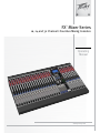 1
1
-
 2
2
-
 3
3
-
 4
4
-
 5
5
-
 6
6
-
 7
7
-
 8
8
-
 9
9
-
 10
10
-
 11
11
-
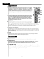 12
12
-
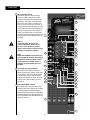 13
13
-
 14
14
-
 15
15
-
 16
16
-
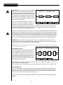 17
17
-
 18
18
-
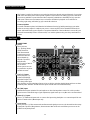 19
19
-
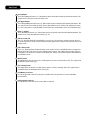 20
20
-
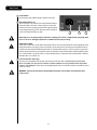 21
21
-
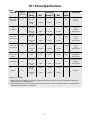 22
22
-
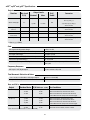 23
23
-
 24
24
-
 25
25
-
 26
26
-
 27
27
-
 28
28
-
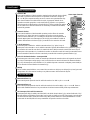 29
29
-
 30
30
-
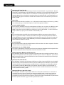 31
31
-
 32
32
-
 33
33
-
 34
34
-
 35
35
-
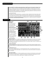 36
36
-
 37
37
-
 38
38
-
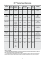 39
39
-
 40
40
-
 41
41
-
 42
42
-
 43
43
-
 44
44
-
 45
45
-
 46
46
-
 47
47
-
 48
48
-
 49
49
-
 50
50
-
 51
51
-
 52
52
-
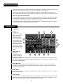 53
53
-
 54
54
-
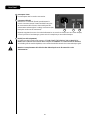 55
55
-
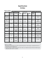 56
56
-
 57
57
-
 58
58
-
 59
59
-
 60
60
-
 61
61
-
 62
62
-
 63
63
-
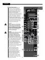 64
64
-
 65
65
-
 66
66
-
 67
67
-
 68
68
-
 69
69
-
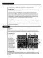 70
70
-
 71
71
-
 72
72
-
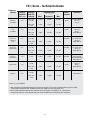 73
73
-
 74
74
-
 75
75
-
 76
76
-
 77
77
-
 78
78
-
 79
79
-
 80
80
-
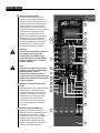 81
81
-
 82
82
-
 83
83
-
 84
84
-
 85
85
-
 86
86
-
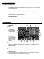 87
87
-
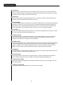 88
88
-
 89
89
-
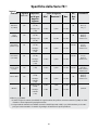 90
90
-
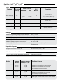 91
91
-
 92
92
-
 93
93
-
 94
94


Peavey 16FX Instrucciones de operación
- Categoría
- Mezcladores de audio
- Tipo
- Instrucciones de operación
- Este manual también es adecuado para
En otros idiomas
- français: Peavey 16FX Mode d'emploi
- italiano: Peavey 16FX Istruzioni per l'uso
- Deutsch: Peavey 16FX Bedienungsanleitung
Documentos relacionados
-
Peavey RQ 2300 Reference Quality Compact Console Manual de usuario
-
Peavey PV 6 Compact Mixer Manual de usuario
-
-
-
-
 Peavy CS 4080 Manual de usuario
-
-
-
-

Otros documentos
-
Phonic AM 1221X Manual de usuario
-
Solac CA 4816 El manual del propietario
-
 SKP Pro Audio VZ-12USB Instrucciones de operación
-
Cuisinart CEC10E El manual del propietario
-
Alesis MultiMix8Line El manual del propietario
-
Cerwin-Vega CVM-1624FXUSB Manual de usuario
-
ULTIMATE SPEED ULG 3.8 A1 Operation and Safety Notes
-
 Budda Head Manual de usuario
-
Panasonic MJ-L500 El manual del propietario
-
BEGLEC SMP 12.22 El manual del propietario

