mothercare Open Changing Unit Guía del usuario
- Tipo
- Guía del usuario

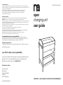
open
changing unit
user guide
IMPORTANT - READ CAREFULLY AND KEEP FOR FUTURE REFERENCE
your child's safety is your responsibility
If you have a problem with this product or require replacement parts,
please contact your nearest Mothercare store or telephone the
Mothercare customer care line on 08453 30 40 30
Alternatively write to:
Customer Care
Mothercare
Cherry Tree Road
Watford
Herts. WD24 6SH
www.mothercare.com
Guía para el usuario
la seguridad de su niño es su responsabilidad
Si surgiera algún problema con este producto o si necesita piezas de recambio,
sirvase ponerse en contacto con el almacén Mothercare más próximo o llamar a la
línea de Atención al Cliente de Mothercare número (+44) 1923 210 210
También puede escribir a:
Customer Care, Mothercare, Cherry Tree Road, Watford, Herts. WD24 6SH, Inglaterra.
www.mothercare.com
Cuidado del producto
Compruebe periódicamente todos los accesorios para asegurarse que no se hayan aflojado.
No utilize el cambiador con cualquiera pieza rota o perdida, ni hasta que ha podido sustituirla con
la pieza correcta de Mothercare.
Puede limpiar su cambiador con un paño húmedo y secarla con un paño suave seco.
Nunca la limpie con limpiadores abrasivos ni a base de amoníaco, lejia o alcohol.
Tenga cuidado al manejar o mover el cambiador. Un manejo sin cuidado puede
dañar los muebles de madera.
Medidas de seguridad
Este Cambiador no es para niños de más de 12 meses de edad o de más de 15Kg de pesor.
¡AVISO! No deje nunca a su niño sin supervisión en la superficie del Cambiador.
Es preciso que todos los accesorios de montaje sean bien apretados. Con tornillos y pernos que se
han aflojado, pueda presionar el niño, partes del cuerpo, también ropa (p.ej. cuerdas, collares,
cintas para chupetes) puedan engancharse.
Es preciso disuadir el subir en el cambiador por un niño más grande mientras que un niño esté en
la superficie, porque es tan peligroso.
Es preciso utilizar el Cambiador sobre una superficie plana y estable.
Una vez montado, no desmonte el Cambiador.
Las fuentes de calor fuerte, p.ej chimeneas, estufas a gas o eléctricas en las proximidades del
Cambiador pueden ser peligrosas si se colocan cerca del Cambiador.
Manténgalo alejado de cordónes y cables eléctricos sueltos, cortinas y enchufes.
No mueva nunca el Cambiador mientras esté el niño en ello.

important notes
1
Please take a few minutes to read this user guide.
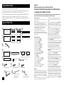
Lay the parts out on the floor and compare to the PARTS CHECKLIST (below). Do not
discard any packaging until you are sure that you have all the parts.
This product has been designed to conform to the Safety Standard BS EN 12221-1: 2000
A Mothercare changing mat is recommended for use with this changing unit, with
maximum dimensions of 75cm x 46cm (29½ x 18 in.) Place the mat evenly between the 4
top barriers.
parts check list
1 Allen Key
12 Long bolts (50mm)
2 Top rails
1 Upper tray
2 Lower trays
1 Left side
4 Lower rails
1 Right side
1 Drawer front
1 Left
drawer side
1 Drawer back
1 Drawer bottom
1 Right
drawer side
2 Short bolts (40mm)
4 Cams
4 Cam pins
fig
1a
fig
1b
fig
1c
fig
1d
fig
1e
fig
1f
fig
1h
fig
1i
fig
1j
fig
1k
fig
1l
fig
1m
fig
1n
fig
1o
fig
1p
fig
1r
fig
1s
You will also need
a "Phillips" head
screwdriver
1 Towel rail
fig
1g
Español:
Guía del usuario para el cambiador abierto.
Contiene información importante, lea aténtamente
y retenga para referencia futura.
Notas importantes 50mm y la llave “Allen”. Asegúrese de que las
ranuras en las barandas inferiores estén por
Por favor, tómese unos minutos en leer esta
encima.
guía de usuario.
Pose la ensambladura en el lado. (Véase fig 3).
Desembale cuidadosamente su producto en
el suelo y familiarícese con las piezas, Superficie mejor hacia arriba, introduzca la
comparándolas con el CATÁLAGO DE PIEZAS bandeja superior, (la más gorda), en las ranuras
que sigue. No tire el embalaje hasta que esté de las barandas superiores. Deslízela por toda la
seguro de que tiene todas las piezas. ranura.
Este cambiador cumple con la norma de Introduzca las bandejas inferiores en las ranuras
seguridad BS EN 12221-1:2000. de las barandas inferiores. (Véase fig 4).
Se aconseja utilizar un cojín cambiador
Monte el otro lado, utilizando los pernos largos
Mothercare de tamaño máximo 75cm x 46cm,
de 50mm y la llave “Allen”. (Véase fig 5).
puesto equitativamente entre las barreras del
Apriete 4 chavetas en los agujeros de la
borde superior.
superficie trasera del frontal de cajón.
Introduzca 2 levas en los agujeros cerca del
Catálogo de piezas
borde anterior de cada lado de cajón. Asegúrese
de que las flechas (”X”) apunten al borde
1 Bandeja superior (fig 1a)
anterior. (Véase fig 6).
2Bandejas inferiores (fig 1b)
Introduzca las chavetas montadas en el frontal en
1 Lado izquierdo (fig 1c)
los agujeros de los bordes anteriores de los lados
1 Lado derecho (fig 1d)
de cajón, hasta que entrén en las levas. Nótese
2Barandas superiores (fig 1e)
que las ranuras en los laterales deben mirar
hacia el interior del cajón, y también deben
4Barandas inferiores (fig 1f)
alinear con la ranura en el frontal. Con un
1 Baranda de toallas (fig 1g)
destornillador, apriete las levas en la dirección de
1 Base de cajón (fig 1h)
las agujas del reloj, para que se cierre la juntura.
1 Frontal de cajón (fig 1i)
(Véase fig 7).
1 Lado de cajón izquierdo (fig 1j)
Introduzca la base de cajón en las ranuras de los
1 Lado de cajón derecho (fig 1k)
lados, hasta el frontal. (Véase fig 8).
1 Fondo de cajón (fig 1l)
Fije el fondo de cajón tal como se indica,
dejando entrar las clavijas en su borde en los
4Levas (fig 1m)
agujeros correspondientes de los lados, y la base
4Chavetas (fig 1n)
en su ranura. Asegure con los 2 pernos de 35mm
12 Pernos largos de 50mm (fig 1o)
y la llave “Allen” proveida. (Véase fig 9).
4 Pernos cortos de 40mm (fig 1p)
Enganche las dos ruedas en cada lado del fondo
2 Pernos de 35mm (fig 1q)
del cajón por encima de las ruedas en los
1 Llave “Allen” (fig 1r)
patines encontrados en cada lado de los
extremos del cambiador. El cajón debe
También necesitará Vd un
deslizarse lisamente. (Véase fig 10).
destornillador tipo “Phillips” (fig 1s)
Sólo se cumple este trabajo por alguién capaz.
Aparato anti-volcar (fig 1t)
Los muros son variados, y por eso no se han
provisto tornillos y tapones. Si Vd. tiene dudas
Montaje
sobre el tipo o la conveniencia del muro, o de los
Monte la baranda para toallas la superficie
accesorios apropiados para ello, busque consejo.
exterior del lado izquierdo, introduciendo dos
Utilizando el tornillo, introducido por un extremo
de los pernos cortos de 40mm en los terceros
de la correa, apriete a una pierna trasera. tan
agujeros y apretándolos en los agujeros de
alto posible. Coloque el mueble en su posición
los soportes, utilizando el llave “Allen.” (Véase
final, cerca del muro, y fíjela al muro utilizando los
fig 2).
accesorios apropiados para el muro. (Véase fig
Monte las barandas en el otro lado, tal como
11).
se indica, utilizando los pernos largos de
Por favor, recuerde que todas las ilustraciones a las que se hace referencia en esta
guía se encuentran en la sección en inglés al principio de la guía.
fig
1t
1 Anti topple device
2 Bolts (35mm)
fig
1q

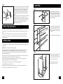
assembly
fig 2
Attach the towel rail to the outer
face of the Left side, passing 2 of the
shorter (40mm) bolts through the
third holes down and into the holes
in the rear of the brackets. Tighten,
using the Allen Key.
fig 3
Attach the rails to the other side, as
shown, using the 50mm bolts and
the Allen key. Make sure, with the
lower tray rails, that the grooves are
near the top.
Rest the assembly on the side panel.
fig 4
Best face upwards, insert the upper
tray (the thicker panel) into the
grooves of the top rails. Slide it all
the way down the grooves.
Insert the lower trays into the
grooves of the lower rails.
Periodically check all fittings to ensure that none have come loose.
The dresser can be cleaned by wiping with a damp cloth and drying with a soft dry
cloth.
Never clean with abrasive, ammonia based, bleach based, or spirit type cleaners.
Take care when handling or moving the dresser. Careless handling can damage
wooden furniture.
This Changing Unit is not to be used for children over 12 months old or 15Kg, whichever
comes first.
WARNING! Do not leave the child unattended.
All Assembly fittings should be tightened properly. Screws and bolts should not be
loose because a child can squeeze parts of the body, or clothing (e.g. strings,
necklaces, ribbons for babies dummies etc.) could get caught. There would be a
danger of strangulation.
Be aware of the risk of open fire and other sources of strong heat, such as electric bar
fires, gas fires, etc. in the near vicinity of the changing unit.
An older child climbing on the dresser while a child is on the changing surface is
extremely dangerous and must be discouraged.
The Changing Unit must be used on a level and stable surface.
Once assembled, do not dismantle.
Keep away from trailing cords, drapes or flexes, and away from electric sockets.
Never move the Changing Unit with the child on it.
care of your product
safety notes
5
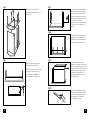
fig 11
This work is only to be carried out by a competent
person. Because of the diverse nature of walls,
wall plugs and screws have not been supplied
with this anti-topple device. If you are at all
unsure of the type or suitability of the wall, or of
the appropriate fixings for it, seek professional
advice.
Attach the wall strap to the rear of one of the legs,
as near the top as you can, using the screw
provided, through one end of the strap. Place the
furniture in its final position, adjacent to the wall,
and fix to the wall, using fixing and screw
appropriate for that wall.
2

fig 5
Attach the left side, using the
remainder of the 50mm bolts and
the Allen key.
3 4
fig 6
Screw 4 cam pins into the holes in
the back of the drawer front.
Insert 2 cams into the holes near the
front edge of each drawer front.
Ensure that the arrows (X) are
pointing towards the front edge.
X
fig 7
Fit the holes in the front edges of the
sides over the cam pins, so that the
pins enter the cams. Note that the
grooves in the sides must be facing
inwards and must align with those in
the drawer front. Using a
screwdriver, turn the cams clockwise,
as far as you can, in order to lock
the joint.
fig 8
Slide the drawer bottom (best face
upwards) into the grooves in the
drawer sides until it sits completely
in the groove in the drawer front.
fig 9
Fit the drawer back as shown,
allowing the 2 dowels in each end to
enter the corresponding holes in the
drawer sides. Ensure that the drawer
bottom slots into the groove on the
drawer back. Secure with the 2
remaining bolts (35mm), using the
Allen key provided.
Hook the two wheels on each side
at the back of the drawer over the
wheels of the runners attached to
the dresser sides. The drawer
should glide in smoothly.
fig 10
-
 1
1
-
 2
2
-
 3
3
-
 4
4


mothercare Open Changing Unit Guía del usuario
- Tipo
- Guía del usuario
en otros idiomas
Artículos relacionados
-
mothercare Beech Open Dresser Guía del usuario
-
-
-
-
-
-
-
-
-