
Copyright © 2023 Pahlén AB, Box 728, SE-194 27 Upplands Väsby, Sweden
Tel. +46 8 594 110 50, Fax +46 8 590 868 80, e-mail: [email protected], www.pahlen.com
User manual
Skimmer Innity
MA55-48 rev.1
2023

SVENSKA 3
ENGLISH 8
DEUTSCH 13
FRANÇAIS 18
ESPAÑOL 23
ITALIANO 28

3
SVENSKA
Skimmer Innity
MA55-48 SE (Instruktionens originalspråk)
Skimmer Infinity
112965 M20509
100
569
179
270
455,5
143
109
30
85
461
152Ø
251,512830-50
100( )
333
186,5
410,5
20
G 2 1/2"
G 1/2"
13
314,5
35
189o
Nivåvakt Ø12
161
387,5
E-E ( 1 : 5 )
E E
270
179
569
100
400
431
128
M5 (17x)
n62x
13
n6,5 (4x)
85
461
112,5
27,25
32,5
Skimmer Infinity
112965 M20509
100
569
179
270
455,5
143
109
30
85
461
152Ø
251,512830-50
100( )
333
186,5
410,5
20
G 2 1/2"
G 1/2"
13
314,5
35
189o
Nivåvakt Ø12
161
387,5
Skimmer Infinity
112965 M20509
100
569
179
270
455,5
143
109
30
85
461
152Ø
251,512830-50
100( )
333
186,5
410,5
20
G 2 1/2"
G 1/2"
13
314,5
35
189o
Nivåvakt Ø12
161
387,5
Skimmer Infinity
112965 M20509
100
569
179
270
455,5
143
109
30
85
461
152Ø
251,512830-50
100( )
333
186,5
410,5
20
G 2 1/2"
G 1/2"
13
314,5
35
189o
Nivåvakt Ø12
161
387,5
Det är viktigt att denna manual läses igenom noggrant för att trygga funktion och livslängd hos utrustningen.
Pahlén AB ansvarar ej för produktgaranti eller skador som sker till följd av felaktig installation, handhavandefel eller felaktigt
underhåll.
Produktbeskrivning
Bräddavloppets funktion i en swimmingpool är att vara ett utlopp för poolens vatten och fånga upp skräp från ytvattnet.
Detta bräddavlopp har genomföringar för anslutning av överbreddning, vattenpåfyllning samt nivåvakt (köps separat).
• Klauckan reglerar ytvattnets hastighet och säkerställer att utloppet inte blockeras av större föremål.
• Den invändiga silkorgen fångar grövre material (som annars skulle transporterats vidare till poolens cirkulationspump).
• Medföljande Skimvac-platta används för bottensugslang vid manuell städning av poolen.
• Bräddavloppets plastkrage är enkel att kapa i höjdled för att passa golvbeläggningen runt poolen.
• Skimmer Innity skall utrustas med en nivåvakt och automatisk vattenpåfyllning.
Pahléns nivåvakt art.nr 11251 (säljs separat) är framtagen till detta bräddavlopp (se instruktion MA55-49 för nivåvakten).
Dimensioner
Drift
Undvik dosering av koncentrerade kemikalier intill rostfria detaljer,
skador kan annars uppstå vid utebliven poolcirkulation.
Töm silkorgen regelbundet.
Rekommenderade värden beträande vattenkvalitet:
Total klorhalt: max 3,5 mg/liter (ppm)*
Klorid(salt)halt: max 250 mg/liter
pH-värde: 7.2 –7.6
Alkalinitet: 60 –120 mg/liter (ppm)
Kalciumhårdhet: 100 – 300 mg/liter (ppm)
Järn: max 0,1 mg/l *
Koppar: max 0,2 mg/l *
Mangan: max 0,05 mg/l *
Fosfor: max 0,01 mg/l *
Nitrat: max 50 mg/l*
* Enligt EN 16713-3
Utanför dessa värden gäller ej produktgarantin.
Vinterstängning
Vid vinterstängning av poolen sänks vattennivån till under bräddavloppet,
lyft ur silkorgen.
Skimmer Innity möjliggör en högre vattennivå i poolen än traditionella
brädd-avlopp. Detta ställer högre krav på att vattennivån är kontrollerad.
Risken nns att pumpen går torr om vattennivån sjunker för mycket.

4
SVENSKA
Skimmer Innity
MA55-48 SE (Instruktionens originalspråk)
F-F ( 1 : 3 )
F F
125
105,5
M20658
Bild 11 - med hel fram kant - OK installation
Skimmer Infinity M20658
Bild 11 - med delad fram kant - EJ OK installation
Skimmer Infinity
M20658
Bild 11 - med hel fram kant - OK installation
Skimmer Infinity M20658
Bild 11 - med delad fram kant - EJ OK installation
Skimmer Infinity
Produktblad
2022-2-14 / SIDA 2 av 3
RRBB9911UU -- BBuussssnniinngg uuttvv//iinnvv.. ggäännggaa
Teknisk specifikation
Artikelnr G×G1 LL1 Z C RSK
RB91U-R020-R015 3/4"x1/2" 16.3 15 13.3 30 2269819
RB91U-R025-R020 1"x3/4" 19.1 16.3 14.8 36 2269827
RB91U-R032-R025 1"1/4x1" 21.4 19.1 16.3 46 2269835
RB91U-R040-R032 1"1/2x1"1/4 21.4 21.4 14 50 2269843
RB91U-R050-R040 2"x1"1/2 25.7 21.4 18.3 65 2269850
RB91U-R065-R050 2"1/2x2" 30.2 25.7 20.5 80 2268555
RB91U-R080-R065 3"x2"1/2 33.3 30.2 20.1 95 2268571
Reservation för eventuella konstruktionsändringar och tekniska ändringar. Rätten till ändringar utan föregående meddelande förbehålls.
GPA Flowsystem AB
Brovägen 5
SE-266 75 Hjärnarp
+46 (0)431-44 58 00
gpa.se
2½”
2”
30,2 20,5
25,7
80
Installation allmänt
Placera bräddavloppet i poolkonstruktionen enligt er poolleverantörs anvisningar. Bräddavlopp placeras normalt med inlopp på
motsatta sidan. Vid montering skall verktyg för rostfritt stål med rengjorda kontaktytor användas.
Förvara produkterna i originalförpackningen fram till installationen för att undvika repor och äckar. Var aktsam vid monteringen
så att inte produkten repas.
Medföljande bussning kan användas när behov nns att reducera 2½”-anslutningen till 2”.
OBS!
Sarg och marktäckning skall INTE ha skarvar där bräddavloppet är placerat.
Trall bör ha stöd på sidorna av bräddavloppet. Trallen bör vara minst 28 mm tjock.
Marksten bör vara minst 30 mm tjock.
Granitkeramik bör vara minst 20 mm tjock.
Avrinning
1. Avrinningsröret limmas i muen med lämpligt PVC-lim.
2. Montera rör och mu i bräddavloppet med medföljande
packning och nippel.
3. Anslut rörkopplingar till överbräddningen.
14. Avrinningsrör
15. Mu
16. Nippel
med packning
105,5

5
SVENSKA
Skimmer Innity
MA55-48 SE (Instruktionens originalspråk)
Detta dokument och dess innehåll ägs
av Pahlén AB och får ej kopieras, delas
eller vidarebefordras till tredjepart utan
skriftlig godkännande.
Art.no.
Revision
Sheet size
Drawing number
Unit E
A2
mm
Trä med liner P105
M20633 0
3D-model
M20633-0
Designed by
Paul.Drotz 2021-11-01 2 (2)
Side of
Date of issue
Unless otherwise stated:
All dimensions are after
surface treatment.
Tolerances/dimensions in this
document take priority over values
found in 3D-model.
General surface profile tolerance Threads
ISO 965
Edges of undefined
shape ISO 13715
Surface roughness
(Ra) ISO 1302
The 3D-model is correct and made in
the middle of the tolerance zon.
Tolerancing
ISO 8015
-
A-A ( 1 : 3 )
B
C
B
C
Art.no.
Revision
Sheet size
Drawing number
Unit E
A2
mm
Trä med liner P105
M20633 0
3D-model
M20633-0
Designed by
Paul.Drotz 2021-11-01 1 (2)
Side of
Date of issue
Unless otherwise stated:
All dimensions are after
surface treatment.
Tolerances/dimensions in this
document take priority over values
found in 3D-model.
General surface profile tolerance Threads
ISO 965
Edges of undefined
shape ISO 13715
Surface roughness
(Ra) ISO 1302
The 3D-model is correct and made in
the middle of the tolerance zon.
Tolerancing
ISO 8015
-
Detta dokument och dess innehåll ägs
av Pahlén AB och får ej kopieras, delas
eller vidarebefordras till tredjepart utan
skriftlig godkännande.
4
10
10
12
18
7
8
B
C
13
8
10
5
34
6
7
21
1
911
12
16
20
20
Art.no.
Revision
Sheet size
Drawing number
Unit E
A2
mm
Håltagning i träpoolstomme
P105 M20634 0
3D-model
M20634-0
Designed by
Paul.Drotz 2021-11-02 1 (1)
Side of
Date of issue
Unless otherwise stated:
All dimensions are after
surface treatment.
Tolerances/dimensions in this
document take priority over values
found in 3D-model.
General surface profile tolerance Threads
ISO 965
Edges of undefined
shape ISO 13715
Surface roughness
(Ra) ISO 1302
The 3D-model is correct and made in
the middle of the tolerance zon.
Tolerancing
ISO 8015
-
Detta dokument och dess innehåll ägs
av Pahlén AB och får ej kopieras, delas
eller vidarebefordras till tredjepart utan
skriftlig godkännande.
0ID för mätprotokoll
435
461
13
122
21
10
()
n6,5 (4x)
85
OBS! Uppdatreade 6/4 2022
pga uppdatering till svetshuset och flytt av fästen
2
18
19 15
16
14
F-F ( 1 : 3 )
F F
125
105,5
L
Montera så här:
1. Gör ett hål i stommen för bräddavloppet, mått och placering enligt bild 3.
2. Montera och xera bräddavloppet i poolstommen enligt bild. Vattenytan skall vara
30 – 40 mm under bräddavloppets överkant. Bräddavloppets äns skall ligga i liv med
färdig poolvägg. För att undvika sättningar skall bräddavloppet xeras med t.ex. tryck-
impregnerade reglar i poolstommen.
3. Anslut rörkoppling till poolcirkulation med lämplig gängtätning.
4. Avrinningsröret (14) limmas i muen (15) med lämpligt PVC-lim och monteras i
bräddavloppet med medföljande packning och nippel (16). Anslut rörkopplingar till
överbräddningen.
5. Montera nivåvakt enligt instruktion MA55-49.
6. Montera klauckan (17) och kontrollera att den sitter korrekt på plats och kan röra sig.
7. Fäst den självhäftande packningen (7) på bräddavloppets framkant (mot poolen).
8. Lägg i linern.
9. Fyll poolen med så mycket vatten att vattenytan når 5 cm under bräddavloppet.
Stäng av vattnet.
10. Montera den yttre packningen (9) och fästramen (10) - fäst först, dra sedan fast
korsvis.
11. Skär rent linern försiktigt längs fästramens (10) insida.
12. Fortsätt nu att fylla vatten i poolen tills vattenytan når centrum av bräddavloppets
öppning.
13. Montera frontramen (12).
14. Montera/justera kragen:
Kapa ev. plastkragen (2) i höjdled så att den passar i förhållande till ytbeläggningen
runt poolen.
Applicera lämplig tätningsmassa på undersidan av kragen mot bräddavloppet.
Tryck ner kragen mot bräddavloppet. Fixera kragen med bifogade skruvar (21).
15. Tryck ner locket (1) i kragen.
1. Lock
(inkl silikonhylsor)
2. Krage
3. Mutter M6 (4x)
4. Sarg
5. Försänkt skruv M6x30 (4x)
6. Självhäftande packning 1,5 mm
7. Väggmatta
8. Liner
9. Packning 2 mm
10. Fästram
11. Skruv M5x16 (13x)
12. Front
13. Försänkt skruv M5x25 (6x)
14. Avrinningsrör PVC
15. Mu
16. Nippel inkl packning
17. Klaucka
18. Silkorg
19. Scimvac-platta
20. Plywood
21. Skruv (2x)
Bild 1.
Bild 3.
Ovankant
linerlist
Vattenyta
Stöd för
brädd-
avloppet
Bild 2.
Installation i poolstomme av trä - klädd med liner

6
SVENSKA
Skimmer Innity
MA55-48 SE (Instruktionens originalspråk)
Detta dokument och dess innehåll ägs
av Pahlén AB och får ej kopieras, delas
eller vidarebefordras till tredjepart utan
skriftlig godkännande.
Art.no.
Revision
Sheet size
Drawing number
Unit E
A2
mm
Mursten med liner
M20649 0
3D-model
M20649-0
Designed by
Paul.Drotz 2021-11-01 2 (2)
Side of
Date of issue
Unless otherwise stated:
All dimensions are after
surface treatment.
Tolerances/dimensions in this
document take priority over value s
found in 3D-model.
General surface profile toleranc e Threads
ISO 965
Edges of undefined
shape ISO 13715
Surface roughness
(Ra) ISO 1302
The 3D-model is correct and mad e in
the middle of the tolerance zon.
Tolerancing
ISO 8015
-
Detta dokument och dess innehåll ägs
av Pahlén AB och får ej kopieras, delas
eller vidarebefordras till tredjepart utan
skriftlig godkännande.
Art.no.
Revision
Sheet size
Drawing number
Unit E
A2
mm
Isolerblock med liner
M20650 0
3D-model
M20650-0
Designed by
Paul.Drotz 2021-11-01 2 (2)
Side of
Date of issue
Unless otherwise stated:
All dimensions are after
surface treatment.
Tolerances/dimensions in this
document take priority over values
found in 3D-model.
General surface profile toleranc e Threads
ISO 965
Edges of undefined
shape ISO 13715
Surface roughness
(Ra) ISO 1302
The 3D-model is correct and mad e in
the middle of the tolerance zon.
Tolerancing
ISO 8015
-
A-A ( 1 : 3 )
B
B
Art.no.
Revision
Sheet size
Drawing number
Unit E
A2
mm
Isolerblock med liner
M20650 0
3D-model
M20650-0
Designed by
Paul.Drotz 2021-11-01 1 (2)
Side of
Date of issue
Unless otherwise stated:
All dimensions are after
surface treatment.
Tolerances/dimensions in this
document take priority over values
found in 3D-model.
General surface profile tolerance Threads
ISO 965
Edges of undefined
shape ISO 13715
Surface roughness
(Ra) ISO 1302
The 3D-model is correct and made in
the middle of the tolerance zon.
Tolerancing
ISO 8015
-
Detta dokument och dess innehåll ägs
av Pahlén AB och får ej kopieras, delas
eller vidarebefordras till tredjepart utan
skriftlig godkännande.
A-A ( 1 : 3 )
C
C
Art.no.
Revision
Sheet size
Drawing number
Unit E
A2
mm
Mursten med liner
M20649 0
3D-model
M20649-0
Designed by
Paul.Drotz 2021-11-01 1 (2)
Side of
Date of issue
Unless otherwise stated:
All dimensions are after
surface treatment.
Tolerances/dimensions in this
document take priority over values
found in 3D-model.
General surface profile tolerance Threads
ISO 965
Edges of undefined
shape ISO 13715
Surface roughness
(Ra) ISO 1302
The 3D-model is correct and made in
the middle of the tolerance zon.
Tolerancing
ISO 8015
-
Detta dokument och dess innehåll ägs
av Pahlén AB och får ej kopieras, delas
eller vidarebefordras till tredjepart utan
skriftlig godkännande.
8
A-A ( 1 : 3 )
B
B
Art.no.
Revision
Sheet size
Drawing number
Unit E
A2
mm
Isolerblock med liner
M20650 0
3D-model
M20650-0
Designed by
Paul.Drotz 2021-11-01 1 (2)
Side of
Date of issue
Unless otherwise stated:
All dimensions are after
surface treatment.
Tolerances/dimensions in this
document take priority over values
found in 3D-model.
General surface profile tolerance Threads
ISO 965
Edges of undefined
shape ISO 13715
Surface roughness
(Ra) ISO 1302
The 3D-model is correct and made in
the middle of the tolerance zon.
Tolerancing
ISO 8015
-
Detta dokument och dess innehåll ägs
av Pahlén AB och får ej kopieras, delas
eller vidarebefordras till tredjepart utan
skriftlig godkännande.
A-A ( 1 : 3 )
C
C
Art.no.
Revision
Sheet size
Drawing number
Unit E
A2
mm
Mursten med liner
M20649 0
3D-model
M20649-0
Designed by
Paul.Drotz 2021-11-01 1 (2)
Side of
Date of issue
Unless otherwise stated:
All dimensions are after
surface treatment.
Tolerances/dimensions in this
document take priority over values
found in 3D-model.
General surface profile tolerance Threads
ISO 965
Edges of undefined
shape ISO 13715
Surface roughness
(Ra) ISO 1302
The 3D-model is correct and made in
the middle of the tolerance zon.
Tolerancing
ISO 8015
-
Detta dokument och dess innehåll ägs
av Pahlén AB och får ej kopieras, delas
eller vidarebefordras till tredjepart utan
skriftlig godkännande.
10
8
25
46
7
2
19
11
12
16
23
13
10
8
25
46
7
2
19
11
12
16
21
22
13
20 24
10
8
7
12
16 21
17
15
14
18
19
10
8
7
12
16
23
17
15
14
24
11
18
19
22
20
13
33
Installation i poolstomme av mursten, isolerblock, betong etc. klädd med poolduk
1. Lock
(inkl silikonhylsor)
2. Krage
3. Skruv
4. Sarg
5. -
6. Självhäftande packning 1,5 mm
7. Väggmatta
8. Liner
9. Packning 2 mm
10. Fästram
11. Skruv M5x16 (13x)
12. Front
13. Försänkt skruv M5x25 (6x)
14. Avrinningsrör PVC
15. Mu
16. Nippel och packning
17. Klaucka
18. Silkorg
19. Scimvac-platta
20. Armeringsjärn
21. Isolerblock
22. Betong
23. Mursten (lecablock)
24. Puts
25. Potentialutjämningspunkt
Montera så här:
OBS! Vid gjutning/armering av stommen får ingen armering ligga närmare rostfritt
material än minst 50 mm.
1. Gör ett hål för bräddavloppet i stommen, mått och placering enligt bild 3, 4, 5, 6 och 7.
2. Montera och xera bräddavloppet i stommen (se bilder ovan).
Vattenytan skall vara 30 – 40 mm under bräddavloppets överkant.
Bräddavloppets äns skall ligga i liv med färdig poolvägg.
3. Montera nivåvakt enligt instruktion MA55-49.
4. Produkten är försedd med en punkt för potentialutjämning (25). Se IEC 60364-7-702
och gällande nationella byggnormer med hänsyn till potentialutjämning.
Observera att felaktig potentialutjämning kan orsaka galvanisk korrosion.
5. Anslut rörkoppling till poolcirkulation med lämplig gängtätning.
6. Avrinningsröret (14) limmas i muen (15) med lämpligt PVC lim och monteras i
bräddavloppet med medföljande packning och nippel (16). Anslut rörkopplingar till
överbräddningen.
7. Maskera bräddavloppets frilagda äns och öppningar innan ev. gjutning för att undvika
betongstänk.
8. Fäst den självhäftande packningen (6) på bräddavloppet (efter gjutningen).
9. Montera klauckan (17) och kontrollera att den sitter korrekt på plats och kan röra sig.
10. Lägg liner i poolen.
11. Fyll poolen med så mycket vatten att vattenytan når 5 cm under bräddavloppet. Stäng av vattnet.
12. Montera den yttre packningen (9) och fästramen (10) - fäst först, dra sedan fast korsvis.
13. Skär rent linern försiktigt längs fästramens (10) insida. Fortsätt nu att fylla vatten i poolen tills vattenytan når centrum av
bräddavloppets öppning.
14. Montera frontramen (12).
15. Montera/justera kragen:
Kapa ev. plastkragen (2) i höjdled så att den passar i förhållande till ytbeläggningen runt poolen.
Applicera lämplig tätningsmassa på undersidan av kragen mot bräddavloppet.
Tryck ner kragen mot bräddavloppet. Fixera kragen med bifogade skruvar (3).
16. Tryck ner locket (1) i kragen.
Bild 4. Bild 5.
Bild 6. Bild 7.

7
SVENSKA
Skimmer Innity
MA55-48 SE (Instruktionens originalspråk)
Detta dokument och dess innehåll ägs
av Pahlén AB och får ej kopieras, delas
eller vidarebefordras till tredjepart utan
skriftlig godkännande.
Art.no.
Revision
Sheet size
Drawing number
Unit E
A2
mm
Betong med kakel
M20651 0
3D-model
M20651-0
Designed by
Paul.Drotz 2021-11-01 2 (2)
Side of
Date of issue
Unless otherwise stated:
All dimensions are after
surface treatment.
Tolerances/dimensions in this
document take priority over values
found in 3D-model.
General surface profile toleranc e Threads
ISO 965
Edges of undefined
shape ISO 13715
Surface roughness
(Ra) ISO 1302
The 3D-model is correct and mad e in
the middle of the tolerance zon.
Tolerancing
ISO 8015
-
10
25
4
1212
16
20
13
24
23
22
10
12
22
27
23
26
MA55-48
Bild - fria monterinhshål
MA55-48
Bild - fria monterinhshål
MA55-48
Bild - fria monterinhshål
3
A-A ( 1 : 3 )
B
B
Detta dokument och dess innehåll ägs
av Pahlén AB och får ej kopieras, delas
eller vidarebefordras till tredjepart utan
skriftlig godkännande.
Art.no.
Revision
Sheet size
Drawing number
Unit E
A2
mm
Betong med kakel
M20651 0
3D-model
M20651-0
Designed by
Paul.Drotz 2021-11-01 1 (2)
Side of
Date of issue
Unless otherwise stated:
All dimensions are after
surface treatment.
Tolerances/dimensions in this
document take priority over values
found in 3D-model.
General surface profile tolerance Threads
ISO 965
Edges of undefined
shape ISO 13715
Surface roughness
(Ra) ISO 1302
The 3D-model is correct and made in
the middle of the tolerance zon.
Tolerancing
ISO 8015
-
16
17
15
14
18
19
A-A ( 1 : 3 )
B
B
Detta dokument och dess innehåll ägs
av Pahlén AB och får ej kopieras, delas
eller vidarebefordras till tredjepart utan
skriftlig godkännande.
Art.no.
Revision
Sheet size
Drawing number
Unit E
A2
mm
Betong med kakel
M20651 0
3D-model
M20651-0
Designed by
Paul.Drotz 2021-11-01 1 (2)
Side of
Date of issue
Unless otherwise stated:
All dimensions are after
surface treatment.
Tolerances/dimensions in this
document take priority over values
found in 3D-model.
General surface profile tolerance Threads
ISO 965
Edges of undefined
shape ISO 13715
Surface roughness
(Ra) ISO 1302
The 3D-model is correct and made in
the middle of the tolerance zon.
Tolerancing
ISO 8015
-
Installation i poolstomme av betong klädd med kakel/mosaik
Rådfråga er betong-/ytskiktsleverantör om eventuellt tätskikt och appliceringsmetod. Pahlén säljer även gjutpluggar för att
underlätta ingjutning (art.nr 822625), se instruktion MA80-15.
Montera så här:
OBS! Vid gjutning/armering av stommen får armering INTE ligga närmare rostfritt material än minst 50 mm.
1. Gör ett hål för bräddavloppet i stommen, mått och placering enligt bild 3, 8 och 9.
2. Applicera lämplig tätningsmassa i skarven mellan ingjutningsänsen och bräddavloppshuset (se bild 10).
Vid applicering av tätningsmassa är det viktigt att skarven blir tät så att eventuellt vatten inte kan tränga igenom skarven.
Se tätningsmedlets instruktion för förberedelser, applicering och härdning.
3. Fixera bräddavloppet i formen så att änsen är i liv med betongväggen.
4. Produkten är försedd med en punkt för potentialutjämning. Se IEC 60364-7-702 och gällande nationella byggnormer med
hänsyn till potentialutjämning. Observera att felaktig potentialutjämning kan orsaka galvanisk korrosion.
5. Före gjutning; maskera bräddavloppets frilagda äns och öppningar för att undvika fula äckar av betongstänk. Öppningarna
i bräddavloppets bakkant för nivåvakt, överbräddning samt påfyllnad kan tätas med medföljande pluggar, se bild 11.
6. Gjut poolstommen.
7. Montera väggbeklädnad (x, kakel, mosaik etc.). Säkerställ att monteringshålen (enlig bild 12) för fästramen är fria så att
fästramen går att montera senare.
8. Montera klauckan (17) och kontrollera att den sitter korrekt på plats och kan röra sig.
9. Montera fästramen (10) och fronten (12) med medföljande skruvar (4st M5x40), se bild 8.
10. Anslut rörkoppling till poolcirkulationen och täta med lämplig gängtätning.
11. Montera nivåvakt enligt instruktion MA55-49.
12. Avrinningsröret (14) limmas i muen (15) med lämpligt PVC-lim och monteras i bräddavloppet med medföljande packning
och nippel (16). Anslut rörkopplingar till överbräddningen.
13. Montera/justera kragen:
Kapa ev. plastkragen (2) i höjdled så att den passar i förhållande till ytbeläggningen runt poolen.
Applicera lämplig tätningsmassa på undersidan av kragen mot bräddavloppet.
Tryck ner kragen mot bräddavloppet. Fixera kragen med bifogade skruvar (3).
14. Tryck ner locket (1) i kragen.
Bild 8.
1. Lock
(inkl silikonhylsor)
2. Krage
3. Skruv
4. Sarg
10. Fästram
12. Front
13. Försänkt skruv M5x40 (6x)
14. Avrinningsrör PVC
15. Mu
16. Nippel och packning
17. Klaucka
18. Silkorg
19. Scimvac-platta
20. Armeringsjärn
22. Betong
23. Kakel/mosaik
24. Puts
25. Potentialutjämningspunkt
26. Kakelx
27. Kakelfog
Bild 9.
Bild 10.
Bild 11.
Bild 12

8
ENGLISH
Skimmer Innity
MA55-48 GB Translation of the original instructions (Swedish)
Skimmer Infinity
112965 M20509
100
569
179
270
455,5
143
109
30
85
461
152Ø
251,512830-50
100( )
333
186,5
410,5
20
G 2 1/2"
G 1/2"
13
314,5
35
189o
Nivåvakt Ø12
161
387,5
E-E ( 1 : 5 )
E E
270
179
569
100
400
431
128
M5 (17x)
n62x
13
n6,5 (4x)
85
461
112,5
27,25
32,5
Skimmer Infinity
112965 M20509
100
569
179
270
455,5
143
109
30
85
461
152Ø
251,512830-50
100( )
333
186,5
410,5
20
G 2 1/2"
G 1/2"
13
314,5
35
189o
Nivåvakt Ø12
161
387,5
Skimmer Infinity
112965 M20509
100
569
179
270
455,5
143
109
30
85
461
152Ø
251,512830-50
100( )
333
186,5
410,5
20
G 2 1/2"
G 1/2"
13
314,5
35
189o
Nivåvakt Ø12
161
387,5
Skimmer Infinity
112965 M20509
100
569
179
270
455,5
143
109
30
85
461
152Ø
251,512830-50
100( )
333
186,5
410,5
20
G 2 1/2"
G 1/2"
13
314,5
35
189o
Nivåvakt Ø12
161
387,5
Level monitor
It is important that you read this manual carefully, to ensure the function and service life of the equipment. Pahlén AB is not
responsible for the product warranty or any damage caused by incorrect installation, incorrect use or incorrect maintenance.
Product description
The function of the skimmer in a swimming pool is to act as an outlet for the pool's water and to remove debris from the surface
of the water.
This skimmer has glands for connecting overow, water lling, as well as level monitor (purchased separately).
• The ap gate regulates the speed of the surface water and prevents the outlet from getting blocked by any large objects.
• The internal screen basket captures coarse material (which would otherwise be transported to the pool's circulation pump).
• The enclosed Skimvac plate is used for the bottom suction hose, when manually cleaning the pool.
• The skimmer’s plastic collar can be easily to cut to height in order to t the oor covering surrounding the pool.
• Skimmer Innity must be equipped with a level monitor and automatic water lling.
Pahlén's level monitor, art. no. 11251 (sold separately), is designed for this skimmer (see instruction MA55-49 for the level monitor).
Dimensions
Operation
Do not dose with concentrated chemicals next to stainless steel parts,
otherwise damage may occur if there is no circulation in the pool.
Empty the screen basket regularly.
Recommended values for the water quality:
Total chlorine concentration: max 3.5 mg/litre (ppm)*
Chloride (salt) concentration: max. 250 mg/litre
pH value: 7.2 –7.6
Alkalinity: 60 –120 mg/litre (ppm)
Calcium hardness: 100 – 300 mg/litre (ppm)
Iron: max 0.1 mg/l *
Copper: max 0.2 mg/l *
Manganese: max 0.05 mg/l *
Phosphorus: max 0.01 mg/l *
Nitrate: max 50 mg/l*
* In accordance with EN 16713-3
The product warranty does not apply outside these values.
Winter storage
When closing down the pool for the winter, lower the water level to below
the skimmer and lift out the screen basket.
The Skimmer Innity allows for a higher water level in the pool than is the
case with traditional skimmers. This places stricter demands on control of
the water level. There is a risk that the pump will run dry, if the water level
drops too much.

9
ENGLISH
Skimmer Innity
MA55-48 GB Translation of the original instructions (Swedish)
F-F ( 1 : 3 )
F F
125
105,5
M20658
Bild 11 - med hel fram kant - OK installation
Skimmer Infinity M20658
Bild 11 - med delad fram kant - EJ OK installation
Skimmer Infinity
M20658
Bild 11 - med hel fram kant - OK installation
Skimmer Infinity M20658
Bild 11 - med delad fram kant - EJ OK installation
Skimmer Infinity
Produktblad
2022-2-14 / SIDA 2 av 3
RRBB9911UU -- BBuussssnniinngg uuttvv//iinnvv.. ggäännggaa
Teknisk specifikation
Artikelnr G×G1 LL1 Z C RSK
RB91U-R020-R015 3/4"x1/2" 16.3 15 13.3 30 2269819
RB91U-R025-R020 1"x3/4" 19.1 16.3 14.8 36 2269827
RB91U-R032-R025 1"1/4x1" 21.4 19.1 16.3 46 2269835
RB91U-R040-R032 1"1/2x1"1/4 21.4 21.4 14 50 2269843
RB91U-R050-R040 2"x1"1/2 25.7 21.4 18.3 65 2269850
RB91U-R065-R050 2"1/2x2" 30.2 25.7 20.5 80 2268555
RB91U-R080-R065 3"x2"1/2 33.3 30.2 20.1 95 2268571
Reservation för eventuella konstruktionsändringar och tekniska ändringar. Rätten till ändringar utan föregående meddelande förbehålls.
GPA Flowsystem AB
Brovägen 5
SE-266 75 Hjärnarp
+46 (0)431-44 58 00
gpa.se
2½”
2”
30,2 20,5
25,7
80
General instruction for installation
Place the skimmer in the pool structure in accordance with your pool supplier's instructions. Skimmers are normally placed
with inlets on the opposite side. During installation, stainless steel tools with clean contact surfaces must be used.
Store the products in their original packaging until installation, to prevent scratches and stains. Take care to avoid scratching
the product during installation.
The supplied bushing can be used when there is a need to reduce the 2½” connection to 2”.
NOTE!
The edge and ground cover must NOT have joints where the skimmer is placed.
Decking should have support on the sides of the skimmer. The decking should be at least 28 mm thick.
The paving stones should be at least 30 mm thick.
Porcelain ceramics should be at least 20 mm thick.
Drainage
1. The drainage pipe is glued in the pipe mu with
suitable PVC adhesive.
2. Fit the pipe and pipe mu in the skimmer using
the enclosed gasket and nipple.
3. Connect pipe ttings to the overow.
14. Drainage pipe
15. Pipe mu
16. Nipple
with gasket
105.5

10
ENGLISH
Skimmer Innity
MA55-48 GB Translation of the original instructions (Swedish)
Detta dokument och dess innehåll ägs
av Pahlén AB och får ej kopieras, delas
eller vidarebefordras till tredjepart utan
skriftlig godkännande.
Art.no.
Revision
Sheet size
Drawing number
Unit E
A2
mm
Trä med liner P105
M20633 0
3D-model
M20633-0
Designed by
Paul.Drotz 2021-11-01 2 (2)
Side of
Date of issue
Unless otherwise stated:
All dimensions are after
surface treatment.
Tolerances/dimensions in this
document take priority over values
found in 3D-model.
General surface profile tolerance Threads
ISO 965
Edges of undefined
shape ISO 13715
Surface roughness
(Ra) ISO 1302
The 3D-model is correct and made in
the middle of the tolerance zon.
Tolerancing
ISO 8015
-
A-A ( 1 : 3 )
B
C
B
C
Art.no.
Revision
Sheet size
Drawing number
Unit E
A2
mm
Trä med liner P105
M20633 0
3D-model
M20633-0
Designed by
Paul.Drotz 2021-11-01 1 (2)
Side of
Date of issue
Unless otherwise stated:
All dimensions are after
surface treatment.
Tolerances/dimensions in this
document take priority over values
found in 3D-model.
General surface profile tolerance Threads
ISO 965
Edges of undefined
shape ISO 13715
Surface roughness
(Ra) ISO 1302
The 3D-model is correct and made in
the middle of the tolerance zon.
Tolerancing
ISO 8015
-
Detta dokument och dess innehåll ägs
av Pahlén AB och får ej kopieras, delas
eller vidarebefordras till tredjepart utan
skriftlig godkännande.
4
10
10
12
18
7
8
B
C
13
8
10
5
34
6
7
21
1
911
12
16
20
20
Art.no.
Revision
Sheet size
Drawing number
Unit E
A2
mm
Håltagning i träpoolstomme
P105 M20634 0
3D-model
M20634-0
Designed by
Paul.Drotz 2021-11-02 1 (1)
Side of
Date of issue
Unless otherwise stated:
All dimensions are after
surface treatment.
Tolerances/dimensions in this
document take priority over values
found in 3D-model.
General surface profile tolerance Threads
ISO 965
Edges of undefined
shape ISO 13715
Surface roughness
(Ra) ISO 1302
The 3D-model is correct and made in
the middle of the tolerance zon.
Tolerancing
ISO 8015
-
Detta dokument och dess innehåll ägs
av Pahlén AB och får ej kopieras, delas
eller vidarebefordras till tredjepart utan
skriftlig godkännande.
0ID för mätprotokoll
435
461
13
122
21
10
()
n6,5 (4x)
85
OBS! Uppdatreade 6/4 2022
pga uppdatering till svetshuset och flytt av fästen
2
18
19 15
16
14
F-F ( 1 : 3 )
F F
125
105,5
L
Install as follows:
1. Make a hole in the frame for the skimmer, dimensions and location as shown in Fig. 3.
2. Install and secure the skimmer in the pool frame as shown. The water surface must be
30 – 40 mm below the top edge of the skimmer. The skimmer’s ange must be level with
the nished pool wall. To prevent subsidence, the skimmer must be secured with, for
example, pressure-impregnated joists in the pool frame.
3. Connect pipe coupling to the pool circulation using a suitable thread sealant.
4. The drainage pipe (14) is glued to the pipe mu (15) using a suitable PVC adhesive
and tted in the skimmer with the enclosed gasket and nipple (16). Connect pipe ttings
to the overow.
5. Install level monitor according to instruction MA55-49.
6. Install the ap gate (17) and check that it is correctly located and can move.
7. Attach the self-adhesive gasket (7) to the front edge of the skimmer (facing the pool).
8. Put in the liner.
9. Fill the pool with enough water for the water surface to reach 5 cm below the skimmer.
Turn o the water.
10. Fit the outer gasket (9) and the mounting frame (10) - fasten rst, then tighten crosswise.
11. Carefully cut the liner cleanly along the inside of the mounting frame (10).
12. Now, continue to ll the pool with water, until the water surface reaches the centre
of the skimmer’s opening.
13. Fit the front frame (12).
14. Install/adjust the collar:
If necessary, cut the plastic collar (2) to height, so it matches the surface coating surrounding the pool.
Apply a suitable sealing compound to the underside of the collar against the skimmer.
Press the collar down against the skimmer. Secure the collar in place with the enclosed screws (21).
15. Press the cover (1) into the collar.
1. Lid
(incl. silicone sleeves)
2. Collar
3. Nut M6 (4x)
4. Edge frame
5. Countersunk screw M6x30 (4x)
6. Self-adhesive gasket 1.5 mm
7. Wall mat
8. Liner
9. Gasket 2 mm
10. Mounting frame
11. Screw M5x16 (13x)
12. Front
13. Countersunk screw M5x25 (6x)
14. PVC drainage pipe
15. Pipe mu
16. Nipple incl. gasket
17. Flap gate
18. Screen basket
19. Skimvac plate
20. Plywood
21. Screw (2x)
Figure 1.
Figure 3.
Top edge,
liner strip
Water surface
Support
for the
skimmer
Figure 2.
Installation in timber pool frame - lined with liner

11
ENGLISH
Skimmer Innity
MA55-48 GB Translation of the original instructions (Swedish)
Detta dokument och dess innehåll ägs
av Pahlén AB och får ej kopieras, delas
eller vidarebefordras till tredjepart utan
skriftlig godkännande.
Art.no.
Revision
Sheet size
Drawing number
Unit E
A2
mm
Mursten med liner
M20649 0
3D-model
M20649-0
Designed by
Paul.Drotz 2021-11-01 2 (2)
Side of
Date of issue
Unless otherwise stated:
All dimensions are after
surface treatment.
Tolerances/dimensions in this
document take priority over value s
found in 3D-model.
General surface profile toleranc e Threads
ISO 965
Edges of undefined
shape ISO 13715
Surface roughness
(Ra) ISO 1302
The 3D-model is correct and mad e in
the middle of the tolerance zon.
Tolerancing
ISO 8015
-
Detta dokument och dess innehåll ägs
av Pahlén AB och får ej kopieras, delas
eller vidarebefordras till tredjepart utan
skriftlig godkännande.
Art.no.
Revision
Sheet size
Drawing number
Unit E
A2
mm
Isolerblock med liner
M20650 0
3D-model
M20650-0
Designed by
Paul.Drotz 2021-11-01 2 (2)
Side of
Date of issue
Unless otherwise stated:
All dimensions are after
surface treatment.
Tolerances/dimensions in this
document take priority over values
found in 3D-model.
General surface profile toleranc e Threads
ISO 965
Edges of undefined
shape ISO 13715
Surface roughness
(Ra) ISO 1302
The 3D-model is correct and mad e in
the middle of the tolerance zon.
Tolerancing
ISO 8015
-
A-A ( 1 : 3 )
B
B
Art.no.
Revision
Sheet size
Drawing number
Unit E
A2
mm
Isolerblock med liner
M20650 0
3D-model
M20650-0
Designed by
Paul.Drotz 2021-11-01 1 (2)
Side of
Date of issue
Unless otherwise stated:
All dimensions are after
surface treatment.
Tolerances/dimensions in this
document take priority over values
found in 3D-model.
General surface profile tolerance Threads
ISO 965
Edges of undefined
shape ISO 13715
Surface roughness
(Ra) ISO 1302
The 3D-model is correct and made in
the middle of the tolerance zon.
Tolerancing
ISO 8015
-
Detta dokument och dess innehåll ägs
av Pahlén AB och får ej kopieras, delas
eller vidarebefordras till tredjepart utan
skriftlig godkännande.
A-A ( 1 : 3 )
C
C
Art.no.
Revision
Sheet size
Drawing number
Unit E
A2
mm
Mursten med liner
M20649 0
3D-model
M20649-0
Designed by
Paul.Drotz 2021-11-01 1 (2)
Side of
Date of issue
Unless otherwise stated:
All dimensions are after
surface treatment.
Tolerances/dimensions in this
document take priority over values
found in 3D-model.
General surface profile tolerance Threads
ISO 965
Edges of undefined
shape ISO 13715
Surface roughness
(Ra) ISO 1302
The 3D-model is correct and made in
the middle of the tolerance zon.
Tolerancing
ISO 8015
-
Detta dokument och dess innehåll ägs
av Pahlén AB och får ej kopieras, delas
eller vidarebefordras till tredjepart utan
skriftlig godkännande.
8
A-A ( 1 : 3 )
B
B
Art.no.
Revision
Sheet size
Drawing number
Unit E
A2
mm
Isolerblock med liner
M20650 0
3D-model
M20650-0
Designed by
Paul.Drotz 2021-11-01 1 (2)
Side of
Date of issue
Unless otherwise stated:
All dimensions are after
surface treatment.
Tolerances/dimensions in this
document take priority over values
found in 3D-model.
General surface profile tolerance Threads
ISO 965
Edges of undefined
shape ISO 13715
Surface roughness
(Ra) ISO 1302
The 3D-model is correct and made in
the middle of the tolerance zon.
Tolerancing
ISO 8015
-
Detta dokument och dess innehåll ägs
av Pahlén AB och får ej kopieras, delas
eller vidarebefordras till tredjepart utan
skriftlig godkännande.
A-A ( 1 : 3 )
C
C
Art.no.
Revision
Sheet size
Drawing number
Unit E
A2
mm
Mursten med liner
M20649 0
3D-model
M20649-0
Designed by
Paul.Drotz 2021-11-01 1 (2)
Side of
Date of issue
Unless otherwise stated:
All dimensions are after
surface treatment.
Tolerances/dimensions in this
document take priority over values
found in 3D-model.
General surface profile tolerance Threads
ISO 965
Edges of undefined
shape ISO 13715
Surface roughness
(Ra) ISO 1302
The 3D-model is correct and made in
the middle of the tolerance zon.
Tolerancing
ISO 8015
-
Detta dokument och dess innehåll ägs
av Pahlén AB och får ej kopieras, delas
eller vidarebefordras till tredjepart utan
skriftlig godkännande.
10
8
25
46
7
2
19
11
12
16
23
13
10
8
25
46
7
2
19
11
12
16
21
22
13
20 24
10
8
7
12
16 21
17
15
14
18
19
10
8
7
12
16
23
17
15
14
24
11
18
19
22
20
13
33
Figure 6.
Figure 4.
Figure 7.
Figure 5.
Installation in a pool frame made from masonry, insulating blocks, concrete, etc.,
lined with pool liner
1. Lid
(incl. silicone sleeves)
2. Collar
3. Screw
4. Edge frame
5. -
6. Self-adhesive gasket 1.5 mm
7. Wall mat
8. Liner
9. Gasket 2 mm
10. Mounting frame
11. Screw M5x16 (13x)
12. Front
13. Countersunk screw M5x25 (6x)
14. PVC drainage pipe
15. Pipe mu
16. Nipple and gasket
17. Flap gate
18. Screen basket
19. Skimvac plate
20. Rebar
21. Insulating block
22. Concrete
23. Masonry (LECA block)
24. Plaster
25. Equipotential bonding point
Install as follows:
NOTE! When pouring concrete/reinforcing the frame, the rebar must not be
any closer to stainless steel material than 50 mm.
1. Make a hole for the skimmer in the frame, dimensions and location as shown in Fig. 3, 4,
5, 6 and 7.
Install and secure the skimmer in the frame (see gures above).
The water surface must be 30 – 40 mm below the top edge of the skimmer.
2. The skimmer’s ange must be level with the nished pool wall.
3. Install level monitor according to instruction MA55-49.
4. The product is provided with an equipotential bonding point (25). See IEC 60364-7-702
and current national building regulations with respect to equipotential bonding.
Please note that improper equipotential bonding can cause galvanic corrosion.
5. Connect pipe coupling to the pool circulation using a suitable thread sealant.
6. The drainage pipe (14) is glued to the pipe mu (15) using a suitable PVC adhesive and
tted in the skimmer with the enclosed gasket and nipple (16). Connect pipe ttings to
the overow.
7. Mask the skimmer's exposed ange and openings before pouring concrete, to prevent
concrete splashes.
8. Attach the self-adhesive gasket (6) to the skimmer (after pouring).
9. Install the ap gate (17) and check that it is correctly located and can move.
10. Place the liner in the pool.
11. Fill the pool with enough water for the water surface to reach 5 cm below the skimmer. Turn o the water.
12. Fit the outer gasket (9) and the mounting frame (10) - fasten rst, then tighten crosswise.
13. Carefully cut the liner cleanly along the inside of the mounting frame (10). Now, continue to ll the pool with water, until the
water surface reaches the centre of the skimmer’s opening.
14. Fit the front frame (12).
15. Install/adjust the collar:
If necessary, cut the plastic collar (2) to height, so it matches the surface coating surrounding the pool. Apply a suitable sealing
compound to the underside of the collar against the skimmer. Press the collar down against the skimmer. Secure the collar in
place with the enclosed screws (3).
16. Press the cover (1) into the collar.

12
ENGLISH
Skimmer Innity
MA55-48 GB Translation of the original instructions (Swedish)
Detta dokument och dess innehåll ägs
av Pahlén AB och får ej kopieras, delas
eller vidarebefordras till tredjepart utan
skriftlig godkännande.
Art.no.
Revision
Sheet size
Drawing number
Unit E
A2
mm
Betong med kakel
M20651 0
3D-model
M20651-0
Designed by
Paul.Drotz 2021-11-01 2 (2)
Side of
Date of issue
Unless otherwise stated:
All dimensions are after
surface treatment.
Tolerances/dimensions in this
document take priority over values
found in 3D-model.
General surface profile toleranc e Threads
ISO 965
Edges of undefined
shape ISO 13715
Surface roughness
(Ra) ISO 1302
The 3D-model is correct and mad e in
the middle of the tolerance zon.
Tolerancing
ISO 8015
-
10
25
4
1212
16
20
13
24
23
22
10
12
22
27
23
26
MA55-48
Bild - fria monterinhshål
MA55-48
Bild - fria monterinhshål
MA55-48
Bild - fria monterinhshål
3
A-A ( 1 : 3 )
B
B
Detta dokument och dess innehåll ägs
av Pahlén AB och får ej kopieras, delas
eller vidarebefordras till tredjepart utan
skriftlig godkännande.
Art.no.
Revision
Sheet size
Drawing number
Unit E
A2
mm
Betong med kakel
M20651 0
3D-model
M20651-0
Designed by
Paul.Drotz 2021-11-01 1 (2)
Side of
Date of issue
Unless otherwise stated:
All dimensions are after
surface treatment.
Tolerances/dimensions in this
document take priority over values
found in 3D-model.
General surface profile tolerance Threads
ISO 965
Edges of undefined
shape ISO 13715
Surface roughness
(Ra) ISO 1302
The 3D-model is correct and made in
the middle of the tolerance zon.
Tolerancing
ISO 8015
-
16
17
15
14
18
19
A-A ( 1 : 3 )
B
B
Detta dokument och dess innehåll ägs
av Pahlén AB och får ej kopieras, delas
eller vidarebefordras till tredjepart utan
skriftlig godkännande.
Art.no.
Revision
Sheet size
Drawing number
Unit E
A2
mm
Betong med kakel
M20651 0
3D-model
M20651-0
Designed by
Paul.Drotz 2021-11-01 1 (2)
Side of
Date of issue
Unless otherwise stated:
All dimensions are after
surface treatment.
Tolerances/dimensions in this
document take priority over values
found in 3D-model.
General surface profile tolerance Threads
ISO 965
Edges of undefined
shape ISO 13715
Surface roughness
(Ra) ISO 1302
The 3D-model is correct and made in
the middle of the tolerance zon.
Tolerancing
ISO 8015
-
Installation in a pool frame made from concrete, lined with tiles/mosaic
Consult your supplier of concrete/surface coating about any waterproong and application method. Pahlén also sells casting
plugs to facilitate embedding (art. no. 822625), see instruction MA80-15.
Install as follows:
NOTE! When pouring concrete/reinforcing the frame, rebar must NOT be any closer than 50 mm to any stainless material.
1. Make a hole for the skimmer in the frame, dimensions and location as shown in Fig. 3, 8 and 9.
2. Apply a suitable sealing compound in the joint between the embedding ange and the skimmer housing (see Fig. 10).
When applying the sealant, it is important that the joint is sealed to prevent any water from penetrating the joint.
Refer to the sealant’s instructions for preparation, application and hardening.
3. Fix the skimmer in the formwork, so the ange is level with the concrete wall.
4. The product is provided with an equipotential bonding point. See IEC 60364-7-702 and current national building regulations
with respect to equipotential bonding. Please note that improper equipotential bonding can cause galvanic corrosion.
5. Before pouring concrete; mask the skimmer's exposed ange and openings to prevent unsightly concrete splashes.
The openings in the back edge of the skimmer for level monitor, overow and lling can be sealed using the enclosed
plugs, see Figure 11.
6. Cast the pool frame.
7. Install wall cladding (x, tile, mosaic, etc.). Make sure that the mounting holes (as shown in Figure 12) for the mounting
frame are free, so the mounting frame can be tted later.
8. Install the ap gate (17) and check that it is correctly located and can move.
9. Fit the mounting frame (10) and front (12) using the enclosed screws (4 M5x40), see Figure 8.
10. Connect the pipe coupling to the pool circulation and seal using a suitable thread sealant.
11. Install level monitor according to instruction MA55-49.
12. The drainage pipe (14) is glued to the pipe mu (15) using a suitable PVC adhesive and tted in the skimmer with the
enclosed gasket and nipple (16). Connect pipe ttings to the overow.
13. Install/adjust the collar:
If necessary, cut the plastic collar (2) to height, so it matches the surface coating surrounding the pool.
Apply a suitable sealing compound to the underside of the collar against the skimmer.
Press the collar down against the skimmer. Secure the collar in place with the enclosed screws (3).
14. Press the cover (1) into the collar.
Figure 8.
1. Lid
(incl. silicone sleeves)
2. Collar
3. Screw
4. Edge frame
10. Mounting frame
12. Front
13. Countersunk screw M5x40 (6x)
14. PVC drainage pipe
15. Pipe mu
16. Nipple and gasket
17. Flap gate
18. Screen basket
19. Skimvac plate
20. Rebar
22. Concrete
23. Tile/mosaic
24. Plaster
25. Equipotential bonding point
26. Tile x
27. Tile grout
Figure 9.
Figure 10.
Figure 11.
Figure 12

13
DEUTSCH
Skimmer Innity
MA55-48 DE Übersetzung der ursprünglichen Anweisungen (Schwedisch)
Skimmer Infinity
112965 M20509
100
569
179
270
455,5
143
109
30
85
461
152Ø
251,512830-50
100( )
333
186,5
410,5
20
G 2 1/2"
G 1/2"
13
314,5
35
189o
Nivåvakt Ø12
161
387,5
E-E ( 1 : 5 )
E E
270
179
569
100
400
431
128
M5 (17x)
n62x
13
n6,5 (4x)
85
461
112,5
27,25
32,5
Skimmer Infinity
112965 M20509
100
569
179
270
455,5
143
109
30
85
461
152Ø
251,512830-50
100( )
333
186,5
410,5
20
G 2 1/2"
G 1/2"
13
314,5
35
189o
Nivåvakt Ø12
161
387,5
Skimmer Infinity
112965 M20509
100
569
179
270
455,5
143
109
30
85
461
152Ø
251,512830-50
100( )
333
186,5
410,5
20
G 2 1/2"
G 1/2"
13
314,5
35
189o
Nivåvakt Ø12
161
387,5
Skimmer Infinity
112965 M20509
100
569
179
270
455,5
143
109
30
85
461
152Ø
251,512830-50
100( )
333
186,5
410,5
20
G 2 1/2"
G 1/2"
13
314,5
35
189o
Nivåvakt Ø12
161
387,5
Dieses Handbuch ist unbedingt sorgfältig zu lesen, damit Betrieb und Haltbarkeit des Geräts sichergestellt sind. Bei Schäden infolge unsach-
gemäßer Installation, Bedienungsfehlern oder mangelnder Wartung übernimmt Pahlén AB keine Gewährleistung oder Schadenshaftung.
Produktbeschreibung
Die Funktion der Überlaufeinrichtung in einem Schwimmbad besteht darin, Poolwasser abzulassen und Schmutz aus dem Oberächenwasser
herauszultern.
Diese Überlaufeinrichtung weist Durchführungen für den Anschluss von überschüssigem Wasser, Wasserzulauf und die Füllstandsregelung
(separat erhältlich).
• Die Klappe reguliert die Geschwindigkeit des Oberächenwassers und sorgt dafür, dass der Auslass nicht durch größere Gegenstände
blockiert wird.
• Der innere Siebkorb fängt gröberes Material ab, das sonst zur Umwälzpumpe des Pools transportiert würde.
• Die mitgelieferte Skimvac-Platte wird für den unteren Bodensaugschlauch bei der manuellen Reinigung des Pools verwendet.
• Die Kunststomanschette der Überlaufeinrichtung lässt sich leicht in der Höhe zuschneiden und so an den Bodenbelag um den
Pool herum anpassen.
• Skimmer Innity muss mit einer Füllstandsregelung und einer automatischen Wasserauüllfunktion ausgestattet sein.
Die Füllstandsregelung von Pahlén, Artikelnr. 11251 (separat erhältlich) ist für diesen Überlauf ausgelegt (siehe Anleitung MA55-49
für die Füllstandsregelung).
Abmessungen
Betrieb
Konzentrierte Chemikalien sollten nicht in der Nähe von Edelstahlbauteilen zugeführt
werden. Andernfalls können Schäden auftreten, wenn im Pool kein Umlauf zustande kommt.
Der Siebkorb ist regelmäßig zu leeren.
Empfohlene Wasserqualität:
Gesamtchlor: max. 3,5 mg/Liter (ppm)*
Chlorid(salz): max. 250 mg/Liter
pH-Wert: 7,2–7,6
Alkalinität: 60–120 mg/Liter (ppm)
Kalziumhärte: 100–300 mg/Liter (ppm)
Eisen: max. 0,1 mg/l *
Kupfer: max. 0,2 mg/l *
Mangan: max. 0,05 mg/l *
Phosphor: max. 0,01 mg/l *
Nitrat: max 50 mg/l*
* Gemäß EN 16713-3
Außerhalb dieser Werte erlischt die Produktgarantie.
Schließung im Winter
Bei Winterschließung des Pools ist der Wasserstand bis unter die Überlaufeinrichtung
abzusenken und der Siebkorb herauszuheben.
Dank Skimmer Innity kann der Wasserstand im Pool höher sein als bei
herkömmlichen Abüssen. Daraus ergeben sich höhere Anforderungen an den zu
kontrollierenden Wasserstand. Sinkt der Wasserstand zu stark ab, besteht Gefahr,
dass die Pumpe trocken läuft.
Füllstandsregelung

14
DEUTSCH
Skimmer Innity
MA55-48 DE Übersetzung der ursprünglichen Anweisungen (Schwedisch)
F-F ( 1 : 3 )
F F
125
105,5
M20658
Bild 11 - med hel fram kant - OK installation
Skimmer Infinity M20658
Bild 11 - med delad fram kant - EJ OK installation
Skimmer Infinity
M20658
Bild 11 - med hel fram kant - OK installation
Skimmer Infinity M20658
Bild 11 - med delad fram kant - EJ OK installation
Skimmer Infinity
Produktblad
2022-2-14 / SIDA 2 av 3
RRBB9911UU -- BBuussssnniinngg uuttvv//iinnvv.. ggäännggaa
Teknisk specifikation
Artikelnr G×G1 LL1 Z C RSK
RB91U-R020-R015 3/4"x1/2" 16.3 15 13.3 30 2269819
RB91U-R025-R020 1"x3/4" 19.1 16.3 14.8 36 2269827
RB91U-R032-R025 1"1/4x1" 21.4 19.1 16.3 46 2269835
RB91U-R040-R032 1"1/2x1"1/4 21.4 21.4 14 50 2269843
RB91U-R050-R040 2"x1"1/2 25.7 21.4 18.3 65 2269850
RB91U-R065-R050 2"1/2x2" 30.2 25.7 20.5 80 2268555
RB91U-R080-R065 3"x2"1/2 33.3 30.2 20.1 95 2268571
Reservation för eventuella konstruktionsändringar och tekniska ändringar. Rätten till ändringar utan föregående meddelande förbehålls.
GPA Flowsystem AB
Brovägen 5
SE-266 75 Hjärnarp
+46 (0)431-44 58 00
gpa.se
2½”
2”
30,2 20,5
25,7
80
Allgemeine Installationshinweise
Die Überlaufeinrichtung ist gemäß den Anweisungen des Poolanbieters in die Poolstruktur zu integrieren. Die Überlaufeinrichtung wird
normalerweise auf der den Einlässen gegenüberliegenden Seite angebracht. Für die Installation sind Werkzeuge aus Edelstahl mit gereinigten
Kontaktächen zu verwenden.
Die Produkte bis zur Installation in der Originalverpackung aufbewahren, damit Kratzer und Flecken verhindert werden. Beim Einbau vorsichtig
vorgehen, damit das Produkt nicht zerkratzt wird.
Die mitgelieferte Buchse kann verwendet werden, wenn der 2½“-Anschluss auf 2“ reduziert werden muss.
HINWEIS!
Umrandung und Bodenbelag dürfen dort KEINE Fugen aufweisen, wo sich die Überlaufeinrichtung bendet.
Holzgitter sollten an den Seiten der Überlaufeinrichtung abgestützt werden. Holzgitter sollten mindestens 28 mm dick sein.
Steinplatten sollten mindestens 30 mm dick sein.
Feinsteinzeugplatten sollten mindestens 20 mm dick sein.
Abuss
1. Das Abussrohr mit dem entsprechenden PVC-Kleber
in die Mue kleben.
2. Das Rohr und die Mue mit der mitgelieferten Dichtung
und dem Nippel in den Überlauf einbauen.
3. Die Rohrverbindungsstücke mit der Überlaufeinrichtung
verbinden.
14. Abussrohr
15. Mue
16. Nippel mit
Dichtung
105,5

15
DEUTSCH
Skimmer Innity
MA55-48 DE Übersetzung der ursprünglichen Anweisungen (Schwedisch)
Detta dokument och dess innehåll ägs
av Pahlén AB och får ej kopieras, delas
eller vidarebefordras till tredjepart utan
skriftlig godkännande.
Art.no.
Revision
Sheet size
Drawing number
Unit E
A2
mm
Trä med liner P105
M20633 0
3D-model
M20633-0
Designed by
Paul.Drotz 2021-11-01 2 (2)
Side of
Date of issue
Unless otherwise stated:
All dimensions are after
surface treatment.
Tolerances/dimensions in this
document take priority over values
found in 3D-model.
General surface profile tolerance Threads
ISO 965
Edges of undefined
shape ISO 13715
Surface roughness
(Ra) ISO 1302
The 3D-model is correct and made in
the middle of the tolerance zon.
Tolerancing
ISO 8015
-
A-A ( 1 : 3 )
B
C
B
C
Art.no.
Revision
Sheet size
Drawing number
Unit E
A2
mm
Trä med liner P105
M20633 0
3D-model
M20633-0
Designed by
Paul.Drotz 2021-11-01 1 (2)
Side of
Date of issue
Unless otherwise stated:
All dimensions are after
surface treatment.
Tolerances/dimensions in this
document take priority over values
found in 3D-model.
General surface profile tolerance Threads
ISO 965
Edges of undefined
shape ISO 13715
Surface roughness
(Ra) ISO 1302
The 3D-model is correct and made in
the middle of the tolerance zon.
Tolerancing
ISO 8015
-
Detta dokument och dess innehåll ägs
av Pahlén AB och får ej kopieras, delas
eller vidarebefordras till tredjepart utan
skriftlig godkännande.
4
10
10
12
18
7
8
B
C
13
8
10
5
34
6
7
21
1
911
12
16
20
20
Art.no.
Revision
Sheet size
Drawing number
Unit E
A2
mm
Håltagning i träpoolstomme
P105 M20634 0
3D-model
M20634-0
Designed by
Paul.Drotz 2021-11-02 1 (1)
Side of
Date of issue
Unless otherwise stated:
All dimensions are after
surface treatment.
Tolerances/dimensions in this
document take priority over values
found in 3D-model.
General surface profile tolerance Threads
ISO 965
Edges of undefined
shape ISO 13715
Surface roughness
(Ra) ISO 1302
The 3D-model is correct and made in
the middle of the tolerance zon.
Tolerancing
ISO 8015
-
Detta dokument och dess innehåll ägs
av Pahlén AB och får ej kopieras, delas
eller vidarebefordras till tredjepart utan
skriftlig godkännande.
0ID för mätprotokoll
435
461
13
122
21
10
()
n6,5 (4x)
85
OBS! Uppdatreade 6/4 2022
pga uppdatering till svetshuset och flytt av fästen
2
18
19 15
16
14
F-F ( 1 : 3 )
F F
125
105,5
L
Einbau:
1. Ein Loch in den Rahmen für die Überlaufeinrichtung bohren, Abmessungen und Anordnung
gemäß Abbildung 3.
2. Die Überlaufeinrichtung gemäß Abbildung im Poolrahmen installieren und befestigen.
Die Wasseroberäche muss 30 — 40 mm unter der Oberkante des Überlaufs liegen. Der Flansch
des Überlaufs muss mit der fertigen Poolwand bündig abschließen. Zur Vermeidung von
Setzungen muss der Überlauf befestigt werden, beispielsweise mit druckimprägnierten Balken
im Poolrahmen.
3. Die Rohrverschraubung mit der entsprechenden Gewindedichtung an den Poolumlauf
anschließen.
4. Das Abussrohr (14) mit geeignetem PVC-Kleber in die Mue (15) kleben und mit beiliegender
Dichtung und Nippel (16) in der Überlaufeinrichtung montieren. Die Rohrverbindungsstücke mit
der Überlaufeinrichtung verbinden.
5. Die Füllstandsregelung gemäß Anleitung MA55-49 einbauen.
6. Die Klappe (17) anbringen und auf korrekten Sitz und Beweglichkeit prüfen.
7. Die selbstklebende Dichtung (7) an der Vorderkante der Überlaufeinrichtung (zum Pool hin)
anbringen.
8. Die Auskleidung anbringen.
9. Den Pool so weit mit Wasser füllen, dass das Wasser 5 cm unter der Überlaufeinrichtung steht.
Die Wasserzufuhr abschalten.
10. Die äußere Dichtung (9) und den Befestigungsrahmen (10) einbauen - zuerst befestigen und
dann über Kreuz festziehen.
11. Die Auskleidung vorsichtig an der Innenseite des Befestigungsrahmens (10) abschneiden.
12. Danach weiter Wasser in den Pool einlassen, bis die Wasseroberäche die Mitte der Überlaufönung erreicht.
13. Den Frontrahmen (12) anbringen.
14. Einbau/Einstellung der Manschette:
Die Kunststomanschette (2) so hoch abschneiden, dass sie im Verhältnis zum Bodenbelag um den Pool herum passt.
An der Unterseite der Manschette an der Überlaufeinrichtung ein geeignetes Dichtmittel auftragen.
Die Manschette nach unten gegen die Überlaufeinrichtung drücken. Die Manschette mit den beiliegenden Schrauben (21) befestigen.
15. Die Abdeckung (1) nach unten in die Manschette drücken.
1. Abdeckung
(inkl. Silikonhülsen)
2. Manschette
3. Mutter M6 (4 x)
4. Umrandung
5. Senkkopfschraube M6x30 (4x)
6. Selbstklebende Dichtung 1,5 mm
7. Wandmatte
8. Auskleidung
9. Dichtung 2 mm
10. Befestigungsrahmen
11. Schraube M5x16 (13x)
12. Front
13. Senkkopfschraube M5x25 (6x)
14. Abussrohr PVC
15. Mue
16. Nippel mit Dichtung
17. Klappe
18. Siebkorb
19. ScimVac-Platte
20. Sperrholz
21. Schraube (2 x)
Abbildung 1
Abbildung 3
Auskleidungsleiste
Oberkante
Wasseroberäche
Abstützung
der Überlauf-
einrichtung
Abbildung 2
Installation im Poolrahmen aus Holz - mit Auskleidung

16
DEUTSCH
Skimmer Innity
MA55-48 DE Übersetzung der ursprünglichen Anweisungen (Schwedisch)
Detta dokument och dess innehåll ägs
av Pahlén AB och får ej kopieras, delas
eller vidarebefordras till tredjepart utan
skriftlig godkännande.
Art.no.
Revision
Sheet size
Drawing number
Unit E
A2
mm
Mursten med liner
M20649 0
3D-model
M20649-0
Designed by
Paul.Drotz 2021-11-01 2 (2)
Side of
Date of issue
Unless otherwise stated:
All dimensions are after
surface treatment.
Tolerances/dimensions in this
document take priority over value s
found in 3D-model.
General surface profile toleranc e Threads
ISO 965
Edges of undefined
shape ISO 13715
Surface roughness
(Ra) ISO 1302
The 3D-model is correct and mad e in
the middle of the tolerance zon.
Tolerancing
ISO 8015
-
Detta dokument och dess innehåll ägs
av Pahlén AB och får ej kopieras, delas
eller vidarebefordras till tredjepart utan
skriftlig godkännande.
Art.no.
Revision
Sheet size
Drawing number
Unit E
A2
mm
Isolerblock med liner
M20650 0
3D-model
M20650-0
Designed by
Paul.Drotz 2021-11-01 2 (2)
Side of
Date of issue
Unless otherwise stated:
All dimensions are after
surface treatment.
Tolerances/dimensions in this
document take priority over values
found in 3D-model.
General surface profile toleranc e Threads
ISO 965
Edges of undefined
shape ISO 13715
Surface roughness
(Ra) ISO 1302
The 3D-model is correct and mad e in
the middle of the tolerance zon.
Tolerancing
ISO 8015
-
A-A ( 1 : 3 )
B
B
Art.no.
Revision
Sheet size
Drawing number
Unit E
A2
mm
Isolerblock med liner
M20650 0
3D-model
M20650-0
Designed by
Paul.Drotz 2021-11-01 1 (2)
Side of
Date of issue
Unless otherwise stated:
All dimensions are after
surface treatment.
Tolerances/dimensions in this
document take priority over values
found in 3D-model.
General surface profile tolerance Threads
ISO 965
Edges of undefined
shape ISO 13715
Surface roughness
(Ra) ISO 1302
The 3D-model is correct and made in
the middle of the tolerance zon.
Tolerancing
ISO 8015
-
Detta dokument och dess innehåll ägs
av Pahlén AB och får ej kopieras, delas
eller vidarebefordras till tredjepart utan
skriftlig godkännande.
A-A ( 1 : 3 )
C
C
Art.no.
Revision
Sheet size
Drawing number
Unit E
A2
mm
Mursten med liner
M20649 0
3D-model
M20649-0
Designed by
Paul.Drotz 2021-11-01 1 (2)
Side of
Date of issue
Unless otherwise stated:
All dimensions are after
surface treatment.
Tolerances/dimensions in this
document take priority over values
found in 3D-model.
General surface profile tolerance Threads
ISO 965
Edges of undefined
shape ISO 13715
Surface roughness
(Ra) ISO 1302
The 3D-model is correct and made in
the middle of the tolerance zon.
Tolerancing
ISO 8015
-
Detta dokument och dess innehåll ägs
av Pahlén AB och får ej kopieras, delas
eller vidarebefordras till tredjepart utan
skriftlig godkännande.
8
A-A ( 1 : 3 )
B
B
Art.no.
Revision
Sheet size
Drawing number
Unit E
A2
mm
Isolerblock med liner
M20650 0
3D-model
M20650-0
Designed by
Paul.Drotz 2021-11-01 1 (2)
Side of
Date of issue
Unless otherwise stated:
All dimensions are after
surface treatment.
Tolerances/dimensions in this
document take priority over values
found in 3D-model.
General surface profile tolerance Threads
ISO 965
Edges of undefined
shape ISO 13715
Surface roughness
(Ra) ISO 1302
The 3D-model is correct and made in
the middle of the tolerance zon.
Tolerancing
ISO 8015
-
Detta dokument och dess innehåll ägs
av Pahlén AB och får ej kopieras, delas
eller vidarebefordras till tredjepart utan
skriftlig godkännande.
A-A ( 1 : 3 )
C
C
Art.no.
Revision
Sheet size
Drawing number
Unit E
A2
mm
Mursten med liner
M20649 0
3D-model
M20649-0
Designed by
Paul.Drotz 2021-11-01 1 (2)
Side of
Date of issue
Unless otherwise stated:
All dimensions are after
surface treatment.
Tolerances/dimensions in this
document take priority over values
found in 3D-model.
General surface profile tolerance Threads
ISO 965
Edges of undefined
shape ISO 13715
Surface roughness
(Ra) ISO 1302
The 3D-model is correct and made in
the middle of the tolerance zon.
Tolerancing
ISO 8015
-
Detta dokument och dess innehåll ägs
av Pahlén AB och får ej kopieras, delas
eller vidarebefordras till tredjepart utan
skriftlig godkännande.
10
8
25
46
7
2
19
11
12
16
23
13
10
8
25
46
7
2
19
11
12
16
21
22
13
20 24
10
8
7
12
16 21
17
15
14
18
19
10
8
7
12
16
23
17
15
14
24
11
18
19
22
20
13
33
Installation in einem Poolrahmen aus Blähtonsteinen, Dämmblöcken, Beton usw. mit
Poolplane ausgekleidet
1. Abdeckung
(inkl. Silikonhülsen)
2. Manschette
3. Schraube
4. Umrandung
5. -
6. Selbstklebende Dichtung 1,5 mm
7. Wandmatte
8. Auskleidung
9. Dichtung 2 mm
10. Befestigungsrahmen
11. Schraube M5x16 (13x)
12. Front
13. Senkkopfschraube M5x25 (6x)
14. Abussrohr PVC
15. Mue
16. Nippel und Dichtung
17. Klappe
18. Siebkorb
19. ScimVac-Platte
20. Bewehrung
21. Isolierblock
22. Beton
23. Mauerstein (Blähtonstein)
24. Putz
25. Potenzialausgleichspunkt
Einbau:
HINWEIS! Bei den Betonier-/Bewehrungsarbeiten am Rahmen muss der Abstand
der Bewehrung zu Edelstahlbauteilen mindestens 50 mm betragen.
1. Im Rahmen ein Loch in die Überlaufeinrichtung bohren, Abmessungen und Anordnung gemäß
Abbildungen 3, 4, 5, 6 und 7.
Den Überlauf im Rahmen anbringen und befestigen (siehe obige Abbildungen).
Die Wasseroberäche muss 30 — 40 mm unter der Oberkante des Überlaufs liegen.
2. Der Flansch des Überlaufs muss mit der fertigen Poolwand bündig abschließen.
3. Die Füllstandsregelung gemäß Anleitung MA55-49 einbauen.
4. Das Produkt ist mit einem Punkt für den Potenzialausgleich versehen (25). Zu Angaben zum
Potenzialausgleich siehe IEC 60364-7-702 und die geltenden nationalen Bauvorschriften.
Es ist zu beachten, dass ein falscher Potenzialausgleich zu galvanischer Korrosion führen kann.
5. Die Rohrverschraubung mit der entsprechenden Gewindedichtung an den Poolumlauf anschließen.
6. Das Abussrohr (14) mit geeignetem PVC-Kleber in die Mue (15) kleben und mit der beiliegen-
den Dichtung und dem beiliegenden Nippel (16) in der Überlaufeinrichtung montieren. Die Rohr-
verbindungsstücke mit der Überlaufeinrichtung verbinden.
7. Vor dem Betonieren den freigelegten Flansch der Überlaufeinrichtung und die Önungen durch
eine Abdeckung vor Betonspritzern schützen.
8. Die selbstklebende Dichtung (6) am Überlauf anbringen (nach dem Betonieren).
9. Die Klappe (17) anbringen und auf korrekten Sitz und Beweglichkeit prüfen.
10. Die Auskleidung im Pool anbringen.
11. Den Pool so weit mit Wasser füllen, dass das Wasser 5 cm unter der Überlaufeinrichtung steht. Die Wasserzufuhr abschalten.
12. Die äußere Dichtung (9) und den Befestigungsrahmen (10) einbauen - zuerst befestigen und dann über Kreuz festziehen.
13. Die Auskleidung vorsichtig an der Innenseite des Befestigungsrahmens (10) abschneiden. Danach weiter Wasser in den Pool einlassen, bis die
Wasseroberäche die Mitte der Überlaufönung erreicht.
14. Den Frontrahmen (12) anbringen.
15. Einbau/Einstellung der Manschette:
Die Kunststomanschette (2) so hoch abschneiden, dass sie im Verhältnis zum Bodenbelag um den Pool herum passt.
An der Unterseite der Manschette an der Überlaufeinrichtung ein geeignetes Dichtmittel auftragen.
Die Manschette nach unten gegen die Überlaufeinrichtung drücken. Die Manschette mit den beiliegenden Schrauben (3) befestigen.
16. Die Abdeckung (1) nach unten in die Manschette drücken.
Abbildung 6
Abbildung 4
Abbildung 7
Abbildung 5

17
DEUTSCH
Skimmer Innity
MA55-48 DE Übersetzung der ursprünglichen Anweisungen (Schwedisch)
Detta dokument och dess innehåll ägs
av Pahlén AB och får ej kopieras, delas
eller vidarebefordras till tredjepart utan
skriftlig godkännande.
Art.no.
Revision
Sheet size
Drawing number
Unit E
A2
mm
Betong med kakel
M20651 0
3D-model
M20651-0
Designed by
Paul.Drotz 2021-11-01 2 (2)
Side of
Date of issue
Unless otherwise stated:
All dimensions are after
surface treatment.
Tolerances/dimensions in this
document take priority over values
found in 3D-model.
General surface profile toleranc e Threads
ISO 965
Edges of undefined
shape ISO 13715
Surface roughness
(Ra) ISO 1302
The 3D-model is correct and mad e in
the middle of the tolerance zon.
Tolerancing
ISO 8015
-
10
25
4
1212
16
20
13
24
23
22
10
12
22
27
23
26
MA55-48
Bild - fria monterinhshål
MA55-48
Bild - fria monterinhshål
MA55-48
Bild - fria monterinhshål
3
A-A ( 1 : 3 )
B
B
Detta dokument och dess innehåll ägs
av Pahlén AB och får ej kopieras, delas
eller vidarebefordras till tredjepart utan
skriftlig godkännande.
Art.no.
Revision
Sheet size
Drawing number
Unit E
A2
mm
Betong med kakel
M20651 0
3D-model
M20651-0
Designed by
Paul.Drotz 2021-11-01 1 (2)
Side of
Date of issue
Unless otherwise stated:
All dimensions are after
surface treatment.
Tolerances/dimensions in this
document take priority over values
found in 3D-model.
General surface profile tolerance Threads
ISO 965
Edges of undefined
shape ISO 13715
Surface roughness
(Ra) ISO 1302
The 3D-model is correct and made in
the middle of the tolerance zon.
Tolerancing
ISO 8015
-
16
17
15
14
18
19
A-A ( 1 : 3 )
B
B
Detta dokument och dess innehåll ägs
av Pahlén AB och får ej kopieras, delas
eller vidarebefordras till tredjepart utan
skriftlig godkännande.
Art.no.
Revision
Sheet size
Drawing number
Unit E
A2
mm
Betong med kakel
M20651 0
3D-model
M20651-0
Designed by
Paul.Drotz 2021-11-01 1 (2)
Side of
Date of issue
Unless otherwise stated:
All dimensions are after
surface treatment.
Tolerances/dimensions in this
document take priority over values
found in 3D-model.
General surface profile tolerance Threads
ISO 965
Edges of undefined
shape ISO 13715
Surface roughness
(Ra) ISO 1302
The 3D-model is correct and made in
the middle of the tolerance zon.
Tolerancing
ISO 8015
-
Installation im Poolrahmen aus mit Fliesen/Mosaik ausgekleidetem Beton
Bei Fragen zu Abdichtungs- und Anbringungsverfahren wenden Sie sich an den Hersteller der Beton-/Oberächenschichten.
Pahlén bietet auch Formstopfen zur Erleichterung des Einbetonierens (Artikelnr. 822625) an, siehe Anleitung MA80-15.
Einbau:
HINWEIS! Bei den Guss-/Bewehrungsarbeiten am Rahmen muss der Abstand der Bewehrung zu Edelstahlbauteilen mindestens
50 mm betragen.
1. Im Rahmen ein Loch in die Überlaufeinrichtung bohren, Abmessungen und Anordnung gemäß Abbildungen 3, 8 und 9.
2. Auf die Fuge zwischen Gussansch und Überlaufgehäuse ein geeignetes Dichtmittel auftragen (siehe Abbildung 10).
Beim Auftragen des Dichtmittels ist es wichtig, dass die Fuge undurchlässig abgedichtet wird, damit kein Wasser durch die Fuge hindurch-
dringt.
Informationen zu Vorbereitung, Anwendung und Aushärtung sind der Anleitung des Dichtmittels zu entnehmen.
3. Die Überlaufeinrichtung in der Schalung so xieren, dass der Flansch bündig zur Betonwand verläuft.
4. Das Produkt ist mit einem Punkt für den Potenzialausgleich versehen. Zu Angaben zum Potenzialausgleich siehe IEC 60364-7-702 und
die geltenden nationalen Bauvorschriften. Es ist zu beachten, dass ein falscher Potenzialausgleich zu galvanischer Korrosion führen kann.
5. Vor dem Betonieren den freigelegten Flansch der Überlaufeinrichtung und die Önungen durch eine Abdeckung vor hässliche Flecken
durch Betonspritzer schützen. Die Önungen hinten am Überlauf für Füllstandsregelung, überschüssiges Wasser und Auüllen können
mit den beiliegenden Stopfen verschlossen werden, siehe Abb. 11.
6. Den Poolrahmen betonieren.
7. Die Wandverkleidung anbringen (Kleber, Fliesen, Mosaik usw.). Sicherstellen, dass die Befestigungslöcher (einzelne Abb. 12) für den
Befestigungsrahmen frei bleiben, damit der Befestigungsrahmen später montiert werden kann.
8. Die Klappe (17) anbringen und auf korrekten Sitz und Beweglichkeit prüfen.
9. Den Befestigungsrahmen (10) und die Vorderseite (12) mit den mitgelieferten Schrauben (4 Stück M5x40) anbringen, siehe Abbildung 8.
10. Die Rohrverschraubung an den Poolumlauf anschließen und mit der entsprechenden Gewindedichtung abdichten.
11. Die Füllstandsregelung gemäß Anleitung MA55-49 einbauen.
12. Das Abussrohr (14) mit geeignetem PVC-Kleber in die Mue (15) kleben und mit beiliegender Dichtung und Nippel (16) in der Überlaufein-
richtung montieren. Die Rohrverbindungsstücke mit der Überlaufeinrichtung verbinden.
13. Einbau/Einstellung der Manschette:
Die Kunststomanschette (2) so hoch abschneiden, dass sie im Verhältnis zum Bodenbelag um den Pool herum passt.
An der Unterseite der Manschette an der Überlaufeinrichtung ein geeignetes Dichtmittel auftragen.
Die Manschette nach unten gegen die Überlaufeinrichtung drücken. Die Manschette mit den beiliegenden Schrauben (3) befestigen.
14. Die Abdeckung (1) nach unten in die Manschette drücken.
Abbildung 8
1. Abdeckung
(inkl. Silikonhülsen)
2. Manschette
3. Schraube
4. Umrandung
10. Befestigungsrahmen
12. Front
13. Senkkopfschraube M5x40 (6x)
14. Abussrohr PVC
15. Mue
16. Nippel und Dichtung
17. Klappe
18. Siebkorb
19. ScimVac-Platte
20. Bewehrung
22. Beton
23. Fliesen/Mosaik
24. Putz
25. Potenzialausgleichspunkt
26. Fliesenkleber
27. Fliesenfuge
Abbildung 9
Abbildung 10
Abbildung 11
Abbildung 12

18
FRANÇAIS
Skimmer Innity
MA55-48 FR Traduction des instructions originales (suédois)
Skimmer Infinity
112965 M20509
100
569
179
270
455,5
143
109
30
85
461
152Ø
251,512830-50
100( )
333
186,5
410,5
20
G 2 1/2"
G 1/2"
13
314,5
35
189o
Nivåvakt Ø12
161
387,5
E-E ( 1 : 5 )
E E
270
179
569
100
400
431
128
M5 (17x)
n62x
13
n6,5 (4x)
85
461
112,5
27,25
32,5
Skimmer Infinity
112965 M20509
100
569
179
270
455,5
143
109
30
85
461
152Ø
251,512830-50
100( )
333
186,5
410,5
20
G 2 1/2"
G 1/2"
13
314,5
35
189o
Nivåvakt Ø12
161
387,5
Skimmer Infinity
112965 M20509
100
569
179
270
455,5
143
109
30
85
461
152Ø
251,512830-50
100( )
333
186,5
410,5
20
G 2 1/2"
G 1/2"
13
314,5
35
189o
Nivåvakt Ø12
161
387,5
Skimmer Infinity
112965 M20509
100
569
179
270
455,5
143
109
30
85
461
152Ø
251,512830-50
100( )
333
186,5
410,5
20
G 2 1/2"
G 1/2"
13
314,5
35
189o
Nivåvakt Ø12
161
387,5
Il est important de lire attentivement ce manuel pour assurer un bon fonctionnement et une longue durée de vie de vos équipements.
Pahlén AB n’est pas responsable de la garantie du produit ou des dommages causés par une mauvaise installation, des erreurs de manipulation
ou d’entretien.
Description du produit
Un déversoir dans une piscine a pour fonction de permettre l’évacuation de l’eau de la piscine et de ramasser les débris de l’eau de surface.
Ce déversoir comporte des œillets pour raccorder le débordement, le remplissage d’eau et le détecteur de niveau (qui peut être acheté
séparément).
• La trappe à rabat régule la vitesse de l’eau de surface et garantit que l’orice d’évacuation n’est pas bloqué par des objets d’une certaine taille.
• Le panier de crépine interne recueille les matériaux plus grossiers (qui seraient entraînés sans cela vers la pompe de circulation de la piscine).
• La plaque Skimvac fournie est utilisée pour le tuyau d’aspiration inférieur lors du nettoyage manuel de la piscine.
• Le collier en plastique à débordement est facile à couper en hauteur pour s’adapter au revêtement de sol autour de la piscine.
• Skimmer Innity doit être équipé d’un protecteur de niveau et d’une recharge automatique d’eau.
Le garde de niveau réf. 11251 de Pahlén (vendu séparément) est conçu pour ce débordement (voir les instructions MA55-49 pour
la surveillance du niveau).
Dimensions
Fonctionnement
Évitez de doser des produits chimiques concentrés à côté de pièces en acier inoxydable
; des dommages risqueraient de se produire en l’absence de circulation dans la piscine.
Videz régulièrement le panier de la crépine.
Valeurs recommandées concernant la qualité de l’eau :
Teneur totale en chlore : 3,5 mg/litre maxi (ppm)*
Teneur en (sels de) chlorure : 250 mg/l maxi
Valeur du pH : 7,2 – 7,6
Alcalinité : 60 – 120 mg/litre (ppm)
Dureté calcique : 100 – 300 mg/litre (ppm)
Fer : max 0,1 mg/l *
Cuivre : max 0,2 mg/l *
Manganèse : max 0,05 mg/l *
Phosphore : max 0,01 mg/l *
Nitrates : max 50 mg/l*
* Conformément à EN 16713-3
En dehors de ces valeurs, la garantie du produit n’est pas applicable.
Hivernage
Pendant la fermeture hivernale de la piscine, le niveau d’eau est abaissé jusque sous
le déversoir : extrayez le panier de la crépine.
Skimmer Innity permet d’avoir un niveau d’eau plus élevé dans la piscine que les
écoulements à débordement traditionnels. Cela impose des exigences plus élevées
par rapport au niveau d’eau à contrôler. La pompe risque de s’assécher si le niveau
d’eau baisse trop.
Contrôle du niveau

19
FRANÇAIS
Skimmer Innity
MA55-48 FR Traduction des instructions originales (suédois)
F-F ( 1 : 3 )
F F
125
105,5
M20658
Bild 11 - med hel fram kant - OK installation
Skimmer Infinity M20658
Bild 11 - med delad fram kant - EJ OK installation
Skimmer Infinity
M20658
Bild 11 - med hel fram kant - OK installation
Skimmer Infinity M20658
Bild 11 - med delad fram kant - EJ OK installation
Skimmer Infinity
Produktblad
2022-2-14 / SIDA 2 av 3
RRBB9911UU -- BBuussssnniinngg uuttvv//iinnvv.. ggäännggaa
Teknisk specifikation
Artikelnr G×G1 LL1 Z C RSK
RB91U-R020-R015 3/4"x1/2" 16.3 15 13.3 30 2269819
RB91U-R025-R020 1"x3/4" 19.1 16.3 14.8 36 2269827
RB91U-R032-R025 1"1/4x1" 21.4 19.1 16.3 46 2269835
RB91U-R040-R032 1"1/2x1"1/4 21.4 21.4 14 50 2269843
RB91U-R050-R040 2"x1"1/2 25.7 21.4 18.3 65 2269850
RB91U-R065-R050 2"1/2x2" 30.2 25.7 20.5 80 2268555
RB91U-R080-R065 3"x2"1/2 33.3 30.2 20.1 95 2268571
Reservation för eventuella konstruktionsändringar och tekniska ändringar. Rätten till ändringar utan föregående meddelande förbehålls.
GPA Flowsystem AB
Brovägen 5
SE-266 75 Hjärnarp
+46 (0)431-44 58 00
gpa.se
2½”
2”
30,2 20,5
25,7
80
Installation, généralités
Placez le déversoir dans la structure de la piscine conformément aux instructions de votre fournisseur de piscine. Les déversoirs sont
normalement placés avec des orices d’admission du côté opposé. Lors de l’installation, utilisez des outils en acier inoxydable avec des
surfaces de contact propres.
Conservez les produits dans leur emballage d’origine jusqu’à l’installation pour éviter les rayures et les taches. Faites attention lors
de l’installation an de ne pas rayer le produit.
La douille fournie peut être utilisée lorsqu’il est nécessaire de réduire la connexion de 2½» à 2».
ATTENTION !
Le châssis et le couvre-sol ne doivent PAS comporter de joints à l’endroit où se trouve le déversoir.
Le caillebotis doit comporter un support sur les côtés du déversoir. Le caillebotis doit avoir une épaisseur d’au moins 28 mm.
Le pavé doit avoir une épaisseur d’au moins 30 mm.
La céramique en granite doit avoir une épaisseur d’au moins 20 mm.
Écoulement
1. Le tuyau d’écoulement doit être collé au manchon avec une
colle PVC appropriée.
2. Installez les tuyaux et le manchon dans le déversoir avec le
joint et le mamelon inclus.
3. Raccordez les raccords de tuyauterie au trop-plein.
14.
Tuyau d’écoulement
15. Manchon
16. Mamelon
avec joint
105,5

20
FRANÇAIS
Skimmer Innity
MA55-48 FR Traduction des instructions originales (suédois)
Detta dokument och dess innehåll ägs
av Pahlén AB och får ej kopieras, delas
eller vidarebefordras till tredjepart utan
skriftlig godkännande.
Art.no.
Revision
Sheet size
Drawing number
Unit E
A2
mm
Trä med liner P105
M20633 0
3D-model
M20633-0
Designed by
Paul.Drotz 2021-11-01 2 (2)
Side of
Date of issue
Unless otherwise stated:
All dimensions are after
surface treatment.
Tolerances/dimensions in this
document take priority over values
found in 3D-model.
General surface profile tolerance Threads
ISO 965
Edges of undefined
shape ISO 13715
Surface roughness
(Ra) ISO 1302
The 3D-model is correct and made in
the middle of the tolerance zon.
Tolerancing
ISO 8015
-
A-A ( 1 : 3 )
B
C
B
C
Art.no.
Revision
Sheet size
Drawing number
Unit E
A2
mm
Trä med liner P105
M20633 0
3D-model
M20633-0
Designed by
Paul.Drotz 2021-11-01 1 (2)
Side of
Date of issue
Unless otherwise stated:
All dimensions are after
surface treatment.
Tolerances/dimensions in this
document take priority over values
found in 3D-model.
General surface profile tolerance Threads
ISO 965
Edges of undefined
shape ISO 13715
Surface roughness
(Ra) ISO 1302
The 3D-model is correct and made in
the middle of the tolerance zon.
Tolerancing
ISO 8015
-
Detta dokument och dess innehåll ägs
av Pahlén AB och får ej kopieras, delas
eller vidarebefordras till tredjepart utan
skriftlig godkännande.
4
10
10
12
18
7
8
B
C
13
8
10
5
34
6
7
21
1
911
12
16
20
20
Art.no.
Revision
Sheet size
Drawing number
Unit E
A2
mm
Håltagning i träpoolstomme
P105 M20634 0
3D-model
M20634-0
Designed by
Paul.Drotz 2021-11-02 1 (1)
Side of
Date of issue
Unless otherwise stated:
All dimensions are after
surface treatment.
Tolerances/dimensions in this
document take priority over values
found in 3D-model.
General surface profile tolerance Threads
ISO 965
Edges of undefined
shape ISO 13715
Surface roughness
(Ra) ISO 1302
The 3D-model is correct and made in
the middle of the tolerance zon.
Tolerancing
ISO 8015
-
Detta dokument och dess innehåll ägs
av Pahlén AB och får ej kopieras, delas
eller vidarebefordras till tredjepart utan
skriftlig godkännande.
0ID för mätprotokoll
435
461
13
122
21
10
()
n6,5 (4x)
85
OBS! Uppdatreade 6/4 2022
pga uppdatering till svetshuset och flytt av fästen
2
18
19 15
16
14
F-F ( 1 : 3 )
F F
125
105,5
L
Eectuez le montage comme suit :
1. Faites un trou dans l’ossature pour le déversoir, les dimensions et l’emplacement comme indiqué
à la gure 3.
2. Installez et xez le déversoir dans l’ossature de la piscine comme indiqué. La surface de l’eau doit
se situer entre 30 et 40 mm sous le haut du déversoir. La bride du déversoir doit être en contact
avec une paroi de piscine nie. Pour éviter tout aaissement, le déversoir doit être xé avec, par
exemple, des solives traitées sous pression dans l’ossature de la piscine.
3. Connectez le raccord de tuyau à la circulation de la piscine au moyen du joint de letage approprié.
4. Le tuyau de vidange (14) doit être collé au manchon (15) avec de la colle PVC appropriée et monté
dans le déversoir avec le joint et le mamelon fournis (16). Raccordez les raccords de tuyauterie au
trop-plein.
5. Installez un protecteur de niveau conformément à l’instruction MA55-49.
6. Installez la trappe à rabat (17) et vériez qu’elle est correctement en place tout en restant mobile.
7. Fixez le joint adhésif (7) au bord d’attaque du déversoir (face à la piscine).
8. Placez la doublure.
9. Remplissez la piscine avec tellement d’eau que la surface de l’eau atteint 5 cm sous le déversoir.
Arrêtez l’eau.
10. Installez le joint extérieur (9) et l’ossature de xation (10) - xez d’abord, puis serrez dans le sens
transversal.
11. Coupez soigneusement la doublure le long de l’intérieur du cadre de xation (10).
12. Maintenant, continuez à remplir l’eau dans la piscine jusqu’à ce que la surface de l’eau atteigne le centre de l’ouverture du déversoir.
13. Installez le cadre avant (12).
14. Installation / réglage du collier :
Si nécessaire, coupez le collier en plastique (2) en hauteur an qu’il s’adapte au revêtement de surface autour de la piscine.
Appliquez le composé d’étanchéité approprié sur la face inférieure du collier contre le déversoir.
Appuyez sur le collier contre le déversoir. Fixez le collier avec les vis fournies (21).
15. Appuyez sur le couvercle (1) dans le collier.
1. Couvercle
(avec manchons en silicone)
2. Collier
3. Écrou M6 (4 x)
4. Paroi
5. Vis encastrée M6 x 30 (x 4)
6. Joint auto-adhésif 1,5 mm
7. Revêtement de paroi
8. Doublure
9. Joint 2 mm
10. Cadre de xation
11. Vis M5 x 16 (13 x)
12. Partie avant
13. Vis encastrée M5 x 25 (6 x)
14. Tuyau d’écoulement en PVC
15. Manchon
16. Mamelon avec joint inclus
17. Trappe à rabat
18. Crépine
19. Plaque Scimvac
20. Contreplaqué
21. Vis (2 x)
Figure 1.
Figure 3.
Bande de
doublure
supérieure
Surface de l’eau
Support
pour le
déversoir
Figure 2.
Installation dans une ossature de piscine en bois - revêtue d’une doublure

21
FRANÇAIS
Skimmer Innity
MA55-48 FR Traduction des instructions originales (suédois)
Detta dokument och dess innehåll ägs
av Pahlén AB och får ej kopieras, delas
eller vidarebefordras till tredjepart utan
skriftlig godkännande.
Art.no.
Revision
Sheet size
Drawing number
Unit E
A2
mm
Mursten med liner
M20649 0
3D-model
M20649-0
Designed by
Paul.Drotz 2021-11-01 2 (2)
Side of
Date of issue
Unless otherwise stated:
All dimensions are after
surface treatment.
Tolerances/dimensions in this
document take priority over value s
found in 3D-model.
General surface profile toleranc e Threads
ISO 965
Edges of undefined
shape ISO 13715
Surface roughness
(Ra) ISO 1302
The 3D-model is correct and mad e in
the middle of the tolerance zon.
Tolerancing
ISO 8015
-
Detta dokument och dess innehåll ägs
av Pahlén AB och får ej kopieras, delas
eller vidarebefordras till tredjepart utan
skriftlig godkännande.
Art.no.
Revision
Sheet size
Drawing number
Unit E
A2
mm
Isolerblock med liner
M20650 0
3D-model
M20650-0
Designed by
Paul.Drotz 2021-11-01 2 (2)
Side of
Date of issue
Unless otherwise stated:
All dimensions are after
surface treatment.
Tolerances/dimensions in this
document take priority over values
found in 3D-model.
General surface profile toleranc e Threads
ISO 965
Edges of undefined
shape ISO 13715
Surface roughness
(Ra) ISO 1302
The 3D-model is correct and mad e in
the middle of the tolerance zon.
Tolerancing
ISO 8015
-
A-A ( 1 : 3 )
B
B
Art.no.
Revision
Sheet size
Drawing number
Unit E
A2
mm
Isolerblock med liner
M20650 0
3D-model
M20650-0
Designed by
Paul.Drotz 2021-11-01 1 (2)
Side of
Date of issue
Unless otherwise stated:
All dimensions are after
surface treatment.
Tolerances/dimensions in this
document take priority over values
found in 3D-model.
General surface profile tolerance Threads
ISO 965
Edges of undefined
shape ISO 13715
Surface roughness
(Ra) ISO 1302
The 3D-model is correct and made in
the middle of the tolerance zon.
Tolerancing
ISO 8015
-
Detta dokument och dess innehåll ägs
av Pahlén AB och får ej kopieras, delas
eller vidarebefordras till tredjepart utan
skriftlig godkännande.
A-A ( 1 : 3 )
C
C
Art.no.
Revision
Sheet size
Drawing number
Unit E
A2
mm
Mursten med liner
M20649 0
3D-model
M20649-0
Designed by
Paul.Drotz 2021-11-01 1 (2)
Side of
Date of issue
Unless otherwise stated:
All dimensions are after
surface treatment.
Tolerances/dimensions in this
document take priority over values
found in 3D-model.
General surface profile tolerance Threads
ISO 965
Edges of undefined
shape ISO 13715
Surface roughness
(Ra) ISO 1302
The 3D-model is correct and made in
the middle of the tolerance zon.
Tolerancing
ISO 8015
-
Detta dokument och dess innehåll ägs
av Pahlén AB och får ej kopieras, delas
eller vidarebefordras till tredjepart utan
skriftlig godkännande.
8
A-A ( 1 : 3 )
B
B
Art.no.
Revision
Sheet size
Drawing number
Unit E
A2
mm
Isolerblock med liner
M20650 0
3D-model
M20650-0
Designed by
Paul.Drotz 2021-11-01 1 (2)
Side of
Date of issue
Unless otherwise stated:
All dimensions are after
surface treatment.
Tolerances/dimensions in this
document take priority over values
found in 3D-model.
General surface profile tolerance Threads
ISO 965
Edges of undefined
shape ISO 13715
Surface roughness
(Ra) ISO 1302
The 3D-model is correct and made in
the middle of the tolerance zon.
Tolerancing
ISO 8015
-
Detta dokument och dess innehåll ägs
av Pahlén AB och får ej kopieras, delas
eller vidarebefordras till tredjepart utan
skriftlig godkännande.
A-A ( 1 : 3 )
C
C
Art.no.
Revision
Sheet size
Drawing number
Unit E
A2
mm
Mursten med liner
M20649 0
3D-model
M20649-0
Designed by
Paul.Drotz 2021-11-01 1 (2)
Side of
Date of issue
Unless otherwise stated:
All dimensions are after
surface treatment.
Tolerances/dimensions in this
document take priority over values
found in 3D-model.
General surface profile tolerance Threads
ISO 965
Edges of undefined
shape ISO 13715
Surface roughness
(Ra) ISO 1302
The 3D-model is correct and made in
the middle of the tolerance zon.
Tolerancing
ISO 8015
-
Detta dokument och dess innehåll ägs
av Pahlén AB och får ej kopieras, delas
eller vidarebefordras till tredjepart utan
skriftlig godkännande.
10
8
25
46
7
2
19
11
12
16
23
13
10
8
25
46
7
2
19
11
12
16
21
22
13
20 24
10
8
7
12
16 21
17
15
14
18
19
10
8
7
12
16
23
17
15
14
24
11
18
19
22
20
13
33
Installation dans le cadre de la piscine en brique, blocs isolants, béton, etc.
revêtus d’un tissu de piscine
1. Couvercle
(avec manchons en silicone)
2. Collier
3. Vis
4. Paroi
5. -
6. Joint auto-adhésif 1,5 mm
7. Revêtement de paroi
8. Doublure
9. Joint 2 mm
10. Cadre de xation
11. Vis M5 x 16 (13 x)
12. Partie avant
13. Vis encastrée M5 x 25 (6 x)
14. Tuyau d’écoulement en PVC
15. Manchon
16. Mamelon et joint
17. Trappe à rabat
18. Crépine
19. Plaque Scimvac
20. Fer d’armature
21. Bloc isolant
22. Béton
23. Brique (lecablock)
24. Enduit
25. Point de liaison équipotentiel
Eectuez le montage comme suit :
ATTENTION ! Lors de la coulée / du renforcement de l’ossature, aucun renfort ne doit se trouver
à une distance du matériau en acier inoxydable inférieure à 50 mm.
1. Percez un trou pour le déversoir dans l’ossature, avec les dimensions et le placement indiqués aux
gures 3, 4, 5, 6 et 7.
Installez et xez le déversoir dans l'ossature (voir les photos ci-dessus).
La surface de l’eau doit se situer entre 30 et 40 mm sous le haut du déversoir.
2. La bride du déversoir doit être en contact avec une paroi de piscine nie.
3. Installez un protecteur de niveau conformément à l’instruction MA55-49.
4. Le produit est pourvu d’un point d’égalisation de potentiel (25). Voir CEI 60364-7-702 et les normes
nationales de construction en vigueur pour l’égalisation de potentiel.
Notez qu’une égalisation de potentiel incorrecte peut provoquer une corrosion galvanique.
5. Connectez le raccord de tuyau à la circulation de la piscine au moyen du joint de letage approprié.
6. Le tuyau de vidange (14) doit être collé au manchon (15) avec de la colle PVC appropriée et monté
dans le déversoir avec le joint et le mamelon fournis (16). Raccordez les raccords de tuyauterie au
trop-plein.
7. Masquez la bride et les ouvertures exposées du déversoir avant la coulée pour éviter les éclabous-
sures de béton.
8. Fixez le joint auto-adhésif (6) sur le déversoir (après la coulée).
9. Installez la trappe à rabat (17) et vériez qu’elle est correctement en place tout en restant mobile.
10. Placez la doublure dans la piscine.
11. Remplissez la piscine avec tellement d’eau que la surface de l’eau atteint 5 cm sous le déversoir. Arrêtez l’eau.
12. Installez le joint extérieur (9) et l’ossature de xation (10) - xez d’abord, puis serrez dans le sens transversal.
13. Coupez soigneusement la doublure le long de l’intérieur du cadre de xation (10). Maintenant, continuez à remplir l’eau dans la piscine
jusqu’à ce que la surface de l’eau atteigne le centre de l’ouverture du déversoir.
14. Installez le cadre avant (12).
15. Installation / réglage du collier :
Si nécessaire, coupez le collier en plastique (2) en hauteur an qu’il s’adapte au revêtement de surface autour de la piscine.
Appliquez le composé d’étanchéité approprié sur la face inférieure du collier contre le déversoir.
Appuyez sur le collier contre le déversoir. Fixez le collier avec les vis fournies (3).
16. Appuyez sur le couvercle (1) dans le collier.
Figure 6.
Figure 4.
Figure 7.
Figure 5.

22
FRANÇAIS
Skimmer Innity
MA55-48 FR Traduction des instructions originales (suédois)
Detta dokument och dess innehåll ägs
av Pahlén AB och får ej kopieras, delas
eller vidarebefordras till tredjepart utan
skriftlig godkännande.
Art.no.
Revision
Sheet size
Drawing number
Unit E
A2
mm
Betong med kakel
M20651 0
3D-model
M20651-0
Designed by
Paul.Drotz 2021-11-01 2 (2)
Side of
Date of issue
Unless otherwise stated:
All dimensions are after
surface treatment.
Tolerances/dimensions in this
document take priority over values
found in 3D-model.
General surface profile toleranc e Threads
ISO 965
Edges of undefined
shape ISO 13715
Surface roughness
(Ra) ISO 1302
The 3D-model is correct and mad e in
the middle of the tolerance zon.
Tolerancing
ISO 8015
-
10
25
4
1212
16
20
13
24
23
22
10
12
22
27
23
26
MA55-48
Bild - fria monterinhshål
MA55-48
Bild - fria monterinhshål
MA55-48
Bild - fria monterinhshål
3
A-A ( 1 : 3 )
B
B
Detta dokument och dess innehåll ägs
av Pahlén AB och får ej kopieras, delas
eller vidarebefordras till tredjepart utan
skriftlig godkännande.
Art.no.
Revision
Sheet size
Drawing number
Unit E
A2
mm
Betong med kakel
M20651 0
3D-model
M20651-0
Designed by
Paul.Drotz 2021-11-01 1 (2)
Side of
Date of issue
Unless otherwise stated:
All dimensions are after
surface treatment.
Tolerances/dimensions in this
document take priority over values
found in 3D-model.
General surface profile tolerance Threads
ISO 965
Edges of undefined
shape ISO 13715
Surface roughness
(Ra) ISO 1302
The 3D-model is correct and made in
the middle of the tolerance zon.
Tolerancing
ISO 8015
-
16
17
15
14
18
19
A-A ( 1 : 3 )
B
B
Detta dokument och dess innehåll ägs
av Pahlén AB och får ej kopieras, delas
eller vidarebefordras till tredjepart utan
skriftlig godkännande.
Art.no.
Revision
Sheet size
Drawing number
Unit E
A2
mm
Betong med kakel
M20651 0
3D-model
M20651-0
Designed by
Paul.Drotz 2021-11-01 1 (2)
Side of
Date of issue
Unless otherwise stated:
All dimensions are after
surface treatment.
Tolerances/dimensions in this
document take priority over values
found in 3D-model.
General surface profile tolerance Threads
ISO 965
Edges of undefined
shape ISO 13715
Surface roughness
(Ra) ISO 1302
The 3D-model is correct and made in
the middle of the tolerance zon.
Tolerancing
ISO 8015
-
Installation dans une ossature de piscine en béton revêtu de carrelage / mosaïques
Consultez votre fournisseur de béton / de couche de surface à propos de la couche d’étanchéité éventuelle et de la méthode d’application.
Pahlén vend également des bouchons de coulée pour faciliter la coulée (réf. 822625), voir l’instruction MA80-15.
Eectuez le montage comme suit :
ATTENTION ! Lors de la coulée/de l’armature de l’ossature, AUCUN renfort ne doit se trouver à moins de 50 mm du matériau inoxydable.
1. Percez un trou pour le déversoir dans l'ossature, avec les dimensions et le placement indiqués aux gures 3, 8 et 9.
2. Appliquer le composé d’étanchéité approprié sur le joint entre la bride de coulée et le boîtier du déversoir (voir gure 10).
Lors de l’application du composé d’étanchéité, veillez à ce que le raccord soit bien étanchéié an que l’eau ne puisse pas pénétrer dans
le raccord.
Voir les instructions du composé d’étanchéité pour la préparation, l’application et le durcissement.
3. Fixez le déversoir dans le moule de manière à ce que la bride soit en contact avec le mur de béton.
4. L’équipement est muni d’un point d’égalisation de potentiel. Voir IEC 60364-7-702 et les normes nationales de construction en vigueur pour
l’égalisation de potentiel. Notez qu’une égalisation de potentiel incorrecte peut provoquer une corrosion galvanique.
5. Avant la coulée, masquez la bride et les ouvertures exposées du déversoir pour éviter les tâches de béton. Les ouvertures sur le bord
arrière du déversoir pour détecteur de niveau, débordement et remplissage peuvent être obturées avec les bouchons fournis, voir gure 11.
6. Coulez l’ossature de la piscine.
7. Installez un revêtement mural (xe, carrelage, mosaïque, etc.). Assurez-vous que les trous de montage (conformément à la gure 12)
du cadre de montage sont dégagés an que l'ossature de xation puisse être monté ultérieurement.
8. Installez la trappe à rabat (17) et vériez qu’elle est correctement en place tout en restant mobile.
9. Installez l'ossature de xation (10) et la partie avant (12) xez-les avec les vis fournies (4 x M5 x 40), voir gure 8.
10. Connectez le raccord de tube à la circulation de la piscine et obturez-le avec le joint leté approprié.
11. Installez un protecteur de niveau conformément à l’instruction MA55-49.
12. Le tuyau de vidange (14) doit être collé au manchon (15) avec de la colle PVC appropriée et monté dans le déversoir avec le joint et le
mamelon fournis (16). Raccordez les raccords de tuyauterie au trop-plein.
13. Installation / réglage du collier :
Si nécessaire, coupez le collier en plastique (2) en hauteur an qu’il s’adapte au revêtement de surface autour de la piscine.
Appliquez le composé d’étanchéité approprié sur la face inférieure du collier contre le déversoir.
Appuyez sur le collier contre le déversoir. Fixez le collier avec les vis fournies (3).
14. Appuyez sur le couvercle (1) dans le collier.
Figure 8.
1. Couvercle
(avec manchons en silicone)
2. Collier
3. Vis
4. Paroi
10. Cadre de xation
12. Partie avant
13. Vis encastrée M5 x 40 (6 x)
14. Tuyau d’écoulement en PVC
15. Manchon
16. Mamelon et joint
17. Trappe à rabat
18. Crépine
19. Plaque Scimvac
20. Fer d’armature
22. Béton
23. Carrelage / mosaïque
24. Enduit
25. Point de liaison équipotentiel
26. Colle de carrelage
27. Joint de carrelage
Figure 9.
Figure 10.
Figure 11.
Figure 12.

23
ESPAÑOL
Desagüe de desbordamiento Innity
MA55-48 ES Traducción de las instrucciones originales (sueco)
Skimmer Infinity
112965 M20509
100
569
179
270
455,5
143
109
30
85
461
152Ø
251,512830-50
100( )
333
186,5
410,5
20
G 2 1/2"
G 1/2"
13
314,5
35
189o
Nivåvakt Ø12
161
387,5
E-E ( 1 : 5 )
E E
270
179
569
100
400
431
128
M5 (17x)
n62x
13
n6,5 (4x)
85
461
112,5
27,25
32,5
Skimmer Infinity
112965 M20509
100
569
179
270
455,5
143
109
30
85
461
152Ø
251,512830-50
100( )
333
186,5
410,5
20
G 2 1/2"
G 1/2"
13
314,5
35
189o
Nivåvakt Ø12
161
387,5
Skimmer Infinity
112965 M20509
100
569
179
270
455,5
143
109
30
85
461
152Ø
251,512830-50
100( )
333
186,5
410,5
20
G 2 1/2"
G 1/2"
13
314,5
35
189o
Nivåvakt Ø12
161
387,5
Skimmer Infinity
112965 M20509
100
569
179
270
455,5
143
109
30
85
461
152Ø
251,512830-50
100( )
333
186,5
410,5
20
G 2 1/2"
G 1/2"
13
314,5
35
189o
Nivåvakt Ø12
161
387,5
Con el n de garantizar el funcionamiento y la vida útil del equipo, es importante leer este manual detenidamente.
Pahlén AB no se hace responsable de la garantía del producto ni de los daños provocados por una instalación incorrecta, errores de mani-
pulación o un mantenimiento incorrecto.
Descripción del producto
La función del desagüe de desbordamiento en una piscina es ser una salida para el agua de la piscina y atrapar los residuos que oten
en la supercie del agua.
Este desagüe de desbordamiento tiene entradas para la conexión de extensiones, el llenado de agua y un indicador de rebase de nivel
(se compran por separado).
• La tapa de la compuerta regula la velocidad del agua supercial y garantiza que la salida no se bloquee por objetos grandes.
• La cesta de rejilla interna captura los materiales más gruesos (de lo contrario, serían transportados a la bomba de circulación de la piscina).
• La placa Skimvac incluida se utiliza para la manguera de succión del fondo durante la limpieza manual de la piscina.
• El collarín de plástico del desagüe de desbordamiento es fácil de cortar verticalmente para adaptarse al suelo alrededor de la piscina.
• Skimmer Innity deberá equiparse con un monitor de nivel y llenado de agua automático.
El monitor de nivel de Pahlén ref. 11251 (se vende por separado) está diseñado para este desagüe de desbordamiento (consulte las
instrucciones MA55-49 del monitor de nivel).
Dimensiones
Funcionamiento
Evite la dosicación de productos químicos concentrados junto a piezas de acero
inoxidable. De lo contrario, pueden producirse daños en caso de ausencia de
circulación en la piscina.
Vacíe la cesta de rejilla de forma periódica.
Valores recomendados para la calidad del agua:
Contenido total de cloro: máx. 3,5 mg/l (ppm)*
Contenido de cloruro (sal): máx. 250 mg/l
Valor pH: 7,2–7,6
Alcalinidad: 60-120 mg/l (ppm)
Dureza de calcio: 100-300 mg/l (ppm)
Hierro: máx. 0,1 mg/l (ppm)*
Cobre: máx. 0,2 mg/l (ppm)*
Manganeso: máx. 0,05 mg/l (ppm)*
Fósforo: máx. 0,01 mg/l*
Nitrato: máx. 50 mg/l*
* Según la norma EN 16713-3
La garantía del producto no será valida si estos valores no se respetan.
Almacenamiento para el invierno
Durante el almacenamiento de la piscina para el invierno, el nivel del agua se debe
bajar hasta que esté por debajo del desagüe de desbordamiento y se debe retirar la
cesta de rejilla.
Skimmer Innity permite un nivel de agua más alto en la piscina que los desagües de
desbordamiento tradicionales. Esto exige mayores requisitos del control del nivel de
agua. Existe el riesgo de que la bomba se seque si el nivel del agua baja en exceso.
Indicador de rebase de nivel

24
ESPAÑOL
Desagüe de desbordamiento Innity
MA55-48 ES Traducción de las instrucciones originales (sueco)
F-F ( 1 : 3 )
F F
125
105,5
M20658
Bild 11 - med hel fram kant - OK installation
Skimmer Infinity M20658
Bild 11 - med delad fram kant - EJ OK installation
Skimmer Infinity
M20658
Bild 11 - med hel fram kant - OK installation
Skimmer Infinity M20658
Bild 11 - med delad fram kant - EJ OK installation
Skimmer Infinity
Produktblad
2022-2-14 / SIDA 2 av 3
RRBB9911UU -- BBuussssnniinngg uuttvv//iinnvv.. ggäännggaa
Teknisk specifikation
Artikelnr G×G1 LL1 Z C RSK
RB91U-R020-R015 3/4"x1/2" 16.3 15 13.3 30 2269819
RB91U-R025-R020 1"x3/4" 19.1 16.3 14.8 36 2269827
RB91U-R032-R025 1"1/4x1" 21.4 19.1 16.3 46 2269835
RB91U-R040-R032 1"1/2x1"1/4 21.4 21.4 14 50 2269843
RB91U-R050-R040 2"x1"1/2 25.7 21.4 18.3 65 2269850
RB91U-R065-R050 2"1/2x2" 30.2 25.7 20.5 80 2268555
RB91U-R080-R065 3"x2"1/2 33.3 30.2 20.1 95 2268571
Reservation för eventuella konstruktionsändringar och tekniska ändringar. Rätten till ändringar utan föregående meddelande förbehålls.
GPA Flowsystem AB
Brovägen 5
SE-266 75 Hjärnarp
+46 (0)431-44 58 00
gpa.se
2½”
2”
30,2 20,5
25,7
80
Instrucciones generales de instalación
Coloque el desagüe de desbordamiento en el armazón de la piscina de acuerdo con las instrucciones del proveedor de la
piscina. Por lo general, el desagüe de desbordamiento se coloca con las entradas en el lado opuesto. Al instalarlo, se deben
utilizar herramientas de acero inoxidable con las supercies de contacto limpias.
Guarde los productos en el envase original hasta su instalación para evitar arañazos y manchas. Tenga cuidado al instalar el
producto para que no se raye.
El casquillo suministrado se puede utilizar cuando sea necesario reducir la conexión de 2½” a 2”.
¡NOTA!
El armazón y la cobertura del suelo NO deben tener juntas donde esté colocado el drenaje de desbordamiento.
La tarima debe tener un soporte en los lados del desagüe de desbordamiento. La tarima debe tener al menos 28 mm de espesor.
El adoquín debe tener al menos 30 mm de espesor.
La cerámica de porcelana debe tener al menos 20 mm de espesor.
Drenaje
1. El tubo de drenaje está pegado al manguito con pegamento
para PVC adecuado.
2. Monte los tubos y el manguito en el desagüe de
desbordamiento con la junta y la boquilla incluidas.
3. Conecte los conectores del tubo a las extensiones.
14. Tubos de drenaje
15. Manguito
16. Boquilla
con junta
105,5

25
ESPAÑOL
Desagüe de desbordamiento Innity
MA55-48 ES Traducción de las instrucciones originales (sueco)
Detta dokument och dess innehåll ägs
av Pahlén AB och får ej kopieras, delas
eller vidarebefordras till tredjepart utan
skriftlig godkännande.
Art.no.
Revision
Sheet size
Drawing number
Unit E
A2
mm
Trä med liner P105
M20633 0
3D-model
M20633-0
Designed by
Paul.Drotz 2021-11-01 2 (2)
Side of
Date of issue
Unless otherwise stated:
All dimensions are after
surface treatment.
Tolerances/dimensions in this
document take priority over values
found in 3D-model.
General surface profile tolerance Threads
ISO 965
Edges of undefined
shape ISO 13715
Surface roughness
(Ra) ISO 1302
The 3D-model is correct and made in
the middle of the tolerance zon.
Tolerancing
ISO 8015
-
A-A ( 1 : 3 )
B
C
B
C
Art.no.
Revision
Sheet size
Drawing number
Unit E
A2
mm
Trä med liner P105
M20633 0
3D-model
M20633-0
Designed by
Paul.Drotz 2021-11-01 1 (2)
Side of
Date of issue
Unless otherwise stated:
All dimensions are after
surface treatment.
Tolerances/dimensions in this
document take priority over values
found in 3D-model.
General surface profile tolerance Threads
ISO 965
Edges of undefined
shape ISO 13715
Surface roughness
(Ra) ISO 1302
The 3D-model is correct and made in
the middle of the tolerance zon.
Tolerancing
ISO 8015
-
Detta dokument och dess innehåll ägs
av Pahlén AB och får ej kopieras, delas
eller vidarebefordras till tredjepart utan
skriftlig godkännande.
4
10
10
12
18
7
8
B
C
13
8
10
5
34
6
7
21
1
911
12
16
20
20
Art.no.
Revision
Sheet size
Drawing number
Unit E
A2
mm
Håltagning i träpoolstomme
P105 M20634 0
3D-model
M20634-0
Designed by
Paul.Drotz 2021-11-02 1 (1)
Side of
Date of issue
Unless otherwise stated:
All dimensions are after
surface treatment.
Tolerances/dimensions in this
document take priority over values
found in 3D-model.
General surface profile tolerance Threads
ISO 965
Edges of undefined
shape ISO 13715
Surface roughness
(Ra) ISO 1302
The 3D-model is correct and made in
the middle of the tolerance zon.
Tolerancing
ISO 8015
-
Detta dokument och dess innehåll ägs
av Pahlén AB och får ej kopieras, delas
eller vidarebefordras till tredjepart utan
skriftlig godkännande.
0ID för mätprotokoll
435
461
13
122
21
10
()
n6,5 (4x)
85
OBS! Uppdatreade 6/4 2022
pga uppdatering till svetshuset och flytt av fästen
2
18
19 15
16
14
F-F ( 1 : 3 )
F F
125
105,5
L
La instalación se hace de la siguiente manera:
1. Perfore un agujero en el armazón para el desagüe de desbordamiento. Las dimensiones y la
posición deben ser las indicadas en la gura 3.
2. Monte y coloque el desagüe de desbordamiento en el armazón de la piscina tal y como se muestra
en la gura. La supercie del agua debe estar entre 30 y 40 mm por debajo del borde superior del
desagüe de desbordamiento. La brida del desagüe de desbordamiento debe estar nivelada con
la pared de la piscina terminada. Para evitar hundimientos, el desagüe de desbordamiento debe
jarse con, por ejemplo, viguetas presotratadas en el armazón de la piscina.
3. Conecte el acoplamiento del tubo a la circulación de la piscina con un sellador de roscas adecuado.
4. El tubo de drenaje (14) se pega al manguito (15) con un pegamento para PVC adecuado y se
monta en el desagüe de desbordamiento con la junta y la boquilla incluidas (16). Conecte los
conectores del tubo a las extensiones.
5. Monte el indicador de rebase de nivel de acuerdo con las instrucciones MA55-49.
6. Monte la tapa de la compuerta (17) y compruebe que esté montada correctamente en su sitio
y pueda moverse.
7. Fije la junta autoadhesiva (7) en el borde frontal del desagüe de desbordamiento (orientado
hacia la piscina).
8. Coloque el revestimiento.
9. Llene la piscina con suciente agua para llegar a 5 cm por debajo del desagüe de desbordamiento.
Cierre el paso de agua.
10. Monte la junta exterior (9) y el marco de jación (10) - fíjelos primero y luego apriételos en el sen-
tido de las agujas del reloj.
11. Corte cuidadosamente el revestimiento a lo largo del interior del marco de jación (10).
12. Ahora continúe llenando de agua la piscina hasta que el nivel de agua llegue al centro de la abertura del desagüe de desbordamiento.
13. Monte el marco frontal (12).
14. Monte/ajuste el collarín:
Si es preciso, corte el collarín de plástico (2) verticalmente para que quepa en relación con el revestimiento de la supercie alrededor de la
piscina.
Aplique un sellador adecuado en la parte inferior del collarín contra el desagüe de desbordamiento.
Presione el collar hacia abajo contra el desagüe de desbordamiento. Fije el collarín con los tornillos incluidos (21).
15. Presione la cubierta (1) en el collarín.
1. Cubierta
(incl. los casquillos de silicona)
2. Collarín
3. Tuerca M6 (4x)
4. Brazola
5. Tornillo avellanado M6x30 (4x)
6. Junta autoadhesiva 1,5 mm
7. Espuma de pared
8. Revestimiento
9. Junta 2 mm
10. Marco de jación
11. Tornillo M5x16 (13x)
12. Parte delantera
13. Tornillo avellanado M5x25 (6x)
14. Tubos de drenaje PVC
15. Manguito
16. Boquilla inc. la junta
17. Tapa de la compuerta
18. Cesta de rejilla
19. Placa Scimvac
20. Contrachapado
21. Tornillo (2 uds.)
Figura 1.
Figura 3.
Tira de
revestimiento
superior
Supercie del agua
Soporte para
el desagüe
de desbor-
damiento
Figura 2.
Instalación en un armazón de piscina de madera, con revestimiento

26
ESPAÑOL
Desagüe de desbordamiento Innity
MA55-48 ES Traducción de las instrucciones originales (sueco)
Detta dokument och dess innehåll ägs
av Pahlén AB och får ej kopieras, delas
eller vidarebefordras till tredjepart utan
skriftlig godkännande.
Art.no.
Revision
Sheet size
Drawing number
Unit E
A2
mm
Mursten med liner
M20649 0
3D-model
M20649-0
Designed by
Paul.Drotz 2021-11-01 2 (2)
Side of
Date of issue
Unless otherwise stated:
All dimensions are after
surface treatment.
Tolerances/dimensions in this
document take priority over value s
found in 3D-model.
General surface profile toleranc e Threads
ISO 965
Edges of undefined
shape ISO 13715
Surface roughness
(Ra) ISO 1302
The 3D-model is correct and mad e in
the middle of the tolerance zon.
Tolerancing
ISO 8015
-
Detta dokument och dess innehåll ägs
av Pahlén AB och får ej kopieras, delas
eller vidarebefordras till tredjepart utan
skriftlig godkännande.
Art.no.
Revision
Sheet size
Drawing number
Unit E
A2
mm
Isolerblock med liner
M20650 0
3D-model
M20650-0
Designed by
Paul.Drotz 2021-11-01 2 (2)
Side of
Date of issue
Unless otherwise stated:
All dimensions are after
surface treatment.
Tolerances/dimensions in this
document take priority over values
found in 3D-model.
General surface profile toleranc e Threads
ISO 965
Edges of undefined
shape ISO 13715
Surface roughness
(Ra) ISO 1302
The 3D-model is correct and mad e in
the middle of the tolerance zon.
Tolerancing
ISO 8015
-
A-A ( 1 : 3 )
B
B
Art.no.
Revision
Sheet size
Drawing number
Unit E
A2
mm
Isolerblock med liner
M20650 0
3D-model
M20650-0
Designed by
Paul.Drotz 2021-11-01 1 (2)
Side of
Date of issue
Unless otherwise stated:
All dimensions are after
surface treatment.
Tolerances/dimensions in this
document take priority over values
found in 3D-model.
General surface profile tolerance Threads
ISO 965
Edges of undefined
shape ISO 13715
Surface roughness
(Ra) ISO 1302
The 3D-model is correct and made in
the middle of the tolerance zon.
Tolerancing
ISO 8015
-
Detta dokument och dess innehåll ägs
av Pahlén AB och får ej kopieras, delas
eller vidarebefordras till tredjepart utan
skriftlig godkännande.
A-A ( 1 : 3 )
C
C
Art.no.
Revision
Sheet size
Drawing number
Unit E
A2
mm
Mursten med liner
M20649 0
3D-model
M20649-0
Designed by
Paul.Drotz 2021-11-01 1 (2)
Side of
Date of issue
Unless otherwise stated:
All dimensions are after
surface treatment.
Tolerances/dimensions in this
document take priority over values
found in 3D-model.
General surface profile tolerance Threads
ISO 965
Edges of undefined
shape ISO 13715
Surface roughness
(Ra) ISO 1302
The 3D-model is correct and made in
the middle of the tolerance zon.
Tolerancing
ISO 8015
-
Detta dokument och dess innehåll ägs
av Pahlén AB och får ej kopieras, delas
eller vidarebefordras till tredjepart utan
skriftlig godkännande.
8
A-A ( 1 : 3 )
B
B
Art.no.
Revision
Sheet size
Drawing number
Unit E
A2
mm
Isolerblock med liner
M20650 0
3D-model
M20650-0
Designed by
Paul.Drotz 2021-11-01 1 (2)
Side of
Date of issue
Unless otherwise stated:
All dimensions are after
surface treatment.
Tolerances/dimensions in this
document take priority over values
found in 3D-model.
General surface profile tolerance Threads
ISO 965
Edges of undefined
shape ISO 13715
Surface roughness
(Ra) ISO 1302
The 3D-model is correct and made in
the middle of the tolerance zon.
Tolerancing
ISO 8015
-
Detta dokument och dess innehåll ägs
av Pahlén AB och får ej kopieras, delas
eller vidarebefordras till tredjepart utan
skriftlig godkännande.
A-A ( 1 : 3 )
C
C
Art.no.
Revision
Sheet size
Drawing number
Unit E
A2
mm
Mursten med liner
M20649 0
3D-model
M20649-0
Designed by
Paul.Drotz 2021-11-01 1 (2)
Side of
Date of issue
Unless otherwise stated:
All dimensions are after
surface treatment.
Tolerances/dimensions in this
document take priority over values
found in 3D-model.
General surface profile tolerance Threads
ISO 965
Edges of undefined
shape ISO 13715
Surface roughness
(Ra) ISO 1302
The 3D-model is correct and made in
the middle of the tolerance zon.
Tolerancing
ISO 8015
-
Detta dokument och dess innehåll ägs
av Pahlén AB och får ej kopieras, delas
eller vidarebefordras till tredjepart utan
skriftlig godkännande.
10
8
25
46
7
2
19
11
12
16
23
13
10
8
25
46
7
2
19
11
12
16
21
22
13
20 24
10
8
7
12
16 21
17
15
14
18
19
10
8
7
12
16
23
17
15
14
24
11
18
19
22
20
13
33
Instalación en un armazón de piscina de ladrillo, bloques aislantes, hormigón, etc.,
revestido de tela para piscinas
1. Cubierta
(incl. los casquillos de silicona)
2. Collarín
3. Tornillo
4. Brazola
5. -
6. Junta autoadhesiva 1,5 mm
7. Espuma de pared
8. Revestimiento
9. Junta 2 mm
10. Marco de jación
11. Tornillo M5x16 (13x)
12. Parte delantera
13. Tornillo avellanado M5x25 (6x)
14. Tubos de drenaje PVC
15. Manguito
16. Boquilla y junta
17. Tapa de la compuerta
18. Cesta de rejilla
19. Placa Scimvac
20. Varillas de refuerzo
21. Bloques aislantes
22. Hormigón
23. Ladrillo (bloque leca)
24. Yeso
25. Punto de conexión equipotencial
La instalación se hace de la siguiente manera:
¡NOTA! Si se moldea/refuerza el armazón, no debe acercarse más de al menos 50 mm a los
materiales inoxidables.
1. Perfore un agujero para el desagüe de desbordamiento en el armazón. Las dimensiones y la
posición deben ser las indicadas en las guras 3, 4, 5, 6 y 7. Monte y coloque el desagüe de
desbordamiento en el armazón (consulte la gura anterior). La supercie del agua debe estar entre
30 y 40 mm por debajo del borde superior del desagüe de desbordamiento.
2. La brida del desagüe de desbordamiento debe estar nivelada con la pared de la piscina terminada.
3. Monte el indicador de rebase de nivel de acuerdo con las instrucciones MA55-49.
4. El producto está provisto de un punto para la conexión equipotencial (25). Consulte IEC 60364-
7-702 y las normas de construcción nacionales vigentes con respecto a la conexión equipotencial.
Tenga en cuenta que la conexión equipotencial inadecuada puede provocar corrosión galvánica.
5. Conecte el acoplamiento del tubo a la circulación de la piscina con un sellador de roscas adecuado.
6. El tubo de drenaje (14) se pega al manguito (15) con un pegamento para PVC adecuado y se
monta en el desagüe de desbordamiento con la junta y la boquilla incluidas (16). Conecte los
conectores del tubo a las extensiones.
7. Enmascare las bridas expuestas del desagüe de desbordamiento y las aberturas antes del
moldeado para evitar salpicaduras de hormigón.
8. Fije la junta autoadhesiva (6) en el desagüe de desbordamiento (después del moldeado).
9. Monte la tapa de la compuerta (17) y compruebe que esté montada correctamente en su sitio y
pueda moverse.
10. Coloque el forro en la piscina.
11. Llene la piscina con suciente agua para llegar a 5 cm por debajo del desagüe de desbordamiento. Cierre el paso de agua.
12. Monte la junta exterior (9) y el marco de jación (10) - fíjelos primero y luego apriételos en el sentido de las agujas del reloj.
13. Corte cuidadosamente el revestimiento a lo largo del interior del marco de jación (10). Ahora continúe llenando de agua la piscina hasta
que el nivel de agua llegue al centro de la abertura del desagüe de desbordamiento.
14. Monte el marco frontal (12).
15. Monte/ajuste el collarín:
Si es preciso, corte el collarín de plástico (2) verticalmente para que quepa en relación con el revestimiento de la supercie alrededor de
a piscina.
Aplique un sellador adecuado en la parte inferior del collarín contra el desagüe de desbordamiento.
Presione el collar hacia abajo contra el desagüe de desbordamiento. Fije el collar con los tornillos incluidos (3).
16. Presione la cubierta (1) en el collarín.
Figura 6.
Figura 4.
Figura 7.
Figura 5.

27
ESPAÑOL
Desagüe de desbordamiento Innity
MA55-48 ES Traducción de las instrucciones originales (sueco)
Detta dokument och dess innehåll ägs
av Pahlén AB och får ej kopieras, delas
eller vidarebefordras till tredjepart utan
skriftlig godkännande.
Art.no.
Revision
Sheet size
Drawing number
Unit E
A2
mm
Betong med kakel
M20651 0
3D-model
M20651-0
Designed by
Paul.Drotz 2021-11-01 2 (2)
Side of
Date of issue
Unless otherwise stated:
All dimensions are after
surface treatment.
Tolerances/dimensions in this
document take priority over values
found in 3D-model.
General surface profile toleranc e Threads
ISO 965
Edges of undefined
shape ISO 13715
Surface roughness
(Ra) ISO 1302
The 3D-model is correct and mad e in
the middle of the tolerance zon.
Tolerancing
ISO 8015
-
10
25
4
1212
16
20
13
24
23
22
10
12
22
27
23
26
MA55-48
Bild - fria monterinhshål
MA55-48
Bild - fria monterinhshål
MA55-48
Bild - fria monterinhshål
3
A-A ( 1 : 3 )
B
B
Detta dokument och dess innehåll ägs
av Pahlén AB och får ej kopieras, delas
eller vidarebefordras till tredjepart utan
skriftlig godkännande.
Art.no.
Revision
Sheet size
Drawing number
Unit E
A2
mm
Betong med kakel
M20651 0
3D-model
M20651-0
Designed by
Paul.Drotz 2021-11-01 1 (2)
Side of
Date of issue
Unless otherwise stated:
All dimensions are after
surface treatment.
Tolerances/dimensions in this
document take priority over values
found in 3D-model.
General surface profile tolerance Threads
ISO 965
Edges of undefined
shape ISO 13715
Surface roughness
(Ra) ISO 1302
The 3D-model is correct and made in
the middle of the tolerance zon.
Tolerancing
ISO 8015
-
16
17
15
14
18
19
A-A ( 1 : 3 )
B
B
Detta dokument och dess innehåll ägs
av Pahlén AB och får ej kopieras, delas
eller vidarebefordras till tredjepart utan
skriftlig godkännande.
Art.no.
Revision
Sheet size
Drawing number
Unit E
A2
mm
Betong med kakel
M20651 0
3D-model
M20651-0
Designed by
Paul.Drotz 2021-11-01 1 (2)
Side of
Date of issue
Unless otherwise stated:
All dimensions are after
surface treatment.
Tolerances/dimensions in this
document take priority over values
found in 3D-model.
General surface profile tolerance Threads
ISO 965
Edges of undefined
shape ISO 13715
Surface roughness
(Ra) ISO 1302
The 3D-model is correct and made in
the middle of the tolerance zon.
Tolerancing
ISO 8015
-
Instalación en el armazón de la piscina de hormigón, revestido con azulejos/mosaicos
Consulte a su proveedor de hormigón/impermeabilización sobre cualquier método de impermeabilización y aplicación. Pahlén también vende
tapones de moldeado para facilitar el moldeado (ref. 822625), consulte las instrucciones MA80-15.
La instalación se hace de la siguiente manera:
¡NOTA! Si se moldea/refuerza el armazón, NO debe acercarse más de al menos 50 mm a los materiales inoxidables.
1. Perfore un agujero para el desagüe de desbordamiento en el armazón. Las dimensiones y la posición deben ser las indicadas en las
guras 3, 8 y 9.
2. Aplique un sellador adecuado en la unión entre las bridas de moldeado y la carcasa del desagüe de desbordamiento (consulte la gura 10).
Cuando aplique el sellador, es importante que la unión se convierta estanca para que no pueda penetrar nada de agua por ella.
Consulte las instrucciones del sellador para la preparación, la aplicación y el endurecimiento.
3. Fije el desagüe de desbordamiento en el molde para que las bridas estén niveladas con la pared de hormigón.
4. El producto está provisto de un punto para la conexión equipotencial. Consulte IEC 60364-7-702 y las normas de construcción nacionales
vigentes con respecto a la conexión equipotencial. Tenga en cuenta que la conexión equipotencial inadecuada puede provocar corrosión
galvánica.
5. Antes del moldeado; enmascare las bridas expuestas del desagüe de desbordamiento y las aberturas para evitar manchas feas por
salpicaduras de hormigón. Las aberturas en el borde trasero del desagüe de desbordamiento para el indicador de rebase de nivel,
las extensiones y el llenado de agua se pueden tapar con los tapones incluidos, consulte la gura 11.
6. Moldee el armazón de la piscina.
7. Monte el revestimiento de pared (jo, azulejos, mosaicos, etc.). Asegúrese de que los oricios de montaje (de acuerdo con la gura 12)
para el marco de jación estén libres para poder montarlo más adelante.
8. Monte la tapa de la compuerta (17) y compruebe que esté montada correctamente en su sitio y pueda moverse.
9. Monte el marco de jación (10) y el frontal (12) con los tornillos incluidos (4 uds. M5x40), consulte la gura 8.
10. Conecte el acoplamiento del tubo a la circulación de la piscina y séllelo con un sellador de roscas adecuado.
11. Monte el indicador de rebase de nivel de acuerdo con las instrucciones MA55-49.
12. El tubo de drenaje (14) se pega al manguito (15) con un pegamento para PVC adecuado y se monta en el desagüe de desbordamiento
con la junta y la boquilla incluidas (16). Conecte los conectores del tubo a las extensiones.
13. Monte/ajuste el collarín:
Si es preciso, corte el collarín de plástico (2) verticalmente para que quepa en relación con el revestimiento de la supercie alrededor
de la piscina.
Aplique un sellador adecuado en la parte inferior del collarín contra el desagüe de desbordamiento.
Presione el collar hacia abajo contra el desagüe de desbordamiento. Fije el collar con los tornillos incluidos (3).
14. Presione la cubierta (1) en el collarín.
Figura 8.
1. Cubierta
(incl. los casquillos de silicona)
2. Collarín
3. Tornillo
4. Brazola
10. Marco de jación
12. Parte delantera
13. Tornillo avellanado M5x40 (6x)
14. Tubos de drenaje PVC
15. Manguito
16. Boquilla y junta
17. Tapa de la compuerta
18. Cesta de rejilla
19. Placa Scimvac
20. Varillas de refuerzo
22. Hormigón
23. Azulejos/mosaicos
24. Yeso
25. Punto de conexión equipotencial
26. Fijación de los azulejos
27. Lechada de los azulejos
Figura 9.
Figura 10.
Figura 11.
Figura 12.

28
ITALIANO
Skimmer Innity
MA55-48 IT Traduzione delle istruzioni originali (svedese)
Skimmer Infinity
112965 M20509
100
569
179
270
455,5
143
109
30
85
461
152Ø
251,512830-50
100( )
333
186,5
410,5
20
G 2 1/2"
G 1/2"
13
314,5
35
189o
Nivåvakt Ø12
161
387,5
E-E ( 1 : 5 )
E E
270
179
569
100
400
431
128
M5 (17x)
n62x
13
n6,5 (4x)
85
461
112,5
27,25
32,5
Skimmer Infinity
112965 M20509
100
569
179
270
455,5
143
109
30
85
461
152Ø
251,512830-50
100( )
333
186,5
410,5
20
G 2 1/2"
G 1/2"
13
314,5
35
189o
Nivåvakt Ø12
161
387,5
Skimmer Infinity
112965 M20509
100
569
179
270
455,5
143
109
30
85
461
152Ø
251,512830-50
100( )
333
186,5
410,5
20
G 2 1/2"
G 1/2"
13
314,5
35
189o
Nivåvakt Ø12
161
387,5
Skimmer Infinity
112965 M20509
100
569
179
270
455,5
143
109
30
85
461
152Ø
251,512830-50
100( )
333
186,5
410,5
20
G 2 1/2"
G 1/2"
13
314,5
35
189o
Nivåvakt Ø12
161
387,5
Leggere attentamente il presente manuale per assicurarsi che l’attrezzatura funzioni correttamente e per garantirne la massima vita utile.
Pahlén AB non è responsabile per i danni causati da errata installazione, utilizzo o manutenzione errata del prodotto, né tali danni sono coperti
da garanzia.
Descrizione del prodotto
Lo skimmer ha il compito di raccogliere l’acqua traboccante dalla piscina e catturare la sporcizia dall’acqua superciale.
Lo skimmer presenta passanti per scarico del troppopieno, raccordo di rabbocco dell’acqua e indicatore di livello (accessorio).
• Lo sportello a ribalta regola la velocità dell’acqua superciale e impedisce che oggetti di grosse dimensioni intasino lo scarico.
• Il ltro a cestello interno cattura i corpi estranei più grandi che altrimenti raggiungerebbero la pompa di ricircolo della piscina.
• La piastra Skimvac in dotazione è utilizzata per il essibile di aspirazione destinato alla pulizia manuale del fondo della
piscina.
• Il collare in plastica dello skimmer è facile da tagliare in altezza per adattarsi al rivestimento del pavimento intorno alla piscina.
• Skimmer Innity è dotato di un indicatore di livello e raccordo di rabbocco dell'acqua.
• L’indicatore di livello Pahlén art.nr 11251 (venduto separatamente) è stato realizzato appositamente per questo skimmer
(vedere le istruzioni MA55-49 per l’indicatore di livello).
Dimensioni
Uso
Evitare il dosaggio di sostanze chimiche concentrate nelle vicinanze di
particolari in acciaio inox, perché potrebbero provocare danni in caso di mancato
ricircolo dell’acqua nella piscina.
Svuotare periodicamente il ltro a cestello.
Valori consigliati per la qualità dell’acqua:
Tenore di cloro totale: max 3,5 mg/l (ppm)*
Tenore di (sali) cloruro: max 250 mg/l
Valore pH: 7,2 –7,6
Alcalinità: 60 –120 mg/l (ppm)
Tenore di calcio: 100 –300 mg/l (ppm)
Ferro: max 0,1 mg/l *
Rame: max 0,2 mg/l *
Manganese: max 0,05 mg/l *
Fosforo: max 0,01 mg/l *
Nitrati: max 50 mg/l*
* Conforme a EN 16713-3
La garanzia del prodotto non è valida al di fuori di questi valori.
Chiusura invernale
In vista della stagione invernale, abbassare il livello dell’acqua al di sotto dello
skimmer e togliere il ltro a cestello.
Skimmer Innity consente un livello dell'acqua più elevato in piscina
rispetto agli skimmer tradizionali. Questo, però, richiede un controllo più
attento del livello dell’acqua.
C'è il rischio, infatti, che la pompa giri a secco se il livello dell'acqua
scende troppo.
Indicatore di livello

29
ITALIANO
Skimmer Innity
MA55-48 IT Traduzione delle istruzioni originali (svedese)
F-F ( 1 : 3 )
F F
125
105,5
M20658
Bild 11 - med hel fram kant - OK installation
Skimmer Infinity M20658
Bild 11 - med delad fram kant - EJ OK installation
Skimmer Infinity
M20658
Bild 11 - med hel fram kant - OK installation
Skimmer Infinity M20658
Bild 11 - med delad fram kant - EJ OK installation
Skimmer Infinity
Produktblad
2022-2-14 / SIDA 2 av 3
RRBB9911UU -- BBuussssnniinngg uuttvv//iinnvv.. ggäännggaa
Teknisk specifikation
Artikelnr G×G1 LL1 Z C RSK
RB91U-R020-R015 3/4"x1/2" 16.3 15 13.3 30 2269819
RB91U-R025-R020 1"x3/4" 19.1 16.3 14.8 36 2269827
RB91U-R032-R025 1"1/4x1" 21.4 19.1 16.3 46 2269835
RB91U-R040-R032 1"1/2x1"1/4 21.4 21.4 14 50 2269843
RB91U-R050-R040 2"x1"1/2 25.7 21.4 18.3 65 2269850
RB91U-R065-R050 2"1/2x2" 30.2 25.7 20.5 80 2268555
RB91U-R080-R065 3"x2"1/2 33.3 30.2 20.1 95 2268571
Reservation för eventuella konstruktionsändringar och tekniska ändringar. Rätten till ändringar utan föregående meddelande förbehålls.
GPA Flowsystem AB
Brovägen 5
SE-266 75 Hjärnarp
+46 (0)431-44 58 00
gpa.se
2½”
2”
30,2 20,5
25,7
80
Indicazioni generali sull’installazione
Installare lo skimmer nella vasca secondo le istruzioni del fornitore della piscina. In genere lo skimmer va collocato sul lato
opposto rispetto alla bocchetta di immissione. Eettuare il montaggio servendosi di attrezzi in acciaio inox con superci di
contatto pulite.
Per evitare gra e macchie, conservare i prodotti nella confezione originale no al momento dell’installazione.
Prestare attenzione, durante il montaggio, per evitare gra.
La boccola in dotazione può essere utilizzata quando c’è la necessità di ridurre l’attacco da 2½” a 2”.
N.B.!
La cornice e il pavimento NON devono avere giunture sopra il punto in cui si trova lo skimmer.
Il tavolato deve essere supportato ai lati dello skimmer. Il tavolato deve avere uno spessore di almeno 28 mm.
La pavimentazione in pietra deve avere uno spessore di almeno 30 mm.
La pavimentazione in ceramica granitica deve avere uno spessore di almeno 20 mm.
Drenaggio
1. Il tubo di drenaggio è incollato al manicotto con colla in
PVC adatta.
2. Installare il tubo e il manicotto nello skimmer utilizzando
la guarnizione e il nipplo acclusi.
3. Collegare i raccordi per lo scarico di troppopieno.
14. Tubo di drenaggio
15. Manicotto
16. Nipplo con
guarnizione
105,5

30
ITALIANO
Skimmer Innity
MA55-48 IT Traduzione delle istruzioni originali (svedese)
Detta dokument och dess innehåll ägs
av Pahlén AB och får ej kopieras, delas
eller vidarebefordras till tredjepart utan
skriftlig godkännande.
Art.no.
Revision
Sheet size
Drawing number
Unit E
A2
mm
Trä med liner P105
M20633 0
3D-model
M20633-0
Designed by
Paul.Drotz 2021-11-01 2 (2)
Side of
Date of issue
Unless otherwise stated:
All dimensions are after
surface treatment.
Tolerances/dimensions in this
document take priority over values
found in 3D-model.
General surface profile tolerance Threads
ISO 965
Edges of undefined
shape ISO 13715
Surface roughness
(Ra) ISO 1302
The 3D-model is correct and made in
the middle of the tolerance zon.
Tolerancing
ISO 8015
-
A-A ( 1 : 3 )
B
C
B
C
Art.no.
Revision
Sheet size
Drawing number
Unit E
A2
mm
Trä med liner P105
M20633 0
3D-model
M20633-0
Designed by
Paul.Drotz 2021-11-01 1 (2)
Side of
Date of issue
Unless otherwise stated:
All dimensions are after
surface treatment.
Tolerances/dimensions in this
document take priority over values
found in 3D-model.
General surface profile tolerance Threads
ISO 965
Edges of undefined
shape ISO 13715
Surface roughness
(Ra) ISO 1302
The 3D-model is correct and made in
the middle of the tolerance zon.
Tolerancing
ISO 8015
-
Detta dokument och dess innehåll ägs
av Pahlén AB och får ej kopieras, delas
eller vidarebefordras till tredjepart utan
skriftlig godkännande.
4
10
10
12
18
7
8
B
C
13
8
10
5
34
6
7
21
1
911
12
16
20
20
Art.no.
Revision
Sheet size
Drawing number
Unit E
A2
mm
Håltagning i träpoolstomme
P105 M20634 0
3D-model
M20634-0
Designed by
Paul.Drotz 2021-11-02 1 (1)
Side of
Date of issue
Unless otherwise stated:
All dimensions are after
surface treatment.
Tolerances/dimensions in this
document take priority over values
found in 3D-model.
General surface profile tolerance Threads
ISO 965
Edges of undefined
shape ISO 13715
Surface roughness
(Ra) ISO 1302
The 3D-model is correct and made in
the middle of the tolerance zon.
Tolerancing
ISO 8015
-
Detta dokument och dess innehåll ägs
av Pahlén AB och får ej kopieras, delas
eller vidarebefordras till tredjepart utan
skriftlig godkännande.
0ID för mätprotokoll
435
461
13
122
21
10
()
n6,5 (4x)
85
OBS! Uppdatreade 6/4 2022
pga uppdatering till svetshuset och flytt av fästen
2
18
19 15
16
14
F-F ( 1 : 3 )
F F
125
105,5
L
Procedura di montaggio:
1. Praticare nella vasca un foro per lo skimmer rispettando le dimensioni e la posizione
mostrate nella gura 3.
2. Installare e ssare lo skimmer nel telaio della piscina come mostrato nella gura. La
supercie dell'acqua deve trovarsi 30 – 40 mm sotto il bordo superiore dello skimmer.
La angia dello skimmer deve essere a lo con la parete della piscina nita. Per
evitare cedimenti, lo skimmer deve essere ssato, ad esempio, con travetti di legno
inseriti a pressione nel telaio della piscina.
3. Collegare il raccordo per il ricircolo nella piscina con un bloccaletti adatto.
4. Il tubo di scarico (14) va incollato al manicotto (15) con colla in PVC idonea e montato
nello skimmer con la guarnizione e il nipplo in dotazione (16). Collegare i raccordi per
lo scarico di troppopieno.
5. Installare l’indicatore di livello secondo le istruzioni MA55-49.
6. Controllare che lo sportello a ribalta (17) sia posizionato correttamente e che possa
muoversi.
7. Fissare la guarnizione autoadesiva (7) al bordo anteriore dello skimmer (lato piscina).
8. Posare il liner.
9. Riempire la piscina quanto basta perché la supercie dell’acqua sia 5 cm sotto lo skimmer.
10. Chiudere l’alimentazione dell’acqua.
11. Montare la guarnizione esterna (9) e il telaio di ssaggio (10), dapprima ssandoli a mano, quindi serrando in sequenza
incrociata.
12. Tagliare delicatamente l’eccesso di liner lungo l’interno del telaio di ssaggio (10).
13. Continuare a riempire la piscina nché la supercie dell’acqua non raggiunge il centro dell’apertura dello skimmer.
14. Montare il frontalino (12).
15. Installare/regolare il collare come segue:
Se necessario, tagliare il collare di plastica (2) in altezza, in modo che si adatti al rivestimento superciale intorno alla piscina.
Applicare il composto sigillante appropriato sul lato inferiore del colletto, contro lo skimmer.
Premere il collare verso lo skimmer. Fissare il collare con le viti in dotazione (21).
16. Premere il coperchio (1) nel colletto.
1. Coperchio
(incl. manicotti in silicone)
2. Collare
3. Dado M6 (4x)
4. Cornice
5. Vite a testa svasata M6x30 (4x)
6. Guarnizione autoadesiva 1,5 mm
7. Tappetino da parete
8. Liner
9. Guarnizione 2 mm
10. Telaio di ssaggio
11. Vite M5x16 (13x)
12. Frontalino
13. Vite a testa svasata M5x25 (6 pz)
14. Tubo di drenaggio in PVC
15. Manicotto
16. Nipplo con guarnizione
17. Sportello a ribalta
18. Filtro a cestello
19. Piastra Scimvac
20. Compensato
21. Vite (2x)
Figura 1.
Figura 3.
Liner sul bordo
superiore
Supercie dell’acqua
Supporto
per
skimmer
Figura 2.
Installazione in vasca in legno, lamiera, plastica polipropilene ecc. con rivestimento in liner

31
ITALIANO
Skimmer Innity
MA55-48 IT Traduzione delle istruzioni originali (svedese)
Detta dokument och dess innehåll ägs
av Pahlén AB och får ej kopieras, delas
eller vidarebefordras till tredjepart utan
skriftlig godkännande.
Art.no.
Revision
Sheet size
Drawing number
Unit E
A2
mm
Mursten med liner
M20649 0
3D-model
M20649-0
Designed by
Paul.Drotz 2021-11-01 2 (2)
Side of
Date of issue
Unless otherwise stated:
All dimensions are after
surface treatment.
Tolerances/dimensions in this
document take priority over value s
found in 3D-model.
General surface profile toleranc e Threads
ISO 965
Edges of undefined
shape ISO 13715
Surface roughness
(Ra) ISO 1302
The 3D-model is correct and mad e in
the middle of the tolerance zon.
Tolerancing
ISO 8015
-
Detta dokument och dess innehåll ägs
av Pahlén AB och får ej kopieras, delas
eller vidarebefordras till tredjepart utan
skriftlig godkännande.
Art.no.
Revision
Sheet size
Drawing number
Unit E
A2
mm
Isolerblock med liner
M20650 0
3D-model
M20650-0
Designed by
Paul.Drotz 2021-11-01 2 (2)
Side of
Date of issue
Unless otherwise stated:
All dimensions are after
surface treatment.
Tolerances/dimensions in this
document take priority over values
found in 3D-model.
General surface profile toleranc e Threads
ISO 965
Edges of undefined
shape ISO 13715
Surface roughness
(Ra) ISO 1302
The 3D-model is correct and mad e in
the middle of the tolerance zon.
Tolerancing
ISO 8015
-
A-A ( 1 : 3 )
B
B
Art.no.
Revision
Sheet size
Drawing number
Unit E
A2
mm
Isolerblock med liner
M20650 0
3D-model
M20650-0
Designed by
Paul.Drotz 2021-11-01 1 (2)
Side of
Date of issue
Unless otherwise stated:
All dimensions are after
surface treatment.
Tolerances/dimensions in this
document take priority over values
found in 3D-model.
General surface profile tolerance Threads
ISO 965
Edges of undefined
shape ISO 13715
Surface roughness
(Ra) ISO 1302
The 3D-model is correct and made in
the middle of the tolerance zon.
Tolerancing
ISO 8015
-
Detta dokument och dess innehåll ägs
av Pahlén AB och får ej kopieras, delas
eller vidarebefordras till tredjepart utan
skriftlig godkännande.
A-A ( 1 : 3 )
C
C
Art.no.
Revision
Sheet size
Drawing number
Unit E
A2
mm
Mursten med liner
M20649 0
3D-model
M20649-0
Designed by
Paul.Drotz 2021-11-01 1 (2)
Side of
Date of issue
Unless otherwise stated:
All dimensions are after
surface treatment.
Tolerances/dimensions in this
document take priority over values
found in 3D-model.
General surface profile tolerance Threads
ISO 965
Edges of undefined
shape ISO 13715
Surface roughness
(Ra) ISO 1302
The 3D-model is correct and made in
the middle of the tolerance zon.
Tolerancing
ISO 8015
-
Detta dokument och dess innehåll ägs
av Pahlén AB och får ej kopieras, delas
eller vidarebefordras till tredjepart utan
skriftlig godkännande.
8
A-A ( 1 : 3 )
B
B
Art.no.
Revision
Sheet size
Drawing number
Unit E
A2
mm
Isolerblock med liner
M20650 0
3D-model
M20650-0
Designed by
Paul.Drotz 2021-11-01 1 (2)
Side of
Date of issue
Unless otherwise stated:
All dimensions are after
surface treatment.
Tolerances/dimensions in this
document take priority over values
found in 3D-model.
General surface profile tolerance Threads
ISO 965
Edges of undefined
shape ISO 13715
Surface roughness
(Ra) ISO 1302
The 3D-model is correct and made in
the middle of the tolerance zon.
Tolerancing
ISO 8015
-
Detta dokument och dess innehåll ägs
av Pahlén AB och får ej kopieras, delas
eller vidarebefordras till tredjepart utan
skriftlig godkännande.
A-A ( 1 : 3 )
C
C
Art.no.
Revision
Sheet size
Drawing number
Unit E
A2
mm
Mursten med liner
M20649 0
3D-model
M20649-0
Designed by
Paul.Drotz 2021-11-01 1 (2)
Side of
Date of issue
Unless otherwise stated:
All dimensions are after
surface treatment.
Tolerances/dimensions in this
document take priority over values
found in 3D-model.
General surface profile tolerance Threads
ISO 965
Edges of undefined
shape ISO 13715
Surface roughness
(Ra) ISO 1302
The 3D-model is correct and made in
the middle of the tolerance zon.
Tolerancing
ISO 8015
-
Detta dokument och dess innehåll ägs
av Pahlén AB och får ej kopieras, delas
eller vidarebefordras till tredjepart utan
skriftlig godkännande.
10
8
25
46
7
2
19
11
12
16
23
13
10
8
25
46
7
2
19
11
12
16
21
22
13
20 24
10
8
7
12
16 21
17
15
14
18
19
10
8
7
12
16
23
17
15
14
24
11
18
19
22
20
13
33
Installazione in vasca in muratura, blocchetti isolanti, cemento ecc.
con membrana di rivestimento
1. Coperchio
(incl. manicotti in silicone)
2. Collare
3. Vite
4. Cornice
5. -
6. Guarnizione autoadesiva 1,5 mm
7. Tappetino da parete
8. Liner
9. Guarnizione 2 mm
10. Telaio di ssaggio
11. Vite M5x16 (13x)
12. Frontalino
13. Vite a testa svasata M5x25 (6 pz)
14. Tubo di drenaggio in PVC
15. Manicotto
16. Nipplo e guarnizione
17. Sportello a ribalta
18. Filtro a cestello
19. Piastra Scimvac
20. Armatura in ferro
21. Blocchetti isolanti
22. Cemento
23. Muratura (Lecablock)
24. Intonaco
25. Punto di legame equipotenziale
Procedura di montaggio:
N.B.! In caso muratura/armatura della vasca non è consentito realizzare armature
a una distanza dal materiale inox inferiore a 50 mm.
1. Praticare nella vasca un foro per lo skimmer rispettando le dimensioni e la posizione
mostrate nelle gure 3, 4, 5, 6 e 7.
Installare e posizionare lo skimmer nel telaio della piscina (vedi gura sovrastante).
La supercie dell'acqua deve trovarsi 30 – 40 mm sotto il bordo superiore dello
skimmer.
2. La angia dello skimmer deve essere a lo con la parete della piscina nita.
3. Installare l’indicatore di livello secondo le istruzioni MA55-49.
4. Il prodotto è dotato di un punto per il collegamento equipotenziale (25). Vedere lo
standard IEC 60364-7-702 e le vigenti norme edilizie nazionali per quanto riguarda il
collegamento equipotenziale.
Si noti che un collegamento equipotenziale errato può causare corrosione galvanica.
5. Collegare il raccordo per il ricircolo nella piscina con un bloccaletti adatto.
6. Il tubo di scarico (14) va incollato al manicotto (15) con colla in PVC idonea e montato
nello skimmer con la guarnizione e il nipplo in dotazione (16). Collegare i raccordi per
lo scarico di troppopieno.
7. Prima dell’eventuale colata del cemento, mascherare la angia e le aperture dello
skimmer per evitare schizzi di cemento.
8. Fissare la guarnizione autoadesiva (6) allo skimmer (dopo la colata).
9. Controllare che lo sportello a ribalta (17) sia posizionato correttamente e che possa muoversi.
10. Posare il liner nella piscina.
11. Riempire la piscina quanto basta perché la supercie dell’acqua sia 5 cm sotto lo skimmer.
Chiudere l’alimentazione dell’acqua.
12. Montare la guarnizione esterna (9) e il telaio di ssaggio (10), dapprima ssandoli a mano, quindi serrando in sequenza
incrociata.
13. Tagliare delicatamente l’eccesso di liner lungo l’interno del telaio di ssaggio (10). Continuare a riempire la piscina nché la
supercie dell’acqua non raggiunge il centro dell’apertura dello skimmer.
14. Montare il frontalino (12).
15. Installare/regolare il collare come segue:
Se necessario, tagliare il collare di plastica (2) in altezza, in modo che si adatti al rivestimento superciale intorno alla pi-
scina.
Applicare il composto sigillante appropriato sul lato inferiore del colletto, contro lo skimmer.
Premere il collare verso lo skimmer. Fissare il collare con le viti in dotazione (3).
16. Premere il coperchio (1) nel colletto.
Figura 6.
Figura 4.
Figura 7.
Figura 5.

32
ITALIANO
Skimmer Innity
MA55-48 IT Traduzione delle istruzioni originali (svedese)
Detta dokument och dess innehåll ägs
av Pahlén AB och får ej kopieras, delas
eller vidarebefordras till tredjepart utan
skriftlig godkännande.
Art.no.
Revision
Sheet size
Drawing number
Unit E
A2
mm
Betong med kakel
M20651 0
3D-model
M20651-0
Designed by
Paul.Drotz 2021-11-01 2 (2)
Side of
Date of issue
Unless otherwise stated:
All dimensions are after
surface treatment.
Tolerances/dimensions in this
document take priority over values
found in 3D-model.
General surface profile toleranc e Threads
ISO 965
Edges of undefined
shape ISO 13715
Surface roughness
(Ra) ISO 1302
The 3D-model is correct and mad e in
the middle of the tolerance zon.
Tolerancing
ISO 8015
-
10
25
4
1212
16
20
13
24
23
22
10
12
22
27
23
26
MA55-48
Bild - fria monterinhshål
MA55-48
Bild - fria monterinhshål
MA55-48
Bild - fria monterinhshål
3
A-A ( 1 : 3 )
B
B
Detta dokument och dess innehåll ägs
av Pahlén AB och får ej kopieras, delas
eller vidarebefordras till tredjepart utan
skriftlig godkännande.
Art.no.
Revision
Sheet size
Drawing number
Unit E
A2
mm
Betong med kakel
M20651 0
3D-model
M20651-0
Designed by
Paul.Drotz 2021-11-01 1 (2)
Side of
Date of issue
Unless otherwise stated:
All dimensions are after
surface treatment.
Tolerances/dimensions in this
document take priority over values
found in 3D-model.
General surface profile tolerance Threads
ISO 965
Edges of undefined
shape ISO 13715
Surface roughness
(Ra) ISO 1302
The 3D-model is correct and made in
the middle of the tolerance zon.
Tolerancing
ISO 8015
-
16
17
15
14
18
19
A-A ( 1 : 3 )
B
B
Detta dokument och dess innehåll ägs
av Pahlén AB och får ej kopieras, delas
eller vidarebefordras till tredjepart utan
skriftlig godkännande.
Art.no.
Revision
Sheet size
Drawing number
Unit E
A2
mm
Betong med kakel
M20651 0
3D-model
M20651-0
Designed by
Paul.Drotz 2021-11-01 1 (2)
Side of
Date of issue
Unless otherwise stated:
All dimensions are after
surface treatment.
Tolerances/dimensions in this
document take priority over values
found in 3D-model.
General surface profile tolerance Threads
ISO 965
Edges of undefined
shape ISO 13715
Surface roughness
(Ra) ISO 1302
The 3D-model is correct and made in
the middle of the tolerance zon.
Tolerancing
ISO 8015
-
Installazione in vasca in cemento con rivestimento in piastrelle/mosaico
Rivolgersi al fornitore di cemento/rivestimento esterno, per informazioni sull’eventuale barriera impermeabilizzante e metodo di
applicazione. Pahlén vende anche tappi di fusione per facilitare la fusione (art.nr 822625), vedere istruzioni MA80-15.
Procedura di montaggio:
N.B.! In caso di muratura/armatura della vasca NON è consentito realizzare armature a una distanza minore di 50 mm
rispetto al materiale inox.
1. Praticare nella vasca un foro per lo skimmer rispettando le dimensioni e la posizione mostrate nelle gure 3, 8 e 9.
2. Applicare sigillante adatto nella giuntura tra angia da murare e alloggiamento dello skimmer (vedere gura 10).
3. Quando si applica il sigillante, è importante che il giunto nito sia completamente impermeabile.
4. Vedere le istruzioni del sigillante per i preparativi, l’applicazione e l’essiccazione.
5. Fissare lo skimmer alla forma in modo che la angia sia a lo con la parete in cemento.
6. Il prodotto è dotato di un punto per il collegamento equipotenziale. Vedere IEC 60364-7-702 e le vigenti norme edilizie
nazionali per quanto riguarda il collegamento equipotenziale. Si noti che un collegamento equipotenziale errato può causare
corrosione galvanica.
7. Prima della colata del cemento: mascherare la angia e le aperture dello skimmer messe a nudo al ne di evitare inestetismi
a causa di schizzi di cemento. Tappare sul lato posteriore dello skimmer i fori per indicatore di livello, scarico di troppopieno
e raccordo di rabbocco dell’acqua con i tappi in dotazione, vedere gura 11.
8. Eettuare la colata del cemento per la vasca.
9. Montare il rivestimento delle pareti (adesivo, piastrelle, mosaico ecc.). Accertarsi che i fori di ssaggio (come nella gura 12)
per il successivo montaggio del telaio di ssaggio restino liberi per l’installazione successiva.
10. Controllare che lo sportello a ribalta (17) sia posizionato correttamente e che possa muoversi.
11. Montare il telaio di ssaggio (10) e il frontalino (12) con le viti in dotazione (4 pz M5x40), vedere gura 8.
12. Collegare il raccordo per il ricircolo nella piscina e isolarlo con un bloccaletti adatto.
13. Installare l’indicatore di livello secondo le istruzioni MA55-49.
14. Il tubo di scarico (14) va incollato al manicotto (15) con colla in PVC idonea e montato nello skimmer con la guarnizione e il
nipplo in dotazione (16). Collegare i raccordi per lo scarico di troppopieno.
15. Installare/regolare il collare come segue:
Se necessario, tagliare il collare di plastica (2) in altezza, in modo che si adatti al rivestimento superciale intorno alla piscina.
Applicare il composto sigillante appropriato sul lato inferiore del colletto, contro lo skimmer.
Premere il collare verso lo skimmer. Fissare il collare con le viti in dotazione (3).
16. Premere il coperchio (1) nel colletto.
Figura 8.
1. Coperchio
(incl. manicotti in silicone)
2. Collare
3. Vite
4. Cornice
10. Telaio di ssaggio
12. Frontalino
13. Vite a testa svasata M5x40 (6 pz)
14. Tubo di drenaggio in PVC
15. Manicotto
16. Nipplo e guarnizione
17. Sportello a ribalta
18. Filtro a cestello
19. Piastra Scimvac
20. Armatura in ferro
22. Cemento
23. Piastrelle/mosaico
24. Intonaco
25. Punto di legame equipotenziale
26. Adesivo per piastrelle
27. Stucco per piastrelle
Figura 9.
Figura 10.
Figura 11.
Figura 12.
-
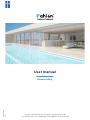 1
1
-
 2
2
-
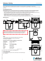 3
3
-
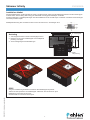 4
4
-
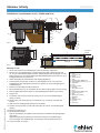 5
5
-
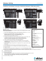 6
6
-
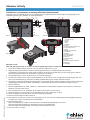 7
7
-
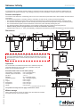 8
8
-
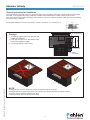 9
9
-
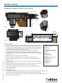 10
10
-
 11
11
-
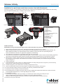 12
12
-
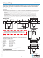 13
13
-
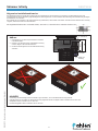 14
14
-
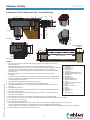 15
15
-
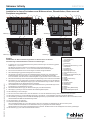 16
16
-
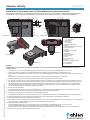 17
17
-
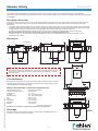 18
18
-
 19
19
-
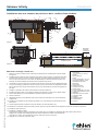 20
20
-
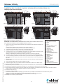 21
21
-
 22
22
-
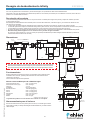 23
23
-
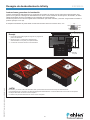 24
24
-
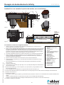 25
25
-
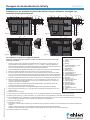 26
26
-
 27
27
-
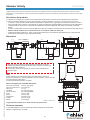 28
28
-
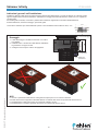 29
29
-
 30
30
-
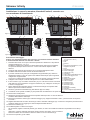 31
31
-
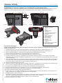 32
32


Pahlen MA55-48 El manual del propietario
- Tipo
- El manual del propietario
- Este manual también es adecuado para
En otros idiomas
- français: Pahlen MA55-48 Le manuel du propriétaire
- italiano: Pahlen MA55-48 Manuale del proprietario
- English: Pahlen MA55-48 Owner's manual
- svenska: Pahlen MA55-48 Bruksanvisning
Documentos relacionados
-
Pahlen Pool skimmer Classic Wide 385/Wide 6° El manual del propietario
-
-
-
-
-
-
-
-
Otros documentos
-
 Renson Sono lock Max Assembly Instructions
-
 Renson Sonoslot 475 Assembly Instructions
-
Bestway Sand Filter Pool Pump El manual del propietario
-
-
-
-
HEIDENHAIN ND 2100G - V2.59.0 El manual del propietario

