
Copyright © 2022 Pahlén AB, Box 728, SE-194 27 Upplands Väsby, Sweden
Tel. +46 8 594 110 50, Fax +46 8 590 868 80, e-mail: [email protected], www.pahlen.com
User manual
Skimmer WIDE
MA55-31 rev.1
2022

SVENSKA 3
ENGLISH 7
DEUTSCH 11
РУССКИЙ 15
FRANÇAIS 19
ESPAÑOL 23
ITALIANO 27

3
SVENSKA
WIDE Bräddavlopp
MA55-31 SE (Instruktionens originalspråk)
96
461
431
64
400
100
6,5 (4x)
M12506 Skimmer WIDE
6
130
M5 (22x)
Skimmer WIDE Classic
112970 - M12506
240
461
152
448
92
385
176,5
30-70
313
100()
165
185
223
325 44
152
30
32
15
98,588,5
G½"
G1½"
13
G2"
245
179
521
13
100
96
51
398
180
Det är viktigt att denna manual läses igenom noggrant för att trygga funktion och livslängd hos utrustningen.
Pahlén AB ansvarar ej för produktgaranti eller skador som sker till följd av felaktig installation, handhavandefel eller felaktigt
underhåll.
Produktbeskrivning
Bräddavloppets funktion i en swimmingpool är att vara ett utlopp för poolens vatten och fånga upp skräp från ytvattnet.
Bräddavloppet har genomföringar för anslutning av överbreddning, vattenpåfyllning samt nivåvakt (tillbehör). Vid leverans med-
följer pluggar för dessa hål.
• Klauckan reglerar ytvattnets hastighet och säkerställer att utloppet inte blockeras av större föremål.
• Den invändiga silkorgen fångar grövre material som annars transporteras vidare till poolens cirkulationspump.
• Medföljande Skimvac-platta används för bottensugslang vid manuell städning av poolen.
• Bräddavloppets krage är justerbar i höjdled 30–70 mm för att kunna anpassas till golvbeläggningen runt poolen. Pahlén kan
också erbjuda högre kragar som tillbehör: art.nr 633022 (höjd=137mm), art.nr 15594410 (höjd=250mm).
Dimensioner
Drift
Undvik dosering av koncentrerade kemikalier intill rostfria detaljer,
skador kan annars uppstå vid utebliven poolcirkulation.
Töm silkorgen regelbundet.
Rekommenderade värden beträande vattenkvalitet:
Total klorhalt: max 3,5 mg/liter (ppm)*
Klorid(salt)halt: max 250 mg/liter
pH-värde: 7.2 - 7.6
Alkalinitet: 60-120 mg/liter (ppm)
Kalciumhårdhet: 100-300 mg/liter (ppm)
Järn: max 0,1 mg/l *
Koppar: max 0,2 mg/l *
Mangan: max 0,05 mg/l *
Fosfor: max 0,01 mg/l *
Nitrat: max 50 mg/l*
* Enligt EN 16713-3
Utanför dessa värden gäller ej produktgarantin.
Vinterstängning
Vid vinterstängning av poolen sänkts vattennivå under bräddavloppet,
lyft ur silkorgen.

4
SVENSKA
WIDE Bräddavlopp
MA55-31 SE (Instruktionens originalspråk)
Art.no.
Rev.no.
Scale
Designed by: Approved by:
Revised by: Date
Drawn by: Date
Drawing number
Assembly drawing no.
Surface treatment
part of ISO 2768-mK
The tolerance class in accordance with this
E
Box 728, SE-194 27 Upplands Väsby, Sweden
Phone +46 8 59411050, Fax +46 8 59086880
TK 2016-11-10
Installationsbild
Bräddavlopp WIDE
Trä-, plåt-, plaststomme/liner M12624 0
This document and its contents are the exclusive
property of Pahléns and may not be copied,
reproduced, transmitted or communicated to a third
party, or used for any purpose without written permission.
1 1
7
1
6
1
11
5111
Sid 2
8
1
0
5
34
6
7
12
9
11 1
2
Art.no.
Rev.no.
Scale
Designed by: Approved by:
Revised by: Date
Drawn by: Date
Drawing number
Assembly drawing no.
Surface treatment
part of ISO 2768-1
The tolerance class in accordance with this
E
Box 728, SE-194 27 Upplands Väsby, Sweden
Phone +46 8 59411050, Fax +46 8 59086880
TK 2016-11-11
Håltagning i träpollstomme WM
M12628 0
This document and its contents are the exclusive
property of Pahléns and may not be copied,
reproduced, transmitted or communicated to a third
party, or used for any purpose without written permission.
Min 15
43513
461
14
96
132
6,5 (4x)
Underkant sarg
* Fronten hamnar ca 3.5 mm
från sargens underkant.
C-C ( 1 : 3 )
A
This document and its contents are the exclusive
property of Pahléns and may not be copied,
reproduced, transmitted or communicated to a third
party, or used for any purpose without written permission.
Art.no.
Rev.no.
Scale
Designed by: Approved by:
Revised by: Date
Drawn by: Date
Drawing number
Assembly drawing no.
Surface treatment
part of ISO 2768-mK
The tolerance class in accordance with this
E
Box 728, SE-194 27 Upplands Väsby, Sweden
Phone +46 8 59411050, Fax +46 8 59086880
TK 2016-11-10
Installationsbild
Bräddavlopp WIDE
Trä-, plåt-, plaststomme/liner M12624 0
A
Installation allmänt
Placera bräddavlopp i poolkonstruktionen enligt er poolleverantörs anvisningar. Bräddavlopp placeras normalt med inlopp på
motsatta sidan. Vid montering skall verktyg av rostfritt stål med rengjorda kontaktytor användas.
Förvara produkterna i originalförpackningen ända till installationen för att undvika repor och äckar.
Var aktsam vid monteringen så att inte produkten repas.
Installation i poolstomme av trä, plåt, plast, etc. - klädd med liner
Montera så här:
1. Gör ett hål i stommen för bräddavloppet,
mått och placering enligt bild 2.
2. Montera och xera bräddavloppet i poolstommen,
placering enligt bild 2. Vattenytan skall vara i
centrum av öppningen och bräddavloppets äns
skall ligga i liv med färdig poolvägg.
För att undvika sättningar skall sand packas runt och under bräddavloppet, alternativt xeras bräddavloppet med t.ex.
tryckimpregnerade reglar i poolstommen.
3. Anslut rörkoppling till poolcirkulation med lämplig gängtätning.
4. Öppningar för nivåvakt, överbräddning samt påfyllnad i bakkant pluggas om dessa ej används.
5. Kontrollera att klauckan sitter korrekt på plats och kan röra sig.
6. Fäst den självhäftande packningen på bräddavloppets framkant (mot poolen).
7. Lägg i linern.
8. Fyll poolen med så mycket vatten att vattenytan når 5 cm under bräddavloppet. Stäng av vattnet.
9. Skär ett litet snitt i linern mitt i bräddavloppshålet. Montera den yttre packningen och fästramen - fäst först, dra sedan fast
korsvis.
10. Skär rent linern försiktigt längs front-/fästramens insida.
11. Fortsätt nu att fylla vatten i poolen tills vattenytan når centrum av bräddavloppets öppning.
12. Montera frontramen.
13. Justera kragen till önskad höjd i förhållande till golvbeläggningen runt poolen.
Fixera kragen med bifogade
fästband.
Vid ev. bearbetning skall
verktyg avsedda enbart
för rostfritt material
användas.
1. Fästband med skruv M5x12 (2x)
2. Krage
3. Mutter M6 (4x)
4. Sarg
5. Försänkt skruv M6x30 (4x)
6. Självhäftande packning 1,5 mm
7. Väggmatta
8. Liner
9. Packning 2 mm
10. Fästram
11. Försänkt skruv M5x12 (26x)
12. Front
Bild 1.
Bild 2.
Underkant
sarg
Vattenyta
Front
Liner
Sarg
Plywood
Väggmatta
Bild 3.
Klaucka
Stöd för
brädd-
avloppet

5
SVENSKA
WIDE Bräddavlopp
MA55-31 SE (Instruktionens originalspråk)
A
This document and its contents are the exclusive
property of Pahléns and may not be copied,
reproduced, transmitted or communicated to a third
party, or used for any purpose without written permission.
Art.no.
Rev.no.
Scale
Designed by: Approved by:
Revised by: Date
Drawn by: Date
Drawing number
Assembly drawing no.
Surface treatment
part of ISO 2768-mK
The tolerance class in accordance with this
E
Box 728, SE-194 27 Upplands Väsby, Sweden
Phone +46 8 59411050, Fax +46 8 59086880
TK 2016-11-10
För poolstomme av mursten
Installationsbild bräddavlopp WM
M12625 0
A
Puts Foam
Front
Mursten
Liner
Klafflucka
A
This document and its contents are the exclusive
property of Pahléns and may not be copied,
reproduced, transmitted or communicated to a third
party, or used for any purpose without written permission.
Art.no.
Rev.no.
Scale
Designed by: Approved by:
Revised by: Date
Drawn by: Date
Drawing number
Assembly drawing no.
Surface treatment
part of ISO 2768-mK
The tolerance class in accordance with this
E
Box 728, SE-194 27 Upplands Väsby, Sweden
Phone +46 8 59411050, Fax +46 8 59086880
TK 2016-11-15
Installationsbild
Bräddavlopp WIDE
poolstomme av isolerblock M12626 0
A
Foam
Front
Liner
Isolerblock
Klafflucka
Art.no.
Rev.no.
Scale
Designed by: Approved by:
Revised by: Date
Drawn by: Date
Drawing number
Assembly drawing no.
Surface treatment
part of ISO 2768-mK
The tolerance class in accordance with this
E
Box 728, SE-194 27 Upplands Väsby, Sweden
Phone +46 8 59411050, Fax +46 8 59086880
TK 2016-11-15
Installationsbild
Bräddavlopp WIDE
poolstomme av isolerblock M12626 0
This document and its contents are the exclusive
property of Pahléns and may not be copied,
reproduced, transmitted or communicated to a third
party, or used for any purpose without written permission.
12
3
13
14
15
7
8
910 11 12
6
49
1
0
6
4
3
7
21
8
11 1
2
1
3
1
4
1
5
Art.no.
Rev.no.
Scale
Designed by: Approved by:
Revised by: Date
Drawn by: Date
Drawing number
Assembly drawing no.
Surface treatment
part of ISO 2768-mK
The tolerance class in accordance with this
E
Box 728, SE-194 27 Upplands Väsby, Sweden
Phone +46 8 59411050, Fax +46 8 59086880
TK 2016-11-10
För poolstomme av mursten
Installationsbild bräddavlopp WM
M12625 0
This document and its contents are the exclusive
property of Pahléns and may not be copied,
reproduced, transmitted or communicated to a third
party, or used for any purpose without written permission.
11 9 1 1 1 1 1
7
8
1
4
9
1
0
6
7
4
3
2
1
8
11 1
2
1
6
Installation i poolstomme av mursten, isolerblock, betong etc. klädd med poolduk
1. Fästband med skruv M5x12 (2x)
2. Krage
3. Jordningspunkt
4. Sarg
5. —
6. Självhäftande packning 1,5 mm
7. Väggmatta
8. Liner
9. Packning 2 mm
10. Fästram
11. Försänkt skruv M5x12 (26x)
12. Front
13. Armeringsjärn
14. Isolerblock
15. Betong
16. Mursten (lecablock)
Montera så här:
OBS! Vid gjutning/armering av stommen får ingen armering ligga närmare rostfritt
material än minst 50 mm.
1. Gör ett hål för bräddavloppet i stommen, mått och placering enligt bild 2.
2. Montera och xera bräddavloppet i stommen, mått och placering enligt bild 2.
Vattenytan skall vara i centrum av öppningen och bräddavloppets äns skall ligga i liv
med färdig poolvägg.
3. Öppningar för nivåvakt, överbräddning samt påfyllnad i bakkant pluggas om dessa
ej används.
4. Anslut en kabel (minst 6 mm2) med ringkabelsko från jordpunkten i ingjutningsänsen
till markjord. Använd förskruvning av rostfri A4-kvalité vid anslutningen (Ø6,0 mm).
5. Anslut rörkoppling till poolcirkulation med lämplig gängtätning.
6. Maskera bräddavloppets frilagda äns och öppningar innan ev. gjutning för att undvika betongstänk.
7. Fäst den självhäftande packningen på bräddavloppet (efter gjutningen).
8. Kontrollera att klauckan sitter korrekt på plats och kan röra sig.
9. Lägg i linern.
10. Fyll poolen med så mycket vatten att
vattenytan når 5 cm under bräddavloppet.
Stäng av vattnet.
11. Skär ett litet snitt i linern mitt i brädd-
avloppshålet.
12. Montera den yttre packningen och fäst-
ramen - fäst först, dra sedan fast korsvis.
13. Skär rent linern försiktigt längs front-/
fästramens insida.
Fortsätt nu att fylla vatten i poolen tills
vattenytan når centrum av bräddavloppets
öppning.
14. Montera frontramen.
15. Kragen justeras i höjdled i förhållande
till golvbeläggningen runt poolen.
Fixera med bifogade fästband.
OBS! Vid ev. bearbetning av kragen
skall verktyg enbart avsedda för rostfritt
material användas
Bild 4. Bild 5.
Front
Liner
Väggmatta
Bild 7. Stomme av isolerblock
Isoler-
block
Klaucka
Front
Liner
Puts
Mursten
Väggmatta
Bild 6. Stomme av lecablock
Klaucka

6
SVENSKA
WIDE Bräddavlopp
MA55-31 SE (Instruktionens originalspråk)
A
This document and its contents are the exclusive
property of Pahléns and may not be copied,
reproduced, transmitted or communicated to a third
party, or used for any purpose without written permission.
Art.no.
Rev.no.
Scale
Designed by: Approved by:
Revised by: Date
Drawn by: Date
Drawing number
Assembly drawing no.
Surface treatment
part of ISO 2768-mK
The tolerance class in accordance with this
E
Box 728, SE-194 27 Upplands Väsby, Sweden
Phone +46 8 59411050, Fax +46 8 59086880
TK 2016-11-15
För poolstomme av thermoblock
Installationsbild bräddavlopp WM
M12627 0
A
min 28
F-F ( 1 : 4 )
G-G ( 1 : 4 )
H-H ( 1 : 4 )
GF Plugg 721961910 124
1998206019982060Nylon 6/6Topptätning för PG7123
PG7-mutter19982303GenericKontramutter PG7122
Kabelförskruvning PG7
19982003Nylon 6/6
Kabelförskruvning PG7
121
1997017019970170
GenericO-ring 17,00x2,00 NBR70
120
19981600 plugg19981600PVC-UPlugg PVC G½" utv119
M1252511267Stainless SteelFront bräddavlopp WM std118
Torx A4 FM5x1219920220Steel, MildSkruv MFT A4 M5x122617
M12513112670GenericFästram116
M12523112817RubberPackning 432x132x2mm115
M125121128179RubberPackning 432x132x1,5mm114
R10639112915Stainless SteelLock Bräddavlopp -16113
DIN 7985 (H) - M5x12-H19909315A4Skruv MRX A4 M5x12 - DIN7985A212
R1110915594310
Stainless Steel
Klamma211
M1253915594405
Stainless Steel
Krage bräddavlopp WM110
R11140112620 Skimvacplatta Pahlén19
R1113951245PPSilkorg komplett18
R111441128161Generic
Ändskydd
27
R11112 ihoptryckt112571Stainless SteelFjäder/bygel16
M1236415581002 Flytkropp 190x100x2015
R1117115516085Stainless SteelKlafflucka -03UH14
ISO 4032 - M619930025A4Mutter M6M A4 M643
Torx A4 FM6x3019920340
GenericSkruv MFT A4 M6x30
42
M1253315594075
Stainless Steel
Bräddavlopp WM11
Drawing.no:Art_nrMaterialTitle/ NameQty.Item.
F
F
G
G
H H
This document and its contents are the exclusive
property of Pahléns and may not be copied,
reproduced, transmitted or communicated to a third
party, or used for any purpose without written permission.
Art.no.
Rev.no.
Scale
Designed by: Approved by:
Revised by: Date
Drawn by: Date
Drawing number
Assembly drawing no.
Surface treatment
part of ISO 2768-1
The tolerance class in accordance with this
E
Box 728, SE-194 27 Upplands Väsby, Sweden
Phone +46 8 59411050, Fax +46 8 59086880
1:1
112970
TK 2016-06-13
Bräddavlopp WM
M12506 P0
15
2
3
21 22 23
1920
82,5
165
64
18,5
31,63
46
46
245
33,87
58,13
230,5
232
STD vattenyta
WM vattenyta
242,5
35,5
2
5,75
120
38
Vattenyta
2,5
1,47
16,5
4
5
6
7
13
10
11
9
8
12
1
18
17
14
16
24
Art.no.
Rev.no.
Scale
Designed by: Approved by:
Revised by: Date
Drawn by: Date
Drawing number
Assembly drawing no.
Surface treatment
part of ISO 2768-mK
The tolerance class in accordance with this
E
Box 728, SE-194 27 Upplands Väsby, Sweden
Phone +46 8 59411050, Fax +46 8 59086880
TK 2016-11-15
För poolstomme av thermoblock
Installationsbild bräddavlopp WM
M12627 0
This document and its contents are the exclusive
property of Pahléns and may not be copied,
reproduced, transmitted or communicated to a third
party, or used for any purpose without written permission.
1513 1
1
917 12 10
6
6
3
2145 6 7
8
9
10
Art.no.
Rev.no.
Scale
Designed by: Approved by:
Revised by: Date
Drawn by: Date
Drawing number
Assembly drawing no.
Surface treatment
part of ISO 2768-mK
The tolerance class in accordance with this
E
Box 728, SE-194 27 Upplands Väsb y, Sweden
Phone +46 8 59411050, Fax +46 8 59086880
TK
1:4
15594075
2016-01-26Betad
Bräddavlopp WM
M12533 0
Art.no.
Rev.no.
Scale
Designed by: Approved by:
Revised by: Date
Drawn by: Date
Drawing number
Assembly drawing no.
Surface treatment
part of ISO 2768-mK
The tolerance class in accordance with this
E
Box 728, SE-194 27 Upplands Väsby, Sweden
Phone +46 8 59411050, Fax +46 8 59086880
TK
1:4
15594075
2016-01-26Betad
Bräddavlopp WM
M12533 0
2 8
Installation i poolstomme av betong klädd med kakel/mosaik
Rådfråga er betong-/ytskiktsleverantör om eventuellt tätskikt och appliceringsmetod.
Bild 9.
Bild 10.
Bild 11.
Montera så här:
OBS! Vid gjutning/armering av stommen får ingen armering ligga närmare
rostfritt material än minst 50 mm.
1. Gör ett hål för bräddavloppet i stommen, mått och placering enligt bild 2.
2. Applicera tätningsmassa i skarven mellan ingjutningsänsen och bräddavlopps-
huset (se bild 9).
Pahlén rekommenderar tätningsmassa TEC7 från Novatech (nns att köpa från
Pahlén) alternativt Aqua Max från Grion.
Vid applicering av tätningsmassa är det viktigt att skarven blir tät så att eventuellt
vatten inte kan tränga igenom skarven.
Se tätningsmedlets instruktion för förberedelser, applicering och härdning.
3. Fixera bräddavloppet i formen så att änsen är i liv med betongväggen.
OBS! Icke rostfritt material (t.ex armering) får inte ligga närmare det rostfria
materialet (bräddavloppet) än 50 mm.
4. Anslut en kabel (minst 6 mm2) med ringkabelsko från ingjutningsänsen till mark-
jord (se pos 3 bild 8). Skruv, taggbricka och mutter följer med produkten.
Om andra komponenter används måste det säkerställas att dessa är av rostfri
kvalitet (minst A4).
5. Före gjutning; maskera bräddavloppets frilagda äns och öppningar för att undvika
fula äckar av betongstänk.
Öppningarna i bräddavloppets bakkant för nivåvakt, överbräddning samt påfyllnad
kan tätas med medföljande pluggar, se bild 11.
6. Gjut poolstommen.
7. Montera väggbeklädnad (x, kakel, mosaik etc.). Säkerställ att monteringshålen
(enlig bild 10) för fästramen är fria så att fästramen går att montera senare.
8. Kontrollera att klauckan sitter korrekt på plats och kan röra sig.
9. Montera fästramen och xera med medföljande skruvar (4st M5x30), se bild 8.
10. Montera fronten i fästramen och xera den med medföljande skruvar (4st M5x12) i andra och åttonde hålet, se bild 12.
11. Anslut rörkoppling till poolcirkulationen och täta med lämplig gängtätning.
12. Kragens läge anpassas i höjdled till
golvbeläggningen runt poolen.
Fixera i önskad höjd med bifogade
fästband.
Om kragen kortas av (eller bearbe-
tas på något annat sätt) ska verktyg
avsett enbart för rostfritt material
användas.
1. Fästband med skruv M5x12 (2x)
2. Krage
3. Jordningspunkt
4. Försänkt skruv M6x30 (4x)
5. Fästram
6. Försänkt skruv M5x12 (4x)
7. Front
8. Ingjutningsäns
9. Betong
10. Armeringsjärn
Bild 8.
Bild 12.
Skruv
Front
Fästram
Kakel/Mosaik
Kakelfog
Betongstomme
Kakelx
Klaucka

7
ENGLISH
Skimmer WIDE
MA55-31 GB Translation of the original instructions (Swedish)
96
461
431
64
400
100
6,5 (4x)
M12506 Skimmer WIDE
6
130
M5 (22x)
Skimmer WIDE Classic
112970 - M12506
240
461
152
448
92
385
176,5
30-70
313
100()
165
185
223
325 44
152
30
32
15
98,588,5
G½"
G1½"
13
G2"
245
179
521
13
100
96
51
398
180
It is important to read this manual thoroughly in order to ensure normal functioning and long service life of the equipment.
Pahlén AB is not responsible for the product warranty in case of any damage due to improper installation, mishandling or
improper maintenance.
Product Description
A skimmer function in a swimming pool is to withdraw excessive pool water and pick up waste from the pool surface water.
The skimmer has inlets for connection of the extension, water lling and level monitor (optional). The skimmer is delivered with
plugs for these holes.
• The ap gate regulates the speed of the surface water and ensures that the outlet is not blocked by any larger objects.
• The internal screen basket catches coarser material, which otherwise is transported to the pool’s circulation pump.
• Skimvac plate is included and used for the bottom suction hose at the pool manual cleaning.
• The skimmer pipe is vertically adjustable to the height of 30-70 mm in order to adapt to the ooring around the pool frame.
Pahlén can also oer higher skimmers with accessories: art.nr 633022 (height=137mm), art.nr 15594410 (height=250mm).
Dimensions
Operation
Avoid dosing of concentrated chemicals next to stainless steel parts,
damage may otherwise occur in case of no pool circulation.
Empty screen basket regularly
Recommended values for water quality:
Total chlorine content: max 3,5 mg/liter (ppm)*
Chlorine (salt) total: max 250 mg/liter
pH-value: 7.2 –7.6
Alkalinity: 60 –120 mg/liter (ppm)
Calcium hardness: 100 – 300 mg/liter (ppm)
Iron: max 0.1 mg/l *
Copper max 0.2 mg/l *
Manganese: max 0.05 mg/l *
Phosphorus: max 0.01 mg/l *
Nitrate: max 50 mg/l *
* Complies with EN 16713-3
Outside these values the product warranty does not apply.
Winter storage
At winter storage of the pool, water level showld be lowered below the
skimmer level, take out the lter basket.

8
ENGLISH
Skimmer WIDE
MA55-31 GB Translation of the original instructions (Swedish)
Art.no.
Rev.no.
Scale
Designed by: Approved by:
Revised by: Date
Drawn by: Date
Drawing number
Assembly drawing no.
Surface treatment
part of ISO 2768-mK
The tolerance class in accordance with this
E
Box 728, SE-194 27 Upplands Väsby, Sweden
Phone +46 8 59411050, Fax +46 8 59086880
TK 2016-11-10
Installationsbild
Bräddavlopp WIDE
Trä-, plåt-, plaststomme/liner M12624 0
This document and its contents are the exclusive
property of Pahléns and may not be copied,
reproduced, transmitted or communicated to a third
party, or used for any purpose without written permission.
1 1
7
1
6
1
11
5111
Sid 2
8
1
0
5
34
6
7
12
9
11 1
2
Art.no.
Rev.no.
Scale
Designed by: Approved by:
Revised by: Date
Drawn by: Date
Drawing number
Assembly drawing no.
Surface treatment
part of ISO 2768-1
The tolerance class in accordance with this
E
Box 728, SE-194 27 Upplands Väsby, Sweden
Phone +46 8 59411050, Fax +46 8 59086880
TK 2016-11-11
Håltagning i träpollstomme WM
M12628 0
This document and its contents are the exclusive
property of Pahléns and may not be copied,
reproduced, transmitted or communicated to a third
party, or used for any purpose without written permission.
Min 15
43513
461
14
96
132
6,5 (4x)
Underkant sarg
* Fronten hamnar ca 3.5 mm
från sargens underkant.
C-C ( 1 : 3 )
A
This document and its contents are the exclusive
property of Pahléns and may not be copied,
reproduced, transmitted or communicated to a third
party, or used for any purpose without written permission.
Art.no.
Rev.no.
Scale
Designed by: Approved by:
Revised by: Date
Drawn by: Date
Drawing number
Assembly drawing no.
Surface treatment
part of ISO 2768-mK
The tolerance class in accordance with this
E
Box 728, SE-194 27 Upplands Väsby, Sweden
Phone +46 8 59411050, Fax +46 8 59086880
TK 2016-11-10
Installationsbild
Bräddavlopp WIDE
Trä-, plåt-, plaststomme/liner M12624 0
A
General installation instruction
Place the skimmer into the pool framework according to your pool supplier’s instructions. The skimmer is typically placed at the
opposite side of the water inlet. During installation works, stainless steel tools with clean contact surfaces should be used.
In order to avoid scratches and stains, keep items in their original packaging until installation.
Be careful during installation, so as not to scratch the skimmer.
For the pool framework made of wood, metal or plastic - nished with pool liner
Installation as following:
1. Make a hole for the skimmer in the framework,
dimensions and placement as shown in Figure 2.
2. Mount and secure the skimmer in the pool
framework, position as shown in Figure 2.
The water surface should be at the centre of the
opening and the ange of the skimmer should be
in line with a nished pool wall.
To avoid subsidence, sand should be packed around and below the skimmer, or x the skimmer with e.g. pressure-treated
joists in the pool frame.
3. Connect the pipe coupling to the pool circulation with an appropriate thread sealant.
4. The openings are for level control, overow and rell should be at the rear plugs if they are not used.
5. Check that the ap cap is properly in place and can move.
6. Attach the self-adhesive packing onto the skimmer front edge (towards the pool).
7. Add the pool liner.
8. Fill the pool with so much water that it reaches 5 cm below the skimmer. Turn o the water.
9. Cut a small incision in the liner middle in the skimmer. Install the outer packing and the mounting frame - secure them rst,
then tighten crosswise.
10. Cut clean the pool liner gently along the front/inside the mounting frame.
11. Continue to ll the water into the pool until its level reaches the center of the skimmer opening.
12. Install the front.
13. Adjust the skimmer to the desired height in relation to the ooring around the pool.
Fix the skimmer with attached straps.
In case of machining the
tool exclusively for stain-
less steel material should
be used.
1. Fixing strip with a screw M5x12 (2 pcs)
2. Pipe
3. Nut M6 (4x)
4. Frame
5. Countersunk screw M6x30 (4 pcs)
6. Self-adhesive packing 1.5 mm
7. Wall mat
8. Liner
9. Packing 2 mm
10. Mounting frame
11. Countersunk screw M5x12 (26 pcs)
12. Frоnt
Bild 1.
Fig 2.
Bottom pool frame
Water surface
Front
Liner
Frame
Plywood
Wall mat
Fig 3.
Flap cap
Support for
the skimmer.

9
ENGLISH
Skimmer WIDE
MA55-31 GB Translation of the original instructions (Swedish)
A
This document and its contents are the exclusive
property of Pahléns and may not be copied,
reproduced, transmitted or communicated to a third
party, or used for any purpose without written permission.
Art.no.
Rev.no.
Scale
Designed by: Approved by:
Revised by: Date
Drawn by: Date
Drawing number
Assembly drawing no.
Surface treatment
part of ISO 2768-mK
The tolerance class in accordance with this
E
Box 728, SE-194 27 Upplands Väsby, Sweden
Phone +46 8 59411050, Fax +46 8 59086880
TK 2016-11-10
För poolstomme av mursten
Installationsbild bräddavlopp WM
M12625 0
A
Puts Foam
Front
Mursten
Liner
Klafflucka
A
This document and its contents are the exclusive
property of Pahléns and may not be copied,
reproduced, transmitted or communicated to a third
party, or used for any purpose without written permission.
Art.no.
Rev.no.
Scale
Designed by: Approved by:
Revised by: Date
Drawn by: Date
Drawing number
Assembly drawing no.
Surface treatment
part of ISO 2768-mK
The tolerance class in accordance with this
E
Box 728, SE-194 27 Upplands Väsby, Sweden
Phone +46 8 59411050, Fax +46 8 59086880
TK 2016-11-15
Installationsbild
Bräddavlopp WIDE
poolstomme av isolerblock M12626 0
A
Foam
Front
Liner
Isolerblock
Klafflucka
Art.no.
Rev.no.
Scale
Designed by: Approved by:
Revised by: Date
Drawn by: Date
Drawing number
Assembly drawing no.
Surface treatment
part of ISO 2768-mK
The tolerance class in accordance with this
E
Box 728, SE-194 27 Upplands Väsby, Sweden
Phone +46 8 59411050, Fax +46 8 59086880
TK 2016-11-15
Installationsbild
Bräddavlopp WIDE
poolstomme av isolerblock M12626 0
This document and its contents are the exclusive
property of Pahléns and may not be copied,
reproduced, transmitted or communicated to a third
party, or used for any purpose without written permission.
12
3
13
14
15
7
8
910 11 12
6
49
1
0
6
4
3
7
21
8
11 1
2
1
3
1
4
1
5
Art.no.
Rev.no.
Scale
Designed by: Approved by:
Revised by: Date
Drawn by: Date
Drawing number
Assembly drawing no.
Surface treatment
part of ISO 2768-mK
The tolerance class in accordance with this
E
Box 728, SE-194 27 Upplands Väsby, Sweden
Phone +46 8 59411050, Fax +46 8 59086880
TK 2016-11-10
För poolstomme av mursten
Installationsbild bräddavlopp WM
M12625 0
This document and its contents are the exclusive
property of Pahléns and may not be copied,
reproduced, transmitted or communicated to a third
party, or used for any purpose without written permission.
11 9 1 1 1 1 1
7
8
1
4
9
1
0
6
7
4
3
2
1
8
11 1
2
1
6
Installation of the pool wall made of stones/bricks, insulating blocks, concrete etc.,
nished with a pool liner
1. Fixing strip with a screw M5x12
(2 pcs)
2. Skimmer top
3. Grounding point
4. Frame
5. —
6. Self-adhesive packing 1,5mm
7. Wall mat
8. Liner
9. Packing 2mm
10. Mounting frame
11. Countersunk screw M5x12
(26 pcs)
12. Front
13. Reinforcing bar
14. Isolating block
15. Concrete
16. Bricks (leca block)
Installation as following:
NOTE! When casting/reinforcing the pool frame work, do not get closer than at least
50 mm to the stainless materials.
1. Make a hole for the skimmer in the framework, dimensions and placement as shown in
Figure 2.
2. Mount and secure the skimmer in the pool framework, position as shown in Figure 2.
3. The water surface should be at the centre of the opening and the ange of the skimmer
should be in line with a nished pool wall.
4. Make a hole in the frame work for the skimmer, see dimensions on Fig. 2.
5. Install and x the skimmer.
The water level should be at the center of the opening and the anges must lie at the
nished pool wall.
6. The openings are for level control, the overow and rells are at the rear plugs if they
are not used.
7. Connect the cable (at least 6 mm²) with a ring from the ground point in the sealed anges
to earth. Use stainless steel screw A4-quality for connection (Ø6,0 mm).
8. Connect the pipe coupling to the pool circulation pump with an appropriate thread sealant.
9. Mask skimmer exposed ange and openings
before sealing in order to avoid concrete
splashes.
10. Attach self-adhesive packing onto the pipe
(after sealing).
11. Check that the ap cap is properly in place
and can move.
12. Add the pool liner.
13. Fill the pool with so much water that it
reaches 5 cm below the outow pipe.
Turn o the water.
14. Cut a small incision in the pool liner in the
middle of the skimmer hole.
15. Install the outer packing and the mounting
frame - secure them rst, then tighten
crosswise.
16. Cut clean the pool liner gently along the
front/inside of the mounting frame.
Continue to ll the water into the pool until
its level reaches the center of the skimmer
opening.
17. Install the front.
18. Adjust the skimmer to the desired height
in relation to the ooring around the pool.
Fix with attached straps.
NOTE! At eventual processing of the skimmer,
the tools intended for stainless materials should be exclusively used.
Fig 4. Fig 5.
Front
Liner
Wall mat
Fig 7. Frame of isolation blocks
Isolation
block
Flap cap
Front
Liner
Grout
Brick
Wall mat
Fig 6. Wall of leca blocks
Flap cap

10
ENGLISH
Skimmer WIDE
MA55-31 GB Translation of the original instructions (Swedish)
A
This document and its contents are the exclusive
property of Pahléns and may not be copied,
reproduced, transmitted or communicated to a third
party, or used for any purpose without written permission.
Art.no.
Rev.no.
Scale
Designed by: Approved by:
Revised by: Date
Drawn by: Date
Drawing number
Assembly drawing no.
Surface treatment
part of ISO 2768-mK
The tolerance class in accordance with this
E
Box 728, SE-194 27 Upplands Väsby, Sweden
Phone +46 8 59411050, Fax +46 8 59086880
TK 2016-11-15
För poolstomme av thermoblock
Installationsbild bräddavlopp WM
M12627 0
A
min 28
F-F ( 1 : 4 )
G-G ( 1 : 4 )
H-H ( 1 : 4 )
GF Plugg 721961910 124
1998206019982060Nylon 6/6Topptätning för PG7123
PG7-mutter19982303GenericKontramutter PG7122
Kabelförskruvning PG7
19982003Nylon 6/6
Kabelförskruvning PG7
121
1997017019970170
GenericO-ring 17,00x2,00 NBR70
120
19981600 plugg19981600PVC-UPlugg PVC G½" utv119
M1252511267Stainless SteelFront bräddavlopp WM std118
Torx A4 FM5x1219920220Steel, MildSkruv MFT A4 M5x122617
M12513112670GenericFästram116
M12523112817RubberPackning 432x132x2mm115
M125121128179RubberPackning 432x132x1,5mm114
R10639112915Stainless SteelLock Bräddavlopp -16113
DIN 7985 (H) - M5x12-H19909315A4Skruv MRX A4 M5x12 - DIN7985A212
R1110915594310
Stainless Steel
Klamma211
M1253915594405
Stainless Steel
Krage bräddavlopp WM110
R11140112620 Skimvacplatta Pahlén19
R1113951245PPSilkorg komplett18
R111441128161Generic
Ändskydd
27
R11112 ihoptryckt112571Stainless SteelFjäder/bygel16
M1236415581002 Flytkropp 190x100x2015
R1117115516085Stainless SteelKlafflucka -03UH14
ISO 4032 - M619930025A4Mutter M6M A4 M643
Torx A4 FM6x3019920340
GenericSkruv MFT A4 M6x30
42
M1253315594075
Stainless Steel
Bräddavlopp WM11
Drawing.no:Art_nrMaterialTitle/ NameQty.Item.
F
F
G
G
H H
This document and its contents are the exclusive
property of Pahléns and may not be copied,
reproduced, transmitted or communicated to a third
party, or used for any purpose without written permission.
Art.no.
Rev.no.
Scale
Designed by: Approved by:
Revised by: Date
Drawn by: Date
Drawing number
Assembly drawing no.
Surface treatment
part of ISO 2768-1
The tolerance class in accordance with this
E
Box 728, SE-194 27 Upplands Väsby, Sweden
Phone +46 8 59411050, Fax +46 8 59086880
1:1
112970
TK 2016-06-13
Bräddavlopp WM
M12506 P0
15
2
3
21 22 23
1920
82,5
165
64
18,5
31,63
46
46
245
33,87
58,13
230,5
232
STD vattenyta
WM vattenyta
242,5
35,5
2
5,75
120
38
Vattenyta
2,5
1,47
16,5
4
5
6
7
13
10
11
9
8
12
1
18
17
14
16
24
Art.no.
Rev.no.
Scale
Designed by: Approved by:
Revised by: Date
Drawn by: Date
Drawing number
Assembly drawing no.
Surface treatment
part of ISO 2768-mK
The tolerance class in accordance with this
E
Box 728, SE-194 27 Upplands Väsby, Sweden
Phone +46 8 59411050, Fax +46 8 59086880
TK 2016-11-15
För poolstomme av thermoblock
Installationsbild bräddavlopp WM
M12627 0
This document and its contents are the exclusive
property of Pahléns and may not be copied,
reproduced, transmitted or communicated to a third
party, or used for any purpose without written permission.
1513 1
1
917 12 10
6
6
3
2145 6 7
8
9
10
Art.no.
Rev.no.
Scale
Designed by: Approved by:
Revised by: Date
Drawn by: Date
Drawing number
Assembly drawing no.
Surface treatment
part of ISO 2768-mK
The tolerance class in accordance with this
E
Box 728, SE-194 27 Upplands Väsb y, Sweden
Phone +46 8 59411050, Fax +46 8 59086880
TK
1:4
15594075
2016-01-26Betad
Bräddavlopp WM
M12533 0
Art.no.
Rev.no.
Scale
Designed by: Approved by:
Revised by: Date
Drawn by: Date
Drawing number
Assembly drawing no.
Surface treatment
part of ISO 2768-mK
The tolerance class in accordance with this
E
Box 728, SE-194 27 Upplands Väsby, Sweden
Phone +46 8 59411050, Fax +46 8 59086880
TK
1:4
15594075
2016-01-26Betad
Bräddavlopp WM
M12533 0
2 8
For the pool frame of concrete - covered with tile/mosaic
Consult your concrete/waterproong supplier for any waterproong and application method.
Fig 9.
Fig 10.
Fig 11.
Installation as following:
NOTE! When casting/reinforcing the pool frame work, do not get closer than at
least 50 mm to the stainless materials.
1. Make a hole for the skimmer in the framework, dimensions and placement as
shown in Figure 2.
2. Apply sealer at the joint between the sealing anges and the skimmer housing
(see Fig. 9).
Pahlén recommends Tec7 as a sealant from Novatech (available from Pahlén) or
Aqua Max from Grion.
Upon application of the sealant, it is important that the joints are tight, so that no
water can penetrate.
See sealant instruction for preparation, application and hardening.
3. Fasten the skimmer in the mold, so that the ange is in contact with the concrete wall
.
NOTE! Non-corrosive material (e.g. steel) may not be closer to the stainless steel
(pipe) than 50 mm.
4. Connect the cable (at least 6 mm²) with a ring from the intake ange to earth
(see item 3 Figure 8). Screw, toothed washer and nut are supplied with the product.
If other components are used, it must be ensured that they are of stainless steel
quality (Min. A4).
5. Prior to sealing; mask the skimmer exposed ange and openings in order to avoid
unsightly stains from concrete splashes.
The openings in the skimmer back edge of the oat switch, the overow and rell
openings can be sealed with supplied plugs, see Fig.11
6. Seal the pool frame.
7. Mount the wall cladding (x, tile, mosaic, etc.). Make sure that the mounting holes
(see Fig. 10) for fastening the frame are free, so that the mounting frame can be
installed later.
8. Check that the ap cap is properly in place and can move.
9. Assemble the frame and secure it with screws (4x M5x30), see Fig. 8.
10. Mount the front of the frame and secure it with the supplied screws (4x M5x12) in
the second and eighth holes, see Fig. 12.
11. Connect the pipe coupling to the
pool circulation with an appropriate
thread sealant.
12. The position of the skimmer top
should be adjusted in height to the
ooring around the pool. Fix to the
desired height with attached straps.
13. If the skimmer top is shortened or
processed in any other way,
tools only for stainless materials
should be used.
1. Fixing strip with a screw M5x12 (2x)
2. Skimmer top
3. Earthing point
4. Countersunk screw M6x30 (4x)
5. Mounting frame
6. Countersunk screw M5x12 (4x)
7. Front
8. Flange
9. Concrete
10. Reinforcing bar
Fig 8.
Fig 12.
Screw
Front
Mountning
frame
Tail/Mosaic
Tail join
Concrete wall
Tail x
Flap cap

11
DEUTSCH
Skimmer WIDE
MA55-31 DE Übersetzung der ursprünglichen Anweisungen (Schwedisch)
96
461
431
64
400
100
6,5 (4x)
M12506 Skimmer WIDE
6
130
M5 (22x)
Skimmer WIDE Classic
112970 - M12506
240
461
152
448
92
385
176,5
30-70
313
100()
165
185
223
325 44
152
30
32
15
98,588,5
G½"
G1½"
13
G2"
245
179
521
13
100
96
51
398
180
Dieses Handbuch muss unbedingt sorgfältig gelesen werden, um die Funktion und Lebensdauer der Ausrüstung sicherzustellen.
Pahlén AB haftet nicht für Produktgarantie oder Schäden, die aufgrund falscher Installation, Bedienungsfehlern oder falscher
Wartung auftreten.
Produktbeschreibung
Der Skimmer dient in einem Swimmingpool als Ablauf für das Wasser des Pools und zum Auangen von auf dem Oberächen-
wasser schwimmendem Schmutz. Der Skimmer hat Önungen für den Anschluss von Überlauf, Wasserbefüllung sowie einer
Wasserstandsregelung (Zubehör). Im Lieferumfang sind Stopfen für die Önungen enthalten.
• Die Einlassvorrichtung regelt die Geschwindigkeit des Oberächenwassers und stellt sicher, dass der Ablauf nicht durch
größere Gegenstände blockiert wird.
• Der innenliegende Siebkorb fängt gröberes Material auf, das sonst zur Umwälzpumpe des Pools transportiert werden würde.
• Die mitgelieferte Skimvac-Platte wird für einen Bodensaugschlauch bei manueller Reinigung des Pools verwendet.
• Das Halsstück des Skimmers ist für Höhen von 30 bis 70 mm einstellbar, um an den Bodenbelag um den Pool herum
angepasst werden zu können. Pahlén hat auch höhere Halsstücke als Zubehör im Angebot:
Art.-Nr. 633022 (Höhe = 137 mm), Art.-Nr. 15594410 (Höhe = 250 mm).
Abmessungen
Betrieb
Vermeiden Sie es, konzentrierte Chemikalien in der Nähe von Edelstahlteilen zu
dosieren. Bei nicht vorhandener Poolzirkulation kann es sonst zu Schäden kommen.
Entleeren Sie den Siebkorb regelmäßig.
Empfohlene Werte für die Wasserqualität:
Gesamter Chlorgehalt: max. 3.5 mg/Liter (ppm)*
Chlorid(Salz)Gehalt: max. 250 mg/Liter
pH-Wert: 7.2–7.6
Alkalinität: 60 –120 mg/Liter (ppm)
Kalziumhärte: 100 – 300 mg/Liter (ppm)
Eisen: max. 0.1 mg/Liter *
Kupfer: max. 0.2 mg/Liter *
Mangan: max. 0.05 mg/Liter *
Phosphor: max. 0.01 mg/Liter *
Nitrat:: max 50 mg/Liter*
* Gemäß EN 16713-3
Bei Nichteinhaltung dieser Werte erlischt die Produktgarantie.
Vorbereitung auf den Winter
Bei der Vorbereitung auf den Winter wird der Wasserstand unter den
Skimmer abgesenkt, nehmen Sie den Siebkorb heraus.

12
DEUTSCH
Skimmer WIDE
MA55-31 DE Übersetzung der ursprünglichen Anweisungen (Schwedisch)
Art.no.
Rev.no.
Scale
Designed by: Approved by:
Revised by: Date
Drawn by: Date
Drawing number
Assembly drawing no.
Surface treatment
part of ISO 2768-mK
The tolerance class in accordance with this
E
Box 728, SE-194 27 Upplands Väsby, Sweden
Phone +46 8 59411050, Fax +46 8 59086880
TK 2016-11-10
Installationsbild
Bräddavlopp WIDE
Trä-, plåt-, plaststomme/liner M12624 0
This document and its contents are the exclusive
property of Pahléns and may not be copied,
reproduced, transmitted or communicated to a third
party, or used for any purpose without written permission.
1 1
7
1
6
1
11
5111
Sid 2
8
1
0
5
34
6
7
12
9
11 1
2
Art.no.
Rev.no.
Scale
Designed by: Approved by:
Revised by: Date
Drawn by: Date
Drawing number
Assembly drawing no.
Surface treatment
part of ISO 2768-1
The tolerance class in accordance with this
E
Box 728, SE-194 27 Upplands Väsby, Sweden
Phone +46 8 59411050, Fax +46 8 59086880
TK 2016-11-11
Håltagning i träpollstomme WM
M12628 0
This document and its contents are the exclusive
property of Pahléns and may not be copied,
reproduced, transmitted or communicated to a third
party, or used for any purpose without written permission.
Min 15
43513
461
14
96
132
6,5 (4x)
Underkant sarg
* Fronten hamnar ca 3.5 mm
från sargens underkant.
C-C ( 1 : 3 )
A
This document and its contents are the exclusive
property of Pahléns and may not be copied,
reproduced, transmitted or communicated to a third
party, or used for any purpose without written permission.
Art.no.
Rev.no.
Scale
Designed by: Approved by:
Revised by: Date
Drawn by: Date
Drawing number
Assembly drawing no.
Surface treatment
part of ISO 2768-mK
The tolerance class in accordance with this
E
Box 728, SE-194 27 Upplands Väsby, Sweden
Phone +46 8 59411050, Fax +46 8 59086880
TK 2016-11-10
Installationsbild
Bräddavlopp WIDE
Trä-, plåt-, plaststomme/liner M12624 0
A
Installation allgemein
Setzen Sie den Skimmer entsprechend den Anweisungen Ihres Poollieferanten in die Poolkonstruktion ein. Der Skimmer wird
normalerweise auf der Seite positioniert, die dem Einlauf gegenüberliegt. Bei der Montage sind Werkzeuge aus Edelstahl mit
gereinigten Berührungsächen zu verwenden.
Die Produkte sind bis zur Installation in der Originalverpackung zu lagern, um Kratzer und Flecken zu vermeiden.
Bei der Montage müssen Sie vorsichtig vorgehen, damit das Produkt nicht zerkratzt wird.
Installation in Schwimmbecken aus Holz, Blech oder Kunststo – mit Poolauskleidung
Gehen Sie bei der Montage wie folgt vor:
1. Machen Sie für den Skimmer ein Loch in den
Poolkörper, Maße und Position gem. Bild 2.
2. Montieren und xieren Sie den Skimmer im
Poolkörper, Position gemäß Bild 2.
Die Wasseroberäche sollte sich in der Mitte der
Önung benden und der Flansch des Skimmers
eng an der fertiggestellten Poolwand anliegen.
Verstärken Sie die den Skimmer umgebenden und unter ihm liegenden Bereiche mit Sand, um ein Absetzen zu verhindern.
Alternativ können Sie den Skimmer auch z. B. mit druckimprägnierten Bolzen am Poolrahmen befestigen.
3. Schließen Sie die Rohrverbindung unter Verwendung einer geeigneten Gewindedichtung an.
4. Önungen für Wasserstandsregelung, Überlauf sowie Wasserbefüllung an der Rückseite werden verstopft, wenn sie nicht
verwendet werden.
5. Überprüfen Sie, dass die Einlassvorrichtung korrekt an ihrem Platz sitzt und sich bewegen kann.
6. Befestigen Sie die selbstklebende Dichtung an der Vorderkante des Skimmers (zum Pool).
7. Verlegen Sie die Poolauskleidung.
8. Füllen Sie den Pool bis 5 cm unterhalb des Skimmers mit Wasser. Stellen Sie das Wasser ab.
9. Schneiden Sie in der Mitte der Skimmerönung einen kleinen Schnitt in die Poolauskleidung. Bringen Sie äußere Abdichtung
und den Frontrahmen an - zunächst xieren und anschließend über Kreuz anziehen.
10. Schneiden Sie die Poolauskleidung an der Innenseite des Frontstücks/-rahmens vorsichtig zurecht
11. Erhöhen Sie nun den Wasserstand, bis dieser in der Mitte der Skimmerönung liegt.
12. Montieren Sie das Frontstück.
13. Stellen Sie das Halsstück im
Verhältnis zum Bodenbelag
um den Pool auf die ge-
wünschte Höhe ein und
befestigen Sie es mit dem
mitgelieferten Klebestreifen.
Bei einer ev. Bearbeitung
darf nur für Edelstahl vor-
gesehenes Werkzeug
verwendet werden.
1. Klebestreifen mit Schraube M5x12 (2x)
2. Halsstück
3. Mutter M6 (4x)
4. Zarge
5. Senkkopfschraube M6x30 (4x)
6. Selbstklebende Dichtung 1,5mm
7. Schaum
8. Auskleidung
9. Dichtung 2mm
10. Frontrahmen
11. Senkkopfschraube M5x12 (26x)
12. Front
Bild 1.
Bild 2.
Unterkante
Zarge
Wasseroberäche
Front
Auskleidung
Zarge
Sperrholz
Wandbekleidung
Bild 3.
Einlass-
vorrichtung
Stütze für
Skimmer

13
DEUTSCH
Skimmer WIDE
MA55-31 DE Übersetzung der ursprünglichen Anweisungen (Schwedisch)
A
This document and its contents are the exclusive
property of Pahléns and may not be copied,
reproduced, transmitted or communicated to a third
party, or used for any purpose without written permission.
Art.no.
Rev.no.
Scale
Designed by: Approved by:
Revised by: Date
Drawn by: Date
Drawing number
Assembly drawing no.
Surface treatment
part of ISO 2768-mK
The tolerance class in accordance with this
E
Box 728, SE-194 27 Upplands Väsby, Sweden
Phone +46 8 59411050, Fax +46 8 59086880
TK 2016-11-10
För poolstomme av mursten
Installationsbild bräddavlopp WM
M12625 0
A
Puts Foam
Front
Mursten
Liner
Klafflucka
A
This document and its contents are the exclusive
property of Pahléns and may not be copied,
reproduced, transmitted or communicated to a third
party, or used for any purpose without written permission.
Art.no.
Rev.no.
Scale
Designed by: Approved by:
Revised by: Date
Drawn by: Date
Drawing number
Assembly drawing no.
Surface treatment
part of ISO 2768-mK
The tolerance class in accordance with this
E
Box 728, SE-194 27 Upplands Väsby, Sweden
Phone +46 8 59411050, Fax +46 8 59086880
TK 2016-11-15
Installationsbild
Bräddavlopp WIDE
poolstomme av isolerblock M12626 0
A
Foam
Front
Liner
Isolerblock
Klafflucka
Art.no.
Rev.no.
Scale
Designed by: Approved by:
Revised by: Date
Drawn by: Date
Drawing number
Assembly drawing no.
Surface treatment
part of ISO 2768-mK
The tolerance class in accordance with this
E
Box 728, SE-194 27 Upplands Väsby, Sweden
Phone +46 8 59411050, Fax +46 8 59086880
TK 2016-11-15
Installationsbild
Bräddavlopp WIDE
poolstomme av isolerblock M12626 0
This document and its contents are the exclusive
property of Pahléns and may not be copied,
reproduced, transmitted or communicated to a third
party, or used for any purpose without written permission.
12
3
13
14
15
7
8
910 11 12
6
49
1
0
6
4
3
7
21
8
11 1
2
1
3
1
4
1
5
Art.no.
Rev.no.
Scale
Designed by: Approved by:
Revised by: Date
Drawn by: Date
Drawing number
Assembly drawing no.
Surface treatment
part of ISO 2768-mK
The tolerance class in accordance with this
E
Box 728, SE-194 27 Upplands Väsby, Sweden
Phone +46 8 59411050, Fax +46 8 59086880
TK 2016-11-10
För poolstomme av mursten
Installationsbild bräddavlopp WM
M12625 0
This document and its contents are the exclusive
property of Pahléns and may not be copied,
reproduced, transmitted or communicated to a third
party, or used for any purpose without written permission.
11 9 1 1 1 1 1
7
8
1
4
9
1
0
6
7
4
3
2
1
8
11 1
2
1
6
Installation in Schwimmbecken aus Mauersteinen, Dämmblöcken,Beton usw.
– mit Poolauskleidung
1. Klebestreifen mit Schraube
M5x12 (2x)
2. Halsstück
3. Erdungspunkt
4. Zarge
5. —
6. Selbstklebende Dichtung 1,5mm
7. Wandbekleidung
8. Auskleidung
9. Dichtung 2mm
10. Frontrahmen
11. Senkkopfschraube M5x12 (26x)
12. Front
13. Bewehrungseisen
14. Dämmblock
15. Beton
16. Mauerstein (Leca-Block)
Gehen Sie bei der Montage wie folgt vor:
ACHTUNG! Beim Betonieren/Bewehren der Poolwand muss der Abstand der
Bewehrung zu Edelstahl mindestens 50 mm betragen.
1. Machen Sie für den Skimmer ein Loch in den Poolkörper, Maße und Position gem. Bild 2.
2. Montieren und xieren Sie den Skimmer im Poolkörper, Position gemäß Bild 2.
Die Wasseroberäche sollte sich in der Mitte der Önung benden und der Flansch
des Skimmers eng an der fertiggestellten Poolwand anliegen.
3. Önungen für Wasserstandsregelung, Überlauf sowie Wasserbefüllung an der Rück-
seite werden verstopft, wenn sie nicht verwendet werden.
4. Schließen Sie ein Kabel (mindestens 6 mm2) mit einem Ringkabelschuh vom Erdungs-
punkt am Betonwandansch an den Erdungsanschuss an. Verwenden Sie für den
Anschluss Verschraubungen aus rostfreiem A4-Material (Ø6,0 mm).
5. Schließen Sie die Rohrverbindung unter Verwendung einer geeigneten Gewinde-
dichtung an.
6. Decken Sie den freigelegten Flansch und die Önungen des Skimmers vor dem Ein-
betonieren ab, um Betonspritzer zu vermeiden.
7. Befestigen Sie die selbstklebende Dichtung am Skimmer (nach dem Einbetonieren).
8. Überprüfen Sie, dass die Einlassvorrichtung korrekt an ihrem Platz sitzt und sich bewegen kann.
9. Verlegen Sie die Poolauskleidung.
10. Füllen Sie den Pool bis 5 cm unterhalb
des Skimmers mit Wasser.
Stellen Sie das Wasser ab.
11. Schneiden Sie in der Mitte der Skimmer-
önung einen kleinen Schnitt in die Pool-
auskleidung.
12. Bringen Sie die äußere Abdichtung und
den Frontrahmen an - zunächst xieren und
anschließend über Kreuz anziehen.
13. Schneiden Sie die Poolauskleidung an der
Innenseite des Frontstücks/-rahmens vorsichtig
zurecht und erhöhen Sie nun den Wasserstand,
bis dieser in der Mitte der Skimmerönung
liegt.
14. Montieren des Frontstücks.
15. Das Halsstück wird höhenmäßig im
Verhältnis zum Bodenbelag um den Pool
eingestellt. Fixieren Sie mit dem mitgeliefer-
ten Klebestreifen.
ACHTUNG! Bei einer ev. Bearbeitung des
Halsstücks darf nur für Edelstahl
vorgesehenes Werkzeug verwendet werden.
Bild 4. Bild 5.
Front
Auskleidung
Wandbekleidung
Bild 7.
Schwimmbecken aus Dämmblöcken
Isolation-
block
Einlass-
vorrichtung
Front
Auskleidung
Putz
Mauer-
stein
Wandbekleidung
Bild 6.
Schwimmbecken aus Leca-Block
Einlass-
vorrichtung

14
DEUTSCH
Skimmer WIDE
MA55-31 DE Übersetzung der ursprünglichen Anweisungen (Schwedisch)
A
This document and its contents are the exclusive
property of Pahléns and may not be copied,
reproduced, transmitted or communicated to a third
party, or used for any purpose without written permission.
Art.no.
Rev.no.
Scale
Designed by: Approved by:
Revised by: Date
Drawn by: Date
Drawing number
Assembly drawing no.
Surface treatment
part of ISO 2768-mK
The tolerance class in accordance with this
E
Box 728, SE-194 27 Upplands Väsby, Sweden
Phone +46 8 59411050, Fax +46 8 59086880
TK 2016-11-15
För poolstomme av thermoblock
Installationsbild bräddavlopp WM
M12627 0
A
min 28
F-F ( 1 : 4 )
G-G ( 1 : 4 )
H-H ( 1 : 4 )
GF Plugg 721961910 124
1998206019982060Nylon 6/6Topptätning för PG7123
PG7-mutter19982303GenericKontramutter PG7122
Kabelförskruvning PG7
19982003Nylon 6/6
Kabelförskruvning PG7
121
1997017019970170
GenericO-ring 17,00x2,00 NBR70
120
19981600 plugg19981600PVC-UPlugg PVC G½" utv119
M1252511267Stainless SteelFront bräddavlopp WM std118
Torx A4 FM5x1219920220Steel, MildSkruv MFT A4 M5x122617
M12513112670GenericFästram116
M12523112817RubberPackning 432x132x2mm115
M125121128179RubberPackning 432x132x1,5mm114
R10639112915Stainless SteelLock Bräddavlopp -16113
DIN 7985 (H) - M5x12-H19909315A4Skruv MRX A4 M5x12 - DIN7985A212
R1110915594310
Stainless Steel
Klamma211
M1253915594405
Stainless Steel
Krage bräddavlopp WM110
R11140112620 Skimvacplatta Pahlén19
R1113951245PPSilkorg komplett18
R111441128161Generic
Ändskydd
27
R11112 ihoptryckt112571Stainless SteelFjäder/bygel16
M1236415581002 Flytkropp 190x100x2015
R1117115516085Stainless SteelKlafflucka -03UH14
ISO 4032 - M619930025A4Mutter M6M A4 M643
Torx A4 FM6x3019920340
GenericSkruv MFT A4 M6x30
42
M1253315594075
Stainless Steel
Bräddavlopp WM11
Drawing.no:Art_nrMaterialTitle/ NameQty.Item.
F
F
G
G
H H
This document and its contents are the exclusive
property of Pahléns and may not be copied,
reproduced, transmitted or communicated to a third
party, or used for any purpose without written permission.
Art.no.
Rev.no.
Scale
Designed by: Approved by:
Revised by: Date
Drawn by: Date
Drawing number
Assembly drawing no.
Surface treatment
part of ISO 2768-1
The tolerance class in accordance with this
E
Box 728, SE-194 27 Upplands Väsby, Sweden
Phone +46 8 59411050, Fax +46 8 59086880
1:1
112970
TK 2016-06-13
Bräddavlopp WM
M12506 P0
15
2
3
21 22 23
1920
82,5
165
64
18,5
31,63
46
46
245
33,87
58,13
230,5
232
STD vattenyta
WM vattenyta
242,5
35,5
2
5,75
120
38
Vattenyta
2,5
1,47
16,5
4
5
6
7
13
10
11
9
8
12
1
18
17
14
16
24
Art.no.
Rev.no.
Scale
Designed by: Approved by:
Revised by: Date
Drawn by: Date
Drawing number
Assembly drawing no.
Surface treatment
part of ISO 2768-mK
The tolerance class in accordance with this
E
Box 728, SE-194 27 Upplands Väsby, Sweden
Phone +46 8 59411050, Fax +46 8 59086880
TK 2016-11-15
För poolstomme av thermoblock
Installationsbild bräddavlopp WM
M12627 0
This document and its contents are the exclusive
property of Pahléns and may not be copied,
reproduced, transmitted or communicated to a third
party, or used for any purpose without written permission.
1513 1
1
917 12 10
6
6
3
2145 6 7
8
9
10
Art.no.
Rev.no.
Scale
Designed by: Approved by:
Revised by: Date
Drawn by: Date
Drawing number
Assembly drawing no.
Surface treatment
part of ISO 2768-mK
The tolerance class in accordance with this
E
Box 728, SE-194 27 Upplands Väsb y, Sweden
Phone +46 8 59411050, Fax +46 8 59086880
TK
1:4
15594075
2016-01-26Betad
Bräddavlopp WM
M12533 0
Art.no.
Rev.no.
Scale
Designed by: Approved by:
Revised by: Date
Drawn by: Date
Drawing number
Assembly drawing no.
Surface treatment
part of ISO 2768-mK
The tolerance class in accordance with this
E
Box 728, SE-194 27 Upplands Väsby, Sweden
Phone +46 8 59411050, Fax +46 8 59086880
TK
1:4
15594075
2016-01-26Betad
Bräddavlopp WM
M12533 0
2 8
Installation in Schwimmbecken aus Beton - mit Kachel-/Mosaikauskleidung
Fragen Sie Ihren Beton-/Oberächenlieferanten nach einer gegebenenfalls erforderlichen Abdichtungsschicht und Auftrags-
verfahren.
Bild 9.
Bild 10.
Bild 11.
Gehen Sie bei der Montage wie folgt vor:
ACHTUNG! Beim Betonieren/Bewehren der Poolwand muss der Abstand der
Bewehrung zu Edelstahl mindestens 50 mm betragen.
1. Tragen Sie an der Fuge zwischen Betonwandansch und Skimmergehäuse
Dichtungsmasse auf (siehe Bild 9).
Pahlén empehlt die Dichtungsmasse TEC7 von Novatech (ist bei Pahlén erhältlich)
oder Aqua Max von Grion.
Beim Auftragen der Dichtungsmasse ist es wichtig, dass die Fuge dicht wird,
damit Wasser nicht durch die Fuge durchsickern kann.
Beachten Sie die Anweisungen zum Dichtungsmittel für Vorbereitung, Auftragen
und Aushärtung.
2. Fixieren Sie den Skimmer in der Form so, dass der Flansch direkt an der Betonwand
anliegt. ACHTUNG! Der Abstand von Nicht-Edelstahl (z. B. Bewehrung) zu Edelstahl
(Skimmer) muss mindestens 50 mm betragen.
3. Schließen Sie ein Kabel (mindestens 6 mm2) mit einem Ringkabelschuh vom
Betonwandansch an den Erdungsanschluss (siehe Pos. 3, Bild 8) an. Schraube,
Zahnscheibe und Mutter sind im Lieferumfang enthalten. Wenn andere Teile
verwendet werden, muss sichergestellt werden, dass sie aus Edelstahl sind
(mindestens A4).
4. Vor dem Betonieren: Decken Sie den freigelegten Flansch und die Önungen des
Skimmers ab, um hässliche Flecken und Betonspritzer zu vermeiden.
Die Önungen an der Rückseite des Skimmers für Wasserstandsregelung,
Überlauf sowie Wasserbefüllung können mit den mitgelieferten Stopfen verstopft
werden, siehe Bild 11.
5. Betonieren Sie das Schwimmbecken.
6. Bringen Sie die Wandverkleidung an (Kleber, Kacheln, Mosaik usw.). Stellen Sie
sicher, dass die Befestigungslöcher (gemäß Bild 10) für den Frontrahmen später
angebracht werden können.
7. Überprüfen Sie, dass die Einlassvorrichtung korrekt an ihrem Platz sitzt und sich
bewegen kann.
8. Montieren Sie den Frontrahmen und xieren Sie ihn mit den mitgelieferten Schrauben (4 x M5x30), siehe Bild 8.
9. Bringen Sie die Front am Frontrahmen an und xieren Sie sie mit den mitgelieferten Schrauben (4 x M5x12) im zweiten
und achten Loch, siehe Bild 12.
10. Schließen Sie die Rohrverbindung
für die Poolzirkulation an und
dichten Sie sie mit einer geeigneten
Gewindedichtung ab.
11. Die Position des Halsstücks wird
höhenmäßig an den Bodenbelag um
den Pool
angepasst. Fixieren Sie die
gewünschte
Höhe mit dem mitgelieferten
Klebestreifen.
Wenn das Halsstück gekürzt oder auf
andere Weise bearbeitet wird, darf nur
für Edelstahl vorgesehenes Werkzeug verwendet werden.
1. Klebestreifen mit Schraube M5x12 (2x)
2. Halsstück
3. Erdungspunkt
4. Senkkopfschraube M6x30 (4x)
5. Frontrahmen
6. Senkkopfschraube M5x12 (4x)
7. Front
8 Flansch für Betonwand
9 Beton
10. Bewehrungseisen
Bild 8.
Bild 12.
Schraube
Front
Front-
rahmen
Kachel/Mosaik
Kachelfuge
Betonkörper
Kachelkleber
Einlassvorrichtung

15
РУССКИЙ
Скиммер
MA55-31 RU Перевод оригинальных инструкций (Шведский)
96
461
431
64
400
100
6,5 (4x)
M12506 Skimmer WIDE
6
130
M5 (22x)
Skimmer WIDE Classic
112970 - M12506
240
461
152
448
92
385
176,5
30-70
313
100()
165
185
223
325 44
152
30
32
15
98,588,5
G½"
G1½"
13
G2"
245
179
521
13
100
96
51
398
180
Для обеспечения нормального функционирования и длительного срока службы устройства необходимо внимательно и
полностью прочитать данное руководство.
Гарантия Pahlén AB не действует, если повреждения были вызваны неправильными установкой, обращением или
обслуживанием устройства.
Описание изделия
Назначение переливной трубы бассейна – обеспечивать отток воды из бассейна и сбор мусора с поверхности воды.
Переливная труба имеет сквозные отверстия для подключения слива, линии добавления воды и датчика уровня (опция).
Поставщик поставляет пробки для этих отверстий.
• Заслонка регулирует скорость воды на поверхности и препятствует тому, чтобы выпускное отверстие блокировалось
крупными предметами.
• Внутреннее сито улавливает крупные частицы материалов, которые в противном случае будут попадать в контур
циркуляционного насоса.
• Прилагаемая пластина Skimvac используется вместе с нижним всасывающим шлангом для ручной очистки бассейна.
• Скиммер переливной трубы регулируется по высоте в пределах 30-70 мм для подгонки его к покрытию пола вокруг
бассейна. В качестве дополнительного аксессуара Pahlén предлагает и более высокие скиммеры: Арт. № 633022
(выс. =137 мм), Арт. № 15594410 (выс.=250 мм).
Размеры
Эксплуатация
Избегайте добавления концентрированных химических веществ рядом с
деталями из нержавеющей стали, в противном случае при прекращении
циркуляции могут возникнуть повреждения.
Регулярно опорожняйте сборное сито.
Рекомендуемые параметры качества воды:
Общее содержание хлора: макс. 3,5 мг/л (ч. на млн)*
Содержание солей-хлоридов: макс. 250 мг/л (ч. на млн)
Значение рН: 7.2 –7.6
Щелочность: 60 –120 мг/л (ч. на млн)
Кальциевая жесткость: 100 – 300 мг/л (ч. на млн)
Железо: макс. 10 мг/л*
Медь: макс. 0,2 мг/л*
Марганец: макс. 0,05 мг/л*
Фосфор: макс. 0,01 мг/л*
Нитрат: макс. 50 мг/л*
* Соотв. документу EN 16713-3
Если вода не соотв. этим ограничениям, действие гарантии
прекращается.
Закрытие на зиму
При закрытии бассейна на зиму необходимо слить воду до уровня ниже
переливной трубы и вынуть сито.

16
РУССКИЙ
Скиммер
MA55-31 RU Перевод оригинальных инструкций (Шведский)
Art.no.
Rev.no.
Scale
Designed by: Approved by:
Revised by: Date
Drawn by: Date
Drawing number
Assembly drawing no.
Surface treatment
part of ISO 2768-mK
The tolerance class in accordance with this
E
Box 728, SE-194 27 Upplands Väsby, Sweden
Phone +46 8 59411050, Fax +46 8 59086880
TK 2016-11-10
Installationsbild
Bräddavlopp WIDE
Trä-, plåt-, plaststomme/liner M12624 0
This document and its contents are the exclusive
property of Pahléns and may not be copied,
reproduced, transmitted or communicated to a third
party, or used for any purpose without written permission.
1 1
7
1
6
1
11
5111
Sid 2
8
1
0
5
34
6
7
12
9
11 1
2
Art.no.
Rev.no.
Scale
Designed by: Approved by:
Revised by: Date
Drawn by: Date
Drawing number
Assembly drawing no.
Surface treatment
part of ISO 2768-1
The tolerance class in accordance with this
E
Box 728, SE-194 27 Upplands Väsby, Sweden
Phone +46 8 59411050, Fax +46 8 59086880
TK 2016-11-11
Håltagning i träpollstomme WM
M12628 0
This document and its contents are the exclusive
property of Pahléns and may not be copied,
reproduced, transmitted or communicated to a third
party, or used for any purpose without written permission.
Min 15
43513
461
14
96
132
6,5 (4x)
Underkant sarg
* Fronten hamnar ca 3.5 mm
från sargens underkant.
C-C ( 1 : 3 )
A
This document and its contents are the exclusive
property of Pahléns and may not be copied,
reproduced, transmitted or communicated to a third
party, or used for any purpose without written permission.
Art.no.
Rev.no.
Scale
Designed by: Approved by:
Revised by: Date
Drawn by: Date
Drawing number
Assembly drawing no.
Surface treatment
part of ISO 2768-mK
The tolerance class in accordance with this
E
Box 728, SE-194 27 Upplands Väsby, Sweden
Phone +46 8 59411050, Fax +46 8 59086880
TK 2016-11-10
Installationsbild
Bräddavlopp WIDE
Trä-, plåt-, plaststomme/liner M12624 0
A
Общие сведения об установке
Вмонтируйте переливную трубу в каркас бассейна в соотв. с инструкциями поставщика бассейна. Обычно переливная
труба устанавливается на стороне, противоположной входу для воды. При монтаже следует использовать инструменты
из нержавеющей стали с чистыми контактными поверхностями.
Храните изделия в оригинальной упаковке вплоть до установки, чтобы избежать появления на них царапин и пятен.
При монтаже будьте осторожны, чтобы не поцарапать изделие.
Установка в корпус бассейна из дерева, металла или пластика – облицовка с
использованием бассейновой ткани
Выполните монтаж:
1. Сделайте отверстие для сливной трубы в корпусе,
его размеры и положение показаны на рисунке 2
.
2. Установите и зафиксируйте сливную трубу в
корпусе бассейна, как показано на рисунке 2.
Поверхность воды должна доходить до центра
отверстия, а фланец сливной трубы должен быть
вровень с готовой стенкой бассейна.
3. Чтобы избежать оседания, необходимо утрамбовать песок вокруг переливной трубы и под ней или закрепить ее,
например, запрессовав скобы в корпус бассейна.
Соедините трубы системы циркуляции, используя подходящие уплотнения для резьбы.
4. Если отверстия для датчика уровня, слива лишней и доливки воды на заднем крае не используются, их нужно
заткнуть.
5. Убедитесь, что откидная крышка правильно установлена на месте и может поворачиваться.
6. Прикрепите самоклеящееся уплотнение к переднему краю трубы (со стор. бассейна).
7. Уложите бассейновую ткань.
8. Заполните бассейн водой, так чтобы поверхность воды была на 5 см ниже трубы. Выключите воду.
9. Сделайте маленький разрез в ткани бассейна на уровне середины переливной трубы. Установите наружное
уплотнение и крепежную раму – прикрепите, потом затяните крест-накрест.
10. Осторожно прорезайте бассейновую ткань вдоль передней внутр. стороны крепежной рамы.
11. Продолжайте заливать воду в бассейн, пока уровень воды не достигнет середины отверстия трубы.
12. Смонтируйте переднюю раму.
13. Отрегулируйте высоту
скиммера, чтобы она
соответствовала уровню
покрытия пола вокруг
бассейна. Закрепите
скиммер с помощью
входящей в комплект
поставки крепежной
ленты.
Если потребуется
обработка, используйте
только инструменты для
нержавеющих материалов
используется.
1. Крепление с помощью винтов M5x12 (2x)
2. Скиммер
3. Гайки M6 (4x)
4. Рамка
5. Винт с потайной головкой M6x30 (4x)
6. Самклеящееся уплотнение 1,5 мм
7. Настенная прокладка
8. Облицовка
9. Уплотнение 2 мм
10. Крепежная рама
11. Винт с потайной головкой M5x12 (26x)
12. Передняя панель
Рис 1.
Рис 2.
Нижний
край рамки
Поверхность воды
Передняя
панель
Лайнер
Рамка
Фанера
Настенная
прокладка
Рис 3.
Откидная
крышка
Опора для
переливной
трубы

17
РУССКИЙ
Скиммер
MA55-31 RU Перевод оригинальных инструкций (Шведский)
A
This document and its contents are the exclusive
property of Pahléns and may not be copied,
reproduced, transmitted or communicated to a third
party, or used for any purpose without written permission.
Art.no.
Rev.no.
Scale
Designed by: Approved by:
Revised by: Date
Drawn by: Date
Drawing number
Assembly drawing no.
Surface treatment
part of ISO 2768-mK
The tolerance class in accordance with this
E
Box 728, SE-194 27 Upplands Väsby, Sweden
Phone +46 8 59411050, Fax +46 8 59086880
TK 2016-11-10
För poolstomme av mursten
Installationsbild bräddavlopp WM
M12625 0
A
Puts Foam
Front
Mursten
Liner
Klafflucka
A
This document and its contents are the exclusive
property of Pahléns and may not be copied,
reproduced, transmitted or communicated to a third
party, or used for any purpose without written permission.
Art.no.
Rev.no.
Scale
Designed by: Approved by:
Revised by: Date
Drawn by: Date
Drawing number
Assembly drawing no.
Surface treatment
part of ISO 2768-mK
The tolerance class in accordance with this
E
Box 728, SE-194 27 Upplands Väsby, Sweden
Phone +46 8 59411050, Fax +46 8 59086880
TK 2016-11-15
Installationsbild
Bräddavlopp WIDE
poolstomme av isolerblock M12626 0
A
Foam
Front
Liner
Isolerblock
Klafflucka
Art.no.
Rev.no.
Scale
Designed by: Approved by:
Revised by: Date
Drawn by: Date
Drawing number
Assembly drawing no.
Surface treatment
part of ISO 2768-mK
The tolerance class in accordance with this
E
Box 728, SE-194 27 Upplands Väsby, Sweden
Phone +46 8 59411050, Fax +46 8 59086880
TK 2016-11-15
Installationsbild
Bräddavlopp WIDE
poolstomme av isolerblock M12626 0
This document and its contents are the exclusive
property of Pahléns and may not be copied,
reproduced, transmitted or communicated to a third
party, or used for any purpose without written permission.
12
3
13
14
15
7
8
910 11 12
6
49
1
0
6
4
3
7
21
8
11 1
2
1
3
1
4
1
5
Art.no.
Rev.no.
Scale
Designed by: Approved by:
Revised by: Date
Drawn by: Date
Drawing number
Assembly drawing no.
Surface treatment
part of ISO 2768-mK
The tolerance class in accordance with this
E
Box 728, SE-194 27 Upplands Väsby, Sweden
Phone +46 8 59411050, Fax +46 8 59086880
TK 2016-11-10
För poolstomme av mursten
Installationsbild bräddavlopp WM
M12625 0
This document and its contents are the exclusive
property of Pahléns and may not be copied,
reproduced, transmitted or communicated to a third
party, or used for any purpose without written permission.
11 9 1 1 1 1 1
7
8
1
4
9
1
0
6
7
4
3
2
1
8
11 1
2
1
6
Установка в осн. корпус бассейна из каменной кладки, бетон, изоляц. блоков и т. п.
– облицовка с исп. бассейновой ткани
1. Крепление с помощью винтов
M5x12 (2x)
2. Скиммер
3. Точка заземления
4. Рамка
5. —
6. Самклеящееся уплотнение 1,5 мм
7. Настенная прокладка
8. Облицовка
9. Уплотнение 2 мм
10. Крепежная рама
11. Винт с потайной головкой
M5x12 (26x)
12. Передняя панель
13. Арматурный стержень
14. Изоляц. блок
15. Бетон
16. Каменная кладка (блоки LECA)
Выполните монтаж:
ВНИМАНИЕ! Следует отметить, что литье/арматура корпуса не должна
размещаться ближе, чем на 50 мм к нержавеющему материалу.
1. Сделайте отверстие для сливной трубы в корпусе, его размеры и положение
показаны на рисунке 2.
2. Установите и зафиксируйте сливную трубу в корпусе бассейна, как показано на
рисунке 2. Поверхность воды должна доходить до центра отверстия, а фланец
сливной трубы должен быть вровень с готовой стенкой бассейна.
3. Если отверстия для датчика уровня, слива лишней и доливки воды на заднем
крае не используются, их нужно заткнуть.
4. Подключите провод (сеч. мин. 6 мм²) с помощью кольцевого наконечника от точки
заземления на фланце для заливки к грунтовому заземлению. Используйте
резьбовое соединение из нержавеющей стали качества A4 при соединении (Ø6мм)
.
5. Соедините трубы системы циркуляции, используя подходящие уплотнения для
резьбы.
6. Перед заливкой закройте свободный фланец трубы и отверстия, чтобы не
допустить образования брызг бетона.
7. Прикрепите самоклеящееся уплотнение
к переливной трубе (после заливки).
8. Убедитесь, что откидная крышка
правильно установлена на месте и
может поворачиваться.
9. Уложите бассейновую ткань.
10. Заполните бассейн водой, чтобы
поверхность воды была на 5 см ниже
переливной трубы. Выключите воду.
11. Сделайте маленький разрез в ткани
бассейна на уровне середины отверстия
переливной трубы.
12. Установите наружное уплотнение и
крепежную раму – прикрепите, потом
затяните крест-накрест.
13. Осторожно прорезайте бассейновую
ткань вдоль передней внутр. стороны
крепежной рамы. Продолжайте заливать
воду в бассейн, пока ее уровень не
достигнет середины отверстия трубы.
14. Смонтируйте переднюю раму.
15. Отрегулируйте высоту скиммера, чтобы
она соответствовала уровню
Рис 4. Рис 5.
Передняя
панель
Лайнер
Настенная
прокладка
Рис 7. Каменная кладка
Изоляц.
блок
Откидная
крышка
Передняя
панель
Лайнер
Шту
Каменн
Настенная
прокладка
Рис 6. Корпус из блоков
Откидная
крышка

18
РУССКИЙ
Скиммер
MA55-31 RU Перевод оригинальных инструкций (Шведский)
A
This document and its contents are the exclusive
property of Pahléns and may not be copied,
reproduced, transmitted or communicated to a third
party, or used for any purpose without written permission.
Art.no.
Rev.no.
Scale
Designed by: Approved by:
Revised by: Date
Drawn by: Date
Drawing number
Assembly drawing no.
Surface treatment
part of ISO 2768-mK
The tolerance class in accordance with this
E
Box 728, SE-194 27 Upplands Väsby, Sweden
Phone +46 8 59411050, Fax +46 8 59086880
TK 2016-11-15
För poolstomme av thermoblock
Installationsbild bräddavlopp WM
M12627 0
A
min 28
F-F ( 1 : 4 )
G-G ( 1 : 4 )
H-H ( 1 : 4 )
GF Plugg 721961910 124
1998206019982060Nylon 6/6Topptätning för PG7123
PG7-mutter19982303GenericKontramutter PG7122
Kabelförskruvning PG7
19982003Nylon 6/6
Kabelförskruvning PG7
121
1997017019970170
GenericO-ring 17,00x2,00 NBR70
120
19981600 plugg19981600PVC-UPlugg PVC G½" utv119
M1252511267Stainless SteelFront bräddavlopp WM std118
Torx A4 FM5x1219920220Steel, MildSkruv MFT A4 M5x122617
M12513112670GenericFästram116
M12523112817RubberPackning 432x132x2mm115
M125121128179RubberPackning 432x132x1,5mm114
R10639112915Stainless SteelLock Bräddavlopp -16113
DIN 7985 (H) - M5x12-H19909315A4Skruv MRX A4 M5x12 - DIN7985A212
R1110915594310
Stainless Steel
Klamma211
M1253915594405
Stainless Steel
Krage bräddavlopp WM110
R11140112620 Skimvacplatta Pahlén19
R1113951245PPSilkorg komplett18
R111441128161Generic
Ändskydd
27
R11112 ihoptryckt112571Stainless SteelFjäder/bygel16
M1236415581002 Flytkropp 190x100x2015
R1117115516085Stainless SteelKlafflucka -03UH14
ISO 4032 - M619930025A4Mutter M6M A4 M643
Torx A4 FM6x3019920340
GenericSkruv MFT A4 M6x30
42
M1253315594075
Stainless Steel
Bräddavlopp WM11
Drawing.no:Art_nrMaterialTitle/ NameQty.Item.
F
F
G
G
H H
This document and its contents are the exclusive
property of Pahléns and may not be copied,
reproduced, transmitted or communicated to a third
party, or used for any purpose without written permission.
Art.no.
Rev.no.
Scale
Designed by: Approved by:
Revised by: Date
Drawn by: Date
Drawing number
Assembly drawing no.
Surface treatment
part of ISO 2768-1
The tolerance class in accordance with this
E
Box 728, SE-194 27 Upplands Väsby, Sweden
Phone +46 8 59411050, Fax +46 8 59086880
1:1
112970
TK 2016-06-13
Bräddavlopp WM
M12506 P0
15
2
3
21 22 23
1920
82,5
165
64
18,5
31,63
46
46
245
33,87
58,13
230,5
232
STD vattenyta
WM vattenyta
242,5
35,5
2
5,75
120
38
Vattenyta
2,5
1,47
16,5
4
5
6
7
13
10
11
9
8
12
1
18
17
14
16
24
Art.no.
Rev.no.
Scale
Designed by: Approved by:
Revised by: Date
Drawn by: Date
Drawing number
Assembly drawing no.
Surface treatment
part of ISO 2768-mK
The tolerance class in accordance with this
E
Box 728, SE-194 27 Upplands Väsby, Sweden
Phone +46 8 59411050, Fax +46 8 59086880
TK 2016-11-15
För poolstomme av thermoblock
Installationsbild bräddavlopp WM
M12627 0
This document and its contents are the exclusive
property of Pahléns and may not be copied,
reproduced, transmitted or communicated to a third
party, or used for any purpose without written permission.
1513 1
1
917 12 10
6
6
3
2145 6 7
8
9
10
Art.no.
Rev.no.
Scale
Designed by: Approved by:
Revised by: Date
Drawn by: Date
Drawing number
Assembly drawing no.
Surface treatment
part of ISO 2768-mK
The tolerance class in accordance with this
E
Box 728, SE-194 27 Upplands Väsb y, Sweden
Phone +46 8 59411050, Fax +46 8 59086880
TK
1:4
15594075
2016-01-26Betad
Bräddavlopp WM
M12533 0
Art.no.
Rev.no.
Scale
Designed by: Approved by:
Revised by: Date
Drawn by: Date
Drawing number
Assembly drawing no.
Surface treatment
part of ISO 2768-mK
The tolerance class in accordance with this
E
Box 728, SE-194 27 Upplands Väsby, Sweden
Phone +46 8 59411050, Fax +46 8 59086880
TK
1:4
15594075
2016-01-26Betad
Bräddavlopp WM
M12533 0
2 8
Установка в корпус бассейна из бетона с облицовкой кафелем/мозаикой.
Относительно возможной укладки изол. слоя и методов работа обратитесь к поставщику бетона/покрытия.
Рис 9.
Рис 10.
Рис 11.
Выполните монтаж:
ВНИМАНИЕ! Следует отметить, что литье/арматура корпуса не должна
размещаться ближе, чем на 50 мм к нержавеющему материалу.
1. Сделайте отверстие для сливной трубы в корпусе, его размеры и положение
показаны на рисунке 2.
2. Заполните швы между залитым фланцем и корпусом переливной трубы
герметиком (рис. 9).
Pahlén рекомендует использовать для этого герметик TEC7 компании
Novatech (можно купить в Pahlén) или Aqua Max компании Grion.
При нанесении герметика важно обеспечить плотное соединение, чтобы
в шов не могла проникнуть вода.
В отношении подготовки, нанесения и отверждения – см. инструкцию к герметику.
3. Закрепите переливную трубу в пресс-форме так, чтобы фланец был заподлицо с
бетонной стеной. ВНИМАНИЕ! Не размещайте ржавеющий материал ближе 50 мм,
к нержавеющему материалу (напр. переливную трубу и арматурные стержни).
4. Подключите провод (сеч. мин. 6 мм²) с помощью кольцевого наконечника от
точки заземления на заливном фланце к грунтовому заземлению (см. поз 3
на рис. 8). Винт¸зубчатая шайба и гайка входят комплект поставки изделия.
Если используются другие компоненты, убедитесь в том, что они изготовлены
из материалов с качеством на уровне нержавеющей стали (не ниже A4).
5. Перед заливкой бетона свободный фланец трубы и ее отверстия необходимо
закрыть, чтобы избежать появления брызг бетона.
Отверстия в задней кромке переливной трубы для датчика уровня, слива
лишней и добавления воды нужно закрыть прилаг. пробками, см. рис. 11.
6. Выполните заливку для корпуса бассейна.
7. Смонтируйте покрытие стенок (крепл., кафель, мозаика и т. п.). Убедитесь,
что монтажное отверстие для крепежной рамы соответствует рис. 10, так
как монтажная рама будет установлена позже.
8. Убедитесь, что откидная крышка правильно установлена на своем месте
и поворачивается.
9. Установите крепежную раму и закрепите ее с помощью прил. винтов
(M5x30, 4 шт.)
,
см. рис. 8.
10. Установите переднюю панель в
крепежную раму и закрепите ее
прилаг. винтами (M5x12, 4 шт.),
используя второе и восьмое
отверстия, см. рис. 12.
11. Соедините трубы системы
циркуляции,
используя подходящие
уплотнения для резьбы.
12. Положение скиммера регулируется
по высоте в зав от уровня напольного
покрытия вокруг бассейна. Закрепите
с помощью прилагаемой крепежной ленты
.
Если скиммер нужно обрезать или обработать каким-то иным образом,
используйте инструменты, предназначенные только для рабо.
1. Крепление с помощью винтов M5x12 (2x)
2. Скиммер
3. Точка заземления
4. Винт с потайной головкой M6x30 (4x)
5. Крепежная рама
6. Винт с потайной головкой M5x12 (4х)
7. Передняя панель
8. Заливной фланец
9. Бетон
10. Арматурный стержень
Рис 8.
Рис 12.
Винт
Передняя
панель
Крепежная
рама
Кафель/мозаика
Кафельн
Бетонный
Клей
Откидная крышка

19
FRANÇAIS
Déversoir WIDE
MA55-31 FR Traduction des instructions originales (suédois)
96
461
431
64
400
100
6,5 (4x)
M12506 Skimmer WIDE
6
130
M5 (22x)
Skimmer WIDE Classic
112970 - M12506
240
461
152
448
92
385
176,5
30-70
313
100()
165
185
223
325 44
152
30
32
15
98,588,5
G½"
G1½"
13
G2"
245
179
521
13
100
96
51
398
180
Il est important de lire attentivement ce manuel pour assurer un bon fonctionnement et une longue durée de vie de vos
équipements.
Pahlén AB n’est pas responsable de la garantie du produit ou des dommages causés par une mauvaise installation, des erreurs
de manipulation ou d’entretien.
Description du produit
La fonction du déversoir dans une piscine est de servir à l’évacuation de l’eau de la piscine et de ramasser les débris de l’eau
de surface.
Le déversoir a des œillets pour raccorder le débordement, le remplissage d’eau et le détecteur de niveau (accessoire).
Lors de la livraison, des bouchons sont inclus pour ces trous.
• La trappe à rabat régule la vitesse de l’eau de surface et garantit que l’orice d’évacuation n’est pas bloqué par des objets
d’une certaine taille.
• Le panier de crépine interne recueille les matériaux plus grossiers qui sinon seraient entraînés vers la pompe de circulation
de la piscine.
• La plaque Skimvac fournie est utilisée pour le tuyau d’aspiration inférieur lors du nettoyage manuel de la piscine.
• Le collier du déversoir est réglable en hauteur de 30 à 70 mm pour être adapté au revêtement de sol autour de la piscine.
Pahlén peut également proposer des colliers plus hauts comme accessoire : art.nr 633022 (hauteur = 137 mm),
art. n° 15594410 (hauteur = 250 mm).
Dimensions
Fonctionnement
Évitez de doser des produits chimiques concentrés à côté de pièces en acier
inoxydable ; des dommages risqueraient de se produire en l’absence de circu-
lation dans la piscine.
Videz régulièrement le panier de la crépine.
Valeurs de qualité de l’eau recommandées :
Teneur totale en chlore : 3,5 mg/litre maxi (ppm)*
Teneur en (sels de) chlorure : 250 mg/l maxi
pH : 7,2 – 7,6
Alcalinité : 60 –120 mg/litre maxi (ppm)
Dureté calcique : 100 – 300 mg/litre maxi (ppm)
Fer : max 0,1 mg/l *
Cuivre : max 0,2 mg/l *
Manganèse : max 0,05 mg/l *
Phosphore : max 0,01 mg/l *
Nitrates : maxi 50 mg/l
*
* Conformément à EN 16713-3
Hors de ces valeurs, la garantie du produit n’est pas applicable.
Fermeture hivernale
Pendant la fermeture hivernale de la piscine, le niveau d’eau est abaissé sous
le déversoir : extrayez le panier de la crépine.

20
FRANÇAIS
Déversoir WIDE
MA55-31 FR Traduction des instructions originales (suédois)
Art.no.
Rev.no.
Scale
Designed by: Approved by:
Revised by: Date
Drawn by: Date
Drawing number
Assembly drawing no.
Surface treatment
part of ISO 2768-mK
The tolerance class in accordance with this
E
Box 728, SE-194 27 Upplands Väsby, Sweden
Phone +46 8 59411050, Fax +46 8 59086880
TK 2016-11-10
Installationsbild
Bräddavlopp WIDE
Trä-, plåt-, plaststomme/liner M12624 0
This document and its contents are the exclusive
property of Pahléns and may not be copied,
reproduced, transmitted or communicated to a third
party, or used for any purpose without written permission.
1 1
7
1
6
1
11
5111
Sid 2
8
1
0
5
34
6
7
12
9
11 1
2
Art.no.
Rev.no.
Scale
Designed by: Approved by:
Revised by: Date
Drawn by: Date
Drawing number
Assembly drawing no.
Surface treatment
part of ISO 2768-1
The tolerance class in accordance with this
E
Box 728, SE-194 27 Upplands Väsby, Sweden
Phone +46 8 59411050, Fax +46 8 59086880
TK 2016-11-11
Håltagning i träpollstomme WM
M12628 0
This document and its contents are the exclusive
property of Pahléns and may not be copied,
reproduced, transmitted or communicated to a third
party, or used for any purpose without written permission.
Min 15
43513
461
14
96
132
6,5 (4x)
Underkant sarg
* Fronten hamnar ca 3.5 mm
från sargens underkant.
C-C ( 1 : 3 )
A
This document and its contents are the exclusive
property of Pahléns and may not be copied,
reproduced, transmitted or communicated to a third
party, or used for any purpose without written permission.
Art.no.
Rev.no.
Scale
Designed by: Approved by:
Revised by: Date
Drawn by: Date
Drawing number
Assembly drawing no.
Surface treatment
part of ISO 2768-mK
The tolerance class in accordance with this
E
Box 728, SE-194 27 Upplands Väsby, Sweden
Phone +46 8 59411050, Fax +46 8 59086880
TK 2016-11-10
Installationsbild
Bräddavlopp WIDE
Trä-, plåt-, plaststomme/liner M12624 0
A
Installation, généralités
Placez le déversoir dans la structure de la piscine conformément aux instructions de votre fournisseur de piscine.
Les déversoirs sont normalement placés avec des orices d’admission du côté opposé. Lors de l’installation, utilisez des outils
en acier inoxydable avec des surfaces de contact propres.
Conservez les produits dans leur emballage d’origine jusqu’à l’installation pour éviter les rayures et les taches.
Faites attention lors de l’installation an de ne pas rayer le produit.
Installation dans une ossature de piscine en bois, tôle, plastique, etc. - revêtue d’une doublure
Eectuez le montage comme suit :
1. Percez un trou dans l’ossature pour le déversoir,
dimensions et emplacement selon la gure 2.
2. Installez et xez le déversoir dans l’ossature de
la piscine, emplacement comme illustré à la
gure 2. La surface de l’eau doit être au centre
de l’ouverture et la bride du déversoir doit être en contact
avec la paroi de piscine nie. Pour éviter les aaissements, du sable doit être compacté autour et sous le déversoir, ou bien
le déversoir doit être xé avec, par exemple, des tasseaux imprégnés sous pression dans l’ossature de la piscine.
3. Connectez le raccord de tube à la circulation de la piscine et obturez-le avec le joint leté approprié.
4. Les ouvertures pour détecteur de niveau, débordement et remplissage sur le bord arrière sont obstruées si elles ne sont pas
utilisées.
5. Assurez-vous que la trappe à rabat est correctement en place et peut bouger.
6. Fixez le joint adhésif sur le bord avant du déversoir (vers la piscine).
7. Placez la doublure.
8. Remplissez la piscine avec susamment d’eau pour que la surface de l’eau atteint 5 cm sous le déversoir. Arrêtez l’eau.
9. Pratiquez une petite coupe dans la doublure au milieu du trou du déversoir.
Montez le joint extérieur et le cadre de xation - commencez par les xer, puis serrez-les en croix.
10. Coupez soigneusement la doublure le long de l’intérieur du cadre avant / de xation.
11. A présent, continuez à remplir la piscine d’eau jusqu’à ce que la surface de l’eau atteigne le centre de l’ouverture du déversoir.
12. Montez le cadre avant.
13. Ajustez le collier à la hauteur souhaitée par rapport au revêtement de sol autour de la piscine.
Fixez le collier avec les bandes
de xation fournies. En cas
de traitement, des outils
uniquement conçus pour
des matériaux inoxydables
doivent être utilisés.
1. Bande de xation avec vis M5x12 (2x)
2. Collier
3. Écrou M6 (4x)
4. Bourrelet
5. Vis noyée M6x30 (x 4)
6. Joint auto-adhésif de 1,5 mm
7. Tapis mural
8. Doublure
9. Joint de 2 mm
10. Cadre de xation
11. Vis noyée M5x12 (x 26)
12. Partie avant
Figure 1.
Figure 2.
Bord inférieur
du bourrelet
Surface de l’eau
Partie avant
Doublure
Bourrelet
Contreplaqué
Tapis mural
Figure 3.
Trappe à
rabat
Support
pour le
déversoir.

21
FRANÇAIS
Déversoir WIDE
MA55-31 FR Traduction des instructions originales (suédois)
A
This document and its contents are the exclusive
property of Pahléns and may not be copied,
reproduced, transmitted or communicated to a third
party, or used for any purpose without written permission.
Art.no.
Rev.no.
Scale
Designed by: Approved by:
Revised by: Date
Drawn by: Date
Drawing number
Assembly drawing no.
Surface treatment
part of ISO 2768-mK
The tolerance class in accordance with this
E
Box 728, SE-194 27 Upplands Väsby, Sweden
Phone +46 8 59411050, Fax +46 8 59086880
TK 2016-11-10
För poolstomme av mursten
Installationsbild bräddavlopp WM
M12625 0
A
Puts Foam
Front
Mursten
Liner
Klafflucka
A
This document and its contents are the exclusive
property of Pahléns and may not be copied,
reproduced, transmitted or communicated to a third
party, or used for any purpose without written permission.
Art.no.
Rev.no.
Scale
Designed by: Approved by:
Revised by: Date
Drawn by: Date
Drawing number
Assembly drawing no.
Surface treatment
part of ISO 2768-mK
The tolerance class in accordance with this
E
Box 728, SE-194 27 Upplands Väsby, Sweden
Phone +46 8 59411050, Fax +46 8 59086880
TK 2016-11-15
Installationsbild
Bräddavlopp WIDE
poolstomme av isolerblock M12626 0
A
Foam
Front
Liner
Isolerblock
Klafflucka
Art.no.
Rev.no.
Scale
Designed by: Approved by:
Revised by: Date
Drawn by: Date
Drawing number
Assembly drawing no.
Surface treatment
part of ISO 2768-mK
The tolerance class in accordance with this
E
Box 728, SE-194 27 Upplands Väsby, Sweden
Phone +46 8 59411050, Fax +46 8 59086880
TK 2016-11-15
Installationsbild
Bräddavlopp WIDE
poolstomme av isolerblock M12626 0
This document and its contents are the exclusive
property of Pahléns and may not be copied,
reproduced, transmitted or communicated to a third
party, or used for any purpose without written permission.
12
3
13
14
15
7
8
910 11 12
6
49
1
0
6
4
3
7
21
8
11 1
2
1
3
1
4
1
5
Art.no.
Rev.no.
Scale
Designed by: Approved by:
Revised by: Date
Drawn by: Date
Drawing number
Assembly drawing no.
Surface treatment
part of ISO 2768-mK
The tolerance class in accordance with this
E
Box 728, SE-194 27 Upplands Väsby, Sweden
Phone +46 8 59411050, Fax +46 8 59086880
TK 2016-11-10
För poolstomme av mursten
Installationsbild bräddavlopp WM
M12625 0
This document and its contents are the exclusive
property of Pahléns and may not be copied,
reproduced, transmitted or communicated to a third
party, or used for any purpose without written permission.
11 9 1 1 1 1 1
7
8
1
4
9
1
0
6
7
4
3
2
1
8
11 1
2
1
6
Installation dans une ossature de piscine en brique, blocs corants isolants, béton, etc.
revêtue d’un tissu de piscine
1. Bande de xation avec vis
M5x12 (2x)
2. Collier
3. Point de mise à la terre
4. Bourrelet
5. —
6. Joint auto-adhésif de 1,5 mm
7. Tapis mural
8. Doublure
9. Joint de 2 mm
10. Cadre de xation
11. Vis noyée M5x12 (x 26)
12. Partie avant
13. Fer d’armature
14. Blocs corants isolants
15. Béton
16. Brique (lecablock)
Eectuez le montage comme suit :
ATTENTION ! Lors de la coulée/de l’armature de l’ossature, aucun renfort ne doit se
trouver à moins de 50 mm du matériau inoxydable.
1. Percez un trou pour le déversoir dans l’ossature, les dimensions et l’emplacement sont
indiqués sur la gure 2.
2. Percez un trou pour le déversoir et xez-le dans le cadre, les dimensions et l’emplacement
sont indiqués sur la gure 2. La surface de l’eau doit être au centre de l’ouverture et la bride
du déversoir doit être en contact avec la paroi de piscine nie.
3. Les ouvertures pour détecteur de niveau, débordement et remplissage sur le bord arrière
sont obstruées si elles ne sont pas utilisées.
4. Connectez un câble (au moins 6 mm²) avec une cosse de câble annulaire allant du point
de mise à la terre de la bride de coulée jusqu’au sol. Utilisez un raccord à vis en acier
inoxydable de qualité A4 lors de la connexion (06,0 mm).
5. Connectez le raccord de tube à la circulation de la piscine et obturez-le avec le joint leté approprié.
6. Masquez la bride et les ouvertures exposées du déversoir avant la coulée pour éviter les éclaboussures de béton.
7. Fixez le joint auto-adhésif sur le déversoir (après la coulée).
8. Assurez-vous que la trappe à rabat est correctement en place et peut bouger
9. Placez la doublure.
10. Remplissez la piscine avec susamment
d’eau pour que la surface de l’eau atteint
5 cm sous le déversoir. Arrêtez l’eau.
11. Pratiquez une petite coupe dans la doublure
au milieu du trou du déversoir.
12. Montez le joint extérieur et le cadre de
xation - commencez par les xer, puis
serrez-les en croix.
13. Coupez soigneusement la doublure le long de
l’intérieur du cadre avant / de xation.
A présent, continuez à remplir la piscine d’eau
jusqu’à ce que la surface de l’eau atteigne le
centre de l’ouverture du.
14. Montez le cadre avant.
15. Ajustez le collier à la hauteur souhaitée par
rapport au revêtement de sol autour de la
piscine. Fixez le collier avec les bandes de
xation fournies. ATTENTION ! En cas de
traitement du collier, des outils uniquement
conçus pour des matériaux inoxydables
doivent être utilisés
Figure 4. Figure 5.
Partie
avant
Doublure
Tapis mural
Figure 7.
Ossature en blocs corants isolants
Blocs
corants
isolants
Trappe à
rabat
Partie
avant
Doublure
Puts
Brique
Tapis mural
Figure 6. Ossature en brique
Trappe à
rabat

22
FRANÇAIS
Déversoir WIDE
MA55-31 FR Traduction des instructions originales (suédois)
A
This document and its contents are the exclusive
property of Pahléns and may not be copied,
reproduced, transmitted or communicated to a third
party, or used for any purpose without written permission.
Art.no.
Rev.no.
Scale
Designed by: Approved by:
Revised by: Date
Drawn by: Date
Drawing number
Assembly drawing no.
Surface treatment
part of ISO 2768-mK
The tolerance class in accordance with this
E
Box 728, SE-194 27 Upplands Väsby, Sweden
Phone +46 8 59411050, Fax +46 8 59086880
TK 2016-11-15
För poolstomme av thermoblock
Installationsbild bräddavlopp WM
M12627 0
A
min 28
F-F ( 1 : 4 )
G-G ( 1 : 4 )
H-H ( 1 : 4 )
GF Plugg 721961910 124
1998206019982060Nylon 6/6Topptätning för PG7123
PG7-mutter19982303GenericKontramutter PG7122
Kabelförskruvning PG7
19982003Nylon 6/6
Kabelförskruvning PG7
121
1997017019970170
GenericO-ring 17,00x2,00 NBR70
120
19981600 plugg19981600PVC-UPlugg PVC G½" utv119
M1252511267Stainless SteelFront bräddavlopp WM std118
Torx A4 FM5x1219920220Steel, MildSkruv MFT A4 M5x122617
M12513112670GenericFästram116
M12523112817RubberPackning 432x132x2mm115
M125121128179RubberPackning 432x132x1,5mm114
R10639112915Stainless SteelLock Bräddavlopp -16113
DIN 7985 (H) - M5x12-H19909315A4Skruv MRX A4 M5x12 - DIN7985A212
R1110915594310
Stainless Steel
Klamma211
M1253915594405
Stainless Steel
Krage bräddavlopp WM110
R11140112620 Skimvacplatta Pahlén19
R1113951245PPSilkorg komplett18
R111441128161Generic
Ändskydd
27
R11112 ihoptryckt112571Stainless SteelFjäder/bygel16
M1236415581002 Flytkropp 190x100x2015
R1117115516085Stainless SteelKlafflucka -03UH14
ISO 4032 - M619930025A4Mutter M6M A4 M643
Torx A4 FM6x3019920340
GenericSkruv MFT A4 M6x30
42
M1253315594075
Stainless Steel
Bräddavlopp WM11
Drawing.no:Art_nrMaterialTitle/ NameQty.Item.
F
F
G
G
H H
This document and its contents are the exclusive
property of Pahléns and may not be copied,
reproduced, transmitted or communicated to a third
party, or used for any purpose without written permission.
Art.no.
Rev.no.
Scale
Designed by: Approved by:
Revised by: Date
Drawn by: Date
Drawing number
Assembly drawing no.
Surface treatment
part of ISO 2768-1
The tolerance class in accordance with this
E
Box 728, SE-194 27 Upplands Väsby, Sweden
Phone +46 8 59411050, Fax +46 8 59086880
1:1
112970
TK 2016-06-13
Bräddavlopp WM
M12506 P0
15
2
3
21 22 23
1920
82,5
165
64
18,5
31,63
46
46
245
33,87
58,13
230,5
232
STD vattenyta
WM vattenyta
242,5
35,5
2
5,75
120
38
Vattenyta
2,5
1,47
16,5
4
5
6
7
13
10
11
9
8
12
1
18
17
14
16
24
Art.no.
Rev.no.
Scale
Designed by: Approved by:
Revised by: Date
Drawn by: Date
Drawing number
Assembly drawing no.
Surface treatment
part of ISO 2768-mK
The tolerance class in accordance with this
E
Box 728, SE-194 27 Upplands Väsby, Sweden
Phone +46 8 59411050, Fax +46 8 59086880
TK 2016-11-15
För poolstomme av thermoblock
Installationsbild bräddavlopp WM
M12627 0
This document and its contents are the exclusive
property of Pahléns and may not be copied,
reproduced, transmitted or communicated to a third
party, or used for any purpose without written permission.
1513 1
1
917 12 10
6
6
3
2145 6 7
8
9
10
Art.no.
Rev.no.
Scale
Designed by: Approved by:
Revised by: Date
Drawn by: Date
Drawing number
Assembly drawing no.
Surface treatment
part of ISO 2768-mK
The tolerance class in accordance with this
E
Box 728, SE-194 27 Upplands Väsb y, Sweden
Phone +46 8 59411050, Fax +46 8 59086880
TK
1:4
15594075
2016-01-26Betad
Bräddavlopp WM
M12533 0
Art.no.
Rev.no.
Scale
Designed by: Approved by:
Revised by: Date
Drawn by: Date
Drawing number
Assembly drawing no.
Surface treatment
part of ISO 2768-mK
The tolerance class in accordance with this
E
Box 728, SE-194 27 Upplands Väsby, Sweden
Phone +46 8 59411050, Fax +46 8 59086880
TK
1:4
15594075
2016-01-26Betad
Bräddavlopp WM
M12533 0
2 8
Installation dans une ossature de piscine en béton revêtue de carreaux/mosaïque
Consultez votre fournisseur de béton/de couche de surface à propos de la couche d’étanchéité éventuelle et de la méthode
d’application.
Figure 9.
Figure 10.
Figure 11.
Eectuez le montage
comme suit :
ATTENTION ! Lors de la coulée/de l’armature de l’ossature, aucun renfort ne doit
se trouver à moins de 50 mm du matériau inoxydable.
1. Percez un trou pour le déversoir dans l’ossature, les dimensions et l’emplacement
étant illustrés par la gure 2.
2. Appliquez un composé d’étanchéité dans le raccord entre la bride de coulée et le
carter du déversoir (voir gure 9).
Pahlén recommande le composé d’étanchéité TEC7 de Novatech (disponible à
l’achat chez Pahlén) ou Aqua Max de Grion.
Lors de l’application du composé d’étanchéité, veillez à ce que le raccord soit bien
étanchéié an que l’eau ne puisse pas pénétrer dans le raccord.
Voir les instructions du composé d’étanchéité pour la préparation, l’application et le
durcissement.
3. Fixez le déversoir dans le moule de manière à ce que la bride soit en contact avec
le mur de béton.
ATTENTION ! Les matériaux non inoxydables (par exemple l’armature) ne doivent
pas être placés à moins de 50 mm du matériau en acier inoxydable (déversoir).
4. Connectez un câble (au moins 6 mm²) avec une cosse de câble annulaire allant de
la bride de coulée jusqu’au sol (voir pos. 3, gure 8). La vis, la rondelle crantée et
l’écrou sont fournis avec le produit. Si d’autres composants sont utilisés, il faut
s’assurer qu’ils sont de qualité acier inoxydable (au moins A4).
5. Avant la coulée, masquez la bride et les ouvertures exposées du déversoir pour
éviter les tâches de béton.
Les ouvertures sur le bord arrière du déversoir pour détecteur de niveau, déborde-
ment et remplissage peuvent être obturées avec les bouchons fournis, voir gure 11.
6. Coulez l’ossature de la piscine.
7. Montera väggbeklädnad (x, kakel, mosaik etc.). Säkerställ att monteringshålen
(enlig bild 10) för fästramen är fria så att fästramen går att montera senare.
8. Montez un revêtement mural (xe, carrelage, mosaïque, etc.). Assurez-vous que les
trous de montage (conformément à la gure 10) du cadre de montage sont dégagés
an que le cadre de xation puisse être monté ultérieurement.
9. Assurez-vous que la trappe à rabat est correctement en place et peut bouger.
10. Insérez la partie avant dans le cadre de xation et xez-la avec les vis fournies (4 x M5x12) dans les deuxième et huitième
trous, voir gure 12.
11. Connectez le raccord de tube à la
circulation de la piscine et obturez-le
avec le joint leté approprié.
12. La position en hauteur du collier est
adaptée au revêtement de sol
autour de la piscine. Fixez-le à la
hauteur souhaitée avec les bandes
de xation fournies.
Si le collier est raccourci (ou ajusté
d’une autre manière), il faudra unique-
ment utiliser des outils en acier
inoxydable conçus pour cela.
1. Bande de xation avec vis M5x12 (2x)
2. Collier
3. Point de mise à la terre
4. Vis noyée M6x30 (x 4)
5. Cadre de xation
6. Vis noyée M5x12 (x 4)
7. Partie avant
8. Bride de coulée
9. Béton
10. Fer d’armature
Figure 8.
Figure 12.
Skruv
Partie avant
Cadre de
xation
Carrelage/
mosaïque
Joint de carrelage
Ossature
en béton
Colle de carrelage
Trappe à rabat

23
ESPAÑOL
Desagüe de desbordamiento WIDE
MA55-31 ES Traducción de las instrucciones originales (sueco)
96
461
431
64
400
100
6,5 (4x)
M12506 Skimmer WIDE
6
130
M5 (22x)
Skimmer WIDE Classic
112970 - M12506
240
461
152
448
92
385
176,5
30-70
313
100()
165
185
223
325 44
152
30
32
15
98,588,5
G½"
G1½"
13
G2"
245
179
521
13
100
96
51
398
180
Con el n de garantizar el funcionamiento y la vida útil del equipo, es importante leer este manual detenidamente.
Pahlén AB no se hace responsable de la garantía del producto ni de los daños provocados por una instalación incorrecta,
errores de manipulación o un mantenimiento incorrecto.
Descripción del producto
La función del desagüe de desbordamiento en una piscina es ser una salida para el agua de la piscina y atrapar los residuos
que oten en la supercie del agua. El desagüe de desbordamiento tiene entradas para la conexión de extensiones, el llenado
de agua y un monitor de nivel (accesorio). En el momento de la entrega, se incluyen tapones para estos oricios.
• La tapa de la compuerta regula la velocidad del agua supercial y garantiza que la salida no se bloquee por objetos grandes.
• La cesta de rejilla interna captura los materiales más gruesos que, de lo contrario, serían transportados a la bomba de
circulación de la piscina.
• La placa Skimvac incluida se utiliza para la manguera de succión del fondo durante la limpieza manual de la piscina.
• El cuello del desagüe de desbordamiento es ajustable en altura 30-70 mm para adaptarse al suelo alrededor de la piscina.
Pahlén puede ofrecerle también cuellos más altos como accesorios: n.º de ref. 633022 (altura = 137 mm), n.º de ref.
15594410 (altura = 250 mm).
Dimensiones
Funcionamiento
Evite la dosicación de productos químicos concentrados junto a piezas de acero
inoxidable. De lo contrario pueden producirse daños en caso de ausencia de
circulación en la piscina.
Vacíe la cesta de rejilla de forma periódica.
Valores recomendados para la calidad del agua:
Contenido total de cloro: máx. 3,5 mg/litro (ppm)*
Contenido en cloruro (sal): máx. 250 mg/litro
Valor de Ph: 7,2 – 7,6
Alcalinidad: 60 –120 mg/litro (ppm)
Dureza de calcio: 100 – 300 mg/litro (ppm)
Hierro: máx. 0,1 mg/l (ppm)*
Cobre: máx. 0,2 mg/l (ppm)*
Manganeso: máx. 0,05 mg/l (ppm)*
Fósforo: máx. 0,01 mg/l*
Nitrato: máx. 50 mg/l*
* Según la norma EN 16713-3
Fuera de estos valores, la garantía del producto no se aplicará.
Almacenamiento para el invierno
Durante el almacenamiento de la piscina para el invierno, el nivel del agua
se debe bajar por debajo del desagüe de desbordamiento y debe extraer
la cesta de rejilla.

24
ESPAÑOL
Desagüe de desbordamiento WIDE
MA55-31 ES Traducción de las instrucciones originales (sueco)
Art.no.
Rev.no.
Scale
Designed by: Approved by:
Revised by: Date
Drawn by: Date
Drawing number
Assembly drawing no.
Surface treatment
part of ISO 2768-mK
The tolerance class in accordance with this
E
Box 728, SE-194 27 Upplands Väsby, Sweden
Phone +46 8 59411050, Fax +46 8 59086880
TK 2016-11-10
Installationsbild
Bräddavlopp WIDE
Trä-, plåt-, plaststomme/liner M12624 0
This document and its contents are the exclusive
property of Pahléns and may not be copied,
reproduced, transmitted or communicated to a third
party, or used for any purpose without written permission.
1 1
7
1
6
1
11
5111
Sid 2
8
1
0
5
34
6
7
12
9
11 1
2
Art.no.
Rev.no.
Scale
Designed by: Approved by:
Revised by: Date
Drawn by: Date
Drawing number
Assembly drawing no.
Surface treatment
part of ISO 2768-1
The tolerance class in accordance with this
E
Box 728, SE-194 27 Upplands Väsby, Sweden
Phone +46 8 59411050, Fax +46 8 59086880
TK 2016-11-11
Håltagning i träpollstomme WM
M12628 0
This document and its contents are the exclusive
property of Pahléns and may not be copied,
reproduced, transmitted or communicated to a third
party, or used for any purpose without written permission.
Min 15
43513
461
14
96
132
6,5 (4x)
Underkant sarg
* Fronten hamnar ca 3.5 mm
från sargens underkant.
C-C ( 1 : 3 )
A
This document and its contents are the exclusive
property of Pahléns and may not be copied,
reproduced, transmitted or communicated to a third
party, or used for any purpose without written permission.
Art.no.
Rev.no.
Scale
Designed by: Approved by:
Revised by: Date
Drawn by: Date
Drawing number
Assembly drawing no.
Surface treatment
part of ISO 2768-mK
The tolerance class in accordance with this
E
Box 728, SE-194 27 Upplands Väsby, Sweden
Phone +46 8 59411050, Fax +46 8 59086880
TK 2016-11-10
Installationsbild
Bräddavlopp WIDE
Trä-, plåt-, plaststomme/liner M12624 0
A
Instrucciones generales de instalación
Coloque el desagüe de desbordamiento en el armazón de la piscina de acuerdo con las instrucciones del proveedor de la
piscina. Por lo general, el desagüe de desbordamiento se coloca con las entradas en el lado opuesto. Al instalarlo, se deben
utilizar herramientas de acero inoxidable con las supercies de contacto limpias.
Guarde los productos en el envase original hasta su instalación para evitar arañazos y manchas.
Tenga cuidado al instalar el producto para que no se raye
Instalación en un armazón de piscina de madera, chapa metálica, plástico, etc.,
con revestimiento
La instalación se hace de la siguiente manera:
1. Haga un agujero en el armazón para el desagüe
de desbordamiento, consulte la gura 2.
2. Monte el desagüe de desbordamiento desde el
exterior de la piscina con las estar nivelada con
la pared de piscina terminada.
Para evitar hundimientos, se debe colocar arena alrededor
y debajo del desagüe de desbordamiento o, si se preere, el desagüe de desbordamiento puede jarse con, por ejemplo,
viguetas tratadas a presión en el armazón de la piscina.
3. Conecte el acoplamiento del tubo a la circulación de la piscina con un sellador de roscas adecuado.
4. Las aberturas en el borde trasero para el monitor de nivel, las extensiones y el rellenado deberían taponarse, si no se están
utilizando.
5. Compruebe que la tapa de la compuerta esté correctamente en su sitio y pueda moverse.
6. Fije la junta autoadhesiva en el borde frontal del desagüe de desbordamiento (hacia la piscina).
7. Coloque el revestimiento.
8. Llene la piscina con suciente agua para llegar a 5 cm por debajo del desagüe de desbordamiento. Cierre el agua.
9. Haga una pequeña incisión en el revestimiento en el medio del oricio del desagüe de desbordamiento. Monte la junta
exterior y el marco de jación - fíjelos primero y luego apriételos en el sentido de las agujas del reloj.
10. Corte cuidadosamente el revestimiento a lo largo del frente/interior del marco de jación.
11. Ahora continúe llenando de agua la piscina hasta que el nivel de agua llegue al centro de la abertura del desagüe de
desbordamiento.
12. Monte el marco frontal.
13. Ajuste el cuello a la altura
deseada en relación con
el suelo alrededor de la
piscina. Fije el cuello
con las correas de
sujeción incluidas.
1. Correas de jación con tornillo M5x12 (2x)
2. Cuello
3. Tuerca M6 (4x)
4. Armazón
5. Tornillo avellanado M6x30 (4x)
6. Junta autoadhesiva 1,5 mm
7. Espuma de pared
8. Revestimiento
9. Junta 2 mm
10. Marco de jación
11. Tornillo avellanado M5x12 (26x
Figura 1.
Figura 2.
Borde
inferior del
armazón
Supercie del agua
Frente
Revestimiento
Armazón
Contrachapado
Espuma de pared
Figura 3.
Tapa de la
compuerta
Soporte para
el desagüe
de desbor-
damiento

25
ESPAÑOL
Desagüe de desbordamiento WIDE
MA55-31 ES Traducción de las instrucciones originales (sueco)
A
This document and its contents are the exclusive
property of Pahléns and may not be copied,
reproduced, transmitted or communicated to a third
party, or used for any purpose without written permission.
Art.no.
Rev.no.
Scale
Designed by: Approved by:
Revised by: Date
Drawn by: Date
Drawing number
Assembly drawing no.
Surface treatment
part of ISO 2768-mK
The tolerance class in accordance with this
E
Box 728, SE-194 27 Upplands Väsby, Sweden
Phone +46 8 59411050, Fax +46 8 59086880
TK 2016-11-10
För poolstomme av mursten
Installationsbild bräddavlopp WM
M12625 0
A
Puts Foam
Front
Mursten
Liner
Klafflucka
A
This document and its contents are the exclusive
property of Pahléns and may not be copied,
reproduced, transmitted or communicated to a third
party, or used for any purpose without written permission.
Art.no.
Rev.no.
Scale
Designed by: Approved by:
Revised by: Date
Drawn by: Date
Drawing number
Assembly drawing no.
Surface treatment
part of ISO 2768-mK
The tolerance class in accordance with this
E
Box 728, SE-194 27 Upplands Väsby, Sweden
Phone +46 8 59411050, Fax +46 8 59086880
TK 2016-11-15
Installationsbild
Bräddavlopp WIDE
poolstomme av isolerblock M12626 0
A
Foam
Front
Liner
Isolerblock
Klafflucka
Art.no.
Rev.no.
Scale
Designed by: Approved by:
Revised by: Date
Drawn by: Date
Drawing number
Assembly drawing no.
Surface treatment
part of ISO 2768-mK
The tolerance class in accordance with this
E
Box 728, SE-194 27 Upplands Väsby, Sweden
Phone +46 8 59411050, Fax +46 8 59086880
TK 2016-11-15
Installationsbild
Bräddavlopp WIDE
poolstomme av isolerblock M12626 0
This document and its contents are the exclusive
property of Pahléns and may not be copied,
reproduced, transmitted or communicated to a third
party, or used for any purpose without written permission.
12
3
13
14
15
7
8
910 11 12
6
49
1
0
6
4
3
7
21
8
11 1
2
1
3
1
4
1
5
Art.no.
Rev.no.
Scale
Designed by: Approved by:
Revised by: Date
Drawn by: Date
Drawing number
Assembly drawing no.
Surface treatment
part of ISO 2768-mK
The tolerance class in accordance with this
E
Box 728, SE-194 27 Upplands Väsby, Sweden
Phone +46 8 59411050, Fax +46 8 59086880
TK 2016-11-10
För poolstomme av mursten
Installationsbild bräddavlopp WM
M12625 0
This document and its contents are the exclusive
property of Pahléns and may not be copied,
reproduced, transmitted or communicated to a third
party, or used for any purpose without written permission.
11 9 1 1 1 1 1
7
8
1
4
9
1
0
6
7
4
3
2
1
8
11 1
2
1
6
Instalación en un armazón de piscina de ladrillo, bloques aislantes, hormigón, etc.,
revestido de tela para piscinas
1. Correas de jación con tornillo
M5x12 (2x)
2. Cuello
3. Punto de conexión a tierra
4. Armazón 5. —
6. Junta autoadhesiva 1,5 mm
7. Espuma de pared
8. Revestimiento
9. Junta 2 mm
10. Marco de jación
11. Tornillo avellanado
M5x12 (26x)
12. Frente
13. Varillas de refuerzo
14. Bloques aislantes
15. Hormigón
16. Ladrillo (bloque leca)
La instalación se hace de la siguiente manera:
1. Haga un agujero para el desagüe de desbordamiento en el armazón. Las dimensiones y
la posición deben ser las indicadas en la gura 2.
2. Monte y je el desagüe de desbordamiento. El agua deberá estar en el centro de la aber-
tura y la brida del desagüe de desbordamiento deberá estar nivelada con la pared de la
piscina terminada.
¡NOTA! Si se moldea/refuerza el armazón, no debe acercarse más de al menos 50 mm
a los materiales inoxidables.
3. Las aberturas en el borde trasero para el monitor de nivel, las extensiones y el rellenado
deberían taponarse, si no se están utilizando.
4. Conecte un cable (de al menos 6 mm2)con un terminal de cable de anillo desde el punto
de conexión a tierra en las bridas de moldeado hasta la conexión a tierra. Cuando realice
la conexión, utilice tornillos de acero inoxidable de calidad A4 (Ø6,0 mm).
5. Conecte el acoplamiento del tubo a la circulación de la piscina con un sellador de roscas adecuado.
6. Enmascare las bridas expuestas del desagüe de desbordamiento y las aberturas antes del moldeado para evitar salpicaduras
de hormigón.
7. Fije la junta autoadhesiva en el desagüe
de desbordamiento (después del moldeado)
.
8. Compruebe que la tapa de la compuerta
esté correctamente en su sitio y pueda
moverse.
9. Coloque el revestimiento.
10. Llene la piscina con suciente agua para
llegar a 5 cm por debajo del desagüe de
desbordamiento. Cierre el agua.
11. Haga una pequeña incisión en el revesti-
miento en el medio del oricio del desagüe
de desbordamiento.
12. Monte la junta exterior y el marco de jación
- fíjelos primero y luego apriételos en el
sentido de las agujas del reloj.
13. Corte cuidadosamente el revestimiento a lo
largo del frente/interior del marco de jación.
Ahora continúe llenando de agua la piscina
hasta que el nivel de agua llegue al centro
de la abertura del desagüe de
desbordamiento.
14. Monte el marco frontal.
15. El cuello se ajusta a la altura deseada en
relación con el suelo alrededor de la piscina.
Fíjelo con las correas de sujeción incluidas.
¡NOTA! Si se realiza algún tipo de mecanizado
en el cuello, se deben utilizar herramientas
diseñadas solo para material de acero inoxidable.
Figura 4. Figura 5.
Frente
Reves-
timiento
Espuma de
pared
Figura 7. Armazón de bloques aislantes
Bloques
aislantes
Tapa de la
compuerta
Frente
Reves-
timiento
Yes
Ladrillo
Espuma de
pared
Figura 6. Armazón de bloque leca
Tapa de la
compuerta

26
ESPAÑOL
Desagüe de desbordamiento WIDE
MA55-31 ES Traducción de las instrucciones originales (sueco)
A
This document and its contents are the exclusive
property of Pahléns and may not be copied,
reproduced, transmitted or communicated to a third
party, or used for any purpose without written permission.
Art.no.
Rev.no.
Scale
Designed by: Approved by:
Revised by: Date
Drawn by: Date
Drawing number
Assembly drawing no.
Surface treatment
part of ISO 2768-mK
The tolerance class in accordance with this
E
Box 728, SE-194 27 Upplands Väsby, Sweden
Phone +46 8 59411050, Fax +46 8 59086880
TK 2016-11-15
För poolstomme av thermoblock
Installationsbild bräddavlopp WM
M12627 0
A
min 28
F-F ( 1 : 4 )
G-G ( 1 : 4 )
H-H ( 1 : 4 )
GF Plugg 721961910 124
1998206019982060Nylon 6/6Topptätning för PG7123
PG7-mutter19982303GenericKontramutter PG7122
Kabelförskruvning PG7
19982003Nylon 6/6
Kabelförskruvning PG7
121
1997017019970170
GenericO-ring 17,00x2,00 NBR70
120
19981600 plugg19981600PVC-UPlugg PVC G½" utv119
M1252511267Stainless SteelFront bräddavlopp WM std118
Torx A4 FM5x1219920220Steel, MildSkruv MFT A4 M5x122617
M12513112670GenericFästram116
M12523112817RubberPackning 432x132x2mm115
M125121128179RubberPackning 432x132x1,5mm114
R10639112915Stainless SteelLock Bräddavlopp -16113
DIN 7985 (H) - M5x12-H19909315A4Skruv MRX A4 M5x12 - DIN7985A212
R1110915594310
Stainless Steel
Klamma211
M1253915594405
Stainless Steel
Krage bräddavlopp WM110
R11140112620 Skimvacplatta Pahlén19
R1113951245PPSilkorg komplett18
R111441128161Generic
Ändskydd
27
R11112 ihoptryckt112571Stainless SteelFjäder/bygel16
M1236415581002 Flytkropp 190x100x2015
R1117115516085Stainless SteelKlafflucka -03UH14
ISO 4032 - M619930025A4Mutter M6M A4 M643
Torx A4 FM6x3019920340
GenericSkruv MFT A4 M6x30
42
M1253315594075
Stainless Steel
Bräddavlopp WM11
Drawing.no:Art_nrMaterialTitle/ NameQty.Item.
F
F
G
G
H H
This document and its contents are the exclusive
property of Pahléns and may not be copied,
reproduced, transmitted or communicated to a third
party, or used for any purpose without written permission.
Art.no.
Rev.no.
Scale
Designed by: Approved by:
Revised by: Date
Drawn by: Date
Drawing number
Assembly drawing no.
Surface treatment
part of ISO 2768-1
The tolerance class in accordance with this
E
Box 728, SE-194 27 Upplands Väsby, Sweden
Phone +46 8 59411050, Fax +46 8 59086880
1:1
112970
TK 2016-06-13
Bräddavlopp WM
M12506 P0
15
2
3
21 22 23
1920
82,5
165
64
18,5
31,63
46
46
245
33,87
58,13
230,5
232
STD vattenyta
WM vattenyta
242,5
35,5
2
5,75
120
38
Vattenyta
2,5
1,47
16,5
4
5
6
7
13
10
11
9
8
12
1
18
17
14
16
24
Art.no.
Rev.no.
Scale
Designed by: Approved by:
Revised by: Date
Drawn by: Date
Drawing number
Assembly drawing no.
Surface treatment
part of ISO 2768-mK
The tolerance class in accordance with this
E
Box 728, SE-194 27 Upplands Väsby, Sweden
Phone +46 8 59411050, Fax +46 8 59086880
TK 2016-11-15
För poolstomme av thermoblock
Installationsbild bräddavlopp WM
M12627 0
This document and its contents are the exclusive
property of Pahléns and may not be copied,
reproduced, transmitted or communicated to a third
party, or used for any purpose without written permission.
1513 1
1
917 12 10
6
6
3
2145 6 7
8
9
10
Art.no.
Rev.no.
Scale
Designed by: Approved by:
Revised by: Date
Drawn by: Date
Drawing number
Assembly drawing no.
Surface treatment
part of ISO 2768-mK
The tolerance class in accordance with this
E
Box 728, SE-194 27 Upplands Väsb y, Sweden
Phone +46 8 59411050, Fax +46 8 59086880
TK
1:4
15594075
2016-01-26Betad
Bräddavlopp WM
M12533 0
Art.no.
Rev.no.
Scale
Designed by: Approved by:
Revised by: Date
Drawn by: Date
Drawing number
Assembly drawing no.
Surface treatment
part of ISO 2768-mK
The tolerance class in accordance with this
E
Box 728, SE-194 27 Upplands Väsby, Sweden
Phone +46 8 59411050, Fax +46 8 59086880
TK
1:4
15594075
2016-01-26Betad
Bräddavlopp WM
M12533 0
2 8
Instalación en armazón de piscina de hormigón, revestido con azulejos/mosaicos
Consulte a su proveedor hormigón/impermeabilización sobre cualquier método de impermeabilización y aplicación.
Figura 9.
Figura 10.
Figura 11.
La instalación se hace de la siguiente manera:
¡NOTA! El material de acero no inoxidable (por ejemplo, el refuerzo) no debe
estar a una distancia inferior a 50 mm del material de acero inoxidable.
1. Aplique sellador en la unión entre las bridas de moldeado y la carcasa del desagüe
de desbordamiento (consulte la gura 9).
Pahlén recomienda sellador TEC7 de Novatech (disponible para su compra en
Pahlén) o Aqua Max de Grion.
Cuando aplique el sellador, es importante que la unión se convierta estanca para
que no pueda penetrar nada de agua por ella.
Consulte las instrucciones del sellador para la preparación, la aplicación y el
endurecimiento.
2. Fije el desagüe de desbordamiento en el molde para que las bridas estén niveladas
con la pared de hormigón.
3. Conecte un cable (de al menos 6 mm2)con un terminal de cable de anillo desde las
bridas de moldeado hasta la conexión a tierra (consulte la posición 3 de la gura 8).
Con el producto se incluyen el tornillo, la arandela dentada y la tuerca. Si se utilizan
otros componentes, debe asegurarse de que sean inoxidables (al menos A4).
4. Antes del moldeado; enmascare las bridas expuestas del desagüe de desborda-
miento y las aberturas para evitar manchas feas por salpicaduras de hormigón.
Las aberturas en el borde trasero del desagüe de desbordamiento para el monitor
de nivel, las extensiones y el rellenado se pueden tapar con los tapones incluidos,
consulte la gura 11.
5. Moldee el armazón de la piscina.
6. Monte el revestimiento de pared (jo, azulejos, mosaicos, etc.). Asegúrese de
que los oricios de montaje (de acuerdo con la gura 10) para el marco de jación
estén libres para poder montarlo más adelante.
7. Compruebe que la tapa de la compuerta esté correctamente en su sitio y pueda
moverse.
8. Monte el marco de jación y fíjelo con los tornillos incluidos (4 uds. M5x30),
consulte la gura 8.
9. Monte la parte delantera en el marco de jación y fíjela con los tornillos incluidos(4 uds. M5x12) en los oricios segundo
y octavo, consulte la gura 12.
10. Conecte el acoplamiento del tubo
a la circulación de la piscina y séllelo
con un sellador de roscas adecuado.
11. La posición del cuello se ajusta
verticalmente al suelo alrededor de
la e piscina. Fíjelo a la altura desea-
da con las correas de sujeción
incluidas. Si el cuello se acorta o se
mecaniza de algún otro modo, se
deben utilizar herramientas diseñadas
solo para material de acero inoxidable.
1. Correas de jación con tornillo M5x12 (2x)
2. Cuello
3. Punto de conexión a tierra
4. Tornillo avellanado M6x30 (4x)
5. Marco de jación
6. Tornillo avellanado M5x12 (4x)
7. Frente
8. Brida de moldeado
9. Hormigón
10. Varillas de refuerzo
Figura 8.
Figura12.
Tornillo
Frente
Marco de
jación
Azulejos/
mosaicos
Lechada de los
azulejos
Armazón de
hormigón
Fijación de los azulejos
Tapa de la compuerta

27
ITALIANO
Skimmer WIDE
MA55-31 IT Traduzione delle istruzioni originali (svedese)
96
461
431
64
400
100
6,5 (4x)
M12506 Skimmer WIDE
6
130
M5 (22x)
Skimmer WIDE Classic
112970 - M12506
240
461
152
448
92
385
176,5
30-70
313
100()
165
185
223
325 44
152
30
32
15
98,588,5
G½"
G1½"
13
G2"
245
179
521
13
100
96
51
398
180
Leggere attentamente il presente manuale per assicurarsi che l’attrezzatura funzioni correttamente e per garantirne la massima
vita utile.
Pahlén AB non è responsabile per la garanzia del prodotto o per danni causati da errata installazione, errori di gestione o da una
manutenzione errata.
Descrizione del prodotto
Lo skimmer ha il compito di raccogliere l’acqua traboccante dalla piscina e catturare la sporcizia dall’acqua superciale.
Lo skimmer presenta passanti per scarico del troppopieno, raccordo di rabbocco dell’acqua e indicatore di livello (accessori).
Alla consegna sono forniti tappi per questi fori.
• La botola regola la velocità dell’acqua superciale e impedisce che oggetti di grosse dimensioni intasino lo scarico.
• Il ltro a cestello interno cattura i corpi estranei più grandi che altrimenti raggiungerebbero la pompa di ricircolo della piscina.
• La
piastra Skimvac in dotazione è utilizzata per il essibile di aspirazione destinato alla pulizia manuale del fondo della piscina.
• Il collo dello skimmer è regolabile in altezza fra 30–70 mm per adattarsi al pavimento attorno alla piscina. Pahlén può orire
anche colli più alti come accessori: n. art. 633022 (altezza = 137 mm), n. art. 15594410 (altezza = 250 mm).
Dimensioni
Uso
Evitare il dosaggio di sostanze chimiche concentrate nelle vicinanze di particolari
inox, perché potrebbero provocare danni in caso di mancato ricircolo dell’acqua
nella piscina.
Vuotare periodicamente il ltro a cestello.
Valori consigliati per la qualità dell’acqua:
Tenore di cloro totale: max 3,5 mg/l (ppm)*
Tenore di (sali) cloruro: max 250 mg/l
Valore pH: 7,2 –7,6
Alcalinità: 60 –120 mg/L (ppm)
Tenore di calcio: 100 – 300 mg/L (ppm)
Ferro: max 0,1 mg/l *
Rame: max 0,2 mg/l *
Manganese: max 0,05 mg/l *
Fosforo: max 0,01 mg/l *
Nitrati: max 50 mg/l*
* Conforme a EN 16713-3
La garanzia del prodotto non è valida al di fuori di questi valori.
Chiusura invernale
In vista della stagione invernale, abbassare il livello dell’acqua al di sotto dello
skimmer e slare il ltro a cestello.

28
ITALIANO
Skimmer WIDE
MA55-31 IT Traduzione delle istruzioni originali (svedese)
Art.no.
Rev.no.
Scale
Designed by: Approved by:
Revised by: Date
Drawn by: Date
Drawing number
Assembly drawing no.
Surface treatment
part of ISO 2768-mK
The tolerance class in accordance with this
E
Box 728, SE-194 27 Upplands Väsby, Sweden
Phone +46 8 59411050, Fax +46 8 59086880
TK 2016-11-10
Installationsbild
Bräddavlopp WIDE
Trä-, plåt-, plaststomme/liner M12624 0
This document and its contents are the exclusive
property of Pahléns and may not be copied,
reproduced, transmitted or communicated to a third
party, or used for any purpose without written permission.
1 1
7
1
6
1
11
5111
Sid 2
8
1
0
5
34
6
7
12
9
11 1
2
Art.no.
Rev.no.
Scale
Designed by: Approved by:
Revised by: Date
Drawn by: Date
Drawing number
Assembly drawing no.
Surface treatment
part of ISO 2768-1
The tolerance class in accordance with this
E
Box 728, SE-194 27 Upplands Väsby, Sweden
Phone +46 8 59411050, Fax +46 8 59086880
TK 2016-11-11
Håltagning i träpollstomme WM
M12628 0
This document and its contents are the exclusive
property of Pahléns and may not be copied,
reproduced, transmitted or communicated to a third
party, or used for any purpose without written permission.
Min 15
43513
461
14
96
132
6,5 (4x)
Underkant sarg
* Fronten hamnar ca 3.5 mm
från sargens underkant.
C-C ( 1 : 3 )
A
This document and its contents are the exclusive
property of Pahléns and may not be copied,
reproduced, transmitted or communicated to a third
party, or used for any purpose without written permission.
Art.no.
Rev.no.
Scale
Designed by: Approved by:
Revised by: Date
Drawn by: Date
Drawing number
Assembly drawing no.
Surface treatment
part of ISO 2768-mK
The tolerance class in accordance with this
E
Box 728, SE-194 27 Upplands Väsby, Sweden
Phone +46 8 59411050, Fax +46 8 59086880
TK 2016-11-10
Installationsbild
Bräddavlopp WIDE
Trä-, plåt-, plaststomme/liner M12624 0
A
Generalità sull’installazione
Sistemare lo skimmer nella vasca secondo le istruzioni del fornitore della piscina. In genere lo skimmer si colloca sul lato opposto
rispetto alla bocchetta di immissione. Eettuare il montaggio servendosi di attrezzi in acciaio inox con superci di contatto pulite.
Per evitare gra e macchie, conservare i prodotti nella confezione originale no al momento dell’installazione.
Prestare attenzione durante il montaggio al ne di evitare gra.
Installazione in vasca in legno, lamiera, plastica polipropilene ecc. con rivestimento in
liner
Procedura di montaggio:
1. Praticare nella vasca un foro per lo skimmer,
vedere immagine 2.
2. Montare lo skimmer dall’esterno della piscina
con le alette di ssaggio rivolte verso la vasca.
La supercie dell’acqua della piscina deve trovarsi
al centro dell’apertura e la angia dello skimmer deve
allinearsi alla parete della piscina nita.
Per evitare assestamenti, applicare un po’ di sabbia attorno e sotto lo skimmer oppure ssarlo ad es. con montanti impregnati
a pressione alla vasca.
3. Collegare il raccordo per il ricircolo nella piscina con un bloccaletti adatto.
4. Se inutilizzati, tappare i fori per indicatore di livello, scarico del troppopieno e raccordo di rabbocco sul lato posteriore.
5. Controllare che la botola sia posizionata correttamente e possa muoversi.
6. Fissare la guarnizione autoadesiva al bordo anteriore dello skimmer (lato piscina).
7. Posare il liner.
8. Riempire la piscina quanto basta perché la supercie dell’acqua sia 5 cm sotto lo skimmer. Chiudere l’alimentazione
dell’acqua.
9. Praticare un taglietto nel liner al centro del foro dello skimmer. Montare la guarnizione esterna e il telaio di ssaggio,
dapprima ssandoli a mano, quindi serrando in sequenza.
10. Sbavare delicatamente il taglio del liner lungo l’interno del frontalino/telaio di ssaggio.
11. Continuare a riempire la piscina nché la supercie dell’acqua non raggiunge il centro dell’apertura dello skimmer.
12. Montare il frontalino.
13. Regolare il collo all’altezza
desiderata rispetto al
pavimento attorno alla
piscina.
Fissare il collo con le
fascette in dotazione.
Per l’eventuale modica è
consentito esclusivamente
utilizzare attrezzi per
materiali inox.
1. Fascetta a vite M5x12 (2x)
2. Collo
3. Dado M6 (4x)
4. Cornice
5. Vite a testa svasata M6x30 (4x)
6. Guarnizione autoadesiva 1,5 mm
7. Tappetino da parete
8. Liner
9. Guarnizione 2 mm
10. Telaio di ssaggio
11. Vite a testa svasata M5x12
12. Frontalino
Immagine 1.
Immagine 2.
Cornice di
fondo
Supercie dell’acqua
Frontalino
Liner
Cornice
Compensato
Tappetino da parete
Immagine 3.
Botola
Supporto
per skimmer

29
ITALIANO
Skimmer WIDE
MA55-31 IT Traduzione delle istruzioni originali (svedese)
A
This document and its contents are the exclusive
property of Pahléns and may not be copied,
reproduced, transmitted or communicated to a third
party, or used for any purpose without written permission.
Art.no.
Rev.no.
Scale
Designed by: Approved by:
Revised by: Date
Drawn by: Date
Drawing number
Assembly drawing no.
Surface treatment
part of ISO 2768-mK
The tolerance class in accordance with this
E
Box 728, SE-194 27 Upplands Väsby, Sweden
Phone +46 8 59411050, Fax +46 8 59086880
TK 2016-11-10
För poolstomme av mursten
Installationsbild bräddavlopp WM
M12625 0
A
Puts Foam
Front
Mursten
Liner
Klafflucka
A
This document and its contents are the exclusive
property of Pahléns and may not be copied,
reproduced, transmitted or communicated to a third
party, or used for any purpose without written permission.
Art.no.
Rev.no.
Scale
Designed by: Approved by:
Revised by: Date
Drawn by: Date
Drawing number
Assembly drawing no.
Surface treatment
part of ISO 2768-mK
The tolerance class in accordance with this
E
Box 728, SE-194 27 Upplands Väsby, Sweden
Phone +46 8 59411050, Fax +46 8 59086880
TK 2016-11-15
Installationsbild
Bräddavlopp WIDE
poolstomme av isolerblock M12626 0
A
Foam
Front
Liner
Isolerblock
Klafflucka
Art.no.
Rev.no.
Scale
Designed by: Approved by:
Revised by: Date
Drawn by: Date
Drawing number
Assembly drawing no.
Surface treatment
part of ISO 2768-mK
The tolerance class in accordance with this
E
Box 728, SE-194 27 Upplands Väsby, Sweden
Phone +46 8 59411050, Fax +46 8 59086880
TK 2016-11-15
Installationsbild
Bräddavlopp WIDE
poolstomme av isolerblock M12626 0
This document and its contents are the exclusive
property of Pahléns and may not be copied,
reproduced, transmitted or communicated to a third
party, or used for any purpose without written permission.
12
3
13
14
15
7
8
910 11 12
6
49
1
0
6
4
3
7
21
8
11 1
2
1
3
1
4
1
5
Art.no.
Rev.no.
Scale
Designed by: Approved by:
Revised by: Date
Drawn by: Date
Drawing number
Assembly drawing no.
Surface treatment
part of ISO 2768-mK
The tolerance class in accordance with this
E
Box 728, SE-194 27 Upplands Väsby, Sweden
Phone +46 8 59411050, Fax +46 8 59086880
TK 2016-11-10
För poolstomme av mursten
Installationsbild bräddavlopp WM
M12625 0
This document and its contents are the exclusive
property of Pahléns and may not be copied,
reproduced, transmitted or communicated to a third
party, or used for any purpose without written permission.
11 9 1 1 1 1 1
7
8
1
4
9
1
0
6
7
4
3
2
1
8
11 1
2
1
6
Installazione in vasca in muratura, blocchetti isolanti, cemento ecc. con membrana di
rivestimento
1. Fascetta a vite M5x12 (2x)
2. Collo
3. Punto di messa a terra
4. Cornice 5. —
6. Guarnizione autoadesiva 1,5 mm
7. Tappetino da parete
8. Liner
9. Guarnizione 2 mm
10. Telaio di ssaggio
11. Vite a testa svasata M5x12 (26x)
12. Frontalino
13. Armatura in ferro
14. Blocchetti isolanti
15. Cemento
16. Muratura (Lecablock)
Procedura di montaggio:
NB! In caso di muratura/armatura della vasca non è consentito realizzare armature
a una distanza minore di 50 mm rispetto al materiale inox.
1. Praticare nella vasca un foro per lo skimmer rispettando le dimensioni e la posizione
mostrate nell’immagine 2.
2. Montare e ssare lo skimmer. La supercie dell’acqua della piscina deve trovarsi al centro
dell’apertura e la angia dello skimmer deve allinearsi alla parete della piscina nita.
3. Se inutilizzati, tappare i fori per indicatore di livello, scarico del troppopieno e raccordo
di rabbocco sul lato posteriore.
4. Collegare un cavo (min 6 mm2) con capocorda ad anello fra il punto di massa nella
angia da murare e il terreno. Utilizzare un fermacavo di qualità inox A4 per il raccordo
(Ø 6,0 mm).
5. Collegare il raccordo per il ricircolo nella piscina con un bloccaletti adatto.
6. Prima dell’eventuale colata del cemento, mascherare la angia e le aperture dello skimmer messe a nudo al ne di
evitare schizzi di cemento.
7. Fissare la guarnizione autoadesiva allo skimmer (dopo la muratura).
8. Controllare che la botola sia posizionata correttamente e possa muoversi.
9. Posare il liner.
10. Riempire la piscina quanto basta perché la
supercie dell’acqua sia 5 cm sotto lo
s
kimmer. Chiudere l’alimentazione dell’acqua.
11. Praticare un taglietto nel liner al centro del
foro dello skimmer.
12. Montare la guarnizione esterna e il telaio
di ssaggio, dapprima ssandoli a mano,
quindi serrando in sequenza.
13. Sbavare delicatamente il taglio del liner lungo
l’interno del frontalino/telaio di ssaggio.
Continuare a riempire la piscina nché la
supercie dell’acqua non raggiunge il centro
dell’apertura dello skimmer.
14. Montare il frontalino.
15. Regolare l’altezza del collo rispetto al
pavimento attorno alla piscina. Fissare con
le fascette in dotazione.
NB! Per l’eventuale modica del collo è
consentito esclusivamente utilizzare
attrezzi per materiali inox.
Immagine 4. Immagine 5.
Frontalino
Liner
Tappetino
da parete
Immagine 7. Vasca in blocchetti isolanti
Blocchetti
isolanti
Botola
Fronta-
lino
Liner
Into naco
Muratura
Tappetino
da parete
Immagine 6. Vasca in bloccetti Leca
Botola

30
ITALIANO
Skimmer WIDE
MA55-31 IT Traduzione delle istruzioni originali (svedese)
A
This document and its contents are the exclusive
property of Pahléns and may not be copied,
reproduced, transmitted or communicated to a third
party, or used for any purpose without written permission.
Art.no.
Rev.no.
Scale
Designed by: Approved by:
Revised by: Date
Drawn by: Date
Drawing number
Assembly drawing no.
Surface treatment
part of ISO 2768-mK
The tolerance class in accordance with this
E
Box 728, SE-194 27 Upplands Väsby, Sweden
Phone +46 8 59411050, Fax +46 8 59086880
TK 2016-11-15
För poolstomme av thermoblock
Installationsbild bräddavlopp WM
M12627 0
A
min 28
F-F ( 1 : 4 )
G-G ( 1 : 4 )
H-H ( 1 : 4 )
GF Plugg 721961910 124
1998206019982060Nylon 6/6Topptätning för PG7123
PG7-mutter19982303GenericKontramutter PG7122
Kabelförskruvning PG7
19982003Nylon 6/6
Kabelförskruvning PG7
121
1997017019970170
GenericO-ring 17,00x2,00 NBR70
120
19981600 plugg19981600PVC-UPlugg PVC G½" utv119
M1252511267Stainless SteelFront bräddavlopp WM std118
Torx A4 FM5x1219920220Steel, MildSkruv MFT A4 M5x122617
M12513112670GenericFästram116
M12523112817RubberPackning 432x132x2mm115
M125121128179RubberPackning 432x132x1,5mm114
R10639112915Stainless SteelLock Bräddavlopp -16113
DIN 7985 (H) - M5x12-H19909315A4Skruv MRX A4 M5x12 - DIN7985A212
R1110915594310
Stainless Steel
Klamma211
M1253915594405
Stainless Steel
Krage bräddavlopp WM110
R11140112620 Skimvacplatta Pahlén19
R1113951245PPSilkorg komplett18
R111441128161Generic
Ändskydd
27
R11112 ihoptryckt112571Stainless SteelFjäder/bygel16
M1236415581002 Flytkropp 190x100x2015
R1117115516085Stainless SteelKlafflucka -03UH14
ISO 4032 - M619930025A4Mutter M6M A4 M643
Torx A4 FM6x3019920340
GenericSkruv MFT A4 M6x30
42
M1253315594075
Stainless Steel
Bräddavlopp WM11
Drawing.no:Art_nrMaterialTitle/ NameQty.Item.
F
F
G
G
H H
This document and its contents are the exclusive
property of Pahléns and may not be copied,
reproduced, transmitted or communicated to a third
party, or used for any purpose without written permission.
Art.no.
Rev.no.
Scale
Designed by: Approved by:
Revised by: Date
Drawn by: Date
Drawing number
Assembly drawing no.
Surface treatment
part of ISO 2768-1
The tolerance class in accordance with this
E
Box 728, SE-194 27 Upplands Väsby, Sweden
Phone +46 8 59411050, Fax +46 8 59086880
1:1
112970
TK 2016-06-13
Bräddavlopp WM
M12506 P0
15
2
3
21 22 23
1920
82,5
165
64
18,5
31,63
46
46
245
33,87
58,13
230,5
232
STD vattenyta
WM vattenyta
242,5
35,5
2
5,75
120
38
Vattenyta
2,5
1,47
16,5
4
5
6
7
13
10
11
9
8
12
1
18
17
14
16
24
Art.no.
Rev.no.
Scale
Designed by: Approved by:
Revised by: Date
Drawn by: Date
Drawing number
Assembly drawing no.
Surface treatment
part of ISO 2768-mK
The tolerance class in accordance with this
E
Box 728, SE-194 27 Upplands Väsby, Sweden
Phone +46 8 59411050, Fax +46 8 59086880
TK 2016-11-15
För poolstomme av thermoblock
Installationsbild bräddavlopp WM
M12627 0
This document and its contents are the exclusive
property of Pahléns and may not be copied,
reproduced, transmitted or communicated to a third
party, or used for any purpose without written permission.
1513 1
1
917 12 10
6
6
3
2145 6 7
8
9
10
Art.no.
Rev.no.
Scale
Designed by: Approved by:
Revised by: Date
Drawn by: Date
Drawing number
Assembly drawing no.
Surface treatment
part of ISO 2768-mK
The tolerance class in accordance with this
E
Box 728, SE-194 27 Upplands Väsb y, Sweden
Phone +46 8 59411050, Fax +46 8 59086880
TK
1:4
15594075
2016-01-26Betad
Bräddavlopp WM
M12533 0
Art.no.
Rev.no.
Scale
Designed by: Approved by:
Revised by: Date
Drawn by: Date
Drawing number
Assembly drawing no.
Surface treatment
part of ISO 2768-mK
The tolerance class in accordance with this
E
Box 728, SE-194 27 Upplands Väsby, Sweden
Phone +46 8 59411050, Fax +46 8 59086880
TK
1:4
15594075
2016-01-26Betad
Bräddavlopp WM
M12533 0
2 8
Installazione in vasca in cemento con rivestimento in piastrelle/mosaico
Rivolgersi al fornitore di cemento/rivestimento per informazioni su eventuale barriera impermeabilizzante e metodo di applicazione.
Immagine 9.
Immagine 10.
Immagine 11.
Procedura di montaggio:
NB! Il materiale non inox (ad es. l’armatura) non deve trovarsi a una distanza mi-
nore di 50 mm rispetto al materiale inox (skimmer).
1. Applicare sigillante al giunto tra angia da murare e alloggiamento dello skimmer
(vedere immagine 9).
Pahlén consiglia il sigillante TEC7 di Novatech (acquistabile presso Pahlén) oppure
Aqua Max di Grion.
Quando si applica il sigillante, è importante che il giunto nito sia impermeabile.
Vedere le istruzioni del sigillante per i preparativi, l’applicazione e l’essiccazione.
2. Fissare lo skimmer allo stampo in modo che la angia sia allineata alla parete in
cemento.
3. Collegare un cavo (min 6 mm2) con capocorda ad anello fra la angia da murare
e il terreno (vedere pos. 3 nell’immagine 8). Vite, rondella dentata e dado sono
forniti in dotazione al prodotto. Se si utilizzano altri componenti, accertarsi che siano
di qualità inox (min A4).
4. Prima della colata del cemento: mascherare la angia e le aperture dello skimmer
messe a nudo al ne di evitare inestetismi a causa di schizzi di cemento.
Tappare sul lato posteriore dello skimmer i fori per indicatore di livello, scarico del
troppopieno e raccordo di rabbocco dell’acqua con i tappi in dotazione, vedere
immagine 11.
5. Eettuare la colata del cemento per la vasca.
6. Montare il rivestimento delle pareti (adesivo, piastrelle, mosaico ecc.). Accertarsi
che i fori di montaggio (come nell’immagine 10) per il successivo montaggio del
telaio di ssaggio restino liberi.
7. Controllare che la botola sia posizionata correttamente e possa muoversi.
8. Montare il telaio di ssaggio e ssarlo con le viti in dotazione (4x M5x30), vedere
immagine 8.
9. Montare il frontalino nel telaio di ssaggio e ssarlo con le viti in dotazione
(4x M5x12) nel secondo e ottavo foro, vedere immagine 12.
10. Collegare il raccordo per il ricircolo nella piscina e isolarlo con un bloccaletti adatto.
11. Regolare l’altezza del collo rispetto
al pavimento attorno alla piscina.
Fissare ll’altezza desiderata con
le fascette in dotazione.
Per l’eventuale accorciamento
o modica del collo è consentito
esclusivamente utilizzare attrezzi
per materiali inox.
1. Fascetta a vite M5x12 (2x)
2. Collo
3. Punto di messa a terra
4. Vite a testa svasata M6x30 (4x)
5. Telaio di ssaggio
6. Vite a testa svasata M5x12 (4x)
7. Frontalino
8. Flangia da murare
9. Cemento
10. Armatura in ferro
Immagine 8.
Immagine 12.
Vite
Frontelli
Telaio di ssaggio
Piastrelle/mosaico
Fughe per piastrelle
Vasca in
cemento
Adesivo per piastrelle
Botola
-
 1
1
-
 2
2
-
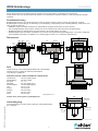 3
3
-
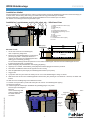 4
4
-
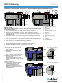 5
5
-
 6
6
-
 7
7
-
 8
8
-
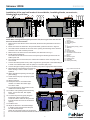 9
9
-
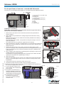 10
10
-
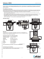 11
11
-
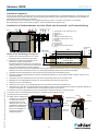 12
12
-
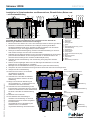 13
13
-
 14
14
-
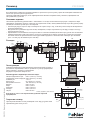 15
15
-
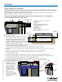 16
16
-
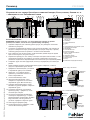 17
17
-
 18
18
-
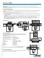 19
19
-
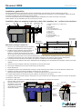 20
20
-
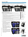 21
21
-
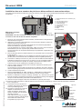 22
22
-
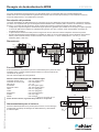 23
23
-
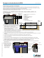 24
24
-
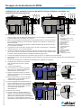 25
25
-
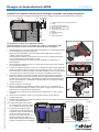 26
26
-
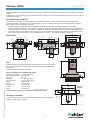 27
27
-
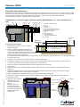 28
28
-
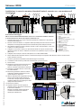 29
29
-
 30
30


Pahlen Pool skimmer Classic Wide 385/Wide 6° El manual del propietario
- Tipo
- El manual del propietario
- Este manual también es adecuado para
en otros idiomas
Artículos relacionados
-
Pahlen MA50-09 El manual del propietario
-
-
-
-
-
-
-
-
-