Panasonic TC26LX20 Instrucciones de operación
- Categoría
- Equipo de música suplementario
- Tipo
- Instrucciones de operación
Este manual también es adecuado para

TQBC0781-2
Before connecting, operating or adjusting this product, please read these instructions completely.
Please keep this manual for future reference.
English
Model No.
For assistance, please call : 1-800-211-PANA (7262)
or send e-mail to : [email protected]
or visit us at www.panasonic.com (U.S.A.)
For assistance, please call : 787-750-4300
or visit us at www.panasonic.com (Puerto Rico)
For assistance, please call : 1-800-561-5505
or visit us at www.panasonic.ca (Canada)
Espan˜ol
[Resumen]
TC-26LX20
TC-32LX20
LCD TV
Operating Instructions

2
Important Safety Instructions
The exclamation point within a
triangle is intended to tell the
user that important operating
and servicing instructions are in
the papers with the appliance.
■ Note to CATV System Installer: This reminder is provided to direct the CATV system installer’s
attention to Article 820–40 of the NEC that provides guidelines for proper grounding and, in particular,
specifies that the cable ground shall be connected to the grounding system of the building, as close to the
point of cable entry as practical.
The lightning flash with arrow
head within a triangle is intended
to tell the user that parts inside
the product are a risk of electric
shock to persons.
■ Important Safety Instructions for LCD TV
1) Read these instructions.
All the safety and operating instructions should be read before the appliance is operated.
2) Keep these instructions.
The safety and operating instructions should be retained for future reference.
3) Heed all warnings.
All warnings on the appliance and in the operating instructions should be adhered to.
4) Follow all instructions.
All operating and use instructions should be followed.
5) Do not use this apparatus near water.
For example, near a bathtub, wash bowl, kitchen sink, or laundry tub, in a wet basement, or near a
swimming pool, and the like.
6) Clean only with dry cloth.
Do not use liquid cleaners or aerosol cleaners. Use a dry cloth for cleaning.
7) Do not block any ventilation openings. Install in accordance with the manufacturer’s instructions.
Slots and Openings in the cabinet are provided for ventilation and to ensure reliable operation of the
product and to protect it from overheating. The openings should never be blocked by placing the
product on a bed, sofa, rug, or other similar surface.
8) Do not install near any heat sources such as radiators, heat registers, stoves, or other apparatus
(including amplifiers) that produce heat.
This product should not be placed in a built-in installation such as a bookcase or rack unless proper
ventilation is provided or the manufacturer’s instructions have been adhered to.
9) Do not defeat the safety purpose of the polarized or grounding-type plug. A polarized plug has two blades
with one wider than the other. A grounding type plug has two blades and a third grounding prong. The
wide blade or the third prong are provided for your safety. If the provided plug does not fit into your
outlet, consult an electrician for replacement of the obsolete outlet.
10) Protect the power cord from being walked on or pinched particularly at plugs, convenience receptacles,
and the point where they exit from the apparatus.
11) Only use attachments / accessories specified by the manufacturer.
12) Use only with the cart, stand, tripod, bracket, or table specified by the manufacturer, or
sold with the apparatus. When a cart is used, use caution when moving the cart /
apparatus combination to avoid injury from tip-over.
Quick stops, excessive force, and uneven surfaces may cause the appliance and cart
combination to overturn.
13) Unplug this apparatus during lightning storms or when unused for long periods of time.
This will prevent damage to the product due to lightning and power-line surges.
14)
Refer all servicing to qualified service personnel. Servicing is required when the apparatus has been damaged in
any way, such as power-supply cord or plug is damaged, liquid has been spilled or objects have fallen into the
apparatus, the apparatus has been exposed to rain or moisture, does not operate normally, or has been dropped.
15) To prevent electric shock, ensure the grounding pin on the AC cord power plug is securely connected.
CAUTION
RISK OF ELECTRIC SHOCK
DO NOT OPEN

3
16) If an outside antenna is connected to the
television
equipment, be sure the antenna system
is grounded so as to provide some protection
against voltage surges and built up static
charges. In the U.S. Selection 810-21 of the
National Electrical Code provides information
with respect to proper grounding of the mast and
supporting structure, grounding of the lead-in wire
to an antenna discharge unit, size of grounding
conductors, location of antenna discharge unit,
connection to grounding electrodes, and
requirements for the grounding electrode.
17) An outside antenna system should not be located
in the vicinity of overhead power lines or other
electric light or power circuits, or where it can fall into such power lines or circuits. When installing an
outside antenna system extreme care should be taken to keep from touching such power lines or circuits
as contact with them might be fatal.
18) Unplug this LCD TV from the wall outlet, and refer servicing to qualified service personnel under the
following conditions:
a. When the power cord or plug is damaged or frayed.
b. If liquid has been spilled into the LCD TV.
c. If the LCD TV has been exposed to rain or water.
d. If the LCD TV does not operate normally by following the operating instructions.
Adjust only those controls that are covered by the operating instructions as improper adjustment of other
controls may result in damage and will often require extensive work by a qualified technician to restore
the LCD TV to normal operation.
e. If the LCD TV has been dropped or the cabinet has been damaged.
f. When the LCD TV exhibits a distinct change in performance - this indicates a need for service.
19) When replacement parts are required, be sure the service technician uses replacement parts specified by
the manufacturer that have the same characteristics as the original part. Unauthorized substitutions may
result in fire, electric shock, or other hazards.
20) WARNING: TO REDUCE THE RISK OF FIRE OR ELECTRIC SHOCK, DO NOT EXPOSE THIS
APPARATUS TO RAIN OR MOISTURE.
DO NOT PLACE LIQUID CONTAINERS (FLOWER VASES, CUPS, COSMETICS, ETC.) ABOVE THE
SET. (INCLUDING ON SHELVES ABOVE, ETC.)
21) CAUTION: TO PREVENT ELECTRIC SHOCK DO NOT USE THIS PLUG WITH A RECEPTACLE OR
OTHER OUTLET UNLESS THE BLADES CAN BE FULLY INSERTED TO PREVENT BLADE EXPOSURE.
Important Safety Instructions
EXAMPLE OF ANTENNA
GROUNDING AS PER (NEC)
NATIONAL ELECTRICAL
CODE
■
Important Information Regarding Use of Video Games, Computers, Captions or Other Fixed Image Displays.
The extended use of fixed image program material can cause a permanent “shadow image” on the LCD panel.
This background image is viewable on normal programs in the form of a stationary fixed image. This type of
irreversible LCD panel deterioration can be limited by observing the following steps:
A. Reduce the brightness / contrast setting to a minimum viewing level.
B. Do not display the fixed image for extended periods of time.
C. Turn the power off when not in actual use.
■
This product utilizes tin-lead solder, and has a fluorescent lamp containing a small amount of mercury. Disposal of
these materials may be regulated in your community due to environmental considerations. For disposal or recycling
information please contact your local authorities, or the Electronics Industries Alliance:
www.eiae.org.
NOTE:
•
This equipment is designed to operate in the U.S.A. and other countries where the broadcasting
system and AC house current is exactly the same as in the U.S.A.
•
The marking or retained image on the LCD panel resulting from fixed image use is not an operating
defect and as such is not covered by Warranty. This product is not designed to display fixed
image patterns for extended periods of time.
GROUND
CLAMP
ANTENNA
LEAD-IN WIRE
ANTENNA
DISCHARGE UNIT
(NEC SECTION 810-20)
GROUNDING CONDUCTORS
(NEC SECTION 810-21)
GROUND CLAMPS
POWER SERVICE GROUNDING
ELECTRODE SYSTEM
(NEC ART 250, PART H)
ELECTRIC
SERVICE
EQUIPMENT

4
HDMI, the HDMI logo and High-Definition Multimedia Interface
are trademarks or registered trademarks of HDMI Licensing LLC.
Dear Panasonic Customer
Welcome to the Panasonic family of customers.
We hope that you will have many years of enjoyment from your new LCD TV.
To obtain maximum benefit from your set, please read these instructions before
making any adjustments, and retain them for future reference.
Retain your purchase receipt, and record the model number and serial number
of your set in the space provided on the rear cover of these instructions.
This equipment has been tested and found to comply with the limits for a TV Broadcast Receiver, pursuant
to Part 15 of the FCC Rules. These limits are designed to provide reasonable protection against harmful
interference in a residential installation. This equipment generates, uses and can radiate radio frequency
energy and, if not installed and used in accordance with the instructions, may cause harmful interference to
radio communications. However, there is no guarantee that interference will not occur in a particular
installation. If this equipment does cause or receive interference, which can be determined by turning
equipment off and on, the user is encouraged to try to correct the interference by one or more of the
following measures:
Reorient or relocate the TV antenna.
Increase the separation between TV and other equipment.
Connect TV into separate outlet from other equipment.
Consult the dealer or an experienced radio / TV technician for help.
FCC Caution: Pursuant to 47CFR, Part 15.21 of the FCC rules, any changes or modifications not expressly
approved by Matsushita Electric Corporation of America could result in harmful interference and would void
the user’s authority to operate this equipment.
For assistance, please call : 1-800-211-PANA (7262)
or send e-mail to : [email protected]
or visit us at www.panasonic.com (U.S.A.)
For assistance, please call : 787-750-4300
or visit us at www.panasonic.com (Puerto Rico)
For assistance, please call : 1-800-561-5505
or visit us at www.panasonic.ca (Canada)
Federal Communication Commission Information
The ENERGY STAR
label, a symbol for energy efficiency, was created by the U.S.
Environmental Protection Agency (EPA) and the U.S. Department of Energy
(DOE) to help customers identify products that can save them money and protect
the environment by saving energy. ENERGY STAR
compliant products generally
consume less energy than similar standard products.

5
123
456
78
0
9
Table of Contents
Important Safety Instructions .............................. 2
SUPPLIED ACCESSORIES ................................... 5
Installation ............................................................. 6
Connections .......................................................... 7
Antenna Connection ............................................ 7
Cable Box Connection ......................................... 8
Connecting Other Equipment .............................. 9
Connecting Headphones / Earphones ............... 10
HDMI Connection .............................................. 11
Basic Controls ..................................................... 12
Remote Control ................................................. 12
Main Unit............................................................ 14
Power ON / OFF ................................................... 14
ASPECT Controls ................................................ 15
Photo Viewer ....................................................... 16
Thumbnail Mode ................................................ 17
Photo Viewer Setup Menu ................................. 18
Menu Operations ................................................. 20
Tuning Channels ................................................ 22
LOCK ................................................................. 24
CLOSED CAPTION ........................................... 27
INPUT LABEL .................................................... 28
OTHER ADJUST ............................................... 28
PICTURE ADJUST ............................................ 29
POSITION/SIZE................................................. 31
AUDIO ADJUST ................................................. 32
Operating peripheral equipment using
the remote control............................................ 33
Programming the remote control code .............. 33
Infrared Code Index ........................................... 34
Mode Operational Key Chart ............................. 37
Troubleshooting .................................................. 50
Specifications ...................................................... 51
Maintenance ........................................................ 51
Check the accessories before installations.
•
Operating Instruction book
•
Remote Control Transmitter
(EUR7603ZG0)
SUPPLIED ACCESSORIES
•
Batteries for the Remote
Control Transmitter
(2 × AA size)
•
Warranty Card
•
F-Type Antenna
Connector
(for 4C-2V) ( × 1)
•
Service Center List
(For U.S.A.)
•
Customer Card
(For U.S.A.)
•
Ferrite core
(for HDMI cable) ( × 1)
Manual de instrucciones [ Resumen ]
Instalación de las pilas
del mando a distancia ................................. 39
Conexión ........................................................ 40
Conexión de antena ................................... 40
Conexión del receptor de TV por cable ...... 41
Controles básicos ......................................... 42
Control remoto iluminado ........................... 42
Aparato principal ......................................... 44
Conexión / desconexión de la alimentación ...
44
Photo Viewer ................................................. 45
Modo de imagen miniatura ......................... 45
Operaciones con menús .............................. 46
Sintonización de canales ............................ 48

6
Receiver Location
Locate for comfortable viewing. Avoid placing where sunlight or other bright light (including reflections) will fall on the screen.
Use of some types of fluorescent lighting can reduce remote control transmitter range.
Adequate ventilation is essential to prevent internal component failure. Keep away from areas of excessive heat or moisture.
Optional External Equipment
The Video / Audio connection between components can be made with shielded video and audio cables. For best performance,
antenna cables should utilize 75 ohm coaxial shielded wire. Cables are available from your dealer or electronic supply store.
Before you purchase any cables, be sure you know what type of output and input connectors your various
components require. Also determine the length of cable you’ll need.
For optimum quality picture
When the LCD is exposed to light from outdoors or lighting fixtures, high-contrast pictures may not be displayed
clearly. Turn off florescent lamps near the LCD and place in a location not exposed to outdoor light.
How to hang the LCD TV on the wall
This LCD TV is for use only with the following optional accessory. Use with any other type of optional
accessories may cause instability which could result in the possibility of injury.
•
Wall-hanging bracket ........................................................ TY-WK32LX20W
Always be sure to ask a qualified technician to carry out set-up.
How to use the LCD stand
Adjust the stand to your desired angle. The stand angle can be adjusted between 20 ° left to 20 ° right.
Installation
1. Open the battery cover.
2. Install the batteries.
Note the correct polarity (+ and -).
3. Replace the cover.
Requires two AA batteries.
Two AA size
Notes:
•
Do not drop, apply shock to or step on the remote control.
•
Do not spill water on the remote control.
•
Do not place objects between the remote control and remote control receiver.
•
Do not use remote controls for other equipment at the same time.
•
If the TV does not operate even when using the remote control from a close range, it is time to replace
the batteries.
Precaution on battery use
Incorrect installation can cause battery leakage and corrosion that will damage the remote control
transmitter.
1. Always use new batteries when replacing the old set.
2. Do not attempt to charge, short-circuit, disassemble, heat or burn used batteries.
3. Battery replacement is necessary when remote control acts sporadically or fails to operate this unit.
SUPPLIED ACCESSORIES / Installation
Remote control battery installation

7
ANT
Connections
Antenna Connection
For proper reception of VHF / UHF channels, an external antenna is required. For best reception an outdoor
antenna is recommended. The antenna mode must be set to TV (see page 22, MODE).
F-Type Antenna Connector
75 Ohm Coaxial Cable
Mixer
UHF AntennaVHF Antenna
Antenna
Terminal
F-Type Antenna Connector
Cable / Antenna Connection
Incoming 75 Ohm Cable from Home
Antenna / Cable Company
Antenna Terminal
on the Back of the TV
Back of the TV
1
2
1
2
1
Removal
Fitting
1. Insert the claws
(at 4 points) at
the bottom end.
2. Push it until
hook will be
cricked.
Note:
Separate the RF cable and the power cord to avoid interference appearing on the screen.
1. Push down hooks and
pull the cover slightly
towards yourself to
disengage the claws (at
4 points).
2. Slowly pull out in the
downward direction.
Cover removal and fitting

8
ANT
OUTPUT
S VIDEO
VIDEO
L-AUDIO-R
ANT
VCR
CABLE BOX
Incoming 75 Ohm Cable
from Cable Company
OUTPUT INPUT
ANT OUTPUT
ANT INPUT
CABLE BOX
OUTPUT INPUT
Incoming 75 Ohm Cable
from Cable Company
Connections
• For reception of cable channels (01 - 125), connect the cable supplied by your local cable company.
The antenna mode must be set to CABLE (see page 22, MODE).
•
Certain cable systems offset some channels to reduce interference or have Premium (scrambled) channels. A cable
converter box is required for proper reception. Check with your local cable company for its compatibility requirements.
• Set the TV channel to CH3 or CH4, cable when using this connection.
Cable Box Connection
Back of the TV
Back of the TV
Cable Box
Cable Box and VCR

9
Y
Pb
Pr
Y
Pb
S-VIDEO
VIDEO
AUDIO
Pr
L
R
AUDIO
OUT
AUDIO
IN
INPUT 1
1
COMPONENT
INPUT
2
VIDEO
VIDEO
PrPbYL
R
COMPONENT VIDEO OUT
Audio
OUT
S-Video
OUT
Video
OUT
L
R
Audio
OUT
Connections
Connecting Other Equipment
Notes:
• When connecting video cables, priority is given to the S-Video cable when both the S-VIDEO input
terminal and the VIDEO input terminal are connected.
• Please make inquiries to video game manufacturers concerning component cables to connect with
video game console.
AUDIO
cable
DVD / STB
COMPONENT
VIDEO cable
AUDIO cable
VIDEO
cable
S-VIDEO cable
Super-VHS VCR CAMCORDER
VIDEO GAME
CONSOLE
Back of the TV
Rear Input Terminals

10
Audio
IN
R
L
ANTANT
VIDEO
Y
Pb
Pr
Y
Pb
S-VIDEO
VIDEO
Pr
AUDIO
IN
INPUT 1
1
COMPONENT
INPUT
2
VIDEO
AUDIO
L
R
AUDIO
OUT
Rear Output Terminals
Connections
Connecting Headphones / Earphones
AUDIO cable
Back of the TV
S-VIDEO
HPJ
VIDEO -AUDIO-
INPUT 2
Audio
OUT
R
L
S-Video
OUT
Video
OUT
S-VIDEO
HPJ
VIDEO -AUDIO-
INPUT 2
M3 plug
(Not supplied)
AUDIO cable
VIDEO cable
S-VIDEO cable
CAMCORDER
VIDEO GAME
CONSOLE
Front of the TV
Front of the TV
Front Input Terminals

11
AV IN
AUDIO
IN
PET TBMU392
VIDEO
HDMI
∗
1
(High Definition Multimedia Interface) is the first all digital consumer electronics A/V interface that
supports uncompressed standard. The HDMI terminal supports both video and audio information.
You can connect an EIA / CEA-861 / 861B
∗
2
compliant consumer electronic device, such as a Set Top
Box or DVD player with HDMI or DVI output terminal to the HDMI
∗
1
input terminal.
Input a High-bandwidth Digital Content Protection (HDCP) high-definition picture source to this HDMI
terminal, so you can display high-definition pictures on this TV in the digital form.
Notes:
•
If the external device has DVI output only, use a
DVI to HDMI adapter cable
∗
3
to connect to the
HDMI terminal.
•
Connect the audio cables to the AUDIO IN
terminals for HDMI.
•
Select the audio setting in HDMI IN (see page 32).
HDMI cable
HDMI or DVI
signal out
Set Top Box
DVD player
Audio cable
HDMI Connection
Connections
∗
1. HDMI, the HDMI logo and High-Definition Multimedia Interface are trademarks or registered
trademarks of HDMI Licensing LLC.
∗
2. EIA / CEA-861 / 861B profiles compliance covers profiles for transmission of uncompressed digital
video including high bandwidth digital content protection.
∗
3. HDMI-DVI conversion cable (TY-SCHO3DH): available on Panasonic website (www.panasonic.com).
Consult your consumer electronics dealer for availability details.
This input terminal is not intended for use with computers.
Notes:
• This HDMI connector is Type A.
• If you connect an equipment without a digital output terminal, connect to the COMPONENT VIDEO, S
VIDEO or VIDEO input terminal on the TV so you can enjoy an analog signal.
1080i
720p
480p
480i
No. of dots (H
× ×
× ×
×
V)
1,920
× ×
× ×
×
1,080i
1,280
× ×
× ×
×
720p
720
× ×
× ×
×
480p
640
× ×
× ×
×
480p
720(1,440)
× ×
× ×
×
480i
Vertical scanning frequency (Hz)
59.94 / 60
59.94 / 60
59.94 / 60
59.94 / 60
59.94 / 60
Compatible VIDEO Signal
Compatible sampling frequency of AUDIO signal (L.PCM) : 48 kHz / 44.1 kHz / 32 kHz
1
2
Put the cable
and close.
Pull back the tabs (in two
places) to open.
Attaching the ferrite core
Ferrite core
(small size) (supplied)
Attach just beside
the connector.

12
123
456
78
0
9
DTV
AUX
DVD
VCR
DBS
RCVR
RETURN
EXIT
MENU
PLAY
R-TUNE SLEEP/PROG
GUIDE
SAP
PAGERECALL
STOPPAUSE
REC
FFREW
TV/VCR
VCR CH
OPEN/CLOSE
M
U
T
E
A
S
P
E
C
T
T
V
/
V
I
D
E
O
L
I
G
H
T
POWER
CBL
CH
CH
VOL VOL
O
K
TV
T V
Mode Selection buttons
(see page 33)
Basic Controls
Operation of other devices
(see pages 37, 38)
MUTE button
Press to mute the sound.
Press again to cancel mute.
Mute is canceled when the power is turned off or
volume level is changed.
R-TUNE button
Press to switch to previously viewed channel or to switch
between TV mode and another input mode.
POWER button
Press to turn the TV on or off (see page 14).
Note:
This does not work when the main power is off
(No light).
RECALL button
Press to display channel number, sleep
timer and other options.
MENU button
(see page 20)
Remote Control
SD button
Press to access Photo Viewer
(see page 17)

13
STEREO SAP MONO
Basic Controls
COMPONENT 2
TV
COMPONENT 1
HDMI VIDEO 1VIDEO 2
Numbered buttons
ASPECT button (see page 15)
GUIDE button (DBS mode)
SAP button
Press to select the audio mode. You can
also change the mode in the MENU screen
(see page 32).
TV/VIDEO button
Press to change the input mode.
LIGHT button
Press to light the remote
control buttons.
The selected button blinks
when lit.
RETURN button
Return to previous MENU (TV mode).
EXIT button
EXIT from menu (DTV, STB or PVR mode).
SLEEP button (TV mode)
Set the sleep time to put the TV into standby mode.
• When 3 minutes left, “ 3 ” will flash. (“2” for 2 minutes and “1” for
1 minute).
• The SLEEP timer is cancelled when the power is turned off.
PROG
-
button (DBS or DTV mode)
When tuning digital channel, press the button to enter the minor
number in a compound channel number.
• To enter the channel number
ex. CH 15-1: [1] [5] [-] [1] [OK]
30 60 90
0
PAGE button
Page up / down (DBS mode).
Skip + /
-
(DVD & CD mode).
Reduces volume
Moves cursor to
the left during
menu mode.
Channel down
Moves cursor downward during menu mode.
Channel up
Moves cursor upward during menu mode.
CH
CH
VOL VOL
O
K
Increases volume
Moves cursor to
the right during
menu mode.
OK button
Choose menu and
submenu entry.

14
R STANDBY
G
-
POWER ON
POWER
TV/VIDEO VOLUME
CHANNEL
Notes:
• The TV consumes some power as long as the power cord is inserted into the wall outlet.
• Do not remove or slide the ferrite core for the safety purpose.
On the main unit
Main POWER
switch
On the remote control
Power ON / OFF
Press to turn the TV on / off.
• Power indicator
Power ON: Green
Power OFF (Standby): Red
• This does not work when the main
power is off (No light) (see above).
Note:
• The screen below is displayed for a few
moments when the TV is turned on.
Basic Controls / Power ON / OFF
POWER
DTV
AUX
DVD
VCR
DBS
RCVR
TV
CBL
M
U
T
E
A
S
P
E
C
T
T
V
/
V
I
D
E
O
L
I
G
H
T
RETURN
EXIT
MENU
CH
CH
VOL VOL
O
K
SAP
POWER
ZOOM
CH 6
STEREO
SAP
MONO
Main Unit
SD CARD slot PC CARD slot
PC CARD
EJECT button
Power indicator
Power on : Green
Power off : No Light
Power off (Standby): Red
Power cord
AC120V, 60Hz
Power Indicator
Note:
• Select the menu language before operating the TV
(see page 21, LANGUAGE).
Main POWER switch
Press to turn the TV’s
main power on / off
(see below).
Channel Up / Down
Volume Up / Down
TV / VIDEO button
R STANDBY
G
-
POWER ON
POWER
Press to turn the TV’s main power on / off.
• Power indicator
Main power ON: Green
Main power OFF: No light
Remote control sensor
Remote control sensor
Within about 20 feet
(6 meters) in front of the
TV set.
Preparation
Connect the plug to the wall outlet.
Ferrite core

15
Each time you press the button:
ASPECT
NORMAL mode will display a 4:3
picture at its standard 4:3 size without
any stretching.
ZOOM mode magnifies the central
section of the picture.
FULL will display the picture at its
maximum size but with slight
elongation.
JUST mode will display a 4:3 picture
at its maximum size but with aspect
correction applied to the sides of the
screen so that elongation is only
apparent at the left and right edges of
the screen. The size of the picture will
depend on the original signal.
Mode
Picture Explanation
NORMAL
ZOOM
FULL
JUST
JUST
4
3
ZOOM
4
3
FULL
4
3
NORMAL
3
4
ASPECT Controls
JUST ZOOM FULL
NORMAL
DTV
AUX
DVD
VCR
DBS
RCVR
RETURN
EXIT
MENU
SAP
M
U
T
E
A
S
P
E
C
T
T
V
/
V
I
D
E
O
L
I
G
H
T
POWER
CBL
CH
CH
VOL VOL
O
K
TV
M
U
T
E
A
S
P
E
C
T
T
V
/
V
I
D
E
O
L
I
G
H
T
This feature allows you to enjoy viewing the picture at its maximum size, including wide screen cinema
format picture.
Notes:
• This feature does not work for 1080i and 720p input signals.
• This feature does not work during Photo Viewer thumbnail mode
or single picture view mode.
• The aspect setting is stored separately for TV, VIDEO1, VIDEO2,
COMPONENT1, COMPONENT2, HDMI and Photo Viewer Slide
Show (see page 18).

16
Photo Viewer
Photo Viewer lets you display JPEG images recorded by digital still camera on SD card or other types of
memory card when it is inserted in the proper card slot.
Compatible card type and card size
Folders and Files
Example folder structure
JPEG images in all the folders are displayed
sequentially.
ROOT
DCIM
P1000001.jpg
P1000002.jpg
P1000003.jpg
P1000004.jpg
P1010001.jpg
P1010002.jpg
P1010003.jpg
P1010004.jpg
100_PANA
101_PANA
Created automatically
Folder names consist of
a 3-digit folder number
which is followed by five
arbitrary characters.
File names consist of
four arbitrary characters
followed by a 4-digit file
number.
Notes:
• Folder and file names may vary according
to the digital still camera.
• Use the characters “a-z”, “A-Z”, “0-9” and
“_” to name a directory or a file. Do not use
two-byte characters or other special codes.
∗ miniSD Card requires miniSD adapter.
•
Photo Viewer is not compatible with card type hard
disk (Micro Drive, Mobile type hard disk, etc).
• Memory cards are not supplied with this television.
• When both SD card and PCMCIA card are inserted
in the slot, SD card has the priority.
Card Data Protection
• Do not remove the card while Photo Viewer is
accessing the information (when the card icon is
flashing). Such action may damage the memory
card or the unit itself.
• Before inserting or removing the PCMCIA card,
make sure that the TV is turned Off. Otherwise, it
may damage the unit.
• Do not touch the terminals on the back of the SD
card / PCMCIA card.
• Always insert a card in the correct direction. Failure
to do so may result in damage to the card and
this unit.
• Do not subject the card to excessive pressure or
strong impacts.
• Electrical interference, electrostatic discharges
and malfunctions of the unit or card may all result
in data loss or damage to the card.
• Stored data should be periodically backed up as
a protection against data corruption, data loss or
device malfunction. Please note that Panasonic
shall not accept any liability for damage or loss of
stored data.
• WARNING: As with any small object, an SD
card can be swallowed by young children. Do
not allow children to handle
SD card. Please
remove SD card immediately after use.
PCMCIA card slot
•
SD Card (512MB)
•
miniSD Card
∗
(128MB)
•
Multi Media Card (128MB)
•
Compact Flash (1GB)
•
Smart Media (128MB)
•
Memory Stick (128MB)
•
xD Picture Card(128MB)
•
Flash ATA (128 MB)
•
Memory Stick Pro (1GB)
The cards require standard PCMCIA card
adapter. (Some PC card adapter will not be
compatible).
SD card slot
•
SD Card (512MB)
•
Multi Media Card (128MB)
•
miniSD Card
∗
(128MB)
• Photo Viewer can only show still images recorded
by a digital still camera with DCF
∗
and EXIF
standard JPEG file.
∗ DCF (Design rule for Camera File system)
Unified standard established by Japan Electronics
and Information Technology Industries Association
(JEITA).
• Memory cards must be formatted with FAT12 or
FAT16 in order to be viewed on TV. If the card is
not formatted, it may cause incompatibility with
certain memory card adapters. If this happens,
reformat the card using your digital still camera.
Reformatting the card will erase the images
stored in it. Refer to your camera manual for
more information.
• Maximum number of folders that can be displayed:
100.
•
Maximum number of files that can be displayed: 3000.
•
Picture resolution: Compatible in the range 64 x
64 - 8192 x 8192 (sub-sampling 4:2:2 or 4:2:0)
• If the image is imported from a PC, it must follow
the EXIF (Exchangeable Image File Format) 2.0,
2.1, 2.2 in addition to the DCF format.
• The JPEG modified using a PC will not be
displayed on TV.
• The Photo Viewer cannot display Motion JPEG
and still image not DCF formatted (i.e. TIFF, BMP).
• If the file is partially corrupted, it may be shown in
lower resolution.
• The displayed image size depends on the recorded
size.

17
PhotoViewer
SELECT
SELECT
OK
OK
MENU
MENU
RETURN
RETURN
SD to setup
SD to setup
0 0 0 1 / 0 0 1 2
Filename :100-0001
Date :11/10/2002
Pixel :1600X1200
SD CARD
SD C
ARD
P
C CARD
EJECT
PC
Inserting and removing a card
SD card slot
Insert the card.
PCMCIA card slot
Turn the TV off before inserting or removing a PCMCIA card.
1. Raise.
Label side
upward
2.
Insert it unit it
clicks in
.
2. Lower.
1.
Push the center
of the card.
Holding
both edges,
securely insert it to
the depth.
Remove the card.
Remove the card.
Align the
direction
of
mark.
Terminal
face to
the depth
Label side
upward
If the eject button does not pop out
Push in PCMCIA card again, and
then push again the eject button.
Note:
If PCMCIA card adapter is used,
remove it together with the
adapter.
Notes:
•
It may take long time to display the thumbnail if there are lots of files or the file size is large.
• The video disappears from the screen while the Photo Viewer access the information
from the card. After accessing the images from the card, a thumbnail screen is
displayed.
The thumbnail screen is the initial entry screen from the main menu.
• When both SD card and PCMCIA card are inserted, the TV plays SD card. To play a PCMCIA card,
select “PC” in “Card” (see page 19) after inserting the PCMCIA card.
Thumbnail Mode
Insert the card into the appropriate slot (see above).
OR
1
2
PLAY
Press to display the thumbnail screen.
Picture No. / Total No. of pictures
File name, the date and the pixel (resolution)
of the picture
Single picture view mode
3
CH
CH
VOL VOL
O K
Press to select the next or the previous picture.
• Press OK to return to the thumbnail screen.
To rotate the picture
While in the single picture view mode
CH
CH
VOL VOL
O K
123
456
78
0
9
DTV
AUX
DVD
VCR
DBS
RCVR
RETURN
EXIT
MENU
R-TUNE SLEEP/PROG
GUIDE
SAP
PAGERECALL
STOPPAUSE
REC
FFREW
TV/VCR
VCR CH
OPEN/CLOSE
M
U
T
E
A
S
P
E
C
T
T
V
/
V
I
D
E
O
L
I
G
H
T
CBL
CH
CH
VOL VOL
O
K
TV
T V
PLAY
POWER
Insert the card.
Select the thumbnail
image.
Press to display the
image in the single picture
view mode.
Press to rotate the
picture ninety degree.
Photo Viewer
Push the
eject button.
PhotoViewer
INDEX
INDEX
MENU
MENU
RETURN
RETURN
SD to setup
SD to setup
0 0 0 1 / 0 0 1 21 0 0 -- 0 0 0 1

18
CH
CH
VOL VOL
O K
CH
CH
VOL VOL
O K
PLAY
Setup Menu
Return
Interval
5Sec
Sequence Order
Slide Show Start
Repeat OFF
Rotate
Zoom
Left
To Fit
Card SD
EXIT
SELECT
CHANGE
MENU
OK
Photo Viewer
Setup Menu
This menu allows you to customize features in the Photo Viewer Setup Menu.
While in the thumbnail mode or the single picture view mode (see page 17)
1
2
Press to select the sub-menu.
Press to adjust or activate the sub-
menu.
Press to display the Setup Menu
screen.
Press to select the sub-menu.
Press to adjust or activate the sub-menu.
Interval
Allows you to change the length of time that a slide is being displayed on
screen. (5Sec, 10Sec, 15Sec, 30Sec, 60Sec, 90Sec, 10Min).
Sequence (Order or Random)
Repeat (OFF or ON)
Select the settings of Interval, Sequence and Repeat before starting the slide show.
Slide Show
Press to select Rotate.
Press to select Left or Right.
Press to activate the setting.
(While in the single picture view mode only)
Allows you to rotate the image (see also page 17).
Rotate
CH
CH
VOL VOL
O K
Photo Viewer
CH
CH
VOL VOL
O K
Press to select Start.
Press to start the slide show.
• Press again to stop.
• Press ASPECT to change the aspect of the image (see page 15).

19
(While in the single picture view mode only)
Lets you select the magnification of the single picture display.
Press to select Zoom.
Press to select To Fit, x2 or x4.
Press to activate the setting.
Press to move the image in the picture frame.
To cancel Zoom
Press OK to view the picture in normal magnification.
Select either SD or PC when both cards are inserted in the slots.
Press to select Card.
Press to select SD or PC.
Zoom
Card
CH
CH
VOL VOL
O K
CH
CH
VOL VOL
O K
Photo Viewer
CH
CH
VOL VOL
O K
1
2
Symptom
Cannot read the content of the card.
PC card cannot be ejected.
Poor picture quality.
Picture takes a long time to display.
Cause and remedy
• Not compatible format. Must be formatted with FAT 12 or FAT
16.
• The extension is not “JPG”.
• The folders not under DCF standard.
Push the card all the way in, and eject.
If the main image cannot be read (the file is partially corrupted),
the Photo viewer will read the thumbnail. Please confirm the format
of the image.
There are lots of images or the file size is large.
“Card is not inserted correctly.
”
“This type of image is not supported.”
“This type of format is not supported.”
“ ”
“Photo Viewer cannot support over 3000 JPEG files.”
“Photo Viewer cannot support over 8192 x 8192 pixels.”
“This type of card is not supported.”
Error messages
Photo Viewer Troubleshooting
Insert a card.
The JPEG file is corrupted and cannot be decoded.
The card is not formatted with FAT 12 or FAT 16 or
if it is not DCF standard.
Thumbnail and main picture cannot be shown.
Over 3000 image files.
Resolution over.
Incompatible card is inserted.

20
123
456
78
0
9
DTV
AUX
DVD
VCR
DBS
RCVR
RETURN
EXIT
MENU
R-TUNE SLEEP/PROG
GUIDE
SAP
PAGERECALL
M
U
T
E
A
S
P
E
C
T
T
V
/
V
I
D
E
O
L
I
G
H
T
POWER
CBL
CH
CH
VOL VOL
O
K
TV
CH
VOL VOL
O
K
CH
MENU
Menu Operations
MENU
ADJUST SET UP
LANGUAGE
PROGRAM CH
LOCK
CLOSED CAPTION
INPUT LABEL
OTHER ADJUST
2
MENU
ADJUST SET UP
LANGUAGE
PROGRAM CH
LOCK
CLOSED CAPTION
INPUT LABEL
OTHER ADJUST
or
Press to display MENU
screen.
MENU
ADJUST
PICTURE
AUDIO
SET UP
PICTURE ADJUST
POSITION / SIZE
AUDIO ADJUST
MENU
ADJUST
PICTURE
AUDIO
SET UP
PICTURE ADJUST
POSITION / SIZE
AUDIO ADJUST
MENU
ADJUST
PICTURE
AUDIO
SET UP
PICTURE ADJUST
POSITION / SIZE
AUDIO ADJUST
An On Screen Help box is displayed when a menu is displayed
on the TV. This Help box indicates which keys on the remote control
are used to navigate the menu shown.
ON SCREEN HELP ‘Instruction’ box
1
LANGUAGE
ENGLISH
LANGUAGE
RETURN
CHANGE

21
Menu Operations
OFF ON
COOLCOOL
NORMAL
PIC MODE
BACK LIGHT
PICTURE
BRIGHTNESS
COLOR
TINT
SHARPNESS
AI PICTURE
+ 20
+ 20
0
0
0
0
OFF ON
STANDARD
PICTURE ADJUST PAGE 1/2
(See page 29)
CH
CH
VOL VOL
O
K
•
To return to the previous screen :
•
To exit the MENU screen:
RETURN
EXIT
This returns TV to normal viewing.
MENU
Press to select the MENU screen (ADJUST or SET UP).
Press to select the sub-menu feature.
Press to display the sub-menu screen.
LOCK
BLOCK PROGRAMS:
STATUS
U. S. MOVIES
CHANGE SETTING
ENTER CODE FIRST
OFF ON
(See pages 24-26)
(See page 32)
AUDIO ADJUST
NORMAL
+ 4
0
0
DYNAMIC
OFF ON
OFF ON
AUTO
MODE
BASS
TREBLE
BALANCE
SURROUND
EQUALIZER
STEREO SAP MONO
HDMI IN
PAGE1/2
POSITION/SIZE
NORMAL
NORMALIZE
SIZE
1
RETURN
LANGUAGE
ENGLISH
LANGUAGE
Select the menu
language.
PROGRAM CHANNELS
MODE
AUTO PROGRAM
MANUAL PROGRAM
TV
CABLE
(See pages 22, 23)
(See page 28)
INPUT LABEL
COMPONENT1
COMPONENT2
VIDEO1
VIDEO2
HDMI
COMPONENT1
COMPONENT2
VIDEO1
VIDEO2
HDMI
(See page 28)
OTHER ADJUST PAGE1/2
VIDEO NR
OFF ON
3D Y/C
COLOR MATRIX
SD HD
OFF ON
MPEG NR
OFF ON
CLOSED CAPTION
MODE
OFF
ON MUTE
NO
(See page 27)
(See page 31)

22
Tuning Channels
Press to select PROGRAM CH.
Press to display the PROGRAM
CHANNELS screen.
2
3
Press to select MODE.
Press to select TV or CABLE.
4
Press to select AUTO PROGRAM.
Press to display the AUTO PROGRAM
screen.
5
Press to select YES.
Press to start AUTO PROGRAM.
Channels will automatically advance until all
channels have been scanned. Channel
numbers with video signal received will be
stored in the Channel Memory.
CH
CH
VOL VOL
O K
CH
CH
VOL VOL
O K
CH
CH
VOL VOL
O K
AUTO PROGRAM
Activate
"AUTO PROGRAM?"
YES NO
AUTO PROGRAM
In "AUTO PROGRAM"
STOP
CHANNEL 59
MENU
PROGRAM CHANNELS
MODE
AUTO PROGRAM
MANUAL PROGRAM
TV
CABLE
Automatically scans and stores all the TV channels.
Automatic channel programming
MENU
ADJUST SET UP
LANGUAGE
PROGRAM CH
LOCK
CLOSED CAPTION
INPUT LABEL
OTHER ADJUST
Menu Operations
1
Press the TV/VIDEO button to display the TV channel.
Notes:
• When any button is pressed during AUTO PROGRAM, the TV will return to normal viewing. (Channels
searched up to the point are added.)
• After AUTO PROGRAM finishes, the lowest channel number added will be displayed.
• When there are no receivable channels, channel 69 (for TV) or channel 125 (for cable TV) is displayed.

23
PROGRAM CHANNELS
MODE
AUTO PROGRAM
MANUAL PROGRAM
TV
CABLE
MANUAL PROGRAM
ENTER CHANNEL
121
Press to select MANUAL PROGRAM.
Press to display the MANUAL
PROGRAM screen.
4
Press to select the channel.
• You can also use the numbered buttons.
5
6
Press to add the channel to the Channel
Memory (the channel number turns blue).
Press to delete the channel from the
Channel Memory (the channel number turns
yellow).
• Repeat steps 5 and 6 for other channels.
CH
CH
VOL VOL
O K
CH
CH
VOL VOL
O K
Add or delete a channel manually.
CH
CH
VOL VOL
O K
Menu Operations
Manual channel programming

24
LOCK
In the United States, the V-CHIP consists of two rating systems, which are MPAA (MOTION PICTURE)
and TV PARENTAL GUIDELINES. Its function is to block programs by the rating data in the XDS data
packets sent from broadcasting stations. The user can select which rating programs should be blocked
by the LOCK MENU options.
LOCK
BLOCK PROGRAMS
:
STATUS
U. S. TV PROGRAMS
CHANGE SETTING
CHANGE CODE
OFF ON
LOCK
BLOCK PROGRAMS
:
STATUS
U. S. MOVIES
CHANGE SETTING
ENTER CODE FIRST
OFF ON
Input 4-digit code.
• To clear the numbers while entering the code,
press Up
or Down
.
• You will need the code to enter the LOCK menu.
• After entering your password for the first time,
ENTER CODE FIRST will change to CHANGE
CODE.
CH
CH
VOL VOL
O K
Press to select LOCK.
Press to display the LOCK screen.
3
Press to select BLOCK PROGRAMS.
Press to select U.S MOVIES, U.S. TV
PROGRAMS, CANADIAN ENGLISH
or CANADIAN FRENCH.
CH
CH
VOL VOL
O
K
4
Press to select STATUS.
Press to select ON or OFF.
CH
CH
VOL VOL
O K
Press to select CHANGE SETTING.
Press to enter the next menu.
5
LOCK
BLOCK PROGRAMS
:
STATUS
U. S. TV PROGRAMS
CHANGE SETTING
CHANGE CODE
OFF ON
LOCK
BLOCK PROGRAMS
:
STATUS
U. S. TV PROGRAMS
CHANGE SETTING
CHANGE CODE
OFF ON
CH
CH
VOL VOL
O K
Menu Operations
MENU
ADJUST SET UP
LANGUAGE
PROGRAM CH
LOCK
CLOSED CAPTION
INPUT LABEL
OTHER ADJUST
Note:
Use a code that is easy to remember and record it in a safe place.
2
1
123
456
78
0
9

25
Menu Operations
Press to select VIEW NR PROGRAMS?
Press to select NO or YES.
NO :
Cannot view programs with NR signals.
YES : Can view programs with NR signals.
CH
CH
VOL VOL
O K
6
8
Press to select SETTING.
Press to select BASIC or DETAILED.
BASIC : You can select the titles.
DETAILED : You can select the titles and options.
CH
CH
VOL VOL
O
K
7
Press to lock or unlock the rating.
Lock: Red
Unlock : Green
CH
CH
VOL VOL
O K
U.S. TV PROGRAMS only
9
VIEW NR PROGRAMS?
U. S. TV PROGRAMS
TV
–
G
TV
–
PG
TV
–
1 4
TV
–
MA
V
V
V
D
D
L
L
L
S
S
S
TV
–
Y
TV
–
Y7
FV
SETTING BASIC
NO YES
Title Option
Press to select the rating.
• When a title field is selected, all ratings below this
rating are selected.
•
When options within an option field are selected,
ratings below this rating within the same field are
selected.

26
CANADIAN ENGLISH RATINGS
Exempt - Exempt programming includes: news, sports, documentaries and other information
programming, talk shows, music videos, and variety programming.
Programming intended for children under age 8. No offensive language, nudity or sexual
content.
Programming contains themes or content which may not be suitable for viewers under
the age of 14. Parents are strongly cautioned to exercise discretion in permitting viewing
by pre-teens and early teens.
Programming generally considered acceptable for children 8 years and over. No profanity,
nudity or sexual content.
General programming, suitable for all audiences.
Parental Guidance suggested. Some material may not be suitable for children.
E
C
C8+
G
PG
14+
18+
18+ years old. Programming restricted to adults. Contains constant violence or
scenes of extreme violence.
CANADIAN FRENCH RATINGS
General - Programming intended for audience of all ages. Contains no violence, or
the violence content is minimal or is depicted appropriately.
Programming may not be suitable for children under the age of 13 - Contains either a
few violent scenes or one or more sufficiently violent scenes to affect them. Adult
supervision strongly suggested.
8+ General - Not recommended for young children. Programming intended for a broad
audience but contains light or occasional violence. Adult supervision recommended.
Exempt - Exempt programming.
E
G
Programming may not be suitable for children under the age of 16 - Contains frequent
scenes of violence or intense violence.
16ANS+
18+ years old. Programming restricted to adults. Contains constant violence or
scenes of extreme violence.
18ANS+
8 ANS+
13ANS+
1. Ratings for children: Divided into ranks as follows.
2. Ratings for teenagers: Created out of these major categories to form various combinations. These
combinations are described in the below diagram. Ratings for all ages are on top and ratings for
adults are on the bottom.
G : General audience
PG : Parental guidance suggested
PG-13 : Parental guidance needed
under 13 years old
U.S. TV PROGRAMS RATINGS
R : Restricted
NC-17 : No one under 17 is admitted
X : Pornography
U.S. MOVIES RATINGS
TV-Y
TV-YTV-Y7 TV-Y7 TV-Y7-FVFV
TV-G
TV-PG
TV-14
TV-MA
V
V
V
S
S
S
L
L
L
D
D
Menu Operations

27
CLOSED CAPTION
This unit has a built in decoder that provides a visual depiction of the audio portion of a television
program in the form of written words across the screen (white or colored letters on a black background).
It allows you to read the dialogue of a television program or other information.
Press to select CLOSED CAPTION.
Press to display the CLOSED
CAPTION screen.
1
2
CC ON MUTE
Displays the On-Screen Closed Caption when the MUTE button is pressed. To delete the closed caption,
press the MUTE button again.
2
Press to select OFF, C1 or C2.
CC MODE
Displays the On-Screen Closed Caption.
CLOSED CAPTION
MODE
OFF
ON MUTE
NO
CH
CH
VOL VOL
O K
Press to select
CC
MODE.
•
OFF -
•
C1 -
•
C2 -
Recommended mode when Closed Caption is not being
used.
For video related information that can be displayed (up to 4
lines of script strategically placed on the television screen so
that it does not obstruct relevant parts of the picture).
Another mode used for video related information.
Press to select
CC
ON MUTE.
CLOSED CAPTION
MODE
OFF
ON MUTE
NO
CH
CH
VOL VOL
O K
Press to select NO (OFF), C1 or C2.
Menu Operations
MENU
ADJUST SET UP
LANGUAGE
PROGRAM CH
LOCK
CLOSED CAPTION
INPUT LABEL
OTHER ADJUST
Note:
To activate this feature, set CC MODE to OFF .
Notes:
• This feature is available only with the 480i input signal and with the programs including the closed caption.
• The closed caption is not displayed when using HDMI connection (see page 11) or when you set the
aspect to “ZOOM” (see page 15).
CH
CH
VOL VOL
O K

28
Press to select OTHER ADJUST.
Press to display the OTHER ADJUST
screen.
1
CH
CH
VOL VOL
O K
INPUT LABEL
Press to select the item.
2
CH
CH
VOL VOL
O
K
Press to select the setting.
OTHER ADJUST
You can change the video input labels displayed on the screen to match the connected device (VCR, DVD
player etc.).
Press to select INPUT LABEL.
Press to display the INPUT LABEL screen.
1
2
Press to select the video input.
CH
CH
VOL VOL
O K
Press to select the INPUT LABEL.
(COMPONENT1 / COMPONENT2 /
VIDEO1 / VIDEO2 / HDMI, VCR, LD,
GAME, DVD, DTV, [BLANK] and SKIP
∗
)
∗ Select to skip unused video input
when pressing TV/VIDEO button.
CH
CH
VOL VOL
O K
OTHER ADJUST PAGE1/2
VIDEO NR
OFF ON
3D Y/C
COLOR MATRIX
SD HD
OFF ON
MPEG NR
OFF ON
INPUT LABEL
COMPONENT1
COMPONENT2
VIDEO1
VIDEO2
HDMI
COMPONENT1
COMPONENT2
VIDEO1
VIDEO2
HDMI
VIDEO NR
Reduce video noise in the picture.
MPEG NR
Noise unique to DVD, STB etc will be reduced.
3D Y/C
Minimizes noise and cross color in the picture. Not available for
COMPONENT VIDEO INPUT and HDMI input.
COLOR MATRIX
Displays input signals (480p signals) in a natural color. Automatically
adjusts color parameters for HD (high definition) and SD (standard
definition).
POWER SAVE
The POWER SAVE mode is suitable for watching television at night.
Power consumption will be reduced.
ONOFF
SD HD
ONOFF
SAVING
STANDARD
MENU
ADJUST SET UP
LANGUAGE
PROGRAM CH
LOCK
CLOSED CAPTION
INPUT LABEL
OTHER ADJUST
MENU
ADJUST SET UP
LANGUAGE
PROGRAM CH
LOCK
CLOSED CAPTION
INPUT LABEL
OTHER ADJUST
OTHER ADJUST
PAGE2/2
POWER SAVE
STANDARD
ONOFF
Menu Operations

29
PICTURE ADJUST
1
2
Press to select PICTURE ADJUST.
Press to select the sub-menu.
Adjust the setting watching the picture
behind the menu.
Press to activate the setting if necessary.
PIC MODE
Press to display the PICTURE ADJUST screen.
CH
CH
VOL VOL
O K
MENU
ADJUST
PICTURE
AUDIO
SET UP
PICTURE ADJUST
POSITION / SIZE
AUDIO ADJUST
PICTURE ADJUST PAGE 1/2
NORMAL
PIC MODE
BACK LIGHT
PICTURE
BRIGHTNESS
COLOR
TINT
SHARPNESS
AI PICTURE
+ 20
+ 20
0
0
0
0
CUSTOM
OFF ON
PICTURE ADJUST PAGE 2/2
NORMAL
COLOR TEMP
ADVANCED ADJUST
OFF ON
NORMAL
MID
MID
MID
EDGE TRANS.
GRAY EMPHASIS
GAMMA ADJUST
+ 8
+ 8
BLACK EXTENSION
WHITE CHAR CORR
ADVANCED ADJUST
3
ADVANCED ADJUST
Press to select ADVANCED ADJUST.
Press to select ON.
CH
CH
VOL VOL
O K
Menu Operations
NORMAL / NORMALIZE
Select “NORMALIZE” and press “OK” to return each PIC MODE to the factory default setting.
Notes:
• “NORMAL” means the PIC MODE is in the factory default setting. “NORMAL” changes to
“NORMALIZE” when you change the setting of BACK LIGHT, PICTURE, BRIGHTNESS, COLOR, TINT,
SHARPNESS, AI PICTURE, COLOR TEMP or ADVANCED ADJUST.
• You can normalize each PIC MODE separately.
MODE
STANDARD
CINEMA
VIVID
CUSTOM
Function
Displays a standard image.
Ideal for watching movies in a dark room.
Displays a clear image with high contrast.
You can customize the picture settings to suit your preference (see page 30,
ADVANCED ADJUST).
4
CH
CH
VOL VOL
O K
Press to display the sub-menu.
The CUSTOM setting is stored for TV, VIDEO1, VIDEO2, COMPONENT1, COMPONENT2, HDMI and Photo
Viewer
mode (see page 16) individually.
CH
CH
VOL VOL
O K

30
Item
EDGE TRANS.
GRAY EMPHASIS
GAMMA ADJUST
BLACK EXTENTION
WHITE CHAR CORR
Function
Improves edges in the background to reduce overshooting and improve the sense of depth.
Emphasizes the sharpness in density of many color differences.
I
ncreases the brightness of the center ranges to improve detail and contrast in dark scenes.
Contrast level will be improved.
It makes white characters brighter.
ADVANCED ADJUST
Menu Operations
Function
Luminance of the back light is adjusted.
Selects proper brightness and density for the room.
Adjusts for easier viewing of dark pictures such as night scenes.
Adjusts the level of color.
Adjusts for flesh tone color.
Adjusts the degree of sharpness.
Displays black and white more accurately when turned ON.
Increases or decreases WARM (red) and COOL (blue) colors to suit personal
preference.
BACK LIGHT, PICTURE, BRIGHTNESS, COLOR, TINT, SHARPNESS, AI PICTURE, COLOR TEMP
You can change the level of each Item (BACK LIGHT, PICTURE, BRIGHTNESS, COLOR, TINT,
SHARPNESS, AI PICTURE and COLOR TEMP) for each MENU (STANDARD, CINEMA, VIVID and
CUSTOM) according to your personal preference.
Sub-menu
BACK LIGHT
PICTURE
BRIGHTNESS
COLOR
TINT
SHARPNESS
AI PICTURE
COLOR TEMP
(Color temperature)
(Only when you selected CUSTOM in PIC MODE)

31
POSITION/SIZE
For “ZOOM” mode (see page 15)
• POSITION
Press to move the picture up or down.
• Press OK to return to the original
position.
For “NORMAL” and “JUST” mode (see page 15)
• SIZE
Press to select the size.
Size 1: reduces black bar.
Size 2: widens black bar.
• Press OK to return to the original setting.
Press to select POSITION/SIZE.
Press to display POSITION/SIZE screen.
POSITION/SIZE
NORMAL
NORMALIZE
SIZE
1
RETURN
ZOOM
Size1
Size2
CH
CH
VOL VOL
O K
MENU
ADJUST
PICTURE
AUDIO
SET UP
PICTURE ADJUST
POSITION / SIZE
AUDIO ADJUST
CH
CH
VOL VOL
O K
Menu Operations
• SIZE
Press to shrink the picture vertically
[by 15 steps: 15 (original setting)
down to 1].
• Press OK to return to the original
setting.
ZOOM

32
AUDIO ADJUST
1
2
Press to select AUDIO ADJUST.
Press to display the AUDIO ADJUST
screen.
Press to select the sub-menu.
Select the setting listening the sound.
Press to activate the setting if necessary.
MODE
• Red display : With signal
White display : No signal
White display (All modes) : MONO
•
To change the mode using SAP button (see page 13).
STEREO / SAP / MONO
BASS
TREBLE
BALANCE
SURROUND
EQUALIZER
BASS, TREBLE, BALANCE, SURROUND,
EQUALIZER
You can change the level of each sub-menu (BASS,
TREBLE, BALANCE, SURROUND, EQUALIZER) for
each MODE (AUTO, STANDARD and DYNAMIC)
according to your personal preference.
STEREO
SAP
MONO
HDMI IN
When using HDMI connection (see page 11), this feature will let you switch between Analog Input and Digital Input.
AUTO Automatically selects Analog / Digital signal.
DIGITAL Digital Input only.
ANALOG Analog Input only.
CH
CH
VOL VOL
O K
CH
CH
VOL VOL
O K
AUDIO ADJUST
NORMAL
+ 4
0
0
DYNAMIC
OFF ON
OFF ON
AUTO
MODE
BASS
TREBLE
BALANCE
SURROUND
EQUALIZER
STEREO SAP MONO
HDMI IN
PAGE1/2
MENU
ADJUST
PICTURE
AUDIO
SET UP
PICTURE ADJUST
POSITION / SIZE
AUDIO ADJUST
NORMAL / NORMALIZE
Select “NORMALIZE” and press “OK” to return each MODE to the factory default setting.
Notes:
• “NORMAL” means the MODE is in the factory default setting. “NORMAL”
changes to “NORMALIZE” when you change the setting of BASS,
TREBLE, BALANCE, SURROUND, EQUALIZER or AUDIO LEVELER.
• You can normalize each MODE separately.
Menu Operations
AUDIO ADJUST
PAGE2/2
NORMAL
0
AUDIO LEVELER
AUDIO LEVELER
You can adjust the volume level for each of the input mode (TV, VIDEO1, VIDEO2, COMPONENT1,
COMPONENT2 and HDMI).
Two channel Audio reception.
Second Audio Programming
( typically used for bilingual audio ).
Use when stereo signal is weak.
Adjusts low frequencies.
Adjusts high frequencies.
Adjusts left and right volume.
To enjoy a concert hall effect,
select ON when stereo is playing.
Makes voice sound clear.
Normally set to ON.
AUTO
STANDARD
DYNAMIC
Automatically adjusts for a wide Dynamic Range.
Emits the original sound.
Gives contrast to sound.

33
Press to select the code.
• The code starts from the current device.
• Press POWER button to test the operation.
• Repeat the steps until the component code is
found. It may take many attempts before the
correct code is found.
Press to store the code.
Operating peripheral equipment using the remote control
1
2
3
Enter the 3-digit infrared code
(see pages 34-36).
•
Factory default setting :
Panasonic
•
Press POWER to test the
operation.
Press and hold POWER and
OK together, for at least 5
seconds.
•
The mode selection
buttons flashes, and then
release the POWER and
OK.
POWER
+
123
456
78
0
9
CH
CH
VOL VOL
O K
DTV
AUX
DVD
VCR
DBS
RCVR
CBL
TV
Select the type of the
component.
•
The selected button light
and all others go out.
Programming the remote control code
You can operate other manufacturers’ components using this TV’s remote control.
Preparation:
•
Connect the plug of the external component to the wall outlet.
•
Make sure the component is turned off.
Notes:
• If the component does not operate with the remote control,
repeat the procedure using another code. (Some brands have
multiple codes).
• If an incorrect code is entered, or if the procedure takes longer
than 30 seconds, the programming will fail.
To find the code not listed in the index
RETURN
EXIT
MENU
PLAY
R-TUNE SLEEP/PROG
GUIDE
SAP
PAGERECALL
STOPPAUSE
REC
FFREW
TV/VCR
VCR CH
OPEN/CLOSE
M
U
T
E
A
S
P
E
C
T
T
V
/
V
I
D
E
O
L
I
G
H
T
T V
POWER
DTV
VCR
TV
DVD
DBS
RCVR
CBL
AUX
CH
CH
VOL VOL
O
K
123
456
789
0
After step 2 above,

34
VCR
Infrared Code Index
The Universal Remote Control is capable of operating many component brands after entering a code. Some components
may not operate because the codes are not available due to limited memory. The Universal Remote Control does not
control all features found in each model.
Write the code numbers from tables in this space. This will serve as a reference if you need to
program your Remote Control.
VCR
RECEIVER
DVD
DTV
Operating peripheral equipment using the remote control
Codes for VCR
Brand Code
Orion 320, 326
Panasonic 321, 322, 323, 324
J.C.Penney 300, 305, 310, 311, 324,
339, 345
Pentax 300, 311, 345
Philco
320, 323, 324, 326, 331, 343
Philips 323, 324, 331
Pioneer 323
Proscan 300, 301, 302, 323, 324,
331, 333, 345, 346
Quasar 321, 322, 323, 324
Radio Shack
305, 309, 324, 333, 336, 340
RCA 300, 301, 302, 323, 324,
331, 333, 345, 346
Realistic 305, 309, 324, 336, 340
Samsung 302, 304, 333
Sansui 320, 326, 339, 352
Sanyo 305, 309, 313
Scott 301, 302, 304, 309, 320,
326, 338, 340, 347, 348
Sears 300, 305, 306, 307, 308
Sharp 335, 336
Shintom 317
Signature 2000 335
Singer 317
Sony 328, 329, 330
Sylvania 323, 324, 331
Tashiro 306
Tatung 310, 311, 339
Teac 310, 311, 339
Technics 321, 322, 323, 324
Teknika 324
Toshiba 301, 346
Vector Research
311
Wards 306, 309, 335, 336, 344
Yamaha 305, 310, 311, 339
Zenith 306, 344
Brand Code
Admiral 335
Aiwa 332
Akai 314, 315, 316, 329
Audio Dynamic
311, 339
Bell &Howell 305, 313
Broksonic 320, 326
Canon 323, 325
Citizen 306
Craig 305, 306, 329
Curtis Mathes 324, 345
Daewoo 301, 324, 343
DBX 310, 311, 339
Dimensia 345
Emerson
303, 319, 320, 325, 326, 343
Fisher 305, 307, 308, 309, 313
Funai 320, 326, 334
GE 324, 333, 345
Goldstar 306
Gradiente 334
Hitachi 300, 323, 345
Instant Replay 323, 324
Jensen 339
JVC 310, 311, 334, 339
Kenwood 306, 310, 311, 339
LXI
300, 305, 306, 307, 308, 309
Magnavox 323, 324, 331
Marantz 310, 311, 339
Marta 306
Memorex 309, 324
MGA 338, 340, 341, 347, 348
Minolta 300, 345
Mitsubishi 338, 340, 341, 347, 348
Multitech 304, 347
NEC 310, 311, 334, 339
Olympic 323, 324
Optimus 306, 321, 328, 335
AUX
DVD (CD)
CABLE
AUX (VCR 2)
DBS
AUX (TAPE)

35
DVD
DVD
Operating peripheral equipment using the remote control
Brand Code
Panasonic Replay
100
Philips Tivo 101
Sony Tivo 102
Codes for Personal Video Recorders
Brand Code
Denon 100
Ferguson 101
JVC 109
Mitsubishi 105
Nordmende 101
Panasonic 100
Philips 103
Pioneer 102
RCA 101
Codes for DVD
Brand Code
Saba 101
Samsung 110
Sharp 108
Sony 104
Technics 100
Thomson 101
Toshiba 103
Yamaha 100
Zenith 107
Brand Code
Admiral 226
Aiwa 233, 235
Carver 229
Denon 242
Emerson 239
Fisher 205
Harman/Kardon
219, 220, 221, 223
Hitachi 207
Jensen 234
JVC 240, 241, 245
Kardon 223
Kenwood 200, 201, 211, 245
LXI/Sears 236
Magnavox 229, 232
Marantz 229
McIntosh 221
Nakamichi 210
Onkyo 214, 215
Codes for CD
Brand Code
Optimus 208, 218, 220, 222
Panasonic 224, 225, 227
Philips 229, 230
Pioneer 208
Quasar 224, 225, 227
RCA 231, 237, 238, 247
Sansui 210, 246
Sanyo 205
Scott 210, 246
Sharp 242, 243
Sherwood 220
Sony 228
Soundesign 244
Teac 212, 216, 218
Technics 224, 225, 227
Victor 240, 241, 245
Yamaha 202, 203, 204
Brand Code
Aiwa 223, 224, 225
Denon 231
Fisher 203
Jensen 214
JVC 229, 230
Kenwood 200, 207
Marantz 202
Nakamichi 205
Onkyo 208, 209, 213
Panasonic 216, 218
Codes for Cassette Decks
Brand Code
Philips 222
Pioneer 204
RCA 226, 227, 228
Sansui 205, 210
Sharp 231
Sony 219, 220
Teac 210, 211, 215
Technics 216, 218
Yamaha 201, 202
AUX
AUX

36
CBL
Operating peripheral equipment using the remote control
Brand Code
ABC 124
Archer 125, 132
Cableview 105, 132
Citizen 105, 122
Curtis 112, 113
Diamond 124, 125, 132
Eagle 129
Eastern 134
GC Brand 105, 132
Gemini 122
General 111, 119, 120, 121, 122,
Instrument/ 123, 124, 125, 126, 127
Jerrold
Hamlin 112, 118, 140, 141, 142,
145
Hitachi 103, 124
Macom 103, 104, 105
Magnavox 133
Memorex 130
Movietime 105, 132
Oak 102, 137, 139
Panasonic 109, 110, 114
Philips 106, 107, 128, 129, 130
Pioneer 101, 116
Pulsar 105, 132
Codes for Cable Box
Brand Code
Puser 132
RCA 115
Realistic 132
Regal 112, 118, 140, 141, 142,
145
Regency 134
Rembrandt 105, 132, 137
Samsung 105
Scientific Atlanta
111, 112, 113
Slmark 101, 105
Sprucer 105, 110
Stargate 105, 132
Tel eview 101, 105
Texscan 144
Tocom 135
Toshiba 104
Unika 125, 132
Universal 122, 132
Videoway 106
Viewstar 129, 130
Zenith 100, 117
Zenith /Drae 100
Satellite
Brand Code
Dish Network 105, 115, 116
Echo Star 105
(Echostar)
Express VU 105, 115
G.E. 106
G.I. 108
(General Instrument)
Gradiente 114
Hitachi 103, 111, 112
HNS (Hughes) 103
Codes for DBS
Brand Code
Magnavox 101, 102
Panasonic 104
Philips 101, 102
Primestar 108
Proscan 106, 109, 110, 113
RCA 106, 109, 110, 113
Sony 107
Star Choice 103, 108
Toshiba 100
Uniden 101, 102
RCVR
Brand Code
Admiral 120
Aiwa 125, 126
Denon 134, 135, 136
Fisher 104
Garrard 113
Harman Kardon
115, 123
Jensen 129
JVC 132, 133
Kenwood 100, 108
Magnavox 127
Marantz 124
Mclntosh 116
Nakamichi 106
Onkyo 109, 114
Codes for Receivers
Brand Code
Optimus 103, 127, 130, 131
Panasonic 118, 119, 121
Philips 123
Pioneer 105, 107
Quasar 118, 119, 121
RCA 103, 105, 127, 130, 131
Sansui 103, 111, 139
Sharp 134, 137
Sony 122
Soundesign 138
Teac 111, 112, 113
Technics 118, 119, 121
Victor 132, 133
Yamaha 101, 102
DBS

37
Operating peripheral equipment using the remote control
Mode Operational Key Chart
This chart defines which keys are operational after programming (if needed), while in the selected remote
control mode DTV, CABLE, DBS, VCR, DVD ...etc.
KEY NAME DTV MODE CABLE MODE DBS MODE VCR MODE
DTV POWER CABLE POWER DBS POWER
VCR POWER
DTV SAP
---
TV MUTE CABLE MUTE TV MUTE TV MUTE
DTV ASPECT
-
DBS ASPECT
-
TV INPUT SW TV INPUT SW TV INPUT SW TV INPUT SW
REMOTE BUTTONS
REMOTE BUTTONS REMOTE BUTTONS
-
CABLE CH UP/DOWN
DBS NAVIGATION UP/DOWN
DTV ACTION CABLE ENTER DBS ACTION TV ACTION
CABLE VOL
-
/+ TV VOLUME
-
/+
STB MENU
-
STB MENU
-
STB PROGRAM INFO.
TV DISPLAY STB PROG. INFO
-
STB EXIT
-
STB PAGE DOWN/ UP
-
STB PAGE DOWN/UP
-
-
DBS PROGRAM GUIDE
-
Select STB Channel
Select CABLE Channel
Select DBS Channel Select VCR Channel
PREVIOUS DTV CH CABLE PREVIOUS STB PREVIOUS
-
DTV PROGRAM/DASH
-
STB PROGRAM/DASH
-
-- -
VCR REW/FF
-- -
VCR PLAY
-- -
VCR PAUSE
-- -
VCR STOP
-
VCR RECORD STB RECORD VCR RECORD
--
STB/DTV/SAT SW TV/VCR SW
-
STB CH DOWN/UP
--
STB SEARCH
-
DTV EXIT (EPG)ELECTRONIC
PROGRAM GUIDE
STB GUIDE (EPG)ELECTRONIC
PROGRAM GUIDE
CABLE CH DOWN/UP
POWER
SAP
MENU
RECALL
RETURN
EXIT
CH
CH
VOL VOL
CH
CH
VOL VOL
O K
GUIDE
R-TUNE
SLEEP/PROG
FFREW
PLAY
PAUSE
STOP
123
456
78
0
9
REC
VCR CH
OPEN/CLOSE
MUTE
ASPECT
TV/VCR
TV/VIDEO
LIGHT
PAG E
DTV NAVIGATION
LEFT/ RIGHT
DBS NAVIGATION
LEFT/RIGHT
REMOTE
BUTTONS
VCR CH UP/DOWN
ONSCREEN VCR
DISPLAY
VCR CH
DOWN/UP

38
Operating peripheral equipment using the remote control
CHANNEL
UP/
DOWN
DVD MODE AUX MODE
KEY NAME RCVR MODE
(DVD) (CD) (VCR2) (PVR) (TAPE)
DVD POWER CD POWER VCR POWER PVR POWER
TAPE POWER
RCVR POWER
---- --
TV MUTE RCVR MUTE TV MUTE TV MUTE RCVR MUTE RCVR MUTE
---- --
TV INPUT SW TV INPUT SW TV INPUT SW TV INPUT SW TV INPUT SW
RCVR INPUT SW
-
TUNER
-
/+
DVD SELECT
-
TV ACTION
---
TV VOLUME
-
/+
RCVR VOLUME
-
/+
RCVR VOLUME
-
/+
DVD MENU
--
PVR MENU
--
DVD DISPLAY TIME FORMAT
---
--- --
DVD SKIP
-
/+ CD SKIP
-
/+
-- --
DVD TITLE
--- --
-
---
DECK A/B
-
--- --
SEARCH REW/FF
VCR REW/FF
-
TAPE REW/FF
SURROUND
-
/+
DVD PLAY CD PLAY VCR PLAY PVR PLAY TAPE PLAY
-
DVD PAUSE CD PAUSE VCR PAUSE PVR PAUSE TAPE PAUSE
-
DVD STOP CD STOP VCR STOP
-
TAPE STOP
-
--
VCR RECORD PVR RECORD TAPE RECORD
-
--
TV/VCR SW
---
DVD SLOW
-
/+
RANDOM/REPLAY
-
CENTER
-
/+
--
NAVIGATION
UP/DOWN
NEXT/PREVIOUS
TRACK
VCR CH
UP/DOWN
NAVIGATION
LEFT/RIGHT
TV/RCVR VOLUME
DOWN/UP
ON SCREEN VCR
DISPLAY
1.... AV1
2.... AV2
3.... AV3
4.... AV4
5.... CD
6.... TUNER
7.... PHONO
8.... TAPE
9.... AUX
Select DVD
Number
Select CD Track
Number
VCR CH
DOWN/UP
REMOTE
BUTTONS
REMOTE
BUTTONS
REMOTE
BUTTONS
REMOTE
BUTTONS
REMOTE
BUTTONS
POWER
SAP
MENU
RECALL
RETURN
EXIT
CH
CH
VOL VOL
CH
CH
VOL VOL
O K
GUIDE
R-TUNE
SLEEP/PROG
FFREW
PAUSE
STOP
123
456
78
0
9
REC
VCR CH
OPEN/CLOSE
MUTE
ASPECT
TV/VCR
TV/VIDEO
LIGHT
PAG E
PLAY
Select VCR
Channel
SKIP SEARCH
REW/FF
DVD
OPEN/CLOSE
CD
OPEN/CLOSE
TAPE
OPEN/CLOSE
REMOTE
BUTTONS
NAVIGATION
UP/DOWN
NAVIGATION
LEFT/RIGHT
EXIT PVR
MENU
Select PVR
Channel
PREVIOUS PVR CH/
RELAY ZONES
PVR RETURN
TO LIVE
PVR CH
DOWN/UP
PVR
QUICK SKIP

39
Estimado cliente de Panasonic
Bienvenido a la familia de clientes de Panasonic.
Esperamos sinceramente que disfrute durante muchos años de su nuevo televisor
LCD.
Para obtener el máximo beneficio de su aparato, lea estas instrucciones antes
de hacer cualquier ajuste, y guárdelas para poder utilizarlas como referencia
en el futuro.
Guarde también el recibo de su compra, y anote el número del modelo y el
número de serie de su aparato en el espacio provisto en la cubierta posterior de
estas instrucciones.
Manuel de instrucciones [Resumen]
Precauciones relacionadas con la utilización de las pilas
La instalación incorrecta de las pilas puede causar fugas en las mismas que podrían estropear el
transmisor de mando a distancia.
1. Utilice siempre pilas nuevas cuando reemplace las viejas.
2. No intente cargar, cortocircuitar, desarmar, calentar o quemar las pilas usadas.
3. El cambio de las pilas resulta necesario cuando el mando a distancia funciona esporádicamente o
no puede controlar esta unidad.
3. Vuelva a colocar la cubierta.
Se necesitan dos pilas AA.
1. Abra la cubierta de las pilas. 2. Instale las pilas. Tenga en cuenta las
polaridades (+ y -) al instalar las pilas.
Dos pilas tamaño AA
Instalación de las pilas del mando a distancia

40
Nota:
Para evitar que aparezcan interferencias en la pantalla, separe el cable de RF y el cable de alimentación.
1
2
1
2
1
ANT
Conexión de antena
Para recibir correctamente los canales de VHF / UHF se requiere una antena externa. Para obtener la
mejor recepción se recomienda utilizar una antena para exteriores. El modo de antena debe ajustarse a
TV (consulte la página 48, MODO).
Antena de VHF
Antena de UHF
Cable coaxial de 75 ohmios
Mezclador
Terminal de antena
Conector de antena tipo F
Conexión
Nota:
Otras conexiones (consulte las páginas 9-11).
La parte posterior del televisor
Conexión de cable / antena
Cable entrante de 75 ohmios procedente de la
antena del hogar / compañía de televisión por
cable
Terminal de antena
en la parte posterior del
televisor
Conector de antena tipo F
Extracción
Instalación
1. Inserte las garras
(en 4 puntos) en
el extremo de la
parte superior.
2. Empuje la
cubierta hasta
que los ganchos
hagan un ruido
seco.
1. Presione en los
ganchos hacia abajo
y tire suavemente de
la tapa hacia usted
para soltar las
garras (en 4 puntos).
2. Tire de la tapa
lentamente hacia
abajo.
Extracción e instalación de la tapa del cable

41
Conexión
ANT
OUTPUT
S VIDEO
VIDEO
L-AUDIO-R
ANT
Receptor de TV por cable
Cable entrante de 75 ohmios
procedente compañía de
televisión por cable
OUTPUT INPUT
Videograbadora
Receptor de TV por cable
Cable entrante de 75 ohmios
procedente compañía de
televisión por cable
OUTPUT INPUT
ANT OUTPUT
ANT INPUT
La parte posterior
del televisor
La parte posterior
del televisor
•
Para recibir los canales de televisión por cable (01 - 125) conecte el cable suministrado por su compañía de
televisión por cable. El modo de antena debe ajustarse a CABLE (consulte la página 48, MODO).
• Ciertos sistemas de televisión por cable neutralizan algunos canales para reducir interferencias o
tienen canales especiales (codificados). Para recibir correctamente estos canales se necesita un
sintonizador de conversión de televisión por cable. Póngase en contacto con su compañía de televisión
por cable para conocer los requerimientos de compatibilidad.
• Ponga el canal del televisor en CH3 o CH4 cuando utilice esta conexión.
Conexión del receptor de TV por cable
Receptor de TV por cable
Receptor de TV por cable y Videograbadora

42
123
456
78
0
9
DTV
AUX
DVD
VCR
DBS
RCVR
RETURN
EXIT
MENU
PLAY
R-TUNE SLEEP/PROG
GUIDE
SAP
PAGERECALL
STOPPAUSE
REC
FFREW
TV/VCR
VCR CH
OPEN/CLOSE
M
U
T
E
A
S
P
E
C
T
T
V
/
V
I
D
E
O
L
I
G
H
T
POWER
CBL
CH
CH
VOL VOL
O
K
TV
T V
Controles básicos
Botones de selección de modo
(consulte la página 33)
Funcionamiento de otro dispositivo
(consulte las páginas 37, 38)
Botón MUTE
Púlselo para silenciar el sonido.
Púlselo de nuevo para cancelar el silenciamiento.
El silenciamiento se cancela cuando se desconecta
la alimentación o se cambia en nivel del sonido.
Botón R-TUNE
Púlselo para cambiar a un canal visto previamente o para
cambiar entre el modo del televisor y otro modo de entrada.
Botón de la alimentación
Púlselo para encender o apagar el televisor
(consulte la página 44).
Nota:
Esto no funciona cuando la alimentación principal
está desconectada (apagado).
Botón RECALL
Púlselo para visualizar el número del
canal, el temporizador de cancelado y
otras opciones.
Botón MENU
(consulte la página 46)
Botón SD
Púlselo para acceder Photo Viewer (consulte la
página 45)
Control remoto iluminado

43
Canal inferior
Mueve el cursor hacia abajo durante el modo
del menú.
Canal superior
Mueve el cursor hacia arriba durante el modo del menú.
Aumenta el volumen
Mueve el cursor
hacia la derecha
durante el
modo del menú.
OK
Selecciona el menú y
la entrada de submenú.
Controles básicos
Botones numerados
Botón ASPECT
Botón GUIDE (modo de DBS)
Botón SAP
Púlselo para seleccionar el modo de audio.
También puede cambiar el modo en la pantalla
MENU (consulte la página 46).
Botón TV/VIDEO
Púlselo para cambiar el modo de entrada.
Botón LIGHT
Enciende los botones del
control remoto. El botón
seleccionado parpadea cuando
está encendida esta luz.
Botón RETURN
Return to previous MENU (modo de TV).
Botón EXIT
EXIT from menu (modo de DTV, STB o PVR).
Botón SLEEP (modo de TV)
Ponga el tiempo tras el cual el televisor se pondrá en el modo de espera.
• Cuando queden 3 minutos parpadeará
“ 3” (“2” para 2 minutos y “1” para 1 minuto).
• El temporizador de cancelado se cancelará cuando se desconecte la
alimentación.
Botón PROG
-
(modo de DBS o DTV)
Cuando se sintonicen canales digitales, presione el botón para
introducir el número menor en un número de canal complejo.
• Para introducir el número del canal
Ej.: CH 15-1: [1] [5] [-] [1] [OK]
Botón PAGE
Subida / bajada de página (modo de DBS).
Salto + /
-
(modo de DVD y CD).
30 60 90
0
JUSTIFICADO ACERCAMIENTO COMPLETO
NORMAL
ESTEREO SPA MONO
Componente2
TV
Componente1
HDMI Video1Video2
Reduce el volumen
Mueve el cursor
hacia la izquierda
durante el
modo del menú.
CH
CH
VOL VOL
O
K

44
R STANDBY
G
-
POWER ON
POWER
TV/VIDEO VOLUME
CHANNEL
Aparato principal
Indicador de la alimentación
Conectada: Verde
Desconectada: Apagado
Apagado (En espera): Rojo
Interruptor POWER
principal
Púlselo para conectar /
desconectar la alimentación
principal del televisor
(consulte abajo).
Sensor de mando
a distancia
Dentro de 20 pies
(6 metros) a partir
del panel delantero
del televisor.
Botón TV/VIDEO
Canal superior / inferior
Subida / bajada
del volumen
Ranura de
SD CARD
Ranura de
PC CARD
Botón PC CARD
EJECT
Controles básicos / Conexión / desconexión de la alimentación
Conexión / desconexión de la alimentación
Púlselo para encender / apagar el televisor.
• Indicador de la alimentación
Encendido: Verde
Apagado (En espera): Rojo
• Esto no funciona cuando la alimentación principal
está desconectada (apagado) (consulte arriba).
Nota:
•
La pantalla de abajo se visualiza durante unos
momentos cuando se enciende el televisor.
Nota:
•
Seleccione el idioma de menú antes de utilizar el
televisor (consulte la página 47, Idioma).
POWER
DTV
AUX
DVD
VCR
DBS
RCVR
TV
CBL
M
U
T
E
A
S
P
E
C
T
T
V
/
V
I
D
E
O
L
I
G
H
T
CH
SAP
POWER
ACERCAMIENTO
Canal 6
ESTEREO
SPA
MONO
R STANDBY
G
-
POWER ON
POWER
Notas:
• El televisor consumirá algo de corriente siempre que el enchufe del cable de alimentación esté introducido
en la toma de corriente.
• Por motivos de seguridad, no quite ni deslice el núcleo de ferrita.
Interruptor
POWER principal
Indicador de la alimentación
Cable de alimentación
CA 120 V, 60 Hz
Púlselo para conectar / desconectar la
alimentación principal del televisor.
• Indicador de la alimentación
Conectada: Verde
Desconectada: Apagado
En el aparato principal
En el mando a distancia
Sensor de mando a
distancia
Preparación
Conecte el enchufe al tomacorriente.
Núcleo de ferrita

45
Photo Viewer
Photo Viewer le permite mostrar imágenes JPEG grabadas mediante una cámara digital en una tarjeta
SD o en otro tipo de tarjeta de memoria cuando ésta se introduce en la ranura correcta.
CH
CH
VOL VOL
O K
PhotoViewer
SELECCIONAR
SELECCIONAR
OK
OK
MENU
MENU
REGRESAR
REGRESAR
SD a ajustes
SD a ajustes
0 0 0 1 / 0 0 1 2
Archivo :100-0001
Fecha :11/10/2002
Pixel :1600X1200
PhotoViewer
í
í
NDICE
NDICE
MENU
MENU
REGRESAR
REGRESAR
SD a ajustes
SD a ajustes
0 0 0 1 / 0 0 1 21 0 0 -- 0 0 0 1
CH
CH
VOL VOL
O K
123
456
78
0
9
DTV
AUX
DVD
VCR
DBS
RCVR
RETURN
EXIT
MENU
R-TUNE SLEEP/PROG
GUIDE
SAP
PAGERECALL
STOPPAUSE
REC
FFREW
TV/VCR
VCR CH
OPEN/CLOSE
M
U
T
E
A
S
P
E
C
T
T
V
/
V
I
D
E
O
L
I
G
H
T
CBL
CH
CH
VOL VOL
O
K
TV
T V
PLAY
POWER
Notas:
•
Si hay muchos archivos o el tamaño del archivo es grande se puede tardar más tiempo en
mostrar la imagen miniatura.
• La imagen desaparece de la pantalla mientras Photo Viewer accede a la información
de la tarjeta. Después de acceder a las imágenes de la tarjeta se muestra una
pantalla de imagen miniatura.
La pantalla de imagen miniatura es la pantalla de entrada inicial desde el menú principal.
• Cuando se introduzcan las tarjetas SD y PCMCIA, el televisor reproducirá la tarjeta SD. Para reproducir
una tarjeta PCMCIA, seleccione “PC” en “Tarjeta” del Ajustes de Menú después de introducir la tarjeta
PCMCIA.
Mode de imagen miniatura
Introduzca la tarjeta en la ranura apropiada (vea las página 17).
O
1
2
Número de imagen/Número total de
imágenes
Nombre de archivo, la fecha y los píxeles
(resolución) de la iamgen
Modo de visión de una
sola imagen
3
Presione para seleccionar la imagen siguiente
o la anterior.
• Presione OK para volver a la pantalla de
imagen miniatura.
Para girar la imagen
Mientras está en el modo de visión de
una sola imagen
Seleccione la imagen
miniatura.
Presione para visualizar
la imagen en el modo de
visión de una sola
imagen.
Presione para girar la
imagen noventa
grados.
PLAY
Presione para mostrar una pantalla de imagen miniatura.
Ajustes de Menú de Photo Viewer
En el modo de imagen miniatura o
en el modo de visión de una sola imagen
Presione para mostrar la pantalla Ajustes de Menú.
PLAY
Ajustes de Menú
Regresar
Intervalo
5Seg
Secuencia Orden
Diapositivas Comenzar
Repetir Apagado
Rotar
Izquierda
Zoom a Justo
Tarjeta SD
REGRESAR
SELECCI
-ONAR
CAMBIAR
MENU
OK

46
123
456
78
0
9
DTV
AUX
DVD
VCR
DBS
RCVR
RETURN
EXIT
MENU
R-TUNE SLEEP/PROG
GUIDE
SAP
PAGERECALL
M
U
T
E
A
S
P
E
C
T
T
V
/
V
I
D
E
O
L
I
G
H
T
POWER
CBL
CH
CH
VOL VOL
O
K
TV
CH
VOL VOL
O
K
CH
MENU
2
1
Operaciones con menús
Púlselo para visualizar la
pantalla MENU.
o
MENU
Ajuste
Imagen
Sonido
Configu.
Ajuste Imagen
Ajuste Sonido
MENU
Ajuste Configu.
MENU
Ajuste
Imagen
Sonido
Configu.
Ajuste Imagen
Ajuste Sonido
MENU
Ajuste Configu.
MENU
Ajuste
Imagen
Sonido
Configu.
Ajuste Imagen
Ajuste Sonido
Idioma
Idioma
VUELVE
CAMBIE
Cuadro de instrucciones de ayuda en pantalla
Cuando se visualiza un menú en el televisor aparece un cuadro de
ayuda en la pantalla. Este cuadro de ayuda indica qué teclas del
mando a distancia se utilizan para navegar por el menú mostrado.

47
CH
CH
VOL VOL
O
K
RETURN
EXIT
MENU
•
Para volver a la pantalla anterior :
•
Para salir de la pantalla MENU : Con esto se retorna a la visión normal.
Púlselo para seleccionar la pantalla MENU (Ajuste o Configu.).
Púlselo para seleccionar la función de menú secundario.
Púlselo para visualizar la pantalla de menú secundario.
Seleccione el idioma del
menú.
No
MODO
No
EN MUDO
Idioma
Idioma
Normal
Imagen
Luz de Atras
CONTRASTE
BRILLO
COLOR
TINTE
NITIDEZ
Imagen IA
Normal
No Si
+ 20
+ 20
0
0
0
0
Ajuste Imagen PAJINA 1/2
Bloqueo
Programas:
Activado
Modificar
INGRESAR CLAVE
No Si
Normal
Sonido
BAJOS
ALTOS
BALANCE
SON. ENVOL
+ 4
0
0
Dinamico
No Si
Auto
Entr. HDMI
ESTEREO SPA MONO
EQUALIZ.
No Si
Ajuste Sonido PAJINA 1/2
Prog. Canales
MODO
PROGRAMA AUTO
PROGRAMA MANUAL
TV
CABLE
1
VUELVE
Normalizar
Normal
Otro Ajuste PAJINA 1/2
REDUC DE RUIDO
Filtro 3D
No Si
REDUC DE RUIDO MPEG
No Si
Matriz Color
SD HD
No Si
Componente1
Componente2
Video1
Video2
HDMI
Componente1
Componente2
Video1
Video2
HDMI
Operaciones con menús

48
CH
CH
VOL VOL
O K
CH
CH
VOL VOL
O K
CH
CH
VOL VOL
O K
MENU
Ajuste Configu.
PROGRAMA AUTO
Activar
"PROGRAMA AUTO?"
Si No
PROGRAMA AUTO
En Programa Auto
PARAR
Canal 58
MENU
Prog. Canales
MODO
PROGRAMA AUTO
PROGRAMA MANUAL
TV
CABLE
Sintonización de canales
Notas:
• Cuando se pulse cualquier botón durante PROGRAMA AUTO, el televisor volverá a mostrar la imagen
normal. (Los canales encontrados hasta ese punto se añaden.)
• Después de terminar PROGRAMA AUTO se visualizará el número del canal más bajo añadido.
• Cuando no haya canales que puedan recibirse, se visualizará el canal 69 (para TV) o el canal 125 (para
TV por cable).
Pulse para seleccionar Prog. Canales.
Pulse para visualizar la pantalla
Prog. Canales.
2
3
Pulse para seleccionar MODO.
Pulse para seleccionar TV o CABLE.
4
Pulse para seleccionar PROGRAMA AUTO.
Púlselo para visualizar la pantalla
PROGRAMA AUTO.
5
Pulse para seleccionar Si.
Púlselo para iniciar PROGRAMA AUTO.
Los canales avanzarán automáticamente
hasta que todos ellos hayan sido
explorados. Los números de los canales
con señal de vídeo recibida se guardarán
en la memoria de canales.
CH
CH
VOL VOL
O K
1
Pulse el botón TV/VIDEO para visualizar el canal de TV.
Explora y guarda automáticamente todos los canales de TV.
Programación automática de canales
Operaciones con menús

49
Pulse para seleccionar PROGRAMA
MANUAL.
Pulse para visualizar la pantalla
PROGRAMA MANUAL.
Pulse para seleccionar canal.
• También puede utilizar los botones
numerados.
Púlselo para añadir el canal a la memoria de
canales (el número del canal se pone de color
azul).
Púlselo para borrar el canal de la memoria de
canales (el número del canal se pone
amarillo).
• Repita los pasos 5 y 6 para otros canales.
CH
CH
VOL VOL
O K
CH
CH
VOL VOL
O K
Prog. Canales
MODO
PROGRAMA AUTO
PROGRAMA MANUAL
TV
CABLE
PROGRAMA MANUAL
Entre Canal
121
4
5
6
CH
CH
VOL VOL
O K
Operaciones con menús
Añada o borre un canal manualmente.
Programación automática de canales

50
Troubleshooting
If there is a problem with your TV please refer to the table below to determine the symptoms, then carry out
the suggested check. If this does not solve the problem, please contact your local Panasonic dealer, quoting
the model number and serial number (both found on the rear of the TV).
Symptoms
Checks
Antenna location, direction or connection.
Picture Sound
Aerial location, direction or connection.
Electrical appliances.
Cars / Motorcycles.
Fluorescent lights.
Volume level.
Sound mute switched on.
Color controls set at minimum levels.
Weak signal.
Retune Channel (s).
Sound reception may have deteriorated.
Switch STEREO mode (AUDIO ADJUST menu) to Off until reception
improves.
Change the audio of the HDMI device to Linear PCM.
Check the audio setting for HDMI. If there is functional problem with
Digital Audio, use Analog audio.
Noisy Sound
Normal Sound
No Sound
No Sound
Normal Sound
Noisy Sound
Weak or No Sound
Weak Wrong
or No Sound
Interference
Multiple Image
Normal Picture
No Picture
No Colour
Snowy Picture
Normal Picture
Poor or Distorted Picture
Cannot operate with the remote control.
The battery is exhausted.
The battery’s polarity is wrong.
The remote control sensor is exposed to strong light of a fluorescent
lamp, etc.
The main unit is hot.
The main unit radiates heat and some of the parts may become hot.
This is not a problem for performance or quality.
Set up at a location with good ventilation.
Do not cover the ventilation holes of the TV with a tablecloth etc., and
do not place on top of other equipment.
There may be red spots, blue spots, green
spots and black spots on the screen.
This is a characteristic of liquid crystal panels and is not a problem.
The liquid crystal panel is built with very high precision technology
giving you fine picture details. Occasionally, a few non-active pixels
may appear on the screen as a fixed point of red, blue, green, or black.
Please note this does not affect the performance of your LCD.
TV set to AV mode.
Not plugged into AC outlet.
Not switched on.
Picture / Sound controls set at minimum levels.
Check if in Standby mode.
Make sure that a PC is not connected to HDMI input. The TV may not
display video in HDMI input from devices with HDMI or DVI output due to
bad communication between the TV and the devices. Should this happen,
unplug the HDMI/DVI device and plug it back on.
H
D
M
I
Poor Video.
(Snow noise, no picture, picture runs, etc.)
Poor Audio.
HDMI cable is not connected securely.
Turn the power supply of the TV set and connected equipment OFF then turn on.
Check compatibility of input signal from the connected equipment.
The connected equipment must be EIA/CEA-861/861B compliant.
Change the audio setting of the connected equipment to L.PCM.
Check the setting of HDMI INPUT.
If the problem is due to the digital audio connection, change to the
analog audio connection.

51
Specifications
Note:
Design and Specifications are subject to change without notice. Weight and Dimensions shown are approximate.
CAUTION :
If water or other liquid enters the monitor through the display panel surface, a malfunction may occur.
To clean this unit, wipe with a soft, dry cloth.
If the surfaces are extremely dirty, use a soft cloth dipped in a soap and
water solution or a weak detergent solution.
• Use eyeglass cleaner to remove stubborn dirt from the LCD.
• Never use alcohol, paint thinner or benzine to clean this unit.
• Before using a chemically treated cloth, read the instructions that came
with the cloth carefully.
Maintenance
Mild
detergent
TC-26LX20 TC-32LX20
AC 120 V, 60 Hz
Average use : 133 W Average use : 164 W
(Maximum Current 1.7 A) (Maximum Current 2.2 A)
Stand-by condition : 0.4 W Stand-by condition : 0.4 W
1280 × 720 pixels widescreen LCD panel. 1280 × 720 pixels widescreen LCD panel.
661mm (26-inch) diagonal. 801mm (32-inch) diagonal.
22.30 ″ ×13.38 ″× 26.00 ″ 27.06 ″ ×16.24 ″× 31.56 ″
(556.4 mm × 339.8 mm × 660.5 mm) 687.4 mm × 412.4 mm × 801.6 mm)
VHF-12 : UHF-56 : Cable-125
8 cm × 2 pcs,
4 cm × 2 pcs, 8 Ω
M3 (3.5 mm) Jack × 1
CLOSED CAPTION, V-Chip, SD / PC card slots
Temperature : 41 °F - 95 °F (5 °C – 35 °C)
Humidity : 5 % - 90 % RH (non-condensing)
VIDEO (RCA PIN Type × 1) × 2 1.0 Vp-p (75 Ω)
S-VIDEO (MINI DIN 4pin × 1) × 2 Y : 1 Vp-p (75 Ω),
C : 0.286 Vp-p (75 Ω)
AUDIO L-R (RCA PIN Type × 2) × 2 0.5 Vrms
Y × 2 1.0 Vp-p
(including synchronization)
P
B
/ P
R
× 2 ±0.35 Vp-p
AUDIO L-R (RCA PIN Type × 2)× 2 0.5 Vrms
AUDIO L-R (RCA PIN Type × 2)× 1 0.5 Vrms
HDMI TYPE A Connector × 1
AUDIO L-R (RCA PIN Type × 2)× 1 0.5 Vrms
33.23 ″ × 22.51 ″× 12.64 ″ 39.37 ″ × 25.66 ″× 12.64 ″
(844 mm × 571.8 mm × 321 mm) (1000 mm × 651.7 mm × 321 mm)
33.23 ″ × 18.82 ″× 5.39 ″ 39.37 ″ × 21.97 ″ × 5.39 ″
(844 mm × 478 mm × 137 mm) (1000 mm × 558 mm × 137 mm)
22.8 kg (50.2 lb.) NET 27.3 kg (60.1 lb.) NET
Power Source
Power Consumption
LCD
Screen Size
(W × H × diagonal)
Channel Capability
Sound
Speakers
Headphones
FEATURES
Operating Conditions
Connection Terminals
INPUT
COMPONENT
VIDEO INPUT
OUTPUT
HDMI
Dimensions ( W
××
××
× H
××
××
× D )
Including TV Stand
TV Set Only
Mass (Weight)

Panasonic Consumer Electronics
Company, Division of Matsushita
Electric Corporation of America
One Panasonic Way Secaucus
New Jersey 07094
Panasonic Sales Company,
Division of Matsushita Electric
of Puerto Rico Inc. (“PSC”)
Ave. 65 de Infanteria, Km 9.5
San Gabriel Industrial Park,
Carolina, Puerto Rico 00985
Printed in Japan
MBS0204S2064
Panasonic Canada Inc.
5770 Ambler Drive
Mississauga, Ontario
L4W 2T3
Customer’s Record
The model number and serial number of this product can be found on its rear panel. You should
note this serial number in the space provided below and retain this book, plus your purchase
receipt, as a permanent record of your purchase to aid in identification in the event of theft or
loss, and for Warranty Service purposes.
Model Number Serial Number
2004 Matsushita Electric Industrial Co.,Ltd. All Rights Reserved.
-
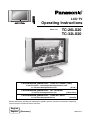 1
1
-
 2
2
-
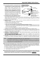 3
3
-
 4
4
-
 5
5
-
 6
6
-
 7
7
-
 8
8
-
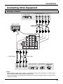 9
9
-
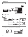 10
10
-
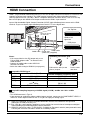 11
11
-
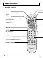 12
12
-
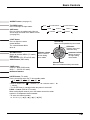 13
13
-
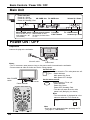 14
14
-
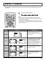 15
15
-
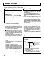 16
16
-
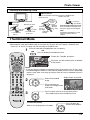 17
17
-
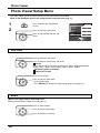 18
18
-
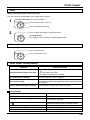 19
19
-
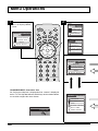 20
20
-
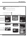 21
21
-
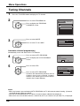 22
22
-
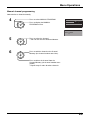 23
23
-
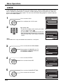 24
24
-
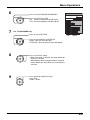 25
25
-
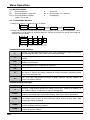 26
26
-
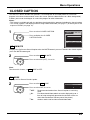 27
27
-
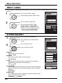 28
28
-
 29
29
-
 30
30
-
 31
31
-
 32
32
-
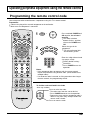 33
33
-
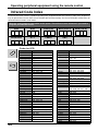 34
34
-
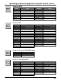 35
35
-
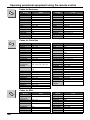 36
36
-
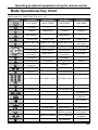 37
37
-
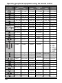 38
38
-
 39
39
-
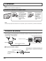 40
40
-
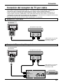 41
41
-
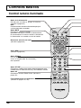 42
42
-
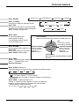 43
43
-
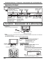 44
44
-
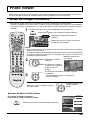 45
45
-
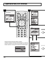 46
46
-
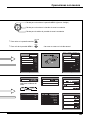 47
47
-
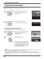 48
48
-
 49
49
-
 50
50
-
 51
51
-
 52
52


Panasonic TC26LX20 Instrucciones de operación
- Categoría
- Equipo de música suplementario
- Tipo
- Instrucciones de operación
- Este manual también es adecuado para
En otros idiomas
Documentos relacionados
-
Panasonic TC-23LX60, TC-26LX60C, TC-26LX60L, TC-32LX60C, TC-32LX60L Manual de usuario
-
-
-
-
-
-
-
-
-