
I ®
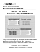
Useand CareManual
bJ II111 O PIRA ... ;_,..o.=o,.o__,=
= = I,I _I '11 _=I I"]11 [" = ....
I'%IilIL I'%1 _,1_/
s
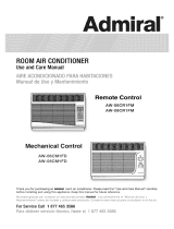
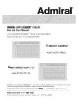
Remote Control
Mechanical Control
Thank you for purchasing an Admiral room air conditioner. Please read this "Use and Care Manuat" carefully
before insta/ing and using this applance, Keep this manual for future reference,
Mucl sse {;y_;as po co, uSers u_ a_e aco_ dco_ac_o_a:lmlr_ Lea _ e_t_ _e_tee IV_sn_.a _:_e_;se y
Ma_e _m en_o ;_'_esd® _tsa ;4_"y utizaf esle p_"ocluc_oCo_-_seve esle rnart_£Apaa co_-_u ts. o e_'_el utu_'o
For Service Call 1 877 465 3566

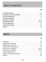
Air Conditioner Safety ............................................ 2-3
introduction and Partsidentification ................................ 4-5
Electrical Specifications ......................................... 6
Tips Before Installation ........................................ 7
installation Instructions ................................... 8-12
Operating Instructions
Careand Maintenance
TroubleShooting Guide
.... 17
.... 18
.... 19
Page
introd_cci6n ................
Identificaci_nde las Piezas ,,,
Especificaciones El_ctricas ....
ConsejosAntes dela Instalaci_n
instrucciones de instaiaci_n ,,,
Instrucciones de Operaci_n ,,.
Cuidadoy Mantenimiento .....
Guiapara _aSolutiOn de Problemas.............
...... 20
..... 2_
...... 22
..... 23
,,24-28
..29-32
...... 33
..... 34
...... 35

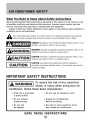
What YouNeed to KnowAboutSafety_instructions
Warning and _mportant Safety instructionsappearing in this manual are net meant to cover
al] possible conditions and situations that may occur. Commonsense, caution, and care
must be exercised when operating or cleaning teoJsand equipment.
Nways contact your deaJe5distributor, service agent, or manufacturer about problemsor
conditions you do not understand.
Thisis the safetyalert symbol,tt is usedto alert youto potentialpersonalinjury hazards
Obeyall safety messagesthat fol!owthis symbolto avoidpossib!einjury ordeath,
DANGERindicates an imminently hazardous situation which, if not
avoided, will result in death or serious injury.
WARNING indicates a potentially tlazardous situation which, if not
avoided, could result in death or serious injury.
CAUTION indicated a potentially Ilazardous situation whicl_, if not
avoided, may result in minor or moderate injury.
CAUTION used without the safety alert symbol indicated a
potentiaiiy hazardous situation which, if not avoided, may result in
property damage.
SAFETY
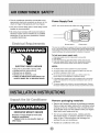
To reduce the risk of fire, electrical
' " r
shock, or _nju y when using your air
conditioner, follow these basic precautions:
- Plug into a grounded
3-prong outlet.
o Do not remove
ground prong.
• Do not use
an adapter.
• Do not use an extension cord.
Unplug air conditioning
before servicing.
Use two or more people to move
and install air conditioner.
INSTRUCTIONS

• The air conditioner should be connected to the
appropnate eJectrical receptacle as shown in the
chart on Page 6 (Receptacle and Fuse Types).
- The use of a time-delay fuse or time-delay circui_
breaker is recommended,
t A!! wiring must comply with _ocaland nationa!
electrical codes and be installed by a qualified
ele_rician, tf you have any questions, contact
a qualified electrician.
E ectrical Requirements
ELECTRIC SHOCK HAZARD
Plug into a grounded 3@rong outlet,
Do not remove ground prong,
Do not use an adapter.
Do riot use an extension cord
Failure to fo|low these instructions can
result in death, fire, or electrical shock.
Power Supply Cord
NOTE:"Yourunit's device may differ from the one shown.
B
A Reset Button B Test Buttes
This room air conditioeer is equipped with a power supplycord required
by UL This power supply cord contains state-of_theoart eJe_Xronicetha_
sense _eakageCu_nL #t_ cord is crush_, the e!eetronics detect _eakage
o_rrsnt and powe_ t wi}_ bie die_lneeted in a fraction of a seceded,
To test your power supply cord:
P!og power supp!y cord into a gro_nd_ 3,_prongoutlet,
2, Pr_e RESET
3, Press TEST (listen for click; Reset br_tton wiI! trip and pop out)_
4, Press and re_e_se RESET (listen for click; Reset button wi_ _etch
and remain hli,The power supply _rd is ready for operation
o The Res_ button must be pushed n for proper o_ration
o Tbe power s_pply cord m_st be _ep_aced_fit fai_sto trip when the
te_ button is p_ss_ or tails to rest.
_ not use the power _pp_y cord as as an off/co switch_ The
power supp!y cord is designed _ a protective device,
A damaged power s_ppiy cord must be repiaced with a new power
s_pp!y cord obtained from the produ_ manufacturer and must not
be repair_Jo
The power supply cord contains no u_ servieeabJe parts. Opening
the tamp_resistant case voids a_iwarranty and performance claim&
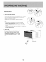
Unpack the Air Conditioner
EXCESSIVE WEIGHT HAZARD
Use _o or more p_p]e to move and
install air conditioner.
Failure to do so can resu_ in back or
other injury.
Remove packaging materials
Remove and propedy dispose of packaging materials,
Remove tape and glue residue from surfaces before
turning on the air condit!oner, Rub a small amount
of iiquid dish soap over the adhesive with your fingers,
Wipe with warm water and dry_
Do not use sharp instruments, rubbing alcohol,
flammabie fluids, or abrasive cleaners to remove
tape or gJue, These products can damage the
sudace of your air conditioner.
• Handle air conditioner with care.

Thank you for choosing this room air conditioner to cod your home This USE AND CARE MANUAL
p_vides information necessa_ for the proper care and maintenance of your new room air conditioner.
If property maintained, your air conditioner will give you many years of trouble free operation. To avoid
installation diffTculties_ read instructions completely before starting. This manual contains information for the
installation and operation of your room air conditioner.
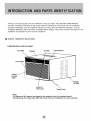
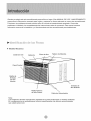
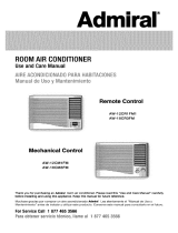
PAtT IIENTIFICRTIOI
I_ Mechanical control model
Air ¢-Jtet Cabinet Air Filter Co_ml Panel
I_edor
Air Inlet
Grille
/
Fresh Air
Vent Le_r
Power Cord
Air Inlet
Note:
The figures in this manual are based on the external view of a standard model
Consequently, the shape may differ from that of the air conditioner you have selected.

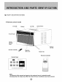
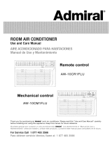
PART DENT F CATION
Remote control model
Air Outlet Cabinet
Air Fi_er Control Panel
lntedor
Air Inlet
Gdlle
Fresh Air
Vent Lever
Power Cod
E_ertor
Air In_et
Control Panel;
Remote Controller
Note:
The figures in this manual are based on the external view of a standard model,
Consequently; the shape may differ from that of the air conditioner you have selected,

1, A!l widng must comply with local and national
electrical codes and must be installed by a
licensed electrician If you have any questions
regarding the following instructions, contact a
iicensed electrician.
2, Check available power supply and resolve any
wiring problems BEFORE installing and operating
this uniL
3, For your safety and protection, this unit is
grounded through the power cord when
plugged into a matching wall outleL If you are
not sure whether your wall outlet is properly
grounded, please consult a licensed
electrician
4. The wail outlet (3_pin) must match the piug
(3-pin) on the power cord supplied with the unit.
DO NOT use plug adapters or extension cords,
See (Table 1) for receptacle and fuse information,
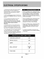
5. The rating plate on the unit contains electrical
and other technical data, The rating plate is
located on the front of the base pan. Make sure
to use the correct power supply according to the
rating plate d your air conditioner.
If the air conditioner has a serial plate rating
of t t5 volts and up to and including 7.5 amps,
the unit maybe on a fuse or circuit breaker
with other devices. However, the maximum
amps on a!! devices for that fuse or circuit
breaker can not exceed the amps of the fuse
for the circuit breaker.
If the air conditioner has a serial plate rating
of t 15 volts and greater than 7_5 amps it
must have its own fuse or circuit breaker,
and no other device or unit should be
operated on the fuse or circuit breaker.
If the air conditioner has a serial plate rating
of 230 volts, it must have its own fuse or
circuit breaker, and no other device or unit
should be operated on the fuse or circuit
breaker_
To avdd the possibility of personal injury,
disconnect power to the unit before installing
or servicing.
COOLING CAPACITY 24K
RATED VOLTS 250
AMPS 20
WALL OUT T
FUSE S!ZE 20
Table I

Your Room Air Conditioner unit is designed to
be highly efficient and save energy. Follow these
recommendations for greater efficiency.
1 Select thermostat setting that suts yeur
comfo_ needs and leave the thermostat at
that chosen se_ing,
2._The air filter is very_efficient in removing airborne
particles. Keep the air filter clean Typicalfy, the filter
should be cleaned once a month. More
frequent cleaning may be necessary depending
on outdoor and indoor air qua_ity_
3. Use drapes curtains, or shades to keep direct
sunlight from heating your room, but DO NOT
obstruct the air conditioner. Aiiow three (3) inches
around unit to circufate.
4_Start },our air conditioner before outdoor
air becomes hotico_d and uncomfo_abie This
avoids an initial period of discomfort while
the unit is cooling or heating off the room
5 When outdoor temperature is cool
enough, use HIGH or LOW FAN
only.. This circulates indoor air; providing
some coo_ing comfort and utilizes less
electricity than when operating on a
"four RoomAir Conditioner was designed
for easy installation in a single or double-hung
window. NOTE*. This unit is NOT designed for
,vertical (s_ider type) windows
To avoid insta|iation/operating difficul_ise,
read the ;instructions thoroughly,
NOTE: Save the shipping carton and packing
materials for future storage or transpo_ of the unit
P_ease check the contents d the hardware kit against
the corresponding model check list, pdor to
installation of the unit
See tis_ below.(Fig.A)
(_> 3/4 _ Screws 410}
i/4 _ Screws (23)
Top Channel(1 )
BoHomChar_nel(i)
(Fac_:_'y-it_stalied
O LockWashers(4}
(_ 1_!/2 xt/4 Boffs(4)
@ !i4" Nuts(4)
_ Shut[er C_amp(2)
_ Gasket(10)
Side CuAair_ RH(1)
Side CuAain LH(I )
Do#b_e
End Cap &
Leveling Legs(2)
NOTE: Surplus screw(s) for spare use,
Tools Needed for Window Installation:
Screw Drivers: Both Philiips and Flat Head
,_ Power Drill: 1/8 inch diameter drill bit
Pencil
• Measuring Tape
'_ Scissors
• Carpenter's Levei

Becausethecompressoristocatedonthe
controlssideoftheunit(rightside},this.side
willbeheavierandmoreawkwardtomanipulate.
Inadequatesupportoncontro_sideoftheunit
canresultinpersonalinjuryanddamagetoyour
unitandproperty.Therefore,itisrecommended
tohavesomeoneassistyouduringtheJnstailation
d this unit.
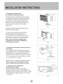
1, Select the Best Location
A, Your room air conditioner was designed to
fit easily into a eingte or double hung window However
since window designs vary, it may be necessary to
make some modifications for safe and proper
installation.
B. Make sure window and frame is structuraiiy
sound and free from dry and rotted wood
C. For maximum efficiency, install the air conditioner
on side of the house or building which favors more
shade than sunlighL If the unit is in direct sunlighL
it is advisable to provide an awning over the unit,
D Provide su_cient clearance around the cabinet
to allow for ample air circulation through the uniL
See (Fig.B). The rear of the unit should be outdoors
and not in a garage nor inside d a building.
Keep unit as far away as possible from obstacles and
obstructions and at !east 30" above the floor or
ground Curtains and other objects within a room
should be prevented from blocking the air flow.
Window opening requirements
'see table be!o_
(W'*H,U)
Mira WindOW
Width
Width
Min. Window
Height
31,2 _'
43,0 _
19_0'
E. Be eerta n the proper electnca! outlet is within reach
d the insta!lation, Use only a single outlet circuit rated
at proper current: (see table 1 on page 6 ), All wiring
should be in accordance with local and national
eiectdcal codes_
R Your unit was designed to evaporate oondeasatbn
under normal conditions. However under extreme
humidity conditions, excess condensation may cause
the basepan to overflow to the outside.
The unit should be instalied where condensation
rumoff cannot ddp on pedestrians or neighboring
Side
obstruction
Fence_
Wa_, or
other
obstacle.

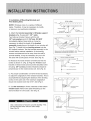
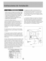
2, Preparation to Remove the
Air Conditioner SHde_Out Chassis
A, Remove totai of (4) PhHips sc:rews securing
the chassis to the cabinet. There are (2) screws
on each side The set d screws closest to the
front of the unit secure the front pane! to the
cabinet The set of screw closest to the rear of
the unit secure the cabinet to the chassis.
See (Fig, 1).
& Remove the front panel assembly from the
cabinet by gentty pulling it,
C, Grasp the pull hande at the front of the
siide-out chassis and carefuliy slide the
air conditioner out of the cabinet. See (Fig_ 2),
Please seek assistance for this procedure.
Note: Screws must be reinstalled upon
completion of the window installation to
secure slide-out chassis
3. Assembly of the upper & lower channels to
the cabinet
A " L° Shaped TOp Channd: Stick the double
adhedng seal to the" L" shaped top channel, and
then Install the "L" shaped top channet to the
cabinet as shown in (Fig. 3) using (5) 1/4" screws.
& "n" Shaped Bottom Channel installed as shown
in (Fig, 3) using (4) 1/4" screws.
NOTE: For 24K , the bottom channel has been
factor/,instafled, and their shapes may differ
from the other, but their functions are simila_
4, Assembly of the side shutte_
(curtains) to the cabinet,
Siide the shutters into the top and bottom
channels as shown in (Fig, 4). The shutters are
identified (on each frame) as "left" & "right"_ Attach
the shu_ers to the cabinet using (4) 1/4" screws
on each side,
Fig, t
For 24K
{Fador_'4nstalied}
Fig 3
Fig, 4

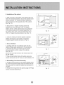
& Installation of Mounting Brackets and
First Sealing Strip
:NOTE: Windows come in a variety of different
style& Therefore it may be necessary to modify
or improve your pa_icu]ar installation
A Attach the bracket assembly to gO°angle suppo_
brackets (Fig, 5) using (2) t t/2" bolts
Two bo_ts per bracket, Secure with the (2)
1/4" lock washers and (2) 1/4"nuts. DO NOT
immediately tighten, these boIts as it may be
necessary to adjust the depth of the bracket
assembty, depending on the depth of your window siII.
See (Fig, 7),Install the two leveling screws into the
90" suppoA brackets. Test the bracket assembly in the
w[ndew before cabinet insta{_ation, if the _eveling
screws are distanced too far away 'from the wali to
provide stabi{ity it may be necessa_ for you to fil_
this area with a solid piece of wood See (Fig: 8)
B, Measure the inside window sill width and find the
center as shown in (Fig, 6), Align the V-slot in each
bracket on these marks and mount the brackets to the
sill using 3/4" screws provided Brackets shouid be
perpendicular to the inside window sill, See (Fig: 6),
Fig, 5
Meas_mer_ f_{ Mc,de_ AWo24CR_FMi_ i 2,#" W nt_r_ sH
Mea_ment _or Mode_ AW-24CM3FM = 12,6
Fig, 6
_,_ .............. (2) 3_ _'screws pet b_acge_
C For proper condensation run-off it wili be necessa_
to adjust the ang!dpiteh d the window brackets, This is
accomplished by adjusting the distance d the leveting
screw on the outer wall, The maximum angfetpitch
should not exceed more than 3/16'L See (Fi'g.7),
Fig, 7
D Cut the seal strip to fit the underside of the bo_:om
window sash Remove the peekoff backing on the
seal and attach it to this sash. See (Fi9, 9).
Fig, 8
Use a solid piece of wood to provide stability This
will be required when sills are extra deep,
See (Fig 8)_
Fig, 9

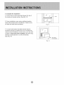
& Installation of the cabinet
A Align one hole in the bottom of the cabinet with one
hole in the bracket assembly Secure the _binet to the
bracket using (3) 1/4" screws provided Repeat the
same procedure on the opposite side of the cabinet,
See (Fig. 10)
B Ensure the "L" shaped mounting channel is
positioned in front d the sash. The "U" shaped
bottom channe_ d the cabinet should be positioned
in the track provided on the bracket assembly Pu!!
the window down unfii it rests just behind the front
d the "L" shaped mounting channel See (Fig 11).
C, Check to make sure that the cabinet is slanted
slightiy downward on the outside tf necessary,
re-adjust suppo_ bracket as shown in (Fig. 7).
7_ Secure Shutters
A° Carefully slide the air conditioner back into the
cabineL(Please seek assistance for this procedure).
B. Reinstall the slide_oubchassis security screws
(removed eadier) on both sides d the cabinet
See (_g. 12).
Secure the top of the frames to the window sash with
(2) 3/4" screws
C_ Now, secure bottom frame d shutters using one
shutter ctamp and one 3!4" screw on each side(Fig: 12).
8. Reinstalling Front Panel Assembly
A, Position the front pane_ on the cabinet .starting at the
top, The front panel lock tabs must be inseAed into the
retaining s_ots in the cabinet. Repeat this procedure on
all sides.
B. Secure the front grille to the cabinet using the Phiiips
screws removed earlier(Fig. 1).
Fig 10
'Wi_daw _h
Fig.I 1
Ce_
Fig.12

9.Completethe installation
A. Cut the foam to fit the opening between the top of
the inside and outside window See (F_g_I3)
B, Some instaliations may require additional sealing
around the window and air conditioner Check for any
air leaks and seal where necessary.
Fig, t3
C, In ve_ humid areas, the water removal may be
excessive enough to overflow the unit or increase the
noise of the air conditioner if this occurs you may wish
to attach a drain hose (not included) to the drain plug
atlowing condensations to run off conveniently
See (Fig, 14)_
Fig, 14

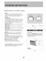
MECHAN/CAL CONTROLMODEL
MODE
The mode knob controls fan speeds and cooling
speeds, To set desired cootJng temperature simpty
rotate the mode knob dia_ to the appropriate
THERMOSTAT
The thermostat automatically controts the coo_ing
cycle (compressor) of the air conditioner to maintain
room temperature, However, the fan motor will
continue to operate after the compressor (cooling
cycle) is completed.
LOW FAN will circulate the air at a minimum speed
without cooJing,
MED FAN wiii circuiate the air at a middie speed
,without cooling,
HIGH FAN wili circulate the air at a maximum speed
without cooling,
LOW COOL provides cooling, automatically with
minimum air circulation Recommended for night-
time use,
MED COOL provides coo)ing automaticaiiy with
midd!e air circulation. Recommended for night°
time use.
HIGH COOL provides coo_ing, automaticaiiy with
quick cooling or for extremely hot days. Once room
is cooled, reduce setting to LOW COOL,
OFF will completely shut-off the uniL
NOTE:: After setting the mode, aliow 3
minutes before switching to another mode.
Fresh, Air Ventilation is usua!ly kept in the dosed
position, Use only when clearing smoke andtor
odors from the room, Pull to open.
Ther_stat Mode knob
k_eb
Fig, 15
When using FAN control, turn slowiy atbwing
When using THERMOSTAT, be sure to aibw
three minutes betere changing temperature
Adjusting too quick!y may cause an overload
resulting in a blown fuse,
Fig, 16

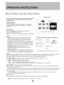
ELECTRONICCONTROLPANELMODEL
You cats easity operate this air conditioner by pressing
relevant button on the contro_ panel as well as the
remote control
The air conditioner wilt be staAed when is ene@ized
or wiJl be stopped when it is in operation, if you press
this button.
Mode button
Each time Mode button is pressed_ the operation
mode is changed in sequence:
COOLING FAN ONLY ENERGY SAVING COOLING
Control Pane_
Mode:
Cooling (with tan speed Lo_ Med H{gh): Compressor
cycles to maintain Temperature Set Point_ Fan remains
on at selected speed during compressor OFF cycle
Cooling (Auto Fan Speed}: Compressor cycles to maintain
Temperature Set Point, Fan speed is controiied from room
temperature, Fan remains on during compressor OFF cycle.
Fan Only; Circulates a_d filters room air a_selected speed
Energy Saving _w_thfan speed Lo Med, High):
Fan cycles ON and OFF with compressor over a wider
Energy Saving (with Auto Fan Speed}: Fan cycles ON and
OFF with compressor at a wider range d temperatures Fan
speed during ON cycle is dependent on room temperature,
indication symbols of LED on control panel;
_;" Auto fan _eed @ Ceofng
88
_ Low Nh _eed _ Fan srgy
Display _t tsmp
D_ay _t timer
+ Medium tan s_ed
High fa_ s_ed
Above LED _ghts o_ whe_ the _e_eva_tme_ _s_nused
NOTE: After setting _he mode, allow three (3) minutes before switcMng to another mode. in the FAN ONLY Mode,
Room Temperature disp!ay range s from 0'_C(32_'F)to 38'_0 (99°F} Room Temperature betow 32_F,the
_'emperature display L0. Room Temperature above 99_K the Temperature display H1.
Fan Speed Button: Used to seiect fan speed !n sequence auto, Jew,medium_ and high.
High Highest fan speed for maximum cooling
Medium Norma!fan speed for average cooling
Low Lowest and quietest speed, greater dehumidification
Auto Works in Coo_iegand £nergy_Savingmode to vary fan speed based on room temperature.
Timer But_oa: Used to set or cance! timer operation
When the unit is in operation you can set OFF TIMER_ When the unit is OFK you can set ON TIMER Timer
setting range is 0 to 24 hours.
if the OFF TIMER is sol the time LED disptays the remaining time to turn off the unit for only 12 seconds,
then LED shifts to display set temperature, if you press TIMER button within the 12 seconds, OFF TIMER
will be cancelled.
if the ON TIMER is set, the timer LED displays the _ma ning time to turn on the unit_ ff you want to
cance_ ON TIMER, press TIMER button
V Button
Used to set room temperature in COOUNG mode or used to set time in TIMER mode.
NOTE: "Temperature setting range isfrom 19_C (66'_F:)to 31 ':_C(88'_F).

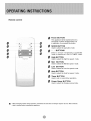
Remote control
D
B
4*
Q
g
Power BUTTON
The appliance wii! be started when it is
energized or wit[be stop_d when it is
in operation, if you press this button
MODE BUTTON
Used to se_ec!the o_ration mode
4° o- BUTTONS
Used to set room temperature in COOLING
mode or used to set time in T]MER mode,
High BUTTON
Used to seiect the high fan speed mode_
Mid
Used to select the Mid fan s_ed mode
Low BUTTON
Used to select the Low fan speed mode,
Auto BUTTON
Used to seiect the Auto fan s_ed mode°
Timer BUTTON
Used to set or ca_'_l timer operation_
Power Saver BU_ON
Used to se]÷ct the Energy-saving mode
* When Changing modes doting operation_ ,sometimes the uni_ does not always _spend e_ once. Wet_ 3 min#te_
, Wait 3 rain#tee before rest_fag the app#ance,

Remote control
s How to Insert the Batteries
Remove the batte_ cover according to the arrow direction_
_nsed new batteries making sure that the (+) and (o) of
batte_ are matched correct_y_
Reattach the cover by sliding it back into position.
Note:
* Use 2 LR5 AA (1.5 volt) batteries. De not #so recha_ge_bte
batteries, Replace batteries with new e_ee of the same type
when the display becomes dim_
Do ne_ mix old batteries with new ones. Dispose of old batteries
properly,
if the reptaeement is done within one (1) minute, the remote control
wilt keep original presetting_
• How to Use
To operate the room air conditioner, aim:
the remote _ntroi to the s_gnal receptor
The remote control wHi operate the air
conditioner at a distance d up to 23 feet
when pointing at signat receptor of indoor
unit,

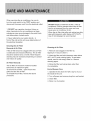
Whenservicingtheair_nditioner,besureto
turnthemodeswitchtothe"OFF"positionand
disconnectthepowercordfromtheelectrical outlet,
1, DO NOT use gasoline, benzine, thinner or
other chemicals on the air conditioner as these
substances may cause damage to the paint finish
and deformation of p_astic paAs.
2, Never attempt to pour water directly in
front of the unit as this will cause deterioration of
the elect:fica_ insulation.
DO NOT forget to instal_ the air filter, }fthe air
conditioner is left to operate without the air filter,
dust is not removed from the room and may
cause your air conditioner to faii.
When the air fi!ter iniet grille and cabinet are dirty
wipe with, lukewarm water (be!ow 40°C/104_).
Use of mfld detergent is recommended
Removal of Air Filter
If the air filter becomes clogged with dust air_flow
is obstructed and reduces efficiency The air filter
shoufd be c_eaned once a month, More frequent
cIeaning may be necessary depending on outdoor
and indoor air quality
Air Filter Removal:
The air fiJter on the above model is focated
behind the air intake front grille
To remove the air fiiter, open the air inlet
grille and take the air filter,
To reinstait the air filter, reverse the above
Cleaning of Air Filter
1. Remove dust clogged in the fiiter by
tapping it or vacuum c_ean it,
2 Wash the filter weii with lukewarm water beiow
40°0 (i04_F) whiie rubbing lightly: To get better
results_ wash it with soapy water or a neutral
3. Rinse the fiiter well using clean water then
dry completely,
End_f-Season Care
1 Operate the fan a_one for half a day to d_ out
the inside of the unit.
2, Turn off power and remove plug from wall socket.
3 Clean filter
4 Store in a dry location

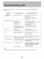
FrequentlyaproblemisminorandaservicecaJJmaynotbenecessary,usethistroubleshootingguidefora
PROBLEM
Air conditioner wiil
not operate
inefficient or no cooling
Noisy unit
Odors
POSSIBLE CAUSE SUGGESTED SOLUTION
No power to the unit.
Dirty air fi_ter
Inappropriate capacity
for application.
Blacked air flow.
Power interruption settings
change too quickly or
compressor overload tripped.
Check connection of power cord to
power source.
Check fuse or circuit breaker.
Set FAN CONTROL to position other
than "OFF"
C_ean or replace air fiiter
Check with dealer to determine proper unit
capacity for application.
Remove obstruction from grii_ or
outdoor !ouvers.
Let fan run to restaA compressor
(in approximately 10 minute8)_
Loose pa_s,
Formation of mold, mildew or
algae on wet surfaces
Tighten Joose parts,
Provide additionaJ suppoA to unit
Remove drain plug and drain base pan,
Water dripping outside Condensation run-off is norma Add f exibie tubing to redirect water flow,
during hot and humid weather (See Fig. 14, Page 12)
Unit is not propedy angied to
allow water to drain outside_
Low outside temperature.ice. or frost build-up
Unit air filter is dirty.
Unit must be installed: on an angte for proper
condensation run-off Check the unit and
make adjustments.
When outdoor temperature is approximately
65T or below, frost may form when unit is in
cooling mode. Switch unit to FAN (only)
operation until frost melts,
Remove and clean fitter_
NOTE:
ff circuit breaker is tripped repeatedly, or fuse is blown more than once, contact a licensed technician,

T¥
For one year f_m the date of purchase by the orig inal owner, ar_ part which
fails in materials or workmanship under normal use, the part will be replaced.
During this period, all parts and service will be provided free of charge, so
long as the air conditioner has been installed and operated in accordance with
the written instructions in this manualoThis warranty includes in home service,
For the second through the third ,/ear from date of original purchas_ this
warranty will provide a replacement compressor free of charge due to
product failure, The customer will be responsible for the labor charges related
to replacing the compressor in years two through three _The consumer is
responsible for the service labor and possible freight charges for shipping
the unit. Cost _ move the air conditioner to the servicers' shop and back to
the user's home may be required and are the user's responsibility.
® This warranty does not apply if damage occurs because of accident,
improper handling or operation, shipping damage, abuse, misuse,
unauthorized repairs made or attempted, c:omme_ial use of the product
or am/other use for which it was not intended.
• This warrant,i does not apply to damage to t_he product caused by accident,.
fire, floods, acts of 'war, terrorism, or acts of God.
o This warranty does not cover service trips 'to your home to educate you on
the use of the product, or toss of food and drink due to spoi_age.
o This warranty does not apply outside the continental United States_
® ALL WARRANTIES, EXPRESSED OR IMPLIED, LAST FOR 3 YEARS FROM
THE DATE OF ORIGINAL PURCHASB THIS WARRANTY DOES NOT COVER
UABiLITY FOR INCIDENTAL OR CONSEQUENTIAL DAMAGES FOR ANY
CAUSE WHATSOEVER_
o This warranty is to the original @_ner for products purchased for home use
within the USA. Some. state do not aiiow the exclusive or _imitation of
incidental damages. This warranty gives you specific rights, and you may
also have other rights which may vary from state to state° To know what
your legal rights are, consult your total or state consumers affairs office
or your state's Attorney General.

Gracias pot etegir este aire acondicionado para enfriaf su hogar, Este MANUAL DE USO Y MAN TO
propot_iona la informacibn necesana para cuidar y mantener en forma adecuada su nuevo aire acondicionado
Funcionar6 sin problemas dura_te muchos a_os sile brinda el mantenimiento aprttpiado Para evitar
problemas al instafar!o, tea completamente tas instrucciones antes de comenzar, Este manual contiene
informacidn acerca de fa instalaci_n y el funcionamt_nto dot aire acondicionado para habitacione&
Modelo Mec&nico
Outlet de Aire Gabinete Filtro de Aire Tablero de Mandos
Panel Frontal
Entrada
de Aire
interior
Reiilla Palanca
de Aire Fresco
Cab_e de Aiimentaci6n
Entrada de
Aire Exterior
Nora:
Las im_genes de este manual est6n basadas en la vista externa de un modelo es_ndar
En consecuencia, es probable que la forma sea diferente a la del aire acondicionado
que usted seleccion&

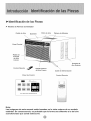
ldentificaci6n de Ins Piezas
Modelo de Remoto Controlador
Outiet de Aire Gabinete Fiitro de Aire Tabgero de Mandos
Panef Frontal
Rejilla de
Entrada
de Aire
interior
Control Remoto
Rej#la Palanca
de Aire Fresco
Entrada de
Aire Exterior
%
%
Cable de Alimentaci6n
Panel de Control
Controi Remoto
iii!
Nora:
Las imagenes de este manual estan basadas en la vista externa de un modelo
est_ndar. En consecuencia, es probable que la forma sea diferente a ia de! aire
acondicionado que usted selection6,

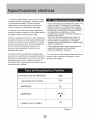
1. Todos Moscables deben cumpJir con _os c6digos
electricos locales y nacionales y _osdebe insta_ar
un e_ectdcista _ieenciado, Si tiene preguntas
relacionadas con las siguientes instrucciones,
comun_quese _n un eJectricista licenciado,
2. Vedfique el suministro de energia disponibIe y
resuelva caatquier problema con los cables ANTES
de instalar y hacer funcionar esta unidad.
3 Para su seguridad y protecci6n, esta unidad esta i
cenectada a tierra a traves de_ cable de alimentaci6n '
cuando se io enchufa a un tomacorriente de pared
provisto de conexi6n a tierra, Si no esta seguro de
que el tomacorriente de pared euenta con la
conexi6n a tierra aprepiada, consu/te con un
eiec_ricista licenciado
4,_El tomacordente de pared (de 3 davijas} debe
coincidir con e/enchufe (de 3 c_avi]as) de_ cabJe de
alimentaci6n suministrado _n la unidad_ NO utilice
adaptadores de enchufe ni cables de extensi6n,
Consu/te la Tabla I para obtener informaci6n acerca
de recept_culos y fiJsibIes,
Si el r6tulo del aire acondicionado indica 115
veeries y hasta 75 amperioa, _a unidad se
puede conectar a un co_acircuito o fusible
utilizado per otros dispositivos No obstante,
la suma de Jos amperios m_ximos de _dos
los dispositivos conectados a dicho
_rtacircuito o fusible no deben exceder los
amperios del mismo.
Si el r6tulo del aire acondicionado indica 115
retries y rues de 75 amperios, debe tenet su
p_epio fusible e ce_acircuito y no se deber_
conectar ning_n _ro dispositivo o unidad a dicho
fusible o cortacircuito.
Para evitar lesiones fi sicas, desconecte el
suministro de energl a de la unidad
antes de instalarJa o repararla
5 E_ r6tulo de _aunidad oontiene dates e_(_ctricos y
t6cnicos, Dicho r6tuto se encuentra en eJlade
derecho de ia unidad_
CAPAClDAD QUE SE REFRESCA 24K
CAPAClDAD DE VOLTtOS
AMPERIOS
TAMANO D+EL FUSIBLE
mj
2O
Tabla 1

Su unidad de Aire Acondicionado pars Habitaciones
se ha disen_ado para Iograr un alto rendimiento y
ahorrar ener9_ a eiectric& Sign Ins siguientes
sugerencias para tograr an mayor rendimiento.
El Aire Acondicionado pars Habitadones se ha
dise_ado de mode tal que resulte f_cil su instafaci6n
en ventanas armadas sendHas o dobles NOTA: esta
unidad NO se ha dise_ado para ventanas verticales
(de tipo deslizante)
1, _uste el termostato a un and que te resulte
agradaMe y d_jeb en el nivel seleccionado.
2_El fiitro es may eficiente a la hera de eliminar
pa_culas que se desp!azan per e! air& Mantenga
limpio el filtro de aire, Per Io general, el filtro deberd
Iimpiarse una vez at rues Es probable que sea
necesario limgiarlo con mt_sfrecaencia dependiendo
de ia calidad det sire exterior o interior,
3, Puede utiJizar tapices, certinas o panta]las para
evitar qae ia luz directs def sol caHente su habitaci6n,
pete NO obstruya el aire acondicionado. Permita
que el sire circule alrededor de la unidad sin
obstruccioneso
4. Encienda el sire acondicionado antes de que la
temperatura exterior sea demasiado elevada y
desagradable. De esta manera evitar_Jsufdr cabr
mientras la unidad enff_ s ia habitaci6n
5 Cuando ta temperatura exterior es Io suficientemente
fres@, utilice s6b HiGH FAN (ventilador al _sximo) o
LOW FAN (ventitador al m£nimo). Esto hace que el sire
intedor circale a una temperatura agradable y consume
menos energ£a e!ectrica que si hiciera funcionar la
unidad come enfdador de aire.
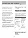
Ins iestrucciones
NOTA: consewe Ia caja de la unidad y los matedales
de empaque para a/macenada o transpoAar/a en et
futur& Antes de instaiar la unidad compare d
contenido dd juego de herrajes con la Iista de control
del modeb correspondiente. Consu!te las siguientes
listas (Fig. 1).
C_ TorniHos de 1_4_(23)
Canal Superior(!)
O AtanddasdePtesi6n(4}
(_ Pemosde'H_2'×ii4(4}
_) Tuercasdei/4*'(4)
Stile (i)
DobieSei_oAdhesiva (1)
Espuma (!)
....71¢p_
(Fig. 1)
Nots; Tomillo Excedente Para d Uso de Reserv&
Herramtentas Necesarias pars la lnetalaci_n en Ventana:
Destetnilladeres: Philtps y de cabeza plans
Ta|adro d_drico: breca de 1/8 pallgadade diamet_e
L6piz
Clara m_trica
Tijeras
Nivel de earpintero

Debido a que et compresor se encuentra dei iado
de los controles (a _aderecha de _aunidad)_ este
iado sera rods pesade y m{ss dif[cil de manipular,
Si la unidad no se sostiene bien de dicho lade,
pueden producirse lesioaes f_sicas y da_os a ia
unidad y a su propJeda& Per Io tanto, le
recomendames que para instaiar esta unidad
solicite ayuda a otras personas
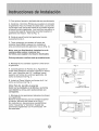
1 Seieccione !a Meier Ubicaci6n
A. E_aire acondicionado para habitaciones tiene un
dise_o que fac#ita su colocaci6n en ventanas
armadas seneiltas o dobles No obstante, debido a
que los dise_os de ventana son tan vadados, es
probable que sea necesafio reatizar algunas
modificaciones para fograr una instaiaci6n segura y
adecuada.
B Asegarese de que a ventana y el mar® tengan
una estructura firme y que la madera no est_ rajada
ni poddda.
C, Para iograr e_meximo rendimientQ instaie e_aire
acondicionado del lade de la casa o edificio donde
haya rods sombra que sol Si la unidad se encantrara
exp_esta a !a luz del soies aconsejable cotocade un
to_do encima.
D, Deje suficiente espacio alrededor del gabinete para
permitir una amplia circulaci6n de aire a travels de !a
un_da& Yea (Fig 2)° La parte posterior de la unidad
debera dar a_aire libre y no a un ga_je ni al interior de
un edificioo Mantenga ia unidad _orods I_os posible de
obst_euios que puedan causar obstrucciones y po_ Io
menos a 30" dei nivei del piso o dei sueio_ Deberdm
tomarse precauciones para evitar que Ins co_:inas o
cualquier otto objeto dentro de una habitaci6n
obstruyan ei flujo de aire_
Requisites para I_s aberturas de ventanas
(coasufte la stguien_e tabla}
(A'H%)
Abe_ura m_nima
deV_
Abe_ra m_xi_a
de Ve_ana
MiasmaA_t_ra
AW_24CR3FM I
AW_24CM3_M
26.5_',18.5' _2&9 '
31,2"
43.0 _`
E. Asegarese de instalar la unidad cerca de un
tomacorriente el_ctrico adecuadoo Utilice un estime
al cordente propio (iea tabta I en p gina 22) con
circuito exclusive para el aire acondicionado. Todos
los cables deberSn cumpfir con los c6digoa el_ctricos
!ocales y naciona_es.
E La unidad est_ dise_ada para evaporar _acondensaciCn
bajo condiciones norma_es No obstante, bajo condiciones
de extrema humedad es probable que la condensaci6n
excesiva haga que la ba#deia base se desberde hacia e]
ex_e_or. Per io _anto _aunidad deber¢ instalarse en un tugar
donde !a descarga de !a condensaci6n no gotee sobre el
paso de peatones ni en las propiedades vecinas
_ido
Obs!rL_ccion
latera_
Suede
pared u
o_ro
obst_culo
I

2. C6mo quitar e! armaz6n des!izable del aire acondicionado
A. Quite los 4 tornillos PhJlips que sujetan el arma_n
al gabinete Hay 2 tornilios de carla lado Los tornillo
s que est0n rues cerca del frente de la unidad sujetan
el panel frontal al gabinete, Los torniilos que est6n m
_s cerca de la parte trasera de la unidad sujetan el
gabinete al armaz6m Yea la (Fig. 1).
B. Quite el panel frontal del gabinete tirando
L_do d÷_echo
To_niitesPhfl ps
C. Tome el mango queestden el frente del
armaz6n deslizable y saque con cuidado el
aire acondicionado del gabinete. Vea la (Fig. 2),
Nota: una vez finalizada la instalaci6n en la
ventana debe votver a co/ocar los
torniHos para sujetar e/ armaz6n des/izable,
Pida ayuda para realizareste procedimiento.
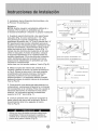
3. Montajede Ioscanales superiore inferioren
el gabinete
A, Canal Superior en Forma de L; Aguante et
doble sello adhesiva al canal superioren forma
de L, con 5tornillos de 114", instaleel canal
superior en forma de L sobreel gabinete, tal
como se indica en la Fig. 3.
B Instaleel Canal inferior en forma de U, tai
como se indica en ia Fig. 3.
Nota: Para los de 24K, el canal de
bot6n se ha instalado en /a f_brica y su forma
sera distinto a otros, pero susfucciones son
Fig 1
Se_per_f_ n
Papa de 24K
( nstalado en la [_bdca)
4, Montaje de Ins persianas iateraies (cortinas)
en el gabinete,
DesHce tas persianas por los canaies superior
e inferior, tal como se indica en la Fig, 4.
En cada marco, las persianas se identifican
como "izquierda" y "derecha". Sujete las
persianas al gabinete con 4 torniilos de 1/4"
de cada lado,
Marco de la Pe_sia#a
Fig, 4

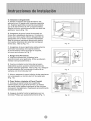
5 Instalacian de !os Soportes Horizontales y de
la Primera Tira Adhesiva
Selladora
NOTA: Existe una gran variedad de estilos de v
ent:anas. Per Io tanto, es probable que se
a necesario modificar o mejorar su propia instalacbn.
A Sujete el soporte horizontal a !as soportes en
escuadra (Fig, 5) con 2 pernosde 1 t!2'L Hay
dos pernos per soporte. Asegare!os con !as 2
arandelas de presian de 1t4" y las 2 tuercas de 1/4"
NO ajuste estos pernos de inmediato ya que es
posible que sea necesario ajustar la distancia del
soporte ensamblado, dependiendo de la profun
didad deJ umbral de Ja ventana. Yea la (Fig. 7),
Instale los dos torni/los de nivelaci6n en los sop
ortes en escuadra. A mode de prueba, coloque
el soporte ensamblado en la ventana antes de
instaiar el gabinete, Si los tornillos de nivelaci6n
esten demasiado lejos de la pared come para
proporcionar estabilidad, es probable que sea
necesario comp_ementar
dicha area con un tacode madera° Vea la (Fig. 8).
B Midael anchode/interiordel umbral de la
ventana y defina e! centre, tal come se indica en
la Fig 64 Alinee la ranura en V de cada soporte
ensamblado sabre estas marcas y monte los
soportes al umbral con los tornillos de 314"
proporcionados. Los soportes deber_n quedar
perpendicu!ares al umbra1 interne de la ventana,
Vea Ja (Fig, 6),
C Para permitir una descarga adecuada de la c
ondensacien, seranecesario ajustar la inclinaci6n
de los soportes en la ventana, Para elio, ajuste la
distancia del tornillo de nivelacian en la pared
exterior. La inclinacian _xima no deber_ser
superior a 3t16'L Vea la (Fig. 7).
D. Carte la primera sello para que quepa en ]a
parte inferiorde! marco de !a ventana. Quite el
revestimienta de ia tira y _guela al marco.
Vea ta (Fig. 9),
(VISTA SUPERIOR'_
@ '> O O @ _ O ©
Nive_aci_n
Fig, 5'
V@_ltana
Nedida papa elModele AW*24CR3gMi=i2 8_
Fig, 6
,_,_ .............. 2 t_r_lilk1_ de 34 _ _or _o_mcte
--- Pared E*_,ema
Fig, 7
......................... i................
Uti!ice un taco de madera para proporcionar
estabiiidad. Esto seranecesario cuando el
umbral de la ventana sobresalga mucho de/
piano de la pared. Vea la (Fig, 8).
Fig: 9

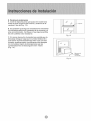
6, instalaci6n del gabinete
A. Aiinee an agujero de la parte inferior dei
gabinete con un agujero de] soporte ensambla
do. Sujete e! gabinete a{ soporte ensamWado
con 3 de los torniHos de 1/4" proporcionados,
Repita el mismo procedimiento del otto !ado del
gabinete. Vea [a (Fig. t0).
B, Aseg_rese de queet cana! de montaje en
forma de L est_delante del marco E_canal en
forma de U de la parte inferior dei gabinete de
ber_quedar en el riei del soporte ensambiado.
Baje ia ventana hasta que apoyejusto detras
de la parte detantera del canal de montaje en
forma deL, Vea [a (Fig_ 11),
C. Aseg_rese de que el gabinete est_levemente
inclinado hacia abajo en ta parte externa.
Si es necesario vuelva a aiustar el soporte,
ta[ comose indicaen la Fig. 7.
7. Asegure las Persianas
A. Vuelva a colocar con cuidado e_ aire
acondicionado en el gabinete. (Pida ayuda par'a
rea[izar este procedimiento )
B. Vuelva a instaIar los torni!los dei armazon
desIizable (que se quitaron anteriormente) de
ambos [ados de! gabinete. Vea la (Fig. 12). Asegure
[a parte superior de los marcos al marco de [a
ventana con 2 tomiiios de 3/4".
C. Ahora, asegure e[ marco inferior de Ias persianas
con una grapa y an tornillo de 3/4" de cada tado
(Fig. 12)
8. C6mo Volver a Instalar el Panel Frontal
A. Coloque el panel fronta{ en el gabinete
comenzando pot [a parle de arriba, Las trabas
de[ panel frontal deben insertarse en ias ranuras
de sujeckm del gabinete. Repita este procedimiento
de todos los [ados.
Fig.I0
Fig. i 1
Tomi!lo deSegeddad
B. Asegure la rejilla frontal aI gabinete con los
tornillos Philips que quitbanteriormente (Fig. 1), Fig, 12

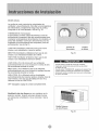
9, Finalice la instalaci#m
A, Corte la espuma para que quepa en la abertura
entre [a parte superior de[ interior y exteriorde la
ventana, Yea ]a (Fig_ 13),
B Es probabIe que algunas instalaciones necesiten
tira selJadora adicional alrededor de [a ventana y el
aire acondicionado Verifique si hay alguna perdida
de aire y seHela si es necesario,
C_ En zonas de mucha humedad, es posib[e que la
descarga de agua haga que la unidad desbordeo
que e[ aire acondicionado haga rr_s ruido. Si esto
sucede, puede acop!ar una manguera de desagtle
(no inc!uida) a! ta_n de drenaje para que [as
condensaciones se descarguen biem Vea !a
(Fig_ 14)_
Fig 13
Fig_ 14

La perilla de modo controla !as velocidades de
ventilador y de enfriamiento, Para fijar una temperatura
de enffiamiento, simp_emente haga rotar Waperil]a y
coldquela en et nivel deseado, Vea fa Fig 15
THERMOSTAT (Termostato)
El termostato controia automdticamente el ciclo de
enfdamiento (compresoO del aire acondicionado para
mantener la temperatura de] ambiente_ No obstante, et
motor deJ venti[ador oonflnuare funcionando una vez
finaJizado el funcionamiento det compresor (cicto de
enfriamiento), Vea la Fig1&
LOW FAN (Ventilador al M_nime) har_Jqueef aire
circule a una veioeidad minima sin enffiar
MED FAN (Venti!ador al Mediano)hara que el aire
circu_e a una velocidad mediana sin enfriar,
HIGH FAN (Ventilador at Maximo) har_/_que el aire
circule a una velocidad maxima sin enffiar.
LOW COOL (Fr_o M _nimo) enfr[a ei ambiente
automdflcamente con una circuiaci6n minima de aire,
Se recomienda durante la noche
MED COOL (Fr[o Mediano) enffia e! ambiente
autom6ticamente con una circu!aci6n mediana de aire.
Se rec,omienda durante la noche,
HIGH COOL (Fr£o Maximo) enfrIa el ambiente
automaticamente de manera rapida o durante d las de
caior intenso. Una vez que ta habitaci@ este fr_a,
reduzca el nivei a LOW COOL
OFF (Apagado) apaga ia unidad comptetamente,
Control de Control
Termostato de Mode
Fig.15
Cuando u_iiice _apedlia de contro_ de ventiiador
hi, gala girar _entamen_e para porto}fir que/a unidad
se adapte a_nive_
Cua_do #t}l_ce THERMOST_S, ase_rese de esperar tres
minu_,os a_tes de cambiar _a _emperatura Si }a cambia
demasiado r41pido es pos_b_e que c_use ann sobrecatga y
se q_eme ÷f fusible
VentilaciSn de aire fresco se raa mantener en la
posiei6n cerrado, Usando s6Io pars fimpiar humos
y/o odores de la habitaci6n, tire a comenzar. Vea {a
Rejiiia Palanca
de Aire Fresco
Fig,16

Esteaireacondicianado se puede aperar fdcilmente
can los batones deJ panel de control as[come tambi6n
con el controi remato.
Bat6n
Si presiona este bot6n, encender_tei aireacondicionado_
Cuando eJaire acondicionado esta de calefacci6n, se per
imprentar este hot6n 3 minutes despu6s
Bot6n Made (Made)
Cada vez que se presiona e! bat6n MODE_ el mada
de operaci6n cambia en estassecuencias:
COOLING (Enfriamiento) FAN ONLY (S61o ventilador)
ENERGY SAVING (Ahorro de Energ_a) COOLING
NOTA: Despu6s de seleccionar un nivel, espere 3
minutes antes de pasar a otto,
Con el mode de FAN ONLY, E! recinto de la temperature
Dehabitaci6n sere Desde 0 "C(32 F) haste 38%(99_'F).
La temperature de !a habitaci6n es superior a32 F,
Jatemperatura lucer6 L0.
La temperatura de ia habitaci0n es superior a 99T
la temperature lucer0 H1.
Bot6n Fan Speed (Velacidad det Ventiladar)
Se utiiiza para seieccionar la vetocidad del ventilader
en secuencia: autometica, baia, media y alta_
Bot6n Timer(Temparizadar)
Se utilize para pragramar o canceler el
funcionamiento del temporizador
Cuando la enidad esteen funcianamiento puede
seleccionar OFF TIMER (ApagarTemporizador)
Ceando la enidad es_apagada, peede seleccionar
ON TIMER (Encender Tempedzador)
EI range de betas para #rogramar el temporizador
es de 0 a 24 betas.
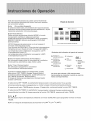
Sfmbalos de| indicador del panel del control:
0 E_f_i_mie_to
O0 °_
so_o
ve_ti|adot
er_er_a _ Mostrar
hera
_?_ "remr_orizador prograq_ada
Las luces del indicador LED anteriormente
mencionadas se encienden cuando se _san los
Si seJecciona OFF TIMER, la pantatla de! temporizador indicar_durante 12 se gundas
el tiempo restante pare e_ apagado de la unidad y iuego indicareta temperatura fiiada
Si presiana eJ bot6n TIMER dentro de esos ! 2 segundos, se desactivarola funci6_ OFF TIMER.
Si selecciona ON TIMER, Ia pantaJla del temporizador indicar_eJ tiempe restante pare eI
encendido de la unidad Si desea cance!ar lafunci_n ON TIMER, presione el bo_n TIMER.
Bat6n _
Se utilize pare fijar la temperatura ambiente en mode COOLING opara pragramar la hera en mada
TIMER.
NOTA: el range de temperatures osci_a entre i 9°C(66 _F) y 31°C (88°F}.

Control remote
0
0
0
0
0
The remote oen#o/ier transmts s/gn_Js to the system
o
I
O
I
¢
0
¢
¢
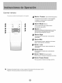
Bot6n Power (Encendido/Apagado}
El aparato se encendera si es_ apagado
o apaga_ cuando est_ en operaci(Sn,
si oprime este bot6n.
Bot6n Mode (Mode)
Utilice este bot6n para seleccionar
ei mode de operaci6m
Bot6n +-
Botones de ajuste de temperatura optima
para ajustar la temepratura del cuarto.
oprima para programar la hera.
Bot6n High
Para a_ustarel mode alta velocidad de
ventila:dor.
Bot6n Mid
Para ajustar el mode mediana (al mismo
baja) velocidad de ventilador
Para ajustarel mode baja velocidad de
ventilador,
Bot6n Auto
Papa ajustare/mode auto velocidad de
ventilador_
Bot6n Timer (Temporizador)
Para ponero canceiarla operac_n detimer
Bot6n Power Saver
Para ajustar el modode energia_ahorro_
m ' Despues de seleccionar un nivel, espere 3 minutos antes de pasar a otto.
"Espere 3 minutes antes de recomenzar el aparato,

Control remoto
• Colocai6n de las pilas
Retire la tapa de las en e] sentido de la flecha.
Jntroduzca las pilas nuevas_con cuidado de
que coincidan los poios(+)y(-)
VueJva a insta!ar Jatapa_desiiz_ndola otra vez
a su posici6n.
No_
e Utilice p#as 2 LR6 AA _1_5V)LNo utilice pilas
recargab/es.Sustituya /as pi/as pot etras nuevas de/
mismotipocuandola pantalla aparezcaatenuada_
• Stlasustituci6n serealizaenetplazo deI minuto,el mandoa
distanciaconservar_losva/orespmfijados oridinales (Este
funci6n es s61opara con_lador remoto deLCD),
• C _mo use
Para operar e! aire acondicionado, apunte el controtador
remoto la seBar de! receptor_
Ei controlador remoto se ra a operar el aire acondiciondo
con una diatancia hasta 23 pies cuaedo apunta a la se_ar
del receptorde Jaunidad
Receptor de seSa!

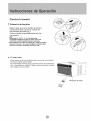
Cuando repare el aire acond_cienado aseggrese de
colocar !a periila de mode en OFF y luego desconectar
e__ble de alimentaci6n del tomacorriente electric,
1 NO ut_iicegaso!ina bendna disolvente u otros
productes qu_micos en el aire acondicionado_ ya que
es_s sustancias pueden dar;_r el acabado de pintura
y defermar iaa piezaa de p_stico_
2 Nunca derrame agua directamente en el frente de _a
unidad ya qua da_ar_a el aislamiento el _tdco,
NO olvide iastalar el filtro de atre, Si e! aire
acondicionade funciona sin e! ill!re de aire,
el pelvo no se puede el!miner de la
habitaci6n y es posible que !a unidad se
Cuando la rejilla de entrada de aire y el
gabinete esten sucies, I_mpielos con ague
templada (per debaje de los 40 °CiI04°F).
Se _eomienda el use de un detergente suave.
Limpieza de! Filtre de Aire
Extracci6n de! F#tro de Aite
Si el ill!re de aire se obstruye con polvo, el flujo de aire
queda obstruido y reduce el rendimiento de ta unidad E_
ill!re de aire deber_ _impJa_e una vez a! me& Es probable
que sea necesad_ !impiado con m_s frecuencia
dependiendo de Jacalidad de aire exterior o interior,.
C_mo Qui_r e! Filtro de Aire:
El fit!re de aire de los modebs anteriormente mencionados
se encuentra detrss de ia _jiHa de entrada de aire delentera
Pare quitado tome el mango det filtro ubieado enia paste
superior de _arejitla de en_radade alre y deal lcelo hacia
arriba
Pare velvet a instalarie reaiiee teaprocedim{e_toa an_eriores
a _a invers&
Limpieza del Fiitre de Abe
1_Eiimine el poive acumutado en el fit!re Pare
ello ap!; queue unos golpes suaves o una
aspiradora dom_stica.
2 Lave bien el fittro con ague templada, de
o o
!:emperatura inferior a los 40 C (t04 F), mien!tea
to ffota suavemente. Para obtener mejores resuitados,
18vole con agua jabonosa o con un producto de
_impieza neutro,
3 Enjuague bien et ill!re con ague lirnpia y tuego
s_queb completamente,
Cuidado de Fin de Temporada
1 Haga funcionar el ventitador durante medio d_a
para que se seque et interior de la unidad,
2. Ap_guelo y desenchdelo de_ tomacordente de
& Limpie el ill!re.
4, Almadmelo en un lugar seco,

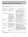
Genera!mente !os prob!emas son sencillos yes probable que no sea necesario Hamar a un t#.cnico.
Esta guta puede ayudarlo a resolverlos,
PROBLEMA
El aire acondicionado
no funciona
Enfrfa poco o _da
Unidad ruidosa
OIores
Gotea agua afuera
Gotea agua adentro
Se forma hielo o
escarcha
CAUSA POSIBLE
La unidad no _cibe
suministro electrico
Filtro de aire sJcJo,
Capacidad inadecuada
para la apJicaci6n,
Flujo de aire _struido.
Carte de energt a el6ctrica,
se cambi6de hive!
demasiado r6pido o se
dispar6el interruptor per
sobrecarga de! c_presor.
Piezas sueltas.
Soporte inadecuado.
Formaci6n de moho u hongos
sobre las superficies
hamedas
Es normal la descarga de
condensaci6n cuando el
dima es _lido_ h_medo,
La unidad no _t6:bien inclina
da como para _rmitir el
desague externo.
Ba_a temperatura exterior,
Ei filtro _ aire de la _idad
est6sucio.
SOLUCf6N SUGERtDA
Verifique si el cable de aiirrentaci6n e
st6conectado al tom_orrJente.
Verifique el fudbte o el cortacircuito.
Fi}e el FAN _NTROL (control del
venti/ador) en una _sici6n que no sea
OFF.
Limpie o reemplace el filtro @ aire.
Hable con el representante para
determinar cu.41es la cap_idad
adecuada para ia _licaci6n,
Quite toda o_trucci6n de |a reji!la o de
las persianas exterioreso
Haga funcionar el ventiiador para
reiniciar el compresor (en
aproximadamente t0 minutos),
Ajuste las piezas sueltas.
Proporcione soporte adicional a la unid_
Quite et ta_n de drenaje y la b_deja
base,
Cambie el ta_n de drenaje.
Limpie la unidad en forma completa.
Utilice tuberias flexibles para desviar el
flujo de agua,
La unidad debe instalarse con un tigero
desnivel para permitir una _scarga
adecuada de ta condensaci6n_ Verifique
Jaunidad y realice los ajustes
necesarios,
Cuando Jatemperatura exterior sea inferior a
los 65°F es posible que se forme escarcha si
Jaunidad funciona en modo de enfriamiento
Cambie el funcionamiento de la unidad a FAN
(soJamente) hasta que la escarcha se derrit&
Quite el filtra y timpielo.
NOTA:
Si el co_acircuito intermmpe la corriente vadas veces o el fusible se quema mds de una vez_ comunt quese
con un t6cnico ticenciado,

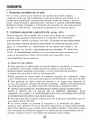
1. Garantia comp!eta de un aSo
Pot un aSo a partir de _a fecha en de compra de_ dueSo original,
cualquier pa_e que falte matedales o eiecuci6n bajo el uso norma_ ci _a
unidad sera substituida. Durante este pedodo, todas Ias piezas y servicio
siempre y cuando et acondieionador
de aire ha estado instalado y funcionado de acuerdo con las instruceiones
escritas en este manual. Incluye de _agarant_a en e_servicio casero
2. Limitada segunda a garanfia de tercer aSo
Para el segundo con el tercer aSo a partir de _afecha de la compra
original, esta gara.nfia proporcionar_ un compresor del reemp_azo
gratuitamente debido a produeir una falta El cliente va a set responsable
para el cargo relatado del labuor de cambiar e! compresor de dos a tres
E! consumidor es responsable de los gastos del trabaio y de
posibte gasto de servicio para embarcar las unidades El gasto para
mover e_ acondicionador de aire a los servisiadores hace eompras y de
nuevo a los usuarios a casa, como puede set requerido yes la
responsabiiidad de tos usuarios.
3. Qu6 no se cubre
e Esta garant_a no aplica daSo si ocurrido debido a accidente, la direcci6n o
la operaci6n ineorrecta, el daSo de env[o el abuse, el uso err6neo,
desautodzados reparada o procurada, o el uso comercia_ de_ producto,
o ningOn otro uso para e_cual no fuera pensado.
e Esta garanfia no aplica daSo al producto causado pot accidente, fuego
y las inundaciones, o _os actos de la guerra, del terrodsmo, o del acto de dios
e Esta garanti'a no cubre viaies de_ servicio a su hogar para educade en
el uso de{ producto, p6rdida de atimento y bebida debido a tos desperdicios
que esta garanda no se ap_ica fuera de_ eontinente los Estados Unidoso
e TODAS LAS GARANTiAS, EXPRESADAS O JMPMCADAS, DURAN POR 3
GARANT[A NO CUBRE LA RESPONSABILIDAD POR LOS DA_aOS FORTUITOS
O CONSECUENTES PARA CUALQU_ER CAUSA.
e Esta garantfa estA a_ dueSo originai para ios productos comprados para el
uso casero dentro de USA
e Un cierto estado no permite la exc_usiva o fa limitaci6n de daSos
fortuitos Esta garantia _e da _os derechos especificas, y usted puede tambien
tenet otros derechos que puedan variar de estado al estado. Para saber cuMes
son, eonsultan sus derechos legates a su oficina de _os consumidores de _os
asuntos o genera_ _oeal o del estado det abogado de su estado.


© 2006Admira', Kelon Air Conditioner Co.0 Ltd., and Ke:ion USA, I:nc. All rights reserved.
Kelon Air Conditioner Co,, Ltd. Kelon USA, Inc,
No_!2 Qiaodong Road 1;7005 Evergreen Place,Bldg A
Ronggui, Shunde, Guangdong China 528303 City of Industry, CA 91745
..._od _.c_.o Version No.819043290 -01
-
 1
1
-
 2
2
-
 3
3
-
 4
4
-
 5
5
-
 6
6
-
 7
7
-
 8
8
-
 9
9
-
 10
10
-
 11
11
-
 12
12
-
 13
13
-
 14
14
-
 15
15
-
 16
16
-
 17
17
-
 18
18
-
 19
19
-
 20
20
-
 21
21
-
 22
22
-
 23
23
-
 24
24
-
 25
25
-
 26
26
-
 27
27
-
 28
28
-
 29
29
-
 30
30
-
 31
31
-
 32
32
-
 33
33
-
 34
34
-
 35
35
-
 36
36
-
 37
37
-
 38
38


Admiral (Kelon) AW-24CM3FM El manual del propietario
- Tipo
- El manual del propietario
- Este manual también es adecuado para
en otros idiomas
Artículos relacionados
-
 Admiral (Kelon) AW-08CM1FHU El manual del propietario
-
 WINTAIR AW-18CR3FM El manual del propietario
-
 Admiral (Kelon) AW-18CR3FM El manual del propietario
-
 Admiral (Kelon) AW-10CM1FLU El manual del propietario
-
 Admiral (Kelon) AW-06CR1FM El manual del propietario
-
Admiral AAW-18CM3FHU Manual de usuario
-
-
 Admiral (Kelon) AW-05CR1FHLU El manual del propietario


