
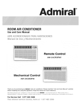
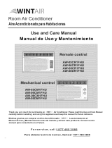
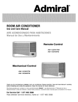
ROOMAIRCONDITIONER
UseandCareManual
Remote Control
AW*IOCR1 FM
AW-12CR1 FM1
AW-18CR3FM
Mechanical Control
AW-10CM1FM
AW-1 2CM1FM
AW-18CM3FM
Thank you for purchasing an WINTAIR_room air conditioner. Please read this "Use and Care Manual" carefully
before installing and using this appliance. Keep this manual for future reference.
Muchase grac_as per comprar un aNre acondic/onado WINTAIF_Lea atentamente el "Manual de Uso y
MantenJmiento" antes de Jnstalar y utilizar este proaucto. Conserve este manua| oara consuitado en el futuro_
For Service Call 1 877 465 3566
_ara obtener servicio :ecn_co, f_am8a/ _ _77 465 3565

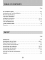
Page
Air Conditioner Safety ......................................... 2-3
Introduction and Parts Identification .............................. 4-5
Electrical Specifications ......................................... 6
Tips Before Installation ......................................... 7
Installation Instructions ...................................... 8-12
Operating Instructions ...................................... 13-16
Care and Maintenance ......................................... 17
Trouble Shooting Guide ........................................ 18
Warranty ................................................... 19
Page
Introducci6n ................................................. 20
Identificaci6n de las Piezas .................................. 20-21
Especificaciones EI6ctricas ..................................... 22
Consejos Antes dela Instalaci6n .................................. 23
Instrucciones de Instalaci6n .................................. 24-28
Instrucciones de Operaci6n .................................. 29-32
Cuidado y Mantenimiento ....................................... 33
Guia para la Soluci6n de Problemas ............................... 34
Garantia .................................................... 35

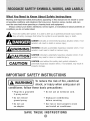
What YouNeed to KnowAbout Safety instructions
Warning and important Safety instructions appearing in this manual are not meant to cover
all possible conditions and situations that may occur. Common sense, caution, and care
must be exercised when operating or cleaning tools and equipment.
Always contact your dealer, distributor, service agent, or manufacturer about problems or
conditions you do not understand.
This is the safety alert symbol. It is used to alert you to potential personal injury hazards.
,y all safety messages that follow this symbol to avoid possible injury or death.
_ ANGER indicates an imminently hazardous situation which, if not
avoided, will result in death or serious injury.
_ ARNING indicates a potentially hazardous situation which, if not
avoided, could result in death or serious injury.
_ AUTION indicated a potentially hazardous situation which, if not
avoided, may result in minor or moderate injury.
_ CAUTION used without the safety alert symbol indicated a
potentially hazardous situation which, if not avoided, may result in
property damage.
IMP RTANTSAFETYINSTRUCTIONS
Toreduce the risk of fire, electrical
shock, or injury when using your air
conditioner, follow these basic precautions:
= Plug into a grounded
3-prong outlet.
• DO not remove
ground prong.
• DO not use
an adapter.
Do not use an extension cord.
Unplug air conditioning
before servicing.
Use two or more people to move
and install air conditioner.
SAVE THESE INSTRUCTIONS

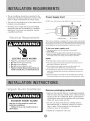
• The air conditioner should be connected to the
appropriate electrical receptacle as shown in the
chart on Page 6 (Receptacle and Fuse Types).
The use of a time-delay fuse or time-delay circuit
breaker is recommended.
All wiring must comply with local and national
electrical codes and be installed by a qualified
electrician. If you have any questions, contact
a qualified electrician.
ELECTRIC SHOCK HAZARD
Plug into a grounded 3-prong outlet.
,, Do not remove ground prong.
Do not use an adapter.
Do not use an extension cord.
,, Failure to follow these instructions can
result in death, fire, or electrical shock.
Power Supply Cord
NOTE: Your unit's device may differ from the one shown.
B
A Reset Button B Test Button
This room air conditioner is equipped with a power supply cord required
by UL This power supply cord contains state-of-the-art electronics that
sense leakage current. If the cord is crushed, the electronics detect leakage
current and power will be disconnected in a fraction of a second.
To test your power supply cord:
1. Plug power supply cord into a grounded 3-prong outlet.
2. Press RESET.
3. Press TEST (listen for click; Reset button will trip and pop out).
4. Press and release RESET (listen for click; Reset button will latch
and remain in).The power supply cord is ready for operation.
NOTES:
• The Reset button must be pushed in for proper operation.
• The power supply cord must be replaced if it fails to trip when the
test button is pressed or fails to rest.
• Do not use the power supply cord as as an off/on switch. The
power supply cord is designed as a protective device.
• A damaged power supply cord must be replaced with a new power
supply cord obtained from the product manufacturer and must not
be repaired.
• The power supply cord contains no use serviceable par_s. Opening
the tamper-resistant case voids all warranty and performance claims.
i, i I _,,,x cJ _,s_ I I _,_ I I, I ,,i I I _w I
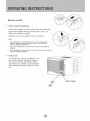
Remove packaging materials
Remove and properly dispose of packaging materials.
Remove tape and glue residue from surfaces before
turning on the air conditioner. Rub a small amount
of liquid dish soap over the adhesive with your fingers.
Wipe with warm water and dry.
Do not use sharp instruments, rubbing alcohol,
flammable fluids, or abrasive cleaners to remove
tape or glue. These products can damage the
surface of your air conditioner.
Handle air conditioner with care.

Thank you for choosing this room air conditioner to cool your home. This USE AND CARE MANUAL
provides information necessary for the proper care and maintenance of your new room air conditioner.
If properly maintained, your air conditioner will give you many years of trouble free operation. To avoid
installation difficulties, read instructions completely before starting. This manual contains information for the
installation and operation of your room air conditioner.
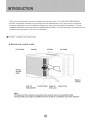
I D,,T
_-Mechanicam control model
Front Panel Cabinet Air Filter Air Outlet
\ •
\\ \ /
x /
Interior
Air Inlet
Grille
/ !x \
,/ /
Auto Air Control Panel Fresh Air Power Cord
Swing Switch Vent Lever
\\\\
....."Exterior
Air Inlet
Note:
The figures in this manual are based on the external view of a standard model.
Consequently, the shape may differ from that of the air conditioner you have selected.

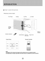
Remote control model
Front Panel
\
x
\\
Cabinet
Interior ...............
Air Inlet
Grille
Remote Controller <_
Air Filter Air Outlet
/
/
/
// \ "\
// t "\\
Control Panel Fresh Air Power Cord
Vent Lever
\\\\\\\\
\ Exterior
Air Inlet
Control Panel Remote Controller
_PEeO
T_ME_
.... / _
Note:
The figures in this manual are based on the external view of a standard model.
Consequently, the shape may differ from that of the air conditioner you have selected.

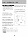
1. All wiring must comply with local and national
electrical codes and must be installed by a
licensed electrician. If you have any questions
regarding the following instructions, contact a
licensed electrician.
2. Check available power supply and resolve any
wiring problems BEFORE installing and operating
this unit.
3. For your safety and protection, this unit is
grounded through the power cord when
plugged into a matching wall outlet. If you are
not sure whether your wall outlet is properly
grounded, please consult a licensed
electrician.
4. The wall outlet (3-pin) must match the plug
(3-pin) on the power cord supplied with the unit.
DO NOT use plug adapters or extension cords.
See (Table 1) for receptacle and fuse information.
5. The rating plate on the unit contains electrical
and other technical data. The rating plate is
located on the front of the base pan. Make sure
to use the correct power supply according to the
rating plate of your air conditioner.
If the air conditioner has a serial plate rating
of 115 volts and up to and including 7.5 amps,
the unit maybe on a fuse or circuit breaker
with other devices. However, the maximum
amps on all devices for that fuse or circuit
breaker can not exceed the amps of the fuse
for the circuit breaker.
If the air conditioner has a serial plate rating
of 115 volts and greater than 7.5 amps it
must have its own fuse or circuit breaker,
and no other device or unit should be
operated on the fuse or circuit breaker.
If the air conditioner has a serial plate rating
of 230 volts, it must have its own fuse or
circuit breaker, and no other device or unit
should be operated on the fuse or circuit
breaker.
To avoid the possibility of personal injury,
disconnect power to the unit before installing
or servicing.
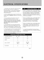
COOLING CAPACITY 1OK - 12K 18K
RATED VOLTS 125 250
AMPS 15 15
WALL OUTLET
FUSE SIZE 15 15
Table 1

Your RoomAir Conditioner unit is designed to
be highly efficient and save energy. Follow these
recommendations for greater efficiency.
1. Select thermostat setting that suits your
comfort needs and leave the thermostat at
that chosen setting.
pr!'
2. The air filter is very efficient in removing airborne
particles. Keep the air filter clean. Typically, the filter
should be cleaned once a month. More
frequent cleaning may be necessary depending
on outdoor and indoor air quality.
3. Use drapes, curtains, or shades to keep direct
sunlight from heating your room, but DO NOT
obstruct the air conditioner. Allow three (3) inches
around unit to circulate.
4. Start your air conditioner before outdoor
air becomes hot/cold and uncomfortable. This
avoids an initial period of discomfort while
the unit is cooling or heating off the room.
5. When outdoor temperature is cool
enough, use HIGH or LOW FAN
only. This circulates indoor air, providing
some cooling comfort, and utilizes less
electricity than when operating on a
cooling setting.
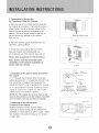
Your RoomAir Conditioner was designed
for easy installation in a single or double-hung
window. NOTE: This unit is NOT designed for
vertical (slider type) windows.
To avoid installation/operating difficulties,
read the instructions thoroughly.
NOTE: Save the shipping carton and packing
materials for future storage or transport of the unit.
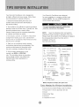
Please check the contents of the hardware kit against
the corresponding model check list, prior to
installation of the unit.
See lists below. (Fig.A)
314" Screws (10) _ Shutter Clamp(2)
(_ 114" Screws (23) f_
Gasket(10)
Top Channel(1 )
[_ Bottom Channel (1) Side Curtain RH(1)
(For 10K to 12K models) Side Curtain LH(1 )
_ BottomChannel(1) _ _
(For 18K models)
(Factorydnstalbd)
O Lock Washers(4)
(_ 1-1/2" x1/4 Bolts(4) _ Seal(l)
114" Nuts(4)
......... I _ Foam (1)
ooooooooooool
U Mounting
Brackets(2) Double
Angle Adhering
_ Brackets(2) Seal(l)
End Cap &
Leveling Legs(2)
NOTE: Surplus screw(s) for spare use.
Tools Needed for Window Installation:
,, Screw Drivers: Both Phillips and Flat Head
,, Power Drill: 1/8 inch diameter drill bit
,, Pencil
,, Measuring Tape
,, Scissors
,, Carpenter's Level

Becausethecompressorislocatedonthe
controlssideoftheunit(rightside),thisside
willbeheavierandmoreawkwardtomanipulate.
Inadequatesupportoncontrolsideoftheunit
canresultinpersonalinjuryanddamagetoyour
unitandproperty.Therefore,itisrecommended
tohavesomeoneassistyouduringtheinstallation
ofthisunit.
1.SelecttheBestLocation
A. Your room air conditioner was designed to
fit easily into a single or double hung window. However,
since window designs vary, it may be necessary to
make some modifications for safe and proper
installation.
E. Be certain the proper electrical outlet is within reach
of the installation. Use only a single outlet circuit rated
at proper current (see table 1 on page 4). All wiring
should be in accordance with local and national
electrical codes.
F. Your unit was designed to evaporate condensation
under normal conditions. However, under extreme
humidity conditions, excess condensation may cause
the basepan to overflow to the outside.
The unit should be installed where condensation
run-off cannot drip on pedestrians or neighboring
properties.
B. Make sure window and frame is structurally
sound and free from dry and rotted wood.
C. For maximum efficiency, install the air conditioner
on side of the house or building which favors more
shade than sunlight. If the unit is in direct sunlight,
it is advisable to provide an awning over the unit.
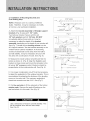
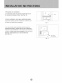
D. Provide sufficient clearance around the cabinet
to allow for ample air circulation through the unit.
See (Fig.B). The rear of the unit should be outdoors
and not in a garage nor inside of a building.
Keep unit as far away as possible from obstacles and
obstructions and at least 30" above the floor or
ground. Curtains and other objects within a room
should be prevented from blocking the air flow.
Fig.B
Window opening requirements
see table below)
_.....Mod el
Size
Cabinet size
(W*H*D)
Min. Window
Width
Max. Window
Width
Min, Window
Height
AW -1 0OR1FM AW -12CR1FM1 AW -18CR3FM
AW-10CMIFM AW-12CMIFM AW-18CM3FM
20.5" "14.8" "23.1" 22.8" "15.7" "24.1" 26.5" "18.5" *26.9"
25.2" 27.3" 31.2"
37.8" 37.8 " 43.0"
I5.7 " I5.8 " 19.0 "
Awning
/
X 30" Min.
Side
obstruction
Ground
Fence,
wall, or
other
obstacle.
I

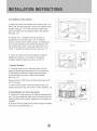
2. Preparation to Remove the
Air Conditioner Slide-Out Chassis
A. Remove total of (4) Philips screws securing
the chassis to the cabinet. There are (2) screws
on each side. The set of screws closest to the
front of the unit secure the front panel to the
cabinet. The set of screw closest to the rear of
the unit secure the cabinet to the chassis.
See (Fig. 1).
B. Remove the front panel assembly from the
cabinet by gently pulling it.
C. Grasp the pull handle at the front of the
slide-out chassis and carefully slide the
air conditioner out of the cabinet, See (Fig. 2).
Please seek assistance for this procedure.
Note: Screws must be reinstalled upon
completion of the window installation to
secure sfide-out chassis,
3. Assembly of the upper & lower channels to
the cabinet
A. " L" Shaped Top Channel: Stick the double
adhering seal to the " L" shaped top channel, and
then Install the "L" shaped top channel to the
cabinet as shown in (Fig. 3) using (5) 1/4" screws.
B. "n" Shaped Bottom Channel installed as shown
in (Fig. 3) using (4) 1/4" screws. On 10K models,
install screws from inside the cabinet.
NOTE: For 18K models, the bottom channel has
been factory-instafled, and their shapes may differ
from the others, but their functions are similar.
4. Assembly of the side shutters
(curtains) to the cabinet.
Slide the shutters into the top and bottom
channels as shown in (Fig. 4). The shutters are
identified (on each frame) as "left" & "right". Attach
the shutters to the cabinet using (4) 1/4" screws
on each side.
Right side Philips screws
Fig. 1
Chassis
Fig. 2
Double
v Adhering seal
1/4" Screw
'n" Shaped Channel For t 8K models,
Position for Bottom Channel
10K to 12K models has been installed in
(smaller space to front) Factory like this.
Fig. 3
Shutter Fiame
Fig. 4

5. Installation of Mounting Brackets and
First Sealing Strip
NOTE: Windows come in a variety of different
styles. Therefore, it may be necessary to modify
or improve your particular installation.
A. Attach the bracket assembly to 90°angle support
brackets (Fig. 5) using (2) 1 1/2" bolts
Two bolts per bracket. Secure with the (2)
1/4" lock washers and (2) 1/4"nuts. DO NOT
immediately tighten these bolts as it may be
necessary to adjust the depth of the bracket
assembly, depending on the depth of your window sill.
See (Fig. 7).Install the two leveling screws into the
90°support brackets. Test the bracket assembly in the
window before cabinet installation. If the leveling
screws are distanced too far away from the wall to
provide stability, it may be necessary for you to fill
this area with a solid piece of wood. See (Fig. 8).
B. Measure the inside window sill width and find the
center as shown in (Fig. 6). Align the V-slot in each
bracket on these marks and mount the brackets to the
sill using 3/4" screws provided. Brackets should be
perpendicular to the inside window sill. See (Fig. 6).
(TOP VIEW)
V-slot_ [_ ...... 1
__p .... o .... I
/ /
Bracket Assembly
Leve Support Brackets
Fig. 5
Measurement for Model 1OK = 9,5"
Measurement for Model 12K = 10.3"
Measurement for Model 18K = 12,6"
Window sitl
Fig. 6
_'_r_ (2) 3/4" screws per bracket ,_
C. For proper condensation run-off it will be necessary
to adjust the angle/pitch of the window brackets. This is
accomplished by adjusting the distance of the leveling
screw on the outer wall. The maximum anglelpitch
should not exceed more than 3/16". See (Fig. 7).
D. Cut the seal strip to fit the underside of the bottom
window sash. Remove the peel-off backing on the
seal and attach it to this sash. See (Fig. 9).
Fig. 7
.... o .... ooo I
_c_)Wood
Fig. 8
M [o : ujjl[o M
Use a solid piece of wood to provide stability. This
will be required when sills are extra deep,
See (Fig. 8).
Fig. 9

6. Installation of the cabinet
A. Align one hole in the bottom of the cabinet with one
hole in the bracket assembly. Secure the cabinet to the
bracket using (3) 1/4" screws provided. Repeat the
same procedure on the opposite side of the cabinet.
See (Fig. 10).
B. Ensure the "L" shaped mounting channel is
positioned in front of the sash. The "U" shaped
bottom channel of the cabinet should be positioned
in the track provided on the bracket assembly. Pull
the window down until it rests just behind the front
of the "L" shaped mounting channel. See (Fig. 11).
C. Check to make sure that the cabinet is slanted
slightly downward on the outside. If necessary,
re-adjust support bracket as shown in (Fig. 7).
7. Secure Shutters
A. Carefully slide the air conditioner back into the
cabinet.(Please seek assistance for this procedure).
B. Reinstall the slide-out-chassis security screws
(removed earlier) on both sides of the cabinet.
See (Fig. 12).
Secure the top of the frames to the window sash with
(2) 3/4" screws.
C. Now, secure bottom frame of shutters using one
shutter clamp and one 3/4" screw on each side(Fig. 12).
8. Reinstalling Front Panel Assembly
A. Position the front panel on the cabinet starting at the
top. The front panel lock tabs must be inserted into the
retaining slots in the cabinet. Repeat this procedure on
all sides.
B. Secure the front grille to the cabinet using the Philips
screws removed earlier(Fig. 1).
Fig. 10
Window Sash
"L'Shaped Seal
Mounting
Channel
Fig. 11
3/4 *' ,_:::teWS
Coil
Fig. 12

9. Complete the installation
A. Cut the foam to fit the opening between the top of
the inside and outside window. See (Fig. 13).
Foam
B. Some installations may require additional sealing
around the window and air conditioner. Check for any
air leaks and seal where necessary.
Fig. 13
C. In very humid areas, the water removal may be
excessive enough to overflow the unit or increase the
noise of the air conditioner. If this occurs, you may wish
to attach a drain hose (not included) to the drain plug
allowing condensations to run off conveniently.
See (Fig. 14).
Fig. 14
Drain Hose
(not included)

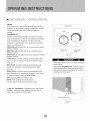
MODE
The mode knob controls fan speeds and cooling
speeds. To set desired cooling temperature, simply
rotate the mode knob dial to the appropriate
setting.
THERMOSTAT
The thermostat automatically controls the cooling
cycle (compressor) of the air conditioner to maintain
room temperature. However, the fan motor will
continue to operate after the compressor (cooling
cycle) is completed.
LOW FAN will circulate the air at a minimum speed
without cooling.
MED FAN will circulate the air at a middle speed
without cooling.
HIGH FAN will circulate the air at a maximum speed
without cooling.
LOW COOL provides cooling, automatically with
minimum air circulation. Recommended for night-
time use.
MED COOL provides cooling, automatically with
middle air circulation. Recommended for night-
time use.
HIGH COOL provides cooling, automatically with
quick cooling or for extremely hot days. Once room
is cooled, reduce setting to LOW COOL.
OFF will completely shut-off the unit.
NOTE: After setting the mode, allow 3
minutes before switching to another mode.
[o_:_UJ_o_
Fresh Air Ventilation is usually kept in the closed
position. Use only when clearing smoke and/or
odors from the room. Pull to open.
Swing s_,4tch
Mode knob Thermostat
knob
Fig. 15
When using FAN control, turn slowly allowing
unit to adjust.
When using THERMOSTAT, be sure to allow
three minutes before changing temperature.
Adjusting too quickly may cause an overload
resulting in a blown fuse.
Fresh Air Vent Lever
Fig. 16

Youcaneasily operate this air conditioner by pressing
relevant button on the control panel as well as the
remote control
ON/OFF Button
The air conditioner will be started when it is energized
or will be stopped when it is in operation, if you press
this button.
Mode button
Each time Mode button is pressed, the operation
mode is changed in sequence:
COOLING FAN ONLY ENERGY SAVING COOLING
f
Mode:
eoeling (with fan speed Lo, Med, High): Compressor
cycles to maintain Temperature Set Point. Fan remains
on at selected speed during compressor OFF cycle.
Cooling (Auto Fan Speed): Compressor cycles to maintain
Temperature Set Point. Fan speed is controlled from room
temperature. Fan remains on during compressor OFF cycle.
Fan Only: Circulates and filters room air at selected speed.
Energy Saving (with fan speed Lo, Med, High):
Fan cycles ON and OFF with compressor over awider
range of temperatures.
Energy Saving (with Auto Fan Speed): Fancycles ON and
OFF with compressor at awider rangeof temperatures. Fan
speed during ON cycle is dependent on room temperature.
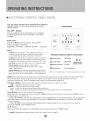
Control Panel
_Jk
FAN .....................................
[T_ME_j
i MoeEi
Indication symbols of LED on control panel:
Auto fan speed _ Cooling
_3 I'F
IHR
Low fan speed _% Fan only
Display set temp
Display set timer
i_ Medium fan speed C) Timer
High fan speed -(3: Energy-saving
LED on control panel lights on when the relevant mode is in used.
NOTE: After setting the mode, allow three (3) minutes before switching to another mode. In the FAN ONLY Mode,
Room Temperature display range is from 0°C (32°F) to 38°C (99°F). Room Temperature below 32°F,the
Temperature display LO. Room Temperature above 99°F, the Temperature display H1.
Fan Speed Button: Used to select fan speed in sequence auto, low, medium, and high.
High Highest fan speed for maximum cooling
Medium Normal fan speed for average cooling
Low Lowest and quietest speed, greater dehumidification
Auto Works in Cooling and Energy-Saving mode to vary fan speed based on room temperature.
Timer Button: Used to set or cancel timer operation.
When the unit is in operation, you can set OFF TIMER. When the unit is OFF, you can set ON TIMER. Timer
setting range is 0 to 24 hours.
If the OFF TIMER is set, the time LED displays the remaining time to turn off the unit for only 12 seconds,
then LED shifts to display set temperature. If you press TIMER button within the 12 seconds, OFF TIMER
will be cancelled.
If the ON TIMER is set, the timer LED displays the remaining time to turn on the unit. If you want to
cancel ON TIMER, press TIMER button.
A V Button
Used to set room temperature in COOLING mode or used to set time in TIMER mode.
NOTE: Temperature setting range is from 19°C (66°F) to 31 °C (88°F).

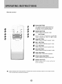
Remote controB
i¸ !?fillet_i_ •
....
Modo Swir_g P(/wc,_S_vr
0
0
0
0
0
0
0
0
0
0
0
0
0
Power BUTTON
The appliancewillbe started whenitis
energizedor wiltbestoppedwhenitis
in operation, ifyou press this button.
MODE BUTTON
Used to selectthe operation mode.
÷ -- BUTTONS
Used to set room temperature in COOLING
mode or used to set time in TIMER mode.
High BUTTON
Used to selectthe highfan speed mode.
Mid BUTTON
Used to selectthe Midfan speed mode.
LOW BUTTON
Used to selectthe Lowfan speed mode.
Auto BUTTON
Used to selectthe Auto fan speed mode,
Timer BUTTON
Used to set or cancel timer operation..
Power Saver BUTTON
Used to select the Energy-saving mode.
SWING BUTTON
Used to select start or stop vertical air
vanes swinging.
[] • When Changing modes during operation, sometimes the unit does not always respond at once. Wait 3 minutes
• Wait 3 minutes before restarting the appfiance.

Remote control
How to insert the Batteries
Remove the battery cover according to the arrow direction.
Insert new batteries making sure that the (+) and (-) of
battery are matched correctly.
Reattach the cover by sliding it back into position.
Notet
* Use 2 LR06 AAA (1.5 volt) batteries, Do not use rechargeable
batteries, Replace batteries with new ones of the same type
when the display becomes dim.
* Do not mix old batteries with new ones. Dispose of old batteries
properly.
° If the replacement is done within one (1) minute, the remote control
will keep original presetting.
How to Use
To operate the room air conditioner, aim
the remote control to the signal receptor.
The remote control will operate the air
conditioner at a distance of up to 23 feet
when pointing at signal receptor of indoor
unit.
Signal receptor

When servicing the air conditioner, be sure to
turn the mode switch to the "OFF" position and
disconnect the power cord from the electrical outlet.
1. DO NOT use gasoline, benzine, thinner or
other chemicals on the air conditioner as these
substances may cause damage to the paint finish
and deformation of plastic parts.
2. Never attempt to pour water directly in
front of the unit as this will cause deterioration of
the electrical insulation.
Cleaning the Air Filter
Removal of Air Filter
If the air filter becomes clogged with dust, air-flow
is obstructed and reduces efficiency. The air filter
should be cleaned once a month. More frequent
cleaning may be necessary depending on outdoor
and indoor air quality.
Air Filter Removal:
The air filter on the above model is located
behind the air intake front grille.
To remove the air filter, open the air inlet
grille and take the air filter.
To reinstall the air filter, reverse the above
procedure.
_!',__.111i [o)
DO NOT forget to install the air filter. If the air
conditioner is left to operate without the air filter,
dust is not removed from the room and may
cause your air conditioner to fail.
When the air filter inlet grille and cabinet are dirty,
wipe with lukewarm water (below 40°C/104°F).
Use of mild detergent is recommended.
Cleaning of Air Filter
1. Remove dust clogged in the filter by
tapping it or vacuum clean it.
2. Wash the filter well with lukewarm water below
40°C (104"F) while rubbing lightly: To get better
results, wash it with soapy water or a neutral
cleaning agent.
3. Rinse the filter well using clean water then
dry completely.
End-of-Season Care
1. Operate the fan alone for half a day to dry out
the inside of the unit.
2. Turn off power and remove plug from wall socket.
3. Clean filter.
4. Store in a dry location.

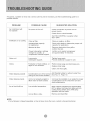
Frequently, a problem is minor and a service call may not be necessary, use this troubleshooting guide for a
possible solution.
PROBLEM
Air conditioner will
not operate
Inefficient or no cooling
POSSIBLE CAUSE SUGGESTED SOLUTION
No power to the unit.
Dirty air filter.
Inappropriate capacity
for application.
Blocked air flow.
Power interruption, settings
change too quickly, or
compressor overload tripped.
Check connection of power cord to
power source.
Check fuse or circuit breaker.
Set FAN CONTROL to position other
than "OFF".
Clean or replace air filter.
Check with dealer to determine proper unit
capacity for application.
Remove obstruction from grill or
outdoor louvers.
Let fan run to restart compressor
(in approximately 10 minutes).
Noisy unit Loose parts. Tighten loose parts.
Inadequate support. Provide additional support to unit.
Odors Formation of mold, mildew, or Remove drain plug and drain base pan.
algae on wet surfaces. Replace drain plug.
Clean unit thoroughly.
Add flexible tubing to redirect water flow.
Water dripping outside Condensation run-off is norma
during hot and humid weather (See Fig. 14, Page 12)
Water dripping inside Unit is not properly angled to Unit must be installed on an angle for proper
allow water to drain outside, condensation run-off. Check the unit and
make adjustments.
Ice or frost build-up Low outside temperature.
Unit air filter is dirty.
When outdoor temperature is approximately
65°F or below, frost may form when unit is in
cooling mode. Switch unit to FAN (only)
operation until frost melts.
Remove and clean filter.
NOTE:
If circuit breaker is tripped repeatedly, or fuse is blown more than once, contact a ficensed technician.

5 YEAR FULL WARRANTY
This product is warranted for 5years from the date of original purchase. Any part
which fails in materials or workmanship will be replaced within the warranty period.
This warranty covers in home service. Acopy of your proof of purchase, with date of
purchase and product name included, is required to arrange this service repair.
For the name and location of an authorized service provider nearest you, please
CALL 1-877-465-3566. Please reference product name, brand name, and model
number when you call.
This warranty does not apply if the damage occurs because of accident, improper
handling or operation, shipping damage, abuse, misuse, unauthorized repairs
made or attempted, or the use of the product for commercial use, or any other use
for which it was not intended.
ALL WARRANTIES, EXPRESSED OR IMPLIED, LAST FOR 5 YEARS FROM THE
DATE OF ORIGINAL PURCHASE. THIS WARRANTY DOES NOT COVER
LIABILITY FOR INCIDENTAL OR CONSEQUENTIAL DAMAGES FOR ANY
CAUSE WHATSOEVER.
This warranty is extended to the original owner and any succeeding owner for
products purchased for home use within the USA. Some states do not allow the
exclusion or limitation of incidental or consequential damages. This warranty
gives you specific rights, and you may also have other rights which may vary from
state to state. To know what your legal rights are, consult your local or state
consumer affairs office or your state's Attorney General.

Gracias per elegir este aire acondicionado para enfriar su hogar. Este MANUAL DE USO Y MANTENIMIENTO
proporciona la informaci6n necesaria para cuidar y mantener en forma adecuada su nuevo aire acondicionado.
Funcionar_] sin problemas durante muchos ahos si le brinda el mantenimiento apropiade. Para evitar
problemas al instalarlo, lea completamente las instrucciones antes de cemenzar. Este manual contiene
informaci6n acerca de la instalaci6n y el funcionamiento del aire acondicionado para habitaciones.
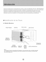
Modelo Mec_.nico
Panel Frontal Gabinete Filtro de Aim Outlet de Aire
,\
j_-f
Rejilla de
Entrada de
Aire Interior
\\\,
\,
// \\\
Entrada de
//
/
, / \ ........ Aire Exterior
Aire de Rejilla ....,,
autom&tico l-ablero de Palanca Cable de Alimentacidn
oscilar selector Mandos de Aire
Fresco
Nota:
Las imagenes de este manual estan basadas en la vista externa de un modelo est(indar.
En consecuencia, es probable que la forma sea diferente a la del aire acondicionado
que usted seleccion6.

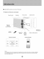
Modelo de Remoto controlador
Panel Frontal Gabinete
Filtro de Aim
Outlet de Aire
/,
Rejilla de
Entrada
de Aire Interior
Control
Remoto
/
/
/
/
/
Tablero de
Mandos
Rejilla
Palanca
de AJre
Fresco
'%
"\\
Entrada de
Abe Exterior
Cable de AlJmentaci6n
Panel de Control Control Remoto
i ........... fi
iiSWl_G ii
iIPlID ii
.............. i
i ................
814
i 2.......................................................................................
......j
ii............ ii
j MOD£ i
iL................ i
C3 ,2
/
Nota:
Las im(3genes de este manual est_n basadas en la vista externa de un modelo estC]ndar.
En consecuencia, es probableque laforma sea diferente a la delaire acondicionado
que usted seleccion6.

1.Todosloscablesdebencumplirconlosc6digos
el6ctricoslocalesynacionalesylosdebeinstalar
unelectricistalicenciado.Sitienepreguntas
relacionadasconlassiguientesinstrucciones,
comuniqueseconuneiectricistalicenciado.
2.Verifiqueelsuministrodeenergfadisponibley
resueivacualquierproblemaconloscablesANTES
deinstalaryhacerfuncionarestaunidad.
3.Parasuseguridadyprotecci6n,estaunidadest6
conectadaatierraatrav6sdelcabledealimentaci6n
cuandoseIoenchufaauntomacorrientedepared
provistodeconexi6natierra.Sinoestasegurode
queeltomacorrientedeparedcuentaconla
conexi6natierraapropiada,consulteconun
electricistalicenciado.
4.Eltomacorrientedepared(de3clavijas)debe
coincidirconelenchufe(de3clavijas)delcablede
alimentaci6nsuministradoconlaunidad.NOutilice
adaptadoresdeenchufenicablesdeextensi6n.
ConsultelaTabla1paraobtenerinformaci6nacerca
derecept6culosyfusibles.
Sielr6tulodelaireacondicionadoindica115
voltiosyhasta7.5amperios,launidadse
puedeconectarauncortacircuitoofusible
utilizadoporotrosdispositivos.Noobstante,
lasumadelosamperiosmaximosdetodos
losdispositivosconectadosadicho
cortacircuitoofusiblenodebenexcederlos
amperiosdelmismo.
Sielr6tulodelaireacondicionadoindica115
voltiosymasde7.5amperios,debetenersu
propiofusibleocortacircuitoynosedebera
conectarning_notrodispositivoounidadadicho
fusibleocortacircuito.
Paraevitarlesionesf_sicas,desconecteel
suministrodeenerg_adelaunidad
antesdeinstalarlaorepararla.
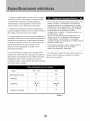
5.Elr6tulodelaunidadcontienedatosel6ctricosy
t6cnicos.Dichor6tuloseencuentraenellado
derechodelaunidad.
MODEL 1OK-12K 18K
125 250
CAPAClDADDEVOLTIOS
AMPERIOS 15 15
AMPERIOS
TAMANOD+ELFUSIBLE 15 15
Table 1

Su unidad de AireAcondicionado para Habitaciones
se ha disen'ado para Iograr un alto rendimiento y
ahorrar energia electrica. Siga las siguientes
sugerencias para Iograr un mayor rendimiento.
El Aire Acondicionado para Habitaciones se ha
dise_ado de mode tal que resulte Ricil su instalaci6n
en ventanas armadas sencillas o dobles. NOTA: esta
unidad NO se ha disenado para ventanas verticales
(de tipo deslizante).
1. Ajuste el termostato a un nivel que le resulte
agradable y d6jelo en el nivel seleccionado.
2. El filtro es muy eficiente a la hora de eliminar
parti culas que se desplazan pot el aire. Mantenga
limpio el filtro de aire. Pot Io general, el filtro deber6
limpiarse una vez al rues. Es probable que sea
necesario limpiarlo con m_s frecuencia dependiendo
de la calidad del aire exterior o interior.
3. Puede utilizar tapices, cortinas o pantallas para
evitar que la luz directa del sol caliente su habitaci6n,
pero NO obstruya el aire acondicionado. Permita
que el aire circule alrededor de la unidad sin
obstrucciones.
4. Encienda el aire acondicionado antes de que la
temperatura exterior sea demasiado elevada y
desagradable. De esta manera evitard sufrir calor
mientras la unidad enfria la habitaci6n.
5. Cuando la temperatura exterior es Io suficientemente
fresca, utilice s61o HIGH FAN (ventilador al m_ximo) o
LOW FAN (ventilador al mfnimo). Esto hace que el aire
interior circule a una temperatura agradable y consume
menos energla el_ctdca que si hiciera funcionar la
unidad como enfdador de aire.
las instrucciones.
NOTA: conserve la caja de la unidad y los materiales
de empaque para almacenarla o transportarla en el
futuro. Antes de instalar la unidad compare el
contenido del juego de herrajes con la lista de control
del modelo correspondiente. Consulte las siguientes
listas (Fig. 1).
(]::_Tor nillos de 3/4" (10) % GrapadePersiana(2)
(_ Tornillos de 1/4"(23)
_:_ Canal Superior (1) (_ Junta de Culata (10)
Canal Inferior (1)(1OKto12K)C0rtinaLateralDerecha(1)
C0rtinaLateralIzquierda(1)
Canal Inferior (1) (18K)
(instalado en la f brica)
O ArandelasdePresidn(4)
Pernos del-1/2"xl/4 (4)
Tuercas de1/4" (4)
Soportes
/ _Horizontales (2)
Soportes
en Escuadra (2)
TapaTrasera y
Paras de Nivelaci6n (2)
Sello (1)
Doble Sello Adhesiva (1)
Espuma (1)
(Fig. 1)
Nota: Tomillo Excedente Para d Uso de Reserva.
Herramientas Necesarias para la Instalaci6n en Ventana:
Destomilladores: Philips y de cabeza plana
Taladro el_ctrico: broca de 1/8 pulgada de didmetro
Ldpiz
Cinta m_trica
Tijeras
Nivel de carpintero

Vf_ I_ z1=[_l[H _ _1V_I
Debido a que el compresor se encuentra del lade
de los controles (a la derecha de la unidad), este
lado ser_ m_s pesado y rods diffcil de manipular.
Si la unidad no se sostiene bien de dicho lado
pueden producirse lesiones ffsicas y da_os a la
unidad y a su propiedad. Por Io tanto, le
recomendamos que para instalar esta unidad
solicite ayuda a otras personas.
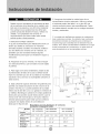
1. Seleccione la Mejor Ubicaci6n
A. El aire acondicionado para habitaciones tiene un
dise_o que facilita su colocaci6n en ventanas
armadas sencillas o dobles. No obstante, debido a
que los dise_os de ventana son tan vadados, es
probable que sea necesario realizar algunas
modificaciones para Iograr una instalaci6n segura y
adecuada.
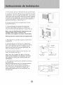
B. Asegarese de que la ventana y el marco tengan
una estructura firme y que la madera no est6 rajada
ni poddda.
C. Para Iograr el mdximo rendimiento, instale el aire
acondicionado del lado de la casa o edificio donde
haya m6s sombra que sol. Si la unidad se encontrara
expuesta a la luz del sol, es aconsejable colocarle un
toldo encima.
E. Asegflrese de instalar la unidad cerca de un
tomacorriente el6ctrico adecuado. Utilice un estime
al cordente propio (lea tabla 1 en p gina 20) con
circuito exclusivo para el aire acondicionado. Todos
los cables deberdn cumplir con los c6digos el6ctricos
locales y nacionales.
F. La unidad estd dise_ada para evaporar la condensaci6n
bajo condiciones normales. No obstante, bajo condiciones
de extrema humedad, es probable que la condensaci6n
excesiva haga que la bandeja base se desborde hacia el
exterior. Por Io tanto la unidad deber6 instalarse en un lugar
donde la descarga de la condensaci6n no gotee sobre el
paso de peatones ni en las propiedades vecinas.
Toldo
D. Deje suficiente espacio alrededor del gabinete para
permitir una amplia circulaci6n de aire a trav6s de la
unidad. Vea (Fig. 2). La parte posterior de la unidad
deber6 dar al aire libre y no a un garaje ni al interior de
un edificio. Mantenga la unidad Io mas lejos posible de
obst_culos que puedan causar obstrucciones y por Io
menos a 30" del nivel del piso o del suelo. Deber_n
tomarse precauciones para evitar que las cortinas o
cualquier otro objeto dentro de una habitaci6n
obstruyan el flujo de aire.
RceqUisi,tos, para las aberturas de ventanas
onsulte la siguiente taula_
_....Modelo AW-10OR1FM AW-12CR1FM1
Tamano _ AW-10OM1FM AW-12CM1FM
Cerca,
30" Min. pared u
Obstrucci6n otro
lateral _ obstdculcl
Suelo
12" Min.
AW -18CR3FM
AW-18CM3FM
Tamanodelgabinete
(A*H*L) 20.5" "14.8" "23.1" 22.8" "15.7" "24.1" 26.5" "18.5" *26.9"
Aberturaminima 25.2 " 27.3" 31 .2"
deVentana
Aberturam_xima 37.8" 37.8 " 43.0"
deVentana
MinutaAltura
deVentana 15.7 " 15.8 " 19.0 "
Fig.2
/

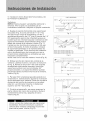
2. Cdmoquitar el armaz6n deslizable del aire acondicionado
A. Quite los 4tornillos Philipsque sujetanel armaz6n
al gabinete. Hay 2tornillos decada lado. Los tornillo
s queest6n m6s cercadel frentede la unidad sujetan
el panel frontal algabinete. Lostornillos queestan m
6s cercade la parte traserade la unidad sujetanel
gabinete alarmaz6n. Vea la(Fig. 1).
B. Quite el panel frontal delgabinete tirando
suavemente de 61.
C. Tome el mango que estden el frente del
armaz6n deslizable y saquecon cuidadoel
aire acondicionadodel gabinete. Veala (Fig. 2).
Nota: una vez finalizada la instalaci6n en la
ventana debe volver a colocar los
tornillos para sujetar el armaz6n deslizable.
Pida ayuda para realizareste procedimiento.
3. Montaje de los canales superiore inferioren
el gabinete
A. Canal Superior en Forma de L:Aguante el
doble selloadhesiva alcanal superioren forma
de L, con 5 tornillos de 1/4", instale el canal
superior en forma de L sobreel gabinete, tal
como se indica en la Fig. 3.
B. Instaleel Canal Inferior en forma de U, tal
como se indica en la Fig. 3.
Nota: Para los modelos de 18K, el canal de
bot6n se ha instalado en la f4brica y su forma
set4 distinto a otros, pero susfucciones son
semejantes.
4. Montaje de las persianas laterales (cortinas)
en elgabinete.
Deslice las persianas porlos canales superior
e inferior, talcomo seindica en la Fig. 4.
En cada marco, las persianas seidentifican
como "izquierda" y "derecha". Sujete las
persianas al gabinete con 4 tornillos de 1/4"
de cadalado.
Lado derecho
Tornillos Philips
Fig. 1
Mango
Armaz6n
Fig. 2
Doble Sello
v Adhesiva
Tomillo de1/4"
Canal
p_ 18K
1 OK to 12K (instalado en la f brica)
Fig. 3
Marco de la Persiana
Tornillo de1/4"
/
Perslana
Derecha
Fig. 4

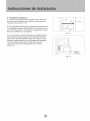
5. Instalaci6n de los Soportes Horizontales yde
la Primera Tira Adhesiva
Selladora
NOTA: Existe unagran variedad de estilos de v
entanas. Porlo tanto, es probableque se
a necesario modificar o mejorar su propia instalaci6n.
A. Sujete el soporte horizontal alos soportesen
escuadra (Fig. 5) con2 pernosde 1 1/2". Hay
dos pernos por soporte. Asegtirelos conlas 2
arandelas de presi6n de 1/4" ylas 2 tuercas de 1/,_"
NO ajuste estos pernos de inmediatoya quees
posible quesea necesario ajustar la distancia del
soporte ensamblado, dependiendo dela profun
didad del umbral dela ventana. Veala (Fig. 7).
Instale los dos tornillosde nivelaci6n enlos sop
ortes en escuadra. Amodo de prueba, coloque
el soporteensamblado en la ventanaantes de
instalar elgabinete. Silos tornillosde nivelaci6n
est6n demasiadolejos dela pared como para
proporcionar estabilidad, es probable que sea
necesario complementar
dicha 6rea con un tacode madera. Veala (Fig. 8).
B. Midael anchodel interior del umbralde la
ventana ydefina elcentro, talcomo seindica en
la Fig. 6. Alinee la ranura enV decada soporte
ensamblado sobreestas marcas y monte los
soportes al umbral con los tornillosde 3/4"
proporcionados. Los soportes deber6n quedar
perpendiculares al umbral interno de la ventana.
Veala (Fig. 6).
C. Para permitir unadescarga adecuadade lac
ondensaci6n, serdnecesario ajustar la inclinaci6n
de los soportes en la ventana. Para ello, ajuste la
distancia deltornillo de nivelaci6n en la pared
exterior. La inclinaci6n m6xima no deber6ser
superior a 3/16". Vea la(Fig. 7).
D. Cortelaprimerasello paraquequepaenla
parte inferiordel marco de la ventana. Quite el
revestimiento dela tiray peguela al marco.
Veala (Fig. 9).
(VISTA SUPERIOR)
en V o o o o o o o o o
Pern os rdellSOport e r_ _ _ SoFort .... Esouadra
Nivelaci6n
Fig. 5
Medida para el Modelo Model 1OK= 9.5"
Medida para el Modelo Model 12K = 10.3"
Medida para el Modelo Model 18K = 12.6"
Fig. 6
_,Umbral de I_
Ventana
_ 2 tornillos de 3/4" por soporte '_
_hOo o o o Ooo o o_
_..._ M_ximo de 3/16"
Z:T,:::::
Pared Externa
Fig, 7
_o o o o Oo o o oO o o I
Fig, 8
V!_ I--1iI =(I,]B[I[I,]t__I V!_
Utilice un taco de madera para proporcionar
estabilidad. Esto ser6necesario cuando el
umbral dela ventanasobresalga muchodel
piano de la pared. Veala (Fig. 8).
Marco de
Sello
Fig. 9

6. Instalaci6n del gabinete
A. Alinee un agujero dela parteinferior del
gabinete con un agujerodel soporteensambla
do. Sujete el gabinete al soporte ensamblado
con 3de los tornillos de 1/4" proporcionados.
Repita el mismo procedimiento del otrolado del
gabinete. Vea la(Fig. 10).
B.Asegt_rese deque el canal demontaje en
forma deL est_delante del marco. El canal en
forma deU dela parteinferior delgabinete de
ber_quedar en el riel del soporte ensamblado.
Baje la ventana hasta que apoyejusto detras
de la parte delanteradel canal de montajeen
forma deL. Vea la (Fig. 11).
C. Asegttrese de que el gabinete est61evemente
inclinado hacia abajo en la parteexterna.
Si es necesario vuelvaa ajustarel soporte,
tal como se indica en la Fig. 7.
7. Asegure las Persianas
A. Vuelvaa colocarcon cuidado el aire
acondicionado enel gabinete. (Pida ayuda para
realizar este procedimiento.)
B. Vuelvaa instalar los tornillos del armaz6n
deslizable (que se quitaron anteriormente) de
ambos ladosdel gabinete. Veala (Fig. 12).Asegure
la partesuperior de los marcosal marco de la
ventana con2 tornillos de 3/4".
C. Ahora, asegureel marco inferior delas persianas
con unagrapa yun tornillode 3/4" de cada lado
(Fig. 12).
8. C6mo Volver alnstalar el Panel Frontal
A. Coloque el panel frontal enel gabinete
comenzando porla partede arriba. Las trabas
del panel frontal deben insertarse en las ranuras
de sujeci6n del gabinete. Repita este procedimiento
de todoslos lados.
B.Asegure la rejilla frontalal gabinetecon los
tornillos Philips que quit6anteriormente (Fig. 1).
Fig. 10
Marco de laVentana
Canal de Sello
Montaje
en Forma
deL
Fig. 11
Ton_ de 3/4"
Montaje en
Forma de L
Tornillo deSeguridad
Fig. 12

9. Finalice la instalaci6n
A. Cortela espumapara quequepa en la abertura
entre la parte superiordel interior y exteriorde la
ventana. Vea la (Fig. 13).
B. Es probable que algunas instalaciones necesiten
tira selladora adicional alrededorde laventana yel
aire acondicionado. Verifique si hay alguna p6rdida
de airey s_llela sies necesario.
C. En zonas demucha humedad,es posible que la
descarga deagua hagaque la unidad desbordeo
que elaire acondicionado haga m6s ruido. Si esto
sucede, puedeacoplar una manguera dedesagae
(no incluida)al tap6n de drenaje para que las
condensaciones se descarguen bien. Vea la
(Fig. 14).
/ Espuma
Fig. 13
Manguera de
_g,Je
(no incluida)
Fig. 14

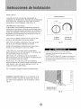
MODE (Modo)
La perilla de modo controla las velocidades de
ventilador y de enfriamiento. Para fijar una temperatura
de enfriamiento, simplemente haga rotar la perilla y
colOquela en el nivel deseado. Vea la Fig. 15.
THERMOSTAT (Termostato)
El termostato controla automaticamente el ciclo de
enfriamiento (compresor) del aire acondicionado para
mantener la temperatura del ambiente. No obstante, el
motor del ventilador continuara funcionando una vez
finalizado el funcionamiento del compresor (ciclo de
enfriamiento). Vea la Fig. 15.
LOW FAN (Ventilador al Minimo) har_ que el aire
circule a una velocidad minima sin enfriar.
MED FAN (Ventilador al Mediano) har6 que el aire
circule a una velocidad mediana sin enfriar.
HIGH FAN (Ventilador al M0ximo) hara que el aire
circule a una velocidad m0xima sin enfriar.
LOW COOL (Fr[o Mfnimo) enfr[a el ambiente
autom0ticamente con una circulaci6n m inima de aire.
Se recomienda durante la noche.
MED COOL (Frio Mediano) enfria el ambiente
autom0ticamente con una circulaciOn mediana de aire.
Se recomienda durante la noche.
HIGH COOL (Frfo Mdximo) enfrla el ambiente
automaticamente de manera rOpida o durante d ias de
calor intenso. Una vez que la habitaci6n est6 fria,
reduzca el nivel a LOW COOL.
OFF (Apagado) apaga la unidad completamente.
Ventilaci6n de aire fresco se ra a mantener en la
posici6n cerrado. Usando sOlo para limpiar humos
y/o odores de la habitaci6n, tire a comenzar. Vea la
Fig.16.
Oscilar Selector
........_v_vtN_G......
Control Control de
de Modo Termostato
Fig.15
Cuando utilice la perilla de control de ventilador,
h_gala girar lentamente para permitir que la unidad
se adapte al nivel.
Cuando utilice THERMOSTAT, ase_rese de esperar tres
minutos antes de cambiar la temperatura. Si la cambia
demasiado r6pido es posible que cause una sobrecarga y
se queme el fusible.
Rejilla Palanca
de Aire Fresco
Fig.16

Esteaireacondicionadosepuedeoperarf6cilmente
conlosbotonesdelpaneldecontrolaslcomotambi6n
conelcontrolremoto.
Bot6n (Encendido/Apagado)
Sipresionaestebot6n,encender6elaireacondicionado.
Cuandoelaireacondicionadoestadecalefacci6n,seper
imprentarestebot6n3minutosdespues.
Bot6nMode(Modo)
Cadavezquesepresionaelbot6nMODE,elmodo
deoperaci6ncambiaenestassecuencias:
COOLING(Enfriamiento)FANONLY(S61oventilador)
ENERGYSAVING(AhorrodeEnergia)COOLING
(Enfriamiento)
NOTA:Despu6sdeseleccionarunnivel,espere3
minutosantesdepasaraotro.
ConelmododeFANONLY,Elrecintodelatemperatura
Dehabitaci6nser6Desde0°C(32°F)hasta38°C(99°F).
Latemperaturadelahabitaci6nessuperiora32°F,
latemperaturalucer6L0.
Latemperaturadelahabitaci6nessuperiora99°F,
latemperaturaluceraHI.
Bot6n Fan Speed (Velocidad del Ventilador)
Se utiliza para seleccionarla velocidad del ventilador
en secuencia: autom6tica, baja, media yalta.
Bot6n Timer(Temporizador)
Se utiliza para programaro cancelar el
funcionamiento del temporizador.
Cuando la unidad est,:_enfuncionamiento, puede
seleccionar OFF TIMER (ApagarTemporizador).
Cuando la unidad est6apagada, puedeseleccionar
ON TIMER (Encender Temporizador).
El rango de horas para programar el temporizador
es de 0 a 24 horas.
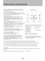
Panel de Control
@_-a:@
Bs ?s
','MEr_' O_'OFF] MODE
S_mbolos del indicador del panel del control:
@ Ventilador en
velocidad autom6tica
Ventilador en
velocidad baja
Ventilador en
velocidad media
Ventilador en
velocidad alta
,4_-Enfriamiento
_ S61o ventitador
Temporizador
X_: Ahorro de energia
u
k_ I°F Mostrar temperatura fijada
IHR Mostrar hora programada
Las luces del indicador LED anteriormente
mencionadas se encienden cuando se usan los
modos correspondientes.
Si selecciona OFF TIMER, la pantalladel temporizador indicar6durante 12se gundos
el tiempo restante parael apagado de la unidad yluego indicar61a temperatura fijada.
Si presiona el bot6n TIMERdentro de esos 12segundos, se desactivar61a funci6n OFFTIMER.
Si seleccionaON TIMER, la pantalladel temporizador indicar6el tiempo restante para el
encendido de la unidad. Si deseacancelar lafunci6n ON TIMER, presioneel bot6n TIMER.
Bot6n • •
Se utiliza para fijarla temperaturaambiente en modo COOLING o para programar la hora en modo
TIMER.
NOTA:el rangode temperaturas oscila entre 19°C(66 °F)y 31°C (88°F).

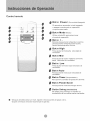
Control remoto
0
0
0
0
0
0 Bot6n Power (Encendido/Apagado)
El aparato se encender_ si est,1 apagado
o apagar_ cuando estd en operaci6n,
si oprime este bot6n.
Bot6n Mode (Modo)
Utilice este bot6n para seleccionar
el modo de operaci6n.
Bot6n +-
Botones de ajuste de temperatura oprima
para ajustar la temepratura del cuarto.
oprima para programar la hora.
_ Botdn High
Paraajustarelmodoalta velocidadde
ventilador,
Bot6n Mid
Para ajustarel modo mediana (al mismo
baja) velocidad de ventilador,
Bot6n Low
Para ajustarel modo baja velocidad de
ventilador,
Botdn Auto
Para ajustarel modoauto velocidad de
ventilador,
Bot6n Timer
(Temporizador)
Para poner o cancelar la operaci6n de timer,
Bot6n Power Saver
Para ajustarel modo de energia-ahorro.
_) Botdn Swing (Oscilaci6n)
Se utiliza para comenzar o terminar el
movimiento de las veletas ae¢ias verticales.
la •Despues de seleccionar un nivel, espere 3 minutos antes de pasar aotro.
• Espere 3 minutos antes de recomenzarel aparato.

Control remoto
• Colocai6n de las pilas
Retire la tape de las en el sentido de la flecha.
r_troduzca las pi|as nuevas,con cuidado de
que coincidan los polos(+)y(-),
Vuelva a instalar la tapa,deslizAndola otra vez
a su posici6n.
Note:
•Utllicepiles 2 LRO6AAA(I.5tO.No utilice piles
recargables,Susti_ya las pilespototrasnuevasde#
mismo tipo cuandolapantalla aparezcaatenuada.
• Stlasustituci6nse realizeen elplezo de I minuto,elmandoa
distancia¢onservardlosvaloresprefijadosoridinales(Este
funci_ness61oparecontroladorremotode LCD).
• C c6mo use
Para operar el aire acondicionado, apunteel controlador
remoto la se_ar del receptor.
El controlador remoto sera a operar el aire acondiciondo
con una diatancia haste 23 pies cuando apunta ala se_ar
del receptorde la unidad.
\.
Receptor de SePal

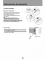
Cuando repare el aire acondicionado, aseg_irese de
colocar la perilla de modo en OFF y luego desconectar
el cable de alimentaci6n del tomacorriente electrico.
1. NO utilice gasolina, bencina, disolvente u otros
productos quimicos en el aire acondicionado, ya que
estas sustancias pueden dan_r el acabado de pintura
y deformar las piezas de pldstico.
2. Nunca derrame agua directamente en el frente de la
unidad ya que da_'ar_a el aislamiento el6ctrico.
Limpieza del Filtro de Aire
Extracci6n del Filtro de Aire
Si el filtro de aire se obstruye con polvo, el flujo de aire
queda obstruido y reduce el rendimiento de la unidad. El
filtro de aire deberd limpiarse una vez al mes. Es probable
que sea necesario limpiarlo con m_s frecuencia
dependiendo de la calidad de aire exterior o interior.
C{'_mo Quitar el Filtro de Aire:
El filtro de aire de los modelos anteriormente mencionados
se encuentra detrds de la rejilla de entrada de aire delantera.
Para quitarlo tome el mango del filtro ubicado enla parte
superior de la rejilla de entrada de aire y desl tcelo hacia
arriba.
Para volver a instalarlo realice los procedimientos anteriores
a la inversa.
NO olvide instaJar et filtro de aire. Si el aire
acondicionado funciona sin el filtro de aire,
e_ polvo no se puede e_iminar de la
habitaci6n y es posible que la unidad se
descomponga.
Cuando _arejilla de entrada de aire y el
gabinete est6n sucios, Ii mpielos con agua
templada (por debajo de los 40 °C/104OF).
Se recomienda eJ use de un detergente suave.
Limpieza dei Filtro de Aire
1. Elimine el polvo acumulado en el fikro. Para
ello apl{quele unos golpes suaves o una
aspiradora domestica.
2. Lave bien el fikro con agua templada, de
temperatura inferior a los 40°C (104°F), mientras
Io frota suavemente. Para obtener mejores resukados,
I_velo con agua jabonosa o con un producto de
limpieza neutro.
3. Enjuague bien el filtro con agua limpia y luego
s_quelo completamente.
Cuidado de Fin de Temporada
1. Haga funcionar el ventilador durante medio di a
para que se seque el interior de la unidad.
2. Ap_guelo y desench_felo del tomacorriente de
pared.
3. Limpie el filtro.
4. Almacenelo en un lugar seco.

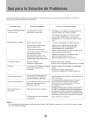
Generalmentelosproblemassonsencillosyesprobablequenoseanecesariollamarauntecnico.
Estaguiapuedeayudarloaresolverlos.
PROBLEMA SOLUCI6NSUGERIDA
Elaireacondicionado
nofunciona
Enfrfapocoonada
CAUSAPOSlBLE
Launidadnorecibe
suministroel6ctrico.
Filtrodeairesucio.
Capacidadinadecuada
paralaaplicaci6n.
Flujodeaireobstruido.
Cortedeenerg[aelectrica,
secambi6denivel
demasiador6pidoose
dispar6elinterruptorpor
sobrecargadelcompresor.
Verifiquesiel cabledealimentaci6ne
st6conectadoal tomacorriente.
Verifiqueelfusibleoelcortacircuito.
Fijeel FANCONTROL(controldel
ventilador)enunaposici6nquenosea
OFF.
Limpieoreemplaceelfiltrodeaire.
Hableconelrepresentantepara
determinarcudleslacapacidad
adecuadaparalaaplicaci6n.
QuitetodaobstrucciOndelarejillaode
laspersianasexteriores.
Hagafuncionarelventiladorpara
reiniciarelcompresor(en
aproximadamente10minutos).
Unidadruidosa Piezassueltas. Ajustelaspiezassueltas.
Soporteinadecuado. Proporcionesoporteadicionalalaunidad
Olores Formaci6ndemohouhongos Quiteeltapdndedrenajeylabandeja
sobrelassuperficies base.
hamedas. Cambieeltap0ndedrenaje.
Limpielaunidadenformacompleta.
Esnormalladescargade
Goteaaguaafuera condensaci6ncuandoel
climaeso_lidoyh_medo.
Goteaaguaadentro Launidadnoestabieninclina
dacomoparapermitirel
desagueexterno.
Seformahieloo Bajatemperaturaexterior.
escarcha
Elfiltrodeairedelaunidad
est6sucio.
Utilice tuberias flexibles para desviar el
flujo de agua.
La unidad debe instalarse con un ligero
desnivel para permitir una descarga
adecuada de la condensacidn. Verifique
la unidad y realice los ajustes
necesarios.
Cuando la temperatura exterior sea inferior a
los 65°F es posible que se forme escarcha si
la unidad funciona en modo de enfriamiento.
Cambie el funcionamiento de la unidad a FAN
(solamente) hasta que la escarcha se derrita.
Quite el filtro y llmpielo.
NOTA:
Si el cortacircuito interrumpe la corriente varias veces o el fusible se quema mas de una vez, comuniquese
con un t6cnico licenciado.

GARANTIA COMPLETADE 5ANOS
Este producto se garantiza por 5 a_os a partir dela fechade la compra original.
Cualquier parte que falle en materiales o la ejecuciOn serd substituida dentro del
periodo dela garant_a. Estagarantia incluyeservicio adomicilio. Una copia de su
prueba dela compra, con lafecha dela compradel productoincluida, se requiere
para acordar esta reparaci0n del servicio.
Para elnombre yla Iocalizaci0n de un prestadorde servicioautorizado Io mds
cerca posible a usted, Ilame porfavor al 1-877-465-3566. Refierase porfavor al
nombre del producto, a la marca, y al namero de modelo cuando usted llama.
Esta garantia no se aplicasi elda_o ocurredebido a accidente, manejo u
operaci0n incorrectos, da_os detransporte, abuso, uso err0neo, reparacion no
autorizada, el uso comercialdel producto utro uso para elcual nofuera pensado.
TODAS LAS GARANTiAS, EXPRESADAS O IMPLICADAS, DURAN POR5AI_OS
APARTIR DE LAFECHADE LACOMPRAORIGINAL. ESTAGARANTIANO
CUBRE LARESPONSABILIDAD POR LOS DAI_OS FORTUITOS O
CONSECUENTES PARACUALESQUIER CAUSAEN NINGUNCASO.
Esta garantia se extiende al duello original y acualquier due_o subsiquiente para
los productoscomprados parael uso casero dentrode los E.E.U.U..Algunos
estados no permiten la exclusion ola limitaciOn de da_os fortuitos o consecuentes
Esta garantia leda lasderecho especificos, yusted puedetambien tenerotras
erechos quepuedan variarde estadoa estado. Para sabercu_les son, sus
derechas legales consulte a su oficinalocal del consumidor o a la procuraduria de
su estado.


WIN'[
@2006 WlN_ . Kelon Air Conditioner Co,, Ltd., and Kelon USA. inc. All rights reserved,
Kelon Air Conditioner Co., Ltd.
No.12 Qiaodong Road
Ronggui, Shunde, Guangdong China 52830:3
Kelon USA, inc,
8000 Virginia Manor Rdo,Suite 170
Bettsville, MD 20705
P_rtn_ed i_ China
Version No. 819042703-01
-
 1
1
-
 2
2
-
 3
3
-
 4
4
-
 5
5
-
 6
6
-
 7
7
-
 8
8
-
 9
9
-
 10
10
-
 11
11
-
 12
12
-
 13
13
-
 14
14
-
 15
15
-
 16
16
-
 17
17
-
 18
18
-
 19
19
-
 20
20
-
 21
21
-
 22
22
-
 23
23
-
 24
24
-
 25
25
-
 26
26
-
 27
27
-
 28
28
-
 29
29
-
 30
30
-
 31
31
-
 32
32
-
 33
33
-
 34
34
-
 35
35
-
 36
36
-
 37
37
-
 38
38
-
 39
39


WINTAIR AW-18CR3FM El manual del propietario
- Tipo
- El manual del propietario
- Este manual también es adecuado para
en otros idiomas
- English: WINTAIR AW-18CR3FM Owner's manual
Artículos relacionados

Otros documentos
-
Admiral AAW-18CM3FHU Manual de usuario
-
-
 Admiral (Kelon) AW-24CM3FM El manual del propietario
-
COMFORT-AIRE RADS-51Q Installation, Operation & Maintenance Manual
-
-
 Admiral (Kelon) AW-08CM1FHU El manual del propietario
-
 Admiral (Kelon) AW-18CR3FM El manual del propietario
-
 Admiral (Kelon) AAWV-06CR1FAU El manual del propietario


