Ameriwood Home 5986333W Manual de usuario
- Tipo
- Manual de usuario

B345986333W00
5986333W
STOP
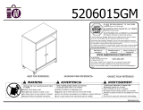
1-800-489-3351
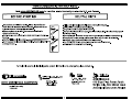
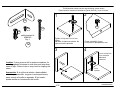
Need Parts or Assistance?
WWW.AMERIWOOD.COM/PARTS
If a part is missing or damaged, visit our website or call our toll-free
customer service line. We will gladly ship your replacement parts
FREE of charge.
For prompt, reliable service please have your assembly manual ready.
DO
NOT RETURN PRODUCT TO THE STORE
Individual stores do not stock parts.
or call toll free:
Recommended # of people needed for assembly: 1
(however it is always better to have an extra hand.)
Estimated assembly time is 2 hours.
Se localizan las traducciones españolas en el centro de este
manual.
THIS INSTRUCTION BOOKLET CONTAINS
IMPORTANT
SAFETY INFORMATION. PLEASE
READ AND KEEP FOR FUTURE REFERENCE.
Date of Purchase
___ / ___ / ___
Please Recycle
Recicle Por Favor
0 2998
6
5
98
6
39


B345986333W00
3 /20
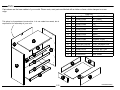
Parts
Parts List
DESCRIPTION
PART NUMBER
QTY
ITEM
LEFT PANEL
35986333010
1A
RIGHT PANEL
35986333020
1
B
TOP35986333030
1
C
BOTTOM35986000040
1
D
APRON35986333050
1E
KICK
35986333060
1
F
BRACE359863330703G
STRINGER35986000080
1
H
DRAWER FRONT35986333090
4I
LEFT DRAWER SIDEC1400346331010L
4J
RIGHT DRAWER SIDEC1400346331010R
4K
DRAWER BACKC1400704331510B
4L
DRAWER BOTTOM35986331130
4M
DRAWER BRACE35986000140
4N
BACK PANELK598600000
1
O
This piece is of paperboard construction. It is not made from wood, but is
required for the assembly of your unit.
Parts shown are the base cabinet of your model. Please note, most parts are labeled with a sticker or have a letter stamped on a raw
edge.
A
B
C
D
E
F
G
G
G
H
I
J
K
L
M
N
O

B345986333W00
4 /20
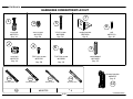
Hardware
HARDWARE COMPARTMENT LAYOUT
right cabinet memberleft cabinet member left drawer runner right drawer runner
x
#A56750
10d
10c10b
10 4
10a
drawer bracket
#A54213
Qty: 8
11
cam bolt
#A22510
Qty: 14
wood dowel
#A21660
Qty: 22
1-1/4" screw
#A11600
Qty: 24
angle bracket
#A53600
Qty: 6
nail
#A21110
Qty: 40
euro screw
#A11070
Qty: 24
7/16" flat screw
#A11080
Qty: 16
7/16" pan screw
#A12120
Qty: 28
cam lock
#A22570
Qty: 14
1
2
4
3
5
6
7
8
9

B345986333W00
5 /20
2
3
½ turn to fully lock.
½ se vuelven a
totalmente
cerradura.
4
Tighten to fully seat. Do not over
tighten.
Apriétese a totalmente asiento. No
haga encima de apriétese.
Proper orientation of cam.
La orientación apropiada de leva.
1
This illustration shows how the cam fastening system works.
Esta ilustración muestra el sistema de fijación de leva y como funciona.
Lock
Apretar
T
i
t
u
s
T
i
t
u
s
T
i
t
u
s
safety bracket kit
#A84050
Qty: 1
12
12a
12b
12c
12d
Caution: If using a power drill or power screwdriver for
screwing, please be aware to slow down and stop when
screw is tight. Failure to do so may result in stripping the
screw.
Precaución:
Si se utiliza un taladro o destornillador
eléctrico para atornillar, tenga en cuenta para frenar y
parar cuando el tornillo es apretado. El no hacerlo
puede resultar en la extracción del tornillo.

1
B345986333W00
6 /20
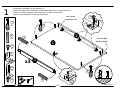
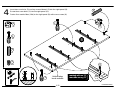
Screw four cam bolts (1) into the top (C).
Fasten the apron (E) to the top (C) with angle brackets (7) and screws (4).
Fasten the safety bracket (12a) to the top (C) with screw (12b).
Tap four wood dowels (3) into the braces (G).
x4
1
4
7
12a
12b
12a
12b
1
1
3
4
4
7
x12
x6
x3
x1
x1
finished edge
borde acabado
raw surface
superficie cruda
C
E
G
3
3
x3

2
B345986333W00
7 /20
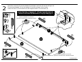
Insert four cam locks (2) into the bottom (D) and two cam locks (2) into the stringer (H).
Tap two wood dowels (3) into the bottom (D) and the stringer (H) as shown.
Fasten the kick (F) to the bottom (D) with angle brackets (7) and screws (4).
x6
x6
x3
center the holes in the Kick (F) with the Angle Brackets (7)
centrar los orificios del Retroceso (F) con los Soportes (7)
2
7
proper orientation of cam lock
posición correcta de la cerradura de leva
proper orientation of cam lock
posición correcta de la cerradura de leva
7
4
4
4
2
2
D
F
H
3
3
3
3
3
x4

3
B345986333W00
8 /20
x2
x3
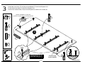
Insert two cam locks (2) and tap a wood dowel (3) into the left panel (A).
Screw three cam bolts (1) into the left panel (A).
Fasten four metal slides (10a) to the left panel (A) with euro screws (9).
2
1
marked with an "L"
marcado con un "L"
proper orientation of cam lock
posición correcta de la cerradura de leva
2
1
3
9
9
10a
x1
x12
finished edge
borde acabado
1
A
3

4
B345986333W00
9 /20
x2
x3
Insert two cam locks (2) and tap a wood dowel (3) into the right panel (B).
Screw three cam bolts (1) into the right panel (B).
Fasten four metal slides (10b) to the right panel (B) with euro screws (9).
2
1
3
9
x1
x12
marked with an "R"
marcado con un "R"
1
2
1
9
B
finished edge
borde acabado
3
10b

5
B345986333W00
10 /20
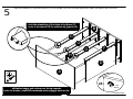
Attach the bottom (D), the three braces (G), and stringer (H) to the left and right panel (A&B) and tighten the cam locks.
LOCK
APRETAR
T
i
t
u
s
all finished edges and surfaces are facing upwards
todos los bordes y superficies acabadas estén mirando hacia arriba
note the orientation of the holes in the Brace (G)
notar la orientación de los orificios del Soporte (G)
x6
A
B
D
H
G
G
G
F

5986333W
No regrese el producto a esta tienda, tiendas individuales no almacenan partes.
Si le falta una parte o esta danada, llame al numbero gratis a la lineas de servicio al cliente. Nosotros con gusto le mandaremos la
parte sin ningun costo adicional.
El numero recomendado de las personas necesito para la asamblea: 1
El tiempo de la asamblea estimado es 2 horas.
EL FOLLETO DE LA INSTRUCCION CONTIENE LE
INFORMACION DE SEGURIDAD IMPORTANTE. POR fecha de compra
FAVOR LEA Y GUARDE PARA LA REFERENCIA FUTURA. ___ / ___ / ___
ANTES DE EMPEZAR
-Lea cada paso cuidadosamente antes de empezar. Es muy importante que cada paso de instrucción haya realizado en el orden
correcto. Si estos pasos no se siguen en la sucesión, las dificultades de la asamblea ocurrirán.
-Haga que todas las partes son incluido. Más partes de la tabla se etiquetan o estamparon en el borde crudo.
-El trabajo en una área espaciosa, preferentemente en una alfombra, cerca del lugar la unidad se usará.
-Tenga las herramientas siguientes cerrar a mano.
-No use las herramientas de poder para congregar su mobiliario. Las herramientas de Power pueden despojar o pueden dañar las
partes.
LAS INDIRECTAS ÚTILES
-visite nuestro website para la asamblea las grapas videas.
-llame nuestro peaje el número libre si usted necesita la ayuda.
-Las clavijas de condensación se taladran en con un martillo.
-Los tableros del parte de atrás proporcionan estabilidad y apoyo. Use todas las uñas proporcionadas. Las unidades a menos que el
tablero de la parte de atrás instalado puede derrumbarse.
-cuando taladrando las uñas en una tabla, esté seguro hay márgenes iguales en todos los lados cuadrar la unidad.
- EL movedor su nuevo mobiliario cuidadosamente, con dos personas, alzamiento y lleva la unidad a él es la nueva situación.
-nunca empuje, arrastre o salga su mobiliario (sobre todo en la alfombra).
-su mobiliario de AMERIWOOD puede desmontarse y puede volverse a montar para mover.
-Las partes adicionales están disponibles para una cuota nominal.

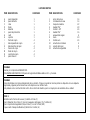
LISTA DE PARTES
ITEM DESCRIPCION CANTIDAD ITEM DESCRIPCION CANTIDAD
A panel izquierdo 1 1 perno de la leva 14
B panel derecho 1 2 cerradura de la leva 14
C cima 1 3 clavija de madera 22
D fondo 1 4 tornillo 7/16” 28
E delantal 1 5 tornillo 1-1/4” 24
F panel de protección 1 6 tornillo 7/16” 16
G carril 3 7 anaquel del angulo 6
H soporte 1 8 clavo 40
I frente de cajon 4 9 tornillo euro 24
J lado izquierdo de cajon 4 10 estuche de corredera 4
K lado derecho de cajon 4 11 soporte del cajon 8
L trasero de cajon 4 12 estuche de seguridad 1
M fondo de cajon 4
N soporte de cajon 4
O panel trasero 1
PAGINA 2
Gracias por comprar de AMERIWOOD.
Visite WWW.AMERIWOOD.COM para vel la garantia limitada valido en U.S. y Canada.
PAGINA 3
Piezas mostradas son la base del gabinete de su modelo. Tenga en cuenta las mismas partes se etiquetan con una etiqueta
engomada y algunas partes tienen una carta impresa en un borde crudo.
Este pedazo es de construcción del carton. No es hecho de madera, pero se require para la asamblea de su unidad.
PASO 1
Atornille cuatro Pernos de la Leva (1) dentro el Cima (C)
Fijar el Delantal (E) al Cima (C) con los Anaqueles del Angulo (7) y Tornillos (4)
Fijar el Soporte de Seguridad (12a) al Cima (C) con el Tornillo (12b)
Toque cuatro Clavijas de Madera (3) dentro los Carriles (G)

PASO 2
Insertar cuatro Cerraduras de la Leva (2) dentro el Fondo (D) y dos Cerraduras de la Leva (2) en el Soporte (H)
Toque dos Clavijas de Madera (3) dentro el Fondo (D) y Soporte (H) como se muestra
Fijar el Panel de Protección (F) al Fondo (D) con los Anaqueles del Angulo (7) y Tornillos (4)
PASO 3
Insertar dos Cerraduras de la Leva (2) y toque una Clavija de Madera (3) dentro el Panel Izquierdo (A)
Atornille tres Pernos de la Leva (1) dentro el Panel Izquierdo (A)
Fijar cuatro Correderas (10a) al Panel Izquierdo (A) con el Tornillos (9)
PASO 4
Insertar dos Cerraduras de la Leva (2) y toque una Clavija de Madera (3) dentro el Panel Derecho (B)
Atornille tres Pernos de la Leva (1) dentro el Panel Derecho (B)
Fijar cuatro Correderas (10b) al Panel Derecho (B) con el Tornillos (9)
PASO 5
Fijar el Fondo (D), los tres Carriles (G), y el Soporte (H) a los Paneles Izquierdo y Derecho (A&B) y serrar los Cerraduras de la Leva
PASO 6
Fijar el Cima (C) a los Paneles Izquierdo y Derecho (A&B) y serrar los Cerraduras de la Leva
El borde inferior del Panel de Protección (F) debe estar alineado con el borde inferior de los Paneles (A&B). Si no está al ras, afloje los
tornillos que fijan las anaqueles al Panel de Protección (F), ajuste según sea necesario y vuelva a apretar los tornillos.
PASO 7
Fijar el Panel Trasero (O) a el mueble con los Clavos (8)
Fijar el Panel Trasero para que el borde inferior quede parejo con la parte inferior (D) y alineados a un lado
Asegura que el unidad is cuadrada
Distancia de esquina a esquina debe ser igual como se muestra por favor
IMPORTANTE! EL PANEL TRASERO ES UNA PARTE ESTRUCTURAL DE ESTA UNIDAD Y DEBE SER INSTALADO
CORRECTAMENTE

PASO 8
Opción 1: Atornille (12c) a través del anaquel de seguridad (12a) y en una área sólida de la pared. Si usted no puede atornillar en
algo el sólido, use opción 2
Opción 2: Taladre un agujero de 3/16" de diámetro (5mm) en la pared. Golpea la ancla de pared (12d) en el agujero hasta que sea
parejo. Abroche la anaquel de seguridad (12a) a la ancla de pared (12d) con el tornillo (12c)
PASO 9
Coloque los lados del cajón (J&K) abajo sobre una superficie plana y dura. Alinear con cuidado el soporte de cajón (11) con los
agujeros en los lados del cajón (J&K) como se muestra. El uso de un martillo, golpee cada soporte de cajón forma parte de tallo en
cada agujero. Repita este proceso hasta que el soporte de cajón está completamente asentado en el lado del cajón
PASO 10
Fijar los Lados de Cajon (J&K) al Frente de Cajon (I) con los Tornillos (4)
Atornille una Perno de la Leva (1) dentro cada Frente de Cajon (I)
PASO 11
Inserte una Cerradura de la Leva (2) y toque una Clavija de Madera (3) dentro cada el Soporte de Cajon (N)
Fijar el Soporte de Cajon (N) al Frente de Cajon (I) y serrar el Cerradura de la Leva
PASO 12
Deslice el Fondo de Cajón (M) en las ranuras de los Lados de Cajón (J&K) y Frente de Cajón (I)
Fijar el Trasero de Cajón (L) a los Lados de Cajón (J&K) y al Soporte de Cajon (N) con los Tornillos (5)
PASO 13
Fijar los Correderas (10c&10d) a los Lados de Cajon (J&K) con los Tornillos (6)
PASO 14
Deslice los cuatro cajones en el armario.
Tenga en cuenta los agujeros de los soportes de cajón están ranurados. Frentes de los cajones pueden ajustarse aflojando los
tornillos, hacen los ajustes necesarios y vuelva a apretar los tornillos.
Limites de carga la página:
Visitenos al correo electronic o llame a el numero gratuito para assistencia:
www.Ameriwood.com/parts 1-800-489-3351
Limpie el producto con su favorito limpiador de muebles con un trapo suave. NO UTILISE quimicos asperos o limpiadores agresivos.
Mueva sus muebles con cuidado con dos personas. Levante y mueva el mueble nunca empuje o jale.
No deje ninos subir o jugar en el mueble. Si no sigue estos avisos puede resultar en un dano muy severo.
Este mueble esta disenado para soportar la carga maxima como lo muestra la foto. Exidiendo estos limites de cargo puede causar
danos como doblamiento, desaliniarlo, y el producto puede caerse o causar danos severos.
Partes adicionales estan disponibles por un precio nomino.

6
B345986333W00
11 /20
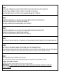
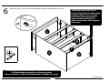
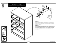
Attach the top (C) to the left and right panel (A&B) and tighten the cam locks.
all finished edges and surfaces are facing upwards
todos los bordes y superficies acabadas estén mirando hacia arriba
LOC K
APRE T AR
T
i
t
u
s
x4
B
C
D
A
F
The bottom edge of the kick (F)
must be flush with the bottom edge
of panels (A&B). If it is not flush,
loosen the screws fastening the
angle brackets to the kick (F),
adjust as necessary, then retighten
the screws.

7
B345986333W00
12 /20
x36
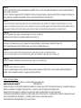
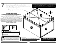
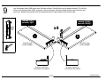
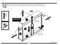
Fasten the back panel (O) to the unit with nails (8).
Attach the back panel so that the bottom edge is even with the
bottom (D) and aligned side to side.
the address label needs to be on this side
la etiqueta de dirección tiene que estar de este lado
turn the unit onto its front
apagar la unidad en su frente
and/or serious injury.
Failure to do so could cause instability, product collapse,
All nails must be driven into the parts straight and centered.
Please make sure that the Back Panel is attached securely.
WARNING
Por favor asegúrese que el Panel Trasero se atan
firmemente. Todos los clavos deben manejarse en las partes
recto y centro. El fracaso para hacer para que podría causar
inestabilidad, derrumbamiento del producto, y/o la lesión
seria.
ADVERTENCIA
8
8
CAUTION / ADVERTENCIA
Locator holes have been provided to show the
proper placement of the nails.
Make sure that the locator holes line up centered
with the edge of all panels before nailing.
Agujeros para la localización se han proporcionado
para mostrar la colocación apropiada de las clavos.
Asegúrese de que los agujeros para la localización
de alineación centrada con el borde de todos los
paneles antes de clavar.
B
D
O
Assure that the unit is square.
Distance from corner to corner must be
equal as shown.
IMPORTANT!
THE BACK PANEL IS A STRUCTURAL PART OF THIS
UNIT AND MUST BE INSTALLED PROPERLY.

8
B345986333W00
13 /20
x1
stud
montante
wallboard
muro
hole
agujero
12c
12d x1
Option 1:
Screw (12c) through the safety bracket (12a) and into a
solid area of the wall. If you cannot screw into something
solid, use option 2.
Option 2:
Drill a 3/16" diameter hole (5mm) in the wallboard. Tap the
wall anchor (12d) into the hole until it is flush. Fasten the
safety bracket (12a) to the wall anchor (12d) with the
screw (12c).
place the unit upright
colocar la unidad en posición vertical
12a
12c
12d

9
B345986333W00
14 /20
x8
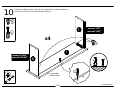
Lay the drawer sides (J&K) down on a flat hard surface. Carefully line up the drawer bracket (11) with the
holes in the drawer sides (J&K) as shown. Using a hammer, tap each drawer bracket stem part way into
each hole. Repeat this process until the drawer bracket is fully seated on the drawer side.
x4
finished edge
borde acabado
finished edge
borde acabado
bracket orientation
orientación del soporte
bracket orientation
orientación del soporte
marked "LEFT"
marcado "LEFT"
marked "RIGHT"
marcado "RIGHT"
11
11
11
J
K

10
B345986333W00
15 /20
Fasten the drawer sides (J&K) to the drawer front (I) with screws (4).
Screw a cam bolt (1) into each drawer front (I).
x16
4
marked "LEFT"
marcado "LEFT"
marked "RIGHT"
marcado "RIGHT"
x4
raw edge
borde cruda
x4
4
1
1
K
J
I

11
B345986333W00
16 /20
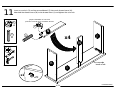
Insert a cam lock (2) and tap a wood dowel (3) into each drawer brace (N).
Attached the drawer brace (N) to the drawer front (I) and tighten the cam lock.
x4
x4
proper orientation of cam lock
posición correcta de la cerradura de leva
raw edge
borde cruda
2
2
LOCK
APRETAR
T
i
t
u
s
x1
K
J
I
N
N
3
3
x4

12
B345986333W00
17 /20
x24
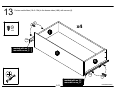
Slide the drawer bottom (M) into the grooves of the drawer sides (J&K) and the drawer front (I)
Fasten the drawer back (L) to the drawer sides (J&K) and to the drawer brace (N) with screws (5).
raw edge
borde cruda
raw surface
superficie cruda
5
5
5
5
marked "BACK"
marcado "BACK"
x4
K
J
I
N
M
L

13
B345986333W00
18 /20
Fasten metal slides (10c & 10d) to the drawer sides (J&K) with screws (6).
x4
6
x16
marked with an "L"
marcado con un "L"
marked with an "R"
marcado con un "R"
10c
10d
6
6
J
K
I

14
B345986333W00
19 /20
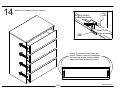
Slide all four Drawers into the Cabinet.
cabinet member
roller
drawer runner
roller
corredera de mueble
rodillo
deslizador de cajon
rodillo
Notice, the drawer bracket holes are
slotted. Drawer fronts can be adjusted
by loosening screws, making needed
adjustments and retightening screws.

B345986333W00
20 /20
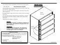
Call our toll free number for any assistance you should need or visit our website:
Clean the product with your favorite furniture polish and a soft cloth. DO NOT USE
harsh chemicals or abrasive cleaners.
Move your new furniture carefully with two people. Lift and carry the unit. Never
push or drag the unit.
Do not allow children to climb or play on the unit. Failure to comply could result in
severe injury.
This unit has been designed to support the maximum loads shown. Exceeding
these load limits could cause unit sagging, instability, product collapse and/or
serious injury.
Additional parts are available for a nominal fee.
1-800-489-3351
www.Ameriwood.com/parts
25 lbs
11.3 kg
50 lbs
22.7 kg
Warning:
Risk of injury to person - do not place a television on
this furniture. This furniture is not approved for use
with a television.
Advertencia:
Riesgo de lesión a la persona - No coloque una
televisión sobre el mueble. Este mueble no está
aprobado para su uso con un televisor.
Weight Limits
Limites de peso
Certificate of Conformity
1. This certificate applies to the Dorel Home Furnishings Inc. product identified
by this instruction manual.
2. This certificate applies to compliance of this product with the CPSC Ban on
Lead-Containing Paint (16 CFR 1303).
3. This product is distributed by: Dorel Home Furnishings Inc.
410 East First Street South
Wright City, MO 63390
636-745-3351
4. Site of Manufacture:
□ Cornwall ON
5. See front page of instruction manual for date of manufacture.
-
 1
1
-
 2
2
-
 3
3
-
 4
4
-
 5
5
-
 6
6
-
 7
7
-
 8
8
-
 9
9
-
 10
10
-
 11
11
-
 12
12
-
 13
13
-
 14
14
-
 15
15
-
 16
16
-
 17
17
-
 18
18
-
 19
19
-
 20
20
-
 21
21
-
 22
22
-
 23
23
-
 24
24


Ameriwood Home 5986333W Manual de usuario
- Tipo
- Manual de usuario
en otros idiomas
- English: Ameriwood Home 5986333W User manual
Artículos relacionados
-
Ameriwood Home 1851335W Assembly Manual
-
-
-
Altra Furniture HD92669 Instrucciones de operación
-
-
-
-
Otros documentos
-
Dorel Ameriwood essential home Anderson 5916303KP El manual del propietario
-
-
 Dorel Home Furnishings 5206015GM El manual del propietario
-
-
SystemBuild HD63203 Manual de usuario
-
-
Ameriwood 1759303KP Manual de usuario
-
mothercare New England Dresser Guía del usuario
