

VER:1.2 │ │ 06.07.2016
ABB-Welcome
Pos: 2 /DinA4 - A nleitungen Onlin e/Inhalt/KNX/D oorEntry/832 20-AP-xxx/Ti telblatt - 83 220-AP-xxx - ABB @ 19\ mod_1323249 806476_15.doc x @ 111084 @ @ 1
M2302
Gateway
=== Ende der List e für Textmarke Cover ===

ABB-Welcome
|
— 2 —
Pos: 4 /Busch-Ja eger (Neustru ktur)/Modul-Str uktur/Online-Doku mentation/In haltsverzeichnis ( --> Für alle Dokumente <--)/Inhalts verzeichnis @ 19\mod_1320 649044386_1 5.docx @ 109653 @ @ 1
1 Safety ............................................................................................................ 3
2 Intended use .................................................................................................. 3
3 Environment .................................................................................................. 3
3.1 ABB devices ................................................................................. 3
4 Operation ....................................................................................................... 5
4.1 Control elements .......................................................................... 5
4.2 Operating modes .......................................................................... 6
4.2.1 Building gateway .......................................................................... 6
4.2.2 Floor gateway ............................................................................... 8
4.2.3 Apartment gateway ..................................................................... 12
4.2.4 Additional power supply mode .................................................... 15
4.2.5 Line amplifier .............................................................................. 18
5 Technical data ............................................................................................. 20
6 Mounting/Installation .................................................................................... 21
6.1 Requirements for the electrician ................................................. 21
6.2 General installation instructions .................................................. 22
6.3 Mounting ..................................................................................... 22
=== Ende der List e für Textmarke TOC ===

ABB-Welcome
|
— 3 —
Pos: 6 /Busch-Ja eger (Neustru ktur)/Modul-Str uktur/Online-Doku mentation/Übers chriften (--> Für alle Dokum ente <--)/1. Ebene/S - T/Sicherheit @ 18\mod_13 02612791790 _15.docx @ 10 3357 @ 1 @ 1
1 Safety
Pos: 7 /Busch-Ja eger (Neustru ktur)/Modul-Str uktur/Online-Doku mentation/Sich erheit (--> Für alle Doku mente <--)/Warnhin weise/Sicherheit - 2 30 V @ 18\m od_1302606816 750_15.docx @ 103308 @ @ 1
Warning
Electric voltage!
Risk of death and fire due to electrical voltage of 100-240 V.
– Work on the 100-240V supply system may only be performed by
authorized electricians!
– Disconnect the main power supply prior to installation and/or
disassembly!
Pos: 8 /Busch-Ja eger (Neustru ktur)/Modul-Str uktur/Online-Doku mentation/Übers chriften (--> Für alle Dokum ente <--)/1. Ebene/A - F/Bestim mungsgemäßer Gebrauch @ 18\mo d_13027633213 16_15.docx @ 103483 @ 1 @ 1
2 Intended use
Pos: 9 /DinA4 - A nleitungen Onlin e/Inhalt/KNX/D oorEntry/832 20-AP-xxx/B estimmungsg emaesser Ge brauch - 83220-AP-xxx- 500 @ 20\mod_1 32456116869 9_15.docx @ 1 12728 @ @ 1
This device is an integral part of the ABB-Welcome door communication system and
operates exclusively with components from this system. The device must only be
installed on mounting rails according to DIN EN 500022.
Pos: 10 /Busch-J aeger (Neustr uktur)/Modul-Stru ktur/Online-Do kumentation/Übersc hriften (--> Für alle Doku mente <--)/1. Ebene/U - Z/Umwelt @ 18\mod_1302 614158967_1 5.docx @ 1033 83 @ 1 @ 1
3 Environment
Pos: 11 /Busch-J aeger (Neustr uktur)/Modul-Stru ktur/Online-Do kumentation/U mwelt (--> Für alle Dokumente <--)/Hi nweise/Hi nweis - Umwelt - Hi nweis Elektrog eräte @ 18\mod_1302 763973434_1 5.docx @ 1035 00 @ @ 1
Consider the protection of the environment!
Used electric and electronic devices must not be disposed of with
domestic waste.
– The device contains valuable raw materials that can be recycled.
Therefore, dispose of the device at the appropriate recycling
facility.
Pos: 12 /DinA4 - Anleitungen Onli ne/Ueberschrif ten/2./ABB G eraete @ 19\m od_13231628438 32_15.docx @ 110875 @ 2 @ 1
3.1 ABB devices
Pos: 13 /Busch-J aeger (Neustr uktur)/Modul-Stru ktur/Online-Do kumentation/U mwelt (--> Für alle Dokumente <--)/Hi nweise/Hi nweis - Umwelt - A BB Elektrogeräte @ 19\ mod_13231627 45839_15.doc x @ 110867 @ @ 1
All packaging materials and devices from ABB bear the markings and test seals for
proper disposal. Always dispose of the packaging material and electric devices and their
components via an authorized recycling facilities or disposal companies.

ABB-Welcome
|
— 4 —
ABB products meet the legal requirements, in particular the laws governing electronic
and electrical devices and the REACH ordinance.
(EU-Directive 2002/96/EG WEEE and 2002/95/EG RoHS)
(EU-REACH ordinance and law for the implementation of the ordinance (EG)
No.1907/2006)

ABB-Welcome
|
— 5 —
Pos: 18 /DinA4 - Anleitungen Onli ne/Ueberschrif ten/1./Bedienu ng @ 18\mod _13026139241 65_15.docx @ 103365 @ 1 @ 1
4 Operation
Pos: 19 /DinA4 - Anleitungen Onli ne/Ueberschrif ten/2./Norm aler Betrieb @ 18\ mod_1302768 820965_15.d ocx @ 103540 @ 2 @ 1
4.1 Control elements
Pos: 20 /DinA4 - Anleitungen Onli ne/Ueberschrif ten/3./Bedienel emente @ 20\ mod_132326 0220559_15.doc x @ 111647 @ 3 @ 1
Pos: 21 /DinA4 - Anleitungen Onli ne/Inhalt/KN X/DoorEntry/83 220-AP-xxx/Bedieneleme nte - 83220- AP-xxx @ 1 8\mod_13032 12853605_15.d ocx @ 103673 @ @ 1
Fig.
1
: Overview of control buttons
No.
Functions
1
Bus in/out
2
Operating mode settings: See chapter “Operating modes” for details.
3
Terminal resistor ON/OFF.
In video installations or audio- and video-combined installations, the switch
must be set as “RC on” on the last device of the line.
4
Rotary switches for addressing (01-99).
5
Connection with outdoor stations, or connection with bus in, in "line
amplifier" mode.
6
Operating status indicating LED
Pos: 22 /Busch-J aeger (Neustr uktur)/Modul-Stru ktur/Online-Do kumentation/S teuermodule - Online-Do kumentation (--> Für alle Dokume nte <--)/++++++ ++++++ Seitenumbruc h +++++++++ +++ @ 9\ mod_1268898668 093_0.docx @ 52149 @ @ 1

ABB-Welcome
|
— 6 —
Pos: 26 /DinA4 - Anleitungen Onli ne/Ueberschrif ten/2./Bediena ktionen @ 20\ mod_1323262 294281_15.docx @ 111911 @ 2 @ 1
4.2 Operating modes
Pos: 71 /DinA4 - Anleitungen Onli ne/Ueberschrif ten/3./Abschlus swiderstand @ 19\mod_1 321958079906_15 .docx @ 1100 83 @ 3 @ 1
Pos: 72 /DinA4 - Anleitungen Onli ne/Inhalt/KN X/DoorEntry/Be dienung/Abschl usswiderstand se tzen 83220- AP-xxx @ 1 9\mod_131072 3392369_15.d ocx @ 1078 41 @ @ 1
4.2.1 Building gateway
Fig.
2
: Building gateway
No.
Functions
1
1->OFF, 2->OFF, 3->OFF
Pos: 74 /DinA4 - Anleitungen Onli ne/Inhalt/KN X/DoorEntry/Be dienung/Mast er/Slave Schalter s etzen 83220-AP- xxx @ 19\mod_1310 723320966_1 5.docx @ 10 7833 @ @
2
3
ON
1
1

ABB-Welcome
|
— 7 —
Enable one building as an independent sub-system (outdoor station(s)/guard unit(s) can
be connected). Up to 60 such systems are supported within the whole system.
The gateway address is equal to the riser number.
Fig.
3
: Building gateway
Wiring diagram:
Fig.
4
: Building gateway

ABB-Welcome
|
— 8 —
4.2.2 Floor gateway
Fig.
5
: Floor gateway
No.
Functions
1
1->OFF, 2->OFF, 3->ON
2
3
ON
1
1

ABB-Welcome
|
— 9 —
Enable a multi-apartment as an independent sub-system (another outdoor station can
be connected, for example in front of the door of the floor with the multi-apartment).
The gateway address is equal to the minimum address of the indoor station inside the
sub-system.
Fig.
6
: Floor gateway

ABB-Welcome
|
— 10 —
Wiring diagram:
Fig.
7
: Floor gateway
If using pushbutton outdoor station as a gate station, floor gateway is available for this
kind of use case.
In following example, an outdoor station is mounted at the gate entrance with which all
six apartments can be called. One outdoor station is on the left building with apartments
01 and 03 and a further outdoor station on the right building with apartments 04 and 05.
This means that only three apartments can be called from these two outdoor stations.
Using floor gateway for each building, and outdoor station 1 can manage these two
buildings, while outdoor station 2 manage the left building and outdoor station 3 manage
the right one.

ABB-Welcome
|
— 11 —
Wiring diagram (using floor gateway for each building)
Apartment 01 A
Apartment 02 B
Apartment 03 C
Apartment 04 A
Apartment 05 B
Apartment 06 C
Outdoor station
Left building
Apartment 01 A
Apartment 02 B
Apartment 03 C
Apartment 04 D
Apartment 05 E
Apartment 06 F
Outdoor station
Gate entrance
Outdoor station
Right building
Apartment 01 A
Apartment 02 B
Apartment 03 C
Apartment 04 A
Apartment 05 B
Apartment 06 C
Apartment 01 A
Apartment 02 B
Apartment 03 C
Apartment 04 D
Apartment 05 E
Apartment 06 F
ST. X100 X10 X1
2 0 0 3
ST. X100 X10 X1
2 0 0 2
ST. X100 X10 X1
2 0 0 1
Address
2
Address
1
Address
3
ST. X100 X10 X1
3 0 0 4
ST. X100 X10 X1
3 0 0 5
ST. X100 X10 X1
3 0 0 6
M2302
X10 X1
0 1
M2302
X10 X1
0 4

ABB-Welcome
|
— 12 —
4.2.3 Apartment gateway
Fig.
8
: Apartment gateway
No.
Functions
1
1->OFF, 2->ON, 3->OFF
2
3
ON
1
1

ABB-Welcome
|
— 13 —
Enable one apartment as an independent sub-system (The 2nd confirmed outdoor
station can be connected). Up to 99 such systems can be supported within the whole
system.
The gateway address is equal to the apartment number.
Fig.
9
: Apartment gateway

ABB-Welcome
|
— 14 —
Wiring diagram:
Fig.
10
: Apartment gateway

ABB-Welcome
|
— 15 —
4.2.4 Additional power supply mode
Fig.
11
: Additional power supply mode
No.
Functions
1
1->OFF, 2->ON, 3->ON
2
3
ON
1
1

ABB-Welcome
|
— 16 —
Enable an additional power source for systems with a system controller.
Fig.
12
: Additional power supply mode
Using gateway
+ system
controller as
auxiliary power
supply to
connect to
other indoor
stations in the
same building,
when one
system
controller can’t
cover all
consmer units.
★
★
★

ABB-Welcome
|
— 17 —
Wiring diagram:
Fig.
13
: Additional power supply mode

ABB-Welcome
|
— 18 —
4.2.5 Line amplifier
Fig.
14
: Line amplifier
No.
Functions
1
1->ON, 2->OFF, 3->OFF
Strengthen the video signal and extend transmission. For increased distance please
refer to ABB-Welcome system manual.
Fig.
15
: Line amplifier
2
3
ON
1
1

ABB-Welcome
|
— 19 —
Wiring diagram:
Fig.
16
: Line amplifier
Pos: 75 /Busch-J aeger (Neustr uktur)/Modul-Stru ktur/Online-Do kumentation/S teuermodule - Online-Do kumentation (--> Für alle Dokume nte <--)/++++++ ++++++ Seitenumbruc h +++++++++ +++ @ 9\ mod_1268898668 093_0.docx @ 52149 @ @ 1

ABB-Welcome
|
— 20 —
Pos: 76 /DinA4 - Anleitungen Onli ne/Ueberschrif ten/1./Technisc he Daten @ 18\ mod_130261 5863001_15.d ocx @ 103416 @ 1 @ 1
5 Technical data
Pos: 77 /DinA4 - Anleitungen Onli ne/Inhalt/KN X/DoorEntry/83 220-AP-xxx/Technische D aten - 832 20-AP-xxx @ 18\mod_13 03212854559_15. docx @ 103 705 @ @ 1
Designation
Value
Operating temperature
-25 °C - +55 °C
Protection
IP 20
Single-wire clamps
2 x 0.28 mm² - 2 x 0.75 mm²
Fine-wire clamps
2 x 0.28 mm² - 2 x 0.75 mm²
Bus voltage
20-30 V
Pos: 78 /Busch-J aeger (Neustr uktur)/Modul-Stru ktur/Online-Do kumentation/S teuermodule - Online-Do kumentation (--> Für alle Dokume nte <--)/++++++ ++++++ Seitenumbruc h +++++++++ +++ @ 9\ mod_1268898668 093_0.docx @ 52149 @ @ 1

ABB-Welcome
|
— 21 —
Pos: 79 /Busch-J aeger (Neustr uktur)/Modul-Stru ktur/Online-Do kumentation/Übersc hriften (--> Für alle Doku mente <--)/1. Ebene/M - O/Montage / Installation @ 1 8\mod_130 2613966111_15.d ocx @ 1033 73 @ 1 @ 1
6 Mounting/Installation
Pos: 80 /Busch-J aeger (Neustr uktur)/Modul-Stru ktur/Online-Do kumentation/Sic herheit (--> Für alle Dokum ente <--)/Warnhinweis e/Sicherheit - Ni ederspannu ngs- und 230 V-L eitungen @ 18\mod_13 02617821491_15. docx @ 10346 5 @ @ 1
Warning
Electric voltage!
Risk of death and fire due to electrical voltage of 100-240 V.
– Low-voltage and 100-240 V cables must not be installed together in
a flush-mounted socket!
In case of a short-circuit there is the danger of a 100-240 V load on
the low-voltage line.
Pos: 81 /Busch-J aeger (Neustr uktur)/Modul-Stru ktur/Online-Do kumentation/Sic herheit (--> Für alle Dokum ente <--)/Warnhinweis e/Sicherheit - F achkenntniss e @ 18\mod_13 02774384017_ 15.docx @ 1 03564 @ 2 @ 1
6.1 Requirements for the electrician
Warning
Electric voltage!
Install the device only if you have the necessary electrical engineering
knowledge and experience.
• Incorrect installation endangers your life and that of the user of the
electrical system.
• Incorrect installation can cause serious damage to property, e.g.
due to fire.
The minimum necessary expert knowledge and requirements for the
installation are as follows:
• Apply the "five safety rules" (DIN VDE 0105, EN 50110):
1. Disconnect from power.
2. Secure against being re-connected.
3. Ensure there is no voltage.
4. Connect to earth.
5. Cover or barricade adjacent live parts.
• Use suitable personal protective clothing.
• Use only suitable tools and measuring devices.
• Check the type supply network (TN system, IT system, TT system)
to secure the following power supply conditions (classic connection
to ground, protective earthing, necessary additional measures,
etc.).
Pos: 82 /DinA4 - Anleitungen Onli ne/Inhalt/KN X/DoorEntry/Mont age/Montage hinweise - Allge mein @ 19\ mod_13105636 70478_15.doc x @ 107743 @ 2 @ 1

ABB-Welcome
|
— 22 —
6.2 General installation instructions
• Terminate all branches of the wiring system via a connected bus device (e.g.,
indoor station, outdoor station, system device).
• Do not install the system controller directly next to the bell transformer and other
power supplies (to avoid interference).
• Do not install the wires of the system bus together with 100-240 V wires.
• Do not use common cables for the connecting wires of the door openers and wires
of the system bus.
• Avoid bridges between different cable types.
• Use only two wires for the system bus in a four-core or multi-core cable.
• When looping, never install the incoming and outgoing bus inside the same cable.
• Never install the internal and external bus inside the same cable.
6.3 Mounting
Pos: 85.1 /DinA 4 - Anleitungen Online/Inhalt/KN X/DoorEntry/83 220-AP-xxx/Montage - M odule/Montage - Montage dose -- 83220-AP- xxx @ 19\mo d_132325040 6848_15.docx @ 111098 @ @ 1
The device M2302 must only be installed on mounting rails according to DIN EN 500022.
Pos: 83 /Busch-J aeger (Neustr uktur)/Modul-Stru ktur/Online-Do kumentation/S teuermodule - Online-Do kumentation (--> Für alle Dokume nte <--)/++++++ ++++++ Seitenumbruc h +++++++++ +++ @ 9\ mod_1268898668 093_0.docx @ 52149 @ @ 1

ABB-Welcome
Pos: 95 /DinA4 - Anleitungen Onli ne/Inhalt/KN X/DoorEntry/Pr ojektierung-Mer kblatt/Proje ktierPos: 97 /Busch-J aeger (Neus truktur)/Modul-Str uktur/Online-Do kumentatio n/Rückseiten (--> Für alle Dokumente <--)/Rückseite - B usch-Jaeger - Allgemein @ 2 0\mod_13273 20074886_ 15.docx @ 137103 @ @ 1
Notice
=== Ende der List e für Textmarke Backco ver ===
We reserve the right to make technical changes at any time as well as changes in the
content of this document without prior notice.
The detailed specifications agreed to at the time of ordering apply to all orders. ABB
accepts no responsibility for possible errors or incompleteness in this document.
We reserve all rights to this document and the topics and illustrations contained therein.
The document and its contents, or extracts thereof, must not be reproduced, transmitted
or reused by third parties without prior written consent by ABB.

VER:1.1 │ 13.10.2015
ABB-Welcome
Pos: 2 /DinA4 - A nleitungen Onlin e/Inhalt/KNX/D oorEntry/832 20-AP-xxx/Ti telblatt - 83 220-AP-xxx - ABB @ 19\ mod_1323249 806476_15.doc x @ 111084 @ @ 1
WM0805
Passerelle
=== Ende der Liste für Textmarke Co ver ===

ABB-Welcome
WM0805
— 2 —
Pos: 4 /Busch-Ja eger (Neustru ktur)/Modul-Str uktur/Online-Doku mentation/In haltsverzeichnis ( --> Für alle Dokumente <--)/Inhalts verzeichnis @ 19\ mod_132064904438 6_15.docx @ 1 09653 @ @ 1
1 Sécurité ......................................................................................................... 3
2 Usage prévu .................................................................................................. 3
3 Environnement .............................................................................................. 3
3.1 Appareils ABB .............................................................................. 4
4 Fonctionnement ............................................................................................. 5
4.1 Éléments de commande ............................................................... 5
4.2 Modes de fonctionnement ............................................................ 7
4.2.1 Passerelle de bâtiment ................................................................. 7
4.2.2 Passerelle d'étage ...................................................................... 10
4.2.3 Passerelle d'appartement ........................................................... 15
4.2.4 Mode alimentation auxiliaire ....................................................... 17
4.2.5 Amplificateur de ligne ................................................................. 21
5 Caractéristiques techniques ........................................................................ 23
6 Montage / Installation .................................................................................. 24
6.1 Exigences à l'égard de l'électricien ............................................. 25
6.2 Consignes d'installation générales ............................................. 26
6.3 Montage ...................................................................................... 26
=== Ende der List e für Textmarke TOC ===
Pos: 6 /Busch-Ja eger (Neustru ktur)/Modul-Str uktur/Online-Doku mentation/Übers chriften (--> Für alle Dokum ente <--)/1. Ebene/S - T/Sicherheit @ 18\mod_13 02612791790 _15.docx @ 10335 7 @ 1 @ 1

ABB-Welcome
WM0805
1 Sécurité
Pos: 7 /Busch-Ja eger (Neustru ktur)/Modul-Str uktur/Online-Doku mentation/Sich erheit (--> Für alle Doku mente <--)/Warnhin weise/Sicherheit - 2 30 V @ 18\mod_130 2606816750_ 15.docx @ 103308 @ @ 1
Avertissement
Tension électrique !
Danger de mort et d'incendie en raison de la présence d'une tension électrique
de 100-240 V.
– Les travaux sur le système d'alimentation 100-240 V peuvent uniquement
être effectués par des électriciens autorisés !
– Débrancher l'alimentation secteur avant l'installation et/ou le démontage !
Pos: 8 /Busch-Ja eger (Neustru ktur)/Modul-Str uktur/Online-Doku mentation/Übers chriften (--> Für alle Dokum ente <--)/1. Ebene/A - F/Bestim mungsgemäßer Gebrauch @ 18\mo d_13027633213 16_15.docx @ 103483 @ 1 @ 1
2 Usage prévu
Pos: 9 /DinA4 - A nleitungen Onlin e/Inhalt/KNX/D oorEntry/832 20-AP-xxx/B estimmungsg emaesser Ge brauch - 83220-AP-xxx- 500 @ 20\mod_1 32456116869 9_15.docx @ 1 12728 @ @ 1
La passerelle WM0805 fait partie intégrale du système ABB-Welcome et fonctionne
exclusivement avec des composants de ce système. L'appareil doit uniquement être installé
sur des rails de montage conformément à la norme DIN EN 500022.
Pos: 10 /Busch-J aeger (Neustr uktur)/Modul-Stru ktur/Online-Do kumentation/Übersc hriften (--> Für alle Doku mente <--)/1. Ebene/U - Z/Umwelt @ 18\mod_1302 614158967_1 5.docx @ 103383 @ 1 @ 1
3 Environnement
Pos: 11 /Busch-J aeger (Neustr uktur)/Modul-Stru ktur/Online-Do kumentation/U mwelt (--> Für alle Dokumente <--)/Hi nweise/Hi nweis - Umwelt - Hi nweis Elektrog eräte @ 18\mod_1302 763973434_1 5.docx @ 103500 @ @ 1
Prendre en compte la protection de l'environnement !
Les appareils électriques et électroniques usagés ne doivent pas être
éliminés avec les ordures ménagères.
– L'appareil contient des matières premières de valeur qui peuvent être
recyclées. Par conséquent, l'élimination de l'appareil doit se faire dans
un centre de collecte approprié.
Pos: 12 /DinA4 - Anleitungen Onli ne/Ueberschrif ten/2./ABB G eraete @ 19\m od_13231628438 32_15.docx @ 110875 @ 2 @ 1

ABB-Welcome
WM0805
3.1 Appareils ABB
Pos: 13 /Busch-J aeger (Neustr uktur)/Modul-Stru ktur/Online-Do kumentation/U mwelt (--> Für alle Dokumente <--)/Hi nweise/Hi nweis - Umwelt - A BB Elektrogeräte @ 19\ mod_13231627 45839_15.doc x @ 110867 @ @ 1
Tous les matériaux d'emballage et appareils ABB portent les marquages et sceaux d'essai
pour une élimination correcte. Il faut toujours éliminer les matériaux d'emballage et les
produits électriques ainsi que leurs composants via des centres de collecte et entreprises
agréés.
Les produits ABB sont conformes aux exigences légales, et aux lois régissant les appareils
électroniques et électriques et au règlement REACH.
(Directive européenne 2002/96/CE DEEE et 2002/95/CE RoHS)
(Règlement REACH et loi sur l'application du règlement (CE) n°1907/2006)

ABB-Welcome
WM0805
Pos: 18 /DinA4 - Anleitungen Onli ne/Ueberschrif ten/1./Bedienu ng @ 18\mod _13026139241 65_15.docx @ 103365 @ 1 @ 1
4 Fonctionnement
Pos: 19 /DinA4 - Anleitungen Onli ne/Ueberschrif ten/2./Norm aler Betrieb @ 18\ mod_1302768 820965_15.d ocx @ 103540 @ 2 @ 1
4.1 Éléments de commande
Pos: 20 /DinA4 - Anleitungen Onli ne/Ueberschrif ten/3./Bedienel emente @ 20\ mod_132326 0220559_15.doc x @ 111647 @ 3 @ 1
Pos: 21 /DinA4 - Anleitungen Onli ne/Inhalt/KN X/DoorEntry/83 220-AP-xxx/Bedieneleme nte - 83220- AP-xxx @ 1 8\mod_13032 12853605_15.d ocx @ 103673 @ @ 1
Fig.
1
: Présentation des boutons de commande

ABB-Welcome
WM0805
N°
Fonctions
1
Bus entrée/sortie
2
Réglages des modes de fonctionnement : Pour plus de détails, voir
Chapitre « Modes de fonctionnement »
3
Résistance terminale ON / OFF
Dans les installations vidéo ou les installations audio/vidéo combinées, le
commutateur doit être défini comme « RC on » sur le dernier appareil de
la ligne.
4
Potentiomètre d'adressage (01-99).
5
Connexion avec les platines de rue ou connexion avec l'entrée de bus,
en mode « amplificateur de ligne ».
6
LED indiquant le statut de fonctionnement
Pos: 22 /Busch-J aeger (Neustr uktur)/Modul-Stru ktur/Online-Do kumentation/S teuermodule - Online-Do kumentation (--> Für alle Dokume nte <--)/++++++ ++++++ Seitenumbruc h +++++++++ +++ @ 9\ mod_1268898668 093_0.docx @ 52149 @ @ 1

ABB-Welcome
WM0805
Pos: 26 /DinA4 - Anleitungen Onli ne/Ueberschrif ten/2./Bediena ktionen @ 20\ mod_1323262 294281_15.docx @ 111911 @ 2 @ 1
4.2 Modes de fonctionnement
Pos: 71 /DinA4 - Anleitungen Onli ne/Ueberschrif ten/3./Abschlus swiderstand @ 19\mod_1 321958079906_15 .docx @ 1100 83 @ 3 @ 1
Pos: 72 /DinA4 - Anleitungen Onli ne/Inhalt/KN X/DoorEntry/Be dienung/Abschl usswiderstand se tzen 83220- AP-xxx @ 1 9\mod_131072 3392369_15.d ocx @ 1078 41 @ @ 1
4.2.1 Passerelle de bâtiment
Fig.
2
: Passerelle de bâtiment
N°
Fonctions
1
1->OFF, 2->OFF, 3->OFF
Pos: 74 /DinA4 - Anleitungen Onli ne/Inhalt/KN X/DoorEntry/Be dienung/Mast er/Slave Schalter s etzen 83220-AP- xxx @ 19\mod_1310 723320966_1 5.docx @ 10 7833 @ @
2
3
ON
1
1

ABB-Welcome
WM0805
Activation d'un bâtiment comme sous-système indépendant (la ou les platine(s) de
rue/interface(s) gardien peuvent être connectées). Jusqu'à 60 bâtiments sont pris en charge
dans l'ensemble du système.
L'adresse de la passerelle est identique au numéro de colonne montante.
Fig.
3
: Passerelle de bâtiment

ABB-Welcome
WM0805
Schéma de câblage :
Fig.
4
: Passerelle de bâtiment

ABB-Welcome
WM0805
4.2.2 Passerelle d'étage
Fig.
5
: Passerelle d'étage
N°
Fonctions
1
1->OFF, 2->OFF, 3->ON
2
3
ON
1
1

ABB-Welcome
WM0805
Activation d'un immeuble à plusieurs appartements comme sous-système indépendant (une
autre platine de rue peut être connectée, par exemple devant la porte avec l'immeuble à
plusieurs appartements).
L'adresse de la passerelle est identique à l'adresse minimum du moniteur intérieur à l'intérieur du sous
système.
Fig.
6
: Passerelle d'étage

ABB-Welcome
WM0805
Schéma de câblage :
Fig.
7
: Passerelle d'étage
Si une platine de rue avec appel par boutons-poussoirs est utilisée comme platine de rue au portail, la
passerelle d'étage conviendra à cette utilisation.
Dans l'exemple suivant, une platine de rue est montée à l'entrée du portail et les six appartements
peuvent être appelés à partir de celle-ci. Une platine de rue est située sur le bâtiment
gauche avec les appartements 01 à 03 et une autre platine de rue située sur le bâtiment
droit avec les appartements 04 à 05.
Cela signifie que seulement trois appartements peuvent être appelés à partir de ces deux platines de
rue.
A l'aide de la passerelle d'étage pour chaque bâtiment, la platine de rue 1 peut gérer ces deux
bâtiments, tandis que la platine de rue 2 gère le bâtiment gauche et la platine de rue 3 gère
celui de droite.

ABB-Welcome
WM0805
Appartement 01
A
Appartement 02
B
Appartement 03
C
Appartement 04
A
Appartement 05
B
Appartement 06
C
Station externe
Bâtiment de
gauche
Appartement 01
A
Appartement 02
B
Appartement 03
C
Appartement 04
D
Appartement 05
E
Appartement 06
F
Station externe
Entrée par le
portail
Station externe
Bâtiment de
droite

ABB-Welcome
WM0805
Schéma de câblage (à l'aide de la passerelle d'étage pour chaque bâtiment) :
Appartement 01
A
Appartement 02
B
Appartement 03
C
Appartement 04
A
Appartement 05
B
Appartement 06
C
Appartement 01 A
Appartement 02
B
Appartement 03
C
Appartement 04 D
Appartement 05
E
Appartement 06
F
ST. X100 X10 X1
2 0 0 3
ST. X100 X10 X1
2 0 0 2
ST. X100 X10 X1
2 0 0 1
Adresse
2
Adresse
1
Adresse
3
ST. X100 X10 X1
3 0 0 4
ST. X100 X10 X1
3 0 0 5
ST. X100 X10 X1
3 0 0 6
M2302
X10 X1
0 1
M2302
X10 X1
0 4

ABB-Welcome
WM0805
4.2.3 Passerelle d'appartement
Fig.
8
: Passerelle d'appartement
N°
Fonctions
1
1->OFF, 2->ON, 3->OFF
2
3
ON
1
1

ABB-Welcome
WM0805
Activation d'un appartement comme sous-système indépendant. Jusqu'à 99 sous-ensembles
peuvent être pris en charge par le système.
L'adresse de la passerelle est identique au numéro d'appartement.
Fig.
9
: Passerelle d'appartement

ABB-Welcome
WM0805
Schéma de câblage :
Fig.
10
: Passerelle d'appartement
4.2.4 Mode alimentation auxiliaire

ABB-Welcome
WM0805
Fig.
11
: Mode alimentation auxiliaire
N°
Fonctions
1
1->OFF, 2->ON, 3->ON
2
3
ON
1
1

ABB-Welcome
WM0805
Activation d'une source d'alimentation supplémentaire avec une unité centrale.
Fig.
12
: Mode alimentation supplémentaire
Utilisation de la
passerelle et
d’une unité
centrale
comme
alimentation
auxiliaire pour
se connecter
aux autres
postes
intérieurs dans
le même
bâtiment,
lorsqu'une
seule unité
centrale ne
peut pas tous
les alimenter
★
★
★

ABB-Welcome
WM0805
Schéma de câblage :
Fig.
13
: Mode alimentation supplémentaire

ABB-Welcome
WM0805
4.2.5 Amplificateur de ligne
Fig.
14
: Amplificateur de ligne
N°
Fonctions
1
1->ON, 2->OFF, 3->OFF
Amplification du signal vidéo et extension de la transmission. Pour une plus grande distance,
voir le manuel du système ABB-Welcome.
Fig.
15
: Amplificateur de ligne
2
3
ON
1
1

ABB-Welcome
WM0805
Schéma de câblage :
Fig.
16
: Amplificateur de ligne
Pos: 75 /Busch-J aeger (Neustr uktur)/Modul-Stru ktur/Online-Do kumentation/S teuermodule - Online-Do kumentation (--> Für alle Dokume nte <--)/++++++ ++++++ Seitenumbruc h ++++++++ ++++ @ 9\ mod_1268898668 093_0.docx @ 52149 @ @ 1

ABB-Welcome
WM0805
Pos: 76 /DinA4 - Anleitungen Onli ne/Ueberschrif ten/1./Technisc he Daten @ 18\ mod_130261 5863001_15.d ocx @ 103416 @ 1 @ 1
5 Caractéristiques techniques
Pos: 77 /DinA4 - Anleitungen Onli ne/Inhalt/KN X/DoorEntry/83 220-AP-xxx/Technische D aten - 832 20-AP-xxx @ 18\mod_13 03212854559_15. docx @ 103 705 @ @ 1
Désignation
Valeur
Température de
fonctionnement
-25 °C - +55 °C
Protection
IP20
Connexions unifilaires
2 x 0.28 mm² – 2 x 0.75 mm²
Connexions à fils fins
2 x 0.28 mm² – 2 x 0.75 mm²
Tension de bus
20-30V
Pos: 78 /Busch-J aeger (Neustr uktur)/Modul-Stru ktur/Online-Do kumentation/S teuermodule - Online-Do kumentation (--> Für alle Dokume nte <--)/++++++ ++++++ Seitenumbruc h ++++++++++++ @ 9\mod_1268898668093 _0.docx @ 52149 @ @ 1

ABB-Welcome
WM0805
Pos: 79 /Busch-J aeger (Neustr uktur)/Modul-Stru ktur/Online-Do kumentation/Übersc hriften (--> Für alle Doku mente <--)/1. Ebene/M - O/Montage / Installation @ 1 8\mod_130 2613966111_15.d ocx @ 1033 73 @ 1 @ 1
6 Montage / Installation
Pos: 80 /Busch-J aeger (Neustr uktur)/Modul-Stru ktur/Online-Do kumentation/Sic herheit (--> Für alle Dokum ente <--)/Warnhinweis e/Sicherheit - Ni ederspannu ngs- und 230 V-L eitungen @ 18\mod _1302617821 491_15.docx @ 10 3465 @ @ 1
Avertissement
Tension électrique !
Danger de mort et d'incendie en raison de la présence d'une tension
électrique de 100-240 V.
– Les câbles basse tension et 100-240 V ne doivent pas être installés
ensemble dans une prise encastrée !
En cas de court-circuit, il existe un risque de charge 100-240 V sur la
ligne basse tension.
Pos: 81 /Busch-J aeger (Neustr uktur)/Modul-Stru ktur/Online-Do kumentation/Sic herheit (--> Für alle Dokum ente <--)/Warnhinweis e/Sicherheit - F achkenntniss e @ 18\mod_13 02774384017_ 15.docx @ 1 03564 @ 2 @ 1

ABB-Welcome
WM0805
6.1 Exigences à l'égard de l'électricien
Avertissement
Tension électrique !
L'installation de l'appareil par un électricien est uniquement possible s'il
possède les connaissances techniques et compétences nécessaires.
• Toute installation incorrecte peut mettre en danger votre vie et celle de
l'utilisateur du système électrique.
• Toute installation incorrecte peut entraîner des dommages, p. ex. : en
raison d'un incendie.
Les connaissances nécessaires minimum et les exigences relatives à
l'installation sont les suivantes :
• Appliquer les « cinq règles de sécurité » (DIN VDE 0105, EN 50110) :
1. Débrancher l'appareil de la source d'alimentation ;
2. Empêcher tout rebranchement de l'appareil ;
3. S'assurer de l'absence de tension ;
4. Raccorder à la terre ;
5. Recouvrir ou isoler les pièces voisines sous tension.
• Porter des vêtements de protection appropriés.
• Utiliser uniquement des outils et appareils de mesure appropriés.
• Vérifier le type de réseau d'alimentation (système TN, système IT,
système TT) pour garantir les conditions d'alimentation électriques
suivantes (connexion à la terre classique, mise à la terre de protection,
mesures supplémentaires nécessaires, etc.).
Pos: 82 /DinA4 - Anleitungen Onli ne/Inhalt/KN X/DoorEntry/Mont age/Montage hinweise - Allge mein @ 19\ mod_13105636 70478_15.doc x @ 107743 @ 2 @ 1

ABB-Welcome
WM0805
6.2 Consignes d'installation générales
• Terminer toutes les extrémités du système de câblage via un appareil de bus connecté (p.
ex., moniteur intérieur, platine de rue, appareil système).
• Ne pas installer le contrôleur système juste à côté du transformateur de sonnerie et
autres alimentations électriques (pour éviter les interférences).
• Ne pas installer les câbles du bus système avec des câbles 100-240 V.
• Ne pas utiliser des câbles communs pour les câbles de raccordement des portiers et les
câbles du bus système.
• Éviter les ponts entre les différents types de câbles.
• Utiliser uniquement deux câbles pour le bus système dans un câble à quatre conducteurs
ou plus.
• En cas de structure en boucle, ne jamais installer les bus de départ et d'arrivée à
l'intérieur du même câble.
• Ne jamais installer les bus interne et externe à l'intérieur du même câble.
6.3 Montage
Pos: 85.1 /DinA 4 - Anleitungen Online/Inhalt/KN X/DoorEntry/83 220-AP-xxx/Montage - M odule/Montage - Montage dose -- 83220-AP- xxx @ 19\mo d_132325040 6848_15.docx @ 111098 @ @ 1
L'appareil WM0805 doit uniquement être installé sur des rails de montage conformément à la
norme DIN EN 500022.
Pos: 83 /Busch-J aeger (Neustr uktur)/Modul-Stru ktur/Online-Do kumentation/S teuermodule - Online-Do kumentation (--> Für alle Dokume nte <--)/++++++ ++++++ Seitenumbruc h +++++++++ +++ @ 9\ mod_1268898668 093_0.docx @ 52149 @ @ 1

ABB-Welcome
WM0805
Pos: 95 /DinA4 - Anleitungen Onli ne/Inhalt/KN X/DoorEntry/Pr ojektierung-Mer kblatt/Proje ktierPos: 97 /Busch-J aeger (Neus truktur)/Modul-Str uktur/Online-Do kumentatio n/Rückseiten (--> Für alle Dokumente <--)/Rückseite - B usch-Jaeger - Allgemein @ 2 0\mod_13273 20074886_ 15.docx @ 137103 @ @ 1
Mentions légales
=== Ende der List e für Textmarke Backco ver ===
Nous nous réservons le droit d'effectuer à tout moment des modifications techniques ou de
modifier le contenu de ce document sans préavis.
Les spécifications détaillées convenues au moment de la commande s'appliquent à toutes les
commandes. ABB ne peut être tenu responsable des erreurs ou omissions dans ce document.
Nous nous réservons tous les droits de propriété sur ce document, ainsi que sur les
informations et les illustrations qu'il contient. Le document et son contenu, ou extraits de celui-
ci, ne doivent pas être reproduits, transmis ou réutilisés par des tiers sans avis écrit préalable
d'ABB.

VER:1.1 │ │ 29.09.2015
Urządzenie ABB-Welcome
Pos: 2 /DinA4 - A nleitungen Onlin e/Inhalt/KNX/D oorEntry/832 20-AP-xxx/Ti telblatt - 83 220-AP-xxx - ABB @ 19\ mod_1323249 806476_15.doc x @ 111084 @ @ 1
M2302
Brama
=== Ende der List e für Textmarke Cover ===

ABB-Welcome
|
— 2 —
Pos: 4 /Busch-Ja eger (Neustru ktur)/Modul-Str uktur/Online-Doku mentation/In haltsverzeichnis ( --> Für alle Dokumente <--)/Inhalts verzeichnis @ 19\mod_1320 649044386_1 5.docx @ 109653 @ @ 1
1 Bezpieczeństwo ............................................................................................. 3
2 Przeznaczenie ............................................................................................... 3
3 Środowisko .................................................................................................... 3
3.1 Urządzenia ABB ........................................................................... 3
4 Działanie ........................................................................................................ 5
4.1 Elementy sterujące ....................................................................... 5
4.2 Tryby pracy ................................................................................... 6
4.2.1 Brama budynku ............................................................................ 6
4.2.2 Brama piętra ................................................................................. 9
4.2.3 Brama mieszkania ...................................................................... 13
4.2.4 Tryb dodatkowego zasilania elektrycznego ................................ 16
4.2.5 Wzmacniacz linii ......................................................................... 19
5 Dane techniczne .......................................................................................... 21
6 Montaż / instalacja ....................................................................................... 22
6.1 Wymagania wobec elektryków ................................................... 22
6.2 Ogólna instrukcja montażu ......................................................... 23
6.3 Montaż ........................................................................................ 23
=== Ende der List e für Textmarke TOC ===

ABB-Welcome
|
— 3 —
Pos: 6 /Busch-Ja eger (Neustru ktur)/Modul-Str uktur/Online-Doku mentation/Übers chriften (--> Für alle Dokum ente <--)/1. Ebene/S - T/Sicherheit @ 18\mod_130261279 1790_15.doc x @ 103357 @ 1 @ 1
1 Bezpieczeństwo
Pos: 7 /Busch-Ja eger (Neustru ktur)/Modul-Str uktur/Online-Doku mentation/Sich erheit (--> Für alle Doku mente <--)/Warnhin weise/Sicherheit - 2 30 V @ 18\m od_1302606816 750_15.doc x @ 103308 @ @ 1
Ostrzeżenie
Napięcie elektryczne!
Ryzyko śmierci i pożaru z powodu napięcia elektrycznego równego 100 –
240 V.
– Prace przy układzie zasilania o mocy 100–240 V mogą być
wykonywane tylko przez uprawnionych elektryków!
– Odłączyć zasilanie elektryczne przed instalacją lub demontażem!
Pos: 8 /Busch-Ja eger (Neustru ktur)/Modul-Str uktur/Online-Doku mentation/Übers chriften (--> Für alle Dokum ente <--)/1. Ebene/A - F/Bestim mungsgemäßer Gebrauch @ 18\mo d_13027633213 16_15.docx @ 103483 @ 1 @ 1
2 Przeznaczenie
Pos: 9 /DinA4 - A nleitungen Onlin e/Inhalt/KNX/D oorEntry/832 20-AP-xxx/B estimmungsg emaesser Ge brauch - 83220-AP-xxx- 500 @ 20\mod_1 32456116869 9_15.docx @ 1 12728 @ @ 1
Brama M2302 stanowi integralną część systemu domofonowego ABB-Welcome,
działającą wyłącznie z elementami tego systemu. Urządzenie zamontować na szynach
montażowych zgodnie z normą DIN EN 500022.
Pos: 10 /Busch-J aeger (Neustr uktur)/Modul-Stru ktur/Online-Do kumentation/Übersc hriften (--> Für alle Doku mente <--)/1. Ebene/U - Z/Umwelt @ 18\mod_1302 614158967_1 5.docx @ 103383 @ 1 @ 1
3 Środowisko
Pos: 11 /Busch-J aeger (Neustr uktur)/Modul-Stru ktur/Online-Do kumentation/U mwelt (--> Für alle Dokumente <--)/Hi nweise/Hi nweis - Umwelt - Hi nweis Elektrog eräte @ 18\mod_1302 763973434_1 5.docx @ 103500 @ @ 1
Ochrona środowiska!
Nie można wyrzucać urządzeń elektrycznych ani elektronicznych z
odpadami z gospodarstwa domowego.
– Urządzenie zawiera cenne surowce, które można ponownie
wykorzystać. Dlatego należy je oddać do odpowiedniego punktu
zbiórki.
Pos: 12 /DinA4 - Anleitungen Onli ne/Ueberschrif ten/2./ABB G eraete @ 19\m od_13231628438 32_15.docx @ 110875 @ 2 @ 1
3.1 Urządzenia ABB
Pos: 13 /Busch-J aeger (Neustr uktur)/Modul-Stru ktur/Online-Do kumentation/U mwelt (--> Für alle Dokumente <--)/Hi nweise/Hi nweis - Umwelt - A BB Elektrogeräte @ 19\ mod_13231627 45839_15.doc x @ 110867 @ @ 1
Na wszystkich materiałach pakunkowych i urządzeniach firmy ABB znajdują się
oznakowania i symbole atestujące dotyczące ich właściwej utylizacji. Materiały
pakunkowe i urządzenia elektryczne, jak również ich elementy należy zawsze oddawać
do utylizacji w autoryzowanych punktach zbiórki lub zakładach utylizacji odpadów.

ABB-Welcome
|
— 4 —
Produkty firmy ABB spełniają wymogi prawne i są w szczególności zgodne z ustawami o
urządzeniach elektrycznych i elektronicznych oraz rozporządzeniem REACH.
(Dyrektywa UE 2002/96/EG WEEE i RoHS 2002/95/WE)
(Rozporządzenie UE REACH i ustawa wykonawcza do rozporządzenia (WE) nr
1907/2006)

ABB-Welcome
|
— 5 —
Pos: 18 /DinA4 - Anleitungen Onli ne/Ueberschrif ten/1./Bedienu ng @ 18\mod _13026139241 65_15.docx @ 103365 @ 1 @ 1
4 Działanie
Pos: 19 /DinA4 - Anleitungen Onli ne/Ueberschrif ten/2./Norm aler Betrieb @ 18\ mod_1302768 820965_15.d ocx @ 103540 @ 2 @ 1
4.1 Elementy sterujące
Pos: 20 /DinA4 - Anleitungen Onli ne/Ueberschrif ten/3./Bedienel emente @ 20\ mod_132326 0220559_15.doc x @ 111647 @ 3 @ 1
Pos: 21 /DinA4 - Anleitungen Onli ne/Inhalt/KN X/DoorEntry/83 220-AP-xxx/Bedieneleme nte - 83220- AP-xxx @ 1 8\mod_13032 12853605_15.d ocx @ 103673 @ @ 1
Rys.
1
Przegląd przycisków sterowania
Nr
Funkcje
1
Wejście/wyjście magistrali
2
Ustawienia trybu pracy: Więcej szczegółów zawiera rozdział Tryby pracy
3
Rezystor końcowy WŁ./WYŁ.
W instalacjach wideo lub audio-wideo należy ustawić przełącznik
w pozycji „RC on” w ostatnim urządzeniu linii.
4
Łączniki pokrętne do adresowania (01-99).
5
Połączenie ze stacjami zewnętrznymi lub z magistralą w trybie
wzmacniacza liniowego.
6
Dioda LED do powiadamiania o statusie pracy
Pos: 22 /Busch-J aeger (Neustr uktur)/Modul-Stru ktur/Online-Do kumentation/S teuermodule - Online-Do kumentation (--> Für alle Dokume nte <--)/++++++ ++++++ Seitenumbruc h +++++++++ +++ @ 9\ mod_1268898668 093_0.docx @ 52149 @ @ 1

ABB-Welcome
|
— 6 —
Pos: 26 /DinA4 - Anleitungen Onli ne/Ueberschrif ten/2./Bediena ktionen @ 20\ mod_1323262 294281_15.docx @ 111911 @ 2 @ 1
4.2 Tryby pracy
Pos: 71 /DinA4 - Anleitungen Onli ne/Ueberschrif ten/3./Abschlus swiderstand @ 19\mod_1 321958079906_15 .docx @ 1100 83 @ 3 @ 1
Pos: 72 /DinA4 - Anleitungen Onli ne/Inhalt/KN X/DoorEntry/Be dienung/Abschl usswiderstand se tzen 83220- AP-xxx @ 1 9\mod_131072 3392369_15.d ocx @ 1078 41 @ @ 1
4.2.1 Brama budynku
Rys.
2
Brama budynku
Nr
Funkcje
1
1->WYŁ., 2->WYŁ., 3->WYŁ.
Pos: 74 /DinA4 - Anleitungen Onli ne/Inhalt/KN X/DoorEntry/Be dienung/Mast er/Slave Schalt er setzen 83220-AP- xxx @ 19\mod_1310 723320966_1 5.docx @ 10 7833 @ @
2
3
ON
1
1

ABB-Welcome
|
— 7 —
Pojedynczy budynek może być teraz niezależnym podsystemem (można podłączyć
stację zewnętrzną/konsolę portierską). Obsługuje nawet 60 systemów w ramach całego
systemu.
Adres bramy jest równoznaczny z numerem pionu.
Rys.
3
Brama budynku

ABB-Welcome
|
— 8 —
Schemat okablowania:
Rys.
4
Brama budynku

ABB-Welcome
|
— 9 —
4.2.2 Brama piętra
Rys.
5
Brama piętra
Nr
Funkcje
1
1->WYŁ., 2->WYŁ., 3->WŁ.
2
3
ON
1
1

ABB-Welcome
|
— 10 —
Dzięki niej kilka mieszkań może stać się niezależnym podsystemem (można podłączyć
dodatkową stację zewnętrzną na przykład przed drzwiami na piętro, na którym znajduje
się kilka mieszkań).
Adres bramy jest równoznaczny z minimalnym adresem stacji wewnętrznej wewnątrz
podsystemu.
Rys.
6
Brama piętra

ABB-Welcome
|
— 11 —
Schemat okablowania:
Rys.
7
Brama piętra
Jeśli stacja zewnętrzna z przyciskami używana jest jako stacja bramy, do tego typu
zastosowań można również wykorzystać
bramę piętra.
W takim przypadku stacja zewnętrzna jest montowana przy bramie wejściowej, z której
można się połączyć ze wszystkimi sześcioma mieszkaniami. Jedna stacja zewnętrzna
znajduje się w budynku po lewej, z mieszkaniami o numerach
01 i 03, a druga – w budynku po prawej, z mieszkaniami 04 i 05.
Oznacza to, że z poszczególnej stacji zewnętrznej można się połączyć tylko z trzema
mieszkaniami.
Zastosowanie bramy piętra w każdym budynku powoduje, że stacja zewnętrzna 1 może
obsłużyć oba
budynki, podczas gdy stacja zewnętrzna 2 zarządza budynkiem po lewej, a stacja 3 –
budynkiem
po prawej.

ABB-Welcome
|
— 12 —
Schemat okablowania (brama piętra w każdym budynku):
Apartment 01 A
Apartment 02 B
Apartment 03 C
Apartment 04 A
Apartment 05 B
Apartment 06 C
Stacja
zewnętrzna
Budynek po
lewej
Apartment 01 A
Apartment 02 B
Apartment 03 C
Apartment 04 D
Apartment 05 E
Apartment 06 F
Stacja
zewnętrzna
Brama
wejściowej
Stacja
zewnętrzna
Budynek po
prawej
Apartment 01 A
Apartment 02 B
Apartment 03 C
Apartment 04 A
Apartment 05 B
Apartment 06 C
Apartment 01 A
Apartment 02 B
Apartment 03 C
Apartment 04 D
Apartment 05 E
Apartment 06 F
ST. X100 X10 X1
2 0 0 3
ST. X100 X10 X1
2 0 0 2
ST. X100 X10 X1
2 0 0 1
Address
2
Address
1
Address
3
ST. X100 X10 X1
3 0 0 4
ST. X100 X10 X1
3 0 0 5
ST. X100 X10 X1
3 0 0 6
M2302
X10 X1
0 1
M2302
X10 X1
0 4

ABB-Welcome
|
— 13 —
4.2.3 Brama mieszkania
Rys.
8
Brama mieszkania
Nr
Funkcje
1
1->WYŁ., 2->WŁ., 3->WYŁ.
2
3
ON
1
1

ABB-Welcome
|
— 14 —
Ustawienie pojedynczego mieszkania jako niezależnego podsystemu (można podłączyć
drugą potwierdzoną stację zewnętrzną). Cały system obsługuje do 99 takich systemów.
Adres bramy jest równoznaczny z numerem mieszkania.
Rys.
9
Brama mieszkania

ABB-Welcome
|
— 15 —
Schemat okablowania:
Rys.
10
Brama mieszkania

ABB-Welcome
|
— 16 —
4.2.4 Tryb dodatkowego zasilania elektrycznego
Rys.
11
Tryb dodatkowego zasilania elektrycznego
Nr
Funkcje
1
1->WYŁ., 2->WŁ., 3->WŁ.
2
3
ON
1
1

ABB-Welcome
|
— 17 —
Stanowi dodatkowe źródło zasilania systemu ze sterownikiem systemu.
Rys.
12
Tryb dodatkowego zasilania elektrycznego
Wykorzystanie
bramy i
sterownika
systemu jako
dodatkowego
zasilania
elektrycznego
dla innych
stacji
wewnętrznych
w tym samym
budynku, jeśli
pojedynczy
sterownik
systemu nie
jest wstanie
dostarczyć
wystarczająco
energii.
★
★
★

ABB-Welcome
|
— 18 —
Schemat okablowania:
Rys.
13
Tryb dodatkowego zasilania elektrycznego

ABB-Welcome
|
— 19 —
4.2.5 Wzmacniacz linii
Rys.
14
Wzmacniacz linii
Nr
Funkcje
1
1->WŁ., 2->WYŁ., 3->WYŁ.
Wzmocnienie sygnału wideo i rozszerzenie transmisji. Więcej informacji na temat
rozszerzania transmisji można znaleźć w instrukcji obsługi systemu ABB-
Welcome.
Rys.
15
Wzmacniacz linii
2
3
ON
1
1

ABB-Welcome
|
— 20 —
Schemat okablowania:
Rys.
16
Wzmacniacz linii
Pos: 75 /Busch-J aeger (Neustr uktur)/Modul-Stru ktur/Online-Do kumentation/S teuermodule - Online-Do kumentation (--> Für alle Dokume nte <--)/++++++ ++++++ Seitenumbruc h +++++++++ +++ @ 9\ mod_1268898668 093_0.docx @ 52149 @ @ 1

ABB-Welcome
|
— 21 —
Pos: 76 /DinA4 - Anleitungen Onli ne/Ueberschrif ten/1./Technisc he Daten @ 18\mo d_13026158630 01_15.docx @ 1 03416 @ 1 @ 1
5 Dane techniczne
Pos: 77 /DinA4 - Anleitungen Onli ne/Inhalt/KN X/DoorEntry/83 220-AP-xxx/Technische D aten - 832 20-AP-xxx @ 18\mod_13 03212854559_15. docx @ 103 705 @ @ 1
Opis
Wartość
Temperatura robocza:
-25 °C – +55 °C
Stopień ochrony
IP 20
Zaciski do przewodów
jednożyłowych
2 x 0,28 mm² – 2 x 0.75 mm²
Zaciski do przewodów
cienkożyłowych
2 x 0,28 mm² – 2 x 0.75 mm²
Napięcie magistrali
20-30V
Pos: 78 /Busch-J aeger (Neustr uktur)/Modul-Stru ktur/Online-Do kumentation/S teuermodule - Online-Do kumentation (--> Für alle Dokume nte <--)/++++++ ++++++ Seitenumbruc h +++++++++ +++ @ 9\ mod_1268898668 093_0.docx @ 52149 @ @ 1

ABB-Welcome
|
— 22 —
Pos: 79 /Busch-J aeger (Neustr uktur)/Modul-Stru ktur/Online-Do kumentation/Üb erschriften (--> Für alle Doku mente <--)/1. Ebene/M - O/Montage / Installation @ 1 8\mod_130 2613966111_15.d ocx @ 1033 73 @ 1 @ 1
6 Montaż / instalacja
Pos: 80 /Busch-J aeger (Neustr uktur)/Modul-Stru ktur/Online-Do kumentation/Sic herheit (--> Für alle Dokum ente <--)/Warnhinweis e/Sicherheit - Ni ederspannu ngs- und 230 V-L eitungen @ 18\mod_13 02617821491_15. docx @ 10346 5 @ @ 1
Ostrzeżenie
Napięcie elektryczne!
Ryzyko śmierci i pożaru z powodu napięcia elektrycznego równego
100–240 V.
– Przewodów niskonapięciowych i 100–240 V nie wolno układać
razem w jednej puszce podtynkowej!
Jeśli dojdzie do zwarcia, istnieje niebezpieczeństwo wystąpienia
napięcia 100–240 V w przewodach niskonapięciowych.
Pos: 81 /Busch-J aeger (Neustr uktur)/Modul-Stru ktur/Online-Do kumentation/Sic herheit (--> Für alle Dokum ente <--)/Warnhinweis e/Sicherheit - F achkenntniss e @ 18\mod_13 02774384017_ 15.docx @ 1 03564 @ 2 @ 1
6.1 Wymagania wobec elektryków
Ostrzeżenie
Napięcie elektryczne!
Urządzenie wolno instalować jedynie osobom posiadającym konieczną
wiedzę i doświadczenie w dziedzinie elektrotechniki.
• Niefachowa instalacja zagraża życiu instalatora i użytkowników
instalacji elektrycznej.
• Niefachowa instalacja może prowadzić do poważnych szkód
rzeczowych, na przykład pożaru.
Wymagana wiedza fachowa i warunki instalacji:
• Stosować poniższe zasady bezpieczeństwa (DIN VDE 0105, EN
50110):
1. Odłączyć od sieci.
2. Zabezpieczyć przed ponownym włączeniem.
3. Sprawdzić, czy urządzenie nie jest pod napięciem.
4. Podłączyć do uziemienia.
5. Zakryć lub odgrodzić sąsiadujące części znajdujące się pod
napięciem.
• Stosować odpowiednią odzież ochronną.
• Stosować wyłącznie odpowiednie narzędzia i przyrządy pomiarowe.
• Sprawdzić rodzaj sieci zasilającej (system TN, system IT i system
TT) i przestrzegać wynikających z tego warunków przyłączenia

ABB-Welcome
|
— 23 —
(klasyczne zerowanie, uziemienie ochronne, konieczność
wykonania dodatkowych pomiarów, itd.).
Pos: 82 /DinA4 - Anleitungen Onli ne/Inhalt/KN X/DoorEntry/Mont age/Montage hinweise - Allge mein @ 19\ mod_13105636 70478_15.doc x @ 107743 @ 2 @ 1
6.2 Ogólna instrukcja montażu
• Wszystkie odgałęzienia przewodów powinny zostać zakończone podłączonym
urządzeniem magistrali (np. stacja wewnętrzna, zewnętrzna lub urządzenie
systemowe).
• Nie instalować centrali systemu bezpośrednio obok transformatorów dzwonka lub
innych urządzeń zasilających (unikanie interferencji).
• Nie układać przewodów magistrali systemowej wspólnie z przewodami 100–240 V.
• Nie używać wspólnego kabla dla przewodów przyłączowych elektrozaczepów i
przewodów magistrali systemowej.
• Unikać złączeń między różnymi typami kabli.
• W kablu, który ma cztery lub więcej żył, do magistrali systemowej należy
wykorzystać tylko dwie żyły.
• Przy łączeniu przelotowym nigdy nie prowadzić przychodzącej i wychodzącej
magistrali w tym samym kablu.
• Nigdy nie prowadzić magistrali wewnętrznej i zewnętrznej w tym samym kablu.
6.3 Montaż
Pos: 85.1 /DinA 4 - Anleitungen Online/Inhalt/KN X/DoorEntry/83 220-AP-xxx/Montage - M odule/Montage - Montage dose -- 83220-AP- xxx @ 19\mo d_132325040 6848_15.docx @ 111098 @ @ 1
Urządzenie M2302 zamontować na szynach montażowych zgodnie z normą DIN EN
500022.

ABB-Welcome
|
— 24 —
Pos: 83 /Busch-J aeger (Neustr uktur)/Modul-Stru ktur/Online-Do kumentation/S teuermodule - Online-Do kumentation (--> Für alle Dokume nte <--)/++++++ ++++++ Seitenumbruc h +++++++++ +++ @ 9\ mod_1268898668 093_0.docx @ 52149 @ @ 1

ABB-Welcome
Montaż / instalacja
|
— 25 —
Pos: 95 /DinA4 - Anleitungen Onli ne/Inhalt/KN X/DoorEntry/Pr ojektierung-Mer kblatt/Proje ktierPos: 97 /Busch-J aeger (Neus truktur)/Modul-Str uktur/Online-Do kumentatio n/Rückseiten (--> Für alle Dokumente <--)/Rückseite - B usch-Jaeger - Allgemein @ 2 0\mod_13273 20074886_ 15.docx @ 137103 @ @ 1
Uwaga
=== Ende der List e für Textmarke Backco ver ===
Firma ABB zastrzega sobie prawo do wprowadzania zmian technicznych, jak również
zmian treści niniejszego dokumentu w dowolnym momencie i bez uprzedzenia.
Szczegółowe dane techniczne uzgodnione w czasie składania zamówienia stosuje się
do wszystkich zamówień. Firma ABB nie ponosi żadnej odpowiedzialności za błędy ani
za braki, jakie mogą pojawić się w niniejszym dokumencie.
Wszelkie prawa do niniejszego dokumentu i zawartych w nim informacji są zastrzeżone.
Osobom trzecim zabrania się powielania, przesyłania czy ponownego wykorzystywania
niniejszego dokumentu lub jego części bez uprzedniej pisemnej zgody firmy ABB.

Sistemi di videocitofonia │ Welcome │ Manuale utente
ABB-Welcome
Pos: 2 /DinA4 - A nleitungen Onlin e/Inhalt/KNX/D oorEntry/832 20-AP-xxx/Ti telblatt - 83 220-AP-xxx - ABB @ 19\ mod_1323249 806476_15.doc x @ 111084 @ @ 1
M2302
Gateway
=== Ende der List e für Textmarke Cover ===

ABB-Welcome
|
— 2 —
Pos: 4 /Busch-Ja eger (Neustru ktur)/Modul-Str uktur/Online-Doku mentation/In haltsverzeichnis ( --> Für alle Dokumente <--)/Inhalts verzeichnis @ 19\mod_1320 649044386_1 5.docx @ 109653 @ @ 1
1 Sicurezza ....................................................................................................... 3
2 Uso previsto................................................................................................... 3
3 Ambiente ....................................................................................................... 3
3.1 Dispositivi ABB ............................................................................. 3
4 Funzionamento .............................................................................................. 5
4.1 Comandi ....................................................................................... 5
4.2 Modalità di funzionamento ............................................................ 6
4.2.1 Gateway dell'edificio ..................................................................... 6
4.2.2 Gateway di piano .......................................................................... 9
4.2.3 Gateway di appartamento ........................................................... 13
4.2.4 Modalità di alimentazione supplementare ................................... 15
4.2.5 Amplificatore di linea................................................................... 19
5 Dati tecnici ................................................................................................... 21
6 Montaggio/Installazione ............................................................................... 22
6.1 Obblighi dell'elettricista ............................................................... 22
6.2 Istruzioni generali di installazione ............................................... 23
6.3 Montaggio ................................................................................... 23
=== Ende der List e für Textmarke TOC ===

ABB-Welcome
|
— 3 —
Pos: 6 /Busch-Ja eger (Neustru ktur)/Modul-Str uktur/Online-Doku mentation/Übers chriften (--> Für alle Dokum ente <--)/1. Ebene/S - T/Sicherheit @ 18\mod_13 02612791790 _15.docx @ 10 3357 @ 1 @ 1
1 Sicurezza
Pos: 7 /Busch-Ja eger (Neustru ktur)/Modul-Str uktur/Online-Doku mentation/Sich erheit (--> Für alle Doku mente <--)/Warnhin weise/Sicherheit - 2 30 V @ 18\m od_1302606816 750_15.docx @ 103308 @ @ 1
Attenzione
Tensione elettrica!
Rischio di morte ed incendio dovuto alla presenza di tensione elettrica 100-
240 V.
– Gli interventi sul sistema di alimentazione 100-240 V possono essere
effettuati solo da elettricisti autorizzati.
– Scollegare l'alimentazione di rete prima dell'installazione e/o dello
smontaggio.
Pos: 8 /Busch-Ja eger (Neustru ktur)/Modul-Str uktur/Online-Doku mentation/Übers chriften (--> Für alle Dokum ente <--)/1. Ebene/A - F/Bestim mungsgemäßer Gebrauch @ 18\mo d_13027633213 16_15.docx @ 103483 @ 1 @ 1
2 Uso previsto
Pos: 9 /DinA4 - A nleitungen Onlin e/Inhalt/KNX/D oorEntry/832 20-AP-xxx/B estimmungsg emaesser Ge brauch - 83220-AP-xxx- 500 @ 20\mod_1 32456116869 9_15.docx @ 1 12728 @ @ 1
Il gateway M2302 è parte integrante del sistema di videocitofonia ABB-Welcome e funziona
unicamente con i componenti di questo sistema. Il dispositivo deve essere installato su guide
di montaggio, in conformità alla norma DIN EN 500022.
Pos: 10 /Busch-J aeger (Neustr uktur)/Modul-Stru ktur/Online-Do kumentation/Üb erschriften (--> Für alle Doku mente <--)/1. Ebene/U - Z/Umwelt @ 18\mod_1302 614158967_1 5.docx @ 103383 @ 1 @ 1
3 Ambiente
Pos: 11 /Busch-J aeger (Neustr uktur)/Modul-Stru ktur/Online-Do kumentation/U mwelt (--> Für alle Dokumente <--)/Hi nweise/Hi nweis - Umwelt - Hi nweis Elektrog eräte @ 18\mod_1302 763973434_1 5.docx @ 103500 @ @ 1
Prestare attenzione alla tutela dell'ambiente!
I dispositivi elettrici ed elettronici usati devono essere smaltiti
separatamente dai rifiuti domestici.
– Il dispositivo è composto da materie prime che possono essere
riciclate. Occorre pertanto smaltire il dispositivo presso specifici centri
di raccolta.
Pos: 12 /DinA4 - Anleitungen Onli ne/Ueberschrif ten/2./ABB G eraete @ 19\m od_13231628438 32_15.docx @ 110875 @ 2 @ 1
3.1 Dispositivi ABB
Pos: 13 /Busch-J aeger (Neustr uktur)/Modul-Stru ktur/Online-Do kumentation/U mwelt (--> Für alle Dokumente <--)/Hi nweise/Hi nweis - Umwelt - A BB Elektrogeräte @ 19\ mod_13231627 45839_15.doc x @ 110867 @ @ 1
Tutti gli imballaggi e i dispositivi ABB riportano i marchi e i sigilli di verifica per il corretto
smaltimento. Smaltire gli imballaggi, i dispositivi elettrici e i relativi componenti presso centri di
raccolta autorizzati e società addette allo smaltimento rifiuti.

ABB-Welcome
|
— 4 —
I prodotti ABB soddisfano i requisiti di legge, in particolare delle leggi relative ai dispositivi
elettrici ed elettronici, e il regolamento per la registrazione, la valutazione, l'autorizzazione e la
restrizione delle sostanze chimiche (REACH).
(Direttiva UE 2002/96/CE RAEE e 2002/95/CE RoHS)
(Regolamento 1907/2006/CE (REACH) e legge per l'implementazione del regolamento CE)

ABB-Welcome
|
— 5 —
Pos: 18 /DinA4 - Anleitungen Onli ne/Ueberschrif ten/1./Bedienu ng @ 18\mod _13026139241 65_15.docx @ 103365 @ 1 @ 1
4 Funzionamento
Pos: 19 /DinA4 - Anleitungen Onli ne/Ueberschrif ten/2./Norm aler Betrieb @ 18\ mod_1302768 820965_15.d ocx @ 103540 @ 2 @ 1
4.1 Comandi
Pos: 20 /DinA4 - Anleitungen Onli ne/Ueberschrif ten/3./Bedienel emente @ 20\ mod_132326 0220559_15.doc x @ 111647 @ 3 @ 1
Pos: 21 /DinA4 - Anleitungen Onli ne/Inhalt/KN X/DoorEntry/83 220-AP-xxx/Bedieneleme nte - 83220- AP-xxx @ 1 8\mod_13032 12853605_15.d ocx @ 103673 @ @ 1
Fig.
1
: Panoramica dei comandi
N°
Funzioni
1
Bus in/out
2
Impostazioni modalità di funzionamento Vedi capitolo 'Modalità di
funzionamento' per maggiori dettagli
3
Resistenza terminale di chiusura ON/OFF.
Negli impianti video o impianti combinati audio-video, lo switch
deve essere impostato come 'RC on' sull'ultimo dispositivo di linea.
4
Commutatore di indirizzamento (01-99).
5
Collegamento con i posti esterni, o collegamento al bus in modalità
"amplificatore di linea".
6
LED stato di funzionamento
Pos: 22 /Busch-J aeger (Neustr uktur)/Modul-Stru ktur/Online-Do kumentation/S teuermodule - Online-Do kumentation (--> Für alle Dokume nte <--)/++++++ ++++++ Seitenumbruc h +++++++++ +++ @ 9\ mod_1268898668 093_0.docx @ 52149 @ @ 1

ABB-Welcome
|
— 6 —
Pos: 26 /DinA4 - Anleitungen Onli ne/Ueberschrif ten/2./Bediena ktionen @ 20\ mod_1323262 294281_15.docx @ 111911 @ 2 @ 1
4.2 Modalità di funzionamento
Pos: 71 /DinA4 - Anleitungen Onli ne/Ueberschrif ten/3./Abschlus swiderstand @ 19\mod_1 321958079906_15 .docx @ 1100 83 @ 3 @ 1
Pos: 72 /DinA4 - Anleitungen Onli ne/Inhalt/KN X/DoorEntry/Be dienung/Abschl usswiderstand se tzen 83220- AP-xxx @ 1 9\mod_131072 3392369_15.d ocx @ 1078 41 @ @ 1
4.2.1 Gateway modalità edificio
Fig.
2
: Gateway modalità edificio
N°
Funzioni
1
1->OFF, 2->OFF, 3->OFF
Pos: 74 /DinA4 - Anleitungen Onli ne/Inhalt/KN X/DoorEntry/Be dienung/Mast er/Slave Schalter s etzen 83220-AP- xxx @ 19\mod_1310 723320966_1 5.docx @ 10 7833 @ @
2
3
ON
1
1

ABB-Welcome
|
— 7 —
Abilita un edificio come sottosistema indipendente (possibilità di collegamento di una
portineria/posto esterno). L'intero sistema supporta fino a 60 edifici secondari.
L'indirizzo di gateway corrisponde al numero della montante.
Fig.
3
: Gateway dell'edificio
Schema elettrico:

ABB-Welcome
|
— 8 —
Fig.
4
: Gateway modalità edificio
Importante: l’utilizzo del gateway in modalità edificio necessità del posto esterno principale
alfanumerico per permettere l’indirizzo corretto degli interni.
Non è disponibile la funzionalità di intercomunicante tra diversi edifici

ABB-Welcome
|
— 9 —
4.2.2 Gateway di piano
Fig.
5
: Gateway di piano
N°
Funzioni
1
1->OFF, 2->OFF, 3->OFF
2
3
ON
1
1

ABB-Welcome
|
— 10 —
Abilita un sottosistema indipendente di multi-appartamenti (è possibile collegare un altro
posto esterno, ad esempio di fronte alla porta del piano).
L'indirizzo di gateway corrisponde all’indirizzo del primp posto interno nel sottosistema gestito.
Fig.
6
: Gateway di piano

ABB-Welcome
|
— 11 —
Schema elettrico:
Fig.
7
: Gateway di piano
Se il posto esterno è usato come gate station, è possibile utilizzare anche il gateway di piano.
L'esempio che segue mostra un posto esterno installato all'ingresso principale con cui è possibile
chiamare tutti e sei gli appartamenti. Un posto esterno si trova nell'edificio di sinistra con gli
appartamenti da 01 a 03 e un altro posto esterno si trova nell'edificio di destra con gli appartamenti da
04 a 06.
Utilizzando il gateway di piano per ogni edificio, il posto esterno 1 gestisce questi due edifici, mentre il
posto esterno 2 gestisce l'edificio di sinistra e il posto esterno 3 gestisce l'edificio di destra.

ABB-Welcome
|
— 12 —
Schema elettrico (usando il gateway di piano per ogni edificio) :
Appartamento 01
A
Appartamento
02 B
Appartamento 03
C
Appartamento
04 A
Appartamento
05 B
Appartamento
06 C
Posto esterno
Edificio di
sinistra
Appartamento
01 A
Appartamento
02 B
Appartamento
03 C
Appartamento
04 D
Appartamento
05 E
Appartamento
06 F
Posto esterno
Ingresso
cancello
Posto esterno
Edificio di destra
Appartamento 01
A
Appartamento 02
B
Appartamento 03
C
Appartamento 04
A
Appartamento 05
B
Appartamento 06
C
Appartamento 01 A
Appartamento 02
B
Appartamento 03
C
Appartamento 04 D
Appartamento 05
E
Appartamento 06
F
ST. X100 X10 X1
2 0 0 3
ST. X100 X10 X1
2 0 0 2
ST. X100 X10 X1
2 0 0 1
Indirizzo
Indirizzo
1
Indirizzo
ST. X100 X10 X1
3 0 0 4
ST. X100 X10 X1
3 0 0 5
ST. X100 X10 X1
3 0 0 6
M2302
X10 X1
0 1
M2302
X10 X1
0 4
Indirizzo
Gateway: 4
Indirizzo
Gateway: 1

ABB-Welcome
|
— 13 —
4.2.3 Gateway di appartamento
Fig.
8
: Gateway di appartamento
N°
Funzioni
1
1->OFF, 2->ON, 3->OFF
2
3
ON
1
1

ABB-Welcome
|
— 14 —
Abilita un appartamento come sottosistema indipendente (possibilità di collegamento di un
posto esterno a singola chiamata ). L'intero sistema è in grado di supportare fino a 99 sotto-
sistemi. L'indirizzo di gateway corrisponde al numero dell'appartamento.
Fig.
9
: Gateway di appartamento
Schema elettrico:

ABB-Welcome
|
— 15 —
Fig.
10
: Gateway di appartamento
4.2.4 Modalità di alimentazione supplementare

ABB-Welcome
|
— 16 —
Fig.
11
: Modalità di alimentazione supplementare
N°
Funzioni
1
1->OFF, 2->ON, 3->ON
2
3
ON
1
1

ABB-Welcome
|
— 17 —
Permette di interfacciare un alimentatore supplementare in un sistema.
Fig.
12
: Modalità di alimentazione supplementare
Gateway +
centrale di
sistema come
alimentazione
ausiliaria per il
collegamento
ad altri posti
interni
all'interno dello
stesso edificio,
nei casi in cui
un solo
alimentatore di
sistema non
sarebbe in
grado di gestire
tutte le unità di
consumo
.
★
★
★

ABB-Welcome
|
— 18 —
Schema elettrico:
Fig.
13
: Modalità di alimentazione supplementare

ABB-Welcome
|
— 19 —
4.2.5 Amplificatore di linea
Fig.
14
: Amplificatore di linea
N°
Funzioni
1
1->ON, 2->OFF, 3->OFF
Permette di rafforzare il segnale video ed estendere le distanze. Per distanze maggiori fare
riferimento al manuale di sistema Welcome ABB.
Fig.
15
: Amplificatore di linea
2
3
ON
1
1

ABB-Welcome
|
— 20 —
Schema elettrico:
Fig.
16
: Amplificatore di linea
Pos: 75 /Busch-J aeger (Neustr uktur)/Modul-Stru ktur/Online-Do kumentation/S teuermodule - Online-Do kumentation (--> Für alle Dokume nte <--)/++++++ ++++++ Seitenumbruc h +++++++++ +++ @ 9\ mod_1268898668 093_0.docx @ 52149 @ @ 1

ABB-Welcome
|
— 21 —
Pos: 76 /DinA4 - Anleitungen Onli ne/Ueberschrif ten/1./Tech nische Daten @ 1 8\mod_130261 5863001_15.d ocx @ 103416 @ 1 @ 1
5 Dati tecnici
Pos: 77 /DinA4 - Anleitungen Onli ne/Inhalt/KN X/DoorEntry/83 220-AP-xxx/Technische D aten - 832 20-AP-xxx @ 18\mod_13 03212854559_15. docx @ 103 705 @ @ 1
Denominazione
Valore
Temperatura di funzionamento
-25 °C - +55 °C
Protezione
IP 20
Morsetti a filo singolo
2 x 0,28 mm² – 2 x 0.75 mm²
Morsetti a filo sottile
2 x 0,28 mm² – 2 x 0.75 mm²
Tensione del bus
20-30V
Pos: 78 /Busch-J aeger (Neustr uktur)/Modul-Stru ktur/Online-Do kumentation/S teuermodule - Online-Do kumentation (--> Für alle Dokume nte <--)/++++++ ++++++ Seitenumbruc h +++++++++ +++ @ 9\ mod_1268898668 093_0.docx @ 52149 @ @ 1

ABB-Welcome
|
— 22 —
Pos: 79 /Busch-J aeger (Neustr uktur)/Modul-Stru ktur/Online-Do kumentation/Übersc hriften (--> Für alle Doku mente <--)/1. Ebene/M - O/Montage / Installation @ 1 8\mod_130 2613966111_15.d ocx @ 1033 73 @ 1 @ 1
6 Montaggio/Installazione
Pos: 80 /Busch-J aeger (Neustr uktur)/Modul-Stru ktur/Online-Do kumentation/Sic herheit (--> Für alle Dokum ente <--)/Warnhinweis e/Sicherheit - Ni ederspannu ngs- und 230 V-L eitungen @ 18\mod_13 02617821491_15. docx @ 10346 5 @ @ 1
Attenzione
Tensione elettrica!
Rischio di morte ed incendio dovuto alla presenza di tensione elettrica 100-
240 V.
– Non installare contemporaneamente i cavi di bassa tensione e i cavi
100-240 V in una presa da incasso!
Pericolo di carico da 100-240 V sulla linea a bassa tensione in caso di
cortocircuito.
Pos: 81 /Busch-J aeger (Neustr uktur)/Modul-Stru ktur/Online-Do kumentation/Sic herheit (--> Für alle Dokum ente <--)/Warnhinweis e/Sicherheit - F achkenntniss e @ 18\mod_13 02774384017_ 15.docx @ 1 03564 @ 2 @ 1
6.1 Obblighi dell'elettricista
Attenzione
Tensione elettrica!
L'installazione del dispositivo può essere effettuata solo se si dispone delle
necessarie competenze ed esperienze in campo elettrico.
• Un'installazione non corretta mette a rischio la vostra vita e quella
dell'utente dell'impianto elettrico.
• Un'installazione non corretta può causare gravi danni materiali, ad
esempio a seguito di un incendio.
Di seguito vengono specificati il livello minimo di competenze tecniche e i
requisiti necessari per poter procedere all'installazione:
• Applicare le "cinque regole di sicurezza" (DIN VDE 0105, EN 50110):
1. Scollegare;
2. Accertarsi che non sia possibile un reinserimento accidentale;
3. Verificare l'assenza di tensione;
4. Collegare a terra;
5. Coprire o proteggere parti adiacenti sotto tensione.
• Indossare indumenti di protezione personale adeguati.
• Utilizzare solo attrezzi e strumenti di misura adatti.

ABB-Welcome
|
— 23 —
• Controllare il tipo di sistema di distribuzione (sistema TN, IT, TT) per
garantire le seguenti condizioni di alimentazione elettrica (messa a
terra tradizionale, messa a terra di protezione, misure di protezione
aggiuntive, ecc.).
Pos: 82 /DinA4 - Anleitungen Onli ne/Inhalt/KN X/DoorEntry/Mo ntage/Montage hinweise - Allge mein @ 19\ mod_13105636 70478_15.doc x @ 107743 @ 2 @ 1
6.2 Istruzioni generali di installazione
• Terminare tutte le derivazioni del sistema di cablaggio con un dispositivo bus collegato
(ad es. posto interno, posto esterno, dispositivo di sistema).
• Non installare la centrale di sistema vicino al trasformatore campanello e alle altre fonti di
alimentazione (per evitare interferenze).
• Non installare i fili del bus di sistema insieme ai fili 100-240 V.
• Non usare cavi tradizionali per i fili di collegamento degli apriporta e del bus di sistema.
• Non collegare in parallelo cavi di diverso tipo.
• Usare solo due fili nel cavo quadripolare o multipolare del bus di sistema.
• In fase di collegamento, non installare il bus in entrata e in uscita all'interno dello stesso
cavo.
• Non installare il bus interno ed esterno nello stesso cavo.
6.3 Montaggio
Pos: 85.1 /DinA 4 - Anleitungen Online/Inhalt/KN X/DoorEntry/83 220-AP-xxx/Montage - M odule/Montage - Montage dose -- 83220-AP- xxx @ 19\mo d_132325040 6848_15.docx @ 111098 @ @ 1
Il dispositivo M2302 deve essere installato su guide di montaggio, in conformità alla norma
DIN EN 500022.

ABB-Welcome
|
— 24 —
Pos: 83 /Busch-J aeger (Neustr uktur)/Modul-Stru ktur/Online-Do kumentation/S teuermodule - Online-Do kumentation (--> Für alle Dokume nte <--)/++++++ ++++++ Seitenumbruc h ++++++++++++ @ 9\mod_1268898668093 _0.docx @ 52149 @ @ 1

ABB-Welcome
Pos: 95 /DinA4 - Anleitungen Onli ne/Inhalt/KN X/DoorEntry/Pr ojektierung-Mer kblatt/Proje ktierPos: 97 /Busch-J aeger (Neus truktur)/Modul-Str uktur/Online-Do kumentatio n/Rückseiten (--> Für alle Dokumente <--)/Rückseite - B usch-Jaeger - Allgemein @ 2 0\mod_13273 20074886_ 15.docx @ 137103 @ @ 1
Avvertenza
=== Ende der List e für Textmarke Backco ver ===
Ci riserviamo il diritto di apportare, in qualsiasi momento, modifiche tecniche o modificare il
contenuto del presente documento senza preavviso.
Le specifiche dettagliate concordate al momento dell'ordine si applicano a tutti gli ordini. ABB
declina ogni responsabilità per eventuali errori o incompletezze in questo documento.
Ci riserviamo tutti i diritti del presente documento, degli argomenti e delle illustrazioni ivi
contenute. È vietata la riproduzione, la divulgazione a terzi o l'utilizzo dei relativi contenuti in
toto o in parte, senza il previo consenso scritto da parte di ABB.

VER:1.1 │ │ 25.09.2015
ABB-Welcome
Pos: 2 /DinA4 - A nleitungen Onlin e/Inhalt/KNX/D oorEntry/832 20-AP-xxx/Ti telblatt - 83 220-AP-xxx - ABB @ 19\ mod_1323249 806476_15.doc x @ 111084 @ @ 1
M2302
Entrada
=== Ende der List e für Textmarke Cover ===

ABB-Welcome
|
— 2 —
Pos: 4 /Busch-Ja eger (Neustru ktur)/Modul-Str uktur/Online-Doku mentation/In haltsverzeichnis ( --> Für alle Dokumente <--)/Inhalts verzeichnis @ 19\mod_1320 649044386_1 5.docx @ 109653 @ @ 1
1 Seguridad ...................................................................................................... 3
2 Uso indicado .................................................................................................. 3
3 Medio ambiente ............................................................................................. 3
3.1 Dispositivos ABB .......................................................................... 3
4 Funcionamiento ............................................................................................. 5
4.1 Elementos de control .................................................................... 5
4.2 Modos de funcionamiento ............................................................. 6
4.2.1 Entrada del edificio ....................................................................... 6
4.2.2 Entrada del piso ............................................................................ 8
4.2.3 Entrada del apartamento ............................................................ 12
4.2.4 Modo de fuente de alimentación adicional .................................. 15
4.2.5 Amplificador de línea .................................................................. 18
5 Datos técnicos ............................................................................................. 20
6 Montaje/instalación ...................................................................................... 21
6.1 Requisitos para el electricista ..................................................... 21
6.2 Instrucciones generales de instalación. ...................................... 22
6.3 Montaje ....................................................................................... 22
=== Ende der List e für Textmarke TOC ===

ABB-Welcome
Seguridad
|
— 3 —
Pos: 6 /Busch-Ja eger (Neustru ktur)/Modul- Struktur/Onlin e-Dokumentatio n/Überschrifte n (--> Für alle Dokumente <--)/1. E bene/S - T/Sich erheit @ 18\ mod_1302612791 790_15.doc x @ 103357 @ 1 @ 1
1 Seguridad
Pos: 7 /Busch-Ja eger (Neustru ktur)/Modul-Str uktur/Online-Doku mentation/Sich erheit (--> Für alle Doku mente <--)/Warnhin weise/Sicherheit - 2 30 V @ 18\m od_1302606816 750_15.docx @ 103308 @ @ 1
Advertencia
¡Tensión eléctrica!
Riesgo de muerte e incendio debido a una tensión eléctrica de 100-
240 V.
– Los trabajos en un sistema de alimentación de 100-240 V solo deben
realizarlos electricistas autorizados.
– ¡Desconecte la fuente de alimentación principal antes de la
instalación y el desmontaje!
Pos: 8 /Busch-Ja eger (Neustru ktur)/Modul-Str uktur/Online-Doku mentation/Übers chriften (--> Für alle Dokum ente <--)/1. Ebene/A - F/Bestim mungsgemäßer Gebrauch @ 18\mo d_13027633213 16_15.docx @ 103483 @ 1 @ 1
2 Uso indicado
Pos: 9 /DinA4 - A nleitungen Onlin e/Inhalt/KNX/D oorEntry/832 20-AP-xxx/B estimmungsg emaesser Ge brauch - 83220-AP-xxx-500 @ 20\mod_132 4561168699_15.d ocx @ 1127 28 @ @ 1
La entrada M2302 es una parte integral del sistema de portero automático de ABB-
Welcome y funciona exclusivamente con componentes de este sistema. El dispositivo
solo debe instalarse en rieles de montaje de acuerdo al DIN EN 500022.
Pos: 10 /Busch-J aeger (Neustr uktur)/Modul-Stru ktur/Online-Do kumentation/Übersc hriften (--> Für alle Doku mente <--)/1. Ebene/U - Z/Umwelt @ 18\mod_1302 614158967_1 5.docx @ 103383 @ 1 @ 1
3 Medio ambiente
Pos: 11 /Busch-J aeger (Neustr uktur)/Modul-Stru ktur/Online-Do kumentation/U mwelt (--> Für alle Dokumente <--)/Hi nweise/Hi nweis - Umwelt - Hi nweis Elektrog eräte @ 18\mod_1302 763973434_1 5.docx @ 103500 @ @ 1
¡Tenga en cuenta la protección del medio ambiente!
Los dispositivos eléctricos y electrónicos usados no pueden
desecharse junto a los residuos domésticos.
– El dispositivo contiene materias primas valiosas que pueden
reciclarse. Por tanto, deshágase del dispositivo en el depósito de
recogida adecuado.
Pos: 12 /DinA4 - Anleitungen Onli ne/Ueberschrif ten/2./ABB G eraete @ 19\m od_13231628438 32_15.docx @ 110875 @ 2 @ 1
3.1 Dispositivos ABB
Pos: 13 /Busch-J aeger (Neustr uktur)/Modul-Stru ktur/Online-Do kumentation/U mwelt (--> Für alle Dokumente <--)/Hi nweise/Hi nweis - Umwelt - A BB Elektrogeräte @ 19\ mod_13231627 45839_15.doc x @ 110867 @ @ 1

ABB-Welcome
Medio ambiente
|
— 4 —
Todos los materiales de embalaje y los dispositivos de ABB cuentan con la marca y los
sellos de prueba para su adecuada eliminación. Deshágase del material de embalaje y
los dispositivos eléctricos y sus componentes haciendo uso siempre de depósitos de
recogida autorizados y empresas de gestión de residuos.
Los productos ABB cumplen los requisitos legales, especialmente las normativas que
se ocupan de los dispositivos eléctricos y electrónicos y la ordenanza REACH.
(Directiva UE 2002/96/CE (RAEE) y 2002/95/CE ROHS)
(Ordenanza y normativa REACH de la UE para la aplicación de la ordenanza (CE) n.º
1907/2006)

ABB-Welcome
Funcionamiento
|
— 5 —
Pos: 18 /DinA4 - Anleitungen Onli ne/Ueberschrif ten/1./Bedienu ng @ 18\mod _13026139241 65_15.docx @ 103365 @ 1 @ 1
4 Funcionamiento
Pos: 19 /DinA4 - Anleitungen Onli ne/Ueberschrif ten/2./Norm aler Betrieb @ 18\ mod_1302768 820965_15.d ocx @ 103540 @ 2 @ 1
4.1 Elementos de control
Pos: 20 /DinA4 - Anleitungen Onli ne/Ueberschrif ten/3./Bedienel emente @ 20\ mod_132326 0220559_15.doc x @ 111647 @ 3 @ 1
Pos: 21 /DinA4 - Anleitungen Onli ne/Inhalt/KN X/DoorEntry/83 220-AP-xxx/Bedieneleme nte - 83220- AP-xxx @ 1 8\mod_13032 12853605_15.d ocx @ 103673 @ @ 1
Fig.
1
: Visión general de los botones de control
N.º
Funciones
1
Entrada/salida de bus
2
Configuración del modo de funcionamiento: Consulte la sección sobre
"Modos de funcionamiento" para más detalles
3
Resistor de terminal Activado / Desactivado
En las instalaciones de vídeo o instalaciones de audio y vídeo combinados,
el interruptor se debe establecer como "RC activado" en el último
dispositivo de la línea.
4
Interruptores giratorios para establecer la dirección (01-99).
5
Conexión con unidades exteriores o conexión con la entrada de bus en el
modo " line amplifier (amplificador de línea)".
6
LED indicador del estado de funcionamiento
Pos: 22 /Busch-J aeger (Neustr uktur)/Modul-Stru ktur/Online-Do kumentation/S teuermodule - Online-Do kumentation (--> Für alle Dokume nte <--)/++++++ ++++++ Seitenumbruc h +++++++++ +++ @ 9\ mod_1268898668 093_0.docx @ 52149 @ @ 1

ABB-Welcome
Funcionamiento
|
— 6 —
Pos: 26 /DinA4 - Anleitungen Onli ne/Ueberschrif ten/2./Bediena ktionen @ 20\ mod_1323262 294281_15.docx @ 111911 @ 2 @ 1
4.2 Modos de funcionamiento
Pos: 71 /DinA4 - Anleitungen Onli ne/Ueberschrif ten/3./Abschlus swiderstand @ 19\mod_1 321958079906_15 .docx @ 1100 83 @ 3 @ 1
Pos: 72 /DinA4 - Anleitungen Onli ne/Inhalt/KN X/DoorEntry/Be dienung/Abschl usswiderstand se tzen 83220- AP-xxx @ 1 9\mod_131072 3392369_15.d ocx @ 1078 41 @ @ 1
4.2.1 Entrada del edificio
Fig.
2
: Entrada del edificio
N.º
Funciones
1
1->Desactivado, 2->Desactivado, 3->Desactivado
Pos: 74 /DinA4 - Anleitungen Onli ne/Inhalt/KN X/DoorEntry/Be dienung/Mast er/Slave Schalter s etzen 83220-AP- xxx @ 19\mod_1310 723320966_1 5.docx @ 10 7833 @ @
2
3
Activado
1
1

ABB-Welcome
Funcionamiento
|
— 7 —
Habilite un edificio como un subsistema independiente (se pueden conectar unidad(es)
exterior(es)/ puesto(s) de guardia). El sistema completo puede admitir hasta 60 de
estos subsistemas.
La dirección de la entrada es la misma que el número de plataforma.
Fig.
3
: Entrada del edificio
Diagrama del cableado:
Fig.
4
: Entrada del edificio

ABB-Welcome
Funcionamiento
|
— 8 —
4.2.2 Entrada del piso
Fig.
5
: Entrada del piso
N.º
Funciones
1
1->Desactivado, 2->Desactivado, 3->Activado
2
3
Activado
1
1

ABB-Welcome
Funcionamiento
|
— 9 —
Habilite un apartamento múltiple como un subsistema independiente (se puede
conectar otra unidad exterior, por ejemplo, frente a la puerta del piso con el
apartamento múltiple).
La dirección de la entrada es la misma que la dirección mínima de la estación interior
dentro del subsistema.
Fig.
6
: Entrada del piso

ABB-Welcome
Funcionamiento
|
— 10 —
Diagrama del cableado:
Fig.
7
: Entrada del piso
En caso de utilizar la unidad exterior de pulsadores como unidad de entrada principal, la
entrada del piso estará disponible para este tipo de uso.
En el siguiente ejemplo, se monta una unidad exterior en la puerta de entrada desde la
que se puede llamar a los seis apartamentos. Una unidad exterior se encuentra en el
edificio izquierdo con los apartamentos 01 y 03 y otra unidad exterior se encuentra en el
edificio derecho con los apartamentos 04 y 05.
Esto significa que solo se puede llamar a tres apartamentos desde estas dos unidades
exteriores.Al utilizar la entrada de piso de cada edificio, la unidad exterior 1 puede
gestionar estos dos edificios, mientras que la unidad exterior 2 gestiona el edificio
izquierdo y la unidad exterior 3 gestiona el derecho.

ABB-Welcome
Funcionamiento
|
— 11 —
Diagrama de cableado (usando la entrada de piso de cada edificio):
Apartamento 01 A
Apartamento 02 B
Apartamento 03 C
Apartamento 04 A
Apartamento 05 B
Apartamento 06 C
Unidad exterior
Edificio
abandonado
Apartment 01 A
Apartment 02 B
Apartment 03 C
Apartment 04 D
Apartment 05 E
Apartment 06 F
Unidad exterior
Edificio
izquierdo
Unidad exterior
Edificio derecho
Apartamento 01 A
Apartamento 02 B
Apartamento 03 C
Apartamento 04 A
Apartamento 05 B
Apartamento 06 C
Apartamento 04 A
Apartamento 05 B
Apartamento 06 C
Apartment 04 D
Apartment 05 E
Apartment 06 F
ST. X100 X10 X1
2 0 0 3
ST. X100 X10 X1
2 0 0 2
ST. X100 X10 X1
2 0 0 1
Dirección
2
Dirección
1
Dirección
3
ST. X100 X10 X1
3 0 0 4
ST. X100 X10 X1
3 0 0 5
ST. X100 X10 X1
3 0 0 6
M2302
X10 X1
0 1
M2302
X10 X1
0 4

ABB-Welcome
Funcionamiento
|
— 12 —
4.2.3 Entrada del apartamento
Fig.
8
: Entrada del apartamento
N.º
Funciones
1
1->Desactivado, 2->Activado, 3->Desactivado
2
3
Activado
1
1

ABB-Welcome
Funcionamiento
|
— 13 —
Habilite un apartamento como un subsistema independiente (se puede conectar la
segunda unidad exterior confirmada). El sistema completo puede admitir hasta 99 de
estos sistemas.
La dirección de la entrada es la misma que el número del apartamento.
Fig.
9
: Entrada del apartamento

ABB-Welcome
Funcionamiento
|
— 14 —
Diagrama del cableado:
Fig.
10
: Entrada del apartamento

ABB-Welcome
Funcionamiento
|
— 15 —
4.2.4 Modo de fuente de alimentación adicional
Fig.
11
: Modo de fuente de alimentación adicional
N.º
Funciones
1
1->Desactivado, 2->Activado, 3->Activado
2
3
Activado
1
1

ABB-Welcome
Funcionamiento
|
— 16 —
Habilite una fuente de alimentación adicional para los sistemas con un controlador de
sistema.
Fig.
12
: Modo de fuente de alimentación adicional
Cuando un
controlador del
sistema no pueda
abarcar todas las
unidades, use un
controlador de
sistema +
entrada como
fuente de
alimentación
auxiliar para
conectar las otras
unidades
interiores del
mismo edificio.
★
★
★

ABB-Welcome
Funcionamiento
|
— 17 —
Diagrama del cableado:
Fig.
13
: Modo de fuente de alimentación adicional

ABB-Welcome
Funcionamiento
|
— 18 —
4.2.5 Amplificador de línea
Fig.
14
: Amplificador de línea
N.º
Funciones
1
1->Activado, 2->Desactivado, 3->Desactivado
Refuerce la señal de vídeo y amplíe la transmisión. Para aumentar la distancia,
consulte el manual del sistema de ABB- Welcome.
Fig.
15
: Amplificador de línea
2
3
Activado
1
1

ABB-Welcome
Funcionamiento
|
— 19 —
Diagrama del cableado:
Fig.
16
: Amplificador de línea
Pos: 75 /Busch-J aeger (Neustr uktur)/Modul-Stru ktur/Online-Do kumentation/S teuermodule - Online-Do kumentation (--> Für alle Dokume nte <--)/++++++++++++ Seitenumbruch ++++++++++++ @ 9\mod_1268898668093_0.d ocx @ 52149 @ @ 1

ABB-Welcome
Datos técnicos
|
— 20 —
Pos: 76 /DinA4 - Anleitungen Onli ne/Ueberschrif ten/1./Technisc he Daten @ 18\ mod_130261 5863001_15.d ocx @ 103416 @ 1 @ 1
5 Datos técnicos
Pos: 77 /DinA4 - Anleitungen Onli ne/Inhalt/KN X/DoorEntry/83 220-AP-xxx/Technische D aten - 832 20-AP-xxx @ 18\mod_13 03212854559_15. docx @ 103 705 @ @ 1
Denominación
Valor
Temperatura de funcionamiento
-25 °C - +55 °C
Protección
IP 20
Abrazaderas para alambre
individual
2 x 0,28 mm² – 2 x 0.75 mm²
Abrazaderas para cable fino
2 x 0,28 mm² – 2 x 0.75 mm²
Tensión de bus
20-30 V
Pos: 78 /Busch-J aeger (Neustr uktur)/Modul-Stru ktur/Online-Do kumentation/S teuermodule - Online-Do kumentation (--> Für alle Dokume nte <--)/++++++++++++ Seitenumbruch ++++++++++++ @ 9\mod_12688 98668093_0.doc x @ 52149 @ @ 1

ABB-Welcome
Montaje/instalación
|
— 21 —
Pos: 79 /Busch-J aeger (Neustr uktur)/Modul-Stru ktur/Online-Do kumentation/Übersc hriften (--> Für alle Doku mente <--)/1. Ebene/M - O/Montage / Installation @ 1 8\mod_130 261396611 1_15.docx @ 1033 73 @ 1 @ 1
6 Montaje/instalación
Pos: 80 /Busch-J aeger (Neustr uktur)/Modul-Stru ktur/Online-Do kumentation/Sic herheit (--> Für alle Dokum ente <--)/Warnhinweis e/Sicherheit - Ni ederspannu ngs- und 230 V-L eitungen @ 18\mod_13 02617821491_15. docx @ 10346 5 @ @ 1
Advertencia
¡Tensión eléctrica!
Riesgo de muerte e incendio debido a una tensión eléctrica de 100-
240 V.
– ¡Los cables de baja tensión y de 100-240 V no se deben instalar
juntos en una toma de corriente empotrada!
En el caso de que se produzca un cortocircuito, existe el peligro de
carga de 100-240 V en la línea de baja tensión.
Pos: 81 /Busch-J aeger (Neustr uktur)/Modul-Stru ktur/Online-Do kumentation/Sic herheit (--> Für alle Dokum ente <--)/Warnhinweis e/Sicherheit - F achkenntniss e @ 18\mod_13 02774384017_ 15.docx @ 1 03564 @ 2 @ 1
6.1 Requisitos para el electricista
Advertencia
¡Tensión eléctrica!
Instale el dispositivo solo si dispone de los conocimientos y la
experiencia necesarios dentro del campo de la ingeniería eléctrica.
• Una instalación incorrecta puede poner en peligro su vida y la del
usuario del sistema eléctrico.
• Una instalación incorrecta puede causar daños graves a la
propiedad, por ejemplo, debido a un incendio.
El mínimo necesario de conocimientos y requisitos para la instalación
es el siguiente:
• Siga las "cinco reglas de oro" (DIN VDE 0105, EN 50110):
1. Desconecte la corriente;
2. Asegúrese de que no vuelva a conectarse;
3. Asegúrese de que no hay tensión;
4. Conéctese a una toma de tierra;
5. Cubra o proteja las piezas activas adyacentes.
• Utilice prendas protectoras adecuadas.
• Utilice solo herramientas y dispositivos de medida adecuados.
• Compruebe el tipo de red de alimentación (sistemas de MT, AT y
BT) para garantizar las siguientes condiciones de suministro de
energía (conexión clásica a tierra, toma a tierra protectora,
medidas necesarias adicionales, etc.).
Pos: 82 /DinA4 - Anleitungen Onli ne/Inhalt/KN X/DoorEntry/Mont age/Montage hinweise - Allge mein @ 19\ mod_13105636 70478_15.doc x @ 107743 @ 2 @ 1

ABB-Welcome
Montaje/instalación
|
— 22 —
6.2 Instrucciones generales de instalación.
• Conecte todas las ramas del sistema de cableado por medio de un dispositivo bus
conectado (por ejemplo: unidad interior, unidad exterior, dispositivo del sistema).
• No instale el controlador del sistema directamente junto al transformador del timbre
y otras fuentes de alimentación (para evitar las interferencias).
• No instale los alambres del bus del sistema junto a los alambres de 100-240 V.
• No utilice cables comunes para los alambres de conexión de abrepuertas y
alambres del bus del sistema.
• Evite puentes entre tipos de cables diferentes.
• Use dos alambres para el bus del sistema en un cable de cuatro núcleos o núcleos
múltiples.
• Cuando realice un bucle, no instale nunca el bus de entrada y de salida dentro del
mismo cable.
• Nunca instale los buses interno y externo dentro del mismo cable.
6.3 Montaje
Pos: 85.1 /DinA 4 - Anleitungen Online/Inhalt/KN X/DoorEntry/83 220-AP-xxx/Montage - M odule/Montage - Montage dose -- 83220-AP- xxx @ 19\mo d_132325040 6848_15.docx @ 111098 @ @ 1
El dispositivo M2302 solo debe ser instalado en rieles de montaje de acuerdo con el
DIN EN 500022.
Pos: 83 /Busch-J aeger (Neustr uktur)/Modul-St ruktur/O nline-Dokument ation/Steuermo dule - Online-D okumentation (--> F ür alle Dokumente <--)/+++ +++++++ ++ Seitenumbruch ++++++ ++++++ @ 9\mod_1268 898668093_0.d ocx @ 52149 @ @ 1

ABB-Welcome
Montaje/instalación
Pos: 95 /DinA4 - Anleitungen Onli ne/Inhalt/KN X/DoorEntry/Pr ojektierung-Mer kblatt/Proje ktierPos: 97 /Busch-J aeger (Neus truktur)/Modul-Str uktur/Online-Do kumentatio n/Rückseiten (--> Für alle Dokumente <--)/Rückseite - B usch-Jaeger - Allgemein @ 2 0\mod_13273 20074886_ 15.docx @ 137103 @ @ 1
Aviso Legal
=== Ende der List e für Textmarke Backco ver ===
Nos reservamos el derecho a realizar cambios técnicos en todo momento, así como
cambios en los contenidos de este documento sin previo aviso.
Las especificaciones detalladas acordadas en el momento del pedido se aplican a todos
los pedidos. ABB no se responsabiliza de posibles errores o lagunas en este
documento.
Nos reservamos todos los derechos de este documento y los temas e ilustraciones
contenidos en su interior. Este documento y sus contenidos, o extractos del mismo, no
deben ser reproducidos, transmitidos o reutilizados por terceros sin consentimiento
escrito previo por parte de ABB.

VER:1.1 │ │ 29.09.2015
ABB-Welcome
Pos: 2 /DinA4 - A nleitungen Onlin e/Inhalt/KNX/D oorEntry/832 20-AP-xxx/Ti telblatt - 83 220-AP-xxx - ABB @ 19\ mod_1323249 806476_15.doc x @ 111084 @ @ 1
M2302
Derivador
=== Ende der Liste für Textmarke Co ver ===

ABB-Welcome
|
— 2 —
Pos: 4 /Busch-Ja eger (Neustru ktur)/Modul-Str uktur/Online-Doku mentation/In haltsverzeichnis ( --> Für alle Dokumente <--)/Inhalts verzeichnis @ 19\mod_1320 649044386_1 5.docx @ 109653 @ @ 1
1 Segurança ..................................................................................................... 3
2 Utilização prevista ......................................................................................... 3
3 Ambiente ....................................................................................................... 3
3.1 Dispositivos ABB .......................................................................... 3
4 Utilização ....................................................................................................... 5
4.1 Elementos de controlo .................................................................. 5
4.2 Modos de funcionamento ............................................................. 6
4.2.1 Derivador de edifício ..................................................................... 6
4.2.2 Derivador de piso ......................................................................... 8
4.2.3 Derivador de apartamento .......................................................... 12
4.2.4 Modo de fonte de alimentação adicional .................................... 15
4.2.5 Amplificador de linha .................................................................. 18
5 Dados técnicos ............................................................................................ 20
6 Montagem/Instalação .................................................................................. 21
6.1 Requisitos para a instalação elétrica .......................................... 21
6.2 Instruções gerais de instalação .................................................. 22
6.3 Montagem ................................................................................... 22
=== Ende der List e für Textmarke TOC ===

ABB-Welcome
Segurança
|
— 3 —
Pos: 6 /Busch-Ja eger (Neustru ktur)/Modul-Str uktur/Online-Doku mentation/Übers chriften (--> Für alle Dokum ente <--)/1. Ebene/S - T/Sicherheit @ 18\mod_13 02612791790 _15.docx @ 10335 7 @ 1 @ 1
1 Segurança
Pos: 7 /Busch-Ja eger (Neustru ktur)/Modul-Str uktur/Online-Doku mentation/Sich erheit (--> Für alle Doku mente <--)/Warnhin weise/Sicherheit - 2 30 V @ 18\m od_1302606816 750_15.docx @ 103308 @ @ 1
Aviso
Tensão elétrica!
Risco de morte e incêndio devido a tensão elétrica de 100-240 V.
– Os trabalhos no sistema de alimentação de 100-240V apenas podem
ser realizados por técnicos autorizados!
– Desligue a alimentação elétrica antes de instalar e/ou desmontar a
unidade!
Pos: 8 /Busch-Ja eger (Neustru ktur)/Modul-Str uktur/Online-Doku mentation/Übers chriften (--> Für alle Dokum ente <--)/1. Ebene/A - F/Bestim mungsgemäßer Gebrauch @ 18\mo d_13027633213 16_15.docx @ 103483 @ 1 @ 1
2 Utilização prevista
Pos: 9 /DinA4 - A nleitungen Onlin e/Inhalt/KNX/D oorEntry/832 20-AP-xxx/B estimmungsg emaesser Ge brauch - 83220-AP-xxx- 500 @ 20\mod_1 32456116869 9_15.docx @ 1 12728 @ @ 1
O derivador M2302 é parte integrante do sistema intercomunicador ABB-Welcome e
funciona exclusivamente com componentes deste sistema. O dispositivo deve ser
instalado apenas em calhas de montagem de acordo com a norma DIN EN 500022.
Pos: 10 /Busch-J aeger (Neustr uktur)/Modul-Stru ktur/Online-Do kumentation/Übersc hriften (--> Für alle Doku mente <--)/1. Ebene/U - Z/Umwelt @ 18\mod_1302 614158967_1 5.docx @ 103383 @ 1 @ 1
3 Ambiente
Pos: 11 /Busch-J aeger (Neustr uktur)/Modul-Stru ktur/Online-Do kumentation/U mwelt (--> Für alle Dokumente <--)/Hi nweise/Hi nweis - Umwelt - Hi nweis Elektrog eräte @ 18\mod_1302 763973434_1 5.docx @ 103500 @ @ 1
Tenha em consideração a proteção do ambiente!
Os dispositivos elétricos e eletrónicos usados não devem ser
eliminados juntamente com o lixo doméstico.
– O dispositivo contém matérias primas valiosas que podem ser
recicladas. Assim, efetue a eliminação do dispositivo num local de
recolha adequado.
Pos: 12 /DinA4 - Anleitungen Onli ne/Ueberschrif ten/2./ABB G eraete @ 19\m od_13231628438 32_15.docx @ 110875 @ 2 @ 1
3.1 Dispositivos ABB
Pos: 13 /Busch-J aeger (Neustr uktur)/Modul-Stru ktur/Online-Do kumentation/U mwelt (--> Für alle Dokumente <--)/Hi nweise/Hi nweis - Umwelt - A BB Elektrogeräte @ 19\ mod_13231627 45839_15.doc x @ 110867 @ @ 1
Todos os materiais de embalagem e dispositivos da ABB possuem as marcações e
selos de teste para eliminação correta. Proceda sempre à eliminação do material de
embalagem e dos dispositivos elétricos e respetivos componentes através de centros
de recolha e empresas de eliminação autorizados.

ABB-Welcome
Ambiente
|
— 4 —
Os produtos da ABB cumprem os requisitos legais, incluindo a legislação que regula os
dispositivos elétricos e eletrónicos e a norma REACH.
(Diretivas da UE 2002/96/CE REEE e 2002/95/CE RoHS)
(Norma REACH da UE e legislação para a implementação da norma (CE) N.º
1907/2006)

ABB-Welcome
Utilização
|
— 5 —
Pos: 18 /DinA4 - Anleitungen Onli ne/Ueberschrif ten/1./Bedienu ng @ 18\mod _13026139241 65_15.docx @ 103365 @ 1 @ 1
4 Utilização
Pos: 19 /DinA4 - Anleitungen Onli ne/Ueberschrif ten/2./Norm aler Betrieb @ 1 8\mod_1302768 820965_15.d ocx @ 103540 @ 2 @ 1
4.1 Elementos de controlo
Pos: 20 /DinA4 - Anleitungen Onli ne/Ueberschrif ten/3./Bedienel emente @ 20\ mod_132326 0220559_15.doc x @ 111647 @ 3 @ 1
Pos: 21 /DinA4 - Anleitungen Onli ne/Inhalt/KN X/DoorEntry/83 220-AP-xxx/Bedieneleme nte - 83220- AP-xxx @ 1 8\mod_13032 12853605_15.d ocx @ 103673 @ @ 1
Fig.
1
: Visão geral dos botões de controlo
N.º
Funções
1
Barramento de entrada/saída
2
Definições de modo de funcionamento: Para mais detalhes, consulte o
capítulo "Modos de funcionamento"
3
Resistência do terminal ON/OFF (LIGADO / DESLIGADO).
Em instalações de vídeo ou instalações de áudio e vídeo combinadas, o
interruptor deve ser definido como "RC ligado" no último dispositivo da
linha.
4
Interruptores rotativos para endereçamento (01 a 99).
5
Ligação a estações externas ou ligação a barramento de entrada, no modo
de "line amplifier (amplificador de linha)".
6
LED de indicação de estado de funcionamento
Pos: 22 /Busch-J aeger (Neustr uktur)/Modul-Stru ktur/Online-Do kumentation/S teuermodule - Online-Do kumentation (--> Für alle Dokume nte <--)/++++++ ++++++ Seitenumbruc h +++++++++ +++ @ 9\ mod_1268898668 093_0.docx @ 52149 @ @ 1

ABB-Welcome
Utilização
|
— 6 —
Pos: 26 /DinA4 - Anleitungen Onli ne/Ueberschrif ten/2./Bediena ktionen @ 20\ mod_1323262 294281_15.docx @ 111911 @ 2 @ 1
4.2 Modos de funcionamento
Pos: 71 /DinA4 - Anleitungen Onli ne/Ueberschrif ten/3./Abschlus swiderstand @ 19\mod_1 321958079906_15 .docx @ 1100 83 @ 3 @ 1
Pos: 72 /DinA4 - Anleitungen Onli ne/Inhalt/KN X/DoorEntry/Be dienung/Abschl usswiderstand se tzen 83220- AP-xxx @ 1 9\mod_131072 3392369_15.d ocx @ 1078 41 @ @ 1
4.2.1 Derivador de edifício
Fig.
2
: Derivador de edifício
N.º
Funções
1
1-> DESLIGADO, 2-> DESLIGADO, 3-> DESLIGADO
Pos: 74 /DinA4 - Anleitungen Onli ne/Inhalt/KN X/DoorEntry/Be dienung/Mast er/Slave Schalter s etzen 83220-AP- xxx @ 19\mod_1310 723320966_1 5.docx @ 10 7833 @ @
2
3
LIGADO
1
1

ABB-Welcome
Utilização
|
— 7 —
Utilizar um edifício como subsistema independente (podem ser ligadas estações
exteriores/unidades de segurança). São suportados até 60 subsistemas dentro de todo
o sistema.
O endereço do derivador é igual ao número do prédio.
Fig.
3
: Derivador de edifício
Diagrama de ligações:
Fig.
4
: Derivador de edifício

ABB-Welcome
Utilização
|
— 8 —
4.2.2 Derivador de piso
Fig.
5
: Derivador de piso
N.º
Funções
1
1-> DESLIGADO, 2-> DESLIGADO, 3-> LIGADO
2
3
LIGADO
1
1

ABB-Welcome
Utilização
|
— 9 —
Utilizar vários apartamentos como subsistema independente (pode ser ligada outra
estação exterior, por exemplo, à frente da porta do piso com vários apartamentos).
O endereço do derivador é igual ao endereço mínimo da estação interior dentro do
subsistema.
Fig.
6
: Derivador de piso

ABB-Welcome
Utilização
|
— 10 —
Diagrama de ligações:
Fig.
7
: Derivador de piso
Se a botoneira exterior for utilizada como estação do portão de entrada, o derivador de
piso pode ser utilizado para este tipo de utilização.
No exemplo seguinte uma estação exterior está instalada no portão de entrada, com a
qual podem ser chamados todos os seis apartamentos. Existe uma estação exterior no
edifício da esquerda com os apartamentos 01 a 03 e outra estação exterior no edifício
da direita com os apartamentos 04 a 05. Isso significa que estas duas estações
exteriores permitem chamar apenas três apartamentos.
Utilizando o derivador de piso para cada edifício, a estação exterior 1 pode gerir estes
dois edifícios, a estação exterior 2 pode gerir o edifício da esquerda e a estação
exterior 3 pode gerir o edifício da direita.

ABB-Welcome
Utilização
|
— 11 —
Diagrama de ligações (utilizando o derivador de piso para cada edifício):
Apartment 01 A
Apartment 02 B
Apartment 03 C
Apartment 04 A
Apartment 05 B
Apartment 06 C
estação exterior
edifício da
esquerda
Apartment 01 A
Apartment 02 B
Apartment 03 C
Apartment 04 D
Apartment 05 E
Apartment 06 F
estação exterior
Gate entrance
estação exterior
edifício da
direita
Apartment 01 A
Apartment 02 B
Apartment 03 C
Apartment 04 A
Apartment 05 B
Apartment 06 C
Apartment 01 A
Apartment 02 B
Apartment 03 C
Apartment 04 D
Apartment 05 E
Apartment 06 F
ST. X100 X10 X1
2 0 0 3
ST. X100 X10 X1
2 0 0 2
ST. X100 X10 X1
2 0 0 1
Endereço
2
Endereço
1
Endereço
3
ST. X100 X10 X1
3 0 0 4
ST. X100 X10 X1
3 0 0 5
ST. X100 X10 X1
3 0 0 6
M2302
X10 X1
0 1
M2302
X10 X1
0 4

ABB-Welcome
Utilização
|
— 12 —
4.2.3 Derivador de apartamento
Fig.
8
: Derivador de apartamento
N.º
Funções
1
1-> DESLIGADO, 2-> LIGADO, 3-> DESLIGADO
2
3
LIGADO
1
1

ABB-Welcome
Utilização
|
— 13 —
Utilizar um apartamento como subsistema independente (pode ser ligada uma segunda
estação exterior confirmada). São suportados até 99 sistemas deste tipo dentro de todo
o sistema.
O endereço do derivador é igual ao número do apartamento.
Fig.
9
: Derivador de apartamento

ABB-Welcome
Utilização
|
— 14 —
Diagrama de ligações:
Fig.
10
: Derivador de apartamento

ABB-Welcome
Utilização
|
— 15 —
4.2.4 Modo de fonte de alimentação adicional
Fig.
11
: Modo de fonte de alimentação adicional
N.º
Funções
1
1-> DESLIGADO, 2-> LIGADO, 3-> LIGADO
2
3
LIGADO
1
1

ABB-Welcome
Utilização
|
— 16 —
Utilizar uma fonte de alimentação adicional para sistemas com controlador do sistema.
Fig.
12
: Modo de fonte de alimentação adicional
Utilizar o
controlador do
sistema +
gateway como
fonte de
alimentação
auxiliar para
ligar outras
estações
interiores no
mesmo
edifício,
quando um
controlador do
sistema não
★
★
★

ABB-Welcome
Utilização
|
— 17 —
Diagrama de ligações:
Fig.
13
: Modo de fonte de alimentação adicional

ABB-Welcome
Utilização
|
— 18 —
4.2.5 Amplificador de linha
Fig.
14
: Amplificador de linha
N.º
Funções
1
1-> LIGADO, 2-> DESLIGADO, 3-> DESLIGADO
Aumentar a intensidade do sinal de vídeo e o alcance da transmissão. Para distâncias
superiores, consulte o manual do sistema ABB-Welcome.
Fig.
15
: Amplificador de linha
2
3
LIGADO
1
1

ABB-Welcome
Utilização
|
— 19 —
Diagrama de ligações:
Fig.
16
: Amplificador de linha
Pos: 75 /Busch-J aeger (Neustr uktur)/Modul-Stru ktur/Online-Do kumentation/S teuermodule - Online-Do kumentation (--> Für alle Dokume nte <--)/++++++ ++++++ Seitenumbruc h +++++++++ +++ @ 9\ mod_1268898668 093_0.docx @ 52149 @ @ 1

ABB-Welcome
Dados técnicos
|
— 20 —
Pos: 76 /DinA4 - Anleitungen Onli ne/Ueberschrif ten/1./Technisc he Daten @ 18\ mod_130261 5863001_15.d ocx @ 103416 @ 1 @ 1
5 Dados técnicos
Pos: 77 /DinA4 - Anleitungen Onli ne/Inhalt/KN X/DoorEntry/83 220-AP-xxx/Technische D aten - 832 20-AP-xxx @ 18\mod_13 03212854559_15. docx @ 103 705 @ @ 1
Designação
Valor
Temperatura em
funcionamento
-25 ℃ a +55 ℃
Proteção
IP 20
Grampos de fio único
2 x 0,28 mm² – 2 x 0.75 mm²
Grampos de fio fino
2 x 0,28 mm² – 2 x 0.75 mm²
Tensão de barramento
20-30V
Pos: 78 /Busch-J aeger (Neustr uktur)/Modul-Stru ktur/Online-Do kumentation/S teuermodule - Online-Do kumentation (--> Für alle Dokume nte <--)/++++++ ++++++ Seitenumbruc h +++++++++ +++ @ 9\ mod_1268898668 093_0.docx @ 52149 @ @ 1

ABB-Welcome
Montagem/Instalação
|
— 21 —
Pos: 79 /Busch-J aeger (Neustr uktur)/Modul-Stru ktur/Online-Do kumentation/Übersc hriften (--> Für alle Doku mente <--)/1. Ebene/M - O/Montage / Installation @ 18\mo d_130261396 6111_15.docx @ 103373 @ 1 @ 1
6 Montagem/Instalação
Pos: 80 /Busch-J aeger (Neustr uktur)/Modul-Stru ktur/Online-Do kumentation/Sic herheit (--> Für alle Dokum ente <--)/Warnhinweis e/Sicherheit - Ni ederspannu ngs- und 230 V-L eitungen @ 18\mod_13 02617821491_15. docx @ 10346 5 @ @ 1
Aviso
Tensão elétrica!
Risco de morte e incêndio devido a tensão elétrica de 100-240 V.
– Os cabos de baixa tensão e de 100-240 V não devem ser
instalados conjuntamente em tomadas embutidas!
Em caso de curto-circuito existe o perigo de uma carga de 100-240
V na linha de baixa tensão.
Pos: 81 /Busch-J aeger (Neustr uktur)/Modul-Stru ktur/Online-Do kumentation/Sic herheit (--> Für alle Dokum ente <--)/Warnhinweis e/Sicherheit - F achkenntniss e @ 18\mod_13 02774384017_ 15.docx @ 1 03564 @ 2 @ 1
6.1 Requisitos para a instalação elétrica
Aviso
Tensão elétrica!
Instale o dispositivo apenas se possuir os conhecimentos e experiência
de engenharia elétrica necessários.
• A instalação incorreta coloca em perigo a sua vida e a vida do
utilizador do sistema elétrico.
• A instalação incorreta pode causar danos materiais graves, por
exemplo, devido a incêndio.
Os conhecimentos e requisitos técnicos mínimos necessários para a
instalação são os seguintes:
• Aplique as "cinco regras de segurança" (DIN VDE 0105, EN
50110):
1. Desligue a alimentação de energia;
2. Impeça que esta possa voltar a ser ligada;
3. Certifique-se de que não existe tensão;
4. Efetue a ligação à terra;
5. Cubra ou obstrua os componentes adjacentes com corrente
elétrica.
• Utilize equipamento de proteção pessoal adequado.
• Utilize apenas ferramentas e dispositivos de medição adequados.
• Verifique o tipo de rede de alimentação (sistema TN, sistema IT,
sistema TT) para assegurar as seguintes condições de

ABB-Welcome
Montagem/Instalação
|
— 22 —
alimentação de energia (ligação clássica à terra, ligação à terra de
proteção, medidas adicionais necessárias, etc.).
Pos: 82 /DinA4 - Anleitungen Onli ne/Inhalt/KN X/DoorEntry/Mont age/Montage hinweise - Allge mein @ 19\mod_13 10563670478_15. docx @ 107 743 @ 2 @ 1
6.2 Instruções gerais de instalação
• Termine todas as secções do sistema de cabos através de um dispositivo de
barramento ligado (por exemplo, estação interior, estação exterior, dispositivo do
sistema).
• Não instale o controlador do sistema diretamente junto ao transformador da
campainha e a outras fontes de energia (para evitar interferências).
• Não instale os cabos do barramento do sistema junto aos cabos de 100-240 V.
• Não utilize cabos comuns para ligar fios dos trincos das portas e fios do
barramento do sistema.
• Evite utilizar pontes entre tipos de cabos diferentes.
• Utilize apenas dois fios para o barramento do sistema num cabo de quatro núcleos
ou de múltiplos núcleos.
• Durante a criação de circuitos, nunca instale o barramento de entrada e o de saída
no mesmo cabo.
• Nunca instale o barramento interno e o externo no mesmo cabo.
6.3 Montagem
Pos: 85.1 /DinA 4 - Anleitungen Online/Inhalt/KN X/DoorEntry/83 220-AP-xxx/Montage - M odule/Montage - Montage dose -- 83220-AP- xxx @ 19\mo d_132325040 6848_15.docx @ 111098 @ @ 1
O dispositivo M2302 deve ser instalado apenas em calhas de montagem de acordo com
a norma DIN EN 500022.
Pos: 83 /Busch-J aeger (Neustr uktur)/Modul-Stru ktur/Online-Do kumentation/S teuermodule - Online-Do kumentation (--> Für alle Dokumente <--)/+ +++++++ ++++ Seitenumbruch ++++ +++++++ + @ 9\mod_12 68898668093 _0.docx @ 521 49 @ @ 1

ABB-Welcome
Montagem/Instalação
Pos: 95 /DinA4 - Anleitungen Onli ne/Inhalt/KN X/DoorEntry/Pr ojektierung-Mer kblatt/Proje ktierPos: 97 /Busch-J aeger (Neus truktur)/Modul-Str uktur/Online-Do kumentatio n/Rückseiten (--> Für alle Dokumente <--)/Rückseite - B usch-Jaeger - Allgemein @ 2 0\mod_13273 20074886_ 15.docx @ 137103 @ @ 1
Aviso
=== Ende der List e für Textmarke Backco ver ===
Reservamos o direito de, a qualquer momento, efetuar alterações técnicas, bem como
alterações ao conteúdo deste documento sem aviso prévio.
As especificações detalhadas acordadas no momento da encomenda aplicam-se a
todas as encomendas. A ABB não aceita qualquer responsabilidade por possíveis erros
ou falhas neste documento.
Reservamos todos os direitos sobre este documento, bem como sobre os tópicos e
ilustrações incluídos no mesmo. O documento e o seu conteúdo, ou extratos do mesmo,
não devem ser reproduzidos, transmitidos ou reutilizados por terceiros sem o
consentimento prévio por escrito da ABB.

Pos: 2 /DinA4 - A nleitungen Onlin e/Inhalt/KNX/D oorEntry/832 20-AP- xxx/Titelblatt - 83 220-AP-xxx - ABB @ 19\ mod_1323249 806476_15.doc x @ 111084 @ @ 1
=== Ende der List e für Textmarke Cover ===
ABB s.r.o., Elektro-Praga
Welcome
Gateway systémová, řadová
Objednací číslo:
8300-0-8105
Návod na instalaci

ABB-Welcome
|
— 2 —
Pos:Pos: 4 /Busch-J aeger (Ne ustruktur)/Modul- Struktur/Onlin e-Dokumentati on/Inhaltsverz eichnis (--> Für alle Dokume nte <--)/Inhaltsverzeich nis @ 19\mo d_132064904 4386_15.docx @ 1 09653 @ @ 1
1 Bezpečnost .................................................................................................... 3
2 Zamýšlené použití přístroje............................................................................ 3
3 Ochrana životního prostředí .......................................................................... 3
3.1 Zařízení ABB ................................................................................ 3
4 Provoz ........................................................................................................... 4
4.1 Ovládací prvky .............................................................................. 4
4.2 Provozní režimy ............................................................................ 5
4.2.1 Brána pro budovu ......................................................................... 5
4.2.2 Brána pro podlaží a pro společný vchod....................................... 7
4.2.3 Brána pro byt .............................................................................. 10
4.2.4 Režim pomocného napájení ....................................................... 12
4.2.5 Linkový zesilovač ........................................................................ 14
5 Technické údaje .......................................................................................... 15
6 Montáž a instalace ....................................................................................... 16
6.1 Bezpečnostní opatření při instalaci ............................................. 16
6.2 Všeobecné pokyny pro instalaci ................................................. 16
6.3 Montáž ........................................................................................ 16
=== Ende der List e für Textmarke TOC ===

ABB-Welcome
|
— 3 —
Pos: 6 /Busch-Ja eger (Neustru ktur)/Modul-Str uktur/Online-Do kumentation/Ü berschriften (--> Für alle Doku mente <--)/1. Ebene/S - T/Sicherheit @ 18\mod_13 02612791790 _15.docx @ 103357 @ 1 @ 1
1 Bezpečnost
Pos: 7 /Busch-Ja eger (Neustru ktur)/Modul-Str uktur/Online-Do kumentation/ Sicherheit (--> Für alle Doku mente <--)/Warnhin weise/Sicherheit - 230 V @ 18\m od_13026068 16750_15.doc x @ 103308 @ @ 1
Výstraha
Elektrické napětí!
Nebezpečí smrti či požáru kvůli elektrickému napětí 100-240 V.
– Na rozvodném systému 100-240 V může pracovat pouze personál s
odpovídající elektrotechnickou kvalifikací!
– Před instalací či demontáží odpojte hlavní přívod napětí!
Pos: 8 /Busch-Ja eger (Neustru ktur)/Modul-Str uktur/Online-Do kumentation/Ü berschriften (--> Für alle Doku mente <--)/1. Ebene/A - F/Besti mmungsgemäßer Gebrauch @ 18\mo d_130276332 1316_15.docx @ 103483 @ 1 @ 1
2 Zamýšlené použití přístroje
Pos: 9 /DinA4 - A nleitungen Onlin e/Inhalt/KNX/D oorEntry/832 20-AP- xxx/Bestimmungsg emaesser Ge brauch - 83220-AP- xxx-500 @ 20\mo d_132456116869 9_15.docx @ 1 12728 @ @ 1
Systémavá gateway je nedílnou součástí dveřního komunikačního systému Welcome od společnosti ABB a pracuje výlučně se
součástmi tohoto systému. Zařízení se smí instalovat pouze na lišty v souladu s normou DIN EN 500022.
Pos: 10 /Busch-J aeger (Neustr uktur)/Modul-Stru ktur/Onlin e-Dokumentation/Üb erschriften (--> Für alle Do kumente <--)/1. Eben e/U - Z/Umwelt @ 18\mod_1 302614158967_1 5.docx @ 10 3383 @ 1 @ 1
3 Ochrana životního prostředí
Pos: 11 /Busch-J aeger (Neustr uktur)/Modul-Stru ktur/Online-D okumentation/U mwelt (--> Für alle Dokum ente <--)/Hinweise/Hi nweis - Um welt - Hinweis Elektrog eräte @ 18\mod_1302 763973434_1 5.docx @ 1035 00 @ @ 1
Dbejte na ochranu životního prostředí!
Použitá elektrická a elektronická zařízení se nesmějí likvidovat v rámci
běžného domovního odpadu.
– Zařízení obsahuje cenné suroviny, které lze recyklovat. Proto je
třeba zařízení nechat zlikvidovat ve vhodném sběrném místě.
Pos: 12 /DinA4 - Anleitungen Onli ne/Ueberschrif ten/2./ABB G eraete @ 19\m od_13231628 43832_15.doc x @ 110875 @ 2 @ 1
3.1 Zařízení ABB
Pos: 13 /Busch-J aeger (Neustr uktur)/Modul-Stru ktur/Online-D okumentation/U mwelt (--> Für alle Dokum ente <--)/Hinweise/Hi nweis - Um welt - ABB Elektrogeräte @ 1 9\mod_13231 62745839_15.d ocx @ 110867 @ @ 1
Všechny obalové materiály a zařízení z ABB nesou označení a testovací pečetě pro správnou likvidaci. Obalové materiály a elek trická
zařízení i jejich součásti je nutné vždy likvidovat prostřednictvím autorizovaných sběrných středisek a společností zaměřených na
likvidaci odpadů.
Výrobky společnosti ABB splňují stanovené zákonné požadavky, především směrnice ohledně elektronických a elektrických zařízen í a
předpisy REACH.
(Směrnice EU-2002/96/EG WEEE a 2002/95/EG RoHS)
(Předpis EU-REACH a zákon pro zavedení předpisu do praxe (EG) č.1907/2006)

ABB-Welcome
|
— 4 —
Pos: 18 /DinA4 - Anleitungen Onli ne/Ueberschrif ten/1./Bedienu ng @ 18\m od_1302613924 165_15.docx @ 103365 @ 1 @ 1
4 Provoz
Pos: 19 /DinA4 - Anleitungen Onli ne/Ueberschrif ten/2./Norm aler Betrieb @ 18\ mod_130 2768820965_15.d ocx @ 103540 @ 2 @ 1
4.1 Ovládací prvky
Pos: 20 /DinA4 - Anleitungen Onli ne/Ueberschrif ten/3./Bedienel emente @ 20\ mod_132326 0220559_15.doc x @ 111647 @ 3 @ 1
Pos: 21 /DinA4 - Anleitungen Onli ne/Inhalt/KN X/DoorEntry/83 220-AP-xxx/Bedienelem ente - 83220- AP-xxx @ 1 8\mod_13032 12853605_15.d ocx @ 103673 @ @ 1
Obr.
1
. Přehled ovládacích prvků
Číslo
Funkce
1
Vstup / výstup sběrnice
2
Nastavení provozního režimu: podrobné informace viz kapitola „Provozní
režimy“.
3
Zakončovací odpor ZAP/VYP (ON/OFF)
Ve video instalacích nebo kombinovaných audio a video instalacích
musí být spínač v posledním zařízení v řadě zapnutý do polohy „RC ON“.
4
Otočné přepínače pro adresování (01-99)
5
Propojení s vnějšími stanicemi nebo propojení se vstupem sběrnice, v
režimu „linkový zesilovač".
6
Provozní stavy indikační diody
Pos: 22 /Busch-J aeger (Neustr uktur)/Modul-Stru ktur/Online-D okumentation/S teuermodule - Online-Do kumentation (--> Für alle Do kumente <--)/++++++ ++++++ Seitenumbruc h +++++++++ +++ @ 9\ mod_1268898668 093_0.docx @ 52149 @ @ 1

ABB-Welcome
|
— 5 —
Pos: 26 /DinA4 - Anleitungen Onli ne/Ueberschrif ten/2./Bediena ktionen @ 20 \mod_1323262 294281_15. docx @ 111911 @ 2 @ 1
4.2 Provozní režimy
Pos: 71 /DinA4 - Anleitungen Onli ne/Ueberschrif ten/3./Abschlus swiderstand @ 19\mod_1 32195807990 6_15.docx @ 1100 83 @ 3 @ 1
Pos: 72 /DinA4 - Anleitungen Onli ne/Inhalt/KN X/DoorEntry/Be dienung/Abschl usswiderstand se tzen 83220- AP-xxx @ 19\mod_131 0723392369_15.d ocx @ 1078 41 @ @ 1
4.2.1 Brána pro budovu
Obr.
2
. Brána pro budovu
Číslo
Funkce
1
1->VYP, 2->VYP, 3->VYP
os: 74 /DinA4 - A nleitungen Onlin e/Inhalt/KNX/D oorEntry/Bedien ung/Master/Sla ve Schalter setz en 83220- AP-xxx @ 19\mod_13107 23320966_15.d ocx @ 107833 @ @
2
3
ZAP
1
1

ABB-Welcome
|
— 6 —
Umožňuje, aby jedna budova figurovala jako nezávislý podsystém (lze připojit vnější stanice nebo hlída cí jednotky). V celém systému
může být až 60 podobných systémů.
Adresa brány je stejná jako číslo stoupacího vedení.
Obr.
3
. Brána pro budovu
Schéma zapojení:
Obr.
4
. Brána pro budovu

ABB-Welcome
|
— 7 —
4.2.2 Brána pro podlaží a pro společný vchod
Obr.
5
. Brána pro podlaží
Číslo
Funkce
1
1->VYP, 2->VYP, 3->ZAP
2
3
ZAP
1
1

ABB-Welcome
|
— 8 —
Umožňuje, aby více bytů dohromady figurovalo jako nezávislý podsystém (lze připojit další vnější stanici, například před dveř e na
podlaží s více byty).
Adresa brány je stejná jako nejnižší adresa vnitřní stanice uvnitř podsystému.
Obr.
6
. Brána pro podlaží
Schéma zapojení:
Obr.
7
. Brána pro podlaží

ABB-Welcome
|
— 9 —
Jestliže se u hlavního vchodu používá vnější stanice s tlačítky, lze pro tento případ použít bránu pro podlaží.
V následujícím příkladu se u hlavního vchodu nainstaluje vnější stanice, z níž lze zavolat všech šest bytů.
Jedna vnější stanice se nalézá na levé budově s byty 01 až 03 a další vnější stanice je na pravé budově s byty 04 až 05.
To znamená, že z těchto dvou vnějších stanic lze volat pouze tři byty.
Při použití bran pro jednotlivé budovy lze z vnější stanice 1 volat obě budovy, zatímco z vnější stanice 2 lze volat levou bu dovu
a z vnější stanice 3 pravou budovu.
Schéma zapojení pro společný vchod (s použitím brány pro podlaží v jednotlivých budovách) :
Byt 01 A
Byt 02 B
Byt 03 C
Byt 04 A
Byt 05 B
Byt 06 C
Byt 01 A
Byt 02 B
Byt 03 C
Byt 04 D
Byt 05 E
Byt 06 F
ST. X100 X10 X1
2 0 0 3
ST. X100 X10 X1
2 0 0 2
ST. X100 X10 X1
2 0 0 1
Adresa:
2
Adresa:
1
Adresa:
3
ST. X100 X10 X1
3 0 0 4
ST. X100 X10 X1
3 0 0 5
ST. X100 X10 X1
3 0 0 6
M2302
X10 X1
0 1
M2302
X10 X1
0 4
Byt 01 A
Byt 02 B
Byt 03 C
Byt 04 A
Byt 05 B
Byt 06 C
Vnější stanice
Levá budova
Byt 01 A
Byt 02 B
Byt 03 C
Byt 04 D
Byt 05 E
Byt 06 F
Vnější stanice
Hlavní vchod
Vnější stanice
Pravá budova

ABB-Welcome
|
— 10 —
4.2.3 Brána pro byt
Obr.
8
. Brána pro byt
Číslo
Funkce
1
1->VYP, 2->ZAP, 3->VYP
2
3
ZAP
1
1

ABB-Welcome
|
— 11 —
Umožňuje, aby jeden byt figuroval jako nezávislý podsystém (lze připojit 2. potvrzenou vnější stanici). V celém systému může být až
99 podobných systémů.
Adresa brány je stejná jako číslo bytu.
Obr.
9
. Brána pro byt
Schéma zapojení:
Obr.
10
. Brána pro byt

ABB-Welcome
|
— 12 —
4.2.4 Režim pomocného napájení
Obr.
11
. Režim pomocného napájení
Číslo
Funkce
1
1->VYP, 2->ZAP, 3->ZAP
Umožňuje dodatečné napájení systémů s ovládacím modulem.
Obr.
12
. Režim pomocného napájení
Použití brány a ovládacího modulu
jako pomocného zdroje při
připojení dalších vnějších stanic
ve stejné budově v situaci, kdy
jeden ovládací modul nezvládne
napájet všechny jednotky.
★
★
★
2
3
ZAP
1
1

ABB-Welcome
|
— 13 —
Schéma zapojení:
Obr.
13
. Režim pomocného napájení

ABB-Welcome
|
— 14 —
4.2.5 Linkový zesilovač
Obr.
14
. Linkový zesilovač
Číslo:
Funkce
1
1->ZAP, 2->VYP, 3->VYP
Zesiluje video signál a prodlužuje přenos. Při delší vzdálenosti nahlédněte technického manuálu k systému ABB-Welcome.
Obr.
15
. Linkový zesilovač
Schéma zapojení:
Obr.
16
. Linkový zesilovač
Pos: 75 /Busch-J aeger (Neustr uktur)/Modul-Stru ktur/Online-D okumentation/S teuermodule - Online-Do kumentation (--> Für alle Do kumente <--)/++++++ ++++++ Seitenumbruc h +++++++++ +++ @ 9\ mod_1268898668 093_0.docx @ 52149 @ @ 1
2
3
ZAP
1
1

ABB-Welcome
|
— 15 —
Pos: 76 /DinA4 - Anleitungen Onli ne/Ueberschrif ten/1./Technisc he Daten @ 18\ mod_130 2615863001_15.d ocx @ 1034 16 @ 1 @ 1
5 Technické údaje
Pos: 77 /DinA4 - Anleitungen Onli ne/Inhalt/KN X/DoorEntry/83 220-AP-xxx/Technische D aten - 832 20-AP-xxx @ 18\mod_13 03212854559 _15.docx @ 103 705 @ @ 1
Popis
Hodnota
Provozní teplota
-25 °C - +55 °C
Stupeň krytí
IP 20
Svorky pro pevné vodiče
2 x 0,28 mm² – 2 x 0.75 mm²
Svorky pro lanka
2 x 0,28 mm² – 2 x 0.75 mm²
Napětí sběrnice
20-30V
Pos: 78 /Busch-J aeger (Neustr uktur)/Modul-Stru ktur/Online-D okumentation/S teuermodule - Online-Do kumentation (--> Für alle Do kumente <--)/++++++ ++++++ Seitenumbruc h +++++++++ +++ @ 9\ mod_1268898668 093_0.docx @ 52149 @ @ 1

ABB-Welcome
|
— 16 —
Pos: 79 /Busch-J aeger (Neustr uktur)/Modul-Stru ktur/Online-D okumentation/Üb erschriften (--> Für alle Do kumente <--)/1. Eben e/M - O/Mont age / Installation @ 18\mod_1 30261396611 1_15.docx @ 1033 73 @ 1 @ 1
6 Montáž a instalace
Pos: 80 /Busch-J aeger (Neustr uktur)/Modul-Stru ktur/Online-D okumentation/Sic herheit (--> Für alle Dokum ente <--)/Warnhinw eise/Sicherheit - Ni ederspan nungs- und 230 V-Leitungen @ 18\mod_1302 617821491_15. docx @ 10346 5 @ @ 1
Bezpečnostní upozornění
Přístroje domovních telefonů a video telefonů ABB-Welcome pracují s elektrickým napětím 230 V AC, tj. napětím životu
nebezpečným. Sběrnicové vedení a vedení 230V nesmí být uloženo v jedné instalační krabici. V případě závady na
vedení 230V hrozí riziko zkratu na sběrnicové vedení.
6.1 Bezpečnostní opatření při instalaci
Přístroje smí instalovat pouze osoba s odpovídající elektrotechnickou kvalifikací.
Před zahájením montáže musí být příslušný elektrický obvod odpojen od napájení. Zároveň musí být zabezpečeno,
aby nemohlo dojít k nežádoucímu zapnutí jinými osobami. Před vlastní montáží je nutné se přesvědčit (zkoušečkou,
měřicím přístrojem), zda k vypnutí skutečně došlo. Totéž platí i při výměně přístrojů.
Není dovoleno užívat přístroje jinak, než je určeno, nebo na jiná vyšší napětí, než je předepsáno.
Je zakázáno používat elektroinstalační přístroje tam, kde by mohlo dojít při užívání k jejich zaplavení, zastříkání
vodou nebo kde by vlivem nadměrné prašnosti byla snížena jejich funkčnost a bezpečnost. Tato podmínka neplatí u přístrojů, které jsou pro
daný typ prostředí určeny a jsou označeny příslušným stupněm krytí IPxx dle ČSN EN 60 529.
Pos: 82 /DinA4 - Anleitungen Onli ne/Inhalt/KN X/DoorEntry/Mont age/Montage hinweise - Allge mein @ 19\ mod_13105636 70478_15.doc x @ 107743 @ 2 @ 1
6.2 Všeobecné pokyny pro instalaci
• Všechna odbočovací vedení kabeláže zakončete na přístroji se sběrnicovou svorkou (např. vnitřní stanice, tlačítková tabla,
systémové zařízení).
• Neinstalujte řídící jednotku systému těsně vedle zvonkového transformátoru nebo jiných napájecích zdrojů (aby nedocházelo k
rušení).
• Neinstalujte sběrnicové vodiče společně s vodiči síťového napájení 100-240 V.
• Nepoužívejte společné kabely pro připojení otevíračů dveří a vedení systémové sběrnice.
• Zamezte vzniku můstků mezi různými typy kabelů.
• Používejte pouze dva vodiče pro systémovou sběrnici ve čtyřžilovém nebo vícežilovém kabelu.
• Při smyčkování nikdy nezapojujte příchozí a odchozí sběrnici do jednoho kabelu.
6.3 Montáž
Pos: 85.1 /DinA 4 - Anleitungen Online/Inhalt/KN X/DoorEntry/83 220-AP-xxx/Montag e - Module/Mont age - Montage dose -- 83220-AP- xxx @ 19\m od_132325040 6848_15.docx @ 111098 @ @ 1
Zařízení M2302 se smí instalovat pouze na lišty v souladu s normou DIN EN 500022.
Pos: 83 /Busch-J aeger (Neustr uktur)/Modul-Stru ktur/Online-D okumentation/S teuermodule - Online-Do kumentation (--> Für alle Do kumente <--)/++++++ ++++++ Seitenumbruc h +++++++++ +++ @ 9\ mod_1268898668 093_0.docx @ 52149 @ @ 1

ABB-Welcome
Pos: 95 /DinA4 - Anleitungen Onli ne/Inhalt/KN X/DoorEntry/Pr ojektierung-Mer kblatt/Proje ktierPos: 97 /Busch-J aeger (Neus truktur)/Modul- Struktur/Online-D okumentatio n/Rückseiten (--> Für alle Dokumente <--)/Rückseite - B usch-Jaeger - Allgemein @ 2 0\mod_13273 20074886_ 15.docx @ 137103 @ @ 1
Poznámka
=== Ende der List e für Textmarke Backco ver ===
Výrobce si vyhrazuje právo provádět technické změny na výrobku, stejně tak v obsahu tohoto dokumentu bez předchozího upozornění. Detailní
specifikace výrobku souhlasí v čase realizace objednávky. Společnost ABB nepřijímá žádnou zodpovědnost za možné chyby nebo
nekompletnost dokumentu.
Výrobce si vyhrazuje práva k tomuto dokumentu a jeho obsahu. Dokument, jeho obsah anebo jeho části nesmějí být reprodukovány, šířeny
nebo opětovně použity třetí stranou bez předchozího písemného svolení společností ABB.
Copyright © 2014, ABB s.r.o., Elektro-Praga. Všechna práva vyhrazena.
Kontaktujte nás
ABB s.r.o.
Elektro-Praga
Resslova 3
466 02 Jablonec nad Nisou
Tel.: 483 364 111
Fax.: 483 364 159
Technická podpora:
Tel.: 800 800 104
E-mail: [email protected].com
www.domovnitelefonyabb.cz
www.abb.cz/elektropraga

VER:1.1 │ │ 29.09.2015
ABB-Welcome
Pos: 2 /DinA4 - A nleitungen Onlin e/Inhalt/KNX/D oorEntry/832 20-AP-xxx/Ti telblatt - 83 220-AP-xxx - ABB @ 19\ mod_1323249 806476_15.doc x @ 111084 @ @ 1
M2302
Yhdyskäytävä
=== Ende der List e für Textmarke Cover ===

ABB-Welcome
|
— 2 —
Pos: 4 /Busch-Ja eger (Neustru ktur)/Modul-Str uktur/Online-Doku mentation/In haltsverzeichnis ( --> Für alle Dokumente <--)/Inhalts verzeichnis @ 19\mod_1320 649044386_1 5.docx @ 109653 @ @ 1
1 Turvallisuus ................................................................................................... 3
2 Käyttötarkoitus ............................................................................................... 3
3 Ympäristö ...................................................................................................... 3
3.1 ABB-laitteet ................................................................................... 3
4 Toiminta ......................................................................................................... 5
4.1 Ohjauselementit ............................................................................ 5
4.2 Käyttötilat ...................................................................................... 6
4.2.1 Yhdyskäytävän muodostaminen ................................................... 6
4.2.2 Kerrosyhdyskäytävä ..................................................................... 8
4.2.3 Asuntoyhdyskäytävä ................................................................... 12
4.2.4 Lisävirtalähdetila ......................................................................... 15
4.2.5 Linjavahvistin .............................................................................. 18
5 Tekniset tiedot ............................................................................................. 20
6 Kiinnitys / Asennus ...................................................................................... 21
6.1 Sähköteknikkovaatimukset ......................................................... 21
6.2 Yleisiä asennusohjeita ................................................................ 22
6.3 Kiinnitys ...................................................................................... 22
=== Ende der List e für Textmarke Cover ===

ABB-Welcome
Turvallisuus
|
— 3 —
Pos: 6 /Busch-Ja eger (Neustru ktur)/Modul-Str uktur/Online-Doku mentation/Übers chriften (--> Für alle Dokum ente <--)/1. Ebene/S - T/Sicherheit @ 18\mod_13 02612791790 _15.docx @ 10335 7 @ 1 @ 1
1 Turvallisuus
Pos: 7 /Busch-Ja eger (Neustru ktur)/Modul-Str uktur/Online-Doku mentation/Sich erheit (--> Für alle Doku mente <--)/Warnhin weise/Sicherheit - 2 30 V @ 18\m od_1302606816 750_15.docx @ 103308 @ @ 1
Varoitus
Sähköjännite!
Kuoleman ja tulipalon vaara 100-240 V:n jännitteen vuoksi.
– Ainoastaan valtuutetut sähköteknikot saavat suorittaa huoltotöitä
100–240 V:n jännitteellä toimivalla virransyöttöjärjestelmällä!
– Irrota virtajohto pistorasiasta ennen tämän kokoonpanon asennusta
ja/tai purkamista!
Pos: 8 /Busch-Ja eger (Neustru ktur)/Modul-Str uktur/Online-Doku mentation/Übers chriften (--> Für alle Dokum ente <--)/1. Ebene/A - F/Bestim mungsgemäßer Gebrauch @ 18\mo d_13027633213 16_15.docx @ 103483 @ 1 @ 1
2 Käyttötarkoitus
Pos: 9 /DinA4 - A nleitungen Onlin e/Inhalt/KNX/D oorEntry/832 20-AP-xxx/B estimmungsg emaesser Ge brauch - 83220-AP-xxx- 500 @ 20\mod_1 32456116869 9_15.docx @ 1 12728 @ @ 1
M2302-yhdyskäytävä on ABB-Welcome -ovenavausjärjestelmän integroitu osa ja se
toimii pelkästään tämän järjestelmän komponenteilla. Laitteen saa asentaa ainoastaan
DIN EN 500022 -normin mukaisiin kiinnityskiskoihin.
Pos: 10 /Busch-J aeger (Neustr uktur)/Modul-Stru ktur/Online-Do kumentation/Übersc hriften (--> Für alle Doku mente <--)/1. Ebene/U - Z/Umwelt @ 18\mod_1302 614158967_1 5.docx @ 103383 @ 1 @ 1
3 Ympäristö
Pos: 11 /Busch-J aeger (Neustr uktur)/Modul-Stru ktur/Online-Do kumentation/U mwelt (--> Für alle Dokumente <--)/Hi nweise/Hi nweis - Umwelt - Hi nweis Elektrog eräte @ 18\mod_1302 763973434_1 5.docx @ 103500 @ @ 1
Huomioi ympäristönsuojelu!
Käytettyjä sähköisiä ja elektronisia laitteita ei saa hävittää
kotitalousjätteiden mukana.
– Laite sisältää arvokkaita raaka-aineita, jotka voidaan kierrättää.
Hävitä laite sen vuoksi asianmukaisessa keräyspisteessä.
Pos: 12 /DinA4 - Anleitungen Onli ne/Ueberschrif ten/2./ABB G eraete @ 19\m od_13231628438 32_15.docx @ 110875 @ 2 @ 1
3.1 ABB-laitteet
Pos: 13 /Busch-J aeger (Neustr uktur)/Modul-Stru ktur/Online-Do kumentation/U mwelt (--> Für alle Dokumente <--)/Hi nweise/Hi nweis - Umwelt - A BB Elektrogeräte @ 19\ mod_13231627 45839_15.doc x @ 110867 @ @ 1
Kaikissa ABB:n pakkausmateriaaleissa ja laitteissa on merkinnät ja testisinetit oikeaa
hävittämistapaa varten. Hävitä aina pakkausmateriaali ja sähkölaitteet osineen
valtuutetuissa keräyspisteissä ja jätehuoltoyrityksissä.
ABB-tuotteet ovat lain vaatimusten, erityisesti lakien, jotka koskevat elektronisia ja
sähköisiä laitteita, ja REACH-asetusten mukaisia.

ABB-Welcome
Ympäristö
|
— 4 —
(EU-direktiivi 2002/96/EY WEEE ja 2002/95/EY RoHS)
(EU-REACH-asetus ja laki asetuksen käyttöönotosta (EY) nro 1907/2006)

ABB-Welcome
Toiminta
|
— 5 —
Pos: 18 /DinA4 - Anleitungen Onli ne/Ueberschrif ten/1./Bedienu ng @ 18\mod _13026139241 65_15.docx @ 103365 @ 1 @ 1
4 Toiminta
Pos: 19 /DinA4 - Anleitungen Onli ne/Ueberschrif ten/2./Norm aler Betrieb @ 18\ mod_1302768 820965_15.d ocx @ 103540 @ 2 @ 1
4.1 Ohjauselementit
Pos: 20 /DinA4 - Anleitungen Onli ne/Ueberschrif ten/3./Bedienel emente @ 20\ mod_132326 0220559_15.doc x @ 111647 @ 3 @ 1
Pos: 21 /DinA4 - Anleitungen Onli ne/Inhalt/KN X/DoorEntry/83 220-AP-xxx/Bedieneleme nte - 83220- AP-xxx @ 1 8\mod_13032 12853605_15.d ocx @ 103673 @ @ 1
Kuva
1
: Ohjauspainikkeiden yleiskatsaus
Nro
Toiminnot
1
Väylä sisään/ulos
2
Käyttötila-asetukset: Katso lisätietoja "Käyttötilat"-luvusta
3
Päätevastus ON / OFF(PÄÄLLE / POIS).
Videoasennuksissa tai yhdistetyissä audio- ja videoasennuksissa, kytkin
on oltava asetettuna tilaan "RC päälle" linjan viimeisessä laitteessa.
4
Kiertokytkimet osoitteita varten (01–99).
5
Yhteys ulkoyksiköiin tai yhteys väylällä "Line amplifier (linjavahvistin)"-
tilassa.
6
Käyttötilan ilmaiseva LED-merkkivalo.
Pos: 22 /Busch-J aeger (Neustr uktur)/Modul-Stru ktur/Online-Do kumentation/S teuermodule - Online-Do kumentation (--> Für alle Dokume nte <--)/++++++ ++++++ Seitenumbruc h +++++++++ +++ @ 9\ mod_1268898668 093_0.docx @ 52149 @ @ 1

ABB-Welcome
Toiminta
|
— 6 —
Pos: 26 /DinA4 - Anleitungen Onli ne/Ueberschrif ten/2./Bediena ktionen @ 20\ mod_1323262 294281_15.docx @ 111911 @ 2 @ 1
4.2 Käyttötilat
Pos: 71 /DinA4 - Anleitungen Onli ne/Ueberschrif ten/3./Abschlus swiderstand @ 19\mo d_132195807 9906_15.docx @ 110083 @ 3 @ 1
Pos: 72 /DinA4 - Anleitungen Onli ne/Inhalt/KN X/DoorEntry/Be dienung/Abschl usswiderstand se tzen 83220- AP-xxx @ 1 9\mod_131072 3392369_15.d ocx @ 1078 41 @ @ 1
4.2.1 Yhdyskäytävän muodostaminen
Kuva
2
: Rakennuksen yhdyskäytävä
Nro
Toiminnot
1
1->POIS, 2->POIS, 3->POIS
Pos: 74 /DinA4 - Anleitungen Onli ne/Inhalt/KN X/DoorEntry/Be dienung/Mast er/Slave Schalter s etzen 83220-AP- xxx @ 19\mod_1310 723320966_1 5.docx @ 10 7833 @ @
2
3
ON
1
1

ABB-Welcome
Toiminta
|
— 7 —
Ota yksi rakennus käyttöön itsenäisenä alajärjestelmänä (-ulkoyksiköt/-valvontayksiköt
voidaan yhdistää). Koko järjestelmässä on tuki enintään 60 tällaiselle järjestelmälle.
Yhdyskäytävän osoite on sama kuin nousulinjan numero.
Kuva
3
: Rakennuksen yhdyskäytävä
Johdotuskaavio:
Kuva
4
: Rakennuksen yhdyskäytävä

ABB-Welcome
Toiminta
|
— 8 —
4.2.2 Kerrosyhdyskäytävä
Kuva
5
: Kerrosyhdyskäytävä
Nro
Toiminnot
1
1->POIS, 2->POIS, 3->PÄÄLLÄ
2
3
ON
1
1

ABB-Welcome
Toiminta
|
— 9 —
Ota usean asunnon yhdistelmä käyttöön itsenäisenä alajärjestelmänä (toisen
ulkoyksikön voi yhdistää, esimerkiksi usean asunnon kerroksen oven eteen).
Yhdyskäytävän osoita on sama kuin alajärjestelmän sisällä olevan sisäyksikön
pienin osoite.
Kuva
6
: Kerrosyhdyskäytävä

ABB-Welcome
Toiminta
|
— 10 —
Johdotuskaavio:
Kuva
7
: Kerrosyhdyskäytävä
Käytettäessä painikeulkoyksikköä porttiyksikkönä, kerroksen yhdyskäytävä on
käytettävissä tähän käyttötarkoitukseen.
Seuraavassa esimerkissä ulkoasema on kiinnitetty porttisisäänkäyntiin, josta voi soittaa
kaikkiin kuuteen asuntoon. Yksi ulkoyksikkö on vasemmassa rakennuksessa asuntojen
01 ja 03 yhteydessä ja toinen ulkoyksikkö oikeassa rakennuksessa asuntojen 04 ja 05
yhteydessä.
Tämä tarkoittaa, että vain komeen asuntoon voi soittaa näistä kahdesta ulkoyksiköstä.
Käyttämällä kerrosyhdyskäytävää näissä rakennuksissa ulkoyksiköllä 1 pystyy
hallitsemaan näitä kahta
rakennusta ulkoyksikön 2 hallitessa vasempaa rakennusta ja ulkoyksikön 3 hallitessa
oikeaa.

ABB-Welcome
Toiminta
|
— 11 —
Johdotuskaavio (kaikilla rakennuksilla käytössä kerrosyhdyskäytävä):
Apartment 01 A
Apartment 02 B
Apartment 03 C
Apartment 04 A
Apartment 05 B
Apartment 06 C
Ulkoyksikkö
Vasen rakennus
Apartment 01 A
Apartment 02 B
Apartment 03 C
Apartment 04 D
Apartment 05 E
Apartment 06 F
Ulkoyksikkö
Porttisisäänkäynti
Ulkoyksikkö
Oikea rakennus
Apartment 01 A
Apartment 02 B
Apartment 03 C
Apartment 04 A
Apartment 05 B
Apartment 06 C
Apartment 01 A
Apartment 02 B
Apartment 03 C
Apartment 04 D
Apartment 05 E
Apartment 06 F
ST. X100 X10 X1
2 0 0 3
ST. X100 X10 X1
2 0 0 2
ST. X100 X10 X1
2 0 0 1
Address
2
Address
1
Address
3
ST. X100 X10 X1
3 0 0 4
ST. X100 X10 X1
3 0 0 5
ST. X100 X10 X1
3 0 0 6
M2302
X10 X1
0 1
M2302
X10 X1
0 4

ABB-Welcome
Toiminta
|
— 12 —
4.2.3 Asuntoyhdyskäytävä
Kuva
8
: Asuntoyhdyskäytävä
Nro
Toiminnot
1
1->POIS, 2->PÄÄLLÄ, 3->POIS
2
3
ON
1
1

ABB-Welcome
Toiminta
|
— 13 —
Ota yksi asunto käyttöön itsenäisenä alajärjestelmänä (2. varmistettu ulkoyksikkö on
yhdistettävissä). Koko järjestelmässä on tuki enintään 99 tällaiselle järjestelmälle.
Yhdyskäytävän osoite on sama kuin asunnon numero.
Kuva
9
: Asuntoyhdyskäytävä

ABB-Welcome
Toiminta
|
— 14 —
Johdotuskaavio:
Kuva
10
: Asuntoyhdyskäytävä

ABB-Welcome
Toiminta
|
— 15 —
4.2.4 Lisävirtalähdetila
Kuva
11
: Lisävirtalähdetila
Nro
Toiminnot
1
1->POIS, 2->PÄÄLLÄ, 3->PÄÄLLÄ
2
3
ON
1
1

ABB-Welcome
Toiminta
|
— 16 —
Ota lisävirtalähde käyttöön järjestelmille, joissa on järjestelmän keskusyksikkö.
Kuva
12
: Lisävirtalähdetila
Yhdyskäytävän +
järjestelmäohjaim
en käyttö
lisävirtalähteenä
yhteyden
muodostamiseksi
muihin
sisäyksikköihin
samassa
rakennuksessa,
kun yksi
järjestelmäohjain
ei pysty
kattamaan
kaikkia
kuluttajayksiköitä.
★
★
★

ABB-Welcome
Toiminta
|
— 17 —
Johdotuskaavio:
Kuva
13
: Lisävirtalähdetila

ABB-Welcome
Toiminta
|
— 18 —
4.2.5 Linjavahvistin
Kuva
14
: Linjavahvistin
Nro
Toiminnot
1
1->PÄÄLLÄ, 2->POIS, 3->POIS
Vahvista videosignaalia ja laajenna lähetystä. Katso lisätietoja lisääntyneestä
etäisyydestä ABB-Welcome -järjestelmän käyttöoppaasta.
Kuva
15
: Linjavahvistin
2
3
ON
1
1

ABB-Welcome
Toiminta
|
— 19 —
Johdotuskaavio:
Kuva
16
: Linjavahvistin
Pos: 75 /Busch-J aeger (Neustr uktur)/Modul-Stru ktur/Online-Do kumentation/S teuermodule - Online-Do kumentation (--> Für alle Dokume nte <--)/++++++ ++++++ Seitenumbruc h +++++++++ +++ @ 9\ mod_1268898668 093_0.docx @ 52149 @ @ 1

ABB-Welcome
Tekniset tiedot
|
— 20 —
Pos: 76 /DinA4 - Anleitungen Onli ne/Ueberschrif ten/1./Technisc he Daten @ 18\ mod_130261 5863001_15.d ocx @ 103416 @ 1 @ 1
5 Tekniset tiedot
Pos: 77 /DinA4 - Anleitungen Onli ne/Inhalt/KN X/DoorEntry/83 220-AP-xxx/Technische D aten - 832 20-AP-xxx @ 18\mod_13 03212854559_15. docx @ 103 705 @ @ 1
Nimi
Arvo
Käyttölämpötila
-25℃ - +55℃
Suojaus
IP 20
Yksijohtoiset kiristimet
2 x 0,28 mm² – 2 x 0.75 mm²
Ohutjohtoiset kiristimet
2 x 0,28 mm² – 2 x 0.75 mm²
Väylän jännite
20-30 V
Pos: 78 /Busch-J aeger (Neustr uktur)/Modul-Stru ktur/Online-Do kumentation/S teuermodule - Online-Do kumentation (--> Für alle Dokume nte <--)/++++++ ++++++ Seitenumbruc h +++++++++ +++ @ 9\ mod_1268898668 093_0.docx @ 52149 @ @ 1

ABB-Welcome
Kiinnitys / Asennus
|
— 21 —
Pos: 79 /Busch-J aeger (Neustr uktur)/Modul-Stru ktur/Online-Do kumentation/Übersc hriften (--> Für alle Doku mente <--)/1. Ebene/M - O/Montage / Installation @ 1 8\mod_130 2613966111_15.d ocx @ 1033 73 @ 1 @ 1
6 Kiinnitys / Asennus
Pos: 80 /Busch-J aeger (Neustr uktur)/Modul-Stru ktur/Online-Do kumentation/Sic herheit (--> Für alle Dokum ente <--)/Warnhinweis e/Sicherheit - Ni ederspannu ngs- und 230 V-L eitungen @ 18\mod_13 02617821491_15. docx @ 10346 5 @ @ 1
Varoitus
Sähköjännite!
Kuoleman ja tulipalon vaara 100-240 V:n jännitteen vuoksi.
– Matalajännite- ja 100–240 V:n kaapeleita ei saa asentaa yhdessä
tasa-asennettuun pistorasiaan!
Oikosulun sattuessa on vaara 100-240 V:n kuormasta
matalajännitelinjassa.
Pos: 81 /Busch-J aeger (Neustr uktur)/Modul-Stru ktur/Online-Do kumentation/Sic herheit (--> Für alle Dokum ente <--)/Warnhinweis e/Sicherheit - F achkenntniss e @ 18\mod_13 02774384017_ 15.docx @ 1 03564 @ 2 @ 1
6.1 Sähköteknikkovaatimukset
Varoitus
Sähköjännite!
Voit asentaa laitteen vain, mikäli sinulla on välttämätön sähköteknikon
tietämys ja kokemus.
• Väärä asennus vaarantaa oman ja sähköisen järjestelmän
käyttäjän hengen.
• Väärä asennus voi aiheuttaa vakavaa vahinkoa omaisuudelle, mm.
tulipalon.
Välttämätön minimiasiantuntijatietämys ja vaatimukset asentamiselle
ovat seuraavat:
• Käytä "viittä turvallisuussääntöä" (DIN VD E 0105, EN 50110):
1. irrota laite verkkovirrasta,
2. varmista, ettei laitetta liitetä uudelleen verkkovirtaan,
3. varmista, ettei laitteessa ole jännitettä,
4. liitä maadoitus,
5. peitä tai eristä lähellä toisiaan olevat jännitteiset osat.
• Käytä sopivaa henkilökohtaista suojavaatetusta.
• Käytä ainoastaa soveltuvia työkaluja ja mittauslaitteita.
• Tarkista jakeluverkon tyyppi (TN-järjestelmä, IT-järjestelmä, TT-
järjestelmä) varmistaaksesi seuraavat virransyöttöolosuhteet
(klassinen liitäntä maahan, suojamaadoitus, välttämättömät
lisätoimenpiteet, jne.).
Pos: 82 /DinA4 - Anleitungen Onli ne/Inhalt/KN X/DoorEntry/Mont age/Montage hinweise - Allge mein @ 19\ mod_13105636 70478_15.doc x @ 107743 @ 2 @ 1

ABB-Welcome
Kiinnitys / Asennus
|
— 22 —
6.2 Yleisiä asennusohjeita
• Päätä kaikki johdotusjärjestelmän haarat liitetyllä väylälaitteella (esim. sisäyksikkö,
ulkoyksikkö, järjestelmälaite).
• Älä asenna järjestelmän ohjainta suoraan kellonmuuntajan ja muiden virtalähteiden
viereen (välttääksesi häiriön).
• Älä asenna järjestelmäväylän johtoja yhteen 100–240 V:n johtojen kanssa.
• Älä käytä tavallisia kaapeleita oven aukaisulaitteiden yhdistämisjohdoiksi ja
järjestelmäväylän johdoiksi.
• Vältä siltoja ei kaapelityyppien välillä.
• Käytä ainoastaan kahta johtoa järjestämäväylässä 4-ytimisessä tai moniytimisessä
kaapelissa.
• Tehdessäsi silmukan, älä koskaan asenna saapuvaa ja lähtevää väylää saman
kaapelin sisälle.
• Älä koskaan asenna sisäistä ja ulkoista väylää saman kaapelin sisälle.
6.3 Kiinnitys
Pos: 85.1 /DinA 4 - Anleitungen Online/Inhalt/KN X/DoorEntry/83 220-AP-xxx/Montage - M odule/Montage - Montage dose -- 83220-AP- xxx @ 19\mo d_132325040 6848_15.docx @ 111098 @ @ 1
M2302-laitteen saa asentaa ainoastaan DIN EN 500022 -normin mukaisiin
kiinnityskiskoihin.
Pos: 83 /Busch-J aeger (Neustr uktur)/Modul-Stru ktur/Online-Do kumentation/S teuermodule - Online-Do kumentation (--> Für alle Dokume nte <--)/++++++ ++++++ Seitenumbruc h +++++++++ +++ @ 9\ mod_1268898668 093_0.docx @ 52149 @ @ 1

ABB-Welcome
Kiinnitys / Asennus
Pos: 95 /DinA4 - Anleitungen Onli ne/Inhalt/KN X/DoorEntry/Pr ojektierung-Mer kblatt/Proje ktierPos: 97 /Busch-J aeger (Neus truktur)/Modul-Str uktur/Online-Do kumentatio n/Rückseiten (--> Für alle Dokumente <--)/Rückseite - B usch-Jaeger - Allgemein @ 2 0\mod_13273 20074886_ 15.docx @ 137103 @ @ 1
Ilmoitus
=== Ende der List e für Textmarke Backco ver ===
Pidätämme oikeudet tehdä milloin tahansa teknisiä muutoksia sekä muutoksia tämän
asiakirjan sisältöön ilman edeltävää ilmoitusta.
Yksityiskohtaiset tekniset tiedot, jotka on hyväksyttyjä tilaushetkellä, pätevät kaikkiin
tilauksiin. ABB ei ota vastuuta tämän asiakirjan mahdollisista virheistä tai
epätäydellisyydestä.
Pidätämme kaikki oikeudet tähän asiakirjaan sekä asiakirjan sisältämiin aiheisiin ja
kuvituksiin. Tämän asiakirjan sisältä tai osia siitä ei saa jäljentää, välittää tai antaa
kolmannen osapuolen uudelleen käytettäväksi ilman ABB:lta etukäteen saatua kirjallista
lupaa.

VER:1.1 │ │25.09.2015
ABB-Welcome
Pos: 2 /DinA4 - A nleitungen Onlin e/Inhalt/KNX/D oorEntry/832 20-AP-xxx/Ti telblatt - 83 220-AP-xxx - ABB @ 19\ mod_1323249 806476_15.doc x @ 111084 @ @ 1
M2302
Gateway
=== Ende der List e für Textmarke Cover ===

ABB-Welcome
|
— 2 —
Pos: 4 /Busch-Ja eger (Neustru ktur)/Modul-Str uktur/Online-Doku mentation/In haltsverzeichnis ( --> Für alle Dokumente <--)/Inhalts verzeichnis @ 19\mod_1320 649044386_1 5.docx @ 109653 @ @ 1
1 Sikkerhet ....................................................................................................... 3
2 Riktig bruk...................................................................................................... 3
3 Miljø ............................................................................................................... 3
3.1 ABB-enheter ................................................................................. 3
4 Drift ................................................................................................................ 5
4.1 Betjeningselementer ..................................................................... 5
4.2 Driftsmoduser ............................................................................... 6
4.2.1 Bygningsgateway ......................................................................... 6
4.2.2 Etasje-gateway ............................................................................. 8
4.2.3 Leilighet-gateway ........................................................................ 12
4.2.4 Ekstra strømforsyningsmodus .................................................... 15
4.2.5 Linjeforsterker ............................................................................. 18
5 Tekniske data .............................................................................................. 20
6 Montering / installering ................................................................................ 21
6.1 Krav til elektriker ......................................................................... 21
6.2 Generell installasjonsveiledning ................................................. 21
6.3 Montering .................................................................................... 22
=== Ende der List e für Textmarke TOC ===

ABB-Welcome
Sikkerhet
|
— 3 —
Pos: 6 /Busch-Ja eger (Neustru ktur)/Modul-Str uktur/Online-Doku mentation/Übers chriften (--> Für alle Dokum ente <--)/1. Ebene/S - T/Sicherheit @ 18\mod_13 02612791790 _15.docx @ 10335 7 @ 1 @ 1
1 Sikkerhet
Pos: 7 /Busch-Ja eger (Neustru ktur)/Modul-Str uktur/Online-Doku mentation/Sich erheit (--> Für alle Doku mente <--)/Warnhin weise/Sicherheit - 2 30 V @ 18\m od_1302606816 750_15.docx @ 103308 @ @ 1
Advarsel
Elektrisk spenning!
Risiko for død og brann grunnet elektrisk spenning på 100–240 V.
– Arbeid på 100–240 V-forsyningssystemet skal kun utføres av
autoriserte elektrikere!
– Koble fra strømnettet før montering og/eller demontering!
Pos: 8 /Busch-Ja eger (Neustru ktur)/Modul-Str uktur/Online-Doku mentation/Übers chriften (--> Für alle Dokum ente <--)/1. Ebene/A - F/Bestim mungsgemäßer Gebrauch @ 18\mo d_13027633213 16_15.docx @ 103483 @ 1 @ 1
2 Riktig bruk
Pos: 9 /DinA4 - A nleitungen Onlin e/Inhalt/KNX/D oorEntry/832 20-AP-xxx/B estimmungsg emaesser Ge brauch - 83220-AP-xxx- 500 @ 20\mod_1324 561168699_15.d ocx @ 1127 28 @ @ 1
M2301-gateway er en integrert del av ABB-Welcome -dørkommunikasjonssystemet og
drives utelukkende med komponenter fra dette systemet. Enheten må bare installeres
på monteringsskinner i henhold til DIN EN 500022.
Pos: 10 /Busch-J aeger (Neustr uktur)/Modul-Stru ktur/Online-Do kumentation/Übersc hriften (--> Für alle Doku mente <--)/1. Ebene/U - Z/Umwelt @ 18\mod_1302 614158967_1 5.docx @ 103383 @ 1 @ 1
3 Miljø
Pos: 11 /Busch-J aeger (Neustr uktur)/Modul-St ruktur/O nline-Dokument ation/Umwelt (--> Für alle Do kumente <--)/Hinweis e/Hinweis - U mwelt - Hinweis Elektrogeräte @ 18\mo d_13027639734 34_15.docx @ 103500 @ @ 1
Tenk på miljøet!
Brukte elektriske og elektroniske apparater skal ikke kastes med
husholdningsavfall.
– Enheten inneholder verdifulle råvarer som kan resirkuleres. Derfor
må du avhende enheten på riktig miljøstasjon.
Pos: 12 /DinA4 - Anleitungen Onli ne/Ueberschrif ten/2./ABB G eraete @ 19\m od_13231628438 32_15.docx @ 110875 @ 2 @ 1
3.1 ABB-enheter
Pos: 13 /Busch-J aeger (Neustr uktur)/Modul-Stru ktur/Online-Do kumentation/U mwelt (--> Für alle Dokumente <--)/Hi nweise/Hi nweis - Umwelt - A BB Elektrogeräte @ 19\ mod_13231627 45839_15.doc x @ 110867 @ @ 1
All emballasje og alle enheter fra ABB har markeringer og sertifiseringer for riktig
avhending. Du må alltid kaste emballasje og elektriske apparater eller deler via
autoriserte miljøstasjoner og renovasjonsselskap.

ABB-Welcome
Miljø
|
— 4 —
ABB-produkter oppfyller lovens krav, særlig de lover som regulerer elektroniske og
elektriske apparater og REACH-forordningen.
(EU-direktiv 2002/96/EF WEEE og 2002/95/EF RoHS)
(EU-REACH-forordning og lov for gjennomføring av forordning (EF) No.1907/2006)

ABB-Welcome
Drift
|
— 5 —
Pos: 18 /DinA4 - Anleitungen Onli ne/Ueberschrif ten/1./Bedienu ng @ 18\mod _13026139241 65_15.docx @ 103365 @ 1 @ 1
4 Drift
Pos: 19 /DinA4 - Anleitungen Onli ne/Ueberschrif ten/2./Norm aler Betrieb @ 18\ mod_1302768 820965_15.d ocx @ 103540 @ 2 @ 1
4.1 Betjeningselementer
Pos: 20 /DinA4 - Anleitungen Onli ne/Ueberschrif ten/3./Bedienel emente @ 20\ mod_132326 0220559_15.doc x @ 111647 @ 3 @ 1
Pos: 21 /DinA4 - Anleitungen Onli ne/Inhalt/KN X/DoorEntry/83 220-AP-xxx/Bedieneleme nte - 83220- AP-xxx @ 1 8\mod_13032 12853605_15.d ocx @ 103673 @ @ 1
Figur
1
: Oversikt over kontrollknapper
Nr.
Funksjoner
1
Buss inn/ut
2
Driftsmodusinnstillinger: Se kapittelet "Driftsmoduser" for detaljer
3
Terminalmotstand “ON / OFF(PÅ/AV)”.
I videoinstallasjoner eller kombinerte lyd- og videoinstallasjoner, må
bryteren være angitt som "RC på" på den siste enheten i linjen.
4
Roterende brytere for adressering (01–99).
5
Forbindelse med utendørsstasjoner eller i forbindelse med buss inn, i “line
Amplifier (linje-forsterker)”-modus.
6
LED-lampe som indikerer driftsstatus
Pos: 22 /Busch-J aeger (Neustr uktur)/Modul-Stru ktur/Online-Do kumentation/S teuermodule - Online-Do kumentation (--> Für alle Dokume nte <--)/++++++ ++++++ Seitenumbruc h +++++++++ +++ @ 9\ mod_1268898668 093_0.docx @ 52149 @ @ 1

ABB-Welcome
Drift
|
— 6 —
Pos: 26 /DinA4 - Anleitungen Onli ne/Ueberschrif ten/2./Bediena ktionen @ 20\ mod_1323262 294281_15.docx @ 111911 @ 2 @ 1
4.2 Driftsmoduser
Pos: 71 /DinA4 - Anleitungen Onli ne/Ueberschrif ten/3./Abschlus swiderstand @ 19\mod_1 321958079906_15 .docx @ 1100 83 @ 3 @ 1
Pos: 72 /DinA4 - Anleitungen Onli ne/Inhalt/KN X/DoorEntry/Be dienung/Abschl usswiderstand se tzen 83220- AP-xxx @ 1 9\mod_131072 3392369_15.d ocx @ 1078 41 @ @ 1
4.2.1 Bygningsgateway
Figur
2
: Bygningsgateway
Nr.
Funksjoner
1
1->AV, 2->AV, 3->AV
Pos: 74 /DinA4 - Anleitungen Onli ne/Inhalt/KN X/DoorEntry/Be dienung/Mast er/Slave Schalter s etzen 83220-AP- xxx @ 19\mod_1310 723320966_1 5.docx @ 10 7833 @ @
2
3
PÅ
1
1

ABB-Welcome
Drift
|
— 7 —
Aktiver en bygning som et uavhengig undersystem (-utendørsstasjon(er) /-
vaktenheten(er) kan kobles til). Opp til 60 slike systemer støttet for hele systemet.
Gateway-adressen er lik stigernummeret.
Figur
3
: Bygningsgateway
Koblingsskjema:
Figur
4
: Bygningsgateway

ABB-Welcome
Drift
|
— 8 —
4.2.2 Etasje-gateway
Figur
5
: Etasje-gateway
Nr.
Funksjoner
1
1->AV, 2->AV, 3->PÅ
2
3
PÅ
1
1

ABB-Welcome
Drift
|
— 9 —
Aktiver en multi-leilighet som uavhengig undersystem (en annen utendørsstasjon kan
tilkobles, for eksempel foran døren på etasjen med multi-leiligheten).
Gateway-adressen er lik den minste adressen til den innestasjonen inne i
undersystemet.
Figur
6
: Etasje-gateway

ABB-Welcome
Drift
|
— 10 —
Koblingsskjema:
Figur
7
: Etasje-gateway
Hvis du bruker en utendørsstasjon med trykknapp som en gatestasjon, kan etasje-
gateway brukes for dette formålet.
I følgende eksempel er en utendørsstasjon er montert på portinngangen, og alle seks
leiligheter kan bli ringes. En utendørsstasjon er på venstre bygning med leiligheter 01,
03 og en ytterligere utendørsstasjon er på høyre bygning med leiligheter 04 og 05.Dette
betyr at bare tre leiligheter kan ringes fra disse to utendørsstasjonene.Ved å bruke
etasje-gateway for hver bygning, kan utendørsstasjon 1 administrere disse to
bygningene, mens utendørsstasjon 2 administrerer den venstre bygningen og
utendørsstasjon 3 administrerer den til høyre.

ABB-Welcome
Drift
|
— 11 —
Koblingsskjema (med etasje-gateway for hver bygning):
Leilighet 01 A
Leilighet 02 B
Leilighet 03 C
Leilighet 04 A
Leilighet 05 B
Leilighet 06 C
Utendørsstasjon
Venstre bygning
Leilighet 01 A
Leilighet 02 B
Leilighet 03 C
Leilighet 04 D
Leilighet 05 E
Leilighet 06 F
Utendørsstasjon
portinngang
Utendørsstasjon
Høyre bygning
Leilighet 01 A
Leilighet 02 B
Leilighet 03 C
Leilighet 04 A
Leilighet 05 B
Leilighet 06 C
Leilighet 04 A
Leilighet 05 B
Leilighet 06 C
Leilighet 04 D
Leilighet 05 E
Leilighet 06 F
ST. X100 X10 X1
2 0 0 3
ST. X100 X10 X1
2 0 0 2
ST. X100 X10 X1
2 0 0 1
Adresse
2
Adresse
1
Adresse
3
ST. X100 X10 X1
3 0 0 4
ST. X100 X10 X1
3 0 0 5
ST. X100 X10 X1
3 0 0 6
M2302
X10 X1
0 1
M2302
X10 X1
0 4

ABB-Welcome
Drift
|
— 12 —
4.2.3 Leilighet-gateway
Figur
8
: Leilighet-gateway
Nr.
Funksjoner
1
1->AV, 2->PÅ, 3->AV
2
3
PÅ
1
1

ABB-Welcome
Drift
|
— 13 —
Aktiver en leilighet som et uavhengig undersystem (Den andre bekreftede
utendørsstasjonen kan kobles til). Opp til 99 slike systemer kan støttes i hele systemet.
Gateway-adressen er lik leilighetsnummeret.
Figur
9
: Leilighet-gateway

ABB-Welcome
Drift
|
— 14 —
Koblingsskjema:
Figur
10
: Leilighet-gateway

ABB-Welcome
Drift
|
— 15 —
4.2.4 Ekstra strømforsyningsmodus
Figur
11
: Ekstra strømforsyningsmodus
Nr.
Funksjoner
1
1->AV, 2->PÅ, 3->PÅ
2
3
PÅ
1
1

ABB-Welcome
Drift
|
— 16 —
Aktiver en ekstra strømkilde for systemer med en systemkontroller.
Figur
12
: Ekstra strømforsyningsmodus
Bruke gateway
+
systemkontrolle
r som ekstra
strømforsyning
for å koble til
andre
innestasjoner i
samme
bygning når én
systemkontrolle
r ikke kan
dekke alle
forbrukerenhet
er.
★
★
★

ABB-Welcome
Drift
|
— 17 —
Koblingsskjema:
Figur
13
: Ekstra strømforsyningsmodus

ABB-Welcome
Drift
|
— 18 —
4.2.5 Linjeforsterker
Figur
14
: Linjeforsterker
Nr.
Funksjoner
1
1->PÅ, 2->AV, 3->AV
Styrker videosignalet og utvider overføring. For lenger avstander kan du se
systemhåndboken til ABB-Welcome.
Figur
15
: Linjeforsterker
2
3
PÅ
1
1

ABB-Welcome
Drift
|
— 19 —
Koblingsskjema:
Figur
16
: Linjeforsterker
Pos: 75 /Busch-J aeger (Neustr uktur)/Modul-Stru ktur/Online-Do kumentation/S teuermodule - Online-Do kumentation (--> Für alle Dokume nte <--)/++++++ ++++++ Seitenumbruc h +++++++++ +++ @ 9\ mod_1268898668 093_0.docx @ 52149 @ @ 1

ABB-Welcome
Tekniske data
|
— 20 —
Pos: 76 /DinA4 - Anleitungen Onli ne/Ueberschrif ten/1./Technisc he Daten @ 18\ mod_130261 5863001_15.d ocx @ 103416 @ 1 @ 1
5 Tekniske data
Pos: 77 /DinA4 - Anleitungen Onli ne/Inhalt/KN X/DoorEntry/83 220-AP-xxx/Technische D aten - 832 20-AP-xxx @ 18\mod_13 03212854559_15. docx @ 103 705 @ @ 1
Betegnelse
Verdi
Driftstemperatur
-25°C – +55 C
Beskyttelse
IP 20
Entrådede klemmer
2 x 0,28 mm² - 2 x 0.75 mm²
Fintrådede klemmer
2 x 0,28 mm² - 2 x 0.75 mm²
Busspenning
20–30 V
Pos: 78 /Busch-J aeger (Neustr uktur)/Modul-Stru ktur/Online-Do kumentation/S teuermodule - Online-Do kumentation (--> Für alle Dokume nte <--)/++++++ ++++++ Seitenumbruc h +++++++++ +++ @ 9\ mod_1268898668 093_0.docx @ 52149 @ @ 1

ABB-Welcome
Montering /
installering
|
— 21 —
Pos: 79 /Busch-J aeger (Neustr uktur)/Modul-Stru ktur/Online-Do kumentation/Übersc hriften (--> Für alle Doku mente <--)/1. Ebene/M - O/Montage / Installation @ 1 8\mod_130 2613966111_15.d ocx @ 1033 73 @ 1 @ 1
6 Montering / installering
Pos: 80 /Busch-J aeger (Neustr uktur)/Modul-Stru ktur/Online-Do kumentation/Sic herheit (--> Für alle Dokum ente <--)/Warnhinweis e/Sicherheit - Ni ederspannu ngs- und 230 V-L eitungen @ 18\mod_13 02617821491_15. docx @ 10346 5 @ @ 1
Advarsel
Elektrisk spenning!
Risiko for død og brann grunnet elektrisk spenning på 100–240 V.
– Lavspennings- og 100–240 V-kabler må ikke monteres sammen i
en innfelt stikkontakt!
Dersom det forekommer en kortslutning, er det fare for at 100–240
V belastning kommer på lavspenningslinjen.
Pos: 81 /Busch-J aeger (Neustr uktur)/Modul-Stru ktur/Online-Do kumentation/Sic herheit (--> Für alle Dokum ente <--)/Warnhinweis e/Sicherheit - F achkenntniss e @ 18\mod_13 02774384017_ 15.docx @ 1 03564 @ 2 @ 1
6.1 Krav til elektriker
Advarsel
Elektrisk spenning!
Du skal bare installere enheten hvis du har den nødvendige
elektrofaglige kunnskapen og erfaringen.
• Feil installasjon kan føre til livsfare for deg og for brukeren av det
elektriske systemet.
• Feil installasjon kan forårsake alvorlig skade på eiendom, for
eksempel som følge av brann.
Minste nødvendige fagkunnskap og krav til installasjonen er som følger:
• Bruk de "Fem sikkerhetsreglene" (DIN VDE 0105, EN 50110):
1. Koble fra strømmen.
2. Sørg for at den ikke kan bli koblet inn igjen.
3. Sørg for at det ikke er noen spenning.
4. Koble til jording.
5. Dekk til eller blokker tilstøtende spennings deler.
• Bruk egnet personlig verneutstyr.
• Bruk bare egnede verktøy og måleinstrumenter.
• Kontroller typen til forsyningsnettet (TN-system, IT-system, TT-
system) for å sikre følgende strømnettforhold (klassisk tilkobling til
jord, beskyttende jording, nødvendige tilleggstiltak osv.).
Pos: 82 /DinA4 - Anleitungen Onli ne/Inhalt/KN X/DoorEntry/Mo ntage/Montage hinweise - Allge mein @ 19\ mod_13105636 70478_15.doc x @ 107743 @ 2 @ 1
6.2 Generell installasjonsveiledning

ABB-Welcome
Montering /
installering
|
— 22 —
• Koble opp alle grenene til ledningssystemet via en tilkoblet bussenhet (f.eks.
innestasjon, utendørsstasjon, systemenhet).
• Ikke installer systemkontrolleren direkte ved siden av klokketransformatoren og
andre strømforsyninger (for å unngå forstyrrelser).
• Ikke monter ledningene til systembussen sammen med 100–240 V-ledninger.
• Ikke bruk vanlige kabler for tilkoblingsledningene på døråpnerne og ledningene til
systembussen.
• Unngå broer mellom ulike kabeltyper.
• Bruk bare to ledninger for systembussen i en fire-kjerners eller fler-kjerners kabel.
• Ved sløyfing må du aldri installere innkommende og utgående buss inne i samme
kabel.
• Du må aldri installere den interne og den eksterne bussen inne i samme kabel.
6.3 Montering
Pos: 85.1 /DinA 4 - Anleitungen Online/Inhalt/KN X/DoorEntry/83 220-AP-xxx/Montage - M odule/Montage - Montage dose -- 83220-AP-xxx @ 19\mod_132 3250406848_ 15.docx @ 111 098 @ @ 1
Enheten M2302 må bare installeres på monteringsskinner i henhold til DIN EN 500022.
Pos: 83 /Busch-J aeger (Neustr uktur)/Modul-Stru ktur/Online-Do kumentation/S teuermodule - Online-Do kumentation (--> Für alle Dokume nte <--)/++++++ ++++++ Seitenumbruc h +++++++++ +++ @ 9\ mod_1268898668 093_0.docx @ 52149 @ @ 1

ABB-Welcome
Montering /
installering
Pos: 95 /DinA4 - Anleitungen Onli ne/Inhalt/KN X/DoorEntry/Pr ojektierung-Mer kblatt/Proje ktierPos: 97 /Busch-J aeger (Neus truktur)/Modul-Str uktur/Online-Do kumentatio n/Rückseiten (--> Für alle Dokumente <--)/Rückseite - B usch-Jaeger - Allgemein @ 20\mod_1327320074 886_15.docx @ 137103 @ @ 1
Merknad
=== Ende der List e für Textmarke Backco ver ===
Vi forbeholder oss retten til å til enhver tid foreta tekniske endringer samt endringer i
innholdet i dette dokumentet uten forvarsel.
De detaljerte spesifikasjoner avtalt på bestillingstidspunktet gjelder for alle bestillinger.
ABB tar intet ansvar for eventuelle feil eller ufullstendigheter i dette dokumentet.
Vi forbeholder oss alle rettigheter til dette dokumentet og emnene og illustrasjonene i
dokumentet. Dokumentet og dets innhold, eller utdrag fra dette, skal ikke reproduseres,
overføres eller gjenbrukes av tredjeparter uten skriftlig tillatelse fra ABB.

VER:1.1 │ │ 29.09.2015
ABB-Welcome
Pos: 2 /DinA4 - A nleitungen Onlin e/Inhalt/KNX/D oorEntry/832 20-AP-xxx/Ti telblatt - 83 220-AP-xxx - ABB @ 19\ mod_1323249 806476_15.doc x @ 111084 @ @ 1
M2302
Gateway
=== Ende der List e für Textmarke Cover ===

ABB-Welcome
|
— 2 —
Pos: 4 /Busch-Ja eger (Neustru ktur)/Modul-Str uktur/Online-Doku mentation/In haltsverzeichnis ( --> Für alle Dokumente <--)/Inhalts verzeichnis @ 19\mod_1320 649044386_1 5.docx @ 109653 @ @ 1
1 Säkerhet ........................................................................................................ 3
2 Avsedd användning ....................................................................................... 3
3 Miljö ............................................................................................................... 3
3.1 ABB-enheter ................................................................................. 3
4 Funktion ......................................................................................................... 5
4.1 Kontrollelement ............................................................................. 5
4.2 Driftslägen .................................................................................... 6
4.2.1 Fastighetsport ............................................................................... 6
4.2.2 Våningsport .................................................................................. 8
4.2.3 Lägenhetsdörr ............................................................................ 12
4.2.4 Extra kraftförsörjningsläge .......................................................... 15
4.2.5 Ledningsförstärkare .................................................................... 18
5 Tekniska data .............................................................................................. 20
6 Montering/Installation .................................................................................. 21
6.1 Krav för elektrikern...................................................................... 21
6.2 Allmänna installationsanvisningar ............................................... 21
6.3 Montering .................................................................................... 22
=== Ende der List e für Textmarke TOC ===

ABB-Welcome
Säkerhet
|
— 3 —
Pos: 6 /Busch-Ja eger (Neustru ktur)/Modul-Str uktur/Online-Doku mentation/Übers chriften (--> Für alle Doku mente <--)/1. Ebene/S - T/Sicherheit @ 18\mod_13 02612791790 _15.docx @ 10335 7 @ 1 @ 1
1 Säkerhet
Pos: 7 /Busch-Ja eger (Neustru ktur)/Modul-Str uktur/Online-Doku mentation/Sich erheit (--> Für alle Doku mente <--)/Warnhin weise/Sicherheit - 2 30 V @ 18\m od_1302606816 750_15.docx @ 103308 @ @ 1
Varning
Elektrisk spänning!
Risk för dödsfall och brand på grund av elektrisk spänning på 100-240 V.
– Arbete på 100-240V energisystem får endast utföras av
auktoriserade elektriker!
– Stäng av huvudströmmen före montering och/eller demontering!
Pos: 8 /Busch-Ja eger (Neustru ktur)/Modul-Str uktur/Online-Doku mentation/Übers chriften (--> Für alle Dokum ente <--)/1. Ebene/A - F/Bestim mungsgemäßer Gebrauch @ 18\mo d_13027633213 16_15.docx @ 103483 @ 1 @ 1
2 Avsedd användning
Pos: 9 /DinA4 - A nleitungen Onlin e/Inhalt/KNX/D oorEntry/832 20-AP-xxx/B estimmungsg emaesser Ge brauch - 83220-AP-xxx- 500 @ 20\mod_1 32456116869 9_15.docx @ 1 12728 @ @ 1
M2302 Gateway är en integrerad del av ABB-Welcome portkommunikationssystem, och
fungerar uteslutande med komponenter från detta system. Enheten får bara installeras
på monteringsskenor enligt DIN EN 500022.
Pos: 10 /Busch-J aeger (Neustr uktur)/Modul-Stru ktur/Online-Do kumentation/Übersc hriften (--> Für alle Doku mente <--)/1. Ebene/U - Z/Umwelt @ 18\mod_1302 614158967_1 5.docx @ 103383 @ 1 @ 1
3 Miljö
Pos: 11 /Busch-J aeger (Neustr uktur)/Modul-Stru ktur/Online-Do kumentation/U mwelt (--> Für alle Dokumente <--)/Hi nweise/Hi nweis - Umwelt - Hi nweis Elektrog eräte @ 18\mod_1302 763973434_1 5.docx @ 103500 @ @ 1
Tänk på att skydda miljön!
Använda elektriska och elektroniska enheter får inte kasseras med
hushållsavfallet.
– Enheten innehåller värdefulla råmaterial som kan återvinnas.
Kassera därför enheten på en återvinningsstation för ändamålet.
Pos: 12 /DinA4 - Anleitungen Onli ne/Ueberschrif ten/2./ABB G eraete @ 19\m od_13231628438 32_15.docx @ 110875 @ 2 @ 1
3.1 ABB-enheter
Pos: 13 /Busch-J aeger (Neustr uktur)/Modul-Stru ktur/Online-Do kumentation/U mwelt (--> Für alle Dokumente <--)/Hi nweise/Hi nweis - Umwelt - A BB Elektrogeräte @ 19\ mod_13231627 45839_15.doc x @ 110867 @ @ 1
Allt förpackningsmaterial och alla enheter från ABB är försedda med märkning och
testsigill för korrekt avyttring. Kassera alltid förpackningsmaterial samt elektriska
enheter och deras komponenter via godkända uppsamlingsplatser och sopföretag.
ABB:s produkter uppfyller de juridiska kraven, i synnerhet de lagar som styr elektroniska
och elektriska enheter, samt REACH-förordningen.

ABB-Welcome
Miljö
|
— 4 —
(EU-direktiv 2002/96/EG WEEE och 2002/95/EG RoHS)
(EU-REACH-förordning och lag för implementering av förordningen (EG) nr 1907/2006)

ABB-Welcome
Funktion
|
— 5 —
Pos: 18 /DinA4 - Anleitungen Onli ne/Ueberschrif ten/1./Bedienu ng @ 18\mod _13026139241 65_15.docx @ 103365 @ 1 @ 1
4 Funktion
Pos: 19 /DinA4 - Anleitungen Onli ne/Ueberschrif ten/2./Norm aler Betrieb @ 18\ mod_1302768 820965_15.d ocx @ 103540 @ 2 @ 1
4.1 Kontrollelement
Pos: 20 /DinA4 - Anleitungen Onli ne/Ueberschrif ten/3./Bedienel emente @ 20\ mod_132326 0220559_15.doc x @ 111647 @ 3 @ 1
Pos: 21 /DinA4 - Anleitungen Onli ne/Inhalt/KN X/DoorEntry/83 220-AP-xxx/Bedieneleme nte - 83220- AP-xxx @ 1 8\mod_13032 12853605_15.d ocx @ 103673 @ @ 1
Fig.
1
: Översikt över kontrollknappar
Nr
Funktioner
1
Buss in/ut
2
Inställningar för driftäge: Se kapitel om 'Driftslägen' för detaljer
3
Terminalresistor " ON / OFF (PÅ/AV) ”.
I videoinstallationer eller kombinerade installationer med ljud och video
måste reglaget ställas in som 'RC på' på den sista enheten på linjen.
4
Roterande omkopplare för adressering (01-99).
5
Anslutning med utomhusstationer, eller anslutning med buss in, i " line
amplifier (lednings-förstärkar)”-läge.
6
Lysdiod för driftstatusindikering
Pos: 22 /Busch-J aeger (Neustr uktur)/Modul-Stru ktur/Online-Do kumentation/S teuermodule - Online-Do kumentation (--> Für alle Dokume nte <--)/++++++ ++++++ Seitenumbruc h +++++++++ +++ @ 9\ mod_1268898668 093_0.docx @ 52149 @ @ 1

ABB-Welcome
Funktion
|
— 6 —
Pos: 26 /DinA4 - Anleitungen Onli ne/Ueberschrif ten/2./Bediena ktionen @ 20\ mod_1323262 294281_15.docx @ 111911 @ 2 @ 1
4.2 Driftslägen
Pos: 71 /DinA4 - Anleitungen Onli ne/Ueberschrif ten/3./Abschlus swiderstand @ 19\mod_1 321958079906_15 .docx @ 1100 83 @ 3 @ 1
Pos: 72 /DinA4 - Anleitungen Onli ne/Inhalt/KN X/DoorEntry/Be dienung/Abschl usswiderstand se tzen 83220- AP-xxx @ 1 9\mod_131072 3392369_15.d ocx @ 1078 41 @ @ 1
4.2.1 Fastighetsport
Fig.
2
: Fastighetsport
Nr
Funktioner
1
1->AV, 2->AV, 3->AV
Pos: 74 /DinA4 - Anleitungen Onli ne/Inhalt/KN X/DoorEntry/Be dienung/Mast er/Slave Schalter s etzen 83220-AP- xxx @ 19\mod_1310 723320966_1 5.docx @ 10 7833 @ @
2
3
PÅ
(PÅ)
1
1

ABB-Welcome
Funktion
|
— 7 —
Aktivera en byggnad som ett oberoende undersystem (-utomhusstation(er)/ -
vaktenhet(er) kan anslutas). Upp till 60 sådana system stöds inom hela systemet.
Portadressen är densamma som stigarens nummer.
Fig.
3
: Fastighetsport
Kopplingsschema:
Fig.
4
: Fastighetsport

ABB-Welcome
Funktion
|
— 8 —
4.2.2 Våningsport
Fig.
5
: Våningsport
Nr
Funktioner
1
1->AV, 2->AV, 3->PÅ
2
3
PÅ
(P
Å)
1
1

ABB-Welcome
Funktion
|
— 9 —
Aktivera flera lägenheter som ett oberoende undersystem (en annan utomhusstation
kan anslutas, t.ex. framför porten på våningen med de flera lägenheterna).
Portadressen är densamma som minimiadressen för inomhusstationen i
undersystemet.
Fig.
6
: Våningsport

ABB-Welcome
Funktion
|
— 10 —
Kopplingsschema:
Fig.
7
: Våningsport
Om man använder tryckknappsstation för en utomhusstation, är våningsporten
tillgänglig för denna typ av användning.
I följande exempel är en utomhusstation monterad vid porten där alla sex lägenheterna.
En utomhusstation finns på den vänstra byggnaden med lägenheterna 01 och 03 och
ytterligare en utomhusstation på den högra byggnaden med lägenheterna 04 och 05.
Detta innebär att man bara kan ringa tre lägenheter från dessa två utomhusstationer.
Med våningsport för varje byggnad, så kan utomhusstation 1 hantera dessa två
byggnader, medan station 2 hanterar den vänstra byggnaden och utomhusstation 3
hanterar den högra.

ABB-Welcome
Funktion
|
— 11 —
Kopplingsschema (med våningsport för varje byggnad):
Lägenhet 01 A
Lägenhet 02 B
Lägenhet 03 C
Lägenhet 04 A
Lägenhet 05 B
Lägenhet 06 C
Utomhusstation
Vänster byggnad
Lägenhet 01 A
Lägenhet 02 B
Lägenhet 03 C
Lägenhet 04 D
Lägenhet 05 E
Lägenhet 06 F
Utomhusstation
Gate Entré
Utomhusstation
Höger byggnad
Lägenhet 01 A
Lägenhet 02 B
Lägenhet 03 C
Lägenhet 04 A
Lägenhet 05 B
Lägenhet 06 C
Lägenhet 01 A
Lägenhet 02 B
Lägenhet 03 C
Lägenhet 04 D
Lägenhet 05 E
Lägenhet 06 F
ST. X100 X10 X1
2 0 0 3
ST. X100 X10 X1
2 0 0 2
ST. X100 X10 X1
2 0 0 1
Adress
2
Adress
1
Adress
3
ST. X100 X10 X1
3 0 0 4
ST. X100 X10 X1
3 0 0 5
ST. X100 X10 X1
3 0 0 6
M2302
X10 X1
0 1
M2302
X10 X1
0 4

ABB-Welcome
Funktion
|
— 12 —
4.2.3 Lägenhetsdörr
Fig.
8
: Lägenhetsdörr
Nr
Funktioner
1
1->AV, 2->PÅ, 3->AV
2
3
PÅ
(PÅ)
1
1

ABB-Welcome
Funktion
|
— 13 —
Aktivera en lägenhet som ett självständigt undersystem (Den andra bekräftade
utomhusstationen kan anslutas). Upp till 99 sådana system kan stödjas inom hela
systemet.
Portadressen är densamma som stigarens nummer.
Fig.
9
: Lägenhetsdörr

ABB-Welcome
Funktion
|
— 14 —
Kopplingsschema:
Fig.
10
: Lägenhetsdörr

ABB-Welcome
Funktion
|
— 15 —
4.2.4 Extra kraftförsörjningsläge
Fig.
11
: Extra kraftförsörjningsläge
Nr
Funktioner
1
1->AV, 2->PÅ, 3->PÅ
2
3
PÅ
(PÅ)
1
1

ABB-Welcome
Funktion
|
— 16 —
Aktivera en extra strömkälla för system med en systemstyrenhet.
Fig.
12
: Extra kraftförsörjningsläge
Använd gateway
+
systemkontroller
som extra
strömkälla för att
ansluta till andra
inomhusstatione
r i samma
byggnad, när en
systemkontroller
inte kan täcka
alla
kundenheter.
★
★
★

ABB-Welcome
Funktion
|
— 17 —
Kopplingsschema:
Fig.
13
: Extra kraftförsörjningsläge

ABB-Welcome
Funktion
|
— 18 —
4.2.5 Ledningsförstärkare
Fig.
14
: Ledningsförstärkare
Nr
Funktioner
1
1->PÅ, 2->AV, 3->AV
Förstärker videosignalen och förlänger sändningen. Det ökade avståndet, se manualen
för ABB-Welcome-system.
Fig.
15
: Ledningsförstärkare
2
3
PÅ
(PÅ)
1
1

ABB-Welcome
Funktion
|
— 19 —
Kopplingsschema:
Fig.
16
: Ledningsförstärkare
Pos: 75 /Busch-J aeger (Neustr uktur)/Modul-Stru ktur/Online-Do kumentation/S teuermodule - Online-Do kumentation (--> Für alle Dokume nte <--)/++++++ ++++++ Seitenumbruc h +++++++++ +++ @ 9\ mod_1268898668 093_0.docx @ 52149 @ @ 1

ABB-Welcome
Tekniska data
|
— 20 —
Pos: 76 /DinA4 - Anleitungen Onli ne/Ueberschrif ten/1./Technisc he Daten @ 18\ mod_130261 5863001_15.d ocx @ 103416 @ 1 @ 1
5 Tekniska data
Pos: 77 /DinA4 - Anleitungen Onli ne/Inhalt/KN X/DoorEntry/83 220-AP-xxx/Technische D aten - 832 20-AP-xxx @ 18\mod_13032128 54559_15.doc x @ 103705 @ @ 1
Beteckning
Värde
Drifttemperatur
-25 °C - +55 °C
Skydd
IP 20
Entrådsklamrar
2 x 0,28 mm² – 2 x 0.75 mm²
Fintrådsklamrar
2 x 0,28 mm² – 2 x 0.75 mm²
Busspänning
20-30V
Pos: 78 /Busch-J aeger (Neustr uktur)/Modul-Stru ktur/Online-Do kumentation/S teuermodule - Online-Do kumentation (--> Für alle Dokume nte <--)/++++++ ++++++ Seitenumbruc h +++++++++ +++ @ 9\ mod_1268898668 093_0.docx @ 52149 @ @ 1

ABB-Welcome
Montering/Installation
|
— 21 —
Pos: 79 /Busch-J aeger (Neustr uktur)/Modul-Stru ktur/Online-Do kumentation/Übersc hriften (--> Für alle Doku mente <--)/1. Ebene/M - O/Montage / Installation @ 1 8\mod_130 2613966111_15.d ocx @ 1033 73 @ 1 @ 1
6 Montering/Installation
Pos: 80 /Busch-J aeger (Neustr uktur)/Modul-Stru ktur/Online-Do kumentation/Sic herheit (--> Für alle Dokum ente <--)/Warnhinweis e/Sicherheit - Ni ederspannu ngs- und 230 V-L eitungen @ 18\mod_13 02617821491_15. docx @ 10346 5 @ @ 1
Varning
Elektrisk spänning!
Risk för dödsfall och brand på grund av elektrisk spänning på 100-240
V.
– Lågspänningskablar och 100-240 V kablar får inte installeras
tillsammans i ett försänkt uttag!
Vid kortslutning finns det risk för en 100-240 V belastning på en
lågspänningsledning.
Pos: 81 /Busch-J aeger (Neustr uktur)/Modul-Stru ktur/Online-Do kumentation/Sic herheit (--> Für alle Dokum ente <--)/Warnhinweis e/Sicherheit - F achkenntniss e @ 18\mod_13 02774384017_ 15.docx @ 1 03564 @ 2 @ 1
6.1 Krav för elektrikern
Varning
Elektrisk spänning!
Installera bara enheten om du har erforderliga kunskaper och
erfarenheter som elektriker.
• Felaktig installation utsätter dig och andra användare av det
elektriska systemet för livsfara.
• Felaktig installation kan orsaka allvarliga skador på egendom, t.ex.
på grund av brand.
De lägsta kraven på expertkunskap och erfarenhet för installationen är:
• Tillämpa de "fem säkerhetsreglerna" (DIN VDE 0105, EN 50110):
1. Stäng av strömmen;
2. Säkerställ så att den inte kan sättas på igen;
3. Kontrollera att det inte finns någon spänning;
4. Anslut till jord;
5. Täck över eller barrikadera spänningsförande delar intill.
• Använd lämplig personlig skyddsutrustning.
• Använd enbart lämpliga verktyg och mätutrustning.
• Kontrollera typen av elnätverk (TN-system, IT-system, TT-system)
för att säkra följande elförsörjningsförhållande (klassisk anslutning
till jord, skyddsjordning, erforderliga extra åtgärder etc.).
Pos: 82 /DinA4 - Anleitungen Onli ne/Inhalt/KN X/DoorEntry/Mont age/Montage hinweise - Allge mein @ 19\ mod_13105636 70478_15.doc x @ 107743 @ 2 @ 1
6.2 Allmänna installationsanvisningar

ABB-Welcome
Montering/Installation
|
— 22 —
• Avsluta alla grenar av ledningssystemet via en ansluten bussenhet (t.ex.
inomhusstation, utomhusstation, systemenhet).
• Installera inte systemstyrenheten direkt intill ringklockans transformator eller andra
kraftkällor (för att undvika interferens).
• Installera inte systembussens ledningar tillsammans med 100-240 V ledningar.
• Använd inte vanliga kablar för att ansluta ledningarna för dörröppnarna och
systembussens ledningar.
• Undvik bryggor mellan olika typer av kablar.
• Använd enbart två ledningar för systembussen i en fyrkärnig eller flerkärnig kabel.
• När man drar slingor ska aldrig den inkommande och utgående bussen installeras
inuti samma kabel.
• Installera aldrig den interna och den externa bussen inuti samma kabel.
6.3 Montering
Pos: 85.1 /DinA 4 - Anleitungen Online/Inhalt/KN X/DoorEntry/83 220-AP-xxx/Montage - M odule/Montage - Montage dose -- 83220-AP- xxx @ 19\mo d_132325040 6848_15.docx @ 111098 @ @ 1
M2302-enheten får bara installeras på monteringsskenor enligt DIN EN 500022.
Pos: 83 /Busch-J aeger (Neustr uktur)/Modul-Stru ktur/Online-Do kumentation/S teuermodule - Online-Do kumentation (--> Für alle Dokume nte <--)/++++++ ++++++ Seitenumbruc h +++++++++ +++ @ 9\ mod_1268898668 093_0.docx @ 52149 @ @ 1

ABB-Welcome
Montering/Installation
Pos: 95 /DinA4 - Anleitungen Onli ne/Inhalt/KN X/DoorEntry/Pr ojektierung-Mer kblatt/Proje ktierPos: 97 /Busch-J aeger (Neus truktur)/Modul-Str uktur/Online-Do kumentatio n/Rückseiten (--> Für alle Dokumente <--)/Rückseite - B usch-Jaeger - Allgemein @ 2 0\mod_13273 20074886_ 15.docx @ 137103 @ @ 1
Anmärkning
=== Ende der List e für Textmarke Backco ver ===
Vi förbehåller oss rätten att när som helst göra tekniska förändringar och ändringar av
innehållet i detta dokument utan föregående information.
De detaljerade specifikationerna som accepterats vid beställningstillfället gäller alla
beställningar. ABB accepterar inget ansvar för eventuella fel eller ofullständigheter i
detta dokument.
Vi förebehåller oss alla rättigheter beträffande detta dokument samt dess innehåll och
illustrationer. Dokumentet och dess innehåll, eller utdrag därur, får inte reproduceras,
överföras eller återanvändas av tredje part utan föregående skriftligt medgivande från
ABB.

VER:V1.1 │ │ 25.09.2015
ABB-Welcome
Pos: 2 /DinA4 - A nleitungen Onlin e/Inhalt/KNX/D oorEntry/832 20-AP-xxx/Ti telblatt - 83 220-AP-xxx - ABB @ 19\ mod_1323249 806476_15.doc x @ 111084 @ @ 1
M2302
Gateway
=== Ende der List e für Textmarke Cover ===

ABB-Welcome
|
— 2 —
Pos: 4 /Busch-Ja eger (Neustru ktur)/Modul-Str uktur/Online-Doku mentation/In haltsverzeichnis ( --> Für alle Dokumente <--)/Inhalts verzeichnis @ 19\mod_1320 649044386_1 5.docx @ 109653 @ @ 1
1 Sikkerhed ...................................................................................................... 3
2 Beregnet brug ................................................................................................ 3
3 Miljø ............................................................................................................... 3
3.1 Enheder fra ABB ........................................................................... 3
4 Arbetssätt ...................................................................................................... 5
4.1 Betjeningselementer ..................................................................... 5
4.2 Betjeningsfunktioner ..................................................................... 6
4.2.1 Bygning af en gateway ................................................................. 6
4.2.2 Gulv-gateway ................................................................................ 8
4.2.3 Lejlighed-gateway ....................................................................... 12
4.2.4 Ekstra strømforsyningsfunktion .................................................. 15
4.2.5 Linjeforstærker ............................................................................ 18
5 Tekniske data .............................................................................................. 20
6 Montering / Installation ................................................................................ 21
6.1 Krav til elektrikeren ..................................................................... 21
6.2 Generelle installationsvejledninger ............................................. 22
6.3 Opstilling ..................................................................................... 23
=== Ende der List e für Textmarke TOC ===

ABB-Welcome
Sikkerhed
|
— 3 —
Pos: 6 /Busch-Ja eger (Neustru ktur)/Modul-Str uktur/Online-Doku mentation/Übers chriften (--> Für alle Dokum ente <--)/1. Ebene/S - T/Sicherheit @ 18\mod_13 02612791790 _15.docx @ 10335 7 @ 1 @ 1
1 Sikkerhed
Pos: 7 /Busch-Ja eger (Neustru ktur)/Modul-Str uktur/Online-Doku mentation/Sich erheit (--> Für alle Doku mente <--)/Warnhin weise/Sicherheit - 2 30 V @ 18\m od_1302606816 750_15.docx @ 103308 @ @ 1
Advarsel
Elektrisk spænding!
Risikoen for dødsfald og brand på grund af elektrisk spænding på 100-
240 V.
– Arbejde på systemer med en strømforsyning på 100-240V må kun
udføres af autoriserede elektrikere!
– Afbryd strømforsyningen inden systemet sættes op eller tages ned!
Pos: 8 /Busch-Ja eger (Neustru ktur)/Modul-Str uktur/Online-Doku mentation/Übers chriften (--> Für alle Dokum ente <--)/1. Ebene/A - F/Bestim mungsgemäßer Gebrauch @ 18\mo d_13027633213 16_15.docx @ 103483 @ 1 @ 1
2 Beregnet brug
Pos: 9 /DinA4 - A nleitungen Onlin e/Inhalt/KNX/D oorEntry/832 20-AP-xxx/B estimmungsg emaesser Ge brauch - 83220-AP-xxx- 500 @ 20\mod_1 32456116869 9_15.docx @ 1 12728 @ @ 1
M2302 er en integreret del af dørindgangssystemet ABB-Welcome, og bruges
udelukkende med komponenter fra dette system. Enheden må kun installeres på
bæreskinner i henhold til DIN EN 500022.
Pos: 10 /Busch-J aeger (Neustr uktur)/Modul-Stru ktur/Online-Do kumentation/Übersc hriften (--> Für alle Doku mente <--)/1. Ebene/U - Z/Umwelt @ 18\mod_1302 614158967_1 5.docx @ 103383 @ 1 @ 1
3 Miljø
Pos: 11 /Busch-J aeger (Neustr uktur)/Modul-Stru ktur/Online-Do kumentation/U mwelt (--> Für alle Dokumente <--)/Hi nweise/Hi nweis - Umwelt - Hi nweis Elektrog eräte @ 18\mod_1302 763973434_1 5.docx @ 103500 @ @ 1
Miljøbeskyttelse
Opbrugt elektrisk og elektronisk udstyr må ikke bortskaffes samme med
husholdningsaffald.
- Enheden indeholder værdifulde råstoffer, der kan genbruges.
Enheden skal derfor bortskaffes på et passende indsamlingsdepot.
Pos: 12 /DinA4 - Anleitungen Onli ne/Ueberschrif ten/2./ABB G eraete @ 19\m od_13231628438 32_15.docx @ 110875 @ 2 @ 1
3.1 Enheder fra ABB
Pos: 13 /Busch-J aeger (Neustr uktur)/Modul-Stru ktur/Online-Do kumentation/U mwelt (--> Für alle Dokumente <--)/Hi nweise/Hi nweis - Umwelt - A BB Elektrogeräte @ 19\ mod_13231627 45839_15.doc x @ 110867 @ @ 1
Al emballage og alle enheder fra ABB bærer mærker og testmærkater vedrørende
korrekt bortskaffelse. Sørg altid for at bortskaffe emballagen og elektriske enheder og
deres komponenter via autoriserede indsamlingsdepoter og affaldsvirksomheder.
Produkterne fra ABB opfylder alle juridiske krav, og særligt lovbestemmelser
vedrørende elektroniske og elektriske apparater, samt REACH-bekendtgørelsen.

ABB-Welcome
Miljø
|
— 4 —
(EU-direktiv 2002/96/EG WEEE og 2002/95/EG RoHS)
(EU-REACH-bekendtgørelsen og lovgivning til gennemførelse af bekendtgørelse (EG)
Nr.1907/2006)

ABB-Welcome
Arbetssätt
|
— 5 —
Pos: 18 /DinA4 - Anleitungen Onli ne/Ueberschrif ten/1./Bedienu ng @ 18\mod _13026139241 65_15.docx @ 103365 @ 1 @ 1
4 Arbetssätt
Pos: 19 /DinA4 - Anleitungen Onli ne/Ueberschrif ten/2./Norm aler Betrieb @ 18\ mod_1302768 820965_15.d ocx @ 103540 @ 2 @ 1
4.1 Betjeningselementer
Pos: 20 /DinA4 - Anleitungen Onli ne/Ueberschrif ten/3./Bedienel emente @ 20\ mod_132326 0220559_15.doc x @ 111647 @ 3 @ 1
Pos: 21 /DinA4 - Anleitungen Onli ne/Inhalt/KN X/DoorEntry/83 220-AP-xxx/Bedieneleme nte - 83220- AP-xxx @ 1 8\mod_13032 12853605_15.d ocx @ 103673 @ @ 1
Fig.
1
: Oversigt over betjeningsknapper
Nr.
Funktioner
1.
Bus ind/ud
2
Betjeningsindstillinger: Du kan finde yderligere oplysninger i kapitlet
'Betjeningsfunktioner'
3.
Stikmodstand ON / OFF (til/fra).
På video-installationer eller installation med både lyd og video, skal
knappen stilles på 'RC on' på den sidste enhed på linjen.
4.
Drejeknapper til adresseindstilling (01-99).
5
Forbindelser med udendørsstationer, eller forbindelse med bus-indgang på
funktionen "line Amplifier (linjeforstærker)".
6.
Indikation af driftsstatus med lysdiode
Pos: 22 /Busch-J aeger (Neustr uktur)/Modul-Stru ktur/Online-Do kumentation/S teuermodule - Online-Do kumentation (--> Für alle Dokume nte <--)/++++++ ++++++ Seitenumbruc h +++++++++ +++ @ 9\ mod_1268898668 093_0.docx @ 52149 @ @ 1

ABB-Welcome
Arbetssätt
|
— 6 —
Pos: 26 /DinA4 - Anleitungen Onli ne/Ueberschrif ten/2./Bediena ktionen @ 20\ mod_1323262 294281_15.docx @ 111911 @ 2 @ 1
4.2 Betjeningsfunktioner
Pos: 71 /DinA4 - Anleitungen Onli ne/Ueberschrif ten/3./Abschlus swiderstand @ 19\mod_1 321958079906_15 .docx @ 1100 83 @ 3 @ 1
Pos: 72 /DinA4 - Anleitungen Onli ne/Inhalt/KN X/DoorEntry/Be dienung/Abschl usswiderstand se tzen 83220- AP-xxx @ 1 9\mod_131072 3392369_15.d ocx @ 1078 41 @ @ 1
4.2.1 Bygning af en gateway
Fig.
2
: Bygning af en gateway
Nr.
Funktioner
1.
1->SLUKKET, 2->SLUKKET, 3->SLUKKET
Pos: 74 /DinA4 - Anleitungen Onli ne/Inhalt/KN X/DoorEntry/Be dienung/Mast er/Slave Schalter s etzen 83220-AP- xxx @ 19\mod_1310 723320966_1 5.docx @ 10 7833 @ @
2
3
Tænd
1
1

ABB-Welcome
Arbetssätt
|
— 7 —
Gør en bygning til et uafhængigt undersystem (-udendørsstation(er) / - vagtenheder kan
forbindes). Hele systemet kan understøtte op til 60 af sådanne systemer.
Gateway-adressen er lig med dørnummeret.
Fig.
3
: Bygning af en gateway
Ledningsdiagram:
Fig.
4
: Bygning af en gateway

ABB-Welcome
Arbetssätt
|
— 8 —
4.2.2 Gulv-gateway
Fig.
5
: Gulv-gateway
Nr.
Funktioner
1.
1->SLUKKET, 2->SLUKKET, 3->TÆ NDT
2
3
Tænd
1
1

ABB-Welcome
Arbetssätt
|
— 9 —
Gør en multi-lejlighed til et uafhængigt undersystem (en anden udendørsstation kan
forbindes, for eksempel foran døren til gulvet på en multi-lejligheden).
Gateway-adressen er lig med den laveste adresse på indendørsstationen i
undersystemet.
Fig.
6
: Gulv-gateway

ABB-Welcome
Arbetssätt
|
— 10 —
Ledningsdiagram:
Fig.
7
: Gulv-gateway
Hvis en udendørsstation med en trykknap bruges som en gate-station, kan en gulv-
gateway bruges til denne slags installationer.
I følgende eksempel er en udendørsstation monteret på gate-indgangen, hvorfra der kan
ringes til alle seks lejligheder. En udendørsstation er til venstre for bygningen på
lejligheder 01 og 03, og en yderligere udendørsstation er til højre for bygningen på
lejligheder 04 og 05.
Det betyder, at der kun kan ringes til tre lejligheder fra disse to udendørsstationer.
Men hvis der bruges en gulv-gateway til hver bygning, kan udendørsstation 1 styre
disse to bygninger, mens udendørsstation 2 styrer den venstre bygning og
udendørsstation 3 styrer den højre bygning.

ABB-Welcome
Arbetssätt
|
— 11 —
Ledningsdiagram (med gulv-gateway til hver bygning):
Lejlighed 01 A
Lejlighed 02 B
Lejlighed 03 C
Lejlighed 04 A
Lejlighed 05 B
Lejlighed 06 C
Udendørsstation
Venstre bygning
Lejlighed 01 A
Lejlighed 02 B
Lejlighed 03 C
Lejlighed 04 D
Lejlighed 05 E
Lejlighed 06 F
Udendørsstation
Gateindgang
Udendørsstation
Højre bygning
Lejlighed 01 A
Lejlighed 02 B
Lejlighed 03 C
Lejlighed 04 A
Lejlighed 05 B
Lejlighed 06 C
Lejlighed 01 A
Lejlighed 02 B
Lejlighed 03 C
Lejlighed 04 D
Lejlighed 05 E
Lejlighed 06 F
ST. X100 X10 X1
2 0 0 3
ST. X100 X10 X1
2 0 0 2
ST. X100 X10 X1
2 0 0 1
Address
2
Address
1
Address
3
ST. X100 X10 X1
3 0 0 4
ST. X100 X10 X1
3 0 0 5
ST. X100 X10 X1
3 0 0 6
M2302
X10 X1
0 1
M2302
X10 X1
0 4

ABB-Welcome
Arbetssätt
|
— 12 —
4.2.3 Lejlighed-gateway
Fig.
8
: Lejlighed-gateway
Nr.
Funktioner
1
1->SLUKKET, 2->TÆ NDT, 3->SLUKKET
2
3
Tænd
1
1

ABB-Welcome
Arbetssätt
|
— 13 —
Gør en lejlighed til et uafhængigt undersystem (den anden bekræftet udendørsstation
kan forbindes). Hele systemet kan understøtte op til 99 af sådanne systemer.
Gateway-adressen er lig med lejlighedsnummeret.
Fig.
9
: Lejlighed-gateway

ABB-Welcome
Arbetssätt
|
— 14 —
Ledningsdiagram:
Fig.
10
: Lejlighed-gateway

ABB-Welcome
Arbetssätt
|
— 15 —
4.2.4 Ekstra strømforsyningsfunktion
Fig.
11
: Ekstra strømforsyningsfunktion
Nr.
Funktioner
1
1->SLUKKET, 2->TIL, 3->TIL
2
3
Tænd
1
1

ABB-Welcome
Arbetssätt
|
— 16 —
Med en systemcontroller kan du få en ekstra strømkilde til systemerne.
Fig.
12
: Ekstra strømforsyningsfunktion
Brug gatewayen +
systemcontrollere
n som ekstra
strømforsyning til
at oprette
forbindelse til
andre
indendørssstation
er i den samme
bygning, hvis en
systemcontroller
ikke kan dække
over alle
brugerenhederne.
★
★
★

ABB-Welcome
Arbetssätt
|
— 17 —
Ledningsdiagram:
Fig.
13
: Ekstra strømforsyningsfunktion

ABB-Welcome
Arbetssätt
|
— 18 —
4.2.5 Linjeforstærker
Fig.
14
: Linjeforstærker
Nr.
Funktioner
1
1->TÆ NDT, 2->SLUKKET, 3->SLUKKET
Forstærk videosignalet og forlæng transmissionsafstanden. Den øgede afstand kan ses
i brugervejledningen til ABB-velkommen M systemet.
Fig.
15
: Linjeforstærker
2
3
Tænd
1
1

ABB-Welcome
Arbetssätt
|
— 19 —
Ledningsdiagram:
Fig.
16
: Linjeforstærker
Pos: 75 /Busch-J aeger (Neustr uktur)/Modul-Stru ktur/Online-Do kumentation/S teuermodule - Online-Do kumentation (--> Für alle Dokume nte <--)/++++++ ++++++ Seitenumbruc h +++++++++ +++ @ 9\ mod_1268898668 093_0.docx @ 52149 @ @ 1

ABB-Welcome
Tekniske data
|
— 20 —
Pos: 76 /DinA4 - Anleitungen Onli ne/Ueberschrif ten/1./Technisc he Daten @ 18\ mod_130261 5863001_15.d ocx @ 103416 @ 1 @ 1
5 Tekniske data
Pos: 77 /DinA4 - Anleitungen Onli ne/Inhalt/KN X/DoorEntry/83 220-AP-xxx/Technische D aten - 832 20-AP-xxx @ 18\mod_13 03212854559_15. docx @ 103 705 @ @ 1
Betegnelse
Værdi
Driftstemperatur
-25 °C til +55 °C
Beskyttelse
IP 20
Enkelt-kabel klemmer
2 x 0,28 mm² – 2 x 0.75 mm²
Fin-kabel klemmer
2 x 0,28 mm² – 2 x 0.75 mm²
Busspænding
20-30V
Pos: 78 /Busch-J aeger (Neustr uktur)/Modul-Stru ktur/Online-Do kumentation/S teuermodule - Online-Do kumentation (--> Für alle Dokume nte <--)/++++++ ++++++ Seitenumbruc h +++++++++ +++ @ 9\ mod_1268898668 093_0.docx @ 52149 @ @ 1

ABB-Welcome
Montering / Installation
|
— 21 —
Pos: 79 /Busch-J aeger (Neustr uktur)/Modul-Stru ktur/Online-Do kumentation/Übersc hriften (--> Für alle Doku mente <--)/1. Ebene/M - O/Montage / Installation @ 1 8\mod_130 2613966111_15.d ocx @ 1033 73 @ 1 @ 1
6 Montering / Installation
Pos: 80 /Busch-J aeger (Neustr uktur)/Modul-Stru ktur/Online-Do kumentation/Sic herheit (--> Für alle Dokum ente <--)/Warnhinweis e/Sicherheit - Ni ederspannu ngs- und 230 V-L eitungen @ 18\mod_13 02617821491_15. docx @ 10346 5 @ @ 1
Advarsel
Elektrisk spænding!
Risikoen for dødsfald og brand på grund af elektrisk spænding på 100-
240 V.
– Lavspændingskabler og 100-240V kabler må ikke installeret
sammen i et planmonteret stik!
I tilfælde af en kortslutning, er der i så fald fare for at
lavspændingslinjen belastes med 100-240 V.
Pos: 81 /Busch-J aeger (Neustr uktur)/Modul-Stru ktur/Online-Do kumentation/Sic herheit (--> Für alle Dokum ente <--)/Warnhinweis e/Sicherheit - F achkenntniss e @ 18\mod_13 02774384017_ 15.docx @ 1 03564 @ 2 @ 1
6.1 Krav til elektrikeren
Advarsel
Elektrisk spænding!
Installer kun enheden, hvis du har viden om og erfaring med elektriske
installationer.
• Forkert installation udgør en fare for både dig og andre brugere af
det elektriske system.
• Forkert installation kan føre til alvorlige skader på ejendom, f.eks.
som følge af en brand.
Installatøren af systemet skal mindst have følgende viden og erfaring
med elektriske installationer:
• Følg de "fem sikkerhedsregler" (DIN VDE 0105, EN 50110):
1. Afbryd strømmen.
2. Sørg for, at strømme ikke tilsluttes igen.
3. Sørg for, at der ikke er nogen spænding.
4. Sørg for, at systemet jordforbindes.
5. Tildæk eller spær for tilstødende elektriske dele.
• Bruge passende beskyttelsesværn.
• Brug kun egnede værktøjer og måleinstrumenter.
• Kontroller forsyningsnetværket (TN-system, IT-system, TT-system),
så du sikrer følgende betingelser til strømforsyningen (klassisk
jordforbindelse, beskyttende jordforbindelse, nødvendige
tillægsforanstaltninger, osv.).
Pos: 82 /DinA4 - Anleitungen Onli ne/Inhalt/KN X/DoorEntry/Mont age/Montage hinweise - Allge mein @ 19\ mod_13105636 70478_15.doc x @ 107743 @ 2 @ 1

ABB-Welcome
Montering / Installation
|
— 22 —
6.2 Generelle installationsvejledninger
• Afslut alle grene på fortrådningssystem via en forbundet busenhed (f.eks.,
indendørsstation, udendørsstation, systemenhed).
• Systemcontrollerne må ikke installeres direkte ved siden af klokketransformeren
eller andre strømforsyninger (så interferens undgås).
• Ledningerne til systembussen må ikke installeres sammen med 100-240 V
ledningerne.
• Almindelige kabler må ikke forbindes til ledningerne på døråbnere og på
systembussen.
• Undgå broer mellem forskellige kabeltyper.
• Brug kun to ledninger til systembussen i et fire-lederkabel eller flerlederkabel.
• På en sløjfeforbindelse, må den indgående eller udgående bus aldrig installeres i
samme kabel.
• Den interne eller eksterne bus må aldrig installeres i samme kabel.

ABB-Welcome
Montering / Installation
|
— 23 —
6.3 Opstilling
Pos: 85.1 /DinA 4 - Anleitungen Online/Inhalt/KN X/DoorEntry/8 3220-AP-xxx/Montage - M odule/Montage - Montage dose -- 83220-AP- xxx @ 19\mo d_132325040 6848_15.docx @ 111098 @ @ 1
Enheden M2302 må kun installeres på bæreskinner i henhold til DIN EN 500022.
Pos: 83 /Busch-J aeger (Neustr uktur)/Modul-Stru ktur/Online-Do kumentation/S teuermodule - Online-Do kumentation (--> Für alle Dokume nte <--)/++++++ ++++++ Seitenumbruc h +++++++++ +++ @ 9\ mod_1268898668 093_0.docx @ 52149 @ @ 1

ABB-Welcome
Montering / Installation
Pos: 95 /DinA4 - Anleitungen Onli ne/Inhalt/KN X/DoorEntry/Pr ojektierung-Mer kblatt/Proje ktierPos: 97 /Busch-J aeger (Neus truktur)/Modul-Str uktur/Online-Do kumentatio n/Rückseiten (--> Für alle Dokumente <--)/Rückseite - B usch-Jaeger - Allgemein @ 2 0\mod_13273 20074886_ 15.docx @ 137103 @ @ 1
Bemærk
=== Ende der List e für Textmarke Backco ver ===
Vi forbeholder os retten til at foretage tekniske ændringer samt ændringer i indholdet af
dette dokument, uden forudgående varsel.
De detaljerede specifikationer kunden accepterer under bestillingen, gælder for alle
ordrer. ABB påtager sig intet ansvar for eventuelle fejl eller mangler i dette dokument.
Vi forbeholder os alle rettighederne til dette dokument, samt emnerne og illustrationerne
heri. Dokumentet og dets indhold, eller uddrag heraf, må ikke reproduceres,
transmitteres eller genbruges af tredjemand uden forudgående skriftlig samtykke fra
ABB.

VER:1.1 │ │ 25.09.2015
ABB-Welcome
Pos: 2 /DinA4 - A nleitungen Onlin e/Inhalt/KNX/D oorEntry/832 20-AP-xxx/Ti telblatt - 83 220-AP-xxx - ABB @ 19\ mod_1323249 806476_15.doc x @ 111084 @ @ 1
M2302
Шлюз
=== Ende der List e für Textmarke Cover ===

ABB-Welcome
|
— 2 —
Pos: 4 /Busch-Ja eger (Neustru ktur)/Modul-Str uktur/Online-Doku mentation/In haltsverzeichnis ( --> Für alle Dokumente <--)/Inhalts verzeichnis @ 19\mod_1320 649044386_1 5.docx @ 109653 @ @ 1
1 Меры предосторожности ............................................................................. 3
2 Назначение .................................................................................................. 3
3 Окружающая среда...................................................................................... 3
3.1 Устройства ABB .......................................................................... 3
4 Эксплуатация ............................................................................................... 5
4.1 Элементы управления ................................................................ 5
4.2 Режимы работы........................................................................... 6
4.2.1 Шлюз в здании ............................................................................ 6
4.2.2 Шлюз на этаже ............................................................................ 8
4.2.3 Шлюз в квартире ....................................................................... 12
4.2.4 Режим дополнительного источника питания .......................... 15
4.2.5 Усилитель на линии .................................................................. 18
5 Технические данные .................................................................................. 20
6 Монтаж/установка ...................................................................................... 21
6.1 Требования к электрику............................................................ 21
6.2 Общие инструкции по установке ............................................. 22
6.3 Монтаж....................................................................................... 22
=== Ende der List e für Textmarke TOC ===

ABB-Welcome
Меры предосторожности
|
— 3 —
Pos: 6 /Busch-Ja eger (Neustru ktur)/Modul-Str uktur/Online-Doku mentation/Übers chriften (--> Für alle Dokum ente <--)/1. Ebene/S - T/Sicherheit @ 18\mod_13 02612791790 _15.docx @ 10335 7 @ 1 @ 1
1 Меры предосторожности
Pos: 7 /Busch-Ja eger (Neustru ktur)/Modul-Str uktur/Online-Doku mentation/Sich erheit (--> Für alle Doku mente <--)/Warnhin weise/Sicherheit - 2 30 V @ 18\m od_1302606816 750_15.docx @ 103308 @ @ 1
Осторожно
Прибор под напряжением!
Поражение электрическим током под напряжением 100–240 В может
привести к смертельному исходу или возгоранию.
– Работы на системе энергоснабжения под напряжением 100 –240
В могут выполнять только электрики с соответствующим
доступом!
– Перед выполнением установки и/или демонтажа отключите
питание!
Pos: 8 /Busch-Jaeger (Neustruktur)/Modul-
Struktur/Online-Dokumentation/Überschriften (-
-> Für alle Dokumente <--)/1. Ebene/A -
F/Bestimmungsgemäßer Gebrauch @
18\mod_1302763321316_15.docx @ 103483
@ 1 @ 1
2 Назначение
Pos: 9 /DinA4 - A nleitungen Onlin e/Inhalt/KNX/D oorEntry/832 20-AP-xxx/B estimmungsg emaesser Ge brauch - 83220-AP-xxx- 500 @ 20\mod_1 32456116869 9_15.docx @ 1 12728 @ @ 1
Шлюз M2302 является неотъемлемой частью домофонной системы ABB-Welcome
и работает исключительно с компонентами этой системы. Это устройство
необходимо устанавливать только на направляющих в соответствии с
требованиями стандарта DIN EN 500022.
Pos: 10 /Busch-J aeger (Neustr uktur)/Modul-Stru ktur/Online-Do kumentation/Übersc hriften (--> Für alle Doku mente <--)/1. Ebene/U - Z/Umwelt @ 18\mod_1302 614158967_1 5.docx @ 103383 @ 1 @ 1
3 Окружающая среда
Pos: 11 /Busch-J aeger (Neustr uktur)/Modul-Stru ktur/Online-Do kumentation/U mwelt (--> Für alle Dokumente <--)/Hi nweise/Hi nweis - Umwelt - Hi nweis Elektrog eräte @ 18\mod_ 130276397343 4_15.docx @ 1 03500 @ @ 1
Заботьтесь о защите окружающей среды!
Использованное электрическое и электронное оборудование
запрещается утилизировать как бытовой отход.
– В этих устройствах содержатся ценные минералы, которые
можно использовать повторно. Сдавайте подобные устройства
в соответствующие пункты приема.
Pos: 12 /DinA4 - Anleitungen Onli ne/Ueberschrif ten/2./ABB G eraete @ 19\m od_13231628438 32_15.docx @ 110875 @ 2 @ 1
3.1 Устройства ABB
Pos: 13 /Busch-J aeger (Neustr uktur)/Modul-Stru ktur/Online-Do kumentation/U mwelt (--> Für alle Dokumente <--)/Hi nweise/Hi nweis - Umwelt - A BB Elektrogeräte @ 19\ mod_13231627 45839_15.doc x @ 110867 @ @ 1
На всех устройствах и упаковке компании ABB имеются маркировка и
испытательные штампы для надлежащей утилизации. Для утилизации упаковочных
материалов, а также электрических устройств и их компонентов сдавайте их в
утвержденные пункты приема и компании по сбору отходов.

ABB-Welcome
Окружающая среда
|
— 4 —
Продукция компании ABB соответствует требованиям законов, в частности законов,
регулирующих использование электронных и электрических устройств, а также
нормативных документов REACH.
(Директива ЕС 2002/96/EG WEEE и директива 2002/95/EG RoHS)
(Нормативные документы ЕС REACH и закон о применении нормативных
документов (EG) №1907/2006)

ABB-Welcome
Эксплуатация
|
— 5 —
Pos: 18 /DinA4 - Anleitungen Onli ne/Ueberschrif ten/1./Bedienu ng @ 18\mod _13026139241 65_15.docx @ 103365 @ 1 @ 1
4 Эксплуатация
Pos: 19 /DinA4 - Anleitungen Onli ne/Ueberschrif ten/2./Norm aler Betrieb @ 1 8\mod_1302768 820965_15.d ocx @ 103540 @ 2 @ 1
4.1 Элементы управления
Pos: 20 /DinA4 - Anleitungen Onli ne/Ueberschrif ten/3./Bedienel emente @ 20\ mod_132326 0220559_15.doc x @ 111647 @ 3 @ 1
Pos: 21 /DinA4 - Anleitungen Onli ne/Inhalt/KN X/DoorEntry/83 220-AP-xxx/Bedieneleme nte - 83220- AP-xxx @ 1 8\mod_13032 12853605_15.d ocx @ 103673 @ @ 1
Рис.
1
Описание клавиш управления
№
Функции
1
Входная/выходная шина
2
Настройки режимов работы. Подробные сведения см. в главе «Режимы
работы».
3
" ON / OFF (Вкл / Выкл) " оконечного резистора.
При установке видеосистем или комбинированных аудио/видеосистем
переключатель необходимо установить в положение RC on на
последнем устройстве в линии.
4
Поворотные переключатели для адресации (01–99).
5
Соединение с наружным блоком или соединение с входной шиной в
"line amplifier (режиме усилителя на линии) ".
6
Светодиодный индикатор рабочего состояния
Pos: 22 /Busch-J aeger (Neustr uktur)/Modul-Stru ktur/Online-Do kumentation/S teuermodule - Online-Do kumentation (--> Für alle Dokume nte <--)/++++++ ++++++ Seitenumbruc h +++++++++ +++ @ 9\ mod_1268898668 093_0.docx @ 52149 @ @ 1

ABB-Welcome
Эксплуатация
|
— 6 —
Pos: 26 /DinA4 - Anleitungen Onli ne/Ueberschrif ten/2./Bediena ktionen @ 20\ mod_1323262 294281_15.docx @ 111911 @ 2 @ 1
4.2 Режимы работы
Pos: 71 /DinA4 - Anleitungen Onli ne/Ueberschrif ten/3./Abschlus swiderstand @ 19\mod_1 321958079906_15 .docx @ 1100 83 @ 3 @ 1
Pos: 72 /DinA4 - Anleitungen Onli ne/Inhalt/KN X/DoorEntry/Be dienung/Abschl usswiderstand se tzen 83220- AP-xxx @ 1 9\mod_131072 3392369_15.d ocx @ 1078 41 @ @ 1
4.2.1 Шлюз в здании
Рис.
2
Шлюз в здании
№
Функции
1
1->Выкл, 2->Выкл, 3->Выкл
Pos: 74 /DinA4 - Anleitungen Onli ne/Inhalt/KN X/DoorEntry/Be dienung/Mast er/Slave Schalter s etzen 83220-AP- xxx @ 19\mod_1310 723320966_1 5.docx @ 10 7833 @ @
2
3
Вкл
1
1

ABB-Welcome
Эксплуатация
|
— 7 —
Одно здание может использоваться как независимая подсистема (можно
подсоединить наружный блок или аппарат консьержа). В одной целой системе
поддерживается до 60 подобных систем.
Адрес шлюза соответствует номеру стояка.
Рис.
3
Шлюз в здании
Схема проводки
Рис.
4
Шлюз в здании

ABB-Welcome
Эксплуатация
|
— 8 —
4.2.2 Шлюз на этаже
Рис.
5
Шлюз на этаже
№
Функции
1
1->Выкл, 2->Выкл, 3->Вкл
2
3
Вкл
1
1

ABB-Welcome
Эксплуатация
|
— 9 —
Несколько квартир могут использоваться как независимая подсистема (можно
подсоединить другой наружный блок, например, перед входной дверью на этаж с
несколькими квартирами).
Адрес шлюза соответствует минимальному адресу внутреннего блока в рамках
подсистемы.
Рис.
6
Шлюз на этаже

ABB-Welcome
Эксплуатация
|
— 10 —
Схема проводки
Рис.
7
Шлюз на этаже
Если наружный блок с кнопкой используется в качестве шлюзового блока, для
таких случаев доступен шлюз на этаже.
В следующем примере наружный блок установлен у ворот, от которых можно
позвонить во все шесть квартир. один наружный блок расположен в здании слева,
в котором находятся квартиры 01 и 03, а следующий наружный блок — в здании
справа, в котором находятся квартиры 04 и 05.
Это значит, что с этих двух наружных блоков можно позвонить только в три
квартиры. При использовании шлюза на этаже в каждом здании наружный блок 1
может управлять этими двумя зданиями, тогда как наружный блок 2 — зданием
слева, а наружный блок 3 —зданием справа.

ABB-Welcome
Эксплуатация
|
— 11 —
Схема проводки (с использованием шлюза на этаже в каждом здании)
Квартира 01 A
Квартира 02 B
Квартира 03 C
Квартира 04 A
Квартира 05 B
Квартира 06 C
Квартира 01 A
Квартира 02 B
Квартира 03 C
Квартира 04 D
Квартира 05 E
Квартира 06 F
ST. X100 X10 X1
2 0 0 3
ST. X100 X10 X1
2 0 0 2
ST. X100 X10 X1
2 0 0 1
Адрес
2
Адрес
1
Адрес
3
ST. X100 X10 X1
3 0 0 4
ST. X100 X10 X1
3 0 0 5
ST. X100 X10 X1
3 0 0 6
M2302
X10 X1
0 1
M2302
X10 X1
0 4
Квартира 01 A
Квартира 02 B
Квартира 03 C
Квартира 04 A
Квартира 05 B
Квартира 06 C
Наружный блок
Здание слева
Квартира 01 A
Квартира 02 B
Квартира 03 C
Квартира 04 D
Квартира 05 E
Квартира 06 F
Наружный блок
Ворота
Наружный блок
Здание справа

ABB-Welcome
Эксплуатация
|
— 12 —
4.2.3 Шлюз в квартире
Рис.
8
Шлюз в квартире
№
Функции
1
1->Выкл, 2->Вкл, 3->Выкл
2
3
Вкл
1
1

ABB-Welcome
Эксплуатация
|
— 13 —
Одна квартира может использоваться как независимая подсистема (можно
подсоединить дополнительный зарегистрированный наружный блок). В одной
целой системе поддерживается до 99 подобных систем.
Адрес шлюза соответствует номеру квартиры.
Рис.
9
Шлюз в квартире

ABB-Welcome
Эксплуатация
|
— 14 —
Схема проводки
Рис.
10
Шлюз в квартире

ABB-Welcome
Эксплуатация
|
— 15 —
4.2.4 Режим дополнительного источника питания
Рис.
11
Режим дополнительного источника питания
№
Функции
1
1->Выкл, 2->Вкл, 3->Вкл
2
3
Вкл
1
1

ABB-Welcome
Эксплуатация
|
— 16 —
Возможность использования дополнительного источника питания для систем с
системным контроллером.
Рис.
12
Режим дополнительного источника питания
Использование
комбинации
«шлюз +
системный
контроллер» в
качестве
вспомогательног
о источника
питания для
подключения к
другим
внутренним
блокам в одном
здании, если
один системный
контроллер не
может
обеспечить
необходимое
питание всех
потребляющих
единиц.
★
★
★

ABB-Welcome
Эксплуатация
|
— 17 —
Схема проводки
Рис.
13
Режим дополнительного источника питания

ABB-Welcome
Эксплуатация
|
— 18 —
4.2.5 Усилитель на линии
Рис.
14
Усилитель на линии
№
Функции
1
1->Вкл, 2->Выкл, 3->Выкл
Усиление видеосигнала и увеличение расстояния передачи. Сведения об
увеличении расстояния см. в руководстве по эксплуатации системы ABB-Welcome.
Рис.
15
Усилитель на линии
2
3
Вкл
1
1

ABB-Welcome
Эксплуатация
|
— 19 —
Схема проводки
Рис.
16
Усилитель на линии

ABB-Welcome
Технические данные
|
— 20 —
: 75 /Busch-Jaeger (N eustruktur)/M odul-Stru ktur/Online-Do kumentation/Ste uermodule - Onlin e-Dokumenta tion (--> Für alle Dokumente <--)/+++ +++++++ ++ Seitenumbruch +++ +++++++ ++ @ 9\mod_1 26889866809 3_0.docx @ 5214 9 @ @ 1
Pos: 76 /DinA4 - Anleitungen Onli ne/Ueberschrif ten/1./Tech nische Daten @ 1 8\mod_130261 5863001_15.d ocx @ 103416 @ 1 @ 1
5 Технические данные
Pos: 77 /DinA4 - Anleitungen Onli ne/Inhalt/KN X/DoorEntry/83 220-AP-xxx/Technische D aten - 832 20-AP-xxx @ 18\mod_13 03212854559_15. docx @ 103 705 @ @ 1
Описание
Значение
Рабочая температура
От -25 до +55 °C
Защита
IP 20
Зажимы с одним проводом
2 x 0,28 мм² – 2 x 0.75 мм²
Зажимы с тонким проводом
2 x 0,28 мм² – 2 x 0.75 мм²
Напряжение на шине
20–30 В

ABB-Welcome
Монтаж/установка
|
— 21 —
uktur/Online-Doku mentation/St euermodule - Onli ne-Doku mentation (--> Für alle Dokumente <--) /++++++++ ++++ Seitenumbr uch ++++++++ ++++ @ 9\mod_ 12688986680 93_0.docx @ 5214 9 @ @ 1
os: 79 /Busch-Ja eger (Neustru ktur)/Modul-Str uktur/Online-Doku mentation/Üb erschriften (--> Für alle Dokum ente <--)/1. Eben e/M - O/Montage / Installation @ 18\mod_13026 13966111_15. docx @ 10337 3 @ 1 @ 1
6 Монтаж/установка
Pos: 80 /Busch-J aeger (Neustr uktur)/Modul-Stru ktur/Online-Do kumentation/Sic herheit (--> Für alle Dokum ente <--)/Warnhinweis e/Sicherheit - Ni ederspannu ngs- und 230 V-L eitungen @ 18\mod_13 02617821491_15. docx @ 10346 5 @ @ 1
Осторожно
Прибор под напряжением!
Поражение электрическим током под напряжением 100–240 В
может привести к смертельному исходу или возгоранию.
– Запрещается совместная установка низковольтных проводов и
кабелей под напряжением 100–240 В в разъеме для установки
с утапливанием!
В случае короткого замыкания в низковольтной линии может
образоваться нагрузка под напряжением 100–240 В.
Pos: 81 /Busch-J aeger (Neustr uktur)/Modul-Stru ktur/Online-Do kumentation/Sic herheit (--> Für alle Dokum ente <--)/Warnhinweis e/Sicherheit - F achkenntniss e @ 18\mod_13 02774384017_ 15.docx @ 1 03564 @ 2 @ 1
6.1 Требования к электрику
Осторожно
Прибор под напряжением!
Установку устройства выполняйте только при наличии необходимых
знаний и опыта в области монтажа электрооборудования.
• При неправильной установке может возникнуть угроза жизни
монтажника и пользователя электрической системы.
• При неправильной установке может быть причинен
значительный ущерб имуществу, например, вследствие
пожара.
Минимальные необходимые знания и требования к установке
перечислены далее.
• Использование «пяти правил по технике безопасности» (DIN
VDE 0105, EN 50110).
1. Отключайте источник питания.
2. Примите меры для предотвращения включения прибора.
3. Убедитесь в отсутствии напряжения.
4. Подсоедините заземляющий провод.
5. Заизолируйте смежные компоненты под напряжением.
• Используйте подходящую защитную одежду.
• Пользуйтесь только подходящими инструментами или
измерительными приборами.
• Проверьте тип цепи питания (система TN, система IT, система
TT), чтобы обеспечить выполнение следующих условий
питания (классическое заземление, защитное заземление,
необходимые дополнительные меры и т.д.).
Pos: 82 /DinA4 - Anleitungen Onli ne/Inhalt/KN X/DoorEntry/Mont age/Montage hinweise - Allge mein @ 19\ mod_13105636 70478_15.doc x @ 107743 @ 2 @ 1

ABB-Welcome
Монтаж/установка
|
— 22 —
6.2 Общие инструкции по установке
• Заделайте все отводы системы проводки с помощью подключенного
устройства шины (например, внутреннего блока, наружного блока, системного
устройства).
• Не устанавливайте системный контроллер в непосредственной близости от
трансформатора звонка и прочих источников питания (во избежание помех).
• Не устанавливайте провода системной шины вместе с проводами 100–240 В.
• Не используйте обычные кабели для выполнения проводки дверных замков
или проводки системной шины.
• Не создавайте перемычек между кабелями разного типа.
• Для системной шины используйте только два провода в четырехжильном или
многожильном кабеле.
• При создании петли запрещается устанавливать входящую и исходящую шины
в одном и том же кабеле.
• Запрещается устанавливать внутреннюю и наружную шины внутри одного и
того же кабеля.
6.3 Монтаж
Pos: 85.1 /DinA 4 - Anleitungen Online/Inhalt/KN X/DoorEntry/83 220-AP-xxx/Montage - M odule/Montage - Montage dose -- 83220-AP- xxx @ 19\mo d_132325040 6848_15.docx @ 111098 @ @ 1
Устройство M2302 необходимо устанавливать только на направляющих в
соответствии с требованиями стандарта DIN EN 500022.
dul-Stru ktur/Online-Do kumentation/Ste uermodule - O nline-Dokumen tation (--> Für alle Dokumente <--)/++++++ ++++++ Seitenumbruc h +++++++++ +++ @ 9\mod _1268898668 093_0.docx @ 521 49 @ @ 1

ABB-Welcome
Монтаж/установка
Pos: 95 /DinA4 - Anleitungen Onli ne/Inhalt/KN X/DoorEntry/Pr ojektierung-Mer kblatt/Proje ktierPos: 97 /Busch-J aeger (Neus truktur)/Modul-Str uktur/Online-Do kumentatio n/Rückseiten (--> Für alle Dokumente <--)/Rückseite - B usch-Jaeger - Allgemein @ 2 0\mod_13273 20074886_ 15.docx @ 137103 @ @ 1
Примечание
=== Ende der List e für Textmarke Backco ver ===
Компания оставляет за собой право в любое время вносить технические
изменения и изменения в содержание данного документа без предварительного
уведомления.
Подробные технические характеристики, согласованные на момент заказа,
применяются ко всем заказам. Компания ABB не несет ответственности за
возможные ошибки или неполноту сведений в данном документе.
Право собственности на данный документ, все разделы и иллюстрации,
содержащиеся в нем, принадлежит компании. Запрещается воспроизведение,
передача или использование третьими сторонами данного документа и его
содержания, в полном или частичном объеме, без предварительного письменного
разрешения компании ABB.
Transcripción de documentos
User manual M2302, Gateway Please select your language English Suomi Français Norsk Polski Svenska Italiano Dansk Español Pусский Português 简体中文 Čeština Deutsch Slovenčina Nederlands VER:1.2 │ │ 06.07.2016 ABB-Welcome Pos : 2 /Di nA4 - Anleitung en Online/Inhalt/KN X/D oorEntr y/83220- AP- xxx/Titelbl att - 83220-AP- xxx - ABB @ 19\mod_1323249806476_15.doc x @ 111084 @ @ 1 M2302 Gateway === Ende der Liste für T extmar ke Cover === ABB-Welcome Pos : 4 /Busch-J aeger (Neus truktur)/M odul-Str uktur/Online-Dokumentation/Inhal ts verz eic hnis (--> Für alle D okumente <--)/Inhalts verz eichnis @ 19\mod_1320649044386_15.doc x @ 109653 @ @ 1 1 2 3 4 5 6 Safety ............................................................................................................ 3 Intended use .................................................................................................. 3 Environment .................................................................................................. 3 3.1 ABB devices ................................................................................. 3 Operation ....................................................................................................... 5 4.1 Control elements .......................................................................... 5 4.2 Operating modes .......................................................................... 6 4.2.1 Building gateway .......................................................................... 6 4.2.2 Floor gateway ............................................................................... 8 4.2.3 Apartment gateway ..................................................................... 12 4.2.4 Additional power supply mode .................................................... 15 4.2.5 Line amplifier .............................................................................. 18 Technical data ............................................................................................. 20 Mounting/Installation .................................................................................... 21 6.1 Requirements for the electrician ................................................. 21 6.2 General installation instructions .................................................. 22 6.3 Mounting ..................................................................................... 22 === Ende der Liste für T extmar ke TOC === | —2— ABB-Welcome Pos : 6 /Busch-J aeger (Neus truktur)/M odul-Str uktur/Online-Dokumentation/Ü bers chriften (--> Für alle Dokumente <--)/1. Ebene/S - T/Sicherheit @ 18\mod_1302612791790_15.doc x @ 10 3357 @ 1 @ 1 1 Safety Pos : 7 /Busch-J aeger (Neus truktur)/M odul-Str uktur/Online-Dokumentation/Sicherheit (--> Für all e D okumente <--)/Warnhi nweis e/Sicherheit - 230 V @ 18\mod_1302606816750_15.doc x @ 103308 @ @ 1 Warning Electric voltage! Risk of death and fire due to electrical voltage of 100-240 V. – Work on the 100-240V supply system may only be performed by authorized electricians! – Disconnect the main power supply prior to installation and/or disassembly! Pos : 8 /Busch-J aeger (Neus truktur)/M odul-Str uktur/Online-Dokumentation/Ü bers chriften (--> Für alle Dokumente <--)/1. Ebene/A - F/Bes ti mmungsgemäßer Gebrauc h @ 18\mod_1302763321316_15.doc x @ 103483 @ 1 @ 1 2 Intended use Pos : 9 /Di nA4 - Anleitung en Online/Inhalt/KN X/D oorEntr y/83220- AP- xxx/Besti mmungsg emaess er Gebrauch - 83220-AP- xxx- 500 @ 20\mod_1324561168699_15.doc x @ 112728 @ @ 1 This device is an integral part of the ABB-Welcome door communication system and operates exclusively with components from this system. The device must only be installed on mounting rails according to DIN EN 500022. Pos : 10 /Busc h-J aeg er (Neustr uktur)/Modul- Struktur /Online-Dokumentati on/Übersc hriften (--> Für alle D okumente <--)/1. Ebene/U - Z/U mwelt @ 18\mod_1302614158967_15.doc x @ 103383 @ 1 @ 1 3 Environment Pos : 11 /Busc h-J aeg er (Neustr uktur)/Modul- Struktur /Online-Dokumentati on/U mwel t (--> Für alle D okumente <--)/Hinweis e/Hi nweis - U mwelt - Hinweis Elektrog eräte @ 18\mod_1302763973434_15.doc x @ 103500 @ @ 1 Consider the protection of the environment! Used electric and electronic devices must not be disposed of with domestic waste. – The device contains valuable raw materials that can be recycled. Therefore, dispose of the device at the appropriate recycling facility. Pos : 12 /DinA4 - Anl eitungen Onli ne/Ueberschriften/2./ABB Geraete @ 19\mod_1323162843832_15.doc x @ 110875 @ 2 @ 1 3.1 ABB devices Pos : 13 /Busc h-J aeg er (Neustr uktur)/Modul- Struktur /Online-Dokumentati on/U mwel t (--> Für alle D okumente <--)/Hinweis e/Hi nweis - U mwelt - ABB El ektr ogeräte @ 19\mod_1323162745839_15.doc x @ 110867 @ @ 1 All packaging materials and devices from ABB bear the markings and test seals for proper disposal. Always dispose of the packaging material and electric devices and their components via an authorized recycling facilities or disposal companies. | —3— ABB-Welcome ABB products meet the legal requirements, in particular the laws governing electronic and electrical devices and the REACH ordinance. (EU-Directive 2002/96/EG WEEE and 2002/95/EG RoHS) (EU-REACH ordinance and law for the implementation of the ordinance (EG) No.1907/2006) | —4— ABB-Welcome Pos : 18 /DinA4 - Anl eitungen Onli ne/Ueberschriften/1./Bedi enung @ 18\mod_1302613924165_15.doc x @ 103365 @ 1 @ 1 4 Operation Pos : 19 /DinA4 - Anl eitungen Onli ne/Ueberschriften/2./Nor maler Betrieb @ 18\mod_1302768820965_15.doc x @ 103540 @ 2 @ 1 4.1 Control elements Pos : 20 /DinA4 - Anl eitungen Onli ne/Ueberschriften/3./Bedi enel emente @ 20\mod_1323260220559_15.doc x @ 111647 @ 3 @ 1 Pos : 21 /DinA4 - Anl eitungen Onli ne/Inhalt/KN X/D oor Entr y/83220-AP- xxx/Bedi enelemente - 83220- AP- xxx @ 18\mod_1303212853605_15.doc x @ 103673 @ @ 1 Fig. 1: Overview of control buttons No. Functions 1 Bus in/out 2 Operating mode settings: See chapter “Operating modes” for details. 3 Terminal resistor ON/OFF. In video installations or audio- and video-combined installations, the switch must be set as “RC on” on the last device of the line. 4 Rotary switches for addressing (01-99). 5 Connection with outdoor stations, or connection with bus in, in "line amplifier" mode. 6 Operating status indicating LED Pos : 22 /Busc h-J aeg er (Neustr uktur)/Modul- Struktur /Online-Dokumentati on/Steuermodul e - Onli ne-D okumentation (--> F ür all e D okumente <--)/++++++++++++ Seitenumbruc h ++++++++++++ @ 9\mod_1268898668093_0.doc x @ 52149 @ @ 1 | —5— ABB-Welcome Pos : 26 /DinA4 - Anl eitungen Onli ne/Ueberschriften/2./Bedi enaktionen @ 20\mod_1323262294281_15.doc x @ 111911 @ 2 @ 1 4.2 Operating modes Pos : 71 /DinA4 - Anl eitungen Onli ne/Ueberschriften/3./Absc hlus s widerstand @ 19\mod_1321958079906_15.doc x @ 110083 @ 3 @ 1 Pos : 72 /DinA4 - Anl eitungen Onli ne/Inhalt/KN X/D oor Entr y/Bedienung/Absc hl uss widerstand setzen 83220-AP- xxx @ 19\mod_1310723392369_15.doc x @ 107841 @ @ 1 4.2.1 Building gateway 1 ON 1 2 3 Fig. 2: Building gateway No. Functions 1 1->OFF, 2->OFF, 3->OFF Pos : 74 /DinA4 - Anl eitungen Onli ne/Inhalt/KN X/D oor Entr y/Bedienung/Master/Sl ave Schalter s etz en 83220-AP- xxx @ 19\mod_1310723320966_15.doc x @ 107833 @ @ | —6— ABB-Welcome Enable one building as an independent sub-system (outdoor station(s)/guard unit(s) can be connected). Up to 60 such systems are supported within the whole system. The gateway address is equal to the riser number. Fig. 3: Building gateway Wiring diagram: Fig. 4: | Building gateway —7— ABB-Welcome 4.2.2 Floor gateway 1 ON 1 2 3 Fig. 5: Floor gateway No. Functions 1 1->OFF, 2->OFF, 3->ON | —8— ABB-Welcome Enable a multi-apartment as an independent sub-system (another outdoor station can be connected, for example in front of the door of the floor with the multi-apartment). The gateway address is equal to the minimum address of the indoor station inside the sub-system. Fig. 6: | Floor gateway —9— ABB-Welcome Wiring diagram: Fig. 7: Floor gateway If using pushbutton outdoor station as a gate station, f loor gateway is available for this kind of use case. In following example, an outdoor station is mounted at the gate entrance with which all six apartments can be called. One outdoor station is on the left building with apartments 01 and 03 and a further outdoor station on the right building with apartments 04 and 05. This means that only three apartments can be called from these two outdoor stations. Using floor gateway for each building, and outdoor station 1 can manage these two buildings, while outdoor station 2 manage the left building and outdoor station 3 manage the right one. | — 10 — ABB-Welcome Apartment 01 A Apartment 02 B Apartment 03 C Apartment 01 A Apartment 04 D Apartment 04 A Apartment 02 B Apartment 05 E Apartment 05 B Apartment 03 C Apartment 06 F Apartment 06 C Outdoor station Left building Outdoor station Gate entrance Outdoor station Right building Wiring diagram (using floor gateway for each building) ST. X100 X10 X1 2 0 0 3 ST. X100 X10 X1 2 0 0 2 ST. X100 X10 X1 2 0 0 1 Address 2 Apartment 01 A Apartment 02 B Apartment 03 C | Address 1 Address 3 ST. X100 X10 X1 3 0 0 4 ST. X100 X10 X1 3 0 0 5 ST. X100 X10 X1 3 0 0 6 Apartment 01 A Apartment 02 B Apartment 03 C Apartment 04 D Apartment 04 A Apartment 05 E Apartment 05 B Apartment 06 F Apartment 06 C M2302 M2302 X10 X1 0 1 X10 X1 0 4 — 11 — ABB-Welcome 4.2.3 Apartment gateway 1 ON 1 2 3 Fig. 8: Apartment gateway No. Functions 1 1->OFF, 2->ON, 3->OFF | — 12 — ABB-Welcome Enable one apartment as an independent sub-system (The 2nd confirmed outdoor station can be connected). Up to 99 such systems can be supported within the whole system. The gateway address is equal to the apartment number. Fig. 9: | Apartment gateway — 13 — ABB-Welcome Wiring diagram: Fig. 10: Apartment gateway | — 14 — ABB-Welcome 4.2.4 Additional power supply mode 1 ON 1 2 3 Fig. 11: Additional power supply mode No. Functions 1 1->OFF, 2->ON, 3->ON | — 15 — ABB-Welcome Enable an additional power source for systems with a system controller. ★ ★ Using gateway + system controller as auxiliary power supply to connect to other indoor stations in the same building, when one system controller can’t cover all consmer units. ★ Fig. 12: Additional power supply mode | — 16 — ABB-Welcome Wiring diagram: Fig. 13: Additional power supply mode | — 17 — ABB-Welcome 4.2.5 Line amplifier 1 ON 1 2 3 Fig. 14: Line amplifier No. Functions 1 1->ON, 2->OFF, 3->OFF Strengthen the video signal and extend transmission. For increased distance please refer to ABB-Welcome system manual. Fig. 15: Line amplifier | — 18 — ABB-Welcome Wiring diagram: Fig. 16: Line amplifier Pos : 75 /Busc h-J aeg er (Neustr uktur)/Modul- Struktur /Online-Dokumentati on/Steuermodul e - Onli ne-D okumentation (--> F ür all e D okumente <--)/++++++++++++ Seitenumbruc h ++++++++++++ @ 9\mod_1268898668093_0.doc x @ 52149 @ @ 1 | — 19 — ABB-Welcome Pos : 76 /DinA4 - Anl eitungen Onli ne/Ueberschriften/1./Tec hnisc he D aten @ 18\mod_1302615863001_15.doc x @ 103416 @ 1 @ 1 5 Technical data Pos : 77 /DinA4 - Anl eitungen Onli ne/Inhalt/KN X/D oor Entr y/83220-AP- xxx/T ec hnische D aten - 83220-AP- xxx @ 18\mod_1303212854559_15.doc x @ 103705 @ @ 1 Designation Value Operating temperature -25 °C - +55 °C Protection IP 20 Single-wire clamps 2 x 0.28 mm²- 2 x 0.75 mm² Fine-wire clamps 2 x 0.28 mm²- 2 x 0.75 mm² Bus voltage 20-30 V Pos : 78 /Busc h-J aeg er (Neustr uktur)/Modul- Struktur /Online-Dokumentati on/Steuermodul e - Onli ne-D okumentation (--> F ür all e D okumente <--)/++++++++++++ Seitenumbruc h ++++++++++++ @ 9\mod_1268898668093_0.doc x @ 52149 @ @ 1 | — 20 — ABB-Welcome Pos : 79 /Busc h-J aeg er (Neustr uktur)/Modul- Struktur /Online-Dokumentati on/Übersc hriften (--> Für alle D okumente <--)/1. Ebene/M - O/Montage / Installation @ 18\mod_1302613966111_15.doc x @ 103373 @ 1 @ 1 6 Mounting/Installation Pos : 80 /Busc h-J aeg er (Neustr uktur)/Modul- Struktur /Online-Dokumentati on/Sic herheit (--> Für alle Dokumente <--)/Warnhinweis e/Sic herheit - Ni eders pannungs- und 230 V-Leitungen @ 18 \mod_1302617821491_15.doc x @ 103465 @ @ 1 Warning Electric voltage! Risk of death and fire due to electrical voltage of 100-240 V. – Low-voltage and 100-240 V cables must not be installed together in a flush-mounted socket! In case of a short-circuit there is the danger of a 100-240 V load on the low-voltage line. Pos : 81 /Busc h-J aeg er (Neustr uktur)/Modul- Struktur /Online-Dokumentati on/Sic herheit (--> Für alle Dokumente <--)/Warnhinweis e/Sic herheit - F ac hkenntniss e @ 18\mod_1302774384017_15.doc x @ 103564 @ 2 @ 1 6.1 Requirements for the electrician Warning Electric voltage! Install the device only if you have the necessary electrical engineering knowledge and experience. • Incorrect installation endangers your life and that of the user of the electrical system. • Incorrect installation can cause serious damage to property, e.g. due to fire. The minimum necessary expert knowledge and requirements for the installation are as follows: • Apply the "five safety rules" (DIN VDE 0105, EN 50110): 1. Disconnect from power. 2. Secure against being re-connected. 3. Ensure there is no voltage. 4. Connect to earth. 5. Cover or barricade adjacent live parts. • Use suitable personal protective clothing. • Use only suitable tools and measuring devices. • Check the type supply network (TN system, IT system, TT system) to secure the following power supply conditions (classic connection to ground, protective earthing, necessary additional measures, etc.). Pos : 82 /DinA4 - Anl eitungen Onli ne/Inhalt/KN X/D oor Entr y/Montage/M ontagehinweise - Allgemein @ 19\mod_1310563670478_15. doc x @ 107743 @ 2 @ 1 | — 21 — ABB-Welcome 6.2 • General installation instructions Terminate all branches of the wiring system via a connected bus device (e.g., indoor station, outdoor station, system device). • Do not install the system controller directly next to the bell tran sformer and other power supplies (to avoid interference). • Do not install the wires of the system bus together with 100-240 V wires. • Do not use common cables for the connecting wires of the door openers and wires of the system bus. • Avoid bridges between different cable types. • Use only two wires for the system bus in a four-core or multi-core cable. • When looping, never install the incoming and outgoing bus inside the same cable. • Never install the internal and external bus inside the same cable. 6.3 Mounting Pos : 85.1 /DinA4 - Anl eitungen Onli ne/Inhalt/KN X/DoorEntr y/83220-AP- xxx/M ontag e - M odul e/Montage - Montagedose -- 83220-AP- xxx @ 19\mod_1323250406848_15.doc x @ 111098 @ @ 1 The device M2302 must only be installed on mounting rails according to DIN EN 500022. Pos : 83 /Busc h-J aeg er (Neustr uktur)/Modul- Struktur /Online-Dokumentati on/Steuermodul e - Onli ne-D okumentation (--> F ür all e D okumente <--)/++++++++++++ Seitenumbruc h ++++++++++++ @ 9\mod_1268898668093_0.doc x @ 52149 @ @ 1 | — 22 — ABB-Welcome Pos : 95 /DinA4 - Anl eitungen Onli ne/Inhalt/KN X/D oor Entr y/Pr ojektier ung-Mer kblatt/Proj ekti erPos: 97 /Busch-J aeger (Neus truktur)/M odul-Str uktur/Online-Dokumentation/R üc ks eiten (--> Für alle D okumente <--)/Rüc ks eite - Busc h-Jaeger - Allgemein @ 20\mod_1327320074886_15.doc x @ 137103 @ @ 1 Notice === Ende der Liste für T extmar ke Bac kc over === We reserve the right to make technical changes at any time as well as changes in the content of this document without prior notice. The detailed specifications agreed to at the time of ordering apply to all orders. ABB accepts no responsibility for possible errors or incompleteness in this document. We reserve all rights to this document and the topics and illustrations contained therein. The document and its contents, or extracts thereof, must not be reproduced, transmit ted or reused by third parties without prior written consent by ABB. VER:1.1 │ 13.10.2015 ABB-Welcome Pos : 2 /Di nA4 - Anleitung en Online/Inhalt/KN X/D oorEntr y/83220- AP- xxx/Titelbl att - 83220-AP- xxx - ABB @ 19\mod_1323249806476_15.doc x @ 111084 @ @ 1 WM0805 Passerelle === Ende der Liste für T extmar ke Cover === ABB-Welcome WM0805 Pos : 4 /Busch-J aeger (Neus truktur)/M odul-Str uktur/Online-Dokumentation/Inhal ts verz eic hnis (--> Für alle D okumente <--)/Inhalts verz eichnis @ 19\mod_1320649044386_15.doc x @ 109653 @ @ 1 1 2 3 4 5 6 Sécurité......................................................................................................... 3 Usage prévu .................................................................................................. 3 Environnement .............................................................................................. 3 3.1 Appareils ABB .............................................................................. 4 Fonctionnement ............................................................................................. 5 4.1 Éléments de commande ............................................................... 5 4.2 Modes de fonctionnement ............................................................ 7 4.2.1 Passerelle de bâtiment .................................................................7 4.2.2 Passerelle d'étage ...................................................................... 10 4.2.3 Passerelle d'appartement ........................................................... 15 4.2.4 Mode alimentation auxiliaire ....................................................... 17 4.2.5 Amplificateur de ligne ................................................................. 21 Caractéristiques techniques ........................................................................ 23 Montage / Installation .................................................................................. 24 6.1 Exigences à l'égard de l'électricien ............................................. 25 6.2 Consignes d'installation générales ............................................. 26 6.3 Montage...................................................................................... 26 === Ende der Liste für T extmar ke TOC === Pos : 6 /Busch-J aeger (Neus truktur)/M odul-Str uktur/Online-Dokumentation/Ü bers chriften (--> Für alle Dokumente <--)/1. Ebene/S - T/Sicherheit @ 18\mod_1302612791790_15.doc x @ 103357 @ 1 @ 1 —2— ABB-Welcome 1 WM0805 Sécurité Pos : 7 /Busch-J aeger (Neus truktur)/M odul-Str uktur/Online-Dokumentation/Sicherheit (--> Für all e D okumente <--)/Warnhi nweis e/Sicherheit - 230 V @ 18\mod_1302606816750_15.doc x @ 103308 @ @ 1 Avertissement Tension électrique ! Danger de mort et d'incendie en raison de la présence d'une tension électrique de 100-240 V. – Les travaux sur le système d'alimentation 100-240 V peuvent uniquement être effectués par des électriciens autorisés ! – Débrancher l'alimentation secteur avant l'installation et/ou le démontage ! Pos : 8 /Busch-J aeger (Neus truktur)/M odul-Str uktur/Online-Dokumentation/Ü bers chriften (--> Für alle Dokumente <--)/1. Ebene/A - F/Bes ti mmungsgemäßer Gebrauc h @ 18\mod_1302763321316_15.doc x @ 103483 @ 1 @ 1 2 Usage prévu Pos : 9 /Di nA4 - Anleitung en Online/Inhalt/KN X/D oorEntr y/83220- AP- xxx/Besti mmungsg emaess er Gebrauch - 83220-AP- xxx- 500 @ 20\mod_1324561168699_15.doc x @ 112728 @ @ 1 La passerelle WM0805 fait partie intégrale du système ABB-Welcome et fonctionne exclusivement avec des composants de ce système. L'appareil doit uniquement être installé sur des rails de montage conformément à la norme DIN EN 500022. Pos : 10 /Busc h-J aeg er (Neustr uktur)/Modul- Struktur /Online-Dokumentati on/Übersc hriften (--> Für alle D okumente <--)/1. Ebene/U - Z/U mwelt @ 18\mod_1302614158967_15.doc x @ 103383 @ 1 @ 1 3 Environnement Pos : 11 /Busc h-J aeg er (Neustr uktur)/Modul- Struktur /Online-Dokumentati on/U mwel t (--> Für alle D okumente <--)/Hinweis e/Hi nweis - U mwelt - Hinweis Elektrog eräte @ 18\mod_1302763973434_15.doc x @ 103500 @ @ 1 Prendre en compte la protection de l'environnement ! Les appareils électriques et électroniques usagés ne doivent pas être éliminés avec les ordures ménagères. – L'appareil contient des matières premières de valeur qui peuvent être recyclées. Par conséquent, l'élimination de l'appareil doit se faire dans un centre de collecte approprié. Pos : 12 /DinA4 - Anl eitungen Onli ne/Ueberschriften/2./ABB Geraete @ 19\mod_1323162843832_15.doc x @ 110875 @ 2 @ 1 ABB-Welcome 3.1 WM0805 Appareils ABB Pos : 13 /Busc h-J aeg er (Neustr uktur)/Modul- Struktur /Online-Dokumentati on/U mwel t (--> Für alle D okumente <--)/Hinweis e/Hi nweis - U mwelt - ABB El ektr ogeräte @ 19\mod_1323162745839_15.doc x @ 110867 @ @ 1 Tous les matériaux d'emballage et appareils ABB portent les marquages et sceaux d'essai pour une élimination correcte. Il faut toujours éliminer les matériaux d'emballage et les produits électriques ainsi que leurs composants via des centres de collecte et entreprises agréés. Les produits ABB sont conformes aux exigences légales, et aux lois régissant les appareils électroniques et électriques et au règlement REACH. (Directive européenne 2002/96/CE DEEE et 2002/95/CE RoHS) (Règlement REACH et loi sur l'application du règlement (CE) n°1907/2006) ABB-Welcome Pos : 18 /DinA4 - Anl eitungen Onli ne/Ueberschriften/1./Bedi enung @ 18\mod_1302613924165_15.doc x @ 103365 @ 1 @ 1 4 Fonctionnement Pos : 19 /DinA4 - Anl eitungen Onli ne/Ueberschriften/2./Nor maler Betrieb @ 18\mod_1302768820965_15.doc x @ 103540 @ 2 @ 1 4.1 Éléments de commande Pos : 20 /DinA4 - Anl eitungen Onli ne/Ueberschriften/3./Bedi enel emente @ 20\mod_1323260220559_15.doc x @ 111647 @ 3 @ 1 Pos : 21 /DinA4 - Anl eitungen Onli ne/Inhalt/KN X/D oor Entr y/83220-AP- xxx/Bedi enelemente - 83220- AP- xxx @ 18\mod_1303212853605_15.doc x @ 103673 @ @ 1 Fig. 1 : Présentation des boutons de commande WM0805 ABB-Welcome WM0805 N° Fonctions 1 Bus entrée/sortie 2 Réglages des modes de fonctionnement : Pour plus de détails, voir Chapitre « Modes de fonctionnement » 3 Résistance terminale ON / OFF Dans les installations vidéo ou les installations audio/vidéo combinées, le commutateur doit être défini comme « RC on » sur le dernier appareil de la ligne. 4 Potentiomètre d'adressage (01-99). 5 Connexion avec les platines de rue ou connexion avec l'entrée de bus, en mode « amplificateur de ligne ». 6 LED indiquant le statut de fonctionnement Pos : 22 /Busc h-J aeg er (Neustr uktur)/Modul- Struktur /Online-Dokumentati on/Steuermodul e - Onli ne-D okumentation (--> F ür all e D okumente <--)/++++++++++++ Seitenumbruc h ++++++++++++ @ 9\mod_1268898668093_0.doc x @ 52149 @ @ 1 ABB-Welcome WM0805 Pos : 26 /DinA4 - Anl eitungen Onli ne/Ueberschriften/2./Bedi enaktionen @ 20\mod_1323262294281_15.doc x @ 111911 @ 2 @ 1 4.2 Modes de fonctionnement Pos : 71 /DinA4 - Anl eitungen Onli ne/Ueberschriften/3./Absc hlus s widerstand @ 19\mod_1321958079906_15.doc x @ 110083 @ 3 @ 1 Pos : 72 /DinA4 - Anl eitungen Onli ne/Inhalt/KN X/D oor Entr y/Bedienung/Absc hl uss widerstand setzen 83220-AP- xxx @ 19\mod_1310723392369_15.doc x @ 107841 @ @ 1 4.2.1 Passerelle de bâtiment 1 ON 1 2 3 Fig. 2 : Passerelle de bâtiment N° Fonctions 1 1->OFF, 2->OFF, 3->OFF Pos : 74 /DinA4 - Anl eitungen Onli ne/Inhalt/KN X/D oor Entr y/Bedienung/Master/Sl ave Schalter s etz en 83220-AP- xxx @ 19\mod_1310723320966_15.doc x @ 107833 @ @ ABB-Welcome WM0805 Activation d'un bâtiment comme sous-système indépendant (la ou les platine(s) de rue/interface(s) gardien peuvent être connectées). Jusqu'à 60 bâtiments sont pris en charge dans l'ensemble du système. L'adresse de la passerelle est identique au numéro de colonne montante. Fig. 3 : Passerelle de bâtiment ABB-Welcome Schéma de câblage : Fig. 4 : Passerelle de bâtiment WM0805 ABB-Welcome 4.2.2 WM0805 Passerelle d'étage 1 ON 1 2 3 Fig. 5 : Passerelle d'étage N° Fonctions 1 1->OFF, 2->OFF, 3->ON ABB-Welcome WM0805 Activation d'un immeuble à plusieurs appartements comme sous-système indépendant (une autre platine de rue peut être connectée, par exemple devant la porte avec l'immeuble à plusieurs appartements). L'adresse de la passerelle est identique à l'adresse minimum du moniteur intérieur à l'intérieur du sous système. Fig. 6 : Passerelle d'étage ABB-Welcome WM0805 Schéma de câblage : Fig. 7 : Passerelle d'étage Si une platine de rue avec appel par boutons-poussoirs est utilisée comme platine de rue au portail, la passerelle d'étage conviendra à cette utilisation. Dans l'exemple suivant, une platine de rue est montée à l'entrée du portail et les six appartements peuvent être appelés à partir de celle-ci. Une platine de rue est située sur le bâtiment gauche avec les appartements 01 à 03 et une autre platine de rue située sur le bâtiment droit avec les appartements 04 à 05. Cela signifie que seulement trois appartements peuvent être appelés à partir de ces deux platines de rue. A l'aide de la passerelle d'étage pour chaque bâtiment, la platine de rue 1 peut gérer ces deux bâtiments, tandis que la platine de rue 2 gère le bâtiment gauche et la platine de rue 3 gère celui de droite. ABB-Welcome Appartement 01 A Appartement 02 B Appartement 03 C Station externe Bâtiment de gauche Appartement 01 A Appartement 02 B Appartement 03 C Appartement 04 D Appartement 05 E Appartement 06 F Station externe Entrée par le portail WM0805 Appartement 04 A Appartement 05 B Appartement 06 C Station externe Bâtiment de droite ABB-Welcome WM0805 Schéma de câblage (à l'aide de la passerelle d'étage pour chaque bâtiment) : ST. X100 X10 X1 2 0 0 3 ST. X100 X10 X1 2 0 0 2 ST. X100 X10 X1 2 0 0 1 Adresse 2 Appartement A Appartement B Appartement C Adresse 1 Adresse 3 01 Appartement 01 A 02 Appartement B Appartement C 03 ST. X100 X10 X1 3 0 0 5 02 03 Appartement 04 D Appartement E Appartement F ST. X100 X10 X1 3 0 0 4 05 06 Appartement A Appartement B Appartement C 04 05 06 M2302 M2302 X10 X1 0 1 X10 X1 0 4 ST. X100 X10 X1 3 0 0 6 ABB-Welcome 4.2.3 WM0805 Passerelle d'appartement 1 ON 1 2 3 Fig. 8 : Passerelle d'appartement N° Fonctions 1 1->OFF, 2->ON, 3->OFF ABB-Welcome WM0805 Activation d'un appartement comme sous-système indépendant. Jusqu'à 99 sous-ensembles peuvent être pris en charge par le système. L'adresse de la passerelle est identique au numéro d'appartement. Fig. 9 : Passerelle d'appartement ABB-Welcome Schéma de câblage : Fig. 10 : 4.2.4 Passerelle d'appartement Mode alimentation auxiliaire WM0805 ABB-Welcome WM0805 1 ON 1 2 3 Fig. 11 : Mode alimentation auxiliaire N° Fonctions 1 1->OFF, 2->ON, 3->ON ABB-Welcome WM0805 Activation d'une source d'alimentation supplémentaire avec une unité centrale. ★ ★ Fig. 12 : Mode alimentation supplémentaire Utilisation de la passerelle et d’une unité ★ centrale comme alimentation auxiliaire pour se connecter aux autres postes intérieurs dans le même bâtiment, lorsqu'une seule unité centrale ne peut pas tous les alimenter ABB-Welcome Schéma de câblage : Fig. 13 : Mode alimentation supplémentaire WM0805 ABB-Welcome 4.2.5 WM0805 Amplificateur de ligne 1 ON 1 2 3 Fig. 14 : Amplificateur de ligne N° Fonctions 1 1->ON, 2->OFF, 3->OFF Amplification du signal vidéo et extension de la transmission. Pour une plus grande distance, voir le manuel du système ABB-Welcome. Fig. 15 : Amplificateur de ligne ABB-Welcome Schéma de câblage : Fig. 16 : Amplificateur de ligne Pos : 75 /Busc h-J aeg er (Neustr uktur)/Modul- Struktur /Online-Dokumentati on/Steuermodul e - Onli ne-D okumentation (--> F ür all e D okumente <--)/++++++++++++ Seitenumbruc h ++++++++++++ @ 9\mod_1268898668093_0.doc x @ 52149 @ @ 1 WM0805 ABB-Welcome WM0805 Pos : 76 /DinA4 - Anl eitungen Onli ne/Ueberschriften/1./Tec hnisc he D aten @ 18\mod_1302615863001_15.doc x @ 103416 @ 1 @ 1 5 Caractéristiques techniques Pos : 77 /DinA4 - Anl eitungen Onli ne/Inhalt/KN X/D oor Entr y/83220-AP- xxx/T ec hnische D aten - 83220-AP- xxx @ 18\mod_1303212854559_15.doc x @ 103705 @ @ 1 Désignation Température Valeur de fonctionnement Protection -25 °C - +55 °C IP20 Connexions unifilaires 2 x 0.28 mm²– 2 x 0.75 mm² Connexions à fils fins 2 x 0.28 mm²– 2 x 0.75 mm² Tension de bus 20-30V Pos : 78 /Busc h-J aeg er (Neustr uktur)/Modul- Struktur /Online-Dokumentati on/Steuermodul e - Onli ne-D okumentation (--> F ür all e D okumente <--)/++++++++++++ Seitenumbruc h ++++++++++++ @ 9\mod_1268898668093_0.doc x @ 52149 @ @ 1 ABB-Welcome WM0805 Pos : 79 /Busc h-J aeg er (Neustr uktur)/Modul- Struktur /Online-Dokumentati on/Übersc hriften (--> Für alle D okumente <--)/1. Ebene/M - O/Montage / Installation @ 18\mod_1302613966111_15.doc x @ 103373 @ 1 @ 1 6 Montage / Installation Pos : 80 /Busc h-J aeg er (Neustr uktur)/Modul- Struktur /Online-Dokumentati on/Sic herheit (--> Für alle Dokumente <--)/Warnhinweis e/Sic herheit - Ni eders pannungs- und 230 V-Leitungen @ 18\mod_1302617821491_15.doc x @ 103465 @ @ 1 Avertissement Tension électrique ! Danger de mort et d'incendie en raison de la présence d'une tension électrique de 100-240 V. – Les câbles basse tension et 100-240 V ne doivent pas être installés ensemble dans une prise encastrée ! En cas de court-circuit, il existe un risque de charge 100-240 V sur la ligne basse tension. Pos : 81 /Busc h-J aeg er (Neustr uktur)/Modul- Struktur /Online-Dokumentati on/Sic herheit (--> Für alle Dokumente <--)/Warnhinweis e/Sic herheit - F ac hkenntniss e @ 18\mod_1302774384017_15.doc x @ 103564 @ 2 @ 1 ABB-Welcome 6.1 WM0805 Exigences à l'égard de l'électricien Avertissement Tension électrique ! L'installation de l'appareil par un électricien est uniquement possible s'il possède les connaissances techniques et compétences nécessaires. • Toute installation incorrecte peut mettre en danger votre vie et celle de l'utilisateur du système électrique. • Toute installation incorrecte peut entraîner des dommages, p. ex. : en raison d'un incendie. Les connaissances nécessaires minimum et les exigences relatives à l'installation sont les suivantes : • Appliquer les « cinq règles de sécurité » (DIN VDE 0105, EN 50110) : 1. Débrancher l'appareil de la source d'alimentation ; 2. Empêcher tout rebranchement de l'appareil ; 3. S'assurer de l'absence de tension ; 4. Raccorder à la terre ; 5. Recouvrir ou isoler les pièces voisines sous tension. • Porter des vêtements de protection appropriés. • Utiliser uniquement des outils et appareils de mesure appropriés. • Vérifier le type de réseau d'alimentation (système TN, système IT, système TT) pour garantir les conditions d'alimentation électriques suivantes (connexion à la terre classique, mise à la terre de protection, mesures supplémentaires nécessaires, etc.). Pos : 82 /DinA4 - Anl eitungen Onli ne/Inhalt/KN X/D oor Entr y/Montage/M ontagehinweise - Allgemein @ 19\mod_1310563670478_15.doc x @ 107743 @ 2 @ 1 ABB-Welcome 6.2 • WM0805 Consignes d'installation générales Terminer toutes les extrémités du système de câblage via un appareil de bus connecté (p. ex., moniteur intérieur, platine de rue, appareil système). • Ne pas installer le contrôleur système juste à côté du transformateur de sonnerie et autres alimentations électriques (pour éviter les interférences). • Ne pas installer les câbles du bus système avec des câbles 100-240 V. • Ne pas utiliser des câbles communs pour les câbles de raccordement des portiers et les câbles du bus système. • Éviter les ponts entre les différents types de câbles. • Utiliser uniquement deux câbles pour le bus système dans un câble à quatre conducteurs ou plus. • En cas de structure en boucle, ne jamais installer les bus de départ et d'arrivée à l'intérieur du même câble. • 6.3 Ne jamais installer les bus interne et externe à l'intérieur du même câble. Montage Pos : 85.1 /DinA4 - Anl eitungen Onli ne/Inhalt/KN X/DoorEntr y/83220-AP- xxx/M ontag e - M odul e/Montage - Montagedose -- 83220-AP- xxx @ 19\mod_1323250406848_15.doc x @ 111098 @ @ 1 L'appareil WM0805 doit uniquement être installé sur des rails de montage conformément à la norme DIN EN 500022. Pos : 83 /Busc h-J aeg er (Neustr uktur)/Modul- Struktur /Online-Dokumentati on/Steuermodul e - Onli ne-D okumentation (--> F ür all e D okumente <--)/++++++++++++ Seitenumbruc h ++++++++++++ @ 9\mod_1268898668093_0.doc x @ 52149 @ @ 1 ABB-Welcome WM0805 Pos : 95 /DinA4 - Anl eitungen Onli ne/Inhalt/KN X/D oor Entr y/Pr ojektier ung-Mer kblatt/Proj ekti erPos: 97 /Busch-J aeger (Neus truktur)/M odul-Str uktur/Online-Dokumentation/R üc ks eiten (--> Für alle D okumente <--)/Rüc ks eite - Busc h-Jaeger - Allgemein @ 20\mod_1327320074886_15.doc x @ 137103 @ @ 1 Mentions légales === Ende der Liste für T extmar ke Bac kc over === Nous nous réservons le droit d'effectuer à tout moment des modifications techniques ou de modifier le contenu de ce document sans préavis. Les spécifications détaillées convenues au moment de la commande s'appliquent à toutes les commandes. ABB ne peut être tenu responsable des erreurs ou omissions dans ce document. Nous nous réservons tous les droits de propriété sur ce document, ainsi que sur les informations et les illustrations qu'il contient. Le document et son contenu, ou extraits de celuici, ne doivent pas être reproduits, transmis ou réutilisés par des tiers sans avis écrit préalable d'ABB. VER:1.1 │ │ 29.09.2015 Urządzenie ABB-Welcome Pos : 2 /Di nA4 - Anleitung en Online/Inhalt/KN X/D oorEntr y/83220- AP- xxx/Titelbl att - 83220-AP- xxx - ABB @ 19\mod_1323249806476_15.doc x @ 111084 @ @ 1 M2302 Brama === Ende der Liste für T extmar ke Cover === ABB-Welcome Pos : 4 /Busch-J aeger (Neus truktur)/M odul-Str uktur/Online-Dokumentation/Inhal ts verz eic hnis (--> Für alle D okumente <--)/Inhalts verz eichnis @ 19\mod_1320649044386_15.doc x @ 109653 @ @ 1 1 2 3 4 5 6 Bezpieczeństwo............................................................................................. 3 Przeznaczenie ............................................................................................... 3 Środowisko .................................................................................................... 3 3.1 Urządzenia ABB ........................................................................... 3 Działanie ........................................................................................................ 5 4.1 Elementy sterujące ....................................................................... 5 4.2 Tryby pracy ................................................................................... 6 4.2.1 Brama budynku ............................................................................ 6 4.2.2 Brama piętra ................................................................................. 9 4.2.3 Brama mieszkania ...................................................................... 13 4.2.4 Tryb dodatkowego zasilania elektrycznego ................................ 16 4.2.5 Wzmacniacz linii ......................................................................... 19 Dane techniczne .......................................................................................... 21 Montaż / instalacja ....................................................................................... 22 6.1 Wymagania wobec elektryków ................................................... 22 6.2 Ogólna instrukcja montażu ......................................................... 23 6.3 Montaż ........................................................................................ 23 === Ende der Liste für T extmar ke TOC === | —2— ABB-Welcome Pos : 6 /Busch-J aeger (Neus truktur)/M odul-Str uktur/Online-Dokumentation/Ü bers chriften (--> Für alle Dokumente <--)/1. Ebene/S - T/Sicherheit @ 18\mod_1302612791790_15.doc x @ 103357 @ 1 @ 1 1 Bezpieczeństwo Pos : 7 /Busch-J aeger (Neus truktur)/M odul-Str uktur/Online-Dokumentation/Sicherheit (--> Für all e D okumente <--)/Warnhi nweis e/Sicherheit - 230 V @ 18\mod_1302606816750_15.doc x @ 103308 @ @ 1 Ostrzeżenie Napięcie elektryczne! Ryzyko śmierci i pożaru z powodu napięcia elektrycznego równego 100 – 240 V. – Prace przy układzie zasilania o mocy 100–240 V mogą być wykonywane tylko przez uprawnionych elektryków! – Odłączyć zasilanie elektryczne przed instalacją lub demontażem! Pos : 8 /Busch-J aeger (Neus truktur)/M odul-Str uktur/Online-Dokumentation/Ü bers chriften (--> Für alle Dokumente <--)/1. Ebene/A - F/Bes ti mmungsgemäßer Gebrauc h @ 18\mod_1302763321316_15.doc x @ 103483 @ 1 @ 1 2 Przeznaczenie Pos : 9 /Di nA4 - Anleitung en Online/Inhalt/KN X/D oorEntr y/83220- AP- xxx/Besti mmungsg emaess er Gebrauch - 83220-AP- xxx- 500 @ 20\mod_1324561168699_15.doc x @ 112728 @ @ 1 Brama M2302 stanowi integralną część systemu domofonowego ABB-Welcome, działającą wyłącznie z elementami tego systemu. Urządzenie zamontować na szynach montażowych zgodnie z normą DIN EN 500022. Pos : 10 /Busc h-J aeg er (Neustr uktur)/Modul- Struktur /Online-Dokumentati on/Übersc hriften (--> Für alle D okumente <--)/1. Ebene/U - Z/U mwelt @ 18\mod_1302614158967_15.doc x @ 103383 @ 1 @ 1 3 Środowisko Pos : 11 /Busc h-J aeg er (Neustr uktur)/Modul- Struktur /Online-Dokumentati on/U mwel t (--> Für alle D okumente <--)/Hinweis e/Hi nweis - U mwelt - Hinweis Elektrog eräte @ 18\mod_1302763973434_15.doc x @ 103500 @ @ 1 Ochrona środowiska! Nie można wyrzucać urządzeń elektrycznych ani elektronicznych z odpadami z gospodarstwa domowego. – Urządzenie zawiera cenne surowce, które można ponownie wykorzystać. Dlatego należy je oddać do odpowiedniego punktu zbiórki. Pos : 12 /DinA4 - Anl eitungen Onli ne/Ueberschriften/2./ABB Geraete @ 19\mod_1323162843832_15.doc x @ 110875 @ 2 @ 1 3.1 Urządzenia ABB Pos : 13 /Busc h-J aeg er (Neustr uktur)/Modul- Struktur /Online-Dokumentati on/U mwel t (--> Für alle D okumente <--)/Hinweis e/Hi nweis - U mwelt - ABB El ektr ogeräte @ 19\mod_1323162745839_15.doc x @ 110867 @ @ 1 Na wszystkich materiałach pakunkowych i urządzeniach firmy ABB znajdują się oznakowania i symbole atestujące dotyczące ich właściwej utylizacji. Materiały pakunkowe i urządzenia elektryczne, jak również ich elementy należy zawsze oddawać do utylizacji w autoryzowanych punktach zbiórki lub zakładach utylizacji odpadów. | —3— ABB-Welcome Produkty firmy ABB spełniają wymogi prawne i są w szczególności zgodne z ustawami o urządzeniach elektrycznych i elektronicznych oraz rozporządzeniem REACH. (Dyrektywa UE 2002/96/EG WEEE i RoHS 2002/95/WE) (Rozporządzenie UE REACH i ustawa wykonawcza do rozporządzenia (WE) nr 1907/2006) | —4— ABB-Welcome Pos : 18 /DinA4 - Anl eitungen Onli ne/Ueberschriften/1./Bedi enung @ 18\mod_1302613924165_15.doc x @ 103365 @ 1 @ 1 4 Działanie Pos : 19 /DinA4 - Anl eitungen Onli ne/Ueberschriften/2./Nor maler Betrieb @ 18\mod_1302768820965_15.doc x @ 103540 @ 2 @ 1 4.1 Elementy sterujące Pos : 20 /DinA4 - Anl eitungen Onli ne/Ueberschriften/3./Bedi enel emente @ 20\mod_1323260220559_15.doc x @ 111647 @ 3 @ 1 Pos : 21 /DinA4 - Anl eitungen Onli ne/Inhalt/KN X/D oor Entr y/83220-AP- xxx/Bedi enelemente - 83220- AP- xxx @ 18\mod_1303212853605_15.doc x @ 103673 @ @ 1 Rys. 1 Przegląd przycisków sterowania Nr Funkcje 1 Wejście/wyjście magistrali 2 Ustawienia trybu pracy: Więcej szczegółów zawiera rozdział Tryby pracy 3 Rezystor końcowy WŁ./WYŁ. W instalacjach wideo lub audio-wideo należy ustawić przełącznik w pozycji „RC on” w ostatnim urządzeniu linii. 4 Łączniki pokrętne do adresowania (01-99). 5 Połączenie ze stacjami zewnętrznymi lub z magistralą w trybie wzmacniacza liniowego. 6 Dioda LED do powiadamiania o statusie pracy Pos : 22 /Busc h-J aeg er (Neustr uktur)/Modul- Struktur /Online-Dokumentati on/Steuermodul e - Onli ne-D okumentation (--> F ür all e D okumente <--)/++++++++++++ Seitenumbruc h ++++++++++++ @ 9\mod_1268898668093_0.doc x @ 52149 @ @ 1 | —5— ABB-Welcome Pos : 26 /DinA4 - Anl eitungen Onli ne/Ueberschriften/2./Bedi enaktionen @ 20\mod_1323262294281_15.doc x @ 111911 @ 2 @ 1 4.2 Tryby pracy Pos : 71 /DinA4 - Anl eitungen Onli ne/Ueberschriften/3./Absc hlus s widerstand @ 19\mod_1321958079906_15.doc x @ 110083 @ 3 @ 1 Pos : 72 /DinA4 - Anl eitungen Onli ne/Inhalt/KN X/D oor Entr y/Bedienung/Absc hl uss widerstand setzen 83220-AP- xxx @ 19\mod_1310723392369_15.doc x @ 107841 @ @ 1 4.2.1 Brama budynku 1 ON 1 2 3 Rys. 2 Brama budynku Nr Funkcje 1 1->WYŁ., 2->WYŁ., 3->WYŁ. Pos : 74 /DinA4 - Anl eitungen Onli ne/Inhalt/KN X/D oor Entr y/Bedienung/Master/Sl ave Schalter s etz en 83220-AP- xxx @ 19\mod_1310723320966_15.doc x @ 107833 @ @ | —6— ABB-Welcome Pojedynczy budynek może być teraz niezależnym podsystemem (można podłączyć stację zewnętrzną/konsolę portierską). Obsługuje nawet 60 systemów w ramach całego systemu. Adres bramy jest równoznaczny z numerem pionu. Rys. 3 | Brama budynku —7— ABB-Welcome Schemat okablowania: Rys. 4 | Brama budynku —8— ABB-Welcome 4.2.2 Brama piętra 1 ON 1 2 3 Rys. 5 Brama piętra Nr Funkcje 1 1->WYŁ., 2->WYŁ., 3->WŁ. | —9— ABB-Welcome Dzięki niej kilka mieszkań może stać się niezależnym podsystemem (można podłączyć dodatkową stację zewnętrzną na przykład przed drzwiami na piętro, na którym znajduje się kilka mieszkań). Adres bramy jest równoznaczny z minimalnym adresem stacji wewnętrznej wewnątrz podsystemu. Rys. 6 | Brama piętra — 10 — ABB-Welcome Schemat okablowania: Rys. 7 Brama piętra Jeśli stacja zewnętrzna z przyciskami używana jest jako stacja bramy, do tego typu zastosowań można również wykorzystać bramę piętra. W takim przypadku stacja zewnętrzna jest montowana przy bramie wejściowej, z której można się połączyć ze wszystkimi sześcioma mieszkaniami. Jedna stacja zewnętrzna znajduje się w budynku po lewej, z mieszkaniami o numerach 01 i 03, a druga – w budynku po prawej, z mieszkaniami 04 i 05. Oznacza to, że z poszczególnej stacji zewnętrznej można się połączyć tylko z trzema mieszkaniami. Zastosowanie bramy piętra w każdym budynku powoduje, że stacja zewnętrzna 1 może obsłużyć oba budynki, podczas gdy stacja zewnętrzna 2 zarządza budynkiem po lewej, a stacja 3 – budynkiem po prawej. | — 11 — ABB-Welcome Apartment 01 A Apartment 02 B Apartment 03 C Apartment 04 A Apartment 01 A Apartment 04 D Apartment 02 B Apartment 03 C Apartment 05 E Apartment 05 B Apartment 06 F Apartment 06 C Stacja zewnętrzna Budynek po lewej Stacja zewnętrzna Brama wejściowej Stacja zewnętrzna Budynek po prawej Schemat okablowania (brama piętra w każdym budynku): ST. X100 X10 X1 2 0 0 3 ST. X100 X10 X1 2 0 0 2 ST. X100 X10 X1 2 0 0 1 Address 2 Apartment 01 A Apartment 01 A Apartment 02 B Apartment 02 B Apartment 03 C | Address 1 Address 3 ST. X100 X10 X1 3 0 0 4 ST. X100 X10 X1 3 0 0 5 ST. X100 X10 X1 3 0 0 6 Apartment 03 C Apartment 04 D Apartment 04 A Apartment 05 E Apartment 05 B Apartment 06 F Apartment 06 C M2302 M2302 X10 X1 0 1 X10 X1 0 4 — 12 — ABB-Welcome 4.2.3 Brama mieszkania 1 ON 1 2 3 Rys. 8 Brama mieszkania Nr Funkcje 1 1->WYŁ., 2->WŁ., 3->WYŁ. | — 13 — ABB-Welcome Ustawienie pojedynczego mieszkania jako niezależnego podsystemu (można podłączyć drugą potwierdzoną stację zewnętrzną). Cały system obsługuje do 99 takich systemów. Adres bramy jest równoznaczny z numerem mieszkania. Rys. 9 | Brama mieszkania — 14 — ABB-Welcome Schemat okablowania: Rys. 10 Brama mieszkania | — 15 — ABB-Welcome 4.2.4 Tryb dodatkowego zasilania elektrycznego 1 ON 1 2 3 Rys. 11 Tryb dodatkowego zasilania elektrycznego Nr Funkcje 1 1->WYŁ., 2->WŁ., 3->WŁ. | — 16 — ABB-Welcome Stanowi dodatkowe źródło zasilania systemu ze sterownikiem systemu. ★ ★ ★ Wykorzystanie bramy i sterownika systemu jako dodatkowego zasilania elektrycznego dla innych stacji wewnętrznych w tym samym budynku, jeśli pojedynczy sterownik systemu nie jest wstanie dostarczyć wystarczająco energii. Rys. 12 Tryb dodatkowego zasilania elektrycznego | — 17 — ABB-Welcome Schemat okablowania: Rys. 13 Tryb dodatkowego zasilania elektrycznego | — 18 — ABB-Welcome 4.2.5 Wzmacniacz linii 1 ON 1 2 3 Rys. 14 Wzmacniacz linii Nr Funkcje 1 1->WŁ., 2->WYŁ., 3->WYŁ. Wzmocnienie sygnału wideo i rozszerzenie transmisji. Więcej informacji na temat rozszerzania transmisji można znaleźć w instrukcji obsługi systemu ABBWelcome. Rys. 15 Wzmacniacz linii | — 19 — ABB-Welcome Schemat okablowania: Rys. 16 Wzmacniacz linii Pos : 75 /Busc h-J aeg er (Neustr uktur)/Modul- Struktur /Online-Dokumentati on/Steuermodul e - Onli ne-D okumentation (--> F ür all e D okumente <--)/++++++++++++ Seitenumbruc h ++++++++++++ @ 9\mod_1268898668093_0.doc x @ 52149 @ @ 1 | — 20 — ABB-Welcome Pos : 76 /DinA4 - Anl eitungen Onli ne/Ueberschriften/1./Tec hnisc he D aten @ 18\mod_1302615863001_15.doc x @ 103416 @ 1 @ 1 5 Dane techniczne Pos : 77 /DinA4 - Anl eitungen Onli ne/Inhalt/KN X/D oor Entr y/83220-AP- xxx/T ec hnische D aten - 83220-AP- xxx @ 18\mod_1303212854559_15.doc x @ 103705 @ @ 1 Opis Wartość Temperatura robocza: Stopień ochrony Zaciski do przewodów jednożyłowych Zaciski do przewodów cienkożyłowych Napięcie magistrali -25 °C – +55 °C IP 20 2 x 0,28 mm²– 2 x 0.75 mm² 2 x 0,28 mm²– 2 x 0.75 mm² 20-30V Pos : 78 /Busc h-J aeg er (Neustr uktur)/Modul- Struktur /Online-Dokumentati on/Steuermodul e - Onli ne-D okumentation (--> F ür all e D okumente <--)/++++++++++++ Seitenumbruc h ++++++++++++ @ 9\mod_1268898668093_0.doc x @ 52149 @ @ 1 | — 21 — ABB-Welcome Pos : 79 /Busc h-J aeg er (Neustr uktur)/Modul- Struktur /Online-Dokumentati on/Übersc hriften (--> Für alle D okumente <--)/1. Ebene/M - O/Montage / Installation @ 18\mod_1302613966111_15.doc x @ 103373 @ 1 @ 1 6 Montaż / instalacja Pos : 80 /Busc h-J aeg er (Neustr uktur)/Modul- Struktur /Online-Dokumentati on/Sic herheit (--> Für alle Dokumente <--)/Warnhinweis e/Sic herheit - Ni eders pannungs- und 230 V-Leitungen @ 18 \mod_1302617821491_15.doc x @ 103465 @ @ 1 Ostrzeżenie Napięcie elektryczne! Ryzyko śmierci i pożaru z powodu napięcia elektrycznego równego 100–240 V. – Przewodów niskonapięciowych i 100–240 V nie wolno układać razem w jednej puszce podtynkowej! Jeśli dojdzie do zwarcia, istnieje niebezpieczeństwo wystąpienia napięcia 100–240 V w przewodach niskonapięciowych. Pos : 81 /Busc h-J aeg er (Neustr uktur)/Modul- Struktur /Online-Dokumentati on/Sic herheit (--> Für alle Dokumente <--)/Warnhinweis e/Sic herheit - F ac hkenntniss e @ 18\mod_1302774384017_15.doc x @ 103564 @ 2 @ 1 6.1 Wymagania wobec elektryków Ostrzeżenie Napięcie elektryczne! Urządzenie wolno instalować jedynie osobom posiadającym konieczną wiedzę i doświadczenie w dziedzinie elektrotechniki. • Niefachowa instalacja zagraża życiu instalatora i użytkowników instalacji elektrycznej. • Niefachowa instalacja może prowadzić do poważnych szkód rzeczowych, na przykład pożaru. Wymagana wiedza fachowa i warunki instalacji: • Stosować poniższe zasady bezpieczeństwa (DIN VDE 0105, EN 50110): 1. Odłączyć od sieci. 2. Zabezpieczyć przed ponownym włączeniem. 3. Sprawdzić, czy urządzenie nie jest pod napięciem. 4. Podłączyć do uziemienia. 5. Zakryć lub odgrodzić sąsiadujące części znajdujące się pod napięciem. • Stosować odpowiednią odzież ochronną. • Stosować wyłącznie odpowiednie narzędzia i przyrządy pomiarowe. • Sprawdzić rodzaj sieci zasilającej (system TN, system IT i system TT) i przestrzegać wynikających z tego warunków przyłączenia | — 22 — ABB-Welcome (klasyczne zerowanie, uziemienie ochronne, konieczność wykonania dodatkowych pomiarów, itd.). Pos : 82 /DinA4 - Anl eitungen Onli ne/Inhalt/KN X/D oor Entr y/Montage/M ont agehinweise - Allgemein @ 19\mod_1310563670478_15.doc x @ 107743 @ 2 @ 1 6.2 • Ogólna instrukcja montażu Wszystkie odgałęzienia przewodów powinny zostać zakończone podłączonym urządzeniem magistrali (np. stacja wewnętrzna, zewnętrzna lub urządzenie systemowe). • Nie instalować centrali systemu bezpośrednio obok transformatorów dzwonka lub innych urządzeń zasilających (unikanie interferencji). • Nie układać przewodów magistrali systemowej wspólnie z przewodami 100 –240 V. • Nie używać wspólnego kabla dla przewodów przyłączowych elektrozaczepów i przewodów magistrali systemowej. • Unikać złączeń między różnymi typami kabli. • W kablu, który ma cztery lub więcej żył, do magistrali systemowej należy wykorzystać tylko dwie żyły. • Przy łączeniu przelotowym nigdy nie prowadzić przychodzącej i wychodzącej magistrali w tym samym kablu. • Nigdy nie prowadzić magistrali wewnętrznej i zewnętrznej w tym samym kablu. 6.3 Montaż Pos : 85.1 /DinA4 - Anl eitungen Onli ne/Inhalt/KN X/DoorEntr y/83220-AP- xxx/M ontag e - M odul e/Montage - Montagedose -- 83220-AP- xxx @ 19\mod_1323250406848_15.doc x @ 111098 @ @ 1 Urządzenie M2302 zamontować na szynach montażowych zgodnie z normą DIN EN 500022. | — 23 — ABB-Welcome Pos : 83 /Busc h-J aeg er (Neustr uktur)/Modul- Struktur /Online-Dokumentati on/Steuermodul e - Onli ne-D okumentation (--> F ür all e D okumente <--)/++++++++++++ Seitenumbruc h ++++++++++++ @ 9\mod_1268898668093_0.doc x @ 52149 @ @ 1 | — 24 — ABB-Welcome Montaż / instalacja Pos : 95 /DinA4 - Anl eitungen Onli ne/Inhalt/KN X/D oor Entr y/Pr ojektier ung-Mer kblatt/Proj ekti erPos: 97 /Busch-J aeger (Neus truktur)/M odul-Str uktur/Online-Dokumentation/R üc ks eiten (--> Für alle D okumente <--)/Rüc ks eite - Busc h-Jaeger - Allgemein @ 20\mod_1327320074886_15.doc x @ 137103 @ @ 1 Uwaga === Ende der Liste für T extmar ke Bac kc over === Firma ABB zastrzega sobie prawo do wprowadzania zmian technicznych, jak również zmian treści niniejszego dokumentu w dowolnym momencie i bez uprzedzenia. Szczegółowe dane techniczne uzgodnione w czasie składania zamówienia stosuje się do wszystkich zamówień. Firma ABB nie ponosi żadnej odpowiedzialności za błędy ani za braki, jakie mogą pojawić się w niniejszym dokumencie. Wszelkie prawa do niniejszego dokumentu i zawartych w nim informacji są zastrzeżone. Osobom trzecim zabrania się powielania, przesyłania czy ponownego wykorzystywania niniejszego dokumentu lub jego części bez uprzedniej pisemnej zgody firmy ABB. | — 25 — Sistemi di videocitofonia │ Welcome │ Manuale utente ABB-Welcome Pos : 2 /Di nA4 - Anleitung en Online/Inhalt/KN X/D oorEntr y/83220- AP- xxx/Titelbl att - 83220-AP- xxx - ABB @ 19\mod_1323249806476_15.doc x @ 111084 @ @ 1 M2302 Gateway === Ende der Liste für T extmar ke Cover === ABB-Welcome Pos : 4 /Busch-J aeger (Neus truktur)/M odul-Str uktur/Online-Dokumentation/Inhal ts verz eic hnis (--> Für alle D okumente <--)/Inhalts verz eichnis @ 19\mod_1320649044386_15.doc x @ 109653 @ @ 1 1 2 3 4 5 6 Sicurezza ....................................................................................................... 3 Uso previsto................................................................................................... 3 Ambiente ....................................................................................................... 3 3.1 Dispositivi ABB ............................................................................. 3 Funzionamento .............................................................................................. 5 4.1 Comandi ....................................................................................... 5 4.2 Modalità di funzionamento ............................................................ 6 4.2.1 Gateway dell'edificio ..................................................................... 6 4.2.2 Gateway di piano .......................................................................... 9 4.2.3 Gateway di appartamento........................................................... 13 4.2.4 Modalità di alimentazione supplementare................................... 15 4.2.5 Amplificatore di linea................................................................... 19 Dati tecnici ................................................................................................... 21 Montaggio/Installazione ............................................................................... 22 6.1 Obblighi dell'elettricista ............................................................... 22 6.2 Istruzioni generali di installazione ............................................... 23 6.3 Montaggio ................................................................................... 23 === Ende der Liste für T extmar ke TOC === | —2— ABB-Welcome Pos : 6 /Busch-J aeger (Neus truktur)/M odul-Str uktur/Online-Dokumentation/Ü bers chriften (--> Für alle Dokumente <--)/1. Ebene/S - T/Sicherheit @ 18\mod_1302612791790_15.doc x @ 10 3357 @ 1 @ 1 1 Sicurezza Pos : 7 /Busch-J aeger (Neus truktur)/M odul-Str uktur/Online-Dokumentation/Sicherheit (--> Für all e D okumente <--)/Warnhi nweis e/Sicherheit - 230 V @ 18\mod_1302606816750_15.doc x @ 103308 @ @ 1 Attenzione Tensione elettrica! Rischio di morte ed incendio dovuto alla presenza di tensione elettrica 100240 V. – Gli interventi sul sistema di alimentazione 100-240 V possono essere effettuati solo da elettricisti autorizzati. – Scollegare l'alimentazione di rete prima dell'installazione e/o dello smontaggio. Pos : 8 /Busch-J aeger (Neus truktur)/M odul-Str uktur/Online-Dokumentation/Ü bers chriften (--> Für alle Dokumente <--)/1. Ebene/A - F/Bes ti mmungsgemäßer Gebrauc h @ 18\mod_1302763321316_15.doc x @ 103483 @ 1 @ 1 2 Uso previsto Pos : 9 /Di nA4 - Anleitung en Online/Inhalt/KN X/D oorEntr y/83220- AP- xxx/Besti mmungsg emaess er Gebrauch - 83220-AP- xxx- 500 @ 20\mod_1324561168699_15.doc x @ 112728 @ @ 1 Il gateway M2302 è parte integrante del sistema di videocitofonia ABB-Welcome e funziona unicamente con i componenti di questo sistema. Il dispositivo deve essere installato su guide di montaggio, in conformità alla norma DIN EN 500022. Pos : 10 /Busc h-J aeg er (Neustr uktur)/Modul- Struktur /Online-Dokumentati on/Übersc hriften (--> Für alle D okumente <--)/1. Ebene/U - Z/U mwelt @ 18\mod_1302614158967_15.doc x @ 103383 @ 1 @ 1 3 Ambiente Pos : 11 /Busc h-J aeg er (Neustr uktur)/Modul- Struktur /Online-Dokumentati on/U mwel t (--> Für alle D okumente <--)/Hinweis e/Hi nweis - U mwelt - Hinweis Elektrog eräte @ 18\mod_1302763973434_15.doc x @ 103500 @ @ 1 Prestare attenzione alla tutela dell'ambiente! I dispositivi elettrici ed elettronici usati devono essere smaltiti separatamente dai rifiuti domestici. – Il dispositivo è composto da materie prime che possono essere riciclate. Occorre pertanto smaltire il dispositivo presso specifici centri di raccolta. Pos : 12 /DinA4 - Anl eitungen Onli ne/Ueberschriften/2./ABB Geraete @ 19\mod_1323162843832_15.doc x @ 110875 @ 2 @ 1 3.1 Dispositivi ABB Pos : 13 /Busc h-J aeg er (Neustr uktur)/Modul- Struktur /Online-Dokumentati on/U mwel t (--> Für alle D okumente <--)/Hinweis e/Hi nweis - U mwelt - ABB El ektr ogeräte @ 19\mod_1323162745839_15.doc x @ 110867 @ @ 1 Tutti gli imballaggi e i dispositivi ABB riportano i marchi e i sigilli di verifica per il corretto smaltimento. Smaltire gli imballaggi, i dispositivi elettrici e i relativi componenti presso centri di raccolta autorizzati e società addette allo smaltimento rifiuti. | —3— ABB-Welcome I prodotti ABB soddisfano i requisiti di legge, in particolare delle leggi relative ai dispositivi elettrici ed elettronici, e il regolamento per la registrazione, la valutazione, l'autorizzazione e la restrizione delle sostanze chimiche (REACH). (Direttiva UE 2002/96/CE RAEE e 2002/95/CE RoHS) (Regolamento 1907/2006/CE (REACH) e legge per l'implementazione del regolamento CE) | —4— ABB-Welcome Pos : 18 /DinA4 - Anl eitungen Onli ne/Ueberschriften/1./Bedi enung @ 18\mod_1302613924165_15.doc x @ 103365 @ 1 @ 1 4 Funzionamento Pos : 19 /DinA4 - Anl eitungen Onli ne/Ueberschriften/2./Nor maler Betrieb @ 18\mod_1302768820965_15.doc x @ 103540 @ 2 @ 1 4.1 Comandi Pos : 20 /DinA4 - Anl eitungen Onli ne/Ueberschriften/3./Bedi enel emente @ 20\mod_1323260220559_15.doc x @ 111647 @ 3 @ 1 Pos : 21 /DinA4 - Anl eitungen Onli ne/Inhalt/KN X/D oor Entr y/83220-AP- xxx/Bedi enelemente - 83220- AP- xxx @ 18\mod_1303212853605_15.doc x @ 103673 @ @ 1 Fig. 1: Panoramica dei comandi N° Funzioni 1 Bus in/out 2 Impostazioni modalità di funzionamento Vedi capitolo 'Modalità di funzionamento' per maggiori dettagli 3 Resistenza terminale di chiusura ON/OFF. Negli impianti video o impianti combinati audio-video, lo switch deve essere impostato come 'RC on' sull'ultimo dispositivo di linea. 4 Commutatore di indirizzamento (01-99). 5 Collegamento con i posti esterni, o collegamento al bus in modalità "amplificatore di linea". 6 LED stato di funzionamento Pos : 22 /Busc h-J aeg er (Neustr uktur)/Modul- Struktur /Online-Dokumentati on/Steuermodul e - Onli ne-D okumentation (--> F ür all e D okumente <--)/++++++++++++ Seitenumbruc h ++++++++++++ @ 9\mod_1268898668093_0.doc x @ 52149 @ @ 1 | —5— ABB-Welcome Pos : 26 /DinA4 - Anl eitungen Onli ne/Ueberschriften/2./Bedi enaktionen @ 20\mod_1323262294281_15.doc x @ 111911 @ 2 @ 1 4.2 Modalità di funzionamento Pos : 71 /DinA4 - Anl eitungen Onli ne/Ueberschriften/3./Absc hlus s widerstand @ 19\mod_1321958079906_15.doc x @ 110083 @ 3 @ 1 Pos : 72 /DinA4 - Anl eitungen Onli ne/Inhalt/KN X/D oor Entr y/Bedienung/Absc hl uss widerstand setzen 83220-AP- xxx @ 19\mod_1310723392369_15.doc x @ 107841 @ @ 1 4.2.1 Gateway modalità edificio 1 ON 1 2 3 Fig. 2: Gateway modalità edificio N° Funzioni 1 1->OFF, 2->OFF, 3->OFF Pos : 74 /DinA4 - Anl eitungen Onli ne/Inhalt/KN X/D oor Entr y/Bedienung/Master/Sl ave Schalter s etz en 83220-AP- xxx @ 19\mod_1310723320966_15.doc x @ 107833 @ @ | —6— ABB-Welcome Abilita un edificio come sottosistema indipendente (possibilità di collegamento di una portineria/posto esterno). L'intero sistema supporta fino a 60 edifici secondari. L'indirizzo di gateway corrisponde al numero della montante. Fig. 3: Gateway dell'edificio Schema elettrico: | —7— ABB-Welcome Fig. 4: Gateway modalità edificio Importante: l’utilizzo del gateway in modalità edificio necessità del posto esterno principale alfanumerico per permettere l’indirizzo corretto degli interni. Non è disponibile la funzionalità di intercomunicante tra diversi edifici | —8— ABB-Welcome 4.2.2 Gateway di piano 1 ON 1 2 3 Fig. 5: Gateway di piano N° Funzioni 1 1->OFF, 2->OFF, 3->OFF | —9— ABB-Welcome Abilita un sottosistema indipendente di multi-appartamenti (è possibile collegare un altro posto esterno, ad esempio di fronte alla porta del piano). L'indirizzo di gateway corrisponde all’indirizzo del primp posto interno nel sottosistema gestito. Fig. 6: | Gateway di piano — 10 — ABB-Welcome Schema elettrico: Fig. 7: Gateway di piano Se il posto esterno è usato come gate station, è possibile utilizzare anche il gateway di piano. L'esempio che segue mostra un posto esterno installato all'ingresso principale con cui è possibile chiamare tutti e sei gli appartamenti. Un posto esterno si trova nell'edificio di sinistra con gli appartamenti da 01 a 03 e un altro posto esterno si trova nell'edificio di destra con gli appartamenti da 04 a 06. Utilizzando il gateway di piano per ogni edificio, il posto esterno 1 gestisce questi due edifici, mentre il posto esterno 2 gestisce l'edificio di sinistra e il posto esterno 3 gestisce l'edificio di destra. | — 11 — ABB-Welcome Appartamento 01 A Appartamento 02 B Appartamento 03 C Appartamento 04 D Appartamento 05 E Appartamento Appartamento 01 A Appartamento 02 B Appartamento 03 06 C 06 F C Posto esterno Edificio di sinistra Appartamento 04 A Appartamento 05 B Appartamento Posto esterno Ingresso cancello Posto esterno Edificio di destra Schema elettrico (usando il gateway di piano per ogni edificio) : ST. X100 X10 X1 2 0 0 3 ST. X100 X10 X1 2 0 0 2 ST. X100 X10 X1 2 0 0 1 Indirizzo Appartamento 01 A Appartamento 02 B Appartamento 03 C Indirizzo 1 ST. X100 X10 X1 3 0 0 5 ST. X100 X10 X1 3 0 0 6 Appartamento 02 B Appartamento 03 C Appartamento 05 E Appartamento 06 F | ST. X100 X10 X1 3 0 0 4 Appartamento 01 A Appartamento 04 D Indirizzo Gateway: 1 Indirizzo Appartamento 04 A Appartamento 05 B Appartamento 06 C M2302 M2302 X10 X1 0 1 X10 X1 0 4 Indirizzo Gateway: 4 — 12 — ABB-Welcome 4.2.3 Gateway di appartamento 1 ON 1 2 3 Fig. 8: Gateway di appartamento N° Funzioni 1 1->OFF, 2->ON, 3->OFF | — 13 — ABB-Welcome Abilita un appartamento come sottosistema indipendente (possibilità di collegamento di un posto esterno a singola chiamata ). L'intero sistema è in grado di supportare fino a 99 sottosistemi. L'indirizzo di gateway corrisponde al numero dell'appartamento. Fig. 9: Gateway di appartamento Schema elettrico: | — 14 — ABB-Welcome Fig. 10: 4.2.4 | Gateway di appartamento Modalità di alimentazione supplementare — 15 — ABB-Welcome 1 ON 1 2 3 Fig. 11: Modalità di alimentazione supplementare N° Funzioni 1 1->OFF, 2->ON, 3->ON | — 16 — ABB-Welcome Permette di interfacciare un alimentatore supplementare in un sistema. ★ ★ ★ Fig. 12: | Gateway + centrale di sistema come alimentazione ausiliaria per il collegamento ad altri posti interni all'interno dello stesso edificio, nei casi in cui un solo alimentatore di sistema non sarebbe in grado di gestire tutte le unità di consumo. Modalità di alimentazione supplementare — 17 — ABB-Welcome Schema elettrico: Fig. 13: | Modalità di alimentazione supplementare — 18 — ABB-Welcome 4.2.5 Amplificatore di linea 1 ON 1 2 3 Fig. 14: Amplificatore di linea N° Funzioni 1 1->ON, 2->OFF, 3->OFF Permette di rafforzare il segnale video ed estendere le distanze. Per distanze maggiori fare riferimento al manuale di sistema Welcome ABB. Fig. 15: | Amplificatore di linea — 19 — ABB-Welcome Schema elettrico: Fig. 16: Amplificatore di linea Pos : 75 /Busc h-J aeg er (Neustr uktur)/Modul- Struktur /Online-Dokumentati on/Steuermodul e - Onli ne-D okumentation (--> F ür all e D okumente <--)/++++++++++++ Seitenumbruc h ++++++++++++ @ 9\mod_1268898668093_0.doc x @ 52149 @ @ 1 | — 20 — ABB-Welcome Pos : 76 /DinA4 - Anl eitungen Onli ne/Ueberschriften/1. /Tec hnisc he D aten @ 18\mod_1302615863001_15.doc x @ 103416 @ 1 @ 1 5 Dati tecnici Pos : 77 /DinA4 - Anl eitungen Onli ne/Inhalt/KN X/D oor Entr y/83220-AP- xxx/T ec hnische D aten - 83220-AP- xxx @ 18\mod_1303212854559_15.doc x @ 103705 @ @ 1 Denominazione Valore Temperatura di funzionamento Protezione -25 °C - +55 °C Morsetti a filo singolo 2 x 0,28 mm²– 2 x 0.75 mm² Morsetti a filo sottile 2 x 0,28 mm²– 2 x 0.75 mm² Tensione del bus 20-30V IP 20 Pos : 78 /Busc h-J aeg er (Neustr uktur)/Modul- Struktur /Online-Dokumentati on/Steuermodul e - Onli ne-D okumentation (--> F ür all e D okumente <--)/++++++++++++ Seitenumbruc h ++++++++++++ @ 9\mod_1268898668093_0.doc x @ 52149 @ @ 1 | — 21 — ABB-Welcome Pos : 79 /Busc h-J aeg er (Neustr uktur)/Modul- Struktur /Online-Dokumentati on/Übersc hriften (--> Für alle D okumente <--)/1. Ebene/M - O/Montage / Installation @ 18\mod_1302613966111_15.doc x @ 103373 @ 1 @ 1 6 Montaggio/Installazione Pos : 80 /Busc h-J aeg er (Neustr uktur)/Modul- Struktur /Online-Dokumentati on/Sic herheit (--> Für alle Dokumente <--)/Warnhinweis e/Sic herheit - Ni eders pannungs- und 230 V-Leitungen @ 18 \mod_1302617821491_15.doc x @ 103465 @ @ 1 Attenzione Tensione elettrica! Rischio di morte ed incendio dovuto alla presenza di tensione elettrica 100240 V. – Non installare contemporaneamente i cavi di bassa tensione e i cavi 100-240 V in una presa da incasso! Pericolo di carico da 100-240 V sulla linea a bassa tensione in caso di cortocircuito. Pos : 81 /Busc h-J aeg er (Neustr uktur)/Modul- Struktur /Online-Dokumentati on/Sic herheit (--> Für alle Dokumente <--)/Warnhinweis e/Sic herheit - F ac hkenntniss e @ 18\mod_1302774384017_15.doc x @ 103564 @ 2 @ 1 6.1 Obblighi dell'elettricista Attenzione Tensione elettrica! L'installazione del dispositivo può essere effettuata solo se si dispone delle necessarie competenze ed esperienze in campo elettrico. • Un'installazione non corretta mette a rischio la vostra vita e quella dell'utente dell'impianto elettrico. • Un'installazione non corretta può causare gravi danni materiali, ad esempio a seguito di un incendio. Di seguito vengono specificati il livello minimo di competenze tecniche e i requisiti necessari per poter procedere all'installazione: • | Applicare le "cinque regole di sicurezza" (DIN VDE 0105, EN 50110): 1. Scollegare; 2. Accertarsi che non sia possibile un reinserimento accidentale; 3. Verificare l'assenza di tensione; 4. Collegare a terra; 5. Coprire o proteggere parti adiacenti sotto tensione. • Indossare indumenti di protezione personale adeguati. • Utilizzare solo attrezzi e strumenti di misura adatti. — 22 — ABB-Welcome • Controllare il tipo di sistema di distribuzione (sistema TN, IT, TT) per garantire le seguenti condizioni di alimentazione elettrica (messa a terra tradizionale, messa a terra di protezione, misure di protezione aggiuntive, ecc.). Pos : 82 /DinA4 - Anl eitungen Onli ne/Inhalt/KN X/D oor Entr y/Montage/M ontagehinweise - Allgemein @ 19\mod_1310563670478_15.doc x @ 107743 @ 2 @ 1 6.2 • Istruzioni generali di installazione Terminare tutte le derivazioni del sistema di cablaggio con un dispositivo bus collegato (ad es. posto interno, posto esterno, dispositivo di sistema). • Non installare la centrale di sistema vicino al trasformatore campanello e alle altre fonti di alimentazione (per evitare interferenze). • Non installare i fili del bus di sistema insieme ai fili 100-240 V. • Non usare cavi tradizionali per i fili di collegamento degli apriporta e del bus di sistema. • Non collegare in parallelo cavi di diverso tipo. • Usare solo due fili nel cavo quadripolare o multipolare del bus di sistema. • In fase di collegamento, non installare il bus in entrata e in uscita all'interno dello stesso cavo. • Non installare il bus interno ed esterno nello stesso cavo. 6.3 Montaggio Pos : 85.1 /DinA4 - Anl eitungen Onli ne/Inhalt/KN X/DoorEntr y/83220-AP- xxx/M ontag e - M odul e/Montage - Montagedose -- 83220-AP- xxx @ 19\mod_1323250406848_15.doc x @ 111098 @ @ 1 Il dispositivo M2302 deve essere installato su guide di montaggio, in conformità alla norma DIN EN 500022. | — 23 — ABB-Welcome Pos : 83 /Busc h-J aeg er (Neustr uktur)/Modul- Struktur /Online-Dokumentati on/Steuermodul e - Onli ne-D okumentation (--> F ür all e D okumente <--)/++++++++++++ Seitenumbruc h ++++++++++++ @ 9\mod_1268898668093_0.doc x @ 52149 @ @ 1 | — 24 — ABB-Welcome Pos : 95 /DinA4 - Anl eitungen Onli ne/Inhalt/KN X/D oor Entr y/Pr ojektier ung-Mer kblatt/Proj ekti erPos: 97 /Busch-J aeger (Neus truktur)/M odul-Str uktur/Online-Dokumentation/R üc ks eiten (--> Für alle D okument e <--)/Rüc ks eite - Busc h-Jaeger - Allgemein @ 20\mod_1327320074886_15.doc x @ 137103 @ @ 1 Avvertenza === Ende der Liste für T extmar ke Bac kc over === Ci riserviamo il diritto di apportare, in qualsiasi momento, modifiche tecniche o modificare il contenuto del presente documento senza preavviso. Le specifiche dettagliate concordate al momento dell'ordine si applicano a tutti gli ordini. ABB declina ogni responsabilità per eventuali errori o incompletezze in questo documento. Ci riserviamo tutti i diritti del presente documento, degli argomenti e delle illustrazioni ivi contenute. È vietata la riproduzione, la divulgazione a terzi o l'utilizzo dei relativi contenuti in toto o in parte, senza il previo consenso scritto da parte di ABB. VER:1.1 │ │ 25.09.2015 ABB-Welcome Pos : 2 /Di nA4 - Anleitung en Online/Inhalt/KN X/D oorEntr y/83220- AP- xxx/Titelbl att - 83220-AP- xxx - ABB @ 19\mod_1323249806476_15.doc x @ 111084 @ @ 1 M2302 Entrada === Ende der Liste für T extmar ke Cover === ABB-Welcome Pos : 4 /Busch-J aeger (Neus truktur)/M odul-Str uktur/Online-Dokumentation/Inhal ts verz eic hnis (--> Für alle D okumente <--)/Inhalts verz eichnis @ 19\mod_1320649044386_15.doc x @ 109653 @ @ 1 1 2 3 4 5 6 Seguridad ...................................................................................................... 3 Uso indicado .................................................................................................. 3 Medio ambiente ............................................................................................. 3 3.1 Dispositivos ABB .......................................................................... 3 Funcionamiento ............................................................................................. 5 4.1 Elementos de control .................................................................... 5 4.2 Modos de funcionamiento............................................................. 6 4.2.1 Entrada del edificio ....................................................................... 6 4.2.2 Entrada del piso ............................................................................ 8 4.2.3 Entrada del apartamento ............................................................ 12 4.2.4 Modo de fuente de alimentación adicional .................................. 15 4.2.5 Amplificador de línea .................................................................. 18 Datos técnicos ............................................................................................. 20 Montaje/instalación ...................................................................................... 21 6.1 Requisitos para el electricista ..................................................... 21 6.2 Instrucciones generales de instalación. ...................................... 22 6.3 Montaje ....................................................................................... 22 === Ende der Liste für T extmar ke TOC === | —2— ABB-Welcome Seguridad Pos : 6 /Busch-J aeger (Neus truktur)/M odul-Str uktur/Online-Dokumentation/Ü bers chriften (--> Für alle Dokumente <--)/1. Ebene/S - T/Sicherheit @ 18\mod_1302612791790_15.doc x @ 103357 @ 1 @ 1 1 Seguridad Pos : 7 /Busch-J aeger (Neus truktur)/M odul-Str uktur/Online-Dokumentation/Sicherheit (--> Für all e D okumente <--)/Warnhi nweis e/Sicherheit - 230 V @ 18\mod_1302606816750_15.doc x @ 103308 @ @ 1 Advertencia ¡Tensión eléctrica! Riesgo de muerte e incendio debido a una tensión eléctrica de 100 240 V. – Los trabajos en un sistema de alimentación de 100-240 V solo deben realizarlos electricistas autorizados. – ¡Desconecte la fuente de alimentación principal antes de la instalación y el desmontaje! Pos : 8 /Busch-J aeger (Neus truktur)/M odul-Str uktur/Online-Dokumentation/Ü bers chriften (--> Für alle Dokumente <--)/1. Ebene/A - F/Bes ti mmungsgemäßer Gebrauc h @ 18\mod_1302763321316_15.doc x @ 103483 @ 1 @ 1 2 Uso indicado Pos : 9 /Di nA4 - Anleitung en Online/Inhalt/KN X/D oorEntr y/83220- AP- xxx/Besti mmungsg emaess er Gebrauch - 83220-AP- xxx- 500 @ 20\mod_1324561168699_15.doc x @ 112728 @ @ 1 La entrada M2302 es una parte integral del sistema de portero automático de ABBWelcome y funciona exclusivamente con componentes de este sistema. El dispositivo solo debe instalarse en rieles de montaje de acuerdo al DIN EN 500022. Pos : 10 /Busc h-J aeg er (Neustr uktur)/Modul- Struktur /Online-Dokumentati on/Übersc hriften (--> Für alle D okumente <--)/1. Ebene/U - Z/U mwelt @ 18\mod_1302614158967_15.doc x @ 103383 @ 1 @ 1 3 Medio ambiente Pos : 11 /Busc h-J aeg er (Neustr uktur)/Modul- Struktur /Online-Dokumentati on/U mwel t (--> Für alle D okumente <--)/Hinweis e/Hi nweis - U mwelt - Hinweis Elektrog eräte @ 18\mod_1302763973434_15.doc x @ 103500 @ @ 1 ¡Tenga en cuenta la protección del medio ambiente! Los dispositivos eléctricos y electrónicos usados no pueden desecharse junto a los residuos domésticos. – El dispositivo contiene materias primas valiosas que pueden reciclarse. Por tanto, deshágase del dispositivo en el depósito de recogida adecuado. Pos : 12 /DinA4 - Anl eitungen Onli ne/Ueberschriften/2./ABB Geraete @ 19\mod_1323162843832_15.doc x @ 110875 @ 2 @ 1 3.1 Dispositivos ABB Pos : 13 /Busc h-J aeg er (Neustr uktur)/Modul- Struktur /Online-Dokumentati on/U mwel t (--> Für alle D okumente <--)/Hinweis e/Hi nweis - U mwelt - ABB El ektr ogeräte @ 19\mod_1323162745839_15.doc x @ 110867 @ @ 1 | —3— ABB-Welcome Medio ambiente Todos los materiales de embalaje y los dispositivos de ABB cuentan con la marca y los sellos de prueba para su adecuada eliminación. Deshágase del material de embalaje y los dispositivos eléctricos y sus componentes haciendo uso siempre de depósitos de recogida autorizados y empresas de gestión de residuos. Los productos ABB cumplen los requisitos legales, especialmente las normativas que se ocupan de los dispositivos eléctricos y electrónicos y la ordenanza REACH. (Directiva UE 2002/96/CE (RAEE) y 2002/95/CE ROHS) (Ordenanza y normativa REACH de la UE para la aplicación de la ordenanza (CE) n.º 1907/2006) | —4— ABB-Welcome Funcionamiento Pos : 18 /DinA4 - Anl eitungen Onli ne/Ueberschriften/1./Bedi enung @ 18\mod_1302613924165_15.doc x @ 103365 @ 1 @ 1 4 Funcionamiento Pos : 19 /DinA4 - Anl eitungen Onli ne/Ueberschriften/2./Nor maler Betrieb @ 18\mod_1302768820965_15.doc x @ 103540 @ 2 @ 1 4.1 Elementos de control Pos : 20 /DinA4 - Anl eitungen Onli ne/Ueberschriften/3./Bedi enel emente @ 20\mod_1323260220559_15.doc x @ 111647 @ 3 @ 1 Pos : 21 /DinA4 - Anl eitungen Onli ne/Inhalt/KN X/D oor Entr y/83220-AP- xxx/Bedi enelemente - 83220- AP- xxx @ 18\mod_1303212853605_15.doc x @ 103673 @ @ 1 Fig. 1: Visión general de los botones de control N.º Funciones 1 Entrada/salida de bus 2 Configuración del modo de funcionamiento: Consulte la sección sobre "Modos de funcionamiento" para más detalles 3 Resistor de terminal Activado / Desactivado En las instalaciones de vídeo o instalaciones de audio y vídeo combinados, el interruptor se debe establecer como "RC activado" en el último dispositivo de la línea. 4 Interruptores giratorios para establecer la dirección (01-99). 5 Conexión con unidades exteriores o conexión con la entrada de bus en el 6 LED indicador del estado de funcionamiento modo " line amplifier (amplificador de línea)". Pos : 22 /Busc h-J aeg er (Neustr uktur)/Modul- Struktur /Online-Dokumentati on/Steuermodul e - Onli ne-D okumentation (--> F ür all e D okumente <--)/++++++++++++ Seitenumbruc h ++++++++++++ @ 9\mod_1268898668093_0.doc x @ 52149 @ @ 1 | —5— ABB-Welcome Funcionamiento Pos : 26 /DinA4 - Anl eitungen Onli ne/Ueberschriften/2./Bedi enaktionen @ 20\mod_1323262294281_15.doc x @ 111911 @ 2 @ 1 4.2 Modos de funcionamiento Pos : 71 /DinA4 - Anl eitungen Onli ne/Ueberschriften/3./Absc hlus s widerstand @ 19\mod_1321958079906_15.doc x @ 110083 @ 3 @ 1 Pos : 72 /DinA4 - Anl eitungen Onli ne/Inhalt/KN X/D oor Entr y/Bedienung/Absc hl uss widerstand setzen 83220-AP- xxx @ 19\mod_1310723392369_15.doc x @ 107841 @ @ 1 4.2.1 Entrada del edificio 1 Activado 1 2 3 Fig. 2: Entrada del edificio N.º Funciones 1 1->Desactivado, 2->Desactivado, 3->Desactivado Pos : 74 /DinA4 - Anl eitungen Onli ne/Inhalt/KN X/D oor Entr y/Bedienung/Master/Sl ave Schalter s etz en 83220-AP- xxx @ 19\mod_1310723320966_15.doc x @ 107833 @ @ | —6— ABB-Welcome Funcionamiento Habilite un edificio como un subsistema independiente (se pueden conectar unidad(es) exterior(es)/ puesto(s) de guardia). El sistema completo puede admitir hasta 60 de estos subsistemas. La dirección de la entrada es la misma que el número de plataforma. Fig. 3: Entrada del edificio Diagrama del cableado: Fig. 4: | Entrada del edificio —7— ABB-Welcome 4.2.2 Funcionamiento Entrada del piso 1 Activado 1 2 3 Fig. 5: Entrada del piso N.º Funciones 1 1->Desactivado, 2->Desactivado, 3->Activado | —8— ABB-Welcome Funcionamiento Habilite un apartamento múltiple como un subsistema independiente (se puede conectar otra unidad exterior, por ejemplo, frente a la puerta del piso con el apartamento múltiple). La dirección de la entrada es la misma que la dirección mínima de la es tación interior dentro del subsistema. Fig. 6: | Entrada del piso —9— ABB-Welcome Funcionamiento Diagrama del cableado: Fig. 7: Entrada del piso E n caso de utilizar la unidad exterior de pulsadores como unidad de entrada principal, la entrada del piso estará disponible para este tipo de uso. En el siguiente ejemplo, se monta una unidad exterior en la puerta de entrada desde la que se puede llamar a los seis apartamentos. Una unidad exterior se encuentra en el edificio izquierdo con los apartamentos 01 y 03 y otra unidad exterior se encuentra en el edificio derecho con los apartamentos 04 y 05. Esto significa que solo se puede llamar a tres apartamentos desde estas dos unidades exteriores.Al utilizar la entrada de piso de cada edificio, la unidad exterior 1 puede gestionar estos dos edificios, mientras que la unidad exterior 2 gestiona el edificio izquierdo y la unidad exterior 3 gestiona el derecho. | — 10 — ABB-Welcome Funcionamiento Apartment 01 A Apartment 02 B Apartment 03 C Apartamento 04 A Apartamento 01 A Apartment 04 D Apartamento 02 B Apartment 05 E Apartamento 05 B Apartamento 03 C Apartment 06 F Apartamento 06 C Unidad exterior Edificio abandonado Unidad exterior Edificio izquierdo Unidad exterior Edificio derecho Diagrama de cableado (usando la entrada de piso de cada edificio): ST. X100 X10 X1 2 0 0 3 ST. X100 X10 X1 2 0 0 2 ST. X100 X10 X1 2 0 0 1 Dirección 2 Apartamento 01 A Apartamento 04 A Apartamento 02 B Apartamento 05 B Apartamento 03 C | Dirección 1 Dirección 3 ST. X100 X10 X1 3 0 0 4 ST. X100 X10 X1 3 0 0 5 ST. X100 X10 X1 3 0 0 6 Apartamento 06 C Apartment 04 D Apartamento 04 A Apartment 05 E Apartamento 05 B Apartment 06 F Apartamento 06 C M2302 M2302 X10 X1 0 1 X10 X1 0 4 — 11 — ABB-Welcome 4.2.3 Funcionamiento Entrada del apartamento 1 Activado 1 2 3 Fig. 8: Entrada del apartamento N.º Funciones 1 1->Desactivado, 2->Activado, 3->Desactivado | — 12 — ABB-Welcome Funcionamiento Habilite un apartamento como un subsistema independiente (se puede conectar la segunda unidad exterior confirmada). El sistema completo puede admitir hasta 99 de estos sistemas. La dirección de la entrada es la misma que el número del apartamento. Fig. 9: | Entrada del apartamento — 13 — ABB-Welcome Funcionamiento Diagrama del cableado: Fig. 10: Entrada del apartamento | — 14 — ABB-Welcome 4.2.4 Funcionamiento Modo de fuente de alimentación adicional 1 Activado 1 2 3 Fig. 11: Modo de fuente de alimentación adicional N.º Funciones 1 1->Desactivado, 2->Activado, 3->Activado | — 15 — ABB-Welcome Funcionamiento Habilite una fuente de alimentación adicional para los sistemas con un controlador de sistema. ★ ★ Cuando un controlador del sistema no pueda abarcar todas las unidades, use un controlador de sistema + entrada como fuente de alimentación auxiliar para conectar las otras unidades interiores del mismo edificio. ★ Fig. 12: Modo de fuente de alimentación adicional | — 16 — ABB-Welcome Funcionamiento Diagrama del cableado: Fig. 13: Modo de fuente de alimentación adicional | — 17 — ABB-Welcome 4.2.5 Funcionamiento Amplificador de línea 1 Activado 1 2 3 Fig. 14: Amplificador de línea N.º Funciones 1 1->Activado, 2->Desactivado, 3->Desactivado Refuerce la señal de vídeo y amplíe la transmisión. Para aumentar la distancia, consulte el manual del sistema de ABB- Welcome. Fig. 15: Amplificador de línea | — 18 — ABB-Welcome Funcionamiento Diagrama del cableado: Fig. 16: Amplificador de línea Pos : 75 /Busc h-J aeg er (Neustr uktur)/Modul- Struktur /Online-Dokumentati on/Steuermodul e - Onli ne-D okumentation (--> F ür all e D okumente <--)/++++++++++++ Seitenumbruc h ++++++++++++ @ 9\mod_1268898668093_0.doc x @ 52149 @ @ 1 | — 19 — ABB-Welcome Datos técnicos Pos : 76 /DinA4 - Anl eitungen Onli ne/Ueberschriften/1./Tec hnisc he D aten @ 18\mod_1302615863001_15.doc x @ 103416 @ 1 @ 1 5 Datos técnicos Pos : 77 /DinA4 - Anl eitungen Onli ne/Inhalt/KN X/D oor Entr y/83220-AP- xxx/T ec hnische D aten - 83220-AP- xxx @ 18\mod_1303212854559_15.doc x @ 103705 @ @ 1 Denominación Valor Temperatura de funcionamiento Protección Abrazaderas para alambre individual Abrazaderas para cable fino -25 °C - +55 °C Tensión de bus 20-30 V IP 20 2 x 0,28 mm²– 2 x 0.75 mm² 2 x 0,28 mm²– 2 x 0.75 mm² Pos : 78 /Busc h-J aeg er (Neustr uktur)/Modul- Struktur /Online-Dokumentati on/Steuermodul e - Onli ne-D okumentation (--> F ür all e D okumente <--)/++++++++++++ Seitenumbruc h ++++++++++++ @ 9\mod_1268898668093_0.doc x @ 52149 @ @ 1 | — 20 — ABB-Welcome Montaje/instalación Pos : 79 /Busc h-J aeg er (Neustr uktur)/Modul- Struktur /Online-Dokumentati on/Übersc hriften (--> Für alle D okumente <--)/1. Ebene/M - O/Montage / Installation @ 18\mod_13026139661 11_15.doc x @ 103373 @ 1 @ 1 6 Montaje/instalación Pos : 80 /Busc h-J aeg er (Neustr uktur)/Modul- Struktur /Online-Dokumentati on/Sic herheit (--> Für alle Dokumente <--)/Warnhinweis e/Sic herheit - Ni eders pannungs- und 230 V-Leitungen @ 18 \mod_1302617821491_15.doc x @ 103465 @ @ 1 Advertencia ¡Tensión eléctrica! Riesgo de muerte e incendio debido a una tensión eléctrica de 100 240 V. – ¡Los cables de baja tensión y de 100-240 V no se deben instalar juntos en una toma de corriente empotrada! En el caso de que se produzca un cortocircuito, existe el peligro de carga de 100-240 V en la línea de baja tensión. Pos : 81 /Busc h-J aeg er (Neustr uktur)/Modul- Struktur /Online-Dokumentati on/Sic herheit (--> Für alle Dokumente <--)/Warnhinweis e/Sic herheit - F ac hkenntniss e @ 18\mod_1302774384017_15.doc x @ 103564 @ 2 @ 1 6.1 Requisitos para el electricista Advertencia ¡Tensión eléctrica! Instale el dispositivo solo si dispone de los conocimientos y la experiencia necesarios dentro del campo de la ingeniería eléctrica. • Una instalación incorrecta puede poner en peligro su vida y la del usuario del sistema eléctrico. • Una instalación incorrecta puede causar daños graves a la propiedad, por ejemplo, debido a un incendio. El mínimo necesario de conocimientos y requisitos para la instalación es el siguiente: • Siga las "cinco reglas de oro" (DIN VDE 0105, EN 50110): 1. Desconecte la corriente; 2. Asegúrese de que no vuelva a conectarse; 3. Asegúrese de que no hay tensión; 4. Conéctese a una toma de tierra; 5. Cubra o proteja las piezas activas adyacentes. • Utilice prendas protectoras adecuadas. • Utilice solo herramientas y dispositivos de medida adecuados. • Compruebe el tipo de red de alimentación (sistemas de MT, AT y BT) para garantizar las siguientes condiciones de suministro de energía (conexión clásica a tierra, toma a tierra protectora, medidas necesarias adicionales, etc.). Pos : 82 /DinA4 - Anl eitungen Onli ne/Inhalt/KN X/D oor Entr y/Montage/M ontagehinweise - Allgemein @ 19\mod_1310563670478_15.doc x @ 107743 @ 2 @ 1 | — 21 — ABB-Welcome 6.2 • Montaje/instalación Instrucciones generales de instalación. Conecte todas las ramas del sistema de cableado por medio de un dispositivo bus conectado (por ejemplo: unidad interior, unidad exterior, dispositivo del sistema). • No instale el controlador del sistema directamente junto al transformador del timbre y otras fuentes de alimentación (para evitar las interferencias). • No instale los alambres del bus del sistema junto a los alambres de 100 -240 V. • No utilice cables comunes para los alambres de conexión de abrepuertas y alambres del bus del sistema. • Evite puentes entre tipos de cables diferentes. • Use dos alambres para el bus del sistema en un cable de cuatro núcleos o núcleos múltiples. • Cuando realice un bucle, no instale nunca el bus de entrada y de salida dentro del mismo cable. • Nunca instale los buses interno y externo dentro del mismo cable. 6.3 Montaje Pos : 85.1 /DinA4 - Anl eitungen Onli ne/Inhalt/KN X/DoorEntr y/83220-AP- xxx/M ontag e - M odul e/Montage - Montagedose -- 83220-AP- xxx @ 19\mod_1323250406848_15.doc x @ 111098 @ @ 1 El dispositivo M2302 solo debe ser instalado en rieles de montaje de acuerdo con el DIN EN 500022. Pos : 83 /Busc h-J aeg er (Neustr uktur)/Modul- Struktur /Online-Dokumentati on/Steuermodul e - Onli ne-D okumentation (--> F ür all e D okumente <--)/++++++++++++ Seitenumbruc h ++++++++++++ @ 9\mod_1268898668093_0.doc x @ 52149 @ @ 1 | — 22 — ABB-Welcome Montaje/instalación Pos : 95 /DinA4 - Anl eitungen Onli ne/Inhalt/KN X/D oor Entr y/Pr ojektier ung-Mer kblatt/Proj ekti erPos: 97 /Busch-J aeger (Neus truktur)/M odul-Str uktur/Online-Dokumentation/R üc ks eiten (--> Für alle D okumente <--)/Rüc ks eite - Busc h-Jaeger - Allgemein @ 20\mod_1327320074886_15.doc x @ 137103 @ @ 1 Aviso Legal === Ende der Liste für T extmar ke Bac kc over === Nos reservamos el derecho a realizar cambios técnicos en todo momento, asícomo cambios en los contenidos de este documento sin previo aviso. Las especificaciones detalladas acordadas en el momento del pedido se aplican a todos los pedidos. ABB no se responsabiliza de posibles errores o lagunas en este documento. Nos reservamos todos los derechos de este documento y los temas e ilustraciones contenidos en su interior. Este documento y sus contenidos, o extractos del mismo, no deben ser reproducidos, transmitidos o reutilizados por terceros sin consentimiento escrito previo por parte de ABB. VER:1.1 │ │ 29.09.2015 ABB-Welcome Pos : 2 /Di nA4 - Anleitung en Online/Inhalt/KN X/D oorEntr y/83220- AP- xxx/Titelbl att - 83220-AP- xxx - ABB @ 19\mod_1323249806476_15.doc x @ 111084 @ @ 1 M2302 Derivador === Ende der Liste für T extmar ke Cover === ABB-Welcome Pos : 4 /Busch-J aeger (Neus truktur)/M odul-Str uktur/Online-Dokumentation/Inhal ts verz eic hnis (--> Für alle D okumente <--)/Inhalts verz eichnis @ 19\mod_1320649044386_15.doc x @ 109653 @ @ 1 1 2 3 4 5 6 Segurança ..................................................................................................... 3 Utilização prevista ......................................................................................... 3 Ambiente ....................................................................................................... 3 3.1 Dispositivos ABB .......................................................................... 3 Utilização ....................................................................................................... 5 4.1 Elementos de controlo .................................................................. 5 4.2 Modos de funcionamento ............................................................. 6 4.2.1 Derivador de edifício ..................................................................... 6 4.2.2 Derivador de piso ......................................................................... 8 4.2.3 Derivador de apartamento .......................................................... 12 4.2.4 Modo de fonte de alimentação adicional .................................... 15 4.2.5 Amplificador de linha .................................................................. 18 Dados técnicos ............................................................................................ 20 Montagem/Instalação .................................................................................. 21 6.1 Requisitos para a instalação elétrica .......................................... 21 6.2 Instruções gerais de instalação .................................................. 22 6.3 Montagem................................................................................... 22 === Ende der Liste für T extmar ke TOC === | —2— ABB-Welcome Segurança Pos : 6 /Busch-J aeger (Neus truktur)/M odul-Str uktur/Online-Dokumentation/Ü bers chriften (--> Für alle Dokumente <--)/1. Ebene/S - T/Sicherheit @ 18\mod_1302612791790_15.doc x @ 103357 @ 1 @ 1 1 Segurança Pos : 7 /Busch-J aeger (Neus truktur)/M odul-Str uktur/Online-Dokumentation/Sicherheit (--> Für all e D okumente <--)/Warnhi nweis e/Sicherheit - 230 V @ 18\mod_1302606816750_15.doc x @ 103308 @ @ 1 Aviso Tensão elétrica! Risco de morte e incêndio devido a tensão elétrica de 100-240 V. – Os trabalhos no sistema de alimentação de 100-240V apenas podem ser realizados por técnicos autorizados! – Desligue a alimentação elétrica antes de instalar e/ou desmontar a unidade! Pos : 8 /Busch-J aeger (Neus truktur)/M odul-Str uktur/Online-Dokumentation/Ü bers chriften (--> Für alle Dokumente <--)/1. Ebene/A - F/Bes ti mmungsgemäßer Gebrauc h @ 18\mod_1302763321316_15.doc x @ 103483 @ 1 @ 1 2 Utilização prevista Pos : 9 /Di nA4 - Anleitung en Online/Inhalt/KN X/D oorEntr y/83220- AP- xxx/Besti mmungsg emaess er Gebrauch - 83220-AP- xxx- 500 @ 20\mod_1324561168699_15.doc x @ 112728 @ @ 1 O derivador M2302 é parte integrante do sistema intercomunicador ABB -Welcome e funciona exclusivamente com componentes deste sistema. O dispositivo deve ser instalado apenas em calhas de montagem de acordo com a norma DIN EN 500022. Pos : 10 /Busc h-J aeg er (Neustr uktur)/Modul- Struktur /Online-Dokumentati on/Übersc hriften (--> Für alle D okumente <--)/1. Ebene/U - Z/U mwelt @ 18\mod_1302614158967_15.doc x @ 103383 @ 1 @ 1 3 Ambiente Pos : 11 /Busc h-J aeg er (Neustr uktur)/Modul- Struktur /Online-Dokumentati on/U mwel t (--> Für alle D okumente <--)/Hinweis e/Hi nweis - U mwelt - Hinweis Elektrog eräte @ 18\mod_1302763973434_15.doc x @ 103500 @ @ 1 Tenha em consideração a proteção do ambiente! Os dispositivos elétricos e eletrónicos usados não devem ser eliminados juntamente com o lixo doméstico. – O dispositivo contém matérias primas valiosas que podem ser recicladas. Assim, efetue a eliminação do dispositivo num local de recolha adequado. Pos : 12 /DinA4 - Anl eitungen Onli ne/Ueberschriften/2./ABB Geraete @ 19\mod_1323162843832_15.doc x @ 110875 @ 2 @ 1 3.1 Dispositivos ABB Pos : 13 /Busc h-J aeg er (Neustr uktur)/Modul- Struktur /Online-Dokumentati on/U mwel t (--> Für alle D okumente <--)/Hinweis e/Hi nweis - U mwelt - ABB El ektr ogeräte @ 19\mod_1323162745839_15.doc x @ 110867 @ @ 1 Todos os materiais de embalagem e dispositivos da ABB possuem as marcações e selos de teste para eliminação correta. Proceda sempre à eliminação do material de embalagem e dos dispositivos elétricos e respetivos componentes através de centros de recolha e empresas de eliminação autorizados. | —3— ABB-Welcome Ambiente Os produtos da ABB cumprem os requisitos legais, incluindo a legislação que regula os dispositivos elétricos e eletrónicos e a norma REACH. (Diretivas da UE 2002/96/CE REEE e 2002/95/CE RoHS) (Norma REACH da UE e legislação para a implementação da norma (CE) N.º 1907/2006) | —4— ABB-Welcome Utilização Pos : 18 /DinA4 - Anl eitungen Onli ne/Ueberschriften/1./Bedi enung @ 18\mod_1302613924165_15.doc x @ 103365 @ 1 @ 1 4 Utilização Pos : 19 /DinA4 - Anl eitungen Onli ne/Ueberschriften/2./Nor maler Betrieb @ 18\mod_1302768820965_15.doc x @ 103540 @ 2 @ 1 4.1 Elementos de controlo Pos : 20 /DinA4 - Anl eitungen Onli ne/Ueberschriften/3./Bedi enel emente @ 20\mod_1323260220559_15.doc x @ 111647 @ 3 @ 1 Pos : 21 /DinA4 - Anl eitungen Onli ne/Inhalt/KN X/D oor Entr y/83220-AP- xxx/Bedi enelemente - 83220- AP- xxx @ 18\mod_1303212853605_15.doc x @ 103673 @ @ 1 Fig. 1: Visão geral dos botões de controlo N.º Funções 1 Barramento de entrada/saída 2 Definições de modo de funcionamento: Para mais detalhes, consulte o 3 Resistência do terminal ON/OFF (LIGADO / DESLIGADO). capítulo "Modos de funcionamento" Em instalações de vídeo ou instalações de áudio e vídeo combinadas, o interruptor deve ser definido como "RC ligado" no último dispositivo da linha. 4 Interruptores rotativos para endereçamento (01 a 99). 5 Ligação a estações externas ou ligação a barramento de entrada, no modo de "line amplifier (amplificador de linha)". 6 LED de indicação de estado de funcionamento Pos : 22 /Busc h-J aeg er (Neustr uktur)/Modul- Struktur /Online-Dokumentati on/Steuermodul e - Onli ne-D okumentation (--> F ür all e D okumente <--)/++++++++++++ Seitenumbruc h ++++++++++++ @ 9\mod_1268898668093_0.doc x @ 52149 @ @ 1 | —5— ABB-Welcome Utilização Pos : 26 /DinA4 - Anl eitungen Onli ne/Ueberschriften/2./Bedi enaktionen @ 20\mod_1323262294281_15.doc x @ 111911 @ 2 @ 1 4.2 Modos de funcionamento Pos : 71 /DinA4 - Anl eitungen Onli ne/Ueberschriften/3./Absc hlus s widerstand @ 19\mod_1321958079906_15.doc x @ 110083 @ 3 @ 1 Pos : 72 /DinA4 - Anl eitungen Onli ne/Inhalt/KN X/D oor Entr y/Bedienung/Absc hl uss widerstand setzen 83220-AP- xxx @ 19\mod_1310723392369_15.doc x @ 107841 @ @ 1 4.2.1 Derivador de edifício 1 LIGADO 1 2 3 Fig. 2: Derivador de edifício N.º Funções 1 1-> DESLIGADO, 2-> DESLIGADO, 3-> DESLIGADO Pos : 74 /DinA4 - Anl eitungen Onli ne/Inhalt/KN X/D oor Entr y/Bedienung/Master/Sl ave Schalter s etz en 83220-AP- xxx @ 19\mod_1310723320966_15.doc x @ 107833 @ @ | —6— ABB-Welcome Utilização Utilizar um edifício como subsistema independente (podem ser ligadas estações exteriores/unidades de segurança). São suportados até 60 subsistemas dentro de todo o sistema. O endereço do derivador é igual ao número do prédio. Fig. 3: Derivador de edifício Diagrama de ligações: Fig. 4: | Derivador de edifício —7— ABB-Welcome 4.2.2 Utilização Derivador de piso 1 LIGADO 1 2 3 Fig. 5: Derivador de piso N.º Funções 1 1-> DESLIGADO, 2-> DESLIGADO, 3-> LIGADO | —8— ABB-Welcome Utilização Utilizar vários apartamentos como subsistema independente (pode ser ligada outra estação exterior, por exemplo, à frente da porta do piso com vários apartamentos). O endereço do derivador é igual ao endereço mínimo da estação interior dentro do subsistema. Fig. 6: | Derivador de piso —9— ABB-Welcome Utilização Diagrama de ligações: Fig. 7: Derivador de piso Se a botoneira exterior for utilizada como estação do portão de entrada, o derivador de piso pode ser utilizado para este tipo de utilização. No exemplo seguinte uma estação exterior está instalada no portão de entrada, com a qual podem ser chamados todos os seis apartamentos. Existe uma estação exterior no edifício da esquerda com os apartamentos 01 a 03 e outra estação exterior no edifício da direita com os apartamentos 04 a 05. Isso significa que estas duas estações exteriores permitem chamar apenas três apartamentos. Utilizando o derivador de piso para cada edifício, a estação exterior 1 pode gerir estes dois edifícios, a estação exterior 2 pode gerir o edifício da esquerda e a estação exterior 3 pode gerir o edifício da direita. | — 10 — ABB-Welcome Utilização Apartment 01 A Apartment 02 B Apartment 03 C Apartment 01 A Apartment 04 D Apartment 04 A Apartment 02 B Apartment 05 E Apartment 05 B Apartment 03 C Apartment 06 F Apartment 06 C estação exterior edifício da esquerda estação exterior Gate entrance estação exterior edifício da direita Diagrama de ligações (utilizando o derivador de piso para cada edifício): ST. X100 X10 X1 2 0 0 3 ST. X100 X10 X1 2 0 0 2 ST. X100 X10 X1 2 0 0 1 Endereço 2 Endereço 1 Apartment 01 A Apartment 01 A Apartment 02 B Apartment 03 C | Endereço 3 ST. X100 X10 X1 3 0 0 4 ST. X100 X10 X1 3 0 0 5 ST. X100 X10 X1 3 0 0 6 Apartment 02 B Apartment 03 C Apartment 04 D Apartment 04 A Apartment 05 E Apartment 05 B Apartment 06 F Apartment 06 C M2302 M2302 X10 X1 0 1 X10 X1 0 4 — 11 — ABB-Welcome 4.2.3 Utilização Derivador de apartamento 1 LIGADO 1 2 3 Fig. 8: Derivador de apartamento N.º Funções 1 1-> DESLIGADO, 2-> LIGADO, 3-> DESLIGADO | — 12 — ABB-Welcome Utilização Utilizar um apartamento como subsistema independente (pode ser ligada uma segunda estação exterior confirmada). São suportados até 99 sistemas deste tipo dentro de todo o sistema. O endereço do derivador é igual ao número do apartamento. Fig. 9: | Derivador de apartamento — 13 — ABB-Welcome Utilização Diagrama de ligações: Fig. 10: Derivador de apartamento | — 14 — ABB-Welcome 4.2.4 Utilização Modo de fonte de alimentação adicional 1 LIGADO 1 2 3 Fig. 11: Modo de fonte de alimentação adicional N.º Funções 1 1-> DESLIGADO, 2-> LIGADO, 3-> LIGADO | — 15 — ABB-Welcome Utilização Utilizar uma fonte de alimentação adicional para sistemas com controlador do sistema. ★ ★ Utilizar o controlador do sistema + gateway como fonte de alimentação auxiliar para ligar outras estações interiores no mesmo edifício, quando um controlador do sistema não ★ Fig. 12: Modo de fonte de alimentação adicional | — 16 — ABB-Welcome Utilização Diagrama de ligações: Fig. 13: Modo de fonte de alimentação adicional | — 17 — ABB-Welcome 4.2.5 Utilização Amplificador de linha 1 LIGADO 1 2 3 Fig. 14: Amplificador de linha N.º Funções 1 1-> LIGADO, 2-> DESLIGADO, 3-> DESLIGADO Aumentar a intensidade do sinal de vídeo e o alcance da transmissão. Para distâncias superiores, consulte o manual do sistema ABB-Welcome. Fig. 15: Amplificador de linha | — 18 — ABB-Welcome Utilização Diagrama de ligações: Fig. 16: Amplificador de linha Pos : 75 /Busc h-J aeg er (Neustr uktur)/Modul- Struktur /Online-Dokumentati on/Steuermodul e - Onli ne-D okumentation (--> F ür all e D okumente <--)/++++++++++++ Seitenumbruc h ++++++++++++ @ 9\mod_1268898668093_0.doc x @ 52149 @ @ 1 | — 19 — ABB-Welcome Dados técnicos Pos : 76 /DinA4 - Anl eitungen Onli ne/Ueberschriften/1./Tec hnisc he D aten @ 18\mod_1302615863001_15.doc x @ 103416 @ 1 @ 1 5 Dados técnicos Pos : 77 /DinA4 - Anl eitungen Onli ne/Inhalt/KN X/D oor Entr y/83220-AP- xxx/T ec hnische D aten - 83220-AP- xxx @ 18\mod_1303212854559_15.doc x @ 103705 @ @ 1 Designação Temperatura Valor em funcionamento Proteção -25 ℃ a +55 ℃ IP 20 Grampos de fio único 2 x 0,28 mm²– 2 x 0.75 mm² Grampos de fio fino 2 x 0,28 mm²– 2 x 0.75 mm² Tensão de barramento 20-30V Pos : 78 /Busc h-J aeg er (Neustr uktur)/Modul- Struktur /Online-Dokumentati on/Steuermodul e - Onli ne-D okumentation (--> F ür all e D okumente <--)/++++++++++++ Seitenumbruc h ++++++++++++ @ 9\mod_1268898668093_0.doc x @ 52149 @ @ 1 | — 20 — ABB-Welcome Montagem/Instalação Pos : 79 /Busc h-J aeg er (Neustr uktur)/Modul- Struktur /Online-Dokumentati on/Übersc hriften (--> Für alle D okumente <--)/1. Ebene/M - O/Montage / Installation @ 18\mod_1302613966111_15.doc x @ 103373 @ 1 @ 1 6 Montagem/Instalação Pos : 80 /Busc h-J aeg er (Neustr uktur)/Modul- Struktur /Online-Dokumentati on/Sic herheit (--> Für alle Dokumente <--)/Warnhinweis e/Sic herheit - Ni eders pannungs- und 230 V-Leitungen @ 18 \mod_1302617821491_15.doc x @ 103465 @ @ 1 Aviso Tensão elétrica! Risco de morte e incêndio devido a tensão elétrica de 100-240 V. – Os cabos de baixa tensão e de 100-240 V não devem ser instalados conjuntamente em tomadas embutidas! Em caso de curto-circuito existe o perigo de uma carga de 100-240 V na linha de baixa tensão. Pos : 81 /Busc h-J aeg er (Neustr uktur)/Modul- Struktur /Online-Dokumentati on/Sic herheit (--> Für alle Dokumente <--)/Warnhinweis e/Sic herheit - F ac hkenntniss e @ 18\mod_1302774384017_15.doc x @ 103564 @ 2 @ 1 6.1 Requisitos para a instalação elétrica Aviso Tensão elétrica! Instale o dispositivo apenas se possuir os conhecimentos e experiência de engenharia elétrica necessários. • A instalação incorreta coloca em perigo a sua vida e a vida do utilizador do sistema elétrico. • A instalação incorreta pode causar danos materiais graves, por exemplo, devido a incêndio. Os conhecimentos e requisitos técnicos mínimos necessários para a instalação são os seguintes: • Aplique as "cinco regras de segurança" (DIN VDE 0105, EN 50110): 1. Desligue a alimentação de energia; 2. Impeça que esta possa voltar a ser ligada; 3. Certifique-se de que não existe tensão; 4. Efetue a ligação à terra; 5. Cubra ou obstrua os componentes adjacentes com corrente elétrica. • Utilize equipamento de proteção pessoal adequado. • Utilize apenas ferramentas e dispositivos de medição adequados. • Verifique o tipo de rede de alimentação (sistema TN, sistema IT, sistema TT) para assegurar as seguintes condições de | — 21 — ABB-Welcome Montagem/Instalação alimentação de energia (ligação clássica à terra, ligação à terra de proteção, medidas adicionais necessárias, etc.). Pos : 82 /DinA4 - Anl eitungen Onli ne/Inhalt/KN X/D oor Entr y/Montage/M ontagehinweise - Allgemein @ 19\mod_1310563670478_15.doc x @ 107743 @ 2 @ 1 6.2 • Instruções gerais de instalação Termine todas as secções do sistema de cabos através de um dispositivo de barramento ligado (por exemplo, estação interior, estação exterior, dispositivo do sistema). • Não instale o controlador do sistema diretamente junto ao transformador da campainha e a outras fontes de energia (para evitar interferências). • Não instale os cabos do barramento do sistema junto aos cabos de 100 -240 V. • Não utilize cabos comuns para ligar fios dos trincos das portas e fios do barramento do sistema. • Evite utilizar pontes entre tipos de cabos diferentes. • Utilize apenas dois fios para o barramento do sistema num cabo de quatro núcleos ou de múltiplos núcleos. • Durante a criação de circuitos, nunca instale o barramento de entrada e o de saída no mesmo cabo. • Nunca instale o barramento interno e o externo no mesmo cabo. 6.3 Montagem Pos : 85.1 /DinA4 - Anl eitungen Onli ne/Inhalt/KN X/DoorEntr y/83220-AP- xxx/M ontag e - M odul e/Montage - Montagedose -- 83220-AP- xxx @ 19\mod_1323250406848_15.doc x @ 111098 @ @ 1 O dispositivo M2302 deve ser instalado apenas em calhas de montagem de acordo com a norma DIN EN 500022. Pos : 83 /Busc h-J aeg er (Neustr uktur)/Modul- Struktur /Online-Dokumentati on/Steuermodul e - Onli ne-D okumentation (--> F ür all e D okumente <--)/++++++++++++ Seitenumbruc h ++++++++++++ @ 9\mod_1268898668093_0.doc x @ 52149 @ @ 1 | — 22 — ABB-Welcome Montagem/Instalação Pos : 95 /DinA4 - Anl eitungen Onli ne/Inhalt/KN X/D oor Entr y/Pr ojektier ung-Mer kblatt/Proj ekti erPos: 97 /Busch-J aeger (Neus truktur)/M odul-Str uktur/Online-Dokumentation/R üc ks eiten (--> Für alle D okumente <--)/Rüc ks eite - Busc h-Jaeger - Allgemein @ 20\mod_1327320074886_15.doc x @ 137103 @ @ 1 Aviso === Ende der Liste für T extmar ke Bac kc over === Reservamos o direito de, a qualquer momento, efetuar alterações técnicas, bem como alterações ao conteúdo deste documento sem aviso prévio. As especificações detalhadas acordadas no momento da encomenda aplicam -se a todas as encomendas. A ABB não aceita qualquer responsabilidade por possíveis erros ou falhas neste documento. Reservamos todos os direitos sobre este documento, bem como sobre os tópicos e ilustrações incluídos no mesmo. O documento e o seu conteúdo, ou extratos do mesmo, não devem ser reproduzidos, transmitidos ou reutilizados por terceiros sem o consentimento prévio por escrito da ABB. Pos : 2 /Di nA4 - Anleitung en Online/Inhalt/KN X/D oorEntr y/83220- AP- xxx/Titelbl att - 83220-AP- xxx - ABB @ 19\mod_1323249806476_15.doc x @ 111084 @ @ 1 === Ende der Liste für T extmar ke Cover === ABB s.r.o., Elektro-Praga Welcome Gateway systémová, řadová Objednací číslo: 8300-0-8105 Návod na instalaci ABB-Welcome Pos :Pos: 4 /Busc h-J aeg er (Neustr uktur)/Modul- Struktur /Online-Dokumentati on/Inhalts verz eichnis (--> F ür all e D okumente <--)/Inhalts verzeic hnis @ 19\mod_1320649044386_15.doc x @ 109653 @ @ 1 1 2 3 4 5 6 Bezpečnost ....................................................................................................3 Zamýšlené použití přístroje............................................................................3 Ochrana životního prostředí ..........................................................................3 3.1 Zařízení ABB ................................................................................3 Provoz ...........................................................................................................4 4.1 Ovládacíprvky ..............................................................................4 4.2 Provozní režimy ............................................................................5 4.2.1 Brána pro budovu .........................................................................5 4.2.2 Brána pro podlaží a pro společný vchod.......................................7 4.2.3 Brána pro byt .............................................................................. 10 4.2.4 Režim pomocného napájení ....................................................... 12 4.2.5 Linkový zesilovač ........................................................................ 14 Technické údaje .......................................................................................... 15 Montáž a instalace....................................................................................... 16 6.1 Bezpečnostní opatření při instalaci ............................................. 16 6.2 Všeobecné pokyny pro instalaci ................................................. 16 6.3 Montáž ........................................................................................ 16 === Ende der Liste für T extmar ke TOC === | —2— ABB-Welcome Pos : 6 /Busch-J aeger (Neus truktur)/M odul-Str uktur/Online-Dokumentation/Ü bers chriften (--> Für alle Dokumente <--)/1. Ebene/S - T/Sicherheit @ 18\mod_1302612791790_15.doc x @ 103357 @ 1 @ 1 1 Bezpečnost Pos : 7 /Busch-J aeger (Neus truktur)/M odul-Str uktur/Online-Dokumentation/Sicherheit (--> Für all e D okumente <--)/Warnhi nweis e/Sicherheit - 230 V @ 18\mod_1302606816750_15.doc x @ 103308 @ @ 1 Výstraha Elektrické napětí! Nebezpečí smrti či požáru kvůli elektrickému napětí 100-240 V. – Na rozvodném systému 100-240 V může pracovat pouze personál s odpovídajícíelektrotechnickou kvalifikací! – Před instalací či demontáží odpojte hlavní přívod napětí! Pos : 8 /Busch-J aeger (Neus truktur)/M odul-Str uktur/Online-Dokumentation/Ü bers chriften (--> Für alle Dokumente <--)/1. Ebene/A - F/Bes ti mmungsgemäßer Gebrauc h @ 18\mod_1302763321316_15.doc x @ 103483 @ 1 @ 1 2 Zamýšlené použití přístroje Pos : 9 /Di nA4 - Anleitung en Online/Inhalt/KN X/D oorEntr y/83220- AP- xxx/Besti mmungsg emaess er Gebrauch - 83220-AP- xxx- 500 @ 20\mod_1324561168699_15.doc x @ 112728 @ @ 1 Systémavá gateway je nedílnou součástí dveřního komunikačního systému Welcome od společnosti ABB a pracuje výlučně se součástmi tohoto systému. Zařízení se smí instalovat pouze na lišty v souladu s normou DIN EN 500022. Pos : 10 /Busc h-J aeg er (Neustr uktur)/Modul- Struktur /Online-Dokumentati on/Übersc hriften (--> Für alle D okumente <--)/1. Ebene/U - Z/U mwelt @ 18\mod_1302614158967_15.doc x @ 103383 @ 1 @ 1 3 Ochrana životního prostředí Pos : 11 /Busc h-J aeg er (Neustr uktur)/Modul- Struktur /Online-Dokumentati on/U mwel t (--> Für alle D okumente <--)/Hinweis e/Hi nweis - U mwelt - Hinweis Elektrog eräte @ 18\mod_1302763973434_15.doc x @ 103500 @ @ 1 Dbejte na ochranu životního prostředí! Použitá elektrická a elektronická zařízení se nesmějí likvidovat v rámci běžného domovního odpadu. – Zařízení obsahuje cenné suroviny, které lze recyklovat. Proto je třeba zařízení nechat zlikvidovat ve vhodném sběrném místě. Pos : 12 /DinA4 - Anl eitungen Onli ne/Ueberschriften/2./ABB Geraete @ 19\mod_1323162843832_15.doc x @ 110875 @ 2 @ 1 3.1 Zařízení ABB Pos : 13 /Busc h-J aeg er (Neustr uktur)/Modul- Struktur /Online-Dokumentati on/U mwel t (--> Für alle D okumente <--)/Hinweis e/Hi nweis - U mwelt - ABB El ektr ogeräte @ 19\mod_1323162745839_15.doc x @ 110867 @ @ 1 Všechny obalové materiály a zařízení z ABB nesou označení a testovací pečetě pro správnou likvidaci. Obalové materiály a elek trická zařízení i jejich součásti je nutné vždy likvidovat prostřednictvím autorizovaných sběrných středisek a společností zaměřených na likvidaci odpadů. Výrobky společnosti ABB splňují stanovené zákonné požadavky, především směrnice ohledně elektronických a elektrických zařízen ía předpisy REACH. (Směrnice EU-2002/96/EG WEEE a 2002/95/EG RoHS) (Předpis EU-REACH a zákon pro zavedení předpisu do praxe (EG) č.1907/2006) | —3— ABB-Welcome Pos : 18 /DinA4 - Anl eitungen Onli ne/Ueberschriften/1./Bedi enung @ 18\mod_1302613924165_15.doc x @ 103365 @ 1 @ 1 4 Provoz Pos : 19 /DinA4 - Anl eitungen Onli ne/Ueberschriften/2./Nor maler Betrieb @ 18\mod_1302768820965_15.doc x @ 103540 @ 2 @ 1 4.1 Ovládacíprvky Pos : 20 /DinA4 - Anl eitungen Onli ne/Ueberschriften/3./Bedi enel emente @ 20\mod_1323260220559_15.doc x @ 111647 @ 3 @ 1 Pos : 21 /DinA4 - Anl eitungen Onli ne/Inhalt/KN X/D oor Entr y/83220-AP- xxx/Bedi enelemente - 83220- AP- xxx @ 18\mod_1303212853605_15.doc x @ 103673 @ @ 1 Obr. 1. Přehled ovládacích prvků Číslo Funkce 1 Vstup / výstup sběrnice 2 Nastavení provozního režimu: podrobné informace viz kapitola „Provozní 3 Zakončovací odpor ZAP/VYP (ON/OFF) režimy“. Ve video instalacích nebo kombinovaných audio a video instalacích musí být spínač v posledním zařízení v řadě zapnutý do polohy „RC ON“. 4 Otočné přepínače pro adresování (01-99) 5 Propojení s vnějšími stanicemi nebo propojení se vstupem sběrnice, v 6 Provozní stavy indikační diody režimu „linkový zesilovač". Pos : 22 /Busc h-J aeg er (Neustr uktur)/Modul- Struktur /Online-Dokumentati on/Steuermodul e - Onli ne-D okumentation (--> F ür all e D okumente <--)/++++++++++++ Seitenumbruc h ++++++++++++ @ 9\mod_1268898668093_0.doc x @ 52149 @ @ 1 | —4— ABB-Welcome Pos : 26 /DinA4 - Anl eitungen Onli ne/Ueberschriften/2./Bedi enaktionen @ 20 \mod_1323262294281_15.doc x @ 111911 @ 2 @ 1 4.2 Provozní režimy Pos : 71 /DinA4 - Anl eitungen Onli ne/Ueberschriften/3./Absc hlus s widerstand @ 19\mod_1321958079906_15.doc x @ 110083 @ 3 @ 1 Pos : 72 /DinA4 - Anl eitungen Onli ne/Inhalt/KN X/D oor Entr y/Bedienung/Absc hl uss widerstand setzen 83220-AP- xxx @ 19\mod_1310723392369_15.doc x @ 107841 @ @ 1 4.2.1 Brána pro budovu 1 ZAP 1 2 3 Obr. 2. Brána pro budovu Číslo Funkce 1 1->VYP, 2->VYP, 3->VYP os: 74 /Di nA4 - Anleitungen Online/Inhal t/KN X/D oorEntr y/Bedienung/M aster/Slave Sc halter s etz en 83220- AP- xxx @ 19\mod_1310723320966_15.doc x @ 107833 @ @ | —5— ABB-Welcome Umožňuje, aby jedna budova figurovala jako nezávislý podsystém (lze připojit vnější stanice nebo hlída cíjednotky). V celém systému může být až 60 podobných systémů. Adresa brány je stejná jako číslo stoupacího vedení. Obr. 3. Brána pro budovu Schéma zapojení: Obr. 4. | Brána pro budovu —6— ABB-Welcome 4.2.2 Brána pro podlaží a pro společný vchod 1 ZAP 1 2 3 Obr. 5. Brána pro podlaží Číslo Funkce 1 1->VYP, 2->VYP, 3->ZAP | —7— ABB-Welcome Umožňuje, aby více bytů dohromady figurovalo jako nezávislý podsystém (lze připojit další vnější stanici, například před dveř e na podlaží s více byty). Adresa brány je stejná jako nejnižší adresa vnitřní stanice uvnitř podsystému. Obr. 6. Brána pro podlaží Schéma zapojení: Obr. 7. | Brána pro podlaží —8— ABB-Welcome Jestliže se u hlavního vchodu používá vnější stanice s tlačítky, lze pro tento případ použít bránu pro podlaží. V následujícím příkladu se u hlavního vchodu nainstaluje vnější stanice, z níž lze zavolat všech šest bytů. Jedna vnější stanice se nalézá na levé budově s byty 01 až 03 a další vnější stanice je na pravé budově s byty 04 až 05. To znamená, že z těchto dvou vnějších stanic lze volat pouze tři byty. Při použití bran pro jednotlivé budovy lze z vnější stanice 1 volat obě budovy, zatímco z vnější stanice 2 lze volat levou bu dovu a z vnějšístanice 3 pravou budovu. Byt 01 A Byt 02 B Byt 03 C Byt 01 A Byt 04 D Byt 04 A Byt 02 B Byt 05 E Byt 06 F Byt 06 C Byt 03 C Vnější stanice Levá budova Byt 05 B Vnější stanice Hlavnívchod Vnější stanice Pravá budova Schéma zapojenípro společný vchod (s použitím brány pro podlaží v jednotlivých budovách) : ST. X100 X10 X1 2 0 0 3 ST. X100 X10 X1 2 0 0 2 ST. X100 X10 X1 2 0 0 1 Adresa: 2 Adresa: 1 Byt 01 A Byt 01 A Byt 02 B Byt 02 B Byt 03 C | Adresa: 3 ST. X100 X10 X1 3 0 0 4 ST. X100 X10 X1 3 0 0 5 ST. X100 X10 X1 3 0 0 6 Byt 03 C Byt 04 D Byt 04 A Byt 05 E Byt 05 B Byt 06 F Byt 06 C M2302 M2302 X10 X1 0 1 X10 X1 0 4 —9— ABB-Welcome 4.2.3 Brána pro byt 1 ZAP 1 2 3 Obr. 8. Brána pro byt Číslo Funkce 1 1->VYP, 2->ZAP, 3->VYP | — 10 — ABB-Welcome Umožňuje, aby jeden byt figuroval jako nezávislý podsystém (lze připojit 2. potvrzenou vnější stanici). V celém systému může být až 99 podobných systémů. Adresa brány je stejná jako číslo bytu. Obr. 9. Brána pro byt Schéma zapojení: Obr. 10. Brána pro byt | — 11 — ABB-Welcome 4.2.4 Režim pomocného napájení 1 ZAP 1 2 3 Obr. 11. Režim pomocného napájení Číslo Funkce 1 1->VYP, 2->ZAP, 3->ZAP Umožňuje dodatečné napájení systémů s ovládacím modulem. ★ ★ Použití brány a ovládacího modulu jako pomocného zdroje při připojení dalších vnějších stanic ve stejné budově v situaci, kdy jeden ovládacímodul nezvládne napájet všechny jednotky. ★ Obr. 12. Režim pomocného napájení | — 12 — ABB-Welcome Schéma zapojení: Obr. 13. Režim pomocného napájení | — 13 — ABB-Welcome 4.2.5 Linkový zesilovač 1 ZAP 1 2 3 Obr. 14. Linkový zesilovač Číslo: Funkce 1 1->ZAP, 2->VYP, 3->VYP Zesiluje video signál a prodlužuje přenos. Při delší vzdálenosti nahlédněte technického manuálu k systému ABB-Welcome. Obr. 15. Linkový zesilovač Schéma zapojení: Obr. 16. Linkový zesilovač Pos : 75 /Busc h-J aeg er (Neustr uktur)/Modul- Struktur /Online-Dokumentati on/Steuermodul e - Onli ne-D okumentation (--> F ür all e D okumente <--)/++++++++++++ Seitenumbruc h ++++++++++++ @ 9\mod_1268898668093_0.doc x @ 52149 @ @ 1 | — 14 — ABB-Welcome Pos : 76 /DinA4 - Anl eitungen Onli ne/Ueberschriften/1./Tec hnisc he D aten @ 18\mod_1302615863001_15.doc x @ 103416 @ 1 @ 1 5 Technické údaje Pos : 77 /DinA4 - Anl eitungen Onli ne/Inhalt/KN X/D oor Entr y/83220-AP- xxx/T ec hnische D aten - 83220-AP- xxx @ 18\mod_1303212854559_15.doc x @ 103705 @ @ 1 Popis Hodnota Provozníteplota Stupeň krytí -25 °C - +55 °C Svorky pro pevné vodiče 2 x 0,28 mm²– 2 x 0.75 mm² Svorky pro lanka 2 x 0,28 mm²– 2 x 0.75 mm² Napětí sběrnice 20-30V IP 20 Pos : 78 /Busc h-J aeg er (Neustr uktur)/Modul- Struktur /Online-Dokumentati on/Steuermodul e - Onli ne-D okumentation (--> F ür all e D okumente <--)/++++++++++++ Seitenumbruc h ++++++++++++ @ 9\mod_1268898668093_0.doc x @ 52149 @ @ 1 | — 15 — ABB-Welcome Pos : 79 /Busc h-J aeg er (Neustr uktur)/Modul- Struktur /Online-Dokumentati on/Übersc hriften (--> Für alle D okumente <--)/1. Ebene/M - O/Montage / Installation @ 18\mod_1302613966111_15.doc x @ 103373 @ 1 @ 1 6 Montáž a instalace Pos : 80 /Busc h-J aeg er (Neustr uktur)/Modul- Struktur /Online-Dokumentati on/Sic herheit (--> Für alle Dokumente <--)/Warnhinweis e/Sic herheit - Ni eders pannungs- und 230 V-Leitungen @ 18\mod_1302617821491_15.doc x @ 103465 @ @ 1 Bezpečnostní upozornění Přístroje domovních telefonů a video telefonů ABB-Welcome pracujís elektrickým napětím 230 V AC, tj. napětím životu nebezpečným. Sběrnicové vedení a vedení 230V nesmí být uloženo v jedné instalační krabici. V případě závady na vedení 230V hrozí riziko zkratu na sběrnicové vedení. 6.1 Bezpečnostní opatření při instalaci Přístroje smí instalovat pouze osoba s odpovídající elektrotechnickou kvalifikací. Před zahájením montáže musí být příslušný elektrický obvod odpojen od napájení. Zároveň musí být zabezpečeno, aby nemohlo dojít k nežádoucímu zapnutí jinými osobami. Před vlastní montáží je nutné se přesvědčit (zkoušečkou, měřicím přístrojem), zda k vypnutí skutečně došlo. Totéž platí i při výměně přístrojů. Nenídovoleno užívat přístroje jinak, než je určeno, nebo na jiná vyšší napětí, než je předepsáno. Je zakázáno používat elektroinstalační přístroje tam, kde by mohlo dojít při užívání k jejich zaplavení, zastříkání vodou nebo kde by vlivem nadměrné prašnosti byla snížena jejich funkčnost a bezpečnost. Tato podmínka neplatí u přístrojů, které jsou pro daný typ prostředí určeny a jsou označeny příslušným stupněm krytí IPxx dle ČSN EN 60 529. Pos : 82 /DinA4 - Anl eitungen Onli ne/Inhalt/KN X/D oor Entr y/Montage/M ontagehin weise - Allgemein @ 19\mod_1310563670478_15.doc x @ 107743 @ 2 @ 1 6.2 • Všeobecné pokyny pro instalaci Všechna odbočovací vedení kabeláže zakončete na přístroji se sběrnicovou svorkou (např. vnitřní stanice, tlačítková tabla, systémové zařízení). • Neinstalujte řídící jednotku systému těsně vedle zvonkového transformátoru nebo jiných napájecích zdrojů (aby nedocházelo k rušení). • Neinstalujte sběrnicové vodiče společně s vodiči síťového napájení 100 -240 V. • Nepoužívejte společné kabely pro připojení otevíračů dveří a vedení systémové sběrnice. • Zamezte vzniku můstků mezi různými typy kabelů. • Používejte pouze dva vodiče pro systémovou sběrnici ve čtyřžilovém nebo vícežilovém kabelu. • Při smyčkování nikdy nezapojujte příchozí a odchozí sběrnici do jednoho kabelu. 6.3 Montáž Pos : 85.1 /DinA4 - Anl eitungen Onli ne/Inhalt/KN X/DoorEntr y/83220-AP- xxx/M ontag e - M odul e/Montage - Montagedose -- 83220-AP- xxx @ 19\mod_1323250406848_15.doc x @ 111098 @ @ 1 Zařízení M2302 se smí instalovat pouze na lišty v souladu s normou DIN EN 500022. Pos : 83 /Busc h-J aeg er (Neustr uktur)/Modul- Struktur /Online-Dokumentati on/Steuermodul e - Onli ne-D okumentation (--> F ür all e D okumente <--)/++++++++++++ Seitenumbruc h ++++++++++++ @ 9\mod_1268898668093_0.doc x @ 52149 @ @ 1 | — 16 — ABB-Welcome Pos : 95 /DinA4 - Anl eitungen Onli ne/Inhalt/KN X/D oor Entr y/Pr ojektier ung-Mer kblatt/Proj ekti erPos: 97 /Busch-J aeger (Neus truktur)/M odul-Str uktur/Online-Dokumentation/R üc ks eiten (--> Für alle D okumente <--)/Rüc ks eite - Busc h-Jaeger - Allgemein @ 20\mod_1327320074886_15.doc x @ 137103 @ @ 1 Poznámka Výrobce si vyhrazuje právo provádět technické změny na výrobku, stejně tak v obsahu tohoto dokumentu bez předchozího upozornění. Detailní specifikace výrobku souhlasív čase realizace objednávky. Společnost ABB nepřijímá žádnou zodpovědnost za možné chyby nebo nekompletnost dokumentu. === Ende der Liste für T extmar ke Bac kc over === Výrobce si vyhrazuje práva k tomuto dokumentu a jeho obsahu. Dokument, jeho obsah anebo jeho části nesmějí být reprodukovány, šířeny nebo opětovně použity třetí stranou bez předchozího písemného svolení společností ABB. Copyright © 2014, ABB s.r.o., Elektro-Praga. Všechna práva vyhrazena. Kontaktujte nás ABB s.r.o. Elektro-Praga Resslova 3 466 02 Jablonec nad Nisou Tel.: 483 364 111 Fax.: 483 364 159 Technická podpora: Tel.: 800 800 104 E-mail: [email protected] www.domovnitelefonyabb.cz www.abb.cz/elektropraga VER:1.1 │ │ 29.09.2015 ABB-Welcome Pos : 2 /Di nA4 - Anleitung en Online/Inhalt/KN X/D oorEntr y/83220- AP- xxx/Titelbl att - 83220-AP- xxx - ABB @ 19\mod_1323249806476_15.doc x @ 111084 @ @ 1 M2302 Yhdyskäytävä === Ende der Liste für T extmar ke Cover === ABB-Welcome Pos : 4 /Busch-J aeger (Neus truktur)/M odul-Str uktur/Online-Dokumentation/Inhal ts verz eic hnis (--> Für alle D okumente <--)/Inhalts verz eichnis @ 19\mod_1320649044386_15.doc x @ 109653 @ @ 1 1 2 3 4 5 6 Turvallisuus ................................................................................................... 3 Käyttötarkoitus ............................................................................................... 3 Ympäristö...................................................................................................... 3 3.1 ABB-laitteet................................................................................... 3 Toiminta ......................................................................................................... 5 4.1 Ohjauselementit ............................................................................ 5 4.2 Käyttötilat ...................................................................................... 6 4.2.1 Yhdyskäytävän muodostaminen ................................................... 6 4.2.2 Kerrosyhdyskäytävä ..................................................................... 8 4.2.3 Asuntoyhdyskäytävä................................................................... 12 4.2.4 Lisävirtalähdetila ......................................................................... 15 4.2.5 Linjavahvistin .............................................................................. 18 Tekniset tiedot ............................................................................................. 20 Kiinnitys / Asennus ...................................................................................... 21 6.1 Sähköteknikkovaatimukset ......................................................... 21 6.2 Yleisiä asennusohjeita ................................................................ 22 6.3 Kiinnitys ...................................................................................... 22 === Ende der Liste für T extmar ke Cover === | —2— ABB-Welcome Turvallisuus Pos : 6 /Busch-J aeger (Neus truktur)/M odul-Str uktur/Online-Dokumentation/Ü bers chriften (--> Für alle Dokumente <--)/1. Ebene/S - T/Sicherheit @ 18\mod_1302612791790_15.doc x @ 103357 @ 1 @ 1 1 Turvallisuus Pos : 7 /Busch-J aeger (Neus truktur)/M odul-Str uktur/Online-Dokumentation/Sicherheit (--> Für all e D okumente <--)/Warnhi nweis e/Sicherheit - 230 V @ 18\mod_1302606816750_15.doc x @ 103308 @ @ 1 Varoitus Sähköjännite! Kuoleman ja tulipalon vaara 100-240 V:n jännitteen vuoksi. – Ainoastaan valtuutetut sähköteknikot saavat suorittaa huoltotöitä 100–240 V:n jännitteellä toimivalla virransyöttöjärjestelmällä! – Irrota virtajohto pistorasiasta ennen tämän kokoonpanon asennusta ja/tai purkamista! Pos : 8 /Busch-J aeger (Neus truktur)/M odul-Str uktur/Online-Dokumentation/Ü bers chriften (--> Für alle Dokumente <--)/1. Ebene/A - F/Bes ti mmungsgemäßer Gebrauc h @ 18\mod_1302763321316_15.doc x @ 103483 @ 1 @ 1 2 Käyttötarkoitus Pos : 9 /Di nA4 - Anleitung en Online/Inhalt/KN X/D oorEntr y/83220- AP- xxx/Besti mmungsg emaess er Gebrauch - 83220-AP- xxx- 500 @ 20\mod_1324561168699_15.doc x @ 112728 @ @ 1 M2302-yhdyskäytävä on ABB-Welcome -ovenavausjärjestelmän integroitu osa ja se toimii pelkästään tämän järjestelmän komponenteilla. Laitteen saa asentaa ainoastaan DIN EN 500022 -normin mukaisiin kiinnityskiskoihin. Pos : 10 /Busc h-J aeg er (Neustr uktur)/Modul- Struktur /Online-Dokumentati on/Übersc hriften (--> Für alle D okumente <--)/1. Ebene/U - Z/U mwelt @ 18\mod_1302614158967_15.doc x @ 103383 @ 1 @ 1 3 Ympäristö Pos : 11 /Busc h-J aeg er (Neustr uktur)/Modul- Struktur /Online-Dokumentati on/U mwel t (--> Für alle D okumente <--)/Hinweis e/Hi nweis - U mwelt - Hinweis Elektrog eräte @ 18\mod_1302763973434_15.doc x @ 103500 @ @ 1 Huomioi ympäristönsuojelu! Käytettyjä sähköisiä ja elektronisia laitteita ei saa hävittää kotitalousjätteiden mukana. – Laite sisältää arvokkaita raaka-aineita, jotka voidaan kierrättää. Hävitä laite sen vuoksi asianmukaisessa keräyspisteessä. Pos : 12 /DinA4 - Anl eitungen Onli ne/Ueberschriften/2./ABB Geraete @ 19\mod_1323162843832_15.doc x @ 110875 @ 2 @ 1 3.1 ABB-laitteet Pos : 13 /Busc h-J aeg er (Neustr uktur)/Modul- Struktur /Online-Dokumentati on/U mwel t (--> Für alle D okumente <--)/Hinweis e/Hi nweis - U mwelt - ABB El ektr ogeräte @ 19\mod_1323162745839_15.doc x @ 110867 @ @ 1 Kaikissa ABB:n pakkausmateriaaleissa ja laitteissa on merkinnät ja testisinetit oikeaa hävittämistapaa varten. Hävitä aina pakkausmateriaali ja sähkölaitteet osineen valtuutetuissa keräyspisteissä ja jätehuoltoyrityksissä. ABB-tuotteet ovat lain vaatimusten, erityisesti lakien, jotka koskevat elektronisia ja sähköisiä laitteita, ja REACH-asetusten mukaisia. | —3— ABB-Welcome Ympäristö (EU-direktiivi 2002/96/EY WEEE ja 2002/95/EY RoHS) (EU-REACH-asetus ja laki asetuksen käyttöönotosta (EY) nro 1907/2006) | —4— ABB-Welcome Toiminta Pos : 18 /DinA4 - Anl eitungen Onli ne/Ueberschriften/1./Bedi enung @ 18\mod_1302613924165_15.doc x @ 103365 @ 1 @ 1 4 Toiminta Pos : 19 /DinA4 - Anl eitungen Onli ne/Ueberschriften/2./Nor maler Betrieb @ 18\mod_1302768820965_15.doc x @ 103540 @ 2 @ 1 4.1 Ohjauselementit Pos : 20 /DinA4 - Anl eitungen Onli ne/Ueberschriften/3./Bedi enel emente @ 20\mod_1323260220559_15.doc x @ 111647 @ 3 @ 1 Pos : 21 /DinA4 - Anl eitungen Onli ne/Inhalt/KN X/D oor Entr y/83220-AP- xxx/Bedi enelemente - 83220- AP- xxx @ 18\mod_1303212853605_15.doc x @ 103673 @ @ 1 Kuva 1: Ohjauspainikkeiden yleiskatsaus Nro Toiminnot 1 Väylä sisään/ulos 2 Käyttötila-asetukset: Katso lisätietoja "Käyttötilat"-luvusta 3 Päätevastus ON / OFF(PÄÄLLE / POIS). Videoasennuksissa tai yhdistetyissä audio- ja videoasennuksissa, kytkin on oltava asetettuna tilaan "RC päälle" linjan viimeisessä laitteessa. 4 Kiertokytkimet osoitteita varten (01–99). 5 Yhteys ulkoyksiköiin tai yhteys väylällä "Line amplifier (linjavahvistin)"tilassa. 6 Käyttötilan ilmaiseva LED-merkkivalo. Pos : 22 /Busc h-J aeg er (Neustr uktur)/Modul- Struktur /Online-Dokumentati on/Steuermodul e - Onli ne-D okumentation (--> F ür all e D okumente <--)/++++++++++++ Seitenumbruc h ++++++++++++ @ 9\mod_1268898668093_0.doc x @ 52149 @ @ 1 | —5— ABB-Welcome Toiminta Pos : 26 /DinA4 - Anl eitungen Onli ne/Ueberschriften/2./Bedi enaktionen @ 20\mod_1323262294281_15.doc x @ 111911 @ 2 @ 1 4.2 Käyttötilat Pos : 71 /DinA4 - Anl eitungen Onli ne/Ueberschriften/3./Absc hlus s widerstand @ 19\mod_1321958079906_15.doc x @ 110083 @ 3 @ 1 Pos : 72 /DinA4 - Anl eitungen Onli ne/Inhalt/KN X/D oor Entr y/Bedienung/Absc hl uss widerstand setzen 83220-AP- xxx @ 19\mod_1310723392369_15.doc x @ 107841 @ @ 1 4.2.1 Yhdyskäytävän muodostaminen 1 ON 1 2 3 Kuva 2: Rakennuksen yhdyskäytävä Nro Toiminnot 1 1->POIS, 2->POIS, 3->POIS Pos : 74 /DinA4 - Anl eitungen Onli ne/Inhalt/KN X/D oor Entr y/Bedienung/Master/Sl ave Schalter s etz en 83220-AP- xxx @ 19\mod_1310723320966_15.doc x @ 107833 @ @ | —6— ABB-Welcome Toiminta Ota yksi rakennus käyttöön itsenäisenä alajärjestelmänä (-ulkoyksiköt/-valvontayksiköt voidaan yhdistää). Koko järjestelmässä on tuki enintään 60 tällaiselle järjestelmälle. Yhdyskäytävän osoite on sama kuin nousulinjan numero. Kuva 3: Rakennuksen yhdyskäytävä Johdotuskaavio: Kuva 4: Rakennuksen yhdyskäytävä | —7— ABB-Welcome 4.2.2 Toiminta Kerrosyhdyskäytävä 1 ON 1 2 3 Kuva 5: Kerrosyhdyskäytävä Nro Toiminnot 1 1->POIS, 2->POIS, 3->PÄÄLLÄ | —8— ABB-Welcome Toiminta Ota usean asunnon yhdistelmä käyttöön itsenäisenä alajärjestelmänä (toisen ulkoyksikön voi yhdistää, esimerkiksi usean asunnon kerroksen oven eteen). Yhdyskäytävän osoita on sama kuin alajärjestelmän sisällä olevan sisäyksikön pienin osoite. Kuva 6: Kerrosyhdyskäytävä | —9— ABB-Welcome Toiminta Johdotuskaavio: Kuva 7: Kerrosyhdyskäytävä Käytettäessä painikeulkoyksikköä porttiyksikkönä, kerroksen yhdyskäytävä on käytettävissä tähän käyttötarkoitukseen. Seuraavassa esimerkissä ulkoasema on kiinnitetty porttisisäänkäyntiin, josta voi soittaa kaikkiin kuuteen asuntoon. Yksi ulkoyksikkö on vasemmassa rakennuksessa asuntojen 01 ja 03 yhteydessä ja toinen ulkoyksikkö oikeassa rakennuksessa asuntojen 04 ja 05 yhteydessä. Tämä tarkoittaa, että vain komeen asuntoon voi soittaa näistä kahdesta ulkoyksiköstä. Käyttämällä kerrosyhdyskäytävää näissä rakennuksissa ulkoyksiköllä 1 pystyy hallitsemaan näitä kahta rakennusta ulkoyksikön 2 hallitessa vasempaa rakennusta ja ulkoyksikön 3 hallitessa oikeaa. | — 10 — ABB-Welcome Toiminta Apartment 01 A Apartment 02 B Apartment 03 C Apartment 01 A Apartment 04 D Apartment 04 A Apartment 02 B Apartment 05 E Apartment 05 B Apartment 03 C Apartment 06 F Apartment 06 C Ulkoyksikkö Vasen rakennus Ulkoyksikkö Porttisisäänkäynti Ulkoyksikkö Oikea rakennus Johdotuskaavio (kaikilla rakennuksilla käytössä kerrosyhdyskäytävä): ST. X100 X10 X1 2 0 0 3 ST. X100 X10 X1 2 0 0 2 ST. X100 X10 X1 2 0 0 1 Address 2 Apartment 01 A Apartment 02 B Apartment 03 C | Address 1 Address 3 ST. X100 X10 X1 3 0 0 4 ST. X100 X10 X1 3 0 0 5 ST. X100 X10 X1 3 0 0 6 Apartment 01 A Apartment 02 B Apartment 03 C Apartment 04 D Apartment 04 A Apartment 05 E Apartment 05 B Apartment 06 F Apartment 06 C M2302 M2302 X10 X1 0 1 X10 X1 0 4 — 11 — ABB-Welcome 4.2.3 Toiminta Asuntoyhdyskäytävä 1 ON 1 2 3 Kuva 8: Asuntoyhdyskäytävä Nro Toiminnot 1 1->POIS, 2->PÄÄLLÄ, 3->POIS | — 12 — ABB-Welcome Toiminta Ota yksi asunto käyttöön itsenäisenä alajärjestelmänä (2. varmistettu ulkoyksikkö on yhdistettävissä). Koko järjestelmässä on tuki enintään 99 tällaiselle järjestelmälle. Yhdyskäytävän osoite on sama kuin asunnon numero. Kuva 9: Asuntoyhdyskäytävä | — 13 — ABB-Welcome Toiminta Johdotuskaavio: Kuva 10: Asuntoyhdyskäytävä | — 14 — ABB-Welcome 4.2.4 Toiminta Lisävirtalähdetila 1 ON 1 2 3 Kuva 11: Lisävirtalähdetila Nro Toiminnot 1 1->POIS, 2->PÄÄLLÄ, 3->PÄÄLLÄ | — 15 — ABB-Welcome Toiminta Ota lisävirtalähde käyttöön järjestelmille, joissa on järjestelmän keskusyksikkö. ★ ★ Yhdyskäytävän + järjestelmäohjaim en käyttö lisävirtalähteenä yhteyden muodostamiseksi muihin sisäyksikköihin samassa rakennuksessa, kun yksi järjestelmäohjain ei pysty kattamaan kaikkia kuluttajayksiköitä. ★ Kuva 12: Lisävirtalähdetila | — 16 — ABB-Welcome Toiminta Johdotuskaavio: Kuva 13: Lisävirtalähdetila | — 17 — ABB-Welcome 4.2.5 Toiminta Linjavahvistin 1 ON 1 2 3 Kuva 14: Linjavahvistin Nro Toiminnot 1 1->PÄÄLLÄ, 2->POIS, 3->POIS Vahvista videosignaalia ja laajenna lähetystä. Katso lisätietoja lisääntyn eestä etäisyydestä ABB-Welcome -järjestelmän käyttöoppaasta. Kuva 15: Linjavahvistin | — 18 — ABB-Welcome Toiminta Johdotuskaavio: Kuva 16: Linjavahvistin Pos : 75 /Busc h-J aeg er (Neustr uktur)/Modul- Struktur /Online-Dokumentati on/Steuermodul e - Onli ne-D okumentation (--> F ür all e D okumente <--)/++++++++++++ Seitenumbruc h ++++++++++++ @ 9\mod_1268898668093_0.doc x @ 52149 @ @ 1 | — 19 — ABB-Welcome Tekniset tiedot Pos : 76 /DinA4 - Anl eitungen Onli ne/Ueberschriften/1./Tec hnisc he D aten @ 18\mod_1302615863001_15.doc x @ 103416 @ 1 @ 1 5 Tekniset tiedot Pos : 77 /DinA4 - Anl eitungen Onli ne/Inhalt/KN X/D oor Entr y/83220-AP- xxx/T ec hnische D aten - 83220-AP- xxx @ 18\mod_1303212854559_15.doc x @ 103705 @ @ 1 Nimi Arvo Käyttölämpötila -25℃ - +55℃ Suojaus IP 20 Yksijohtoiset kiristimet 2 x 0,28 mm²– 2 x 0.75 mm² Ohutjohtoiset kiristimet 2 x 0,28 mm²– 2 x 0.75 mm² Väylän jännite 20-30 V Pos : 78 /Busc h-J aeg er (Neustr uktur)/Modul- Struktur /Online-Dokumentati on/Steuermodul e - Onli ne-D okumentation (--> F ür all e D okumente <--)/++++++++++++ Seitenumbruc h ++++++++++++ @ 9\mod_1268898668093_0.doc x @ 52149 @ @ 1 | — 20 — ABB-Welcome Kiinnitys / Asennus Pos : 79 /Busc h-J aeg er (Neustr ukt ur)/Modul- Struktur /Online-Dokumentati on/Übersc hriften (--> Für alle D okumente <--)/1. Ebene/M - O/Montage / Installation @ 18\mod_1302613966111_15.doc x @ 103373 @ 1 @ 1 6 Kiinnitys / Asennus Pos : 80 /Busc h-J aeg er (Neustr uktur)/Modul- Struktur /Online-Dokumentati on/Sic herheit (--> Für alle Dokumente <--)/Warnhinweis e/Sic herheit - Ni eders pannungs- und 230 V-Leitungen @ 18 \mod_1302617821491_15.doc x @ 103465 @ @ 1 Varoitus Sähköjännite! Kuoleman ja tulipalon vaara 100-240 V:n jännitteen vuoksi. – Matalajännite- ja 100–240 V:n kaapeleita ei saa asentaa yhdessä tasa-asennettuun pistorasiaan! Oikosulun sattuessa on vaara 100-240 V:n kuormasta matalajännitelinjassa. Pos : 81 /Busc h-J aeg er (Neustr uktur)/Modul- Struktur /Online-Dokumentati on/Sic herheit (--> Für alle Dokumente <--)/Warnhinweis e/Sic herheit - F ac hkenntniss e @ 18\mod_1302774384017_15.doc x @ 103564 @ 2 @ 1 6.1 Sähköteknikkovaatimukset Varoitus Sähköjännite! Voit asentaa laitteen vain, mikäli sinulla on välttämätön sähköteknikon tietämys ja kokemus. • Väärä asennus vaarantaa oman ja sähköisen järjestelmän käyttäjän hengen. • Väärä asennus voi aiheuttaa vakavaa vahinkoa omaisuudelle, mm. tulipalon. Välttämätön minimiasiantuntijatietämys ja vaatimukset asentamiselle ovat seuraavat: • Käytä "viittä turvallisuussääntöä" (DIN VD E 0105, EN 50110): 1. irrota laite verkkovirrasta, 2. varmista, ettei laitetta liitetä uudelleen verkkovirtaan, 3. varmista, ettei laitteessa ole jännitettä, 4. liitä maadoitus, 5. peitä tai eristä lähellä toisiaan olevat jännitteiset osat. • Käytä sopivaa henkilökohtaista suojavaatetusta. • Käytä ainoastaa soveltuvia työkaluja ja mittauslaitteita. • Tarkista jakeluverkon tyyppi (TN-järjestelmä, IT-järjestelmä, TTjärjestelmä) varmistaaksesi seuraavat virransyöttöolosuhteet (klassinen liitäntä maahan, suojamaadoitus, välttämättömät lisätoimenpiteet, jne.). Pos : 82 /DinA4 - Anl eitungen Onli ne/Inhalt/KN X/D oor Entr y/Montage/M ontagehinweise - Allgemein @ 19\mod_1310563670478_15.doc x @ 107743 @ 2 @ 1 | — 21 — ABB-Welcome 6.2 • Kiinnitys / Asennus Yleisiä asennusohjeita Päätä kaikki johdotusjärjestelmän haarat liitetyllä väylälaitteella (esim. sisäyksikkö, ulkoyksikkö, järjestelmälaite). • Älä asenna järjestelmän ohjainta suoraan kellonmuuntajan ja muiden virtalähteiden viereen (välttääksesi häiriön). • Älä asenna järjestelmäväylän johtoja yhteen 100–240 V:n johtojen kanssa. • Älä käytä tavallisia kaapeleita oven aukaisulaitteiden yhdistämisjohdoiksi ja järjestelmäväylän johdoiksi. • Vältä siltoja ei kaapelityyppien välillä. • Käytä ainoastaan kahta johtoa järjestämäväylässä 4-ytimisessä tai moniytimisessä kaapelissa. • Tehdessäsi silmukan, älä koskaan asenna saapuvaa ja lähtevää väylää saman kaapelin sisälle. • Älä koskaan asenna sisäistä ja ulkoista väylää saman kaapelin sisälle. 6.3 Kiinnitys Pos : 85.1 /DinA4 - Anl eitungen Onli ne/Inhalt/KN X/DoorEntr y/83220-AP- xxx/M ontag e - M odul e/Montage - Montagedose -- 83220-AP- xxx @ 19\mod_1323250406848_15.doc x @ 111098 @ @ 1 M2302-laitteen saa asentaa ainoastaan DIN EN 500022 -normin mukaisiin kiinnityskiskoihin. Pos : 83 /Busc h-J aeg er (Neustr uktur)/Modul- Struktur /Online-Dokumentati on/Steuermodul e - Onli ne-D okumentation (--> F ür all e D okumente <--)/++++++++++++ Seitenumbruc h ++++++++++++ @ 9\mod_1268898668093_0.doc x @ 52149 @ @ 1 | — 22 — ABB-Welcome Kiinnitys / Asennus Pos : 95 /DinA4 - Anl eitungen Onli ne/Inhalt/KN X/D oor Entr y/Pr ojektier ung-Mer kblatt/Proj ekti erPos: 97 /Busch-J aeger (Neus truktur)/M odul-Str uktur/Online-Dokumentation/R üc ks eiten (--> Für alle D okumente <--)/Rüc ks eite - Busc h-Jaeger - Allgemein @ 20\mod_1327320074886_15.doc x @ 137103 @ @ 1 Ilmoitus === Ende der Liste für T extmar ke Bac kc over === Pidätämme oikeudet tehdä milloin tahansa teknisiä muutoksia sekä muutoksia tämän asiakirjan sisältöön ilman edeltävää ilmoitusta. Yksityiskohtaiset tekniset tiedot, jotka on hyväksyttyjä tilaushetkellä, pätevät kaikkiin tilauksiin. ABB ei ota vastuuta tämän asiakirjan mahdollisista virheistä tai epätäydellisyydestä. Pidätämme kaikki oikeudet tähän asiakirjaan sekä asiakirjan sisältämiin aiheisiin ja kuvituksiin. Tämän asiakirjan sisältä tai osia siitä ei saa jäljentää, välittää tai antaa kolmannen osapuolen uudelleen käytettäväksi ilman ABB:lta etukäteen saatua kirjallista lupaa. VER:1.1 │ │25.09.2015 ABB-Welcome Pos : 2 /Di nA4 - Anleitung en Online/Inhalt/KN X/D oorEntr y/83220- AP- xxx/Titelbl att - 83220-AP- xxx - ABB @ 19\mod_1323249806476_15.doc x @ 111084 @ @ 1 M2302 Gateway === Ende der Liste für T extmar ke Cover === ABB-Welcome Pos : 4 /Busch-J aeger (Neus truktur)/M odul-Str uktur/Online-Dokumentation/Inhal ts verz eic hnis (--> Für alle D okumente <--)/Inhalts verz eichnis @ 19\mod_1320649044386_15.doc x @ 109653 @ @ 1 1 2 3 4 5 6 Sikkerhet ....................................................................................................... 3 Riktig bruk...................................................................................................... 3 Miljø............................................................................................................... 3 3.1 ABB-enheter ................................................................................. 3 Drift ................................................................................................................ 5 4.1 Betjeningselementer ..................................................................... 5 4.2 Driftsmoduser ............................................................................... 6 4.2.1 Bygningsgateway ......................................................................... 6 4.2.2 Etasje-gateway ............................................................................. 8 4.2.3 Leilighet-gateway ........................................................................ 12 4.2.4 Ekstra strømforsyningsmodus .................................................... 15 4.2.5 Linjeforsterker ............................................................................. 18 Tekniske data .............................................................................................. 20 Montering / installering ................................................................................ 21 6.1 Krav til elektriker ......................................................................... 21 6.2 Generell installasjonsveiledning ................................................. 21 6.3 Montering.................................................................................... 22 === Ende der Liste für T extmar ke TOC === | —2— ABB-Welcome Sikkerhet Pos : 6 /Busch-J aeger (Neus truktur)/M odul-Str uktur/Online-Dokumentation/Ü bers chriften (--> Für alle Dokumente <--)/1. Ebene/S - T/Sicherheit @ 18\mod_1302612791790_15.doc x @ 103357 @ 1 @ 1 1 Sikkerhet Pos : 7 /Busch-J aeger (Neus truktur)/M odul-Str uktur/Online-Dokumentation/Sicherheit (--> Für all e D okumente <--)/Warnhi nweis e/Sicherheit - 230 V @ 18\mod_1302606816750_15.doc x @ 103308 @ @ 1 Advarsel Elektrisk spenning! Risiko for død og brann grunnet elektrisk spenning på 100–240 V. – Arbeid på 100–240 V-forsyningssystemet skal kun utføres av autoriserte elektrikere! – Koble fra strømnettet før montering og/eller demontering! Pos : 8 /Busch-J aeger (Neus truktur)/M odul-Str uktur/Online-Dokumentation/Ü bers chriften (--> Für alle Dokumente <--)/1. Ebene/A - F/Bes ti mmungsgemäßer Gebrauc h @ 18\mod_1302763321316_15.doc x @ 103483 @ 1 @ 1 2 Riktig bruk Pos : 9 /Di nA4 - Anleitung en Online/Inhalt/KN X/D oorEntr y/83220- AP- xxx/Besti mmungsg emaess er Gebrauch - 83220-AP- xxx- 500 @ 20\mod_1324561168699_15.doc x @ 112728 @ @ 1 M2301-gateway er en integrert del av ABB-Welcome -dørkommunikasjonssystemet og drives utelukkende med komponenter fra dette systemet. Enheten må bare installeres på monteringsskinner i henhold til DIN EN 500022. Pos : 10 /Busc h-J aeg er (Neustr uktur)/Modul- Struktur /Online-Dokumentati on/Übersc hriften (--> Für alle D okumente <--)/1. Ebene/U - Z/U mwelt @ 18\mod_1302614158967_15.doc x @ 103383 @ 1 @ 1 3 Miljø Pos : 11 /Busc h-J aeg er (Neustr uktur)/Modul- Struktur /Online-Dokumentati on/U mwel t (--> Für alle D okumente <--)/Hinweis e/Hi nweis - U mwelt - Hinweis Elektrog eräte @ 18\mod_1302763973434_15.doc x @ 103500 @ @ 1 Tenk på miljøet! Brukte elektriske og elektroniske apparater skal ikke kastes med husholdningsavfall. – Enheten inneholder verdifulle råvarer som kan resirkuleres. Derfor må du avhende enheten på riktig miljøstasjon. Pos : 12 /DinA4 - Anl eitungen Onli ne/Ueberschriften/2./ABB Geraete @ 19\mod_1323162843832_15.doc x @ 110875 @ 2 @ 1 3.1 ABB-enheter Pos : 13 /Busc h-J aeg er (Neustr uktur)/Modul- Struktur /Online-Dokumentati on/U mwel t (--> Für alle D okumente <--)/Hinweis e/Hi nweis - U mwelt - ABB El ektr ogeräte @ 19\mod_1323162745839_15.doc x @ 110867 @ @ 1 All emballasje og alle enheter fra ABB har markeringer og sertifiseringer for riktig avhending. Du må alltid kaste emballasje og elektriske apparater eller deler via autoriserte miljøstasjoner og renovasjonsselskap. | —3— ABB-Welcome Miljø ABB-produkter oppfyller lovens krav, sæ rlig de lover som regulerer elektroniske og elektriske apparater og REACH-forordningen. (EU-direktiv 2002/96/EF WEEE og 2002/95/EF RoHS) (EU-REACH-forordning og lov for gjennomføring av forordning (EF) No.1907/2006) | —4— ABB-Welcome Drift Pos : 18 /DinA4 - Anl eitungen Onli ne/Ueberschriften/1./Bedi enung @ 18\mod_1302613924165_15.doc x @ 103365 @ 1 @ 1 4 Drift Pos : 19 /DinA4 - Anl eitungen Onli ne/Ueberschriften/2./Nor maler Betrieb @ 18\mod_1302768820965_15.doc x @ 103540 @ 2 @ 1 4.1 Betjeningselementer Pos : 20 /DinA4 - Anl eitungen Onli ne/Ueberschriften/3./Bedi enel emente @ 20\mod_1323260220559_15.doc x @ 111647 @ 3 @ 1 Pos : 21 /DinA4 - Anl eitungen Onli ne/Inhalt/KN X/D oor Entr y/83220-AP- xxx/Bedi enelemente - 83220- AP- xxx @ 18\mod_1303212853605_15.doc x @ 103673 @ @ 1 Figur 1: Oversikt over kontrollknapper Nr. Funksjoner 1 Buss inn/ut 2 Driftsmodusinnstillinger: Se kapittelet "Driftsmoduser" for detaljer 3 Terminalmotstand “ON / OFF(PÅ/AV)”. I videoinstallasjoner eller kombinerte lyd- og videoinstallasjoner, må bryteren væ re angitt som "RC på" på den siste enheten i linjen. 4 Roterende brytere for adressering (01–99). 5 Forbindelse med utendørsstasjoner eller i forbindelse med buss inn, i “line Amplifier (linje-forsterker)”-modus. 6 LED-lampe som indikerer driftsstatus Pos : 22 /Busc h-J aeg er (Neustr uktur)/Modul- Struktur /Online-Dokumentati on/Steuermodul e - Onli ne-D okumentation (--> F ür all e D okumente <--)/++++++++++++ Seitenumbruc h ++++++++++++ @ 9\mod_1268898668093_0.doc x @ 52149 @ @ 1 | —5— ABB-Welcome Drift Pos : 26 /DinA4 - Anl eitungen Onli ne/Ueberschriften/2./Bedi enaktionen @ 20\mod_1323262294281_15.doc x @ 111911 @ 2 @ 1 4.2 Driftsmoduser Pos : 71 /DinA4 - Anl eitungen Onli ne/Ueberschriften/3./Absc hlus s widerstand @ 19\mod_1321958079906_15.doc x @ 110083 @ 3 @ 1 Pos : 72 /DinA4 - Anl eitungen Onli ne/Inhalt/KN X/D oor Entr y/Bedienung/Absc hl uss widerstand setzen 83220-AP- xxx @ 19\mod_1310723392369_15.doc x @ 107841 @ @ 1 4.2.1 Bygningsgateway 1 PÅ 1 2 3 Figur 2: Bygningsgateway Nr. Funksjoner 1 1->AV, 2->AV, 3->AV Pos : 74 /DinA4 - Anl eitungen Onli ne/Inhalt/KN X/D oor Entr y/Bedienung/Master/Sl ave Schalter s etz en 83220-AP- xxx @ 19\mod_1310723320966_15.doc x @ 107833 @ @ | —6— ABB-Welcome Drift Aktiver en bygning som et uavhengig undersystem (-utendørsstasjon(er) /vaktenheten(er) kan kobles til). Opp til 60 slike systemer støttet for hele systemet. Gateway-adressen er lik stigernummeret. Figur 3: Bygningsgateway Koblingsskjema: Figur 4: Bygningsgateway | —7— ABB-Welcome 4.2.2 Drift Etasje-gateway 1 PÅ 1 2 3 Figur 5: Etasje-gateway Nr. Funksjoner 1 1->AV, 2->AV, 3->PÅ | —8— ABB-Welcome Drift Aktiver en multi-leilighet som uavhengig undersystem (en annen utendørsstasjon kan tilkobles, for eksempel foran døren på etasjen med multi-leiligheten). Gateway-adressen er lik den minste adressen til den innestasjonen inne i undersystemet. Figur 6: Etasje-gateway | —9— ABB-Welcome Drift Koblingsskjema: Figur 7: Etasje-gateway Hvis du bruker en utendørsstasjon med trykknapp som en gatestasjon, kan etasjegateway brukes for dette formålet. I følgende eksempel er en utendørsstasjon er montert på portinngangen, og alle seks leiligheter kan bli ringes. En utendørsstasjon er på venstre bygning med leiligheter 01, 03 og en ytterligere utendørsstasjon er på høyre bygning med leiligheter 04 og 05.Dette betyr at bare tre leiligheter kan ringes fra disse to utendørsstasjonene.Ved å bruke etasje-gateway for hver bygning, kan utendørsstasjon 1 administrere disse to bygningene, mens utendørsstasjon 2 administrerer den venstre bygningen og utendørsstasjon 3 administrerer den til høyre. | — 10 — ABB-Welcome Drift Leilighet 01 A Leilighet 02 B Leilighet 03 C Leilighet 01 A Leilighet 04 D Leilighet 04 A Leilighet 02 B Leilighet 05 E Leilighet 05 B Leilighet 03 C Leilighet 06 F Leilighet 06 C Utendørsstasjon Venstre bygning Utendørsstasjon portinngang Utendørsstasjon Høyre bygning Koblingsskjema (med etasje-gateway for hver bygning): ST. X100 X10 X1 2 0 0 3 ST. X100 X10 X1 2 0 0 2 ST. X100 X10 X1 2 0 0 1 Adresse 2 Leilighet 01 A Leilighet 02 B Leilighet 03 C | Adresse 1 Adresse 3 ST. X100 X10 X1 3 0 0 4 ST. X100 X10 X1 3 0 0 5 ST. X100 X10 X1 3 0 0 6 Leilighet 04 A Leilighet 05 B Leilighet 06 C Leilighet 04 D Leilighet 04 A Leilighet 05 E Leilighet 05 B Leilighet 06 F Leilighet 06 C M2302 M2302 X10 X1 0 1 X10 X1 0 4 — 11 — ABB-Welcome 4.2.3 Drift Leilighet-gateway 1 PÅ 1 2 3 Figur 8: Leilighet-gateway Nr. Funksjoner 1 1->AV, 2->PÅ, 3->AV | — 12 — ABB-Welcome Drift Aktiver en leilighet som et uavhengig undersystem (Den andre bekreftede utendørsstasjonen kan kobles til). Opp til 99 slike systemer kan støttes i hele systemet. Gateway-adressen er lik leilighetsnummeret. Figur 9: Leilighet-gateway | — 13 — ABB-Welcome Drift Koblingsskjema: Figur 10: Leilighet-gateway | — 14 — ABB-Welcome 4.2.4 Drift Ekstra strømforsyningsmodus 1 PÅ 1 2 3 Figur 11: Ekstra strømforsyningsmodus Nr. Funksjoner 1 1->AV, 2->PÅ, 3->PÅ | — 15 — ABB-Welcome Drift Aktiver en ekstra strømkilde for systemer med en systemkontroller. ★ ★ Bruke gateway + systemkontrolle r som ekstra strømforsyning for å koble til andre innestasjoner i samme bygning når én systemkontrolle r ikke kan dekke alle forbrukerenhet er. ★ Figur 12: Ekstra strømforsyningsmodus | — 16 — ABB-Welcome Drift Koblingsskjema: Figur 13: Ekstra strømforsyningsmodus | — 17 — ABB-Welcome 4.2.5 Drift Linjeforsterker 1 PÅ 1 2 3 Figur 14: Linjeforsterker Nr. Funksjoner 1 1->PÅ, 2->AV, 3->AV Styrker videosignalet og utvider overføring. For lenger avstander kan du se systemhåndboken til ABB-Welcome. Figur 15: Linjeforsterker | — 18 — ABB-Welcome Drift Koblingsskjema: Figur 16: Linjeforsterker Pos : 75 /Busc h-J aeg er (Neustr uktur)/Modul- Struktur /Online-Dokumentati on/Steuermodul e - Onli ne-D okumentation (--> F ür all e D okumente <--)/++++++++++++ Seitenumbruc h ++++++++++++ @ 9\mod_1268898668093_0.doc x @ 52149 @ @ 1 | — 19 — ABB-Welcome Tekniske data Pos : 76 /DinA4 - Anl eitungen Onli ne/Ueberschriften/1./Tec hnisc he D aten @ 18\mod_1302615863001_15.doc x @ 103416 @ 1 @ 1 5 Tekniske data Pos : 77 /DinA4 - Anl eitungen Onli ne/Inhalt/KN X/D oor Entr y/83220-AP- xxx/T ec hnische D aten - 83220-AP- xxx @ 18\mod_1303212854559_15.doc x @ 103705 @ @ 1 Betegnelse Verdi Driftstemperatur -25°C – +55 C Beskyttelse IP 20 Entrådede klemmer 2 x 0,28 mm²- 2 x 0.75 mm² Fintrådede klemmer 2 x 0,28 mm²- 2 x 0.75 mm² Busspenning 20–30 V Pos : 78 /Busc h-J aeg er (Neustr uktur)/Modul- Struktur /Online-Dokumentati on/Steuermodul e - Onli ne-D okumentation (--> F ür all e D okumente <--)/++++++++++++ Seitenumbruc h ++++++++++++ @ 9\mod_1268898668093_0.doc x @ 52149 @ @ 1 | — 20 — ABB-Welcome Montering / installering Pos : 79 /Busc h-J aeg er (Neustr uktur)/Modul- Struktur /Online-Dokumentati on/Übersc hriften (--> Für alle D okumente <--)/1. Ebene/M - O/Montage / Installation @ 18\mod_1302613966111_15.doc x @ 103373 @ 1 @ 1 6 Montering / installering Pos : 80 /Busc h-J aeg er (Neustr uktur)/Modul- Struktur /Online-Dokumentati on/Sic herheit (--> Für alle Dokumente <--)/Warnhinweis e/Sic herheit - Ni eders pannungs- und 230 V-Leitungen @ 18 \mod_1302617821491_15.doc x @ 103465 @ @ 1 Advarsel Elektrisk spenning! Risiko for død og brann grunnet elektrisk spenning på 100–240 V. – Lavspennings- og 100–240 V-kabler må ikke monteres sammen i en innfelt stikkontakt! Dersom det forekommer en kortslutning, er det fare for at 100–240 V belastning kommer på lavspenningslinjen. Pos : 81 /Busc h-J aeg er (Neustr uktur)/Modul- Struktur /Online-Dokumentati on/Sic herheit (--> Für alle Dokumente <--)/Warnhinweis e/Sic herheit - F ac hkenntniss e @ 18\mod_1302774384017_15.doc x @ 103564 @ 2 @ 1 6.1 Krav til elektriker Advarsel Elektrisk spenning! Du skal bare installere enheten hvis du har den nødvendige elektrofaglige kunnskapen og erfaringen. • Feil installasjon kan føre til livsfare for deg og for brukeren av det elektriske systemet. • Feil installasjon kan forårsake alvorlig skade på eiendom, for eksempel som følge av brann. Minste nødvendige fagkunnskap og krav til installasjonen er som følger: • Bruk de "Fem sikkerhetsreglene" (DIN VDE 0105, EN 50110): 1. Koble fra strømmen. 2. Sørg for at den ikke kan bli koblet inn igjen. 3. Sørg for at det ikke er noen spenning. 4. Koble til jording. 5. Dekk til eller blokker tilstøtende spennings deler. • Bruk egnet personlig verneutstyr. • Bruk bare egnede verktøy og måleinstrumenter. • Kontroller typen til forsyningsnettet (TN-system, IT-system, TTsystem) for å sikre følgende strømnettforhold (klassisk tilkobling til jord, beskyttende jording, nødvendige tilleggstiltak osv.). Pos : 82 /DinA4 - Anl eitungen Onli ne/Inhalt/KN X/D oor Entr y/Montage/M ontagehinweise - Allgemein @ 19\mod_1310563670478_15.doc x @ 107743 @ 2 @ 1 6.2 | Generell installasjonsveiledning — 21 — ABB-Welcome Montering / installering • Koble opp alle grenene til ledningssystemet via en tilkoblet bussenhet (f.eks. innestasjon, utendørsstasjon, systemenhet). • Ikke installer systemkontrolleren direkte ved siden av klokketransformatoren og andre strømforsyninger (for å unngå forstyrrelser). • Ikke monter ledningene til systembussen sammen med 100–240 V-ledninger. • Ikke bruk vanlige kabler for tilkoblingsledningene på døråpnerne og ledningene til systembussen. • Unngå broer mellom ulike kabeltyper. • Bruk bare to ledninger for systembussen i en fire-kjerners eller fler-kjerners kabel. • Ved sløyfing må du aldri installere innkommende og utgående buss inne i samme kabel. • Du må aldri installere den interne og den eksterne bussen inne i samme kabel. 6.3 Montering Pos : 85.1 /DinA4 - Anl eitungen Onli ne/Inhalt/KN X/DoorEntr y/83220-AP- xxx/M ontag e - M odul e/Montage - Montagedose -- 83220-AP- xxx @ 19\mod_1323250406848_15.doc x @ 111098 @ @ 1 Enheten M2302 må bare installeres på monteringsskinner i henhold til DIN EN 500022. Pos : 83 /Busc h-J aeg er (Neustr uktur)/Modul- Struktur /Online-Dokumentati on/Steuermodul e - Onli ne-D okumentation (--> F ür all e D okumente <--)/++++++++++++ Seitenumbruc h ++++++++++++ @ 9\mod_1268898668093_0.doc x @ 52149 @ @ 1 | — 22 — ABB-Welcome Montering / installering Pos : 95 /DinA4 - Anl eitungen Onli ne/Inhalt/KN X/D oor Entr y/Pr ojektier ung-Mer kblatt/Proj ekti erPos: 97 /Busch-J aeger (Neus truktur)/M odul-Str uktur/Online-Dokumentation/R üc ks eiten (--> Für alle D okumente <--)/Rüc ks eite - Busc h-Jaeger - Allgemein @ 20\mod_1327320074886_15.doc x @ 137103 @ @ 1 Merknad === Ende der Liste für T extmar ke Bac kc over === Vi forbeholder oss retten til å til enhver tid foreta tekniske endringer samt endringer i innholdet i dette dokumentet uten forvarsel. De detaljerte spesifikasjoner avtalt på bestillingstidspunktet gjelder for alle bestillinger. ABB tar intet ansvar for eventuelle feil eller ufullstendigheter i dette dokumentet. Vi forbeholder oss alle rettigheter til dette dokumentet og emnene og illustrasjonene i dokumentet. Dokumentet og dets innhold, eller utdrag fra dette, skal ikke reproduseres, overføres eller gjenbrukes av tredjeparter uten skriftlig tillatelse fra ABB. VER:1.1 │ │ 29.09.2015 ABB-Welcome Pos : 2 /Di nA4 - Anleitung en Online/Inhalt/KN X/D oorEntr y/83220- AP- xxx/Titelbl att - 83220-AP- xxx - ABB @ 19\mod_1323249806476_15.doc x @ 111084 @ @ 1 M2302 Gateway === Ende der Liste für T extmar ke Cover === ABB-Welcome Pos : 4 /Busch-J aeger (Neus truktur)/M odul-Str uktur/Online-Dokumentation/Inhal ts verz eic hnis (--> Für alle D okumente <--)/Inhalts verz eichnis @ 19\mod_1320649044386_15.doc x @ 109653 @ @ 1 1 2 3 4 5 6 Säkerhet ........................................................................................................ 3 Avsedd användning ....................................................................................... 3 Miljö............................................................................................................... 3 3.1 ABB-enheter ................................................................................. 3 Funktion ......................................................................................................... 5 4.1 Kontrollelement ............................................................................. 5 4.2 Driftslägen .................................................................................... 6 4.2.1 Fastighetsport ............................................................................... 6 4.2.2 Våningsport .................................................................................. 8 4.2.3 Lägenhetsdörr ............................................................................ 12 4.2.4 Extra kraftförsörjningsläge .......................................................... 15 4.2.5 Ledningsförstärkare .................................................................... 18 Tekniska data .............................................................................................. 20 Montering/Installation .................................................................................. 21 6.1 Krav för elektrikern...................................................................... 21 6.2 Allmänna installationsanvisningar ............................................... 21 6.3 Montering.................................................................................... 22 === Ende der Liste für T extmar ke TOC === | —2— ABB-Welcome Säkerhet Pos : 6 /Busch-J aeger (Neus truktur)/M odul-Str uktur/Online-Dokumentation/Ü bers chriften (--> Für alle Dokumente <--)/1. Ebene/S - T/Sicherheit @ 18\mod_1302612791790_15.doc x @ 103357 @ 1 @ 1 1 Säkerhet Pos : 7 /Busch-J aeger (Neus truktur)/M odul-Str uktur/Online-Dokumentation/Sicherheit (--> Für all e D okumente <--)/Warnhi nweis e/Sicherheit - 230 V @ 18\mod_1302606816750_15.doc x @ 103308 @ @ 1 Varning Elektrisk spänning! Risk för dödsfall och brand på grund av elektrisk spänning på 100 -240 V. – Arbete på 100-240V energisystem får endast utföras av auktoriserade elektriker! – Stäng av huvudströmmen före montering och/eller demontering! Pos : 8 /Busch-J aeger (Neus truktur)/M odul-Str uktur/Online-Dokumentation/Ü bers chriften (--> Für alle Dokumente <--)/1. Ebene/A - F/Bes ti mmungsgemäßer Gebrauc h @ 18\mod_1302763321316_15.doc x @ 103483 @ 1 @ 1 2 Avsedd användning Pos : 9 /Di nA4 - Anleitung en Online/Inhalt/KN X/D oorEntr y/83220- AP- xxx/Besti mmungsg emaess er Gebrauch - 83220-AP- xxx- 500 @ 20\mod_1324561168699_15.doc x @ 112728 @ @ 1 M2302 Gateway är en integrerad del av ABB-Welcome portkommunikationssystem, och fungerar uteslutande med komponenter från detta system. Enheten får bara installeras på monteringsskenor enligt DIN EN 500022. Pos : 10 /Busc h-J aeg er (Neustr uktur)/Modul- Struktur /Online-Dokumentati on/Übersc hriften (--> Für alle D okumente <--)/1. Ebene/U - Z/U mwelt @ 18\mod_1302614158967_15.doc x @ 103383 @ 1 @ 1 3 Miljö Pos : 11 /Busc h-J aeg er (Neustr uktur)/Modul- Struktur /Online-Dokumentati on/U mwel t (--> Für alle D okumente <--)/Hinweis e/Hi nweis - U mwelt - Hinweis Elektrog eräte @ 18\mod_1302763973434_15.doc x @ 103500 @ @ 1 Tänk på att skydda miljön! Använda elektriska och elektroniska enheter får inte kasseras med hushållsavfallet. – Enheten innehåller värdefulla råmaterial som kan återvinnas. Kassera därför enheten på en återvinningsstation för ändamålet. Pos : 12 /DinA4 - Anl eitungen Onli ne/Ueberschriften/2./ABB Geraete @ 19\mod_1323162843832_15.doc x @ 110875 @ 2 @ 1 3.1 ABB-enheter Pos : 13 /Busc h-J aeg er (Neustr uktur)/Modul- Struktur /Online-Dokumentati on/U mwel t (--> Für alle D okumente <--)/Hinweis e/Hi nweis - U mwelt - ABB El ektr ogeräte @ 19\mod_1323162745839_15.doc x @ 110867 @ @ 1 Allt förpackningsmaterial och alla enheter från ABB är försedda med märkning och testsigill för korrekt avyttring. Kassera alltid förpackningsmaterial samt elektriska enheter och deras komponenter via godkända uppsamlingsplatser och sopföretag. ABB:s produkter uppfyller de juridiska kraven, i synnerhet de lagar som styr elektroniska och elektriska enheter, samt REACH-förordningen. | —3— ABB-Welcome Miljö (EU-direktiv 2002/96/EG WEEE och 2002/95/EG RoHS) (EU-REACH-förordning och lag för implementering av förordningen (EG) nr 1907/2006) | —4— ABB-Welcome Funktion Pos : 18 /DinA4 - Anl eitungen Onli ne/Ueberschriften/1./Bedi enung @ 18\mod_1302613924165_15.doc x @ 103365 @ 1 @ 1 4 Funktion Pos : 19 /DinA4 - Anl eitungen Onli ne/Ueberschriften/2./Nor maler Betrieb @ 18\mod_1302768820965_15.doc x @ 103540 @ 2 @ 1 4.1 Kontrollelement Pos : 20 /DinA4 - Anl eitungen Onli ne/Ueberschriften/3./Bedi enel emente @ 20\mod_1323260220559_15.doc x @ 111647 @ 3 @ 1 Pos : 21 /DinA4 - Anl eitungen Onli ne/Inhalt/KN X/D oor Entr y/83220-AP- xxx/Bedi enelemente - 83220- AP- xxx @ 18\mod_1303212853605_15.doc x @ 103673 @ @ 1 Fig. 1: Översikt över kontrollknappar Nr Funktioner 1 Buss in/ut 2 Inställningar för driftäge: Se kapitel om 'Driftslägen' för detaljer 3 Terminalresistor " ON / OFF (PÅ/AV) ”. I videoinstallationer eller kombinerade installationer med ljud och video måste reglaget ställas in som 'RC på' på den sista enheten på linjen. 4 Roterande omkopplare för adressering (01-99). 5 Anslutning med utomhusstationer, eller anslutning med buss in, i " line amplifier (lednings-förstärkar)”-läge. 6 Lysdiod för driftstatusindikering Pos : 22 /Busc h-J aeg er (Neustr uktur)/Modul- Struktur /Online-Dokumentati on/Steuermodul e - Onli ne-D okumentation (--> F ür all e D okumente <--)/++++++++++++ Seitenumbruc h ++++++++++++ @ 9\mod_1268898668093_0.doc x @ 52149 @ @ 1 | —5— ABB-Welcome Funktion Pos : 26 /DinA4 - Anl eitungen Onli ne/Ueberschriften/2./Bedi enaktionen @ 20\mod_1323262294281_15.doc x @ 111911 @ 2 @ 1 4.2 Driftslägen Pos : 71 /DinA4 - Anl eitungen Onli ne/Ueberschriften/3./Absc hlus s widerstand @ 19\mod_1321958079906_15.doc x @ 110083 @ 3 @ 1 Pos : 72 /DinA4 - Anl eitungen Onli ne/Inhalt/KN X/D oor Entr y/Bedienung/Absc hl uss widerstand setzen 83220-AP- xxx @ 19\mod_1310723392369_15.doc x @ 107841 @ @ 1 4.2.1 Fastighetsport 1 PÅ (PÅ) 1 2 3 Fig. 2: Fastighetsport Nr Funktioner 1 1->AV, 2->AV, 3->AV Pos : 74 /DinA4 - Anl eitungen Onli ne/Inhalt/KN X/D oor Entr y/Bedienung/Master/Sl ave Schalter s etz en 83220-AP- xxx @ 19\mod_1310723320966_15.doc x @ 107833 @ @ | —6— ABB-Welcome Funktion Aktivera en byggnad som ett oberoende undersystem (-utomhusstation(er)/ vaktenhet(er) kan anslutas). Upp till 60 sådana system stöds inom hela systemet. Portadressen är densamma som stigarens nummer. Fig. 3: Fastighetsport Kopplingsschema: Fig. 4: | Fastighetsport —7— ABB-Welcome 4.2.2 Funktion Våningsport 1 PÅ (P Å) 1 2 Fig. 5: Våningsport Nr Funktioner 1 1->AV, 2->AV, 3->PÅ | 3 —8— ABB-Welcome Funktion Aktivera flera lägenheter som ett oberoende undersystem (en annan utomhusstation kan anslutas, t.ex. framför porten på våningen med de flera lägenheterna). Portadressen är densamma som minimiadressen för inomhusstationen i undersystemet. Fig. 6: | Våningsport —9— ABB-Welcome Funktion Kopplingsschema: Fig. 7: Våningsport Om man använder tryckknappsstation för en utomhusstation, är våningsporten tillgänglig för denna typ av användning. I följande exempel är en utomhusstation monterad vid porten där alla sex lägenheterna. En utomhusstation finns på den vänstra byggnaden med lägenheterna 01 och 03 och ytterligare en utomhusstation på den högra byggnaden med lägenheterna 04 och 05. Detta innebär att man bara kan ringa tre lägenheter från dessa två utomhusstationer. Med våningsport för varje byggnad, så kan utomhusstation 1 hantera dessa två byggnader, medan station 2 hanterar den vänstra byggnaden och utomhusstation 3 hanterar den högra. | — 10 — ABB-Welcome Funktion Lägenhet 01 A Lägenhet 02 B Lägenhet 03 C Lägenhet 04 A Lägenhet 01 A Lägenhet 04 D Lägenhet 02 B Lägenhet 03 C Lägenhet 05 E Lägenhet 05 B Lägenhet 06 F Lägenhet 06 C Utomhusstation Vänster byggnad Utomhusstation Gate Entré Utomhusstation Höger byggnad Kopplingsschema (med våningsport för varje byggnad): ST. X100 X10 X1 2 0 0 3 ST. X100 X10 X1 2 0 0 2 ST. X100 X10 X1 2 0 0 1 Adress 2 Lägenhet 01 A Lägenhet 01 A Lägenhet 02 B Lägenhet 02 B Lägenhet 03 C | Adress 1 Adress 3 ST. X100 X10 X1 3 0 0 4 ST. X100 X10 X1 3 0 0 5 ST. X100 X10 X1 3 0 0 6 Lägenhet 03 C Lägenhet 04 D Lägenhet 04 A Lägenhet 05 E Lägenhet 05 B Lägenhet 06 F Lägenhet 06 C M2302 M2302 X10 X1 0 1 X10 X1 0 4 — 11 — ABB-Welcome 4.2.3 Funktion Lägenhetsdörr 1 PÅ (PÅ) 1 2 3 Fig. 8: Lägenhetsdörr Nr Funktioner 1 1->AV, 2->PÅ, 3->AV | — 12 — ABB-Welcome Funktion Aktivera en lägenhet som ett självständigt undersystem (Den andra bekräftade utomhusstationen kan anslutas). Upp till 99 sådana system kan stödjas inom hela systemet. Portadressen är densamma som stigarens nummer. Fig. 9: | Lägenhetsdörr — 13 — ABB-Welcome Funktion Kopplingsschema: Fig. 10: Lägenhetsdörr | — 14 — ABB-Welcome 4.2.4 Funktion Extra kraftförsörjningsläge 1 PÅ (PÅ) 1 2 3 Fig. 11: Extra kraftförsörjningsläge Nr Funktioner 1 1->AV, 2->PÅ, 3->PÅ | — 15 — ABB-Welcome Funktion Aktivera en extra strömkälla för system med en systemstyrenhet. ★ ★ Använd gateway + systemkontroller som extra strömkälla för att ansluta till andra inomhusstatione r i samma byggnad, när en systemkontroller inte kan täcka alla kundenheter. ★ Fig. 12: Extra kraftförsörjningsläge | — 16 — ABB-Welcome Funktion Kopplingsschema: Fig. 13: Extra kraftförsörjningsläge | — 17 — ABB-Welcome 4.2.5 Funktion Ledningsförstärkare 1 PÅ (PÅ) 1 2 3 Fig. 14: Ledningsförstärkare Nr Funktioner 1 1->PÅ, 2->AV, 3->AV Förstärker videosignalen och förlänger sändningen. Det ökade avstånde t, se manualen för ABB-Welcome-system. Fig. 15: Ledningsförstärkare | — 18 — ABB-Welcome Funktion Kopplingsschema: Fig. 16: Ledningsförstärkare Pos : 75 /Busc h-J aeg er (Neustr uktur)/Modul- Struktur /Online-Dokumentati on/Steuermodul e - Onli ne-D okumentation (--> F ür all e D okumente <--)/++++++++++++ Seitenumbruc h ++++++++++++ @ 9\mod_1268898668093_0.doc x @ 52149 @ @ 1 | — 19 — ABB-Welcome Tekniska data Pos : 76 /DinA4 - Anl eitungen Onli ne/Ueberschriften/1./Tec hnisc he D aten @ 18\mod_1302615863001_15.doc x @ 103416 @ 1 @ 1 5 Tekniska data Pos : 77 /DinA4 - Anl eitungen Onli ne/Inhalt/KN X/D oor Entr y/83220-AP- xxx/T ec hnische D aten - 83220-AP- xxx @ 18\mod_1303212854559_15.doc x @ 103705 @ @ 1 Beteckning Värde Drifttemperatur Skydd -25 °C - +55 °C Entrådsklamrar 2 x 0,28 mm²– 2 x 0.75 mm² Fintrådsklamrar 2 x 0,28 mm²– 2 x 0.75 mm² Busspänning 20-30V IP 20 Pos : 78 /Busc h-J aeg er (Neustr uktur)/Modul- Struktur /Online-Dokumentati on/Steuermodul e - Onli ne-D okumentation (--> F ür all e D okumente <--)/++++++++++++ Seitenumbruc h ++++++++++++ @ 9\mod_1268898668093_0.doc x @ 52149 @ @ 1 | — 20 — ABB-Welcome Montering/Installation Pos : 79 /Busc h-J aeg er (Neustr uktur)/Modul- Struktur /Online-Dokumentati on/Übersc hriften (--> Für alle D okumente <--)/1. Ebene/M - O/Montage / Installation @ 18\mod_1302613966111_15.doc x @ 103373 @ 1 @ 1 6 Montering/Installation Pos : 80 /Busc h-J aeg er (Neustr uktur)/Modul- Struktur /Online-Dokumentati on/Sic herheit (--> Für alle Dokumente <--)/Warnhinweis e/Sic herheit - Ni eders pannungs- und 230 V-Leitungen @ 18 \mod_1302617821491_15.doc x @ 103465 @ @ 1 Varning Elektrisk spänning! Risk för dödsfall och brand på grund av elektrisk spänning på 100-240 V. – Lågspänningskablar och 100-240 V kablar får inte installeras tillsammans i ett försänkt uttag! Vid kortslutning finns det risk för en 100-240 V belastning på en lågspänningsledning. Pos : 81 /Busc h-J aeg er (Neustr uktur)/Modul- Struktur /Online-Dokumentati on/Sic herheit (--> Für alle Dokumente <--)/Warnhinweis e/Sic herheit - F ac hkenntniss e @ 18\mod_1302774384017_15.doc x @ 103564 @ 2 @ 1 6.1 Krav för elektrikern Varning Elektrisk spänning! Installera bara enheten om du har erforderliga kunsk aper och erfarenheter som elektriker. • Felaktig installation utsätter dig och andra användare av det elektriska systemet för livsfara. • Felaktig installation kan orsaka allvarliga skador på egendom, t.ex. på grund av brand. De lägsta kraven på expertkunskap och erfarenhet för installationen är: • Tillämpa de "fem säkerhetsreglerna" (DIN VDE 0105, EN 50110): 1. Stäng av strömmen; 2. Säkerställ så att den inte kan sättas på igen; 3. Kontrollera att det inte finns någon spänning; 4. Anslut till jord; 5. Täck över eller barrikadera spänningsförande delar intill. • Använd lämplig personlig skyddsutrustning. • Använd enbart lämpliga verktyg och mätutrustning. • Kontrollera typen av elnätverk (TN-system, IT-system, TT-system) för att säkra följande elförsörjningsförhållande (klassisk anslutning till jord, skyddsjordning, erforderliga extra åtgärder etc.). Pos : 82 /DinA4 - Anl eitungen Onli ne/Inhalt/KN X/D oor Entr y/Montage/M ontagehinweise - Allgemein @ 19\mod_1310563670478_15.doc x @ 107743 @ 2 @ 1 6.2 | Allmänna installationsanvisningar — 21 — ABB-Welcome • Montering/Installation Avsluta alla grenar av ledningssystemet via en ansluten bussenhet (t.ex. inomhusstation, utomhusstation, systemenhet). • Installera inte systemstyrenheten direkt intill ringklockans transformator eller andra kraftkällor (för att undvika interferens). • Installera inte systembussens ledningar tillsammans med 100-240 V ledningar. • Använd inte vanliga kablar för att ansluta ledningarna för dörröppnarna och systembussens ledningar. • Undvik bryggor mellan olika typer av kablar. • Använd enbart två ledningar för systembussen i en fyrkärnig eller flerkärnig kabel. • När man drar slingor ska aldrig den inkommande och utgående bussen installeras inuti samma kabel. • Installera aldrig den interna och den externa bussen inuti samma kabel. 6.3 Montering Pos : 85.1 /DinA4 - Anl eitungen Onli ne/Inhalt/KN X/DoorEntr y/83220-AP- xxx/M ontag e - M odul e/Montage - Montagedose -- 83220-AP- xxx @ 19\mod_1323250406848_15.doc x @ 111098 @ @ 1 M2302-enheten får bara installeras på monteringsskenor enligt DIN EN 500022. Pos : 83 /Busc h-J aeg er (Neustr uktur)/Modul- Struktur /Online-Dokumentati on/Steuermodul e - Onli ne-D okumentation (--> F ür all e D okumente <--)/++++++++++++ Seitenumbruc h ++++++++++++ @ 9\mod_1268898668093_0.doc x @ 52149 @ @ 1 | — 22 — ABB-Welcome Montering/Installation Pos : 95 /DinA4 - Anl eitungen Onli ne/Inhalt/KN X/D oor Entr y/Pr ojektier ung-Mer kblatt/Proj ekti erPos: 97 /Busch-J aeger (Neus truktur)/M odul-Str uktur/Online-Dokumentation/R üc ks eiten (--> Für alle D okumente <--)/Rüc ks eite - Busc h-Jaeger - Allgemein @ 20\mod_1327320074886_15.doc x @ 137103 @ @ 1 Anmärkning === Ende der Liste für T extmar ke Bac kc over === Vi förbehåller oss rätten att när som helst göra tekniska förändringar och ändringar av innehållet i detta dokument utan föregående information. De detaljerade specifikationerna som accepterats vid beställningstillfället gäller alla beställningar. ABB accepterar inget ansvar för eventuella fel eller ofullständigheter i detta dokument. Vi förebehåller oss alla rättigheter beträffande detta dokument samt dess innehåll och illustrationer. Dokumentet och dess innehåll, eller utdrag därur, får inte reproduceras, överföras eller återanvändas av tredje part utan föregående skriftligt medgivande från ABB. VER:V1.1 │ │ 25.09.2015 ABB-Welcome Pos : 2 /Di nA4 - Anleitung en Online/Inhalt/KN X/D oorEntr y/83220- AP- xxx/Titelbl att - 83220-AP- xxx - ABB @ 19\mod_1323249806476_15.doc x @ 111084 @ @ 1 M2302 Gateway === Ende der Liste für T extmar ke Cover === ABB-Welcome Pos : 4 /Busch-J aeger (Neus truktur)/M odul-Str uktur/Online-Dokumentation/Inhal ts verz eic hnis (--> Für alle D okumente <--)/Inhalts verz eichnis @ 19\mod_1320649044386_15.doc x @ 109653 @ @ 1 1 2 3 4 5 6 Sikkerhed ...................................................................................................... 3 Beregnet brug ................................................................................................ 3 Miljø............................................................................................................... 3 3.1 Enheder fra ABB ........................................................................... 3 Arbetssätt ...................................................................................................... 5 4.1 Betjeningselementer ..................................................................... 5 4.2 Betjeningsfunktioner ..................................................................... 6 4.2.1 Bygning af en gateway .................................................................6 4.2.2 Gulv-gateway ................................................................................ 8 4.2.3 Lejlighed-gateway ....................................................................... 12 4.2.4 Ekstra strømforsyningsfunktion .................................................. 15 4.2.5 Linjeforstæ rker ............................................................................ 18 Tekniske data .............................................................................................. 20 Montering / Installation ................................................................................ 21 6.1 Krav til elektrikeren ..................................................................... 21 6.2 Generelle installationsvejledninger ............................................. 22 6.3 Opstilling ..................................................................................... 23 === Ende der Liste für T extmar ke TOC === | —2— ABB-Welcome Sikkerhed Pos : 6 /Busch-J aeger (Neus truktur)/M odul-Str uktur/Online-Dokumentation/Ü bers chriften (--> Für alle Dokumente <--)/1. Ebene/S - T/Sicherheit @ 18\mod_1302612791790_15.doc x @ 103357 @ 1 @ 1 1 Sikkerhed Pos : 7 /Busch-J aeger (Neus truktur)/M odul-Str uktur/Online-Dokumentation/Sicherheit (--> Für all e D okumente <--)/Warnhi nweis e/Sicherheit - 230 V @ 18\mod_1302606816750_15.doc x @ 103308 @ @ 1 Advarsel Elektrisk spæ nding! Risikoen for dødsfald og brand på grund af elektrisk spæ nding på 100 240 V. – Arbejde på systemer med en strømforsyning på 100-240V må kun udføres af autoriserede elektrikere! – Afbryd strømforsyningen inden systemet sæ ttes op eller tages ned! Pos : 8 /Busch-J aeger (Neus truktur)/M odul-Str uktur/Online-Dokumentation/Ü bers chriften (--> Für alle Dokumente <--)/1. Ebene/A - F/Bes ti mmungsgemäßer Gebrauc h @ 18\mod_1302763321316_15.doc x @ 103483 @ 1 @ 1 2 Beregnet brug Pos : 9 /Di nA4 - Anleitung en Online/Inhalt/KN X/D oorEntr y/83220- AP- xxx/Besti mmungsg emaess er Gebrauch - 83220-AP- xxx- 500 @ 20\mod_1324561168699_15.doc x @ 112728 @ @ 1 M2302 er en integreret del af dørindgangssystemet ABB-Welcome, og bruges udelukkende med komponenter fra dette system. Enheden må kun installeres på bæ reskinner i henhold til DIN EN 500022. Pos : 10 /Busc h-J aeg er (Neustr uktur)/Modul- Struktur /Online-Dokumentati on/Übersc hriften (--> Für alle D okumente <--)/1. Ebene/U - Z/U mwelt @ 18\mod_1302614158967_15.doc x @ 103383 @ 1 @ 1 3 Miljø Pos : 11 /Busc h-J aeg er (Neustr uktur)/Modul- Struktur /Online-Dokumentati on/U mwel t (--> Für alle D okumente <--)/Hinweis e/Hi nweis - U mwelt - Hinweis Elektrog eräte @ 18\mod_1302763973434_15.doc x @ 103500 @ @ 1 Miljøbeskyttelse Opbrugt elektrisk og elektronisk udstyr må ikke bortskaffes samme med husholdningsaffald. - Enheden indeholder væ rdifulde råstoffer, der kan genbruges. Enheden skal derfor bortskaffes på et passende indsamlingsdepot. Pos : 12 /DinA4 - Anl eitungen Onli ne/Ueberschriften/2./ABB Geraete @ 19\mod_1323162843832_15.doc x @ 110875 @ 2 @ 1 3.1 Enheder fra ABB Pos : 13 /Busc h-J aeg er (Neustr uktur)/Modul- Struktur /Online-Dokumentati on/U mwel t (--> Für alle D okumente <--)/Hinweis e/Hi nweis - U mwelt - ABB El ektr ogeräte @ 19\mod_1323162745839_15.doc x @ 110867 @ @ 1 Al emballage og alle enheder fra ABB bæ rer mæ rker og testmæ rkater vedrørende korrekt bortskaffelse. Sørg altid for at bortskaffe emballagen og elektriske enheder og deres komponenter via autoriserede indsamlingsdepoter og affaldsvirksomheder. Produkterne fra ABB opfylder alle juridiske krav, og sæ rligt lovbestemmelser vedrørende elektroniske og elektriske apparater, samt REACH-bekendtgørelsen. | —3— ABB-Welcome Miljø (EU-direktiv 2002/96/EG WEEE og 2002/95/EG RoHS) (EU-REACH-bekendtgørelsen og lovgivning til gennemførelse af bekendtgørelse (EG) Nr.1907/2006) | —4— ABB-Welcome Arbetssätt Pos : 18 /DinA4 - Anl eitungen Onli ne/Ueberschriften/1./Bedi enung @ 18\mod_1302613924165_15.doc x @ 103365 @ 1 @ 1 4 Arbetssätt Pos : 19 /DinA4 - Anl eitungen Onli ne/Ueberschriften/2./Nor maler Betrieb @ 18\mod_1302768820965_15.doc x @ 103540 @ 2 @ 1 4.1 Betjeningselementer Pos : 20 /DinA4 - Anl eitungen Onli ne/Ueberschriften/3./Bedi enel emente @ 20\mod_1323260220559_15.doc x @ 111647 @ 3 @ 1 Pos : 21 /DinA4 - Anl eitungen Onli ne/Inhalt/KN X/D oor Entr y/83220-AP- xxx/Bedi enelemente - 83220- AP- xxx @ 18\mod_1303212853605_15.doc x @ 103673 @ @ 1 Fig. 1: Oversigt over betjeningsknapper Nr. Funktioner 1. Bus ind/ud 2 Betjeningsindstillinger: Du kan finde yderligere oplysninger i kapitlet 'Betjeningsfunktioner' 3. Stikmodstand ON / OFF (til/fra). På video-installationer eller installation med både lyd og video, skal knappen stilles på 'RC on' på den sidste enhed på linjen. 4. Drejeknapper til adresseindstilling (01-99). 5 Forbindelser med udendørsstationer, eller forbindelse med bus -indgang på funktionen "line Amplifier (linjeforstæ rker)". 6. Indikation af driftsstatus med lysdiode Pos : 22 /Busc h-J aeg er (Neustr uktur)/Modul- Struktur /Online-Dokumentati on/Steuermodul e - Onli ne-D okumentation (--> F ür all e D okumente <--)/++++++++++++ Seitenumbruc h ++++++++++++ @ 9\mod_1268898668093_0.doc x @ 52149 @ @ 1 | —5— ABB-Welcome Arbetssätt Pos : 26 /DinA4 - Anl eitungen Onli ne/Ueberschriften/2./Bedi enaktionen @ 20\mod_1323262294281_15.doc x @ 111911 @ 2 @ 1 4.2 Betjeningsfunktioner Pos : 71 /DinA4 - Anl eitungen Onli ne/Ueberschriften/3./Absc hlus s widerstand @ 19\mod_1321958079906_15.doc x @ 110083 @ 3 @ 1 Pos : 72 /DinA4 - Anl eitungen Onli ne/Inhalt/KN X/D oor Entr y/Bedienung/Absc hl uss widerstand setzen 83220-AP- xxx @ 19\mod_1310723392369_15.doc x @ 107841 @ @ 1 4.2.1 Bygning af en gateway 1 Tæ nd 1 2 3 Fig. 2: Bygning af en gateway Nr. Funktioner 1. 1->SLUKKET, 2->SLUKKET, 3->SLUKKET Pos : 74 /DinA4 - Anl eitungen Onli ne/Inhalt/KN X/D oor Entr y/Bedienung/Master/Sl ave Schalter s etz en 83220-AP- xxx @ 19\mod_1310723320966_15.doc x @ 107833 @ @ | —6— ABB-Welcome Arbetssätt Gør en bygning til et uafhæ ngigt undersystem (-udendørsstation(er) / - vagtenheder kan forbindes). Hele systemet kan understøtte op til 60 af sådanne systemer. Gateway-adressen er lig med dørnummeret. Fig. 3: Bygning af en gateway Ledningsdiagram: Fig. 4: | Bygning af en gateway —7— ABB-Welcome 4.2.2 Arbetssätt Gulv-gateway 1 Tæ nd 1 2 3 Fig. 5: Gulv-gateway Nr. Funktioner 1. 1->SLUKKET, 2->SLUKKET, 3->TÆ NDT | —8— ABB-Welcome Arbetssätt Gør en multi-lejlighed til et uafhæ ngigt undersystem (en anden udendørsstation kan forbindes, for eksempel foran døren til gulvet på en multi-lejligheden). Gateway-adressen er lig med den laveste adresse på indendørsstationen i undersystemet. Fig. 6: | Gulv-gateway —9— ABB-Welcome Arbetssätt Ledningsdiagram: Fig. 7: Gulv-gateway Hvis en udendørsstation med en trykknap bruges som en gate-station, kan en gulvgateway bruges til denne slags installationer. I følgende eksempel er en udendørsstation monteret på gate-indgangen, hvorfra der kan ringes til alle seks lejligheder. En udendørsstation er til venstre for bygningen på lejligheder 01 og 03, og en yderligere udendørsstation er til højre for bygningen på lejligheder 04 og 05. Det betyder, at der kun kan ringes til tre lejligheder fra disse to ud endørsstationer. Men hvis der bruges en gulv-gateway til hver bygning, kan udendørsstation 1 styre disse to bygninger, mens udendørsstation 2 styrer den venstre bygning og udendørsstation 3 styrer den højre bygning. | — 10 — ABB-Welcome Arbetssätt Lejlighed 01 A Lejlighed 02 B Lejlighed 03 C Lejlighed 01 A Lejlighed 04 D Lejlighed 04 A Lejlighed 02 B Lejlighed 05 E Lejlighed 05 B Lejlighed 03 C Lejlighed 06 F Lejlighed 06 C Udendørsstation Venstre bygning Udendørsstation Gateindgang Udendørsstation Højre bygning Ledningsdiagram (med gulv-gateway til hver bygning): ST. X100 X10 X1 2 0 0 3 ST. X100 X10 X1 2 0 0 2 ST. X100 X10 X1 2 0 0 1 Address 2 Lejlighed 01 A Lejlighed 02 B Lejlighed 03 C | Address 1 Address 3 ST. X100 X10 X1 3 0 0 4 ST. X100 X10 X1 3 0 0 5 ST. X100 X10 X1 3 0 0 6 Lejlighed 01 A Lejlighed 02 B Lejlighed 03 C Lejlighed 04 D Lejlighed 04 A Lejlighed 05 E Lejlighed 05 B Lejlighed 06 F Lejlighed 06 C M2302 M2302 X10 X1 0 1 X10 X1 0 4 — 11 — ABB-Welcome 4.2.3 Arbetssätt Lejlighed-gateway 1 Tæ nd 1 2 3 Fig. 8: Lejlighed-gateway Nr. Funktioner 1 1->SLUKKET, 2->TÆ NDT, 3->SLUKKET | — 12 — ABB-Welcome Arbetssätt Gør en lejlighed til et uafhæ ngigt undersystem (den anden bekræ ftet udendørsstation kan forbindes). Hele systemet kan understøtte op til 99 af sådanne systemer. Gateway-adressen er lig med lejlighedsnummeret. Fig. 9: | Lejlighed-gateway — 13 — ABB-Welcome Arbetssätt Ledningsdiagram: Fig. 10: Lejlighed-gateway | — 14 — ABB-Welcome 4.2.4 Arbetssätt Ekstra strømforsyningsfunktion 1 Tæ nd 1 2 3 Fig. 11: Ekstra strømforsyningsfunktion Nr. Funktioner 1 1->SLUKKET, 2->TIL, 3->TIL | — 15 — ABB-Welcome Arbetssätt Med en systemcontroller kan du få en ekstra strømkilde til systemerne. ★ ★ Brug gatewayen + systemcontrollere n som ekstra strømforsyning til at oprette forbindelse til andre indendørssstation er i den samme bygning, hvis en systemcontroller ikke kan dæ kke over alle brugerenhederne. ★ Fig. 12: Ekstra strømforsyningsfunktion | — 16 — ABB-Welcome Arbetssätt Ledningsdiagram: Fig. 13: Ekstra strømforsyningsfunktion | — 17 — ABB-Welcome 4.2.5 Arbetssätt Linjeforstæ rker 1 Tæ nd 1 2 3 Fig. 14: Linjeforstæ rker Nr. Funktioner 1 1->TÆ NDT, 2->SLUKKET, 3->SLUKKET Forstæ rk videosignalet og forlæ ng transmissionsafstanden. Den øgede afstand kan ses i brugervejledningen til ABB-velkommen M systemet. Fig. 15: Linjeforstæ rker | — 18 — ABB-Welcome Arbetssätt Ledningsdiagram: Fig. 16: Linjeforstæ rker Pos : 75 /Busc h-J aeg er (Neustr uktur)/Modul- Struktur /Online-Dokumentati on/Steuermodul e - Onli ne-D okumentation (--> F ür all e D okumente <--)/++++++++++++ Seitenumbruc h ++++++++++++ @ 9\mod_1268898668093_0.doc x @ 52149 @ @ 1 | — 19 — ABB-Welcome Tekniske data Pos : 76 /DinA4 - Anl eitungen Onli ne/Ueberschriften/1./Tec hnisc he D aten @ 18\mod_1302615863001_15.doc x @ 103416 @ 1 @ 1 5 Tekniske data Pos : 77 /DinA4 - Anl eitungen Onli ne/Inhalt/KN X/D oor Entr y/83220-AP- xxx/T ec hnische D aten - 83220-AP- xxx @ 18\mod_1303212854559_15.doc x @ 103705 @ @ 1 Betegnelse Væ rdi Driftstemperatur -25 °C til +55 °C Beskyttelse IP 20 Enkelt-kabel klemmer 2 x 0,28 mm²– 2 x 0.75 mm² Fin-kabel klemmer 2 x 0,28 mm²– 2 x 0.75 mm² Busspæ nding 20-30V Pos : 78 /Busc h-J aeg er (Neustr uktur)/Modul- Struktur /Online-Dokumentati on/Steuermodul e - Onli ne-D okumentation (--> F ür all e D okumente <--)/++++++++++++ Seitenumbruc h ++++++++++++ @ 9\mod_1268898668093_0.doc x @ 52149 @ @ 1 | — 20 — ABB-Welcome Montering / Installation Pos : 79 /Busc h-J aeg er (Neustr uktur)/Modul- Struktur /Online-Dokumentati on/Übersc hriften (--> Für alle D okumente <--)/1. Ebene/M - O/Montage / Installation @ 18\mod_1302613966111_15.doc x @ 103373 @ 1 @ 1 6 Montering / Installation Pos : 80 /Busc h-J aeg er (Neustr uktur)/Modul- Struktur /Online-Dokumentati on/Sic herheit (--> Für alle Dokumente <--)/Warnhinweis e/Sic herheit - Ni eders pannungs- und 230 V-Leitungen @ 18 \mod_1302617821491_15.doc x @ 103465 @ @ 1 Advarsel Elektrisk spæ nding! Risikoen for dødsfald og brand på grund af elektrisk spæ nding på 100 240 V. – Lavspæ ndingskabler og 100-240V kabler må ikke installeret sammen i et planmonteret stik! I tilfæ lde af en kortslutning, er der i så fald fare for at lavspæ ndingslinjen belastes med 100-240 V. Pos : 81 /Busc h-J aeg er (Neustr uktur)/Modul- Struktur /Online-Dokumentati on/Sic herheit (--> Für alle Dokumente <--)/Warnhinweis e/Sic herheit - F ac hkenntniss e @ 18\mod_1302774384017_15.doc x @ 103564 @ 2 @ 1 6.1 Krav til elektrikeren Advarsel Elektrisk spæ nding! Installer kun enheden, hvis du har viden om og erfaring med elektriske installationer. • Forkert installation udgør en fare for både dig og andre brugere af det elektriske system. • Forkert installation kan føre til alvorlige skader på ejendom, f.eks. som følge af en brand. Installatøren af systemet skal mindst have følgende viden og erfaring med elektriske installationer: • Følg de "fem sikkerhedsregler" (DIN VDE 0105, EN 50110): 1. Afbryd strømmen. 2. Sørg for, at strømme ikke tilsluttes igen. 3. Sørg for, at der ikke er nogen spæ nding. 4. Sørg for, at systemet jordforbindes. 5. Tildæ k eller spæ r for tilstødende elektriske dele. • Bruge passende beskyttelsesvæ rn. • Brug kun egnede væ rktøjer og måleinstrumenter. • Kontroller forsyningsnetvæ rket (TN-system, IT-system, TT-system), så du sikrer følgende betingelser til strømforsyningen (klassisk jordforbindelse, beskyttende jordforbindelse, nødvendige tillæ gsforanstaltninger, osv.). Pos : 82 /DinA4 - Anl eitungen Onli ne/Inhalt/KN X/D oor Entr y/Montage/M ontagehinweise - Allgemein @ 19\mod_1310563670478_15.doc x @ 107743 @ 2 @ 1 | — 21 — ABB-Welcome 6.2 • Montering / Installation Generelle installationsvejledninger Afslut alle grene på fortrådningssystem via en forbundet busenhed (f. eks., indendørsstation, udendørsstation, systemenhed). • Systemcontrollerne må ikke installeres direkte ved siden af klokketransformeren eller andre strømforsyninger (så interferens undgås). • Ledningerne til systembussen må ikke installeres sammen med 100 -240 V ledningerne. • Almindelige kabler må ikke forbindes til ledningerne på døråbnere og på systembussen. • Undgå broer mellem forskellige kabeltyper. • Brug kun to ledninger til systembussen i et fire-lederkabel eller flerlederkabel. • På en sløjfeforbindelse, må den indgående eller udgående bus aldrig installeres i samme kabel. • Den interne eller eksterne bus må aldrig installeres i samme kabel. | — 22 — ABB-Welcome 6.3 Montering / Installation Opstilling Pos : 85.1 /DinA4 - Anl eitungen Onli ne/Inhalt/KN X/DoorEntr y/83220-AP- xxx/M ontag e - M odul e/Montage - Montagedose -- 83220-AP- xxx @ 19\mod_1323250406848_15.doc x @ 111098 @ @ 1 Enheden M2302 må kun installeres på bæ reskinner i henhold til DIN EN 500022. Pos : 83 /Busc h-J aeg er (Neustr uktur)/Modul- Struktur /Online-Dokumentati on/Steuermodul e - Onli ne-D okumentation (--> F ür all e D okumente <--)/++++++++++++ Seitenumbruc h ++++++++++++ @ 9\mod_1268898668093_0.doc x @ 52149 @ @ 1 | — 23 — ABB-Welcome Montering / Installation Pos : 95 /DinA4 - Anl eitungen Onli ne/Inhalt/KN X/D oor Entr y/Pr ojektier ung-Mer kblatt/Proj ekti erPos: 97 /Busch-J aeger (Neus truktur)/M odul-Str uktur/Online-Dokumentation/R üc ks eiten (--> Für alle D okumente <--)/Rüc ks eite - Busc h-Jaeger - Allgemein @ 20\mod_1327320074886_15.doc x @ 137103 @ @ 1 Bemæ rk === Ende der Liste für T extmar ke Bac kc over === Vi forbeholder os retten til at foretage tekniske æ ndringer samt æ ndringer i indholdet af dette dokument, uden forudgående varsel. De detaljerede specifikationer kunden accepterer under bestillingen, gæ lder for alle ordrer. ABB påtager sig intet ansvar for eventuelle fejl eller mangler i dette dokument. Vi forbeholder os alle rettighederne til dette dokument, samt emnerne og illustrationerne heri. Dokumentet og dets indhold, eller uddrag heraf, må ikke reproduceres, transmitteres eller genbruges af tredjemand uden forudgående skriftlig samtykke fra ABB. VER:1.1 │ │ 25.09.2015 ABB-Welcome Pos : 2 /Di nA4 - Anleitung en Online/Inhalt/KN X/D oorEntr y/83220- AP- xxx/Titelbl att - 83220-AP- xxx - ABB @ 19\mod_1323249806476_15.doc x @ 111084 @ @ 1 M2302 Шлюз === Ende der Liste für T extmar ke Cover === ABB-Welcome Pos : 4 /Busch-J aeger (Neus truktur)/M odul-Str uktur/Online-Dokumentation/Inhal ts verz eic hnis (--> Für alle D okumente <--)/Inhalts verz eichnis @ 19\mod_1320649044386_15.doc x @ 109653 @ @ 1 1 2 3 4 5 6 Меры предосторожности ............................................................................. 3 Назначение .................................................................................................. 3 Окружающая среда...................................................................................... 3 3.1 Устройства ABB .......................................................................... 3 Эксплуатация ............................................................................................... 5 4.1 Элементы управления ................................................................ 5 4.2 Режимы работы........................................................................... 6 4.2.1 Шлюз в здании ............................................................................ 6 4.2.2 Шлюз на этаже ............................................................................ 8 4.2.3 Шлюз в квартире ....................................................................... 12 4.2.4 Режим дополнительного источника питания .......................... 15 4.2.5 Усилитель на линии .................................................................. 18 Технические данные .................................................................................. 20 Монтаж/установка ...................................................................................... 21 6.1 Требования к электрику............................................................ 21 6.2 Общие инструкции по установке ............................................. 22 6.3 Монтаж....................................................................................... 22 === Ende der Liste für T extmar ke TOC === | —2— ABB-Welcome Меры предосторожности Pos : 6 /Busch-J aeger (Neus truktur)/M odul-Str uktur/Online-Dokumentation/Ü bers chriften (--> Für alle Dokumente <--)/1. Ebene/S - T/Sicherheit @ 18\mod_1302612791790_15.doc x @ 103357 @ 1 @ 1 1 Меры предосторожности Pos : 7 /Busch-J aeger (Neus truktur)/M odul-Str uktur/O nline-Dokumentation/Sicherheit (--> Für all e D okumente <--)/Warnhi nweis e/Sicherheit - 230 V @ 18\mod_1302606816750_15.doc x @ 103308 @ @ 1 Осторожно Прибор под напряжением! Поражение электрическим током под напряжением 100–240 В может привести к смертельному исходу или возгоранию. – Работы на системе энергоснабжения под напряжением 100 –240 В могут выполнять только электрики с соответствующим доступом! – Перед выполнением установки и/или демонтажа отключите питание! Pos: 8 alle /Busch-Jaeger Struktur/Online-Dokumentation/Überschriften (-> <--)/1. Ebene/A F/Bestimmungsgemäßer Gebrauch @103483 18\mod_1302763321316_15.docx @ @ Für 1@ 1 Dokumente(Neustruktur)/Modul2 Назначение Pos : 9 /Di nA4 - Anleitung en Online/Inhalt/KN X/D oorEntr y/83220- AP- xxx/Besti mmungsg emaess er Gebrauch - 83220-AP- xxx- 500 @ 20\mod_1324561168699_15.doc x @ 112728 @ @ 1 Шлюз M2302 является неотъемлемой частью домофонной системы ABB-Welcome и работает исключительно с компонентами этой системы. Это устройство необходимо устанавливать только на направляющих в соответствии с требованиями стандарта DIN EN 500022. Pos : 10 /Busc h-J aeg er (Neustr uktur)/Modul- Struktur /Online-Dokumentati on/Übersc hriften (--> Für alle D okumente <--)/1. Ebene/U - Z/U mwelt @ 18\mod_1302614158967_15.doc x @ 103383 @ 1 @ 1 3 Окружающая среда Pos : 11 /Busc h-J aeg er (Neustr uktur)/Modul- Struktur /Online-Dokumentati on/U mwel t (--> Für alle D okumente <--)/Hinweis e/Hi nweis - U mwelt - Hinweis Elektrog eräte @ 18\mod_1302763973434_15.doc x @ 103500 @ @ 1 Заботьтесь о защите окружающей среды! Использованное электрическое и электронное оборудование запрещается утилизировать как бытовой отход. – В этих устройствах содержатся ценные минералы, которые можно использовать повторно. Сдавайте подобные устройства в соответствующие пункты приема. Pos : 12 /DinA4 - Anl eitungen Onli ne/Ueberschriften/2./ABB Geraete @ 19\mod_1323162843832_15.doc x @ 110875 @ 2 @ 1 3.1 Устройства ABB Pos : 13 /Busc h-J aeg er (Neustr uktur)/Modul- Struktur /Online-Dokumentati on/U mwel t (--> Für alle D okumente <--)/Hinweis e/Hi nweis - U mwelt - ABB El ektr ogeräte @ 19\mod_1323162745839_15.doc x @ 110867 @ @ 1 На всех устройствах и упаковке компании ABB имеются маркировка и испытательные штампы для надлежащей утилизации. Для утилизации упаковочных материалов, а также электрических устройств и их компонентов сдавайте их в утвержденные пункты приема и компании по сбору отходов. | —3— ABB-Welcome Окружающая среда Продукция компании ABB соответствует требованиям законов, в частности законов, регулирующих использование электронных и электрических устройств, а также нормативных документов REACH. (Директива ЕС 2002/96/EG WEEE и директива 2002/95/EG RoHS) (Нормативные документы ЕС REACH и закон о применении нормативных документов (EG) №1907/2006) | —4— ABB-Welcome Эксплуатация Pos : 18 /DinA4 - Anl eitungen Onli ne/Ueberschriften/1./Bedi enung @ 18\mod_1302613924165_15.doc x @ 103365 @ 1 @ 1 4 Эксплуатация Pos : 19 /DinA4 - Anl eitungen Onli ne/Ueberschriften/2./Nor maler Betrieb @ 18\mod_1302768820965_15.doc x @ 103540 @ 2 @ 1 4.1 Элементы управления Pos : 20 /DinA4 - Anl eitungen Onli ne/Ueberschriften/3./Bedi enel emente @ 20\mod_1323260220559_15.doc x @ 111647 @ 3 @ 1 Pos : 21 /DinA4 - Anl eitungen Onli ne/Inhalt/KN X/D oor Entr y/83220-AP- xxx/Bedi enelemente - 83220- AP- xxx @ 18\mod_1303212853605_15.doc x @ 103673 @ @ 1 Рис. 1 Описание клавиш управления № Функции 1 Входная/выходная шина Настройки режимов работы. Подробные сведения см. в главе «Режимы 2 работы». " ON / OFF (Вкл / Выкл) " оконечного резистора. 3 При установке видеосистем или комбинированных аудио/видеосистем переключатель необходимо установить в положение RC on на последнем устройстве в линии. 4 Поворотные переключатели для адресации (01–99). 5 Соединение с наружным блоком или соединение с входной шиной в "line amplifier (режиме усилителя на линии) ". Светодиодный индикатор рабочего состояния 6 Pos : 22 /Busc h-J aeg er (Neustr uktur)/Modul- Struktur /Online-Dokumentati on/Steuermodul e - Onli ne-D okumentation (--> F ür all e D okumente <--)/++++++++++++ Seitenumbruc h ++++++++++++ @ 9\mod_1268898668093_0.doc x @ 52149 @ @ 1 | —5— Эксплуатация ABB-Welcome Pos : 26 /DinA4 - Anl eitungen Onli ne/Ueberschriften/2./Bedi enaktionen @ 20\mod_1323262294281_15.doc x @ 111911 @ 2 @ 1 4.2 Режимы работы Pos : 71 /DinA4 - Anl eitungen Onli ne/Ueberschriften/3./Absc hlus s widerstand @ 19\mod_1321958079906_15.doc x @ 110083 @ 3 @ 1 Pos : 72 /DinA4 - Anl eitungen Onli ne/Inhalt/KN X/D oor Entr y/Bedienung/Absc hl uss widerstand setzen 83220-AP- xxx @ 19\mod_1310723392369_15.doc x @ 107841 @ @ 1 4.2.1 Шлюз в здании 1 Вкл 1 2 3 Рис. 2 Шлюз в здании № Функции 1 1->Выкл, 2->Выкл, 3->Выкл Pos : 74 /DinA4 - Anl eitungen Onli ne/Inhalt/KN X/D oor Entr y/Bedienung/Master/Sl ave Schalter s etz en 83220-AP- xxx @ 19\mod_1310723320966_15.doc x @ 107833 @ @ | —6— ABB-Welcome Эксплуатация Одно здание может использоваться как независимая подсистема (можно подсоединить наружный блок или аппарат консьержа). В одной целой системе поддерживается до 60 подобных систем. Адрес шлюза соответствует номеру стояка. Рис. 3 Шлюз в здании Схема проводки Рис. 4 | Шлюз в здании —7— Эксплуатация ABB-Welcome 4.2.2 Шлюз на этаже 1 Вкл 1 2 3 Рис. 5 Шлюз на этаже № Функции 1 1->Выкл, 2->Выкл, 3->Вкл | —8— ABB-Welcome Эксплуатация Несколько квартир могут использоваться как независимая подсистема (можно подсоединить другой наружный блок, например, перед входной дверью на этаж с несколькими квартирами). Адрес шлюза соответствует минимальному адресу внутреннего блока в рамках подсистемы. Рис. 6 | Шлюз на этаже —9— ABB-Welcome Эксплуатация Схема проводки Рис. 7 Шлюз на этаже Если наружный блок с кнопкой используется в качестве шлюзового блока, для таких случаев доступен шлюз на этаже. В следующем примере наружный блок установлен у ворот, от которых можно позвонить во все шесть квартир. один наружный блок расположен в здании слева, в котором находятся квартиры 01 и 03, а следующий наружный блок — в здании справа, в котором находятся квартиры 04 и 05. Это значит, что с этих двух наружных блоков можно позвонить только в три квартиры. При использовании шлюза на этаже в каждом здании наружный блок 1 может управлять этими двумя зданиями, тогда как наружный блок 2 — зданием слева, а наружный блок 3 —зданием справа. | — 10 — Эксплуатация ABB-Welcome Квартира 01 A Квартира 02 B Квартира 03 C Квартира 01 A Квартира 04 D Квартира 04 A Квартира 02 B Квартира 03 C Квартира 05 E Квартира 05 B Квартира 06 F Квартира 06 C Наружный блок Здание слева Наружный блок Ворота Наружный блок Здание справа Схема проводки (с использованием шлюза на этаже в каждом здании) ST. X100 X10 X1 2 0 0 3 ST. X100 X10 X1 2 0 0 2 ST. X100 X10 X1 2 0 0 1 Адрес 2 Квартира 01 A Квартира 01 A Квартира 02 B Квартира 02 B Квартира 03 C | Адрес 1 Адрес 3 ST. X100 X10 X1 3 0 0 4 ST. X100 X10 X1 3 0 0 5 ST. X100 X10 X1 3 0 0 6 Квартира 03 C Квартира 04 D Квартира 04 A Квартира 05 E Квартира 05 B Квартира 06 F Квартира 06 C M2302 M2302 X10 X1 0 1 X10 X1 0 4 — 11 — Эксплуатация ABB-Welcome 4.2.3 Шлюз в квартире 1 Вкл 1 2 3 Рис. 8 Шлюз в квартире № Функции 1 1->Выкл, 2->Вкл, 3->Выкл | — 12 — ABB-Welcome Эксплуатация Одна квартира может использоваться как независимая подсистема (можно подсоединить дополнительный зарегистрированный наружный блок). В одной целой системе поддерживается до 99 подобных систем. Адрес шлюза соответствует номеру квартиры. Рис. 9 | Шлюз в квартире — 13 — ABB-Welcome Эксплуатация Схема проводки Рис. 10 Шлюз в квартире | — 14 — Эксплуатация ABB-Welcome 4.2.4 Режим дополнительного источника питания 1 Вкл 1 2 3 Рис. 11 Режим дополнительного источника питания № Функции 1 1->Выкл, 2->Вкл, 3->Вкл | — 15 — Эксплуатация ABB-Welcome Возможность использования дополнительного источника питания для систем с системным контроллером. ★ ★ ★ Использование комбинации «шлюз + системный контроллер» в качестве вспомогательног о источника питания для подключения к другим внутренним блокам в одном здании, если один системный контроллер не может обеспечить необходимое питание всех потребляющих единиц. Рис. 12 Режим дополнительного источника питания | — 16 — ABB-Welcome Эксплуатация Схема проводки Рис. 13 Режим дополнительного источника питания | — 17 — Эксплуатация ABB-Welcome 4.2.5 Усилитель на линии 1 Вкл 1 2 3 Рис. 14 Усилитель на линии № Функции 1 1->Вкл, 2->Выкл, 3->Выкл Усиление видеосигнала и увеличение расстояния передачи. Сведения об увеличении расстояния см. в руководстве по эксплуатации системы ABB-Welcome. Рис. 15 Усилитель на линии | — 18 — ABB-Welcome Эксплуатация Схема проводки Рис. 16 Усилитель на линии | — 19 — Технические данные ABB-Welcome : 75 /Busc h-Jaeger (N eus truktur)/M odul-Struktur/Onli ne-D okumentation/Steuer module - Online-Dokumentation (--> Für alle Dokumente <--)/++++++++++++ Seitenumbruc h ++++++++++++ @ 9 \mod_1268898668093_0.doc x @ 52149 @ @ 1 Pos : 76 /DinA4 - Anl eitungen Onli ne/Ueberschriften/1./Tec hnisc he D aten @ 18\mod_1302615863001_15.doc x @ 103416 @ 1 @ 1 5 Технические данные Pos : 77 /DinA4 - Anl eitungen Onli ne/Inhalt/KN X/D oor Entr y/83220-AP- xxx/T ec hnische D aten - 83220-AP- xxx @ 18\mod_1303212854559_15.doc x @ 103705 @ @ 1 Описание Значение Рабочая температура Защита От -25 до +55 °C Зажимы с одним проводом 2 x 0,28 мм²– 2 x 0.75 мм² Зажимы с тонким проводом 2 x 0,28 мм² – 2 x 0.75 мм² Напряжение на шине 20–30 В | IP 20 — 20 — ABB-Welcome Монтаж/установка uktur/Online-Dokumentation/Steuer modul e - Onli ne-D okumentati on (--> Für alle D okumente <--)/++++++++++++ Seitenumbr uch ++++++++++++ @ 9\mod_1268898668093_0.doc x @ 52149 @ @ 1 os: 79 /Busch-J aeger (Neus truktur)/M odul-Str uktur/Online-Dokumentation/Ü berschriften (--> Für alle Dokumente <--)/1. Ebene/M - O/M ontage / Ins tall ati on @ 18\mod_1302613966111_15.doc x @ 103373 @ 1 @ 1 6 Монтаж/установка Pos : 80 /Busc h-J aeg er (Neustr uktur)/Modul- Struktur /Online-Dokumentati on/Sic herheit (--> Für alle Dokumente <--)/Warnhinweis e/Sic herheit - Ni eders pannungs- und 230 V-Leitungen @ 18 \mod_1302617821491_15.doc x @ 103465 @ @ 1 Осторожно Прибор под напряжением! Поражение электрическим током под напряжением 100–240 В может привести к смертельному исходу или возгоранию. – Запрещается совместная установка низковольтных проводов и кабелей под напряжением 100–240 В в разъеме для установки с утапливанием! В случае короткого замыкания в низковольтной линии может образоваться нагрузка под напряжением 100–240 В. Pos : 81 /Busc h-J aeg er (Neustr uktur)/Modul- Struktur /Online-Dokumentati on/Sic herheit (--> Für alle Dokumente <--)/Warnhinweis e/Sic herheit - F ac hkenntniss e @ 18\mod_1302774384017_15.doc x @ 103564 @ 2 @ 1 6.1 Требования к электрику Осторожно Прибор под напряжением! Установку устройства выполняйте только при наличии необходимых знаний и опыта в области монтажа электрооборудования. • При неправильной установке может возникнуть угроза жизни монтажника и пользователя электрической системы. • При неправильной установке может быть причинен значительный ущерб имуществу, например, вследствие пожара. Минимальные необходимые знания и требования к установке перечислены далее. • Использование «пяти правил по технике безопасности» (DIN VDE 0105, EN 50110). 1. Отключайте источник питания. 2. Примите меры для предотвращения включения прибора. 3. Убедитесь в отсутствии напряжения. 4. Подсоедините заземляющий провод. 5. Заизолируйте смежные компоненты под напряжением. • Используйте подходящую защитную одежду. • Пользуйтесь только подходящими инструментами или измерительными приборами. • Проверьте тип цепи питания (система TN, система IT, система TT), чтобы обеспечить выполнение следующих условий питания (классическое заземление, защитное заземление, необходимые дополнительные меры и т.д.). Pos : 82 /DinA4 - Anl eitungen Onli ne/Inhalt/KN X/D oor Entr y/Montage/M ontagehinweise - Allgemein @ 19\mod_1310563670478_15.doc x @ 107743 @ 2 @ 1 | — 21 — ABB-Welcome 6.2 • Монтаж/установка Общие инструкции по установке Заделайте все отводы системы проводки с помощью подключенного устройства шины (например, внутреннего блока, наружного блока, системного устройства). Не устанавливайте системный контроллер в непосредственной близости от трансформатора звонка и прочих источников питания (во избежание помех). Не устанавливайте провода системной шины вместе с проводами 100–240 В. Не используйте обычные кабели для выполнения проводки дверных замков или проводки системной шины. Не создавайте перемычек между кабелями разного типа. Для системной шины используйте только два провода в четырехжильном или многожильном кабеле. При создании петли запрещается устанавливать входящую и исходящую шины в одном и том же кабеле. Запрещается устанавливать внутреннюю и наружную шины внутри одного и того же кабеля. • • • • • • • 6.3 Монтаж Pos : 85.1 /DinA4 - Anl eitungen Onli ne/Inhalt/KN X/DoorEntr y/83220-AP- xxx/M ontag e - M odul e/Montage - Montagedose -- 83220-AP- xxx @ 19\mod_1323250406848_15.doc x @ 111098 @ @ 1 Устройство M2302 необходимо устанавливать только на направляющих в соответствии с требованиями стандарта DIN EN 500022. dul-Struktur/Online-D okumentati on/Steuer modul e - Online-Dokumentation (--> Für alle Dokumente <--)/++++++++++++ Seitenumbruc h ++++++++++++ @ 9\mod_1268898668093_0.doc x @ 52149 @ @ 1 | — 22 — ABB-Welcome Монтаж/установка Pos : 95 /DinA4 - Anl eitungen Onli ne/Inhalt/KN X/D oor Entr y/Pr ojektier ung-Mer kblatt/Proj ekti erPos: 97 /Busch-J aeger (Neus truktur)/M odul-Str uktur/Online-Dokumentation/R üc ks eiten (--> Für alle D okumente <--)/Rüc ks eite - Busc h-Jaeger - Allgemein @ 20\mod_1327320074886_15.doc x @ 137103 @ @ 1 Примечание === Ende der Liste für T extmar ke Bac kc over === Компания оставляет за собой право в любое время вносить технические изменения и изменения в содержание данного документа без предварительного уведомления. Подробные технические характеристики, согласованные на момент заказа, применяются ко всем заказам. Компания ABB не несет ответственности за возможные ошибки или неполноту сведений в данном документе. Право собственности на данный документ, все разделы и иллюстрации, содержащиеся в нем, принадлежит компании. Запрещается воспроизведение, передача или использование третьими сторонами данного документа и его содержания, в полном или частичном объеме, без предварительного письменного разрешения компании ABB.-
 1
1
-
 2
2
-
 3
3
-
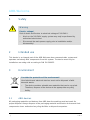 4
4
-
 5
5
-
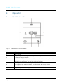 6
6
-
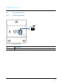 7
7
-
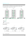 8
8
-
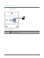 9
9
-
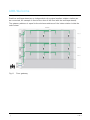 10
10
-
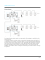 11
11
-
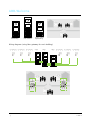 12
12
-
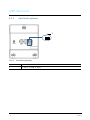 13
13
-
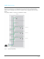 14
14
-
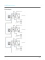 15
15
-
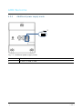 16
16
-
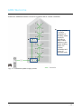 17
17
-
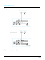 18
18
-
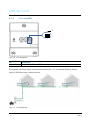 19
19
-
 20
20
-
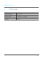 21
21
-
 22
22
-
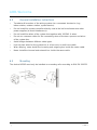 23
23
-
 24
24
-
 25
25
-
 26
26
-
 27
27
-
 28
28
-
 29
29
-
 30
30
-
 31
31
-
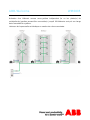 32
32
-
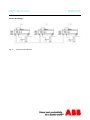 33
33
-
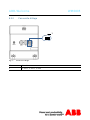 34
34
-
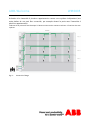 35
35
-
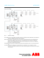 36
36
-
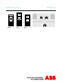 37
37
-
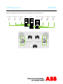 38
38
-
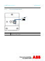 39
39
-
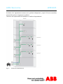 40
40
-
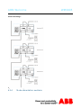 41
41
-
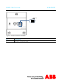 42
42
-
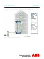 43
43
-
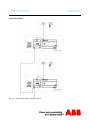 44
44
-
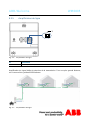 45
45
-
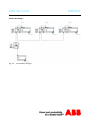 46
46
-
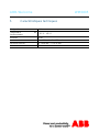 47
47
-
 48
48
-
 49
49
-
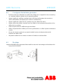 50
50
-
 51
51
-
 52
52
-
 53
53
-
 54
54
-
 55
55
-
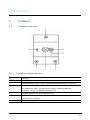 56
56
-
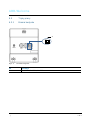 57
57
-
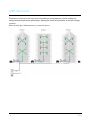 58
58
-
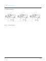 59
59
-
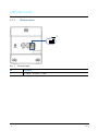 60
60
-
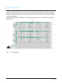 61
61
-
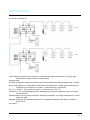 62
62
-
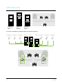 63
63
-
 64
64
-
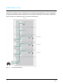 65
65
-
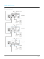 66
66
-
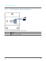 67
67
-
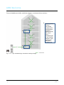 68
68
-
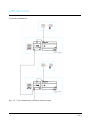 69
69
-
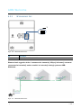 70
70
-
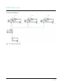 71
71
-
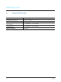 72
72
-
 73
73
-
 74
74
-
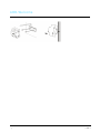 75
75
-
 76
76
-
 77
77
-
 78
78
-
 79
79
-
 80
80
-
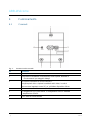 81
81
-
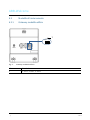 82
82
-
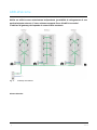 83
83
-
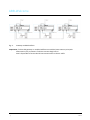 84
84
-
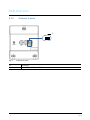 85
85
-
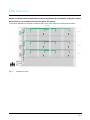 86
86
-
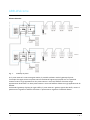 87
87
-
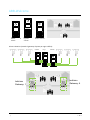 88
88
-
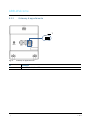 89
89
-
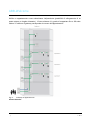 90
90
-
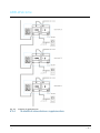 91
91
-
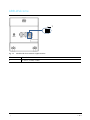 92
92
-
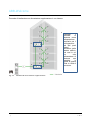 93
93
-
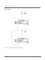 94
94
-
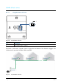 95
95
-
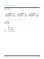 96
96
-
 97
97
-
 98
98
-
 99
99
-
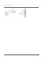 100
100
-
 101
101
-
 102
102
-
 103
103
-
 104
104
-
 105
105
-
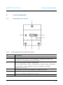 106
106
-
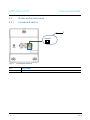 107
107
-
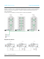 108
108
-
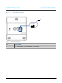 109
109
-
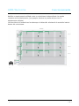 110
110
-
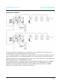 111
111
-
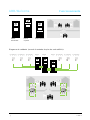 112
112
-
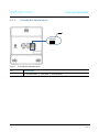 113
113
-
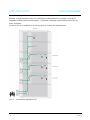 114
114
-
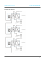 115
115
-
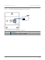 116
116
-
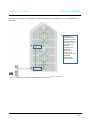 117
117
-
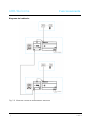 118
118
-
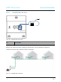 119
119
-
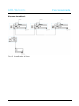 120
120
-
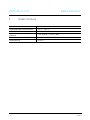 121
121
-
 122
122
-
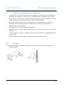 123
123
-
 124
124
-
 125
125
-
 126
126
-
 127
127
-
 128
128
-
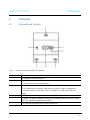 129
129
-
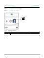 130
130
-
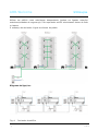 131
131
-
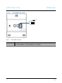 132
132
-
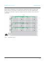 133
133
-
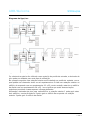 134
134
-
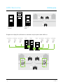 135
135
-
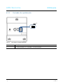 136
136
-
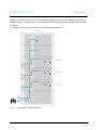 137
137
-
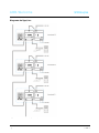 138
138
-
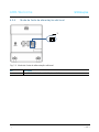 139
139
-
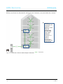 140
140
-
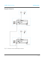 141
141
-
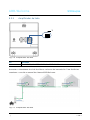 142
142
-
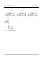 143
143
-
 144
144
-
 145
145
-
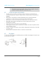 146
146
-
 147
147
-
 148
148
-
 149
149
-
 150
150
-
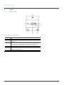 151
151
-
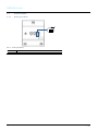 152
152
-
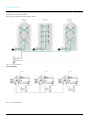 153
153
-
 154
154
-
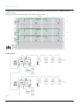 155
155
-
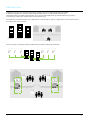 156
156
-
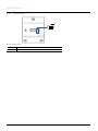 157
157
-
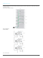 158
158
-
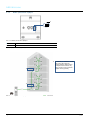 159
159
-
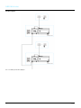 160
160
-
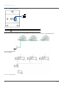 161
161
-
 162
162
-
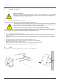 163
163
-
 164
164
-
 165
165
-
 166
166
-
 167
167
-
 168
168
-
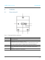 169
169
-
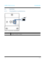 170
170
-
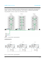 171
171
-
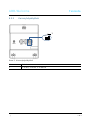 172
172
-
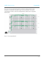 173
173
-
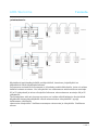 174
174
-
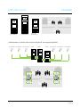 175
175
-
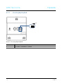 176
176
-
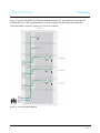 177
177
-
 178
178
-
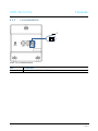 179
179
-
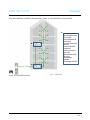 180
180
-
 181
181
-
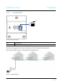 182
182
-
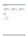 183
183
-
 184
184
-
 185
185
-
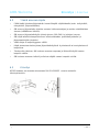 186
186
-
 187
187
-
 188
188
-
 189
189
-
 190
190
-
 191
191
-
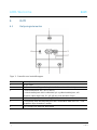 192
192
-
 193
193
-
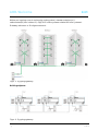 194
194
-
 195
195
-
 196
196
-
 197
197
-
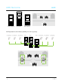 198
198
-
 199
199
-
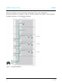 200
200
-
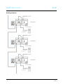 201
201
-
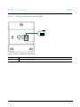 202
202
-
 203
203
-
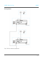 204
204
-
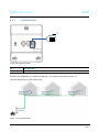 205
205
-
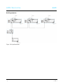 206
206
-
 207
207
-
 208
208
-
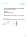 209
209
-
 210
210
-
 211
211
-
 212
212
-
 213
213
-
 214
214
-
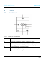 215
215
-
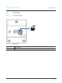 216
216
-
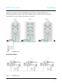 217
217
-
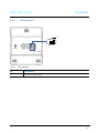 218
218
-
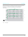 219
219
-
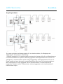 220
220
-
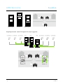 221
221
-
 222
222
-
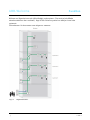 223
223
-
 224
224
-
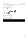 225
225
-
 226
226
-
 227
227
-
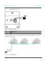 228
228
-
 229
229
-
 230
230
-
 231
231
-
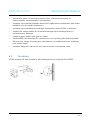 232
232
-
 233
233
-
 234
234
-
 235
235
-
 236
236
-
 237
237
-
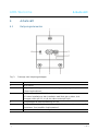 238
238
-
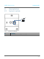 239
239
-
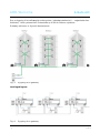 240
240
-
 241
241
-
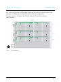 242
242
-
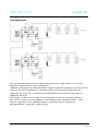 243
243
-
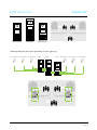 244
244
-
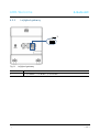 245
245
-
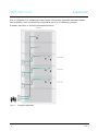 246
246
-
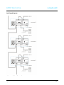 247
247
-
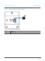 248
248
-
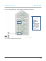 249
249
-
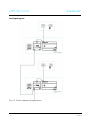 250
250
-
 251
251
-
 252
252
-
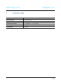 253
253
-
 254
254
-
 255
255
-
 256
256
-
 257
257
-
 258
258
-
 259
259
-
 260
260
-
 261
261
-
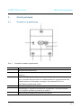 262
262
-
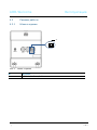 263
263
-
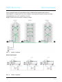 264
264
-
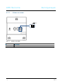 265
265
-
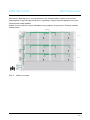 266
266
-
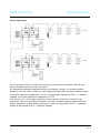 267
267
-
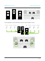 268
268
-
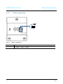 269
269
-
 270
270
-
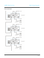 271
271
-
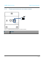 272
272
-
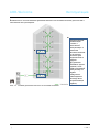 273
273
-
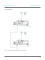 274
274
-
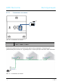 275
275
-
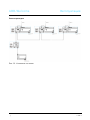 276
276
-
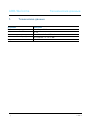 277
277
-
 278
278
-
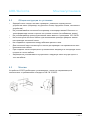 279
279
-
 280
280


ABB 2TMC107009M9702-M2302 gateway Manual de usuario
- Tipo
- Manual de usuario
- Este manual también es adecuado para
en otros idiomas
- italiano: ABB 2TMC107009M9702-M2302 gateway Manuale utente
- Deutsch: ABB 2TMC107009M9702-M2302 gateway Benutzerhandbuch
- русский: ABB 2TMC107009M9702-M2302 gateway Руководство пользователя
- dansk: ABB 2TMC107009M9702-M2302 gateway Brugermanual
- polski: ABB 2TMC107009M9702-M2302 gateway Instrukcja obsługi
- čeština: ABB 2TMC107009M9702-M2302 gateway Uživatelský manuál
- svenska: ABB 2TMC107009M9702-M2302 gateway Användarmanual
- suomi: ABB 2TMC107009M9702-M2302 gateway Ohjekirja
Artículos relacionados
Otros documentos
-
MAHA MBT 1000 EUROSYSTEM Instrucciones de operación
-
Krone BA EasyCollect 6000, 7500, 9000 Instrucciones de operación
-
Krone EasyCut 280 CV-Q_CRI-Q_320 CV-Q Instrucciones de operación
-
NORD Drivesystems NORDAC START - SK 135E - Motor Starter Manual de usuario
-
Vanderbilt ISRW6-12 Quick Manual
-
Nilfisk Alto ATTIX 200 El manual del propietario
-
Tau speed El manual del propietario
-
Comelit 1456S Technical Manual
-
Honor Band 5 Meteorite Black (CRS-B19S) Manual de usuario
-
Kingston Technology MobileLite Wireless Manual de usuario