Southern States 96012002500 El manual del propietario
- Categoría
- Cortadoras de césped
- Tipo
- El manual del propietario
Este manual también es adecuado para

OPERATOR'S MANUAL
MODEL NO. SP24H48YT
24 HP 48 INCH
LAWN TRACTOR
|
• Assembly
• Operation
° Maintenance
• Service and Adjustments
° Storage
° Troubleshooting
• Espa_ol
For Parts and Service, contact our authorized distributor:
call 1-800-849-1297 ForTechnical Assistance: call 1-800-829-5886
SOUTHERN STATES
195478 Rev. 2 3.18.05 RD
PRINTED IN U.S.A.

Warranty ................................................ 2
Safety Rules .......................................... 3
Product Specifications ........................... 6
Assembly/Pre-Operation ....................... 8
Operation ............................................. 13
Maintenance ....................................... 20
Maintenance Schedule ........................ 20
Service and Adjustments ..................... 24
Storage ................................................ 31
Troubleshooting ................................... 32
EspaSol ................................................ 36
LIMITED WARRANTY
The Manufacturer warrants to the original consumer purchaser that this product as
manufactured is free from defects in materials and workmanship. For a period of two
(2) years from date of purchase by the original consumer purchaser, we will repair or
replace, at our option, without charge for parts or labor incurred in replacing parts, any
part which we find to be defective due to materials or workmanship. This Warranty is
subject to the following limitations and exclusions.
1. This warranty does not apply to the engine, other than EHP manufactured transaxle/
transmission components, battery (except as noted below) or components parts
thereof. Please refer to the applicable manufacturer's warranty on these items.
2. Transportation charges for the movement of any power equipment unit or attachment
are the responsibility of the purchaser. Transportation charges for any parts submit-
ted for replacement under this warranty must be paid by the purchaser unless such
return is requested by Electrolux Home Products.
3. Battery Warranty: On products equipped with a Battery, we will replace, without
charge to you, any battery which we find to be defective in manufacture, during the
first ninety (90) days of ownership. After ninety (90) days, we will exchange the Bat-
tery, charging you 1/12 of the price of a new Battery for each full month from the date
of the original sale. Battery must be maintained in accordance with the instructions
furnished.
4. The Warranty period for any products used for rental or commercial purposes is
limited to 90 days from the date of original purchase.
5. This Warranty applies only to products which have been properly assembled, ad-
justed, operated, and maintained in accordance with the instructions furnished. This
Warranty does not apply to any product which has been subjected to alteration, mis-
use, abuse, improper assembly or installation, delivery damage, or to normal wear of
the product.
6. Exclusions: Excluded from this Warranty are belts, blades, blade adapters, normal
wear, normal adjustments, standard hardware and normal maintenance.
7. In the event you have a claim under this Warranty, you must return the product to an
authorized service dealer.
Should you have any unanswered questions concerning this Warranty, please contact:
In Canada contact:
Electrolux Home Products, Inc. Electrolux Canada Corp.
Outdoor Products Customer Service Dept. 7075 Ordan Drive
250 Bobby Jones Expressway Mississauga, Ontario
Augusta, GA 30909 USA L5T 1K6
giving the model number, serial number and date of purchase of your product and the
name and address of the authorized dealer from whom it was purchased.
THIS WARRANTY DOES NOT APPLY TO INCIDENTAL OR CONSEQUENTIAL
DAMAGES AND ANY IMPLIED WARRANTIES ARE LIMITED TO THE SAME TIME
PERIODS STATED HEREIN FOR OUR EXPRESSED WARRANTIES. Some areas do
not allow the limitation of consequential damages or limitations of how long an implied
Warranty may last, so the above limitations or exclusions may not apply to you. This
Warranty gives you specific legal rights, and you may have other rights which vary from
locale to locale.
This is a limited Warranty within the meaning of that term as defined in the Magnuson-
Moss Act of 1975.

IMPORTANT:Thiscuttingmachineiscapableofamputatinghandsandfeetandthrow-
ingobjects.Failuretoobservethefollowingsafetyinstructionscouldresultin serious
injuryor death.
WARNING: Inorderto prevent
accidentalstartingwhensetting up,
transporting,adjustingor makingrepairs,
alwaysdisconnectsparkplugwireand
placewirewhereitcannotcontactspark
plug.
WARNING: Donotcoastdowna
hillin neutral,you maylosecontrolofthe
tractor.
WARNING: Towonly theattach-
mentsthatare recommendedbyand
complywithspecificationsofthe man-
ufacturerof yourtractor.Usecommon
sensewhentowing.Operateonlyat the
lowestpossiblespeedwhenon a slope.
Tooheavyof a load,while on aslope,is
dangerous.Tirescan losetractionwith
thegroundandcauseyouto losecontrol
ofyourtractor.
WARNING:Engineexhaust, some
of its constituents, and certain vehicle
components contain or emit chemicals
known to the State of California to cause
cancer and birth defects or other repro-
ductive harm.
WARNING: Battery posts, terminals
and related accessories contain lead and
lead compounds, chemicals known to the
State of California to cause cancer and
birth defects or other reproductive harm.
Wash hands after handling.
I. GENERAL OPERATION
• Read, understand, and follow all
instructions on the machine and in the
manual before starting.
• Do not put hands or feet near rotating
parts or under the machine. Keep clear
of the discharge opening at all times.
• Only allow responsible adults, who are
familiar with the instructions, to operate
the machine.
• Clear the area of objects such as
rocks, toys, wire, etc., which could be
picked up and thrown by the blades.
• Be sure the area is clear of bystand-
ers before operating. Stop machine if
anyone enters the area.
• Never carry passengers.
3
• Do not mow in reverse unless abso-
lutely necessary. Always look down
and behind before and while backing.
• Never direct discharged material
toward anyone. Avoid discharging
material against a wall or obstruction.
Material may ricochet back toward the
operator. Stop the blades when cross-
ing gravel surfaces.
• Do not operate machine without the
entire grass catcher, discharge guard,
or other safety devices in place and
working.
• Slow down before turning.
• Never leave a running machine
unattended. Always turn off blades,
set parking brake, stop engine, and
remove keys before dismounting.
• Disengage blades when not mowing.
Shut off engine and wait for all parts to
come to a complete stop before clean-
ing the machine, removing the grass
catcher, or unclogging the discharge
guard.
• Operate machine only in daylight or
good artificial light.
• Do not operate the machine while
under the influence of alcohol or drugs.
• Watch for traffic when operating near
or crossing roadways.
• Use extra care when loading or unload-
ing the machine into a trailer or truck.
• Always wear eye protection when oper-
ating machine.
• Data indicates that operators, age 60
years and above, are involved in a
large percentage of riding mower-re-
lated injuries. These operators should
evaluate their ability to operate the
riding mower safely enough to protect
themselves and others from serious
injury.
• Follow the manufacturer's recommen-
dation for wheel weights or counter-
weights.
• Keep machine free of grass, leaves or
other debris build-up which can touch
hot exhaust / engine parts and burn.
Do not allow the mower deck to plow
leaves or other debris which can cause
build-up to occur. Clean any oil or fuel
spillage before operating or storing the
machine. Allow machine to cool before
storage.

I1.SLOPE OPERATION
Slopesare a majorfactorrelatedto lossof
controlandtip-overaccidents,whichcan
resultin severeinjuryordeath. Opera-
tion onall slopesrequiresextra caution. If
you cannot back up the slope or if you feel
uneasy on it, do not mow it.
• Mow up and down slopes, not across.
• Watch for holes, ruts, bumps, rocks, or
other hidden objects. Uneven terrain
could overturn the machine. Tall grass
can hide obstacles.
• Choose a low ground speed so that
you will not have to stop or shift while
on the slope.
• Do not mow on wet grass. Tires may
lose traction.
Always keep the machine in gear when
going down slopes. Do not shift to
neutral and coast downhill.
• Avoid starting, stopping, or turning on
a slope. If the tires lose traction, dis-
engage the blades and proceed slowly
straight down the slope.
• Keep all movement on the slopes slow
and gradual. Do not make sudden
changes in speed or direction, which
could cause the machine to roll over.
• Use extra care while operating ma-
chine with grass catchers or other at-
tachments; they can affect the stability
of the machine. Do no use on steep
slopes.
• Do not try to stabilize the machine by
putting your foot on the ground.
• Do not mow near drop-offs, ditches,
or embankments. The machine could
suddenly roll over if a wheel is over the
edge or if the edge caves in.
III. CHILDREN
Tragic accidents can occur if the operator
is not alert to the presence of children.
Children are often attracted to the machine
and the mowing activity. Never assume
that children will remain where you last
saw them.
• Keep children out of the mowing area
and in the watchful care of a respon-
sible adult other than the operator.
• Be alert and turn machine off if a child
enters the area.
• Before and while backing, look behind
and down for small children.
• Never carry children, even with the
blades shut off. They may fall off and
be seriously injured or interfere with
safe machine operation. Children who
have been given rides in the past may
suddenly appear in the mowing area
for another ride and be run over or
backed over by the machine.
• Never allow children to operate the
machine.
• Use extra care when approaching blind
corners, shrubs, trees, or other objects
that may block your view of a child.
IV. TOWING
• Tow only with a machine that has a
hitch designed for towing. Do not at-
tach towed equipment except at the
hitch point.
• Follow the manufacturer's recommen-
dation for weight limits for towed equip-
ment and towing on slopes.
• Never allow children or others in or on
towed equipment.
• On slopes, the weight of the towed
equipment may cause loss of traction
and loss of control.
• Travel slowly and allow extra distance
to stop.
V. SERVICE
SAFE HANDLING OF GASOLINE
To avoid personal injury or property
damage, use extreme care in handling
gasoline. Gasoline is extremely flammable
and the vapors are explosive.
• Extinguish all cigarettes, cigars, pipes,
and other sources of ignition.
• Use only approved gasoline container.
• Never remove gas cap or add fuel with
the engine running. Allow engine to
cool before refueling.
• Never fuel the machine indoors.
• Never store the machine or fuel con-
tainer where there is an open flame,
spark, or pilot light such as on a water
heater or other appliances.
• Never fill containers inside a vehicle
or on a truck or trailer bed with plastic
liner. Always place containers on the
ground away from your vehicle when
filling.

• Removegas-poweredequipmentfrom
thetruckortrailerandrefuelit onthe
ground.Ifthisisnotpossible,then
refuelsuchequipmentwith aportable
container,ratherthan froma gasoline
dispensernozzle.
• Keepthe nozzlein contactwith the rim
of thefueltankorcontaineropeningat
all timesuntilfuelingiscomplete.Do
notusea nozzlelock-opendevice.
• Iffuelis spilledon clothing,change
clothingimmediately.
• Neveroverfillfueltank.Replacegas
cap andtightensecurely.
GENERAL SERVICE
• Neveroperatemachinein aclosed
area.
• Keepall nutsandboltstightto besure
theequipment is in safe working condi-
tion.
• Never tamper with safety devices.
Check their proper operation regularly.
• Keep machine free of grass, leaves, or
other debris build-up. Clean oil or fuel
spillage and remove any fuel-soaked
debris. Allow machine to cool before
storing.
• If you strike a foreign object, stop and
inspect the machine. Repair, if neces-
sary, before restarting.
• Never make any adjustments or repairs
with the engine running.
• Check grass catcher components and
the discharge guard frequently and
replace with manufacturer's recom-
mended parts, when necessary.
• Mower blades are sharp. Wrap the
blade or wear gloves, and use extra
caution when servicing them.
• Check brake operation frequently. Ad-
just and service as required.
• Maintain or replace safety and instruc-
tion labels, as necessary.
• Be sure the area is clear of bystand-
ers before operating. Stop machine if
anyone enters the area.
• Never carry passengers.
• Do not mow in reverse unless abso-
lutely necessary. Always look down
and behind before and while backing.
• Never carry children, even with the
blades shut off. They may fall off and
be seriously injured or interfere with
safe machine operation. Children who
have been given rides in the past may
suddenly appear in the mowing area
for another ride and be run over or
backed over by the machine.
• Keep children out of the mowing area
and in the watchful care of a respon-
sible adult other than the operator.
• Be alert and turn machine off if a child
enters the area.
• Before and while backing, look behind
and down for small children.
• Mow up and down slopes (15 ° Max),
not across.
• Choose a low ground speed so that
you will not have to stop or shift while
on the slope.
• Avoid starting, stopping, or turning on
a slope. If the tires lose traction, dis-
engage the blades and proceed slowly
straight down the slope.
• If machine stops while going uphill,
disengage blades, shift into reverse
and back down slowly.
• Do not turn on slopes unless neces-
sary, and then, turn slowly and gradu-
ally downhill, if possible.
5

PRODUCT SPECIFICATIONS
Gasoline 4.0 Gallons
Capacity Unleaded
and Type: Regular
Oil Type SAE 30 (above 32°F)
(API-SG-SL): SAE 5W-30
(Below 32°F)
Oil Capacity: W/Filter: 4.0 Pints
W/O Filter: 3.75 Pints
Spark Plug: Champion QC12YC
(GapP: .040")
Ground Speed Forward: 5.5
(MPH): Reverse: 2.4
Tire Pressure: Front: 14 PSI
Rear: 10 PSI
Charging 16 Amps @ 3600RPM
System:
Battery: Amp/Hr: 35
Min. CCA: 280
Case Size: U1R
Blade Bolt 45-55 Ft. Lbs.
Torque:
CONGRATULATIONS on your purchase
of a new tractor. It has been designed,
engineered and manufactured to give
you the best possible dependability and
performance.
Should you experience any problem you
cannot easily remedy, please contact
your nearest authorized service center/
department. We have competent, well-
trained technicians and the proper tools to
service or repair this tractor.
Please read and retain this manual. The
instructions will enable you to assemble
and maintain your tractor properly. Always
observe the "SAFETY RULES".
CUSTOMER RESPONSIBILITIES
• Read and observe the safety rules.
• Follow a regular schedule in main-
taining, caring for and using your tractor.
• Follow the instructions under "Mainte-
nance" and "Storage" sections of this
owner's manual.
_WARNING: This tractor is equipped
with an internal combustion engine and
should not be used on or near any unim-
proved forest-covered, brush-covered or
grass-covered land unless the engine's
exhaust system is equipped with a spark
arrester meeting applicable local or state
laws (if any). If a spark arrester is used, it
should be maintained in effective working
order by the operator.
In the state of California the above is
required by law (Section 4442 of the
California Public Resources Code). Other
states may have similar laws. Federal
laws apply on federal lands. A spark ar-
rester for the muffler is available through
your nearest authorized service center/de-
partment (See REPAIR PARTS section of
this manual).

Steering
Wheel
Adapter
Steering Wheel
Steering
Sleeve
Gauge Wheels
(4) Adjusting Bar
f
0
o
0
(4) Retainer Springs
(double loop)
@"
_ (4) Locknut 3/8-16
Rod
Nose Roller
Retainer "_,,//
Spring
(4) Washers
3/8 x 3/4 x 14 Ga.
,o :[I
(4) Clevis Pins
(4) Wheels
(4) Shoulder Bolt
Seat
(1) Washer @
17/32 x 1-3/16 x 12 Gauge
_(1) Knob
@
(2) Locknuts
5/16-18
U
Nose Rolle_,)
Bracke_
(2) Hex Bolts 5/16-18 x 1
Mower
(5) Retainer Springs
_loop) (2) Retainer Springs
(single loop)
(_i
(1)Front
Assembly
(1) Oil Drain Tube
For Future Use
Keys
(2)Flanged
Pins
(2) Keys
Slope Sheet
7

Your new tractor has been assembled at the factory with the exception of those parts left
unassembled for shipping purposes. To ensure safe and proper operation of your tractor
all parts and hardware you assemble must be tightened securely. Use the correct tools
as necessary to insure proper tightness. Review the video cassette before you begin.
TOOLS REQUIRED FOR ASSEMBLY
A socket wrench set will make assembly
easier. Standard wrench sizes you need
are listed below.
(1) 3/4" wrench (1) Pliers
(1) 9/16" wrench (1) Utility knife
(1) Tire pressure gauge
When right or left hand is mentioned in
this manual, it means, from your point of
view, when you are in the operating posi-
tion (seated behind the steering wheel).
TO REMOVE TRACTOR FROM
CARTON
UNPACK CARTON
1. Remove all accessible loose parts and
parts boxes from carton.
2. Cut along dotted lines on all four pan-
els of carton. Remove end panels and
lay side panels flat.
3. Remove mower and packing materials.
4. Check for any additional loose parts or
cartons and remove.
BEFORE REMOVING TRACTOR
FROM SKID
ATTACH STEERING WHEEL
1. Remove Iocknut and large flat washer
from steering shaft.
2. Position front wheels of the tractor so
they are pointing straight forward.
3. Slide the steering sleeve over the
steering shaft.
4. Position steering wheel so cross bars
are horizontal (left to right) and slide
onto steering wheel adapter.
5. Secure steering wheel to steering
shaft with Iocknut and large flat washer
previously removed. Tighten securely.
6. Snap steering wheel insert into center
of steering wheel.
7. Remove protective materials from trac-
tor hood and grill.
IMPORTANT: Check for and remove any
staples in skid that may puncture tires
where tractor is to roll off skid.
Steering
Steering Wheel
Steering
Wheel
Steering Adaptor
Shaft
Steering
Sleeve
CHECK BATTERY
1. Lift hood to raised position.
NOTE: If this battery is put into service
after month and year indicated on label
(label located between terminals) charge
battery for minimum of one hour at 6-10
amps. (See "BATTERY" in Maintenance
section of this manual for charging instruc-
tions).
,abe

INSTALL SEAT
Adjust seat before tightening adjustment
knob.
1. Remove adjustment knob and flat
washer securing seat to cardboard
packing and set aside for assembly of
seat to tractor.
2. Pivot seat upward and remove from
the cardboard packing. Remove the
cardboard packing and discard.
3. Place seat on seat pan so head of
shoulder bolts are positioned over the
large slotted holes in pan.
4. Push down on seat to engage shoulder
bolts in slots and pull seat towards rear
of tractor.
5. Pivot seat and pan forward and as-
semble adjustment knob and flat
washer loosely. Do not tighten.
6. Lower seat into operating position and
sit in seat.
7. Slide seat until a comfortable position
is reached which allows you to press
clutch/brake pedal all the way down.
8. Get off seat without moving its ad-
justed position.
9. Raise seat and tighten adjustment
knob securely.
Seat
Seat Pan
Shoulder
Bolts
Flat Wa
Adjustment
NOTE: You may now roll or drive your
tractor off the skid. Follow the appropriate
instruction below to remove the tractor
from the skid.
TO ROLL TRACTOR OFF SKID
(See Operation section for location
and function of controls)
1. Press lift lever plunger and raise
attachment lift lever to its highest
position.
2. Release parking brake by depressing
clutch/brake pedal.
3. Place freewheel control in "trans-
mission disengaged position" (See
"TO TRANSPORT" in the Operation
section of this manual).
4. Roll tractor forward off skid.
TO DRIVE TRACTOR OFF SKID
(See Operation section for location
_dAfunction of controls)
RNING: Before starting, read, un-
derstand and follow all instructions in the
Operation section of this manual. Be sure
tractor is in a well-ventilated area. Be sure
the area in front of tractor is clear of other
people and objects.
1. Be sure all the above assembly steps
have been completed.
2. Check engine oil level and fill fuel tank
with gasoline.
3. Place freewheel control in "trans-
mission engaged" position (see "TO
TRANSPORT" in Operation section of
this manual).
4. Sit on seat in operating position,
depress clutch/brake pedal and set the
parking brake.
5. Place motion control lever in neutral
(N) position.
6. Press lift lever plunger and raise
attachment lift lever to its highest posi-
tion.
7. Start the engine. After engine has
started, move throttle control to idle
position.
8. Release parking brake.
9. Slowly move the motion control lever
forward and slowly drive tractor off
skid.
10. Apply brake to stop tractor, set parking
brake and place motion control lever in
neutral position.
11. Turn ignition key to "STOP" position.
Continue with the instructions that follow.
9

TO ATTACH NOSE ROLLER
1. Assemble brackets "A" and "B" to the
inside of mower mounting brackets as
shown. Tighten securely.
NOTE: Be sure bracket tabs are posi-
tioned in tab holes in mower brackets.
2. Position nose roller between brackets
and install rod and retainer spring.
Lock Hex Bolt
Rod
Tab "B"
Hole Bracket
"A" Bracket
Retainer Spring
Nose Roller
ASSEMBLE GAUGE WHEELS TO
MOWER DECK
The gauge wheels are designed to keep
the mower deck in proper position when
operating mower. Be sure they are prop-
erly adjusted to ensure optimum mower
performance.
1. Slide gauge wheel bar down into
bracket channel, Be sure that gauge
wheel bar aligning holes are on top.
Assemble gauge wheels as shown
using shoulder bolts, 3/8 washers and
3/8-16 center Iocknuts and tighten
securely.
2. For ease of mower to tractor assembly,
raise gauge wheels to highest position
and retain with clevis pins and spring
retainers.
NOTE: Adjust gauge wheels before oper-
ating mower. See "TO ADJUST GAUGE
WHEELS" in the Operation section of this
manual.
3/8 Washer
"@_ 3/8-16 Center
Locknut
10

INSTALL MOWER AND DRIVE
BELT
Be sure tractor is on level surface and
mower suspension arms are raised with
attachment lift control. Engage parking
brake.
1. Cut and remove ties securing anti-
sway bar and belts. Swing anti-sway
bar to left side of mower deck.
2. Slide mower under tractor with deflec-
tor shield to right side of tractor.
IMPORTANT: Check belt for proper rout-
ing in all mower pulley grooves.
3. If equipped, turn height adjustment
knob counterclockwise until it stops.
4. Lower mower linkage with attachment
lift control.
5. Be sure belt tension rod is in disen-
gaged position.
6. Install belt into electric clutch pulley
groove.
7. Place the suspension arms on outward
pointing deck pins. Retain with double
loop retainer spring with loops up as
shown.
8. Install front plate assembly to tractor
suspension brackets and retain with
single loop retainer springs as shown.
Belt Tension Rod Lock Bracket
Disengaged Position
Chassis _ _-_
Gauge
Wheel
\
9. Position front plate assembly between
front mower brackets. Raise deck and
plate assembly to align holes and
insert flanged pins. Secure pins with
double loop retainer springs between
the plate assembly and mower brack-
ets.
NOTE: To assist in locating hole in flanged
pin, the hole in pin is inline with notch on
head of pin. If necessary, move mower
side-to-side to give space between plate
and mower brackets.
IMPORTANT: Check belt for proper rout-
ing in all mower pulley grooves.
10. Engage belt tension rod by pushing
rod into locking bracket.
,_CAUTION: Belt tension rod is spring
loaded. Have a tight grip on rod and en-
gage slowly.
11. Connect anti-sway bar to chassis
bracket under left footrest and retain
with double loop retainer spring.
12. If equipped, turn height adjustment
knob clockwise to remove slack from
mower suspension.
13. Raise deck to highest position.
14. Adjust gauge wheels before operating
mower as shown in the Operation sec-
tion of this manual.
Electric Clutch
Pulley Front
Suspension Front Plate
Brackets
Front Assembly
Retainer
Single
Loop
Flanged Retainer
Springs
Double Loop
Retainer
Spring
USE PLIERS FOR
RETAINER SPRINGS
Loop Up
Anti-Sway
Bar
Suspension Arms
Double Loop
Retainer Spring
(Outward pointing
deck pins)
Deflector Shield
11

CHECK TIRE PRESSURE
The tires on your tractor were overinflated
at the factory for shipping purposes. Cor-
rect tire pressure is important for best
cutting performance.
• Reduce tire pressure to PSI shown in
"PRODUCT SPECIFICATIONS" section
of this manual.
CHECK DECK LEVELNESS
For best cutting results, mower housing
should be properly leveled. See "TO LEV-
EL MOWER HOUSING" in the Service
and Adjustments section of this manual.
CHECK FOR PROPER POSITION
OF ALL BELTS
See the figures that are shown for replac-
ing motion and mower blade drive belts
in the Service and Adjustments section
of this manual. Verify that the belts are
routed correctly.
CHECK BRAKE SYSTEM
After you learn how to operate your trac-
tor, check to see that the brake is properly
adjusted. See "TO ADJUST BRAKE" in
the Service and Adjustments section of
this manual.
#'CHECKLIST
Before you operate your new tractor, we
wish to assure that you receive the best
performance and satisfaction from this
Quality Product.
Please review the following checklist:
,/All assembly instructions have been
completed.
,/No remaining loose parts in carton.
,/Battery is properly prepared and
charged. (Minimum 1 hour at 6 amps).
,/Seat is adjusted comfortably and tight-
ened securely.
,/All tires are properly inflated. (For ship-
ping purposes, the tires were overin-
flated at the factory).
,/Be sure mower deck is properly leveled
side-to-side/front-to-rear for best cutting
results. (Tires must be properly inflated
for leveling).
,/Check mower and drive belts. Be sure
they are routed properly around pulleys
and inside all belt keepers.
,/Check wiring. See that all connections
are still secure and wires are properly
clamped.
,/Before driving tractor, be sure freewheel
control is in "transmission engaged"
position (see "TO TRANSPORT" in the
Operation section of this manual).
While learning how to use your tractor, pay
extra attention to the following important
items:
,/Engine oil is at proper level.
,/Fuel tank is filled with fresh, clean, regu-
lar unleaded gasoline.
,/Become familiar with all controls, their
location and function. Operate them
before you start the engine.
,/Be sure brake system is in safe operat-
ing condition.
,/Be sure Operator Presence System
and Reverse Operation System (ROS)
are working properly (See the Opera-
tion and Maintenance sections in this
manual).
,/It is important to purge the transmission
before operating your tractor for the first
time. Follow proper starting and trans-
mission purging instructions (See "TO
START ENGINE" and "PURGE TRANS-
MISSION" in the Operation section of
this manual).
12

These symbols may appear on your tractor or in literature supplied with the product.
Learn and understand their meaning.
R N H L I'.,I
REVERSE NEUTRAL HIGH LOW CHOKE FAST SLOW
IGNITION SWITCH
ENGINE OFF REVERSE ENGINE ON ENGINE START PARKING BRAKE MOWER HEIGHT MOWER LIFT
OPERATION
SYSTEM (ROS)
LIGHTS ON FUEL BATTERY CLUTCH/BRAKE
PEDAL
ATTACHMENT ATTACHMENT
CLUTCH DISENGAGED CLUTCH ENGAGED
FREE WHEEL
(Automatic Models only)
&
Failure to follow instructions
could result in serious injury or
death. The safety alert symbol
is used to identify safety inform-
ation about hazards which can
result in death, serious injury
and/or property damage.
, ® s6:gs¢>
REVERSE FORWARD CRUISE CONTROL
DANGER, KEEP HANDS
AND FEET AWAY
®@@@@
KEEP AREA CLEAR SLOPE HAZARDS
(SEE SAFETY RULES SECTION)
DANGER indicates a hazard which, if not avoided,
will result in death or serious injury.
WARNING indicates a hazard which, if not avoided,
could result in death or serious injury.
CAUTION indicates a hazard which, if not avoided,
might result in minor or moderate injury.
,l_llIll/l=l_l.,
CAUTION when used without the alert symbol,
indicates a situation that could result in damage
to the tractor and/or engine.
HOT SURFACES indicates a hazard which,
if not avoided, could result in death, serious injury
and/or property damage.
FIRE indicates a hazard which, if not avoided,
could result in death, serious injury and/or
property damage.
13

KNOW YOUR TRACTOR
READ THIS OWNER'S MANUAL AND SAFETY RULES BEFORE OPERATING YOUR
TRACTOR
Compare the illustrations with your tractor to familiarize yourself with the locations of
various controls and adjustments. Save this manual for future reference.
Ignition ROS "ON"
Hourmeter Switch Position
Choke Control
Lift Lever
Plunger
Throttle Control
Clutch/Brake
Pedal
Attachment
Lift Lever
Height
Adjustment
Knob
Free Wheel
Light Switch
g Brake Lever
Motion
Control
Lever
2883
Our tractors conform to the safety standards of the
American National Standards Institute.
ATTACHMENT CLUTCH SWITCH - Used
to engage the mower blades, or other at-
tachments mounted to your tractor.
ATTACHMENT LIFT LEVER - Used to
raise, lower, and adjust the mower deck or
other attachments mounted to your tractor.
CLUTCH/BRAKE PEDAL - Used for declutch-
ing and braking the tractor and starting the
engine.
CHOKE CONTROL - Used when starting
a cold engine.
FREEWHEEL CONTROL - Disengagages
transmission for pushing or slowly towing
the tractor with the engine off.
HEIGHT ADJUSTMENT KNOB - Used to
adjust the mower cutting height.
HOURMETER - Indicates hours of op-
eration.
IGNITION SWITCH - Used for starting
and stopping the engine.
LIFT LEVER PLUNGER - Used to release
attachment lift lever when changing its
position.
LIGHT SWITCH - Turns the headlights on
and off.
MOTION CONTROL LEVER - Selects the
speed and direction of the tractor.
PARKING BRAKE LEVER - Locks clutch/
brake pedal into the brake position.
REVERSE OPERATION SYSTEM (ROS)
"ON" POSlTON - Allows operation of
mower deck or other powered attachment
while in reverse.
THROTTLE CONTROL - Used to control
engine speed.
14

The operation of any tractor can result in foreign objects thrown into the
eyes, which can result in severe eye damage. Always wear safety glasses
or eye shields while operating your tractor or performing any adjustments
or repairs. We recommend standard safety glasses or a wide vision
safety mask worn over spectacles.
HOW TO USE YOUR TRACTOR
TO SET PARKING BRAKE
Your tractor is equipped with an operator
presence sensing switch. When engine
is running, any attempt by the operator
to leave the seat without first setting the
parking brake will shut off the engine.
1. Depress clutch/brake pedal all the way
down and hold.
2. Pull parking brake lever up and release
pressure from clutch/brake pedal.
Pedal should remain in brake position.
Make sure parking brake will hold trac-
tor secure.
Attachment Clutch Switch
Pull Out To Engage
Choke nition Key Push In To
Throttle Cont-rof--.. Disengage
Brake
Motion
Control
Lever
Clutch gaged Parking Brake
Pedal Position "Engaged"
Height Position
Adjustment Knob
STOPPING
MOWER BLADES -
• To stop mower blades, push attachment
clutch switch in to disengaged position.
GROUND DRIVE -
• To stop ground drive, depress clutch/
brake pedal all the way down.
• Move motion control lever to neutral (N)
position.
IMPORTANT: The motion control lever
does not return to neutral (N) position
when the clutch/brake pedal is depressed.
ENGINE -
• Move throttle control between half and
full speed (fast) position.
NOTE: Failure to move throttle control
between half and full speed (fast) posi-
tion, before stopping, may cause engine
to "backfire".
• Turn ignition key to "STOP" position and
remove key. Always remove key when
leaving tractor to prevent unauthorized
use. 15
• Never use choke to stop engine.
IMPORTANT: Leaving the ignition switch
in any position other than "STOP" will
cause the battery to discharge and go
dead.
NOTE: Under certain conditions when
tractor is standing idle with the engine
running, hot engine exhaust gases may
cause "browning" of grass. To eliminate
this possibility, always stop engine when
stopping tractor on grass areas.
CAUTION: Always stop tractor com-
pletely, as described above, before leaving
the operator's position.
TO USE THROTTLE CONTROL
Always operate engine at full throttle.
• Operating engine at less than full
throttle reduces the battery charging
rate.
• Full throttle offers the best bagging and
mower performance.
TO USE CHOKE CONTROL
Use choke control whenever you are start-
ing a cold engine. Do not use to start a
warm engine.
• To engage choke control, pull knob out.
Slowly push knob in to disengage.
TO MOVE FORWARD AND
BACKWARD
The direction and speed of movement is
controlled by the motion control lever.
1. Start tractor with motion control lever in
neutral (N) position.
2. Release parking brake.
3. Slowly move motion control lever to
desired position.

TO ADJUST MOWER CUTTING HEIGHT
The cutting height is controlled by turning
the height adjustment knob in desired
direction.
• Turn knob clockwise (f_i) to raise cut-
ting height.
• Turn knob counterclockwise (1_-_) to
lower cutting height.
The cutting height range is approximately
1-1/2" to 4". The heights are measured
from the ground to the blade tip with the
engine not running. These heights are ap-
proximate and may vary depending upon
soil conditions, height of grass and types
of grass being mowed.
• The average lawn should be cut to
approximately 2-1/2 inches during the
cool season and to over 3 inches during
hot months. For healthier and better
looking lawns, mow often and after
moderate growth.
• For best cutting performance, grass over
6 inches in height should be mowed
twice. Make the first cut relatively high;
the second to desired height.
TO ADJUST GAUGE WHEELS
Gauge wheels are properly adjusted
when they are slightly off the ground when
mower is at the desired cutting height in
operating position. Gauge wheels then
keep the deck in proper position to help
prevent scalping in most terrain conditions.
NOTE: Be sure tractor is on a flat level
surface.
1. Lower mower and adjust mower to de-
sired cutting height(See "TO ADJUST
MOWER CUTTING HEIGHT" in this
section of manual).
2. Remove retainer spring and clevis pin
which secure each gauge wheel bar.
3. Lower gauge wheels to ground. Raise
gauge wheels slightly to align holes
in bracket and gauge wheel bar and
insert clevis pin. Gauge wheels should
be slightly off the ground.
4. Replace retainer spring into clevis pin.
5. Be sure all gauge wheels are in the
same setting.
IMPORTANT: Be sure to readjust gauge
wheels if you change the cutting height
of the mower deck.
Retainer
S
TO OPERATE MOWER
Your tractor is equipped with an operator
presence sensing switch. Any attempt
by the operator to leave the seat with the
engine running and the attachment clutch
engaged will shut off the engine. You must
remain fully and centrally positioned in the
seat to prevent the engine from hesitating
or cutting off when operating your equip-
ment on rough, rolling terrain or hills.
1. Select desired height of cut.
2. Lower mower with attachment lift con-
trol.
3. Start mower blades by engaging at-
tachment clutch control.
TO STOP MOWER BLADES -
disengage attachment clutch control.
_iCAUTION: Do not operate the mower
without either the entire grass catcher,
on mowers so equipped, or the deflector
shield in place.
Attachment Attachemnt Lift Lever
Clutch Switch High Position
Pull Out to
Enga(e
In to
Disengage
Low
Position
Deflector
Shield
REVERSE OPERATION SYSTEM (ROS)
Your tractor is equipped with a Reverse
Operation System (ROS). Any attempt by
the operator to travel in the reverse direc-
tion with the attachment clutch engaged
will shut off the engine unless ignition key
is placed in the ROS "ON" position.
_iWARNING: Backing up with the at-
tachment clutch engaged while mowing
is strongly discouraged. Turning the ROS
"ON", to allow reverse operation with the
attachment clutch engaged, should only
be done when the operator decides it is
necessary to reposition the machine with
the attachment engaged. Do not mow in
reverse unless absolutely necessary.
Clevis
Pin 16

USING THE REVERSE OPERATION
SYSTEM -
1. Move motion control lever to neutral
(N) position.
2. With engine running, turn ignition key
counterclockwise to ROS "ON" posi-
tion.
3. Look down and behind before backing.
4. Slowly move motion control lever to
reverse (R) position to start movement.
5. When use of the ROS is no longer
needed, turn the ignition key clockwise
to engine "ON" position.
ROS "ON" Position
Engine "ON" Position
(Normal Operating)
TO OPERATE ON HILLS
_I, WARNING: Do not drive up or down
hills with slopes greater than 15 ° and do
not drive across any slope. Use the slope
guide provided at the back of this manual.
• Choose the slowest speed before start-
ing up or down hills.
• Avoid stopping or changing speed on
hills.
• If slowing is necessary, move throttle
control lever to slower position.
• If stopping is absolutely necessary, push
clutch/brake pedal quickly to brake posi-
tion and engage parking brake.
• Move motion control lever to neutral (N)
position.
IMPORTANT: The motion control lever
does not return to neutral (N) position
when the clutch/brake pedal is depressed.
• To restart movement, slowly release
parking brake and clutch/brake pedal.
• Slowly move motion control lever to
slowest setting.
• Make all turns slowly.
TO TRANSPORT
When pushing or towing your tractor, be
sure to disengage transmission by placing
freewheel control in freewheeling position.
Freewheel control is located at the rear
drawbar of tractor.
1. Raise attachment lift to highest posi-
tion with attachment lift control.
2. Pull freewheel control out and down
into the slot and release so it is held in
the disengaged position.
• Do not push or tow tractor at more than
two (2) MPH.
• To re-engage transmission, reverse
above procedure.
Transmission Engaged
Transmission Disengaged
NOTE: To protect hood from damage
when transporting your tractor on a truck
or a trailer, be sure hood is closed and
secured to tractor. Use an appropriate
means of tying hood to tractor (rope, cord,
etc.).
TOWING CARTS AND OTHER ATTACH-
MENTS
Tow only the attachments that are recom-
mended by and comply with specifications
of the manufacturer of your tractor. Use
common sense when towing. Too heavy
of a load, while on a slope, is dangerous.
Tires can lose traction with the ground and
cause you to lose control of your tractor.
BEFORE STARTING THE ENGINE
CHECK ENGINE OIL LEVEL
The engine in your tractor has been
shipped, from the factory, already filled
with summer weight oil.
1. Check engine oil with tractor on level
ground.
2. Remove oil fill cap/dipstick and wipe
clean, reinsert the dipstick and screw
cap tight, wait for a few seconds, re-
move and read oil level. If necessary,
add oil until "FULl" mark on dipstick is
reached. Do not overfill.
• For cold weather operation you should
change oil for easier starting ((See the
oil viscosity chart in the Maintenance
section of this manual).
To change engine oil, see the Mainte-
nance section in this manual.
17

ADD GASOLINE
• Fillfuel tankto bottomof tankfiller neck.
Do notoverfill.Usefresh,clean,regular
unleadedgasolinewith aminimumof 87
octane.(Useof leadedgasolinewill in-
creasecarbonand leadoxidedeposits
andreducevalvelife).Do notmixoil
with gasoline.Purchasefuel in quanti-
tiesthat canbe usedwithin30daysto
assurefuelfreshness.
_CAUTION: Wipe off anyspilledoilor
fuel.Donotstore,spillor usegasoline
nearan openflame.
IMPORTANT:Whenoperatingintempera-
turesbelow32°F(0°C),usefresh,clean
wintergradegasolineto helpinsuregood
coldweatherstarting.
CAUTION: Alcoholblendedfuels (called
gasoholorusingethanolormethanol)can
attractmoisturewhichleadsto separa-
tion andformationof acidsduringstorage.
Acidicgas can damagethefuel systemof
an engine while in storage.
To avoid engine problems, the fuel system
should be emptied before storage of 30
days or longer. Drain the gas tank, start
the engine and let it run until the fuel lines
and carburetor are empty. Use fresh fuel
next season. See Storage Instructions for
additional information.
Never use engine or carburetor cleaner
products in the fuel tank or permanent
damage may occur.
TO START ENGINE
When starting the engine for the first time
or if the engine has run out of fuel, it will
take extra cranking time to move fuel from
the tank to the engine.
1. Be sure freewheel control is in the
transmission engaged position.
2. Sit on seat in operating position,
depress clutch/brake pedal and set
parking brake.
3. Place motion control lever in neutral
(N) position.
4. Move attachment clutch to disengaged
position.
5. Move throttle control to fast position
6. Pull choke control out for a cold engine
start attempt. For a warm engine start
attempt the choke control may not be
needed.
NOTE: Before starting, read the warm and
cold starting procedures below.
7. Insert key into ignition and turn key
clockwise to start position and release
key as soon as engine starts. Do
not run starter continuously for more
than fifteen seconds per minute. If the
engine does not start after several
attempts, push choke control in, wait
a few minutes and try again. If engine
still does not start, pull the choke con-
trol out and retry.
WARM WEATHER STARTING (50 ° F and
above)
8. When engine starts, slowly push choke
control in until the engine begins to
run smoothly. If the engine starts to
run roughly, pull the choke control out
slightly for a few seconds and then
continue to push the control in slowly.
• The attachments and ground drive can
now be used. If the engine does not
accept the load, restart the engine and
allow it to warm up for one minute using
the choke as described above.
COLD WEATHER STARTING (50 ° F and
below)
8. When engine starts, slowly push choke
control in until the engine begins to run
smoothly. Continue to push the choke
control in small steps allowing the en-
gine to accept small changes in speed
and load, until the choke control is fully
in. If the engine starts to run roughly,
pull the choke control out slightly for a
few seconds and then continue to push
the control in slowly. This may require
an engine warm-up period from several
seconds to several minutes, depending
on the temperature.
AUTOMATIC TRANSMISSION WARM UP
Before driving the unit in cold weather,
the transmission should be warmed up as
follows:
1. Be sure the tractor is on level ground.
2. Place the motion control lever in
neutral. Release the parking brake and
let the clutch/brake slowly return to
operating position.
3. Allow one minute for transmission to
warm up. This can be done during the
engine warm up period.
• The attachments can be used during
the engine warm-up period after the
transmission has been warmed up and
may require the choke control be pulled
out slightly.
NOTE: If at a high altitude (above 3000
feet) or in cold temperatures (below 32 F)
the carburetor fuel mixture may need to
be adjusted for best engine performance
(see "TO ADJUST CARBURETOR" in the
Service and Adjustments section of this
manual).
18

PURGE TRANSMISSION
_IbCAUTION: Never engage or dis-
engage freewheel lever while the engine
is running.
To ensure proper operation and per-
formance, it is recommended that the
transmission be purged before operating
tractor for the first time. This procedure will
remove any trapped air inside the trans-
mission which may have developed during
shipping of your tractor.
IMPORTANT: Should your transmission
require removal for service or replace-
ment, it should be purged after reinstall-
ation before operating the tractor.
1. Place tractor safely on level surface
with engine off and parking brake set.
2. Disengage transmission by placing
freewheel control in disengaged posi-
tion (See "TO TRANSPORT" in this
section of manual).
3. Sitting in the tractor seat, start engine.
After the engine is running, move
throttle control to slow position. With
motion control lever in neutral (N)
position, slowly disengage clutch/brake
pedal.
4. Move motion control lever to full
forward position and hold for five (5)
seconds. Move lever to full reverse
position and hold for five (5) seconds.
Repeat this procedure three (3) times.
NOTE: During this step there will be no
movement of drive wheels. The air is being
removed from hydraulic drive system.
5. Move motion control lever to neutral
(N) position. Shutoff engine and set
parking brake.
6. Engage transmission by placing free-
wheel control in engaged position (See
"TO TRANSPORT" in this section of
manual).
7. Sitting in the tractor seat, start engine.
After the engine is running, move
throttle control to half (1/2) speed.
With motion control lever in neutral (N)
position, slowly disengage clutch/brake
pedal.
8. Slowly move motion control lever for-
ward, after the tractor moves approxi-
mately five (5) feet, slowly move motion
control lever to reverse position. After
the tractor moves approximately five
(5) feet return the motion control lever
to the neutral (N) position. Repeat this
procedure with the motion control lever
three (3) times.
Your transmission is now purged and now
ready for normal operation.
MOWING TIPS
• Mower should be properly leveled for
best mowing performance. See "TO
LEVEL MOWER HOUSING" in the
Service and Adjustments section of this
manual.
• The left hand side of mower should be
used for trimming.
• Drive so that clippings are discharged
onto the area that has already been
cut. Have the cut area to the right of
the tractor. This will result in a more
even distribution of clippings and more
uniform cutting.
• When mowing large areas, start by
turning to the right so that clippings will
discharge away from shrubs, fences,
driveways, etc. After one or two rounds,
mow in the opposite direction making
left hand turns until finished.
19
f
1
J
00272
• If grass is extremely tall, it should be
mowed twice to reduce load and pos-
sible fire hazard from dried clippings.
Make first cut relatively high; the second
to the desired height.
• Do not mow grass when it is wet.
Wet grass will plug mower and leave
undesirable clumps. Allow grass to dry
before mowing.
• Always operate engine at full throttle
when mowing to assure better mowing
performance and proper discharge of
material. Regulate ground speed by
selecting a low enough gear to give the
mower cutting performance as well as
the quality of cut desired.
• When operating attachments, select a
ground speed that will suit the terrain
and give best performance of the at-
tachment being used.

F,L.,.OATES
MAINTENANCE SCHEDULE
AS YOU COMPLETE £._ £9,: 9, 9, 9, £O
REOOLARSERVICE EOATES
Check Brake Operation _
Check Tire Pressure
Check Operator Presence and
T ROS Systems
R Check for Loose Fasteners if Ks
A Sharpen/Replace Mower Blades _:_
C Lubrication Chart
0 Check Battery Level _4
a Clean Battery and Terminals
v'Check Transaxle Cooling
Check V-Belts I_
Check Engine Oil Level If If
Change Engine Oil (with oil filter) _1#1, 2
E Change Engine Oil (without oil filter) _1d1_1,2
N Clean Air Filter 1_2
G Clean Air Screen _2
Inspect Muffler/Spark
Arrester
E Replace Oil Filter (If equipped) 11_1,2
Clean Engine Cooling Fins If 2
Replace Spark Plug I_
Replace Air Filter Paper Cartridge 1_2
Replace Fuel Filter
1 - Change more often when operating under a heavy load or
in high ambient temperatures.
2 - Service more often when operating in dirty or dusty conditions.
GENERAL RECOMMENDATIONS
The warranty on this tractor does not
cover items that have been subjected to
operator abuse or negligence. To receive
full value from the warranty, operator
must maintain tractor as instructed in this
manual.
Some adjustments will need to be made
periodically to properly maintain your
tractor.
At least once a season, check to see if
you should make any of the adjustments
described in the Service and Adjustments
section of this manual.
• At least once a year you should replace
the spark plug, clean or replace air filter,
and check blades and belts for wear.
A new spark plug and clean air filter
assure proper air-fuel mixture and help
your engine run better and last longer.
3 - Replace blades more often when mowing in sandy soil,
4 - Not required if equipped with maintenance-free battery.
5 - Tighten front axle pivot bolt to 35 ft.-Ibs, maximum.
Do not overtighten,
LUBRICATION CHART
S_ Spindle
Zerk "qP Zerk
Front Front
Wheel Wheel
Bearing Bearing zerk
zerk
Zerks
Engine
IMPORTANT: Do not oil or grease the
BEFORE EACH USE
1. Check engine oil level.
2. Check brake operation.
3. Check tire pressure.
4. Check operator presence and
ROS systems for proper operation.
5. Check for loose fasteners.
pivot points which have special nylon
bearings. Viscous lubricants will attract
dust and dirt that will shorten the life of the
self-lubricating bearings. If you feel they
must be lubricated, use only a dry, pow-
dered graphite type lubricant sparingly.
20
I o25o0 l
General Purpose Grease
@ Refer to Maintenance "ENGINE" Section

TRACTOR
Alwaysobservesafetyruleswhenper-
formingany maintenance.
BRAKE OPERATION
Iftractorrequiresmorethanfive (5)feetto
stopathighestspeedin highestgearona
level,dryconcreteorpavedsurface,then
brakemustbe checkedandadjusted.(See
"TOADJUSTBRAKE"intheServiceand
Adjustmentssectionof thismanual).
TIRES
• Maintain proper air pressure in all tires
(See "PRODUCT SPECIFICATIONS"
section of this manual).
• Keep tires free of gasoline, oil, or insect
control chemicals which can harm rub-
ber.
• Avoid stumps, stones, deep ruts, sharp
objects and other hazards that may
cause tire damage.
NOTE: To seal tire punctures and prevent
flat tires due to slow leaks, tire sealant
may be purchased from your local parts
dealer. Tire sealant also prevents tire dry
rot and corrosion.
OPERATOR PRESENCE SYSTEM AND
REVERSE OPERATION SYSTEM (ROS)
Be sure operator presence and reverse
operation systems are working properly. If
your tractor does not function as de-
scribed, repair the problem immediately.
• The engine should not start unless the
brake pedal is fully depressed, and the
attachment clutch control is in the disen-
gaged position.
CHECK OPERATOR PRESENCE
SYSTEM
• When the engine is running, any at-
tempt by the operator to leave the seat
without first setting the parking brake
should shut off the engine.
• When the engine is running and the
attachment clutch is engaged, any at-
tempt by the operator to leave the seat
should shut off the engine.
• The attachment clutch should never op-
erate unless the operator is in the seat.
ROS "ON" Position
Engine "ON" Position
(Normal Operating)
21
CHECK REVERSE OPERATION (ROS)
SYSTEM
• When the engine is running with the
ignition switch in the engine "ON" posi-
tion and the attachment clutch engaged,
any attempt by the operator to shift into
reverse should shut off the engine.
• When the engine is running with the
ignition switch in the ROS "ON" position
and the attachment clutch engaged,
any attempt by the operator to shift into
reverse should NOT shut off the engine.
BLADE CARE
For best results mower blades must be
kept sharp. Replace bent or damaged
blades.
_, CAUTION: Use only a replacement
blade approved by the manufacturer of
your tractor. Using a blade not approved
by the manufacturer of your tractor is
hazardous, could damage your tractor and
void your warranty.
BLADE REMOVAL
1. Raise mower to highest position to al-
low access to blades.
NOTE: Protect your hands with gloves
and/or wrap blade with heavy cloth.
2. Remove blade bolt by turning counter-
clockwise.
3. Install new or resharpened blade with
stamped "THIS SIDE UP" facing deck
and mandrel assembly.
IMPORTANT: To ensure proper assembly,
center hole in blade must align with star on
mandrel assembly.
4. Install and tighten blade bolt securely
(45-55 Ft. Lbs. torque).
IMPORTANT: Special blade bolt is heat
treated.
Blade
Blade Bolt _.._.__. _-_J l Mandrel
Assemb,y
Cente:Ho,e- Star
TO SHARPEN BLADE
NOTE: We do not recommend sharpening
blade - but if you do, be sure the blade is
balanced.
Care should be taken to keep the blade
balanced. An unbalanced blade will cause
excessive vibration and eventual damage
to mower and engine.
• The blade can be sharpened with a file
or on a grinding wheel. Do not attempt
to sharpen while on the mower.

• Tocheckbladebalance,youwillneeda
5/8"diametersteelbolt,pin,or acone
balancer. (Whenusinga conebalancer,
followtheinstructionssuppliedwith
balancer.)
NOTE: Donotuse a nailforbalancing
blade.Thelobesofthecenterholemay
appearto be centered,butare not.
• Slidebladeonto anunthreadedportion
of thesteelboltor pinand holdthe
boltor pinparallelwiththe ground. If
bladeisbalanced,it shouldremainin a
horizontalposition. Ifeitherendof the
blademovesdownward,sharpenthe
heavyend untilthebladeisbalanced.
5/8" Bolt
Center Hole
Blade
BATTERY
Your tractor has a battery charging system
which is sufficient for normal use. How-
ever, periodic charging of the battery with
an automotive charger will extend its life.
• Keep battery and terminals clean.
• Keep battery bolts tight.
• Keep small vent holes open.
• Recharge at 6-10 amperes for 1 hour.
NOTE: The original equipment battery on
your tractor is maintenance free. Do not
attempt to open or remove caps or covers.
Adding or checking level of electrolyte is
not necessary.
TO CLEAN BATTERY AND TERMINALS
Corrosion and dirt on the battery and termi-
nals can cause the battery to "leak" power.
1. Remove terminal guard.
2. Disconnect BLACK battery cable first
then RED battery cable and remove
battery from tractor.
3. Rinse the battery with plain water and
dry.
4. Clean terminals and battery cable ends
with wire brush until bright.
5. Coat terminals with grease or petro-
leum jelly.
6. Reinstall battery (See "REPLACING
BATTERY" in the SERVICE AND AD-
JUSTMENTS section of this manual).
TRANSAXLE COOLING
The transmission fan and cooling fins
should be kept clean to assure proper
cooling.
Do not attempt to clean fan or transmis-
sion while engine is running or while the
transmission is hot. To prevent possible
damage to seals, do not use high pressure
water or steam to clean transaxle.
• Inspect cooling fan to be sure fan blades
are intact and clean.
• Inspect cooling fins for dirt, grass clip-
pings and other materials. To prevent
damage to seals, do not use com-
pressed air or high pressure sprayer to
clean cooling fins.
TRANSAXLE PUMP FLUID
The transaxle was sealed at the factory
and fluid maintenance is not required for
the life of the transaxle. Should the trans-
axle ever leak or require servicing, contact
our authorized service center/department.
V-BELTS
Check V-belts for deterioration and wear
after 100 hours of operation and replace
if necessary. The belts are not adjustable.
Replace belts if they begin to slip from
wear.
ENGINE
LUBRICATION
Only use high quality detergent oil rated
with API service classification SG-SL.
Select the oil's SAE viscosity grade
according to your expected operating
temperature.
SAE VISCOSITY GRADES t
/
F _20 0 30 32 40 60 80 100
C -30 -2'0 -10 0 1'0 20 10 40
TEMPERATURE RANGE ANTICIPATED BEFORE NEXT OIL CHANGE
oilvJs¢ chartle
NOTE: Although multi-viscosity oils
(5W30, 10W30 etc.) improve starting in
cold weather, they will result in increased
oil consumption when used above 32°E
Check your engine oil level more frequent-
ly to avoid possible engine damage from
running low on oil.
Change the oil after every 50 hours of op-
eration or at least once a year if the tractor
is not used for 50 hours in one year.
Check the crankcase oil level before starting
the engine and after each eight (8) hours of
operation. Tighten oil fill cap/dipstick securely
each time you check the oil level.
TO CHANGE ENGINE OIL
Determine temperature range expected
before oil change. All oil must meet API
service classification SG-SL.
• Be sure tractor is on level surface.
• Oil will drain more freely when warm.
22 ° Catch oil in a suitable container.

1. Removeoilfill cap/dipstick. Becareful
notto allowdirtto entertheengine
whenchangingoil.
2. Removeyellowcapfromend of drain
valveandinstallthedraintube ontothe
fitting.
Oil Drain Valve
3. Unlock drain valve by pushing inward
slightly and turning counterclockwise.
4. To open, pull out on the drain valve.
5. After oil has drained completely, close
and lock the drain valve by pushing
inward and turning clockwise until the
pin is in the locked position as shown.
6. Remove the drain tube and replace the
cap onto the end of the drain valve.
7. Refill engine with oil through oil fill dip-
stick tube. Pour slowly. Do not overfill.
For approximate capacity see "PROD-
UCT SPECIFICATIONS" section of this
manual.
8. Use gauge on oil fill cap/dipstick for
checking level. For accurate reading,
tighten dipstick cap securely onto the
tube before removing dipstick. Keep oil
at "FULl" line on dipstick. Tighten cap
onto the tube securely when finished.
CLEAN AIR SCREEN
Air screen must be kept free of dirt and
chaff to prevent engine damage from
overheating. Clean with a wire brush or
compressed air to remove dirt and stub-
born dried gum fibers.
AIR FILTER
Your engine will not run properly using
a dirty air filter. Service air cleaner more
often under dusty conditions. See Engine
Manual.
ENGINE OIL FILTER
Replace the engine oil filter every season
or every other oil change if the tractor is
used more than 100 hours in one year.
CLEAN AIR INTAKE/COOLING AREAS
To insure proper cooling, make sure the
grass screen, cooling fins, and other exter-
nal surfaces of the engine are kept clean
Every 100 hours of operation (more often
under extremely dusty, dirty conditions),
remove the blower housing and other cool-
ing shrouds. Clean the cooling fins and
external surfaces as necessary. Make sure
the cooling shrouds are reinstalled.
NOTE: Operating the engine with a
blocked grass screen, dirty or plugged
cooling fins, and/or cooling shrouds
removed will cause engine damage due to
overheating.
MUFFLER
Inspect and replace corroded muffler and
spark arrester (if equipped) as it could cre-
ate a fire hazard and/or damage.
SPARK PLUG(S)
Replace spark plug(s) at the beginning
of each mowing season or after every
100 hours of operation, whichever occurs
first. Spark plug type and gap setting are
shown in "PRODUCT SPECIFICATIONS"
section of this manual.
IN-LINE FUEL FILTER
The fuel filter should be replaced once
each season. If fuel filter becomes
clogged, obstructing fuel flow to carbu-
retor, replacement is required.
1. With engine cool, remove filter and
plug fuel line sections.
2. Place new fuel filter in position in fuel
line with arrow pointing towards carbu-
retor.
3. Be sure there are no fuel line leaks
and clamps are properly positioned.
4. Immediately wipe up any spilled gaso-
line.
Clamp_ Clamp
Fuel Filter
CLEANING
• Clean engine, battery, seat, finish, etc.
of all foreign matter.
• Keep finished surfaces and wheels free
of all gasoline, oil, etc.
• Protect painted surfaces with auto-
motive type wax.
We do not recommend using a garden
hose or pressure washer to clean your
tractor unless the engine and transmis-
sion are covered to keep water out. Water
in engine or transmission will shorten the
useful life of your tractor. Use compressed
air or a leaf blower to remove grass,
leaves and trash from tractor and mower.
at all times.
23

&WARNING: TO AVOID SERIOUS INJURY, BEFORE PERFORMING ANY SER-
VICE OR ADJUSTMENTS:
1. Depress clutch/brake pedal fully and set parking brake.
2. Place motion control lever in neutral (N) position.
3. Place attachment clutch in "DISENGAGED" position.
4. Turn ignition key to "STOP" and remove key.
5. Make sure the blades and all moving parts have completely stopped.
6. Disconnect spark plug wire from spark plug and place wire where it cannot
come in contact with plug.
TRACTOR
TO REMOVE MOWER
1. Place attachment clutch in "DISEN-
GAGED" position.
2. If equipped, turn height adjustment
knob to lowest setting.
3. Lower mower to its lowest position.
4. Disengage belt tension rod from lock
bracket.
J_CAUTION: Rod is spring loaded. Have
a tight grip on rod and release slowly.
5. Remove retainer spring holding
anti-swaybar to chassis bracket and
disengage anti-sway bar from bracket.
6. Remove four retainer springs from
front plate assembly and remove plate.
7. Remove retainer springs from suspen-
sion arms at deck and disengage arms
from deck.
8. Raise attachment lift to its highest
position.
9. Slide mower forward and remove belt
from electric clutch pulley. 8.
10. Slide mower out from under right side
of tractor.
Lock Bracket
Front Mower
Belt Tension Rod _, Bracket
(Disengaged _/,
Position
Chassis
Bracket
Spring
TO INSTALL MOWER
Be sure tractor is on level surface and
mower suspension arms are raised with
attachment lift control. Engage parking
brake.
1. Swing anti-sway bar to left side of
mower deck.
2. Slide mower under tractor with deflec-
tor shield to right side of tractor.
IMPORTANT: Check belt for proper rout-
ing in all mower pulley grooves.
3. If equipped, turn height adjustment
knob counterclockwise until it stops.
4. Lower mower linkage with attachment
lift control.
5. Be sure belt tension rod is in disen-
gaged position.
6. Install belt into electric clutch pulley
groove.
7. Place the suspension arms on outward
pointing deck pins. Retain with double
loop retainer spring with loops up as
shown.
Install front plate assembly to tractor
suspension brackets and retain with
single loop retainer springs as shown.
Electric Clutch
Pulley
Double Loop
Retainer Springs
Front Plate
Assembly
Single Loop
Retainer Springs
Flanged Pins
Bar
USE PLIERS FOR
RETAINER SPRINGS
Mower
Bracket
Jp
Suspension Arm
Double Loop
Retainer Springs
(Outward pointing
deck pins)
24
-_ Deflector Shield

9. Position front plate assembly between
front mower brackets. Raise deck and
plate assembly to align holes and
insert flanged pins. Secure pins with
double loop retainer springs between
the plate assembly and mower brack-
ets.
NOTE: To assist in locating hole in flanged
pin, the hole in pin is inline with notch on
head of pin. If necessary, move mower
side-to-side to give space between plate
and mower brackets.
IMPORTANT: Check belt for proper rout-
ing in all mower pulley grooves.
10. Engage belt tension rod by pushing
rod into locking bracket.
_L,CAUTION: Belt tension rod is spring
loaded. Have a tight grip on rod and en-
gage slowly.
11. Connect anti-sway bar to chassis
bracket under left footrest and retain
with double loop retainer spring.
12. If equipped, turn height adjustment
knob clockwise to remove slack from
mower suspension.
13. Raise deck to highest position.
TO LEVEL MOWER HOUSING
Adjust the mower while tractor is parked
on level ground or driveway. Make sure
tires are properly inflated (See "PROD-
UCT SPECIFICATIONS" section of this
manual). If tires are over or underinflated,
you will not properly adjust your mower.
SIDE-TO-SIDE ADJUSTMENT
• Raise mower to its highest position.
• Measure height from bottom edge of
mower to ground level at front corners
of mower. Distance "A" on both sides of
mower should be the same.
• If adjustment is necessary, make adjust-
ment on one side of mower only.
• To raise one side of mower, tighten lift
link adjustment nut on that side.
• To lower one side of mower, loosen lift
link adjustment nut on that side.
NOTE: Each full turn of adjustment nut
will change mower height about 3/16".
• Recheck measurements after adjusting.
Bottom Edge of Bottom Edge of
Mower to Ground Mower to Ground
Suspension
Lift Link J
Adjustment Nut /
FRONT-TO-BACK ADJUSTMENT
IMPORTANT: Deck must be level side-
to-side. If the following front-to-back
adjustment is necessary, be sure to adjust
both front links equally so mower will stay
level side-to-side.
To obtain the best cutting results, the
mower blades should be adjusted so the
front tip is approximately 1/8" to 1/2" lower
than the rear tip when the mower is in its
highest position.
_CAUTION: Blades are sharp. Protect
your hands with gloves and/or wrap blade
with heaw cloth.
Check adjustment on right side of tractor.
Position any blade so the tip is pointing
straight forward. Measure distance "B" at
front and rear tip of blade
• Before making any necessary adjust-
ments, check that both front plate links
are equal in length.
• If links are not equal in length, adjust
one link to same length as other link.
• To lower front of blade, loosen nut "C"
on both front links an equal number of
turns.
NOTE: Each full turn of nut "C" will
change distance "B" by approximately
3/16".
• When distance "B" is 1/8" to 1/2" lower
at front than rear, tighten nut "D" against
trunnion on both front links.
• To raise front of blade, loosen nut
"D" from trunnion on both front links.
Tighten nut "C" on both front links an
equal number of turns. The two front
links must remain equal in length.
• When distance "B" is 1/8" to 1/2" lower
at front than rear, tighten nut "D" against
trunnion on both front links.
• Recheck side-to-side adjustment.
_..,.°o\_ I oo! Blade
\
25

BOTH FRONT PLATE LINKS MUST BE
EQUAL IN LENGTH
Nut
_C _
Front Plate Assembly
TO REPLACE MOWER DRIVE BELT
MOWER DRIVE BELT REMOVAL
1. Park tractor on a level surface. Engage
parking brake.
2. Lower mower to its lowest position.
3. Disengage belt tension rod from lock
bracket.
_CAUTION: Rod is spring loaded. Have
a firm grip on rod and release slowly.
4. Remove screws from R.H. mandrel
cover and remove cover.
5. Remove any dirt or grass clippings
which may have accumulated around
mandrels and entire upper deck sur-
face.
6. Disconnect R.H. suspension arm from
rear deck bracket by removing retainer
spring.
7. Carefully roll belt over the top of R.H.
mandrel pulley.
8. Remove belt from electric clutch pulley.
9. Remove belt from idler pulleys.
10. Check primary idler arm and two idlers
to see that they rotate freely.
11. Be sure spring is securely hooked to
primary idler arm and spring arm.
MOWER DRIVE BELT INSTALLATION
12. Install belt in both idlers.
13. Install new belt onto electric clutch pul-
ley.
14. Carefully roll belt into upper groove of
R.H. mandrel pulley.
15. Carefully check belt routing making
sure belt is in the grooves correctly.
16. Reconnect R.H. suspension arm to
rear deck bracket with retainer spring.
17. Reassemble R.H. mandrel cover.
18. Engage belt tension rod by pushing
rod into locking bracket.
R.H. Mandrel
I
Belt Tension Rod
(Disengaged ,;_
Position) _'
//
Electric Clutch
Pulley
Idler
Pulleys
Spring
Arm
B,a.
Mandrel
B,a.
Suspension
Arm
Primary
Idler Arm
26

TO REPLACE MOWER BLADE (SEC-
ONDARY) DRIVE BELT
Park the tractor on level surface. Engage
parking brake.
1. Remove mower (See "TO REMOVE
MOWER" in this section of manual).
2. Remove screws from R.H. and L.H.
mandrel covers and remove covers.
REMOVE MOWER DRIVE BELT
(Refer to "TO REMOVE MOWER DRIVE
BELT" illustration in this section of
manual).
3. Carefully roll belt over the top of R.H.
mandrel pulley.
4. Remove belt from idler pulleys.
5. Check primary idler arm and two idlers
to see that they rotate freely.
6. Be sure spring is securely hooked to
primary idler arm and spring arm.
REMOVE MOWER BLADE
(SECONDARY) DRIVE BELT
7. Carefully roll belt off L.H. mandrel pul-
ley.
8. Remove belt from center mandrel
pulley, idler pulley, and R.H. mandrel
pulley.
9. Remove any dirt or grass which may
have accumulated around mandrels
and entire upper deck surface.
10. Check secondary idler arm and idler
pulley to see that they rotate freely.
11. Be sure spring is hooked in secondary
idler arm and secondary spring arm.
INSTALL NEW MOWER BLADE
(SECONDARY) DRIVE BELT
12. Install new belt in lower groove of R.H.
mandrel pulley, idler pulley, and center
mandrel pulley as shown.
13. Carefully roll belt over L.H. mandrel
pulley. Make sure belt is in all grooves
properly.
REINSTALL MOWER DRIVE BELT
(Refer to "TO REMOVE MOWER DRIVE
BELT" illustration in this section of
manual).
14. Install belt into upper groove of R.H.
mandrel pulley and around both idlers.
Pull belt to front of mower to remove
slack.
15. Reinstall mandrel covers and securely
tighten all screws.
16. Carefully check belt routing making
sure belt is in all grooves correctly.
17. Reinstall mower to tractor (See "TO
INSTALL MOWER" in this section of
manual).
Secondary
Idler Arm Idler
L.H. Pulley
;ing
Secondary
Arm
Mandrel
Mower Blade
(Secondary)
Drive Belt
27

TO CHECK AND ADJUST BRAKE
Your tractor is equipped with an adjustable
brake system which is mounted on the
right side of the transaxle.
If tractor requires more than five (5) feet to
stop at highest speed in highest gear on a
level, dry concrete or paved surface, then
brake must be checked and adjusted.
TO CHECK BRAKE
1. Park tractor on a level, dry concrete or
paved surface, depress clutch/brake
pedal all the way down and engage
parking brake.
2. Disengage transmission by placing
freewheel control in "transmission dis-
engaged" position. Pull freewheel con-
trol out and into the slot and release so
it is held in the disengaged position.
The rear wheels must lock and skid when
you try to manually push the tractor for-
ward. If the rear wheels rotate, the brake
needs to be adjusted or the pads need to
be replaced.
TO ADJUST BRAKE
1. Depress clutch/brake pedal all the way
down and engage parking brake.
2. Measure distance between brake op-
erating arm and nut "A" on brake rod.
3. If distance is other than 1-9/16",
loosen jam nut and turn nut "A" until
distance becomes 1-9/16". Retighten
jam nut against nut "A".
4. Engage transmission by placing
freewheel control in "transmission
engaged" position.
5. Road test tractor for proper stopping
distance as stated above. Readjust
if necessary. If stopping distance is
still greater than five (5) feet in highest
gear, further maintenance is neces-
sary. Replace brake pads or contact a
qualified service center.
With parking brake "Engaged"
._N_t "A"
am Nut
perating
rm
Do not touch this nut. If further brake
adjustment is necessary contact qualified
service center,
TO REPLACE MOTION DRIVE BELT
Park the tractor on level surface. Engage
parking brake. For assistance, there is a
belt installation guide decal on bottom side
of left footrest.
BELT REMOVAL -
1. Remove mower (See "TO REMOVE
MOWER" in this section of manual).
NOTE: Observe entire motion drive belt
and position of all belt guides and keepers.
2. Disconnect clutch wire harness.
3. Remove clutch Iocator.
4. Remove belt from stationary idler and
clutching idler.
5. Remove belt downward from engine
pulley and around electric clutch.
6. Pull belt slack toward rear of tractor.
Carefully remove belt upwards from
transmission input pulley and over
cooling fan blades.
7. Remove belt from center span keeper
and pull belt away from tractor.
BELT INSTALLATION -
1. Carefully work new belt down around
transmission cooling fan and onto the
input pulley.
2. Slide belt into the center span keeper.
3. Pull belt toward front of tractor and roll
belt around electric clutch and onto
engine pulley.
4. Install belt through stationary idler and
clutching idler.
5. Reinstall clutch Iocator and tighten nut
securely.
6. Reconnect clutch harness.
7. Make sure belt is in all pulley grooves
and inside all belt guides and keepers.
8. Install mower (See "TO INSTALL
MOWER" in this section of manual).
Electric
Clutch
Clutch
Clutching Locator
Idler
Stationary
Idler
Center Span
Keeper J"J
Clutch
Transmission Wire
Input Pulley Harness
28

TRANSMISSION REMOVAL/
REPLACEMENT
Should your transmission require removal
for service or replacement, it should be
purged after reinstallation and before op-
erating the tractor. See "PURGE TRANS-
MISSION" in the Operation section of this
manual.
TO ADJUST STEERING WHEEL ALIGN-
MENT
If steering wheel crossbars are not
horizontal (left to right) when wheels are
positioned straight forward, remove steer-
ing wheel and reassemble with crossbars
horizontal. Tighten securely.
FRONT WHEEL TOE-IN/CAMBER
The front wheel toe-in and camber are not
adjustable on your tractor. If damage has
occurred to affect the front wheel toe-in
or camber, contact our authorized service
center/department.
TO REMOVE WHEEL FOR REPAIRS
1. Block up axle securely.
2. Remove axle cover, retaining ring and
washers to allow wheel removal (rear
wheels have a square key - Do not
lose).
3. Repair tire and reassemble.
NOTE: On rear wheels only: align grooves
in rear wheel hub and axle. Insert square
key.
4. Replace washers and snap retaining
ring securely in axle groove.
5. Replace axle cover.
NOTE: To seal tire punctures and prevent
flat tires due to slow leaks, purchase and
use tire sealant from an authorized service
center/department. Tire sealant also pre-
vents tire dry rot and corrosion.
Washers
Retaining
Ring
Axle
Cover
Square Key
(Rear Wheel Only)
I
TO START ENGINE WITH A WEAK BAT-
TERY
,_kWARNING: Lead-acid batteries
generate explosive gases. Keep sparks,
flame and smoking materials away from
batteries. Always wear eye protection
when around batteries.
If your battery is too weak to start the
engine, it should be recharged. (See "BAT-
TERY" in the MAINTENANCE section of
this manual).
If "jumper cables" are used for emergency
starting, follow this procedure:
IMPORTANT: Your tractor is equipped
with a 12 volt system. The other vehicle
must also be a 12 volt system. Do not use
your tractor battery to start other vehicles.
TO ATTACH JUMPER CABLES -
1. Connect one end of the RED cable
to the POSITIVE (+) terminal of each
battery(A-B), taking care not to short
against tractor chassis.
2. Connect one end of the BLACK cable
to the NEGATIVE (-) terminal (C) of
fully charged battery.
3. Connect the other end of the BLACK
cable (D) to good chassis ground,
away from fuel tank and battery.
TO REMOVE CABLES, REVERSE
ORDER -
1. BLACK cable first from chassis and
then from the fully charged battery.
2. RED cable last from both batteries.
DD
02614
Weak or Dead Fully Charged
Battery Battery
29

REPLACING BATTERY
,_WARNING: Do not short battery
terminals by allowing a wrench or any
other object to contact both terminals at
the same time. Before connecting battery,
remove metal bracelets, wristwatch bands,
rings, etc.
Positive terminal must be connected
first to prevent sparking from accidental
grounding.
1. Lift hood to raised position.
2. Remove terminal guard.
3. Disconnect BLACK battery cable
then RED battery cable and carefully
remove battery from tractor.
4. Install new battery with terminals in
same position as old battery.
5. Reinstall terminal guard.
6. First connect RED battery cable to
positive (+) battery terminal with hex
bolt and keps nut as shown. Tighten
securely.
7. Connect BLACK grounding cable to
negative (-) battery terminal with re-
maining hex bolt and keps nut. Tighten
securely
8. Close terminal access doors.
9. Close hood.
Hex Bolt
Keps_
Terminal _-_i:'.-.;!_'",:-Y-:_"("_ _ _ _
Access_,.,'-_ --'-_,. L:_] J
Door ""_
i_ _/_ositive
_,' _ _lJ--(Red)
C ,e
Terminal _..--. _Neaative
Cable
TO REPLACE HEADLIGHT BULB
1. Raise hood.
2. Pull bulb holder out of the hole in the
backside of the grill.
3. Replace bulb in holder and push bulb
holder securely back into the hole in
the backside of the grill.
4. Close hood.
INTERLOCKS AND RELAYS
Loose or damaged wiring may cause
your tractor to run poorly, stop running, or
prevent it from starting.
• Check wiring. See electrical wiring
diagram in the Repair Parts section.
TO REPLACE FUSE
Replace with 20 amp automotive-type
plug-in fuse. The fuse holder is located
behind the dash.
TO REMOVE HOOD AND GRILL AS-
SEMBLY
1. Raise hood.
2. Unsnap headlight wire connector.
3. Stand in front of tractor. Grasp hood at
sides, tilt toward engine and lift off of
tractor.
4. When replacing hood, be sure to
reconnect the headlight wire connector.
Hood
Headlight Wire
Connector
ENGINE
TO ADJUST THROTTLE CONTROL
CABLE
The throttle control has been preset at the
factory and adjustment should not be nec-
essary. Check adjustment as described
below before loosening cable. If adjust-
ment is necessary, see engine manual.
TO ADJUST CARBURETOR
Your carburetor is not adjustable. If your
engine does not operate properly due to
suspected carburetor problems, take your
tractor to an authorized service center/
department for repair and/or adjustment.
30

Immediately prepare your tractor for stor-
age at the end of the season or if the trac-
tor will not be used for 30 days or more.
AI_WARNING: Never store the tractor
with gasoline in the tank inside a building
where fumes may reach an open flame
or spark. Allow the engine to cool before
storing in any enclosure.
TRACTOR
Remove mower from tractor for winter
storage. When mower is to be stored for a
period of time, clean it thoroughly, remove
all dirt, grease, leaves, etc. Store in a
clean, dry area.
1. Clean entire tractor (See "CLEANING"
in the Maintenance section of this
manual).
2. Inspect and replace belts, if necessary
(See belt replacement instructions in
the Service and Adjustments section of
this manual).
3. Lubricate as shown in the Maintenance
section of this manual.
4. Be sure that all nuts, bolts and screws
are securely fastened. Inspect moving
parts for damage, breakage and wear.
Replace if necessary.
5. Touch up all rusted or chipped paint
surfaces; sand lightly before painting.
BATTERY
• Fully charge the battery for storage.
• After a period of time in storage, battery
may require recharging.
• To help prevent corrosion and power
leakage during long periods of storage,
battery cables should be disconnected
and battery cleaned thoroughly (see "TO
CLEAN BATTERY AND TERMINALS" in
the Maintenance section of this manual).
• After cleaning, leave cables discon-
nected and place cables where they
cannot come in contact with battery
terminals.
• If battery is removed from tractor for
storage, do not store battery directly on
concrete or damp surfaces.
ENGINE
FUEL SYSTEM
IMPORTANT: It is important to prevent
gum deposits from forming in essential
fuel system parts such as carburetor, fuel
hose, or tank during storage. Also, alcohol
blended fuels (called gasohol or using
ethanol or methanol) can attract moisture
which leads to separation and formation of
acids during storage. Acidic gas can dam-
age the fuel system of an engine while in
storage.
• Empty the fuel tank by starting the en-
gine and letting it run until the fuel lines
and carburetor are empty.
• Never use engine or carburetor cleaner
products in the fuel tank or permanent
damage may occur.
• Use fresh fuel next season.
NOTE: Fuel stabilizer is an acceptable
alternative in minimizing the formation of
fuel gum deposits during storage. Add
stabilizer to gasoline in fuel tank or stor-
age container. Always follow the mix ratio
found on stabilizer container. Run engine
at least 10 minutes after adding stabilizer
to allow the stabilizer to reach the car-
buretor. Do not empty the gas tank and
carburetor if using fuel stabilizer.
ENGINE OIL
Drain oil (with engine warm) and replace
with clean engine oil. (See "ENGINE" in
the Maintenance section of this manual).
CYLINDER(S)
1. Remove spark plug(s).
2. Pour one ounce of oil through spark
plug hole(s) into cylinder(s).
3. Turn ignition key to "START" position
for a few seconds to distribute oil.
4. Replace with new spark plug(s).
OTHER
• Do not store gasoline from one season
to another.
• Replace your gasoline can if your can
starts to rust. Rust and/or dirt in your
gasoline will cause problems.
• If possible, store your tractor indoors
and cover it to give protection from dust
and dirt.
• Cover your tractor with a suitable pro-
tective cover that does not retain mois-
ture. Do not use plastic. Plastic cannot
breathe which allows condensation to
form and will cause your tractor to rust.
IMPORTANT: Never cover tractor while
engine and exhaust areas are still warm.
31

TROUBLESHOOTING CHART:
PROBLEM CAUSE
Will not start 1. Out of fuel.
Hard to start
Engine will not
turn over
Engine clicks but
will not start
2. Engine not "CHOKED"
properly.
3. Engine flooded.
4. Bad spark plug.
5. Dirty air filter.
6. Dirty fuel filter.
7. Water in fuel.
8. Loose or damaged wiring.
9. Carburetor out of adjustment.
10. Engine valves out of
adjustment.
1. Dirty air filter.
2. Bad spark plug.
3. Weak or dead battery.
4. Dirty fuel filter.
5. Stale or dirty fuel.
6. Loose or damaged wiring.
7. Carburetor out of adjustment.
8. Engine valves out of
adjustment.
1. Brake pedal not depressed.
2. Attachment clutch is engaged.
3. Weak or dead battery.
4. Blown fuse.
5. Corroded battery terminals.
6. Loose or damaged wiring.
7. Faulty ignition switch.
8. Faulty solenoid or starter.
9. Faulty operator presence
switch(es).
1. Weak or dead battery.
2. Corroded battery terminals.
3. Loose or damaged wiring.
4. Faulty solenoid or starter.
1. Cutting too much grass/too
fast.
2. Throttle in "CHOKE" position.
3. Build-up of grass, leaves and
trash under mower.
4. Dirty air filter.
5. Low oil level/dirty oil.
Loss of power
CORRECTION
1. Fill fuel tank.
2. See "TO START ENGINE" in
Operation section.
3. Wait several minutes before
attempting to start.
4. Replace spark plug.
5. Clean/replace air filter.
6. Replace fuel filter.
7. Empty fuel tank and carbure-
tor, refill tank with fresh gas-
oline and replace fuel filter.
8. Check all wiring.
9. See "To Adjust Carburetor"
in Service and Adjustments
section.
10. Contact an authorized
service center/department.
1. Clean/replace air filter.
2. Replace spark plug.
3. Recharge or replace battery.
4. Replace fuel filter.
5. Empty fuel tank and refill tan_
with fresh, clean gasoline.
6. Check all wiring.
7. See "To Adjust Carburetor" in
Service and Adjustments
section.
8. Contact an authorized
service center/department.
1. Depress brake pedal.
2. Disengage attachment clutch.
3. Recharge or replace battery.
4. Replace fuse.
5. Clean battery terminals.
6. Check all wiring.
7. Check/replace ignition switch.
8. Check/replace solenoid or
starter.
9. Contact an authorized
service center/department.
1. Recharge or replace battery.
2. Clean battery terminals.
3. Check all wiring.
4. Check/replace solenoid or
starter.
1. Raise cutting height/reduce
speed.
2. Adjust throttle control.
3. Clean underside of mower
housing.
4. Clean/replace air filter.
5. Check oil level/change oil.
32

TROUBLESHOOTING CHART:
PROBLEM CAUSE
Loss of power
(continued)
Excessive
vibration
6. Faulty spark plug.
Engine dies wher
tractor is shifted
into reverse
Engine continues
to run when
operator leaves
seat with
attachment
clutch engaged
Poor cut - unever
Mower blades wil
not rotate
7. Dirty fuel filter.
8. Stale or dirty fuel.
9. Water in fuel.
10. Spark plug wire loose.
11. Dirty engine air screen/fins.
12. Dirty/clogged muffler.
13. Loose or damaged wiring.
14. Carburetor out of adjustment
15.Engine valves out of
adjustment.
1. Worn, bent or loose blade.
2. Bent blade mandrel.
3. Loose/damaged part(s).
,
Reverse operation system
(ROS) is not "ON" while
mower or other attachment
is engaged.
1. Faulty operator-safety
presence control system.
1. Worn, bent or loose blade.
2. Mower deck not level.
3. Buildup of grass, leaves, and
trash under mower.
4. Bent blade mandrel.
5. Clogged mower deck vent
from build-up of grass, leaves,
and trash around mandrels.
1. Obstruction in clutch
mechanism.
2. Worn/damaged mower drive
belt.
3. Frozen idler pulley.
4. Frozen blade mandrel.
33
CORRECTION
6. Clean and regap or change
spark plug.
7. Replace fuel filter.
8. Empty fuel tank and refill tank
with fresh, clean gasoline.
9. Empty fuel tank and carbure-
tor, refill tank with fresh gas-
oline and replace fuel filter.
10. Connect and tighten spark
plug wire.
11. Clean engine air screen/fins.
12. Clean/replace muffler.
13. Check all wiring.
14. See "To Adjust Carburetor"
in Service and Adjustments
section.
15. Contact an authorized
service center/department.
1. Replace blade. Tighten
blade bolt.
2. Contact an authorized
service center/department.
3. Tighten loose part(s).
Replace damaged parts.
1. Turn ignition key to
ROS "ON" position.
See Operation section.
,
Check wiring, switches and
connections. If not corrected
contact an authorized
service center/department.
1. Replace blade. Tighten
blade bolt.
2. Level mower deck.
3. Clean underside of mower
housing.
4. Contact an authorized
service center/department.
5. Clean around mandrels to
open vent holes.
1. Remove obstruction.
2. Replace mower drive belt.
3. Replace idler pulley.
4. Contact an authorized
service center/department.

TROUBLESHOOTING CHART:
PROBLEM
Poor grass
discharge
Headlight(s) not
working
(if so equipped)
Battery will not
charge
Loss of drive
Engine "backfires'
when turning
engine "OFF"
CAUSE
1. Engine speed too slow.
2. Travel speed too fast.
3. Wet grass.
4. Mower deck not level.
5. Low/uneven tire air pressure.
6. Worn, bent or loose blade.
7. Buildup of grass, leaves and
trash under mower.
8. Mower drive belt worn.
9. Blades improperly installed.
10.
11.
Improper blades used.
Clogged mower deck vent
holes from buildup of grass,
leaves, and trash around
mandrels.
1. Light switch is "OFF".
2. Bulb(s) or lamp(s) burned out.
3. Faulty light switch.
4. Loose or damaged wiring.
5. Blown fuse.
1. Bad battery cell(s).
2. Poor cable connections.
3. Faulty regulator
(if so equipped).
4. Faulty alternator.
1. Freewheel control in
"disengaged" position.
2. Motion drive belt worn,
damaged, or broken.
3. Air trapped in transmission
during shipment or servicing.
,
Engine throttle control not set
between half and full speed
(fast) position before stopping
engine.
CORRECTION
1. Place throttle control in
"FAST" position.
2. Shift to slower speed.
3. Allow grass to dry before
mowing.
4. Level mower deck.
5. Check tires for proper air
pressure.
6. Replace/sharpen blade.
Tighten blade bolt.
7. Clean underside of mower
housing.
8. Replace mower drive belt.
9. Reinstall blades sharp edge
down.
10. Replace with blades listed in
this manual.
11. Clean around mandrels to
open vent holes.
1. Turn light switch "ON".
2. Replace bulb(s) or lamp(s).
3. Check/replace light switch.
4. Check wiring and connections.
5. Replace fuse.
1. Replace battery.
2. Check/clean all connections.
3. Replace regulator.
4. Replace alternator.
1. Place freewheel control in
"engaged" position.
2. Replace motion drive belt.
3. Purge transmission.
, Move throttle control
between half and full speed
(fast) position before
stopping engine.
34

SUGGESTED GUIDE FOR SIGHTING SLOPES FOR SAFE OPERATION
GO
07
ONLY RIDE UP AND DOWN HILL,
NOT ACROSS HILL
15 DEGREES MAX.
WARNING: To avoid serious injury, operate your tractor up and
down the face of slopes, never across the face. Do not mow
slopes greater than 15 degrees. Make turns gradually to prevent
tipping or loss of control. Exercise extreme caution when
changing direction on slopes.
1. Fold this page along dotted line indicated above.
2. Hold page before you so that its left edge is vertically parallel to a tree
trunk or other upright structure.
3. Sight across the fold in the direction of hill slope you want to measure.
4. Compare the angle of the fold with the slope of the hill.

Garantfa ........................................................ 36
Reglas de Seguridad .................................... 37
Especificaciones del Producto ..................... 40
Montaje/Pre-Operaci6n ................................ 42
Operaci6n ..................................................... 47
Mantenimiento .............................................. 54
Programa de Mantenimiento ........................ 54
Servicio y Ajustes ......................................... 58
Almacenamiento ........................................... 65
Identificaci6n de Problemas ......................... 66
GARANTJA LIMITADA
El Fabricante le garantiza al comprador original que este producto segt3n rue fabricado ester libre
de defecto tanto de materiales como de mano de obra. Durante (2) dos aSo, a partir de la fecha de
compra por el comprador original, repararemos o reemplazaremos, a opci6n nuestra, gratuitamente
las partes o el servicio rendido en reemplazar las partes, cualquier parte la cual encontremos con
defecto a causa de materiales usados o de mano de obra. Esta garantfa est,. sujeta a los Ifmites y
las exclusiones siguientes:
1. Esta garantfa no se aplica al motor, a los elementos del transeje/transmisi6n los cuales no
fueron fabricados por EHE a la baterfa (excepto como anotado abajo) o alas piezas de esta.
Por favor refierase a la garantfa del fabricante de esos artfculos.
2. Los cargos del transporte para el traslado de cualquier equipo o accesorio son la responsabili-
dad del comprador. Los cargos de transporte de cualquier pieza sometida para ser reemplazada
bajo esta garantfa deben ser pagados por el comprador a menos que la devoluci6n sea solic-
itada por Electrolux Home Products.
3. La garantfa de la baterfa: En los productos equipados con una Baterfa, reemplazaremos gratu-
itamente cualquier baterfa la cual encontramos con defecto de fabricaci6n, durante los primeros
(90) noventa dfas a partir de la fecha de compra. Despues de (90) noventa dfas, cambiaremos
la baterfa, cobr_tndole 1/12 del precio de una Baterfa nueva por cada mes completo desde la
fecha de compra original. La baterfa debe ser mantenida de acuerdo con las instrucciones que
se le ha proporcionado.
4. El periodo de garantfa para cualquier producto que se usa para fines comerciales o de arriendo
est,. limitado a 90 dfas a partir de la fecha de compra original.
5. Esta Garantfa se aplica a los productos los cuales han sido bien montados, ajustados, operados,
y mantenidos en acuerdo con las instrucciones proporcionadas. Esta Garantfa no se aplica a
los productos los cuales han sido sujetos a alteraciones, al mal uso, abuso, mal montados o
instalados, daSo sufrido durante el transporte, o al desgaste normal del producto.
6. Exclusiones: Exclufdos de esta garantfa est_.n las correas, cuchillas, adaptadores de cuchilla,
desgaste normal, ajuste normal, la ferreterfa y el mantenimiento normal.
7. En el caso que tenga alguna reclamaci6n, debe devolver el producto a un centro de servicio
autorizado.
En el caso que tenga alguna otra pregunta con respecto a esta Garantfa, haga el favor de ponerse
en contacto con:
Electrolux Home Products, Inc.
Outdoor Products Customer Service Dept.
250 Bobby Jones Expressway
Augusta, GA 30909 USA
In Canada contact:
Electrolux Canada Corp.
7075 Ordan Drive
Mississauga, Ontario
L5T 1K6
dando el ntJmero del modelo, el ntJmero de serie, la fecha de compra de su producto y el nombre y
la direcci6n del centro de servicio autorizado donde Io compr6.
ESTA GARANTfA NO SE APLICA A LOS DANOS INCIDENTALES O CONSIGUIENTES Y CU-
ALQUIER GARANTfA SOBREENTENDIDA EST,_,LIMITADA AL MISMO PERIODO DE TIEMPO
MENCIONADO EN ESTE DOCUMENTO PARA NUESTRAS GARANTiAS DESCRITAS. Algunos
lugares no permiten las limitaciones de daSos consiguientes o las limitaciones de cuanto tiempo
puede durar una garantfa, asi que las limitaciones o exclusiones de arriba puede que no se apli-
quen a usted. Esta Garantia le otorga derechos legales especificos, y puede que tambien tenga
otros derechos que varian de lugar en lugar.
Esta es una Garantia limitada definida en la ley de Magnuson-Moss Acto de 1975.
36

IMPORTANTE: Esta Maquina cortadora es capaz de amputar las manosy los pies y de lanzar
objetos, si no se observan las instrucciones de seguridad siguientes se pueden producir lesiones
graves o la muerte.
_ADVERTENClA: Siempre desconecte el
alambre de la bujfa y pSngalo donde no pueda
entrar en contacto con la bujfa, para evitar el
arranque por accidente, durante la preparaciSn,
el transporte, el ajuste o cuando se hacen
reparaciones.
,_ADVERTENClA: No avance cuesta abajo a
punto muerto ya que podrfa perder el control
del tractor.
,_ADVERTENClA: Remolque solamente los
accesorios recomendados y conformes a las
caracterfsticas indicadas por el fabricante de
su tractor. Tenga cuidado y prudencia al utilizar
el tractor. Cuando se encuentre en un declive,
oper utilizando exclusivamente la velocidad
m_ts baja. En caso de un declive una carga ex-
cesiva podrfa resultar peligrosa. Los neum_tti-
cos pueden perder la tracciSn con el suelo y
hacerle perder el control de su tractor.
_,ADVERTENClA: El tubo de escape del
motor, algunos de sus constituyentes y algunos
componentes del vehfculo contienen o despren-
den productos qufmicos conocidos en el Estado
de California como causa de c_tncer y defectos
al nacimiento u otros daSos reproductivos.
,_ADVERTENClA: Los bornes, terminales y
accesorios relativos de la baterfa contienen
plomo o compuestos de plomo, productos
qufmicos conocidos en el Estado de California
como causa de c_tncer y defectos al nacimiento
u otros daSos reproductivos. Lavar las manos
despu_s de manipularlos.
I. FUNClONAMIENTO GENERAL
• Leer, entender y seguir todas las instruccio-
nes sobre la m_tquina yen el manual antes
de empezar.
• No poner las manos o los pies cerca de
partes giratorias o debajo de la m_.quina.
mantener siempre limpia la abertura de
descarga.
• Permitir el funcionamiento de la m_tquina
sSIo a adultos que tengan familiaridad con
las instrucciones.
• Limpiar el _trea de objetos como piedras,
juguetes, cables, etc. que pueden ser recogi-
dos y disparados con las cuchillas.
• Asegurarse de que el _trea este libre de otras
personas antes de ponerla en marcha. Parar
la m_.quina si alguien entra en el _.rea.
• Nunca Ilevar pasajeros.
• No cortar marcha atr_.s al no ser absolu-
tamente necesario. Mirar siempre abajo y
delante mientras se procede atr_.s.
• Nunca dirigir el material descargado hacia
nadie. Evitar descargar material contra
paredes u obstrucciones. El material podrfa
rebotar hacia el operador. Parar las cuchillas
cuando se pasan superficies de grava.
• No hacer funcionar la m_tquina sin el
captador de hierba entera, la protecci6n de
descarga u otros dispositivos de seguridad
en su lugar yen buenas condiciones.
• Ralentizar antes de girar.
• Nunca dejar una m_.quina encendida sin vigi-
lancia. Apagar siempre las cuchillas, poner el
freno de estacionamiento, parar el motor, y
quitar las Ilaves antes de bajar.
• Desconectar las cuchillas cuando no se
corta. Apagar el motor y esperar que todas
las partes est_n completamente paradas
antes de limpiar la m_.quina, quitar el capta-
dor de hierba, o desatascar la protecciSn de
descarga.
• Hacer funcionar la m_tquina sSIo con la luz
del dfa o luz artificial buena.
• No hacer funcionar la m_.quina estando bajo
los efectos de alcohol o droga.
• Poner atenci6n al tr_tfico cuando se opera
cerca de calles o se cruzan.
• Poner la m_txima atenciSn al cargar o descar-
gar la m_tquina en una caravana o camiSn.
• Llevar siempre gafas de protecciSn cuando
se hace funcionar la m_tquina.
• Los datos indican que los operadores a
partir de los 60 aSos est_tn afectados por
un gran porcentaje de heridas relativas a la
conducciSn del cortacesped. Estos opera-
dores tendrfan que evaluar su habilidad de
hacer funcionar el cortac_sped de modo Io
bastante seguro para proteger a sf mismos y
a otras personas de heridas graves.
• Seguir las recomendaciones del fabricante
para los pesos y contrapesos de las ruedas.
• Mantener la m_.quina libre de hierba, hojas
u otros escombros que pueden tocar el
tubo de escape / partes del motor calientes
y quemarse. No permitir que el puente del
cortac_sped cargue hojas u otros residuos
que pueden causar acumulaciones. Limpiar
toda salpicadura de aceite o carburante an-
tes de hacer operaciones sobre la m_.quina o
guardarla. Dejarla enfriar antes de guardarla.
I1. FUNClONAMIENTO EN PENDIENTES
Las pendientes son el mayor factor de acciden-
tes relativos a la p_rdida de control y vuelco,
que pueden causar severas heridas o muerte.
El funcionamiento en pendientes requiere una
atenciSn extra. Si no es posible hacer marcha
atr_ts en una pendiente o si te sientes inco-
modo, no la cortes.
• Cortar hacia arriba y abajo de una pendiente,
no de modo horizontal.
• Poner atenciones a los hoyos, las rafces, los
bultos, las piedras u otros objetos escon-
didos. El terreno irregular puede volcar la
m_.quina. La hierba alta puede esconder
obst_.culos.
37

• Escoger una velocidad de marcha baja de
modo que no sea necesario pararse o cam-
biar estando en una pendiente.
• No cortar la hierba mojada. Las ruedas
pueden perder tracci6n.
Poner siempre una marcha cuando se est,.
en pendientes. No poner en punto muerto e
ir cuesta abajo.
• Evitar arrancar, pararse o girar en una
pendiente. Si las ruedas pierden tracci6n,
desconectar las cuchillas y proceder despa-
cio cuesta abajo en la pendiente.
• Mantener todo los movimientos en las pen-
dientes lentos y gradual. No hacer cambios
repentinos de velocidad o direcci6n, ya que
pueden causar el escape de la m_.quina.
• Poner la m_.xima atenci6n cuando la m_.-
quina funciona con captadores de hierba
u otros dispositivos enganchados; pueden
afectar la estabilidad de la m_.quina. No usar
en pendientes empinados.
• No intentar estabilizar la m_.quina poniendo
el pie en el terreno.
• No cortar cerca de bajadas, cunetas y orillas.
Las m_.quina puede volcarse improvisamente
si una rueda est,. en el borde o se hunde.
III. NINOS
Si el operador no pone atenci6n a la presencia
de los niSos pueden ocurrir accidentes tr_.gicos.
Los niSos a menudo est_.n atraidos por la m_.-
quina y las actividad de cortar. No dar por hecho
de que los niSos se queden adonde estaban la
Oltima vez que los vistes.
• Mantener los niSos fuera del _.rea de corte y
vigilados por un adulto responsable que no
sea el operador.
• Estar alerta y apagar la m_.quina si un niSos
entra en el _.rea.
• Antes y durante la marcha atr_.s, mirar adel-
ante y abajo para ver si hay niSos pequeSos.
• Nunca Ilevar niSos, incluso si hay las
cuchillas apagadas. Podrian caer y herirse
seriamente o interferir con el funcionamiento
seguro de la m_.quina, los niSos que se han
Ilevado precedentemente pueden aparecer
de pronto en el _.rea de corte por otro paseo
y ser atropellados o tumbados por la m_.-
quina.
• Nunca dejar que los niSos manipulen la
m_.quina.
• Tener el m_.ximo cuidado cuando se acerca
a cantos ciegos, arbustos, _.rboles u otros
objetos que pueden impedir la vista de niSos.
IV. REMOLOUE
• Remolcar s61ocon una m_.quina que tenga
un gancho diseSado para remolcar. En-
ganchar el equipo o remolcar s61oen el
punto dispuesto al efecto.
• Seguir las recomendaciones del productor
con respecto a los limites del equipo por
remolcar y el remolque en pendientes.
• Nunca permitir que niSos u otras personas
esten dentro del equipo por remolcar.
• En pendientes, el peso del equipo remolcado
puede causar la p_rdida de tracci6n y la
p_rdida de control.
• Viajar despacio y dejar m_.sdistancia para
frenar.
V. SERVIClO
MANIPULACION SEGURA DE LA
GASOLINA
Para evitar heridas personales o daSos alas
cosas, poner el m_.ximo cuidado a la hora de
manipular la gasolina. La gasolina es extrema-
mente inflamable y los vapores son explosivos.
• Apagar todos los cigarrillos, cigarros, pipas y
otras fuentes de ignici6n.
• Usar s61ocontenedores para gasolina apro-
bados.
• Nunca quitar el tap6n de la gasolina o aSadir
carburante con el motor en marcha, dejar
enfriar el motor antes del abastecimiento de
la gasolina.
• Nunca abastecer la m_.quina al interior de un
local.
• Nunca guardar la m_.quina o el contenedor
del carburante donde haya una llama abierta,
chispas o una luz piloto como un calentador
de agua u otros dispositivos.
• Nunca Ilenar los contenedores al interior de
un vehiculo o en una caravana o cami6n
recubiertos con un forro de pl_.stico. Colocar
siempre los contenedores en el terreno lejos
del vehiculo cuando se est,. Ilenando.
• Quitar el equipo de gas del cami6n o cara-
vana y abastecerlo en el terreno. Si no es
posible, abastecer dicho equipo con un con-
tenedor port_ttil, m_ts bien que de un surtidor
de gasolina.
• Mantener la boquilla a contacto del borde
del depdsito de carburante o la abertura del
contenedor durante toda la operaci6n de
abastecimiento. No utilizar un dispositivo con
boquilla cerrada-abierta.
• Si se vierte carburante sobre la ropa, cambi-
arse la ropa inmediatamente.
• Nunca Ilenar el dep6sito m_tsde Io debido.
Volver a colocar el tapdn del gas y cerrar de
modo firme.
OPERAClONES DE SERVIClO
GENERALES
• Nunca hacer funcionar la m_.quina en un
_.rea cerrada.
• Mantener todas las tuercas y pernos apre-
tados para asegurarse de que trabaja en
condiciones seguras.
• Nunca modificar los dispositivos de seguri-
dad. Controlar su correcto funcionamiento
regularmente.
38

• Mantener la m_.quina libre de hierba, hojas
u otros residuos acumulados. Limpiar las
salpicaduras de aceite o carburante y quitar
cualquier cosa mojada con carburante. Dejar
que la m_.quina se enfrfe antes de guardarla.
• Si se golpea un objeto ajeno, hay que
pararse e inspeccionar la m_.quina. Reparar,
si es necesario, antes de volver a poner en
marcha.
• Nunca hacer ning_n ajuste o reparaci6n con
el motor en funci6n.
• Controlar los componentes del captador de
hierba y la protecci6n de la descarga fre-
cuentemente y sustituir con partes recomen-
dadas por el fabricante, en su caso.
• Las cuchillas del cortacesped son afiladas.
Envolver la cuchilla, ponerse guantes y poner
la m_.xima atenci6n cuando se hacen opera-
ciones en elias.
• Controlar el funcionamiento del freno fre-
cuentemente. Ajustar y hacer las opera-
ciones de mantenimiento cuando eso sea
necesario.
• Mantener y sustituir las etiquetas de
seguridad e instrucci6n, cuando sea
necesario.
• Asegurarse de que el _.rea este libre de otras
personas antes de ponerla en marcha, para
la m_.quina si alguien entra en el _.rea.
• Nunca Ilevar pasajeros.
• No cortar marcha atr_ts al no ser absolu-
tamente necesario. Mirar siempre abajo y
delante mientras se procede atr_.s.
• Nunca Ilevar ni_os, incluso si hay las
cuchillas apagadas. Podrfan caer y herirse
seriamente o interferir con el funcionamiento
seguro de la m_.quina, los ni_os que se han
Ilevado precedentemente pueden aparecer
de pronto en el Area de corte por otro paseo
y ser atropellados o tumbados por la m_.-
quina.
• Mantener los ni_os fuera del _.rea de corte y
vigilados por un adulto responsable que no
sea el operador.
• Estar alerta y apagar la m_tquina si un niSos
entra en el _.rea.
• Antes y durante la marcha atr_.s, mirar
adelante y abajo para ver si hay niSos
peque_os.
• Cortar hacia arriba y abajo de una pendi-
ente (15° MAx), no de modo horizontal.
• Estar alerta y apagar la m_.quina si un
niSos entra en el Area.
• Escoger una velocidad de marcha baja
de modo que no sea necesario pararse o
cambiar estando en una pendiente.
• Evitar arrancar, pararse o girar en una
pendiente. Si las ruedas pierden tracci6n,
desconectar las cuchillas y proceder despa-
cio cuesta abajo en la pendiente.
• Si la m_.quina se para mientras va cuesta
arriba, desconectar las cuchillas, poner la
marcha atr_.s y ir hacia atr_.s despacio.
• No girar estando en pendientes si no es
necesario, y luego girar despacio y gradual-
mente cuesta abajo, si es posible.
39

ESPEClFICAClONES DEL PRODUCTO
Capacidad y Tipo 4,0 Galones
de Gasolina Regular Sin Plomo
Tipo de Aceite SAE 30 (Sobre 32°F)
API-SG-SL): SAE 5W-30 (Debajo 32°F)
Capacidad de Con Filtro: 4.0 Pintas
Aceite: Sin Filtro: 3.75 Pintas
Bujla: Champion QC12YC
Abertura: .040")
Velocidad de Marcha Hacia
Recarrido Adelante: 5.5
(MPH): Marcha Atras: 2.4
Presi6n de: Delanteras: 14 PSI
Llantas: Traseras: 10 PSI
Sistema de Carga: 16 Amps @ 3600 RPM
Bateria: Amp/Hr: 35
Min. CCA: 280
Case Size: U1R
Torsi6n del Perno
de la Cuchilla: 45-55 Ft. Lbs.
FELIClTAClONES por la compra de su tractor.
Ha sido diseSado, planificado y fabricado para
darle la mejor confiabilidad y el mejor ren-
dimiento posible.
En el caso de que se encuentre con cualquier
problema que no pueda solucionar f_.cilmente,
haga el favor de ponerse en contacto con su
centro/departamento de servicio m_.s cercano.
Cuenta con tecnicos bien capacitados y compe-
tentes y con las herramientas adecuadas para
darle servicio o para reparar este tractor.
Haga el favor de leer y de guardar este manual.
Estas instruc-ciones le permitir_.n montar y
mantener su tractor en forma adecuada. Siem-
pre observe las "REGLAS DE SEGURIDAD."
RESPONSABILIDADES DEL CLIENTE
• Lea y observe las reglas de seguridad.
• Siga un programa regular de mantenimiento,
cuidado y uso de su tractor.
• Siga las instrucciones descritas en las sec-
ciones "Mantenimiento" y "Almacenamiento"
de este Manual del Due_o.
,_,ADVERTENClA: Este tractor viene equipa-
do con un motor de combusti6n interna y no se
debe usar sobre, o cerca, de un terreno no de-
sarrollado cubierto de bosques, de arbustos o
de cesped, o menos que el sistema de escape
del motor venga equipado con un amortiguador
de chispas que cumpla con las leyes locales o
estatales (si existen). Si se usa un amortigua-
dor de chispas, el operador debe mantenerlo
en condiciones de trabajo eficientes.
En el estado de California, la ley exige Io
anterior (Secci6n 4442 del "California Public
Resources Code"). Otros estados pueden
contar con otras leyes parecidas. Las leyes
federales se aplican en la tierras federales. Su
centro/departamento de servicio m_.s cercano
tiene disponible amortiguadores de chispas
para el silenciador. (Vea la secci6n de Partes de
Repuesto en el manual Ingles del due_o.)
40

Adaptador
del volante
de direcci6n
(
Volante de direccion
O
)
Accesorio
de transci6n
de la direcci6n
Rueda Calibradora
Ajlste de Bar
(4) Resorte de Retenci6n
f
O
O
O
O
O
1
Varilla
Rondillo delantero
1
Resort de
retenci6n
(2) Tuercas
5/16-18
Puntales del
(4) Tuerca de
(4) Arandela Seguridad 3/8-16
3/8 x 3/4 x 14 Ga.
los soportes ....
delant_
(2) Pernos hexagonales
5/16-18 x 1
Io [I
(4) Clavis de
horquilla
D
(4) Perno con Resalto
(4) Ruedas
Asiento
@
(1) Arandela de calibre
17/32 x 1-3/16 x 12
_(1) Manilla
_ Segadora
) Resorte de
etenci6n
(1) Conjunto
frontales
(1) Tubo de desagee
Llaves
(2) Llaves
_) Resorte de
etenci6n
(2)Pasaor
de aletas
Hoja de pendiente
41

Su tractor nuevo ha sido montado en la f_.brica con la excepci6n de aquellas partes que no se
han montado por razones de envio. Para asegurarse que su tractor funcione en forma adecuada
y segura todas las partes y los articulos de ferreteria que se monten tienen que ser apretados en
forma segura. Use las herramientas correctas, segtJn sea necesario, para asegurarse de que est_n
apretados en forma segura.Vea el videocasete antes de empezar.
HERRAMIENTAS NECESARIAS PARA
EL MONTAJE
Un juego de Ilaves de tubo facilitar_, el montaje.
A continuaci6n se enumeran los tamaSos de
las Ilaves est_.ndar.
(1) Llave de 9/16" (1) Medidor de pre-
(1) Llave de 3/4" si6n de las Ilantas
(1) Cuchillo para todo (1) Pinzas
uso
Cuando en teste manual se mencionan los
t_rminos "mano derecha" o "mano izquierda"
se refiere a cuando usted se encuentra en la
posici6n de operaci6n (sentado/a detr_.s del
volante de direcci6n).
PARA REMOVER EL TRACTOR DE
LA CAJA DE CARTON
DESEMPAQUE LA CAJA DE CARTON
1. Remueva todas las partes sueltas que
esten accesibles, y las cajas de partes, de
la caja de cart6n grande.
2. Cortar a Io largo de las lineas de puntos
en todos los cuatro paneles de cart6n.
Remover los paneles de cierre y aplanar
los paneles laterales.
3. Remueva la segadora y los materiales del
embalage.
4. Revise si hay partes sueltas adicionales o
cart6n y remuevalas.
ANTES DE REMOVER EL TRACTOR DE
LA CORREDERA
ADJUNTE EL VOLANTE DE DIRECCION
1. Remueva la tuerca de seguridad y la aran-
dela plana grande del eje de direcci6n.
2. Ponga las ruedas delanteras del tractor de
modo que queden mirando derecho hacia
adelante.
3. Deslice el manguito de la direcci6n sobre el
eje de direcci6n.
4. Ponga el volante de direcci6n de modo que
las barras transversales queden horizon-
tales (izquierda a derecha) y deslicelo en el
adaptador.
5. Asegure el volante de direcci6n al eje de
direcci6n con la tuerca de seguridad y la
arandela plana grande que se removie-
ron con anterioridad. Apri_telas en forma
segura.
6. Presione el inserto del volante de direcci6n
en el centro de _ste.
7. Remueva el embalaje de cart6n del cap6 y
de la rejilla.
IMPORTANTE: Revise y remueva todas las
grampas en la corredera porque pueden per-
forar las Ilantas en donde el tractor tiene que
rodar para salirse de ella.
42
Inserto del
_ de
direcci6n
_ Tuerca de
Seguddad
Arandela
Plana Grande
Volante de
direccidn
Eje de direcci6n_
Manguito de / -
direccidn
VERIFIQUE LA BATERIA
1. Levante el asiento a la posici6n elevada
AVlSO" Siesta bateria esta utilizada despues
del mes y aSo indicado sobre la etiqueta (la
etiqueta que se encuentra entre los terminales),
cargue la bateria por un minimo de una hora
a 6-10 amps. (Vea "Bateria" en la secci6n de
Mantenimento de este manual).

INSTALAClONDELASlENTO
Ajusteelasientoantesdeapretarlamanillade
ajuste.
1. Remuevalamanilladeajusteylaarandela
planaqueaseguranelasientoalempaque
decart6nyp6ngalosdeladoparapoder
utilizarlosdurantelainstalaci6ndelasiento
sobreeltractor.
2. Gireelasientohaciaarribayremuevalodel
embalajedecart6n.Remuevaydesechese
delembalajedecart6n.
3. Colocarelasientoenelc_.rterdelasiento
demaneraquelacabezadelospernos
deespald6nest_nposicionadossobrelos
agujerosderanuralargosenelc_.rterdel
asiento.
4. Empujarelasientohaciaabajoparaacoplar
lospernosdeespald6nenlasranurasy
tirarelasientohacialapartetraseradel
tractor.
5. Pivotearelasientoy elrecipientehaciaad-
elanteyensamblarelbot6nderegulaci6n
ylaarandelaplanademodonofuerte.No
apretarenroscarfuerte.
6. Bajeelasientoalaposici6ndeoperaci6ny
si_nteseenelasiento.
7. DesliceelasientohastaqueIlegueauna
posici6nc6moda,quelepermitapresionar
elpedaldelembrague/frenocompletamente
hastaabajo.
8. Desm6ntesedelasientosinmoversu
posici6najustada.
9. Levanteelasientoyaprietelamanillade
ajusteenformasegura.
Asiento
Base del
Asiento
Perno con
Resalto
Arandela
Manilla de
Ajuste
AVISO: Ahora puede rodar o conducir su trac-
tor fuera de la corredera. Siga las siguientes
instrucciones para remover el tractor de la
corredera.
PARA HACER RODAR EL TRACTOR
FUERA DE LA CORREDERA (Vea la
secci6n de la operaci6n para la Iocali-
dad y la funci6n de los controles)
_REMOVE THE FOLLOWING BULLET FOR
MODELS WITH ELECTRIC LIFT,
1. Apriete la manilla de levantamiento del
pist6n y, levante la palanca de levantamien-
to del accesorio a su posici6n m_ts alta.
2. Suelte el freno de estacionamiento presion-
ando el pedal del embrague/freno.
3. Ponga el control de la rueda libre en la
posici6n de giro libre para desenganchar
la transmisi6n. (Vea "PARA TRANSPOR-
TAR" en la secci6n de Operaci6n de este
manual).
4. Haga rodar el tractor hacia delante fuera de
la corredera.
REMOVER EL TRACTOR DE LA PLATA-
FORMA (Vea la secci6n de la oper-
aci6n para la Iocalidad y la funci6n de
_,_controles)
DVERTENClA: Antes de empezar, leer,
entender y seguir todas las instrucciones
presentes en la secci6n de Operaciones de
este manual. Asegurarse que el tractor este en
un _.rea bien ventilada. Asegurarse que la zona
delante clel tractor este libre de otras personas
y objetos.
1. Asegurarse que se hayan completaclo toda
las fases del montaje.
2. Controlar el nivel del aceite en el motor y
Ilenar el dep6sito con gasolina.
3. Colocar el control de la rueda libre en la
posici6n "transmisi6n ocupada'. (Vea "PARA
TRANSPORTAR" en la secci6n de Oper-
aci6n de este manual).
4. Asentarse en la posici6n de guia, bajar el
pedal embrague/freno y colocar el freno de
mano.
5. Colocar la palanca de control de movimien-
to en la posici6n neutra (N).
6. Apretar el embolo de la palanca de le-
vantamiento y levantar el dispositivo de la
palanca de levantamiento hasta su posici6n
m_.s alta.
7. Poner en marcha el motor. Despues de
poner en marcha el motor mover la palanca
del gas en posici6n neutra.
8. Quitar el freno de mano.
9. Mover lentamente la palanca de control de
movimiento hacia adelante y guiar lenta-
mente el tractor fuera de la plataforma.
10. Actuar sobre el freno para parar el tractor,
colocar el freno de mano y la palanca de
control en la posici6n neutra.
11. Girar la Ilave de encendido en la posici6n
"STOP".
Continuar con las siguientes instrucciones.
43

PARA AJUSTAR EL RODILLO DELANTERO
1. Ponga los soportes "A" y" B" al interior
de los soportes de montaje de la segadora
seg_n Io mostrado. Apriete con seguridad.
AVlSO: Aseg_rese que las orejas de los
soportes est_n situadas en los agujeros de las
orejas en los puntales de la segadora.
2. Coloque el rodillo delantero entre los
soportes e instale la barra y el resorte de
retenci6n
Tuerca de
Seguridad
Agojero
la Oreja_
Retencidn
So
"A"
Perno
Hexagonal
Varilla
_e "B"
Rodillo Delantero
)orte
MONTAJE DE LAS RUEDAS CALIBRA-
DORAS EN EL CONJUNTO SEGADOR
Las ruedas calibradoras est_.n dise_adas para
mantener el conjunto segador de la segadora
en posici6n cuando la segadora este funciona-
ndo. AsegtJrese que est_n bien ajustadas para
asegurar la operaci6n total de la segadora.
1. Deslice la barra de la rueda calibradora ha-
cia dentro del canal del puntal de montaje.
AsegtJrese que los agujeros alienadores de
la barra de la rueda calibradora est_n hacia
arriba. Monte las ruedas calibradoras como
mostrado usando los pernos con resalto,
las arandelas 3/8 y las tuercas de seguridad
centrales 3/8-16 y apriete con seguridad.
2. Para facilitar el montaje de la segadora al
tractor, levante las ruedas calibradoras a
la posici6n la m_.salta y retengalas con
las clavijas de horquillas y los resortes de
retenci6n.
AVlSO: Ajuste las ruedas calibradoras antes de
operar la segadora. Vea "PARA AJUSTAR LAS
RUEDAS CALIBRADORAS" en la secci6n de
Operaci6n de este manual.
Resortes de
Clavija de Retenci6n
Horquilla
Perno con Barrade
Resalto Ajuste_
Ruedas
Calibradoras
3/8 Rondelle
3/8-16 Tuercas de
_/Cerradura Central
44

INSTALACION DE LA SEGADORA Y DE
LA CORREA DE IMPULSION
Aseg_rese que la segadora este sobre una
superficie nivelada y los brazos de suspensi6n
de la segadora est_n levantados con el control
de levantamiento del accesorio. Enganche el
freno de estacionamiento.
1. Corte y remueva las amarras que aseguran
la barra de antioscilacion y correas. Ponga
la barra de antioscilaci6n al lado izquierdo
de la cubierta de la segadora.
2. Deslice la segadora debajo del tractor, con
la protecci6n contra la descarga al lado
derecho del tractor.
IMPORTANTE: Aseg_rese que la correa est_
en el trazado correcto de toclas las ranuras de
la polea de la segadora.
3. Si equpadas, gire la manilla de ajuste de
altura en el sentido contrario de las manillas
del reloj hasta que se pare.
4. Baje el enlace de la segadora con el control
del levantamiento del accesorio.
5. Asegurarse de que la varilla de tensi6n de
la correa est_ en la posici6n desembraga-
da.
6. Instale la correa sobre la polea clel em-
brague electrico.
7. Colocar los brazos de suspensi6n exteri-
ormente a la altura de los pasadores de la
cubierta. Sujetar con un muelle de retenci6n
de dos espiras con las espiras hacia arriba
como indicado.
8. Colocar el conjunto de la placa frontal alas
abrazaderas de suspensi6n del tractor y
sujetarlo con muelles de retenci6n de una
espira, como indicado.
9. Posicionar el conjunto placa frontal entre
las abrazaderas frontales del cortacesped.
Levantar el conjunto cubierta y placa para
alinear los taladros e introducir los pasa-
dores de aletas. Fijar los pasadores con
muelles de retenci6n de doble espira entre
el conjunto placa y las abrazaderas del
cortacesped.
AVlSO: Para ayudar la individuaci6n de los
taladros en los pasadores de aletas, el taladro
en el pasador est,. en linea con la ranura en
la cabeza del pasador. Si hace fata, mueva la
segadora de lado a lado para dar el espacio
entre la placa y los soportes de la segadora.
IMPORTANTE: AsegOrese que la correa este
en el trazado correcto de todas las ranuras de
la polea de la segadora.
10. Embragar la varilla de tensi6n de la correa
empujando la varilla dentro de la abraza-
dera de bloqueo.
_bPRECAUCl6N: La barra de la tensi6n de la
correa esta cargada por resorte. Agarre tensa-
mente la barra y enganchela lentamente.
11. Enlace la barra de antioscilaci6n al soporte
del chasis a debajo del escabel izquierdo y
retenga con resortes de retenci6n de doble
lazo.
12. Si equpadas, gire la manilla de ajuste de
altura en el sentido de las manillas del reloj,
para remover la soltura de la suspensi6n de
la segadora.
13. Levante la segadora a su altura mas alta.
14. Ajuste las ruedas calibradoras antes de
operar la segadora como mostrado en la
secci6n de Operaci6n de est_ manual.
Abrazadera de
Varrilla de Bloqueo
Soporte de
tensi6n de la Segadora
correa Posici6n
desembragada
Soporte del
Soporte de
suspensi6n
Delantero
Polea del Resortes de
Embrague Retenci6n de
Electrico Doble Lazo
Conjunto Place
Rueda
Calibradora
Retenci6n de
Doble Lazo
Barra de
Antioscilaci6n
Utilize Alicates Para
Tener los Resortes
=spira arriba
Brazos de Suspensi6n
Resortes de Retenci6n
de Doble Lazo
(clavijas de la cubierta
indicadas hacia fuera)
Pasadorde
Protecci6n Contra
de Descarga
Resortes de
Retenci6n de
Unico Lazo
45

REVISION DE LA PRESION DE LAS
LLANTAS
Las Ilantas en su tractor fueron infladas de-
masiado en la f_.brica por razones de envfo. La
presi6n de las Ilantas correctas es importante
para obtener el mejor rendimiento en el corte.
• Reduzca la presi6n de las Ilantas a la PSI
que aparece en las "ESPECIFICACIONES
DEL PRODUCTO" seccion de este manual.
REVISION DE LA NIVELAClON DEL
CONJUNTO
Para obtener los mejores resultados en el
corte, la caja de la segadora tiene que estar
nivelada en la forma adecuada. Vea "PARA
NIVELAR LA CAJA DE LA SEGADORA" en la
secci6n de Servicio y Ajustes de este manual.
REVISION DE LA POSlClON ADECUA-
DA DE TODAS LAS CORREAS
Vea las figuras que aparecen para cambiar
las correas de impulsi6n de la cuchilla de la
segadora y de movimiento en la secci6n de
Servicio y Ajustes de este manual. Verifique uq
las correas sigan su paso correcto.
REVISION DEL SlSTEMA DE FRENOS
Despu_s de que haya aprendido c6mo operar
su tractor, revise para verificar que el freno este
ajustado en forma correcta. Vea "PARA AJU-
STAR EL FRENO" en la secci6n de Servicio y
Ajustes de este manual.
,/LISTA DE REVISION
Antes de operar y de disfrutar de su trac-
tor nuevo, le deseamos que reciba el mejor
rendimiento y la mayor satisfaccion de este
producto de calidad.
Haga el favor de revisar la lista a continuacion:
,/ Se han completado todas las instrucciones
de montaje.
,/ No quedan partes sueltas en la caja de
cart6n.
,/ La baterfa est,. preparada y cargada en
forma adecuada. (1 hora mfnimo a 6 amps.)
,/ El asiento ha sido ajustado en forma c6moda
y apretado en forma segura.
,/Todas las Ilantas han sido infladas en forma
adecuada. (Para fines de envfo, las Ilantas se
inflaron demasiado en la f_.brica.)
,/AsegQrese que el conjunto segador este
nivelado en forma adecuada, de lado a lado
y desde adelante hacia atr_.s, para obtener
los mejores resultados en el corte. (Las
Ilantas tienen que estar infladas en forma
adecuada para la nivelaci6n.)
,/ Revise las correas de impulsi6n y de la
segadora. AsegQrese que recorran el paso
adecuado alrededor de las poleas y dentro
de todos los fijadores de las correas.
,/ Revise el alambrado. Ffjese que todas las
conexiones todavfa esten seguras y que los
alambres esten sujetos en forma adecuada.
,/Antes de conducir el tractor, asegQrese que
el control de rueda libre este en la posici6n
de "transmisi6n enganchada" (Vea "PARA
TRANSPORTAR" en la secci6n de la Oper-
aci6n de este manual).
AI mismo tiempo que aprende a como usar su
tractor, preste atenci6n extra a los puntos de
importancia que se presentan a continuaci6n:
,/ El aceite del motor tiene que Ilegar al nivel
adecuado.
,/ El estanque de combustible tiene que estar
Ileno con gasolina sin plomo regular, nueva y
limpia.
,/ Familiarfcese con todos los controles - su
ubicaci6n y su funci6n. Operelos antes de
hacer arrancar el motor.
,/AsegQrese que el sistema de frenos est_ en
una condici6n de operaci6n segura.
,/Asegurarse de que el Sistema de
Presencia del Operador y el Sistema de
Funcionamiento Atr_.s (ROS) funcionan
de modo adecuado (Ver las Secciones de
Funcionamiento y Mantenimiento en este
manual).
,/ Es importante purgar la transmisi6n antes
de operar su tractor por la primera vez. Siga
las instrucciones adecuadas para el empiezo
y para purgar (Vea "PARA EMPEZAR EL
MOTOR" y "PARA PURGAR LA TRANSMIS-
ION" en la secci6n de la Operaci6n de este
manual).
46

Estos simbolos pueden aparecer sobre su tractor o en la literatura proporcionada con el producto.
Aprenda y comprenda sus significados.
R N H L I',,,I
MARCHA ATR,_,S NEUTRO ALTO BAJO ESTRANGU-
LACION
- G @)
MOTOR _ MOTOR MOTOR FRENO DE
APAGADO SISTEMA ENCENDIDO EN MARCHA ESTACIONAMIENTO
FUNCIONAMIENTO
_D ATRAS (ROS)
LUCES
ENSENDIDAS COMBUSTIBLE BATERIA
ACCESORIO DEL ACCESORIO DEL
EMBRAGUE EMBRAGUE
ENGANCHADO DESENGANCHADO
_]
RUEDA LIBRE
(Solamente para los
modelos automatico)
&
No seguir las siguientes instrucciones
puede provocar heridas o muerte. Los
simbolos de aviso de seguridadse utilizan
para identificar informaciones de seguridad
relativas a peligros que puedenprovocar la
muerte, heridas graves y/o dalhos a la
RAPIDO LENTO
ALTURA DE LA
SEGADORA
LEVANTAMIENTO
DE LA SEGADORA
, ®$
MARCHA MARCHA PALANCA DE MANDO PEDAL DE FRENO /
ATRAS HACIAADELANTE CRUCERO DE EMBRAGUE
®@@@@
PELIGRO, GUARDE LAS
MANOS Y LOS PIES LEJOS MANTENGA EL PELIGROS DE
AREA DESPEJADA PENDIENTES
(Vea la seccion de las reglas de seguridad)
PELIGRO indica un peligro que, si no se evita,
provoca muerte o lesiones graves.
ADVERTENClA indica un peligro que, si no se evita,
puede provocar muerte o lesiones graves.
PRECAUCION indica un peligro que, si no se evita,
puede provocar lesiones ligeras o moderadas.
PRECAUCION cuando se utiliza sin el simbolo de aviso,
indica una situaci6n que puede provoear da6os al
tractor y/o al motor.
,}t}lIIBll]lllJ.
SUPERFICIES CALIENTES indica un peligro que,
si no se evita, puede provoear la muerte, lesiones
graves y/o danos a la m_quina.
FUEGO indica un peligro que, si no se evita, puede
provocar la muerte, lesiones graves y/o danos
a la mz_quina.
47

FAMILIARICESE CON SU TRACTOR
LEA ESTE MANUAL DEL DUEI_IO Y LAS REGLAS DE SEGURIDAD ANTES DE OPERAR SU
TRACTOR
Compare las ilustraciones con su tractor para familiarizarse con las ubicaciones de los diversos
controles y ajustes. Guarde este manual para referencia en el futuro.
Interruptorde ROS
"ON"
Macho de la
Palanca de
Levantamiento
Control de Interruptor de
Estrangulaci6n levantamiento
deaccesorio Palanca del
Control de del Accesorio
Pedal
Embrague/
Freno
Interruptor de
Luces
Palanca de freno de
Estacionamiento
Manilla de ajuste
de la altura
Palanca de Control
de Movimiento
2883
Nuestros tractores cumplen con los est_.ndares de seguridad del
American National Standards Institute.
CONTROL DE ACELERACION - Se usa para
controlar la velocidad del motor.
CONTROL DE ESTRANGULAClON - Se usa
cuando se hace arrancar un motor frio.
CONTROL DE RUEDA LIBRE - Desengancha la
transmisi6n para empujar o arrastrar lentamente
el tractor con el motor apagado.
CUENTAHORAS -Indica las horas de operaci6n.
INTERRUPTOR DE IGNICION - Se usa para
hacer arrancar o hacer parar el motor.
INTERRUPTOR DE LA LUZ - Enciende y apaga
las luces delanteras.
INTERRUPTOR DE LEVANTAMIENTO DEAC-
CESORIO - Se usa para levantar ,bajar, y ajustar
el conjunto segador o los dem_.s accesorios
montados en su tractor.
INTERRUPTOR DEL SlSTEMA DE
FUNClONAMIENTO HACIA ATR_,S (ROS)
EN POSlCl0N "ON" - Permite la operaci6n del
conjunto segador o otro accesorio accionado
mientras queen rev_s.
MACHO DE LA PALANCA DE LEVANTAMIENTO
- Se usa para soltar la palanca de levantamiento
del accesorio cuando se cambia su posici6n.
MANILLA DE AJUSTE DE LA ALTURA - Se
usa para ajustar la altura de corte de la sega-
dora.
PALANCA DE CONTROL DE MOVIMIENTO
- Selecciona la velocidad y la direcci6n del
tractor.
PALANCA DE FRENO DE ESTACIONAMIEN-
TO - Asegura el pedal del embrague/freno en la
posici6n del freno.
PEDAL DE MARCHA ADELANTE - Se utiliza
para el movimiento del tractor hacia adelante.
PEDAL DE MARCHA ATR,_,S - Se utiliza para
el movimiento del tractor hacia atr_.s.
PALANCA DEL EMBRAGUE DEL ACCESO-
RIO - Se usa para enganchar las cuchillas
segadoras, o los dem_.s accesorios montados
en su tractor.
PEDAL DEL EMBRAGUE/FRENO - Se usa
para desembragar y frenar el tractor y para
hacer arrancar el motor.
48

La operaci6n de cualquier tractor puede hacer que salten objetos extrafios dentro
de sus ojos, Io que puede producir dafios graves en _stos. Siempre use anteojos
de seguridad o protecciones para los ojos mientras opere su tractor o cuando
haga ajustes o reparaciones. Recomendamos gafas de seguridad o una mascara
de visidn amplia de seguridad usada sobre las gafas.
COMO USAR SU TRACTOR
PARA AJUSTAR EL FRENO DE ESTACIONA-
MIENTO
Su tractor viene equipado con un interruptor
sensor que exige la presencia del operador.
Cuando el motor ester funcionando, si el op-
erador trata de bajarse del asiento sin primero
aplicar el freno de estacionamiento, se apagar_t
el motor.
1. Presione el pedal del freno completamente
y sostengalo.
2. Tire la palanca del freno de estacionamien-
to hacia arriba y alivie la presi6n del pedal
de freno. El pedal tiene que quedar en la
posicidn de freno. Asegt_rese que el freno
de estacionamiento va a sujetar el tractor
en forma segura.
Control de
Estrangulacidn
Control de
Aceleracidn
Pedal del
embra(
Freno la
Interrupteur D'embrayage
D'accessoire Tirez Pour
"Eng!
Llave de
Interruptor Appuyez Pour
"Desengager"
de "Freno"
(brake).,
Palanca de
Movimiento
Posicidn de
"Conducir"
(Drive)
Manilla de
ajuste de la
altura
PARADA
La Palanca
"Desenganchado" del Freno de
(Disengaged) Estacionamiento
en la Posicion
de "Enganchado"
(Engaged)
CUCHILLAS DE LA SEGADORA -
• Mueva el interruptor del embrague del ac-
cesorio a la posici6n desenganchado (disen-
gaged).
IMPULSION DE RECORRIDO -
• Para parar el mecanismo impulsor, presione
el pedal del freno/embrague completamente.
• Mueva la palanca de control de movimiento a
la posici6n de neutro (N).
IMPORTANTE: La palanca de control de m
ovimento no vuelve a la posici6n de neutro
(N) cuando el pedal del embrague/freno esta
presionado.
MOTOR -
• Mover la palanca de mando entre la posici6n
de velocidad media y m_txima (r_.pida).
AVlSO:Si no se mueve la palanca de mando
entre la posici6n de velocidad media y m_.xima
(r_tpida), antes de pararse, se puede causar un
"retorno de llama" del motor.
• Gire la Ilave de ignici6n a la posici6n de
apagado "STOP" y remueva la Ilave al
abandonar el tractor para evitar el uso no
autorizado.
• Nunca use la estrangulaci6n para parar el
motor.
IMPORTANTE: Dejando el interruptor de la
ignici6n en cualquier posici6n otra que "STOP"
causar i que la bateria se descargue (muerta).
AVlSO: Bajo ciertas condiciones, cuando el
tractor est,. parado con el motor andando en
vacio, los gases de escape del motor caliente
pueden hacer que el c_sped se ponga "caf&"
Para eliminar esta posibilidad, siempre pare
el motor cuando pare el tractor en Areas con
cesped.
_IbPRECAUCl6N: Siempre pare el tractor
completamente, segQn se ha descrito anteri-
ormente, antes de abandonar la posici6n del
operador.
PARA USAR EL CONTROL DE LA ACELER-
ACION
Siempre opere el motor a una aceleraci6n
completa.
• Si se opera el motor a menos que la acel-
eraci6n completa se reduce la corriente de
carga de la bateria.
• La aceleracidn completa ofrece el mejor
rendimiento de la operaci6n de ensacado y
de la segadora.
PARA USAR EL CONTROL DE
ESTRANGULACION
Use el control de estrangulaci6n cuando este
haciendo arrancar un motor frio. No Io use
para hacer arrancar un motor caliente.
• Para enganchar el control de estrangulaci6n,
tire la manilla hacia afuera. Lentamente,
empuje la manilla hacia adentro para desen-
gancharlo.
PARA MOVERSE HACIA ADELANTE Y HA-
CIA ATRAS
La direcci6n y la velocidad del movimiento son
controladas por medio de la palanca de control
de movimiento.
1. Haga arrancar el motor con la palanca de
control de movimiento en la posici6n de
neutro (N).
2. Suelte el freno de estacionamiento.
3. Lentamente, mueva la palanca de control
de movimiento a la posici6n deseada.
PARA AJUSTAR LA ALTURA DE CORTE DE
LA SEGADORA
La altura de corte se controla haciendo girar
la manilla de ajuste de la altura a la posici6n
deseada.
• Gire la manilla en el sentido de las manil-
las del reloj (F_) topara levantar la altura de
49 corte.

• Gire la manilla en el sentido contrario de las
manillas del reloj (_) para bajar la altura de
corte.
La gama de la altura de corte es de aproxima-
damente 1-1/2 a 4 pulgadas. Las alturas se
miden desde el suelo a la punta de la cuchilla
cuando el motor no esterfuncionando. Estas
alturas son aproximadas y pueden variar
dependiendo de las condiciones del suelo, de la
altura del c_sped y del tipo del cesped que se
est,. segando.
• El c_sped promedio debe cortarse aproxima-
damente a 2-1/2 pulgadas durante la tem-
porada frfa y sobre 3 pulgadas durante los
meses calurosos. Para obtener un c_sped
m_.ssaludable y de mejor apariencia, siegue
a menudo y despu_s de un crecimiento
moderado.
• Para obtener el mejor rendimiento de corte,
el cesped que tiene m_.s de 6 pulgadas de
altura debe segarse dos veces. Haga el
primer corte relativamente alto; el segundo a
la altura deseada.
PARA AJUSTAR LAS RUEDAS CALIBRADO-
RAS
Las ruedas calibradoras est_tn bien ajustadas
cuando se encuentran un poco a distancia del
terreno al mismo tiempo que la segadora est_
a la altura de corte deseada. Entonces las rue-
das calibradoras mantienen el conjunto segador
en posici6n para prevenir el corte raspeo en
casi todos los terrenos.
AVlSO'Asegt3rese que la segadora est_ sobre
una superficie nivelada.
1. Baje la segadora y ajuste la segadora a
la altura de corte deseada. (Vea "PARA
AJUSTAR LA ALTURA DE CORTE DE LA
SEGADORA" en la secci6n de Operaci6n
de este manual).
2. Remueva el resorte de retenci6n y la clavija
de horquilla los curries aseguran cada barra
de la ruedas calibradora.
3. Baje las ruedas calibradoras al suelo. Le-
vante las ruedas calibradoras un poco para
alinear los agujeros del puntal y de la barra
de la rueda calibradora y inserte la clavija
de horquilla. Las ruedas calibradoras deben
estar un poco levantadas del suelo.
4. Vuelva a poner el resorte e retenci6n en la
clavija de horquilla.
5. Asegt3rese que todas las ruedas queden
igualmento ajustadas.
IMPORTANTE: Asegt3rese de volver a ajustar
las ruedas calibradoras cuando halla cambiado
la altura de corte de conbjunto segador.
Resorte de
Clavijasde
j;, Horquilla
PARA OPERAR LA SEGADORA
Su tractor viene equipada con un interruptor
sensor que exige la presencia del operador. Si
el motor est,. funcionando y el embrague del
accesorio ester enganchado y el operador trata
de bajarse del asiento, se apagar_t el motor.
Tiene que mantenerse sentado completa y
centralmente en el asiento para impedir que
el motor vacile o se apague cuando se opere
su equipo en terreno disparejo, _.spero o en
cerros.
1. Seleccione la altura de corte deseada.
2. Baje la segadora con el control de levanta-
miento del accesorio.
3. Haga arrancar las cuchillas de la segadora
enganchando el control del embrague del
accesorio.
PARA PARAR LAS CUCHILLAS DE LA SEGA-
DORA - desenganche el control del embrague
del accesorio.
,_PRECAUCl6N: No opere la segadora sin,
ya sea, el recogedor de cesped complete en
las segadoras asf equipadas o con la protec-
ci6n contra la descarga en su lugar.
InterrupteurD'embrayage Palancade
D'accessoireTirez Pour Levantamiento
"Engager" del accesorio
Mas
Alta
Posici6n
Mas Baja
/
Appuyez Pour
"Desengager"
Protecci6n
Contra de
Descarga
FUNClONAMIENTO ATR,_,S
Si tu tractor ester equipado con el Sistema
de Funcionamiento Atr_.s (ROS). Cualquier
tentativa del operador de viajar marcha atr_ts
con el embrague puesto apagar_t el motor a
menos que la Nave de ignici6n se ponga en la
posici6n de "ON" del ROS.
ATENClON: Ir marcha atr_.s con el embrague
puesto para cortar, no es recomendable.
Poniendo el ROSen posici6n "ON", para
permitir el funcionamiento atr_.s con el
embrague puesto, se tiene que hacer s61o
cuando el operador Io considera necesario
para reposicionar la m_.quina con el dispositivo
embragado. No siegue en rev_s a menos que
sea absolutamente necesario.
USAR EL SISTEMA DE FUNCIONAMIENTO
ATR,_,S -
• Mover la palanca de mando del movimiento
en la posici6n neutro (N).
• Con del motor en marcha, girar la Ilave del
interruptor de la ignici6n el sentido inverso al
de las agujas del reloj hasta la posici6n "ON".
50

• Mirar abajo y detr_.s antes de ir hacia atr_.s.
• Mover despacio la palanca de mando del
movimiento hacia la posici6n atr_.s (R) para
empezar el movimiento.
• Cuando el uso del ROSes m_.s necesario,
de vuelta a la Ilave de ignici6n en el sentido
al de las agujas del reloj hasta la posici6n
"ON".
Posici6n ROS"ON" Motor en posici6n"ON"
• No empuje o arrastre el tractor a m_.sde dos
(2) MPH.
• Para volver a accionar la transmisi6n, invierta
este procedimiento.
Transmisibn Enganchada
PARA OPERAR EN CERROS
,_ADVERTENCIA: No maneje hacia arriba o
hacia abajo en cerros con pendientes superio-
res a 15° y no maneje atravesando ninguna
pendiente. Utilice la guia de la pendiente
proporcionada en la parte posteriora de este
manual.
• Escoja la velocidad m_.s lenta antes de ar-
rancar hacia arriba o hacia abajo en cerros.
• Evite parar o cambiar la velocidad en cerros.
• Si es necesario andar m_ts lento, mueva la
palanca de control de la aceleraci6n a una
posici6n m_.slento.
• Si es absolutamente necesario el parar,
empuje el pedal del embrague/freno r_tpida-
mente a la posici6n de freno y enganche el
freno de estacionamiento.
• Mueva la palanca de control de movimiento a
la posici6n de neutro (N).
IMPORTANTE: La palanca de control de
movimiento no vuelve a la posici6n de neutro
(N) cuando el pedal del embrague/freno esta
presionado.
• Para volver a empezar con el movimiento,
suelte lentamente, el freno de estaciona-
miento y el pedal del embrague/freno.
• Lentamente, mueva la palanca de control de
movimiento al ajuste m_tslento.
• Gire siempre lentamente.
PARA TRANSPORTAR
Cuando empuje o arrastre su tractor asegt]rese
de desenganchar la transmisi6n poniendo
el control de la rueda libre en la posici6n de
marcha de rueda libre. El control de marcha de
rueda libre esta situado en la barra de tracci6n
trasera del tractor.
1. Levante la palanca de levantamiento del ac-
cesorio a la posici6n m_tsalta con el control
de levantamiento del accesorio.
2. Tire del mando de la rueda libre hacia
afuera y hacia abajo hasta que se coloque
en la gufa y sueltalo de manera que se
mantenga en la posici6n de desengancha-
da.
Transmisibn Desenganchada
AVlSO: Para proteger el cap6 contra el daSo
cuando transporte su tractor en un cami6n o re-
molcador, asegtJrese que el cap6 este cerrado
y asegurado al tractor. Use los medios apropia-
dos para amarrar el cap6 al tractor (cuerdas,
cordeles, etc.).
REMOLQUE DE CARRETILLAS O OTROS
ACCESORIOS
Remolque solamente los accesorios reco-
mendados y especificados por el fabricante
del tractor. Use sentido comtJn cuado este
remolcando. Las cargas pesadas, cuando este
yendo sobre una pendiente, son peligrosas, las
Ilantas pueden perder su tracci6n con el terreno
y pueden ocasionar que pierda el control de su
tractor.
ANTES DE HAOER ARRANOAR EL
MOTOR
REVISE EL NIVEL DE ACEITE DEL MOTOR
El motor en su tractor ha sido enviado desde la
f_tbrica Ileno con aceite de calidad para verano.
1. Revise el aceite del motor con el tractor en
terreno nivelado.
2. Remueva la tapa/varilla indicadora de nivel
de relleno del aceite y limpielas, vuelva
a insertar la varilla indicadora de nivel y
atornille la tapa hasta que quede apre-
tad& espere por unos cuantos segundos,
remuevala y lea el nivel del aceite. Si es
necesario, agregue aceite hasta que se
haya alcanzado la marca Ileno (FULL) en
la varilla indicadora de nivel. No Io Ilene
demasiado.
• Para la operaci6n en clima frfo, debe cambiar
el aceite para poder arrancar m_ts f_tcilmente
(Vea Tabla de Viscosidad del Aceite en la
secci6n de Mantenimento de este manual).
• Para cambiar el aceite del motor, vea la sec-
ci6n de Mantenimento en este manual.
AGREGUE GASOLINA
• Llene el estanque de combustible. Llene has-
ta la parte inferior del cuello de relleno del
estanque de gasolina. No Io Ilene demasiado.
Use gasolina regular, sin plomo, nueva y lim-
pia con el mfnimo de 87 octanos. (El uso de
gasolina con plomo aumentar_t los dep6sitos
de 6xido de plomo y carbono y se reducir_t la
duraci6n de la v_.lvula). No mezcle el aceite
con la gasolina. Para asegurar que la gaso-
lina utilizada sea fresca compre estanques
los cuales puedan ser utilizados durante los
primeros 30 dias.
51

,_PRECAUCl6N: Limpie el aceite o el com-
bustible derramado. No almacene, derrame o
use gasolina cerca de una llama expuesta.
IMPORTANTE: Cuando se opere en temperatu-
ras por debajo de 32°F (0°C) use gasolina de
invierno limpia y nueva para auedar a asegurar
un buen arranque en clima frio.
PRECAUClON: Combustibles mezclados con
alcohol (conocidos como gasohol, o el uso de
etanol o metanol) pueden atraer la humedad,
la que conduce a la separaci6n y formaci6n de
_.cidos durante el almacenamiento. La gasolina
acidica puede daSar el sistema del combustible
de un motor durante el almacenamiento. Para
evitar los problemas con el motor, se debe vaci-
ar el sistema de combustible antes de guardarlo
por un periodo de 30 dias o m_.s.Vacie el
estanque de combustible, haga arrancar el mo-
tor y h_.galo funcionar hasta que las lineas del
combustible y el carburador queden vacios. La
pr6xima temporada use combustible nuevo. Vea
las Instrucciones para el Almacenamiento para
m_.s informaci6n.
Nunca use productos de limpieza para el mo-
tor o para el carburador en el estanque del
combustible pues se pueden producir da_os
permanentes.
PARA HACER ARRANCAR EL MOTOR
AI hacer arrancar el motor por la primera vez o
si se ha acabado el combustible del motor, se
necesitar_, tiempo para el arranque extra para
mover el combustible desde el estanque hasta
el motor.
1. Asegt3rese que el control de rueda libre
este en la posici6n enganchada.
2. Sientase en el sill6n en la posici6n de oper-
aci6n, suelte el pedal del embrague/freno y
ponga el freno de estacionamiento.
3. Ponga la palanca de control de movimiento
en la posici6n de neutro(n).
4. Mueva el embrague del accesorio a la
posici6n desenganchado disengaged.
5. Mueva el control de la aceleraci6n a la
posici6n de r_tpido.
6. Tire el control de estrangulaci6n a la
posici6n de estrangulaci6n para el arranque
de un motor frio. Para el arrancar un motor
caliente el uso del control de la estrangu-
laci6n puede que no sea necesario.
AVlSO: Antes de arrancar, lea las instruccio-
nes siguientes para el arranque en clima frio y
templado.
7. Inserte la Ilave en la ignici6n y gire la Ilave
en el sentido que giran las manillas del reloj
a la posici6n de arranque start, y suelte la
Ilave tan pronto como arranque el motor.
No haga funcionar el arrancador continu-
amente por m_ts de quince segundos por
minuto. Si el motor no arranca despues de
varios intentarlos, mueva el control de la
estrangulaci6n hacia adentro, espere unos
cuantos minutos y trate de nuevo. Si el mo-
tor sigue sin funcionar, estire del control de
la estrangulaci6n y trate de nuevo.
ARRANQUE CON TIEMPO TEMPLADO (50°
Y M,_,S)
8. Cuando arranque el motor, empuje el con-
trol de la estrangulaci6n hasta que el motor
empiece a funcionar m_ts suavemente. Si el
motor empieza a funcionar mal, estire del
control de la estrangulaci6n un poco por
unos cuantos segundos y entonces continue
a empujar lentamente el control.
• Los accesorios y el embrague de suelo ahora
puede ser utilizados. Si el motor no acepta
esta carga, vuelva a arrancar el motor para
permitirle que se caliente por un minuto,
utilizando el estrangulador como describido
arriba.
ARRANQUE CON TIEMPO FRIO (50°Y ME-
NOS)
8. Cuando arranque el motor, empuje lenta-
mente el control de la estrangulaci6n hacia
adentro hasta que el motor empiece a
funcionar suavemente. Siga empuj_.ndolo
poco a poco permitiendo que el motor acepte
peque_os cambios de velocidad y carga,
hasta que este completamente hacia adentro.
Si el motor empieza a funcionar mal, estire
del control de la estrangulaci6n un poco por
unos cuantos segundos y contint3e a empujar
el control hacia adentro. Esto puede requerir
que el motor se caliente por unos cuantos
minutos, depende de la temperatura.
CALENTAMIENTO PARA LA TRANSMISlON
AUTOMATICA
Antes de conducir la unidad en un tiempo frio,
la transmisi6n debe ser calentada como las
instrucciones siguientes:
1. Asegt3rese que el tractor este situado en
una superficie nivelada.
2. Ponga la palanca de control en neutro. Alivie
el freno de estacionamiento y deje que el
embrague/freno vuelva a la posici6n de
operaci6n.
3. Permita que la transmisi6n se caliente
durante un minuto. Esto puede ser echo du-
rante el tiempo de calentamiento del motor.
• Los accesorios pueden ser utilizados durante
el periodo del recalentamiento del motor
despues que la transmisi6n halla sido calen-
tada y puede requerir que el control de la
estrangulaci6n sea estirado un poco.
AVISO: Si se encuentra a mucha altura (sobre
3000 pies) o en clima frio (por debajo de 32°F
[0°C]), la mezcla del combustible del carburador
debe ser ajustada para el mejor rendimiento
del motor. (Vea "PARA AJUSTAR EL CARBU-
RADOR" en la secci6n de Servicio y Ajustes de
este manual).
52

PURGAR LA TRANSMISION
_PRECAUCI6N: Nunca enganche o desen-
ganche la palanca del control de rueda libre
cuando el motor esta funcionando.
Para asegurar la operaci6n y ejecuci6n adec-
uada, es recomendado que la transmisi6n sea
purgada antes de operar el tractor para la prim-
era vez. Este proceso remover_t cualquier aire
adentro de la transmisi6n que se halla formado
durante el transporte de su tractor.
IMPORTANTE: Si por acaso su transmisi6n
debe ser removida para servicio o reemplazo,
debe ser purgada despues de la reinstalaci6n y
antes de operar el tractor.
1. Estacione el tractor con seguridad sobre
una superficie nivelada con el motor
apagado y el freno de estacionamiento
enganchado.
2. Desenganche la transmisi6n poniendo el
control de rueda libre en la posici6n de
desenganchado (Vea "PARA EL TRANS-
PORTE" en esta secci6n de este manual).
3. Sentado en el asiento del tractor, empiece
el motor. Despues que este corriendo el
motor, mueva el control de estrangulaci6n
a la posici6n de lento. Con la palanca de
rueda libre en la posici6n de neutral (N),
desenganche lentamente el embrague/el
freno del pedal.
4. Mueva la palanca del control de movimiento
a la posici6n total de adelante y sujetela
durante cinco (5) segundos. Mueva la
palanca hacia la posici6n total de marcha
atr_.s y suj_tela durante cinco (5) segundos.
Repita este proceso tres (3) veces.
AVlSO: Durante este procedimiento no
habr_, ningt3n movimiento de las ruedas de la
impulsi6n. El aire es removido del sistema de
impulsi6n hidrostatica.
5. Mueva la palanca del control de movimiento
a la posici6n de neutro (N). Apague el motor
y embrague el freno de estacionamiento.
6. Enganche la transmisi6n poniendo el
control de rueda libre en la posici6n de
conducir (Vea "PARA TRANSPORTAR" en
esta secci6n del manual).
7. Sentado en el asiento del tractor, empiece
el motor. Despu_s que este corriendo el
motor, mueva el control de estrangulaci6n
media (1/2) velocidad. Con la palanca de
control de movimiento a la posici6n de
neutro (N), lentamente desenganche el
embrague/el freno del pedal.
8. Mueva lentamente la palanca de control
de movimiento hacia adelante, despues
que el tractor se mueva aproximadamen-
te cinco (5) pies, mueva lentamente con
la palanca de control de movimiento a la
posici6n contraria. Despues que el tractor
se mueva aproximadamente unos cinco (5)
pies vuelva a poner la palanca de control
de movimiento en la posici6n de neutro (N).
Repita este procedimiento la palanca de
control de movimiento tres (3) veces.
Su transmisi6n esta ahora purgado y dispuesto
para la operaci6n normal.
CONSEJOS PARA SEGAR
• La segadora debe estar nivelada en forma
adecuada para obtener el mejor rendimiento
al segar. Vea "PARA NIVELAR LA CAJA DE
LA SEGADORA" en la secci6n de Servicio y
Ajustes de este manual.
• El lado izquierdo de la segadora se debe
usar para recorte.
• Maneje de modo que los recortes se desc-
arguen en el _.rea que ya ha sido cortada.
Mantenga el _.rea de corte a la derecha
del tractor. Esto producir_, una distribuci6n
m_.s pareja de los recortes y un corte m_.s
uniforme.
• AI segar las _.rea grandes, empiece girando
a la derecha de modo que los recortes se
descarguen, alej_.ndose de los arbustos, cer-
cos, entradas de autom6viles, etc. Despu_s
de una o dos vueltas, siegue en la direcci6n
opuesta, haciendo virajes a la izquierda,
hasta que termine.
f
T
(
00272
• Si el cesped ester demasiado alto, se debe
segar dos veces para reducir la carga y los
posibles peligros de incendio debido a los
recortes secos. Haga el primer corte relativa-
mente alto; el segundo a la altura deseada.
• No siegue el cesped cuando est,. mojado.
El cesped mojado taponar_, la segadora y
dejar_, montones indeseables. Permita que
se seque el cesped antes de segarlo.
• Siempre opere el motor con una aceler-
acibn completa cuando siegue para ase-
gurarse de conseguir un mejor rendimiento
y una descarga apropiada de los materiales.
Regule la velocidad de recorrido selecciona-
ndo un cambio Io suficientemente bajo para
obtener un mejor rendimiento de corte de
parte de su segadora y tambien la calidad
del corte deseada.
• Cuando opere con accesorios, seleccione
una velocidad de recorrido que se acomode
al terreno y le permita obtener el mejor ren-
dimiento del accesorio que se est,. usando.
53

PROGRAMA DE MANTENIMIENTO
LLENE LAS FECHAS A MEDIDA
QUE COMPLETE SU
SERVlCIO REGULAR
Revisar la operack_n del freno
Revisar la presi6n de las Ilantas
d6rifiez la commande de pr6sence d'op_rateur
et le sisterna d ROS
T Revisar si hay sujetadores sueltos
A &filar/carnbiar las cuchillas de la segadora
Tabla de [ubricaci6n
C Revisar el nivel
0 Limpiar la bateria y los terminales
R Revisar el enffiamiento del transeje
Inspeccione las correas trapezoidales
Revisar el nivel del aceite del motor
Cambiar el aceite del motor (con filtro)
Cambiar el aceite del motor (sin filtro)
M Limpiar el filtro de aire
O Lirnpiar la rejilla de aire
T Inspeccionar el silenciador/amortiguador de chispas
O Cambiar el filtro de aceite (si equipado)
R Limpiar las aletas de enfriamiento
Cambiar la buj[a
Cambiar el cartucho de papel del filtro de aire
Cambiar el filtro de combustible
1- Cambiar mas a menudo cuando se opere bajo carga pesada o en
ambientes con altas temperaturas.
2- Dar servicio mas a menudo cuando se opere en condiciones sucias
o polvorosas.
v'
v'
v'
3- Cambiar las cuchillas mdts a menudo cuando se siegue en suelo
arenoso,
4- No requerido si equipado con una bateria libre de mantenimiento.
5- Aprete el perno del pivote del eje delantero a 35 )ies-libras maximo,
No aprete, No aprete demaciado.
RECOMENDACIONES GENERALES
La garantia de este tractor no cubre los articulos
que han estado sujetos al abuso o a la negli-
gencia del operador. Para recibir todo el valor de
la garantia, el operador tiene que mantener la
segadora segt3n las instrucciones descritas en
este manual.
Hay algunos ajustes que se tienen que hacer en
forma peri6dica para poder mantener su tractor
adecuadamente.
AI menos una vez cada estaci6n comprobar
si es necesario efectuar los adjustes descritos
en las secciones de Servicio y Ajustes de este
manual.
• Una vez al afio, cambie la bujia, limpie o
cambie el filtro de aire y revise si las cuchillas
y las correas estan desgastadas. Una bujia
nueva y un filtro de aire limpio aseguran una
mezcla de aire-combustible adecuada y le
ayudan a que su motor funcione mejor y que
dure mas.
ANTES DE CADA USO
1. Revise el nivel del aceite del motor.
2. Revise la operaci6n de los frenos.
3. Revise la presi6n de las Ilantas.
4. Verifique que el sistema de presencia del
operado y ROS funcionen adecuatamente.
5. Revise si hay sujetadores sueltos.
TABLA DE LUBRICACION
Accesorio de
Grasa del Arbol Grasa del Arbol
Accesorio
de Grasa del <-J
de Grasa del
Rodamiento Rodamiento
de la Rueda de la Rueda
Delantera Delantera
dP
de grasa
del mandril
] 02500
@ Motor
Grasa de proposito general
@ Refierase a la secci6n del "MOTOR" en
Mantenimiento
IMPORTANTE: No aceite o engrase los puntas
pivotes, los que tienen rodamientos de nil6n
especiales. Los lubricantes viscosos atraer_.n
polvo y mugre, Io que acortara la duraci6n de
los roclamientos auto-lubricarse, use solamente
un lubricante tipo grafito de polvo seco in forma
moderada.
54

TRACTOR
Siempre observe las reglas de seguridad cu-
ando d_ mantenimiento.
OPERAClON DEL FRENO
Si el tractor exige m_.s de cinco (5) pies para
pararse a una velocidad m_tsalta en el cambio
m_.s alto en una superficie nivelada de hor-
mig6n seco o pavimentada, entonces se debe
controlar y ajustar el freno. (Vea "PARA AJU-
STAR EL FRENO" en la secci6n de Servicio y
Ajustes de este manual.)
LLANTAS
• Mantenga la presi6n de aire adecuada en
todas las Ilantas. (Vea "ESPECIFICACIONES
DEL PRODUCTO" en la secci6n de este
manual.)
• Mantenga las Ilantas sin gasolina, aceite o
substancias quimicas para control de insec-
tos que pueden daSar la goma.
• Evite los tocones, las piedras, las grietas pro-
fundas, los objetos afilados y otros peligros
que pueden daSar a las Ilantas.
AVlSO: Para arreglar las Ilantas perforadas
y p@a prevenir que tenga Ilantas pinchadas a
causa de pequeSas fugas, puede comprar el
sello para Ilantas de su comerciante de partes
de repuesto m_ts cercano. Elsello previene que
las Ilantas se sequen y tambien la corrosi6n.
SlSTEMA PRESENClA OPERADOR Y SlSTE-
MA FUNClONAMIENTO ATRAS (ROS)
Asegurarse de que el sistema de presencia del
operador, el sistema de trabajo y el sistema fun-
cionamiento atras funcionen bien. Si tu tractor
no funci6n como descrito, reparar el problema
inmediatamente.
• El motor no arrancar_, si el pedal de
embrague/freno estercompletamente
presionado y el mando del embrague del
accesorio ester desconectado:
VC:RIFIC:Z SISTEMA PRESENCIA OPERADOR
• Cuando el motor est,. en march& cualquier
tentativa del operador de abandonar
el asiento sin haber puesto el freno de
estacionamiento primero, apagar_t el motor.
• Cuando el motor ester en marcha y el
embrague del accesorio ester conectado,
cualquier tentativa del operador de
abandonar el asiento, apagar_, el motor.
• El embrague del accesorio no tendria que
funcionar nunca si el operador no est,. en su
asiento.
VC:RIFIC:Z SISTEMA FUNCIONAMIENTO
ATR,_,S(ROS)
• Cuando el motor ester en marcha con el
interruptor de Ilave en posici6n de motor
"ON" y el embrague del accesorio conectado,
cualquier tentativa del operador de viajar
marcha atr_.s, apagar_, el motor.
• Cuando el motor ester en marcha con
el interruptor de Ilave del sistema de
funcionamiento atr_ts (ROS) en la posici6n
"ON" y el embrague del accesorio conectado,
cualquier tentativa del operador de viajar
marcha atr_.s, NO apagar_, el motor.
55
Posici6n ROS "ON"
Motor en posici6n "ON"
(Operaci6n Normal)
CUlDADO DE LA CUCHILLA
Para obtener los mejores resultados, las cuchil-
las de la segadora deben mantenerse afiladas.
mbie las cuchillas dobladas o daSadas.
PRECAUClON: Usar solamente la hojas
de repuesto aprobada por el fabricante de su
cortac_sped. Usar una hoja no aprobada por el
fabricante de su cortac_sped es peligroso, pu-
ede da_ar su cortacesped y anular su garantia.
REMOCION DE LA CUCHILLA
1. Levante la segadora a su posici6n m_tsalta
para permitir el acceso a las cuchillas.
AVlSO: Proteja sus manos con guantes y/o
envuelva la cuchilla con una tela gruesa.
2. Remueva el perno de la cuchilla dandole
vueltas en el sentido inverso al de las
agujas del reloj.
3. Instale la nueva cuchilla o cuchilla afilada
con el estampado "THIS SIDE UP" en la
direccion de la segadora y del conjunto del
mandril.
IMPORTANTE: Para asegurar la instalacion
apropiada, posicione el agujero central de la
cuchilla con la estrella del conjunto del mandril.
4. Instale y apriete el perno de la cuchilla
firmemente (Par 45-55 pies/libras).
IMPORTANTE: El perno especial de la cuchilla
es termotratado.
Cuchilla
Agujero
Central
Conjunto del
Mandril
Pernode la Cuchilla
Estrella
PARA AFILAR LA CUCHILLA
AVlSO: No recomendamos que se afile la
cuchilla - si Io hace, asegt3rese que la cuchilla
est_ balanceada.
Se tiene que tener cuidado de mantenerla bal-
anceada. Una cuchilla que no est,. balanceada
va a producir una vibraci6n excesiva y eventual-
mente daSo en la segadora o en el motor.
• La cuchilla puede afilarse con una lima o en
una rueda rectificadora. No trate de afilarla
mientras se encuentre en la segadora.

• Pararevisarelbalancedelacuchilla,vaa
necesitarunpernodeacerode5/8",una
clavijaounbalanceadorcdnico.(Cuandose
useunbalanceadorcdnico,sigalasinstruc-
cionesquevienenconelbalanceador.)
AVlSO:Nouseunelavoparabalancearla
cuchilla.Los16bulosdelagujerocentralpueden
aparecercomocentrados,peronoIoest_.n.
• Deslicelacuchillaenunapartenoroscada
delpernodeacerooclavijaysujeteel
pernoolaclavijaparaleloalsuelo.Sila
cuchillaest,.balanceada,debepermanecer
enlaposici6nhorizontal.Sicualquierade
losextremosdelacuchillasemuevahacia
abajo,afileelextremopesadohastaqueesta
quedebalanceada.
AgujeroCentra,/ /
c,av,ja -r ....
Pernode 5/8_ buuntlla
BATERiA
Su tractor cuenta con un sistema de carga de la
bateria que es suficiente para el uso normal. Sin
embargo, si se carga la bateria peri6dicamente,
con un cargador de autom6viles, se prolongar_.
su duraci6n.
• Mantenga la bateria y los terminales limpios.
• Mantenga los pernos de la bateria apretados.
• Mantenga los agujeros de ventilaci6n peque-
5os abiertos.
• Vuelva a cargar de 6-10 amperes por 1 hora.
AVlSO: La bateria original del equipo de su
tractor no necesita servicio. No intente abrir o
remover las tapas o cubiertas. No esnecesario
aSadir o verificar el nivel del electr61ito.
PARA LIMPIAR LA BATERiA Y LOS TERMINA-
LES -
La corrosi6n y la mugre de la bateria y de los
terminales pueden producir"escapes" de poten-
cia en la bateria.
1. Remueva la protecci6n de los terminales.
2. Desconecte el cable de la bateria NEGRO
primero y luego el cable de la bateria ROJO
y remueva la bateria del tractor.
3. Enjuague la bateria con agua corriente y
sequela.
4. Limpie los terminales y los extremos del
cable de la bateria con un cepillo de alam-
bre hasta que queden brillantes.
5. Cubra los terminales con grasa o parafina.
6. Reinstale la bateria (Vea"Reemplazar la
Bateria" en la secci6n de Servicio y ajustes
de este manual).
ENFRIAMIENTO DEL TRANSEJE
Las aletas de enfriamiento y el ventilador de
la transmisi6n tienen que mantenerse limpios
para asegurar el enfriamiento adecuado.
No trate de limpiar el ventilador o la transmisi6n
cuando el motor est_ funcionando o mientras la
transmisi6n este caliente.
• Inspeccione el ventilador de enfriamiento
para asegurarse que las aspas del ventilador
est_n intactas y limpias.
• Inspeccione las aletas de enfriamiento para
verificar si hay mugre, recortes de cesped u
otros materiales. Para impedir da_os a los
cellos, no use un rociador de aire compresa-
do o de alta pressi6n para limpiar las aletas
de enfriamiento
NIVEL DEL FLUIDO DE LA BOMBA DEL
TRANSEJE
El transeje ha sido sellado en la f_tbrica y el
mantenimiento del fluido no es necesario
para la vida del transeje. En el caso de que el
transeje se filtrase o necesitase servicio, haga
el favor de ponerse en contacto con un centro
de servicio o con un otro centro de servicio
cualificado.
CORREAS V
Revise las correas V para verificar si existe
deterioro y desgaste despu_s de 100 horas y
c_.mbielas si es necesario. Las correas no son
ajustables. Cambie las correas si empiezan a
deslizarse debido al desgaste.
MOTOR
LUBRICACION
Use solamente aceite de detergente de alta
calidad clasificado con la clasificaci6n SG-SL.
Seleccione la calidad de viscosidad del aceite
SAE seg_n su temperatura de operaci6n es-
perada.
SAE VISCOSITY GRADES
F -20 0 30 32 40 60 80 100
c -_o -20 -_ _ ;o _o 3o 4_
TEMPERATURE RANGE ANTICIPATED BEFORE NEXT OIL CHANGE
oi_vlscch_rt I e
AVlSO: A pesar de que los aceites de multi-
viscosidad (5W30, 10W30, etc.) mejoran el
arranque en clima frio, estos aceites de mul-
tiviscosidad van a aumentar el consumo de
aceite cuando se usan en temperaturas sobre
32 ° F (0° C). Revise el nivel del aceite del mo-
tor m_.s a menudo, para evitar un posible daSo
en el motor, debido a que no tiene suficiente
aceite.
Cambie el aceite despues de 50 horas de oper-
aci6n o por Io menos una vez al aSo si el tractor
se utiliza menos 50 horas el aSo.
Revise el nivel del aceite del c_.rter antes de
arrancar el motor y despues de cada ocho (8)
horas de uso continuado. Apriete la tapa del
relleno/varilla indicadora de nivel del aceite en
forma segura cada vez que revise el nivel del
aceite.
PARA CAMBIAR EL ACEITE DEL MOTOR
Determine la gama de la temperatura esperada
antes de cambiar el aceite. Todo el aceite debe
cumplir con la clasificaci6n de servicio API
SG-SL.
56

• Asegt3rese que el tractor este en una superfi-
cie nivelada.
• El aceite se drenar_, m_.s f_.cilmente cuando
est_ caliente.
• Recoja el aceite en un envase adecuado.
1. Remueva la tapa/varilla indicadora de nivel
para relleno del aceite. Tenga cuidado de
no permitir que la mugre entre en el motor
cuando cambie el aceite.
2. Quite el casquillo amarillo de la guarnici6n
inferior de la v_.lvula de desagQe e instale el
tubo de desagQe sobre la guarnici6n.
Posici6n
cerrada y
bloc
Valvula de desagee del aceite
Casquillo
amarill(
1-ubode
desagQe
3. Abra la v_tlvula de desagee empujando
hacia dentro y dando vuelta a la izquierda.
4. Para abrirse, tire hacia fuera la v_.lvula de
desagQe.
5. Despues de que el aceite haya drenado
totalmente, cerrar y bloquee la v_tlvula de
desagQe empujando hacia dentro y dando
vuelta en sentido de las agujas de un reloj
hasta que la clavija est,. en la posici6n
bloqueada segt3n Io mostrado.
6. Remueva el tubo de desagQe y substituya
el casquillo sobre la guarnici6n inferior de la
v_tlvula de desagQe.
7. Vuelva a Ilenar el motor con aceite a trav_s
del tubo de la varilla indicadora de nivel
para relleno del aceite. Vacielo lentamente.
No Io Ilene demasiado. Para la capacidad
aproximada vea las "Especificaciones del
Producto" secci6n de este manual.
8. Use un medidor en la tapa/varilla indicadora
del nivel para relleno del aceite para revisar
el nivel. Inserte la varilla indicadora de nivel
en el tubo, y haga descansar la tapa del
dep6sito para relleno del aceite en el tubo
al leer las medidas. No enrosque el tap6n
cuando este tomando una lectura. Manten-
ga el nivel del aceite en la marca de Ileno
(FULL) en la varilla indicadora de nivel.
Apriete la tapa en el tubo en forma segura
cuando termine.
FILTRO DEL AIRE
Su motor puede sufrir averias y funcionar de
manera incorrecta con un filtro del aire sucio.
D_le servicio al filtro de aire m_ts a menudo
si se usa en condiciones polvorosas. Vea la
manual de la motor.
FILTRO DE ACEITE DEL MOTOR
Cambie el filtro de aceite del motor cada tem-
porada ovez por medio que cambie el aceite, si
el tractor se usa m_.sde 100 horas en un aSo.
LIMPIEZA DE LA ENTRADA DE AIRE/AREAS
DE ENFRIAMIENTO
Para asegurar un enfriamiento adecuado,
asegt_rese que la rejilla del cesped, las aletas
de enfriamiento, y otras superficies externas del
motor se mantengan limpias en todo momento.
Cada 100 horas de operaci6n (m_ts a menudo
bajo condiciones extremadamente polvorosas
o sucias), remueva la caja del ventilador y otras
tapas de enfriamiento. Limpie las aletas de en-
friamiento y las superficies externas, segt_n sea
necesario. Asegt_rese que se vuelvan a instalar
las tapas de enfriamiento.
AVlSO: Si se opera la m_.quina con una rejilla
del cesped bloqueada, sucia, o con las aletas
de enfriamiento taponadas, y/o las tapas de
enfriamiento removidas se producir_, daho en el
motor debido al calentamiento excesivo.
SILENClADOR
Inspeccione y cambie el silenciador corrofdo y
el amortiguador de chispas (si viene equipado)
pues pueden crear un peligro de incendio y/o
daSos.
BUJiA(S)
Cambie las bujfa(s) al comienzo de cada tem-
porada de siega o despu_s de cada 100 horas
de operaci6n, Io que suceda primero. El tipo de
bujfa y el ajuste de la abertura aparecen en "ES-
PECIFICACIONES DEL PRODUCTO" seccion
de este manual.
FILTRO DE COMBUSTIBLE EN LINEA
El filtro de combustible debe cambiarse una
vez cada temporada. Si el filtro de combustible
se tapona, obstruyendo el flujo del combustible
hacia el carburador, es necesario cambiarlo.
1. Con el motor frfo, remueva el filtro y tapone
las secciones de la Ifnea de combustible.
2. Ponga el filtro de combustible nuevo en su
posici6n en la Ifnea de combustible con la
flecha seSalando hacia el carburador.
3. Asegt3rese de que no hayan fugas en la
Ifnea del combustible y que las grapas
esten colocadas en forma adecuada.
4. Inmediatamente limpie toda la gasolina der-
ramada.
Abrazade_/_-_
(_._ ii ) ) _Abrazadera
Filtro de l.J / / /cz_.____.j
combustible _ ...._
LIMPIEZA
• Limpie todo material extra_o del motor, la
bateria, el asiento, el pulido, etc.
• Mantenga las superficies pulidas y las rue-
das sin derrames de gasolina, aceite, etc.
• Proteja las superficies pintadas con cera tipo
automotriz.
No recomendamos que se utilice una manguera
de jardin o agua a presi6n para limpiar el tractor
a no ser que el motor y la transmisi6n esten
cubiertos para protegerlos del agua.
El agua en el motor y la transmisi6n acortan la
vida t3til del tractor. Utilizar aire comprimido o un
soplador de hojas para remover hierba, hojas y
basura del tractor y cortac_spedes.
57

ADVERTENCIA:PARA EVITAR LESIONES SERIAS, ANTES DE DAR CUALQUIER
VICIO O DE HACER AJUSTES:
1.
2.
3.
4.
5.
.
SER-
Presione el pedal del embrague/freno completamente y aplique el freno de estacionamiento.
Ponga la palanca de control de movimiento en la posici6n de neutro (N).
Ponga el embrague del accesorio en la posici6n desenganchado (DISENGAGED).
Ponga la Ilave de ignici6n en la posici6n de apagado (STOP) y remuevala.
Asegt3rese que las cuchillas y que todas las partes movibles se hayan detenido completa-
mente.
Desconecte el alambre de la bujia y pdngalo en donde no pueda entrar en contacto con _sta.
TRACTOR
PARA REMOVER LA SEGADORA
1. Asegt3rese que el control del embrague
del accesorio est_ en la posici6n desen-
ganchado (DISENGAGED).
2. Si equpadas, gire la manilla de ajuste de
la altura hacia abajo a la posici6n de corte
m_.s baja.
3. Baje la segadora a su nivel m_.s bajo.
4. Desembragar la varilla de tensi6n de la cor-
rea de la abrazadera de bloqueo.
_I_,PRECAUCI6N: La barra de la tensi6n de la
correa esta cargada por resorte. Agarre tensa-
mente la barra y sueltela lentamente.
5. Remueva el resorte de retenci6n que presa
la barra de antioscilaci6n al puntal de
armaz6n y desconecte la barra de antiosci-
laci6n del puntal.
6. Remover cuatro muelles de retenci6n del
conjunto placa frontal y remover la placa.
7. Remueva los resortes de retenci6n de los
brazos de suspensi6n hacia la cubierta y
desconecte los brazos de la cubierta.
8. Levante la palanca de levantamiento del ac-
cesorio a su posici6n mas alta.
9. Deslice la segadora hacia delante y rem-
ueva la correa de la polea del embrague
electrico.
10. Deslice la segadora fuera de debajo del
lado derecho del tractor.
Vailade tensi6n de
la correa Posici6n
desembragada_
,2
Soporte del _
Resorte de
Retenci6n-
Utilize Alicates Para
Tener los Resortes
Espira
arriba
Barra de
Brazos de Suspensi6n
Resortes de Retenci6nde
Doble Lazo(clavijasde la
cubierta indicadas hacia
fuera)
58
PARA INSTALAR LA SEGADORA
Aseg0rese que la segadora est_ sobre una
superficie nivelada y los brazos de suspensi6n
de la segadora esten levantados con el control
de levantamiento del accesorio. Enganche el
freno de estacionamiento.
1. Ponga la barra de antioscilaci6n al lado
izquierdo de la cubierta de la segadora.
2. Deslice la segadora debajo del tractor, con
la protecci6n contra la descarga al lado
derecho del tractor.
IMPORTANTE: Aseg0rese que la correa este
en el trazado correcto de todas las ranuras de
la polea de la segadora.
3. Si equpadas, gire la manilla de ajuste de
altura en el sentido contrario de las manillas
del reloj hasta que se pare.
4. Baje el enlace de la segadora con el control
del levantamiento del accesorio.
5. Asegurarse de que la varilla de tensi6n de
la correa est_ en la posici6n desembraga-
da.
6. Instale la correa sobre la polea del em-
brague electrico.
7. Colocar los brazos de suspensi6n exteri-
ormente a la altura de los pasadores de la
cubierta. Sujetar con un muelle de retenci6n
de dos espiras con las espiras hacia arriba
como indicado.
8. Colocar el conjunto de la placa frontal alas
abrazaderas de suspensi6n del tractor y
sujetarlo con muelles de retenci6n de una
deeSpira, como indicado.
Abrazadera
Bloqueo Polea del Embrague
Electrico
Soporte de Conjunto Placa
Segadora Frontales
Delantero
Resortes de
Retenci6n de
.,P-._e Lazo
Resortes de
Retencidn de
Unico Lazo
Pasador de
aletas
Protecci6n Contra
de Descarga

9. Posicionar el conjunto placa frontal entre
las abrazaderas frontales del cortac@sped.
Levantar el conjunto cubierta y placa para
alinear los taladros e introducir los pasa-
dores de aletas. Fijar los pasadores con
muelles de retenci6n de doble espira entre
el conjunto placa y las abrazaderas del
cortac@sped.
AVISO: Para ayudar la individuacidn de los
taladros en los pasadores de aletas, el taladro
en el pasador est,. en linea con la ranura en
la cabeza del pasador. Si hace fata, mueva la
segadora de lado a lado para dar el espacio
entre la placa y los soportes de la segadora.
IMPORTANTE: Aseg_rese que la correa este
en el trazado correcto de todas las ranuras de
la polea de la segadora.
10. Embragar la varilla de tensi6n de la correa
empujando la varilla dentro de la abraza-
dera de bloqueo.
_I_PRECAUCl6N: La barra de la tensi6n de la
correa esta cargada por resorte. Agarre tensa-
mente la barra y enganchela lentamente.
11. Enlace la barra de antioscilaci6n al soporte
del chasis a debajo del escabel izquierdo y
retenga con resortes de retenci6n de doble
lazo.
12. Si equpadas, gire la manilla de ajuste de
altura en el sentido de las manillas del reloj,
para remover la soltura de la suspensi6n de
la segadora.
13. Levante la segadora a su altura mas alta.
PARA NIVELAR LA CAJA DE LA SEGA-
DORA
Ajuste la segadora con el tractor estacionado
en terreno nivelado o en una entrada de
autom6viles. Asegurase que las Ilantas esten
infladas en forma adecuada, (vea "ESPECIFI-
CACIONES DEL PRODUCTO"). Si las Ilantas
est_.n demasiado infladas o si no est_.n infladas
Io suficiente, no podr_, ajustar su segadora en
forma adecuada.
AJUSTE DE LADO A LADO
• Levante la palanca de levantamiento de la
segadora a la posici6n m_.s alta.
• Micla la altura desde la parte inferior del
bucle de la segadora al nivel del suelo en
las esquinas delanteras de la segadora. La
distancia "A" en ambos lados de la segadora
debe ser la misma.
• Si el ajuste es necesario, haga el ajuste en
un lado de la segadora solamente.
• Levante un lado de la segadora por apretar
la tuerca de ajuste del varillaje de levanta-
miento en ese lado.
• BaD un ladode la segadora por desapretar
la tuerca de ajuste del varillaje de levanta-
miento en ese lado.
AVlSO: Cada vuelta completa de la tuerca
de ajuste cambiar_, la altura de la cubierta en
aproximadamente 3/16".
• Vuela a revisar las medidas despues del
ajuste.
Parte inferiorde Parteinferiorde
la esquina de la esquinade
la segadora al la segadoraal
Brazo de
Suspensidn
Tuerca de Ajuste del Wrillaje de Levantamiento
AJUSTE DESCE ADELANTE HACIA ATR,_,S
IMPORTANTE: El cojunto tiene que ser nive-
lado de lado a lado. Si el ajuste desde adelante
hacia atr_.s siguiente es necesario, asegurese
de ajustar amboos varillajes delanteros
igualmene de modo que la segadora quede
nivelada de lado a lado.
Para obtener los mejores resultados de corte,
las cuchillas del cortac@sped tiene que ser
reguladas de manera que la punta clelantera
est@aproximadamente entre 1/8 y 1/22 m_.s
abajo que la punta trasera cuando el corta-
c@sped ester en su posici6n m_.s alta.
,_PRECAUCl6N: Las cuchillas son cortantes.
Protegerse las manos con guantes y/o envolver
la cuchilla con una tela pesada.
Controlar el ajuste en el lado derecho del trac-
tor. Posicionar todas las cuchillas de manera
que la punta apunte hacia adelante.
Medir la distancia "B" en la punta delantera y
trasera de la cuchilla.
• Antes de hacer cualquier ajuste necesario,
revise que ambos varillajes delanteros ten-
gan la misma Iongitud.
• Si los varillajes no tienen la misma Iongitud,
ajuste un varillaje a la misma Iongitud que el
otro.
• Para bajar la parte delantera de la cuchilla,
aflojar la tuerca "C" en ambos anillos del-
anteros de un ntJmero igual de giros.
AVlSO: Cada vuela completa de la tuerca "C"
cambiar_, la distancia "B" en aproximadamente
3/16 pulgada.
• Cuando la distancia"B" sea de 1/8" a 1/2"
m_.s baja en la parte delantera queen la
trasera, apriete las tuercas "D" en contra del
mu56n en ambos varillajes delanteros.
• Para subir la parte delantera de la cuchilla,
aflojar la tuerca "D" del mu56n en ambos
anillos delanteros.
• Cuando la distancia"B" sea de 1/8" a 1/2"
m_.s baja en la parte delantera queen la
trasera, apriete la tuerca "D" en contra del
mu56n, en ambos varillajes delanteros.
Vuela a revisar el ajuste de lado a lado.
59

\
Los Varillajes Delanteros Deben Ser De Igual Longitud
Mu_on
Tuerca "C"
Conjunto Placa Frontales
PARA CAMBIAR LA CORREA DE IMPUL-
SION DE LA SEGADORA
REMOVIMIENTO DE LA CORREA DE IMPUL-
SION DE LA SEGADORA
1. Estacione el tractor en una superficie
nivelada. Enganche el freno del estaciona-
miento.
2. Mueva la palanca de levantamiento del
accesorio hacia adelante para bajar la
segadora a su posici6n m_.s baja.
3. Desembragar la varilla de tensi6n de la cor-
rea de la abrazadera de bloqueo.
_PRECAUCI6N: La barra de la tensi6n de la
correa esta cargacla por resorte. Agarre tensa-
mente la barra y sueltela lentamente.
4. Remover los tornillos de la tapa clerecha clel
mandril y remover la tapa.
5. Remueva cualquiera sucieclacl y recortes
de hierba que pueclan haberse acumulaclo
alrecleclor de los manclriles y la superficie.
6. Desunir el brazo clerecho de suspensi6n de
la abrazaclera trasera de la cubierta removi-
enclo el muelle de retenci6n.
7. Arrollar la correa encima de la polea clere-
cha clel mandril.
8. Remueva la correa de la polea clel em-
brague electrico.
9. Remueva la correa de las guias de la polea.
10. Revise el brazo de la guia principal y las
dos guias para ver si giran bien.
11. Asegurarse de que el muelle est_ bien
enganchaclo al brazo tensor primario y el
brazo clel muelle.
INSTALACION DE LA CORREA DE IMPUL-
SION DE LA SEGADORA
12. Instale la correa en las dos guias.
13. Instale la nueva correa sobre de la polea
clel embrague el_ctrico.
14. Arrollar la correa en la acanaladura superior
de la polea clerecha del mandril.
15. Cuidaclosamente examine el intinerario de
la correa para ver si la correa esta en las
muescas correctamente.
16. Conectar otra vez el brazo clerecho de
suspensi6n a la abrazaclera trasera de la
cubierta con el muelle de retenci6n
17. Ensamblar otra vez la tapa clerecha clel
manclril.
18. Embragar la varilla de tensi6n de la correa
empujanclo la varilla clentro de la abraza-
clera de bloqueo.
Varillade tensi6n de
la correa Posicidn_
desembragada _,,7
//
Cubierta del Mandril
I
Poleadel
Embrague
Gufas de la
Brazo de Muelle
Brazo de
Suspensi6n Lado
Derecho
Brazo Principal
de la Guia
Lado
Derecho
60

PARA CAMBIAR LA CORREA DE IMPUL-
SION (SECONDARIA) DE LA CUCHILLA
SEGADORA
Estacione el tractor en una superficie nivelada.
Aplique el freno del estacionamiento.
1. Remueva la segadora (Vea"PARA RE-
MOVER LA segadora" en esta secci6n del
manual).
2. Remueva los tornillos de las cubiertas del
mandril del lado derecho y del lado izqui-
erdo y remueva las cubiertas.
REMUEVA LA CORREA DE IMPULSION DE
LA SEGADORA
(Vea la ilustracidn "PARA REMOVER LA COR-
REA DE IMPULSION DE LA SEGADORA" en
esta secci6n del manual).
3. Arrollar la correa encima de la polea dere-
cha del mandril.
4. Remueva la correa de las guias de la polea.
5. Revise el brazo de la guia principal y las
dos guias para ver si giran bien.
6. Asegurarse de que el muelle est_ bien
enganchado al brazo tensor primario y el
brazo del muelle.
REMUEVA LA CORREA DE IMPULSION (SE-
CUNDARIA) DE LA CUCHILLA SEGADORA
7. Con cuidado remover la correa enroll_.ndola
fuera de la polea izquierda del mandril.
8. Remover la correa de la poleas central del
mandril, la polea-guia y la polea derecha
del mandril.
9. Remueva cualquier suciedad y hierba que
pueda haberse acumulado alrededor de los
mandriles y toda la superficie de la cubierta.
10. Revise el brazo de la guia secondaria y la
guia para ver si pueden girar libremente.
11. Asegurarse de que el muelle est_ bien
fijado en el brazo tensor secundario yen el
brazo de muelle secundario.
INSTALE LA NUEVA CORREA DE IMPUL-
SION (SECUNDARIA) DE LA CUCHILLA
SEGADORA
12.Colocar una nueva correa en la acanaladura
inferior de la polea derecha del mandril,
polea-guia, y polea central del mandril,
como indicado.
13. Arrollar la polea en la polea izquierda del
mandril. Asegurarse de que la correa est_
bien colocada en todas las acanaladuras.
VUELVA A INSTALAR LA CORREA DE IMPUL-
SION DE LA SEGADORA
(VEA LA ILUSTRAClON "PARA REMOVER LA
CORREA DE IMPULSION DE LA SEGADORA"
EN ESTA SECClON DEL MANUAL).
14. Instale la correa en la ranura superior de
la polea del mandril del lado derecho, y
alrededor de ambas guias. Tire la correa
hacia la parte anterior de la segadora para
remover la holdura.
15. Vuelva a instalar las cubiertas del mandril y
apriete los tornillos en forma segura.
16. Cuidadosamente examine el itinerario de
la correa para ver si la correa esta en las
muescas correctamente.
17. Vuelva a instalar la segadora al tractor (Vea
"PARA INSTALAR LA SEGADORA" en esta
secci6n de este manual).
Mandril Lade
Izquierdo
Brazo de
la Guia Secondarfa
Resorte
Guia de la
Polea
Braze de
la Gufa Secondaria
Mandril
Central
Correa de Impulsi6n
(secundaria) de la
Cuchilla Segadora
Mandril Lade Derecho
61

CONTROLAR Y AJUSTAR EL FRENO
Su tractor viene equipado con un sistema de
freno ajustable que est,. montado en el lado
derecho del transeje.
Si el tractor exige m_.s de cinco (5) pies para
pararse a una velocidad m_.salta en el cambio
m_.s alto en una superficie nivelada de hor-
mig6n seco o pavimentada, entonces se debe
controlar y ajustar el freno.
CONTROL DEL FRENO
1. Aparcar el tractor en una superficie nivelada
de hormig6n seco o pavimentada, presionar
el pedal del embrague/freno hasta el fondo
y accionar el freno de estacionamiento.
2. Desembragar la transmisi6n colocando
el mando de la rueda libre en la posicidn
"transmisi6n desembragada". Tirar el
mando de la rueda libre fuera y dentro la
ranura y soltar asi se coloca en la posici6n
desembragada.
Las ruedas traseras tiene que bloquearse y pa-
tinar cuando se intenta empujar hacia adelante
el tractor manualmente. Si las ruedas traseras
giran, es necesario ajustar el freno o sustituir
las zapatas.
AJUSTE DEL FRENO
1. Presionar el pedal del embrague/freno
hasta el fondo y accionar el freno de estac-
ionamiento.
2. Medir la distancia entre el brazo de func-
ionamiento del freno y la tuerca "A" en la
carilla del freno.
3. Si la distancia es distinta que 1-9/16",
suelte la contratuerca y gire la tuerca "A"
hasta que la distancia sea de 1-9/16".
Vuelva a apretar la contratuerca en contra
de la tuerca "A".
4. Enganche la transmisi6n colocando el
mando de la rueda libre en la posicidn
"transmisi6n enganchada"
5. Pruebe el tractor en el camino para verificar
si existe la distancia de parada adecuada,
seg_n se ha establecido anteriormente.
Vuelva a ajustarla si es necesario. Si la
distancia de parada es ann mayor que los
cinco (5) pies en el cambio m_.salto, es
necesario hacer m_.s mantenimiento. Susti-
tuir las zapatas del freno o contactar centro
de servicio cualificado.
Con el Freno de Estacionamiento
(Enganchado)
Tuerca "A"
Contratuerca
i.;/
/
Brazo de
peraci6n
No toque esta tuerca. Si cualquier ajuste adicional
del freno es necesario p6ngase en contacto centro de
servicio cualificado.
PARA CAMBIAR LA CORREA DE IMPUL-
SION DE MOVIMIENTO
Estacione el tractor en una superficie nivelada.
Enganche el freno de estacionamiento. Para fa-
cilidad del servicio, remueva la barra de arrastre
trasera del chasis y el fijador de la correa de la
polea de entrada de la transmisi6n. Para ayuda,
hay una calcomania de guia para la instalaci6n
en la parte inferior del descanso para pies
izquierdo.
PARA REMOVER LA CORREA -
1. Remueva la segadora (vea"PARA RE-
MOVER LA SEGADORA" en esta secci6n
de este manual).
AVlSO: Examine completamente la correa de
impulsi6n y las posici6nes de todas las guias y
de los fijadores.
2. Desconecte el arn_s de cables del em-
brague.
3. Remueva el indicador del embrague.
4. Remueva la correa de la guia estacionaria y
la guia de embrague.
5. Remueva la correa hacia abajo de la polea
de motor y alrededor del embrague elec-
trico.
6. Tire la soltura de la correa hacia la parte
trasera del tractor. Remueva cuidadosa-
mente la correa hacia arriba desde la polea
de entrada del transeje y sobre las cuchillas
del ventilador de enfriamiento.
7. Remueva la correa desde el fijador central
del tramo y tire la correa a distancia del
tractor.
INSTALACION DE LA CORREA -
1. Mueva cuidadosamente la correa hacia
alrededor de las cuchillas del ventilador de
enfriamiento.
2. Deslice la correa dentro del fijador central
del tramo.
3. Tire la correa hacia la parte delantera del
tractor y deslice la correa alrededor del em-
brague electrico y sobre la polea de motor.
4. Instale la correa a trav_s de la guia estacio-
naria y la guia de embrague.
5. Vuelva a instralar el indicador del embrague
y apriete la tuerca en forma segura.
6. Vuelva a connectar el arnes de cables del
embrague.
7. AsegtJrese que la correa este en todas las
en las muescas de la polea y adentro de las
guias y los fijadores de la correa.
8. Instale la segadora (Vea"PARA INSTALAR
LA SEGADORA" en esta secci6n de este
manual).
62

Embragu Ubicador del Arandelas
Electrico Embrague
Gufa de
Embrague
Anillo de
Retenci6n
Cubierta
del Eje
Guia
Estacionaria
Polea de
Entrada
Arnes'del
Alambre del
Embrague
REMOClON/REEMPLAZO DE LA
TRANSMISION
Si por acaso su transmisi6n debe ser removida
para servicio o reemplazo, debe ser purgada
despu_s de la reinstalaci6n y antes de operar el
tractor. Vea "PURGAR LA TRANSMISION" en
la secci6n de la Operati6n de este manual.
PARA AJUSTAR EL ALINEAMIENTO DEL
VOLANTE DE DIRECClON
Si las barras transversales del volante de
direcci6n no est_.n horizontales (izquierda a
derecha), cuando las ruedas est_n derecho ha-
cia adelante, remueva el volante de direcci6n y
vu_lvalo a montar con las barras transversales
horizontales. Apriete con seguridad.
CONVERGENClNINCLINAClON DE LAS
RUEDAS DELANTERAS
La convergencia y la inclinaci6n de las ruedas
delanteras no son ajustables en su tractor. Si ha
sufrido dafio como para afectar la convergencia
o la inclinaci6n de las ruedas delanteras, p6n-
gase en contacto con un centro de servicio con
un otro centro de servicio cualificado.
PARA REMOVER LAS RUEDAS PARA
HACER REPARACIONES
1. Bloquee el eje en forma segura.
2. Remueva la cubierta del eje, el anillo de
retenci6n y las arandelas para permitir la
remoci6n de las ruedas (la rueda trasera
contiene una Ilave cuadrada - no la pierda).
3. Repare la Ilanta y vuelvala a montar.
AVlSO" En las ruedas traseras solamente:
alinee las ranuras en el cubo de la rueda
trasera en el eje. Inserte la Ilave cuadrada.
4. Vuelva a colocar las arandelas e inserte el
anillo de retenci6n en forma segura en la
ranura del eje.
5. Vuelva a colocar la cubierta del eje.
AVlSO" Para arreglar las Ilantas perforadas
y pera prevenir que tenga Ilantas pinchadas a
causa de pequefias fugas, comprar de su com-
merciante contacto con su centro/departamento
de servicio m_.s cercano y utilizar el sello para
Ilantas. Elsello previene que las Ilantas se
sequen y tambien la corrosi6n.
63
I
LlaveCuadrada
(RuedaTraseraSolamente
PARA HACER ARRANCAR EL MOTOR CON
UNA BATER[A BAJA
_,ADVERTENClA: Las baterias de _tcido-plo-
mo generan gases explosivos. Mantenga las
chispas, las llamas y los materiales para fumar
alejados de las baterias. Siempre use una pro-
tecci6n para los ojos alrededor de las baterias.
Si su bateria est,. demasiado baja como para
hacer arrancar el motor tiene que volverse a
cargar. (Vea "Bateria" en la secci6n de Manten-
imiento de este manual).
Si se usan "cables de empalme" para un
arranque de emergencia, siga este procecl-
imiento:
IMPORTANTE: Su tractor esta equipado con
un sistema de 12 volts. El otro vehiculo tambien
tiene que tener un sistema de 12 volts. No use
la bateria de su tractor para hacer arrancar a
otros vehiculos.
PARA ADJUNTAR LOS CABLES DE
EMPALME -
1. Conecte cada extremo del cable ROJO con
el terminal (A-B) POSITIVO (+) de cada
bateria, preocup_tndose de no hacer corto-
circuito en el chasis.
2. Conecte un extremo del cable NEGRO
con el terminal (C) NEGATIVO (-) de una
bateria completamente cargada.
3. Conecte el otro extremo del cable (D) NE-
GRO con un buena CONEXlON A TIERRA
DEL CHASlS, alejado del estanque de
combustible y de la bateria.
PARA REMOVER LOS CABLES, INVlERTA EL
ORDEN
1. El cable NEGRO primero del chasis y luego
de la bateria completamente cargada.
2. El cable ROJO al t31timode ambas baterias.
02614
Bateria Debil o Baterfa
Descargada Completamente
Cargada

REEMPLAZAR LA BATERIA
o_sADVERTENClA: No haga cortocircuito con
terminales de la baterfa al permitir que una
Ilave de tuerca o cualquier otro objeto entre
en contacto con ambos terminales a la misma
vez. Antes de instalar la baterfa remueva las
pulseras de metal, los relojes de pulsera de
metal, los anillos, etc.
El terminal positivo tiene que conectarse prim-
ero para evitar las chispas debido a la conexi6n
a tierra por accidente.
1. Levante el asiento a la posici6n elevada.
2. Remueve la protecci6n de los terminales.
3. Desconecte el cable de la baterfa NEGRO
primero y luego el cable de la baterfa ROJO
y remueva la baterfa del tractor.
4. Instale la nueva baterfa con los t0rminos en
misma posici6n como la baterfa vieja.
5. Reinstale la protecci6n de los terminales
6. Primero, conecte el cable de la baterfa
ROJO con el terminal positivo (+) con el
perno hexagonal y la tuerca seg_n se
muestra. Aprietelos en forma segura.
7. Conecte el cable de conexi6n a tierra
NEGRO al terminal negativo (-) con el
perno hexagonal y la tuerca que queden.
Apri0telos en forma segura.
8. Cierre las puertas acceso de los terminales.
9. Sierre el capo.
Pertade Acceso Perno
del Terminal Hexagonal
Tuerca
ENTREClERRE Y RELI_S
El alambrado suelto o daSado puede producir
el mal funcionamiento de su tractor, o que deje
de funcionar, o le impida el arrancar.
• Revise el alambrado. Vea el diagrama del
alambrado el0ctrico en la secci6n de Partes
de Repuesto.
PARA CAMBIAR EL FUSIBLE
C_.mbielo por un fusible tipo enchufable de 20
amps, tipo automotriz. El sujetador del fusible
est,. ubicado detr_.s del tablero.
PARA REMOVER EL CONJUNTO DEL CAPO
Y DEL ENREJADO
1. Levante el cap6.
2. Desabroche el conector del alambre de las
luces delanteras.
3. P_.rese delante del tractor. Agarre el cap6
en los lados, inclfnelo un poco hacia el mo-
tor y s_.quelo del tractor.
4. Para volver a instalar el cap6, aseg_rese de
volver a conectar el conector del alambre
de las luces.
Cap6
Conector del
Alambre de
las Luces
Delanteras
(positivo)
Cable Rojo
Protector del (negative) Cable
Terminal Negro
PARA CAMBIAR LA BOMBILLA DE LA LUZ
DELANTERA
1. Levante el capÜ.
2. Tire el sujetador de la bombilla fuera del
agujero en la parte trasera del enrejado.
3. Cambie la bombilla en el sujetador y em-
puje el sujetador de la bombilla, en forma
segura, hacia atr_.s en el agujero en la
parte trasera del enrejado.
4. Cierre el cap6.
MOTOR
PARA AJUSTAR EL CABLE DE CONTROL
DE LA ACELERACION
El control de la aceleraci6n ha sido preajustado
en la f_.brica y no deberfa necesitar ajustes. Si
el ajuste es necesario, Ver el manual del motor.
PARA AJUSTAR EL CONTROL DE LA ES-
TRANGULACION
El control de la estrangulaci6n ha sido
preajustado en la f_.brica y no deberfa necesitar
ajustes. Revise los ajustes que se describen
a continuaci6n, antes de soltar el cable. Si el
ajuste es necesario, Ver el manual del motor.
64

Inmediatamente prepare su tractor para el
almacenamiento al final de la temporada o si el
tractor no se va a usar por 30 dias o m_.s.
_I_ADVERTENClA: Nunca almacene el trac-
tor con gasolina en el estanque dentro de un
edificio en donde los gases pueden alcanzar
una llama expuesta o una chispa. Permita que
el motor se enfrie antes de almacenarlo en
cualquier recinto privado.
TRACTOR
Remueva la segadora del tractor para el alma-
cenamiento por el invierno. Cuando la segadora
se va a almacenar por cierto perfodo de tiempo,
Ifmpiela cuidadosamente, quite toda la mugre,
la grasa, las hojas, etc. Gu_.rdela en una _.rea
limpia y seca.
1. Limpie todo el tractor (vea"LIMPIEZA" en la
secci6n de Mantenimiento en este manual).
2. Inspeccione y cambie las correas, si es
necesario (vea las instrucciones para el
cambio de las correas en la secci6n de
Servicio y Ajustes de este manual).
3. Lubrfquelo, seg_n se muestra en la secci6n
de Mantenimiento de este manual.
4. Aseg_rese que todas las tuercas, los
pernos y los tornillos est_n sujetados
en forma segura. Inspeccione las partes
movibles para verificar si hay daSo, rotura o
desgaste. C_.mbielas si es necesario.
5. Retoque todas superficies pintadas oxida-
das o picadas; aplique lija antes de pintar.
BATER|A
• Cargue la baterfa completamente antes de
guardarla.
• Despu_s de cierto perfodo de tiempo en
almacenamiento, la baterfa puede necesitar
volver a cargarse.
• Para ayudar a evitar la corrosi6n y las fugas
de potencia durante largos periodos de
almacenamiento, se deben desconectar
los cables de la bateria y se debe limpiar
cuidadosamente (vea "PARA LIMPIAR LA
BATERfA Y LOS TERMINALES" en la sec-
ci6n de Mantenimientode este manual).
• Despu_s de limpiarla, deje los cables desco-
nectados y pdngalos en donde no puedan
entrar en contacto con los terminales de la
bateria.
• Si se remueve la bateria del tractor para el
almacenamiento, no la guarde directamente
sobre concreto o sobre superficies h_medas.
MOTOR
SlSTEMA DE COMBUSTIBLE
IMPORTANTE: Es important evitar que se
forman depositos de goma en partes funda-
mentales del sistema de combus-tible tales
como el carburador, el filtro del combustible,
la manguera del combustibles mezclados con
alcohol (conocido como gasohol o que tienen
etanol o metanol) pueden atraer humedad, Io
que conduce a la separaci6n y a la formaci6n
de acudos durante elalmacenamiento. La
gasolina acidica puede da_ar el sistema de
combustible de un motor durante el periodo de
almacenamiento.
• Vaciar el depdsito del carburante poniendo
en marcha el motor y dej_.ndolo funcionar
hasta que el carburante termine el carbura-
dor este vacio.
• Nunca use los productos para limpieza del
carburador o del motor en el estanque de
combustible pues se pueden producir da_os
permanentes.
• Use combustible nuevo la pr6xima
temporada.
AVlSO: El estabilizador de combustible es una
alternativa aceptable para reducir a un minimo
la formaci6n de dep6sitos de goma en el com-
bustible durante el periodo de almacenamiento.
Agregue estabilizador a la gasolina en el
estanque de combustible o en el envase para el
almacenamiento. Siempre siga la proporci6n de
mezcla que se encuentra en el envase del esta-
bilizador. Haga funcionar el motor por Io menos
10 minutos despues de agregar el estabilizador,
para permitir que _ste Ilegue al carburador. No
vaciar la gasolina del estanque de gasolina y el
carburador si se est,. usando estabilizador de
combustible.
ACEITE DEL MOTOR
Drene el aceite (con el motor caliente) y
c_.mbielo con aceite de motor limpio. (Vea "MO-
TOR" en la secci6n de Mantenimiento" de este
manual.)
ClLINDRO(S)
1. Remueva la(s) bujia(s).
2. Vacie una onza de aceite a trav_s del
agujero(s) de la bujia en el cilindro(s).
3. Gire la Ilave de ignici6n a la posici6n de
"ARRANQUE" (START), por unos cuantos
segundos para distribuir el aceite.
4. Cambie por bujia(s) nueva(s).
OTROS
• No guarde la gasolina de una temporada a la
otra.
• Cambie el envase de la gasolina si se emp-
ieza a oxidar. La oxidaci6n y/o la mugre en
su gasolina producir_.n problemas.
• Si es posible, guarde su unidad en un recinto
cerrado y c_brala para protegerla contra el
polvo y la mugre.
• Cubra su unidad con un forro protector
adecuado que no retenga la humedad. No
use pl_.stico. El pl_.stico no puede respirar, Io
que permite la formaci6n de condensaci6n,
Io que producir_, la oxidaci6n de su unidad.
IMPORTANTE: Nunca cubra el tractor mientras
el motor y las _.reas de escape todavia est_.n
calientes.
65

IDENTIFICACION DE PROBLEMAS:
PROBLEMA
No arranca 1.
2.
3.
4.
5.
6.
7.
CAUSA CORRECCION
Sin combustible.
Motor sin la "ESTRANGULACION"
(CHOKE) adecuada.
Motor ahogado.
Bujfa mala.
Filtro de aire sucio.
Filtro de combustible sucio.
Agua en el combustible,
8. Alambrado suelto o daSado.
9. Carburador desajustado.
Dificil de arrancar
10.V_.lvulas del motor desajustadas.
1. Filtro de aire sucio.
2. Bujfa mala.
3. Baterfa baja o descargada.
4. Filtro de combustible sucio.
5. Combustible rancio o sucio.
El motor no da 1.
vuelta 2.
3.
4.
5.
6.
7.
8.
9.
El motor suena 1.
pero noarranca 2.
3.
4.
P_rdida de fuerza 1.
2.
3.
4.
5.
6. Alambrado suelto o daSado
7. Carburador desajustado.
8. V_.lvulas del motor desajustadas.
Pedal del freno no presionado.
El embrague del accesorio est,.
enganchado.
Bateria baja o descargada.
Fusible quemado.
Terminales de la bateria
corroidos.
Alambrado suelto o da_ado.
Interruptor de la ignici6n fallado.
Solenoide o arrancador fallados.
Interruptor(es) que exige(n)la
presencia del operador fallado.
Bateria baja o descargada
Terminales de la bateria corroidos
Interruptor de la ignici6n
Solenoide o arrancador fallados.
Corta mucho cesped, muy
Aceleracidn en la posicidn de
"ESTRANGULAClON" (CHOKE).
Acumulaci6n de c_sped, hojas y
basura debajo de la segadora.
Filtro de aire sucio.
Nivel de aceite bajo/aceite sucio.
1. Llene el estanque de combustible.
2. Vea"PARA ARRANCAR EL
MOTOR" en la secci6n de operaci6n.
3. Espere varios minutos antes de
tratar de arrancar.
4. Cambie la bujia.
5. Limpie/cambie el filtro de aire.
6. Cambie el filtro de combustible.
7. Vaciar el estanque de combustible
y el carburador, vuelva a Ilenar el
estanque con gasolina nueva y
cambie el filtro de combustible.
8. Revise todo el alambrado.
9. Vea"Para ajustar el Carburador" en
la secci6n de Servicio y Ajustes.
10.Pongase en contacto con un centro
de servicio o con un otro centro de
servicio cualificado.
1. Limpie/cambie el filtro de aire.
2. Cambie la bujia.
3. Vuelva a cargar o cambie la bateria.
4. Cambie el filtro de combustible.
5. Vaciar el estanque de combustible
y vuelva a Ilenarlo con gasolina
nueva.
6. Revise todo el alambrado.
7. Vea"Para ajustar el Carburador" en
la secci6n de Servicio y Ajustes.
8 Pongase en contacto con un centro
de servicio o con un otro centro de
servicio cualificado.
1. Presione el pedal del freno.
2. Desenganche el embrague del
accesorio.
3. Vuelva a cargar o cambie la bateria.
4. Cambie el fusible.
5. Limpie los terminales de la bateria.
6. Revise todo el alambrado.
7. Revise/cambie el interruptor de la
Ignlclon.
8. Revise/cambie el solenoide o
arrancador.
9. Pongase en contacto con un centro
de servicio o con un otro centro de
servicio cualificado.
1. Vuelva a cargar o cambie la bateria.
2. Limpie los terminales de la bateria.
3. Revise todo el alambrado.
4. Revise/cambie el solenoide o
arrancador.
.
2.
3.
4.
5.
Eleve la altura de corte.
Ajuste el control de la aceleraci6n.
Limpie la parte inferior de la caja
de la segadora.
Limpie/cambie el filtro de aire.
Revise el nivel de aceite/cambie el
aceite.
66

IDENTIFICACION DE PROBLEMAS:
PROBLEMA
P_rdida de fuerza
(continuado)
Vibracibn
Excesiva
CAUSA
6. Bujia fallada.
7. Filtro de combustible sucio.
8. Combustible rancio o sucio.
9. Agua en el combustible.
CORRECCION
10.Alambrado de la bujia suelto.
11 .Rejilla/aletas de aire del motor
sucias.
12.Silenciador sucio/taponado.
13.Alambrado suelto o dafiado.
14.Carburador desajustado.
15.V_.lvulas del motor desajustadas.
1. Cuchilla desgastada, doblada o
suelta.
2. Mandril de la cuchilla doblado.
3. Parte(s) suelta(s)/dafiada(s).
6. Limpie y vuelva a ajustar la
abertura o cambie la bujia.
7. Cambie el filtro de combustible.
8. Viciar el estanque de combustible
y vuelva a Ilenarlo con gasolina
nueva.
9. Vaciar el estanque de combustible
el carburador, vuelva a Ilenar el
estanque con gasolina nueva y
cambie el filtro de combustible.
10.Conecte y apriete el alambre de
la bujia.
11 .Limpie las rejilla/aletas de aire del
motor.
12.Limpie/cambie el silenciador.
13.Revise todo el alambrado.
14.Vea "Para ajustar el Carburador" en
la secci6n de Servicio y Ajustes.
15.Pongase en contacto con un centre
de servicio o con un otto centre de
servicio cualificado.
1. Cambie la cuchilla. Apriete el
perno de la cuchilla.
2. Pongase en contacto con un centre
de servicio o con un otto centre de
servicio cualificado.
3. Apriete la(s) parte(s). Cambie las
partes dafiadas.
El tractor se pon 1. El sistema de funcionamiento 1. Girar el ROSen la posici6n "ON".
en marcha atr_s atras (ROS) no esta "ON". Vea la secci6n de operaci6n.
1. Sistema de control que exige la
presencia del operador - seguridad
fallado.
1. Cuchilla desgastada, doblada o
suelta.
2. El conjunto segador no est,.
nivelado.
3. Acumulaci6n de cesped, hojas y
basura debajo de la segadora.
4. Mandril de la cuchilla doblado.
.
Los agujeros de ventilaci6n del
conjunto segador taponados
debido a la acumulaci6n de
cesped, hojas y basura alrededor
de los mandriles.
El motor contint_a
funcionan do
cuando el operador
se baja del asiento
con el embra-gue
del accesorio
enganchado
Ma corte-disparejo
1. Revise el alambrado, los
interruptores y la conexiones. Si
.
2.
3.
4.
.
no est_.n correctas, pongase en
contacto con un centro de
servicio o con un otro centro
de servicio cualificado.
Cambie la cuchilla. Apriete el
perno de la cuchilla.
Nivele el conjunto segador.
Limpie la parte inferior de la caja
de la segadora.
Pongase en contacto con un centre
de servicio o con un otto centre de
servicio cualificado.
Limpie alrededor de los mandriles
para abrir los de ventilaci6n.
67

IDENTIFICACION DE PROBLEMAS:
PROBLEMA
Las cuchillas
segadoras no
rotan
Mala descarga del
c_sped
Las luz (ces)
delantera(s) no
est.(n)
funcionando
(si equipadas)
La bateria no carga
P_rdida de
impulsibn
El motor tiene
"contraexp-
Iosiones"cuando
se "APAGA"
CAUSA
1. Obstruccidn en el mecanismo del
embrague.
2. La correa de impulsi6n de la
segadora esterdesgastada/dafiada
3. Polea de guia atascada.
4. Mandril de la cuchilla atascado.
1. Velocidad del motor muy lenta.
2. Velocidad de recorrido demasiado
r_.pida.
3. C_sped mojado
4. El conjunto segador no est..
nivelado.
5. Presi6n de mire de las Ilantas
baja o dispareja.
6. Cuchilla desgastada, doblada o
suelta.
7. Acumulaci6n de cesped, hojas y
basura debajo de la segadora.
8. La correa de impulsi6n de la
segadora est,. desgastada o
desajustada.
9. Las cuchillas est_.n mal con
instaladas.
10.Cuchillas inadecuadas en uso.
11.Los agujeros de ventilaci6n del
conjunto agujeros segador
taponados debido a la acumulaci6r
de cesped, hojas y basura alrededor
basura alrededor de los mandriles.
.
2.
3.
4.
5.
El interruptor est,. "APAGADO"
(OFF).
Bombilla(s) o I_.mpara(s)
quemadas.
Interruptor de la luz fallado.
Alambrado suelto o dafiado.
Fusible quemado.
1. Elemento(s) de la bateria male(s).
2. Maimsconexiones de conexiones.
3. Regulador fallado (si equipado).
4. Alternador fallado.
1. El control de rueda libre est,. en
la posici6n "desenganchado"
(disengaged).
2. La correa de impulsi6n de
impulsi6n de movimiento.
3. Aire atrapado en la transporte o
el servicio.
. El control de la aceleraci6n del
motor no rue ajustado en la
posici6n de velocidad media y
m_.xima (r_.pida) antes de parar
el motor,
68
CORRECCION
1. Remueva la obstrucci6n.
2. Cambie la correa de impulsi6n de
la segadora.
3. Cambie la polea de guia.
4. Pongase en contacto con un centre
de servicio o con un otto centre de
servicio cualificado.
1. Ponga el control de la aceleraci6n
en la posici6n de "R,_,PIDO" (fast).
2. Cambie a una velocidad m_.s lenta.
3. Permita que se seque el c_sped
antes de segar.
4. Nivele el conjunto segador.
5. Revise las Ilantas para verificar
que tienen la presi6n de mire
adecuada.
6. Cambie/afile la cuchilla. Apriete el
perno de la cuchilla.
7. Limpie la parte inferior de la caja
de la segadora.
8. Cambie/ajuste la correa de
impulsi6n de la segadora.
9. Vuelva a instalar las cuchillas el
borde afilado hacia abajo.
10.Cambie por las cuchillas
enumeradas en este manual.
11.Limpie alrededor de los mandriles
para abrir los de ventilaci6n.
1. "ENCIENDA" (ON) el interruptor.
2. Cambie la bombilla(s) o lampara(s).
3. Revise/cambie el interruptor de la
luz.
4. Revise el alambrado y las conexiones.
5. Cambie el fusible.
1. Cambie la bateria.
2. Revise/limpie todas las cables.
3. Cambie el regulador.
4. Cambie el alternador.
1. Ponga el control de rueda libre en
la posici6n "enganchado"
(disengaged).
2. Reemplace la correa de movimiento
esta gastada, dafiada o rota.
3. Purgue la transmisi6n.
. Mueva el control de la aceleraci6n
a la posici6n de velocidad media y
m_.xima (r_tpida) antes de parar
el motor.

GU[A SUGERIDA PARA MEDiR LAS PENDIENTES CON LA VISTA PARA UNA
OPERACiON SEGURA
(33
_O
15 GRADOS MAX.
ADVERTENClA: Para evitar dahos graves, haga funcionar su tractor arrib_
y abajo de las pendientes, nunca transversalmente con respecto alas
bpendientes. No cortar pendientes mayores de 15 grados. Haga los
vlrajes gradua[mente para evitar vo[carse o [a perdida de control
Tenga touche cuidado cuando cambie de direcci6n en las pendientes.
1. Plegar esta pagina a Io largo de la linea punteada arriba indicada.
2. Tener la pagina ante de si mismos de mode que su borde izquierdo sea vertical
paralelo al tronco del arbel u otra estructura vertical.
3. Mirar a traves del pliegue en direccion de la pendiente que se quiere medir.
4. Comparar el angulo del pliegue con la pendiente del terreno.

70

71

SOUTHERN STATES
This product has been expertly engineered and carefully manufactured to rigid
quality standards. As with all mechanical products, some adjustments or part
replacement may be necessary during the life of your unit.
For Parts and service, contact our authorized distributor: call 1-800-849-1297
• For replacement parts, have available the following information:
a. Model Number/Manufacturer's I.D. Number
b. Description of part.
For Technical Assistance: call 1-800-829-5886
-
 1
1
-
 2
2
-
 3
3
-
 4
4
-
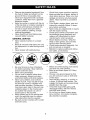 5
5
-
 6
6
-
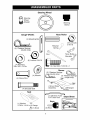 7
7
-
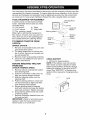 8
8
-
 9
9
-
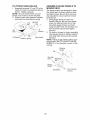 10
10
-
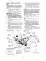 11
11
-
 12
12
-
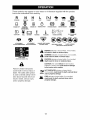 13
13
-
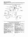 14
14
-
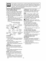 15
15
-
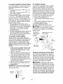 16
16
-
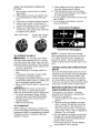 17
17
-
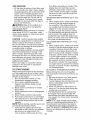 18
18
-
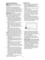 19
19
-
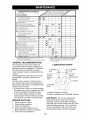 20
20
-
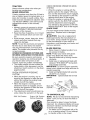 21
21
-
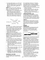 22
22
-
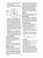 23
23
-
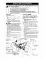 24
24
-
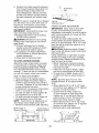 25
25
-
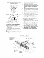 26
26
-
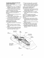 27
27
-
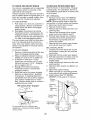 28
28
-
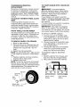 29
29
-
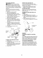 30
30
-
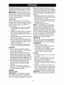 31
31
-
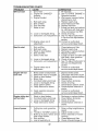 32
32
-
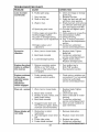 33
33
-
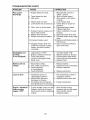 34
34
-
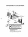 35
35
-
 36
36
-
 37
37
-
 38
38
-
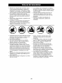 39
39
-
 40
40
-
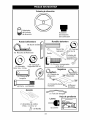 41
41
-
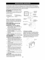 42
42
-
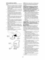 43
43
-
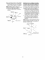 44
44
-
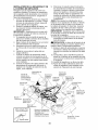 45
45
-
 46
46
-
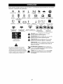 47
47
-
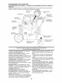 48
48
-
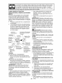 49
49
-
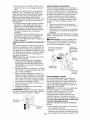 50
50
-
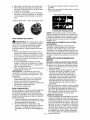 51
51
-
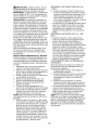 52
52
-
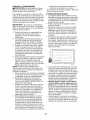 53
53
-
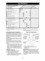 54
54
-
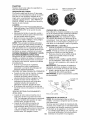 55
55
-
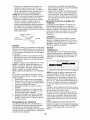 56
56
-
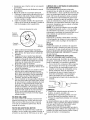 57
57
-
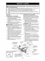 58
58
-
 59
59
-
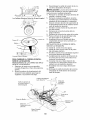 60
60
-
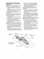 61
61
-
 62
62
-
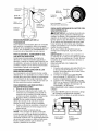 63
63
-
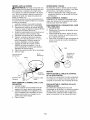 64
64
-
 65
65
-
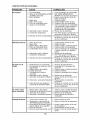 66
66
-
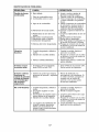 67
67
-
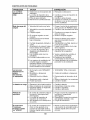 68
68
-
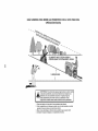 69
69
-
 70
70
-
 71
71
-
 72
72


Southern States 96012002500 El manual del propietario
- Categoría
- Cortadoras de césped
- Tipo
- El manual del propietario
- Este manual también es adecuado para
en otros idiomas
Artículos relacionados
-
 Southern States 96012002400 El manual del propietario
-
Southern States SO15538LT El manual del propietario
-
 Southern States 96012005700 El manual del propietario
-
 Southern States SO1638LT El manual del propietario
-
Southern States 96012005500 El manual del propietario
-
 Southern States 96012002200 El manual del propietario


