
PLEASE CONTACT US
BEFORE RETURNING
YOUR UNIT TO THE STORE
1-800-523-3987
www.sauder.com
Made in the USA
Archbold, OH
NOTE: THIS INSTRUCTION BOOKLET CONTAINS
IMPORTANT SAFETY INFORMATION.
PLEASE READ AND KEEP FOR FUTURE REFERENCE.
English .................... Page 1-27
Français ...............Pages 28-31
Espanol .............Páginas 32-36
Lot #: 354606 07 / 10 / 13
Date Purchased: ____________________
402159
Executive Desk
Heritage Collection

ASSEMBLY TOOLS REQUIRED
Hammer
No. 2 Phillips Screwdriver
Tip Shown Actual Size
ADULT ASSEMBLY REQUIRED
TABLE OF CONTENTS
Part Identifi cation ...................2-3
Hardware Identifi cation ......... 4-5
Assembly Steps ....................6-27
Français ..............................28-31
Espanol ...............................32-36
Safety .................................37-38
Warranty ...................................39
PART IDENTIFICATION: While not all parts are labeled, some of the parts will have a label or an inked
letter on the edge to help distinguish similar parts from each other. Use this PART IDENTIFICATION to help
identify similar parts.
A RIGHT END 1
B LEFT END 1
C2 RIGHT UPRIGHT 1
D2 LEFT UPRIGHT 1
E BACK 2
F2 TOP INSERT 1
G2 MODESTY PANEL 1
H LARGE DRAWER FRONT 3
D227 LARGE DRAWER BACK 3
D244 LARGE DRAWER SIDE 6
D794 LARGE DRAWER BOTTOM 3
L SMALL DRAWER FRONT 2
D229 SMALL DRAWER BACK 2
D233 SMALL DRAWER SIDE 4
D883 SMALL DRAWER BOTTTOM 2
P KEYBOARD FRONT 1
Q KEYBOARD BACK 1
R RIGHT KEYBOARD SIDE 1
S LEFT KEYBOARD SIDE 1
T KEYBOARD SHELF 1
U LONG MOLDING 2
V SHORT MOLDING 2
W SIDE MOLDING 4
X BASE MOLDING 4
Page 2 www.sauder.com/services 402159

PART IDENTIFICATION:
A
B
C2
D2
E
E
F2
G2
H
L
P
Q
R
S
T
U
U
V
V
W
W
W
W
X
X
X
X
Page 3
www.sauder.com/services402159
D244
D227
D883
D233
D229
D794
D233
D244

HARDWARE IDENTIFICATION
EE
RIGHT CABINET RAIL - 2
FF
LEFT CABINET RAIL - 2
HH
LEFT DRAWER SLIDE - 2
GG
RIGHT DRAWER SLIDE - 2
KEYBOARD RIGHT
CABINET RAIL -1
AA
KEYBOARD LEFT
CABINET RAIL -1
BB
CC
KEYBOARD RIGHT
DRAWER SLIDE -1
DD
KEYBOARD LEFT
DRAWER SLIDE - 1
(EXTENSION SET SHOWN SEPARATED)
Y
EXTENSION RAIL - 6
Z
EXTENSION SLIDE - 6
FILE ROD - 6
8B
FILE GLIDE - 6
5B
FILE DRAWER
FRONT BRACKET - 6
10G
SMALL DRAWER
FRONT BRACKET - 2
7G
TIE PLATE - 4
3G
LOCK BRACKET - 2
9J
TWIST-LOCK
®
FASTENER - 24
7F
HINGE - 2
16H
MOLDING
CONNECTOR - 4
17F
TACK GLIDE - 8
12E
MAGNETIC CATCH - 2
2I
LOCK COVER - 1
10J
STRIKE PLATE - 2
6I
LOCK PACK - 1
11J
Page 4 www.sauder.com/services 402159

HARDWARE IDENTIFICATION
Screws are shown actual size. You may receive extra hardware with your unit.
BLACK 9/16" PAN HEAD SCREW - 2
25S
BLACK 9/16" LARGE HEAD SCREW - 24
1S
BLACK 1-1/4" FLAT HEAD SCREW - 8
7S
SILVER 5/8" MACHINE SCREW - 20
15S
SILVER 7/8" PAN HEAD SCREW - 14
22S
BROWN 7/16" LARGE HEAD SCREW - 10
6S
BLACK 1-7/8" FLAT HEAD SCREW - 4
2S
GROMMET CAP - 1
1P
TOUCH-UP PEN - 1
9M
BROWN 1-1/2" FLAT HEAD SCREW - 6
14S
BROWN 1" FLAT HEAD SCREW - 4
18S
GOLD 5/16" FLAT HEAD SCREW - 44
3S
BLACK 1/2" FLAT HEAD SCREW - 2
11S
PULL - 10
77K
PULL MOUNT - 20
78K
10P
GROMMET - 1
Page 5
www.sauder.com/services402159

1
1
S
t
e
p
Look for this icon. It means a video
assembly tip is available at:
www.sauder.com/services/tips
Assemble your unit on a carpeted fl oor or on the empty carton to avoid scratching your unit or the fl oor.
To begin assembly, push a SAUDER TWIST-LOCK
®
FASTENER (7F) into the large holes in the RIGHT END (A), LEFT END (B),
and UPRIGHTS (C2 and D2).
Do not tighten the TWIST-LOCK® FASTENERS in this step.
Page 6 www.sauder.com/services 402159
A
7F
7F
7F
Scan this QR code or go to this address:
http://qr.sauder.com/?ID=673
to watch a video on how to assemble your unit.

2
2
S
t
e
p
Page 7
www.sauder.com/services402159
17F
17F
Tap four MOLDING CONNECTORS (17F) into the notches in the MOLDINGS (U and V).
Flat end
Flat end
U
U
V
V
Use your hammer to tap the MOLDING CONNECTOR (17F) into the notches in the MOLDINGS.

Fasten the MOLDINGS (U and V) to the TOP INSERT (F2). Use fourteen SILVER 7/8" PAN HEAD SCREWS (22S).
Fasten four TIE PLATES (3G) to the MOLDINGS (U and V). Use eight BLACK 9/16" LARGE HEAD SCREWS (1S).
3
3
S
t
e
p
Page 8 www.sauder.com/services 402159
U
U
V
V
F2
BLACK 9/16" LARGE HEAD SCREW
(8 used for the TIE PLATES)
1S
3G
3G
3G
SILVER 7/8" PAN HEAD SCREW
(14 used for the TOP)
22S

4
4
S
t
e
p
Page 9
www.sauder.com/services402159
Separate the EXTENSION SLIDES (Z) from the EXTENSION RAILS (Y) as shown in the upper diagram. Be prepared, the parts are
greasy.
Fasten the EXTENSION RAILS (Y) to the ENDS (A and B) and UPRIGHTS (C2 and D2). Use twelve GOLD 5/16" FLAT HEAD
SCREWS (3S).
NOTE: For each EXTENSION RAIL, turn a SCREW into the hole shown in the enlarged diagram. Then, slide the inner
cartridge of the EXTENSION RAIL in or out to find the other hole that lines up with the hole in the ENDS and UPRIGHTS. Turn a
SCREW into this hole.
Push the black lever in and pull the SLIDE from the RAIL.
Open end
Open end
Open end
GOLD 5/16" FLAT HEAD SCREW
(12 used in this step)
3S
Open end
A
B
C2
D2
Y
Y
Y
Y
Y
Y
Y
Finished edge
Finished edge
Z

5
5
S
t
e
p
Page 10 www.sauder.com/services 402159
Fasten the CABINET RAILS (EE and FF) to the RIGHT END (A) and RIGHT UPRIGHT (C2). Use eight GOLD 5/16" FLAT HEAD
SCREWS (3S) through holes #1 and #4.
NOTE: The CABINET RAILS are marked "CABINET RIGHT" and "CABINET LEFT" for easy identification.
Fasten the KEYBOARD RAILS (AA and BB) to the UPRIGHTS (C2 and D2). Use four GOLD 5/16" FLAT HEAD SCREWS (3S).
NOTE: The CABINET RAILS are marked "CABINET RIGHT" and "CABINET LEFT" for easy identification.
GOLD 5/16" FLAT HEAD SCREW
(12 used in this step)
3S
1
1
2
2
3
3
4
4
4
4
3
3
2
2
1
1
Roller end
Roller end
Finished edge
Finished edge
Finished edge
Finished edge
A
C2
C2
D2
Finished surface
Finished surface
AA
BB
EE
EE
FF
FF
Roller end
Roller end

6
6
S
t
e
p
Page 11
www.sauder.com/services402159
Fasten the ENDS (A and B) to the SHORT MOLDINGS (V). Tighten four TWIST-LOCK
®
FASTENERS.
Fasten the UPRIGHTS (C2 and D2) to the TOP INSERT (F2). Tighten four TWIST-LOCK
®
FASTENERS.
Dowel end
How to use the SAUDER TWIST-LOCK
®
FASTENER
1. Insert the dowel end of the FASTENER into the
hole of the adjoining part.
NOTE: The dowel end of the FASTENER must remain
fully inserted in the hole of the adjoining part while
locking the FASTENER.
2. Tighten the FASTENER with a Phillips screwdriver
as tight as possible.
A
B
V
V
C2
D2
F2
Finished edge
Finished edge

Fasten the MODESTY PANEL (G2) to the UPRIGHTS (C2 and D2). Use four BLACK 1-7/8" FLAT HEAD SCREWS (2S).
7
7
S
t
e
p
Page 12 www.sauder.com/services 402159
BLACK 1-7/8" FLAT HEAD SCREW
(4 used in this step)
2S
C2
D2
G2

Fasten the BACKS (E) to the ENDS (A and B) and UPRIGHTS (C2 and D2). Tighten eight TWIST-LOCK
®
FASTENERS.
8
8
S
t
e
p
Page 13
www.sauder.com/services402159
C2
D2
A
B
E
E

Fasten the SIDE MOLDINGS (W) to the ENDS (A and B) and UPRIGHTS (C2 and D2). Use eight BLACK 1- 1/4" FLAT HEAD
SCREWS (7S).
9
9
S
t
e
p
Page 14 www.sauder.com/services 402159
C2
D2
A
B
W
W
W
W
W
BLACK 1-1/4" FLAT HEAD SCREW
(8 used in this step)
7S
7S
Curved edge
Curved edge
Curved edge

Fasten the BASE MOLDINGS (X) to the ENDS (A and B) and UPRIGHTS (C2 and D2). Tighten eight TWIST-LOCK
®
FASTENERS.
10
10
S
t
e
p
Page 15
www.sauder.com/services402159
C2
D2
A
B
X
X
X
X
Curved edge
Curved edge
Curved edge
Curved edge

Using your hammer, tap the TACK GLIDES (12E) into the ENDS (A and B) and UPRIGHTS (C2 and D2).
11
11
S
t
e
p
Page 16 www.sauder.com/services 402159
A
B
C2
D2
12E
12E

Press a MAGNETIC CATCH (2I) into the large holes of the KEYBOARD SIDES (R and S).
Fasten the KEYBOARD SIDES (R and S) to the KEYBOARD BACK (Q) and then to the KEYBOARD SHELF (T). Use six
BROWN 1-1/2" FLAT HEAD SCREWS (14S).
NOTE: You should start each SCREW a few turns before completely tightening any of them.
12
12
S
t
e
p
Page 17
www.sauder.com/services402159
For adjustment turn the barrel
counter-clockwise.
2I
R
S
These surfaces should be the same color.
Q
R
S
T
Finished surface
Long fi nished edge
14S
BROWN 1-1/2" FLAT HEAD SCREW
(6 used in this step)

Fasten two STRIKE PLATES (6I) to the KEYBOARD FRONT (P). Use two BLACK 1/2" FLAT HEAD SCREWS (11S).
Fasten the HINGES (16H) to the KEYBOARD SHELF (T). Use four BROWN 7/16" LARGE HEAD SCREWS (6S).
Fasten the KEYBOARD FRONT (P) to the HINGES (TT). Use four BROWN 7/16" LARGE HEAD SCREWS (6S).
13
13
S
t
e
p
Page 18 www.sauder.com/services 402159
BROWN 7/16" LARGE HEAD SCREW
(8 used for the HINGES)
6S
BLACK 1/2" FLAT HEAD SCREW
(2 used in this step)
11S
P
P
T
6I
6I
16H

Fasten the KEYBOARD SLIDES (CC and DD) to the KEYBOARD SHELF (T). Use four BROWN 1 "FLAT HEAD SCREWS (18S).
NOTE: The DRAWER SLIDES are marked “DRAWER RIGHT” and “DRAWER LEFT” for easy identification.
14
14
S
t
e
p
Page 19
www.sauder.com/services402159
BROWN 1" FLAT HEAD SCREW
(4 used in this step)
18S
T
CC
DD

Carefully stand your unit upright.
Fasten the LOCK (11J) to the inside of the LEFT UPRIGHT (D2). Use two BLACK 9/16" PAN HEAD SCREWS (25S) through the
small holes in the LOCK and into the small pre-drilled holes in the inside of the LEFT UPRIGHT (D2).
Insert the LOCK RING (10J) over the key extension on the LOCK. When the drawers are locked, the metal bars on the LOCK will
extend beyond the LOCK BRACKETS (9J) on the large drawers in step 18. You may need to loosen the SCREWS that fasten the
LOCK BRACKETS and adjust the BRACKETS in or out.
15
15
S
t
e
p
Page 20 www.sauder.com/services 402159
11J
10J
BLACK 9/16" PAN HEAD SCREW
(2 used in this step)
25S
D2

16
16
S
t
e
p
Page 21
www.sauder.com/services402159
Slide the LARGE DRAWER SIDES (D244) onto the DRAWER BACK (D227).
Slide the DRAWER BOTTOM (D794) into the grooves in the DRAWER SIDES and DRAWER BACK.
Repeat this step for each drawer.
These edges
should be even.
Slide the SIDES down.
Groove
view the t-slot drawer video
Finished
D244
D227
D794
D244
D244
D227
D244

17
17
S
t
e
p
Page 22 www.sauder.com/services 402159
Pull the FILE DRAWER FRONT BRACKETS (10G) apart and slide them into the grooves in the DRAWER SIDES (D244).
Fasten the LARGE DRAWER FRONT (H) to the FILE DRAWER FRONT BRACKETS. Use four BLACK 9/16" LARGE HEAD SCREW (1S).
Repeat this step for the other drawers.
Tap down with your screwdriver and hammer.
BLACK 9/16" LARGE HEAD SCREW
(12 used in this step)
1S
view the t-slot drawer video
H
10G
D244
D244
D244

Fasten an EXTENSION SLIDE (Z) to each LARGE DRAWER SIDE (D244) as shown. Use two GOLD 5/16" FLAT HEAD SCREWS
(3S) through the round holes shown in each EXTENSION SLIDE and into the pre-drilled holes in the LARGE DRAWER SIDES.
Repeat this step for the other large drawers.
Fasten a LOCK BRACKET (9J) to two large drawers exactly as shown. Use a BROWN 7/16" LARGE HEAD SCREW (6S) through
the oblong hole in each LOCK BRACKET and into the exact pre-drilled hole shown in the LARGE DRAWER SIDES (D244).
18
18
S
t
e
p
Page 23
www.sauder.com/services402159
9J
9J
Z
Z
Z
Z
Use the slotted hole.
Use the slotted hole.
This drawer will be the lower drawer.
This drawer will be the upper drawer.
Open end
Open end
Open end
Open end
GOLD 5/16" FLAT HEAD SCREW
(12 used for the EXTENSION SLIDES)
3S
BROWN 7/16" LARGE HEAD SCREW
(2 used in this step)
6S
D244
D244
D244
D244

Pull the SMALL DRAWER FRONT BRACKETS (7G) apart and slide them into the grooves in the DRAWER SIDES (D233). You
may need to gently tap them in with a hammer.
NOTE: The DRAWER FRONT BRACKETS are marked “RH” and “LH” for easy identification.
Fasten the DRAWER FRONT (L) to the SMALL DRAWER FRONT BRACKETS. Use two BLACK 9/16" LARGE HEAD SCREWS (1S).
NOTE: Be sure the DRAWER BOTTOM (D883) fi ts into the groove in the DRAWER FRONT.
Repeat this step for the other small drawer.
19
19
S
t
e
p
Page 24 www.sauder.com/services 402159
7G
L
BLACK 9/16" LARGE HEAD SCREW
(4 used in this step)
1S
D883
D233
D233
D233

20
20
S
t
e
p
Page 25
www.sauder.com/services402159
Fasten the DRAWER SLIDES (GG and HH) to the DRAWER SIDES (D233). Use four GOLD 5/16" FLAT HEAD SCREWS (3S)
through holes 1# and # 3.
NOTE: The DRAWER SLIDES are marked “DRAWER RIGHT” and “DRAWER LEFT” for easy identification.
Repeat this step for the other small drawer.
GOLD 5/16" FLAT HEAD SCREW
(8 used for the SLIDES)
3S
Roller end
Roller end
1
2
3
1
2
3
GG
HH
D233
D233

Insert a PULL (77K ) into two PULL MOUNTS (78K) and fasten them to the LARGE DRAWER FRONTS. Use four SILVER 5/8"
MACHINE SCREWS (15S).
Push a FILE GLIDE (5B) onto the right LARGE DRAWER SIDE (D244).
Slide the FILE RODS (8B) into the FILE GLIDE (5B) on the right DRAWER SIDE.
Slide another FILE GLIDE (5B) onto the other end of the FILE RODS (8B), then press this FILE GLIDE over the left LARGE DRAWER
SIDE (D244).
Repeat this step for the other large drawers.
21
21
S
t
e
p
Page 26 www.sauder.com/services 402159
SILVER 5/8" MACHINE SCREW
(20 used for the PULLS)
15S
78K
77K
5B
5B
8B
8B
D244
D244

Insert a GROMMET (10P) and GROMMET CAP (1P) into th hole in the TOP INSERT (F2)
To insert a large drawer into your unit, line up the EXTENSION SLIDES on the drawer with the EXTENSION RAILS on the unit and
push the drawer into the unit until the drawer is fully inserted. The drawer will push in hard until it is all the way in, then it will slide
in and out easier.
To insert the small drawers into your unit, tip the front of the drawer down and drop the rollers on the drawer behind the rollers on the
unit. Lift the front of the drawer up and slide it into the unit. Repeat this step to insert the KEYBOARD SHELF (T).
NOTE: The DRAWER FRONTS may need adjustments. To adjust the DRAWER FRONTS, loosen the SCREWS in the DRAWER
FRONT BRACKETS. Make adjustments and tighten the SCREWS.
For long-term care and maintenance of your unit, you may touch up the edges with the TOUCH-UP PEN (9M).
NOTE: Please read the back pages of the instruction booklet for important safety information.
This completes assembly. Clean with your favorite furniture polish or a damp cloth. Wipe dry.
22
22
S
t
e
p
Page 27
www.sauder.com/services402159
10P
1P
T
F2
100 lbs.
35 lbs.
35 lbs.
35 lbs.
15 lbs.
15 lbs.
25 lbs.

A l’usage exclusif du
Canada Noter la date
d’achat de cet élément
et conserver le livret
pour future référence.
Pour contacter Sauder
en ce qui concerne cet
élément, faire référence
au numéro de lot et
numéro de modèle en
appelant notre numéro
sans frais.
Lot nº : ____________
Date de
l’achat: ____________
LISTE DE PIÈCES
REFERENCE DESCRIPTION QUANTITÉ
LISTE DE PIÈCES
REFERENCE DESCRIPTION QUANTITÉ
NOUS SOMMES LA POUR VOUS AIDER!
Nous faisons de notre mieux pour nous assurer que
votre meuble arrive dans d’excellentes conditions. Nos
représentants du service Clientèle sont aimables et prêts
à vous aider au cas où une pièce aurait été endommagée
ou manquerait (ou si vous aviez besoin d’aide pour
l’assemblage). NE RAMENEZ PAS LE MEUBLE AU
MAGASIN. Au Canada, composez ce numéro d’appel gratuit:
1-800-523-3987
Du lundi au vendredi, de 9 heures du matin à
5:30 heures du soir (horaire Côte Est)
(sauf jours fériés)
Si une pièce a besoin d’être remplacée, la pièce de
remplacement sera envoyée dans les 48 heures. (Sauf
week-ends et jours fériés)
Utilisez les instructions d’assemblage en français avec
les schémas étape par étape du manuel d’instruction
en anglais. Chaque étape en français correspond à la
même étape en anglais. La pièce devant être attachée
à l’élément est représentée en gris sur les schémas de
chaque étape pour plus de précision. Comparer la “Liste
de pièces” ci-dessous avec la “PART IDENTIFICATION”
du manuel en anglais pour vous familiariser avec les
pièces avant l’assemblage.
REMARQUE : CE MANUEL D’INSTRUCTIONS
CONTIENT D’IMPORTANTES INFORMATIONS
RELATIVES À LA SÉCURITÉ. À LIRE ET CONSERVER
POUR TOUTE RÉFÉRENCE FUTURE.
FF GLISSIÈRE GAUCHE D'ÉLÉMENT ...............2
GG COULISSE DROITE DE TIROIR ....................2
HH COULISSE GAUCHE DE TIROIR ..................2
5B ARMATURE POUR DOSSIERS .....................6
8B TIGE DE DOSSIER ........................................6
12E PATIN .............................................................8
7F FIXATION TWIST-LOCK® ............................24
17F CONNECTEUR DE MOULURE .....................4
3G PLAQUE D’ATTACHE ....................................4
7G CONSOLE DE DEVANT DE PETIT TIROIR ..2
10G CONSOLE DE DEVANT DE TIROIR POUR
DOSSIERS .....................................................6
16H CHARNIÈRE ..................................................2
2I LOQUETEAU MAGNÉTIQUE ........................2
6I PLAQUE DE BUTÉE ......................................2
9J CONSOLE DE VERROU ...............................2
10J COUVERCLE DE VERROU ...........................1
11J ENSEMBLE DE SERRURE ...........................1
77K POIGNÉE .....................................................10
78K MONTURE DE POIGNÉE ............................20
9M FEUTRE DE RETOUCHE ..............................1
1P COUVERCLE DE PASSE-CÂBLES ...............1
10P PASSE-CÂBLES ............................................1
1S VIS TÊTE LARGE 14 mm NOIRE ................24
2S VIS TÊTE PLATE 48 mm NOIRE ...................4
3S VIS TÊTE PLATE 8 mm DORÉE ..................44
6S VIS TÊTE LARGE 11 mm MARRON ............10
7S VIS TÊTE PLATE 32 mm NOIRE ...................8
11S VIS TÊTE PLATE 13 mm NOIRE ...................2
14S VIS TÊTE PLATE 38 mm MARRON ..............6
15S VIS À MÉTAUX 16 mm ARGENT .................20
18S VIS TÊTE PLATE 25 mm MARRON ..............4
22S
VIS TÊTE GOUTTE DE SUIF 22 mm ARGENT ...14
25S VIS TÊTE GOUTTE DE SUIF 14 mm NOIRE 2
A EXTRÉMITÉ DROITE ....................................1
B EXTRÉMITÉ GAUCHE...................................1
C2 MONTANT DROIT ..........................................1
D2 MONTANT GAUCHE ......................................1
E ARRIÈRE .......................................................2
F2 INSERT SUPÉRIEUR ....................................1
G2 VOILE DE FOND ............................................1
H DEVANT DE GRAND TIROIR ........................3
D227 ARRIÈRE DE GRAND TIROIR ......................3
D244 CÔTÉ DE GRAND TIROIR ............................6
D794 FOND DE GRAND TIROIR ............................3
L DEVANT DE PETIT TIROIR ...........................2
D229 ARRIÈRE DE PETIT TIROIR .........................2
D233 CÔTÉ DE PETIT TIROIR ...............................4
D883 FOND DE PETIT TIROIR ...............................2
P DEVANT DE TABLETTE DE CLAVIER ..........1
Q ARRIÈRE DE TABLETTE DE CLAVIER ........1
R
CÔTÉ DROIT DE LA TABLETTE DE CLAVIER ...1
S
CÔTÉ GAUCHE DE LA TABLETTE DE CLAVIER .
1
T TABLETTE DE CLAVIER ...............................1
U LONGUE MOULURE .....................................2
V COURTE MOULURE .....................................2
W MOULURE LATÉRALE ..................................4
X MOULURE DE SOCLE ..................................4
(ENSEMBLE DE GLISSIÈRE ILLUSTRÉ À PART)
Y GLISSIÈRE D'EXTENSION ...........................6
Z COULISSE D'EXTENSION ............................6
AA GLISSIÈRE DROITE D'ÉLÉMENT POUR
CLAVIER ........................................................1
BB GLISSIÈRE GAUCHE D'ÉLÉMENT
POUR CLAVIER .............................................1
CC
COULISSE DE TIROIR DROITE POUR CLAVIER .1
DD
COULISSE DE TIROIR GAUCHE POUR CLAVIER 1
EE GLISSIÈRE DROITE D'ÉLÉMENT .................2
Bureau Ministre402159
Page 28 www.sauder.com/services 402159

ÉTAPE 6
Utilisation de la FIXATION TWIST-LOCK® SAUDER
1. Insérer l'extrémité fi letée de la FIXATION dans le trou
de la pièce attenante.
REMARQUE : L'extrémité fi letée de la FIXATION doit
rester complètement insérée dans le trou de la pièce
attenante lorsque l'on bloque la FIXATION.
2. Bien serrer la FIXATION à l'aide d'un tournevis Phillips.
Fixer les EXTRÉMITÉS (A et B) aux COURTES
MOULURES (V). Serrer quatre FIXATIONS TWIST-LOCK®.
Fixer les MONTANTS (C2 et D2) à l’INSERT
SUPÉRIEUR (F2). Serrer quatre FIXATIONS TWIST-LOCK®.
ÉTAPE 7
Fixer le VOILE DE FOND (G2) aux MONTANTS (C2 et D2).
Utiliser quatre VIS TÊTE PLATE 48 mm NOIRES (2S).
ÉTAPE 8
Fixer les ARRIÈRES (E) aux EXTRÉMITÉS (A et B) et
aux MONTANTS (C2 et D2). Serrer huit FIXATIONS
TWIST-LOCK®.
ÉTAPE 9
Fixer les MOULURES LATÉRALES (W) aux
EXTRÉMITÉS (A et B) et aux MONTANTS (C2 et D2).
Utiliser huit VIS TÊTE PLATE 32 mm NOIRES (7S).
ÉTAPE 10
Fixer les MOULURES DE SOCLE (X) aux
EXTRÉMITÉS (A et B) et aux MONTANTS (C2 et D2).
Serrer huit FIXATIONS TWIST-LOCK®.
ÉTAPE 5
Fixer les GLISSIÈRES D'ÉLÉMENT (EE et FF) à
l'EXTRÉMITÉ DROITE (A) et au MONTANT DROIT (C2).
Utiliser huit VIS TÊTE PLATE 8 mm DORÉES (3S) à
travers les trous nº 1 et nº 4.
REMARQUE : Les GLISSIÈRES D'ÉLÉMENT ont une
inscription « CABINET RIGHT » (droite) et « CABINET
LEFT » (gauche) pour faciliter leur identifi cation.
Fixer les GLISSIÈRES DE TABLETTE DE CLAVIER (AA
et BB) aux MONTANTS (C2 et D2). Utiliser quatre VIS
TÊTE PLATE 8 mm DORÉES (3S).
REMARQUE : Les GLISSIÈRES D'ÉLÉMENT ont une
inscription « CABINET RIGHT » (droite) et « CABINET
LEFT » (gauche) pour faciliter leur identifi cation.
ÉTAPE 4
Séparer les COULISSES D'EXTENSION (Z) des
GLISSIÈRES D'EXTENSION (Y) comme l'indique le schéma
du haut. Faire attention car les pièces sont graissées.
Fixer les GLISSIÈRES D'EXTENSION (Y) aux
EXTRÉMITÉS (A et B) et aux MONTANTS (C2 et D2).
Utiliser douze VIS TÊTE PLATE 8 mm DORÉES (3S).
REMARQUE : Pour chaque GLISSIÈRE D'EXTENSION,
faire tourner une VIS dans le trou indiqué dans le
schéma agrandi. Ensuite, enfi ler la cartouche interne
de la GLISSIÈRE D'EXTENSION vers l'intérieur ou vers
l'extérieur pour trouver l'autre trou qui est aligné sur le
trou dans les EXTRÉMITÉS et les MONTANTS. Faire
tourner une VIS dans ce trou.
ÉTAPE 3
Fixer les MOULURES (U et V) à l’INSERT
SUPÉRIEUR (F2). Utiliser quatorze VIS TÊTE GOUTTE
DE SUIF 22 mm ARGENT (22S).
Fixer quatre PLAQUES DE CONNECTEUR (3G) aux
MOULURES (U et V). Utiliser huit VIS TÊTE LARGE 14
mm NOIRES (1S).
ÉTAPE 2
Enfoncer quatre CONNECTEURS DE MOULURE (17F)
dans les crans des MOULURES (U et V).
ÉTAPE 1
Ne pas serrer les FIXATIONS TWIST-LOCK® à cette
étape.
Assembler l'élément sur un sol à moquette ou sur le
carton vide pour éviter d'endommager l'élément ou le sol.
Pour commencer l'assemblage, enfoncer une FIXATION
TWIST-LOCK® SAUDER (7F) dans les gros trous de
l'EXTRÉMITÉ DROITE (A), l'EXTRÉMITÉ GAUCHE (B)
et les MONTANTS (C2 et D2).
Page 29
www.sauder.com/services402159
ÉTAPE 11
À l’aide d’un marteau, enfoncer huit PATINS (12E) dans les
EXTRÉMITÉS (A et B) et les MONTANTS (C2 et D2).
ÉTAPE 12
Appuyer un LOQUETEAU MAGNÉTIQUE (2I) dans les gros
trous des CÔTÉS DE TABLETTE DE CLAVIER (R et S).
Fixer les CÔTÉS DE TABLETTE DE CLAVIER (R et S)
à l'ARRIÈRE DE TABLETTE DE CLAVIER (Q) et ensuite
à la TABLETTE DE CLAVIER (T). Utiliser six VIS TÊTE
PLATE 38 mm MARRON (14S).
REMARQUE : Il est préférable de donner quelques
tours de tournevis à chaque VIS avant de les serrer
toutes à bloc.

ÉTAPE 15
Relever, avec précaution, l'élément dans sa position verticale.
Fixer le VERROU (11J) sur l’intérieur du MONTANT
GAUCHE (D2). Utiliser deux VIS TÊTE GOUTTE DE
SUIF 14 mm NOIRES (25S) à travers les petits trous du
VERROU et dans les petits trous pré-percés à l’intérieur
du MONTANT GAUCHE.
Insérer le CACHE DE VERROU (10J) sur la prolongation
de clé sur le VERROU. Une fois les tiroirs verrouillés, les
tiges en métal sur le VERROU s’étendront au-delà des
CONSOLES DE VERROU (9J) sur les grands tiroirs à
l’étape 18. Il faudra peut-être desserrer les VIS qui fi xent
les CONSOLES DE VERROU et ajuster les CONSOLES
vers l’intérieur ou l’extérieur.
ÉTAPE 19
Séparer les CONSOLES DE DEVANT DE PETIT
TIROIR (7G) et les enfi ler dans les rainures des CÔTÉS
DE TIROIR (D233). Il est peut-être nécessaire de les
enfoncer délicatement à l'aide d'un marteau.
REMARQUE : Les CONSOLES DE DEVANT DE
TIROIR ont l'inscription "RH" (Droite) et l'inscription "LH"
(Gauche) pour faciliter leur identifi cation.
Fixer le DEVANT DE TIROIR (L) aux CONSOLES DE
DEVANT DE PETIT TIROIR. Utiliser deux VIS TÊTE
LARGE 14 mm NOIRES (1S).
REMARQUE : S'assurer que le FOND DE TIROIR (D883)
s'encastre dans la rainure du DEVANT DE TIROIR.
Répéter cette étape pour l'autre petit tiroir.
ÉTAPE 14
Fixer les COULISSES DE TABLETTE DE
CLAVIER (CC et DD) à la TABLETTE DE CLAVIER (T).
Utiliser quatre VIS TÊTE PLATE 25 mm MARRON (18S).
REMARQUE : Les COULISSES DE TIROIR ont
une inscription “DRAWER RIGHT” (droite) et une
inscription “DRAWER LEFT” (gauche) pour faciliter leur
identifi cation.
ÉTAPE 13
Fixer deux PLAQUES DE BUTÉE (6I) au DEVANT DE
TABLETTE DE CLAVIER (P). Utiliser deux VIS TÊTE
PLATE 13 mm NOIRES (11S).
Fixer les CHARNIÈRES (16H) à la TABLETTE DE
CLAVIER (T). Utiliser quatre VIS TÊTE LARGE 11 mm
MARRON (6S).
Fixer le DEVANT DE TABLETTE DE CLAVIER (P) aux
CHARNIÈRES (TT). Utiliser quatre VIS TÊTE LARGE 11
mm MARRON (6S).
ÉTAPE 18
Fixer une COULISSE D’EXTENSION (Z) sur chaque
CÔTÉ DE GRAND TIROIR (D244) comme l’indique le
schéma. Utiliser deux VIS TÊTE PLATE 8 mm DORÉES
(3S) à travers les trous ronds illustrés dans chaque
COULISSE D’EXTENSION et dans les trous pré-percés
des CÔTÉS DE GRAND TIROIR.
Répéter cette étape pour les autres grands tiroirs.
Fixer un CONSOLE DE VERROU (9J) sur les deux
grands tiroirs exactement comme il l’est indiqué. Utiliser
une VIS TÊTE LARGE 11 mm MARRON (6S) à travers
le trou oblong dans chaque CONSOLE DE VERROU
et dans le trou pré-percé exact dans les CÔTÉS DE
GRAND TIROIR (D244).
ÉTAPE 17
Séparer les CONSOLES DE DEVANT DE TIROIR
POUR DOSSIERS (10G) et les enfi ler dans les rainures
des CÔTÉS DE TIROIR (D244).
Fixer le DEVANT DE GRAND TIROIR (H) aux
CONSOLES DE DEVANT DE TIROIR POUR
DOSSIERS. Utiliser quatre VIS TÊTE LARGE 14 mm
NOIRES (1S).
Répéter cette étape pour les autres tiroirs.
ÉTAPE 16
Enfi ler les CÔTÉS DE GRAND TIROIR (D244) sur
l'ARRIÈRE DE TIROIR (D227).
Enfi ler le FOND DE TIROIR (D794) dans les rainures
des CÔTÉS DE TIROIR et de l'ARRIÈRE DE TIROIR.
Répéter cette étape pour chaque tiroir.
Page 30 www.sauder.com/services 402159

ÉTAPE 22
Insérer un PASSE-CÂBLES (10P) et un COUVERCLE
DE PASSE-CÂBLES (1P) dans le trou sur l’INSERT
SUPÉRIEUR (F2).
Pour insérer un grand tiroir dans l'élément, aligner
les COULISSES D'EXTENSION du tiroir sur les
GLISSIÈRES D'EXTENSION de l'élément et enfoncer
le tiroir dans l'élément jusqu'à ce que le tiroir soit
complètement inséré. Le tiroir offrira une certaine
résistance jusqu'à ce qu'il soit complètement inséré dans
l'élément, il glissera ensuite sans diffi culté.
Pour insérer les petits tiroirs dans l'élément, abaisser le
devant du tiroir et faire passer les roulettes situées sur le
tiroir derrière les roulettes situées sur l'élément. Relever
le devant du tiroir et l'enfi ler dans l'élément. Répéter
cette étape pour insérer la TABLETTE DE CLAVIER (T).
REMARQUE : Il est peut-être nécessaire d'ajuster les
DEVANTS DE TIROIR. Pour ajuster les DEVANTS
DE TIROIR, desserrer les VIS des CONSOLES DE
DEVANT DE TIROIR. Ajuster et resserrer les VIS.
Pour un entretien à long terme de l'élément, il est
possible de retoucher les chants à l'aide du FEUTRE DE
RETOUCHE (9M).
REMARQUE : Prière de lire les informations importantes
sur la sécurité fi gurant sur les pages arrière du manuel
d’instructions.
Ceci complète l'assemblage. Nettoyer à l’aide d’une
encaustique pour meubles ou d’un chiffon humide.
Essuyer.
ÉTAPE 21
Insérer une POIGNÉE (77K) dans deux MONTURES DE
POIGNÉE (78K) et les fi xer aux DEVANTS DE GRAND
TIROIR. Utiliser quatre VIS À MÉTAUX 16 mm ARGENT (15S).
Enfoncer une ARMATURE POUR DOSSIERS (5B) sur
le CÔTÉ DE GRAND TIROIR (D244).
Enfi ler les GUIDES POUR DOSSIERS (8B) dans
l'ARMATURE POUR DOSSIERS (5B) située sur le
CÔTÉ DROIT DE TIROIR.
Enfi ler une autre ARMATURE POUR DOSSIERS (5B)
sur l'autre extrémité des GUIDES POUR DOSSIERS (8B)
et appuyer cette ARMATURE POUR DOSSIERS sur le
CÔTÉ GAUCHE DE GRAND TIROIR (D244).
Répéter cette étape pour les autres grands tiroirs.
ÉTAPE 20
Fixer les COULISSES DE TIROIR (GG et HH) aux CÔTÉS
DE TIROIR (D233). Utiliser quatre VIS TÊTE PLATE 8 mm
DORÉES (3S) à travers les trous nº 1 et nº 3.
REMARQUE : Les COULISSES DE TIROIR ont
une inscription “DRAWER RIGHT” (droite) et une
inscription “DRAWER LEFT” (gauche) pour faciliter leur
identifi cation.
Répéter cette étape pour l'autre petit tiroir.
Page 31
www.sauder.com/services402159

Use estas instrucciones de ensamblaje en español junto
con las fi guras paso-a-paso provistas en el folleto inglés.
Cada paso en español corresponde al mismo paso en
inglés. Se destacan las fi guras de cada paso con una
tonalidad oscura para mostrar precisamente cual parte se
debe montar a la unidad. Compare la “Lista de Part” abajo
con la “Part Identifi cation” en el folleto en inglés para
familiarizarse con Las partes de ensamblaje.
NOTA: ESTE FOLLETO DE INSTRUCCIONES
CONTIENE INFORMACIÓN IMPORTANTE SOBRE LA
SEGURIDAD. POR FAVOR LEA Y GUÁRDELO PARA
REFERENCIA EN EL FUTURO.
ESTAMOS AQUI PARA AYUDAR!
Tratamos de asegurar que su mueble llega en condición
excelente. Nuestros representantes de Servicio al Cliente
son amables y listos para ayudarle con servicio rápido
y efi ciente si una parte está defectuosa o ausente (o si
necesita ayuda con el ensamblaje). NO DEVUELVA LA
UNIDAD A LA TIENDA. Llame este número sin cargo:
1-800-523-3987
Lunes a viernes, 9:00 a.m. - 5:30 p.m.
Hora ofi cial del Este
(excepto días festivos)
Si requiere un repuesto de una parte, será enviado dentro
de 48 horas (excepto los fi nes de semana y días festivos)
Anote la fecha de
comprar esta unidad y
guarde el folleto para
su referencia futura.
Si necesita ponerse
en contacto con
Sauder en cuanto a
esta unidad, refi érase
al número de lote y
al número de modelo
cuando llame a nuestro
número gratis.
No. Lote: ___________
Fecha
de compra: _________
LISTA DE PARTES
ITEM DESCRIPCIÓN CANTIDAD
LISTA DE PARTES
ITEM DESCRIPCIÓN CANTIDAD
5B CORRIMIENTO DE ARCHIVERO ..................6
8B VARILLA DE ARCHIVERO .............................6
12E TACHUELA DESLIZANTE ..............................8
7F SUJETADOR TWIST-LOCK® ......................24
17F CONECTOR DE MOLDURA ..........................4
3G PLACA DE CONEXIÓN ..................................4
7G
MÉNSULA DE CARA DE CAJÓN PEQUEÑO..........2
10G MÉNSULA DE CARA DE CAJÓN DE ARCHIVERO 6
16H BISAGRA ........................................................2
2I AGARRADOR MAGNÉTICO..........................2
6I PLACA DE CONTACTO .................................2
9J SOPORTE DE CERRADURA ........................2
10J CUBIERTA DE CERRADURA ........................1
11J PAQUETE DE CERRADURA .........................1
77K TIRADOR .....................................................10
78K MONTAJE DE TIRADOR .............................20
9M PLUMA DE RETOQUE ...................................1
1P CUBIERTA DE OJAL ......................................1
10P OJAL ...............................................................1
1S TORNILLO NEGRO DE CABEZA GRANDE de
14 mm ..........................................................24
2S TORNILLO NEGRO DE CABEZA PERDIDA de
48 mm ............................................................4
3S TORNILLO DORADO DE CABEZA PERDIDA
de 8 mm .......................................................44
6S TORNILLO MARRÓN DE CABEZA GRANDE
de 11 mm ......................................................10
7S TORNILLO NEGRO DE CABEZA PERDIDA de
32 mm ............................................................8
11S TORNILLO NEGRO DE CABEZA PERDIDA de
13 mm ............................................................2
14S TORNILLO MARRÓN DE CABEZA PERDIDA
de 38 mm .......................................................6
15S TORNILLO PLATEADO PARA METAL de 16
mm................................................................20
18S TORNILLO MARRÓN DE CABEZA PERDIDA
de 25 mm .......................................................4
22S TORNILLO PLATEADO DE CABEZA
REDONDA de 22 mm ...................................14
25S TORNILLO NEGRO DE CABEZA REDONDA
de 14 mm .......................................................2
A EXTREMO DERECHO ...................................1
B EXTREMO IZQUIERDO .................................1
C2 PARAL DERECHO .........................................1
D2 PARAL IZQUIERDO .......................................1
E DORSO ..........................................................2
F2
INSERCIÓN DEL PANEL SUPERIOR .................1
G2 VELO DE FONDO ..........................................1
H CARA DE CAJÓN GRANDE ..........................3
D227 DORSO DE CAJÓN GRANDE .......................3
D244 LADO DE CAJÓN GRANDE ..........................6
D794 FONDO DE CAJÓN GRANDE .......................3
L CARA DE CAJÓN PEQUEÑO .......................2
D229 DORSO DE CAJÓN PEQUEÑO ....................2
D233 LADO DE CAJÓN PEQUEÑO .......................4
D883 FONDO DE CAJÓN PEQUEÑO ....................2
P CARA DE ESTANTE DE TECLADO ..............1
Q
DORSO DE ESTANTE DE TECLADO ...............1
R LADO DERECHO DE ESTANTE DE TECLADO ..........1
S LADO IZQUIERDO DE ESTANTE DE TECLADO .1
T ESTANTE DE TECLADO ...............................1
U MOLDURA LARGA .........................................2
V MOLDURA CORTA .........................................2
W MOLDURA LATERAL .....................................4
X MOLDURA DE BASE .....................................4
(JUEGO DE EXTENSIÓN SE MUESTRA POR SEPARADO)
Y RIEL DE EXTENSIÓN ....................................6
Z CORREDERA DE EXTENSIÓN .....................6
AA RIEL DERECHO DEL GABINETE PARA
EL TECLADO .................................................1
BB RIEL IZQUIERDO DEL GABINETE PARA
EL TECLADO .................................................1
CC CORREDERA DERECHA DEL CAJÓN
DEL TECLADO ...............................................1
DD CORREDERA IZQUIERDA DEL CAJÓN
DEL TECLADO ...............................................1
EE RIEL DERECHO DE GABINETE ...................2
FF RIEL IZQUIERDO DE GABINETE .................2
GG CORREDERA DERECHA DE CAJÓN ...........2
HH CORREDERA IZQUIERDA DE CAJÓN .........2
402159 Escritorio Ejecutivo
Page 32 www.sauder.com/services 402159

PASO 5
Fije los RIELES DE GABINETE (EE y FF) al EXTREMO
DERECHO (A) y al PARAL DERECHO (C2). Utilice ocho
TORNILLOS DORADOS DE CABEZA PERDIDA de 8
mm (3S) a través de los agujeros No. 1 y No. 4.
NOTA: Los RIELES DE GABINETE tienen la inscripción
"CABINET RIGHT" (derecho) y la inscripción "CABINET
LEFT" (izquierdo) para identifi carlos fácilmente.
Fije los RIELES DE ESTANTE DE TECLADO (AA y BB)
a los PARALES (C2 y D2). Utilice cuatro TORNILLOS
DORADOS DE CABEZA PERDIDA de 8 mm (3S).
NOTA: Los RIELES DE GABINETE tienen la inscripción
"CABINET RIGHT" (derecho) y la inscripción "CABINET
LEFT" (izquierdo) para identifi carlos fácilmente.
PASO 4
Separe las CORREDERAS DE EXTENSIÓN (Z) de los
RIELES DE EXTENSIÓN (Y) como se muestra en el
diagrama superior. Prepárese, las piezas son grasientas.
Fije los RIELES DE EXTENSIÓN (Y) a los EXTREMOS (A y B) y
a los PARALES (C2 y D2). Utilice doce TORNILLOS DORADOS
DE CABEZA PERDIDA de 8 mm (3S).
NOTA: Para cada RIEL DE EXTENSIÓN, atornille un
TORNILLO dentro del agujero indicado en el diagrama
ampliado. A continuación deslice el cartucho interno del
RIEL DE EXTENSIÓN hacia el interior o exterior para
encontrar el otro agujero que se alinea con el agujero
de los EXTREMOS y PARALES. Atornille un TORNILLO
dentro de este agujero.
PASO 8
Fije los DORSOS (E) a los EXTREMOS (A y B) y a los
PARALES (C2 y D2). Apriete ocho SUJETADORES
TWIST-LOCK®.
PASO 3
Fije las MOLDURAS (U y V) a la INSERCIÓN DEL
PANEL SUPERIOR (F2). Utilice catorce TORNILLOS
PLATEADOS DE CABEZA REDONDA de 22 mm (22S).
Fije cuatro PLACAS DE CONEXIÓN (3G) a las
MOLDURAS (U y V). Utilice ocho TORNILLOS
NEGROS DE CABEZA GRANDE de 14 mm (1S).
PASO 7
Fije el VELO DE FONDO (G2) a los PARALES (C2 y D2).
Utilice cuatro TORNILLOS NEGROS DE CABEZA PERDIDA
de 48 mm (2S).
PASO 2
Ligeramente clave cuatro CONECTORES DE
MOLDURA (17F) dentro de las muescas de las
MOLDURAS (U y V).
PASO 6
Cómo utilizar el SUJETADOR TWIST-LOCK® SAUDER
1. Inserte el extremo con cabilla del SUJETADOR dentro
del agujero de la parte adjunta.
NOTA: El extremo con cabilla del SUJETADOR debe
quedarse completamente insertado en el agujero de la
parte adjunta cuando se enclava el SUJETADOR.
2. Apriete el SUJETADOR lo más apretado posible con
un destornillador Phillips (cruz).
Fije los EXTREMOS (A y B) a las MOLDURAS CORTAS (V).
Apriete cuatro SUJETADORES TWIST-LOCK®.
Fije los PARALES (C2 y D2) a la INSERCIÓN DEL
PANEL SUPERIOR (F2). Apriete cuatro SUJETADORES
TWIST-LOCK®.
PASO 1
No apriete los SUJETADORES TWIST-LOCK® en este paso.
Ensamble la unidad sobre un piso alfombrado o sobre el
cartón vacío para evitar rayar la unidad o el piso.
Para comenzar el ensamblaje, empuje un SUJETADOR
TWIST-LOCK® SAUDER (7F) dentro de los agujeros
grandes del EXTREMO DERECHO (A), del EXTREMO
IZQUIERDO (B) y de los PARALES (C2 y D2).
Page 33
www.sauder.com/services402159

PASO 15
Cuidadosamente ponga la unidad en posición vertical.
Fije la CERRADURA (11J) al interior del PARAL
IZQUIERDO (D2). Use dos TORNILLOS NEGROS
DE CABEZA REDONDA de 14 mm (25S) a través de
los agujeros pequeños en la CERRADURA y hacia los
agujeros pequeños ya perforados al interior del PARAL
IZQUIERDO.
Inserte la CUBIERTA DE CERRADURA (10J) sobre
la extensión de llave de la CERRADURA. Cuando los
cajones estén asegurados, las barras metálicas del
SEGURO se extenderán más allá de los SOPORTES
DE CERRADURA (9J) de los cajones grandes en
el paso 18. Es posible que tenga que afl ojar los
TORNILLOS que aseguran los SOPORTES DE
CERRADURA y ajustar los SOPORTES dentro o fuera.
PASO 14
Fije las CORREDERAS DE ESTANTE DE
TECLADO (CC y DD) al ESTANTE DE TECLADO (T).
Utilice cuatro TORNILLOS MARRONES DE CABEZA
PERDIDA de 25 mm (18S).
NOTA: Las CORREDERAS DE CAJÓN tienen
una inscripción "DRAWER RIGHT" (derecha) y
una inscripción "DRAWER LEFT" (izquierda) para
identifi carlas fácilmente.
PASO 13
Fije dos PLACAS DE CONTACTO (6I) a la CARA DE
ESTANTE DE TECLADO (P). Utilice dos TORNILLOS
NEGROS DE CABEZA PERDIDA de 13 mm (11S).
Fije las BISAGRAS (16H) al ESTANTE DE TECLADO (T).
Utilice cuatro TORNILLOS MARRONES DE CABEZA GRANDE
de 11 mm (6S).
Fije la CARA DE ESTANTE DE TECLADO (P) a
las BISAGRAS (TT). Utilice cuatro TORNILLOS
MARRONES DE CABEZA GRANDE de 11 mm (6S).
Page 34 www.sauder.com/services 402159
PASO 10
Fije las MOLDURAS DE BASE (X) a los EXTREMOS (A y B)
y a los PARALES (C2 y D2). Apriete ocho SUJETADORES
TWIST-LOCK®.
PASO 9
Fije las MOLDURAS LATERALES (W) a los
EXTREMOS (A y B) y a los PARALES (C2 y D2). Utilice ocho
TORNILLOS NEGROS DE CABEZA PERDIDA de 32 mm (7S).
PASO 11
Utilizando un martillo, golpee las TACHUELAS
DESLIZANTES (12E) en los EXTREMOS (A y B) y los
PARALES (C2 y D2).
PASO 12
Presione un AGARRADOR MAGNÉTICO (2I) dentro de
los agujeros grandes de los LADOS DE ESTANTE DE
TECLADO (R y S).
Fije los LADOS DE ESTANTE DE TECLADO (R y S)
al DORSO DE ESTANTE DE TECLADO (Q) y al fi n al
ESTANTE DE TECLADO (T). Utilice seis TORNILLOS
MARRONES DE CABEZA PERDIDA de 38 mm (14S).
NOTA: Debe apretar cada TORNILLO unas vueltas
antes de apretar cualquier tornillo fi rmemente.

PASO 20
Fije las CORREDERAS DE CAJÓN (GG y HH) a los
LADOS DE CAJÓN (D233). Utilice cuatro TORNILLOS
DORADOS DE CABEZA PERDIDA de 8 mm (3S) a
través de los agujeros No. 1 y No. 3.
NOTA: Las CORREDERAS DE CAJÓN tienen
una inscripción "DRAWER RIGHT" (derecha) y
una inscripción "DRAWER LEFT" (izquierda) para
identifi carlas fácilmente.
Repita este paso para el otro cajón pequeño.
PASO 19
Separe las MÉNSULAS DE CARA DE CAJÓN
PEQUEÑO (7G) y deslícelas dentro de las ranuras de
los LADOS DE CAJÓN (D233). Puede ser necesario
que las clave ligeramente adentro con un martillo.
NOTA: Las MÉNSULAS DE CARA DE CAJÓN tienen
una inscripción "RH" (derecha) y una inscripción "LH"
(izquierda) para identifi carlas fácilmente.
Fije la CARA DE CAJÓN (L) a las MÉNSULAS DE
CARA DE CAJÓN PEQUEÑO. Utilice dos TORNILLOS
NEGROS DE CABEZA GRANDE de 14 mm (1S).
NOTA: Asegúrese que el FONDO DE CAJÓN (D883)
ajuste dentro de la ranura de la CARA DE CAJÓN.
Repita este paso para el otro cajón pequeño.
PASO 18
Fije una CORREDERA DE EXTENSIÓN (Z) a cada
LADO DE CAJÓN GRANDE (D244) como se muestra.
Inserte dos TORNILLOS DORADOS DE CABEZA
PERDIDA de 8 mm (3S) a través de los agujeros
redondos en cada una de las CORREDERAS
DE EXTENSIÓN y entre los agujeros perforados
previamente en los LADOS DE CAJÓN GRANDE.
Repita este paso para los otros cajones grandes.
Fije un SOPORTE DE CERRADURA (9J) a los dos
cajones grandes tal como se muestra. Inserte un
TORNILLO MARRÓN DE CABEZA GRANDE de 11
mm (6S) a través del agujero alargado en cada uno de
los SOPORTES DE CERRADURA y entre el agujero
perforado previamente de los LADOS DE CAJÓN
GRANDE (D244).
PASO 17
Separe las MÉNSULAS DE CARA DE CAJÓN DE
ARCHIVERO (10G) y deslícelas dentro de las ranuras
de los LADOS DE CAJÓN (D244).
Fije la CARA DE CAJÓN GRANDE (H) a las
MÉNSULAS DE CARA DE CAJÓN DE ARCHIVERO.
Utilice cuatro TORNILLOS NEGROS DE CABEZA
GRANDE de 14 mm (1S).
Repita este paso para los otros cajones.
PASO 16
Deslice los LADOS DE CAJÓN GRANDE (D244) sobre
el DORSO DE CAJÓN (D227).
Deslice el FONDO DE CAJÓN (D794) dentro de las ranuras
de los LADOS DE CAJÓN y del DORSO DE CAJÓN.
Repita este paso para cada cajón.
Page 35
www.sauder.com/services402159

Page 36 www.sauder.com/services 402159
PASO 22
Inserte un OJAL (10P) y la CUBIERTA DE OJAL (1P)
dentro del agujero de la INSERCIÓN DEL PANEL
SUPERIOR (F2).
Para insertar un cajón grande dentro de la unidad,
alinee las CORREDERAS DE EXTENSIÓN sujetadas al
cajón con los RIELES DE EXTENSIÓN sujetados a la
unidad y empuje el cajón dentro de la unidad hasta que
el cajón está completamente insertado. El cajón mueve
con difi cultad hasta que se inserte completamente
dentro de la unidad, después deslizará fácilmente hacia
dentro y hacia fuera.
Para insertar los cajones pequeños dentro de la
unidad, incline la parte delantera del cajón y deje que
los rodillos del cajón caigan detrás de los rodillos de la
unidad. Levante la parte delantera del cajón y deslícelo
dentro de la unidad. Repita este paso para insertar el
ESTANTE DE TECLADO (T).
NOTA: Las CARAS DE CAJÓN pueden requerir de
ajustes. Para ajustar las CARAS DE CAJÓN, afl oje los
TORNILLOS de las MÉNSULAS DE CARA DEL CAJÓN.
Haga los ajustes y apriete los TORNILLOS.
Para el cuidado y mantenimiento de la unidad, puede
retocar los bordes con la PLUMA DE RETOQUE (9M).
NOTA: Por favor, lea las páginas de atrás del folleto de
instrucciones en cuanto a importante información de
seguridad.
Esto completa el ensamblaje. Limpie con su pulimento
para muebles preferido o un paño húmedo. Seque con
un paño.
PASO 21
Inserte un TIRADOR (77K) dentro de dos MONTAJES
DE TIRADOR (78K) y fíjelos a las CARAS DE CAJÓN
GRANDE. Utilice cuatro TORNILLOS PLATEADOS
PARA METAL de 16 mm (15S).
Empuje un CORRIMIENTO DE ARCHIVERO (5B) sobre
el LADO DERECHO DE CAJÓN GRANDE (D244).
Deslice las VARILLAS DE ARCHIVERO (8B) dentro del
CORRIMIENTO DE ARCHIVERO (5B) sujetada al LADO
DERECHO DE CAJÓN.
Deslice otro CORRIMIENTO DE ARCHIVERO (5B) sobre
el otro extremo de las VARILLAS DE ARCHIVERO (8B) y
presione este CORRIMIENTO DE ARCHIVERO sobre el
LADO IZQUIERDO DE CAJÓN GRANDE (D244).
Repita este paso para los otros cajones grandes.

Page 37
www.sauder.com/services402159
WARNING
Please use your furniture correctly and safely. Improper use can cause safety hazards,
or damage to your furniture or household items. Carefully read the following chart.
Look out for: What can happen: How to avoid the problem:
• Overloaded shelves and drawers.
• Improper loading can cause the product
to be top-heavy.
• Risk of injury.
• Top-heavy furniture can tip over.
• Overloaded shelves and drawers can
break.
• Never exceed the weight limits shown in
the instructions.
• Work from bottom to top when loading
shelves and drawers. Place the heavier
items on the lower shelves or in lower
drawers.
• Improperly moving furniture that is not
designed and equipped with casters.
• Furniture can tip over or break if
improperly moved.
• Physical injury. Furniture can be very
heavy.
• Breakage of tops - particularly with
double pedestal furniture (drawers at both
ends).
• Unload shelves and drawers from top to
bottom before moving the unit.
• Do not push furniture, especially on a
carpeted fl oor. Have a friend help you lift
the item and set it in place.
• Provide support to the center section of
the top when lifting the furniture.
• Placing TVs on furniture items that are
not designed to support a television is
hazardous.
• Risk of injury or death. TVs can be
very heavy. Plus the weight and location
of the picture tube tends to make TVs
unbalanced and prone to tipping forward.
• This product is not designed to support a
television.
AVERTISSEMENT
Prière d’utiliser le mobilier à bon escient et avec prudence. Une mauvaise utilisation peut être à l’origine de risques
d’accident ou peut endommager le mobilier et les articles ménagers. Lire attentivement le tableau suivant.
À surveiller : Danger éventuel : Solution :
• Tablettes et tiroirs surchargés.
• En cas de chargement inadéquat
l’élément peut être lourd du haut.
• Risque de blessure.
• Du mobilier mal équilibré risque de se
renverser.
• Tablettes et tiroirs surchargés risquent de
casser.
• Ne jamais excéder les limites de poids
indiquées dans les instructions.
• Pour charger les tablettes et tiroirs,
commencer par remplir celui du bas pour
fi nir par celui du haut. Placer les articles
plus lourds sur les tablettes inférieures ou
dans les tiroirs inférieurs.
• Déplacement inadéquat d’un mobilier
qui n’est pas conçu pour avoir des
roulettes et n’en est pas équipé.
• Le mobilier risque de se renverser ou de
casser en cas de déplacement inadéquat.
• Blessure physique. Le mobilier peut être
très lourd.
• Défaillance des dessus surtout avec les
éléments de double piédestaux (tiroirs en
chaque extrémité).
• Décharger les tablettes et tiroirs en
commençant par celui du haut avant de
déplacer l’élément.
• Ne pas pousser le mobilier, surtout sur
la moquette. Se faire aider par une autre
personne pour soulever l'élément et le
mettre en place.
• Supporter la section centrale du dessus
lorsque l’on soulève le meuble.
• Il est dangereux de placer des téléviseurs
sur des meubles que ne sont pas prévus à
cet effet.
• Risque de blessures graves, voire
mortelles. Les téléviseurs peuvent être
particulièrement lourds. De plus, le poids
et l’emplacement du tube image ont
tendance à rendre les téléviseurs instables
et enclins à tomber vers l’avant.
• Ce produit n’est pas destiné à supporter
un téléviseur.

Page 38 www.sauder.com/services 402159
ADVERTENCIA
Por favor use el mobiliario correcta y seguramente. El mal uso puede causar riesgos de seguridad
o daño a las unidades o artículos domésticos. Cuidadosamente lea la tabla a continuación.
Esté alerto de: Puede ocurrir: Evitar el problema:
• Estantes y cajones sobrecargados
• Cargar el producto de manera inadecuada
puede causar la inestabilidad.
• Riesgo de lesiones.
• El mobiliario inestable puede volcarse.
• Estantes y cajones sobrecargados pueden
romperse.
• Nunca exceder los límites de peso
indicados en las instrucciones.
• Cargue los estantes y cajones a partir de
la base y trabaje hacia arriba. Coloque los
artículos más pesados sobre los estantes
inferiores o en los cajones inferiores.
• Mover incorrectamente el mobiliario que
no está diseñado y provisto con ruedecitas.
• La inclinación o rotura del mobiliario es
posible si se mueve de manera inadecuada.
• Lesión física. El mobiliario puede ser
muy pesado.
• Rotura de las superfi cies especialmente
las unidades con dos pedestales (con
cajones en cada extremo).
• Descargue los estantes y cajones desde
arriba hacia abajo antes de mover la
unidad.
• No empuje la unidad, especialmente
sobre un piso alfombrado. Pide la ayuda
de otra persona para levantar la unidad y
colocarla en lugar.
• Soporte la sección central del panel
superior cuando levanta el mueble.
• Es peligroso colocar los televisores
sobre unidades de mobiliario que no están
diseñadas para soportar un televisor.
• Riesgo de lesiones o muerte. Los
televisores pueden ser muy pesados.
Además, el peso y la ubicación del tubo de
imagen tienden a causar la inestabilidad
de televisores y propensa a volcarse hacia
adelante.
• Este producto no está diseñado para
soportar un televisor.

1. Sauder Woodworking Co. (Sauder®) provides limited warranty coverage to
the original purchaser of this product for a period of fi ve years from the date
of purchase against defects in materials or workmanship of Sauder furniture
components. As used in this Warranty, “defect” means imperfections in
components which substantially impair the utility of the product. This Warranty
gives you specifi c legal rights, and you may also have other rights which vary
from state to state.
2. There is no warranty coverage for defects or conditions that result from the
failure to follow product assembly instructions, information or warnings, misuse
or abuse, intentional damage, fi re, fl ood, alteration or modifi cation of the product,
or use of the product in a manner inconsistent with its intended use, nor any
condition resulting from incorrect or inadequate maintenance, cleaning, or care.
There is also no warranty coverage for rented products or any products purchased
“used” or “as is”, at a distress or going-out-of business sale, or from a liquidator.
3. As the exclusive remedy under this Warranty, Sauder will (at its sole
option) repair or replace any defective furniture component. Sauder may
require independent confi rmation of the claimed defect and proof of purchase.
Replacement parts will be warranted for only the remaining period of the original
Warranty. SAUDER SHALL HAVE NO LIABILITY for ANY INCIDENTAL
OR CONSEQUENTIAL DAMAGES OF ANY KIND and all such damages
are EXCLUDED FROM THIS WARRANTY, such as loss of use, disassembly,
transportation, labor or damage to property on or near the product. Some states do
not allow the exclusion or limitation of incidental or consequential damages, so
the above limitation or exclusion may not apply to you.
4. This Warranty applies only to warranted defects that fi rst arise and are reported
to Sauder within the warranty coverage period. The Warranty cannot be transferred
to subsequent owners or users of the product, and it shall be immediately void in
the event the product is resold, transferred, leased or rented to any third party or
person other than the original purchaser.
5. THERE ARE NO OTHER WARRANTIES APPLICABLE TO THIS
PRODUCT. Under the laws of certain states, there may be no implied warranties
from Sauder and all implied warranties, INCLUDING ANY IMPLIED
WARRANTY OF MERCHANTABILITY OR FITNESS FOR A PARTICULAR
PURPOSE are disclaimed where allowed by law. TO THE EXTENT ANY
IMPLIED WARRANTIES ARE APPLICABLE, ANY IMPLIED WARRANTIES,
INCLUDING ANY IMPLIED WARRANTY OF MERCHANTABILITY OR
FITNESS FOR A PARTICULAR PURPOSE, ARE LIMITED IN DURATION
TO THE DURATION OF THIS EXPRESS WARRANTY or the minimum period
allowed by law, whichever is shorter. Some states do not allow limitations on how
long an implied Warranty lasts, so the above limitation may not apply to you.
6. For Warranty inquiries or claims, please visit our website www.sauder.com.
You can also contact Sauder at 1-800-523-3987. Sauder may require Warranty
claims to be submitted in writing to Sauder Woodworking Co., 502 Middle Street,
Archbold, OH 43502 USA. Please include your sales receipt or other proof of
purchase and a specifi c description of the product defect.
5-YEAR LIMITED WARRANTY
GARANTIE LIMITÉE DE 5 ANS
1. Sauder Woodworking Co. (Sauder®) offre une couverture de garantie
limitée à l’acheteur initial du présent produit pendant une période de cinq ans
à compter de la date d’achat contre tout défaut de matériaux ou de fabrication
des composantes de mobilier Sauder. Le mot « défaut », tel qu’il est utilisé sous
les termes de la présente garantie, comprend les imperfections des pièces qui
empêchent substantiellement l’utilisation du produit. La présente garantie vous
donne des droits légaux spécifi ques et il est possible que vous ayez des droits
supplémentaires variant d’État en État ou de province en province.
2. La présente garantie ne saurait couvrir les défauts ou conditions qui surviendraient
à la suite du non respect des instructions, informations ou mises en garde de
montage, d’une mauvaise utilisation ou d’un abus, d’un dommage intentionnel,
d’un incendie, d’une inondation, d’une altération ou modifi cation du produit, d’une
utilisation du produit allant à l’encontre de son usage prévu, ni aucune condition
résultant d’une maintenance, d’un nettoyage ou d’un entretien inappropriés ou
inadéquats. De plus, il n’existe aucune garantie pour les produits loués ou tous
les produits achetés « d’occasion » ou « en l’état », dans le cadre d’une vente aux
enchères ou de solde pour cessation de commerce, ou auprès d’un liquidateur.
3. En tant que recours exclusif en vertu de la présente garantie, Sauder réparera
ou remplacera (sur sa seule décision) toute composante de mobilier défectueuse.
Sauder peut exiger une confi rmation indépendante du défaut revendiqué ainsi
qu’une preuve d’achat. Les pièces de rechange seront garanties uniquement
pendant la période restante de la garantie originale. SAUDER NE SERA EN
AUCUN CAS RESPONSABLE de TOUT DOMMAGE ACCESSOIRE OU
CONSÉCUTIF DE TOUTE SORTE et lesdits dommages sont EXCLUS DE LA
PRÉSENTE GARANTIE, à savoir perte d’utilisation, démontage, transport, main
d’ceuvre ou dommages matériels sur ou à proximité du produit. Certains États
ou provinces ne permettant pas l’exclusion ou la limite aux responsabilités pour
dommages accidentels ou consécutifs, la limite ou l’exclusion ci-dessus peut ne
pas être applicable.
4. La présente garantie ne s’applique qu’aux défauts garantis qui se produisent
pour la première fois et qui sont signalés à Sauder dans les limites de ouverture
de la garantie. La garantie ne peut pas être transférée à des propriétaires ou
utilisateurs subséquents du produit, et sera immédiatement invalidée dans le cas
où le produit est revendu, transféré, loué sous bail ou loué à une tierce partie ou
personne autre que l’acheteur original.
5. IL N’EXISTE AUCUNE AUTRE GARANTIE EN VIGUEUR POUR LE
PRÉSENT PRODUIT. En vertu des lois de certains États ou provinces, il ne peut y
avoir de garanties implicites de la part de Sauder et toutes les garanties implicites,
Y COMPRIS TOUTE GARANTIE IMPLICITE DE COMMERCIABILITÉ
OU D’ADAPTATION À UN USAGE PARTICULIER sont déclinées partout où
la loi l’autorise. DANS LA MESURE OÙ TOUTE GARANTIE IMPLICITE
EST APPLICABLE, TOUTE GARANTIE IMPLICITE, Y COMPRIS TOUTE
GARANTIE DE COMMERCIABILITÉ OU D’ADAPTATION À UN USAGE
PARTICULIER, EST LIMITÉE À LA DURÉE DE LA PRÉSENTE GARANTIE
EXPRESSE ou à la période minimum autorisée par la loi, la période la plus courte
étant retenue. Certains États ne permettant pas que des limites soient imposées quant à
la durée d’une garantie implicite, la limite ci-dessus peut donc ne pas être applicable.
6. Pour toute question concernant la garantie ou toute demande de réclamation,
consulter le site Web www.sauder.com. Il est également possible de contacter
Sauder en composant le 1-800-523-3987. Sauder peut exiger de soumettre les
demandes de réclamation sous garantie par écrit à Sauder Woodworking Co., 502
Middle Street, Archbold, OH 43502 USA. Veuillez joindre votre ticket de caisse ou
toute autre preuve d’achat ainsi qu’une description spécifi que du défaut de produit.
1. Sauder Woodworking Co. (Sauder®) provee cobertura de garantía limitada
al comprador original de este producto por un período de cinco años, a partir de
la fecha de compra, contra defectos en los materiales o de mano de obra en los
componentes de muebles Sauder. Como es utilizado en esta Garantía, “defecto”
signifi ca imperfecciones en los componentes que de manera fundamental afecta
la utilidad del producto. Esta Garantía le permite a usted ciertos derechos legales,
y usted también podría poseer otros derechos adicionales, los cuales varían de
estado a estado.
2. No hay cobertura de garantía para defectos o estados que resulten del
incumplimiento en seguir las instrucciones, la información o las advertencias
sobre el ensamblaje del producto; del uso incorrecto o maltrato, del daño
intencional, incendio, inundación, cambio o modifi cación del producto; o de
la utilización del producto de manera contradictoria con el uso para el cual fue
fabricado, ni por ningún estado que resulte del mantenimiento, limpieza o cuidado
incorrecto o inadecuado. Tampoco no hay cobertura de garantía para los productos
rentados o para cualesquiera productos comprados “de uso” o “como está”, en una
venta de bienes embargados o en una venta por salirse del negocio, o comprados a
un liquidador.
3. Como un recurso exclusivo bajo esta Garantía, Sauder (sólo a su opción)
reparará o reemplazará cualquier componente defectuoso de mueble. Sauder
puede requerir una confi rmación independiente de un defecto reclamado y una
prueba de compra. Las piezas de repuesto serán garantizadas solamente por el
período de tiempo que queda de la Garantía original. SAUDER NO TENDRÁ
RESPONSABILIDAD por NINGÚN DAÑO INCIDENTAL O CONSECUENTE
DE NINGÚN TIPO y todos dichos daños SE EXCLUYEN DE ESTA
GARANTÍA, tales como pérdida de uso, desensamblaje, transportación, trabajo
o daño a la propiedad en o cerca del producto. Algunos estados no permiten la
exclusión o limitación de daños incidentales o consecuentes, en tales instancias la
limitación o exclusión antes mencionada podría no ser aplicable a usted.
4. Esta Garantía sólo es aplicable a defectos garantizados que primeramente surjan
y se informen a Sauder dentro del período de cobertura de garantía. La Garantía
no puede ser transferida a propietarios o usuarios subsiguientes del producto, y
ésta será inmediatamente invalidada en el caso que el producto sea revendido,
transferido, arrendado o rentado a cualquier tercero u otra persona que no sea el
comprador original.
5. NO HAY OTRA GARANTÍA APLICABLE A ESTE PRODUCTO. Bajo
las leyes de ciertos estados, pueden no haber garantías implícitas de Sauder
y se hace renuncia de responsabilidad de todas las garantías implícitas donde
lo permita la ley, INCLUYENDO CUALQUIER GARANTÍA IMPLÍCITA
DE MERCANTIBILIDAD O DE APTITUD PARA UN PROPÓSITO EN
PARTICULAR. EN LA MEDIDA CUALQUIER GARANTÍA IMPLÍCITA ES
APLICABLE, CUALESQUIERA GARANTÍAS IMPLÍCITAS, INCLUYENDO
AQUELLA DE MERCANTIBILIDAD O DE APTITUD PARA UN PROPÓSITO
EN PARTICULAR, SE LIMITAN EN DURACIÓN HASTA LA DURACIÓN
DE ESTA GARANTÍA IMPLÍCITA o hasta el periodo mínimo permitido por la
ley, la que sea más corta. Algunos estados no permiten limitaciones en cuanto a la
duración de una garantía implícita, por eso la limitación arriba citada pueda no ser
aplicable a usted.
6. Para solicitud de información o reclamación de Garantía, por favor, visite
nuestro sitio Web www.sauder.com. Usted también puede contactar a Sauder
llamando al 1-800-523-3987. Sauder puede solicitar que las reclamaciones sean
presentadas por escrito a Sauder Woodworking Co., 502 Middle Street, Archbold,
OH 43502 EE.UU. Por favor incluya su recibo de venta u otra prueba de compra y
una descripción detallada del defecto del producto.
GARANTÍA LIMITADA DE 5 AÑOS
Page 39
www.sauder.com/services402159

Dear valued customer:
Thank you for your purchase
from the Sauder family
companies. It’s our pleasure
to provide you with an
affordable solution that meets
your furniture and storage
needs. I hope you will enjoy it
for years to come.
I am pleased with this company’s consistent
ability to amaze the customer over time. My
grandfather, Erie Sauder, founded the company
in 1934 and later invented and patented the fi rst
commercially successful ready-to-assemble
table. Since then, our furniture has evolved
to always provide you with top performance,
fashionable styling and uncompromised value.
A privately-held family-run business, Sauder
has been able to hold true to the core values
of innovation, integrity, servanthood and
stewardship on which it was founded. As a
result, we offer unmatched style and function in
a product manufactured with industry-leading
and environmentally responsible materials and
processes. Our Sauder branded product line is
still made in Archbold, Ohio, where it all began.
The Sauder name on the box ensures that
the item you have purchased is made with
the best quality workmanship and materials.
If you should encounter issues with your
product, please let us know. Our award-winning
customer service crew is ready to help at
800-523-3987 or you can reach us online.
Again, thank you for being a valued
customer. I invite you to visit our website at
www.sauder.com to see additional furniture
selections, fi nd a dealer near you, or learn more
about the heritage of the Sauder company.
Sincerely,
Kevin J. Sauder
President/CEO
Certifi cate of Conformity
1. This certifi cate applies to the Sauder Woodworking
Product identifi ed by this Instruction Book.
2. This certifi cate applies to compliance of this
product with the CPSC Ban on Lead-Containing
Paint (16 CFR 1303).
3. This product is manufactured by:
Sauder Woodworking Company
502 Middle Street
Archbold, Ohio 43502
(419) 446-2711
4. Date of Manufacture: __________________________
register your new
product online
For immediate service, our website is available
24 hours a day, 7 days a week to order replacement
parts, access assembly tips, register your product,
and view Sauder products.
www.sauder.com
Consumer Services in United States and Canada
Mon.-Fri. – 9am-5:30pm ET(except holidays)
1-800-523-3987
November 2013
Transcripción de documentos
402159 Executive Desk Heritage Collection PLEASE CONTACT US BEFORE RETURNING YOUR UNIT TO THE STORE 1-800-523-3987 www.sauder.com NOTE: THIS INSTRUCTION BOOKLET CONTAINS IMPORTANT SAFETY INFORMATION. PLEASE READ AND KEEP FOR FUTURE REFERENCE. English .................... Page 1-27 Français ...............Pages 28-31 Made in the USA Archbold, OH Espanol.............Páginas 32-36 Lot #: 354606 07 / 10 / 13 Date Purchased: ____________________ TABLE OF CONTENTS ADULT ASSEMBLY REQUIRED Part Identification ................... 2-3 Hardware Identification ......... 4-5 ASSEMBLY TOOLS REQUIRED Assembly Steps .................... 6-27 No. 2 Phillips Screwdriver Français .............................. 28-31 Tip Shown Actual Size Espanol............................... 32-36 Safety ................................. 37-38 Hammer Warranty ...................................39 PART IDENTIFICATION: While not all parts are labeled, some of the parts will have a label or an inked letter on the edge to help distinguish similar parts from each other. Use this PART IDENTIFICATION to help identify similar parts. A RIGHT END 1 D244 LARGE DRAWER SIDE 6 S LEFT KEYBOARD SIDE 1 B LEFT END 1 D794 LARGE DRAWER BOTTOM 3 T KEYBOARD SHELF 1 C2 RIGHT UPRIGHT 1 2 U LONG MOLDING 2 D2 LEFT UPRIGHT 1 D229 SMALL DRAWER BACK 2 V SHORT MOLDING 2 E BACK 2 D233 SMALL DRAWER SIDE 4 W SIDE MOLDING 4 F2 TOP INSERT 1 D883 SMALL DRAWER BOTTTOM 2 X BASE MOLDING 4 G2 MODESTY PANEL 1 P KEYBOARD FRONT 1 H LARGE DRAWER FRONT 3 Q KEYBOARD BACK 1 3 R RIGHT KEYBOARD SIDE 1 D227 LARGE DRAWER BACK Page 2 L SMALL DRAWER FRONT www.sauder.com/services 402159 PART IDENTIFICATION: F2 V U U V E D229 A G2 D233 D883 D233 X C2 D2 X W X B L W E W D227 W X D244 D794 D244 H R Q T S P 402159 www.sauder.com/services Page 3 HARDWARE IDENTIFICATION (EXTENSION SET SHOWN SEPARATED) Y EXTENSION RAIL - 6 Z CC KEYBOARD RIGHT EXTENSION SLIDE - 6 AA CABINET RAIL -1 KEYBOARD RIGHT KEYBOARD LEFT EE RIGHT CABINET RAIL - 2 DD DRAWER SLIDE -1 DRAWER SLIDE - 1 BB FF LEFT CABINET RAIL - 2 GG RIGHT DRAWER SLIDE - 2 HH LEFT DRAWER SLIDE - 2 5B FILE GLIDE - 6 8B 12E TACK GLIDE - 8 7F TWIST-LOCK® FASTENER - 24 SMALL DRAWER 7G FRONT BRACKET - 2 6I STRIKE PLATE - 2 Page 4 10G 9J FILE DRAWER FRONT BRACKET - 6 LOCK BRACKET - 2 KEYBOARD LEFT CABINET RAIL -1 FILE ROD - 6 MOLDING 17F CONNECTOR - 4 16H HINGE - 2 10J LOCK COVER - 1 www.sauder.com/services 3G TIE PLATE - 4 2I MAGNETIC CATCH - 2 11J LOCK PACK - 1 402159 HARDWARE IDENTIFICATION 77K PULL - 10 78K PULL MOUNT - 20 9M TOUCH-UP PEN - 1 1P GROMMET CAP - 1 1S BLACK 9/16" LARGE HEAD SCREW - 24 2S BLACK 1-7/8" FLAT HEAD SCREW - 4 3S GOLD 5/16" FLAT HEAD SCREW - 44 6S BROWN 7/16" LARGE HEAD SCREW - 10 7S BLACK 1-1/4" FLAT HEAD SCREW - 8 11S BLACK 1/2" FLAT HEAD SCREW - 2 10P GROMMET - 1 14S BROWN 1-1/2" FLAT HEAD SCREW - 6 15S SILVER 5/8" MACHINE SCREW - 20 18S BROWN 1" FLAT HEAD SCREW - 4 22S SILVER 7/8" PAN HEAD SCREW - 14 25S BLACK 9/16" PAN HEAD SCREW - 2 Screws are shown actual size. You may receive extra hardware with your unit. 402159 www.sauder.com/services Page 5 S p te 1 Look for this icon. It means a video assembly tip is available at: www.sauder.com/services/tips Scan this QR code or go to this address: http://qr.sauder.com/?ID=673 to watch a video on how to assemble your unit. Do not tighten the TWIST-LOCK® FASTENERS in this step. 7F 7F A 7F Assemble your unit on a carpeted floor or on the empty carton to avoid scratching your unit or the floor. To begin assembly, push a SAUDER TWIST-LOCK® FASTENER (7F) into the large holes in the RIGHT END (A), LEFT END (B), and UPRIGHTS (C2 and D2). Page 6 www.sauder.com/services 402159 S p te 2 Use your hammer to tap the MOLDING CONNECTOR (17F) into the notches in the MOLDINGS. Flat end Flat end 17F 17F V U V U Tap four MOLDING CONNECTORS (17F) into the notches in the MOLDINGS (U and V). 402159 www.sauder.com/services Page 7 S p te 3 3G 22S SILVER 7/8" PAN HEAD SCREW (14 used for the TOP) 3G V U 3G U F2 V 1S BLACK 9/16" LARGE HEAD SCREW (8 used for the TIE PLATES) Fasten the MOLDINGS (U and V) to the TOP INSERT (F2). Use fourteen SILVER 7/8" PAN HEAD SCREWS (22S). Fasten four TIE PLATES (3G) to the MOLDINGS (U and V). Use eight BLACK 9/16" LARGE HEAD SCREWS (1S). Page 8 www.sauder.com/services 402159 S p te 4 Z Y Push the black lever in and pull the SLIDE from the RAIL. GOLD 5/16" FLAT HEAD SCREW (12 used in this step) 3S Open end Y Y Finished edge D2 Y Open end B Y A Y Open end C2 Finished edge Y Open end Separate the EXTENSION SLIDES (Z) from the EXTENSION RAILS (Y) as shown in the upper diagram. Be prepared, the parts are greasy. Fasten the EXTENSION RAILS (Y) to the ENDS (A and B) and UPRIGHTS (C2 and D2). Use twelve GOLD 5/16" FLAT HEAD SCREWS (3S). NOTE: For each EXTENSION RAIL, turn a SCREW into the hole shown in the enlarged diagram. Then, slide the inner cartridge of the EXTENSION RAIL in or out to find the other hole that lines up with the hole in the ENDS and UPRIGHTS. Turn a SCREW into this hole. 402159 www.sauder.com/services Page 9 S p te 5 Roller end 3S GOLD 5/16" FLAT HEAD SCREW (12 used in this step) 1 EE 2 3 4 Finished edge 1 EE 2 3 4 A 4 FF 3 4 2 FF 3 1 2 C2 1 Roller end Roller end Finished edge AA e Finished edge F in is he d su rf ac C2 BB F in i sh ed su rf ac e D2 Roller end Finished edge Fasten the CABINET RAILS (EE and FF) to the RIGHT END (A) and RIGHT UPRIGHT (C2). Use eight GOLD 5/16" FLAT HEAD SCREWS (3S) through holes #1 and #4. NOTE: The CABINET RAILS are marked "CABINET RIGHT" and "CABINET LEFT" for easy identification. Fasten the KEYBOARD RAILS (AA and BB) to the UPRIGHTS (C2 and D2). Use four GOLD 5/16" FLAT HEAD SCREWS (3S). NOTE: The CABINET RAILS are marked "CABINET RIGHT" and "CABINET LEFT" for easy identification. Page 10 www.sauder.com/services 402159 S p te 6 Finished edge Finished edge B D2 V C2 A F2 V How to use the SAUDER TWIST-LOCK® FASTENER 1. Insert the dowel end of the FASTENER into the hole of the adjoining part. Dowel end NOTE: The dowel end of the FASTENER must remain fully inserted in the hole of the adjoining part while locking the FASTENER. 2. Tighten the FASTENER with a Phillips screwdriver as tight as possible. Fasten the ENDS (A and B) to the SHORT MOLDINGS (V). Tighten four TWIST-LOCK® FASTENERS. Fasten the UPRIGHTS (C2 and D2) to the TOP INSERT (F2). Tighten four TWIST-LOCK® FASTENERS. 402159 www.sauder.com/services Page 11 S p te 7 D2 G2 C2 2S BLACK 1-7/8" FLAT HEAD SCREW (4 used in this step) Fasten the MODESTY PANEL (G2) to the UPRIGHTS (C2 and D2). Use four BLACK 1-7/8" FLAT HEAD SCREWS (2S). Page 12 www.sauder.com/services 402159 S p te 8 B D2 E C2 A E Fasten the BACKS (E) to the ENDS (A and B) and UPRIGHTS (C2 and D2). Tighten eight TWIST-LOCK® FASTENERS. 402159 www.sauder.com/services Page 13 S p te 9 7S W 7S B Curved edge BLACK 1-1/4" FLAT HEAD SCREW (8 used in this step) W W D2 C2 Curved edge W A W Curved edge Fasten the SIDE MOLDINGS (W) to the ENDS (A and B) and UPRIGHTS (C2 and D2). Use eight BLACK 1- 1/4" FLAT HEAD SCREWS (7S). Page 14 www.sauder.com/services 402159 S p te 10 X B Curved edge X X D2 Curved edge C2 Curved edge X A Curved edge Fasten the BASE MOLDINGS (X) to the ENDS (A and B) and UPRIGHTS (C2 and D2). Tighten eight TWIST-LOCK® FASTENERS. 402159 www.sauder.com/services Page 15 S p te 11 12E 12E B D2 C2 A Using your hammer, tap the TACK GLIDES (12E) into the ENDS (A and B) and UPRIGHTS (C2 and D2). Page 16 www.sauder.com/services 402159 S p te 12 R S 2I For adjustment turn the barrel counter-clockwise. These surfaces should be the same color. R Q T S Finished surface Long finished edge 14S BROWN 1-1/2" FLAT HEAD SCREW (6 used in this step) Press a MAGNETIC CATCH (2I) into the large holes of the KEYBOARD SIDES (R and S). Fasten the KEYBOARD SIDES (R and S) to the KEYBOARD BACK (Q) and then to the KEYBOARD SHELF (T). Use six BROWN 1-1/2" FLAT HEAD SCREWS (14S). NOTE: You should start each SCREW a few turns before completely tightening any of them. 402159 www.sauder.com/services Page 17 S p te 13 11S BLACK 1/2" FLAT HEAD SCREW (2 used in this step) 6I 6I P T 6S BROWN 7/16" LARGE HEAD SCREW (8 used for the HINGES) 16H P Fasten two STRIKE PLATES (6I) to the KEYBOARD FRONT (P). Use two BLACK 1/2" FLAT HEAD SCREWS (11S). Fasten the HINGES (16H) to the KEYBOARD SHELF (T). Use four BROWN 7/16" LARGE HEAD SCREWS (6S). Fasten the KEYBOARD FRONT (P) to the HINGES (TT). Use four BROWN 7/16" LARGE HEAD SCREWS (6S). Page 18 www.sauder.com/services 402159 S p te 14 DD T CC 18S BROWN 1" FLAT HEAD SCREW (4 used in this step) Fasten the KEYBOARD SLIDES (CC and DD) to the KEYBOARD SHELF (T). Use four BROWN 1 "FLAT HEAD SCREWS (18S). NOTE: The DRAWER SLIDES are marked “DRAWER RIGHT” and “DRAWER LEFT” for easy identification. 402159 www.sauder.com/services Page 19 S p te 15 D2 11J 10J 25S BLACK 9/16" PAN HEAD SCREW (2 used in this step) Carefully stand your unit upright. Fasten the LOCK (11J) to the inside of the LEFT UPRIGHT (D2). Use two BLACK 9/16" PAN HEAD SCREWS (25S) through the small holes in the LOCK and into the small pre-drilled holes in the inside of the LEFT UPRIGHT (D2). Insert the LOCK RING (10J) over the key extension on the LOCK. When the drawers are locked, the metal bars on the LOCK will extend beyond the LOCK BRACKETS (9J) on the large drawers in step 18. You may need to loosen the SCREWS that fasten the LOCK BRACKETS and adjust the BRACKETS in or out. Page 20 www.sauder.com/services 402159 S p te 16 view the t-slot drawer video Slide the SIDES down. D244 D227 D244 These edges should be even. Groove D227 D244 D244 F ed h is in D794 Slide the LARGE DRAWER SIDES (D244) onto the DRAWER BACK (D227). Slide the DRAWER BOTTOM (D794) into the grooves in the DRAWER SIDES and DRAWER BACK. Repeat this step for each drawer. 402159 www.sauder.com/services Page 21 S p te 17 view the t-slot drawer video Tap down with your screwdriver and hammer. D244 10G D244 D244 H 1S BLACK 9/16" LARGE HEAD SCREW (12 used in this step) Pull the FILE DRAWER FRONT BRACKETS (10G) apart and slide them into the grooves in the DRAWER SIDES (D244). Fasten the LARGE DRAWER FRONT (H) to the FILE DRAWER FRONT BRACKETS. Use four BLACK 9/16" LARGE HEAD SCREW (1S). Repeat this step for the other drawers. Page 22 www.sauder.com/services 402159 S p te Open end 18 Z D244 Open end D244 Z This drawer will be the upper drawer. 3S GOLD 5/16" FLAT HEAD SCREW (12 used for the EXTENSION SLIDES) 9J Use the slotted hole. 6S Open end BROWN 7/16" LARGE HEAD SCREW (2 used in this step) Z D244 9J Use the slotted hole. D244 Open end Z This drawer will be the lower drawer. Fasten an EXTENSION SLIDE (Z) to each LARGE DRAWER SIDE (D244) as shown. Use two GOLD 5/16" FLAT HEAD SCREWS (3S) through the round holes shown in each EXTENSION SLIDE and into the pre-drilled holes in the LARGE DRAWER SIDES. Repeat this step for the other large drawers. Fasten a LOCK BRACKET (9J) to two large drawers exactly as shown. Use a BROWN 7/16" LARGE HEAD SCREW (6S) through the oblong hole in each LOCK BRACKET and into the exact pre-drilled hole shown in the LARGE DRAWER SIDES (D244). 402159 www.sauder.com/services Page 23 S p te 19 D233 D883 D233 L 7G D233 1S BLACK 9/16" LARGE HEAD SCREW (4 used in this step) Pull the SMALL DRAWER FRONT BRACKETS (7G) apart and slide them into the grooves in the DRAWER SIDES (D233). You may need to gently tap them in with a hammer. NOTE: The DRAWER FRONT BRACKETS are marked “RH” and “LH” for easy identification. Fasten the DRAWER FRONT (L) to the SMALL DRAWER FRONT BRACKETS. Use two BLACK 9/16" LARGE HEAD SCREWS (1S). NOTE: Be sure the DRAWER BOTTOM (D883) fits into the groove in the DRAWER FRONT. Repeat this step for the other small drawer. Page 24 www.sauder.com/services 402159 S p te 20 Roller end 1 HH 3 2 D233 Roller end D233 1 GG 2 3 3S GOLD 5/16" FLAT HEAD SCREW (8 used for the SLIDES) Fasten the DRAWER SLIDES (GG and HH) to the DRAWER SIDES (D233). Use four GOLD 5/16" FLAT HEAD SCREWS (3S) through holes 1# and # 3. NOTE: The DRAWER SLIDES are marked “DRAWER RIGHT” and “DRAWER LEFT” for easy identification. Repeat this step for the other small drawer. 402159 www.sauder.com/services Page 25 S p te 21 5B 8B 8B D244 5B D244 78K 77K SILVER 5/8" MACHINE SCREW (20 used for the PULLS) 15S Insert a PULL (77K ) into two PULL MOUNTS (78K) and fasten them to the LARGE DRAWER FRONTS. Use four SILVER 5/8" MACHINE SCREWS (15S). Push a FILE GLIDE (5B) onto the right LARGE DRAWER SIDE (D244). Slide the FILE RODS (8B) into the FILE GLIDE (5B) on the right DRAWER SIDE. Slide another FILE GLIDE (5B) onto the other end of the FILE RODS (8B), then press this FILE GLIDE over the left LARGE DRAWER SIDE (D244). Repeat this step for the other large drawers. Page 26 www.sauder.com/services 402159 S p te 22 1P 10P 15 lbs. F2 100 lbs. 25 lbs. 15 lbs. T 35 lbs. 35 lbs. 35 lbs. Insert a GROMMET (10P) and GROMMET CAP (1P) into th hole in the TOP INSERT (F2) To insert a large drawer into your unit, line up the EXTENSION SLIDES on the drawer with the EXTENSION RAILS on the unit and push the drawer into the unit until the drawer is fully inserted. The drawer will push in hard until it is all the way in, then it will slide in and out easier. To insert the small drawers into your unit, tip the front of the drawer down and drop the rollers on the drawer behind the rollers on the unit. Lift the front of the drawer up and slide it into the unit. Repeat this step to insert the KEYBOARD SHELF (T). NOTE: The DRAWER FRONTS may need adjustments. To adjust the DRAWER FRONTS, loosen the SCREWS in the DRAWER FRONT BRACKETS. Make adjustments and tighten the SCREWS. For long-term care and maintenance of your unit, you may touch up the edges with the TOUCH-UP PEN (9M). NOTE: Please read the back pages of the instruction booklet for important safety information. This completes assembly. Clean with your favorite furniture polish or a damp cloth. Wipe dry. 402159 www.sauder.com/services Page 27 402159 Utilisez les instructions d’assemblage en français avec les schémas étape par étape du manuel d’instruction en anglais. Chaque étape en français correspond à la même étape en anglais. La pièce devant être attachée à l’élément est représentée en gris sur les schémas de chaque étape pour plus de précision. Comparer la “Liste de pièces” ci-dessous avec la “PART IDENTIFICATION” du manuel en anglais pour vous familiariser avec les pièces avant l’assemblage. REMARQUE : CE MANUEL D’INSTRUCTIONS CONTIENT D’IMPORTANTES INFORMATIONS RELATIVES À LA SÉCURITÉ. À LIRE ET CONSERVER POUR TOUTE RÉFÉRENCE FUTURE. Bureau Ministre NOUS SOMMES LA POUR VOUS AIDER! Nous faisons de notre mieux pour nous assurer que votre meuble arrive dans d’excellentes conditions. Nos représentants du service Clientèle sont aimables et prêts à vous aider au cas où une pièce aurait été endommagée ou manquerait (ou si vous aviez besoin d’aide pour l’assemblage). NE RAMENEZ PAS LE MEUBLE AU MAGASIN. Au Canada, composez ce numéro d’appel gratuit: 1-800-523-3987 Du lundi au vendredi, de 9 heures du matin à 5:30 heures du soir (horaire Côte Est) (sauf jours fériés) Si une pièce a besoin d’être remplacée, la pièce de remplacement sera envoyée dans les 48 heures. (Sauf week-ends et jours fériés) LISTE DE PIÈCES REFERENCE DESCRIPTION QUANTITÉ EXTRÉMITÉ DROITE .................................... 1 FF B EXTRÉMITÉ GAUCHE................................... 1 GG COULISSE DROITE DE TIROIR.................... 2 C2 MONTANT DROIT .......................................... 1 HH COULISSE GAUCHE DE TIROIR .................. 2 D2 MONTANT GAUCHE...................................... 1 5B ARMATURE POUR DOSSIERS..................... 6 E ARRIÈRE ....................................................... 2 8B TIGE DE DOSSIER ........................................ 6 F2 INSERT SUPÉRIEUR .................................... 1 12E PATIN ............................................................. 8 G2 VOILE DE FOND ............................................ 1 7F FIXATION TWIST-LOCK®............................ 24 H DEVANT DE GRAND TIROIR ........................ 3 17F CONNECTEUR DE MOULURE ..................... 4 3G PLAQUE D’ATTACHE .................................... 4 D244 CÔTÉ DE GRAND TIROIR ............................ 6 7G CONSOLE DE DEVANT DE PETIT TIROIR .. 2 D794 FOND DE GRAND TIROIR ............................ 3 10G CONSOLE DE DEVANT DE TIROIR POUR DOSSIERS ..................................................... 6 16H CHARNIÈRE .................................................. 2 2I LOQUETEAU MAGNÉTIQUE ........................ 2 DEVANT DE PETIT TIROIR ........................... 2 D233 CÔTÉ DE PETIT TIROIR ............................... 4 D883 FOND DE PETIT TIROIR ............................... 2 Date de l’achat: ____________ Page 28 GLISSIÈRE GAUCHE D'ÉLÉMENT ............... 2 D227 ARRIÈRE DE GRAND TIROIR ...................... 3 D229 ARRIÈRE DE PETIT TIROIR ......................... 2 Lot nº : ____________ QUANTITÉ A L A l’usage exclusif du Canada Noter la date d’achat de cet élément et conserver le livret pour future référence. Pour contacter Sauder en ce qui concerne cet élément, faire référence au numéro de lot et numéro de modèle en appelant notre numéro sans frais. LISTE DE PIÈCES REFERENCE DESCRIPTION P DEVANT DE TABLETTE DE CLAVIER .......... 1 Q ARRIÈRE DE TABLETTE DE CLAVIER ........ 1 R S T U CÔTÉ DROIT DE LA TABLETTE DE CLAVIER ...1 CÔTÉ GAUCHE DE LA TABLETTE DE CLAVIER .1 TABLETTE DE CLAVIER ............................... 1 LONGUE MOULURE ..................................... 2 V COURTE MOULURE ..................................... 2 W MOULURE LATÉRALE .................................. 4 X MOULURE DE SOCLE .................................. 4 (ENSEMBLE DE GLISSIÈRE ILLUSTRÉ À PART) Y Z AA GLISSIÈRE D'EXTENSION ........................... 6 COULISSE D'EXTENSION ............................ 6 GLISSIÈRE DROITE D'ÉLÉMENT POUR CLAVIER ........................................................ 1 BB GLISSIÈRE GAUCHE D'ÉLÉMENT POUR CLAVIER ............................................. 1 CC COULISSE DE TIROIR DROITE POUR CLAVIER.1 DD COULISSE DE TIROIR GAUCHE POUR CLAVIER 1 EE GLISSIÈRE DROITE D'ÉLÉMENT................. 2 www.sauder.com/services 6I PLAQUE DE BUTÉE ...................................... 2 9J CONSOLE DE VERROU ............................... 2 10J COUVERCLE DE VERROU ........................... 1 11J ENSEMBLE DE SERRURE ........................... 1 77K POIGNÉE ..................................................... 10 78K MONTURE DE POIGNÉE ............................ 20 9M FEUTRE DE RETOUCHE .............................. 1 1P COUVERCLE DE PASSE-CÂBLES ............... 1 10P PASSE-CÂBLES ............................................ 1 1S VIS TÊTE LARGE 14 mm NOIRE ................ 24 2S VIS TÊTE PLATE 48 mm NOIRE ................... 4 3S VIS TÊTE PLATE 8 mm DORÉE.................. 44 6S VIS TÊTE LARGE 11 mm MARRON............ 10 7S VIS TÊTE PLATE 32 mm NOIRE ................... 8 11S VIS TÊTE PLATE 13 mm NOIRE ................... 2 14S VIS TÊTE PLATE 38 mm MARRON .............. 6 15S VIS À MÉTAUX 16 mm ARGENT ................. 20 18S VIS TÊTE PLATE 25 mm MARRON .............. 4 22S VIS TÊTE GOUTTE DE SUIF 22 mm ARGENT ...14 25S VIS TÊTE GOUTTE DE SUIF 14 mm NOIRE 2 402159 ÉTAPE 1 ÉTAPE 6 Ne pas serrer les FIXATIONS TWIST-LOCK® à cette étape. Assembler l'élément sur un sol à moquette ou sur le carton vide pour éviter d'endommager l'élément ou le sol. Pour commencer l'assemblage, enfoncer une FIXATION TWIST-LOCK® SAUDER (7F) dans les gros trous de l'EXTRÉMITÉ DROITE (A), l'EXTRÉMITÉ GAUCHE (B) et les MONTANTS (C2 et D2). Utilisation de la FIXATION TWIST-LOCK® SAUDER 1. Insérer l'extrémité filetée de la FIXATION dans le trou de la pièce attenante. REMARQUE : L'extrémité filetée de la FIXATION doit rester complètement insérée dans le trou de la pièce attenante lorsque l'on bloque la FIXATION. 2. Bien serrer la FIXATION à l'aide d'un tournevis Phillips. Fixer les EXTRÉMITÉS (A et B) aux COURTES MOULURES (V). Serrer quatre FIXATIONS TWIST-LOCK®. Fixer les MONTANTS (C2 et D2) à l’INSERT SUPÉRIEUR (F2). Serrer quatre FIXATIONS TWIST-LOCK®. ÉTAPE 2 Enfoncer quatre CONNECTEURS DE MOULURE (17F) dans les crans des MOULURES (U et V). ÉTAPE 7 Fixer le VOILE DE FOND (G2) aux MONTANTS (C2 et D2). Utiliser quatre VIS TÊTE PLATE 48 mm NOIRES (2S). ÉTAPE 3 Fixer les MOULURES (U et V) à l’INSERT SUPÉRIEUR (F2). Utiliser quatorze VIS TÊTE GOUTTE DE SUIF 22 mm ARGENT (22S). Fixer quatre PLAQUES DE CONNECTEUR (3G) aux MOULURES (U et V). Utiliser huit VIS TÊTE LARGE 14 mm NOIRES (1S). ÉTAPE 8 Fixer les ARRIÈRES (E) aux EXTRÉMITÉS (A et B) et aux MONTANTS (C2 et D2). Serrer huit FIXATIONS TWIST-LOCK®. ÉTAPE 4 ÉTAPE 9 Séparer les COULISSES D'EXTENSION (Z) des GLISSIÈRES D'EXTENSION (Y) comme l'indique le schéma du haut. Faire attention car les pièces sont graissées. Fixer les GLISSIÈRES D'EXTENSION (Y) aux EXTRÉMITÉS (A et B) et aux MONTANTS (C2 et D2). Utiliser douze VIS TÊTE PLATE 8 mm DORÉES (3S). REMARQUE : Pour chaque GLISSIÈRE D'EXTENSION, faire tourner une VIS dans le trou indiqué dans le schéma agrandi. Ensuite, enfiler la cartouche interne de la GLISSIÈRE D'EXTENSION vers l'intérieur ou vers l'extérieur pour trouver l'autre trou qui est aligné sur le trou dans les EXTRÉMITÉS et les MONTANTS. Faire tourner une VIS dans ce trou. Fixer les MOULURES LATÉRALES (W) aux EXTRÉMITÉS (A et B) et aux MONTANTS (C2 et D2). Utiliser huit VIS TÊTE PLATE 32 mm NOIRES (7S). Fixer les MOULURES DE SOCLE (X) aux EXTRÉMITÉS (A et B) et aux MONTANTS (C2 et D2). Serrer huit FIXATIONS TWIST-LOCK®. ÉTAPE 11 À l’aide d’un marteau, enfoncer huit PATINS (12E) dans les EXTRÉMITÉS (A et B) et les MONTANTS (C2 et D2). ÉTAPE 5 Fixer les GLISSIÈRES D'ÉLÉMENT (EE et FF) à l'EXTRÉMITÉ DROITE (A) et au MONTANT DROIT (C2). Utiliser huit VIS TÊTE PLATE 8 mm DORÉES (3S) à travers les trous nº 1 et nº 4. REMARQUE : Les GLISSIÈRES D'ÉLÉMENT ont une inscription « CABINET RIGHT » (droite) et « CABINET LEFT » (gauche) pour faciliter leur identification. Fixer les GLISSIÈRES DE TABLETTE DE CLAVIER (AA et BB) aux MONTANTS (C2 et D2). Utiliser quatre VIS TÊTE PLATE 8 mm DORÉES (3S). REMARQUE : Les GLISSIÈRES D'ÉLÉMENT ont une inscription « CABINET RIGHT » (droite) et « CABINET LEFT » (gauche) pour faciliter leur identification. 402159 ÉTAPE 10 ÉTAPE 12 Appuyer un LOQUETEAU MAGNÉTIQUE (2I) dans les gros trous des CÔTÉS DE TABLETTE DE CLAVIER (R et S). Fixer les CÔTÉS DE TABLETTE DE CLAVIER (R et S) à l'ARRIÈRE DE TABLETTE DE CLAVIER (Q) et ensuite à la TABLETTE DE CLAVIER (T). Utiliser six VIS TÊTE PLATE 38 mm MARRON (14S). REMARQUE : Il est préférable de donner quelques tours de tournevis à chaque VIS avant de les serrer toutes à bloc. www.sauder.com/services Page 29 ÉTAPE 13 ÉTAPE 17 Fixer deux PLAQUES DE BUTÉE (6I) au DEVANT DE TABLETTE DE CLAVIER (P). Utiliser deux VIS TÊTE PLATE 13 mm NOIRES (11S). Fixer les CHARNIÈRES (16H) à la TABLETTE DE CLAVIER (T). Utiliser quatre VIS TÊTE LARGE 11 mm MARRON (6S). Fixer le DEVANT DE TABLETTE DE CLAVIER (P) aux CHARNIÈRES (TT). Utiliser quatre VIS TÊTE LARGE 11 mm MARRON (6S). Séparer les CONSOLES DE DEVANT DE TIROIR POUR DOSSIERS (10G) et les enfiler dans les rainures des CÔTÉS DE TIROIR (D244). Fixer le DEVANT DE GRAND TIROIR (H) aux CONSOLES DE DEVANT DE TIROIR POUR DOSSIERS. Utiliser quatre VIS TÊTE LARGE 14 mm NOIRES (1S). Répéter cette étape pour les autres tiroirs. ÉTAPE 18 ÉTAPE 14 Fixer les COULISSES DE TABLETTE DE CLAVIER (CC et DD) à la TABLETTE DE CLAVIER (T). Utiliser quatre VIS TÊTE PLATE 25 mm MARRON (18S). REMARQUE : Les COULISSES DE TIROIR ont une inscription “DRAWER RIGHT” (droite) et une inscription “DRAWER LEFT” (gauche) pour faciliter leur identification. ÉTAPE 15 Relever, avec précaution, l'élément dans sa position verticale. Fixer le VERROU (11J) sur l’intérieur du MONTANT GAUCHE (D2). Utiliser deux VIS TÊTE GOUTTE DE SUIF 14 mm NOIRES (25S) à travers les petits trous du VERROU et dans les petits trous pré-percés à l’intérieur du MONTANT GAUCHE. Insérer le CACHE DE VERROU (10J) sur la prolongation de clé sur le VERROU. Une fois les tiroirs verrouillés, les tiges en métal sur le VERROU s’étendront au-delà des CONSOLES DE VERROU (9J) sur les grands tiroirs à l’étape 18. Il faudra peut-être desserrer les VIS qui fixent les CONSOLES DE VERROU et ajuster les CONSOLES vers l’intérieur ou l’extérieur. ÉTAPE 16 Enfiler les CÔTÉS DE GRAND TIROIR (D244) sur l'ARRIÈRE DE TIROIR (D227). Enfiler le FOND DE TIROIR (D794) dans les rainures des CÔTÉS DE TIROIR et de l'ARRIÈRE DE TIROIR. Répéter cette étape pour chaque tiroir. Page 30 Fixer une COULISSE D’EXTENSION (Z) sur chaque CÔTÉ DE GRAND TIROIR (D244) comme l’indique le schéma. Utiliser deux VIS TÊTE PLATE 8 mm DORÉES (3S) à travers les trous ronds illustrés dans chaque COULISSE D’EXTENSION et dans les trous pré-percés des CÔTÉS DE GRAND TIROIR. Répéter cette étape pour les autres grands tiroirs. Fixer un CONSOLE DE VERROU (9J) sur les deux grands tiroirs exactement comme il l’est indiqué. Utiliser une VIS TÊTE LARGE 11 mm MARRON (6S) à travers le trou oblong dans chaque CONSOLE DE VERROU et dans le trou pré-percé exact dans les CÔTÉS DE GRAND TIROIR (D244). ÉTAPE 19 Séparer les CONSOLES DE DEVANT DE PETIT TIROIR (7G) et les enfiler dans les rainures des CÔTÉS DE TIROIR (D233). Il est peut-être nécessaire de les enfoncer délicatement à l'aide d'un marteau. REMARQUE : Les CONSOLES DE DEVANT DE TIROIR ont l'inscription "RH" (Droite) et l'inscription "LH" (Gauche) pour faciliter leur identification. Fixer le DEVANT DE TIROIR (L) aux CONSOLES DE DEVANT DE PETIT TIROIR. Utiliser deux VIS TÊTE LARGE 14 mm NOIRES (1S). REMARQUE : S'assurer que le FOND DE TIROIR (D883) s'encastre dans la rainure du DEVANT DE TIROIR. Répéter cette étape pour l'autre petit tiroir. www.sauder.com/services 402159 ÉTAPE 20 ÉTAPE 22 Fixer les COULISSES DE TIROIR (GG et HH) aux CÔTÉS DE TIROIR (D233). Utiliser quatre VIS TÊTE PLATE 8 mm DORÉES (3S) à travers les trous nº 1 et nº 3. REMARQUE : Les COULISSES DE TIROIR ont une inscription “DRAWER RIGHT” (droite) et une inscription “DRAWER LEFT” (gauche) pour faciliter leur identification. Répéter cette étape pour l'autre petit tiroir. Insérer un PASSE-CÂBLES (10P) et un COUVERCLE DE PASSE-CÂBLES (1P) dans le trou sur l’INSERT SUPÉRIEUR (F2). Pour insérer un grand tiroir dans l'élément, aligner les COULISSES D'EXTENSION du tiroir sur les GLISSIÈRES D'EXTENSION de l'élément et enfoncer le tiroir dans l'élément jusqu'à ce que le tiroir soit complètement inséré. Le tiroir offrira une certaine résistance jusqu'à ce qu'il soit complètement inséré dans l'élément, il glissera ensuite sans difficulté. Pour insérer les petits tiroirs dans l'élément, abaisser le devant du tiroir et faire passer les roulettes situées sur le tiroir derrière les roulettes situées sur l'élément. Relever le devant du tiroir et l'enfiler dans l'élément. Répéter cette étape pour insérer la TABLETTE DE CLAVIER (T). REMARQUE : Il est peut-être nécessaire d'ajuster les DEVANTS DE TIROIR. Pour ajuster les DEVANTS DE TIROIR, desserrer les VIS des CONSOLES DE DEVANT DE TIROIR. Ajuster et resserrer les VIS. Pour un entretien à long terme de l'élément, il est possible de retoucher les chants à l'aide du FEUTRE DE RETOUCHE (9M). REMARQUE : Prière de lire les informations importantes sur la sécurité figurant sur les pages arrière du manuel d’instructions. Ceci complète l'assemblage. Nettoyer à l’aide d’une encaustique pour meubles ou d’un chiffon humide. Essuyer. ÉTAPE 21 Insérer une POIGNÉE (77K) dans deux MONTURES DE POIGNÉE (78K) et les fixer aux DEVANTS DE GRAND TIROIR. Utiliser quatre VIS À MÉTAUX 16 mm ARGENT (15S). Enfoncer une ARMATURE POUR DOSSIERS (5B) sur le CÔTÉ DE GRAND TIROIR (D244). Enfiler les GUIDES POUR DOSSIERS (8B) dans l'ARMATURE POUR DOSSIERS (5B) située sur le CÔTÉ DROIT DE TIROIR. Enfiler une autre ARMATURE POUR DOSSIERS (5B) sur l'autre extrémité des GUIDES POUR DOSSIERS (8B) et appuyer cette ARMATURE POUR DOSSIERS sur le CÔTÉ GAUCHE DE GRAND TIROIR (D244). Répéter cette étape pour les autres grands tiroirs. 402159 www.sauder.com/services Page 31 402159 Use estas instrucciones de ensamblaje en español junto con las figuras paso-a-paso provistas en el folleto inglés. Cada paso en español corresponde al mismo paso en inglés. Se destacan las figuras de cada paso con una tonalidad oscura para mostrar precisamente cual parte se debe montar a la unidad. Compare la “Lista de Part” abajo con la “Part Identification” en el folleto en inglés para familiarizarse con Las partes de ensamblaje. NOTA: ESTE FOLLETO DE INSTRUCCIONES CONTIENE INFORMACIÓN IMPORTANTE SOBRE LA SEGURIDAD. POR FAVOR LEA Y GUÁRDELO PARA REFERENCIA EN EL FUTURO. Escritorio Ejecutivo ESTAMOS AQUI PARA AYUDAR! Tratamos de asegurar que su mueble llega en condición excelente. Nuestros representantes de Servicio al Cliente son amables y listos para ayudarle con servicio rápido y eficiente si una parte está defectuosa o ausente (o si necesita ayuda con el ensamblaje). NO DEVUELVA LA UNIDAD A LA TIENDA. Llame este número sin cargo: 1-800-523-3987 Lunes a viernes, 9:00 a.m. - 5:30 p.m. Hora oficial del Este (excepto días festivos) Si requiere un repuesto de una parte, será enviado dentro de 48 horas (excepto los fines de semana y días festivos) LISTA DE PARTES ITEM Anote la fecha de comprar esta unidad y guarde el folleto para su referencia futura. Si necesita ponerse en contacto con Sauder en cuanto a esta unidad, refiérase al número de lote y al número de modelo cuando llame a nuestro número gratis. No. Lote: ___________ Fecha de compra: _________ Page 32 DESCRIPCIÓN CANTIDAD A EXTREMO DERECHO ................................... 1 B EXTREMO IZQUIERDO ................................. 1 C2 PARAL DERECHO ......................................... 1 D2 PARAL IZQUIERDO ....................................... 1 E DORSO .......................................................... 2 F2 INSERCIÓN DEL PANEL SUPERIOR .................1 G2 VELO DE FONDO .......................................... 1 H CARA DE CAJÓN GRANDE .......................... 3 D227 DORSO DE CAJÓN GRANDE ....................... 3 D244 LADO DE CAJÓN GRANDE .......................... 6 D794 FONDO DE CAJÓN GRANDE ....................... 3 L CARA DE CAJÓN PEQUEÑO ....................... 2 D229 DORSO DE CAJÓN PEQUEÑO .................... 2 D233 LADO DE CAJÓN PEQUEÑO ....................... 4 D883 FONDO DE CAJÓN PEQUEÑO .................... 2 P CARA DE ESTANTE DE TECLADO .............. 1 Q DORSO DE ESTANTE DE TECLADO ...............1 R LADO DERECHO DE ESTANTE DE TECLADO ..........1 S LADO IZQUIERDO DE ESTANTE DE TECLADO .1 T ESTANTE DE TECLADO ............................... 1 U MOLDURA LARGA......................................... 2 V MOLDURA CORTA......................................... 2 W MOLDURA LATERAL ..................................... 4 X MOLDURA DE BASE ..................................... 4 (JUEGO DE EXTENSIÓN SE MUESTRA POR SEPARADO) Y RIEL DE EXTENSIÓN .................................... 6 Z CORREDERA DE EXTENSIÓN ..................... 6 AA RIEL DERECHO DEL GABINETE PARA EL TECLADO ................................................. 1 BB RIEL IZQUIERDO DEL GABINETE PARA EL TECLADO ................................................. 1 CC CORREDERA DERECHA DEL CAJÓN DEL TECLADO ............................................... 1 DD CORREDERA IZQUIERDA DEL CAJÓN DEL TECLADO ............................................... 1 EE RIEL DERECHO DE GABINETE ................... 2 FF RIEL IZQUIERDO DE GABINETE ................. 2 GG CORREDERA DERECHA DE CAJÓN ........... 2 HH CORREDERA IZQUIERDA DE CAJÓN ......... 2 www.sauder.com/services LISTA DE PARTES ITEM 5B 8B 12E 7F 17F 3G 7G 10G 16H 2I 6I 9J 10J 11J 77K 78K 9M 1P 10P 1S 2S 3S 6S 7S 11S 14S 15S 18S 22S 25S DESCRIPCIÓN CANTIDAD CORRIMIENTO DE ARCHIVERO .................. 6 VARILLA DE ARCHIVERO ............................. 6 TACHUELA DESLIZANTE.............................. 8 SUJETADOR TWIST-LOCK® ...................... 24 CONECTOR DE MOLDURA .......................... 4 PLACA DE CONEXIÓN .................................. 4 MÉNSULA DE CARA DE CAJÓN PEQUEÑO..........2 MÉNSULA DE CARA DE CAJÓN DE ARCHIVERO 6 BISAGRA........................................................ 2 AGARRADOR MAGNÉTICO.......................... 2 PLACA DE CONTACTO ................................. 2 SOPORTE DE CERRADURA ........................ 2 CUBIERTA DE CERRADURA ........................ 1 PAQUETE DE CERRADURA ......................... 1 TIRADOR ..................................................... 10 MONTAJE DE TIRADOR ............................. 20 PLUMA DE RETOQUE................................... 1 CUBIERTA DE OJAL ...................................... 1 OJAL............................................................... 1 TORNILLO NEGRO DE CABEZA GRANDE de 14 mm .......................................................... 24 TORNILLO NEGRO DE CABEZA PERDIDA de 48 mm ............................................................ 4 TORNILLO DORADO DE CABEZA PERDIDA de 8 mm ....................................................... 44 TORNILLO MARRÓN DE CABEZA GRANDE de 11 mm ...................................................... 10 TORNILLO NEGRO DE CABEZA PERDIDA de 32 mm ............................................................ 8 TORNILLO NEGRO DE CABEZA PERDIDA de 13 mm ............................................................ 2 TORNILLO MARRÓN DE CABEZA PERDIDA de 38 mm ....................................................... 6 TORNILLO PLATEADO PARA METAL de 16 mm................................................................ 20 TORNILLO MARRÓN DE CABEZA PERDIDA de 25 mm ....................................................... 4 TORNILLO PLATEADO DE CABEZA REDONDA de 22 mm ................................... 14 TORNILLO NEGRO DE CABEZA REDONDA de 14 mm ....................................................... 2 402159 PASO 1 PASO 5 No apriete los SUJETADORES TWIST-LOCK® en este paso. Ensamble la unidad sobre un piso alfombrado o sobre el cartón vacío para evitar rayar la unidad o el piso. Para comenzar el ensamblaje, empuje un SUJETADOR TWIST-LOCK® SAUDER (7F) dentro de los agujeros grandes del EXTREMO DERECHO (A), del EXTREMO IZQUIERDO (B) y de los PARALES (C2 y D2). Fije los RIELES DE GABINETE (EE y FF) al EXTREMO DERECHO (A) y al PARAL DERECHO (C2). Utilice ocho TORNILLOS DORADOS DE CABEZA PERDIDA de 8 mm (3S) a través de los agujeros No. 1 y No. 4. NOTA: Los RIELES DE GABINETE tienen la inscripción "CABINET RIGHT" (derecho) y la inscripción "CABINET LEFT" (izquierdo) para identificarlos fácilmente. Fije los RIELES DE ESTANTE DE TECLADO (AA y BB) a los PARALES (C2 y D2). Utilice cuatro TORNILLOS DORADOS DE CABEZA PERDIDA de 8 mm (3S). NOTA: Los RIELES DE GABINETE tienen la inscripción "CABINET RIGHT" (derecho) y la inscripción "CABINET LEFT" (izquierdo) para identificarlos fácilmente. PASO 2 Ligeramente clave cuatro CONECTORES DE MOLDURA (17F) dentro de las muescas de las MOLDURAS (U y V). PASO 6 PASO 3 Fije las MOLDURAS (U y V) a la INSERCIÓN DEL PANEL SUPERIOR (F2). Utilice catorce TORNILLOS PLATEADOS DE CABEZA REDONDA de 22 mm (22S). Fije cuatro PLACAS DE CONEXIÓN (3G) a las MOLDURAS (U y V). Utilice ocho TORNILLOS NEGROS DE CABEZA GRANDE de 14 mm (1S). PASO 4 Separe las CORREDERAS DE EXTENSIÓN (Z) de los RIELES DE EXTENSIÓN (Y) como se muestra en el diagrama superior. Prepárese, las piezas son grasientas. Fije los RIELES DE EXTENSIÓN (Y) a los EXTREMOS (A y B) y a los PARALES (C2 y D2). Utilice doce TORNILLOS DORADOS DE CABEZA PERDIDA de 8 mm (3S). NOTA: Para cada RIEL DE EXTENSIÓN, atornille un TORNILLO dentro del agujero indicado en el diagrama ampliado. A continuación deslice el cartucho interno del RIEL DE EXTENSIÓN hacia el interior o exterior para encontrar el otro agujero que se alinea con el agujero de los EXTREMOS y PARALES. Atornille un TORNILLO dentro de este agujero. Cómo utilizar el SUJETADOR TWIST-LOCK® SAUDER 1. Inserte el extremo con cabilla del SUJETADOR dentro del agujero de la parte adjunta. NOTA: El extremo con cabilla del SUJETADOR debe quedarse completamente insertado en el agujero de la parte adjunta cuando se enclava el SUJETADOR. 2. Apriete el SUJETADOR lo más apretado posible con un destornillador Phillips (cruz). Fije los EXTREMOS (A y B) a las MOLDURAS CORTAS (V). Apriete cuatro SUJETADORES TWIST-LOCK®. Fije los PARALES (C2 y D2) a la INSERCIÓN DEL PANEL SUPERIOR (F2). Apriete cuatro SUJETADORES TWIST-LOCK®. PASO 7 Fije el VELO DE FONDO (G2) a los PARALES (C2 y D2). Utilice cuatro TORNILLOS NEGROS DE CABEZA PERDIDA de 48 mm (2S). PASO 8 Fije los DORSOS (E) a los EXTREMOS (A y B) y a los PARALES (C2 y D2). Apriete ocho SUJETADORES TWIST-LOCK®. 402159 www.sauder.com/services Page 33 PASO 9 PASO 13 Fije las MOLDURAS LATERALES (W) a los EXTREMOS (A y B) y a los PARALES (C2 y D2). Utilice ocho TORNILLOS NEGROS DE CABEZA PERDIDA de 32 mm (7S). Fije dos PLACAS DE CONTACTO (6I) a la CARA DE ESTANTE DE TECLADO (P). Utilice dos TORNILLOS NEGROS DE CABEZA PERDIDA de 13 mm (11S). Fije las BISAGRAS (16H) al ESTANTE DE TECLADO (T). Utilice cuatro TORNILLOS MARRONES DE CABEZA GRANDE de 11 mm (6S). Fije la CARA DE ESTANTE DE TECLADO (P) a las BISAGRAS (TT). Utilice cuatro TORNILLOS MARRONES DE CABEZA GRANDE de 11 mm (6S). PASO 10 Fije las MOLDURAS DE BASE (X) a los EXTREMOS (A y B) y a los PARALES (C2 y D2). Apriete ocho SUJETADORES TWIST-LOCK®. PASO 14 PASO 11 Utilizando un martillo, golpee las TACHUELAS DESLIZANTES (12E) en los EXTREMOS (A y B) y los PARALES (C2 y D2). PASO 12 Presione un AGARRADOR MAGNÉTICO (2I) dentro de los agujeros grandes de los LADOS DE ESTANTE DE TECLADO (R y S). Fije los LADOS DE ESTANTE DE TECLADO (R y S) al DORSO DE ESTANTE DE TECLADO (Q) y al fin al ESTANTE DE TECLADO (T). Utilice seis TORNILLOS MARRONES DE CABEZA PERDIDA de 38 mm (14S). NOTA: Debe apretar cada TORNILLO unas vueltas antes de apretar cualquier tornillo firmemente. Page 34 Fije las CORREDERAS DE ESTANTE DE TECLADO (CC y DD) al ESTANTE DE TECLADO (T). Utilice cuatro TORNILLOS MARRONES DE CABEZA PERDIDA de 25 mm (18S). NOTA: Las CORREDERAS DE CAJÓN tienen una inscripción "DRAWER RIGHT" (derecha) y una inscripción "DRAWER LEFT" (izquierda) para identificarlas fácilmente. PASO 15 Cuidadosamente ponga la unidad en posición vertical. Fije la CERRADURA (11J) al interior del PARAL IZQUIERDO (D2). Use dos TORNILLOS NEGROS DE CABEZA REDONDA de 14 mm (25S) a través de los agujeros pequeños en la CERRADURA y hacia los agujeros pequeños ya perforados al interior del PARAL IZQUIERDO. Inserte la CUBIERTA DE CERRADURA (10J) sobre la extensión de llave de la CERRADURA. Cuando los cajones estén asegurados, las barras metálicas del SEGURO se extenderán más allá de los SOPORTES DE CERRADURA (9J) de los cajones grandes en el paso 18. Es posible que tenga que aflojar los TORNILLOS que aseguran los SOPORTES DE CERRADURA y ajustar los SOPORTES dentro o fuera. www.sauder.com/services 402159 PASO 16 PASO 19 Deslice los LADOS DE CAJÓN GRANDE (D244) sobre el DORSO DE CAJÓN (D227). Deslice el FONDO DE CAJÓN (D794) dentro de las ranuras de los LADOS DE CAJÓN y del DORSO DE CAJÓN. Repita este paso para cada cajón. Separe las MÉNSULAS DE CARA DE CAJÓN PEQUEÑO (7G) y deslícelas dentro de las ranuras de los LADOS DE CAJÓN (D233). Puede ser necesario que las clave ligeramente adentro con un martillo. NOTA: Las MÉNSULAS DE CARA DE CAJÓN tienen una inscripción "RH" (derecha) y una inscripción "LH" (izquierda) para identificarlas fácilmente. Fije la CARA DE CAJÓN (L) a las MÉNSULAS DE CARA DE CAJÓN PEQUEÑO. Utilice dos TORNILLOS NEGROS DE CABEZA GRANDE de 14 mm (1S). NOTA: Asegúrese que el FONDO DE CAJÓN (D883) ajuste dentro de la ranura de la CARA DE CAJÓN. Repita este paso para el otro cajón pequeño. PASO 17 Separe las MÉNSULAS DE CARA DE CAJÓN DE ARCHIVERO (10G) y deslícelas dentro de las ranuras de los LADOS DE CAJÓN (D244). Fije la CARA DE CAJÓN GRANDE (H) a las MÉNSULAS DE CARA DE CAJÓN DE ARCHIVERO. Utilice cuatro TORNILLOS NEGROS DE CABEZA GRANDE de 14 mm (1S). Repita este paso para los otros cajones. PASO 18 Fije una CORREDERA DE EXTENSIÓN (Z) a cada LADO DE CAJÓN GRANDE (D244) como se muestra. Inserte dos TORNILLOS DORADOS DE CABEZA PERDIDA de 8 mm (3S) a través de los agujeros redondos en cada una de las CORREDERAS DE EXTENSIÓN y entre los agujeros perforados previamente en los LADOS DE CAJÓN GRANDE. Repita este paso para los otros cajones grandes. Fije un SOPORTE DE CERRADURA (9J) a los dos cajones grandes tal como se muestra. Inserte un TORNILLO MARRÓN DE CABEZA GRANDE de 11 mm (6S) a través del agujero alargado en cada uno de los SOPORTES DE CERRADURA y entre el agujero perforado previamente de los LADOS DE CAJÓN GRANDE (D244). 402159 PASO 20 Fije las CORREDERAS DE CAJÓN (GG y HH) a los LADOS DE CAJÓN (D233). Utilice cuatro TORNILLOS DORADOS DE CABEZA PERDIDA de 8 mm (3S) a través de los agujeros No. 1 y No. 3. NOTA: Las CORREDERAS DE CAJÓN tienen una inscripción "DRAWER RIGHT" (derecha) y una inscripción "DRAWER LEFT" (izquierda) para identificarlas fácilmente. Repita este paso para el otro cajón pequeño. www.sauder.com/services Page 35 PASO 21 PASO 22 Inserte un TIRADOR (77K) dentro de dos MONTAJES DE TIRADOR (78K) y fíjelos a las CARAS DE CAJÓN GRANDE. Utilice cuatro TORNILLOS PLATEADOS PARA METAL de 16 mm (15S). Empuje un CORRIMIENTO DE ARCHIVERO (5B) sobre el LADO DERECHO DE CAJÓN GRANDE (D244). Deslice las VARILLAS DE ARCHIVERO (8B) dentro del CORRIMIENTO DE ARCHIVERO (5B) sujetada al LADO DERECHO DE CAJÓN. Deslice otro CORRIMIENTO DE ARCHIVERO (5B) sobre el otro extremo de las VARILLAS DE ARCHIVERO (8B) y presione este CORRIMIENTO DE ARCHIVERO sobre el LADO IZQUIERDO DE CAJÓN GRANDE (D244). Repita este paso para los otros cajones grandes. Inserte un OJAL (10P) y la CUBIERTA DE OJAL (1P) dentro del agujero de la INSERCIÓN DEL PANEL SUPERIOR (F2). Para insertar un cajón grande dentro de la unidad, alinee las CORREDERAS DE EXTENSIÓN sujetadas al cajón con los RIELES DE EXTENSIÓN sujetados a la unidad y empuje el cajón dentro de la unidad hasta que el cajón está completamente insertado. El cajón mueve con dificultad hasta que se inserte completamente dentro de la unidad, después deslizará fácilmente hacia dentro y hacia fuera. Para insertar los cajones pequeños dentro de la unidad, incline la parte delantera del cajón y deje que los rodillos del cajón caigan detrás de los rodillos de la unidad. Levante la parte delantera del cajón y deslícelo dentro de la unidad. Repita este paso para insertar el ESTANTE DE TECLADO (T). NOTA: Las CARAS DE CAJÓN pueden requerir de ajustes. Para ajustar las CARAS DE CAJÓN, afloje los TORNILLOS de las MÉNSULAS DE CARA DEL CAJÓN. Haga los ajustes y apriete los TORNILLOS. Para el cuidado y mantenimiento de la unidad, puede retocar los bordes con la PLUMA DE RETOQUE (9M). NOTA: Por favor, lea las páginas de atrás del folleto de instrucciones en cuanto a importante información de seguridad. Esto completa el ensamblaje. Limpie con su pulimento para muebles preferido o un paño húmedo. Seque con un paño. Page 36 www.sauder.com/services 402159 WARNING Please use your furniture correctly and safely. Improper use can cause safety hazards, or damage to your furniture or household items. Carefully read the following chart. Look out for: What can happen: How to avoid the problem: • Overloaded shelves and drawers. • Improper loading can cause the product to be top-heavy. • Risk of injury. • Top-heavy furniture can tip over. • Overloaded shelves and drawers can break. • Never exceed the weight limits shown in the instructions. • Work from bottom to top when loading shelves and drawers. Place the heavier items on the lower shelves or in lower drawers. • Improperly moving furniture that is not designed and equipped with casters. • Furniture can tip over or break if improperly moved. • Physical injury. Furniture can be very heavy. • Breakage of tops - particularly with double pedestal furniture (drawers at both ends). • Unload shelves and drawers from top to bottom before moving the unit. • Do not push furniture, especially on a carpeted floor. Have a friend help you lift the item and set it in place. • Provide support to the center section of the top when lifting the furniture. • Placing TVs on furniture items that are not designed to support a television is hazardous. • Risk of injury or death. TVs can be very heavy. Plus the weight and location of the picture tube tends to make TVs unbalanced and prone to tipping forward. • This product is not designed to support a television. AVERTISSEMENT Prière d’utiliser le mobilier à bon escient et avec prudence. Une mauvaise utilisation peut être à l’origine de risques d’accident ou peut endommager le mobilier et les articles ménagers. Lire attentivement le tableau suivant. À surveiller : Danger éventuel : Solution : • Tablettes et tiroirs surchargés. • En cas de chargement inadéquat l’élément peut être lourd du haut. • Risque de blessure. • Du mobilier mal équilibré risque de se renverser. • Tablettes et tiroirs surchargés risquent de casser. • Ne jamais excéder les limites de poids indiquées dans les instructions. • Pour charger les tablettes et tiroirs, commencer par remplir celui du bas pour finir par celui du haut. Placer les articles plus lourds sur les tablettes inférieures ou dans les tiroirs inférieurs. • Déplacement inadéquat d’un mobilier qui n’est pas conçu pour avoir des roulettes et n’en est pas équipé. • Le mobilier risque de se renverser ou de casser en cas de déplacement inadéquat. • Blessure physique. Le mobilier peut être très lourd. • Défaillance des dessus surtout avec les éléments de double piédestaux (tiroirs en chaque extrémité). • Décharger les tablettes et tiroirs en commençant par celui du haut avant de déplacer l’élément. • Ne pas pousser le mobilier, surtout sur la moquette. Se faire aider par une autre personne pour soulever l'élément et le mettre en place. • Supporter la section centrale du dessus lorsque l’on soulève le meuble. • Il est dangereux de placer des téléviseurs • Risque de blessures graves, voire sur des meubles que ne sont pas prévus à mortelles. Les téléviseurs peuvent être cet effet. particulièrement lourds. De plus, le poids et l’emplacement du tube image ont tendance à rendre les téléviseurs instables et enclins à tomber vers l’avant. 402159 www.sauder.com/services • Ce produit n’est pas destiné à supporter un téléviseur. Page 37 ADVERTENCIA Por favor use el mobiliario correcta y seguramente. El mal uso puede causar riesgos de seguridad o daño a las unidades o artículos domésticos. Cuidadosamente lea la tabla a continuación. Esté alerto de: Puede ocurrir: Evitar el problema: • Estantes y cajones sobrecargados • Riesgo de lesiones. • Cargar el producto de manera inadecuada • El mobiliario inestable puede volcarse. puede causar la inestabilidad. • Estantes y cajones sobrecargados pueden romperse. • Nunca exceder los límites de peso indicados en las instrucciones. • Cargue los estantes y cajones a partir de la base y trabaje hacia arriba. Coloque los artículos más pesados sobre los estantes inferiores o en los cajones inferiores. • Mover incorrectamente el mobiliario que • La inclinación o rotura del mobiliario es no está diseñado y provisto con ruedecitas. posible si se mueve de manera inadecuada. • Lesión física. El mobiliario puede ser muy pesado. • Rotura de las superficies especialmente las unidades con dos pedestales (con cajones en cada extremo). • Descargue los estantes y cajones desde arriba hacia abajo antes de mover la unidad. • No empuje la unidad, especialmente sobre un piso alfombrado. Pide la ayuda de otra persona para levantar la unidad y colocarla en lugar. • Soporte la sección central del panel superior cuando levanta el mueble. • Es peligroso colocar los televisores sobre unidades de mobiliario que no están diseñadas para soportar un televisor. Page 38 • Riesgo de lesiones o muerte. Los • Este producto no está diseñado para televisores pueden ser muy pesados. soportar un televisor. Además, el peso y la ubicación del tubo de imagen tienden a causar la inestabilidad de televisores y propensa a volcarse hacia adelante. www.sauder.com/services 402159 5-YEAR LIMITED WARRANTY 1. Sauder Woodworking Co. (Sauder®) provides limited warranty coverage to the original purchaser of this product for a period of five years from the date of purchase against defects in materials or workmanship of Sauder furniture components. As used in this Warranty, “defect” means imperfections in components which substantially impair the utility of the product. This Warranty gives you specific legal rights, and you may also have other rights which vary from state to state. 2. There is no warranty coverage for defects or conditions that result from the failure to follow product assembly instructions, information or warnings, misuse or abuse, intentional damage, fire, flood, alteration or modification of the product, or use of the product in a manner inconsistent with its intended use, nor any condition resulting from incorrect or inadequate maintenance, cleaning, or care. There is also no warranty coverage for rented products or any products purchased “used” or “as is”, at a distress or going-out-of business sale, or from a liquidator. 3. As the exclusive remedy under this Warranty, Sauder will (at its sole option) repair or replace any defective furniture component. Sauder may require independent confirmation of the claimed defect and proof of purchase. Replacement parts will be warranted for only the remaining period of the original Warranty. SAUDER SHALL HAVE NO LIABILITY for ANY INCIDENTAL OR CONSEQUENTIAL DAMAGES OF ANY KIND and all such damages are EXCLUDED FROM THIS WARRANTY, such as loss of use, disassembly, transportation, labor or damage to property on or near the product. Some states do not allow the exclusion or limitation of incidental or consequential damages, so the above limitation or exclusion may not apply to you. 4. This Warranty applies only to warranted defects that first arise and are reported to Sauder within the warranty coverage period. The Warranty cannot be transferred to subsequent owners or users of the product, and it shall be immediately void in the event the product is resold, transferred, leased or rented to any third party or person other than the original purchaser. 5. THERE ARE NO OTHER WARRANTIES APPLICABLE TO THIS PRODUCT. Under the laws of certain states, there may be no implied warranties from Sauder and all implied warranties, INCLUDING ANY IMPLIED WARRANTY OF MERCHANTABILITY OR FITNESS FOR A PARTICULAR PURPOSE are disclaimed where allowed by law. TO THE EXTENT ANY IMPLIED WARRANTIES ARE APPLICABLE, ANY IMPLIED WARRANTIES, INCLUDING ANY IMPLIED WARRANTY OF MERCHANTABILITY OR FITNESS FOR A PARTICULAR PURPOSE, ARE LIMITED IN DURATION TO THE DURATION OF THIS EXPRESS WARRANTY or the minimum period allowed by law, whichever is shorter. Some states do not allow limitations on how long an implied Warranty lasts, so the above limitation may not apply to you. 6. For Warranty inquiries or claims, please visit our website www.sauder.com. You can also contact Sauder at 1-800-523-3987. Sauder may require Warranty claims to be submitted in writing to Sauder Woodworking Co., 502 Middle Street, Archbold, OH 43502 USA. Please include your sales receipt or other proof of purchase and a specific description of the product defect. GARANTIE LIMITÉE DE 5 ANS 1. Sauder Woodworking Co. (Sauder®) offre une couverture de garantie limitée à l’acheteur initial du présent produit pendant une période de cinq ans à compter de la date d’achat contre tout défaut de matériaux ou de fabrication des composantes de mobilier Sauder. Le mot « défaut », tel qu’il est utilisé sous les termes de la présente garantie, comprend les imperfections des pièces qui empêchent substantiellement l’utilisation du produit. La présente garantie vous donne des droits légaux spécifiques et il est possible que vous ayez des droits supplémentaires variant d’État en État ou de province en province. 2. La présente garantie ne saurait couvrir les défauts ou conditions qui surviendraient à la suite du non respect des instructions, informations ou mises en garde de montage, d’une mauvaise utilisation ou d’un abus, d’un dommage intentionnel, d’un incendie, d’une inondation, d’une altération ou modification du produit, d’une utilisation du produit allant à l’encontre de son usage prévu, ni aucune condition résultant d’une maintenance, d’un nettoyage ou d’un entretien inappropriés ou inadéquats. De plus, il n’existe aucune garantie pour les produits loués ou tous les produits achetés « d’occasion » ou « en l’état », dans le cadre d’une vente aux enchères ou de solde pour cessation de commerce, ou auprès d’un liquidateur. 3. En tant que recours exclusif en vertu de la présente garantie, Sauder réparera ou remplacera (sur sa seule décision) toute composante de mobilier défectueuse. Sauder peut exiger une confirmation indépendante du défaut revendiqué ainsi qu’une preuve d’achat. Les pièces de rechange seront garanties uniquement pendant la période restante de la garantie originale. SAUDER NE SERA EN AUCUN CAS RESPONSABLE de TOUT DOMMAGE ACCESSOIRE OU CONSÉCUTIF DE TOUTE SORTE et lesdits dommages sont EXCLUS DE LA PRÉSENTE GARANTIE, à savoir perte d’utilisation, démontage, transport, main d’ceuvre ou dommages matériels sur ou à proximité du produit. Certains États ou provinces ne permettant pas l’exclusion ou la limite aux responsabilités pour dommages accidentels ou consécutifs, la limite ou l’exclusion ci-dessus peut ne pas être applicable. 4. La présente garantie ne s’applique qu’aux défauts garantis qui se produisent pour la première fois et qui sont signalés à Sauder dans les limites de ouverture de la garantie. La garantie ne peut pas être transférée à des propriétaires ou utilisateurs subséquents du produit, et sera immédiatement invalidée dans le cas où le produit est revendu, transféré, loué sous bail ou loué à une tierce partie ou personne autre que l’acheteur original. 5. IL N’EXISTE AUCUNE AUTRE GARANTIE EN VIGUEUR POUR LE PRÉSENT PRODUIT. En vertu des lois de certains États ou provinces, il ne peut y avoir de garanties implicites de la part de Sauder et toutes les garanties implicites, Y COMPRIS TOUTE GARANTIE IMPLICITE DE COMMERCIABILITÉ OU D’ADAPTATION À UN USAGE PARTICULIER sont déclinées partout où la loi l’autorise. DANS LA MESURE OÙ TOUTE GARANTIE IMPLICITE EST APPLICABLE, TOUTE GARANTIE IMPLICITE, Y COMPRIS TOUTE GARANTIE DE COMMERCIABILITÉ OU D’ADAPTATION À UN USAGE PARTICULIER, EST LIMITÉE À LA DURÉE DE LA PRÉSENTE GARANTIE EXPRESSE ou à la période minimum autorisée par la loi, la période la plus courte étant retenue. Certains États ne permettant pas que des limites soient imposées quant à la durée d’une garantie implicite, la limite ci-dessus peut donc ne pas être applicable. 6. Pour toute question concernant la garantie ou toute demande de réclamation, consulter le site Web www.sauder.com. Il est également possible de contacter Sauder en composant le 1-800-523-3987. Sauder peut exiger de soumettre les demandes de réclamation sous garantie par écrit à Sauder Woodworking Co., 502 Middle Street, Archbold, OH 43502 USA. Veuillez joindre votre ticket de caisse ou toute autre preuve d’achat ainsi qu’une description spécifique du défaut de produit. GARANTÍA LIMITADA DE 5 AÑOS 1. Sauder Woodworking Co. (Sauder®) provee cobertura de garantía limitada al comprador original de este producto por un período de cinco años, a partir de la fecha de compra, contra defectos en los materiales o de mano de obra en los componentes de muebles Sauder. Como es utilizado en esta Garantía, “defecto” significa imperfecciones en los componentes que de manera fundamental afecta la utilidad del producto. Esta Garantía le permite a usted ciertos derechos legales, y usted también podría poseer otros derechos adicionales, los cuales varían de estado a estado. 2. No hay cobertura de garantía para defectos o estados que resulten del incumplimiento en seguir las instrucciones, la información o las advertencias sobre el ensamblaje del producto; del uso incorrecto o maltrato, del daño intencional, incendio, inundación, cambio o modificación del producto; o de la utilización del producto de manera contradictoria con el uso para el cual fue fabricado, ni por ningún estado que resulte del mantenimiento, limpieza o cuidado incorrecto o inadecuado. Tampoco no hay cobertura de garantía para los productos rentados o para cualesquiera productos comprados “de uso” o “como está”, en una venta de bienes embargados o en una venta por salirse del negocio, o comprados a un liquidador. 3. Como un recurso exclusivo bajo esta Garantía, Sauder (sólo a su opción) reparará o reemplazará cualquier componente defectuoso de mueble. Sauder puede requerir una confirmación independiente de un defecto reclamado y una prueba de compra. Las piezas de repuesto serán garantizadas solamente por el período de tiempo que queda de la Garantía original. SAUDER NO TENDRÁ RESPONSABILIDAD por NINGÚN DAÑO INCIDENTAL O CONSECUENTE DE NINGÚN TIPO y todos dichos daños SE EXCLUYEN DE ESTA GARANTÍA, tales como pérdida de uso, desensamblaje, transportación, trabajo o daño a la propiedad en o cerca del producto. Algunos estados no permiten la 402159 exclusión o limitación de daños incidentales o consecuentes, en tales instancias la limitación o exclusión antes mencionada podría no ser aplicable a usted. 4. Esta Garantía sólo es aplicable a defectos garantizados que primeramente surjan y se informen a Sauder dentro del período de cobertura de garantía. La Garantía no puede ser transferida a propietarios o usuarios subsiguientes del producto, y ésta será inmediatamente invalidada en el caso que el producto sea revendido, transferido, arrendado o rentado a cualquier tercero u otra persona que no sea el comprador original. 5. NO HAY OTRA GARANTÍA APLICABLE A ESTE PRODUCTO. Bajo las leyes de ciertos estados, pueden no haber garantías implícitas de Sauder y se hace renuncia de responsabilidad de todas las garantías implícitas donde lo permita la ley, INCLUYENDO CUALQUIER GARANTÍA IMPLÍCITA DE MERCANTIBILIDAD O DE APTITUD PARA UN PROPÓSITO EN PARTICULAR. EN LA MEDIDA CUALQUIER GARANTÍA IMPLÍCITA ES APLICABLE, CUALESQUIERA GARANTÍAS IMPLÍCITAS, INCLUYENDO AQUELLA DE MERCANTIBILIDAD O DE APTITUD PARA UN PROPÓSITO EN PARTICULAR, SE LIMITAN EN DURACIÓN HASTA LA DURACIÓN DE ESTA GARANTÍA IMPLÍCITA o hasta el periodo mínimo permitido por la ley, la que sea más corta. Algunos estados no permiten limitaciones en cuanto a la duración de una garantía implícita, por eso la limitación arriba citada pueda no ser aplicable a usted. 6. Para solicitud de información o reclamación de Garantía, por favor, visite nuestro sitio Web www.sauder.com. Usted también puede contactar a Sauder llamando al 1-800-523-3987. Sauder puede solicitar que las reclamaciones sean presentadas por escrito a Sauder Woodworking Co., 502 Middle Street, Archbold, OH 43502 EE.UU. Por favor incluya su recibo de venta u otra prueba de compra y una descripción detallada del defecto del producto. www.sauder.com/services Page 39 Dear valued customer: Thank you for your purchase from the Sauder family companies. It’s our pleasure to provide you with an affordable solution that meets your furniture and storage needs. I hope you will enjoy it for years to come. I am pleased with this company’s consistent ability to amaze the customer over time. My grandfather, Erie Sauder, founded the company in 1934 and later invented and patented the first commercially successful ready-to-assemble table. Since then, our furniture has evolved to always provide you with top performance, fashionable styling and uncompromised value. A privately-held family-run business, Sauder has been able to hold true to the core values of innovation, integrity, servanthood and stewardship on which it was founded. As a result, we offer unmatched style and function in a product manufactured with industry-leading and environmentally responsible materials and processes. Our Sauder branded product line is still made in Archbold, Ohio, where it all began. Certificate of Conformity The Sauder name on the box ensures that the item you have purchased is made with the best quality workmanship and materials. If you should encounter issues with your product, please let us know. Our award-winning customer service crew is ready to help at 800-523-3987 or you can reach us online. 1. This certificate applies to the Sauder Woodworking Product identified by this Instruction Book. Again, thank you for being a valued customer. I invite you to visit our website at www.sauder.com to see additional furniture selections, find a dealer near you, or learn more about the heritage of the Sauder company. November 2013 4. Date of Manufacture: __________________________ 2. This certificate applies to compliance of this product with the CPSC Ban on Lead-Containing Paint (16 CFR 1303). 3. This product is manufactured by: Sauder Woodworking Company 502 Middle Street Archbold, Ohio 43502 (419) 446-2711 Sincerely, Kevin J. Sauder President/CEO register your new product online For immediate service, our website is available 24 hours a day, 7 days a week to order replacement parts, access assembly tips, register your product, and view Sauder products. www.sauder.com Consumer Services in United States and Canada Mon.-Fri. – 9am-5:30pm ET(except holidays) 1-800-523-3987-
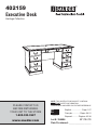 1
1
-
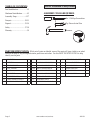 2
2
-
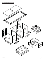 3
3
-
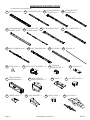 4
4
-
 5
5
-
 6
6
-
 7
7
-
 8
8
-
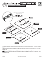 9
9
-
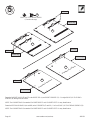 10
10
-
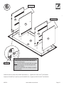 11
11
-
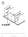 12
12
-
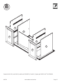 13
13
-
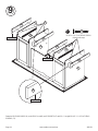 14
14
-
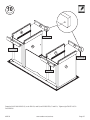 15
15
-
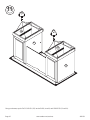 16
16
-
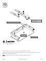 17
17
-
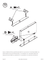 18
18
-
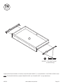 19
19
-
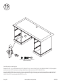 20
20
-
 21
21
-
 22
22
-
 23
23
-
 24
24
-
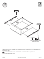 25
25
-
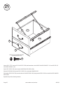 26
26
-
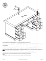 27
27
-
 28
28
-
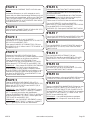 29
29
-
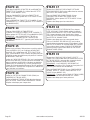 30
30
-
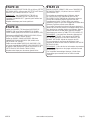 31
31
-
 32
32
-
 33
33
-
 34
34
-
 35
35
-
 36
36
-
 37
37
-
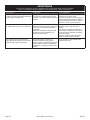 38
38
-
 39
39
-
 40
40


en otros idiomas
- français: Sauder 402159 Manuel utilisateur
- English: Sauder 402159 User manual
Artículos relacionados
-
Sauder Palladia Collection 412902 Instrucciones de operación
-
-
-
-
-
-
-
-
-
