MC CULLOCH CS330 El manual del propietario
- Categoría
- Motosierras eléctricas
- Tipo
- El manual del propietario
La página se está cargando...

2
TABLE OF CONTENTS
Introduction 2
Identification of Symbols 2
Identification (What is What?) 3
General Safety Precautions 4
Assembly 7
Fuel Handling 10
Starting and Stopping 11
Working Techniques 12
Service and Adjustments 15
Storage 17
Troubleshooting Table 18
Technical Data 19
Declaration of Conformity 21
INTRODUCTION
Dear Customer,
Thank you for choosing a McCulloch product. You are thereby part of a story that started long
ago, when the McCulloch Corporation startedits manufacturing of engines during WorldWar II. In
1949, when McCulloch introduced its first light one-man chain saw, woodworking would never be
the same again.
The line of innovative chain saws would continue over the decades, and business was expanded,
first by airplane and kart engines in the 1950s, then by mini chainsaws in the 1960s. Later, in the
1970s and 80s, trimmers and blower/vacs were added to the range.
Today, as a part of the Husqvarna group, McCulloch continues the tradition of powerful engines,
technical innovations, and strong designs that have been our hallmarks for more than half a century.
Lowering fuel consumption, emissions and noise levels are of top priority to us, as is improving safety
and user-friendliness.
We certainly hope that you will be satisfied with your McCulloch product, as it is designed to be
your companion for a long time. By following this operators manual’s advice on usage, service,
and maintenance, its lifespan can be extended. If you should need professional helpwith repair or
service, please use the Service Locator at www.mcculloch.com.
McCulloch has a policy of continuous product development and therefore reserves the right to
modify the design and appearance of products without prior notice.
This manual can also be downloaded at www.mcculloch.com.
IDENTIFICATION OF SYMBOLS
Chain brake,
activated (right)
Chain brake,
not activated (left)
W ARNING! This chain
saw can be dangerous! Care-
less or improper use can cause
serious or even fatal injury.
Read and understand the
instruction manual before
using the chain saw.
Always use two
hands when
operating the
chain saw .
WARNING! Contacting the guide bar tip with any object
should be avoided; tip contact may cause the guide bar to
move suddenly upward and backward, which may cause se-
rious injury.
Always wear appropriate ear
protection, eye protection
and head protection.
Sound power level
Sound pressure level
at 7,5 meters
This product is in accord-
ance with applicable
EC directives.
87
DECLARACION DE CONFORMIDAD
Declaración de conformidad de la CE (Sólo aplicable en Europa)
Nosotros, Husqvarna AB, SE--561 82 Huskvarna, Suecia, con teléfono +46--36--146500, en
calidad de representante autorizado en la Comunidad, declara que la motosierra para servicio
forestal modeloMcCulloch CS 330, CS 360, CS 370, y CS 400 SAS---AV u a partir del número
de serie del año 2012 en adelante (el año se indica claramente en la placa de identificación,
seguido del número de serie), cumple con lo establecido por las estipulaciones de la
DIRECTIV A DEL CONSEJO:
2006/42/CE, “referente a máquinas”, del 17 de Mayo de 2006.
2004/108/CE, “referente a compatibilidad electromagnética”, del15 de Diciembre de 2004,
y los suplementos válidos a la fecha.
2000/14/CE, “sobre emisiones sonoras en el entorno” del 8 de Mayo de 2000, según el
anexo V. Para más información sobre las emisiones sonoras, consulte el capítulo Datos
técnicos.
Se han aplicado las siguientes normas: ISO 12100:2010, CISPR 12:2007, ISO
11681-1:2011.
Organismo inscripto: 0404, SMP, Svensk Maskinprovning AB, Fyrisborgsgatan 3,
SE--754 50 Uppsala, Suecia, ha efectuado el examen CE de tipo conforme a la Directiva
sobre máquinas (2006/42/CE), artículo 12, apartado 3b. El certificado sobre el examen CE
de tipo conforme al Anexo IX tiene el número: 0404/09/2035.
La motosierra entregada coincide con el ejemplar que fue sometido al examen CE de tipo.
15--10--12
Ronnie E. Goldman, Director técnico
Presentante autorizado de Husqvarna AB y
responsable de la documentación técnica

86
DA TOS TÉCNICOS
Barra guía Cadena
Máximo número Longitud,
Longitud, Paso, Anchura de de dientes, eslabones de
pulgadas pulgadas ranur a, mm cabezal de rueda Tipo arr as tre (unidad)
14 0,375 / 3/8″ 1,3 7T Oregon 91VJ/PJ 52
14 0,375 / 3/8″ 1,3 7T Oregon 91VG/PX 52
16 0,375 / 3/8″ 1,3 7T Oregon 91PJ/VJ 56
16 0,375 / 3/8″ 1,3 7T Oregon 91VG/PX 56
Combinaciones de barra guía y cadena
Los siguientes equipos de corte están homologados para los modelos McCulloch CS 330,
CS 360, CS 370, y CS 400.
0,375
80° 30°
0°
14/35:52
16/40:56
0,050/1,3 5/32 / 4,0 0,025/0,65
91VJ
91PJ
0,375
0,050/1,3
5/32 / 4,0
80°
30°
0° 0,025/0,65
14/35:52
16/40:56
Tipo mm mm mm Grado Grado Grado mm in/cm :dl
91VG
0,375
0,050/1,3
5/32 / 4,0
80°
30°
0°
0,025/0,65
14/35:52
16/40:56
91PX
0,375
0,050/1,3
5/32 / 4,0
80°
30°
0°
0,025/0,65
14/35:52
16/40:56
3
IDENTIFICATION OF SYMBOLS
Move ON/STOP switch to
the ON position.
Slowly press primer bulb
6 times.
Pull the starter rope
sharply with your right
hand until the engine fires.
Pull the starter rope sharply
with your right hand until
the engine starts.
Pull choke/fast idle lever
out to the full extent (to
the FULL CHOKE posi-
tion).
Push the choke/fast idle
lever in to the HALF
CHOKE position.
Starting Reminder
Starting a warm engine
IDENTIFICATION (WHAT IS WHAT?)
Chain
Adjustment Tool
(Bar Tool)
Bar Oil Fill Cap
Chain
Front Hand Guard
Starter Rope
ON/STOP
Switch
Muffler
Choke/
Fast Idle
Lever
Fuel Mix Fill Cap
Starter Housing
Idle Speed Screw
Bumper
spike
Primer Bulb
Front Handle
Guide Bar
Bar Nuts
Cylinder Cover
Throttle
Lockout
Rear
Handle
Throttle
Trigger
Chain
Brake
Chain
Direction
of Travel
Adjusting Screw
Chain
Catcher
Clutch Cover

4
GENERAL SAFETY PRECAUTIONS
WARNING: Always disconnect spark
plug wire and place wire where it cannot con-
tact spark plug to prevent accidental starting
when setting up, transporting, adjusting or
making repairs except carburetor adjustments.
This chain saw for forest service is only de-
signed for cutting wood. Because a chain saw
is a high-speed wood-cutting tool, special safe-
ty precautions must be observed to reduce the
risk of accidents. Careless or improper use of
this tool can cause serious injury.
PLAN AHEAD
S Read this manual carefully until you com-
pletely understand and can follow all safety
rules, precautions, and operating instruc-
tions before attempting to use the unit.
S Restrict the use of your saw to adult users
who understand and can follow safety
rules, precautions, and operating instruc-
tions found in this manual.
Snug
Fitting
Clothing
Safety
Shoes
Safety Chaps
Heavy Duty
Gloves
Eye
Protection
Hearing
Protection
Safety Hat
S Wear protective gear. Always use steel-toed
safety footwear with non-slip soles; snug-fit-
ting clothing; heavy-duty, non-slip gloves;
eye protection such as non-fogging, vented
goggles or face screen; an approved safety
hard hat; and sound barriers (ear plugs or
mufflers) to protect your hearing. Secure hair
above shoulder length.
S Always use approved hearing protection.
Regular users should have hearing checked
regularly as chain saw noise can damage
hearing. Long--term exposure to noise can
result in permanent hearing impairment.
S Keep all parts of your body away from the
chain when the engine is running.
S Keep children, bystanders, and animals a
minimum of 10 meters away from the work
area. Do not allow other people or animals
to be near the chain saw when starting or
operating the chain saw.
S Do not handle or operate a chain saw when
you are fatigued, ill, or upset, or if you have
taken alcohol, drugs, or medication. You
must be in good physical condition and men-
tally alert. Chain saw work is strenuous. If
you have any condition that might be aggra-
vated by strenuous work, check with your
doctor before operating a chain saw.
S Carefully plan your sawing operation inad-
vance. Do not start cutting until you have a
clear work area, secure footing, and, if you
are felling trees, a planned retreat path.
OPERATE YOUR SAW SAFELY
WARNING: Long term inhalation of
the engine’s exhaust fumes, chain oil mist and
dust from sawdust can result in serious per-
sonal injury.
WARNING: This machine produces
an electromagnetic field during operation. This
field may under some circumstances interfere
with active or passive medical implants. To re-
duce the risk of serious or fatal inju ry , we rec-
ommend persons with medical implants to
consult their physician and the medical implant
manufacturer before operating this machine.
S Do not operate a chain saw with one hand.
Serious injury to the operator , helpers, by-
standers or any combination of these per-
sons may result from one-handed operation.
A chain saw is intended for two-handed use.
S Operate the chain saw only in a well-venti-
lated outdoor area.
S Do not operate saw from a ladder or in a tree,
unless you are specifically trained to do so.
S Make sure the chain will not make contact
with any object while starting the engine.
Never try to start the saw when the guide bar
is in a cut.
S Do not put pressure on the saw at the end of
the cut. Applying pressure can cause you to
lose control of the chain saw when the cut is
completed and may cause serious personal
injury.
S Stop the engine before setting the saw down.
S Do not operate a chain saw that is damaged,
improperly adjusted, or not completely and
securely assembled. Always replace bar ,
chain, hand guard, or chain brake immedi-
ately if it becomes damaged, broken or is
otherwise removed.
S With the engine stopped, hand carry the
chain saw with the muffler away from your
body , and the guide bar and chain to the rear,
preferably covered with a scabbard.
S Secure the machine during transport.
CHAIN SA W
SAFETY EQUIPMENT
NOTE: In thi s section, th e safe t y fea t u r e s of
the chain saw and their function are explained.
For inspection and maintenance, see instruc-
tio n s in th e CHECK ING, M AI NTAINI NG AND
SERVICING CHAIN SAW SAFETY EQUIP-
MENT section. See instructions under the
WHAT IS WHA T? section, to find where these
parts are located on your chain saw. The life
span of the machine can be reduced and the
risk of accidents can increase if machine main-
tenance is not carried out correctly and if ser-
vice and/or repairs are not carried out profes-
sionally. If you need further information, please
contact your nearest service dealer.
85
DA TOS TÉCNICOS
Datos técnicos
CS 330 CS 360 CS 370 CS 400
Motor
Cilindrada, cm
3
33 36 38 40
Carrera, mm 32 32 32 32
Régimen de ralentí, r.p.m. 3000 3000 3000 3000
Potencia, kW 1,2/9000 1,3/9000 1,4/9000 1,5/9000
Sistema de encendido
Bujía Champion Champion Champion Champion
RCJ--7Y RCJ--7Y RCJ--7Y RCJ--7Y
Distancia de electrodos, mm 0,5 0,5 0,5 0,5
Sistema de combustible y lubricación
Capacidad del depósito de gasolina, litros 0,3 0,3 0,3 0,3
Caudal de la bomba de aceite a 8.500 r.p.m.,
m l / m i n . 4 -- 8 4 -- 8 4 -- 8 4 -- 8
Capacidad del depósito de aceite, litros 0,2 0,2 0,2 0,2
Tipo de bomba de aceite Automática Automática Automática Automática
Peso
Motosierra sin espada ni cadena, con depósitos
vacíos, kg 5,5 5,5 5,5 5,5
Emisiones de ruido
(ver la nota 1)
Nivel de potencia acústica medido dB(A) 108,7 108,7 108,7 108,7
Nivel de potencia acústica garantizado L
WA
dB(A)113 113 113 113
Niveles acústicos
(vea la nota 2)
Nivel equivalente de presión acús tic a en el oído
del usuario, dB(A) 99,7 99,7 99,7 99,7
Niveles de vibración equivalentes, a
hv,eq
(vea la nota 3)
Mango delanter o, m/s
2
2,4 2,4 2,4 2,4
Mango trasero, m/s
2
2,4 2,4 2,4 2,4
Cadena/barra guía
Longitud de barra estándar, pulgadas/cm 14/35, 16/40, 18/45
Longitudes de barra recomendadas, pulgadas/cm 14--18 / 35--45
Longitud efectiva de corte, pulgadas/cm 13--17 / 34--44
Paso, pulgadas 0,375
Gros or del eslabón de arrastre, pulgadas/mm 0,050/1,3
Tipo de piñón de arrastre/número de dientes 6
Velocidad de la cadena a potencia máxima, m/s 18,5
Nota 1: Emisiones sonoras en el entorno medidas como potencia acústica (L
WA
) según la directiva CE
2000/14/CE.
Nota 2: el nivel de presión sonora equivalente, según la norma ISO 22868, se calcula como la suma
de energÌa, ponderada en el tiempo, de los niveles de presión sonora en diferentes condiciones de
trabajo. La dispersión estadÌstica habitual del nivel de presión sonora equivalente es la desviación
tÌpica de 1 dB(A).
Nota 3: el nivel de vibración equivalente, según la norma ISO 22867, se calcula como la suma de
energÌa, ponderada en el tiempo, de los niveles de vibración en diferentes condiciones de trabajo. Los
datos referidos del nivel de vibración equivalente poseen una dispersión estadÌstica habitual (desvia-
ción tÌpica) de 1 m/s
2
.

84
ALMACENAMIENTO
ADVERTENCIA: Antes de alm ace-
nar o transportar la motosierra en un vehículo,
pare el motor, deje que se enfríe y asegúrela
bien. Guarde el aparato y el combustible en un
lugar donde los vapores que emanen del com-
bustible no puedan entrar en contacto con
chispas ni llamas de calentadores de agua,
motores eléctricos, interruptores, hornos, etc.
Guarde el aparato con todas las protecciones
en su sitio. Colóquelo de modo que ninguna de
sus partes afiladas pueda ocasionar acidental-
mente lesiones a nadie. Guarde el aparato fue-
ra del alcance de los niños.
S Antes de guardarlo, saque todo el com-
bustible que quede en el aparato. Arran-
que el motor y déjelo funcionando hasta
que se pare.
S Limp ie la motosierra antes de guardarl a.
Preste especial atención a la zona de toma
de aire, compruebe que no queden briznas.
Utilice un detergente suave y una esponja
para limpiar las superficies de plástico.
S No guarde la motosierra ni el combustible en
un lugar donde los vapores que emanen del
combustible puedan entrar en contacto con
chispas o llamas procedentes de calentado-
res de agua, motores o interruptores eléctri-
cos, hornos, etc.
S Guárdelos en una zona seca fuera del al-
cance de los niños.
S Antes del almacenaje prolongado, limpie
bien la máquina y haga el servicio completo.
S La protección de transporte del equipo de
corte debe estar siempre montada para el
transporte y almacenamiento de la máquina,
a fin de evitar el contacto fortuito con la
cadena aguda. Una cadena inmóvil también
puede causar daños graves al usuario u
otras personas que llegan a la cadena.
ADVERTENCIA: Durante el alma-
cenamiento, es importante evitar la forma-
ción de depósitos y agarrotamientos en los
principales elementos del sistema de com-
bustible, como el carburador, el filtro, el man-
guito o el depósito. Los combustibles mez-
clados con alcohol (gasohol, etanol o
metanol) pueden atraer la humedad, lo que
provoca la separación de la mezcla y la for-
mación de ácidos durante el almacenamien-
to. Los gases ácidos pueden dañar el motor.
PROBLEMA CAUSA SOLUCION
El motor no
arranca o se
mantiene en
marcha sólo
unos segundos
después de ar-
rancar.
1. El interruptor está off.
2. El motor está ahogado.
3. El tanque de
combustible está vacío.
4. La bujía no hace chispa.
5. El combustible no está
llegando al carburador .
1. Coloque el interruptor en ON.
2. Vea “Arranque Dificil” en la
sección Uso.
3. Llene el tanque con la mezcla
correcta de combustible.
4. Instale una bujía nueva.
5. Verifique si el filtro de combustible
está sucio; límpielo. Verifique si hay
dobleces en la línea de combustible
o si está partida: repárla o cámbiela.
El motor no
anda en
marcha lenta
como debe.
1. La marcha lenta
requiere ajuste.
2. El carburador requiere
ajuste.
1. Vea “Ajustes al Carburador” en la
sección Servicio.
2. Entre en contacto con su distribuidor
autorizado del servicio.
1. El filtro de aire está
sucio.
2. La bujía está
carbonizada.
3. La freno de cadena es
activado.
4. El carburador requiere
ajuste.
El motor no
acelera, le falta
potencia o se
para bajo car-
ga.
1. Limpie o cambie el filtro de aire.
2. Limpie o cambie la bujía y
calibre la separación.
3. Desactive el freno de cadena.
4. Entre en contacto con su distribuidor
autorizado del servicio.
El motor humea
excesivamente.
1. La mezcla de combus-
tible se ha hecho.
1. Vacíe el tanque de combustible y llénelo
de combustible con la mezcla correcta.
ADVERTENCIA: Siempre apague el aparato y desconecte la bujíaantes dehacer
cualquiera de las reparaciones recomendadas a continuación excepto reparaciones
que requieran que la unidad esté en operación.
La cadena se
mueve en
marcha lenta.
1. La marcha lenta
requiere ajuste.
2. El embrague requiere
reparaciones.
1. Vea “Ajustes al Carburador” en la
sección Servicio.
2. Entre en contacto con su distribuidor
autorizado del servicio.
TABLA DIAGNOSTICA
5
GENERAL SAFETY PRECAUTIONS
S Chain brake. Your chain saw is equipped
with a chain brake that is designed to stop
the chain from moving.
WARNING: The chain brake is de-
signed to stop the chain immediately if you get
a kickback. The chain brake reduces the risk of
accidents, but only you can prevent them. DO
NOT ASSUME THA T THE CHAIN BRAKE
WIL L PROTECT YOU IN THE EVEN T OF A
KICKBACK.
S Throttle trigger lock--out. The throttle
lock--out is designed to prevent accidental
operation of the throttle trigger.
S Chain catcher. The chain catcher is de-
signed to catch the saw chain if it breaks.
S Vibration damping system. Your chain
saw is equipped with a vibration damping
system that is des igned to minimize vibra-
tion and make operation easier .
SAFETY NOTICE: Exposure to vibrations
through prolonged use of gasoline powered
hand tools could cause blood vessel or nerve
damage in the fingers, hands, and joints of peo-
ple prone to circulation disorders or abnormal
swellings. Prolonged use in cold weather has
been linked to blood vessel damage in other-
wise healthy people. If symptoms occur such
as numbness, pain, loss of strength, change in
skin color or texture, or loss of feeling in the fin-
gers, hands, or joints, discontinue the use of
this tool and seek medical attention. An anti-
vibration system does not guarantee the avoid-
ance of these problems. Users who operate
power tools on a continual and regular basis
must monitor closely their physical condition
and the condition of this tool.
S ON/STOP switch. The ON/STOP switch
should be used to stop the engine.
CHECKING, MAINT AINING
AN D SER VICIN G CH AIN SA W
SAFETY EQUIPMENT
WARNING: Never use a chain saw
with defective safety equipment. Safety
equipment must be inspected and main-
tained. If your chain saw does not pass in-
spection, take the saw to your nearest ser-
vice dealer for repair.
S Chain brake. Brush off any wood dust, res-
in and dirt from the chain brake and clutch
drum. Dirt and wear can impair operation of
the brake. For additional information, see
OPERATING YOUR UNIT section.
S Throttle trigger lock--out. Check that the
throttle trigger can not beoperated untilthe
throttle lock--out is pressed.
S Chain catcher. Check that the chain
catcher is not damaged and is firmly at-
tached to the body of the chain saw.
S Vibration damping system. Regularly
check the vibration damping units for
cracks or deformation. Make sure the
vibration damping units are securely at-
tached to the engine unit and handle unit.
S ON/STOP switch. Start the engine and
make sure the engine stops when you move
the ON/STOP switch to the STOP position.
MAINTAIN YOUR SAW IN
GOOD WORKING ORDER
S Have all chain saw service performed by a
qualified service dealer with the exception of
the items listed in the maintenance section of
this manual. For example, if improper tools
are used to remove or hold the flywheel
when servicing the clutch, structural damage
to the flywheel can occur and cause the fly-
wheel to burst.
S Make certain the saw chain stops moving
when the throttle trigger is released. For
correction, refer to CARBURETOR AD-
JUSTMENTS.
S Never modify your saw in any way . Use
only attachments supplied or specifically
recommended by the manufacturer .
S Keep the handles dry, clean, and free of oil
or fuel mixture.
S Keep fuel and oil caps, screws, and fas-
teners securely tightened.
S Use only McCulloch accessories and re-
placement parts as recommended.
HANDLE FUEL WITH CAUTION
S Do not smoke while handling fuel or while
operating the saw.
S Eliminate all sources of sparks or flame in
the areas where fuel is mixed or poured.
There should be no smoking, open flames,
or work that could cause sparks. Allow en-
gine to cool before refueling.
S Mix and pour fuel in an outdoor area on bare
ground; store fuel in a cool, dry, well venti-
lated place; and use an approved, marked
container for all fuel purposes. Wipe up all
fuel spills before starting saw.
S M ove at least 10 feet (3 meters) from fuel-
ing site before starting engine.
S Turn the engine off and let saw cool in a
non-combustible area, not on dry leaves,
straw, paper, etc. Slowly remove fuel cap
and refuel unit.
S Store the unit and fuel in an area where fuel
vapors cannot reach sparks or open
flames from water heaters, electric motors
or switches, furnaces, etc.
KICKBACK
WARNING: Avoid kickback which
can result in serious injury. Kickback is the
backward, upward or sudden forward motion
of the guide bar occurring when the saw
chain near the upper tip of the guide bar con-
tacts any object such as a log or branch, or
when the wood closes in and pinches the
saw chain in the cut. Contacting a foreign ob-
ject in the wood can also result in loss of
chain saw control.
S Rotational Kickback can occur when the
moving chain contacts an object at the up-
per tip of the guide bar. This contact can
cause the chain to dig into the object,

6
GENERAL SAFETY PRECAUTIONS
which stops the chain for an instant. The
result is a lightning fast, reverse reaction
which kicks the guide bar up and back to-
ward the operator.
S Pinch-Kickback can occur when the the
wood closes in and pinches the moving
saw chain in the cut along the top of the
guide bar and the saw chain is suddenly
stopped. This sudden stopping of the
chain results in a reversal of the chain
force used to cut wood and causes the
saw to move in the opposite direction of the
chain rotation. The saw is driven straight
back toward the operator.
S Pull-In can occur when the moving chain
contacts a foreign object in the wood in the
cut along the bottom of the guide bar and the
saw chain is suddenly stopped. This sudden
stopping pulls the saw forward and away
from the operator and could easily cause the
operator to lose control of the saw.
Avoid Pinch--Kickback:
S Be extremely aware of situations or obstruc-
tions that can cause material to pinch the top
of or otherwise stop the chain.
S Do not cut more than one log at a time.
S Do not twist the saw as the bar is with-
drawn from an undercut when bucking.
Avoid Pull--In:
S Always begin cutting with the engine at full
speed and the saw housing against wood.
S Use wedges made of plastic or wood.
Never use metal to hold the cut open.
Kickback Path
Clear The
Working Area
Avoid Obstructions
REDUCE THE CHANCE OF
KICKBACK
S Recognize that kickback can happen.
With a basic understanding of kickback,
you can reduce the element of surprise
which contributes to accidents.
S Never let the moving chain contact any ob-
ject at the tip of the guide bar.
S Keep the working area free from obstruc-
tions such as other trees, branches, rocks,
fences, stumps, etc. Eliminate or avoid any
obstruction that your saw chain could hit
while you are cutting through a particular log
or branch.
S Keep your saw chain sharp and properly
tensioned. A loose or dull chain can increase
the chance of kickback occurring. Follow
manufacturer’s chain sharpening and main-
tenance instructions. Check tension at regu-
lar intervals with the engine stopped, never
with the engine running. Make sure the bar
clamp nuts are securely tightened after ten-
sioning the chain.
S Begin and continue cutting at full speed. If
the chain is moving at a slower speed, there
is greater chance of kickback occurring.
S Cut one log at a time.
S Use extreme caution when re-entering a
previous cut.
S Do not attempt cuts starting with the tip of
the bar (plunge cuts).
S Watch for shifting logs or other forces that
could close a cut and pinch or fall into chain.
S Use the Reduced--Kickback Guide Bar and
Low--Kickback Chain specified for your saw.
MAINTAIN CONTROL
Never reverse
hand positions
Stand to the left of
the saw
Thumb on underside of
handlebar
Elbow locked
S Keep a good, firm grip on the saw with both
hands when the engine is running and don’t
let go. A firm grip will help you reduce kick-
back and maintain control of the saw. Keep
the fingers of your left hand encircling and
your left thumb under the front handlebar .
Keep your right hand completely around the
rear handle whether your are right handed or
left handed. Keep your left arm straight with
the elbow locked.
S Position your left hand on the front handle-
bar so it is in a straight line with your right
hand on the rear handle when making
bucking cuts. Never reverse right and left
hand positions for any type of cutting.
S Stand with your weight evenly balancedon
both feet.
S Stand slightly to the left side of the saw to
keep your body from being in a direct line
with the cutting chain.
S Do not overreach. You could be drawn or
thrown off balance and lose control of the
saw.
83
SERVICIO Y AJUSTES
S Lime sólo el golpe de avance; use 2 o
3 golpes por borde de corte.
S Mantenga todas las cuchillas de la
misma longitud cuando las lima.
S Lime lo suficiente como para eliminar
cualquier daño en los bordes de
corte (placa lateral y placa superior
de la cuchilla).
Cuchillas
igual longitud
Remueva daño
Placa
Superior
Placa
Lateral
S Lime la cadena según las
especificaciones, tal como se ilustra.
30°
80°
60°
Esquina
Redondeada
0,65 mm
Correcto
Ángulo de gancho
Incorrecto
Fuera Elevada el
Cuadrado Esquina
Ángulo del Gancho
Incorrecto
ADVERTENCIA: Mantenga el
ángulo de gancho correcto de acuerdo con las
especificaciones del fabricante de la cadena
que usa. Si el ángulo del gancho es incorrecto,
aumentan las probabilidades de reculadas,
que pueden producir lesiones graves.
4. Verifique y baje los marcadores de pro-
fundidad.
Herramienta marcadora
de profundidad
Lima
Marcador de
Profundidad
S Coloque la herramienta marcadora
sobre la cuchilla.
S Si el marcador de profu ndidad es más
alto que la herramienta marcadora de
profundidad, límelo para nivelarlo con
la parte superior de la herramienta
marcadora.
S Mantenga redondeada la esquina
delantera del marcador de
profundidad con una lima plana.
AVISO: El extremo superior del
marcador de profundidad debe ser
parejo con la mitad delantera,
redondeada con una lima plana.
Si n ecesita m ás a sistenc ia o no est á seg uro
sobre cómo llevar a cabo este procedimiento,
entre en contacto con su distribuidor
autorizado del servicio.
AJUSTE AL CARBURADOR
ADVERTENCIA: La cadena estará
en movimiento durante la mayor parte de
este prodecimiento. Use el equipo protector
y observe todad las precauciones de seguri-
dad. La cadena no debe moverse con el mo-
tor en marcha lenta.
El carburador ha sido ajustado cuidadosa-
mente en la fábrica. Posiblemente se hagan
necesarios ajustes si se nota cualquiera de las
siguientes condiciones:
S La cadena se mueve con el motor en mar-
cha lenta. V ea procedimiento de MARCHA
LENTA “T”.
S La sierra no anda a marcha lenta. V ea pro-
cedimie nto de MARCHA LENTA “T”.
Marcha Len ta “T”
Deje que el motor trabaje en marcha lenta.Si
la cadena se mueve, la marcha lenta es de-
masiado. Si el motor se para, la marcha len-
ta es demasiado lenta. Ajuste las revolu-
ciones hasta que el motor se mantenga en
marcha sin que la cadena se mueva (la mar-
cha lenta es demasiado) o que el motor se
ahogue (la marcha lenta es demasiado len-
ta). El tornillo de la marcha lenta está situado
arriba del bombeador y marcado con la “T”.
S Gire el tornillo de la marcha lenta “T” a la der-
echa (en el sentido del reloj) para aumentar
las revoluciones del motor .
S Gire el tornillo de la marcha lenta “T” a la iz-
quierda (en contra del sentido del reloj) para
bajar las revoluciones.

82
SERVICIO Y AJUSTES
Retire el Aserrín de la
Ranura de la Barra Guía
Orificios del aceite
S Añada lubricante al orificio del engranaje
después de cada uso.
S Los rieles de la barra guía desarrollan pro-
tuberancias al gastarse. Sáquelas con una
lima plana.
S Si la superficie superior del riel está desnive-
lada, use una lima plana para restaurar la
forma cuadrada.
Ranura
gastada
Ranura
correcta
Encuadre los
Bordes del Riels
con una Lima
Cambie la barra guía si la ranura está gastada,
si la barra guía está torcida o resquebrajada o
si hay calentamiento excesivo o formación de
protuberancias en los rieles. Si es necesario
cambiar la barra guía, use exclusivamente la
barra guía especificada para su sierra en la lis-
ta de repuestos.
BUJIA
Deberá cambiarse la bujía anualmente para
asegurar que el motor arranque más fácil-
mente y marche mejor . El encendido es fijo y
no se puede ajustar .
1. Afloje los tres tornillos en la tapa del
cilindro.
2. Retire la tapa del cilindro.
3. Saquelacubiertadelabujía.
4. Retire la bujía del cilindro y deséchela.
5. Reemplácela con una bujía Champion
RCJ--7Y ajústela con una llave de 19 mm.
Apriete firm eme nte. Separa ción d e
electrodos: 0,5 mm.
6. Reinstale la cubierta de la bujía.
7. Reinstale la tapa del cilindro y tos tres
tornillos. Apriete firmemente.
Bujía
Tapa del
cilindro
Cubierta
de la
bujía
AFILADO DE LA CADENA
ADVERTENCIA: Las técnicas de
afilado de la cadena y/o el mantenimiento del
marcador de profundidad incorrectos au-
mentan las probabilidades de reculadas,
que pueden producir lesiones graves.
ADVERTENCIA: Use guantes pro-
tectores al manejar la cadena. La cadena
tiene filo y podría causarle graves cortadu-
ras, aun cuando ésta no se encuentre en
movimiento.
Condiciones que indican la necesidad de
afilar la cadena:
S Reducción del tamaño de las astillas de
madera. El tamaño de las astillas de madera
se reduce a medida que la cadena se desafi-
la, hasta volverse más un polvo que una as-
tilla. Observe que la madera muerta o podri-
da no produce una buena astilla.
S La sierra corta de lado o en ángulo.
S La sierra debe ser forzada a través del corte.
Herramientas necesarias:
S Lima redonda de 5/32 de pulgada (4 mm) de
diámetro y soporte para lima
S Lima plana
S Herramienta marcadora de profundidad
PARA AFILAR LA CADENA:
1. Mueva el interruptor ON/STOP a la posi-
ción STOP.
2. Verifique la tensión correcta de la cade-
na. Ajústela si es necesario.
3. Afile las cuchillas.
S Para afilar las cuchillas, ubique el
nivel del soporte de la lima (90° )de
modo que se apoye sobre los bordes
superiores de la cuchilla y el
marcador de profundidad.
AVISO: La cadena tiene cuchillas
del lado izquierdo y del lado derecho.
Marcador de Profundida
d
Lima
Soporte para Lima
Cuchilla
90°
S Alinee las marcas de 30° del soporte
para lima, paralelas a la barra y al
centro de la cadena.
Cuchilla
Cuchilla
30°
Marca del Soporte
para Lima
S Afile primero las cuchillas de un lado de
la cadena. Lime desde el interior de
cada cuchilla hacia el exterior . Des-
pués, gire la sierra de cadena y repita
el proceso en el otro lado de la cadena.
7
GENERAL SAFETY PRECAUTIONS
S Do not cut above shoulder height. It is diffi-
cult to maintain control of saw above
shoulder height.I
KICKBACK SAFETY FEA TURES
WARNING: The following features
are included on your saw to help reduce the
hazard of kickback; however , such features will
not totally eliminate this dangerous reaction.
As a chain saw user , do not rely only on safety
devices. You must follow all safety precau-
tions, instructions, and maintenance in this
manual to help avoid kickback and other forces
which can result in serious injury.
S Reduced--Kickback Guide Bar, designed
with a small radius tip which reduces the
size of the kickback danger zone on the
bar tip. A Reduced--Kickback Guide Bar has
been demonstrated to significantly reduce
the number and seriousness of kickbacks.
Small Radius Tip
Reduced Kickback
Symmetrical
Guide Bar
Symmetrical Guide Bar
Large Radius Tip
S Low--Kickback Chain, designed with a
contoured depth gauge and guard link
which deflect kickback force and allow
wood to gradually ride into the cutter .
L
ow-
K
ickback Chain
Contoured Depth Gauge
Elongated Guard Link
Deflects Kickback
Force And Allows
Wood To Gradually
Ride Into Cutter
S Handguard, designed to reduce the chance
of your left hand contacting the chain if your
hand slips off the front handlebar .
S Position of front and rear handlebars, de-
signed with distance between handles and
“in-line” with each other . The spread and
“in-line” position of the hands provided by
this design work together to give balance
and resistance in controlling the pivot of
the saw back toward the operator if kick-
back occurs.
WARNING: DO NOT RELY UPON
ANY OF THE DEVICES BUILT INTO YOUR
SAW. YOU SHOULD USE THE SAW
PROPERLY AND CAREFULLY TO AVOID
KICKBACK. Reduced--kickback guide bars
and low--kickback saw chains reduce the
chance and magnitude of kickback and are
recommended. Your saw has a low kickback
chain and bar as original equipment. Repairs
on a chain brake should be made by an au-
thorized servicing dealer . Take your unit to
the place of purchase if purchased from a
servicing dealer, or to the nearest authorized
master service dealer.
S Tip contact in some cases may cause a light-
ning fast reverse REACTION, kicking the
guide bar up and back toward the operator .
S Pinching the saw chain along the top of the
guide bar may push the guide bar rapidly
back toward the operator.
S Either of these reactions may cause you to
lose control of the saw which could result
in serious injury. Do not rely exclusively
uponthe safety devices built into your saw.
ASSEMBLY
Protective gloves (not provided) should be
worn during assembly .
A TT ACHING THE BUMPER
SPIKE (if not already attached)
The bumper spike may be used as a pivot
when making a cut.
1. Loosen and remove the bar nuts and the
clutch cover from the saw.
2. Attach the bumper spike with the two
screws as illustrated.

8
ASSEMBLY
WARNING: Recheck each assem-
bly step if the saw is received assembled. Al-
ways wear gloves when handling the chain.
The chain is sharp and can cut you even
when it is not moving!
1. Loosen and remove the bar nuts and the
clutch cover from the saw.
2. Remove the plastic shipping spacer (if
present).
Clutch cover
Bar nuts
Chain adjustment tool
(Bar Tool)
Location of
shipping
spacer
3. An adjusting pin and screw is used to ad-
just the tension of the chain. It is very im-
portant when assembling the bar, that the
pin located on the adjusting screw aligns
into a hole in the bar. Turning the screw will
move the adjustment pin up and down the
screw. Locate this adjustment before you
begin mounting the bar onto the saw . See
following illustration.
Adjustment located on clutch cover
Inside
view of
clutch
cover
4. Turn the adjusting screw by hand coun-
terclockwise until the adjusting pin just
touches the stop. This should allow the
pin to be near the correct position.
5. Slide guide bar on bar bolts until guide bar
stops against clutch drum sprocket.
Guide bar
Bar bolts
6. Carefully remove the chain from the pack-
age. Hold chain with the drive links as
sho wn .
CUTTERS MUST FACE IN
DIIRECTION OF ROT
A
TION
Tip of
Bar
Cutters
Depth Gauge
Drive Links
7. Place chain over and behind clutch re-
tainer, fitting the drive links in the clutch
drum sprocket.
8. Fit bottom of drive links between the
teeth in the sprocket in the nose of the
guide bar.
9. Fit chain drive links into bar groove.
10. Pull guide bar forward until chain is snug
in guide bar groove. Ensureall drive links
are in the bar groove.
11. Now, install clutch cover making sure the
adjusting pin is positioned in the lower
hole in the guide bar. Remember this pin
moves the bar forward and backward as
the screw is turned.
81
SERVICIO Y AJUSTES
ADVERTENCIA: El mantenimiento
incorrecto podía causar daño serio al motor o a
graves lesiones al operador.
ADVERTENCIA: Desconecte la
bujía antes de hacer cualquier mantenimiento,
con la excepción de los ajustes al carburador .
Se recomienda que confíe todas las repara-
ciones y ajustes no descritos en el manual a
su Distribuidor Autorizado.
PLANILLA DE MANTENIMIENTO
Verifique:
Elniveldecombustible Antesdecadauso-.
Lubricacióndelabarra Antesdecadauso.
Tensión de la cadena Antes de cada uso...
Afilación de la cadena Antes de cada uso..
Piezas dañadas Antes de cada uso.......
Tapas sueltas Antes de cada uso.........
Fijadores sueltas Antes de cada uso......
Piezas sueltas Antes de cada uso
Inspeccionar y Limpiar:
barra guía Antes de cada uso.............
Sierra completa Después de cada........
uso
Filtro de aire Cada 5 horas*..........
Freno de cadena Cada 5 horas*......
Rejilla antichispas y
silenciador Cada 25 horas*............
Cambiar la bujia Anualmente......
Cambiar el filtro de
combustible Anualmente..........
* Horas de uso
FRENO DE CADENA
ADVERTENCIA: La banda del
freno podrá romperse al activar el freno si ésta
se encuentra demasiado usada y fina. Si la
banda del freno se encuentra rota, el freno de
cadena no detendrá la cadena. El freno de
cadena debe ser substituido si cualquier parte
se desgasta menos de 0,5 mm densamente.
Cualquier reparación en un freno de cadena
deber ser realizada por el distribuidor
autorizado. Si compró la máquina a un
distribuidor,acudaconsumáquinaaésteoala
oficina principal del distribuidor autorizado.
CONTROL DEL FRENO
PRECAUCION: El freno de cadena debe
probarse varias veces al día. Al hacer esta
inspección, el motor siempre debe estar
prendido.
Coloque la sierra en suelo firme. Sostenga la
mango trasera con la mano derecha y la
mango delantera con la mano izquierda.
Aplique a la velocidad máxima presionando el
gatillo del acelerador . Active el freno de
cadena dando vuelta a su muñeca izquierda
contra el protector de mano delantera sin soltar
la mango delantera. La cadena deberá
detenerse inmediatamente.
FILTRO DE AIRE
ADVERTENCIA: No limpie el filtro
con gasolina ni con otros disolventes infla-
mables para evitar el peligro de incendio o
emisiones de vapores nocivos.
Limpieza del filtro de aire:
Un filtro de aire sucio reduce el rendimiento
del motor y aumenta el consumo de combus-
tible y las emisiones nocivas. Siempre limpie
el filtro cada 5 horas de funcionamiento.
1. Limpie la cubierta y la zona que la rodea
para evitar que se introduzca suciedad y
serrín en la cámara del carburador cuan-
do se extraiga la cubierta.
2. Retire las piezas que se ilustran abajo.
3. Lave el filtro con agua y jabón. Enjuague
biencon agua clara y fría. Séquelo al aire
totalmente antes de reinstalarlo.
4. Aplique varias gotas de aceite al filtro;
apriete el filtro para distribuir el aceite.
5. Reinstale las piezas.
Filtro de
Aire
Tapa del
Cilindro
Cubierta
del Filtro
de Aire
MANTENIMIENTO DE LA
BARRA GUÍA
Si la sierra de cadena sólo corta por un lado,
tiene que forzarla para cortar o ha estado
funcionando con una cantidad inadecuada
de lubricante, puede que necesite revisarla.
Una barra guía desgastada puede dañar la
cadena y dificultar el corte.
Después de usar, asegúrese el interruptor ON/
STOP está en posición STOP, luego limpie
todo el aserrín y cualquier otro escombro de la
ranura de la barra guía y del orificio del engra-
naje.
Para mantener la ba rra guía:
S Mueva el interruptor ON/STOP en posición
ST OP.
S Afloje y retire las tuercas del freno de cadena
y el freno de cadena. Retire la barra guía y la
cadena del aparato.
S Limpie los orificios del aceite y el ranura de la
barra guía después de cada 5 horas de la
operación.

80
TÉCNICA DE TRABAJO
TRONZADO UTILIZANDO UN
TRONCO O SOPORTE
S Recuerde que debe hacer siempre el pri-
mer corte por el lado retorcido del tronco.
S Deberá hundir el primer corte hasta un
1/3
del diámetro del tronco.
S Termine con el segundo corte.
U
tila ndo un tronco
1
er
corte
2
º
corte
2
º
corte
1
er
corte
1
er
corte
2
º
corte
Utilizando un soporte
1
er
corte
2
º
corte
PODA Y RECORTE
ADVERTENCIA: Esté alerta y ten-
ga cuidado con los reculada. Cuando cortar
ramas y podar, nunca permita que la cadena
en movimiento toque ningún objeto en la
punta de la espada. Permitir tal contacto
puede causar graves heridas.
ADVERTENCIA: No se suba a los
árboles para podarlos o recortarlos. No per-
manezca de pié sobre escaleras, platafor-
mas, en un tronco o en cualquier posición en
la que pueda perder el equilibrio o el control
de la sierra.
PUNTOS IMPORT ANTES
S Tenga cuidado con las ramas, pueden dar
latigazos. Tenga especial precaución al po-
dar ramas pequeñas. Éstas pueden engan-
charse en la motosierra y salir disparadas en
la dirección del operador o hacerle perder el
equilibrio.
S Preste atención y evite golpes por rebote.
Tenga cuidado con las ramas dobladas o
que soportan tensión. Evite golpes del rama-
je o de la sierra producidas por la tensión de
las fibras de la madera.
S De vez en cuando, despeje las ramas del
camino para no tropezar con ellas.
PODA
S Pode siempre los árboles después de talar-
los. Después podrá proceder a podarlos co-
rrectamente y con seguridad.
S Deje las ramas más grandes bajo el árbol
talado para que lo sujeten mientras trabaja.
S Comience por la base del tronco y trabaje
hacia la copa, podando todas las ramas.
Quite las ramas pequeñas de un solo corte.
S Siempre que sea posible, mantenga el árbol
entre usted y la motosierra.
S Pode los troncos y ramas más gruesos
con los sistemas de corte descritos en la
sección de TRONZADO SIN SOPORTE.
S Utilice siempre la técnica del corte por arriba
para las ramas pequeñas y las que estén
sueltas. Si utiliza el corte por debajo, al caer,
las ramas pueden engancharse en la sierra.
RECORTE
ADVERTENCIA: Limite el recorta-
do de las ramas a aquellas que se encuen-
tren a la altura del hombro o más abajo. No
corte las ramas superiores. Este trabajo de-
berá hacerlo un profesional.
S El primer corte deberá llegar hasta
1/3 de
la parte inferior de la rama.
S Luego, con el segundo corte, termine de
cortar la rama. Con el tercer corte por arri-
ba, deje un borde de 3 a 5 cm desde el
tronco del árbol.
Primer corte
Segundo corte
Tercer
corte
Borde
Técn ica de re corte
9
Clutch
Cover
Lower
Hole
Guide Bar
Adjusting Pin
12. Install bar nuts and finger tighten only.
Once the chain is tensioned, you will
need to tighten bar nuts.
CHAIN TENSION (Including units
with chain already installed)
WARNING: Wear protective gloves
when handling chain. The chain is sharp and
can cut you even when it is not moving.
NOTE: When adjusting chain tension,
make sure the bar nuts are finger tight only.
Attempting to tension the chain when the bar
nuts are tight can cause damage.
Checking the tension:
Use the screwdriver end of the chain adjust-
ment tool (bar tool) to move chain around
guide bar . If the chain does not rotate, it is too
tight. If the chain is too loose, itwill sag below
the bar.
Chain Adjustment
Tool
(Bar Tool)
Guid
e
Bar
Adjusting
Screw
Bar Nuts
Adjusting the tension:
Chain tension is very important. Chains
stretch during use. This is especially true
during the first few times you use your saw.
Always check chain tension each time you
use and refuel your saw.
1. Loosen bar nuts until they are finger tight
against the clutch cover.
2. Turn adjusting screw clockwise until chain
solidly contacts bottom of guide bar rail.
Adjusting
Screw
3. Using bar tool, roll chain around guide bar
to ensure all links are in bar groove.
4. Lift up tip of guide bar to check for sag.
Release tip of guide bar,then turn adjust-
ing screw
1
/
4
turn clockwise. Repeat un-
til sag does not exist.
Adjusting Screw --
1
/
4
Turn
5. While lifting tip of guide bar , tighten bar
nuts securely with the bar tool.
Bar Nuts
6. Use the screwdriver end of the bar tool to
move chain around guide bar .
7. If chain does not rotate, it is too tight.
Slightly loosen bar nuts and loosen chain
by turning the adjusting screw
1
/
4
turn
counterclockwise. Retighten bar nuts.
8. If chain is too loose, it will sag below the
guidebar.DO NOT operate thesaw if the
chain is loose.
NOTE: The chain is tensioned correctly
when the weight of the chain does not cause it
to sag below the guide bar (with the chain saw
sitting in an upright position), but the chain still
moves.
WARNING: If the saw is operated
with a loose chain, the chain could jump of f
the guide bar and result in serious injury.
WARNING: Muffler is very hot during
and after use. Do not touch the muffler or al-
low combustible material such as dry grass
or fuel to do so.

10
FUEL HANDLING
FUEL
Note! The machine is equipped with a two-
stroke engine and must always be run using
a mixture of petrol and two-stroke oil. It is im-
portant to accurately measure the amount of
oil to be mixed to ensure that the correct mix-
ture is obtained. When mixing small amounts
of fuel, even small inaccuracies can drastic-
ally affect the ratio of the mixture.
WARNING: Always ensure there is
adequate ventilation when handling fuel.
PETROL
S Use good quality unleaded or leaded petrol.
S The lowest recommended octane grade is
90 (RON ).
S If you run the engine on a lower octane grade
than 90 so--called knocking can occur. This
gives rise to a high engine temperature and
increased bearing load, which can result in
serious engine damage.
S When working with continuous high revs
(e.g. limbing) a higher octane is recom-
mended.
Running--in
AvoId running at a too high speed for exten-
ded periods during the first 10 hours.
TWO-STROKE OIL
S For best results and performance use Uni-
versal, Universal powered by McCulloch
two--stroke engine oil, which is specially
formulated for our air cooled two--stroke
engines.
S Never use two-stroke oil intended for water-
cooled engines, sometimes referred to as
outboard oil (rated TCW).
S Never use oil intended for four--stroke en-
gines.
S A poor oil quality and/or too high oil/fuel ra-
tio may jeopardise function and decrease
the lifetme of catalytic converters.
MIXING RATIO
1:50 (2%) with Universal, Universal powered
by McCulloch two-stroke oil.
1:33 (3%) with oils class JASO FB or ISO EGB
formulated for air-cooled, two-stroke engines.
Petrol, litre Two--Stroke Oil, litre
2% (1:50) 3% (1:33)
5 0,10 0,15
10 0,20 0,30
15 0,30 0,45
20 0,40 0,60
MIXING
S Always mix the petrol and oil in a clean
container intended for fuel.
S Always start by filling half the amount of the
petrol to be used. Then add the entire
amount of oil. Mix (shake) the fuel mixture.
Add the remaining amount of petrol.
S Mix (shake) the fuel mixture thoroughly be-
fore filling the machine’s fuel tank.
S Do not mix more than one month’s supply
of fuel at a time.
S If the machine is not used for some time
the fuel tank should be emptied and
cleaned.
CHAIN OIL
S We recommend the use of special oil
(chain oil) with good adhesion character-
istics.
S Never use waste oil. This results in dam-
age to the oil pump, the bar and the chain.
S It is important to use oil of the right grade
(suitable viscosity range) to suit the air
temperature.
S In temperatures below 0°C(32°F) some
oils become too viscous. This can over-
load the oil pump and result in damage to
the oil pump components.
S Contact your service dealer when choos-
ing chain oil.
FUELING
WARNING: Taking the following pre-
cautions will lessen the risk of fire: do not
smoke and do not place any hot objects in
the vicinity of fuel; always stop the engine
and let it cool for a few minutes before refuel-
ing; when refueling, open the fuel cap slowly
so that any excess pressure is released
gently; tighten the fuel cap carefully after re-
fueling; always move the machine away
from the refueling area and source before
starting.
Clean the area around the fuel cap. Clean
the fuel and chain oil tanks regularly. The fuel
filter must be replaced at least once a year.
Contamination in the tanks causes malfunc-
tion. Make sure the fuel is well mixed by
shaking the container before refuelling. The
capacities of the chain oil tank and fuel tank
are carefully matched. You should therefore
always fill the chain oil tank and fuel tank at
the same time.
WARNING: Fuel and fuel vapour are
highly flammable. Take care when handling
fuel and chain oil. Be aware of the risks of
fire, explosion and those associated with in-
halation.
79
TÉCNICA DE TRABAJO
Apertura
del corte de
tala
Cierre del
cachado
La bisagra sostiene el
á
rbol en el toc
ó
n,
ayudand o a controlar la caída
NOTA: Antes de completar el corte de
talado, utilice cuñas para abrir el corte cuando
sea necesario controlar la dirección de caída.
Utilice cuñas de madera o de plástico, pero
nunca de acero o hierro, que podrían causar
rebotes y daños en la cadena.
S Preste atención a los indicios de que el ár-
bol está a punto de caer: crujidos, ensan-
chamiento del corte de talado o movimien-
tos en las ramas superiores.
S Cuando el árbol comience a caer, detenga
la sierra, déjela en el suelo y aléjese rápi-
damente a una zona despejada.
S NO CORTE con la sierra un árbol parcial-
mente caído. Extreme las precauciones con
los árboles parcialmente caídos, ya que
pueden caer con facilidad al no disponer de
apoyo. Si el árbol no cae completamente,
deje la sierra y tire de él con un cabrestante
de cables, bloque y polea o un tractor.
CORTE DE UN ÁRBOL CAÍDO
(TRONZADO)
El término ”tronzado” se utiliza para designar la
tala de árboles a la altura del tronco deseada.
ADVERTENCIA: No se apoye so-
bre el tronco que está cortando. Podría des-
prenderse un trozo provocando la pérdida de
equilibrio y control. No permanezca cuesta
abajo respecto al tronco que está cortando.
Puntos importantes
S No corte más de un tronco simultánea-
mente.
S Corte con cuidado la madera astillada, ya
que las astillas pueden salir despedidas
hacia el operador.
S Utilice un caballete para cortar los troncos
pequeños. Al cortar un tronco, no lo sujete
con el pié o con la mano, ni permita que
otra persona haga lo mismo.
S No corte en zonas en las que se los troncos,
raíces y ramas estén enredados. Arrastre
los troncos a una zona despejada y corte pri-
mero los que están más visibles y limpios.
TIPOSDECORTEUTILIZADOS
PARA EL TRONZADO
ADVERTENCIA: Si la sierra se que-
da atascada o enganchada en un tronco, no in-
tente sacarla por la fuerza. Podría perder el
control de la herramienta y dañarla o sufrir ac-
cidentes. Pare el motor e inserte una cuña de
plástico o de madera en el corte hasta que
pueda extraer fácilmente la sierra. Vuelva a en-
cenderla y corte con cuidado por el mismo lu-
gar . No intente conectar la sierra estando atas-
cada o enganchada en un tronco.
Apague la sierra OFF y utilice una cuña
de plástico o de madera para abrir más
el corte.
El corte por arriba empieza en la parte su-
perior del tronco apoyando la sierra contra el
mismo. Cuando vaya a cortar por arriba, pre-
sione la sierra hacia abajo.
Corte descendiente
Corte ascendiente
El corte por debajo implica cortar desde la
parte inferior del tronco apoyando la sierra
contra el mismo. Cuando vaya a cortar por
debajo, empuje la sierra hacia arriba. Sujete
la sierra con firmeza para mantenerla bajo
control. La sierra tenderá a caer hacia abajo
y a ejercer presión contra el operador.
ADVERTENCIA: No dé la vuelta a
la sierra para cortar por debajo. En esa posi-
ción no la podrá controlar.
Segundo corte
Primer corte en el lado de
presión del tronco
Primercorteenelladodepresión
del tronco
Segundo corte
TRONZADO SIN SOPORTE
S Corte por arriba de 1/3 del diámetro del
tronco.
S Gire el tronco y termine el serrado hacien-
do un segundo corte.
S Preste mucha atención a los troncos retorci-
dos para evitar que la sierra quede atasca-
da. Realice el primer corte en el lado retorci-
do del tronco para eliminarlo parcialmente.

78
TÉCNICA DE TRABAJO
TÉCNICAS DE T ALA DE ÁRBO-
LES
ADVERTENCIA: La tala de árbol es
requiere mucha experiencia. Un usuario de
motosierra inexperto no debe talar árboles.
¡Evite los trabajos para los que no se
considere suficientemente capacitado!
ADVERTENCIA: No realice cortes
junto a edificios o tendidos eléctricos si no
conoce la dirección de caída del árbol, du-
rante la noche, pues no podrá ver con clari-
dad, o bajo condiciones meteorológicas ina-
decuadas como lluvia, nieve o vientos
fuertes, ya que en tales circunstancias no
podrá predecir la caída.
Planifique con antelación y detenidamente el
trabajo que va a realizar con la motosierra.
Necesita una zona despejada en torno al ár-
bol, de modo que pueda situarse firmemente
en el suelo. Tenga cuidado con las ramas ro-
tas o muertas, puesto quepodrían caerle en-
cima y provocarle lesiones graves.
Entre las condiciones naturales que pueden
provocar la caida de un árbol en una direc-
ción concreta están:
S La dirección y velocidad del viento.
S La inclinación del árbol. La inclinación de un
árbol puede no estar clara debido a la falta
de uniformidad o a la inclinación del terreno.
Utilice un plomo o nivel para determinar la
dirección de inclinación del árbol.
S Peso y ramas en un lado.
S Árboles alrededor y obstáculos.
Busque posibles podredumbres o descom-
posiciones. Si el tronco está podrido, puede
romperse y caer sobre el operador.
Asegúrese de que hay suficiente espacio
para que caiga el árbol. Mantenga una dis-
tancia de
2 veces y media la longitud del ár-
bol hasta la persona u objeto más cercano.
El ruido del motor puede ahogar una llamada
de advertencia.
Retire suciedad, piedras, tallos, clavos y ca-
bles del árbol en el que se van a realizar los
cortes.
Dirección de
caída
45_
Tenga despejada
una zona de retirada
Retirada
Retirada
TALA DE GRANDES ÁRBOLES
(de15cmdediámetroomayo-
res)
Para talar grandes árboles se utiliza el
método de cachado. Un cachado es uncorte
en el lateral del árbol en la dirección de caída
deseada. Al realizar el corte en un extremo
del árbol, éste tenderá a caer en esa
dirección.
CACHADO Y TALA DEL
ÁRBOL
S Realice en primer lugar el corte superior
del cachado. Corte
1/3 del diámetro del ár-
bol. A continuación, realice el corte infe-
rior . Consulte el gráfico. Una vez hecho el
corte, retire del árbol la cuña de madera.
Cachado
Primer
corte
Segundo
corte
Corte final aquí. unos 5 centímetros
por encima del centro del cachado.
5cm
5cm
S Una vez extraída la cuña, realice el corte
de talado en el lado opuesto del tronco.
Esto se consigue realizando un corte unos
seis centímetros más arriba del centro del
cachado. Esto dejará suficiente madera
sin cortar entre el corte de talado y el ca-
chado para formar una especie de bisa-
gra. Esta bisagra ayudará a evitar que el
árbol caiga en la dirección equivocada.
11
STARTING AND STOPPING
WARNING: The chain must not
move when the engine runs at idle speed. If
the chain moves at idle speed refer to CAR-
BURETOR ADJUSTMENT within this
manual. Avoid contact with the muffler. A hot
muffler can cause serious burns.
To stop the engine, move the ON/STOP
switch to the STOP position.
To start the engine, hold the saw firmly on
the ground as illustrated below. Make sure
the chain is free to turn without contacting
any object.
Left Hand
on Front
Handle
Starter Rope Handle
Right Foot Through Rear Handle
Use only 40 --- 45 cm of rope per pull.
Hold saw firmly while pulling starter rope.
IMPORT ANT POINTS TO
REMEMB ER
When pulling the starter rope, do not use the full
extent of the rope as this can cause the rope to
break. Do not let starter rope snap back. Hold
the handle and let the rope rewind slowly.
For cold weather starting, start the unit at full
choke; allow the engine to warm up before
squeezing the throttle trigger .
NOTE: Do not cut materi al with the choke/
fast idle lever at the FULL CHOKE position.
STARTING A COLD ENGINE
(orawarmengineafterrun-
ning out of fuel)
NOTE:
In the following steps, when the
choke/fast idle lever is pulled out to the full
extent, the correct throttle setting for starting
is set automatically.
IGNITION
SWITCH
ON
STOP
Choke
Lever
1. M ove ON/STOP swit ch to the ON p o si ti on.
2. Slowly press primer bulb 6 times.
3. Pull out choke/fast idle to the full extent
(to the FULL CHOKE position).
4. Pull the starter rope sharply with your
right hand until the engine fires, which
can be heard through a “puff” sound.
Then, proceed to the next step.
NOTE: If the engine sounds as if it is trying
to start before the 5th pull, stop pulling and
immediately proceed to the next step.
5. Push the choke/fast idle lever in to the
HALF CHOKE position.
OFF
HALF
CHOKE/FAST IDLE LEVER
FULL
6. Pull the starter rope sharply with your
right hand until the engine starts.
7. Allow the engine to run for approximately
30 seconds. Then, squeeze and release
throttle trigger to allow engineto return to
idle speed.
There is a simplified start reminder with
illustrations to describe each step on the
rear edge of the chain saw.
STARTING A WARM ENGINE
1. M ove ON/STOP swit ch to the ON p o si ti on.
2. Pull the choke/fast idle lever out to the
FULL CHOKE position to set the fast
idle, then push the lever in to the HALF
CHOKE position.
3. Slowly press the primer bulb 6 times.
4. Pull the starter rope sharply with your
right hand until the engine starts.
5. Squeeze and release throttle trigger to
allow engine to return to idle speed.
DIFFICULT STARTING (or start-
ing a flooded engine)
The engine may be flooded with too much
fuel if it has not started after 10 pulls.
Flooded engines can be cleared of excess
fuel by pushing the choke/fast idle lever in
completely (to the OFF CHOKE position)
and then following the warm engine starting
procedure listed above. Ensure the ON/
STOP switch is in the ON position.
Starting could require pulling the starter rope
handle many times depending on how badly
the unit is flooded. If engine fails to start, re-
fer to the TROUBLESHOOTING TABLE.

12
WORKING TECHNIQUES
CHAIN BRAKE
WARNING: Ensure chain brake is
disengaged by pulling the front hand guard
back toward the front handle as far as possible.
The chain brake must be disengaged before
cuttingwiththesaw.
S This saw is equipped with a chain brake.
The brake is designed to stop the chain if
kickback occurs.
S The inertia activated chain brake is activated
if the front hand guard is pushed forward, ei-
ther manually or by centrifugal force.
S If the brake is already activated, it is disen-
gaged by pulling the front hand guard back
toward the front handle as far as possible.
S When cutting with the saw,the chain brake
must be disengaged.
Engaged
Disengaged
IMPORTANT POINTS
WARNING: Sometimes wood chips
get stuck in the clutch cover causing the chain
to jam. Always stop the engine before cleaning.
S Check chain tension before first use and af-
ter 1 minute of operation. See CHAIN TEN-
SION in the ASSEMBLY section.
S Cut wood only. Do not cut metal, plastics,
masonry , non-wood buildi ng materials, etc.
S The bumper spike may be used as a pivot
when making a cut.
S Stop the saw if the chain strikes a foreign
object. Inspect the saw and repair parts as
necessary.
S Keep the chain out of dirt and sand. Even a
small amount of dirt will quickly dull a chain
and increase the possibility of kickback.
S Practice cutting a few small logs using the
following techniques to get the “feel” of us-
ing your saw before you begin a major
sawing operation.
S Squeeze the throttle trigger and allow the
engine to reach full speed before cutting.
S Begin cutting with the saw frame
against the log.
S Keep the engine at full speed the entire
time you are cutting.
S Allow the chain to cut for you. Exert only
light downward pressure.
S Release the throttle trigger as soon as
the cut is completed, allowing the en-
gine to idle. If you run the saw at full
throttle without a cutting load, unneces-
sary wear can occur.
S To avoid losing control when cut is com-
plete, do not put pressure on saw at end
of cut.
S Stop the engine before setting the saw down.
TREE FELLING TECHNIQUES
WARNING: Felling a tree requires
chain saw skills and experience. Inexperi-
enced users should not fell trees. Do not at-
tempt any task that makes you feel uncom-
fortable or unsure.
WARNING: Do not cut near buildings
or electrical wires if you do not know the direc-
tion of tree fall, at night since you will not be able
to see well, or during bad weather such as rain,
snow, or strong winds. as fall is unpredictable.
Carefully plan your sawing operation in ad-
vance. You need a clear area all around the
tree so you can have secure footing. Check
for broken or dead branches which can fall
on you causing serious injury .
Natural conditions that can cause a tree to
fall in a particular direction include:
S The wind direction and speed.
S The lean of the tree. The lean of a tree
might not be apparent due to uneven or
sloping terrain. Use a plumb or level to de-
termine the direction of tree lean.
S Weight and branches on one side.
S Surrounding trees and obstacles.
Look for decay and rot. If the trunk is rotted, it
can snap and fall toward the opera tor. Make
sure there is enough room for the tree to fall.
Maintain a distance of
2-1/2 tree lengths from
the nearest person or other objects. Engine
noise can drown out a warning call. Remove
dirt, stones, loose bark, nails, staples, and wire
from the tree where cuts are to be made.
Direction of Fall
45_
Plan a clear retreat path
FELLING LARGE TREES
(15 cm in diameter or larger)
The notch method is used to fell large trees.
A notch is cut on the side of the tree in the de-
sired direction of fall. After a felling cut is
made on the opposite side of tree, the tree
will tend to fall into the notch.
NOTCH CUT AND FELLING THE
TREE
S Make notch cut by cutting the top of the
notch first. Cut through
1/3 of the diameter
of the tree. Next complete the notch by cut-
ting the bottom of the notch. See illustra-
tion. Once the notch is cut remove the
notch of wood from the tree.
77
ARRANQUE Y PARADA
1. Mueva el interruptor ON/STOP a la posi-
ción ON.
2. Lentamente, oprima el bombeador 6
vece s.
3. Tire de la palanca del cebador/marcha
lenta rapida a la posición HALF CHOKE.
4. Firmemente, tire de la cuerda de arran-
que con su mano derecha hasta que el
motor se ponga en marcha.
5. Apriete y suelte el gatillo acelerador para
para permitir que el motor regrese a mar-
cha lenta.
ARRANQUE DIFICIL (o arran-
que de motor ahogado)
El motor puede encontrarse ahogado con
demasiado combustible si no se ha puesto en
marcha después del 10 tirón. Un motor que se
encuentre ahogado puede ser aclarado del
exceso de combustible empujando la palanca
del cebador/marcha lenta rapida en totalmente
(a la posición OFF CHOKE) y luego siguiendo
el procedimiento de puesta en marcha para
motore s calientes que se has indicado
anteriormente. Asegúrese de que el interruptor
ON/STOP se encuentre en la posición ON.
Que el motor se ponga en marcha puede
requerir que se tire de la cuerda de arranque
muchas veces, dependiendo cuán ahogado
se encuentre el motor. Si el motor no arranca,
refiérase a la T ABL A DIAGNÓSTICA.
TÉCNICA DE TRABAJO
FRENO DE CADENA
ADVERTENCIA: Asegúrese el fre-
no de cadena se disactiva tirando el protector
de mano delantero hacia atrás, acercándolo a
la manija delantera todo lo que sea posible. Es
necesario desactivar el freno de cadena para
cortar con la sierra.
S Esta sierra está equipada con un freno de
cadena diseñada para detener la cadena en
el caso de rebote.
S El freno de cadena inercia--activado se
activa si el protector delantero de mano es
empujado hacia adelante ya sea
manualmente (a mano) o automáticamente
(por el movimiento repentino).
S Si el freno ya está activado, se lo desactiva
tirando el protector de mano delantero hacia
ánoà, acercándolo a la mango delantera
todo lo que sea posible.
S Para cortar con la sierra, es necesario
desactivar el freno de cadena.
Activado
Desactivado
PUNTOS IMPORT ANTES
ADVERTENCIA: A veces las astil-
las quedan atrapadas en la cubierta del em-
brague, lo que hace que la cadena se atas-
que. Pare siempre el motor antes de limpiar
la máquina.
S V erifique la tensión de la cadena antes del
primer uso y después de un minuto de fun-
cionami ento. Ve a TENSION DE LA CADE-
NA en la secci ó n de MONTAGE.
S Corte únicamente madera. No corte mate-
riales metálicos, plásticos, de albañilería,
materiales de construcción que no sean
de madera, etc.
S La espiga de tope se puede utilizar como eje
central al realizar un corte.
S Detenga la sierra en caso de que la cadena
toque un objeto extraño. Inspeccione la sie-
rra y cambie las piezas que sean necesa-
rias.
S Mantenga la cadena apartada de tierra y
suciedad. Incluso una pequeña cantidad
de suciedad desafilará rápidamente la ca-
dena y aumentará el riesgo de rebotes.
S Practique cortando algunos troncos pe-
queños empleando las siguientes técni-
cas y así familiarizarse con la sierra antes
de comenzar trabajos de serrado más im-
portantes.
S Pulse el gatillo del acelerador y deje
que el motor alcance la máxima veloci-
dad antes de comenzar a cortar .
S Comience a realizar cortes con el bas-
tidor de la sierra contra el tronco.
S Mantenga el motor con la máxima velo-
cidad durante todo el tiempo en el que
esté cortando.
S Deje que la cadena corte por usted.
Únicamente ejerza un ligera presión.
S Libere el gatillo del acelerador tan pronto
como se haya terminado el corte, permi-
tiendo que el motor funcione en ralentí. Si
utiliza la sierra con la máxima aceleración
sin una carga de corte, puede producirse
un desgaste innecesario.
S Para evitar perder el control, no ejerza
presión al final del corte.
S Apague el motor antes de dejar lamotosie-
rra en el suelo.

76
ARRANQUE Y PARADA
ADVERTENCIA: La cadena no de-
be moverse nunca cuando el motor funcione
a velocidad de ralentí. Si la cadena se mue-
ve a velocidad de ralentí, consulte la sección
AJUSTE DEL CARBURADOR de este ma-
nual. Evite todo contacto con el silenciador.
En estado caliente, el silenciador puede cau-
sar graves quemaduras.
Para apagar el motor, mueva el interruptor
ON/STOP a la posición STOP.
Para poner en marcha el motor mantenga
firmemente la sierra contra el suelo como se
indica debajo. Asegúrese de que la cadena
puedagirar libremente sin entrar en contacto
con ningún objeto.
Mango de la cuerda de arranque
El pie derecho en el interior de la
mango trasera.
La mano
izquierda en
la mango
delantera
Use únicamente de 40 a 45 cm (15 a 18
pulgadas) de cuerda por tirón.
Sujete la sierra firmemente mientras
tira de la cuerda de arranque.
PUNTOS IMPORTANTES PARA
RECORDAR
Cuando tire de la cuerda de arranque, no utilice
todo el largo de la cuerda, ya que podría rom-
perse. No permita que la cuerda de arranque
retroceda bruscamente. Sujete el mango y
permita que se rebobine lentamente.
Para arranques bajo condiciones de clima
frío, ponga en marcha el motor con el
cebador en la posición FULL CHOKE;
permita que el motor caliente antes de
apretar el gatillo acelerador.
NOTA:No corte materiales con la palanca
del cebador/marcha lenta rapida en posición
FULL CHOKE.
PARA ARRANCAR EL MOTOR FRIO
(o motor caliente después de que -
dar sin combustible)
NOTA:En los siguientes pasos, cuando la
palanca del cebador/marcha lenta rapida
coloque en la posición FULL CHOKE., el
ajuste correcto del acelerador de arranque
se fijará automáticamente.
ON
STOP
Cebador
INTERRUPTOR
1. Mueva el interruptor ON/STOP a la posi-
ción ON.
2. Lentamente, oprima el bombeador 6
vece s.
3. Tire de la palanca del cebador/marcha
lenta rapida su máxima extensión.
4. Tire del mango de la cuerda de arranque
con su mano derecha hasta que el motor
parece que esté intentando arrancar;
oirá una especie de soplido. Luego, pase
al siguiente paso.
NOTA:Si el motor parece que esté intentan-
do arrancar antes del quinto tirón, pare de tirar
y proceda inmediatamente al siguiente paso.
5. Empuje la palanca del cebador/marcha
lenta rapida a la posición HALF CHOKE.
OFF
HALF
FULL
PALANCA DEL CEBADOR/
MARCHA LENTA RAPIDA
6. Firmemente, tire del mango de la cuerda
dearranque hasta que el motor se ponga
en marcha.
7. Permita que el motor continúe en mar-
cha por approximadamente 30 segun-
dos. Luego, apriete y suelte el gatillo
acelerador para permitir que el motor re-
grese a marcha lenta.
En la parte trasera de la motosierra hay un
recordatorio de arranque simplificado, con
figuras que describen cada paso.
PARA ARRANCAR CON EL
MOTOR CALIENTE
13
WORKING TECHNIQUES
Notch
First cut
Second cut
Final cut here. 5 cm above
center of notch.
5cm
5cm
S After removing the wood from the notch,
make the felling cut on the opposite side of
the notch. This is done by making a cut about
5 cm higher than the center of the notch.
This will leave enough uncut wood between
the felling cut and the notch to form a hinge.
This hinge will help prevent the tree from fall-
ing in the wrong direction.
Opening
of felling
cut
Closing
of notch
Hinge holds tree on stump and helps
control fall
NOTE: Before felling cut is complete, use
wedges to open the cut when necessary to
control the direction of fall. To avoid kickback
or chain damage, use wood or plastic
wedges, but never steel or iron wedges.
S Be alert to signs that the tree is ready to fall:
cracking sounds, widening of the felling cut,
or movement in the upper branches.
S As tree starts to fall, stop saw, put it down,
and get away quickly on your planned re-
treat path.
S DO NOT cut down a partially fallen tree with
your saw. Be extremely cautious with par-
tially fallen trees that may be poorly sup-
ported. When a tree doesn’t fall completely,
set the saw aside and pull down the tree with
a cable winch, block and tackle, or tractor .
CUTTING A FALLEN TREE
(BUCKING)
Bucking is the term used for cutting a fallen
tree to the desired log length.
WARNING: Do not stand on the log
being cut. Any portion can roll causing loss
of footing and control. Do not stand downhill
of the log being cut.
Importa nt points
S Cut only one log at a time.
S Cut shattered wood very carefully; sharp
pieces of wood could be flung toward oper-
ator.
S Use a sawhorse to cut small logs. Never
allow another person to hold the log while
cutting and never hold the log with your leg
or foot.
S Do not cut in an area where logs, limbs,
and roots are tangled. Drag the logs into a
clear area before cutting by pulling out ex-
posed and cleared logs first.
TYPES OF CUTTING USED
FOR BUCKING
WARNING: If saw becomes pinched
or hung in a log, don’t try to force it out. You
can lose control of the saw resulting in injury
and/or damage to the saw . Stop the saw,
drive a wedge of plastic or wood into the cut
until the saw can be removed easily. Restart
the saw and carefully reenter the cut. Do not
attempt to restart your saw when it is pinched
or hung in a log.
Turn saw OFF and use a plastic or
wooden wedge to force cut open.
Overcutting begins on the top side of thelog
with the saw against the log. When overcut-
ting use light downward pressure.
Overcutting
Undercutting
Undercutting involves cutting on the under-
side of the log with top of saw against thelog.
When undercutting use light upward pres-
sure. Hold saw firmly and maintain control.
The saw will tend to push back toward you.
WARNING: Never turn saw upside
down to undercut. The saw cannot be con-
trolled in this position.
First cut on pressure side of log
Second cut
First cut on pressure side of log
Second cut
BUCKING WITHOUT A
SUPPORT
S Overcut through 1/3 of the diameter of the
log.
S Roll the log over and finish with a second
overcut.

14
WORKING TECHNIQUES
S Give special attention to logs under strain
to prevent the saw from pinching. Make
the first cut on the pressure side to relieve
the stress on the log.
BUCKING USING A LOG OR
SUPPORT STAND
S Remember your first cut is always on the
pressure side of the log.
S Your first cut should extend
1/3 of the
diameter of the log.
S Finish with your second cut.
1
st
Cut
2
nd
Cut
Usingalogforsupport
2
nd
Cut
1
st
Cut
1
st
Cut
2
nd
Cut
Using a support stand
1
st
Cut
2
nd
Cut
LIMBING AND PRUNING
WARNING: Be alert for and guard
against kickback. Do not allow the moving
chain to contact any other branched or objects
at the nose of the guide bar when limbing or
pruning. Allowing such contact can result in
serious injury.
WARNING: Ne ver clim b int o a tre e to
limb or prune. Do not stand on ladders, plat-
forms, a log, or in any position which can cause
you to lose your balance or control of the saw .
IMPORT ANT POINTS
S Watch out for springpoles. Use extreme
caution when cutting small size limbs. Slen-
der material may catch the saw chain and be
whipped toward you or pull you off balance.
S Be alert for springback. Watch out for
branches that are bent or under pressure.
Avoid being struck by the branch or the
saw when the tension in the wood fibers is
released.
S Keep a clear work area. Frequently clear
branches out of the way to avoid tripping
over them.
LIMBING
S Always limb a tree after it is cut down. Only
then can limbing be done safely and prop-
erly.
S Leave the larger limbs underneath the
felled tree to support the tree as you work.
S Start at base of the felled tree and work to-
ward the top, cutting branches and limbs.
Remove small limbs with one cut.
S Keep the tree between you and the chain
as much as possible.
S Remove larger, supporting branches with
the cutting techniques described in BUCK-
ING WITHOUT A SUPPORT.
S Always use an overcut to cut small and
freely hanging limbs. Undercutting could
cause limbs to fall and pinch saw.
PRUNING
WARNING: Limit pruning to limbs
shoulder height or below. Do not cut if
branches are higher than your shoulder. Get
a professional to do the job.
S Make your fist cut
1/3 of the way through
the bottom of the limb.
S Next make a 2nd cut all the way through
the limb. Then cut a third overcut leaving
a 3 to 5 cm collar from the trunk of the tree.
First cut
Second cut
Third cut
Collar
Pruning technique
75
MANIPULACION DEL COMBUSTIBLE
ACEITE PARA MOTORES DE
DOS TIEMPOS
S Para un resultado y prestaciones óptimos,
utilice aceite para motores de dos tiempos
Universal, Universal powered by McCulloch,
especialmente fabricado para motores de
dos tiempos refrigerados por aire.
S No utilice nunca aceite para motores de
dos tiempos fuera borda refrigerados por
agua (llamado outboard oil), con desig-
nación TCW.
S No utilice nunca aceite para motores de
cuatro tiempos.
S Un aceite de calidad deficiente o una
mezcla de aceite/combustible demasiado
rica puede perjudicar el funcionamiento
del catalizador y reducir su vida útil.
MEZCLA
1:50 (2%) con aceite para motores de dos
tiempos Universal, Universal powered by
McCulloch.
1:33 (3 %) con otros aceites para motores de
dos tiempos refrigerados por aire y clasifica-
dos para JASO FB/ISO EGB.
Aceite para motores de
Gasolina, litros dos tiempos, litros
2% (1:50) 3% (1:33)
5 0,10 0,15
10 0,20 0,30
15 0,30 0,45
20 0,40 0,60
MEZCLA
S Siempre haga la mezcla de gasolina y
aceite en un recipiente limpio, homo-
logado para gasolina.
S Primero, ponga la mitad de la gasolina que
se va a mezclar . Luego, añada todo el
aceite y agite la mezcla. A continuación,
añada el resto de la gasolina.
S Agite bien la mezcla de combustible antes
de ponerla en el depósito de combustible
de la máquina.
S No mezcle más combustible que el ne-
cesario para utilizar un mes como máximo.
S Si no se ha utilizado la máquina por un
tiempo prolongado, vacíe el depósito de
combustible y límpielo.
ACEITE PARA CADENA
• Para lubricar se recomienda un aceite es-
pecial (aceite para lubricar cadenas) con
buena aptitud adherente.
S No utilice nunca aceite residual. Puede
ocasionar averías en la bomba de aceite,
la espada y la cadena.
S Es importante utilizar un aceite adecuado
para la temperatura ambiente (con la vis-
cosidad correcta).
S Con temperaturas bajo cero, algunos
aceites se espesan. Ello puede causar
sobrecargas en la bomba de aceite, con
averías subsiguientes de las piezas de la
bomba.
S Para la selección de aceite lubricante de
cadena, consulte con su taller de servicio.
REPOSTAJE
ADVERTENCIA: Las siguientes
medidas preventivas reducen el riesgo de
incendio: no fume ni ponga objetos calientes
cerca del combustible; apague el motor y de-
je que se enfríe unos minutos antes de re-
postar; para repostar, abra despacio la tapa
del depósito de combustible para evacuar
lentamente la eventual sobrepresión; des-
pués de repostar, apriete bien la tapa del de-
pósito de combustible; antes de arrancar ,
aparte siempre la máquina del lugar y de la
fuente de repostaje.
Seque minuciosamente alrededor de las
tapas de los depósitos. Limpie regularmente
los depósitos de combustible y de aceite
para cadena. Cambie el filtro de combustible
una vez al año como mínimo.La suciedad en
los depósitos produce perturbaciones del
funcionamiento. Asegúrese de que el com-
bustible esté bien mezclado, agitando el re-
cipiente antes de repostar. Las capacidades
de los depósitos de combustible y aceite
para cadena están adaptadas entre sí. Por
consiguiente, haga el repostaje de ambos al
mismo tiempo.
ADVERTENCIA: El combustible y
los vapores de combustible son muy inflam-
ables. Proceda con cuidado en la manipula-
ción del combustible y el aceite de cadena.
Tenga en cuenta el riesgo de incendio, ex-
plosión e inhalación.

74
MONTAJE
1. Afloje las tuercas de la barra hasta que
estén tan ajustadas contra la cubierta del
embrague con los dedos únicamente.
2. Gire el tornillo de ajuste a la derecha (en
el sentido del reloj) hasta entra en con-
tacto con sólidamente el fondo del riel de
la barra guía.
Tornillo de
ajuste
3. Usando la herramienta de la barra, haga
girar la cadena alrededor de la barra guía
para asegurarse de que todos los esla-
bones se encuentren dentro de las ranura
de la barra
.
4. Levante la punta de la barra guía para
asegurarse que ninguna parte de la ca-
dena se encuentre floja o cuelgue.
Suelte la punta de labarra, entonces gire
el tornillo de ajuste ¼ de vuelta a la dere-
cha (en el sentido del reloj) hasta que la
cadena quede tirante.
Tornillo de ajuste -- ¼ de vuelta
5. Manteniendo la punta de la barra le-
vantada, ajuste firmemente las tuercas de
la barra con la herramienta de ajuste de la
barra.
Tuercas de
la barra
6. Use la punta en forma de destornillador
de la herramienta de la barra para hacer
rotar la cadena por la barra.
7. Si no puede hacer rotar la cadena, está
demasiado ajustada. Afloje levemente
las tuercas de la barra y afloje cadena
dar vuelta el tornillo de ajuste hacia la
izquierda (en contra del sentido del
reloj). Vuelva a ajustar las tuercas de la
barra.
8. Si la cadena se encuentra demasiado
floja, colgará por debajo de la barra guía.
NO USE la sierra si la cadena se en-
cuentra floja.
NOTA: Clean the Air Filter:La cadena está
correctamente tensada cuando el peso de la
cadena no provoca que se caigan por debajo
de la barra de guía (con la sierra de cadena
que se sienta en una posición vertical)., Pero
la cadena se mueve en silencio
ADVERTENCIA: Si la sierra se util-
iza con la cadena floja, ésta podría salirse de
la barra y causar lesiones graves al usuario,
o la propia cadena podría dañarse y quedar
inutilizable. Si la cadena se sale de la barra,
observe los eslabones, uno por uno, para
ver si han sufrido daños. Si la cadena está
dañada, se debe reparar o sustituir.
ADVERTENCIA: El silenciador al-
canza una temperatura muy elevada dur-
ante y después del. No toque el silenciador,
su protección ni las superficies circund-
antes, ni deje que lo haga material combust-
ible, como hierba seca o gasolina.
MANIPULACION DEL COMBUSTIBLE
CARBURANTE
Aclaración! La máquina tiene motor de dos
tiempos, por lo que debe utilizarse siempre
una mezcla de gasolina con aceite para
motores de 2 tiempos. Es importante medir
con precisión la cantidad de aceite que se
mezcla para conseguir la proporción de
mezcla adecuada. Al mezclar pequeñas
cantidades de combustible, incluso los
pequeños errores en la cantidad de aceite
tienen una gran incidencia en la proporción
de mezcla.
ADVERTENCIA: Para hacer la
mezcla, compruebe que haya buena ventila-
ción.
GASOLINA
S Utilice gasolina sin plomo o gasolina con
plomo de alta calidad.
S El octanaje mínimo recomendado es 90
(RON).
S Si se utiliza gasolina de octanaje inferior a
90, se puede producir el efecto “clavazón”.
Esto produce un aumento de la temper-
atura del motor y de la carga sobre los
cojinetes, fenómenos que pueden causar
averías graves del motor.
S Para trabajos con régimen alto continuado
(por ejemplo, para desramar), se re-
comienda un octanaje más alto.
Rodaje
No manejar la máquina a revoluciones de-
masiado altas por periodos prolongados
durante las primeras diez horas.
15
SERVICE AND ADJUSTMENTS
WARNING: Improper maintenance
could result in serious engine damage or in se-
rious injury .
WARNING: Disconnect the spark
plug before performing maintenance, except
for carburetor adjustments.
We recommend all service and adjustments
not listed in this manual be performed by an
Authorized Service Dealer.
MAINTENANCE SCHEDULE
Check:
Fuel mixture level Before each use....
Bar lubrication Before each use.......
Chain tension Before each use.......
Chain sharpness Before each use....
For damaged parts Before each use..
For loose caps Before each use......
For loose fasteners Before each use...
Fo r loose parts Before each use......
Inspect a nd Clean:
Bar Before each use................
Complete saw After each use.......
Air filter Every 5 hours*.............
Chain brake Every 5 hours*........
Spark arresting screen
and muffler Every 25 hours*.........
Replace spark plug Yearly.
Replace fuel filter Yearly...
*HoursofOperation
CHAIN BRAKE
WARNING: If the brake band is worn
too thin it may break when the chain brake is
triggered. With a broken brake band, the chain
brake will not stop the chain. The chain brake
should be replaced by an authorized service
dealer if any part is worn to less than 0,02″ (0,5
mm) thick. Repairs on a chain brake should be
made by an authorized service dealer . Take
your unit to the place of purchase if purchased
from a servicing dealer, or to the nearest autho-
rized master service dealer .
BRAKING FUNCTION CONTROL
CAUTION: The chain brake must be
checked several times daily. The engine
must be running when performing this proce-
dure. This is the only instance when the saw
should be placed on the ground with the en-
gine running.
Place the saw on firm ground. Grip the rear
handlewith your right hand and the front han-
dle with your left hand. Apply full throttle by
fully depressing the throttle trigger. Activate
the chain brake by turning your left wrist
against the hand guard without releasing
your grip around the front handle. The chain
should stop immediately.
AIR FILTER
CAUTION: Do not clean filter in gaso-
line or other flammable solvent to avoid
creating a fire hazard or producing harmful
evaporative emissions.
Cleaning the air filter:
A dirty air filter decreases engine perform-
ance and increases fuel consumption and
harmful emissions. Always clean after every
5 hours of operation.
1. Clean the cover and the area around it to
keep dirt and sawdust from falling into
the carburetor chamber when the cover
is removed.
2. Remove the parts as illustrated.
3. Wash the filter in soap and water. Rinse
in clean cool water . Air dry completely
before reinstalling.
4. Reinstall parts.
Air Filter
Cover
Cylinder
Cover
Air Filter
BAR MAINTENANCE
If your saw cuts to one side, has to be forced
through the cut, or been run with an improper
amount of bar lubrication it may be neces-
sary to service your bar. A worn bar will dam-
age your chain and make cutting dif ficult.
After each use, ensure ON/STOP switch is
in the STOP position, then clean all sawdust
from the guide bar and sprocket hole.
To maintain guide bar:
S Move ON/STOP switch to the STOP posi-
tion.
S Loosen and remove bar nuts and chain
brake. Remove bar and chain from saw.
S Clean the oil holes and bar groove after each
5 hours of operation.
Remov e Sawdust From
Guide Bar Groove
Oil Holes
S Burring of guide bar rails is a normal
process of rail wear. Remove these burrs
with a flat file.
S When rail top is uneven, use a flat file to re-
store square edges and sides.

16
SERVICE AND ADJUSTMENTS
Correct GrooveWorn Groove
File Rail Edges
and Sides
Square
Replace guide bar when the groove is worn,
the guide bar is bent or cracked, or when
excess heating or burring of the rails occurs.
If replacement is necessary, use only the guide
bar specified for your saw in the repair parts list
or on the decal located on the chain saw.
SPARK PLUG
The spark plug should be replaced each
year to ensure the engine starts easier and
runs better. Ignition timing is fixed and non-
adjustable.
1. Loosen 3 screws on cylinder cover.
2. Remove the cylinder cover.
3. Pull off the spark plug boot.
4. Remove spark plug from cylinder and
discard.
5. Replace with Champion RCJ--7Y spark
plug and tighten securely with a 19 mm
socket wrench. Spark plug gap should be
0,5 mm.
6. Reinstall the spark plug boot.
7. Reinstall the cylinder cover and 3
screws. Tighten securely.
Spark
Plug
Cylinder
Cover
Spark
Plug Boot
CHAIN SHARPENING
WARNING: Improper chain sharpen-
ing techniques and/or depth gauge mainte-
nance will increase the chance of kickback
which can result in serious injury.
WARNING: Wear protective gloves
when handling chain. The chain is sharp and
can cut you even when it is not moving.
Conditions which indicate the need for chain
sharpening:
S Reduction in size of wood chips. The size
of the wood chip will decrease as the chain
gets duller until it becomes more like a
powder than a chip. Note that dead or
rotted wood will not produce a good chip.
S Saw cuts to one side or at an angle.
S Saw has to be forced through the cut.
Tools required:
S 5/32 inch (4 mm) diameter round file and
file holder
S Flat file
S Depth gauge tool
TO SHARPEN CHAIN:
1. MoveON/STOPswitchtotheSTOP
position.
2. Check chain for proper tension. Adjust
chain tension if necessary.
3. Sharpen cutters.
S To sharpen the cutters, position the
file holder level (90° ) so that it rests
on the top edges of the cutter and
depth gauge.
NOTE: The chain has both left and
right hand cutters.
Depth Gauge
File
File Holder
Cutter
90°
S Align the 30° file holder marks paral-
lelwith thebar and to the center of the
chain.
Cutter
Cutter
30°
File Holder Line
S Sharpen cutters on one side of the
chain first. File from the inside of each
cutter to the outside. Then, turn the
chain saw around and repeat the pro-
cess for the other side of the chain.
S File on the forward stroke only. Use 2
or 3 strokes per cutting edge.
S Keep all cutters the same length
when filing.
S File enough to remove any damage
to cutting edges (side plate and top
plate of cutter).
A
ll Cutters
Same Length
Remove Damage
Top Plate
Side Plate
S File chain to meet the specifications
as shown.
30°
80°
60°
73
MONTAJE
5. Haga deslizar la barra en los pernos de la
barra hasta que la barra se detenga al to-
car el engranaje del cilindro del em-
brague.
Barra guía
Pernos de
la barra
6. Retire muy cuidadosamente la cadena
delpaquete. Sostenga la cadena con los
eslabones de impulsión orientados
como se ve en la ilustración.
Punta de
la Barra
Cuchillas
Eslabones
LAS CUCHILLAS
DEBERAN APUNTAR EN
DIRECCION A LA ROTACION
Cuchillas
Marcador de Profundidad
Eslabones de Funcionamiento
7. Coloque la cadena por encima y detrás del
seguidor del embrague, ponga las esla-
bones de funcionamiento en el cilindro del
embrague.
8. Coloque los eslabones de propulsión
entre los dientes del engranaje en la
punta de la barra.
9. Coloque los eslabones de propulsión en
la ranura de la barra.
10. Tire la barra hacia adelante hasta que la
cadena quede tirante en la ranura de la
barra. Asegure que todas los eslabones
depropulsión se encuentren en el ranura
de la barra.
11. Ahora instale la cubierta del embrague
asegurándose que la clavija de ajuste
esté posicionada en el orificio inferior en
la barra guía.
Barra guía
Orificio
inferior
Clavija
Cubierta
del
embrague
12. Instale las tuercas de la barra y ajústelas
a mano únicamente. Ajuste las tuercas
dela barra después de que la cadena es-
té tensionada.
TENSION DE LA CADENA (inclusive
losaparatosconlacadenayainstalada)
ADVERTENCIA: Use guantes
protectores para tocar la cadena. La cadena
es muy filosa y puede cortar aun no estando
en movimiento.
NOTA: Al hacer ajuste a la tensión de la
cadena, asegúrese que las tuercas de la
barra estén ajustadas a mano únicamente.
Si intenta tensionar la cadena con las tuer-
cas de la barra ajustadas, puede dañar el
aparato.
Para verificar la tensión:
Use la punta destornilladora de la
herramienta doble para hacer girar la
cadena alrededor de la barra. Si la cadena
no gira, está demasiado tirante. Si está
demasiado floja, se la verá colgar separada
de la parte inferior de la barra.
Barra
guía
Tuercas de
la barra
Tornillo de
ajuste
Herramienta
de Ajuste de
la Cadena
(Herramienta
de la Barra)
Para ajustar la tensión:
La tensión de la cadena es muy importante. La
cadena se va estirando con el uso,
especialmente durante las primeras veces que
usa la sierra. Verifique sin falta la tensión de la
cadena caga vez que use la sierra y cada vez
que la abastezca de combustible.

72
INSTRUCCIONES GENERALES DE SEGURIDAD
ADVERTENCIA: NO DEPENDA
CIEGAMENTE EN CUALQUIERA DE LOS
DISP OSI T IV OS INCLUI DOS EN SU CUIDA-
DOSAMENTE P ARA EVIT AR LAS RECULA-
DAS. Las barra guía reducidoras de reculadas
y las cadenas de sierra de baja acción de recu-
ladas reducen la ocasión y magnitud de las re-
culadas y son recomendadas. Con su sierra
vienen incluídas una cadena de baja acción de
reculadas y una barra guía de equipo original.
Las reparaciones del freno de cadena deberán
ser efectuadas por un agente de servicio auto-
rizado. Lleve su aparato al luga r de compra, si
lo adquirió en una agencia de servicio, o al
agente perito autorizado para este tipo de ser-
vicio más cercano.
S El contacto con la punta de la sierra de
cadena puede causar una REACCIÓN
contraria que a una velocidad vertiginosa ex-
pulsa la barra guía hacia arriba y hacia atrás,
en dirección al operador.
S Si la cadena queda atrapada por la parte su-
perior de la barra guía, ésta puede rebotar
bruscamente hacia el operador.
S Cualquiera de estas dos reacciones puede
provocar la pérdida del control de la sierra de
cadena y causar una grave lesión. No confíe
exclusivamente en los dispositivos de segu-
ridad que incorpora su sierra de cadena.
MONTAJE
Es necesario utilizar guantes protectores
(no incluidos) durante el ensamblaje.
ACOPLAMIENTO DE LA ESPI-
GA DE TOPE
(si no están ya aco -
pladas)
La espiga de tope se puede utilizar como eje
central al realizar un corte.
1. Afloje y saque las tuercas de la barra y la
cubierta del embrague de la sierra.
2. Acople la espiga de tope con los dos tornil-
loscomosiindica.
ACOPLAMIENTO DE LA
BARRA GUÍA Y LA CADENA
(si
no están ya acopladas)
ADVERTENCIA: En el caso de que
la sierra venga ya montada, vuelva a
comprobar cada paso del ensamblaje.
Utilice siempre guantes protectores cuando
manipulela cadena. La cadena está afilada y
puede cortar aunque no esté en movimiento.
1. Afloje y remueva las tuercas dela barra y
la cubierta del embrague de la sierra.
2. Retire el separador de plástico (si
presente).
Ubicación del
separador de
plástico
Cubierta del
embrague
Tuerca de
la barra
Herramienta de
Ajuste de la Cadena
(Herramienta de la Barra)
3. El aparato tiene clavija y tornillo de ajuste
para ajustar la tensión de la cadena. Es
muy importante que al instalar la barra, la
clavija que se encuentra en el tornillo de
ajuste esté alineada con un orificio en la
barra. Girar el tornillo hace que la clavija de
ajuste se deslice hacia arriba y hacia abajo
por el tornillo. Ubique este ajuste antes de
empezar a instalar la barra en la sierra.
V ea la ilustración siguiente.
Ajuste situado en la cubierta
Vista interior
de la cubierta
del embrague
4. Gire el tornillo de ajuste a mano hacia la
izquierda (en contra del sentido del reloj)
hasta que la clavija de ajuste toque el re-
tentor. Esto debe colocar el clavija cerca
de l a posició n correct a .
17
SERVICE AND ADJUSTMENTS
Rounded
Corner
0,65 mm
Right
Hook Angle
Wrong
Squared O
f
f
Corner
Too Much Hook
A
ngle
WARNING: Maintain the proper hook
angle according to the manufacturer’s specifi-
cations for the chain you are using. Improper
hook angle will increase the chance of kick-
back which can result in serious injury.
4. Check and lower depth gauges.
Depth Gauge Tool
Depth Gauge
File
S Place gauge tool on cutter.
S If the depth gauge is higher than the
depth gauge tool, file it level to the top of
the depth gauge tool.
S Maintain rounded front corner of
depth gauge with a flat file.
NOTE: The very top of the depth
gauge should be flat with the front
half rounded off with a flat file.
If you require further assistance or are unsure
about performing this procedure, contact your
authorized service dealer .
CARBURETOR ADJUSTMENT
WARNING: The chain will be moving
during most of this procedure. Wear your pro-
tective equipment and observe all safety pre-
cautions. The chain must not move at idle
speed.
The carburetor has been carefully set at the
factory. Adjustments may be necessary if
you notice any of the following conditions:
S Chain moves at idle. See IDLE SPEED--T
adjusting procedure.
S Saw will not idle. See IDLE SPEED--T ad-
justing procedure.
Idle Speed-- T
Allow engine to idle. If the chain moves, idle
is too fast. If the engine stalls, idle is too slow.
Adjust speed until engine runs without chain
movement (idle too fast) or stalling (idle too
slow). The idle speed screw is located in the
area above the primer bulb and is labeled T.
S Turn idle speed screw (T) clockwise to in-
crease engine speed.
S Turn idle speed screw (T) counterclock-
wise to decrease engine speed.
STORAGE
WARNING: Stop engine and allow to
cool, and secure the unit before storing or
transporting in a vehicle. Store unit and fuel
in an area where fuel vapors cannot reach
sparks or open flames from water heaters,
electric motors or switches, furnaces, etc.
Store unit with all guards in place. Position so
that any sharp object cannot accidentally
cause injury to passersby. Store the unit out
of reach of children.
S Before storing, drain all fuel from the unit.
Start engine and allow to run until it stops.
S Clean the unit before storing. Pay particu-
lar attention to the air intake area, keeping
it free of debris. Use a mild detergent and
sponge to clean the plastic surfaces.
S Do not store the unit or fuel in a closed area
where fuel vapors can reach sparks or an
openflame from hot water heaters, electric
motors or switches, furnaces, etc.
S Store in a dry area out of the reach of chil-
dren.
S Ensure the machine is cleaned and that a
complete service is carried out before
long--term storage.
S The guide bar and chain must always be
covered with a scabbard when the machine
is being transported or in storage in order to
prevent accident contact with the sharp
chain. Even a non--moving chain can cause
serious cuts to yourself or persons you
bump into with an exposed chain.
CAUTION: It is important to prevent
gum deposits from forming in essential fuel
system parts such as the carburetor , fuel fil-
ter, fuel hose, or fuel tank during storage. Al-
cohol blended fuels (called gasohol or using
ethanol or methanol) can attract moisture
which leads to fuel mixture separation and
formation of acids during storage. Acidic gas
can damage the engine.

18
TROUBLE CAUSE REMEDY
Engine will not
start or will run
only a few
seconds after
starting.
1. Ignition switch off.
2. Engine flooded.
3. Fuel tank empty.
4. Spark plug not firing.
5. Fuel not reaching
carburetor.
1. Move ignition switch to ON.
2. See “Difficult Starting” in
Operation Section.
3. Fill tank with correct fuel mixture.
4. Install new spark plug.
5. Check for dirty fuel filter; replace.
Check for kinked or split fuel line;
repair or replace.
Engine will
not idle
properly.
1. Idle speed requires
adjustment.
2. Carburetor requires
adjustment.
1. See “Carburetor Adjustment” in the
Service and Adjustments Section.
2. Contact an authorized service dealer.
1. Air filter dirty.
2. Spark plug fouled.
3. Chain brake engaged.
4. Carburetor requires
adjustment.
Engine will not
accelerate,
lacks power ,
or dies under
a load.
1. Clean or replace air filter .
2. Clean or replace plug and regap.
3. Disengage chain brake.
4. Contact an authorized service dealer.
Engine
smokes
excessively.
1. Too much oil mixed with
gasoline.
1. Empty fuel tank and refill with
correct fuel mixture.
WARNING: Always stop unit and disconnect spark plug before performing all of
the recommended remedies below except remedies that require operation of the unit.
TROUBLESHOOTING TABLE
Chain moves
at idle speed.
1. Idle speed requires
adjustment.
2. Clutch requires repair.
1. See “Carburetor Adjustment” in the
Service and Adjustments Section.
2. Contact an authorized service dealer.
71
INSTRUCCIONES GENERALES DE SEGURIDAD
S Comience y continúe cortando siempre a
toda marcha. Si se reduce la velocidad de
la cadena, aumentan las posibilidades de
que se produzca un rebote.
S Corte sólo un tronco a la vez.
S Tenga especial cuidado cuando entre en
un corte ya existente.
S No intente empezar el corte con el extre-
mo de la b arra guía (método de rayado).
S Tenga cuidado con los corrimientos de tron-
cos y otras fuerzas que pueden cerrar un
corte y atrapar o incidir sobre la cadena.
S Utilice una ba rraguía y una cadena antirre-
bote especificada para su motosierra.
MANTENGA EL CONTROL
Párese hacia la
izquierda de la
sierra
Nunca
invierta la posición
de las manos
El pulgar por
debajo de la
mango
El dedo pulgar por debajo
del mango
Codo estirado
S Con el motor esté en marcha, agarre la mo-
tosierra con las dos manos y sujétela con fir-
meza. Un agarre firme le ayudará a reducir
el riesgo de rebote y a mantener el control de
la motosierra. Agarre con la mano izquierda
el mango delantero, pasando el pulgar por
debajo del mango. Agarre el mango trasero
con la mano derecha tanto si es diestro co-
mo si es zurdo. Mantenga bien estirado su
brazo izquierdo sin doblar el codo.
S Coloque la mano izquierda en el mango de-
lantero de modo que esté en línea recta con
respecto a la mano derecha que sujeta el
mango trasero cuando realice cortes de
tronzado. Nunca intercambie la posición de
las manos para ningún tipo de corte.
S Sitúese firmemente en el suelo con el peso
de su cuerpo bien equilibrado.
S Colóquese ligeramente a laizquierda de la
motosierra para evitar que su cuerpo esté
en línea recta con respecto a la cadena de
corte.
S No se estire demasiado. Puede ser desequi-
librado y perder el control de la motosierra.
S No corte por encima de la altura de los
hombros. Es difícil mantener el control de
la motosierra por encima de dicha altura.
CARACTERÍSTICAS DE SEGU-
RIDAD FRENTE AL REBOTE
ADVERTENCIA: Las siguientes
características han sido incluidas en su mo-
tosierra para reducir el riesgo de rebote, sin
embargo, tales características no eliminan
completamente esta peligrosa reacción.
Como usuario de una motosierra, no debe
confiar únicamente en los dispositivos de
seguridad. Debe seguir todas las precaucio-
nes e instrucciones de seguridad y manteni-
miento que se dan en este manual para evi-
tar el efecto de rebote y cualquier otra fuerza
que pueda ocasionar graves lesiones.
S Barr a guía anti--rebotes, diseñada con un
menor radio de punta que reduce el ta-
maño de la zona de peligro de rebote en el
extremo de la barra gu ía. Se ha demostra-
do que una barra guía anti--rebotes dismi-
nuye significativamente el número y la
gravedad de los rebotes.
Radio pequeño del
extremo de la barra guía
Barra guía
Barra guía
Anti--- Rebotes
Radio Grande del extre-
mo de la barra guía
Zona De Peligro
Zona De
Peligro
S Cadena anti--rebotes, dotada de calibres de
profundidad contorneados y de eslabones
de protección que desvían la fuerza de re-
bote y permiten el avance gradual del corte a
travès de la madera.
Cadena
Anti--- rebotes
CalibredeProfundidad
Contorneado
Eslabón de Protección
Alargado
Eslabón de protección
alargado desvía la fuer-
za de rebote y permiten
el avance gradual del
corte en la madura
S Guardamano Delantera, diseñado para re-
ducir la probabilidad de que la mano izquier-
da entre en contacto con la cadena, si la
mano se desprende de la mango delantera.
S La posición de las mangos delantera y
trasera, diseñadas con una amplia distan-
cia entre los dos mangos y con ambos “en
linea”. La posición separada y “en línea”,
de las manos en este diseño proporcionan
al operador equilibrio y resistencia para
hacerse con el control del centro de giro de
la sierra en caso de producirse un rebote.

70
INSTRUCCIONES GENERALES DE SEGURIDAD
MANEJE EL COMBUSTIBLE
CON CUIDADO
S No fume mientras trabaje con combustible
o la motosierra esté en funcionamiento.
S Elimine cualquier posible fuente de chis-
pas o llamas de la zona en la que se va a
proceder a mezclar o verter combustible.
No debe haber cigarrillos ni fuego alguno,
ni realizarse ningún trabajo del que pue-
dan saltar chispas. Deje que el motor se
enfríe antes de llenar el depósito.
S Mezcle y vierta el combustible en un lugar
abierto y sobre suelo raso; guarde el com-
bustible en un lugar frío, seco y ventilado,
y siempre dentro de un contenedor etique-
tado y aprobado para almacenar combus-
tible. Antes de poner en marcha la moto-
sierra, limpie todo posible resto de
combustible derramado.
S Antes de poner en marcha el motor , aléjese
como mínimo 3 metros del lugar de
repostaje.
S Apague el motor y deje que se enfríe en
una zona no inflamable, sin hojas secas,
paja, papel, etc. Quite con cuidado la tapa
del depósito y llénelo.
S Guarde la motosierra y el combustible en
un lugar donde los vapores emanados del
combustible no puedan entrar en contacto
con chispas ni llamas procedentes de ca-
lentadores de agua, motores o interrupto-
res eléctricos, hornos, etc.
REBOTE
ADVERTENCIA: Evite rebote le
puedencausar graves heridas. Rebote es el
movimiento hacia el frente, hacia atrás o
rápidamente hacia adelante, esto puede
ocurrir cuando la punta de la b arr a guía de la
sierra de cadena entra en contacto con cual-
quier objeto como puede ser otra rama o
tronco, o cuando la madera se cierra y atas-
ca mientras se hace el corte. El entrar en
contacto con algún objeto extraño a la mad-
era le puede causar al usuario la pérdida del
control de la sierra de cadena.
S La Rebote Rotacional puede acontecer
cuando la cadena en movimiento entra en
contacto con algún objeto en la parte superi-
or de la punta de la barra guía puede causar
que la cadena entre al material y se detenga
por un instante. El resultado es una reacción
inversa, a velocidad de relámpago, que hace
recular la barra guía hacia arriba y hacia
atrás hacia el usuario.
S La Rebote por Atasco acontecen cuando
la madera se cierra y atasca la cadena en
movimien to en el corte a lo largo de la parte
superior de la barra guía y la cadena se de-
tiene repentin amente . Esta detención re-
pentina de la cadena tiene como resultado
una inversión de la fuerza de la cadena usa-
da para cortar madera y causa que la sierra
se mueva en sentido opuesto al de la rota-
ción de la cadena. La sierra directamente
hacia atrás en dirección al usuario.
S La Rebote por Impulsión puede acontecer
cuando la cadena en movimiento entra en
contacto con algún objeto extraño a la mad-
era en el corte a lo largo de la parte inferior de
la barra guía y la cadena se detiene repenti-
namente. Esta detención repentina de la ca-
dena tira de la sierra adelante y lejos del
usuario y podría hacer fácilmente al usuario
perder el control de la sierra.
Para Evitar la Rebote por Atasco:
S Manténgase completamente conciente de
toda situación u obstrucción que pueda hac-
er que el material presione la cadena en la
parte superior o que pueda parar la cadena
de cualquier otro modo.
S No corte más de un tronco a la vez.
S No retuerza la sierra de cadena al retirar la
barr aguía de un corte ascendiente cuando
está seccionando troncos.
Para Evitar la Rebote por Impulsión:
S Empiece todo corte con el motor acelerado a
fondo y con la caja de la sierra apoyada con-
tra la madera.
S Use cuñas de plástico o de madera (nunca
de metal) para mantener abierto el corte.
Trayectoria de la
Rebote
Despeje el Area de Trabajo
Evite las obstrucciones
REDUCCIÓN DE LAS POSIBI-
LIDADES DE REBOTE
S Tenga claro que un rebote se puede pro-
ducir en cualquier momento. Un conoci-
miento básico del rebote podrá reducir el
elemento de sorpresa que multiplica los
accidentes.
S Nunca deje que la cadena en movimiento
entre en contacto con objeto alguno cuan-
do pasa por el extremo de la barra gu ía.
S Mantenga la zona de trabajo libre de árbo-
les, ramas, rocas, cercas, tocones, etc.
Elimine o evite cualquier obstrucción que
pueda entrar en contacto con la cadena de
la motosierra mientras esté cortando un
tronco o rama en particular.
S Mantenga siempre la cadena afilada y bien
tensa. Una cadena suelta o sin filo aumenta
las posibilidades de que se produzcan rebo-
tes. Siga las instrucciones de afilado y man-
tenimiento del fabricante. Compruebe regu-
larmente la tensión de la cadena con el
motor parado, nunca con el motor en mar-
cha. Asegúrese de que las tuercas de fija-
ción de la barra guía están bien apretadas
después de tensar la cadena.
19
TECHNICAL DATA
Technical data
CS 330 CS 360 CS 370 CS 400
Engine
Cylinder displacement, cm
3
33 36 38 40
Stroke,mm 32323232
Idle speed, rpm 3000 3000 3000 3000
Power , kW (Europe) 1,2/9000 1,3/9000 1,4/9000 1,5/9000
Ignition system
Spark plug Champion Champion Champion Champion
RCJ--7Y RCJ--7Y RCJ--7Y RCJ--7Y
Electrode gap, mm 0,5 0,5 0,5 0,5
Fuel and lubrication system
Fuel tank capacity, litre 0,3 0,3 0,3 0,3
Oil pump capacity at 8,500 rpm, ml/min 4 -- 8 4 -- 8 4 -- 8 4 -- 8
Oil tank capacity, litre 0,2 0,2 0,2 0,2
Type of oil pump Automatic Automatic Automatic Automatic
Weight
Chain saw without bar or chain,
empty tanks, kg 5,5 5,5 5,5 5,5
Sound emissions
(see Note 1)
Sound power level, measured dB(A) 108,7 108,7 108,7 108,7
Sound power level, guaranteed L
WA
dB(A) 1 13 1 13 1 13 113
Sound levels
(see Note 2)
Equivalent sound pressure level at the
operators’ ear, dB(A) 99,7 99,7 99,7 99,7
Equivalent vibration levels, a
hv ,eq
(see Note 3)
Front handle, m/s
2
2,4 2,4 2,4 2,4
Rear handle, m/s
2
2,4 2,4 2,4 2,4
Chain/bar
Standard bar length, inch/cm 14/35, 16/40, 18/45
Recommended bar lengths, inch/cm 14--18 / 35--45
Usable cutting length, inch/cm 13--17 / 34--44
Pitch, inch 0,375 / 3/8″
Thickness of drive links, inch/mm 0,050/1,3
Type of drive sprocket/number of teeth 6
Chain speed at max. power, m/sec 18,5
Note 1: Noise emissions in the environment measured as sound power (L
WA
) in conformi-
ty with EC directive 2000/14/EC.
Note 2: Equivalent sound pressure level, according to ISO 22868, is calculated as
the time--weighted energy total for different sound pressure levels under various working
conditions. T ypical statistical dispersion for equivalent sound pressure level is a standard
deviation of 1 dB(A).
Note 3: Equivalent vibration level, according to ISO 22867, is calculated as the time--
weighted energy total for vibration levels under various working conditions. Reported
data for equivalent vibration level has a typical statistical dispersion (standard deviation)
of 1 m/s
2
.

20
TECHNICAL DATA
Bar Chain
Length, Pitch, Gauge, Length,
inch inch mm Max. nose radius Type drive links (no.)
14 0,375 / 3/8″ 1,3 7T Oregon 91VJ/PJ 52
14 0,375 / 3/8″ 1,3 7T Oregon 91VG/PX 52
16 0,375 / 3/8″ 1,3 7T Oregon 91PJ/VJ 56
16 0,375 / 3/8″ 1,3 7T Oregon 91VG/PX 56
Bar and chain combinations
The following cutting attachments are approved for models McCulloch CS 330, CS 360,
CS 370, and CS 400.
0,375
80° 30°
0°
14/35:52
16/40:56
0,050/1,3 5/32 / 4,0 0,025/0,65
91VJ
in/cm :dl
91PJ
0,375
0,050/1,3
5/32 / 4,0
80°
30°
0° 0,025/0,65
14/35:52
16/40:56
91VG
0,375
0,050/1,3
5/32 / 4,0
80°
30°
0° 0,025/0,65
14/35:52
16/40:56
91PX
0,375
0,050/1,3
5/32 / 4,0
80°
30°
0° 0,025/0,65
14/35:52
16/40:56
69
INSTRUCCIONES GENERALES DE SEGURIDAD
barr a guía y la cadena hacia atrás, preferi-
blemente cubiertas con una funda.
S Asegure la máquina durante el transporte.
EQUIPO DE SEGURIDAD DE
LA MÁQUINA
NOTA: En este capítulo se e xplican los
componentes de seguridad de la máquina y
sus funciones. Para el control y
mantenimiento, vea las instrucciones del
sección CONTROL, MANTENIMIENTO Y
SERVICIO DEL EQUIPO DE SEGURIDAD
DE LA MOTOSIERRA. Vea el sección ID-
ENTIFICACIÓN (¿QUÉ ES QUÉ?) para ver
dónde están situados estos componentes
en su máquina. La vida útil de la máquina
puede acortarse y el riesgo de accidentes
puede aumentar si el mantenimiento de la
máquina no se hace de forma adecuada y si
los trabajos de servicio y/o reparación no se
efectúan de forma profesional. Para más
información, consulte con el taller de
servicio oficial más cercano.
S Freno de Cadena. Su motosierra está equi-
pada con un freno de cadena diseñado para
detener la cadena de sierra.
ADVERTENCIA: La sierra de
cadena está equipada con un freno de
cadena diseñado para la inmediata
detención de la cadena en caso de rebote.
El freno de candena reduce el riesgo de
accidentes, pero se trata de una simple
prevención. NO DEBE ASUMIR QUE EL
FRENO DE CADENA LE PROTEGERA EN
EL CASO DE PRODUCIRSE UN REBOTE.
S Traba del acelerador. El traba del
acelerador está diseñado para impedir la
activación involuntaria del acelerador.
S Captor de cadena. El captor de cadena
está diseñado para captar las cadenas
que se sueltan.
S Sistema amortiguador de vibraciones.
Su máquina incorpora un sistema
amortiguador diseñado para reducir al
máximo posible las vibraciones y
optimizar la comodidad de uso.
NOTA DE SEGURIDAD: La exposición
prolongada a las vibraciones gen eradas por
herramientas de mano accionadas por moto-
res de gasolina puede causar lesiones vascu-
lares o nerviosas en los dedos, manos y articu-
laciones de personas propensas a padecer
desórdenes circulatorios o hinchazones anó-
malas. El uso prolongado de estas herramien-
tas a bajas temperaturas se ha llegado a rela-
cionar con lesiones vasculares en personas
normalmente sanas. Si aparecen síntomas, ta-
les como entumecimientos, dolor, pérdida de
fuerza, cambios en el color o la textura de la
piel, o pérdida de sensibilidad en los dedos, las
manos o las articulaciones, deje de utilizar la
herramienta y acuda a un médico. El uso de
sistemas para la reducción de vibraciones no
garantiza que se eviten estos problemas. Los
usuarios que utilicen herramientas motoriza-
das de forma regular y periódica deben vigilar
estrechamente su condición física y el estado
de esta herramienta.
S Interruptor de parada. El interruptor de
parada se utiliza pa ra parar el motor.
CONTROL, MANTENIMIENTO Y
SERVICIO DEL EQUIPO DE
SEGURIDAD DE L A MOTOSIERRA
ADVERTENCIA: No emplee nunca
una máquina con equipo de seguridad
defectuoso. El equipo de seguridad se debe
controlar y mantener. Si el control de su
máquina no da resultado satisfactorio, hay que
acudir a un taller de servicio para la reparación.
S Freno de Cadena. Limpie el freno de
cadena y el tambor de embrague de serrín,
resina y suciedad. La suciedad y el desgaste
perjudican la función de frenado. V ea la
sección FUNCIONAMIENTO para la
información adicional.
S Traba del acelerador . Compruebe que el
acelerador no pueda ser funcionado hasta
que se presiona el traba del acelerador.
S Captor de cad ena. Compruebe que el
captor de cadena esté intacto y que esté
firmemente montado al cuerpo de la
motosierra .
S Sistema amortiguador de vibraciones.
Compruebe regularmente que los
elementos antivibraciones no estén
agrietados o deformados. Compruebe
que los elementos antivibraciones estén
bien anclados entre la parte del motor y la
parte de los mangos, respectivamente.
S Interruptor de parada. Arranque el motor
y compruebe que se pare cuando se mueve
el botón de parada a la posición de parada.
MANTENGA LA MOTOSIERRA
EN BUEN ESTADO
S Cualquier reparación de la motosierra de-
be ser realizada por el personal cualifica-
dode su distribuidor, salvo cuando se trate
de elementos que aparecen en la sección
de mantenimiento de este manual. Por
ejemplo, si, al reparar el embrague, se utili-
zan herramientas inadecuadas para sacar
o poner el volante de inercia, este podría
sufrir daños en su estructura y romperse.
S Asegúrese de que la cadena de la moto-
sierra se detiene al aplicar el freno de se-
guridad. Para posibles correcciones, con-
sulte AJUSTES DEL CARBURADOR.
S Nunca trate de modificar la motosierra de
ninguna manera. Utilice sólo aquellos
complementos proporcionados o específi-
camente recomendados por el fabricante.
S Mantenga los mangos secos, limpios, y
sin aceite ni combustible.
S Mantenga siempre apretados los tornillos,
los fijadores y las tapas del aceite y del
combustible.
S Utilice sólo accesorios y piezas de re-
puesto McCulloch recomendadas.

68
INSTRUCCIONES GENERALES DE SEGURIDAD
ADVERTENCIA: Para evitar el
arranque accidental de la motosierra mientras
esté preparándola, transportándola o realizan-
do en ella algún ajuste o reparación, siempre
desconecte el cable de la bujía y colóquelo
donde no pueda entrar en contacto con ella,
salvo cuando realice ajustes en el carburador .
Esta motosierra para servicios forestales está
diseñada sólo para el corte de madera. Debido
a que la motosierra es una herramienta que
corta la madera a gran velocidad, deberán to-
marse especiales medidas de seguridad para
re ducir al máximo el rie sgo de acciden te. El
uso imprudente o inadecuado de esta herra-
mienta puede ocasionar graves lesiones.
ANTES DE COMENZAR
S Antes de utilizar la herramienta, lea aten-
tamente este manual hasta estar seguro
de comprenderlo completamente y poder
seguir todas las normas de seguridad,
precauciones e instrucciones de uso que
se dan en él.
S Limite el uso de la motosierra a adultos que
comprendan y puedan seguir todas las nor-
mas de seguridad, precauciones e instruc-
ciones de uso que se dan en este manual.
Ropa
ajustada
Calzado
protector
Zahones
protectores
Guantes
de trabajo
resistentes
Gafas
protectoras
Protectores
acústicos
Casco de seguridad
S Vista un equipo protector. Utilice siempre
calzado de seguridad con punteras de
acero y suelas no deslizantes; ropa ajus-
tada; guantes de trabajo resistentes y no
deslizantes; protectores oculares, como
gafas protectoras o visores ventilados y
anti--vaho; un casco de seguridad aproba-
do y protectores acústicos (orejeras o si-
lenciadores) para proteger sus oídos.
Sujétese el cabello por encima de la altura
de los hombros.
S Use siempre protectores auriculares
homologados. Los usuarios habituales
deberán revisar su oído regularmente ya
que el ruido de la motosierra puede dañar-
lo. La exposición prolongada al ruido
puede causar daños crónicos en el oídos.
S Mientras el motor esté en marcha, man-
tenga todas las partes de su cuerpo aleja-
das de la cadena.
S Mantenga alejados a niños, acompañan-
tes y animales a más de 10 metros del
área de trabajo. Nunca permita queperso-
na o animal alguno se acerque a la moto-
sierra cuando arranque o trabaje con ella.
S No utilice ni trabaje con la motosierra cuando
esté cansado, enfermo o enfadado, o se en-
cuentre bajo el efecto de alcohol, drogas o
medicación. Debe estar en buena forma físi-
ca y siempre alerta. Trabajar con la motosie-
rra es agotador . Si usted padece alguna
afección que pueda agravarse con un traba-
jo agotador , consulte a su médico antes de
trabajar con una motosierra.
S Planifique con antelación y detenidamente
el trabajo que va a realizar con la motosie-
rra. No comience a trabajar hasta que ten-
ga la zona de trabajo despejada; sitúese
firmemente en el suelo y, si está talando
árboles, tenga preparada la zona de retiro.
TRABAJE A SALVO CON LA
MOTOSIERRA
ADVERTENCIA: La inhalación
prolongada de los gases de escape del motor ,
la neblina de aceite de cadena y el polvo de
serrín puede poner en riesgo la salud.
ADVERTENCIA: Esta máquina
genera un campo electromagnético durante el
funcionamiento. Este campo magnético
puede, en determinadas circunstancias,
interferir con implantes médicos activos o
pasivos. Para reducir el riesgo de lesiones
graves o letales, las personas que utilizan
implantes médicos deben consultar a su
médico y al fabricante del implante antes de
emplear esta máquina.
S Nunca maneje una motosierra con una so-
la mano. Si lo hace, podría causar graves
lesiones a sus ayudantes, a las personas
que se encuentren alrededor, o a usted
mismo. Una motosierra requiere el uso de
las dos manos.
S Sólo trabaje con la motosierra en áreas
abiertas y bien ventiladas.
S No trabaje con la motosierra desde una
escalera o un árbol, a menos que esté es-
pecialmente entrenado para ello.
S Asegúrese de que la cadena no pueda en-
trar en contacto con ningún objeto cuando
arranque el motor. Nunca trate de arrancar
la motosierra cuando la barr a gu ía esté so-
breuncorte.
S No empuje ni presione la sierra al final del
corte. Cualquier presión puede hacer que
pierda el control nada más terminar el corte y
pueden ocasionar accidentes graves.
S Apague el motor antes de dejar lamotosie-
rra en el suelo.
S No ponga en funcionamiento la sierra de ca-
dena si está dañada, incorrectamente ajus-
tada, o si no está armada completa y segu-
ramente. Siempre cambie el protector de
mano immediatamente si ésta queda daña-
do, roto, o se sale por cualquier motivo.
S Cuando transporte a mano la motosierra ,
siempre con el motor apagado, llévela con
el silenciador apartado del cuerpo y la
21
DECLARATION OF CONFORMITY
EC Declaration of Conformity (Only applies to Europe)
We, Husqvarna AB, SE-561 82 Huskvarna, Sweden, tel: +46--36--146500, as authorised
representative in the Community , declare that the chain saw for forest service models
McCulloch CS 330, CS 360, CS 370, and CS 400 SAS-AV with serial numbers dating from
2012and onwards (the year is clearly stated on the rating plate, followed by the serial number),
comply with the requirements of the COUNCIL’S DIRECTIVES:
of 17 May 2006 “relating to machinery” 2006/42/EC;
of 15 December 2004 “relating to electromagnetic compatibility” 2004/108/EC, and applicable
supplements; and
of 8 May 2000 “relating to the noise emissions in the environment” in accordance with Annex
Vof2000/14/EC. For information relating to noise emissions, see Technical data section.
The following standards have been applied: EN ISO 12100-1/A1:2009, EN ISO
12100-2/A1:2009, CISPR 12:2007, EN ISO 11681-1:2008.
Notified body, 0404, SMP Svensk Maskinprovning AB, Fyrisborgsgatan 3 S--754 50
Uppsala, Sweden, has carried out EC type examination in accordance with the machinery
directive’s (2006/42/EC) article 12, point 3b. The certificates for EC type examination in
accordance with annex IX, have the numbers: 0404/09/2035.
The supplied chain saw conforms to the example that underwent EC type examination.
1 2 -- 0 4 -- 1 5
Ronnie E. Goldman, Director of Engineering
Authorized representative for Husqvarna AB and
responsible for technical documentation

22
TABLE DES MATIÈRES
Introduction 22
Explication des symboles 22
Description des pièces 23
Instructions générales de sécurité 24
Montage 28
Manipulation du carburant 30
Démarrage et arrêt 32
Techniques de travail 33
Réparations et réglages 37
Stockage 40
Tableau de dépannage 40
Donnees techniques 41
Déclaration de conformité 43
INTRODUCTION
Cher client,
Nous vous remercions d’avoir choisi un produit McCulloch! Vous faites désormais partie d’une
histoire débutée il y a longtemps, lorsque l’entreprise McCulloch commença à fabriquer des
moteurs pendant la Seconde Guerre mondiale. En 1949, McCulloch lançait sa première tronçon-
neuse légère à utilisateur unique et révolutionnait le travail du bois à tout jamais.
La gamme de trononneuses innovantes allait se développer au fil des décennies et les activités
se diversifier , d’abord avec des moteurs d’avion et de kart dans les années 1950, puis avec des
mini--tronçonneuses dans les années 1960. Plus tard, dans les années 1970 et 1980, les coupe--
herbes et aspiro--souffleurs venaient compléter la gamme.
Aujourd’hui, McCulloch a rejoint le groupe Husqvarna et poursuit la tradition de moteurs puis-
sants, d’innovations techniques et de conceptions résistantes, nos marques de fabrique depuis
plus d’un siècle. La réduction de la consommation en carburant, des émissions et des niveaux
sonores est notre priorité, tout comme l’amélioration de la sécurité et de la convivialité du produit.
Nous espérons que ce produit McCulloch vous donnera toute satisfaction et qu’il vous accom-
pagnera pendant de longues années. Le respect des conseils de ce manuel d’utilisation relatifs à
l’utilisation, à l’entretien et à la maintenance permettra de prolonger sa durée de vie. Si vous avez
besoin de l’aide d’un professionnel pour une réparation ou un entretien, veuillez utiliser leservice
de localisation sur www.mcculloch.com.
McCulloch travaille continuellement au développement de ses produits et se réserve le droit d’en
modifier, entre autres, la conception et l’aspect sans préavis.
Vous pouvez également télécharger ce manuel sur www.mcculloch.com.
EXPLICATION DES SYMBOLES
Frein de chaîne,
activé (droit)
Frein de chaîne,
non activé (gauche)
AVERTISSEMENT:
Cette tronçonneuse peut être
dangereuse! L’emploi négli-
geant ou impropre peut causer
des blessures graves ou
mêmes fatales.
Lisez et comprenez le man-
uel d’instructions avant
d’utiliser la tronçonneuse.
Employez tou-
jours l’appareil
à deux mains.
AVERTISSEMENT! Il faudra éviter soigneusement
tout contact de la pointe de la barre avec n’importe quel ob-
jet; ce contact peut faire que la barre saute soudainement
vers le haut et vers l’arrière, ce que pourrait entraîner des
blessures graves.
Toujours utiliser casque de pro-
tection homologué, protecteurs
d’oreilles homologués, lunettes
protectrices ou visière.
Niveau de puissance
sonore garantie
Niveau de pression
sonore à 7,5 mètres
Ce produit est conforme aux
directives CE en vigueur.
67
IDENTIFICACIÓN DE SYMBOLES
Mueva el interruptor ON/
STOP a la posición ON.
Lentamente, oprima el
bombeador 6 veces.
Tire del mango de la
cuerda de arranque con
su mano derecha hasta
que el motor parece que
esté intentando arrancar.
Tire del mango de la cuer-
da de arranque con su
mano derecha hasta que el
motor se ponga en marcha.
Tire de la palanca del
cebador/marcha lenta ra-
pida su máxima extensión
(a la posición FULL
CHOKE).
Empuje la palanca del
cebador/marcha lenta rapida
a la posición HALF CHOKE.
Símbolos de arranque
Para arrancar con el motor caliente
IDENTIFICACIÓN (¿QUÉ ES QUÉ?)
Palanca del
cebador/
marcha
lenta
rápida
Herramienta de
Ajuste de la Cadena
(Herramienta de la Barra)
Protector
de Mano
Delantera
Manija Delantera
Cuerda de Arranque
Interruptor
ON/STOP
Bombeador
Tapa del Tanque de Combustible
Caja del Arranque
Tapa del Tanque de
Lubricante de Barra
Cadena
Silenciador
Espiga de
tope
Eslabones de
Funcionamiento
Cuchillas
Marcador de profundid ad
Dirección de
Rotación de
la Cadena
Barra G uía
Freno de
Cadena
Tornillo de
Ajuste
Captor de
Cadena
Tapa del Cilindro
Traba del
Acelerador
Manija
Trasera
Gatillo
Acelerador
Cubierta del
Embrague
Tuercas de
la Barra

66
ÍNDICE
Introducción 66
Identificación de Symboles 66
Identificación (¿Qué es qué?) 67
Instrucciones generales de seguridad 68
Montaje 72
Manipulación del combustible 75
Arranque y parada 76
Técnica de trabajo 77
Servicio y Ajustes 81
Almacenaje 84
Tabla diagnostica 84
Especificaciones de técnicas 85
Declaración de conformidad 87
INTRODUCCIÓN
Apreciado cliente,
Gracias por elegir un producto McCulloch. Desde ahora forma parte de una historia que se inició
hace mucho tiempo: McCulloch Corporation empezó a fabricar motores durante la II Guerra
Mundial. Cuando McCulloch presentó su primera motosierra ligera de uso individual en 1949,
marcó un hito en la historia de las motosierras.
La innovadora línea de motosierras continuófabricándose durante décadas y el negocio se amp-
lió, primero con los motores de aviones y karts en los años 50, y posteriormente con las motosier-
ras pequeñas en los años 60. Más tarde, en las décadas de los 70 y los 80, las recortadoras y las
sopladoras se sumaron a la gama de productos de la firma.
Hoy en día, integrada en el grupo Husqvarna, McCulloch sigue fabricando motores potentes y
desarrollando innovaciones técnicas y diseños robustos que hansido nuestro sello durante más
de medio siglo. La reducción del consumo de carburante, las emisiones y los niveles de ruido son
prioritarios para la empresa, así como la mejora de la seguridad y la sencillez de manejo de
nuestros productos.
Esperamos que su producto McCulloch le proporcione plena satisfacción, ya que ha sido dis-
eñado para que dure mucho tiempo. Si sigue las recomendaciones de uso, servicio y mantenimi-
ento de este manual, puede ampliar la vida útil del producto. Si necesita ayuda profesional para la
reparación o el mantenimiento, utilice el buscador de servicios técnicos autorizados en
www.mcculloch.com.
McCulloch trabaja constantemente para perfeccionar sus productos y se reserva, por lo tanto, el
derecho a introducir modificaciones en la construcción y el diseño sin previo aviso.
En www.mcculloch.com también puede descargarse este manual.
IDENTIFICACIÓN DE SYMBOLES
Freno de cadena,
activado (derecha)
Freno de cadena,
no activado
(izquierda)
ADVERTENCIA: ¡Esta
sierra de cadena puede ser
peligrosa! El uso descuidado
oindebido de esta herramienta
puede causar graves heridas.
Lea y comprenda el manual
de instrucciones antes de
usar la sierra.
Use siempre
las dos manos
cuando trabaje
con la sierra de
cadena.
ADVERTENCIA: Debe evitarse cualquier contacto de
la punta de la barra guía con cualguier objeto, ya que puede
causar que la barra guía se desplace repentinamente hacia
arriba y hacia atrás, con posibles graves heridas.
Utilice siempre casco protector
homologado, protectores auri-
culares homologados, gafas
protectoras o visor .
Nivel de potencia acústica
Nivel de presión
acústica en 7,5
metros
Este producto cumple con la
directiva CE vigente.
23
EXPLICATION DES SYMBOLES
Mettez l’interrupteur ON/
STOP en position «ON».
Pressez lentement 6 fois
la poire d’amorçage.
Avec la main droite, tirez
rapidement la corde de
démarreur jusqu’á ce que
le moteur s’allume.
Avec la main droite, tirez
rapidement la corde de
démarreur jusqu’á ce que
le moteur dèmarre.
Tirez le levier de l’étrang-
leur/du ralenti rapide au
maximum (dans la posi-
tion «FULL CHOKE»).
Mettez le levier de
l’étrangleur/du ralenti
rapide dans la position
«HALF CHOKE».
Symboles pour démarrage
Démarrage d’un moteur froid
DESCRIPTION DES PIÈCES
Chaîne
Silencieux
Outil de réglage
de la chaîne
Protecteur de
main avant
Poignée avant
Corde du
démarreur
Vis du ralenti
Interrupteur de
mise en route/
d’arrêt (ON/STOP)
Levier de
l’étrangleur
Poire
d’amorçage
Capuchon de
remplissage (carburant)
Boîtier du
démarreur
Capuchon de
remplissage
(huile pour la
barre)
Crampon
Amortisseur
Barre--guide
Écrous de la barre
Gâchette
des gaz
Frein de
chaîne
Capteur de
chaîne
Couteaux
Calibre
de profondeur
Maillons
d’entraînement
Direction de
rotation de
la chaîne
Vis de
réglage
Couvercle
du cylindre
Verrouillage
des gaz
Poignée
arrière
Couvercle
d’embrayage
La página se está cargando...
La página se está cargando...
La página se está cargando...
La página se está cargando...
La página se está cargando...
La página se está cargando...
La página se está cargando...
La página se está cargando...
La página se está cargando...
La página se está cargando...
La página se está cargando...
La página se está cargando...
La página se está cargando...
La página se está cargando...
La página se está cargando...
La página se está cargando...
La página se está cargando...
La página se está cargando...
La página se está cargando...
La página se está cargando...
La página se está cargando...
La página se está cargando...
La página se está cargando...
La página se está cargando...
La página se está cargando...
La página se está cargando...
La página se está cargando...
La página se está cargando...
La página se está cargando...
La página se está cargando...
La página se está cargando...
La página se está cargando...
La página se está cargando...
La página se está cargando...
La página se está cargando...
La página se está cargando...
La página se está cargando...
La página se está cargando...
La página se está cargando...
La página se está cargando...
La página se está cargando...
La página se está cargando...

66
ÍNDICE
Introducción 66
Identificación de Symboles 66
Identificación (¿Qué es qué?) 67
Instrucciones generales de seguridad 68
Montaje 72
Manipulación del combustible 75
Arranque y parada 76
Técnica de trabajo 77
Servicio y Ajustes 81
Almacenaje 84
Tabla diagnostica 84
Especificaciones de técnicas 85
Declaración de conformidad 87
INTRODUCCIÓN
Apreciado cliente,
Gracias por elegir un producto McCulloch. Desde ahora forma parte de una historia que se inició
hace mucho tiempo: McCulloch Corporation empezó a fabricar motores durante la II Guerra
Mundial. Cuando McCulloch presentó su primera motosierra ligera de uso individual en 1949,
marcó un hito en la historia de las motosierras.
La innovadora línea de motosierras continuófabricándose durante décadas y el negocio se amp-
lió, primero con los motores de aviones y karts en los años 50, y posteriormente con las motosier-
ras pequeñas en los años 60. Más tarde, en las décadas de los 70 y los 80, las recortadoras y las
sopladoras se sumaron a la gama de productos de la firma.
Hoy en día, integrada en el grupo Husqvarna, McCulloch sigue fabricando motores potentes y
desarrollando innovaciones técnicas y diseños robustos que hansido nuestro sello durante más
de medio siglo. La reducción del consumo de carburante, las emisiones y los niveles de ruido son
prioritarios para la empresa, así como la mejora de la seguridad y la sencillez de manejo de
nuestros productos.
Esperamos que su producto McCulloch le proporcione plena satisfacción, ya que ha sido dis-
eñado para que dure mucho tiempo. Si sigue las recomendaciones de uso, servicio y mantenimi-
ento de este manual, puede ampliar la vida útil del producto. Si necesita ayuda profesional para la
reparación o el mantenimiento, utilice el buscador de servicios técnicos autorizados en
www.mcculloch.com.
McCulloch trabaja constantemente para perfeccionar sus productos y se reserva, por lo tanto, el
derecho a introducir modificaciones en la construcción y el diseño sin previo aviso.
En www.mcculloch.com también puede descargarse este manual.
IDENTIFICACIÓN DE SYMBOLES
Freno de cadena,
activado (derecha)
Freno de cadena,
no activado
(izquierda)
ADVERTENCIA: ¡Esta
sierra de cadena puede ser
peligrosa! El uso descuidado
oindebido de esta herramienta
puede causar graves heridas.
Lea y comprenda el manual
de instrucciones antes de
usar la sierra.
Use siempre
las dos manos
cuando trabaje
con la sierra de
cadena.
ADVERTENCIA: Debe evitarse cualquier contacto de
la punta de la barra guía con cualguier objeto, ya que puede
causar que la barra guía se desplace repentinamente hacia
arriba y hacia atrás, con posibles graves heridas.
Utilice siempre casco protector
homologado, protectores auri-
culares homologados, gafas
protectoras o visor .
Nivel de potencia acústica
Nivel de presión
acústica en 7,5
metros
Este producto cumple con la
directiva CE vigente.
23
EXPLICATION DES SYMBOLES
Mettez l’interrupteur ON/
STOP en position «ON».
Pressez lentement 6 fois
la poire d’amorçage.
Avec la main droite, tirez
rapidement la corde de
démarreur jusqu’á ce que
le moteur s’allume.
Avec la main droite, tirez
rapidement la corde de
démarreur jusqu’á ce que
le moteur dèmarre.
Tirez le levier de l’étrang-
leur/du ralenti rapide au
maximum (dans la posi-
tion «FULL CHOKE»).
Mettez le levier de
l’étrangleur/du ralenti
rapide dans la position
«HALF CHOKE».
Symboles pour démarrage
Démarrage d’un moteur froid
DESCRIPTION DES PIÈCES
Chaîne
Silencieux
Outil de réglage
de la chaîne
Protecteur de
main avant
Poignée avant
Corde du
démarreur
Vis du ralenti
Interrupteur de
mise en route/
d’arrêt (ON/STOP)
Levier de
l’étrangleur
Poire
d’amorçage
Capuchon de
remplissage (carburant)
Boîtier du
démarreur
Capuchon de
remplissage
(huile pour la
barre)
Crampon
Amortisseur
Barre--guide
Écrous de la barre
Gâchette
des gaz
Frein de
chaîne
Capteur de
chaîne
Couteaux
Calibre
de profondeur
Maillons
d’entraînement
Direction de
rotation de
la chaîne
Vis de
réglage
Couvercle
du cylindre
Verrouillage
des gaz
Poignée
arrière
Couvercle
d’embrayage

22
TABLE DES MATIÈRES
Introduction 22
Explication des symboles 22
Description des pièces 23
Instructions générales de sécurité 24
Montage 28
Manipulation du carburant 30
Démarrage et arrêt 32
Techniques de travail 33
Réparations et réglages 37
Stockage 40
Tableau de dépannage 40
Donnees techniques 41
Déclaration de conformité 43
INTRODUCTION
Cher client,
Nous vous remercions d’avoir choisi un produit McCulloch! Vous faites désormais partie d’une
histoire débutée il y a longtemps, lorsque l’entreprise McCulloch commença à fabriquer des
moteurs pendant la Seconde Guerre mondiale. En 1949, McCulloch lançait sa première tronçon-
neuse légère à utilisateur unique et révolutionnait le travail du bois à tout jamais.
La gamme de trononneuses innovantes allait se développer au fil des décennies et les activités
se diversifier , d’abord avec des moteurs d’avion et de kart dans les années 1950, puis avec des
mini--tronçonneuses dans les années 1960. Plus tard, dans les années 1970 et 1980, les coupe--
herbes et aspiro--souffleurs venaient compléter la gamme.
Aujourd’hui, McCulloch a rejoint le groupe Husqvarna et poursuit la tradition de moteurs puis-
sants, d’innovations techniques et de conceptions résistantes, nos marques de fabrique depuis
plus d’un siècle. La réduction de la consommation en carburant, des émissions et des niveaux
sonores est notre priorité, tout comme l’amélioration de la sécurité et de la convivialité du produit.
Nous espérons que ce produit McCulloch vous donnera toute satisfaction et qu’il vous accom-
pagnera pendant de longues années. Le respect des conseils de ce manuel d’utilisation relatifs à
l’utilisation, à l’entretien et à la maintenance permettra de prolonger sa durée de vie. Si vous avez
besoin de l’aide d’un professionnel pour une réparation ou un entretien, veuillez utiliser leservice
de localisation sur www.mcculloch.com.
McCulloch travaille continuellement au développement de ses produits et se réserve le droit d’en
modifier, entre autres, la conception et l’aspect sans préavis.
Vous pouvez également télécharger ce manuel sur www.mcculloch.com.
EXPLICATION DES SYMBOLES
Frein de chaîne,
activé (droit)
Frein de chaîne,
non activé (gauche)
AVERTISSEMENT:
Cette tronçonneuse peut être
dangereuse! L’emploi négli-
geant ou impropre peut causer
des blessures graves ou
mêmes fatales.
Lisez et comprenez le man-
uel d’instructions avant
d’utiliser la tronçonneuse.
Employez tou-
jours l’appareil
à deux mains.
AVERTISSEMENT! Il faudra éviter soigneusement
tout contact de la pointe de la barre avec n’importe quel ob-
jet; ce contact peut faire que la barre saute soudainement
vers le haut et vers l’arrière, ce que pourrait entraîner des
blessures graves.
Toujours utiliser casque de pro-
tection homologué, protecteurs
d’oreilles homologués, lunettes
protectrices ou visière.
Niveau de puissance
sonore garantie
Niveau de pression
sonore à 7,5 mètres
Ce produit est conforme aux
directives CE en vigueur.
67
IDENTIFICACIÓN DE SYMBOLES
Mueva el interruptor ON/
STOP a la posición ON.
Lentamente, oprima el
bombeador 6 veces.
Tire del mango de la
cuerda de arranque con
su mano derecha hasta
que el motor parece que
esté intentando arrancar.
Tire del mango de la cuer-
da de arranque con su
mano derecha hasta que el
motor se ponga en marcha.
Tire de la palanca del
cebador/marcha lenta ra-
pida su máxima extensión
(a la posición FULL
CHOKE).
Empuje la palanca del
cebador/marcha lenta rapida
a la posición HALF CHOKE.
Símbolos de arranque
Para arrancar con el motor caliente
IDENTIFICACIÓN (¿QUÉ ES QUÉ?)
Palanca del
cebador/
marcha
lenta
rápida
Herramienta de
Ajuste de la Cadena
(Herramienta de la Barra)
Protector
de Mano
Delantera
Manija Delantera
Cuerda de Arranque
Interruptor
ON/STOP
Bombeador
Tapa del Tanque de Combustible
Caja del Arranque
Tapa del Tanque de
Lubricante de Barra
Cadena
Silenciador
Espiga de
tope
Eslabones de
Funcionamiento
Cuchillas
Marcador de profundid ad
Dirección de
Rotación de
la Cadena
Barra G uía
Freno de
Cadena
Tornillo de
Ajuste
Captor de
Cadena
Tapa del Cilindro
Traba del
Acelerador
Manija
Trasera
Gatillo
Acelerador
Cubierta del
Embrague
Tuercas de
la Barra

68
INSTRUCCIONES GENERALES DE SEGURIDAD
ADVERTENCIA: Para evitar el
arranque accidental de la motosierra mientras
esté preparándola, transportándola o realizan-
do en ella algún ajuste o reparación, siempre
desconecte el cable de la bujía y colóquelo
donde no pueda entrar en contacto con ella,
salvo cuando realice ajustes en el carburador .
Esta motosierra para servicios forestales está
diseñada sólo para el corte de madera. Debido
a que la motosierra es una herramienta que
corta la madera a gran velocidad, deberán to-
marse especiales medidas de seguridad para
re ducir al máximo el rie sgo de acciden te. El
uso imprudente o inadecuado de esta herra-
mienta puede ocasionar graves lesiones.
ANTES DE COMENZAR
S Antes de utilizar la herramienta, lea aten-
tamente este manual hasta estar seguro
de comprenderlo completamente y poder
seguir todas las normas de seguridad,
precauciones e instrucciones de uso que
se dan en él.
S Limite el uso de la motosierra a adultos que
comprendan y puedan seguir todas las nor-
mas de seguridad, precauciones e instruc-
ciones de uso que se dan en este manual.
Ropa
ajustada
Calzado
protector
Zahones
protectores
Guantes
de trabajo
resistentes
Gafas
protectoras
Protectores
acústicos
Casco de seguridad
S Vista un equipo protector. Utilice siempre
calzado de seguridad con punteras de
acero y suelas no deslizantes; ropa ajus-
tada; guantes de trabajo resistentes y no
deslizantes; protectores oculares, como
gafas protectoras o visores ventilados y
anti--vaho; un casco de seguridad aproba-
do y protectores acústicos (orejeras o si-
lenciadores) para proteger sus oídos.
Sujétese el cabello por encima de la altura
de los hombros.
S Use siempre protectores auriculares
homologados. Los usuarios habituales
deberán revisar su oído regularmente ya
que el ruido de la motosierra puede dañar-
lo. La exposición prolongada al ruido
puede causar daños crónicos en el oídos.
S Mientras el motor esté en marcha, man-
tenga todas las partes de su cuerpo aleja-
das de la cadena.
S Mantenga alejados a niños, acompañan-
tes y animales a más de 10 metros del
área de trabajo. Nunca permita queperso-
na o animal alguno se acerque a la moto-
sierra cuando arranque o trabaje con ella.
S No utilice ni trabaje con la motosierra cuando
esté cansado, enfermo o enfadado, o se en-
cuentre bajo el efecto de alcohol, drogas o
medicación. Debe estar en buena forma físi-
ca y siempre alerta. Trabajar con la motosie-
rra es agotador . Si usted padece alguna
afección que pueda agravarse con un traba-
jo agotador , consulte a su médico antes de
trabajar con una motosierra.
S Planifique con antelación y detenidamente
el trabajo que va a realizar con la motosie-
rra. No comience a trabajar hasta que ten-
ga la zona de trabajo despejada; sitúese
firmemente en el suelo y, si está talando
árboles, tenga preparada la zona de retiro.
TRABAJE A SALVO CON LA
MOTOSIERRA
ADVERTENCIA: La inhalación
prolongada de los gases de escape del motor ,
la neblina de aceite de cadena y el polvo de
serrín puede poner en riesgo la salud.
ADVERTENCIA: Esta máquina
genera un campo electromagnético durante el
funcionamiento. Este campo magnético
puede, en determinadas circunstancias,
interferir con implantes médicos activos o
pasivos. Para reducir el riesgo de lesiones
graves o letales, las personas que utilizan
implantes médicos deben consultar a su
médico y al fabricante del implante antes de
emplear esta máquina.
S Nunca maneje una motosierra con una so-
la mano. Si lo hace, podría causar graves
lesiones a sus ayudantes, a las personas
que se encuentren alrededor, o a usted
mismo. Una motosierra requiere el uso de
las dos manos.
S Sólo trabaje con la motosierra en áreas
abiertas y bien ventiladas.
S No trabaje con la motosierra desde una
escalera o un árbol, a menos que esté es-
pecialmente entrenado para ello.
S Asegúrese de que la cadena no pueda en-
trar en contacto con ningún objeto cuando
arranque el motor. Nunca trate de arrancar
la motosierra cuando la barr a gu ía esté so-
breuncorte.
S No empuje ni presione la sierra al final del
corte. Cualquier presión puede hacer que
pierda el control nada más terminar el corte y
pueden ocasionar accidentes graves.
S Apague el motor antes de dejar lamotosie-
rra en el suelo.
S No ponga en funcionamiento la sierra de ca-
dena si está dañada, incorrectamente ajus-
tada, o si no está armada completa y segu-
ramente. Siempre cambie el protector de
mano immediatamente si ésta queda daña-
do, roto, o se sale por cualquier motivo.
S Cuando transporte a mano la motosierra ,
siempre con el motor apagado, llévela con
el silenciador apartado del cuerpo y la
21
DECLARATION OF CONFORMITY
EC Declaration of Conformity (Only applies to Europe)
We, Husqvarna AB, SE-561 82 Huskvarna, Sweden, tel: +46--36--146500, as authorised
representative in the Community , declare that the chain saw for forest service models
McCulloch CS 330, CS 360, CS 370, and CS 400 SAS-AV with serial numbers dating from
2012and onwards (the year is clearly stated on the rating plate, followed by the serial number),
comply with the requirements of the COUNCIL’S DIRECTIVES:
of 17 May 2006 “relating to machinery” 2006/42/EC;
of 15 December 2004 “relating to electromagnetic compatibility” 2004/108/EC, and applicable
supplements; and
of 8 May 2000 “relating to the noise emissions in the environment” in accordance with Annex
Vof2000/14/EC. For information relating to noise emissions, see Technical data section.
The following standards have been applied: EN ISO 12100-1/A1:2009, EN ISO
12100-2/A1:2009, CISPR 12:2007, EN ISO 11681-1:2008.
Notified body, 0404, SMP Svensk Maskinprovning AB, Fyrisborgsgatan 3 S--754 50
Uppsala, Sweden, has carried out EC type examination in accordance with the machinery
directive’s (2006/42/EC) article 12, point 3b. The certificates for EC type examination in
accordance with annex IX, have the numbers: 0404/09/2035.
The supplied chain saw conforms to the example that underwent EC type examination.
1 2 -- 0 4 -- 1 5
Ronnie E. Goldman, Director of Engineering
Authorized representative for Husqvarna AB and
responsible for technical documentation

20
TECHNICAL DATA
Bar Chain
Length, Pitch, Gauge, Length,
inch inch mm Max. nose radius Type drive links (no.)
14 0,375 / 3/8″ 1,3 7T Oregon 91VJ/PJ 52
14 0,375 / 3/8″ 1,3 7T Oregon 91VG/PX 52
16 0,375 / 3/8″ 1,3 7T Oregon 91PJ/VJ 56
16 0,375 / 3/8″ 1,3 7T Oregon 91VG/PX 56
Bar and chain combinations
The following cutting attachments are approved for models McCulloch CS 330, CS 360,
CS 370, and CS 400.
0,375
80° 30°
0°
14/35:52
16/40:56
0,050/1,3 5/32 / 4,0 0,025/0,65
91VJ
in/cm :dl
91PJ
0,375
0,050/1,3
5/32 / 4,0
80°
30°
0° 0,025/0,65
14/35:52
16/40:56
91VG
0,375
0,050/1,3
5/32 / 4,0
80°
30°
0° 0,025/0,65
14/35:52
16/40:56
91PX
0,375
0,050/1,3
5/32 / 4,0
80°
30°
0° 0,025/0,65
14/35:52
16/40:56
69
INSTRUCCIONES GENERALES DE SEGURIDAD
barr a guía y la cadena hacia atrás, preferi-
blemente cubiertas con una funda.
S Asegure la máquina durante el transporte.
EQUIPO DE SEGURIDAD DE
LA MÁQUINA
NOTA: En este capítulo se e xplican los
componentes de seguridad de la máquina y
sus funciones. Para el control y
mantenimiento, vea las instrucciones del
sección CONTROL, MANTENIMIENTO Y
SERVICIO DEL EQUIPO DE SEGURIDAD
DE LA MOTOSIERRA. Vea el sección ID-
ENTIFICACIÓN (¿QUÉ ES QUÉ?) para ver
dónde están situados estos componentes
en su máquina. La vida útil de la máquina
puede acortarse y el riesgo de accidentes
puede aumentar si el mantenimiento de la
máquina no se hace de forma adecuada y si
los trabajos de servicio y/o reparación no se
efectúan de forma profesional. Para más
información, consulte con el taller de
servicio oficial más cercano.
S Freno de Cadena. Su motosierra está equi-
pada con un freno de cadena diseñado para
detener la cadena de sierra.
ADVERTENCIA: La sierra de
cadena está equipada con un freno de
cadena diseñado para la inmediata
detención de la cadena en caso de rebote.
El freno de candena reduce el riesgo de
accidentes, pero se trata de una simple
prevención. NO DEBE ASUMIR QUE EL
FRENO DE CADENA LE PROTEGERA EN
EL CASO DE PRODUCIRSE UN REBOTE.
S Traba del acelerador. El traba del
acelerador está diseñado para impedir la
activación involuntaria del acelerador.
S Captor de cadena. El captor de cadena
está diseñado para captar las cadenas
que se sueltan.
S Sistema amortiguador de vibraciones.
Su máquina incorpora un sistema
amortiguador diseñado para reducir al
máximo posible las vibraciones y
optimizar la comodidad de uso.
NOTA DE SEGURIDAD: La exposición
prolongada a las vibraciones gen eradas por
herramientas de mano accionadas por moto-
res de gasolina puede causar lesiones vascu-
lares o nerviosas en los dedos, manos y articu-
laciones de personas propensas a padecer
desórdenes circulatorios o hinchazones anó-
malas. El uso prolongado de estas herramien-
tas a bajas temperaturas se ha llegado a rela-
cionar con lesiones vasculares en personas
normalmente sanas. Si aparecen síntomas, ta-
les como entumecimientos, dolor, pérdida de
fuerza, cambios en el color o la textura de la
piel, o pérdida de sensibilidad en los dedos, las
manos o las articulaciones, deje de utilizar la
herramienta y acuda a un médico. El uso de
sistemas para la reducción de vibraciones no
garantiza que se eviten estos problemas. Los
usuarios que utilicen herramientas motoriza-
das de forma regular y periódica deben vigilar
estrechamente su condición física y el estado
de esta herramienta.
S Interruptor de parada. El interruptor de
parada se utiliza pa ra parar el motor.
CONTROL, MANTENIMIENTO Y
SERVICIO DEL EQUIPO DE
SEGURIDAD DE L A MOTOSIERRA
ADVERTENCIA: No emplee nunca
una máquina con equipo de seguridad
defectuoso. El equipo de seguridad se debe
controlar y mantener. Si el control de su
máquina no da resultado satisfactorio, hay que
acudir a un taller de servicio para la reparación.
S Freno de Cadena. Limpie el freno de
cadena y el tambor de embrague de serrín,
resina y suciedad. La suciedad y el desgaste
perjudican la función de frenado. V ea la
sección FUNCIONAMIENTO para la
información adicional.
S Traba del acelerador . Compruebe que el
acelerador no pueda ser funcionado hasta
que se presiona el traba del acelerador.
S Captor de cad ena. Compruebe que el
captor de cadena esté intacto y que esté
firmemente montado al cuerpo de la
motosierra .
S Sistema amortiguador de vibraciones.
Compruebe regularmente que los
elementos antivibraciones no estén
agrietados o deformados. Compruebe
que los elementos antivibraciones estén
bien anclados entre la parte del motor y la
parte de los mangos, respectivamente.
S Interruptor de parada. Arranque el motor
y compruebe que se pare cuando se mueve
el botón de parada a la posición de parada.
MANTENGA LA MOTOSIERRA
EN BUEN ESTADO
S Cualquier reparación de la motosierra de-
be ser realizada por el personal cualifica-
dode su distribuidor, salvo cuando se trate
de elementos que aparecen en la sección
de mantenimiento de este manual. Por
ejemplo, si, al reparar el embrague, se utili-
zan herramientas inadecuadas para sacar
o poner el volante de inercia, este podría
sufrir daños en su estructura y romperse.
S Asegúrese de que la cadena de la moto-
sierra se detiene al aplicar el freno de se-
guridad. Para posibles correcciones, con-
sulte AJUSTES DEL CARBURADOR.
S Nunca trate de modificar la motosierra de
ninguna manera. Utilice sólo aquellos
complementos proporcionados o específi-
camente recomendados por el fabricante.
S Mantenga los mangos secos, limpios, y
sin aceite ni combustible.
S Mantenga siempre apretados los tornillos,
los fijadores y las tapas del aceite y del
combustible.
S Utilice sólo accesorios y piezas de re-
puesto McCulloch recomendadas.

70
INSTRUCCIONES GENERALES DE SEGURIDAD
MANEJE EL COMBUSTIBLE
CON CUIDADO
S No fume mientras trabaje con combustible
o la motosierra esté en funcionamiento.
S Elimine cualquier posible fuente de chis-
pas o llamas de la zona en la que se va a
proceder a mezclar o verter combustible.
No debe haber cigarrillos ni fuego alguno,
ni realizarse ningún trabajo del que pue-
dan saltar chispas. Deje que el motor se
enfríe antes de llenar el depósito.
S Mezcle y vierta el combustible en un lugar
abierto y sobre suelo raso; guarde el com-
bustible en un lugar frío, seco y ventilado,
y siempre dentro de un contenedor etique-
tado y aprobado para almacenar combus-
tible. Antes de poner en marcha la moto-
sierra, limpie todo posible resto de
combustible derramado.
S Antes de poner en marcha el motor , aléjese
como mínimo 3 metros del lugar de
repostaje.
S Apague el motor y deje que se enfríe en
una zona no inflamable, sin hojas secas,
paja, papel, etc. Quite con cuidado la tapa
del depósito y llénelo.
S Guarde la motosierra y el combustible en
un lugar donde los vapores emanados del
combustible no puedan entrar en contacto
con chispas ni llamas procedentes de ca-
lentadores de agua, motores o interrupto-
res eléctricos, hornos, etc.
REBOTE
ADVERTENCIA: Evite rebote le
puedencausar graves heridas. Rebote es el
movimiento hacia el frente, hacia atrás o
rápidamente hacia adelante, esto puede
ocurrir cuando la punta de la b arr a guía de la
sierra de cadena entra en contacto con cual-
quier objeto como puede ser otra rama o
tronco, o cuando la madera se cierra y atas-
ca mientras se hace el corte. El entrar en
contacto con algún objeto extraño a la mad-
era le puede causar al usuario la pérdida del
control de la sierra de cadena.
S La Rebote Rotacional puede acontecer
cuando la cadena en movimiento entra en
contacto con algún objeto en la parte superi-
or de la punta de la barra guía puede causar
que la cadena entre al material y se detenga
por un instante. El resultado es una reacción
inversa, a velocidad de relámpago, que hace
recular la barra guía hacia arriba y hacia
atrás hacia el usuario.
S La Rebote por Atasco acontecen cuando
la madera se cierra y atasca la cadena en
movimien to en el corte a lo largo de la parte
superior de la barra guía y la cadena se de-
tiene repentin amente . Esta detención re-
pentina de la cadena tiene como resultado
una inversión de la fuerza de la cadena usa-
da para cortar madera y causa que la sierra
se mueva en sentido opuesto al de la rota-
ción de la cadena. La sierra directamente
hacia atrás en dirección al usuario.
S La Rebote por Impulsión puede acontecer
cuando la cadena en movimiento entra en
contacto con algún objeto extraño a la mad-
era en el corte a lo largo de la parte inferior de
la barra guía y la cadena se detiene repenti-
namente. Esta detención repentina de la ca-
dena tira de la sierra adelante y lejos del
usuario y podría hacer fácilmente al usuario
perder el control de la sierra.
Para Evitar la Rebote por Atasco:
S Manténgase completamente conciente de
toda situación u obstrucción que pueda hac-
er que el material presione la cadena en la
parte superior o que pueda parar la cadena
de cualquier otro modo.
S No corte más de un tronco a la vez.
S No retuerza la sierra de cadena al retirar la
barr aguía de un corte ascendiente cuando
está seccionando troncos.
Para Evitar la Rebote por Impulsión:
S Empiece todo corte con el motor acelerado a
fondo y con la caja de la sierra apoyada con-
tra la madera.
S Use cuñas de plástico o de madera (nunca
de metal) para mantener abierto el corte.
Trayectoria de la
Rebote
Despeje el Area de Trabajo
Evite las obstrucciones
REDUCCIÓN DE LAS POSIBI-
LIDADES DE REBOTE
S Tenga claro que un rebote se puede pro-
ducir en cualquier momento. Un conoci-
miento básico del rebote podrá reducir el
elemento de sorpresa que multiplica los
accidentes.
S Nunca deje que la cadena en movimiento
entre en contacto con objeto alguno cuan-
do pasa por el extremo de la barra gu ía.
S Mantenga la zona de trabajo libre de árbo-
les, ramas, rocas, cercas, tocones, etc.
Elimine o evite cualquier obstrucción que
pueda entrar en contacto con la cadena de
la motosierra mientras esté cortando un
tronco o rama en particular.
S Mantenga siempre la cadena afilada y bien
tensa. Una cadena suelta o sin filo aumenta
las posibilidades de que se produzcan rebo-
tes. Siga las instrucciones de afilado y man-
tenimiento del fabricante. Compruebe regu-
larmente la tensión de la cadena con el
motor parado, nunca con el motor en mar-
cha. Asegúrese de que las tuercas de fija-
ción de la barra guía están bien apretadas
después de tensar la cadena.
19
TECHNICAL DATA
Technical data
CS 330 CS 360 CS 370 CS 400
Engine
Cylinder displacement, cm
3
33 36 38 40
Stroke,mm 32323232
Idle speed, rpm 3000 3000 3000 3000
Power , kW (Europe) 1,2/9000 1,3/9000 1,4/9000 1,5/9000
Ignition system
Spark plug Champion Champion Champion Champion
RCJ--7Y RCJ--7Y RCJ--7Y RCJ--7Y
Electrode gap, mm 0,5 0,5 0,5 0,5
Fuel and lubrication system
Fuel tank capacity, litre 0,3 0,3 0,3 0,3
Oil pump capacity at 8,500 rpm, ml/min 4 -- 8 4 -- 8 4 -- 8 4 -- 8
Oil tank capacity, litre 0,2 0,2 0,2 0,2
Type of oil pump Automatic Automatic Automatic Automatic
Weight
Chain saw without bar or chain,
empty tanks, kg 5,5 5,5 5,5 5,5
Sound emissions
(see Note 1)
Sound power level, measured dB(A) 108,7 108,7 108,7 108,7
Sound power level, guaranteed L
WA
dB(A) 1 13 1 13 1 13 113
Sound levels
(see Note 2)
Equivalent sound pressure level at the
operators’ ear, dB(A) 99,7 99,7 99,7 99,7
Equivalent vibration levels, a
hv ,eq
(see Note 3)
Front handle, m/s
2
2,4 2,4 2,4 2,4
Rear handle, m/s
2
2,4 2,4 2,4 2,4
Chain/bar
Standard bar length, inch/cm 14/35, 16/40, 18/45
Recommended bar lengths, inch/cm 14--18 / 35--45
Usable cutting length, inch/cm 13--17 / 34--44
Pitch, inch 0,375 / 3/8″
Thickness of drive links, inch/mm 0,050/1,3
Type of drive sprocket/number of teeth 6
Chain speed at max. power, m/sec 18,5
Note 1: Noise emissions in the environment measured as sound power (L
WA
) in conformi-
ty with EC directive 2000/14/EC.
Note 2: Equivalent sound pressure level, according to ISO 22868, is calculated as
the time--weighted energy total for different sound pressure levels under various working
conditions. T ypical statistical dispersion for equivalent sound pressure level is a standard
deviation of 1 dB(A).
Note 3: Equivalent vibration level, according to ISO 22867, is calculated as the time--
weighted energy total for vibration levels under various working conditions. Reported
data for equivalent vibration level has a typical statistical dispersion (standard deviation)
of 1 m/s
2
.

18
TROUBLE CAUSE REMEDY
Engine will not
start or will run
only a few
seconds after
starting.
1. Ignition switch off.
2. Engine flooded.
3. Fuel tank empty.
4. Spark plug not firing.
5. Fuel not reaching
carburetor.
1. Move ignition switch to ON.
2. See “Difficult Starting” in
Operation Section.
3. Fill tank with correct fuel mixture.
4. Install new spark plug.
5. Check for dirty fuel filter; replace.
Check for kinked or split fuel line;
repair or replace.
Engine will
not idle
properly.
1. Idle speed requires
adjustment.
2. Carburetor requires
adjustment.
1. See “Carburetor Adjustment” in the
Service and Adjustments Section.
2. Contact an authorized service dealer.
1. Air filter dirty.
2. Spark plug fouled.
3. Chain brake engaged.
4. Carburetor requires
adjustment.
Engine will not
accelerate,
lacks power ,
or dies under
a load.
1. Clean or replace air filter .
2. Clean or replace plug and regap.
3. Disengage chain brake.
4. Contact an authorized service dealer.
Engine
smokes
excessively.
1. Too much oil mixed with
gasoline.
1. Empty fuel tank and refill with
correct fuel mixture.
WARNING: Always stop unit and disconnect spark plug before performing all of
the recommended remedies below except remedies that require operation of the unit.
TROUBLESHOOTING TABLE
Chain moves
at idle speed.
1. Idle speed requires
adjustment.
2. Clutch requires repair.
1. See “Carburetor Adjustment” in the
Service and Adjustments Section.
2. Contact an authorized service dealer.
71
INSTRUCCIONES GENERALES DE SEGURIDAD
S Comience y continúe cortando siempre a
toda marcha. Si se reduce la velocidad de
la cadena, aumentan las posibilidades de
que se produzca un rebote.
S Corte sólo un tronco a la vez.
S Tenga especial cuidado cuando entre en
un corte ya existente.
S No intente empezar el corte con el extre-
mo de la b arra guía (método de rayado).
S Tenga cuidado con los corrimientos de tron-
cos y otras fuerzas que pueden cerrar un
corte y atrapar o incidir sobre la cadena.
S Utilice una ba rraguía y una cadena antirre-
bote especificada para su motosierra.
MANTENGA EL CONTROL
Párese hacia la
izquierda de la
sierra
Nunca
invierta la posición
de las manos
El pulgar por
debajo de la
mango
El dedo pulgar por debajo
del mango
Codo estirado
S Con el motor esté en marcha, agarre la mo-
tosierra con las dos manos y sujétela con fir-
meza. Un agarre firme le ayudará a reducir
el riesgo de rebote y a mantener el control de
la motosierra. Agarre con la mano izquierda
el mango delantero, pasando el pulgar por
debajo del mango. Agarre el mango trasero
con la mano derecha tanto si es diestro co-
mo si es zurdo. Mantenga bien estirado su
brazo izquierdo sin doblar el codo.
S Coloque la mano izquierda en el mango de-
lantero de modo que esté en línea recta con
respecto a la mano derecha que sujeta el
mango trasero cuando realice cortes de
tronzado. Nunca intercambie la posición de
las manos para ningún tipo de corte.
S Sitúese firmemente en el suelo con el peso
de su cuerpo bien equilibrado.
S Colóquese ligeramente a laizquierda de la
motosierra para evitar que su cuerpo esté
en línea recta con respecto a la cadena de
corte.
S No se estire demasiado. Puede ser desequi-
librado y perder el control de la motosierra.
S No corte por encima de la altura de los
hombros. Es difícil mantener el control de
la motosierra por encima de dicha altura.
CARACTERÍSTICAS DE SEGU-
RIDAD FRENTE AL REBOTE
ADVERTENCIA: Las siguientes
características han sido incluidas en su mo-
tosierra para reducir el riesgo de rebote, sin
embargo, tales características no eliminan
completamente esta peligrosa reacción.
Como usuario de una motosierra, no debe
confiar únicamente en los dispositivos de
seguridad. Debe seguir todas las precaucio-
nes e instrucciones de seguridad y manteni-
miento que se dan en este manual para evi-
tar el efecto de rebote y cualquier otra fuerza
que pueda ocasionar graves lesiones.
S Barr a guía anti--rebotes, diseñada con un
menor radio de punta que reduce el ta-
maño de la zona de peligro de rebote en el
extremo de la barra gu ía. Se ha demostra-
do que una barra guía anti--rebotes dismi-
nuye significativamente el número y la
gravedad de los rebotes.
Radio pequeño del
extremo de la barra guía
Barra guía
Barra guía
Anti--- Rebotes
Radio Grande del extre-
mo de la barra guía
Zona De Peligro
Zona De
Peligro
S Cadena anti--rebotes, dotada de calibres de
profundidad contorneados y de eslabones
de protección que desvían la fuerza de re-
bote y permiten el avance gradual del corte a
travès de la madera.
Cadena
Anti--- rebotes
CalibredeProfundidad
Contorneado
Eslabón de Protección
Alargado
Eslabón de protección
alargado desvía la fuer-
za de rebote y permiten
el avance gradual del
corte en la madura
S Guardamano Delantera, diseñado para re-
ducir la probabilidad de que la mano izquier-
da entre en contacto con la cadena, si la
mano se desprende de la mango delantera.
S La posición de las mangos delantera y
trasera, diseñadas con una amplia distan-
cia entre los dos mangos y con ambos “en
linea”. La posición separada y “en línea”,
de las manos en este diseño proporcionan
al operador equilibrio y resistencia para
hacerse con el control del centro de giro de
la sierra en caso de producirse un rebote.

72
INSTRUCCIONES GENERALES DE SEGURIDAD
ADVERTENCIA: NO DEPENDA
CIEGAMENTE EN CUALQUIERA DE LOS
DISP OSI T IV OS INCLUI DOS EN SU CUIDA-
DOSAMENTE P ARA EVIT AR LAS RECULA-
DAS. Las barra guía reducidoras de reculadas
y las cadenas de sierra de baja acción de recu-
ladas reducen la ocasión y magnitud de las re-
culadas y son recomendadas. Con su sierra
vienen incluídas una cadena de baja acción de
reculadas y una barra guía de equipo original.
Las reparaciones del freno de cadena deberán
ser efectuadas por un agente de servicio auto-
rizado. Lleve su aparato al luga r de compra, si
lo adquirió en una agencia de servicio, o al
agente perito autorizado para este tipo de ser-
vicio más cercano.
S El contacto con la punta de la sierra de
cadena puede causar una REACCIÓN
contraria que a una velocidad vertiginosa ex-
pulsa la barra guía hacia arriba y hacia atrás,
en dirección al operador.
S Si la cadena queda atrapada por la parte su-
perior de la barra guía, ésta puede rebotar
bruscamente hacia el operador.
S Cualquiera de estas dos reacciones puede
provocar la pérdida del control de la sierra de
cadena y causar una grave lesión. No confíe
exclusivamente en los dispositivos de segu-
ridad que incorpora su sierra de cadena.
MONTAJE
Es necesario utilizar guantes protectores
(no incluidos) durante el ensamblaje.
ACOPLAMIENTO DE LA ESPI-
GA DE TOPE
(si no están ya aco -
pladas)
La espiga de tope se puede utilizar como eje
central al realizar un corte.
1. Afloje y saque las tuercas de la barra y la
cubierta del embrague de la sierra.
2. Acople la espiga de tope con los dos tornil-
loscomosiindica.
ACOPLAMIENTO DE LA
BARRA GUÍA Y LA CADENA
(si
no están ya acopladas)
ADVERTENCIA: En el caso de que
la sierra venga ya montada, vuelva a
comprobar cada paso del ensamblaje.
Utilice siempre guantes protectores cuando
manipulela cadena. La cadena está afilada y
puede cortar aunque no esté en movimiento.
1. Afloje y remueva las tuercas dela barra y
la cubierta del embrague de la sierra.
2. Retire el separador de plástico (si
presente).
Ubicación del
separador de
plástico
Cubierta del
embrague
Tuerca de
la barra
Herramienta de
Ajuste de la Cadena
(Herramienta de la Barra)
3. El aparato tiene clavija y tornillo de ajuste
para ajustar la tensión de la cadena. Es
muy importante que al instalar la barra, la
clavija que se encuentra en el tornillo de
ajuste esté alineada con un orificio en la
barra. Girar el tornillo hace que la clavija de
ajuste se deslice hacia arriba y hacia abajo
por el tornillo. Ubique este ajuste antes de
empezar a instalar la barra en la sierra.
V ea la ilustración siguiente.
Ajuste situado en la cubierta
Vista interior
de la cubierta
del embrague
4. Gire el tornillo de ajuste a mano hacia la
izquierda (en contra del sentido del reloj)
hasta que la clavija de ajuste toque el re-
tentor. Esto debe colocar el clavija cerca
de l a posició n correct a .
17
SERVICE AND ADJUSTMENTS
Rounded
Corner
0,65 mm
Right
Hook Angle
Wrong
Squared O
f
f
Corner
Too Much Hook
A
ngle
WARNING: Maintain the proper hook
angle according to the manufacturer’s specifi-
cations for the chain you are using. Improper
hook angle will increase the chance of kick-
back which can result in serious injury.
4. Check and lower depth gauges.
Depth Gauge Tool
Depth Gauge
File
S Place gauge tool on cutter.
S If the depth gauge is higher than the
depth gauge tool, file it level to the top of
the depth gauge tool.
S Maintain rounded front corner of
depth gauge with a flat file.
NOTE: The very top of the depth
gauge should be flat with the front
half rounded off with a flat file.
If you require further assistance or are unsure
about performing this procedure, contact your
authorized service dealer .
CARBURETOR ADJUSTMENT
WARNING: The chain will be moving
during most of this procedure. Wear your pro-
tective equipment and observe all safety pre-
cautions. The chain must not move at idle
speed.
The carburetor has been carefully set at the
factory. Adjustments may be necessary if
you notice any of the following conditions:
S Chain moves at idle. See IDLE SPEED--T
adjusting procedure.
S Saw will not idle. See IDLE SPEED--T ad-
justing procedure.
Idle Speed-- T
Allow engine to idle. If the chain moves, idle
is too fast. If the engine stalls, idle is too slow.
Adjust speed until engine runs without chain
movement (idle too fast) or stalling (idle too
slow). The idle speed screw is located in the
area above the primer bulb and is labeled T.
S Turn idle speed screw (T) clockwise to in-
crease engine speed.
S Turn idle speed screw (T) counterclock-
wise to decrease engine speed.
STORAGE
WARNING: Stop engine and allow to
cool, and secure the unit before storing or
transporting in a vehicle. Store unit and fuel
in an area where fuel vapors cannot reach
sparks or open flames from water heaters,
electric motors or switches, furnaces, etc.
Store unit with all guards in place. Position so
that any sharp object cannot accidentally
cause injury to passersby. Store the unit out
of reach of children.
S Before storing, drain all fuel from the unit.
Start engine and allow to run until it stops.
S Clean the unit before storing. Pay particu-
lar attention to the air intake area, keeping
it free of debris. Use a mild detergent and
sponge to clean the plastic surfaces.
S Do not store the unit or fuel in a closed area
where fuel vapors can reach sparks or an
openflame from hot water heaters, electric
motors or switches, furnaces, etc.
S Store in a dry area out of the reach of chil-
dren.
S Ensure the machine is cleaned and that a
complete service is carried out before
long--term storage.
S The guide bar and chain must always be
covered with a scabbard when the machine
is being transported or in storage in order to
prevent accident contact with the sharp
chain. Even a non--moving chain can cause
serious cuts to yourself or persons you
bump into with an exposed chain.
CAUTION: It is important to prevent
gum deposits from forming in essential fuel
system parts such as the carburetor , fuel fil-
ter, fuel hose, or fuel tank during storage. Al-
cohol blended fuels (called gasohol or using
ethanol or methanol) can attract moisture
which leads to fuel mixture separation and
formation of acids during storage. Acidic gas
can damage the engine.

16
SERVICE AND ADJUSTMENTS
Correct GrooveWorn Groove
File Rail Edges
and Sides
Square
Replace guide bar when the groove is worn,
the guide bar is bent or cracked, or when
excess heating or burring of the rails occurs.
If replacement is necessary, use only the guide
bar specified for your saw in the repair parts list
or on the decal located on the chain saw.
SPARK PLUG
The spark plug should be replaced each
year to ensure the engine starts easier and
runs better. Ignition timing is fixed and non-
adjustable.
1. Loosen 3 screws on cylinder cover.
2. Remove the cylinder cover.
3. Pull off the spark plug boot.
4. Remove spark plug from cylinder and
discard.
5. Replace with Champion RCJ--7Y spark
plug and tighten securely with a 19 mm
socket wrench. Spark plug gap should be
0,5 mm.
6. Reinstall the spark plug boot.
7. Reinstall the cylinder cover and 3
screws. Tighten securely.
Spark
Plug
Cylinder
Cover
Spark
Plug Boot
CHAIN SHARPENING
WARNING: Improper chain sharpen-
ing techniques and/or depth gauge mainte-
nance will increase the chance of kickback
which can result in serious injury.
WARNING: Wear protective gloves
when handling chain. The chain is sharp and
can cut you even when it is not moving.
Conditions which indicate the need for chain
sharpening:
S Reduction in size of wood chips. The size
of the wood chip will decrease as the chain
gets duller until it becomes more like a
powder than a chip. Note that dead or
rotted wood will not produce a good chip.
S Saw cuts to one side or at an angle.
S Saw has to be forced through the cut.
Tools required:
S 5/32 inch (4 mm) diameter round file and
file holder
S Flat file
S Depth gauge tool
TO SHARPEN CHAIN:
1. MoveON/STOPswitchtotheSTOP
position.
2. Check chain for proper tension. Adjust
chain tension if necessary.
3. Sharpen cutters.
S To sharpen the cutters, position the
file holder level (90° ) so that it rests
on the top edges of the cutter and
depth gauge.
NOTE: The chain has both left and
right hand cutters.
Depth Gauge
File
File Holder
Cutter
90°
S Align the 30° file holder marks paral-
lelwith thebar and to the center of the
chain.
Cutter
Cutter
30°
File Holder Line
S Sharpen cutters on one side of the
chain first. File from the inside of each
cutter to the outside. Then, turn the
chain saw around and repeat the pro-
cess for the other side of the chain.
S File on the forward stroke only. Use 2
or 3 strokes per cutting edge.
S Keep all cutters the same length
when filing.
S File enough to remove any damage
to cutting edges (side plate and top
plate of cutter).
A
ll Cutters
Same Length
Remove Damage
Top Plate
Side Plate
S File chain to meet the specifications
as shown.
30°
80°
60°
73
MONTAJE
5. Haga deslizar la barra en los pernos de la
barra hasta que la barra se detenga al to-
car el engranaje del cilindro del em-
brague.
Barra guía
Pernos de
la barra
6. Retire muy cuidadosamente la cadena
delpaquete. Sostenga la cadena con los
eslabones de impulsión orientados
como se ve en la ilustración.
Punta de
la Barra
Cuchillas
Eslabones
LAS CUCHILLAS
DEBERAN APUNTAR EN
DIRECCION A LA ROTACION
Cuchillas
Marcador de Profundidad
Eslabones de Funcionamiento
7. Coloque la cadena por encima y detrás del
seguidor del embrague, ponga las esla-
bones de funcionamiento en el cilindro del
embrague.
8. Coloque los eslabones de propulsión
entre los dientes del engranaje en la
punta de la barra.
9. Coloque los eslabones de propulsión en
la ranura de la barra.
10. Tire la barra hacia adelante hasta que la
cadena quede tirante en la ranura de la
barra. Asegure que todas los eslabones
depropulsión se encuentren en el ranura
de la barra.
11. Ahora instale la cubierta del embrague
asegurándose que la clavija de ajuste
esté posicionada en el orificio inferior en
la barra guía.
Barra guía
Orificio
inferior
Clavija
Cubierta
del
embrague
12. Instale las tuercas de la barra y ajústelas
a mano únicamente. Ajuste las tuercas
dela barra después de que la cadena es-
té tensionada.
TENSION DE LA CADENA (inclusive
losaparatosconlacadenayainstalada)
ADVERTENCIA: Use guantes
protectores para tocar la cadena. La cadena
es muy filosa y puede cortar aun no estando
en movimiento.
NOTA: Al hacer ajuste a la tensión de la
cadena, asegúrese que las tuercas de la
barra estén ajustadas a mano únicamente.
Si intenta tensionar la cadena con las tuer-
cas de la barra ajustadas, puede dañar el
aparato.
Para verificar la tensión:
Use la punta destornilladora de la
herramienta doble para hacer girar la
cadena alrededor de la barra. Si la cadena
no gira, está demasiado tirante. Si está
demasiado floja, se la verá colgar separada
de la parte inferior de la barra.
Barra
guía
Tuercas de
la barra
Tornillo de
ajuste
Herramienta
de Ajuste de
la Cadena
(Herramienta
de la Barra)
Para ajustar la tensión:
La tensión de la cadena es muy importante. La
cadena se va estirando con el uso,
especialmente durante las primeras veces que
usa la sierra. Verifique sin falta la tensión de la
cadena caga vez que use la sierra y cada vez
que la abastezca de combustible.

74
MONTAJE
1. Afloje las tuercas de la barra hasta que
estén tan ajustadas contra la cubierta del
embrague con los dedos únicamente.
2. Gire el tornillo de ajuste a la derecha (en
el sentido del reloj) hasta entra en con-
tacto con sólidamente el fondo del riel de
la barra guía.
Tornillo de
ajuste
3. Usando la herramienta de la barra, haga
girar la cadena alrededor de la barra guía
para asegurarse de que todos los esla-
bones se encuentren dentro de las ranura
de la barra
.
4. Levante la punta de la barra guía para
asegurarse que ninguna parte de la ca-
dena se encuentre floja o cuelgue.
Suelte la punta de labarra, entonces gire
el tornillo de ajuste ¼ de vuelta a la dere-
cha (en el sentido del reloj) hasta que la
cadena quede tirante.
Tornillo de ajuste -- ¼ de vuelta
5. Manteniendo la punta de la barra le-
vantada, ajuste firmemente las tuercas de
la barra con la herramienta de ajuste de la
barra.
Tuercas de
la barra
6. Use la punta en forma de destornillador
de la herramienta de la barra para hacer
rotar la cadena por la barra.
7. Si no puede hacer rotar la cadena, está
demasiado ajustada. Afloje levemente
las tuercas de la barra y afloje cadena
dar vuelta el tornillo de ajuste hacia la
izquierda (en contra del sentido del
reloj). Vuelva a ajustar las tuercas de la
barra.
8. Si la cadena se encuentra demasiado
floja, colgará por debajo de la barra guía.
NO USE la sierra si la cadena se en-
cuentra floja.
NOTA: Clean the Air Filter:La cadena está
correctamente tensada cuando el peso de la
cadena no provoca que se caigan por debajo
de la barra de guía (con la sierra de cadena
que se sienta en una posición vertical)., Pero
la cadena se mueve en silencio
ADVERTENCIA: Si la sierra se util-
iza con la cadena floja, ésta podría salirse de
la barra y causar lesiones graves al usuario,
o la propia cadena podría dañarse y quedar
inutilizable. Si la cadena se sale de la barra,
observe los eslabones, uno por uno, para
ver si han sufrido daños. Si la cadena está
dañada, se debe reparar o sustituir.
ADVERTENCIA: El silenciador al-
canza una temperatura muy elevada dur-
ante y después del. No toque el silenciador,
su protección ni las superficies circund-
antes, ni deje que lo haga material combust-
ible, como hierba seca o gasolina.
MANIPULACION DEL COMBUSTIBLE
CARBURANTE
Aclaración! La máquina tiene motor de dos
tiempos, por lo que debe utilizarse siempre
una mezcla de gasolina con aceite para
motores de 2 tiempos. Es importante medir
con precisión la cantidad de aceite que se
mezcla para conseguir la proporción de
mezcla adecuada. Al mezclar pequeñas
cantidades de combustible, incluso los
pequeños errores en la cantidad de aceite
tienen una gran incidencia en la proporción
de mezcla.
ADVERTENCIA: Para hacer la
mezcla, compruebe que haya buena ventila-
ción.
GASOLINA
S Utilice gasolina sin plomo o gasolina con
plomo de alta calidad.
S El octanaje mínimo recomendado es 90
(RON).
S Si se utiliza gasolina de octanaje inferior a
90, se puede producir el efecto “clavazón”.
Esto produce un aumento de la temper-
atura del motor y de la carga sobre los
cojinetes, fenómenos que pueden causar
averías graves del motor.
S Para trabajos con régimen alto continuado
(por ejemplo, para desramar), se re-
comienda un octanaje más alto.
Rodaje
No manejar la máquina a revoluciones de-
masiado altas por periodos prolongados
durante las primeras diez horas.
15
SERVICE AND ADJUSTMENTS
WARNING: Improper maintenance
could result in serious engine damage or in se-
rious injury .
WARNING: Disconnect the spark
plug before performing maintenance, except
for carburetor adjustments.
We recommend all service and adjustments
not listed in this manual be performed by an
Authorized Service Dealer.
MAINTENANCE SCHEDULE
Check:
Fuel mixture level Before each use....
Bar lubrication Before each use.......
Chain tension Before each use.......
Chain sharpness Before each use....
For damaged parts Before each use..
For loose caps Before each use......
For loose fasteners Before each use...
Fo r loose parts Before each use......
Inspect a nd Clean:
Bar Before each use................
Complete saw After each use.......
Air filter Every 5 hours*.............
Chain brake Every 5 hours*........
Spark arresting screen
and muffler Every 25 hours*.........
Replace spark plug Yearly.
Replace fuel filter Yearly...
*HoursofOperation
CHAIN BRAKE
WARNING: If the brake band is worn
too thin it may break when the chain brake is
triggered. With a broken brake band, the chain
brake will not stop the chain. The chain brake
should be replaced by an authorized service
dealer if any part is worn to less than 0,02″ (0,5
mm) thick. Repairs on a chain brake should be
made by an authorized service dealer . Take
your unit to the place of purchase if purchased
from a servicing dealer, or to the nearest autho-
rized master service dealer .
BRAKING FUNCTION CONTROL
CAUTION: The chain brake must be
checked several times daily. The engine
must be running when performing this proce-
dure. This is the only instance when the saw
should be placed on the ground with the en-
gine running.
Place the saw on firm ground. Grip the rear
handlewith your right hand and the front han-
dle with your left hand. Apply full throttle by
fully depressing the throttle trigger. Activate
the chain brake by turning your left wrist
against the hand guard without releasing
your grip around the front handle. The chain
should stop immediately.
AIR FILTER
CAUTION: Do not clean filter in gaso-
line or other flammable solvent to avoid
creating a fire hazard or producing harmful
evaporative emissions.
Cleaning the air filter:
A dirty air filter decreases engine perform-
ance and increases fuel consumption and
harmful emissions. Always clean after every
5 hours of operation.
1. Clean the cover and the area around it to
keep dirt and sawdust from falling into
the carburetor chamber when the cover
is removed.
2. Remove the parts as illustrated.
3. Wash the filter in soap and water. Rinse
in clean cool water . Air dry completely
before reinstalling.
4. Reinstall parts.
Air Filter
Cover
Cylinder
Cover
Air Filter
BAR MAINTENANCE
If your saw cuts to one side, has to be forced
through the cut, or been run with an improper
amount of bar lubrication it may be neces-
sary to service your bar. A worn bar will dam-
age your chain and make cutting dif ficult.
After each use, ensure ON/STOP switch is
in the STOP position, then clean all sawdust
from the guide bar and sprocket hole.
To maintain guide bar:
S Move ON/STOP switch to the STOP posi-
tion.
S Loosen and remove bar nuts and chain
brake. Remove bar and chain from saw.
S Clean the oil holes and bar groove after each
5 hours of operation.
Remov e Sawdust From
Guide Bar Groove
Oil Holes
S Burring of guide bar rails is a normal
process of rail wear. Remove these burrs
with a flat file.
S When rail top is uneven, use a flat file to re-
store square edges and sides.

14
WORKING TECHNIQUES
S Give special attention to logs under strain
to prevent the saw from pinching. Make
the first cut on the pressure side to relieve
the stress on the log.
BUCKING USING A LOG OR
SUPPORT STAND
S Remember your first cut is always on the
pressure side of the log.
S Your first cut should extend
1/3 of the
diameter of the log.
S Finish with your second cut.
1
st
Cut
2
nd
Cut
Usingalogforsupport
2
nd
Cut
1
st
Cut
1
st
Cut
2
nd
Cut
Using a support stand
1
st
Cut
2
nd
Cut
LIMBING AND PRUNING
WARNING: Be alert for and guard
against kickback. Do not allow the moving
chain to contact any other branched or objects
at the nose of the guide bar when limbing or
pruning. Allowing such contact can result in
serious injury.
WARNING: Ne ver clim b int o a tre e to
limb or prune. Do not stand on ladders, plat-
forms, a log, or in any position which can cause
you to lose your balance or control of the saw .
IMPORT ANT POINTS
S Watch out for springpoles. Use extreme
caution when cutting small size limbs. Slen-
der material may catch the saw chain and be
whipped toward you or pull you off balance.
S Be alert for springback. Watch out for
branches that are bent or under pressure.
Avoid being struck by the branch or the
saw when the tension in the wood fibers is
released.
S Keep a clear work area. Frequently clear
branches out of the way to avoid tripping
over them.
LIMBING
S Always limb a tree after it is cut down. Only
then can limbing be done safely and prop-
erly.
S Leave the larger limbs underneath the
felled tree to support the tree as you work.
S Start at base of the felled tree and work to-
ward the top, cutting branches and limbs.
Remove small limbs with one cut.
S Keep the tree between you and the chain
as much as possible.
S Remove larger, supporting branches with
the cutting techniques described in BUCK-
ING WITHOUT A SUPPORT.
S Always use an overcut to cut small and
freely hanging limbs. Undercutting could
cause limbs to fall and pinch saw.
PRUNING
WARNING: Limit pruning to limbs
shoulder height or below. Do not cut if
branches are higher than your shoulder. Get
a professional to do the job.
S Make your fist cut
1/3 of the way through
the bottom of the limb.
S Next make a 2nd cut all the way through
the limb. Then cut a third overcut leaving
a 3 to 5 cm collar from the trunk of the tree.
First cut
Second cut
Third cut
Collar
Pruning technique
75
MANIPULACION DEL COMBUSTIBLE
ACEITE PARA MOTORES DE
DOS TIEMPOS
S Para un resultado y prestaciones óptimos,
utilice aceite para motores de dos tiempos
Universal, Universal powered by McCulloch,
especialmente fabricado para motores de
dos tiempos refrigerados por aire.
S No utilice nunca aceite para motores de
dos tiempos fuera borda refrigerados por
agua (llamado outboard oil), con desig-
nación TCW.
S No utilice nunca aceite para motores de
cuatro tiempos.
S Un aceite de calidad deficiente o una
mezcla de aceite/combustible demasiado
rica puede perjudicar el funcionamiento
del catalizador y reducir su vida útil.
MEZCLA
1:50 (2%) con aceite para motores de dos
tiempos Universal, Universal powered by
McCulloch.
1:33 (3 %) con otros aceites para motores de
dos tiempos refrigerados por aire y clasifica-
dos para JASO FB/ISO EGB.
Aceite para motores de
Gasolina, litros dos tiempos, litros
2% (1:50) 3% (1:33)
5 0,10 0,15
10 0,20 0,30
15 0,30 0,45
20 0,40 0,60
MEZCLA
S Siempre haga la mezcla de gasolina y
aceite en un recipiente limpio, homo-
logado para gasolina.
S Primero, ponga la mitad de la gasolina que
se va a mezclar . Luego, añada todo el
aceite y agite la mezcla. A continuación,
añada el resto de la gasolina.
S Agite bien la mezcla de combustible antes
de ponerla en el depósito de combustible
de la máquina.
S No mezcle más combustible que el ne-
cesario para utilizar un mes como máximo.
S Si no se ha utilizado la máquina por un
tiempo prolongado, vacíe el depósito de
combustible y límpielo.
ACEITE PARA CADENA
• Para lubricar se recomienda un aceite es-
pecial (aceite para lubricar cadenas) con
buena aptitud adherente.
S No utilice nunca aceite residual. Puede
ocasionar averías en la bomba de aceite,
la espada y la cadena.
S Es importante utilizar un aceite adecuado
para la temperatura ambiente (con la vis-
cosidad correcta).
S Con temperaturas bajo cero, algunos
aceites se espesan. Ello puede causar
sobrecargas en la bomba de aceite, con
averías subsiguientes de las piezas de la
bomba.
S Para la selección de aceite lubricante de
cadena, consulte con su taller de servicio.
REPOSTAJE
ADVERTENCIA: Las siguientes
medidas preventivas reducen el riesgo de
incendio: no fume ni ponga objetos calientes
cerca del combustible; apague el motor y de-
je que se enfríe unos minutos antes de re-
postar; para repostar, abra despacio la tapa
del depósito de combustible para evacuar
lentamente la eventual sobrepresión; des-
pués de repostar, apriete bien la tapa del de-
pósito de combustible; antes de arrancar ,
aparte siempre la máquina del lugar y de la
fuente de repostaje.
Seque minuciosamente alrededor de las
tapas de los depósitos. Limpie regularmente
los depósitos de combustible y de aceite
para cadena. Cambie el filtro de combustible
una vez al año como mínimo.La suciedad en
los depósitos produce perturbaciones del
funcionamiento. Asegúrese de que el com-
bustible esté bien mezclado, agitando el re-
cipiente antes de repostar. Las capacidades
de los depósitos de combustible y aceite
para cadena están adaptadas entre sí. Por
consiguiente, haga el repostaje de ambos al
mismo tiempo.
ADVERTENCIA: El combustible y
los vapores de combustible son muy inflam-
ables. Proceda con cuidado en la manipula-
ción del combustible y el aceite de cadena.
Tenga en cuenta el riesgo de incendio, ex-
plosión e inhalación.

76
ARRANQUE Y PARADA
ADVERTENCIA: La cadena no de-
be moverse nunca cuando el motor funcione
a velocidad de ralentí. Si la cadena se mue-
ve a velocidad de ralentí, consulte la sección
AJUSTE DEL CARBURADOR de este ma-
nual. Evite todo contacto con el silenciador.
En estado caliente, el silenciador puede cau-
sar graves quemaduras.
Para apagar el motor, mueva el interruptor
ON/STOP a la posición STOP.
Para poner en marcha el motor mantenga
firmemente la sierra contra el suelo como se
indica debajo. Asegúrese de que la cadena
puedagirar libremente sin entrar en contacto
con ningún objeto.
Mango de la cuerda de arranque
El pie derecho en el interior de la
mango trasera.
La mano
izquierda en
la mango
delantera
Use únicamente de 40 a 45 cm (15 a 18
pulgadas) de cuerda por tirón.
Sujete la sierra firmemente mientras
tira de la cuerda de arranque.
PUNTOS IMPORTANTES PARA
RECORDAR
Cuando tire de la cuerda de arranque, no utilice
todo el largo de la cuerda, ya que podría rom-
perse. No permita que la cuerda de arranque
retroceda bruscamente. Sujete el mango y
permita que se rebobine lentamente.
Para arranques bajo condiciones de clima
frío, ponga en marcha el motor con el
cebador en la posición FULL CHOKE;
permita que el motor caliente antes de
apretar el gatillo acelerador.
NOTA:No corte materiales con la palanca
del cebador/marcha lenta rapida en posición
FULL CHOKE.
PARA ARRANCAR EL MOTOR FRIO
(o motor caliente después de que -
dar sin combustible)
NOTA:En los siguientes pasos, cuando la
palanca del cebador/marcha lenta rapida
coloque en la posición FULL CHOKE., el
ajuste correcto del acelerador de arranque
se fijará automáticamente.
ON
STOP
Cebador
INTERRUPTOR
1. Mueva el interruptor ON/STOP a la posi-
ción ON.
2. Lentamente, oprima el bombeador 6
vece s.
3. Tire de la palanca del cebador/marcha
lenta rapida su máxima extensión.
4. Tire del mango de la cuerda de arranque
con su mano derecha hasta que el motor
parece que esté intentando arrancar;
oirá una especie de soplido. Luego, pase
al siguiente paso.
NOTA:Si el motor parece que esté intentan-
do arrancar antes del quinto tirón, pare de tirar
y proceda inmediatamente al siguiente paso.
5. Empuje la palanca del cebador/marcha
lenta rapida a la posición HALF CHOKE.
OFF
HALF
FULL
PALANCA DEL CEBADOR/
MARCHA LENTA RAPIDA
6. Firmemente, tire del mango de la cuerda
dearranque hasta que el motor se ponga
en marcha.
7. Permita que el motor continúe en mar-
cha por approximadamente 30 segun-
dos. Luego, apriete y suelte el gatillo
acelerador para permitir que el motor re-
grese a marcha lenta.
En la parte trasera de la motosierra hay un
recordatorio de arranque simplificado, con
figuras que describen cada paso.
PARA ARRANCAR CON EL
MOTOR CALIENTE
13
WORKING TECHNIQUES
Notch
First cut
Second cut
Final cut here. 5 cm above
center of notch.
5cm
5cm
S After removing the wood from the notch,
make the felling cut on the opposite side of
the notch. This is done by making a cut about
5 cm higher than the center of the notch.
This will leave enough uncut wood between
the felling cut and the notch to form a hinge.
This hinge will help prevent the tree from fall-
ing in the wrong direction.
Opening
of felling
cut
Closing
of notch
Hinge holds tree on stump and helps
control fall
NOTE: Before felling cut is complete, use
wedges to open the cut when necessary to
control the direction of fall. To avoid kickback
or chain damage, use wood or plastic
wedges, but never steel or iron wedges.
S Be alert to signs that the tree is ready to fall:
cracking sounds, widening of the felling cut,
or movement in the upper branches.
S As tree starts to fall, stop saw, put it down,
and get away quickly on your planned re-
treat path.
S DO NOT cut down a partially fallen tree with
your saw. Be extremely cautious with par-
tially fallen trees that may be poorly sup-
ported. When a tree doesn’t fall completely,
set the saw aside and pull down the tree with
a cable winch, block and tackle, or tractor .
CUTTING A FALLEN TREE
(BUCKING)
Bucking is the term used for cutting a fallen
tree to the desired log length.
WARNING: Do not stand on the log
being cut. Any portion can roll causing loss
of footing and control. Do not stand downhill
of the log being cut.
Importa nt points
S Cut only one log at a time.
S Cut shattered wood very carefully; sharp
pieces of wood could be flung toward oper-
ator.
S Use a sawhorse to cut small logs. Never
allow another person to hold the log while
cutting and never hold the log with your leg
or foot.
S Do not cut in an area where logs, limbs,
and roots are tangled. Drag the logs into a
clear area before cutting by pulling out ex-
posed and cleared logs first.
TYPES OF CUTTING USED
FOR BUCKING
WARNING: If saw becomes pinched
or hung in a log, don’t try to force it out. You
can lose control of the saw resulting in injury
and/or damage to the saw . Stop the saw,
drive a wedge of plastic or wood into the cut
until the saw can be removed easily. Restart
the saw and carefully reenter the cut. Do not
attempt to restart your saw when it is pinched
or hung in a log.
Turn saw OFF and use a plastic or
wooden wedge to force cut open.
Overcutting begins on the top side of thelog
with the saw against the log. When overcut-
ting use light downward pressure.
Overcutting
Undercutting
Undercutting involves cutting on the under-
side of the log with top of saw against thelog.
When undercutting use light upward pres-
sure. Hold saw firmly and maintain control.
The saw will tend to push back toward you.
WARNING: Never turn saw upside
down to undercut. The saw cannot be con-
trolled in this position.
First cut on pressure side of log
Second cut
First cut on pressure side of log
Second cut
BUCKING WITHOUT A
SUPPORT
S Overcut through 1/3 of the diameter of the
log.
S Roll the log over and finish with a second
overcut.

12
WORKING TECHNIQUES
CHAIN BRAKE
WARNING: Ensure chain brake is
disengaged by pulling the front hand guard
back toward the front handle as far as possible.
The chain brake must be disengaged before
cuttingwiththesaw.
S This saw is equipped with a chain brake.
The brake is designed to stop the chain if
kickback occurs.
S The inertia activated chain brake is activated
if the front hand guard is pushed forward, ei-
ther manually or by centrifugal force.
S If the brake is already activated, it is disen-
gaged by pulling the front hand guard back
toward the front handle as far as possible.
S When cutting with the saw,the chain brake
must be disengaged.
Engaged
Disengaged
IMPORTANT POINTS
WARNING: Sometimes wood chips
get stuck in the clutch cover causing the chain
to jam. Always stop the engine before cleaning.
S Check chain tension before first use and af-
ter 1 minute of operation. See CHAIN TEN-
SION in the ASSEMBLY section.
S Cut wood only. Do not cut metal, plastics,
masonry , non-wood buildi ng materials, etc.
S The bumper spike may be used as a pivot
when making a cut.
S Stop the saw if the chain strikes a foreign
object. Inspect the saw and repair parts as
necessary.
S Keep the chain out of dirt and sand. Even a
small amount of dirt will quickly dull a chain
and increase the possibility of kickback.
S Practice cutting a few small logs using the
following techniques to get the “feel” of us-
ing your saw before you begin a major
sawing operation.
S Squeeze the throttle trigger and allow the
engine to reach full speed before cutting.
S Begin cutting with the saw frame
against the log.
S Keep the engine at full speed the entire
time you are cutting.
S Allow the chain to cut for you. Exert only
light downward pressure.
S Release the throttle trigger as soon as
the cut is completed, allowing the en-
gine to idle. If you run the saw at full
throttle without a cutting load, unneces-
sary wear can occur.
S To avoid losing control when cut is com-
plete, do not put pressure on saw at end
of cut.
S Stop the engine before setting the saw down.
TREE FELLING TECHNIQUES
WARNING: Felling a tree requires
chain saw skills and experience. Inexperi-
enced users should not fell trees. Do not at-
tempt any task that makes you feel uncom-
fortable or unsure.
WARNING: Do not cut near buildings
or electrical wires if you do not know the direc-
tion of tree fall, at night since you will not be able
to see well, or during bad weather such as rain,
snow, or strong winds. as fall is unpredictable.
Carefully plan your sawing operation in ad-
vance. You need a clear area all around the
tree so you can have secure footing. Check
for broken or dead branches which can fall
on you causing serious injury .
Natural conditions that can cause a tree to
fall in a particular direction include:
S The wind direction and speed.
S The lean of the tree. The lean of a tree
might not be apparent due to uneven or
sloping terrain. Use a plumb or level to de-
termine the direction of tree lean.
S Weight and branches on one side.
S Surrounding trees and obstacles.
Look for decay and rot. If the trunk is rotted, it
can snap and fall toward the opera tor. Make
sure there is enough room for the tree to fall.
Maintain a distance of
2-1/2 tree lengths from
the nearest person or other objects. Engine
noise can drown out a warning call. Remove
dirt, stones, loose bark, nails, staples, and wire
from the tree where cuts are to be made.
Direction of Fall
45_
Plan a clear retreat path
FELLING LARGE TREES
(15 cm in diameter or larger)
The notch method is used to fell large trees.
A notch is cut on the side of the tree in the de-
sired direction of fall. After a felling cut is
made on the opposite side of tree, the tree
will tend to fall into the notch.
NOTCH CUT AND FELLING THE
TREE
S Make notch cut by cutting the top of the
notch first. Cut through
1/3 of the diameter
of the tree. Next complete the notch by cut-
ting the bottom of the notch. See illustra-
tion. Once the notch is cut remove the
notch of wood from the tree.
77
ARRANQUE Y PARADA
1. Mueva el interruptor ON/STOP a la posi-
ción ON.
2. Lentamente, oprima el bombeador 6
vece s.
3. Tire de la palanca del cebador/marcha
lenta rapida a la posición HALF CHOKE.
4. Firmemente, tire de la cuerda de arran-
que con su mano derecha hasta que el
motor se ponga en marcha.
5. Apriete y suelte el gatillo acelerador para
para permitir que el motor regrese a mar-
cha lenta.
ARRANQUE DIFICIL (o arran-
que de motor ahogado)
El motor puede encontrarse ahogado con
demasiado combustible si no se ha puesto en
marcha después del 10 tirón. Un motor que se
encuentre ahogado puede ser aclarado del
exceso de combustible empujando la palanca
del cebador/marcha lenta rapida en totalmente
(a la posición OFF CHOKE) y luego siguiendo
el procedimiento de puesta en marcha para
motore s calientes que se has indicado
anteriormente. Asegúrese de que el interruptor
ON/STOP se encuentre en la posición ON.
Que el motor se ponga en marcha puede
requerir que se tire de la cuerda de arranque
muchas veces, dependiendo cuán ahogado
se encuentre el motor. Si el motor no arranca,
refiérase a la T ABL A DIAGNÓSTICA.
TÉCNICA DE TRABAJO
FRENO DE CADENA
ADVERTENCIA: Asegúrese el fre-
no de cadena se disactiva tirando el protector
de mano delantero hacia atrás, acercándolo a
la manija delantera todo lo que sea posible. Es
necesario desactivar el freno de cadena para
cortar con la sierra.
S Esta sierra está equipada con un freno de
cadena diseñada para detener la cadena en
el caso de rebote.
S El freno de cadena inercia--activado se
activa si el protector delantero de mano es
empujado hacia adelante ya sea
manualmente (a mano) o automáticamente
(por el movimiento repentino).
S Si el freno ya está activado, se lo desactiva
tirando el protector de mano delantero hacia
ánoà, acercándolo a la mango delantera
todo lo que sea posible.
S Para cortar con la sierra, es necesario
desactivar el freno de cadena.
Activado
Desactivado
PUNTOS IMPORT ANTES
ADVERTENCIA: A veces las astil-
las quedan atrapadas en la cubierta del em-
brague, lo que hace que la cadena se atas-
que. Pare siempre el motor antes de limpiar
la máquina.
S V erifique la tensión de la cadena antes del
primer uso y después de un minuto de fun-
cionami ento. Ve a TENSION DE LA CADE-
NA en la secci ó n de MONTAGE.
S Corte únicamente madera. No corte mate-
riales metálicos, plásticos, de albañilería,
materiales de construcción que no sean
de madera, etc.
S La espiga de tope se puede utilizar como eje
central al realizar un corte.
S Detenga la sierra en caso de que la cadena
toque un objeto extraño. Inspeccione la sie-
rra y cambie las piezas que sean necesa-
rias.
S Mantenga la cadena apartada de tierra y
suciedad. Incluso una pequeña cantidad
de suciedad desafilará rápidamente la ca-
dena y aumentará el riesgo de rebotes.
S Practique cortando algunos troncos pe-
queños empleando las siguientes técni-
cas y así familiarizarse con la sierra antes
de comenzar trabajos de serrado más im-
portantes.
S Pulse el gatillo del acelerador y deje
que el motor alcance la máxima veloci-
dad antes de comenzar a cortar .
S Comience a realizar cortes con el bas-
tidor de la sierra contra el tronco.
S Mantenga el motor con la máxima velo-
cidad durante todo el tiempo en el que
esté cortando.
S Deje que la cadena corte por usted.
Únicamente ejerza un ligera presión.
S Libere el gatillo del acelerador tan pronto
como se haya terminado el corte, permi-
tiendo que el motor funcione en ralentí. Si
utiliza la sierra con la máxima aceleración
sin una carga de corte, puede producirse
un desgaste innecesario.
S Para evitar perder el control, no ejerza
presión al final del corte.
S Apague el motor antes de dejar lamotosie-
rra en el suelo.

78
TÉCNICA DE TRABAJO
TÉCNICAS DE T ALA DE ÁRBO-
LES
ADVERTENCIA: La tala de árbol es
requiere mucha experiencia. Un usuario de
motosierra inexperto no debe talar árboles.
¡Evite los trabajos para los que no se
considere suficientemente capacitado!
ADVERTENCIA: No realice cortes
junto a edificios o tendidos eléctricos si no
conoce la dirección de caída del árbol, du-
rante la noche, pues no podrá ver con clari-
dad, o bajo condiciones meteorológicas ina-
decuadas como lluvia, nieve o vientos
fuertes, ya que en tales circunstancias no
podrá predecir la caída.
Planifique con antelación y detenidamente el
trabajo que va a realizar con la motosierra.
Necesita una zona despejada en torno al ár-
bol, de modo que pueda situarse firmemente
en el suelo. Tenga cuidado con las ramas ro-
tas o muertas, puesto quepodrían caerle en-
cima y provocarle lesiones graves.
Entre las condiciones naturales que pueden
provocar la caida de un árbol en una direc-
ción concreta están:
S La dirección y velocidad del viento.
S La inclinación del árbol. La inclinación de un
árbol puede no estar clara debido a la falta
de uniformidad o a la inclinación del terreno.
Utilice un plomo o nivel para determinar la
dirección de inclinación del árbol.
S Peso y ramas en un lado.
S Árboles alrededor y obstáculos.
Busque posibles podredumbres o descom-
posiciones. Si el tronco está podrido, puede
romperse y caer sobre el operador.
Asegúrese de que hay suficiente espacio
para que caiga el árbol. Mantenga una dis-
tancia de
2 veces y media la longitud del ár-
bol hasta la persona u objeto más cercano.
El ruido del motor puede ahogar una llamada
de advertencia.
Retire suciedad, piedras, tallos, clavos y ca-
bles del árbol en el que se van a realizar los
cortes.
Dirección de
caída
45_
Tenga despejada
una zona de retirada
Retirada
Retirada
TALA DE GRANDES ÁRBOLES
(de15cmdediámetroomayo-
res)
Para talar grandes árboles se utiliza el
método de cachado. Un cachado es uncorte
en el lateral del árbol en la dirección de caída
deseada. Al realizar el corte en un extremo
del árbol, éste tenderá a caer en esa
dirección.
CACHADO Y TALA DEL
ÁRBOL
S Realice en primer lugar el corte superior
del cachado. Corte
1/3 del diámetro del ár-
bol. A continuación, realice el corte infe-
rior . Consulte el gráfico. Una vez hecho el
corte, retire del árbol la cuña de madera.
Cachado
Primer
corte
Segundo
corte
Corte final aquí. unos 5 centímetros
por encima del centro del cachado.
5cm
5cm
S Una vez extraída la cuña, realice el corte
de talado en el lado opuesto del tronco.
Esto se consigue realizando un corte unos
seis centímetros más arriba del centro del
cachado. Esto dejará suficiente madera
sin cortar entre el corte de talado y el ca-
chado para formar una especie de bisa-
gra. Esta bisagra ayudará a evitar que el
árbol caiga en la dirección equivocada.
11
STARTING AND STOPPING
WARNING: The chain must not
move when the engine runs at idle speed. If
the chain moves at idle speed refer to CAR-
BURETOR ADJUSTMENT within this
manual. Avoid contact with the muffler. A hot
muffler can cause serious burns.
To stop the engine, move the ON/STOP
switch to the STOP position.
To start the engine, hold the saw firmly on
the ground as illustrated below. Make sure
the chain is free to turn without contacting
any object.
Left Hand
on Front
Handle
Starter Rope Handle
Right Foot Through Rear Handle
Use only 40 --- 45 cm of rope per pull.
Hold saw firmly while pulling starter rope.
IMPORT ANT POINTS TO
REMEMB ER
When pulling the starter rope, do not use the full
extent of the rope as this can cause the rope to
break. Do not let starter rope snap back. Hold
the handle and let the rope rewind slowly.
For cold weather starting, start the unit at full
choke; allow the engine to warm up before
squeezing the throttle trigger .
NOTE: Do not cut materi al with the choke/
fast idle lever at the FULL CHOKE position.
STARTING A COLD ENGINE
(orawarmengineafterrun-
ning out of fuel)
NOTE:
In the following steps, when the
choke/fast idle lever is pulled out to the full
extent, the correct throttle setting for starting
is set automatically.
IGNITION
SWITCH
ON
STOP
Choke
Lever
1. Mo ve ON/STOP switch to the ON posit i on.
2. Slowly press primer bulb 6 times.
3. Pull out choke/fast idle to the full extent
(to the FULL CHOKE position).
4. Pull the starter rope sharply with your
right hand until the engine fires, which
can be heard through a “puff” sound.
Then, proceed to the next step.
NOTE: If the engine sounds as if it is trying
to start before the 5th pull, stop pulling and
immediately proceed to the next step.
5. Push the choke/fast idle lever in to the
HALF CHOKE position.
OFF
HALF
CHOKE/FAST IDLE LEVER
FULL
6. Pull the starter rope sharply with your
right hand until the engine starts.
7. Allow the engine to run for approximately
30 seconds. Then, squeeze and release
throttle trigger to allow engineto return to
idle speed.
There is a simplified start reminder with
illustrations to describe each step on the
rear edge of the chain saw.
STARTING A WARM ENGINE
1. Mo ve ON/STOP switch to the ON posit i on.
2. Pull the choke/fast idle lever out to the
FULL CHOKE position to set the fast
idle, then push the lever in to the HALF
CHOKE position.
3. Slowly press the primer bulb 6 times.
4. Pull the starter rope sharply with your
right hand until the engine starts.
5. Squeeze and release throttle trigger to
allow engine to return to idle speed.
DIFFICULT STARTING (or start-
ing a flooded engine)
The engine may be flooded with too much
fuel if it has not started after 10 pulls.
Flooded engines can be cleared of excess
fuel by pushing the choke/fast idle lever in
completely (to the OFF CHOKE position)
and then following the warm engine starting
procedure listed above. Ensure the ON/
STOP switch is in the ON position.
Starting could require pulling the starter rope
handle many times depending on how badly
the unit is flooded. If engine fails to start, re-
fer to the TROUBLESHOOTING TABLE.

10
FUEL HANDLING
FUEL
Note! The machine is equipped with a two-
stroke engine and must always be run using
a mixture of petrol and two-stroke oil. It is im-
portant to accurately measure the amount of
oil to be mixed to ensure that the correct mix-
ture is obtained. When mixing small amounts
of fuel, even small inaccuracies can drastic-
ally affect the ratio of the mixture.
WARNING: Always ensure there is
adequate ventilation when handling fuel.
PETROL
S Use good quality unleaded or leaded petrol.
S The lowest recommended octane grade is
90 (RON ).
S If you run the engine on a lower octane grade
than 90 so--called knocking can occur. This
gives rise to a high engine temperature and
increased bearing load, which can result in
serious engine damage.
S When working with continuous high revs
(e.g. limbing) a higher octane is recom-
mended.
Running--in
AvoId running at a too high speed for exten-
ded periods during the first 10 hours.
TWO-STROKE OIL
S For best results and performance use Uni-
versal, Universal powered by McCulloch
two--stroke engine oil, which is specially
formulated for our air cooled two--stroke
engines.
S Never use two-stroke oil intended for water-
cooled engines, sometimes referred to as
outboard oil (rated TCW).
S Never use oil intended for four--stroke en-
gines.
S A poor oil quality and/or too high oil/fuel ra-
tio may jeopardise function and decrease
the lifetme of catalytic converters.
MIXING RATIO
1:50 (2%) with Universal, Universal powered
by McCulloch two-stroke oil.
1:33 (3%) with oils class JASO FB or ISO EGB
formulated for air-cooled, two-stroke engines.
Petrol, litre Two--Stroke Oil, litre
2% (1:50) 3% (1:33)
5 0,10 0,15
10 0,20 0,30
15 0,30 0,45
20 0,40 0,60
MIXING
S Always mix the petrol and oil in a clean
container intended for fuel.
S Always start by filling half the amount of the
petrol to be used. Then add the entire
amount of oil. Mix (shake) the fuel mixture.
Add the remaining amount of petrol.
S Mix (shake) the fuel mixture thoroughly be-
fore filling the machine’s fuel tank.
S Do not mix more than one month’s supply
of fuel at a time.
S If the machine is not used for some time
the fuel tank should be emptied and
cleaned.
CHAIN OIL
S We recommend the use of special oil
(chain oil) with good adhesion character-
istics.
S Never use waste oil. This results in dam-
age to the oil pump, the bar and the chain.
S It is important to use oil of the right grade
(suitable viscosity range) to suit the air
temperature.
S In temperatures below 0°C(32°F) some
oils become too viscous. This can over-
load the oil pump and result in damage to
the oil pump components.
S Contact your service dealer when choos-
ing chain oil.
FUELING
WARNING: Taking the following pre-
cautions will lessen the risk of fire: do not
smoke and do not place any hot objects in
the vicinity of fuel; always stop the engine
and let it cool for a few minutes before refuel-
ing; when refueling, open the fuel cap slowly
so that any excess pressure is released
gently; tighten the fuel cap carefully after re-
fueling; always move the machine away
from the refueling area and source before
starting.
Clean the area around the fuel cap. Clean
the fuel and chain oil tanks regularly. The fuel
filter must be replaced at least once a year.
Contamination in the tanks causes malfunc-
tion. Make sure the fuel is well mixed by
shaking the container before refuelling. The
capacities of the chain oil tank and fuel tank
are carefully matched. You should therefore
always fill the chain oil tank and fuel tank at
the same time.
WARNING: Fuel and fuel vapour are
highly flammable. Take care when handling
fuel and chain oil. Be aware of the risks of
fire, explosion and those associated with in-
halation.
79
TÉCNICA DE TRABAJO
Apertura
del corte de
tala
Cierre del
cachado
La bisagra sostiene el
á
rbol en el toc
ó
n,
ayudand o a controlar la caída
NOTA: Antes de completar el corte de
talado, utilice cuñas para abrir el corte cuando
sea necesario controlar la dirección de caída.
Utilice cuñas de madera o de plástico, pero
nunca de acero o hierro, que podrían causar
rebotes y daños en la cadena.
S Preste atención a los indicios de que el ár-
bol está a punto de caer: crujidos, ensan-
chamiento del corte de talado o movimien-
tos en las ramas superiores.
S Cuando el árbol comience a caer, detenga
la sierra, déjela en el suelo y aléjese rápi-
damente a una zona despejada.
S NO CORTE con la sierra un árbol parcial-
mente caído. Extreme las precauciones con
los árboles parcialmente caídos, ya que
pueden caer con facilidad al no disponer de
apoyo. Si el árbol no cae completamente,
deje la sierra y tire de él con un cabrestante
de cables, bloque y polea o un tractor.
CORTE DE UN ÁRBOL CAÍDO
(TRONZADO)
El término ”tronzado” se utiliza para designar la
tala de árboles a la altura del tronco deseada.
ADVERTENCIA: No se apoye so-
bre el tronco que está cortando. Podría des-
prenderse un trozo provocando la pérdida de
equilibrio y control. No permanezca cuesta
abajo respecto al tronco que está cortando.
Puntos importantes
S No corte más de un tronco simultánea-
mente.
S Corte con cuidado la madera astillada, ya
que las astillas pueden salir despedidas
hacia el operador.
S Utilice un caballete para cortar los troncos
pequeños. Al cortar un tronco, no lo sujete
con el pié o con la mano, ni permita que
otra persona haga lo mismo.
S No corte en zonas en las que se los troncos,
raíces y ramas estén enredados. Arrastre
los troncos a una zona despejada y corte pri-
mero los que están más visibles y limpios.
TIPOSDECORTEUTILIZADOS
PARA EL TRONZADO
ADVERTENCIA: Si la sierra se que-
da atascada o enganchada en un tronco, no in-
tente sacarla por la fuerza. Podría perder el
control de la herramienta y dañarla o sufrir ac-
cidentes. Pare el motor e inserte una cuña de
plástico o de madera en el corte hasta que
pueda extraer fácilmente la sierra. Vuelva a en-
cenderla y corte con cuidado por el mismo lu-
gar . No intente conectar la sierra estando atas-
cada o enganchada en un tronco.
Apague la sierra OFF y utilice una cuña
de plástico o de madera para abrir más
el corte.
El corte por arriba empieza en la parte su-
perior del tronco apoyando la sierra contra el
mismo. Cuando vaya a cortar por arriba, pre-
sione la sierra hacia abajo.
Corte descendiente
Corte ascendiente
El corte por debajo implica cortar desde la
parte inferior del tronco apoyando la sierra
contra el mismo. Cuando vaya a cortar por
debajo, empuje la sierra hacia arriba. Sujete
la sierra con firmeza para mantenerla bajo
control. La sierra tenderá a caer hacia abajo
y a ejercer presión contra el operador.
ADVERTENCIA: No dé la vuelta a
la sierra para cortar por debajo. En esa posi-
ción no la podrá controlar.
Segundo corte
Primer corte en el lado de
presión del tronco
Primercorteenelladodepresión
del tronco
Segundo corte
TRONZADO SIN SOPORTE
S Corte por arriba de 1/3 del diámetro del
tronco.
S Gire el tronco y termine el serrado hacien-
do un segundo corte.
S Preste mucha atención a los troncos retorci-
dos para evitar que la sierra quede atasca-
da. Realice el primer corte en el lado retorci-
do del tronco para eliminarlo parcialmente.

80
TÉCNICA DE TRABAJO
TRONZADO UTILIZANDO UN
TRONCO O SOPORTE
S Recuerde que debe hacer siempre el pri-
mer corte por el lado retorcido del tronco.
S Deberá hundir el primer corte hasta un
1/3
del diámetro del tronco.
S Termine con el segundo corte.
U
tila ndo un tronco
1
er
corte
2
º
corte
2
º
corte
1
er
corte
1
er
corte
2
º
corte
Utilizando un soporte
1
er
corte
2
º
corte
PODA Y RECORTE
ADVERTENCIA: Esté alerta y ten-
ga cuidado con los reculada. Cuando cortar
ramas y podar, nunca permita que la cadena
en movimiento toque ningún objeto en la
punta de la espada. Permitir tal contacto
puede causar graves heridas.
ADVERTENCIA: No se suba a los
árboles para podarlos o recortarlos. No per-
manezca de pié sobre escaleras, platafor-
mas, en un tronco o en cualquier posición en
la que pueda perder el equilibrio o el control
de la sierra.
PUNTOS IMPORT ANTES
S Tenga cuidado con las ramas, pueden dar
latigazos. Tenga especial precaución al po-
dar ramas pequeñas. Éstas pueden engan-
charse en la motosierra y salir disparadas en
la dirección del operador o hacerle perder el
equilibrio.
S Preste atención y evite golpes por rebote.
Tenga cuidado con las ramas dobladas o
que soportan tensión. Evite golpes del rama-
je o de la sierra producidas por la tensión de
las fibras de la madera.
S De vez en cuando, despeje las ramas del
camino para no tropezar con ellas.
PODA
S Pode siempre los árboles después de talar-
los. Después podrá proceder a podarlos co-
rrectamente y con seguridad.
S Deje las ramas más grandes bajo el árbol
talado para que lo sujeten mientras trabaja.
S Comience por la base del tronco y trabaje
hacia la copa, podando todas las ramas.
Quite las ramas pequeñas de un solo corte.
S Siempre que sea posible, mantenga el árbol
entre usted y la motosierra.
S Pode los troncos y ramas más gruesos
con los sistemas de corte descritos en la
sección de TRONZADO SIN SOPORTE.
S Utilice siempre la técnica del corte por arriba
para las ramas pequeñas y las que estén
sueltas. Si utiliza el corte por debajo, al caer,
las ramas pueden engancharse en la sierra.
RECORTE
ADVERTENCIA: Limite el recorta-
do de las ramas a aquellas que se encuen-
tren a la altura del hombro o más abajo. No
corte las ramas superiores. Este trabajo de-
berá hacerlo un profesional.
S El primer corte deberá llegar hasta
1/3 de
la parte inferior de la rama.
S Luego, con el segundo corte, termine de
cortar la rama. Con el tercer corte por arri-
ba, deje un borde de 3 a 5 cm desde el
tronco del árbol.
Primer corte
Segundo corte
Tercer
corte
Borde
Técn ica de re corte
9
Clutch
Cover
Lower
Hole
Guide Bar
Adjusting Pin
12. Install bar nuts and finger tighten only.
Once the chain is tensioned, you will
need to tighten bar nuts.
CHAIN TENSION (Including units
with chain already installed)
WARNING: Wear protective gloves
when handling chain. The chain is sharp and
can cut you even when it is not moving.
NOTE: When adjusting chain tension,
make sure the bar nuts are finger tight only.
Attempting to tension the chain when the bar
nuts are tight can cause damage.
Checking the tension:
Use the screwdriver end of the chain adjust-
ment tool (bar tool) to move chain around
guide bar . If the chain does not rotate, it is too
tight. If the chain is too loose, itwill sag below
the bar.
Chain Adjustment
Tool
(Bar Tool)
Guid
e
Bar
Adjusting
Screw
Bar Nuts
Adjusting the tension:
Chain tension is very important. Chains
stretch during use. This is especially true
during the first few times you use your saw.
Always check chain tension each time you
use and refuel your saw.
1. Loosen bar nuts until they are finger tight
against the clutch cover.
2. Turn adjusting screw clockwise until chain
solidly contacts bottom of guide bar rail.
Adjusting
Screw
3. Using bar tool, roll chain around guide bar
to ensure all links are in bar groove.
4. Lift up tip of guide bar to check for sag.
Release tip of guide bar,then turn adjust-
ing screw
1
/
4
turn clockwise. Repeat un-
til sag does not exist.
Adjusting Screw --
1
/
4
Turn
5. While lifting tip of guide bar , tighten bar
nuts securely with the bar tool.
Bar Nuts
6. Use the screwdriver end of the bar tool to
move chain around guide bar .
7. If chain does not rotate, it is too tight.
Slightly loosen bar nuts and loosen chain
by turning the adjusting screw
1
/
4
turn
counterclockwise. Retighten bar nuts.
8. If chain is too loose, it will sag below the
guidebar.DO NOT operate thesaw if the
chain is loose.
NOTE: The chain is tensioned correctly
when the weight of the chain does not cause it
to sag below the guide bar (with the chain saw
sitting in an upright position), but the chain still
moves.
WARNING: If the saw is operated
with a loose chain, the chain could jump of f
the guide bar and result in serious injury.
WARNING: Muffler is very hot during
and after use. Do not touch the muffler or al-
low combustible material such as dry grass
or fuel to do so.

8
ASSEMBLY
WARNING: Recheck each assem-
bly step if the saw is received assembled. Al-
ways wear gloves when handling the chain.
The chain is sharp and can cut you even
when it is not moving!
1. Loosen and remove the bar nuts and the
clutch cover from the saw.
2. Remove the plastic shipping spacer (if
present).
Clutch cover
Bar nuts
Chain adjustment tool
(Bar Tool)
Location of
shipping
spacer
3. An adjusting pin and screw is used to ad-
just the tension of the chain. It is very im-
portant when assembling the bar, that the
pin located on the adjusting screw aligns
into a hole in the bar. Turning the screw will
move the adjustment pin up and down the
screw. Locate this adjustment before you
begin mounting the bar onto the saw . See
following illustration.
Adjustment located on clutch cover
Inside
view of
clutch
cover
4. Turn the adjusting screw by hand coun-
terclockwise until the adjusting pin just
touches the stop. This should allow the
pin to be near the correct position.
5. Slide guide bar on bar bolts until guide bar
stops against clutch drum sprocket.
Guide bar
Bar bolts
6. Carefully remove the chain from the pack-
age. Hold chain with the drive links as
sho wn .
CUTTERS MUST FACE IN
DIIRECTION OF ROT
A
TION
Tip of
Bar
Cutters
Depth Gauge
Drive Links
7. Place chain over and behind clutch re-
tainer, fitting the drive links in the clutch
drum sprocket.
8. Fit bottom of drive links between the
teeth in the sprocket in the nose of the
guide bar.
9. Fit chain drive links into bar groove.
10. Pull guide bar forward until chain is snug
in guide bar groove. Ensureall drive links
are in the bar groove.
11. Now, install clutch cover making sure the
adjusting pin is positioned in the lower
hole in the guide bar. Remember this pin
moves the bar forward and backward as
the screw is turned.
81
SERVICIO Y AJUSTES
ADVERTENCIA: El mantenimiento
incorrecto podía causar daño serio al motor o a
graves lesiones al operador.
ADVERTENCIA: Desconecte la
bujía antes de hacer cualquier mantenimiento,
con la excepción de los ajustes al carburador .
Se recomienda que confíe todas las repara-
ciones y ajustes no descritos en el manual a
su Distribuidor Autorizado.
PLANILLA DE MANTENIMIENTO
Verifique:
Elniveldecombustible Antesdecadauso-.
Lubricacióndelabarra Antesdecadauso.
Tensión de la cadena Antes de cada uso...
Afilación de la cadena Antes de cada uso..
Piezas dañadas Antes de cada uso.......
Tapas sueltas Antes de cada uso.........
Fijadores sueltas Antes de cada uso......
Piezas sueltas Antes de cada uso
Inspeccionar y Limpiar:
barra guía Antes de cada uso.............
Sierra completa Después de cada........
uso
Filtro de aire Cada 5 horas*..........
Freno de cadena Cada 5 horas*......
Rejilla antichispas y
silenciador Cada 25 horas*............
Cambiar la bujia Anualmente......
Cambiar el filtro de
combustible Anualmente..........
* Horas de uso
FRENO DE CADENA
ADVERTENCIA: La banda del
freno podrá romperse al activar el freno si ésta
se encuentra demasiado usada y fina. Si la
banda del freno se encuentra rota, el freno de
cadena no detendrá la cadena. El freno de
cadena debe ser substituido si cualquier parte
se desgasta menos de 0,5 mm densamente.
Cualquier reparación en un freno de cadena
deber ser realizada por el distribuidor
autorizado. Si compró la máquina a un
distribuidor,acudaconsumáquinaaésteoala
oficina principal del distribuidor autorizado.
CONTROL DEL FRENO
PRECAUCION: El freno de cadena debe
probarse varias veces al día. Al hacer esta
inspección, el motor siempre debe estar
prendido.
Coloque la sierra en suelo firme. Sostenga la
mango trasera con la mano derecha y la
mango delantera con la mano izquierda.
Aplique a la velocidad máxima presionando el
gatillo del acelerador . Active el freno de
cadena dando vuelta a su muñeca izquierda
contra el protector de mano delantera sin soltar
la mango delantera. La cadena deberá
detenerse inmediatamente.
FILTRO DE AIRE
ADVERTENCIA: No limpie el filtro
con gasolina ni con otros disolventes infla-
mables para evitar el peligro de incendio o
emisiones de vapores nocivos.
Limpieza del filtro de aire:
Un filtro de aire sucio reduce el rendimiento
del motor y aumenta el consumo de combus-
tible y las emisiones nocivas. Siempre limpie
el filtro cada 5 horas de funcionamiento.
1. Limpie la cubierta y la zona que la rodea
para evitar que se introduzca suciedad y
serrín en la cámara del carburador cuan-
do se extraiga la cubierta.
2. Retire las piezas que se ilustran abajo.
3. Lave el filtro con agua y jabón. Enjuague
biencon agua clara y fría. Séquelo al aire
totalmente antes de reinstalarlo.
4. Aplique varias gotas de aceite al filtro;
apriete el filtro para distribuir el aceite.
5. Reinstale las piezas.
Filtro de
Aire
Tapa del
Cilindro
Cubierta
del Filtro
de Aire
MANTENIMIENTO DE LA
BARRA GUÍA
Si la sierra de cadena sólo corta por un lado,
tiene que forzarla para cortar o ha estado
funcionando con una cantidad inadecuada
de lubricante, puede que necesite revisarla.
Una barra guía desgastada puede dañar la
cadena y dificultar el corte.
Después de usar, asegúrese el interruptor ON/
STOP está en posición STOP, luego limpie
todo el aserrín y cualquier otro escombro de la
ranura de la barra guía y del orificio del engra-
naje.
Para mantener la ba rra guía:
S Mueva el interruptor ON/STOP en posición
ST OP.
S Afloje y retire las tuercas del freno de cadena
y el freno de cadena. Retire la barra guía y la
cadena del aparato.
S Limpie los orificios del aceite y el ranura de la
barra guía después de cada 5 horas de la
operación.

82
SERVICIO Y AJUSTES
Retire el Aserrín de la
Ranura de la Barra Guía
Orificios del aceite
S Añada lubricante al orificio del engranaje
después de cada uso.
S Los rieles de la barra guía desarrollan pro-
tuberancias al gastarse. Sáquelas con una
lima plana.
S Si la superficie superior del riel está desnive-
lada, use una lima plana para restaurar la
forma cuadrada.
Ranura
gastada
Ranura
correcta
Encuadre los
Bordes del Riels
con una Lima
Cambie la barra guía si la ranura está gastada,
si la barra guía está torcida o resquebrajada o
si hay calentamiento excesivo o formación de
protuberancias en los rieles. Si es necesario
cambiar la barra guía, use exclusivamente la
barra guía especificada para su sierra en la lis-
ta de repuestos.
BUJIA
Deberá cambiarse la bujía anualmente para
asegurar que el motor arranque más fácil-
mente y marche mejor . El encendido es fijo y
no se puede ajustar .
1. Afloje los tres tornillos en la tapa del
cilindro.
2. Retire la tapa del cilindro.
3. Saquelacubiertadelabujía.
4. Retire la bujía del cilindro y deséchela.
5. Reemplácela con una bujía Champion
RCJ--7Y ajústela con una llave de 19 mm.
Apriete firmeme nte. Separación de
electrodos: 0,5 mm.
6. Reinstale la cubierta de la bujía.
7. Reinstale la tapa del cilindro y tos tres
tornillos. Apriete firmemente.
Bujía
Tapa del
cilindro
Cubierta
de la
bujía
AFILADO DE LA CADENA
ADVERTENCIA: Las técnicas de
afilado de la cadena y/o el mantenimiento del
marcador de profundidad incorrectos au-
mentan las probabilidades de reculadas,
que pueden producir lesiones graves.
ADVERTENCIA: Use guantes pro-
tectores al manejar la cadena. La cadena
tiene filo y podría causarle graves cortadu-
ras, aun cuando ésta no se encuentre en
movimiento.
Condiciones que indican la necesidad de
afilar la cadena:
S Reducción del tamaño de las astillas de
madera. El tamaño de las astillas de madera
se reduce a medida que la cadena se desafi-
la, hasta volverse más un polvo que una as-
tilla. Observe que la madera muerta o podri-
da no produce una buena astilla.
S La sierra corta de lado o en ángulo.
S La sierra debe ser forzada a través del corte.
Herramientas necesarias:
S Lima redonda de 5/32 de pulgada (4 mm) de
diámetro y soporte para lima
S Lima plana
S Herramienta marcadora de profundidad
PARA AFILAR LA CADENA:
1. Mueva el interruptor ON/STOP a la posi-
ción STOP.
2. Verifique la tensión correcta de la cade-
na. Ajústela si es necesario.
3. Afile las cuchillas.
S Para afilar las cuchillas, ubique el
nivel del soporte de la lima (90° )de
modo que se apoye sobre los bordes
superiores de la cuchilla y el
marcador de profundidad.
AVISO: La cadena tiene cuchillas
del lado izquierdo y del lado derecho.
Marcador de Profundida
d
Lima
Soporte para Lima
Cuchilla
90°
S Alinee las marcas de 30° del soporte
para lima, paralelas a la barra y al
centro de la cadena.
Cuchilla
Cuchilla
30°
Marca del Soporte
para Lima
S Afile primero las cuchillas de un lado de
la cadena. Lime desde el interior de
cada cuchilla hacia el exterior . Des-
pués, gire la sierra de cadena y repita
el proceso en el otro lado de la cadena.
7
GENERAL SAFETY PRECAUTIONS
S Do not cut above shoulder height. It is diffi-
cult to maintain control of saw above
shoulder height.I
KICKBACK SAFETY FEA TURES
WARNING: The following features
are included on your saw to help reduce the
hazard of kickback; however , such features will
not totally eliminate this dangerous reaction.
As a chain saw user , do not rely only on safety
devices. Y ou must follow all safety precau-
tions, instructions, and maintenance in this
manual to help avoid kickback and other forces
which can result in serious injury.
S Reduced--Kickback Guide Bar, designed
with a small radius tip which reduces the
size of the kickback danger zone on the
bar tip. A Reduced--Kickback Guide Bar has
been demonstrated to significantly reduce
the number and seriousness of kickbacks.
Small Radius Tip
Reduced Kickback
Symmetrical
Guide Bar
Symmetrical Guide Bar
Large Radius Tip
S Low--Kickback Chain, designed with a
contoured depth gauge and guard link
which deflect kickback force and allow
wood to gradually ride into the cutter .
L
ow-
K
ickback Chain
Contoured Depth Gauge
Elongated Guard Link
Deflects Kickback
Force And Allows
Wood To Gradually
Ride Into Cutter
S Handguard, designed to reduce the chance
of your left hand contacting the chain if your
hand slips off the front handlebar .
S Position of front and rear handlebars, de-
signed with distance between handles and
“in-line” with each other . The spread and
“in-line” position of the hands provided by
this design work together to give balance
and resistance in controlling the pivot of
the saw back toward the operator if kick-
back occurs.
WARNING: DO NOT RELY UPON
ANY OF THE DEVICES BUILT INTO YOUR
SAW. YOU SHOULD USE THE SAW
PROPERLY AND CAREFULLY TO AVOID
KICKBACK. Reduced--kickback guide bars
and low--kickback saw chains reduce the
chance and magnitude of kickback and are
recommended. Your saw has a low kickback
chain and bar as original equipment. Repairs
on a chain brake should be made by an au-
thorized servicing dealer . Take your unit to
the place of purchase if purchased from a
servicing dealer, or to the nearest authorized
master service dealer.
S Tip contact in some cases may cause a light-
ning fast reverse REACTION, kicking the
guide bar up and back toward the operator .
S Pinching the saw chain along the top of the
guide bar may push the guide bar rapidly
back toward the operator.
S Either of these reactions may cause you to
lose control of the saw which could result
in serious injury. Do not rely exclusively
uponthe safety devices built into your saw.
ASSEMBLY
Protective gloves (not provided) should be
worn during assembly .
A TT ACHING THE BUMPER
SPIKE (if not already attached)
The bumper spike may be used as a pivot
when making a cut.
1. Loosen and remove the bar nuts and the
clutch cover from the saw.
2. Attach the bumper spike with the two
screws as illustrated.

6
GENERAL SAFETY PRECAUTIONS
which stops the chain for an instant. The
result is a lightning fast, reverse reaction
which kicks the guide bar up and back to-
ward the operator.
S Pinch-Kickback can occur when the the
wood closes in and pinches the moving
saw chain in the cut along the top of the
guide bar and the saw chain is suddenly
stopped. This sudden stopping of the
chain results in a reversal of the chain
force used to cut wood and causes the
saw to move in the opposite direction of the
chain rotation. The saw is driven straight
back toward the operator.
S Pull-In can occur when the moving chain
contacts a foreign object in the wood in the
cut along the bottom of the guide bar and the
saw chain is suddenly stopped. This sudden
stopping pulls the saw forward and away
from the operator and could easily cause the
operator to lose control of the saw.
Avoid Pinch--Kickback:
S Be extremely aware of situations or obstruc-
tions that can cause material to pinch the top
of or otherwise stop the chain.
S Do not cut more than one log at a time.
S Do not twist the saw as the bar is with-
drawn from an undercut when bucking.
Avoid Pull--In:
S Always begin cutting with the engine at full
speed and the saw housing against wood.
S Use wedges made of plastic or wood.
Never use metal to hold the cut open.
Kickback Path
Clear The
Working Area
Avoid Obstructions
REDUCE THE CHANCE OF
KICKBACK
S Recognize that kickback can happen.
With a basic understanding of kickback,
you can reduce the element of surprise
which contributes to accidents.
S Never let the moving chain contact any ob-
ject at the tip of the guide bar.
S Keep the working area free from obstruc-
tions such as other trees, branches, rocks,
fences, stumps, etc. Eliminate or avoid any
obstruction that your saw chain could hit
while you are cutting through a particular log
or branch.
S Keep your saw chain sharp and properly
tensioned. A loose or dull chain can increase
the chance of kickback occurring. Follow
manufacturer’s chain sharpening and main-
tenance instructions. Check tension at regu-
lar intervals with the engine stopped, never
with the engine running. Make sure the bar
clamp nuts are securely tightened after ten-
sioning the chain.
S Begin and continue cutting at full speed. If
the chain is moving at a slower speed, there
is greater chance of kickback occurring.
S Cut one log at a time.
S Use extreme caution when re-entering a
previous cut.
S Do not attempt cuts starting with the tip of
the bar (plunge cuts).
S Watch for shifting logs or other forces that
could close a cut and pinch or fall into chain.
S Use the Reduced--Kickback Guide Bar and
Low--Kickback Chain specified for your saw.
MAINTAIN CONTROL
Never reverse
hand positions
Stand to the left of
the saw
Thumb on underside of
handlebar
Elbow locked
S Keep a good, firm grip on the saw with both
hands when the engine is running and don’t
let go. A firm grip will help you reduce kick-
back and maintain control of the saw. Keep
the fingers of your left hand encircling and
your left thumb under the front handlebar .
Keep your right hand completely around the
rear handle whether your are right handed or
left handed. Keep your left arm straight with
the elbow locked.
S Position your left hand on the front handle-
bar so it is in a straight line with your right
hand on the rear handle when making
bucking cuts. Never reverse right and left
hand positions for any type of cutting.
S Stand with your weight evenly balancedon
both feet.
S Stand slightly to the left side of the saw to
keep your body from being in a direct line
with the cutting chain.
S Do not overreach. You could be drawn or
thrown off balance and lose control of the
saw.
83
SERVICIO Y AJUSTES
S Lime sólo el golpe de avance; use 2o
3 golpes por borde de corte.
S Mantenga todas las cuchillas de la
misma longitud cuando las lima.
S Lime lo suficiente como para eliminar
cualquier daño en los bordes de
corte (placa lateral y placa superior
de la cuchilla).
Cuchillas
igual longitud
Remueva daño
Placa
Superior
Placa
Lateral
S Lime la cadena según las
especificaciones, tal como se ilustra.
30°
80°
60°
Esquina
Redondeada
0,65 mm
Correcto
Ángulo de gancho
Incorrecto
Fuera Elevada el
Cuadrado Esquina
Ángulo del Gancho
Incorrecto
ADVERTENCIA: Mantenga el
ángulo de gancho correcto de acuerdo con las
especificaciones del fabricante de la cadena
que usa. Si el ángulo del gancho es incorrecto,
aumentan las probabilidades de reculadas,
que pueden producir lesiones graves.
4. Verifique y baje los marcadores de pro-
fundidad.
Herramienta marcadora
de profundidad
Lima
Marcador de
Profundidad
S Coloque la herramienta marcadora
sobre la cuchilla.
S Si el marcador de profu ndidad es más
alto que la herramienta marcadora de
profundidad, límelo para nivelarlo con
la parte superior de la herramienta
marcadora.
S Mantenga redondeada la esquina
delantera del marcador de
profundidad con una lima plana.
AVISO: El extremo superior del
marcador de profundidad debe ser
parejo con la mitad delantera,
redondeada con una lima plana.
Si n ecesita m ás a sistenc ia o no est á seg uro
sobre cómo llevar a cabo este procedimiento,
entre en contacto con su distribuidor
autorizado del servicio.
AJUSTE AL CARBURADOR
ADVERTENCIA: La cadena estará
en movimiento durante la mayor parte de
este prodecimiento. Use el equipo protector
y observe todad las precauciones de seguri-
dad. La cadena no debe moverse con el mo-
tor en marcha lenta.
El carburador ha sido ajustado cuidadosa-
mente en la fábrica. Posiblemente se hagan
necesarios ajustes si se nota cualquiera de las
siguientes condiciones:
S La cadena se mueve con el motor en mar-
cha lenta. V ea procedimiento de MARCHA
LENTA “T”.
S La sierra no anda a marcha lenta. V ea pro-
cedimie nto de MARCHA LENTA “T”.
Marcha Len ta “T”
Deje que el motor trabaje en marcha lenta.Si
la cadena se mueve, la marcha lenta es de-
masiado. Si el motor se para, la marcha len-
ta es demasiado lenta. Ajuste las revolu-
ciones hasta que el motor se mantenga en
marcha sin que la cadena se mueva (la mar-
cha lenta es demasiado) o que el motor se
ahogue (la marcha lenta es demasiado len-
ta). El tornillo de la marcha lenta está situado
arriba del bombeador y marcado con la “T”.
S Gire el tornillo de la marcha lenta “T” a la der-
echa (en el sentido del reloj) para aumentar
las revoluciones del motor .
S Gire el tornillo de la marcha lenta “T” a la iz-
quierda (en contra del sentido del reloj) para
bajar las revoluciones.

84
ALMACENAMIENTO
ADVERTENCIA: Antes de alm ace-
nar o transportar la motosierra en un vehículo,
pare el motor, deje que se enfríe y asegúrela
bien. Guarde el aparato y el combustible en un
lugar donde los vapores que emanen del com-
bustible no puedan entrar en contacto con
chispas ni llamas de calentadores de agua,
motores eléctricos, interruptores, hornos, etc.
Guarde el aparato con todas las protecciones
en su sitio. Colóquelo de modo que ninguna de
sus partes afiladas pueda ocasionar acidental-
mente lesiones a nadie. Guarde el aparato fue-
ra del alcance de los niños.
S Antes de guardarlo, saque todo el com-
bustible que quede en el aparato. Arran-
que el motor y déjelo funcionando hasta
que se pare.
S Limp ie la motosierra antes de guardarl a.
Preste especial atención a la zona de toma
de aire, compruebe que no queden briznas.
Utilice un detergente suave y una esponja
para limpiar las superficies de plástico.
S No guarde la motosierra ni el combustible en
un lugar donde los vapores que emanen del
combustible puedan entrar en contacto con
chispas o llamas procedentes de calentado-
res de agua, motores o interruptores eléctri-
cos, hornos, etc.
S Guárdelos en una zona seca fuera del al-
cance de los niños.
S Antes del almacenaje prolongado, limpie
bien la máquina y haga el servicio completo.
S La protección de transporte del equipo de
corte debe estar siempre montada para el
transporte y almacenamiento de la máquina,
a fin de evitar el contacto fortuito con la
cadena aguda. Una cadena inmóvil también
puede causar daños graves al usuario u
otras personas que llegan a la cadena.
ADVERTENCIA: Durante el alma-
cenamiento, es importante evitar la forma-
ción de depósitos y agarrotamientos en los
principales elementos del sistema de com-
bustible, como el carburador, el filtro, el man-
guito o el depósito. Los combustibles mez-
clados con alcohol (gasohol, etanol o
metanol) pueden atraer la humedad, lo que
provoca la separación de la mezcla y la for-
mación de ácidos durante el almacenamien-
to. Los gases ácidos pueden dañar el motor.
PROBLEMA CAUSA SOLUCION
El motor no
arranca o se
mantiene en
marcha sólo
unos segundos
después de ar-
rancar.
1. El interruptor está off.
2. El motor está ahogado.
3. El tanque de
combustible está vacío.
4. La bujía no hace chispa.
5. El combustible no está
llegando al carburador .
1. Coloque el interruptor en ON.
2. Vea “Arranque Dificil” en la
sección Uso.
3. Llene el tanque con la mezcla
correcta de combustible.
4. Instale una bujía nueva.
5. Verifique si el filtro de combustible
está sucio; límpielo. Verifique si hay
dobleces en la línea de combustible
o si está partida: repárla o cámbiela.
El motor no
anda en
marcha lenta
como debe.
1. La marcha lenta
requiere ajuste.
2. El carburador requiere
ajuste.
1. Vea “Ajustes al Carburador” en la
sección Servicio.
2. Entre en contacto con su distribuidor
autorizado del servicio.
1. El filtro de aire está
sucio.
2. La bujía está
carbonizada.
3. La freno de cadena es
activado.
4. El carburador requiere
ajuste.
El motor no
acelera, le falta
potencia o se
para bajo car-
ga.
1. Limpie o cambie el filtro de aire.
2. Limpie o cambie la bujía y
calibre la separación.
3. Desactive el freno de cadena.
4. Entre en contacto con su distribuidor
autorizado del servicio.
El motor humea
excesivamente.
1. La mezcla de combus-
tible se ha hecho.
1. Vacíe el tanque de combustible y llénelo
de combustible con la mezcla correcta.
ADVERTENCIA: Siempre apague el aparato y desconecte la bujíaantes dehacer
cualquiera de las reparaciones recomendadas a continuación excepto reparaciones
que requieran que la unidad esté en operación.
La cadena se
mueve en
marcha lenta.
1. La marcha lenta
requiere ajuste.
2. El embrague requiere
reparaciones.
1. Vea “Ajustes al Carburador” en la
sección Servicio.
2. Entre en contacto con su distribuidor
autorizado del servicio.
TABLA DIAGNOSTICA
5
GENERAL SAFETY PRECAUTIONS
S Chain brake. Your chain saw is equipped
with a chain brake that is designed to stop
the chain from moving.
WARNING: The chain brake is de-
signed to stop the chain immediately if you get
a kickback. The chain brake reduces the risk of
accidents, but only you can prevent them. DO
NOT ASSUME THA T THE CHAIN BRAKE
WIL L PROTECT YOU IN THE EVEN T OF A
KICKBACK.
S Throttle trigger lock--out. The throttle
lock--out is designed to prevent accidental
operation of the throttle trigger.
S Chain catcher. The chain catcher is de-
signed to catch the saw chain if it breaks.
S Vibration damping system. Your chain
saw is equipped with a vibration damping
system that is des igned to minimize vibra-
tion and make operation easier .
SAFETY NOTICE: Exposure to vibrations
through prolonged use of gasoline powered
hand tools could cause blood vessel or nerve
damage in the fingers, hands, and joints of peo-
ple prone to circulation disorders or abnormal
swellings. Prolonged use in cold weather has
been linked to blood vessel damage in other-
wise healthy people. If symptoms occur such
as numbness, pain, loss of strength, change in
skin color or texture, or loss of feeling in the fin-
gers, hands, or joints, discontinue the use of
this tool and seek medical attention. An anti-
vibration system does not guarantee the avoid-
ance of these problems. Users who operate
power tools on a continual and regular basis
must monitor closely their physical condition
and the condition of this tool.
S ON/STOP switch. The ON/STOP switch
should be used to stop the engine.
CHECKING, MAINT AINING
AN D SER VICIN G CH AIN SA W
SAFETY EQUIPMENT
WARNING: Never use a chain saw
with defective safety equipment. Safety
equipment must be inspected and main-
tained. If your chain saw does not pass in-
spection, take the saw to your nearest ser-
vice dealer for repair.
S Chain brake. Brush off any wood dust, res-
in and dirt from the chain brake and clutch
drum. Dirt and wear can impair operation of
the brake. For additional information, see
OPERATING YOUR UNIT section.
S Throttle trigger lock--out. Check that the
throttle trigger can not beoperated untilthe
throttle lock--out is pressed.
S Chain catcher. Check that the chain
catcher is not damaged and is firmly at-
tached to the body of the chain saw.
S Vibration damping system. Regularly
check the vibration damping units for
cracks or deformation. Make sure the
vibration damping units are securely at-
tached to the engine unit and handle unit.
S ON/STOP switch. Start the engine and
make sure the engine stops when you move
the ON/STOP switch to the STOP position.
MAINTAIN YOUR SAW IN
GOOD WORKING ORDER
S Have all chain saw service performed by a
qualified service dealer with the exception of
the items listed in the maintenance section of
this manual. For example, if improper tools
are used to remove or hold the flywheel
when servicing the clutch, structural damage
to the flywheel can occur and cause the fly-
wheel to burst.
S Make certain the saw chain stops moving
when the throttle trigger is released. For
correction, refer to CARBURETOR AD-
JUSTMENTS.
S Never modify your saw in any way . Use
only attachments supplied or specifically
recommended by the manufacturer .
S Keep the handles dry, clean, and free of oil
or fuel mixture.
S Keep fuel and oil caps, screws, and fas-
teners securely tightened.
S Use only McCulloch accessories and re-
placement parts as recommended.
HANDLE FUEL WITH CAUTION
S Do not smoke while handling fuel or while
operating the saw.
S Eliminate all sources of sparks or flame in
the areas where fuel is mixed or poured.
There should be no smoking, open flames,
or work that could cause sparks. Allow en-
gine to cool before refueling.
S Mix and pour fuel in an outdoor area on bare
ground; store fuel in a cool, dry, well venti-
lated place; and use an approved, marked
container for all fuel purposes. Wipe up all
fuel spills before starting saw.
S M ove at least 10 feet (3 meters) from fuel-
ing site before starting engine.
S Turn the engine off and let saw cool in a
non-combustible area, not on dry leaves,
straw, paper, etc. Slowly remove fuel cap
and refuel unit.
S Store the unit and fuel in an area where fuel
vapors cannot reach sparks or open
flames from water heaters, electric motors
or switches, furnaces, etc.
KICKBACK
WARNING: Avoid kickback which
can result in serious injury. Kickback is the
backward, upward or sudden forward motion
of the guide bar occurring when the saw
chain near the upper tip of the guide bar con-
tacts any object such as a log or branch, or
when the wood closes in and pinches the
saw chain in the cut. Contacting a foreign ob-
ject in the wood can also result in loss of
chain saw control.
S Rotational Kickback can occur when the
moving chain contacts an object at the up-
per tip of the guide bar. This contact can
cause the chain to dig into the object,

4
GENERAL SAFETY PRECAUTIONS
WARNING: Always disconnect spark
plug wire and place wire where it cannot con-
tact spark plug to prevent accidental starting
when setting up, transporting, adjusting or
making repairs except carburetor adjustments.
This chain saw for forest service is only de-
signed for cutting wood. Because a chain saw
is a high-speed wood-cutting tool, special safe-
ty precautions must be observed to reduce the
risk of accidents. Careless or improper use of
this tool can cause serious injury.
PLAN AHEAD
S Read this manual carefully until you com-
pletely understand and can follow all safety
rules, precautions, and operating instruc-
tions before attempting to use the unit.
S Restrict the use of your saw to adult users
who understand and can follow safety
rules, precautions, and operating instruc-
tions found in this manual.
Snug
Fitting
Clothing
Safety
Shoes
Safety Chaps
Heavy Duty
Gloves
Eye
Protection
Hearing
Protection
Safety Hat
S Wear protective gear. Always use steel-toed
safety footwear with non-slip soles; snug-fit-
ting clothing; heavy-duty, non-slip gloves;
eye protection such as non-fogging, vented
goggles or face screen; an approved safety
hard hat; and sound barriers (ear plugs or
mufflers) to protect your hearing. Secure hair
above shoulder length.
S Always use approved hearing protection.
Regular users should have hearing checked
regularly as chain saw noise can damage
hearing. Long--term exposure to noise can
result in permanent hearing impairment.
S Keep all parts of your body away from the
chain when the engine is running.
S Keep children, bystanders, and animals a
minimum of 10 meters away from the work
area. Do not allow other people or animals
to be near the chain saw when starting or
operating the chain saw.
S Do not handle or operate a chain saw when
you are fatigued, ill, or upset, or if you have
taken alcohol, drugs, or medication. Y ou
must be in good physical condition and men-
tally alert. Chain saw work is strenuous. If
you have any condition that might be aggra-
vated by strenuous work, check with your
doctor before operating a chain saw.
S Carefully plan your sawing operation inad-
vance. Do not start cutting until you have a
clear work area, secure footing, and, if you
are felling trees, a planned retreat path.
OPERATE YOUR SAW SAFELY
WARNING: Long term inhalation of
the engine’s exhaust fumes, chain oil mist and
dust from sawdust can result in serious per-
sonal injury.
WARNING: This machine produces
an electromagnetic field during operation. This
field may under some circumstances interfere
with active or passive medical implants. To re-
duce the risk of serious or fatal inju ry , we rec-
ommend persons with medical implants to
consult their physician and the medical implant
manufacturer before operating this machine.
S Do not operate a chain saw with one hand.
Serious injury to the operator , helpers, by-
standers or any combination of these per-
sons may result from one-handed operation.
A chain saw is intended for two-handed use.
S Operate the chain saw only in a well-venti-
lated outdoor area.
S Do not operate saw from a ladder or in a tree,
unless you are specifically trained to do so.
S Make sure the chain will not make contact
with any object while starting the engine.
Never try to start the saw when the guide bar
is in a cut.
S Do not put pressure on the saw at the end of
the cut. Applying pressure can cause you to
lose control of the chain saw when the cut is
completed and may cause serious personal
injury.
S Stop the engine before setting the saw down.
S Do not operate a chain saw that is damaged,
improperly adjusted, or not completely and
securely assembled. Always replace bar ,
chain, hand guard, or chain brake immedi-
ately if it becomes damaged, broken or is
otherwise removed.
S With the engine stopped, hand carry the
chain saw with the muffler away from your
body , and the guide bar and chain to the rear,
preferably covered with a scabbard.
S Secure the machine during transport.
CHAIN SA W
SAFETY EQUIPMENT
NOTE: In thi s section, th e safe t y fea t u r e s of
the chain saw and their function are explained.
For inspection and maintenance, see instruc-
tio n s in th e CHECK ING, M AI NTAINI NG AND
SERVICING CHAIN SAW SAFETY EQUIP-
MENT section. See instructions under the
WHAT IS WHA T? section, to find where these
parts are located on your chain saw. The life
span of the machine can be reduced and the
risk of accidents can increase if machine main-
tenance is not carried out correctly and if ser-
vice and/or repairs are not carried out profes-
sionally. If you need further information, please
contact your nearest service dealer.
85
DA TOS TÉCNICOS
Datos técnicos
CS 330 CS 360 CS 370 CS 400
Motor
Cilindrada, cm
3
33 36 38 40
Carrera, mm 32 32 32 32
Régimen de ralentí, r.p.m. 3000 3000 3000 3000
Potencia, kW 1,2/9000 1,3/9000 1,4/9000 1,5/9000
Sistema de encendido
Bujía Champion Champion Champion Champion
RCJ--7Y RCJ--7Y RCJ--7Y RCJ--7Y
Distancia de electrodos, mm 0,5 0,5 0,5 0,5
Sistema de combustible y lubricación
Capacidad del depósito de gasolina, litros 0,3 0,3 0,3 0,3
Caudal de la bomba de aceite a 8.500 r.p.m.,
m l / m i n . 4 -- 8 4 -- 8 4 -- 8 4 -- 8
Capacidad del depósito de aceite, litros 0,2 0,2 0,2 0,2
Tipo de bomba de aceite Automática Automática Automática Automática
Peso
Motosierra sin espada ni cadena, con depósitos
vacíos, kg 5,5 5,5 5,5 5,5
Emisiones de ruido
(ver la nota 1)
Nivel de potencia acústica medido dB(A) 108,7 108,7 108,7 108,7
Nivel de potencia acústica garantizado L
WA
dB(A)113 113 113 113
Niveles acústicos
(vea la nota 2)
Nivel equivalente de presión acús tic a en el oído
del usuario, dB(A) 99,7 99,7 99,7 99,7
Niveles de vibración equivalentes, a
hv,eq
(vea la nota 3)
Mango delanter o, m/s
2
2,4 2,4 2,4 2,4
Mango trasero, m/s
2
2,4 2,4 2,4 2,4
Cadena/barra guía
Longitud de barra estándar, pulgadas/cm 14/35, 16/40, 18/45
Longitudes de barra recomendadas, pulgadas/cm 14--18 / 35--45
Longitud efectiva de corte, pulgadas/cm 13--17 / 34--44
Paso, pulgadas 0,375
Gros or del eslabón de arrastre, pulgadas/mm 0,050/1,3
Tipo de piñón de arrastre/número de dientes 6
Velocidad de la cadena a potencia máxima, m/s 18,5
Nota 1: Emisiones sonoras en el entorno medidas como potencia acústica (L
WA
) según la directiva CE
2000/14/CE.
Nota 2: el nivel de presión sonora equivalente, según la norma ISO 22868, se calcula como la suma
de energÌa, ponderada en el tiempo, de los niveles de presión sonora en diferentes condiciones de
trabajo. La dispersión estadÌstica habitual del nivel de presión sonora equivalente es la desviación
tÌpica de 1 dB(A).
Nota 3: el nivel de vibración equivalente, según la norma ISO 22867, se calcula como la suma de
energÌa, ponderada en el tiempo, de los niveles de vibración en diferentes condiciones de trabajo. Los
datos referidos del nivel de vibración equivalente poseen una dispersión estadÌstica habitual (desvia-
ción tÌpica) de 1 m/s
2
.

86
DA TOS TÉCNICOS
Barra guía Cadena
Máximo número Longitud,
Longitud, Paso, Anchura de de dientes, eslabones de
pulgadas pulgadas ranur a, mm cabezal de rueda Tipo arr as tre (unidad)
14 0,375 / 3/8″ 1,3 7T Oregon 91VJ/PJ 52
14 0,375 / 3/8″ 1,3 7T Oregon 91VG/PX 52
16 0,375 / 3/8″ 1,3 7T Oregon 91PJ/VJ 56
16 0,375 / 3/8″ 1,3 7T Oregon 91VG/PX 56
Combinaciones de barra guía y cadena
Los siguientes equipos de corte están homologados para los modelos McCulloch CS 330,
CS 360, CS 370, y CS 400.
0,375
80° 30°
0°
14/35:52
16/40:56
0,050/1,3 5/32 / 4,0 0,025/0,65
91VJ
91PJ
0,375
0,050/1,3
5/32 / 4,0
80°
30°
0° 0,025/0,65
14/35:52
16/40:56
Tipo mm mm mm Grado Grado Grado mm in/cm :dl
91VG
0,375
0,050/1,3
5/32 / 4,0
80°
30°
0°
0,025/0,65
14/35:52
16/40:56
91PX
0,375
0,050/1,3
5/32 / 4,0
80°
30°
0°
0,025/0,65
14/35:52
16/40:56
3
IDENTIFICATION OF SYMBOLS
Move ON/STOP switch to
the ON position.
Slowly press primer bulb
6 times.
Pull the starter rope
sharply with your right
hand until the engine fires.
Pull the starter rope sharply
with your right hand until
the engine starts.
Pull choke/fast idle lever
out to the full extent (to
the FULL CHOKE posi-
tion).
Push the choke/fast idle
lever in to the HALF
CHOKE position.
Starting Reminder
Starting a warm engine
IDENTIFICATION (WHAT IS WHAT?)
Chain
Adjustment Tool
(Bar Tool)
Bar Oil Fill Cap
Chain
Front Hand Guard
Starter Rope
ON/STOP
Switch
Muffler
Choke/
Fast Idle
Lever
Fuel Mix Fill Cap
Starter Housing
Idle Speed Screw
Bumper
spike
Primer Bulb
Front Handle
Guide Bar
Bar Nuts
Cylinder Cover
Throttle
Lockout
Rear
Handle
Throttle
Trigger
Chain
Brake
Chain
Direction
of Travel
Adjusting Screw
Chain
Catcher
Clutch Cover

2
TABLE OF CONTENTS
Introduction 2
Identification of Symbols 2
Identification (What is What?) 3
General Safety Precautions 4
Assembly 7
Fuel Handling 10
Starting and Stopping 11
Working Techniques 12
Service and Adjustments 15
Storage 17
Troubleshooting Table 18
Technical Data 19
Declaration of Conformity 21
INTRODUCTION
Dear Customer,
Thank you for choosing a McCulloch product. You are thereby part of a story that started long
ago, when the McCulloch Corporation startedits manufacturing of engines during WorldWar II. In
1949, when McCulloch introduced its first light one-man chain saw, woodworking would never be
the same again.
The line of innovative chain saws would continue over the decades, and business was expanded,
first by airplane and kart engines in the 1950s, then by mini chainsaws in the 1960s. Later, in the
1970s and 80s, trimmers and blower/vacs were added to the range.
Today, as a part of the Husqvarna group, McCulloch continues the tradition of powerful engines,
technical innovations, and strong designs that have been our hallmarks for more than half a century.
Lowering fuel consumption, emissions and noise levels are of top priority to us, as is improving safety
and user-friendliness.
We certainly hope that you will be satisfied with your McCulloch product, as it is designed to be
your companion for a long time. By following this operators manual’s advice on usage, service,
and maintenance, its lifespan can be extended. If you should need professional helpwith repair or
service, please use the Service Locator at www.mcculloch.com.
McCulloch has a policy of continuous product development and therefore reserves the right to
modify the design and appearance of products without prior notice.
This manual can also be downloaded at www.mcculloch.com.
IDENTIFICATION OF SYMBOLS
Chain brake,
activated (right)
Chain brake,
not activated (left)
W ARNING! This chain
saw can be dangerous! Care-
less or improper use can cause
serious or even fatal injury.
Read and understand the
instruction manual before
using the chain saw.
Always use two
hands when
operating the
chain saw .
WARNING! Contacting the guide bar tip with any object
should be avoided; tip contact may cause the guide bar to
move suddenly upward and backward, which may cause se-
rious injury.
Always wear appropriate ear
protection, eye protection
and head protection.
Sound power level
Sound pressure level
at 7,5 meters
This product is in accord-
ance with applicable
EC directives.
87
DECLARACION DE CONFORMIDAD
Declaración de conformidad de la CE (Sólo aplicable en Europa)
Nosotros, Husqvarna AB, SE--561 82 Huskvarna, Suecia, con teléfono +46--36--146500, en
calidad de representante autorizado en la Comunidad, declara que la motosierra para servicio
forestal modeloMcCulloch CS 330, CS 360, CS 370, y CS 400 SAS---AV u a partir del número
de serie del año 2012 en adelante (el año se indica claramente en la placa de identificación,
seguido del número de serie), cumple con lo establecido por las estipulaciones de la
DIRECTIV A DEL CONSEJO:
2006/42/CE, “referente a máquinas”, del 17 de Mayo de 2006.
2004/108/CE, “referente a compatibilidad electromagnética”, del15 de Diciembre de 2004,
y los suplementos válidos a la fecha.
2000/14/CE, “sobre emisiones sonoras en el entorno” del 8 de Mayo de 2000, según el
anexo V. Para más información sobre las emisiones sonoras, consulte el capítulo Datos
técnicos.
Se han aplicado las siguientes normas: ISO 12100:2010, CISPR 12:2007, ISO
11681-1:2011.
Organismo inscripto: 0404, SMP, Svensk Maskinprovning AB, Fyrisborgsgatan 3,
SE--754 50 Uppsala, Suecia, ha efectuado el examen CE de tipo conforme a la Directiva
sobre máquinas (2006/42/CE), artículo 12, apartado 3b. El certificado sobre el examen CE
de tipo conforme al Anexo IX tiene el número: 0404/09/2035.
La motosierra entregada coincide con el ejemplar que fue sometido al examen CE de tipo.
15--10--12
Ronnie E. Goldman, Director técnico
Presentante autorizado de Husqvarna AB y
responsable de la documentación técnica
La página se está cargando...
Transcripción de documentos
DECLARACION DE CONFORMIDAD TABLE OF CONTENTS Introduction Identification of Symbols Identification (What is What?) General Safety Precautions Assembly Fuel Handling Starting and Stopping 2 2 3 4 7 10 11 Working Techniques Service and Adjustments Storage Troubleshooting Table Technical Data Declaration of Conformity 12 15 17 18 19 21 INTRODUCTION Dear Customer, Thank you for choosing a McCulloch product. You are thereby part of a story that started long ago, when the McCulloch Corporation started its manufacturing of engines during World War II. In 1949, when McCulloch introduced its first light one-man chain saw, woodworking would never be the same again. The line of innovative chain saws would continue over the decades, and business was expanded, first by airplane and kart engines in the 1950s, then by mini chainsaws in the 1960s. Later, in the 1970s and 80s, trimmers and blower/vacs were added to the range. Today, as a part of the Husqvarna group, McCulloch continues the tradition of powerful engines, technical innovations, and strong designs that have been our hallmarks for more than half a century. Lowering fuel consumption, emissions and noise levels are of top priority to us, as is improving safety and user-friendliness. We certainly hope that you will be satisfied with your McCulloch product, as it is designed to be your companion for a long time. By following this operators manual’s advice on usage, service, and maintenance, its lifespan can be extended. If you should need professional help with repair or service, please use the Service Locator at www.mcculloch.com. McCulloch has a policy of continuous product development and therefore reserves the right to modify the design and appearance of products without prior notice. This manual can also be downloaded at www.mcculloch.com. Declaración de conformidad de la CE (Sólo aplicable en Europa) Nosotros, Husqvarna AB, SE-- 561 82 Huskvarna, Suecia, con teléfono +46--36--146500, en calidad de representante autorizado en la Comunidad, declara que la motosierra para servicio forestal modelo McCulloch CS 330, CS 360, CS 370, y CS 400 SAS---AV u a partir del número de serie del año 2012 en adelante (el año se indica claramente en la placa de identificación, seguido del número de serie), cumple con lo establecido por las estipulaciones de la DIRECTIVA DEL CONSEJO: 2006/42/CE, “referente a máquinas”, del 17 de Mayo de 2006. 2004/108/CE, “referente a compatibilidad electromagnética”, del 15 de Diciembre de 2004, y los suplementos válidos a la fecha. 2000/14/CE, “sobre emisiones sonoras en el entorno” del 8 de Mayo de 2000, según el anexo V. Para más información sobre las emisiones sonoras, consulte el capítulo Datos técnicos. Se han aplicado las siguientes normas: ISO 12100:2010, CISPR 12:2007, ISO 11681-1:2011. Organismo inscripto: 0404, SMP, Svensk Maskinprovning AB, Fyrisborgsgatan 3, SE--754 50 Uppsala, Suecia, ha efectuado el examen CE de tipo conforme a la Directiva sobre máquinas (2006/42/CE), artículo 12, apartado 3b. El certificado sobre el examen CE de tipo conforme al Anexo IX tiene el número: 0404/09/2035. La motosierra entregada coincide con el ejemplar que fue sometido al examen CE de tipo. 15--10--12 Ronnie E. Goldman, Director técnico Presentante autorizado de Husqvarna AB y responsable de la documentación técnica IDENTIFICATION OF SYMBOLS WARNING! Read and understand the instruction manual before using the chain saw. This chain saw can be dangerous! Careless or improper use can cause serious or even fatal injury. Always wear appropriate ear protection, eye protection and head protection. Sound power level Always use two hands when operating the chain saw. Sound pressure level at 7,5 meters Chain brake, activated (right) This product is in accordance with applicable EC directives. Chain brake, not activated (left) WARNING! Contacting the guide bar tip with any object should be avoided; tip contact may cause the guide bar to move suddenly upward and backward, which may cause serious injury. 2 87 DATOS TÉCNICOS IDENTIFICATION OF SYMBOLS Combinaciones de barra guía y cadena Los siguientes equipos de corte están homologados para los modelos McCulloch CS 330, CS 360, CS 370, y CS 400. Barra guía Máximo número Anchura de de dientes, ranura, mm cabezal de rueda Cadena Longitud, eslabones de arrastre (unidad) Longitud, pulgadas Paso, pulgadas 14 14 16 0,375 / 3/8″ 0,375 / 3/8″ 0,375 / 3/8″ 1,3 1,3 1,3 7T 7T 7T Oregon 91VJ/PJ Oregon 91VG/PX Oregon 91PJ/VJ 52 52 56 16 0,375 / 3/8″ 1,3 7T Oregon 91VG/PX 56 Tipo Starting Reminder Move ON/STOP switch to the ON position. Pull the starter rope sharply with your right hand until the engine fires. Slowly press primer bulb 6 times. Push the choke/fast idle lever in to the HALF CHOKE position. Pull choke/fast idle lever out to the full extent (to the FULL CHOKE position). Pull the starter rope sharply with your right hand until the engine starts. Starting a warm engine Tipo mm mm mm Grado Grado Grado mm IDENTIFICATION (WHAT IS WHAT?) in/cm :dl 91VJ 0,375 0,050/1,3 5/32 / 4,0 80° 30° 0° 0,025/0,65 14/35:52 16/40:56 91PJ 0,375 0,050/1,3 5/32 / 4,0 80° 30° 0° 0,025/0,65 14/35:52 16/40:56 91VG 0,375 0,050/1,3 5/32 / 4,0 80° 30° 0° 0,025/0,65 14/35:52 16/40:56 91PX 0,375 0,050/1,3 5/32 / 4,0 80° 30° 0° 0,025/0,65 14/35:52 16/40:56 Chain Adjustment Tool (Bar Tool) Front Handle Idle Speed Screw Starter Rope ON/STOP Switch Choke/ Fast Idle Lever Front Hand Guard Chain Muffler Bar Oil Fill Cap Bumper spike Starter Housing Cylinder Cover Rear Handle 86 Primer Bulb Chain Brake Throttle Lockout Throttle Trigger Fuel Mix Fill Cap Chain Direction of Travel Adjusting Screw Clutch Cover Chain Catcher Bar Nuts 3 Guide Bar DATOS TÉCNICOS GENERAL SAFETY PRECAUTIONS S Carefully plan your sawing operation in advance. Do not start cutting until you have a clear work area, secure footing, and, if you are felling trees, a planned retreat path. WARNING: Always disconnect spark plug wire and place wire where it cannot contact spark plug to prevent accidental starting when setting up, transporting, adjusting or making repairs except carburetor adjustments. This chain saw for forest service is only designed for cutting wood. Because a chain saw is a high-speed wood-cutting tool, special safety precautions must be observed to reduce the risk of accidents. Careless or improper use of this tool can cause serious injury. OPERATE YOUR SAW SAFELY WARNING: Long term inhalation of the engine’s exhaust fumes, chain oil mist and dust from sawdust can result in serious personal injury. WARNING: This machine produces an electromagnetic field during operation. This field may under some circumstances interfere with active or passive medical implants. To reduce the risk of serious or fatal injury, we recommend persons with medical implants to consult their physician and the medical implant manufacturer before operating this machine. S Do not operate a chain saw with one hand. Serious injury to the operator, helpers, bystanders or any combination of these persons may result from one-handed operation. A chain saw is intended for two-handed use. S Operate the chain saw only in a well-ventilated outdoor area. S Do not operate saw from a ladder or in a tree, unless you are specifically trained to do so. S Make sure the chain will not make contact with any object while starting the engine. Never try to start the saw when the guide bar is in a cut. S Do not put pressure on the saw at the end of the cut. Applying pressure can cause you to lose control of the chain saw when the cut is completed and may cause serious personal injury. S Stop the engine before setting the saw down. S Do not operate a chain saw that is damaged, improperly adjusted, or not completely and securely assembled. Always replace bar, chain, hand guard, or chain brake immediately if it becomes damaged, broken or is otherwise removed. S With the engine stopped, hand carry the chain saw with the muffler away from your body, and the guide bar and chain to the rear, preferably covered with a scabbard. S Secure the machine during transport. PLAN AHEAD S Read this manual carefully until you completely understand and can follow all safety rules, precautions, and operating instructions before attempting to use the unit. S Restrict the use of your saw to adult users who understand and can follow safety rules, precautions, and operating instructions found in this manual. Hearing Protection Snug Fitting Clothing Safety Shoes Safety Hat Eye Protection Heavy Duty Gloves Safety Chaps S Wear protective gear. Always use steel-toed safety footwear with non-slip soles; snug-fitting clothing; heavy-duty, non-slip gloves; eye protection such as non-fogging, vented goggles or face screen; an approved safety hard hat; and sound barriers (ear plugs or mufflers) to protect your hearing. Secure hair above shoulder length. S Always use approved hearing protection. Regular users should have hearing checked regularly as chain saw noise can damage hearing. Long--term exposure to noise can result in permanent hearing impairment. S Keep all parts of your body away from the chain when the engine is running. S Keep children, bystanders, and animals a minimum of 10 meters away from the work area. Do not allow other people or animals to be near the chain saw when starting or operating the chain saw. S Do not handle or operate a chain saw when you are fatigued, ill, or upset, or if you have taken alcohol, drugs, or medication. You must be in good physical condition and mentally alert. Chain saw work is strenuous. If you have any condition that might be aggravated by strenuous work, check with your doctor before operating a chain saw. CHAIN SAW SAFETY EQUIPMENT NOTE: In this section, the safety features of 4 the chain saw and their function are explained. For inspection and maintenance, see instructions in the CHECKING, MAINTAINING AND SERVICING CHAIN SAW SAFETY EQUIPMENT section. See instructions under the WHAT IS WHAT? section, to find where these parts are located on your chain saw. The life span of the machine can be reduced and the risk of accidents can increase if machine maintenance is not carried out correctly and if service and/or repairs are not carried out professionally. If you need further information, please contact your nearest service dealer. Datos técnicos CS 330 CS 360 CS 370 CS 400 33 32 3000 1,2/9000 36 32 3000 1,3/9000 38 32 3000 1,4/9000 40 32 3000 1,5/9000 Champion RCJ--7Y 0,5 Champion RCJ--7Y 0,5 Champion RCJ--7Y 0,5 Champion RCJ--7Y 0,5 0,3 0,3 0,3 0,3 4 -- 8 0,2 Automática 4 -- 8 0,2 Automática 4 -- 8 0,2 Automática 4 -- 8 0,2 Automática Peso Motosierra sin espada ni cadena, con depósitos vacíos, kg 5,5 5,5 5,5 5,5 Emisiones de ruido (ver la nota 1) Nivel de potencia acústica medido dB(A) 108,7 Nivel de potencia acústica garantizado LWA dB(A)113 108,7 113 108,7 113 108,7 113 Niveles acústicos (vea la nota 2) Nivel equivalente de presión acústica en el oído del usuario, dB(A) 99,7 99,7 99,7 99,7 Niveles de vibración equivalentes, ahv,eq (vea la nota 3) Mango delantero, m/s2 Mango trasero, m/s2 2,4 2,4 2,4 2,4 2,4 2,4 Motor Cilindrada, cm3 Carrera, mm Régimen de ralentí, r.p.m. Potencia, kW Sistema de encendido Bujía Distancia de electrodos, mm Sistema de combustible y lubricación Capacidad del depósito de gasolina, litros Caudal de la bomba de aceite a 8.500 r.p.m., ml/min. Capacidad del depósito de aceite, litros Tipo de bomba de aceite 2,4 2,4 Cadena/barra guía Longitud de barra estándar, pulgadas/cm 14/35, 16/40, 18/45 Longitudes de barra recomendadas, pulgadas/cm 14--18 / 35--45 Longitud efectiva de corte, pulgadas/cm 13--17 / 34--44 Paso, pulgadas 0,375 Grosor del eslabón de arrastre, pulgadas/mm 0,050/1,3 Tipo de piñón de arrastre/número de dientes 6 Velocidad de la cadena a potencia máxima, m/s 18,5 Nota 1: Emisiones sonoras en el entorno medidas como potencia acústica (LWA) según la directiva CE 2000/14/CE. Nota 2: el nivel de presión sonora equivalente, según la norma ISO 22868, se calcula como la suma de energÌa, ponderada en el tiempo, de los niveles de presión sonora en diferentes condiciones de trabajo. La dispersión estadÌstica habitual del nivel de presión sonora equivalente es la desviación tÌpica de 1 dB(A). Nota 3: el nivel de vibración equivalente, según la norma ISO 22867, se calcula como la suma de energÌa, ponderada en el tiempo, de los niveles de vibración en diferentes condiciones de trabajo. Los datos referidos del nivel de vibración equivalente poseen una dispersión estadÌstica habitual (desviación tÌpica) de 1 m/s2. 85 ALMACENAMIENTO ADVERTENCIA: Antes de almace- nar o transportar la motosierra en un vehículo, pare el motor, deje que se enfríe y asegúrela bien. Guarde el aparato y el combustible en un lugar donde los vapores que emanen del combustible no puedan entrar en contacto con chispas ni llamas de calentadores de agua, motores eléctricos, interruptores, hornos, etc. Guarde el aparato con todas las protecciones en su sitio. Colóquelo de modo que ninguna de sus partes afiladas pueda ocasionar acidentalmente lesiones a nadie. Guarde el aparato fuera del alcance de los niños. S Antes de guardarlo, saque todo el combustible que quede en el aparato. Arranque el motor y déjelo funcionando hasta que se pare. S Limpie la motosierra antes de guardarla. Preste especial atención a la zona de toma de aire, compruebe que no queden briznas. Utilice un detergente suave y una esponja para limpiar las superficies de plástico. S No guarde la motosierra ni el combustible en un lugar donde los vapores que emanen del combustible puedan entrar en contacto con chispas o llamas procedentes de calentadores de agua, motores o interruptores eléctricos, hornos, etc. S Guárdelos en una zona seca fuera del alcance de los niños. S Antes del almacenaje prolongado, limpie bien la máquina y haga el servicio completo. S La protección de transporte del equipo de corte debe estar siempre montada para el transporte y almacenamiento de la máquina, a fin de evitar el contacto fortuito con la cadena aguda. Una cadena inmóvil también puede causar daños graves al usuario u otras personas que llegan a la cadena. ADVERTENCIA: Durante el almacenamiento, es importante evitar la formación de depósitos y agarrotamientos en los principales elementos del sistema de combustible, como el carburador, el filtro, el manguito o el depósito. Los combustibles mezclados con alcohol (gasohol, etanol o metanol) pueden atraer la humedad, lo que provoca la separación de la mezcla y la formación de ácidos durante el almacenamiento. Los gases ácidos pueden dañar el motor. TABLA DIAGNOSTICA ADVERTENCIA: Siempre apague el aparato y desconecte la bujía antes de hacer cualquiera de las reparaciones recomendadas a continuación excepto reparaciones que requieran que la unidad esté en operación. PROBLEMA CAUSA El motor no arranca o se mantiene en marcha sólo unos segundos después de arrancar. 1. El interruptor está off. 2. El motor está ahogado. El motor no anda en marcha lenta como debe. 1. El motor no acelera, le falta potencia o se para bajo carga. 1. 3. 4. 5. 2. 2. 3. 4. SOLUCION 1. Coloque el interruptor en ON. 2. Vea “Arranque Dificil” en la sección Uso. El tanque de 3. Llene el tanque con la mezcla combustible está vacío. correcta de combustible. La bujía no hace chispa. 4. Instale una bujía nueva. El combustible no está 5. Verifique si el filtro de combustible llegando al carburador. está sucio; límpielo. Verifique si hay dobleces en la línea de combustible o si está partida: repárla o cámbiela. 1. Vea “Ajustes al Carburador” en la La marcha lenta sección Servicio. requiere ajuste. 2. Entre en contacto con su distribuidor El carburador requiere autorizado del servicio. ajuste. El filtro de aire está 1. Limpie o cambie el filtro de aire. sucio. La bujía está 2. Limpie o cambie la bujía y carbonizada. calibre la separación. La freno de cadena es 3. Desactive el freno de cadena. activado. El carburador requiere 4. Entre en contacto con su distribuidor ajuste. autorizado del servicio. La mezcla de combus1. Vacíe el tanque de combustible y llénelo tible se ha hecho. de combustible con la mezcla correcta. El motor humea excesivamente. 1. La cadena se mueve en marcha lenta. 1. La marcha lenta requiere ajuste. 2. El embrague requiere reparaciones. 1. Vea “Ajustes al Carburador” en la sección Servicio. 2. Entre en contacto con su distribuidor autorizado del servicio. 84 GENERAL SAFETY PRECAUTIONS S Chain brake. Your chain saw is equipped with a chain brake that is designed to stop the chain from moving. S ON/STOP switch. Start the engine and make sure the engine stops when you move the ON/STOP switch to the STOP position. MAINTAIN YOUR SAW IN GOOD WORKING ORDER WARNING: The chain brake is designed to stop the chain immediately if you get a kickback. The chain brake reduces the risk of accidents, but only you can prevent them. DO NOT ASSUME THAT THE CHAIN BRAKE WILL PROTECT YOU IN THE EVENT OF A KICKBACK. S Throttle trigger lock-- out. The throttle lock--out is designed to prevent accidental operation of the throttle trigger. S Chain catcher. The chain catcher is designed to catch the saw chain if it breaks. S Vibration damping system. Your chain saw is equipped with a vibration damping system that is designed to minimize vibration and make operation easier. SAFETY NOTICE: Exposure to vibrations through prolonged use of gasoline powered hand tools could cause blood vessel or nerve damage in the fingers, hands, and joints of people prone to circulation disorders or abnormal swellings. Prolonged use in cold weather has been linked to blood vessel damage in otherwise healthy people. If symptoms occur such as numbness, pain, loss of strength, change in skin color or texture, or loss of feeling in the fingers, hands, or joints, discontinue the use of this tool and seek medical attention. An antivibration system does not guarantee the avoidance of these problems. Users who operate power tools on a continual and regular basis must monitor closely their physical condition and the condition of this tool. S ON/STOP switch. The ON/STOP switch should be used to stop the engine. S Have all chain saw service performed by a qualified service dealer with the exception of the items listed in the maintenance section of this manual. For example, if improper tools are used to remove or hold the flywheel when servicing the clutch, structural damage to the flywheel can occur and cause the flywheel to burst. S Make certain the saw chain stops moving when the throttle trigger is released. For correction, refer to CARBURETOR ADJUSTMENTS. S Never modify your saw in any way. Use only attachments supplied or specifically recommended by the manufacturer. S Keep the handles dry, clean, and free of oil or fuel mixture. S Keep fuel and oil caps, screws, and fasteners securely tightened. S Use only McCulloch accessories and replacement parts as recommended. HANDLE FUEL WITH CAUTION S Do not smoke while handling fuel or while operating the saw. S Eliminate all sources of sparks or flame in the areas where fuel is mixed or poured. There should be no smoking, open flames, or work that could cause sparks. Allow engine to cool before refueling. S Mix and pour fuel in an outdoor area on bare ground; store fuel in a cool, dry, well ventilated place; and use an approved, marked container for all fuel purposes. Wipe up all fuel spills before starting saw. S Move at least 10 feet (3 meters) from fueling site before starting engine. S Turn the engine off and let saw cool in a non-combustible area, not on dry leaves, straw, paper, etc. Slowly remove fuel cap and refuel unit. S Store the unit and fuel in an area where fuel vapors cannot reach sparks or open flames from water heaters, electric motors or switches, furnaces, etc. CHECKING, MAINTAINING AND SERVICING CHAIN SAW SAFETY EQUIPMENT WARNING: Never use a chain saw with defective safety equipment. Safety equipment must be inspected and maintained. If your chain saw does not pass inspection, take the saw to your nearest service dealer for repair. S Chain brake. Brush off any wood dust, resin and dirt from the chain brake and clutch drum. Dirt and wear can impair operation of the brake. For additional information, see OPERATING YOUR UNIT section. S Throttle trigger lock-- out. Check that the throttle trigger can not be operated until the throttle lock--out is pressed. S Chain catcher. Check that the chain catcher is not damaged and is firmly attached to the body of the chain saw. S Vibration damping system. Regularly check the vibration damping units for cracks or deformation. Make sure the vibration damping units are securely attached to the engine unit and handle unit. KICKBACK 5 WARNING: Avoid kickback which can result in serious injury. Kickback is the backward, upward or sudden forward motion of the guide bar occurring when the saw chain near the upper tip of the guide bar contacts any object such as a log or branch, or when the wood closes in and pinches the saw chain in the cut. Contacting a foreign object in the wood can also result in loss of chain saw control. S Rotational Kickback can occur when the moving chain contacts an object at the upper tip of the guide bar. This contact can cause the chain to dig into the object, GENERAL SAFETY PRECAUTIONS which stops the chain for an instant. The result is a lightning fast, reverse reaction which kicks the guide bar up and back toward the operator. S Pinch-Kickback can occur when the the wood closes in and pinches the moving saw chain in the cut along the top of the guide bar and the saw chain is suddenly stopped. This sudden stopping of the chain results in a reversal of the chain force used to cut wood and causes the saw to move in the opposite direction of the chain rotation. The saw is driven straight back toward the operator. S Pull-In can occur when the moving chain contacts a foreign object in the wood in the cut along the bottom of the guide bar and the saw chain is suddenly stopped. This sudden stopping pulls the saw forward and away from the operator and could easily cause the operator to lose control of the saw. Avoid Pinch-- Kickback: S Be extremely aware of situations or obstructions that can cause material to pinch the top of or otherwise stop the chain. S Do not cut more than one log at a time. S Do not twist the saw as the bar is withdrawn from an undercut when bucking. Avoid Pull-- In: S Always begin cutting with the engine at full speed and the saw housing against wood. S Use wedges made of plastic or wood. Never use metal to hold the cut open. S S S S S S lar intervals with the engine stopped, never with the engine running. Make sure the bar clamp nuts are securely tightened after tensioning the chain. Begin and continue cutting at full speed. If the chain is moving at a slower speed, there is greater chance of kickback occurring. Cut one log at a time. Use extreme caution when re-entering a previous cut. Do not attempt cuts starting with the tip of the bar (plunge cuts). Watch for shifting logs or other forces that could close a cut and pinch or fall into chain. Use the Reduced--Kickback Guide Bar and Low--Kickback Chain specified for your saw. MAINTAIN CONTROL SERVICIO Y AJUSTES S Lime sólo el golpe de avance; use 2 o 3 golpes por borde de corte. S Mantenga todas las cuchillas de la misma longitud cuando las lima. S Lime lo suficiente como para eliminar cualquier daño en los bordes de corte (placa lateral y placa superior de la cuchilla). Cuchillas Remueva daño igual longitud Placa Superior Placa Lateral S Lime la cadena según las especificaciones, tal como se ilustra. 80° Stand to the left of the saw 60° 30° Ángulo de gancho 0,65 mm Never reverse hand positions Esquina Redondeada Correcto Fuera Elevada el Ángulo del Gancho Cuadrado Esquina Incorrecto Kickback Path AJUSTE AL CARBURADOR ADVERTENCIA: La cadena estará en movimiento durante la mayor parte de este prodecimiento. Use el equipo protector y observe todad las precauciones de seguridad. La cadena no debe moverse con el motor en marcha lenta. El carburador ha sido ajustado cuidadosamente en la fábrica. Posiblemente se hagan necesarios ajustes si se nota cualquiera de las siguientes condiciones: S La cadena se mueve con el motor en marcha lenta. Vea procedimiento de MARCHA LENTA “T”. S La sierra no anda a marcha lenta. Vea procedimiento de MARCHA LENTA “T”. Marcha Lenta “T” Elbow locked Incorrecto Avoid Obstructions Thumb on underside of handlebar Clear The Working Area REDUCE THE CHANCE OF KICKBACK S Recognize that kickback can happen. With a basic understanding of kickback, you can reduce the element of surprise which contributes to accidents. S Never let the moving chain contact any object at the tip of the guide bar. S Keep the working area free from obstructions such as other trees, branches, rocks, fences, stumps, etc. Eliminate or avoid any obstruction that your saw chain could hit while you are cutting through a particular log or branch. S Keep your saw chain sharp and properly tensioned. A loose or dull chain can increase the chance of kickback occurring. Follow manufacturer’s chain sharpening and maintenance instructions. Check tension at regu- S Coloque la herramienta marcadora sobre la cuchilla. S Si el marcador de profundidad es más alto que la herramienta marcadora de profundidad, límelo para nivelarlo con la parte superior de la herramienta marcadora. S Mantenga redondeada la esquina delantera del marcador de profundidad con una lima plana. AVISO: El extremo superior del marcador de profundidad debe ser parejo con la mitad delantera, redondeada con una lima plana. Si necesita más asistencia o no está seguro sobre cómo llevar a cabo este procedimiento, entre en contacto con su distribuidor autorizado del servicio. 6 S Keep a good, firm grip on the saw with both hands when the engine is running and don’t let go. A firm grip will help you reduce kickback and maintain control of the saw. Keep the fingers of your left hand encircling and your left thumb under the front handlebar. Keep your right hand completely around the rear handle whether your are right handed or left handed. Keep your left arm straight with the elbow locked. S Position your left hand on the front handlebar so it is in a straight line with your right hand on the rear handle when making bucking cuts. Never reverse right and left hand positions for any type of cutting. S Stand with your weight evenly balanced on both feet. S Stand slightly to the left side of the saw to keep your body from being in a direct line with the cutting chain. S Do not overreach. You could be drawn or thrown off balance and lose control of the saw. ADVERTENCIA: Mantenga el ángulo de gancho correcto de acuerdo con las especificaciones del fabricante de la cadena que usa. Si el ángulo del gancho es incorrecto, aumentan las probabilidades de reculadas, que pueden producir lesiones graves. 4. Verifique y baje los marcadores de profundidad. Herramienta marcadora Lima de profundidad Marcador de Profundidad Deje que el motor trabaje en marcha lenta. Si la cadena se mueve, la marcha lenta es demasiado. Si el motor se para, la marcha lenta es demasiado lenta. Ajuste las revoluciones hasta que el motor se mantenga en marcha sin que la cadena se mueva (la marcha lenta es demasiado) o que el motor se ahogue (la marcha lenta es demasiado lenta). El tornillo de la marcha lenta está situado arriba del bombeador y marcado con la “T”. S Gire el tornillo de la marcha lenta “T” a la derecha (en el sentido del reloj) para aumentar las revoluciones del motor. S Gire el tornillo de la marcha lenta “T” a la izquierda (en contra del sentido del reloj) para bajar las revoluciones. 83 SERVICIO Y AJUSTES GENERAL SAFETY PRECAUTIONS AFILADO DE LA CADENA Retire el Aserrín de la Ranura de la Barra Guía ADVERTENCIA: Las técnicas de afilado de la cadena y/o el mantenimiento del marcador de profundidad incorrectos aumentan las probabilidades de reculadas, que pueden producir lesiones graves. Orificios del aceite S Añada lubricante al orificio del engranaje después de cada uso. S Los rieles de la barra guía desarrollan protuberancias al gastarse. Sáquelas con una lima plana. S Si la superficie superior del riel está desnivelada, use una lima plana para restaurar la forma cuadrada. Encuadre los Bordes del Riels con una Lima Ranura Ranura correcta gastada Cambie la barra guía si la ranura está gastada, si la barra guía está torcida o resquebrajada o si hay calentamiento excesivo o formación de protuberancias en los rieles. Si es necesario cambiar la barra guía, use exclusivamente la barra guía especificada para su sierra en la lista de repuestos. BUJIA Deberá cambiarse la bujía anualmente para asegurar que el motor arranque más fácilmente y marche mejor. El encendido es fijo y no se puede ajustar. 1. Afloje los tres tornillos en la tapa del cilindro. 2. Retire la tapa del cilindro. 3. Saque la cubierta de la bujía. 4. Retire la bujía del cilindro y deséchela. 5. Reemplácela con una bujía Champion RCJ--7Y ajústela con una llave de 19 mm. Apriete firmemente. Separación de electrodos: 0,5 mm. 6. Reinstale la cubierta de la bujía. 7. Reinstale la tapa del cilindro y tos tres tornillos. Apriete firmemente. ADVERTENCIA: Use guantes protectores al manejar la cadena. La cadena tiene filo y podría causarle graves cortaduras, aun cuando ésta no se encuentre en movimiento. Condiciones que indican la necesidad de afilar la cadena: S Reducción del tamaño de las astillas de madera. El tamaño de las astillas de madera se reduce a medida que la cadena se desafila, hasta volverse más un polvo que una astilla. Observe que la madera muerta o podrida no produce una buena astilla. S La sierra corta de lado o en ángulo. S La sierra debe ser forzada a través del corte. Herramientas necesarias: S Lima redonda de 5/32 de pulgada (4 mm) de diámetro y soporte para lima S Lima plana S Herramienta marcadora de profundidad S Do not cut above shoulder height. It is difficult to maintain control of saw above shoulder height.I Low-Kickback Chain Contoured Depth Gauge Elongated Guard Link Deflects Kickback Force And Allows Wood To Gradually Ride Into Cutter S Handguard, designed to reduce the chance of your left hand contacting the chain if your hand slips off the front handlebar. S Position of front and rear handlebars, designed with distance between handles and “in-line” with each other. The spread and “in-line” position of the hands provided by this design work together to give balance and resistance in controlling the pivot of the saw back toward the operator if kickback occurs. KICKBACK SAFETY FEATURES WARNING: The following features are included on your saw to help reduce the hazard of kickback; however, such features will not totally eliminate this dangerous reaction. As a chain saw user, do not rely only on safety devices. You must follow all safety precautions, instructions, and maintenance in this manual to help avoid kickback and other forces which can result in serious injury. S Reduced--Kickback Guide Bar, designed with a small radius tip which reduces the size of the kickback danger zone on the bar tip. A Reduced--Kickback Guide Bar has been demonstrated to significantly reduce the number and seriousness of kickbacks. WARNING: DO NOT RELY UPON ANY OF THE DEVICES BUILT INTO YOUR SAW. YOU SHOULD USE THE SAW PROPERLY AND CAREFULLY TO AVOID KICKBACK. Reduced--kickback guide bars and low--kickback saw chains reduce the chance and magnitude of kickback and are recommended. Your saw has a low kickback chain and bar as original equipment. Repairs on a chain brake should be made by an authorized servicing dealer. Take your unit to the place of purchase if purchased from a servicing dealer, or to the nearest authorized master service dealer. S Tip contact in some cases may cause a lightning fast reverse REACTION, kicking the guide bar up and back toward the operator. S Pinching the saw chain along the top of the guide bar may push the guide bar rapidly back toward the operator. S Either of these reactions may cause you to lose control of the saw which could result in serious injury. Do not rely exclusively upon the safety devices built into your saw. Reduced Kickback Symmetrical Guide Bar Small Radius Tip Symmetrical Guide Bar PARA AFILAR LA CADENA: 1. Mueva el interruptor ON/STOP a la posición STOP. 2. Verifique la tensión correcta de la cadena. Ajústela si es necesario. 3. Afile las cuchillas. S Para afilar las cuchillas, ubique el nivel del soporte de la lima (90° ) de modo que se apoye sobre los bordes superiores de la cuchilla y el marcador de profundidad. AVISO: La cadena tiene cuchillas del lado izquierdo y del lado derecho. Soporte para Lima Lima 90° Cuchilla Marcador de Profundidad S Alinee las marcas de 30° del soporte para lima, paralelas a la barra y al centro de la cadena. Cuchilla Tapa del cilindro Cubierta de la bujía Bujía 82 30° Cuchilla Marca del Soporte para Lima S Afile primero las cuchillas de un lado de la cadena. Lime desde el interior de cada cuchilla hacia el exterior. Después, gire la sierra de cadena y repita el proceso en el otro lado de la cadena. Large Radius Tip S Low--Kickback Chain, designed with a contoured depth gauge and guard link which deflect kickback force and allow wood to gradually ride into the cutter. ASSEMBLY Protective gloves (not provided) should be worn during assembly. ATTACHING THE BUMPER SPIKE (if not already attached) The bumper spike may be used as a pivot when making a cut. 1. Loosen and remove the bar nuts and the clutch cover from the saw. 2. Attach the bumper spike with the two screws as illustrated. 7 ASSEMBLY SERVICIO Y AJUSTES ADVERTENCIA: El mantenimiento incorrecto podía causar daño serio al motor o a graves lesiones al operador. WARNING: Recheck each assembly step if the saw is received assembled. Always wear gloves when handling the chain. The chain is sharp and can cut you even when it is not moving! 1. Loosen and remove the bar nuts and the clutch cover from the saw. 2. Remove the plastic shipping spacer (if present). Bar bolts Guide bar 6. Carefully remove the chain from the package. Hold chain with the drive links as shown. Clutch cover Bar nuts ADVERTENCIA: Desconecte la bujía antes de hacer cualquier mantenimiento, con la excepción de los ajustes al carburador. Se recomienda que confíe todas las reparaciones y ajustes no descritos en el manual a su Distribuidor Autorizado. Tip of Bar Location of shipping spacer Chain adjustment tool (Bar Tool) CUTTERS MUST FACE IN DIIRECTION OF ROTATION 3. An adjusting pin and screw is used to adjust the tension of the chain. It is very important when assembling the bar, that the pin located on the adjusting screw aligns into a hole in the bar. Turning the screw will move the adjustment pin up and down the screw. Locate this adjustment before you begin mounting the bar onto the saw. See following illustration. Cutters Depth Gauge PLANILLA DE MANTENIMIENTO Verifique: El nivel de combustible . Antes de cada usoLubricación de la barra . Antes de cada uso Tensión de la cadena . . . Antes de cada uso Afilación de la cadena . . Antes de cada uso Piezas dañadas . . . . . . . Antes de cada uso Tapas sueltas . . . . . . . . . Antes de cada uso Fijadores sueltas . . . . . . Antes de cada uso Piezas sueltas Antes de cada uso Inspeccionar y Limpiar: barra guía . . . . . . . . . . . . . Antes de cada uso Sierra completa . . . . . . . . Después de cada uso Filtro de aire . . . . . . . . . . Cada 5 horas* Freno de cadena . . . . . . Cada 5 horas* Rejilla antichispas y silenciador . . . . . . . . . . . . Cada 25 horas* Cambiar la bujia . . . . . . Anualmente Cambiar el filtro de combustible . . . . . . . . . . Anualmente * Horas de uso FILTRO DE AIRE ADVERTENCIA: No limpie el filtro con gasolina ni con otros disolventes inflamables para evitar el peligro de incendio o emisiones de vapores nocivos. Limpieza del filtro de aire: Un filtro de aire sucio reduce el rendimiento del motor y aumenta el consumo de combustible y las emisiones nocivas. Siempre limpie el filtro cada 5 horas de funcionamiento. 1. Limpie la cubierta y la zona que la rodea para evitar que se introduzca suciedad y serrín en la cámara del carburador cuando se extraiga la cubierta. 2. Retire las piezas que se ilustran abajo. 3. Lave el filtro con agua y jabón. Enjuague bien con agua clara y fría. Séquelo al aire totalmente antes de reinstalarlo. 4. Aplique varias gotas de aceite al filtro; apriete el filtro para distribuir el aceite. 5. Reinstale las piezas. Cubierta Tapa del del Filtro Cilindro de Aire Filtro de Aire FRENO DE CADENA Drive Links Inside view of clutch cover 7. Place chain over and behind clutch retainer, fitting the drive links in the clutch drum sprocket. 8. Fit bottom of drive links between the teeth in the sprocket in the nose of the guide bar. 9. Fit chain drive links into bar groove. 10. Pull guide bar forward until chain is snug in guide bar groove. Ensure all drive links are in the bar groove. 11. Now, install clutch cover making sure the adjusting pin is positioned in the lower hole in the guide bar. Remember this pin moves the bar forward and backward as the screw is turned. Adjustment located on clutch cover 4. Turn the adjusting screw by hand counterclockwise until the adjusting pin just touches the stop. This should allow the pin to be near the correct position. 5. Slide guide bar on bar bolts until guide bar stops against clutch drum sprocket. 8 ADVERTENCIA: La banda del freno podrá romperse al activar el freno si ésta se encuentra demasiado usada y fina. Si la banda del freno se encuentra rota, el freno de cadena no detendrá la cadena. El freno de cadena debe ser substituido si cualquier parte se desgasta menos de 0,5 mm densamente. Cualquier reparación en un freno de cadena deber ser realizada por el distribuidor autorizado. Si compró la máquina a un distribuidor, acuda con su máquina a éste o a la oficina principal del distribuidor autorizado. CONTROL DEL FRENO PRECAUCION: El freno de cadena debe probarse varias veces al día. Al hacer esta inspección, el motor siempre debe estar prendido. Coloque la sierra en suelo firme. Sostenga la mango trasera con la mano derecha y la mango delantera con la mano izquierda. Aplique a la velocidad máxima presionando el gatillo del acelerador. Active el freno de cadena dando vuelta a su muñeca izquierda contra el protector de mano delantera sin soltar la mango delantera. La cadena deberá detenerse inmediatamente. MANTENIMIENTO DE LA BARRA GUÍA Si la sierra de cadena sólo corta por un lado, tiene que forzarla para cortar o ha estado funcionando con una cantidad inadecuada de lubricante, puede que necesite revisarla. Una barra guía desgastada puede dañar la cadena y dificultar el corte. Después de usar, asegúrese el interruptor ON/ STOP está en posición STOP, luego limpie todo el aserrín y cualquier otro escombro de la ranura de la barra guía y del orificio del engranaje. Para mantener la barra guía: S Mueva el interruptor ON/STOP en posición STOP. S Afloje y retire las tuercas del freno de cadena y el freno de cadena. Retire la barra guía y la cadena del aparato. S Limpie los orificios del aceite y el ranura de la barra guía después de cada 5 horas de la operación. 81 Adjusting the tension: TÉCNICA DE TRABAJO TRONZADO UTILIZANDO UN TRONCO O SOPORTE S Recuerde que debe hacer siempre el primer corte por el lado retorcido del tronco. S Deberá hundir el primer corte hasta un 1/3 del diámetro del tronco. S Termine con el segundo corte. Utilando un tronco 2ºcorte S Tenga cuidado con las ramas, pueden dar latigazos. Tenga especial precaución al podar ramas pequeñas. Éstas pueden engancharse en la motosierra y salir disparadas en la dirección del operador o hacerle perder el equilibrio. S Preste atención y evite golpes por rebote. Tenga cuidado con las ramas dobladas o que soportan tensión. Evite golpes del ramaje o de la sierra producidas por la tensión de las fibras de la madera. S De vez en cuando, despeje las ramas del camino para no tropezar con ellas. PODA 1ercorte 1ercorte 2ºcorte Utilizando un soporte 2ºcorte 1ercorte 1ercorte 2ºcorte PODA Y RECORTE ADVERTENCIA: Esté alerta y tenga cuidado con los reculada. Cuando cortar ramas y podar, nunca permita que la cadena en movimiento toque ningún objeto en la punta de la espada. Permitir tal contacto puede causar graves heridas. Chain tension is very important. Chains stretch during use. This is especially true during the first few times you use your saw. Always check chain tension each time you use and refuel your saw. 1. Loosen bar nuts until they are finger tight against the clutch cover. 2. Turn adjusting screw clockwise until chain solidly contacts bottom of guide bar rail. PUNTOS IMPORTANTES S Pode siempre los árboles después de talarlos. Después podrá proceder a podarlos correctamente y con seguridad. S Deje las ramas más grandes bajo el árbol talado para que lo sujeten mientras trabaja. S Comience por la base del tronco y trabaje hacia la copa, podando todas las ramas. Quite las ramas pequeñas de un solo corte. S Siempre que sea posible, mantenga el árbol entre usted y la motosierra. S Pode los troncos y ramas más gruesos con los sistemas de corte descritos en la sección de TRONZADO SIN SOPORTE. S Utilice siempre la técnica del corte por arriba para las ramas pequeñas y las que estén sueltas. Si utiliza el corte por debajo, al caer, las ramas pueden engancharse en la sierra. RECORTE ADVERTENCIA: Limite el recortado de las ramas a aquellas que se encuentren a la altura del hombro o más abajo. No corte las ramas superiores. Este trabajo deberá hacerlo un profesional. S El primer corte deberá llegar hasta 1/3 de la parte inferior de la rama. S Luego, con el segundo corte, termine de cortar la rama. Con el tercer corte por arriba, deje un borde de 3 a 5 cm desde el tronco del árbol. Tercer corte ADVERTENCIA: No se suba a los árboles para podarlos o recortarlos. No permanezca de pié sobre escaleras, plataformas, en un tronco o en cualquier posición en la que pueda perder el equilibrio o el control de la sierra. Borde 80 Clutch Cover Adjusting Pin Lower Hole Adjusting Screw Guide Bar 12. Install bar nuts and finger tighten only. Once the chain is tensioned, you will need to tighten bar nuts. 3. Using bar tool, roll chain around guide bar to ensure all links are in bar groove. 4. Lift up tip of guide bar to check for sag. Release tip of guide bar, then turn adjusting screw 1/4 turn clockwise. Repeat until sag does not exist. Adjusting Screw -- 1/4 Turn CHAIN TENSION (Including units with chain already installed) WARNING: Wear protective gloves when handling chain. The chain is sharp and can cut you even when it is not moving. NOTE: When adjusting chain tension, make sure the bar nuts are finger tight only. Attempting to tension the chain when the bar nuts are tight can cause damage. 5. While lifting tip of guide bar, tighten bar nuts securely with the bar tool. Checking the tension: Use the screwdriver end of the chain adjustment tool (bar tool) to move chain around guide bar. If the chain does not rotate, it is too tight. If the chain is too loose, it will sag below the bar. Bar Nuts 6. Use the screwdriver end of the bar tool to move chain around guide bar. 7. If chain does not rotate, it is too tight. Slightly loosen bar nuts and loosen chain by turning the adjusting screw 1/4 turn counterclockwise. Retighten bar nuts. 8. If chain is too loose, it will sag below the guide bar. DO NOT operate the saw if the chain is loose. NOTE: The chain is tensioned correctly when the weight of the chain does not cause it to sag below the guide bar (with the chain saw sitting in an upright position), but the chain still moves. Guide Bar Bar Nuts Chain Adjustment Tool Adjusting Screw (Bar Tool) Segundo corte WARNING: If the saw is operated with a loose chain, the chain could jump off the guide bar and result in serious injury. Primer corte Técnica de recorte WARNING: Muffler is very hot during and after use. Do not touch the muffler or allow combustible material such as dry grass or fuel to do so. 9 FUEL HANDLING FUEL Note! The machine is equipped with a twostroke engine and must always be run using a mixture of petrol and two-stroke oil. It is important to accurately measure the amount of oil to be mixed to ensure that the correct mixture is obtained. When mixing small amounts of fuel, even small inaccuracies can drastically affect the ratio of the mixture. WARNING: Always ensure there is adequate ventilation when handling fuel. PETROL S Use good quality unleaded or leaded petrol. S The lowest recommended octane grade is 90 (RON). S If you run the engine on a lower octane grade than 90 so--called knocking can occur. This gives rise to a high engine temperature and increased bearing load, which can result in serious engine damage. S When working with continuous high revs (e.g. limbing) a higher octane is recommended. Running-- in AvoId running at a too high speed for extended periods during the first 10 hours. TWO-STROKE OIL S For best results and performance use Universal, Universal powered by McCulloch two--stroke engine oil, which is specially formulated for our air cooled two--stroke engines. S Never use two-stroke oil intended for watercooled engines, sometimes referred to as outboard oil (rated TCW). S Never use oil intended for four--stroke engines. S A poor oil quality and/or too high oil/fuel ratio may jeopardise function and decrease the lifetme of catalytic converters. MIXING RATIO 1:50 (2%) with Universal, Universal powered by McCulloch two-stroke oil. 1:33 (3%) with oils class JASO FB or ISO EGB formulated for air-cooled, two-stroke engines. Petrol, litre 5 10 15 20 Two-- Stroke Oil, litre 2% (1:50) 3% (1:33) 0,10 0,20 0,30 0,40 0,15 0,30 0,45 0,60 MIXING S Always mix the petrol and oil in a clean container intended for fuel. S Always start by filling half the amount of the petrol to be used. Then add the entire amount of oil. Mix (shake) the fuel mixture. Add the remaining amount of petrol. S Mix (shake) the fuel mixture thoroughly before filling the machine’s fuel tank. S Do not mix more than one month’s supply of fuel at a time. S If the machine is not used for some time the fuel tank should be emptied and cleaned. CHAIN OIL S We recommend the use of special oil (chain oil) with good adhesion characteristics. S Never use waste oil. This results in damage to the oil pump, the bar and the chain. S It is important to use oil of the right grade (suitable viscosity range) to suit the air temperature. S In temperatures below 0°C (32°F) some oils become too viscous. This can overload the oil pump and result in damage to the oil pump components. S Contact your service dealer when choosing chain oil. FUELING WARNING: Taking the following precautions will lessen the risk of fire: do not smoke and do not place any hot objects in the vicinity of fuel; always stop the engine and let it cool for a few minutes before refueling; when refueling, open the fuel cap slowly so that any excess pressure is released gently; tighten the fuel cap carefully after refueling; always move the machine away from the refueling area and source before starting. Clean the area around the fuel cap. Clean the fuel and chain oil tanks regularly. The fuel filter must be replaced at least once a year. Contamination in the tanks causes malfunction. Make sure the fuel is well mixed by shaking the container before refuelling. The capacities of the chain oil tank and fuel tank are carefully matched. You should therefore always fill the chain oil tank and fuel tank at the same time. WARNING: Fuel and fuel vapour are highly flammable. Take care when handling fuel and chain oil. Be aware of the risks of fire, explosion and those associated with inhalation. 10 TÉCNICA DE TRABAJO La bisagra sostiene el árbol en el tocón, ayudando a controlar la caída Apertura del corte de tala cidentes. Pare el motor e inserte una cuña de plástico o de madera en el corte hasta que pueda extraer fácilmente la sierra. Vuelva a encenderla y corte con cuidado por el mismo lugar. No intente conectar la sierra estando atascada o enganchada en un tronco. Cierre del cachado NOTA: Antes de completar el corte de talado, utilice cuñas para abrir el corte cuando sea necesario controlar la dirección de caída. Utilice cuñas de madera o de plástico, pero nunca de acero o hierro, que podrían causar rebotes y daños en la cadena. S Preste atención a los indicios de que el árbol está a punto de caer: crujidos, ensanchamiento del corte de talado o movimientos en las ramas superiores. S Cuando el árbol comience a caer, detenga la sierra, déjela en el suelo y aléjese rápidamente a una zona despejada. S NO CORTE con la sierra un árbol parcialmente caído. Extreme las precauciones con los árboles parcialmente caídos, ya que pueden caer con facilidad al no disponer de apoyo. Si el árbol no cae completamente, deje la sierra y tire de él con un cabrestante de cables, bloque y polea o un tractor. CORTE DE UN ÁRBOL CAÍDO (TRONZADO) El término ”tronzado” se utiliza para designar la tala de árboles a la altura del tronco deseada. ADVERTENCIA: No se apoye sobre el tronco que está cortando. Podría desprenderse un trozo provocando la pérdida de equilibrio y control. No permanezca cuesta abajo respecto al tronco que está cortando. Apague la sierra OFF y utilice una cuña de plástico o de madera para abrir más el corte. El corte por arriba empieza en la parte superior del tronco apoyando la sierra contra el mismo. Cuando vaya a cortar por arriba, presione la sierra hacia abajo. Corte descendiente Corte ascendiente El corte por debajo implica cortar desde la parte inferior del tronco apoyando la sierra contra el mismo. Cuando vaya a cortar por debajo, empuje la sierra hacia arriba. Sujete la sierra con firmeza para mantenerla bajo control. La sierra tenderá a caer hacia abajo y a ejercer presión contra el operador. ADVERTENCIA: No dé la vuelta a la sierra para cortar por debajo. En esa posición no la podrá controlar. Primer corte en el lado de presión del tronco Puntos importantes S No corte más de un tronco simultáneamente. S Corte con cuidado la madera astillada, ya que las astillas pueden salir despedidas hacia el operador. S Utilice un caballete para cortar los troncos pequeños. Al cortar un tronco, no lo sujete con el pié o con la mano, ni permita que otra persona haga lo mismo. S No corte en zonas en las que se los troncos, raíces y ramas estén enredados. Arrastre los troncos a una zona despejada y corte primero los que están más visibles y limpios. TIPOS DE CORTE UTILIZADOS PARA EL TRONZADO ADVERTENCIA: Si la sierra se queda atascada o enganchada en un tronco, no intente sacarla por la fuerza. Podría perder el control de la herramienta y dañarla o sufrir ac- Segundo corte Segundo corte Primer corte en el lado de presión del tronco TRONZADO SIN SOPORTE S Corte por arriba de 1/3 del diámetro del tronco. S Gire el tronco y termine el serrado haciendo un segundo corte. S Preste mucha atención a los troncos retorcidos para evitar que la sierra quede atascada. Realice el primer corte en el lado retorcido del tronco para eliminarlo parcialmente. 79 TÉCNICA DE TRABAJO TÉCNICAS DE TALA DE ÁRBOLES Retirada ADVERTENCIA: La tala de árboles requiere mucha experiencia. Un usuario de motosierra inexperto no debe talar árboles. ¡Evite los trabajos para los que no se considere suficientemente capacitado! ADVERTENCIA: No realice cortes junto a edificios o tendidos eléctricos si no conoce la dirección de caída del árbol, durante la noche, pues no podrá ver con claridad, o bajo condiciones meteorológicas inadecuadas como lluvia, nieve o vientos fuertes, ya que en tales circunstancias no podrá predecir la caída. Planifique con antelación y detenidamente el trabajo que va a realizar con la motosierra. Necesita una zona despejada en torno al árbol, de modo que pueda situarse firmemente en el suelo. Tenga cuidado con las ramas rotas o muertas, puesto que podrían caerle encima y provocarle lesiones graves. Entre las condiciones naturales que pueden provocar la caida de un árbol en una dirección concreta están: S La dirección y velocidad del viento. S La inclinación del árbol. La inclinación de un árbol puede no estar clara debido a la falta de uniformidad o a la inclinación del terreno. Utilice un plomo o nivel para determinar la dirección de inclinación del árbol. S Peso y ramas en un lado. S Árboles alrededor y obstáculos. Busque posibles podredumbres o descomposiciones. Si el tronco está podrido, puede romperse y caer sobre el operador. Asegúrese de que hay suficiente espacio para que caiga el árbol. Mantenga una distancia de 2 veces y media la longitud del árbol hasta la persona u objeto más cercano. El ruido del motor puede ahogar una llamada de advertencia. Retire suciedad, piedras, tallos, clavos y cables del árbol en el que se van a realizar los cortes. STARTING AND STOPPING Tenga despejada una zona de retirada Dirección de caída 45_ Retirada TALA DE GRANDES ÁRBOLES (de 15 cm de diámetro o mayores) Para talar grandes árboles se utiliza el método de cachado. Un cachado es un corte en el lateral del árbol en la dirección de caída deseada. Al realizar el corte en un extremo del árbol, éste tenderá a caer en esa dirección. CACHADO Y TALA DEL ÁRBOL S Realice en primer lugar el corte superior del cachado. Corte 1/3 del diámetro del árbol. A continuación, realice el corte inferior. Consulte el gráfico. Una vez hecho el corte, retire del árbol la cuña de madera. Corte final aquí. unos 5 centímetros por encima del centro del cachado. Primer corte Cachado 5 cm WARNING: The chain must not move when the engine runs at idle speed. If the chain moves at idle speed refer to CARBURETOR ADJUSTMENT within this manual. Avoid contact with the muffler. A hot muffler can cause serious burns. To stop the engine, move the ON/STOP switch to the STOP position. To start the engine, hold the saw firmly on the ground as illustrated below. Make sure the chain is free to turn without contacting any object. Use only 40 --- 45 cm of rope per pull. Hold saw firmly while pulling starter rope. Starter Rope Handle Segundo corte S Una vez extraída la cuña, realice el corte de talado en el lado opuesto del tronco. Esto se consigue realizando un corte unos seis centímetros más arriba del centro del cachado. Esto dejará suficiente madera sin cortar entre el corte de talado y el cachado para formar una especie de bisagra. Esta bisagra ayudará a evitar que el árbol caiga en la dirección equivocada. Right Foot Through Rear Handle When pulling the starter rope, do not use the full extent of the rope as this can cause the rope to break. Do not let starter rope snap back. Hold the handle and let the rope rewind slowly. For cold weather starting, start the unit at full choke; allow the engine to warm up before squeezing the throttle trigger. NOTE: Do not cut material with the choke/ fast idle lever at the FULL CHOKE position. HALF FULL 6. Pull the starter rope sharply with your right hand until the engine starts. 7. Allow the engine to run for approximately 30 seconds. Then, squeeze and release throttle trigger to allow engine to return to idle speed. There is a simplified start reminder with illustrations to describe each step on the rear edge of the chain saw. STARTING A WARM ENGINE the choke/fast idle lever is pulled out to the full extent, the correct throttle setting for starting is set automatically. 1. Move ON/STOP switch to the ON position. 2. Pull the choke/fast idle lever out to the FULL CHOKE position to set the fast idle, then push the lever in to the HALF CHOKE position. 3. Slowly press the primer bulb 6 times. 4. Pull the starter rope sharply with your right hand until the engine starts. 5. Squeeze and release throttle trigger to allow engine to return to idle speed. IGNITION SWITCH DIFFICULT STARTING (or starting a flooded engine) STARTING A COLD ENGINE (or a warm engine after running out of fuel) NOTE: In the following steps, when ON STOP Choke Lever 78 OFF Left Hand on Front Handle IMPORTANT POINTS TO REMEMBER 5 cm 3. Pull out choke/fast idle to the full extent (to the FULL CHOKE position). 4. Pull the starter rope sharply with your right hand until the engine fires, which can be heard through a “puff” sound. Then, proceed to the next step. NOTE: If the engine sounds as if it is trying to start before the 5th pull, stop pulling and immediately proceed to the next step. 5. Push the choke/fast idle lever in to the HALF CHOKE position. CHOKE/FAST IDLE LEVER 1. Move ON/STOP switch to the ON position. 2. Slowly press primer bulb 6 times. The engine may be flooded with too much fuel if it has not started after 10 pulls. Flooded engines can be cleared of excess fuel by pushing the choke/fast idle lever in completely (to the OFF CHOKE position) and then following the warm engine starting procedure listed above. Ensure the ON/ STOP switch is in the ON position. Starting could require pulling the starter rope handle many times depending on how badly the unit is flooded. If engine fails to start, refer to the TROUBLESHOOTING TABLE. 11 WORKING TECHNIQUES CHAIN BRAKE WARNING: Ensure chain brake is disengaged by pulling the front hand guard back toward the front handle as far as possible. The chain brake must be disengaged before cutting with the saw. S This saw is equipped with a chain brake. The brake is designed to stop the chain if kickback occurs. S The inertia activated chain brake is activated if the front hand guard is pushed forward, either manually or by centrifugal force. S If the brake is already activated, it is disengaged by pulling the front hand guard back toward the front handle as far as possible. S When cutting with the saw, the chain brake must be disengaged. Disengaged Engaged IMPORTANT POINTS WARNING: Sometimes wood chips get stuck in the clutch cover causing the chain to jam. Always stop the engine before cleaning. S Check chain tension before first use and after 1 minute of operation. See CHAIN TENSION in the ASSEMBLY section. S Cut wood only. Do not cut metal, plastics, masonry, non-wood building materials, etc. S The bumper spike may be used as a pivot when making a cut. S Stop the saw if the chain strikes a foreign object. Inspect the saw and repair parts as necessary. S Keep the chain out of dirt and sand. Even a small amount of dirt will quickly dull a chain and increase the possibility of kickback. S Practice cutting a few small logs using the following techniques to get the “feel” of using your saw before you begin a major sawing operation. S Squeeze the throttle trigger and allow the engine to reach full speed before cutting. S Begin cutting with the saw frame against the log. S Keep the engine at full speed the entire time you are cutting. S Allow the chain to cut for you. Exert only light downward pressure. S Release the throttle trigger as soon as the cut is completed, allowing the engine to idle. If you run the saw at full throttle without a cutting load, unnecessary wear can occur. S To avoid losing control when cut is complete, do not put pressure on saw at end of cut. S Stop the engine before setting the saw down. ARRANQUE Y PARADA TREE FELLING TECHNIQUES WARNING: Felling a tree requires chain saw skills and experience. Inexperienced users should not fell trees. Do not attempt any task that makes you feel uncomfortable or unsure. WARNING: Do not cut near buildings or electrical wires if you do not know the direction of tree fall, at night since you will not be able to see well, or during bad weather such as rain, snow, or strong winds. as fall is unpredictable. Carefully plan your sawing operation in advance. You need a clear area all around the tree so you can have secure footing. Check for broken or dead branches which can fall on you causing serious injury. Natural conditions that can cause a tree to fall in a particular direction include: S The wind direction and speed. S The lean of the tree. The lean of a tree might not be apparent due to uneven or sloping terrain. Use a plumb or level to determine the direction of tree lean. S Weight and branches on one side. S Surrounding trees and obstacles. Look for decay and rot. If the trunk is rotted, it can snap and fall toward the operator. Make sure there is enough room for the tree to fall. Maintain a distance of 2-1/2 tree lengths from the nearest person or other objects. Engine noise can drown out a warning call. Remove dirt, stones, loose bark, nails, staples, and wire from the tree where cuts are to be made. Plan a clear retreat path Direction of Fall 45_ FELLING LARGE TREES (15 cm in diameter or larger) The notch method is used to fell large trees. A notch is cut on the side of the tree in the desired direction of fall. After a felling cut is made on the opposite side of tree, the tree will tend to fall into the notch. 1. Mueva el interruptor ON/STOP a la posición ON. 2. Lentamente, oprima el bombeador 6 veces. 3. Tire de la palanca del cebador/marcha lenta rapida a la posición HALF CHOKE. 4. Firmemente, tire de la cuerda de arranque con su mano derecha hasta que el motor se ponga en marcha. 5. Apriete y suelte el gatillo acelerador para para permitir que el motor regrese a marcha lenta. ARRANQUE DIFICIL (o arranque de motor ahogado) El motor puede encontrarse ahogado con demasiado combustible si no se ha puesto en marcha después del 10 tirón. Un motor que se encuentre ahogado puede ser aclarado del exceso de combustible empujando la palanca del cebador/marcha lenta rapida en totalmente (a la posición OFF CHOKE) y luego siguiendo el procedimiento de puesta en marcha para motores calientes que se has indicado anteriormente. Asegúrese de que el interruptor ON/STOP se encuentre en la posición ON. Que el motor se ponga en marcha puede requerir que se tire de la cuerda de arranque muchas veces, dependiendo cuán ahogado se encuentre el motor. Si el motor no arranca, refiérase a la TABLA DIAGNÓSTICA. TÉCNICA DE TRABAJO FRENO DE CADENA ADVERTENCIA: Asegúrese el freno de cadena se disactiva tirando el protector de mano delantero hacia atrás, acercándolo a la manija delantera todo lo que sea posible. Es necesario desactivar el freno de cadena para cortar con la sierra. S Esta sierra está equipada con un freno de cadena diseñada para detener la cadena en el caso de rebote. S El freno de cadena inercia--activado se activa si el protector delantero de mano es empujado hacia adelante ya sea manualmente (a mano) o automáticamente (por el movimiento repentino). S Si el freno ya está activado, se lo desactiva tirando el protector de mano delantero hacia ánoà, acercándolo a la mango delantera todo lo que sea posible. S Para cortar con la sierra, es necesario desactivar el freno de cadena. S S S S S Desactivado Activado NOTCH CUT AND FELLING THE TREE S Make notch cut by cutting the top of the notch first. Cut through 1/3 of the diameter of the tree. Next complete the notch by cutting the bottom of the notch. See illustration. Once the notch is cut remove the notch of wood from the tree. 12 PUNTOS IMPORTANTES ADVERTENCIA: A veces las astillas quedan atrapadas en la cubierta del embrague, lo que hace que la cadena se atasque. Pare siempre el motor antes de limpiar la máquina. S Verifique la tensión de la cadena antes del primer uso y después de un minuto de fun- S 77 cionamiento. Vea TENSION DE LA CADENA en la sección de MONTAGE. Corte únicamente madera. No corte materiales metálicos, plásticos, de albañilería, materiales de construcción que no sean de madera, etc. La espiga de tope se puede utilizar como eje central al realizar un corte. Detenga la sierra en caso de que la cadena toque un objeto extraño. Inspeccione la sierra y cambie las piezas que sean necesarias. Mantenga la cadena apartada de tierra y suciedad. Incluso una pequeña cantidad de suciedad desafilará rápidamente la cadena y aumentará el riesgo de rebotes. Practique cortando algunos troncos pequeños empleando las siguientes técnicas y así familiarizarse con la sierra antes de comenzar trabajos de serrado más importantes. S Pulse el gatillo del acelerador y deje que el motor alcance la máxima velocidad antes de comenzar a cortar. S Comience a realizar cortes con el bastidor de la sierra contra el tronco. S Mantenga el motor con la máxima velocidad durante todo el tiempo en el que esté cortando. S Deje que la cadena corte por usted. Únicamente ejerza un ligera presión. S Libere el gatillo del acelerador tan pronto como se haya terminado el corte, permitiendo que el motor funcione en ralentí. Si utiliza la sierra con la máxima aceleración sin una carga de corte, puede producirse un desgaste innecesario. S Para evitar perder el control, no ejerza presión al final del corte. Apague el motor antes de dejar la motosierra en el suelo. ARRANQUE Y PARADA ADVERTENCIA: La cadena no debe moverse nunca cuando el motor funcione a velocidad de ralentí. Si la cadena se mueve a velocidad de ralentí, consulte la sección AJUSTE DEL CARBURADOR de este manual. Evite todo contacto con el silenciador. En estado caliente, el silenciador puede causar graves quemaduras. Para apagar el motor, mueva el interruptor ON/STOP a la posición STOP. Para poner en marcha el motor mantenga firmemente la sierra contra el suelo como se indica debajo. Asegúrese de que la cadena pueda girar libremente sin entrar en contacto con ningún objeto. Use únicamente de 40 a 45 cm (15 a 18 pulgadas) de cuerda por tirón. Sujete la sierra firmemente mientras tira de la cuerda de arranque. Mango de la cuerda de arranque La mano izquierda en la mango delantera WORKING TECHNIQUES INTERRUPTOR First cut ON STOP Cebador 1. Mueva el interruptor ON/STOP a la posición ON. 2. Lentamente, oprima el bombeador 6 veces. 3. Tire de la palanca del cebador/marcha lenta rapida su máxima extensión. 4. Tire del mango de la cuerda de arranque con su mano derecha hasta que el motor parece que esté intentando arrancar; oirá una especie de soplido. Luego, pase al siguiente paso. NOTA: Si el motor parece que esté intentando arrancar antes del quinto tirón, pare de tirar y proceda inmediatamente al siguiente paso. 5. Empuje la palanca del cebador/marcha lenta rapida a la posición HALF CHOKE. PALANCA DEL CEBADOR/ MARCHA LENTA RAPIDA OFF El pie derecho en el interior de la mango trasera. PUNTOS IMPORTANTES PARA RECORDAR 6. Firmemente, tire del mango de la cuerda de arranque hasta que el motor se ponga en marcha. 7. Permita que el motor continúe en marcha por approximadamente 30 segundos. Luego, apriete y suelte el gatillo acelerador para permitir que el motor regrese a marcha lenta. En la parte trasera de la motosierra hay un recordatorio de arranque simplificado, con figuras que describen cada paso. PARA ARRANCAR EL MOTOR FRIO (o motor caliente después de quedar sin combustible) NOTA: En los siguientes pasos, cuando la palanca del cebador/marcha lenta rapida coloque en la posición FULL CHOKE., el ajuste correcto del acelerador de arranque se fijará automáticamente. PARA ARRANCAR CON EL MOTOR CALIENTE 76 5 cm Notch 5 cm Second cut S After removing the wood from the notch, make the felling cut on the opposite side of the notch. This is done by making a cut about 5 cm higher than the center of the notch. This will leave enough uncut wood between the felling cut and the notch to form a hinge. This hinge will help prevent the tree from falling in the wrong direction. Hinge holds tree on stump and helps control fall Opening of felling cut Closing of notch S Use a sawhorse to cut small logs. Never allow another person to hold the log while cutting and never hold the log with your leg or foot. S Do not cut in an area where logs, limbs, and roots are tangled. Drag the logs into a clear area before cutting by pulling out exposed and cleared logs first. TYPES OF CUTTING USED FOR BUCKING WARNING: If saw becomes pinched or hung in a log, don’t try to force it out. You can lose control of the saw resulting in injury and/or damage to the saw. Stop the saw, drive a wedge of plastic or wood into the cut until the saw can be removed easily. Restart the saw and carefully reenter the cut. Do not attempt to restart your saw when it is pinched or hung in a log. Turn saw OFF and use a plastic or wooden wedge to force cut open. Overcutting begins on the top side of the log with the saw against the log. When overcutting use light downward pressure. Overcutting NOTE: Before felling cut is complete, use HALF FULL Cuando tire de la cuerda de arranque, no utilice todo el largo de la cuerda, ya que podría romperse. No permita que la cuerda de arranque retroceda bruscamente. Sujete el mango y permita que se rebobine lentamente. Para arranques bajo condiciones de clima frío, ponga en marcha el motor con el cebador en la posición FULL CHOKE; permita que el motor caliente antes de apretar el gatillo acelerador. NOTA: No corte materiales con la palanca del cebador/marcha lenta rapida en posición FULL CHOKE. Final cut here. 5 cm above center of notch. wedges to open the cut when necessary to control the direction of fall. To avoid kickback or chain damage, use wood or plastic wedges, but never steel or iron wedges. S Be alert to signs that the tree is ready to fall: cracking sounds, widening of the felling cut, or movement in the upper branches. S As tree starts to fall, stop saw, put it down, and get away quickly on your planned retreat path. S DO NOT cut down a partially fallen tree with your saw. Be extremely cautious with partially fallen trees that may be poorly supported. When a tree doesn’t fall completely, set the saw aside and pull down the tree with a cable winch, block and tackle, or tractor. Undercutting Undercutting involves cutting on the underside of the log with top of saw against the log. When undercutting use light upward pressure. Hold saw firmly and maintain control. The saw will tend to push back toward you. WARNING: Never turn saw upside down to undercut. The saw cannot be controlled in this position. First cut on pressure side of log CUTTING A FALLEN TREE Second cut (BUCKING) Bucking is the term used for cutting a fallen tree to the desired log length. WARNING: Do not stand on the log being cut. Any portion can roll causing loss of footing and control. Do not stand downhill of the log being cut. Important points S Cut only one log at a time. S Cut shattered wood very carefully; sharp pieces of wood could be flung toward operator. Second cut First cut on pressure side of log BUCKING WITHOUT A SUPPORT S Overcut through 1/3 of the diameter of the log. S Roll the log over and finish with a second overcut. 13 WORKING TECHNIQUES S Give special attention to logs under strain to prevent the saw from pinching. Make the first cut on the pressure side to relieve the stress on the log. BUCKING USING A LOG OR SUPPORT STAND S Remember your first cut is always on the pressure side of the log. S Your first cut should extend 1/3 of the diameter of the log. S Finish with your second cut. Using a log for support 2nd Cut MANIPULACION DEL COMBUSTIBLE WARNING: Never climb into a tree to limb or prune. Do not stand on ladders, platforms, a log, or in any position which can cause you to lose your balance or control of the saw. IMPORTANT POINTS S Watch out for springpoles. Use extreme caution when cutting small size limbs. Slender material may catch the saw chain and be whipped toward you or pull you off balance. S Be alert for springback. Watch out for branches that are bent or under pressure. Avoid being struck by the branch or the saw when the tension in the wood fibers is released. S Keep a clear work area. Frequently clear branches out of the way to avoid tripping over them. LIMBING 1st Cut 1st Cut 2nd Cut Using a support stand 2nd Cut S Always limb a tree after it is cut down. Only then can limbing be done safely and properly. S Leave the larger limbs underneath the felled tree to support the tree as you work. S Start at base of the felled tree and work toward the top, cutting branches and limbs. Remove small limbs with one cut. S Keep the tree between you and the chain as much as possible. S Remove larger, supporting branches with the cutting techniques described in BUCKING WITHOUT A SUPPORT. S Always use an overcut to cut small and freely hanging limbs. Undercutting could cause limbs to fall and pinch saw. PRUNING 1st Cut 1st Cut 2nd Cut WARNING: Limit pruning to limbs shoulder height or below. Do not cut if branches are higher than your shoulder. Get a professional to do the job. S Make your fist cut 1/3 of the way through the bottom of the limb. S Next make a 2nd cut all the way through the limb. Then cut a third overcut leaving a 3 to 5 cm collar from the trunk of the tree. Second cut Third cut LIMBING AND PRUNING WARNING: Be alert for and guard against kickback. Do not allow the moving chain to contact any other branched or objects at the nose of the guide bar when limbing or pruning. Allowing such contact can result in serious injury. Collar 14 ACEITE PARA MOTORES DE DOS TIEMPOS S Para un resultado y prestaciones óptimos, utilice aceite para motores de dos tiempos Universal, Universal powered by McCulloch, especialmente fabricado para motores de dos tiempos refrigerados por aire. S No utilice nunca aceite para motores de dos tiempos fuera borda refrigerados por agua (llamado outboard oil), con designación TCW. S No utilice nunca aceite para motores de cuatro tiempos. S Un aceite de calidad deficiente o una mezcla de aceite/combustible demasiado rica puede perjudicar el funcionamiento del catalizador y reducir su vida útil. MEZCLA 1:50 (2%) con aceite para motores de dos tiempos Universal, Universal powered by McCulloch. 1:33 (3 %) con otros aceites para motores de dos tiempos refrigerados por aire y clasificados para JASO FB/ISO EGB. Aceite para motores de Gasolina, litros dos tiempos, litros 5 10 15 20 MEZCLA 2% (1:50) 0,10 0,20 0,30 0,40 3% (1:33) 0,15 0,30 0,45 0,60 S Siempre haga la mezcla de gasolina y aceite en un recipiente limpio, homologado para gasolina. S Primero, ponga la mitad de la gasolina que se va a mezclar. Luego, añada todo el aceite y agite la mezcla. A continuación, añada el resto de la gasolina. S Agite bien la mezcla de combustible antes de ponerla en el depósito de combustible de la máquina. S No mezcle más combustible que el necesario para utilizar un mes como máximo. S Si no se ha utilizado la máquina por un tiempo prolongado, vacíe el depósito de combustible y límpielo. ACEITE PARA CADENA • S S S S Para lubricar se recomienda un aceite especial (aceite para lubricar cadenas) con buena aptitud adherente. No utilice nunca aceite residual. Puede ocasionar averías en la bomba de aceite, la espada y la cadena. Es importante utilizar un aceite adecuado para la temperatura ambiente (con la viscosidad correcta). Con temperaturas bajo cero, algunos aceites se espesan. Ello puede causar sobrecargas en la bomba de aceite, con averías subsiguientes de las piezas de la bomba. Para la selección de aceite lubricante de cadena, consulte con su taller de servicio. REPOSTAJE ADVERTENCIA: Las siguientes medidas preventivas reducen el riesgo de incendio: no fume ni ponga objetos calientes cerca del combustible; apague el motor y deje que se enfríe unos minutos antes de repostar; para repostar, abra despacio la tapa del depósito de combustible para evacuar lentamente la eventual sobrepresión; después de repostar, apriete bien la tapa del depósito de combustible; antes de arrancar, aparte siempre la máquina del lugar y de la fuente de repostaje. Seque minuciosamente alrededor de las tapas de los depósitos. Limpie regularmente los depósitos de combustible y de aceite para cadena. Cambie el filtro de combustible una vez al año como mínimo. La suciedad en los depósitos produce perturbaciones del funcionamiento. Asegúrese de que el combustible esté bien mezclado, agitando el recipiente antes de repostar. Las capacidades de los depósitos de combustible y aceite para cadena están adaptadas entre sí. Por consiguiente, haga el repostaje de ambos al mismo tiempo. ADVERTENCIA: El combustible y los vapores de combustible son muy inflamables. Proceda con cuidado en la manipulación del combustible y el aceite de cadena. Tenga en cuenta el riesgo de incendio, explosión e inhalación. First cut Pruning technique 75 MONTAJE 1. Afloje las tuercas de la barra hasta que estén tan ajustadas contra la cubierta del embrague con los dedos únicamente. 2. Gire el tornillo de ajuste a la derecha (en el sentido del reloj) hasta entra en contacto con sólidamente el fondo del riel de la barra guía. Tornillo de ajuste 3. Usando la herramienta de la barra, haga girar la cadena alrededor de la barra guía para asegurarse de que todos los eslabones se encuentren dentro de las ranura de la barra. 4. Levante la punta de la barra guía para asegurarse que ninguna parte de la cadena se encuentre floja o cuelgue. Suelte la punta de la barra, entonces gire el tornillo de ajuste ¼ de vuelta a la derecha (en el sentido del reloj) hasta que la cadena quede tirante. Tornillo de ajuste -- ¼ de vuelta 5. Manteniendo la punta de la barra levantada, ajuste firmemente las tuercas de la barra con la herramienta de ajuste de la barra. 6. Use la punta en forma de destornillador de la herramienta de la barra para hacer rotar la cadena por la barra. 7. Si no puede hacer rotar la cadena, está demasiado ajustada. Afloje levemente las tuercas de la barra y afloje cadena dar vuelta el tornillo de ajuste hacia la izquierda (en contra del sentido del reloj). Vuelva a ajustar las tuercas de la barra. 8. Si la cadena se encuentra demasiado floja, colgará por debajo de la barra guía. NO USE la sierra si la cadena se encuentra floja. NOTA: Clean the Air Filter:La cadena está correctamente tensada cuando el peso de la cadena no provoca que se caigan por debajo de la barra de guía (con la sierra de cadena que se sienta en una posición vertical)., Pero la cadena se mueve en silencio ADVERTENCIA: Si la sierra se utiliza con la cadena floja, ésta podría salirse de la barra y causar lesiones graves al usuario, o la propia cadena podría dañarse y quedar inutilizable. Si la cadena se sale de la barra, observe los eslabones, uno por uno, para ver si han sufrido daños. Si la cadena está dañada, se debe reparar o sustituir. ADVERTENCIA: El silenciador alcanza una temperatura muy elevada durante y después del. No toque el silenciador, su protección ni las superficies circundantes, ni deje que lo haga material combustible, como hierba seca o gasolina. Tuercas de la barra MANIPULACION DEL COMBUSTIBLE CARBURANTE Aclaración! La máquina tiene motor de dos tiempos, por lo que debe utilizarse siempre una mezcla de gasolina con aceite para motores de 2 tiempos. Es importante medir con precisión la cantidad de aceite que se mezcla para conseguir la proporción de mezcla adecuada. Al mezclar pequeñas cantidades de combustible, incluso los pequeños errores en la cantidad de aceite tienen una gran incidencia en la proporción de mezcla. ADVERTENCIA: Para hacer la mezcla, compruebe que haya buena ventilación. GASOLINA S Utilice gasolina sin plomo o gasolina con plomo de alta calidad. S El octanaje mínimo recomendado es 90 (RON). S Si se utiliza gasolina de octanaje inferior a 90, se puede producir el efecto “clavazón”. Esto produce un aumento de la temperatura del motor y de la carga sobre los cojinetes, fenómenos que pueden causar averías graves del motor. S Para trabajos con régimen alto continuado (por ejemplo, para desramar), se recomienda un octanaje más alto. Rodaje No manejar la máquina a revoluciones demasiado altas por periodos prolongados durante las primeras diez horas. 74 SERVICE AND ADJUSTMENTS WARNING: Improper maintenance could result in serious engine damage or in serious injury. WARNING: Disconnect the spark plug before performing maintenance, except for carburetor adjustments. We recommend all service and adjustments not listed in this manual be performed by an Authorized Service Dealer. MAINTENANCE SCHEDULE Check: Fuel mixture level . . . . Before each use Bar lubrication . . . . . . . Before each use Chain tension . . . . . . . Before each use Chain sharpness . . . . Before each use For damaged parts . . Before each use For loose caps . . . . . . Before each use For loose fasteners . . . Before each use For loose parts . . . . . . Before each use Inspect and Clean: Bar . . . . . . . . . . . . . . . . Before each use Complete saw . . . . . . . After each use Air filter . . . . . . . . . . . . . Every 5 hours* Chain brake . . . . . . . . Every 5 hours* Spark arresting screen and muffler . . . . . . . . . Every 25 hours* Replace spark plug . Yearly Replace fuel filter . . . Yearly * Hours of Operation creating a fire hazard or producing harmful evaporative emissions. Cleaning the air filter: A dirty air filter decreases engine performance and increases fuel consumption and harmful emissions. Always clean after every 5 hours of operation. 1. Clean the cover and the area around it to keep dirt and sawdust from falling into the carburetor chamber when the cover is removed. 2. Remove the parts as illustrated. 3. Wash the filter in soap and water. Rinse in clean cool water. Air dry completely before reinstalling. 4. Reinstall parts. Cylinder Cover Air Filter Cover Air Filter CHAIN BRAKE WARNING: If the brake band is worn too thin it may break when the chain brake is triggered. With a broken brake band, the chain brake will not stop the chain. The chain brake should be replaced by an authorized service dealer if any part is worn to less than 0,02″ (0,5 mm) thick. Repairs on a chain brake should be made by an authorized service dealer. Take your unit to the place of purchase if purchased from a servicing dealer, or to the nearest authorized master service dealer. BRAKING FUNCTION CONTROL CAUTION: The chain brake must be checked several times daily. The engine must be running when performing this procedure. This is the only instance when the saw should be placed on the ground with the engine running. Place the saw on firm ground. Grip the rear handle with your right hand and the front handle with your left hand. Apply full throttle by fully depressing the throttle trigger. Activate the chain brake by turning your left wrist against the hand guard without releasing your grip around the front handle. The chain should stop immediately. AIR FILTER CAUTION: Do not clean filter in gasoline or other flammable solvent to avoid BAR MAINTENANCE If your saw cuts to one side, has to be forced through the cut, or been run with an improper amount of bar lubrication it may be necessary to service your bar. A worn bar will damage your chain and make cutting difficult. After each use, ensure ON/STOP switch is in the STOP position, then clean all sawdust from the guide bar and sprocket hole. To maintain guide bar: S Move ON/STOP switch to the STOP position. S Loosen and remove bar nuts and chain brake. Remove bar and chain from saw. S Clean the oil holes and bar groove after each 5 hours of operation. Remove Sawdust From Guide Bar Groove Oil Holes S Burring of guide bar rails is a normal process of rail wear. Remove these burrs with a flat file. S When rail top is uneven, use a flat file to restore square edges and sides. 15 SERVICE AND ADJUSTMENTS MONTAJE Tools required: File Rail Edges and Sides Square Worn Groove Correct Groove Replace guide bar when the groove is worn, the guide bar is bent or cracked, or when excess heating or burring of the rails occurs. If replacement is necessary, use only the guide bar specified for your saw in the repair parts list or on the decal located on the chain saw. SPARK PLUG The spark plug should be replaced each year to ensure the engine starts easier and runs better. Ignition timing is fixed and nonadjustable. 1. Loosen 3 screws on cylinder cover. 2. Remove the cylinder cover. 3. Pull off the spark plug boot. 4. Remove spark plug from cylinder and discard. 5. Replace with Champion RCJ--7Y spark plug and tighten securely with a 19 mm socket wrench. Spark plug gap should be 0,5 mm. 6. Reinstall the spark plug boot. 7. Reinstall the cylinder cover and 3 screws. Tighten securely. S 5/32 inch (4 mm) diameter round file and file holder S Flat file S Depth gauge tool la barra guía. Cubierta del embrague TO SHARPEN CHAIN: 1. Move ON/STOP switch to the STOP position. 2. Check chain for proper tension. Adjust chain tension if necessary. 3. Sharpen cutters. S To sharpen the cutters, position the file holder level (90° ) so that it rests on the top edges of the cutter and depth gauge. NOTE: The chain has both left and right hand cutters. File Holder File Cutter Clavija Depth Gauge S Align the 30° file holder marks parallel with the bar and to the center of the chain. Barra guía Cuchillas Eslabones Punta de la Barra Cutter 30° File Holder Line Spark Plug Boot LAS CUCHILLAS DEBERAN APUNTAR EN DIRECCION A LA ROTACION Cutter S Sharpen cutters on one side of the chain first. File from the inside of each cutter to the outside. Then, turn the chain saw around and repeat the process for the other side of the chain. S File on the forward stroke only. Use 2 or 3 strokes per cutting edge. S Keep all cutters the same length when filing. S File enough to remove any damage to cutting edges (side plate and top plate of cutter). Remove Damage All Cutters Same Length Spark Plug CHAIN SHARPENING WARNING: Improper chain sharpening techniques and/or depth gauge maintenance will increase the chance of kickback which can result in serious injury. Top Plate Side Plate S File chain to meet the specifications as shown. 80° 60° Cuchillas Marcador de Profundidad 12. Instale las tuercas de la barra y ajústelas a mano únicamente. Ajuste las tuercas de la barra después de que la cadena esté tensionada. TENSION DE LA CADENA (inclusive los aparatos con la cadena ya instalada) ADVERTENCIA: Use guantes protectores para tocar la cadena. La cadena es muy filosa y puede cortar aun no estando en movimiento. NOTA: Al hacer ajuste a la tensión de la cadena, asegúrese que las tuercas de la barra estén ajustadas a mano únicamente. Si intenta tensionar la cadena con las tuercas de la barra ajustadas, puede dañar el aparato. Para verificar la tensión: Use la punta destornilladora de la herramienta doble para hacer girar la cadena alrededor de la barra. Si la cadena no gira, está demasiado tirante. Si está demasiado floja, se la verá colgar separada de la parte inferior de la barra. Barra guía Eslabones de Funcionamiento 7. Coloque la cadena por encima y detrás del seguidor del embrague, ponga las eslabones de funcionamiento en el cilindro del embrague. 8. Coloque los eslabones de propulsión entre los dientes del engranaje en la punta de la barra. 9. Coloque los eslabones de propulsión en la ranura de la barra. 10. Tire la barra hacia adelante hasta que la cadena quede tirante en la ranura de la barra. Asegure que todas los eslabones de propulsión se encuentren en el ranura de la barra. 11. Ahora instale la cubierta del embrague asegurándose que la clavija de ajuste esté posicionada en el orificio inferior en Tuercas de la barra Herramienta Tornillo de de Ajuste de la Cadena ajuste (Herramienta de la Barra) Para ajustar la tensión: La tensión de la cadena es muy importante. La cadena se va estirando con el uso, especialmente durante las primeras veces que usa la sierra. Verifique sin falta la tensión de la cadena caga vez que use la sierra y cada vez que la abastezca de combustible. 30° 16 Orificio inferior Barra guía Pernos de la barra 6. Retire muy cuidadosamente la cadena del paquete. Sostenga la cadena con los eslabones de impulsión orientados como se ve en la ilustración. 90° Cylinder Cover WARNING: Wear protective gloves when handling chain. The chain is sharp and can cut you even when it is not moving. Conditions which indicate the need for chain sharpening: S Reduction in size of wood chips. The size of the wood chip will decrease as the chain gets duller until it becomes more like a powder than a chip. Note that dead or rotted wood will not produce a good chip. S Saw cuts to one side or at an angle. S Saw has to be forced through the cut. 5. Haga deslizar la barra en los pernos de la barra hasta que la barra se detenga al tocar el engranaje del cilindro del embrague. 73 INSTRUCCIONES GENERALES DE SEGURIDAD ADVERTENCIA: NO DEPENDA CIEGAMENTE EN CUALQUIERA DE LOS DISPOSITIVOS INCLUIDOS EN SU CUIDADOSAMENTE PARA EVITAR LAS RECULADAS. Las barra guía reducidoras de reculadas y las cadenas de sierra de baja acción de reculadas reducen la ocasión y magnitud de las reculadas y son recomendadas. Con su sierra vienen incluídas una cadena de baja acción de reculadas y una barra guía de equipo original. Las reparaciones del freno de cadena deberán ser efectuadas por un agente de servicio autorizado. Lleve su aparato al lugar de compra, si lo adquirió en una agencia de servicio, o al agente perito autorizado para este tipo de servicio más cercano. S El contacto con la punta de la sierra de cadena puede causar una REACCIÓN contraria que a una velocidad vertiginosa expulsa la barra guía hacia arriba y hacia atrás, en dirección al operador. S Si la cadena queda atrapada por la parte superior de la barra guía, ésta puede rebotar bruscamente hacia el operador. S Cualquiera de estas dos reacciones puede provocar la pérdida del control de la sierra de cadena y causar una grave lesión. No confíe exclusivamente en los dispositivos de seguridad que incorpora su sierra de cadena. MONTAJE ACOPLAMIENTO DE LA ESPIGA DE TOPE (si no están ya acoLa espiga de tope se puede utilizar como eje central al realizar un corte. 1. Afloje y saque las tuercas de la barra y la cubierta del embrague de la sierra. 2. Acople la espiga de tope con los dos tornillos como si indica. Right Too Much Hook Angle Tuerca de la barra Depth Gauge Tool Rounded Corner Squared Off Corner Ubicación del separador de plástico 3. El aparato tiene clavija y tornillo de ajuste para ajustar la tensión de la cadena. Es muy importante que al instalar la barra, la clavija que se encuentra en el tornillo de ajuste esté alineada con un orificio en la barra. Girar el tornillo hace que la clavija de ajuste se deslice hacia arriba y hacia abajo por el tornillo. Ubique este ajuste antes de empezar a instalar la barra en la sierra. Vea la ilustración siguiente. Vista interior de la cubierta del embrague Ajuste situado en la cubierta 4. Gire el tornillo de ajuste a mano hacia la izquierda (en contra del sentido del reloj) hasta que la clavija de ajuste toque el retentor. Esto debe colocar el clavija cerca de la posición correcta. 72 File Depth Gauge Herramienta de Ajuste de la Cadena (Herramienta de la Barra) ADVERTENCIA: En el caso de que la sierra venga ya montada, vuelva a comprobar cada paso del ensamblaje. Utilice siempre guantes protectores cuando manipule la cadena. La cadena está afilada y puede cortar aunque no esté en movimiento. 1. Afloje y remueva las tuercas de la barra y la cubierta del embrague de la sierra. 2. Retire el separador de plástico (si presente). 0,65 mm WARNING: Maintain the proper hook angle according to the manufacturer’s specifications for the chain you are using. Improper hook angle will increase the chance of kickback which can result in serious injury. 4. Check and lower depth gauges. Cubierta del embrague pladas) no están ya acopladas) Hook Angle Wrong Es necesario utilizar guantes protectores (no incluidos) durante el ensamblaje. ACOPLAMIENTO DE LA BARRA GUÍA Y LA CADENA (si SERVICE AND ADJUSTMENTS S Place gauge tool on cutter. S If the depth gauge is higher than the depth gauge tool, file it level to the top of the depth gauge tool. S Maintain rounded front corner of depth gauge with a flat file. NOTE: The very top of the depth gauge should be flat with the front half rounded off with a flat file. If you require further assistance or are unsure about performing this procedure, contact your authorized service dealer. CARBURETOR ADJUSTMENT WARNING: The chain will be moving during most of this procedure. Wear your protective equipment and observe all safety precautions. The chain must not move at idle speed. The carburetor has been carefully set at the factory. Adjustments may be necessary if you notice any of the following conditions: S Chain moves at idle. See IDLE SPEED--T adjusting procedure. S Saw will not idle. See IDLE SPEED--T adjusting procedure. Idle Speed--T Allow engine to idle. If the chain moves, idle is too fast. If the engine stalls, idle is too slow. Adjust speed until engine runs without chain movement (idle too fast) or stalling (idle too slow). The idle speed screw is located in the area above the primer bulb and is labeled T. S Turn idle speed screw (T) clockwise to increase engine speed. S Turn idle speed screw (T) counterclockwise to decrease engine speed. STORAGE WARNING: Stop engine and allow to cool, and secure the unit before storing or transporting in a vehicle. Store unit and fuel in an area where fuel vapors cannot reach sparks or open flames from water heaters, electric motors or switches, furnaces, etc. Store unit with all guards in place. Position so that any sharp object cannot accidentally cause injury to passersby. Store the unit out of reach of children. S Before storing, drain all fuel from the unit. Start engine and allow to run until it stops. S Clean the unit before storing. Pay particular attention to the air intake area, keeping it free of debris. Use a mild detergent and sponge to clean the plastic surfaces. S Do not store the unit or fuel in a closed area where fuel vapors can reach sparks or an open flame from hot water heaters, electric motors or switches, furnaces, etc. S Store in a dry area out of the reach of children. S Ensure the machine is cleaned and that a complete service is carried out before long--term storage. S The guide bar and chain must always be covered with a scabbard when the machine is being transported or in storage in order to prevent accident contact with the sharp chain. Even a non--moving chain can cause serious cuts to yourself or persons you bump into with an exposed chain. CAUTION: It is important to prevent gum deposits from forming in essential fuel system parts such as the carburetor, fuel filter, fuel hose, or fuel tank during storage. Alcohol blended fuels (called gasohol or using ethanol or methanol) can attract moisture which leads to fuel mixture separation and formation of acids during storage. Acidic gas can damage the engine. 17 TROUBLESHOOTING TABLE WARNING: Always stop unit and disconnect spark plug before performing all of the recommended remedies below except remedies that require operation of the unit. TROUBLE CAUSE Engine will not start or will run only a few seconds after starting. 1. Ignition switch off. 2. Engine flooded. Engine will not idle properly. 1. Idle speed requires adjustment. 2. Carburetor requires adjustment. Engine will not accelerate, lacks power, or dies under a load. Engine smokes excessively. Chain moves at idle speed. 1. 2. 3. 4. 3. Fuel tank empty. 4. Spark plug not firing. 5. Fuel not reaching carburetor. REMEDY 1. Move ignition switch to ON. 2. See “Difficult Starting” in Operation Section. 3. Fill tank with correct fuel mixture. 4. Install new spark plug. 5. Check for dirty fuel filter; replace. Check for kinked or split fuel line; repair or replace. 1. See “Carburetor Adjustment” in the Service and Adjustments Section. 2. Contact an authorized service dealer. Air filter dirty. Spark plug fouled. Chain brake engaged. Carburetor requires adjustment. 1. Too much oil mixed with gasoline. 1. 2. 3. 4. Clean or replace air filter. Clean or replace plug and regap. Disengage chain brake. Contact an authorized service dealer. 1. Idle speed requires adjustment. 2. Clutch requires repair. 1. See “Carburetor Adjustment” in the Service and Adjustments Section. 2. Contact an authorized service dealer. INSTRUCCIONES GENERALES DE SEGURIDAD S Comience y continúe cortando siempre a toda marcha. Si se reduce la velocidad de la cadena, aumentan las posibilidades de que se produzca un rebote. S Corte sólo un tronco a la vez. S Tenga especial cuidado cuando entre en un corte ya existente. S No intente empezar el corte con el extremo de la barra guía (método de rayado). S Tenga cuidado con los corrimientos de troncos y otras fuerzas que pueden cerrar un corte y atrapar o incidir sobre la cadena. S Utilice una barra guía y una cadena antirrebote especificada para su motosierra. MANTENGA EL CONTROL Párese hacia la izquierda de la sierra 1. Empty fuel tank and refill with correct fuel mixture. Nunca invierta la posición de las manos El pulgar por debajo de la mango S No corte por encima de la altura de los hombros. Es difícil mantener el control de la motosierra por encima de dicha altura. CARACTERÍSTICAS DE SEGURIDAD FRENTE AL REBOTE ADVERTENCIA: Las siguientes características han sido incluidas en su motosierra para reducir el riesgo de rebote, sin embargo, tales características no eliminan completamente esta peligrosa reacción. Como usuario de una motosierra, no debe confiar únicamente en los dispositivos de seguridad. Debe seguir todas las precauciones e instrucciones de seguridad y mantenimiento que se dan en este manual para evitar el efecto de rebote y cualquier otra fuerza que pueda ocasionar graves lesiones. S Barra guía anti--rebotes, diseñada con un menor radio de punta que reduce el tamaño de la zona de peligro de rebote en el extremo de la barra guía. Se ha demostrado que una barra guía anti--rebotes disminuye significativamente el número y la gravedad de los rebotes. Barra guía Anti --- Rebotes Zona De Peligro Radio pequeño del extremo de la barra guía Barra guía Zona De Peligro Codo estirado El dedo pulgar por debajo del mango 18 S Con el motor esté en marcha, agarre la motosierra con las dos manos y sujétela con firmeza. Un agarre firme le ayudará a reducir el riesgo de rebote y a mantener el control de la motosierra. Agarre con la mano izquierda el mango delantero, pasando el pulgar por debajo del mango. Agarre el mango trasero con la mano derecha tanto si es diestro como si es zurdo. Mantenga bien estirado su brazo izquierdo sin doblar el codo. S Coloque la mano izquierda en el mango delantero de modo que esté en línea recta con respecto a la mano derecha que sujeta el mango trasero cuando realice cortes de tronzado. Nunca intercambie la posición de las manos para ningún tipo de corte. S Sitúese firmemente en el suelo con el peso de su cuerpo bien equilibrado. S Colóquese ligeramente a la izquierda de la motosierra para evitar que su cuerpo esté en línea recta con respecto a la cadena de corte. S No se estire demasiado. Puede ser desequilibrado y perder el control de la motosierra. Radio Grande del extremo de la barra guía S Cadena anti--rebotes, dotada de calibres de profundidad contorneados y de eslabones de protección que desvían la fuerza de rebote y permiten el avance gradual del corte a travès de la madera. Calibre de Profundidad Contorneado Eslabón de Protección Alargado Cadena Anti --- rebotes Eslabón de protección alargado desvía la fuerza de rebote y permiten el avance gradual del corte en la madura S Guardamano Delantera, diseñado para reducir la probabilidad de que la mano izquierda entre en contacto con la cadena, si la mano se desprende de la mango delantera. S La posición de las mangos delantera y trasera, diseñadas con una amplia distancia entre los dos mangos y con ambos “en linea”. La posición separada y “en línea”, de las manos en este diseño proporcionan al operador equilibrio y resistencia para hacerse con el control del centro de giro de la sierra en caso de producirse un rebote. 71 INSTRUCCIONES GENERALES DE SEGURIDAD MANEJE EL COMBUSTIBLE CON CUIDADO S No fume mientras trabaje con combustible o la motosierra esté en funcionamiento. S Elimine cualquier posible fuente de chispas o llamas de la zona en la que se va a proceder a mezclar o verter combustible. No debe haber cigarrillos ni fuego alguno, ni realizarse ningún trabajo del que puedan saltar chispas. Deje que el motor se enfríe antes de llenar el depósito. S Mezcle y vierta el combustible en un lugar abierto y sobre suelo raso; guarde el combustible en un lugar frío, seco y ventilado, y siempre dentro de un contenedor etiquetado y aprobado para almacenar combustible. Antes de poner en marcha la motosierra, limpie todo posible resto de combustible derramado. S Antes de poner en marcha el motor, aléjese como mínimo 3 metros del lugar de repostaje. S Apague el motor y deje que se enfríe en una zona no inflamable, sin hojas secas, paja, papel, etc. Quite con cuidado la tapa del depósito y llénelo. S Guarde la motosierra y el combustible en un lugar donde los vapores emanados del combustible no puedan entrar en contacto con chispas ni llamas procedentes de calentadores de agua, motores o interruptores eléctricos, hornos, etc. S La Rebote por Impulsión puede acontecer cuando la cadena en movimiento entra en contacto con algún objeto extraño a la madera en el corte a lo largo de la parte inferior de la barra guía y la cadena se detiene repentinamente. Esta detención repentina de la cadena tira de la sierra adelante y lejos del usuario y podría hacer fácilmente al usuario perder el control de la sierra. Para Evitar la Rebote por Atasco: S Manténgase completamente conciente de toda situación u obstrucción que pueda hacer que el material presione la cadena en la parte superior o que pueda parar la cadena de cualquier otro modo. S No corte más de un tronco a la vez. S No retuerza la sierra de cadena al retirar la barra guía de un corte ascendiente cuando está seccionando troncos. Para Evitar la Rebote por Impulsión: S Empiece todo corte con el motor acelerado a fondo y con la caja de la sierra apoyada contra la madera. S Use cuñas de plástico o de madera (nunca de metal) para mantener abierto el corte. Trayectoria de la Rebote Evite las obstrucciones REBOTE ADVERTENCIA: Evite rebote le pueden causar graves heridas. Rebote es el movimiento hacia el frente, hacia atrás o rápidamente hacia adelante, esto puede ocurrir cuando la punta de la barra guía de la sierra de cadena entra en contacto con cualquier objeto como puede ser otra rama o tronco, o cuando la madera se cierra y atasca mientras se hace el corte. El entrar en contacto con algún objeto extraño a la madera le puede causar al usuario la pérdida del control de la sierra de cadena. S La Rebote Rotacional puede acontecer cuando la cadena en movimiento entra en contacto con algún objeto en la parte superior de la punta de la barra guía puede causar que la cadena entre al material y se detenga por un instante. El resultado es una reacción inversa, a velocidad de relámpago, que hace recular la barra guía hacia arriba y hacia atrás hacia el usuario. S La Rebote por Atasco acontecen cuando la madera se cierra y atasca la cadena en movimiento en el corte a lo largo de la parte superior de la barra guía y la cadena se detiene repentinamente. Esta detención repentina de la cadena tiene como resultado una inversión de la fuerza de la cadena usada para cortar madera y causa que la sierra se mueva en sentido opuesto al de la rotación de la cadena. La sierra directamente hacia atrás en dirección al usuario. Despeje el Area de Trabajo REDUCCIÓN DE LAS POSIBILIDADES DE REBOTE S Tenga claro que un rebote se puede producir en cualquier momento. Un conocimiento básico del rebote podrá reducir el elemento de sorpresa que multiplica los accidentes. S Nunca deje que la cadena en movimiento entre en contacto con objeto alguno cuando pasa por el extremo de la barra guía. S Mantenga la zona de trabajo libre de árboles, ramas, rocas, cercas, tocones, etc. Elimine o evite cualquier obstrucción que pueda entrar en contacto con la cadena de la motosierra mientras esté cortando un tronco o rama en particular. S Mantenga siempre la cadena afilada y bien tensa. Una cadena suelta o sin filo aumenta las posibilidades de que se produzcan rebotes. Siga las instrucciones de afilado y mantenimiento del fabricante. Compruebe regularmente la tensión de la cadena con el motor parado, nunca con el motor en marcha. Asegúrese de que las tuercas de fijación de la barra guía están bien apretadas después de tensar la cadena. 70 TECHNICAL DATA Technical data Engine Cylinder displacement, cm3 Stroke, mm Idle speed, rpm Power, kW (Europe) Ignition system Spark plug CS 330 CS 360 CS 370 CS 400 33 32 3000 1,2/9000 36 32 3000 1,3/9000 38 32 3000 1,4/9000 40 32 3000 1,5/9000 Champion RCJ--7Y 0,5 Champion RCJ--7Y 0,5 Champion RCJ--7Y 0,5 Champion RCJ--7Y 0,5 Electrode gap, mm Fuel and lubrication system Fuel tank capacity, litre 0,3 0,3 0,3 0,3 Oil pump capacity at 8,500 rpm, ml/min 4 -- 8 4 -- 8 4 -- 8 4 -- 8 Oil tank capacity, litre 0,2 0,2 0,2 0,2 Type of oil pump Automatic Automatic Automatic Automatic Weight Chain saw without bar or chain, empty tanks, kg 5,5 5,5 5,5 5,5 Sound emissions (see Note 1) Sound power level, measured dB(A) 108,7 108,7 108,7 108,7 113 113 113 Sound power level, guaranteed LWA dB(A) 113 Sound levels (see Note 2) Equivalent sound pressure level at the operators’ ear, dB(A) 99,7 99,7 99,7 99,7 Equivalent vibration levels, ahv,eq (see Note 3) Front handle, m/s2 2,4 2,4 2,4 2,4 Rear handle, m/s2 2,4 2,4 2,4 2,4 Chain/bar Standard bar length, inch/cm 14/35, 16/40, 18/45 Recommended bar lengths, inch/cm 14--18 / 35--45 Usable cutting length, inch/cm 13--17 / 34--44 Pitch, inch 0,375 / 3/8″ Thickness of drive links, inch/mm 0,050/1,3 Type of drive sprocket/number of teeth 6 Chain speed at max. power, m/sec 18,5 Note 1: Noise emissions in the environment measured as sound power (LWA) in conformity with EC directive 2000/14/EC. Note 2: Equivalent sound pressure level, according to ISO 22868, is calculated as the time--weighted energy total for different sound pressure levels under various working conditions. Typical statistical dispersion for equivalent sound pressure level is a standard deviation of 1 dB(A). Note 3: Equivalent vibration level, according to ISO 22867, is calculated as the time-weighted energy total for vibration levels under various working conditions. Reported data for equivalent vibration level has a typical statistical dispersion (standard deviation) of 1 m/s2. 19 TECHNICAL DATA INSTRUCCIONES GENERALES DE SEGURIDAD Bar and chain combinations The following cutting attachments are approved for models McCulloch CS 330, CS 360, CS 370, and CS 400. Length, inch 14 14 16 16 Pitch, inch 0,375 / 3/8″ 0,375 / 3/8″ 0,375 / 3/8″ 0,375 / 3/8″ Bar Gauge, mm 1,3 1,3 1,3 1,3 Chain Length, Max. nose radius Type drive links (no.) 7T Oregon 91VJ/PJ 52 7T Oregon 91VG/PX 52 7T Oregon 91PJ/VJ 56 7T Oregon 91VG/PX 56 in/cm :dl 91VJ 0,375 0,050/1,3 5/32 / 4,0 80° 30° 0° 0,025/0,65 14/35:52 16/40:56 91PJ 0,375 0,050/1,3 5/32 / 4,0 80° 30° 0° 0,025/0,65 14/35:52 16/40:56 91VG 0,375 0,050/1,3 5/32 / 4,0 80° 30° 0° 0,025/0,65 14/35:52 16/40:56 91PX 0,375 0,050/1,3 5/32 / 4,0 80° 30° 0° 0,025/0,65 14/35:52 16/40:56 20 barra guía y la cadena hacia atrás, preferiblemente cubiertas con una funda. S Asegure la máquina durante el transporte. EQUIPO DE SEGURIDAD DE LA MÁQUINA NOTA: En este capítulo se e xplican los componentes de seguridad de la máquina y sus funciones. Para el control y mantenimiento, vea las instrucciones del sección CONTROL, MANTENIMIENTO Y SERVICIO DEL EQUIPO DE SEGURIDAD DE LA MOTOSIERRA. Vea el sección IDENTIFICACIÓN (¿QUÉ ES QUÉ?) para ver dónde están situados estos componentes en su máquina. La vida útil de la máquina puede acortarse y el riesgo de accidentes puede aumentar si el mantenimiento de la máquina no se hace de forma adecuada y si los trabajos de servicio y/o reparación no se efectúan de forma profesional. Para más información, consulte con el taller de servicio oficial más cercano. S Freno de Cadena. Su motosierra está equipada con un freno de cadena diseñado para detener la cadena de sierra. ADVERTENCIA: La sierra de cadena está equipada con un freno de cadena diseñado para la inmediata detención de la cadena en caso de rebote. El freno de candena reduce el riesgo de accidentes, pero se trata de una simple prevención. NO DEBE ASUMIR QUE EL FRENO DE CADENA LE PROTEGERA EN EL CASO DE PRODUCIRSE UN REBOTE. S Traba del acelerador. El traba del acelerador está diseñado para impedir la activación involuntaria del acelerador. S Captor de cadena. El captor de cadena está diseñado para captar las cadenas que se sueltan. S Sistema amortiguador de vibraciones. Su máquina incorpora un sistema amortiguador diseñado para reducir al máximo posible las vibraciones y optimizar la comodidad de uso. NOTA DE SEGURIDAD: La exposición prolongada a las vibraciones generadas por herramientas de mano accionadas por motores de gasolina puede causar lesiones vasculares o nerviosas en los dedos, manos y articulaciones de personas propensas a padecer desórdenes circulatorios o hinchazones anómalas. El uso prolongado de estas herramientas a bajas temperaturas se ha llegado a relacionar con lesiones vasculares en personas normalmente sanas. Si aparecen síntomas, tales como entumecimientos, dolor, pérdida de fuerza, cambios en el color o la textura de la piel, o pérdida de sensibilidad en los dedos, las manos o las articulaciones, deje de utilizar la herramienta y acuda a un médico. El uso de sistemas para la reducción de vibraciones no garantiza que se eviten estos problemas. Los usuarios que utilicen herramientas motoriza- das de forma regular y periódica deben vigilar estrechamente su condición física y el estado de esta herramienta. S Interruptor de parada. El interruptor de parada se utiliza para parar el motor. CONTROL, MANTENIMIENTO Y SERVICIO DEL EQUIPO DE SEGURIDAD DE LA MOTOSIERRA ADVERTENCIA: No emplee nunca una máquina con equipo de seguridad defectuoso. El equipo de seguridad se debe controlar y mantener. Si el control de su máquina no da resultado satisfactorio, hay que acudir a un taller de servicio para la reparación. S Freno de Cadena. Limpie el freno de cadena y el tambor de embrague de serrín, resina y suciedad. La suciedad y el desgaste perjudican la función de frenado. Vea la sección FUNCIONAMIENTO para la información adicional. S Traba del acelerador. Compruebe que el acelerador no pueda ser funcionado hasta que se presiona el traba del acelerador. S Captor de cadena. Compruebe que el captor de cadena esté intacto y que esté firmemente montado al cuerpo de la motosierra. S Sistema amortiguador de vibraciones. Compruebe regularmente que los elementos antivibraciones no estén agrietados o deformados. Compruebe que los elementos antivibraciones estén bien anclados entre la parte del motor y la parte de los mangos, respectivamente. S Interruptor de parada. Arranque el motor y compruebe que se pare cuando se mueve el botón de parada a la posición de parada. MANTENGA LA MOTOSIERRA EN BUEN ESTADO S Cualquier reparación de la motosierra debe ser realizada por el personal cualificado de su distribuidor, salvo cuando se trate de elementos que aparecen en la sección de mantenimiento de este manual. Por ejemplo, si, al reparar el embrague, se utilizan herramientas inadecuadas para sacar o poner el volante de inercia, este podría sufrir daños en su estructura y romperse. S Asegúrese de que la cadena de la motosierra se detiene al aplicar el freno de seguridad. Para posibles correcciones, consulte AJUSTES DEL CARBURADOR. S Nunca trate de modificar la motosierra de ninguna manera. Utilice sólo aquellos complementos proporcionados o específicamente recomendados por el fabricante. S Mantenga los mangos secos, limpios, y sin aceite ni combustible. S Mantenga siempre apretados los tornillos, los fijadores y las tapas del aceite y del combustible. S Utilice sólo accesorios y piezas de repuesto McCulloch recomendadas. 69 INSTRUCCIONES GENERALES DE SEGURIDAD ADVERTENCIA: Para evitar el arranque accidental de la motosierra mientras esté preparándola, transportándola o realizando en ella algún ajuste o reparación, siempre desconecte el cable de la bujía y colóquelo donde no pueda entrar en contacto con ella, salvo cuando realice ajustes en el carburador. Esta motosierra para servicios forestales está diseñada sólo para el corte de madera. Debido a que la motosierra es una herramienta que corta la madera a gran velocidad, deberán tomarse especiales medidas de seguridad para reducir al máximo el riesgo de accidente. El uso imprudente o inadecuado de esta herramienta puede ocasionar graves lesiones. ANTES DE COMENZAR S Antes de utilizar la herramienta, lea atentamente este manual hasta estar seguro de comprenderlo completamente y poder seguir todas las normas de seguridad, precauciones e instrucciones de uso que se dan en él. S Limite el uso de la motosierra a adultos que comprendan y puedan seguir todas las normas de seguridad, precauciones e instrucciones de uso que se dan en este manual. Protectores acústicos Ropa ajustada Calzado protector Casco de seguridad Gafas protectoras Guantes de trabajo resistentes Zahones protectores S Vista un equipo protector. Utilice siempre calzado de seguridad con punteras de acero y suelas no deslizantes; ropa ajustada; guantes de trabajo resistentes y no deslizantes; protectores oculares, como gafas protectoras o visores ventilados y anti--vaho; un casco de seguridad aprobado y protectores acústicos (orejeras o silenciadores) para proteger sus oídos. Sujétese el cabello por encima de la altura de los hombros. S Use siempre protectores auriculares homologados. Los usuarios habituales deberán revisar su oído regularmente ya que el ruido de la motosierra puede dañarlo. La exposición prolongada al ruido puede causar daños crónicos en el oídos. S Mientras el motor esté en marcha, mantenga todas las partes de su cuerpo alejadas de la cadena. S Mantenga alejados a niños, acompañantes y animales a más de 10 metros del área de trabajo. Nunca permita que perso- na o animal alguno se acerque a la motosierra cuando arranque o trabaje con ella. S No utilice ni trabaje con la motosierra cuando esté cansado, enfermo o enfadado, o se encuentre bajo el efecto de alcohol, drogas o medicación. Debe estar en buena forma física y siempre alerta. Trabajar con la motosierra es agotador. Si usted padece alguna afección que pueda agravarse con un trabajo agotador, consulte a su médico antes de trabajar con una motosierra. S Planifique con antelación y detenidamente el trabajo que va a realizar con la motosierra. No comience a trabajar hasta que tenga la zona de trabajo despejada; sitúese firmemente en el suelo y, si está talando árboles, tenga preparada la zona de retiro. TRABAJE A SALVO CON LA MOTOSIERRA ADVERTENCIA: La inhalación prolongada de los gases de escape del motor, la neblina de aceite de cadena y el polvo de serrín puede poner en riesgo la salud. ADVERTENCIA: Esta máquina genera un campo electromagnético durante el funcionamiento. Este campo magnético puede, en determinadas circunstancias, interferir con implantes médicos activos o pasivos. Para reducir el riesgo de lesiones graves o letales, las personas que utilizan implantes médicos deben consultar a su médico y al fabricante del implante antes de emplear esta máquina. S Nunca maneje una motosierra con una sola mano. Si lo hace, podría causar graves lesiones a sus ayudantes, a las personas que se encuentren alrededor, o a usted mismo. Una motosierra requiere el uso de las dos manos. S Sólo trabaje con la motosierra en áreas abiertas y bien ventiladas. S No trabaje con la motosierra desde una escalera o un árbol, a menos que esté especialmente entrenado para ello. S Asegúrese de que la cadena no pueda entrar en contacto con ningún objeto cuando arranque el motor. Nunca trate de arrancar la motosierra cuando la barra guía esté sobre un corte. S No empuje ni presione la sierra al final del corte. Cualquier presión puede hacer que pierda el control nada más terminar el corte y pueden ocasionar accidentes graves. S Apague el motor antes de dejar la motosierra en el suelo. S No ponga en funcionamiento la sierra de cadena si está dañada, incorrectamente ajustada, o si no está armada completa y seguramente. Siempre cambie el protector de mano immediatamente si ésta queda dañado, roto, o se sale por cualquier motivo. S Cuando transporte a mano la motosierra , siempre con el motor apagado, llévela con el silenciador apartado del cuerpo y la 68 DECLARATION OF CONFORMITY EC Declaration of Conformity (Only applies to Europe) We, Husqvarna AB, SE-561 82 Huskvarna, Sweden, tel: +46--36--146500, as authorised representative in the Community, declare that the chain saw for forest service models McCulloch CS 330, CS 360, CS 370, and CS 400 SAS-AV with serial numbers dating from 2012 and onwards (the year is clearly stated on the rating plate, followed by the serial number), comply with the requirements of the COUNCIL’S DIRECTIVES: of 17 May 2006 “relating to machinery” 2006/42/EC; of 15 December 2004 “relating to electromagnetic compatibility” 2004/108/EC, and applicable supplements; and of 8 May 2000 “relating to the noise emissions in the environment” in accordance with Annex V of 2000/14/EC. For information relating to noise emissions, see Technical data section. The following standards have been applied: EN ISO 12100-1/A1:2009, EN ISO 12100-2/A1:2009, CISPR 12:2007, EN ISO 11681-1:2008. Notified body, 0404, SMP Svensk Maskinprovning AB, Fyrisborgsgatan 3 S--754 50 Uppsala, Sweden, has carried out EC type examination in accordance with the machinery directive’s (2006/42/EC) article 12, point 3b. The certificates for EC type examination in accordance with annex IX, have the numbers: 0404/09/2035. The supplied chain saw conforms to the example that underwent EC type examination. 12--04--15 Ronnie E. Goldman, Director of Engineering Authorized representative for Husqvarna AB and responsible for technical documentation 21 TABLE DES MATIÈRES Introduction Explication des symboles Description des pièces Instructions générales de sécurité Montage Manipulation du carburant Démarrage et arrêt Techniques de travail Réparations et réglages Stockage Tableau de dépannage Donnees techniques Déclaration de conformité 22 22 23 24 28 30 32 IDENTIFICACIÓN DE SYMBOLES 33 37 40 40 41 43 Símbolos de arranque INTRODUCTION Cher client, Nous vous remercions d’avoir choisi un produit McCulloch! Vous faites désormais partie d’une histoire débutée il y a longtemps, lorsque l’entreprise McCulloch commença à fabriquer des moteurs pendant la Seconde Guerre mondiale. En 1949, McCulloch lançait sa première tronçonneuse légère à utilisateur unique et révolutionnait le travail du bois à tout jamais. La gamme de trononneuses innovantes allait se développer au fil des décennies et les activités se diversifier, d’abord avec des moteurs d’avion et de kart dans les années 1950, puis avec des mini--tronçonneuses dans les années 1960. Plus tard, dans les années 1970 et 1980, les coupe-herbes et aspiro--souffleurs venaient compléter la gamme. Aujourd’hui, McCulloch a rejoint le groupe Husqvarna et poursuit la tradition de moteurs puissants, d’innovations techniques et de conceptions résistantes, nos marques de fabrique depuis plus d’un siècle. La réduction de la consommation en carburant, des émissions et des niveaux sonores est notre priorité, tout comme l’amélioration de la sécurité et de la convivialité du produit. Nous espérons que ce produit McCulloch vous donnera toute satisfaction et qu’il vous accompagnera pendant de longues années. Le respect des conseils de ce manuel d’utilisation relatifs à l’utilisation, à l’entretien et à la maintenance permettra de prolonger sa durée de vie. Si vous avez besoin de l’aide d’un professionnel pour une réparation ou un entretien, veuillez utiliser le service de localisation sur www.mcculloch.com. McCulloch travaille continuellement au développement de ses produits et se réserve le droit d’en modifier, entre autres, la conception et l’aspect sans préavis. Vous pouvez également télécharger ce manuel sur www.mcculloch.com. EXPLICATION DES SYMBOLES AVERTISSEMENT: Mueva el interruptor ON/ STOP a la posición ON. Tire del mango de la cuerda de arranque con su mano derecha hasta que el motor parece que esté intentando arrancar. Lentamente, oprima el bombeador 6 veces. Empuje la palanca del cebador/marcha lenta rapida a la posición HALF CHOKE. Tire de la palanca del cebador/marcha lenta rapida su máxima extensión (a la posición FULL CHOKE). Tire del mango de la cuerda de arranque con su mano derecha hasta que el motor se ponga en marcha. Para arrancar con el motor caliente IDENTIFICACIÓN (¿QUÉ ES QUÉ?) Protector Herramienta de de Mano Ajuste de la Cadena Delantera (Herramienta de la Barra) Cadena Manija Delantera Cuerda de Arranque Interruptor ON/STOP Palanca del cebador/ marcha lenta rápida Silenciador Lisez et comprenez le manuel d’instructions avant d’utiliser la tronçonneuse. Cette tronçonneuse peut être dangereuse! L’emploi négligeant ou impropre peut causer des blessures graves ou mêmes fatales. Toujours utiliser casque de protection homologué, protecteurs d’oreilles homologués, lunettes protectrices ou visière. Niveau de puissance sonore garantie Employez toujours l’appareil à deux mains. Niveau de pression sonore à 7,5 mètres Frein de chaîne, activé (droit) Frein de chaîne, non activé (gauche) Ce produit est conforme aux directives CE en vigueur. AVERTISSEMENT! Il faudra éviter soigneusement tout contact de la pointe de la barre avec n’importe quel objet; ce contact peut faire que la barre saute soudainement vers le haut et vers l’arrière, ce que pourrait entraîner des blessures graves. 22 Tapa del Tanque de Espiga de Lubricante de Barra tope Caja del Arranque Tapa del Cilindro Traba del Acelerador Cubierta del Embrague Freno de Cadena Tornillo de Ajuste Manija Trasera Gatillo Acelerador Bombeador Tapa del Tanque de Combustible Captor de Cadena Tuercas de la Barra 67 Cuchillas Marcador de profundidad Eslabones de Funcionamiento Dirección de Rotación de la Cadena Barra Guía ÍNDICE Introducción Identificación de Symboles Identificación (¿Qué es qué?) Instrucciones generales de seguridad Montaje Manipulación del combustible Arranque y parada EXPLICATION DES SYMBOLES Técnica de trabajo Servicio y Ajustes Almacenaje Tabla diagnostica Especificaciones de técnicas Declaración de conformidad 66 66 67 68 72 75 76 77 81 84 84 85 87 Symboles pour démarrage INTRODUCCIÓN Apreciado cliente, Gracias por elegir un producto McCulloch. Desde ahora forma parte de una historia que se inició hace mucho tiempo: McCulloch Corporation empezó a fabricar motores durante la II Guerra Mundial. Cuando McCulloch presentó su primera motosierra ligera de uso individual en 1949, marcó un hito en la historia de las motosierras. La innovadora línea de motosierras continuó fabricándose durante décadas y el negocio se amplió, primero con los motores de aviones y karts en los años 50, y posteriormente con las motosierras pequeñas en los años 60. Más tarde, en las décadas de los 70 y los 80, las recortadoras y las sopladoras se sumaron a la gama de productos de la firma. Hoy en día, integrada en el grupo Husqvarna, McCulloch sigue fabricando motores potentes y desarrollando innovaciones técnicas y diseños robustos que han sido nuestro sello durante más de medio siglo. La reducción del consumo de carburante, las emisiones y los niveles de ruido son prioritarios para la empresa, así como la mejora de la seguridad y la sencillez de manejo de nuestros productos. Esperamos que su producto McCulloch le proporcione plena satisfacción, ya que ha sido diseñado para que dure mucho tiempo. Si sigue las recomendaciones de uso, servicio y mantenimiento de este manual, puede ampliar la vida útil del producto. Si necesita ayuda profesional para la reparación o el mantenimiento, utilice el buscador de servicios técnicos autorizados en www.mcculloch.com. McCulloch trabaja constantemente para perfeccionar sus productos y se reserva, por lo tanto, el derecho a introducir modificaciones en la construcción y el diseño sin previo aviso. En www.mcculloch.com también puede descargarse este manual. IDENTIFICACIÓN DE SYMBOLES ADVERTENCIA: ¡Esta sierra de cadena puede ser peligrosa! El uso descuidado o indebido de esta herramienta puede causar graves heridas. Mettez l’interrupteur ON/ STOP en position «ON». Avec la main droite, tirez rapidement la corde de démarreur jusqu’á ce que le moteur s’allume. Pressez lentement 6 fois la poire d’amorçage. Mettez le levier de l’étrangleur/du ralenti rapide dans la position «HALF CHOKE». Tirez le levier de l’étrangleur/du ralenti rapide au maximum (dans la position «FULL CHOKE»). Avec la main droite, tirez rapidement la corde de démarreur jusqu’á ce que le moteur dèmarre. Démarrage d’un moteur froid DESCRIPTION DES PIÈCES Chaîne Lea y comprenda el manual de instrucciones antes de usar la sierra. Utilice siempre casco protector homologado, protectores auriculares homologados, gafas protectoras o visor. Nivel de potencia acústica Use siempre las dos manos cuando trabaje con la sierra de cadena. Nivel de presión acústica en 7,5 metros Freno de cadena, activado (derecha) Freno de cadena, no activado (izquierda) Este producto cumple con la directiva CE vigente. Protecteur de main avant Outil de réglage de la chaîne Crampon Amortisseur Silencieux Capuchon de remplissage (huile pour la barre) Poignée avant Vis du ralenti Corde du Interrupteur de démarreur mise en route/ d’arrêt (ON/STOP) Levier de l’étrangleur Couvercle du cylindre Verrouillage des gaz Poignée arrière Poire d’amorçage Capuchon de remplissage (carburant) Boîtier du démarreur Frein de chaîne Vis de réglage ADVERTENCIA: Debe evitarse cualquier contacto de la punta de la barra guía con cualguier objeto, ya que puede causar que la barra guía se desplace repentinamente hacia arriba y hacia atrás, con posibles graves heridas. 66 Gâchette des gaz Couvercle d’embrayage Capteur de chaîne Écrous de la barre 23 Calibre Couteaux de profondeur Maillons d’entraînement Direction de rotation de la chaîne Barre--guide ÍNDICE Introducción Identificación de Symboles Identificación (¿Qué es qué?) Instrucciones generales de seguridad Montaje Manipulación del combustible Arranque y parada EXPLICATION DES SYMBOLES Técnica de trabajo Servicio y Ajustes Almacenaje Tabla diagnostica Especificaciones de técnicas Declaración de conformidad 66 66 67 68 72 75 76 77 81 84 84 85 87 Symboles pour démarrage INTRODUCCIÓN Apreciado cliente, Gracias por elegir un producto McCulloch. Desde ahora forma parte de una historia que se inició hace mucho tiempo: McCulloch Corporation empezó a fabricar motores durante la II Guerra Mundial. Cuando McCulloch presentó su primera motosierra ligera de uso individual en 1949, marcó un hito en la historia de las motosierras. La innovadora línea de motosierras continuó fabricándose durante décadas y el negocio se amplió, primero con los motores de aviones y karts en los años 50, y posteriormente con las motosierras pequeñas en los años 60. Más tarde, en las décadas de los 70 y los 80, las recortadoras y las sopladoras se sumaron a la gama de productos de la firma. Hoy en día, integrada en el grupo Husqvarna, McCulloch sigue fabricando motores potentes y desarrollando innovaciones técnicas y diseños robustos que han sido nuestro sello durante más de medio siglo. La reducción del consumo de carburante, las emisiones y los niveles de ruido son prioritarios para la empresa, así como la mejora de la seguridad y la sencillez de manejo de nuestros productos. Esperamos que su producto McCulloch le proporcione plena satisfacción, ya que ha sido diseñado para que dure mucho tiempo. Si sigue las recomendaciones de uso, servicio y mantenimiento de este manual, puede ampliar la vida útil del producto. Si necesita ayuda profesional para la reparación o el mantenimiento, utilice el buscador de servicios técnicos autorizados en www.mcculloch.com. McCulloch trabaja constantemente para perfeccionar sus productos y se reserva, por lo tanto, el derecho a introducir modificaciones en la construcción y el diseño sin previo aviso. En www.mcculloch.com también puede descargarse este manual. IDENTIFICACIÓN DE SYMBOLES ADVERTENCIA: ¡Esta sierra de cadena puede ser peligrosa! El uso descuidado o indebido de esta herramienta puede causar graves heridas. Mettez l’interrupteur ON/ STOP en position «ON». Avec la main droite, tirez rapidement la corde de démarreur jusqu’á ce que le moteur s’allume. Pressez lentement 6 fois la poire d’amorçage. Mettez le levier de l’étrangleur/du ralenti rapide dans la position «HALF CHOKE». Tirez le levier de l’étrangleur/du ralenti rapide au maximum (dans la position «FULL CHOKE»). Avec la main droite, tirez rapidement la corde de démarreur jusqu’á ce que le moteur dèmarre. Démarrage d’un moteur froid DESCRIPTION DES PIÈCES Chaîne Lea y comprenda el manual de instrucciones antes de usar la sierra. Utilice siempre casco protector homologado, protectores auriculares homologados, gafas protectoras o visor. Nivel de potencia acústica Use siempre las dos manos cuando trabaje con la sierra de cadena. Nivel de presión acústica en 7,5 metros Freno de cadena, activado (derecha) Freno de cadena, no activado (izquierda) Este producto cumple con la directiva CE vigente. Protecteur de main avant Outil de réglage de la chaîne Crampon Amortisseur Silencieux Capuchon de remplissage (huile pour la barre) Poignée avant Vis du ralenti Corde du Interrupteur de démarreur mise en route/ d’arrêt (ON/STOP) Levier de l’étrangleur Couvercle du cylindre Verrouillage des gaz Poignée arrière Poire d’amorçage Capuchon de remplissage (carburant) Boîtier du démarreur Frein de chaîne Vis de réglage ADVERTENCIA: Debe evitarse cualquier contacto de la punta de la barra guía con cualguier objeto, ya que puede causar que la barra guía se desplace repentinamente hacia arriba y hacia atrás, con posibles graves heridas. 66 Gâchette des gaz Couvercle d’embrayage Capteur de chaîne Écrous de la barre 23 Calibre Couteaux de profondeur Maillons d’entraînement Direction de rotation de la chaîne Barre--guide TABLE DES MATIÈRES Introduction Explication des symboles Description des pièces Instructions générales de sécurité Montage Manipulation du carburant Démarrage et arrêt Techniques de travail Réparations et réglages Stockage Tableau de dépannage Donnees techniques Déclaration de conformité 22 22 23 24 28 30 32 IDENTIFICACIÓN DE SYMBOLES 33 37 40 40 41 43 Símbolos de arranque INTRODUCTION Cher client, Nous vous remercions d’avoir choisi un produit McCulloch! Vous faites désormais partie d’une histoire débutée il y a longtemps, lorsque l’entreprise McCulloch commença à fabriquer des moteurs pendant la Seconde Guerre mondiale. En 1949, McCulloch lançait sa première tronçonneuse légère à utilisateur unique et révolutionnait le travail du bois à tout jamais. La gamme de trononneuses innovantes allait se développer au fil des décennies et les activités se diversifier, d’abord avec des moteurs d’avion et de kart dans les années 1950, puis avec des mini--tronçonneuses dans les années 1960. Plus tard, dans les années 1970 et 1980, les coupe-herbes et aspiro--souffleurs venaient compléter la gamme. Aujourd’hui, McCulloch a rejoint le groupe Husqvarna et poursuit la tradition de moteurs puissants, d’innovations techniques et de conceptions résistantes, nos marques de fabrique depuis plus d’un siècle. La réduction de la consommation en carburant, des émissions et des niveaux sonores est notre priorité, tout comme l’amélioration de la sécurité et de la convivialité du produit. Nous espérons que ce produit McCulloch vous donnera toute satisfaction et qu’il vous accompagnera pendant de longues années. Le respect des conseils de ce manuel d’utilisation relatifs à l’utilisation, à l’entretien et à la maintenance permettra de prolonger sa durée de vie. Si vous avez besoin de l’aide d’un professionnel pour une réparation ou un entretien, veuillez utiliser le service de localisation sur www.mcculloch.com. McCulloch travaille continuellement au développement de ses produits et se réserve le droit d’en modifier, entre autres, la conception et l’aspect sans préavis. Vous pouvez également télécharger ce manuel sur www.mcculloch.com. EXPLICATION DES SYMBOLES AVERTISSEMENT: Mueva el interruptor ON/ STOP a la posición ON. Tire del mango de la cuerda de arranque con su mano derecha hasta que el motor parece que esté intentando arrancar. Lentamente, oprima el bombeador 6 veces. Empuje la palanca del cebador/marcha lenta rapida a la posición HALF CHOKE. Tire de la palanca del cebador/marcha lenta rapida su máxima extensión (a la posición FULL CHOKE). Tire del mango de la cuerda de arranque con su mano derecha hasta que el motor se ponga en marcha. Para arrancar con el motor caliente IDENTIFICACIÓN (¿QUÉ ES QUÉ?) Protector Herramienta de de Mano Ajuste de la Cadena Delantera (Herramienta de la Barra) Cadena Manija Delantera Cuerda de Arranque Interruptor ON/STOP Palanca del cebador/ marcha lenta rápida Silenciador Lisez et comprenez le manuel d’instructions avant d’utiliser la tronçonneuse. Cette tronçonneuse peut être dangereuse! L’emploi négligeant ou impropre peut causer des blessures graves ou mêmes fatales. Toujours utiliser casque de protection homologué, protecteurs d’oreilles homologués, lunettes protectrices ou visière. Niveau de puissance sonore garantie Employez toujours l’appareil à deux mains. Niveau de pression sonore à 7,5 mètres Frein de chaîne, activé (droit) Frein de chaîne, non activé (gauche) Ce produit est conforme aux directives CE en vigueur. AVERTISSEMENT! Il faudra éviter soigneusement tout contact de la pointe de la barre avec n’importe quel objet; ce contact peut faire que la barre saute soudainement vers le haut et vers l’arrière, ce que pourrait entraîner des blessures graves. 22 Tapa del Tanque de Espiga de Lubricante de Barra tope Caja del Arranque Tapa del Cilindro Traba del Acelerador Cubierta del Embrague Freno de Cadena Tornillo de Ajuste Manija Trasera Gatillo Acelerador Bombeador Tapa del Tanque de Combustible Captor de Cadena Tuercas de la Barra 67 Cuchillas Marcador de profundidad Eslabones de Funcionamiento Dirección de Rotación de la Cadena Barra Guía INSTRUCCIONES GENERALES DE SEGURIDAD ADVERTENCIA: Para evitar el arranque accidental de la motosierra mientras esté preparándola, transportándola o realizando en ella algún ajuste o reparación, siempre desconecte el cable de la bujía y colóquelo donde no pueda entrar en contacto con ella, salvo cuando realice ajustes en el carburador. Esta motosierra para servicios forestales está diseñada sólo para el corte de madera. Debido a que la motosierra es una herramienta que corta la madera a gran velocidad, deberán tomarse especiales medidas de seguridad para reducir al máximo el riesgo de accidente. El uso imprudente o inadecuado de esta herramienta puede ocasionar graves lesiones. ANTES DE COMENZAR S Antes de utilizar la herramienta, lea atentamente este manual hasta estar seguro de comprenderlo completamente y poder seguir todas las normas de seguridad, precauciones e instrucciones de uso que se dan en él. S Limite el uso de la motosierra a adultos que comprendan y puedan seguir todas las normas de seguridad, precauciones e instrucciones de uso que se dan en este manual. Protectores acústicos Ropa ajustada Calzado protector Casco de seguridad Gafas protectoras Guantes de trabajo resistentes Zahones protectores S Vista un equipo protector. Utilice siempre calzado de seguridad con punteras de acero y suelas no deslizantes; ropa ajustada; guantes de trabajo resistentes y no deslizantes; protectores oculares, como gafas protectoras o visores ventilados y anti--vaho; un casco de seguridad aprobado y protectores acústicos (orejeras o silenciadores) para proteger sus oídos. Sujétese el cabello por encima de la altura de los hombros. S Use siempre protectores auriculares homologados. Los usuarios habituales deberán revisar su oído regularmente ya que el ruido de la motosierra puede dañarlo. La exposición prolongada al ruido puede causar daños crónicos en el oídos. S Mientras el motor esté en marcha, mantenga todas las partes de su cuerpo alejadas de la cadena. S Mantenga alejados a niños, acompañantes y animales a más de 10 metros del área de trabajo. Nunca permita que perso- na o animal alguno se acerque a la motosierra cuando arranque o trabaje con ella. S No utilice ni trabaje con la motosierra cuando esté cansado, enfermo o enfadado, o se encuentre bajo el efecto de alcohol, drogas o medicación. Debe estar en buena forma física y siempre alerta. Trabajar con la motosierra es agotador. Si usted padece alguna afección que pueda agravarse con un trabajo agotador, consulte a su médico antes de trabajar con una motosierra. S Planifique con antelación y detenidamente el trabajo que va a realizar con la motosierra. No comience a trabajar hasta que tenga la zona de trabajo despejada; sitúese firmemente en el suelo y, si está talando árboles, tenga preparada la zona de retiro. TRABAJE A SALVO CON LA MOTOSIERRA ADVERTENCIA: La inhalación prolongada de los gases de escape del motor, la neblina de aceite de cadena y el polvo de serrín puede poner en riesgo la salud. ADVERTENCIA: Esta máquina genera un campo electromagnético durante el funcionamiento. Este campo magnético puede, en determinadas circunstancias, interferir con implantes médicos activos o pasivos. Para reducir el riesgo de lesiones graves o letales, las personas que utilizan implantes médicos deben consultar a su médico y al fabricante del implante antes de emplear esta máquina. S Nunca maneje una motosierra con una sola mano. Si lo hace, podría causar graves lesiones a sus ayudantes, a las personas que se encuentren alrededor, o a usted mismo. Una motosierra requiere el uso de las dos manos. S Sólo trabaje con la motosierra en áreas abiertas y bien ventiladas. S No trabaje con la motosierra desde una escalera o un árbol, a menos que esté especialmente entrenado para ello. S Asegúrese de que la cadena no pueda entrar en contacto con ningún objeto cuando arranque el motor. Nunca trate de arrancar la motosierra cuando la barra guía esté sobre un corte. S No empuje ni presione la sierra al final del corte. Cualquier presión puede hacer que pierda el control nada más terminar el corte y pueden ocasionar accidentes graves. S Apague el motor antes de dejar la motosierra en el suelo. S No ponga en funcionamiento la sierra de cadena si está dañada, incorrectamente ajustada, o si no está armada completa y seguramente. Siempre cambie el protector de mano immediatamente si ésta queda dañado, roto, o se sale por cualquier motivo. S Cuando transporte a mano la motosierra , siempre con el motor apagado, llévela con el silenciador apartado del cuerpo y la 68 DECLARATION OF CONFORMITY EC Declaration of Conformity (Only applies to Europe) We, Husqvarna AB, SE-561 82 Huskvarna, Sweden, tel: +46--36--146500, as authorised representative in the Community, declare that the chain saw for forest service models McCulloch CS 330, CS 360, CS 370, and CS 400 SAS-AV with serial numbers dating from 2012 and onwards (the year is clearly stated on the rating plate, followed by the serial number), comply with the requirements of the COUNCIL’S DIRECTIVES: of 17 May 2006 “relating to machinery” 2006/42/EC; of 15 December 2004 “relating to electromagnetic compatibility” 2004/108/EC, and applicable supplements; and of 8 May 2000 “relating to the noise emissions in the environment” in accordance with Annex V of 2000/14/EC. For information relating to noise emissions, see Technical data section. The following standards have been applied: EN ISO 12100-1/A1:2009, EN ISO 12100-2/A1:2009, CISPR 12:2007, EN ISO 11681-1:2008. Notified body, 0404, SMP Svensk Maskinprovning AB, Fyrisborgsgatan 3 S--754 50 Uppsala, Sweden, has carried out EC type examination in accordance with the machinery directive’s (2006/42/EC) article 12, point 3b. The certificates for EC type examination in accordance with annex IX, have the numbers: 0404/09/2035. The supplied chain saw conforms to the example that underwent EC type examination. 12--04--15 Ronnie E. Goldman, Director of Engineering Authorized representative for Husqvarna AB and responsible for technical documentation 21 TECHNICAL DATA INSTRUCCIONES GENERALES DE SEGURIDAD Bar and chain combinations The following cutting attachments are approved for models McCulloch CS 330, CS 360, CS 370, and CS 400. Length, inch 14 14 16 16 Pitch, inch 0,375 / 3/8″ 0,375 / 3/8″ 0,375 / 3/8″ 0,375 / 3/8″ Bar Gauge, mm 1,3 1,3 1,3 1,3 Chain Length, Max. nose radius Type drive links (no.) 7T Oregon 91VJ/PJ 52 7T Oregon 91VG/PX 52 7T Oregon 91PJ/VJ 56 7T Oregon 91VG/PX 56 in/cm :dl 91VJ 0,375 0,050/1,3 5/32 / 4,0 80° 30° 0° 0,025/0,65 14/35:52 16/40:56 91PJ 0,375 0,050/1,3 5/32 / 4,0 80° 30° 0° 0,025/0,65 14/35:52 16/40:56 91VG 0,375 0,050/1,3 5/32 / 4,0 80° 30° 0° 0,025/0,65 14/35:52 16/40:56 91PX 0,375 0,050/1,3 5/32 / 4,0 80° 30° 0° 0,025/0,65 14/35:52 16/40:56 20 barra guía y la cadena hacia atrás, preferiblemente cubiertas con una funda. S Asegure la máquina durante el transporte. EQUIPO DE SEGURIDAD DE LA MÁQUINA NOTA: En este capítulo se e xplican los componentes de seguridad de la máquina y sus funciones. Para el control y mantenimiento, vea las instrucciones del sección CONTROL, MANTENIMIENTO Y SERVICIO DEL EQUIPO DE SEGURIDAD DE LA MOTOSIERRA. Vea el sección IDENTIFICACIÓN (¿QUÉ ES QUÉ?) para ver dónde están situados estos componentes en su máquina. La vida útil de la máquina puede acortarse y el riesgo de accidentes puede aumentar si el mantenimiento de la máquina no se hace de forma adecuada y si los trabajos de servicio y/o reparación no se efectúan de forma profesional. Para más información, consulte con el taller de servicio oficial más cercano. S Freno de Cadena. Su motosierra está equipada con un freno de cadena diseñado para detener la cadena de sierra. ADVERTENCIA: La sierra de cadena está equipada con un freno de cadena diseñado para la inmediata detención de la cadena en caso de rebote. El freno de candena reduce el riesgo de accidentes, pero se trata de una simple prevención. NO DEBE ASUMIR QUE EL FRENO DE CADENA LE PROTEGERA EN EL CASO DE PRODUCIRSE UN REBOTE. S Traba del acelerador. El traba del acelerador está diseñado para impedir la activación involuntaria del acelerador. S Captor de cadena. El captor de cadena está diseñado para captar las cadenas que se sueltan. S Sistema amortiguador de vibraciones. Su máquina incorpora un sistema amortiguador diseñado para reducir al máximo posible las vibraciones y optimizar la comodidad de uso. NOTA DE SEGURIDAD: La exposición prolongada a las vibraciones generadas por herramientas de mano accionadas por motores de gasolina puede causar lesiones vasculares o nerviosas en los dedos, manos y articulaciones de personas propensas a padecer desórdenes circulatorios o hinchazones anómalas. El uso prolongado de estas herramientas a bajas temperaturas se ha llegado a relacionar con lesiones vasculares en personas normalmente sanas. Si aparecen síntomas, tales como entumecimientos, dolor, pérdida de fuerza, cambios en el color o la textura de la piel, o pérdida de sensibilidad en los dedos, las manos o las articulaciones, deje de utilizar la herramienta y acuda a un médico. El uso de sistemas para la reducción de vibraciones no garantiza que se eviten estos problemas. Los usuarios que utilicen herramientas motoriza- das de forma regular y periódica deben vigilar estrechamente su condición física y el estado de esta herramienta. S Interruptor de parada. El interruptor de parada se utiliza para parar el motor. CONTROL, MANTENIMIENTO Y SERVICIO DEL EQUIPO DE SEGURIDAD DE LA MOTOSIERRA ADVERTENCIA: No emplee nunca una máquina con equipo de seguridad defectuoso. El equipo de seguridad se debe controlar y mantener. Si el control de su máquina no da resultado satisfactorio, hay que acudir a un taller de servicio para la reparación. S Freno de Cadena. Limpie el freno de cadena y el tambor de embrague de serrín, resina y suciedad. La suciedad y el desgaste perjudican la función de frenado. Vea la sección FUNCIONAMIENTO para la información adicional. S Traba del acelerador. Compruebe que el acelerador no pueda ser funcionado hasta que se presiona el traba del acelerador. S Captor de cadena. Compruebe que el captor de cadena esté intacto y que esté firmemente montado al cuerpo de la motosierra. S Sistema amortiguador de vibraciones. Compruebe regularmente que los elementos antivibraciones no estén agrietados o deformados. Compruebe que los elementos antivibraciones estén bien anclados entre la parte del motor y la parte de los mangos, respectivamente. S Interruptor de parada. Arranque el motor y compruebe que se pare cuando se mueve el botón de parada a la posición de parada. MANTENGA LA MOTOSIERRA EN BUEN ESTADO S Cualquier reparación de la motosierra debe ser realizada por el personal cualificado de su distribuidor, salvo cuando se trate de elementos que aparecen en la sección de mantenimiento de este manual. Por ejemplo, si, al reparar el embrague, se utilizan herramientas inadecuadas para sacar o poner el volante de inercia, este podría sufrir daños en su estructura y romperse. S Asegúrese de que la cadena de la motosierra se detiene al aplicar el freno de seguridad. Para posibles correcciones, consulte AJUSTES DEL CARBURADOR. S Nunca trate de modificar la motosierra de ninguna manera. Utilice sólo aquellos complementos proporcionados o específicamente recomendados por el fabricante. S Mantenga los mangos secos, limpios, y sin aceite ni combustible. S Mantenga siempre apretados los tornillos, los fijadores y las tapas del aceite y del combustible. S Utilice sólo accesorios y piezas de repuesto McCulloch recomendadas. 69 INSTRUCCIONES GENERALES DE SEGURIDAD MANEJE EL COMBUSTIBLE CON CUIDADO S No fume mientras trabaje con combustible o la motosierra esté en funcionamiento. S Elimine cualquier posible fuente de chispas o llamas de la zona en la que se va a proceder a mezclar o verter combustible. No debe haber cigarrillos ni fuego alguno, ni realizarse ningún trabajo del que puedan saltar chispas. Deje que el motor se enfríe antes de llenar el depósito. S Mezcle y vierta el combustible en un lugar abierto y sobre suelo raso; guarde el combustible en un lugar frío, seco y ventilado, y siempre dentro de un contenedor etiquetado y aprobado para almacenar combustible. Antes de poner en marcha la motosierra, limpie todo posible resto de combustible derramado. S Antes de poner en marcha el motor, aléjese como mínimo 3 metros del lugar de repostaje. S Apague el motor y deje que se enfríe en una zona no inflamable, sin hojas secas, paja, papel, etc. Quite con cuidado la tapa del depósito y llénelo. S Guarde la motosierra y el combustible en un lugar donde los vapores emanados del combustible no puedan entrar en contacto con chispas ni llamas procedentes de calentadores de agua, motores o interruptores eléctricos, hornos, etc. S La Rebote por Impulsión puede acontecer cuando la cadena en movimiento entra en contacto con algún objeto extraño a la madera en el corte a lo largo de la parte inferior de la barra guía y la cadena se detiene repentinamente. Esta detención repentina de la cadena tira de la sierra adelante y lejos del usuario y podría hacer fácilmente al usuario perder el control de la sierra. Para Evitar la Rebote por Atasco: S Manténgase completamente conciente de toda situación u obstrucción que pueda hacer que el material presione la cadena en la parte superior o que pueda parar la cadena de cualquier otro modo. S No corte más de un tronco a la vez. S No retuerza la sierra de cadena al retirar la barra guía de un corte ascendiente cuando está seccionando troncos. Para Evitar la Rebote por Impulsión: S Empiece todo corte con el motor acelerado a fondo y con la caja de la sierra apoyada contra la madera. S Use cuñas de plástico o de madera (nunca de metal) para mantener abierto el corte. Trayectoria de la Rebote Evite las obstrucciones REBOTE ADVERTENCIA: Evite rebote le pueden causar graves heridas. Rebote es el movimiento hacia el frente, hacia atrás o rápidamente hacia adelante, esto puede ocurrir cuando la punta de la barra guía de la sierra de cadena entra en contacto con cualquier objeto como puede ser otra rama o tronco, o cuando la madera se cierra y atasca mientras se hace el corte. El entrar en contacto con algún objeto extraño a la madera le puede causar al usuario la pérdida del control de la sierra de cadena. S La Rebote Rotacional puede acontecer cuando la cadena en movimiento entra en contacto con algún objeto en la parte superior de la punta de la barra guía puede causar que la cadena entre al material y se detenga por un instante. El resultado es una reacción inversa, a velocidad de relámpago, que hace recular la barra guía hacia arriba y hacia atrás hacia el usuario. S La Rebote por Atasco acontecen cuando la madera se cierra y atasca la cadena en movimiento en el corte a lo largo de la parte superior de la barra guía y la cadena se detiene repentinamente. Esta detención repentina de la cadena tiene como resultado una inversión de la fuerza de la cadena usada para cortar madera y causa que la sierra se mueva en sentido opuesto al de la rotación de la cadena. La sierra directamente hacia atrás en dirección al usuario. Despeje el Area de Trabajo REDUCCIÓN DE LAS POSIBILIDADES DE REBOTE S Tenga claro que un rebote se puede producir en cualquier momento. Un conocimiento básico del rebote podrá reducir el elemento de sorpresa que multiplica los accidentes. S Nunca deje que la cadena en movimiento entre en contacto con objeto alguno cuando pasa por el extremo de la barra guía. S Mantenga la zona de trabajo libre de árboles, ramas, rocas, cercas, tocones, etc. Elimine o evite cualquier obstrucción que pueda entrar en contacto con la cadena de la motosierra mientras esté cortando un tronco o rama en particular. S Mantenga siempre la cadena afilada y bien tensa. Una cadena suelta o sin filo aumenta las posibilidades de que se produzcan rebotes. Siga las instrucciones de afilado y mantenimiento del fabricante. Compruebe regularmente la tensión de la cadena con el motor parado, nunca con el motor en marcha. Asegúrese de que las tuercas de fijación de la barra guía están bien apretadas después de tensar la cadena. 70 TECHNICAL DATA Technical data Engine Cylinder displacement, cm3 Stroke, mm Idle speed, rpm Power, kW (Europe) Ignition system Spark plug CS 330 CS 360 CS 370 CS 400 33 32 3000 1,2/9000 36 32 3000 1,3/9000 38 32 3000 1,4/9000 40 32 3000 1,5/9000 Champion RCJ--7Y 0,5 Champion RCJ--7Y 0,5 Champion RCJ--7Y 0,5 Champion RCJ--7Y 0,5 Electrode gap, mm Fuel and lubrication system Fuel tank capacity, litre 0,3 0,3 0,3 0,3 Oil pump capacity at 8,500 rpm, ml/min 4 -- 8 4 -- 8 4 -- 8 4 -- 8 Oil tank capacity, litre 0,2 0,2 0,2 0,2 Type of oil pump Automatic Automatic Automatic Automatic Weight Chain saw without bar or chain, empty tanks, kg 5,5 5,5 5,5 5,5 Sound emissions (see Note 1) Sound power level, measured dB(A) 108,7 108,7 108,7 108,7 113 113 113 Sound power level, guaranteed LWA dB(A) 113 Sound levels (see Note 2) Equivalent sound pressure level at the operators’ ear, dB(A) 99,7 99,7 99,7 99,7 Equivalent vibration levels, ahv,eq (see Note 3) Front handle, m/s2 2,4 2,4 2,4 2,4 Rear handle, m/s2 2,4 2,4 2,4 2,4 Chain/bar Standard bar length, inch/cm 14/35, 16/40, 18/45 Recommended bar lengths, inch/cm 14--18 / 35--45 Usable cutting length, inch/cm 13--17 / 34--44 Pitch, inch 0,375 / 3/8″ Thickness of drive links, inch/mm 0,050/1,3 Type of drive sprocket/number of teeth 6 Chain speed at max. power, m/sec 18,5 Note 1: Noise emissions in the environment measured as sound power (LWA) in conformity with EC directive 2000/14/EC. Note 2: Equivalent sound pressure level, according to ISO 22868, is calculated as the time--weighted energy total for different sound pressure levels under various working conditions. Typical statistical dispersion for equivalent sound pressure level is a standard deviation of 1 dB(A). Note 3: Equivalent vibration level, according to ISO 22867, is calculated as the time-weighted energy total for vibration levels under various working conditions. Reported data for equivalent vibration level has a typical statistical dispersion (standard deviation) of 1 m/s2. 19 TROUBLESHOOTING TABLE WARNING: Always stop unit and disconnect spark plug before performing all of the recommended remedies below except remedies that require operation of the unit. TROUBLE CAUSE Engine will not start or will run only a few seconds after starting. 1. Ignition switch off. 2. Engine flooded. Engine will not idle properly. 1. Idle speed requires adjustment. 2. Carburetor requires adjustment. Engine will not accelerate, lacks power, or dies under a load. Engine smokes excessively. Chain moves at idle speed. 1. 2. 3. 4. 3. Fuel tank empty. 4. Spark plug not firing. 5. Fuel not reaching carburetor. REMEDY 1. Move ignition switch to ON. 2. See “Difficult Starting” in Operation Section. 3. Fill tank with correct fuel mixture. 4. Install new spark plug. 5. Check for dirty fuel filter; replace. Check for kinked or split fuel line; repair or replace. 1. See “Carburetor Adjustment” in the Service and Adjustments Section. 2. Contact an authorized service dealer. Air filter dirty. Spark plug fouled. Chain brake engaged. Carburetor requires adjustment. 1. Too much oil mixed with gasoline. 1. 2. 3. 4. Clean or replace air filter. Clean or replace plug and regap. Disengage chain brake. Contact an authorized service dealer. 1. Idle speed requires adjustment. 2. Clutch requires repair. 1. See “Carburetor Adjustment” in the Service and Adjustments Section. 2. Contact an authorized service dealer. INSTRUCCIONES GENERALES DE SEGURIDAD S Comience y continúe cortando siempre a toda marcha. Si se reduce la velocidad de la cadena, aumentan las posibilidades de que se produzca un rebote. S Corte sólo un tronco a la vez. S Tenga especial cuidado cuando entre en un corte ya existente. S No intente empezar el corte con el extremo de la barra guía (método de rayado). S Tenga cuidado con los corrimientos de troncos y otras fuerzas que pueden cerrar un corte y atrapar o incidir sobre la cadena. S Utilice una barra guía y una cadena antirrebote especificada para su motosierra. MANTENGA EL CONTROL Párese hacia la izquierda de la sierra 1. Empty fuel tank and refill with correct fuel mixture. Nunca invierta la posición de las manos El pulgar por debajo de la mango S No corte por encima de la altura de los hombros. Es difícil mantener el control de la motosierra por encima de dicha altura. CARACTERÍSTICAS DE SEGURIDAD FRENTE AL REBOTE ADVERTENCIA: Las siguientes características han sido incluidas en su motosierra para reducir el riesgo de rebote, sin embargo, tales características no eliminan completamente esta peligrosa reacción. Como usuario de una motosierra, no debe confiar únicamente en los dispositivos de seguridad. Debe seguir todas las precauciones e instrucciones de seguridad y mantenimiento que se dan en este manual para evitar el efecto de rebote y cualquier otra fuerza que pueda ocasionar graves lesiones. S Barra guía anti--rebotes, diseñada con un menor radio de punta que reduce el tamaño de la zona de peligro de rebote en el extremo de la barra guía. Se ha demostrado que una barra guía anti--rebotes disminuye significativamente el número y la gravedad de los rebotes. Barra guía Anti --- Rebotes Zona De Peligro Radio pequeño del extremo de la barra guía Barra guía Zona De Peligro Codo estirado El dedo pulgar por debajo del mango 18 S Con el motor esté en marcha, agarre la motosierra con las dos manos y sujétela con firmeza. Un agarre firme le ayudará a reducir el riesgo de rebote y a mantener el control de la motosierra. Agarre con la mano izquierda el mango delantero, pasando el pulgar por debajo del mango. Agarre el mango trasero con la mano derecha tanto si es diestro como si es zurdo. Mantenga bien estirado su brazo izquierdo sin doblar el codo. S Coloque la mano izquierda en el mango delantero de modo que esté en línea recta con respecto a la mano derecha que sujeta el mango trasero cuando realice cortes de tronzado. Nunca intercambie la posición de las manos para ningún tipo de corte. S Sitúese firmemente en el suelo con el peso de su cuerpo bien equilibrado. S Colóquese ligeramente a la izquierda de la motosierra para evitar que su cuerpo esté en línea recta con respecto a la cadena de corte. S No se estire demasiado. Puede ser desequilibrado y perder el control de la motosierra. Radio Grande del extremo de la barra guía S Cadena anti--rebotes, dotada de calibres de profundidad contorneados y de eslabones de protección que desvían la fuerza de rebote y permiten el avance gradual del corte a travès de la madera. Calibre de Profundidad Contorneado Eslabón de Protección Alargado Cadena Anti --- rebotes Eslabón de protección alargado desvía la fuerza de rebote y permiten el avance gradual del corte en la madura S Guardamano Delantera, diseñado para reducir la probabilidad de que la mano izquierda entre en contacto con la cadena, si la mano se desprende de la mango delantera. S La posición de las mangos delantera y trasera, diseñadas con una amplia distancia entre los dos mangos y con ambos “en linea”. La posición separada y “en línea”, de las manos en este diseño proporcionan al operador equilibrio y resistencia para hacerse con el control del centro de giro de la sierra en caso de producirse un rebote. 71 INSTRUCCIONES GENERALES DE SEGURIDAD ADVERTENCIA: NO DEPENDA CIEGAMENTE EN CUALQUIERA DE LOS DISPOSITIVOS INCLUIDOS EN SU CUIDADOSAMENTE PARA EVITAR LAS RECULADAS. Las barra guía reducidoras de reculadas y las cadenas de sierra de baja acción de reculadas reducen la ocasión y magnitud de las reculadas y son recomendadas. Con su sierra vienen incluídas una cadena de baja acción de reculadas y una barra guía de equipo original. Las reparaciones del freno de cadena deberán ser efectuadas por un agente de servicio autorizado. Lleve su aparato al lugar de compra, si lo adquirió en una agencia de servicio, o al agente perito autorizado para este tipo de servicio más cercano. S El contacto con la punta de la sierra de cadena puede causar una REACCIÓN contraria que a una velocidad vertiginosa expulsa la barra guía hacia arriba y hacia atrás, en dirección al operador. S Si la cadena queda atrapada por la parte superior de la barra guía, ésta puede rebotar bruscamente hacia el operador. S Cualquiera de estas dos reacciones puede provocar la pérdida del control de la sierra de cadena y causar una grave lesión. No confíe exclusivamente en los dispositivos de seguridad que incorpora su sierra de cadena. MONTAJE ACOPLAMIENTO DE LA ESPIGA DE TOPE (si no están ya acoLa espiga de tope se puede utilizar como eje central al realizar un corte. 1. Afloje y saque las tuercas de la barra y la cubierta del embrague de la sierra. 2. Acople la espiga de tope con los dos tornillos como si indica. Right Too Much Hook Angle Tuerca de la barra Depth Gauge Tool Rounded Corner Squared Off Corner Ubicación del separador de plástico 3. El aparato tiene clavija y tornillo de ajuste para ajustar la tensión de la cadena. Es muy importante que al instalar la barra, la clavija que se encuentra en el tornillo de ajuste esté alineada con un orificio en la barra. Girar el tornillo hace que la clavija de ajuste se deslice hacia arriba y hacia abajo por el tornillo. Ubique este ajuste antes de empezar a instalar la barra en la sierra. Vea la ilustración siguiente. Vista interior de la cubierta del embrague Ajuste situado en la cubierta 4. Gire el tornillo de ajuste a mano hacia la izquierda (en contra del sentido del reloj) hasta que la clavija de ajuste toque el retentor. Esto debe colocar el clavija cerca de la posición correcta. 72 File Depth Gauge Herramienta de Ajuste de la Cadena (Herramienta de la Barra) ADVERTENCIA: En el caso de que la sierra venga ya montada, vuelva a comprobar cada paso del ensamblaje. Utilice siempre guantes protectores cuando manipule la cadena. La cadena está afilada y puede cortar aunque no esté en movimiento. 1. Afloje y remueva las tuercas de la barra y la cubierta del embrague de la sierra. 2. Retire el separador de plástico (si presente). 0,65 mm WARNING: Maintain the proper hook angle according to the manufacturer’s specifications for the chain you are using. Improper hook angle will increase the chance of kickback which can result in serious injury. 4. Check and lower depth gauges. Cubierta del embrague pladas) no están ya acopladas) Hook Angle Wrong Es necesario utilizar guantes protectores (no incluidos) durante el ensamblaje. ACOPLAMIENTO DE LA BARRA GUÍA Y LA CADENA (si SERVICE AND ADJUSTMENTS S Place gauge tool on cutter. S If the depth gauge is higher than the depth gauge tool, file it level to the top of the depth gauge tool. S Maintain rounded front corner of depth gauge with a flat file. NOTE: The very top of the depth gauge should be flat with the front half rounded off with a flat file. If you require further assistance or are unsure about performing this procedure, contact your authorized service dealer. CARBURETOR ADJUSTMENT WARNING: The chain will be moving during most of this procedure. Wear your protective equipment and observe all safety precautions. The chain must not move at idle speed. The carburetor has been carefully set at the factory. Adjustments may be necessary if you notice any of the following conditions: S Chain moves at idle. See IDLE SPEED--T adjusting procedure. S Saw will not idle. See IDLE SPEED--T adjusting procedure. Idle Speed--T Allow engine to idle. If the chain moves, idle is too fast. If the engine stalls, idle is too slow. Adjust speed until engine runs without chain movement (idle too fast) or stalling (idle too slow). The idle speed screw is located in the area above the primer bulb and is labeled T. S Turn idle speed screw (T) clockwise to increase engine speed. S Turn idle speed screw (T) counterclockwise to decrease engine speed. STORAGE WARNING: Stop engine and allow to cool, and secure the unit before storing or transporting in a vehicle. Store unit and fuel in an area where fuel vapors cannot reach sparks or open flames from water heaters, electric motors or switches, furnaces, etc. Store unit with all guards in place. Position so that any sharp object cannot accidentally cause injury to passersby. Store the unit out of reach of children. S Before storing, drain all fuel from the unit. Start engine and allow to run until it stops. S Clean the unit before storing. Pay particular attention to the air intake area, keeping it free of debris. Use a mild detergent and sponge to clean the plastic surfaces. S Do not store the unit or fuel in a closed area where fuel vapors can reach sparks or an open flame from hot water heaters, electric motors or switches, furnaces, etc. S Store in a dry area out of the reach of children. S Ensure the machine is cleaned and that a complete service is carried out before long--term storage. S The guide bar and chain must always be covered with a scabbard when the machine is being transported or in storage in order to prevent accident contact with the sharp chain. Even a non--moving chain can cause serious cuts to yourself or persons you bump into with an exposed chain. CAUTION: It is important to prevent gum deposits from forming in essential fuel system parts such as the carburetor, fuel filter, fuel hose, or fuel tank during storage. Alcohol blended fuels (called gasohol or using ethanol or methanol) can attract moisture which leads to fuel mixture separation and formation of acids during storage. Acidic gas can damage the engine. 17 SERVICE AND ADJUSTMENTS MONTAJE Tools required: File Rail Edges and Sides Square Worn Groove Correct Groove Replace guide bar when the groove is worn, the guide bar is bent or cracked, or when excess heating or burring of the rails occurs. If replacement is necessary, use only the guide bar specified for your saw in the repair parts list or on the decal located on the chain saw. SPARK PLUG The spark plug should be replaced each year to ensure the engine starts easier and runs better. Ignition timing is fixed and nonadjustable. 1. Loosen 3 screws on cylinder cover. 2. Remove the cylinder cover. 3. Pull off the spark plug boot. 4. Remove spark plug from cylinder and discard. 5. Replace with Champion RCJ--7Y spark plug and tighten securely with a 19 mm socket wrench. Spark plug gap should be 0,5 mm. 6. Reinstall the spark plug boot. 7. Reinstall the cylinder cover and 3 screws. Tighten securely. S 5/32 inch (4 mm) diameter round file and file holder S Flat file S Depth gauge tool la barra guía. Cubierta del embrague TO SHARPEN CHAIN: 1. Move ON/STOP switch to the STOP position. 2. Check chain for proper tension. Adjust chain tension if necessary. 3. Sharpen cutters. S To sharpen the cutters, position the file holder level (90° ) so that it rests on the top edges of the cutter and depth gauge. NOTE: The chain has both left and right hand cutters. File Holder File Cutter Clavija Depth Gauge S Align the 30° file holder marks parallel with the bar and to the center of the chain. Barra guía Cuchillas Eslabones Punta de la Barra Cutter 30° File Holder Line Spark Plug Boot LAS CUCHILLAS DEBERAN APUNTAR EN DIRECCION A LA ROTACION Cutter S Sharpen cutters on one side of the chain first. File from the inside of each cutter to the outside. Then, turn the chain saw around and repeat the process for the other side of the chain. S File on the forward stroke only. Use 2 or 3 strokes per cutting edge. S Keep all cutters the same length when filing. S File enough to remove any damage to cutting edges (side plate and top plate of cutter). Remove Damage All Cutters Same Length Spark Plug CHAIN SHARPENING WARNING: Improper chain sharpening techniques and/or depth gauge maintenance will increase the chance of kickback which can result in serious injury. Top Plate Side Plate S File chain to meet the specifications as shown. 80° 60° Cuchillas Marcador de Profundidad 12. Instale las tuercas de la barra y ajústelas a mano únicamente. Ajuste las tuercas de la barra después de que la cadena esté tensionada. TENSION DE LA CADENA (inclusive los aparatos con la cadena ya instalada) ADVERTENCIA: Use guantes protectores para tocar la cadena. La cadena es muy filosa y puede cortar aun no estando en movimiento. NOTA: Al hacer ajuste a la tensión de la cadena, asegúrese que las tuercas de la barra estén ajustadas a mano únicamente. Si intenta tensionar la cadena con las tuercas de la barra ajustadas, puede dañar el aparato. Para verificar la tensión: Use la punta destornilladora de la herramienta doble para hacer girar la cadena alrededor de la barra. Si la cadena no gira, está demasiado tirante. Si está demasiado floja, se la verá colgar separada de la parte inferior de la barra. Barra guía Eslabones de Funcionamiento 7. Coloque la cadena por encima y detrás del seguidor del embrague, ponga las eslabones de funcionamiento en el cilindro del embrague. 8. Coloque los eslabones de propulsión entre los dientes del engranaje en la punta de la barra. 9. Coloque los eslabones de propulsión en la ranura de la barra. 10. Tire la barra hacia adelante hasta que la cadena quede tirante en la ranura de la barra. Asegure que todas los eslabones de propulsión se encuentren en el ranura de la barra. 11. Ahora instale la cubierta del embrague asegurándose que la clavija de ajuste esté posicionada en el orificio inferior en Tuercas de la barra Herramienta Tornillo de de Ajuste de la Cadena ajuste (Herramienta de la Barra) Para ajustar la tensión: La tensión de la cadena es muy importante. La cadena se va estirando con el uso, especialmente durante las primeras veces que usa la sierra. Verifique sin falta la tensión de la cadena caga vez que use la sierra y cada vez que la abastezca de combustible. 30° 16 Orificio inferior Barra guía Pernos de la barra 6. Retire muy cuidadosamente la cadena del paquete. Sostenga la cadena con los eslabones de impulsión orientados como se ve en la ilustración. 90° Cylinder Cover WARNING: Wear protective gloves when handling chain. The chain is sharp and can cut you even when it is not moving. Conditions which indicate the need for chain sharpening: S Reduction in size of wood chips. The size of the wood chip will decrease as the chain gets duller until it becomes more like a powder than a chip. Note that dead or rotted wood will not produce a good chip. S Saw cuts to one side or at an angle. S Saw has to be forced through the cut. 5. Haga deslizar la barra en los pernos de la barra hasta que la barra se detenga al tocar el engranaje del cilindro del embrague. 73 MONTAJE 1. Afloje las tuercas de la barra hasta que estén tan ajustadas contra la cubierta del embrague con los dedos únicamente. 2. Gire el tornillo de ajuste a la derecha (en el sentido del reloj) hasta entra en contacto con sólidamente el fondo del riel de la barra guía. Tornillo de ajuste 3. Usando la herramienta de la barra, haga girar la cadena alrededor de la barra guía para asegurarse de que todos los eslabones se encuentren dentro de las ranura de la barra. 4. Levante la punta de la barra guía para asegurarse que ninguna parte de la cadena se encuentre floja o cuelgue. Suelte la punta de la barra, entonces gire el tornillo de ajuste ¼ de vuelta a la derecha (en el sentido del reloj) hasta que la cadena quede tirante. Tornillo de ajuste -- ¼ de vuelta 5. Manteniendo la punta de la barra levantada, ajuste firmemente las tuercas de la barra con la herramienta de ajuste de la barra. 6. Use la punta en forma de destornillador de la herramienta de la barra para hacer rotar la cadena por la barra. 7. Si no puede hacer rotar la cadena, está demasiado ajustada. Afloje levemente las tuercas de la barra y afloje cadena dar vuelta el tornillo de ajuste hacia la izquierda (en contra del sentido del reloj). Vuelva a ajustar las tuercas de la barra. 8. Si la cadena se encuentra demasiado floja, colgará por debajo de la barra guía. NO USE la sierra si la cadena se encuentra floja. NOTA: Clean the Air Filter:La cadena está correctamente tensada cuando el peso de la cadena no provoca que se caigan por debajo de la barra de guía (con la sierra de cadena que se sienta en una posición vertical)., Pero la cadena se mueve en silencio ADVERTENCIA: Si la sierra se utiliza con la cadena floja, ésta podría salirse de la barra y causar lesiones graves al usuario, o la propia cadena podría dañarse y quedar inutilizable. Si la cadena se sale de la barra, observe los eslabones, uno por uno, para ver si han sufrido daños. Si la cadena está dañada, se debe reparar o sustituir. ADVERTENCIA: El silenciador alcanza una temperatura muy elevada durante y después del. No toque el silenciador, su protección ni las superficies circundantes, ni deje que lo haga material combustible, como hierba seca o gasolina. Tuercas de la barra MANIPULACION DEL COMBUSTIBLE CARBURANTE Aclaración! La máquina tiene motor de dos tiempos, por lo que debe utilizarse siempre una mezcla de gasolina con aceite para motores de 2 tiempos. Es importante medir con precisión la cantidad de aceite que se mezcla para conseguir la proporción de mezcla adecuada. Al mezclar pequeñas cantidades de combustible, incluso los pequeños errores en la cantidad de aceite tienen una gran incidencia en la proporción de mezcla. ADVERTENCIA: Para hacer la mezcla, compruebe que haya buena ventilación. GASOLINA S Utilice gasolina sin plomo o gasolina con plomo de alta calidad. S El octanaje mínimo recomendado es 90 (RON). S Si se utiliza gasolina de octanaje inferior a 90, se puede producir el efecto “clavazón”. Esto produce un aumento de la temperatura del motor y de la carga sobre los cojinetes, fenómenos que pueden causar averías graves del motor. S Para trabajos con régimen alto continuado (por ejemplo, para desramar), se recomienda un octanaje más alto. Rodaje No manejar la máquina a revoluciones demasiado altas por periodos prolongados durante las primeras diez horas. 74 SERVICE AND ADJUSTMENTS WARNING: Improper maintenance could result in serious engine damage or in serious injury. WARNING: Disconnect the spark plug before performing maintenance, except for carburetor adjustments. We recommend all service and adjustments not listed in this manual be performed by an Authorized Service Dealer. MAINTENANCE SCHEDULE Check: Fuel mixture level . . . . Before each use Bar lubrication . . . . . . . Before each use Chain tension . . . . . . . Before each use Chain sharpness . . . . Before each use For damaged parts . . Before each use For loose caps . . . . . . Before each use For loose fasteners . . . Before each use For loose parts . . . . . . Before each use Inspect and Clean: Bar . . . . . . . . . . . . . . . . Before each use Complete saw . . . . . . . After each use Air filter . . . . . . . . . . . . . Every 5 hours* Chain brake . . . . . . . . Every 5 hours* Spark arresting screen and muffler . . . . . . . . . Every 25 hours* Replace spark plug . Yearly Replace fuel filter . . . Yearly * Hours of Operation creating a fire hazard or producing harmful evaporative emissions. Cleaning the air filter: A dirty air filter decreases engine performance and increases fuel consumption and harmful emissions. Always clean after every 5 hours of operation. 1. Clean the cover and the area around it to keep dirt and sawdust from falling into the carburetor chamber when the cover is removed. 2. Remove the parts as illustrated. 3. Wash the filter in soap and water. Rinse in clean cool water. Air dry completely before reinstalling. 4. Reinstall parts. Cylinder Cover Air Filter Cover Air Filter CHAIN BRAKE WARNING: If the brake band is worn too thin it may break when the chain brake is triggered. With a broken brake band, the chain brake will not stop the chain. The chain brake should be replaced by an authorized service dealer if any part is worn to less than 0,02″ (0,5 mm) thick. Repairs on a chain brake should be made by an authorized service dealer. Take your unit to the place of purchase if purchased from a servicing dealer, or to the nearest authorized master service dealer. BRAKING FUNCTION CONTROL CAUTION: The chain brake must be checked several times daily. The engine must be running when performing this procedure. This is the only instance when the saw should be placed on the ground with the engine running. Place the saw on firm ground. Grip the rear handle with your right hand and the front handle with your left hand. Apply full throttle by fully depressing the throttle trigger. Activate the chain brake by turning your left wrist against the hand guard without releasing your grip around the front handle. The chain should stop immediately. AIR FILTER CAUTION: Do not clean filter in gasoline or other flammable solvent to avoid BAR MAINTENANCE If your saw cuts to one side, has to be forced through the cut, or been run with an improper amount of bar lubrication it may be necessary to service your bar. A worn bar will damage your chain and make cutting difficult. After each use, ensure ON/STOP switch is in the STOP position, then clean all sawdust from the guide bar and sprocket hole. To maintain guide bar: S Move ON/STOP switch to the STOP position. S Loosen and remove bar nuts and chain brake. Remove bar and chain from saw. S Clean the oil holes and bar groove after each 5 hours of operation. Remove Sawdust From Guide Bar Groove Oil Holes S Burring of guide bar rails is a normal process of rail wear. Remove these burrs with a flat file. S When rail top is uneven, use a flat file to restore square edges and sides. 15 WORKING TECHNIQUES S Give special attention to logs under strain to prevent the saw from pinching. Make the first cut on the pressure side to relieve the stress on the log. BUCKING USING A LOG OR SUPPORT STAND S Remember your first cut is always on the pressure side of the log. S Your first cut should extend 1/3 of the diameter of the log. S Finish with your second cut. Using a log for support 2nd Cut MANIPULACION DEL COMBUSTIBLE WARNING: Never climb into a tree to limb or prune. Do not stand on ladders, platforms, a log, or in any position which can cause you to lose your balance or control of the saw. IMPORTANT POINTS S Watch out for springpoles. Use extreme caution when cutting small size limbs. Slender material may catch the saw chain and be whipped toward you or pull you off balance. S Be alert for springback. Watch out for branches that are bent or under pressure. Avoid being struck by the branch or the saw when the tension in the wood fibers is released. S Keep a clear work area. Frequently clear branches out of the way to avoid tripping over them. LIMBING 1st Cut 1st Cut 2nd Cut Using a support stand 2nd Cut S Always limb a tree after it is cut down. Only then can limbing be done safely and properly. S Leave the larger limbs underneath the felled tree to support the tree as you work. S Start at base of the felled tree and work toward the top, cutting branches and limbs. Remove small limbs with one cut. S Keep the tree between you and the chain as much as possible. S Remove larger, supporting branches with the cutting techniques described in BUCKING WITHOUT A SUPPORT. S Always use an overcut to cut small and freely hanging limbs. Undercutting could cause limbs to fall and pinch saw. PRUNING 1st Cut 1st Cut 2nd Cut WARNING: Limit pruning to limbs shoulder height or below. Do not cut if branches are higher than your shoulder. Get a professional to do the job. S Make your fist cut 1/3 of the way through the bottom of the limb. S Next make a 2nd cut all the way through the limb. Then cut a third overcut leaving a 3 to 5 cm collar from the trunk of the tree. Second cut Third cut LIMBING AND PRUNING WARNING: Be alert for and guard against kickback. Do not allow the moving chain to contact any other branched or objects at the nose of the guide bar when limbing or pruning. Allowing such contact can result in serious injury. Collar 14 ACEITE PARA MOTORES DE DOS TIEMPOS S Para un resultado y prestaciones óptimos, utilice aceite para motores de dos tiempos Universal, Universal powered by McCulloch, especialmente fabricado para motores de dos tiempos refrigerados por aire. S No utilice nunca aceite para motores de dos tiempos fuera borda refrigerados por agua (llamado outboard oil), con designación TCW. S No utilice nunca aceite para motores de cuatro tiempos. S Un aceite de calidad deficiente o una mezcla de aceite/combustible demasiado rica puede perjudicar el funcionamiento del catalizador y reducir su vida útil. MEZCLA 1:50 (2%) con aceite para motores de dos tiempos Universal, Universal powered by McCulloch. 1:33 (3 %) con otros aceites para motores de dos tiempos refrigerados por aire y clasificados para JASO FB/ISO EGB. Aceite para motores de Gasolina, litros dos tiempos, litros 5 10 15 20 MEZCLA 2% (1:50) 0,10 0,20 0,30 0,40 3% (1:33) 0,15 0,30 0,45 0,60 S Siempre haga la mezcla de gasolina y aceite en un recipiente limpio, homologado para gasolina. S Primero, ponga la mitad de la gasolina que se va a mezclar. Luego, añada todo el aceite y agite la mezcla. A continuación, añada el resto de la gasolina. S Agite bien la mezcla de combustible antes de ponerla en el depósito de combustible de la máquina. S No mezcle más combustible que el necesario para utilizar un mes como máximo. S Si no se ha utilizado la máquina por un tiempo prolongado, vacíe el depósito de combustible y límpielo. ACEITE PARA CADENA • S S S S Para lubricar se recomienda un aceite especial (aceite para lubricar cadenas) con buena aptitud adherente. No utilice nunca aceite residual. Puede ocasionar averías en la bomba de aceite, la espada y la cadena. Es importante utilizar un aceite adecuado para la temperatura ambiente (con la viscosidad correcta). Con temperaturas bajo cero, algunos aceites se espesan. Ello puede causar sobrecargas en la bomba de aceite, con averías subsiguientes de las piezas de la bomba. Para la selección de aceite lubricante de cadena, consulte con su taller de servicio. REPOSTAJE ADVERTENCIA: Las siguientes medidas preventivas reducen el riesgo de incendio: no fume ni ponga objetos calientes cerca del combustible; apague el motor y deje que se enfríe unos minutos antes de repostar; para repostar, abra despacio la tapa del depósito de combustible para evacuar lentamente la eventual sobrepresión; después de repostar, apriete bien la tapa del depósito de combustible; antes de arrancar, aparte siempre la máquina del lugar y de la fuente de repostaje. Seque minuciosamente alrededor de las tapas de los depósitos. Limpie regularmente los depósitos de combustible y de aceite para cadena. Cambie el filtro de combustible una vez al año como mínimo. La suciedad en los depósitos produce perturbaciones del funcionamiento. Asegúrese de que el combustible esté bien mezclado, agitando el recipiente antes de repostar. Las capacidades de los depósitos de combustible y aceite para cadena están adaptadas entre sí. Por consiguiente, haga el repostaje de ambos al mismo tiempo. ADVERTENCIA: El combustible y los vapores de combustible son muy inflamables. Proceda con cuidado en la manipulación del combustible y el aceite de cadena. Tenga en cuenta el riesgo de incendio, explosión e inhalación. First cut Pruning technique 75 ARRANQUE Y PARADA ADVERTENCIA: La cadena no debe moverse nunca cuando el motor funcione a velocidad de ralentí. Si la cadena se mueve a velocidad de ralentí, consulte la sección AJUSTE DEL CARBURADOR de este manual. Evite todo contacto con el silenciador. En estado caliente, el silenciador puede causar graves quemaduras. Para apagar el motor, mueva el interruptor ON/STOP a la posición STOP. Para poner en marcha el motor mantenga firmemente la sierra contra el suelo como se indica debajo. Asegúrese de que la cadena pueda girar libremente sin entrar en contacto con ningún objeto. Use únicamente de 40 a 45 cm (15 a 18 pulgadas) de cuerda por tirón. Sujete la sierra firmemente mientras tira de la cuerda de arranque. Mango de la cuerda de arranque La mano izquierda en la mango delantera WORKING TECHNIQUES INTERRUPTOR First cut ON STOP Cebador 1. Mueva el interruptor ON/STOP a la posición ON. 2. Lentamente, oprima el bombeador 6 veces. 3. Tire de la palanca del cebador/marcha lenta rapida su máxima extensión. 4. Tire del mango de la cuerda de arranque con su mano derecha hasta que el motor parece que esté intentando arrancar; oirá una especie de soplido. Luego, pase al siguiente paso. NOTA: Si el motor parece que esté intentando arrancar antes del quinto tirón, pare de tirar y proceda inmediatamente al siguiente paso. 5. Empuje la palanca del cebador/marcha lenta rapida a la posición HALF CHOKE. PALANCA DEL CEBADOR/ MARCHA LENTA RAPIDA OFF El pie derecho en el interior de la mango trasera. PUNTOS IMPORTANTES PARA RECORDAR 6. Firmemente, tire del mango de la cuerda de arranque hasta que el motor se ponga en marcha. 7. Permita que el motor continúe en marcha por approximadamente 30 segundos. Luego, apriete y suelte el gatillo acelerador para permitir que el motor regrese a marcha lenta. En la parte trasera de la motosierra hay un recordatorio de arranque simplificado, con figuras que describen cada paso. PARA ARRANCAR EL MOTOR FRIO (o motor caliente después de quedar sin combustible) NOTA: En los siguientes pasos, cuando la palanca del cebador/marcha lenta rapida coloque en la posición FULL CHOKE., el ajuste correcto del acelerador de arranque se fijará automáticamente. PARA ARRANCAR CON EL MOTOR CALIENTE 76 5 cm Notch 5 cm Second cut S After removing the wood from the notch, make the felling cut on the opposite side of the notch. This is done by making a cut about 5 cm higher than the center of the notch. This will leave enough uncut wood between the felling cut and the notch to form a hinge. This hinge will help prevent the tree from falling in the wrong direction. Hinge holds tree on stump and helps control fall Opening of felling cut Closing of notch S Use a sawhorse to cut small logs. Never allow another person to hold the log while cutting and never hold the log with your leg or foot. S Do not cut in an area where logs, limbs, and roots are tangled. Drag the logs into a clear area before cutting by pulling out exposed and cleared logs first. TYPES OF CUTTING USED FOR BUCKING WARNING: If saw becomes pinched or hung in a log, don’t try to force it out. You can lose control of the saw resulting in injury and/or damage to the saw. Stop the saw, drive a wedge of plastic or wood into the cut until the saw can be removed easily. Restart the saw and carefully reenter the cut. Do not attempt to restart your saw when it is pinched or hung in a log. Turn saw OFF and use a plastic or wooden wedge to force cut open. Overcutting begins on the top side of the log with the saw against the log. When overcutting use light downward pressure. Overcutting NOTE: Before felling cut is complete, use HALF FULL Cuando tire de la cuerda de arranque, no utilice todo el largo de la cuerda, ya que podría romperse. No permita que la cuerda de arranque retroceda bruscamente. Sujete el mango y permita que se rebobine lentamente. Para arranques bajo condiciones de clima frío, ponga en marcha el motor con el cebador en la posición FULL CHOKE; permita que el motor caliente antes de apretar el gatillo acelerador. NOTA: No corte materiales con la palanca del cebador/marcha lenta rapida en posición FULL CHOKE. Final cut here. 5 cm above center of notch. wedges to open the cut when necessary to control the direction of fall. To avoid kickback or chain damage, use wood or plastic wedges, but never steel or iron wedges. S Be alert to signs that the tree is ready to fall: cracking sounds, widening of the felling cut, or movement in the upper branches. S As tree starts to fall, stop saw, put it down, and get away quickly on your planned retreat path. S DO NOT cut down a partially fallen tree with your saw. Be extremely cautious with partially fallen trees that may be poorly supported. When a tree doesn’t fall completely, set the saw aside and pull down the tree with a cable winch, block and tackle, or tractor. Undercutting Undercutting involves cutting on the underside of the log with top of saw against the log. When undercutting use light upward pressure. Hold saw firmly and maintain control. The saw will tend to push back toward you. WARNING: Never turn saw upside down to undercut. The saw cannot be controlled in this position. First cut on pressure side of log CUTTING A FALLEN TREE Second cut (BUCKING) Bucking is the term used for cutting a fallen tree to the desired log length. WARNING: Do not stand on the log being cut. Any portion can roll causing loss of footing and control. Do not stand downhill of the log being cut. Important points S Cut only one log at a time. S Cut shattered wood very carefully; sharp pieces of wood could be flung toward operator. Second cut First cut on pressure side of log BUCKING WITHOUT A SUPPORT S Overcut through 1/3 of the diameter of the log. S Roll the log over and finish with a second overcut. 13 WORKING TECHNIQUES CHAIN BRAKE WARNING: Ensure chain brake is disengaged by pulling the front hand guard back toward the front handle as far as possible. The chain brake must be disengaged before cutting with the saw. S This saw is equipped with a chain brake. The brake is designed to stop the chain if kickback occurs. S The inertia activated chain brake is activated if the front hand guard is pushed forward, either manually or by centrifugal force. S If the brake is already activated, it is disengaged by pulling the front hand guard back toward the front handle as far as possible. S When cutting with the saw, the chain brake must be disengaged. Disengaged Engaged IMPORTANT POINTS WARNING: Sometimes wood chips get stuck in the clutch cover causing the chain to jam. Always stop the engine before cleaning. S Check chain tension before first use and after 1 minute of operation. See CHAIN TENSION in the ASSEMBLY section. S Cut wood only. Do not cut metal, plastics, masonry, non-wood building materials, etc. S The bumper spike may be used as a pivot when making a cut. S Stop the saw if the chain strikes a foreign object. Inspect the saw and repair parts as necessary. S Keep the chain out of dirt and sand. Even a small amount of dirt will quickly dull a chain and increase the possibility of kickback. S Practice cutting a few small logs using the following techniques to get the “feel” of using your saw before you begin a major sawing operation. S Squeeze the throttle trigger and allow the engine to reach full speed before cutting. S Begin cutting with the saw frame against the log. S Keep the engine at full speed the entire time you are cutting. S Allow the chain to cut for you. Exert only light downward pressure. S Release the throttle trigger as soon as the cut is completed, allowing the engine to idle. If you run the saw at full throttle without a cutting load, unnecessary wear can occur. S To avoid losing control when cut is complete, do not put pressure on saw at end of cut. S Stop the engine before setting the saw down. ARRANQUE Y PARADA TREE FELLING TECHNIQUES WARNING: Felling a tree requires chain saw skills and experience. Inexperienced users should not fell trees. Do not attempt any task that makes you feel uncomfortable or unsure. WARNING: Do not cut near buildings or electrical wires if you do not know the direction of tree fall, at night since you will not be able to see well, or during bad weather such as rain, snow, or strong winds. as fall is unpredictable. Carefully plan your sawing operation in advance. You need a clear area all around the tree so you can have secure footing. Check for broken or dead branches which can fall on you causing serious injury. Natural conditions that can cause a tree to fall in a particular direction include: S The wind direction and speed. S The lean of the tree. The lean of a tree might not be apparent due to uneven or sloping terrain. Use a plumb or level to determine the direction of tree lean. S Weight and branches on one side. S Surrounding trees and obstacles. Look for decay and rot. If the trunk is rotted, it can snap and fall toward the operator. Make sure there is enough room for the tree to fall. Maintain a distance of 2-1/2 tree lengths from the nearest person or other objects. Engine noise can drown out a warning call. Remove dirt, stones, loose bark, nails, staples, and wire from the tree where cuts are to be made. Plan a clear retreat path Direction of Fall 45_ FELLING LARGE TREES (15 cm in diameter or larger) The notch method is used to fell large trees. A notch is cut on the side of the tree in the desired direction of fall. After a felling cut is made on the opposite side of tree, the tree will tend to fall into the notch. 1. Mueva el interruptor ON/STOP a la posición ON. 2. Lentamente, oprima el bombeador 6 veces. 3. Tire de la palanca del cebador/marcha lenta rapida a la posición HALF CHOKE. 4. Firmemente, tire de la cuerda de arranque con su mano derecha hasta que el motor se ponga en marcha. 5. Apriete y suelte el gatillo acelerador para para permitir que el motor regrese a marcha lenta. ARRANQUE DIFICIL (o arranque de motor ahogado) El motor puede encontrarse ahogado con demasiado combustible si no se ha puesto en marcha después del 10 tirón. Un motor que se encuentre ahogado puede ser aclarado del exceso de combustible empujando la palanca del cebador/marcha lenta rapida en totalmente (a la posición OFF CHOKE) y luego siguiendo el procedimiento de puesta en marcha para motores calientes que se has indicado anteriormente. Asegúrese de que el interruptor ON/STOP se encuentre en la posición ON. Que el motor se ponga en marcha puede requerir que se tire de la cuerda de arranque muchas veces, dependiendo cuán ahogado se encuentre el motor. Si el motor no arranca, refiérase a la TABLA DIAGNÓSTICA. TÉCNICA DE TRABAJO FRENO DE CADENA ADVERTENCIA: Asegúrese el freno de cadena se disactiva tirando el protector de mano delantero hacia atrás, acercándolo a la manija delantera todo lo que sea posible. Es necesario desactivar el freno de cadena para cortar con la sierra. S Esta sierra está equipada con un freno de cadena diseñada para detener la cadena en el caso de rebote. S El freno de cadena inercia--activado se activa si el protector delantero de mano es empujado hacia adelante ya sea manualmente (a mano) o automáticamente (por el movimiento repentino). S Si el freno ya está activado, se lo desactiva tirando el protector de mano delantero hacia ánoà, acercándolo a la mango delantera todo lo que sea posible. S Para cortar con la sierra, es necesario desactivar el freno de cadena. S S S S S Desactivado Activado NOTCH CUT AND FELLING THE TREE S Make notch cut by cutting the top of the notch first. Cut through 1/3 of the diameter of the tree. Next complete the notch by cutting the bottom of the notch. See illustration. Once the notch is cut remove the notch of wood from the tree. 12 PUNTOS IMPORTANTES ADVERTENCIA: A veces las astillas quedan atrapadas en la cubierta del embrague, lo que hace que la cadena se atasque. Pare siempre el motor antes de limpiar la máquina. S Verifique la tensión de la cadena antes del primer uso y después de un minuto de fun- S 77 cionamiento. Vea TENSION DE LA CADENA en la sección de MONTAGE. Corte únicamente madera. No corte materiales metálicos, plásticos, de albañilería, materiales de construcción que no sean de madera, etc. La espiga de tope se puede utilizar como eje central al realizar un corte. Detenga la sierra en caso de que la cadena toque un objeto extraño. Inspeccione la sierra y cambie las piezas que sean necesarias. Mantenga la cadena apartada de tierra y suciedad. Incluso una pequeña cantidad de suciedad desafilará rápidamente la cadena y aumentará el riesgo de rebotes. Practique cortando algunos troncos pequeños empleando las siguientes técnicas y así familiarizarse con la sierra antes de comenzar trabajos de serrado más importantes. S Pulse el gatillo del acelerador y deje que el motor alcance la máxima velocidad antes de comenzar a cortar. S Comience a realizar cortes con el bastidor de la sierra contra el tronco. S Mantenga el motor con la máxima velocidad durante todo el tiempo en el que esté cortando. S Deje que la cadena corte por usted. Únicamente ejerza un ligera presión. S Libere el gatillo del acelerador tan pronto como se haya terminado el corte, permitiendo que el motor funcione en ralentí. Si utiliza la sierra con la máxima aceleración sin una carga de corte, puede producirse un desgaste innecesario. S Para evitar perder el control, no ejerza presión al final del corte. Apague el motor antes de dejar la motosierra en el suelo. TÉCNICA DE TRABAJO TÉCNICAS DE TALA DE ÁRBOLES Retirada ADVERTENCIA: La tala de árboles requiere mucha experiencia. Un usuario de motosierra inexperto no debe talar árboles. ¡Evite los trabajos para los que no se considere suficientemente capacitado! ADVERTENCIA: No realice cortes junto a edificios o tendidos eléctricos si no conoce la dirección de caída del árbol, durante la noche, pues no podrá ver con claridad, o bajo condiciones meteorológicas inadecuadas como lluvia, nieve o vientos fuertes, ya que en tales circunstancias no podrá predecir la caída. Planifique con antelación y detenidamente el trabajo que va a realizar con la motosierra. Necesita una zona despejada en torno al árbol, de modo que pueda situarse firmemente en el suelo. Tenga cuidado con las ramas rotas o muertas, puesto que podrían caerle encima y provocarle lesiones graves. Entre las condiciones naturales que pueden provocar la caida de un árbol en una dirección concreta están: S La dirección y velocidad del viento. S La inclinación del árbol. La inclinación de un árbol puede no estar clara debido a la falta de uniformidad o a la inclinación del terreno. Utilice un plomo o nivel para determinar la dirección de inclinación del árbol. S Peso y ramas en un lado. S Árboles alrededor y obstáculos. Busque posibles podredumbres o descomposiciones. Si el tronco está podrido, puede romperse y caer sobre el operador. Asegúrese de que hay suficiente espacio para que caiga el árbol. Mantenga una distancia de 2 veces y media la longitud del árbol hasta la persona u objeto más cercano. El ruido del motor puede ahogar una llamada de advertencia. Retire suciedad, piedras, tallos, clavos y cables del árbol en el que se van a realizar los cortes. STARTING AND STOPPING Tenga despejada una zona de retirada Dirección de caída 45_ Retirada TALA DE GRANDES ÁRBOLES (de 15 cm de diámetro o mayores) Para talar grandes árboles se utiliza el método de cachado. Un cachado es un corte en el lateral del árbol en la dirección de caída deseada. Al realizar el corte en un extremo del árbol, éste tenderá a caer en esa dirección. CACHADO Y TALA DEL ÁRBOL S Realice en primer lugar el corte superior del cachado. Corte 1/3 del diámetro del árbol. A continuación, realice el corte inferior. Consulte el gráfico. Una vez hecho el corte, retire del árbol la cuña de madera. Corte final aquí. unos 5 centímetros por encima del centro del cachado. Primer corte Cachado 5 cm WARNING: The chain must not move when the engine runs at idle speed. If the chain moves at idle speed refer to CARBURETOR ADJUSTMENT within this manual. Avoid contact with the muffler. A hot muffler can cause serious burns. To stop the engine, move the ON/STOP switch to the STOP position. To start the engine, hold the saw firmly on the ground as illustrated below. Make sure the chain is free to turn without contacting any object. Use only 40 --- 45 cm of rope per pull. Hold saw firmly while pulling starter rope. Starter Rope Handle Segundo corte S Una vez extraída la cuña, realice el corte de talado en el lado opuesto del tronco. Esto se consigue realizando un corte unos seis centímetros más arriba del centro del cachado. Esto dejará suficiente madera sin cortar entre el corte de talado y el cachado para formar una especie de bisagra. Esta bisagra ayudará a evitar que el árbol caiga en la dirección equivocada. Right Foot Through Rear Handle When pulling the starter rope, do not use the full extent of the rope as this can cause the rope to break. Do not let starter rope snap back. Hold the handle and let the rope rewind slowly. For cold weather starting, start the unit at full choke; allow the engine to warm up before squeezing the throttle trigger. NOTE: Do not cut material with the choke/ fast idle lever at the FULL CHOKE position. HALF FULL 6. Pull the starter rope sharply with your right hand until the engine starts. 7. Allow the engine to run for approximately 30 seconds. Then, squeeze and release throttle trigger to allow engine to return to idle speed. There is a simplified start reminder with illustrations to describe each step on the rear edge of the chain saw. STARTING A WARM ENGINE the choke/fast idle lever is pulled out to the full extent, the correct throttle setting for starting is set automatically. 1. Move ON/STOP switch to the ON position. 2. Pull the choke/fast idle lever out to the FULL CHOKE position to set the fast idle, then push the lever in to the HALF CHOKE position. 3. Slowly press the primer bulb 6 times. 4. Pull the starter rope sharply with your right hand until the engine starts. 5. Squeeze and release throttle trigger to allow engine to return to idle speed. IGNITION SWITCH DIFFICULT STARTING (or starting a flooded engine) STARTING A COLD ENGINE (or a warm engine after running out of fuel) NOTE: In the following steps, when ON STOP Choke Lever 78 OFF Left Hand on Front Handle IMPORTANT POINTS TO REMEMBER 5 cm 3. Pull out choke/fast idle to the full extent (to the FULL CHOKE position). 4. Pull the starter rope sharply with your right hand until the engine fires, which can be heard through a “puff” sound. Then, proceed to the next step. NOTE: If the engine sounds as if it is trying to start before the 5th pull, stop pulling and immediately proceed to the next step. 5. Push the choke/fast idle lever in to the HALF CHOKE position. CHOKE/FAST IDLE LEVER 1. Move ON/STOP switch to the ON position. 2. Slowly press primer bulb 6 times. The engine may be flooded with too much fuel if it has not started after 10 pulls. Flooded engines can be cleared of excess fuel by pushing the choke/fast idle lever in completely (to the OFF CHOKE position) and then following the warm engine starting procedure listed above. Ensure the ON/ STOP switch is in the ON position. Starting could require pulling the starter rope handle many times depending on how badly the unit is flooded. If engine fails to start, refer to the TROUBLESHOOTING TABLE. 11 FUEL HANDLING FUEL Note! The machine is equipped with a twostroke engine and must always be run using a mixture of petrol and two-stroke oil. It is important to accurately measure the amount of oil to be mixed to ensure that the correct mixture is obtained. When mixing small amounts of fuel, even small inaccuracies can drastically affect the ratio of the mixture. WARNING: Always ensure there is adequate ventilation when handling fuel. PETROL S Use good quality unleaded or leaded petrol. S The lowest recommended octane grade is 90 (RON). S If you run the engine on a lower octane grade than 90 so--called knocking can occur. This gives rise to a high engine temperature and increased bearing load, which can result in serious engine damage. S When working with continuous high revs (e.g. limbing) a higher octane is recommended. Running-- in AvoId running at a too high speed for extended periods during the first 10 hours. TWO-STROKE OIL S For best results and performance use Universal, Universal powered by McCulloch two--stroke engine oil, which is specially formulated for our air cooled two--stroke engines. S Never use two-stroke oil intended for watercooled engines, sometimes referred to as outboard oil (rated TCW). S Never use oil intended for four--stroke engines. S A poor oil quality and/or too high oil/fuel ratio may jeopardise function and decrease the lifetme of catalytic converters. MIXING RATIO 1:50 (2%) with Universal, Universal powered by McCulloch two-stroke oil. 1:33 (3%) with oils class JASO FB or ISO EGB formulated for air-cooled, two-stroke engines. Petrol, litre 5 10 15 20 Two-- Stroke Oil, litre 2% (1:50) 3% (1:33) 0,10 0,20 0,30 0,40 0,15 0,30 0,45 0,60 MIXING S Always mix the petrol and oil in a clean container intended for fuel. S Always start by filling half the amount of the petrol to be used. Then add the entire amount of oil. Mix (shake) the fuel mixture. Add the remaining amount of petrol. S Mix (shake) the fuel mixture thoroughly before filling the machine’s fuel tank. S Do not mix more than one month’s supply of fuel at a time. S If the machine is not used for some time the fuel tank should be emptied and cleaned. CHAIN OIL S We recommend the use of special oil (chain oil) with good adhesion characteristics. S Never use waste oil. This results in damage to the oil pump, the bar and the chain. S It is important to use oil of the right grade (suitable viscosity range) to suit the air temperature. S In temperatures below 0°C (32°F) some oils become too viscous. This can overload the oil pump and result in damage to the oil pump components. S Contact your service dealer when choosing chain oil. FUELING WARNING: Taking the following precautions will lessen the risk of fire: do not smoke and do not place any hot objects in the vicinity of fuel; always stop the engine and let it cool for a few minutes before refueling; when refueling, open the fuel cap slowly so that any excess pressure is released gently; tighten the fuel cap carefully after refueling; always move the machine away from the refueling area and source before starting. Clean the area around the fuel cap. Clean the fuel and chain oil tanks regularly. The fuel filter must be replaced at least once a year. Contamination in the tanks causes malfunction. Make sure the fuel is well mixed by shaking the container before refuelling. The capacities of the chain oil tank and fuel tank are carefully matched. You should therefore always fill the chain oil tank and fuel tank at the same time. WARNING: Fuel and fuel vapour are highly flammable. Take care when handling fuel and chain oil. Be aware of the risks of fire, explosion and those associated with inhalation. 10 TÉCNICA DE TRABAJO La bisagra sostiene el árbol en el tocón, ayudando a controlar la caída Apertura del corte de tala cidentes. Pare el motor e inserte una cuña de plástico o de madera en el corte hasta que pueda extraer fácilmente la sierra. Vuelva a encenderla y corte con cuidado por el mismo lugar. No intente conectar la sierra estando atascada o enganchada en un tronco. Cierre del cachado NOTA: Antes de completar el corte de talado, utilice cuñas para abrir el corte cuando sea necesario controlar la dirección de caída. Utilice cuñas de madera o de plástico, pero nunca de acero o hierro, que podrían causar rebotes y daños en la cadena. S Preste atención a los indicios de que el árbol está a punto de caer: crujidos, ensanchamiento del corte de talado o movimientos en las ramas superiores. S Cuando el árbol comience a caer, detenga la sierra, déjela en el suelo y aléjese rápidamente a una zona despejada. S NO CORTE con la sierra un árbol parcialmente caído. Extreme las precauciones con los árboles parcialmente caídos, ya que pueden caer con facilidad al no disponer de apoyo. Si el árbol no cae completamente, deje la sierra y tire de él con un cabrestante de cables, bloque y polea o un tractor. CORTE DE UN ÁRBOL CAÍDO (TRONZADO) El término ”tronzado” se utiliza para designar la tala de árboles a la altura del tronco deseada. ADVERTENCIA: No se apoye sobre el tronco que está cortando. Podría desprenderse un trozo provocando la pérdida de equilibrio y control. No permanezca cuesta abajo respecto al tronco que está cortando. Apague la sierra OFF y utilice una cuña de plástico o de madera para abrir más el corte. El corte por arriba empieza en la parte superior del tronco apoyando la sierra contra el mismo. Cuando vaya a cortar por arriba, presione la sierra hacia abajo. Corte descendiente Corte ascendiente El corte por debajo implica cortar desde la parte inferior del tronco apoyando la sierra contra el mismo. Cuando vaya a cortar por debajo, empuje la sierra hacia arriba. Sujete la sierra con firmeza para mantenerla bajo control. La sierra tenderá a caer hacia abajo y a ejercer presión contra el operador. ADVERTENCIA: No dé la vuelta a la sierra para cortar por debajo. En esa posición no la podrá controlar. Primer corte en el lado de presión del tronco Puntos importantes S No corte más de un tronco simultáneamente. S Corte con cuidado la madera astillada, ya que las astillas pueden salir despedidas hacia el operador. S Utilice un caballete para cortar los troncos pequeños. Al cortar un tronco, no lo sujete con el pié o con la mano, ni permita que otra persona haga lo mismo. S No corte en zonas en las que se los troncos, raíces y ramas estén enredados. Arrastre los troncos a una zona despejada y corte primero los que están más visibles y limpios. TIPOS DE CORTE UTILIZADOS PARA EL TRONZADO ADVERTENCIA: Si la sierra se queda atascada o enganchada en un tronco, no intente sacarla por la fuerza. Podría perder el control de la herramienta y dañarla o sufrir ac- Segundo corte Segundo corte Primer corte en el lado de presión del tronco TRONZADO SIN SOPORTE S Corte por arriba de 1/3 del diámetro del tronco. S Gire el tronco y termine el serrado haciendo un segundo corte. S Preste mucha atención a los troncos retorcidos para evitar que la sierra quede atascada. Realice el primer corte en el lado retorcido del tronco para eliminarlo parcialmente. 79 Adjusting the tension: TÉCNICA DE TRABAJO TRONZADO UTILIZANDO UN TRONCO O SOPORTE S Recuerde que debe hacer siempre el primer corte por el lado retorcido del tronco. S Deberá hundir el primer corte hasta un 1/3 del diámetro del tronco. S Termine con el segundo corte. Utilando un tronco 2ºcorte S Tenga cuidado con las ramas, pueden dar latigazos. Tenga especial precaución al podar ramas pequeñas. Éstas pueden engancharse en la motosierra y salir disparadas en la dirección del operador o hacerle perder el equilibrio. S Preste atención y evite golpes por rebote. Tenga cuidado con las ramas dobladas o que soportan tensión. Evite golpes del ramaje o de la sierra producidas por la tensión de las fibras de la madera. S De vez en cuando, despeje las ramas del camino para no tropezar con ellas. PODA 1ercorte 1ercorte 2ºcorte Utilizando un soporte 2ºcorte 1ercorte 1ercorte 2ºcorte PODA Y RECORTE ADVERTENCIA: Esté alerta y tenga cuidado con los reculada. Cuando cortar ramas y podar, nunca permita que la cadena en movimiento toque ningún objeto en la punta de la espada. Permitir tal contacto puede causar graves heridas. Chain tension is very important. Chains stretch during use. This is especially true during the first few times you use your saw. Always check chain tension each time you use and refuel your saw. 1. Loosen bar nuts until they are finger tight against the clutch cover. 2. Turn adjusting screw clockwise until chain solidly contacts bottom of guide bar rail. PUNTOS IMPORTANTES S Pode siempre los árboles después de talarlos. Después podrá proceder a podarlos correctamente y con seguridad. S Deje las ramas más grandes bajo el árbol talado para que lo sujeten mientras trabaja. S Comience por la base del tronco y trabaje hacia la copa, podando todas las ramas. Quite las ramas pequeñas de un solo corte. S Siempre que sea posible, mantenga el árbol entre usted y la motosierra. S Pode los troncos y ramas más gruesos con los sistemas de corte descritos en la sección de TRONZADO SIN SOPORTE. S Utilice siempre la técnica del corte por arriba para las ramas pequeñas y las que estén sueltas. Si utiliza el corte por debajo, al caer, las ramas pueden engancharse en la sierra. RECORTE ADVERTENCIA: Limite el recortado de las ramas a aquellas que se encuentren a la altura del hombro o más abajo. No corte las ramas superiores. Este trabajo deberá hacerlo un profesional. S El primer corte deberá llegar hasta 1/3 de la parte inferior de la rama. S Luego, con el segundo corte, termine de cortar la rama. Con el tercer corte por arriba, deje un borde de 3 a 5 cm desde el tronco del árbol. Tercer corte ADVERTENCIA: No se suba a los árboles para podarlos o recortarlos. No permanezca de pié sobre escaleras, plataformas, en un tronco o en cualquier posición en la que pueda perder el equilibrio o el control de la sierra. Borde 80 Clutch Cover Adjusting Pin Lower Hole Adjusting Screw Guide Bar 12. Install bar nuts and finger tighten only. Once the chain is tensioned, you will need to tighten bar nuts. 3. Using bar tool, roll chain around guide bar to ensure all links are in bar groove. 4. Lift up tip of guide bar to check for sag. Release tip of guide bar, then turn adjusting screw 1/4 turn clockwise. Repeat until sag does not exist. Adjusting Screw -- 1/4 Turn CHAIN TENSION (Including units with chain already installed) WARNING: Wear protective gloves when handling chain. The chain is sharp and can cut you even when it is not moving. NOTE: When adjusting chain tension, make sure the bar nuts are finger tight only. Attempting to tension the chain when the bar nuts are tight can cause damage. 5. While lifting tip of guide bar, tighten bar nuts securely with the bar tool. Checking the tension: Use the screwdriver end of the chain adjustment tool (bar tool) to move chain around guide bar. If the chain does not rotate, it is too tight. If the chain is too loose, it will sag below the bar. Bar Nuts 6. Use the screwdriver end of the bar tool to move chain around guide bar. 7. If chain does not rotate, it is too tight. Slightly loosen bar nuts and loosen chain by turning the adjusting screw 1/4 turn counterclockwise. Retighten bar nuts. 8. If chain is too loose, it will sag below the guide bar. DO NOT operate the saw if the chain is loose. NOTE: The chain is tensioned correctly when the weight of the chain does not cause it to sag below the guide bar (with the chain saw sitting in an upright position), but the chain still moves. Guide Bar Bar Nuts Chain Adjustment Tool Adjusting Screw (Bar Tool) Segundo corte WARNING: If the saw is operated with a loose chain, the chain could jump off the guide bar and result in serious injury. Primer corte Técnica de recorte WARNING: Muffler is very hot during and after use. Do not touch the muffler or allow combustible material such as dry grass or fuel to do so. 9 ASSEMBLY SERVICIO Y AJUSTES ADVERTENCIA: El mantenimiento incorrecto podía causar daño serio al motor o a graves lesiones al operador. WARNING: Recheck each assembly step if the saw is received assembled. Always wear gloves when handling the chain. The chain is sharp and can cut you even when it is not moving! 1. Loosen and remove the bar nuts and the clutch cover from the saw. 2. Remove the plastic shipping spacer (if present). Bar bolts Guide bar 6. Carefully remove the chain from the package. Hold chain with the drive links as shown. Clutch cover Bar nuts ADVERTENCIA: Desconecte la bujía antes de hacer cualquier mantenimiento, con la excepción de los ajustes al carburador. Se recomienda que confíe todas las reparaciones y ajustes no descritos en el manual a su Distribuidor Autorizado. Tip of Bar Location of shipping spacer Chain adjustment tool (Bar Tool) CUTTERS MUST FACE IN DIIRECTION OF ROTATION 3. An adjusting pin and screw is used to adjust the tension of the chain. It is very important when assembling the bar, that the pin located on the adjusting screw aligns into a hole in the bar. Turning the screw will move the adjustment pin up and down the screw. Locate this adjustment before you begin mounting the bar onto the saw. See following illustration. Cutters Depth Gauge PLANILLA DE MANTENIMIENTO Verifique: El nivel de combustible . Antes de cada usoLubricación de la barra . Antes de cada uso Tensión de la cadena . . . Antes de cada uso Afilación de la cadena . . Antes de cada uso Piezas dañadas . . . . . . . Antes de cada uso Tapas sueltas . . . . . . . . . Antes de cada uso Fijadores sueltas . . . . . . Antes de cada uso Piezas sueltas Antes de cada uso Inspeccionar y Limpiar: barra guía . . . . . . . . . . . . . Antes de cada uso Sierra completa . . . . . . . . Después de cada uso Filtro de aire . . . . . . . . . . Cada 5 horas* Freno de cadena . . . . . . Cada 5 horas* Rejilla antichispas y silenciador . . . . . . . . . . . . Cada 25 horas* Cambiar la bujia . . . . . . Anualmente Cambiar el filtro de combustible . . . . . . . . . . Anualmente * Horas de uso FILTRO DE AIRE ADVERTENCIA: No limpie el filtro con gasolina ni con otros disolventes inflamables para evitar el peligro de incendio o emisiones de vapores nocivos. Limpieza del filtro de aire: Un filtro de aire sucio reduce el rendimiento del motor y aumenta el consumo de combustible y las emisiones nocivas. Siempre limpie el filtro cada 5 horas de funcionamiento. 1. Limpie la cubierta y la zona que la rodea para evitar que se introduzca suciedad y serrín en la cámara del carburador cuando se extraiga la cubierta. 2. Retire las piezas que se ilustran abajo. 3. Lave el filtro con agua y jabón. Enjuague bien con agua clara y fría. Séquelo al aire totalmente antes de reinstalarlo. 4. Aplique varias gotas de aceite al filtro; apriete el filtro para distribuir el aceite. 5. Reinstale las piezas. Cubierta Tapa del del Filtro Cilindro de Aire Filtro de Aire FRENO DE CADENA Drive Links Inside view of clutch cover 7. Place chain over and behind clutch retainer, fitting the drive links in the clutch drum sprocket. 8. Fit bottom of drive links between the teeth in the sprocket in the nose of the guide bar. 9. Fit chain drive links into bar groove. 10. Pull guide bar forward until chain is snug in guide bar groove. Ensure all drive links are in the bar groove. 11. Now, install clutch cover making sure the adjusting pin is positioned in the lower hole in the guide bar. Remember this pin moves the bar forward and backward as the screw is turned. Adjustment located on clutch cover 4. Turn the adjusting screw by hand counterclockwise until the adjusting pin just touches the stop. This should allow the pin to be near the correct position. 5. Slide guide bar on bar bolts until guide bar stops against clutch drum sprocket. 8 ADVERTENCIA: La banda del freno podrá romperse al activar el freno si ésta se encuentra demasiado usada y fina. Si la banda del freno se encuentra rota, el freno de cadena no detendrá la cadena. El freno de cadena debe ser substituido si cualquier parte se desgasta menos de 0,5 mm densamente. Cualquier reparación en un freno de cadena deber ser realizada por el distribuidor autorizado. Si compró la máquina a un distribuidor, acuda con su máquina a éste o a la oficina principal del distribuidor autorizado. CONTROL DEL FRENO PRECAUCION: El freno de cadena debe probarse varias veces al día. Al hacer esta inspección, el motor siempre debe estar prendido. Coloque la sierra en suelo firme. Sostenga la mango trasera con la mano derecha y la mango delantera con la mano izquierda. Aplique a la velocidad máxima presionando el gatillo del acelerador. Active el freno de cadena dando vuelta a su muñeca izquierda contra el protector de mano delantera sin soltar la mango delantera. La cadena deberá detenerse inmediatamente. MANTENIMIENTO DE LA BARRA GUÍA Si la sierra de cadena sólo corta por un lado, tiene que forzarla para cortar o ha estado funcionando con una cantidad inadecuada de lubricante, puede que necesite revisarla. Una barra guía desgastada puede dañar la cadena y dificultar el corte. Después de usar, asegúrese el interruptor ON/ STOP está en posición STOP, luego limpie todo el aserrín y cualquier otro escombro de la ranura de la barra guía y del orificio del engranaje. Para mantener la barra guía: S Mueva el interruptor ON/STOP en posición STOP. S Afloje y retire las tuercas del freno de cadena y el freno de cadena. Retire la barra guía y la cadena del aparato. S Limpie los orificios del aceite y el ranura de la barra guía después de cada 5 horas de la operación. 81 SERVICIO Y AJUSTES GENERAL SAFETY PRECAUTIONS AFILADO DE LA CADENA Retire el Aserrín de la Ranura de la Barra Guía ADVERTENCIA: Las técnicas de afilado de la cadena y/o el mantenimiento del marcador de profundidad incorrectos aumentan las probabilidades de reculadas, que pueden producir lesiones graves. Orificios del aceite S Añada lubricante al orificio del engranaje después de cada uso. S Los rieles de la barra guía desarrollan protuberancias al gastarse. Sáquelas con una lima plana. S Si la superficie superior del riel está desnivelada, use una lima plana para restaurar la forma cuadrada. Encuadre los Bordes del Riels con una Lima Ranura Ranura correcta gastada Cambie la barra guía si la ranura está gastada, si la barra guía está torcida o resquebrajada o si hay calentamiento excesivo o formación de protuberancias en los rieles. Si es necesario cambiar la barra guía, use exclusivamente la barra guía especificada para su sierra en la lista de repuestos. BUJIA Deberá cambiarse la bujía anualmente para asegurar que el motor arranque más fácilmente y marche mejor. El encendido es fijo y no se puede ajustar. 1. Afloje los tres tornillos en la tapa del cilindro. 2. Retire la tapa del cilindro. 3. Saque la cubierta de la bujía. 4. Retire la bujía del cilindro y deséchela. 5. Reemplácela con una bujía Champion RCJ--7Y ajústela con una llave de 19 mm. Apriete firmemente. Separación de electrodos: 0,5 mm. 6. Reinstale la cubierta de la bujía. 7. Reinstale la tapa del cilindro y tos tres tornillos. Apriete firmemente. ADVERTENCIA: Use guantes protectores al manejar la cadena. La cadena tiene filo y podría causarle graves cortaduras, aun cuando ésta no se encuentre en movimiento. Condiciones que indican la necesidad de afilar la cadena: S Reducción del tamaño de las astillas de madera. El tamaño de las astillas de madera se reduce a medida que la cadena se desafila, hasta volverse más un polvo que una astilla. Observe que la madera muerta o podrida no produce una buena astilla. S La sierra corta de lado o en ángulo. S La sierra debe ser forzada a través del corte. Herramientas necesarias: S Lima redonda de 5/32 de pulgada (4 mm) de diámetro y soporte para lima S Lima plana S Herramienta marcadora de profundidad S Do not cut above shoulder height. It is difficult to maintain control of saw above shoulder height.I Low-Kickback Chain Contoured Depth Gauge Elongated Guard Link Deflects Kickback Force And Allows Wood To Gradually Ride Into Cutter S Handguard, designed to reduce the chance of your left hand contacting the chain if your hand slips off the front handlebar. S Position of front and rear handlebars, designed with distance between handles and “in-line” with each other. The spread and “in-line” position of the hands provided by this design work together to give balance and resistance in controlling the pivot of the saw back toward the operator if kickback occurs. KICKBACK SAFETY FEATURES WARNING: The following features are included on your saw to help reduce the hazard of kickback; however, such features will not totally eliminate this dangerous reaction. As a chain saw user, do not rely only on safety devices. You must follow all safety precautions, instructions, and maintenance in this manual to help avoid kickback and other forces which can result in serious injury. S Reduced--Kickback Guide Bar, designed with a small radius tip which reduces the size of the kickback danger zone on the bar tip. A Reduced--Kickback Guide Bar has been demonstrated to significantly reduce the number and seriousness of kickbacks. WARNING: DO NOT RELY UPON ANY OF THE DEVICES BUILT INTO YOUR SAW. YOU SHOULD USE THE SAW PROPERLY AND CAREFULLY TO AVOID KICKBACK. Reduced--kickback guide bars and low--kickback saw chains reduce the chance and magnitude of kickback and are recommended. Your saw has a low kickback chain and bar as original equipment. Repairs on a chain brake should be made by an authorized servicing dealer. Take your unit to the place of purchase if purchased from a servicing dealer, or to the nearest authorized master service dealer. S Tip contact in some cases may cause a lightning fast reverse REACTION, kicking the guide bar up and back toward the operator. S Pinching the saw chain along the top of the guide bar may push the guide bar rapidly back toward the operator. S Either of these reactions may cause you to lose control of the saw which could result in serious injury. Do not rely exclusively upon the safety devices built into your saw. Reduced Kickback Symmetrical Guide Bar Small Radius Tip Symmetrical Guide Bar PARA AFILAR LA CADENA: 1. Mueva el interruptor ON/STOP a la posición STOP. 2. Verifique la tensión correcta de la cadena. Ajústela si es necesario. 3. Afile las cuchillas. S Para afilar las cuchillas, ubique el nivel del soporte de la lima (90° ) de modo que se apoye sobre los bordes superiores de la cuchilla y el marcador de profundidad. AVISO: La cadena tiene cuchillas del lado izquierdo y del lado derecho. Soporte para Lima Lima 90° Cuchilla Marcador de Profundidad S Alinee las marcas de 30° del soporte para lima, paralelas a la barra y al centro de la cadena. Cuchilla Tapa del cilindro Cubierta de la bujía Bujía 82 30° Cuchilla Marca del Soporte para Lima S Afile primero las cuchillas de un lado de la cadena. Lime desde el interior de cada cuchilla hacia el exterior. Después, gire la sierra de cadena y repita el proceso en el otro lado de la cadena. Large Radius Tip S Low--Kickback Chain, designed with a contoured depth gauge and guard link which deflect kickback force and allow wood to gradually ride into the cutter. ASSEMBLY Protective gloves (not provided) should be worn during assembly. ATTACHING THE BUMPER SPIKE (if not already attached) The bumper spike may be used as a pivot when making a cut. 1. Loosen and remove the bar nuts and the clutch cover from the saw. 2. Attach the bumper spike with the two screws as illustrated. 7 GENERAL SAFETY PRECAUTIONS which stops the chain for an instant. The result is a lightning fast, reverse reaction which kicks the guide bar up and back toward the operator. S Pinch-Kickback can occur when the the wood closes in and pinches the moving saw chain in the cut along the top of the guide bar and the saw chain is suddenly stopped. This sudden stopping of the chain results in a reversal of the chain force used to cut wood and causes the saw to move in the opposite direction of the chain rotation. The saw is driven straight back toward the operator. S Pull-In can occur when the moving chain contacts a foreign object in the wood in the cut along the bottom of the guide bar and the saw chain is suddenly stopped. This sudden stopping pulls the saw forward and away from the operator and could easily cause the operator to lose control of the saw. Avoid Pinch-- Kickback: S Be extremely aware of situations or obstructions that can cause material to pinch the top of or otherwise stop the chain. S Do not cut more than one log at a time. S Do not twist the saw as the bar is withdrawn from an undercut when bucking. Avoid Pull-- In: S Always begin cutting with the engine at full speed and the saw housing against wood. S Use wedges made of plastic or wood. Never use metal to hold the cut open. S S S S S S lar intervals with the engine stopped, never with the engine running. Make sure the bar clamp nuts are securely tightened after tensioning the chain. Begin and continue cutting at full speed. If the chain is moving at a slower speed, there is greater chance of kickback occurring. Cut one log at a time. Use extreme caution when re-entering a previous cut. Do not attempt cuts starting with the tip of the bar (plunge cuts). Watch for shifting logs or other forces that could close a cut and pinch or fall into chain. Use the Reduced--Kickback Guide Bar and Low--Kickback Chain specified for your saw. MAINTAIN CONTROL SERVICIO Y AJUSTES S Lime sólo el golpe de avance; use 2 o 3 golpes por borde de corte. S Mantenga todas las cuchillas de la misma longitud cuando las lima. S Lime lo suficiente como para eliminar cualquier daño en los bordes de corte (placa lateral y placa superior de la cuchilla). Cuchillas Remueva daño igual longitud Placa Superior Placa Lateral S Lime la cadena según las especificaciones, tal como se ilustra. 80° Stand to the left of the saw 60° 30° Ángulo de gancho 0,65 mm Never reverse hand positions Esquina Redondeada Correcto Fuera Elevada el Ángulo del Gancho Cuadrado Esquina Incorrecto Kickback Path AJUSTE AL CARBURADOR ADVERTENCIA: La cadena estará en movimiento durante la mayor parte de este prodecimiento. Use el equipo protector y observe todad las precauciones de seguridad. La cadena no debe moverse con el motor en marcha lenta. El carburador ha sido ajustado cuidadosamente en la fábrica. Posiblemente se hagan necesarios ajustes si se nota cualquiera de las siguientes condiciones: S La cadena se mueve con el motor en marcha lenta. Vea procedimiento de MARCHA LENTA “T”. S La sierra no anda a marcha lenta. Vea procedimiento de MARCHA LENTA “T”. Marcha Lenta “T” Elbow locked Incorrecto Avoid Obstructions Thumb on underside of handlebar Clear The Working Area REDUCE THE CHANCE OF KICKBACK S Recognize that kickback can happen. With a basic understanding of kickback, you can reduce the element of surprise which contributes to accidents. S Never let the moving chain contact any object at the tip of the guide bar. S Keep the working area free from obstructions such as other trees, branches, rocks, fences, stumps, etc. Eliminate or avoid any obstruction that your saw chain could hit while you are cutting through a particular log or branch. S Keep your saw chain sharp and properly tensioned. A loose or dull chain can increase the chance of kickback occurring. Follow manufacturer’s chain sharpening and maintenance instructions. Check tension at regu- S Coloque la herramienta marcadora sobre la cuchilla. S Si el marcador de profundidad es más alto que la herramienta marcadora de profundidad, límelo para nivelarlo con la parte superior de la herramienta marcadora. S Mantenga redondeada la esquina delantera del marcador de profundidad con una lima plana. AVISO: El extremo superior del marcador de profundidad debe ser parejo con la mitad delantera, redondeada con una lima plana. Si necesita más asistencia o no está seguro sobre cómo llevar a cabo este procedimiento, entre en contacto con su distribuidor autorizado del servicio. 6 S Keep a good, firm grip on the saw with both hands when the engine is running and don’t let go. A firm grip will help you reduce kickback and maintain control of the saw. Keep the fingers of your left hand encircling and your left thumb under the front handlebar. Keep your right hand completely around the rear handle whether your are right handed or left handed. Keep your left arm straight with the elbow locked. S Position your left hand on the front handlebar so it is in a straight line with your right hand on the rear handle when making bucking cuts. Never reverse right and left hand positions for any type of cutting. S Stand with your weight evenly balanced on both feet. S Stand slightly to the left side of the saw to keep your body from being in a direct line with the cutting chain. S Do not overreach. You could be drawn or thrown off balance and lose control of the saw. ADVERTENCIA: Mantenga el ángulo de gancho correcto de acuerdo con las especificaciones del fabricante de la cadena que usa. Si el ángulo del gancho es incorrecto, aumentan las probabilidades de reculadas, que pueden producir lesiones graves. 4. Verifique y baje los marcadores de profundidad. Herramienta marcadora Lima de profundidad Marcador de Profundidad Deje que el motor trabaje en marcha lenta. Si la cadena se mueve, la marcha lenta es demasiado. Si el motor se para, la marcha lenta es demasiado lenta. Ajuste las revoluciones hasta que el motor se mantenga en marcha sin que la cadena se mueva (la marcha lenta es demasiado) o que el motor se ahogue (la marcha lenta es demasiado lenta). El tornillo de la marcha lenta está situado arriba del bombeador y marcado con la “T”. S Gire el tornillo de la marcha lenta “T” a la derecha (en el sentido del reloj) para aumentar las revoluciones del motor. S Gire el tornillo de la marcha lenta “T” a la izquierda (en contra del sentido del reloj) para bajar las revoluciones. 83 ALMACENAMIENTO ADVERTENCIA: Antes de almace- nar o transportar la motosierra en un vehículo, pare el motor, deje que se enfríe y asegúrela bien. Guarde el aparato y el combustible en un lugar donde los vapores que emanen del combustible no puedan entrar en contacto con chispas ni llamas de calentadores de agua, motores eléctricos, interruptores, hornos, etc. Guarde el aparato con todas las protecciones en su sitio. Colóquelo de modo que ninguna de sus partes afiladas pueda ocasionar acidentalmente lesiones a nadie. Guarde el aparato fuera del alcance de los niños. S Antes de guardarlo, saque todo el combustible que quede en el aparato. Arranque el motor y déjelo funcionando hasta que se pare. S Limpie la motosierra antes de guardarla. Preste especial atención a la zona de toma de aire, compruebe que no queden briznas. Utilice un detergente suave y una esponja para limpiar las superficies de plástico. S No guarde la motosierra ni el combustible en un lugar donde los vapores que emanen del combustible puedan entrar en contacto con chispas o llamas procedentes de calentadores de agua, motores o interruptores eléctricos, hornos, etc. S Guárdelos en una zona seca fuera del alcance de los niños. S Antes del almacenaje prolongado, limpie bien la máquina y haga el servicio completo. S La protección de transporte del equipo de corte debe estar siempre montada para el transporte y almacenamiento de la máquina, a fin de evitar el contacto fortuito con la cadena aguda. Una cadena inmóvil también puede causar daños graves al usuario u otras personas que llegan a la cadena. ADVERTENCIA: Durante el almacenamiento, es importante evitar la formación de depósitos y agarrotamientos en los principales elementos del sistema de combustible, como el carburador, el filtro, el manguito o el depósito. Los combustibles mezclados con alcohol (gasohol, etanol o metanol) pueden atraer la humedad, lo que provoca la separación de la mezcla y la formación de ácidos durante el almacenamiento. Los gases ácidos pueden dañar el motor. TABLA DIAGNOSTICA ADVERTENCIA: Siempre apague el aparato y desconecte la bujía antes de hacer cualquiera de las reparaciones recomendadas a continuación excepto reparaciones que requieran que la unidad esté en operación. PROBLEMA CAUSA El motor no arranca o se mantiene en marcha sólo unos segundos después de arrancar. 1. El interruptor está off. 2. El motor está ahogado. El motor no anda en marcha lenta como debe. 1. El motor no acelera, le falta potencia o se para bajo carga. 1. 3. 4. 5. 2. 2. 3. 4. SOLUCION 1. Coloque el interruptor en ON. 2. Vea “Arranque Dificil” en la sección Uso. El tanque de 3. Llene el tanque con la mezcla combustible está vacío. correcta de combustible. La bujía no hace chispa. 4. Instale una bujía nueva. El combustible no está 5. Verifique si el filtro de combustible llegando al carburador. está sucio; límpielo. Verifique si hay dobleces en la línea de combustible o si está partida: repárla o cámbiela. 1. Vea “Ajustes al Carburador” en la La marcha lenta sección Servicio. requiere ajuste. 2. Entre en contacto con su distribuidor El carburador requiere autorizado del servicio. ajuste. El filtro de aire está 1. Limpie o cambie el filtro de aire. sucio. La bujía está 2. Limpie o cambie la bujía y carbonizada. calibre la separación. La freno de cadena es 3. Desactive el freno de cadena. activado. El carburador requiere 4. Entre en contacto con su distribuidor ajuste. autorizado del servicio. La mezcla de combus1. Vacíe el tanque de combustible y llénelo tible se ha hecho. de combustible con la mezcla correcta. El motor humea excesivamente. 1. La cadena se mueve en marcha lenta. 1. La marcha lenta requiere ajuste. 2. El embrague requiere reparaciones. 1. Vea “Ajustes al Carburador” en la sección Servicio. 2. Entre en contacto con su distribuidor autorizado del servicio. 84 GENERAL SAFETY PRECAUTIONS S Chain brake. Your chain saw is equipped with a chain brake that is designed to stop the chain from moving. S ON/STOP switch. Start the engine and make sure the engine stops when you move the ON/STOP switch to the STOP position. MAINTAIN YOUR SAW IN GOOD WORKING ORDER WARNING: The chain brake is designed to stop the chain immediately if you get a kickback. The chain brake reduces the risk of accidents, but only you can prevent them. DO NOT ASSUME THAT THE CHAIN BRAKE WILL PROTECT YOU IN THE EVENT OF A KICKBACK. S Throttle trigger lock-- out. The throttle lock--out is designed to prevent accidental operation of the throttle trigger. S Chain catcher. The chain catcher is designed to catch the saw chain if it breaks. S Vibration damping system. Your chain saw is equipped with a vibration damping system that is designed to minimize vibration and make operation easier. SAFETY NOTICE: Exposure to vibrations through prolonged use of gasoline powered hand tools could cause blood vessel or nerve damage in the fingers, hands, and joints of people prone to circulation disorders or abnormal swellings. Prolonged use in cold weather has been linked to blood vessel damage in otherwise healthy people. If symptoms occur such as numbness, pain, loss of strength, change in skin color or texture, or loss of feeling in the fingers, hands, or joints, discontinue the use of this tool and seek medical attention. An antivibration system does not guarantee the avoidance of these problems. Users who operate power tools on a continual and regular basis must monitor closely their physical condition and the condition of this tool. S ON/STOP switch. The ON/STOP switch should be used to stop the engine. S Have all chain saw service performed by a qualified service dealer with the exception of the items listed in the maintenance section of this manual. For example, if improper tools are used to remove or hold the flywheel when servicing the clutch, structural damage to the flywheel can occur and cause the flywheel to burst. S Make certain the saw chain stops moving when the throttle trigger is released. For correction, refer to CARBURETOR ADJUSTMENTS. S Never modify your saw in any way. Use only attachments supplied or specifically recommended by the manufacturer. S Keep the handles dry, clean, and free of oil or fuel mixture. S Keep fuel and oil caps, screws, and fasteners securely tightened. S Use only McCulloch accessories and replacement parts as recommended. HANDLE FUEL WITH CAUTION S Do not smoke while handling fuel or while operating the saw. S Eliminate all sources of sparks or flame in the areas where fuel is mixed or poured. There should be no smoking, open flames, or work that could cause sparks. Allow engine to cool before refueling. S Mix and pour fuel in an outdoor area on bare ground; store fuel in a cool, dry, well ventilated place; and use an approved, marked container for all fuel purposes. Wipe up all fuel spills before starting saw. S Move at least 10 feet (3 meters) from fueling site before starting engine. S Turn the engine off and let saw cool in a non-combustible area, not on dry leaves, straw, paper, etc. Slowly remove fuel cap and refuel unit. S Store the unit and fuel in an area where fuel vapors cannot reach sparks or open flames from water heaters, electric motors or switches, furnaces, etc. CHECKING, MAINTAINING AND SERVICING CHAIN SAW SAFETY EQUIPMENT WARNING: Never use a chain saw with defective safety equipment. Safety equipment must be inspected and maintained. If your chain saw does not pass inspection, take the saw to your nearest service dealer for repair. S Chain brake. Brush off any wood dust, resin and dirt from the chain brake and clutch drum. Dirt and wear can impair operation of the brake. For additional information, see OPERATING YOUR UNIT section. S Throttle trigger lock-- out. Check that the throttle trigger can not be operated until the throttle lock--out is pressed. S Chain catcher. Check that the chain catcher is not damaged and is firmly attached to the body of the chain saw. S Vibration damping system. Regularly check the vibration damping units for cracks or deformation. Make sure the vibration damping units are securely attached to the engine unit and handle unit. KICKBACK 5 WARNING: Avoid kickback which can result in serious injury. Kickback is the backward, upward or sudden forward motion of the guide bar occurring when the saw chain near the upper tip of the guide bar contacts any object such as a log or branch, or when the wood closes in and pinches the saw chain in the cut. Contacting a foreign object in the wood can also result in loss of chain saw control. S Rotational Kickback can occur when the moving chain contacts an object at the upper tip of the guide bar. This contact can cause the chain to dig into the object, DATOS TÉCNICOS GENERAL SAFETY PRECAUTIONS S Carefully plan your sawing operation in advance. Do not start cutting until you have a clear work area, secure footing, and, if you are felling trees, a planned retreat path. WARNING: Always disconnect spark plug wire and place wire where it cannot contact spark plug to prevent accidental starting when setting up, transporting, adjusting or making repairs except carburetor adjustments. This chain saw for forest service is only designed for cutting wood. Because a chain saw is a high-speed wood-cutting tool, special safety precautions must be observed to reduce the risk of accidents. Careless or improper use of this tool can cause serious injury. OPERATE YOUR SAW SAFELY WARNING: Long term inhalation of the engine’s exhaust fumes, chain oil mist and dust from sawdust can result in serious personal injury. WARNING: This machine produces an electromagnetic field during operation. This field may under some circumstances interfere with active or passive medical implants. To reduce the risk of serious or fatal injury, we recommend persons with medical implants to consult their physician and the medical implant manufacturer before operating this machine. S Do not operate a chain saw with one hand. Serious injury to the operator, helpers, bystanders or any combination of these persons may result from one-handed operation. A chain saw is intended for two-handed use. S Operate the chain saw only in a well-ventilated outdoor area. S Do not operate saw from a ladder or in a tree, unless you are specifically trained to do so. S Make sure the chain will not make contact with any object while starting the engine. Never try to start the saw when the guide bar is in a cut. S Do not put pressure on the saw at the end of the cut. Applying pressure can cause you to lose control of the chain saw when the cut is completed and may cause serious personal injury. S Stop the engine before setting the saw down. S Do not operate a chain saw that is damaged, improperly adjusted, or not completely and securely assembled. Always replace bar, chain, hand guard, or chain brake immediately if it becomes damaged, broken or is otherwise removed. S With the engine stopped, hand carry the chain saw with the muffler away from your body, and the guide bar and chain to the rear, preferably covered with a scabbard. S Secure the machine during transport. PLAN AHEAD S Read this manual carefully until you completely understand and can follow all safety rules, precautions, and operating instructions before attempting to use the unit. S Restrict the use of your saw to adult users who understand and can follow safety rules, precautions, and operating instructions found in this manual. Hearing Protection Snug Fitting Clothing Safety Shoes Safety Hat Eye Protection Heavy Duty Gloves Safety Chaps S Wear protective gear. Always use steel-toed safety footwear with non-slip soles; snug-fitting clothing; heavy-duty, non-slip gloves; eye protection such as non-fogging, vented goggles or face screen; an approved safety hard hat; and sound barriers (ear plugs or mufflers) to protect your hearing. Secure hair above shoulder length. S Always use approved hearing protection. Regular users should have hearing checked regularly as chain saw noise can damage hearing. Long--term exposure to noise can result in permanent hearing impairment. S Keep all parts of your body away from the chain when the engine is running. S Keep children, bystanders, and animals a minimum of 10 meters away from the work area. Do not allow other people or animals to be near the chain saw when starting or operating the chain saw. S Do not handle or operate a chain saw when you are fatigued, ill, or upset, or if you have taken alcohol, drugs, or medication. You must be in good physical condition and mentally alert. Chain saw work is strenuous. If you have any condition that might be aggravated by strenuous work, check with your doctor before operating a chain saw. CHAIN SAW SAFETY EQUIPMENT NOTE: In this section, the safety features of 4 the chain saw and their function are explained. For inspection and maintenance, see instructions in the CHECKING, MAINTAINING AND SERVICING CHAIN SAW SAFETY EQUIPMENT section. See instructions under the WHAT IS WHAT? section, to find where these parts are located on your chain saw. The life span of the machine can be reduced and the risk of accidents can increase if machine maintenance is not carried out correctly and if service and/or repairs are not carried out professionally. If you need further information, please contact your nearest service dealer. Datos técnicos CS 330 CS 360 CS 370 CS 400 33 32 3000 1,2/9000 36 32 3000 1,3/9000 38 32 3000 1,4/9000 40 32 3000 1,5/9000 Champion RCJ--7Y 0,5 Champion RCJ--7Y 0,5 Champion RCJ--7Y 0,5 Champion RCJ--7Y 0,5 0,3 0,3 0,3 0,3 4 -- 8 0,2 Automática 4 -- 8 0,2 Automática 4 -- 8 0,2 Automática 4 -- 8 0,2 Automática Peso Motosierra sin espada ni cadena, con depósitos vacíos, kg 5,5 5,5 5,5 5,5 Emisiones de ruido (ver la nota 1) Nivel de potencia acústica medido dB(A) 108,7 Nivel de potencia acústica garantizado LWA dB(A)113 108,7 113 108,7 113 108,7 113 Niveles acústicos (vea la nota 2) Nivel equivalente de presión acústica en el oído del usuario, dB(A) 99,7 99,7 99,7 99,7 Niveles de vibración equivalentes, ahv,eq (vea la nota 3) Mango delantero, m/s2 Mango trasero, m/s2 2,4 2,4 2,4 2,4 2,4 2,4 Motor Cilindrada, cm3 Carrera, mm Régimen de ralentí, r.p.m. Potencia, kW Sistema de encendido Bujía Distancia de electrodos, mm Sistema de combustible y lubricación Capacidad del depósito de gasolina, litros Caudal de la bomba de aceite a 8.500 r.p.m., ml/min. Capacidad del depósito de aceite, litros Tipo de bomba de aceite 2,4 2,4 Cadena/barra guía Longitud de barra estándar, pulgadas/cm 14/35, 16/40, 18/45 Longitudes de barra recomendadas, pulgadas/cm 14--18 / 35--45 Longitud efectiva de corte, pulgadas/cm 13--17 / 34--44 Paso, pulgadas 0,375 Grosor del eslabón de arrastre, pulgadas/mm 0,050/1,3 Tipo de piñón de arrastre/número de dientes 6 Velocidad de la cadena a potencia máxima, m/s 18,5 Nota 1: Emisiones sonoras en el entorno medidas como potencia acústica (LWA) según la directiva CE 2000/14/CE. Nota 2: el nivel de presión sonora equivalente, según la norma ISO 22868, se calcula como la suma de energÌa, ponderada en el tiempo, de los niveles de presión sonora en diferentes condiciones de trabajo. La dispersión estadÌstica habitual del nivel de presión sonora equivalente es la desviación tÌpica de 1 dB(A). Nota 3: el nivel de vibración equivalente, según la norma ISO 22867, se calcula como la suma de energÌa, ponderada en el tiempo, de los niveles de vibración en diferentes condiciones de trabajo. Los datos referidos del nivel de vibración equivalente poseen una dispersión estadÌstica habitual (desviación tÌpica) de 1 m/s2. 85 DATOS TÉCNICOS IDENTIFICATION OF SYMBOLS Combinaciones de barra guía y cadena Los siguientes equipos de corte están homologados para los modelos McCulloch CS 330, CS 360, CS 370, y CS 400. Barra guía Máximo número Anchura de de dientes, ranura, mm cabezal de rueda Cadena Longitud, eslabones de arrastre (unidad) Longitud, pulgadas Paso, pulgadas 14 14 16 0,375 / 3/8″ 0,375 / 3/8″ 0,375 / 3/8″ 1,3 1,3 1,3 7T 7T 7T Oregon 91VJ/PJ Oregon 91VG/PX Oregon 91PJ/VJ 52 52 56 16 0,375 / 3/8″ 1,3 7T Oregon 91VG/PX 56 Tipo Starting Reminder Move ON/STOP switch to the ON position. Pull the starter rope sharply with your right hand until the engine fires. Slowly press primer bulb 6 times. Push the choke/fast idle lever in to the HALF CHOKE position. Pull choke/fast idle lever out to the full extent (to the FULL CHOKE position). Pull the starter rope sharply with your right hand until the engine starts. Starting a warm engine Tipo mm mm mm Grado Grado Grado mm IDENTIFICATION (WHAT IS WHAT?) in/cm :dl 91VJ 0,375 0,050/1,3 5/32 / 4,0 80° 30° 0° 0,025/0,65 14/35:52 16/40:56 91PJ 0,375 0,050/1,3 5/32 / 4,0 80° 30° 0° 0,025/0,65 14/35:52 16/40:56 91VG 0,375 0,050/1,3 5/32 / 4,0 80° 30° 0° 0,025/0,65 14/35:52 16/40:56 91PX 0,375 0,050/1,3 5/32 / 4,0 80° 30° 0° 0,025/0,65 14/35:52 16/40:56 Chain Adjustment Tool (Bar Tool) Front Handle Idle Speed Screw Starter Rope ON/STOP Switch Choke/ Fast Idle Lever Front Hand Guard Chain Muffler Bar Oil Fill Cap Bumper spike Starter Housing Cylinder Cover Rear Handle 86 Primer Bulb Chain Brake Throttle Lockout Throttle Trigger Fuel Mix Fill Cap Chain Direction of Travel Adjusting Screw Clutch Cover Chain Catcher Bar Nuts 3 Guide Bar DECLARACION DE CONFORMIDAD TABLE OF CONTENTS Introduction Identification of Symbols Identification (What is What?) General Safety Precautions Assembly Fuel Handling Starting and Stopping 2 2 3 4 7 10 11 Working Techniques Service and Adjustments Storage Troubleshooting Table Technical Data Declaration of Conformity 12 15 17 18 19 21 INTRODUCTION Dear Customer, Thank you for choosing a McCulloch product. You are thereby part of a story that started long ago, when the McCulloch Corporation started its manufacturing of engines during World War II. In 1949, when McCulloch introduced its first light one-man chain saw, woodworking would never be the same again. The line of innovative chain saws would continue over the decades, and business was expanded, first by airplane and kart engines in the 1950s, then by mini chainsaws in the 1960s. Later, in the 1970s and 80s, trimmers and blower/vacs were added to the range. Today, as a part of the Husqvarna group, McCulloch continues the tradition of powerful engines, technical innovations, and strong designs that have been our hallmarks for more than half a century. Lowering fuel consumption, emissions and noise levels are of top priority to us, as is improving safety and user-friendliness. We certainly hope that you will be satisfied with your McCulloch product, as it is designed to be your companion for a long time. By following this operators manual’s advice on usage, service, and maintenance, its lifespan can be extended. If you should need professional help with repair or service, please use the Service Locator at www.mcculloch.com. McCulloch has a policy of continuous product development and therefore reserves the right to modify the design and appearance of products without prior notice. This manual can also be downloaded at www.mcculloch.com. Declaración de conformidad de la CE (Sólo aplicable en Europa) Nosotros, Husqvarna AB, SE-- 561 82 Huskvarna, Suecia, con teléfono +46--36--146500, en calidad de representante autorizado en la Comunidad, declara que la motosierra para servicio forestal modelo McCulloch CS 330, CS 360, CS 370, y CS 400 SAS---AV u a partir del número de serie del año 2012 en adelante (el año se indica claramente en la placa de identificación, seguido del número de serie), cumple con lo establecido por las estipulaciones de la DIRECTIVA DEL CONSEJO: 2006/42/CE, “referente a máquinas”, del 17 de Mayo de 2006. 2004/108/CE, “referente a compatibilidad electromagnética”, del 15 de Diciembre de 2004, y los suplementos válidos a la fecha. 2000/14/CE, “sobre emisiones sonoras en el entorno” del 8 de Mayo de 2000, según el anexo V. Para más información sobre las emisiones sonoras, consulte el capítulo Datos técnicos. Se han aplicado las siguientes normas: ISO 12100:2010, CISPR 12:2007, ISO 11681-1:2011. Organismo inscripto: 0404, SMP, Svensk Maskinprovning AB, Fyrisborgsgatan 3, SE--754 50 Uppsala, Suecia, ha efectuado el examen CE de tipo conforme a la Directiva sobre máquinas (2006/42/CE), artículo 12, apartado 3b. El certificado sobre el examen CE de tipo conforme al Anexo IX tiene el número: 0404/09/2035. La motosierra entregada coincide con el ejemplar que fue sometido al examen CE de tipo. 15--10--12 Ronnie E. Goldman, Director técnico Presentante autorizado de Husqvarna AB y responsable de la documentación técnica IDENTIFICATION OF SYMBOLS WARNING! Read and understand the instruction manual before using the chain saw. This chain saw can be dangerous! Careless or improper use can cause serious or even fatal injury. Always wear appropriate ear protection, eye protection and head protection. Sound power level Always use two hands when operating the chain saw. Sound pressure level at 7,5 meters Chain brake, activated (right) This product is in accordance with applicable EC directives. Chain brake, not activated (left) WARNING! Contacting the guide bar tip with any object should be avoided; tip contact may cause the guide bar to move suddenly upward and backward, which may cause serious injury. 2 87-
 1
1
-
 2
2
-
 3
3
-
 4
4
-
 5
5
-
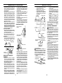 6
6
-
 7
7
-
 8
8
-
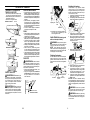 9
9
-
 10
10
-
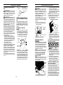 11
11
-
 12
12
-
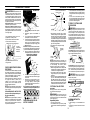 13
13
-
 14
14
-
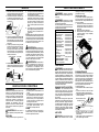 15
15
-
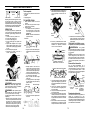 16
16
-
 17
17
-
 18
18
-
 19
19
-
 20
20
-
 21
21
-
 22
22
-
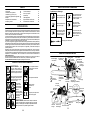 23
23
-
 24
24
-
 25
25
-
 26
26
-
 27
27
-
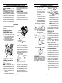 28
28
-
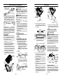 29
29
-
 30
30
-
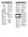 31
31
-
 32
32
-
 33
33
-
 34
34
-
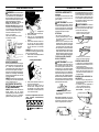 35
35
-
 36
36
-
 37
37
-
 38
38
-
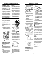 39
39
-
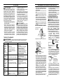 40
40
-
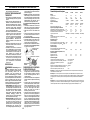 41
41
-
 42
42
-
 43
43
-
 44
44
-
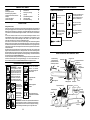 45
45
-
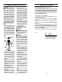 46
46
-
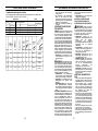 47
47
-
 48
48
-
 49
49
-
 50
50
-
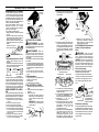 51
51
-
 52
52
-
 53
53
-
 54
54
-
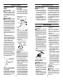 55
55
-
 56
56
-
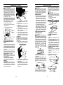 57
57
-
 58
58
-
 59
59
-
 60
60
-
 61
61
-
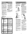 62
62
-
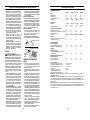 63
63
-
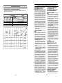 64
64
-
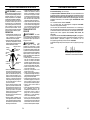 65
65
-
 66
66
-
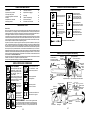 67
67
-
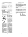 68
68
-
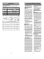 69
69
-
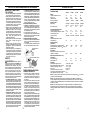 70
70
-
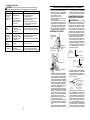 71
71
-
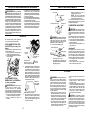 72
72
-
 73
73
-
 74
74
-
 75
75
-
 76
76
-
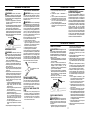 77
77
-
 78
78
-
 79
79
-
 80
80
-
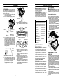 81
81
-
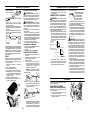 82
82
-
 83
83
-
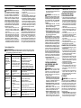 84
84
-
 85
85
-
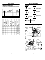 86
86
-
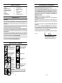 87
87
-
 88
88


MC CULLOCH CS330 El manual del propietario
- Categoría
- Motosierras eléctricas
- Tipo
- El manual del propietario
en otros idiomas
- français: MC CULLOCH CS330 Le manuel du propriétaire
- English: MC CULLOCH CS330 Owner's manual
- Deutsch: MC CULLOCH CS330 Bedienungsanleitung
Otros documentos
-
AL-KO SOLO 127430 Manual de usuario
-
McCulloch CS 370 El manual del propietario
-
Ikra BDA PCS 5046 El manual del propietario
-
McCulloch Dakota 442-16 40cc FA TL Manual de usuario
-
-
-
-
McCulloch Mac20X El manual del propietario
-
Festool IS 330 EB-FS Instrucciones de operación
-