SICK C2000 Eco Safety Light Curtain Instrucciones de operación
- Tipo
- Instrucciones de operación

ADDENDUM OPERATING INSTRUCTIONS
C2000 Eco
Safety Light Curtain
D
E
F
GB
I

Addendum Operating Instructions
C2000 Eco
2 © SICK AG • Industrial Safety Systems • Germany • All rights reserved 8011905/TI60/2010-02-12
Subject to change without notice
Inhalt/Contents
Inhalt/Contents
D
CH
A Seite 3–10
E Páginas 11–18
F Pages 19–26
GB Pages 27-34
I Pagine 35-43
This document is protected by the law of copyright, whereby all rights established therein remain with the company SICK AG. Reproduction of this
document or parts of this document is only permissible within the limits of the legal determination of Copyright Law. Alteration or abridgement of the
document is not permitted without the explicit written approval of the company SICK AG.

Addendum Betriebsanleitung
C2000 Eco
8011905/TI60/2010-02-12 © SICK AG • Industrial Safety Systems • Deutschland • Alle Rechte vorbehalten 3
Irrtümer und Änderungen vorbehalten
Inhalt
D
Inhalt
1 Zu diesem Dokument ........................................................................................................4
2 Zur Sicherheit ....................................................................................................................4
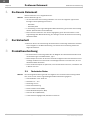
3 Produktbeschreibung........................................................................................................4
3.1 Technische Daten .................................................................................................4
3.2 Anzeigeelemente...................................................................................................5
4 Montage .............................................................................................................................5
5 Elektroinstallation und Konfiguration.............................................................................6
5.1 Gerätekonfiguration..............................................................................................6
6 Maßbilder ...........................................................................................................................7
7 Bestelldaten.......................................................................................................................9

Kapitel 1 Addendum Betriebsanleitung
C2000 Eco
4 © SICK AG • Industrial Safety Systems • Deutschland • Alle Rechte vorbehalten 8011905/TI60/2010-02-12
Irrtümer und Änderungen vorbehalten
Zu diesem Dokument
D
1 Zu diesem Dokument
Dieses Dokument ist ein Originaldokument.
Dieses Addendum gilt nur
für den Sicherheits-Lichtvorhang C2000 Eco mit einem der folgenden Typenschild-
Einträge im Feld Operating Instructions:
–
8011905
– 8011905/TI60
in Verbindung mit der zugrundeliegenden Betriebsanleitung „Sicherheits-Lichtvorhang
C2000“ (SICK-Artikelnummer 8009140).
Falls in diesem Dokument nicht anders angegeben, gelten die Informationen in der
zugrundeliegenden Betriebsanleitung, dort bezogen auf den Sicherheits-Lichtvorhang
C2000 Standard.
2 Zur Sicherheit
Beachten Sie bei der Verwendung des Sicherheits-Lichtvorhangs C2000 Eco zusätzlich
zu den Angaben in der Betriebsanleitung zum Sicherheits-Lichtvorhang C2000 die
folgenden Hinweise.
3 Produktbeschreibung
Der Sicherheits-Lichtvorhang C2000 Eco als Mitglied der C2000-Produktfamilie erfüllt
die Anforderungen nach EN 61496D1, Typ 2.
Dieses Kapitel informiert Sie über die besonderen Eigenschaften des Sicherheits-Licht-
vorhangs C2000 Eco. Es beschreibt auch die Eigenschaften und Funktionen, die vom
C2000 Standard abweichen.
Lesen Sie dieses Kapitel auf jeden Fall, bevor Sie das Gerät montieren, installieren und
in Betrieb nehmen.
3.1 Technische Daten
Die nachfolgende Auflistung enthält nur Angaben zum Sicherheits-Lichtvorhang C2000
Eco, die sich nicht aus der zugrundeliegenden Betriebsanleitung ergeben.
Schutzfeldhöhe: 150–1200 mm
Reichweite: 0 … 6 m
Auflösung: 30 mm
Keine Strahlcodierung
Keine Schützkontrolle (EDM)
Keine Wiederanlaufsperre (RES)
Schutzart IP 54 (EN 60529)
2 überwachte Ausgänge, PNP, Schaltstrom 250 mA
Hinweis
Hinweis

Addendum Betriebsanleitung Kapitel 4
C2000 Eco
8011905/TI60/2010-02-12 © SICK AG • Industrial Safety Systems • Deutschland • Alle Rechte vorbehalten 5
Irrtümer und Änderungen vorbehalten
Montage
D
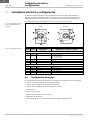
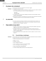
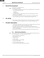
3.2 Anzeigeelemente
D
as Einstiegsmodell C2000 Eco bietet kein 7-Segment-Display, also keine Status- und
Diagnosemöglichkeit. Auch die LED-Anzeigen unterscheiden sich vom C2000 Standard.
LED gelb: Betriebsspannung
LED rot: Schaltausgang aus
LED grün: Schaltausgang an
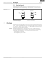
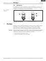
4 Montage
Der Sicherheits-Lichtvorhang C2000 Eco kann nicht mit dem Swivel-Mount-Halter befestigt
werden. Sender und Empfänger werden mit je zwei Seithalterungen befestigt. Die Montage
ist in Kapitel 4.2 „Montage mit Seithalterung“ in der zugrundeliegenden Betriebsanleitung
„Sicherheits-Lichtvorhang C2000“ beschrieben.
Bei der Bestellung des Zubehörs (siehe Kapitel 11.1„Zubehör“ der Betriebsanleitung
Sicherheits-Lichtvorhang C2000) bitte beachten, dass für Befestigung und Verkabelung
nur die beiden folgenden Artikel mit dem C2000 Eco eingesetzt werden können:
Befestigungssatz 6 mit Seithalter
M12-Leitungsdose 5-polig mit Kabel
Abb.
1
:
Anzeigeelemente
C2000 Eco
Hinweis
Sender
Empfänger

Kapitel 5 Addendum Betriebsanleitung
C2000 Eco
6 © SICK AG • Industrial Safety Systems • Deutschland • Alle Rechte vorbehalten 8011905/TI60/2010-02-12
Irrtümer und Änderungen vorbehalten
Elektroinstallation und
Konfiguration
D
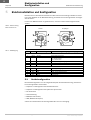
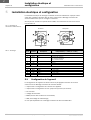
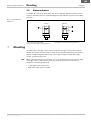
5 Elektroinstallation und Konfiguration
Beachten Sie bei der Elektroinstallation des Sicherheits-Lichtvorhangs C2000 Eco zusätz-
lich zu den Angaben in der Betriebsanleitung „Sicherheits-Lichtvorhang C2000“ die folgen-
den Hinweise:
Um die volle EMV-Sicherheit zu gewährleisten, muss die Funktionserde angeschlossen
werden.
PIN-Nr. Farbe Bezeichnung Bedeutung (I = Eingang, O = Ausgang)
Sender
1 Braun 24 V DC Spannungsversorgung U
B
2 Weiß Test I: Geräteselbsttest
0 V = Sender inaktiv
24 V = Sender aktiv
3 Blau GND 0 V DC, Spannungsversorgung
4 Schwarz nc Reserviert
5 Grau Shield Funktionserde
Empfänger
1 Braun 24 V DC Spannungsversorgung U
B
2 Weiß OSSD 1 O: Schaltausgang 1
3 Blau GND 0 V DC, Spannungsversorgung
4 Schwarz OSSD 2 O: Schaltausgang 2
5 Grau Shield Funktionserde
5.1 Gerätekonfiguration
Die Gerätekonfiguration ist in den folgenden Kapiteln der Betriebsanleitung „Sicherheits-
Lichtvorhang C2000“ beschrieben:
Kapitel 5.4.1 Konfiguration des Geräteselbsttests
Kapitel 5.4.2 Konfiguration des zyklischen Systemtests
Die Funktionen
Strahlcodierung
EDM (Schützkontrolle)
RES (Wiederanlaufsperre)
stehen beim Sicherheits-Lichtvorhang C2000 Eco nicht zur Verfügung.
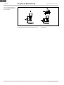
Abb.
2
:
PIN-Anordnung
M12$Stecker 5-Pin
Tab.
1
:
PIN-Belegung
Sender
Empfänger

Addendum Betriebsanleitung Kapitel 6
C2000 Eco
8011905/TI60/2010-02-12 © SICK AG • Industrial Safety Systems • Deutschland • Alle Rechte vorbehalten 7
Irrtümer und Änderungen vorbehalten
Maßbilder
D
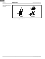
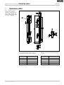
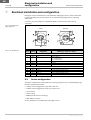
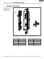
6 Maßbilder
Befestigungssatz 6 Schutzfeldhöhe
M8 Sechskantschraube DIN 933 mit Scheibe
DIN 9021 (nicht im Lieferumfang)
Schiebemutternut für Seitmontage
S1 L1 S1 L1
150 246 750 816
300 364 900 967
450 515 1050 1117
600 666 1200 1266
Abb.
3
:
Maß
bilder und me-
chanische Abmessungen
C2000 Eco, Sender (Empfän-
ger ist spiegelbildlich), Seit-
halter, Schutzfeldhöhen
S1 = 150 … 1200 mm
ca.
ca.

Kapitel 6 Addendum Betriebsanleitung
C2000 Eco
8 © SICK AG • Industrial Safety Systems • Deutschland • Alle Rechte vorbehalten 8011905/TI60/2010-02-12
Irrtümer und Änderungen vorbehalten
Maßbilder
D
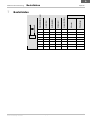
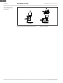
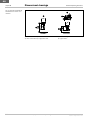
Leitungsdose M12 5-polig mit Leitung Steckbereich
Leitungsdose M12 5-polig gewinkelt mit Leitung Lichtaustritt
Abb.
4
:
Maßbilder und me-
chanische Abmessungen der
Anschlüsse

Addendum Betriebsanleitung Kapitel 7
C2000 Eco
8011905/TI60/2010-02-12 © SICK AG • Industrial Safety Systems • Deutschland • Alle Rechte vorbehalten 9
Irrtümer und Änderungen vorbehalten
Bestelldaten
D
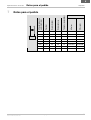
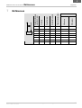
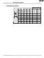
7 Bestelldaten
Artikelnummer
Schutzfeldhöhe S [mm]
Gewicht [kg]
Auflösung [mm]
Strahlanzahl
Ansprechzeit [ms]
Sender
Empfänger
150 0,27 30 8 8 1041577 1041578
300 0,38 30 16 8,5 1041579 1041580
450 0,51 30 24 8,5 1041581 1041582
600 0,65 30 32 10,5 1041583 1041584
750 0,78 30 40 12,5 1041585 1041586
900 0,91 30 48 15 1041587 1041588
1050 1,04 30 56 17 1041589 1041590
1200 1,18 30 64 19 1041591 1041592

Kapitel 7 Addendum Betriebsanleitung
C2000 Eco
10 © SICK AG • Industrial Safety Systems • Deutschland • Alle Rechte vorbehalten 8011905/TI60/2010-02-12
Irrtümer und Änderungen vorbehalten
Bestelldaten
D

Suplemento Instr. de servicio
C2000 Eco
8011905/TI60/2010-02-12 © SICK AG • Industrial Safety Systems • Alemania • Reservados todos los derechos 11
Sujeto a cambio sin previo aviso
Contenido
E
Contenido
1 Respecto a este documento ..........................................................................................12
2 Respecto a la seguridad .................................................................................................12
3 Descripción del producto................................................................................................12
3.1 Datos técnicos.....................................................................................................12
3.2 Elementos indicadores .......................................................................................13
4 Montaje.............................................................................................................................13
5 Instalación eléctrica y configuración............................................................................14
5.1 Configuración del equipo....................................................................................14
6 Croquis de dimensiones .................................................................................................15
7 Datos para el pedido .......................................................................................................17

Capítulo 1 Suplemento Instr. de servicio
C2000 Eco
12 © SICK AG • Industrial Safety Systems • Alemania • Reservados todos los derechos 8011905/TI60/2010-02-12
Sujeto a cambio sin previo aviso
Respecto a este documento
E
1 Respecto a este documento
Este documento es una traducción del documento original.
Esta suplemento sólo tiene validez
para la cortina fotoeléctrica de seguridad C2000 Eco con una de las siguientes
inscripciónes en el recuadro Operating Instructions de la placa de características:
–
8011905
– 8011905/TI60
junto con las instrucciones de servicio originales “Cortina fotoeléctrica de seguridad
C2000” (número de referencia del artículo SICK 8009140).
En el caso de que en este documento no se indique otra cosa, tienen validez aquellas
informaciones de las correspondientes instrucciones de servicio que se refieran a la
cortina fotoeléctrica de seguridad C2000 Standard.
2 Respecto a la seguridad
Al utilizar la cortina fotoeléctrica de seguridad C2000 Eco, además de los datos
incluidos en las instrucciones de servicio sobre la cortina fotoeléctrica de seguridad
C2000, se debe observar el cumplimiento de las siguientes indicaciones.
3 Descripción del producto
La cortina fotoeléctrica de seguridad C2000 Eco, integrante de la gama de productos
C2000, cumple los requisitos según EN 61496?1, tipo 2.
En este capítulo le informaremos acerca de las propiedades características de la
cortina fotoeléctrica de seguridad C2000 Eco. También describe las propiedades y
funciones distintas de las de la C2000 Standard.
Antes de montar, instalar y poner en servicio el equipo, es indispensable leer este
capítulo.
3.1 Datos técnicos
El siguiente listado sólo contiene datos sobre la cortina fotoeléctrica de seguridad
C2000 Eco que no constan en las instrucciones de servicio subyacentes.
altura del campo de protección: 150–1200 mm
alcance: 0 … 6 m
resolución: 30 mm
sin codificación de haces
sin chequeo externo de contactores (EDM)
sin bloqueo de rearme (RES)
grado de protección IP 54 (EN 60529)
2 salidas supervisadas, PNP, corriente conmutada 250 mA
Indicación
Indicación

Suplemento Instr. de servicio Capítulo 4
C2000 Eco
8011905/TI60/2010-02-12 © SICK AG • Industrial Safety Systems • Alemania • Reservados todos los derechos 13
Sujeto a cambio sin previo aviso
Montaje
E
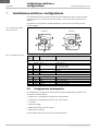
3.2 Elementos indicadores
E
l modelo C2000 Eco no dispone de display de 7 segmentos, es decir, no tiene medios
para indicar el estado ni para el diagnóstico. Los indicadores LED también son distintos
que los de la C2000 Standard.
LED amarillo: tensión de alimentación
LED rojo: salida de aviso off
LED verde: salida de aviso on
4 Montaje
La cortina fotoeléctrica de seguridad C2000 Eco no se puede fijar con el soporte giratorio
(swivel mount). El emisor y el receptor se fijan con dos soportes laterales,
respectivamente. El montaje está descrito en el apartado 4.2 “Montaje con soporte
lateral” en las instrucciones de servicio subyacentes “Cortina fotoeléctrica de seguridad
C2000”.
Al pedir el accesorio (ver aptdo. 11.1 de las instrucciones de servicio cortina fotoeléctrica
de seguridad C2000), tener presente que para la fijación y el cableado sólo pueden
usarse los dos siguientes artículos con la C2000 Eco:
escuadra de fijación 6 con soporte lateral
conector hembra M12 de 5 polos con cable
Fig.
1
:
Elementos indicado-
res C2000 Eco
Indicación
Emisor
Receptor

Capítulo 5 Suplemento Instr. de servicio
C2000 Eco
14 © SICK AG • Industrial Safety Systems • Alemania • Reservados todos los derechos 8011905/TI60/2010-02-12
Sujeto a cambio sin previo aviso
Instalación eléctrica y
configuración
E
5 Instalación eléctrica y configuración
Al realizar la instalación eléctrica de la cortina fotoeléctrica de seguridad C2000 Eco,
además de los datos incluidos en las instrucciones de servicio “Cortina fotoeléctrica de
seguridad C2000”, se ha de observar el cumplimiento de las siguientes indicaciones:
Para garantizar la seguridad CEM se tiene que conectar la tierra funcional.
Nº pin Color Designación Significado (I = entrada, O = salida)
Emisor
1 Marrón 24 V c.c. Alimentación de tensión U
B
2 Blanco Test
I: autotest del equipo
0 V = emisor inactivo
24 V = emisor activo
3 Azul GND 0 V c.c., alimentación de tensión
4 Negro nc Reservado
5 Gris Pantalla Tierra funcional
Receptor
1 Marrón 24 V c.c. Alimentación de tensión U
B
2 Blanco OSSD 1 O: salida de aviso 1
3 Azul GND 0 V c.c., alimentación de tensión
4 Negro OSSD 2 O: salida de aviso 2
5 Gris Pantalla Tierra funcional
5.1 Configuración del equipo
La configuración del equipo está descrita en los siguientes capítulos de las instrucciones
de servicio “Cortina fotoeléctrica de seguridad C2000”:
capítulo 5.4.1 Configuración del autotest del equipo
capítulo 5.4.2 Configuración del test cíclico del sistema
las funciones
codificación de haces
EDM (chequeo externo de contactores)
RES (bloqueo de rearme)
no están disponibles en la cortina fotoeléctrica de seguridad C2000 Eco.
Fig.
2
:
Disposición de pines
conector macho M12 de
5 pines
Tab.
1
:
Ocupación de pines
Emisor
Receptor

Suplemento Instr. de servicio Capítulo 6
C2000 Eco
8011905/TI60/2010-02-12 © SICK AG • Industrial Safety Systems • Alemania • Reservados todos los derechos 15
Sujeto a cambio sin previo aviso
Croquis de dimensiones
E
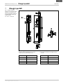
6 Croquis de dimensiones
Escuadra de fijación 6 Altura del campo de protección
Tornillo hexagonal M8 DIN 933 con arandela
DIN 9021 (no está incluido en el suministro)
Ranura con tuerca corrediza para montaje
lateral
S1 L1 S1 L1
150 246 750 816
300 364 900 967
450 515 1050 1117
600 666 1200 1266
Fig.
3
:
Croquis de dimensio-
nes y medidas mecánicas
C2000 Eco, emisor (receptor
de simetría complementaria),
soporte lateral, alturas del
campo de protección
S1 = 150 … 1200 mm
Aprox.
Aprox.

Capítulo 6 Suplemento Instr. de servicio
C2000 Eco
16 © SICK AG • Industrial Safety Systems • Alemania • Reservados todos los derechos 8011905/TI60/2010-02-12
Sujeto a cambio sin previo aviso
Croquis de dimensiones
E
Conector hembra M12 de 5 polos con cable Área de conexión
Conector hembra M12 de 5 polos acodado con cable Salida de luz
Fig.
4
:
Croquis de dimensio-
nes y medidas mecánicas de
las conexiones

Suplemento Instr. de servicio Capítulo 7
C2000 Eco
8011905/TI60/2010-02-12 © SICK AG • Industrial Safety Systems • Alemania • Reservados todos los derechos 17
Sujeto a cambio sin previo aviso
Datos para el pedido
E
7 Datos para el pedido
Nº art.
Altura del campo de
protección S [mm]
Peso [kg]
Resolución [mm]
Número de haces
Tiempo de respuesta [ms]
Emisor
Receptor
150 0,27 30 8 8 1041577 1041578
300 0,38 30 16 8,5 1041579 1041580
450 0,51 30 24 8,5 1041581 1041582
600 0,65 30 32 10,5 1041583 1041584
750 0,78 30 40 12,5 1041585 1041586
900 0,91 30 48 15 1041587 1041588
1050 1,04 30 56 17 1041589 1041590
1200 1,18 30 64 19 1041591 1041592

Capítulo 7 Suplemento Instr. de servicio
C2000 Eco
18 © SICK AG • Industrial Safety Systems • Alemania • Reservados todos los derechos 8011905/TI60/2010-02-12
Sujeto a cambio sin previo aviso
Datos para el pedido
E

Addendum Notice d’instructions
C2000 Eco
8011905/TI60/2010-02-12 © SICK AG • Industrial Safety Systems • Allemagne • Tous droits réservés 19
Sujet à modification sans préavis
Sommaire
F
Sommaire
1 A propos de ce manuel ...................................................................................................20
2 La sécurité........................................................................................................................20
3 Description du produit ....................................................................................................20
3.1 Caractéristiques techniques...............................................................................20
3.2 Indicateurs...........................................................................................................21
4 Montage ...........................................................................................................................21
5 Installation électrique et configuration........................................................................22
5.1 Configuration de l’appareil .................................................................................22
6 Schémas cotés ................................................................................................................23
7 Références .......................................................................................................................25

Chapitre 1 Addendum Notice d’instructions
C2000 Eco
20 © SICK AG • Industrial Safety Systems • Allemagne • Tous droits réservés 8011905/TI60/2010-02-12
Sujet à modification sans préavis
A propos de ce manuel
F
1 A propos de ce manuel
Ce document constitue une traduction du document original.
Ce complément ne concerne que
le barrage immatériel de sécurité C2000 Eco comportant l’une des mentions suivantes
sur le champ Operating Instructions de la plaque signalétique :
–
8011905
– 8011905/TI60
il complète la notice d’instructions «Barrage immatériel de sécurité C2000» de base
(référence SICK 8009140).
Sauf mention contraire, les informations de la notice d’instructions de base concernant
le barrage immatériel de sécurité C2000 Standard sont valables.
2 La sécurité
La mise en œuvre du barrage immatériel de sécurité C2000 Eco doit respecter les
consignes données dans la notice d’instructions du barrage immatériel de sécurité
C2000 ainsi que les consignes ci-dessous.
3 Description du produit
Intégrant la famille C2000, le barrage immatériel de sécurité C2000 Eco répond aux
exigences du type 2 selon la norme EN 61496>1.
Ce chapitre informe sur les caractéristiques du barrage immatériel de sécurité
C2000 Eco. Il décrit également les caractéristiques et fonctionnalités différentes de
celles du C2000 Standard.
Il faut impérativement lire ce chapitre avant de monter, installer et mettre en service
l’appareil.
3.1 Caractéristiques techniques
La liste suivante donne les caractéristiques du barrage immatériel de sécurité C2000 Eco
ne figurant pas dans la notice d’instructions de base.
hauteur de champ de protection : 150–1200 mm
portée : 0 … 6 m
résolution : 30 mm
aucun codage des faisceaux
aucun contrôle des contacteurs commandés (EDM)
aucun verrouillage de redémarrage (RES)
indice de protection IP 54 (EN 60529)
2 sorties surveillées, PNP, pouvoir de commutation 250 mA
Remarque
Remarque

Addendum Notice d’instructions Chapitre 4
C2000 Eco
8011905/TI60/2010-02-12 © SICK AG • Industrial Safety Systems • Allemagne • Tous droits réservés 21
Sujet à modification sans préavis
Montage
F
3.2 Indicateurs
L
e modèle d’entrée de gamme C2000 Eco ne possède pas d’afficheur à 7 segments, et
n’offre par conséquent aucune possibilité d’affichage d’état ou de diagnostic. Les LED de
signalisation sont différentes de celles du C2000 Standard.
LED jaune : tension d’alimentation
LED rouge : sortie TOR désactivée
LED verte : sortie TOR activée
4 Montage
Le barrage immatériel de sécurité C2000 Eco ne peut pas être fixé au moyen d’un support
de montage sur rotules. L’émetteur et le récepteur sont chacun montés avec deux
fixations latérales. Le montage est décrit au paragraphe 4.2 «Montage avec fixation
latérale» de la notice d’instructions «Barrage immatériel de sécurité C2000» de base.
Pour la commande des accessoires (cf. section 11.1 de la notice d’instructions du barrage
immatériel de sécurité C2000), s’assurer que seuls les deux articles ci-dessous soient
effectivement utilisés pour la fixation et le câblage du C2000 Eco :
système de fixation 6 avec fixation latérale
connecteur femelle M12 à 5 broches avec câble
Fig.
1
:
Indicateurs
C2000 Eco
Remarque
Émetteur
Récepteur

Chapitre 5 Addendum Notice d’instructions
C2000 Eco
22 © SICK AG • Industrial Safety Systems • Allemagne • Tous droits réservés 8011905/TI60/2010-02-12
Sujet à modification sans préavis
Installation électrique et
configuration
F
5 Installation électrique et configuration
L’installation électrique du barrage immatériel de sécurité C2000 Eco implique l’obser-
vation des consignes données dans la notice d’instructions «Barrage immatériel de
sécurité C2000» ainsi que les consignes ci-dessous :
Afin de pouvoir atteindre les spécifications CEM, il est nécessaire de connecter la terre
fonctionnelle TF.
N° br. Couleur Description Interprétation (I = entrée, O = sortie)
Émetteur
1 Marron 24 V CC Alimentation U
B
2 Blanc Test I : autotest de l’appareil
0 V = émetteur désactivé
24 V = émetteur activé
3 Bleu GND 0 V CC, alimentation
4 Noir nc Réservé
5 Gris Blindage Terre fonctionnelle
Récepteur
1 Marron 24 V CC Alimentation U
B
2 Blanc OSSD 1 O : sortie TOR 1
3 Bleu GND 0 V CC, alimentation
4 Noir OSSD 2 O : sortie TOR 2
5 Gris Shield Terre fonctionnelle
5.1 Configuration de l’appareil
La configuration de l’appareil est décrite dans les paragraphes suivants de la notice
d’instructions du «Barrage immatériel de sécurité C2000» :
chapitre 5.4.1 Configuration de l’autotest de l’appareil
chapitre 5.4.2 Configuration du test cyclique du système (test externe)
les fonctions
codage des faisceaux
EDM (contrôle des contacteurs commandés)
RES (verrouillage de redémarrage)
ne sont pas disponibles sur le barrage immatériel de sécurité C2000 Eco.
Fig.
2
:
Brochage du
connecteur mâle M12 5 br.
Tab.
1
:
Brochage
Émetteur
Récepteur

Addendum Notice d’instructions Chapitre 6
C2000 Eco
8011905/TI60/2010-02-12 © SICK AG • Industrial Safety Systems • Allemagne • Tous droits réservés 23
Sujet à modification sans préavis
Schémas cotés
F
6 Schémas cotés
Système de fixation 6 Hauteur de champ de protection
Vis hexagonale M8 DIN 933 avec rondelle
DIN 9021 (non inclus sur la liste de colisage)
Rainure pour écrous coulissants pour montage
latéral
S1 L1 S1 L1
150 246 750 816
300 364 900 967
450 515 1050 1117
600 666 1200 1266
Fig.
3
:
Plans et cotes d’en-
combrement C2000 Eco,
émetteur (le récepteur est in-
versé), fixation latérale, hau-
teurs de champ de protection
S1 = 150 … 1200 mm
Env.Env.

Chapitre 6 Addendum Notice d’instructions
C2000 Eco
24 © SICK AG • Industrial Safety Systems • Allemagne • Tous droits réservés 8011905/TI60/2010-02-12
Sujet à modification sans préavis
Schémas cotés
F
Connecteur femelle M12 à 5 br. avec câble Cote d’enfichage
Connecteur femelle coudé M12 à 5 br. avec câble Sortie du faisceau
Fig.
4
:
Plans et cotes
d’encombrement des
connecteurs

Addendum Notice d’instructions Chapitre 7
C2000 Eco
8011905/TI60/2010-02-12 © SICK AG • Industrial Safety Systems • Allemagne • Tous droits réservés 25
Sujet à modification sans préavis
Références
F
7 Références
Référence
Hauteur de champ de
protection S [mm]
Poids [kg]
Résolution [mm]
Nombre de faisceaux
Temps de réponse [ms]
Émetteur
Récepteur
150 0,27 30 8 8 1041577 1041578
300 0,38 30 16 8,5 1041579 1041580
450 0,51 30 24 8,5 1041581 1041582
600 0,65 30 32 10,5 1041583 1041584
750 0,78 30 40 12,5 1041585 1041586
900 0,91 30 48 15 1041587 1041588
1050 1,04 30 56 17 1041589 1041590
1200 1,18 30 64 19 1041591 1041592

Chapitre 7 Addendum Notice d’instructions
C2000 Eco
26 © SICK AG • Industrial Safety Systems • Allemagne • Tous droits réservés 8011905/TI60/2010-02-12
Sujet à modification sans préavis
Références
F

Addendum Operating Instructions
C2000 Eco
8011905/TI60/2010-02-12 © SICK AG • Industrial Safety Systems • Germany • All rights reserved 27
Subject to change without notice
Contents
GB
Contents
1 About this document.......................................................................................................28
2 On safety...........................................................................................................................28
3 Product description.........................................................................................................28
3.1 Technical specifications .....................................................................................28
3.2 Status indicators .................................................................................................29
4 Mounting ..........................................................................................................................29
5 Electrical installation and configuration ......................................................................30
5.1 Device configuration ...........................................................................................30
6 Dimensional drawings ....................................................................................................31
7 Ordering information.......................................................................................................33

Chapter 1 Addendum Operating Instructions
C2000 Eco
28 © SICK AG • Industrial Safety Systems • Germany • All rights reserved 8011905/TI60/2010-02-12
Subject to change without notice
About this document
GB
1 About this document
This document is an original document.
This addendum only applies
to the C2000 Eco safety light curtain with one of the following entries on the type label
in the Operating Instructions field:
–
8011905
– 8011905/TI60
in conjunction with the original operating instructions “C2000 Safety Light Curtain”
(SICK part number 8009140).
If not otherwise revised in this document, the information in the original operating
instructions applies, which relate to the C2000 Standard safety light curtain.
2 On safety
When using the C2000 Eco safety light curtain, observe the following notes in addition
to the information in the operating instructions for the C2000 safety light curtain.
3 Product description
The C2000 Eco safety light curtain, as a member of the C2000 product family, complies
with the requirements in accordance with EN 61496:1, type 2.
This chapter provides information on the special features and properties of the
C2000 Eco safety light curtain. It also describes the properties and functions that differ
from the C2000 Standard.
Please read this chapter before mounting, installing and commissioning the device.
3.1 Technical specifications
The following list contains information only concerning the C2000 Eco safety light curtain
that is not already given in the original operating instructions.
protective field height: 150-1200 mm
scanning range: 0 … 6 m
resolution: 30 mm
no beam coding
no external device monitoring (EDM)
no restart interlock (RES)
enclosure rating IP 54 (EN 60529)
2 monitored outputs, PNP, switching current 250 mA
Note
Note

Addendum Operating Instructions Chapter 4
C2000 Eco
8011905/TI60/2010-02-12 © SICK AG • Industrial Safety Systems • Germany • All rights reserved 29
Subject to change without notice
Mounting
GB
3.2 Status indicators
T
he C2000 Eco entry-level model does not have a 7:segment display, therefore it has no
status or diagnostics features. The LED displays are also different to those on the C2000
Standard.
LED yellow: operating voltage
LED red: output signal switching device off
LED green: output signal switching device on
4 Mounting
The C2000 Eco safety light curtain cannot be fastened using the swivel mount bracket.
Sender and receiver are each fastened using two side brackets. Mounting is described in
chapter 4.2 “Mounting with side bracket” in the original original “C2000 Safety Light
Curtain” operating instructions.
When ordering accessories (see chapter 11.1 of the operating instructions for the C2000
safety light curtain), please note that only the following items can be used with the
C2000 Eco for fastening and wiring:
mounting kit 6 with side bracket
M12 cable socket 5-pin with cable
Fig.
1
:
Status indicators
C2000 Eco
Note
Sender
Receiver

Chapter 5 Addendum Operating Instructions
C2000 Eco
30 © SICK AG • Industrial Safety Systems • Germany • All rights reserved 8011905/TI60/2010-02-12
Subject to change without notice
Electrical installation and
configuration
GB
5 Electrical installation and configuration
During the electrical installation of the C2000 Eco safety light curtain, observe the follow-
ing notes in addition to the information in the “C2000 Safety Light Curtain” operating
instructions:
To ensure full electromagnetic compatibility (EMC), functional earth (FE) must be
connected.
Pin no. Colour Designation Meaning (I = input, O = output)
Sender
1 Brown 24 V DC Voltage supply U
B
2 White Test I: device self-test
0 V = sender inactive
24 V = sender active
3 Blue GND 0 V DC, voltage supply
4 Black nc Reserved
5 Grey Shield Functional earth
Receiver
1 Brown 24 V DC Voltage supply U
B
2 White OSSD 1 O: output signal switching device 1
3 Blue GND 0 V DC, voltage supply
4 Black OSSD 2 O: output signal switching device 2
5 Grey Shield Functional earth
5.1 Device configuration
The device configuration is described in the following chapters of the “C2000 Safety Light
Curtain” operating instructions:
chapter 5.4.1 Configuration of the device self test
chapter 5.4.2 Configuration of the cyclic system test
the functions
beam coding
EDM (external device monitoring)
RES (restart interlock)
are not available on the C2000 Eco safety light curtain.
Fig.
2
:
PIN assignment
M12 plug 5-pin
Tab.
1
:
Pin assignment
Sender
Receiver

Addendum Operating Instructions Chapter 6
C2000 Eco
8011905/TI60/2010-02-12 © SICK AG • Industrial Safety Systems • Germany • All rights reserved 31
Subject to change without notice
Dimensional drawings
GB
6 Dimensional drawings
Mounting kit 6 Protective field height
M8 hex screw, DIN 933, with washer DIN 9021
(not in the delivery)
Sliding nut groove for side mounting
S1 L1 S1 L1
150 246 750 816
300 364 900 967
450 515 1050 1117
600 666 1200 1266
Fig.
3
:
Dimensional drawings
and dimensions C2000 Eco,
sender (receiver mirror
image), side bracket,
protective field heights
S1 = 150 … 1200 mm
Ca.
Ca.

Chapter 6 Addendum Operating Instructions
C2000 Eco
32 © SICK AG • Industrial Safety Systems • Germany • All rights reserved 8011905/TI60/2010-02-12
Subject to change without notice
Dimensional drawings
GB
Cable socket M12 5-pin with cable Connector range
Cable socket M12 5-pin, angled with cable Light emission
Fig.
4
:
Dimensional drawings
and dimensions of the con-
nections

Addendum Operating Instructions Chapter 7
C2000 Eco
8011905/TI60/2010-02-12 © SICK AG • Industrial Safety Systems • Germany • All rights reserved 33
Subject to change without notice
Ordering information
GB
7 Ordering information
Part No.
Protective field
height S [mm]
Weight [kg]
Resolution [mm]
Number of beams
Response time [ms]
Sender
Receiver
150 0.27 30 8 8 1041577 1041578
300 0.38 30 16 8,5 1041579 1041580
450 0.51 30 24 8,5 1041581 1041582
600 0.65 30 32 10,5 1041583 1041584
750 0.78 30 40 12,5 1041585 1041586
900 0.91 30 48 15 1041587 1041588
1050 1.04 30 56 17 1041589 1041590
1200 1.18 30 64 19 1041591 1041592

Chapter 7 Addendum Operating Instructions
C2000 Eco
34 © SICK AG • Industrial Safety Systems • Germany • All rights reserved 8011905/TI60/2010-02-12
Subject to change without notice
Ordering information
GB

Addendum Istruzioni per l’uso
C2000 Eco
8011905/TI60/2010-02-12 © SICK AG • Industrial Safety Systems • Germania • Tutti i diritti riservati 35
Contenuti soggetti a modifiche senza preavviso
Indice
I
Indice
1 A proposito di questo documento..................................................................................36
2 Sulla sicurezza .................................................................................................................36
3 Descrizione del prodotto.................................................................................................36
3.1 Dati tecnici...........................................................................................................36
3.2 Elementi di visualizzazione.................................................................................37
4 Montaggio ........................................................................................................................37
5 Installazione elettrica e configurazione .......................................................................38
5.1 Configurazione del dispositivo............................................................................38
6 Disegni quotati ................................................................................................................39
7 Dati di ordinazione ..........................................................................................................41

Capitolo 1 Addendum Istruzioni per l’uso
C2000 Eco
36 © SICK AG • Industrial Safety Systems • Germania • Tutti i diritti riservati 8011905/TI60/2010-02-12
Contenuti soggetti a modifiche senza preavviso
A proposito di questo
documento
I
1 A proposito di questo documento
Il presente documento è una traduzione dell’originale.
Il presente addendum vale esclusivamente
per una cortina di sicurezza C2000 Eco che riporta sulla sua targhetta alla voce
Operating Instructions una delle scritte seguenti:
–
8011905
– 8011905/TI60
in abbinamento alle istruzioni d’uso di riferimento “Cortina di sicurezza C2000” (codice
numerico SICK 8009140).
In caso il documento presente non dia indicazioni contrarie, valgono le informazioni
delle istruzioni d’uso di base riportate per la cortina di sicurezza C2000 Standard.
2 Sulla sicurezza
Per usare la cortina di sicurezza C2000 Eco, oltre a quanto indicato nelle istruzioni
d’uso della cortina di sicurezza C2000, vanno osservate le note che seguono.
3 Descrizione del prodotto
La cortina di sicurezza C2000 Eco è un componente della famiglia di prodotti C2000 e
risponde ai requisiti di sicurezza, per il tipo 2 secondo EN 61496<1.
Questo capitolo vi informa sulle particolarità della cortina di sicurezza C2000 Eco. Esso
descrive anche le proprietà e le funzioni che la distinguono dalla C2000 Standard.
Leggete assolutamente questo capitolo prima di montare, installare o mettere in
funzione il dispositivo.
3.1 Dati tecnici
L’elenco seguente contiene esclusivamente delle indicazioni per la cortina di sicurezza
C2000 Eco non ancora incluse nelle istruzioni d’uso di base.
altezza del campo protetto: 150-1200 mm
campo di lavoro: 0 … 6 m
risoluzione: 30 mm
nessuna codifica dei raggi
nessuno controllo dei contattori esterni (EDM)
nessuno blocco al riavvio (RES)
tipo di protezione IP 54 (EN 60529)
2 uscite sorvegliate, PNP, corrente di commutazione 250 mA
Nota
Nota

Addendum Istruzioni per l’uso Capitolo 4
C2000 Eco
8011905/TI60/2010-02-12 © SICK AG • Industrial Safety Systems • Germania • Tutti i diritti riservati 37
Contenuti soggetti a modifiche senza preavviso
Montaggio
I
3.2 Elementi di visualizzazione
I
l modello base C2000 Eco non offre la visualizzazione a 7 segmenti ed è privo quindi
della possibilità di visualizzare lo stato e la diagnosi. Anche le visualizzazioni LED si
distinguono dalla C2000 Standard.
LED giallo: tensione di esercizio
LED rosso: uscita di comando disattiva
LED verde: uscita di comando attiva
4 Montaggio
La cortina di sicurezza C2000 Eco non può essere fissata con il supporto Swivel Mount.
Proiettore e ricevitore vanno fissati ognuno con due supporti su guida laterale. Il
montaggio è descritto nel capitolo 4.2 “Montaggio con supporto su guida laterale” delle
istruzioni d’uso di base “Cortina di sicurezza C2000”.
Per quanto riguarda l’ordinazione di accessori (vedere il capitolo 11.1 delle istruzioni d’uso
della cortina di sicurezza C2000), considerare che per il fissaggio e il cablaggio della
C2000 Eco è possibile impiegare esclusivamente i due articoli seguenti:
set di fissaggio 6 con supporto su guida laterale
connettore M12, a 5 poli, con cavo
Fig.
1
:
elementi di visualizza-
zione C2000 Eco
Nota
proiettore
ricevitore

Capitolo 5 Addendum Istruzioni per l’uso
C2000 Eco
38 © SICK AG • Industrial Safety Systems • Germania • Tutti i diritti riservati 8011905/TI60/2010-02-12
Contenuti soggetti a modifiche senza preavviso
Installazione elettrica e
configurazione
I
5 Installazione elettrica e configurazione
Per l’installazione elettrica della cortina di sicurezza C2000 Eco, oltre a quanto indicato
nelle istruzioni d’uso “Cortina di sicurezza C2000”, vanno osservate le indicazioni che
seguono:
per garantire la sicurezza di compatibilità EMC la messa a terra funzionale (TF) deve
essere collegata.
Num.
pin
Colore Denominazione Significato (I = ingresso, O = uscita)
Proiettore
1 Marrone 24 V cc Alimentazione U
B
2 Bianco Test
I: autotest del dispositivo
0 V = proiettore inattivo
24 V = proiettore attivo
3 Blu GND 0 V cc, alimentazione
4 Nero nc Riservato
5 Grigio Schermo Messa a terra funzionale
Ricevitore
1 Marrone 24 V cc Alimentazione U
B
2 Bianco OSSD 1 O: uscita di comando 1
3 Blu GND 0 V cc, alimentazione
4 Nero OSSD 2 O: uscita di comando 2
5 Grigio Schermo Messa a terra funzionale
5.1 Configurazione del dispositivo
La configurazione del dispositivo è descritta nei seguenti capitoli delle istruzioni d’uso
“Cortina di sicurezza C2000”:
capitolo 5.4.1 Configurazione dell’autotest del dispositivo
capitolo 5.4.2 Configurazione del test ciclico del sistema
le funzioni
codifica dei raggi
EDM (controllo dei contattori esterni)
RES (blocco al riavvio)
non sono disponibili nella cortina di sicurezza C2000 Eco.
Fig.
2
:
disposizione dei PIN,
spina M12 a 5 pin
Tab.
1
:
assegnazione dei pin
proiettore
ricevitore

Addendum Istruzioni per l’uso Capitolo 6
C2000 Eco
8011905/TI60/2010-02-12 © SICK AG • Industrial Safety Systems • Germania • Tutti i diritti riservati 39
Contenuti soggetti a modifiche senza preavviso
Disegni quotati
I
6 Disegni quotati
Set di fissaggio 6 Altezza del campo protetto
Bullone esagonale M8 DIN 933 con rondella
DIN 9021 (non fa parte della fornitura)
Scanalatura tassello per montaggio su guida
laterale
S1 L1 S1 L1
150 246 750 816
300 364 900 967
450 515 1050 1117
600 666 1200 1266
Fig.
3
:
disegni quotati e
dimensioni meccaniche della
C2000 Eco, proiettore (rice-
vitore in simmetria), supporto
su guide laterali, altezze del
campo protetto
S1 = 150 … 1200 mm
circa
circa

Capitolo 6 Addendum Istruzioni per l’uso
C2000 Eco
40 © SICK AG • Industrial Safety Systems • Germania • Tutti i diritti riservati 8011905/TI60/2010-02-12
Contenuti soggetti a modifiche senza preavviso
Disegni quotati
I
Connettore M12, a 5 poli, con cavo Zona di innesto
Connettore M12 a 5 poli, ad angolo e con cavo Emissione di luce
Fig.
4
:
disegni quotati e di-
mensioni meccaniche delle
connessioni

Addendum Istruzioni per l’uso Capitolo 7
C2000 Eco
8011905/TI60/2010-02-12 © SICK AG • Industrial Safety Systems • Germania • Tutti i diritti riservati 41
Contenuti soggetti a modifiche senza preavviso
Dati di ordinazione
I
7 Dati di ordinazione
Codice num.
Altezza del campo
protetto S [mm]
Peso [kg]
Risoluzione [mm]
Numero di raggi
Tempo di risposta [ms]
Proiettore
Ricevitore
150 0,27 30 8 8 1041577 1041578
300 0,38 30 16 8,5 1041579 1041580
450 0,51 30 24 8,5 1041581 1041582
600 0,65 30 32 10,5 1041583 1041584
750 0,78 30 40 12,5 1041585 1041586
900 0,91 30 48 15 1041587 1041588
1050 1,04 30 56 17 1041589 1041590
1200 1,18 30 64 19 1041591 1041592

Capitolo 7 Addendum Istruzioni per l’uso
C2000 Eco
42 © SICK AG • Industrial Safety Systems • Germania • Tutti i diritti riservati 8011905/TI60/2010-02-12
Contenuti soggetti a modifiche senza preavviso
Dati di ordinazione
I

Addendum Istruzioni per l’uso Capitolo 7
C2000 Eco
8011905/TI60/2010-02-12 © SICK AG • Industrial Safety Systems • Germania • Tutti i diritti riservati 43
Contenuti soggetti a modifiche senza preavviso
Dati di ordinazione
I

SICK AG | Waldkirch | Germany | www.sick.com
8011905/TI60/2010-02-12 ∙ RP/XX (2010-03) ∙ A4 sw int35
Australia
Phone +61 3 9497 4100
1800 33 48 02 – tollfree
E-Mail [email protected]
Belgium/Luxembourg
Phone +32 (0)2 466 55 66
E-Mail [email protected]
Brasil
Phone +55 11 3215-4900
E-Mail [email protected]
Ceská Republika
Phone +420 2 57 91 18 50
E-Mail [email protected]
China
Phone +852-2763 6966
E-Mail [email protected]
Danmark
Phone +45 45 82 64 00
E-Mail [email protected]
Deutschland
Phone +49 211 5301-301
E-Mail kundenser[email protected]
España
Phone +34 93 480 31 00
E-Mail [email protected]
France
Phone +33 1 64 62 35 00
E-Mail [email protected]
Great Britain
Phone +44 (0)1727 831121
E-Mail [email protected]
India
Phone +91–22–4033 8333
E-Mail [email protected]
Israel
Phone +972-4-999-0590
E-Mail [email protected]
Italia
Phone +39 02 27 43 41
E-Mail [email protected]
Japan
Phone +81 (0)3 3358 1341
E-Mail suppor[email protected]
Nederlands
Phone +31 (0)30 229 25 44
E-Mail [email protected]
Norge
Phone +47 67 81 50 00
E-Mail aus[email protected]
Österreich
Phone +43 (0)22 36 62 28 8-0
E-Mail of[email protected]
Polska
Phone +48 22 837 40 50
E-Mail [email protected]
Republic of Korea
Phone +82-2 786 6321/4
E-Mail [email protected]t
Republika Slovenija
Phone +386 (0)1-47 69 990
E-Mail of[email protected]
România
Phone +40 356 171 120
E-Mail of[email protected]
Russia
Phone +7 495 775 05 34
E-Mail [email protected]
Schweiz
Phone +41 41 619 29 39
E-Mail cont[email protected]
Singapore
Phone +65 6744 3732
E-Mail [email protected]
Suomi
Phone +358-9-25 15 800
E-Mail [email protected]
Sverige
Phone +46 10 110 10 00
E-Mail [email protected]
Taiwan
Phone +886 2 2375-6288
E-Mail [email protected]
Türkiye
Phone +90 216 587 74 00
E-Mail [email protected]
United Arab Emirates
Phone +971 4 8865 878
E-Mail [email protected]
USA/Canada/México
Phone +1(952) 941-6780
1 800-325-7425 – tollfree
E-Mail [email protected]
More representatives and agencies
in all major industrial nations at
www.sick.com
-
 1
1
-
 2
2
-
 3
3
-
 4
4
-
 5
5
-
 6
6
-
 7
7
-
 8
8
-
 9
9
-
 10
10
-
 11
11
-
 12
12
-
 13
13
-
 14
14
-
 15
15
-
 16
16
-
 17
17
-
 18
18
-
 19
19
-
 20
20
-
 21
21
-
 22
22
-
 23
23
-
 24
24
-
 25
25
-
 26
26
-
 27
27
-
 28
28
-
 29
29
-
 30
30
-
 31
31
-
 32
32
-
 33
33
-
 34
34
-
 35
35
-
 36
36
-
 37
37
-
 38
38
-
 39
39
-
 40
40
-
 41
41
-
 42
42
-
 43
43
-
 44
44


SICK C2000 Eco Safety Light Curtain Instrucciones de operación
- Tipo
- Instrucciones de operación
en otros idiomas
Artículos relacionados
-
SICK C2000 RES/EDM Safety Light Curtain Instrucciones de operación
-
-
-
-
-
-
Otros documentos
-
Insignia NS-C2000 Manual de usuario
-
-
schmersal EX-SLC440-ER-0810-30-H Instrucciones de operación
-
SBC PCD2.C1000 Extension module holder for 4 I/O mod. Ficha de datos
-
-
Ohaus 80010621 El manual del propietario