
Nachrüstdecoder
55029
D
GB
USA
F

2
GB
D
Sicherheitshinweise 4
Technische Daten 4
Funktionen 4
Einbau 4
Spannungspuffer 5
Analogbetrieb 5
Digitalbetrieb 5
Hinweise für den Betrieb unter DCC 6
Einstellbare CV 10
Lokomotiven mit mtc27-Schnittstelle 34
Lautsprecher zu verschiedenen Baureihen 34
Safety Notes 14
Technical Data 14
Functions 14
Installation 14
Voltage Buffer 15
Analog Operation 15
Digital Operation 15
Notes for Operation with DCC 16
Controllable CV 20
Locomotives with the mtc27 Interface 34
Speaker for various classes 34


4
menstellung bzw. Kombination von Funktionen.
• Funktionen können über bis zu 2 Reedkontakte
gesteuert werden (nicht im Lieferumfang).
• Die Lautstärke ist für jeden Sound extra einstellbar.
• Betrieb von zusätzlichen SUSI-Modulen
• Updatefähig
Die Einstell- und Digitalfunktionen sind nur im Digi-
talbetrieb anwendbar. Es stehen jedoch nicht in allen
Protokollen die gleichen Möglichkeiten zur Verfügung.
Einbau
Schnittstelle
Der Decoder ist für eine mtc27-Schnittstelle ausgelegt.
Bei Lokomotiven mit dieser Schnittstelle (siehe Liste
auf Seite 34) kann der Decoder direkt eingesteckt
werden. Bei allen anderen Lokomotiven muss die
beiliegende Adapterplatine verwendet werden.
Sound
Ab Werk ist der Decoder mit den Sounds einer EL-Lok
Ge 4/4 II bestückt. Durch programmieren können die
Sounds ersetzt werden. Dazu wird der Programmer
(Märklin-) 60971 und der Programmieradapter (LGB-)
55129 benötigt. Beachten Sie hierzu insbesondere die
Anleitung zu 60971, in der das Vorgehen beschrieben ist.
Für die erste Inbetriebnahme kann der beiliegende
Lautsprecher verwendet werden. Um ein besseres
Sound-Ergebnis zu bekommen, können jedoch auch
die Lautsprecher vergleichbarer Lokomotiven einge-
baut werden (Siehe Liste auf Seite 34).
Der Decoder verfügt über die Eingänge für einen Takt-
geber und für 2 Sensoren zum Auslösen von Sounds.
Einbau
Aufgrund der hohen Leistung der Motoren kann sich
der Decoder im Betrieb erwärmen. Der Einbauplatz
des Decoders sollte so gewählt werden, dass der
Decoder gut belüftet ist.
Vor dem Einbau ist die Lokomotive auf einwandfreie
mechanische und elektrische Funktion zu prüfen.
Gegebenenfalls muss die Lokomotive vor dem Umbau
repariert werden. Für Schäden durch nicht fachge-
rechte Arbeiten können wir keine Garantie gewähren.
Hinweis: Die AUX-Ausgänge des Decoders sind für
die Verwendung von Glühlampen voreingestellt (18 V).
1 Lok entsprechend der Angaben in der Bedienungs-
anleitung öffnen. Einbauplatz für den Decoder
festlegen.
2 Bestehende Elektroniken geg. ausbauen.
3 Kabel entsprechend der Belegung anschließen
(siehe Seite 13). Die Enden der nicht benötigten
Kabel isolieren.
Beachten Sie die empfohlenen Kabelquerschnitte.
Am Decoder selbst darf nicht gelötet werden.
4 Die Leiterplatte einbauen. Achten Sie darauf die
Leiterplatte sicher zu befestigen (z.B. Klebepad). Es
dürfen keine Kurzschlüsse durch Berührung metal-
lischer oder elektrisch leitender Bauteile entstehen
Diese Anleitung beschreibt den Einbau und die Ein-
stellmöglichkeiten des Decoders 55029, der sowohl für
LGB-Lokomotiven, als auch für Lokomotiven der Spur 1
verwendet werden kann.
Das Nachrüsten eines Lokmodells mit einem neuen
Decoder bedarf umfangreicher Kenntnisse über die im
jeweiligen Modell eingesetzte Technik, dem Pro-
grammieren von Elektronik sowie der fachgerechten
Durchführung von Reparaturen. Im Zweifelsfall sollten
Sie daher für solche Umbauarbeiten immer einen
Fachbetrieb beauftragen. Für Schäden an den einzel-
nen eingebauten Komponenten oder Folgeschäden
an sonstigen Teilen, die durch falsche Auswahl von
Komponenten, unsachgemäßem Einbau oder falschen
Einstellungen an den Komponenten entstehen, ist
alleine die Person verantwortlich, die den Umbau
durchführt.
Sicherheitshinweise
• ACHTUNG! Funktionsbedingte scharfe Kanten.
• Nicht für Kinder unter 15 Jahren.
• Verkabelungs- und Montagearbeiten nur im span-
nungslosen Zustand ausführen. Bei nicht Beach-
tung kann es zu gefährlichen Körperströmen und
damit zu Verletzungen führen.
• Decoder nur mit der zulässigen Spannung (siehe
technische Daten) betreiben.
Beim Umgang mit dem Lötkolben besteht die
Gefahr von Hautverbrennungen.
Technische Daten
Maße des Decoders 51 x 40 mm
Maße der Leiterplatte 65 x 40 mm
Belastung am Motorausgang < 4 A
Belastung der Lichtausgänge / AUX 1 – 4 je 900 mA
AUX 1 + 2 ges. max 900 mA
AUX 3 + 4 ges. max. 900 mA
Belastung AUX 5 – 6 je 1,75 A
ges. max. 3,5 A
Belastung ges. < 8,4 A
Sound-Leistung an 4 Ω 6,7 W
Funktionen
• Automatische System-Erkennung.
• Anfahr- und Bremsverzögerung können getrennt
voneinander eingestellt werden.
• Alternativ „konstante Bremsstrecke“
• Programming on Main (PoM), diese Programmie-
rung muss vom Steuergerät unterstützt werden.
Beachten Sie hierzu die Bedienungsanleitung ihres
Steuergerätes.
• Einstellbarer Rangiergang
• Brems- /Signalhalteabschnitt-Erkennung im Digital-
betrieb.
• Besonders feine Motorregelung
• Automatische Einstellung der Motorregelung durch
„Einmessfahrt“
• Weit reichendes Funktionsmapping. Freie Zusam-

5
(auch im Fahrbetrieb!).
5 Alle in der Lok verbliebenen Kabel sauber verlegen
und befestigen.
6 Gegebenenfalls Lautsprecher in der Lok befestigen
und anschließen
7 Decoder in die Leiterplatte einstecken.
8 Lok für eine Versuchsfahrt in Betrieb nehmen.
Auch die Fahrtrichtung beachten. Erkannte Fehler
beheben.
9 Decoder nach eigenen Wünschen programmieren
und anpassen.
10 Lok wieder zusammenbauen.
Wenn ein Decoder in die Lok eingebaut ist, ist der
Betriebsartenschalter funktionslos.
Empfohlene Kabelquerschnitte
0,2 mm² Gleis, Motor, Lautsprecher
0,1 mm² Lampen, LEDs,
Einmessfahrt
1 Vor dem Einmessen muss der Motortyp ausgewählt
werden (siehe CV 52).
2 Das automatische Einmessen der Lokomotive
muss auf einem geeigneten Oval ohne Hindernisse
(Signale, Steigung usw.)erfolgen. Auf einem Rollen-
prüfstand kann die Einmessfahrt nicht durchgeführt
werden. Die Lokomotive wird auf die maximale
Geschwindigkeit beschleunigt und kann dadurch
bei kleinen Radien aus dem Gleis kippen.
3 Zum automatischen Einmessen der Lok:
mfx - gehen Sie in die Lok-Konfiguration der Central
Station 2 oder Central Station 3. Tragen Sie im Feld
„Firmware Version“ an der ersten Stelle den Wert 77 ein.
DCC/MM - Programmieren Sie die CV 7 auf den
Wert 77.
4 Starten Sie die Einmessfahrt indem Sie am Fahr-
regler eine beliebige Geschwindigkeit einstellen
Daraufhin startet die Lokomotive langsam und be-
schleunigt auf höchste Geschwindigkeit und stoppt
nach kurzer Zeit. Danach macht die Lokomotive
mehrere Anfahrversuche. Bleibt die Lokomotive
endgültig stehen, ist das Einmessen beendet.
Während des gesamten Vorgangs darf nicht einge-
griffen werden.
5 Mit Stop, drehen am Fahregler (-> 0) oder ändern
der Fahrrichtung kann das Einmessen abgebrochen
werden. Die Einmessfahrt kann mehrfach wieder-
holt werden.
6 Ist das Ergebnis nicht zufriedenstellend kann das
Einmessen mit einem anderen Motortyp wiederholt
werden.
7 Nach der Einmessfahrt können die einzelnen
Regelparameter über die Einstellungen der CVs
nachjustiert werden.
Spannungspuffer
Der Decoder verfügt über einen Puffer der es
ermöglicht, dass der Sound in kurzen spannunslosen
Gleisstellen nicht abbricht.
Um darüber hinaus gehende Stützfunktionen zu
erreichen, kann der Decoder mit dem Energiespeicher
55429 ergänzt werden. Die Steuerung dieses Speichers
übernimmt der Decoder 55029.
Analogbetrieb
Lokomotiven mit diesem Decoder können analog (AC /
DC) betrieben werden. Die Betriebsart wird automa-
tisch erkannt. Es sind jeweils die Funktionen aktiv, die
zuvor im Digitalbetrieb für „alternative Gleisformate“
aktiviert wurden (siehe DCC, „Einstellbare CVs“).
Digitalbetrieb
Das Digital-Protokoll mit den meisten Möglichkeiten ist
das höchstwertige Digital-Protokoll. Die Reihenfolge
der Digital-Protokolle ist in der Wertung fallend:
Priorität 1: mfx
Priorität 2: DCC
Priorität 3: MM
Wenn zwei oder mehr digital-Protokolle am Gleis er-
kannt werden, stellt sich der Decoder auf das höchst-
wertige Protokoll ein. Wird z.B. mfx und MM erkannt,
wählt der Decoder mfx. Einzelne Protokolle können
über den Parameter CV 50 deaktiviert werden.
Hinweise zum Digitalbetrieb
• Die genaue Vorgehensweise zum Einstellen der
diversen Parameter entnehmen Sie bitte der Bedie-
nungsanleitung Ihrer Mehrzug-Zentrale.
• Der Betrieb mit gegenpoliger Gleichspannung im
Bremsabschnitt ist mit der werkseitigen Einstellung
nicht möglich. Ist diese Eigenschaft gewünscht, so
muss auf den konventionellen Gleichstrombetrieb
verzichtet werden (CV 29/Bit 2 = 0).
• Adresse ab Werk:
DCC: 03
MM/fx 78
mfx Steuerung über UID, keine Adresse
mfx-Protokoll
Adressierung
• Keine Adresse erforderlich, jeder Decoder erhält
eine einmalige und eindeutige Kennung (UID).
• Der Decoder meldet sich an einer Central Station
oder Mobile Station mit seiner UID automatisch an.
Programmierung
• Die Eigenschaften können über die grafische Ober-
fläche der Central Station bzw. teilweise auch mit
der Mobile Station programmiert werden.
• Es können alle Configuration Variablen (CV) mehr-
fach gelesen und programmiert werden.
• Die Programmierung kann entweder auf dem Haupt-
oder dem Programmiergleis erfolgen.
• Die Defaulteinstellungen (Werkseinstellungen)
können wieder hergestellt werden.

6
DCC-Protokoll
Adressierung
• Mögliche Adressen: Kurze, lange und Traktionsa-
dresse
• Adressbereich:
1 – 127 (kurze Adresse, Traktionsadresse)
1 – 10239 (lange Adresse)
• Jede Adresse ist manuell programmierbar.
• Kurze oder lange Adresse wird über die CVs ausge-
wählt.
• Eine angewandte Traktionsadresse deaktiviert die
Standard-Adresse.
Programmierung
• Die Eigenschaften können über die Configurations
Vari-ablen (CV) mehrfach geändert werden.
• Die CV-Nummer und die CV-Werte werden direkt
eingegeben.
• Die CVs können mehrfach gelesen und program-
miert werden (Programmierung auf dem Program-
miergleis).
• Die CVs können beliebig programmiert werden.
PoM (Programmierung auf dem Hauptgleis PoM) ist
nur bei den in der CV-Tabelle gekennzeichneten CV
möglich. PoM muss von Ihrer Zentrale unterstützt
werden (siehe Bedienungsanleitung ihres Gerätes).
• Die Defaulteinstellungen (Werkseinstellungen)
können wieder hergestellt werden.
• 14 bzw. 28/126 Fahrstufen einstellbar.
Hinweise für den Betrieb unter DCC
Die CVs von CV 257 bis CV 512 sind mehrfach belegt.
Um diese CVs zu erreichen (lesen oder schreiben)
muss in den CV 31 und 32 die entsprechende Auswahl
eingestellt sein (siehe auch „Einstellbare CV“, Tabelle
ab Seite 10).
Sound, Einzellautstärken CV31=16 CV32=0
Mapping, Zuweisung CV31=17 CV32=0
Mapping, Timer CV31=17 CV32=1
Mapping, altern. Signal/
Traktion CV31=17 CV32=2
Stromschwellen/-begrenzung CV31=18 CV32=0
Spannungspuffer CV31=18 CV32=1
Decoder-Infos CV31=255 CV32=255
Lange Adresse
Der Decoder kann unter DCC wahlweise über die
kurze (CV 1, Adresse 1 – 127) oder die lange Adresse
(CV 17 & CV 18, Adresse 1 – 10239) gesteuert werden.
Grundsätzlich sind immer beide Adressen belegt.
Mit CV 29, Bit 5 wird festgelegt, welche der beiden
Adressen aktuell gilt.
Die Einstellungen für die lange Adresse werden wie
folgt berechnet:
X = Adresse / 256 (nur der ganzzahlige Anteil)
CV 17 = X + 192
CV 18 = Adresse – (X * 256)
Beispiel:
Adresse 1324
X = 5 (1324 / 256 = 5,17)
CV 17 = 197 (5 + 192 = 197)
CV 18 = 44 (5 * 256 = 1280; 1324 - 1280 = 44)
Traktionsadresse
Soll die Lok als Teil einer Traktion eingesetzt werden,
kann unter DCC eine Traktionsadresse (CV 19) ein-
gegeben werden, unter der dann alle Fahrzeuge der
Traktion gemeinsam angesprochen werden können.
Sobald eine Traktionsadresse > 0 eingegeben ist, sind
die normalen Adressen (kurze und lange) wirkungslos.
Da die Lok im Rahmen einer Traktion nicht mehr
einzeln angesprochen werden kann, können auch für
die Traktion einzelne Funktionen eingeschaltet werden.
Die entsprechenden CVs entnehmen Sie bitte der
Tabelle auf S.10.
Fahrstufen
Der Decoder kann wahlweise mit 14 oder 28/128
Fahrstufen betrieben werden (CV 29, Bit 2). Achten
Sie darauf, dass die Einstellung am Decoder zu den
Einstellungen an Ihrem Steuergerät passt.
Funktionsweisen / Konfiguration der Aus-
gänge
Die Schaltfunktionen des Decoders können konfigu-
riert werden. So können z.B. Lichter gedimmt oder
andere Funktionsweisen eingestellt werden.
Die entsprechenden CVs entnehmen Sie bitte der
Tabelle auf S.10. Die Einstellwerte finden Sie in der
Tabelle „Funktionsweisen“ auf S.9.
Funktionsmapping
Es ist möglich, die Funktionalitäten, die vom Decoder
gesteuert werden, den Funktionstasten nach Wunsch
zuzuordnen (mappen). Das kann unter mfx mit der Cen-
tral Station (60213/14/15/16/26) oder unter DCC über die
entsprechenden CV programmiert werden.
Wird das Funktionsmapping unter DCC durchgeführt,
so wirkt sich das auch bei mfx aus, und umgekehrt.
Grundsätzlich ist es möglich, einer Taste mehrere
Funktionalitäten, bzw. eine Funktonalität mehreren
Tasten zuzuweisen.
Je nach Auslegung des Decoders können einzelne
Funktionalitäten über SUSI (oder Bus) gesteuert sein.
Allgemeines
Das Funktonsmapping ist sehr weitreichend und
komplex. Jedes einzelne Mapping wird über drei Ein-
stellungen vorgenommen. Dabei wird festgelegt:
- Welche Funktion wird ausgelöst (Sound, AUX, ...)
- Wie wird die Funktion ausgelöst (Auslöser)
- mögliche Bedingungen für diese Funktion
Diese Informationen werden, nachdem sie eingestellt
wurden, gemeinsam in einer „Zeile“ gespeichert.
Insgesamt können 80 Zeilen (0 – 79) gespeichert wer-

7
den. Alle gespeicherten Zeilen werden vom Decoder
übernommen.
Vorgehensweise
1. In CV 33 wird eingetragen, welche der 80 möglichen
Zeilen eingelesen und bearbeitet werden soll. Wird
ein neues Mapping angelegt, kann diese CV leer
bleiben.
2. In CV 34 wird der „Auslöser“ angegeben (siehe
Tabelle „Auslöser & Ereignisse“).
3. In CV 35 können Bedingungen angegeben werden
(siehe Tabelle „Bedingungen“). Diese CV kann auch
leer bleiben (-> Wert 0).
Hinweis: Werden bestehende Mapping-Zeilen
überschrieben, so könnte eine Bedingung enthalten
sein die erhalten bleibt, wenn in CV 35 nichts einge-
tragen wird.
4. In CV 36 wird angegeben, welche Funktion
ausgelöst werden soll (siehe Tabelle „Auslöser &
Ereignisse“).
5. In CV 37 wird angegeben, in welche Zeile das
aktuell angelegte Mapping eingetragen werden
soll. Wird hier eine schon belegte Zeile angegeben,
so wird diese durch die neuen Einstellungen über-
schrieben.
Ein neu angelegtes Mapping ist erst gültig, wenn es
in eine Zeile geschrieben wurde.
Fiktives Beispiel: Feuerbüchse
Mit der Taste F3 soll das Flackern der Feuerbüch-
se zusammen mit dem Sound „Kohlen schaufeln“
geschaltet werden. Es wird so programmiert, dass die
Taste zunächst den Sound auslöst und der Sound das
Licht auslöst. So ist gewährleistet, dass das Licht erst
dann aus geht, wenn der Sound zu Ende ist.
Programmierung:
Die LED ist an AUX 3 angeschlossen, das Kohlen-
schaufeln liegt auf Sound 6. Das Auslesen von CV 257
(CV31=31, CV32=0!) hat ergeben, dass bisher 17 Map-
pings eingetragen sind. Im Beispiel werden die noch
freien Zeilen 30 und 31 belegt.
CV 34 -> 3 (Auslöser: F3)
CV 35 -> 0 (keine Bedingung)
CV 36 -> 182 (Sound 6)
CV 37 -> 30 (scheiben in die dreißigste Zeile)
CV 34 -> 182 (Auslöser: Sound 6)
CV 35 -> 0 (keine Bedingung)
CV 36 -> 84 (AUX3)
CV 37 -> 31 (schreiben in einunddreißigste Zeile)
CV 128 -> 6 (Modus „Zufall“)
CV 129 -> 150 (LED gedimmt)
CV 130 -> /
CV 131 -> /

8
Wert Auslöser / Ereignis / ...
178 Sound 2
179 Sound 3
180 Sound 4
181 Sound 5
182 Sound 6
183 Sound 7
184 Sound 8
185 Sound 9
186 Sound 10
187 Sound 11
188 Sound 12
189 Sound 13
190 Sound 14
191 Sound 15
192 Sound 16
193 Sound 17
194 Sound 18
195 Sound 19
196 Sound 20
197 Sound 21
198 Sound 22
199 Sound 23
200 Sound 24
201 Sound 25
202 Sound 26
203 Sound 27
204 Sound 28
208 – 215 Oder 1 – Oder 8
216 – 219 XOder 1 – XOder 4
224 – 231 Und 9 – Und 16
240 FlipFlop 1 ein
241 FlipFlop 1 aus
242 FlipFlop 2 ein
243 FlipFlop 2 aus
244 FlipFlop 3 ein
245 FlipFlop 3 aus
246 FlipFlop 4 ein
247 FlipFlop 4 aus
Auslöser, Ereignisse, Ausgänge &
logische Funktionen
Wert Auslöser / Ereignis / ...
0 F0
1 F1
2 F2
...
31 F31
64 immer
66 Fahrtrichtungswechsel
67 Richtungswechsel
68 Sensor 1
69 Sensor 2
79 Zufall
80 Licht vorne
81 Licht hinten
82 AUX 1
83 AUX 2
84 AUX 3
85 AUX 4
86 AUX 5
87 AUX 6
112 ABV aus
113 Rangiergang
114 Bremsenquietschen aus
117 Sound aus (Mute)
119 Motor Stopp
120 Fahrsound halten
128 SUSI F0
129 SUSI F1
130 SUSI F2
131 SUSI F3
132 SUSI F4
133 SUSI F5
134 SUSI F6
135 SUSI F7
136 SUSI F8
137 SUSI F9
138 SUSI F10
139 SUSI F11
140 SUSI F12
141 SUSI F13
142 SUSI F14
143 SUSI F15
144 SUSI F16
145 SUSI F17
146 SUSI F18
147 SUSI F19
148 SUSI F20
160 – 167 Und 1 – Und 8
168 – 171 Timer 1 – Timer 4
176 Fahrsound
177 Sound 1

9
Funktionsweisen
Wert Effekt (Mode)
0 Ausgang aus
1 Dimmer
2 Blinklicht 1
3 Blinklicht 2
4 Einzelnes Blitzlicht
5 Doppeltes Blitzlicht
6 Zufallsgenerator (z.B. Feuerbüchse)
7 Rauchgenerator Zustand abhängig von „Stand“ oder „Fahrt“
8 Licht auf- / abblenden
9 Mars Licht
10 Gyra Licht
11 Licht nach „Rule 17“ vorwärts Licht wird im Stand gedimmt
12 Licht nach „Rule 17“ rückwärts Licht wird im Stand gedimmt
13 Neonröhre
14 Energiesparlampe
15 Telex
16 genaue Zeit schalten normal ein-, zeitgesteuert ausschalten
17 min. Zeit schalten kann erst nach vorgegebener Zeit ausge-
schaltet werden
18 genaue Zeit ein, mit Sensor ausschalten
19 dauerhaft einschalten nur einschalten. Aus nur über STOP
20 Puffersteuerung
Bedingungen
Bit Bedeutung Wert Bemerkung
0 — 0 / 1
1 — 0 / 2
2 Stand 0 / 4 0 = immer
4 = nur im Stand
8 = nur bei Fahrt
3 Fahrt 0 / 8
4 Vorwärts 0 / 16 0 = immer
16 = nur bei Fahrtrichtung v.
32 = nur bei Fahrtrichtung r.
5 Rückwärts 0 / 32
6 Pegel 0 / 64 0 = mit Pegel (on)
64 = ohne Pegel (off)
128 = steigende Flanke
192 = fallende Flanke
7 Flanke 128 /
192

10
Einstellbare CV
CV Belegung Bereich Bemerkung
1 Adresse 1 – 127 kurze Adresse
2 Minimalgeschwindigkeit 0 – 255
3 Anfahrverzögerung 0 – 71
4 Bremsverzögerung 0 – 71
5 Maximalgeschwindigkeit 0 – 255
8 Reset
1
2
4
8
Reset, eigene Daten bleiben
eigene Daten speichern
Reset auf eigene Daten
Werksreset
13 Funktionen F1 – F8 bei alternativem Gleissignal 0 – 255 Funktionen für analog-Betrieb
14 Funktionen FL, F9 – f15 bei alternativem Gleissignal 0 – 255 Funktionen für analog-Betrieb
17 lange Adresse, höherwertiges Byte 192 – 231 lange Adresse muss in
CV 29 Bit 5 aktiviert werden.
18 lange Adresse, niederwertiges Byte 0 – 255
19 Traktionsadresse 0 – 255
21 Funktionen F1 – F8 bei Traktion 0 – 255
22 Funktionen Licht, F9 – F15 bei Traktion 0 – 255
27 Bit 4 : normales Bremsverhalten
Bit 5 : inverses Bremsverhalten
0, 16, 32,
48
0 / 16
0 / 32
29
Bit 0 : Fahrtrichtung normal/invers
Bit 1 : Anzahl der Fahrstufen 14/28(128)
Bit 2 : Analogbetrieb aus
Bit 4 : immer an
Bit 5 : kurze / lange Adresse
0 – 55
0 / 1
0 / 2
0 / 4
16
0 / 32
30 Fehlerinfo nur lesen
0 = kein Fehler
1 = Überlast
2 = Kurzschluss
3 = kein Motor
31 Auswahl für mehrfach belegten CV-Bereich, CV 257 – 512 0 – 255
32 Auswahl für mehrfach belegten CV-Bereich, CV 257 – 512 0 – 255
33 Mapping, Eintrag lesen 0 – 79
34 Mapping, Auslöser setzen 0 – 255
35 Mapping, Bedingung setzen 0 – 255
36 Mapping, Ereignis setzen 0 – 255
37 Mapping, Eintrag schreiben 0 – 79
47 Motorregelung:
Bit 0: Analogregelung aus/an 0, 1
48
Motorregelung:
2-Punkt-Regler (klassischer Regler)
Auto-Pi-Regler
PID-Regler
Zustandsregler
0 – 3
0
1
2
3
50
Bit 0: Analog AC aus/ein
Bit 1: Analog DC aus/ein
Bit 2: MM aus/ein
Bit 3: mfx aus/ein
0 – 15
0/1
0/2
0/4
0/8
51
Anschlüsse tauschen
Bit 0: Motoranschluss tauschen
Bit 1: LV / LR tauschen
Bit 2: Gleisanschlüsse tauschen
Bit 3: AUX 3 verstärkt / Logik
Bit 4: AUX 4 verstärkt / Logik
0/1
0/2
0/4
0/8
0/16
52
Motor-Typ
ungeregelt
Hochleistungsantrieb c90
Glockenanker
Gleichstrom weich
Gleichstrom hart
Gleichstrom Spur1
Gleichstrom kurze EMK Messpause
2 – 8
2
3
4
5
6
7
8

11
CV Belegung Bereich Bemerkung
53 Motorregelung: Regelreferenz 5 – 255
54 Motorregelung: Regler K 0 – 255
55 Motorregelung: Regler I 0 – 255
56 Motorregelung: Regeleinluss 0 – 255
57
Sound:
Dampf: Abstand der Dampfstöße bei Fahrstufe 1
Diesel/EL-Lok: Wert 1 eintragen
0 – 255
58
Sound:
Dampf: Abstand der Dampfstöße größer Fahrstufe 1
Diesel/EL-Lok: Wert 0 eintragen
0 – 255
59 Sound bei Richtungswechsel 0 – 28 0 = kein Sound
60
Multibahnhofsansage
Bit 0 – 3 = Anzahl der Bahnhöfe
Bit 4 = letzter Bahnhof kehrt Reihenfolge um
Bit 5 = Lokrichtung bestimmt Reihnefolge
Bit 6 = Reihenfolge Grundeinstellung
0 – 126
61 Zufallssound: Intervall min. 0 – 255
62 Zufallssound: Intervall max. 0 – 255
63 Lautstärke 0 – 255
64 Schwelle für Bremsenquietschen 0 – 126
66 Trimm Vorwärts 0 – 255
67 – 94 Geschwindigkeitstabelle Fahrstufen 1 – 28 0 – 255
95 Trimm Rückwärts 0 – 255
105 Benutzerkennung # 1 0 – 255
106 Benutzerkennung #2 0 – 255
112 Licht vorne: Modus 0 – 21 siehe Tabelle „Funktionswei-
sen“
113 Licht vorne: Dimmer 0 – 255 siehe Tabelle „Funktionswei-
sen“
114 Licht vorne: Periode 0 – 255 siehe Tabelle „Funktionswei-
sen“
115 Ein- und Ausschalt-Verzögerung 0 – 255
Ausschaltverz.:
Verzögerung in Sec. = X
Einschaltverz.:
Verzögerung in Sec. * 16 = Y
Wert = X + Y
116 – 119 Licht hinten 0 – 255 (siehe CV 112 – 114)
120 – 143 AUX1 — AUX 6 0 – 255 je 3 CVs (siehe CV 112 – 114)
162 Betriebsgeräusch nach Fahrstufe oder lastabhängig 0 – 255 0 = Fahrstufe
163 Bremsenquietschen, Auslaufkorrektur 0 – 255
164 Bremsenquietschen, Dauer dess Geräusches 0 – 255 Wert * 0,1 = Dauer in Sec.
165 Motorregelung: Regler D 0 – 255 Differentialanteil der Regelung
166 Motorregelung: Langsam-Grenze 0 – 255 Übergang vom 2-Punkt- zum
PI-Regler
167 Motorregelung: Langsam-K 0 – 255
168 Motorregelung: Langsam I 0 – 255
169 Motorregelung: Langsam D 0 – 255
170 Motorregelung: PWM-Start 0 – 255
171 Motorregelung: EMK-Max 0 – 255
172 Motorregelung: PWM-Offset 0 – 255
176 Minimalgeschwindigkeit, Analog DC 0 – 255
177 Maximalgeschwindigkeit, Analog DC 0 – 255
178 Minimalgeschwindigkeit, Analog AC 0 – 255
179 Maximalgeschwindigkeit; Analog AC 0 – 255
248 Wegstrecke: Basisspannung EMK 0 – 255 f(x)=a*x+b
a=Steigung, b=Basisspannung
249 Wegstrecke: Steigung EMK 0 – 255

12
CV Belegung Bereich Bemerkung
250 Wegstrecke: Getriebeübersetzung 0 – 255
Bestimmt das Verhältnis x
Motordrehzahl zu Raddrehzahl.
Eine Radumdrehung ergibt x
Motorumdrehungen
251 Wegstrecke: Radumfang, höherwertiges Byte [mm] 0 – 255
Bestimmt aus der Raddrehzahl
die Wegstrecke.
(U = π*d=2*π*r )
252 Wegstrecke: Radumfang, niederwertiges Byte [mm] 0 – 255
253
konstanter Bremsweg aktivieren
Bit 0: Bremsweg in der Bremsstrecke
Bit 1: Bremsweg außerhalb der Bremsstrecke
0 – 3
0/1
0/2
254 konstanter Bremsweg vorwärts 0 – 255
255 konstanter Bremsweg rückwärts 0 – 255
Sound, Einzellautstärken: CV 31 = 16, CV 32 = 0
257 Anzahl Sounds nur lesen
300 Lautstärke Betriebsgeräusch 0 – 255
301 – 328 Lautstärke der Sounds 1 – 28 0 – 255
Mapping, Timer: CV 31 = 17, CV 32 = 1
261 Timer 1 0 – 255 CV-Wert * 0,25 = Laufzeit des
Timers
262 – 264 Timer 2 – 4 0 – 255 siehe CV 261
Mapping, alternatives Signal / Traktion: CV 31 = 17, CV 32 = 2
260 Funktionen F1 – F8 bei alternativem Gleissignal 0 – 255 = CV 13
261 Funktionen Licht, F9 – f15 bei alternativem Gleissignal 0 – 255 = CV 14
262 Funktionen F16 – F23 bei alternativem Gleissignal 0 – 255
263 Funktionen F24– F31 bei alternativem Gleissignal 0 – 255
270 Funktionen F1 – F8 bei Traktion 0 – 255 = CV 21
271 Funktionen FL, F9 – F15 bei Traktion 0 – 255 = CV 22
272 Funktionen F16 – F23 bei Traktion 0 – 255
273 Funktionen F24 – F31 bei Traktion 0 – 255
Stromschwellen, -begrenzung: CV 31 = 18, CV 32 = 0
260 Überstrom: Schwelle im Analogbetrieb [%] 0 – 100
261 Überstrom: Schwelle im Digitalbetrieb [%] 0 – 100
263 Überstrom: Schwelle LV+LR+AUX1–4 gemeinsam [
*10=mA) 0 – 90
Spannungspuffer: CV 31 = 18, CV 32 = 1
260
Auswahl der zu puffernden Verbraucher
Bit 0 : Motor puffern
Bit 1 : Sound puffern
Bit 2 : Analogsound puffern
Bit 3: SUSI puffern
0/1
0/2
0/4
0/8
263
Auswahl der zu puffernden Verbraucher
Bit 0 : LV
Bit 1 : LR
Bit 2 : AUX1
Bit 3: AUX2
Bit 4: AUX3
Bit 5: AUX4
Bit 6: AUX 5
Bit 7: AUX6
0/1
0/2
0/4
0/8
0/16
0/32
0/64
0/128
270 Überbrückungsweg 0 – 255 Wegstrecke die überbrückt
wird

13
Anschlüsse
Bei Fahrzeugen mit mtc27-Schnittstelle kann der De-
coder direkt über die Schnittstelle angeschlossen wer-
den. Bei Fahrzeugen ohne diese Schnittstelle ist für
den Anschluss die beiliegende Platine zu verwenden.
Die verschiedenen Verbraucher werden jeweils an
den entsprechenden Anschluss und den zugehörigen
UB+ angeschlossen.
MR Motor
MV Motor
GL Gleis links
GR Gleis rechts
GND Rückleiter von nicht geschalteten Verbrauchern
und Reed-Kontakten.
Nicht auf Fahrzeugmasse!
LV Licht vorne
LR Licht hinten
AUX Ausgänge
Takt Anschluss für Taktgeber
(für Radsynchronen Dampfsound)
UB+ Anschluss für den Rückleiter vom jeweiligen
Verbraucher. Nicht auf Fahrzeugmasse!
SUSI Anschlüsse für SUSI-Module
Reed Anschlüsse für Sensoren zur Funktionsauslö-
sung
CV Belegung Bereich Bemerkung
271 Anhalteweg 0 – 255 vgl. konstanter Bremsweg
272 Motorenergie anpassen 0 – 255
280 Überbrückungszeit für AUX 0 – 255 0 = ohne Zeitlimit
281 Überbrückungszeit für Sound 0 – 255 0 = ohne Zeitlimit
282 Überbrückungszeit für SUSI 0 – 255 0 = ohne Zeitlimit
290 Mindestgleisspannung ab der der Puffer geladen wird 0 – 255 Wert * 0,1 V
Decoder-Infos: CV 31 = 255, CV32 = 255
271 Firmware-Version, erstes Byte nur lesen
272 Firmware-Version, zweites Byte nur lesen
273 Firmware-Version, drittes Byte nur lesen
274 Firmware-Version, viertes Byte nur lesen

14
These instructions describe the installation and
options for settings on the 55029 decoder, which can
be used for LGB locomotives as well as for 1 Gauge
locomotives.
Retrofitting a locomotive model with a new decoder
requires extensive knowledge about the technology
used in that model, the programming of electronics,
as well as skills in doing repairs. In case of doubt, you
should therefore always go to a specialist for such
conversion work. The individual doing the conversion
is solely responsible for damages to the individual com-
ponents installed or damages to other parts resulting
from incorrect selection of components, unprofessional
installation, or incorrect settings on the components.
Safety Notes
• WARNING! Sharp edges and points required for
operation.
• Not for children under the age of 15.
• Do wiring and assembly work only on a voltage-free
or grounded work mat. Failure to do this can lead
to dangerous static charge from your body and to
damage to the components.
• Operate the decoder only with the authorized
voltage (see technical data).
There is a danger of burning yourself when working
with a soldering station.
Technical Data
Dimensions decoder 51 x 40 mm / 2“ x 1-9/16“
Dimensions circuit board 65 x 40 mm / 2-9/16“ x 1-9/16“
Load at the motor output < 4 amps
Load for the light outputs / AUX 1 – 4 each 900
milliamps
AUX 1 + 2 together max. 900 milliamps
AUX 3 + 4 together max. 900 milliamps
Load AUX 5 – 6 each 1.75 amps
together max. 3.5 amps
Total load 8.4 amps
Sound output at 4 Ohms 6.7 watts
Functions
• Automatic system recognition.
• Acceleration and braking delay can be set separa-
tely from each other.
• Alternative „constant braking length“.
• Programming on Main (PoM), this programming
must be supported by the controller. To do this,
follow the operating instructions for your controller.
• Adjustable switching range.
• Braking / signal stopping section recognition in
digital operation.
• Especially fine motor control.
• Automatic setting for the motor control with a „Cali-
bration Run“.
• Wide ranging function mapping. Independent com-
bination of functions.
• Functions can be controlled with up to two (2) reed
contacts (not included).
• The volume can be set extra for each sound.
• Operation of additional SUSI modules.
• Can be updated.
The setting and digital functions can only be used in
digital operation. However, the same options are not
available in all protocols.
Installation
Interface
The decoder is designed for an mtc27 interface. On
locomotives with this interface, (see list on page 34)
the decoder can be plugged in directly. The adapter
board included with this decoder must be used with all
other locomotives.
Sound
The decoder comes from the factory with the sounds
set for a class Ge 4/4 II electric locomotive. These
sounds can be replaced by doing programming. The
60971 Programmer (Märklin) and the 55129 Program-
ming Adapter (LGB) are required to do this. When
doing this, make sure to follow the 60971 instructions,
in which the procedure is described.
The speaker included with the decoder can be used
the first time you run the locomotive with the decoder.
The speakers from comparable locomotives can also be
used to get better sound results (See list on page 34).
The decoder has inputs for a clock and for two (2)
sensors to activate sounds.
Installation
The decoder can warm up in operation due to the high
performance of the motors. The installation location for
the decoders should be selected so that the decoder is
well ventilated.
The locomotive must be checked for trouble-free
mechanical and electrical function before installing
the decoder. It may be that the locomotive must be
repaired before the conversion. We cannot cover the
warranty for damages caused by unprofessional work.
Note: The AUX outputs on the decoder are preset for
the use of light bulbs (18 volts).
1 Open the locomotive following the information in the
operating instructions. Determine the installation
spot for the decoder.
2 If may be necessary to remove the existing electro-
nics.
3 Connect the wires according to their assignments
(see page 23). Insulate the ends of the wires that
will not be used. Pay attention to the recommended
wire cross sections.
Do not do any soldering on the decoder itself.
4
Install the circuit board. Make sure you mount
the circuit board securely (example: double-sided
adhesive pad). There must not be any short circuits
caused by touching metallic or electrically conductive

15
components (also when the locomotive is running!).
5 All of the remaining wires in the locomotive should
be positioned and mounted in an orderly manner.
6 Where appropriate mount the speaker in the loco-
motive and connect it to the decoder.
7 Plug the decoder into the circuit board.
8
Put the locomotive into operation for a test run. Note
the direction of travel. Correct recognized mistakes.
9 Program and adjust the decoder according to your
wishes.
10 Assemble the locomotive again.
When a decoder is installed in the locomotive, the
mode of operation switch no longer has a function.
Recommended Wire Cross Sections
0.2 sq. mm / 24 gauge track, motor, speaker
0.1 sq. mm / 26 gauge lamps, LEDs
Calibration Run
1 The motor type must be selected before doing the
calibration (see CV 52).
2 The automatic calibration of the locomotive must be
done on a suitable oval of track without obstacles
(signals, grades, etc.). The calibration run cannot
be done on a roller test stand. The locomotive is
accelerated during the procedure to the maximum
speed and it can thereby tip over from the track on
small radius curves.
3 For automatic calibration of the locomotive:
mfx – Go into the locomotive configuration on the
Central Station 2 or Central Station 3. Enter the value
77 at the first spot in the field „Firmware Version“.
DCC/MM – Program the CV 7 to the value 77.
4 Start the calibration run by setting the speed control
knob to any speed. The locomotive will then start
slowly and accelerate to the highest speed and
it will then stop after a short while. After that, the
locomotive will attempt to start up. When the loco-
motive is finally standing at a stop, the calibration
is completed. You must not interfere at any point
during the entire procedure.
5 The calibration can be terminated with Stop, turning
the speed control knob (-> 0), or changing the direc-
tion of travel. The calibration run can be repeated
several times.
6 If the result is not satisfactory, the calibration can
be repeated with another motor type.
7 After the calibration run, the individual control para-
meters can be adjusted with the settings on the CVs.
Voltage Buffer
The decoder has a buffer that allows you to keep sound
operating in short areas of track without voltage.
The 55429 power storage device can be added to the
decoder in order to reach support functions that go
beyond the decoder. The 55029 decoder takes on the
control of this storage device.
Analog Operation
Locomotives with this decoder can be operated in
analog (AC / DC). The mode of operation is recognized
automatically. Those functions are active, which were
previously activate in digital operation for „Alternative
Track Formats“ (see DCC, „Adjustable CVs“).
Digital Operation
The digital protocol with the most possibilities is the
highest order digital protocol. The sequence of digital
protocols in descending order is:
Priority 1: mfx
Priority 2: DCC
Priority 3: MM
If two or more digital protocols are recognized in the
track, the decoder automatically takes on the highest
value digital protocol.For example, if mfx & MM are
recognized, the mfx digital protocol is taken on by the
decoder. Individual protocols can be deactivated with
Parameter CV 50.
Notes on digital operation
• The operating instructions for your central unit will
give you exact procedures for setting the different
parameters.
• The setting done at the factory does not permit
operation with opposite polarity DC power in the
braking block. If you want this characteristic, you
must do without conventional DC power operation
(CV 29/Bit 2 = 0).
• Address set at the facto:
DCC: 03
MM/fx 78
mfx Control by UID, no adress
mfx-Protokoll
Addresses
• No address is required; each decoder is given a
onetime, unique identifier (UID).
• The decoder automatically registers itself on a
Central Station or a Mobile Station with its UID.
Programmierung
• The characteristics can be programmed using
the graphic screen on the Central Station or also
partially with the Mobile Station.
• All of the Configuration Variables (CV) can be read
and programmed repeatedly.
• The programming can be done either on the main
track or the programming track.
• The default settings (factory settings) can be produ-
ced repeatedly.
DCC-Protocol
Addresses
• Possible addresses: short, long, and m.u. address
• Address range:
1 – 127 (short address, m.u. address)

16
1 – 10239 (long address)
• Every address can be programmed manually.
• A short or a long address is selected using the CVs.
• A multiple unit address that is being used deacti-
vates the standard address.
Programming
• The characteristics can be changed repeatedly
using the Configuration Variables (CV).
• The CV numbers and the CV values are entered
directly.
• The CVs can be read and programmed repeatedly.
(Programming is done on the programming track.)
• The CVs can be programmed, as you desire. PoM
(Programming on the layout track) is only possible
with those CVs marked in the CV table. PoM must
be supported by your central controller (see the
instructions for your controller).
• The default settings (factory settings) can be produ-
ced repeatedly.
• 14 or 28/126 speed levels can be set.
Notes for Operation with DCC
The CVs from CV 257 to CV 512 occupied in several
instances. The appropriate selection must be set in
CVs 31 and 32 in order to access these CVs (reading or
writing, see page 20).
Sound, individual volumes CV31=16 CV32=0
Mapping, assignment CV31=17 CV32=0
Mapping, timer CV31=17 CV32=1
Mapping, altern. signal/m.u. CV31=17 CV32=2
Current thresholds / limitation CV31=18 CV32=0
Voltage buffer CV31=18 CV32=1
Decoder info CV31=255 CV32=255
Long Address
This decoder can be controlled in DCC by means of a
short (CV 1, address 1 – 127) or a long address (CV 17 &
CV 18, address 1 – 10239). Both addresses are basical-
ly always occupied. CV 29, Bit 5 is used to determine
which of the two addresses is currently valid.
The settings for the long address are calculated as
follows:
X = Address / 256 (only the whole number part)
CV 17 = X + 192
CV 18 = Address – (X x 256)
Example:
Address 1324
X = 5 (1324 / 256 = 5,17)
CV 17 = 197 (5 + 192 = 197)
CV 18 = 44 (5 * 256 = 1280; 1324 - 1280 = 44)
Multiple Unit Address
If the locomotive is to be used as part of a multiple unit
lashup, a multiple unit address can be entered (CV 19)
that can be used to address all of the powered units in
the multiple unit lashup. The normal addresses (short
and long) are not effective as soon as a multiple unit
address > 0 is entered.
Since a locomotive that is part of a multiple unit lashup
can no longer be addressed separately, individual
functions can be turned on for the multiple unit lashup
too.
The appropriate CVs can be found in the table on p.20.
Speed Levels
This decoder can be operated with 14 or 28/128 speed
levels (CV 29, Bit 2). Make sure that the setting on
the decoder is compatible with the settings on your
controller.
Operating Modes / Configuration of the
Outputs
The decoder‘s switching functions can be configured.
Things such as lights can be dimmed or other opera-
ting modes can be set.
Appropriate CVs can be found in the table on p.20.
Settings can be found in the table „Operating Modes“
on p.19.
Function Mapping
It is possible to assign functions controlled from the
decoder to function buttons as desired (mapping).
This can be programmed in mfx with the Central
Station (60213/14/15/16/26) or in DCC by means of the
appropriate CVs.
If function mapping is done in DCC, it will also be
effective with mfx and vice versa.
It is basically possible to assign several functions
to one button and one function to several buttons.
Several functions can be controlled by means of SUSI
depending on the layout of the decoder.
Miscellaneous
Function mapping is very extensive and complex. Each
individual mapping is done by means of three settings.
The following is defined when doing this:
- Which function is being activated (Sound, AUX, ...)
- How is the function being activated (activator)
- Possible stipulations for this function
After this information has been set, it is stored jointly in
a „line“. Up to 80 lines (0 – 79) can be stored. All stored
lines are taken in by the decoder.
Procedure
1. Which of the 80 possible lines to be read in and
edited is entered in CV 33. If a new mapping is set
up, this CV can remain empty.
2. The „activator“ is indicated in CV 34 (see table
„Activators & Events“).
3. Stipulations can be indicated in CV 35 (see table
„Stipulations“). This CV can also remain empty
(-> Value 0).
Note: If existing mapping lines are overwritten, a sti-
pulation may be in that line that remains preserved
if nothing is entered in CV 35.

17
4. Which function is to be activated is indicated in CV
36 (see table „Activators & Events“).
5. The line in which the mapping currently set up is
to be entered is indicated in CV 37. If a line already
occupied is indicated here, this is overwritten by the
new settings.
A newly created mapping is not valid until it has
been written in a line.
Fictitious Example: Firebox
The flickering of the firebox together with the sound
„Shoveling Coal“ is to be switched with Button F3. It is
programmed such that the button initially activates the
sound and the sound activates the light. This ensures
that the light does not go out until the sound is ended.
Programming:
The LED is connected to AUX 3; the shoveling of coal
is at Sound 6. Reading CV 257 (CV31=31, CV32=0!)
resulted previously in 17 mappings being entered. In
the example, Lines 30 and 31 are still free and are now
occupied.
CV 34 -> 3 (Activator: F3)
CV 35 -> 0 (no stipulation)
CV 36 -> 182 (Sound 6)
CV 37 -> 30 (writing in the thirtieth line)
CV 34 -> 182 (Activator: Sound 6)
CV 35 -> 0 (no stipulation)
CV 36 -> 84 (AUX3)
CV 37 -> 31 (writing in the thirty-first line)
CV 128 -> 6 (Mode „Random“)
CV 129 -> 150 (LED dimmed)
CV 130 -> /
CV 131 -> /

18
Activators, Events, Outputs, &
Logical Functions
Value Activator / Event / ...
0 F0
1 F1
2 F2
...
31 F31
64 always
66 Direction reversal
67 Direction reversal
68 Sensor 1
69 Sensor 2
79 random
80 80 Front light(s)
81 Rear light(s)
82 AUX 1
83 AUX 2
84 AUX 3
85 AUX 4
86 AUX 5
87 AUX 6
112 ABV OFF
113 Switching range
114 Brake squealing off
117 Sound OFF (Mute)
119 Stop motor
120 Stop running sound
128 SUSI F0
129 SUSI F1
130 SUSI F2
131 SUSI F3
132 SUSI F4
133 SUSI F5
134 SUSI F6
135 SUSI F7
136 SUSI F8
137 SUSI F9
138 SUSI F10
139 SUSI F11
140 SUSI F12
141 SUSI F13
142 SUSI F14
143 SUSI F15
144 SUSI F16
145 SUSI F17
146 SUSI F18
147 SUSI F19
148 SUSI F20
160 – 167 and 1 – and 8
168 – 171 Timer 1 – Timer 4
176 Running sound
177 Sound 1
Value Activator / Event / ...
178 Sound 2
179 Sound 3
180 Sound 4
181 Sound 5
182 Sound 6
183 Sound 7
184 Sound 8
185 Sound 9
186 Sound 10
187 Sound 11
188 Sound 12
189 Sound 13
190 Sound 14
191 Sound 15
192 Sound 16
193 Sound 17
194 Sound 18
195 Sound 19
196 Sound 20
197 Sound 21
198 Sound 22
199 Sound 23
200 Sound 24
201 Sound 25
202 Sound 26
203 Sound 27
204 Sound 28
208 – 215 or 1 – or 8
216 – 219 XOr 1 – XOr 4
224 – 231 and 9 – and 16
240 FlipFlop 1 on
241 FlipFlop 1 off
242 FlipFlop 2 on
243 FlipFlop 2 off
244 FlipFlop 3 on
245 FlipFlop 3 off
246 FlipFlop 4 on
247 FlipFlop 4 off

19
Operating Modes
Value Effect (Mode)
0 Output off
1 Dimmer
2 Blinking Light 1
3 Blinking Light 2
4 Single blinking light
5 Double blinking light
6 Random generator (ex. firebox)
7 Smoke generator Status depends on "Stop" or "Go"
8 Light fade in / out
9 Mars Light
10 Gyro Light
11 Light by "Rule 17" forward Light dimmed at Stop
12 Licht by "Rule 17" reverse Light dimmed at Stop
13 Neon lights
14 Energy saving lamp
15 Telex
16 Switching exact time normally on, shutoff by time-control
17 Switching min. time cannot be turned off until after predefined
time
18 Exact time on, turn off with sensor
19 Turn on continuously only on. Off by STOP
20 Buffer control
Stipulations
Bit Meaning Value Note
0 — 0 / 1
1 — 0 / 2
2 Stand 0 / 4 0 = always
4 = only at Stop
8 = only at Go
3 Go 0 / 8
4 Forward 0 / 16 0 = always
16 = only in forward
32 = only in reverse
5 Reverse 0 / 32
6 Level 0 / 64 0 = with level (on)
64 = without level (off)
128 = rising edge
192 = falling edge
7 Edge 128 /
192

20
CV Assignment Range Note
1 Address 1 – 127 kurze Adresse
2 Minimum speed 0 – 255
3 Acceleration delay 0 – 71
4 Braking delay 0 – 71
5 Maximum speed 0 – 255
8 Reset
1
2
4
8
Reset, own data remain
Store own data
Reset to own data
Factory reset
13 Functions F1 – F8 when alternative track signal present 0 – 255 Functions for analog
14 Functions FL, F9 – f15 when alternative track signal present 0 – 255 Functions for analog
17 Long address, high order byte 192 – 231 Long address must be activated
in CV 29 Bit 5.
18 Long address, low order byte 0 – 255
19 M.U. address 0 – 255
21 Functions F1 – F8 when M.U. present 0 – 255
22 Light functions, F9 – F15 when M.U. 0 – 255
27 Bit 4 : normal braking
Bit 5 : inverse braking
0, 16, 32,
48
0 / 16
0 / 32
29
Bit 0 : Direction normal/inverse
Bit 1 : Number of speed levels 14/28(128)
Bit 2 : Analog operation off
Bit 4: always on
Bit 5 : Short / long address
0 – 55
0 / 1
0 / 2
0 / 4
16
0 / 32
30 Error information read only
0 = No error
1 = Overload
2 = Short circuit
3 = No motor
31 Selection for multiple occupation CV range, CV 257 – 512 0 – 255
32 Selection for multiple occupation CV range, CV 257 – 512 0 – 255
33 Mapping, read entry 0 – 79
34 Mapping, set activator(s) 0 – 255
35 Mapping, set stipulation 0 – 255
36 Mapping, set event 0 – 255
37 Mapping, write entry 0 – 79
47 Motor control:
Bit 0: Analog control off/on 0, 1
48
Motor control:
2-point controller (classic controller)
Auto-Pi controller
PID controller
Status controller
0 – 3
0
1
2
3
50
Bit 0: Analog AC off/on
Bit 1: Analog DC off/on
Bit 2: MM off/on
Bit 3: mfx off/on
0 – 15
0/1
0/2
0/4
0/8
51
Swap Connections
Bit 0: Swap motor connection
Bit 1: Swap LV / LR
Bit 2: Swap track connections
Bit 3: AUX 3 amplified / logic
Bit 4: AUX 4 amplified / logic
0/1
0/2
0/4
0/8
0/16
52
Motor Type
Uncontrolled
High-efficiency propulsion c90
Bell-shaped armature
DC soft
DC hard
DC 1 Gauge
DC short EMK timing pause
2 – 8
2
3
4
5
6
7
8
Controllable CV

21
CV Assignment Range Note
53 Motor control: control reference 5 – 255
54 Motor control: Control K 0 – 255
55 Motor control: Control I 0 – 255
56 Motor control: control influence 0 – 255
57
Sound:
Steam: Interval of steam chuffs at Speed Level 1
Diesel/electric locomotive: enter Value 1
0 – 255
58
Sound:
Steam: Interval of steam chuffs greater than Speed Level 1
Diesel/electric locomotive: enter Value 0
0 – 255
59 Sound when direction reversed 0 – 28 0 = no sound
60
Multi-station announcement
Bit 0 – 3 = Number of stations
Bit 4 = Last station inverts order
Bit 5 = Locomotive direction defines order
Bit 6 = Basic setting for order
0 – 126
61 Random sound: min. interval 0 – 255
62 Random sound: max. interval 0 – 255
63 Volume 0 – 255
64 Threshold for brake squealing 0 – 126
66 Forward trim 0 – 255
67 – 94 Speed table levels 1 – 28 0 – 255
95 Reverse trim 0 – 255
105 User recognition # 1 0 – 255
106 User recognition #2 0 – 255
112 Front light(s): Mode 0 – 21
see table "Operating Modes"
113 Front light(s): Dimmer 0 – 255
see table "Operating Modes"
114 Front light(s): Period 0 – 255
see table "Operating Modes"
115 On and Off Delay 0 – 255
Shutoff Delay:
Delay in Seconds = X
Turn on Delay:
Delay in Seconds * 16 = Y
Value = X + Y
116 – 119 Rear light(s) 0 – 255 (see CV 112 – 114)
120 – 143 AUX1 — AUX 6 0 – 255 ea. 3 CVs (see CV 112 – 114)
162 Running sound by speed level or load-dependent 0 – 255 0 = speed level
163 Brakes squealing, coasting correction 0 – 255
164 Brakes squealing, band width 0 – 255
165 Motor control: Control D 0 – 255 Differential part of the control
166 Motor control: Slow limit 0 – 255 Transition from 2-Point to PI
Control
167 Motor control: Slow K 0 – 255
168 Motor control: Slow I 0 – 255
169 Motor control: Slow D 0 – 255
170 Motor control: PWM Start 0 – 255
171 Motor control: EMK Max 0 – 255
172 Motor control: PWM Offset 0 – 255
176 Minimum speed, analog DC 0 – 255
177 Maximum speed, analog DC 0 – 255
178 Minimum speed, analog AC 0 – 255
179 Maximum speed, analog AC 0 – 255
248 Distance: Base voltage EMK 0 – 255 f(x)=a*x+b
a=Slope, b=Base voltage
249 Distance: Slope EMK 0 – 255
250 Distance: Gear ratio 0 – 255
Defines the ratio x motor rpm to
wheel speed. A wheel speed is
produced by x motor rpm

22
CV Assignment Range Note
251 Distance: wheel circumference, higher value Byte [mm] 0 – 255
Defines the distance from the
wheel speed.
(U = π*d=2*π*r )
252 Distance: wheel circumference, lower value Byte [mm] 0 – 255
253
Activating constant braking path
Bit 0: braking path in the braking route
Bit 1: braking path outside of the braking route
0 – 3
0/1
0/2
254 Constant braking path forward 0 – 255
255 Constant braking path reverse 0 – 255
Sound, Individual Volumes: CV 31 = 16, CV 32 = 0
257 Number of sounds read only
300 Running sound volume 0 – 255
301 – 328 Volume of Sounds 1 – 28 0 – 255
Mapping, Timer: CV 31 = 17, CV 32 = 1
261 Timer 1 0 – 255 CV value x 0.25 = timer duration
262 – 264 Timer 2 – 4 0 – 255 see CV 261
Mapping, Alternative Signal / M.U.: CV 31 = 17, CV 32 = 2
260 Functions F1 – F8 when alternative track signal present 0 – 255 = CV 13
261
Functions Licht, F9 – f15 when alternative track signal present
0 – 255 = CV 14
262 Functions F16 – F23 when alternative track signal present 0 – 255
263 Functions F24– F31 when alternative track signal present 0 – 255
270 Functions F1 – F8 when M.U. present 0 – 255 = CV 21
271 Functions FL, F9 – F15 when M.U. present 0 – 255 = CV 22
272 Functions F16 – F23 when M.U. present 0 – 255
273 Functions F24 – F31 when M.U. present 0 – 255
Current Thresholds, Limit: CV 31 = 18, CV 32 = 0
260 Overcurrent: threshold in analog operation [%] 0 – 100
261 Overcurrent: threshold in digital operation [%] 0 – 100
263 Overcurrent: threshold LV+LR+AUX1–4 jointly [ *10=mA) 0 – 90
Voltage Buffer: CV 31 = 18, CV 32 = 1
260
Selecting users to be buffered
Bit 0 : Buffer motor
Bit 1 : Buffer sound
Bit 2 : Buffer analog sound
Bit 3: Buffer SUSI
0/1
0/2
0/4
0/8
263
Selecting users to be buffered
Bit 0 : LV
Bit 1 : LR
Bit 2 : AUX1
Bit 3: AUX2
Bit 4: AUX3
Bit 5: AUX4
Bit 6: AUX 5
Bit 7: AUX6
0/1
0/2
0/4
0/8
0/16
0/32
0/64
0/128
270 Buffering path 0 – 255 Route to be buffered
271 Stopping distance 0 – 255 Comp. constant braking path
272 Adjust motor energy 0 – 255
280 Buffering duration for AUX 0 – 255 0 = without time limit
281 Buffering duration for Sound 0 – 255 0 = without time limit
282 Buffering duration for SUSI 0 – 255 0 = without time limit
290 Min. track voltage at which the buffer is charged 0 – 255 Value * 0,1 V

23
Connections
On locomotives / powered rail cars with the mtc27
interface, the decoder can be connected directly by
means of the interface. On units without this interface,
the circuit board included with the decoder is to be
used for the connections.
The various users are each connected to the appropri-
ate connection and the UB+ assigned to it.
MR Motor
MV Motor
GL Track left
GR Track right
GND Ground wire from non-switched users and reed
contacts.
Not to the locomotive ground!
LV Front light
LR Rear light
AUX Outputs
Takt Connection for clock
(for steam sound synchronized to wheels)
UB+ Connection for ground from respective user.
Not to the locomotive ground!
SUSI Connections for SUSI modules
Reed Connections for sensors for function activation
CV Assignment Range Note
Decoder Info: CV 31 = 255, CV32 = 255
271 Firmware Version, first byte read only
272 Firmware Version, second byte read only
273 Firmware Version, third byte read only
274 Firmware Version, fourth byte read only

24
Cette notice décrit l’installation et les possibilités de
paramétrage du décodeur réf. 55029 qui peut être
utilisé aussi bien pour des locomotives LGB que pour
des locomotive à l’échelle 1.
L’installation d’un nouveau décodeur dans un modèle
de loco nécessite des connaissances approfondies en
ce qui concerne la technique utilisée dans le modèle
concerné, la programmation des modules électro-
niques et l’exécution correcte de réparations. Dans le
doute, adressez vous toujours à un professionnel pour
ce type de d’interventions. La personne qui exécute
la transformation assume seule la responsabilité
quant à des dommages sur les différents composants
intégrés ou dommages sur d‘autres pièces consécu-
tifs au mauvais choix de certains composants, une
installation incorrecte ou à de mauvais paramétrages
des composants.
Remarque sur la sécurité
• ATTENTION ! Pointes et bords coupants lors du
fonctionnement du produit.
• Ne convient pas aux enfants de moins de 15 ans.
• N’effectuer les travaux de câblage et d’installation
que dans un état hors tension. L’inobservation de
cette règle peut être à l’origine de courants de choc
dangereux et donc de blessures.
• N’exploiter le décodeur qu’avec la tension admis-
sible (voir les données techniques).
Lors du maniement du fer à souder, il y a un
danger de brûlures de la peau.
Caractéristiques techniques
Dimensions du décodeur 51 x 40 mm
Dimensions de la platine 65 x 40 mm
Charge à la sortie moteur 4 A
Charge des sorties éclairage / AUX 1 – 4
respectivement 900 mA
AUX 1 + 2 Au total max 900 mA
AUX 3 + 4 Au total max. 900 mA
Charge électrique AUX 5 – AUX 6 Resp. 1,75 A
Au total max. 3,5 mA
Charge totale < 8,4 A
Puissance son pour 4 Ω 6,7 W
Fonctions
• Reconnaissance automatique du système.
• Les temporisations d’accélération/freinage peuvent
être réglées indépendamment l’une de l’autre.
• Alternative « Distance de freinage constante »
• Programming on Main (PoM), ce mode de pro-
grammation doit être pris en charge par l‘appareil
de commande. Observez pour cela les instructions
figurant sur la notice d‘utilisation de votre appareil
de commande.
• Vitesse de manœuvre réglable.
• Reconnaissance sections freinage/d’arrêt devant
signal en mode numérique.
• Régulation du moteur particulièrement sensible
• Configuration automatique de la régulation du
moteur via « Marche de réglage »
• Mappage des fonctions étendu. Libre combinaison
de fonctions.
• Les fonctions peuvent être commandées via max.
deux contacts à lames souples (non fournis).
• Le volume sonore peut être réglé individuellement
pour chaque bruitage.
• Exploitation de modules SUSI supplémentaires.
• Mises à jour possible
Fonctions de réglage et numériques disponibles
uniquement en mode numérique. Tous les protocoles
ne disposent toutefois pas des mêmes possibilités.
Installation
Interface
Le décodeur est conçu pour une interface mtc27. Sur
des locomotives dotées de cette interface (voir liste
page 35), le décodeur peut être enfiché directement.
Pour toutes les autres locomotives, il faut utiliser la
platine d’adaptation fournie.
Son
Le décodeur est fourni départ usine avec les bruitages
d’une locomotive électrique Ge 4/4 II. La programmati-
on permet de remplacer ces bruitages. Cette program-
mation nécessite le Programmer (Märklin) réf. 60971
et l’adaptateur de programmation (LGB) réf. 55129. A
cet effet reportez-vous notamment à la notice relative
au Programmer réf. 60971 dans laquelle la procédure
est décrite.
Pour la première mise en service, le haut-parleur
fourni peut être utilisé. Pour obtenir un meilleur son, il
est toutefois également possible d’installer les haut-
parleurs de locomotives similaires (voir liste page 35).
Le décodeur dispose des entrées pour un généra-
teur de synchronisation et de deux capteurs pour le
déclenchement de bruitages.
Installation
Du fait de la grande puissance des moteurs, le
décodeur peut chauffer durant l’exploitation.
L’emplacement du décodeur doit donc être choisi de
manière à ce qu’il soit bien aéré.
Avant l’installation, vérifier le bon fonctionnement
mécanique et électrique de la locomotive. Le cas
échéant, la locomotive devra être réparée avant la
transformation. Toute détérioration causée par des
interventions non conformes ne saurait être prise en
charge par la garantie
Remarque : Les sorties AUX du décodeur sont prédé-
finies pour l’utilisation de lampes à incandescence
(18 V).
1 Ouvrir la loco conformément aux instructions de la
notice d’utilisation. Déterminer l’emplacement du
décodeur.
2 Le cas échéant, démonter les composants électro-
niques existants.

25
3 Raccorder les câbles conformément à l’affectation
(voir page 33). Isoler les extrémités des câbles non
requis. Respecter les sections de câble conseillées.
En aucun cas vous ne devez souder sur le décodeur
lui-même.
4 Installer la platine. Veillez à bien la fixer (par ex. pad
adhésif) Il faut absolument éviter qu’un court-circuit
puisse être provoqué par la mise en contact de
pièces métalliques ou conductrices (également
durant l’exploitation !).
5 Disposer proprement et fixer tous les câbles restés
dans la loco.
6 Le cas échéant, fixer et raccorder le haut-parleur
dans la loco.
7 Enficher le décodeur dans la platine.
8 Mettre la locomotive en marche pour une marche
d’essai. Tenir compte également du sens de mar-
che. Parer aux dysfonctionnements identifiés
9 Programmer et adapter le décodeur en fonction de
vos propres besoins.
10 Remonter la loco.
Si vous installez un décodeur dans la loco, le commutateur
de sélection du mode de marche n’est plus fonctionnel.
Section de câble recommandée
0,2 mm² Voie, moteur, haut-parleur
0,1 mm² Lampes, LED
Marche de réglage
1 Le type du moteur doit être sélectionné (voir CV 52)
avant de procéder à la marche de réglage.
2 La réglage automatique de la locomotive doit se
faire sur un ovale de voie adapté sans obstacle
(signaux, rampe etc.). La marche de réglage ne peut
pas être effectuée sur un banc d’essai à rouleaux.
La locomotive accélèrera jusqu’à ce qu’elle atteigne
sa vitesse maximale et risque donc de sortir de la
voie si les rayons de courbure sont petits.
3 Pour le réglage automatique de la loco :
mfx – Accédez à la configuration loco de la Central
Station 2 ou Central Station 3. Dans le champ
„Firmware Version“ entrez la valeur 77 à la première
place.
DCC/MM – Programmez la CV 7 sur la valeur 77.
4 Lancez la marche de réglage en réglant librement la
vitesse sur le régulateur de marche. La locomo-
tive démarre alors lentement et accélère jusqu’à
la vitesse maximale, puis s‘arrête au bout d‘un
court instant. La locomotive fait ensuite plusieurs
tentatives de démarrage. Si la locomotive s’arrête
définitivement, le marche de réglage est terminé.
Vous ne devez en aucun cas intervenir durant toute
la durée du processus.
5 La marche de réglage peut être interrompue avec la
touche Stop, en tournant le bouton du régulateur de
marche (->0) ou en modifiant le sens de marche. La
marche de réglage peut être répétée plusieurs fois.
6 Si le résultat n’est pas satisfaisant, le réglage peut
être renouvelé avec un autre type de moteur.
7 Une fois la marche de réglage terminée, les diffé-
rents paramètres de réglage peuvent être ajustés
via la configuration des CV.
Tampon de tension
Le décodeur dispose d’un tampon qui permet de
maintenir le son sur de courtes sections de voie hors
tension.
Pour obtenir des fonctions de soutien plus impor-
tantes, le décodeur peut être complété par le réservoir
d’énergie réf. 55429. La commande de ce réservoir est
assurée par le décodeur.
Exploitation analogique
Les locomotives équipées de ce décodeur peuvent
être exploitées en mode analogique (c.a./c.c.). Le
mode d’exploitation est automatiquement reconnu.
Sont activées les fonctions qui l’ont été auparavant
dans l’exploitation numérique pour « formats de voie
alternatifs » (voir DCC, « CV programmables »).
Mode numérique
Le protocole numérique offrant les possibilités les plus
nombreuses est le protocole numérique à bit de poids
fort. La hiérarchisation des protocoles numériques est
descendante :
Priorité 1: mfx
Priorité 2: DCC
Priorité 3: MM
Si deux ou plus de deux protocoles numériques sont
reconnus sur la voie, le décodeur choisit automatique-
ment le protocole numérique le plus significatif. Entre
les protocoles mfx & DCC par exemple, le décodeur
choisira le protocole numérique mfx. Vous pouvez
désactiver les différents protocoles via le paramètre
CV 50.
Remarques relatives au fonctionnement en
mode digital
• En ce qui concerne la procédure de réglage des
divers paramètres, veuillez vous référer au mode
d‘emploi de votre centrale de commande multitrain.
• L’exploitation avec courant continu de polarité
inverse dans les sections de freinage n’est pas
possible avec le réglage d’usine. Si cette propriété
est désirée, il faut alors renoncer à l’exploitation
conventionnelle en courant continu (CV 29/Bit 2 = 0).
• Adresse encodée en usin :
DCC: 03
MM/fx 78
mfx Contrôle avec UID, pas d‘adresse
Protocole mfx
Adressage
• Aucune adresse n’est nécessaire, le décodeur
reçoit toutefois une identification unique et non
équivoque (UID).
• Avec son UID, le décodeur indique automatique-

26
ment à une station centrale ou à une station mobile
qu’il est connecté.
Programmation
• Les caractéristiques peuvent être programmées
par l’intermédiaire de la couche graphique de la
station centrale, voire en partie aussi au moyen de
la station mobile.
• Toutes les configurations variables (CV) peuvent
être lues et programmées de façon réitérée.
• La programmation peut être réalisée soit sur la voie
principale, soit sur la voie de programmation.
• Les paramétrages par défaut (paramétrages usine)
peuvent être rétablis.
Protocole DCC
Adressage
• Adresse possibles: Courtes, longues et adresses de
traction
• Catégorie d’adresse :
1 à 127 (adresses courtes, adresses de traction)
1 à 10239 (adresses longues)
• Chaque adresse est programmable manuellement.
• L’adresse brève ou longue est choisie par
l’intermédiaire des CVs.
• Une adresse de traction utilisée désactive l’adresse
standard.
Programmation
• Les caractéristiques peuvent être modifiées de
façon réitérée par l’intermédiaire des variables de
configuration (CVs).
• Toutes les configurations variables (CV) peuvent
être lues et programmées de façon réitérée.
• La programmation peut être réalisée soit sur la voie
principale, soit sur la voie de programmation.
• Les CV peuvent être programmées librement. La
PoM (programmation sur la voie principale) est
possible uniquement pour les CV signalées dans le
tableau des CV.
La PoM doit être prise en charge par votre centrale
(voir la notice d’utilisation de votre appareil).
• Les paramétrages par défaut (paramétrages usine)
peuvent être rétablis.
• 14 voire 28/126 crans de marche sont paramétrables.
Indications relatives à l’exploitation
sous DCC
Les CV de CV 257 à CV 512 sont affectées plusieurs
fois. Afin d’accéder à ces CV (lire ou écrire), la sélec-
tion correspondante doit être définie dans les CV 31 et
32 (page 30).
Son, volumes respectifs CV31=16 CV32=0
Mappage, affectation CV31=17 CV32=0
Mappage, timer CV31=17 CV32=1
Mappage, altern. Signal/Traction
CV31=17 CV32=2
Seuils/limitation de courant CV31=18 CV32=0
Tampon tension CV31=18 CV32=1
Infos décodeur CV31=255 CV32=255
Adresse longue
Sous DCC, le décodeur peut être commandé au
choix via l‘adresse courte (CV 1, adresse 1 – 127) ou
l’adresse longue (CV 17 & CV 18, adresse 1 – 10239). En
principe, les deux adresses sont toujours affectées. La
CV 29, Bit 5, permet de définir l’adresse à valider.
Les paramètres pour l‘adresse longue se calculent de
la manière suivante:
X = Adresse / 256 (uniquement la partie en nombres
entiers)
CV 17 = X + 192
CV 18 = Adresse – (X * 256)
Exemple :
Adresse 1324
X = 5 (1324 / 256 = 5,17)
CV 17 = 197 (5 + 192 = 197)
CV 18 = 44 (5 * 256 = 1280; 1324 - 1280 = 44)
Adresse de traction
Si la locomotive doit être utilisée comme élément
d’une traction multiple, vous pouvez définir une
adresse de traction (CV 19) permettant de sélectionner
simultanément tous les véhicules de la traction. A
partir du moment où une adresse de traction > 0 est
définie, les adresses normales (courtes ou longues)
sont désactivées.
Etant donné que dans le cadre d’une traction, la loco-
motive ne peut plus être sélectionnée individuellement,
différentes fonctions peuvent être activées également
pour la traction. Les CV correspondantes figurent dans
le tableau de la page 30.
Crans de marche
Le décodeur peut être exploité au choix avec 14 ou
28/128 crans de arche (CV 29, bit 2). Veillez à ce que la
configuration de votre décodeur corresponde bien à la
configuration de votre appareil de commande.

27
Modes de fonctionnements/Configuration
des sorties
Les fonctions de commutation du décodeur peuvent
être configurées. Ainsi, vous pouvez par exemple faire
varier l’intensité de certains éclairages ou configurer
d’autres modes de fonctionnement.
Les CV correspondantes figurent dans le tableau de la
page 30. Vous trouverez les valeurs de réglage dans le
tableau « Modes de fonctionnement » page 29.
Mappage des fonctions
Les fonctions commandées par le décodeur peuvent
être librement affectées aux différentes touches de
fonctions (mappage). La programmation peut se faire
sous mfx avec la Central Station (60213/14/15/16/26) ou
sous DCC via les CV correspondantes.
Si le mappage des fonctions est réalisé sous DCC, il
sera également effectif pour mfx et inversement.
En principe, plusieurs fonctions peuvent être affectées
à une même touche, resp. une même fonction peut
être affectée à plusieurs touches.
En fonction de la configuration du décodeur, les
différentes fonctions peuvent être commandées via
SUSI (ou bus).
Généralités :
Le mappage des fonctions est très étendu et com-
plexe. Chaque mappage dépend de trois paramètres. Il
vous faut en effet définir :
- quelle fonction doit être déclenchée (son, AUX,...)
- comment doit-elle être déclenchée (déclencheur)
- les conditions possibles pour cette fonction
Ces informations, une fois renseignées, sont enregis-
trées ensemble dans une « ligne ». 80 lignes (0 à 79)
peuvent être enregistrées au total. Toutes les lignes
enregistrées sont reprises par le décodeur.
Procédure
1.
Dans la CV 33 doit être définie, parmi les 80 possibles,
la ligne pouvant être enregistrée et traitée. Si un
nouveau mappage est créé, cette CV peut rester vide.
2. Dans la CV 34 doit être indiqué le « déclencheur »
(voir tableau « déclencheurs & évènements »).
3. Dans la CV 35 peuvent être indiquées des conditions
(voir tableau « conditions »). Cette CV peut égale-
ment rester vide (-> valeur 0).
Remarque : Si des lignes de mappage existantes
sont écrasées, il pourrait y avoir une condition
préservée quand la CV 35 n’est pas renseignée.
4. Dans la CV 36 est indiquée la fonction à déclencher
(voir tableau „déclencheurs & évènements“).
5. Dans la CV 37 est indiquée la ligne dans laquelle le
mappage actuel doit être enregistré. Si la ligne in-
diquée est déjà occupée, les nouveaux paramètres
écrasent alors les anciens.
Un nouveau mappage devient valable uniquement
après avoir été enregistré dans une ligne.
Exemple fictif : Boîte à feu
La touche F3 doit permettre d‘activer le scintillement
de la boîte à feu simultanément avec le bruitage «
pelletage du charbon ». La programmation est effec-
tuée de sorte à ce que la touche déclenche d’abord
le bruitage qui, à son tour, déclenche l’éclairage. Ceci
permet de garantir que la lumière s’éteint uniquement
à la fin du bruitage.
Programmation :
La LED est reliée à AUX 3, le pelletage du charbon est
affecté au bruitage 6. La lecture de CV 257 (CV31=31,
CV32=0!) a permis de voir que 17 mappages ont été
enregistrés jusqu’à maintenant. Dans l’exemple, les
lignes 30 et 31, encore libres, sont utilisées.
CV 34 -> 3 (déclencheur : F3)
CV 35 -> 0 (aucune condition)
CV 36 -> 182 (Bruitage 6)
CV 37 -> 30 (enregistrement dans la 30e ligne)
CV 34 -> 182 (déclencheur : (Bruitage 6)
CV 35 -> 0 (aucune condition)
CV 36 -> 84 (AUX3)
CV 37 -> 31 (enregistrement dans la 31e ligne)
CV 128 -> 6 (Mode aléatoire)
CV 129 -> 150 (LED régulée)
CV 130 -> /
CV 131 -> /

28
Déclencheurs, évènements, sorties &
fonctions logiques
Valeur Déclencheur / Evènement / …
0 F0
1 F1
2 F2
...
31 F31
64 toujours
66 Invers. sens de marche
67 Invers. direct.
68 Capteur 1
69 Capteur 2
79 Aléatoire
80 Feu avant
81 Feu arrière
82 AUX 1
83 AUX 2
84 AUX 3
85 AUX 4
86 AUX 5
87 AUX 6
112 TAF désactivée
113 Vitesse de manœuvre
114 Grincement frein dés.
117 Son dés. (Mute)
119 Arrêt moteur
120 Maintient bruitage de marche
128 SUSI F0
129 SUSI F1
130 SUSI F2
131 SUSI F3
132 SUSI F4
133 SUSI F5
134 SUSI F6
135 SUSI F7
136 SUSI F8
137 SUSI F9
138 SUSI F10
139 SUSI F11
140 SUSI F12
141 SUSI F13
142 SUSI F14
143 SUSI F15
144 SUSI F16
145 SUSI F17
146 SUSI F18
147 SUSI F19
148 SUSI F20
160 – 167 Et 1 – et 8
168 – 171 Timer 1 – Timer 4
176 Bruitage de marche
177 Bruitage 1
Valeur Déclencheur / Evènement / …
178 Bruitage 2
179 Bruitage 3
180 Bruitage 4
181 Bruitage 5
182 Bruitage 6
183 Bruitage 7
184 Bruitage 8
185 Bruitage 9
186 Bruitage 10
187 Bruitage 11
188 Bruitage 12
189 Bruitage 13
190 Bruitage 14
191 Bruitage 15
192 Bruitage 16
193 Bruitage 17
194 Bruitage 18
195 Bruitage 19
196 Bruitage 20
197 Bruitage 21
198 Bruitage 22
199 Bruitage 23
200 Bruitage 24
201 Bruitage 25
202 Bruitage 26
203 Bruitage 27
204 Bruitage 28
208 – 215 Ou 1 – ou 8
216 – 219 Xou1 – Xou 4
224 – 231 Et 9 – et 16
240 FlipFlop 1 act.
241 FlipFlop 1 dés.
242 FlipFlop 2 act.
243 FlipFlop 2 dés.
244 FlipFlop 3 act.
245 FlipFlop 3 dés.
246 FlipFlop 4 act.
247 FlipFlop 4 dés.

29
Modes de fonctionnement
Valeur Effet (Mode)
0 Sortie dés.
1 Régulateur
2 Clignotant 1
3 Clignotant 2
4 Clignotant simple
5 Clignotant double
6Générateur aléatoire (par ex. boîte à feu)
7 Générateur de fumée Etat dépend de « arrêt » ou « marche »
8 Augm./Dim. luminosité
9 Feu Mars
10 Gyrophare
11 Feu selon « Rule 17 » en avt Intensité régulée à l’arrêt
12 Feu selon « Rule 17 » en arrière Intensité régulée à l’arrêt
13 Tubes au néon
14 Lampe à écon.d’énergie
15 Telex
16 Commuter durée exacte Act. normale, dés. temporisée
17 Commuter temps min. Ne peut être désactivé qu’après un temps
déterminé
18 Act. selon temps extact, dés. avec
capteur
19 Activer durablement seulement sur. Off par STOP
20 Commande tampon
Conditions
Bit Signification Valeur Remarque
0 — 0 / 1
1 — 0 / 2
2 Arrêt 0 / 4 0 = toujours
4 = uniquement arrêt
8 = uniquement marche
3 Marche 0 / 8
4 En avant 0 / 16 0 = toujours
16 = uniquement marche avt.
32 = uniquement marche arr.
5 En arrière 0 / 32
6 Niveau 0 / 64 0 = avec niveau (on)
64 = sans niveau (off)
128 = front montant
192 = front desc
7 Front 128 /
192

30
CV Affectation Domaine Remarque
1 Adresse 1 – 127 adresse courte
2 Vitesse minimale 0 – 255
3 Temporisation de démarrage 0 – 71
4 Temporisation de freinage 0 – 71
5 Vitesse maximale 0 – 255
8 Reset
1
2
4
8
13 Fonctions F1à F8 pour signal de voie alternatif 0 – 255
Fonctions pour exploitation analogique
14 Fonctions FL, F9 à f15 pour signal de voie alternatif 0 – 255
Fonctions pour exploitation analogique
17 Adresse longue, byte de valeur sup. 192 – 231 Adresse longue, doit être
activée dans CV 29 bit 5.
18 Adresse longue, byte de valeur inf. 0 – 255
19 Adresse de traction 0 – 255
21 Fonctions F1 à F8 pour traction 0 – 255
22 Fonctions FL, F9 à F15 pour traction 0 – 255
27 Bit 4 : Comp. au freinage normal
Bit 5 : Comp. au freinage inverse
0, 16, 32,
48
0 / 16
0 / 32
29
Bit 0 : Sens de M. normal/inverse
Bit 1 : Nbre crans de marche 14/28 (128)
Bit 2 : Exploitation anal. dés.
Bit 4: Toujours allumé
Bit 5 : Adresse courte/longue
0 – 55
0 / 1
0 / 2
0 / 4
16
0 / 32
30 Info d’erreur nur lesen
0 = pas d’erreur
1 = surcharge
2 = court-circuit
3 = pas de moteur
31 Sélection pour intervalle de CV à affectations multiples,
CV 257 à 512 0 – 255
32 Sélection pour intervalle de CV à affectations multiples,
CV 257 à 512 0 – 255
33 Mappage, lire entrée. 0 – 79
34 Mappage, définir déclencheur 0 – 255
35 Mappage, définir condition 0 – 255
36 Mappage, définir évènement 0 – 255
37 Mappage, enreg. l'entrée 0 – 79
47 Régulation du moteur :
Bit 0 : Régulation analogique désactivée/activée 0, 1
48
Régulation du moteur :
Régulateur 2 points (régulateur classique)
Régulateur automatique Pi
Régulateur PID
Régulateur d’état
0 – 3
0
1
2
3
50
it 0 : C.A. anal. dés./act.
Bit 1 : C.C. anal. dés./act.
Bit 2 : Mfx dés./act.
Bit 3 : Mfx dés./act.
0 – 15
0/1
0/2
0/4
0/8
51
Echanger connexions
Bit 0: Changer connexion moteur
Bit 1 : Echanger LV / LR
Bit 2 : Echanger connexions voie
Bit 3: AUX 3 amplifiée / logique
Bit 4: AUX 4 amplifiée / logique
0/1
0/2
0/4
0/8
0/16
52
Type moteur
non régulé
motorisation haute performance c90
moteur à rotor sans fer
courant continu doux
courant continu dur
courant continu échelle 1
courant continu courte pause de mesure FEM
2 – 8
2
3
4
5
6
7
8
CV programmable
Réinitialisation, vos propres données restent
Enregistrer vos propres données
Réinitialisation à vos propres données
Réinitialisation aux données d’usine

31
CV Affectation Domaine Remarque
53 Régulation du moteur : Référence de réglage 5 – 255
54 Régulation du moteur : Régulateur K 0 – 255
55 Régulation du moteur : Régulateur I 0 – 255
56 Régulation du moteur : Influence de réglage 0 – 255
57
Son :
Vapeur : Intervalle des coups d’échappement pour cran de
marche 1 Locomotive diesel/électrique Entrer valeur 1
0 – 255
58
Son :
Vapeur : Intervalles des coups d’échappement plus espa-
cés pour cran de marche 1
Locomotive diesel/électrique : Entrer valeur 0
0 – 255
59 Son pour invers. sens de marche 0 – 28 0 = pas de son
60
Annonce multigare
Bit 0 – 3 = nombre de gares
Bit 4 = dernière gare inverse l’ordre
Bit 5 = ordre selon sens de la loco
Bit 6 = paramètre de base Ordre
0 – 126
61 Son aléatoire : Intervalle min. 0 – 255
62 Son aléatoire : Intervalle max. 0 – 255
63 Volume 0 – 255
64 Seuil pour grincement de frein 0 – 126
66 Réglage marche avt 0 – 255
67 – 94 Tableau de vitesse, crans de marche 1 à 28 0 – 255
95 Réglage marche arr. 0 – 255
105 Ident. Utilisateur # 1 0 – 255
106 Ident. Utilisateur # 2 0 – 255
112 Feu avant : Mode 0 – 21
Voir tableau « modes de fonctionnement »
113 Feu avant : Régulateur 0 – 255
Voir tableau « modes de fonctionnement »
114 Feu avant : Période 0 – 255
Voir tableau « modes de fonctionnement »
115 Temporisation de mise en marche/arrêt 0 – 255
Temporisation d‘arrêt
Temporisation en Sec. = X
Temporisation de mise en marche:
Temporisation en sec. * 16 = Y
Valeur = X + Y
116 – 119 Feu arrière 0 – 255 (voir CV 112 à 114)
120 – 143 AUX1 — AUX 6 0 – 255 Resp. 3 CV (voir CV 112 à 114)
162 Bruitage d’exploitation selon cran de marche ou charge 0 – 255 0 = cran de marche
163 Grincement de frein, correction marche/erre 0 – 255
164 Grincement de frein, bande passante 0 – 255 Wert * 0,1 = Dauer in Sec.
165 Régulation du moteur : Régulateur D 0 – 255 Partie différentielle de la régulation
166 Régulation du moteur : Limite marche lente 0 – 255 Transition de régulateur 2 points
à régulateur PI
167 Régulation du moteur : Marche lente-K 0 – 255
168 Régulation du moteur : Marche lente I 0 – 255
169 Régulation du moteur : Marche lente D 0 – 255
170 Régulation du moteur : Lancement MLI 0 – 255
171 Régulation du moteur : FEM max 0 – 255
172 Régulation du moteur : Offset MLI 0 – 255
176 Vitesse minimale analogique c.c. 0 – 255
177 Vitesse maximale analogique c.c. 0 – 255
178 Vitesse minimale analogique c.a. 0 – 255
179 Vitesse maximale analogique c.a. 0 – 255
248 Parcours : Tension de base FEM 0 – 255 f(x)=a*x+b
a=rampe, b=tension de base
249 Parcours : Rampe FEM 0 – 255
250 Parcours : Rapport de vitesse 0 – 255
Définit le rapport x nombre
de tours moteur/nombre de
tours de roue Un tour de roue
équivaut à x tours moteur

32
CV Affectation Domaine Remarque
251 Parcours : Périphérie des roues, byte supérieur (mm) 0 – 255
Définit le parcours à partir du
nombre de tours de roue
(U = π*d=2*π*r )
252 Parcours : Périphérie des roues, byte inférieur (mm) 0 – 255
253
Activer distance de freinage constante
Bit 0 : Bremsweg in der Bremsstrecke/Distance de freina-
ge dans parcours de freinage
Bit 1 : Distance de freinage hors parcours de freinage
0 – 3
0/1
0/2
254 konstanter Bremsweg vorwärts 0 – 255
255 konstanter Bremsweg rückwärts 0 – 255
Son, volumes respectifs : CV 31 = 16, CV 32 = 0
257 Nombre de sons Lire uniquement
300 Volume bruitage de marche 0 – 255
301 – 328 Volume des bruitages 1 à 28 0 – 255
Mappage, timer : CV 31 = 17, CV 32 = 1
261 Timer 1 0 – 255 Valeur CV * 0,25 = durée du
timer
262 – 264 Timer 2 – 4 0 – 255 voir CV 261
Mappage, signal alternatif / traction : CV 31 = 17, CV 32 = 2
260 Fonctions F1à F8 pour signal de voie alternatif 0 – 255 = CV 13
261 Fonctions éclairage, F9 à f15 pour signal de voie alternatif 0 – 255 = CV 14
262 Fonctions F16 à F23 pour signal de voie alternatif 0 – 255
263 Fonctions F24 à F31 pour signal de voie alternatif 0 – 255
270 Fonctions F1 à F8 pour traction 0 – 255 = CV 21
271 Fonctions FL, F9 à F15 pour traction 0 – 255 = CV 22
272 Fonctions F16 à F23 pour traction 0 – 255
273 Fonctions F24 à F31 pour traction 0 – 255
Seuils/limitation de courant CV 31 = 18, CV 32 = 0
260 Surintensité : Seuil en exploitation analogique [%] 0 – 100
261 Surintensité : Seuil en exploitation numérique [%] 0 – 100
263 Surintensité : Seuil LV+LR+AUX1–4 ensemble [ *10=mA) 0 – 90
Tampon de tension : CV 31 = 18, CV 32 = 1
260
Sélect. consomm. requérant tampon
Bit 0 : Tampon moteur
Bit 1 : Tampon son
Bit 2 : Tampon son anal.
Bit 3 : Tampon SUSI
0/1
0/2
0/4
0/8
263
Sélect. consomm. requérant tampon
Bit 0 : LV
Bit 1 : LR
Bit 2 : AUX1
Bit 3 : AUX2
Bit 4 : AUX3
Bit 5 : AUX4
Bit 6 : AUX 5
Bit 7 : AUX6
0/1
0/2
0/4
0/8
0/16
0/32
0/64
0/128
270 Distance de pontage 0 – 255 Itinéraire ponté
271 Distance d’arrêt 0 – 255 Cf. distance de freinage
constante
272 Adapter énergie moteur 0 – 255
280 Durée de pontage pour AUX 0 – 255
281 Durée de pontage pour son 0 – 255

33
Connexions
Sur les véhicules équipés de l’interface mtc27, le dé-
codeur peut être directement raccordé via l’interface.
Pour les véhicules qui ne sont pas pourvus de cette
interface, le raccordement doit se faire via la platine
fournie.
Les différents consommateurs sont respectivement
raccordés à la connexion correspondante et au UB+
correspondant.
MR Moteur
MV Moteur
GL Voie à gauche
GR Voie à droite
GND Connecteur de retour des consommateurs et
contacts à lames souples non commutés.
Pas sur la masse du véhicule!
LV Eclairage avant
LR Eclairage arrière
AUX Sorties
Cadence Connexion pour générateur de synchroni-
sation
(pour synchronisation du bruitage vapeur avec
le mouvement des roues)
UB+ Connexion pour conducteur de retour de chaque
consommateur Pas sur la masse du véhicule!
SUSI Connexions pour modules SUSI
Reed Connexions pour capteurs pour le déclenche-
ment des fonctions
CV Affectation Domaine Remarque
282 Durée de pontage pour SUSI 0 – 255
290 Tension voie minimale pour chargement tampon 0 – 255
Infos décodeur : CV 31 = 255, CV32 = 255
271 Version micrologiciel, 1er Byte Lire uniquement
272 Version micrologiciel, 2e Byte Lire uniquement
273 Version micrologiciel, 3e Byte Lire uniquement
274 Version micrologiciel, 4e Byte Lire uniquement

34
Locomotives with the mtc27 Interface
20225 24741 24661 20274 20181
21225 28440 24742 28443 21750
28437 26843 24267 21411 21755
22930 24660 21755 20580 23530
20755 20120 22225 20383 20481
24266 26814 20273 20482 26844
20121 24450 23461 26605 20782
55028 25702 21980 20756 20301
22412 23406 21428 20280 23407
28439 25555 29272 28442 70231
23945 21935 23591 20220 55029
28438 25390 21751 27253 20320
70530 26842 28441 29271 20483
20752 24772 70018 20381 21429
70530 20480 20578 20382 20321
21985 25556 20579 20781
21427 25557 29050 20180
Speaker for various classes
E129838, 70 mm, 2 W F7
E130625, 57 mm, 3 W Ge 4/4 II
E131155, 70 mm, 2 W DRG BR 99
E144952, 57 mm, 3 W VI K
E162295, 57 mm, 3 W saxon IK
E163390, 57 mm, 3 W BR 110, Heidi
E242808, 30 x 30 mm Köf
Lokomotiven mit mtc27-Schnittstelle
20225 24741 24661 20274 20181
21225 28440 24742 28443 21750
28437 26843 24267 21411 21755
22930 24660 21755 20580 23530
20755 20120 22225 20383 20481
24266 26814 20273 20482 26844
20121 24450 23461 26605 20782
55028 25702 21980 20756 20301
22412 23406 21428 20280 23407
28439 25555 29272 28442 70231
23945 21935 23591 20220 55029
28438 25390 21751 27253 20320
70530 26842 28441 29271 20483
20752 24772 70018 20381 21429
70530 20480 20578 20382 20321
21985 25556 20579 20781
21427 25557 29050 20180
Lautsprecher zu verschiedenen
Baureihen
E129838, 70 mm, 2 W F7
E130625, 57 mm, 3 W Ge 4/4 II
E131155, 70 mm, 2 W DRG BR 99
E144952, 57 mm, 3 W VI K
E162295, 57 mm, 3 W sächs. IK
E163390, 57 mm, 3 W BR 110, Heidi
E242808, 30 x 30 mm Köf

35
Locomotives avec interface mtc27
20225 24741 24661 20274 20181
21225 28440 24742 28443 21750
28437 26843 24267 21411 21755
22930 24660 21755 20580 23530
20755 20120 22225 20383 20481
24266 26814 20273 20482 26844
20121 24450 23461 26605 20782
55028 25702 21980 20756 20301
22412 23406 21428 20280 23407
28439 25555 29272 28442 70231
23945 21935 23591 20220 55029
28438 25390 21751 27253 20320
70530 26842 28441 29271 20483
20752 24772 70018 20381 21429
70530 20480 20578 20382 20321
21985 25556 20579 20781
21427 25557 29050 20180
Haut-parleur pour différentes séries
E129838, 70 mm, 2 W F7
E130625, 57 mm, 3 W Ge 4/4 II
E131155, 70 mm, 2 W DRG BR 99
E144952, 57 mm, 3 W VI K
E162295, 57 mm, 3 W saxon IK
E163390, 57 mm, 3 W BR 110, Heidi
E242808, 30 x 30 mm Köf

Gebr. Märklin & Cie. GmbH
Stuttgarter Straße 55 - 57
73033 Göppingen
Germany
www.maerklin.de
327799/0923/Sm4Ef
Änderungen vorbehalten
© Gebr. Märklin & Cie. GmbH
www.maerklin.com/en/imprint.html
PAP
22
Le décodeur
se recycle

Nachrüstdecoder
55029
NL

2
NL
Veiligheidsvoorschriften 4
Technische gegevens 4
Functies 4
Installatie 4
Spanningsbuffer 5
Analoog bedrijf 5
Digitaalbedrijf 5
Informatie voor gebruik onder DCC 6
Instelbare CV 10
Locomotieven met mtc27-interface 34
Luidspreker voor verschillende bouwseries 34
Instrucciones de seguridad 14
Datos técnicos 14
Funciones 14
Montaje 14
Electrónica de tamponaje de tensión 15
Modo analógico 15
Modo digital 15
Indicaciones para el funcionamiento en DCC 16
CVs configurables 20
Locomotoras con interfaz mtc27 34
Altavoz para diferentes series 34


4
• Updatebaar
De instel- en digitale functies kunnen alleen worden
gebruikt in digitale modus. Dezelfde opties zijn echter
niet in alle protocollen beschikbaar.
Installatie
Interface
De decoder is geschikt voor een mtc27-interface. Bij
locomotieven met deze interface (zie lijst op pag. 34)
kan de decoder direct worden aangesloten. Bij alle
andere locomotieven moet het bijgeleverde adapter
board worden gebruikt.
Geluid
De decoder is standaard voorzien van de geluiden van
een EL-loc Ge 4/4 II. Deze geluiden kunnen worden
geprogrammeerd en vervangen door andere. Hiervoor
hebt u programmeerder (Märklin-) 60971 en program-
meeradapter (LGB-) 55129 nodig. In de handleiding bij
60971 staat beschreven hoe dit gebeurt.
Voor eerste gebruik kan de meegeleverde luidspreker
worden gebruikt. Voor een beter geluid kunnen ook de
luidsprekers van vergelijkbare locomotieven worden
ingebouwd (zie lijst op pag. 34).
De decoder heeft ingangen voor een signaalgever en 2
sensoren voor het activeren van geluiden.
Installatie
Door het hoge vermogen van de motoren kan de
decoder tijdens het rijden warm worden. Kies voor
installatie daarom een plek waar de decoder goed
geventileerd wordt.
Voor installatie moet de loc worden gecontroleerd op
correcte mechanische en elektrische werking. Indien
nodig moet de loc eerst worden gerepareerd. Wij ver-
lenen geen garantie voor niet vakkundig uitgevoerde
werkzaamheden.
Let op: De AUX-uitgangen van de decoder staan inge-
steld voor gebruik van gloeilampjes (18 V).
1 Open de loc volgens de informatie in de handleiding.
Bepaal de installatieplek voor de decoder.
2 Demonteer evt. bestaande elektronica.
3 Sluit kabels aan volgens de bezetting (zie pag.13).
Isoleer de uiteinden van niet benodigde kabels.
Let op de aanbevolen diameters van kabels.
Op de decoder mag niet worden gesoldeerd.
4 Installeer de printplaat. Let op dat de printplaat
goed wordt bevestigd (bv. lijmpad). Er mag geen
kortsluiting ontstaan door het aanraken van metalen
of elektrisch geleidende onderdelen (ook bij het
rijden).
5 Monteer alle kabels in de loc netjes.
6 Bevestig eventueel de luidspreker in de loc en sluit
aan.
7 Steek de decoder op de printplaat.
8 Voer een testrit uit met de loc. Let op de rijrichting.
Los eventuele fouten op.
9 Programmeer de decoder naar wens.
In deze handleiding worden de installatie en instel-
mogelijkheden beschreven van decoder 55029, die
gebruikt kan worden voor LGB-locomotieven en spoor
1-locomotieven.
Om een nieuwe decoder in een bestaand locmodel te
zetten is uitgebreide kennis nodig van de techniek van
het model, het programmeren van elektronica en het
correct repareren. Laat dit in geval van twijfel doen
door een vaktechnisch bedrijf. Degene die de ombouw
uitvoert, is als enige verantwoordelijk voor schade
aan geïnstalleerde componenten of gevolgschade
aan andere onderdelen, veroorzaakt door een onjuiste
keuze van componenten, onjuiste installatie of onjuiste
instelling van de componenten.
Veiligheidsvoorschriften
• Let op! Bevat functionele scherpe kanten.
• Niet voor kinderen onder 15 jaar.
•
Bedrading- en montagewerkzaamheden alleen
in spanningsloze toestand uitvoeren. Indien deze
aanwijzing niet opgevolgd wordt, kan dit gevaarlijke
lichaamsstromen en verwondingen tot gevolg hebben.
• De decoder alleen met de toegelaten spanning (zie
technische gegevens) gebruiken.
Bij het werken met een soldeerbout bestaat het
gevaar voor brandwonden.
Technische gegevens
Afmetingen decoder 51 x 40 mm
Afmetingen printplaat 65 x 40 mm
Belasting op de motoruitgang < 4 A
Belasting van de lichtuitgangen/AUX 1- 4 per 900 mA
AUX 1 + 2 totaal max. 900 mA
AUX 3 + 4 totaal max. 900 mA
Belasting AUX 5-6 per 1,75 A
totaal max. 3,5 A
Belasting totaal < 8,4 A
Geluidsvermogen aan 4 Ω 6,7 W
Functies
• Automatische systeemherkenning
• Optrek- en remvertraging kunnen apart worden
ingesteld.
• Alternatief “constante remweg”
• Programming on Main (PoM), deze programmering
moet worden ondersteund door de rijregelaar.
Neem de handleiding van uw rijregelaar in acht.
• Instelbare rangeergang
• Rem-/seinstopsectie-herkenning in digitale modus
• Bijzonder fijne motorregeling
• Automatische instelling van de motorregeling d.m.v.
inmeten
• Uitgebreide functiemapping. Vrije samenstelling
resp. combinatie van functies.
• Functies kunnen via max. 2 reed-contacten worden
geregeld (niet inbegrepen).
• Volume is voor ieder geluid apart instelbaar.
• Gebruik van extra SUSI-modules

5
10 Monteer de loc weer.
Als de decoder is ingebouwd, heeft de bedrijfssoorten
schakelaar geen functie meer.
Aanbevolen kabeldiameters
0,2 mm² rails, motor, luidspreker
0,1 mm² lampen, leds
Inmeten van locomotieven
1 Kies voor het inmeten het motortype (zie CV 52).
2 Het automatisch inmeten van locomotieven moet
op een geschikt ovaal stuk zonder hindernissen
(signalen, stijging enz.) worden gedaan. Inmeten
kan niet worden gedaan op een rollenbank. De
locomotief wordt versneld tot zijn maximumsnelheid
en zou bij kleine bogen uit de rails kunnen kantelen.
3 Voor het automatisch inmeten van de loc:
mfx - ga naar de loc-configuratie van Central Stati-
on 2 of Central Station 3. Voer in het veld “Firmware
Version” op de eerste plek de waarde 77 in.
DCC/MM - programmeer CV 7 op de waarde 77.
4 Start het inmeten door op de rijregelaar een willek-
eurige snelheid in te stellen. De locomotief start nu
langzaam, versnelt tot maximumsnelheid en stopt
na korte tijd. Daarna doet de locomotief meerdere
startpogingen. Zodra de locomotief definitief blijft
staan is het inmeten beëindigd.
Tijdens het inmeten mag niet worden ingegrepen.
5 Het inmeten kan worden gestopt via Stop, draaien
aan de rijregelaar (-> 0) of wijzigen van de rijrich-
ting. De inmeetrit kan meerdere malen worden
herhaald.
6 Als het resultaat niet tevredenstellend is kan het
inmeten worden herhaald met een ander motortype.
7 Na het inmeten kunnen de regelparameters worden
afgesteld via de CV’s.
Spanningsbuffer
De decoder heeft een buffer die ervoor zorgt dat
het geluid op korte spanningsloze stukken rails niet
worden onderbroken.
Voor een nog betere bescherming tegen onderbre-
kingen kan de decoder worden voorzien van ener-
gieopslag 55429. De energieopslag wordt geregeld via
decoder 55029.
Analoog bedrijf
Locomotieven met deze decoder kunnen analoog (AC/
DC) worden gebruikt. De modus wordt automatisch
herkend. De functies die eerder in digitaal bedrijf
werden geactiveerd voor Alternatieve railsformaten
zijn actief (zie DCC, Instelbare CV’s).
Digitaalbedrijf
Het digitaalprotocol met de meeste mogelijkheden
is het primaire digitaalprotocol. De volgorde van de
digitaalprotocollen is afnemend in mogelijkheden:
Prioriteit 1: mfx
Prioriteit 2: DCC
Prioriteit 3: MM
Als er twee of meer digitale protocollen op de rails
worden herkend, dan neemt de decoder automatisch
het hoogwaardigste protocol over; bijv. word mfx
& DCC herkend, dan wordt het mfx signaal door de
decoder overgenomen. De verschillende protocollen
kunnen via de parameter CV 50 gedeactiveerd worden.
Aanwijzingen voor digitale besturing
• Het op de juiste wijze instellen van de diverse
parameters staat beschreven in de handleiding van
uw digitale Centrale.
• Het bedrijf met tegengepoolde gelijkspanning in
de afremsectie is met de fabrieksinstelling niet
mogelijk. Indien deze eigenschap wenselijk is,
dan moet worden afgezien van het conventioneel
gelijkstroombedrijf (CV 29/Bit 2 = 0).
• Vanaf de fabriek ingesteld adres:
DCC: 03
MM/fx 78
mfx Controle met UID, geen adres
mfx-protocol
Adressering
• Een adres is niet nodig, elke decoder heeft een
éénmalig en éénduidig kenmerk (UID).
• De decoder meldt zich vanzelf aan bij het Central
Station of Mobile Station met zijn UID.
Programmering
• De eigenschappen kunnen m.b.v. het grafische
scherm op het Central Station resp. deels ook met
het Mobile Station geprogrammeerd worden.
• Alle configuratie variabelen (CV) kunnen vaker
gelezen en geprogrammeerd worden.
• De programmering kan zowel op het hoofdspoor als
op het programmeerspoor gebeuren.
• De default-instellingen (fabrieksinstelling) kunnen
weer hersteld worden.
DCC-protocol
Adressering
• Mogelijke adressen: kort, lang en tractieadres
• Adresbereik:
1 – 127 (kort adres, tractieadres)
1 – 10239 (lange adres)
• Elk adres is handmatig programmeerbaar.
• Kort of lang adres wordt via de CV gekozen.
• Een toegepast tractieadres deactiveert het stand-
aardadres.
Programmering
• De eigenschappen van de decoder kunnen via
de configuratie variabelen (CV) vaker gewijzigd
worden.
• De CV-nummers en de CV-waarden worden direct
ingevoerd.
• De CV’s kunnen vaker gelezen en geprogrammeerd
worden (programmering op het programmeerspoor).

6
• De CVs kunnen naar wens geprogrammeerd
worden. PoM (Programmering op het hoofdspoor)
is alleen mogelijk bij de in de CV-tabel gemerkte CV.
PoM moet door uw centrale ondersteund worden
(zie de gebruiksaanwijzing van uw centrale).
• De default-instellingen (fabrieksinstelling) kunnen
weer hersteld worden.
• 14 resp. 28/126 rijstappen instelbaar.
Informatie voor gebruik onder DCC
De CV’s in het bereik 257-512 zijn geïndexeerd en
kunnen meerdere malen worden gebruikt. Om deze
CV’s te bereiken (lezen of schrijven) moeten eerst
CV 31 en 32 juist worden ingesteld (pag. 10).
Sound, volumes CV31=16 CV32=0
Mapping, toewijzing CV31=17 CV32=0
Mapping, timer CV31=17 CV32=1
Mapping, altern. Signaal/
tractie CV31=17 CV32=2
Stroomgrenzen/-begrenzing CV31=18 CV32=0
Spanningsbuffer CV31=18 CV32=1
Decoderinformatie CV31=255 CV32=255
Lange adressen
De decoder kan onder DCC na keuze via het korte
(CV 1, adres 1-127) of via het lange adres
(CV 17 & CV 18), adres 1 – 10239) bestuurd worden. In
principe zijn beide adressen bezet. Met CV 29, Bit 5
wordt bepaald welke van de adressen actueel geldig is.
De instelling van het lange adres wordt als volgt
berekend:
X = adres / 256 (alleen het voltallige deel voor de komma)
CV 17 = X + 192
CV 18 = adres – (X x 256)
Voorbeeld:
adres 1324
X = 5 (1324 / 256 = 5,17)
CV 17 = 197 (5 + 192 = 197)
CV 18 = 44 (5 * 256 = 1280; 1324 - 1280 = 44)
Tractieadres
Indien de loc als deel van een tractie wordt ingezet,
kan een tractieadres (CV 19) worden ingesteld, waarop
dan alle voertuigen van de tractie samen bestuurd
kunnen worden. Zodra een tractieadres > 0 is inge-
steld, zijn de normale adressen (kort en lang) buiten
bedrijf.
Aangezien de loc bij een tractie niet meer apart kan
worden bestuurd, kunnen ook voor de tractie aparte
functies worden ingesteld. De CV’s vindt u in de tabel
op pag. 10.
Rijfasen
De decoder kan met 14 of 28/128 rijfasen worden
gebruikt (CV 29, bit 2). Let erop dat de instelling op
de decorder overeenkomt met de instellingen van de
rijregelaar.
Functieaansluitingen/configuratie van
uitgangen
De schakelfuncties van de decoder kunnen worden
geconfigureerd. Zo kan bijv. verlichting worden gedimd
of andere functies worden ingesteld.
De CV’s vindt u in de tabel op pag. 10. De instelwaar-
den vindt u in de tabel Functieaansluitingen op pag. 9.
Functiemapping
De functieaansluitingen van de decoder kunnen wor-
den geherprogrammeerd en aan andere functietoet-
sen worden toegewezen (mappen). Dit kan onder mfx
met Central Station (60213/14/15/16/26) of onder DCC
via het programmeren van de CV’s.
Wordt de functiemapping onder DCC gedaan, dan
heeft dat ook effect op mfx en omgekeerd.
Het is in principe mogelijk om meerdere functies aan
één toets of één functie aan meerdere toetsen toe te
wijzen.
Afhankelijk van de decoder kunnen bepaalde functies
via SUSI (of bus) worden aangestuurd.
Algemeen
Functiemapping is zeer complex en gaat heel ver. Bij
iedere mapping worden er drie zaken ingesteld:
- Welke functie er wordt geactiveerd (sound, Aux, ...)
- Hoe de functie wordt geactiveerd (trigger)
- Eventuele voorwaarden voor deze functie
Deze informatie wordt na het instellen samen in een
“regel” opgeslagen. In totaal kunnen er 80 regels
(0 – 79) worden opgeslagen. Alle opgeslagen regels
worden overgenomen door de decoder.

7
Werkwijze
1. In CV 33 wordt ingevuld welke van de 80 regels
moet worden ingelezen en bewerkt. Als er een
nieuwe mapping wordt aangelegd, kan deze CV leeg
blijven.
2. In CV 34 wordt de trigger aangegeven (zie tabel
Triggers en acties).
3. In CV 35 kunt u voorwaarden aangeven (zie tabel
“Voorwaarden”). Deze CV kan ook leeg blijven (->
waarde 0).
Let op: als bestaande mappingregels worden
overschreven, kan er een voorwaarde in staan die
behouden blijft, als in CV 35 niets wordt ingevoerd.
4. In CV 36 wordt aangegeven welke functie geac-
tiveerd moet worden (zie tabel Triggers & acties).
5. In CV 37 wordt aangegeven in welke regel de
aangelegde mapping moet worden ingevoerd. Als
hier een regel wordt aangegeven die al bezet is, dan
wordt die door de nieuwe instelling overschreven.
Een nieuw aangelegde mapping is pas geldig als het
in een regel is geschreven.
Fictief voorbeeld: vuurkast
Met toets F3 wordt het flakkeren van de vuurkast
met de sound “kolen scheppen” geschakeld. Bij het
programmeren activeert de toets eerst de sound, en
daarna activeert de sound het licht. Op die manier gaat
het licht pas uit als het geluid niet meer klinkt.
Programmering:
de led is aangesloten op Aux 3, kolen scheppen ligt op
Sound 6. Bij uitlezen van CV 257 (CV31=31, CV32=0!)
is gebleken dat tot nu toe 17 mappings zijn ingevoerd.
In het voorbeeld worden de nog vrije regels 30 en 31
bezet.
CV 34 -> 3 (trigger: F3)
CV 35 -> 0 (geen voorwaarde)
CV 36 -> 182 (Sound 6)
CV 37 -> 30 (schrijven in regel 30)
CV 34 -> 182 (trigger: Sound 6)
CV 35 -> 0 (geen voorwaarde)
CV 36 -> 84 (Aux 3)
CV 37 -> 31 (schrijven in regel 31)
CV 128 -> 6 (modus “toeval”)
CV 129 -> 150 (led gedimd)
CV 130 -> /
CV 131 -> /

8
Waarde Trigger/actie/ ...
178 Geluid 2
179 Geluid 3
180 Geluid 4
181 Geluid 5
182 Geluid 6
183 Geluid 7
184 Geluid 8
185 Geluid 9
186 Geluid 10
187 Geluid 11
188 Geluid 12
189 Geluid 13
190 Geluid 14
191 Geluid 15
192 Geluid 16
193 Geluid 17
194 Geluid 18
195 Geluid 19
196 Geluid 20
197 Geluid 21
198 Geluid 22
199 Geluid 23
200 Geluid 24
201 Geluid 25
202 Geluid 26
203 Geluid 27
204 Geluid 28
208 – 215 of 1 – of 8
216 – 219 Xof 1 – Xof 4
224 – 231 en 9 – en 16
240 FlipFlop 1 aan
241 FlipFlop 1 uit
242 FlipFlop 2 aan
243 FlipFlop 2 uit
244 FlipFlop 3 aan
245 FlipFlop 3 uit
246 FlipFlop 4 aan
247 FlipFlop 4 uit
Triggers, acties, uitgangen &
logische functies
Waarde Trigger/actie/ ...
0 F0
1 F1
2 F2
...
31 F31
64 altijd
66 Rijrichtingwissel
67 Richtingswissel
68 Sensor 1
69 Sensor 2
79 Toeval
80 Licht voor
81 Licht achter
82 AUX 1
83 AUX 2
84 AUX 3
85 AUX 4
86 AUX 5
87 AUX 6
112 ABV aus
113 Rangeergang
114 Remmen piepen uit
117 Geluid uit (mute)
119 Motor stop
120 Rijgeluid houden
128 SUSI F0
129 SUSI F1
130 SUSI F2
131 SUSI F3
132 SUSI F4
133 SUSI F5
134 SUSI F6
135 SUSI F7
136 SUSI F8
137 SUSI F9
138 SUSI F10
139 SUSI F11
140 SUSI F12
141 SUSI F13
142 SUSI F14
143 SUSI F15
144 SUSI F16
145 SUSI F17
146 SUSI F18
147 SUSI F19
148 SUSI F20
160 – 167 en 1 – en 8
168 – 171 Timer 1 – Timer 4
176 Rijgeluid
177 Geluid 1

9
Functieaansluitingen
Waarde Effect (mode)
0 Uitgang uit
1 Dimmer
2 Knipperlicht 1
3 Knipperlicht 2
4 Enkel flitslicht
5 Dubbel flitslicht
6 Toevalsgenerator (bv. vuurkast)
7 Rookgenerator Toestand afhankelijk van “stilstaan” of “rijden”
8 Licht dimmen uit/aan
9 Mars Licht
10 Gyra Licht
11 Licht volgens „Rule 17“ voorwaarts Licht wordt gedimd bij stilstaan
12 Licht volgens „Rule 17“ achterwaarts Licht wordt gedimd bij stilstaan
13 Neonbuis
14 Energiespaarlamp
15 Telex
16 Precieze tijd schakelen Normaal aan-, tijdgestuurd uitschakelen
17 Min. tijd schakelen Kan pas na gedefinieerde tijd worden uit-
geschakeld
18 Precieze tijd in, met sensor uitschakelen
19 Duurzaam inschakelen alleen op. Uit door STOPP
20 Bufferregeling
Voorwaarden
Bit Betekenis Waarde Opmerking
0 — 0 / 1
1 — 0 / 2
2 Stand 0 / 4 0 = altijd
4 = alleen bij stilstaan
8 = alleen bij rijden
3 Rijden 0 / 8
4 Voorwaarts 0 / 16 0 = altijd
16 = alleen bij rijrichting v.
32 = alleen bij rijrichting a.
5 Achterwaarts 0 / 32
6
Functie in-/
uitgescha-
keld
0 / 64 0 = functie ingeschakeld (on)
64 = functie uitgeschakeld (off)
128 = inschakelen functie
192 = uitschakelen functie
7Omschakel-
moment 128 / 192

10
CV Toewijzing Bereik Opmerking
1 Adres 1 – 127 kort adres
2 Minimumsnelheid 0 – 255
3 Optrekvertraging 0 – 71
4 Remvertraging 0 – 71
5 Maximumsnelheid 0 – 255
8 Reset
1
2
4
8
Reset, eigen data blijven
Eigen data opslaan
Reset op eigen data
Reset fabriek
13 Functies F1 – F8 bij alternatief baansein 0 – 255 Functies voor analoog bedrijf
14 Functies FL, F9 – F15 bij alternatief baansein 0 – 255 Functies voor analoog bedrijf
17 Lang adres, hogere byte 192 – 231 Lang adres moet in
CV 29 bit 5 worden geactiveerd.
18 Lang adres, lagere byte 0 – 255
19 Tractieadres 0 – 255
21 Functies F1 – F8 bij tractie 0 – 255
22 Functies licht, F9 – F15 bij tractie 0 – 255
27 Bit 4: normaal remgedrag
Bit 5: invers remgedrag
0, 16, 32,
48
0 / 16
0 / 32
29
Bit 0: rijrichting normaal/invers
Bit 1: aantal rijfasen 14/28(128)
Bit 2: analoog bedrijf uit
Bit 4: Altijd aan
Bit 5: kort/lang adres
0 – 55
0 / 1
0 / 2
0 / 4
16
0 / 32
30 Foutinfo nur lesen
0 = geen fout
1 = overlast
2 = kortsluiting
3 = geen motor
31 Keuze voor meervoudig bezette CV-bereik, CV 257 – 512 0 – 255
32 Keuze voor meervoudig bezette CV-bereik, CV 257 – 512 0 – 255
33 Mapping, invoer lezen 0 – 79
34 Mapping, trigger instellen 0 – 255
35 Mapping, voorwaarde instellen 0 – 255
36 Mapping, actie instellen 0 – 255
37 Mapping, invoer schrijven 0 – 79
47 Motorregeling:
Bit 0: analoge regeling uit/aan 0, 1
48
Motorregeling:
2-puntsregelaar (klassieke regelaar)
auto PI-regelaar
PID-regelaar
toestandsregelaar
0 – 3
0
1
2
3
50
Bit 0: analoog AC uit/aan
Bit 1: analoog DC uit/aan
Bit 2: MM uit/aan
Bit 3: mfx uit/aan
0 – 15
0/1
0/2
0/4
0/8
51
Aansluitingen omwisselen
Bit 0: motoraansluiting omwisselen
Bit 1: LV/LR wisselen
Bit 2: railsaansluitingen omwisselen
Bit 3: AUX 3 versterkt/logic
Bit 4: AUX 4 versterkt/logic
0/1
0/2
0/4
0/8
0/16
52
Motortype
ongeregeld
Hoogvermogenaandrijving c90
Permanente magneet
Gelijkstroom zacht
Gelijkstroom hard
Gelijkstroom spoor 1
Gelijkstroom korte EMK meetpauze
2 – 8
2
3
4
5
6
7
8
Instelbare CV

11
CV Toewijzing Bereik Opmerking
53 Motorregeling: regelreferentie 5 – 255
54 Motorregeling: regelaar K 0 – 255
55 Motorregeling: regelaar I 0 – 255
56 Motorregeling: regelinvloed 0 – 255
57
Geluid:
Stoom: afstand van de stoomstoten bij rijniveau 1
Diesel/EL-loc: waarde 1 invoeren
0 – 255
58
Geluid:
Stoom: afstand van de stoomstoten groter rijniveau 1
Diesel/EL-loc: waarde 0 invoeren
0 – 255
59 Sound bij richtingwissel 0 – 28 0 = geen geluid
60
Omroepen meerdere stations
Bit 0 – 3 = aantal stations
Bit 4 = laatste station keert volgorde om
Bit 5 = locrichting bepaalt volgorde
Bit 6 = default volgorde
0 – 126
61 Toevalsgeluid: Interval min. 0 – 255
62 Toevalsgeluid: Interval max. 0 – 255
63 Volume 0 – 255
64 Grens voor piepen remmen 0 – 126
66 Trim voorwaarts 0 – 255
67 – 94 Snelheidstabel rijfasen 1 – 28 0 – 255
95 Trim achterwaarts 0 – 255
105 Gebruikers-ID # 1 0 – 255
106 Gebruikers-ID # 2 0 – 255
112 Licht voor: modus 0 – 21
Zie tabel Functieaansluitingen
113 Licht voor: dimmer 0 – 255
Zie tabel Functieaansluitingen
114 Licht voor: periode 0 – 255
Zie tabel Functieaansluitingen
115 In- en uitschakelvertraging 0 – 255
Uitschakelvertr.:
vertraging in sec. = X
Inschakelvertr.:
vertraging in sec. * 16 = Y
Waarde = X + Y
116 – 119 Licht achter 0 – 255 (siehe CV 112 – 114)
120 – 143 AUX1 — AUX 6 0 – 255 je 3 CVs (siehe CV 112 – 114)
162 Bedrijfsgeluid afhankelijk van rijfase of lastafhankelijk 0 – 255 0 = Fahrstufe
163 Remmen piepen, uitloopcorrectie 0 – 255
164 Remmen piepen, bandbreedte 0 – 255 Wert * 0,1 = Dauer in Sec.
165 Motorregeling: regelaar D 0 – 255 Differentiaaldeel van de regeling
166 Motorregeling: langzaamgrens 0 – 255 Overgang van 2-punts naar
PI-regelaar
167 Motorregeling: langzaam K 0 – 255
168 Motorregeling: langzaam I 0 – 255
169 Motorregeling: langzaam D 0 – 255
170 Motorregeling: PWM-start 0 – 255
171 Motorregeling: EMK-max 0 – 255
172 Motorregeling: PWM-offset 0 – 255
176 Minimumsnelheid, analoog DC 0 – 255
177 Maximumsnelheid, analoog DC 0 – 255
178 Minimumsnelheid, analoog AC 0 – 255
179 Maximumsnelheid; analoog AC 0 – 255
248 Traject: basisspanning EMK 0 – 255 f(x)=a*x+b
a=stijging, b=basisspanning
249 Traject: stijging EMK 0 – 255
250 Traject: tandwieloverbrenging 0 – 255
Bepaalt de verhouding x
motortoerental t.o.v. wieltoeren-
tal Een wielomwenteling is x
motoromwentelingen

12
CV Toewijzing Bereik Opmerking
251 Traject: wielomvang, hogere byte [mm] 0 – 255
Bepaalt uit het wieltoerental het
traject.
(U = π*d=2*π*r )
252 Traject: wielomvang, lagere byte [mm] 0 – 255
253
Constante remweg activeren
Bit 0: remweg in het remtraject
Bit 1: remweg buiten remtraject
0 – 3
0/1
0/2
254 Constante remweg voorwaarts 0 – 255
255 Constante remweg achterwaarts 0 – 255
Geluid, volumes: CV 31 = 16, CV 32 = 0
257 Aantal geluiden alleen lezen
300 Volume bedrijfsgeluid 0 – 255
301 – 328 Volume van de sounds 1 – 28 0 – 255
Mapping, timer: CV 31 = 17, CV 32 = 1
261 Timer 1 0 – 255 CV-waarde * 0,25 = looptijd
timer
262 – 264 Timer 2 – 4 0 – 255 Zie CV 261
Mapping, alternatief sein/tractie: CV 31 = 17, CV 32 = 2
260 Functies F1 – F8 bij alternatief baansein 0 – 255 = CV 13
261 Functies licht, F9 – F15 bij alternatief baansein 0 – 255 = CV 14
262 Functies F16 – F23 bij alternatief baansein 0 – 255
263 Functies F24 – F31 bij alternatief baansein 0 – 255
270 Functies F1 – F8 bij tractie 0 – 255 = CV 21
271 Functies FL, F9 – F15 bij tractie 0 – 255 = CV 22
272 Functies F16 – F23 bij tractie 0 – 255
273 Functies F24 – F31 bij tractie 0 – 255
Stroomgrenzen, -begrenzing CV 31 = 18, CV 32 = 0
260 Overstroom: grens in analoog bedrijf [%] 0 – 100
261 Overstroom: grens in digitaal bedrijf [%] 0 – 100
263 Overstroom: grens LV+LR+AUX1–4 totaal [ *10=mA) 0 – 90
Spanningsbuffer: CV 31 = 18, CV 32 = 1
260
Selectie te bufferen verbruikers
Bit 0 : motor bufferen
Bit 1 : sound bufferen
Bit 2 : analoge sound bufferen
Bit 3: SUSI bufferen
0/1
0/2
0/4
0/8
263
Selectie te bufferen verbruikers
Bit 0 : EAv.
Bit 1 : EAr.
Bit 2 : Aux 1
Bit 3: Aux 2
Bit 4: Aux 3
Bit 5: Aux 4
Bit 6: Aux 5
Bit 7: Aux 6
0/1
0/2
0/4
0/8
0/16
0/32
0/64
0/128
270 Overbruggingsweg 0 – 255 Traject dat overbrugd wordt
271 Stopweg 0 – 255 vgl. constante rem
272 Motorenergie aanpassen 0 – 255
280 Overbruggingstijd voor AUX 0 – 255 0 = zonder tijdslimiet
281 Overbruggingsstijd voor geluid 0 – 255 0 = zonder tijdslimiet
282 Overbruggingstijd voor SUSI 0 – 255 0 = zonder tijdslimiet
290 Minimumspoorspanning voor opladen buffer 0 – 255 waarde* 0,1 V

13
Aansluitingen
Bij voertuigen met mtc27-interface kan de decoder
direct worden aangesloten via de interface. Bij voer-
tuigen zonder deze interface moet de meegeleverde
printplaat worden gebruikt.
De verbruikers worden aangesloten op de desbetref-
fende aansluiting en de bijbehorende UB+.
MR motor
MV motor
GL rails links
GR rails rechts
GND retourdraad van niet geschakelde verbruikers
en reed-contacten.
Niet op voertuigmassa!
LV licht voor
LR licht achter
AUX uitgangen
Takt aansluiting voor signaalgever
(voor wielsynchroon stoomgeluid)
UB+ aansluiting voor de retourdraad van de desbe-
treffende verbruiker Niet op voertuigmassa!
SUSI aansluitingen voor SUSI-modules
Reed aansluitingen voor sensoren voor functie-
activering
CV Toewijzing Bereik Opmerking
Decoderinformatie: CV 31 = 255, CV32 = 255
271 Firmwareversie, eerste byte alleen lezen
272 Firmwareversie, tweede byte alleen lezen
273 Firmwareversie, derde byte alleen lezen
274 Firmwareversie, vierde byte alleen lezen

14
Las presentes instrucciones describen el montaje y las
opciones de configuración del decoder 55029, el cual
se puede utilizar tanto para locomotoras LGB como
para locomotoras del ancho de vía 1.
La actualización de un modelo en miniatura de loco-
motora con un nuevo decoder requiere numerosos
conocimientos sobre la tecnología utilizada en el mo-
delo en miniatura en cuestión, la programación de la
electrónica así como la ejecución profesional de repa-
raciones. Por este motivo, en caso de duda para tales
trabajos de modificación se debe recurrir siempre a
una empresa especializada. La responsabilidad por los
daños en los distintos componentes integrados o los
perjuicios que como consecuencia de dichos daños
se produzcan en otras piezas, a raíz de una selección
incorrecta de componentes, un montaje inadecuado o
una configuración incorrecta de parámetros en dichos
componentes, recae exclusivamente en la persona
que lleve a cabo las modificaciones.
Instrucciones de seguridad
• ¡ATENCIÓN! Esquinas y puntas afiladas condiciona-
das a la función.
• No apto para niños menores de 15 años.
• Realizar los trabajos de cableado y montaje siempre
sin tensión. Si no se respeta esta instrucción, pueden
producirse corrientes peligrosas a través del cuerpo
humano y llegar a ocasionar lesiones físicas.
• Conectar el decoder siempre a la tensión admisible
(véase Datos técnicos.)
En el manejo del soldador, existe peligro de
sufrir quemaduras de piel.
Datos técnicos
Dimensiones del decoder 51 x 40 mm
Dimensiones de la placa de circuito impreso
65 x 40 mm
Carga admisible en la salida para motor < 4 A
Carga admisible de las salidas para luz / AUX 1 – 4
Cada una 900 mA
AUX 1 + 2 Total máx. 900 mA
AUX 3 + 4 Total máx. 900 mA
Carga admisible AUX 5 – 6 Cada una 1,75 A
Total máx. 3,5 A
Carga admisible total < 8,4 A
Potencia sonora con conexión a 4 Ω 6,7 W
Funciones
• Identificación automática del sistema.
• La deceleración de arranque y de frenado se pue-
den configurar por separado uno del otro.
• Como alternativa, „tramo de frenado constante“
• Programming on Main (PoM), esta modalidad de
programación debe ser soportada por la unidad de
control. Tenga presente al respecto las instruc-
ciones de empleo de la unidad de control.
• Marcha de maniobras ajustable
• Detección de tramo de frenado/parada ante señal
en el modo digital.
• Regulación del motor con mucha precisión
• Configuración automática de los parámetros de
la regulación del motor mediante una „Marcha de
ajuste y pruebas“
• Mapeado de funciones de amplio alcance. Compo-
sición o combinación libre de funciones.
• Las funciones de pueden controlar mediante un
total de hasta 2 contactos reed (no incluidos en el
alcance de suministro).
• El volumen se puede configurar de manera extra
para cada sonido.
• Empleo de módulos SUSI adicionales
• Actualizable
Las funciones de ajuste y digitales se pueden utilizar
únicamente en el modo digital. Sin embargo, no en
todos los protocolos están disponibles las mismas
opciones.
Montaje
Interfaz
El decoder se ha concebido para una interfaz mtc27.
En locomotoras con esta interfaz (véase lista en pági-
na 34), se puede enchufar directamente el decoder. En
todas las demás locomotoras se debe utilizar la platina
adaptadora que se adjunta.
Sonido
De fábrica, el decoder viene equipado con los sonidos
de una locomotora eléctrica Ge 4/4 II. Los sonidos se
pueden sustituir mediante programación. Para ello, se
necesita el programador 60971 (de Märklin) y el adap-
tador de programación 55129 (de LGB). Tenga en cuen-
ta al respecto en particular las instrucciones relativas
al 60971 en las cuales se describe el procedimiento.
Para la primera puesta en servicio, se puede utilizar
los altavoces adjuntos. Sin embargo, para lograr un
mejor resultado de sonido, se pueden montar también
los altavoces de locomotoras semejantes (véase Lista
en página 34).
El decoder dispone de las entradas para un generador
de señal de reloj y para 2 sensores para la activación
de sonidos.
Montaje
Debido a la elevada potencia de los motores, el deco-
der se puede calentar durante el funcionamiento. La
ubicación de montaje del decoder se debe elegir de tal
modo que el decoder esté bien ventilado.
Antes del montaje, debe comprobarse el perfecto
funcionamiento mecánico y eléctrico de la locomotora.
En su caso, la locomotora se debe reparar antes de su
modificación. No podemos asumir ninguna garantía en el
caso de daños por haber trabajado de modo inadecuado.
Nota: Las salidas AUX del decoder están preconfigur-
adas para el uso de bombillas de incandescencia (18 V).
1 Abrir la loco conforme a los datos contenidos en
las instrucciones de empleo. Definir el lugar de
ubicación del decoder.

15
2 Dado el caso, desmontar las electrónicas existentes.
3 Conectar el cable conforme a la asignación de los
conductores (véase página 23). Aislar los extremos
de los cables que no se necesiten.
Tener presentes las secciones de cable reco-
mendadas.
No está permitido soldar con estaño en el propio
decoder.
4 Montar la placa de circuito impreso. Asegúrese de
sujetar de modo seguro la placa de circuito impreso
(p. ej., almohadilla adhesiva). No se deben producir
cortocircuitos por contacto directo con compo-
nentes metálicos o conductores de la electricidad
(¡Tampoco en circulación!).
5 Instalar correctamente y sujetar todos los cables
que permanezcan en la locomotora.
6 Dado el caso, sujetar y conectar los altavoces en la
locomotora
7 Enchufar el decoder en la placa de circuito impreso.
8 Poner en servicio la locomotora para una circula-
ción de pruebas. Tener presente también el sentido
de la marcha. Subsanar los fallos detectados.
9 Programar y adaptar el decoder en función de los
propios deseos.
10 Reensamblar la loco.
Si está enchufado un decoder en la locomotora, el
selector de modo de funcionamiento no está funcio-
nalmente operativo.
Secciones de cable recomendadas
0,2 mm² Vía, motor, altavoz
0,1 mm² Lámparas, LEDs
Marcha de ajuste y pruebas
1 Antes del ajuste y las pruebas se debe seleccionar
el tipo de motor (véase variable CV 52).
2 El ajuste y las pruebas automáticas de la locomotora
se deben realizar en un circuito de vías ovalado sin
obstáculos (señales, rampas, etc.). No se puede
llevar a cabo la circulación de ajuste y pruebas en un
banco de pruebas de rodillos. La locomotora se ace-
lera a la velocidad máxima y, de este modo, puede
volcar y salirse de la vía en vías de radio de pequeño.
3 Para el ajuste y pruebas automáticas de la loco:
mfx – vaya a la configuración de locomotora en la
Central Station 2 o en la Central Station 3. Registre
en el campo „Versión de firmware“ en la primera
posición el valor 77.
DCC/MM – Programe la variable CV 7 al valor 77.
4
Comience la marcha de ajuste y pruebas ajustando en
el mando de regulación de la marcha una velocidad
cualquiera. Acto seguido, la locomotora arrancará
lentamente y acelerará a la velocidad máxima, dete-
niéndose al cabo de poco tiempo. A continuación, la
locomotora ejecuta varios intentos de arranque. Si
la locomotora permanece definitivamente en reposo,
han finalizado el ajuste y las pruebas.
No está permitido intervenir durante toda la operación.
5 La calibración se puede cancelar con Stop, girando
el mando regulador de la marcha (-> 0) o cambiando
el sentido de la marcha. Es posible repetir varias
veces la marcha de ajuste y pruebas.
6 Si el resultado no es satisfactorio, se puede repetir
el ajuste y las pruebas con otro tipo de motor.
7 Tras la marcha de ajuste y pruebas, es posible
reajustar los distintos parámetros de regulación
mediante la configuración de los valores de las
variables CV.
Electrónica de tamponaje de tensión
El decoder dispone de un búfer que impide que el soni-
do se interrumpa en tramos cortos de vía sin tensión.
Para lograr funciones de apoyo que cubran tramos
más largos, se puede complementar el decoder con
el dispositivo de almacenamiento de energía 55429. El
control de este dispositivo de almacenamiento corre a
cargo del decoder 55029.
Modo analógico
Las locomotoras con este decoder se pueden emplear
en modo analógico (AC/DC). El modo de funcionamien-
to se detecta automáticamente. Están activas las fun-
ciones que previamente han sido activadas en modo
digital para „Formatos de vía alternativos“ (véase DCC,
„Variables CV configurables“).
Modo digital
El protocolo digital que ofrece el mayor número de
posibilidades es el protocolo digital de mayor peso.
El orden de pesos de los protocolos digitales es
descendente.:
Prioridad 1: mfx
Prioridad 2: DCC
Prioridad 3: MM
Si se detectan en la vía dos o varios protocolos
digitales, el decoder asume automáticamente el pro-
tocolo digital de mayor valor; p. ej., si se detecta mfx
y DCC, el decoder asume el protocolo digital mfx. Los
distintos protocolos se pueden desactivar mediante el
parámetro CV 50.
Informaciones para el funcionamiento
digital
• Deberá consultar el procedimiento exacto de con-
figuración de los diversos parámetros en el manual
de instrucciones de la central multitren que desee
utilizar.
• No es posible el funcionamiento con tensión de
corriente continua de polaridad opuesta en el tramo
de frenado en funcionamiento en modo DCC. Si se
desea esta característica, debe renunciarse al fun-
cionamiento convencional con corriente continua
(CV 29/Bit 2 = 0).
• Código de fábrica:
DCC: 03
MM/fx 78
mfx Control con UID, sin dirección

16
Protocolo mfx
Direccionamiento
• No se requiere direccionamiento, recibiendo cada
decoder una identificación universalmente única e
inequívoca (UID)
• El decoder se da de alta automáticamente en una
Central Station o en una Mobile Station con su UID.
Programación
• Las características pueden programarse mediante
la interfaz gráfica de la Central Station o bien en
parte también con la Mobile Station.
• Es posible leer y programar múltiples veces todas
las Variables de Configuración (CV).
• La programación puede realizarse bien en la vía
principal o en la vía de programación.
• Es posible restaurar la configuración por defecto
(configuración de fábrica).
Protocolo DCC
Direccionamiento
• Direcciones posibles: dirección corta, dirección
larga y dirección de tracción
• Intervalo de direcciones:
1 – 127 (dirección corta, dirección de tracción)
1 – 10239 (dirección larga)
• Cada dirección puede programarse manualmente.
• La dirección corta o larga se selecciona mediante
las CVs.
• Una dirección de tracción aplicada desactiva la
dirección estándar.
Programación
• Las características pueden modificarse múltiples
veces mediante las Variables de Configuración (CV).
• El número de CV y los valores de cada CV se intro-
ducen directamente.
• Las CVs pueden leerse y programarse múltiples
veces (programación en la vía de programación).
• Las CVs se pueden programar libremente. PoM
(programación en la vía principal) es posible
únicamente en las variables CVs identificadas en la
tabla de CVs. Para poder utilizar la PoM, ésta debe
ser soportada por su central (ver Instrucciones de
empleo de su dispositivo).
• Las configuraciones por defecto (configuraciones
de fábrica) pueden restaurarse.
• Pueden configurarse 14 o bien 28/126 niveles de
marcha.
Indicaciones para el funcionamien-
to en DCC
Las variables desde la CV 257 hasta la CV 512 con-
tienen varios parámetros. Para acceder a estas CVs
(leer o escribir), en las variables CV 31 y 32 debe estar
configurada la opción correspondiente (pág. 20).
Sonido, volúmenes individuales CV31=16 CV32=0
Mapeo, asignación CV31=17 CV32=0
Mapeo, temporizadores CV31=17 CV32=1
Mapeo, señal. altern./tracción CV31=17 CV32=2
Umbrales/limit.corriente CV31=18 CV32=0
Electró. tamponaje tensión CV31=18 CV32=1
Infos sobre el decoder CV31=255 CV32=255
Dirección larga
Opcionalmente, en DCC, el decoder se puede controlar
mediante la dirección corta (CV 1, dirección 1 – 127) o
mediante la dirección larga (CV 17 y CV 18, dirección
1 – 10239). Por norma, ambas direcciones están
siempre asignadas. Con CV 29, Bit 5 se define cuál de
ambas direcciones es la actualmente válida.
La configuración para la dirección larga se calcula del
siguiente modo:
X = Dirección / 256 (solo la parte entera)
CV 17 = X + 192
CV 18 = Dirección – (X x 256)
Ejemplo:
Dirección 1324
X = 5 (1324 / 256 = 5,17)
CV 17 = 197 (5 + 192 = 197)
CV 18 = 44 (5 * 256 = 1280; 1324 - 1280 = 44)
Dirección de tracción
Si se desea utilizar la locomotora como parte de una
tracción, se puede introducir una dirección de trac-
ción (CV 19) con la cual se pueden direccionar todos
los vehículos de la tracción. Tan pronto como se haya
introducido una dirección de tracción > 0, las direc-
ciones normales (corta y larga) dejan de tener efecto.
Dado que la locomotora, cuando está integrada en una
tracción, ya no se puede direccionar individualmente,
es posible activar algunas funciones también para la
tracción. En la tabla en la pág. 20 encontrará las CVs
correspondientes.
Niveles de marcha
El decoder se puede utilizar opcionalmente con
14 o 28/128 niveles de marcha (CV 29, bit 2). Asegúrese
de que la configuración del decoder encaja con la
configuración en su unidad de control.

17
Modos de funcionamiento/Configuración
de las salidas
Se pueden configurar las funciones de conmutación del
decoder. De este modo se pueden atenuar, p. ej., luces o
se pueden ajustar otros modos de funcionamiento.
En la tabla en la pág. 20 encontrará las CVs correspon-
dientes. Encontrará los valores de configuración en la
tabla „Modos de funcionamiento“ en pág. 19.
Mapeado de funciones
Es posible asignar (mapear), a gusto del usuario, las
funcionalidades controladas por el decoder a las
teclas de función. Esto se puede programar en mfx
con la Central Station (60213/14/15/16/26) o en DCC
mediante las CV correspondientes.
Si el mapeado de funciones se realiza en DCC, esto
repercute también en mfx y viceversa.
Por norma, es posible asignar a una tecla varias fun-
cionalidades o bien asignar una misma funcionalidad
a varias teclas.
En función de la concepción del decoder, se pueden
controlar funcionalidades individuales mediante SUSI
(o bus).
General
El mapeado de funciones es muy extenso y complejo.
Cada mapeado en cuestión se realiza mediante tres
parámetros. Mediante esto se define:
- Qué función se activa (sonido, AUX, ...)
- Cómo se activa la función (desencadenante)
- Posibles condiciones para esta función
Estas informaciones se almacenan juntas en una „lí-
nea“ después de haber sido configuradas. En total se
pueden almacenar 80 líneas (0 – 79). Todas las líneas
memorizadas son asumidas por el decoder.
Principio de procedimiento
1. En la CV 33 se anota cuál de las 80 líneas posibles
se desea leer y editar. Si se crea un nuevo mapea-
do, esta CV puede permanecer vacía.
2. En la CV 34 se indica el „desencadenante“ (véase la
tabla „Desencadenantes y eventos“).
3. En la CV 35 se pueden indicar condiciones (véase
la tabla „Condiciones“). Esta CV puede permanecer
también vacía (-> Valor 0).
Nota: Si se sobreescriben las líneas de mapeado
existentes, podría estar incluida una condición que
se mantiene si no se registra nada en la CV 35.
4. En la CV 36 se indica qué función se desea activar
(véase la tabla „Desencadenantes y eventos“).
5. En la CV 37 se indica en qué línea se desea registrar
el mapeado actualmente creado. Si se indica aquí
una línea ya ocupada, ésta se sobreescribe con los
nuevos parámetros de configuración.
Un mapeado nuevo creado no entra en vigor hasta
que no se haya escrito en una línea.
Ejemplo ficticio: Hogar de fuego
Con la tecla F3 se desea gobernar el parpadeo del
hogar de fuego junto con el sonido „Carga de carbón
con pala“. De este modo se programa que la tecla
activa en un primer momento el sonido y que el sonido
activa la luz. De este modo se garantiza que la luz no
se apaga hasta que no ha finalizado el sonido.
Programación:
El LED está conectado a AUX 3, la carga de carbón
con pala está grabada en el sonido 6. La lectura de
la variable CV 257 (CV31=31, CV32=0!) ha dado como
resultado que hasta ahora se han registrado 17 mape-
ados. En el ejemplo se configuran las líneas todavía
libres 30 y 31.
CV 34 -> 3 (Desencadenante: F3)
CV 35 -> 0 (no hay condiciones)
CV 36 -> 182 (Sonido 6)
CV 37 -> 30 (escribir en la línea treinta)
CV 34 -> 182 (Desencadenante: Sonido 6)
CV 35 -> 0 (no hay condiciones)
CV 36 -> 84 (AUX3)
CV 37 -> 31 (escribir en la línea treinta y uno)
CV 128 -> 6 (Modo „aleatorio“)
CV 129 -> 150 (LED atenuado)
CV 130 -> /
CV 131 -> /

18
Desencadenantes, eventos, salidas y
funciones lógicas
Valor Desencadenante / Evento / ...
0 F0
1 F1
2 F2
...
31 F31
64 siempre
66 Cambio de sentido de marcha
67 Cambio de sentido
68 Sensor 1
69 Sensor 2
79 Aleatorio
80 Luces delanteras
81 Luces traseras
82 AUX 1
83 AUX 2
84 AUX 3
85 AUX 4
86 AUX 5
87 AUX 6
112 Desact. DAF
113 Marcha de maniobra
114 Desact. chirrido de frenos
117 Desact. sonido (Enmu.)
119 Paro motor
120 Detener sonido marcha
128 SUSI F0
129 SUSI F1
130 SUSI F2
131 SUSI F3
132 SUSI F4
133 SUSI F5
134 SUSI F6
135 SUSI F7
136 SUSI F8
137 SUSI F9
138 SUSI F10
139 SUSI F11
140 SUSI F12
141 SUSI F13
142 SUSI F14
143 SUSI F15
144 SUSI F16
145 SUSI F17
146 SUSI F18
147 SUSI F19
148 SUSI F20
160 – 167 Y 1 – Y 8
168 – 171 Tempor. 1 – Tempor. 4
176 Sonido marcha
177 Sonido 1
Valor Desencadenante / Evento / ...
178 Sonido 2
179 Sonido 3
180 Sonido 4
181 Sonido 5
182 Sonido 6
183 Sonido 7
184 Sonido 8
185 Sonido 9
186 Sonido 10
187 Sonido 11
188 Sonido 12
189 Sonido 13
190 Sonido 14
191 Sonido 15
192 Sonido 16
193 Sonido 17
194 Sonido 18
195 Sonido 19
196 Sonido 20
197 Sonido 21
198 Sonido 22
199 Sonido 23
200 Sonido 24
201 Sonido 25
202 Sonido 26
203 Sonido 27
204 Sonido 28
208 – 215 O 1 – O 8
216 – 219 XO 1 – XO 4
224 – 231 Y 9 – Y 16
240 Act. FlipFlop 1
241 Desact. FlipFlop 1
242 Act. FlipFlop 2
243 Desact. FlipFlop 2
244 Act. FlipFlop 3
245 Desact. FlipFlop 3
246 Act. FlipFlop 4
247 Desact. FlipFlop 4

19
Modos de funcionamiento
Valor Efecto (Modo)
0 Desact. salida
1 Regulador de intensidad luminosa
2 Lámpara intermitente 1
3 Lámpara intermitente 2
4 Luz intermitente individual
5 Luz intermitente doble
6Generador aleatorio (p. ej., caja de hogar)
7 Generador de humo Estado según "Posición" o "Marcha"
8 Desconectar luces de circulación
9 Luz de Marte
10 Luz Gyra
11 Luz según "Rule 17" hacia adel. La luz se atenúa en reposo
12 Luz según "Rule 17" hacia atrás La luz se atenúa en reposo
13 Tubo de neón
14 Lámpara bajo consumo
15 Telex
16 Conmutar un tiempo exacto conectar de modo normal, desconectar con
control por tiempo
17 Conmutar tiempo mín. No se puede desactivar hasta después de un
tiempo predefinido
18 Activar tiempo exacto, desactivar con
sensor
19 Conectar de modo permanente sólo en. Apagado por STOPP
20 Control electró. tamponaje
Condiciones
Bit Significado Valor Observación
0 — 0 / 1
1 — 0 / 2
2 Reposo 0 / 4 0 = siempre
4 = solo en reposo
8 = solo en marcha
3 Marcha 0 / 8
4 Adelante 0 / 16 0 = siempre
16 = solo en sentido marcha ad.
32 = solo en sentido marcha at.
5 Atrás 0 / 32
6 Nivel 0 / 64 0 = con nivel (on)
64 = sin nivel (off)
128 = flanco ascendente
192 = flanco descendente
7 Flanco 128 /
192

20
CV Configuración Rango Observación
1 Dirección 1 – 127 Dirección corta
2 Velocidad mínima 0 – 255
3 Retardo de arranque 0 – 71
4 Retardo de frenado 0 – 71
5 Velocidad máxima 0 – 255
8 Reset
1
2
4
8
Reset, los datos propios permanecen
Guardar datos propios
Reset a datos propios
Reset de fábrica
13 Funciones F1 – F8 con señal vía alternativa 0 – 255 Funciones p. modo analógico
14 Funci. FL, F9 – F15 con señal vía alternativa 0 – 255 Funciones p. modo analógico
17 Dirección larga, byte de mayor peso 192 – 231 La dirección larga se debe acti-
var en la variable CV 29, bit 5
18 Dirección larga, byte de menor peso 0 – 255
19 Dirección de tracción 0 – 255
21 Funciones F1 – F8 en tracción 0 – 255
22 Funciones de luz, F9 – F15 en tracción 0 – 255
27 Bit 4: Respuesta normal de frenado
Bit 5: Respuesta inversa de frenado
0, 16, 32,
48
0 / 16
0 / 32
29
Bit 0: Sentido de marcha normal/inverso
Bit 1: Número de niveles de marcha 14/28(128)
Bit 2: Desactivar módulo analógico
Bit 4: Siempre encendido
Bit 5: Dirección corta/larga
0 – 55
0 / 1
0 / 2
0 / 4
16
0 / 32
30 Info de fallos solo
lectura
0 = no hay fallos
1 = sobrecarga
2 = cortocircuito
3 = no hay motor
31 Selección de intervalo de variables CV con asignación múltiple,
CV 257 – 512 0 – 255
32 Selección de intervalo de variables CV con asignación múltiple,
CV 257 – 512 0 – 255
33 Mapeado, leer entrada 0 – 79
34 Mapeado, definir desencadenantes 0 – 255
35 Mapeado, definir condición 0 – 255
36 Mapeado, definir evento 0 – 255
37 Mapeado, escribir entrada 0 – 79
47 Regulación del motor:
Bit 0 : Desactivar/activar regulación analógica 0, 1
48
Regulación del motor:
Regulador de dos posiciones (Regulador clásico)
Regulador Pi-automático
Regulador PID
Regulador de estado
0 – 3
0
1
2
3
50
Bit 0: Desactivar/activar AC analógico
Bit 1: Desactivar/activar DC analógico
Bit 2: Desact./act. MM
Bit 3: Desact./act. mfx
0 – 15
0/1
0/2
0/4
0/8
51
Intercambiar las conexiones
Bit 0: Intercambiar conexión del motor
Bit 1 : Intercambiar LV / LR
Bit 2 : Intercambiar las conexiones de vía
Bit 3: AUX 3 reforzada / lógica
Bit 4: AUX 4 reforzada / Lógica
0/1
0/2
0/4
0/8
0/16
52
Tipo de motor
no regulado
Accionamiento de alta potencia c90
Inducido de campana
Corriente continua blanda
Corriente continua dura
Corriente continua ancho de vía 1
Corriente continua, pausa breve de medición de f.e.m.
2 – 8
2
3
4
5
6
7
8
CVs configurables

21
CV Configuración Rango Observación
53 Regulación del motor: Referencia de regulación 5 – 255
54 Regulación del motor: Regulador K 0 – 255
55 Regulación del motor: Regulador I 0 – 255
56 Regulación del motor: Factor de regulación 0 – 255
57
Sonido:
Vapor: Separación de las emboladas de vapor en el nivel
de marcha 1
Locomotora diésel/eléctrica: Registrar el valor 1
0 – 255
58
Sonido:
Vapor: Separación de las emboladas de vapor con un nivel
de marcha superior a 1
Locomotora diésel/eléctrica: Registrar el valor 0
0 – 255
59 Sonido en el caso de cambio de sentido 0 – 28 0 = ningún sonido
60
ocución en múltiples estaciones
Bit 0 – 3 = Número de estaciones
Bit 4 = La última estación invierte el orden de reproducción
Bit 5 = El sentido de la locomotora determina el orden
Bit 6 = Configuración básica de orden de reproducción
0 – 126
61 Sonido aleat.: Intervalo mín. 0 – 255
62 Sonido aleat.: Intervalo máx. 0 – 255
63 Volumen 0 – 255
64 Umbral para chirrido de frenos 0 – 126
66 Practicar hacia adelante 0 – 255
67 – 94 Tabla de velocidades de niveles de marcha 1 – 28 0 – 255
95 Practicar hacia atrás 0 – 255
105 Código de usuario N.º 1 0 – 255
106 Código de usuario N.º 2 0 – 255
112 Luces delanteras: Modo 0 – 21
Véase tabla „Modos de funcionamiento“
113 Luces del.: Regul. de intensidad luminosa 0 – 255
Véase tabla „Modos de funcionamiento“
114 Luces delanteras: Período 0 – 255
Véase tabla „Modos de funcionamiento“
115 Retardo de conexión y desconexión 0 – 255
Ret. de desconexión:
Retardo en s. = X
Retardo de conexión:
Retardo en s. * 16 = Y
Valor= X + Y
116 – 119 Luces traseras 0 – 255 (véase CV 112 – 114)
120 – 143 AUX1 — AUX 6 0 – 255 cada 3 CVs (véase CV 112 – 114)
162
Sonido de explotación según nivel de marcha o en función de la carga
0 – 255 0 = Nivel de marcha
163 Chirrido de frenos, corrección de parada por inercia 0 – 255
164 Chirrido de frenos, ancho de banda 0 – 255
165 Regulación del motor: Regulador D 0 – 255 Componente diferencial de la
regulación
166 Regulación del motor: Límite de lento 0 – 255 Transición de 2 puntos respecto
al regulador PI
167 Regulación del motor: Lento K 0 – 255
168 Regulación del motor: Lento I 0 – 255
169 Regulación del motor: Lento D 0 – 255
170 Regulación del motor: Arranque PWM 0 – 255
171 Regulación del motor: F.E.M. máx. 0 – 255
172 Regulación del motor: Offset de PWM 0 – 255
176 Velocidad mín. en modo analógico DC 0 – 255
177 Velocidad máx. en modo analógico DC 0 – 255
178 Velocidad mín. en modo analógico AC 0 – 255
179 Velocidad máx. en modo analógico AC 0 – 255
248 Tramo de recorrido: Tensión base f.e.m. 0 – 255 f(x)=a*x+b
a=Pendiente, b=Tensión base
249 Tramo de recorrido: Pendiente f.e.m. 0 – 255

22
CV Configuración Rango Observación
250 Tramo de recorrido: Multiplicación de la caja de engra-
najes 0 – 255
Determina la relación x
velocidad del motor respecto
a velocidad de la rueda. Una
vuelta de la rueda equivale a x
vueltas del motor
251 Tramo de recorrido: Perímetro de la rueda, byte de mayor
peso [mm] 0 – 255
Determina el trayecto recorrido
a partir de la velocidad de
rotación de la rueda.
(U = π*d=2*π*r )
252 Tramo de recorrido: Perímetro de la rueda, byte de menor
peso [mm] 0 – 255
253
Activar distancia frenado constante
Bit 0: Distancia de frenado en tramo frenado
Bit 1: Distancia de frenado fuera de tramo frenado
0 – 3
0/1
0/2
254 Distancia frenado constante hacia adelante 0 – 255
255 Distancia frenado constante hacia atrás 0 – 255
Sonido, volúmenes individuales: CV 31 = 16, CV 32 = 0
257 Número sonidos solo lectura
300 Volumen sonido explotación 0 – 255
301 – 328 Volumen de los sonidos 1 – 28 0 – 255
Mapeado, temporizador: CV 31 = 17, CV 32 = 1
261 Tempor. 1 0 – 255 Valor CV * 0,25 = Tiempo mar-
cha del tempor.
262 – 264 Tempors. 2 – 4 0 – 255 véase CV 261
Mapeado, señal alternativa / tracción: CV 31 = 17, CV 32 = 2
260 Func. F1 – F8 con señal de vía alternativa 0 – 255 = CV 13
261 Funciones de luz, F9 – F15 con señal de vía alternativa 0 – 255 = CV 14
262 Func. F16 – F23 con señal de vía alternativa 0 – 255
263 Func. F24 – F31 con señal de vía alternativa 0 – 255
270 Funciones F1 – F8 en tracción 0 – 255 = CV 21
271 Funciones FL, F9 – F15 en tracción 0 – 255 = CV 22
272 Funciones F16 – F23 en tracción 0 – 255
273 Funciones F24 – F31 en tracción 0 – 255
Umbrales de corriente, limitación de la corriente: CV 31 = 18, CV 32 = 0
260 Sobreintensidad: Umbral en modo analógico [%] 0 – 100
261 Sobreintensidad: Umbral en modo digital [%] 0 – 100
263 Sobreintensidad: Umbral LV+LR+AUX1–4 conjuntamente
[ *10=mA) 0 – 90
Electrónica de tamponaje de tensión: CV 31 = 18, CV 32 = 1
260
Selección de los consumidores con alimentación de
tamponaje
Bit 0: Tamponaje motor
Bit 1: Tamponaje de sonido
Bit 2: Tamponaje sonido analóg.
Bit 3: Tamponaje SUSI
0/1
0/2
0/4
0/8
263
Selección de los consumidores con alimentación de tamponaje
Bit 0: LAD
Bit 1: LAT
Bit 2: AUX1
Bit 3: AUX2
Bit 4: AUX3
Bit 5: AUX4
Bit 6: AUX 5
Bit 7: AUX6
0/1
0/2
0/4
0/8
0/16
0/32
0/64
0/128

23
Conexiones
En vehículos con interfaz mtc27, el decoder se puede
conectar directamente a través de la interfaz. En
vehículos sin esta interfaz, para la conexión se debe
utilizar la platina que se adjunta.
Cada uno de los distintos consumidores se conecta al
borne correspondiente y al UB+ asociado.
MR Motor
MV Motor
GL Vía izquierda
GR Vía derecha
GND Conductor de retorno de consumidores no
conectados y contactos reed.
¡No a masa del vehículo!
LAD Luces delanteras
LAT Luces traseras
AUX Salidas
Señal de reloj Terminal para generador de
señal de reloj
(para sonido de vapor en sincronismo con las ruedas)
UB+ Conexión para el conductor de retorno del con-
sumidor en cuestión. ¡No a masa del vehículo!
SUSI Conexiones para módulos SUSI
Reed Conexiones para sensores para activación de
funciones
CV Configuración Rango Observación
270 Distancia de autonomía 0 – 255 Distancia recorrible que se
puede salvar
271 Distancia parada 0 – 255 Véase distancia frenado constante
272 Adaptar energía motor 0 – 255
280 Tiempo autonomía para AUX 0 – 255 0 = sin límite de tiempo
281 Tiempo autonomía para sonido 0 – 255 0 = sin límite de tiempo
282 Tiempo autonomía para SUSI 0 – 255 0 = sin límite de tiempo
290 Tensión mínima de vía a partir de la cual se carga la elec-
trónica de tamponaje 0 – 255 valor * 0,1 V
Infos de decoders: CV 31 = 255, CV32 = 255
271 Versión de firmware, primer byte solo lectura
272 Versión de firmware, segundo byte solo lectura
273 Versión de firmware, tercer byte solo lectura
274 Versión de firmware, cuarto byte solo lectura

24
Queste istruzioni descrivono il montaggio e le possibi-
lità di impostazione del Decoder 55029, che può venire
utilizzato tanto per le locomotive LGB, quanto anche
per locomotive dello scartamento 1.
L‘equipaggiamento successivo di un modello di
locomotiva con un nuovo Decoder richiede estensive
conoscenze circa la tecnologia impiegata nel rispet-
tivo modello, la programmazione di moduli elettronici
nonché l‘esecuzione professionale di riparazioni. Nel
caso di dubbi, per tali lavori di trasformazione Voi
dovreste pertanto sempre dare l‘incarico ad un labo-
ratorio specializzato. Per danneggiamenti ai singoli
componenti installati oppure danni consequenziali ad
altri elementi, i quali si verifichino a causa di un‘errata
scelta di componenti, un montaggio inappropriato
oppure delle impostazioni errate ai componenti,
è responsabile soltanto la persona che esegue la
trasformazione.
Avvertenze per la sicurezza
• ATTENZIONE! Spigoli aguzzi per motivi funzionali.
• Non adatto per bambini sotto i 15 anni.
• Eseguire i lavori di cablaggio e di montaggio solta-
nto in condizioni di assenza di tensione. In caso di
mancato rispetto, questo può portare a pericolose
correnti corporee e pertanto a ferimenti.
• Far funzionare il Decoder solo con la tensione
ammissibile (si vedano i dati tecnici).
Durante la manipolazione con il saldatore
sussiste il pericolo di scottature della pelle.
Dati tecnici
Dimensioni del Decoder 51 x 40 mm
Dimensioni del circuito stampato 65 x 40 mm
Carico all’uscita del motore < 4 A
Carico delle uscite per illuminazione / AUX 1 – 4
ciascuna 900 mA
AUX 1 + 2 max. 900 mA in totale
AUX 3 + 4 max. 900 mA in totale
Carico AUX 5 – 6 1,75 A ciascuna
max. 3,5 A in totale
Carico complessivo < 8,4 A
Potenza sonora su 4 Ω 6,7 W
Funzioni
• Riconoscimento automatico del sistema.
• Ritardo di avviamento e di frenatura possono venire
regolati separatamente uno dall’altro.
• In alternativa „tratta di frenatura costante“
• Programmazione in linea (PoM), questa program-
mazione deve venire supportata dall’apparato di co-
mando. Vogliate a questo scopo prestare attenzione
alle istruzioni di azionamento del Vostro apparato di
comando.
• Andatura da manovra impostabile
• Riconoscimento della tratta di frenatura/arresto al
segnale nell’esercizio Digital.
• Regolazione del motore particolarmente fine
• Impostazione automatica della regolazione del
motore mediante „corsa di calibrazione“
• Mappatura delle funzioni ad ampio spettro. Libera
associazione o rispett. combinazione di funzioni.
• Le funzioni possono venire comandate tramite sino
a 2 contatti Reed (non nel corredo di fornitura).
• Il volume sonoro è impostabile in modo speciale per
ciascun effetto sonoro.
• Funzionamento di moduli SUSI aggiuntivi
• Adatto per venire aggiornato
Le funzioni di impostazione e digitali sono utilizzabili
soltanto nel funzionamento digitale. Comunque non
in tutti i protocolli si hanno a disposizione le stesse
possibilità.
Montaggio
Interfaccia
Il Decoder è dimensionato per un‘interfaccia mtc27.
In caso di locomotive con questa interfaccia (si veda
elenco a pagina 35) il Decoder può venire innestato
direttamente. Con tutte le altre locomotive deve venire
utilizzato l‘accluso circuito stampato adattatore.
Effetti sonori
Di fabbrica il Decoder è equipaggiato con gli effetti
sonori di una locomotiva elettrica Ge 4/4 II. Mediante
programmazione i suoni possono venire sostituiti. A
tale scopo si ha bisogno del Programmer (Märklin)
60971 e dell‘adattatore di programmazione (LGB)
55129. A questo proposito, vogliate prestare attenzione
in modo particolare alle istruzioni del 60971, nelle quali
è descritto tale procedimento.
Per la prima messa in esercizio può venire utilizzato
l‘altoparlante accluso. Per ottenere un migliore risul-
tato di effetto sonoro, possono tuttavia venire installati
anche gli altoparlanti di similari locomotive (si veda
elenco a pagina 35).
Il Decoder dispone degli ingressi per un segnale di
clock e per 2 sensori per l‘attivazione dei suoni.
Montaggio
In conseguenza dell‘elevata potenza dei motori, nel
funzionamento il Decoder può riscaldarsi. Il luogo di
montaggio del Decoder dovrebbe venire scelto cosic-
ché il Decoder sia ben ventilato.
Prima del montaggio, la locomotiva si deve verificare
per un funzionamento meccanico ed elettrico esente
da inconvenienti. Eventualmente la locomotiva deve
venire riparata prima di tale montaggio. Per guasti
derivanti da lavori non professionali noi non possiamo
riconoscere alcuna garanzia.
Avvertenza: Le uscite AUX del Decoder sono predispo-
ste per l‘utilizzo di lampadine a incandescenza (18 V).
1 Aprire la locomotiva in modo corrispondente alle
indicazioni nelle istruzioni di azionamento. Determi-
nare il luogo di montaggio per il Decoder.
2 Eventualmente smontare i moduli elettronici
esistenti.

25
3 Collegare i cavetti in modo rispondente alla configu-
razione (si veda pagina 33). Isolare le terminazioni
dei cavetti non necessari.
Vogliate rispettare la consigliata sezione trasversale
dei cavetti.
Sul Decoder stesso non si devono fare saldature.
4
Installare la piastra di circuito stampato. Nel fare ciò
prestate attenzione a fissare in modo sicuro il circuito
stampato (ad es. cuscinetto adesivo). Non devono
sussistere in alcun modo corti circuiti causati da
contatto di elementi costruttivi metallici oppure elett-
ricamente conduttivi (anche nell‘esercizio di marcia!).
5 Ricollocate in modo pulito tutti i cavetti rimanenti
nella locomotiva e fissateli.
6 Eventualmente fissare e collegare un altoparlante
nella locomotiva
7 Innestare il Decoder nella piastra di circuito stam-
pato.
8 Mettere in esercizio la locomotiva per una corsa di
prova. Prestare attenzione anche alla direzione di
marcia. Eliminare i difetti riconosciuti.
9 Programmare ed adattare il Decoder secondo i
propri desideri.
10 Assemblare nuovamente la locomotiva.
Quando un Decoder è installato nella locomotiva, il
commutatore del tipo di esercizio è privo di funzionalità.
Sezione trasversale consigliata dei cavetti
0,2 mm² Binario, motore, altoparlante
0,1 mm² Lampadine, LED
Corsa di calibrazione
1 Prima della calibrazione deve venire selezionati il
tipo di motore (si veda CV 52).
2 La calibrazione automatica della locomotiva deve
avvenire su un adeguato ovale senza impedimenti
(segnali, pendenze ecc.). La corsa di calibrazione
non può venire eseguita sopra un banco di prova a
rulli. La locomotiva viene accelerata alla massima
velocità e può di conseguenza ribaltarsi fuori dal
binario in caso di raggi piccoli.
3 Per la calibrazione automatica della locomotiva:
mfx - vogliate andare nella configurazione della
locomotiva della Central Station 2 oppure Central
Station 3. Nel campo „Firmware Version“ introduce-
te nel primo punto il valore 77.
DCC/MM - Vogliate programmare la CV 7 con il
valore 77.
4 Avviate la corsa di calibrazione non appena Voi
impostate sul regolatore di marcia una velocità a
piacere. Dopo di ciò la locomotiva si avvia lenta-
mente ed accelera alla velocità più elevata e dopo
un breve tempo si arresta. Di seguito la locomotiva
effettua numerose prove di avviamento. Quando la
locomotiva rimane definitivamente ferma, la calibra-
zione è terminata.
Durante tutto quanto il procedimento non si può
interferire.
5 Con Stop, la rotazione a zero sul regolatore di mar-
cia (-> 0) oppure la variazione del senso di marcia,
la calibrazione può venire interrotta. La corsa di
calibrazione può venire ripetuta molte volte.
6 Se il risultato non è soddisfacente, la calibrazione
può venire ripetuta con un altro tipo di motore.
7 Dopo la corsa di calibrazione, i singoli parametri di
regolazione possono venire ancora regolati tramite
le impostazioni delle CV.
Accumulatore di tensione
Il Decoder dispone di un accumulatore che rende
possibile questo, ossia che il suono non si interrompa
in brevi punti del binario privi di tensione.
Per conseguire oltre a ciò una funzione di sostenta-
mento del movimento, il Decoder può venire completa-
to con l‘accumulatore di energia 55429. Il comando di
questo accumulatore lo assume il Decoder 55029.
Esercizio analogico
Le locomotive con questo Decoder possono venire
messe in funzione in modo analogico (AC / DC). Il tipo
di funzionamento viene automaticamente riconosci-
uto. Ci sono rispettivamente attive le funzioni che in
precedenza sono state attivate nell‘esercizio Digital
per i „formati di binario alternativi“ (si veda DCC, „CV
impostabili“).
Esercizio Digital
Il protocollo Digital con il maggior numero di possibilità
è il protocollo digitale di massimo valore. La sequenza
dei protocolli Digital, con valori decrescenti, è:
Priorità 1: mfx
Priorità 2: DCC
Priorità 3: MM
Qualora sul binario vengano riconosciuti due o più
protocolli digitali, il Decoder assume automaticamente
il protocollo digitale con il valore più elevato; ad es.
se viene riconosciuto mfx & DCC, viene assunto dal
Decoder il protocollo digitale mfx. I singoli protocolli
possono venire disattivati mediante il parametro CV 50.
Istruzioni per la funzione digitale
• L’esatto procedimento per l’impostazione dei differen-
ti parametri siete pregati di ricavarlo dalle istruzioni di
servizio della Vostra centrale per molti treni.
• Un funzionamento con tensione continua di polarità
invertita nella sezione di frenatura, in caso di
esercizio con DCC, non è possibile. Se si desidera
questa caratteristica, si deve in tal caso rinunciare
al funzionamento tradizionale in corrente continua
(CV 29/Bit 2 = 0).
• Indirizzo impostato dalla fabbrica:
DCC: 03
MM/fx 78
mfx Controllo con UID, nessun indirizzo

26
Protocollo mfx
Indirizzamento
• Nessun indirizzo necessario, ciascun Decoder riceve
una sua identificazione irripetibile e univoca (UID).
• Il Decoder si annuncia automaticamente ad una
Central Station oppure Mobile Station con il suo UID.
Programmazione
• Le caratteristiche possono venire programmate
tramite la superficie grafica della Central Station
o rispettivamente in parte anche con la Mobile
Station.
• Tutte le Variabili di Configurazione (CV) possono
venire ripetutamente lette e programmate.
• Tale programmazione può avvenire sui binari princi-
pali oppure sul binario di programmazione.
• Le impostazioni di default (impostazioni di fabbrica)
possono venire nuovamente riprodotte.
Protocollo DCC
Indirizzamento
• Possibili indirizzi: brevi, lunghi e indirizzi per trazioni
multiple
• Campo degli indirizzi:
1 – 127 (indirizzi brevi, indirizzi per trazioni multiple)
1 – 10239 (indirizzi lunghi)
• Ciascun indirizzo è programmabile manualmente.
• L’indirizzo breve o lungo viene selezionato tramite le
CV.
• Un indirizzo di unità di trazione utilizzato disattiva
l’indirizzo standard.
Programmazione
• Le caratteristiche possono venire ripetutamente
modificate tramite le Variabili di Configurazione (CV).
• Il numero della CV ed i valori della CV vengono
introdotti direttamente.
•
Le CV possono venire ripetutamente lette e program-
mate (Programmazione sul binario di programmazione).
• Le CV possono venire programmate come si vuole.
La PoM (programmazione sul binario principale) è
possibile soltanto nel caso delle CV contrassegnate
nella tabella delle CV. La PoM deve venire supporta-
ta dalla Vostra Unità Centrale (si vedano le istruzioni
di azionamento del Vostro apparato).
• Le impostazioni di default (impostazioni di fabbrica)
possono venire nuovamente riprodotte.
• 14 o rispettivamente 26/126 gradazioni di marcia
impostabili.
Avvertenze per l’esercizio sotto DCC
Le CV dalla CV 257 sino alla CV 512 sono occupate in
modo multiplo. Per accedere a queste CV (leggere
oppure scrivere) nelle CV 31 e 32 deve venire imposta-
ta la corrispondente selezione (pag. 30).
Suono, singoli livelli sonori CV31=16 CV32=0
Mappatura, assegnazione CV31=17 CV32=0
Mappatura, temporizz. CV31=17 CV32=1
Mappatura, alternativa se-
gnale/trazione CV31=17 CV32=2
Soglia di corrente/ limitazione
soglia CV31=18 CV32=0
Accumulo tensione CV31=18 CV32=1
Informazioni Decoder CV31=255 CV32=255
Indirizzo lungo
Il Decoder può venire comandato sotto DCC a piacere
tramite l’indirizzo breve (CV 1, indirizzi 1 – 127) oppure
l’indirizzo lungo (CV 17 & CV 18, indirizzi 1 – 10239).
Sostanzialmente, entrambi gli indirizzi sono sempre
occupati. Con la CV 29, Bit 5, viene determinato quale
dei due indirizzi vale attualmente.
Le impostazioni per l’indirizzo lungo vengono calcolate
come segue:
X = indirizzo / 256 (solo la porzione con cifre intere)
CV 17 = X + 192
CV 18 = indirizzo – (X x 256)
Esempio:
indirizzo 1324
X = 5 (1324 / 256 = 5,17)
CV 17 = 197 (5 + 192 = 197)
CV 18 = 44 (5 * 256 = 1280; 1324 - 1280 = 44)
Indirizzo di trazione multipla
Qualora la locomotiva debba venire messa in esercizio
quale componente di una trazione multipla, può venire
inserito un indirizzo di trazione multipla (CV 19), sotto
il quale possono allora venire indirizzate insieme tutte
le motrici della trazione multipla. Non appena viene
inserito un indirizzo di trazione multipla > 0, gli indirizzi
normali (corti e lunghi) sono privi di efficacia.
Poiché la locomotiva nel quadro di una trazione
multipla non può più venire indirizzata singolarmente,
anche per la trazione multipla possono venire attivate
le singole funzioni. Le corrispondenti CV siete pregati
di ricavarle dalla tabella a pag. 30.
Gradazioni di marcia
Il Decoder può venire messo in esercizio a scelta con
14 oppure 28/128 gradazioni di marcia (CV 29, Bit 2).
A tale scopo vogliate prestare attenzione affinché
l’impostazione sul Decoder si adatti alle impostazioni
sul Vostro apparecchio di comando.

27
Modalità di funzionamento / Configurazio-
ne delle uscite
Le funzioni di commutazione del Decoder possono
venire configurate. Possono così ad es. venire atte-
nuati i fanali oppure venire impostate altre modalità
funzionali.
Le corrispondenti CV siete pregati di ricavarle dalla
tabella a pag. 30. I valori di impostazione potete trovarli
nella tabella „Modalità di funzionamento“ a pag. 29.
Mappatura di funzioni
È possibile attribuire a piacere le funzionalità, che
vengono comandate dal Decoder, ai tasti funzione
(“mappare”). Questo può venire programmato sotto
mfx con la Central Station (60213/14/15/16/26) oppure
sotto DCC mediante le corrispettive CV.
Qualora la mappatura delle funzioni venga eseguita
sotto DCC, allora questo ha efficacia anche con mfx, e
viceversa.
Sostanzialmente è possibile attribuire ad un solo tasto
numerose funzionalità, e rispettivam. una data funzio-
nalità a numerosi tasti.
A seconda di ciascuna predisposizione del Decoder,
delle funzionalità singole possono essere comandate
tramite SUSI (oppure Bus).
Generalità
La mappatura di funzioni è molto estensiva e comp-
lessa. Ciascuna singola mappatura viene intrapresa
mediante tre impostazioni. Nel fare questo viene
determinato:
- Quale funzione viene fatta agire (Suono, AUX, ...)
- Come tale funzione viene fatta agire (attivatori)
- Possibili condizionamenti per questa funzione
Queste informazioni, dopo che esse sono state
impostate, vengono memorizzate in modo unitario in
una „riga“. Complessivamente possono venire me-
morizzate 80 righe (0 – 79). Tutte le righe memorizzate
vengono prese in carico dal Decoder.
Modalità operativa
1. Nella CV 33 viene inserita quale delle 80 possibili
righe deve venire letta internamente ed elabora-
ta. Quando viene allocata una nuova mappatura,
questa CV può rimanere vuota.
2. Nella CV 34 viene specificato l’„attivatore“ (si veda
la tabella „Attivatori & Avvenimenti“).
3. Nella CV 35 possono venire specificate le condizioni
(si veda la tabella „Condizioni“). Questa CV può
anche rimanere vuota (-> valore 0).
Avvertenza: se vengono sovrascritte delle pree-
sistenti righe di mappatura, potrebbe allora esservi
contenuta una condizione che rimane mantenuta,
mentre nella CV 35 non viene inserito niente.
4. Nella CV 36 viene specificato quale funzione deve
venire fatta agire (si veda la tabella „Attivatori &
Avvenimenti“).
5. Nella CV 37 viene specificato in quale riga deve
venire introdotta la mappatura attualmente allocata.
Qualora venga qui specificata una riga già occupa-
ta, questa viene allora sovrascritta da parte delle
nuove impostazioni.
Una mappatura allocata da nuova è valevole solta-
nto quando essa è stata scritta in una riga.
Esempio ipotetico: boccaporta del focolaio
Con il tasto F3 deve venire commutato il baluginare
della boccaporta del focolaio insieme con l’effetto
sonoro „spalatura del carbone“. Esso viene pro-
grammato cosicché il tasto dapprima fa attivare il
suono ed il suono fa attivare la luce. Così è garantito il
fatto che la luce si spegne soltanto dopo che il suono
è verso la fine.
Programmazione:
Il LED è collegato ad AUX 3, la spalatura del carbone
risiede nel suono 6. La lettura della CV 257 (CV31=31,
CV32=0!) ha determinato che sinora sono registrate 17
mappature. Nell’esempio vengono occupate le righe
ancora libere 30 e 31.
CV 34 -> 3 (attivatore: F3)
CV 35 -> 0 (nessuna condizione)
CV 36 -> 182 (suono 6)
CV 37 -> 30 (scrittura nella trentesima riga)
CV 34 -> 182 (attivatore: suono 6)
CV 35 -> 0 (nessuna condizione)
CV 36 -> 84 (AUX3)
CV 37 -> 31 (scrittura nella trentunesima riga)
CV 128 -> 6 (modo „casuale“)
CV 129 -> 150 (LED attenuato)
CV 130 -> /
CV 131 -> /

28
Attivatori, avvenimenti, uscite &
funzioni logiche
Valore Attivatore / avvenimento / ...
0 F0
1 F1
2 F2
...
31 F31
64 sempre
66 cambio direzione di marcia
67 cambio direzione
68 sensore 1
69 sensore 2
79 casuale
80 fanali anteriori
81 fanali posteriori
82 AUX 1
83 AUX 2
84 AUX 3
85 AUX 4
86 AUX 5
87 AUX 6
112 ABV esclusa
113 andatura da manovra
114 stridore freni escluso
117 suono escluso (Mute)
119 arresto motore
120 arresto suoni di marcia
128 SUSI F0
129 SUSI F1
130 SUSI F2
131 SUSI F3
132 SUSI F4
133 SUSI F5
134 SUSI F6
135 SUSI F7
136 SUSI F8
137 SUSI F9
138 SUSI F10
139 SUSI F11
140 SUSI F12
141 SUSI F13
142 SUSI F14
143 SUSI F15
144 SUSI F16
145 SUSI F17
146 SUSI F18
147 SUSI F19
148 SUSI F20
160 – 167 And 1 – And 8
168 – 171 temporizz. 1 – temporizz. 4
176 suoni di marcia
177 suono 1
Valore Attivatore / avvenimento / ...
178 suono 2
179 suono 3
180 suono 4
181 suono 5
182 suono 6
183 suono 7
184 suono 8
185 suono 9
186 suono 10
187 suono 11
188 suono 12
189 suono 13
190 suono 14
191 suono 15
192 suono 16
193 suono 17
194 suono 18
195 suono 19
196 suono 20
197 suono 21
198 suono 22
199 suono 23
200 suono 24
201 suono 25
202 suono 26
203 suono 27
204 suono 28
208 – 215 Or 1 – Or 8
216 – 219 XOr 1 – XOr 4
224 – 231 And 9 – And 16
240 FlipFlop 1 attivo
241 FlipFlop 1 spento
242 FlipFlop 2 attivo
243 FlipFlop 2 spento
244 FlipFlop 3 attivo
245 FlipFlop 3 spento
246 FlipFlop 4 attivo
247 FlipFlop 4 spento

29
Modalità delle funzioni
Valore Effetto (modo)
0 Uscita spenta
1 Attenuatore
2 Luce lampegg. 1
3 Luce lampegg. 2
4 Luce lampegg. singola
5 Luce lampegg. doppia
6Generatore casuale (ad es. boccaporta
del focolaio)
7 Apparato fumogeno Condiz. dipendente da „fermo“ o „marcia“
8 Dissolv. luce spegne / accende
9 Fanale Mars
10 Fanale Gyra
11 Fanale secondo „Rule 17“ davanti Il fanale viene attenuato da fermo
12 Fanale secondo „Rule 17“ dietro Il fanale viene attenuato da fermo
13 Tubo al Neon
14 Lampada a risparmio energetico
15 Telex
16 commutazione a tempo esatto norm. acceso, spegnimento a tempo
17 commutazione tempo min. può venire disattivato solo dopo il tempo
specificato
18 accensione a tempo esatto, disattivaz.
con sensore
19 attivazione permanente solo su. Off da STOPP
20 comando accumulatore
Condizioni
Bit Significato Valore Annotazioni
0 — 0 / 1
1 — 0 / 2
2 fermo 0 / 4 0 = sempre
4 = solo da fermo
8 = solo in marcia
3 marcia 0 / 8
4 avanti 0 / 16 0 = sempre
16 = solo in senso di marcia avanti
32 = solo in senso di marcia indietro
5 indietro 0 / 32
6 livello 0 / 64 0 = con livello (on)
64 = senza livello (off)
128 = pendenza in salita
192 = pendenza in discesa
7 pendenza 128 /
192

30
CV Allocazione Campo Annotazioni
1 Indirizzo 1 – 127 Indirizzo corto
2 Velocità minima 0 – 255
3 Ritardo di avviamento 0 – 71
4 Ritardo di frenatura 0 – 71
5 Velocità massima 0 – 255
8 Reset
1
2
4
8
Reset, restano propri dati
memorizza i propri dati
Reset sui propri dati
Reset di fabbrica
13 Funzioni F1 – F8 con segnale di binario alternativo 0 – 255 Funzioni esercizio analogico
14 Funzioni FL, F9 – F15 con segnale di binario alternativo 0 – 255 Funzioni esercizio analogico
17 Indirizzo lungo, Byte di valore più alto 192 – 231 L’indirizzo lungo deve venire
attivato in CV 29 Bit 5.
18 Indirizzo lungo, Byte di valore più basso 0 – 255
19 Indirizzo trazione multipla 0 – 255
21 Funzioni F1 – F8 con trazione multipla 0 – 255
22 Funzioni luci, F9 – F15 con trazione multipla 0 – 255
27 Bit 4 : comportamento di frenatura normale
Bit 5 : comportamento di frenatura inverso
0, 16, 32,
48
0 / 16
0 / 32
29
Bit 0 : senso di marcia normale/inverso
Bit 1 : numero gradaz. di marcia 14/28(128)
Bit 2 : esercizio analogico escluso
Bit 4: Sempre acceso
Bit 5 : indirizzo corto / lungo
0 – 55
0 / 1
0 / 2
0 / 4
16
0 / 32
30 Informazioni di errore solo
lettura
0 = nessun errore
1 = sovraccarico
2 = corto circuito
3 = nessun motore
31 Scelta di campo CV occupato in modo multiplo, CV 257 – 512 0 – 255
32 Scelta di campo CV occupato in modo multiplo, CV 257 – 512 0 – 255
33 Mappatura, legge un inserimento 0 – 79
34 Mappatura, mette un attivatore 0 – 255
35 Mappatura, mette una condizione 0 – 255
36 Mappatura, mette un avvenimento 0 – 255
37 Mappatura, scrive un inserimento 0 – 79
47 Regolazione motore:
Bit 0: Regolazione analogica spenta/accesa 0, 1
48
RRegolazione motore:
Regolatore a 2 punti (regolatore classico)
Regolatore Auto-Pi
Regolatore PID
Regolatore di condizione
0 – 3
0
1
2
3
50
it 0 : C.A. anal. dés./act.
Bit 1 : C.C. anal. dés./act.
Bit 2 : Mfx dés./act.
Bit 3 : Mfx dés./act.
0 – 15
0/1
0/2
0/4
0/8
51
Scambio connessioni
Bit 0: Scambio connessioni motore
Bit 1: Scambio LV / LR
Bit 2: Scambio connessioni al binario
Bit 3: AUX 3 amplificato / logico
Bit 4: AUX 4 amplificato / logico
0/1
0/2
0/4
0/8
0/16
52
Tipo di motore
non regolato
Motorizz. di alte prestazioni c90
Indotto a campana
Corrente continua debole
Corrente continua forte
Corrente continua Scartamento 1
Corrente continua breve pausa di misura EMK
2 – 8
2
3
4
5
6
7
8
CV impostabili

31
CV Allocazione Campo Annotazioni
53 Regolazione motore: riferimento regolaz. 5 – 255
54 Regolazione motore: Regolatore K 0 – 255
55 Regolazione motore: Regolatore I 0 – 255
56 Regolazione motore: Influenza regolatore 0 – 255
57
Suono:
Vapore: distanza sbuffi di vapore con gradazione di marcia 1
Loco Diesel/EL: introdurre valore 1
0 – 255
58
Suono:
Vapore: distanza sbuffi di vapore con gradazione di marcia
maggiore di 1
Loco Diesel/EL: introdurre valore 0
0 – 255
59 Suono in caso di cambio di direzione 0 – 28 0 = nessun suono
60
Annuncio di stazione multiplo
Bit 0 – 3 = numero delle stazioni
Bit 4 = l’ultima staz. inverte la successione
Bit 5 = la direz. della loco inverte la success.
Bit 6 = impostaz. di base della success.
0 – 126
61 Suono casuale: intervallo min. 0 – 255
62 Suono casuale: intervallo max. 0 – 255
63 Intensità sonora 0 – 255
64 Soglia per stridore dei freni 0 – 126
66 Regolazione fine in avanti 0 – 255
67 – 94 Tableau de vitesse, crans de marche 1 à 28 0 – 255
95 Regolazione fine indietro 0 – 255
105 Identificatore utente # 1 0 – 255
106 Identificatore utente #2 0 – 255
112 Fanali anteriori: modalità 0 – 21
si veda tabella „Modalità delle funzioni “
113 Fanali anteriori: attenuatore 0 – 255
si veda tabella „Modalità delle funzioni “
114 Fanali anteriori: periodo 0 – 255
si veda tabella „Modalità delle funzioni “
115 Attivazione e disattivazione ritardo 0 – 255
TDisattivazione ritardo:
ritardo in sec. = X
Attivazione ritardo:
ritardo in sec. * 16 = Y
valore = X + Y
116 – 119 AUX1 — AUX 6 0 – 255 (voir CV 112 à 114)
120 – 143 AUX1 — AUX 6 0 – 255 Resp. 3 CV (voir CV 112 à 114)
162 Rumori di marcia secondo gradaz. di marcia o dipendenti dal carico 0 – 255 0 = cran de marche
163 Stridore freni, correzione terminale 0 – 255
164 Stridore freni, larghezza di banda 0 – 255 Wert * 0,1 = Dauer in Sec.
165 Regolazione motore: Regolatore D 0 – 255 Quota differenziale della regolazione
166 Regolazione motore: Limite lentezza 0 – 255 Transizione da regolatore a 2
punti a regolatore PI
167 Regolazione motore: Lentezza-K 0 – 255
168 Regolazione motore: Lentezza I 0 – 255
169 Regolazione motore: Lentezza D 0 – 255
170 Regolazione motore: avvio PWM 0 – 255
171 Regolazione motore: max. EMK 0 – 255
172 Regolazione motore: Offset PWM 0 – 255
176 Velocità minima, analogica in DC 0 – 255
177 Velocità massima, analogica in DC 0 – 255
178 Velocità minima, analogica in AC 0 – 255
179 Velocità massima, analogica in AC 0 – 255
248 Tratto percorso: tensione base EMK 0 – 255 f(x)=a*x+b
a= pendenza, b= tensione base
249 Tratto percorso: pendenza EMK 0 – 255
250 Tratto percorso: rapporto di trasmissione 0 – 255
Determina il rapporto x giri
motore verso giri ruote. Un giro
di ruota risulta x giri del motore

32
CV Allocazione Campo Annotazioni
251 Tratto percorso: circonferenza ruota, Byte di valore più
alto [mm] 0 – 255
Determina la distanza tratta dal
numero di giri ruota.
(U = π*d=2*π*r )
252 Parcours : Périphérie des roues, byte inférieur (mm) 0 – 255
253
attivazione corsa di frenatura costante
Bit 0: corsa di frenat. nella tratta di frenat.
Bit 1: corsa di frenat. fuori tratta di frenat.
0 – 3
0/1
0/2
254 corsa di frenatura costante in avanti 0 – 255
255 corsa di frenatura costante indietro 0 – 255
Suoni, singole intensità sonore: CV 31 = 16, CV 32 = 0
257 Numero dei suoni solo lettura
300 Intensità sonora rumori di esercizio 0 – 255
301 – 328 Intensità sonora dei suoni 1 – 28 0 – 255
Mappatura, temporizzatore: CV 31 = 17, CV 32 = 1
261 Temporizz. 1 0 – 255 Valore CV * 0,25 = durata di
decorso temporizz.
262 – 264 Temporizz. 2 – 4 0 – 255 si veda CV 261
Mappatura, segnale alternativo / trazione: CV 31 = 17, CV 32 = 2
260 Funzioni F1 – F8 con segnale di binario alternativo 0 – 255 = CV 13
261 Funzioni fanali, F9 – F15 con segnale di binario alternativo 0 – 255 = CV 14
262 Funzioni F16 – F23 con segnale di binario alternativo 0 – 255
263 Funzioni F24– F31 con segnale di binario alternativo 0 – 255
270 Funzioni F1 – F8 con trazione 0 – 255 = CV 21
271 Funzioni FL, F9 – F15 con trazione 0 – 255 = CV 22
272 Funzioni F16 – F23 con trazione 0 – 255
273 Funzioni F24 – F31 con trazione 0 – 255
Soglia di corrente, sua limitazione: CV 31 = 18, CV 32 = 0
260 Sovracorrente: Soglia esercizio analogico [%] 0 – 100
261 Sovracorrente: Soglia esercizio digitale [%] 0 – 100
263
Sovracorrente: Soglia LV+LR+AUX1–4 complessivi [ *10=mA)
0 – 90
Accumulo di tensione: CV 31 = 18, CV 32 = 1
260
celta dell’utilizzatore da compensare
Bit 0 : Compensaz. motore
Bit 1 : Compensaz. suono
Bit 2 : Compensaz. suono analogico
Bit 3: Compensaz. SUSI
0/1
0/2
0/4
0/8
263
Scelta dell’utilizzatore da compensare
Bit 0 : LV
Bit 1 : LR
Bit 2 : AUX1
Bit 3: AUX2
Bit 4: AUX3
Bit 5: AUX4
Bit 6: AUX 5
Bit 7: AUX6
0/1
0/2
0/4
0/8
0/16
0/32
0/64
0/128
270 Percorso di scavalcamento 0 – 255 Tratta di percorso che viene
scavalcata
271 Percorso di arresto 0 – 255 cfr. percorso frenat. costante
272 Adeguamento energia motore 0 – 255
280 Tempo di scavalcamento per AUX 0 – 255
281 Tempo di scavalcamento per suono 0 – 255
282 Tempo di scavalcamento per SUSI 0 – 255
290 Minima tensione al binario dalla quale l’accumulo viene
caricato 0 – 255

33
Connessioni
In caso di rotabili con interfaccia mtc27 il Decoder può
venire direttamente collegato sopra l‘interfaccia. In
caso di rotabili senza questa interfaccia, per la con-
nessione si deve utilizzare l‘accluso circuito stampato.
I differenti utilizzatori vengono rispettivamente collega-
ti alla corrispondente connessione ed al relativo UB+.
MR Motore
MV Motore
GL Rotaia sinistra
GR Rotaia destra
GND Conduttore di ritorno di utilizzatori non commu-
tati e contatti Reed.
Non sulla massa del rotabile!
LV Fanali anteriori
LR Fanali posteriori
AUX Uscite
Takt Connessione per generatore di clock
(per suoni del vapore sincronizzati alle ruote)
UB+ Connessione per il conduttore di ritorno dal
rispettivo utilizzatore. Non sulla massa del
rotabile!
SUSI Connessioni per moduli SUSI
Reed Connessioni per sensori per l‘attivazione di
funzioni
CV Allocazione Campo Annotazioni
Informazioni Decoder: CV 31 = 255, CV32 = 255
271 Versione Firmware, primo Byte solo lettura
272 Versione Firmware, secondo Byte solo lettura
273 Versione Firmware, terzo Byte solo lettura
274 Versione Firmware, quarto Byte solo lettura

34
Locomotoras con interfaz mtc27
20225 24741 24661 20274 20181
21225 28440 24742 28443 21750
28437 26843 24267 21411 21755
22930 24660 21755 20580 23530
20755 20120 22225 20383 20481
24266 26814 20273 20482 26844
20121 24450 23461 26605 20782
55028 25702 21980 20756 20301
22412 23406 21428 20280 23407
28439 25555 29272 28442 70231
23945 21935 23591 20220 55029
28438 25390 21751 27253 20320
70530 26842 28441 29271 20483
20752 24772 70018 20381 21429
70530 20480 20578 20382 20321
21985 25556 20579 20781
21427 25557 29050 20180
Altavoz para diferentes series
E129838, 70 mm, 2 W F7
E130625, 57 mm, 3 W Ge 4/4 II
E131155, 70 mm, 2 W DRG BR 99
E144952, 57 mm, 3 W VI K
E162295, 57 mm, 3 W saxon IK
E163390, 57 mm, 3 W BR 110, Heidi
E242808, 30 x 30 mm Köf
Locomotieven met mtc27-interface
20225 24741 24661 20274 20181
21225 28440 24742 28443 21750
28437 26843 24267 21411 21755
22930 24660 21755 20580 23530
20755 20120 22225 20383 20481
24266 26814 20273 20482 26844
20121 24450 23461 26605 20782
55028 25702 21980 20756 20301
22412 23406 21428 20280 23407
28439 25555 29272 28442 70231
23945 21935 23591 20220 55029
28438 25390 21751 27253 20320
70530 26842 28441 29271 20483
20752 24772 70018 20381 21429
70530 20480 20578 20382 20321
21985 25556 20579 20781
21427 25557 29050 20180
Luidspreker voor verschillende
bouwseries
E129838, 70 mm, 2 W F7
E130625, 57 mm, 3 W Ge 4/4 II
E131155, 70 mm, 2 W DRG BR 99
E144952, 57 mm, 3 W VI K
E162295, 57 mm, 3 W sächs. IK
E163390, 57 mm, 3 W BR 110, Heidi
E242808, 30 x 30 mm Köf

35
Locomotive con interfaccia mtc27
20225 24741 24661 20274 20181
21225 28440 24742 28443 21750
28437 26843 24267 21411 21755
22930 24660 21755 20580 23530
20755 20120 22225 20383 20481
24266 26814 20273 20482 26844
20121 24450 23461 26605 20782
55028 25702 21980 20756 20301
22412 23406 21428 20280 23407
28439 25555 29272 28442 70231
23945 21935 23591 20220 55029
28438 25390 21751 27253 20320
70530 26842 28441 29271 20483
20752 24772 70018 20381 21429
70530 20480 20578 20382 20321
21985 25556 20579 20781
21427 25557 29050 20180
Altoparlante per differenti Gruppi
E129838, 70 mm, 2 W F7
E130625, 57 mm, 3 W Ge 4/4 II
E131155, 70 mm, 2 W DRG BR 99
E144952, 57 mm, 3 W VI K
E162295, 57 mm, 3 W saxon IK
E163390, 57 mm, 3 W BR 110, Heidi
E242808, 30 x 30 mm Köf

Gebr. Märklin & Cie. GmbH
Stuttgarter Straße 55 - 57
73033 Göppingen
Germany
www.maerklin.de
327839/0923/Sm4Ef
Änderungen vorbehalten
© Gebr. Märklin & Cie. GmbH
www.maerklin.com/en/imprint.html
PAP
22
Le décodeur
se recycle
-
 1
1
-
 2
2
-
 3
3
-
 4
4
-
 5
5
-
 6
6
-
 7
7
-
 8
8
-
 9
9
-
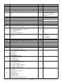 10
10
-
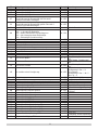 11
11
-
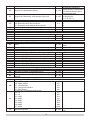 12
12
-
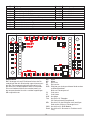 13
13
-
 14
14
-
 15
15
-
 16
16
-
 17
17
-
 18
18
-
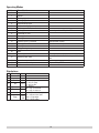 19
19
-
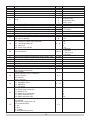 20
20
-
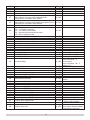 21
21
-
 22
22
-
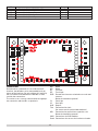 23
23
-
 24
24
-
 25
25
-
 26
26
-
 27
27
-
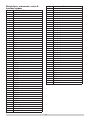 28
28
-
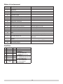 29
29
-
 30
30
-
 31
31
-
 32
32
-
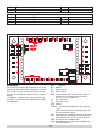 33
33
-
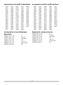 34
34
-
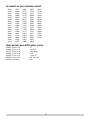 35
35
-
 36
36
-
 37
37
-
 38
38
-
 39
39
-
 40
40
-
 41
41
-
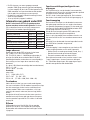 42
42
-
 43
43
-
 44
44
-
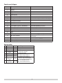 45
45
-
 46
46
-
 47
47
-
 48
48
-
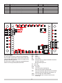 49
49
-
 50
50
-
 51
51
-
 52
52
-
 53
53
-
 54
54
-
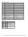 55
55
-
 56
56
-
 57
57
-
 58
58
-
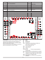 59
59
-
 60
60
-
 61
61
-
 62
62
-
 63
63
-
 64
64
-
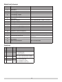 65
65
-
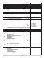 66
66
-
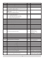 67
67
-
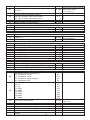 68
68
-
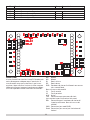 69
69
-
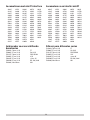 70
70
-
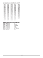 71
71
-
 72
72


En otros idiomas
- français: LGB 55029 Le manuel du propriétaire
- italiano: LGB 55029 Manuale del proprietario
- English: LGB 55029 Owner's manual
- Deutsch: LGB 55029 Bedienungsanleitung
- Nederlands: LGB 55029 de handleiding
Documentos relacionados

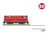
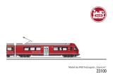
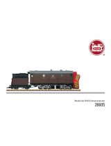
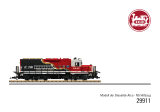


Otros documentos
-
Märklin 193 Series Manual de usuario
-
-
-
-
Hornby Railmaster Instrucciones de operación
-
-
-
Märklin 36632 Manual de usuario
-
-