Bushnell BL3940BS9 El manual del propietario
- Tipo
- El manual del propietario

Model#s BL3940BS9 / BL3940BS11 / BL4124BS11 / BL6185BS11 6-23
RIFLESCOPE OWNER’S GUIDE
LEGEND®
®

2
TABLE OF CONTENTS
PARTS GUIDE 3
KEY ELEMENTS OF A RIFLESCOPE 4
MOUNTING YOUR RIFLESCOPE 4
ILLUMINATED RETICLE OPERATION/BATTERY REPLACEMENT 4
PRELIMINARY SCOPE ADJUSTMENTS - SETTING THE DIOPTER 5
ATTACHING A MOUNT, RINGS AND SCOPE TO YOUR RIFLE 5
PARALLAX 6
SIDE-FOCUS CONTROLS (MODEL BL6185BS11 ONLY) 6
PRELIMINARY SIGHTING-IN 6
FINAL SIGHTING-IN 6
THE CF500 RETICLE 7
ALTITUDE AND TEMPERATURE 7
DO YOU NEED TO SEND YOUR SCOPE TO US? 7
STORAGE 7
TECHNICAL SPECIFICATIONS 8
CF 500 RETICLE DIMENSIONS 8
GLOSSARY OF COMMON RIFLESCOPE TERMS 9
WARRANTY 11

3
Bushnell® is constantly at the forefront of quality and value, and Legend® riflescopes are the next step in the revolution.
Legend® riflescopes are built with premium technology. Fully-Multi Coated Optics and waterproof construction offer crisp,
bright images in every environment.
All exterior lens surfaces have our new EXO Barrier™ coating (in addition to full multi-coating). EXO Barrier, quite simply,
is the best protective lens coating technology Bushnell has ever developed. Added at the end of the coating process, EXO
Barrier molecularly bonds to the lens and fills the microscopic pores in the glass. The result is an ultra-slick coating that
repels water, oil, fog, dust and debris - rain, snow, fingerprints and dirt will not stick. EXO Barrier is built to last: the bonded
coating will not fade with the passage of time or normal wear and tear.
WARNING: NEVER LOOK AT THE SUN THROUGH THE RIFLESCOPE (OR ANY OTHER OPTICAL
INSTRUMENT). IT MAY PERMANENTLY DAMAGE YOUR EYES.
PARTS GUIDE
YOU’VE MADE THE RIGHT DECISION BY CHOOSING THE BUSHNELL LEGEND RIFLESCOPE!
Elevation Adjustment
Windage Adjustment
Ocular
Lens
Fast Focus Eyepiece
Power Change Ring
Objective
Lens
Side Focus (model BL6185BS11 only)
Illumination Dial & Battery Compartment
(model BL3940BS9 only)

4
KEY ELEMENTS OF A RIFLESCOPE
1. Objective Lens: This lens has three functions. First, it permits light to pass into the scope. Second, it determines
resolution. Generally, larger lenses allow more light to enter the scope and resolve details better than smaller ones.
Finally, it forms an image for the other lenses to magnify to a usable size. The image formed by this lens is upside
down.
2. Erector System: The erector system serves several functions. Its primary function is to erect the image (that is, flips
the image right-side up) and align it to the reticle. During this process, primary magnification of the image takes
place. These two functions are the result of lens action.
3. Windage & Elevation Controls: The erector lenses are housed in a tube that is fixed at one end, while the other end
of the tube is free to move and respond to adjustments. By moving the erector system, the point-of-aim of the scope
is adjusted to match the point-of-impact of the bullet.
4. Reticle: In simple terms, the aiming device around which the scope is built. This element replaces the iron sight
system of non-scoped rifles.
5. Ocular or Eye Lens: This element provides the secondary and final magnification of the image.
MOUNTING YOUR RIFLESCOPE
Your new scope, even with its technologically advanced design and features, will not perform at its best if not properly
mounted. One of the most important contributing factors to the precision of your scope and rifle is the selection of the
mount and the care with which mounting is done. Dependable mounts that attach your scope securely to the rifle will
reward you with dependability and precision. You should take as much care in selecting a mounting system as you did in
selecting your scope.
Remember, not all scopes are compatible with all mounts on all rifles. If there is any doubt in your mind, you should seek
the advice of your local retailer or gunsmith.
WARNING: A RIFLESCOPE SHOULD NEVER BE USED AS A SUBSTITUTE FOR EITHER A BINOCULAR OR
SPOTTING SCOPE. IT MAY RESULT IN YOU INADVERTENTLY POINTING THE GUN AT ANOTHER PERSON.
ILLUMINATED RETICLE OPERATION/BATTERY REPLACEMENT (MODEL BL3940BS9 ONLY)
The Multi-X reticle in this 3-9x40 model is illuminated. The illumination adjustment dial is located opposite from the
windage adjustment, numbered from 1 to 6. To increase the brightness, set the control to a higher number (opposite the
white index dot). To turn off the illumination and when storing the scope, set the dial to any of the “Off” positions (dots)
between each numbered illumination setting.
Before powering on your scope for the first time, you must activate the installed CR2032 lithium battery by removing the
protective disc isolating the battery.
1. Unscrew the battery cap counterclockwise, located on
the end of the Side Focus and Illumination Controls
on the left side of the scope. We suggest holding the
Illumination control ring steady while unscrewing the
battery cap with a coin or Bushnell Multi-tool (not
included).
2. Once the cap is off, tip the battery out of the scope.
Locate the protective disc and remove.
3. Replace the battery and battery cap.
Alternatively, the battery may be found as a separate insert
within child-resistant packaging. If so, remove the battery
from the secondary packaging, then install it into the battery
compartment.
Should your reticle grow dim or not light, replace the battery,
following the installation procedure described above.
CAUTION: Improper installation of the battery may
damage the internal contacts. Ensure that the positive (+)
side faces up and the negative (-) side is down.
THIS PRODUCT CONTAINS A BUTTON BATTERY
If swallowed, a lithium button battery can cause severe or
fatal injuries within 2 hours.
Keep batteries out of reach of children.
If you think batteries may have been swallowed or placed
inside any part of the body, seek immediate medical attention.
WARNING
C
M
Y
CM
MY
CY
CMY
K
ButtonBatteryWarning-Label-BW-0622.pdf 1 6/23/22 1:49 PM
THIS PRODUCT CONTAINS A BUTTON BATTERY
If swallowed, a lithium button battery can cause severe or fatal injuries within 2 hours. Keep batteries out of reach of children.
If you think batteries may have been swallowed or placed inside any part of the body, seek immediate medical attention.

5
PRELIMINARY SCOPE ADJUSTMENTS - SETTING THE DIOPTER
Before installing the scope, we recommend you set the diopter adjustment to fit your individual eyesight. Refocusing the
diopter will result in a sharper reticle focus, an improved optical image, and will help to avoid eye fatigue when using the
scope for prolonged periods of time. To refocus, hold the scope about 3 to 4 inches from your eye and point at a flatly lit
area such as a light colored painted wall.
Quickly glance into the scope. If the reticle appears blurred at first glance, it is out of focus. Turn the eyepiece clockwise
or counter clockwise while looking into the scope until reticle sharpness is improved. Look away from the eyepiece for a
couple of seconds and then glance into the scope again to check the sharpness of the reticle. Remember to take quick
glances, as the eye will compensate for slightly out of focus conditions with prolonged looks. If the reticle does not appear
in focus right away, continue to make fine adjustments. Repeat this procedure until the reticle is sharp and clearly defined
right away when looking into the scope.
Unless your eyes undergo a significant change over the years, you will not have to make this adjustment again.
WARNING: DO NOT LOOK TOWARDS THE SUN WHILE SETTING THE DIOPTER!
ATTACHING A MOUNT, RINGS AND SCOPE TO YOUR RIFLE
WARNING: BEFORE BEGINNING THE MOUNTING PROCEDURE, BE SURE THE ACTION IS OPEN, THE CLIP
OR MAGAZINE IS REMOVED AND THE CHAMBER IS CLEAR. DO NOT ATTEMPT ANY WORK UNTIL YOUR
FIREARM HAS BEEN CLEARED AND DETERMINED TO BE SAFE.
WARNING: IF THE SCOPE IS NOT MOUNTED FAR ENOUGH FORWARD, ITS REARWARD MOTION MAY
INJURE THE SHOOTER WHEN THE RIFLE RECOILS.
In mounting your scope, we recommend that you DO NOT take short cuts as it may lead to damage to either the mounting
system or to the scope. Each mounting system will have its own instructions to follow, and it is best to read the instructions
first to be sure you understand them and have the necessary tools on hand.
We further recommend that you plan to go through the mounting procedure twice. The first time, to be sure everything fits
together and functions properly. On the first run through, please keep the following in mind:
• Before attaching the base, clean the mounting holes in the receiver and the threads of the attaching screws with high
concentrate rubbing alcohol or any good solvent to free them of oil or grease.
• If the mount manufacturer has recommended the use of a thread adhesive, do not use it on the first mounting trial.
Once adhesive has set, it is difficult to demount if anything needs correction and will leave residue.
• Be sure the mounting screws do not protrude into the receiver.
• When using dovetail, twist-in or twist-and-lock ring mounts, do not use the scope as a lever when installing the scope.
The initial resistance to turning may cause damage to the scope and is not covered by the warranty. We recommend
using a wooden dowel or metal cylinder to seat the rings.
• Be sure the position of the scope does not interfere with the operation of the action.
• Be sure there is at least 2mm of clearance between the edges of the rings and any protruding surfaces such as the
turret housing (saddle), power selecting ring, and the flare of the objective bell. Also be sure there is at least 3mm of
clearance between the objective bell and the barrel.
• You should test position the scope for the proper eye relief. The scope rings should be left loose enough so that
the scope will slide easily. Variable power scopes should be set at the highest magnification when performing this
procedure. Mount scope onto the rifle and look through the scope in your normal shooting position.
• Test position the rifle for the proper cheek welds several times to ensure that your scope is positioned properly.
• When you are satisfied that everything is okay, mark relative positions with masking tape or similar, demount and start
again. This time, seat all screws firmly.

6
PARALLAX
You may have noticed that placing your eye at different positions behind the scope’s eyepiece causes the reticle crosshairs
to appear to move around to different points on your target. This is called “parallax error” (target and reticle are not in the
same focal plane), and it becomes more noticeable (and more of a problem) at shorter distances and/or when the scope
is set to higher powers. In most cases, parallax will not affect bullet point of impact enough to be of significant concern in
large game hunting situations. The Legend 6-18x50 model provides an adjustment for parallax compensation (side focus
knob), which works by moving an optical element until the target (based on its distance) appears in the same plane of
focus as the reticle. All Legend scopes are set at the factory to be parallax-free at 100 yards.
SIDE-FOCUS CONTROLS (MODEL BL6185BS11 ONLY)
The 6-18x50 model employs a movable lens back near the reticle, so the adjustment can be made with a “side focus”
knob placed next to the windage and elevation adjustments. Just line up the estimated distance to your target with the
index dot, and you will eliminate the aiming errors caused by parallax. After setting the side focus, you can double check
by moving your head around from side to side behind the eyepiece-the point of aim should not shift if the side focus is
correctly set. An alternative method is to look through the scope and turn the side focus knob until the target, at whatever
range, is sharply focused.
PRELIMINARY SIGHTING-IN
You can save a significant amount of expense and frustration by pre-sighting the scope to the rifle before you take it to the
range for zeroing.
There are two basic methods that can be used for pre-sighting your scope. Method one is to use a Bushnell® Bore Sighter
(laser, magnetic or standard). The use of a Bore Sighter saves time and ammunition and is the system most often used by
gunsmiths. The second method is traditional bore sighting:
BORE SIGHTING METHOD
1. Place a target at 25 to 50 yards.
2. Remove the bolt from the rifle.
3. Place the rifle on sandbags or a shooting rest.
4. Set the scope to its lowest magnification.
5. Peer through the bore from the receiver and adjust the
position of the rifle to center the target bull’s eye in the bore
(Fig. A).
6. Without moving the rifle, look into the scope and note the
position of the reticle on the target. On models with capped
elevations and windage adjustments, remove the caps. Adjust
the windage and elevation adjustments to center the reticle on the bull’s eye (Fig. B).
FINAL SIGHTING-IN
WARNING: SINCE THIS PROCEDURE INVOLVES LIVE FIRE, IT SHOULD BE DONE AT AN APPROVED RANGE
OR OTHER SAFE AREA. CHECK BORE FOR OBSTRUCTIONS. AN OBSTRUCTED BORE MAY CAUSE INJURY
TO YOU AND OTHERS NEARBY. EYE AND EAR PROTECTION IS RECOMMENDED.
1. From a steady rest position, fire two or three rounds at a 100-yard target. Note the impact of the bullet on the target
and adjust the windage and elevation dials as needed.
2. To move the bullet impact, turn the windage and/or elevation adjustments in the direction on the dials that
corresponds to where the impact point falls on the target (for example, if test shots are hitting low, adjust elevation
“down”). The adjustments on your riflescope model are marked in MOA (minutes of arc), and the point of impact at
100 yards will change by 1/4 MOA for each click of the windage or elevation adjustment. One full revolution of the
adjustment=12 MOA.
3. When the impact on the 100-yard target is satisfactory, switch to a target set at the desired distance for final zeroing.
Set the magnification to the desired power on variable power models.
Fig. A
Reticle not in alignment
Fig. B
Reticle in alignment

7
THE CF500 RETICLE
Designed to be used with today’s most popular centerfire rifle cartridges, the CF 500 reticle is intended to be sighted in
at 100 yards, and provides aiming points at every 100 yd increment, out to 500 yds. The user can sight-in at 100 yds on
any magnification setting, but for the ballistic reticle feature to function properly, the scope’s magnification must be set to
the maximum power (9x, 12x or 18x depending on the model). The correct settings for the scopes that include the CF 500
reticle are as follows:
HOW TO USE THE CF500 RETICLE:
4. 1. Sight in at 100 yds on any magnification setting
5. 2. Determine distance to target. For the best accuracy
in determining distance, utilize a Bushnell Laser
Rangefinder (Prime, Legend, Nitro).
6. 3. Set the magnification to the appropriate setting.
7. 4. Place appropriate aiming point on the desired target.
If the target is determined to be at 350 yds, hold directly
between the 300 yd aiming point and the 400 yd aiming
point.
The CF 500 reticle will work with any of the following
ammunition loads:
.223 Win 55 gr
.243 Win, 95 gr.
. 25-06 Rem 115 gr
.270 Win, 130 gr.
. 270 WSM, 150 gr.
.7mm Rem Mag, 150 gr.
.7mm WSM, 150 gr.
.30-06 Sprg, 150 gr.
.300 Winchester Mag, 180 gr.
.300 WSM, 180 gr.
.338 Win, 200 gr.
This is only a partial list of the ammunition that the reticle is ballistically matched to. For a complete list of all ammunition
compatible with the CF 500 reticle technology, please visit: http://www.bushnell.com
ALTITUDE AND TEMPERATURE
Ballistic charts published by ammunition manufacturers are based upon standard sea level conditions. When sighting in,
it is well to keep in mind that altitude and temperature affect trajectory. It is best to sight-in under the same conditions in
which you will be hunting.
STORAGE
Avoid storing the scope in hot places, such as the passenger compartment of a vehicle on a hot day. The high temperature
could adversely affect the lubricants and sealants. A vehicle’s trunk, a gun cabinet or a closet is preferable. Never leave the
scope where direct sunlight can enter either the objective or the eyepiece lens. Damage may result from the concentration
(burning glass effect) of the sun’s rays.
Based on a 100-yard zero and the ballistics of the most
common magnum loads, and with MOA dots as the long-
range aiming points, the CF 500 offers a higher level of
precision than competing extended-yardage reticles.
300 YARDS
400 YARDS
CF500
Centerfire
Reticle
200 YARDS
500 YARDS
100 YARDS
See pg. 8 for reticle
dimension details.

8
(all dimensions shown in MOA)
SKU
Mag x Obj. Diam.
Reticle
Turrets
Elev. Travel (MOA)
Travel per Revolution
Parallax Adjustment
Min. Parallax (Yards)
Eye Relief, Max Mag.
Field of View
@ 100 Yds (Feet)
Length (inches)
Weight (oz )
BL3940BS9 3-9x40 Illuminated
Multi-X
Capped 30/30 15 Fixed 100 2.9” 37.5-12.2 12.3 14.8
BL3940BS11 3-9x40 CF500 Capped 30/30 15 Fixed 100 2.9” 37.5-12.2 12.3 14.8
BL4124BS11 4-12x40 CF500 Capped 30/30 15 Fixed 100 2.9” 26-9 13.3 16.6
BL6185BS11 6-18x50 CF500 Capped 20/20 15 Side
Focus
10 3.7” 17.3-5.7 12.8 19.4
TECHNICAL SPECIFICATIONS
CF 500 RETICLE DIMENSIONS

9
Aberration - Aberrations are imperfections inherent to all
optics designs. The best optics limit aberration as much as
possible to provide a clear, accurate image. One example
of aberration is chromatic aberration, which occurs when
lenses in an optic incorrectly refract different colors of light.
The result of this aberration is differing focal points and a
distorted image.
Adjustable Objective - An Adjustable Objective (AO) is
a dial around the objective end of the scope or a knob on
the left side of the turret housing. It allows you to adjust
your scope’s parallax to a certain distance by moving
these adjustments until a clear picture is perceived and/
or the marked corresponding incremental yardages are
approximated to your target distance.
Concerning parallax, an adjustable objective is typically a
dial of sorts located either at the objective end of the scope
or a dial on the left side of the turret (commonly called
Side AO). Most AO set-ups are designated in yards, and by
adjusting the AO to the approximate distance to the target,
resolving the potential parallax.
Ballistic Reticle - A ballistic reticle is a reticle that includes
various factors to ensure the correct aiming point. They are
used to increase the range of an aimed shot and predict
the bullet’s flight at an angle. Ballistic reticles use BDC
technology to correlate angles, atmospheric conditions,
ammunition data, and angles. Ballistic reticles come in
different flavors, with different designs, densities, and
different stage lines and crosshair heights.
Ballistic Turret - A ballistic turret is a feature common
to expensive and high-end riflescopes. It allows you to
set several preset distances. It helps to eliminate the
uncertainty in the distance estimation and eliminates the
need for ballistic reticles.
Bullet Drop Compensation - BDC The principle of
interaction between the fired bullet, gravity, and target
indicators.
Centerfire - Centerfire is a concept relevant to all cartridges,
including shot, hand, and rifle weapons. Indicates the point
at which the weapon striker hits the bullet base becomes
the catalyst that triggers the chain of events that lead to the
shot.
Coatings - Microscopic coatings on the lens surfaces reduce
light loss and glare due to reflection. Coated lenses offer a
brighter, higher-contrast image with less eyestrain. More
coatings allow better light transmission, but it is possible to
have a scope with a single coating to outperform a scope
with multicoated lenses greatly. It all depends on the quality
of the coatings and the glass. Good quality does not come
cheap. The following are acceptable terms for coatings:
• Coated: A single layer on at least one lens surface.
• Fully Coated: A single layer on all air to glass surfaces.
• Multicoated: Multiple layers on at least one lens surface.
• Fully Multicoated: Multiple layers on all air to glass surfaces.
Click - A click is one adjustment notch on the windage or
elevation turret of a scope. One-click most often changes a
scope’s point of impact 1/4 inch at 100 yards. Some clicks
are 1/8 inch, 1/2 inch, one inch, or even more.
Duplex Reticle - A duplex reticle is available in the most
common reticle style, with many conventional, affordable,
and entry-level rifle scopes. It typically features a reticle with
crosshairs reaching the entire edges of the field of view.
As the crosshairs reach to meet like a “t” or a cross in the
center, the posts’ thickness may or may not become finer.
Each duplex-style reticle can vary slightly from one optics
brand to another.
Exit Pupil - An exit pupil is the small circle (column) of
light visible in the ocular lens when you hold your scope
(or binocular) at arm’s length. The larger the exit pupil is,
the brighter the image entering your eye. To find the exit
pupil for your scope, divide the objective lens diameter
in millimeters by the magnification. For example, if your
scope is four power (4X), and your objective lens is thirty-
six millimeters in diameter (36mm), divide four into 36, and
it equals 9. Therefore, nine would be the exit pupil size in
diameter in millimeters. Typically measured in millimeters,
the larger the size of the exit pupil, the brighter the scope
image will be.
Eye Relief - Eye relief is the distance your eye must be
from the ocular lens and still get a full field of view. This
measurement is usually defined in inches.
Fast Focus Eyepiece - The Fast Focus Eyepiece is a
European-style eyepiece technology with a fraction of a turn
focal length. It allows you to focus on the grid, which gives
you a sharp and clear image. At the same time, the focusing
speed is higher than the standard method. Frequently,
however, the Fast Focus Eyepiece does not have a locking
mechanism for the slower method.
First Focal Plane - FFP is an indication of the first (focal)
plane to the position of the reticle. FFP scopes retain the
amount of stretch, while the size of the crosshair of the sight
will correlate with the image’s magnification.
Field of View - Field of view (FOV) is the amount of
area seen through your scope from right to left at 100
yards. As magnification is increased, FOV is lessened. As
magnification is decreased, FOV is increased.
Fixed Power - denotes a fixed magnification of the sight. It
does not have a range of power settings from low to high,
as the manufacturer sets a constant increase within a certain
scaling.
Hold Over/Under - Holdover/under is the amount of point
of aim change either above or below your target, without
adjusting your scope, to adjust for the trajectory of your
projectile.
GLOSSARY OF COMMON RIFLESCOPE TERMS

10
Illuminated Reticles - Many rifle scopes have battery-
operated reticles that light up when activated. In hunting,
this color is nearly always red. In tactical conditions, green
is often another available color. The entire part, center, or
certain feature of a reticle can be illuminated.
Internal Adjustment Travel - The amount of room or the
maximum adjustment potential of the erector tube has
provided scope adjustments to be made. Additionally,
larger tube bodies such as 30 mm or even 34 mm tubes
can provide more internal adjustment travel to provide the
potential for longer distance shots.
Magnification - Also called the power setting or rating,
magnification is a power rating that defines how much or
far the scope will magnify your sight. Power settings are
measured against the naked eye. For example, a 3 power
scope would offer the user 3 times the view of what they
could see with the naked eye, while a 10 power would mean
10 times the power of the naked eye.
Main tube - The main tube is the scope portion between the
objective bell and the eyepiece. Most scopes have either
a 1-inch or 30mm main tube. The added tube diameter
increases windage and elevation travel range. Long-range
target scopes may have tube diameters between 34 and
36mms. Scope rings are built to specific scopes with specific
main tube diameters.
Maximum Point Blank Range - The longest distance you
can hold the dead center in your kill zone and not be too
high or too low for a hit in the vital area. Flatter trajectories
and/or larger targets increase this range.
MIL/MRAD – Milliradians of Angle - A measurement system
is used to determine the correct elevation and windage
adjustments to sight in your scope. Typically found on
European-based optics.
Minute of Angle - Minute of Angle (MOA) is a unit of
measurement within a circle and is 1.0472 inches at 100
yards. For all practical purposes, it is called 1 inch at 100
yards. It is 2 inches at 200 yards, 5 inches at 500 yards, one-
half inch at 50 yards, etcetera.
MOA is generally the standard for measuring the accuracy
of a rifle. A rifle that will shoot a 3 to 5 shot group that
measures under an inch, it’s considered an MOA shooter. If
it groups at 1/2 an inch, it’s a sub-MOA shooter.
MIL vs. MOA: MIL is a common abbreviated form of
milliradians, while MOA is an abbreviation of Minute of
Angle. Both are measurements of angle (not distance or
length, as some shooters believe). As ranges increase, so
does 1 MOA or 1 MIL value. At 100 yards, an MOA is 1.047
inches, so a scope with ¼ MOA per click adjustments should
move the point of impact about .25-inches every click at 100
yards (and .50-inches at 200 yards). One MIL is 3.6 inches
at 100 yards, and since most MIL scopes have 1/10 click
adjustments, each click will adjust the point of impact by .36
inches at 100 yards.
MOAR 20 MOA/MOAR-T - These are a couple of the
NightForce scopes ballistic reticle options available with
elevation and windage markings for long-range hunting
holdovers. (See also Ballistic Reticle)
Objective Lens - The objective lens is the lens closest to
the object being viewed. It is measured in millimeters in
diameter. A larger objective lens allows more light to enter
the scope.
Original Zero - This is the distance you sighted your scope.
Zero reset features are popular for getting you back to your
original zero. When dialing up/making scope adjustments,
you don’t need to remember how many clicks you made
and how to get back. Instead, turn the turret back till it
stops, and you’re back to your 100 yards or “x” yard zero.
Parallax - Parallax is an optical error or illusion typically
found in scopes designed for longer ranges. Without getting
overly technical, parallax occurs when the optical image
that you see through the scope is created in front of behind
the reticle. This means that the target you are looking at isn’t
being correctly portrayed in its actual location. Some scope
models feature a parallax compensation feature built-in to
correct this issue. The most popular parallax compensation
seen today is either through a front objective lens or side
focus parallax. With these features, the shooter can adjust
the distance (typically in yards) to the target, and the scope
is preset to be parallax-free at those predefined distances.
Most riflescopes without adjustable objectives are set at
100 or 150 yards. Rimfire scopes are often set at 50 or 60
yards, and shotgun scopes are often set at 60 or 75 yards.
Point of Aim (POA) - an auxiliary mark or marker at which
a target shooter sights the firearm so as to achieve correct
elevation.
Reticle - Reticle refers to the sighting device used for
a specific scope. A reticle is a system of lines, dots,
or crosshairs in your scope that appear superimposed
on your target. Reticles come in various variations and
configurations, designed for very specific uses.
Second Focal Plane - SFP can be used interchangeably
with the rear focal plane. This more commonly used design
has crosshairs that remain the same size as magnification
increases. Due to this system, the suspension is constantly
changing as the target gets larger or smaller in size as you
change the power. (See also Subtension)
Trajectory - The trajectory is the flight of your projectile
after it leaves the barrel. This flight is an arc. The amount of
arc depends on the projectile weight and velocity.
Turret - A turret is one of two knobs in the outside center
part of the scope tube. They are marked in increments
and are used to adjust elevation and windage for points
of impact change. These knobs protrude from the turret
housing.

11
Variable Power - This means the riflescope’s magnification
is not fixed; it’s variable. It can range from as low as 1.5-4X
or as high as 6-24X in a rifle scope, and sometimes even
higher. The most common variable power specs for a hunter
are the popular 3-9X.
Windage - This is the horizontal crosshair of the reticle.
Zero - Zero is the distance you are sighted in and references
the flight of the projectile. For example, if you are sighted in
at 200 yards, you have a 200 yard zero.
Bushnell Blog Post: A BREAKDOWN OF THE RELATIONSHIP
BETWEEN RIFLE SCOPE MAGNIFICATION VS. DISTANCE
WARRANTY
Click to read the Bushnell Warranty
DO YOU NEED TO SEND YOUR SCOPE TO US?
Before returning your scope for service, you should check the following points to make sure the problem is with the
scope:
• Check the mounting system and rings for looseness or misalignment.
• Check to be sure the barrel and action are properly bedded and all receiver screws are tight.
• Check to be sure the mounting system allows sufficient clearance between the objective bell and the barrel.
• Check to be sure you are using the same type and weight ammunition that you used for sighting-in.
For assistance with your Bushnell riflescope, contact the US and Canadian customer service team by calling
1-800-423-3537 during the days and times listed below:
• Monday-Tuesday, 8:00 am to 6:00 pm CST
• Wednesday-Thursday 8:00 am to 4:30 pm
• Friday 8AM to 2PM
If you are calling with a product related issue, please have the product available when you call.
©2023 Bushnell Outdoor Products
Bushnell,™, ®, denote trademarks of Bushnell Outdoor Products
www.bushnell.com
9200 Cody, Overland Park, KS 66214

12
Félicitations pour votre achat d'une lunette de visée Bushnell® Legend®! Vous venez d'acquérir l'une des lunettes de
visée les plus avancées de l'industrie sur le plan technologique. Bushnell veille entièrement à l'intégrité et au contrôle
qualité de cette lunette tout au long de son cycle de conception, de production et de livraison.
Toutes les surfaces extérieures des lentilles ont notre nouveau revêtement EXO Barrier™ (en plus du multi-revêtement
complet). EXO Barrier, tout simplement, est la meilleure technologie de revêtement de lentille de protection jamais
développée par Bushnell. Ajouté à la fin du processus de revêtement, EXO Barrier se lie moléculairement à la lentille et
remplit les pores microscopiques du verre. Le résultat est un revêtement ultra-lisse qui repousse l’eau, l’huile, le brouillard,
la poussière et les débris - la pluie, la neige, les empreintes digitales et la saleté ne colleront pas. EXO Barrier est conçu
pour durer : le revêtement collé ne se décolore pas avec le temps ou l’usure normale.
AVERTISSEMENT: NE REGARDEZ JAMAIS LE SOLEIL À TRAVERS LA LUNETTE DE VISÉE (OU TOUT AUTRE
INSTRUMENT OPTIQUE). CECI POURRAIT ENDOMMAGER VOS YEUX DE FAÇON PERMANENTE.
ÉLEMENTS PRINCIPAUX D’UNE LUNETTE DE VISÉE
1. Lentille d’objectif : La lentille d’objectif a trois fonctions. La première, permettre à la lumière de passer dans la
lunette. La deuxième, déterminer la résolution. Généralement, plus la lentille est grande, plus elle laisse pénétrer de
lumière dans la lunette, permettant un meilleur discernement des détails. Et la troisième, former une image que les
autres lentilles grossissent à une taille utilisable. L’image formée par cette lentille est à l’envers.
2. Système érecteur : Le système érecteur remplit plusieurs fonctions. Sa fonction principale consiste à ériger l’image
(c’est-à-dire, à retourner l’image dans le bon sens) et à l’aligner sur le réticule. Pendant ce processus a lieu le
grossissement principal de l’image. Ces deux fonctions sont le résultat de l’action de l’objectif.
3. Commandes de l’élévation et de la dérive : Les lentilles érectrices sont logées dans un tube fixé à une extrémité.
L’autre extrémité du tube est mobile et peut répondre aux réglages de la tourelle de dérive ou d’élévation. En
déplaçant le système érecteur, le point de visée de la lunette est ajusté afin de correspondre au point d’impact de la
balle.
4. Réticule : Le réticule est tout simplement le dispositif de visée autour duquel est construite la lunette. Cet élément
remplace le système de vue en fer des fusils sans lunette.
5. Oculaire ou œilleton : Cet élément fournit le grossissement de l’image secondaire et final.
FRANÇAIS
GUIDE DES PIÈCES
Réglage de la hauteur
Réglage de la dérivation
Lentille
oculaire
Système de mise au point rapide Oculaire
Bague de changement
de portée
Lentille de
l’objectif
Mise au point latérale
(modèleBL6185BS11 uniquement)
Cadran d’éclairage et compartiment à piles
(modèle BL3940BS9 uniquement)

13
MONTAGE DE VOTRE LUNETTE
Votre nouvelle lunette, malgré sa conception et ses caractéristiques technologiquement avancées, ne fonctionnera pas de
manière optimale si elle n’est pas correctement montée. L’un des principaux facteurs contribuant à la précision de votre
lunette et de votre fusil réside dans la sélection de la monture et le soin avec lequel le montage est effectué. Les montures
qui fixent solidement votre lunette au fusil vous procureront une fiabilité et une précision constante. Accordez autant de
soin à choisir un système de montage qu’à choisir votre lunette.
N’oubliez pas que les lunettes de visée ne sont pas toutes compatibles avec toutes les montures de fusil. Si vous avez le
moindre doute, demandez conseil à votre détaillant ou à votre armurier.
FONCTIONNEMENT DE LA RÉTICULE ÉCLAIRÉE/
REMPLACEMENT DE LA PILE
(MODÈLE BL3940BS9 SEULEMENT)
Avant de mettre la lunette sous tension pour la première fois,
activer la pile CR2032 au lithium installée en ôtant le disque
protecteur en plastique isolant la pile.
1. Dévisser le couvercle de la pile dans le sens contraire
des aiguilles d’une montre, situé à l’extrémité des
commandes latérales gauches de mise au point et
d’éclairage de la lunette. Nous suggérons maintenir
l’anneau de commande de l’éclairage bien ferme
pendant le retrait du couvercle de la pile.
2. Une fois le couvercle retiré, sortir la pile. Localiser le
disque en plastique et l’ôter.
3. Replacer la pile et le couvercle.
Il est également possible que la pile se trouve à part, dans
un sachet sans risque pour les enfants. Si c’est le cas, sortir la
pile de ce deuxième sachet et l’installer dans le compartiment
prévu à cet effet.
Si le réticule s’obscurcit ou s’allume difficilement, remplacer la
pile en suivant la procédure d’installation décrite ci-dessus.
ATTENTION : Une mauvaise installation de la pile peut
endommager les contacts internes. S’assurer que le pôle
positif (+) est orienté vers le haut et le pôle négatif (-) vers
le bas.
RÉGLAGES PRÉLIMINAIRES DE LA LUNETTE
Avant d’installer la lunette, nous vous recommandons d’effectuer la mise au point de l’oculaire en fonction de votre vue.
Une nouvelle mise au point de la distance oculaire se traduira par une mise au point du réticule plus nette et une image
optique améliorée, ce qui limitera la sensation de fatigue oculaire lorsque la lunette est utilisée pendant de longues
périodes. Pour effectuer une nouvelle mise au point, maintenez la lunette à environ 7 à 10centimètres (3 ou 4pouces)
de votre œil, puis pointez vers le ciel ouvert ou sur une autre zone présentant un éclairage plat, par exemple une peinture
murale monotone.
Jetez rapidement un coup d’œil dans la lunette. Si le réticule apparaît flou au premier coup d’œil, c’est qu’il n’est pas
mis au point. Tournez plusieurs fois l’oculaire dans le sens ou dans le sens inverse des aiguilles d’une montre. Jetez de
nouveau un coup d’œil dans la lunette pour vérifier la netteté du réticule. N’oubliez pas de jeter des coups d’œil rapides,
car l’œil compensera les conditions légèrement floues par des regards prolongés. Si le réticule est encore flou, tournez
l’oculaire encore deux ou trois fois. Répétez cette procédure jusqu’à ce que le réticule soit net et clairement défini.
À moins que vos yeux ne subissent un changement important au cours des années, vous n’aurez plus à effectuer ce
réglage.
AVERTISSEMENT: NE REGARDEZ PAS VERS LE SOLEIL LORS DU RÉGLAGE DE LA DIOPTRIE!
Remarque : Ôter le disque en plastique sous la pile bouton avant la première utilisation.
CE PRODUIT CONTIENT UNE PILE BOUTON
En cas d’ingestion, une pile bouton au lithium peut provoquer des lésions
graves ou mortelles dans les 2 heures.
Veuillez garder les piles hors de portée des enfants.
Si vous pensez que des piles ont pu être avalées ou insérées dans n’importe
quelle partie du corps, veuillez consulter immédiatement un médecin.
AVERTISSEMENT

14
RATTACHER UNE MONTURE, DES BAGUES ET UNE LUNETTE À VOTRE FUSIL
ATTENTION : AVANT DE COMMENCER LA PROCÉDURE DE MONTAGE, ASSUREZ-VOUS QUE L’ACTION
EST OUVERTE, LE CLIP OU LE MAGAZINE RETIRÉ ET LA CHAMBRE VIDE. N’INTERVENEZ PAS AVANT DE
VOUS ASSURER QUE L’ARME EST VIDE ET SÛRE.
AVERTISSEMENT : SI LA LUNETTE N’EST PAS MONTÉE SUFFISAMMENT EN AVANT, SON MOUVEMENT
VERS L’ARRIÈRE PEUT BLESSER LE TIREUR AU MOMENT DU RECUL DE L’ARME.
Lors du montage de votre lunette, nous vous recommandons de ne PAS prendre de raccourcis, car cela pourrait
endommager le système de montage ou la lunette. Chaque système de montage comporte ses propres instructions qu’il
convient de suivre. De plus, il est préférable de commencer par lire les instructions pour être sûr de les comprendre et de
disposer des outils nécessaires à portée de main.
Nous vous recommandons en outre d’effectuer deux fois la procédure de montage. La première fois, pour être sûr que
toutes les pièces sont bien installées et fonctionnent correctement. Au premier passage cependant, gardez à l’esprit les
points suivants:
• Avant de fixer la base, nettoyez les trous de montage dans le récepteur et les filets des vis de fixation avec de l’acétone
ou tout autre solvant jugé efficace pour retirer l’huile ou la graisse qui s’est accumulée.
• Si le fabricant de la monture recommande une colle à filetage, ne l’utilisez pas lors du premier essai de montage. Une
fois que la colle prend, il est difficile de démonter l’ensemble si une pièce doit être corrigée.
• Vérifiez que les vis de montage ne pénètrent pas dans le récepteur ou le canon.
• Lorsque vous utilisez des montures en queue d’aronde, n’utilisez pas la lunette comme levier pour l’installer. La résistance initiale
à la rotation peut endommager la lunette et cela n’est pas couvert par la garantie. Nous vous recommandons d’utiliser
une cheville en bois de 1” ou un cylindre métallique pour installer les bagues.
• Vérifiez que la position de la lunette n’interfère pas avec le fonctionnement du mécanisme.
• Assurez-vous qu’il y a au moins 1/8” de jeu entre les bords des bagues et les surfaces en saillie telles que le logement
de la tourelle (selle), la bague de sélection de portée et l’évasement du logement de l’objectif. Assurez-vous également
qu’il y a au moins 1/8” de jeu entre le logement de l’objectif et le canon.
• Testez la position de la lunette pour obtenir un dégagement oculaire adéquat. Les bagues de la lunette doivent être
suffisamment lâches pour que la lunette puisse coulisser facilement. Dans le cadre de cette procédure, les lunettes à
portée variable doivent être réglées sur le grossissement maximal. Montez le fusil, puis regardez à travers la lunette en
position de tir normale.
• Testez plusieurs fois la position du fusil pour déterminer le point de soudure approprié et afin de vous assurer que
votre lunette est correctement positionnée.
• Dès que vous êtes satisfait, procédez au démontage, puis recommencez. Cette fois, vissez toutes les vis fermement.
PARALLAXE
Vous avez sans doute remarqué que la position du réticule sur la cible varie en fonction de la position de votre œil derrière
la lunette. Ce phénomène est appelé «erreur de parallaxe». Il est dû au fait que la cible et le réticule ne se trouvent pas
sur le même plan focal. Ce phénomène est plus visible (et donc plus problématique) sur des distances plus courtes ou à
des grossissements plus élevés. Dans la plupart des cas, la parallaxe n’aura pas suffisamment d’effet sur le point d’impact
de la balle et ne devrait donc pas vous gêner pour la chasse au gros gibier. Le modèle Legend 6-18x50 offre un réglage
pour corriger la parallaxe (molette de mise au point latérale), qui fonctionne en déplaçant un élément optique jusqu’à ce
que la cible (en fonction de sa distance) apparaisse dans le même plan focal que le réticule. Toutes les lunettes Legend
sont réglées en usine pour être sans parallaxe à 91mètres (100yards).
UTILISER MISE AU POINTE LATÉRALE (MODÈLE Nº BL6185BS11SEULEMENT)
Le modèle 6-18x50 utilise une lentille mobile à proximité du réticule, de sorte que le réglage peut être fait avec un bouton
de «mise au point latérale» placé à côté des ajustements de la dérive et de l’élévation. Pour éliminer toute erreur de visée
causée par les problèmes de parallaxe, alignez simplement la distance estimée à votre cible avec le repère. Vous pouvez
vérifier le réglage de la mise au point latérale en bougeant votre tête d’un côté à l’autre derrière la lunette: si la mise au
point latérale est bonne, votre point de visée ne doit pas bouger. Vous pouvez également effectuer un réglage à n’importe
quelle distance, en regardant à travers votre lunette et en tournant la molette de mise au point latérale jusqu’à ce que la
cible devienne nette.

15
AJUSTEMENT PRÉLIMINAIRE
Épargnez-vous des dépenses inutiles et bien des frustrations en préréglant la lunette sur le fusil avant d’amener ce dernier
au champ de tir en vue de sa remise à zéro.
Deux méthodes de base vous permettent de prérégler votre lunette. La première méthode consiste à utiliser un
collimateur de réglage Bushnell® (laser, magnétique ou standard). L’utilisation d’un collimateur de réglage permet de
gagner du temps et d’économiser les munitions. C’est le procédé le plus utilisé par les armuriers. La deuxième méthode
est le simbleautage traditionnel:
MÉTHODE DE SIMBLEAUTAGE
1. Placez une cible à une distance comprise entre 23 et
46mètres (25/50yards).
2. Retirez le boulon du fusil.
3. Placez le fusil sur des sacs de sable ou un repose fusil.
4. Définissez la lunette sur son plus faible grossissement.
5. Regardez à travers l’alésage depuis le récepteur et ajustez la
position du fusil pour centrer la cible dans l’alésage (Fig.A).
6. Sans bouger le fusil, regardez dans la lunette et notez la
position du réticule sur la cible. Sur les modèles équipés de
réglages de dérive et d’élévation, retirez les caches. Ajustez
les réglages de dérive et d’élévation pour centrer le réticule
sur la cible (Fig.B).
AJUSTEMENT FINAL
AVERTISSEMENT : DANS LA MESURE OÙ CETTE PROCÉDURE IMPLIQUE DE TIRER, ELLE DOIT ÊTRE
EFFECTUÉE À UNE DISTANCE AUTORISÉE OU DANS TOUT AUTRE ESPACE SÉCURISÉ. VÉRIFIEZ QUE L’ÂME
DE L’ARME N’EST PAS OBSTRUÉE. UN ALÉSAGE OBSTRUÉ PEUT VOUS BLESSER OU BLESSER D’AUTRES
PERSONNES À PROXIMITÉ. UNE PROTECTION DES YEUX ET DES OREILLES EST RECOMMANDÉE.
1. À partir d’une position de repos stable, tirez deux ou trois balles sur une cible située à 91mètres (100yards). Notez
l’impact de la balle sur la cible et ajustez les cadrans de dérive et d’élévation selon les besoins.
2. Pour déplacer l’impact de la balle, tournez les réglages de dérive et/ou d’élévation dans le sens des cadrans. Cela
correspond à l’endroit où le point d’impact se trouve sur la cible (par exemple, si les tirs d’essai sont bas, réglez
l’élévation sur le bas). Les réglages sur votre modèle de lunette de visée sont indiqués en MOA (minutes of arc),
et le point d’impact à 91mètres (100yards) change de 1/4” de MOA pour chaque clic du réglage de dérive ou
d’élévation. Une révolution complète du réglage = 12MOA.
3. Lorsque l’impact sur la cible à 91 mètres (100 yards) est satisfaisant, passez à une cible définie à la distance
souhaitée en vue de la remise à zéro finale. Réglez le grossissement sur la distance souhaitée pour les modèles à
portée variable.
Fig. A
Réticule non aligné
Fig. B
Réticule aligné

16
RÉTICULE CF500
Conçu pour être utilisé avec les cartouches de fusil à percussion centrale les plus populaires d’aujourd’hui, le réticule CF
500est destiné à être aperçu à 91m (100yards) et fournit des points de visée à chaque incrément de 91m (100yards),
jusqu’à 455m (500yards). L’utilisateur peut viser à 91m (100yards) quel que soit le réglage du grossissement, mais pour
que la fonction de réticule balistique fonctionne correctement, le grossissement de la lunette de visée doit être réglé à la
puissance maximale (9x, 12x ou 18x selon le modèle). Les réglages indiqués pour les lunettes équipées du réticule CF 500
sont présentés ci-contre:
Utilisation du réticuleCF500:
1. Zérotez la lunette à 91m (100yards), à n’importe quel
grossissement
2. Déterminez la distance à la cible. Pour une estimation
optimale de la distance, nous vous conseillons un
télémètre laser Bushnell (Prime, Legend, Nitro).
3. Réglez le grossissement sur le paramètre approprié.
4. Placez le point de visée adéquat sur la cible souhaitée.
Si la distance à la cible est de 320 m (350 yards),
maintenez-la entre le point de visée à 275m (300yards)
et le point de visée à 366m (400yards).
Le réticule CF 500 fonctionne avec les charges de munitions
suivantes:
.223 Win 55 g
.243 Win, 95 g
. 25-06 Rem, 115 g.
.270 Win, 130 g
. 270 WSM, 150g.
.7mm Rem Mag, 150g
.7mm WSM, 150 g
.30-06 Sprg, 150 g
.300 Winchester Mag, 180 g
.300 WSM, 180 g
.338 Win, 200 g
Ceci n’est qu’une liste partielle des munitions auxquelles le réticule a une correspondance balistique. Pour une liste
complète de toutes les munitions compatibles avec la technologie du réticule CF 500, veuillez visiter : http://www.
bushnell.com
ALTITUDE ET TEMPÉRATURE
Les cartes balistiques publiées par les fabricants de munitions sont basées sur les conditions standard au niveau de la mer.
Lors de l’ajustement, il est bon de garder à l’esprit que l’altitude et la température affectent la trajectoire. Il est préférable
d’effectuer l’ajustement dans les mêmes conditions que celles dans lesquelles vous allez chasser.
AVEZ-VOUS BESOIN DE NOUS ENVOYER VOTRE LUNETTE?
Avant d’envoyer votre lunette en réparation, vérifiez les points suivants pour vous assurer que le problème concerne bien
la lunette:
• Vérifiez que le système et les bagues de montage ne sont pas desserrés ou mal alignés.
• Vérifiez que le canon et le mécanisme sont correctement installés et que toutes les vis du récepteur sont bien serrées.
• Vérifiez que le système de montage autorise un jeu suffisant entre le logement de l’objectif et le canon.
• Vérifiez que vous utilisez des munitions de même type et de même poids que celles que vous avez utilisées pour
l’ajustement.
Basé sur un zéro 91 m (100 yards) et la balistique des
charges magnum les plus courantes, et avec des points
MOA comme points de visée à longue portée, le CF
500 offre un niveau de précision plus élevé que les
réticules concurrents à longue distance.
274M (300YARDS)
366M (400YARDS )
Réticule
CF500Centerfire
183M (200YARDS)
457M (500YARDS)
91MÈTRES (100YARDS)
Voir p. 15pour les
détails de la dimension
du réticule.

17
Dimensions du réticule CF 500
(toutes les dimensions sont en MOA)
UGS
Mag x Diam. de
l'objectif
Réticule
Tourelles
Élév. Déplacements
(MOA)
Déplacements par
tour
Réglage de la
parallaxe
Parallaxe min. (yards)
Dégagement
oculaire, Gross max.
Champ de vision
@ 100yards (pieds)
Longueur (cm)
Poids (g)
BL3940BS9 3-9x40 Multi-X
éclairé
Plafonné 30/30 15 Fixe 100 2.9” 37.5-12.2 12.3 14.8
BL3940BS11 3-9x40 CF500 Plafonné 30/30 15 Fixe 100 2.9” 37.5-12.2 12.3 14.8
BL4124BS11 4-12x40 CF500 Plafonné 30/30 15 Fixe 100 2.9” 26-9 13.3 16.6
BL6185BS11 6-18x50 CF500 Plafonné 20/20 15 Mise au
point
latérale
10 3.7” 17.3-5.7 12.8 19.4
CARACTÉRISTIQUES TECHNIQUES

18
Enhorabuena por comprar el visor para rifles Bushnell® Legend®. Ahora es el propietario de uno de los visores para
rifles más avanzados tecnológicamente del sector. Bushnell mantiene la integridad absoluta del producto yel control de
calidad durante todo el ciclo de diseño, producción yentrega de estos visores.
Todas las superficies exteriores de las lentes tienen nuestro nuevo revestimiento EXO Barrier™ (además del revestimiento
múltiple completo). EXO Barrier, simplemente, es la mejor tecnología de recubrimiento protector de lentes que Bushnell
haya desarrollado jamás. Agregado al final del proceso de recubrimiento, EXO Barrier se une molecularmente a la lente y
llena los poros microscópicos del vidrio. El resultado es una capa ultra resbaladiza que repele el agua, el aceite, la niebla,
el polvo y los escombros; la lluvia, la nieve, las huellas dactilares y la suciedad no se pegarán. EXO Barrier está construido
para durar: el revestimiento adherido no se desvanecerá con el paso del tiempo o el desgaste normal.
PRECAUCIÓN: NO MIRE NUNCA AL SOL A TRAVÉS DEL VISOR PARA RIFLES (O CUALQUIER OTRO
INSTRUMENTO ÓPTICO). PODRÍA DAÑAR SU CAPACIDAD DE VISIÓN PERMANENTEMENTE.
CARACTERÍSTICAS DEL VISOR PARA RIFLES LEGEND
1. Lente objetivo: Este lente tiene tres funciones. La primera es que permite pasar la luz hacia adentro de la mira. La
segunda es que determina la resolución. En general, un lente más grande permite que más luz entre a la mira y
resuelva mejor los detalles que los lentes más pequeños. Finalmente, forma una imagen para que los otros lentes la
amplifiquen a un tamaño útil. La imagen formada por este lente está de cabeza.
2. Sistema erector: El sistema erector tiene varias funciones. Su función principal es erigir la imagen, (es decir, voltear la
imagen para que quede cabeza arriba) y alinearla con la retícula. Durante este proceso se lleva acabo la ampliación
principal de la imagen. Estas dos funciones son el resultado de la acción del lente.
3. Controles de resistencia al viento y elevación: Los lentes erectores están alojados en un tubo que está fijo en uno
de sus extremos, mientras que el otro extremo del tubo se mueve libremente y responde a los ajustes. Al mover el
sistema erector, el punto de mira de la mira se ajusta para igualar el punto de impacto de la bala.
4. Retícula: En términos sencillos, es el dispositivo para apuntar alrededor de la cuál está construida la mira. Este
elemento remplaza el sistema de vista de hierro de los rifles sin mira.
5. Lente ocular o del ojo: Este elemento proporciona la ampliación secundaria y final de la imagen.
Ajuste de elevación
Lente de
objetivo
Enfoque lateral
(solo en el modelo BL6185BS11)
Esfera de iluminación y compartimento de batería
(solo en el modelo BL3940BS9)
ESPAÑOL
GUÍA DE PARTES
Ajuste de resistencia al viento
Anillo de cambio de
aumento
Enfoque rápido Ocular
Lentes
oculares

19
CÓMO MONTAR SU MIRA PARA RIFLE
Aun con su diseño y características de tecnología avanzada, su nueva mira no brindará su mejor desempeño si no está
montada adecuadamente. Uno de los factores más importantes que contribuyen a la precisión de su mira y rifle es la
selección de la montura y el cuidado con el que se realiza el montaje. La confiabilidad de las monturas que fijan de
manera segura su mira al rifle lo recompensarán con confiabilidad y precisión. Debe tener tanto cuidado con la selección
del sistema de montaje como lo hizo para seleccionar su mira.
Recuerde, no todas las miras son compatibles con todos los montajes en todos los rifles. Si tiene alguna duda, busque la
asesoría de su distribuidor o armero local.
ADVERTENCIA: NUNCA SE DEBE USAR UNA MIRA PARA RIFLE COMO SUSTITUTO DE UNOS BINOCULARES
O UN MONOCULAR. PODRÍA RESULTAR EN QUE INADVERTIDAMENTE APUNTE EL ARMA HACIA OTRA
PERSONA.
FUNCIONAMIENTO DE LA RETÍCULA ILUMINADA/SUSTITUCIÓN DE LA BATERÍA
(SOLO PARA EL MODELO BL3940BS9)
Antes de encender su mira por primera vez, debe activar la
batería de litio CR2031 instalada retirando el disco protector
de plástico que aísla la batería.
1. Desatornille en el sentido contrario a las manecillas del
reloj la tapa de la batería ubicada en el extremo de los
controles laterales de enfoque e iluminación en el lado
izquierdo de la mira. Le sugerimos mantener estable el
anillo de control de iluminación mientras desatornilla la
tapa.
2. Una vez retirada la tapa, saque la batería de la mira.
Ubique el disco de plástico y retírelo.
3. Vuelva a colocar la batería y la tapa de la batería.
Alternativamente, puede encontrar la batería en un inserto
separado dentro de un empaque a prueba de niños. Si es
así, retire la batería del empaque secundario e instálela en el
compartimiento de la batería.
Si la retícula se atenúa o no tiene luz, remplace la batería
siguiendo las instrucciones descritas anteriormente.
PRECAUCIÓN: La instalación inadecuada de la batería
puede dañar los contactos internos. Asegúrese de que el
lado positivo (+) está hacia arriba y el lado negativo (-)
hacia abajo.
AJUSTES PRELIMINARES DEL VISOR
Antes de instalar el visor, le recomendamos que ajuste el foco del ocular para que se adapte asus propias necesidades
visuales. Si reorienta la distancia ocular, el foco de retícula será más nítido yla imagen óptica se verá mejor, lo que ayudará
aevitar la fatiga ocular al usar el visor durante períodos de tiempo prolongados. Para volver aenfocar, mantenga el visor
auna distancia de 3a4pulgadas de su ojo yapunte hacia el cielo abierto uotra área iluminada, como una pared pintada
del mismo color.
Eche un vistazo rápidamente al visor. Si la retícula aparece borrosa aprimera vista, está desenfocada. Gire el ocular en
el sentido de las agujas del reloj oen el sentido contrario varias veces. Compruebe el visor nuevamente para verificar la
nitidez de la retícula. Recuerde mirar rápidamente, ya que el ojo compensará las condiciones ligeramente desenfocadas
si se mira durante un período de tiempo prolongado. Si la retícula aún aparece borrosa, gire el ocular otras dos otres
vueltas. Repita este procedimiento hasta que la retícula se vea nítida ydefinida.
Amenos que sus ojos sufran un cambio significativo alo largo de los años, no tendrá que hacer este ajuste nuevamente.
ADVERTENCIA: ¡NO MIRE HACIA EL SOL MIENTRAS AJUSTA LAS DIOPTRÍAS!
Nota: Retire el disco de plástico situado debajo de la pila de botón antes del primer uso.
ESTE PRODUCTO CONTIENE UNA PILA DE BOTÓN
En caso de ingestión, una pila de botón de litio puede causar lesiones
graves o mortales en 2 horas.
Mantenga las baterías fuera del alcance de los niños.
Si cree que las pilas pueden haber sido ingeridas colocadas dentro de
cualquier parte del cuerpo, busque atención médica inmediata.
ATENCIÓN

20
ACOPLAR MONTAJE, ANILLOS YVISOR ASU RIFLE
PRECAUCIÓN: ANTES DE MONTAR EL VISOR, ASEGÚRESE DE ABRIR LA ACCIÓN, DE EXTRAER EL CLIP
OEL CARGADOR YDE QUE NO HAYA NINGÚN PROYECTIL EN LA RECÁMARA. NO SIGA CON EL PROCESO
HASTA HABER VACIADO EL ARMA YHABER COMPROBADO QUE ES SEGURA.
PRECAUCIÓN: SI EL VISOR NO ESTÁ MONTADO EN UNA POSICIÓN SUFICIENTEMENTE ADELANTADA, EL
MOVIMIENTO DE RETROCESO DEL RIFLE AL DISPARARLO PODRÍA HERIR AL TIRADOR.
Al montar el visor, le recomendamos que NO apure el proceso, ya que podría dañar el sistema de montaje oel visor. Cada
sistema de montaje tendrá sus propias indicaciones que hay que seguir ylo mejor es leer las instrucciones primero para
asegurarse de que las comprende yde tener las herramientas necesarias amano.
Recomendamos además que realice el procedimiento de montaje dos veces. La primera vez, para asegurarse de que todo
encaja yfunciona correctamente. Cuando lo haga por primera vez, tenga en cuenta lo siguiente:
• Antes de colocar la base, limpie los orificios de montaje en el receptor y las roscas de los tornillos de fijación con
acetona ocualquier disolvente de calidad para eliminar los restos de aceite ograsa.
• Si el fabricante del montaje recomienda el uso de un adhesivo para roscas, no lo use en la primera prueba de montaje.
Una vez que se ha fijado el adhesivo, será difícil desmontarlo si hay que rectificar algo.
• Asegúrese de que los tornillos de montaje no sobresalgan en el receptor oel cañón.
• Si usa soportes de cola de milano, no utilice el visor como palanca cuando los instale. La resistencia inicial al giro
puede causar daños al visor yesto no lo cubre la garantía. Recomendamos el uso de una clavija de madera de 1" oun
cilindro de metal para colocar los anillos.
• Asegúrese de que la posición del visor no interfiere con el funcionamiento de la acción.
• Asegúrese de que haya al menos 1/8" de espacio libre entre los bordes de los anillos y cualquier superficie que
sobresalga, como la carcasa de la torreta (sillín), el anillo de selección de potencia yel destello de la campana del
objetivo. También asegúrese de que haya al menos 1/8" de espacio libre entre la campana del objetivo yel cañón.
• Es recomendable que intente colocar el visor de manera que haya una distancia ocular adecuada. Los anillos del visor
deben dejarse lo suficientemente sueltos para que el visor se desplace fácilmente. Los visores de aumento variable
deben ajustarse con el mayor aumento al realizar este procedimiento. Monte el rifle ymire através del visor en su
posición normal de disparo.
• Pruebe diferentes posiciones del rifle para garantizar que quede bien apoyado y asegurarse de que su visor está
colocado correctamente.
• Cuando esté todo asu gusto, desmóntelo yvuelva amontarlo. Esta vez, enrosque bien todos los tornillos.
PARALAJE
Es posible que haya notado que al colocar el ojo en diferentes posiciones detrás del ocular de la mira, la cruz reticular
parece moverse adiferentes puntos del objetivo. Esto se denomina “error de paralaje” (el objetivo yla retícula no están en
el mismo plano focal) yse aprecia más (lo que supone más un problema) adistancias más cortas ocuando el alcance está
ajustado para aumentos más altos. En la mayoría de los casos, la paralaje no afectará el punto de impacto lo suficiente
como para ser una gran limitación en situaciones de caza mayor. El modelo Legend 6-18x50 proporciona un ajuste para
la compensación de paralaje (perilla de foco lateral), que funciona moviendo un elemento óptico hasta que el objetivo
(según la distancia) aparezca en el mismo plano de enfoque que la retícula. Todos los visores Legend se ajustan en fábrica
para eliminar el paralaje a100 yardas (91 metros).
USO DEL ENFOQUE LATERAL (SOLO EN EL MODELO BL6185BS11)
El modelo 6-18x50 cuenta con un diseño de compensación del paralaje que utiliza una lente móvil cerca de la retícula,
por lo que el ajuste se puede realizar con una perilla de "enfoque lateral" colocada junto a los ajustes de desviación
y elevación. Solo tiene que alinear la distancia estimada a su objetivo con el punto índice y eliminará los errores de
puntería causados por el paralaje. Después de establecer el enfoque lateral, puede verificarlo dos veces moviendo
la cabeza de un lado a otro detrás del ocular: el punto de mira no debe cambiar si el foco lateral está correctamente
ajustado. Un método alternativo es observar através de la mira ygirar la perilla de enfoque lateral hasta que el objetivo,
en el rango que sea, se enfoque claramente.

21
PRUEBAS PRELIMINARES
Puede ahorrarse muchos gastos ypreocupaciones si prueba el visor en el rifle antes de llevarlo al campo de tiro para
prepararse.
Hay dos métodos básicos que se pueden usar para probar su visor. El primer método es usar un Bushnell® Bore Sighter
(láser, magnético oestándar). El uso de un Bore Sighter ahorra tiempo ymunición yes el sistema más utilizado por los
armeros. El segundo método es la alineación tradicional del cañón yla mira:
MÉTODO DE ALINEACIÓN DEL CAÑÓN CON LA MIRA
1. Coloque un objetivo auna distancia de entre 25 y50 yardas
(22-45 metros).
2. Retire el pasador del rifle.
3. Coloque el rifle sobre sacos de arena oun apoyo de tiro.
4. Ponga el visor en el aumento más bajo.
5. Mire através del orificio del calibre yajuste la posición del
rifle para centrar la diana del objetivo en el cañón (Fig. A).
6. Sin mover el rifle, mire por el visor yobserve la posición de
la retícula en el objetivo. Retire las tapas en los modelos
provistos ajustes de elevación yde resistencia del viento con
tapas. Regule los ajustes de elevación yresistencia del viento
para centrar la retícula en la diana (Fig. B).
PRUEBAS FINALES
PRECAUCIÓN: PUESTO QUE ESTE PROCEDIMIENTO IMPLICA FUEGO REAL, DEBERÍA LLEVARSE ACABO
EN UNA GALERÍA DE TIRO AUTORIZADA U OTRA ZONA SEGURA. COMPRUEBE QUE EL INTERIOR DEL
CAÑÓN NO TENGA OBSTRUCCIONES. UN CAÑÓN OBSTRUIDO PUEDE CAUSARLE LESIONES A USTED
YAOTRAS PERSONAS CERCANAS. SE RECOMIENDA USAR PROTECCIÓN PARA OJOS YOÍDOS.
1. Desde una posición relajada yestable, dispare dos otres cartuchos aun objetivo a una distancia de 100 yardas
(91metros). Compruebe el impacto de la bala en el blanco yajuste los diales de elevación ydesviación según sea
necesario.
2. Para cambiar la zona de impacto de la bala, gire los ajustes de la resistencia del viento oelevación en la dirección de
los diales que corresponda al punto de impacto del objetivo (por ejemplo, si los tiros de prueba son bajos, ajuste la
elevación "hacia abajo"). Los ajustes en su modelo de visor para rifles están marcados en MOA (minutos de arco) yel
punto de impacto en 100 yardas (91 metros) cambiará en 1/4MOA por cada vez que regule el ajuste de elevación
oresistencia del viento. Una vuelta completa del ajuste = 12 MOA.
3. Cuando el impacto en el objetivo auna distancia de 100 yardas (91 metros) sea el correcto, cambie aun objetivo
que esté auna distancia deseada para la preparación para el disparo. Establezca la amplificación al nivel deseado
en los modelos con aumentos variables.
Fig. A
Retícula no alineada
Fig. B
Retícula alineada

22
LA RETÍCULA CF500
Está fabricada para usarse con los cartuchos de percusión central para rifles más populares en la actualidad, la retícula
CF 500 está diseñada para disparar a100yardas (91 metros) yofrece puntos de retención cada aumento de 100 yardas,
hasta 500 yardas (457 metros). El usuario puede disparar a100yardas con cualquier ajuste de aumento, pero, para que la
función de retícula balística funcione correctamente, el aumento del visor se debe ajustar al máximo (9, 12 o18 aumentos
según el modelo). Los ajustes correctos para los visores que incluyan la retícula CF 500 son los siguientes:
Cómo usar la retícula CF500:
1. Punto de mira a 100 yardas (91 metros) en
cualquier tipo de aumento
2. Determine la distancia al objetivo. Para obtener
la mejor precisión en la determinación de la
distancia, utilice un telémetro láser Bushnell
(Prime, Legend, Nitro).
3. Fije el aumento hasta ajustarlo correctamente.
4. Coloque el punto de retención apropiado en
el objetivo deseado. Si se ha determinado que
el objetivo está a 350 yardas (320 metros),
manténgalo fijado directamente entre el punto de
retención de 300yardas (274metros) yel punto
de retención de 400yardas (365metros).
La retícula CF 500 funcionará con cualquiera de las
siguientes cargas de munición:
.223 Win 55 gr
.243 Win, 95 gr.
. 25-06 Rem 115 gr
.270 Win, 130 gr.
. 270 WSM, 150 gr.
.7mm Rem Mag, 150 gr.
.7mm WSM, 150 gr.
.30-06 Sprg, 150 gr.
.300 Winchester Mag, 180 gr.
.300 WSM, 180 gr.
.338 Win, 200 gr.
Esta es solo una lista parcial de los tipos de munición con los que la retícula coincide en términos balísticos. Para consultar
la lista completa de municiones compatibles con la tecnología de la retícula CF 500, visite: http://www.bushnell.com
ALTITUD YTEMPERATURA
Los gráficos balísticos publicados por los fabricantes de municiones se basan en las condiciones estándar anivel del mar.
Durante las pruebas de disparos, es bueno tener en cuenta que la altitud yla temperatura afectan la trayectoria. Lo mejor
es realizar las pruebas en las mismas condiciones en las que estará cuando vaya acazar.
ALMACENAJE
Evite almacenar la mira en lugares calientes, como la guantera del vehículo durante un día caliente. La temperatura alta
puede afectar adversamente los lubricantes y los sellos. Es preferible usar la cajuela del vehículo, o un gabinete o armario
para armas. Nunca deje la mira donde la luz directa del sol pueda entrar por el lente del objetivo o del ocular. Esto puede
provocar daños como resultado de la concentración (efecto de vidrio ardiente) de los rayos del sol.
300YARDAS (274METROS)
400YARDAS (365METROS)
Retícula CF500 de
percusión central
200YARDAS (182METROS)
500YARDAS (457METROS)
100YARDAS (91 METROS)
Ver pág. 22para consultar
los detalles sobre las
dimensiones de la retícula.
Según una distancia de partida de 100 yardas
(91 metros) y la balística de las cargas más comunes
para mágnum, y con puntos basados en MOA como
puntos de retención de largo alcance, el CF 500 ofrece
un mayor nivel de precisión que las retículas de alcance
ampliado de la competencia.

23
Dimensiones de la retícula CF 500
(todas las medidas están en MOA)
N.ºde referencia
Aumentoxdiámetro
del objetivo
Retícula
Torretas
Desplazamiento por
elev. (MOA)
Desplazamiento por
vuelta
Ajuste del paralaje
Min. paralaje (yardas)
Distancia ocular,
aumento máx.
Campo de visión
a100 yardas (pies)
Longitud (pulgadas)
Peso (onzas)
BL3940BS9 3-9x40 Multi-Xcon
iluminación
Con tapa 30/30 15 Fijo 100 2.9” 37.5-12.2 12.3 14.8
BL3940BS11 3-9x40 CF500 Con tapa 30/30 15 Fijo 100 2.9” 37.5-12.2 12.3 14.8
BL4124BS11 4-12x40 CF500 Con tapa 30/30 15 Fijo 100 2.9” 26-9 13.3 16.6
BL6185BS11 6-18x50 CF500 Con tapa 20/20 15 Enfoque
lateral
10 3.7” 17.3-5.7 12.8 19.4
ESPECIFICACIONES TÉCNICAS

24
Herzlichen Glückwunsch zum Kauf eines Bushnell® Legend®-Zielfernrohrs! Sie sind jetzt Besitzer eines der technologisch
fortschrittlichsten Zielfernrohre der Branche. Bushnell gewährleistet absolute Produktintegrität und Qualitätskontrolle
während des gesamten Design-, Produktions- und Lieferzyklus dieser Zielfernrohre.
Alle äußeren Linsenoberflächen verfügen über unsere neue EXO Barrier™-Beschichtung (zusätzlich zur vollständigen
Multi-Beschichtung). Einfach ausgedrückt, ist EXO Barrier die beste Linsenschutzbeschichtungstechnologie, die Bushnell
je entwickelt hat. EXO Barrier wird am Ende des Beschichtungsprozesses hinzugefügt, verbindet sich auf molekularer
Ebene mit der Linse und füllt die mikroskopischen Poren des Glases aus. Das Ergebnis ist eine ultraglatte Beschichtung, die
Wasser, Öl, Nebel, Staub und Schmutz abstößt – Regen, Schnee, Fingerabdrücke und Schmutz bleiben nicht haften. EXO
Barrier ist wirklich dauerhaft: Die gebundene Beschichtung wird nicht durch Zeit und normale Abnutzung beeinträchtigt.
WARNUNG: SCHAUEN SIE MIT DEM ZIELFERNROHR (ODER EINEM ANDEREN OPTISCHEN INSTRUMENT)
NIEMALS IN DIE SONNE. DIES KANN DAUERHAFTE AUGENSCHÄDEN VERURSACHEN.
KERNELEMENTE EINES ZIELFERNROHRS
1. Objektivlinse: Diese Linse hat drei Funktionen. Zuerst ermöglicht sie den Einfall von Licht in das Zielfernrohr.
Zweitens bestimmt sie die Auflösung. Im Allgemeinen lassen größere Objektive mehr Licht in das Zielfernrohr
eindringen und lösen Details besser auf als kleinere. Schließlich erzeugt sie ein Bild, das die anderen Linse bis zu
einer brauchbaren Größe vergrößern. Das Bild, das von dieser Linse erzeugt wird, steht auf dem Kopf.
2. Erektor-System: Das Erektor-System erfüllt drei Funktionen. Die Hauptfunktion besteht darin, das Bild aufzurichten
(d.h. das Bild richtig herum zu drehen) und es auf das Fadenkreuz auszurichten. Während dieses Vorgangs findet
eine primäre Vergrößerung des Bildes statt. Diese beiden Funktionen sind das Ergebnis der Linsenwirkung.
3. Die dritte ist eine mechanische Funktion. Die Erektor-Linsen sind in einem Rohr untergebracht, das an einem Ende
befestigt ist, während das andere Ende des Rohrs sich frei bewegen und auf die Skaleneinstellungen reagieren kann.
Durch die Bewegung des Erektor-Systems wird der Zielpunkt des Zielfernrohrs an den Auftreffpunkt des Projektils
angepasst.
4. Absehen: Einfach ausgedrückt, ist dies das Zielgerät, um das herum das Zielfernrohr gebaut ist. Dieses Element
ersetzt das Visiersystem von Gewehren ohne Zielfernrohr.
5. Okular- oder Augenlinse: Dieses Element sorgt für die sekundäre und abschließende Vergrößerung des Bildes.
DEUTSCH
Höhenverstellung
Seiteneinstellung
Okularlinse
Schnellfokussystem Okular
Zoomfaktorring
Objektivlinse
Seitenfokus (nur Modell BL6185BS11)
Beschreibung der Bauteile
Beleuchtungszifferblatt und Batteriefach
(nur Modell BL3940BS9)

25
MONTAGE IHRES ZIELFERNROHRS
Ihr neues Zielfernrohr wird selbst mit seinem technologisch fortschrittlichen Design und seinen Leistungsmerkmalen nicht
optimal funktionieren, wenn es nicht ordnungsgemäß montiert wird. Zu den wichtigsten Aspekten für die Genauigkeit
Ihres Zielfernrohrs und Gewehrs gehören die Auswahl der Halterung und die Sorgfalt, mit der die Montage durchgeführt
wird. Gute Befestigungen, die Ihr Zielfernrohr fest mit dem Gewehr verbinden, werden Sie mit Zuverlässigkeit und
gleichbleibender Genauigkeit begeistern. Sie sollten bei der Auswahl eines Befestigungssystems genauso sorgfältig
vorgehen wie bei der Auswahl Ihres Zielfernrohrs.
Denken Sie daran, dass nicht alle Zielfernrohre mit allen Befestigungen an allen Gewehren kompatibel sind. Wenn Sie
irgendwelche Zweifel haben, sollten Sie den Rat Ihres Händlers oder Büchsenmachers einholen.
WARNUNG: EIN ZIELFERNROHR SOLLTE NIEMALS ALS ERSATZ FÜR EIN FERNGLAS ODER EIN SPEKTIV
VERWENDET WERDEN. DIES KÖNNTE DAZU FÜHREN, DASS SIE UNABSICHTLICH IHRE WAFFE AUF EINE
PERSON RICHTEN.
BETRIEB DES BELEUCHTETEN FADENKREUZES/BATTERIEAUSTAUSCH (NUR MODELL BL3940BS9)
Bevor Sie Ihr Zielfernrohr zum ersten Mal einschalten, müssen
Sie die mitgelieferte CR2032-Lithium-Batterie aktivieren,
indem sie die schützende Plastikscheibe entfernen, durch die
die Batterie abgeklemmt wird.
1. Schrauben Sie die Batterieabdeckung am Ende der
Seitenfokus- und Helligkeitsregelung an der linken Seite
des Zielfernrohrs gegen den Uhrzeigersinn ab. Wir
empfehlen, den Helligkeitsring ruhig zu halten, während
Sie die Batterieabdeckung abschrauben.
2. Sobald die Abdeckung entfernt ist, kippen Sie die
Batterie aus dem Zielfernrohr. Entfernen Sie nun die
Plastikscheibe.
3. Setzen Sie die Batterie wieder ein und schließen Sie das
Batteriefach.
Alternativ kann die Batterie auch als separater Einsatz in einer
kindersicheren Verpackung enthalten sein. Nehmen Sie in
dem Fall die Batterie aus der zweiten Verpackung und setzen
Sie sie in das Batteriefach ein.
Wenn Ihr Absehen schwächer oder gar nicht mehr leuchtet,
tauschen Sie die Batterie wie oben beschrieben aus.
VORSICHT: Wird die Batterie falsch eingesetzt, können die internen
Kontakte beschädigt werden. Achten Sie darauf, dass die positive (+)
Seite nach oben und die negative (-) Seite nach unten zeigt.
VORLÄUFIGE ZIELFERNROHR-EINSTELLUNGEN
Vor der Installation des Zielfernrohrs empfehlen wir, den Fokus des Okulars auf Ihre individuellen Sehanforderungen
einzustellen. Die Fokussierung des Augenabstandes führt zu einer schärferen Fokussierung des Fadenkreuzes sowie einem
verbesserten optischen Bild und hilft dabei, die Ermüdung der Augen zu vermeiden, wenn das Zielfernrohr über längere
Zeiträume verwendet wird. Halten Sie das Visier zum Nachfokussieren etwa 7 bis 10 cm (3 bis 4 Zoll) vom Auge entfernt.
Richten Sie es auf den offenen Himmel oder andere gleichmäßig beleuchtete Bereiche, z.B. eine einfarbig gestrichene
Wand.
Blicken Sie schnell in das Zielfernrohr. Wenn das Fadenkreuz beim ersten Blick unscharf erscheint, ist es nicht fokussiert.
Drehen Sie das Okular mehrmals im oder gegen den Uhrzeigersinn. Schauen Sie erneut in das Zielfernrohr, um die Schärfe
des Fadenkreuzes zu überprüfen. Denken Sie daran, nur einen kurzen Blick hineinzuwerfen, denn das Auge kompensiert
die leichte Unschärfe bei längerem Hinsehen. Wenn das Fadenkreuz immer noch unscharf erscheint, drehen Sie das Okular
noch um zwei bis drei Umdrehungen. Wiederholen Sie diesen Vorgang, bis das Fadenkreuz scharf und klar erscheint.
Wenn sich Ihre Augen im Laufe der Jahre nicht wesentlich verändern, müssen Sie diese Einstellung nicht erneut
vornehmen.
ACHTUNG: SCHAUEN SIE BEIM EINSTELLEN DES DIOPTRIENWERTS NICHT IN DIE SONNE!
Hinweis: Entfernen Sie vor dem ersten Gebrauch die Plastikscheibe unter der Knopfzelle.
DIESES PRODUKT ENTHÄLT EINE KNOPFBATTERIE
Eine Lithium-Knopfbatterie kann beim Verschlucken innerhalb von 2
Stunden schwere oder tödliche Verletzungen verursachen.
Bewahren Sie Batterien außerhalb der Reichweite von Kindern auf.
Wenn Sie glauben, dass Batterien verschluckt wurden oder sich in
irgendeinem Körperteil befinden, suchen Sie sofort einen Arzt auf.
WARNUNG

26
BEFESTIGEN VON HALTERUNG, RINGEN UND ZIELFERNROHR AN IHREM GEWEHR
WARNUNG: BEVOR SIE MIT DER MONTAGE BEGINNEN, VERGEWISSERN SIE SICH, DASS DER ABZUG
OFFEN IST, DER LADESTREIFEN ODER DAS MAGAZIN ENTFERNT WURDE UND DIE KAMMER FREI IST.
BEGINNEN SIE NICHT MIT DER ARBEIT, BEVOR IHRE WAFFE VOLLSTÄNDIG ENTLADEN WURDE UND ALS
GESICHERT ANZUSEHEN IST.
WARNUNG: WENN DAS ZIELFERNROHR NICHT AUSREICHEND WEIT VORN MONTIERT WIRD, KANN ES
DURCH DIE RÜCKWÄRTSBEWEGUNG BEIM RÜCKSTOSS DER WAFFE DEN SCHÜTZEN VERLETZEN.
Bei der Montage Ihres Zielfernrohrs empfehlen wir, KEINE Prozeduren zu verkürzen, da dies zu Schäden am Halterungssystem oder am
Zielfernrohr führen kann. Für jedes Halterungssystem gelten eigene Anweisungen, die zu befolgen sind, und es ist am besten, diese
Anweisungen zuerst zu lesen, um sicherzustellen, dass Sie sie verstehen und die notwendigen Werkzeuge zur Hand haben.
Wir empfehlen Ihnen außerdem, die Montage zweimal durchzuführen. Das erste Mal dient dazu, sicherzugehen, dass alles zusammenpasst
und richtig funktioniert. Beachten Sie beim ersten Durchlauf Folgendes:
•
Bevor Sie die Grundplatte befestigen, reinigen Sie die Befestigungslöcher in der Aufnahme und die Gewinde der Befestigungsschrauben
mit Aceton oder einem anderen geeigneten Lösungsmittel, um sie von Öl oder Fett zu befreien.
•
Wenn der Hersteller der Halterung die Verwendung eines Gewindehaftmittels empfohlen hat, verwenden Sie dieses beim ersten
Montageversuch nicht. Sobald das Haftmittel ausgehärtet ist, wird es schwierig, das Zielfernrohr zu demontieren, wenn etwas korrigiert
werden muss.
•
Achten Sie darauf, dass die Befestigungsschrauben nicht in die Aufnahme oder den Lauf ragen.
•
Bei Verwendung von Schwalbenschwanzbefestigungen darf das Zielfernrohr bei der Montage des Zielfernrohrs nicht als Hebel verwendet
werden. Der anfängliche Drehwiderstand kann zu Schäden am Zielfernrohr führen, die nicht von der Garantie abgedeckt werden. Wir
empfehlen die Verwendung eines 2,5 cm (1 Zoll) langen Holzdübels oder eines Metallzylinders, um die Ringe zu setzen.
•
Stellen Sie sicher, dass die Position des Zielfernrohrs den Abzug nicht beeinträchtigt.
•
Vergewissern Sie sich, dass zwischen den Rändern der Ringe und den überstehenden Flächen, z.B. dem Revolvergehäuse (Sattel), dem
Einstellring und der Schürze der Objektivglocke, ein Mindestabstand von 0,3cm (1/8 Zoll) vorhanden ist. Stellen Sie außerdem sicher,
dass zwischen der Objektivglocke und dem Lauf ein Abstand von mindestens 0,3cm (1/8Zoll) vorhanden ist.
•
Sie sollten die Position des Zielfernrohrs für die richtige Augenentlastung testen. Die Zielfernrohrringe sollten locker genug sein, damit
das Zielfernrohr leicht gleiten kann. Zielfernrohre mit variabler Leistung sollten bei dieser Vorgehensweise auf die höchste Vergrößerung
eingestellt werden. Montieren Sie das Gewehr, und schauen Sie in normaler Schussposition durch das Zielfernrohr.
•
Testen Sie das Gewehr für eine Position mehrere Male, um sicherzustellen, dass Ihr Zielfernrohr korrekt positioniert ist.
•
Wenn Sie zufrieden sind und alles in Ordnung ist, demontieren Sie das Zielfernrohr, und beginnen Sie erneut. Ziehen Sie dieses Mal alle
Schrauben fest an.
PARALLAXE
Wahrscheinlich ist Ihnen schon aufgefallen, dass sich beim Blick durch das Okular aus verschiedenen Richtungen das
Fadenkreuz in Bezug auf Ihr Ziel zu verschieben scheint. Dies bezeichnet man als „Parallaxenfehler“ (die Fokalebenen
von Ziel und Zielfernrohr stimmen nicht überein), der auf kürzeren Distanzen deutlicher ins Gewicht fällt (und dabei
auch problematischer wird), und/oder wenn das Zielfernrohr auf starke Vergrößerung eingestellt ist. In den meisten
Fällen wird die Parallaxe den Auftreffpunkt des Projektils nicht so stark beeinflussen, dass sie bei der Großwildjagd von
großer Bedeutung ist. Das Modell Legend 6-18x50 ist mit einer Funktion zum Parallaxenausgleich ausgestattet (seitlicher
Fokusregler), bei der ein optisches Element so lange hin und her bewegt wird, bis das Ziel (basierend auf der Entfernung)
in derselben Fokusebene erscheint wie das Fadenkreuz. Alle Legend-Zielfernrohre sind werksseitig so eingestellt, dass sie
auf 91,45Meter (100Yard) parallaxenfrei sind.
VERWENDUNG DES SEITENFOKUS (NUR MODELL BL6185BS11)
Das 6-18x50-Modell verfügt über ein Parallaxenkompensationsdesign, bei dem sich eine bewegliche Linse hinten
nahe dem Fadenkreuz befindet, so dass die Anpassung mittels eines „Seitenfokus“-Reglers neben der Seiten- und
Höhenanpassung vorgenommen werden kann. Bringen Sie einfach die geschätzte Entfernung zum Ziel mit dem
Indexpunkt in Übereinstimmung; so vermeiden Sie durch Parallaxe verursachte Fehler beim Anvisieren. Nachdem
der Seitenfokus eingestellt ist, können Sie durch Hin- und Herbewegen Ihres Kopfes hinter dem Okular die Einstellung
überprüfen. Bei korrekter Einstellung des Seitenfokus sollte sich der Haltepunkt nicht mehr verschieben. Ein alternatives
Verfahren besteht darin, durch das Zielfernrohr zu schauen und den Seitenfokus-Regler so lange zu drehen, bis das Ziel in
jeder Entfernung scharf fokussiert ist.

27
VORLÄUFIGES EINSCHIESSEN
Sie können eine erhebliche Menge an Kosten und Frustration sparen, indem Sie das Zielfernrohr vor dem Einschießen
einrichten.
Es gibt zwei grundlegende Methoden zum Einrichten des Zielfernrohrs. Die erste Methode ist die Verwendung eines
Bushnell® Bore Sighters (Laser, magnetisch oder Standard). Der Einsatz eines Bore Sighters spart Zeit und Munition und ist
das am häufigsten von Büchsenmachern verwendete System. Die zweite Methode ist das traditionelle Einschießen:
EINSCHIESSEN
1. Platzieren Sie ein Ziel in einer Entfernung von 23 bis 45Metern
(25 bis 50Yard).
2. Entfernen Sie den Bolzen vom Gewehr.
3. Legen Sie das Gewehr auf Sandsäcke oder auf eine
Schießbank.
4. Stellen Sie das Zielfernrohr auf die niedrigste Vergrößerung
ein.
5. Sehen Sie von der Aufnahme her durch den Lauf, und stellen
Sie die Position des Gewehrs so ein, dass das Zielobjekt im
Lauf zentriert erscheint (Abb. A).
6. Sehen Sie, ohne das Gewehr zu bewegen, in das
Zielfernrohr, und notieren Sie die Position des Zielfernrohrs
auf dem Ziel. Entfernen Sie bei Modellen mit Seiten- und
Höhenverstellungskappen diese Kappen. Passen Sie
die Seiten- und Höhenverstellungskappen an, um das
Zielfernrohr auf dem Ziel zu zentrieren (Abb. B).
LETZTES EINSCHIESSEN
WARNUNG: DA DIESER VORGANG SCHARFE SCHÜSSE BEINHALTET, MUSS ER INNERHALB EINER
ZUGELASSENEN ANLAGE ODER EINES ANDEREN SICHEREN BEREICHS ERFOLGEN. PRÜFEN SIE DEN LAUF
AUF BEHINDERNDE OBJEKTE. EIN VERSTOPFTER LAUF KANN GROSSE GEFAHR FÜR SIE UND ANDERE
PERSONEN IN IHRER NÄHE BEDEUTEN. WIR EMPFEHLEN DIE VERWENDUNG VON AUGEN- UND
GEHÖRSCHUTZ.
1. Feuern Sie aus einer Ruheposition zwei oder drei Schüsse auf ein Ziel in einer Entfernung von 91,45 Metern
(100Yard). Beobachten Sie den Aufschlag des Projektils auf dem Ziel, und passen Sie die Höhen- und Seitenstellräder
nach Bedarf an.
2. Um den Auftreffpunkt des Projektils zu verändern, drehen Sie die Höhen- und/oder Seitenverstellungsregler in die
Richtung auf der Skala, die dem Punkt entspricht, an dem der Treffpunkt auf dem Ziel liegt (wenn beispielsweise
Testschüsse zu niedrig ausfallen, stellen Sie die Höhe nach unten ein). Die Einstellungen an Ihrem Zielfernrohrmodell
sind in MOA (Bogenminuten) markiert. Der Aufschlagpunkt bei 91,45 Metern (100 Yard) ändert sich für jeden
Klick der Seiten- und Höheneinstellung um 1/4 Bogenminute. Eine volle Umdrehung der Einstellung entspricht 12
Bogenminuten.
3. Wenn das Trefferbild auf dem Ziel in einer Entfernung von 91,45Metern (100Yard) zufriedenstellend ist, wechseln
Sie zu einem Ziel, das in der gewünschten Entfernung für den endgültigen Nullabgleich eingestellt wurde. Stellen
Sie die Vergrößerung bei Modellen mit variabler Leistung auf die gewünschte Leistung ein.
Abb.A
Fadenkreuz nicht ausgerichtet
Abb.B
Fadenkreuz ausgerichtet

28
DAS CF500-FADENKREUZ
Das CF500-Fadenkreuz wurde für die Verwendung mit den heute sehr beliebten Centerfire-Gewehrpatronen entwickelt.
Es ist für eine Sichtweite von 91,45 Metern (100 Yard) vorgesehen und bietet Zielpunkte in Schritten von jeweils
91,45Metern (100Yard) bis zu insgesamt 457,20Metern (500Yard). Der Anwender kann das Einschießen auf 91,45Meter
(100Yard) bei jeder Vergrößerungseinstellung vornehmen. Damit das ballistische Fadenkreuz korrekt funktioniert, muss
die Vergrößerung des Zielfernrohrs jedoch auf die höchste Leistungsstufe eingestellt werden (9-mal, 12-mal oder 18-mal,
abhängig vom Modell). Die korrekten Einstellungen für Zielfernrohre mit dem CF 500-Fadenkreuz sind:
Verwendung des CF500-Fadenkreuzes:
1. Schießen Sie das Zielfernrohr auf 91,45 Meter
(100Yard) bei beliebiger Vergrößerung ein.
2. Bestimmen Sie die Zielentfernung. Für größtmögliche
Genauigkeit bei der Entfernungsbestimmung
verwenden Sie einen Bushnell Laser Rangefinder (Prime,
Legend, Nitro).
3. Stellen Sie die Vergrößerung auf die gewünschte
Einstellung ein.
4. Setzen Sie den Haltepunkt am gewünschten Ziel an.
Wenn das Ziel auf 320 Meter (350 Yard) festgelegt
wurde, halten Sie das Gewehr direkt zwischen
den Haltepunkten bei 274 Metern (300 Yard) und
365Metern (400Yard).
Das CF 500-Fadenkreuz funktioniert mit den folgenden
Munitionsarten:
.223 Win, 55g
.243 Win, 95g
. 25-06 Rem, 115g.
.270 Win, 130g
. 270 WSM, 150g
.7mm Rem Mag, 150g
.7mm WSM, 150g
.30-06 Sprg, 150g
.300 Winchester Mag, 180g
.300 WSM, 180g
.338 Win, 200g
Dies ist keine vollständige Liste der Munition, auf die das Fadenkreuz ballistisch abgestimmt ist. Die vollständige Liste aller
mit der CF 500-Fadenkreuztechnologie kompatiblen Munitionsarten finden Sie unter http://www.bushnell.com.
HÖHE UND TEMPERATUR
Ballistische Karten, die von Munitionsherstellern veröffentlicht werden, basieren auf Standardbedingungen auf
Meereshöhe. Beim Einschießen ist zu beachten, dass Höhe und Temperatur die Flugbahn beeinflussen. Sie sollten das
Einschießen unter den gleichen Bedingungen vornehmen, unter denen Sie jagen werden.
LAGERUNG
Vermeiden Sie es, das Zielfernrohr an heißen Orten wie dem Innenraum eines Fahrzeugs an einem heißen Tag
aufzubewahren. Hohe Temperaturen können die Schmier- und Dichtungsmittel beeinträchtigen. Verwenden Sie nach
Möglichkeit den Kofferraum eines Fahrzeugs oder einen Waffen- oder Wandschrank. Achten Sie darauf, dass kein direktes
Sonnenlicht in das Objektiv oder die Okularlinse eindringen kann, wenn Sie das Zielfernrohr nicht benutzen. Aufgrund des
Brennglaseffekts können konzentrierte Sonnenstrahlen zu Schäden führen.
Dank der Nullstellung von 91,45 Metern (100 Yard),
der Ballistik der häufigsten Magnum-Munitionsarten
und Bogenminutenpunkten als Fernzielpunkten bietet
das CF 500 ein höheres Maß an Präzision als andere
Fadenkreuze mit größerer Reichweite.
300 YARD (274,32Meter)
400 YARD (365,80Meter)
CF500 Centerfire-
Fadenkreuz
200 YARD (182,90Meter)
500 YARD (457,20Meter)
100 YARD (91,45Meter)
Vgl. Seite 29 für Details zu den
Fadenkreuzabmessungen.

29
Abmessungen CF 500-Fadenkreuz
(alle Abmessungen in Bogenminuten)
SKU
Vergrößerung x
Objektdurchmesser
Fadenkreuz
Verstelltürme
Höhen- Weg (Bogenminuten)
Weg pro Umdrehung
Parallaxenausgleich
Mindestparallaxe (Meter/
Yard)
Augenentlastung, max.
Vergrößerung
Sichtfeld
bei 91,45Metern (100Yard)
(Fuß)
Länge (Zoll)
Gewicht (oz)
BL3940BS9 3-9x40 Beleuchtetes
Multi-X
Mit Kappe 30/30 15 Fest 100 2.9” 37.5-12.2 12.3 14.8
BL3940BS11 3-9x40 CF500 Mit Kappe 30/30 15 Fest 100 2.9” 37.5-12.2 12.3 14.8
BL4124BS11 4-12x40 CF500 Mit Kappe 30/30 15 Fest 100 2.9” 26-9 13.3 16.6
BL6185BS11 6-18x50 CF500 Mit Kappe 20/20 15 Seitenfokus 10 3.7” 17.3-5.7 12.8 19.4
TECHNISCHE DATEN

30
Congratulazioni per avere acquistato un cannocchiale da puntamento Bushnell® Legend®, uno dei cannocchiali più
tecnologicamente avanzati del settore. Bushnell garantisce l'integrità assoluta eil controllo di qualità del prodotto per la
durata dell'intero ciclo di progettazione, produzione econsegna di questi cannocchiali da puntamento.
Le superfici di tutte le lenti esterne sono dotate di un nuovo rivestimento EXO Barrier™ (oltre al rivestimento multi-
strato). EXO Barrier, semplicemente, è la migliore tecnologia di rivestimento protettivo che Bushnell abbia mai
sviluppato. Aggiunta alla fine del processo di rivestimento, EXO Barrier forma legami molecolari con le lenti eriempie
ipori microscopici del vetro. Il risultato èun rivestimento multistrato repellente per acqua, olio, nebbia, polvere edetriti:
pioggia, neve, impronte digitali esporcizia non aderiscono. EXO Barrier ècreata per durare: il rivestimento legato non si
attenua con il passare del tempo ola normale usura.
AVVERTENZA: NON GUARDARE MAIL IL SOLE ATTRAVERSO IL CANNOCCHIALE DA PUNTAMENTO
(OQUALSIASI ALTRO STRUMENTO OTTICO). CIÒ PUÒ PROVOCARE DANNI PERMANENTI AGLI OCCHI.
ELEMENTI CHIAVE DI UN CANNOCCHIALE
1. Lente dell’obiettivo: questa lente ha tre funzioni. Innanzitutto permette alla luce di passare attraverso il cannocchiale.
Quindi, determina la risoluzione. Generalmente le lenti più grandi consentono auna quantità maggiore di luce di
entrare nel cannocchiale e, rispetto alle lenti più piccole, permettono di vedere un numero maggiore di dettagli.
Infine, forma un’immagine che le altre lenti possono ingrandire fino auna dimensione utilizzabile. Questa immagine
ècapovolta.
2. Sistema erettore: questo sistema ha tre funzioni. Innanzitutto erige l’immagine (ovvero la capovolge nel verso giusto)
ela allinea al reticolo. Durante questo processo si verifica l’ingrandimento principale dell’immagine. Queste due
funzioni sono il risultato dell’azione della lente.
3. La terza funzione èdi natura meccanica. Le lenti erettrici sono alloggiate in un tubo fissato aun’estremità. L’altra
estremità del tubo èlibera di muoversi edi adattarsi alle regolazioni della manopola. Spostando il sistema erettore,
il punto di mira del cannocchiale viene regolato in base al punto di impatto del proiettile.
4. Reticolo: si tratta del dispositivo di mira intorno acui viene costruito il cannocchiale. Questo elemento sostituisce il
sistema di puntamento in ferro dei fucili senza cannocchiale.
5. Oculare olente oculare: questo elemento fornisce il secondo eultimo ingrandimento dell’immagine.
ITALIANO
Regolazione dell’alzo
Lente
dell’obiettivo
Messa a fuoco laterale
(solo modello BL6185BS11)
Quadrante di illuminazione e vano batteria
(solo modello BL3940BS9)
Regolazione della deriva
Anello di regolazione
dell’ingrandimento
Enfoque Messa afuoco rapida Oculare rápido Ocular
Lentes
oculare
Guida ai componenti

31
MONTAGGIO DEL CANNOCCHIALE
Nonostante il design ele funzioni tecnologicamente avanzati, il nuovo cannocchiale deve essere montato correttamente
per garantire prestazioni ottimali. Due dei fattori più importanti che contribuiscono alla precisione del cannocchiale edel
fucile sono la scelta dell’attacco ela cura nel montaggio. Scegliere un attacco affidabile in grado di fissare saldamente
il cannocchiale al fucile per un’accuratezza costante. Nella scelta del sistema di attacco prestare la stessa cura che si
èprestata nella selezione del cannocchiale.
Tenere presente che non tutti icannocchiali sono compatibili con tutti gli attacchi su tutti ifucili. In caso di dubbi, richiedere
l’assistenza del rivenditore odell’armaiolo locale.
FUNZIONAMENTO DEL RETICOLO ILLUMINATO/SOSTITUZIONE DELLA BATTERIA (SOLO MODELLO BL3940BS9)
Prima di accendere il mirino per la prima volta, è necessario
attivare la batteria al litio CR2032 installata rimuovendo il
disco di plastica protettivo che ricopre la batteria.
1. Ruotare in senso antiorario il coperchio dello scomparto
della batteria, posizionato all’estremità dei comandi per
Illuminazione e Messa a fuoco laterale, sul lato sinistro
del mirino. Si consiglia di mantenere fermo l’anello per la
regolazione dell’illuminazione mentre si svita il coperchio
della batteria.
2. Dopo aver rimosso il coperchio, estrarre la batteria dal
mirino. Individuare il disco di plastica e rimuoverlo.
3. Riposizionare la batteria e il coperchio.
In alternativa, la batteria potrebbe essere fornita
separatamente all’interno di una confezione comn chiusura di
sicurezza per i bambini. In questo caso, rimuovere la batteria
dalla sua confezione e installarla nell’apposito scomparto.
Se il reticolo si affievolisce o non si illumina, sostituire la
batteria seguendo la procedura di installazione descritta in
precedenza.
ATTENZIONE: un’installazione errata della batteria
potrebbe causare danni ai contatti interni. Posizionare il
polo positivo (+) rivolto verso l’alto e il polo negativo (-)
verso il basso.
REGOLAZIONI PRELIMINARI DEL CANNOCCHIALE
Prima di montare il cannocchiale, si consiglia di regolare la messa afuoco dell’oculare in base ai propri requisiti visivi. La
rifocalizzazione della distanza oculare comporta una messa afuoco più nitida del reticolo eun’immagine ottica migliore
ed evita che gli occhi si affatichino quando si utilizza il cannocchiale per lunghi periodi di tempo. Aquesto scopo, tenere il
cannocchiale a7,5-10 cm (3-4pollici) di distanza dall’occhio epuntarlo verso il cielo aperto oun’altra area completamente
illuminata, ad esempio una parete verniciata di un solo colore.
Dare un’occhiata rapida nel cannocchiale. Se aprima vista non si distingue bene il reticolo, significa che non èafuoco.
Ruotare l’oculare in senso orario oantiorario di più giri. Dare di nuovo un’occhiata rapida nel cannocchiale per verificare la
nitidezza del reticolo. Èimportante che le occhiate siano rapide per evitare che l’occhio compensi le condizioni di leggera
sfocatura. Se il reticolo continua anon distinguersi bene, ruotare l’oculare di altri due otre giri. Ripetere la procedura fino
aquando il reticolo non risulta nitido eben definito.
Ameno che la propria vista non subisca grandi variazioni negli anni, questa regolazione non si rende più necessaria.
ATTENZIONE: NON GUARDARE VERSO IL SOLE DURANTE L’IMPOSTAZIONE DELLE DIOTTRIE!
Nota: Rimuovere il disco di plastica posizionato sotto la batteria prima del primo utilizzo.
QUESTO PRODOTTO CONTIENE una BATTERIA A BOTTONE
Se ingerita, una batteria a bottone al litio può causare lesioni gravi o mortali entro
2 ore.
Tenere le batterie fuori dalla portata dei bambini.
Se si ritiene che le batterie possano essere state ingerite o collocate all’interno di
qualsiasi parte del corpo, consultare immediatamente un medico.
ATTENZIONE

32
FISSAGGIO DI ATTACCO, ANELLI ECANNOCCHIALE AL FUCILE
AVVERTENZA: PRIMA DI PROCEDERE AL MONTAGGIO, ASSICURARSI CHE L'AZIONE SIA APERTA, IL
FERMO OIL CARICATORE SIA STATO RIMOSSO ENON SIA RIMASTO UN COLPO NELLA CAMERA. NON
TENTARE DI ESEGUIRE ALCUN LAVORO FINCHÉ L'ARMA DA FUOCO NON ÈSCARICA ENON ÈRITENUTA
SICURA.
AVVERTENZA: QUALORA IL CANNOCCHIALE NON VENGA MONTATO AUNA DISTANZA SUFFICIENTE, IL
MOVIMENTO DI SPINTA ALL'INDIETRO PUÒ PROVOCARE LESIONI AL TIRATORE A CAUSA DEL
CONTRACCOLPO DEL FUCILE.
Durante il montaggio del cannocchiale si consiglia di NON saltare passaggi, per evitare di danneggiare il sistema di
montaggio o il cannocchiale. Per ogni sistema di montaggio sono disponibili delle istruzioni. Si consiglia di leggerle
attentamente prima per assicurarsi di comprenderle edi avere gli strumenti necessari aportata di mano.
Si raccomanda altresì di ripetere la procedura di montaggio. La prima volta assicurarsi che tutti gli elementi siano montati
efunzionino correttamente. Tenere amente quanto riportato di seguito:
• Prima di fissare la base, pulire ifori di montaggio nel ricevitore eifiletti delle viti di montaggio con acetone oun altro
solvente valido per rimuovere olio ograsso.
• Se il produttore dell'attacco consiglia l'utilizzo di un adesivo per filetti, non usarlo nella prima prova di montaggio. Una
volta che l'adesivo si èasciugato, èdifficile rimuoverlo qualora fosse necessario apportare una correzione.
• Assicurarsi che le viti di montaggio non sporgano nel ricevitore onella canna.
• Se si utilizzano attacchi acoda di rondine, non usare il cannocchiale come leva durante l'installazione. La resistenza
iniziale alla rotazione può danneggiare il cannocchiale ed eventuali danni risultanti non sono coperti dalla garanzia. Si
consiglia di utilizzare un tassello in legno oun cilindro in metallo di 2,5cm (1") per bloccare gli anelli.
• Assicurarsi che la posizione del cannocchiale non interferisca con il funzionamento dell'azione.
• Assicurarsi che vi sia una distanza di almeno 3 mm tra i bordi degli anelli ed eventuali superfici sporgenti, ad
esempio la sede della torretta (appoggio), l'anello di regolazione dell'ingrandimento ela svasatura della campana
dell'obiettivo. Accertarsi inoltre che la campana dell'obiettivo ela canna distino almeno 3mm (1/8") l'una dall'altra.
• Provare la posizione del cannocchiale per verificare che il rilievo oculare sia appropriato. Lasciare gli anelli
sufficientemente allentati affinché il cannocchiale scorra facilmente. Durante questa procedura, impostare il valore
di ingrandimento più alto nei cannocchiali a ingrandimento variabile. Montare il fucile e guardare attraverso il
cannocchiale nella normale posizione di tiro.
• Provare la posizione del fucile più volte per assicurarsi che la guancia poggi bene eche il cannocchiale sia posizionato
correttamente.
• Una volta che si èsoddisfatti, smontare il cannocchiale eripetere la procedura stringendo le viti.
PARALLASSE
Si sarà notato che, con l'occhio in posizioni differenti dietro l'oculare del cannocchiale, si ha l'impressione che le linee di
incrocio del reticolo si spostino intorno apunti diversi del bersaglio. Tale fenomeno prende il nome di "errore di parallasse"
(il bersaglio eil reticolo non si trovano nello stesso piano focale) erisulta particolarmente evidente (epiù problematico)
adistanze inferiori e/oquando il cannocchiale èimpostato su valori di ingrandimento maggiori. Nella maggior parte dei
casi la parallasse non ha un impatto significativo sul punto di impatto del proiettile durante la caccia grossa. Il modello
Legend 6-18x50 consente di regolare la compensazione della parallasse (manopola di messa afuoco laterale). Aquesto
scopo spostare l'elemento ottico fino aquando il bersaglio (in base alla distanza) non appare nello stesso piano focale del
reticolo. Tutti icannocchiali da puntamento Legend sono impostati in fabbrica perché la parallasse sparisca a100 iarde.
UTILIZZO DELLA MESSA AFUOCO LATERALE (SOLO MODELLO BL6185BS11)
Il modello 6-18x50 impiega una lente mobile in prossimità del reticolo, per consentire la regolazione mediante una
manopola di "messa afuoco laterale" posta afianco di quelle di alzo ederiva. Allineare la distanza stimata dal bersaglio
con il punto indice. In questo modo èpossibile eliminare eventuali errori di mira causati dal fenomeno della parallasse.
Dopo avere impostato la messa a fuoco laterale, è possibile eseguire una controprova muovendo la testa da un lato
all'altro dietro l'oculare. Se la messa a fuoco laterale è stata impostata correttamente, il punto di mira non dovrebbe
cambiare. Un metodo alternativo consiste nel guardare attraverso il cannocchiale eruotare la manopola di messa afuoco
laterale fino aquando il bersaglio non risulti perfettamente afuoco aqualsiasi distanza.

33
PUNTAMENTO PRELIMINARE
Eseguire il puntamento preliminare del cannocchiale con il fucile prima di portarlo al poligono per l'azzeramento per
evitare di sprecare denaro eforze.
Esistono due metodi di base che èpossibile utilizzare per il puntamento preliminare del cannocchiale. Il primo comporta
l'utilizzo di un collimatore Bushnell® (laser, magnetico ostandard). Consente di risparmiare tempo e munizioni ed è il
sistema utilizzato più di frequente dagli armaioli. Il secondo metodo èil puntamento del calibro tradizionale.
METODO DI PUNTAMENTO DEL CALIBRO
1. Sistemare un bersaglio a una distanza compresa tra 25
e50iarde.
2. Rimuovere la sicura dal fucile.
3. Posizionare il fucile su sacchi di sabbia osu un'apposita base
di appoggio.
4. Impostare il cannocchiale sul valore di ingrandimento
minimo.
5. Guardare attraverso il calibro del ricevitore e regolare la
posizione del fucile in modo da centrare il bersaglio nel
calibro (Fig. A).
6. Senza spostare il fucile, guardare nel cannocchiale
eosservare la posizione del reticolo sul bersaglio. Sui modelli
con cappucci della regolazione di alzo e deriva, rimuovere
icappucci. Regolare le manopole di alzo ederiva per centrare
il reticolo con il centro del bersaglio (Fig. B).
PUNTAMENTO FINALE
AVVERTENZA: POICHÉ LA PROCEDURA PREVEDE ESERCITAZIONI AFUOCO, DEVE ESSERE ESEGUITA IN
UN POLIGONO AUTORIZZATO OIN UN'ALTRA ZONA SICURA. CONTROLLARE CHE IL CALIBRO NON SIA
OSTRUITO. UN CALIBRO OSTRUITO PUÒ PROVOCARE LESIONI ALL'UTILIZZATORE E AD ALTRI NELLE
VICINANZE. SI RACCOMANDA DI UTILIZZARE PROTEZIONI VISIVE EACUSTICHE.
1. Da una posizione di tiro stabile sparare due otre colpi aun bersaglio a100 iarde di distanza. Osservare l'impatto del
proiettile sul bersaglio eregolare di conseguenza le manopole di alzo ederiva.
2. Per spostare l'impatto del proiettile, ruotare le manopole di alzo e/oderiva nella direzione corrispondente al punto
di impatto sul bersaglio. Ad esempio, se itiri di prova sono bassi, regolare l'alzo verso il basso. Le regolazioni sul
cannocchiale da puntamento sono contrassegnate in MOA (minuti di arco) eil punto di impatto a100 iarde cambia
di 1/4MOA per ogni scatto della manopola di alzo oderiva. Un giro completo della manopola corrisponde a12
MOA.
3. Quando l'impatto sul bersaglio a100 iarde èsoddisfacente, passare aun bersaglio posto alla distanza desiderata
per l'azzeramento finale. Impostare l'ingrandimento sul valore desiderato sui modelli aingrandimento variabile.
Fig. A
Reticolo non allineato
Fig. B
Reticolo allineato

34
IL RETICOLO CF500
Progettato per essere utilizzato con le cartucce per fucili apercussione centrale più popolari di oggi, il reticolo CF 500
deve essere puntato a 100 iarde e fornisce punti di mira ad ogni incremento di 100 iarde, fino a 500 iarde. L'utente
può puntare a100 iarde con qualunque impostazione di ingrandimento, ma per il funzionamento corretto del reticolo
balistico, l'ingrandimento del cannocchiale deve essere impostato sull'ingrandimento massimo (9x, 12x o18x aseconda
del modello). Le impostazioni corrette per icannocchiali che includono il reticolo CF 500 sono le seguenti:
Modalità di impiego del reticolo CF500:
1. Tarare la distanza di tiro a 100 iarde con qualsiasi
ingrandimento
2. Determinare la distanza dal bersaglio. Per stabilire la
distanza con la massima accuratezza, usare un telemetro
laser Bushnell (Prime, Legend, Nitro).
3. Impostare l'ingrandimento sull'impostazione
appropriata.
4. Prendere il punto di mira appropriato sul bersaglio
desiderato. Se l'obiettivo èauna distanza di 350 iarde,
mantenere il punto di mira tra 300 e400 iarde.
Il reticolo CF 500 funziona con le seguenti cariche:
.223 Win 55 gr
.243 Win, 95 gr.
. 25-06 Rem 115 gr
.270 Win, 130 gr.
. 270 WSM, 150 gr.
.7mm Rem Ingr., 150 gr.
.7mm WSM, 150 gr.
.30-06 Sprg, 150 gr.
.300 Winchester Ingr., 180 gr.
.300 WSM, 180 gr.
.338 Win, 200 gr.
Questo èsolo un elenco parziale delle munizioni acui il reticolo èabbinato balisticamente. Per un elenco completo di
tutte le munizioni compatibili con la tecnologia del reticolo CF 500, visitare: http://www.bushnell.com
ALTITUDINE ETEMPERATURA
Nelle tabelle balistiche pubblicate dai produttori di munizioni si fa riferimento al livello del mare standard. Durante il
puntamento si consiglia di tenere amente che l'altitudine ela temperatura influenzano la traiettoria. Èmeglio eseguire il
puntamento nelle stesse condizioni in cui si andrà acaccia.
RIPORRE IL CANNOCCHIALE
Evitare di riporre il cannocchiale in luoghi caldi, come l’abitacolo di un veicolo in una giornata calda. Le temperature
elevate potrebbero danneggiare i lubrificanti e i sigillanti. È preferibile riporre il cannocchiale all’interno del bagagliaio
di un veicolo, di un armadietto per armi o di un armadio. Non posizionare mai il cannocchiale in modo che la luce solare
diretta possa entrare nell’obiettivo o nell’oculare. La concentrazione dei raggi solari (effetto della combustione del vetro)
potrebbe danneggiarli.
Basato su un azzeramento di 100 iarde e sulla balistica
dei carichi magnum più comuni e con i punti MOA
come punti di mira a lungo raggio, il CF 500 offre un
livello di precisione più elevato rispetto ai reticoli estesi
concorrenti.
300 IARDE
400 IARDE
Reticolo afuoco
centrale CF500
200 IARDE
500 IARDE
100 IARDE
Vedere pag. 36 per i
dettagli sulle dimensioni
del reticolo.

35
Dimensioni del reticolo CF 500
(tutte le dimensioni mostrate sono in MOA)
SKU
Ingr. x diam. obiett.
Reticolo
Torrette
Corsa alzo (MOA)
Cosa per giro completo
Regolazione del
parallasse
Parallasse min. (iarde)
Estrazione pupillare, ingr.
max
Campo visivo a
100 iarde (piedi)
Lunghezza (pollici)
Peso (once)
BL3940BS9 3-9x40 Multi-Xcon
iluminación
Con tapa 30/30 15 Fijo 100 2.9” 37.5-12.2 12.3 14.8
BL3940BS11 3-9x40 CF500 Con tapa 30/30 15 Fijo 100 2.9” 37.5-12.2 12.3 14.8
BL4124BS11 4-12x40 CF500 Con tapa 30/30 15 Fijo 100 2.9” 26-9 13.3 16.6
BL6185BS11 6-18x50 CF500 Con tapa 20/20 15 Enfoque
lateral
10 3.7” 17.3-5.7 12.8 19.4
SPECIFICHE TECNICHE

©2023 Bushnell Outdoor Products
Bushnell,™, ®, denote trademarks of Bushnell Outdoor Products
www.bushnell.com
9200 Cody, Overland Park, KS 66214
-
 1
1
-
 2
2
-
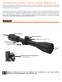 3
3
-
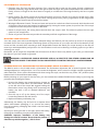 4
4
-
 5
5
-
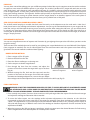 6
6
-
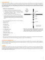 7
7
-
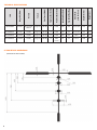 8
8
-
 9
9
-
 10
10
-
 11
11
-
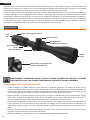 12
12
-
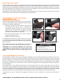 13
13
-
 14
14
-
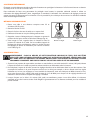 15
15
-
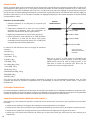 16
16
-
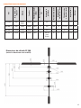 17
17
-
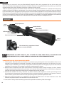 18
18
-
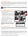 19
19
-
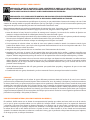 20
20
-
 21
21
-
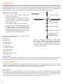 22
22
-
 23
23
-
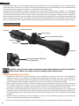 24
24
-
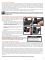 25
25
-
 26
26
-
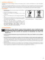 27
27
-
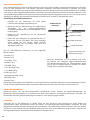 28
28
-
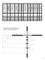 29
29
-
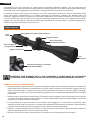 30
30
-
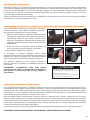 31
31
-
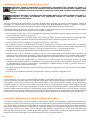 32
32
-
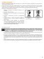 33
33
-
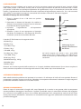 34
34
-
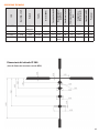 35
35
-
 36
36


Bushnell BL3940BS9 El manual del propietario
- Tipo
- El manual del propietario
En otros idiomas
- français: Bushnell BL3940BS9 Le manuel du propriétaire
- italiano: Bushnell BL3940BS9 Manuale del proprietario
- English: Bushnell BL3940BS9 Owner's manual
- Deutsch: Bushnell BL3940BS9 Bedienungsanleitung
Documentos relacionados
Otros documentos
-
Tasco T3940, T3950, T41240, T62444 Manual de usuario
-
-
Leupold FX-I Manual de usuario
-
-
Zeiss Conquest HD5 Riflescope Manual de usuario
-
-