Fischer FIS EM Plus Injection Mortar Manual de usuario
- Tipo
- Manual de usuario

fischer
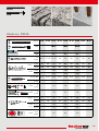
FIS EM Plus
See ICC-ES
Evaluation Report
at www.icc-es.org
ESR-1990
Seismic performance category C1, C2
Option 1 for cracked concrete
ETA-17/0979
EAD 330499-01-0601
ETA-17/1056
EAD 331522-00-0601
Post-installed rebar connection
(TR23)
Seismic
C1, C2
Information sur le niveau d’émission de substances
volatiles dans l’air intérieur, présentant un risque de
toxicité par inhalation, sur une échelle de classe allant
de A+ (très faibles émissions) à C (fortes émissions).
WHG
Water resources law
Z-74.8-199
Mit allgemeiner Bauartgenehmigung

2
fischer
FIS EM Plus
DE Gebrauchsanweisung
EN Operating instructions
FR Mode d’emploi
NL Montagehandleiding
IT Istruzioni per l’installazione
ES Instrucciones de uso
PT Instruções de utilização
DA Installationsvejledning
SV Installationsinstruktioner
NO Installasjonsveiledning
FI Asennusohjeet
IS Notkunarleiðbeiningar
ET Kasutusjuhend
LV Lietošanas instrukcija
LT Naudojimo instrukcija
PL Instrukcja instalacji
CS Návod k instalaci
SK Návod na používanie
HU Szerelési útmutató
RO Instrucţiuni de utilizare
SL Navodila za namestitev
HR Upute za instalaciju
SR Uputstvo za instalaciju
TR Kurulum talimatları
EL
Οδηγίες Εγκατάστασης
BG
RU
UK
KK
ZH 使用说明书
JA 取扱説明書
KO
사용 설명서
HI Panduan Penggunaan
AR

3
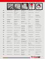
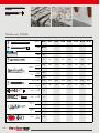
DE Trockener Beton Nasser Beton Verschmutztes
Bohrloch Wassergefülltes
Bohrloch Bohrloch unter
Wasser
EN Dry concrete Water saturated
concrete Contaminated drill
hole Water filled
borehole Drillhole under
water
FR Béton sec Béton humide Perçage non
dépoussiéré Trou inondé Forage sous l‘eau
NL Droog beton Met water
verzadigd beton Vervuild boorgat Met water gevuld
boorgat Boorgat onder
water
IT Calcestruzzo secco Calcestruzzo saturo
d‘acqua Foro sporco Foro pieno d‘acqua
nel calcestruzzo Foro sotto acqua
ES Hormigón seco Hormigón saturado
de agua Agujero de
taladrado sucio Taladro lleno de
agua en hormigón Perforación bajo el
agua
PT Betão seco Betão saturado de
água Furo com sujidade Furo cheio de água Furo debaixo de
água
DA Tør beton Vandmættet beton Tilsmudset borehul Vandfyldt borehul Borehul under
vandet
SV Torr betong Vattenmättad
betong Smutsigt hål Vattenfyllt hål Borrhål under
vattnet
NO Tørr betong Vannmettet betong Tilskitnet borehull Vannfylte borehull Borehull under
vann
FI Kuiva betony Veden kyllästämä
betoni Likaantunut
poranreikä Vedellä täyttynyt
porareikä Porausreikä veden
alla
IS Þurr steinsteypa Blaut steinsteypa Óhrein borhola Vatnsfyllt borhola Borhola
neðansjávar
ET Kuivbetoon Märgbetoon Mustunud
puuriauk Veega täidetud
puuriauk Puurkaev vee all
LV Sauss betons Mitrs betons Piesārņots urbums Urbums ar ūdeni Urbums zem ūdens
LT Sausas betonas Drėgnas betonas Užteršta išgręžta
skylė Vandens pripildyta
išgręžta skylė Gręžinys po
vandeniu
PL Beton suchy wodą Beton nasycony
wodą Zabrudzony
wywiercony otwór Wywiercony otwór
wypełnionym Odwiert pod wodą
CS Suchý beton Mokrý beton
otvory vyvrtané do Znečištěný vývrt Naplněné vodou Vrt pod vodou
SK Suchý betón Vodou nasýtený
betón Znečistený vývrt Vodou naplnený
otvor vyvŕtaný Vrt pod vodou
HU Száraz beton Nedves beton Szennyezett furat Vízzel töltött furat Fúrólyuk a víz alatt
RO Beton uscat Beton ud Gaură forată
contaminată Gaură forată
umplută cu apă Foraj sub apă
SL Suh beton Moker beton Umazana izvrtina Z vodo napolnjena
izvrtina Izvrtina pod vodo

4
HR Suhi beton Mokri beton Zaprljani provrt Vodom napunjen
provrt Bušotina pod
vodom
SR Suv beton Mokar beton Zaprljan provrt Provrt napunjen
vodom Bušotina pod
vodom
TR Kuru beton Yaş beton Kirli delik Su dolu delik Kuyu sualtı
EL
Στεγνό μπετόν Υγρό μπετόν Βρώμικη τρύπα Τρύπα γεμάτη
νερό
Υποβρύχια
γεώτρηση
BG
RU
-
,
-
UK
KK
-
ZH 干燥混凝土 湿混凝土 受污的钻孔 注水的钻孔 水下钻孔
JA
いたべトン 湿っ た べトン 汚れた掘削孔 水がたまった掘
削孔
水中ボアホール
KO
건조 콘트리트 습윤 콘크리트 이물질이 삽입된
드릴 구멍
물이 찬 드릴 구멍 수중 시추공
HI Beton kering Beton basah Lubang bor
terkontaminasi Lubang bor terisi
air Lubang bor di
bawah air
AR

5
t work
Tinst
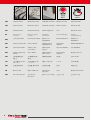
DE Gerissener Beton Ungerissener
Beton Bewehrungs-
anschluss Drehmoment Verarbeitungszeit
EN Cracked concrete Non-cracked
concrete Reinforcement
connection Required torque Open time
FR Béton fissuré Béton non fissuré Scellement
d‘armatures Couple Temps de
manipulation
NL Gescheurd beton Ongescheurd beton Wapenings-
aansluiting Draaimoment Verwerkingstijd
IT Calcestruzzo
fessurato Calcestruzzo non
fessurato Ferri di ripresa Coppia Tempo di
lavorazione
ES Hormigón
agrietado Hormigón sin
grietas Conexión de
refuerzo Par Tiempo de
tratamiento
PT Betão fissurado Betão não
fissurado Conetor de reforço Binário Tempo de
processamento
DA Revnet beton Ikkerevnet beton Armerings-
tilslutninger Tilspændings-
moment Forarbejds ningstid
SV Sprucken betong Ej sprucken betong Armerings-
anslutning Vridmoment Bearbetningstid
NO Betong med riss Betong uten riss Armerings-
forbindelse Dreiemoment Bearbeidelsestid
FI Haljennut betoni Halkeamaton
betoni Vahvistusliitäntä Vääntömomentti Käsittelyaika
IS Sprungin steypa Óbrotin
steinsteypa Tenging við
styrkingu Snúningsátak Vinnslutími
ET Pragunenud
betoon Pragudeta betoon Sarrusühendus Pöördemoment Töötlemisaeg
LV Betons ar plaisām Betons bez
plaisām Stiegrojuma
savienojums Griezes moments Apstrādājamības
laiks
LT Sutrūkinėjęs
betonas Vientisas betonas Armatūros sujungi-
mo elementas Sukimo momentas Darbo su medžiaga
laikas
PL Beton spękany Beton niespękany Złącze zbrojarskie Moment
dokręcenia Czas żelowania
CS Beton s trhlinami Beton bez trhlin Přípojka výztuže Utahovací moment Doba zpracování
SK Betón s trhlinami Betón bez trhlín Styková výstuž Uťahovací moment Doba spracovania
HU Repedéses beton Repedésmentes
beton Betonvasalatcsat-
lakozás Forgatónyomaték Feldolgozási idő
RO Beton fisurat Beton fără fisuri Racord de
armătură Cuplu Timp de punere în
operă
SL Razpokan beton Nerazpokan beton Priključek za
armaturo Navor Čas obdelave

6
t work
Tinst
HR Ispucani beton Neispucani beton Priključak armature Okretni moment Vrijeme obrade
SR Ispucao beton Neispucao beton Priključak armature Obrtni moment Vreme obrade
TR Çatlamış beton Çatlamamış beton Destek bağlantısı Tork Kullanma süresi
EL
Μπετόν με
ρωγμές
Μπετόν χωρίς
ρωγμές
Σύνδεση
οπλισμού
Ροπή σύσφιξης Χρόνος
επεξεργασίας
BG
RU
UK
KK
ZH 有裂缝的混
凝土
无裂缝的混
凝土
钢筋连接件 扭矩 加工时间
JA
ひび割れが あ
るべトン
ひび割れのな
い べトン
強 化 コネ クタ トルク 加工時間
KO
균열 콘크리트 비균열 콘크리트 보강재 연결 토크 작업 시간
HI Beton retak Beton tidak licin Sambungan
penguat Torsi Waktu pemrosesan
AR

7
Rebar
FRA
t cure
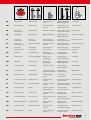
DE Aushärtezeit Ankerstangen Innengewinde-
anker Bewehrungsstab,
Bewehrungsanker Skalenteile
EN Hardening time Anchor rods Internal thread
anchors
Reinforcement rod,
Reinforcement anchor
Scale divisions
FR Temps de
durcissement Tiges filetées Douilles taraudées
Barres d‘armatures,
Ancrage d‘armature
Graduations
NL Uithardtijd Ankerstangen Binnendraadanker Wapeningsstaaf,
Wapeningsanker Schaalonderdelen
IT Tempo di
indurimento Barre di
ancoraggio Ancoraggio con
filettatura interna
Ferro di ripresa,
Ancoraggio di ripresa
Divisioni di scala
ES Tiempo de
endurecimiento Barras de anclaje Anclaje de rosca
interior Barra de refuerzo,
Anclaje de refuerzo Unidades de escala
PT Tempo de
endurecimento Tirantes de
ancoragem Ancoragem de
rosca interna
Barra de armação,
Ancoragem de reforço
Intervalos de
graduação
DA Hærdetid Gevindstænger Anker med
indvendigt gevind Armeringsstav,
Armeringsanker Skalatrin
SV Härdningstid Förankringsstänger Ankare med
innergänga Armeringsjärn,
Armeringsankare Skaldelar
NO Herdetid Ankerstenger Innvendig
gjengeanker Wapeningsstaaf,
Wapeningsanker Skaladeler
FI Kovettumisaika Harustangot Sisäkierreankkuri Tartuntateräs,
Tartuntaankkuri Asteikkojaot
IS Þornunartími Festistangir
Festing með skrúf-
gangi að innanverðu
Styrktarteinn,
Styrktarfesting Mælikvarði
ET Kõvastumisaeg Ankurvardad Sisekeermega
ankur Sarrusvarras,
Sarrusankur Skaala jaotused
LV Sacietēšanas laiks Enkura stienis Iekšējās vītnes
enkurs
Enkura stiegrojuma,
Enkura stienis
Skalas iedaļas
LT Kietėjimo laikas Inkariniai strypai Strypas su vidiniu
sriegiu
Armatūrinis strypas,
Armatūrinis inkaras
Skalės padalos
PL Czas wiązania Kotwy Kotwy z gwintem
wewnętrznym Pręt zbrojarski,
Kotwa zbrojarska Podziałki skali
CS Doba vytvrzení Kotevní tyče Svorník s vnitřním
závitem Výztužná tyč,
Kotva výztuže Dílky na stupnici
SK Doba vytvrdnutia Kotviace tyče Kotva s vnútorným
závitom Výstužný prút,
Vystužovacia kotva Diely na stupnici
HU Kikeményedési idő Horgonyrudak Belsőmenetes
horgony Betonvas rúd,
Horgonyzó vas Skálarészértékek
RO Timp de întărire Bare de ancorare Ancoră cu filet
interior
Tijă de armătură,
Ancoră de armătură
Diviziuni scală
SL Čas strjevanja Sidra Sidro z notranjim
navojem Armaturna palica,
Sidro armature Razdelki na skali
Sk
FIS A
RG M
RG M I

8
HR Vrijeme
stvrdnjavanja Sidrene šipke Sidro s unutraš-
njim navojem Armaturna šipka,
Armaturno sidro Dijelovi skale
SR Vreme
otvrdnjavanja Šipke za
ankerovanje Kotva s unutraš-
njim navojem Armaturna šipka,
Armaturna kotva Delovi skale
TR Sertleşme süresi Dübel çubukları İçten dişli dübel Takviye çubuğu,
Takviye demiri Kadran bölümleri
EL
Χρόνος
σκλήρυνσης
Ντίζες
αγκύρωσης
Αγκύρια εσωτερι-
κού σπειρώμα-
τος
Ράβδος οπλι-
σμού, Αγκύριο
οπλισμού
Διαβαθμίσεις
κλίμακας
BG
,
RU
-
, -
UK
-
, -
KK
A
I
, A-
ZH 硬化时间 系杆 内部螺纹系杆 钢筋,
钢筋锚杆
刻度
JA
凝固時間 アンカーロッド めねじアンカー 鉄筋,
強化アンカー
目盛り分割
KO
경화 시간 앵커 로드 頂睡 蝶溯萄 操 보강 로드,
보강 앵커
스케일의 눈 금폭
HI Waktu pengerasan Batang jangkar Jangkar berulir
dalam Batang penguat,
Jangkar penguat Bagian skala
AR
Rebar
FRA
t cure
Sk
FIS A
RG M
RG M I
twork tcure
FIS EM Plus FIS EM Plus
- 5 °C – ± 0 °C 240 min. 200 h
> ± 0 °C – + 5 °C 150 min. 90 h
> + 5 °C – + 10 °C 120 min. 40 h
> + 10 °C – + 20 °C 30 min. 22 h
> + 20 °C – + 30 °C 14 min. 10 h
> + 30 °C – + 40 °C 7 min. 5 h

9
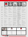
ETA-17/0979
EAD 330499-01-0601
Option 1 for cracked concrete
FIS A,
RG M
10, 11,
15-17
ETA-17/0979
EAD 330499-01-0601
Option 1 for cracked concrete
RG M I 12, 15,
17
ETA-17/0979
EAD 330499-01-0601
Option 1 for cracked concrete
Rebar,
FRA 13-16
See ICC-ES
Evaluation Report
at www.icc-es.org
ESR-1990
FIS A,
RG M,
RG M I,
Rebar
18-23
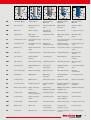
Art. No.
390 ml
FIS DM S 511118
FIS MR Plus
FIS AM 058000
FIS DCD S 543629
FIS AP 058027
585 ml FIS DM S-L 510992 FIS UMR
FIS DP S-L 511125
1500 ml FIS DP S-XL 512401
11/2023
+ 5 °C — + 30 °C

10
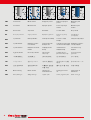
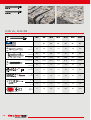
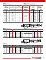
FIS A
RG M
ØM6 M8 M10 M12 M14 M16 M20
ETA-17/0979
EAD 330499-01-0601
Option 1 for cracked concrete
–✔ ✔ ✔ ✔ ✔ ✔
dodo
[mm] 810 12 14 16 18 24
hoho,min
[mm] 50 60 60 70 75 80 90
ho,max
[mm] 120 160 200 240 280 320 400
db
fischer BS Ø 8 Ø 10 Ø 12 Ø 14 Ø 16 Ø 18 Ø 14
db
[mm] 10 11 14 16 20 20 26
dfdf
[mm] 7 9 12 14 16 18 22
dfdf
[mm] 912 14 16 18 20 26
Sk
Sk (ho,min)
[–] 2 3 4 3 5 5 11
Sk (ho,max)
[–] 4 8 12 10 16 19 48
Tinst
[Nm] 510 20 40 50 60 120
FIS A, RG M
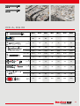
FIS A
RG M

11
ØM22 M24 M27 M30 M33 M36 M40
ETA-17/0979
EAD 330499-01-0601
Option 1 for cracked concrete
✔ ✔ ✔ ✔ – – –
dodo
[mm] 25 28 30 35 37 40 44
hoho,min
[mm] 93 96 108 120 132 144 160
ho,max
[mm] 440 480 540 600 660 720 800
db
fischer BS Ø 25 Ø 28 Ø 35 Ø 35 Ø 37 Ø 40 Ø 44
db
[mm] 27 30 40 40 40 42 47
dfdf
[mm] 24 26 30 33 36 39 43
dfdf
[mm] 28 30 33 40 43 46 50
Sk
Sk (ho,min)
[–] 10 14 17 27 29 36 50
Sk (ho,max)
[–] 46 69 85 132 144 179 245
Tinst
[Nm] 135 150 200 300 400 500 600
FIS A, RG M
FIS A
RG M
FIS A
RG M

12
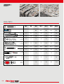
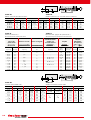
RG M I
ØM5 M6 M8 M10 M12 M16 M20
ETA-17/0979
EAD 330499-01-0601
Option 1 for cracked concrete
– – ✔ ✔ ✔ ✔ ✔
lE, min.
lE, max.
lE,min
[mm] 8 8 8 10 12 16 20
lE,max
[mm] 14 16 18 23 26 35 45
dodo
[mm] 10 12 14 18 20 24 32
hoho
[mm] 75 75 90 90 125 160 200
db
fischer BS Ø 10 Ø 12 Ø 14 Ø 18 Ø 20 Ø 24 Ø 35
db
[mm] 11 14 16 20 25 26 40
dfdf
[mm] 6 7 9 12 14 18 22
Sk
Sk
[–] 3 3 4 6 11 17 39
Tinst
[Nm] – – 10 20 40 80 120
RG M I

13
Rebar
FRA
Ø
Ø
Rebar Ø 8 Ø 10 Ø 12 Ø 14 Ø 16 Ø 18 Ø 20 Ø 22 Ø 24
FRA – – M12 –M16 –M20 – –
ETA-17/0979
EAD 330499-01-0601
Option 1 for cracked concrete
Rebar ✔ ✔ ✔ ✔ ✔ ✔ ✔ ✔ ✔
FRA – – ✔–✔–✔– –
dodo
[mm] 10/12 12/14 14/16 18 20 25 25 30 30
hoRebar
ho,min
[mm] 60 60 70 75 80 85 90 94 98
ho,max
[mm] 160 200 240 280 320 360 400 440 480
FRA
ho,min
[mm] – – 170 –180 –190 – –
ho,max
[mm] – – 240 –320 –400 – –
db
fischer BS Ø 12 Ø 14 Ø 16 Ø 18 Ø 20 Ø 25 Ø 25 Ø 30 Ø 30
db
[mm] 14 16 20 20 25 27 27 40 40
dfFRA df
[mm] – – 14 –18 –22 – –
dfFRA df
[mm] – – 18 –22 –26 – –
Sk
Rebar
Sk [–]
ho,min 3 3 4 5 6 12 10 18 15
ho,max 710 14 18 24 50 45 80 69
FRA
Sk [–]
ho,min – – 10 –14 –22 – –
ho,max – – 14 –24 –45 – –
FRA Tinst
[Nm] – – 40 –60 –120 – –
Rebar, FRA

14
Rebar
FRA
Ø
Ø
Rebar Ø 25 Ø 26 Ø 28 Ø 30 Ø 32 Ø 34 Ø 36 Ø 40
FRA M24 –––––––
ETA-17/0979
EAD 330499-01-0601
Option 1 for cracked concrete
Rebar ✔✔✔✔✔✔✔✔
FRA ✔–––––––
dodo
[mm] 30 35 35 40 40 40 45 55
ho
Rebar
ho,min
[mm] 100 104 112 120 128 136 144 160
ho,max
[mm] 500 520 560 600 640 680 720 800
FRA
ho,min
[mm] 196 –––––––
ho,max
[mm] 480 –––––––
db
fischer BS Ø 30 Ø 35 Ø 35 Ø 40 Ø 40 Ø 40 Ø 45 Ø 55
db
[mm] 40 40 40 42 42 42 47 58
dfFRA df
[mm] 26 –––––––
dfFRA df
[mm] 32 –––––––
Sk
Rebar
Sk [–]
ho,min 13 26 24 36 35 28 47 101
ho,max 65 127 116 175 173 135 233 457
FRA
Sk [–]
ho,min 26 –––––––
ho,max 63 –––––––
FRA Tinst
[Nm] 150 –––––––
Rebar, FRA

15
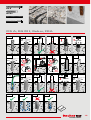
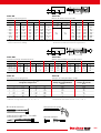
FIS A
RG M I
Rebar
FRA
FIS A, RG M I, Rebar, FRA
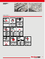
1.1
1.2a
1.1a
2x
> 6
bar
!
<
ø
!
>
ø
1.1b 1.1c
2x ≥ 30 mm
2x
1.1d
2x
> 6
bar
1.2b 1.2c
2a 2b 2c 2d
1.3 1.3a
1.3b 1.3c
2x
> 6
bar
!
<
ø
!
>
ø
1.3d
≥ 30 mm
2x
1.3e 1.3f
2x
> 6
bar
3/4

16
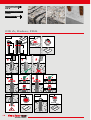
FIS A
Rebar
FRA
FIS A, Rebar, FRA
5a
h
100
hef
3
7 8
7/8
tcure
10
13/14
10/11
max. Tinst
9
6
5b
13/14
10/11
4
8
5/6
twork

17
RG M I
RG M I
6 7
7/8
tcure
8
5b
3
8
5/6
twork
5a
9
12
5/6
max. Tinst
4

18
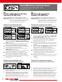
EN
fischer adhesive anchoring
system FIS EM Plus
fischer FIS EM Plus is an epoxy adhesive anchoring
system for fastenings in normal weight concrete.
Important:
Before use, read and review the installation
instructions and the SDS (safety data sheet).
Do not use expired adhesive. Minimal
concrete temperature - 5°C (23°F).
Drilling and cleaning the hole
(hammer drilling with standard drill bit)
1 Drill the hole. Nominal drill hole diameter d0 and
drill hole depth h0 see Tables II, III, IV or VI, VII,
VIII respectively.
2a Cleaning of the drill hole (not applicable for under-
water installation): Blow out the drill hole twice,
with oil free compressed air (p ≥ 6 bar / 87 psi).
2b For underwater installation only: Flush the drill hole
with clean water until it flows clear.
3 Brush the drill hole at least twice, brush type see
Table I or V respectively.
For drill hole diameter ≥ 30 mm / 1 1/2 inch use a
power drill. For deep holes use an extension.
4a Cleaning of the drill hole (not applicable for under-
water installation): Blow out the drill hole twice,
with oil free compressed air (p ≥ 6 bar / 87 psi).
4b For underwater installation only: Flush the drill hole
with clean water until it flows clear.
→ Go to step 6.
Drilling and cleaning the hole
(hammer drilling with hollow drill bit)
1 Check a suitable hollow drill for correct operation of
the dust extraction.
2 Use a suitable dust extraction system, e. g. fischer
FVC 35 M or a comparable dust extraction system
with at least equivalent performance data (volume
flow at the hose end ≥ 36 l/s / 1.27 cfs).
Drill the hole with hollow drill bit. The dust extraction
system has to extract the drill dust nonstop during
ES
Mortero de inyección
fischer FIS EM Plus
fischer FIS EM Plus es un sistema de anclaje de resina
epoxi para fijaciones en hormigón de peso normal.
Importante: Antes de utilizarlo, lea y revise las instruc-
ciones de instalación y la hoja de datos de
seguridad. No utilice adhesivo caducado.
Temperatura mínima del hormigón - 5°C.
Perforación y limpieza del agujero
(perforación con percutor con broca estándar)
1 Perfore el agujero. Diámetro nominal del agujero d0
y profundidad del agujero h0 véanse los Tablas II,
III, IV o VI, VII, VIII respectivamente.
2a La limpieza del agujero de perforación (no se aplica
a la instalación submarina): Sople el agujero de
perforación dos veces, con aire comprimido sin
aceite (p ≥ 6 bar / 87 psi).
2b Sólo para instalación submarina: Enjuague el agujero
de perforación con agua limpia hasta que fluya con
claridad.
3 Cepille el agujero de perforación al menos dos veces,
el tipo de cepillo ver Tabla I o V respectivamente.
Para el diámetro del orificio de perforación
≥ 30 mm / 1 1/2 inch utilice un taladro eléctrico.
Para agujeros profundos use una extensión.
4a La limpieza del agujero de perforación (no se aplica
a la instalación submarina): Sople el agujero de
perforación dos veces, con aire comprimido sin
aceite (p ≥ 6 bar / 87 psi).
4b Sólo para instalación submarina: Enjuague el agujero
de perforación con agua limpia hasta que fluya con
claridad.
→ Ir al paso 6.
Perforación y limpieza del agujero
(perforación con percutor con broca hueca)
1 Verifique un taladro hueco adecuado para el correcto
funcionamiento de la extracción de polvo.
2 Utilice un sistema de extracción de polvo adecuado,
por ejemplo fischer FVC 35 M o un sistema de
extracción de polvo comparable con datos de
rendimiento al menos equivalentes (volumen de flujo
en el extremo de la manguera ≥ 36 l/s / 1.27 cfs).
Taladrar el agujero con una broca hueca. El sistema
de extracción de polvo debe extraer el polvo de la
broca sin parar durante el proceso de perforación
Installation instruction
see ICC-ES Evaluation Report No. 1990
at www.icc-es.org
1 2a 2b 3
4a 4b
1
2

19
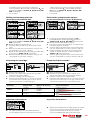
the drilling process and must be adjusted to
maximum power. Nominal drill hole diameter d0 and
drill hole depth h0 see Tables II, III, IV or VI, VII,
VIII respectively.
→ Go to step 6.
Drilling and cleaning the hole
(wet drilling with diamond drill)
1a Drill the hole. Drill hole diameter d0 and nominal
drill hole depth h0 see Tables II, III, IV or VI, VII,
VIII respectively.
1b Break the drill core and remove it.
2 Flush the drill hole with clean water until it flows
clear.
3 Blow out the drill hole at least twice, using oil free
compressed air (p ≥ 6 bar / 87 psi).
4 Brush the drill hole at least twice using a power drill,
brush type see Table I or V respectively.
5 Blow out the drill hole at least twice, using oil free
compressed air (p ≥ 6 bar / 87 psi).
Preparing the cartridge
6a Remove the sealing cap.
6b Screw on the static mixer (the spiral in the static
mixer must be clearly visible).
7 Place the cartridge into the dispenser.
8 Extrude approximately 10 cm / 4 inch of material
out until the resin is evenly grey in colour. Do not
inject mortar that is not uniformly grey.
Injection of the mortar
9 Fill approximately 2/3 of the drilled hole with
mortar. Always begin from the bottom of the hole
y debe ajustarse a la potencia máxima. Diámetro
nominal del taladro d0 y profundidad del taladro
h0 véanse los Tablas II, III, IV o VI, VII, VIII
respectivamente.
→ Ir al paso 6.
Perforación y limpieza del agujero
(perforación húmeda con broca de diamante)
1 Perfore el agujero. Diámetro del agujero d0 y
profundidad nominal del agujero h0 véanse los
Tablas II, III, IV o VI, VII, VIII respectivamente.
1b Rompa el núcleo del taladro y retírelo.
2 Enjuague el agujero de perforación con agua limpia
hasta que fluya con claridad.
3 Sople el agujero de perforación al menos dos veces,
con aire comprimido sin aceite (p ≥ 6 bar / 87 psi).
4 Cepille el agujero de la broca al menos dos veces
usando un taladro eléctrico, el tipo de cepillo ver
Tabla I o V respectivamente.
5 Sople el agujero de perforación al menos dos veces,
con aire comprimido sin aceite (p ≥ 6 bar / 87 psi).
Preparación del cartucho
6a Quite el tapón del cartucho.
6b Atornille la cánula mezcladora (la espiral en la
cánula mezcladora debe ser claramente visible).
7 Coloque el cartucho en el dispensador.
8
Extraiga aproximadamente 10 cm / 4 inch de material
hasta que la resina tenga un color gris uniforme. No
inyecte mortero que no sea uniformemente gris.
Inyección del mortero
9 Rellene aproximadamente 2/3 del agujero perforado
con mortero. Empiece siempre desde el fondo del
agujero y evite las bolsas de aire o los vacíos.
Para la profundidad del agujero de perforación
1a 1b 2 3
4 5
6a 6b 7 8
Cartridge
Cartucho
Dispenser
Dispensador
Item No.
Número de artículo
Static mixer
Cánula mezcladora
390 ml
FIS DM S 511118 FIS Mixer Red Plus
FIS DCD S 543629
FIS AP 058027
585 ml FIS DM S-L 510992 FIS Ultra Mixer Red
FIS DP S-L 511125
1500 ml FIS DP S-XL 512401
9

20
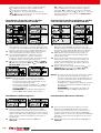
and avoid air pockets or voids. For drill hole depth
h0 ≥ 150 mm / 6 inch use an extension tube.
For overhead installation, deep holes
(h0 > 250 mm / 10 inch) or drill hole diameter
(d0 ≥ 40 mm / 1 1/2 inch) use an injection-adapter
see Table I or V respectively.
Installation of anchor rods or fischer
internal threaded anchors RG M I
10
Only use clean and oil-free metal parts.
Mark the
setting depth on the anchor rod. Push the anchor rod
or fischer internal threaded anchor RG M I down to the
bottom of the hole, turning it slightly while doing so.
11 After inserting the anchor element, excess mortar
must be emerged around the anchor element.
12 For overhead installations support the anchor
element with wedges (e. g. fischer centering
wedges) or fischer overhead clips. For push through
installation fill the annular gap with mortar.
13 Wait for the specified curing time tcure see Table
IX. Mounting the fixture max. Tinst see Tables II,
IV or VI, VIII respectively.
Option After the minimum curing time is reached,
the gap between anchor element and fixture
(annular clearance) may be filled with mortar
via the fischer filling disc FFD.
Compressive strength ≥ 50 N/mm2 / 7250 psi
(e.g. fischer injection mortars FIS HB, FIS SB,
FIS V, FIS EM Plus).
ATTENTION: Using fischer filling disk FFD
reduces tfix (usable length of the anchor).
Installation reinforcing bars
10
Only use clean and oil-free reinforcing bars. Mark
the setting depth. Turn while using force to push the
reinforcement bar into the filled hole up to the setting
depth mark). When the setting depth mark is reached,
excess mortar must be emerged from the mouth of
the drill hole.
11 Wait for the specified curing time tcure see
Table IX.
h0 ≥ 150 mm / 6 inch usar un tubo de extensión.
Para la instalación en la parte superior, agujeros
profundos (h0 > 250 mm / 10 inch) o el diámetro
del agujero de perforación
(d0 ≥ 40 mm / 1 1/2 inch)
utilice un adaptador de inyección ver Tabla I o V
respectivamente.
Instalación de varillas roscadas o varillas
con roscado interno de fischer RG M I
10 Sólo utilice piezas de metal limpias y sin aceite.
Marque la profundidad de ajuste en la barra de
anclaje. Empuje la varilla de anclaje o el anclaje de
rosca interna de fischer RG M I hasta el fondo del
agujero, girándolo ligeramente mientras lo hace.
11 Después de insertar el elemento de anclaje, el
exceso de mortero debe emerger alrededor del
elemento de anclaj.
12 En el caso de las instalaciones aéreas, apoye el
elemento de anclaje con cuñas (por ejemplo, las
cuñas de centrado de fischer) o clips aéreos de
fischer. Para la instalación de empuje, rellene el
hueco anular con mortero.
13 Espere el tiempo de curado especificado tcure ver
Tabla IX. Montar el accesorio max. Tinst ver
Tablas II, IV o VI, VIII respectivamente.
Opción Una vez alcanzado el tiempo mínimo de curado,
el espacio entre el elemento de anclaje y el
accesorio (espacio anular) puede rellenarse con
mortero a través del disco de relleno de fischer
FFD. Resistencia a la compresión
≥ 50 N/mm2 / 7250 psi (por ejemplo, morteros
de inyección de fischer FIS HB, FIS SB, FIS V,
FIS EM Plus).
ATENCIÓN: El uso del disco de relleno de
fischer FFD reduce el tfix (longitud útil del
anclaje).
Instalación de barras de refuerzo
10
Sólo usar barras de refuerzo limpias y sin aceite.
Marque la profundidad de ajuste. Gire mientras
usa la fuerza para empujar la barra de refuerzo en
el agujero lleno hasta la marca de profundidad de
ajuste. Cuando se alcanza la marca de profundidad de
fraguado, el exceso de mortero debe salir de la boca
del taladro.
11 Espere el tiempo de curado especificado tcure ver
Tabla IX.
10 11 12 Tinst
13
10 11 12 Tinst
13
Tinst
13 14
10 11

21
Drill bit Rods Rebar Internal
threaded anchor Brush Injection
adapter
Broca de
perforación Varilla roscada Acero corrugado Varilla con
roscado interno Cepillo Adaptador
de inyecció
Type Item No. Size Color
Tipo
[BS] Número de
artículo
ø [inch] ø [mm] ø [mm] ø [mm] ø [mm] Tamaño Color
3/8 10 M8 – – 10 78178 – –
7/16 12 M10 – – 12 78179 12 nature
9/16 14 M12 10 RG M8 I 14 78180 14 blue
5/8 16 –12 –16/18 78181 16 red
3/4 18 M16 –RG M10 I 16/18 78181 18 yellow
13/16 20 –16 RG M12 I 20 52277 20 green
124 M20 –RG M16 I 24 78182 24 brown
125 –20 –25 97806 25 black
1 1/8 28 M24 – – 28 78183 28 blue
1 1/4 30 M27 25 –35 78184 30 grey
1 1/4 32 – – RG M20 I 35 78184 30 grey
1 3/8 35 M30 28 –35 78184 35 brown
1 1/2 40 –32 –40 505061 40 red
Table I.
Drill hole diameter /
Accessories for metric sizes.
Tabla I.
Diámetro del agujero de perforación /
Accesorios para medidas métricas.
dad0hef, min hef, max hmin smin = cmin max Tinst
[mm] [mm] [inch] [mm] [inch] [mm] [inch] [mm] [inch] [mm] [inch] [Nm] [ft · lb]
M8 10 3/8 60 2.36 160 6.30 hef +30
(≥ 100) hef +1.25
(≥ 4)
40 1.57 10 7
M10 12 7/16 60 2.36 200 7.87 45 1.77 20 15
M12 14 9/16 70 2.76 240 9.45 55 2.17 40 30
M16 18 3/4 80 3.15 320 12.60 65 2.56 60 44
M20 24 190 3.54 400 15.75 hef + hef + 85 3.35 120 89
M24 28 1 1/8 96 3.78 480 18.90 2d02d0105 4.13 150 111
M27 30 1 1/4 108 4.25 540 21.26 120 4.72 200 148
M30 35 1 3/8 120 4.72 600 23.62 140 5.51 300 221
Table II.
Metric threaded rods. Tabla II.
Varillas métricas roscadas.
smin
cmin
h
min
T
inst
d
d
0
h
ef
= h
0
da / dbd0hef, min hef, max hmin smin = cmin max Tinst 1)
[mm] [mm] [inch] [mm] [inch] [mm] [inch] [mm] [inch] [mm] [inch] [Nm] [ft · lb]
10 14 9/16 60 2.36 200 7,87 hef +30
(≥ 100) hef +1.25
(≥ 4) 45 1.77 30 22
12 16 5/8 70 2.76 240 9,45 55 2.17 50 37
16 20 13/16 80 3.15 320 12,60 65 2.56 110 81
20 25 190 3.54 400 15,75 hef + hef + 85 3.35 190 140
25 30 1 1/4 100 3.94 500 19,69 2d02d0120 4.72 280 207
28 35 1 3/8 112 4.41 560 22,05 140 5.51 350 258
32 40 1 1/2 128 5.04 640 25,20 160 6.30 430 317
Table III.
Metric reinforcing bars. Tabla III.
Barras métricas de refuerzo.
1) Torque moment only required when using threaded reinforcing
bars to resist seismic loading.
1) El momento de torsión sólo se requiere cuando se usan barras
de refuerzo roscadas para resistir la carga sísmica.
smin
cmin
h
min
d
0
h
ef
= h
0
d

22
Drill bit Rods Rebar Internal
threaded anchor Brush Injection
adapter
Broca de
perforación Varilla roscada Acero corrugado Varilla con
roscado interno Cepillo Adaptador
de inyecció
Type Item No. Size Color
Tipo
[BS] Número de
artículo
ø [inch] ø [mm] ø [inch] #ø [inch] Tamaño Color
7/16 12 3/8 – – 12 78179 – –
1/2 14 – 3 – 14 78180 12 nature
9/16 15 1/2 – – 14 78180 14 blue
5/8 16 – 4 – 16/18 78181 16 red
3/4 18 5/8 –RG M I 3/8 16/18 78181 18 yellow
13/16 20 – 5 RG M I 1/2 20 52277 20 green
7/8 22 3/4 6 – 20 52277 20 green
125 7/8 –RG M I 5/8 25 97806 25 black
1 1/8 28 1 7 – 28 78183 28 blue
1 1/4 32 1 1/8 8RG M I 3/4 35 78184 30 grey
1 3/8 35 1 1/4 9 – 35 78184 35 brown
1 1/2 40 –10 –40 505061 40 red
1 3/4 45 –11 –45 506254 45 yellow
Table V.
Drill hole diameter /
Accessories for fractional sizes.
Tabla V.
Diámetro del agujero de perforación /
Accesorios para tamaños fraccionarios.
dedad0hef hmin smin = cmin max Tinst
[mm] [mm] [inch] [mm] [inch] [mm] [inch] [mm] [inch] [mm] [inch] [Nm] [ft · lb]
RG M8 I 12 1/2 14 9/16 90 3.54 120 4.72 55 2.17 10 7
RG M10 I 16 5/8 18 3/4 90 3.54 125 4.92 65 2.56 20 15
RG M12 I 18 11/16 20 13/16 125 4.92 165 6.50 75 2.95 40 30
RG M16 I 22 7/8 24 1160 6.30 205 8.07 95 3.74 80 59
RG M20 I 28 1 1/8 32 1 1/4 200 7.87 260 10.24 125 4.92 120 89
Table IV.
Metric internal threaded anchors. Tabla IV.
Varillas métricas con roscado interno métricas.
smin
cmin
h
min
T
inst
d
d
0
h
ef
= h
0
dad0hef, min hef, max hmin smin = cmin max Tinst
[mm] [mm] [inch] [mm] [inch] [mm] [inch] [mm] [inch] [mm] [inch] [Nm] [ft · lb]
3/8 12 7/16 60 2 3/8 191 7 1/2 hef +30 hef +1.25 42.5 1.67 20 15
1/2 15 9/16 70 2 3/4 254 10 (≥ 100) (≥ 4) 57.5 2.26 41 30
5/8 18 3/4 79 3 1/8 318 12 1/2 65 2.56 68 50
3/4 22 7/8 89 3 1/2 381 15 80 3.15 122 90
7/8 25 189 3 1/2 445 17 1/2 hef + hef + 95 3.74 136 100
128 1 1/8 102 4508 20 2d02d0110 4.33 183 135
1 1/8 32 1 1/4 114 4 1/2 572 22 1/2 135 5.31 244 180
1 1/4 35 1 3/8 127 5635 25 160 6.30 325 240
Table VI.
Fractional threaded rods. Tabla VI.
Varillas roscadas fraccionadas.
smin
cmin
h
min
T
inst
d
d
0
h
ef
= h
0

23
Temperature range 1) Processing time Curing time
Rango de temperatura 1) Tiempo de trabajabilidad Tiempo de curado
twork tcure
[°C] [°F] [min] [h]
– 5 — ± 0 + 23 — + 32 240 200
> ± 0 — + 5 > + 32 — + 41 150 90
> + 5 — + 10 > + 41 — + 50 120 40
> + 10 — + 20 > + 50 — + 68 30 22
> + 20 — + 30 > + 68 — + 86 14 10
> + 30 — + 40 > + 86 — + 104 7 5
Table IX.
Processing and curing times. Tabla IX.
Tiempos de trabajabilidad y curado.
Store mortar in a cool dry place.
1) Minimal cartridge temperature + 5 °C / + 41 °F.
Almacenar el mortero en un lugar fresco y seco.
1) Temperatura mínima del cartucho + 5 °C / + 41 °F.
da / dbd0hef, min hef, max hmin smin = cmin max Tinst 1)
[-] [mm] [inch] [mm] [inch] [mm] [inch] [mm] [inch] [mm] [inch] [Nm] [ft · lb]
#3 14 1/2 60 2 3/8 190 7 1/2 hef +30
(≥ 100) hef +1.25
(≥ 4) 43 1.69 30 22
#4 16 5/8 70 2 3/4 254 10 58 2.28 60 44
#5 20 13/16 79 3 1/8 318 12 1/2 65 2.56 110 81
#6 22 7/8 89 3 1/2 382 15 80 3.15 175 129
#7 28 1 1/8 89 3 1/2 444 17 1/2 hef + hef + 95 3.74 240 177
#8 32 1 1/4 102 4508 20 2d02d0110 4.33 320 236
#9 35 1 3/8 114 4 1/2 574 22 1/2 130 5.12 380 280
#10 40 1 1/2 127 5644 25 160 6.30 450 332
#11 45 1 3/4 140 5 1/2 698 27 1/2 175 6.89 450 332
Table VII.
Fractional reinforcing bars. Tabla VII.
Barras de refuerzo fraccionadas.
1) Torque moment only required when using threaded reinforcing
bars to resist seismic loading.
1) El momento de torsión sólo se requiere cuando se usan barras
de refuerzo roscadas para resistir la carga sísmica.
smin
cmin
h
min
d
0
h
ef
= h
0
d
dedad0hef hmin smin = cmin max Tinst
[inch] [mm] [inch] [mm] [inch] [mm] [inch] [mm] [inch] [mm] [inch] [Nm] [ft · lb]
RG M I 3/8 16 5/8 18 3/4 90 3.54 125 4.92 65 2.56 20 15
RG M I 1/2 18 11/16 20 13/16 125 4.92 165 6.50 75 2.95 40 30
RG M I 5/8 22 7/8 24 1160 6.30 205 8.07 95 3.74 80 59
RG M I 3/4 28 1 1/8 32 1 1/4 200 7.87 260 10.24 125 4.92 120 89
Table VIII.
Fractional internal threaded anchors. Tabla VIII.
Varillas fraccionadas con roscado interno.
smin
cmin
h
min
T
inst
d
d
0
h
ef
= h
0
FIS EM Plus 390 S / FIS EM Plus 585 S /
FIS EM Plus 1500 S
3
1
2x
2.1
2x
2.3
2.2a
2x
34
3
3
h0 ≥ 150 mm
5
hef
7
Tinst
tcure
6
Brush with extension
Static mixer FIS MR Plus / FIS UMR
and extension tube
Compressed air pistol
Injection adapter
A
B
h0
d0
h0>250 mm
12 2
FIS EM Plus 390 S FIS EM Plus 585 S,
FIS EM Plus 1500 S
FIS Mixer Red Plus FIS Ultra Mixer Red
2.2b
2x

www.fischer-international.com
www.fischer.de
Contact
fischerwerke
GmbH & Co. KG
Klaus-Fischer-Straße 1
72178 Waldachtal
Germany
Phone +49 7443 12-0
www.fischer.de
info@fischer.de
www.fischer.de
00182253 · 01/2021 · [ajm] · EL · Printed in Germany
We cannot be responsible for any errors, and we reserve the right to make technical and range modifications without notice.
fischer Deutschland
Vertriebs GmbH
Klaus-Fischer-Straße 1
72178 Waldachtal
Tel.: +49 7443 12 6000
fischer Austria GmbH
Wiener Straße 95
2514 Traiskirchen
Tel.: +43 2252 53730 0
fischer fixings UK Ltd.
Whitely Road
Oxon OX10 9AT Wallingford
Tel.: +44 1491 82 79 00
fischer S. A. S.
12, rue Livio, P. O. Box 10182
67022 Strasbourg-Cedex 1
Tel.: +33 388 39 18 67
fischer Cobemabel snc
Schaliënhoevedreef 20 D
2800 Mechelen
Tel.: +32 152 8 47 00
fischer Benelux B.V.
Amsterdamsestraatweg 45 B/C
1411 AX Naarden
Tel.: +31 35 6 95 66 66
fischer italia S.R.L
Corso Stati Uniti, 25
Casella Postale 391
35127 Padova Z.l. Sud
Tel.: +39 049 806 31 11
fischer Ibérica S.A.U.
Klaus Fischer 1
43300 Mont-Roig del Camp
Tarragona
Tel.: +34 977 83 87 11
fischerwerke Portugal, Lda.
Rua das Musas, Passeio dos
Cruzados Lote 2.01 (Bloco3),
Loja 8 (01.D) / Parque das Nações
1990-171 Lisboa
Tel.: +351 218 954 180
fischer a/s
Sandvadsvej 17 A
4600 Køge
Tel.: +45 46 32 02 20
fischer Sverige AB
Nygatan 93
602 34 Norrköping
Tel.: +46 11 31 44 50
fischer Norge AS
Oluf Onsumsvei 9
0680 Oslo
Tel.: +47 23 24 27 10
fischer Finland Oy
Suomalaistentie 7 B
02270 Espoo
Tel.: +358 20 7414660
fischerpolska Sp.z o.o
ul. Albatrosow 2
30-716 Kraków
Tel.: +48 12 2 90 08 80
fischer international s.r.o.
Prùmyslová 1833
25001 Brandýs nad Labem
Tel.: +42 03 26 90 46 01
fischer S.K. s.r.o.
Nová Rožňavská 134 A
831 04 Bratislava
Tel.: +421 2 4920 6046
fischer Hungária Bt.
Szerémi út 7/b
1117 Budapest
Tel.: +36 1 347 97 55
fischer fixings Romania
S.R.L.
Str. Calea Baciului 179/B
400230 Cluj Napoca
Tel.: +40 (264) 455 166, 592 449
fischer Metal San. ve Tic.
Ltd. Şti
Cevizli Mahallesi Mustafa Kemal
Cad. No. 66,
Hukukçular Towers A Blok Kat 9
34865 Kartal Istanbul
Tel.: +90 21 63 26 00 66
fischer Hellas Emporiki EPE
Nat. Road Athens-Lamia (17th)
& Roupel 6
145 64 Kifissia, Athens
Tel.: +30 210 2838 167
ООО Фишер Крепежные
Системы Рус
125195, r. Москва
Ленинградское шоссе 47, стр.2
Тел./факс:
+7-495-223-61-62
fischer (Taicang)
fixings Co. Ltd.
Shanghai Rep. Office Rm
1503-1504,
No. 63 Chifeng Road
200092 Shanghai
Tel.: +86 21 51 00 16 68
fischer Japan K.K.
Seishin Kudan Building 3rd Floor
3-4-15 Kudan Minami, Chiyoda-ku
102-0074 Tokyo
Tel.: +81 3 3263 4491
fischer systems Asia
Pte. Ltd.
4 Kaki Bukit Ave.
#01-06
417939 Singapore
Tel.: +65 62 85 22 07
fischer Korea Co., Ltd
Room 601/602, Kolon Digital
Billant 30, Digitalro 32-Gil, Guro-
Gu, Seoul, Korea 08390
Tel.: +82 15 44 89 55
fischer FZE
R/A 07, BA - 04,
Jebel Ali Free Zone
Dubai
Tel.: +97 14 8 83 74 77
fischer fixings LLC
205 US HWY 46 Suite 4
07512 Totowa, New Jersey
Tel.: +1 973 256 3045
fischer Argentina s.a.
Armenia 3044
1605 Munro Ra-PCIA Buenos Aires
Tel.: +54 1147 21 77 00
fischer brasil Industria e
Comercio Ltda.
Avenida Marginal Projetada
1652 Galpão
15 - Barueri / São Paulo
Tel.: +55 11 3178 25 20
fischer Sistemas de Fijación,
S.A. de C.V.
Blvd. Manuel Avila Camacho
3130-400 B
54020 Col. Valle Dorado,
Tlalnepantla
Tel.: +52 55 55 72 08 83
fischer Building Materials
India PVT Ltd.
Prestige Garnet Unit No. 401,
4th Floor 36, Ulsoor Road
560042 Bengaluru
Tel.: +91 0804 151 199 12 01
fischer PH Asia, Inc.
100 Congressional Avenue,
Project 8
1106 Quezon City
Metro Manila
Tel.: +63 (02) 426 0888 217
fischer fasteners
QD Trading LLC
HUB Business Center,
Barwa Commercial Avenue,
Arkan Building No. 115,
Block No. 4, Office No. 56,
Street 964, Zone 56 Doha, Qatar
-
 1
1
-
 2
2
-
 3
3
-
 4
4
-
 5
5
-
 6
6
-
 7
7
-
 8
8
-
 9
9
-
 10
10
-
 11
11
-
 12
12
-
 13
13
-
 14
14
-
 15
15
-
 16
16
-
 17
17
-
 18
18
-
 19
19
-
 20
20
-
 21
21
-
 22
22
-
 23
23
-
 24
24


Fischer FIS EM Plus Injection Mortar Manual de usuario
- Tipo
- Manual de usuario
Otros documentos
-
Hilti Hilti HIT-CT 1 Guía del usuario
-
Schmalz DUE-SET-8xDYN-M16x125/25-ST-VZ Assembly Instructions
-
-
Hilti HIT-HY 200-A Instrucciones de operación
-
-
-
-
-
-