
CEBORA S.p.A. 1
3300305-B 18-03-2016
I
MANUALE DI ISTRUZIONE PER GENERATORI Artt. 387 E 389 IN
APPLICAZIONI ROBOT.
pag. 2
GB
INSTRUCTIONS MANUAL FOR POWER SOURCES Arts. 387 AND
389 IN ROBOT APPLICATIONS.
page 11
E
MANUAL DE ISTRUCCIONES PARA GENERADORES Artt. 387 Y
389 EN APPLICACIONES ROBOT.
pag. 20
D
BETRIEBSANLEITUNG FÜR DIE STROMQUELLEN Art. 387 UND
389 IN ROBOTERANWENDUNGEN.
seite 29
Parti di ricambio e schemi elettrici.
Spare parts and wiring diagrams. page 39
Piezas de repuesto y esquemas electricos.
Ersatzteile und Schaltpläne.

CEBORA S.p.A. 2
3300305-B 18-03-2016
I
IMPORTANTE: PRIMA DELLA MESSA IN
OPERA DELL'APPARECCHIO LEGGERE IL
CONTENUTO DI QUESTO MANUALE E
CONSERVARLO, PER TUTTA LA VITA
OPERATIVA, IN UN LUOGO NOTO AGLI
INTERESSATI. QUESTO APPARECCHIO
DEVE ESSERE UTILIZZATO
ESCLUSIVAMENTE PER OPERAZIONI DI
SALDATURA.
1 PRECAUZIONI DI SICUREZZA.
LA SALDATURA ED IL TAGLIO AD ARCO
POSSONO ESSERE
NOCIVI PER VOI E PER
GLI ALTRI, pertanto
l'utilizzatore deve essere istruito contro i rischi, di
seguito riassunti, derivanti dalle operazioni di
saldatura. Per informazioni più dettagliate
richiedere il manuale cod. 3.300.758.
RUMORE.
Questo apparecchio non produce di per
se rumori eccedenti gli 80dB. Il
procedimento di taglio
plasma/saldatura può produrre livelli di rumore
superiori a tale limite; pertanto, gli utilizzatori
dovranno mettere in atto le precauzioni previste
dalla legge.
CAMPI ELETTROMAGNETICI. Possono
essere dannosi. La corrente
elettrica che attraversa qualsiasi
conduttore produce dei campi
elettromagnetici (EMF). La
corrente di saldatura o di taglio
genera campi elettromagnetici attorno ai cavi ed
ai generatori.
I campi magnetici derivanti da correnti elevate
possono incidere sul funzionamento di
pacemaker.
I portatori di apparecchiature elettroniche vitali
(pacemaker) devono consultare il medico prima
di avvicinarsi alle operazioni di saldatura ad arco,
di taglio, scriccatura o di saldatura a punti.
L’ esposizione ai campi elettromagnetici della
saldatura o del taglio potrebbe avere effetti
sconosciuti sulla salute. Ogni operatore, per
ridurre i rischi derivanti dall’ esposizione ai
campi elettromagnetici, deve attenersi alle
seguenti procedure:
- Fare in modo che il cavo di massa e della
pinza portaelettrodo o della torcia rimangano
affiancati. Se possibile, fissarli assieme con
del nastro.
- Non avvolgere i cavi di massa e della pinza
porta elettrodo o della torcia attorno al corpo.
- Non stare mai tra il cavo di massa e quello
della pinza portaelettrodo o della torcia. Se il
cavo di massa si trova sulla destra
dell’operatore anche quello della pinza
portaelettrodo o della torcia deve stare da
quella parte.
- Collegare il cavo di massa al pezzo in
lavorazione più vicino possibile alla zona di
saldatura o di taglio.
- Non lavorare vicino al generatore.
ESPLOSIONI.
Non saldare in prossimità di recipienti
a pressione o in presenza di polveri, gas
o vapori esplosivi.
Maneggiare con cura bombole e regolatori di
pressione utilizzati nelle operazioni di saldatura.
COMPATIBILITÀ ELETTROMAGNETICA.
Questo apparecchio è costruito in conformità alle
indicazioni contenute nella norma IEC 60974-
10(Cl. A) e deve essere usato solo a scopo
professionale in un ambiente industriale. Vi
possono essere, infatti, potenziali difficoltà
nell'assicurare la compatibilità
elettromagnetica in un ambiente diverso da
quello industriale.
SMALTIMENTO APPARECCHIATURE
ELETTRICHE ED ELETTRONICHE.
Non smaltire le apparecchiature
elettriche assieme ai rifiuti normali!
In ottemperanza alla Direttiva Europea
2002/96/CE sui rifiuti da apparecchiature
elettriche ed elettroniche e relativa attuazione
nell'ambito della legislazione nazionale, le
apparecchiature elettriche giunte a fine vita
devono essere raccolte separatamente e conferite
ad un impianto di riciclo ecocompatibile. In
qualità di proprietario delle apparecchiature
dovrà informarsi presso il nostro rappresentante
in loco sui sistemi di raccolta approvati. Dando
applicazione a questa Direttiva Europea
migliorerà la situazione ambientale e la salute
umana!
IN CASO DI CATTIVO FUNZIONAMENTO
RICHIEDETE L’ASSISTENZA DI
PERSONALE QUALIFICATO.

CEBORA S.p.A. 3
3300305-B 18-03-2016
I
1.1 Targa delle AVVERTENZE.
Il testo numerato seguente corrisponde alle
caselle numerate della targa.
B. I rullini trainafilo possono ferire le mani.
C. Il filo di saldatura ed il gruppo trainafilo
sono sotto tensione durante la saldatura.
Tenere mani eoggetti metallici a distanza.
1. Le scosse elettriche provocate dall’elettrodo
di saldatura o dal cavo possono essere letali.
Proteggersi adeguatamente dal pericolo di
scosse elettriche.
1.1 Indossare guanti isolanti. Non toccare
l’elettrodo a mani nude. Non indossare
guanti umidi o danneggiati.
1.2 Assicurarsi di essere isolati dal pezzo da
saldare e dal suolo.
1.3 Scollegare la spina del cavo di
alimentazione prima di lavorare sulla
macchina.
2. Inalare le esalazioni prodotte dalla saldatura
può essere nocivo alla salute.
2.1 Tenere la testa lontana dalle esalazioni.
2.2 Utilizzare un impianto di ventilazione
forzata o di scarico locale per eliminare le
esalazioni.
2.3 Utilizzare una ventola di aspirazione per
eliminare le esalazioni.
3. Le scintille provocate dalla saldatura
possono causare esplosioni od incendi.
3.1 Tenere i materiali infiammabili lontano
dall’area di saldatura.
3.2 Le scintille provocate dalla saldatura
possono causare incendi Tenere un estintore
nelle immediate vicinanze e far sì che una
persona resti pronta ad utilizzarlo.
3.3 Non saldare mai contenitori chiusi.
4. I raggi dell’arco possono bruciare gli occhi e
ustionare la pelle.
4.1 Indossare elmetto e occhiali di sicurezza.
Utilizzare adeguate protezioni per le
orecchie e camici con il colletto abbottonato.
Utilizzare maschere a casco con filtri della
corretta gradazione. Indossare una
protezione completa per il corpo.
5. Leggere le istruzioni prima di utilizzare la
macchina od eseguire qualsiasi operazione
su di essa.
6. Non rimuovere né coprire le etichette di
avvertenza.

CEBORA S.p.A. 4
3300305-B 18-03-2016
I
2 DESCRIZIONE SISTEMA.
Il Sistema di Saldatura SOUND MIG ROBOT PULSE Cebora è un sistema multiprocesso idoneo alla
saldatura MIG/MAG pulsato sinergico, MIG/MAG non pulsato sinergico, MIG/MAG convenzionale,
realizzato per essere abbinato ad un braccio Robot Saldante, su impianti di saldatura automatizzati.
È composto da un Generatore, equipaggiato eventualmente di Gruppo di Raffreddamento, da un Carrello
Trainafilo, da un Pannello di Controllo e da una Interfaccia Robot (vedi fig. 1).
fig. 1
1 Cavo collegamento Generatore - Pannello di Controllo (art. 1199.00, l = 5m; art. 1199.20, l = 10m).
2 Prolunga Generatore – Carrello Trainafilo (WF4-R1 : art. 1197.00, l = 5m; art. 1197.20, l = 10m).
(WF4-R2 : art. 1173.00, l = 5m; art. 1173.20, l = 10m).
3 Cavo dei segnali collegamento Generatore – Interfaccia Robot (art. 1200, l = 5m).
4 Cavo CANopen Generatore – Interfaccia Robot (l = 1,5 m incluso nell’Interfaccia Robot).
5 Armadio del Controllo Robot.
6 Porta bobina da 15 kg del filo di saldatura (art. 121).
7 Torcia MIG.
8 Carrello Trainafilo (WF4-R1, art. 1657; WF4-R2, art. 1658).
10 Guaina del filo di saldatura (art. 1935.00, l = 1,6 m; art. 1935.01, per Marathon Pack).
21 Generatore (MIG 3840/T art. 387.80; MIG 5040/T art. 389.80).
22 Gruppo di Raffreddamento (GR54 o GR52).
24 Pannello di Controllo del Generatore (versione completa, art. 208.00; versione ridotta, art. 208.10).
25 Interfaccia Robot (RDI 210, art. 210; RAI 211, art. 211; RAI 217, art. 217).
26 Per RDI210: cavo “DeviceNet”, (cod. 5585987, l = 2 m, incluso nell’Interfaccia Robot).
Per RAI211 e RAI217: cablaggio multifilare personalizzato.
Questo Manuale Istruzioni si riferisce ai Generatori, equipaggiati di Gruppo di Raffreddamento, ed è stato
preparato allo scopo di istruire il personale addetto all'installazione, al funzionamento ed alla
manutenzione della saldatrice. Deve essere conservato con cura, in un luogo noto ai vari interessati, dovrà
essere consultato ogni qual volta vi siano dubbi e dovrà seguire tutta la vita operativa della macchina ed
impiegato per l'ordinazione delle parti di ricambio.
Il sistema SOUND MIG ROBOT PULSE Cebora prevede due modelli di Generatori da scegliere, uno in
alternativa all’altro, in funzione delle esigenze dell’impianto e due Gruppi di Raffreddamento abbinabili o
meno ai Generatori:
Generatore MIG 3840/T art. 387.80. Gruppo di Raffreddamento GR54 (per art. 387).
Generatore MIG 5040/T art. 389.80. Gruppo di Raffreddamento GR52 (per art. 389).

CEBORA S.p.A. 5
3300305-B 18-03-2016
I
3 INSTALLAZIONE.
Questo apparecchio deve essere utilizzato esclusivamente per operazioni di saldatura.
L'installazione delle apparecchiature deve essere eseguita da personale qualificato.
Tutti i collegamenti devono essere eseguiti in conformità delle vigenti norme e nel pieno rispetto della
legge antinfortunistica.
3.1 Sistemazione.
Il peso del Generatore e del Gruppo di Raffreddamento è di 100 Kg circa, pertanto per l'eventuale
sollevamento attenersi alle indicazioni di fig. 2.
Posizionare il Generatore in una zona che assicuri una buona stabilità, un'efficiente ventilazione e tale da
evitare che polvere metallica possa entrare.
fig. 2
3.2 Messa in opera Generatore (fig. 1).
Collocare l’Interfaccia Robot (25) all’interno dell’Armadio (5) del controllo Robot, seguendo le
indicazioni riportate nel Manuale Istruzioni dell’Interfaccia Robot.
Collegare il Generatore (21) al Pannello di Controllo (24) mediante il cavo di collegamento (1).
Collegare il Generatore (21) all’Interfaccia Robot (25) mediante il cavo dei segnali (3) ed il cavo
CANopen (4) (questo ultimo è incluso nell’Interfaccia Robot).
Collegare il Generatore (21) al Carrello Trainafilo (8) mediante la prolunga (2).
NOTA: evitare di disporre la prolunga sotto forma di bobina per ridurre al minimo gli effetti induttivi che
potrebbero influenzare il risultati in saldatura MIG/MAG pulsato.
Montare la spina sul cavo d'alimentazione facendo particolare attenzione a collegare il conduttore giallo
verde al polo di terra.
Verificare che la tensione d'alimentazione corrisponda a quella nominale del Generatore.
Dimensionare i fusibili di protezione in base ai dati riportati sulla targa dei dati tecnici del Generatore.
Eseguire i restanti collegamenti delle altre apparecchiature del Sistema di Saldatura, consultando i relativi
Manuali di Istruzioni al par. “Installazione”.
Alimentare il Sistema di Saldatura tramite l’interruttore BU del Generatore (fig. 3).
NOTA: Il Gruppo di Raffreddamento è predisposto dalla fabbrica su OFF. Se è utilizzata una torcia con
raffreddamento ad acqua, modificare tale impostazione (vedi par. 6.4).
3.3 Messa in opera Gruppo di Raffreddamento (fig 3).
Svitare il tappo BW e riempire il serbatoio, capienza 5 litri. L'apparecchio è fornito dalla fabbrica con
circa un litro di liquido già presente.
E' importante controllare periodicamente, attraverso l'asola BX, che il liquido sia al livello “max”.
Utilizzare come liquido refrigerante acqua (preferibilmente del tipo deionizzato) miscelata con alcool,
nella percentuale definita dalla seguente tabella:

CEBORA S.p.A. 6
3300305-B 18-03-2016
I
temperatura
acqua/alcool.
0°C fino a -5°C
4L/1L
-5°C fino a -10°C
3,8L/1,2L
NOTA: Se la pompa ruota in assenza del liquido refrigerante è necessario togliere l'aria dai tubi:
- spegnere il Generatore e riempire il serbatoio;
- scollegare il tubo blu della prolunga (2) Generatore - Carrello Trainafilo dal raccordo BT;
- collegare una estremità di un nuovo tubo al raccordo BT rimasto libero e inserire l’altra
estremità del tubo nel serbatoio;
- accendere il Generatore e quindi il Gruppo di Raffreddamento per circa 10/15 secondi per
riempire la pompa;
- spegnere il Generatore e ripristinare i collegamenti dei tubi della prolunga (2) Generatore -
Carrello Trainafilo.
4 GENERATORE.
Il Generatore non ha un funzionamento autonomo, ma deve essere collegato alle altre apparecchiature del
Sistema. Il Generatore è l’alimentatore principale del Sistema di Saldatura e fornisce le tensioni di
alimentazione a tutte le altre apparecchiature.
L'apparecchio può essere utilizzato solo per gli impieghi descritti nel presente manuale.
4.1 Dati tecnici.
IEC 60974.1 Il Generatore è costruito secondo queste norme internazionali.
EN 50199
N°. Numero di matricola da citare per ogni richiesta relativa al Generatore.
Convertitore statico di frequenza trifase.
Trasformatore - raddrizzatore.
MIG Adatto per saldatura MIG/MAG.
MMA Adatto per saldatura con elettrodi rivestiti.
TIG Adatto per saldatura TIG.
U0. Tensione a vuoto secondaria.
X. Fattore di servizio percentuale. Il fattore di servizio esprime la percentuale di 10 minuti in
cui il Generatore può lavorare ad una determinata corrente senza surriscaldarsi.
I2. Corrente di saldatura.
U2. Tensione secondaria con corrente I2.
U1. Tensione nominale di alimentazione.
3~ 50/60Hz Alimentazione trifase 50 / 60 Hz.
I
1
Max Corrente max. assorbita alla corrispondente corrente I
2
e tensione U
2
.
I
1
eff E’ il valore massimo della corrente effettiva assorbita considerando il fattore i servizio.
Solitamente, questo valore corrisponde alla portata del fusibile (di tipo ritardato) da
utilizzare come protezione per l’ apparecchio.
IP23 C Grado di protezione della carcassa. Grado 3 come seconda cifra significa che questo
apparecchio è idoneo a lavorare all’esterno sotto la pioggia. La lettera addizionale C
significa che l’apparecchio è protetto contro l’accesso di un utensile (Ø 2,5 mm) alle parti
in tensione del circuito di alimentazione.
Idoneo a lavorare in ambienti con rischio accresciuto.
NOTA: Il Generatore è idoneo per lavorare in ambienti con grado di inquinamento 3 (vedi IEC 664).

CEBORA S.p.A. 7
3300305-B 18-03-2016
I
4.2 Descrizione generatore (fig. 3).
fig. 3
BO - Presa.
Collegare il connettore del cavo di massa (potenziale del pezzo da saldare).
BP - Connettore.
Connettore tipo DB9 (linea seriale RS232) da utilizzare per aggiornare i programmi del Sistema di
Saldatura (Generatore, Carrello Trainafilo e Pannello di Controllo).
BR - Presa.
Collegare il connettore del cavo di potenza della prolunga (2) Generatore - Carrello Trainafilo.
BS - Connettore.
Collegare il connettore del cavo dei servizi della prolunga (2) Generatore - Carrello Trainafilo.
BU - Interruttore ON/OFF.
Interruttore generale del Sistema di Saldatura (Generatore, Carrello Trainafilo, Pannello di Controllo e
Interfaccia Robot) (esclusa la parte di gestione Robot).
BV - Cavo di alimentazione.
BY - Connettore.
Collegare il connettore del cavo (1) per collegamento Generatore – Pannello di Controllo.
BZ - Connettore.
Collegare il connettore del cavo (3) per collegamento Generatore – Interfaccia Robot.
5 GRUPPO DI RAFFREDDAMENTO.
Il Gruppo di Raffreddamento è stato progettato per raffreddare le torce utilizzate per la saldatura.
Deve essere utilizzato esclusivamente con i generatori descritti in questo manuale.
5.1 Dati tecnici.
U1 Tensione nominale di alimentazione.
1x400V Alimentazione monofase.
50/60 Hz Frequenza.
I1max Corrente massima assorbita.
Pmax Pressione massima.
P (1l/min) Potenza refrigerante misurata a 1L/min.
5.2 Descrizione Gruppo di Raffreddamento (fig. 3).
BX - Asola.
Asola per l'ispezione del livello del liquido refrigerante.
BQ - Rubinetti ad innesto rapido.
Non utilizzare in applicazioni Robot. Collegare i tubi del circuito di raffreddamento ai rubinetti BT.
Non debbono essere cortocircuitati.

CEBORA S.p.A. 8
3300305-B 18-03-2016
I
BW - Tappo.
Tappo del serbatoio del liquido di raffreddamento.
BT - Rubinetti ad innesto rapido.
Collegare i tubi segnalati con la fascetta adesiva rossa e blu della prolunga Generatore - Carrello
Trainafilo (2). Fare corrispondere i colori dei tubi con quelli dei rubinetti.
5.3 Descrizione protezioni.
5.3.1 Pressione liquido refrigerante.
Questa protezione è realizzata mediante un pressostato, inserito nel circuito di mandata della pompa, che
comanda un microinterruttore.
La pressione insufficiente è segnalata, con la sigla H2O lampeggiante sul display O del Pannello di
Controllo.
5.3.2 Fusibile (T 1,6A/400V - Ø 6,3x32 mm).
Questo fusibile è inserito a protezione della pompa ed è collocato sul pannello posteriore del Generatore.
5.4 Gestione Gruppo di Raffreddamento (vedi Manuale Istruzioni del Pannello di Controllo).
Su Pannello di Controllo premere il pulsante AO e, mantenendolo premuto, premere il pulsante E per
entrare in un sottomenu.
Con la manopola N eseguire la scelta: H2O.
Ruotare la manopola Q per selezionare il tipo di funzionamento:
OFF = spento;
OnC = sempre acceso;
OnA = accensione automatica.
Premere nuovamente i tasti AO ed E per uscire dal sottomenu, memorizzando automaticamente tutte le
impostazioni attuali.
All’accensione del Generatore, il Gruppo entra in funzione per mettere in pressione il liquido nel circuito
di raffreddamento.
Se entro 15 secondi non arriva il comando di start (segnale ARC-ON) il gruppo si arresta.
Ad ogni comando di start (segnale ARC-ON) il Gruppo inizia a funzionare e si arresta 3 minuti dopo la
scomparsa del segnale di start.
Se la pressione del liquido refrigerante è insufficiente il Generatore non eroga corrente e sul display O
compare la scritta H2O lampeggiante.
6 MANUTENZIONE.
6.1 Ispezione periodica, pulizia.
Periodicamente controllare che le apparecchiature del Sistema di Saldatura e tutti i collegamenti siano in
condizione di garantire la sicurezza dell'operatore.
Periodicamente aprire i pannelli del Generatore per controllare gli elementi interni. Rimuovere eventuale
sporco o polvere dagli elementi interni, utilizzando un getto d’aria compressa secca a bassa pressione o un
pennello.
Controllare le condizioni delle connessioni interne di potenza e dei connettori sulle schede elettroniche; se
si trovano connessioni “lente” serrarle o sostituire i connettori.
Per assicurare un corretto flusso d’aria e quindi l’adeguato raffreddamento degli elementi interni del
Generatore, periodicamente aprire le griglie sul Generatore e controllare l’interno del tunnel d’aerazione.
Rimuovere l’eventuale sporco o polvere dagli elementi interni del Tunnel, utilizzando un getto d’aria
compressa secca a bassa pressione o un pennello.
Controllare le condizioni dei connettori elettrici, del cavo di alimentazione e degli attacchi pneumatici; se
danneggiati sostituirli.
Dopo aver eseguito una riparazione fare attenzione a riordinare il cablaggio in modo che vi sia un sicuro
isolamento tra le parti connesse all'alimentazione e le parti connesse al circuito di saldatura.
Evitare che i fili possano andare a contatto con parti in movimento o con parti che si riscaldano durante il
funzionamento.
Rimontare le fascette come erano in origine in modo da evitare che, se accidentalmente un conduttore si
rompe o si scollega, possa avvenire un collegamento tra alimentazione ed i circuiti di saldatura.

CEBORA S.p.A. 9
3300305-B 18-03-2016
I
6.2 Codici Errore.
La tabella seguente indica i “Codici Errore” che possono essere visualizzati sui display O e P del Pannello
di Controllo in caso di malfunzionamento del Sistema di Saldatura.
Per una descrizione più dettagliata sulla ricerca guasti consultare il Manuale di Servizio del Generatore.
Codici
Errore
Descrizione Errore
Soluzione
2
Errore EEPROM.
Sostituire scheda Controllo.
6
Errore di comunicazione sul CAN bus
fra Carrello Trainafilo e Generatore, o
fra Pannello di Controllo e Generatore
(rilevato da Generatore).
Allarme rilevato dalla scheda Controllo. Controllare il
collegamento CAN bus fra schede Controllo, Controllo
Motore e Pannello di Controllo. Verificare compatibilità
delle versioni dei programmi inseriti nelle schede.
Sostituire schede Controllo e/o Controllo Motore e/o
Pannello di Controllo.
“rob int”
7
Errore di comunicazione sul CAN bus
fra Robot e scheda Controllo (rilevato
da Generatore).
Allarme rilevato dalla scheda Controllo. Controllare il
collegamento CAN bus fra schede Controllo, Controllo
Motore e Robot. Verificare compatibilità delle versioni dei
programmi inseriti nelle schede. Sostituire schede Controllo
e/o Controllo Motore.
9
Errore di comunicazione sul CAN bus.
Il Pannello di Controllo non comunica
con la scheda Controllo (rilevato da
Pannello di Controllo).
Allarme rilevato dal Pannello di Controllo. Controllare il
collegamento CAN bus fra Pannello di Controllo e scheda
Controllo. Verificare compatibilità delle versioni dei
programmi inseriti nelle schede. Sostituire scheda Controllo
e/o Pannello di Controllo.
10
Tensione d’uscita e corrente d’uscita
nulle, con pulsante di start premuto.
Errore nei circuiti di rilievo tensione o
corrente d’uscita.
Sostituire schede Controllo e/o Driver e/o Igbt. Sostituire
Trasformatore di potenza e/o Gruppo Diodi e/o Induttanza
d’uscita e/o Trasduttore di corrente.
13
Mancanza comunicazione con scheda
Precarica, all’accensione.
Controllare cablaggio fra schede Precarica e Controllo.
Sostituire schede Precarica e Controllo.
14
Errore della tensione di alimentazione
del Microprocessore, su scheda Micro.
Controllare cablaggio fra schede Micro e Flyback.
Sostituire schede Controllo e/o Flyback.
15
(solo 389)
Tensione continua all’uscita della
scheda Precarica inferiore al valore
previsto.
Controllare condizioni della tensione di rete. Verificare che
Ponte Raddrizzatore, Condensatori-DC o Gruppo Igbt non
siano in cortocircuito. Sostituire schede Precarica e/o
Controllo.
16
Tensione continua all’uscita della
scheda Precarica inferiore al valore
minimo (400 Vdc).
Controllare condizioni della tensione di rete. Verificare che
Ponte Raddrizzatore, Condensatori-DC o Gruppo Igbt non
siano in cortocircuito. Sostituire schede Precarica e/o
Controllo.
17
(solo 389)
Errore ripartizione tensione continua.
Tensione sul condensatore connesso al
negativo maggiore della tensione sul
condensatore connesso al positivo.
Controllare cablaggio fra scheda Precarica e Condensatori-
DC. Sostituire Condensatori-DC e/o Resistori di scarica e/o
scheda Precarica.
18
(solo 389)
Errore ripartizione tensione continua.
Tensione sul condensatore connesso al
negativo minore della tensione sul
condensatore connesso al positivo.
Controllare cablaggio fra scheda Precarica e Condensatori-
DC. Sostituire Condensatori-DC e/o Resistori di scarica e/o
scheda Precarica.
19
(solo 389)
Mancanza comunicazione con scheda
Precarica, durante il funzionamento.
Controllare cablaggio fra schede Precarica e Controllo.
Sostituire schede Precarica e Controllo.
20
Mancanza segnale “interlock” su
modulo Master.
Controllare che i terminali 3 e 4 di J1 su scheda TA siano
connessi fra loro. Sostituire schede TA e/o Controllo.
25
Errore nella EPLD. Corrente al primario
eccessiva.
Sostituire schede Controllo e/o Driver e/o TA. Sostituire gli
Igbt dell’inverter e/o Trasformatore di potenza e/o Gruppo
Diodi secondario.
30
Taratura errata del trimmer su modulo
master.
Eseguire la procedura di taratura del trimmer su scheda
Controllo, seguendo le istruzioni del Manuale di Servizio
del Generatore. Sostituire scheda Controllo.
41
Scheda Connettore/Robot scollegata.
Sostituire schede Controllo Motore e/o Connettore.

CEBORA S.p.A. 10
3300305-B 18-03-2016
I
42
Errore Encoder (eccessiva differenza fra
velocità di riferimento e misurata).
Sostituire Encoder o Motore Trainafilo e/o scheda
Controllo Motore.
43
Errore di comunicazione con scheda
Connettore (seriale UART).
Controllare flat-cable fra schede Connettore e Controllo
Motore. Sostituire schede Connettore e/o Controllo Motore.
45
(solo 389)
Scheda Push-pull non connessa.
Controllare cablaggio fra schede Push-pull e Controllo
Motore. Sostituire schede Push-pull e/o Controllo Motore.
46
(solo 389)
Errore su scheda Push-pull.
Controllare cablaggio fra schede Push-pull e Controllo
Motore. Sostituire schede Push-pull e/o Controllo Motore.
“trG”
(53)
Pulsante di Start premuto al ripristino da
allarme per sovratemperatura.
Sostituire schede Connettore e/o Controllo Motore.
54
Presenza di corrente in uscita
Generatore all’accensione (cortocircuito
fra torcia e pezzo).
Controllare il cablaggio di potenza fra uscita Gruppo Diodi
e terminali d’uscita del Generatore. Sostituire scheda
Controllo e/o Trasduttore di corrente.
56
Time-out max., durata del Cortocircuito
eccessiva.
Controllare condizioni di usura della torcia, cablaggio di
potenza fra uscita Gruppo Diodi e terminali d’uscita del
Generatore. Sostituire schede Misura e/o Controllo e/o
Driver-ac e/o Trasduttore di corrente.
“Mot”
(57)
Errore eccessivo nella corrente del
Motore trainafilo.
Sostituire Motore trainafilo o Gruppo trainafilo e/o scheda
Controllo Motore.
58
(solo 389)
Disallineamento delle versioni del
Firmware.
Riprogrammare il Generatore con il Firmware nelle
versioni corrette. Sostituire schede Controllo e/o Controllo
Motore e/o Pannello di Controllo.
61
Fase LI della tensione di rete inferiore al
valore minimo consentito.
Verificare il valore delle tre fasi della tensione di rete.
Sostituire schede Precarica e/o Controllo.
62
(solo 389)
Fase LI della tensione di rete superiore
al valore massimo consentito.
Verificare il valore delle tre fasi della tensione di rete.
Sostituire schede Precarica e/o Controllo.
63
(solo 389)
Fase L2 della tensione di rete inferiore
al valore minimo consentito.
Verificare il valore delle tre fasi della tensione di rete.
Sostituire schede Precarica e/o Controllo.
64
(solo 389)
Fase L2 della tensione di rete superiore
al valore massimo consentito.
Verificare il valore delle tre fasi della tensione di rete.
Sostituire schede Precarica e/o Controllo.
65
(solo 389)
Fase L3 della tensione di rete inferiore
al valore minimo consentito.
Verificare il valore delle tre fasi della tensione di rete.
Sostituire schede Precarica e/o Controllo.
66
(solo 389)
Fase L3 della tensione di rete superiore
al valore massimo consentito.
Verificare il valore delle tre fasi della tensione di rete.
Sostituire schede Precarica e/o Controllo.
“tH0”
(73)
Sovratemperatura Gruppo Diodi di
uscita.
Sostituire termostato su Gruppo Diodi e/o scheda Controllo.
“tH1”
(74)
Sovratemperatura Igbt Inverter (segnale
analogico).
Sostituire schede Termostato su Gruppo Igbt e/o Controllo.
“H2O”
(75)
Pressione bassa del liquido di
raffreddamento.
Controllare presenza del ponticello sui terminali 3 e 4 del
connettore J18 su scheda Controllo (solo 389). Sostituire
pressostato su Gruppo di raffreddamento e/o schede
Precarica e/o Controllo.
“OPn”
(80)
Carter Motore trainafilo aperto.
Sostituire microinterruttore del carter e/o scheda Controllo
Motore.
“rob”
(90)
Stop di emergenza da Robot, o Robot
spento.
Controllare collegamenti fra Generatore e Robot,
alimentazione del Robot e/o condizioni di sicurezza
dell’impianto.
“Sti”
(91)
Filo incollato.
Tagliare il filo o eseguire la procedura di “distacco
automatico del filo” (vedi Manuale Istruzioni Interfaccia
Robot).
“End”
(92)
Filo finito.
Sostituire la bobina del filo.
“Ito”
(98)
Arco non acceso entro il tempo
consentito.
Sostituire scheda Controllo.
“OFF”
(99)
Mancanza tensione di rete (Generatore
spento).
Sostituire schede Precarica e/o Controllo.

CEBORA S.p.A. 11
3300305-B 18-03-2016
GB
IMPORTANT: BEFORE STARTING THE
EQUIPMENT, READ THE CONTENTS OF
THIS MANUAL, WHICH MUST BE STORED
IN A PLACE FAMILIAR TO ALL USERS FOR
THE ENTIRE OPERATIVE LIFE-SPAN OF
THE MACHINE. THIS EQUIPMENT MUST
BE USED SOLELY FOR WELDING
OPERATIONS.
1 SAFETY PRECAUTIONS.
WELDING AND ARC CUTTING CAN BE
HARMFUL TO
YOURSELF AND
OTHERS.
The user must therefore be educated against the
hazards, summarized below, deriving from
welding operations. For more detailed
information, order the manual code 3.300.758.
NOISE.
This machine does not directly produce
noise exceeding 80dB. The plasma
cutting/welding procedure may produce
noise levels beyond said limit; users must
therefore implement all precautions required by
law.
ELECTRIC AND MAGNETIC FIELDS.
May be dangerous.
Electric current following through
any conductor causes localized
Electric and Magnetic Fields
(EMF).
Welding/cutting current creates EMF fields
around cables and power sources.
The magnetic fields created by high currents may
affect the operation of pacemakers. Wearers of
vital electronic equipment (pacemakers) shall
consult their physician before beginning any arc
welding, cutting, gouging or spot welding
operations.
Exposure to EMF fields in welding/cutting may
have other health effects which are now not
known.
All operators should use the following
procedures in order to minimize exposure to
EMF fields from the welding/cutting circuit:
- Route the electrode and work cables together
– Secure them with tape when possible.
- Never coil the electrode/torch lead around
your body.
- Do not place your body between the
electrode/torch lead and work cables. If the
electrode/torch lead cable is on your right
side, the work cable should also be on your
right side.
- Connect the work cable to the workpiece as
close as possible to the area being welded/cut.
- Do not work next to welding/cutting power
source.
EXPLOSIONS.
Do not weld in the vicinity of
containers under pressure, or in the
presence of explosive dust, gases or
fumes.
All cylinders and pressure regulators used in
welding operations should be handled with care.
ELECTROMAGNETIC COMPATIBILITY.
This machine is manufactured in compliance
with the instructions contained in the harmonized
standard IEC 60974-10 (CL.A), and must be
used solely for professional purposes in an
industrial environment. There may be
potential difficulties in ensuring
electromagnetic compatibility in non-
industrial environments.
DISPOSAL OF ELECTRICAL AND
ELECTRONIC EQUIPMENT.
Do not dispose of electrical equipment
together with normal waste!
In observance of European Directive
2002/96/EC on Waste Electrical and
Electronic Equipment and its implementation in
accordance with national law, electrical
equipment that has reached the end of its life
must be collected separately and returned to an
environmentally compatible recycling facility. As
the owner of the equipment, you should get
information on approved collection systems from
our local representative. By applying this
European Directive you will improve the
environment and human health!
IN CASE OF MALFUNCTIONS, REQUEST
ASSISTANCE FROM QUALIFIED
PERSONNEL

CEBORA S.p.A. 12
3300305-B 18-03-2016
GB
1.1 WARNING label.
The following numbered text corresponds to the
label numbered boxes.
B. Drive rolls can injure fingers.
C. Welding wire and drive parts are at welding
voltage during operation — keep hands and
metal objects away.
1. Electric shock from welding electrode or
wiring can kill.
1.1 Wear dry insulating gloves. Do not touch
electrode with bare hand. Do not wear wet
or damaged gloves.
1.2 Protect yourself from electric shock by
insulating yourself from work and ground.
1.3 Disconnect input plug or power before
working on machine.
2. Breathing welding fumes can be hazardous
to your health.
2.1 Keep your head out of fumes.
2.2 Use forced ventilation or local exhaust to
remove fumes.
2.3 Use ventilating fan to remove fumes.
3. Welding sparks can cause explosion or fire.
3.1 Keep flammable materials away from
welding.
3.2 Welding sparks can cause fires. Have a fire
extinguisher nearby and have a watchperson
ready to use it.
3.3 Do not weld on drums or any closed
containers.
4 Arc rays can burn eyes and injure skin.
4.1 Wear hat and safety glasses. Use ear
protection and button shirt collar. Use
welding helmet with correct shade of filter.
Wear complete body protection.
5 Become trained and read the instructions
before working on the machine or welding.
6 Do not remove or paint over (cover) label.

CEBORA S.p.A. 13
3300305-B 18-03-2016
GB
2 SYSTEM DESCRIPTION.
The Cebora SOUND MIG ROBOT PULSE Welding System is a multi-process system for pulsed
synergic MIG/MAG, non-pulsed synergic MIG/MAG, and conventional MIG/MAG welding, developed
for use in combination with a Welding Robot arm on automated welding systems.
It comprises a power source, possibly equipped with cooling unit, a wire feeder, a control panel and a
Robot Interface (see fig. 1).
fig. 1
1 Power Source – Control panel cable connection (art. 1199.00, l = 5m; art. 1199.20, l = 10m).
2 Power Source – Wire feeder extension (WF4-R1 : art. 1197.00, l = 5m; art. 1197.20, l = 10m).
(WF4-R2 : art. 1173.00, l = 5m; art. 1173.20, l = 10m).
3 Power Source – Robot Interface signal cable connection (art. 1200, l = 5m).
4 Power Source – Robot Interface CANopen cable (1.5 m long, included in the Robot Interface).
5 Robot control cabinet.
6 Welding wire 15 Kg spool holder (art. 121).
7 MIG Torch.
8 Wire Feeder unit (WF4-R1, art. 1657; WF4-R2, art. 1658).
10 Welding wire sheath (art. 1935.00, l = 1,6 m; art. 1935.01, per Marathon Pack).
21 Power Source (MIG 3840/T art. 387.80; MIG 5040/T art. 389.80).
22 Cooling unit (GR54 o GR52).
24 Power Source Control Panel (full version , art. 208.00; light version, 208.10).
25 Robot Interface (RDI 210, art. 210; RAI 211, art. 211; RAI 217, art. 217).
26 For RDI210: cable “DeviceNet”, (cod. 5585987, l = 2 m, included in Robot Interface).
For RAI211 e RAI217: dedicated multiwire wiring.
This Instruction Manual refers to the Power Source, equipped with Cooling Unit, and has been prepared
to educate the personnel assigned to install, operate and maintain the welding machine. It must be stored
carefully in a place familiar to users, and consulted whenever there are doubts. It must be kept for the
entire operative life-span of the machine, and used to order spare parts.
The Cebora SOUND MIG ROBOT PULSE system has two models of Power Source to choose from, one
or the other, based on system needs, and two Cooling Units that may or may not be used in combination
with the Power Sources:
Power source MIG 3840/T art. 387.80. Cooling Unit GR54 (for art. 387).
Power source MIG 5040/T art. 389.80. Cooling Unit GR52 (for art. 389).

CEBORA S.p.A. 14
3300305-B 18-03-2016
GB
3 INSTALLATION.
This equipment must be used solely for welding operations.
The equipment must be installed by qualified personnel.
All connections must be carried out in compliance with current standards and in full observance of
current safety laws.
3.1 Placement.
The combined weight of the Power Source and Cooling Unit is approximately 100 Kg, thus when lifting
following the instructions shown in fig. 2.
Position the Power Source in an area that ensures good stability, and efficient ventilation so as to prevent
metal dust from entering.
fig. 2
3.2 Power Source installation (fig. 1).
Place the Robot Interface (25) inside the Robot Control Cabinet (5), following the instructions provided
in the Robot Interface Instruction Manual.
Connect the Power Source (21) to the Control Panel (24) using the connection cable (1).
Connect the Power Source (21) to the Robot Interface (25) using the signal cable (3) and the CANopen
cable (4) (the latter is included in the Robot Interface).
Connect the Power Source (21) to the Wire Feeder (8) by means of the extension (2).
NOTE: avoid coiling the connection to reduce to a minimum the inductive effects that could affect the
results in pulsed MIG/MAG welding.
Mount the plug on the power cord, being especially carefully to connect the yellow/green conductor to the
earth pole.
Make sure that the supply voltage corresponds to the rated voltage of the Power Source.
Size the protective fuses based on the data listed on the technical specifications plate of the Power Source.
Complete the remaining connections of the other welding system equipment, consulting the relevant
Instruction Manuals in par. “Installation”.
Power up the Welding System using the switch BU of the Power Source (fig. 3).
NOTE: The Cooling Unit is preset by the factory to OFF. Change this setting if a water-cooled torch is
used (see par. 6.4).
3.3 Setting up the cooling unit (fig 3).
Unscrew the cap BW and fill the 5-liter tank. The device is supplied by the factory with approximately
one litre of fluid already present.
It is important to periodically check, through the slot BX, that the fluid remains at the “max” level.
As a coolant, use water (preferably de-ionized) mixed with alcohol, in the percentage shown in the
following table:

CEBORA S.p.A. 15
3300305-B 18-03-2016
GB
Temperature
water/alcohol.
0°C up to -5°C
4L/1L
-5°C up to -10°C
3.8L/1.2L
NOTE: If the pump turns with no coolant present, you must remove all air from the tubes:
- shut off the Power Source and fill the tank;
- disconnect the blue tube of the Power Source - Wire Feeder extension (2) from the fitting BT;
- connect one end of a new tube to the free fitting BT and insert the other end of the pipe in the
tank;
- run the Power Source and then the Cooling Unit for approximately 10/15 seconds to fill the
pump;
- shut off the Power Source and reset the tube connections of the Power Source - Wire Feeder
extension (2).
4 POWER SOURCE.
The Power Source does not work independently, but must be connected to the other system equipment.
The Power Source is the main power supply of the Welding System and provides the supply voltages to
all other equipments.
The equipments may be used only for the purposes described in the present manual.
4.1 Technical specifications.
IEC 60974.1 The Power Source is built according to the following international standards.
EN 50199
N°. Serial number. Must be indicated on any request regarding the Power Source.
Three-phase static frequency converter
Transformer - rectifier.
MIG Suitable for MIG/MAG welding.
MMA Suitable for welding with covered electrodes.
TIG Suitable for TIG welding.
U0. Secondary open-circuit voltage.
X. Duty cycle percentage. The duty cycle expresses the percentage of 10 minutes during
which the Power Source may run at a certain current without overheating.
I2. Welding current.
U2. Secondary voltage with I2 current.
U1. Rated supply voltage.
3~ 50/60Hz 50 / 60-Hz three-phase power supply.
I
1
Max Max. current absorbed at the corresponding current I
2
and voltage U
2
.
I
1
eff This is the maximum value of the actual absorbed current considering the duty cycle. This
value usually corresponds to the capacity of the fuse (delayed type) to be used as a
protection for the equipment.
IP23 C Protection rating for the housing. Grade 3 as the second digit means that this equipment is
suitable for use outdoors in the rain. The additional letter C means that the equipment is
protected against access by a tool (Ø 2.5 mm) to the live parts of the power supply circuit.
Suitable for use in high-risk environments.
NOTE: The Power Source has been designed for work in environments with pollution rating 3 (See IEC
664).

CEBORA S.p.A. 16
3300305-B 18-03-2016
GB
4.2 Power Source description (fig. 3).
fig. 3
BO - Socket.
Connect the earth cable connector (workpiece potential).
BP - Connector.
Connector type DB9 (RS232 serial line) to use for updating the Welding System programs (Power
Source, Wire Feeder and Control Panel).
BR - Socket.
Connect the power cable connector of the Power Source - Wire Feeder extension (2).
BS - Connector.
Connect the service cable connector of the Power Source - Wire Feeder extension (2).
BU - ON/OFF switch.
Main switch of the Welding System (Power Source, Wire Feeder, Control Panel and Robot Interface) (not
including the Robot management part).
BV - Power cord.
BY - Connector.
Connect the connector of the cable (1) to connect the Power Source – Control Panel.
BZ - Connector.
Connect the connector of the cable (3) to connect the Power Source – Robot Interface.
5 COOLING UNIT.
The Cooling Unit was designed to cool the torches used for welding.
It must be used exclusively with the Power Sources described in this manual.
5.1 Technical specifications.
U1 Rated supply voltage.
1x400V Single-phase power supply.
50/60 Hz Frequency.
I1max Maximum absorbed current.
Pmax Maximum pressure.
P (1l/min) Refrigerant power measured at 1L/min.
5.2 Cooling Unit description (fig. 3).
BX - Slot.
Slot to inspect the coolant fluid level.
BQ - Quick-fitting valves.
Do not use in Robot applications. Connect the cooling circuit hoses to the valves BT.
Do not short-circuit them.

CEBORA S.p.A. 17
3300305-B 18-03-2016
GB
BW - Cap.
Cooling liquid tank cap.
BT - Quick-fitting valves.
Connect the hoses of the Power Source - Wire Feeder extension (2) marked with the adhesive red and
blue bands. Match the hose and valve colours correctly.
5.3 Protections description.
5.3.1 Coolant pressure.
This protection is achieved by means of a pressure switch, inserted in the fluid delivery circuit, which
controls a microswitch.
Low pressure is indicated by the abbreviation H2O flashing on the display O of the Control Panel.
5.3.2 Fuse (T 1.6A/400V - Ø 6.3x32) mm.
This fuse is inserted to protect the pump, and is located on the rear panel of the Power Source.
5.4 Managing the cooling unit (see Control Panel Instruction Manual).
On the Control Panel, press the button AO and, while holding it down, press the button E to enter a
submenu.
Use the knob N to make your choice: H2O.
Turn the knob Q to select the type of operation:
OFF = off;
OnC = always on;
OnA = automatic start-up.
Press once again the keys AO and E to exit the submenu, storing automatically the actual setup.
At Power Source start-up, the unit starts running to place the liquid in the cooling circuit under pressure.
If the start command (ARC-ON signal) does not arrive within 15 seconds, the unit stops.
At each start command (ARC-ON signal) the unit begins operating and stops 3 minutes after the start
signal disappears.
If the coolant pressure is too low, the Power Source delivers no current and on the display O the message
H2O will appear, flashing, on the display.
6 MAINTENANCE.
6.1 Periodic inspection, cleaning.
Periodically make sure that the Welding System equipment and all connections are in proper condition to
ensure operator safety.
Periodically open the panels of the Power Source to check the internal parts. Periodically remove dirt or
dust from the internal parts, using a jet of low-pressure dry compressed air or a brush.
Check the condition of the internal power connections and connectors on the electronic boards; if you
find “loose” connections, tighten or replace the connectors.
To ensure proper air flow and thus adequate cooling of the internal parts of the Power Source,
periodically open the grids on the Power Source and check the interior of the aeration tunnel.
Periodically remove dirt or dust from the internal parts of the tunnel, using a jet of low-pressure dry
compressed air or a brush.
Check the condition of the electrical connectors, the power cable and the pneumatic fittings; replace if
damaged.
After making a repair, be careful to arrange the wiring in such a way that the parts connected to the power
supply are safely insulated from the parts connected to the welding circuit.
Do not allow wires to come into contact with moving parts or those that heat up during operation.
Mount the clamps as on the original machine to prevent, if a conductor accidentally breaks or becomes
disconnected, a connection from occurring between power supply and the welding circuits.

CEBORA S.p.A. 18
3300305-B 18-03-2016
GB
6.2 Error Code Table.
Listed below the “Error Code Table”. For a detailed description of the displayed service codes please
refer to the “Service Manual” of the Power Source.
Error
code
Error description
Solutions
2
EEPROM error.
Replace Control board.
6
CAN bus communication error between
Wire Feeder and Power Source, or
between Control Panel and Power Source
(detected by Power Source).
Alarm detected by Control board. Check CAN bus
connection between Control board, Motor Control board
and Panel Control. Make sure compatibility of the
program releases inserted into the boards. Replace
Control, and/or Control Panel and/or Motor Control
boards.
“rob int”
7
CAN bus communication error between
Robot and Control board (detected by
Control board).
Alarm detected by Control board. Check CAN bus
connection between Control board, Motor Control board
and Robot. Make sure compatibility of the program
releases inserted into the boards. Replace Control and/or
Motor Control boards.
9
CAN bus error: Control Panel doesn’t
communicate with Control board
(detected by Control Panel).
Alarm detected by Control Panel. Check CAN bus
connection between Control Panel and Control board.
Make sure compatibility of the program releases inserted
into the boards. Replace Control and/or Control Panel.
10
Output voltage and output current null,
with start button pressed. Voltage or
current detecting circuits damaged.
Replace Control and/or Driver and/or Igbt boards. Replace
Power Transformer and/or Diode Group and/or output
Inductor and/or current Transducer.
13
At start up, no communication with
Precharge board.
Check wiring between Precharge and Control boards.
Replace Precharge and/or Control boards.
14
Microprocessor supply voltage error, on
Micro board.
Check wiring between Micro and Flyback boards. Replace
Control and/or Flyback boards.
15
(only 389)
Precharge board output DC voltage lower
than preview value.
Check mains voltage conditions. Make sure Rectifier
Bridge, DC-capacitors or Igbt Group are not in short
circuit. Replace Precharge and/or Control boards.
16
Precharge board output DC voltage lower
than allowed minimum value (400 Vdc).
Check mains voltage conditions. Make sure Rectifier
Bridge, DC-capacitors or Igbt Group are not in short
circuit. Replace Precharge and/or Control boards.
17
(only 389)
Voltage across negative connected
capacitor higher than voltage across
positive connected capacitor.
Check wiring between Precharge board and DC-
capacitors. Replace DC-capacitors and/or discharge
Resistors and/or Precharge board.
18
(only 389)
Voltage across negative connected
capacitor lower than voltage across
positive connected capacitor.
Check wiring between Precharge board and DC-
capacitors. Replace DC-capacitors and/or discharge
Resistors and/or Precharge board.
19
(only 389)
During working, no communication with
Precharge board.
Check wiring between Precharge and Control boards.
Replace Precharge and/or Control boards.
20
Master module “interlock” signal
missing.
Check terminals 3 and 4 of J1 on TA board are connected
between them. Replace TA and/or Control boards.
25
EPLD Fault. Primary current excessive.
Replace Control and/or Driver and/or TA boards. Replace
inverter Igbt and/or Power Transformer and/or secondary
Diode Group.
30
Incorrect trimmer set on master module.
Perform trimmer adjusting procedure on Control board,
following Power Source Service Manual instructions.
Replace Control board.
41
Connector/Robot board disconnected.
Replace Motor Control and/or Connector boards.
42
Encoder error (excessive difference
between set point and measured speed).
Replace Encoder or Wire Feeder Motor and/or Motor
Control board.
43
Connector board communication error
(serial UART).
Check flat-cable between Connector and Motor Control
boards. Replace Connector and/or Motor Control boards.

CEBORA S.p.A. 19
3300305-B 18-03-2016
GB
45
(only 389)
Push-pull board not connected.
Check wiring between Push-pull and Motor Control
boards. Replace Push-pull and/or Motor Control boards.
46
(only 389)
Push-pull board error.
Check wiring between Push-pull and Motor Control
boards. Replace Push-pull and/or Motor Control boards.
“trG”
(53)
Start button pressed at the
overtemperature alarm reset.
Replace Connector and/or Motor Control boards.
54
Output current presence at the Power
Source start up (short circuit between
torch and workpiece).
Check the power wiring between output Diode Group and
Power Source output terminals. Replace Control board
and/or Current Transducer.
56
Time-out max. Short circuit lasting time
excessive.
Check torch wearing conditions, power wiring between
Diode Group and Power Source output terminals. Replace
Measurement and/or Control and/or Driver-ac boards
and/or Current Transducer.
“Mot”
(57)
Excessive error Wire Feeder Motor
current.
Replace Wire Feeder Motor or Wire Feeder group and/or
Motor Control board.
58
(only 389)
Firmware versions misalignment error.
Re-Program Power Source with the right firmware
versions. Replace Control and/or Motor Control and/or
Panel boards.
61
L1 Mains Phase voltage lower than
minimum allowed value.
Make sure the mains three phases values. Replace
Precharge and/or Control boards.
62
(only 389)
L1 Mains Phase voltage higher than
maximum allowed value.
Make sure the mains three phases values. Replace
Precharge and/or Control boards.
63
(only 389)
L2 Mains Phase voltage lower than
minimum allowed value.
Make sure the mains three phases values. Replace
Precharge and/or Control boards.
64
(only 389)
L2 Mains Phase voltage higher than
maximum allowed value.
Make sure the mains three phases values. Replace
Precharge and/or Control boards.
65
(only 389)
L3 Mains Phase voltage lower than
minimum allowed value.
Make sure the mains three phases values. Replace
Precharge and/or Control boards.
66
(only 389)
L3 Mains Phase voltage higher than
maximum allowed value.
Make sure the mains three phases values. Replace
Precharge and/or Control boards.
“tH0”
(73)
Output Diodes overtemperature.
Replace Thermostat on Diode Group and/or Control
board.
“tH1”
(74)
Inverter Igbt overtemperature (analog
signal).
Replace Thermostat board on Igbt Group and/or Control
board.
“H2O”
(75)
Cooling liquid pressure low.
Check the wired bridge presence on terminals 3 and 4 of
connector J18 Control board (only 389). Replace pressure
switch on cooling unit and/or Precharge and/or Control
boards. Replace Control Board.
“Opn”
(80)
Wire Feeder Motor carter open.
Replace carter switch and/or Motor Control board.
“rob”
90
Emergency stop by Robot, or Robot off.
Check Power Source - Robot connections and Robot
power supply and/or plant safety conditions.
“Sti”
(91)
Stuck wire.
Cut the wire or perform the “automatic wire detachment
procedure” (see Robot Interface Instructions Manual).
“End”
(92)
Wire end.
Replace the wire spool.
“Ito”
(98)
Inching time out.
Replace Control board.
“OFF”
(99)
Mains supply missing (Power Source
power off).
Replace Precharge and/or Control board.

CEBORA S.p.A. 20
3300305-B 18-03-2016
E
IMPORTANTE: ANTES DE LA PUESTA EN
FUNCIONAMIENTO DEL APARATO, LEER
EL CONTENIDO DE ESTE MANUAL Y
CONSERVARLO, DURANTE TODA LA
VIDA OPERATIVA, EN UN SITIO
CONOCIDO POR TODOS LOS
INTERESADOS. ESTE APARATO DEBERÁ
SER UTILIZADO EXCLUSIVAMENTE PARA
OPERACIONES DE SOLDADURA.
1 PRECAUCIONES DE SEGURIDAD.
LA SOLDADURA Y EL CORTE DE ARCO
PUEDEN SER NOCIVOS
PARA USTEDES Y PARA
LOS DEMÁS, por lo que el
utilizador deberá ser informado de los riesgos,
resumidos a contiuaciόn, que derivan de las
operaciones de soldadura. Para informaciones
más detalladas, pedir el manual cód. 3.300.758.
RUIDO.
Este aparato no produce de por sí
ruidos superiores a los 80dB.
El procedimiento de corte
plasma/soldadura puede producir niveles de ruido
superiores a tal límite; por tanto, los utilizadores
deberán actuar las precauciones previstas por la
ley.
CAMPOS ELECTROMAGNÉTICOS.
Pueden ser dañosos.
La corriente eléctrica que atraviesa
cualquier conductor produce
campos electromagnéticos (EMF).
La corriente de soldadura o de
corte genera campos electromagnéticos alrededor
de los cables y generadores.
Los campos magnéticos derivantes de corrientes
elevadas pueden incidir en el funcionamiento de
los pacemaker.
Los portadores de aparados electrónicos vitales
(pacemaker) deben consultar el médico antes de
acercarse a las operaciones de soldadura de arco,
de corte, desagrietamiento o de soldadura por
puntos.
La exposición a los campos electromagnéticos de
la soldadura o del corte podrían tener efectos
desconocidos sobre la salud.
Cada operador, para reducir los riesgos derivados
de la exposición a los campos electromagnéticos,
tiene que atenerse a los siguientes
procedimientos:
- Colocar el cable de masa y de la pinza
portaelectrodo o de la antorcha de manera que
permanezcan flanqueados. Si posible, fijarlos
junto con cinta adhesiva.
- No envolver los cables de masa y de la pinza
portaelectrodo o de la antorcha alrededor del
cuerpo.
- Nunca permanecer entre el cable de masa y el
de la pinza portaelectrodo o de la antorcha. Si
el cable de masa se encuentra a la derecha del
operador también el de la pinza portaelectrodo
o de la antorcha tienen que quedar al mismo
lado.
- Conectar el cable de masa a la pieza en
tratamiento lo más cerca posible a la zona de
soldadura o de corte.
- No trabajar cerca del generador.
EXPLOSIONES.
No soldar en proximidad de recipientes
a presión o en presencia de polvos,
gases o vapores explosivos. Manejar
con cuidado las bombonas y los reguladores de
presión utilizados en operaciones de soldadura.
COMPATIBILIDAD ELECTROMAGNÉTICA.
Este aparato se ha construido de conformidad con
las indicaciones contenidas en la norma
armonizada IEC 60974-10 (CL.A), y se deberá
usar solo de forma profesional en un ambiente
industrial. En efecto, podrían presentarse
potenciales dificultades en el asegurar la
compatibilidad electromagnética en un
ambiente diferente del industrial.
RECOGIDA Y GESTION DE LOS RESIDUOS
DE APARATOS ELÉCTRICOS Y
ELECTRÓNICOS.
No està permitido eliminar los aparatos
eléctricos junto con los residuos solidos
urbanos!
Segun lo establecido por la Directiva
Europea 2002/96/CE sobre residuos de aparatos
eléctricos y electrónicos y su aplicaciόn en el
ámbito de la legislación nacional, los aparatos
eléctricos que han concluido su vida útil deben
ser recogidos por separado y entregados a una
instalación de reciclado ecocompatible. En
calidad de propietario de los aparatos, usted
deberá informarse con nuestro representante local
sobre los sistemas aprobados de recogida.
Aplicando lo establecido por esta Directiva
Europea mejorará la situación ambiental y la
salud humana.

CEBORA S.p.A. 21
3300305-B 18-03-2016
E
EN CASO DE MAL FUNCIONAMIENTO
PEDIR LA ASISTENCIA DE PERSONAL
CUALIFICADO
1.1 Placa de las ADVERTENCIAS.
El texto numerado que sigue corresponde a los
apartados numerados de la placa.
B. Los rodillos arrastrahilo pueden herir las
manos.
C. El hilo de soldadura y la unidad arrastrahilo
están bajo tensión durante la soldadura.
Mantener lejos las manos y objetos
metálicos.
1. Las sacudidas eléctricas provocadas por el
electrodo de soldadura o el cable pueden ser
letales. Protegerse adecuadamente contra el
riesgo de sacudidas eléctricas.
1.1 Llevar guantes aislantes. No tocar el
electrodo con las manos desnudas. No
llevar guantes mojados o dañados.
1.2 Asegurarse de estar aislados de la pieza a
soldar y del suelo.
1.3 Desconectar el enchufe del cable de
alimentación antes de trabajar en la
máquina.
2. Inhalar las exhalaciones producidas por la
soldadura puede ser nocivo a la salud.
2.1 Mantener la cabeza lejos de las
exhalaciones.
2.2 Usar un sistema de ventilación forzada o de
descarga local para eliminar las
exhalaciones.
2.3 Usar un ventilador de aspiración para
eliminar las exhalaciones.
3. Las chispas provocadas por la soldadura
pueden causar explosiones o incendios.
3.1 Mantener los materiales inflamables lejos
del área de soldadura.
3.2 Las chispas provocadas por la soldadura
pueden causar incendios. Tener un extintor
a la mano de manera que una persona esté
lista para usarlo.
3.3 Nunca soldar contenedores cerrados.
4. Los rayos del arco pueden herir los ojos y
quemar la piel.
4.1 Llevar casco y gafas de seguridad. Usar
protecciones adecuadas para orejas y batas
con el cuello abotonado. Usar máscaras con
casco con filtros de gradación correcta.
Llevar una protección completa para el
cuerpo.
5. Leer las instrucciones antes de usar la
máquina o de ejecutar cualquiera operación
con la misma.
6. No quitar ni cubrir las etiquetas de
advertencia.

CEBORA S.p.A. 22
3300305-B 18-03-2016
E
2 DESCRIPCIÓN DEL SISTEMA.
El Sistema de Soldadura SOUND MIG ROBOT PULSE Cebora es un sistema multiprocesador idóneo
para la soldadura MIG/MAG pulsado sinérgico, MIG/MAG no pulsado sinérgico, MIG/MAG
convencional, realizado para ser acoplado a un brazo Robot Saldante, en instalaciones de soldadura
automatizadas.
Está compuesto por un Generador, equipado eventualmente con un Grupo de Enfriamiento, un Carro
Arrastrahilo, un Panel de Control y una Interfaz Robot (ver fig. 1).
fig. 1
1 Cable conexión Generador – Panel de Control (art. 1199.00, l = 5m; art. 1199.20, l = 10m).
2 Prolongación Generador - Carro Arrastrahilo (WF4-R1 : art. 1197.00, l = 5m; art. 1197.20, l = 10m)
(WF4-R2 : art. 1173.00, l = 5m; art. 1173.20, l = 10m)
3 Cable de las señales de conexión Generador – Interfaz Robot (art. 1200, l = 5m).
4 Cable CANopen Generador – Interfaz Robot (l = 1,5 m incluso en la Interfaz Robot).
5 Armario del Control Robot.
6 Porta bobina de 15 kg del hilo de soldadura (art. 121).
7 Antorcha MIG.
8 Carro Arrastrahilo (WF4-R1, art. 1657; WF4-R2, art. 1658).
10 Funda del hilo de soldadura (art. 1935.00, l = 1,6 m; art. 1935.01, per Marathon Pack).
21 Generador (MIG 3840/T art. 387.80; MIG 5040/T art. 389.80).
22 Grupo de Enfriamiento (GR54 o GR52).
24 Panel de Control del Generador (versión completa, art. 208.00; versión reducida, art. 208.10).
25 Interfaz Robot (RDI 210, art. 210; RAI 211, art. 211; RAI 217, art. 217).
26 Para RDI210: cable “DeviceNet”, (cod. 5585987, l = 2 m, incluso en la Interfaz Robot).
Para RAI211 y RAI217: cablaje multifilar personalizado.
Este Manual de Instrucciones se refiere a los Generadores, dotados de Grupo de Enfriamiento, y se ha
preparado con el fin de enseñar al personal encargado de la instalación, el funcionamiento y el
mantenimiento de la soldadora. Deberá conservarse con cuidado, en un sitio conocido por los distintos
interesados, deberá ser consultado cada vez que se tengan dudas y deberá seguir toda la vida operativa de
la máquina y empleado para el pedido de las partes de repuesto.
El sistema SOUND MIG ROBOT PULSE Cebora prevé dos modelos de Generadores a elegir, uno en
alternativa del otro, en función de las exigencias de la instalación y dos Grupos de Enfriamiento que se
puede acoplar o no a los Generadores:
Generador MIG 3840/T art. 387.80. Grupo de Enfriamiento GR54 (para art. 387).
Generador MIG 5040/T art. 389.80. Grupo de Enfriamiento GR52 (para art. 389).

CEBORA S.p.A. 23
3300305-B 18-03-2016
E
3 INSTALACIÓN.
Este aparato deberá ser utilizado exclusivamente para operaciones de soldadura.
La instalación de los dispositivos deberá ser realizada por personal cualificado.
Todas las conexiones deberán realizarse de conformidad con las normas vigentes en el pleno respeto de la
ley de prevención de accidentes.
3.1 Colocación.
El peso del Generador y del Grupo de Enfriamiento es de 100 kg aproximadamente, por lo que para un
eventual levantamiento hay que atenerse a las indicaciones de la fig. 2.
Colocar el Generador en una zona que asegure una buena estabilidad, una eficiente ventilación en grado
de evitar que el polvo metálico pueda entrar.
fig. 2
3.2 Puesta en marcha del Generador (fig. 1).
Colocar la Interfaz Robot (25) en el interior del Armario (5) del control Robot, siguiendo las indicaciones
citadas en el Manual de Instrucciones de la Interfaz Robot.
Conectar el Generador (21) al Panel de Control (24) mediante el cable de conexión (1).
Conectar el Generador (21) a la Interfaz Robot (25) mediante el cable de señales (3) y el cable CANopen
(4) (este último está incluido en la Interfaz Robot).
Conectar el Generador (21) al Carro Arrastra hilo (8) mediante el cable de prolongación (2).
NOTA: evitar de disponer el cable de prolongación bajo forma de bobina para reducir al mínimo los
efectos inductivos que podrían influenciar el resultado en la soldadura MIG/MAG pulsado.
Montar el enchufe en el cable de alimentación teniendo particular cuidado de conectar el conductor
amarillo verde al polo de tierra.
Verificar que la tensión de alimentación corresponda a la nominal del Generador.
Dimensionar los fusibles de protección en base a los datos citados en la placa de los datos técnicos del
Generador.
Efectuar las restantes conexiones de los otros dispositivos del Sistema de Soldadura, consultando los
correspondientes Manuales de Instrucciones en el par. “Instalación”.
Alimentar el Sistema de Soldadura mediante el interruptor BU del Generador (fig. 3).
NOTA: El Grupo de Enfriamiento está predispuesto por la fábrica en OFF. Si se utilizase una antorcha
con enfriamiento por agua, modificar tal programación (ver par. 6.4).
3.3 Puesta en marcha Grupo de Enfriamiento (fig 3).
Destornillar el tapón BW y llenar el depósito, cabida 5 litros. El aparato se entrega de la fábrica con
aproximadamente un litro de liquido ya presente.
Es importante controlar periódicamente, a través de la ranura BX, que el líquido esté al nivel “max”.
Utilizar como líquido refrigerante agua (preferiblemente del tipo desionizada) mezclada con alcohol, en el
porcentaje definido por la siguiente tabla:

CEBORA S.p.A. 24
3300305-B 18-03-2016
E
Temperatura
agua/alcohol.
0°C hasta -5°C
4L/1L
-5°C hasta -10°C
3,8L/1,2L
NOTA: Si la bomba girase sin líquido refrigerante sería necesario quitar el aire de los tubos:
- apagar el Generador y llenar el depósito;
- desconectar el tubo azul del cable de prolongación (2) Generador - Carro Arrastra hilo del
empalme BT;
- conectar un extremo de un nuevo tubo al empalme BT quedado libre e insertar el otro extremo
del tubo en el depósito;
- encender el Generador y a continuación el Grupo de Enfriamiento durante aproximadamente
10/15 segundos para llenar la bomba;
- apagar el Generador y restablecer las conexiones de los tubos del cable de prolongación (2)
Generador - Carro Arrastra hilo.
4 GENERADOR.
El Generador no tiene un funcionamiento autónomo, sino que debe estar conectado a los demás
dispositivos del Sistema. El Generador es el alimentador principal del Sistema de Soldadura y
proporciona las tensiones de alimentación a todos los demás dispositivos.
El aparato puede ser utilizado solo para los empleos descritos en el presente manual.
4.1 Datos técnicos.
IEC 60974.1 El Generador se ha construido según estas normas internacionales.
EN 50199
N°. Número de matrícula que se citará en todas las peticiones relativas al Generador.
Convertidor estático de frecuencia trifásica.
Transformador - rectificador.
MIG Adapto a la soldadura MIG/MAG.
MMA Adapto a la soldadura con electrodos revestidos.
TIG Adapto a la soldadura TIG.
U0. Tensión en vacío secundaria.
X. Factor de servicio porcentaje. El factor de servicio expresa el porcentaje de 10 minutos en
el que el Generador puede trabajar a una determinada corriente sin recalentarse.
I2. Corriente de soldadura.
U2. Tensión secundaria con corriente I2.
U1. Tensión nominal de alimentación.
3~ 50/60Hz Alimentación trifásica 50 / 60 Hz.
I
1
Max Corriente máx. absorbida a la correspondiente corriente I
2
y tensión U
2
.
I
1
eff Es el valor máximo de la corriente efectiva absorbida considerando el factor de servicio.
Usualmente, este valor corresponde al calibre del fusible (de tipo retardado) que se
utilizará como protección para el aparato.
IP23 C Grado de protección del armazón. Grado 3 como segunda cifra significa que este aparato
es idóneo para trabajar en el exterior bajo la lluvia. La letra adicional C significa que el
aparato está protegido contra el acceso de una herramienta (Ø 2,5 mm) a las partes en
tensión del circuito de alimentación.
Idóneo para trabajar en ambientes con riesgo aumentado.
NOTA: El Generador se ha proyectado para trabajar en ambientes con grado de contaminación 3 (ver IEC
664).

CEBORA S.p.A. 25
3300305-B 18-03-2016
E
4.2 Descripción generador (fig. 3).
fig. 3
BO - Enchufe.
Conectar el conector del cable de masa (potencial de la pieza por soldar).
BP - Conector.
Conector tipo DB9 (línea serial RS232) que se utilizará para actualizar los programas del Sistema de
Soldadura (Generador, Carro Arrastra hilo y Panel de Control).
BR - Enchufe.
Conectar el conector del cable de potencia del cable de prolongación (2) Generador - Carro Arrastra hilo.
BS - Conector.
Conectar el conector del cable de los servicios de la prolongación (2) Generador - Carro Arrastra hilo.
BU - Interruptor ON/OFF.
Interruptor general del Sistema de Soldadura (Generador, Carro Arrastra hilo, Panel de Control e Interfaz
Robot) (excluida la parte de gestión Robot).
BV - Cable de alimentación.
BY - Conector.
Conectar el conector del cable (1) para conexión Generador - Panel de Control.
BZ - Conector.
Conectar el conector del cable (3) para conexión Generador - Interfaz Robot.
5 GRUPO DE ENFRIAMIENTO.
El Grupo de Enfriamiento ha sido proyectado para enfriar las antorchas utilizadas para la soldadura.
Deberá ser utilizado exclusivamente con los generadores descritos en este manual.
5.1 Datos técnicos.
U1 Tensión nominal de alimentación.
1x400V Alimentación monofásica.
50/60 Hz Frecuencia.
I1max Corriente máxima absorbida.
Pmax Presión máxima.
P (1l/min) Potencia refrigerante medida a 1L/min.
5.2 Descripción Grupo de Enfriamiento (fig. 3).
BX - Ranura.
Ranura para la inspección del nivel del líquido refrigerante.
BQ - Grifos de encaje rápido.
No utilizar en aplicaciones Robot. Conectar los tubos del circuito de enfriamiento a los grifos BT.
No deberán estar cortocircuitados.

CEBORA S.p.A. 26
3300305-B 18-03-2016
E
BW - Tapón.
Tapón del depósito del líquido de enfriamiento.
BT - Grifos de encaje rápido.
Conectar los tubos señalados con la abrazadera adhesiva roja y azul del cable de prolongación Generador
- Carro Arrastra hilo (2). Hacer corresponder los colores de los tubos con los de los grifos.
5.3 Descripción protecciones.
5.3.1 Presión líquido refrigerante.
Esta protección está realizada mediante un presóstato, insertado en el circuito de empuje de la bomba, que
acciona un microinterruptor. La presión insuficiente viene señalada, con la sigla H2O centelleante en el
display O del Panel de Control.
5.3.2 Fusible (T 1,6A/400V – Ø 6,3x32 mm).
Está insertado como protección de la bomba y está colocado en el panel posterior del Generador.
5.4 Gestión Grupo de Enfriamiento (ver Manual Instrucciones del Panel de Control).
En el Panel de Control pulsar el pulsante AO y, manteniéndolo pulsado, presionar el pulsante E para
entrar en un submenú.
Con la manecilla N efectuar la elección: H2O.
Girar la manecilla Q para seleccionar el tipo de funcionamiento:
OFF = apagado;
OnC = siempre encendido;
OnA = encendido automático.
Pulsar nuevamente teclas AO y E para salir del submenú memorizando todas las impostaciones actuales.
Al encendido del Generador, el Grupo entra en funcionamiento para poner bajo presión el líquido en el
circuito de enfriamiento.
Si pasados 15 segundos no llegase el mando de start (señal ARC-ON) el grupo se detendría.
A cada accionamiento de start (señal ARC-ON) el Grupo inicia a funcionar y se para 3 minutos después
de la desaparición de la señal de start.
Si la presión del líquido refrigerante es insuficiente, el Generador no da corriente y en el display O
aparece escrito H2O centelleante.
6 MANTENIMIENTO.
6.1 Inspección periódica, limpieza.
Periódicamente controlar que los dispositivos del Sistema de Soldadura y todas las conexiones sean
capaces de garantizar la seguridad del operador. Periódicamente abrir los paneles del Generador y
controlar los elementos internos. Eliminar la eventual suciedad o polvo de los elementos internos,
utilizando un chorro de aire comprimido seco a baja presión o un pincel.
Controlar las condiciones de las conexiones internas de potencia de los conectores en las tarjetas
electrónicas; si se encontrasen conexiones “flojas” apretarlas o sustituir los conectores.
Para asegurarse un correcto flujo de aire y por tanto el adecuado enfriamiento de los elementos internos
del Generador, periódicamente abrir las rejillas en el Generador y controlar el interno del túnel de
ventilación. Eliminar la eventual suciedad o polvo de los elementos internos del Túnel, utilizando un
chorro de aire comprimido seco a baja presión o un pincel.Controlar las condiciones de los conectores
eléctricos, del cable de alimentación y de las uniones neumáticas; si estuvieran dañados, sustituirlos.
Después de haber realizado una reparación, hay que tener cuidado de reordenar el cablaje de forma que
exista un aislamiento entre las partes conectadas a la alimentación y las partes conectadas al circuito de
soldadura. Evitar que los hilos puedan entrar en contacto con partes en movimiento o con partes que se
recalientan durante el funcionamiento.
Volver a montar las abrazaderas como estaban en principio para evitar que, si accidentalmente un
conductor se desconecta, se produzca una conexión entre la alimentación y los circuitos de soldadura.
6.2 Códigos Error.
La tabla siguiente indica los códigos de error que pueden ser visualizadas a usted en los display O y P del
Panel de Control en caso de funcionamiento no correcto del Sistema de Soldadura. Para una descripción
más detallada en la búsqueda de averias consultar el Manual de Servicio del Generador.

CEBORA S.p.A. 27
3300305-B 18-03-2016
E
Codigos
error
Description error
Solución
2
EEPROM error.
Substituir tarjeta Control.
6
Error de comunicación en el CAN bus
entre Carro Arrastrahilo y Generador, o
entre Panel de Control y Generador
(detectado por el generador).
Alarma detectado por la tarjeta Control. Controlar la
conexión CAN bus entre tarjetas Control, Control Motor y
Panel de Control. Verificar la compatibilidad de las
versiones de los programas insertados en las tarjetas.
Substituir tarjetas Control y/o Control Motor y/o Panel de
Control.
“rob int”
7
Error de comunicación en el CAN bus
entre Robot y tarjeta Control (detectado
por el Generador).
Alarma detectado por la tarjeta Control. Controlar la
conexión CAN bus entre tarjeta Control, Control Motor y
Robot. Verificar la compatibilidad de las versiones de los
programas insertados en las tarjetas. Substituir tarjetas
Control y/o Control Motor.
9
Error de comunicación en el CAN bus.
El Panel de Control no comunica con la
tarjeta Control (detectado por el Panel
de Control).
Alarma detectado por el Panel de Control. Controlar
conexion CAN bus entre Panel de Control y tarjeta Control.
Verificar la compatibilidad de las versiones de los programas
insertados en las tarjetas. Substituir tarjetas Control y/o
Panel de Control.
10
Tensión de salida y corriente de salida
nulo, con el pulsador de start
presionado. Error en los circuitos de
relevación de la tensión y/o de la
corriente de salida.
Substituir tarjetas Control y/o Driver y/o Igbt. Substituir
Transformador de potenzia y/o Grupo Diodos y/o
Inductancia de salida y/o Transductor de Corriente.
13
Falta de comunicación con tarjeta
Precarga al encendido.
Controlar el cablaje entre tarjetas Precarga y Control.
Substituir las tarjetas Precarga y Control.
14
Error de la tensión de alimentación del
Microprocessador, en la tarjeta Micro.
Controlar el cablaje entre tarjetas Micro y Flyback.
Substituir las tarjetas Control y/o Flyback.
15
(solo 389)
Tension continua a la salida de la tarjeta
Precarga inferior al valor previsto.
Controlar las condiciones de la tension de red. Verificar que
el Puente Rectificador, los Condensadores-DC o el Grupo
Igbt no sean en cortocircuito. Substituir las tarjetas Precarga
y/o Control.
16
Tension continua a la salida de la tarjeta
Precarga inferior al valor minimo (400
Vdc).
Controlar las condiciones de la tension de red. Verificar que
el Puente Rectificador, los Condensadores-DC o el Grupo
Igbt no sean en cortocircuito. Substituir las tarjetas Precarga
y/o Control.
17
(solo 389)
Error en la repartición de la tension
continua. La tensión en el condensador
conectado con el negativo es major de la
tensión en el condensador conectado con
el positivo.
Controlar el cablaje entre tarjeta Precarga y Condensadores-
DC. Substituir Condensadores-DC y/o Resistores de
descarga y/o tarjeta Precarga.
18
(solo 389)
Error en la repartición de la tension
continua. La tensión en el condensador
conectado con el negativo es minor de la
tensión en el condensador conectado con
el positivo.
Controlar el cablaje entre tarjeta Precarga y Condensadores-
DC. Substituir Condensadores-DC y/o Resistores de
descarga y/o tarjeta Precarga.
19
(solo 389)
Falta de comunicación con tarjeta
Precarga durante el funcionamiento.
Controlar el cablaje entre tarjetas Precarga y Control.
Substituir las tarjetas Precarga y Control.
20
Falta de la senal “interlock” en el
modulo master.
Controlar que los terminales 3 y 4 de J1 en la tarjeta TA
estan conectado entre ellos. Substituir las tarjetas TA y/o
Control.
25
Error en la EPLD. Corriente primaria
excesiva.
Substituir las tarjetas Control y/o Driver y/o TA. Substituir
los Igbt en el inverter y/o el Transformador de potencia y/o
el Grupo Diodos al secundario.
30
Calibración incorrecta del adjuste en el
modulo Master.
Ejecutar el procedimiento de calibración del ajuste en tarjeta
Control, siendo seguido las instrucciones del Manual de
Servicio del Generador. Substituir tarjeta Control.
41
Tarjeta Conector/Robot desconnectada.
Substituir tarjetas Control Motor y/o Conector/Robot.

CEBORA S.p.A. 28
3300305-B 18-03-2016
E
42
Error en el Encoder (diferencia excesiva
entre velocidad medida y la de
referencia).
Substituir el Encoder o Motor Arrastrahilo y/o tarjeta
Control Motor.
43
Error de comunicación con tarjeta
Conector (serial UART).
Controlar el flat-cable entre las tarjetas Conector y Control
Motor. Substituir las tarjetas Conector y/o Control Motor.
45
(solo 389)
Tarjeta Push-pull no conectada.
Controlar cablaje entre tarjetas Push-pull y Control Motor.
Substituir tarjetas Push-pull y/o Control Motor.
46
(solo 389)
Error en la tarjeta Push-pull.
Controlar cablaje entre tarjetas Push-pull y Control Motor.
Substituir tarjetas Push-pull y/o Control Motor.
“trG”
(53)
Pulsador de Start presionado a la
restauración de la alarma para
sovratemperatura.
Substituir tarjetas Conector y/o Control Motor.
54
Presencia de corriente a la salida del
Generador al encendido (cortocircuito
entre antorcha y pieza).
Controlar el cablaje de potenzia entre salida Grupo Diodos y
terminales de salida del Generador. Substituir tarjeta Control
y/o Transductor de Corriente.
56
Time-out maximo. Duración del
cortocircuito excesivo.
Controlar las condiciones de usura de la antorcha, cablaje de
potenzia entre Grupo Diodos y terminales de salida del
Generador. Substituir tarjetas Medida y/o Control y/o
Driver-AC y/o Trasduttore de Corriente.
“Mot”
(57)
Error excesivo en la corriente del Motor
Arrastrahilo.
Substituir Motor Arrastrahilo o Grupo Arrastrahilo y/o
tarjeta Control Motor.
58
(solo 389)
Desalineamiento de las versiones del
Firmware.
Riprogrammar el Generador con el Firmware correcto.
Substituir tarjetas Control y/o Control Motor y/o Panel de
Control.
61
Fase L1 de la tension de red inferior del
valor mínimo concurrido.
Verificar el valor de las tres fases de la tension de red.
Substituir las tarjetas Precarga y/o Control.
62
(solo 389)
Fase L1 de la tension de red superior del
valor massimo concurrido.
Verificar el valor de las tres fases de la tension de red.
Substituir las tarjetas Precarga y/o Control.
63
(solo 389)
Fase L2 de la tension de red inferior del
valor mínimo concurrido.
Verificar el valor de las tres fases de la tension de red.
Substituir las tarjetas Precarga y/o Control.
64
(solo 389)
Fase L2 de la tension de red superior del
valor maximo concurrido.
Verificar el valor de las tres fases de la tension de red.
Substituir las tarjetas Precarga y/o Control.
65
(solo 389)
Fase L3 de la tension de red inferior del
valor mínimo concurrido.
Verificar el valor de las tres fases de la tension de red.
Substituir las tarjetas Precarga y/o Control.
66
(solo 389)
Fase L3 de la tension de red superior del
valor maximo concurrido.
Verificar el valor de las tres fases de la tension de red.
Substituir las tarjetas Precarga y/o Control.
“tH0”
(73)
Sovratemperatura del Grupo Diodos de
salida.
Substituir termostato en Grupo Diodos y/o tarjeta Control.
“tH1”
(74)
Sovratemperatura de los Igbt del
Inverter (senal analogico).
Substituir tarjetas termostato en Grupo Igbt y/o Control.
“H2O”
(75)
Presión baja del líquido de enfriamiento.
Controlar la presencia del conector puente en terminales 3 y
4 del conector J18 en la tarjeta control (solamente 389).
Substituir pressostato en el Grupo de Enfriamiento y/o
tarjetas Precarga y/o Control.
“Opn”
(80)
Carter Motor Arrastrahilo abierto.
Substituir microinterruptor en el carter y/o tarjeta Control
Motor.
“rob”
90
Parada de emergencia por Robot o
Robot apagado.
Controlar conexiones entre Generador y Robot, alimentación
del Robot y/o condiciones de emergencia del sistema.
“Sti”
(91)
Hilo pegado.
Cortar el hilo o ejecutar el procedimiento de “separación
automático del hilo” (ver el Manual de Instrucciones de la
Interfaz Robot).
“End”
(92)
Hilo terminado.
Substituir la bobina del hilo.
“Ito”
(98)
Arco no encendido dentro del tiempo
consentido.
Substituir tarjeta Control.
“OFF”
(99)
Falta tension de red (Generador
apagado).
Substituir tarjetas Precarga y/o Control.

CEBORA S.p.A. 29
3300305-B 18-03-2016
D
WICHTIG: VOR DER INBETRIEBNAHME
DES GERÄTS DEN INHALT DER
VORLIEGENDEN BETRIEBSANLEITUNG
AUFMERKSAM DURCHLESEN; DIE
BETRIEBSANLEITUNG MUSS FÜR DIE
GESAMTE LEBENSDAUER DES GERÄTS
AN EINEM ALLEN INTERESSIERTEN
PERSONEN BEKANNTEN ORT
AUFBEWAHRT WERDEN. DIESES GERÄT
DARF AUSSCHLIESSLICH ZUR AUSFÜHR-
UNG VON SCHWEISSARBEITEN
VERWENDET WERDEN.
1 SICHERHEITSVORSCHRIFTEN.
DAS LICHTBOGENSCHWEISSEN UND
SCHNEIDEN KANN FÜR
SIE UND ANDERE
GESUNDHEITSSCHÄDLI
CH SEIN.
Daher muß der Benutzer über die nachstehend
kurz dargelegten Gefahren beim Schweißen
unterrichtet werden. Für ausführlichere
Informationen das Handbuch Nr. 3.300758
anfordern.
LÄRM.
Dieses Gerät erzeugt selbst keine
Geräusche, die 80 dB überschreiten.
Beim Plasmaschneid und
Plasmaschweißprozeß kann es zu einer
Geräuschentwicklung kommen, die diesen Wert
überschreitet. Daher müssen die Benutzer die
gesetzlich vorgeschriebenen
Vorsichtsmaßnahmen treffen.
ELEKTROMAGNETISCHE FELDER.
Schädlich können sein:
Der elektrische Strom, der durch
einen beliebigen Leiter fl ießt,
erzeugt elektromagnetische Felder
(EMF).
Der Schweiß- oder Schneidstrom erzeugt
elektromagnetische Felder um die Kabel und die
Stromquellen.
Die durch große Ströme erzeugten agnetischen
Felder können den Betrieb von
Herzschrittmachern stören.
Träger von lebenswichtigen elektronischen
Geräten (Herzschrittmacher) müssen daher ihren
Arzt befragen, bevor sie sich in die Nähe von
Lichtbogenschweiß-, Schneid, Brennputz oder
Punktschweißprozessen begeben.
Die Aussetzung an die beim Schweißen oder
Schneiden erzeugten elektromagnetischen Felder
kann bislang unbekannte Auswirkungen auf die
Gesundheit haben.
Um die Risiken durch die Aussetzung an elektro-
magnetische Felder zu mindern, müssen sich alle
SchweißerInnen an die folgenden
Verfahrensweisen halten:
- Sicherstellen, dass das Massekabel und das
Kabel der Elektrodenzange oder des Brenners
nebeneinan der bleiben. Die Kabel nach
Möglichkeit mit einem Klebeband aneinander
befestigen.
- Das Massekabel und das Kabel der
Elektrodenzange oder des Brenners nicht um
den Körper wickeln.
- Sich nicht zwischen das Massekabel und das
Kabel der Elektrodenzange oder des Brenners
stellen. Wenn sich das Massekabel rechts vom
Schweißer bzw. der Schweißerin befindet,
muss sich auch das Kabel der
Elektrodenzange oder des Brenners auf dieser
Seite befinden.
- Das Massekabel so nahe wie möglich an der
Schweiß- oder Schneidstelle an das
Werkstück anschließen.
- Nicht in der Nähe der Stromquelle arbeiten.
EXPLOSIONSGEFAHR.
Keine Schneid-/Schweißarbeiten in der
Nähe von Druckbehältern oder in
Umge-bungen ausführen, die
explosiven Staub, Gas oder Dämpfe enthalten.
Die für den Schweiß-/Schneiprozeß verwendeten
Gasflaschen und Druckregler sorgsam behandeln.
ELEKTROMAGNETISCHE
VERTRÄGLICHKEIT.
Dieses Gerät wurde in Übereinstimmung mit den
Anga-ben der harmonisierten Norm IEC 60974-
10 (Cl.A) konstruiert und darf ausschließlich
zu gewerblichen Zwecken und nur in
industriellen Arbeitsumgebungen verwendet
werden. Es ist nämlich unter Umständen mit
Schwierigkeiten verbunden ist, die
elektromagnetische Verträglichkeit des Geräts
in anderen als industriellen Umgebungen zu
gewährleisten.
ENTSORGUNG DER ELEKTRO UND
ELEKTRONIKGERÄTE
Elektrogeräte dürfen niemals
gemeinsam mit gewöhnlichen Abfällen
entsorgt werden!
In Übereinstimmung mit der
Europäischen Richtlinie 2002/96/EG über
Elektro- und Elektronik-Altgeräte und der
jeweiligen Umsetzung in nationales Recht sind
nicht mehr verwendete Elektrogeräte gesondert

CEBORA S.p.A. 30
3300305-B 18-03-2016
D
zu sammeln und einer Anlage für
umweltgerechtes Recycling zuzuführen.
Als Eigentümer der Geräte müssen Sie sich bei
unserem örtlichen Vertreter über die
zugelassenen Sammlungssysteme informieren.
Die Umsetzung genannter Europäischer
Richtlinie wird Umwelt und menschlicher
Gesundheit zugute kommen!
IM FALLE VON FEHLFUNKTIONEN MUß
MAN SICH AN EINEN FACHMANN
WENDEN.
1.1 WARNHINWEISSCHILD.
Die Nummerierung der Beschreibungen
entspricht der Nummerierung der Felder des
Schilds.
B. Die Drahtförderrollen können Verletzungen
an den Händen verursachen.
C. Der Schweißdraht und das
Drahtvorschubgerät stehen während des
Schweißens unter Spannung. Die Hände und
Metallgegenstände fern halten.
1. Von der Schweißelektrode oder vom Kabel
verursachte Stromschläge können tödlich
sein. Für einen angemessenen Schutz gegen
Stromschläge Sorge tragen.
1.1 Isolierhandschuhe tragen. Die Elektrode
niemals mit bloßen Händen berühren.
Keinesfalls feuchte oder schadhafte
Schutzhandschuhe verwenden.
1.2 Sicherstellen, dass eine angemessene
Isolierung vom Werkstück und vom Boden
gewährleistet ist.
1.3 Vor Arbeiten an der Maschine den Stecker
ihres Netzkabels abziehen.
2. Das Einatmen der beim Schweißen
entstehenden Dämpfe kann
gesundheitsschädlich sein.
2.1 Den Kopf von den Dämpfen fern halten.
2.2 Zum Abführen der Dämpfe eine lokale
Zwangslüftungs- oder Absauganlage
verwenden.
2.3 Zum Beseitigen der Dämpfe einen
Sauglüfter verwenden.
3. Die beim Schweißen entstehenden Funken
können Explosionen oder Brände auslösen.
3.1 Keine entflammbaren Materialien im
Schweißbereich aufbewahren.
3.2 Die beim Schweißen entstehenden Funken
können Brände auslösen. Einen Feuerlöscher
in der unmittelbaren Nähe bereit halten und
sicherstellen, dass eine Person anwesend ist,
die ihn notfalls sofort einsetzen kann.
3.3 Niemals Schweißarbeiten an geschlossenen
Behältern ausführen.
4. Die Strahlung des Lichtbogens kann
Verbrennungen an Augen und Haut
verursachen.
4.1 Schutzhelm und Schutzbrille tragen. Einen
geeigneten Gehörschutztragen und bei
Hemden den Kragen zuknöpfen. Einen
Schweißerschutzhelm mit einem Filter mit
der geeigneten Tönung tragen. Einen
kompletten Körperschutz tragen.
5. Vor der Ausführung von Arbeiten an oder
mit der Maschine die Betriebsanleitung
lesen.
6. Die Warnhinweisschilder nicht abdecken
oder entfernen.

CEBORA S.p.A. 31
3300305-B 18-03-2016
D
2 BESCHREIBUNG DES SYSTEMS.
Das Schweißsystem SOUND MIG ROBOT PULSE ist für den Betrieb mit einem Schweißroboterarm
einer automatischen Schweißanlage konzipiert und gestattet die Arbeit mit mehreren Schweißverfahren:
synergisches MIG/MAG-Impulslichtbogenschweißen, synergisches MIG/MAG-Schweißen ohne Pulsen
und konventionelles MIG/MAG-Schweißen.
Es umfasst eine Stromquelle sowie ggf. ein Kühlaggregat, ein Drahtvorschubgerät, eine Steuertafel und
eine Roboterschnittstelle (siehe Abb. 1).
Abb. 1
1 Verbindungskabel Stromquelle/Steuertafel (Art. 1199.00, L = 5m; Art. 1199.20, L = 10m).
2 Zwischenverbindung Stromquelle/Drahtvorschubgerät
(WF4-R1: Art. 1197.00, L = 5m; Art. 1197.20, L = 10m).
(WF4-R2: Art. 1173.00, L = 5m; Art. 1173.20, L = 10m).
3 Signalkabel Stromquelle/Roboterschnittstelle (Art. 1200, L = 5m).
4 CANopen-Kabel Stromquelle/Roboterschnittstelle (L = 1,5 m, im Lieferumfang der
Roboterschnittstelle enthalten).
5 Schrank der Robotersteuerung.
6 Spulenhalter für Schweißdrahtspulen von 15 kg (Art. 121).
7 MIG-Brenner.
8 Drahtvorschubgerät (WF4-R1, Art. 1657; WF4-R2, Art. 1658).
10 Drahtführungsseele (Art. 1935.00, L = 1,6 m; Art. 1935.01, für Marathon Pack).
21 Stromquelle (MIG 3840/T, Art. 387.80; MIG 5040/T, Art. 389.80).
22 Kühlaggregat (GR54 oder GR52).
24 Steuertafel der Stromquelle (komplette Version, Art. 208.00; reduzierte Version, Art. 208.10).
25 Roboterschnittstelle (RDI 210, Art. 210; RAI 211, Art. 211; RAI 217, Art. 217).
26 Für RDI210: DeviceNet-Kabel, (Bestellnr. 5585987, L = 2 m, im Lieferumfang der
Roboterschnittstelle enthalten).
Für RAI211 und RAI217: benutzerspezifisches mehradriges Kabel.
Diese Betriebsanleitung bezieht sich auf die mit Kühlaggregat ausgestatteten Stromquellen und dient der
Unterweisung des für die Installation, den Betrieb und die Wartung des Schweißgeräts zuständigen
Personals. Sie muss an einem allen Interessierten bekannten Ort sorgfältig aufbewahrt werden und die
Maschine während ihrer ganzen Lebensdauer begleiten. Sie muss in allen Zweifelsfällen konsultiert sowie
zur Ersatzteilbestellung herangezogen werden.
Das System SOUND MIG ROBOT PULSE von Cebora gestattet die Wahl zwischen zwei zueinander
alternativen Stromquellenmodellen in Abhängigkeit von den Anforderungen, welche die Anlage stellt,
sowie zwischen zwei Kühlaggregaten in Abhängigkeit von der gewählten Stromquelle.
Stromquelle MIG 3840/T Art. 387.80. Kühlaggregat GR54 (für Art. 387).
Stromquelle MIG 5040/T Art. 389.80. Kühlaggregat GR52 (für Art. 389).

CEBORA S.p.A. 32
3300305-B 18-03-2016
D
3 INSTALLATION.
Dieses Gerät darf ausschließlich für Schweißarbeiten verwendet werden.
Die Installation der Geräte muss durch Fachpersonal erfolgen.
Alle Anschlüsse müssen nach den geltenden Bestimmungen und unter strikter Beachtung der
Unfallverhütungsvorschriften ausgeführt werden.
3.1 Aufstellung.
Das Gewicht der Stromquelle und des Kühlaggregat beläuft sich auf rund 100 kg. Daher sind beim
Anheben die Anweisungen in Abb. 2 zu beachten.
Die Stromquelle in einem Bereich aufstellen, in dem ihr sicherer Stand und eine wirksame Belüftung
gewährleistet sind. Außerdem ist sicherzustellen, dass kein Metallstaub in das Gerät eindringen kann.
Abb. 2
3.2 Inbetriebnahme der Stromquelle (Abb. 1).
Die Roboterschnittstelle (25) nach den Anweisungen in der Betriebsanleitung der Roboterschnittstelle im
Schrank (5) der Robotersteuerung anordnen.
Die Stromquelle (21) mit dem Verbindungskabel (1) mit der Steuertafel (24) verbinden.
Die Stromquelle (21) mit dem Signalkabel (3) und dem CANopen-Kabel (4) (im Lieferumfang der
Roboterschnittstelle enthalten) mit der Roboterschnittstelle (25) verbinden.
Die Stromquelle (21) mit der Zwischenverbindung (2) an das Drahtvorschubgerät (8) anschließen.
ANMERKUNG: Beim Verlegen der Zwischenverbindung darauf achten, dass sich keine Spirale bildet,
um induktive Störungen beim MIG/MAG-Impulslichtbogenschweißen zu vermeiden.
Den Netzstecker auf das Netzkabel montieren. Hierbei ist unbedingt zu beachten, dass der gelb-grüne
Schutzleiter an den Schutzkontakt angeschlossen werden muss.
Sicherstellen, dass die Netzspannung der Nennspannung der Stromquelle entspricht.
Die Sicherungen in Einklang mit den technischen Daten auf dem Leistungsschild der Stromquelle
dimensionieren.
Die übrigen Verbindungen zwischen den Geräten des Schweißsystems nach den Anweisungen im
Abschnitt "Installation" der jeweiligen Betriebsanleitungen herstellen.
Die Stromversorgung des Schweißsystems mit dem Schalter BU der Stromquelle (Abb. 3) einschalten.
ANMERKUNG: Das Kühlaggregat ist werkseitig auf AUS geschaltet. Bei Verwendung eines
wassergekühlten Brenners muss diese Einstellung geändert werden (siehe Abs. 6.4).
3.3 Inbetriebnahme des Kühlaggregats (Abb. 3).
Den Verschlussdeckel BW abschrauben und den Behälter füllen (Nutzinhalt 5 Liter). Bei Lieferung
befindet sich schon ungefähr 1 Liter Flüssigkeit im Gerät.
Man muss unbedingt regelmäßig durch das Fenster BX kontrollieren, ob sich die Flüssigkeit auf dem
Stand “Max” befindet.
Als Kühlflüssigkeit mit Alkohol vermischtes (vorzugsweise deionisiertes) Wasser verwenden. Der
Alkoholanteil ist in der nachstehenden Tabelle angegeben:

CEBORA S.p.A. 33
3300305-B 18-03-2016
D
Temperatur
Wasser/Alkohol
0°C bis -5°C
4l/1l
-5°C bis -10°C
3,8l/1,2l
ANMERKUNG: Wenn die Pumpe trocken läuft, muss man die Leitungen entlüften:
- Die Stromquelle ausschalten und den Behälter füllen.
- Den blauen Schlauch der Zwischenverbindung (2) Stromquelle/Drahtvorschubgerät
vom Anschluss BT lösen.
- Ein Ende eines neuen Schlauchs an den frei gebliebenen Anschluss BT anschließen
und das andere Ende des Schlauchs in den Behälter eintauchen.
- Die Stromquelle und dann das Kühlaggregat für rund 10 bis 15 Sekunden
einschalten, um die Pumpe zu füllen.
- Die Stromquelle ausschalten und die Schläuche der Zwischenverbindung (2)
Stromquelle/Drahtvorschubgerät wieder anschließen.
4 STROMQUELLE.
Die Stromquelle kann nicht alleine betrieben werden, sondern muss an die anderen Geräte des Systems
angeschlossen werden. Die Stromquelle ist die Hauptstromversorgungseinheit des Schweißsystems und
liefert die Versorgungsspannungen für alle anderen Geräte.
Das Gerät darf nur zu den in der vorliegenden Betriebsanleitung beschriebenen Verwendungszwecken
verwendet werden.
4.1 Technische Daten.
IEC 60974.1 Die Konstruktion der Stromquelle entspricht diesen internationalen Normen.
EN 50199
N°. Seriennummer; sie muss bei allen Anfragen zur Stromquelle stets angegeben werden.
Statischer Dreiphasen-Frequenzumrichter.
Transformator - Gleichrichter.
MIG Geeignet zum MIG/MAG-Schweißen.
MMA Geeignet zum Schweißen mit umhüllten Elektroden.
TIG Geeignet zum WIG-Schweißen.
U0. Leerlauf-Sekundärspannung.
X. Relative Einschaltdauer. Die relative Einschaltdauer ist der auf eine Einschaltdauer von
10 Minuten bezogene Prozentsatz der Zeit, die die Stromquelle bei einer bestimmten
Stromstärke arbeiten kann, ohne sich zu überhitzen.
I2. Schweißstrom.
U2. Sekundärspannung bei Schweißstrom I2.
U1. Nennspannung.
3~ 50/60Hz Dreiphasige Stromversorgung 50/60 Hz.
I
1
Max Maximale Stromaufnahme bei entsprechendem Strom I
2
und Spannung U
2
.
I
1
eff Maximale effektive Stromaufnahme unter Berücksichtigung der relativen Einschaltdauer.
Normalerweise entspricht dieser Wert dem Bemessungsstrom der Sicherung (träge), die
zum Schutz des Geräts zu verwenden ist.
IP23 C Schutzart des Gehäuses. Die zweite Ziffer 3 gibt an, dass dieses Gerät im Freien bei
Regen betrieben werden darf. Der zusätzliche Buchstabe C gibt an, dass das Gerät gegen
das Eindringen eines Werkzeugs (Durchmesser 2,5 mm) in den Bereich der aktiven Teile
des Stromversorgungskreises geschützt ist.
Geeignet zum Betrieb in Umgebungen mit erhöhter Gefährdung.
ANMERKUNG: Die Stromquelle ist für den Betrieb in Umgebungen mit Verunreinigungsgrad 3
geeignet (siehe IEC 664).

CEBORA S.p.A. 34
3300305-B 18-03-2016
D
4.2 Beschreibung der Stromquelle (Abb. 3).
Abb. 3
BO - Steckdose.
Den Steckverbinder des Massekabels anschließen (Werkstückpotential).
BP - Steckverbinder.
Steckverbinder vom Typ DB9 (serielle Leitung RS232), der zum Aktualisieren der Programme des
Schweißsystems (Stromquelle, Drahtvorschubgerät und Steuertafel) dient.
BR - Steckdose.
Den Stecker des Hauptstromkabels der Zwischenverbindung (2) Stromquelle/Drahtvorschubgerät
anschließen.
BS - Steckverbinder.
Den Stecker der Steuerleitung der Zwischenverbindung (2) Stromquelle/Drahtvorschubgerät anschließen.
BU - EIN/AUS-Schalter.
Hauptschalter des Schweißsystems (Stromquelle, Drahtvorschubgerät, Steuertafel und
Roboterschnittstelle) (ausschließlich des Teils für die Robobersteuerung).
BV - Netzkabel.
BY - Steckverbinder.
Den Steckverbinder des Kabels (1) für die Verbindung Stromquelle/Steuertafel anschließen.
BZ - Steckverbinder.
Den Steckverbinder des Kabels (3) für die Verbindung Stromquelle/Roboterschnittstelle anschließen.
5 KÜHLAGGREGAT.
Das Kühlaggregat dient zum Kühlen der zum Schweißen verwendeten Brenner.
Es darf nur mit den in dieser Betriebsanleitung beschriebenen Stromquellen verwendet werden.
5.1 Technische Daten.
U1 Nennspannung.
1x400V Einphasen-Stromversorgung.
50/60 Hz Frequenz.
I1max Maximale Stromaufnahme.
Pmax Maximaler Druck.
P (1l/min) Kühlleistung, gemessen bei 1 l/min.
5.2 Beschreibung des Kühlaggregats (Abb. 3).
BX - Fenster.
Fenster für die Kontrolle des Kühlmittelstands.
BQ - Hähne mit Schnellkupplungen.
Nicht in Roboteranwendungen verwenden! Die Schläuche des Kühlkreislaufs an die Hähne BT
anschließen.
Sie dürfen nicht kurzgeschlossen werden.
BW - Verschlussdeckel.
Verschlussdeckel des Kühlflüssigkeitsbehälters.

CEBORA S.p.A. 35
3300305-B 18-03-2016
D
BT - Hähne mit Schnellkupplung.
Die mit dem roten und blauen Klebestreifen gekennzeichneten Schläuche der Zwischenverbindung
Stromquelle/Drahtvorschubgerät (2) anschließen. Die Farben der Schläuche müssen denen der Hähne
entsprechen.
5.3 Beschreibung der Schutzeinrichtungen.
5.3.1 Druck der Kühlflüssigkeit.
Diese Schutzfunktion wird von einem Druckschalter realisiert, der sich auf der Druckleitung der Pumpe
befindet und einen Mikroschalter steuert. Ein ungenügender Druck wird durch das blinkende Kürzel H2O
auf dem Display O der Steuertafel signalisiert.
5.3.2 Sicherung (T 1,6A/400V - Ø 6,3x32 mm).
Diese Sicherung dient zum Schutz der Pumpe und befindet sich auf der Rückwand der Stromquelle.
5.4 Steuerung des Kühlaggregats (siehe die Betriebsanleitung der Steuertafel).
Die Taste AO auf der Steuertafel gedrückt halten und dann die Taste E drücken, um ein Untermenü
aufzurufen.
Mit dem Regler N die Wahl ausführen: H2O.
Durch Drehen des Reglers Q die Funktionsweise wählen:
OFF = ausgeschaltet;
OnC = immer eingeschaltet;
OnA = automatische Einschaltung.
Zum Verlassen des Untermenüs erneut die Tasten AO und E drücken; hierbei werden alle aktuellen
Einstellungen automatisch gespeichert.
Beim Einschalten der Stromquelle schaltet sich das Kühlaggregat ein, um die Flüssigkeit im
Kühlkreislauf mit Druck zu beaufschlagen.
Wird nicht innerhalb von 15 Sekunden der Startbefehl (Signal ARC-ON) empfangen, schaltet sich das
Aggregat aus.
Das Aggregat wird bei jedem Startbefehl (Signal ARC-ON) eingeschaltet und drei Minuten nach Wegfall
des Startsignals wieder ausgeschaltet.
Wenn der Kühlmitteldruck ungenügend ist, gibt die Stromquelle keinen Strom ab und auf dem Display O
erscheint die blinkende Anzeige H2O.
6 WARTUNG.
6.1 Regelmäßige Inspektion, Reinigung.
In regelmäßigen Zeitabständen kontrollieren, ob sich das Schweißsystem und alle Verbindungen in einem
Zustand befinden, der die Sicherheit des Benutzers garantiert.
Die Stromquelle in regelmäßigen Zeitabständen öffnen und ihre internen Komponenten kontrollieren. Die
internen Komponenten mit trockener Druckluft mit niedrigem Druck oder mit einem Pinsel von
Verunreinigungen und Staub säubern.
Den Zustand der internen Hauptstromanschlüsse und der Steckverbinder der Platinen kontrollieren.
Lockere Verbindungen festziehen bzw. die Steckverbinder auswechseln.
Zur Gewährleistung der ordnungsgemäßen Luftzirkulation und folglich der ausreichenden Kühlung der
internen Komponenten der Stromquelle die Lüftungsgitter der Stromquelle in regelmäßigen
Zeitabständen entfernen und den inneren Lüftungskanal kontrollieren.
Die internen Komponenten des Kanals mit trockener Druckluft mit niedrigem Druck oder mit einem
Pinsel von Verunreinigungen und Staub säubern.
Den Zustand der elektrischen Steckverbinder, des Netzkabels und der Druckluftanschlüsse kontrollieren;
falls sie beschädigt sind, müssen sie ausgewechselt werden.
Nach Ausführung einer Reparatur darauf achten, die Verdrahtung wieder so anzuordnen, dass eine sichere
Isolierung zwischen den ans Netz angeschlossenen Teilen und den an den Schweißkreis angeschlossenen
Teilen gewährleistet ist.
Verhindern, dass die Drähte in Berührung mit bewegten Teilen oder mit Teilen kommen können, die sich
während des Betriebs erhitzen.
Alle Kabelbinder wieder wie ursprünglich vorgesehen anbringen, damit es nicht zu einem Kurzschluss
zwischen der Stromversorgung und den Schweißstromkreisen kommen kann, wenn sich ein Leiter löst
oder bricht.

CEBORA S.p.A. 36
3300305-B 18-03-2016
D
6.2 Fehlercodes.
In der nachstehenden Tabelle sind die “Fehlercodes” aufgeführt, die auf den Displays O und P der
Steuertafel im Falle von Fehlfunktionen des Schweißsystems angezeigt werden.
Für eine ausführliche Beschreibung der Fehlersuche siehe die Wartungsanleitung der Stromquelle.
Fehler-
codes
Beschreibung des Fehlers
Lösung
2
Fehler des EEPROM.
Steuerplatine auswechseln.
6
Kommunikationsfehler auf dem CAN-
Bus zwischen Drahtvorschubgerät und
Stromquelle oder zwischen Steuertafel
und Stromquelle (von der Stromquelle
festgestellt).
Von der Steuerplatine festgestellter Alarm. Die CAN-Bus-
Verbindung zwischen der Steuerplatine, der Platine für die
Motorsteuerung und der Platine der Steuertafel kontrollieren.
Die Kompatibilität der auf die Platinen installierten
Programme kontrollieren. Die Steuerplatine und/oder die
Platine für die Motorsteuerung und/oder die Platine der
Steuertafel auswechseln.
“rob int”
7
Kommunikationsfehler auf dem CAN-
Bus zwischen Roboter und Steuerplatine
(von der Stromquelle festgestellt).
Von der Steuerplatine festgestellter Alarm. Die CAN-Bus-
Verbindung zwischen der Steuerplatine, der Platine für die
Motorsteuerung und der Platine des Roboters kontrollieren.
Die Kompatibilität der auf die Platinen installierten
Programme kontrollieren. Die Steuerplatine und/oder die
Platine für die Motorsteuerung auswechseln.
9
Kommunikationsfehler auf dem CAN-
Bus. Die Steuertafel kommuniziert nicht
mit der Steuerplatine (von der
Steuertafel festgestellt).
Von der Steuertafel festgestellter Alarm. Die CAN-Bus-
Verbindung zwischen der Steuertafel und der Steuerplatine
kontrollieren. Die Kompatibilität der auf die Platinen
installierten Programme kontrollieren. Die Steuerplatine
und/oder die Steuertafel auswechseln.
10
Bei gedrückter Start-Taste sind
Ausgangsspannung und Ausgangsstrom
gleich Null. Fehler in den Schaltungen
für die Überwachung von
Ausgangsspannung oder -strom.
Die Steuerplatine und/oder die Driver-Platine und/oder die
IGBT-Platine auswechseln. Den Haupttrafo und/oder die
Diodengruppe und/oder die Ausgangsdrossel und/oder den
Strommessumformer auswechseln.
13
Keine Kommunikation mit der
Vorladeplatine beim Einschalten.
Verdrahtung zwischen der Vorladeplatine und der
Steuerplatine kontrollieren. Die Vorladeplatine und die
Steuerplatine auswechseln.
14
Fehler bei der Versorgungsspannung
des Mikroprozessors auf der Platine
Micro.
Die Verdrahtung zwischen den Platinen Micro und Flyback
kontrollieren. Die Steuerplatine und/oder die Platine Flyback
auswechseln.
15
(nur 389)
Die Gleichspannung am Ausgang der
Vorladeplatine liegt unter dem
vorgesehenen Wert.
Die Netzspannung kontrollieren. Sicherstellen, dass beim
Brückengleichrichter, bei den DC-Kondensatoren oder bei
der IGBT-Gruppe kein Kurzschluss vorliegt. Die
Vorladeplatine und/oder die Steuerplatine auswechseln.
16
Die Gleichspannung am Ausgang der
Vorladeplatine liegt unter dem
Mindestwert (400 VDC).
Die Netzspannung kontrollieren. Sicherstellen, dass beim
Brückengleichrichter, bei den DC-Kondensatoren oder bei
der IGBT-Gruppe kein Kurzschluss vorliegt. Die
Vorladeplatine und/oder die Steuerplatine auswechseln.
17
(nur 389)
Fehler bei der Verteilung der
Gleichspannung. Die Spannung an dem
an den Minuspol angeschlossenen
Kondensator ist größer als die Spannung
an dem an den Pluspol angeschlossenen
Kondensator.
Die Verdrahtung zwischen der Vorladeplatine und den DC-
Kondensatoren kontrollieren. Die DC-Kondensatoren
und/oder die Entladewiderstände und/oder die
Vorladeplatine auswechseln.
18
(nur 389)
Fehler bei der Verteilung der
Gleichspannung. Die Spannung an dem
an den Minuspol angeschlossenen
Kondensator ist kleiner als die
Spannung an dem an den Pluspol
angeschlossenen Kondensator.
Die Verdrahtung zwischen der Vorladeplatine und den DC-
Kondensatoren kontrollieren. Die DC-Kondensatoren
und/oder die Entladewiderstände und/oder die
Vorladeplatine auswechseln.
19
(nur 389)
Keine Kommunikation mit der
Vorladeplatine während des Betriebs.
Verdrahtung zwischen der Vorladeplatine und der
Steuerplatine kontrollieren. Die Vorladeplatine und die
Steuerplatine auswechseln.

CEBORA S.p.A. 37
3300305-B 18-03-2016
D
20
Das Signal “Interlock” liegt nicht am
Master-Modul an.
Kontrollieren, ob die Anschlüsse 3 und 4 von J1 auf der
Platine TA miteinander verbunden sind. Die Platine TA
und/oder die Steuerplatine auswechseln.
25
Fehler im EPLD. Primärstrom zu hoch.
Die Steuerplatine und/oder die Driver-Platine und/oder die
Platine TA auswechseln. Die IGBT des Inverters und/oder
den Haupttrafo und/oder die sekundärseitige Diodengruppe
auswechseln.
30
Trimmer auf Master-Modul falsch
eingestellt.
Den Trimmer auf der Steuerplatine nach den Anweisungen
im Wartungshandbuch der Stromquelle einstellen. Die
Steuerplatine auswechseln.
41
Roboter-Anschlussplatine nicht
angeschlossen.
Die Platine für die Motorsteuerung und/oder die
Anschlussplatine auswechseln.
42
Fehler beim Drehgeber (zu große
Differenz zwischen Bezugsdrehzahl und
gemessener Drehzahl).
Den Drehgeber oder den Drahtvorschubmotor und/oder die
Platine für die Motorsteuerung auswechseln.
43
Fehler bei der Kommunikation mit der
Anschlussplatine (serielle UART-
Schnittstelle).
Das Flachkabel zwischen der Anschlussplatine und der
Platine für die Motorsteuerung kontrollieren. Die
Anschlussplatine und/oder die Platine für die
Motorsteuerung auswechseln.
45
(nur 389)
Push-Pull-Platine nicht angeschlossen.
Die Verdrahtung zwischen der Push-Pull-Platine und der
Platine für die Motorsteuerung kontrollieren. Die Push-Pull-
Platine und/oder die Platine für die Motorsteuerung
auswechseln.
46
(nur 389)
Fehler bei der Push-Pull-Platine.
Die Verdrahtung zwischen der Push-Pull-Platine und der
Platine für die Motorsteuerung kontrollieren. Die Push-Pull-
Platine und/oder die Platine für die Motorsteuerung
auswechseln.
“trG”
(53)
Starttaste beim Zurücksetzen des
Übertemperaturalarms gedrückt.
Die Anschlussplatine und/oder die Platine für die
Motorsteuerung auswechseln.
54
Strom am Ausgang der Stromquelle
beim Einschalten (Kurzschluss
zwischen Brenner und Werkstück).
Die Hauptstromverdrahtung zwischen dem Ausgang der
Diodengruppe und den Ausgangsanschlüssen der
Stromquelle kontrollieren. Die Steuerplatine und/oder den
Strommessumformer auswechseln.
56
Zeitüberschreitung; zu lange Dauer des
Kurzschlusses.
Den Verschleißzustand des Brenners und die
Hauptstromverdrahtung zwischen dem Ausgang der
Diodengruppe und den Ausgangsanschlüssen der
Stromquelle kontrollieren. Die Messplatine und/oder die
Steuerplatine und/oder die Platine Driver-AC und/oder den
Strommessumformer auswechseln.
“Mot”
(57)
Zu große Abweichung beim Strom des
Drahtvorschubmotors.
Den Drahtvorschubmotor oder die Drahtvorschubeinrichtung
und/oder die Platine für die Motorsteuerung auswechseln.
58
(nur 389)
Abweichung bei den Firmware-
Versionen.
Die Stromquelle mit den richtigen Firmware-Versionen neu
programmieren. Die Steuerplatine und/oder die Platine für
die Motorsteuerung und/oder die Platine der Steuertafel
auswechseln.
61
Phase L1 der Netzspannung unter dem
zulässigen Mindestwert.
Den Wert der drei Phasen der Netzspannung kontrollieren.
Die Vorladeplatine und/oder die Steuerplatine auswechseln.
62
(nur 389)
Phase L1 der Netzspannung über dem
zulässigen Höchstwert.
Den Wert der drei Phasen der Netzspannung kontrollieren.
Die Vorladeplatine und/oder die Steuerplatine auswechseln.
63
(nur 389)
Phase L2 der Netzspannung unter dem
zulässigen Mindestwert.
Den Wert der drei Phasen der Netzspannung kontrollieren.
Die Vorladeplatine und/oder die Steuerplatine auswechseln.
64
(nur 389)
Phase L2 der Netzspannung über dem
zulässigen Höchstwert.
Den Wert der drei Phasen der Netzspannung kontrollieren.
Die Vorladeplatine und/oder die Steuerplatine auswechseln.
65
(nur 389)
Phase L3 der Netzspannung unter dem
zulässigen Mindestwert.
Den Wert der drei Phasen der Netzspannung kontrollieren.
Die Vorladeplatine und/oder die Steuerplatine auswechseln.
66
(nur 389)
Phase L3 der Netzspannung über dem
zulässigen Höchstwert.
Den Wert der drei Phasen der Netzspannung kontrollieren.
Die Vorladeplatine und/oder die Steuerplatine auswechseln.
“tH0”
(73)
Übertemperatur bei der Diodengruppe
am Ausgang.
Den Thermostaten der Diodengruppe und/oder die
Steuerplatine auswechseln.

CEBORA S.p.A. 38
3300305-B 18-03-2016
D
“tH1”
(74)
Übertemperatur beim IGBT des
Inverters (analoges Signal).
Die Thermostat-Platine der IGBT-Gruppe und/oder die
Steuerplatine auswechseln.
“H2O”
(75)
Niedriger Druck der Kühlflüssigkeit.
Kontrollieren, ob die Drahtbrücke auf den Anschlüssen 3
und 4 des Steckverbinders J18 auf der Steuerplatine
vorhanden ist (nur 389). Den Druckschalter des
Kühlaggregats und/oder die Vorladeplatine und/oder die
Steuerplatine auswechseln.
“OPn”
(80)
Schutzverkleidung des
Drahtvorschubmotors geöffnet.
Den Mikroschalter der Schutzverkleidung und/oder die
Platine für die Motorsteuerung auswechseln.
“rob”
(90)
Not-Aus vom Roboter oder Roboter
ausgeschaltet.
Die Verbindungen zwischen der Stromquelle und dem
Roboter, die Stromversorgung des Roboters und/oder die
Sicherheitsbedingungen der Anlage kontrollieren.
“Sti”
(91)
Draht verklebt.
Den Draht abschneiden oder die Prozedur “Automatisches
Lösen des Drahts” ausführen (siehe die Betriebsanleitung der
Roboterschnittstelle).
“End”
(92)
Draht zu Ende.
Die Drahtspule auswechseln.
“Ito”
(98)
Der Lichtbogen wurde nicht in der
zulässigen Zeit gezündet.
Die Steuerplatine auswechseln.
“OFF”
(99)
Netzspannung fehlt (Stromquelle
ausgeschaltet).
Die Vorladeplatine und/oder die Steuerplatine auswechseln.
QUESTA PARTE È DESTINATA ESCLUSIVAMENTE AL PERSONALE QUALIFICATO.
THIS PART IS INTENDED SOLELY FOR QUALIFIED PERSONNEL.
ESTA PARTE ESTÁ DESTINADA EXCLUSIVAMENTE AL PERSONAL CUALIFICADO.
DIESER TEIL IST AUSSCHLIEßLICH FÜR DAS FACHPERSONAL BESTIMMT.

CEBORA S.p.A. 39
3300305-B 18-03-2016

CEBORA S.p.A. 40
3300305-B 18-03-2016
Art. 387.80
La richiesta di pezzi di ricambio deve indicare sempre:
numero di articolo, matricola e data di acquisto della
macchina, posizione e quantità del ricambio.
Art. 387.80
When ordering spare parts please always state the
machine item and serial number and its purchase data, the
spare part position and the quantity.

CEBORA S.p.A. 41
3300305-B 18-03-2016

CEBORA S.p.A. 42
3300305-B 18-03-2016
Art. 389.80
La richiesta di pezzi di ricambio deve indicare sempre:
numero di articolo, matricola e data di acquisto della
macchina, posizione e quantità del ricambio.
Art. 389.80
When ordering spare parts please always state the
machine item and serial number and its purchase data,
the spare part position and the quantity.

CEBORA S.p.A. 43
3300305-B 18-03-2016
GR 54

CEBORA S.p.A. 44
3300305-B 18-03-2016
GR 52

CEBORA S.p.A. 45
3300305-B 18-03-2016
GR 54
La richiesta di pezzi di ricambio deve indicare
sempre: numero di articolo, matricola e data di
acquisto della macchina, posizione e quantità del
ricambio.
When ordering spare parts please always
state the machine item and serial
number and its purchase data, the spare
part position and the quantity.
GR 52
La richiesta di pezzi di ricambio deve indicare sempre:
numero di articolo, matricola e data di acquisto della
macchina, posizione e quantità del ricambio.
GR 52
When ordering spare parts please always state the
machine item and serial number and its purchase data,
the spare part position and the quantity.

CEBORA S.p.A. 46
3300305-B 18-03-2016

CEBORA S.p.A. 47
3300305-B 18-03-2016

CEBORA S.p.A. 48
3300305-B 18-03-2016
Transcripción de documentos
CEBORA S.p.A. I MANUALE DI ISTRUZIONE PER GENERATORI Artt. 387 E 389 IN APPLICAZIONI ROBOT. 1 pag. 2 GB INSTRUCTIONS MANUAL FOR POWER SOURCES Arts. 387 AND page 11 389 IN ROBOT APPLICATIONS. E MANUAL DE ISTRUCCIONES PARA GENERADORES Artt. 387 Y pag. 20 389 EN APPLICACIONES ROBOT. D BETRIEBSANLEITUNG FÜR DIE STROMQUELLEN Art. 387 UND seite 29 389 IN ROBOTERANWENDUNGEN. Parti di ricambio e schemi elettrici. Spare parts and wiring diagrams. Piezas de repuesto y esquemas electricos. Ersatzteile und Schaltpläne. 3300305-B page 39 18-03-2016 CEBORA S.p.A. I IMPORTANTE: PRIMA DELLA MESSA IN OPERA DELL'APPARECCHIO LEGGERE IL CONTENUTO DI QUESTO MANUALE E CONSERVARLO, PER TUTTA LA VITA OPERATIVA, IN UN LUOGO NOTO AGLI INTERESSATI. QUESTO APPARECCHIO DEVE ESSERE UTILIZZATO ESCLUSIVAMENTE PER OPERAZIONI DI SALDATURA. 1 PRECAUZIONI DI SICUREZZA. LA SALDATURA ED IL TAGLIO AD ARCO POSSONO ESSERE NOCIVI PER VOI E PER GLI ALTRI, pertanto l'utilizzatore deve essere istruito contro i rischi, di seguito riassunti, derivanti dalle operazioni di saldatura. Per informazioni più dettagliate richiedere il manuale cod. 3.300.758. RUMORE. Questo apparecchio non produce di per se rumori eccedenti gli 80dB. Il procedimento di taglio plasma/saldatura può produrre livelli di rumore superiori a tale limite; pertanto, gli utilizzatori dovranno mettere in atto le precauzioni previste dalla legge. ELETTROMAGNETICI. Possono essere dannosi. La corrente elettrica che attraversa qualsiasi conduttore produce dei campi elettromagnetici (EMF). La corrente di saldatura o di taglio genera campi elettromagnetici attorno ai cavi ed ai generatori. I campi magnetici derivanti da correnti elevate possono incidere sul funzionamento di pacemaker. I portatori di apparecchiature elettroniche vitali (pacemaker) devono consultare il medico prima di avvicinarsi alle operazioni di saldatura ad arco, di taglio, scriccatura o di saldatura a punti. L’ esposizione ai campi elettromagnetici della saldatura o del taglio potrebbe avere effetti sconosciuti sulla salute. Ogni operatore, per ridurre i rischi derivanti dall’ esposizione ai campi elettromagnetici, deve attenersi alle seguenti procedure: - Fare in modo che il cavo di massa e della pinza portaelettrodo o della torcia rimangano affiancati. Se possibile, fissarli assieme con del nastro. 2 - Non avvolgere i cavi di massa e della pinza porta elettrodo o della torcia attorno al corpo. - Non stare mai tra il cavo di massa e quello della pinza portaelettrodo o della torcia. Se il cavo di massa si trova sulla destra dell’operatore anche quello della pinza portaelettrodo o della torcia deve stare da quella parte. - Collegare il cavo di massa al pezzo in lavorazione più vicino possibile alla zona di saldatura o di taglio. - Non lavorare vicino al generatore. ESPLOSIONI. Non saldare in prossimità di recipienti a pressione o in presenza di polveri, gas o vapori esplosivi. Maneggiare con cura bombole e regolatori di pressione utilizzati nelle operazioni di saldatura. COMPATIBILITÀ ELETTROMAGNETICA. Questo apparecchio è costruito in conformità alle indicazioni contenute nella norma IEC 6097410(Cl. A) e deve essere usato solo a scopo professionale in un ambiente industriale. Vi possono essere, infatti, potenziali difficoltà nell'assicurare la compatibilità elettromagnetica in un ambiente diverso da quello industriale. CAMPI 3300305-B SMALTIMENTO APPARECCHIATURE ELETTRICHE ED ELETTRONICHE. Non smaltire le apparecchiature elettriche assieme ai rifiuti normali! In ottemperanza alla Direttiva Europea 2002/96/CE sui rifiuti da apparecchiature elettriche ed elettroniche e relativa attuazione nell'ambito della legislazione nazionale, le apparecchiature elettriche giunte a fine vita devono essere raccolte separatamente e conferite ad un impianto di riciclo ecocompatibile. In qualità di proprietario delle apparecchiature dovrà informarsi presso il nostro rappresentante in loco sui sistemi di raccolta approvati. Dando applicazione a questa Direttiva Europea migliorerà la situazione ambientale e la salute umana! IN CASO DI CATTIVO FUNZIONAMENTO RICHIEDETE L’ASSISTENZA DI PERSONALE QUALIFICATO. 18-03-2016 CEBORA S.p.A. 1.1 Targa delle AVVERTENZE. Il testo numerato seguente corrisponde alle caselle numerate della targa. B. C. 1. I rullini trainafilo possono ferire le mani. Il filo di saldatura ed il gruppo trainafilo sono sotto tensione durante la saldatura. Tenere mani eoggetti metallici a distanza. Le scosse elettriche provocate dall’elettrodo di saldatura o dal cavo possono essere letali. Proteggersi adeguatamente dal pericolo di scosse elettriche. 3300305-B 3 1.1 Indossare guanti isolanti. Non toccare l’elettrodo a mani nude. Non indossare guanti umidi o danneggiati. 1.2 Assicurarsi di essere isolati dal pezzo da saldare e dal suolo. 1.3 Scollegare la spina del cavo di alimentazione prima di lavorare sulla macchina. 2. Inalare le esalazioni prodotte dalla saldatura può essere nocivo alla salute. 2.1 Tenere la testa lontana dalle esalazioni. 2.2 Utilizzare un impianto di ventilazione forzata o di scarico locale per eliminare le esalazioni. 2.3 Utilizzare una ventola di aspirazione per eliminare le esalazioni. 3. Le scintille provocate dalla saldatura possono causare esplosioni od incendi. 3.1 Tenere i materiali infiammabili lontano dall’area di saldatura. 3.2 Le scintille provocate dalla saldatura possono causare incendi Tenere un estintore nelle immediate vicinanze e far sì che una persona resti pronta ad utilizzarlo. 3.3 Non saldare mai contenitori chiusi. 4. I raggi dell’arco possono bruciare gli occhi e ustionare la pelle. 4.1 Indossare elmetto e occhiali di sicurezza. Utilizzare adeguate protezioni per le orecchie e camici con il colletto abbottonato. Utilizzare maschere a casco con filtri della corretta gradazione. Indossare una protezione completa per il corpo. 5. Leggere le istruzioni prima di utilizzare la macchina od eseguire qualsiasi operazione su di essa. 6. Non rimuovere né coprire le etichette di avvertenza. 18-03-2016 I CEBORA S.p.A. 4 2 DESCRIZIONE SISTEMA. Il Sistema di Saldatura SOUND MIG ROBOT PULSE Cebora è un sistema multiprocesso idoneo alla saldatura MIG/MAG pulsato sinergico, MIG/MAG non pulsato sinergico, MIG/MAG convenzionale, realizzato per essere abbinato ad un braccio Robot Saldante, su impianti di saldatura automatizzati. È composto da un Generatore, equipaggiato eventualmente di Gruppo di Raffreddamento, da un Carrello Trainafilo, da un Pannello di Controllo e da una Interfaccia Robot (vedi fig. 1). I 1 2 3 4 5 6 7 8 10 21 22 24 25 26 fig. 1 Cavo collegamento Generatore - Pannello di Controllo (art. 1199.00, l = 5m; art. 1199.20, l = 10m). Prolunga Generatore – Carrello Trainafilo (WF4-R1 : art. 1197.00, l = 5m; art. 1197.20, l = 10m). (WF4-R2 : art. 1173.00, l = 5m; art. 1173.20, l = 10m). Cavo dei segnali collegamento Generatore – Interfaccia Robot (art. 1200, l = 5m). Cavo CANopen Generatore – Interfaccia Robot (l = 1,5 m incluso nell’Interfaccia Robot). Armadio del Controllo Robot. Porta bobina da 15 kg del filo di saldatura (art. 121). Torcia MIG. Carrello Trainafilo (WF4-R1, art. 1657; WF4-R2, art. 1658). Guaina del filo di saldatura (art. 1935.00, l = 1,6 m; art. 1935.01, per Marathon Pack). Generatore (MIG 3840/T art. 387.80; MIG 5040/T art. 389.80). Gruppo di Raffreddamento (GR54 o GR52). Pannello di Controllo del Generatore (versione completa, art. 208.00; versione ridotta, art. 208.10). Interfaccia Robot (RDI 210, art. 210; RAI 211, art. 211; RAI 217, art. 217). Per RDI210: cavo “DeviceNet”, (cod. 5585987, l = 2 m, incluso nell’Interfaccia Robot). Per RAI211 e RAI217: cablaggio multifilare personalizzato. Questo Manuale Istruzioni si riferisce ai Generatori, equipaggiati di Gruppo di Raffreddamento, ed è stato preparato allo scopo di istruire il personale addetto all'installazione, al funzionamento ed alla manutenzione della saldatrice. Deve essere conservato con cura, in un luogo noto ai vari interessati, dovrà essere consultato ogni qual volta vi siano dubbi e dovrà seguire tutta la vita operativa della macchina ed impiegato per l'ordinazione delle parti di ricambio. Il sistema SOUND MIG ROBOT PULSE Cebora prevede due modelli di Generatori da scegliere, uno in alternativa all’altro, in funzione delle esigenze dell’impianto e due Gruppi di Raffreddamento abbinabili o meno ai Generatori: Generatore MIG 3840/T art. 387.80. Gruppo di Raffreddamento GR54 (per art. 387). Generatore MIG 5040/T art. 389.80. Gruppo di Raffreddamento GR52 (per art. 389). 3300305-B 18-03-2016 CEBORA S.p.A. 5 3 INSTALLAZIONE. Questo apparecchio deve essere utilizzato esclusivamente per operazioni di saldatura. L'installazione delle apparecchiature deve essere eseguita da personale qualificato. Tutti i collegamenti devono essere eseguiti in conformità delle vigenti norme e nel pieno rispetto della legge antinfortunistica. 3.1 Sistemazione. Il peso del Generatore e del Gruppo di Raffreddamento è di 100 Kg circa, pertanto per l'eventuale sollevamento attenersi alle indicazioni di fig. 2. Posizionare il Generatore in una zona che assicuri una buona stabilità, un'efficiente ventilazione e tale da evitare che polvere metallica possa entrare. fig. 2 3.2 Messa in opera Generatore (fig. 1). Collocare l’Interfaccia Robot (25) all’interno dell’Armadio (5) del controllo Robot, seguendo le indicazioni riportate nel Manuale Istruzioni dell’Interfaccia Robot. Collegare il Generatore (21) al Pannello di Controllo (24) mediante il cavo di collegamento (1). Collegare il Generatore (21) all’Interfaccia Robot (25) mediante il cavo dei segnali (3) ed il cavo CANopen (4) (questo ultimo è incluso nell’Interfaccia Robot). Collegare il Generatore (21) al Carrello Trainafilo (8) mediante la prolunga (2). NOTA: evitare di disporre la prolunga sotto forma di bobina per ridurre al minimo gli effetti induttivi che potrebbero influenzare il risultati in saldatura MIG/MAG pulsato. Montare la spina sul cavo d'alimentazione facendo particolare attenzione a collegare il conduttore giallo verde al polo di terra. Verificare che la tensione d'alimentazione corrisponda a quella nominale del Generatore. Dimensionare i fusibili di protezione in base ai dati riportati sulla targa dei dati tecnici del Generatore. Eseguire i restanti collegamenti delle altre apparecchiature del Sistema di Saldatura, consultando i relativi Manuali di Istruzioni al par. “Installazione”. Alimentare il Sistema di Saldatura tramite l’interruttore BU del Generatore (fig. 3). NOTA: Il Gruppo di Raffreddamento è predisposto dalla fabbrica su OFF. Se è utilizzata una torcia con raffreddamento ad acqua, modificare tale impostazione (vedi par. 6.4). 3.3 Messa in opera Gruppo di Raffreddamento (fig 3). Svitare il tappo BW e riempire il serbatoio, capienza 5 litri. L'apparecchio è fornito dalla fabbrica con circa un litro di liquido già presente. E' importante controllare periodicamente, attraverso l'asola BX, che il liquido sia al livello “max”. Utilizzare come liquido refrigerante acqua (preferibilmente del tipo deionizzato) miscelata con alcool, nella percentuale definita dalla seguente tabella: 3300305-B 18-03-2016 I CEBORA S.p.A. 6 temperatura 0°C fino a -5°C -5°C fino a -10°C I acqua/alcool. 4L/1L 3,8L/1,2L NOTA: Se la pompa ruota in assenza del liquido refrigerante è necessario togliere l'aria dai tubi: - spegnere il Generatore e riempire il serbatoio; - scollegare il tubo blu della prolunga (2) Generatore - Carrello Trainafilo dal raccordo BT; - collegare una estremità di un nuovo tubo al raccordo BT rimasto libero e inserire l’altra estremità del tubo nel serbatoio; - accendere il Generatore e quindi il Gruppo di Raffreddamento per circa 10/15 secondi per riempire la pompa; - spegnere il Generatore e ripristinare i collegamenti dei tubi della prolunga (2) Generatore Carrello Trainafilo. 4 GENERATORE. Il Generatore non ha un funzionamento autonomo, ma deve essere collegato alle altre apparecchiature del Sistema. Il Generatore è l’alimentatore principale del Sistema di Saldatura e fornisce le tensioni di alimentazione a tutte le altre apparecchiature. L'apparecchio può essere utilizzato solo per gli impieghi descritti nel presente manuale. 4.1 Dati tecnici. IEC 60974.1 Il Generatore è costruito secondo queste norme internazionali. EN 50199 N°. Numero di matricola da citare per ogni richiesta relativa al Generatore. Convertitore statico di frequenza trifase. Trasformatore - raddrizzatore. MIG Adatto per saldatura MIG/MAG. MMA Adatto per saldatura con elettrodi rivestiti. TIG Adatto per saldatura TIG. Tensione a vuoto secondaria. Fattore di servizio percentuale. Il fattore di servizio esprime la percentuale di 10 minuti in cui il Generatore può lavorare ad una determinata corrente senza surriscaldarsi. Corrente di saldatura. Tensione secondaria con corrente I2. Tensione nominale di alimentazione. Alimentazione trifase 50 / 60 Hz. Corrente max. assorbita alla corrispondente corrente I2 e tensione U2. E’ il valore massimo della corrente effettiva assorbita considerando il fattore i servizio. Solitamente, questo valore corrisponde alla portata del fusibile (di tipo ritardato) da utilizzare come protezione per l’ apparecchio. Grado di protezione della carcassa. Grado 3 come seconda cifra significa che questo apparecchio è idoneo a lavorare all’esterno sotto la pioggia. La lettera addizionale C significa che l’apparecchio è protetto contro l’accesso di un utensile (Ø 2,5 mm) alle parti in tensione del circuito di alimentazione. U0. X. I2. U2. U1. 3~ 50/60Hz I1 Max I1 eff IP23 C Idoneo a lavorare in ambienti con rischio accresciuto. NOTA: Il Generatore è idoneo per lavorare in ambienti con grado di inquinamento 3 (vedi IEC 664). 3300305-B 18-03-2016 CEBORA S.p.A. 4.2 7 Descrizione generatore (fig. 3). I fig. 3 BO - Presa. Collegare il connettore del cavo di massa (potenziale del pezzo da saldare). BP - Connettore. Connettore tipo DB9 (linea seriale RS232) da utilizzare per aggiornare i programmi del Sistema di Saldatura (Generatore, Carrello Trainafilo e Pannello di Controllo). BR - Presa. Collegare il connettore del cavo di potenza della prolunga (2) Generatore - Carrello Trainafilo. BS - Connettore. Collegare il connettore del cavo dei servizi della prolunga (2) Generatore - Carrello Trainafilo. BU - Interruttore ON/OFF. Interruttore generale del Sistema di Saldatura (Generatore, Carrello Trainafilo, Pannello di Controllo e Interfaccia Robot) (esclusa la parte di gestione Robot). BV - Cavo di alimentazione. BY - Connettore. Collegare il connettore del cavo (1) per collegamento Generatore – Pannello di Controllo. BZ - Connettore. Collegare il connettore del cavo (3) per collegamento Generatore – Interfaccia Robot. 5 GRUPPO DI RAFFREDDAMENTO. Il Gruppo di Raffreddamento è stato progettato per raffreddare le torce utilizzate per la saldatura. Deve essere utilizzato esclusivamente con i generatori descritti in questo manuale. 5.1 Dati tecnici. U1 Tensione nominale di alimentazione. 1x400V Alimentazione monofase. 50/60 Hz Frequenza. I1max Corrente massima assorbita. Pmax Pressione massima. P (1l/min) Potenza refrigerante misurata a 1L/min. 5.2 Descrizione Gruppo di Raffreddamento (fig. 3). BX - Asola. Asola per l'ispezione del livello del liquido refrigerante. BQ - Rubinetti ad innesto rapido. Non utilizzare in applicazioni Robot. Collegare i tubi del circuito di raffreddamento ai rubinetti BT. Non debbono essere cortocircuitati. 3300305-B 18-03-2016 CEBORA S.p.A. 8 BW - Tappo. Tappo del serbatoio del liquido di raffreddamento. BT - Rubinetti ad innesto rapido. Collegare i tubi segnalati con la fascetta adesiva rossa e blu della prolunga Generatore - Carrello Trainafilo (2). Fare corrispondere i colori dei tubi con quelli dei rubinetti. I 5.3 Descrizione protezioni. 5.3.1 Pressione liquido refrigerante. Questa protezione è realizzata mediante un pressostato, inserito nel circuito di mandata della pompa, che comanda un microinterruttore. La pressione insufficiente è segnalata, con la sigla H2O lampeggiante sul display O del Pannello di Controllo. 5.3.2 Fusibile (T 1,6A/400V - Ø 6,3x32 mm). Questo fusibile è inserito a protezione della pompa ed è collocato sul pannello posteriore del Generatore. 5.4 Gestione Gruppo di Raffreddamento (vedi Manuale Istruzioni del Pannello di Controllo). Su Pannello di Controllo premere il pulsante AO e, mantenendolo premuto, premere il pulsante E per entrare in un sottomenu. Con la manopola N eseguire la scelta: H2O. Ruotare la manopola Q per selezionare il tipo di funzionamento: OFF = spento; OnC = sempre acceso; OnA = accensione automatica. Premere nuovamente i tasti AO ed E per uscire dal sottomenu, memorizzando automaticamente tutte le impostazioni attuali. All’accensione del Generatore, il Gruppo entra in funzione per mettere in pressione il liquido nel circuito di raffreddamento. Se entro 15 secondi non arriva il comando di start (segnale ARC-ON) il gruppo si arresta. Ad ogni comando di start (segnale ARC-ON) il Gruppo inizia a funzionare e si arresta 3 minuti dopo la scomparsa del segnale di start. Se la pressione del liquido refrigerante è insufficiente il Generatore non eroga corrente e sul display O compare la scritta H2O lampeggiante. 6 MANUTENZIONE. 6.1 Ispezione periodica, pulizia. Periodicamente controllare che le apparecchiature del Sistema di Saldatura e tutti i collegamenti siano in condizione di garantire la sicurezza dell'operatore. Periodicamente aprire i pannelli del Generatore per controllare gli elementi interni. Rimuovere eventuale sporco o polvere dagli elementi interni, utilizzando un getto d’aria compressa secca a bassa pressione o un pennello. Controllare le condizioni delle connessioni interne di potenza e dei connettori sulle schede elettroniche; se si trovano connessioni “lente” serrarle o sostituire i connettori. Per assicurare un corretto flusso d’aria e quindi l’adeguato raffreddamento degli elementi interni del Generatore, periodicamente aprire le griglie sul Generatore e controllare l’interno del tunnel d’aerazione. Rimuovere l’eventuale sporco o polvere dagli elementi interni del Tunnel, utilizzando un getto d’aria compressa secca a bassa pressione o un pennello. Controllare le condizioni dei connettori elettrici, del cavo di alimentazione e degli attacchi pneumatici; se danneggiati sostituirli. Dopo aver eseguito una riparazione fare attenzione a riordinare il cablaggio in modo che vi sia un sicuro isolamento tra le parti connesse all'alimentazione e le parti connesse al circuito di saldatura. Evitare che i fili possano andare a contatto con parti in movimento o con parti che si riscaldano durante il funzionamento. Rimontare le fascette come erano in origine in modo da evitare che, se accidentalmente un conduttore si rompe o si scollega, possa avvenire un collegamento tra alimentazione ed i circuiti di saldatura. 3300305-B 18-03-2016 CEBORA S.p.A. 9 6.2 Codici Errore. La tabella seguente indica i “Codici Errore” che possono essere visualizzati sui display O e P del Pannello di Controllo in caso di malfunzionamento del Sistema di Saldatura. Per una descrizione più dettagliata sulla ricerca guasti consultare il Manuale di Servizio del Generatore. Codici Errore 2 Descrizione Errore Errore EEPROM. 6 Errore di comunicazione sul CAN bus fra Carrello Trainafilo e Generatore, o fra Pannello di Controllo e Generatore (rilevato da Generatore). “rob int” 7 Errore di comunicazione sul CAN bus fra Robot e scheda Controllo (rilevato da Generatore). 9 Errore di comunicazione sul CAN bus. Il Pannello di Controllo non comunica con la scheda Controllo (rilevato da Pannello di Controllo). 10 13 14 Tensione d’uscita e corrente d’uscita nulle, con pulsante di start premuto. Errore nei circuiti di rilievo tensione o corrente d’uscita. Mancanza comunicazione con scheda Precarica, all’accensione. Errore della tensione di alimentazione del Microprocessore, su scheda Micro. Tensione continua all’uscita della 15 scheda Precarica inferiore al valore (solo 389) previsto. 16 Tensione continua all’uscita della scheda Precarica inferiore al valore minimo (400 Vdc). Errore ripartizione tensione continua. 17 Tensione sul condensatore connesso al (solo 389) negativo maggiore della tensione sul condensatore connesso al positivo. Errore ripartizione tensione continua. 18 Tensione sul condensatore connesso al (solo 389) negativo minore della tensione sul condensatore connesso al positivo. 19 Mancanza comunicazione con scheda (solo 389) Precarica, durante il funzionamento. Mancanza segnale “interlock” su 20 modulo Master. 25 30 41 3300305-B Soluzione Sostituire scheda Controllo. Allarme rilevato dalla scheda Controllo. Controllare il collegamento CAN bus fra schede Controllo, Controllo Motore e Pannello di Controllo. Verificare compatibilità delle versioni dei programmi inseriti nelle schede. Sostituire schede Controllo e/o Controllo Motore e/o Pannello di Controllo. Allarme rilevato dalla scheda Controllo. Controllare il collegamento CAN bus fra schede Controllo, Controllo Motore e Robot. Verificare compatibilità delle versioni dei programmi inseriti nelle schede. Sostituire schede Controllo e/o Controllo Motore. Allarme rilevato dal Pannello di Controllo. Controllare il collegamento CAN bus fra Pannello di Controllo e scheda Controllo. Verificare compatibilità delle versioni dei programmi inseriti nelle schede. Sostituire scheda Controllo e/o Pannello di Controllo. Sostituire schede Controllo e/o Driver e/o Igbt. Sostituire Trasformatore di potenza e/o Gruppo Diodi e/o Induttanza d’uscita e/o Trasduttore di corrente. Controllare cablaggio fra schede Precarica e Controllo. Sostituire schede Precarica e Controllo. Controllare cablaggio fra schede Micro e Flyback. Sostituire schede Controllo e/o Flyback. Controllare condizioni della tensione di rete. Verificare che Ponte Raddrizzatore, Condensatori-DC o Gruppo Igbt non siano in cortocircuito. Sostituire schede Precarica e/o Controllo. Controllare condizioni della tensione di rete. Verificare che Ponte Raddrizzatore, Condensatori-DC o Gruppo Igbt non siano in cortocircuito. Sostituire schede Precarica e/o Controllo. Controllare cablaggio fra scheda Precarica e CondensatoriDC. Sostituire Condensatori-DC e/o Resistori di scarica e/o scheda Precarica. Controllare cablaggio fra scheda Precarica e CondensatoriDC. Sostituire Condensatori-DC e/o Resistori di scarica e/o scheda Precarica. Controllare cablaggio fra schede Precarica e Controllo. Sostituire schede Precarica e Controllo. Controllare che i terminali 3 e 4 di J1 su scheda TA siano connessi fra loro. Sostituire schede TA e/o Controllo. Sostituire schede Controllo e/o Driver e/o TA. Sostituire gli Errore nella EPLD. Corrente al primario Igbt dell’inverter e/o Trasformatore di potenza e/o Gruppo eccessiva. Diodi secondario. Eseguire la procedura di taratura del trimmer su scheda Taratura errata del trimmer su modulo Controllo, seguendo le istruzioni del Manuale di Servizio master. del Generatore. Sostituire scheda Controllo. Scheda Connettore/Robot scollegata. Sostituire schede Controllo Motore e/o Connettore. 18-03-2016 I CEBORA S.p.A. 42 43 I 45 (solo 389) 46 (solo 389) “trG” (53) 54 56 “Mot” (57) 58 (solo 389) 61 62 (solo 389) 63 (solo 389) 64 (solo 389) 65 (solo 389) 66 (solo 389) “tH0” (73) “tH1” (74) “H2O” (75) “OPn” (80) “rob” (90) “Sti” (91) “End” (92) “Ito” (98) “OFF” (99) 3300305-B Errore Encoder (eccessiva differenza fra velocità di riferimento e misurata). Errore di comunicazione con scheda Connettore (seriale UART). Scheda Push-pull non connessa. Errore su scheda Push-pull. 10 Sostituire Encoder o Motore Trainafilo e/o scheda Controllo Motore. Controllare flat-cable fra schede Connettore e Controllo Motore. Sostituire schede Connettore e/o Controllo Motore. Controllare cablaggio fra schede Push-pull e Controllo Motore. Sostituire schede Push-pull e/o Controllo Motore. Controllare cablaggio fra schede Push-pull e Controllo Motore. Sostituire schede Push-pull e/o Controllo Motore. Pulsante di Start premuto al ripristino da Sostituire schede Connettore e/o Controllo Motore. allarme per sovratemperatura. Presenza di corrente in uscita Controllare il cablaggio di potenza fra uscita Gruppo Diodi Generatore all’accensione (cortocircuito e terminali d’uscita del Generatore. Sostituire scheda fra torcia e pezzo). Controllo e/o Trasduttore di corrente. Controllare condizioni di usura della torcia, cablaggio di Time-out max., durata del Cortocircuito potenza fra uscita Gruppo Diodi e terminali d’uscita del eccessiva. Generatore. Sostituire schede Misura e/o Controllo e/o Driver-ac e/o Trasduttore di corrente. Errore eccessivo nella corrente del Sostituire Motore trainafilo o Gruppo trainafilo e/o scheda Motore trainafilo. Controllo Motore. Riprogrammare il Generatore con il Firmware nelle Disallineamento delle versioni del versioni corrette. Sostituire schede Controllo e/o Controllo Firmware. Motore e/o Pannello di Controllo. Fase LI della tensione di rete inferiore al Verificare il valore delle tre fasi della tensione di rete. valore minimo consentito. Sostituire schede Precarica e/o Controllo. Fase LI della tensione di rete superiore Verificare il valore delle tre fasi della tensione di rete. al valore massimo consentito. Sostituire schede Precarica e/o Controllo. Fase L2 della tensione di rete inferiore Verificare il valore delle tre fasi della tensione di rete. al valore minimo consentito. Sostituire schede Precarica e/o Controllo. Fase L2 della tensione di rete superiore Verificare il valore delle tre fasi della tensione di rete. al valore massimo consentito. Sostituire schede Precarica e/o Controllo. Fase L3 della tensione di rete inferiore Verificare il valore delle tre fasi della tensione di rete. al valore minimo consentito. Sostituire schede Precarica e/o Controllo. Fase L3 della tensione di rete superiore Verificare il valore delle tre fasi della tensione di rete. al valore massimo consentito. Sostituire schede Precarica e/o Controllo. Sovratemperatura Gruppo Diodi di Sostituire termostato su Gruppo Diodi e/o scheda Controllo. uscita. Sovratemperatura Igbt Inverter (segnale Sostituire schede Termostato su Gruppo Igbt e/o Controllo. analogico). Controllare presenza del ponticello sui terminali 3 e 4 del Pressione bassa del liquido di connettore J18 su scheda Controllo (solo 389). Sostituire raffreddamento. pressostato su Gruppo di raffreddamento e/o schede Precarica e/o Controllo. Sostituire microinterruttore del carter e/o scheda Controllo Carter Motore trainafilo aperto. Motore. Controllare collegamenti fra Generatore e Robot, Stop di emergenza da Robot, o Robot alimentazione del Robot e/o condizioni di sicurezza spento. dell’impianto. Tagliare il filo o eseguire la procedura di “distacco Filo incollato. automatico del filo” (vedi Manuale Istruzioni Interfaccia Robot). Filo finito. Sostituire la bobina del filo. Arco non acceso entro il tempo Sostituire scheda Controllo. consentito. Mancanza tensione di rete (Generatore Sostituire schede Precarica e/o Controllo. spento). 18-03-2016 CEBORA S.p.A. IMPORTANT: BEFORE STARTING THE EQUIPMENT, READ THE CONTENTS OF THIS MANUAL, WHICH MUST BE STORED IN A PLACE FAMILIAR TO ALL USERS FOR THE ENTIRE OPERATIVE LIFE-SPAN OF THE MACHINE. THIS EQUIPMENT MUST BE USED SOLELY FOR WELDING OPERATIONS. 1 SAFETY PRECAUTIONS. WELDING AND ARC CUTTING CAN BE HARMFUL TO YOURSELF AND OTHERS. The user must therefore be educated against the hazards, summarized below, deriving from welding operations. For more detailed information, order the manual code 3.300.758. NOISE. This machine does not directly produce noise exceeding 80dB. The plasma cutting/welding procedure may produce noise levels beyond said limit; users must therefore implement all precautions required by law. ELECTRIC AND MAGNETIC FIELDS. May be dangerous. Electric current following through any conductor causes localized Electric and Magnetic Fields (EMF). Welding/cutting current creates EMF fields around cables and power sources. The magnetic fields created by high currents may affect the operation of pacemakers. Wearers of vital electronic equipment (pacemakers) shall consult their physician before beginning any arc welding, cutting, gouging or spot welding operations. Exposure to EMF fields in welding/cutting may have other health effects which are now not known. All operators should use the following procedures in order to minimize exposure to EMF fields from the welding/cutting circuit: - Route the electrode and work cables together – Secure them with tape when possible. - Never coil the electrode/torch lead around your body. 3300305-B 11 - Do not place your body between the electrode/torch lead and work cables. If the electrode/torch lead cable is on your right side, the work cable should also be on your right side. - Connect the work cable to the workpiece as close as possible to the area being welded/cut. - Do not work next to welding/cutting power source. EXPLOSIONS. Do not weld in the vicinity of containers under pressure, or in the presence of explosive dust, gases or fumes. All cylinders and pressure regulators used in welding operations should be handled with care. ELECTROMAGNETIC COMPATIBILITY. This machine is manufactured in compliance with the instructions contained in the harmonized standard IEC 60974-10 (CL.A), and must be used solely for professional purposes in an industrial environment. There may be potential difficulties in ensuring electromagnetic compatibility in nonindustrial environments. DISPOSAL OF ELECTRICAL AND ELECTRONIC EQUIPMENT. Do not dispose of electrical equipment together with normal waste! In observance of European Directive 2002/96/EC on Waste Electrical and Electronic Equipment and its implementation in accordance with national law, electrical equipment that has reached the end of its life must be collected separately and returned to an environmentally compatible recycling facility. As the owner of the equipment, you should get information on approved collection systems from our local representative. By applying this European Directive you will improve the environment and human health! IN CASE OF MALFUNCTIONS, REQUEST ASSISTANCE FROM QUALIFIED PERSONNEL 18-03-2016 GB CEBORA S.p.A. 1.1 WARNING label. The following numbered text corresponds to the label numbered boxes. 12 1. 1.1 1.2 1.3 2. 2.1 2.2 2.3 3. 3.1 3.2 GB 3.3 4 4.1 B. C. Drive rolls can injure fingers. Welding wire and drive parts are at welding voltage during operation — keep hands and metal objects away. 3300305-B 5 6 Electric shock from welding electrode or wiring can kill. Wear dry insulating gloves. Do not touch electrode with bare hand. Do not wear wet or damaged gloves. Protect yourself from electric shock by insulating yourself from work and ground. Disconnect input plug or power before working on machine. Breathing welding fumes can be hazardous to your health. Keep your head out of fumes. Use forced ventilation or local exhaust to remove fumes. Use ventilating fan to remove fumes. Welding sparks can cause explosion or fire. Keep flammable materials away from welding. Welding sparks can cause fires. Have a fire extinguisher nearby and have a watchperson ready to use it. Do not weld on drums or any closed containers. Arc rays can burn eyes and injure skin. Wear hat and safety glasses. Use ear protection and button shirt collar. Use welding helmet with correct shade of filter. Wear complete body protection. Become trained and read the instructions before working on the machine or welding. Do not remove or paint over (cover) label. 18-03-2016 CEBORA S.p.A. 13 2 SYSTEM DESCRIPTION. The Cebora SOUND MIG ROBOT PULSE Welding System is a multi-process system for pulsed synergic MIG/MAG, non-pulsed synergic MIG/MAG, and conventional MIG/MAG welding, developed for use in combination with a Welding Robot arm on automated welding systems. It comprises a power source, possibly equipped with cooling unit, a wire feeder, a control panel and a Robot Interface (see fig. 1). GB fig. 1 1 2 3 4 5 6 7 8 10 21 22 24 25 26 Power Source – Control panel cable connection (art. 1199.00, l = 5m; art. 1199.20, l = 10m). Power Source – Wire feeder extension (WF4-R1 : art. 1197.00, l = 5m; art. 1197.20, l = 10m). (WF4-R2 : art. 1173.00, l = 5m; art. 1173.20, l = 10m). Power Source – Robot Interface signal cable connection (art. 1200, l = 5m). Power Source – Robot Interface CANopen cable (1.5 m long, included in the Robot Interface). Robot control cabinet. Welding wire 15 Kg spool holder (art. 121). MIG Torch. Wire Feeder unit (WF4-R1, art. 1657; WF4-R2, art. 1658). Welding wire sheath (art. 1935.00, l = 1,6 m; art. 1935.01, per Marathon Pack). Power Source (MIG 3840/T art. 387.80; MIG 5040/T art. 389.80). Cooling unit (GR54 o GR52). Power Source Control Panel (full version , art. 208.00; light version, 208.10). Robot Interface (RDI 210, art. 210; RAI 211, art. 211; RAI 217, art. 217). For RDI210: cable “DeviceNet”, (cod. 5585987, l = 2 m, included in Robot Interface). For RAI211 e RAI217: dedicated multiwire wiring. This Instruction Manual refers to the Power Source, equipped with Cooling Unit, and has been prepared to educate the personnel assigned to install, operate and maintain the welding machine. It must be stored carefully in a place familiar to users, and consulted whenever there are doubts. It must be kept for the entire operative life-span of the machine, and used to order spare parts. The Cebora SOUND MIG ROBOT PULSE system has two models of Power Source to choose from, one or the other, based on system needs, and two Cooling Units that may or may not be used in combination with the Power Sources: Power source MIG 3840/T art. 387.80. Cooling Unit GR54 (for art. 387). Power source MIG 5040/T art. 389.80. Cooling Unit GR52 (for art. 389). 3300305-B 18-03-2016 CEBORA S.p.A. 14 3 INSTALLATION. This equipment must be used solely for welding operations. The equipment must be installed by qualified personnel. All connections must be carried out in compliance with current standards and in full observance of current safety laws. 3.1 Placement. The combined weight of the Power Source and Cooling Unit is approximately 100 Kg, thus when lifting following the instructions shown in fig. 2. Position the Power Source in an area that ensures good stability, and efficient ventilation so as to prevent metal dust from entering. GB fig. 2 3.2 Power Source installation (fig. 1). Place the Robot Interface (25) inside the Robot Control Cabinet (5), following the instructions provided in the Robot Interface Instruction Manual. Connect the Power Source (21) to the Control Panel (24) using the connection cable (1). Connect the Power Source (21) to the Robot Interface (25) using the signal cable (3) and the CANopen cable (4) (the latter is included in the Robot Interface). Connect the Power Source (21) to the Wire Feeder (8) by means of the extension (2). NOTE: avoid coiling the connection to reduce to a minimum the inductive effects that could affect the results in pulsed MIG/MAG welding. Mount the plug on the power cord, being especially carefully to connect the yellow/green conductor to the earth pole. Make sure that the supply voltage corresponds to the rated voltage of the Power Source. Size the protective fuses based on the data listed on the technical specifications plate of the Power Source. Complete the remaining connections of the other welding system equipment, consulting the relevant Instruction Manuals in par. “Installation”. Power up the Welding System using the switch BU of the Power Source (fig. 3). NOTE: The Cooling Unit is preset by the factory to OFF. Change this setting if a water-cooled torch is used (see par. 6.4). 3.3 Setting up the cooling unit (fig 3). Unscrew the cap BW and fill the 5-liter tank. The device is supplied by the factory with approximately one litre of fluid already present. It is important to periodically check, through the slot BX, that the fluid remains at the “max” level. As a coolant, use water (preferably de-ionized) mixed with alcohol, in the percentage shown in the following table: 3300305-B 18-03-2016 CEBORA S.p.A. 15 Temperature 0°C up to -5°C -5°C up to -10°C water/alcohol. 4L/1L 3.8L/1.2L NOTE: If the pump turns with no coolant present, you must remove all air from the tubes: - shut off the Power Source and fill the tank; - disconnect the blue tube of the Power Source - Wire Feeder extension (2) from the fitting BT; - connect one end of a new tube to the free fitting BT and insert the other end of the pipe in the tank; - run the Power Source and then the Cooling Unit for approximately 10/15 seconds to fill the pump; - shut off the Power Source and reset the tube connections of the Power Source - Wire Feeder extension (2). 4 POWER SOURCE. The Power Source does not work independently, but must be connected to the other system equipment. The Power Source is the main power supply of the Welding System and provides the supply voltages to all other equipments. The equipments may be used only for the purposes described in the present manual. 4.1 Technical specifications. IEC 60974.1 The Power Source is built according to the following international standards. EN 50199 N°. Serial number. Must be indicated on any request regarding the Power Source. Three-phase static frequency converter Transformer - rectifier. MIG Suitable for MIG/MAG welding. MMA Suitable for welding with covered electrodes. TIG Suitable for TIG welding. Secondary open-circuit voltage. Duty cycle percentage. The duty cycle expresses the percentage of 10 minutes during which the Power Source may run at a certain current without overheating. Welding current. Secondary voltage with I2 current. Rated supply voltage. 50 / 60-Hz three-phase power supply. Max. current absorbed at the corresponding current I2 and voltage U2. This is the maximum value of the actual absorbed current considering the duty cycle. This value usually corresponds to the capacity of the fuse (delayed type) to be used as a protection for the equipment. Protection rating for the housing. Grade 3 as the second digit means that this equipment is suitable for use outdoors in the rain. The additional letter C means that the equipment is protected against access by a tool (Ø 2.5 mm) to the live parts of the power supply circuit. U0. X. I2. U2. U1. 3~ 50/60Hz I1 Max I1 eff IP23 C Suitable for use in high-risk environments. NOTE: The Power Source has been designed for work in environments with pollution rating 3 (See IEC 664). 3300305-B 18-03-2016 GB CEBORA S.p.A. 4.2 GB 16 Power Source description (fig. 3). fig. 3 BO - Socket. Connect the earth cable connector (workpiece potential). BP - Connector. Connector type DB9 (RS232 serial line) to use for updating the Welding System programs (Power Source, Wire Feeder and Control Panel). BR - Socket. Connect the power cable connector of the Power Source - Wire Feeder extension (2). BS - Connector. Connect the service cable connector of the Power Source - Wire Feeder extension (2). BU - ON/OFF switch. Main switch of the Welding System (Power Source, Wire Feeder, Control Panel and Robot Interface) (not including the Robot management part). BV - Power cord. BY - Connector. Connect the connector of the cable (1) to connect the Power Source – Control Panel. BZ - Connector. Connect the connector of the cable (3) to connect the Power Source – Robot Interface. 5 COOLING UNIT. The Cooling Unit was designed to cool the torches used for welding. It must be used exclusively with the Power Sources described in this manual. 5.1 Technical specifications. U1 Rated supply voltage. 1x400V Single-phase power supply. 50/60 Hz Frequency. I1max Maximum absorbed current. Pmax Maximum pressure. P (1l/min) Refrigerant power measured at 1L/min. 5.2 Cooling Unit description (fig. 3). BX - Slot. Slot to inspect the coolant fluid level. BQ - Quick-fitting valves. Do not use in Robot applications. Connect the cooling circuit hoses to the valves BT. Do not short-circuit them. 3300305-B 18-03-2016 CEBORA S.p.A. 17 BW - Cap. Cooling liquid tank cap. BT - Quick-fitting valves. Connect the hoses of the Power Source - Wire Feeder extension (2) marked with the adhesive red and blue bands. Match the hose and valve colours correctly. 5.3 Protections description. 5.3.1 Coolant pressure. This protection is achieved by means of a pressure switch, inserted in the fluid delivery circuit, which controls a microswitch. Low pressure is indicated by the abbreviation H2O flashing on the display O of the Control Panel. 5.3.2 Fuse (T 1.6A/400V - Ø 6.3x32) mm. This fuse is inserted to protect the pump, and is located on the rear panel of the Power Source. 5.4 Managing the cooling unit (see Control Panel Instruction Manual). On the Control Panel, press the button AO and, while holding it down, press the button E to enter a submenu. Use the knob N to make your choice: H2O. Turn the knob Q to select the type of operation: OFF = off; OnC = always on; OnA = automatic start-up. Press once again the keys AO and E to exit the submenu, storing automatically the actual setup. At Power Source start-up, the unit starts running to place the liquid in the cooling circuit under pressure. If the start command (ARC-ON signal) does not arrive within 15 seconds, the unit stops. At each start command (ARC-ON signal) the unit begins operating and stops 3 minutes after the start signal disappears. If the coolant pressure is too low, the Power Source delivers no current and on the display O the message H2O will appear, flashing, on the display. 6 MAINTENANCE. 6.1 Periodic inspection, cleaning. Periodically make sure that the Welding System equipment and all connections are in proper condition to ensure operator safety. Periodically open the panels of the Power Source to check the internal parts. Periodically remove dirt or dust from the internal parts, using a jet of low-pressure dry compressed air or a brush. Check the condition of the internal power connections and connectors on the electronic boards; if you find “loose” connections, tighten or replace the connectors. To ensure proper air flow and thus adequate cooling of the internal parts of the Power Source, periodically open the grids on the Power Source and check the interior of the aeration tunnel. Periodically remove dirt or dust from the internal parts of the tunnel, using a jet of low-pressure dry compressed air or a brush. Check the condition of the electrical connectors, the power cable and the pneumatic fittings; replace if damaged. After making a repair, be careful to arrange the wiring in such a way that the parts connected to the power supply are safely insulated from the parts connected to the welding circuit. Do not allow wires to come into contact with moving parts or those that heat up during operation. Mount the clamps as on the original machine to prevent, if a conductor accidentally breaks or becomes disconnected, a connection from occurring between power supply and the welding circuits. 3300305-B 18-03-2016 GB CEBORA S.p.A. 18 6.2 Error Code Table. Listed below the “Error Code Table”. For a detailed description of the displayed service codes please refer to the “Service Manual” of the Power Source. Error code 2 GB Error description EEPROM error. Solutions Replace Control board. Alarm detected by Control board. Check CAN bus connection between Control board, Motor Control board and Panel Control. Make sure compatibility of the program releases inserted into the boards. Replace Control, and/or Control Panel and/or Motor Control boards. Alarm detected by Control board. Check CAN bus connection between Control board, Motor Control board and Robot. Make sure compatibility of the program releases inserted into the boards. Replace Control and/or Motor Control boards. Alarm detected by Control Panel. Check CAN bus connection between Control Panel and Control board. Make sure compatibility of the program releases inserted into the boards. Replace Control and/or Control Panel. 6 CAN bus communication error between Wire Feeder and Power Source, or between Control Panel and Power Source (detected by Power Source). “rob int” 7 CAN bus communication error between Robot and Control board (detected by Control board). 9 CAN bus error: Control Panel doesn’t communicate with Control board (detected by Control Panel). 10 Output voltage and output current null, Replace Control and/or Driver and/or Igbt boards. Replace with start button pressed. Voltage or Power Transformer and/or Diode Group and/or output current detecting circuits damaged. Inductor and/or current Transducer. 13 14 At start up, no communication with Precharge board. Microprocessor supply voltage error, on Micro board. Check wiring between Precharge and Control boards. Replace Precharge and/or Control boards. Check wiring between Micro and Flyback boards. Replace Control and/or Flyback boards. Check mains voltage conditions. Make sure Rectifier 15 Precharge board output DC voltage lower Bridge, DC-capacitors or Igbt Group are not in short (only 389) than preview value. circuit. Replace Precharge and/or Control boards. Check mains voltage conditions. Make sure Rectifier Precharge board output DC voltage lower Bridge, DC-capacitors or Igbt Group are not in short than allowed minimum value (400 Vdc). circuit. Replace Precharge and/or Control boards. Voltage across negative connected Check wiring between Precharge board and DC17 capacitor higher than voltage across capacitors. Replace DC-capacitors and/or discharge (only 389) positive connected capacitor. Resistors and/or Precharge board. Voltage across negative connected Check wiring between Precharge board and DC18 capacitor lower than voltage across capacitors. Replace DC-capacitors and/or discharge (only 389) positive connected capacitor. Resistors and/or Precharge board. 19 During working, no communication with Check wiring between Precharge and Control boards. (only 389) Precharge board. Replace Precharge and/or Control boards. Master module “interlock” signal Check terminals 3 and 4 of J1 on TA board are connected 20 missing. between them. Replace TA and/or Control boards. Replace Control and/or Driver and/or TA boards. Replace 25 EPLD Fault. Primary current excessive. inverter Igbt and/or Power Transformer and/or secondary Diode Group. Perform trimmer adjusting procedure on Control board, 30 Incorrect trimmer set on master module. following Power Source Service Manual instructions. Replace Control board. 41 Connector/Robot board disconnected. Replace Motor Control and/or Connector boards. 16 42 43 3300305-B Encoder error (excessive difference between set point and measured speed). Connector board communication error (serial UART). Replace Encoder or Wire Feeder Motor and/or Motor Control board. Check flat-cable between Connector and Motor Control boards. Replace Connector and/or Motor Control boards. 18-03-2016 CEBORA S.p.A. 45 (only 389) 46 (only 389) “trG” (53) 54 56 “Mot” (57) 58 (only 389) 61 62 (only 389) 63 (only 389) 64 (only 389) 65 (only 389) 66 (only 389) “tH0” (73) “tH1” (74) “H2O” (75) “Opn” (80) “rob” 90 “Sti” (91) “End” (92) “Ito” (98) “OFF” (99) 3300305-B 19 Check wiring between Push-pull and Motor Control boards. Replace Push-pull and/or Motor Control boards. Check wiring between Push-pull and Motor Control boards. Replace Push-pull and/or Motor Control boards. Push-pull board not connected. Push-pull board error. Start button pressed overtemperature alarm reset. at the Replace Connector and/or Motor Control boards. Output current presence at the Power Check the power wiring between output Diode Group and Source start up (short circuit between Power Source output terminals. Replace Control board torch and workpiece). and/or Current Transducer. Check torch wearing conditions, power wiring between Time-out max. Short circuit lasting time Diode Group and Power Source output terminals. Replace excessive. Measurement and/or Control and/or Driver-ac boards and/or Current Transducer. Excessive error Wire Feeder Motor Replace Wire Feeder Motor or Wire Feeder group and/or current. Motor Control board. Re-Program Power Source with the right firmware Firmware versions misalignment error. versions. Replace Control and/or Motor Control and/or Panel boards. L1 Mains Phase voltage lower than Make sure the mains three phases values. Replace minimum allowed value. Precharge and/or Control boards. L1 Mains Phase voltage higher than Make sure the mains three phases values. Replace maximum allowed value. Precharge and/or Control boards. L2 Mains Phase voltage lower than Make sure the mains three phases values. Replace minimum allowed value. Precharge and/or Control boards. L2 Mains Phase voltage higher than Make sure the mains three phases values. Replace maximum allowed value. Precharge and/or Control boards. L3 Mains Phase voltage lower than Make sure the mains three phases values. Replace minimum allowed value. Precharge and/or Control boards. L3 Mains Phase voltage higher than Make sure the mains three phases values. Replace maximum allowed value. Precharge and/or Control boards. Replace Thermostat on Diode Group and/or Control Output Diodes overtemperature. board. Inverter Igbt overtemperature (analog Replace Thermostat board on Igbt Group and/or Control signal). board. Check the wired bridge presence on terminals 3 and 4 of connector J18 Control board (only 389). Replace pressure Cooling liquid pressure low. switch on cooling unit and/or Precharge and/or Control boards. Replace Control Board. Wire Feeder Motor carter open. Emergency stop by Robot, or Robot off. Stuck wire. Replace carter switch and/or Motor Control board. Check Power Source - Robot connections and Robot power supply and/or plant safety conditions. Cut the wire or perform the “automatic wire detachment procedure” (see Robot Interface Instructions Manual). Wire end. Replace the wire spool. Inching time out. Replace Control board. Mains supply missing (Power Source Replace Precharge and/or Control board. power off). 18-03-2016 GB CEBORA S.p.A. IMPORTANTE: ANTES DE LA PUESTA EN FUNCIONAMIENTO DEL APARATO, LEER EL CONTENIDO DE ESTE MANUAL Y CONSERVARLO, DURANTE TODA LA VIDA OPERATIVA, EN UN SITIO CONOCIDO POR TODOS LOS INTERESADOS. ESTE APARATO DEBERÁ SER UTILIZADO EXCLUSIVAMENTE PARA OPERACIONES DE SOLDADURA. 1 PRECAUCIONES DE SEGURIDAD. LA SOLDADURA Y EL CORTE DE ARCO PUEDEN SER NOCIVOS PARA USTEDES Y PARA LOS DEMÁS, por lo que el utilizador deberá ser informado de los riesgos, resumidos a contiuaciόn, que derivan de las operaciones de soldadura. Para informaciones más detalladas, pedir el manual cód. 3.300.758. RUIDO. Este aparato no produce de por sí ruidos superiores a los 80dB. El procedimiento de corte plasma/soldadura puede producir niveles de ruido superiores a tal límite; por tanto, los utilizadores deberán actuar las precauciones previstas por la ley. E CAMPOS ELECTROMAGNÉTICOS. Pueden ser dañosos. La corriente eléctrica que atraviesa cualquier conductor produce campos electromagnéticos (EMF). La corriente de soldadura o de corte genera campos electromagnéticos alrededor de los cables y generadores. Los campos magnéticos derivantes de corrientes elevadas pueden incidir en el funcionamiento de los pacemaker. Los portadores de aparados electrónicos vitales (pacemaker) deben consultar el médico antes de acercarse a las operaciones de soldadura de arco, de corte, desagrietamiento o de soldadura por puntos. La exposición a los campos electromagnéticos de la soldadura o del corte podrían tener efectos desconocidos sobre la salud. Cada operador, para reducir los riesgos derivados de la exposición a los campos electromagnéticos, tiene que atenerse a los siguientes procedimientos: 3300305-B 20 - Colocar el cable de masa y de la pinza portaelectrodo o de la antorcha de manera que permanezcan flanqueados. Si posible, fijarlos junto con cinta adhesiva. - No envolver los cables de masa y de la pinza portaelectrodo o de la antorcha alrededor del cuerpo. - Nunca permanecer entre el cable de masa y el de la pinza portaelectrodo o de la antorcha. Si el cable de masa se encuentra a la derecha del operador también el de la pinza portaelectrodo o de la antorcha tienen que quedar al mismo lado. - Conectar el cable de masa a la pieza en tratamiento lo más cerca posible a la zona de soldadura o de corte. - No trabajar cerca del generador. EXPLOSIONES. No soldar en proximidad de recipientes a presión o en presencia de polvos, gases o vapores explosivos. Manejar con cuidado las bombonas y los reguladores de presión utilizados en operaciones de soldadura. COMPATIBILIDAD ELECTROMAGNÉTICA. Este aparato se ha construido de conformidad con las indicaciones contenidas en la norma armonizada IEC 60974-10 (CL.A), y se deberá usar solo de forma profesional en un ambiente industrial. En efecto, podrían presentarse potenciales dificultades en el asegurar la compatibilidad electromagnética en un ambiente diferente del industrial. RECOGIDA Y GESTION DE LOS RESIDUOS DE APARATOS ELÉCTRICOS Y ELECTRÓNICOS. No està permitido eliminar los aparatos eléctricos junto con los residuos solidos urbanos! Segun lo establecido por la Directiva Europea 2002/96/CE sobre residuos de aparatos eléctricos y electrónicos y su aplicaciόn en el ámbito de la legislación nacional, los aparatos eléctricos que han concluido su vida útil deben ser recogidos por separado y entregados a una instalación de reciclado ecocompatible. En calidad de propietario de los aparatos, usted deberá informarse con nuestro representante local sobre los sistemas aprobados de recogida. Aplicando lo establecido por esta Directiva Europea mejorará la situación ambiental y la salud humana. 18-03-2016 CEBORA S.p.A. EN CASO DE MAL FUNCIONAMIENTO PEDIR LA ASISTENCIA DE PERSONAL CUALIFICADO 1.1 Placa de las ADVERTENCIAS. El texto numerado que sigue corresponde a los apartados numerados de la placa. B. C. 1. Los rodillos arrastrahilo pueden herir las manos. El hilo de soldadura y la unidad arrastrahilo están bajo tensión durante la soldadura. Mantener lejos las manos y objetos metálicos. Las sacudidas eléctricas provocadas por el electrodo de soldadura o el cable pueden ser letales. Protegerse adecuadamente contra el riesgo de sacudidas eléctricas. 3300305-B 21 1.1 Llevar guantes aislantes. No tocar el electrodo con las manos desnudas. No llevar guantes mojados o dañados. 1.2 Asegurarse de estar aislados de la pieza a soldar y del suelo. 1.3 Desconectar el enchufe del cable de alimentación antes de trabajar en la máquina. 2. Inhalar las exhalaciones producidas por la soldadura puede ser nocivo a la salud. 2.1 Mantener la cabeza lejos de las exhalaciones. 2.2 Usar un sistema de ventilación forzada o de descarga local para eliminar las exhalaciones. 2.3 Usar un ventilador de aspiración para eliminar las exhalaciones. 3. Las chispas provocadas por la soldadura pueden causar explosiones o incendios. 3.1 Mantener los materiales inflamables lejos del área de soldadura. 3.2 Las chispas provocadas por la soldadura pueden causar incendios. Tener un extintor a la mano de manera que una persona esté lista para usarlo. 3.3 Nunca soldar contenedores cerrados. 4. Los rayos del arco pueden herir los ojos y quemar la piel. 4.1 Llevar casco y gafas de seguridad. Usar protecciones adecuadas para orejas y batas con el cuello abotonado. Usar máscaras con casco con filtros de gradación correcta. Llevar una protección completa para el cuerpo. 5. Leer las instrucciones antes de usar la máquina o de ejecutar cualquiera operación con la misma. 6. No quitar ni cubrir las etiquetas de advertencia. 18-03-2016 E CEBORA S.p.A. 22 2 DESCRIPCIÓN DEL SISTEMA. El Sistema de Soldadura SOUND MIG ROBOT PULSE Cebora es un sistema multiprocesador idóneo para la soldadura MIG/MAG pulsado sinérgico, MIG/MAG no pulsado sinérgico, MIG/MAG convencional, realizado para ser acoplado a un brazo Robot Saldante, en instalaciones de soldadura automatizadas. Está compuesto por un Generador, equipado eventualmente con un Grupo de Enfriamiento, un Carro Arrastrahilo, un Panel de Control y una Interfaz Robot (ver fig. 1). E 1 2 3 4 5 6 7 8 10 21 22 24 25 26 fig. 1 Cable conexión Generador – Panel de Control (art. 1199.00, l = 5m; art. 1199.20, l = 10m). Prolongación Generador - Carro Arrastrahilo (WF4-R1 : art. 1197.00, l = 5m; art. 1197.20, l = 10m) (WF4-R2 : art. 1173.00, l = 5m; art. 1173.20, l = 10m) Cable de las señales de conexión Generador – Interfaz Robot (art. 1200, l = 5m). Cable CANopen Generador – Interfaz Robot (l = 1,5 m incluso en la Interfaz Robot). Armario del Control Robot. Porta bobina de 15 kg del hilo de soldadura (art. 121). Antorcha MIG. Carro Arrastrahilo (WF4-R1, art. 1657; WF4-R2, art. 1658). Funda del hilo de soldadura (art. 1935.00, l = 1,6 m; art. 1935.01, per Marathon Pack). Generador (MIG 3840/T art. 387.80; MIG 5040/T art. 389.80). Grupo de Enfriamiento (GR54 o GR52). Panel de Control del Generador (versión completa, art. 208.00; versión reducida, art. 208.10). Interfaz Robot (RDI 210, art. 210; RAI 211, art. 211; RAI 217, art. 217). Para RDI210: cable “DeviceNet”, (cod. 5585987, l = 2 m, incluso en la Interfaz Robot). Para RAI211 y RAI217: cablaje multifilar personalizado. Este Manual de Instrucciones se refiere a los Generadores, dotados de Grupo de Enfriamiento, y se ha preparado con el fin de enseñar al personal encargado de la instalación, el funcionamiento y el mantenimiento de la soldadora. Deberá conservarse con cuidado, en un sitio conocido por los distintos interesados, deberá ser consultado cada vez que se tengan dudas y deberá seguir toda la vida operativa de la máquina y empleado para el pedido de las partes de repuesto. El sistema SOUND MIG ROBOT PULSE Cebora prevé dos modelos de Generadores a elegir, uno en alternativa del otro, en función de las exigencias de la instalación y dos Grupos de Enfriamiento que se puede acoplar o no a los Generadores: Generador MIG 3840/T art. 387.80. Grupo de Enfriamiento GR54 (para art. 387). Generador MIG 5040/T art. 389.80. Grupo de Enfriamiento GR52 (para art. 389). 3300305-B 18-03-2016 CEBORA S.p.A. 23 3 INSTALACIÓN. Este aparato deberá ser utilizado exclusivamente para operaciones de soldadura. La instalación de los dispositivos deberá ser realizada por personal cualificado. Todas las conexiones deberán realizarse de conformidad con las normas vigentes en el pleno respeto de la ley de prevención de accidentes. 3.1 Colocación. El peso del Generador y del Grupo de Enfriamiento es de 100 kg aproximadamente, por lo que para un eventual levantamiento hay que atenerse a las indicaciones de la fig. 2. Colocar el Generador en una zona que asegure una buena estabilidad, una eficiente ventilación en grado de evitar que el polvo metálico pueda entrar. fig. 2 3.2 Puesta en marcha del Generador (fig. 1). Colocar la Interfaz Robot (25) en el interior del Armario (5) del control Robot, siguiendo las indicaciones citadas en el Manual de Instrucciones de la Interfaz Robot. Conectar el Generador (21) al Panel de Control (24) mediante el cable de conexión (1). Conectar el Generador (21) a la Interfaz Robot (25) mediante el cable de señales (3) y el cable CANopen (4) (este último está incluido en la Interfaz Robot). Conectar el Generador (21) al Carro Arrastra hilo (8) mediante el cable de prolongación (2). NOTA: evitar de disponer el cable de prolongación bajo forma de bobina para reducir al mínimo los efectos inductivos que podrían influenciar el resultado en la soldadura MIG/MAG pulsado. Montar el enchufe en el cable de alimentación teniendo particular cuidado de conectar el conductor amarillo verde al polo de tierra. Verificar que la tensión de alimentación corresponda a la nominal del Generador. Dimensionar los fusibles de protección en base a los datos citados en la placa de los datos técnicos del Generador. Efectuar las restantes conexiones de los otros dispositivos del Sistema de Soldadura, consultando los correspondientes Manuales de Instrucciones en el par. “Instalación”. Alimentar el Sistema de Soldadura mediante el interruptor BU del Generador (fig. 3). NOTA: El Grupo de Enfriamiento está predispuesto por la fábrica en OFF. Si se utilizase una antorcha con enfriamiento por agua, modificar tal programación (ver par. 6.4). 3.3 Puesta en marcha Grupo de Enfriamiento (fig 3). Destornillar el tapón BW y llenar el depósito, cabida 5 litros. El aparato se entrega de la fábrica con aproximadamente un litro de liquido ya presente. Es importante controlar periódicamente, a través de la ranura BX, que el líquido esté al nivel “max”. Utilizar como líquido refrigerante agua (preferiblemente del tipo desionizada) mezclada con alcohol, en el porcentaje definido por la siguiente tabla: 3300305-B 18-03-2016 E CEBORA S.p.A. 24 Temperatura 0°C hasta -5°C -5°C hasta -10°C agua/alcohol. 4L/1L 3,8L/1,2L NOTA: Si la bomba girase sin líquido refrigerante sería necesario quitar el aire de los tubos: - apagar el Generador y llenar el depósito; - desconectar el tubo azul del cable de prolongación (2) Generador - Carro Arrastra hilo del empalme BT; - conectar un extremo de un nuevo tubo al empalme BT quedado libre e insertar el otro extremo del tubo en el depósito; - encender el Generador y a continuación el Grupo de Enfriamiento durante aproximadamente 10/15 segundos para llenar la bomba; - apagar el Generador y restablecer las conexiones de los tubos del cable de prolongación (2) Generador - Carro Arrastra hilo. 4 GENERADOR. El Generador no tiene un funcionamiento autónomo, sino que debe estar conectado a los demás dispositivos del Sistema. El Generador es el alimentador principal del Sistema de Soldadura y proporciona las tensiones de alimentación a todos los demás dispositivos. El aparato puede ser utilizado solo para los empleos descritos en el presente manual. 4.1 Datos técnicos. IEC 60974.1 El Generador se ha construido según estas normas internacionales. EN 50199 N°. Número de matrícula que se citará en todas las peticiones relativas al Generador. Convertidor estático de frecuencia trifásica. Transformador - rectificador. E MIG Adapto a la soldadura MIG/MAG. MMA Adapto a la soldadura con electrodos revestidos. TIG Adapto a la soldadura TIG. Tensión en vacío secundaria. Factor de servicio porcentaje. El factor de servicio expresa el porcentaje de 10 minutos en el que el Generador puede trabajar a una determinada corriente sin recalentarse. Corriente de soldadura. Tensión secundaria con corriente I2. Tensión nominal de alimentación. Alimentación trifásica 50 / 60 Hz. Corriente máx. absorbida a la correspondiente corriente I2 y tensión U2. Es el valor máximo de la corriente efectiva absorbida considerando el factor de servicio. Usualmente, este valor corresponde al calibre del fusible (de tipo retardado) que se utilizará como protección para el aparato. Grado de protección del armazón. Grado 3 como segunda cifra significa que este aparato es idóneo para trabajar en el exterior bajo la lluvia. La letra adicional C significa que el aparato está protegido contra el acceso de una herramienta (Ø 2,5 mm) a las partes en tensión del circuito de alimentación. U0. X. I2. U2. U1. 3~ 50/60Hz I1 Max I1 eff IP23 C Idóneo para trabajar en ambientes con riesgo aumentado. NOTA: El Generador se ha proyectado para trabajar en ambientes con grado de contaminación 3 (ver IEC 664). 3300305-B 18-03-2016 CEBORA S.p.A. 4.2 25 Descripción generador (fig. 3). fig. 3 BO - Enchufe. Conectar el conector del cable de masa (potencial de la pieza por soldar). BP - Conector. Conector tipo DB9 (línea serial RS232) que se utilizará para actualizar los programas del Sistema de Soldadura (Generador, Carro Arrastra hilo y Panel de Control). BR - Enchufe. Conectar el conector del cable de potencia del cable de prolongación (2) Generador - Carro Arrastra hilo. BS - Conector. Conectar el conector del cable de los servicios de la prolongación (2) Generador - Carro Arrastra hilo. BU - Interruptor ON/OFF. Interruptor general del Sistema de Soldadura (Generador, Carro Arrastra hilo, Panel de Control e Interfaz Robot) (excluida la parte de gestión Robot). BV - Cable de alimentación. BY - Conector. Conectar el conector del cable (1) para conexión Generador - Panel de Control. BZ - Conector. Conectar el conector del cable (3) para conexión Generador - Interfaz Robot. 5 GRUPO DE ENFRIAMIENTO. El Grupo de Enfriamiento ha sido proyectado para enfriar las antorchas utilizadas para la soldadura. Deberá ser utilizado exclusivamente con los generadores descritos en este manual. 5.1 Datos técnicos. U1 Tensión nominal de alimentación. 1x400V Alimentación monofásica. 50/60 Hz Frecuencia. I1max Corriente máxima absorbida. Pmax Presión máxima. P (1l/min) Potencia refrigerante medida a 1L/min. 5.2 Descripción Grupo de Enfriamiento (fig. 3). BX - Ranura. Ranura para la inspección del nivel del líquido refrigerante. BQ - Grifos de encaje rápido. No utilizar en aplicaciones Robot. Conectar los tubos del circuito de enfriamiento a los grifos BT. No deberán estar cortocircuitados. 3300305-B 18-03-2016 E CEBORA S.p.A. 26 BW - Tapón. Tapón del depósito del líquido de enfriamiento. BT - Grifos de encaje rápido. Conectar los tubos señalados con la abrazadera adhesiva roja y azul del cable de prolongación Generador - Carro Arrastra hilo (2). Hacer corresponder los colores de los tubos con los de los grifos. 5.3 Descripción protecciones. 5.3.1 Presión líquido refrigerante. Esta protección está realizada mediante un presóstato, insertado en el circuito de empuje de la bomba, que acciona un microinterruptor. La presión insuficiente viene señalada, con la sigla H2O centelleante en el display O del Panel de Control. 5.3.2 Fusible (T 1,6A/400V – Ø 6,3x32 mm). Está insertado como protección de la bomba y está colocado en el panel posterior del Generador. 5.4 Gestión Grupo de Enfriamiento (ver Manual Instrucciones del Panel de Control). En el Panel de Control pulsar el pulsante AO y, manteniéndolo pulsado, presionar el pulsante E para entrar en un submenú. Con la manecilla N efectuar la elección: H2O. Girar la manecilla Q para seleccionar el tipo de funcionamiento: OFF = apagado; OnC = siempre encendido; OnA = encendido automático. Pulsar nuevamente teclas AO y E para salir del submenú memorizando todas las impostaciones actuales. Al encendido del Generador, el Grupo entra en funcionamiento para poner bajo presión el líquido en el circuito de enfriamiento. Si pasados 15 segundos no llegase el mando de start (señal ARC-ON) el grupo se detendría. A cada accionamiento de start (señal ARC-ON) el Grupo inicia a funcionar y se para 3 minutos después de la desaparición de la señal de start. Si la presión del líquido refrigerante es insuficiente, el Generador no da corriente y en el display O aparece escrito H2O centelleante. E 6 MANTENIMIENTO. 6.1 Inspección periódica, limpieza. Periódicamente controlar que los dispositivos del Sistema de Soldadura y todas las conexiones sean capaces de garantizar la seguridad del operador. Periódicamente abrir los paneles del Generador y controlar los elementos internos. Eliminar la eventual suciedad o polvo de los elementos internos, utilizando un chorro de aire comprimido seco a baja presión o un pincel. Controlar las condiciones de las conexiones internas de potencia de los conectores en las tarjetas electrónicas; si se encontrasen conexiones “flojas” apretarlas o sustituir los conectores. Para asegurarse un correcto flujo de aire y por tanto el adecuado enfriamiento de los elementos internos del Generador, periódicamente abrir las rejillas en el Generador y controlar el interno del túnel de ventilación. Eliminar la eventual suciedad o polvo de los elementos internos del Túnel, utilizando un chorro de aire comprimido seco a baja presión o un pincel.Controlar las condiciones de los conectores eléctricos, del cable de alimentación y de las uniones neumáticas; si estuvieran dañados, sustituirlos. Después de haber realizado una reparación, hay que tener cuidado de reordenar el cablaje de forma que exista un aislamiento entre las partes conectadas a la alimentación y las partes conectadas al circuito de soldadura. Evitar que los hilos puedan entrar en contacto con partes en movimiento o con partes que se recalientan durante el funcionamiento. Volver a montar las abrazaderas como estaban en principio para evitar que, si accidentalmente un conductor se desconecta, se produzca una conexión entre la alimentación y los circuitos de soldadura. 6.2 Códigos Error. La tabla siguiente indica los códigos de error que pueden ser visualizadas a usted en los display O y P del Panel de Control en caso de funcionamiento no correcto del Sistema de Soldadura. Para una descripción más detallada en la búsqueda de averias consultar el Manual de Servicio del Generador. 3300305-B 18-03-2016 CEBORA S.p.A. Codigos error 2 Description error EEPROM error. 6 Error de comunicación en el CAN bus entre Carro Arrastrahilo y Generador, o entre Panel de Control y Generador (detectado por el generador). “rob int” 7 Error de comunicación en el CAN bus entre Robot y tarjeta Control (detectado por el Generador). 9 Error de comunicación en el CAN bus. El Panel de Control no comunica con la tarjeta Control (detectado por el Panel de Control). 10 13 14 15 (solo 389) 16 17 (solo 389) 18 (solo 389) 19 (solo 389) 20 25 30 41 3300305-B Tensión de salida y corriente de salida nulo, con el pulsador de start presionado. Error en los circuitos de relevación de la tensión y/o de la corriente de salida. Falta de comunicación con tarjeta Precarga al encendido. Error de la tensión de alimentación del Microprocessador, en la tarjeta Micro. 27 Solución Substituir tarjeta Control. Alarma detectado por la tarjeta Control. Controlar la conexión CAN bus entre tarjetas Control, Control Motor y Panel de Control. Verificar la compatibilidad de las versiones de los programas insertados en las tarjetas. Substituir tarjetas Control y/o Control Motor y/o Panel de Control. Alarma detectado por la tarjeta Control. Controlar la conexión CAN bus entre tarjeta Control, Control Motor y Robot. Verificar la compatibilidad de las versiones de los programas insertados en las tarjetas. Substituir tarjetas Control y/o Control Motor. Alarma detectado por el Panel de Control. Controlar conexion CAN bus entre Panel de Control y tarjeta Control. Verificar la compatibilidad de las versiones de los programas insertados en las tarjetas. Substituir tarjetas Control y/o Panel de Control. Substituir tarjetas Control y/o Driver y/o Igbt. Substituir Transformador de potenzia y/o Grupo Diodos y/o Inductancia de salida y/o Transductor de Corriente. Controlar el cablaje entre tarjetas Precarga y Control. Substituir las tarjetas Precarga y Control. Controlar el cablaje entre tarjetas Micro y Flyback. Substituir las tarjetas Control y/o Flyback. Controlar las condiciones de la tension de red. Verificar que Tension continua a la salida de la tarjeta el Puente Rectificador, los Condensadores-DC o el Grupo Precarga inferior al valor previsto. Igbt no sean en cortocircuito. Substituir las tarjetas Precarga y/o Control. Controlar las condiciones de la tension de red. Verificar que Tension continua a la salida de la tarjeta el Puente Rectificador, los Condensadores-DC o el Grupo Precarga inferior al valor minimo (400 Igbt no sean en cortocircuito. Substituir las tarjetas Precarga Vdc). y/o Control. Error en la repartición de la tension continua. La tensión en el condensador Controlar el cablaje entre tarjeta Precarga y Condensadoresconectado con el negativo es major de la DC. Substituir Condensadores-DC y/o Resistores de tensión en el condensador conectado con descarga y/o tarjeta Precarga. el positivo. Error en la repartición de la tension continua. La tensión en el condensador Controlar el cablaje entre tarjeta Precarga y Condensadoresconectado con el negativo es minor de la DC. Substituir Condensadores-DC y/o Resistores de tensión en el condensador conectado con descarga y/o tarjeta Precarga. el positivo. Falta de comunicación con tarjeta Controlar el cablaje entre tarjetas Precarga y Control. Precarga durante el funcionamiento. Substituir las tarjetas Precarga y Control. Controlar que los terminales 3 y 4 de J1 en la tarjeta TA Falta de la senal “interlock” en el estan conectado entre ellos. Substituir las tarjetas TA y/o modulo master. Control. Substituir las tarjetas Control y/o Driver y/o TA. Substituir Error en la EPLD. Corriente primaria los Igbt en el inverter y/o el Transformador de potencia y/o excesiva. el Grupo Diodos al secundario. Ejecutar el procedimiento de calibración del ajuste en tarjeta Calibración incorrecta del adjuste en el Control, siendo seguido las instrucciones del Manual de modulo Master. Servicio del Generador. Substituir tarjeta Control. Tarjeta Conector/Robot desconnectada. Substituir tarjetas Control Motor y/o Conector/Robot. 18-03-2016 E CEBORA S.p.A. 42 43 28 Error en el Encoder (diferencia excesiva entre velocidad medida y la de referencia). Error de comunicación con tarjeta Conector (serial UART). 45 Tarjeta Push-pull no conectada. (solo 389) 46 Error en la tarjeta Push-pull. (solo 389) Pulsador de Start presionado a la “trG” restauración de la alarma para (53) sovratemperatura. Presencia de corriente a la salida del 54 Generador al encendido (cortocircuito entre antorcha y pieza). 56 “Mot” (57) Time-out maximo. Duración cortocircuito excesivo. del Error excesivo en la corriente del Motor Arrastrahilo. 58 Desalineamiento de las versiones del (solo 389) Firmware. 61 E 62 (solo 389) 63 (solo 389) 64 (solo 389) 65 (solo 389) 66 (solo 389) “tH0” (73) “tH1” (74) “H2O” (75) “Opn” (80) “rob” 90 “Sti” (91) “End” (92) “Ito” (98) “OFF” (99) 3300305-B Substituir el Encoder o Motor Arrastrahilo y/o tarjeta Control Motor. Controlar el flat-cable entre las tarjetas Conector y Control Motor. Substituir las tarjetas Conector y/o Control Motor. Controlar cablaje entre tarjetas Push-pull y Control Motor. Substituir tarjetas Push-pull y/o Control Motor. Controlar cablaje entre tarjetas Push-pull y Control Motor. Substituir tarjetas Push-pull y/o Control Motor. Substituir tarjetas Conector y/o Control Motor. Controlar el cablaje de potenzia entre salida Grupo Diodos y terminales de salida del Generador. Substituir tarjeta Control y/o Transductor de Corriente. Controlar las condiciones de usura de la antorcha, cablaje de potenzia entre Grupo Diodos y terminales de salida del Generador. Substituir tarjetas Medida y/o Control y/o Driver-AC y/o Trasduttore de Corriente. Substituir Motor Arrastrahilo o Grupo Arrastrahilo y/o tarjeta Control Motor. Riprogrammar el Generador con el Firmware correcto. Substituir tarjetas Control y/o Control Motor y/o Panel de Control. Verificar el valor de las tres fases de la tension de red. Substituir las tarjetas Precarga y/o Control. Verificar el valor de las tres fases de la tension de red. Substituir las tarjetas Precarga y/o Control. Verificar el valor de las tres fases de la tension de red. Substituir las tarjetas Precarga y/o Control. Verificar el valor de las tres fases de la tension de red. Substituir las tarjetas Precarga y/o Control. Verificar el valor de las tres fases de la tension de red. Substituir las tarjetas Precarga y/o Control. Verificar el valor de las tres fases de la tension de red. Substituir las tarjetas Precarga y/o Control. Fase L1 de la tension de red inferior del valor mínimo concurrido. Fase L1 de la tension de red superior del valor massimo concurrido. Fase L2 de la tension de red inferior del valor mínimo concurrido. Fase L2 de la tension de red superior del valor maximo concurrido. Fase L3 de la tension de red inferior del valor mínimo concurrido. Fase L3 de la tension de red superior del valor maximo concurrido. Sovratemperatura del Grupo Diodos de Substituir termostato en Grupo Diodos y/o tarjeta Control. salida. Sovratemperatura de los Igbt del Substituir tarjetas termostato en Grupo Igbt y/o Control. Inverter (senal analogico). Controlar la presencia del conector puente en terminales 3 y 4 del conector J18 en la tarjeta control (solamente 389). Presión baja del líquido de enfriamiento. Substituir pressostato en el Grupo de Enfriamiento y/o tarjetas Precarga y/o Control. Substituir microinterruptor en el carter y/o tarjeta Control Carter Motor Arrastrahilo abierto. Motor. Parada de emergencia por Robot o Controlar conexiones entre Generador y Robot, alimentación Robot apagado. del Robot y/o condiciones de emergencia del sistema. Cortar el hilo o ejecutar el procedimiento de “separación Hilo pegado. automático del hilo” (ver el Manual de Instrucciones de la Interfaz Robot). Hilo terminado. Substituir la bobina del hilo. Arco no encendido dentro del tiempo Substituir tarjeta Control. consentido. Falta tension de red (Generador Substituir tarjetas Precarga y/o Control. apagado). 18-03-2016 CEBORA S.p.A. WICHTIG: VOR DER INBETRIEBNAHME DES GERÄTS DEN INHALT DER VORLIEGENDEN BETRIEBSANLEITUNG AUFMERKSAM DURCHLESEN; DIE BETRIEBSANLEITUNG MUSS FÜR DIE GESAMTE LEBENSDAUER DES GERÄTS AN EINEM ALLEN INTERESSIERTEN PERSONEN BEKANNTEN ORT AUFBEWAHRT WERDEN. DIESES GERÄT DARF AUSSCHLIESSLICH ZUR AUSFÜHRUNG VON SCHWEISSARBEITEN VERWENDET WERDEN. 1 SICHERHEITSVORSCHRIFTEN. DAS LICHTBOGENSCHWEISSEN UND SCHNEIDEN KANN FÜR SIE UND ANDERE GESUNDHEITSSCHÄDLI CH SEIN. Daher muß der Benutzer über die nachstehend kurz dargelegten Gefahren beim Schweißen unterrichtet werden. Für ausführlichere Informationen das Handbuch Nr. 3.300758 anfordern. LÄRM. Dieses Gerät erzeugt selbst keine Geräusche, die 80 dB überschreiten. Beim Plasmaschneid und Plasmaschweißprozeß kann es zu einer Geräuschentwicklung kommen, die diesen Wert überschreitet. Daher müssen die Benutzer die gesetzlich vorgeschriebenen Vorsichtsmaßnahmen treffen. ELEKTROMAGNETISCHE FELDER. Schädlich können sein: Der elektrische Strom, der durch einen beliebigen Leiter fl ießt, erzeugt elektromagnetische Felder (EMF). Der Schweiß- oder Schneidstrom erzeugt elektromagnetische Felder um die Kabel und die Stromquellen. Die durch große Ströme erzeugten agnetischen Felder können den Betrieb von Herzschrittmachern stören. Träger von lebenswichtigen elektronischen Geräten (Herzschrittmacher) müssen daher ihren Arzt befragen, bevor sie sich in die Nähe von Lichtbogenschweiß-, Schneid, Brennputz oder Punktschweißprozessen begeben. Die Aussetzung an die beim Schweißen oder Schneiden erzeugten elektromagnetischen Felder kann bislang unbekannte Auswirkungen auf die Gesundheit haben. 3300305-B 29 Um die Risiken durch die Aussetzung an elektromagnetische Felder zu mindern, müssen sich alle SchweißerInnen an die folgenden Verfahrensweisen halten: - Sicherstellen, dass das Massekabel und das Kabel der Elektrodenzange oder des Brenners nebeneinan der bleiben. Die Kabel nach Möglichkeit mit einem Klebeband aneinander befestigen. - Das Massekabel und das Kabel der Elektrodenzange oder des Brenners nicht um den Körper wickeln. - Sich nicht zwischen das Massekabel und das Kabel der Elektrodenzange oder des Brenners stellen. Wenn sich das Massekabel rechts vom Schweißer bzw. der Schweißerin befindet, muss sich auch das Kabel der Elektrodenzange oder des Brenners auf dieser Seite befinden. - Das Massekabel so nahe wie möglich an der Schweiß- oder Schneidstelle an das Werkstück anschließen. - Nicht in der Nähe der Stromquelle arbeiten. EXPLOSIONSGEFAHR. Keine Schneid-/Schweißarbeiten in der Nähe von Druckbehältern oder in Umge-bungen ausführen, die explosiven Staub, Gas oder Dämpfe enthalten. Die für den Schweiß-/Schneiprozeß verwendeten Gasflaschen und Druckregler sorgsam behandeln. ELEKTROMAGNETISCHE VERTRÄGLICHKEIT. Dieses Gerät wurde in Übereinstimmung mit den Anga-ben der harmonisierten Norm IEC 6097410 (Cl.A) konstruiert und darf ausschließlich zu gewerblichen Zwecken und nur in industriellen Arbeitsumgebungen verwendet werden. Es ist nämlich unter Umständen mit Schwierigkeiten verbunden ist, die elektromagnetische Verträglichkeit des Geräts in anderen als industriellen Umgebungen zu gewährleisten. ENTSORGUNG DER ELEKTRO UND ELEKTRONIKGERÄTE Elektrogeräte dürfen niemals gemeinsam mit gewöhnlichen Abfällen entsorgt werden! In Übereinstimmung mit der Europäischen Richtlinie 2002/96/EG über Elektro- und Elektronik-Altgeräte und der jeweiligen Umsetzung in nationales Recht sind nicht mehr verwendete Elektrogeräte gesondert 18-03-2016 D CEBORA S.p.A. zu sammeln und einer Anlage für umweltgerechtes Recycling zuzuführen. Als Eigentümer der Geräte müssen Sie sich bei unserem örtlichen Vertreter über die zugelassenen Sammlungssysteme informieren. Die Umsetzung genannter Europäischer Richtlinie wird Umwelt und menschlicher Gesundheit zugute kommen! 30 1. 1.1 1.2 IM FALLE VON FEHLFUNKTIONEN MUß MAN SICH AN EINEN FACHMANN WENDEN. 1.3 1.1 2. WARNHINWEISSCHILD. Die Nummerierung der Beschreibungen entspricht der Nummerierung der Felder des Schilds. 2.1 2.2 2.3 3. 3.1 3.2 3.3 4. 4.1 D B. C. Die Drahtförderrollen können Verletzungen an den Händen verursachen. Der Schweißdraht und das Drahtvorschubgerät stehen während des Schweißens unter Spannung. Die Hände und Metallgegenstände fern halten. 3300305-B 5. 6. Von der Schweißelektrode oder vom Kabel verursachte Stromschläge können tödlich sein. Für einen angemessenen Schutz gegen Stromschläge Sorge tragen. Isolierhandschuhe tragen. Die Elektrode niemals mit bloßen Händen berühren. Keinesfalls feuchte oder schadhafte Schutzhandschuhe verwenden. Sicherstellen, dass eine angemessene Isolierung vom Werkstück und vom Boden gewährleistet ist. Vor Arbeiten an der Maschine den Stecker ihres Netzkabels abziehen. Das Einatmen der beim Schweißen entstehenden Dämpfe kann gesundheitsschädlich sein. Den Kopf von den Dämpfen fern halten. Zum Abführen der Dämpfe eine lokale Zwangslüftungsoder Absauganlage verwenden. Zum Beseitigen der Dämpfe einen Sauglüfter verwenden. Die beim Schweißen entstehenden Funken können Explosionen oder Brände auslösen. Keine entflammbaren Materialien im Schweißbereich aufbewahren. Die beim Schweißen entstehenden Funken können Brände auslösen. Einen Feuerlöscher in der unmittelbaren Nähe bereit halten und sicherstellen, dass eine Person anwesend ist, die ihn notfalls sofort einsetzen kann. Niemals Schweißarbeiten an geschlossenen Behältern ausführen. Die Strahlung des Lichtbogens kann Verbrennungen an Augen und Haut verursachen. Schutzhelm und Schutzbrille tragen. Einen geeigneten Gehörschutztragen und bei Hemden den Kragen zuknöpfen. Einen Schweißerschutzhelm mit einem Filter mit der geeigneten Tönung tragen. Einen kompletten Körperschutz tragen. Vor der Ausführung von Arbeiten an oder mit der Maschine die Betriebsanleitung lesen. Die Warnhinweisschilder nicht abdecken oder entfernen. 18-03-2016 CEBORA S.p.A. 31 2 BESCHREIBUNG DES SYSTEMS. Das Schweißsystem SOUND MIG ROBOT PULSE ist für den Betrieb mit einem Schweißroboterarm einer automatischen Schweißanlage konzipiert und gestattet die Arbeit mit mehreren Schweißverfahren: synergisches MIG/MAG-Impulslichtbogenschweißen, synergisches MIG/MAG-Schweißen ohne Pulsen und konventionelles MIG/MAG-Schweißen. Es umfasst eine Stromquelle sowie ggf. ein Kühlaggregat, ein Drahtvorschubgerät, eine Steuertafel und eine Roboterschnittstelle (siehe Abb. 1). 1 2 3 4 5 6 7 8 10 21 22 24 25 26 Abb. 1 Verbindungskabel Stromquelle/Steuertafel (Art. 1199.00, L = 5m; Art. 1199.20, L = 10m). Zwischenverbindung Stromquelle/Drahtvorschubgerät (WF4-R1: Art. 1197.00, L = 5m; Art. 1197.20, L = 10m). (WF4-R2: Art. 1173.00, L = 5m; Art. 1173.20, L = 10m). Signalkabel Stromquelle/Roboterschnittstelle (Art. 1200, L = 5m). CANopen-Kabel Stromquelle/Roboterschnittstelle (L = 1,5 m, im Lieferumfang der Roboterschnittstelle enthalten). Schrank der Robotersteuerung. Spulenhalter für Schweißdrahtspulen von 15 kg (Art. 121). MIG-Brenner. Drahtvorschubgerät (WF4-R1, Art. 1657; WF4-R2, Art. 1658). Drahtführungsseele (Art. 1935.00, L = 1,6 m; Art. 1935.01, für Marathon Pack). Stromquelle (MIG 3840/T, Art. 387.80; MIG 5040/T, Art. 389.80). Kühlaggregat (GR54 oder GR52). Steuertafel der Stromquelle (komplette Version, Art. 208.00; reduzierte Version, Art. 208.10). Roboterschnittstelle (RDI 210, Art. 210; RAI 211, Art. 211; RAI 217, Art. 217). Für RDI210: DeviceNet-Kabel, (Bestellnr. 5585987, L = 2 m, im Lieferumfang der Roboterschnittstelle enthalten). Für RAI211 und RAI217: benutzerspezifisches mehradriges Kabel. Diese Betriebsanleitung bezieht sich auf die mit Kühlaggregat ausgestatteten Stromquellen und dient der Unterweisung des für die Installation, den Betrieb und die Wartung des Schweißgeräts zuständigen Personals. Sie muss an einem allen Interessierten bekannten Ort sorgfältig aufbewahrt werden und die Maschine während ihrer ganzen Lebensdauer begleiten. Sie muss in allen Zweifelsfällen konsultiert sowie zur Ersatzteilbestellung herangezogen werden. Das System SOUND MIG ROBOT PULSE von Cebora gestattet die Wahl zwischen zwei zueinander alternativen Stromquellenmodellen in Abhängigkeit von den Anforderungen, welche die Anlage stellt, sowie zwischen zwei Kühlaggregaten in Abhängigkeit von der gewählten Stromquelle. Stromquelle MIG 3840/T Art. 387.80. Kühlaggregat GR54 (für Art. 387). Stromquelle MIG 5040/T Art. 389.80. Kühlaggregat GR52 (für Art. 389). 3300305-B 18-03-2016 D CEBORA S.p.A. 32 3 INSTALLATION. Dieses Gerät darf ausschließlich für Schweißarbeiten verwendet werden. Die Installation der Geräte muss durch Fachpersonal erfolgen. Alle Anschlüsse müssen nach den geltenden Bestimmungen und unter strikter Beachtung der Unfallverhütungsvorschriften ausgeführt werden. 3.1 Aufstellung. Das Gewicht der Stromquelle und des Kühlaggregat beläuft sich auf rund 100 kg. Daher sind beim Anheben die Anweisungen in Abb. 2 zu beachten. Die Stromquelle in einem Bereich aufstellen, in dem ihr sicherer Stand und eine wirksame Belüftung gewährleistet sind. Außerdem ist sicherzustellen, dass kein Metallstaub in das Gerät eindringen kann. Abb. 2 3.2 Inbetriebnahme der Stromquelle (Abb. 1). Die Roboterschnittstelle (25) nach den Anweisungen in der Betriebsanleitung der Roboterschnittstelle im Schrank (5) der Robotersteuerung anordnen. Die Stromquelle (21) mit dem Verbindungskabel (1) mit der Steuertafel (24) verbinden. Die Stromquelle (21) mit dem Signalkabel (3) und dem CANopen-Kabel (4) (im Lieferumfang der Roboterschnittstelle enthalten) mit der Roboterschnittstelle (25) verbinden. Die Stromquelle (21) mit der Zwischenverbindung (2) an das Drahtvorschubgerät (8) anschließen. ANMERKUNG: Beim Verlegen der Zwischenverbindung darauf achten, dass sich keine Spirale bildet, um induktive Störungen beim MIG/MAG-Impulslichtbogenschweißen zu vermeiden. D Den Netzstecker auf das Netzkabel montieren. Hierbei ist unbedingt zu beachten, dass der gelb-grüne Schutzleiter an den Schutzkontakt angeschlossen werden muss. Sicherstellen, dass die Netzspannung der Nennspannung der Stromquelle entspricht. Die Sicherungen in Einklang mit den technischen Daten auf dem Leistungsschild der Stromquelle dimensionieren. Die übrigen Verbindungen zwischen den Geräten des Schweißsystems nach den Anweisungen im Abschnitt "Installation" der jeweiligen Betriebsanleitungen herstellen. Die Stromversorgung des Schweißsystems mit dem Schalter BU der Stromquelle (Abb. 3) einschalten. ANMERKUNG: Das Kühlaggregat ist werkseitig auf AUS geschaltet. Bei Verwendung eines wassergekühlten Brenners muss diese Einstellung geändert werden (siehe Abs. 6.4). 3.3 Inbetriebnahme des Kühlaggregats (Abb. 3). Den Verschlussdeckel BW abschrauben und den Behälter füllen (Nutzinhalt 5 Liter). Bei Lieferung befindet sich schon ungefähr 1 Liter Flüssigkeit im Gerät. Man muss unbedingt regelmäßig durch das Fenster BX kontrollieren, ob sich die Flüssigkeit auf dem Stand “Max” befindet. Als Kühlflüssigkeit mit Alkohol vermischtes (vorzugsweise deionisiertes) Wasser verwenden. Der Alkoholanteil ist in der nachstehenden Tabelle angegeben: 3300305-B 18-03-2016 CEBORA S.p.A. 33 Temperatur 0°C bis -5°C -5°C bis -10°C Wasser/Alkohol 4l/1l 3,8l/1,2l ANMERKUNG: Wenn die Pumpe trocken läuft, muss man die Leitungen entlüften: - Die Stromquelle ausschalten und den Behälter füllen. - Den blauen Schlauch der Zwischenverbindung (2) Stromquelle/Drahtvorschubgerät vom Anschluss BT lösen. - Ein Ende eines neuen Schlauchs an den frei gebliebenen Anschluss BT anschließen und das andere Ende des Schlauchs in den Behälter eintauchen. - Die Stromquelle und dann das Kühlaggregat für rund 10 bis 15 Sekunden einschalten, um die Pumpe zu füllen. - Die Stromquelle ausschalten und die Schläuche der Zwischenverbindung (2) Stromquelle/Drahtvorschubgerät wieder anschließen. 4 STROMQUELLE. Die Stromquelle kann nicht alleine betrieben werden, sondern muss an die anderen Geräte des Systems angeschlossen werden. Die Stromquelle ist die Hauptstromversorgungseinheit des Schweißsystems und liefert die Versorgungsspannungen für alle anderen Geräte. Das Gerät darf nur zu den in der vorliegenden Betriebsanleitung beschriebenen Verwendungszwecken verwendet werden. 4.1 Technische Daten. IEC 60974.1 Die Konstruktion der Stromquelle entspricht diesen internationalen Normen. EN 50199 N°. Seriennummer; sie muss bei allen Anfragen zur Stromquelle stets angegeben werden. Statischer Dreiphasen-Frequenzumrichter. Transformator - Gleichrichter. MIG Geeignet zum MIG/MAG-Schweißen. MMA Geeignet zum Schweißen mit umhüllten Elektroden. TIG Geeignet zum WIG-Schweißen. Leerlauf-Sekundärspannung. Relative Einschaltdauer. Die relative Einschaltdauer ist der auf eine Einschaltdauer von 10 Minuten bezogene Prozentsatz der Zeit, die die Stromquelle bei einer bestimmten Stromstärke arbeiten kann, ohne sich zu überhitzen. Schweißstrom. Sekundärspannung bei Schweißstrom I2. Nennspannung. Dreiphasige Stromversorgung 50/60 Hz. Maximale Stromaufnahme bei entsprechendem Strom I2 und Spannung U2. Maximale effektive Stromaufnahme unter Berücksichtigung der relativen Einschaltdauer. Normalerweise entspricht dieser Wert dem Bemessungsstrom der Sicherung (träge), die zum Schutz des Geräts zu verwenden ist. Schutzart des Gehäuses. Die zweite Ziffer 3 gibt an, dass dieses Gerät im Freien bei Regen betrieben werden darf. Der zusätzliche Buchstabe C gibt an, dass das Gerät gegen das Eindringen eines Werkzeugs (Durchmesser 2,5 mm) in den Bereich der aktiven Teile des Stromversorgungskreises geschützt ist. U0. X. I2. U2. U1. 3~ 50/60Hz I1 Max I1 eff IP23 C Geeignet zum Betrieb in Umgebungen mit erhöhter Gefährdung. ANMERKUNG: Die Stromquelle ist für den Betrieb in Umgebungen mit Verunreinigungsgrad 3 geeignet (siehe IEC 664). 3300305-B 18-03-2016 D CEBORA S.p.A. 4.2 34 Beschreibung der Stromquelle (Abb. 3). Abb. 3 BO - Steckdose. Den Steckverbinder des Massekabels anschließen (Werkstückpotential). BP - Steckverbinder. Steckverbinder vom Typ DB9 (serielle Leitung RS232), der zum Aktualisieren der Programme des Schweißsystems (Stromquelle, Drahtvorschubgerät und Steuertafel) dient. BR - Steckdose. Den Stecker des Hauptstromkabels der Zwischenverbindung (2) Stromquelle/Drahtvorschubgerät anschließen. BS - Steckverbinder. Den Stecker der Steuerleitung der Zwischenverbindung (2) Stromquelle/Drahtvorschubgerät anschließen. BU - EIN/AUS-Schalter. Hauptschalter des Schweißsystems (Stromquelle, Drahtvorschubgerät, Steuertafel und Roboterschnittstelle) (ausschließlich des Teils für die Robobersteuerung). BV - Netzkabel. BY - Steckverbinder. Den Steckverbinder des Kabels (1) für die Verbindung Stromquelle/Steuertafel anschließen. BZ - Steckverbinder. Den Steckverbinder des Kabels (3) für die Verbindung Stromquelle/Roboterschnittstelle anschließen. 5 KÜHLAGGREGAT. Das Kühlaggregat dient zum Kühlen der zum Schweißen verwendeten Brenner. Es darf nur mit den in dieser Betriebsanleitung beschriebenen Stromquellen verwendet werden. D 5.1 Technische Daten. U1 Nennspannung. 1x400V Einphasen-Stromversorgung. 50/60 Hz Frequenz. I1max Maximale Stromaufnahme. Pmax Maximaler Druck. P (1l/min) Kühlleistung, gemessen bei 1 l/min. 5.2 Beschreibung des Kühlaggregats (Abb. 3). BX - Fenster. Fenster für die Kontrolle des Kühlmittelstands. BQ - Hähne mit Schnellkupplungen. Nicht in Roboteranwendungen verwenden! Die Schläuche des Kühlkreislaufs an die Hähne BT anschließen. Sie dürfen nicht kurzgeschlossen werden. BW - Verschlussdeckel. Verschlussdeckel des Kühlflüssigkeitsbehälters. 3300305-B 18-03-2016 CEBORA S.p.A. 35 BT - Hähne mit Schnellkupplung. Die mit dem roten und blauen Klebestreifen gekennzeichneten Schläuche der Zwischenverbindung Stromquelle/Drahtvorschubgerät (2) anschließen. Die Farben der Schläuche müssen denen der Hähne entsprechen. 5.3 Beschreibung der Schutzeinrichtungen. 5.3.1 Druck der Kühlflüssigkeit. Diese Schutzfunktion wird von einem Druckschalter realisiert, der sich auf der Druckleitung der Pumpe befindet und einen Mikroschalter steuert. Ein ungenügender Druck wird durch das blinkende Kürzel H2O auf dem Display O der Steuertafel signalisiert. 5.3.2 Sicherung (T 1,6A/400V - Ø 6,3x32 mm). Diese Sicherung dient zum Schutz der Pumpe und befindet sich auf der Rückwand der Stromquelle. 5.4 Steuerung des Kühlaggregats (siehe die Betriebsanleitung der Steuertafel). Die Taste AO auf der Steuertafel gedrückt halten und dann die Taste E drücken, um ein Untermenü aufzurufen. Mit dem Regler N die Wahl ausführen: H2O. Durch Drehen des Reglers Q die Funktionsweise wählen: OFF = ausgeschaltet; OnC = immer eingeschaltet; OnA = automatische Einschaltung. Zum Verlassen des Untermenüs erneut die Tasten AO und E drücken; hierbei werden alle aktuellen Einstellungen automatisch gespeichert. Beim Einschalten der Stromquelle schaltet sich das Kühlaggregat ein, um die Flüssigkeit im Kühlkreislauf mit Druck zu beaufschlagen. Wird nicht innerhalb von 15 Sekunden der Startbefehl (Signal ARC-ON) empfangen, schaltet sich das Aggregat aus. Das Aggregat wird bei jedem Startbefehl (Signal ARC-ON) eingeschaltet und drei Minuten nach Wegfall des Startsignals wieder ausgeschaltet. Wenn der Kühlmitteldruck ungenügend ist, gibt die Stromquelle keinen Strom ab und auf dem Display O erscheint die blinkende Anzeige H2O. 6 WARTUNG. 6.1 Regelmäßige Inspektion, Reinigung. In regelmäßigen Zeitabständen kontrollieren, ob sich das Schweißsystem und alle Verbindungen in einem Zustand befinden, der die Sicherheit des Benutzers garantiert. Die Stromquelle in regelmäßigen Zeitabständen öffnen und ihre internen Komponenten kontrollieren. Die internen Komponenten mit trockener Druckluft mit niedrigem Druck oder mit einem Pinsel von Verunreinigungen und Staub säubern. Den Zustand der internen Hauptstromanschlüsse und der Steckverbinder der Platinen kontrollieren. Lockere Verbindungen festziehen bzw. die Steckverbinder auswechseln. Zur Gewährleistung der ordnungsgemäßen Luftzirkulation und folglich der ausreichenden Kühlung der internen Komponenten der Stromquelle die Lüftungsgitter der Stromquelle in regelmäßigen Zeitabständen entfernen und den inneren Lüftungskanal kontrollieren. Die internen Komponenten des Kanals mit trockener Druckluft mit niedrigem Druck oder mit einem Pinsel von Verunreinigungen und Staub säubern. Den Zustand der elektrischen Steckverbinder, des Netzkabels und der Druckluftanschlüsse kontrollieren; falls sie beschädigt sind, müssen sie ausgewechselt werden. Nach Ausführung einer Reparatur darauf achten, die Verdrahtung wieder so anzuordnen, dass eine sichere Isolierung zwischen den ans Netz angeschlossenen Teilen und den an den Schweißkreis angeschlossenen Teilen gewährleistet ist. Verhindern, dass die Drähte in Berührung mit bewegten Teilen oder mit Teilen kommen können, die sich während des Betriebs erhitzen. Alle Kabelbinder wieder wie ursprünglich vorgesehen anbringen, damit es nicht zu einem Kurzschluss zwischen der Stromversorgung und den Schweißstromkreisen kommen kann, wenn sich ein Leiter löst oder bricht. 3300305-B 18-03-2016 D CEBORA S.p.A. 36 6.2 Fehlercodes. In der nachstehenden Tabelle sind die “Fehlercodes” aufgeführt, die auf den Displays O und P der Steuertafel im Falle von Fehlfunktionen des Schweißsystems angezeigt werden. Für eine ausführliche Beschreibung der Fehlersuche siehe die Wartungsanleitung der Stromquelle. FehlerBeschreibung des Fehlers Lösung codes 2 Fehler des EEPROM. 6 Kommunikationsfehler auf dem CANBus zwischen Drahtvorschubgerät und Stromquelle oder zwischen Steuertafel und Stromquelle (von der Stromquelle festgestellt). Kommunikationsfehler auf dem CAN“rob int” Bus zwischen Roboter und Steuerplatine 7 (von der Stromquelle festgestellt). 9 Kommunikationsfehler auf dem CANBus. Die Steuertafel kommuniziert nicht mit der Steuerplatine (von der Steuertafel festgestellt). 10 Bei gedrückter Start-Taste sind Ausgangsspannung und Ausgangsstrom gleich Null. Fehler in den Schaltungen für die Überwachung von Ausgangsspannung oder -strom. 13 Keine Kommunikation mit Vorladeplatine beim Einschalten. 14 Fehler bei der Versorgungsspannung des Mikroprozessors auf der Platine Micro. der Die Gleichspannung am Ausgang der 15 Vorladeplatine liegt unter dem (nur 389) vorgesehenen Wert. 16 D Die Gleichspannung am Ausgang der Vorladeplatine liegt unter dem Mindestwert (400 VDC). Fehler bei der Verteilung der Gleichspannung. Die Spannung an dem 17 an den Minuspol angeschlossenen (nur 389) Kondensator ist größer als die Spannung an dem an den Pluspol angeschlossenen Kondensator. Fehler bei der Verteilung der Gleichspannung. Die Spannung an dem 18 an den Minuspol angeschlossenen (nur 389) Kondensator ist kleiner als die Spannung an dem an den Pluspol angeschlossenen Kondensator. Steuerplatine auswechseln. Von der Steuerplatine festgestellter Alarm. Die CAN-BusVerbindung zwischen der Steuerplatine, der Platine für die Motorsteuerung und der Platine der Steuertafel kontrollieren. Die Kompatibilität der auf die Platinen installierten Programme kontrollieren. Die Steuerplatine und/oder die Platine für die Motorsteuerung und/oder die Platine der Steuertafel auswechseln. Von der Steuerplatine festgestellter Alarm. Die CAN-BusVerbindung zwischen der Steuerplatine, der Platine für die Motorsteuerung und der Platine des Roboters kontrollieren. Die Kompatibilität der auf die Platinen installierten Programme kontrollieren. Die Steuerplatine und/oder die Platine für die Motorsteuerung auswechseln. Von der Steuertafel festgestellter Alarm. Die CAN-BusVerbindung zwischen der Steuertafel und der Steuerplatine kontrollieren. Die Kompatibilität der auf die Platinen installierten Programme kontrollieren. Die Steuerplatine und/oder die Steuertafel auswechseln. Die Steuerplatine und/oder die Driver-Platine und/oder die IGBT-Platine auswechseln. Den Haupttrafo und/oder die Diodengruppe und/oder die Ausgangsdrossel und/oder den Strommessumformer auswechseln. Verdrahtung zwischen der Vorladeplatine und der Steuerplatine kontrollieren. Die Vorladeplatine und die Steuerplatine auswechseln. Die Verdrahtung zwischen den Platinen Micro und Flyback kontrollieren. Die Steuerplatine und/oder die Platine Flyback auswechseln. Die Netzspannung kontrollieren. Sicherstellen, dass beim Brückengleichrichter, bei den DC-Kondensatoren oder bei der IGBT-Gruppe kein Kurzschluss vorliegt. Die Vorladeplatine und/oder die Steuerplatine auswechseln. Die Netzspannung kontrollieren. Sicherstellen, dass beim Brückengleichrichter, bei den DC-Kondensatoren oder bei der IGBT-Gruppe kein Kurzschluss vorliegt. Die Vorladeplatine und/oder die Steuerplatine auswechseln. Die Verdrahtung zwischen der Vorladeplatine und den DCKondensatoren kontrollieren. Die DC-Kondensatoren und/oder die Entladewiderstände und/oder die Vorladeplatine auswechseln. Die Verdrahtung zwischen der Vorladeplatine und den DCKondensatoren kontrollieren. Die DC-Kondensatoren und/oder die Entladewiderstände und/oder die Vorladeplatine auswechseln. Verdrahtung zwischen der Vorladeplatine und der 19 Keine Kommunikation mit der Steuerplatine kontrollieren. Die Vorladeplatine und die (nur 389) Vorladeplatine während des Betriebs. Steuerplatine auswechseln. 3300305-B 18-03-2016 CEBORA S.p.A. 20 25 30 41 42 43 45 (nur 389) 46 (nur 389) “trG” (53) 54 56 “Mot” (57) 58 (nur 389) 61 62 (nur 389) 63 (nur 389) 64 (nur 389) 65 (nur 389) 66 (nur 389) “tH0” (73) 3300305-B 37 Kontrollieren, ob die Anschlüsse 3 und 4 von J1 auf der Das Signal “Interlock” liegt nicht am Platine TA miteinander verbunden sind. Die Platine TA Master-Modul an. und/oder die Steuerplatine auswechseln. Die Steuerplatine und/oder die Driver-Platine und/oder die Platine TA auswechseln. Die IGBT des Inverters und/oder Fehler im EPLD. Primärstrom zu hoch. den Haupttrafo und/oder die sekundärseitige Diodengruppe auswechseln. Den Trimmer auf der Steuerplatine nach den Anweisungen Trimmer auf Master-Modul falsch im Wartungshandbuch der Stromquelle einstellen. Die eingestellt. Steuerplatine auswechseln. Roboter-Anschlussplatine nicht Die Platine für die Motorsteuerung und/oder die angeschlossen. Anschlussplatine auswechseln. Fehler beim Drehgeber (zu große Den Drehgeber oder den Drahtvorschubmotor und/oder die Differenz zwischen Bezugsdrehzahl und Platine für die Motorsteuerung auswechseln. gemessener Drehzahl). Das Flachkabel zwischen der Anschlussplatine und der Fehler bei der Kommunikation mit der Platine für die Motorsteuerung kontrollieren. Die Anschlussplatine (serielle UARTAnschlussplatine und/oder die Platine für die Schnittstelle). Motorsteuerung auswechseln. Die Verdrahtung zwischen der Push-Pull-Platine und der Platine für die Motorsteuerung kontrollieren. Die Push-PullPush-Pull-Platine nicht angeschlossen. Platine und/oder die Platine für die Motorsteuerung auswechseln. Die Verdrahtung zwischen der Push-Pull-Platine und der Platine für die Motorsteuerung kontrollieren. Die Push-PullFehler bei der Push-Pull-Platine. Platine und/oder die Platine für die Motorsteuerung auswechseln. Starttaste beim Zurücksetzen des Die Anschlussplatine und/oder die Platine für die Übertemperaturalarms gedrückt. Motorsteuerung auswechseln. Die Hauptstromverdrahtung zwischen dem Ausgang der Strom am Ausgang der Stromquelle Diodengruppe und den Ausgangsanschlüssen der beim Einschalten (Kurzschluss Stromquelle kontrollieren. Die Steuerplatine und/oder den zwischen Brenner und Werkstück). Strommessumformer auswechseln. Den Verschleißzustand des Brenners und die Hauptstromverdrahtung zwischen dem Ausgang der Zeitüberschreitung; zu lange Dauer des Diodengruppe und den Ausgangsanschlüssen der Kurzschlusses. Stromquelle kontrollieren. Die Messplatine und/oder die Steuerplatine und/oder die Platine Driver-AC und/oder den Strommessumformer auswechseln. Zu große Abweichung beim Strom des Den Drahtvorschubmotor oder die Drahtvorschubeinrichtung Drahtvorschubmotors. und/oder die Platine für die Motorsteuerung auswechseln. Die Stromquelle mit den richtigen Firmware-Versionen neu Abweichung bei den Firmware- programmieren. Die Steuerplatine und/oder die Platine für Versionen. die Motorsteuerung und/oder die Platine der Steuertafel auswechseln. Phase L1 der Netzspannung unter dem Den Wert der drei Phasen der Netzspannung kontrollieren. zulässigen Mindestwert. Die Vorladeplatine und/oder die Steuerplatine auswechseln. Phase L1 der Netzspannung über dem Den Wert der drei Phasen der Netzspannung kontrollieren. zulässigen Höchstwert. Die Vorladeplatine und/oder die Steuerplatine auswechseln. Phase L2 der Netzspannung unter dem Den Wert der drei Phasen der Netzspannung kontrollieren. zulässigen Mindestwert. Die Vorladeplatine und/oder die Steuerplatine auswechseln. Phase L2 der Netzspannung über dem Den Wert der drei Phasen der Netzspannung kontrollieren. zulässigen Höchstwert. Die Vorladeplatine und/oder die Steuerplatine auswechseln. Phase L3 der Netzspannung unter dem Den Wert der drei Phasen der Netzspannung kontrollieren. zulässigen Mindestwert. Die Vorladeplatine und/oder die Steuerplatine auswechseln. Phase L3 der Netzspannung über dem Den Wert der drei Phasen der Netzspannung kontrollieren. zulässigen Höchstwert. Die Vorladeplatine und/oder die Steuerplatine auswechseln. Übertemperatur bei der Diodengruppe Den Thermostaten der Diodengruppe und/oder die am Ausgang. Steuerplatine auswechseln. 18-03-2016 D CEBORA S.p.A. “tH1” (74) “H2O” (75) “OPn” (80) “rob” (90) “Sti” (91) “End” (92) “Ito” (98) “OFF” (99) D 38 Übertemperatur beim IGBT Inverters (analoges Signal). des Die Thermostat-Platine der IGBT-Gruppe und/oder die Steuerplatine auswechseln. Kontrollieren, ob die Drahtbrücke auf den Anschlüssen 3 und 4 des Steckverbinders J18 auf der Steuerplatine Niedriger Druck der Kühlflüssigkeit. vorhanden ist (nur 389). Den Druckschalter des Kühlaggregats und/oder die Vorladeplatine und/oder die Steuerplatine auswechseln. Schutzverkleidung des Den Mikroschalter der Schutzverkleidung und/oder die Drahtvorschubmotors geöffnet. Platine für die Motorsteuerung auswechseln. Die Verbindungen zwischen der Stromquelle und dem Not-Aus vom Roboter oder Roboter Roboter, die Stromversorgung des Roboters und/oder die ausgeschaltet. Sicherheitsbedingungen der Anlage kontrollieren. Den Draht abschneiden oder die Prozedur “Automatisches Draht verklebt. Lösen des Drahts” ausführen (siehe die Betriebsanleitung der Roboterschnittstelle). Draht zu Ende. Die Drahtspule auswechseln. Der Lichtbogen wurde nicht in der Die Steuerplatine auswechseln. zulässigen Zeit gezündet. Netzspannung fehlt (Stromquelle Die Vorladeplatine und/oder die Steuerplatine auswechseln. ausgeschaltet). QUESTA PARTE È DESTINATA ESCLUSIVAMENTE AL PERSONALE QUALIFICATO. THIS PART IS INTENDED SOLELY FOR QUALIFIED PERSONNEL. ESTA PARTE ESTÁ DESTINADA EXCLUSIVAMENTE AL PERSONAL CUALIFICADO. DIESER TEIL IST AUSSCHLIEßLICH FÜR DAS FACHPERSONAL BESTIMMT. 3300305-B 18-03-2016 CEBORA S.p.A. 3300305-B 39 18-03-2016 CEBORA S.p.A. 40 Art. 387.80 Art. 387.80 La richiesta di pezzi di ricambio deve indicare sempre: numero di articolo, matricola e data di acquisto della macchina, posizione e quantità del ricambio. When ordering spare parts please always state the machine item and serial number and its purchase data, the spare part position and the quantity. 3300305-B 18-03-2016 CEBORA S.p.A. 3300305-B 41 18-03-2016 CEBORA S.p.A. Art. 389.80 La richiesta di pezzi di ricambio deve indicare sempre: numero di articolo, matricola e data di acquisto della macchina, posizione e quantità del ricambio. 3300305-B 42 Art. 389.80 When ordering spare parts please always state the machine item and serial number and its purchase data, the spare part position and the quantity. 18-03-2016 CEBORA S.p.A. 43 GR 54 3300305-B 18-03-2016 CEBORA S.p.A. 44 GR 52 3300305-B 18-03-2016 CEBORA S.p.A. 45 GR 54 La richiesta di pezzi di ricambio deve indicare sempre: numero di articolo, matricola e data di acquisto della macchina, posizione e quantità del ricambio. GR 52 La richiesta di pezzi di ricambio deve indicare sempre: numero di articolo, matricola e data di acquisto della macchina, posizione e quantità del ricambio. 3300305-B When ordering spare parts please always state the machine item and serial number and its purchase data, the spare part position and the quantity. GR 52 When ordering spare parts please always state the machine item and serial number and its purchase data, the spare part position and the quantity. 18-03-2016 CEBORA S.p.A. 3300305-B 46 18-03-2016 CEBORA S.p.A. 3300305-B 47 18-03-2016 CEBORA S.p.A. 3300305-B 48 18-03-2016-
 1
1
-
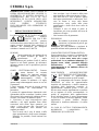 2
2
-
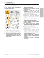 3
3
-
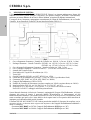 4
4
-
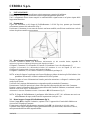 5
5
-
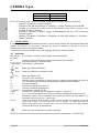 6
6
-
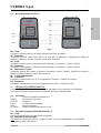 7
7
-
 8
8
-
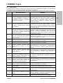 9
9
-
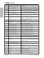 10
10
-
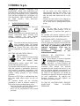 11
11
-
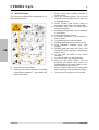 12
12
-
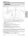 13
13
-
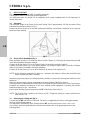 14
14
-
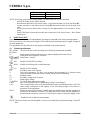 15
15
-
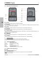 16
16
-
 17
17
-
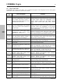 18
18
-
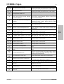 19
19
-
 20
20
-
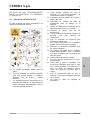 21
21
-
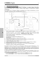 22
22
-
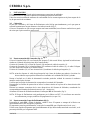 23
23
-
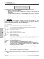 24
24
-
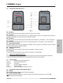 25
25
-
 26
26
-
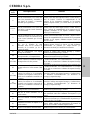 27
27
-
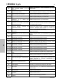 28
28
-
 29
29
-
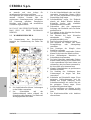 30
30
-
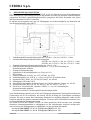 31
31
-
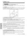 32
32
-
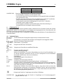 33
33
-
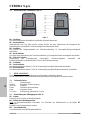 34
34
-
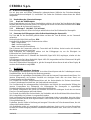 35
35
-
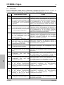 36
36
-
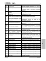 37
37
-
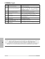 38
38
-
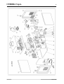 39
39
-
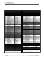 40
40
-
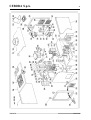 41
41
-
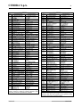 42
42
-
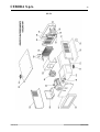 43
43
-
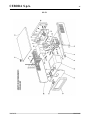 44
44
-
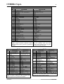 45
45
-
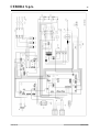 46
46
-
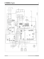 47
47
-
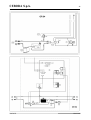 48
48


Cebora 389.80 Sound MIG 5040/T Pulse Robot Manual de usuario
- Tipo
- Manual de usuario
- Este manual también es adecuado para
En otros idiomas
Documentos relacionados
-
Cebora 295.80 Sound MIG 3240/T Pulse Robot Manual de usuario
-
-
-
-
-
Cebora 288 Sound MIG 5040/T Pulse Manual de usuario
-
-
-
-
Cebora 107.01 PROFI-BUS interface Manual de usuario