La página se está cargando...

Istruzioni ed avvertenze per l’installazione e l’uso
Instructions and warnings for installation and use
Instructions et avertissements pour l’installation et l’usage
Anleitungen und Hinweise zu Installation und Einsatz
Instrucciones y advertencias para su instalación y uso
Instruções e advertências para a instalação e utilização
Instrukcje i zalecenia dotyczące instalacji i użytkowania
Centrale per un motore 230 Vac, per serranda o cancello scorrevole
Control unit for a 230 Vac motor, for a rolling shutter or sliding gate
Logique de commande pour un moteur 230 Vca, pour rideaux métalliques ou portail coulissant
Central para un motor 230 Vca, para cierres enrrollables o puerta de corredera
Steuergerät für einen Motor 230V Wechselstrom, für Rollläden oder Schiebetore
Unidade de controlo para motor 230V ca para portas rolantes e portas corrediças
Centrala sterująca do silnika 230 Vac do rolety lub bramy przesuwnej
CT1RS
34567812

IT
2
INDICE
1Avvertenze per la sicurezza pag. 3
3Veriche preliminari pag. 6
7Risoluzione dei problemi pag. 13
2
2.1
2.2
2.3
2.4
Introduzione al prodotto
Descrizione del prodotto
Modelli e caratteristiche tecniche
Descrizione dei collegamenti
Elenco cavi necessari
pag. 5
pag. 5
pag. 5
pag. 5
pag. 6
4
4.1
4.2
4.3
4.4
4.5
4.6
Installazione del prodotto
Collegamenti elettrici
Tabella dei collegamenti
Tabella DIP
Tabella TRIMMER
Legenda funzionamento della centrale
Selezione della modalità di funzionamento - DIP8
pag. 7
pag. 7
pag. 8
pag. 8
pag. 8
pag. 9
pag. 9
5
5.1
5.2
5.3
5.4
5.5
5.6
5.7
5.8
5.9
5.10
Funzioni su serrande
Apprendimento della corsa
Apprendimento dei trasmettitori
Funzione uomo presente di servizio
Funzione DIP1
Funzione DIP2
Funzione DIP3
Funzione DIP4
Funzione DIP5
Funzione DIP6
Funzione DIP7
pag. 9
pag. 9
pag. 9
pag. 10
pag. 10
pag. 10
pag. 10
pag. 11
pag. 11
pag. 11
pag. 11
6
6.1
6.2
6.3
6.4
6.5
6.6
6.7
6.8
6.9
6.10
Funzioni su scorrevoli
Apprendimento della corsa
Apprendimento dei trasmettitori
Funzione uomo presente di servizio
Funzione DIP1
Funzione DIP2
Funzione DIP3
Funzione DIP4
Funzione DIP5
Funzione DIP6
Funzione DIP7
pag. 11
pag. 11
pag. 11
pag. 11
pag. 12
pag. 12
pag. 12
pag. 12
pag. 12
pag. 12
pag. 12
8.1
8.2
Collaudo e messa in servizio dell’automazione
Collaudo
Messa in servizio
8pag. 13
pag. 13
pag. 13

3
IT
1 - AVVERTENZE PER LA SICUREZZA
ISTRUZIONI ORIGINALI – importanti istruzio-
ni di sicurezza. Seguire tutte le istruzioni per-
chè una scorretta installazione può portare a
lesioni gravi! Conservare queste istruzioni.
Leggere attentamente le istruzioni prima di ese-
guire l’installazione.
La progettazione e la fabbricazione dei di-
spositivi che compongono il prodotto e le in-
formazioni contenute nel presente manuale
rispettano le normative vigenti sulla sicurez-
za. Ciò nonostante un’installazione e una pro-
grammazione errata possono causare gravi
ferite alle persone che eseguono il lavoro e
a quelle che useranno l’impianto. Per questo
motivo, durante l’installazione, è importante
seguire attentamente tutte le istruzioni ripor-
tate in questo manuale.
Non procedere con l’installazione se si hanno dub-
bi di qualunque natura e richiedere eventuali chia-
rimenti al Servizio Assistenza Key Automation.
Per la legislazione Europea la realizzazione
di una porta automatica o un cancello auto-
matico deve rispettare le norme previste dalla
Direttiva 2006/42/CE (Direttiva Macchine) e in
particolare, le norme EN 12453; EN 12635 e
EN 13241-1, che consentono di dichiarare la
conformità dell’automazione.
In considerazione di ciò, il collegamento deniti-
vo dell’automatismo alla rete elettrica, il collaudo
dell’impianto, la sua messa in servizio e la ma-
nutenzione periodica devono essere eseguiti da
personale qualicato ed esperto, rispettando le
istruzioni riportate nel riquadro “Collaudo e mes-
sa in servizio dell’automazione”.
Inoltre, egli dovrà farsi carico di stabilire anche
le prove previste in funzione dei rischi presenti e
dovrà vericare il rispetto di quanto previsto da
leggi, normative e regolamenti: in particolare, il
rispetto di tutti i requisiti della norma EN 12453
che stabilisce i metodi di prova per la verica de-
gli automatismi per porte e cancelli.
Prima di iniziare l’installazione, eettuare le
seguenti analisi e veriche:
vericare che i singoli dispositivi destinati all’au-
tomazione siano adatti all’impianto da realizza-
re. Al riguardo, controllare con particolare atten-
zione i dati riportati nel capitolo “Caratteristiche
tecniche”. Non eettuare l’installazione se anche
uno solo di questi dispositivi non è adatto all’uso;
vericare se i dispositivi acquistati sono sucien-
ti a garantire la sicurezza dell’impianto e la sua
funzionalità;
eseguire l’analisi dei rischi che deve comprendere
anche l’elenco dei requisiti essenziali di sicurez-
za riportati nell’Allegato I della Direttiva Macchine,
indicando le soluzioni adottate. L’analisi dei rischi
è uno dei documenti che costituiscono il fascico-
lo tecnico dell’automazione. Questo dev’essere
compilato da un installatore professionista.
Considerando le situazioni di rischio che pos-
sono vericarsi durante le fasi di installazione e
di uso del prodotto è necessario installare l’au-
tomazione osservando le seguenti avvertenze:
non eseguire modiche su nessuna parte dell’au-
tomatismo se non quelle previste nel presente
manuale. Operazioni di questo tipo possono solo
causare malfunzionamenti. Il costruttore declina
ogni responsabilità per danni derivanti da prodot-
ti modicati arbitrariamente;
evitare che le parti dei componenti dell’automa-
zione possano venire immerse in acqua o in altre
sostanze liquide. Durante l’installazione evitare
che i liquidi possano penetrare all’interno dei di-
spositivi presenti;
se il cavo di alimentazione risulta danneggiato
esso deve essere sostituito dal costruttore o dal
suo servizio di assistenza tecnica o comunque
da una persona con qualica similare in modo da
prevenire ogni rischio;
se sostanze liquide penetrano all’interno delle
parti dei componenti dell’automazione, scolle-
gare immediatamente l’alimentazione elettrica e
rivolgersi al Servizio Assistenza Key Automation.
L’utilizzo dell’automazione in tali condizioni può
causare situazioni di pericolo;
non mettere i vari componenti dell’automazione
vicino a fonti di calore né esporli a amme libere.
Tali azioni possono danneggiarli ed essere cau-
sa di malfunzionamenti, incendio o situazioni di
pericolo;
L’unità deve essere scollegata dalla fonte di ali-
mentazione durante la pulizia, la manutenzione
e la sostituzione di componenti. Se il dispositivo
di sconnessione non è a vista, apporre un cartel-
lo con la seguente dicitura: “MANUTENZIONE IN
CORSO”:
ATTENZIONE ! ATTENZIONE !
ATTENZIONE !

IT
4
ATTENZIONE !
ATTENZIONE !
nel caso di rilevamento ostacolo durante la ma-
novra di chiusura, il portone inverte la corsa libe-
rando l’ostacolo no ad aprirsi completamente;
installare l’attuatore per il rilascio manuale a
un’altezza massima di 1,8m. Se removibile, l’at-
tuatore deve essere riposto nelle immediate vici-
nanze della porta;
installare qualsiasi comando sso a un’altezza
minima di 1,5m e in vista sulla porta, ma lontano
da parti in movimento;
dopo l’installazione, accertarsi che il meccani-
smo sia regolato correttamente e che l’aziona-
mento inverta il senso di marcia, oppure che sia
possibile rimuovere dal pavimento un oggetto di
50 mm di altezza, quando la porta entra a contat-
to con l’oggetto (per meccanismi di azionamento
con sistema integrato di protezione anti-intrappo-
lamento attivato dal contatto con il bordo inferiore
della porta);
dopo l’installazione, vericare che nessun pun-
to della porta sporga sul marciapiede o sulla via
pubblica;
qualora il dispositivo sia dotato di pulsate sepa-
rato di arresto, tale pulsante dovrà essere chiara-
mente identicabile.
Esaminare periodicamente l’impianto per ve-
ricare la presenza di sbilanciamenti e segni
di usura meccanica, danneggiamento di cavi,
molle, parti di sostegno.
Non utilizzare se è necessaria riparazione o
regolazione.
Il materiale dell’imballaggio di tutti i compo-
nenti dell’automazione deve essere smaltito
nel pieno rispetto della normativa presente a
livello locale.
Key Automation si riserva il diritto di modi-
care le presenti istruzioni qualora necessario,
queste e/o versione superiore si possono tro-
vare sul sito www.keyautomation.it
tutti i dispositivi devono essere collegati ad una
linea di alimentazione elettrica dotata di messa a
terra di sicurezza;
il prodotto non può essere considerato un eca-
ce sistema di protezione contro l’intrusione. Se
desiderate proteggervi ecacemente, è neces-
sario integrare l’automazione con altri dispositivi;
il prodotto può essere utilizzato esclusivamente
dopo che è stata eettuata la “messa in servizio”
dell’automazione, come previsto nel paragrafo
“Collaudo e messa in servizio dell’automazione”;
prevedere nella rete di alimentazione dell’impian-
to un dispositivo di disconnessione con una di-
stanza di apertura dei contatti che consenta la
disconnessione completa nelle condizioni dettate
dalla categoria di sovratensione III;
per la connessione di tubi rigidi e essibili o pas-
sacavi utilizzare raccordi conformi al grado di
protezione IP55 o superiore;
l’impianto elettrico a monte dell’automazione
deve rispondere alle vigenti normative ed essere
eseguito a regola d’arte;
l’apparecchio può essere utilizzato da bambini di
età non inferiore a 8 anni e da persone con ridot-
te capacità siche, sensoriali o mentali, o prive di
esperienza o della necessaria consapevolezza,
purché sotto sorveglianza oppure dopo che le
stesse abbiano ricevuto istruzioni relative all’uso
sicuro dell’apparecchio e alla comprensione dei
pericoli ad esso inerenti;
prima di avviare l’automazione assicurarsi che le
persone non siano nelle immediate vicinanze;
prima di procedere a qualsiasi operazione di puli-
zia e manutenzione dell’automazione eseguire la
disconnessione dalla rete elettrica;
fare particolare attenzione per evitare lo schiac-
ciamento tra la parte guidata ed eventuali ele-
menti ssi circostanti;
i bambini devono essere sorvegliati per sincerar-
si che non giochino con l’apparecchio;
il meccanismo di azionamento non deve essere
usato per porte aventi un raggio di apertura su-
periore a 50 mm, oppure aventi bordi o sporgen-
ze su cui una persona potrebbe salire o ai quali
aggrapparsi;
l’apparecchio non può essere utilizzato con una
porta guidata che incorpora una porta pedonale;

5
IT
2 - INTRODUZIONE AL PRODOTTO
2.1 - Descrizione del prodotto
2.2 - Modelli e caratteristiche tecniche
Centrale di comando per un motore in corrente alternata con
regolazione di coppia se scorrevole e tempo di cortesia se serranda,
ingresso per necorsa o pulsanti Apre/Chiude selezionabili, ingressi
per fotocellule, pulsante stop, passo passo, con radio modulare.
Questa centrale di comando è stata ideata per l’automazione di
serrande, tapparelle e cancelli scorrevoli.
CODICE DESCRIZIONE
900CT1RS Centrale 230V per un motore per serranda o cancello scorrevole con ricevitore radio incorporato
DATI TECNICI CT1RS
Alimentazione 230 Vac (±10%) 50-60 Hz
Potenza nominale 700 W
Uscita alimentazione accessori 24 Vac 150 mA non stabilizzata
Uscita lampeggiante 230 Vac 60 W
Tempo di pausa da 1 a 125 sec.
Temperatura di esercizio -20 + 55 °C
Frequenza ricevitore 433.92 MHz
Codice ricezione codice sso/rolling code
N° max trasmettitori memorizzabili 120 (Utilizzando 2 canali per ogni trasmettitore)
Protezione uscite 230Vac Fusibile rapido da 5A (F1)
Grado di protezione IP54
Utilizzo in atmosfera particolarmente acida, salina o esplosiva No
Dimensioni (L-P-H) 200-160-90 mm
Peso 0,95 kg
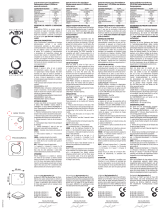
2.3 - Descrizione dei collegamenti
L
+P
OUT
+24V
-24V
PH1
COM
SEQSTEP BY STEP
COMMON
COMMON
STOP
PHOTOCELL 1
NEGATIVE
POSITIVE
MOTOR
L1
L2
COM
COM
SHIELD
ANT
M3
STOP
OPEN
CLOSE
DIP 8= OFF ►OPEN
DIP8=ON►LIMIT SWITCH OPEN
DIP 8= OFF ►CLOSE
DIP8=ON ►LIMIT SWITCH CLOSE
N
L1
L2
COM
FLASH
FLASH
N
L
M
1 12 2 3 4
TX RX
NC
PHOTOCELL
GND
_GND
_
12/24
AC/DC 12/24
AC/DCCOM OUT
TR1
P1 P2
TR2
DL6
34567812
4
6
5
3
2
87
1
1

IT
6
2.4 - Elenco cavi necessari
Nell’impianto tipico i cavi necessari per i collegamenti dei vari
dispositivi sono indicati nella tabella elenco cavi.
I cavi utilizzati devono essere adatti al tipo di installazione; ad
esempio si consiglia un cavo tipo H03VV-F per posa in ambienti
interni oppure H05RN-F/H07RN-F se posato all’esterno.
Prima di installare il prodotto vericare e controllare i seguenti punti:
Controllare che la porta sia adatta ad essere automatizzata;
il peso e la dimensione della porta deve rientrare nei limiti d’impiego
specicati per l’automazione su cui viene installato il prodotto;
controllare la presenza e la solidità degli arresti meccanici di
sicurezza della porta;
vericare che la zona di ssaggio del prodotto non sia soggetta ad
allagamenti;
condizioni di elevata acidità o salinità o la vicinanza a fonti di calore
potrebbero causare malfunzionamenti del prodotto;
in caso di condizioni climatiche estreme (per esempio in presenza
di neve, ghiaccio, elevata escursione termica, temperature elevate)
gli attriti potrebbero aumentare e quindi la forza necessaria per la
movimentazione e lo spunto iniziale potrebbe essere superiori a
quella necessaria in condizioni normali;
controllare che la movimentazione manuale della porta sia uida
e priva di zone di maggiore attrito o vi sia rischio di deragliamento
della stessa;
controllare che la porta sia in equilibrio e rimanga quindi ferma se
lasciata in qualsiasi posizione;
vericare che la linea elettrica a cui sarà collegato il prodotto sia
provvista di opportuna messa a terra di sicurezza e protetta da un
dispositivo magnetotermico e dierenziale;
prevedere nella rete di alimentazione dell'impianto un dispositivo
di disconnessione con una distanza di apertura dei contatti che
consenta la disconnessione completa nelle condizioni dettate dalla
categoria di sovratensione III;
vericare che tutto il materiale utilizzato per l’installazione sia
conforme alle normative vigenti.
* Se il cavo di alimentazione supera i 20 m di lunghezza occorre utilizzare un cavo con sezione maggiore (3x2,5 mm2) ed è necessario
installare una messa a terra di sicurezza in prossimità dell’automazione
SPECIFICHE TECNICHE CAVI ELETTRICI
Collegamento cavo limite massimo consentito
Linea elettrica alimentazione centrale comando 1 x cavo 3 x 1,5 mm220 m *
Lampeggiante 1 x cavo 2 x 0,5 mm220 m
Antenna 1 x cavo tipo RG58 20 m (consigliato < 5 m)
Fotocellule trasmettitore 1 x cavo 2 x 0,5 mm220 m
Fotocellule ricevitore 1 x cavo 4 x 0,5 mm220 m
Bordo sensibile 1 x cavo 2 x 0,5 mm220 m
Selettore a chiave 1 x cavo 4 x 0,5 mm220 m
3 - VERIFICHE PRELIMINARI
1Fusibile rapido da 5A (F1)
3
STOP Ingresso stop (N.C.) / bordo 8k2
2
Terra di sicurezza COM Comune per ingressi
LFase alimentazione 230Vac OPEN Ingresso open (N.O.) / necorsa open (N.C.)
NNeutro alimentazione 230Vac CLOSE ingresso close (N.O.) / necorsa close (N.C.)
L1 Morsetto close del motore SEQ Pulsante SBS (N.O.)
L2 Morsetto open del motore COM Comune per ingressi
COM Comune del motore
4
Shield Calza
FLASH Lampeggiante / luce di cortesia 230Vac ANT Antenna
3
+P.OUT spia cancello aperto / test fotodispositivi 5DIP-Switch DIP-Switch
+24V Uscita 24Vdc non regolati 6Trimmer Aumenta ruotando in senso orario
-24V Uscita 24Vdc non regolati 7Pulsanti P1 e P2
PH1 Ingresso fotocellula (NC) 8LED Led di segnalazione tricolor

7
IT
L
+P
OUT
+24V
-24V
PH1
COM
SEQSTEP BY STEP
COMMON
COMMON
STOP
PHOTOCELL 1
NEGATIVE
POSITIVE
MOTOR
L1
L2
COM
COM
SHIELD
ANT
M3
STOP
OPEN
CLOSE
DIP 8= OFF ►OPEN
DIP8=ON►LIMIT SWITCH OPEN
DIP 8= OFF ►CLOSE
DIP8=ON ►LIMIT SWITCH CLOSE
N
L1
L2
COM
FLASH
FLASH
N
L
M
1 12 2 3 4
TX RX
NC
PHOTOCELL
GND
_GND
_
12/24
AC/DC 12/24
AC/DCCOM OUT
TR1
P1 P2
TR2
DL6
34567812
+P
OUT
+24V
-24V
PH1
COM
SEQSTEP BY STEP
COMMON
COMMON
STOP
PHOTOCELL 1
NEGATIVE
POSITIVE
PHOTOTEST
COM
STOP
OPEN
CLOSE
OPEN
CLOSE
1 12 2 3 4
TX RX
NC
PHOTOCELL
GND
_GND
_
12/24
AC/DC 12/24
AC/DCCOM OUT
4.1 - Collegamenti elettrici
4 - INSTALLAZIONE DEL PRODOTTO
DIP4 = ON ► FOTOTEST
COLLEGAMENTO CON
TEST DELLE FOTOCELLULE

IT
8
4.3 - Tabella DIP-Switch
4.2 - Tabella dei collegamenti
DIP Funzione OFF ON
1Richiusura automatica Non Abilitata Abilitata
2Funzionamento SEQ (SBS) Passo - Passo Apri - Chiudi
3Condominiale Non Abilitata Abilitata
4Output P.OUT Spia Test sicurezze
5Input STOP STOP (N.C.) Safety (8k2)
6Output FLASH Lampeggiante Cortesia
7Uomo presente (se SERRANDA) Non Abilitato Abilitato
7Velocità rallentamento (se SCORREVOLE) Bassa Alta
8Modalità SERRANDA SCORREVOLE
COLLEGAMENTI MORSETTIERA 1
Terra di sicurezza
L Fase alimentazione 230Vac 50-60 Hz
N Neutro alimentazione 230Vac 50-60 Hz
L1 Fase motore chiude
L2 Fase motore apre
COM Comune motore
FLASH Lampeggiante / luce di cortesia 230Vac
COLLEGAMENTI MORSETTIERA 2
+P OUT Uscita spia cancello aperto o Uscita test fotodispositivi (Impostare DIP4)
+24 V Positivo uscita 24Vdc non regolati
-24 V Negativo uscita 24Vdc non regolati
PH1 Fotocellule (chiusura) contatto NC tra PH1 e COM. La fotocellula interviene in qualsiasi momento durante la chiusura
dell’automazione provocando l’immediato blocco del moto invertendo il senso di marcia
STOP
Se DIP5 = OFF ► Ingresso STOP (NC)
Se DIP5 = ON ► Ingresso 8K2 Bordo di sicurezza:
8K2 interviene in apertura e chiusura con breve inversione del moto
COM Comune per ingressi PH1, STOP, SBS, OPEN, CLOSE (GND)
OPEN
Comando APERTURA contatto NA tra OPEN e COM
Contatto per la funzione UOMO PRESENTE. Il cancello APRE nchè è premuto il contatto
Con DIP8 = ON ► necorsa apertura
CLOSE
Comando CHIUSURA contatto NA tra CLOSE e COM
Contatto per la funzione UOMO PRESENTE. Il cancello CHIUDE nchè è premuto il contatto
Con DIP8 = ON ► necorsa chiusura
SEQ Comando PASSO PASSO contatto NA tra SBS e COM
Comando Apre/Stop/Chiude/Stop
COM Comune per ingressi PH1, STOP, SBS, OPEN, CLOSE
M3 Morsetto per antenna / GND
4.4 - Tabella TRIMMER
PULSANTE Funzione
TR1 Tempo di Pausa 1 - 125 Sec.
TR2 Forza motore (se SCORREVOLE) Tempo cortesia 10 - 300 Sec. (se SERRANDA)

9
IT
N.B: Non è possibile accedere al menu di congurazione con l’automazione in movimento.
É INDISPENSABILE CHE L’AUTOMAZIONE SIA CHIUSA!
STATO LED TASTI CENTRALE TRASMETTITORE
2 s LAMPEGGIO
LENTO
1 s LAMPEGGIO
VELOCE
0,5 s LAMPEGGIO
MOLTO VELOCE
PREMERE
P1 P2
TENERE PREMUTO
P2
3s
P1
3s
4.5 - Legenda funzionamento della centrale
5.2 - Apprendimento dei trasmettitori
APPRENDIMENTO FUNZIONE PASSO PASSO:
Tenere premuto P2 no a lampeggio arancio lento del
led DL6, rilasciare. Attivare il trasmettitore da apprendere
no a quando il led DL6 diventa verde.
(Led DL6 arancione errore di ricezione, Led DL6 rosso
memoria piena - 250 pulsanti).
La funzione SBS non funziona se DIP8=OFF e DIP7=ON. P2
3s LAMPEGGIO
LENTO
ARANCIONE
2 s
ACCESO
VERDE
3s
CANCELLAZIONE SINGOLO PULSANTE:
Tenere premuto P2 no a lampeggio arancio lento del
led DL6, non rilasciare, attendere lampeggio veloce, non
rilasciare, attendere lampeggio velocissimo. Attivare il
pulsante da cancellare no a quando il led DL6 diventa
verde (se arancione errore di ricezione)
LAMPEGGIO
VELOCE
ARANCIONE
1 s
LAMPEGGIO
MOLTO VELOCE
ARANCIONE
0,5 s
P2
3s LAMPEGGIO
LENTO
ARANCIONE
2 s
ACCESO
VERDE
3s
CANCELLAZIONE TOTALE TRASMETTITORI:
Accendere l’apparecchiatura tenendo premuto P2 no
a lampeggio arancio veloce del led DL6, non rilasciare,
attendere lampeggio verde. Tutti i trasmettitori cancellati.
LAMPEGGIO
LENTO
ARANCIONE
2 s
LAMPEGGIO
VELOCE
ARANCIONE
1 s
P2
3s LAMPEGGIO
LENTO
VERDE
2 s
Dopo una cancellazione totale dei trasmettitori, il primo trasmettitore
appreso ssa la modalità Rolling Code o Codice Fisso per tutti gli altri trasmettitori.
4.6 - Selezione modalità di funzionamento - DIP8
MODALITÀ DI FUNZIONAMENTO OFF ON
Impostare su ON per funzionamento su motore SCORREVOLE o impostare su OFF per
funzionamento su SERRANDA SERRANDA SCORREVOLE
5 - FUNZIONI PER SERRANDE
5.1 - Apprendimento della corsa
L’operazione va fatta da serranda CHIUSA. Tenere
premuto P1 no a lampeggio rosso del led DL6. Rilasciare
P1. A serranda CHIUSA tenere premuto il tasto P2 per far
muovere il motore in apertura. Rilasciare P2 a battuta
in posizione aperta. Aspettare che DL6 diventi verde.
Tenere premuto il tasto P2 per far muovere il motore in
chiusura. Rilasciare P2 a battuta in posizione chiusa. P1
3s LAMPEGGIO
LENTO
ROSSO
2 s
ACCESO
ROSSO
P2
3s
P2
3s

IT
10
5.4 - Funzione DIP1
CHIUSURA AUTOMATICA OFF ON
Se abilitato dopo l’apertura completa rimane aperto per un tempo impostato con TR1
da 1 Sec a 120 Sec. NON ABILITATA ABILITATA
5.5 - Funzione DIP2
STEPBYSTEP OFF ON
Per serranda impostare su OFF PASSO-PASSO APRI-CHIUDI
5.6 - Funzione DIP3
FUNZIONE CONDOMINIALE OFF ON
Se impostata su ON il comando SBS solo APRE. NON ABILITATA ABILITATA
5.7 - Funzione DIP4
OUTPUT P.OUT 24Vdc OFF ON
SE IMPOSTATO SU OFF SI COLLEGA UNA SPIA 24V:
- Lampeggia lento se il motore è in movimento di apertura.
- Lampeggia veloce se il motore è in movimento di chiusura.
- Luce ssa accesa se il motore è fermo e non si è in chiuso.
SE IMPOSTATO SU ON:
Esegue il test della fotocellula
SPIA CANCELLO
APERTO FOTOTEST
5.9 - Funzione DIP6
OUTPUT FLASH OFF ON
Se impostato su OFF allora l’uscita lampeggia durante il moto del motore, si spegne
circa 5 sec dopo lo spegnimento del motore.
Se impostato su ON l’uscita si attiva con il motore e rimane attivo per un tempo
impostato da TR2.
LAMPEGGIANTE LUCE DI
CORTESIA
5.8 - Funzione DIP5
INPUT STOP OFF ON
Se impostato su OFF ► Ingresso STOP (NC)
Se impostato su ON ► Ingresso di sicurezza bordo 8K2 STOP
(NC) SAFETY
(8K2)
5.3 - Funzione uomo presente
Premere contemporaneamente P1 e P2 no a quando
il led DL6 diventa rosso. P1 apre uomo presente, P2
chiude uomo presente. Premere contemporaneamente
P1 e P2 per uscire dalla modalità. ACCESO
ROSSO
P1 + P2
3s
P1
3s
P2
3s
P1 + P2
3s

11
IT
6 - FUNZIONI PER SCORREVOLI
6.1 - Apprendimento della corsa e della funzione APERTURA PARZIALE
L’operazione va fatta da cancello CHIUSO. Tenere
premuto P1 no a lampeggio rosso del led DL6. Rilasciare
P1. Premere e rilasciare P2 inizia apertura veloce,
premere e rilasciare P2 inizia rallentamento, il motore si
ferma sul necorsa in apertura. Dopo 2 sec inizia chiusura
veloce, premere e rilasciare P2 inizia rallentamento, il
motore si ferma sul necorsa in chiusura. Dopo 2 sec
inizia APERTURA PARZIALE, premere e rilasciare P2
ferma apertura parziale. Dopo 2 sec inizia chiusura no a
necorsa in chiusura. La velocità del motore è determinata
dal Trimmer 2, anche in apprendimento, quindi prima
impostare TR2 e poi fare l’apprendimento.
LAMPEGGIO
LENTO
ROSSO
2 s
P1
3s
P2 P2
2 Sec.
P2
2 Sec.
P2
2 Sec.
6.3 - Funzione uomo presente
Premere contemporaneamente P1 e P2 no a quando
il led DL6 diventa rosso. P1 apre uomo presente, P2
chiude uomo presente. Premere contemporaneamente
P1 e P2 per uscire dalla modalità. ACCESO
ROSSO
P1 + P2
3s
P1
3s
P2
3s
P1 + P2
3s
5.10 - Funzione DIP7
UOMO PRESENTE OFF ON
Il comando OPEN e il comando CLOSE aprono nche si tiene premuto.
Il comando SBS viene ignorato, anche da trasmettitore. NON ABILITATO ABILITATO
6.2 - Apprendimento dei trasmettitori
Dopo una cancellazione totale dei trasmettitori, il primo trasmettitore
appreso ssa la modalità Rolling Code o Codice Fisso per tutti gli
altri trasmettitori.
La funzione SBS si comporterà in base ai settaggi dei DIP2 e DIP3.
La funzione PARZIALE è disponibile sono con il trasmettitore.
APPRENDIMENTO FUNZIONE PASSO PASSO:
Tenere premuto P2 no a lampeggio arancio lento del
led DL6, rilasciare. Attivare il trasmettitore da apprendere
no a quando il led DL6 diventa verde.
(Led DL6 arancione errore di ricezione, Led DL6 rosso
memoria piena - 250 pulsanti).
La funzione SBS non funziona se DIP8=OFF e DIP7=ON. P2
3s LAMPEGGIO
LENTO
ARANCIONE
2 s
ACCESO
VERDE
3s
APPRENDIMENTO FUNZIONE PARZIALE: Tenere
premuto P2 no a lampeggio arancio lento del led DL6,
non rilasciare, attendere lampeggio veloce. Attivare il
trasmettitore da apprendere no a quando il led DL6
diventa verde. (led DL6 arancione errore di ricezione, led
DL6 rosso memoria piena)
LAMPEGGIO
LENTO
ARANCIONE
2 s
LAMPEGGIO
VELOCE
ARANCIONE
1 s
P2
3s ACCESO
VERDE
3s
CANCELLAZIONE SINGOLO PULSANTE:
Tenere premuto P2 no a lampeggio arancio lento del
led DL6, non rilasciare, attendere lampeggio veloce, non
rilasciare, attendere lampeggio velocissimo. Attivare il
pulsante da cancellare no a quando il led DL6 diventa
verde (se arancione errore di ricezione)
LAMPEGGIO
VELOCE
ARANCIONE
1 s
LAMPEGGIO
MOLTO VELOCE
ARANCIONE
0,5 s
P2
3s LAMPEGGIO
LENTO
ARANCIONE
2 s
ACCESO
VERDE
3s
CANCELLAZIONE TOTALE TRASMETTITORI:
Accendere l’apparecchiatura tenendo premuto P2 no
a lampeggio arancio veloce del led DL6, non rilasciare,
attendere lampeggio verde. Tutti i trasmettitori cancellati.
LAMPEGGIO
LENTO
ARANCIONE
2 s
LAMPEGGIO
VELOCE
ARANCIONE
1 s
P2
3s LAMPEGGIO
LENTO
VERDE
2 s

IT
12
6.5 - Funzione DIP2
STEPBYSTEP La funzione SBS è subordinata al settaggio del DIP3. OFF ON
La funzione SEQ è l’equivalente della funzione SBS. Se DIP 2=OFF allora il comando
SBS esegue: apre-stop-chiude-stop-apre. Se DIP2=ON allora il comando PP esegue:
apre-chiude-apre. PASSO-PASSO APRI-CHIUDI
6.6 - Funzione DIP3
FUNZIONE CONDOMINIALE OFF ON
Un comando SBS di apertura porta il cancello in totale apertura, nessun altro comando
viene considerato (ad eccezione del comando di STOP che blocca l’automazione). Un
comando SBS in chiusura si comporta normalmente: se DIP2 è impostato su OFF esegue
il comando STOP - APRI TUTTO, se DIP2 è impostato su ON esegue il comando APRI
TUTTO.
NON
ABILITATA ABILITATA
6.7 - Funzione DIP4
OUTPUT P.OUT 24Vdc OFF ON
SE IMPOSTATO SU OFF SI COLLEGA UNA SPIA 24V:
- Lampeggia lento se il motore è in movimento di apertura.
- Lampeggia veloce se il motore è in movimento di chiusura.
- Luce ssa accesa se il motore è fermo e non si è in chiuso.
SE IMPOSTATO SU ON:
Esegue il test della fotocellula
SPIA CANCELLO
APERTO FOTOTEST
6.8 - Funzione DIP5
INPUT STOP OFF ON
Se impostato su OFF ► Ingresso STOP (NC)
Se impostato su ON ► Ingresso di sicurezza bordo 8K2 STOP
(NC) SAFETY
(8K2)
6.9 - Funzione DIP6
OUTPUT FLASH OFF ON
Se impostato su OFF lampeggia durante il movimento.
Se impostato su ON rimane acceso durante il movimento e i successivi 10s. LAMPEGGIANTE LUCE DI
CORTESIA
6.10 - Funzione DIP7
VEL. RALLENTAMENTO OFF ON
Determina la velocità di rallentamento. BASSA ALTA
6.4 - Funzione DIP1
CHIUSURA AUTOMATICA OFF ON
Se abilitato dopo l’apertura completa rimane aperto per un tempo impostato con TR1
da 1 Sec a 120 Sec. NON ABILITATA ABILITATA

DESCRIZIONE INDICAZIONE LAMPEGGIANTE
E LED CENTRALE
Errore eeprom. Non è stata rilevata nessuna eeprom o schedina MEM. 1 lampeggio rosso DL6
e FLASH (o cortesia)
Procedura apprendimento corse fallita 2 lampeggi rossi DL6
e FLASH (o cortesia)
Test sicurezze fallito 3 lampeggi rossi DL6
e FLASH (o cortesia)
Entrambi i necorsa aperti 4 lampeggi rossi DL6
e FLASH (o cortesia)
7 - RISOLUZIONE DEI PROBLEMI
13
IT
8 - COLLAUDO E MESSA IN SERVIZIO DELL’AUTOMAZIONE
Il collaudo dell impianto va eseguito da un tecnico qualicato che
deve eettuare le prove richieste dalla normativa di riferimento
in funzione dei rischi presenti, vericando il rispetto di quanto
Tutti i componenti dell’impianto devono essere collaudati seguendo
le procedure indicate nei rispettivi manuali di istruzioni;
controllare che siano rispettate le indicazioni del
Capitolo 1 - Avvertenze per la sicurezza;
controllare che la porta si possa muovere liberamente una volta
sbloccata l’automazione e che sia in equilibrio e rimanga quindi
ferma se lasciata in qualsiasi posizione;
A seguito del positivo collaudo di tutti (e non solo di alcuni) i
dispositivi dell’impianto si può procedere con la messa in servizio;
è necessario realizzare e conservare per 10 anni il fascicolo
tecnico dell’impianto che dovrà contenere lo schema elettrico,
il disegno o foto dell’impianto, l’analisi dei rischi e le soluzioni
adottate, la dichiarazione di conformità del fabbricante di tutti
i dispositivi collegati, il manuale istruzioni di ogni dispositivo e il
piano di manutenzione dell’impianto;
ssare sulla porta una targa indicante i dati dell’automazione,
il nome del responsabile della messa in servizio, il numero di
matricola e l’anno di costruzione, il marchio CE;
ssare una targa che indichi le operazioni necessarie per sbloccare
manualmente l’impianto;
previsto dalle normative, in particolare la norma EN12445 che
indica i metodi di prova per gli automatismi per porte e cancelli.
controllare il corretto funzionamento di tutti i dispositivi collegati
(fotocellule, bordi sensibili, pulsanti di emergenza, altro) eettuando
delle prove di apertura, chiusura e arresto della porta tramite i
dispositivi di comando collegati (trasmettitori, pulsanti, selettori);
eettuare le misurazioni della forza d’impatto come previsto dalla
normativa EN12445 regolando le funzioni di velocità, forza motore
e rallentamenti della centrale nel caso in cui le misurazioni non
diano i risultati desiderati no a trovare il giusto settaggio.
realizzare e consegnare all’utilizzatore nale la dichiarazione di
conformità, le istruzioni e avvertenze d’uso per l’utilizzatore nale
e il piano di manutenzione dell’impianto;
accertarsi che l’utilizzatore abbia compreso il corretto funzionamento
automatico, manuale e di emergenza dell’automazione;
informare anche in forma scritta l’utilizzatore nale sui pericoli e
rischi ancora presenti;
8.1 - Collaudo
8.2 - Messa in servizio
ATTENZIONE !
Dopo la rilevazione di un ostacolo, la porta si ferma in apertura e
viene esclusa la chiusura automatica; per riprendere il movimento
bisogna premere il tasto di comando o usare il trasmettitore.

14
EN
TABLE OF CONTENTS
1Safety warnings Page 15
3Preliminary checks Page 18
7Troubleshooting Page 25
2
2.1
2.2
2.3
2.4
Product introduction
Product description
Models and technical specications
Description of connections
List of necessary cables
Page 17
Page 17
Page 17
Page 17
Page 18
4
4.1
4.2
4.3
4.4
4.5
4.6
Product installation
Electrical connections
Table of connections
DIP table
TRIMMER table
Legend control unit operation
Selecting the operating mode - DIP8
Page 19
Page 19
Page 20
Page 20
Page 20
Page 21
Page 21
5
5.1
5.2
5.3
5.4
5.5
5.6
5.7
5.8
5.9
5.10
Functions on rolling shutters
Learning of travel stroke
Learning of transmitters
Service man present function
DIP1 Function
DIP2 Function
DIP3 Function
DIP4 Function
DIP5 Function
DIP6 Function
DIP7 Function
Page 21
Page 21
Page 21
Page 22
Page 22
Page 22
Page 22
Page 23
Page 23
Page 23
Page 23
6
6.1
6.2
6.3
6.4
6.5
6.6
6.7
6.8
6.9
6.10
Functions on sliding elements
Learning of travel stroke
Learning of transmitters
Service man present function
DIP1 Function
DIP2 Function
DIP3 Function
DIP4 Function
DIP5 Function
DIP6 Function
DIP7 Function
Page 23
Page 23
Page 23
Page 23
Page 24
Page 24
Page 24
Page 24
Page 24
Page 24
Page 24
8.1
8.2
Testing and commission the automation
Testing
Commissioning
8Page 25
Page 25
Page 25

15
EN
1 - SAFETY WARNINGS
ORIGINAL INSTRUCTIONS - important safety
instructions. Follow the instructions since in-
correct installation can lead to severe inqui-
ry! Save these instructions.
Read the instructions carefully before proceeding
with installation.
The design and manufacture of the devices
making up the product and the information in
this manual are compliant with current safe-
ty standards. However, incorrect installation
or programming may cause serious injury to
those working on or using the system. Com-
pliance with the instructions provided here
when installing the product is therefore extre-
mely important.
If in any doubt regarding installation, do not pro-
ceed and contact the Key Automation Technical
Service for clarications.
Under European legislation, an automatic
door or gate system must comply with the
standards envisaged in the Directive 2006/42/
EC (Machinery Directive) and in particular
standards; EN 12453; EN 12635 and EN 13241-
1, which enable declaration of presumed con-
formity of the automation system.
Therefore, nal connection of the automation
system to the electrical mains, system testing,
commissioning and routine maintenance must
be performed by skilled, qualied personnel, in
observance of the instructions in the “Testing and
commissioning the automation system” section.
The aforesaid personnel are also responsible for
the tests required to verify the solutions adopted
according to the risks present, and for ensuring
observance of all legal provisions, standards and
regulations, with particular reference to all requi-
rements of the EN 12445 standard which establi-
shes the test methods for testing door and gate
automation systems.
Before starting installation, perform the fol-
lowing checks and assessments:
ensure that every device used to set up the au-
tomation system is suited to the intended system
overall. For this purpose, pay special attention
to the data provided in the “Technical specica-
tions” section. Do not proceed with installation if
any one of these devices is not suitable for its
intended purpose;
check that the devices purchased are sucient to
guarantee system safety and functionality;
perform a risk assessment, including a list of the
essential safety requirements as envisaged in
Annex I of the Machinery Directive, specifying
the solutions adopted. The risk assessment is
one of the documents included in the automation
system’s technical le. This must be compiled by
a professional installer.
Considering the risk situations that may arise
during installation phases and use of the pro-
duct, the automation system must be installed
in compliance with the following safety precau-
tions:
never make modications to any part of the auto-
mation system other than those specied in this
manual. Operations of this type can only lead to
malfunctions. The manufacturer declines all liabi-
lity for damage caused by unauthorised modica-
tions to products;
if the power cable is damaged, it must be repla-
ced by the manufacturer or its after-sales servi-
ce, or in all cases by a person with similar quali-
cations, to prevent all risks;
do not allow parts of the automation system to be
immersed in water or other liquids. During instal-
lation ensure that no liquids are able to enter the
various devices; should this occur, disconnect the
power supply immediately and contact a Key Au-
tomation Service Centre. Use of the automation
system in these conditions may cause hazards;
never place automation system components
near to sources of heat or expose them to naked
lights. This may damage system components
and cause malfunctions, re or hazards;
The drive shall be disconnected from its power
source during cleaning, maintenance and when
replacing parts. If the disconnect device is not in
a visible location, ax a notice stating: “MAINTE-
NANCE IN PROGRESS”:
connect all devices to an electric power line
equipped with an earthing system;
the product cannot be considered to provide ef-
fective protection against intrusion. If eective
protection is required, the automation system
must be combined with other devices;
ATTENTION !
ATTENTION !
ATTENTION !

16
EN
1,5m and within sight of the door but away from
moving parts;
after installation, ensure that the mechanism is
properly adjusted and that the drive reverses or
the object can be freed when the door contacts a
50mm high object placed on the oor (for drives
incorporating an entrapment protection system
depending on contact with the bottom edge of
the door);
after installation, ensure that parts of the door do
not extend over public footpaths or roads;
when the appliance is provided with a separate
stop button, that stop button shall be unambi-
guously identiable.
Frequently examine the installation for imba-
lance where applicable and signs of wear or
damage to cables, springs and mounting. Do
not use if repair or adjustment is necessary.
The automation system component packa-
ging material must be disposed of in full
observance of current local waste disposal
legislation. Key Automation reserves the
right to amend these instructions if necessa-
ry; they and/or any more recent versions are
available at www.keyautomation.it.
ATTENTION !
ATTENTION !
the product may not be used until the automation
system “commissioning” procedure has been
performed as specied in the “Automation sy-
stem testing and commissioning” section;
the system power supply line must include a cir-
cuit breaker device with a contact gap allowing
complete disconnection in the conditions speci-
ed by class III overvoltage;
use unions with IP55 or higher protection when
connecting hoses, pipes or cable glands;
the electrical system upstream of the automation
system must comply with the relevant regulations
and be constructed to good workmanship stan-
dards;
this appliance can be used by children aged from
8 years and above and persons with reduced
physical, sensory or mental capabilities or lack
of experience and knowledge if they have been
given supervision or instruction concerning use
of the appliance in a safe way and understand
the hazards involved;
before starting the automation system, ensure
that there is no-one in the immediate vicinity;
before proceeding with any cleaning or mainte-
nance work on the automation system, discon-
nect it from the electrical mains;
special care must be taken to avoid crushing
between the part operated by the automation sy-
stem and any xed parts around it;
children must be supervised to ensure that they
do not play with the equipment;
drive is not to be used with doors having openings
exceeding 50mm in diameter or having edges or
protruding parts a person could grip or stand on;
that the drive cannot be used with a driven part
incorporating a wicket door unless the drive can
only be operated with the wicket door in the safe
position;
in the case of detection of an obstacle during its
closing travel, the garage door reverses its tra-
vel direction, releasing the obstacle until it opens
completely;
install the actuating member for the manual re-
lease at a height less than 1,8m. If removable,
the actuating member should be stored in direct
vicinity of the door;
install any xed control at a height of at least

17
EN
2 - INTRODUCTION TO THE PRODUCT
2.1 - Product description
2.2 - Models and technical characteristics
Control unit for an alternating current motor with torque adjustment
if sliding gate and courtesy light time if rolling shutter, input for limit
switch or selectable Open / Close buttons, inputs for photocells,
stop button, step by step, with modular radio. This control unit
has been designed for the automation of various types of rolling
shutters and sliding gates.
CODE DESCRIPTION
900CT1RS 230V control unit for a motor for rolling shutter or sliding gate with built-in radio receiver
TECHNICAL DATA CT1RS
Power supply 230 Vac (±10%) 50-60 Hz
Rated power 700 W
Accessories power outlet 24 Vac 150 mA not stablised
Flashing light output 230 Vac 60 W
Pause time from 1 to 125 sec.
Operating temperature -20 + 55 °C
Received frequency 433.92 MHz
Reception code x code/rolling code
No. max storable transmitters 120 (Using 2 channels for each transmitter)
230Vac outputs protection Rapid fuse 5A (F1)
Protection rating IP54
Use in highly acid, saline or explosive atmosphere No
Dimensions (L-D-H) 200-160-90 mm
Weight 0.95 kg
2.3 - Description of connections
L
+P
OUT
+24V
-24V
PH1
COM
SEQSTEP BY STEP
COMMON
COMMON
STOP
PHOTOCELL 1
NEGATIVE
POSITIVE
MOTOR
L1
L2
COM
COM
SHIELD
ANT
M3
STOP
OPEN
CLOSE
DIP 8= OFF ►OPEN
DIP8=ON►LIMIT SWITCH OPEN
DIP 8= OFF ►CLOSE
DIP8=ON ►LIMIT SWITCH CLOSE
N
L1
L2
COM
FLASH
FLASH
N
L
M
1 12 2 3 4
TX RX
NC
PHOTOCELL
GND
_GND
_
12/24
AC/DC 12/24
AC/DCCOM OUT
TR1
P1 P2
TR2
DL6
34567812
4
6
5
3
2
87
1
1

18
EN
2.4 - List of necessary cables
In the typical system, the cables necessary for the connections of
the various devices are indicated in the cable list table.
The cables used must be suitable for the type of installation; for
example, a cable type H03VV-F is recommended for installation
indoors or H05RN-F/H07RN-F if laid outdoors.
Before installing the product, check and verify the following points:
Make sure that the door is suitable for automation;
the weight and size of the door must be within the operating
limits specied for the automation system in which the product is
installed;
check that the door has rm, eective mechanical safety stops;
make sure that the product xing zone is not subject to ooding;
high acidity or salinity or nearby heat sources might cause the
product to malfunction;
in case of extreme weather conditions (e.g. snow, ice, wide
temperature variations or high temperatures), friction may
increase, causing a corresponding rise in the force needed to
operate the system; the starting torque may therefore exceed that
required in normal conditions;
check that when operated by hand the door moves smoothly
without any areas of greater friction or derailment risk;
check that the door is well balanced and will therefore remain
stationery when released in any position;
check that the electricity supply line to which the product is to be
connected is suitably earthed and protected by an overload and
dierential safety breaker device;
the system power supply line must include a circuit breaker
device with a contact gap allowing complete disconnection in the
conditions specied by class III overvoltage;
ensure that all the material used for installation complies with the
relevant regulatory standards.
* If the power supply cable exceeds 20 m in length, a cable with a larger section (3x2.5 mm2) must be used and a safety earthing must
be installed near the automation
TECHNICAL SPECIFICATIONS OF ELECTRIC CABLES
Connection cable maximum limit permitted
Control unit power supply electrical line 1 x cable 3 x 1.5 mm220 m *
Flashing light 1 x cable 2 x 0.5 mm220 m
Antenna 1 x cable type RG58 20 m (recommended < 5 m)
Transmitter photocells 1 x cable 2 x 0.5 mm220 m
Receiver photocells 1 x cable 4 x 0.5 mm220 m
Sensitive edge 1 x cable 2 x 0.5 mm220 m
Key selector 1 x cable 4 x 0.5 mm220 m
3 - PRELIMINARY CHECKS
1Rapid fuse 5A (F1)
3
STOP Stop input (N.C.) / edge 8k2
2
Safety earth COM Common for inputs
L 230Vac power supply phase OPEN Input open (N.O.) / limit switch open (N.C.)
N 230Vac power supply neutral CLOSE input closed (N.O.) / limit switch close (N.C.)
L1 Motor close terminal SEQ SBS button (N.O.)
L2 Motor open terminal COM Common for inputs
COM Common of motor
4
Shield Sock
FLASH Flashing light / 230Vac courtesy light FRONT Antenna
3
+P.OUT gate open light / photo devices test 5DIP-Switch DIP-Switch
+24V Non-regulated 24Vdc output 6Trimmer Increase rotating clockwise
-24V Non-regulated 24Vdc output 7Buttons P1 and P2
PH1 Photocell input (NC) 8LED Three-colour indicator LED

19
EN
L
+P
OUT
+24V
-24V
PH1
COM
SEQSTEP BY STEP
COMMON
COMMON
STOP
PHOTOCELL 1
NEGATIVE
POSITIVE
MOTOR
L1
L2
COM
COM
SHIELD
ANT
M3
STOP
OPEN
CLOSE
DIP 8= OFF ►OPEN
DIP8=ON►LIMIT SWITCH OPEN
DIP 8= OFF ►CLOSE
DIP8=ON ►LIMIT SWITCH CLOSE
N
L1
L2
COM
FLASH
FLASH
N
L
M
1 12 2 3 4
TX RX
NC
PHOTOCELL
GND
_GND
_
12/24
AC/DC 12/24
AC/DCCOM OUT
TR1
P1 P2
TR2
DL6
34567812
+P
OUT
+24V
-24V
PH1
COM
SEQSTEP BY STEP
COMMON
COMMON
STOP
PHOTOCELL 1
NEGATIVE
POSITIVE
PHOTOTEST
COM
STOP
OPEN
CLOSE
OPEN
CLOSE
1 12 2 3 4
TX RX
NC
PHOTOCELL
GND
_GND
_
12/24
AC/DC 12/24
AC/DCCOM OUT
4.1 - Electrical connections
4 - PRODUCT INSTALLATION
DIP4 = ON ► PHOTO TEST
CONNECTION WITH
PHOTOCELL TESTING

20
EN
4.3 - DIP-Switch Table
4.2 - Table of connections
DIP Function OFF ON
1 Automatic reclosure Not Enabled Enabled
2 SEQ Operation (SBS) Step by Step Open - Close
3 Condominium Not Enabled Enabled
4 Output P.OUT Light Safety devices testing
5 Input STOP STOP (N.C.) Safety (8k2)
6 Output FLASH Flashing light Courtesy light
7 Man present (if ROLLING SHUTTER) Not Enabled Enabled
7 Slowing speed (if SLIDING GATE) Low High
8 Mode ROLLING SHUTTER SLIDING GATE
CONNECTIONS TERMINAL BOARD 1
Safety earth
L Power supply phase 230Vac 50-60 Hz
N Power supply neutral 230Vac 50-60 Hz
L1 Close motor phase
L2 Open motor phase
COM Common motor
FLASH Flashing / 230Vac courtesy light
CONNECTIONS TERMINAL BOARD 2
+P OUT Gate open light output or photo devices test output (Set DIP4)
+24 V Non-regulated 24Vdc output positive
-24 V Non-regulated 24Vdc output negative
PH1 NC contact (closure) photocells between PH1 and COM. The photocell intervenes at any time during closing of the
automation causing immediate stopping of motion, reversing the direction of travel
STOP
If DIP5 = OFF ► Input STOP (NC)
If DIP5 = ON ► Input 8K2 Safety edge:
8K2 intervenes during opening and closing with a brief inversion of motion
COM Common for inputs PH1, STOP, SBS, OPEN, CLOSE (GND)
OPEN
NA contact OPENING command between OPEN and COM
MAN PRESENT function contact. The gate OPENS as long as the contact is being pressed
With DIP8 = ON ► opening limit switch
CLOSE
NA contact CLOSURE command between CLOSE and COM
MAN PRESENT function contact. The gate CLOSES as long as the contact is being pressed
With DIP8 = ON ► closure limit switch
SEQ NA contact STEP-BY-STEP command between SBS and COM
Open/Stop/Close/Stop command
COM Common for inputs PH1, STOP, SBS, OPEN, CLOSE
M3 Terminal for antenna / GND
4.4 - TRIMMER table
BUTTON Function
TR1 Pause Time 1 - 125 Sec.
TR2 Motor force (if SLIDING GATE) Courtesy light time 10 - 300 Sec. (if ROLLING SHUTTER)

21
EN
N.B: It is not possible to access the conguration menu with the automation in motion.
T HE AUTOMATION MUST BE CLOSED!
LED STATUS CONTROL UNIT BUTTONS TRANSMITTER
2 s FLASHING
SLOW
1 s FLASHING
FAST
0.5 s FLASHING
VERY FAST
PRESS
P1 P2
HOLD PRESSED
P2
3s
P1
3s
4.5 - Legend control unit operation
5.2 - Learning of transmitters
STEP-BY-STEP FUNCTION LEARNING:
Press and hold P2 until the DL6 LED slowly ashes
orange, release. Activate the transmitter to undergo
learning until the DL6 LED turns green.
(LED DL6 orange reception error, LED DL6 red memory
full - 250 buttons). The SBS function does not work if
DIP8=OFF and DIP7=ON. P2
3s FLASHING-
SLOW
ORANGE
2 s
ON
GREEN
3s
SINGLE BUTTON CANCELLATION:
Press and hold P2 until the DL6 LED slowly ashes
orange, do not release, wait for rapid ashing, do not
release, wait for very rapid ashing. Activate the button to
be deleted until the DL6 LED turns green (if the reception
error is orange)
FLASHING-
FAST
ORANGE
1 s
FLASHINGVERY
FAST
ORANGE
0.5 s
P2
3s FLASHING-
SLOW
ORANGE
2 s
ON
GREEN
3s
TRANSMITTER TOTAL CANCELLATION:
Turn on the appliance by holding down P2 until the DL6
LED quickly ashes orange, do not release, wait for
green ashing. All transmitters cancelled.
FLASHING-
SLOW
ORANGE
2 s
FLASHING-
FAST
ORANGE
1 s
P2
3s FLASHING-
SLOW
GREEN
2 s
After a total cancellation of the transmitters, the rst taught
transmitter sets the Rolling Code or Fixed Code mode for all the other transmitters.
4.6 - Selection of operating mode - DIP8
OPERATING MODE OFF ON
Set to ON for operation on SLIDING GATE motor or set to OFF for operation on
ROLLING SHUTTER ROLLING
SHUTTER SLIDING GATE
5 - ROLLING SHUTTER FUNCTIONS
5.1 - Learning of stroke
The operation must be performed with the rolling shutter
CLOSED. Keep P1 pressed until the DL6 LED ashes
red. Release P1. With the rolling shutter CLOSED, hold
down the P2 button to make the motor move in opening.
Release P2 in the open position. Wait for DL6 to turn
green. Press and hold the P2 button to make the motor
move in closing. Release P2 in the closed position. P1
3s FLASHING-
SLOW
RED
2 s
ON
RED
P2
3s
P2
3s

22
EN
5.4 - DIP1 function
AUTOMATIC CLOSURE OFF ON
If enabled after complete opening, it remains open for a time set with TR1 from 1 Sec
to 120 Sec. NOT ENABLED ENABLED
5.5 - DIP2 function
STEP-BY-STEP OFF ON
With rolling shutter set to OFF STEP-BY-STEP OPEN-CLOSE
5.6 - DIP3 function
CONDOMINIUM FUNCTION OFF ON
If set to ON the SBS command only OPENS. NOT ENABLED ENABLED
5.7 - DIP4 function
OUTPUT P.OUT 24Vdc OFF ON
IF SET TO OFF, A 24V LIGHT IS CONNECTED:
- It ashes slowly if the motor is in the opening movement.
- It ashes quickly if the motor is in the closing movement.
- Steady light on if the motor is stopped and not in closing.
IF SET ON ON:
Perform the photocell test
GATE OPEN LIGHT PHOTO TEST
5.9 - DIP6 function
OUTPUT FLASH OFF ON
If set to OFF then the output ashes during motor motion, it switches o approximately
5 sec after the motor is turned o.
If set to ON, the output is activated with the motor and remains active for a time set by
TR2.
FLASHING LIGHT COURTESY
LIGHT
5.8 - DIP5 function
INPUT STOP OFF ON
If set on OFF ► STOP input (NC)
IF set on ON ► 8K2 edge safety input STOP
(NC) SAFETY
(8K2)
5.3 - Man present function
Press P1 and P2 simultaneously until the DL6 LED turns
red. P1 opens man present, P2 closes man present.
Press P1 and P2 simultaneously to exit the mode. ON
RED
P1 + P2
3s
P1
3s
P2
3s
P1 + P2
3s

23
EN
6 - FUNCTIONS FOR ROLLING SHUTTERS
6.1 - Learning of the STROKE and of the PARTIAL OPENING function
The operation must be performed with the gate
CLOSED. Keep P1 pressed until the DL6 LED ashes
red. Release P1. Pressing and releasing P2 starts fast
opening, pressing and releasing P2 starts slowing down,
the motor stops on the limit switch during opening. After 2
sec it starts fast closing, pressing and releasing P2 starts
slowing down, the motor stops on the closing limit switch.
After 2 sec it starts PARTIAL OPENING, pressing and
releasing P2 stops partial opening. After 2 sec it starts
closing up to the closing limit switch. The motor speed
is determined by Trimmer 2, also in learning, so rst set
TR2 and then perform the learning.
FLASHING-
SLOW
RED
2 s
P1
3s
P2 P2
2 Sec.
P2
2 Sec.
P2
2 Sec.
6.3 - Man present function
Press P1 and P2 simultaneously until the DL6 LED turns
red. P1 opens man present, P2 closes man present.
Press P1 and P2 simultaneously to exit the mode. ON
RED
P1 + P2
3s
P1
3s
P2
3s
P1 + P2
3s
5.10 - DIP7 Function
PERSON PRESENT OFF ON
The OPEN command and the CLOSE command open as long as they are held down.
The SBS command is ignored, even by the transmitter. NOT ENABLED ENABLED
6.2 - Learning of transmitters
After a total cancellation of the transmitters, the rst taught
transmitter sets the Rolling Code or Fixed Code mode for all the
other transmitters.
The SBS function will behave according to the settings of DIP2 and
DIP3. The PARTIAL function is only available with the transmitter.
STEP-BY-STEP FUNCTION LEARNING:
Press and hold P2 until the DL6 LED slowly ashes
orange, release. Activate the transmitter to undergo
learning until the DL6 LED turns green.
(Led DL6 orange reception error, Led DL6 red memory
full - 250 buttons). The SBS function does not work if
DIP8=OFF and DIP7=ON. P2
3s FLASHING-
SLOW
ORANGE
2 s
ON
GREEN
3s
PARTIAL FUNCTION LEARNING: Press and hold P2
until LED DL6 slowly ashes orange, do not release,
wait for rapid ashing. Activate the transmitter to undergo
learning until the DL6 LED turns green. (LED DL6 orange
reception error, LED DL6 red memory full)
FLASHING-
SLOW
ORANGE
2 s
FLASHING-
FAST
ORANGE
1 s
P2
3s ON
GREEN
3s
SINGLE BUTTON CANCELLATION:
Press and hold P2 until the DL6 LED slowly ashes
orange, do not release, wait for rapid ashing, do not
release, wait for very rapid ashing. Activate the button to
be deleted until the DL6 LED turns green (if the reception
error is orange)
FLASHING-
FAST
ORANGE
1 s
FLASHINGVERY
FAST
ORANGE
0.5 s
P2
3s FLASHING-
SLOW
ORANGE
2 s
ON
GREEN
3s
TRANSMITTER TOTAL CANCELLATION:
Turn on the appliance by holding down P2 until the DL6
LED quickly ashes orange, do not release, wait for
green ashing. All transmitters canceled.
FLASHING-
SLOW
ORANGE
2 s
FLASHING-
FAST
ORANGE
1 s
P2
3s FLASHING-
SLOW
GREEN
2 s

24
EN
6.5 - DIP2 function
STEP-BY-STEP The SBS function is subordinate to the setting of the DIP3. OFF ON
The SEQ function is the equivalent of the SBS function. If DIP 2=OFF then the SBS
command executes: open-stop-close-stop-open. If DIP2=ON then the PP command
executes: open-close-open. STEP-BY-STEP OPEN-CLOSE
6.6 - DIP3 function
CONDOMINIUM FUNCTION OFF ON
An SBS opening command brings the gate to full opening, no other command is
considered (except for the STOP command that blocks the automation). A closing SBS
command behaves normally: if DIP2 is set to OFF it executes the STOP - OPEN ALL
command, if DIP2 is set to ON it executes the OPEN ALL command.
DO NOT
ENABLED ENABLED
6.7 - DIP4 function
OUTPUT P.OUT 24Vdc OFF ON
IF SET TO OFF, A 24V LIGHT IS CONNECTED:
- It ashes slowly if the motor is in the opening movement.
- It ashes quickly if the motor is in the closing movement.
- Steady light on if the motor is stopped and not in closing.
IF SET ON ON:
Perform the photocell test
GATE OPEN LIGHT PHOTO TEST
6.8 - DIP5 function
INPUT STOP OFF ON
If set on OFF ► STOP input (NC)
IF set on ON ► 8K2 edge safety input STOP
(NC) SAFETY
(8K2)
6.9 - DIP6 function
OUTPUT FLASH OFF ON
If set to OFF it ashes during movement.
If set to ON, it remains on during movement and for the next 10s. FLASHING LIGHT COURTESY
LIGHT
6.10 - DIP7 function
SLOWING SPEED OFF ON
Determines the slowing speed. LOW HIGH
6.4 - DIP1 function
AUTOMATIC CLOSURE OFF ON
If enabled after complete opening, it remains open for a time set with TR1 from 1 Sec
to 120 Sec. NOT ENABLED ENABLED

DESCRIPTION FLASHING LIGHT AND LEDS
CONTROL UNIT
Eeprom error. No eeprom or MEM card was detected. 1 red ash DL6 and FLASH (or courtesy)
Learning of the travel stroke procedure failed 2 red ashes DL6 and FLASH (or
courtesy)
Security test failed 3 red ashes DL6 and FLASH (or
courtesy)
Both limit switches open 4 red ashes DL6 and FLASH (or
courtesy)
7 - TROUBLESHOOTING
25
EN
8 - TESTING AND COMMISSION THE AUTOMATION
The system must be tested by a qualied technician, who must
perform the tests required by the relevant standards in relation to
the risks present and must check that the installation complies with
All the system components must be tested following the procedures
described in their respective operator manuals;
ensure that the recommendations in Chapter 1 – Safety Warnings
- have been complied with;
check that the door can move freely once the automation is
released and that it is in balance and therefore remains stationary
if left in any position;
Once all (and not just some) of the system devices have passed
the testing procedure, the system can be commissioned;
the system’s technical dossier must be produced and kept for
10 years.It must contain the electrical wiring diagram, a drawing
or photograph of the system, the analysis of the risks and the
solutions adopted to deal with them, the manufacturer’s declaration
of conformity for all connected devices, the operator’s manual for
every device and the system maintenance plan;
x a plate on the door indicating the automation data, the name of
the person responsible for commissioning, the serial number, the
year of construction and the CE mark;
also t a plate specifying the procedure for releasing the system
by hand;
the relevant regulatory requirements, especially with the EN12445
standard which species the test methods for gate and door
automation systems.
check that all the connected devices (photocells, sensitive edges,
emergency buttons, etc.) are operating correctly by performing
door opening, closing and stop tests using the connected control
devices (transmitters, buttons or switches);
perform the impact measurements as required by the EN12445
standard, adjusting the control unit’s speed, motor force and
deceleration functions if the measurements do not give the
required results, until the correct setting is obtained.
draw up the declaration of conformity, the instructions and
precautions for use for the end user and the system maintenance
plan and consign them to the end user;
ensure that the user has fully understood how to operate the
system in automatic, manual and emergency modes;
the end user must also be informed in writing about any risks and
hazards still present;
8.1 - Testing
8.2 - Commissioning
ATTENTION !
After detection of an obstacle, the door stops on opening and
automatic closing is excluded; to resume movement, press
the control button or use the transmitter.

26
FR
SOMMAIRE
1Consignes de sécurité Page 27
3Contrôles préliminaires page 30
7Dépannage page 37
2
2.1
2.2
2.3
2.4
Présentation du produit
Description du produit
Modèles et caractéristiques techniques
Description des connexions
Liste des câbles nécessaires
page 29
page 29
page 29
page 29
page 30
4
4.1
4.2
4.3
4.4
4.5
4.6
Installation du produit
Connexions électriques
Tableau des connexions
Tableau DIP
Tableau TRIMMER
Légende de fonctionnement du panneau de commande
Sélection du mode de fonctionnement - DIP8
page 31
page 31
page 32
page 32
page 32
page 33
page 33
5
5.1
5.2
5.3
5.4
5.5
5.6
5.7
5.8
5.9
5.10
Fonctions sur les rideaux métalliques
Programmation de la course
Programmation des émetteurs
Fonction homme présent auxiliaire
Fonction DIP1
Fonction DIP2
Fonction DIP3
Fonction DIP4
Fonction DIP5
Fonction DIP6
Fonction DIP7
page 33
page 33
page 33
page 34
page 34
page 34
page 34
page 35
page 35
page 35
page 35
6
6.1
6.2
6.3
6.4
6.5
6.6
6.7
6.8
6.9
6.10
Fonctions sur les éléments coulissants
Programmation de la course
Programmation des émetteurs
Fonction homme présent auxiliaire
Fonction DIP1
Fonction DIP2
Fonction DIP3
Fonction DIP4
Fonction DIP5
Fonction DIP6
Fonction DIP7
page 35
page 35
page 35
page 35
page 36
page 36
page 36
page 36
page 36
page 36
page 36
8.1
8.2
Test et mise en service de l’automatisme
Test
Mise en service
8page 37
page 37
page 37

27
FR
1 - AVERTISSEMENTS EN VUE DE LA SÉCURITÉ
INSTRUCTIONS ORIGINALES – importantes
consignes de sécurité. Il est important, pour
la sécurité des personnes, de respecter les
consignes de sécurité suivantes. Conserver
ces instructions.
Lire attentivement les instructions avant d’eec-
tuer l’installation.
La conception et la fabrication des dispositifs
qui composent le produit et les informations
contenues dans ce guide respectent les nor-
mes de sécurité en vigueur. Néanmoins, une
installation et une programmation erronées
peuvent causer de graves blessures aux per-
sonnes qui exécutent le travail et à celles
qui utiliseront l’installation. C’est pourquoi
il est important, durant l’installation, de sui-
vre scrupuleusement toutes les instructions
fournies dans ce guide.
Ne pas eectuer l’installation en cas de doute, de
quelque nature que ce soit, et, au besoin, deman-
der des éclaircissements au service après-vente
de Key Automation.
Pour la législation européenne, la réalisation
d’une porte ou d’un portail automatique doit
respecter les normes prévues par la directive
2006/42/CE (directive Machines) et, en par-
ticulier, les normes EN 12445, EN 12453, EN
12635 et EN 13241-1, qui permettent de décla-
rer la conformité de l’automatisme.
C’est pourquoi le branchement dénitif de l’au-
tomatisme au réseau électrique, la réception de
l’installation, sa mise en service et la maintenan-
ce périodique doivent être conés à du personnel
qualié et spécialisé qui interviendra selon les in-
structions fournies dans la section « Réception et
mise en service de l’automatisme ».
De plus, il devra se charger de procéder aux
essais prévus en fonction des risques présents
et vérier le respect de toutes les prescriptions
des lois, normes et règlements : en particulier,
le respect de toutes les exigences de la norme
EN 12445 qui dénit les méthodes d’essai pour
la vérication des automatismes pour portes et
portails.
Avant de commencer l’installation, eectuer
les analyses et vérications suivantes:
vérier que chacun des dispositifs destinés à
l’automatisme est adapté à l’installation à réali-
ser. À ce sujet, contrôler tout particulièrement les
données indiquées dans le chapitre « Caractéri-
stiques techniques ». Ne pas eectuer l’installa-
tion si ne serait-ce qu’un seul de ces dispositifs
n’est pas adapté à ce type d’utilisation;
vérier que les dispositifs achetés sont susants
pour garantir la sécurité de l’installation et son
bon fonctionnement;
eectuer l’analyse des risques, qui doit aussi
comprendre la liste des exigences essentiel-
les de sécurité contenues dans l’annexe I de la
directive Machines, en indiquant les solutions
adoptées. L’analyse des risques est l’un des do-
cuments qui constituent le dossier technique de
l’automatisme. Ce dernier doit être rédigé par un
installateur professionnel.
Compte tenu des situations de risque qui peu-
vent se présenter durant les phases d’installa-
tion et d’utilisation du produit, il est nécessaire
d’installer l’automatisme en respectant les con-
signes suivantes:
ne pas apporter de modications à une quelcon-
que partie de l’automatisme, en dehors de celles
qui sont prévues dans ce guide. Ce type d’inter-
ventions ne peut que causer des problèmes de
fonctionnement. Le constructeur décline toute
responsabilité en cas de dommages dérivant de
produits modiés de manière arbitraire;
il faut faire en sorte que les pièces des com-
posants de l’automatisme ne soient jamais
plongées dans l’eau ni dans d’autres substances
liquides. Durant l’installation, éviter que des liqui-
des puissent pénétrer à l’intérieur des dispositifs
présents;
si le câble d’alimentation est détérioré, il doit être
remplacé par le constructeur, par son service
après-vente ou, dans tous les cas, par une per-
sonne ayant une qualication similaire, de ma-
nière à prévenir tout risque éventuel;
si des substances liquides pénètrent à l’intérieur
des pièces des composants de l’automatisme,
débrancher immédiatement l’alimentation élec-
trique et s’adresser au service après-vente Key
Automation. L’utilisation de l’automatisme dans
ces conditions peut être source de danger;
ne pas mettre les diérents composants de l’au-
tomatisme à proximité de sources de chaleur et
ne pas les exposer à des ammes libres. Ces
ATTENTION !
ATTENTION !

28
FR
nettoyage et de maintenance de l’automatisme,
le débrancher du réseau électrique;
les enfants doivent être surveillés an de s’assu-
rer qu’ils ne jouent pas avec l’appareil;
ne pas utiliser la système d’entraînement en
cas d’ouverture de porte dépassant 50 mm
de diamètre ou de bords ou parties en saillie
auxquelles une personne pourrait s’agripper ou
utiliser comme support ;
l’appareil ne peut pas être utilisé avec une porte
automatisée, avec portillon piéton intégré
en cas de détection d’un obstacle durant la fer-
meture, le portail inverse sa course et libère ainsi
l’obstacle jusqu’à ouverture complète ;
installer l’actionneur pour débrayage manuel à
une hauteur max. d’1,80 m. Si amovible, ranger
l’actionneur à proximité immédiate de la porte ;
installer toutes les commandes xes à une hau-
teur min. d’1,50 m et visibles depuis la porte,
mais à distance des composants mobiles ;
après l’installation, vérier que le mécanisme est
correctement réglé et que le mouvement s’in-
verse ou que l’objet intéressé peut être libéré en
cas de contact de la porte avec un objet d’une
hauteur de 50 mm placé sur le sol (pour les ac-
tionnements intégrant un système de protection
contre les blocages en cas de contact avec le
bord inférieur de la porte) ;
après l’installation, vérier qu’aucune partie de la
porte ne dépasse sur le trottoir ou sur la rue ;
si l’appareil est fourni avec un bouton d’arrêt
séparé, ce dernier doit être identiable de ma-
nière univoque.
Vérier périodiquement l’installation pour
s’assurer qu’elle ne présente pas de déséqui-
librages, de signes d’usure mécanique ou
de dommages sur les câbles, les ressorts et
les éléments de support. Ne pas utiliser si la
réparation ou l’ajustement est nécessaire
Les matériaux d’emballage de tous les compo-
sants de l’automatisme doivent être éliminés
conformément à la norme locale en vigueur.
KEY AUTOMATION se réserve le droit de modi-
er, si nécessaire, les présentes instructions,
dont vous pouvez trouver sur le site www.
keyautomation.it une version mise à jour.
ATTENTION !
ATTENTION !
actions peuvent les endommager et causer des
problèmes de fonctionnement, un incendie ou
des dangers;
L’unité doit être débranchée de la source d’alimen-
tation durant le nettoyage, la maintenance et le
remplacement de composants. Si le dispositif de
mise hors tension ne peut pas être surveillé, il faut
poser dessus un écriteau indiquant : « MAINTE-
NANCE EN COURS »:
tous les dispositifs doivent être raccordés à une
ligne d’alimentation électrique avec mise à la ter-
re de sécurité ;
le produit ne peut pas être considéré comme un
système de protection ecace contre l’intrusion.
Si vous souhaitez vous protéger ecacement, il
faut intégrer d’autres dispositifs à l’automatisme;
le produit ne peut être utilisé qu’après les opéra-
tions de « mise en service » de l’automatisme, com-
me cela est prévu dans le paragraphe « Réception
et mise en service de l’automatisme »;
prévoir dans le réseau d’alimentation de l’instal-
lation un dispositif de disjonction avec une di-
stance d’ouverture des contacts qui garantisse la
disjonction complète dans les conditions prévues
par la catégorie de surtension III;
pour le raccordement de tubes rigides et exibles
ou de passe-câbles, utiliser des raccords confor-
mes à l’indice de protection IP55 ou supérieur;
l’installation électrique en amont de l’automati-
sme doit être conforme aux normes en vigueur et
être réalisée dans les règles de l’art;
Les enfants de moins de 8 ans, les personnes
sourant d’un handicap physique, sensoriel ou
mental ou les personnes sans expérience ou
sans la connaissance nécessaire, ne peuvent
utiliser l’appareil que sous surveillance ou après
avoir reçu les instructions nécessaires pour utili-
ser l’appareil en toute sécurité et avoir bien com-
pris les dangers qui peuvent en découler;
si le câble d’alimentation est détérioré, il doit être
remplacé par le constructeur, par son service
après-vente ou, dans tous les cas, par une per-
sonne ayant une qualication similaire, de ma-
nière à prévenir tout risque éventuel;
avant d’actionner l’automatisme, s’assurer que
personne ne se trouve à proximité;
avant d’eectuer une quelconque opération de
ATTENTION !

29
FR
2 - PRÉSENTATION DU PRODUIT
2.1 - Description du produit
2.2 - Modèles et caractéristiques techniques
Unité de commande pour moteur à courant alternatif avec réglage du
couple (pour l'élément coulissant) et temps de courtoisie (pour le volet
métallique), entrée pour n de course ou boutons d'ouverture/fermeture
sélectionnables, entrées pour photodispositif, bouton d'arrêt, pas à pas,
avec radio modulaire. Ce panneau de commande a été conçu pour l'au-
tomatisme de volets métalliques, volets roulants et portails coulissants.
CODE DESCRIPTION
900CT1RS Boîtier de commande 230V pour un moteur de volet métallique ou de portail coulissant avec récepteur radio
intégré
CARACTÉRISTIQUES TECHNIQUES CT1RS
Alimentation 230 Vca (± 10%) 50 à 60 Hz
Puissance nominale 700 W
Sortie de courant accessoire 24 Vac 150 mA non stabilisée
Sortie clignotante 230 Vca 60 W
Pause de 1 à 125 sec.
Température de fonctionnement -20 + 55 ° C
Fréquence du récepteur 433,92 MHz
Code de réception Code xe/code tournant
Nbre max d’émetteurs mémorisables 120 (en utilisant 2 canaux pour chaque émetteur)
Protection sorties 230 Vac Fusible rapide 5A (F1)
Degré de protection IP54
Utilisation dans une atmosphère particulièrement acide, saline ou explosive Non
Dimensions (L-P-H) 200-160-90 mm
Poids 0,95 kg
2.3 - Description des connexions
L
+P
OUT
+24V
-24V
PH1
COM
SEQSTEP BY STEP
COMMON
COMMON
STOP
PHOTOCELL 1
NEGATIVE
POSITIVE
MOTOR
L1
L2
COM
COM
SHIELD
ANT
M3
STOP
OPEN
CLOSE
DIP 8= OFF ►OPEN
DIP8=ON►LIMIT SWITCH OPEN
DIP 8= OFF ►CLOSE
DIP8=ON ►LIMIT SWITCH CLOSE
N
L1
L2
COM
FLASH
FLASH
N
L
M
1 12 2 3 4
TX RX
NC
PHOTOCELL
GND
_GND
_
12/24
AC/DC 12/24
AC/DCCOM OUT
TR1
P1 P2
TR2
DL6
34567812
4
6
5
3
2
87
1
1

30
FR
2.4 - Liste des câbles nécessaires
Dans le système standard, les câbles nécessaires pour le bran-
chement des diérents appareils sont indiqués dans le tableau des
câbles.
Les câbles utilisés doivent être adaptés au type d'installation; par
exemple, nous recommandons un câble de type H03VV-F pour l'instal-
lation à l'intérieur ou H05RN-F / H07RN-F pour l'installation à l'extérieur.
Avant d'installer l’appareil, contrôler les points suivants :
contrôler que la porte est prévue pour l'automatisation ;
le poids et la taille de la porte doivent être compris dans les limites
d'utilisation spéciées pour l’automatisme sur lequel sera installé
l’appareil ;
vérier la présence et la solidité des butées mécaniques de
sécurité de la porte ;
vérier que la zone de xation du produit n'est pas sujette à des
inondations ;
des conditions d'acidité ou de salinité élevées ou la proximité de
sources de chaleur peuvent entraîner des dysfonctionnements de
l’appareil ;
en cas de conditions climatiques extrêmes (par exemple en
présence de neige, de glace, d’amplitude thermique élevée, de
températures élevées) les frottements pourraient augmenter
et donc la force nécessaire à la manutention et au démarrage
initial pourrait être supérieure à celle requise dans des conditions
normales ;
vérier que le mouvement manuel de la porte est régulier et
exempt de zones de frottement plus importantes et qu’elle ne
puisse dérailler ;
vérier que la porte est équilibrée et reste donc bloquée dans
n'importe quelle position ;
vérier que la ligne électrique à laquelle l’appareil sera connecté
est dotée d'une mise à la terre de sécurité appropriée et protégée
par un disjoncteur ;
prévoir un dispositif de déconnexion dans le réseau d'alimentation
électrique avec une distance d'ouverture des contacts permettant
une déconnexion complète dans les conditions dictées par la
catégorie de surtension III ;
vérier que tout le matériel utilisé pour l'installation est conforme
aux réglementations en vigueur.
* Si le câble d'alimentation dépasse 20 m de longueur, utiliser un câble de section supérieure (3x2,5 mm²) et installer une mise à la terre
de sécurité à proximité de l’automatisme
CARACTÉRISTIQUES TECHNIQUES DES CÂBLES ÉLECTRIQUES
Branchement câble limite maximale autorisée
Ligne d'alimentation du boîtier de commande 1 x câble 3 x 1,5 mm220 m *
Clignotant 1 x câble 2 x 0,5 mm220 m
Antenne 1 x câble type RG58 20 m (conseillé < 5 m)
Cellules photoélectriques émetteurs 1 x câble 2 x 0,5 mm220 m
Cellules photoélectriques récepteur 1 x câble 4 x 0,5 mm220 m
Bordure sensible 1 x câble 2 x 0,5 mm220 m
Sélecteur à clé 1 x câble 4 x 0,5 mm220 m
3 - CONTRÔLES PRÉLIMINAIRES
1Fusible rapide 5A (F1)
3
STOP Entrée stop (NF) / bordure 8k2
2
Terre de sécurité COM Commun pour les entrées
L Alimentation phase 230 Vac OPEN Entrée open (NO) /n de course open (NF)
N Alimentation neutre 230Vac CLOSE entrée close (NO) /n de course close (NF)
L1 Cosse close du moteur SEQ Bouton SBS (NO)
L2 Cosse open du moteur COM Commun pour les entrées
COM Commun du moteur
4
Shield Tresse
FLASH Lampe clignotante/éclairage de courtoisie 230 Vac ANT Antenne
3
+P.OUT témoin portail ouvert/test photodispositifs 5DIP-Switch Commutateur DIP
+24V Sortie 24Vdc non régulée 6Trimmer Augmenter en tournant dans le sens des aiguilles
d'une montre
-24V. Sortie 24Vdc non régulée 7Boutons P1 et P2
PH1 Entrée cellule photoélectrique (NF) 8LED LED de signalisation tricolore

31
FR
L
+P
OUT
+24V
-24V
PH1
COM
SEQSTEP BY STEP
COMMON
COMMON
STOP
PHOTOCELL 1
NEGATIVE
POSITIVE
MOTOR
L1
L2
COM
COM
SHIELD
ANT
M3
STOP
OPEN
CLOSE
DIP 8= OFF ►OPEN
DIP8=ON►LIMIT SWITCH OPEN
DIP 8= OFF ►CLOSE
DIP8=ON ►LIMIT SWITCH CLOSE
N
L1
L2
COM
FLASH
FLASH
N
L
M
1 12 2 3 4
TX RX
NC
PHOTOCELL
GND
_GND
_
12/24
AC/DC 12/24
AC/DCCOM OUT
TR1
P1 P2
TR2
DL6
34567812
+P
OUT
+24V
-24V
PH1
COM
SEQSTEP BY STEP
COMMON
COMMON
STOP
PHOTOCELL 1
NEGATIVE
POSITIVE
PHOTOTEST
COM
STOP
OPEN
CLOSE
OPEN
CLOSE
1 12 2 3 4
TX RX
NC
PHOTOCELL
GND
_GND
_
12/24
AC/DC 12/24
AC/DCCOM OUT
4.1 - Connexions électriques
4 - INSTALLATION DE L’APPAREIL
DIP4 = ON ► PHOTOTEST
CONNEXION AVEC
TEST DES CELLULES PHOTOÉLECTRIQUES

32
FR
4.3 - Tableau des commutateurs DIP
4.2 - Tableau des connexions
DIP Fonction OFF ON
1 Refermeture automatique Désactivée Activée
2 Fonctionnement SEQ (SBS) Pas à pas Ouverture - Fermeture
3 Copropriété Désactivée Activée
4 Sortie P.OUT Témoin Tests dispositifs de sécurité
5 Entrée STOP STOP (NF) Safety (8k2)
6 Sortie FLASH Clignotant Courtoisie
7 Homme présent (pour volet métallique) Déactivé Activé
7 Vitesse de ralentissement (pour élément coulissant) Basse Haute
8 Mode VOLET MÉTALLIQUE ÉLÉMENT COULISSANT
CONNEXIONS DU BORNIER 1
Terre de sécurité
L Phase alimentation 230Vac 50-60 Hz
N Neutre alimentation 230Vac 50-60 Hz
L1 Phase moteur ouverture
L2 Phase moteur fermeture
COM Moteur commun
FLASH Lampe clignotante/éclairage de courtoisie 230 Vac
CONNEXIONS DU BORNIER 2
+P OUT Sortie témoin portail ouvert ou sortie test de photodispositifs (congurer DIP4)
+24 V Positif sortie 24Vdc non régulé
-24 V. Négatif sortie 24Vdc non régulé
PH1 Cellules photoélectriques (fermeture) contact NF entre PH1 et COM. La cellule photoélectrique se déclenche à n’importe
quel moment lors de la fermeture de l’automatisme et bloque immédiatement le mouvement en inversant le sens de marche
STOP
Si DIP5 = OFF ► Entrée STOP (NF)
Si DIP5 = ON ► Entrée 8K2 Bordure de sécurité :
8K2 intervient lors de l'ouverture et de la fermeture avec une brève inversion du mouvement
COM Commun pour les entrées PH1, STOP, SBS, OPEN, CLOSE (GND)
OPEN
Commande OUVERTURE contact NO entre OPEN et COM
Contact pour la fonction HOMME PRÉSENT. Le portail S'OUVRE tant que le contact est enfoncé
Avec DIP8 = ON ► n de course d'ouverture
CLOSE
Commande FERMETURE contact NO entre OPEN et COM
Contact pour la fonction HOMME PRÉSENT. Le portail SE FERME tant que le contact est enfoncé
Avec DIP8 = ON ► n de course de fermeture
SEQ Commande PAS À PAS contact NO entre SBS et COM
Commande Ouverture/Stop/Fermeture/Stop
COM Commun pour les entrées PH1, STOP, SBS, OPEN, CLOSE
M3 Cosse pour l’antenne / GND
4.4 - Tableau TRIMMER
BOUTON Fonction
TR1 Temps de pause 1 - 125 s
TR2 Force du moteur (pour élément coulissant) Temps de courtoisie 10 - 300 s (pour volet métallique)

33
FR
Il est impossible d'accéder au menu de conguration avec l’automatisme en mouvement.
IL EST ESSENTIEL QUE L’automatisme SOIT FERMÉ !
ÉTAT DE LA LED TOUCHES DU BOÎTIER DE COMMANDE ÉMETTEUR
2 s COLIGNOTEMENT
LENT
1 s COLIGNOTEMENT
RAPIDE
0,5 s COLIGNOTEMENT
ULTRARAPIDE
APPUYER
SUR
P1 P2
MAINTENIR
APPUYÉ
P2
3 s
P1
3 s
4.5 - Légende de fonctionnement du boîtier de commande
5.2 - Programmation des émetteurs
PROGRAMMATION DES FONCTIONS PAS À PAS :
Maintenir la touche P2 appuyée jusqu'à ce que la led
DL6 clignote lentement en orange puis relâcher. Activer
l'émetteur à programmer jusqu'à ce que la LED DL6
devienne verte. (Led DL6 orange erreur de réception,
Led DL6 rouge mémoire pleine - 250 boutons).
La fonction SBS ne fonctionne pas si DIP8 = OFF et DIP7
= ON.
P2
3 s CLIGNOTE-
MENT LENT
ORANGE
2 s
ALLUMÉ
VERT
3 s
ANNULATION D'UN SEUL BOUTON :
Maintenir le bouton P2 jusqu'à ce que la led DL6
clignote lentement en orange, ne pas relâcher, attendre
le clignotement rapide, ne pas relâcher, attendre le
clignotement ultrarapide. Activer le bouton à supprimer
jusqu'à ce que la led DL6 devienne verte (si l'erreur de
réception est orange)
CLIGNOTE-
MENT RAPIDE
ORANGE
1 s
CLIGNOTEMENT
ULTRARAPIDE
ORANGE
0,5 s
P2
3 s CLIGNOTE-
MENT LENT
ORANGE
2 s
ALLUMÉ
VERT
3 s
ANNULATION TOTALE DES ÉMETTEURS
Allumer l'appareil en maintenant le bouton P2 enfoncé
jusqu'à ce que la led DL6 clignote rapidement en orange,
ne pas relâcher, attendre le clignotement vert. Tous les
émetteurs ont été annulés.
CLIGNOTE-
MENT LENT
ORANGE
2 s
CLIGNOTE-
MENT RAPIDE
ORANGE
1 s
P2
3 s CLIGNOTE-
MENT LENT
VERT
2 s
Après une annulation totale des émetteurs, le premier émetteur
programmé xe le mode code tournant ou code xe pour tous les autres émetteurs.
4.6 - Sélection du mode de fonctionnement - DIP8
MODE DE FONCTIONNEMENT OFF ON
Régler sur ON pour le fonctionnement sur le moteur de l’ÉLÉMENT COULISSANT ou
sur OFF pour le fonctionnement sur le VOLET MÉTALLIQUE VOLET
MÉTALLIQUE ÉLÉMENT
COULISSANT
5 - FONCTIONS POUR LES VOLETS MÉTALLIQUES
5.1 - Programmation de la course
L'opération doit être eectuée à partir du volet métallique
FERMÉ. Maintenir le bouton P1 appuyé jusqu'à ce que la
led DL6 ne clignote en rouge. Relâcher le bouton P1. Avec le
volet métallique FERMÉ, maintenir le bouton P2 enfoncé pour
actionner le moteur en ouverture. Relâcher le bouton P2 en
butée en position ouverte. Attendre que la led DL6 passe au
vert. Maintenir le bouton P2 enfoncé pour actionner le moteur en
fermeture. Relâcher le bouton P2 en butée en position fermée.
P1
3 s CLIGNOTE-
MENT LENT
ROUGE
2 s
ALLUMÉ
ROUGE
P2
3 s
P2
3 s

34
FR
5.4 - Fonction DIP1
FERMETURE AUTOMATIQUE OFF ON
S'il est activé après l’ouverture complète, il reste ouvert pendant une durée dénie avec
TR1 de 1 s à 120 s DÉACTIVÉE ACTIVÉE
5.5 - Fonction DIP2
PAS À PAS OFF ON
Pour le volet métallique, programmer OFF PAS À PAS OUVERTURE -
FERMETURE
5.6 - Fonction DIP3
FONCTION COPROPRIÉTÉ OFF ON
Programmée sur ON, la commande SBS OUVRE uniquement. DÉACTIVÉE ACTIVÉE
5.7 - Fonction DIP4
SORTIE P.OUT 24Vdc OFF ON
PROGRAMMÉE SUR OFF, UN TÉMOIN 24 V EST CONNECTÉ :
- Clignote lentement si le moteur est en mouvement d'ouverture.
- Clignote rapidement si le moteur est en mouvement de fermeture.
- Voyant xe allumé si le moteur est arrêté et hors fermeture.
PROGRAMMÉE SUR ON :
Eectue le test de la photocellule
TÉMOIN PORTAIL
OUVERT PHOTOTEST
5.9 - Fonction DIP6
SORTIE FLASH OFF ON
Programmée sur OFF, la sortie clignote pendant que le moteur tourne, s'éteint environ
5 secondes après l'arrêt du moteur.
Programmée sur ON, la sortie se déclenche avec le moteur et reste activée pendant
une durée dénie par le paramètre TR2.
CLIGNOTANT ÉCLAIRAGE DE
COURTOISIE
5.8 - Fonction DIP5
ENTRÉE STOP OFF ON
Si programmée sur OFF ► Entrée STOP (NF)
Si programmée ON ► Entrée de sécurité bordure 8K2 STOP
(NF) SAFETY
(8K2)
5.3 - Fonction homme présent
Appuyer simultanément sur les boutons P1 et P2 jusqu'à
ce que la led DL6 devienne rouge. P1 déclenchement
homme présent, P2 arrêt homme présent. Appuyer
simultanément sur les boutons P1 et P2 pour quitter le
mode.
ALLUMÉ
ROUGE
P1 + P2
3 s
P1
3 s
P2
3 s
P1 + P2
3 s

35
FR
6 - FONCTIONS POUR LES ÉLÉMENTS COULISSANTS
6.1 - Programmation de la course et de la fonction OUVERTURE PARTIELLE
L'opération doit être eectuée à partir du portail FERMÉ. Maintenir
le bouton P1 appuyé jusqu'à ce que la led DL6 ne clignote en rouge.
Relâcher le bouton P1. Appuyer et relâcher P2 pour l’ouverture rapide,
appuyer et relâcher P2 pour le ralentissement, le moteur s'arrête
sur l'interrupteur de n de course pendant l'ouverture. 2 secondes
après commence la fermeture rapide, appuyer et relâcher P2 pour le
ralentissement, le moteur s'arrête sur le n de course de fermeture.
2 secondes après, L'OUVERTURE PARTIELLE commence, appuyer
et relâcher P2 pour arrêter l'ouverture partielle. 2 secondes après
commence la fermeture jusqu'au n de course de fermeture. La vitesse
du moteur est déterminée par le Trimmer 2, même en programmation,
commencer donc par régler TR2, puis eectuer la programmation.
CLIGNOTE-
MENT LENT
ROUGE
2 s
P1
3 s
P2 P2
2 s
P2
2 s
P2
2 s
6.3 - Fonction homme présent
Appuyer simultanément sur les boutons P1 et P2 jusqu'à
ce que la led DL6 devienne rouge. P1 déclenchement
homme présent, P2 arrêt homme présent. Appuyer
simultanément sur les boutons P1 et P2 pour quitter le
mode.
ALLUMÉ
ROUGE
P1 + P2
3 s
P1
3 s
P2
3 s
P1 + P2
3 s
5.10 - Fonction DIP7
HOMME PRÉSENT OFF ON
La commande OPEN et la commande CLOSE s'ouvrent tant que l’on appuie dessus.
La commande SBS est ignorée, même par l'émetteur. DÉACTIVÉE Activée
6.2 - Programmation des émetteurs
Après une annulation totale des émetteurs, le premier émetteur
programmé xe le mode code tournant ou code xe pour tous les
autres émetteurs.
La fonction SBS se comportera selon les réglages de DIP2 et
DIP3. La fonction PARTIELLE n'est disponible qu'avec l'émetteur.
PROGRAMMATION DES FONCTIONS PAS À PAS :
Maintenir la touche P2 appuyée jusqu'à ce que la led
DL6 clignote lentement en orange puis relâcher. Activer
l'émetteur à programmer jusqu'à ce que la LED DL6
devienne verte. (Led DL6 orange erreur de réception,
Led DL6 rouge mémoire pleine - 250 boutons).
La fonction SBS ne fonctionne pas si DIP8 = OFF et DIP7
= ON.
P2
3 s CLIGNOTE-
MENT LENT
ORANGE
2 s
ALLUMÉ
VERT
3 s
PROGRAMMATION DE LA FONCTION PARTIELLE :
Maintenir le bouton P2 jusqu'à ce que la led DL6
clignote lentement en orange, ne pas relâcher, attendre
le clignotement rapide. Activer l'émetteur à programmer
jusqu'à ce que la LED DL6 devienne verte. (led DL6 orange
erreur de réception, Led DL6 rouge mémoire pleine).
CLIGNOTE-
MENT LENT
ORANGE
2 s
CLIGNOTE-
MENT RAPIDE
ORANGE
1 s
P2
3 s ALLUMÉ
VERT
3 s
ANNULATION D'UN SEUL BOUTON :
Maintenir le bouton P2 jusqu'à ce que la led DL6
clignote lentement en orange, ne pas relâcher, attendre
le clignotement rapide, ne pas relâcher, attendre le
clignotement ultrarapide. Activer le bouton à supprimer
jusqu'à ce que la led DL6 devienne verte (si l'erreur de
réception est orange)
CLIGNOTE-
MENT RAPIDE
ORANGE
1 s
CLIGNOTEMENT
ULTRARAPIDE
ORANGE
0,5 s
P2
3 s CLIGNOTE-
MENT LENT
ORANGE
2 s
ALLUMÉ
VERT
3 s
ANNULATION TOTALE DES ÉMETTEURS
Allumer l'appareil en maintenant le bouton P2 enfoncé
jusqu'à ce que la led DL6 clignote rapidement en orange,
ne pas relâcher, attendre le clignotement vert. Tous les
émetteurs ont été annulés.
CLIGNOTE-
MENT LENT
ORANGE
2 s
CLIGNOTE-
MENT RAPIDE
ORANGE
1 s
P2
3 s CLIGNOTE-
MENT LENT
VERT
2 s

36
FR
6.5 - Fonction DIP2
STEPBYSTEP La fonction SBS dépend du réglage du DIP3. OFF ON
La fonction SEQ équivaut à la fonction SBS. Si DIP 2 = OFF, la commande SBS
exécute : ouverture-stop-fermeture-stop-ouverture. Si DIP2 = ON alors la commande
PP exécute : ouverture-fermeture-ouverture. PAS À PAS OUVERTURE -
FERMETURE
6.6 - Fonction DIP3
FONCTION COPROPRIÉTÉ OFF ON
Une commande d'ouverture SBS ouvre complètement le portail, aucune autre
commande n'est prise en compte (à l'exception de la commande STOP qui bloque
l’automatisme). Une commande de fermeture SBS se comporte normalement : si DIP2
est programmé sur OFF, il exécute la commande STOP - OUVERTURE COMPLÈTE,
si DIP2 est programmé sur ON, il exécute la commande OUVERTURE COMPLÈTE.
NE PAS
ACTIVÉE ACTIVÉE
6.7 - Fonction DIP4
SORTIE P.OUT 24Vdc OFF ON
PROGRAMMÉE SUR OFF, UN TÉMOIN 24 V EST CONNECTÉ :
- Clignote lentement si le moteur est en mouvement d'ouverture.
- Clignote rapidement si le moteur est en mouvement de fermeture.
- Voyant xe allumé si le moteur est arrêté et hors fermeture.
PROGRAMMÉE SUR ON :
Eectue le test de la photocellule
TÉMOIN PORTAIL
OUVERT PHOTOTEST
6.8 - Fonction DIP5
ENTRÉE STOP OFF ON
Si programmée sur OFF ► Entrée STOP (NF)
Si programmée ON ► Entrée de sécurité bordure 8K2 STOP
(NF) SAFETY
(8K2)
6.9 - Fonction DIP6
SORTIE FLASH OFF ON
Programmée sur OFF, elle clignote durant le mouvement.
Programmée sur ON, elle reste éclairée durant le mouvement et les 10 secondes
suivantes. CLIGNOTANT ÉCLAIRAGE DE
COURTOISIE
06:10 - Fonction DIP7
VIT . RALENTISSEMENT OFF ON
Détermine la vitesse de ralentissement. BASSE ÉLEVÉE
6.4 - Fonction DIP1
FERMETURE AUTOMATIQUE OFF ON
S'il est activé après l’ouverture complète, il reste ouvert pendant une durée dénie avec
TR1 de 1 s à 120 s DÉACTIVÉE ACTIVÉE

DESCRIPTION INDICATION CLIGNOTANT ET
LED LOGIQUE DE COMMANDE
Erreur d’Eeprom. Aucune eeprom ou carte MEM détectée. 1 ash rouge DL6
et FLASH (ou courtoisie)
Échec de la procédure d’apprentissage de la course 2 ash rouge DL6
et FLASH (ou courtoisie)
Test de sécurité échoué 3 ash rouge DL6
et FLASH (ou courtoisie)
Les deux interrupteurs de n de course sont ouverts 4 ash rouge DL6
et FLASH (ou courtoisie)
7 - DÉPANNAGE
37
FR
8 - TEST ET MISE EN SERVICE DE L’AUTOMATISME
Coner l'essai de l’installation à un technicien qualié qui doit
eectuer les essais requis par la législation de référence en fonction
des risques présents, en vériant le respect des dispositions de
Tous les composants de l’installation doivent être testés en
suivant les procédures indiquées dans les manuels d'instructions
respectifs ;
vérier que les indications du chapitre 1 - Consignes de sécurité
sont respectées ;
vérier que la porte peut bouger librement une fois l'automatisme
déverrouillé et qu'elle est en équilibre et reste donc immobile si elle
est laissée n'importe comment ;
Après le test positif de tous les appareils de l’installation (et pas
seulement de certains), il est possible de procéder à la mise en
service ;
il est nécessaire de remplir et de conserver pendant 10 ans
le dossier technique du système qui doit contenir le schéma
électrique, le dessin ou la photo de l’installation, l'analyse des
risques et les solutions adoptées, la déclaration de conformité du
fabricant de tous les appareils connectés, le mode d’emploi de
chaque appareil et le plan d'entretien de l'installation ;
xer une plaque sur la porte indiquant les données de l'automatisme,
le nom du responsable de la mise en service, le numéro de série et
l'année de construction, le marquage CE ;
xer une plaque indiquant les opérations nécessaires pour
déverrouiller manuellement le système ;
remplir et remettre à l'utilisateur nal la déclaration de conformité,
la réglementation, notamment la norme EN12445 qui indique les
méthodes d'essais des systèmes d'automatisation pour portes et
portails.
vérier le bon fonctionnement de tous les appareils connectés
(cellules photoélectriques, bordures sensibles, boutons d'urgence,
etc.) en eectuant des tests d'ouverture, de fermeture et d'arrêt de
la porte à l'aide des appareils de commande connectés (émetteurs,
boutons, sélecteurs) ;
mesurer la résistance aux chocs conformément à la
réglementation EN12445 en ajustant les fonctions de vitesse, la
force du moteur et les ralentissements de la centrale dans le cas
où les mesures ne donnent pas les résultats souhaités jusqu'à
trouver le bon réglage.
les instructions et les consignes de sécurité à l'utilisateur nal ainsi
que le plan de maintenance de l’installation ;
s'assurer que l'utilisateur a bien compris le fonctionnement
automatique, manuel et d'urgence de l'automatisme ;
informer également l'utilisateur nal par écrit des dangers et des
risques résiduels ;
8.1 - Essais
8.2 - Mise en service
ATTENTION !
Après détection d'un obstacle, la porte s'arrête à l'ouverture
et la fermeture automatique est exclue; pour reprendre le
mouvement, appuyer sur le bouton de commande ou utiliser
l'émetteur.

38
ES
ÍNDICE
1Advertencias para la seguridad pág. 39
3Controles preliminares pág. 42
3Resolución de problemas pág. 49
2
2,1
2,2
2,3
2,4
Introducción al producto
Descripción del producto
Modelos y características técnicas
Descripción de las conexiones
Lista de cables necesarios
pág. 41
pág. 41
pág. 41
pág. 41
pág. 42
4
4,1
4,2
4,3
4,4
4,5
4,6
Instalación del producto
Conexiones eléctricas
Tabla de las conexiones
Tabla DIP
Tabla TRIMMER
Leyenda funcionamiento de la central
Selección de la modalidad de funcionamiento - DIP8
pág. 43
pág. 43
pág. 44
pág. 44
pág. 44
pág. 45
pág. 45
5
5.1
5.2
5.3
5.4
5.5
5.6
5.7
5.8
5.9
5.10
Funciones en cierres enrrollables
Memorización del recorrido
Memorización de los transmisores
Función hombre presente de servicio
Función DIP1
Función DIP2
Función DIP3
Función DIP4
Función DIP5
Función DIP6
Función DIP7
pág. 45
pág. 45
pág. 45
pág. 46
pág. 46
pág. 46
pág. 46
pág. 47
pág. 47
pág. 47
pág. 47
6
6.1
6.2
6.3
6.4
6.5
6.6
6.7
6.8
6.9
6.10
Funciones en correderas
Memorización del recorrido
Memorización de los transmisores
Función hombre presente de servicio
Función DIP1
Función DIP2
Función DIP3
Función DIP4
Función DIP5
Función DIP6
Función DIP7
pág. 47
pág. 47
pág. 47
pág. 47
pág. 48
pág. 48
pág. 48
pág. 48
pág. 48
pág. 48
pág. 48
7.1
7.2
Ensayo y puesta en servicio del automatismo
Ensayo
Puesta en servicio
7pág. 49
pág. 49
pág. 49

39
ES
tenidamente los datos indicados en el capítulo
“Características técnicas”. No realice la instala-
ción incluso si uno de dichos dispositivos no es
adecuado para el uso;
compruebe que los dispositivos comprados sean
sucientes para garantizar la seguridad del siste-
ma y su funcionamiento;
realice el análisis de los riesgos que debe incluir
la lista de los requerimientos esenciales de segu-
ridad indicados en el Anexo I de la Directiva de
Máquinas, indicando las soluciones tomadas. El
análisis de los riesgos es uno de los documentos
que constituyen el expediente técnico del auto-
matismo. El mismo deberá ser cumplimentado
por un instalador profesional.
Teniendo en cuenta las situaciones peligro-
sas que pueden generarse durante las etapas
de instalación y uso del producto, es nece-
sario instalar el automatismo respetando las
siguientes advertencias:
no modique ninguna pieza del automatismo,
salvo aquellas previstas en este manual. Las
operaciones de este tipo pueden provocar solo
fallos en el funcionamiento. El fabricante no se
asume ninguna responsabilidad por los daños
provocados por los productos modicados arbi-
trariamente;
procure que las piezas de los componentes del
automatismo no queden sumergidas en agua o
en otras sustancias líquidas. Durante la instala-
ción, evite que los líquidos puedan penetrar en el
interior de los dispositivos;
si el cable de alimentación estuviera dañado, de-
berá ser sustituido por el fabricante o por su ser-
vicio de asistencia técnica, o bien por una perso-
na cualicada con el n de prevenir cualquier tipo
de riesgo;
si sustancias líquidas penetraran en el interior
de las piezas de los componentes del automa-
tismo, desconecte inmediatamente la alimenta-
ción eléctrica y contacte con el Servicio de Asi-
stencia Key Automation. Utilizar el automatismo
en dichas condiciones podría causar situaciones
peligrosas.
No coloque los componentes del automatismo
cerca de fuentes de calor ni los exponga al fue-
go. Esto podría averiarlos y provocar fallos de
funcionamiento, incendios o situaciones peligro-
sas;
INSTRUCCIONES ORIGINALES – instruccio-
nes importantes de seguridad. Para la segu-
ridad de las personas es importante respetar
las siguientes instrucciones de seguridad.
Guarde estas instrucciones.
Lea detenidamente las instrucciones antes de
realizar la instalación.
El diseño y la fabricación de los dispositivos
que componen el producto y las informacio-
nes contenidas en este manual respetan las
normativas vigentes sobre la seguridad. No
obstante esto, una instalación y una progra-
mación incorrectas pueden provocar graves
lesiones a las personas que realizan el traba-
jo y a aquellas que utilizarán el sistema. Por
dicho motivo, durante la instalación es impor-
tante respetar escrupulosamente todas las
instrucciones mencionadas en este manual.
No proceda con la instalación si tuviera alguna
duda y, si fuera necesario, solicite aclaraciones
al Servicio de Asistencia Key Automation.
Para la legislación Europea la realización
de una puerta automática debe respetar las
Normas previstas por la Directiva 2006/42/CE
(Directiva de Máquinas) y, en particular, las
Normas EN 12445, EN 12453, EN 12635 y EN
13241-1, que permiten declarar la conformi-
dad del automatismo.
En virtud de esto, la conexión denitiva del auto-
matismo a la red eléctrica, el ensayo del sistema,
su puesta en servicio y el mantenimiento periódi-
co deben ser realizados por personal calicado y
experto, respetando las instrucciones indicadas
en el apartado “Ensayo y puesta en servicio del
automatismo”.
Además, el personal deberá establecer los ensa-
yos previstos en función de los riesgos presen-
tes y deberá comprobar la conformidad con las
leyes, normativas y reglamentos: en particular, el
respeto de todos los requerimientos de la Norma
EN 12445 que establece los métodos de ensayo
para las puertas motorizadas.
Antes de comenzar con la instalación, realice
los siguientes análisis y controles:
compruebe que los dispositivos destinados al
automatismo sean adecuados para el sistema
que se debe realizar. Para tal n, controle de-
1 - ADVERTENCIAS PARA LA SEGURIDAD
¡ATENCIÓN!
¡ATENCIÓN!

40
ES
controle que los niños no jueguen con el dispo-
sitivo;
el motor no debe usarse con puertas que tengan
aberturas que superen los 50 mm de diámetro o
que tengan bordes o partes salientes en las que
una persona pueda asirse o pararse;
el dispositivo no puede ser utilizado con una
puerta automatizada que incorpora una puerta
peatonal.
en caso de detección de obstáculos durante la
maniobra de cierre, la puerta invierte la dirección
de marcha, liberando el obstáculo hasta que se
abre completamente;
instale cualquier control jo a una altura de al
menos 1,5 m y al alcance de la vista de la puerta
pero lejos de las partes móviles;
Después de la instalación, verique que el me-
canismo esté ajustado correctamente y que el
motor invierta la marcha o que sea posible retirar
del suelo un objeto de 50 mm de altura cuando la
puerta entra en contacto con el mismo (para mo-
tores que incorporan un sistema de protección
contra atrapamientos, dependiendo del contacto
con el borde inferior de la puerta
Después de la instalación, compruebe que la
parte no invada la acera o vía pública
cuando el aparato incorpora un pulsador de pa-
rada separado, este estará claramente identi-
cado.
Examinar periódicamente la instalación para
comprobar desequilibrios y signos de desga-
ste mecánico, daños a los cables, muelles,
piezas de sostén.
No utilizar si es necesario reparar o ajuste.
Elimine el material de embalaje de todos los
componentes del automatismo respetando la
normativa vigente del país de instalación.
KEY AUTOMATION se reserva la facultad de
modicar estas instrucciones de ser necesa-
rio, esta versión o aquella superior se pueden
encontrar en la web www.keyautomation.it
¡ATENCIÓN!
¡ATENCIÓN!
La unidad no debe estar conectada a la fuen-
te de alimentación durante la limpieza, man-
tenimiento y sustitución de componentes. Si
el dispositivo de desconexión no estuviera a
la vista, cuelgue un cartel que indique: “MAN-
TENIMIENTO EN CURSO”:
todos los dispositivos deben estar conectados a
una línea de alimentación eléctrica con puesta a
tierra de seguridad incorporada;
el producto no puede ser considerado un siste-
ma de protección ecaz contra las intrusiones.
Si usted deseara una protección ecaz, es ne-
cesario integrar el automatismo con otros dispo-
sitivos;
el producto se puede utilizar exclusivamente de-
spués de haber realizado la “puesta en servicio”
del automatismo, tal como previsto en el apar-
tado “Ensayo y puesta en servicio del automati-
smo”;
instale en la red de alimentación del sistema un
dispositivo de desconexión con una distancia de
apertura de los contactos que permita la desco-
nexión completa en las condiciones establecidas
por la categoría de sobretensión III;
para la conexión de tubos rígidos o exibles o
prensaestopas, utilice racores de conformidad
con el grado de protección IP55 o superior;
el sistema eléctrico que alimenta el automatismo
debe responder a las normativas vigentes y debe
estar realizado correctamente;
el dispositivo puede ser utilizado por niños ma-
yores de 8 años de edad, y por personas con
capacidades físicas, sensoriales o mentales re-
ducidas, o sin experiencia ni conocimientos ne-
cesarios, siempre y cuando estén supervisados,
o una vez que hayan sido instruidos sobre el uso
seguro del dispositivo y hayan comprendido los
peligros que entraña;
antes de poner en marcha el automatismo,
asegúrese de que no haya ninguna persona en
las cercanías;
antes de limpiar o mantener el automatismo, de-
sconecte la corriente eléctrica;
tenga mucho cuidado para evitar el aplastamien-
to entre la parte guiada y los elementos jos de
alrededor;
¡ATENCIÓN!

41
ES
2 - INTRODUCCIÓN AL PRODUCTO
2.1 - Descripción del producto
2.2 - Modelos y características técnicas
Central de mando para un motor con corriente alternada con regulación
de par si es corredera y tiempo de pausa si son cierres enrrollables,
entrada para n de recorrido o botones Abrir/Cerrar seleccionables,
entradas para fotocélula, botón stop, paso a paso, con radio modular.
Este cuadro de mando ha sido ideado para el automatismo de cierres
enrrollables, persianas y puertas de corredera.
CÓDIGO DESCRIPCIÓN
900CT1RS Central 230V para un motor para cierre enrrollable o puerta de corredera con radio receptor incorporado
DATOS TÉCNICOS CT1RS
Alimentación 230 Vac (±10%) 50-60 Hz
Potencia nominal 700 W
Salida alimentación accesorios 24 Vac 150 mA no estabilizada
Salida intermitente 230 Vac 60 W
Tiempo de pausa de 1 a 125 seg.
Temperatura de servicio -20 + 55 °C
Frecuencia receptor 433.92 MHz
Código recepción código jo/rolling code
N° máx transmisores memorizables 120 (Utilizando 2 canales por cada transmisor)
Protección salidas 230Vac Fusible rápido de 5A (F1)
Grado de protección IP54
Uso en atmósfera particularmente ácida, salina o explosiva No
Dimensiones (L-P-H) 200-160-90 mm
Peso 0,95 kg
2.3 - Descripción de las conexiones
L
+P
OUT
+24V
-24V
PH1
COM
SEQSTEP BY STEP
COMMON
COMMON
STOP
PHOTOCELL 1
NEGATIVE
POSITIVE
MOTOR
L1
L2
COM
COM
SHIELD
ANT
M3
STOP
OPEN
CLOSE
DIP 8= OFF ►OPEN
DIP8=ON►LIMIT SWITCH OPEN
DIP 8= OFF ►CLOSE
DIP8=ON ►LIMIT SWITCH CLOSE
N
L1
L2
COM
FLASH
FLASH
N
L
M
1 12 2 3 4
TX RX
NC
PHOTOCELL
GND
_GND
_
12/24
AC/DC 12/24
AC/DCCOM OUT
TR1
P1 P2
TR2
DL6
34567812
4
6
5
3
2
87
1
1

42
ES
2.4 - Lista de cables necesarios
En la instalación típica los cables necesarios para las conexiones de
los distintos dispositivos están indicados en la tabla de la lista de ca-
bles.
Los cables utilizados deben ser adecuados al tipo de instalación; por
ejemplo se recomienda un cable tipo H03VV-F para colocación en
ambientes interiores o H05RN-F/H07RN-F si se coloca en exteriores.
Antes de instalar el producto, compruebe y controle los siguientes
puntos:
Controle que la puerta sea adecuada para ser automatizada;
el peso y las medidas de la puerta deben estar dentro de los
límites de uso especicados para el automatismo donde se instala
el producto;
controle la presencia y solidez de los topes mecánicos de
seguridad de la puerta;
compruebe que la zona de jación del producto no se inunde;
las condiciones de alta acidez o salinidad o la cercanía a fuentes
de calor podrían causar fallos de funcionamiento en el producto;
en caso de condiciones climáticas extremas (por ejemplo nieve,
helada, excursión térmica elevada, altas temperaturas) podrían
aumentar las fricciones y, por lo tanto, la fuerza necesaria para el
movimiento y el punto de arranque inicial podrían ser superiores a
los necesarios en condiciones normales;
controle que el movimiento manual de la puerta sea uido y no
tenga zonas de fricción y que no exista el riesgo de descarrilamiento
de la misma;
controle que la puerta esté equilibrada y que no se mueva al
soltarla en cualquier posición;
compruebe que la línea eléctrica a la que se debe conectar el
producto tenga una puesta a tierra de seguridad y esté protegida
por un dispositivo magnetotérmico y diferencial;
instale en la red de alimentación del sistema un dispositivo de
desconexión con una distancia de apertura de los contactos que
permita la desconexión completa en las condiciones establecidas
por la categoría de sobretensión III;
compruebe que todo el material utilizado para la instalación sea
conforme a las normativas vigentes.
* Si el cable de alimentación supera los 20 m de longitud es necesario utilizar un cable con sección mayor (3x2,5 mm2) y es necesario
instalar una toma de tierra de seguridad cerca del automatismo
ESPECIFICACIONES TÉCNICAS CABLES ELÉCTRICOS
Conexión cable límite máximo permitido
Línea eléctrica alimentación central mando 1 x cable 3 x 1,5 mm220 m *
Intermitente 1 x cable 2 x 0,5 mm220 m
Antena 1 x cable tipo RG58 20 m (recomendado < 5 m)
Fotocélulas transmisor 1 x cable 2 x 0,5 mm220 m
Fotocélulas receptor 1 x cable 4 x 0,5 mm220 m
Banda sensible 1 x cable 2 x 0,5 mm220 m
Selector con llave 1 x cable 4 x 0,5 mm220 m
3 - CONTROLES PRELIMINARES
1Fusible rápido de 5A (F1)
3
STOP Entrada stop (N.C.) / banda 8k2
2
Tierra de seguridad MAN Común para entradas
L Fase alimentación 230Vac OPEN Entrada abrir (N.A.) / n de recorrido abrir (N.C.)
N Neutro alimentación 230Vac CLOSE entrada cerrar (N.A.) / n de recorrido cerrar (N.C.)
L1 Borne cierre del motor SEC Botón SBS (N.A.)
L2 Borne apertura del motor MAN Común para entradas
MAN Común del motor
4
Escudo Calza
FLASH Intermitente / luz de pausa 230Vac ANT Antena
3
+P.OUT Testigo puerta abierto / prueba fotocélulas 5DIP-
Interruptor DIP-Interruptor
+24V Salida 24Vdc no regulados 6Cortador Aumenta girando en sentido horario
-24V Salida 24Vdc no regulados 7Botones P1 y P2
PH1 Entrada fotocélula (NC) 8LED Led de indicación tricolor

43
ES
L
+P
OUT
+24V
-24V
PH1
COM
SEQSTEP BY STEP
COMMON
COMMON
STOP
PHOTOCELL 1
NEGATIVE
POSITIVE
MOTOR
L1
L2
COM
COM
SHIELD
ANT
M3
STOP
OPEN
CLOSE
DIP 8= OFF ►OPEN
DIP8=ON►LIMIT SWITCH OPEN
DIP 8= OFF ►CLOSE
DIP8=ON ►LIMIT SWITCH CLOSE
N
L1
L2
COM
FLASH
FLASH
N
L
M
1 12 2 3 4
TX RX
NC
PHOTOCELL
GND
_GND
_
12/24
AC/DC 12/24
AC/DCCOM OUT
TR1
P1 P2
TR2
DL6
34567812
+P
OUT
+24V
-24V
PH1
COM
SEQSTEP BY STEP
COMMON
COMMON
STOP
PHOTOCELL 1
NEGATIVE
POSITIVE
PHOTOTEST
COM
STOP
OPEN
CLOSE
OPEN
CLOSE
1 12 2 3 4
TX RX
NC
PHOTOCELL
GND
_GND
_
12/24
AC/DC 12/24
AC/DCCOM OUT
4.1 - Conexiones eléctricas
4 - INSTALACIÓN DEL PRODUCTO
DIP4 = ON ► FOTOTEST
CONEXIÓN CON
TEST DE LAS FOTOCÉLULAS

44
ES
4.3 - Tabla DIP-Interruptor
4.2 - Tabla de las conexiones
DIP Función OFF ON
1 Nuevo cierre automático No Habilitado Habilitado
2 Funcionamiento SEC (SBS) Paso a Paso Abre - Cierra
3 Solo apertura No Habilitado Habilitado
4 Output P.OUT Testigo Test seguridades
5 Input STOP STOP (N.C.) Seguridad (8k2)
6 Output FLASH Intermitente Pausa
7 Hombre presente (si es CIERRE ENRROLLABLE) No Habilitado Habilitado
7 Velocidad ralentización (si es CORREDERA) Baja Alta
8 Modalidad CIERRE ENRROLLABLE CORREDERA
CONEXIONES CAJA DE CONEXIONES 1
Tierra de seguridad
L Fase alimentación 230Vac 50-60 Hz
N Neutro alimentación 230Vac 50-60 Hz
L1 Fase motor cierra
L2 Fase motor abre
MAN Común motor
FLASH Intermitente / luz de pausa 230Vac
CONEXIONES CAJA DE CONEXIONES 2
+P OUT Salida testigo puerta abierta o Salida test fotocélulas (Congurar DIP4)
+24 V Positivo salida 24Vdc no regulados
-24 V Negativo salida 24Vdc no regulados
PH1 Fotocélulas (cierre) contacto NC entre PH1 y COM. La fotocélula interviene en cualquier momento durante el cierre del
automatismo provocando el bloqueo inmediato del movimiento invirtiendo el sentido de marcha
STOP
Si DIP5 = OFF ► Entrada STOP (NC)
Si DIP5 = ON ► Entrada 8K2 Banda de seguridad:
8K2 interviene en apertura y cierre con breve inversión del movimiento
MAN Común para entradas PH1, STOP, SBS, OPEN, CLOSE (GND)
OPEN
Mando APERTURA contacto NA entre OPEN y COM
Contacto para la función HOMBRE PRESENTE. La puerta ABRE hasta que el contacto es presionado
Con DIP8 = ON ► n de recorrido apertura
CLOSE
Mando CIERRE contacto NA entre CLOSE y COM
Contacto para la función HOMBRE PRESENTE. La puerta CIERRA hasta que el contacto es presionado
Con DIP8 = ON ► n de recorrido cierre
SEC Mando PASO A PASO contacto NA entre SBS y COM
Mando Abre/Stop/Cierra/Stop
MAN Común para entradas PH1, STOP, SBS, OPEN, CLOSE
M3 Borne para antena / GND
4.4 - Tabla TRIMMER
BOTÓN Función
TR1 Tiempo de Pausa 1 - 125 Seg.
TR2 Fuerza motor (si es CORREDERA) Tiempo pausa 10 - 300 Seg. (si es CIERRE ENRROLLABLE)

45
ES
NOTA: No es posible acceder al menú de conguración con el automatismo en movimiento.
¡ES INDISPENSABLE QUE EL AUTOMATISMO ESTÉ CERRADO!
ESTADO LED TECLAS CENTRAL TRANSMISOR
2 s PARPADEO
LENTO
1 s PARPADEO
RÁPIDO
0,5 s PARPADEO
MUY RÁPIDO
PULSAR
P1 P2
TENER PULSADO
P2
3s
P1
3s
4.5 - Leyenda funcionamiento de la central
5.2 - Memorización de los transmisores
MEMORIZACIÓN FUNCIÓN PASO A PASO:
Tener pulsado P2 hasta el parpadeo naranja lento del led
DL6, soltar. Activar el transmisor a aprender hasta que el
led DL6 se pone verde.
(Led DL6 naranja error de recepción, Led DL6 rojo
memoria llena - 250 botones).
La función SBS no funciona si DIP8=OFF y DIP7=ON. P2
3s PARPADEO
LENTO
NARANJA
2 s
ENCENDIDO
VERDE
3s
CANCELACIÓN BOTÓN INDIVIDUAL:
Tener pulsado P2 hasta el parpadeo naranja lento del
led DL6, no soltar, esperar parpadeo rápido, no soltar,
esperar parpadeo rapidísimo. Activar el botón a cancelar
hasta que el led DL6 se pone verde (si está naranja error
de recepción)
PARPADEO
RÁPIDO
NARANJA
1 s
PARPADEO MUY
RÁPIDO
NARANJA
0,5 s
P2
3s PARPADEO
LENTO
NARANJA
2 s
ENCENDIDO
VERDE
3s
CANCELACIÓN TOTAL TRANSMISORES:
Encender el equipo teniendo pulsado P2 hasta el
parpadeo naranja rápido del DL6, no soltar, esperar
parpadeo verde. Todos los transmisores cancelados.
PARPADEO
LENTO
NARANJA
2 s
PARPADEO
RÁPIDO
NARANJA
1 s
P2
3s PARPADEO
LENTO
VERDE
2 s
Después de una cancelación total de los transmisores, el primer
transmisor aprendido ja la modalidad Rolling Code o Código Fijo para todos los otros transmisores.
4.6 - Selección modalidad de funcionamiento - DIP8
MODALIDAD DE FUNCIONAMIENTO OFF ON
Congurar en ON para funcionamiento en motor CORREDERA o congurar en OFF
para funcionamiento en CIERRE ENRROLLABLE CIERRE
ENRROLLABLE CORREDERA
5 - FUNCIONES PARA CIERRES ENRROLLABLES
5.1 - Memorización del recorrido
La operación debe realizarse con el cierre enrrollable
CERRADO. Tener pulsado P1 hasta el parpadeo rojo del led
DL6. Soltar P1. Con el cierre enrrollable CERRADO tener
pulsada la tecla P2 para hacer mover el motor en apertura.
Soltar P2 a tope en posición abierta. Esperar a que DL6 se
ponga verde. Tener pulsada la tecla P2 para hacer mover el
motor en cierre. Soltar P2 a tope en posición cerrada. P1
3s PARPADEO
LENTO
ROJO
2 s
ENCENDIDO
ROJO
P2
3s
P2
3s

46
ES
5.4 - Función DIP1
CIERRE AUTOMÁTICO OFF ON
Si está habilitado después de la apertura completa permanece abierto por un tiempo
congurado con TR1 de 1 Seg a 120 Seg. NO HABILITADO HABILITADO
5.5 - Función DIP2
PASO A PASO OFF ON
Para cierre enrrollable congurar en OFF PASO A PASO ABRE-CIERRA
5.6 - Función DIP3
FUNCIÓN SOLO APERTURA OFF ON
Si está congurada en ON el mando SBS solo ABRE. NO HABILITADO HABILITADO
5.7 - Función DIP4
OUTPUT P.OUT 24Vdc OFF ON
SI ESTÁ CONFIGURADO EN OFF SE CONECTA UN TESTIGO 24V:
- Parpadea lento si el motor está en movimiento de apertura.
- Parpadea rápido si el motor está en movimiento de cierre.
- Luz ja encendida si el motor está detenido y no está cerrado.
SI ESTÁ CONFIGURADO EN ON:
Realiza el test de la fotocélula
TESTIGO PUERTA
ABIERTA FOTOTEST
5.9 - Función DIP6
OUTPUT FLASH OFF ON
Si está congurado en OFF entonces la salida parpadea durante el movimiento del
motor, se apaga aproximadamente 5 seg después del apagado del motor.
Si está congurado en ON la salida se activa con el motor y permanece activo por un
tiempo congurado desde TR2.
INTERMITENTE LUZ DE
PAUSA
5.8 - Función DIP5
INPUT STOP OFF ON
Si está congurado en OFF ► Entrada STOP (NC)
Si está congurado en ON ► Entrada de seguridad banda 8K2 STOP
(NC) SEGURIDAD
(8K2)
5.3 - Función hombre presente
Pulsar contemporáneamente P1 y P2 hasta que el led
DL6 se pone rojo. P1 abre hombre presente, P2 cierra
hombre presente. Pulsar contemporáneamente P1 y P2
para salir de la modalidad. ENCENDIDO
ROJO
P1 + P2
3s
P1
3s
P2
3s
P1 + P2
3s

47
ES
6 - FUNCIONES PARA CORREDERAS
6.1 - Memorización del recorrido y de la función APERTURA PARCIAL
La operación debe realizarse con la puerta CERRADA.
Tener pulsado P1 hasta el parpadeo rojo del led DL6.
Soltar P1. Pulsar y soltar P2 inicia apertura rápida, pulsar
y soltar P2 inicia ralentización, el motor se detiene en el n
de recorrido en apertura. Después de 2 seg inicia apertura
rápida, pulsar y soltar P2 inicia ralentización, el motor se
detiene en el n de recorrido en cierre. Después de 2 seg
inicia APERTURA PARCIAL, pulsar y soltar P2 detiene
apertura parcial. Después de 2 seg inicia cierre hasta n de
recorrido en cierre. La velocidad del motor está determinada
por el Trimmer 2, incluso en memorización, por lo tanto
congurar primero TR2 y luego realizar la memorización.
PARPADEO
LENTO
ROJO
2 s
P1
3s
P2 P2
2 Seg.
P2
2 Seg.
P2
2 Seg.
5.10 - Función DIP7
HOMBRE PRESENTE OFF ON
El mando OPEN y el mando CLOSE abren hasta que se tiene presionado.
El mando SBS es ignorado, también desde transmisor. NO HABILITADO HABILITADO
6.3 - Función hombre presente
Pulsar contemporáneamente P1 y P2 hasta que el led
DL6 se pone rojo. P1 abre hombre presente, P2 cierra
hombre presente. Pulsar contemporáneamente P1 y P2
para salir de la modalidad. ENCENDIDO
ROJO
P1 + P2
3s
P1
3s
P2
3s
P1 + P2
3s
6.2 - Memorización de los transmisores
Después de una cancelación total de los transmisores, el primer
transmisor aprendido ja la modalidad Rolling Code o Código Fijo
para todos los otros transmisores.
La función SBS se comportará en base a las conguraciones de
los DIP2 y DIP3. La función PARCIAL está disponible solo con el
transmisor.
MEMORIZACIÓN FUNCIÓN PASO A PASO:
Tener pulsado P2 hasta el parpadeo naranja lento del led
DL6, soltar. Activar el transmisor a aprender hasta que el
led DL6 se pone verde.
(Led DL6 naranja error de recepción, Led DL6 rojo
memoria llena - 250 botones).
La función SBS no funciona si DIP8=OFF y DIP7=ON. P2
3s PARPADEO
LENTO
NARANJA
2 s
ENCENDIDO
VERDE
3s
MEMORIZACIÓN FUNCIÓN PARCIAL: Tener pulsado
P2 hasta el parpadeo naranja lento del led DL6, no
soltar, esperar parpadeo rápido. Activar el transmisor a
aprender hasta que el led DL6 se pone verde. (led DL6
naranja error de recepción, led DL6 rojo memoria llena)
PARPADEO
LENTO
NARANJA
2 s
PARPADEO
RÁPIDO
NARANJA
1 s
P2
3s ENCENDIDO
VERDE
3s
CANCELACIÓN BOTÓN INDIVIDUAL:
Tener pulsado P2 hasta el parpadeo naranja lento del
led DL6, no soltar, esperar parpadeo rápido, no soltar,
esperar parpadeo rapidísimo. Activar el botón a cancelar
hasta que el led DL6 se pone verde (si está naranja error
de recepción)
PARPADEO
RÁPIDO
NARANJA
1 s
PARPADEO MUY
RÁPIDO
NARANJA
0,5 s
P2
3s PARPADEO
LENTO
NARANJA
2 s
ENCENDIDO
VERDE
3s
CANCELACIÓN TOTAL TRANSMISORES:
Encender el equipo teniendo pulsado P2 hasta el
parpadeo naranja rápido del DL6, no soltar, esperar
parpadeo verde. Todos los transmisores cancelados.
PARPADEO
LENTO
NARANJA
2 s
PARPADEO
RÁPIDO
NARANJA
1 s
P2
3s PARPADEO
LENTO
VERDE
2 s

48
ES
6.5 - Función DIP2
PASO A PASO La función SBS está subordinada a la conguración del DIP3. OFF ON
La función SEQ es la equivalente de la función SBS. Si DIP 2=OFF entonces el mando
SBS realiza: abre-stop-cierra-stop-abre. Si DIP2=ON entonces el mando PP realiza:
abre-cierra-abre. PASO A PASO ABRE-CIERRA
6.6 - Función DIP3
FUNCIÓN SOLO APERTURA OFF ON
Un mando SBS de apertura lleva la puerta a apertura total, ningún otro mando es
considerado (a excepción del mando de STOP que bloquea el automatismo). Un
mando SBS en cierre se comporta normalmente: si DIP2 está congurado en OFF
realiza el mando STOP - ABRE TODO, si DIP2 está congurado en ON realiza el
mando ABRE TODO.
NO
HABILITADO HABILITADO
6.7 - Función DIP4
OUTPUT P.OUT 24Vdc OFF ON
SI ESTÁ CONFIGURADO EN OFF SE CONECTA UN TESTIGO 24V:
- Parpadea lento si el motor está en movimiento de apertura.
- Parpadea rápido si el motor está en movimiento de cierre.
- Luz ja encendida si el motor está detenido y no está cerrado.
SI ESTÁ CONFIGURADO EN ON:
Realiza el test de la fotocélula
TESTIGO PUERTA
ABIERTA FOTOTEST
6.8 - Función DIP5
INPUT STOP OFF ON
Si está congurado en OFF ► Entrada STOP (NC)
Si está congurado en ON ► Entrada de seguridad banda 8K2 STOP
(NC) SEGURIDAD
(8K2)
6.9 - Función DIP6
OUTPUT FLASH OFF ON
Si está congurado en OFF parpadea durante el movimiento.
Si está congurado en ON permanece encendido durante el movimiento y los 10s siguientes. INTERMITENTE LUZ DE
PAUSA
6.10 - Función DIP7
VEL. RALENTIZACIÓN OFF ON
Determina la velocidad de ralentización. BAJA ALTA
6.4 - Función DIP1
CIERRE AUTOMÁTICO OFF ON
Si está habilitado después de la apertura completa permanece abierto por un tiempo
congurado con TR1 de 1 Seg a 120 Seg. NO HABILITADO HABILITADO

DESCRIPCIÓN INDICACIÓN LUZ INTERMITENTE
Y LED CENTRAL DE MANDO
Error de eeprom. No se ha detectado ninguna eeprom o tarjeta MEM. 1 ash rojo de DL6 y FLASH (o cortesía)
Procedimiento de aprendizaje de la carrera fallido 2 ash rojos de DL6 y FLASH (o cortesía)
Prueba de seguridad fallida 3 ash rojos de DL6 y FLASH (o cortesía)
Ambos nales de carrera abiertos 4 ash rojos de DL6 y FLASH (o cortesía)
7 - RESOLUCIÓN DE PROBLEMAS
49
ES
8 - ENSAYO Y PUESTA EN SERVICIO DEL AUTOMATISMO
El ensayo del sistema debe ser llevado a cabo por un técnico
calicado que debe realizar las pruebas requeridas por la normativa
de referencia de acuerdo con los riesgos presentes, comprobando
Todos los componentes del sistema deben ser probados siguiendo
los procedimientos indicados en los manuales de instrucciones
respectivos;
controle que se hayan respetado las indicaciones del
Capítulo 1 - Advertencias para la seguridad;
controle que la puerta se pueda mover libremente una vez
desbloqueado el automatismo y que esté en equilibrio y que luego
permanezca detenida se dejada en cualquier posición;
Tras el ensayo positivo de todos los dispositivo del sistema, (y no
solo de algunos de ellos), se puede proceder con la puesta en
servicio;
es necesario realizar y conservar por 10 años el expediente técnico
del sistema que deberá contener el diagrama eléctrico, el dibujo
o la foto del sistema, el análisis de los riesgos y las soluciones
tomadas, la declaración de conformidad del fabricante de todos
los dispositivos conectados, el manual de instrucciones de cada
dispositivo y el plan de mantenimiento del sistema;
je en la puerta una placa que indique los datos del automatismo,
el nombre del encargado de la puesta en servicio, el número de
matrícula y el año de fabricación, el marcado CE;
coloque una placa que indique las operaciones que hay que hacer
el cumplimiento de lo previsto por las normativas, especialmente
la Norma EN12445 que indica los métodos de ensayos para los
automatismos de puertas motorizadas.
controle que todos los dispositivos conectados (fotocélulas,
bandas sensibles, pulsadores de emergencia, etc.) funcionen
correctamente, realizando pruebas de apertura, cierre y parada de
la puerta con los dispositivos de mando conectados (transmisores,
pulsadores, selectores);
mida la fuerza de impacto, tal como está establecido por la
Normativa EN12445, regulando las funciones de velocidad, fuerza
del motor y ralentizaciones de la central, hasta que las medidas
den los resultados deseados y determinar el ajuste exacto.
para desbloquear manualmente el sistema;
realice y entregue al usuario nal la declaración de conformidad,
las instrucciones y advertencias de uso para el usuario nal y el
plan de mantenimiento del sistema;
asegúrese de que el usuario haya entendido el correcto
funcionamiento automático, manual y de emergencia del
automatismo;
informe al usuario nal, incluso por escrito, los peligros y riesgos
presentes;
8.1 - Ensayo
8.2 - Puesta en servicio
¡ATENCIÓN!
Después de la detección de un obstáculo, la puerta se detiene
en cierre y es excluido el cierre automático; para retomar el
movimiento es necesario pulsar la tecla de mando o usar el
transmisor.

50
DE
INHALTSVERZEICHNIS
1Sicherheitshinweise Seite 51
3Vorabklärungen Seite 54
7Fehlersuche Seite 61
2
2.1
2.2
2.3
2.4
Produkteinführung
Produktbeschreibung
Modelle und technische Eigenschaften
Beschreibung der Anschlüsse
Liste der notwendigen Kabel
Seite 53
Seite 53
Seite 53
Seite 53
Seite 54
4
4.1
4.2
4.3
4.4
4.5
4.6
Produktinstallation
Elektrische Anschlüsse
Tabelle der Anschlüsse
DIP-Tabelle
TRIMMER-Tabelle
Legende Funktionsweise des Steuergeräts
Auswahl der Betriebsweise - DIP 8
Seite 55
Seite 55
Seite 56
Seite 56
Seite 56
Seite 57
Seite 57
5
5.1
5.2
5.3
5.4
5.5
5.6
5.7
5.8
5.9
5.10
Rollladen-Funktionen
Den Lauf abspeichern
Die Sender abspeichern
Totmann-Funktion
Funktion DIP1
Funktion DIP2
Funktion DIP3
Funktion DIP4
Funktion DIP5
Funktion DIP6
Funktion DIP7
Seite 57
Seite 57
Seite 57
Seite 58
Seite 58
Seite 58
Seite 58
Seite 59
Seite 59
Seite 59
Seite 59
6
6.1
6.2
6.3
6.4
6.5
6.6
6.7
6.8
6.9
6.10
Schiebetor-Funktionen
Den Lauf abspeichern
Die Sender abspeichern
Totmann-Funktion
Funktion DIP1
Funktion DIP2
Funktion DIP3
Funktion DIP4
Funktion DIP5
Funktion DIP6
Funktion DIP7
Seite 59
Seite 59
Seite 59
Seite 59
Seite 60
Seite 60
Seite 60
Seite 60
Seite 60
Seite 60
Seite 60
8.1
8.2
Abnahme und Inbetriebnahme der Automation
Abnahme
Inbetriebnahme
8Seite 61
Seite 61
Seite 61

51
DE
Sicherstellen, dass die für die Automatisierung
vorgesehenen Vorrichtungen für die zu realisieren-
de Anlage geeignet sind. Diesbezüglich aufmer-
ksam die im Kapitel „Technische Eigenschaften“
aufgeführten Daten prüfen. Die Installation nicht
durchführen, wenn auch nur eine der Vorrichtun-
gen nicht für den Gebrauch geeignet ist.
Sicherstellen, dass die erworbenen Vorrichtungen
ausreichend sind, um die Sicherheit und Funktion
der Anlage zu gewährleisten.
Die Risikoanalyse durchführen, welche auch die
Liste der Sicherheitsanforderungen, aufgeführt
in Anhang I der Maschinenrichtlinie, beinhalten
muss, und die angewandten Lösungen nennen.
Die Risikoanalyse ist eine der Unterlagen, aus
denen sich die technischen Unterlagen der Auto-
matisierung zusammensetzen. Diese müssen von
einem erfahrenen Installateur ausgefüllt werden.
In Anbetracht der Gefahrensituationen, die
bei Installation und Benutzung des Produktes
auftreten können, muss die Automatisierung
unter Berücksichtigung folgender Hinweise
installiert werden:
Keine Änderungen an der Automatisierung vor-
nehmen, wenn diese nicht in diesem Handbuch
vorgesehen sind. Diese können nur zu
Funktionsstörungen führen. Der Hersteller über-
nimmt keine Haftung für Schäden, die durch ei-
genmächtige Änderungen am Produkt verursacht
wurden.
Ist das Stromkabel beschädigt, muss es vom Her-
steller, seinem technischen Kundendienst oder ei-
ner ähnlich qualizierten Person ersetzt werden,
um Gefährdungen zu vermeiden;
Die einzelnen Komponenten der Automatisierung
dürfen nicht in Wasser oder andere Flüssigkei-
ten getaucht werden. Bei der Installation darauf
achten, dass keine Flüssigkeit ins Innere der Vor-
richtungen dringt.
Sollten Flüssigkeiten ins Innere der Automatisie-
rungskomponenten dringen, sofort die Stromzu-
fuhr abschalten und sich an den Key Automation
Kundendienst wenden. Die Benutzung der Auto-
matisierung in derartigen Situationen kann gefähr-
lich sein.
Die einzelnen Komponenten weder Wärmequel-
len noch oenen Flammen aussetzen. Dadurch
können Schäden, Störungen und Gefahrensitua-
tionen entstehen oder ein Brand ausbrechen
ORIGINALANWEISUNGEN – Wichtige Si-
cherheitsanweisungen. Für die Sicherheit
der Personen ist es wichtig, die folgenden Si-
cherheitsanweisungen zu befolgen. Bewahren
Sie diese Anweisungen auf.
Vor Durchführung der Installation lesen Sie die
Anleitung bitte aufmerksam durch.
Die Konstruktion und die Herstellung der
Geräte, aus denen sich das Produkt zusam-
mensetzt, und die in diesem Handbuch en-
thaltenen Informationen entsprechen den
geltenden Sicherheitsvorschriften. Dennoch
können eine falsche Installation und eine fal-
sche Programmierung schwerwiegende Ver-
letzungen bei Personen verursachen, die die
Arbeit ausführen, und bei denen, die die Anla-
ge benutzen werden. Aus diesem Grund ist es
wichtig, während der Installation strikt alle An-
weisungen in diesem Handbuch zu beachten.
Bei Zweifel jeglicher Art die Installation abbrechen
und ggf. den Key Automation Kundendienst zur
Klärung kontaktieren.
Für die europäische Gesetzgebung muss der
Einbau einer automatischen Tür oder eines
automatischen Tors den Bestimmungen der
Richtlinie 2006/42/EG (Maschinenrichtlinie)
und im Besonderen den Normen EN 12445, EN
12453, EN 12635 und EN 13241-1 entsprechen,
die eine Konformitätserklärung der Automati-
sierung ermöglichen.
In Anbetracht dessen müssen die endgültige Ver-
bindung der Automatisierung ans Stromnetz, die
Endabnahme der Anlage, die Inbetriebnahme und
die regelmäßige Wartung von qualiziertem und
erfahrenem Personal entsprechend den Anleitun-
gen unter „Prüfung und Inbetriebnahme der Auto-
matisierung“ durchgeführt werden.
Außerdem muss das Personal auch die vorge-
sehenen Tests nach den vorhandenen Risiken
festlegen und die Einhaltung der Gesetze, Vor-
schriften und Regeln überprüfen: insbesondere
die Einhaltung der Norm EN 12445, welche die
Prüfverfahren für die Automatisierung von Türen
und Toren festlegt.
Vor Installationsbeginn folgende Analysen
und Prüfungen durchführen:
1 - SICHERHEITSHINWEISE
ACHTUNG!
ACHTUNG!

52
DE
Der Antrieb wird nicht verwendet für Türen mit Ö-
nungen von mehr als 50 mm Durchmesser oder
Kanten oder vorstehenden Bauteilen, die eine
Person greifen kann oder auf denen eine Person
stehen kann;
Das Gerät darf mit einer automatisierten Tür mit
eingebauter Fußgängertür nicht verwendet wer-
den.
Bei Hinderniserfassung während des Schließung-
smanövers invertiert das Tor die Bewe-
gungsrichtung bis zur vollständigen Önung;
das Stellglied für die manuelle Entriegelung auf ei-
ner Höhe von weniger als 1,8 m installieren. Falls
abnehmbar, muss das Stellglied in direkter Nähe
der Tür aufbewahrt werden;
alle festen Bedienelemente auf einer Höhe von
mindestens 1,5 m und in Sichtweite der Tür, je-
doch von beweglichen Bauteilen entfernt installie-
ren;
Nach der Installation sicherstellen, dass der Me-
chanismus ordnungsgemäß eingestellt ist und
dass der Antrieb umkehrt bzw. der Gegenstand
freigesetzt werden kann, wenn das Tor einen am
Boden vorhandenen 50mm hohen Gegenstand
berührt (bei Antrieben mit eingebautem Ein-
klemmschutzsystem von der Berührung mit der
unteren Torkante abhängig);
Nach erfolgter Installation sicherstellen, dass kei-
ne Teile des Tors über öentliche Fußwege oder
Straßen reichen
wenn die Vorrichtung eine separate Stopp-Taste
aufweist, muss diese Stopp-Taste eindeutig iden-
tiziert werden können.
Die Anlage ist regelmäßig dahingehend zu
prüfen, dass keine Unwucht und Zeichen einer
mechanischen Abnutzung, sowie beschädigte
Kabel, Federn und Stützelemente vorhanden
sind.
Verwenden Sie nicht, wenn eine Reparatur
oder Einstellung erforderlich ist.
Das Verpackungsmaterial aller Automatisie-
rungskomponenten muss entsprechend den
örtlichen Bestimmungen entsorgt werden.
KEY AUTOMATION behält sich vor, diese An-
weisungen notfalls zu ändern; diese Anwei-
sungen und/oder eine neuere Version benden
sich auf der Website www.keyautomation.it
ACHTUNG!
ACHTUNG!
Die Einheit ist während der Reinigung, Wartung
und Auswechslung von Bestandteilen von der
Speisung abzutrennen. Sollte die Abschaltvor-
richtung nicht sichtbar sein, ein Schild mit der
Aufschrift „IN WARTUNG“ anbringen:
Alle Vorrichtungen müssen mit einer Stromleitung
verbunden werden, die sicher geerdet ist;
Dieses Produkt kann nicht als ausreichendes Sy-
stem für den Einbruchsschutz angesehen werden.
Wenn Sie sich ausreichend schützen wollen, müs-
sen andere Vorrichtungen in die Automatisierung
integriert werden;
Wie im Absatz „Prüfung und Inbetriebnahme der
Automatisierung“ vorgesehen, darf das Produkt
erst nach der „Inbetriebnahme“ der Automatisie-
rung benutzt werden;
Im Stromnetz der Anlage eine Abschaltvorrichtung
mit ausreichendem Önungsabstand der Kontakte
vorsehen, die, wie von der Überspannungskate-
gorie III gefordert, die komplette Abschaltung er-
laubt;
Verwenden Sie für die Verbindung von steifen
und exiblen Rohren oder Kabeldurchgängen An-
schlüsse mit dem Schutzgrad IP55 oder höher;
Die elektrische Anlage vor der Automatisierung
muss den geltenden Bestimmungen entsprechen
und fachgerecht ausgeführt sein;
Das Gerät kann von Kindern im Alter von nicht
weniger als 8 Jahren und von Personen mit be-
schränkten körperlichen, sensoriellen und geisti-
gen Fähigkeiten oder ohne Erfahrung bzw. ohne
das notwendige Bewußtsein verwendet werden,
vorausgesetzt, dass sie dabei überwacht werden
oder dass sie Anweisungen über den sicheren
Gebrauch des Gerätes und das Verständnis der
damit verbundenen Gefahren erhalten haben;
Vergewissern Sie sich vor der Inbetriebsetzung
der Automatisierung, dass sich keine Personen in
unmittelbarer Nähe benden;
Vor jeder Reinigung und Wartung ist die Automati-
sierung vom Stromnetz zu trennen;
Besondere Vorsicht ist geboten, um Quetschun-
gen zwischen dem geführten Teil und festen Ele-
menten in der unmittelbaren Nähe zu vermeiden;
Kinder sollten beaufsichtigt werden, um sicherzu-
stellen, dass sie nicht mit dem Gerät spielen;
ACHTUNG!

53
DE
2 - EINFÜHRUNG ZUM PRODUKT
2.1 - Produktbeschreibung
2.2 - Modelle und technische Eigenschaften
Steuergerät für Wechselstrom-Motor mit Drehmoment-
Regulierung bei Schiebetoren und mit Pausenzeit bei Rollläden,
wählbarer Eingang für Endschalter oder Taste Önen/Schließen,
Eingänge für Fotozelle, Stopp-Taste, Step-by-Step, mit modularem
Funkgerät. Dieses Steuergerät wurde zur Automatisierung von
Rollläden, Jalousien und Schiebetoren entworfen.
CODE BESCHREIBUNG
900CT1RS Steuereinheit 230 V für den Motor eines Rollladens oder einer Schiebetür, mit eingebautem Funktempfänger
TECHNISCHE DATEN CT1RS
Versorgung 230 V Wechselstrom (±10%) 50-60 Hz
Nennleistung 700 W
Ausgang Stromversorgung Zusatzgeräte 24 V Wechselstrom 150 mA nicht stabilisiert
Ausgang Blinkvorrichtung 230 V Wechselstrom 60 W
Pausenzeit von 1 bis 125 Sek.
Betriebstemperatur -20 + 55 °C
Empfängerfrequenz 433.92 MHz
Empfangscode Fester Code/Rolling-Code
Anzahl der speicherbare Sender 120 (mit 2 Kanälen pro Sender)
Schutz Ausgänge 230 V Wechselstrom Schmelzsicherung 5A (F1)
Schutzgrad IP54
Verwendung in einer besonders sauren, salzhaltigen oder
explosiven Atomosphäre Nein
Abmessungen (L-T-H) 200-160-90 mm
Gewicht 0,95 kg
2.3 - Beschreibung der Anschlüsse
L
+P
OUT
+24V
-24V
PH1
COM
SEQSTEP BY STEP
COMMON
COMMON
STOP
PHOTOCELL 1
NEGATIVE
POSITIVE
MOTOR
L1
L2
COM
COM
SHIELD
ANT
M3
STOP
OPEN
CLOSE
DIP 8= OFF ►OPEN
DIP8=ON►LIMIT SWITCH OPEN
DIP 8= OFF ►CLOSE
DIP8=ON ►LIMIT SWITCH CLOSE
N
L1
L2
COM
FLASH
FLASH
N
L
M
1 12 2 3 4
TX RX
NC
PHOTOCELL
GND
_GND
_
12/24
AC/DC 12/24
AC/DCCOM OUT
TR1
P1 P2
TR2
DL6
34567812
4
6
5
3
2
87
1
1

54
DE
2.4 - Liste der notwendigen Kabel
In einer herkömmlichen Anlage sind die für die Anschlüsse der
verschiedenen Geräte erforderlichen Kabel in der Tabelle der Ka-
belliste aufgeführt. Die verwendeten Kabel müssen für die Art der
Installation geeignet sein; es wird ein Kabel des Typs H03VV-F zur
Verlegung in Innenräumen empfohlen oder ein H05RN-F/H07RN-
Fbei Verlegung im Außenbereich.
Bevor das Produkt installiert wird, folgende Punkte überprüfen:
Kontrollieren, dass sich die Tür für eine Automatisierung eignet;
das Gewicht und die Größe des Tors müssen innerhalb der
Nutzungsgrenzen liegen, die für die Automation, auf der das
Produkt installiert ist, angegeben sind;
kontrollieren, dass die mechanischen Anschläge des Tors
vorhanden und widerstandsfähig sind;
überprüfen, dass der Befestigungsbereich nicht überschwemmt
werden kann;
Bedingungen mit hohem Säure- oder Salzgehalt oder die Nähe
von Wärmequellen können zu Fehlfunktionen des Produkts führen;
unter extremen Klimabedingungen (z.B. Schnee, Eis, hohen
Temperaturschwankungen, hohen Temperaturen) könnte sich
die Reibung erhöhen und daher die notwendige Kraft, um die
Bewegung auszuführen und der Anzugsmoment könnte höher
sein, als unter normalen Bedingungen;
kontrollieren, dass sich das Tor von Hand üssig bewegen lässt,
keine Bereiche mit erhöhter Reibung vorhanden sind oder das Tor
entgleisen kann;
kontrollieren, dass sich das Tor im Gleichgewicht bendet, d.h. es
in jeder Position, in der es losgelassen wird, stehen bleibt;
überprüfen, dass die Stromlinie, an die es angeschlossen wird,
geerdet und durch einen Magnet- und Dierenzialschutzschalter
geschützt ist;
an der Stromversorgungslinie eine Abschaltvorrichtung mit
einem solchen Kontaktabstand vorsehen, dass unter der in
Überspannungkategorie III vorgegebenen Bedingungen eine
vollkommene Abschaltung erfolgt.
überprüfen, dass das gesamte Material, das zur Installation der
Anlage verwendet wird, den geltenden Normen entspricht.
* Ist das Kabel der Stromversorgung länger als 20 m, dann muss ein Kabel mit größerem Durchmesser (3x2,5 mm2) verwendet werden
und es muss zur Sicherheit eine Erdung in der Nähe der Automation installiert werden.
TECHNISCHE SPEZIFIKATIONEN DER ELEKTROKABEL
Anschluss Kabel max. erlaubte Grenze
Stromversorgungsleitung für zentrale Steuerung 1 x Kabel 3 x 1,5 mm220 m *
Blinklicht 1 x Kabel 2 x 0,5 mm220 m
Antenne 1 x Kabel Typ RG58 20 m (empfohlen < 5 m)
Fotozellen Sender 1 x Kabel 2 x 0,5 mm220 m
Fotozellen Empfänger 1 x Kabel 4 x 0,5 mm220 m
Näherungsleiste 1 x Kabel 2 x 0,5 mm220 m
Wahlschalter mit Schlüssel 1 x Kabel 4 x 0,5 mm220 m
3 - VORABKLÄRUNGEN
1Schmelzsicherung 5A (F1)
3
STOPP Eingang Stopp (N.C. = normally closed) / Leiste
8k2
2
Erdung COM Gemeinsamer Anschluss für Eingänge
L Versorgungsleiter 230 V Wechselstrom OPEN Eingang open (N.O. = normally open) /
Endschalter open (N.C.)
NNeutralleiter Stromversorgung 230 V
Wechselstrom CLOSE Eingang close (N.O.) / Endschalter close (N.C.)
L1 Klemme des Motors close SEQ SBS-Taste (N.O.)
L2 Klemme des Motors open COM Gemeinsamer Anschluss für Eingänge
COM Gemeinsamer Anschluss für Motor
4
Shield Umechtung
FLASH Blinklicht / Service-Leuchte 230 V Wechselstrom ANT Antenne
3
+P.OUT Kontrollleuchte Tor oen / Test optische
Vorrichtungen 5DIP-Switch DIP-Switch
+24V Ausgang 24Vdc nicht reguliert 6Trimmer Nimmt beim Drehen im Uhrzeigersinn zu
-24V Ausgang 24Vdc nicht reguliert 7Tasten P1 und P2
PH1 Eingang Fotozelle (NC) 8LED Led dreifarbige Anzeige

55
DE
L
+P
OUT
+24V
-24V
PH1
COM
SEQSTEP BY STEP
COMMON
COMMON
STOP
PHOTOCELL 1
NEGATIVE
POSITIVE
MOTOR
L1
L2
COM
COM
SHIELD
ANT
M3
STOP
OPEN
CLOSE
DIP 8= OFF ►OPEN
DIP8=ON►LIMIT SWITCH OPEN
DIP 8= OFF ►CLOSE
DIP8=ON ►LIMIT SWITCH CLOSE
N
L1
L2
COM
FLASH
FLASH
N
L
M
1 12 2 3 4
TX RX
NC
PHOTOCELL
GND
_GND
_
12/24
AC/DC 12/24
AC/DCCOM OUT
TR1
P1 P2
TR2
DL6
34567812
+P
OUT
+24V
-24V
PH1
COM
SEQSTEP BY STEP
COMMON
COMMON
STOP
PHOTOCELL 1
NEGATIVE
POSITIVE
PHOTOTEST
COM
STOP
OPEN
CLOSE
OPEN
CLOSE
1 12 2 3 4
TX RX
NC
PHOTOCELL
GND
_GND
_
12/24
AC/DC 12/24
AC/DCCOM OUT
4.1 - Elektrische Anschlüsse
4 - DAS PRODUKT INSTALLIEREN
DIP4 = ON ► FOTOTEST
ANSCHLUSS MIT
TEST DER FOTOZELLEN

56
DE
4.3 - Tabelle DIP-Switch
4.2 - Tabelle der Anschlüsse
DIP Funktion OFF ON
1 Automatischer Verschluss Nicht freigegeben Freigegeben
2 Betriebsweise SEQ (SBS) Schrittmotor Önen - Schließen
3 Wohnanlage Nicht freigegeben Freigegeben
4 Output P.OUT Kontrollleuchte Sicherheitstest
5 Input STOPP STOPP (N.C.) Sicherheit (8k2)
6 Output FLASH Blinklicht Service-Leuchte
7 Totmanntaste (bei ROLLLADEN) Nicht freigegeben Freigegeben
7 Bremsgeschwindigkeit (bei SCHIEBETOR) Niedrig Hoch
8 Betriebsweise ROLLLADEN SCHIEBETOR
ANSCHLÜSSE KLEMMLEISTE 1
Erdung
L Außenleiter 230Vac 50-60 Hz
N Neutralleiter 230Vac 50-60 Hz
L1 Außenleiter Motor schließt
L2 Außenleiter Motor önet
COM Gemeinsamer Anschluss für Motor
FLASH Blinklicht / Service-Leuchte 230 V Wechselstrom
ANSCHLÜSSE KLEMMLEISTE 2
+P OUT Ausgang Kontrollleuchte Tor oen oder Ausgang Test optische Vorrichtungen (DIP 4 einstellen)
+24 V Pluspol Ausgang 24 V Gleichstrom, nicht reguliert
-24 V Negativpol Ausgang 24 V, nicht reguliert
PH1 Fotozellen (Schließen) Kontakt NC zwischen PH1 und COM. Die Fotozelle greift jederzeit während des Schließvor-
gang der Automation ein und hält die Bewegung sofort an, indem die Bewegungsrichtung geändert wird.
STOPP
Falls DIP5 = OFF ► Eingang STOPP (NC)
Falls DIP5 = ON ► Eingang 8K2 Sicherheitsleiste:
8K2 greift beim Önen oder Schließen mit kurzer Umkehrung der Bewegungsrichtung ein
COM Gemeinsamer Anschluss für Eingänge PH1, STOPP, SBS, OPEN, CLOSE (GND)
OPEN
Steuerung ÖFFNEN Kontakt NA zwischen OPEN und COM
Kontakt für TOTMANN-Funktion Das Tor ÖFFNET solange, bis der Kontakt gedrückt wird
Bei DIP8 = ON ► Endschalter Önung
CLOSE
Steuerung SCHLIESSEN Kontakt NA zwischen CLOSE und COM
Kontakt für TOTMANN-Funktion Das Tor SCHLIESST solange, bis der Kontakt gedrückt wird
Bei DIP8 = ON ► Endschalter Schließen
SEQ STEP-BY-STEP-STEUERUNGKontakt NA zwischen SBS und COM
Steuerung Önen/Stopp/Schließen/Stopp
COM Gemeinsamer Anschluss für Eingänge PH1, STOP, SBS, OPEN, CLOSE
M3 Klemme für Antenne / GND
4.4 - TRIMMER-Tabelle
TASTE Funktion
TR1 Pausenzeit 1 - 125 Sek.
TR2 Motorleistung (bei SCHIEBETOR) Pausenzeit 10 - 300 Sek. (bei ROLLLADEN)

57
DE
MERKE: Der Zugri zum Kongurationsmenü ist bei laufender Automatisierung nicht möglich.
DIE AUTOMATISIERUNG MUSS GESCHLOSSEN SEIN!
LED-ZUSTAND TASTEM DER STEUERUNG SENDER
2 s BLINKT
LANGSAM
1 s BLINKT
SCHNELL
0,5 s BLINKT
SEHR SCHNELL
DRÜCKEN
P1 P2
GEDRÜCKT HALTEN
P2
3s
P1
3s
4.5 - Legende der Betriebsweise der Steuerung
5.2 - Die Sender abspeichern
DIE FUNKTION STEP-BY-STEP ABSPEICHERN:
P2 gedrückt halten, bis LED DL6 langsam orangefarben
blinkt, dann loslassen. Den abzuspeichernden Sender
aktivieren, bis LED DL6 grün wird.
(LED DL6 orange - Fehler bei Empfang, LED DL6 rot -
Speicher voll - 250 Tasten). Funktion SBS funktioniert
nicht, wenn DIP8=OFF und DIP7=ON.
P2
3s LANGSAMES-
BLINKEN
ORANGEFARBEN
2 s
ZUGANG
GRÜN
3s
EINE EINZELNE TASTE LÖSCHEN:
P2 gedrückt halten, bis LED DL6 langsam orangefarben
blinkt, nicht loslassen; sondern warten, bis es schnell
blinkt; nicht loslassen, sondern warten, bis es sehr
schnell blinkt. Die zu löschende Taste aktivieren, bis LED
DL6 grün wird (bei Empfangsfehler orangefarben).
SCHNELLES
BLINKEN
ORANGEFARBEN
1 s
SEHR SCHNELLES
BLINKEN
ORANGEFARBEN
0,5 s
P2
3s LANGSAMES-
BLINKEN
ORANGEFARBEN
2 s
ZUGANG
GRÜN
3s
ALLE SENDER LÖSCHEN.
Das Gerät anschalten, dabei P2 gedrückt halten, bis
LED DL6 schnell orangefarben leuchten; nicht loslassen,
warten, bis es grün blinkt. Alle Sender wurden gelöscht.
LANGSAMES-
BLINKEN
ORANGEFARBEN
2 s
SCHNELLES
BLINKEN
ORANGEFARBEN
1 s
P2
3s LANGSAMES-
BLINKEN
GRÜN
2 s
Nachdem alle Sender gelöscht wurden, xiert der erste Sender
beim Lernen die Betriebsweise Rolling Code oder feststehender Coder für alle anderen Sender.
4.6 - Auswahl der Betriebsweise - DIP8
BETRIEBSWEISE OFF ON
Für Betriebsweise mit SCHIEBETÜR-Motor auf ON stellen oder mit ROLLLADEN-
Funktion auf OFF stellen. ROLLLADEN SCHIEBETOR
5 - FUNKTIONEN FÜR ROLLLÄDEN
5.1 - Den Lauf abspeichern
Dieser Vorgang muss bei GESCHLOSSENEM Rollladen
durchgeführt werden. P1 gedrückt halten, bis LED DL6 rot blinkt.
P1 wieder loslassen. Bei GESCHLOSSENEM Rollladen, Taste P2
drücken, um den Motor zum Önen zu bewegen. P2 am Anschlag
in oener Position loslassen. Warten, bis DL6 grün wird. Taste P2
gedrückt halten, um den Motor zum Schließen zu bewegen. P2 am
Anschlag in geschlossener Position loslassen. P1
3s LANGSAMES-
BLINKEN
ROT
2 s
ZUGANG
ROT
P2
3s
P2
3s

58
DE
5.4 - Funktion DIP1
AUTOMATISCHES SCHLIESSEN OFF ON
Falls freigegeben, bleibt sie nach dem vollständigen Önen solange oen, wie in TR1
zwischen 1 und 120 Sek. eingegeben wurde. NICHT
FREIGEGEBEN FREIGEGEBEN
5.5 - Funktion DIP2
STEPBYSTEP OFF ON
Bei Rollläden auf OFF stellen SCHRITTMOTOR
ÖFFNEN-SCHLIESSEN
5.6 - Funktion DIP3
FUNKTION WOHNANLAGE OFF ON
Falls auf ON gestellt, dann ÖFFNET die SBS-Steuerung nur.
NICHT FREIGEGEBEN
FREIGEGEBEN
5.7 - Funktion DIP4
OUTPUT P.OUT 24V Gleichstrom OFF ON
FALLS AUF OFF GESTELLT, DANN WIRD EINE 24V-KONTROLLLEUCHTE ANGESCHLOSSEN
- Blinkt langsam, wenn der Motor die Önung ausführt.
- Blinkt schnell, wenn der Motor das Schließen ausführt.
- Leuchte feststehend und an, wenn der Motor steht und nicht geschlossen wurde.
FALLS AUF ON GESTELLT:
Führt den Test der Fotozelle durch
KONTROLL-
LEUCHTE TOR
OFFEN FOTOTEST
5.9 - Funktion DIP6
OUTPUT FLASH OFF ON
Falls auf OFF gestellt, dann blinkt der Ausgang, wenn der Motorbewegung; schaltet
aus, nachdem der Motor etwa 5 Sekunden ausgeschaltet hat.
Falls auf ON gestellt, dann aktiviert sich der Ausgang mit dem Motor und bleibt solange
aktiv, wie in TR2 eingestellt.
BLINKT SERVICE-
LEUCHTE
5.8 - Funktion DIP5
INPUT STOPP OFF ON
Falls auf OFF gestellt ► Eingang STOPP (NC)
Falls auf ON gestellt ► Eingang Sicherheitsleiste 8K2 STOPP
(NC) SAFETY
(8K2)
5.3 - Totmannschalter-Funktion
Gleichzeitig P1 und P2 drücken, bis LED DL6 rot wird.
P1 önet den Totmann, P2 schließt den Totmann.
Gleichzeitig P1 und P2 drücken, um die Betriebsweise
zu verlassen. ZUGANG
ROT
P1 + P2
3s
P1
3s
P2
3s
P1 + P2
3s

59
DE
6 - FUNKTIONEN FÜR SCHIEBETORE
6.1 - Den Lauf und die Funktion TEILWEISE ÖFFNEN abspeichern
Dieser Vorgang muss bei GESCHLOSSENEM Tor durchgeführt werden.
P1 gedrückt halten, bis LED DL6 rot blinkt. P1 wieder loslassen. Wird P2
gedrückt und wieder losgelassen, dann beginnt eine Schnellönung; wird
P2 gedrückt und wieder losgelassen, dann beginnt der Bremsvorgang,
der Motor hält am Endschalter der Önung an. Nach 2 Sek. beginnt
die Schnellschließung; wird P2 gedrückt und wieder losgelassen, dann
beginnt der Bremsvorgang, der Motor hält am Endschalter der Schließung
an. Nach 2 Sek. beginnt die TEILÖFFNUNG; P2 drücken und wieder
loslassen, die Teilönung stoppt. Nach 2 Sek. beginnt der Schließvorgang
bis zum Endschalter der Schließung. Die Motorgeschwindigkeit wird
durch Trimmer 2 festgelegt, auch beim Abspeichern; daher zuerst TR2
einstellen und dann abspeichern.
LANGSAMES-
BLINKEN
ROT
2 s
P1
3s
P2 P2
2 Sek.
P2
2 Sek.
P2
2 Sek.
6.3 - Totmannschalter-Funktion
Gleichzeitig P1 und P2 drücken, bis LED DL6 rot wird.
P1 önet den Totmann, P2 schließt den Totmann.
Gleichzeitig P1 und P2 drücken, um die Betriebsweise
zu verlassen. ZUGANG
ROT
P1 + P2
3s
P1
3s
P2
3s
P1 + P2
3s
5.10 - Funktion DIP7
TOTMANN OFF ON
Die Steuerung OPEN und CLOSE önen, solange sie gedrückt gehalten wird.
Die Steuerung SBS wird nicht beachtet, auch nicht vom Sender. NICHT
FREIGEGEBEN FREIGEGEBEN
6.2 - Lernfunktion der Sender
Nachdem alle Sender gelöscht wurden, xiert der erste Sender
beim Lernen die Betriebsweise Rolling Code oder feststehender
Coder für alle anderen Sender.
Die SBS-Funktion verhält sich entsprechend der Einstellungen
von DIP2 und DIP3. Die TEIL-Funktion steht nur mit dem Sender
zur Verfügung.
DIE FUNKTION STEP-BY-STEP ABSPEICHERN:
P2 gedrückt halten, bis LED DL6 langsam orangefarben
blinkt, dann loslassen. Den abzuspeichernden Sender
aktivieren, bis LED DL6 grün wird.
(LED DL6 orange - Fehler bei Empfang, LED DL6 rot -
Speicher voll - 250 Tasten). Funktion SBS funktioniert
nicht, wenn DIP8=OFF und DIP7=ON.
P2
3s LANGSAMES-
BLINKEN
ORANGEFARBEN
2 s
ZUGANG
GRÜN
3s
DIE TEILFUNKTION ABSPEICHERN: P2 gedrückt
halten bis LED DL6 langsam orangefarben blinkt;
nicht loslassen und warten, bis sie schnell blinkt. Den
abzuspeichernden Sender aktivieren, bis LED DL6 grün
wird. (LED DL6 orangefarben: Empfangsfehler, LED DL6
rot: Speicher voll)
LANGSAMES-
BLINKEN
ORANGEFARBEN
2 s
SCHNELLES
BLINKEN
ORANGEFARBEN
1 s
P2
3s ZUGANG
GRÜN
3s
EINE EINZELNE TASTE LÖSCHEN:
P2 gedrückt halten, bis LED DL6 langsam orangefarben
blinkt, nicht loslassen; sondern warten, bis es schnell
blinkt; nicht loslassen, sondern warten, bis es sehr
schnell blinkt. Die zu löschende Taste aktivieren, bis LED
DL6 grün wird (bei Empfangsfehler orangefarben).
SCHNELLES
BLINKEN
ORANGEFARBEN
1 s
SEHR SCHNEL-
LES BLINKEN
ORANGEFARBEN
0,5 s
P2
3s LANGSAMES-
BLINKEN
ORANGEFARBEN
2 s
ZUGANG
GRÜN
3s
ALLE SENDER LÖSCHEN.
Das Gerät anschalten, dabei P2 gedrückt halten, bis
LED DL6 schnell orangefarben leuchten; nicht loslassen,
warten, bis es grün blinkt. Alle Sender wurden gelöscht.
LANGSAMES-
BLINKEN
ORANGEFARBEN
2 s
SCHNELLES
BLINKEN
ORANGEFARBEN
1 s
P2
3s LANGSAMES-
BLINKEN
GRÜN
2 s

60
DE
6.5 - Funktion DIP2
STEPBYSTEP Die SBS-Funktion ist der Einstellung von DIP3untergeordnet. OFF ON
Die SEQ-Funktion ist mit der SBS-Funktion gleichwertig. Ist DIP 2=OFF, dann führt das
Kommando SBS aus: önen-Stopp-schließen-Stopp-önen. Ist DIP2=ON, dann führt
das Kommando PP aus: önen-schließen-önen. SCHRITTMOTOR ÖFFNEN-
SCHLIESSEN
6.6 - Funktion DIP3
FUNKTION WOHNANLAGE OFF ON
Ein Önungskommando SBS önet das Tor vollkommen; es wird kein anderes
Kommando in Betracht gezogen (mit Ausnahme des Kommandos STOPP, das die
Automation blockiert). Ein Kommando SBS zum Schließen verhält sich normalerweise
so: steht DIP2 auf OFF, dann wird das Kommando STOPP - VOLLKOMMEN ÖFFNEN
ausgeführt, steht DIP2 auf ON, dann wird das Kommando VOLLKOMMEN ÖFFNEN
ausgeführt.
NICHT
FREIGEGEBEN FREIGEGEBEN
6.7 - Funktion DIP4
OUTPUT P.OUT 24V Gleichstrom OFF ON
FALLS AUF OFF GESTELLT, DANN WIRD EINE 24V-KONTROLLLEUCHTE
ANGESCHLOSSEN
- Blinkt langsam, wenn der Motor die Önung ausführt.
- Blinkt schnell, wenn der Motor das Schließen ausführt.
- Leuchte feststehend und an, wenn der Motor steht und nicht geschlossen wurde.
FALLS AUF ON GESTELLT:
Führt den Test der Fotozelle durch
KONTROLL-
LEUCHTE TOR
OFFEN FOTOTEST
6.8 - Funktion DIP5
INPUT STOPP OFF ON
Falls auf OFF gestellt ► Eingang STOPP (NC)
Falls auf ON gestellt ► Eingang Sicherheitsleiste 8K2 STOPP
(NC) SAFETY
(8K2)
6.9 - Funktion DIP6
OUTPUT FLASH OFF ON
Falls auf OFF gestellt: blinkt während der Bewegung.
Falls auf ON gestellt: bleibt während der Bewegung und den nachfolgenden 10s
angeschaltet. BLINKT SERVICE-
LEUCHTE
6.10 - Funktion DIP7
GESCHW. BREMSEN OFF ON
Legt die Bremsgeschwindigkeit fest. NIEDRIG HOCH
6.4 - Funktion DIP1
AUTOMATISCHES SCHLIESSEN OFF ON
Falls freigegeben, bleibt sie nach dem vollständigen Önen solange oen, wie in TR1
zwischen 1 und 120 Sek. eingegeben wurde. NICHT
FREIGEGEBEN FREIGEGEBEN

BESCHREIBUNG ANZEIGE BLINKLICHT UND
LED DES STEUERGERÄTS
Eeprom-Fehler. Kein Eeprom oder MEM-Card erkannt. 1 roter blinken DL6 und FLASH (oder
Höichkeit)
Race Learning-Verfahren fehlgeschlagen 2 rote blinken DL6 und FLASH (oder
Höichkeit)
Sicherheitstest nicht bestanden 3 rote blinken DL6 und FLASH (oder
Höichkeit)
Beide Endschalter oen 4 rote blinken DL6 und FLASH (oder
Höichkeit)
7 - FEHLERSUCHE
61
DE
8 - ABNAHME UND INBETRIEBNAHME DER AUTOMATION
Das Anlage muss von einem Fachmann abgenommen werden,
der die von der Bezugsnorm geforderten Prüfungen entsprechend
den vorhandenen Risiken durchführt und dabei die Einhaltung der
Alle Bauteile der Anlage müssen entsprechend den Verfahren,
die in den jeweiligen Bedienungsanleitungen angegeben sind,
abgenommen werden;
kontrollieren, dass die Hinweise von
Kapitel 1 - Sicherheitshinweise beachtet werden;
kontrollieren, dass sich das Tor frei bewegen kann, nachdem die
Automation freigegeben wurde, im Gleichgewicht ist und in jeder
Position anhält, wenn es losgelassen wird;
Nachdem alle Vorrichtungen (und nicht nur einige) der Anlage
abgenommen wurden, kann die Inbetriebnahme erfolgen;
die technischen Unterlagen mit den Schaltplänen, Zeichnungen
und Fotos der Anlage, die Risikoanalyse und die verwendeten
Lösungen, die Konformitätserklärung des Herstellers aller
angeschlossenen Vorrichtungen, die Bedienungsanleitung jeder
Vorrichtung sowie der Wartungsplan der Anlage müssen 10 Jahre
lang aufbewahrt werden;
an der Tür ein Schild mit den Daten der Automatisierung, dem Namen
des Verantwortlichen der Inbetriebnahme, der Kennnummer, dem
Baujahr und der CE-Kennzeichnung befestigen;
ein Schild anbringen, das die notwendigen Vorgänge erläutert, um
die Anlage von Hand freizugeben;
Bestimmungen der Normen überprüft, insbesondere der Norm
EN12445, die die Prüfverfahren für Tür- und Torautomatiken
vorschreibt.
die einwandfreie Betriebsweise aller angeschlossenen
Vorrichtungen überprüfen (Fotozellen, Näherungsleiste, Not-Aus-
Tasten, anderes); dazu das Tor zur Probe mit den angeschlossenen
Steuerungsvorrichtungen (Sender, Tasten, Wahlschalter) önen,
schließen und anhalten.
die Aufprallkraft messen, wie von der Bestimmung EN12445
vorgesehen und dabei die Funktionen Geschwindigkeit, Motorkraft
und Bremsvorgänge der Steuereinheit solange regulieren, bis die
Messungen die gewünschten Ergebnisse erzielen.
Konformitätserklärung, Anleitungen und Hinweise für den
Endbenutzer sowie den Wartungsplan der Anlage erstellen und
dem Endbenutzer übergeben;
sicherstellen, dass der Benutzer den korrekten automatischen,
manuellen und Notfallbetrieb der Automation verstanden hat;
Den Endbenutzer auch schriftlich über die noch vorhandenen
Gefahren und Risiken informieren;
8.1 - Abnahme
8.2 - Inbetriebnahme
ACHTUNG!
Nachdem ein Hindernis erkannt wurde, hält die Tür beim Önen
an und das automatische Schließen wird ausgeschlossen; um
die Bewegung wieder aufzunehmen, die Steuertaste drücken
oder den Sender verwenden.

62
PT
ÍNDICE
1Advertências de segurança pág. 63
3Vericações preliminares pág. 66
7Resolução de problemas pág. 73
2
2.1
2.2
2.3
2.4
Introdução ao produto
Descrição do produto
Modelos e características técnicas
Descrição das conexões
Lista de cabos necessários
pág. 65
pág. 65
pág. 65
pág. 65
pág. 66
4
4.1
4.2
4.3
4.4
4.5
4.6
Instalação do produto
Conexões elétricas
Tabela das conexões
Tabela dos DIP
Tabela dos TRIMMER
Legenda de funcionamento da unidade de controlo
Seleção da modalidade de funcionamento - DIP8
pág. 67
pág. 67
pág. 68
pág. 68
pág. 68
pág. 69
pág. 69
5
5.1
5.2
5.3
5.4
5.5
5.6
5.7
5.8
5.9
5.10
Funções em portas rolantes
Memorização do curso
Memorização dos transmissores
Função de serviço presença de pessoa
Função DIP1
Função DIP2
Função DIP3
Função DIP4
Função DIP5
Função DIP6
Função DIP7
pág. 69
pág. 69
pág. 69
pág. 70
pág. 70
pág. 70
pág. 70
pág. 71
pág. 71
pág. 71
pág. 71
6
6.1
6.2
6.3
6.4
6.5
6.6
6.7
6.8
6.9
6.10
Funções em portas corrediças
Memorização do curso
Aprendizado dos transmissores
Função de serviço presença de pessoa
Função DIP1
Função DIP2
Função DIP3
Função DIP4
Função DIP5
Função DIP6
Função DIP7
pág. 71
pág. 71
pág. 71
pág. 71
pág. 72
pág. 72
pág. 72
pág. 72
pág. 72
pág. 72
pág. 72
8.1
8.2
Inspeção e entrada em funcionamento do sistema
de automatização
Inspeção
Entrada em funcionamento
8
pág. 73
pág. 73
pág. 73

63
PT
capítulo “Características técnicas”. Não fazer a
instalação mesmo se apenas um destes disposi-
tivos não for apropriado para a utilização.
Vericar se os dispositivos adquiridos são su-
cientes para garantir a segurança do sistema e o
seu funcionamento.
Analisar os riscos, vericando também a lista
dos requisitos essenciais de segurança constan-
tes do Anexo I da Diretiva Máquinas, e indicar
as soluções adotadas. A análise dos riscos é um
dos documentos que fazem parte do processo
técnico da automação. O processo deve ser pre-
enchido por instalador prossional.
Considerando as situações de risco que po-
dem ocorrer durante as fases de instalação e
de utilização do produto, é necessário insta-
lar a automação, observando as seguintes
indicações:
não fazer modicações em nenhuma parte do
automatismo se não as indicadas neste manual.
Operações deste tipo podem causar funciona-
mento defeituoso. O fabricante declina qualquer
responsabilidade por danos que resultam de pro-
dutos alterados de forma abusiva.
Evitar que as partes dos componentes da auto-
mação possam car submersas em água ou em
outros líquidos. Durante a instalação, evitar que
os líquidos possam penetrar nos dispositivos
presentes;
Se o o elétrico estiver danicado, este deve ser
substituído pelo fabricante ou por seu serviço de
assistência técnica ou, todavia, por uma pessoa
com qualicação similar, de modo a prevenir
qualquer risco;
Se substâncias líquidas penetrarem nas partes
dos componentes da automação, desligar de
imediato a alimentação elétrica e contactar o ser-
viço de Assistência Key Automation. A utilização
da automação nestas condições pode causar si-
tuações de perigo;
Manter os componentes da automação afasta-
dos do calor e de chama aberta. Isso pode dani-
cá-los e ser causa de funcionamento defeituo-
so, incêndio ou situações de perigo.
A unidade deve ser desligada da fonte de ali-
mentação durante a limpeza, manutenção e
substituição de componentes. Se o disposi-
INSTRUÇÕES ORIGINAIS – instruções impor-
tantes de segurança. É importante para a se-
gurança das pessoas observar as seguintes
instruções de segurança. Conservar estas
instruções.
Ler com atenção as instruções antes de instalar.
O projeto e o fabrico dos dispositivos que
compõem o produto e as informações pre-
sentes neste manual respeitam as normas vi-
gentes sobre segurança. Porém, a instalação
ou a programação inadequada podem causar
feridas graves às pessoas que fazem o tra-
balho e às que utilizarão o sistema. Por este
motivo, durante a instalação, é importante se-
guir com atenção todas as instruções deste
manual.
Não fazer a instalação se houver dúvidas de
qualquer natureza e solicitar eventuais esclare-
cimentos ao serviço de Assistência Key Automa-
tion.
De acordo com a legislação Europeia, a re-
alização de uma porta ou de um portão au-
tomático deve respeitar as normas previstas
pela diretiva 2006/42/CE (Diretiva Máquinas)
e, em especial, as normas EN 12445; EN
12453; EN 12635 e EN 13241-1, que permitem
declarar a conformidade da automação.
Tendo em conta o que precede, a ligação de-
nitiva do automatismo à rede elétrica, o ensa-
io do sistema, a sua colocação em serviço e a
manutenção periódica devem ser feitas por pes-
soal qualicado e experiente, respeitando as in-
struções indicadas na caixa “Ensaio e colocação
em serviço da automação”.
Além disso, deverá denir os ensaios previstos
de acordo com os riscos presentes e vericar
que sejam cumpridas as leis, normas e regula-
mentos, sobretudo todos os requisitos da norma
EN 12445 que estabelece os métodos de ensaio
para o controlo dos automatismos para portas e
portões.
Antes de iniciar a instalação, fazer as seguin-
tes análises e controlos.
Vericar se todos os dispositivos destinados à
automação são adequados ao sistema a realizar.
Para tal, controlar cuidadosamente os dados no
1 - AVISOS SOBRE A SEGURANÇA
ATENÇÃO!
ATENÇÃO!
ATENÇÃO!

64
PT
sa pendurar-se;
o aparelho não pode ser utilizado com uma porta
automatizada que possui uma porta para peões;
em caso de deteção de um obstáculo durante
o fecho, o portão inverte o curso e liberta o ob-
stáculo até se abrir totalmente;
instalar o controlo para libertação manual a uma
altura inferior a 1,80 m. Se for amovível, o con-
trolo deve ser guardado num local próximo da
porta;
instalar qualquer controlo xo a uma altura de,
pelo menos, 1,50 m e à vista da porta, embora
afastado de quaisquer peças móveis;
após a instalação, certique-se de que o meca-
nismo está devidamente regulado e que o acio-
nador faz o movimento inverso ou se, quando a
porta entra em contacto com um objeto com altu-
ra de 50 mm pousado no pavimento, esse objeto
pode ser libertado (para acionadores equipados
com sistema de proteção contra entalamento,
ativado por contacto com o extremo inferior da
porta);
após a instalação, certique-se de que partes da
porta não ocupe o caminho de peões ou a estra-
da;
se o dispositivo for fornecido com um botão de
paragem independente, esse botão deve ser cla-
ramente identicável.
Examine periodicamente o sistema para ve-
ricar se há desalinhamentos ou sinais de
desgaste mecânico, danos nos cabos, molas,
peças de suporte.
Não use se é necessária a reparação ou aju-
ste.
O material da embalagem de todos os com-
ponentes da automação deve ser eliminado
de acordo com a norma local.
A KEY AUTOMATION reserva-se o direito de
modicar estas instruções se necessário.
Esta versão ou versão superior encontra-se
no sítio www.keyautomation.it
ATENÇÃO!
ATENÇÃO!
tivo de desligar não for visível, colocar um
aviso com a seguinte mensagem: “MANU-
TENÇÃO EM CURSO”:
Todos os dispositivos devem ser ligados a uma
instalação elétrica equipada com ligação à terra
de segurança;
O produto não pode ser considerado um sistema
de proteção ecaz contra a intrusão. Se desejar
proteger-se de forma ecaz, é necessário agre-
gar na automação outros dispositivos;
O produto só pode ser utilizado depois que foi
feita a “colocação em serviço” da automação,
conforme previsto no parágrafo “Ensaio e colo-
cação em serviço da automação”;
Instalar na rede de alimentação do sistema um
dispositivo de corte de corrente com uma distân-
cia de abertura entre os contactos que permita
cortar a corrente completamente nas condições
estabelecidas pela categoria de sobretensão III;
Para a ligação de tubos rígidos e exíveis ou
passa-os, utilizar ligações conformes ao grau
de proteção IP55 ou superior;
O sistema elétrico a montante da automação
deve cumprir as normas vigentes e ser realizado
como manda a lei;
o aparelho pode ser utilizado por crianças de
idade não inferior a 8 anos e por pessoas com
capacidade física, sensorial ou mental reduzida,
ou que não tenha experiência ou a consciência
necessária, à condição que sob supervisão ou
depois de terem recebido instruções sobre a uti-
lização segura do aparelho e se compreenderam
os perigos existentes;
Antes de ligar a automação, assegurar-se que as
pessoas não estejam perto da mesma;
Antes de fazer qualquer operação de limpeza e
de manutenção da automação, desligar da cor-
rente elétrica;
Deve-se ter cuidado para evitar o esmagamento
entre a parte guiada e eventuais elementos xos
circundantes;
As crianças devem ser supervisionadas para ga-
rantir que não brinquem com o aparelho.
o acionador não deve ser usado com portas que
tenham aberturas com diâmetro superior a 50
mm ou que tenham arestas ou partes salientes,
às quais alguém possa agarrar-se ou onde pos-

65
PT
2 - INTRODUÇÃO AO PRODUTO
2.1 - Descrição do produto
2.2 - Modelos e características técnicas
Unidade de controlo para motor em corrente alternada com regulação
de binário, para portas corrediças, e tempo de cortesia, para portas ro-
lantes, entrada para m de curso ou botões Abrir/Fechar selecionáveis,
entradas para fotodispositivo, botão de paragem, passo a passo, com
radio modular. Este quadro de comando foi projetado para a automa-
ção de portas rolantes, fundos móveis e portas corrediças.
CÓDIGO DESCRIÇÃO
900CT1RS Unidade de controlo 230V para motor para portas rolantes ou corrediças com receptor de rádio incorporado
DADOS TÉCNICOS CT1RS
Alimentação 230 V ca (±10%) 50-60 Hz
Potência nominal 700 W
Saída de alimentação para acessórios 24 V ca 150 mA não estabilizada
Saída para luz pisca-pisca 230 V ca 60 W
Tempo de pausa de 1 a 125 seg
Temperatura de exercício -20 + 55 °C
Frequência do receptor 433,92 MHz
Código de recepção código xo/rolling code
N° máx de transmissores memorizáveis 120 (utilizando 2 canais para cada transmissor)
Proteção das saídas 230V ca Fusível rápido de 5A (F1)
Grau de proteção IP54
Utilização em atmosferas particularmente ácidas, salinas ou explosivas Não
Dimensões (L-P-A) 200-160-90 mm
Peso 0,95 kg
2.3 - Descrição das conexões
L
+P
OUT
+24V
-24V
PH1
COM
SEQSTEP BY STEP
COMMON
COMMON
STOP
PHOTOCELL 1
NEGATIVE
POSITIVE
MOTOR
L1
L2
COM
COM
SHIELD
ANT
M3
STOP
OPEN
CLOSE
DIP 8= OFF ►OPEN
DIP8=ON►LIMIT SWITCH OPEN
DIP 8= OFF ►CLOSE
DIP8=ON ►LIMIT SWITCH CLOSE
N
L1
L2
COM
FLASH
FLASH
N
L
M
1 12 2 3 4
TX RX
NC
PHOTOCELL
GND
_GND
_
12/24
AC/DC 12/24
AC/DCCOM OUT
TR1
P1 P2
TR2
DL6
34567812
4
6
5
3
2
87
1
1

66
PT
2.4 - Lista de cabos necessários
Em um sistema típico, os cabos necessários para as ligações dos
vários dispositivos são indicados na tabela de lista de cabos.
Os cabos utilizados devem ser adequados para o tipo de
instalação; por exemplo, aconselha-se um cabo tipo H03VV-F
para a colocação em ambientes internos, ou H05RN-F/H07RN-F
para ambientes externos.
Antes de instalar o produto, vericar os seguintes pontos:
se a porta é adequada para ser automatizada;
se o peso e as dimensões da porta se encontram dentro dos
limites de uso especicados para o sistema de automatização em
que o produto será instalado;
a presença e a solidez das paragens mecânicas de segurança
da porta;
se a zona de xação do produto não está sujeita a alagamentos;
se há condições de alta acidez ou salinidade ou a proximidade
de fontes de calor, que podem causar mau funcionamento do
produto;
se há condições climáticas extremas (por exemplo, a presença
de neve, gelo, alta variabilidade térmica, temperaturas elevadas),
pois, nesse caso, os atritos podem aumentar e, portanto, a força
necessária para a movimentação e o início do movimento pode
ser superior àquela necessária em condições normais;
se a movimentação manual da porta é uida e livre de zonas de
maior atrito ou se há o risco do seu descarrilamento;
se a porta está em equilíbrio e, assim, permanece parada se
deixada em qualquer posição;
se a linha elétrica à qual o produto será ligado dispõe de uma
ligação à terra de segurança adequada e protegida por um
dispositivo termomagnético e diferencial;
prever na rede de alimentação do equipamento um dispositivo
de desconexão com uma distância de abertura dos contatos que
permita a desconexão completa nas condições denidas pela
categoria de sobretensão III;
se todo o material utilizado para a instalação está em conformidade
com as normativas em vigor.
* Se o cabo de alimentação superar os 20 m de comprimento, é necessário utilizar um cabo com seção maior (3 x 2,5 mm2) e instalar
uma ligação à terra de segurança nas proximidades do sistema de automatização
ESPECIFICAÇÕES TÉCNICAS DOS CABOS ELÉTRICOS
Ligação Cabo Limite máximo permitido
Linha elétrica de alimentação da unidade de comando 1 cabo 3 x 1,5 mm220 m *
Luz pisca-pisca 1 cabo 2 x 0,5 mm220 m
Antena 1 cabo tipo RG58 20 m (aconselha-se < 5 m)
Fotocélulas do transmissor 1 cabo 2 x 0,5 mm220 m
Fotocélulas do receptor 1 cabo 4 x 0,5 mm220 m
Borda sensível 1 cabo 2 x 0,5 mm220 m
Seletor de chave 1 cabo 4 x 0,5 mm220 m
3 - VERIFICAÇÕES PRELIMINARES
1Fusível rápido de 5A (F1)
3
STOP Entrada da paragem (N.C.) / bordo 8k2
2
Terra de segurança COM Comum para entradas
L Fase da alimentação 230V ca OPEN Entrada para abertura (N.O.) / m de curso de
abertura (N.C.)
N Neutro da alimentação 230V ca CLOSE Entrada para fechamento (N.O.) / m de curso de
fechamento (N.C.)
L1 Terminal close do motor SEQ Botão SBS (N.O.)
L2 Terminal open do motor COM Comum para entradas
COM Comum do motor
4
Shield Manga
FLASH Luz pisca-pisca / luz de cortesia 230V ca ANT Antena
3
+P.OUT Indicador luminoso de portão aberto / teste dos
fotodispositivos 5DIP-Switch DIP-Switch
+24V Saída 24V cc não regulados 6Trimmer Aumenta girando-se no sentido horário
-24V Saída 24V cc não regulados 7Botões P1 e P2
PH1 Entrada da fotocélula (NC) 8LED Led de sinalização com três cores

67
PT
L
+P
OUT
+24V
-24V
PH1
COM
SEQSTEP BY STEP
COMMON
COMMON
STOP
PHOTOCELL 1
NEGATIVE
POSITIVE
MOTOR
L1
L2
COM
COM
SHIELD
ANT
M3
STOP
OPEN
CLOSE
DIP 8= OFF ►OPEN
DIP8=ON►LIMIT SWITCH OPEN
DIP 8= OFF ►CLOSE
DIP8=ON ►LIMIT SWITCH CLOSE
N
L1
L2
COM
FLASH
FLASH
N
L
M
1 12 2 3 4
TX RX
NC
PHOTOCELL
GND
_GND
_
12/24
AC/DC 12/24
AC/DCCOM OUT
TR1
P1 P2
TR2
DL6
34567812
+P
OUT
+24V
-24V
PH1
COM
SEQSTEP BY STEP
COMMON
COMMON
STOP
PHOTOCELL 1
NEGATIVE
POSITIVE
PHOTOTEST
COM
STOP
OPEN
CLOSE
OPEN
CLOSE
1 12 2 3 4
TX RX
NC
PHOTOCELL
GND
_GND
_
12/24
AC/DC 12/24
AC/DCCOM OUT
4.1 - Conexões elétricas
4 - INSTALAÇÃO DO PRODUTO
DIP4 = ON ► FOTOTESTE
CONEXÃO COM
TESTE DAS FOTOCÉLULAS

68
PT
4.3 - Tabela de DIP-Switches
4.2 - Tabela das conexões
DIP Função OFF ON
1 Fechamento automático Não habilitado Habilitado
2 Funcionamento SEQ (SBS) Passo a passo Abrir - Fechar
3 Condomínio Não habilitado Habilitado
4 Saída P.OUT Indicador luminoso Teste de segurança
5 Entrada STOP STOP (N.C.) Segurança (8k2)
6 Saída FLASH Luz pisca-pisca Cortesia
7 Presença de pessoa (em caso de PORTA ROLANTE) Não habilitada Habilitada
7Velocidade de desaceleração (em caso de PORTA CORREDIÇA) Baixa Alta
8 Modalidade PORTA ROLANTE PORTA CORREDIÇA
CONEXÕES DA PLACA DE TERMINAIS 1
Terra de segurança
L Fase da alimentação 230V ca 50-60 Hz
N Neutro da alimentação 230V ca 50-60 Hz
L1 Fase fechar do motor
L2 Fase abrir do motor
COM Comum do motor
FLASH Luz pisca-pisca / luz de cortesia 230V ca
CONEXÕES DA PLACA DE TERMINAIS 2
+P OUT Saída do indicador luminoso de portão aberto ou Saída de teste dos fotodispositivos (congurar DIP4)
+24 V Positivo da saída 24V cc não regulada
-24 V Negativo da saída 24V cc não regulada
PH1 Fotocélulas (fechamento) do contato NC entre PH1 e COM. A fotocélula intervém a qualquer momento durante o
fechamento do sistema de automatização, provocando o bloqueio imediato do movimento e invertendo seu sentido
STOP
Se DIP5 = OFF ► Entrada STOP (NC)
Se DIP5 = ON ► Entrada 8K2 da borda de segurança:
o 8K2 intervém na abertura e no fechamento com breve inversão do movimento
COM Comum para entradas PH1, STOP, SBS, OPEN, CLOSE (GND)
OPEN
Comando de ABERTURA do contato NA entre OPEN e COM
Contato para a função PRESENÇA DE PESSOA. O portão ABRE enquanto o contato for premido
Com DIP8 = ON ► m de curso de abertura
CLOSE
Comando de FECHAMENTO do contato NA entre CLOSE e COM
Contato para a função PRESENÇA DE PESSOA. O portão FECHA enquanto o contato for premido
Com DIP8 = ON ► m de curso de fechamento
SEQ Comando PASSO A PASSO do contato NA entre SBS e COM
Comando Abrir/Stop/Fechar/Stop
COM Comum para entradas PH1, STOP, SBS, OPEN, CLOSE
M3 Terminal para antena / GND
4.4 - Tabela dos TRIMMER
BOTÃO Função
TR1 Tempo de pausa 1 - 125 seg
TR2 Força do motor (em caso de PORTA CORREDIÇA) Tempo de cortesia 10 - 300 seg (em caso de PORTA ROLANTE)

69
PT
Atenção: não é possível aceder ao menu de conguração com o sistema de automatização em movimento.
É INDISPENSÁVEL QUE O SISTEMA DE AUTOMATIZAÇÃO ESTEJA FECHADO!
ESTADO DO LED TECLAS DA UNIDADE DE CONTROLO TRANSMISSOR
2 s INTERMITÊNCIA
LENTA
1 s INTERMITÊNCIA
RÁPIDA
0,5 s INTERMITÊNCIA
MUITO RÁPIDA
PREMIR
P1 P2
PREMIR E SEGURAR
P2
3s
P1
3s
4.5 - Legenda de funcionamento da unidade de controlo
5.2 - Memorização dos transmissores
MEMORIZAÇÃO DA FUNÇÃO PASSO A PASSO:
Premir e segurar P2 até o led DL6 piscar lentamente em
laranja; soltar. Ativar o transmissor a ser aprendido até
que o led DL6 se torne verde.
(Led DL6 laranja: erro de recepção; Led DL6 vermelho:
memória cheia - 250 botões).
A função SBS não funciona se DIP8=OFF e DIP7=ON. P2
3s INTERMITÊN-
CIA LENTA
LARANJA
2 s
ACESO
EM
VERDE
3s
APAGAMENTO DE UM ÚNICO BOTÃO:
Premir e segurar P2 até o led DL6 piscar lentamente em
laranja; não soltar, aguardar que pisque rapidamente,
não soltar, aguardar que pisque muito rapidamente.
Ativar o botão a ser apagado até que o led DL6 se torne
verde (se laranja: erro de recepção)
INTERMITÊN-
CIA RÁPIDA
LARANJA
1 s
INTERMITÊNCIA
MUITO RÁPIDA
LARANJA
0,5 s
P2
3s INTERMITÊN-
CIA LENTA
LARANJA
2 s
ACESO
EM
VERDE
3s
APAGAMENTO TOTAL DOS TRANSMISSORES:
Ativar a aparelhagem premindo e segurando P2 até o led
DL6 piscar rapidamente em laranja; não soltar, aguardar
que pisque em verde. Todos os transmissores apagados.
INTERMITÊN-
CIA LENTA
LARANJA
2 s
INTERMITÊN-
CIA RÁPIDA
LARANJA
1 s
P2
3s INTERMITÊN-
CIA LENTA
VERDE
2 s
Após o apagamento total dos transmissores, o primeiro transmissor
aprendido xa a modalidade Rolling code ou Código Fixo para todos os outros transmissores.
4.6 - Seleção da modalidade de funcionamento - DIP8
MODALIDADE DE FUNCIONAMENTO OFF ON
Congurar em ON para funcionamento no motor CORREDIÇO, ou em OFF para
funcionamento em PORTA ROLANTE PORTA ROLANTE PORTA
CORREDIÇA
5 - FUNÇÕES PARA PORTAS ROLANTES
5.1 - Memorização do curso
A operação deve ser realizada com a porta rolante FECHADA.
Premir e segurar P1 até o led DL6 piscar em vermelho. Soltar
P1. Com a porta rolante FECHADA, premir e segurar a tecla P2
para fazer o motor se mover para a abertura. Soltar P2 ao chegar
ao m na posição aberta. Aguardar que DL6 se torne verde.
Premir e segurar a tecla P2 para fazer o motor se mover para
o fechamento. Soltar P2 ao chegar ao m na posição fechada. P1
3s INTERMITÊN-
CIA LENTA
VERMELHA
2 s
ACESO
EM VER-
MELHO
P2
3s
P2
3s

70
PT
5.4 - Função DIP1
FECHAMENTO AUTOMÁTICO OFF ON
Se habilitado após a abertura completa, permanece aberto por um tempo congurado
com TR1 por 1 a 120 seg. NÃO HABILITADO HABILITADO
5.5 - Função DIP2
PASSO A PASSO OFF ON
Para porta rolante, congurar em OFF PASSO A PASSO ABRIR-FECHAR
5.6 - Função DIP3
FUNÇÃO CONDOMÍNIO OFF ON
Se congurada em ON, o comando SBS apenas ABRE. NÃO HABILITADA HABILITADA
5.7 - Função DIP4
SAÍDA P.OUT 24V cc OFF ON
SE CONFIGURADA EM OFF, CONECTA-SE A UM INDICADOR LUMINOSO 24 V:
- Intermitência lenta se o motor estiver em movimento de abertura.
- Intermitência veloz se o motor estiver em movimento de fechamento.
- Luz xa acesa se o motor estiver parado e não tiver fechado.
SE CONFIGURADA EM ON:
Executa o teste da fotocélula
INDICADOR
LUMINOSO DE
PORTÃO ABERTO FOTOTESTE
5.9 - Função DIP6
SAÍDA FLASH OFF ON
Se congurada em OFF, a saída pisca durante a movimentação do motor e se apaga
cerca de 5 segundos após seu desligamento.
Se congurada em ON, a saída se ativa com o motor e permanece ativa por um tempo
congurado por TR2.
LUZ PISCA-PISCA LUZ DE
CORTESIA
5.8 - Função DIP5
ENTRADA STOP OFF ON
Se congurada em OFF ► Entrada STOP (NC)
Se congurada em ON ► Entrada de segurança da borda com 8K2 STOP
(NC) SAFETY
(8K2)
5.3 - Função presença de pessoa
Premir contemporaneamente P1 e P2 até que o led DL6
se torne vermelho. P1 abre presença de pessoa, P2
fecha presença de pessoa. Premir contemporaneamente
P1 e P2 para sair da modalidade. ACESO
EM
VERMELHO
P1 + P2
3s
P1
3s
P2
3s
P1 + P2
3s

71
PT
6 - FUNÇÕES PARA PORTAS CORREDIÇAS
6.1 - Memorização do curso e da função de ABERTURA PARCIAL
A operação deve ser realizada com o portão FECHADO. Premir
e segurar P1 até o led DL6 piscar em vermelho. Soltar P1. Ao
premir e soltar P2, é iniciada a abertura veloz; ao premir e soltar
P2, é iniciada a desaceleração e o motor para no m de curso de
abertura. Após 2 seg, é iniciado o fechamento veloz; ao premir e
soltar P2, é iniciada a desaceleração e o motor para no m de curso
de fechamento. Após 2 seg, tem início a ABERTURA PARCIAL;
ao premir e soltar P2, a abertura parcial é parada. Após 2 seg, tem
início o fechamento até o m de curso de fechamento. A velocidade
do motor é determinada pelo Trimmer 2, inclusive na memorização,
assim, congurar primeiro TR2 e depois realizar a memorização.
INTERMITÊN-
CIA LENTA
VERMELHA
2 s
P1
3s
P2 P2
2 seg
P2
2 seg
P2
2 seg
6.3 - Função presença de pessoa
Premir contemporaneamente P1 e P2 até que o led DL6
se torne vermelho. P1 abre presença de pessoa, P2
fecha presença de pessoa. Premir contemporaneamente
P1 e P2 para sair da modalidade. ACESO
EM VER-
MELHO
P1 + P2
3s
P1
3s
P2
3s
P1 + P2
3s
5.10 - Função DIP7
PRESENÇA DE PESSOA OFF ON
O comando OPEN e o comando CLOSE abrem enquanto forem premidos.
O comando SBS é ignorado, inclusive pelo transmissor. NÃO HABILITADA HABILITADA
6.2 - Memorização dos transmissores
Após o apagamento total dos transmissores, o primeiro transmissor
aprendido xa a modalidade Rolling code ou Código Fixo para
todos os outros transmissores.
A função SBS se comportará com base nas denições de DIP2
e DIP3. A função PARCIAL só está disponível com o transmissor.
MEMORIZAÇÃO DA FUNÇÃO PASSO A PASSO:
Premir e segurar P2 até o led DL6 piscar lentamente em
laranja; soltar. Ativar o transmissor a ser aprendido até
que o led DL6 se torne verde.
(Led DL6 laranja: erro de recepção; Led DL6 vermelho:
memória cheia - 250 botões).
A função SBS não funciona se DIP8=OFF e DIP7=ON. P2
3s INTERMITÊN-
CIA LENTA
LARANJA
2 s
ACESO
EM
VERDE
3s
MEMORIZAÇÃO DA FUNÇÃO PARCIAL: Premir e
segurar P2 até o led DL6 piscar lentamente em laranja;
não soltar, aguardar que pisque rapidamente. Ativar
o transmissor a ser aprendido até que o led DL6 se
torne verde. (led DL6 laranja: erro de recepção; led DL6
vermelho: memória cheia)
INTERMITÊN-
CIA LENTA
LARANJA
2 s
INTERMITÊN-
CIA RÁPIDA
LARANJA
1 s
P2
3s ACESO
EM
VERDE
3s
APAGAMENTO DE UM ÚNICO BOTÃO:
Premir e segurar P2 até o led DL6 piscar lentamente em
laranja; não soltar, aguardar que pisque rapidamente,
não soltar, aguardar que pisque muito rapidamente.
Ativar o botão a ser apagado até que o led DL6 se torne
verde (se laranja: erro de recepção)
INTERMITÊN-
CIA RÁPIDA
LARANJA
1 s
INTERMITÊNCIA
MUITO RÁPIDA
LARANJA
0,5 s
P2
3s INTERMITÊN-
CIA LENTA
LARANJA
2 s
ACESO
EM
VERDE
3s
APAGAMENTO TOTAL DOS TRANSMISSORES:
Ativar a aparelhagem premindo e segurando P2 até o led
DL6 piscar rapidamente em laranja; não soltar, aguardar
que pisque em verde. Todos os transmissores apagados.
INTERMITÊN-
CIA LENTA
LARANJA
2 s
INTERMITÊN-
CIA RÁPIDA
LARANJA
1 s
P2
3s INTERMITÊN-
CIA LENTA
VERDE
2 s

72
PT
6.5 - Função DIP2
STEPBYSTEP A função SBS está subordinada à denição do DIP3. OFF ON
A função SEQ equivale à função SBS. Se DIP 2=OFF, o comando SBS executa: abre-
stop-fecha-stop-abre. Se DIP2=ON, o comando PP executa: abre-fecha-abre. PASSO A PASSO ABRIR-FECHAR
6.6 - Função DIP3
FUNÇÃO CONDOMÍNIO OFF ON
Um comando SBS de abertura leva o portão à abertura total; nenhum outro comando
é tido em conta (com exceção do comando STOP, que bloqueia o sistema de
automatização). Um comando SBS no fechamento se comporta normalmente: se DIP2
estiver congurado em OFF, executa o comando STOP - ABRE TUDO; se DIP2 estiver
congurado em ON, executa o comando ABRE TUDO.
NÃO
HABILITADA HABILITADA
6.7 - Função DIP4
SAÍDA P.OUT 24V cc OFF ON
SE CONFIGURADA EM OFF, CONECTA-SE A UM INDICADOR LUMINOSO 24 V:
- Intermitência lenta se o motor estiver em movimento de abertura.
- Intermitência veloz se o motor estiver em movimento de fechamento.
- Luz xa acesa se o motor estiver parado e não tiver fechado.
SE CONFIGURADA EM ON:
Executa o teste da fotocélula
INDICADOR
LUMINOSO DE
PORTÃO ABERTO FOTOTESTE
6.8 - Função DIP5
ENTRADA STOP OFF ON
Se congurada em OFF ► Entrada STOP (NC)
Se congurada em ON ► Entrada de segurança da borda com 8K2 STOP
(NC) SAFETY
(8K2)
6.9 - Função DIP6
SAÍDA FLASH OFF ON
Se congurada em OFF, pisca durante o movimento.
Se congurada em ON, permanece acesa durante o movimento e os próximos 10 s. LUZ PISCA-PISCA LUZ DE
CORTESIA
6.10 - Função DIP7
VEL. DESACELERAÇÃO OFF ON
Determina a velocidade de desaceleração. BAIXA ALTA
6.4 - Função DIP1
FECHAMENTO AUTOMÁTICO OFF ON
Se habilitado após a abertura completa, permanece aberto por um tempo congurado
com TR1 por 1 a 120 seg. NÃO HABILITADO HABILITADO

DESCRIÇÃO INDICAÇÃO LUZ DE
SINALIZAÇÃO E LED UNIDADE
Erro Eeprom. Não foi detectado nenhum cartão eeprom ou MEM. 1 ash vermelho DL6 e FLASH (ou
cortesia)
Procedimento de aprendizagem da raça falhado 2 ashes vermelhos DL6 e FLASH (ou
cortesia)
Teste de segurança falhado 3 ashes vermelhos DL6 e FLASH (ou
cortesia)
Ambos os interruptores de m de curso abertos 4 ashes vermelhos DL6 e FLASH (ou
cortesia)
7 - RESOLUÇÃO DE PROBLEMAS
73
PT
8 - INSPEÇÃO E ENTRADA EM FUNCIONAMENTO DO SISTEMA DE AUTOMATIZAÇÃO
A inspeção do equipamento deve ser realizada por um técnico
qualicado, que deve efetuar os testes exigidos pela normativa
de referência em função dos riscos presentes, vericando o
Todos os componentes do equipamento devem ser inspecionados
seguindo-se os procedimentos indicados nos respectivos manuais
de instruções;
vericar se foram respeitadas as indicações do
Capítulo 1 - Advertências de segurança;
vericar se a porta pode-se mover livremente uma vez
desbloqueado o sistema de automatização, se está em equilíbrio
e se permanece parada se deixada em qualquer posição;
Depois dos resultados positivos nas inspeções de todos (e não de
apenas alguns) os dispositivos do equipamento, pode-se proceder
à entrada em funcionamento;
é necessário elaborar e conservar por 10 anos o dossiê técnico do
equipamento, que deverá conter o esquema elétrico, o desenho
ou a foto do equipamento, a análise dos riscos e as soluções
adotadas, a declaração de conformidade do fabricante de todos
os dispositivos conectados, o manual de instruções de cada
dispositivo e o plano de manutenção do equipamento;
xar na porta uma placa indicando os dados do sistema de
automatização, o nome do responsável pela entrada em
funcionamento, o número de série, o ano de fabrico e a marcação
CE;
respeito das prescrições das normativas, em particular da norma
EN12445, que indica os métodos de teste para os sistemas de
automatização para portas e portões.
vericar o funcionamento correto de todos os dispositivos
conectados (fotocélulas, bordas sensíveis, botões de emergência
etc.) fazendo testes de abertura, fechamento e paragem da porta
por meio dos dispositivos de comando conectados (transmissores,
botões, seletores);
efetuar as medições da força de impacto conforme previsto pela
normativa EN12445 regulando as funções de velocidade, força
do motor e desacelerações da unidade de controlo, caso as
medições não indiquem os resultados desejados até encontrar o
ajuste correto.
xar uma placa que indica as operações necessárias para
desbloquear manualmente o equipamento;
elaborar e entregar ao utilizador nal a declaração de conformidade,
as instruções e advertências de uso para o utilizador nal e o
plano de manutenção do equipamento;
assegurar-se de que o utilizador tenha compreendido o correto
funcionamento automático, manual e de emergência do sistema
de automatização;
informar o utilizador nal, inclusive por escrito, sobre os perigos e
riscos ainda presentes.
8.1 - Inspeção
8.2 - Entrada em funcionamento
ATENÇÃO!
Depois da detecção de um obstáculo, a porta para em abertura
e o fechamento automático é desativado; para retomar o
movimento, é necessário premir a tecla de comando ou usar
o transmissor.

74
PL
SPIS TREŚCI
1Ostrzeżenia dotyczące bezpieczeństwa str. 75
3Kontrole wstępne str. 78
7Rozwiązywanie problemów str. 85
2
2.1
2.2
2.3
2.4
Informacje wstępne o produkcie
Opis produktu
Modele i charakterystyka techniczna
Opis podłączeń
Wykaz niezbędnych przewodów
str. 77
str. 77
str. 77
str. 77
str. 78
4
4.1
4.2
4.3
4.4
4.5
4.6
Montaż produktu
Podłączenia elektryczne
Tabela połączeń
Tabela DIP
Tabela TRIMMER
Legenda działania centrali sterującej
Wybór trybu pracy - DIP8
str. 79
str. 79
str. 80
str. 80
str. 80
str. 81
str. 81
5
5.1
5.2
5.3
5.4
5.5
5.6
5.7
5.8
5.9
5.10
Funkcje na roletach
Programowanie przebiegu
Programowanie nadajników
Funkcja aktywacji z obecnością człowieka
Funkcja DIP1
Funkcja DIP2
Funkcja DIP3
Funkcja DIP4
Funkcja DIP5
Funkcja DIP6
Funkcja DIP7
str. 81
str. 81
str. 81
str. 82
str. 82
str. 82
str. 82
str. 83
str. 83
str. 83
str. 83
6
6.1
6.2
6.3
6.4
6.5
6.6
6.7
6.8
6.9
6.10
Funkcje na bramach przesuwnych
Programowanie przebiegu
Programowanie nadajników
Funkcja aktywacji z obecnością człowieka
Funkcja DIP1
Funkcja DIP2
Funkcja DIP3
Funkcja DIP4
Funkcja DIP5
Funkcja DIP6
Funkcja DIP7
str. 83
str. 83
str. 83
str. 83
str. 84
str. 84
str. 84
str. 84
str. 84
str. 84
str. 84
8.1
8.2
Odbiór techniczny i wprowadzenie do użytku
automatyki
Odbiór techniczny
Wprowadzenie do użytku
8
str. 85
str. 85
str. 85

75
PL
Sprawdzić, czy poszczególne urządzenia auto-
matyki są przydatne do danych celów i dosto-
sowane do wykonywanej instalacji. W tym celu
sprawdzić dokładnie dane podane w rozdziale
„Parametry techniczne”. Nie przystępować do
wykonywania instalacji w przypadku, gdy nawet
jeden element nie nadaje się do użycia.
Sprawdzić, czy urządzenia obecne w zestawie są
wystarczające do zapewnienia bezpieczeństwa
instalacji oraz jej poprawnego działania.
Przeprowadzić analizę zagrożeń, która powin-
na obejmować również wykaz zasadniczy-
ch wymogów bezpieczeństwa, wymienionych
w Załączniku I Dyrektywy Maszynowej, wraz
ze wskazaniem zastosowanych rozwiązań.
Analiza zagrożeń jest jednym z dokumentów
wchodzących w zakres dokumentacji technicz-
nej automatyki. Dokument powinien zostać
wypełniony przez profesjonalnego instalatora.
Z uwagi na niebezpieczne sytuacje, które
mogą wystąpić podczas montażu oraz
używania produktu, produkt należy montować,
przestrzegając następujących zaleceń:
Zabrania się dokonywania modykacji ja-
kiejkolwiek części, jeżeli nie zostało to wyraźnie
wskazane w niniejszej instrukcji. Niestosowa-
nie się do powyższych zaleceń może stanowić
przyczynę nieprawidłowego działania napędu.
Producent nie ponosi żadnej odpowiedzialności
z tytułu szkód powstałych w wyniku tego rodzaju
modykacji.
w przypadku stwierdzenia uszkodzenia przewo-
du elektrycznego, powinien on zostać wymienio-
ny przez producenta, autoryzowany serwis tech-
niczny lub przez osobę posiadającą odpowiednie
kwalikacje, co zapobiegnie powstawaniu
zagrożenia;
Należy unikać zanurzania elementów układu
automatyki w wodzie lub w innego rodzaju
cieczach. Podczas montażu zwracać uwagę,
aby żadnego rodzaju ciecze nie dostały się do
wnętrza urządzeń.
W przypadku, gdyby płynne substancje
przedostały się do wnętrza elementów układu
automatyki, odłączyć niezwłocznie zasila-
nie elektryczne i skontaktować się z serwisem
technicznym Key Automation. Użytkowanie au-
tomatyki w powyższej sytuacji stanowi źródło
zagrożenia.
Nie składować żadnego z elementów układu
automatyki w pobliżu źródeł ciepła oraz nie
wystawiać na działanie otwartych płomieni. Może
INSTRUKCJA ORYGINALNA – ważne zale-
cenia dotyczące bezpieczeństwa. W celu
zapewniania bezpieczeństwa osób należy
stosować się do poniższych zaleceń.
Zachować niniejszą instrukcję.
Przed przystąpieniem do montażu zapoznać się
uważnie z treścią instrukcji.
Procesy projektowania i produkcji urządzeń
wchodzących w skład produktu, jak też in-
formacje zawarte w niniejszej instrukcji,
spełniają wymogi obowiązujących przepisów
bezpieczeństwa. Pomimo tego nieprawidłowa
instalacja oraz błędne programowanie mogą
spowodować poważne obrażenia osób
wykonujących montaż lub eksploatujących
instalację. Dlatego też podczas wykonywania
instalacji należy rygorystycznie stosować się
do wszelkich zaleceń podanych w niniejszej
instrukcji.
Nie kontynuować montażu w przypadku
wystąpienia jakichkolwiek wątpliwości. Zwrócić
się wcześniej o wyjaśnienia do serwisu technicz-
nego Key Automation.
W myśl prawodawstwa europejskiego wyko-
nanie bramy garażowej lub ogrodzeniowej
z napędem powinno przebiegać zgodnie
z wymogami Dyrektywy 2006/42/WE (Dyrektywa
Maszynowa), a w szczególności zgodnie
z wymogami norm EN 12445; EN 12453; EN
12635 oraz EN 13241-1, które umożliwiają wyda-
nie deklaracji zgodności automatyki.
Zważając na powyższe, ostateczne podłączenie
automatyki do sieci elektrycznej, odbiór insta-
lacji, uruchomienie oraz konserwacja okresowa
powinny być wykonywane przez wykwalikowany
i doświadczony personel. Zobowiązany on jest do
stosowania się do zaleceń podanych w rozdziale
„Odbiór techniczny i uruchomienie automatyki”.
Ponadto wspomniany personel zobowiązany
jest do przeprowadzenia odpowiednich testów,
w zależności od występujących zagrożeń, oraz
do sprawdzenia, czy spełniane są wymogi
odpowiednich przepisów, norm i uregulowań. W
szczególności dotyczy to spełniania wszystkich
wymogów normy EN 12445, która określa metody
badań kontrolnych automatyki bram garażowych
i ogrodzeniowych.
Przed przystąpieniem do montażu wykonać
następujące analizy i kontrole:
1 - UWAGI DOTYCZĄCE BEZPIECZEŃSTWA
UWAGA!
UWAGA!

76
PL
co wykluczy możliwość niewłaściwej obsługi
urządzenia;
nie stosować napędu w bramach z otworami o
średnicy większej niż 50 mm i bramach mających
krawędzie lub wystające części, które można
chwycić dłonią lub stanąć na nich;
urządzenie nie może być wykorzystywane do ob-
sługi bramy automatycznej, w którą wbudowane
jest przejście dla pieszych;
w przypadku wykrycia przedmiotu w trakcie
zamykania brama zmienia swój bieg, uwalniając
przedmiot i otwierając się całkowicie;
element uruchamiający zwalnianie ręczne
zamontować na wysokości mniejszej niż 1,8 m.
Jeśli element uruchamiający jest zdejmowany,
przechowywać go w pobliżu bramy;
stały element sterujący zamontować na wysokości
co najmniej 1,5 m, w prostej linii wolnej od pr-
zeszkód do bramy i dala od ruchomych części;
po zamontowaniu upewnić się, że mecha-
nizm jest dobrze wyregulowany, napęd działa
wstecz a umieszczony na podłodze przedmiot
o wysokości 50 mm można uwolnić po zakleszc-
zeniu w wyniku zetknięcia z bramą (w przypadku
napędów wyposażonych w system ochrony pr-
zed zakleszczeniem – w zależności od zetknięcia
z dolną krawędzią bramy);
po zamontowaniu upewnić się, że elementy bramy
po wysunięciu nie zajmują ogólnodostępnego
chodnika lub drogi.
jeżeli urządzenie jest wyposażone w odd-
zielny przycisk zatrzymywania, powinien on być
oznaczony w sposób jednoznacznie wskazujący
jego działanie.
Sprawdzać okresowo konstrukcję pod kątem
utraty wyważenia, oznak zużycia mechanicz-
nego, uszkodzenia przewodów, sprężyn lub
części podporowych. Nie używać, jeżeli jest
to konieczne naprawy lub regulacji.
Materiał, z którego zostało wykonane opa-
kowanie wszystkich elementów układu au-
tomatyki, należy zutylizować, przestrzegając
miejscowych przepisów prawa w tym zakre-
sie.
KEY AUTOMATION zastrzega sobie prawo do
modykowania niniejszej instrukcji w razie
takiej potrzeby. Wersja aktualna, i/lub nowsze
wersje instrukcji znajdują się na stronie inter-
netowej www.keyautomation.it
UWAGA!
UWAGA!
to spowodować uszkodzenia lub nieprawidłowe
działanie, pożar bądź sytuację zagrożenia.
Jednostkę należy odłączyć od źródła zasilania
na czas czyszczenia, konserwacji i wymiany
komponentów. Jeżeli urządzenie odłączające
nie jest widoczne, umieścić tablicę z napi-
sem: „UWAGA TRWAJĄ PRACE KONSERWA-
CYJNE”:
Wszystkie urządzenia należy podłączać do linii
zasilania elektrycznego wyposażonej w uziemie-
nie zabezpieczające;
Produkt nie stanowi skutecznego systemu
zabezpieczającego przed włamaniem. W przypadku
konieczności takiego zabezpieczenia, automatykę
należy poszerzyć o dodatkowe urządzenia;
Produkt może być używany wyłącznie po
podłączeniu automatyki do uziemienia, zgodnie
z instrukcją podana w paragrae „Odbiór tech-
niczny oraz uruchomienie automatyki”;
W sieci zasilania instalacji zamontować
urządzenie odłączające, w którym odległość
otwartych styków umożliwiać będzie całkowite
odłączenie instalacji w warunkach określonych
w III kategorii przepięciowej;
Na użytek podłączenia sztywnych lub elastyczny-
ch przewodów lub też prowadnic przewodów
używać złączy posiadających stopień ochrony
IP55 lub wyższy;
Instalacja elektryczna znajdująca się pr-
zed automatyką powinna spełniać wymogi
obowiązujących przepisów oraz powinna zostać
wykonana zgodnie z zasadami sztuki;
urządzenie może być obsługiwane przez
dzieci w wieku powyżej 8 lat oraz przez oso-
by z ograniczonymi zdolnościami zycznymi,
sensorycznymi lub umysłowymi lub osoby
nieposiadające wystarczającego doświadczenia
albo wiedzy, jeśli osoby te pozostają pod nadzo-
rem lub zostały pouczone w zakresie bezpiecznej
obsługi urządzenia i są świadome związanych z
tym zagrożeń;
przed uruchomieniem automatyki upewnić się,
że w pobliżu nie znajdują się żadne osoby;
przed przystąpieniem do czynności czyszczenia i kon-
serwacji automatyki, odłączyć ją od sieci elektrycznej;
należy zachować szczególną uwagę, aby uniknąć
zgniecenia pomiędzy elementem ruchomym a
otaczającymi go elementami stałymi;
dzieci powinny pozostawać pod opieką dorosłych,
UWAGA!

77
PL
2 - OPIS PRODUKTU
2.1 - Opis produktu
2.2 - Modele i charakterystyka techniczna
Centrala sterująca do silnika prądu przemiennego z regulacją momentu
w przypadku bramy przesuwnej i czasem pauzy w przypadku rolety, wej-
ściem dla wyłącznika krańcowego lub możliwych do wyboru przycisków
Otwieranie/Zamykanie, wejściami dla fotokomórki, przyciskiem stop,
krokowym, z modułowym urządzeniem radiowym. Ten panel sterowania
jest przeznaczony do automatyzacji rolet, żaluzji i bram przesuwnych.
KOD OPIS
900CT1RS Centrala sterująca 230V do silnika rolety lub bramy przesuwnej z wbudowanym odbiornikiem radiowym
DANE TECHNICZNE CT1RS
Zasilanie 230 Vac (±10%) 50-60 Hz
Moc znamionowa 700 W
Wyjście zasilnia akcesoriów 24 Vac 150 mA nieustabilizowane
Wyjście lampy ostrzegawczej 230 Vac 60 W
Czas pauzy od 1 do 125 sekund.
Temperatura robocza -20 + 55 °C
Częstotliwość odbiornika 433.92 MHz
Kod odbioru kod stały/rolling code
Maks. liczba nadajników, które można zapisać 120 (używając 2 kanałów dla każdego nadajnika)
Zabezpieczenie wyjść 230Vac Bezpiecznik szybki 5A (F1)
Stopień zabezpieczenia IP54
Zastosowanie w szczególnie kwaśnej, słonej lub wybuchowej
atmosferze Nie
Wymiary (Dł.-Gł.-Wys.) 200-160-90 mm
Waga 0,95 kg
2.3 - Opis połączeń
L
+P
OUT
+24V
-24V
PH1
COM
SEQSTEP BY STEP
COMMON
COMMON
STOP
PHOTOCELL 1
NEGATIVE
POSITIVE
MOTOR
L1
L2
COM
COM
SHIELD
ANT
M3
STOP
OPEN
CLOSE
DIP 8= OFF ►OPEN
DIP8=ON►LIMIT SWITCH OPEN
DIP 8= OFF ►CLOSE
DIP8=ON ►LIMIT SWITCH CLOSE
N
L1
L2
COM
FLASH
FLASH
N
L
M
1 12 2 3 4
TX RX
NC
PHOTOCELL
GND
_GND
_
12/24
AC/DC 12/24
AC/DCCOM OUT
TR1
P1 P2
TR2
DL6
34567812
4
6
5
3
2
87
1
1

78
PL
2.4 - Wykaz niezbędnych przewodów
W przypadku typowej instalacji, przewody niezbędne do
podłączenia różnych urządzeń zostały wskazane w tabeli z
wykazem przewodów.
Stosowane przewody muszą być dostosowane do rodzaju instalacji;
na przykład przewód typu H03VV-F do instalacji wewnętrznej lub
H05RN-F/H07RN-F w przypadku instalacji na zewnątrz.
Przed zainstalowaniem produktu, przeprowadzić następujące
kontrole i sprawdzenia:
Sprawdzić, czy drzwi nadają się do automatyzacji;
masa i wymiary drzwi muszą się mieścić w granicach użytkowania
określonych dla automatyki, na której będzie zainstalowany
produkt;
sprawdzić obecność i solidność mechanicznych ograniczników
bezpieczeństwa drzwi;
sprawdzić, czy obszar mocowania produktu nie jest narażony na
zalanie;
wysoka kwasowość lub zasolenie, lub bliskość źródeł ciepła może
spowodować nieprawidłowe działanie produktu;
w przypadku ekstremalnych warunków klimatycznych (np. śnieg,
lód, duże skoki temperatury, wysoka temperatura) może wzrosnąć
tarcie i w związku z tym, siła potrzebna do obsługi i rozruchu może
być większa niż ta wymagana w normalnych warunkach;
sprawdzić, czy ręczne przesuwanie drzwi jest płynne i nie ma
odcinków o zwiększonym tarciu oraz czy nie istnieje ryzyko
wykolejenia się skrzydła;
sprawdzić, czy brama lub drzwi są w równowadze i czy po
pozostawieniu ich w dowolnej pozycji, pozostają nieruchome;
sprawdzić, czy linia elektryczna, do której będzie podłączony
produkt, jest wyposażona w odpowiednie uziemienie
zabezpieczające oraz jest zabezpieczona przez wyłącznik
magnetotermiczny i wyłącznik różnicowy;
Wyposażyć sieć zasilającą instalację należy wyposażyć w
urządzenie rozłączające o takiej odległości rozwarcia styków,
która umożliwi całkowite rozłączenie w warunkach określonych
dla kategorii przepięć III;
sprawdzić, czy wszystkie materiały użyte do instalacji są zgodne z
obowiązującymi przepisami.
* Jeżeli długość przewodu zasilającego przekracza 20 m, należy zastosować przewód o większym przekroju (3x2,5 mm2) i zainstalować
uziemienie ochronne w pobliżu automatyki
DANE TECHNICZNE PRZEWODÓW ELEKTRYCZNYCH
Podłączenie przewód maksymalny dopuszczalny limit
Linia elektryczna zasilania centrali sterującej 1 x przewód 3 x 1,5 mm220 m *
Lampa ostrzegawcza 1 x przewód 2 x 0,5 mm220 m
Antena 1 x przewód typu RG58 20 m (zalecane < 5 m)
Fotokomórki nadajnika 1 x przewód 2 x 0,5 mm220 m
Fotokomórki odbiornika 1 x przewód 4 x 0,5 mm220 m
Listwa bezpieczeństwa 1 x przewód 2 x 0,5 mm220 m
Przełącznik kluczykowy 1 x przewód 4 x 0,5 mm220 m
3 - KONTROLE WSTĘPNE
1Bezpiecznik szybki 5A (F1)
3
STOP Wejście stop (N.C.) / listwa 8k2
2
Uziemienie COM Wspólne dla wejść
L Faza zasilania 230Vac OPEN Wejście open (N.O.) / wyłącznik krańcowy open
(N.C.)
N Zero zasilania 230Vac CLOSE wejście close (N.O.) / wyłącznik krańcowy close
(N.C.)
L1 Zacisk close silnika SEQ Przycisk SBS (N.O.)
L2 Zacisk open silnika COM Wspólne dla wejść
COM Wspólne silnika
4
Shield Oplot
FLASH Lampa ostrzegawcza / światło odprowadzające
230Vac ANT Antena
3
+P.OUT kontrolka otwartej bramy / test fotokomórek 5DIP-Switch DIP-Switch
+24V Wyjście 24Vdc nieregulowane 6Trymer Zwiększa poprzez obrócenie w kierunku zgodnym
z ruchem wskazówek zegara
-24V Wyjście 24Vdc nieregulowane 7Przyciski P1 i P2
PH1 Wejście fotokomórki (NC) 8LED Trójkolorowe diody sygnalizacyjne

79
PL
L
+P
OUT
+24V
-24V
PH1
COM
SEQSTEP BY STEP
COMMON
COMMON
STOP
PHOTOCELL 1
NEGATIVE
POSITIVE
MOTOR
L1
L2
COM
COM
SHIELD
ANT
M3
STOP
OPEN
CLOSE
DIP 8= OFF ►OPEN
DIP8=ON►LIMIT SWITCH OPEN
DIP 8= OFF ►CLOSE
DIP8=ON ►LIMIT SWITCH CLOSE
N
L1
L2
COM
FLASH
FLASH
N
L
M
1 12 2 3 4
TX RX
NC
PHOTOCELL
GND
_GND
_
12/24
AC/DC 12/24
AC/DCCOM OUT
TR1
P1 P2
TR2
DL6
34567812
+P
OUT
+24V
-24V
PH1
COM
SEQSTEP BY STEP
COMMON
COMMON
STOP
PHOTOCELL 1
NEGATIVE
POSITIVE
PHOTOTEST
COM
STOP
OPEN
CLOSE
OPEN
CLOSE
1 12 2 3 4
TX RX
NC
PHOTOCELL
GND
_GND
_
12/24
AC/DC 12/24
AC/DCCOM OUT
4.1 - Połączenia elektryczne
4 - MONTAŻ PRODUKTU
DIP4 = NA ► FOTOTEST
POŁĄCZENIE Z
TEST FOTOKOMÓREK

80
PL
4.3 - Tabela DIP-Switch
4.2 - Tabela połączeń
DIP Funkcja OFF ON
1 Automatyczne ponowne zamykanie Nieaktywna Aktywna
2Działanie SEQ (SBS) Krokowy Otwórz - Zamknij
3 Tryb Wspólnotowy Nieaktywna Aktywna
4Wyjście P.OUT Kontrolka Test zabezpieczeń
5Wejście STOP STOP (N.C.) Safety (8k2)
6Wyjście FLASH Lampa ostrzegawcza światło odprowadzające
7Obecność człowieka (w przypadku ROLETY) Nieaktywny Aktywny
7Prędkość zwalniania (jeśli PRZESUWNA) Mała Duża
8 Tryb ROLETA PRZESUWNA
POŁĄCZENIA TABLICZKI ZACISKOWEJ 1
Uziemienie
L Faza zasilania 230Vac 50-60 Hz
N Zero zasilania 230Vac 50-60 Hz
L1 Faza silnika zamykania
L2 Faza silnika otwierania
COM Wspólne silnika
FLASH Lampa ostrzegawcza / światło odprowadzające 230Vac
POŁĄCZENIA TABLICZKI ZACISKOWEJ 2
+P OUT Wyjście kontrolki otwartej bramy lub Wyjście testu fotokomórek (ustawić DIP4)
+24 V Dodatnie wyjście 24Vdc nieregulowane
-24 V Ujemne wyjście 24Vdc nieregulowane
PH1 Fotokomórki (zamykanie) styk NC pomiędzy PH1 i COM. W każdej chwili podczas zamykania automatyki może inter-
weniować fotokomórka, powodując natychmiastowe zablokowanie ruchu poprzez odwrócenie jego kierunku
STOP
Jeśli DIP5 = OFF ► Wejście STOP (NC)
Jeśli DIP5 = ON ► Wejście 8K2 Listwa zabezpieczająca:
8K2 interweniuje przy otwieraniu i zamykaniu z krótką zmianą kierunku ruchu
COM Wspólne dla wejść PH1, STOP, SBS, OPEN, CLOSE (GND)
OPEN
Polecenie OTWIERANIA styk NO pomiędzy OPEN i COM
Styk dla funkcji OBECNOŚĆ CZŁOWIEKA. Brama OTWIERA SIĘ, dopóki jest wciśnięty styk
Z DIP8 = ON ► wyłącznik krańcowy otwierania
CLOSE
Polecenie ZAMYKANIA styk NO pomiędzy CLOSE i COM
Styk dla funkcji OBECNOŚĆ CZŁOWIEKA. Brama ZAMYKA SIĘ, dopóki jest wciśnięty styk
Z DIP8 = ON ► wyłącznik krańcowy zamykania
SEQ Polecenie KORKOWY styk NA pomiędzy SBS i COM
Polecenie Otwieranie/Stop/Zamykanie/Stop
COM Wspólne dla wejść PH1, STOP, SBS, OPEN, CLOSE
M3 Zacisk dla anteny / GND
4.4 - Tabela TRYMERÓW
PRZYCISK Funkcja
TR1 Czas przerwy 1 - 125 sekund.
TR2 Siła silnika (jeśli PRZESUWNA) Czas pauzy 10 - 300 sekund. (jeśli ROLETA)

81
PL
Zwróć Uwagę: Podczas ruchu automatyki nie jest możliwy dostęp do menu konguracji.
JEST KONIECZNE ZAMKNIĘCIE AUTOMATYKI!
STAN LED PRZYCISKI CENTRALI NADAJNIK
2 s MIGNIĘCIE
WOLNE
1 s MIGNIĘCIE
SZYBKIE
0,5 s MIGNIĘCIE
BARDZO SZYBKIE
WCISNĄĆ
P1 P2
WCISNĄĆ I PRZYTRZYMAĆ
P2
3s
P1
3s
4.5 - Legenda dotycząca działania centrali sterującej
5.2 - Programowanie nadajników
PROGRAMOWANIE FUNKCJI KROKOWEJ:
Przytrzymać P2, dopóki dioda LED DL6 nie zacznie
powoli migać na pomarańczowo, puścić. Uaktywnić
nadajnik do zaprogramowania, dopóki dioda LED DL6
nie zaświeci się na zielono. (LED DL6 pomarańczowa -
błąd odbioru, LED DL6 czerwona - pamięć pełna - 250
przycisków).
Funkcja SBS nie działa, jeśli DIP8=OFF i DIP7=ON.
P2
3s MIGANIE WOLNE
POMARAŃCZOWY
2 s
WŁĄCZONA
ZIELONY
3s
KASOWANIE POJEDYNCZEGO PRZYCISKU:
Wcisnąć i przytrzymać P2, aż dioda DL6 zacznie powoli
migać na pomarańczowo; nie puszczać, poczekać na
szybkie miganie; nie puszczać, poczekać na bardzo
szybkie miganie. Uaktywnić przycisk do wykasowania,
dopóki dioda LED DL6 nie stanie się zielona (jeżeli jest
pomarańczowa, nastąpił błąd odbioru)
MIGANIE
SZYBKIE
POMARAŃCZOWY
1 s
MIGANIE
BARDZO SZYBKIE
POMARAŃCZOWY
0,5 s
P2
3s MIGANIE
WOLNE
POMARAŃCZOWY
2 s
WŁĄCZONA
ZIELONY
3s
CAŁKOWITE KASOWANIE NADAJNIKÓW:
Włączyć urządzenie przytrzymując P2, dopóki dioda
LED DL6 nie zacznie szybko migać na pomarańczowo;
nie puszczać, poczekać na zielone miganie. Wszystkie
nadajniki zostały wykasowane.
MIGANIE
WOLNE
POMARAŃCZOWY
2 s
MIGANIE
SZYBKIE
POMARAŃCZOWY
1 s
P2
3s MIGANIE
WOLNE
ZIELONY
2 s
Po całkowitym wykasowaniu nadajników, pierwszy rozpoznany
nadajnik ustawia tryb Rolling Code lub Kod Stały dla wszystkich innych nadajników.
4.6 - Wybór trybu działania - DIP8
TRYBY DZIAŁANIA OFF ON
Ustawić na ON do pracy na silniku PRZESUWNA lub na OFF do pracy na ROLECIE ROLETA PRZESUWNA
5 - FUNKCJE DLA ROLET
5.1 - Automatyczne programowanie przebiegu
Czynność musi być wykonywana na zamkniętej rolecie. Wcisnąć
i przytrzymać P1, dopóki dioda LED DL6 nie zacznie migać na
czerwono. Puścić P1. Gdy roleta jest ZAMKNIĘTA, przytrzymać
wciśnięty przycisk P2, aby przesunąć silnik do otwierania. Puścić
P2 w pozycji otwartej. Poczekać, aż DL6 stanie się zielona.
Wcisnąć i przytrzymać przycisk P2, aby przesunąć silnik do
zamykania. Puścić P2 w pozycji zamkniętej. P1
3s MIGANIE
WOLNE
CZERWONY
2 s
WŁĄCZONA
CZERWONY
P2
3s
P2
3s

82
PL
5.4 - Funkcja DIP1
ZAMYKANIE AUTOMATYCZNE OFF ON
Jeśli jest aktywne, po pełnym otwarciu pozostaje otwarta przez czas ustawiony w TR1
od 1 s do 120 s NIEAKTYWNA AKTYWNA
5.5 - Funkcja DIP2
STEPBYSTEP OFF ON
W przypadku rolety ustawić na OFF KROKOWY OTWÓRZ-ZAMKNIJ
5.6 - Funkcja DIP3
FUNKCJA WSPÓLNOTOWA OFF ON
Jeśli jest ustawiona na ON, polecenie SBS tylko OTWIERA. NIEAKTYWNA AKTYWNA
5.7 - Funkcja DIP4
WYJŚCIE P.OUT 24Vdc OFF ON
JEŚLI JEST USTAWIONA NA OFF, PODŁĄCZA SIĘ KONTROLKA 24V JEST:
- Miga powoli, jeśli silnik jest w ruchu otwierania.
- Miga szybko, jeśli silnik jest w ruchu zamykania.
- Włączona na stałe, gdy silnik jest zatrzymany i nie ma zamykania.
JEŚLI JEST USTAWIONA NA ON:
Wykonuje test fotokomórek
KONTROLKA
OTWARTEJ
BRAMY
TEST
FOTOKOMÓREK
5.9 - Funkcja DIP6
WYJŚCIE FLASH OFF ON
Jeśli jest ustawiona na OFF, wyjście miga podczas pracy silnika, wyłącza się około 5
sekund po wyłączeniu silnika.
Jeśli jest ustawiona na ON, wyjście uaktywnia się wraz z silnikiem i pozostaje aktywne
przez czas ustawiony w TR2.
MIGANIE ŚWIATŁO
ODPROWADZAJĄCE
5.8 - Funkcja DIP5
WEJŚCIE STOP OFF ON
Jeśli jest ustawiona na OFF ► Wejście STOP (NC)
Jeśli jest ustawiona na ON ► Wejście bezpieczeństwa listwy 8K2 STOP
(NC) SAFETY
(8K2)
5.3 - Funkcja obecność człowieka
Równocześnie wcisnąć P1 i P2, dopóki dioda LED
DL6 nie zaświeci się na czerwono. P1 otwiera
obecność człowieka, P2 zamyka obecność człowieka.
Równocześnie wcisnąć P1 i P2, aby wyjść z trybu. WŁĄCZONA
CZERWONY
P1 + P2
3s
P1
3s
P2
3s
P1 + P2
3s

83
PL
6 - FUNKCJE DLA BRAMACH PRZESUWNYCH
6.1 - Programowanie przebiegu i funkcji OTWIERANIA CZĘŚCIOWEGO
Czynność musi być wykonywana przy zamkniętejbramie. Wcisnąć i przy-
trzymać P1, dopóki dioda LED DL6 nie zacznie migać na czerwono. Puścić
P1. Wciśnięcie i puszczenie P2 powoduje rozpoczęcie szybkiego otwarcia;
po wciśnięciu i puszczeniu P2 rozpoczyna się zwalnianie, silnik zatrzymuje
się na wyłączniku krańcowym otwierania. Po 2 sekundach rozpoczyna się
szybkie zamykanie; po wciśnięciu i puszczeniu P2 rozpoczyna się zwalnianie,
silnik zatrzymuje się na wyłączniku krańcowym zamykania. Po 2 sekundach
rozpoczyna się OTWIERANIE CZĘŚCIOWE ; wciśnięcie i puszczenie P2
zatrzymaj otwieranie częściowe. Po 2 sekundach rozpoczyna się zamykanie
do wyłącznika krańcowego zamykania. Prędkość silnika jest określana przez
Trymer 2, również podczas programowania; w związku z tym należy najpierw
ustawić TR2, a następnie przeprowadzić programowanie.
MIGANIE
WOLNE
CZERWONY
2 s
P1
3s
P2 P2
2 s
P2
2 s
P2
2 s
6.3 - Funkcja obecność człowieka
Równocześnie wcisnąć P1 i P2, dopóki dioda LED
DL6 nie zaświeci się na czerwono. P1 otwiera
obecność człowieka, P2 zamyka obecność człowieka.
Równocześnie wcisnąć P1 i P2, aby wyjść z trybu. WŁĄCZONA
CZERWONY
P1 + P2
3s
P1
3s
P2
3s
P1 + P2
3s
5.10 - Funkcja DIP7
OBECNOŚĆ CZŁOWIEKA OFF ON
Polecenie OTWÓRZ i polecenie ZAMKNIJ otwierają tak długo, jak długo jest trzymany przycisk.
Sterowanie SBS jest ignorowane, nawet przez nadajnik. NIEAKTYWNA AKTYWNA
6.2 - Programowanie nadajników
Po całkowitym wykasowaniu nadajników, pierwszy rozpoznany
nadajnik ustawia tryb Rolling Code lub Kod Stały dla wszystkich
innych nadajników.
Funkcja SBS zachowuje się w zależności od ustawień DIP2 i DIP3.
Funkcja CZĘŚCIOWE jest dostępna tylko z nadajnikiem.
PROGRAMOWANIE FUNKCJI KROKOWEJ:
Przytrzymać P2, dopóki dioda LED DL6 nie zacznie
powoli migać na pomarańczowo, puścić. Uaktywnić
nadajnik do zaprogramowania, dopóki dioda LED DL6
nie zaświeci się na zielono. (LED DL6 pomarańczowa -
błąd odbioru, LED DL6 czerwona - pamięć pełna - 250
przycisków).
Funkcja SBS nie działa, jeśli DIP8=OFF i DIP7=ON.
P2
3s MIGANIE WOLNE
POMARAŃCZOWY
2 s
WŁĄCZONA
ZIELONY
3s
PROGRAMOWANIE FUNKCJI CZĘŚCIOWEJ: Przytrzymać
P2, dopóki dioda LED DL6 nie zacznie powoli migać na
pomarańczowo; nie puszczać, poczekać na szybkie miganie.
Uaktywnić nadajnik do zaprogramowania, dopóki dioda LED
DL6 nie zaświeci się na zielono. (Dioda LED DL6 pomarańczowa
- błąd odbioru, dioda LED DL6, czerwona - pełna pamięć)
MIGANIE WOLNE
POMARAŃCZOWY
2 s
MIGANIE SZYBKIE
POMARAŃCZOWY
1 s
P2
3s WŁĄCZONA
ZIELONY
3s
KASOWANIE POJEDYNCZEGO PRZYCISKU:
Wcisnąć i przytrzymać P2, aż dioda DL6 zacznie powoli
migać na pomarańczowo; nie puszczać, poczekać na
szybkie miganie; nie puszczać, poczekać na bardzo
szybkie miganie. Uaktywnić przycisk do wykasowania,
dopóki dioda LED DL6 nie stanie się zielona (jeżeli jest
pomarańczowa, nastąpił błąd odbioru)
MIGANIE
SZYBKIE
POMARAŃCZOWY
1 s
MIGANIE
BARDZO SZYBKIE
POMARAŃCZOWY
0,5 s
P2
3s MIGANIE
WOLNE
POMARAŃCZOWY
2 s
WŁĄCZONA
ZIELONY
3s
CAŁKOWITE KASOWANIE NADAJNIKÓW:
Włączyć urządzenie przytrzymując P2, dopóki dioda
LED DL6 nie zacznie szybko migać na pomarańczowo;
nie puszczać, poczekać na zielone miganie. Wszystkie
nadajniki zostały wykasowane.
MIGANIE
WOLNE
POMARAŃCZOWY
2 s
MIGANIE
SZYBKIE
POMARAŃCZOWY
1 s
P2
3s MIGANIE
WOLNE
ZIELONY
2 s

84
PL
6.5 - Funkcja DIP2
STEPBYSTEP Funkcja SBS jest podporządkowana ustawieniu DIP3. OFF ON
Funkcja SEQ jest równoznaczna funkcji SBS. Jeśli DIP 2=OFF to polecenie SBS
wykonuje: otwieranie-stop-zamykanie-stop-otwieranie. Jeśli DIP2=ON to polecenie PP
wykonuje: otwieranie-zamykanie-otwieranie. KROKOWY OTWÓRZ-ZAMKNIJ
6.6 - Funkcja DIP3
FUNKCJA WSPÓLNOTOWA OFF ON
Polecenie SBS otwierania ustawia bramę w całkowitym otwarciu, nie jest brane pod
uwagę żadne inne polecenie (z wyjątkiem polecenia STOP, które blokuje automatykę).
Polecenie SBS podczas zamykania zachowuje się normalnie: jeśli DIP2 jest ustawione
na OFF wykonuje polecenie STOP - OTWÓRZ CAŁOŚĆ, jeśli DIP2 jest ustawione na
ON wykonuje polecenie OTWÓRZ CAŁOŚĆ.
NON
NIEAKTYWNA AKTYWNA
6.7 - Funkcja DIP4
WYJŚCIE P.OUT 24Vdc OFF ON
JEŚLI JEST USTAWIONA NA OFF, PODŁĄCZA SIĘ KONTROLKA 24V JEST:
- Miga powoli, jeśli silnik jest w ruchu otwierania.
- Miga szybko, jeśli silnik jest w ruchu zamykania.
- Włączona na stałe, gdy silnik jest zatrzymany i nie ma zamykania.
JEŚLI JEST USTAWIONA NA ON:
Wykonuje test fotokomórek
KONTROLKA
OTWARTEJ
BRAMY
TEST
FOTOKOMÓREK
6.8 - Funkcja DIP5
WEJŚCIE STOP OFF ON
Jeśli jest ustawiona na OFF ► Wejście STOP (NC)
Jeśli jest ustawiona na ON ► Wejście bezpieczeństwa listwy 8K2 STOP
(NC) SAFETY
(8K2)
6.9 - Funkcja DIP6
WYJŚCIE FLASH OFF ON
Jeśli jest ustawiona na OFF, miga podczas ruchu.
Jeśli jest ustawiona na ON, pozostaje włączona podczas ruchu i przez następne 10 s. MIGANIE ŚWIATŁO
ODPROWADZAJĄCE
6.10 - Funkcja DIP7
PRĘD. ZWALNIANIA OFF ON
Określa prędkość zwalniania. MAŁA DUŻA
6.4 - Funkcja DIP1
ZAMYKANIE AUTOMATYCZNE OFF ON
Jeśli jest aktywne, po pełnym otwarciu pozostaje otwarta przez czas ustawiony w TR1
od 1 s do 120 s NIEAKTYWNA AKTYWNA

OPIS WSKAZANIA LAMPY OSTRZE-
GAWCZEJ ORAZ LED CENTRALE
Błąd Eepromu. Nie wykryto eepromu ani karty MEM. 1 czerwony błysk DL6 i FLASH (lub
grzecznościowo)
Procedura nauki jazdy nie powiodła się 2 czerwone błyski DL6 i FLASH (lub
grzecznościowo)
Test bezpieczeństwa nie powiódł się 3 czerwone błyski DL6 i FLASH (lub
grzecznościowo)
Oba wyłączniki krańcowe otwarte 4 czerwone błyski DL6 i FLASH (lub
grzecznościowo)
7 - ROZWIĄZYWANIE PROBLEMÓW
85
PL
8 - ODBIÓR TECHNICZNY I ODDANIE DO UŻYTKU
Odbiór techniczny instalacji powinien zostać wykonany przez wykwa-
likowanego technika, który zobowiązany jest do przeprowadzenia
testów, określonych przez odpowiednie przepisy w zależności od wy-
Wszystkie elementy instalacji muszą być sprawdzone zgodnie z
procedurami określonymi w odpowiednich instrukcjach;
sprawdzić, czy są przestrzegane instrukcje zawarte w
rozdziale 1 - Ostrzeżenia dotyczące bezpieczeństwa;
sprawdzić, czy brama może się swobodnie poruszać po
odblokowaniu automatyki oraz, czy jest wyważona, a zatem
pozostaje nieruchoma niezależnie od pozycji, w której zostanie
Po pomyślnym przetestowaniu wszystkich (a nie tylko niektórych)
urządzeń instalacji, można przystąpić do jej uruchomienia;
należy sporządzić i przechowywać przez 10 lat dokumentację.
techniczną instalacji. Powinna ona zawierać schemat elektryczny,
rysunek lub zdjęcie instalacji, analizę zagrożeń wraz z
zastosowanymi rozwiązaniami, deklaracje zgodności wydane
przez producentów wszystkich podłączonych urządzeń, instrukcje
obsługi każdego z urządzeń oraz harmonogram konserwacji
instalacji;
umieścić na bramie tabliczkę zawierającą dane dotyczące
automatyki, nazwisko osoby odpowiedzialnej za uruchomienie,
numer seryjny, rok produkcji oraz oznakowanie CE;
przymocować tabliczkę z opisem czynności niezbędnych do
stępujących zagrożeń, oraz do sprawdzenia, czy spełniane są wymogi
właściwych przepisów. W szczególności dotyczy to normy EN 12445,
która określa metody badań kontrolnych automatyki do drzwi i bram.
pozostawiona;
sprawdzić prawidłowe działanie wszystkich podłączonych
urządzeń (fotokomórki, listwy bezpieczeństwa, przyciski
awaryjne itp.), przeprowadzając próby otwierania, zamykania
i zatrzymywania bramy za pomocą podłączonych urządzeń
sterujących (nadajników, przycisków, przełączników);
Dokonać pomiarów siły uderzenia, zgodnie z wymogami normy EN
12445; w przypadku niezadowalającego rezultatu przeprowadzić
regulację funkcji prędkości, siły silnika i zwalniania centrali
sterującej do momentu znalezienia właściwego ustawienia.
ręcznego odblokowania systemu;
sporządzić i przekazać użytkownikowi końcowemu deklarację
zgodności, instrukcje i ostrzeżenia dotyczące użytkowania oraz
plan konserwacji instalacji;
upewnić się, że użytkownik zrozumiał zasady prawidłowego
działania automatyki w trybie automatycznym, ręcznym i
awaryjnym;
należy również pisemnie poinformować użytkownika końcowego o
istniejących pozostałych zagrożeniach i ryzyku;
8.1 - Odbiór techniczny
8.2 - Uruchomienie
UWAGA!
P wykryciu przeszkody brama zatrzymuje się w otwarciu i
zamykanie automatyczne jest wykluczone; aby wznowić ruch,
należy wcisnąć przycisk polecenie lub użyć nadajnika.

86
NOTE

87
IT
DECLARATION OF CONFORMITY
DICHIARAZIONE DI INCORPORAZIONE DI QUASI-MACCHINA
DECLARATION OF INCORPORATION OF PARTLY COMPLETED MACHINERY
Key Automation S.r.l.
Via Meucci 23 Capitale sociale 154.000,00 i.v.
30027 San Dona’ di Piave (VE) Reg. Imprese di Venezia 03627650264
P.IVA 03627650264 C.F. 03627650264 REA VE 326953
Il sottoscritto Nicola Michelin, Amministratore Delegato dell’azienda
The undersigned Nicola Michelin, General Manager of the company
Key Automation srl, Via Meucci 23 - 30027 San Dona’ di Piave (VE) – ITALIA
dichiara che il prodotto tipo:
declares that the product type:
CT1RS
Centrale di commando 1 motore 230Vac
Control unit for one 230Vac motor
Modello:
Model:
900CT1RS, 850CT1RS
E’ conforme a quanto previsto dalle seguenti direttive comunitarie:
Is in conformity with the following community (EC) regulations:
Direttiva macchine / Machinery Directive 2006/42/EC
Direttiva compatibilità elettromagnetica / EMC Directive 2014/30/EU
Direttiva bassa tensione / LVD Directive 2014/35/EU
Direttiva radiofrequenza / RED Directive 2014/53/EU
Direttiva RoHS / RoHS Directive 2011/65/EU
Secondo quanto previsto dalle seguenti norme armonizzate:
In accordance with the following harmonized standards regulations:
EN 61000-6-2:2016
EN 61000-6-3:2007+A1:2011
ETSI EN 301 489-3 V2.1.1
EN 60335-1:2012+A2:2019
Dichiara che la documentazione tecnica pertinente al prodotto è stata redatta conformemente a quanto previsto dalla direttiva
2006/42/CE Allegato VII parte B e verrà fornita a fronte di una richiesta adeguatamente motivata dalle autorità nazionali.
Declares that the technical documentation is compiled in accordance with the directive 2006/42/EC Annex VII part B and will be
transmitted in response to a reasoned request by the national authorities.
Dichiara altresì che non è consentita la messa in servizio del prodotto finché la macchina, in cui il prodotto è incorporato, non
sia stata dichiarata conforme alla direttiva 2006/42/CE.
He also declares that is not allowed to use the above-mentioned product until the machine, in which this product is
incorporated, has been identified and declared in conformity with the regulation 2006/42/EC.
San Donà di Piave (VE) 07/08/20
Amministratore Delegato
General Manager
Nicola Michelin

Key Automation S.r.l.
Via Meucci 23 - 30027 San Donà di Piave (VE)
T. +39 0421 307456 - [email protected]
www.keyautomation.com 580CT1RS REV.04
Instruction version
/