Minka-Aire F556-ORB Instrucciones de operación
- Categoría
- Ventiladores domésticos
- Tipo
- Instrucciones de operación

CERTIFICATE
Contractor Plus

Manual design and all elements of manual design are protected by U.S. Federal and/or State Law, including Patent, Trademark and/or Copyright laws.

The Minka-Aire® warranty is for one (1) year from the date of purchase from an authorized Minka-Aire® dealer.
This warranty is only valid to the original purchaser or user against all defects in material and workmanship light bulbs (
excluded for one full year. Additionally, Minka-Aire® warrants the motor only for the lifetime of the Minka Aire ceiling ) (1)
fan excluding wall controls and electrical components , to the original purchaser or user. ( )
* The warranty is voided with the use of any non- Minka-Aire®electrical devices, e.g., wall controls or electrical dimmer switches, etc…
* The warranty is void once the original purchaser or user ceases to own the fan or the fan is moved from its original point of installation.
* The warranty is void with the use of any hanger bracket (non-Minka Aire or non-fan specific other than the hanger bracket supplied )
& installed
with this specific fan.

Date Purchased Store Purchased Model Number Serial Number
F556
Warranty Service Information
To obtain warranty service during the warranty period, the purchaser should return the fan with the sales receipt to the original place of
purchase. The authorized Minka-Aire® dealer, at its sole discretion, will either repair or replace the fan after verifying the legitimacy of the warranty
claim. Replacement is subject to availability of the same model. If the model is unavailable it will be replaced by one of equal value. This is a limited
warranty; the original purchaser or user is responsible for the cost of removal and reinstallation of repaired or replacement product.
To obtain the name of the Minka-Aire® authorized dealer nearest you call the Minka-Aire® customer care department at 1-800-307-3267, or
contact Minka-Aire® through www.minkagroup.net and select FAQ to answer any questions or if you require additional assistance submit the question
form found there.

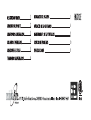
BLADE INSTALLATION 7
OPERATING YOUR FAN 8
CARE OF YOUR FAN
9
TROUBLESHOOTING 10
SPECIFICATIONS
11
1
SAFETY RULES
PACKAGE CONTENTS
2
INSTALLING THE FAN
3
HANGING THE FAN
4
ELECTRICAL CONNECTIONS
5
FINISHING THE INSTALLATION 6
CONTENTS

SAFETY RULES
1
1.
2. Be cautious! Read all instructions and safety information before installing your new fan. Review accompanying assembly diagrams.
3. Make sure that all electrical connections comply with local codes, ordinance, or National Electrical Codes. Hire a qualified electrician or
consult a do-it-your self wiring handbook if you are unfamiliar with installing electrical wiring.
4. Make sure the installation site you choose allows the fan blades to rotate without any obstructions. Allow a minimum clearance of 7 feet
from the floor and 18 inches from the top of the blades to the wall.
5. If you are mounting the fan to a ceiling fan outlet box, use a U.L Listed metal octagonal outlet box marked"Acceptable For Fan Support".
Secure the box directly to the building structure. The outlet box and its support must be able to support the moving weight of the fan (at
least 50 pounds). Do not use a plastic box.
6. Caution: To reduce the risk of injury use only the screws provided with the outlet box in conjunction with the lock washers provided with
the fan.
7. If you are mounting the fan to a joist, make sure it is able to support the moving weight of the fan (at least 50 pounds).
8. After you install the fan, make sure that all mounting components are secured to prevent the fan from falling.
9. Do not insert anything into the fan blades while the fan is operating.
10. Turn the fan off and wait for the blades to stop completely before performing any maintenance or cleaning.
Before you begin installing the fan, shut power off the circuit breaker of the fuse box.

NOTE: The important safeguards and instructions appearing in this manual are not meant to cover all possible conditions and
situations that may occur. It must be understood that common sense, caution and care are factors which can not be built into
this product. These factors must be supplied by the person(s) installing, caring for and operating the unit.
NOTE: READ AND SAVE ALL INSTRUCTIONS!
WARNING
TO REDUCE THE RISK OF FIRE,ELECTRIC SHOCK OR OTHER PERSONAL INJURY, MOUNT FAN ONLY TO A U.L LISTED OUTLET BOX OR SUPPORTING
SYSTEM MARKED ACCEPTABLE FOR FAN SUPPORT AND USE MOUNTING SCREWS PROVIDED WITH THE OUTLET BOX IN CONJUCTION WITH THE
LOCK WASHERS PROVIDED WITH THE FAN. MOST OUTLET BOXS COMMONLY USED FOR FAN SUPPORT OF LIGHTING FIXTURES ARE NOT
ACCEPTABLE FOR FAN SUPPORT AND NEED TO BE REPLACED. CONSULT A QUALIFIDE ELECTRICIAN IF IN DOUBT.
TO REDUCE THE RISK OF PERSONAL INJURY, DO NOT BEND THE BLADE HOLDERS WHILE INSTALLING BALANCING THE BLADES OR CLEANING
THE FAN. DO NOT INSERT FOREIGN OBJECTS BETWEEN ROTATING FAN BLADES.
TO REDUCE THE RISK OF FIRE OR ELECTRONIC SHOCK, DO NOT USE THIS FAN WITH ANY SOLID-STATE SPEED CONTROL DEVICE .

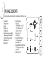
PACKAGE CONTENTS
1. Fan blades(5)
2. Hanger bracket
3. Canopy
4. Canopy cover
5. Coupling cover
6. Standard downrod assembly(6")
Minimum-length downrod(3.5")
7. Fan motor/housing assembly
8. Blade holders (5)
9. Balancing kit
C
B
A
A. Mounting hardware:
Wire nuts(3)
#8x3/4”Machine screws (2)
#10x1.5Wood screws (2)
4mm Star washers (2)
Metal washers (2)
Lock washers (2)
B. Blade attachment hardware:
3/16“x6mm Screws(16)
Fiber washers (16)
C. Blade holder attachment hardware:
1/4“x12.7mm screws with lock
washers(11)
D. Pull chain fobs (1)
2
Unpack your fan and check the contents. You should have the following items:
2
1
9
7
8
3
5
6
4
D

3
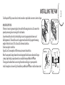
INSTALLING THE FAN
MOUNTING OPTIONS
If there isn't an existing mounting box, then read the following instructions. Disconnect the
power by removing fuses or turning off circuit breakers.
Secure the outlet box directly to the building structure. Use appropriate fasteners and
building materials. The outlet box and its support must be able to fully support the moving
weight of the fan (at least 50 lbs.).Use a UL listed metal outlet box.
Do not use a plastic outlet box.
Figure1,2 and 3 are examples of different ways to mount the outlet box.
Note: You may need a longer downrod to maintain proper blade clearance when installing on
R
a steep, sloped ceiling. Longer downrods are available from your Minka-Aire dealer.
To hang your fan where there is an existing fixture but no ceiling joist, you may need to
R
install a hanger bar as shown in Fig.4(available at your Minka Aire dealer or local hardware store)
Tools Required: Philips screw driver, slotted screw driver, step-ladder, wire cutters, electrical tape.
FIG. 1
CROSS BRACE
CEILING
JOIST
CEILING
jOIST
OUTLET
BOX
FIG. 2
PARALLEL
WOOD BRACE
(MIN. 2’’ THICK)
OUTLET
BOX
CEILING
JOIST OR
CROSS BRACE
FIG. 3
ANGLED CEILING
MAXIMUM 18°ANGLE
PROVIDE
STRONG
SUPPORT
RECESSED
OUTLET
BOX
HANGER
OPENING
must be
FACING
UPSIDE
FIG. 4
CEILING
JOIST
OUTLET BOX
HANGER BAR
(OPTIONAL)
HANGER
BRACKET

4
HANGING THE FAN
WARNING: All of the parts, hardware and components such as the
hanger bracket and hanger ball have been provided for your safety and
the proper installation of your new ceiling fan. The use of other
R
parts,hardware or components not supplied by Minka Aire with the fan
R
will void the Minka Aire Warranty.
REMEMBER to turn off the power. Follow the steps below to hang your
fan properly:
Step 2.Lossen the two set screws and remove the hitch pin and lock pin
from the top coupling of the motor assembly.(Fig 6)
Step 3.Remove hanger ball from downrod assembly by loosening set
screw,removing the cross pin, and sliding ball off rod.(Fig 7)
Step 1.Secure the hanger bracket to the ceiling outlet box using screws
and washers included with mounting hardware.(Fig.5)
Step 4.Carefully feed fan wires up through the downrod(Fig 8).
Thread the rod into the coupling, next line up holes and replace lock
pin and hitch pin. Tighten set screws.
Step 6. Now lift motor assembly into position and place hanger ball
into hanger bracket. Rotate until the check groove has dropped into
the registration slot and seats firmly.(Fig 10)Rod should not rotate
if this is done correctly.
Step5.Slip coupling cover, canopy cover, and canopy onto downrod
(Fig.9).Carefully reinstall hanger ball onto rod being sure that cross
pin is in the correct position, set screws are tighten and wires are
not twisted.

Fig. 10
REGISTRATION
SLOT
Fig. 8
DOWNROD
SUPPLY
WIRES
Fig. 7
CROSS PIN
HANGER
BALL
DOWNROD
SET SCREW
Fig. 6
HITCH
PIN
LOCK
PIN
SET SCREWS
Fig. 5
OUTLET BOX
HANGER BRACKET
Fig. 9
LOCK PIN
CANOPY
COVER
DOWNROD
CANOPY
SCREWS
HITCH PIN
COUPLING

5
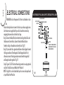
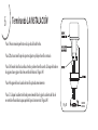
ELECTRICAL CONNECTIONS
REMEMBER to shut the power off at the circuit breaker or fuse
box.
Follow the steps below to connect the fan to your house supply wires.
Use the wire nuts supplied with your fan. Secure the wire nuts by
wrapping the connection with electrical tape.
Step 1. Connect the black (hot) wire from the ceiling to the black and
the blue wires from the fan. Connect the white (Neutral) wire
from the ceiling to the white wire from the fan. (Fig 11)
Step 2. If your outlet has a ground wire (Green or Bare Copper) connect
the fan ground wires (from hanger ball and hanger bracket) to it;
otherwise connect the fan ground wire wires from the hanger ball
and hanger bracket together. (Fig. 11)
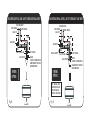
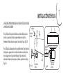
Step 3. Figure 12 & 13 Illustrate the wiring connections using optional
wall unit. (Available at your Minka-Aire® Retailer.)
NOTE: If a light kit is not included with your fan, one can be purchased
at your Minka-Aire®Retailer.
Fig.11
BLACK (HOT)
WALL
WHITE (NEUTRAL)
GREEN (GROUND)
CEILING
HOUSE WIRE SUPPLY
BLUE (OPTIONAL LIGHT)
BLACK (MOTOR)
WHITE (NEUTRAL)
FAN CONTROLLED BY PULL CHAIN, LIGHT KIT CONTROLLED BY PULL CHAIN.
GROUND
(CONNECT TO GROUND WIRE ON
HANGER BRACKET IF NO HOUSE
GROUND WIRE EXISTS.)

Fig.12 Fig.13
FAN CONTROLLED BY PULL CHAIN, LIGHT KIT CONTROLLED BY WALL SWITCH.
WIRING
OPTION 1
BLACK (HOT)
WALL
WHITE (NEUTRAL)
GREEN (GROUND)
CEILING
HOUSE WIRE SUPPLY
BLUE (OPTIONAL LIGHT)
WHITE (NEUTRAL)
LIGHT SWITCH
BLACK (MOTOR)
FAN CONTROLLED BY WALL CONTROL, LIGHT KIT CONTROLLED BY LIGHT SWITCH.
WIRING
OPTION 2
BLACK (HOT)
WALL
WHITE (NEUTRAL)
GREEN (GROUND)
CEILING
HOUSE WIRE SUPPLY
BLUE (OPTIONAL LIGHT)
BLACK (MOTOR)
WHITE (NEUTRAL)
LIGHT SWITCH
FAN WALL CONTROL
GROUND
(CONNECT TO GROUND WIRE ON
HANGER BRACKET IF NO HOUSE
GROUND WIRE EXISTS.)
GROUND
(CONNECT TO GROUND WIRE ON
HANGER BRACKET IF NO HOUSE
GROUND WIRE EXISTS.)
NOTE: SOME WALL UNITS
INCORPORATE BOTH LIGHT
SWITCH AND FAN WALL
CONTROL IN ONE HOUSING.

6
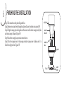
FINISHING THE INSTALLATION
Fig. 14
OUTLET BOX
HANGER
BRACKET
HANGER
BALL
CANOPY
CANOPY
COVER
Step 1. Tuck connections neatly into ceiling outlet box.
Step 2. Remove one screw from the hanger bracket and loosen the other screw around 1/4. ”
Step 3. Align the canopy up to ceiling and over the loose screw. Place the canopy into key hole
and rotate canopy clockwise. (Figure 14)
Step 4. Secure the canopy by use previous removed screw.
Step 5. Place the canopy cover to the canopy and rotate canopy cover clockwise until it is
locked into right position.(Figure 14)

7
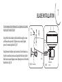
BLADE INSTALLATION
THE FOLLOWING OPERATION MUST BE ACCOMPLISHED BEFORE
INSTALLING THE SWITCH CUP.
Step 1.Attach the fan blade to the blade holder using the screws
and fiber washers provided. Tighten screws securely. Repeat
process for remaining blades.(Fig.15)
Step2.Remove the rubber stops from motor. Rotate the motor so
that the screw holes in motor are aligned with the holes in blade
holder and secure with proper screws. Repeat process for the other
blade holders.(Fig. 16)
Fiber
Washer
Blade
Screw
Blade holder
Fig. 15
Fig. 16
Blade holder
screws
Blade
holder

8
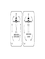
OPERATING YOUR FAN
Restore power to ceiling fan and test for proper operation.
Speed settings for warm or cool weather depend on factors such as the room size. Ceiling height, number of fans, etc.
The Reverse switch is located on the switch cup. Slide the switch to the Left for warm weather operation. Slide the switch to the Right for cool
weather operation.
NOTE: Wait for fan to stop before changing the setting of the slide switch.
Warm weather - (Forward)
A downward airflow creates a cooling effect as shown in Fig. 17. This allows you to set your air conditioner on a warmer setting without affecting
your comfort.
Cool weather - (Reverse)
An upward airflow moves warm air off the ceiling area as shown in Fig. 18. This allows you to set your heating unit on a cooler setting without
affecting your comfort.
The pull chain controls the fan speed as follows: 1st pull - High , 2nd pul l - Med, 3rd pull - Low and 4th pul l - Off.

Fig. 18
WINTER OPERATION
Fig. 17
SUMMER OPERATION
COUNTER CLOCKWISE CLOCKWISE

9
CARE OF YOUR FAN
Here are some suggestions to help maintain your fan.
1.Because of the fan’s natural movement some connections may
become loose. Check the support connections, brackets and blade
attachment twice a year. Make sure they are secure.(It is not necessary
to remove fan from the ceiling).
2.Clean your fan periodically to help maintain its new appearance over
the years. Use only a soft brush or lint free cloth to avoid scratching
the finish. Plated finishes are sealed with lacquer to minimize
discoloration or tarnishing.
Do not use water when cleaning, this could damage the motor, wood
blades or possibly cause an electrical shock.
3.Use a lint free lightly damp cloth or duster to remove dust from the
blades.
4.There is no need to oil your fan. The motor has permanently
lubricated bearings.
5.If your fan is provided with glass shades, clean with lukewarm
soapy water and a soft cloth or sponge.DO NOT IMMERSE
GLASS SHADES IN HOT WATER. DO NOT PUT GLASS SHADES
INTO AN AUTOMATIC DISHWASHER.
WARNING
MAKE SURE THE POWER IS OFF AT THE ELECTRLCAL PAEL BOX
BEORE YOU ATTEMPT ANY REPAIRS. REFER TO THE
SECTION”ELECTRICAL CONECTIONS”.

10
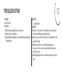
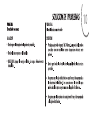
TROUBLESHOOTING
SYMPTOM
Fan will not start
SOLUTION
Check to make sure the wall switch is turned on.
Check circuit fuses or breakers.
Caution! Make sure the power is turned off before performing the
following steps.
SYMPTOM
Fan Sounds Noisy
SOLUTION
Allow a 24 - hour “ break in ” period. Most noises associated
with a new fan will go away during this time.
Make sure the screws that attach the fan blade holder to the
motor hub is tight.
Make sure outlet box is secured to building structure, if
necessary use the wood screws provided to further secure
outlet box to joist.
Make sure hanger bracket is secure to the outlet box, screws are
tight.

SYMPTOM
Fan Wobble
SOLUTION
NOTE: All blade sets are grouped by weight. Because wood and plastic blades vary in density, the fan may wobble even though blades are matched.
Make sure outlet box is secured to building structure, if necessary use the wood screws provided to further secure outlet box to joist.
Make sure hanger bracket is secure to the outlet box, screws are tight.
If a Balancing kit is provided follow the instructions included with the balancing kit to help correct any excessive wobble.

11
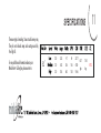
SPECIFICATIONS
These are typical readings. Your actual fan may vary.
They do not include amps and wattage used by
the light (s).
R
For any additional information about your
Minka Aire Ceiling fan, please write to:
R
52”
120
120
120
0.22
0.42
0.56
9.7
33.6
66.5
69
136
183
2277
4180
5966
6.57
kgs
7.84
kgs
1.472’

2277
4180
5966
9.7
33.6
66.5
234.74
124.40
89.71

Contractor Plus
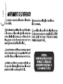
MANUAL DE INSTRUCCIONES CERTIFICADO DE GARANTIA

Diseño del manual y todos los elementos del diseño de manual están protegidos por EE.UU. y / o federales del Estado de Derecho, incluyendo
patentes, marcas y / o derechos de autor.

La garantía de Minka-Aire® es de un año a partir de la fecha de compra de un distribuidor autorizado de (1)
Minka-Aire®. Esta garant a sólo es válida para el comprador original o al usuario contra cualquier defecto de material y í
mano de obra focos no incluidos por año completo. Adem s, Minka-Aire® garantiza por vida el motor del ventilador ( ) (1) á
de techo únicamente por vida con exclusi n de los controles de la pared y componentes el ctricos , al comprador ( ó é )
original o al usuario.
* La garant a queda anulada con el uso de los equipos el ctricos que no son de Minka-Aire®, controles de ejemplo, interruptoresí é de pared o
interruptores eléctricos regulador, etc ...
* La garant a no es v lida una vez que el comprador original o el usuario deja de poseer el ventilador o el ventilador se mueveí á
desde su punto de
instalaci n original. ó
* La garant a es vac a con demandar de cualquier soporte de suspensi n (non-Minka Aire o no abanico espec fico) adem s del sopoí í ó í á
rte de suspensi n ó
suministrado e instalado con este abanico especificamente.

Fecha de Compra Tienda Donde Lo Compro Num. De Modelo Num. De Serie
F556
Para obtener servicio de garant a durante el per odo de garant a, el comprador debe devolver el ventilador con el recií í í bo de compra al lugar
original de compra. El distribuidor autorizado de Minka-Aire®, a su discreci n, puede reparar o reemplazar el ventilador despuó és de verificar la
legitimidad de la reclamaci n de garant a. Reemplazo est sujeto a la disponibilidad del mismo modelo. Si el modelo no est disó í á á
ponible ser , á
sustituido por uno de igual valor. Esta es de una garant a limitada, el comprador original o usuario es responsable por el costí o de quitar y reinstalar
del producto reparado o reemplazado.
Informaci n de Servicio de Garant aó í
Para obtener el nombre del distribuidor Minka-Aire® autorizado m s cercano se llama a Minka-Aire® departamento de atená
ci n al cliente al ó
1-800-307-3267, ó é o p ngase en contacto Minka-Aire® a trav s de www.minkagroup.net y seleccione FAQ para responder a cualquier pregunta, o si
necesita ayuda adicional, envie el formulario de preguntas que encontró alli.

1
2
3
4
5
6
7
8
9
10
11

1
10.Apague el ventilador y espere a que las aspas se detengan por completo antes de realizar cualquier tarea de mantenimiento o limpieza.

PARA REDUCIR EL RIESGO DE INCENDIO O DESCARGA ELÉCTRICA, NO USE ESTE VENTILADOR CON NINGÚN DISPOSITIVO DE CONTROL DE
VELOCIDAD DE ESTADO SOLIDO.

2
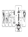
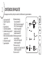
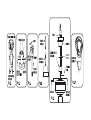
1. (5)
2. Soporte de suspensión
3. Dosel
4. Cubierta de dosel
5. Cubierta de acoplamiento
6. Asamblea de barra estándar (6 ")
Barra más corta (3.5 ")
7. Motor de ventilador/asamblea de
caja protectora
8. Abrazadera de la aspa(5)
9. Juego de Equilibrio
Hojas de ventilador
A. Hardware de montaje:
Tuercas de alambre (3)
#8x3/4” Tornillos de la máquina (2)
#10x1.5 Tornillos de madera (2)
Arandelas de seguridad (2)
Arandelas de estrella (2)
Arandelas de muelle (2)
B. Hardware para montaje de
accesorios de hoja:
Tornillos de 3/16“x8mm (16)
Arandelas de papel (16)
C. Partes para colocar la
abrazadera: 1/4“x12.7mm Tornillos (11)
Arandela de seguridad (11)
D. Cadena tiradora(1)
CONTENIDOS EN PAQUETE
Desempaquete su ventilador y verifique los contenidos. Usted debe tener los siguientes elementos:
C
B
A
D
2
1
9
7
8
3
5
6
4

3
18

4

CUBIERTA
DE DOSEL

5
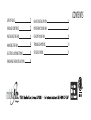
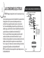
LAS CONEXIONES ELECTRICAS
RECORDAR: Apagar la energia electrica en el circuito principal o en la caja
de fusibles
.Siga los siguientes pasos para conectar los alambres de la casa que suministran
la energia electrica. Use los conectores de alambres proveidos con su
ventilador. Para mas seguridad, envuelva la conexion con cinta aislante.
Paso 1. Conecte el Alambre Negro (corriente) de la caja de distribucion a los
alambres negro y azul del ventilador. Conecte el alambre Blanco (neutral) de la
caja de distribucion con el alambre blanco del ventilador (Fig. 11).
Paso 2. Si su caja de distribucion tiene un alambre a tierra (verde o cobre)
conectelo a los alambres a tierra (verdes) del ventilador. Si su caja de
distribucion no tiene un alambre a tierra, entonces unicamente conecte los dos
alambres a tierra del ventilador, asegurelos con un conector de plastico.
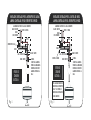
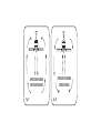
Paso 3. Las figuras 12 y 13 muestran las conexiones de cables para el control en
la pared opcional. (Disponible en su distribuidor Minka-Aire®.)
NOTA: Si su ventilador no incluye un juego de luces, puede comprar uno con su
distribuidor Minka-Aire®.
Fig. 11
VENTILADOR Y LAMPARA CONTROLADO POR INTERRUPTORES DE CADENA.
NEGRO
(CON CORRIENTE)
BLANCO (NEUTRO)
VERDE (A TIERRA)
ALAMBRADO ELECTRICO DE LA CASA (SUMINISTRO)
PARED
TECHO
AZUL (OPCION DE LUZ)
NEGRO (MOTOR)
BLANCO (NEUTRO)
A TIERRA -
(CONECTE AL ALAMBRE A
TIERRA DE LA ABRAZADERA
DE MONTAJE SI NO EXISTE
ALAMBRE A TIERRA DE LA
CASA.)

Fig. 12 Fig. 13
VENTILADOR CONTROLADO POR EL INTERRUPTOR DE CADENA.
LAMPARA CONTROLADA POR EL INTERRUPTOR DE PARED.
OPCION DE
CONEXION
ELECTRICA #1
OPCION DE
CONEXION
ELECTRICA #2
INTERRUPTOR DE LUZ
PARED
BLANCO (NEUTRO)
VERDE (A TIERRA)
TECHO
ALAMBRADO ELECTRICO DE LA CASA (SUMINISTRO)
AZUL (OPCION DE LUZ)
NEGRO (MOTOR)
BLANCO (NEUTRO)
NEGRO
(CON CORRIENTE)
NEGRO
(CON CORRIENTE)
PARED
BLANCO (NEUTRO)
VERDE (A TIERRA)
TECHO
ALAMBRADO ELECTRICO DE LA CASA (SUMINISTRO)
AZUL (OPCION DE LUZ)
NEGRO (MOTOR)
BLANCO (NEUTRO)
CONTROL DE PARED
VENTILADOR CONTROLADO POR EL CONTROL DE PARED.
LAMPARA CONTROLADA POR EL INTERRUPTOR DE PARED.
A TIERRA -
(CONECTE AL ALAMBRE A
TIERRA DE LA ABRAZADERA
DE MONTAJE SI NO EXISTE
ALAMBRE A TIERRA DE LA
CASA.)
A TIERRA -
(CONECTE AL ALAMBRE A
TIERRA DE LA ABRAZADERA
DE MONTAJE SI NO EXISTE
ALAMBRE A TIERRA DE LA
CASA.)
NOTA: ALGUNAS UNIDADES DE
PARED TIENE EL INTERRUPTOR
DE LUZ Y EL CONTROL DE
PARED PARA EL VENTILADOR EN
UN SOLO BASTIDOR.

6
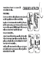
Paso 1. Hace conexión perfecta en la caja de salida del techo.
Paso 2. Quita un tornillo por el soporte colgante y afloje el tornillo contrario.
Paso 3. Alinea el dosel hacia arriba al techo,y sobre el tornillo suelto. Coloque el dosel en
el agujero clave y gira el dosel en sentido del horario. (Figura 14)
Paso 4. Asegúre el dosel usando el tornillo quitado anteriormente.
Paso 5. Coloque la cubierta de dosel por encima del dosel y girar la cubierta del dosel
en sentido el horario hasta que quede el la posición correcta. (Figura 14)
Terminando LA INSTALACIÓN
Fig. 14
CUBIERTA
DE DOSEL

7
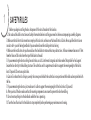
INSTALACIÓN DE HOJA
LA SIGUIENTE OPERACIÓN DEBE REALIZARSE ANTES DE INSTALAR
LA PANTALLA DE VIDRIO.
Paso 1.Adjunte la hoja de ventilador a sujetador de hoja con los
tornillos y arandelas de fibra siempre. Apriete los tornillos
firmemente. Repita el proceso para el resto de las hojas. (Fig.15)
Paso 2.Quite los bloqueadores de caucho del motor. Gire el motor a
fin de que los agujeros de los tornillos de motor están alineados
con los agujeros en el sujetador de hojas y fije con tornillos
adecuados. Repita el proceso para los demás sujetadores de hoja.
(Fig. 16)
TORNILLOS
ARANDELAS
DE FIBRA
HOJA
SUJETADOR
DE HOJA
TORNILLO DE
SUJETADOR
DE HOJA
SUJETADOR
DE HOJA
Fig. 15
Fig. 16

8
Restablesca al energia electrica al ventilador.
Los ajustes de velocidad para clima caliente o frio dependen de factores como el tamaño del cuarto, la altura del techo, cantidad de
ventiladores, etc.
El interruptor de reversa se encuentra en la caja del interruptor. Delize el boton hacia la isquierda para operacion en clima calido. Deslize el
boton hacia la derecha para operacion en clima frio.
NOTA: Espere que el ventilador se detenga antes de cambiar la direccion de las Aspas.
Clima Caliente (Adelante) Una corriente de aire descendiente crea un efecto refrescante como se muestra en la (Fig. 17) esto permite ajustar el
aire acondicionado a una temperatura mas alta sin que esto afecte su bienestar.
Clima Frio (Reversa) Una corriente de aire ascendiente empuja el aire caliente delarea del techo como se muestra en la (Fig. 18) esto permite
ajustar la calefaccion a una temperatura mas baja sin que esto afecte su bienestar.
Este interruptor de cadena controla las velocidades de la manera siguiente:
1-Jalon = Velocidad Alta 2-Jalones = Velocidad Media
3-Jalones = Velocidad Baja 4-Jalones = Ventilador apagado

Fig. 18
Fig. 17
OPERACIÓN EN INVIERNO
OPERACIÓN EN VERANO
SENTIDO ANTIHORARIO SENTIDO HORARIO

9

10

Si el juego de balanceo fue proporcionada siga las instrucciones
que se incluyen con el juego para ayudar a corregir el balanceo
excesivo.

11
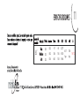
120
120
120
52”
0.22
0.42
0.56
9.7
33.6
66.5
69
136
183
2277
4180
5966
6.57
kgs
7.84
kgs
1.472’

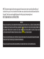
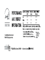
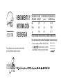
RENDIMIENTO Y
INFORMACIÓN
DE ENERGÍA
Para cualquier información adcional sobre su ventilador
de Techo de Minka Aire por favor escriba a:
VELOCIDAD DE
VENTILADOR
FLUJO DE
AIRE(CFM)*
USO DE POTENCIA
(vatios)
EFICIENCIA DE FLUJO
DE AIRE(CFM/vatio)
Baja
Media
Alta
El flujo de ventilador de techo se mide en pies cúbicos por minuto(CFM).
El uso de potencia se mide en vatios. Para maximizar los ahorros de energía:
Seleccione un ventilador con alta eficiencia de flujo(CFM/vatio).
Use -etiquetada iluminando en su ventilador.
Recuerde a apagar su ventilador cuando sala de la habitación
*
el método de ensayo de
Estado Sólido aprobado
por
Medido de acuerdo con
2277
4180
5966
9.7
33.6
66.5
234.74
124.40
89.71
-
 1
1
-
 2
2
-
 3
3
-
 4
4
-
 5
5
-
 6
6
-
 7
7
-
 8
8
-
 9
9
-
 10
10
-
 11
11
-
 12
12
-
 13
13
-
 14
14
-
 15
15
-
 16
16
-
 17
17
-
 18
18
-
 19
19
-
 20
20
-
 21
21
-
 22
22
-
 23
23
-
 24
24
-
 25
25
-
 26
26
-
 27
27
-
 28
28
-
 29
29
-
 30
30
-
 31
31
-
 32
32
-
 33
33
-
 34
34
-
 35
35
-
 36
36
-
 37
37
-
 38
38
-
 39
39
-
 40
40
-
 41
41
-
 42
42
-
 43
43
-
 44
44


Minka-Aire F556-ORB Instrucciones de operación
- Categoría
- Ventiladores domésticos
- Tipo
- Instrucciones de operación
en otros idiomas
Artículos relacionados
-
Minka-Aire F533-BN Manual de usuario
-
Minka-Aire F745-DK Instrucciones de operación
-
Minka-Aire F563-WH Manual de usuario
-
Minka Group F656L-ORB Manual de usuario
-
Minka Group F888L-BNW Manual de usuario
-
Minka Group WCS223 Manual de usuario
-
Minka Group F546-WH Manual de usuario
-