
CERTIFICATE
Mojo II

Manual design and all elements of manual design are protected by U.S. Federal and/or State Law, including Patent, Trademark and/or Copyright laws.

The Minka-Aire® warranty is for one (1) year from the date of purchase from an authorized Minka-Aire® dealer.
This warranty is only valid to the original purchaser or user against all defects in material and workmanship light bulbs (
excluded for one full year. Additionally, Minka-Aire® warrants the
motor only for the lifetime of the Minka Aire ceiling ) (1)
fan excluding wall controls and electrical components , to the original purchaser or user. ()
* The warranty is voided with the use of any non- Minka-Aire®electrical devices, e.g., wall controls or electrical dimmer switches, etc…
* The warranty is
void once the original purchaser or user ceases to own the fan or the fan is moved from its original point of installation.
* The warranty is void with the use of any hanger bracket (non-Minka Aire or non-fan specific other than the hanger bracket supplied )
& installed
with this specific fan.

Date Purchased Store Purchased Model Number Serial Number
F533
Warranty Service Information
To obtain warranty service during the warranty period, the purchaser should return the fan with the sales receipt to the original place of
purchase. The authorized Minka-Aire® dealer, at its sole discretion, will either repair or replace the fan after verifying the legitimacy of the warranty
claim. Replacement is
subject to availability of the same model. If the model is unavailable it will be replaced by one of equal value. This is a limited
warranty; the original purchaser or user is responsible for the cost of removal and reinstallation of repaired or replacement product.
To obtain the name of the Minka-Aire® authorized dealer nearest you call the Minka-Aire® customer care department at 1-800-307-3267, or
contact Minka-Aire® through www.minkagroup.net and select FAQ to answer any questions or if you require additional assistance submit the question
form found there.

INSTALLING THE LIGHT KIT ASSEMBLY
INSTALLING THE GLASS SHADE & LIGHT BULB
OPERATING YOUR FAN
CARE OF YOUR FAN
TROUBLESHOOTING
SPECIFICATIONS
SAFETY RULES
PACKAGE CONTENTS
INSTALLING THE MOUNTING BRACKET
ELECTRICAL CONNECTIONS
FINISHING THE INSTALLATION
BLADE INSTALLATION
1
2
3
4
5
6
7
8
9
10
11
12
.........................................
............................
...................................................
......................................
.....
..........................
....................
....................................
......................................................................
CONTENTS
.............................................................................
..........................................................................
..................................................................................

SAFETY RULES
1
1.
2. Be cautious! Read all instructions and safety information before installing your new fan. Review accompanying assembly diagrams.
3. Make sure that all electrical connections comply with local codes, ordinance, or National Electrical Codes. Hire a qualified electrician or
consult a do-it-your self wiring handbook if you are unfamiliar with installing electrical wiring.
4. Make sure the installation site you choose allows the fan blades to rotate without any obstructions. Allow a minimum clearance of 7 feet
from the floor and 18 inches from the top of the blades to the wall.
5. If you are mounting the fan to a ceiling fan outlet box, use a U.L Listed metal octagonal outlet box marked"Acceptable For Fan Support".
Secure the box directly to the building structure. The outlet box and its support must be able to support the moving weight of the fan (at
least 50 pounds). Do not use a plastic box.
6. Caution: To reduce the risk of injury use only the screws provided with the outlet box in conjunction with the lock washers provided with
the fan.
7. If you are mounting the fan to a joist, make sure it is able to support the moving weight of the fan (at least 50 pounds).
8. After you install the fan, make sure that all mounting components are secured to prevent the fan from falling.
9. Do not insert anything into the fan blades while the fan is operating.
10. To operate the reverse function on this fan, press the reverse button while the fan isn’t running.
Before you begin installing the fan, shut power off the circuit breaker of the fuse box.

NOTE: The important safeguards and instructions appearing in this manual are not meant to cover all possible conditions and
situations that may occur. It must be understood that common sense, caution and care are factors which can not be built into
this product. These factors must be supplied by the person(s) installing, caring for and operating the unit.
NOTE: READ AND SAVE ALL INSTRUCTIONS!
WARNING
TO REDUCE THE RISK OF FIRE,ELECTRIC SHOCK OR OTHER PERSONAL INJURY, MOUNT FAN ONLY TO A U.L LISTED OUTLET BOX OR SUPPORTING
SYSTEM MARKED ACCEPTABLE FOR FAN SUPPORT AND USE MOUNTING SCREWS PROVIDED WITH THE OUTLET BOX IN CONJUCTION WITH THE
LOCK WASHERS PROVIDED WITH THE FAN. MOST OUTLET BOXS COMMONLY USED FOR FAN SUPPORT OF LIGHTING FIXTURES ARE NOT
ACCEPTABLE FOR FAN SUPPORT AND NEED TO BE REPLACED. CONSULT A QUALIFIDE ELECTRICIAN IF IN DOUBT.
TO REDUCE THE RISK OF PERSONAL INJURY, DO NOT BEND THE BLADE HOLDERS WHILE INSTALLING BALANCING THE BLADES OR CLEANING
THE FAN. DO NOT INSERT FOREIGN OBJECTS BETWEEN ROTATING FAN BLADES.
TO REDUCE THE RISK OF FIRE OR ELECTRONIC SHOCK, DO NOT USE THIS FAN WITH ANY SOLID-STATE SPEED CONTROL DEVICE .

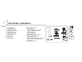
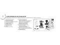
PACKAGE CONTENTS
1. Fan blades(4)
2. Blade holders (4)
3. Mounting bracket
4. Fan motor assembly
5. Motor housing
6. Light kit assembly
7. 60W E12 blubs(3)
8. Glass shade
9. Extra cap
10. Extra finial
1 1. Balancing kit
A. Mounting hardware:
Wire nuts(3)
#8x3/4” Machine screws (2)
#10x1.5” Wood screws (2)
Star washers (2)
Metal washers (2)
Lock washers (2)
B. Blade attachment hardware:
3/16“x8mm Screws(13)
Fiber washers (13)
C. Blade holder attachment hardware:
1/4“x12.7mm screws with lock
washers(9)
D. Pull chain fobs (2)
2
Unpack your fan and check the contents. You should have the following items:
A
D
C
B
7
2
1
3
4
5
6
8
11
9
10

3
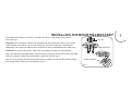
INSTALLING THE MOUNTING BRACKET
Tools Required: Phillips screw driver; slotted screw driver; step-ladder; wire cutters;
electrical tape.
WARNING: All of the parts, hardware and components have been provided for your safety
and the proper installation of your new ceiling fan. The use of other parts, hardware or
components not supplied by Minka Aire® with the fan will void the Minka Aire® Warranty.
REMEMBER To turn off the power. Follow the steps below to hang your fan properly.
Step 1. Attach the mounting bracket to the outlet box with two screws and washers provided
with the outlet box. Make sure the bracket is tight and secured. (Fig. 1)
Step 2. Lift fan into position by hanging the motor assembly onto the hook from the ceiling
mounting bracket allowing it to hang freely. (Fig. 1)
Fig. 1
OUTLET BOX
MOUNTING BRACKET
FAN MOTOR ASSEMBLY

4
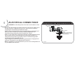
ELECTRICAL CONNECTIONS
REMEMBER to shut the power off at the circuit breaker or fuse
box.
Follow the steps below to connect the fan to your house supply wires.
Use the wire nuts supplied with your fan. Secure the wire nuts by
wrapping the connection with electrical tape.
Step 1. Connect the black (hot) wire from the ceiling to the black and
the blue wires from the fan. Connect the white (Neutral) wire
from the ceiling to the white wire from the fan. (Fig 2)
Step 2. If your outlet has a ground wire (Green or Bare Copper) connect
the fan ground wires ((from hanger ball and hanger bracket) to it;
otherwise connect the fan ground wire wires from the hanger ball
and hanger bracket together. (Fig. 2)
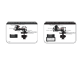
Step 3. Figure 3 & 4 Illustrate the wiring connections using optional
wall unit. (Available at your Minka-Aire® Retailer.)
NOTE: If a light kit is not included with your fan, one can be purchased
at your Minka-Aire®Retailer.
Fig. 2
BLACK (HOT)
WALL
WHITE (NEUTRAL)
GREEN (GROUND)
CEILING
HOUSE WIRE SUPPLY
BLUE (OPTIONAL LIGHT)
BLACK (MOTOR)
WHITE (NEUTRAL)
FAN CONTROLLED BY PULL CHAIN, LIGHT KIT CONTROLLED BY PULL CHAIN.
GROUND
(CONNECT TO GROUND WIRE ON
HANGER BRACKET IF NO HOUSE
GROUND WIRE EXISTS.)

Fig. 3 Fig. 4
FAN CONTROLLED BY PULL CHAIN, LIGHT KIT CONTROLLED BY WALL SWITCH.
WIRING
OPTION 1
BLACK (HOT)
WALL
WHITE (NEUTRAL)
GREEN (GROUND)
CEILING
HOUSE WIRE SUPPLY
BLUE (OPTIONAL LIGHT)
WHITE (NEUTRAL)
LIGHT SWITCH
BLACK (MOTOR)
FAN CONTROLLED BY WALL CONTROL, LIGHT KIT CONTROLLED BY LIGHT SWITCH.
WIRING
OPTION 2
BLACK (HOT)
WALL
WHITE (NEUTRAL)
GREEN (GROUND)
CEILING
HOUSE WIRE SUPPLY
BLUE (OPTIONAL LIGHT)
BLACK (MOTOR)
WHITE (NEUTRAL)
LIGHT SWITCH
FAN WALL CONTROL
GROUND
(CONNECT TO GROUND WIRE ON
HANGER BRACKET IF NO HOUSE
GROUND WIRE EXISTS.)
GROUND
(CONNECT TO GROUND WIRE ON
HANGER BRACKET IF NO HOUSE
GROUND WIRE EXISTS.)
NOTE: SOME WALL UNITS
INCORPORATE BOTH LIGHT
SWITCH AND FAN WALL
CONTROL IN ONE HOUSING.

5
FINISHING THE INSTALLATION
Step 1. Remove one of the four screws on the mounting bracket and
loosen, but do not remove, the other three screws.
Step 2. Remove the motor assembly from the J hook.
Step 3. Lift and place the key holes on the mounting plate over the three
screws previously loosened on the mounting bracket and turn the
mounting plate until it locks in place and no longer turns. (FIG. 5)
Step 4. Secure by tightening the three screws previously loosened and the
screw previously removed.
Step 5. Align the four large screwheads pre-locked on the fan housing to
the key holes of the mounting bracket.
Step 6. Turn the fan housing at the right side and twist the screwheads to
the end of the slotted holes until they lock in place and no longer turn.
WARNING: Ensure you complete this step correctly and follow all steps.
Failure to correctly follow this step might cause the fan to fall.
Fig. 5
Fig. 6
SCREW
FAN
MOTOR
ASSEMBIY
KEY
HOLES
MOUNTING
BRACKET
MOUNTING
BRACKET
KEY
HOLES
SLOTTED HOLE
FAN HOUSING
SCREWHEAD

6
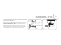
BLADE INSTALLATION
THE FOLLOWING OPERATION MUST BE ACCOMPLISHED BEFORE
INSTALLING THE SWITCH CUP.
Step 1.Attach the fan blade to the blade holder using the screws
and fiber washers provided. Tighten screws securely. Repeat
process for remaining blades.(Fig.7)
Step2.Rotate the motor so that the screw holes in motor are
aligned with the holes in blade holder and secure with proper
screws. Repeat process for the other blade holders.(Fig. 8)
Fiber
Washer
Blade
Screw
Blade holder
Fig. 7
Fig. 8
Blade holder
screws
Blade
holder

7
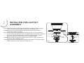
INSTALLING THE LIGHT KIT
ASSEMBLY
Step1. Remove the light kit plate from the light kit assembly by removing three
screws from the rim of the light kit plate and reserve the screws.
Step2.Remove 1of 3screws from the mounting ring and loosen the other 2
screws.(Do not remove.) (Fig.9)
Step3.Place the key holes from the light kit plate over the 2 screws previously
loosened from the mounting ring , turn light kit plate until it locks in place at
the narrow section of the key holes. Secure by tightening the 2 screws
previously loosened and the one previously removed.(Fig.9)
Step4.While holding the light kit assembly under your fan, firmly snap the wire
connection plugs together.(Fig.9)
Step5.Align the holes in the light kit assembly with the holes in the light kit plate.
Tighten the three screws removed in step1.(Fig. 9)
Fig. 9
Mounting ring
Light kit plate
Light kit
assembly
Screw
Connection plug
Connection
plug
Screw

8
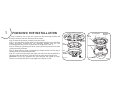
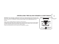
INSTALLING THE GLASS SHADE & LIGHT BULB
WARNING: Shut of the power supply before removing or replacing lamp. If you accidentally come
into contact, wipe thoroughly with a clean, lint-free,cotton cloth. Use light bulb in accordance with
the fan’s specification. TO REDUCE THE RISK OF FIRE DO NOT EXCEED MAXIMUM WATTAGE
RATING.
Step1. Install 3*60W E12 bulbs (included) into socket.(Fig.10)
Step2. Remove the rubber washer, metal washer, metal nut, metal cup and finial from the light kit
assembly. Place glass shade over the light kit stem, secure with the rubber washer, metal washer,
metal nut, metal cap and finial. Do not over tighten.(Fig.10)
Step3. Attach the pull chain fob to the chain on the light kit assembly.
Fig. 10
Bulb
Rubber washer
Metal washer
Metal nut
Glass shade
Metal cap
Finial

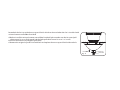
Remarked: the fan is provided extra cap and finial, which can be used when the fan is installed with
univeral remote control(Not Provided)
a) Before install the univeral remote control(Not Provided), please make sure the fan speed pull
chain control is set to "high speed"and the light pull chain control is set to " on" status.
b)Cut off the unnecessary length of pull chain.
c) Remove the original cap and finial with hole and replace the extra cap and finial without hole.
Fig. 11
Extra cap
Pull chain
Extra finial

9
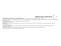
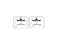
OPERATING YOUR FAN
Restore power to ceiling fan and test for proper operation.
Speed settings for warm or cool weather depend on factors such as the room size. Ceiling height, number of fans, etc.
The Reverse switch is located on the switch cup. Slide the switch to the Left for warm weather operation. Slide the switch to the Right for cool
weather operation.
NOTE: Wait for fan to stop before changing the setting of the slide switch.
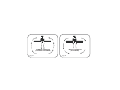
Warm weather - (Forward)
A downward airflow creates a cooling effect as shown in Fig. 12. This allows you to set your air conditioner on a warmer setting without affecting
your comfort.
Cool weather - (Reverse)
An upward airflow moves warm air off the ceiling area as shown in Fig. 13. This allows you to set your heating unit on a cooler setting without
affecting your comfort.
The fan pull chain controls the fan speed as follows: 1st pull - High , 2nd pul l - Med, 3rd pull - Low and 4th pul l - Off.
The light kit pull chain controls the light kit in “ON” or “OFF”.

Fig. 13
WINTER OPERATION
Fig. 12
SUMMER OPERATION
(COUNTER CLOCKWISE) (CLOCKWISE)

10
Here are some suggestions to help maintain your fan.
1.Because of the fan’s natural movement some connections may
become loose. Check the support connections, brackets and blade
attachment twice a year. Make sure they are secure.(It is not necessary
to remove fan from the ceiling).
2.Clean your fan periodically to help maintain its new appearance over
the years. Use only a soft brush or lint free cloth to avoid scratching
the finish. Plated finishes are sealed with lacquer to minimize
discoloration or tarnishing.
Do not use water when cleaning, this could damage the motor, wood
blades or possibly cause an electrical shock.
3.Use a lint free lightly damp cloth or duster to remove dust from the
blades.
4.There is no need to oil your fan. The motor has
permanently lubricated bearings.
5.If your fan is provided with glass shades, clean with lukewarm
soapy water and a soft cloth or sponge.DO NOT IMMERSE
GLASS SHADES IN HOT WATER. DO NOT PUT GLASS SHADES
INTO AN AUTOMATIC DISHWASHER.
WARNING
MAKE SURE THE POWER IS OFF AT THE ELECTRLCAL PAEL BOX
BEORE YOU ATTEMPT ANY REPAIRS. REFER TO THE
SECTION”ELECTRICAL CONECTIONS”.
CARE OF YOUR FAN

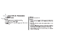
TROUBLESHOOTING
SYMPTOM
Fan will not start
SOLUTION
Check to make sure the wall switch is turned on.
Check circuit fuses or breakers.
Caution! Make sure the power is turned off before performing the
following steps.
SYMPTOM
Fan Sounds Noisy
SOLUTION
Allow a 24 - hour “ break in ” period. Most noises associated
with a new fan will go away during this time.
Make sure the screws that attach the fan blade holder to the
motor hub is tight.
Make sure outlet box is secured to building structure, if
necessary use the wood screws provided to further secure
outlet box to joist.
Make sure hanger bracket is secure to the outlet box, screws are
tight.
11

SYMPTOM
Fan Wobble
SOLUTION
NOTE: All blade sets are grouped by weight. Because wood and plastic blades vary in density, the fan may wobble even though blades are matched.
Make sure outlet box is secured to building structure, if necessary use the wood screws provided to further secure outlet box to joist.
Make sure hanger bracket is secure to the outlet box, screws are tight.
If a Balancing kit is provided follow the instructions included with the balancing kit to help correct any excessive wobble.

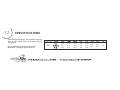
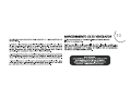
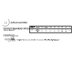
SPECIFICATIONS
These are typical readings. Your actual fan may vary.
They do not include amps and wattage used by
the light (s).
For any additional information about your
Minka Aire Ceiling fan, please write to:
R
52”
120
120
120
0.27
0.42
0.53
14.0
34.7
62.6
84
133
168
2641
4090
5138
8.28
kgs
9.95
kgs
2.41’
12

2641
4090
5138
14.0
34.7
62.6
188.6
117.9
82

Mojo II
MANUAL DE INSTRUCCIONES CERTIFICADO DE GARANTIA

Diseño del manual y todos los elementos del diseño de manual están protegidos por EE.UU. y / o federales del Estado de Derecho, incluyendo
patentes, marcas y / o derechos de autor.

La garantía de Minka-Aire® es de un año a partir de la fecha de compra de un distribuidor autorizado de (1)
Minka-Aire®. Esta garant a sólo es válida para el comprador original o al usuario contra cualquier defecto de material y í
mano de obra focos no incluidos
por año completo. Adem s, Minka-Aire® garantiza por vida el motor del ventilador ( ) (1) á
de techo únicamente por vida con exclusi n de los controles de la pared y componentes el ctricos , al comprador (ó é)
original o al usuario.
* La garant a queda anulada con el uso de los equipos el ctricos que no
son de Minka-Aire®, controles de ejemplo, interruptoresíé de pared o
interruptores eléctricos regulador, etc ...
* La garant a no es v lida una vez que el comprador original o el usuario deja de poseer el ventilador o el ventilador se mueveíá
desde su punto de
instalaci n original. ó
* La garant a
es vac a con demandar de cualquier soporte de suspensi n (non-Minka Aire o no abanico espec fico) adem s del sopoíí ó í á
rte de suspensi n ó
suministrado e instalado con este abanico especificamente.

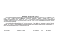
Fecha de Compra Tienda Donde Lo Compro Num. De Modelo Num. De Serie
F533
Para obtener servicio de garant a durante el per odo de garant a, el comprador debe devolver el ventilador con el reciííí bo de compra al lugar
original de compra. El distribuidor autorizado de Minka-Aire®, a su discreci n, puede reparar o reemplazar el ventilador despuóés de verificar la
legitimidad de la reclamaci n
de garant a. Reemplazo est sujeto a la disponibilidad del mismo modelo. Si el modelo no est disóí á á
ponible ser , á
sustituido por uno de igual valor. Esta es de una garant a limitada, el comprador original o usuario es responsable por el costío de quitar y reinstalar
del producto reparado o
reemplazado.
Informaci n de Servicio de Garant aóí
Para obtener el nombre del distribuidor Minka-Aire® autorizado ms cercano se llama a Minka-Aire® departamento de atená
ci n al cliente al ó
1-800-307-3267, óé o p ngase en contacto Minka-Aire® a trav s de www.minkagroup.net y seleccione FAQ para responder a cualquier pregunta, o si
necesita ayuda adicional, envie el formulario de preguntas que encontró alli.

INSTALAR EL APARATO DE LUZ
INSTALAR LA PANTALLA DE VIDRIO Y BOMBILLAS DE LUZ
OPERACION DEL SU VENTILADOR
MANTENIMIENTO DE SU VENTILADOR
SOLUCION DE PROBLEMAS
ESPECIFICACIONES
LA SEGURIDAD PRIMERO
CONTENIDO DEL PAQUETE
INSTALE EL SOPORTE DE MONTAJE
CONEXIONES ELECTRICAS
FINALIZAR
LA INSTALACIÓN
INSTALACION DE LAS ASPAS
1
2
3
4
5
6
7
8
9
10
11
12
........................................................
......
..................................................
.........................................
..............................................................
.............................................................................
...............................
...........................
.............
............................
........................
........................

1

PARA REDUCIR EL RIESGO DE INCENDIO O DESCARGA ELÉCTRICA, NO USE ESTE VENTILADOR CON NINGÚN DISPOSITIVO DE CONTROL DE
VELOCIDAD DE ESTADO SOLIDO.

1. Aspa de ventilador
(
4)
2. Sujetador de aspa (4)
3. Soporte de momtaje
4. Conjunto de motor de ventilador
5. Cáscara de ventilador
6. Aparato de luz
7. 60W E12 bombilla(3)
8. Pantalla de vidrio
9. Tapa de metálica
10. Finial
1 1. Juego de Equilibrio
2
CONTENIDOS EN PAQUETE
Desempaquete su ventilador y verifique los contenidos. Usted debe tener los siguientes elementos:
A. Hardware de montaje:
Tuercas de alambre (3)
#8x3/4” Tornillos de la máquina (2)
#10x1.5 Tornillos de madera (2)
Arandelas de seguridad (2)
Arandelas de estrella (2)
Arandelas de metálica (2)
B. Hardware para montaje de
accesorios de aspa:
Tornillos de 3/16“x8mm (13)
Arandelas de fibra (13)
C. Partes para colocar la abrazadera:
1/4“x12.7mm Tornillos con arandelas
de sequridad (9)
D. Cadena tiradora(2)
A
D
C
B
7
1
3
4
5
6
8
11
9
10
2

3
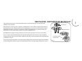
Fig. 1
CAJA DE SALIDA
SOPORTE DE MONTAJE
CONJUNTO DE MOTOR
DE VENTILADOR
INSTALE EL SOPORTE DE MONTAJE
Herramientas necesarias: Un desarmador plano, un desarmador de cruz, cortadoras de
alambre, cinta aislante.
Advertencia: Todas las partes, equipos y componentes, tales como el soporte de la percha y
percha de bolas han sido proveidos para su seguridad y la correcta Instalacion de su nuevo
ventilador de techo. El uso de otras parets, equipos o componentes no suministrados por
Minka Aire® con el ventilador anulara la Garantia de Minka Aire® .
ACUÉRDESE de apagar la energía eléctrica en el circuito principal o en la caja de fusibles.
Paso 1. Fije el soporte de montaje en la caja de salida por los dos tornillos y las arandelas
proporcionados con la caja de salida. Asegúrese de que el soporte de montaje se apriete bien
y rmemente. (Fig. 1)
Paso 2. Levante el ventilador en la posición por colgando la conjunto de motor de ventilador
encima del gancho desde el soporte de montaje de techo y le haga colgar libremente.
(Fig. 1)

4
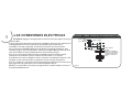
LAS CONEXIONES ELECTRICAS
RECORDAR: Apagar la energia electrica en el circuito principal o en la caja
de fusibles.
Siga los siguientes pasos para conectar los alambres de la casa que suministran
la energia electrica. Use los conectores de alambres proveidos con su
ventilador. Para mas seguridad, envuelva la conexion con cinta aislante.
Paso 1. Conecte el Alambre Negro (corriente) de la caja de distribucion a los
alambres negro y azul del ventilador. Conecte el alambre Blanco (neutral) de la
caja de distribucion con el alambre blanco del ventilador (Fig. 2).
Paso 2. Si su caja de distribucion tiene un alambre a tierra (verde o cobre)
conectelo a los alambres a tierra (verdes) del ventilador. Si su caja de
distribucion no tiene un alambre a tierra, entonces unicamente conecte los dos
alambres a tierra del ventilador, asegurelos con un conector de plastico.
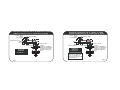
Paso 3. Las figuras 3 y 4 muestran las conexiones de cables para el control en la
pared opcional. (Disponible en su distribuidor Minka-Aire®.)
NOTA: Si su ventilador no incluye un juego de luces, puede comprar uno con su
distribuidor Minka-Aire®.
VENTILADOR Y LAMPARA CONTROLADO POR INTERRUPTORES DE CADENA.
NEGRO
(CON CORRIENTE)
BLANCO (NEUTRO)
VERDE (A TIERRA)
ALAMBRADO ELECTRICO DE LA CASA (SUMINISTRO)
PARED
TECHO
AZUL (OPCION DE LUZ)
NEGRO (MOTOR)
BLANCO (NEUTRO)
A TIERRA -
(CONECTE AL ALAMBRE A
TIERRA DE LA ABRAZADERA
DE MONTAJE SI NO EXISTE
ALAMBRE A TIERRA DE LA
CASA.)
Fig. 2

OPCION DE
CONEXION
ELECTRICA #2
NEGRO
(CON CORRIENTE)
PARED
BLANCO (NEUTRO)
VERDE (A TIERRA)
TECHO
ALAMBRADO ELECTRICO DE LA CASA (SUMINISTRO)
AZUL (OPCION DE LUZ)
NEGRO (MOTOR)
BLANCO (NEUTRO)
CONTROL DE PARED
VENTILADOR CONTROLADO POR EL CONTROL DE PARED.
LAMPARA CONTROLADA POR EL INTERRUPTOR DE PARED.
A TIERRA -
(CONECTE AL ALAMBRE A
TIERRA DE LA ABRAZADERA
DE MONTAJE SI NO EXISTE
ALAMBRE A TIERRA DE LA
CASA.)
NOTA: ALGUNAS UNIDADES DE
PARED TIENE EL INTERRUPTOR
DE LUZ Y EL CONTROL DE
PARED PARA EL VENTILADOR EN
UN SOLO BASTIDOR.
Fig. 4
VENTILADOR CONTROLADO POR EL INTERRUPTOR DE CADENA.
LAMPARA CONTROLADA POR EL INTERRUPTOR DE PARED.
OPCION DE
CONEXION
ELECTRICA #1
INTERRUPTOR DE LUZ
PARED
BLANCO (NEUTRO)
VERDE (A TIERRA)
TECHO
ALAMBRADO ELECTRICO DE LA CASA (SUMINISTRO)
AZUL (OPCION DE LUZ)
NEGRO (MOTOR)
BLANCO (NEUTRO)
NEGRO
(CON CORRIENTE)
A TIERRA -
(CONECTE AL ALAMBRE A
TIERRA DE LA ABRAZADERA
DE MONTAJE SI NO EXISTE
ALAMBRE A TIERRA DE LA
CASA.)
Fig. 3

5
FINALIZAR LA INSTALACIÓN
lo aoje, pero no quite, los otros tres tornillos.
Paso 2. Quite el conjunto de motor (D) del gancho J.
Paso 3. Levante y coloque los agujeros de llave en la placa de montaje a
través de los tres tornillos previamente aojándolos en el soporte de
montaje y gire la placa de montaje hasta que cual bloquee en su lugar.
(Figura 5)
Paso 4. Haga la jación por apretando los tornillos previamente aojando
y el tornillo previamente quitando.
Paso 5. Alinee las cabezas de tornillos largas que se han bloqueado
previamente en la cáscara de ventilador en los agujeros de llave del
soporte de montaje. (Figura 6)
Paso 6. Gire la cáscara de ventilador por la parte derecha y retorca las
cabezas de tornillo en la extremidad de los agujeros acanalados hasta
que ellos bloqueen en su lugar.
Advertencia: Asegúrese de cumplir correctamente con este paso y
seguir todos los pasos. Si no los siguen correctamente este paso podría
causar la caída del ventilador.
Paso 1. Quite uno de los cuatro tornillos en el soporte de montaje y
Fig. 5
Fig. 6
TORNILLO
CONJUNTO
DE MOTOR
AGUJEROS
DE LLAVE
SOPORTE
DE MONTAJE
AGUJEROS
ACANALADOS
CÁSCARA DE
VENTILADOR
CABEZAS
DE TORNILLO
AGUJEROS
DE LLAVE
SOPORTE
DE MONTAJE

6
TORNILLO DE
SUJETADOR
DE ASPA
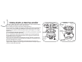
INSTALACIÓN DE LAS ASPAS
LA SIGUIENTE OPERACIÓN DEBE REALIZARSE ANTES DE INSTALAR
LA PANTALLA DE CAJA DE INTERRUPTOR Y
.
Paso 1.Adjunte la aspa de ventilador a sujetador de aspa con los
tornillos y arandelas de fibra siempre. Apriete los tornillos
firmemente. Repita el proceso para el resto de las aspas. (Fig.7)
Paso 2.Gire el motor a fin de que los agujeros de los tornillos de
motor están alineados con los agujeros en el sujetador de aspas y
fije con tornillos adecuados. Repita el proceso para los demás
sujetadores de aspa. (Fig. 8)
ARANDELAS
DE FIBRA
ASPA
TORNILLOS
SUJETADOR
DE ASPA
Fig. 7
Fig. 8
SUJETADOR
DE ASPA

7
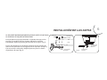
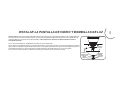
INSTALAR EL APARATO DE LUZ
Paso 1. Retire la placa de aparato de luz de la aparato de luz alejando los tres
tornillosdesde el borde de la placa de aparato de luz y reserva los tornillos.
Paso 2. Quite 1 de 3 tornillos del anillo de montaje y afloje los otros 2 tornillos. (No los quite.)
(Figura 9)
Paso 3. Coloque los principales agujeros de la placa de aparato de luz sobre los 2 tornillos
previamente aflojados en el anillo de montaje, gire la placa de aparato de luz hasta que
encaje en su lugar en la sección estrecha de los principales agujeros. Apriete los 2
tornillos previamente aflojados y el previamente eliminado. (Figura 9)
Paso 4. Sujeta la aparato de luz bajo el ventilador, mientras cierre firmemente y juntos los
enchufes de conexión de alambres . (Fig. 9)
Paso 5.Quite los tres tornillos del borde de la placa de aparato de luz. Alinee los orificios de la
aparato de luz con los orificios de la placa de aparato de luz. Apriete los tres tornillos.
(Figura 9)
Fig. 9
ANILLO DE
MONTAJE
PLACA DE
APARATO
DE LUZ
APARATO DE LUZ
TORNILLOS
ENCHUFES DE
CONEXIÓN
TORNILLOS
ENCHUFES
DE
CONEXIÓN

8
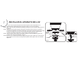
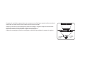
ADVERTENCIA: Cierre de la fuente de alimentación antes de retirar o reemplazar la lámpara. Si accidentalmente
entra en contacto, limpie cuidadosamente con una tela de algodón limpia, libre de pelusa. Utilice bombillas de
conformidad con la especificación del ventilador. PARA REDUCIR EL RIESGO DE INCENDIO NO EXCEDA LA
POTENCIA MÁXIMA.
Paso 1. Instale bombillas 3 * 60W E12 (incluidas) en zócalo. (Figura10)
Paso2. Quite la arandela de goma, la arandela de metálica, la tuerca de metálica, y la tapa de metálica y finial del
aparato de luz. Coloque la pantalla de vidrio sobre el vástago de aparato de luz, fijela con la arandela de goma, la
arandela de metálica, la tuerca de metálica, tapa de metálica y finial. No apriete en exceso.
(Fig.10)
Paso 3. Conecte el llavero de la cadena de tracción para la cadena en la caja del interruptor.
INSTALAR LA PANTALLA DE VIDRIO Y BOMBILLAS DE LUZ
Fig. 10
BOMBILLA
PANTALLA
DE VIDRIO
ARANDELA
DE GOMA
TUERCA DE
METÁLICA
FINIAL
ARANDELA DE
METÁLICA
TAPA DE
METÁLICA

Fig. 11
Finial
Comentó: el ventilador se proporciona con une tapa extra y finial, que se puede utilizar cuando el
ventilador se instala con un control remoto universal (no incluido).
a) Antes de instalar el control remoto univeral (no incluido), asegúrese de que la velocidad del
ventilador este en la "alta velocidad" y la luz este encendida.
b) Corte la cadena de traccion necesaria para usar la tapa y finial.
c) Retire la tapa original y finial con el agujero y coloque la tapa adicional y remate sin agujero.
Tapa de
metálica
Cadena De
Traccion

9
Restablesca al energia electrica al ventilador.
Los ajustes de velocidad para clima caliente o frio dependen de factores como el tamaño del cuarto, la altura del techo, cantidad de
ventiladores, etc.
El interruptor de reversa se encuentra en la caja del interruptor. Delize el boton hacia la isquierda para operacion en clima calido. Deslize el
boton hacia la derecha para operacion en clima frio.
NOTA: Espere que el ventilador se detenga antes de cambiar la direccion de las Aspas.
Clima Caliente (Adelante) Una corriente de aire descendiente crea un efecto refrescante como se muestra en la (Fig. 12) esto permite ajustar el
aire acondicionado a una temperatura mas alta sin que esto afecte su bienestar.
Clima Frio (Reversa) Una corriente de aire ascendiente empuja el aire caliente delarea del techo como se muestra en la (Fig. 13) esto permite
ajustar la calefaccion a una temperatura mas baja sin que esto afecte su bienestar.
Este interruptor de cadena controla las velocidades de la manera siguiente:
1-Jalon = Velocidad Alta 2-Jalones = Velocidad Media
3-Jalones = Velocidad Baja 4-Jalones = Ventilador apagado
Cordán del juego de luz-controla el juego de luz para “encendido” o “apagado”.

Fig. 13
Fig. 12
OPERACIÓN EN INVIERNO
OPERACIÓN EN VERANO
(SENTIDO CONTRARIO) (LAS AGUJAS DEL RELOJ)

10

11

Si el juego de balanceo fue proporcionada siga las instrucciones
que se incluyen con el juego para ayudar a corregir el balanceo
excesivo.

12
52”
120
120
120
2.41’
8.28
9.95
0.27
0.42
0.53
14.0
34.7
62.6
84
133
168
2641
4090
5138

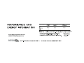
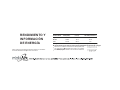
RENDIMIENTO Y
INFORMACIÓN
DE ENERGÍA
Para cualquier información adcional sobre su ventilador
de Techo de Minka Aire por favor escriba a:
VELOCIDAD DE
VENTILADOR
FLUJO DE
AIRE(CFM)*
USO DE POTENCIA
(vatios)
EFICIENCIA DE FLUJO
DE AIRE(CFM/vatio)
Baja
Media
Alta
El flujo de ventilador de techo se mide en pies cúbicos por minuto(CFM).
El uso de potencia se mide en vatios. Para maximizar los ahorros de energía:
Seleccione un ventilador con alta eficiencia de flujo(CFM/vatio).
Use -etiquetada iluminando en su ventilador.
Recuerde a apagar su ventilador cuando sala de la habitación
*
el método de ensayo de
Estado Sólido aprobado
por
Medido de acuerdo con
2641
4090
5138
14.0
34.7
62.6
188.6
117.9
82
-
 1
1
-
 2
2
-
 3
3
-
 4
4
-
 5
5
-
 6
6
-
 7
7
-
 8
8
-
 9
9
-
 10
10
-
 11
11
-
 12
12
-
 13
13
-
 14
14
-
 15
15
-
 16
16
-
 17
17
-
 18
18
-
 19
19
-
 20
20
-
 21
21
-
 22
22
-
 23
23
-
 24
24
-
 25
25
-
 26
26
-
 27
27
-
 28
28
-
 29
29
-
 30
30
-
 31
31
-
 32
32
-
 33
33
-
 34
34
-
 35
35
-
 36
36
-
 37
37
-
 38
38
-
 39
39
-
 40
40
-
 41
41
-
 42
42
-
 43
43
-
 44
44
-
 45
45
-
 46
46


Minka-Aire F533-BN Manual de usuario
- Categoría
- Ventiladores domésticos
- Tipo
- Manual de usuario
en otros idiomas
- English: Minka-Aire F533-BN User manual
Artículos relacionados
-
Minka-Aire F556-ORB Instrucciones de operación
-
Minka-Aire F745-DK Instrucciones de operación
-
Minka-Aire F563-WH Manual de usuario
-
Minka Group F888L-BNW Manual de usuario
-
Minka Group WCS223 Manual de usuario
-
Minka Group F522L-BN Manual de usuario
-
-
Minka Group F553L-WHF Manual de usuario
-
Minka Group F656L-ORB Manual de usuario
-
Minka Group F546-WH Manual de usuario
