Yamaha DM2000 Manual de usuario
- Categoría
- Controladores de DJ
- Tipo
- Manual de usuario
Este manual también es adecuado para

EN
Owner’s Manual
Owner’s Manual
Keep This Manual For Future Reference.
Keep This Manual For Future Reference.

WARNING: THIS APPARATUS MUST BE EARTHED
IMPORTANT
THE WIRES IN THIS MAINS LEAD ARE COLOURED IN
ACCORDANCE WITH THE FOLLOWING CODE:
GREEN-AND-YELLOW : EARTH
BLUE : NEUTRAL
BROWN : LIVE
As the colours of the wires in the mains lead of this apparatus may
not correspond with the coloured markings identifying the terminals in
your plug, proceed as follows:
The wire which is coloured GREEN and YELLOW must be
connected to the terminal in the plug which is marked by the letter E
or by the safety earth symbol or coloured GREEN and YELLOW.
The wire which is coloured BLUE must be connected to the terminal
which is marked with the letter N or coloured BLACK.
The wire which is coloured BROWN must be connected to the
terminal which is marked with the letter L or coloured RED.
* This applies only to products distributed by YAMAHA KEMBLE
MUSIC (U.K.) LTD.
FCC INFORMATION (U.S.A.)
1. IMPORTANT NOTICE: DO NOT MODIFY THIS UNIT! This product, when installed as indicated in the instructions contained in this manual, meets FCC
requirements. Modifications not expressly approved by Yamaha may void your authority, granted by the FCC, to use the product.
2. IMPORTANT: When connecting this product to accessories and/or another product use only high quality shielded cables. Cable/s supplied with this product MUST
be used. Follow all installation instructions. Failure to follow instructions could void your FCC authorization to use this product in the USA.
3. NOTE: This product has been tested and found to comply with the requirements listed in FCC Regulations, Part 15 for Class “B” digital devices. Compliance with
these requirements provides a reasonable level of assurance that your use of this product in a residential environment will not result in harmful interference with
other electronic devices. This equipment generates/uses radio frequencies and, if not installed and used according to the instructions found in the users manual, may
cause interference harmful to the operation of other electronic devices. Compliance with FCC regulations does not guarantee that interference will not occur in all
installations. If this product is found to be the source of interference, which can be determined by turning the unit “OFF” and “ON”, please try to eliminate the
problem by using one of the following measures: Relocate either this product or the device that is being affected by the interference. Utilize power outlets that are on
different branch (circuit breaker or fuse) circuits or install AC line filter/s. In the case of radio or TV interference, relocate/reorient the antenna. If the antenna lead-in
is 300 ohm ribbon lead, change the lead-in to coaxial type cable. If these corrective measures do not produce satisfactory results, please contact the local retailer
authorized to distribute this type of product. If you can not locate the appropriate retailer, please contact Yamaha Corporation of America, Electronic Service
Division, 6600 Orangethorpe Ave, Buena Park, CA 90620
The above statements apply ONLY to those products distributed by Yamaha Corporation of America or its subsidiaries.
ADVARSEL!
Lithiumbatteri—Eksplosionsfare ved fejlagtig
håndtering. Udskiftning må kun ske med batteri
af samme fabrikat og type. Levér det brugte
batteri tilbage til leverandoren.
VARNING
Explosionsfara vid felaktigt batteribyte. Använd
samma batterityp eller en ekvivalent typ som
rekommenderas av apparattillverkaren.
Kassera använt batteri enligt fabrikantens
instruktion.
VAROITUS
Paristo voi räjähtää, jos se on virheellisesti
asennettu. Vaihda paristo ainoastaan
laitevalmistajan suosittelemaan tyyppiin. Hävitä
käytetty paristo valmistajan ohjeiden
mukaisesti.
* This applies only to products distributed by YAMAHA CORPORATION OF AMERICA. (mercury)
This product contains a high intensity lamp that contains a small amount of mercury. Disposal of this material may be regulated
due to environmental considerations. For disposal information in the United States, refer to the Electronic Industries Alliance web
site: www.eiae.org
NEDERLAND / THE NETHERLANDS
• Dit apparaat bevat een lithium batterij voor geheugen back-up.
• This apparatus contains a lithium battery for memory back-up.
• Raadpleeg uw leverancier over de verwijdering van de batterij op het
moment dat u het apparaat ann het einde van de levensduur of gelieve
dan contact op te nemen met de vertegenwoordiging van Yamaha in
uw land.
•For the removal of the battery at the moment of the disposal at the end
of life please consult your retailer or Yamaha representative office in
your country.
• Gooi de batterij niet weg, maar lever hem in als KCA.
• Do not throw away the battery. Instead, hand it in as small chemical
waste.
(lithium disposal)

Important Information
3
DM2000 Version 2—Owner’s Manual
Important Information
Warnings
•Connect this unit’s power cord only to an AC outlet of the type stated in this Owner’s Man-
ual or as marked on the unit. Failure to do so is a fire and electrical shock hazard.
•Be sure to connect to an appropriate outlet with a protective grounding connection.
Improper grounding can result in electrical shock.
•Do not allow water to enter this unit or allow the unit to become wet. Fire or electrical shock
may result.
•Do not place heavy objects, including this unit, on top of the power cord. A damaged power
cord is a fire and electrical shock hazard. In particular, be careful not to place heavy objects
on a power cord covered by a carpet.
•Do not place a container with liquid or small metal objects on top of this unit. Liquid or
metal objects inside this unit are a fire and electrical shock hazard.
•This unit is equipped with a dedicated ground connection to prevent electrical shock.
Before connecting the power plug to an AC outlet, be sure to ground the unit. If the power
cord has a three-pin plug, it will provide sufficient grounding so long as the AC outlet is
grounded correctly.
•Do not scratch, bend, twist, pull, or heat the power cord. A damaged power cord is a fire
and electrical shock hazard.
•Do not remove the unit’s cover. You could receive an electrical shock. If you think internal
inspection, maintenance, or repair is necessary, contact your dealer.
•Do not modify the unit. Doing so is a fire and electrical shock hazard.
•If lightning begins to occur, turn off the power switch of the unit as soon as possible, and
unplug the power cable plug from the electrical outlet.
•If there is a possibility of lightning, do not touch the power cable plug if it is still connected.
Doing so may be an electrical shock hazard.
•Use only the included power cord for this unit. Using other types may be a fire and electrical
shock hazard.
•The DM2000 has six rear-panel slots for installing mini-YGDAI cards. For technical rea-
sons, certain card combinations are not supported. Before installing any cards, check the
Yamaha web site to if your card is compatible. Installing cards that are not endorsed by
Yamaha may cause electrical shock, fire, or damage to the unit.
•If the power cord is damaged (i.e., cut or a bare wire is exposed), ask your dealer for a
replacement. Using the unit with a damaged power cord is a fire and electrical shock hazard.
•If you notice any abnormality, such as smoke, odor, or noise, or if a foreign object or liquid
gets inside the unit, turn it off immediately. Remove the power cord from the AC outlet. Con-
sult your dealer for repair. Using the unit in this condition is a fire and electrical shock hazard.
• Should this unit be dropped or the cabinet be damaged, turn the power switch off, remove
the power plug from the AC outlet, and contact your dealer. If you continue using the unit
without heeding this instruction, fire or electrical shock may result.
Cautions
•Keep this unit away from the following locations:
—Locations exposed to oil splashes or steam, such as near cooking stoves, humidifiers, etc.
—Unstable surfaces, such as a wobbly table or slope.
—Locations exposed to excessive heat, such as inside a car with all the windows closed, or
places that receive direct sunlight.
—Locations subject to excessive humidity or dust accumulation.

4
Important Information
DM2000 Version 2—Owner’s Manual
•Hold the power cord plug when disconnecting it from an AC outlet. Never pull the cord. A
damaged power cord is a potential fire and electrical shock hazard.
•Do not touch the power plug with wet hands. Doing so is a potential electrical shock hazard.
•This unit has ventilation holes along the front underside and at the rear to prevent the inter-
nal temperature from rising too high. Do not block them. Blocked ventilation holes are a
fire hazard. In particular, do not operate the unit while it’s on its side, is upside down, or
while it’s covered with a cloth or dust sheet.
•If you are using the optional MB2000 Peak Meter Bridge, do not hold only the MB2000
when you move the entire unit. Otherwise, the meter angle may be deformed or damaged,
the main unit may malfunction, or you may be injured if the unit falls.
•This unit is heavy. Use two or more people to carry it.
•When you transport or move the DM2000 with the MB2000 attached, do not permit
impact or stress on the cable connector that connects the MB2000 to the DM2000. Other-
wise, malfunction may occur.
•To relocate the unit, turn the power switch off, remove the power plug from the AC outlet,
and remove all connecting cables. Damaged cables may cause fire or electrical shock.
•When setting up the product, make sure that the AC outlet you are using is easily accessible.
If some trouble or malfunction occurs, immediately turn off the power switch and discon-
nect the plug from the outlet. Even when the power switch is turned off, electricity is still
flowing to the product at the minimum level. When you are not using the product for a long
time, make sure to unplug the power cord from the wall AC outlet.
•If you know you will not use this unit for a long period of time, such as when going on vaca-
tion, remove the power plug from the AC outlet. Leaving it connected is a potential fire hazard.
•The inside of the unit should be cleaned periodically. Dust accumulation inside the unit may cause
malfunction and is a potential fire hazard. Consult your dealer for information about cleaning.
•To prevent electrical shock when cleaning the unit, remove the power plug from the AC outlet.
•Do not apply oil, grease, or contact cleaner to the faders. Doing so may cause problems with
electrical contact or fader motion.
•Do not use the headphones for a long period of time at a high or uncomfortable volume
level, since this can cause permanent hearing loss. If you experience any hearing loss or ring-
ing in the ears, consult a physician.
Operating Notes
• XLR-type connectors are wired as follows: pin 1–ground, pin 2–hot (+), and pin 3–cold (–).
•Insert TRS phone jacks are wired as follows: sleeve–ground, tip–send, and ring–return.
•The performance of components with moving contacts, such switches, rotary controls, faders,
and connectors, deteriorates over time. The rate of deterioration depends on the operating
environment and is unavoidable. Consult your dealer about replacing defective components.
•Using a mobile telephone near this unit may induce noise. If noise occurs, use the telephone
away from the unit.
•If the message “WARNING Low Battery!” appears when you turn on this unit, contact your
dealer as soon as possible about replacing the internal data backup battery. The unit will still
operate correctly, but data other than the presets will be lost.
•Before replacing the batteries, back up your data to a memory card, or another unit by using
MIDI Bulk Dump.
•The digital circuits of this unit may induce a slight noise into nearby radios and TVs. If noise
occurs, relocate the affected equipment.
•When connecting D-sub cables, be sure to tighten the screws on both sides of the connector
securely. To disconnect the cable, loosen the screws completely, then remove the cable by
holding the connector part. Do not remove the plug by pulling the cable while the screws
are still attached. Otherwise, the connector may be damaged, leading to malfunction.

SmartMedia Handling Precautions
5
DM2000 Version 2—Owner’s Manual
•When you change the wordclock settings on any device in your digital audio system, some
devices may output noise, so turn down your power amps beforehand, otherwise your
speakers may be damaged.
SmartMedia Handling Precautions
•The CARD slot is for use with SmartMedia only. Never attempt to insert any other type of
storage media.
•Use only SmartMedia of the type specified in this
Owner’s Manual
.
•Store SmartMedia in a place free from extreme temperatures, humidity, dust, and dirt.
•Always store SmartMedia in its original case.
•Write only on the designated area.
•When handling SmartMedia, be careful not to touch the gold contacts. Fingerprints,
smudges, scratches, or dirt can affect performance.
• Fingerprints and dust should be removed by wiping gently using a soft, dry cloth. Do not
use benzene, thinner, cleaning detergent, or a chemical cloth.
•If SmartMedia is stored in a cold place (e.g., overnight in a car), and then moved to a
warmer environment, or if the temperature rises sharply, condensation may form on the
surface, which may affect performance. In this case, the SmartMedia should be allowed to
acclimatize for about one hour before use.
•Insert SmartMedia carefully into the CARD slot, with the gold contacts facing upward.
•Do not bend or twist SmartMedia.
•Do not under any circumstances attempt to use SmartMedia that is cracked or warped.
Doing so may seriously damage the CARD slot.
•Do not remove SmartMedia while saving or loading data. Doing so may cause data lose.
• Data stored on SmartMedia can be protected against inadvertent overwriting by attaching
a write-protect sticker (supplied with SmartMedia).
Interference
The DM2000 uses high-frequency digital circuits that may cause interference on radio and
television equipment located nearby. If interference is a problem, relocate the affected
equipment. Using a mobile telephone near the unit may induce noise. In this case use the
telephone away from the unit.
DM2000 Exclusion of Certain Responsibility
Manufacturer, importer, or dealer shall not be liable for any incidental damages including
personal injury or any other damages caused by improper use or operation of the DM2000.
Trademarks
ADAT MultiChannel Optical Digital Interface is a trademark and ADAT and Alesis are reg-
istered trademarks of Alesis Corporation. Apogee is a trademark of Apogee Electronics, Inc.
Apple, Mac, and Power Macintosh are registered trademarks and Mac OS is a trademark of
Apple Corporation, Inc. HUI is a trademark of Mackie Designs, Inc. Intel and Pentium are
registered trademarks of Intel Corporation. Nuendo is a registered trademark of Steinberg
Media Technologies AG. Pro Tools is a trademark or registered trademark of Digidesign
and/or Avid Technology, Inc. SmartMedia is a trademark of Toshiba, Corp. Sony is a regis-
tered trademark of Sony Corporation, Inc. Tascam Digital Interface is a trademark and Tas-
cam and Teac are registered trademarks of Teac Corporation. Microsoft and Windows are
registered trademarks of Microsoft Corporation, Inc. Waves is a trademark of Waves, Inc.
Yamaha is a trademark of Yamaha Corporation. Nuendo and Cubse SX are trademarks of
Steinberg Media Technologies GmbH. All other trademarks are the property of their
respective holders and are hereby acknowledged.

6
Important Information
DM2000 Version 2—Owner’s Manual
Copyright
No part of the DM2000, its software, or this
Owner’s Manual
may be reproduced or distrib-
uted in any form or by any means without the prior written authorization of Yamaha Cor-
poration.
© 2003 Yamaha Corporation. All rights reserved.
Yamaha Web Site
Further information about the DM2000, related products, and other Yamaha professional
audio equipment is available on the Yamaha Professional Audio Web site at:
<http://www.yamahaproaudio.com/>.
Package Contents
• DM2000 Digital Production Console
• CD-ROM
•Power cord
•This manual
•Studio Manager Installation Guide
Optional Extras
• MB2000 Peak Meter Bridge
• SP2000 Wooden Side Panels
•LA1800 Light Gooseneck
• mini YGDAI I/O cards
About this Owner’s Manual
This
Owner’s Manual
covers the DM2000 Digital Production Console.
All the information you need in order to operate the DM2000 Digital Production Console
is contained in this manual. Use the table of contents to familiarize yourself with the man-
ual’s organization and to locate tasks and topics, and use the index to locate specific infor-
mation. Before diving in, it’s recommend that you read the “Operating Basics” chapter,
starting on page 51.
Each chapter of this manual discusses a specific section or function of the DM2000. The
Input and Output Channels are explained in the following chapters: “Input Channels,” “Bus
Outs,” “Aux Sends,” “Matrix Sends,” and “Stereo Out.” Where possible, these chapters have
been organized in order of signal flow, from input through to output.
Functions such as EQ and Delay are common to all channels. Rather than repeat the same
information over and over, these functions are explained once in the “Common Channel
Functions” chapter, which starts on page 127. The “Input Channels,” “Bus Outs,” “Aux
Sends,” “Matrix Sends,” and “Stereo Out” chapters contain cross-references to the relevant
sections of the “Common Channel Functions” chapter.
Conventions Used in this Manual
The DM2000 features two types of button: physical buttons that you can press (e.g., ENTER
and DISPLAY) and buttons that appear on the display pages. References to physical buttons
are enclosed in square brackets, for example, “press the [ENTER] button.” References to dis-
play page buttons are not emphasized, for example, “press the ENTER button.”
Display pages can be selected by using the [DISPLAY] buttons or the Left Tab Scroll, Right
Tab Scroll, and F1–4 buttons below the display. In order to simplify explanations, only the
[DISPLAY] button method is mentioned in the procedures. See “Selecting Display Pages”
on page 53 for details on all the ways in which pages can be selected.

Installing the DM2000
7
DM2000 Version 2—Owner’s Manual
Installing the DM2000
The DM2000 should be placed on a strong and stable surface, somewhere that complies
with the warnings and cautions listed in the previous sections.
New Functions in DM2000 Version 2
The following functions have been added to the DM2000 as part of the upgrade of the firm-
ware from version 1.2 to version 2.0.
Control Surface
•When you operate the faders (for fader levels) or Encoders (for pan settings), the corre-
sponding fader level or pan setting appears on the channel strip display.
•You can switch the indication on the channel strip display between channel name/ID and
port name/ID.
→
page 276
• Encoder mode now features an assignable function, ALT LAYER, which enables you to con-
trol the channel level for all 48 channels without switching between layers.
→
page 61
•There are now 50 assignable Encoder mode parameters.
→
page 63
Input Channels
•Surround Pan supports 6.1 Surround.
→
page 97
•You can change the bus assigned to each surround pan channel.
→
page 99
•The Fader Group Master function enables you to control the overall level of the Fader group
channels simultaneously while maintaining the relative level balance of each channel.
→
page 92
•The Mute Group Master function enables you to mute all channels in a Mute group simul-
taneously.
→
page 90
•The on/off status of the Follow Pan button is reflected in the pan and Surround Pan settings.
→
page 93
Aux Sends
•You can exclude channels from Aux Sends (Mix Minus).
→
page 117
•You can copy the channel fader positions to Aux Sends.
→
page 118
•You can set all Send levels to nominal simultaneously.
→
page 112
•If an Aux Send is set to pre-fader, you can set the Pre point before or after the [ON] button.
→
page 112
Common Channel Functions
•Input and Output Channel Meter pages indicate the gain reduction being applied by the
Gate and Compressor.
→
page 128
•You can select whether the Input Channel’s Pan setting is used when the Input Channel Solo
signal is set to Pre Fader.
→
page 143
•Raising the channel faders for soloed Channels from –
∞
can unsolo the Channels.
→
page 143
•The AUX SELECT [AUX 1]–[AUX 12] buttons enable you to solo or unsolo Aux Sends.
→
page 143
•The Fader Group Master function enables you to control the overall level of the Fader group
channels simultaneously while maintaining the relative level balance of each channel.
→
page 147
•The Mute Group Master function enables you to mute all channels in a Mute group simul-
taneously.
→
page 149

8
Important Information
DM2000 Version 2—Owner’s Manual
Monitor
•The level of the Surround Monitor can be reset to 85dB SPL.
→
page 160
•A new parameter has been added to Bass Management on the Surround Monitor Setup
page.
→
page 162
•Surround Monitor is also available when Surround mode is set to Stereo.
•You can simultaneously select BUS and ASSIGN1 or BUS and ASSIGN 2 for surround
monitoring.
•You can select from Slot Channel 9 through Channel 16 as Surround Monitor signal sources.
•You can simultaneously select 2TRD, D2, D3, A1, or A2, and STEREO, ASSIGN1, or
ASSIGN2 as Control Monitor signal sources.
•You can select the Talkback mic signal as the Studio Monitor source.
→
page 164
Effects, Plug-ins and GEQ
•You can add optional Add-On Effects to the preset effects.
→
page 178
•The channel faders enable you to adjust the gain for each band in the graphic EQ.
→
page 184
Scene Memory
•You can globally apply the Fade Time setting to all scenes.
→
page 189
•You can globally apply the Recall Safe setting to all scenes.
→
page 190
•Any channel or parameter settings in the current scene can be copied and pasted into other
scenes.
→
page 191
•You can select more parameters for the Recall Safe function.
→
page 190
Automix
•You can insert the current mix parameters in a region specified in the Automix data.
→
page 203
•Touching the faders can punch parameter values in and out if the corresponding OVER-
WRITE button is set to on.
→
page 194
•Some parameters related to timecode synchronization have been added.
→
page 278
Remote Control
•The Joystick or the controls in the SELECTED CHANNEL section enable you to control Pro
To ols Surround Pan settings.
•The USER DEFINED KEYS enable you to switch windows in the included Studio Manager
application software.
•You can remotely control the Yamaha AD8HR A/D Converter.
Other Functions
•A user-assignable layer enables you to assign Channels to Remote layer targets.
→
page 269
•You can also select General DAW (for DAW software that supports the Pro Tools protocol)
or Cubase SX as the target for a Remote layer.
→
page 253
•Yamaha’s proprietary Advanced DAW protocol has been added to Nuendo, Cubase SX, and
General DAW. This enables you to control these devices using the DM2000’s SELECTED
CHANNEL section. (Controllable functions vary depending on the DAW software and ver-
sion you are using.)
•You can now assign any of 214 functions to the USER DEFINED KEYS.
→
page 283
•You can assign the selected channels to a Fader or Mute group using the USER DEFINED
KEYS.
→
page 283
•An Operation Lock function prevents unintentional edits and uses a password to restrict
access to panel operation.
→
page 280

New Functions in DM2000 Version 2
9
DM2000 Version 2—Owner’s Manual
•The Oscillator can output sine wave signals with different frequencies to the L and R chan-
nels and odd and even buses.
→
page 279
•You can set the Auto Direct Out On check box so that if you change a channel’s Direct Out
destination, the channel Direct Out will automatically be enabled.
→
page 276
•You can set the Routing ST Pair Link check box so that the routing from paired Channels to
the Stereo Bus is linked.
→
page 276
* This applies only to products distributed by
YAMAHA CORPORATION OF AMERICA.
COMPLIANCE INFORMATION STATEMENT
(DECLARATION OF CONFORMITY PROCEDURE)
Responsible Party : Yamaha Corporation of America
Address : 6600 Orangethorpe Ave., Buena Park, Calif. 90620
Telephone : 714-522-9011
Type of Equipment : Digital Production Console
Model Name : DM2000
This device complies with Part 15 of the FCC Rules.
Operation is subject to the following two conditions:
1) this device may not cause harmful interference, and
2) this device must accept any interference received including interference
that may cause undesired operation.
See user manual instructions if interference to radio reception is sus-
pected.
(FCC DoC)
* This applies only to products distributed by YAMAHA CORPORATION OF AMERICA. (Perchlorate)
This product contains a battery that contains perchlorate material.
Perchlorate Material—special handling may apply,
See www.dtsc.ca.gov/hazardouswaste/perchlorate.

10
Contents
DM2000 Version 2—Owner’s Manual
Contents
1 Welcome . . . . . . . . . . . . . . . . . . . . . . . . . . . . . . . . . 17
2 Control Surface & Rear Panel . . . . . . . . . . . . . . . . . 20
Control Surface . . . . . . . . . . . . . . . . . . . . . . . . . . . . . . . . . . . . . . . . . . . . . . . . . . . . . 20
Rear Panel . . . . . . . . . . . . . . . . . . . . . . . . . . . . . . . . . . . . . . . . . . . . . . . . . . . . . . . . . 45
3 Operating Basics . . . . . . . . . . . . . . . . . . . . . . . . . . . 51
Connecting the Power Cord . . . . . . . . . . . . . . . . . . . . . . . . . . . . . . . . . . . . . . . . . . 51
Turning On & Off the DM2000 . . . . . . . . . . . . . . . . . . . . . . . . . . . . . . . . . . . . . . . 51
About the Display . . . . . . . . . . . . . . . . . . . . . . . . . . . . . . . . . . . . . . . . . . . . . . . . . . . 52
Selecting Display Pages . . . . . . . . . . . . . . . . . . . . . . . . . . . . . . . . . . . . . . . . . . . . . . . 53
Display History . . . . . . . . . . . . . . . . . . . . . . . . . . . . . . . . . . . . . . . . . . . . . . . . . . . . . 53
Display Page Controls . . . . . . . . . . . . . . . . . . . . . . . . . . . . . . . . . . . . . . . . . . . . . . . 54
Parameter Windows . . . . . . . . . . . . . . . . . . . . . . . . . . . . . . . . . . . . . . . . . . . . . . . . . 54
Confirmation Messages . . . . . . . . . . . . . . . . . . . . . . . . . . . . . . . . . . . . . . . . . . . . . . 54
Title Edit Window . . . . . . . . . . . . . . . . . . . . . . . . . . . . . . . . . . . . . . . . . . . . . . . . . . 54
Using a Keyboard . . . . . . . . . . . . . . . . . . . . . . . . . . . . . . . . . . . . . . . . . . . . . . . . . . . 55
Channel Strip Displays . . . . . . . . . . . . . . . . . . . . . . . . . . . . . . . . . . . . . . . . . . . . . . . 55
Selecting Layers . . . . . . . . . . . . . . . . . . . . . . . . . . . . . . . . . . . . . . . . . . . . . . . . . . . . . 58
Selecting Channels . . . . . . . . . . . . . . . . . . . . . . . . . . . . . . . . . . . . . . . . . . . . . . . . . . 59
Selecting Fader Modes . . . . . . . . . . . . . . . . . . . . . . . . . . . . . . . . . . . . . . . . . . . . . . . 60
Selecting Encoder Modes . . . . . . . . . . . . . . . . . . . . . . . . . . . . . . . . . . . . . . . . . . . . . 61
Assigning Parameters to the ENCODER MODE Assign Buttons . . . . . . . . . . . . 62
4 Analog I/O & the AD Input Section . . . . . . . . . . . . 64
AD Input Section . . . . . . . . . . . . . . . . . . . . . . . . . . . . . . . . . . . . . . . . . . . . . . . . . . . 64
Stereo Out . . . . . . . . . . . . . . . . . . . . . . . . . . . . . . . . . . . . . . . . . . . . . . . . . . . . . . . . . 65
Control Room Monitor Outs . . . . . . . . . . . . . . . . . . . . . . . . . . . . . . . . . . . . . . . . . 65
Studio Monitor Outs . . . . . . . . . . . . . . . . . . . . . . . . . . . . . . . . . . . . . . . . . . . . . . . . 65
Omni Outs . . . . . . . . . . . . . . . . . . . . . . . . . . . . . . . . . . . . . . . . . . . . . . . . . . . . . . . . . 65
2TR Analog INs . . . . . . . . . . . . . . . . . . . . . . . . . . . . . . . . . . . . . . . . . . . . . . . . . . . . . 65
5 Digital I/O & Cascading . . . . . . . . . . . . . . . . . . . . . 66
Wordclocks . . . . . . . . . . . . . . . . . . . . . . . . . . . . . . . . . . . . . . . . . . . . . . . . . . . . . . . . 66
2TR Digital Outs . . . . . . . . . . . . . . . . . . . . . . . . . . . . . . . . . . . . . . . . . . . . . . . . . . . . 68
2TR Digital Ins . . . . . . . . . . . . . . . . . . . . . . . . . . . . . . . . . . . . . . . . . . . . . . . . . . . . . 69
2TR In/Out Sampling Rate Conversion . . . . . . . . . . . . . . . . . . . . . . . . . . . . . . . . . 69
Slot I/O . . . . . . . . . . . . . . . . . . . . . . . . . . . . . . . . . . . . . . . . . . . . . . . . . . . . . . . . . . . . 70
Dithering Digital Outputs . . . . . . . . . . . . . . . . . . . . . . . . . . . . . . . . . . . . . . . . . . . . 73
Monitoring Digital Input Channel Status . . . . . . . . . . . . . . . . . . . . . . . . . . . . . . . 73
Cascading Consoles . . . . . . . . . . . . . . . . . . . . . . . . . . . . . . . . . . . . . . . . . . . . . . . . . 74
6 Input & Output Patching . . . . . . . . . . . . . . . . . . . . 77
Input Patching . . . . . . . . . . . . . . . . . . . . . . . . . . . . . . . . . . . . . . . . . . . . . . . . . . . . . . 77
Output Patching . . . . . . . . . . . . . . . . . . . . . . . . . . . . . . . . . . . . . . . . . . . . . . . . . . . . 79
Naming Input & Output Ports . . . . . . . . . . . . . . . . . . . . . . . . . . . . . . . . . . . . . . . . 82
Patch Select Window . . . . . . . . . . . . . . . . . . . . . . . . . . . . . . . . . . . . . . . . . . . . . . . . 83
Patching with the Encoders . . . . . . . . . . . . . . . . . . . . . . . . . . . . . . . . . . . . . . . . . . . 83

Contents
11
DM2000 Version 2—Owner’s Manual
7 Input Channels . . . . . . . . . . . . . . . . . . . . . . . . . . . 84
Patching Input Channels . . . . . . . . . . . . . . . . . . . . . . . . . . . . . . . . . . . . . . . . . . . . . 84
Metering Input Channels . . . . . . . . . . . . . . . . . . . . . . . . . . . . . . . . . . . . . . . . . . . . . 84
Reversing the Signal Phase . . . . . . . . . . . . . . . . . . . . . . . . . . . . . . . . . . . . . . . . . . . . 84
Gating Input Channels . . . . . . . . . . . . . . . . . . . . . . . . . . . . . . . . . . . . . . . . . . . . . . . 85
Attenuating Input Channels . . . . . . . . . . . . . . . . . . . . . . . . . . . . . . . . . . . . . . . . . . . 87
EQ’ing Input Channels . . . . . . . . . . . . . . . . . . . . . . . . . . . . . . . . . . . . . . . . . . . . . . . 87
Grouping Input Channel EQs . . . . . . . . . . . . . . . . . . . . . . . . . . . . . . . . . . . . . . . . . 87
Input Channel Inserts . . . . . . . . . . . . . . . . . . . . . . . . . . . . . . . . . . . . . . . . . . . . . . . . 87
Compressing Input Channels . . . . . . . . . . . . . . . . . . . . . . . . . . . . . . . . . . . . . . . . . . 87
Grouping Input Channel Compressors . . . . . . . . . . . . . . . . . . . . . . . . . . . . . . . . . . 88
Delaying Input Channels . . . . . . . . . . . . . . . . . . . . . . . . . . . . . . . . . . . . . . . . . . . . . 88
Muting Input Channels (ON/OFF) . . . . . . . . . . . . . . . . . . . . . . . . . . . . . . . . . . . . . 88
Grouping Input Channel Mutes (ON/OFF) . . . . . . . . . . . . . . . . . . . . . . . . . . . . . . 89
Input Channel Mute Master . . . . . . . . . . . . . . . . . . . . . . . . . . . . . . . . . . . . . . . . . . . 90
Setting Input Channel Levels . . . . . . . . . . . . . . . . . . . . . . . . . . . . . . . . . . . . . . . . . . 90
Grouping Input Channel Faders . . . . . . . . . . . . . . . . . . . . . . . . . . . . . . . . . . . . . . . 91
Group Master for Input Channel Faders . . . . . . . . . . . . . . . . . . . . . . . . . . . . . . . . 92
Routing Input Channels . . . . . . . . . . . . . . . . . . . . . . . . . . . . . . . . . . . . . . . . . . . . . . 93
Panning Input Channels . . . . . . . . . . . . . . . . . . . . . . . . . . . . . . . . . . . . . . . . . . . . . . 95
Using Surround Pan . . . . . . . . . . . . . . . . . . . . . . . . . . . . . . . . . . . . . . . . . . . . . . . . . 97
Assigning Surround Channels to Buses . . . . . . . . . . . . . . . . . . . . . . . . . . . . . . . . . . 99
Sending Input Channels to Aux Sends . . . . . . . . . . . . . . . . . . . . . . . . . . . . . . . . . . 102
Soloing Input Channels . . . . . . . . . . . . . . . . . . . . . . . . . . . . . . . . . . . . . . . . . . . . . . 102
Direct Outs . . . . . . . . . . . . . . . . . . . . . . . . . . . . . . . . . . . . . . . . . . . . . . . . . . . . . . . . . 102
Pairing Input Channels . . . . . . . . . . . . . . . . . . . . . . . . . . . . . . . . . . . . . . . . . . . . . . . 102
Viewing Input Channel Settings . . . . . . . . . . . . . . . . . . . . . . . . . . . . . . . . . . . . . . . 102
Copying Input Channel Settings . . . . . . . . . . . . . . . . . . . . . . . . . . . . . . . . . . . . . . . 102
Naming Input Channels . . . . . . . . . . . . . . . . . . . . . . . . . . . . . . . . . . . . . . . . . . . . . . 102
Using the MS Stereo Microphone . . . . . . . . . . . . . . . . . . . . . . . . . . . . . . . . . . . . . . 103
8 Stereo Out . . . . . . . . . . . . . . . . . . . . . . . . . . . . . . . 104
Stereo Out Connectors . . . . . . . . . . . . . . . . . . . . . . . . . . . . . . . . . . . . . . . . . . . . . . . 104
Patching the Stereo Out to Outputs . . . . . . . . . . . . . . . . . . . . . . . . . . . . . . . . . . . . 104
Routing Input Channels to the Stereo Out . . . . . . . . . . . . . . . . . . . . . . . . . . . . . . . 104
Sending Bus Outs to the Stereo Out . . . . . . . . . . . . . . . . . . . . . . . . . . . . . . . . . . . . 104
Metering the Stereo Out . . . . . . . . . . . . . . . . . . . . . . . . . . . . . . . . . . . . . . . . . . . . . . 104
Monitoring the Stereo Out . . . . . . . . . . . . . . . . . . . . . . . . . . . . . . . . . . . . . . . . . . . . 104
Attenuating the Stereo Out . . . . . . . . . . . . . . . . . . . . . . . . . . . . . . . . . . . . . . . . . . . . 104
EQ’ing the Stereo Out . . . . . . . . . . . . . . . . . . . . . . . . . . . . . . . . . . . . . . . . . . . . . . . . 104
Grouping Master EQs . . . . . . . . . . . . . . . . . . . . . . . . . . . . . . . . . . . . . . . . . . . . . . . . 104
Stereo Out Inserts . . . . . . . . . . . . . . . . . . . . . . . . . . . . . . . . . . . . . . . . . . . . . . . . . . . 104
Compressing the Stereo Out . . . . . . . . . . . . . . . . . . . . . . . . . . . . . . . . . . . . . . . . . . 105
Grouping Master Compressors . . . . . . . . . . . . . . . . . . . . . . . . . . . . . . . . . . . . . . . . 105
Muting the Stereo Out (ON/OFF) . . . . . . . . . . . . . . . . . . . . . . . . . . . . . . . . . . . . . . 105
Grouping Master Mutes (ON/OFF) . . . . . . . . . . . . . . . . . . . . . . . . . . . . . . . . . . . . 105
Setting the Stereo Out Level . . . . . . . . . . . . . . . . . . . . . . . . . . . . . . . . . . . . . . . . . . . 105
Grouping Master Faders . . . . . . . . . . . . . . . . . . . . . . . . . . . . . . . . . . . . . . . . . . . . . . 105
Sending the Stereo Out to the Matrix Sends . . . . . . . . . . . . . . . . . . . . . . . . . . . . . . 105
Balancing the Stereo Out . . . . . . . . . . . . . . . . . . . . . . . . . . . . . . . . . . . . . . . . . . . . . 106
Delaying the Stereo Out . . . . . . . . . . . . . . . . . . . . . . . . . . . . . . . . . . . . . . . . . . . . . . 106
Inserting GEQs . . . . . . . . . . . . . . . . . . . . . . . . . . . . . . . . . . . . . . . . . . . . . . . . . . . . . 106
Viewing Stereo Out Settings . . . . . . . . . . . . . . . . . . . . . . . . . . . . . . . . . . . . . . . . . . . 106
Copying Stereo Out Settings . . . . . . . . . . . . . . . . . . . . . . . . . . . . . . . . . . . . . . . . . . 106
Naming the Stereo Out . . . . . . . . . . . . . . . . . . . . . . . . . . . . . . . . . . . . . . . . . . . . . . . 106

12
Contents
DM2000 Version 2—Owner’s Manual
9 Bus Outs . . . . . . . . . . . . . . . . . . . . . . . . . . . . . . . . 107
Patching Bus Outs to Outputs . . . . . . . . . . . . . . . . . . . . . . . . . . . . . . . . . . . . . . . . . 107
Routing Input Channels to Bus Outs . . . . . . . . . . . . . . . . . . . . . . . . . . . . . . . . . . . 107
Metering Bus Outs . . . . . . . . . . . . . . . . . . . . . . . . . . . . . . . . . . . . . . . . . . . . . . . . . . 107
Monitoring Bus Outs . . . . . . . . . . . . . . . . . . . . . . . . . . . . . . . . . . . . . . . . . . . . . . . . 107
Attenuating Bus Outs . . . . . . . . . . . . . . . . . . . . . . . . . . . . . . . . . . . . . . . . . . . . . . . . 107
EQ’ing Bus Outs . . . . . . . . . . . . . . . . . . . . . . . . . . . . . . . . . . . . . . . . . . . . . . . . . . . . 107
Grouping Master EQs . . . . . . . . . . . . . . . . . . . . . . . . . . . . . . . . . . . . . . . . . . . . . . . . 107
Bus Out Inserts . . . . . . . . . . . . . . . . . . . . . . . . . . . . . . . . . . . . . . . . . . . . . . . . . . . . . 107
Compressing Bus Outs . . . . . . . . . . . . . . . . . . . . . . . . . . . . . . . . . . . . . . . . . . . . . . . 107
Grouping Master Compressors . . . . . . . . . . . . . . . . . . . . . . . . . . . . . . . . . . . . . . . . 107
Muting Bus Outs (ON/OFF) . . . . . . . . . . . . . . . . . . . . . . . . . . . . . . . . . . . . . . . . . . 108
Grouping Master Mutes (ON/OFF) . . . . . . . . . . . . . . . . . . . . . . . . . . . . . . . . . . . . 108
Setting Bus Out Levels . . . . . . . . . . . . . . . . . . . . . . . . . . . . . . . . . . . . . . . . . . . . . . . 108
Grouping Master Faders . . . . . . . . . . . . . . . . . . . . . . . . . . . . . . . . . . . . . . . . . . . . . 108
Sending Bus Outs to Matrix Sends . . . . . . . . . . . . . . . . . . . . . . . . . . . . . . . . . . . . . 108
Delaying Bus Outs . . . . . . . . . . . . . . . . . . . . . . . . . . . . . . . . . . . . . . . . . . . . . . . . . . 108
Inserting GEQs . . . . . . . . . . . . . . . . . . . . . . . . . . . . . . . . . . . . . . . . . . . . . . . . . . . . . 108
Soloing Bus Outs . . . . . . . . . . . . . . . . . . . . . . . . . . . . . . . . . . . . . . . . . . . . . . . . . . . . 108
Pairing Bus Outs . . . . . . . . . . . . . . . . . . . . . . . . . . . . . . . . . . . . . . . . . . . . . . . . . . . . 108
Sending Bus Outs to the Stereo Out . . . . . . . . . . . . . . . . . . . . . . . . . . . . . . . . . . . . 109
Viewing Bus Out Settings . . . . . . . . . . . . . . . . . . . . . . . . . . . . . . . . . . . . . . . . . . . . . 109
Copying Bus Out Settings . . . . . . . . . . . . . . . . . . . . . . . . . . . . . . . . . . . . . . . . . . . . 109
Naming Bus Outs . . . . . . . . . . . . . . . . . . . . . . . . . . . . . . . . . . . . . . . . . . . . . . . . . . . 109
10 Aux Sends . . . . . . . . . . . . . . . . . . . . . . . . . . . . . . . 110
Patching Aux Send Masters to Outputs . . . . . . . . . . . . . . . . . . . . . . . . . . . . . . . . . 110
Setting the Aux Send Mode . . . . . . . . . . . . . . . . . . . . . . . . . . . . . . . . . . . . . . . . . . . 110
Pre-Fader or Post-Fader Aux Sends . . . . . . . . . . . . . . . . . . . . . . . . . . . . . . . . . . . . 111
Setting Aux Send Levels . . . . . . . . . . . . . . . . . . . . . . . . . . . . . . . . . . . . . . . . . . . . . . 111
Muting Aux Sends (ON/OFF) . . . . . . . . . . . . . . . . . . . . . . . . . . . . . . . . . . . . . . . . . 112
Aux Send Pages . . . . . . . . . . . . . . . . . . . . . . . . . . . . . . . . . . . . . . . . . . . . . . . . . . . . . 112
Viewing Aux Send Settings . . . . . . . . . . . . . . . . . . . . . . . . . . . . . . . . . . . . . . . . . . . 114
Panning Aux Sends . . . . . . . . . . . . . . . . . . . . . . . . . . . . . . . . . . . . . . . . . . . . . . . . . . 116
Excluding Certain Channels from Aux Sends (Mix Minus) . . . . . . . . . . . . . . . . . 117
Copying Channel Fader Positions to Aux Sends . . . . . . . . . . . . . . . . . . . . . . . . . . 118
Metering Aux Send Masters . . . . . . . . . . . . . . . . . . . . . . . . . . . . . . . . . . . . . . . . . . . 118
Monitoring Aux Send Masters . . . . . . . . . . . . . . . . . . . . . . . . . . . . . . . . . . . . . . . . . 118
Attenuating Aux Send Masters . . . . . . . . . . . . . . . . . . . . . . . . . . . . . . . . . . . . . . . . 118
EQ’ing Aux Send Masters . . . . . . . . . . . . . . . . . . . . . . . . . . . . . . . . . . . . . . . . . . . . 118
Grouping Master EQs . . . . . . . . . . . . . . . . . . . . . . . . . . . . . . . . . . . . . . . . . . . . . . . . 118
Aux Send Master Inserts . . . . . . . . . . . . . . . . . . . . . . . . . . . . . . . . . . . . . . . . . . . . . . 119
Compressing Aux Send Masters . . . . . . . . . . . . . . . . . . . . . . . . . . . . . . . . . . . . . . . 119
Grouping Master Compressors . . . . . . . . . . . . . . . . . . . . . . . . . . . . . . . . . . . . . . . . 119
Muting Aux Send Masters (ON/OFF) . . . . . . . . . . . . . . . . . . . . . . . . . . . . . . . . . . 119
Grouping Master Mutes (ON/OFF) . . . . . . . . . . . . . . . . . . . . . . . . . . . . . . . . . . . . 119
Settings Aux Send Master Levels . . . . . . . . . . . . . . . . . . . . . . . . . . . . . . . . . . . . . . . 119
Grouping Master Faders . . . . . . . . . . . . . . . . . . . . . . . . . . . . . . . . . . . . . . . . . . . . . 119
Sending Aux Sends to Matrix Sends . . . . . . . . . . . . . . . . . . . . . . . . . . . . . . . . . . . . 119
Delaying Aux Send Masters . . . . . . . . . . . . . . . . . . . . . . . . . . . . . . . . . . . . . . . . . . . 119
Inserting GEQs . . . . . . . . . . . . . . . . . . . . . . . . . . . . . . . . . . . . . . . . . . . . . . . . . . . . . 120
Soloing Aux Sends . . . . . . . . . . . . . . . . . . . . . . . . . . . . . . . . . . . . . . . . . . . . . . . . . . 120
Pairing Aux Sends . . . . . . . . . . . . . . . . . . . . . . . . . . . . . . . . . . . . . . . . . . . . . . . . . . . 120
Viewing Aux Send Master Settings . . . . . . . . . . . . . . . . . . . . . . . . . . . . . . . . . . . . . 120
Copying Aux Send Master Settings . . . . . . . . . . . . . . . . . . . . . . . . . . . . . . . . . . . . . 120
Naming Aux Send Masters . . . . . . . . . . . . . . . . . . . . . . . . . . . . . . . . . . . . . . . . . . . . 120

Contents
13
DM2000 Version 2—Owner’s Manual
11 Matrix Sends . . . . . . . . . . . . . . . . . . . . . . . . . . . . . 121
Patching Matrix Send Masters to Outputs . . . . . . . . . . . . . . . . . . . . . . . . . . . . . . . 121
Pre-Fader or Post-Fader Matrix Sends . . . . . . . . . . . . . . . . . . . . . . . . . . . . . . . . . . 121
Setting Matrix Send Levels . . . . . . . . . . . . . . . . . . . . . . . . . . . . . . . . . . . . . . . . . . . . 121
Muting Matrix Sends (ON/OFF) . . . . . . . . . . . . . . . . . . . . . . . . . . . . . . . . . . . . . . . 122
Matrix Send Pages . . . . . . . . . . . . . . . . . . . . . . . . . . . . . . . . . . . . . . . . . . . . . . . . . . . 122
Panning Matrix Sends . . . . . . . . . . . . . . . . . . . . . . . . . . . . . . . . . . . . . . . . . . . . . . . . 123
Viewing Matrix Send Settings . . . . . . . . . . . . . . . . . . . . . . . . . . . . . . . . . . . . . . . . . 124
Metering Matrix Send Masters . . . . . . . . . . . . . . . . . . . . . . . . . . . . . . . . . . . . . . . . . 124
Monitoring Matrix Send Masters . . . . . . . . . . . . . . . . . . . . . . . . . . . . . . . . . . . . . . 124
Attenuating Matrix Send Masters . . . . . . . . . . . . . . . . . . . . . . . . . . . . . . . . . . . . . . 125
EQ’ing Matrix Send Masters . . . . . . . . . . . . . . . . . . . . . . . . . . . . . . . . . . . . . . . . . . 125
Grouping Master EQs . . . . . . . . . . . . . . . . . . . . . . . . . . . . . . . . . . . . . . . . . . . . . . . . 125
Matrix Send Master Inserts . . . . . . . . . . . . . . . . . . . . . . . . . . . . . . . . . . . . . . . . . . . 125
Compressing Matrix Send Masters . . . . . . . . . . . . . . . . . . . . . . . . . . . . . . . . . . . . . 125
Grouping Master Compressors . . . . . . . . . . . . . . . . . . . . . . . . . . . . . . . . . . . . . . . . 125
Muting Matrix Send Masters (ON/OFF) . . . . . . . . . . . . . . . . . . . . . . . . . . . . . . . . 125
Grouping Master Mutes (ON/OFF) . . . . . . . . . . . . . . . . . . . . . . . . . . . . . . . . . . . . 125
Setting Matrix Send Master Levels . . . . . . . . . . . . . . . . . . . . . . . . . . . . . . . . . . . . . . 125
Grouping Master Faders . . . . . . . . . . . . . . . . . . . . . . . . . . . . . . . . . . . . . . . . . . . . . . 126
Balancing Matrix Send Masters . . . . . . . . . . . . . . . . . . . . . . . . . . . . . . . . . . . . . . . . 126
Delaying Matrix Send Masters . . . . . . . . . . . . . . . . . . . . . . . . . . . . . . . . . . . . . . . . . 126
Soloing Matrix Sends . . . . . . . . . . . . . . . . . . . . . . . . . . . . . . . . . . . . . . . . . . . . . . . . 126
Inserting GEQs . . . . . . . . . . . . . . . . . . . . . . . . . . . . . . . . . . . . . . . . . . . . . . . . . . . . . 126
Viewing Matrix Send Master Settings . . . . . . . . . . . . . . . . . . . . . . . . . . . . . . . . . . . 126
Copying Matrix Send Master Settings . . . . . . . . . . . . . . . . . . . . . . . . . . . . . . . . . . . 126
Naming Matrix Send Masters . . . . . . . . . . . . . . . . . . . . . . . . . . . . . . . . . . . . . . . . . 126
12 Common Channel Functions . . . . . . . . . . . . . . . . . 127
Metering . . . . . . . . . . . . . . . . . . . . . . . . . . . . . . . . . . . . . . . . . . . . . . . . . . . . . . . . . . . 127
Attenuating Signals . . . . . . . . . . . . . . . . . . . . . . . . . . . . . . . . . . . . . . . . . . . . . . . . . . 130
Using EQ . . . . . . . . . . . . . . . . . . . . . . . . . . . . . . . . . . . . . . . . . . . . . . . . . . . . . . . . . . 131
Grouping Output Channel EQs . . . . . . . . . . . . . . . . . . . . . . . . . . . . . . . . . . . . . . . . 135
Using Inserts . . . . . . . . . . . . . . . . . . . . . . . . . . . . . . . . . . . . . . . . . . . . . . . . . . . . . . . 135
Compressing Channels . . . . . . . . . . . . . . . . . . . . . . . . . . . . . . . . . . . . . . . . . . . . . . . 137
Grouping Output Channel Compressors . . . . . . . . . . . . . . . . . . . . . . . . . . . . . . . . 140
Delaying Channel Signals . . . . . . . . . . . . . . . . . . . . . . . . . . . . . . . . . . . . . . . . . . . . . 141
Soloing Channels . . . . . . . . . . . . . . . . . . . . . . . . . . . . . . . . . . . . . . . . . . . . . . . . . . . . 142
Pairing Channels . . . . . . . . . . . . . . . . . . . . . . . . . . . . . . . . . . . . . . . . . . . . . . . . . . . . 144
Grouping Output Channel Faders . . . . . . . . . . . . . . . . . . . . . . . . . . . . . . . . . . . . . . 146
Group Master for the Output Channel Faders . . . . . . . . . . . . . . . . . . . . . . . . . . . . 147
Grouping Output Channel Mutes (ON/OFF) . . . . . . . . . . . . . . . . . . . . . . . . . . . . 149
Output Channel Mute Master . . . . . . . . . . . . . . . . . . . . . . . . . . . . . . . . . . . . . . . . . 149
Viewing Channel Parameter Settings . . . . . . . . . . . . . . . . . . . . . . . . . . . . . . . . . . . 150
Viewing Channel Fader Settings . . . . . . . . . . . . . . . . . . . . . . . . . . . . . . . . . . . . . . . 151
Copying Channel Settings . . . . . . . . . . . . . . . . . . . . . . . . . . . . . . . . . . . . . . . . . . . . 155
Naming Channels . . . . . . . . . . . . . . . . . . . . . . . . . . . . . . . . . . . . . . . . . . . . . . . . . . . 156
13 Monitoring & Talkback . . . . . . . . . . . . . . . . . . . . . 158
Control Room Monitoring . . . . . . . . . . . . . . . . . . . . . . . . . . . . . . . . . . . . . . . . . . . . 158
Studio Monitoring . . . . . . . . . . . . . . . . . . . . . . . . . . . . . . . . . . . . . . . . . . . . . . . . . . . 159
Surround Monitoring . . . . . . . . . . . . . . . . . . . . . . . . . . . . . . . . . . . . . . . . . . . . . . . . 160
Using Talkback & Slate . . . . . . . . . . . . . . . . . . . . . . . . . . . . . . . . . . . . . . . . . . . . . . . 163

14
Contents
DM2000 Version 2—Owner’s Manual
14 Libraries . . . . . . . . . . . . . . . . . . . . . . . . . . . . . . . . 165
About the Libraries . . . . . . . . . . . . . . . . . . . . . . . . . . . . . . . . . . . . . . . . . . . . . . . . . . 165
General Library Operation . . . . . . . . . . . . . . . . . . . . . . . . . . . . . . . . . . . . . . . . . . . . 165
Channel Library . . . . . . . . . . . . . . . . . . . . . . . . . . . . . . . . . . . . . . . . . . . . . . . . . . . . 166
Input Patch Library . . . . . . . . . . . . . . . . . . . . . . . . . . . . . . . . . . . . . . . . . . . . . . . . . . 167
Output Patch Library . . . . . . . . . . . . . . . . . . . . . . . . . . . . . . . . . . . . . . . . . . . . . . . . 167
GEQ Library . . . . . . . . . . . . . . . . . . . . . . . . . . . . . . . . . . . . . . . . . . . . . . . . . . . . . . . 168
Effects Library . . . . . . . . . . . . . . . . . . . . . . . . . . . . . . . . . . . . . . . . . . . . . . . . . . . . . . 168
Bus to Stereo Library . . . . . . . . . . . . . . . . . . . . . . . . . . . . . . . . . . . . . . . . . . . . . . . . 169
Gate Library . . . . . . . . . . . . . . . . . . . . . . . . . . . . . . . . . . . . . . . . . . . . . . . . . . . . . . . . 170
Comp Library . . . . . . . . . . . . . . . . . . . . . . . . . . . . . . . . . . . . . . . . . . . . . . . . . . . . . . 171
EQ Library . . . . . . . . . . . . . . . . . . . . . . . . . . . . . . . . . . . . . . . . . . . . . . . . . . . . . . . . . 172
Automix Library . . . . . . . . . . . . . . . . . . . . . . . . . . . . . . . . . . . . . . . . . . . . . . . . . . . . 173
Surround Monitor Library . . . . . . . . . . . . . . . . . . . . . . . . . . . . . . . . . . . . . . . . . . . . 173
15 Internal Effects, Plug-Ins & GEQs . . . . . . . . . . . . . 174
About the Effects . . . . . . . . . . . . . . . . . . . . . . . . . . . . . . . . . . . . . . . . . . . . . . . . . . . . 174
Patching Effects Processors . . . . . . . . . . . . . . . . . . . . . . . . . . . . . . . . . . . . . . . . . . . 174
Preset Effects & Types . . . . . . . . . . . . . . . . . . . . . . . . . . . . . . . . . . . . . . . . . . . . . . . . 174
Editing Effects . . . . . . . . . . . . . . . . . . . . . . . . . . . . . . . . . . . . . . . . . . . . . . . . . . . . . . 177
Adding Optional Add-On Effects . . . . . . . . . . . . . . . . . . . . . . . . . . . . . . . . . . . . . . 178
About Plug-Ins . . . . . . . . . . . . . . . . . . . . . . . . . . . . . . . . . . . . . . . . . . . . . . . . . . . . . 179
Configuring Plug-Ins . . . . . . . . . . . . . . . . . . . . . . . . . . . . . . . . . . . . . . . . . . . . . . . . 180
Editing Plug-Ins . . . . . . . . . . . . . . . . . . . . . . . . . . . . . . . . . . . . . . . . . . . . . . . . . . . . 181
About the GEQs . . . . . . . . . . . . . . . . . . . . . . . . . . . . . . . . . . . . . . . . . . . . . . . . . . . . 183
Editing GEQs . . . . . . . . . . . . . . . . . . . . . . . . . . . . . . . . . . . . . . . . . . . . . . . . . . . . . . . 183
Editing the Graphic EQ Using the Channel Faders . . . . . . . . . . . . . . . . . . . . . . . . 184
16 Scene Memories . . . . . . . . . . . . . . . . . . . . . . . . . . 185
About Scene Memories . . . . . . . . . . . . . . . . . . . . . . . . . . . . . . . . . . . . . . . . . . . . . . 185
Auto Scene Memory Update . . . . . . . . . . . . . . . . . . . . . . . . . . . . . . . . . . . . . . . . . . 186
Storing & Recalling Scenes with the SCENE MEMORY Buttons . . . . . . . . . . . . . 187
Using the Scene Memory Page . . . . . . . . . . . . . . . . . . . . . . . . . . . . . . . . . . . . . . . . 188
Fading Scenes . . . . . . . . . . . . . . . . . . . . . . . . . . . . . . . . . . . . . . . . . . . . . . . . . . . . . . 189
Recalling Scenes Safely . . . . . . . . . . . . . . . . . . . . . . . . . . . . . . . . . . . . . . . . . . . . . . . 190
Sorting Scenes . . . . . . . . . . . . . . . . . . . . . . . . . . . . . . . . . . . . . . . . . . . . . . . . . . . . . . 191
Copying and Pasting a Scene (Global Paste) . . . . . . . . . . . . . . . . . . . . . . . . . . . . . 191
17 Automix . . . . . . . . . . . . . . . . . . . . . . . . . . . . . . . . 193
About Automix . . . . . . . . . . . . . . . . . . . . . . . . . . . . . . . . . . . . . . . . . . . . . . . . . . . . . 193
What’s Recorded in an Automix? . . . . . . . . . . . . . . . . . . . . . . . . . . . . . . . . . . . . . . 193
Automix Main Page . . . . . . . . . . . . . . . . . . . . . . . . . . . . . . . . . . . . . . . . . . . . . . . . . 194
AUTOMIX Section . . . . . . . . . . . . . . . . . . . . . . . . . . . . . . . . . . . . . . . . . . . . . . . . . . 198
Channel Strip [AUTO] Buttons . . . . . . . . . . . . . . . . . . . . . . . . . . . . . . . . . . . . . . . 199
Automix Memory Page . . . . . . . . . . . . . . . . . . . . . . . . . . . . . . . . . . . . . . . . . . . . . . 199
Fader Edit Pages . . . . . . . . . . . . . . . . . . . . . . . . . . . . . . . . . . . . . . . . . . . . . . . . . . . . 199
Selecting the Timecode Source & Frame Rate . . . . . . . . . . . . . . . . . . . . . . . . . . . . 201
Creating a Time Signature Map . . . . . . . . . . . . . . . . . . . . . . . . . . . . . . . . . . . . . . . 202
Recording an Automix . . . . . . . . . . . . . . . . . . . . . . . . . . . . . . . . . . . . . . . . . . . . . . . 202
Inserting Mix Parameters into Automix . . . . . . . . . . . . . . . . . . . . . . . . . . . . . . . . . 203
Rerecording Events . . . . . . . . . . . . . . . . . . . . . . . . . . . . . . . . . . . . . . . . . . . . . . . . . . 205
Parameter Recording . . . . . . . . . . . . . . . . . . . . . . . . . . . . . . . . . . . . . . . . . . . . . . . . 206
Punching In & Out Individual Parameters . . . . . . . . . . . . . . . . . . . . . . . . . . . . . . 207
Playing Back an Automix . . . . . . . . . . . . . . . . . . . . . . . . . . . . . . . . . . . . . . . . . . . . . 208
Editing Events Offline . . . . . . . . . . . . . . . . . . . . . . . . . . . . . . . . . . . . . . . . . . . . . . . 209

Contents 15
DM2000 Version 2—Owner’s Manual
18 MIDI . . . . . . . . . . . . . . . . . . . . . . . . . . . . . . . . . . . . 215
MIDI & the DM2000 . . . . . . . . . . . . . . . . . . . . . . . . . . . . . . . . . . . . . . . . . . . . . . . . . 215
MIDI I/O . . . . . . . . . . . . . . . . . . . . . . . . . . . . . . . . . . . . . . . . . . . . . . . . . . . . . . . . . . 215
MIDI Port Setup . . . . . . . . . . . . . . . . . . . . . . . . . . . . . . . . . . . . . . . . . . . . . . . . . . . . 216
MIDI Channel Setup . . . . . . . . . . . . . . . . . . . . . . . . . . . . . . . . . . . . . . . . . . . . . . . . . 217
Assigning Scenes to Program Changes . . . . . . . . . . . . . . . . . . . . . . . . . . . . . . . . . . 218
Assigning Parameters to Control Changes . . . . . . . . . . . . . . . . . . . . . . . . . . . . . . . 219
Controlling Parameters by Using Parameter Changes . . . . . . . . . . . . . . . . . . . . . . 219
Using Bulk Dump . . . . . . . . . . . . . . . . . . . . . . . . . . . . . . . . . . . . . . . . . . . . . . . . . . . 220
19 Pro Tools Remote Layer . . . . . . . . . . . . . . . . . . . . 221
Configuring Windows Computers . . . . . . . . . . . . . . . . . . . . . . . . . . . . . . . . . . . . . 221
Configuring Macintosh Computers (MacOS 8.6 to 9.2.2) . . . . . . . . . . . . . . . . . . 221
Configuring Macintosh Computer (MacOS X) . . . . . . . . . . . . . . . . . . . . . . . . . . . 221
Configuring the DM2000 . . . . . . . . . . . . . . . . . . . . . . . . . . . . . . . . . . . . . . . . . . . . . 222
Configuring Pro Tools . . . . . . . . . . . . . . . . . . . . . . . . . . . . . . . . . . . . . . . . . . . . . . . 222
Control Surface Operation with the Pro Tools Remote Layer . . . . . . . . . . . . . . . 224
Scrolling Windows . . . . . . . . . . . . . . . . . . . . . . . . . . . . . . . . . . . . . . . . . . . . . . . . . . 238
Selecting Channels . . . . . . . . . . . . . . . . . . . . . . . . . . . . . . . . . . . . . . . . . . . . . . . . . . . 239
Assigning Inputs to Channels . . . . . . . . . . . . . . . . . . . . . . . . . . . . . . . . . . . . . . . . . . 239
Assigning Outputs to Channels . . . . . . . . . . . . . . . . . . . . . . . . . . . . . . . . . . . . . . . . 240
Setting Channel Levels . . . . . . . . . . . . . . . . . . . . . . . . . . . . . . . . . . . . . . . . . . . . . . . 240
Muting Channels . . . . . . . . . . . . . . . . . . . . . . . . . . . . . . . . . . . . . . . . . . . . . . . . . . . . 241
Panning Channels . . . . . . . . . . . . . . . . . . . . . . . . . . . . . . . . . . . . . . . . . . . . . . . . . . . 241
Soloing Channels . . . . . . . . . . . . . . . . . . . . . . . . . . . . . . . . . . . . . . . . . . . . . . . . . . . . 241
Assigning Send Destinations . . . . . . . . . . . . . . . . . . . . . . . . . . . . . . . . . . . . . . . . . . 242
Configuring Sends as Pre or Post . . . . . . . . . . . . . . . . . . . . . . . . . . . . . . . . . . . . . . . 242
Setting Send Levels . . . . . . . . . . . . . . . . . . . . . . . . . . . . . . . . . . . . . . . . . . . . . . . . . . 243
Muting Sends . . . . . . . . . . . . . . . . . . . . . . . . . . . . . . . . . . . . . . . . . . . . . . . . . . . . . . . 243
Panning Sends . . . . . . . . . . . . . . . . . . . . . . . . . . . . . . . . . . . . . . . . . . . . . . . . . . . . . . 243
Flip Mode . . . . . . . . . . . . . . . . . . . . . . . . . . . . . . . . . . . . . . . . . . . . . . . . . . . . . . . . . . 243
Assigning Inserts/Plug-ins . . . . . . . . . . . . . . . . . . . . . . . . . . . . . . . . . . . . . . . . . . . . 244
Editing Plug-ins . . . . . . . . . . . . . . . . . . . . . . . . . . . . . . . . . . . . . . . . . . . . . . . . . . . . . 245
Bypassing Individual Plug-ins . . . . . . . . . . . . . . . . . . . . . . . . . . . . . . . . . . . . . . . . . 246
Bypassing all Plug-ins . . . . . . . . . . . . . . . . . . . . . . . . . . . . . . . . . . . . . . . . . . . . . . . . 246
Resetting Faders, Sends, Panpots & Plug-ins . . . . . . . . . . . . . . . . . . . . . . . . . . . . . 247
Navigating the Edit Window . . . . . . . . . . . . . . . . . . . . . . . . . . . . . . . . . . . . . . . . . . 247
Zooming . . . . . . . . . . . . . . . . . . . . . . . . . . . . . . . . . . . . . . . . . . . . . . . . . . . . . . . . . . . 248
Making Fine Adjustments to the Selected Region . . . . . . . . . . . . . . . . . . . . . . . . . 248
Scrub & Shuttle . . . . . . . . . . . . . . . . . . . . . . . . . . . . . . . . . . . . . . . . . . . . . . . . . . . . . 249
Automation . . . . . . . . . . . . . . . . . . . . . . . . . . . . . . . . . . . . . . . . . . . . . . . . . . . . . . . . 250
Panner . . . . . . . . . . . . . . . . . . . . . . . . . . . . . . . . . . . . . . . . . . . . . . . . . . . . . . . . . . . . 252
20 Remote Control . . . . . . . . . . . . . . . . . . . . . . . . . . . 253
About Remote Layers . . . . . . . . . . . . . . . . . . . . . . . . . . . . . . . . . . . . . . . . . . . . . . . . 253
About Machine Control (MMC & P2) . . . . . . . . . . . . . . . . . . . . . . . . . . . . . . . . . . 256
GPI (General Purpose Interface) . . . . . . . . . . . . . . . . . . . . . . . . . . . . . . . . . . . . . . . 264
Controlling AD8HR/AD824 A/D Converters . . . . . . . . . . . . . . . . . . . . . . . . . . . . . 267
21 Other Functions . . . . . . . . . . . . . . . . . . . . . . . . . . . 269
Using the User Assignable Layers . . . . . . . . . . . . . . . . . . . . . . . . . . . . . . . . . . . . . . 269
Using the User Defined Keys . . . . . . . . . . . . . . . . . . . . . . . . . . . . . . . . . . . . . . . . . . 270
Saving DM2000 Data to SmartMedia . . . . . . . . . . . . . . . . . . . . . . . . . . . . . . . . . . . 271
Setting Preferences . . . . . . . . . . . . . . . . . . . . . . . . . . . . . . . . . . . . . . . . . . . . . . . . . . 274
Using the Oscillator . . . . . . . . . . . . . . . . . . . . . . . . . . . . . . . . . . . . . . . . . . . . . . . . . . 279

16 Contents
DM2000 Version 2—Owner’s Manual
Operation Lock . . . . . . . . . . . . . . . . . . . . . . . . . . . . . . . . . . . . . . . . . . . . . . . . . . . . . 280
Checking the Battery and the System Version . . . . . . . . . . . . . . . . . . . . . . . . . . . . 282
Initializing the DM2000 . . . . . . . . . . . . . . . . . . . . . . . . . . . . . . . . . . . . . . . . . . . . . . 282
Initializing the Password . . . . . . . . . . . . . . . . . . . . . . . . . . . . . . . . . . . . . . . . . . . . . 282
Appendix A: Parameter Lists . . . . . . . . . . . . . . . . . . . 283
USER DEFINED KEYS . . . . . . . . . . . . . . . . . . . . . . . . . . . . . . . . . . . . . . . . . . . . . . . 283
USER DEFINED KEYS Initial Assignments . . . . . . . . . . . . . . . . . . . . . . . . . . . . . . 285
Input Patch Parameters . . . . . . . . . . . . . . . . . . . . . . . . . . . . . . . . . . . . . . . . . . . . . . 286
Initial Input Patch Settings . . . . . . . . . . . . . . . . . . . . . . . . . . . . . . . . . . . . . . . . . . . 289
Output Patch Parameters . . . . . . . . . . . . . . . . . . . . . . . . . . . . . . . . . . . . . . . . . . . . . 290
Initial Output Patch Settings . . . . . . . . . . . . . . . . . . . . . . . . . . . . . . . . . . . . . . . . . . 297
Initial Input Channel Names . . . . . . . . . . . . . . . . . . . . . . . . . . . . . . . . . . . . . . . . . . 298
Initial Output Channel Names . . . . . . . . . . . . . . . . . . . . . . . . . . . . . . . . . . . . . . . . 299
Initial Input Port Names . . . . . . . . . . . . . . . . . . . . . . . . . . . . . . . . . . . . . . . . . . . . . 300
Initial Output Port Names . . . . . . . . . . . . . . . . . . . . . . . . . . . . . . . . . . . . . . . . . . . . 301
GPI Trigger Source & Target List . . . . . . . . . . . . . . . . . . . . . . . . . . . . . . . . . . . . . . 302
User Defined Remote Layer Initial Bank Settings . . . . . . . . . . . . . . . . . . . . . . . . . 306
Effects Parameters . . . . . . . . . . . . . . . . . . . . . . . . . . . . . . . . . . . . . . . . . . . . . . . . . . . 310
Effects and tempo synchronization . . . . . . . . . . . . . . . . . . . . . . . . . . . . . . . . . . . . . 331
Preset EQ Parameters . . . . . . . . . . . . . . . . . . . . . . . . . . . . . . . . . . . . . . . . . . . . . . . . 332
Preset Gate Parameters
(fs = 44.1 kHz) . . . . . . . . . . . . . . . . . . . . . . . . . . . . . . . . . . . . . . . . . . . . . . . . . . . . . 333
Preset Compressor Parameters (fs = 44.1 kHz) . . . . . . . . . . . . . . . . . . . . . . . . . . . 334
Dynamics Parameters . . . . . . . . . . . . . . . . . . . . . . . . . . . . . . . . . . . . . . . . . . . . . . . . 336
Appendix B: Specifications . . . . . . . . . . . . . . . . . . . . . 341
General Spec . . . . . . . . . . . . . . . . . . . . . . . . . . . . . . . . . . . . . . . . . . . . . . . . . . . . . . . 341
Libraries . . . . . . . . . . . . . . . . . . . . . . . . . . . . . . . . . . . . . . . . . . . . . . . . . . . . . . . . . . . 346
Analog Input Spec . . . . . . . . . . . . . . . . . . . . . . . . . . . . . . . . . . . . . . . . . . . . . . . . . . . 347
Analog Output Spec . . . . . . . . . . . . . . . . . . . . . . . . . . . . . . . . . . . . . . . . . . . . . . . . . 347
Digital Input Spec . . . . . . . . . . . . . . . . . . . . . . . . . . . . . . . . . . . . . . . . . . . . . . . . . . . 348
Digital Output Spec . . . . . . . . . . . . . . . . . . . . . . . . . . . . . . . . . . . . . . . . . . . . . . . . . 348
I/O Slot Spec . . . . . . . . . . . . . . . . . . . . . . . . . . . . . . . . . . . . . . . . . . . . . . . . . . . . . . . 349
Control I/O Spec . . . . . . . . . . . . . . . . . . . . . . . . . . . . . . . . . . . . . . . . . . . . . . . . . . . . 349
Connector Pin Assignments . . . . . . . . . . . . . . . . . . . . . . . . . . . . . . . . . . . . . . . . . . 350
Dimensions . . . . . . . . . . . . . . . . . . . . . . . . . . . . . . . . . . . . . . . . . . . . . . . . . . . . . . . . 351
Appendix C: MIDI . . . . . . . . . . . . . . . . . . . . . . . . . . . . 352
Scene Memory to Program Change Table . . . . . . . . . . . . . . . . . . . . . . . . . . . . . . . 352
Initial Parameter to Control Change Table . . . . . . . . . . . . . . . . . . . . . . . . . . . . . . 353
MIDI Data Format . . . . . . . . . . . . . . . . . . . . . . . . . . . . . . . . . . . . . . . . . . . . . . . . . . 369
Format Details . . . . . . . . . . . . . . . . . . . . . . . . . . . . . . . . . . . . . . . . . . . . . . . . . . . . . . 369
Appendix D: Options . . . . . . . . . . . . . . . . . . . . . . . . . 386
MB2000 Peak Meter Bridge . . . . . . . . . . . . . . . . . . . . . . . . . . . . . . . . . . . . . . . . . . . 386
SP2000 Wooden Side Panels . . . . . . . . . . . . . . . . . . . . . . . . . . . . . . . . . . . . . . . . . . 388
Index . . . . . . . . . . . . . . . . . . . . . . . . . . . . . . . . . . . . . . 389

Welcome 17
DM2000 Version 2—Owner’s Manual
1 Welcome
Thank you for choosing the Yamaha DM2000 Digital Production Console.
Designed with production in mind, the DM2000 Digital Production Console offers
24-bit/96 kHz digital audio processing without compromise, comprehensive surround
mixing and monitoring, including bass management and down mixing, and hands-on con-
trol of popular DAW (Digital Audio Workstation) systems.
Sonic Spec
• Linear 24-bit, 128-times oversampling A/D converters
• Linear 24-bit, 128-times oversampling D/A converters
• 20 Hz–40 kHz (0.5, –1.5 dB) frequency response at 96 kHz sampling rate
• 108 dB typical dynamic range (AD Input to Stereo Out)
• 32-bit internal signal processing (58-bit accumulator)
Channel Architecture
• 96 Input Channels, with Direct Outs
•8 Bus Outs, with to Stereo Out routing for subgrouping
• 12 Aux Sends
•4 stereo Matrix Sends (22 x 8 matrix)
•Stereo Out
•Channels can be named for easy identification
•Channel library with 127 user memories
•Copy and paste channel settings
I/O Architecture
• 24 analog mic/line inputs on balanced XLRs and phone jacks (plus 48 V phantom)
• 24 analog inserts on individual in/out phone jacks
• 48 inputs, 48 outputs via six mini-YGDAI slots and optional I/O cards, which
offer a variety
of analog and digital I/O options, with support for all the popular digital audio inter-
connect formats, including AES/EBU, ADAT, Tascam TDIF-1, and mLAN.
•8 assignable Omni outputs
•2 AES/EBU, 1 Coaxial 2-track digital input
•2 AES/EBU, 1 Coaxial 2-track digital output
•2 analog 2-track inputs
• XLR and phone jack stereo outputs
• Large and small control room outputs
•Dedicated studio monitor outputs
• AES/EBU and Coaxial I/O sampling rate converters for connecting 44.1/48 kHz legacy dig-
ital audio equipment
•Double channel digital I/O for use with legacy 44.1/48 kHz multitrack recorders
•Cascade ports for cascading up to four DM2000s (i.e., 384 Input Channels)

18 Chapter 1—Welcome
DM2000 Version 2—Owner’s Manual
I/O Patching
•Any available input port can be patched to the Input Channels, Insert Ins, or Effects inputs
•Direct Outs, Insert Outs, Bus Outs, Aux Sends, Matrix Sends, and the Stereo Out can be
patched to any output port
•Input and output ports can be named for easy identification
•Patches can be stored in the Input and Output Patch libraries
EQ & GEQ
•4-band parametric EQ on all Input and Output Channels
• EQ library with 40 presets, 160 user memories
•Six 31-band graphic equalizers that can be patched into Output Channels
• GEQ library with 128 user memories
Groups & Pairs
•Horizontal and vertical pairing of Input Channels
•Horizontal pairing of Bus Outs, Aux Sends, and Surround Pan
•8 Input Channel, 4 Output Channel Fader groups
•8 Input Channel, 4 Output Channel Mute groups
•4 Input Channel, 4 Output Channel EQ groups
•4 Input Channel, 4 Output Channel Compressor groups
Effects
•8 internal effects processors
• Effects library with 61 presets, 67 user memories (presets 53–61 are used for optional
Add-On Effects.)
•Optional Add-On Effect package includes effects that featuring new algorithms.
•Multichannel effects for surround sound processing
•Joystick control of early reflections and reverb with the Reverb 5.1 effect
•Optional Waves 56K effects plug-in card
•User defined plug-ins for external effects control via MIDI, with Learn function
Dynamics
• Gates on all 96 Input Channels
• Gate library with 4 presets, 124 user memories
•Compressors on all Input Channels and Out Channels (126 in total)
•Compressor library with 36 presets, 92 user memories
Automation
•Dynamic automation of virtually all mix parameters, with 1/4-frame accuracy
•Automix library with 16 memories
•Snapshot style automation with 99 Scene memories, recallable via MIDI or Automix
•Individual fade time settings for all Input and Output faders
•Scene and library recalls
•Punch in/out entire channels with dedicated [AUTO] buttons, or individual parameters
• Editing fader moves with Fader Return, Fader Takeover, Absolute/Relative modes
• Offline event editing includes, erase, copy, move/merge, trim, duplicate, delete, and insert

Welcome 19
DM2000 Version 2—Owner’s Manual
Surround Sound
•3-1, 5.1 and 6.1 Surround modes
•Joystick control
•Bass management
•Down mixing
•Surround monitor speaker alignment functions
•Surround monitor library with 32 user memories
Remote Control
•Control and manage your DM2000 from your Mac or PC by using the bundled Studio
Manager software
•Remote Layers for external equipment control, including predefined targets for controlling
DAW systems, and user defined targets for controlling MIDI equipment, with Learn func-
tion
•Comprehensive machine control via MMC or P2, including transport, track arming,
jog/shuttle, and built-in locator with eight Locate memories, all with independent control
of master and MTR machines
•Assignable GPI (General Purpose Interface) port for external control and “Recording” light
•Remote control of parameters on up to 12 Yamaha AD8HR/AD824 A/D Converters
MIDI
• Standard MIDI ports, USB TO HOST port, or SERIAL TO HOST port
• USB, and SERIAL offer multiport operation
•Scene recall, mix parameter control, Bulk Dump, MTC and MIDI Clock for Automix syn-
chronization, MMC for external machine control
Control Surface
• 25 touch-sensitive 100-mm motorized faders (touch sense used to select channels or punch
faders in/out during Automix recording)
•Use the faders to set channel levels or Aux/Matrix Send levels
•Use the 24 Encoders to control Pan, Aux/Matrix Send levels, or user assigned parameters
•Channels arranged into four Input Layers, Master Layer, and four Remote Layers
• 320 x 240 dot LCD display with fluorescent backlight
•Fluorescent channel strip displays, showing channel names, Encoder status, routing, etc.
•Complete hands-on control of all channel functions via the SELECTED CHANNEL section
•2-digit Scene memory display
•4 EQ displays for frequency, gain, and Q
• 16 user-definable buttons make light work of repetitive tasks
•Display History buttons for quick access to recently viewed display pages
•SmartMedia card slot for Automix, Scene, library, and setup data storage and transfer
•Optional PS/2-compatible keyboard for quick title entry

20 Chapter 2—Control Surface & Rear Panel
DM2000 Version 2—Owner’s Manual
2 Control Surface & Rear Panel
Control Surface
CH01 CH02 CH03 CH04 CH05 CH06 CH07 CH08 CH09 CH10 CH11 CH12 CH13 CH14 CH15 CH16 CH17 CH18 CH19 CH20 CH21 CH22 CH23 CH24
ROUTING
12
34
56
78
STEREOFOLLOW PAN DIRECT
GATE ON COMP ON
GATE
COMP
RANGE
RATIO
ATT ACK
ATT ACK
DECAY
RELEASETHRESHOLD
THRESHOLD HOLD
LINK GRAB EFFECT
L
EVEN
R
L
R
EQUALIZER
CHANNEL
COPY
PASTE
EQ ON
AT T.
dB
Hz
kHz
LOW
SELECTED CHANNEL
PHASE / INSERT
INSERT ON
AUX/MATRIX SEND
DELAY
ON
TIME
FB
MIX
LEVEL
ON
LEVEL
ON
LEVEL
ON
LEVEL
ON
AUX 1 /MATRIX 1
AUX 5
AUX 9
AUX 2 /MATRIX 2
AUX 6
AUX 10
AUX 3 /MATRIX 3
AUX 7
AUX 11
AUX 4 /MATRIX 4
AUX 8
AUX 12
DYNA MICS
PAN/SURROUND
HIGH
BANK
GATE / COMP
GAIN
GAIN
Q
FREQUENCY
dB
Hz
kHz
GAIN
Q
FREQUENCY
dB
Hz
kHz
GAIN
Q
FREQUENCY
dB
Hz
kHz
GAIN
Q
FREQUENCY
TALKBACK LEVEL
1
2
3
4
5
6
78
PAD
11
12 13 14 15
16
910 21 22 23 24
17
18 19 20
ON
OFF
OFF
ON
26dB
-16
-60
GAIN
PEAK
SIGNAL
INSERT
PHONES
LEVEL
PHONES
STUDIO
LEVEL
010
ON
SOLO
SEL
AUTO
ON
SOLO
SEL
AUTO
ON
SOLO
SEL
AUTO
ON
SOLO
SEL
AUTO
ON
SOLO
SEL
AUTO
ON
SOLO
SEL
AUTO
ON
SOLO
SEL
AUTO
ON
SOLO
SEL
AUTO
ON
SOLO
SEL
AUTO
ON
SOLO
SEL
AUTO
ON
SOLO
SEL
AUTO
ON
SOLO
SEL
AUTO
ON
SOLO
SEL
AUTO
ON
SOLO
SEL
AUTO
ON
SOLO
SEL
AUTO
ON
SOLO
SEL
AUTO
ON
SOLO
SEL
AUTO
ON
SOLO
SEL
AUTO
ON
SOLO
SEL
AUTO
ON
SOLO
SEL
AUTO
ON
SOLO
SEL
AUTO
ON
SOLO
SEL
AUTO
ON
SOLO
SEL
AUTO
ON
SOLO
SEL
AUTO
ON
SEL
INC
STUDIO
CONTROL
ROOM
STEREO
AUX 11 AUX 12
CONTROL ROOM
SOLO
CLEAR
SOLO CONTRAST
2TR D1 2TR A1
2TR D2 2TR A2
2TRD3STEREO
ASSIGN 1 ASSIGN 2
ASSIGN 1 ASSIGN 2
DIMMER
SMALL
MONO
SURROUND
MONITOR LEVEL
SLATE
TALKBACK
REMOTE 1
REMOTE 2
REMOTE 3
REMOTE 4
LAYER
STEREO
MONITOR
STEREO
REC
REW
FF STOP PLAY
AUTO
ENTER
CONTROL ROOM LEVEL
DEC
DATA DIO SETUP UTILIT Y
MIDI REMOTE METER VIEW
PAI R GROUP INPUT
PATCH
OUTPUT
PATC H
DISPLAY ACCESS
INTERNAL
EFFECTS
1234
5678
F1 F2 F3
F4
1234
CARD
3.3V
CHANNEL
INSERTS
BUS
GRAPHIC
EQUALIZERS
TALKBACK
USER DEFINED KEYS
STORERECALL
SCENE MEM ORY
OVERWRITE
AUTOMIX
ABCD
MASTERALL CLEAR
12 45678
910 12131415
16
21 22 23 2417 18 2019
TRACK ARMING
TRACK ARMING GROUP
BACK FORWARD
SHUTTLE
DISPLAY HISTORY
SCRUB
12345678
910111213141516
FADER ON
PAN
EQAUX AUX
ON
ENABLE
REC ABORT/
UNDO
AUTO-
REC
RETURN
RELATIVE
TOUCH
SENSE
AUX 2AUX 1 AUX 3 AU X 4
AUX 6AUX 5 AUX 7
AUX 10AUX 9 AUX 11
AUX 8
AUX 12
AUX SELECT
AUX / MTRX
AUX / MTRX
FADER
PAN
ASSIGN 4ASSIGN 3
MATRIX SELECT
DISPLAY
DISPLAY
DISPLAY
DISPLAY
DISPLAY
DISPLAY
DISPLAY
DISPLAY
DISPLAY
DISPLAY
DISPLAY
DISPLAY
DISPLAY
DISPLAY
DISPLAY
DISPLAY
DISPLAY
MATRIX2 MATRIX 4MATRIX 3
SUSPEND WRITE TOUCH L ATCH READ TRIM OFF
ASSIGN 2ASSIGN 1
PAN SENDLEVEL
INSERTSEND ASSIGNOUTPUTINPUT
MASTER
ODD
11
PLUG INS
EFFECTS / PLUG INS
50
40
30
20
15
10
10
5
0
5
87654321
MATRIX1
910111213141516 1718192021222324
87654321 910111213141516 1718192021222324
HIGH MIDLOW MID
124
25 48
49 72
73 96
010
010
STEREO
SURROUND
3
LOCATE MEMORY
LOCATOR
12345678
ONLINE
AUDITION
LOOP
MASTER
PRE POST
ROLL
BACK
IN OUT MTR
END QUICK
PUNCH
REHEARSAL
SET
RETURN
TO ZERO
70
60
50
40
30
20
15
10
5
0
50
40
30
20
15
10
10
5
0
5
70
60
50
40
30
20
15
10
5
0
50
40
30
20
15
10
10
5
0
5
70
60
50
40
30
20
15
10
5
0
50
40
30
20
15
10
10
5
0
5
70
60
50
40
30
20
15
10
5
0
50
40
30
20
15
10
10
5
0
5
70
60
50
40
30
20
15
10
5
0
50
40
30
20
15
10
10
5
0
5
70
60
50
40
30
20
15
10
5
0
50
40
30
20
15
10
10
5
0
5
70
60
50
40
30
20
15
10
5
0
50
40
30
20
15
10
10
5
0
5
70
60
50
40
30
20
15
10
5
0
50
40
30
20
15
10
10
5
0
5
70
60
50
40
30
20
15
10
5
0
50
40
30
20
15
10
10
5
0
5
70
60
50
40
30
20
15
10
5
0
50
40
30
20
15
10
10
5
0
5
70
60
50
40
30
20
15
10
5
0
50
40
30
20
15
10
10
5
0
5
70
60
50
40
30
20
15
10
5
0
50
40
30
20
15
10
10
5
0
5
70
60
50
40
30
20
15
10
5
0
50
40
30
20
15
10
10
5
0
5
70
60
50
40
30
20
15
10
5
0
50
40
30
20
15
10
10
5
0
5
70
60
50
40
30
20
15
10
5
0
50
40
30
20
15
10
10
5
0
5
70
60
50
40
30
20
15
10
5
0
50
40
30
20
15
10
10
5
0
5
70
60
50
40
30
20
15
10
5
0
50
40
30
20
15
10
10
5
0
5
70
60
50
40
30
20
15
10
5
0
50
40
30
20
15
10
10
5
0
5
70
60
50
40
30
20
15
10
5
0
50
40
30
20
15
10
10
5
0
5
70
60
50
40
30
20
15
10
5
0
50
40
30
20
15
10
10
5
0
5
70
60
50
40
30
20
15
10
5
0
50
40
30
20
15
10
10
5
0
5
70
60
50
40
30
20
15
10
5
0
50
40
30
20
15
10
10
5
0
5
70
60
50
40
30
20
15
10
5
0
50
40
30
20
15
10
10
5
0
5
70
60
50
40
30
20
15
10
5
0
ON
OFF
OFF
ON
26dB
-16
-60
GAIN
PEAK
SIGNAL
INSERT
ON
OFF
OFF
ON
26dB
-16
-60
GAIN
PEAK
SIGNAL
INSERT
ON
OFF
OFF
ON
26dB
-16
-60
GAIN
PEAK
SIGNAL
INSERT
ON
OFF
OFF
ON
26dB
-16
-60
GAIN
PEAK
SIGNAL
INSERT
ON
OFF
OFF
ON
26dB
-16
-60
GAIN
PEAK
SIGNAL
INSERT
ON
OFF
OFF
ON
26dB
-16
-60
GAIN
PEAK
SIGNAL
INSERT
ON
OFF
OFF
ON
26dB
-16
-60
GAIN
PEAK
SIGNAL
INSERT
ON
OFF
OFF
ON
26dB
-16
-60
GAIN
PEAK
SIGNAL
INSERT
ON
OFF
OFF
ON
26dB
-16
-60
GAIN
PEAK
SIGNAL
INSERT
ON
OFF
OFF
ON
26dB
-16
-60
GAIN
PEAK
SIGNAL
INSERT
ON
OFF
OFF
ON
26dB
-16
-60
GAIN
PEAK
SIGNAL
INSERT
ON
OFF
OFF
ON
26dB
-16
-60
GAIN
PEAK
SIGNAL
INSERT
ON
OFF
OFF
ON
26dB
-16
-60
GAIN
PEAK
SIGNAL
INSERT
ON
OFF
OFF
ON
26dB
-16
-60
GAIN
PEAK
SIGNAL
INSERT
ON
OFF
OFF
ON
26dB
-16
-60
GAIN
PEAK
SIGNAL
INSERT
ON
OFF
OFF
ON
26dB
-16
-60
GAIN
PEAK
SIGNAL
INSERT
ON
OFF
OFF
ON
26dB
-16
-60
GAIN
PEAK
SIGNAL
INSERT
ON
OFF
OFF
ON
26dB
-16
-60
GAIN
PEAK
SIGNAL
INSERT
ON
OFF
OFF
ON
26dB
-16
-60
GAIN
PEAK
SIGNAL
INSERT
ON
OFF
OFF
ON
26dB
-16
-60
GAIN
PEAK
SIGNAL
INSERT
ON
OFF
OFF
ON
26dB
-16
-60
GAIN
PEAK
SIGNAL
INSERT
ON
OFF
OFF
ON
26dB
-16
-60
GAIN
PEAK
SIGNAL
INSERT
ON
OFF
OFF
ON
26dB
-16
-60
GAIN
PEAK
SIGNAL
INSERT
SMALL
TRIM
0010
70
60
50
40
30
20
15
10
5
0
ENCODER MODE
FADER MODE
+
48V
+
48V
+
48V
+
48V
+
48V
+
48V
+
48V
+
48V
+
48V
+
48V
+
48V
+
48V
+
48V
+
48V
+
48V
+
48V
+
48V
+
48V
+
48V
+
48V
+
48V
+
48V
+
48V
+
48V
100
SURROUND
00
10.04.001.00125
AD Input Section (p. 21)
Channel strips (p. 21)
LOCATOR
(p. 37)
SmartMedia CARD
Slot (p. 22)
MATRIX SELECT
(p. 22)
AUX SELECT
(p. 23)
ENCODER
MODE (p. 23)
FADER MODE
(p. 24)
DISPLAY ACCESS (p. 24)
EFFECTS/PLUG-INS
(p. 26)
Display Section (p. 27) SELECTED CHANNEL Section (p. 28)
LAYER (p. 34) STEREO (p. 34)
TRACK ARM-
ING (p. 35)
Data Entry &
Transport (p. 39)
Monitor, Phones &
Talkback Section
(p. 41)
MONITOR Sec-
tion (p. 42)
SCENE MEM-
ORY (p. 35)
AUTOMIX
(p. 36)
USER DEFINED
KEYS (p. 37)
CHANNEL COPY (p. 33)

Control Surface 21
DM2000 Version 2—Owner’s Manual
AD Input Section
AD Input #1 is shown here.
A +48V ON/OFF switches
These switches turn on and off the +48 V phantom power feed to each INPUT A
(XLR-type connector). Phantom power is typically used to power condenser-type
microphones or direct boxes. See “Phantom Power” on page 64 for more informa-
tion.
B PAD switches
These switches turn on and off the 26 dB pad (attenuator) for each AD Input. See
“Pad” on page 64 for more information.
C GAIN controls
These controls adjust the gain of the AD Input Head Amps. They have an input
sensitivity of –16 dB to –60 dB or +10 dB to –34 dB when Pad is on. See “Gain” on
page 64 for more information.
D PEAK indicators
These indicators light up when the input signal level is 3 dB below clipping. See
“PEAK & SIGNAL Indicators” on page 64 for more information.
E SIGNAL indicators
These indicators light up when the input signal level is 20 dB below nominal. See
“PEAK & SIGNAL Indicators” on page 64 for more information.
F INSERT ON/OFF switches
These switches are for turning on and off the AD Input inserts. See “AD Inserts”
on page 65 for more information.
Channel strips
Channel strip #1 is shown here.
The function of each channel strip depends on the currently selected Layer. See
“Selecting Layers” on page 58 for more information.
A Encoders
These controls are used to edit Input and Output Channel parameters. Their exact
operation depends on the currently selected Encoder mode and Layer. There are
two preset Encoder modes, Pan and Aux/Mtrx, and four assignable modes, with
over 50 parameters to choose from. See “Selecting Encoder Modes” on page 61 for
more information.
The Encoders feature push switches that are used to punch the parameter cur-
rently assigned to the Encoders in and out during Automix recording. See
“Punching In & Out Individual Parameters” on page 207 for more information.
B AUTO buttons
These buttons are used to set Automix recording and playback for each channel.
Their exact operation depends on the currently selected Layer. Their indicators
light up orange in Record-Ready mode, red while recording, and green during
playback. See “Channel Strip [AUTO] Buttons” on page 199 for more information.
C SEL buttons
These buttons are used to select Input and Output Channels for editing with the
SELECTED CHANNEL section. Their exact operation depends on the currently
selected Layer. The [SEL] button indicator of the currently selected channel lights
up. See “Selecting Channels” on page 59 for more information. They are also used
to display the Long channel names. See “Channel Names” on page 57 for more
information. The [SEL] buttons can also be used to pair channels, and to add and
remove channels to and from the EQ, Comp, Fader, and Mute groups.
1
PAD
ON
OFF
OFF
ON
26dB
-16
-60
GAIN
PEAK
SIGNAL
INSERT
+
48V
1
2
3
4
5
6
CH01
ON
SOLO
SEL
AUTO
1
30
20
15
10
10
5
0
5
50
40
30
20
15
10
5
0
1
2
3
4
5
6
7

22 Chapter 2—Control Surface & Rear Panel
DM2000 Version 2—Owner’s Manual
D SOLO buttons
These buttons are used to solo Channels. The [SOLO] button indicators of channels that
are soloed light up. See “Soloing Channels” on page 142 for more information.
E ON buttons
These buttons are used to mute Input and Output Channels. Their exact operation depends
on the currently selected Layer. The [ON] button indicators of channels that are on light up.
You can also use these buttons along with the AUX SELECT buttons to turn Aux Sends on
and off (Mix Minus) (page 117).
F Channel strip displays
These fluorescent displays graphically display the value of the Input or Output Channel
parameter currently assigned to the Encoders. They also display routing settings, and the
on/off status of the EQ, Insert, Delay, Comp, and Gate functions. They also display Long
and Short channel names and indicate the currently selected channel. When you operate
the channel faders or Encoders, they display the corresponding values. See “Channel Strip
Displays” on page 55 for more information.
G Channel faders
These 100 mm touch-sensitive motorized faders are used to set the levels of Input Channels,
Bus Outs, Aux Sends, and Matrix Sends. Their exact operation depends on the currently
selected Fader mode and Layer. See “Selecting Fader Modes” on page 60 for more informa-
tion. Faders can be grouped for simultaneous operation. See “Grouping Input Channel
Faders” on page 91 and “Grouping Output Channel Faders” on page 146 for more informa-
tion.
Faders can also be used to select Input and Output Channels. See “Auto Channel Select &
Touch Sense Select” on page 60 for more information. They can also be used to punch chan-
nels in and out during Automix recording. See “Punching In & Out Individual Parameters”
on page 207 for more information.
Channel faders also enable you to set graphic equalizer curves. See “Editing GEQs” on page
183 for more information.
SmartMedia CARD Slot
This CARD slot is for use with SmartMedia (3.3 V), which can be
used to store DM2000 data, including Setups, Scenes, Automixes,
Libraries, and so on. See “Saving DM2000 Data to SmartMedia” on
page 271 for more information.
MATRIX SELECT
A
MATRIX SELECT DISPLAY button
This button is used to select the following pages: Matrix Send, Matrix Send Pan, and Matrix
View. See “Matrix Sends” on page 121 for more information.
B MATRIX 1–4 buttons
These buttons are used to select Matrix Sends when sending Bus Out, Aux Send, and Stereo
Out signals to Matrix Sends. The button indicator of the currently selected Matrix Send
lights up. See “Matrix Sends” on page 121 for more information.
CARD
3.3V
MATRIX SELECT
DISPLAY
MATRIX 2 MATRIX 4MATRIX 3
MATRIX 1
1
2

Control Surface 23
DM2000 Version 2—Owner’s Manual
AUX SELECT
A
AUX SELECT DISPLAY button
This button is used to select the following pages: Aux Send, Aux Send Pan, and Input Chan-
nel Aux View. See “Aux Sends” on page 110 for more information.
B AUX 1–12 buttons
These buttons are used to select Aux Sends when sending Input Channel signals to Aux
Sends. The button indicator of the currently selected Aux Send lights up. If the currently
selected Aux Send is paired, the indicator of its partner flashes. See “Aux Sends” on page 110
for more information.
Using these buttons along with the channel [ON] buttons enables you to turn Aux Sends on
and off (Mix Minus) (page 117).
Using these buttons along with the LAYER buttons enables you to copy the corresponding
channel levels to the Aux Send levels.
These buttons are also used to turn the Aux Out Solo function on and off when Aux/Solo
Link is turned on (page 142).
ENCODER MODE
The small text labels below the ASSIGN buttons apply to the DAW Remote Layer. See
“About Remote Layers” on page 253 for more information.
A ENCODER MODE DISPLAY button
This button is used to select the Encoder Mode Assign page. See “Selecting Encoder Modes”
on page 61 for more information.
B PAN button
This button is used to select the Pan Encoder mode. Its indicator lights up when this mode
is selected. In this mode, the Encoders function as Pan controls when an Input Channel
Layer is selected. When the Master Layer is selected, Encoders 21–24 function as Matrix
Send Balance controls. The other Encoders are inactive. See “Selecting Encoder Modes” on
page 61 for more information.
C AUX/MTRX button
This button is used to select the Aux/Mtrx Encoder mode. Its indicator lights up when this
mode is selected. In this mode, the Encoders function as Aux Send level controls when an
Input Channel Layer is selected. When the Master Layer is selected, Encoders 1–20 function
as Matrix Send level controls. See “Selecting Encoder Modes” on page 61.
AUX 2AUX 1 AUX 3 AUX 4
AUX 6AUX 5 AUX 7
AUX 10AUX 9 AUX 11
AUX 8
AUX 12
AUX SELECT
DISPLAY
1
2
AUX / MTRX
PAN
ASSIGN 4ASSIGN 3
DISPLAY
ASSIGN 2ASSIGN 1
PAN SEND LEVEL
INSERTSEND ASSIGNOUTPUTINPUT
1
4
2 3
ENCODER MODE

24 Chapter 2—Control Surface & Rear Panel
DM2000 Version 2—Owner’s Manual
D ASSIGN 1–4 buttons
These buttons are used to select the assignable Encoder modes. The button indicator for the
currently selected mode lights up. When an assignable mode is selected, the function of the
Encoders depends on the assigned parameter. Up to four parameters, from a list of 50, can
be assigned to these four buttons. See “Assigning Parameters to the ENCODER MODE
Assign Buttons” on page 62 for more information.
FADER MODE
A
FADER button
This button selects Fader mode, in which the faders control Input or Output Channel levels,
depending on the currently selected Layer. Its indicator lights up when this mode is selected.
See “Selecting Fader Modes” on page 60 for more information.
B AUX/MTRX button
This button selects the Aux/Mtrx Fader mode, in which the faders control Aux Send or
Matrix Send levels, depending on the currently selected Layer. Its indicator lights up when
this mode is selected. See “Selecting Fader Modes” on page 60 for more information.
DISPLAY ACCESS
A
DATA button
This button is used to select the Save, Load, and File pages, which are used to save and load
DM2000 data to SmartMedia. See “Saving DM2000 Data to SmartMedia” on page 271 for
more information.
B DIO button
This button is used to select the following pages: Word Clock Select, Dither, Cascade In,
Cascade Out, Sampling Rate Converter, and Higher Sample Rate Data Transfer Format. See
“Digital I/O & Cascading” on page 66 for more information.
C SETUP button
This button is used to select the following pages: Preferences 1, Preferences 2, Preferences 3,
MIDI/TO HOST Setup, GPI Setup, Input Port Name, Output Port Name, Time Reference,
Time Signature, Remote Port Setup, and Surround Bus Setup.
D UTILITY button
This button is used to select the following pages: Oscillator, Channel Status Monitor, Bat-
tery Check, and Operation Lock.
E REMOTE button
This button is used to select the Remote pages. See “About Remote Layers” on page 253 for
more information.
AUX / MTRXFADER
FADER MODE
1 2
DATA DIO SETUP UTILITY
MIDI REMOTE METER VIEW
PAIR GROUP INPUT
PATCH
OUTPUT
PATCH
9
6
5
8
7
1 2 3 4
J K L
DISPLAY ACCESS

Control Surface 25
DM2000 Version 2—Owner’s Manual
F MIDI button
This button is used to select the following pages: MIDI Setup, Program Change Assign
Ta ble, Control Change Assign Table, and Bulk Dump. See “MIDI” on page 215 for more
information.
G METER button
This button is used to select the following pages: Input Channel Meter, Master Meter, Effect
Input/Output Meter, Effect 1-8 Input/Output Meter, Effect 1–2 Input/Output Meter, Stereo
Meter, and Metering Position. See “Metering” on page 127 for more information.
H VIEW button
This button is used to select the following pages: Parameter View, Fader View, and Channel
Library. See “Viewing Channel Parameter Settings” on page 150, “Viewing Channel Fader
Settings” on page 151, and “Channel Library” on page 166 for more information.
I PAIR button
This button is used to select the Input and Output Pair pages. See “Pairing Channels” on
page 144 for more information.
J GROUP button
This button is used to select the following pages: Fader group, Mute group, Output Fader
group, Output Mute group, Input Equalizer Link, Output Equalizer Link, Input Comp
Link, Output Comp Link, Input Fader Group Master, and Output Fader Group Master.
K INPUT PATCH button
This button is used to select the following pages: Input Channel Patch, Input Channel Insert
In Patch, Effects 1-2 Input/Output Patch, Effects 3–8 Input/Output Patch, Input Channel
Name, and Input Patch Library. See “Input Patching” on page 77 for more information.
L OUTPUT PATCH button
This button is used to select the following pages: Slot Output Patch, Omni Out Patch, Out-
put Insert In Patch, Input Channel Direct Out Destination, 2TR Out Digital Patch, Graphic
Equalizer Insert, Output Channel Name, and Output Patch Library. See “Output Patching”
on page 79 for more information.

26 Chapter 2—Control Surface & Rear Panel
DM2000 Version 2—Owner’s Manual
EFFECTS/PLUG-INS
A
EFFECTS/PLUG-INS DISPLAY button
This button is used to select the following pages: Effects Edit, Effects Library, Graphic
Equalizer Edit, Graphic Equalizer Library, Plug-In Setup, and Plug-In Edit. See “Internal
Effects, Plug-Ins & GEQs” on page 174 for more information.
B INTERNAL EFFECTS button
This button is used to select the internal effects processors in conjunction with the
EFFECTS/PLUG-INS [1–8] buttons. Its indicator lights up when it’s pressed. See “Editing
Effects” on page 177 for more information.
C GRAPHIC EQUALIZERS button
This button is used to select the GEQs in conjunction with the EFFECTS/PLUG-INS [1–6]
buttons. Its indicator lights up when it’s pressed. See “Editing GEQs” on page 183 for more
information.
D PLUG-INS button
This button is used to select the Plug-Ins in conjunction with the EFFECTS/PLUG-INS
[1–8] buttons. Its indicator lights up when it’s pressed. See “Editing Plug-Ins” on page 181
for more information.
E CHANNEL INSERTS button
If an internal effects processor or Y56K card effects chain is inserted in the currently selected
channel, the relevant Effects Edit or Plug-In Edit page appears when this button is pressed,
and its indicator lights up. In addition, the corresponding EFFECTS/PLUG-INS [1–8] but-
ton indicator flashes. If it’s a Y56K that is inserted, the [PLUG-INS] button indicator also
flashes. If it’s an internal effects processor, the [INTERNAL EFFECTS] button indicator
flashes. A warning message appears if there’s nothing inserted in the currently selected
channel. See “Editing Effects” on page 177 and “Editing Plug-Ins” on page 181 for more
information.
F EFFECTS/PLUG-INS 1–8 buttons
These buttons are used to select the internal effects processors, GEQs, and Plug-Ins in con-
junction with the EFFECTS/PLUG-INS [INTERNAL EFFECTS], [GRAPHIC EQUALIZ-
ERS], and [PLUG-INS] buttons. The button indicator of the currently selected internal
effects processor, GEQ, or Plug-In lights up. Since there are six GEQs, buttons [7] and [8]
are inactive when the [GRAPHIC EQUALIZERS] button’s indicator is lit. When the
EFFECTS/PLUG-INS [CHANNEL INSERTS] button indicator is lit, all of these buttons are
inactive.
G Parameter Up/Down buttons
These buttons are used to select the rows of internal effects processor and Plug-In parame-
ters for editing with Parameter controls 1–4. The parameters in the currently selected row
appear highlighted. Up to 16 parameters can be displayed at a time. If more are available,
an up or down arrow is displayed. See “Editing Effects” on page 177 and “Editing Plug-Ins”
on page 181 for more information.
INTERNAL
EFFECTS
1234
5678
CHANNEL
INSERTS
GRAPHIC
EQUALIZERS
DISPLAY
PLUG INS
2 3 4 5
1
EFFECTS / PLUG INS
6
1234
8
7

Control Surface 27
DM2000 Version 2—Owner’s Manual
H Parameter controls 1–4
These are rotary controls and push switches. The rotary controls are used to edit the param-
eters of the currently selected internal effects processor, Plug-In, or GEQ. When the Effects
Edit page is selected, they control the currently selected row of parameters, rows being
selected by the Parameter Up/Down buttons. When the Graphic Equalizer Edit page is
selected, Parameter control #1 selects the frequency bands and Parameter control #4 sets the
gain of the selected band. Parameter controls #2 and #3 are inactive. See “Editing Effects”
on page 177, “Editing Plug-Ins” on page 181, and “Editing GEQs” on page 183 for more
information.
The push switches are used to punch the Effects or Plug-In parameters currently being con-
trolled by the rotary controls in and out during Automix recording. See “Punching In & Out
Individual Parameters” on page 207 for more information.
Display Section
A
Display
This 320 x 240 dot display with fluorescent backlight displays pages, information on the
currently selected Scene and channel, the sampling rate, and more. See “About the Display”
on page 52 for more information.
B Contrast control
This control is used to adjust the contrast of the display.
C F1–F4 buttons
These buttons are used to select the pages whose tabs are currently visible. See “Selecting
Display Pages” on page 53 for more information.
D Left Tab Scroll button
This button, which is active only when the left Tab Scroll arrow is displayed, is used to dis-
play the tabs of pages available to the left of the currently selected page. See “Selecting Dis-
play Pages” on page 53 for more information.
E Right Tab Scroll button
This button, which is active only when the right Tab Scroll arrow is displayed, is used to dis-
play the tabs of pages available to the right of the currently selected page. See “Selecting Dis-
play Pages” on page 53 for more information.
F1 F2 F3
F4
1
4
3
2
5

28 Chapter 2—Control Surface & Rear Panel
DM2000 Version 2—Owner’s Manual
SELECTED CHANNEL Section
The subsections of the SELECTED CHANNEL section are explained below.
ROUTING
A ROUTING DISPLAY button
This button is used to select the following pages: Input Channel Routing, Bus to Stereo, and
Bus to Stereo Library. See “Routing Input Channels” on page 93 and “Sending Bus Outs to
the Stereo Out” on page 109 for more information.
B FOLLOW PAN button
This button determines whether or not the currently selected Input Channel’s pan setting,
and Surround pan setting are applied to the Bus Outs. Its indicator lights up when it’s
pressed. See “Routing Input Channels” on page 93 for more information.
C STEREO button
This button is used to route the currently selected Input Channel to the Stereo Out. Its indi-
cator lights up when it’s pressed. See “Routing Input Channels” on page 93 for more infor-
mation.
D DIRECT button
This button is used to route the currently selected Input Channel to its Direct Out. Its indi-
cator lights up when it’s pressed. See “Routing Input Channels” on page 93 for more infor-
mation.
ROUTING
12
34
56
78
STEREOFOLLOW PAN DIRECT
GATE ON COMP ON
GATE
COMP
RANGE
RATIO
ATTAC K
ATTAC K
DECAY
RELEASETHRESHOLD
THRESHOLD HOLD
LINK GRAB EFFECT
L
EVEN
R
L
R
EQUALIZER
CHANNEL
COPY
PASTE
EQ ON
AT T.
dB
Hz
kHz
LOW
SELECTED CHANNEL
PHASE / INSERT
INSERT ON
AUX/MATRIX SEND
DELAY
ON
TIME
FB
MIX
LEVEL
ON
LEVEL
ON
LEVEL
ON
LEVEL
ON
AUX 1 /MATRIX 1
AUX 5
AUX 9
AUX 2 /MATRIX 2
AUX 6
AUX 10
AUX 3 /MATRIX 3
AUX 7
AUX 11
AUX 4 /MATRIX 4
AUX 8
AUX 12
DYNAMICS
PAN/SURROUND
HIGH
BANK
GATE / COMP
GAIN
GAIN
Q
FREQUENCY
dB
Hz
kHz
GAIN
Q
FREQUENCY
dB
Hz
kHz
GAIN
Q
FREQUENCY
dB
Hz
kHz
GAIN
Q
FREQUENCY
DISPLAY
DISPLAY
DISPLAY
DISPLAY
DISPLAY
DISPLAY
DISPLAY
ODD
HIGH MIDLOW MID
10.04.001.00125
ROUTING
12
34
56
78
STEREOFOLLOW PAN DIRECT
DISPLAY
1
2
3 4
5

Control Surface 29
DM2000 Version 2—Owner’s Manual
E ROUTING 1–8 buttons
These buttons are used to route the currently selected Input Channel to the Bus Outs. The
button indicators of Bus Outs to which the Input Channel is routed light up. See “Routing
Input Channels” on page 93 for more information.
PHASE/INSERT
A PHASE/INSERT DISPLAY button
This button is used to select the Input Channel Phase and Insert pages. See “Reversing the
Signal Phase” on page 84 and “Using Inserts” on page 135 for more information.
B Phase [ ] button
This button is used to reverse the signal phase of the currently selected Input Channel. Its
indicator lights up when the phase is reversed. See “Reversing the Signal Phase” on page 84
for more information.
C INSERT ON button
This button is used to turn on and off the Insert of the currently selected channel. Its indi-
cator lights up when the Insert is on. See “Using Inserts” on page 135 for more information.
DELAY
A DELAY DISPLAY button
This button is used to select the Delay pages. See “Delaying Channel Signals” on page 141
for more information.
B ON button
This button is used to turn on and off the Delay of the currently selected channel. Its indi-
cator lights up when the Delay function is on. See “Delaying Channel Signals” on page 141
for more information.
C TIME control
This control is used to set the delay time of the currently selected channel’s Delay function.
See “Delaying Channel Signals” on page 141 for more information.
D FB/MIX indicators
These indicators show whether the FB/MIX control is set to control Feedback Gain or Feed-
back Mix. The FB indicator lights up when it’s set to control Feedback Gain; the MIX indi-
cator, when its set to control Feedback Mix. See “Delaying Channel Signals” on page 141 for
more information.
E FB/MIX control
This is a rotary control and push switch. When the currently selected channel is an Input
Channel, the push switch can be used to select either Feedback Gain (FB) or Feedback Mix
(MIX). The rotary control is used to set the Feedback Gain or Feedback Mix, as selected by
the push switch. See “Delaying Channel Signals” on page 141 for more information.
PHASE / INSERT
INSERT ON
DISPLAY
1
2 3
DELAY
ON
TIME
FB
MIX
DISPLAY
1
2 3 4 5

30 Chapter 2—Control Surface & Rear Panel
DM2000 Version 2—Owner’s Manual
AUX/MATRIX SEND
A AUX/MATRIX SEND DISPLAY button
The pages selected by this button depends on the type of channel currently selected. If it’s
an Input Channel, it selects the Aux Send, Aux Send Pan, and Input Channel Aux View
pages. If it’s an Output Channel, it selects the Matrix Send, Matrix Send Pan, and Matrix
View pages.
B BANK button
This button is used to select Aux 1–4/Matrix 1–4, Aux 5–8, or Aux 9–12 for use with the
AUX/MATRIX LEVEL controls and [ON] buttons. When an Output Channel is selected,
the Aux 1–4/Matrix 1–4 bank is selected automatically and cannot be changed. See “Using
the SELECTED CHANNEL AUX/MATRIX SEND LEVEL Controls” on page 111 for more
information.
C Bank indicators
These indicators show which bank of Aux/Matrix Sends has been selected by the [BANK]
button. When an Output Channel is selected, the Aux 1–4/Matrix 1–4 bank is selected auto-
matically and cannot be changed.
D LEVEL controls
These controls are used to set the levels of the Aux or Matrix Send currently selected by the
[BANK] button. If the currently selected channel is an Input Channel, they control Aux
Send levels. If it’s a Bus Out, Aux Send, or the Stereo Out, they control Matrix Send levels.
See “Setting Aux Send Levels” on page 111 and “Setting Matrix Send Levels” on page 121
for more information.
E ON buttons
These buttons are used to mute the Aux/Matrix Sends currently selected by the [BANK]
button. The button indicators of channels that are on light up. If the currently selected
channel is an Input Channel, they mute Aux Sends. If the currently selected channel is a Bus
Out, Aux Send, or the Stereo Out, they mute Matrix Sends. See “Muting Aux Sends
(ON/OFF)” on page 112 and “Muting Matrix Sends (ON/OFF)” on page 122 for more
information.
DYNAMICS
A DYNAMICS DISPLAY button
This button is used to select the following pages: Gate Edit, Gate Library, Comp Edit, and
Comp Library. See “Gating Input Channels” on page 85 and “Compressing Channels” on
page 137 for more information.
AUX/MATRIX SEND
LEVEL
ON
LEVEL
ON
LEVEL
ON
LEVEL
ON
AUX 1 /MATRIX 1
AUX 5
AUX 9
AUX 2 /MATRIX 2
AUX 6
AUX 10
AUX 3 /MATRIX 3
AUX 7
AUX 11
AUX 4 /MATRIX 4
AUX 8
AUX 12
BANK
DISPLAY
1
4
5
2
3
GATE ON COMP ON
GATE
COMP
RANGE
RATIO
ATTAC K
ATTAC K
DECAY
RELEASETHRESHOLD
THRESHOLD HOLD
DYNAMICS
GATE / COMP
GAIN
DISPLAY
1
4 5 6
2 3

Control Surface 31
DM2000 Version 2—Owner’s Manual
B GATE/COMP button
This button is used to set the rotary controls for either Gate or Compressor operation.
When an Output Channel is selected, Compressor is selected automatically and cannot be
changed. See “Gating Input Channels” on page 85 and “Compressing Channels” on
page 137 for more information.
C THRESHOLD, RANGE, ATTACK, DECAY, HOLD (THRESHOLD, RATIO, ATTACK,
RELEASE, GAIN) controls
When the GATE/COMP button is set to GATE, these controls set the Threshold, Range,
Attack, Decay, and Hold parameters of the currently selected Input Channel’s Gate. When
it’s set to COMP, they set the Threshold, Ratio, Attack, Release, and Gain parameters of the
currently selected channel’s Compressor. See “Gating Input Channels” on page 85 and
“Compressing Channels” on page 137 for more information.
D GATE ON button
This button is used to turn the currently selected Input Channel’s Gate on and off. Its indi-
cator lights up when the Gate is on. See “Gating Input Channels” on page 85 for more infor-
mation.
E COMP ON button
This button is used to turn the currently selected channel’s Compressor on and off. Its indi-
cator lights up when the Compressor is on. See “Compressing Channels” on page 137 for
more information.
F GATE/COMP indicators
These indicators show whether the rotary controls are set to control either a Gate or a Com-
pressor. The GATE indicator lights up when they’re set to control a Gate; the COMP indi-
cator, when they’re set to control a Compressor. See “Gating Input Channels” on page 85
and “Compressing Channels” on page 137 for more information.
PAN/SURROUND
A PAN/SURROUND DISPLAY button
This button is used to select the Input Channel Pan pages, the Surround Mode page, and
the Surround Edit pages. See “Panning Input Channels” on page 95 and “Using Surround
Pan” on page 97.
B L & R buttons
These buttons can be used to select horizontally or vertically partnered Input or Output
Channels. They can be used to select the left and right channels when a Matrix Send or the
Stereo Out is selected. For Input Channels, in Individual Pan mode, the [L] button indica-
tor lights up when an odd/left channel is selected; the [R] button indicator, when an
even/right channel is selected. In Gang or Inverse Gang Pan mode, the button indicator of
the other channel in the pair flashes when its partner is selected.
C PAN display
This 10-segment display indicates the pan position of the currently selected Input Channel.
When pan is set to center, the center two segments light up. When a Matrix Send or the Ste-
reo Out is selected, it displays the balance.
LINK GRAB EFFECT
L
EVEN
R
L
R
PAN/SURROUND
DISPLAY
ODD
1
2 3 4 5 6 7 8

32 Chapter 2—Control Surface & Rear Panel
DM2000 Version 2—Owner’s Manual
D PAN control
This rotary control is used to pan the currently selected Input Channel. When a Matrix
Send or the Stereo Out is selected, it is used to set the balance. For Input Channels in Gang
or Inverse Gang Pan mode, horizontally or vertically paired Input Channels are panned
simultaneously. See “Panning Input Channels” on page 95, “Balancing the Stereo Out” on
page 106, and “Balancing Matrix Send Masters” on page 126.
E LINK button
This button, which is enabled only when a Surround mode other than Stereo is selected, is
used to link the PAN control and the Joystick so that either control can be used for normal
and surround panning. It’s a global setting that applies to all Input Channels. Its indicator
lights up when the PAN control and Joystick are linked. If the Joystick is set to control effects
(i.e., the [EFFECT] button indicator is lit), this button is disabled. See “Panning Input
Channels” on page 95 and “Using Surround Pan” on page 97 for more information.
F GRAB button
This button is used to turn on and off Joystick control for the currently selected Input Chan-
nel. Its indicator lights up when Grab is on. When Grab is on, the Joystick can be used to
control the currently selected Input Channel’s surround pan position. When turned off, the
Joystick does not control surround pan. In Stereo mode, it controls the currently-selected
Input Channel’s pan position. If the PAN control and the Joystick are linked (i.e., the
[LINK] button indicator is lit), Grab is turned off if the PAN control is adjusted. If the Joy-
stick is set to control effects (i.e., the [EFFECT] button indicator is lit), this button is dis-
abled.
G EFFECT button
This button is used to select the Joystick for parameter control of the Reverb 5.1 effect. Its
indicator lights up when Reverb 5.1 effect control is on, and the Joystick cannot be used for
surround panning. See “REVERB 5.1” on page 326 for more information.
H Joystick
This control can be used for surround panning, normal panning, or parameter control of
the Reverb 5.1 effect. When the [EFFECT] button indicator is lit, the Joystick controls the
Reverb 5.1 effect. See “REVERB 5.1” on page 326 for more information. When the
[EFFECT] button indicator is off and the [GRAB] button indicator is on, the Joystick con-
trols surround panning of the currently selected Input Channel. When the [EFFECT] but-
ton and [GRAB] button indicators are both off, the Joystick can still be used for surround
panning if the Auto Grab preference is on. See “Using Surround Pan” on page 97 for more
information. When the [EFFECT] button indicator is off but the [GRAB] button and
[LINK] button indicators are both on, the Joystick can be used for normal panning in uni-
son with the PAN control. See “Panning Input Channels” on page 95 for more information.

Control Surface 33
DM2000 Version 2—Owner’s Manual
EQUALIZER
A EQUALIZER DISPLAY button
This button is used to select the following pages: Equalizer Edit, Equalizer Library, Input
Channel Attenuator/Shifter, and Output Attenuator.
B EQ ON button
This button is used to turn the EQ of the currently selected channel on and off. Its indicator
lights up when the EQ is on. See “Using EQ” on page 131 for more information.
C ATT control
This control is used to attenuate the pre-EQ signal of the currently selected channel. See
“Attenuating Signals” on page 130 for more information.
D FREQUENCY/Q indicators
These indicators show whether each FREQUENCY/Q control is set to control frequency or
Q. The FREQUENCY indicator lights up when it’s set to control frequency; the Q indicator,
when it’s set to control Q. See “Using EQ” on page 131 for more information.
E FREQUENCY/Q controls
These are rotary controls and push switches. The push switches are used to select either fre-
quency or Q. The current setting is shown by the FREQUENCY/Q indicators. The rotary
controls are used to set the frequency or Q, as selected by the push switches. See “Using EQ”
on page 131 for more information.
F EQ GAIN controls
These controls are used to set the gain of each EQ band. See “Using EQ” on page 131 for
more information.
G EQ displays
Normally these displays show the frequency of each band. When the GAIN is adjusted, the
gain value is displayed. When the Q is adjusted, the Q value is displayed. If the gain or Q is
not adjusted for two seconds, the frequency value reappears. See “Using EQ” on page 131
for more information.
CHANNEL COPY
A COPY button
This button is used to copy channel settings to the Copy buffer. See “Copying Channel Set-
tings” on page 155 for more information.
B PASTE button
This button is used to paste the settings in the Copy buffer to the specified channel. See
“Copying Channel Settings” on page 155 for more information.
CHANNEL
COPY
PASTE
EQ ON
AT T.
dB
Hz
kHz
HIGH
GAIN
Q
FREQUENCY
dB
Hz
kHz
GAIN
Q
FREQUENCY
dB
Hz
kHz
GAIN
Q
FREQUENCY
dB
Hz
kHz
GAIN
Q
FREQUENCY
DISPLAY
HIGH MIDLOW MID
10.04.001.00125
1
32 54 67
EQUALIZER
LOW
CHANNEL
COPY
PASTE
1
2

34 Chapter 2—Control Surface & Rear Panel
DM2000 Version 2—Owner’s Manual
LAYER
A
1–24, 25–48, 49–72 & 73–96 buttons
These buttons select the Input Channel Layers, which determine which Input Channels are
controlled by the channel strips. The LAYER button indicator for the currently selected
Layer lights up. See “Selecting Layers” on page 58 for more information.
B MASTER button
This button selects the Master Layer, from which the channel strips control Bus Outs, Aux
Sends, and Matrix Sends. Its indicator lights up when the Master Layer is selected. See
“Selecting Layers” on page 58 for more information.
C REMOTE 1–4 buttons
These buttons select the Remote Layers, which can be used to control external devices,
including DAWs. See “About Remote Layers” on page 253 for more information. The
LAYER button indicator for the currently selected Remote Layer lights up. See “Selecting
Layers” on page 58 for more information.
STEREO
A
AUTO button
This button is used exclusively to set Automix recording and playback for the Ste-
reo Out. Its indicator lights up orange in Record-Ready mode, red while record-
ing, and green during playback. See “Channel Strip [AUTO] Buttons” on page 199
for more information.
B SEL button
The Stereo Out [SEL] button is used exclusively to select the Stereo Out for editing
with the SELECTED CHANNEL section. Its indicator lights up when the Stereo
Out is selected. Each time it’s pressed, the selection toggles between the Stereo
Out’s left and right channels. See “Selecting Channels” on page 59 for more infor-
mation. It can also be used to add and remove the Stereo Out to and from EQ,
Comp, Fader, and Mute groups.
C ON button
This button is used exclusively to mute the Stereo Out. Its indicator lights up when
the Stereo Out is on. See “Muting the Stereo Out (ON/OFF)” on page 105 for
more information.
D Fader
This 100 mm touch-sensitive motorized fader is used exclusively to adjust the level
of the Stereo Out. See “Setting the Stereo Out Level” on page 105 for more infor-
mation. It can be grouped with other Output Channel faders for simultaneous
operation. See “Grouping Output Channel Faders” on page 146 for more infor-
mation. It can also be used to select the Stereo Out, see “Auto Channel Select &
Touch Sense Select” on page 60, or to punch the Stereo Out in and out during
Automix recording. See “Punching In & Out Individual Parameters” on page 207
for more information.
1 3
2
REMOTE 1
REMOTE 2
REMOTE 3
REMOTE 4
LAYER
MASTER
124
25 48
49 72
73 96
ON
SEL
STEREO
STEREO
AUTO
70
60
50
40
30
20
15
10
5
0
3
2
1
4

Control Surface 35
DM2000 Version 2—Owner’s Manual
TRACK ARMING
A
TRACK ARMING DISPLAY button
This button is used to select the following pages: Track Arming Group, MTR Track Arming
Configuration, and Master Track Arming Configuration. See “Arming Machine Tracks” on
page 261 for more information.
B TRACK ARMING 1–24 buttons
These buttons are used to arm tracks on the target machine (DAW, MMC or P2). Their
indicators light up when tracks are armed. See “Arming Machine Tracks” on page 261 for
more information.
C TRACK ARMING GROUP A–D buttons
These buttons arm all tracks assigned to the corresponding track arming groups A, B, C,
and D. If all tracks in the currently-selected group are armed, the button indicator for the
corresponding group lights up. See “Arming Machine Tracks” on page 261 for more infor-
mation.
D ALL CLEAR button
This button is used to clear all track arming on the target machine (DAW, MMC or P2). See
“A r ming Machine Tracks” on page 261 for more information.
E MASTER button
This button is used to select Master or MTR machines for track arming. Its indicator lights
up when Master is selected, and is off when MTR is selected. See “About Machine Control
(MMC & P2)” on page 256 for more information.
SCENE MEMORY
A
SCENE MEMORY DISPLAY button
This button is used to select the following pages: Scene Memory, Input Channel Fade Time,
Output Fade Time, Recall Safe, and Scene Memory Sort. See “Scene Memories” on page 185
for more information.
B Scene memory display
This displays the number of the currently selected Scene memory. See “Scene Memories” on
page 185 for more information.
C Edit indicator
This indicates that the current mix settings no longer match those of the Scene that was
recalled last. See “Edit Buffer & Edit Indicator” on page 185 for more information.
ABCD
MASTERALL CLEAR
12 45678
910 12131415
16
21 22 23 2417 18 2019
TRACK ARMING
TRACK ARMING GROUP
DISPLAY
11
3
1
2
543
STORERECALL
SCENE MEMORY
DISPLAY
00
1
23 4 65

36 Chapter 2—Control Surface & Rear Panel
DM2000 Version 2—Owner’s Manual
D STORE button
This button is used to store the current Scene to the selected Scene memory. See “Storing &
Recalling Scenes with the SCENE MEMORY Buttons” on page 187.
E Scene Up/Down buttons
These buttons are used to select Scene memories. Pressing the
Scene Up [ ] button incre-
ments the selection; pressing the
Scene Down [ ] button decrements the selection. Holding
down a button causes the selection to increment/decrement continuously. See “Storing &
Recalling Scenes with the SCENE MEMORY Buttons” on page 187.
F RECALL button
This button is used to recall the selected Scene memory. See “Storing & Recalling Scenes
with the SCENE MEMORY Buttons” on page 187.
AUTOMIX
The small text labels below the AUTOMIX buttons apply to the DAW Remote Layer. See
“About Remote Layers” on page 253 for more information.
A AUTOMIX DISPLAY button
This button is used to select the following pages: Automix Main, Automix Memory, Input
Channel Fader Edit, Event Copy, and Event Edit. See “Automix” on page 193.
B ENABLE button
This button is used to enable and disable the Automix function. It works in unison with the
ENABLED/DISABLED button on the Automix Main page. See “Automix Main Page” on
page 194.
C REC button
This button is used with Automix recording. It works in unison with the REC button on the
Automix Main page. See “REC” on page 197 for more information.
D ABORT/UNDO button
This button is used to abort Automix recording or playback. It works in unison with the
ABORT button on the Automix Main page. See “ABORT” on page 197. When not recording
or playing an Automix, it’s used to undo the Automix, in unison with the UNDO button on
the Automix Main page. See “UNDO” on page 197 for more information.
E AUTO-REC button
This button is used to arm Automix Auto Recording function. It works in unison with the
AUTO REC button on the Automix Main page. See “AUTO REC” on page 197 for more
information.
F RETURN button
This button is used to select the Automix Edit Out mode. It works in unison with the EDIT
OUT RETURN buttons on the Automix Main page. See “EDIT OUT” on page 195 for more
information.
G RELATIVE button
This button is used to set the Automix Fader Edit mode. It works in unison with the FADER
EDIT buttons on the Automix Main page. See “FADER EDIT” on page 196 for more infor-
mation.
OVERWRITE
FADER ON
PAN
EQAUX AUX
ON
ENABLE
REC ABORT/
UNDO
AUTO-
REC
RETURN
RELATIVE
TOUCH
SENSE
DISPLAY
SUSPEND WRITE TOUCH LATCH READ TRIM OFF
SURROUND
1
9
2 3 4 5 6 7 8
AUTOMIX

Control Surface 37
DM2000 Version 2—Owner’s Manual
H TOUCH SENSE button
This button is used to turn on and off Fader Touch Sense for Automix recording. See “Fader
Edit Pages” on page 199 for more information.
I FADER, ON, PAN, SURROUND, AUX, AUX ON & EQ buttons
These buttons are used to select the type of parameters that are recorded in an Automix.
They work in unison with their counterparts on the Automix Main and Memory pages. See
“OVERWRITE” on page 196 for more information.
USER DEFINED KEYS
A
USER DEFINED KEYS DISPLAY button
This button is used to select the User Defined Key Assign page. See “Using the User Defined
Keys” on page 270 for more information.
B USER DEFINED KEYS 1–16 buttons
Up to 16 functions, from a list of over 214, can be assigned to these buttons. See “Using the
User Defined Keys” on page 270 for more information. These buttons have specific func-
tions when the DAW Remote Layer is selected. See “About Remote Layers” on page 253 for
more information.
LOCATOR
A
LOCATOR DISPLAY button
This button is used to select the Locate Memory and Machine Configuration pages. See
“Setting the Locate Memories, Pre-roll, Post-roll & Roll-back” on page 260 and “Configur-
ing Machines” on page 256 respectively for more information.
B AUDITION button
This button is used to turn on and off the Audition function on the target machine (DAW,
MMC or P2). Its indicator lights up while the Audition function is on. See “Using the Loca-
tor” on page 258 for more information.
C PRE button
Pressing this button transmits a Locate command to the target machine (DAW, MMC or
P2) in order to locate the Pre-Roll point. Its indicator lights up momentarily when it’s
pressed. The Pre-Roll point is a predefined number of seconds before the specified In point.
See “Using the Locator” on page 258 for more information.
USER DEFINED KEYS
12345678
910111213141516
DISPLAY
1
2
DISPLAY
LOCATE MEMORY
LOCATOR
12345678
ONLINE
AUDITION
LOOP
MASTER
PRE POST
ROLL
BACK
IN OUT MTR
END QUICK
PUNCH
REHEARSAL
SET
RETURN
TO ZERO
1
9
J K L M N O P Q
56 78234

38 Chapter 2—Control Surface & Rear Panel
DM2000 Version 2—Owner’s Manual
D IN button
Pressing this button transmits a Locate command to the target machine (DAW, MMC or
P2) in order to locate the In point. Its indicator lights up momentarily when it’s pressed. See
“Using the Locator” on page 258 for more information.
E OUT button
Pressing this button transmits a Locate command to the target machine (DAW, MMC or
P2) in order to locate the Out point. Its indicator lights up momentarily when it’s pressed.
See “Using the Locator” on page 258 for more information.
F POST button
Pressing this button transmits a Locate command to the target machine (DAW, MMC or
P2) in order to locate the Post-Roll point. Its indicator lights up momentarily when it’s
pressed. The Post-Roll point is a predefined number of seconds after the specified Out
point. See “Using the Locator” on page 258 for more information.
G SET button
This button is used when specifying the eight Locate points, In point, Out point, and Return
to Zero point. Its indicator lights up while it’s pressed. See “Using the Locator” on page 258
for more information.
H MTR button
This button is used to select the MTR machine for Locator, Transport, Scrub, and Shuttle
control (MMC or P2). Its indicator lights up when MTR is selected (the [MASTER] button
indicator goes off). See “Using the Locator” on page 258 for more information.
I LOCATE MEMORY 1–8 buttons
Pressing these buttons transmits Locate commands to the target machine (DAW, MMC or
P2) in order to locate the Locate memory points. Their indicators light up momentarily
when they’re pressed. See “Using the Locator” on page 258 for more information.
J RETURN TO ZERO button
Pressing this button transmits a Locate command to the target machine (DAW, MMC or
P2) in order to locate the Return to Zero point. Its indicator lights up momentarily when
it’s pressed. See “Using the Locator” on page 258 for more information.
K END button
Pressing this button transmits a Locate command when using the DAW Remote Layer in
order to locate the end of the session. Its indicator lights up momentarily when it’s pressed.
See “About Remote Layers” on page 253 for more information.
L ONLINE button
This button is used to turn the Chase function on and off on the target machine (DAW,
MMC or P2). Its indicator lights up while the Chase function is on. See “Using the Locator”
on page 258 for more information.
M LOOP button
This button is used to turn on and off Loop Playback on the target machine (DAW, MMC
or P2). Its indicator lights up when Loop Playback is on. See “Using the Locator” on page
258 for more information.
N QUICK PUNCH button
This button is used to turn on and off the Quick Punch function on the target machine
(DAW, MMC or P2). Its indicator lights up when Quick Punch is on. See “Using the Loca-
tor” on page 258 for more information.
O ROLL BACK button
This button is used to roll back (i.e., rewind) the target machine (MMC or P2) from the cur-
rent position by a predefined amount. Its indicator lights up momentarily when it’s pressed.
See “Using the Locator” on page 258 for more information.

Control Surface 39
DM2000 Version 2—Owner’s Manual
P REHEARSAL button
This button is used to turn on and off the Rehearsal function on the target machine (MMC
or P2). Its indicator lights up when Rehearsal is on. See “Using the Locator” on page 258 for
more information.
Q MASTER button
This button is used to select the Master machine for Locator, Transport, Scrub, and Shuttle
control. Its indicator lights up when Master is selected (the [MTR] button indicator goes
off). See “Using the Locator” on page 258 for more information.
Data Entry & Transport
A
REW button
This button starts rewind on the target machine (DAW, MMC or P2). Its indicator lights up
while rewinding is in progress. See “Transport Buttons” on page 257.
B FF button
This button starts fast forward on the target machine (DAW, MMC or P2). Its indicator
lights up while fast forwarding is in progress. See “Transport Buttons” on page 257.
C STOP button
This button stops the target machine (DAW, MMC or P2). Its indicator lights up momen-
tarily when it’s pressed. See “Transport Buttons” on page 257.
D PLAY button
This button starts playback on the target machine (DAW, MMC or P2). Its indicator lights
up while playback is in progress. See “Transport Buttons” on page 257.
E REC button
This button is used in conjunction with the [PLAY] button to start recording on the target
machine (DAW, MMC or P2). Its indicator lights up while recording is in progress. See
“Transport Buttons” on page 257.
F DISPLAY HISTORY BACK/FORWARD buttons
These buttons work like the back and forward buttons on a Web browser, allowing you to
return to recently displayed pages. See “Display History” on page 53 for more information.
G SHUTTLE button
This button is used to set the Parameter wheel to Shuttle mode for machine control (DAW,
MMC or P2). Its indicator lights up when Shuttle mode is on. See “Using Shuttle & Scrub”
on page 258 for more information.
INC
REC
REW
FF STOP PLAY
DEC
BACK FORWARD
SHUTTLE
DISPLAY HISTORY
SCRUB
6
9
7
8
J
1 2 3 4 5
K L
ENTER

40 Chapter 2—Control Surface & Rear Panel
DM2000 Version 2—Owner’s Manual
H SCRUB button
This button is used to set the Parameter wheel to Scrub mode for machine control (DAW,
MMC or P2). Its indicator lights up when Scrub mode is on. See “Using Shuttle & Scrub”
on page 258 for more information.
I DEC & INC buttons
These buttons are used to adjust parameter values. Pressing the [INC] button increases the
value of the currently selected parameter by one. Pressing the [DEC] decreases it. Pressing
and holding either button causes the parameter value to change continuously.
These buttons can also be used to set on/off-type parameters, such as EQ ON/OFF. When
such a parameter is selected, pressing the [DEC] button turns the function off, pressing the
[INC] button turns it on.
These buttons can also used to scroll through Scene and library lists.
J ENTER button
This button is used to select and finalize parameter settings, to set on/off-type parameters,
such as EQ ON/OFF, and to enter characters when titling Scenes, Effects, and so on. When
a Pan control is selected on a Pan display page, pressing this button resets the pan position
to center. For certain parameters, the [ENTER] button supports double clicking (i.e., two
quick presses).
K Parameter wheel
The Parameter wheel is used to edit parameter values, scroll through Scene and library lists,
and to position the cursor when titling Scenes, Effects, and so on. Its detented action gives
it a positive feel, allowing quick and accurate parameter editing. Turning it clockwise
increases parameter values; turning it counterclockwise decreases them. Turning it fast
allows quick parameter editing.
The Parameter wheel is also used with the Shuttle and Scroll functions. See “Using Shuttle
& Scrub” on page 258 for more information.
L Cursor buttons
These buttons are used to move the cursor around the display pages, selecting parameters
and options. The cursor appears as a flashing box, making it easy to see which parameter or
option is currently selected. Holding down a cursor button moves the cursor continuously
in the respective direction.

Control Surface 41
DM2000 Version 2—Owner’s Manual
Monitor, Phones & Talkback Section
A
SMALL TRIM control
This control is used to set the level of the SMALL CONTROL ROOM MONITOR OUT. See
“Control Room Monitoring” on page 158 for more information.
B STUDIO LEVEL control
This control is used to set the level of the STUDIO MONITOR OUT. See “Studio Monitor-
ing” on page 159 for more information.
C PHONES LEVEL control
This control is used to set the level of the PHONES. See “Control Room Monitoring” on
page 158 for more information.
D PHONES jack
This stereo TRS phone jack outputs the
Control room signal for monitoring via a
pair of stereo headphones.
E Talkback mic
This built-in microphone is used for talkback. See “Using Talkback & Slate” on page 163 for
more information.
F TALKBACK LEVEL control
This control is used to set the level of the built-in talkback microphone. See “Using Talkback
& Slate” on page 163 for more information.
TALKBACK LEVEL
PHONES
LEVEL
PHONES
STUDIO
LEVEL
010 010
010
SMALL
TRIM
0010
4
6
5
1 2 3
1/4" TRS phone plug
Tip (left)
Ring (right)
Sleeve (ground)

42 Chapter 2—Control Surface & Rear Panel
DM2000 Version 2—Owner’s Manual
MONITOR Section
The various subsections of the MONITOR section are explained below.
STUDIO
A MONITOR DISPLAY button
This button is used to select the following pages: Solo Setting, Control Room Setup, Talk-
back Setup, Surround Monitor, Surround Monitor Setup, Surround Monitor Patch, and
Surround Monitor Library. See “Configuring Solo” on page 143, “Control Room Monitor-
ing” on page 158 “Using Talkback & Slate” on page 163, and “Surround Monitoring” on
page 160 respectively for more information.
B CONTROL ROOM button
This button selects the Control Room Monitor signal as the Studio Monitor signal source.
Its indicator lights up when this source is selected. See “Studio Monitoring” on page 159 for
more information.
C STEREO button
This button selects the Stereo Out signal as the Studio Monitor signal source. Its indicator
lights up when this source is selected. See “Studio Monitoring” on page 159 for more infor-
mation.
D AUX 11 button
This button selects Aux Send #11 as the Studio Monitor signal source. Its indicator lights up
when this source is selected. See “Studio Monitoring” on page 159 for more information.
E AUX 12 button
This button selects Aux Send #12 as the Studio Monitor signal source. Its indicator lights up
when this source is selected. See “Studio Monitoring” on page 159 for more information.
SOLO
A SOLO indicator
This indicator flashes when one or more Channels are soloed, indicating that the Solo func-
tion is active. See “Soloing Channels” on page 142 for more information.
B SOLO CONTRAST control
This control is used to set the level balance between soloed Input Channels and the cur-
rently selected CONTROL ROOM source. It has no effect on soloed Output Channels. See
“Soloing Channels” on page 142 for more information.
C CLEAR button
This button can be used to unsolo all soloed Channels. See “Soloing Channels” on page 142
for more information.
STUDIO
CONTROL
ROOM
STEREO
AUX 11 AUX 12
CONTROL ROOM
SOLO
CLEAR
SOLO CONTRAST
2TR D1 2TR A1
2TR D2 2TR A2
2TRD3STEREO
ASSIGN 1 ASSI GN 2
ASSIGN 1 ASSI GN 2
DIMMER
SMALL
MONO
SURROUND
MONITOR LEVEL
SLATE
TALKBACK
MONITOR
CONTROL ROOM LEVEL
BUS
TALKBACK
DISPLAY
STEREO
SURROUND
100
STUDIO
CONTROL
ROOM
STEREO
AUX 11 AUX 12
MONITOR
DISPLAY
1
2
4
3
5
SOLO
CLEAR
SOLO CONTRAST
1
2
3

Control Surface 43
DM2000 Version 2—Owner’s Manual
CONTROL ROOM
A STEREO 2TR D1 button
This button selects the 2TR IN DIGITAL AES/EBU 1 as the Control Room Mon-
itor signal source. Its indicator lights up when this source is selected. See “Control
Room Monitoring” on page 158 for more information.
B STEREO 2TR D2 button
This button selects the
2TR IN DIGITAL AES/EBU 2 as the Control Room Monitor
signal source. Its indicator lights up when this source is selected. See “Control
Room Monitoring” on page 158 for more information.
C STEREO 2TR D3 button
This button selects the
2TR IN DIGITAL COAXIAL 3 as the Control Room Moni-
tor signal source. Its indicator lights up when this source is selected. See “Control
Room Monitoring” on page 158 for more information.
D STEREO 2TR A1 button
This button selects the
2TR IN ANALOG 1 as the Control Room Monitor signal
source. Its indicator lights up when this source is selected. See “Control Room
Monitoring” on page 158 for more information.
E STEREO 2TR A2 button
This button selects the
2TR IN ANALOG 2 as the Control Room Monitor signal
source. Its indicator lights up when this source is selected. See “Control Room
Monitoring” on page 158 for more information.
F STEREO button
This button selects the Stereo Out as the Control Room Monitor signal source. Its indicator
lights up when this source is selected. See “Control Room Monitoring” on page 158 for
more information.
G STEREO ASSIGN 1 button
This button is used to select the assigned Output Channel as the Control Room Monitor
signal source. Its indicator lights up when this source is selected. See “Control Room Setup”
on page 159 for more information.
H STEREO ASSIGN 2 button
This button is used to select the assigned Output Channel as the Control Room Monitor
signal source. Its indicator lights up when this source is selected. See “Control Room Setup”
on page 159 for more information.
I SURROUND BUS button
This button is used to select the Bus Outs as the Surround Monitor signal source. Its indi-
cator lights up when this source is selected. See “Surround Monitoring” on page 160 for
more information.
J SURROUND ASSIGN 1 button
This button is used to select the assigned Slot’s Inputs as the Surround Monitor signal
source. Its indicator lights up when this source is selected. See “Surround Monitoring” on
page 160 for more information.
K SURROUND ASSIGN 2 button
This button is used to select the assigned Slot’s Inputs as the Surround Monitor signal
source. Its indicator lights up when this source is selected. See “Surround Monitoring” on
page 160 for more information.
L SURROUND MONITOR LEVEL control
This control is used to adjust the level of the Surround Monitor signals. See “Surround
Monitoring” on page 160 for more information.
CONTROL ROOM
2TR D1 2TR A1
2TR D2 2TR A2
2TRD3STEREO
ASSIGN 1 ASSI GN 2
ASSIGN 1 ASSI GN 2
DIMMER
SMALL
MONO
SURROUND
MONITOR LEVEL
CONTROL ROOM LEVEL
BUS
STEREO
SURROUND
100
1 4
2 5
3 6
7 8
J
L
K
M
O
P
N
9

44 Chapter 2—Control Surface & Rear Panel
DM2000 Version 2—Owner’s Manual
M MONO button
This button is used to switch the Control Room Monitor signal into mono. Its indicator
lights up when mono is selected. See “Control Room Monitoring” on page 158 for more
information.
N DIMMER button
This button is used to dim the Control Room Monitor and Surround Monitor signals. Its
indicator lights up when these signals are dimmed. See “Control Room Monitoring” on
page 158 for more information.
O SMALL button
This button is used to route the Control Room Monitor signal to either the SMALL or
LARGE CONTROL ROOM MONITOR OUTs. When it’s off (indicator off), the signal is
routed through to the LARGE CONTROL ROOM MONITOR OUTs, and when it’s on
(indicator on), the signal is routed through to the SMALL CONTROL ROOM MONITOR
OUTs. See “Control Room Monitoring” on page 158 for more information.
P CONTROL ROOM LEVEL control
This control is used to adjust the level of the Control Room Monitor signal. See “Control
Room Monitoring” on page 158 for more information.
TALKBACK
A SLATE button
This button turns on the Slate function, which distributes the Talkback mic signal to all Bus
Outs, Matrix Sends, and the Stereo Out. See “Using Talkback & Slate” on page 163 for more
information.
B TALKBACK button
This button turns on the Talkback function, which distributes the Talkback mic signal to the
Studio Monitor Outs, any Slot and Omni Outputs specified on the Talkback Setup page. See
“Using Talkback & Slate” on page 163 for more information.
SLATE
TALKBACK
TALKBACK
1
2


46 Chapter 2—Control Surface & Rear Panel
DM2000 Version 2—Owner’s Manual
AD Input Section
A INPUT A & B (BAL) connectors
AD Inputs 1 through 24 feature balanced XLR-3-31-type connectors and bal-
anced 1/4-inch phone jacks, both with a nominal input range of –60 dB to
+10 dB. Phantom powering (+48 V) is supplied to the XLR-type connectors, with
individual ON/OFF switches on each input. The phone jacks, which can also be
used with unbalanced phone plugs, have priority over the XLR-type connectors,
so when a phone plug is inserted, the XLR-type connector is disconnected. These
inputs can be patched individually to the Input Channels or Insert Ins. With their
high sensitivity and PAD switches, these inputs can handle a wide range of signals,
from condenser microphones to “hot” line levels. See “AD Input Section” on page
64 for more information.
B INSERT IN & OUT +4dB (BAL) connectors
These balanced 1/4-inch TRS phone jacks are used to insert
external signal processors, etc., into AD Inputs 1 through
24. They are wired: sleeve–ground, ring–cold, tip–hot. The
nominal signal level of both jacks is +4 dB. Inserts can be
turned on and off individually by using the INSERT
ON/OFF switches. See “AD Input Section” on page 64 for
more information.
Analog Master I/O Section
A
STUDIO MONITOR OUT +4 dB (BAL)
These balanced 1/4-inch TRS phone jacks, nominal output
level +4 dB, output the analog Studio Monitor signal for
monitoring in the actual studio. The source, which is
selected by using the STUDIO buttons in the MONITOR
section, can be Aux Send #11, Aux Send #12, the Stereo Out, or Control Room. The output
level is controlled by the STUDIO LEVEL control. See “Studio Monitoring” on page 159 for
more information.
2
1
Male XLR plug
1 (ground)
2 (hot)
3 (cold)
1/4" TRS phone plug
Tip (hot)
Ring (cold)
Sleeve (ground)
1/4" TRS phone plug
Tip (hot)
Ring (cold)
Sleeve (ground)
21
6 7
53 4
1/4" TRS phone plug
Tip (hot)
Ring (cold)
Sleeve (ground)

Rear Panel 47
DM2000 Version 2—Owner’s Manual
B STEREO OUT +4 dB (BAL)
These balanced XLR-3-32-type connectors, nomi-
nal output level +4 dB, output the analog Stereo
Out signal and are typically connected the stereo
inputs of a 2-track recorder. They are wired pin
1–ground, pin 2–hot (+), and pin 3–cold (–). See “Stereo Out Connectors” on page 104.
C SMALL CONTROL ROOM MONITOR OUT +4 dB (BAL)
These balanced XLR-3-32-type connectors, nomi-
nal output level +4 dB, output the analog Small
Control Room Monitor signal and are typically used
to feed the control room’s nearfield monitors. See
“Control Room Monitoring” on page 158 for more information.
D LARGE CONTROL ROOM MONITOR OUT +4 dB (BAL)
These balanced XLR-3-32-type connectors, nomi-
nal output level +4 dB, output the analog Large
Control Room Monitor signal and are typically used
to feed the control room’s main monitors. See
“Control Room Monitoring” on page 158 for more information.
E 2TR IN ANALOG 1 +4 dB (BAL)
These balanced 1/4-inch TRS phone jacks, nominal input
level +4 dB, are typically used to connect the analog stereo
outputs of a 2-track recorder. Signals connected here can
be monitored via the CONTROL ROOM MONITOR
OUT by pressing the CONTROL ROOM [2TR A1] button. In addition, this input can be
patched to Input Channels or Insert Ins. See “2TR Analog INs” on page 65.
F STEREO OUT –10 dBV (UNBAL)
These unbalanced phono connectors, nominal output level
–10 dBV, output the analog Stereo Out signal and are typically
connected to the stereo inputs of a 2-track recorder. See “Stereo
Out Connectors” on page 104.
G 2TR IN ANALOG 2 –10 dBV (UNBAL)
These unbalanced phono connectors, nominal input level
–10 dBV, are typically used to connect the analog stereo outputs
of a 2-track recorder. Signals connected here can be monitored
via the CONTROL ROOM MONITOR OUTs by pressing the
CONTROL ROOM [2TR A2] button. In addition, this input can be patched to Input Chan-
nels or Insert Ins. See “2TR Analog INs” on page 65.
OMNI OUT Section
A
OMNI OUT +4dB (BAL)
These balanced 1/4-inch TRS phone jacks, nominal output
level +4 dB, provide eight analog outputs that can be
patched to the following: Bus Outs, Aux Sends, Matrix
Sends, the Stereo Out, Insert Outs, Direct Outs, or Sur-
round Monitor Channels. See “Omni Outs” on page 65.
Female XLR plug
2 (hot)
1 (ground)
3 (cold)
Female XLR plug
2 (hot)
1 (ground)
3 (cold)
Female XLR plug
2 (hot)
1 (ground)
3 (cold)
1/4" TRS phone plug
Tip (hot)
Ring (cold)
Sleeve (ground)
Phono plug
Tip (hot)
Sleeve (ground)
Phono plug
Tip (hot)
Sleeve (ground)
1
1/4" TRS phone plug
Tip (hot)
Ring (cold)
Sleeve (ground)

48 Chapter 2—Control Surface & Rear Panel
DM2000 Version 2—Owner’s Manual
Digital I/O & Control Section
A
KEYBOARD connector
A PS/2 compatible keyboard can be connected here for quick entry of scene and library
titles and channel names. See “Using a Keyboard” on page 55 for more information.
B SMPTE TIME CODE INPUT connector
This balanced XLR-3-31-type connector is used to input SMPTE timecode for synchroniz-
ing the Automix function. See “Selecting the Timecode Source & Frame Rate” on page 201.
C MTC TIME CODE INPUT connector
This 5-pin DIN connector is used to input MTC for synchronizing the Automix function.
See “Selecting the Timecode Source & Frame Rate” on page 201.
D USB TO HOST port
This USB port is for MIDI communication between the DM2000 and a host computer with
a USB port. See “MIDI I/O” on page 215 for more information.
E SERIAL TO HOST port
This 8-pin mini DIN port is for MIDI communication between the DM2000 and a host
computer with a serial port. See “MIDI I/O” on page 215 for more information.
F WORD CLOCK OUT 2 connector
This BNC connector outputs a wordclock signal at half the clock rate of the DM2000 when
using 88.2 kHz or 96 kHz. See “Wordclock Connections” on page 66 for more information.
G WORD CLOCK OUT 1 connector
This BNC connector outputs a wordclock signal at the same clock rate as the DM2000. See
“Wordclock Connections” on page 66 for more information.
H WORD CLOCK 75Ω ON/OFF termination switch
This switch applies 75Ω termination to the WORD CLOCK IN. See “Terminating External
Wordclocks” on page 68 for more information.
I WORD CLOCK IN connector
This BNC connector is for connecting an external wordclock signal. See “Selecting the
Wordclock Source” on page 67 for more information.
J 2TR OUT DIGITAL COAXIAL 3
This phono connector outputs consumer format (IEC-60958) digital audio, and is typically
connected to the digital stereo input of a 2-track recorder. The following signals can be
patched to this output: Stereo Out, Bus Outs, Aux Sends, Matrix Sends, Direct Outs, Insert
Outs, and Control Room. The sampling rate of the digital audio output can be set indepen-
dently of the DM2000 sampling rate by using the internal sampling rate converter. Dither
can be applied for digital audio transfer to lower-resolution systems. See “2TR Digital Outs”
on page 68 for more information.
1 2 3 4 5 6 7 8 9J KL
N O P RQ
M

Rear Panel 49
DM2000 Version 2—Owner’s Manual
K 2TR OUT DIGITAL AES/EBU 1 & 2
These XLR-3-32-type connectors output AES/EBU format digital audio, and are typically
connected to the digital stereo inputs of 2-track recorders. The following signals can be
patched to these outputs: Stereo Out, Bus Outs, Aux Sends, Matrix Sends, Direct Outs,
Insert Outs, and Control Room. The sampling rate of the digital audio output can be set
independently of the DM2000 sampling rate by using the internal sampling rate converters.
Dither can be applied for digital audio transfer to lower-resolution systems. See “2TR Dig-
ital Outs” on page 68 for more information.
L 2TR IN DIGITAL COAXIAL 3
This phono connector accepts consumer format (IEC-60958) digital audio, and is typically
used to connect the digital stereo output of a 2-track recorder. Signals connected here can
be monitored via the CONTROL ROOM MONITOR OUT by pressing the CONTROL
ROOM [2TR D3] button. In addition, this input can be patched to Input Channels or
Insert Ins. Unsynchronized digital audio signals can be converted by the internal sampling
rate converters. See “2TR Digital Ins” on page 69 for more information.
M 2TR IN DIGITAL AES/EBU 1 & 2
These XLR-3-31-type connectors accept AES/EBU format digital audio, and are typically
used to connect the digital stereo outputs of 2-track recorders. Signals connected here can
be monitored via the CONTROL ROOM MONITOR OUT by pressing the CONTROL
ROOM [2TR D1] button or [2TR D2] button. In addition, these inputs can be patched
Input Channels or Insert Ins. Unsynchronized digital audio signals can be converted by the
internal sampling rate converters. See “2TR Digital Ins” on page 69 for more information.
N METER port
This 15-pin D-sub connector is for connecting the optional MB2000 Peak Meter Bridge.
O CONTROL port
This 25-pin D-sub connector provides access to the GPI (General Purpose Interface)
through which external equipment can be triggered when specified DM2000 faders or
USER DEFINE KEYS are operated. It can also be used to control a “RECORDING” light
outside of a studio, to trigger the Solo function of an 02R Digital Recording Console, or to
turn on Talkback from an external device. See “GPI (General Purpose Interface)” on page
264 for more information.
P REMOTE port
This 9-pin D-sub connector can be used to connect an optional Yamaha AD8HR/AD824
AD Converter, providing remote and recallable control of its head amp settings. Machines
that support the Sony P2 protocol can also be controlled from the DM2000 via this port. A
straight cable should be used to connect a P2 device; a reversed cable for an AD8HR/AD824.
See “Controlling AD8HR/AD824 A/D Converters” on page 267 and “About Machine Con-
trol (MMC & P2)” on page 256 for more information.
Q MIDI IN, OUT & THRU ports
These standard MIDI IN, OUT, and THRU ports are used to connect the DM2000 to other
MIDI equipment. Supported MIDI messages include Program Changes for Scene recall,
Control Changes and Parameter Changes for real-time parameter control, Bulk Dump for
data storage, MIDI Clock, MTC, and MMC. See “MIDI I/O” on page 215 for more infor-
mation.
R CASCADE IN & OUT ports
These 64-pin connectors can be used to cascade up to four DM2000s to create a multi-
ple-unit mixing system. The DM2000 can also be cascaded with an 02R Digital Recording
Console. See “Cascading Consoles” on page 74 for more information.

50 Chapter 2—Control Surface & Rear Panel
DM2000 Version 2—Owner’s Manual
Power Section
A POWER ON/OFF switch
This switch is used to turn on the power to the DM2000. See “Turning On & Off the
DM2000” on page 51 for more information.
B Grounding screw
For electrical safety reasons, and correct operation of the touch-sensitive faders, it’s impor-
tant that the DM2000 is grounded properly. The supplied power cord has a three-pin plug,
and if the ground terminal of the AC outlet is grounded, then the unit will be grounded suf-
ficiently through the power cord. If the AC outlet does not provide a suitable ground, this
screw must be connected to a suitable ground point. Grounding is also an effective method
for eliminating hum, interference, and other noise.
C AC IN connector
This connector is used to connect the DM2000 to an AC outlet via the supplied power cord.
See “Connecting the Power Cord” on page 51 for more information.
D Cooling fan
The cooling fan expels air out through this outlet. If the airflow is restricted, the DM2000
may overheat, so make sure this outlet is not blocked.
SLOT Section
A SLOT 1–6
These six slots are for use with optional mini YGDAI cards, which offer a variety of analog
and digital I/O options. See “Slot I/O” on page 70 for more information. Slot inputs can be
patched to Input Channels or Insert Ins. See “Input Patching” on page 77 for more infor-
mation. The following signals can be patched to the Slot Outputs: Bus Outs, Aux Sends,
Matrix Sends, Stereo Out, Insert Outs, Direct Outs, and Surround Monitor Channels. See
“Output Patching” on page 79 for more information.
1
2
4
3
1

Operating Basics 51
DM2000 Version 2—Owner’s Manual
3 Operating Basics
Connecting the Power Cord
Connect the socket-end of the supplied power cord to the AC IN
on the rear panel of the DM2000. Connect the plug-end to a suit-
able AC wall outlet, one that conforms to the power supply
requirements stated on the DM2000’s rear panel.
Turning On & Off the DM2000
To prevent loud clicks and thumps in your speakers, turn on your
audio equipment in the following order (reverse this order when turn-
ing off)—sound sources, multitrack and master recorders, DM2000,
monitoring power amplifiers.
1 To turn on the DM2000, press the [POWER] switch.
The startup page appears for a while, and then the last selected display page appears.
2 To turn off the DM2000, press the [POWER] switch again.
Warning: Turn off all equipment connected to the DM2000 before making any power connec-
tions.

52 Chapter 3—Operating Basics
DM2000 Version 2—Owner’s Manual
About the Display
All DM2000 mix parameters can be edited on the various display pages.
Current Scene: The number and title of the currently selected Scene memory are dis-
played here. See “Storing & Recalling Scenes with the SCENE MEMORY Buttons” on page
187 for more information. If the selected Scene is write-protected, a padlock icon appears.
See “Using the Scene Memory Page” on page 188 for more information.
MIDI indicator: This indicator appears when the DM2000 is receiving MIDI data via the
MIDI IN port, USB TO HOST port, or SERIAL TO HOST port.
EDIT indicator: This indicator appears when the current mix settings no longer match
those of the Scene that was recalled last. It works in unison with the Edit indicator dot on
the SCENE MEMORY display. See “Edit Buffer & Edit Indicator” on page 185 for more
information.
Selected DISPLAY: This indicates the currently selected display page group, for example,
AUX, EQ, or AUTOMIX. Display page groups are selected by using the [DISPLAY] buttons.
Sampling rate/Surround mode: This indicates the current sampling rate—44.1 kHz
(44k), 48 kHz (48k), 88.2 kHz (88k), or 96 kHz (96k), and surround mode—6.1, 5.1, 3-1,
and ST.
Selected channel: The Input or Output Channel currently selected by the [SEL] buttons
is indicated here. See “Selecting Channels” on page 59. The first four characters are the
Channel ID (e.g., CH1–CH96, BUS1–BUS8, AUX1–AUX9, AX10–AX12, MT1L–MT4R,
ST-L, ST-R. The second four, are the channel’s Short name. See “Naming Channels” on
page 156.
Channel name: Depending on the currently selected page, this is the Long name of
either the currently selected channel or the channel selected by the cursor buttons. On some
pages, the Aux Send pages, for example, it’s possible to edit Aux Send levels without having
to select each Input Channel. Instead, Input Channel Aux Sends can be selected by using the
cursor buttons. In this case, the name displayed here is different to the name displayed in
the upper-right corner of the display.
Page title: This is the title of the currently selected page.
Page #: Depending on the group of pages currently selected, page numbers are displayed
here. For example, although you can view only one Input Channel 1–24 Aux Send page at
a time, there are in fact 12 Input Channel 1–24 Aux Send pages, one for each of the 12 Aux
Sends. Page numbers are also displayed when the following page groups are selected: Matrix
Sends, Effects, and GEQ.
Page title
Page #
Page area
Current Scene
MIDI indicator
EDIT indicator
Selected
DISPLAY
Selected channel
Sampling rate/Surround mode
Channel name
Page tab scroll arrows
Page tabs

Selecting Display Pages 53
DM2000 Version 2—Owner’s Manual
Page area: This area of the display is where the various display pages appear.
Page tabs: These tabs are used when selecting pages. Up to four tabs are visible at a time.
See “Selecting Display Pages” on page 53 for more information.
Page tab scroll arrows: These arrows indicate that there are more pages available. See
“Selecting Display Pages” on page 53 for more information.
Selecting Display Pages
Display pages are grouped by function, and each group of pages can be selected by
using the following [DISPLAY] buttons: MATRIX SELECT, AUX SELECT,
ENCODER MODE, EFFECTS/PLUG-INS, ROUTING, PHASE/INSERT, DELAY,
AUX/MATRIX SEND, DYNAMICS, PAN/SURROUND, EQUALIZER, TRACK
ARMING, SCENE MEMORY, AUTOMIX, USER DEFINED KEYS, LOCATOR, MONI-
TOR. Further page groups can be selected by using the DISPLAY ACCESS buttons.
•The next page in the group can be selected by pressing the [DISPLAY] button.
•Previous pages can be selected by pressing and holding down the [DISPLAY] button.
•The first page in the group can be selected by double-clicking the [DISPLAY] button.
•Pages whose tabs are currently displayed can be
selected by using the F1–F4 buttons.
If there are more pages available than the four whose
tabs are currently displayed, depending on whether they
are located to the left or right, either the left or right Tab
Scroll arrow appears. Pressing either the Left or Right
Tab Scroll button displays the tabs of these pages, which
can then be selected by using the F1–F4 buttons.
When parameters are divided among several pages, for example, the Input Channel Atten-
uators, which are divided among four pages, the page containing the parameter for the cur-
rently selected channel is selected automatically when channels on different Layers are
selected. For example, if the Input Channel 1–24 Attenuator page is currently selected, and
then you select, say, Input Channel #25 by using the LAYER [25–48] button and [SEL] but-
ton #1, the Input Channel 25–48 Attenuator page is selected automatically.
The currently selected page in a group, and the parameter selected on that page, are remem-
bered when you select another group of pages, so when you return to that group, by press-
ing its [DISPLAY] button, that page is displayed with the same parameter selected.
The Auto Display preferences can be set so that certain pages appear automatically when a
corresponding control is adjusted. For example, if the “Auto EQUALIZER Display” prefer-
ence is on, the EQ page appears automatically when a SELECTED CHANNEL EQUAL-
IZER control is operated. See page 274 for information on the Auto Display preferences.
Display History
The Display History function works like the history function on a
We b browser, and allows you to return quickly to up to eight recently
displayed pages. Each time you view a page for more than five sec-
onds, it’s added to the Display History buffer.
Pressing the DISPLAY HISTORY [BACK] button selects the previous page in the buffer.
Pressing the DISPLAY HISTORY [FORWARD] button selects the next page in the buffer. If
there are no pages in the buffer, nothing happens when these buttons are pressed.
You can scroll forwards or backwards through all the pages in the buffer by pressing and
holding the [BACK] or [FORWARD] button respectively. Scrolling like this continuously
cycles through all the pages in the buffer. You can clear the Display History buffer by press-
ing the [BACK] and [FORWARD] buttons simultaneously.
DISPLAY
F1 F2 F3
F4
Tab Scroll arrows
Tab scroll buttons
BACK FORWARD
DISPLAY HISTORY

54 Chapter 3—Operating Basics
DM2000 Version 2—Owner’s Manual
Display Page Controls
Operation of the various buttons, rotary controls, and faders that appear on the
display pages is straightforward. The only items that require a special mention
are the parameter boxes, such as the GEQ Insert parameter box shown here.
Operation of these boxes consists of two steps. First you select a value, typically
by using the Parameter wheel or INC/DEC buttons. Second you confirm your
selection, while the value is flashing, by pressing the [ENTER] button. If you
select another parameter while the value is still flashing, it remains unchanged.
Parameter Windows
When a rotary control in the SELECTED CHANNEL section is operated, if the
corresponding parameter does not appear on the currently selected page, a
parameter window like the one shown here is displayed while the control is
adjusted. If the control is not adjusted for awhile, the window closes automat-
ically. If the Auto Display preference for the adjusted parameter is on, the page containing
that parameter appears instead of this parameter window.
Confirmation Messages
For certain functions, the DM2000 prompts you for
confirmation before executing them, as shown here.
Press YES to execute the function, or press NO to can-
cel. If no action is taken for awhile, the confirmation
window closes automatically and the function is not
executed.
Title Edit Window
The Title Edit window is used to enter titles for Scene and library memories, automixes, and
so on. Depending on the item being titled, the number of characters that can be entered is
either 4, 12, or 16. The following screen shots show the available characters. The one on the
left shows uppercase characters and various punctuation marks. That on the right, lower-
case characters and numbers.
Use the cursor buttons to select characters, and the [ENTER] button to enter them into the
title. The cursor moves to the right automatically as each character is entered. The Param-
eter wheel or the arrow buttons can be used to move the cursor within the title.
Use the SHIFT LOCK button to select uppercase and lowercase characters, and use the SPC
button to enter a space. To insert a space at the cursor position and move subsequent char-
acters to the right, press the INS button. To delete the character at the cursor position, press
the DEL button.
When you’ve finished, press the OK button to enter the title, or press CANCEL to cancel
title entry.

Using a Keyboard 55
DM2000 Version 2—Owner’s Manual
Using a Keyboard
A PS/2 compatible keyboard can be connected to the KEYBOARD port and used
for quick title entry while the Title Edit window is displayed. Note that only 101
and 104-key U.S. keyboards are supported.
Characters, including letters, numbers, and punctuation marks, supported by the
DM2000 can be entered. Characters appear directly in the Title Edit window, the
same as when they are entered on the DM2000. The following table shows how
other keys correspond to Title Edit window functions.
Channel Strip Displays
The fluorescent channel strip displays show information regarding the
channel strips, as described below.
You can adjust their brightness by using the Channel Strip Display
Brightness preference on page 277.
Selected Channel
The border of the currently selected channel’s channel strip display lights
up like this.
Fader Touch Sense
When fader knobs are touched, the corresponding Touch Sense indica-
tors light up like this.
Routing Indicators
These indicators show to which Output Channels an Input Channel is
being routed: 1 through 8 being the Bus Outs, “S” being the Stereo Out,
and “D,” the Direct Out.
EQ, Insert, Delay, Comp & Gate Indicators
These indicators show whether a channel’s EQ, Insert, Delay, Comp, and
Gate functions are on or off.
Key Title Edit Window function Description
ESC CANCEL Cancels title entry
RETURN/ENTER OK Enters the specified title
CAPS LOCK SHIFT LOCK Toggles between uppercase and lowercase
SHIFT — Switches to uppercase characters
Backspace — Deletes the character to the left
Cursor (left/right) Left/right arrow buttons Moves the cursor within the title
INSERT INS Toggles between insert and overwrite modes
DELETE DEL Deletes the selected character
SPACE bar SPACE Inserts a space at the current position
CH01

56 Chapter 3—Operating Basics
DM2000 Version 2—Owner’s Manual
Encoder Displays
Operation of the Encoder displays depends on the parameter assigned to the
Encoders, as follows.
Pan Mode, Surround L/R, and Surround F/R position
Aux/Mtrx Mode and Alt Layer
Surr LFE Level
Attenuator Parameter
Delay Feedback Gain, Delay Mix & EQ Gain Parameters
On/Off & Pre/Post Parameters
EQ On/Off, Phase On/Off, Insert On/Off, EQ Type, Gate On/Off, Comp On/Off, Aux Send
Pre/Post.
Scene Fade Time Parameters
Other position Hard rightCenter
( indicates at center)
Hard left
( indicates center position)
Other position MaximumNominal
( indicates at nominal)
Minimum (–∞)
( indicates nominal position)
Other position MaximumNominal
( indicates at nominal)
Minimum (–96 dB)
( indicates nominal position)
Other position MaximumNominal
( indicates at nominal)
Minimum (–96 dB)
( indicates nominal position)
Negative value
( indicates 0%, ±0 dB)
Positive value0%, ±0 dB
( indicates at 0%, ±0 dB)
On/Pre Off/Post
Minimum
(Off when Fade Time is minimum)
MaximumOther value

Channel Strip Displays 57
DM2000 Version 2—Owner’s Manual
Other Parameters
Delay Time, EQ Q, EQ Frequency, Comp Threshold, Comp Ratio, Comp Attack, Comp
Release, Comp Out Gain, Comp Knee, Gate Threshold, Gate Range, Gate Attack, Gate
Hold, Gate Decay, Compander Width, HA Input Gain, HA Insert In Gain.
No Assign
When the Encoders are assigned to the No Assign, Input Patch, Insert In Patch, Insert Out
Patch, Direct Out, or Surround Pan Wheel parameter, the Encoder displays are inactive.
Channel Names
The channel strip displays also display the names or IDs of all the channels on the currently
selected Layer. Each Input and Output Channel has a fixed Channel ID and Short and Long
names that you can edit. See “Naming Channels” on page 156.
You can specify whether Short names or Channel IDs are displayed in
the preferences. You can also choose whether Port names or Port IDs are
displayed. See “Preferences 2” on page 276 for more information.
1 To display a channel’s Long name, press and hold its [SEL] button.
After about one second, the channel’s Short name, Long name, and Channel ID are dis-
played, as shown below.
All other items in the displays are turned off while the [SEL] button is held down.
2 Release the [SEL] button when you’ve finished.
The channel strip displays return to normal.
Channel Faders and Encoders
When you operate the channel faders, the corresponding levels are indicated in four digits
on the channel strip displays. The displays return to the previous indication one second
after you finish moving the faders.
If Pan, Aux Send, Matrix Send, or Alt Layer is assigned to the Encoders, four-digit parameter
values appear on the channel strip displays when you operate the Encoders. The displays
return to the previous indication one second after you finish operating the Encoders.
Input Patch, Insert In Patch, Insert Out Patch & Direct Out
When the Input Patch, Insert In Patch, Insert Out Patch, or Direct Out parameter is
assigned to the Encoders, the Encoder displays show Port IDs. See “Patching with the
Encoders” on page 83 for more information.
Minimum Other position Other position Maximum
CH01
ACGT ACOU STIC GUIT ARCH01
Channel ID Short Name Long Name

58 Chapter 3—Operating Basics
DM2000 Version 2—Owner’s Manual
Selecting Layers
Input and Output Channels are arranged into Layers, as illustrated below. There are nine
Layers altogether: four Input Channel Layers, one Master Layer (or Output Layer), and four
Remote Layers.
To select Input and Output Channels for editing with the channel
strip controls, you use the LAYER buttons to select a Layer.
The LAYER button indicator for the currently selected Layer lights
up, and the channel strip displays show the Short names/Channel
IDs of the channels on the selected Layer.
The currently selected Layer determines the function of the chan-
nel strip Encoders, [AUTO] buttons, [SEL] buttons, [SOLO] but-
tons, [ON] buttons,
channel strip displays, and faders. For
example, when Layer 1–24 is selected, [SEL] button #1 controls
Input Channel #1. When Layer 25–48 is selected, it controls Input
Channel #25. And when the Master Layer is selected, it controls
Bus Out #1.
The following table shows which Input and Output Channels are
controlled by the channel strips for each Layer.
The exact function of each channel strip fader and Encoder also depends on the currently
selected Fader mode and Encoder mode respectively. See “Selecting Fader Modes” on
page 60 and “Selecting Encoder Modes” on page 61 for more information.
Layers
Channel Strips
1–8 9–16 17–20 21–24
1–24
Input Channels 1–24
25–48
Input Channels 25–48
49–72
Input Channels 49–72
73–96
Input Channels 73–96
MASTER
Bus Out masters 1–8 Aux Send masters 1–12 Matrix Send masters 1–4
REMOTE
1–4
Operation depends on the selected target.
See “About Remote Layers” on page 253 for more information.
Input Channels [1–24]
Input Channels [25–48]
Input Channels [49–72]
Input Channels [73–96]
Bus Outs, Aux Sends, Matrix Sends [MASTER]
[REMOTE 1]
[REMOTE 2]
[REMOTE 3]
[REMOTE 4]
87654321 910111213141516 1718192021222324
87654321 910111213141516 1718192021222324
87654321 910111213141516 1718192021222324
87654321 910111213141516 1718192021222324
87654321 910111213141516 1718192021222324
87654321 910111213141516 1718192021222324
87654321 910111213141516 1718192021222324
87654321 910111213141516 1718192021222324
87654321 910111213141516 1718192021222324
REMOTE 1
REMOTE 2
REMOTE 3
REMOTE 4
LAYER
MASTER
124
25 48
49 72
73 96

Selecting Channels 59
DM2000 Version 2—Owner’s Manual
Selecting Channels
To select Input and Output Channels for editing with the SELECTED CHANNEL controls,
you use the LAYER buttons to select a Layer, and the [SEL] buttons to select a channel on
that Layer.
1 Select a Layer, as explained on page 58.
2 Use the [SEL] buttons to select an Input or Output Channel.
The [SEL] button indicator for the currently selected channel lights up, and the
border of its channel strip display lights up (see page 55). In addition, the Chan-
nel’s ID and Short name appear in the upper right corner of the display (see page 52).
The exact channel selected by each [SEL] button depends on the currently selected Layer.
For example, when Layer 1–24 is selected, [SEL] button #1 selects Input Channel #1. When
Layer 25–48 is selected, it selects Input Channel #25. And when the Master Layer is selected,
it selects Bus Out #1, as shown in the following table.
For paired Input or Output channels, the channel whose [SEL] button you press is selected,
and its indicator lights up. The [SEL] button indicator of the other channel flashes.
Ve rtical and horizontal Input and Output channel partners can also be selected by using the
SELECTED CHANNEL PAN/SURROUND [L] and [R] buttons, which can also be used to
select left and right channels when a Matrix Send or the Stereo Out is selected.
If the currently displayed page contains a relevant parameter, when a channel’s [SEL] but-
ton is pressed, the cursor moves to that parameter automatically. If the currently displayed
page contains no such parameter, the page that does contain such a parameter is selected
automatically. For example, if a Delay page for the Output Channels is selected when an
Input Channel [SEL] button is pressed, the Delay page showing the relevant Input Channel
Delay parameter is selected automatically.
Layer
[SEL] Button
1–8 9–16 17–20 21–24
1–24
Input Channels 1–24
25–48
Input Channels 25–48
49–72
Input Channels 49–72
73–96
Input Channels 73–96
MASTER
Bus Outs 1–8 Aux Sends 1–12
Matrix Sends 1–4
1
1. Each time a [SEL] button is pressed, the selection toggles between the Matrix Send’s left and right
channels.
REMOTE
1–4
Operation depends on the selected target.
See “About Remote Layers” on page 253 for more information.
SEL

60 Chapter 3—Operating Basics
DM2000 Version 2—Owner’s Manual
Stereo Out [SEL] Button
The Stereo Out [SEL] button is used exclusively to select the Stereo Out for editing with the
SELECTED CHANNEL controls. Its indicator lights up when the Stereo Out is selected.
Each time it’s pressed, the selection toggles between the Stereo Out’s left and right channels.
The SELECTED CHANNEL PAN/SURROUND [L] and [R] buttons can also be used to
select the left and right channels.
If the currently displayed page contains a Stereo Out parameter, that parameter is selected
automatically when the Stereo Out [SEL] button is pressed. If the currently selected page
contain no such parameter, the page that does contain such a parameter is selected auto-
matically. For example, if a Delay page for the Input Channels is currently selected when the
Stereo Out [SEL] button is pressed, the Delay page showing the Stereo Out Delay parameter
is selected automatically.
Auto Channel Select & Touch Sense Select
While the Auto Channel Select preference is on (see page 275), channels can be selected by
moving the corresponding fader or Encoder, or by turning on the corresponding [AUTO],
[SOLO], or [ON] button. Note that you can use the [AUTO] buttons to select channels only
during Automix recording or in Automix record ready mode.
While the Fader Touch Sense SELECT preference is on (see page 276), channels can be
selected simply by touching the fader knobs.
Selecting Fader Modes
The exact function of each fader depends on the selected Layer and Fader mode.
1 Select a Layer, as explained on page 58.
2 Use the FADER MODE buttons to select a Fader mode.
[FADER]: Channel faders control Input Channel levels or Output Chan-
nel master levels, depending on the selected Layer.
[AUX/MTRX]: Channel faders control Aux or Matrix Send levels,
depending on the selected Layer.
The indicator of the currently selected FADER MODE button lights up.
The following table shows the channel fader functions for each Layer and Fader mode.
Layer
Fader
Mode
Fader
1–8 9–16 17–20 21–24
1–24
Fader CH 1–24: level
Aux/Mtrx CH 1–24: Aux Send level
25–48
Fader CH 25–48: level
Aux/Mtrx CH 25–48: Aux Send level
49–72
Fader CH 49–72: level
Aux/Mtrx CH 49–72: Aux Send level
73–96
Fader CH 73–96 level
Aux/Mtrx CH 73–96: Aux Send level
Master
Fader
Bus Out 1–8:
master level
Aux Send 1–12: master level
Matrix Send 1–4:
master level
Aux/Mtrx
Bus Out 1–8:
Matrix Send level
Aux Send 1–12: Matrix Send level
No operation: Fad-
ers fixed at –∞
Remote
1–4
Fader
Operation depends on the selected target.
See “About Remote Layers” on page 253 for more information.
Aux/Mtrx
AUX / MTRXFADER
FADER MODE

Selecting Encoder Modes 61
DM2000 Version 2—Owner’s Manual
Selecting Encoder Modes
The exact function of each Encoder depends on the selected Layer and Encoder
mode. There are two preset Encoder modes, Pan and Aux/Mtrx, and four assign-
able modes, for which you can choose from over 40 parameters.
1 Select a Layer, as explained in page 58.
2 Use the ENCODER MODE buttons to select
an Encoder mode.
[PAN]: Encoders function as Pan controls. When
you press the Encoder push-switches, the current
Pan positions appear on the channel strip displays.
[AUX/MTRX]: Encoders control Aux or Matrix
Send levels, depending on the selected Layer. When
you press the Encoder push-switches, the currently-selected Aux or Matrix Send levels
appear on the channel strip displays.
[ASSIGN 1–4]: Encoders control the parameters assigned to the ASSIGN buttons. See
“A ssigning Parameters to the ENCODER MODE Assign Buttons” on page 62 for more
information.
The indicator of the currently selected ENCODER MODE button lights up.
The following table shows the exact Encoder functions for each Layer and Encoder mode.
The values of the parameters being controlled by the Encoders are displayed graphically by
the channel strip displays. See “Channel Strip Displays” on page 55 for more information.
Layer
Encoder
Mode
Encoder
1–8 9–16 17–20 21–24
1–24
Pan CH 1–24: pan
Aux/Mtrx CH 1–24: Aux Send level
Assign 1–4
CH 1–24: assigned parameter
1
1. When Alt Layer is assigned, the Encoders enable you to control a parameter that is assigned to the cor-
responding channel fader in the partner layer. (A partner layer would be the layer of channels 25-48
if the layer of channels 1-24 is currently selected, or the layer of channels 73-96 if the layer of channels
49-72 is currently selected.)
25–48
Pan CH 25–48: pan
Aux/Mtrx CH 25–48: Aux Send level
Assign 1–4
CH 25–48: assigned parameter
1
49–72
Pan CH 49–72: pan
Aux/Mtrx CH 49–72: Aux Send level
Assign 1–4
CH 49–72: assigned parameter
1
73–96
Pan CH 73–96 pan
Aux/Mtrx CH 73–96: Aux Send level
Assign 1–4
CH 73–96: assigned parameter
1
Master
Pan No operation No operation Matrix 1–4: Balance
Aux/Mtrx
Bus Out 1–8:
Matrix Send level
Aux Send 1–12:
Matrix Send level
No operation
Assign 1–4
Bus Out 1–8:
assigned parameter
Aux Send 1–12:
assigned parameter
Matrix Send 1–4:
assigned parameter
Remote
1–4
Pan
Operation depends on the selected target.
See “About Remote Layers” on page 253 for more information.
Aux/Mtrx
Assign 1–4
AUX / MTRX
PAN
ASSIGN 4ASSIGN 3
DISPLAY
ASSIGN 2ASSIGN 1
PAN SEND LEVEL
INSERTSEND ASSIGNOUTPUTINPUT
ENCODER MODE

62 Chapter 3—Operating Basics
DM2000 Version 2—Owner’s Manual
Assigning Parameters to the ENCODER MODE Assign Buttons
Up to four parameters can be assigned to the four ENCODER MODE ASSIGN buttons.
Initially, the following parameters are assigned to the ASSIGN buttons:
[ASSIGN 1]: Input Patch
[ASSIGN 2]: Direct Out
[ASSIGN 3]: Surr. LFE Level
[ASSIGN 4]: Surr. Pan Wheel
1 Use the ENCODER MODE [DISPLAY] button to select the Encoder Mode
Assign page.
The names of the parameters currently assigned to each ASSIGN button are displayed in the
left-hand box. The parameter currently assigned to the selected ASSIGN button appears
highlighted in the right-hand box.
2 Press an ASSIGN button, or use the Up/Down cursor buttons, to select an
ASSIGN button.
3 Use the Parameter wheel, or the INC/DEC buttons to select a parameter.
A parameter is selected when it appears inside the dotted box.
See the “Assignable Encoder Mode Parameter List” on page 63 for a complete list of assign-
able parameters.
4 Press the [ENTER] button to assign your choice.
Once assigned, the selected parameter appears highlighted in the right-hand box.
When channels that do not feature the currently assigned parameter are selected, the
Encoders are inactive. For example, if the assigned Encoder parameter is “Phase,” and the
Master Layer is selected, the Encoders are inactive, because the Bus Outs, Aux Sends, and
Matrix Sends do not feature Phase parameters.

Assigning Parameters to the ENCODER MODE Assign Buttons 63
DM2000 Version 2—Owner’s Manual
Assignable Encoder Mode Parameter List
# Parameter Encoder Operation Push Switch Operation
1 No Assign ——
2 Attenuator Attenuator —
3 Input Patch Input Channel patch Confirm or execute patch selection.
4 Insert In Patch Insert In patch Confirm or execute patch selection.
5 Insert Out Patch Insert Out patch Confirm or execute patch selection.
6 Direct Out Direct Out patch Confirm or execute patch selection.
7 Phase Phase: normal/reverse —
8 Insert On Insert on/off —
9 Aux pre/post Aux pre/post —
10 Delay On Delay on/off —
11 Delay Time Delay Time —
12 Delay FB.Gain Delay FB.Gain —
13 Delay Mix Delay Mix —
14 EQ On EQ on/off —
15 EQ Type EQ Type —
16 EQ Low Q EQ Low Q —
17 EQ Low F EQ Low Frequency —
18 EQ Low G EQ Low Gain —
19 EQ Low-Mid Q EQ Low-Mid Q —
20 EQ Low-Mid F EQ Low-Mid Frequency —
21 EQ Low-Mid G EQ Low-Mid Gain —
22 EQ High-Mid Q EQ High-Mid Q —
23 EQ High-Mid F EQ High-Mid Frequency —
24 EQ High-Mid G EQ High-Mid Gain —
25 EQ High Q EQ High Q —
26 EQ High F EQ High Frequency —
27 EQ High G EQ High Gain —
28 Gate On Gate on/off —
29 Gate Threshold Gate Threshold —
30 Gate Range Gate Range —
31 Gate Attack Gate Attack —
32 Gate Decay Gate Decay —
33 Gate Hold Gate Hold —
34 Comp On Comp on/off —
35 Comp Threshold Comp Threshold —
36 Comp Ratio Comp Ratio —
37 Comp Attack Comp Attack —
38 Comp Release Comp Release —
39 Comp Out Gain Comp Out Gain —
40 Comp Knee/Width Comp Knee/Width —
41 Surr L/R Pan Surround L/R Pan —
42 Surr F/R Pan Surround F/R Pan —
43 Surr Front DIV Surround Front DIV —
44 Surr Rear DIV Surround Rear DIV —
45 Surr. LFE Level Surround LFE level —
46 Surr. Pan Wheel Surround Pan Wheel —
47 Scene Fade Time Scene Fade Time —
48 Alt Layer Alt Layer Indicate values on the channel strip displays.
49 HA Gain HA Gain —
50 Ins HA Gain HA Insert Gain —

64 Chapter 4—Analog I/O & the AD Input Section
DM2000 Version 2—Owner’s Manual
4 Analog I/O & the AD Input Section
AD Input Section
The DM2000 features 24 AD Inputs for connecting microphone and line-level sources.
AD Inputs can be patched to Input Channels or Input Channel Insert Ins (see page 77).
They can also be patched to Output Channel Insert Ins (see page 80).
AD Input Connectors
AD Inputs feature balanced XLR-3-31-type connectors and balanced 1/4-inch
phone jacks, both with a nominal input range of –60 dB to +10 dB. The phone
jacks, which can also be used with unbalanced phone plugs, have priority over
the XLR-type connectors, so when a phone plug is inserted, the XLR-type con-
nector is disconnected.
Phantom Power
AD Inputs feature switchable +48 V phantom powering for use with con-
denser-type microphones and direct boxes. Phantom power is supplied to the
balanced XLR-3-31-type connector, and can be switched individually for each
AD Input.
Pad
AD Inputs feature pad switches, which attenuate input signals by 26 dB, allow-
ing the Head Amps to work with high-level signals. Pad is typically used to
attenuate “hot” signals from bass or snare drum microphones, or “hot”
line-level signals.
Gain
AD Inputs feature detented rotary gain controls with an input sensitivity of –16
dB to –60 dB, or +10 dB to –34 dB when the Pad is on. The GAIN controls
adjust the gain of the Head Amps, allowing you to optimize input signal levels
for the best signal-to-noise performance. Ideally, the GAIN control should be
set so that the signal level is relatively high, and it’s okay for the PEAK indicator
to light up occasionally. If the PEAK indicator lights up often, however, you
should back off the GAIN control a little, otherwise, signal clipping may occur.
If the GAIN is set too low, the signal-to-noise performance will suffer.
Caution:
•If you don’t need phantom power, be sure to turn the switch off.
•Before you turn phantom power on, make sure that no devices other than phantom-pow-
ered devices, such as a condenser microphone, are connected. Otherwise, you risk damag-
ing the devices.
•Do not connect or disconnect a device while phantom power is applied. Doing so can dam-
age the connected device and/or the unit itself.
•To protect your speaker system, leave the power amps (powered speakers) turned off when
switching the phantom power on/off. We also recommend that you set all output level fad-
ers to the minimum position. Otherwise, high-volume output may damage your hearing
or equipment.
ON
OFF
+
48V
PAD
26dB
-16
-60
GAIN

Stereo Out 65
DM2000 Version 2—Owner’s Manual
PEAK & SIGNAL Indicators
These indicators are used in conjunction with the GAIN controls and PAD
switches to optimize signal levels. The SIGNAL indicator lights up when the
input signal level is 20 dB below the rated level. The PEAK indicator lights up
when the input signal level is 3 dB below clipping.
AD Inserts
AD Inputs feature switchable analog inserts with individual balanced 1/4-inch
TRS phone jacks for the send and return signals. They are wired:
sleeve–ground, ring–cold, tip–hot. The rated level for both connectors is +4 dB.
AD Input inserts can be turned on and off individually by using the INSERT
ON/OFF switches, so you don’t have to disconnect your external equipment in
order to remove an insert.
Stereo Out
See page 104 for information on the Stereo Out outputs.
Control Room Monitor Outs
See page 158 for information on the Control Room Monitor outputs.
Studio Monitor Outs
See page 159 for information on the Studio Monitor outputs.
Omni Outs
The DM2000 features assignable Omni Outs on balanced 1/4-inch TRS phone jacks. Omni
Outs can be patched to Bus Outs, Aux Sends, Matrix Sends, the Stereo Out, Input or Output
Channel Insert Outs, or Surround Monitor Channels (see page 80). In addition, Input
Channel Direct Outs can be patched to the Omni Outs (see page 81).
The maximum output level of each OMNI OUT can be set internally to either +4 dB
(–10 dB operating level) or +18 dB (+4 dB operating level). Contact your dealer for further
details.
2TR Analog INs
The DM2000 features two sets of 2-track analog inputs: 2TR IN ANALOG 1
+4 dB (BAL) uses balanced 1/4-inch TRS phone jacks. 2TR IN ANALOG 2
–10 dBV (UNBAL) uses unbalanced phono jacks. These inputs can be moni-
tored via the Control Room monitors by pressing the CONTROL ROOM
[2TR A1] and [2TR A2] buttons. They can be patched to Input Channels (see
page 77), Input Channel Insert Ins (see page 78), or Output Channel Insert Ins
(see page 80).
PEAK
SIGNAL
OFF
ON
INSERT

66 Chapter 5—Digital I/O & Cascading
DM2000 Version 2—Owner’s Manual
5 Digital I/O & Cascading
Wordclocks
Unlike analog audio equipment, digital audio equipment must be synchronized when dig-
ital audio signals are transferred from one device to another, otherwise, signals may not be
received correctly and audible noise, glitches, or clicks may occur. Synchronization is
achieved using what’s called a wordclock, which is a clock signal for synchronizing all the
digital audio signals in a system. Note that wordclocks are not the same as SMPTE/EBU or
MTC timecode, which is typically used to synchronize tape machines, MIDI sequencers,
and so on. Wordclock synchronization refers to the synchronization of the digital audio
processing circuits inside each digital audio device.
In a typical digital audio system, one device operates as the wordclock master, and the other
devices operate as wordclock slaves, synchronizing to the wordclock master. Wordclock sig-
nals can be distributed via dedicated cables, typically BNC cables, or derived from digital
audio connections, including AES/EBU, ADAT, and Tascam formats.
If you’re connecting to the DM2000 using only analog inputs and outputs, no special word-
clock settings are required, and the DM2000 can be set to use its own internally generated
wordclock. If you’re connecting other equipment digitally, however, you must decide which
device to use as the wordclock master and which devices to use as slaves.
The DM2000 can be used as the wordclock master running at either 44.1 kHz, 48 kHz,
88.2 kHz, or 96 kHz, or slaved to an external wordclock source. External wordclock signals
can be received via the Slot Inputs, 2TR Digital Inputs, the CASCADE IN port, or the ded-
icated BNC WORD CLOCK IN connector.
In a system where all devices share a common wordclock, it’s important that all devices be
turned on even if they’re not being used. Turn on the wordclock master first, and then the
slaves. When shutting down the system, turn off the slaves first, and then the master. Before
use, make sure that the wordclock slaves are correctly locked to the wordclock master. Most
devices have front panel indicators to indicate this. Refer to the relevant owner’s manuals
for more information.
Wordclock Connections
The DM2000 features one BNC wordclock input and two BNC
wordclock outputs. External wordclock signals can be connected
to the WORD CLOCK IN connector, and terminated by using the
75Ω ON/OFF switch (see page 68). WORD CLOCK OUT 1 out-
puts a wordclock signal at the same clock rate as the DM2000. WORD CLOCK OUT 2 out-
puts a wordclock signal at half the clock rate of the DM2000 when using 88.2 kHz or
96 kHz, so if the DM2000 is running at 96 kHz, a wordclock signal at 48 kHz is output here.

Wordclocks 67
DM2000 Version 2—Owner’s Manual
Selecting the Wordclock Source
The wordclock source can be selected as follows.
1 Use the DISPLAY ACCESS [DIO] button to locate the Word Clock Select page.
2 Use the cursor buttons to select the sources, and press [ENTER] to set.
The SLOT TYPE column displays the names of any installed I/O Cards. The IN and OUT
columns indicate the number of inputs and outputs available for each installed I/O Card.
The FS box in the lower-left corner displays the current wordclock status: 44.1kHz, 48kHz,
88.2kHz, 96kHz, or Unlock.
The following are possible wordclock sources:
SLOT1–6 (1/2–15/16): These buttons select the Slot Inputs as the wordclock source.
Inputs are selected in pairs, the number of pairs depending on the type of I/O Card
installed.
WC IN: This button selects the WORDCLOCK IN connector as the wordclock source.
CAS. IN: This button selects the CASCADE IN port as the wordclock source.
2TRD1, 2TRD2, 2TRD3: These buttons select the 2TR Digital Inputs as the wordclock
source.
INT44.1k, INT48k, INT88.2k, INT96k: These buttons select the internal wordclock
generator as the wordclock source.
The source select buttons have the following indications:
A usable wordclock signal is present at this input.
No wordclock signal is present at this input.
A wordclock signal is present, but it’s out of sync with the current DM2000 clock.
This is the currently selected wordclock source.
This input was selected as the wordclock source, but no usable signal was received.
This cannot be selected as the wordclock source because a wordclock signal cannot be
sourced from this input on this type of I/O Card, or no I/O Card is installed.
If an external wordclock source fails for some reason, the DM2000 automatically switches
to its internal wordclock generator at the closest frequency.
Note: When you change the wordclock settings on any device in your digital audio system, some
devices may output noise, so turn down your power amps beforehand, otherwise your speakers
may be damaged.

68 Chapter 5—Digital I/O & Cascading
DM2000 Version 2—Owner’s Manual
Terminating External Wordclocks
Wo rdclock signals distributed via BNC cables must be terminated correctly, otherwise, jitter
and synchronization errors may result. Ideally, you should make a separate wordclock con-
nection to each device and terminate it. The following examples show two ways in which
wordclock signals can be distributed and how termination should be applied in each case.
Normally the WORD CLOCK 75Ω ON/OFF switch should be set to ON. The OFF setting
provides support for wordclock source devices with special specifications.
Star Distribution
In this example a dedicated wordclock distribution box is used to supply wordclock signals
to each device individually. Termination is applied at each device.
Daisy Chain Distribution
In this example the wordclock signal is distributed in a “daisy-chain” fashion, with each
device feeding the wordclock signal on to the next. This method of distribution is not rec-
ommended for larger systems.
2TR Digital Outs
The DM2000 features three sets of 2-track digital outputs: 2TR OUT
DIGITAL AES/EBU 1 and AES/EBU 2 use XLR-3-32-type connectors
and output AES/EBU format digital audio. 2TR OUT DIGITAL
COAXIAL 3 uses a phono connector and outputs consumer format
(IEC-60958) digital audio. These outputs can be patched to the Bus Outs, Aux Sends,
Matrix Sends, the Stereo Out, Input or Output Channel Insert Outs, or the Control Room
signal (see page 81). They can also be patched to Direct Outs (see page 81). These outputs
can output digital audio signals at sampling rates other than the current DM2000 rate by
using the internal sampling rate converters (see page 69). Digital output signals can be dith-
ered for transfer to lower-resolution systems (see page 73).
WC OUT
(BNC)
WC IN (BNC) WC IN (BNC) WC IN (BNC) WC IN (BNC)
Wordclock
master
Wordclock
distribution box
Device-A
Ter mination = ON
Wordclock slave
Device-B
Ter mination = ON
Wordclock slave
Device-C
Ter mination = ON
Wordclock slave
Device-D
Ter mination = ON
Wordclock slave
WC IN
(BNC)
WC OUT
(BNC)
WC OUT (BNC)
WC IN
(BNC)
WC IN
(BNC)
WC OUT
(BNC)
Device-A
Ter mination = ON
Wordclock slave
Device-B
Ter mination = ON
Wordclock slave
Device-C
Ter mination = ON
Wordclock slave
Wordclock
master

2TR Digital Ins 69
DM2000 Version 2—Owner’s Manual
2TR Digital Ins
The DM2000 features three sets of 2-track digital inputs: 2TR IN
DIGITAL AES/EBU 1 and AES/EBU 2 use XLR-3-31-type connec-
tors and accept AES/EBU format digital audio. 2TR IN DIGITAL
COAXIAL 3 uses a phono connector and accepts consumer format
(IEC-60958) digital audio. These inputs can be monitored via the Control Room monitors
by using the CONTROL ROOM [2TR D1], [2TR D2], and [2TR D3] buttons. They can be
patched to Input Channels (see page 77), Input Channel Insert Ins (see page 78), or Output
Channel Insert Ins (see page 80). Digital audio signals received at sampling rates other than
the current DM2000 rate can be converted by the internal sampling rate converters (see
page 69). You can monitor the Channel Status of digital signals present at these inputs on
the Channel Status Monitor page (see page 73).
2TR In/Out Sampling Rate Conversion
The DM2000’s 2TR Digital Inputs and Outputs feature sampling rate converters so you can
easily connect your legacy 44.1/48 kHz digital audio equipment.
1 Use the DISPLAY ACCESS [DIO] button to locate the Sampling Rate Con-
verter page.
2 Use the cursor buttons to select the parameters, and use the Parameter
wheel, INC/DEC buttons, or [ENTER] button to set them.
The FS box in the lower-left corner displays the current wordclock status: 44.1kHz, 48kHz,
88.2kHz, 96kHz, or Unlock.
2TR IN D1–3: These buttons are used to turn on and off the sampling rate converter for
each 2TR Digital Input. When on, the sampling rate of the received digital audio is con-
verted to the DM2000’s current sampling rate. The original sampling rate is displayed.
2TR OUT D1–3: These buttons are used to turn on and off the sampling rate converters
for each 2TR Digital Output. When on, the sampling rate of the transmitted digital audio is
converted to the specified rate, which can be set to either 44.1 kHz or 48 kHz.

70
Chapter 5—Digital I/O & Cascading
DM2000 Version 2—Owner’s Manual
Slot I/O
The DM2000 features six Slots for installing optional mini-YGDAI (Yamaha General Digi-
tal Audio Interface) I/O Cards, which offer various analog I/O options and digital I/O inter-
faces in all the popular digital audio interconnect formats, including AES/EBU, ADAT, and
Tascam.
Slot Inputs can be assigned to Input Channels or Input Channel Insert Ins (see page 77), or
to Output Channel Insert Ins (see page 80). Slot Outputs can be assigned to Bus Outs, Aux
Sends, Matrix Sends, the Stereo Out, Insert Outs, or the Surround Monitor Channels (see
page 79), or Direct Outs (see page 81).
Slot outputs can be dithered for digital audio transfer to lower-resolution systems (see
page 73).
Available Cards
The following mini-YGDAI I/O Cards are currently available. See the Yamaha Professional
Audio Web site at the following URL for up-to-date news on I/O Cards:
<http://www.yamahaproaudio.com/>.
Card Format In Out Resolution/Sampling Rate Connectors
MY8-AD
Analog in
8
—
20-bit, 44.1/48 kHz
Phone jack (balanced) x8
MY8-AD24
1
1. This card is a substitution for a 20-bit MY8-AD card.
24-bit, 44.1/48 kHz
MY4-AD
4 XLR-3-31 type (balanced) x4
MY8-AD96
8 24-bit, 44.1/48/88.2/96 kHz D-sub 25-pin
MY4-DA
Analog out —
4 20-bit, 44.1/48 kHz XLR-3-32 type (balanced) x4
MY8-DA96
8
24-bit, 44.1/48/88.2/96 kHz
D-sub 25-pin
MY8-ADDA96
Analog
in/out
88 Euroblock x4
MY8-AE
2
2. These cards support 24-bit/96 kHz in Double Channel mode. (Separate 96 kHz wordclock required.)
AES/EBU I/O
88
24-bit, 44.1/48 kHz
D-sub 25-pin
MY16-AE
2
16 16
MY8-AEB
88 BNC connector x8
MY8-AE96
8824-bit, 44.1/48/88.2/96 kHz D-sub 25-pin
MY8-AE96S
3
3. This card is identical to the MY8-AE96, except that it features a sampling rate converter.
MY8-AT
2
ADAT I/O
88
24-bit, 44.1/48 kHz
Optical x2
MY16-AT
2
16 16 Optical x4
MY8-TD
2
Tascam
88
D-sub 25-pin
BNC wordclock output
MY16-TD
2
16 16 D-sub 25-pin
MY8-mLAN
2
IEEE1394
88
6-pin 1394 connector x2
MY16-mLAN
2
16 16
MY16-C
2
CobraNet 16 16 24-bit, 44.1/48 kHz RJ-45 x2
WAVES Y56K
ADAT 8 8
24-bit, 44.1/48 kHz
Optical x2
WAVES Y96K
24-bit, 44.1/48/88.2/96 kHz

Slot I/O 71
DM2000 Version 2—Owner’s Manual
Installing I/O Cards
This section explains how to install I/O Cards.
1 Turn off the DM2000.
2 Undo the two fixing screws and remove the slot cover, as shown below.
Keep the cover and fixing screws in a safe place for future use.
3 Insert the card between the guide rails and slide it all the way into the slot,
as shown below. You may have to push firmly to plug the card into the inter-
nal connector.
4 Secure the card using the attached thumbscrews. Do not leave them loose,
as the card will not be grounded correctly, which may cause the DM2000 to
malfunction.
You can check which I/O Cards are installed on the Word Clock Select page (see page 67).
For technical reasons, certain card combinations are not supported. Before
installing any cards, check the Yamaha web site (see page 6) to see whether your
card is compatible.
http://www.yamahaproaudio.com/
Also check the total number of cards that can be installed in the unit. Installing cards that are
not endorsed by Yamaha may cause electrical shock, fire, or damage to the unit.

72 Chapter 5—Digital I/O & Cascading
DM2000 Version 2—Owner’s Manual
Setting the Transfer Format for Higher Sampling Rates
The data transfer format for the higher sampling rates can be set as follows.
1 Use the DISPLAY ACCESS [DIO] button to locate the Higher Sample Rate Data
Transfer Format page.
2 Use the cursor buttons to select the parameters, and use the Parameter
wheel, INC/DEC buttons, or [ENTER] button to set them.
The SLOT TYPE column displays the names of any installed I/O Cards.
IN/OUT: These parameters are used to set the input and output data transfer format of I/O
Cards when running at the higher sampling rates (i.e., 88.2 kHz or 96 kHz) to either Double
Channel, Double Speed or Single. In Double Speed mode, digital audio data is received and
transmitted at the current higher sampling rate (i.e., 88.2 kHz or 96 kHz). In Double Chan-
nel mode, digital audio data is received and transmitted at a sampling rate that is exactly half
the current higher sampling rate and data is handled by two channels, thereby reducing the
total number of inputs or outputs for an eight channel I/O Card to four. In Double Channel
mode, the even-numbered channels are disabled. Double Channel mode allows you to
record 96 kHz audio to legacy 44.1/48 kHz digital multitrack recorders. In Single mode,
digital audio data is received and transmitted at a sampling rate that is exactly half the cur-
rent higher sampling rate. This is useful for digital MTR recording and playback situations.
The IN and OUT parameters are only available when a higher sampling rate (i.e., 88.2 kHz
or 96 kHz) is selected. When the sampling rate is 44.1 kHz or 48 kHz, all parameters on this
page are unavailable. As are individual parameters for Slots with analog I/O Cards installed,
or no I/O Card installed. When a digital I/O card that does not support 88.2/96 kHz is
installed, such as the MY8-AE, MY8-AT, or MY8-TD, its IN and OUT formats cannot be
set to Double Speed mode.
SRC: These parameters are used to turn on and off the sampling rate converter for each
pair of Slot Inputs. When on, the sampling rate of the received digital audio is converted to
the DM2000’s current sampling rate. The original sampling rate is displayed. These param-
eters are available only when an I/O Card with onboard sampling rate converters is
installed, such as the MY8-AE96S.

Dithering Digital Outputs
73
DM2000 Version 2—Owner’s Manual
Dithering Digital Outputs
For digital audio transfer to lower-resolution systems, the 2TR Digital Outputs and Slot
Outputs can be dithered to 16-bit, 20-bit, or 24-bit.
1
Use the DISPLAY ACCESS [DIO] button to locate the Dither page.
2
Use the cursor buttons to select the Dither parameters, and use the Param-
eter wheel or INC/DEC buttons to set them.
The SLOT column displays the names of any installed I/O Cards.
You can copy the currently selected setting to all Dither parameters by double-clicking the
[ENTER] button.
Monitoring Digital Input Channel Status
You can monitor the Channel Status of digital audio signals connected to the 2TR Digital
Inputs and Slot Inputs as follows.
1
Use the DISPLAY ACCESS [UTILITY] button to locate the Channel Status Mon-
itor page.
2
Use the cursor buttons to select the SLOT 1–6 and 2TR IN buttons, then press
[ENTER].
Displayed Channel Status information includes sampling rate (FS), emphasis, category, and
copy protection.
However, if a mini-YGDAI I/O card other than AES/EBU format is installed, Channel Status
information will be grayed out.

74 Chapter 5—Digital I/O & Cascading
DM2000 Version 2—Owner’s Manual
3 If you select the SLOT button for a slot that has an
MY16-AE card installed, use the 01–08 and 09–16 but-
tons located in the lower-right corner of the screen
to select a channel group you wish to display.
Cascading Consoles
Total four DM2000s or 02R96s can be cascaded, offering a maximum of 384 Input Chan-
nels. Several functions are linked between all cascaded consoles, including Solo, Scene
Recall and Store, so that all consoles work just like one big console. A single Yamaha 02R
Digital Recording Console can be included in the cascade system.
The CASCADE IN and CASCADE OUT ports are used
to transmit and receive Cascade and control signals.
Only use the optional dedicated Cascade cables for con-
necting.
Linked Functions
The following DM2000 functions are linked via the cascade ports:
•AUX SELECT (Aux 9–12 are not linked with the 02R96.)
•MATRIX SELECT (Not linked with the 02R96.)
•Display page selection (Not linked with the 02R96.)
•Solo function
•FADER MODE
• ENCODER MODE
•Metering position setting
•Peak Hold On/Off
•Meter Fast Fall on/off
•Scene Store, Recall, and Title Edit
When a Scene is recalled on the master console, that scene is recalled on all cascaded con-
soles.
•The following Automix functions: Make New Automix, Store, Recall, Title Edit, Transport
(AutoREC, REC, PLAY, STOP, ABORT).
•The following Automix parameters: Automix Enable/Disable, Internal Start Time, Offset
Time, Frame Rate, Overwrite (FADER, ON, PAN, SURR, AUX, AUX ON, EQ), Motor
ON/OFF, Edit Out Mode OFF/RETURN/TAKEOVER, Return Time, Update To End
On/Off, ABSOLUTE/RELATIVE Fader Edit Mode, Touch Sense Edit Off/Touch/Latch.
Function and parameter linking can be turned on or off by using the Cascade COMM Link
preference (see page 276). The Solo function is always linked regardless of this preference.
Note: When the Cascade COMM Link preference is on, do not make any MIDI connections
between cascaded DM2000s/02R96s. If two DM2000s/02R96s are cascaded and connected via
MIDI, and the Cascade COMM Link preference is on, when a store operation is performed
on the master console, a loop will be created, causing both consoles to execute endless store oper-
ations.

Cascading Consoles 75
DM2000 Version 2—Owner’s Manual
Cascade Hookup Examples
Cascading Two DM2000s
Cascading Three or More DM2000s
Cascading an 02R Digital Recording Console
DM2000 #1 DM2000 #2
CASCADE IN
CASCADE OUT
CASCADE OUT
CASCADE IN
Master: Off
Bi-directional: –
Final signals can be output by
the Slot Outputs or Omni Outs.
Final signals can be output by
the Slot Outputs or Omni Outs.
Master: On
Bi-directional: On
DM2000 #1 DM2000 #2/3 DM2000 #4
CASCADE IN
CASCADE OUT
CASCADE IN
CASCADE OUT CASCADE OUT
CASCADE IN
Master: Off
Bi-directional: –
Final signals can be output by
the Slot Outputs or Omni Outs.
Master: Off
Bi-directional: –
Master: On
Bi-directional: On
Final signals can be output by
the Slot Outputs or Omni Outs.
02R DM2000 #1/2 DM2000 #3
CASCADE IN
CASCADE OUT
CASCADE IN
CASCADE OUT
Master: On
Bi-directional: Off
Final signals can be output by
the Slot Outputs or Omni Outs.
Aux Sends 9–12 are cascaded
between the DM2000s only.
Master: Off
Bi-directional: –
Cascade In from: 02R

76 Chapter 5—Digital I/O & Cascading
DM2000 Version 2—Owner’s Manual
Attenuating Cascade Inputs
Cascade Inputs can be attenuated, and the Cascade mode and Cascade source can be spec-
ified on the Cascade In page.
1 Use the DISPLAY ACCESS [DIO] button to locate the Cascade In page.
2 Use the cursor buttons to select the parameters, and use the Parameter
wheel, INC/DEC buttons, or [ENTER] button to set them.
CASCADE MODE: When you want to output the same signals from two DM2000s, turn
on the BI-DIRECTIONAL button. In this case, the Cascade connections are looped. Turn
on the CASCADE MASTER option on one of the DM2000s to make it the master console.
When the BI-DIRECTIONAL button is off, the last DM2000 in the cascade is automatically
configured as the master console and it output the final signals.
CASCADE IN FROM: This is used to specify the type of device connected to the CAS-
CADE IN port, either DM2000 or 02R. When a DM2000 or 02R96 is connected to the CAS-
CADE IN port, DM2000 is specified automatically.
CASCADE IN ATTENUATOR: These controls are used to attenuate Cascade Input sig-
nals. You can copy the currently selected setting to all Attenuator parameters by dou-
ble-clicking the [ENTER] button.
Turning On & Off Cascade Outputs
Individual Cascade Outputs can be turned on or off as follows.
1 Use the DISPLAY ACCESS [DIO] button to locate the Cascade Out page.
2 Use the cursor buttons to select the ON/OFF buttons, and use the [ENTER]
button to set them.

Input & Output Patching 77
DM2000 Version 2—Owner’s Manual
6 Input & Output Patching
Input Patching
Input and Output signals for the Input Channels, Input Channel Insert Ins, and internal
effects processors are selected on the Input Patch pages, which you select using the DISPLAY
ACCESS [INPUT PATCH] button. Use the cursor buttons to select the patch parameters,
use the Parameter wheel or INC/DEC buttons to select a source, and press [ENTER] to set.
Patch parameters display Short Port names. The Long Port name of the currently selected
patch parameter is displayed in the upper-right corner of each page.
Patching can also be done by using the Patch Select Window (see page 83). Input Channel
Inputs, Insert Ins, and Insert Outs can also be patched by using the Encoders (see page 83).
See page 286 for a complete list of input patch sources. See page 289 for a list of initial input
patches.
Input Patch settings can be stored in the Input Patch library, which contains 1 preset mem-
ory and 32 user memories. See “Input Patch Library” on page 167 for more information.
Patching Input Channels
AD Inputs, Slot Inputs, internal effects Processor outputs, Digital or Analog 2TR Inputs,
Bus Outs, or Aux Sends can be patched to the Input Channel Inputs.
The Input Channel Patch parameters for the 96 Input Channels are divided between two
pages. The Input Channel 1–48 Patch page is shown below. The layout of the other page is
the same. When Vertical Input Channel pairing mode is selected, patch parameters for ver-
tical partners are displayed, for example, CH1, CH25, CH2, CH26, and so on.
In addition to using the cursor buttons, Patch parameters can also be selected by using the
[SEL] buttons and the Input Layers.

78
Chapter 6—Input & Output Patching
DM2000 Version 2—Owner’s Manual
Patching Input Channel Insert Ins
AD Inputs, Slot Inputs, internal effects processor outputs, Digital or Analog 2TR Inputs can
be patched to the Input Channel Insert Ins.
The Input Channel Insert In Patch parameters for the 96 Input Channels are divided
between two pages. The Input Channel 1–48 Insert In Patch page is shown below. The lay-
out of the other page is the same. When Vertical Input Channel pairing mode is selected,
patch parameters for vertical partners are displayed, for example, CH1, CH25, CH2, CH26,
and so on.
In addition to using the cursor buttons, Patch parameters can also be selected by using the
[SEL] buttons.
Patching Effects Inputs and Outputs
Aux Sends, internal effects processor outputs (OUT1 and OUT2 only), or Output Channel
Insert Outs can be patched to the internal effects processor inputs.
Input Channels, or Insert Ins can be patched to the internal effects processor outputs. Inter-
nal effects processor inputs can be also patched to the internal effects processor outputs
(OUT1 and OUT2 only).
The internal effects processor Input Patch parameters are divided between two pages: One
for Effects Processors #1 and #2, and one for Effects Processors 3–8. The effects type for each
Effects Processor is displayed in the boxes.
FOLLOW SURROUND:
When surround effects are recalled to Effects processor 1 or 2,
this button sorts the effect inputs and outputs displayed in the list in the order specified on
the Surround Bus Setup page (see page 99). If the recalled surround effects are compatible
with 5.1 Channel systems, the surround bus setting for 5.1 surround mode will be used.
:
Press this button repeatedly until an Effect Edit (1–8) page for the effects processor you
wish to edit appears.

Output Patching 79
DM2000 Version 2—Owner’s Manual
Output Patching
Signal sources for the Slot Outputs, Omni Outs, Output Channel Inserts Ins, Direct Outs,
2TR Digital Outputs, and GEQs are selected on the Output Patch pages, which are selected
by using the DISPLAY ACCESS [OUTPUT PATCH] button. Use the cursor buttons to select
the patch parameters, use the Parameter wheel or INC/DEC buttons to select a source, and
press [ENTER] to set.
Depending on the patch page, patch parameters display either Short Channel or Short Port
names. The Long Channel or Port name of the currently selected patch parameter is dis-
played in the upper-right corner of each page.
Signal sources can also be selected by using the Patch Select Window (see page 83). Insert
Ins, Insert Outs, and Direct Outs can also be patched by using the Encoders (see page 83).
See page 290 for a complete list of output patch sources. See page 297 for a list of initial out-
put patches.
Output Patch settings can be stored in the Output Patch library, which contains 1 preset
memory and 32 user memories. See “Output Patch Library” on page 167 for more informa-
tion.
Patching Slot Outputs
Bus Outs, Aux Sends, Matrix Sends, the Stereo Out, Input or Output Channel Insert Outs,
or Surround Monitor Channels can be patched to the Slot Outputs. Slot Outputs can be
patched to Direct Outs on the Direct Out Destination pages (see page 81).
The Slot Output Patch parameters for the six Slots are arranged into three pages. The Slot
1–2 Output Patch page is shown below. The layout of the other two pages is the same.
When a Slot Output is patched to a Direct Out (see page 81), and that Direct Out is assigned
on an Input Channel Routing page, the Slot Output patch cannot be changed here. If the
higher sampling rate (88.2 kHz/96 kHz) data format is set to Double Channel mode, the
Slot’s even channel patch is disabled and cannot be changed.

80 Chapter 6—Input & Output Patching
DM2000 Version 2—Owner’s Manual
Patching Omni Outs
Bus Outs, Aux Sends, Matrix Sends, the Stereo Out, Input or Output Channel Insert Outs,
or Surround Monitor Channels can be patched to the Omni Outs. Omni Outs can be
patched to Direct Outs on the Direct Out Destination pages (see page 81).
When an Omni Out is patched to a Direct out (see page 81), and that Direct Out is assigned
on an Input Channel Routing page, the Omni Out patch cannot be changed here.
Output Channel Inserts Ins
AD Inputs, Slot Inputs, internal effects processor outputs, or Digital or Analog 2TR Inputs
can be patched to the Output Channel Insert Ins. The left and right channels of the Matrix
Sends and the Stereo Out can be patched individually.
In addition to using the cursor buttons, Patch parameters can also be selected by using the
[SEL] buttons.

Output Patching 81
DM2000 Version 2—Owner’s Manual
Patching Direct Outs
Direct Outs can be patched to the Slot Outputs, Omni Outs, or 2TR Digital Outputs.
The Direct Out Destination parameters for the 96 Input Channels are divided between two
pages. The Input Channel 1–48 Direct Out Destination page is shown below. The layout of
the other page is the same.
In addition to using the cursor buttons, Patch parameters can also be selected by using the
[SEL] buttons.
Patching the 2TR Digital Outputs
Bus Outs, Aux Sends, Matrix Sends, the Stereo Out, Input or Output Channel Insert Outs,
or the Control Room signal can be patched to the 2TR Digital Outputs. 2TR Digital Out-
puts can be patched to Direct Outs on the Direct Out Destination pages (see page 81). The
left and right channels of each Digital Output can be patched individually.
When a 2TR Digital Output is patched to a Direct out (see page 81), and that Direct Out is
assigned on an Input Channel Routing page, the 2TR Digital Output patch cannot be
changed here.

82 Chapter 6—Input & Output Patching
DM2000 Version 2—Owner’s Manual
Patching the GEQs
The six 31-band graphic equalizers can be inserted into the Bus Outs, Aux Sends, or the left
or right channels of the Matrix Sends or Stereo Out on the Graphic Equalizer Insert page.
GEQs can also be patched on the Graphic Equalizer Edit page (see page 183) or the Output
Channel Insert page (see page 135).
Naming Input & Output Ports
You can specify Long and Short names for the Input and Output Ports as follows. These
names appear on the Input and Output Patch pages and the channel strip displays when
patching with the Encoders.
See page 300 for a list of the initial Input Port names; page 301 for Output Port names.
1 Use the DISPLAY ACCESS [SETUP] button to locate the Input Port or Output
Port Name page.
2 Use the Parameter wheel or INC/DEC buttons to select the ports.
3 Use the cursor buttons to select the Long or Short name, and then press
[ENTER].
When the Title Edit window appears, edit the port name, and press OK when you’ve fin-
ished. See “Title Edit Window” on page 54 for more information.
When the Name Input Auto Copy option is on, the first four characters of a newly entered
Long name are automatically copied to the Short name and vice versa.
You can reset all port names back to their initial values by pressing the INITIALIZE button.

Patch Select Window 83
DM2000 Version 2—Owner’s Manual
Patch Select Window
Input and Output patches can be made by using the Patch Select window, shown below,
which appears when the [ENTER] button is pressed while a patch parameter is selected.
Available input and output sources and destinations are displayed in a hierarchical format
in three panes. The existing source or destination is displayed in the upper-right corner of
the window. Use the cursor buttons to move the cursor to the pane on the left, and use the
Parameter wheel or INC/DEC buttons to select the top level item. Then move the cursor to
the center pane, and select an item at the next level. Select an item in the right pane, if avail-
able, and then select the YES button and press [ENTER].
Patching with the Encoders
The following patches can be made by using the Encoders: Input Channel Inputs, Insert
Outs, Insert Ins, and Direct Outs.
1 Assign one of the above parameters to an Encoder ASSIGN button, as
explained on page 62.
To set the Input Channel Input or Direct Out patches, you must select an Input Channel
Layer. For Insert Out or Insert In patches, you can select an Input Channel Layer or the Mas-
ter Layer.
2 Press the ASSIGN button to which you assigned the patch parameter.
If no further action is taken within five seconds, the channel strip displays
return to normal, and you must press the ASSIGN button again.
Depending on the “Port ID/Name on FL Display” preference on page 276, the
channel strip displays show the Port IDs or Short Port names for the current
patches.
3 Use the Encoders to select ports, and press the Encoder push switches to set
them.
If you don’t activate your selection within five seconds (i.e., while the Port ID or Short
Channel name flashes), or you operate another Encoder, the selection is cancelled and the
patch is left unchanged.
AD1

84 Chapter 7—Input Channels
DM2000 Version 2—Owner’s Manual
7 Input Channels
Patching Input Channels
AD Inputs, Slot Inputs, internal effects processor outputs, Digital or Analog 2TR Inputs,
Bus Outs, or Aux Sends can be patched to the Input Channel Inputs. See “Patching Input
Channels” on page 77 for more information.
Metering Input Channels
Input Channel signal levels can be metered on the Meter pages. See “Metering” on page 127
for more information.
Reversing the Signal Phase
The signal phase of each Input Channel can be reversed as follows.
Using the SELECTED CHANNEL PHASE/INSERT [ ] Button
1 Use the LAYER buttons to select Input Channel Layers, and use the [SEL] but-
tons to select Input Channels.
2 Use the Phase [ ] button to set the phase.
Phase is reversed when the Phase [ ] button indicator is lit.
Phase Pages
Phase settings can be viewed and set on the Phase pages. If the Auto PHASE/INSERT Dis-
play preference is on, these pages appear automatically when you press the Phase [ ] button
in the SELECTED CHANNEL PHASE/INSERT section, turning on the button indicator.
See “Auto PHASE/INSERT Display” on page 274.
1 Use the SELECTED CHANNEL PHASE/INSERT [DISPLAY] button to select the
Phase pages.
The Phase parameters for the 96 Input Channels are divided between two pages. The Input
Channel 1–48 Phase page is shown below. The layout of the other page is the same.
2 Use the cursor buttons or Parameter wheel to select the NOR/REV buttons,
then use the [ENTER] button and INC/DEC buttons to set them.
The NOR/REV buttons can also be selected by using the [SEL] buttons.
GLOBAL NOR/REV: These buttons allow you to set the phase of all Input Channels
simultaneously.

Gating Input Channels 85
DM2000 Version 2—Owner’s Manual
Gating Input Channels
Each Input Channel features a noise Gate for automatically shutting out unwanted noise.
Gate settings can be stored in the Gate library, which contains 4 preset memories and 124
user memories. See “Gate Library” on page 170 for more information.
Preset Gates & Types
The following table lists the preset Gates and types. See page 333 for detailed parameter
information.
Using the SELECTED CHANNEL DYNAMICS Controls
1 Use the LAYER buttons to select Input Channel Layers, and use the [SEL] but-
tons to select Input Channels.
2 Use the [GATE ON] button to turn the currently selected Input Channel’s
Gate on or off.
3 Use the [GATE/COMP] button to set the DYNAMICS controls to GATE (GATE
indicator lit), and use the THRESHOLD, RANGE, ATTACK, DECAY, and HOLD
controls to set the Gate.
# Preset Name Type Description
1
Gate
GATE Gate template
2
Ducking
DUCKING Ducking template
3
A. Dr. BD
GATE Gate preset for use with acoustic bass drums
4
A. Dr. SN
GATE Gate preset for use with acoustic snare drums
GATE ON COMP ON
GATE
COMP
RANGE
RATIO
ATTAC K
ATTAC K
DECAY
RELEASETHRESHOLD
THRESHOLD HOLD
DYNAMICS
GATE / COMP
GAIN
DISPLAY

86 Chapter 7—Input Channels
DM2000 Version 2—Owner’s Manual
Gate Edit Page
Gate settings can be viewed and set on the Gate Edit page. If the Auto DYNAMICS Display
preference is on, this page appears automatically when a gate control in the SELECTED
CHANNEL DYNAMICS section is operated.
1 Use the LAYER buttons to select Input Channel Layers, and use the [SEL] but-
tons to select Input Channels.
2 Use the SELECTED CHANNEL DYNAMICS [DISPLAY] button to locate the
Gate Library page, and then recall a Gate preset that contains the gate type
that you want.
See “Gate Library” on page 170 for more information.
3 Use the SELECTED CHANNEL DYNAMICS [DISPLAY] button to locate the
Gate Edit page.
4 Use the cursor buttons to select the parameters, and use the Parameter
wheel, INC/DEC buttons, and [ENTER] button to set them.
KEYIN SOURCE: This determines the trigger source for the currently selected Input
Channel’s Gate. Trigger sources include SELF (the Gate’s own input signal), CHANNEL
(another Input Channel), or AUX (an Aux Send from 1–12). Input Channel trigger sources
are selectable in blocks of 12 channels. For example, if Input Channel #1 is currently
selected, an Input Channel from 1–12 can be selected as the trigger source. However, if
Input Channel #13 is currently selected, an Input Channel from 13–24 can be selected.
STEREO LINK: This allows you to pair Gates for stereo operation even when Input Chan-
nels are not paired. Input Channel Gates are paired either horizontally or vertically depend-
ing on the Pair mode setting for the currently selected Input Channel. See “Pairing
Channels” on page 144 for more information on horizontal and vertical pairing. When
Input Channels are paired, this parameter is turned on automatically and cannot be
changed.
CURVE: This displays the gate curve (i.e., input level vs. output level).
TYPE: This is the gate type used by the currently selected Input Channel’s Gate.
Meters: These meters indicate the levels of the currently selected Input Channel and its
horizontal or vertical partner. The GR meter indicates the amount of gain reduction being
applied by the currently selected Input Channel’s Gate.
ON/OFF: This turns the currently selected Input Channel’s Gate on and off. It works in
unison with the SELECTED CHANNEL DYNAMICS [GATE ON] button.
PARAMETER: These controls are used to set the Threshold, Range, Attack, Decay, and
Hold parameters.

Attenuating Input Channels 87
DM2000 Version 2—Owner’s Manual
Attenuating Input Channels
Input Channels signals can be attenuated pre-EQ. See “Attenuating Signals” on page 130 for
more information.
EQ’ing Input Channels
Each Input Channel features 4-band parametric EQ. See “Using EQ” on page 131 for more
information.
Grouping Input Channel EQs
Input Channel EQs can be grouped, allowing you to control the EQ of several Input Chan-
nels simultaneously. There are four Input Channel EQ groups: a, b, c, and d.
1 Use the DISPLAY ACCESS [GROUP] button to locate the Input Equalizer Link
page.
2 Use the LAYER buttons to select the Input Channel Layers.
The corresponding group row is selected as each Input Channel Layer is selected.
3 Use the Up/Down cursor buttons to select EQ groups a–d.
The selected group is highlighted by a flashing cursor box.
4 Use the [SEL] buttons to add and remove Input Channels to and from the
selected group.
The EQ settings of the first Input Channel added to the group are applied to all subse-
quently added Input Channels.
When an Input Channel is added to a group, its [SEL] button indicator lights up.
Input Channel Inserts
Internal effects processors and external signal processors can be patched into the Input
Channels by using the Inserts. See “Using Inserts” on page 135 for more information.
Compressing Input Channels
Each Input Channel features a Compressor. See “Compressing Channels” on page 137 for
more information.

88 Chapter 7—Input Channels
DM2000 Version 2—Owner’s Manual
Grouping Input Channel Compressors
Input Channel Compressors can be grouped, allowing you to control the compression of
several Input Channels simultaneously by operating any Compressor control in the group.
There are four Input Channel Compressor groups: i, j, k, and l.
1 Use the DISPLAY ACCESS [GROUP] button to locate the Input Comp Link
page.
2 Use the LAYER buttons to select the Input Channel Layers.
The corresponding group row is selected as each Input Channel Layer is selected.
3 Use the Up/Down cursor buttons to select Comp groups i–l.
The selected group is highlighted by a flashing cursor box.
4 Use the [SEL] buttons to add and remove Input Channels to and from the
selected group.
The Compressor settings of the first Input Channel added to the group are applied to all
subsequently added Input Channels.
When an Input Channel is added to a group, its [SEL] button indicator lights up.
Delaying Input Channels
Each Input Channel features a Delay function. See “Delaying Channel Signals” on page 141
for more information.
Muting Input Channels (ON/OFF)
Input Channels can be muted as follows.
1 Use the LAYER buttons to select the Input Channel Layers.
2 Use the [ON] buttons to mute the Input Channels on the selected Layer.
The [ON] button indicators of channels that are on are lit.
ON

Grouping Input Channel Mutes (ON/OFF) 89
DM2000 Version 2—Owner’s Manual
Grouping Input Channel Mutes (ON/OFF)
Input Channel Mutes can be grouped, allowing you to mute several Input Channels simul-
taneously. There are eight Input Channel Mute groups: I, J, K, L, M, N, O, and P.
1 Use the DISPLAY ACCESS [GROUP] button to locate the Input Channel Mute
Group pages.
The Mute group parameters for the 96 Input Channels are divided between two pages. The
Input Channel 1–48 Mute Group page is shown below. The layout of the other page is the
same.
2 Use the LAYER buttons to select the Input Channel Layers.
The corresponding Mute Group page and group row is selected as each Input Channel
Layer is selected.
3 Use the Up/Down cursor buttons to select Mute groups I–P.
The selected group is highlighted by a flashing cursor box.
4 Use the [SEL] buttons to add and remove mutes to and from the selected
group.
When an Input Channel is added to a Mute group, its [SEL] button indicator lights up.
ENABLE: These buttons are used to enable and disable the groups.
INPUT MUTE MASTER: When this check box is checked, clicking a MASTER MUTE
button mutes or unmutes all channels in the corresponding Mute group. When this check
box is unchecked, the Input Channel [ON] button status links to the mute on/off status of
the channels in the group.
MASTER MUTE: When the Input Mute Master check box is checked, use this button to
mute or unmute all channels in the corresponding Mute group.
When the Input Mute Master check box is unchecked, pressing the Input Channel [ON]
button mutes or unmutes the channels in the corresponding Mute group (Mute On chan-
nels turn off and Mute Off channels turn on).

90 Chapter 7—Input Channels
DM2000 Version 2—Owner’s Manual
Input Channel Mute Master
The DM2000 features a Mute Master function that enables you to mute all channels in the
Mute group using the MASTER button, much like a Mute group on an analog mixing con-
sole. When the Mute Master function is enabled, the channel [ON] button status does not
link to the corresponding Mute group.
1 Follow Steps 1–4 as described in the “Grouping Input Channel Mutes
(ON/OFF)” section on the previous page, select the Input Mute Master check
box, then press the [ENTER] button to check or uncheck the Input Mute Mas-
ter check box.
2 When the Input Mute Master check box is checked, the MASTER MUTE but-
ton for each Mute group turns mute on or off for the channels in the corre-
sponding Mute group.
If the channels are muted by the Mute Master function, the corresponding channel [ON]
button indicators flash. You can assign the MASTER MUTE button function to one of the
USER DEFINED KEYS for convenient operation.
Setting Input Channel Levels
Input Channel levels can be set as follows.
1 Use the LAYER buttons to select the Input Channel Layers.
2 Press the FADER MODE [FADER] button to select Fader mode.
3 Use the faders to set the Input Channel levels.
Refer to the legend on the left side of the faders when setting Input Channel levels.
You can view the fader level values on the channel strip displays while you operate
the faders.
You can also view fader positions on the Fader View pages, which you can access
by pressing the DISPLAY ACCESS [VIEW] button. See “Viewing Channel Fader
Settings” on page 151 for more information.
50
40
30
20
15
10
10
5
0
5
70
60
50
40
30
20
15
10
5
0

Grouping Input Channel Faders 91
DM2000 Version 2—Owner’s Manual
Grouping Input Channel Faders
Input Channel faders can be grouped, allowing you to control the level of several Input
Channels simultaneously. There are eight Input Channel Fader groups: A, B, C, D, E, F, G,
and H.
1 Use the DISPLAY ACCESS [GROUP] button to locate the Input Channel Fader
Group pages.
The Fader Group parameters for the 96 Input Channels are divided between two pages. The
Input Channel 1–48 Fader Group page is shown below. The layout of the other page is the
same.
2 Use the LAYER buttons to select the Input Channel Layers.
The corresponding Fader Group page and group row is selected as each Input Channel
Layer is selected.
3 Use the Up/Down cursor buttons to select Fader groups A–H.
The selected group is highlighted by a flashing cursor box.
4 Use the [SEL] buttons to add and remove faders to and from the selected
group.
When an Input Channel is added to a group, its [SEL] button indicator lights up.
ENABLE: These buttons are used to enable and disable the groups.
INPUT FADER MASTER: When this check box is unchecked, the Input Channel fader
positions link to the fader levels for the channels in the corresponding Fader group. When
this check box is checked, you can set the master level for the corresponding Input Channel
Fader group in the Master column. The resultant Input Channel level equals the corre-
sponding Input Channel fader level plus the Group Master level. See “Group Master for
Input Channel Faders” on page 92.
When the Input Fader Master check box is not checked, operating the channel faders will
affect the input levels for the corresponding Fader group. Pressing and holding down the
[SEL] button while operating the fader of an Input Channel will temporarily cancel the cor-
responding Fader group, which is convenient if you want to adjust the relative balance
between channels.
Fader groups are active only in Fader mode (i.e., when the FADER MODE [FADER] button
indicator is on). See “Selecting Fader Modes” on page 60 for more information.

92 Chapter 7—Input Channels
DM2000 Version 2—Owner’s Manual
Group Master for Input Channel Faders
The DM2000 features a Fader Group Master function that enables you to control the level
of all channels using the Group Master level while maintaining the relative balance between
channels, much like a VCA group on an analog mixing console. While this function is
enabled, channel fader operation does not affect channel levels in the corresponding Fader
group.
1 Follow Steps 1-4 as described in the “Grouping Input Channel Faders” sec-
tion on the previous page, select the Input Fader Master check box, then
press the [ENTER] button to check or uncheck the Input Fader Master check
box.
2 When the Input Fader Master check box is checked, you can set channel lev-
els of the Fader groups in the Master column.
When the Master column is selected, repeatedly pressing the [ENTER] button turns the
Input Fader group on and off.
You can also make these settings in the Input Fader Group Master page, as shown below.
3 Use the DISPLAY ACCESS [GROUP] button to locate the Input Fader Group
Master page.
4 Use the cursor buttons to select parameters, then use the Parameter wheel,
INC/DEC buttons, or [ENTER] button to set the parameters.
INPUT FADER MASTER: When this check box is checked, you can set the master levels
for the Input Fader groups. The resultant Input Channel level equals the corresponding
Input Channel fader level plus the Group Master level.
ALL NOMINAL: This button resets the master levels for all Input Fader groups to nomi-
nal.
ON/OFF: This turns each Input Fader group on or off. This function works like a VCA
mute on an analog mixing console.
Faders: These faders adjust the master levels of the Fader groups. Fader knobs are high-
lighted when faders are set to 0.0 dB. Press the [ENTER] button to set the currently-selected
fader to 0.0 dB.

Routing Input Channels 93
DM2000 Version 2—Owner’s Manual
You can also control the parameters from the channel strips on the control surface as
described below by using the User Assignable Layer of the Remote Layers. See page 269 for
information on the User Assignable Layer.
Encoders: The Encoders are not available.
[AUTO] buttons: These buttons are used to control the Fader Group Master On/Off and
the master level during Automix.
[SEL] buttons: These buttons move the cursor on the Input Fader Group Master page.
[SOLO] buttons: These buttons turn the Solo function of each Fader group on and off.
You can monitor all the channels in each Fader group.
Channel Strip Displays: The displays indicate the Group names (GrpA – GrpH). When
you operate the channel faders, the displays indicate the corresponding master level values.
Channel Faders: The channel faders enable you to set the master level for each Fader
group.
Routing Input Channels
Each Input Channel can be routed to the Bus Outs, Stereo Out, or its own Direct Out.
Using the SELECTED CHANNEL ROUTING Controls
1 Use the LAYER buttons to select the Input Channel Layers,
and use the [SEL] buttons to select the Input Channels.
2 Use the [1–8], [STEREO], and [DIRECT] buttons to route the
currently selected Input Channel.
[1–8]: These buttons route the currently selected Input Channel to the
Bus Outs.
[STEREO]: This button routes the currently selected Input Channel to
the Stereo Out.
DIRECT: This button routes the currently selected Input Channel to its Direct Out.
[FOLLOW PAN]: This determines whether the Input Channel’s Pan control setting is
applied to the Bus Outs. When off, the levels of the signals fed to the odd and even Bus Outs
is the same. When on, the levels of the signals fed to the odd and even Bus Outs follows the
Pan control.
In Surround mode, when this button is turned off, the surround pan setting does not affect
signals fed to the Bus Outs. You can enable the surround pan setting when the input source
is monaural, and patch the surround sources or surround effects directly to the Surround
Buses.
ROUTING
12
34
56
78
STEREOFOLLOW PAN DIRECT
DISPLAY

94 Chapter 7—Input Channels
DM2000 Version 2—Owner’s Manual
Routing Pages
Input Channel routing settings can be viewed and set on the Routing pages. If the Auto
ROUTING Display preference is on, these pages appear automatically when a button in the
SELECTED CHANNEL ROUTING section is pressed. See “Auto ROUTING Display” on
page 274.
1 Use the SELECTED CHANNEL ROUTING [DISPLAY] button to select the Rout-
ing pages.
The Routing parameters for the 96 Input Channels are divided among four pages. The
Input Channel 1–24 Routing page is shown below. The layout of the other three pages is the
same.
2 Use the cursor buttons and Parameter wheel to select the parameters, and
use the [ENTER] button or INC/DEC buttons to set them.
Channels can also be selected by using the Input Channel Layer buttons and [SEL] buttons.
ALL STEREO: This button assigns all Input Channels that are currently displayed to the
Stereo Out.
ALL BUS: This button assigns all Input Channels that are currently displayed to all Bus
Outs
ALL CLEAR: This button clears all routing assignments that are currently displayed.
The currently selected Surround mode is displayed in the lower-left corner. When Stereo
mode is selected, the Bus Out routing buttons display numbers from 1 through 8. When a
Surround Pan mode is selected, they display abbreviations of the Surround Channel names,
as shown in the following table. See “Using Surround Pan” on page 97 for more informa-
tion.
This table shows the default assignments. The actual assignments may vary depending on
the settings on the Surround Bus Setup page. See “Assigning Surround Channels to Buses”
on page 99 for more information.
Surround Mode
Bus Outs
12345678
Stereo
12345678
3-1
LRCS5678
5.1
LRLsRs C
E
1
1. Short for LFE (Low frequency Effects).
78
6.1
LRLsRs C Bs E 8

Panning Input Channels 95
DM2000 Version 2—Owner’s Manual
Panning Input Channels
Input Channels can be panned between the left and right channels of the Stereo Out.
Using the Encoders
1 Use the LAYER buttons to select the Input Channel Layers.
2 Press the ENCODER MODE [PAN] button to select the Pan Encoder
mode.
3 Use the Encoders to pan the input channels.
Using the SELECTED CHANNEL PAN/SURROUND Controls
1 Use the LAYER buttons to select the Input Channel Layers, and use the [SEL]
buttons to select the Input Channels.
2 Use the Pan control to pan the currently selected Input Channel.
The pan display indicates the pan position of the currently selected Input Channel. When
pan is set to center, the center two segments light up. You can use the [L] and [R] buttons
to select horizontal or vertical Input Channel partners.
The [LINK] button, which is enabled only when a Surround mode other than Stereo is
selected, is used to link the Pan control and the Joystick so that either control can be used
for panning. This setting applies only to Input Channels that are currently selected. For this
to work, the [EFFECT] button indicator must be off and the [GRAB] and [LINK] button
indicators must be on.
LINK GRAB EFFECT
L
EVEN
R
L
R
PAN/SURROUND
DISPLAY
ODD

96 Chapter 7—Input Channels
DM2000 Version 2—Owner’s Manual
Pan Pages
Pan settings can be viewed and set on the Pan pages. If the Auto PAN/SURROUND Display
preference is on, these pages appear automatically when a control in the SELECTED
CHANNEL PAN/SURROUND section is operated.
1 Use the SELECTED CHANNEL PAN/SURROUND [DISPLAY] button to select
the Input Channel Pan pages.
The Pan parameters for the 96 Input Channels are arranged into four pages. The Input
Channel 1–24 Pan page is shown below. The layout of the other three pages is the same.
2 Use the cursor buttons to select the Pan controls, and use the Parameter
wheel and INC/DEC buttons to set them.
Pan parameters can also be selected by using the Input Channel Layer buttons and [SEL]
buttons.
The currently selected Pan control can be set to center by pressing [ENTER].
MODE: There are three Pan modes that determine how horizontally and vertically paired
Input Channels are panned: Individual, Gang, and Inverse Gang. This is a global setting that
applies to all paired Input Channels.
In individual mode, paired Input Channel pan controls operate independently.
In Gang mode, paired Input Channel pan controls operate in unison.
In Inverse Gang mode, paired Input Channel pan controls operate in unison but
move in opposite directions.
Aux Send Pan controls can be linked to Input Channel Pan controls so that operating an
Input Channel Pan control also operates the corresponding Aux Send Pan control, and vice
versa (see page 116). While linked, the Pan mode can be set on the Aux Pan page or the
Input Channel Pan page.
Note: While the PAN/SURROUND [LINK] button is turned on, the Pan mode is automati-
cally set to Individual. When the Pan mode is switched from Gang mode to Inverse Gang mode,
the [LINK] button is turned off.

Using Surround Pan 97
DM2000 Version 2—Owner’s Manual
Using Surround Pan
The DM2000 supports 3-1, 5.1 and 6.1 Surround modes. Surround pan is independent of
normal panning. Normal panning determines how the Input Channel signal is panned
between the left and right channels of the Stereo out. Whereas surround panning deter-
mines how the Input Channel signal is panned among the Surround channels (i.e., the Bus
Outs).
If Input Channel Follow Pan is off, you can patch signals to the corresponding Bus Outs
without being affected by the surround pan setting. This is useful when you want to assign
the surround source or surround effect return to Bus Outs.
When the Nominal Pan preference is on (see page 275), signals will be at nominal level
when panned hard left or hard right, and at +3 dB when the preference is turned off.
The following table shows how Surround channels are handled by the Bus Outs.
The table may vary depending on the settings on the Surround Bus Setup page (see
page 99).
Selecting Surround Pan Modes
The Surround mode can be selected as follows.
1 Use the SELECTED CHANNEL PAN/SURROUND [DISPLAY] button to select
the Surround Mode page.
Note: If you have saved a scene with the Follow Pan function turned off on a DM2000 that is
older than Version 2.0, the surround setting may not be reproduced
Surround
Mode
Bus Outs
12345 6 7
3-1
LRCS
—— —
Front left Front right Center Surround
5.1
LRLsRs C LFE
—
Front left Front right Rear left Rear right Center Subwoofer
6.1
LRLsRs C Bs LFE
Front left Front right Rear left Rear right Center Rear center Subwoofer

98 Chapter 7—Input Channels
DM2000 Version 2—Owner’s Manual
2 Use the cursor buttons to select the surround mode buttons, and press
[ENTER] to activate the selected mode.
The diagram on each page shows the typical sound image placement and the Surround
channel to Bus Out configuration.
Select the SURR/BUS SETUP button, then press the [ENTER] button to display the Sur-
round Bus Setup page, which enables you to change the Surround Channel to Bus Out
assignment. See “Assigning Surround Channels to Buses” on page 99 for more information
on the Surround Bus Setup page.
3-1 Surround 5.1 Surround
6.1 Surround

Assigning Surround Channels to Buses 99
DM2000 Version 2—Owner’s Manual
Assigning Surround Channels to Buses
You can modify the Surround Channel to Bus assignment.
1 Use the DISPLAY ACCESS [SETUP] button to locate the Surround Bus Setup
page.
2 Use the cursor buttons to select the bus for which you want to change the
surround channel assignment, then use the Parameter wheel or INC/DEC
buttons to select a surround channel.
INIT: These buttons reset the channel assignment to the default setting.
Using the Joystick
1 Use the LAYER buttons to select the Input Channel Layers, and use the [SEL]
buttons to select the Input Channels.
2 Press the [GRAB] button to grab the current Joystick position, and then use
the Joystick to set the surround pan.
This is used to turn on and off Joystick surround pan control for the currently selected Input
Channel. While Grab is on, the Joystick can be used to set the surround pan position of the
currently selected Input Channel. If the Joystick is set to control effects (i.e., the [EFFECT]
button indicator is lit), the [GRAB] button is disabled.
LINK GRAB EFFECT
L
EVEN
R
L
R
PAN/SURROUND
DISPLAY
ODD

100 Chapter 7—Input Channels
DM2000 Version 2—Owner’s Manual
Selected Channel Surround Edit Page
Surround pan settings can be viewed and set on the Input Channel Surround Edit page. If
the Auto PAN/SURROUND Display preference is on, and a Surround Pan mode other than
Stereo is selected, this page appears automatically when a PAN/SURROUND control other
than the [EFFECT] button is operated. See “Auto PAN/SURROUND Display” on page 275.
1 Use the SELECTED CHANNEL PAN/SURROUND [DISPLAY] button to select
the Surround Edit page.
2 Use the LAYER buttons to select the Input Channel Layers, and use the [SEL]
buttons to select the Input Channels.
The Surround Edit page displays surround pan parameters for the currently selected Input
Channel and its horizontal or vertical partner. The current surround pan position of each
Input Channel is indicated by a small circle. It’s also indicated numerically next to each
Input Channel number, for example, “CH1 (L9, R10).”
The graph of the currently selected Input Channel displays a small square, which indicates
the current position of the Joystick. If the Auto Grab preference is on (see page 276), when
the Joystick is moved to the current surround pan position, the Joystick kicks in as surround
pan control and the small square disappears.
The number of speaker icons and meters around the surround graph depends on the cur-
rently selected Surround mode. The meters indicate Bus Out signal levels.
You can move the surround pan directly to one of the speaker icons, including the box icons
without speakers, by selecting its icon, and then pressing [ENTER].
3 Use the cursor buttons to select the parameters, and use the Parameter
wheel, INC/DEC buttons, and [ENTER] button to set them.
Patterns: These buttons are used to select the seven patterns that determine how the sur-
round pan moves by the Parameter wheel and INC/DEC buttons.
FAST: This sets the speed of surround pan control when using the Parameter wheel and
INC/DEC buttons.
WIDTH: This sets the left-to-right width of the selected pattern.
DEPTH: This sets the front-to-rear depth of the selected pattern.
WIDTH OFFSET: This can be used to offset the left-to-right direction of the selected pat-
tern.
DEPTH OFFSET: This can be used to offset the front-to-rear direction of the selected pat-
tern.
LFE: This sets the level of the LFE (Low Frequency Effects) Channel (5.1 and 6.1 mode
only).

Assigning Surround Channels to Buses 101
DM2000 Version 2—Owner’s Manual
DIV (divergence): This determines how the Center signal is fed to the Left, Right, and
Center channels. When set to 0, the Center signal is fed only to the Left and Right channels
(i.e., Phantom Center). When set to 50, the Center signal is fed equally to the Left, Right,
and Center channels. When set to 100, it’s fed to only the Center channel (i.e., Real Center)
(3-1 and 5.1 mode only).
DIV F/R: The F parameter control determines how the Front Center signal is fed to the Left
and Right channels. The R parameter control determines how the rear surround signal is
fed to the Left and Right surround channels (only for 6.1 surround).
DIV LINK: When DIV LINK is on, the F and R parameter controls are set to the same value
and linked to each other (only for 6.1 Surround).
ST LINK: This can be used to link the surround pan parameters of the currently selected
Input Channel and its horizontal or vertical partner regardless of whether they are paired.
PATTERN: When Input Channels are linked, the eight patterns selectable here determine
how the linked surround pan moves by the Parameter wheel and INC/DEC buttons.
Input Channel Surround Pages
Surround pan positions can be viewed and set on the Surround pages.
1 Use the SELECTED CHANNEL PAN/SURROUND [DISPLAY] button to select
the Input Channel Surround pages.
The Surround parameters for the 96 Input Channels are arranged into four pages. The
Input Channel 1–24 Surround page is shown below. The layout of the other three pages is
the same.
2 Use the cursor buttons to select the Surround parameters, and use the
Parameter wheel and INC/DEC buttons to set them.
Input Channels can also be selected by using the Input Channel Layer buttons and [SEL]
buttons. The graph for the currently selected Input Channel displays a small square, which
indicates the current position of the Joystick.
L/R: These parameters are used to set the left/right surround position. While selected, they
can quickly be set to center by pressing [ENTER].
F/R: These parameters are used to set the front/rear surround position. While selected, they
can quickly be set to center by pressing [ENTER].
You can jump to the more detailed Surround Edit page by pressing [ENTER] while an Input
Channel’s surround graph is selected.

102 Chapter 7—Input Channels
DM2000 Version 2—Owner’s Manual
Sending Input Channels to Aux Sends
Input Channel signals can be sent to Aux Sends 1–12. See “Setting Aux Send Levels” on
page 111, “Muting Aux Sends (ON/OFF)” on page 112, and “Pre-Fader or Post-Fader Aux
Sends” on page 111.
Soloing Input Channels
Input Channels can be soloed. See page 142 for more information.
Direct Outs
Each Input Channel features a Direct Out, which can be patched to the Slot Outputs, Omni
Outs, or the 2TR Digital Outputs. Direct Out signals can be sourced pre-EQ, pre-fader, or
post-fader. See “Patching Direct Outs” on page 81 and “Routing Input Channels” on
page 93 for more information.
Pairing Input Channels
Horizontal or vertical Input Channel partners can be paired for stereo operation. See “Pair-
ing Channels” on page 144 for more information.
Viewing Input Channel Settings
Parameter and fader settings for each Input Channel can be viewed on the View pages. See
“Viewing Channel Parameter Settings” on page 150 and “Viewing Channel Fader Settings”
on page 151 for more information.
Copying Input Channel Settings
Input Channel settings can be copied to other Input Channels by using the Channel Copy
function. See “Copying Channel Settings” on page 155 for more information.
Naming Input Channels
Input Channels can be named for easy identification. See “Naming Channels” on page 156
for more information.

Using the MS Stereo Microphone 103
DM2000 Version 2—Owner’s Manual
Using the MS Stereo Microphone
The MS system is a type of stereo recording that uses two microphones: mono-directional
M (Middle) and bi-directional S (Side) microphones. An M microphone picks up main sig-
nals, and an S microphone picks up directional signals. These two signals are decoded by
calculating a sum (M plus S) and a difference (M minus S), and are recorded to L and R
channels.
An MS microphone is usually a stereo microphone that features both M and S functions.
To use an MS microphone, do the following:
1 Connect the L connector of an MS microphone to an odd channel input jack,
and the R connector to an even channel input jack.
Signals from the MS microphone are
input from the L and R connectors. To
use an MS microphone with the
DM2000, connect the L connector to
the input jack of an odd Input Chan-
nel, and connect the R connector to
the input jack of the partner channel.
2 Use the DISPLAY ACCESS [PAIR] button to locate the Pair pages.
3 Turn on the MS button for the channels to which the MS microphone is con-
nected.
The two channels are automatically paired and MS Decoding is turned on. With MS Decod-
ing turned on, the faders and Encoders (Pan parameters) function as follows:
• Odd-channel faders.................M level (Controls the volume level.)
• Odd-channel Encoders...........ML/MR balance
• Even-channel faders................S level (Controls the left and right directional spread.)
• Even-channel Encoders ..........SL/SR balance
4 Use the faders and Encoders to adjust the MS microphone level and balance.
When the signals are routed to paired Buses or the Stereo Bus, a sum of signals (ML plus
SL) is sent to the odd-numbered Bus, and a difference of signals (ML minus SL) is sent to
the even-numbered Bus.
MS microphone
R connector L connector

104 Chapter 8—Stereo Out
DM2000 Version 2—Owner’s Manual
8 Stereo Out
Stereo Out Connectors
The Stereo Out is output by the STEREO OUT +4 dB (BAL) balanced
XLR-3-32-type connectors and the STEREO OUT –10 dBV (UNBAL)
unbalanced phono connectors.
Patching the Stereo Out to Outputs
The left and right channels of the Stereo Out can be patched to the Slot Outputs, Omni
Outs, or the 2TR Digital Outputs. See “Output Patching” on page 79 for more information.
Routing Input Channels to the Stereo Out
Input Channels can be routed and panned to the Stereo Out. See “Routing Input Channels”
on page 93 for more information.
Sending Bus Outs to the Stereo Out
Bus Out signals can be sent to the Stereo Out. See “Sending Bus Outs to the Stereo Out” on
page 109 for more information.
Metering the Stereo Out
Stereo Out signal levels can be metered on the Meter pages. See “Metering” on page 127 for
more information.
Monitoring the Stereo Out
The Stereo Out can be monitored via the LARGE and SMALL CONTROL ROOM MON-
ITOR OUTs and the PHONES (see page 158) or the STUDIO MONITOR OUT (see
page 159).
Attenuating the Stereo Out
Stereo Out signals can be attenuated pre-EQ. See “Attenuating Signals” on page 130 for
more information.
EQ’ing the Stereo Out
The Stereo Out features 4-band parametric EQ. See “Using EQ” on page 131 for more infor-
mation.
Grouping Master EQs
The Stereo Out EQ can be grouped with the EQs of other Output Channels. See “Grouping
Output Channel EQs” on page 135 for more information.
Stereo Out Inserts
Internal effects processors and external signal processors can be patched into the Stereo Out
by using the Inserts. See “Using Inserts” on page 135 for more information.

Compressing the Stereo Out 105
DM2000 Version 2—Owner’s Manual
Compressing the Stereo Out
Signal dynamics can be controlled by using the Stereo Out Compressor. See “Compressing
Channels” on page 137 for more information.
Grouping Master Compressors
The Stereo Out Compressor can be grouped with the Compressors of other Output Chan-
nels. See “Grouping Output Channel Compressors” on page 140 for more information.
Muting the Stereo Out (ON/OFF)
The Stereo Out can be muted by using the STEREO [ON] button, which is used
exclusively for this task and is not affected by the Layers. Its indicator lights up
when the Stereo Out is on.
Grouping Master Mutes (ON/OFF)
The Stereo Out Mute can be grouped with the Mutes of other Output Channels. See
“Grouping Output Channel Mutes (ON/OFF)” on page 149 for more information.
Setting the Stereo Out Level
The Stereo Out level is set by using the STEREO fader, which is used exclu-
sively for this task and is not affected by the Layers or Fader modes.
Grouping Master Faders
The Stereo Out fader can be grouped with the faders of other Output Channels. See
“Grouping Output Channel Faders” on page 146 for more information.
Sending the Stereo Out to the Matrix Sends
The left and right channels of the Stereo Out can be sent individually to the Matrix Sends.
See “Matrix Sends” on page 121 for more information.
ON
STEREO
70
60
50
40
30
20
15
10
5
0

106 Chapter 8—Stereo Out
DM2000 Version 2—Owner’s Manual
Balancing the Stereo Out
The left and right channels of the Stereo Out can be balanced as follows.
1 Press the STEREO [SEL] button to select the Stereo Out.
2 Use the Pan control to set the balance.
The pan display indicates the balance. When the balance is set to center, the center two seg-
ments light up.
The Stereo Out balance can also be set on the Stereo Fader View page. See “Viewing Channel
Fader Settings” on page 151 for more information.
Delaying the Stereo Out
The left and right channels of the Stereo Out can be delayed independently by using the Ste-
reo Out Delay. See “Delaying Channel Signals” on page 141 for more information.
Inserting GEQs
Internal GEQs can be inserted into the left and right channels of the Stereo Out. See “About
the GEQs” on page 183 for more information.
Viewing Stereo Out Settings
Parameter and fader settings for the Stereo Out can be viewed and set on the View pages.
See “Viewing Channel Parameter Settings” on page 150 and “Viewing Channel Fader Set-
tings” on page 151 for more information.
Copying Stereo Out Settings
Settings can be copied between the left and right channels of the Stereo Out by using the
Channel Copy function. See “Copying Channel Settings” on page 155 for more informa-
tion.
Naming the Stereo Out
The Stereo Out can be named for easy identification. See “Naming Channels” on page 156
for more information.
L
EVEN
R
L
R
PAN/SURROUND
DISPLAY
ODD

Bus Outs 107
DM2000 Version 2—Owner’s Manual
9 Bus Outs
Patching Bus Outs to Outputs
Bus Outs can be patched to the Slot Outputs, Omni Outs, or the 2TR Digital Outputs. See
“Output Patching” on page 79 for more information.
Routing Input Channels to Bus Outs
Input Channels can be routed to the Bus Outs. See “Routing Input Channels” on page 93
for more information.
Metering Bus Outs
Bus Out signal levels can be metered on the Meter pages. See “Metering” on page 127 for
more information.
Monitoring Bus Outs
Bus Outs can be assigned to the CONTROL ROOM [ASSIGN 1] or [ASSIGN 2] button for
monitoring. See “Control Room Monitoring” on page 158 for more information.
Attenuating Bus Outs
Bus Out signals can be attenuated pre-EQ. See “Attenuating Signals” on page 130 for more
information.
EQ’ing Bus Outs
Each Bus Out features 4-band parametric EQ. See “Using EQ” on page 131 for more infor-
mation.
Grouping Master EQs
Bus Out EQs can be grouped with the EQs of other Output Channels. See “Grouping Out-
put Channel EQs” on page 135 for more information.
Bus Out Inserts
Internal effects processors and external signal processors can be patched into the Bus Outs
by using the Inserts. See “Using Inserts” on page 135 for more information.
Compressing Bus Outs
Signal dynamics can be controlled by using the Bus Out Compressors. See “Compressing
Channels” on page 137 for more information.
Grouping Master Compressors
Bus Out Compressors can be grouped with the Compressors of other Output Channels. See
“Grouping Output Channel Compressors” on page 140 for more information.

108 Chapter 9—Bus Outs
DM2000 Version 2—Owner’s Manual
Muting Bus Outs (ON/OFF)
Bus Outs can be muted by using the channel strip [ON] buttons.
1 Press the LAYER [MASTER] button to select the Master Layer.
2 Use channel strip [ON] buttons 1–8 to mute the Bus Outs.
The [ON] button indicators of Bus Outs that are on light up.
Grouping Master Mutes (ON/OFF)
Bus Out Mutes can be grouped with the Mutes of other Output Channels. See “Grouping
Output Channel Mutes (ON/OFF)” on page 149 for more information.
Setting Bus Out Levels
Bus Out levels can be set as follows.
1 Press the LAYER [MASTER] button to select the Master Layer.
2 Press the FADER MODE [FADER] button to select Fader mode.
3 Use faders 1–8 to set the Bus Out levels.
Refer to the legend on the right side of the faders when setting Bus Out levels.
Grouping Master Faders
Bus Out faders can be grouped with the faders of other Output Channels. See “Grouping
Output Channel Faders” on page 146 for more information.
Sending Bus Outs to Matrix Sends
Bus Out signals can be sent to the Matrix Sends. See “Matrix Sends” on page 121 for more
information.
Delaying Bus Outs
Each Bus Out features a Delay function. See “Delaying Channel Signals” on page 141 for
more information.
Inserting GEQs
Internal GEQs can be inserted into the Bus Outs. See “About the GEQs” on page 183 for
more information.
Soloing Bus Outs
Bus Outs can be soloed. See page 142 for more information.
Pairing Bus Outs
Bus Outs can be paired for stereo operation. See “Pairing Channels” on page 144 for more
information.
ON
50
40
30
20
15
10
10
5
0
5
70
60
50
40
30
20
15
10
5
0

Sending Bus Outs to the Stereo Out 109
DM2000 Version 2—Owner’s Manual
Sending Bus Outs to the Stereo Out
Bus Outs can be routed to the Stereo Out buses as follows. Bus Out to Stereo Out settings
can be stored in the Bus to Stereo library, which contains 1 preset memory and 32 user
memories. See “Bus to Stereo Library” on page 169 for more information.
1 Use the SELECTED CHANNEL ROUTING [DISPLAY] button to locate the Bus
to Stereo page.
2 Use the cursor buttons to select the parameters, and use the Parameter
wheel, INC/DEC buttons, and [ENTER] button to set them.
PAN: These controls are used to pan the Bus Out signals between the left and right Stereo
Out buses. The currently selected Pan control can be set to center by pressing [ENTER].
ON/OFF: These buttons are used to turn on and off the Bus Out to Stereo Out routing.
Faders: These faders are used to set the Bus Out to Stereo Out levels. Fader knobs appear
highlighted when faders are set to 0.0 dB.
Press the [ENTER] button to set the currently-selected fader to 0.0 dB. You can copy the
currently-selected fader position to other faders by double-clicking the [ENTER] button.
Viewing Bus Out Settings
Parameter and fader settings for each Bus Out can be viewed and set on the View pages. See
“Viewing Channel Parameter Settings” on page 150 and “Viewing Channel Fader Settings”
on page 151 for more information.
Copying Bus Out Settings
Bus Out settings can be copied to other Bus Outs by using the Channel Copy function. See
“Copying Channel Settings” on page 155 for more information.
Naming Bus Outs
Bus Outs can be named for easy identification. See “Naming Channels” on page 156 for
more information.

110 Chapter 10—Aux Sends
DM2000 Version 2—Owner’s Manual
10 Aux Sends
Patching Aux Send Masters to Outputs
Aux Send Masters can be patched to the Slot Outputs, Omni Outs, or the 2TR Digital Out-
puts. See “Output Patching” on page 79 for more information.
Setting the Aux Send Mode
Aux Sends have two operating modes—Variable and Fixed—which can be set individually
for each of the 12 Aux Sends. In Variable mode, Aux Send levels are variable and the signal
source point can be either pre-fader or post-fader. In Fixed mode, Aux Send levels are fixed
at nominal and the signal source point is fixed to post-fader.
1 Use the AUX SELECT [DISPLAY] button to select the Aux Send pages.
The Aux Send parameters for the 96 Input Channels are divided among four pages. The
Input Channel 1–24 Aux Send page is shown below: Variable mode on the left, Fixed mode
on the right. The layout of the other three pages is the same.
On the Fixed mode page, “GLOBAL POST” is displayed in the lower-right corner, indicat-
ing that the Aux Send Pre/Post parameter is fixed at Post.
2 Use the AUX SELECT [AUX 1]–[AUX 12] buttons to select Aux Sends 1–12.
3 Use the cursor buttons to select the FIXED and VARIABLE buttons, and press
[ENTER] to select a mode.
When the Aux mode is changed, the parameters of the selected Aux Send are set as follows.
Parameters Change from Variable to Fixed Change from Fixed to Variable
Level
All set to nominal All set to –∞
Pre/Post
All set to Post
On/Off
All turned off All turned on

Pre-Fader or Post-Fader Aux Sends 111
DM2000 Version 2—Owner’s Manual
Pre-Fader or Post-Fader Aux Sends
Aux Sends can be configured individually as either pre-fader or post-fader on the Aux Send
pages (see page 112) or the Aux View pages (see page 115). If Aux Sends are configured as
pre-fader, you can position the send points before or after the [ON] buttons.
Setting Aux Send Levels
Aux Send levels can be set by using the SELECTED CHANNEL AUX/MATRIX SEND
LEVEL controls, the faders, or the Encoders.
Using the SELECTED CHANNEL AUX/MATRIX SEND LEVEL Controls
1 Use the LAYER buttons to select the Input Channel Layers, and use the [SEL]
buttons to select Input Channels.
2 Use the [BANK] button to select Aux 1–4, Aux 5–8, or Aux 9–12.
3 Use the LEVEL controls to set the Aux Send levels.
Using the Faders
1 Use the LAYER buttons to select the Input Channel Layers.
2 Press the FADER MODE [AUX/MTRX] button to select the Aux/Mtrx
Fader mode.
3 Use the AUX SELECT [AUX 1]–[AUX 12] buttons to select Aux Sends
1–12.
4 Use the faders to set the Aux Send levels.
Refer to the legend on the left side of the faders when setting Aux Send levels.
Using the Encoders
1 Use the LAYER buttons to select the Input Channel Layers.
2 Press the ENCODER MODE [AUX/MTRX] button to select the Aux/Mtrx
Encoder mode.
3 Use the AUX SELECT [AUX 1]–[AUX 12] buttons to select Aux Sends 1–12.
4 Use the Encoders to set the Aux Send levels.
AUX/MATRIX SEND
LEVEL
ON
LEVEL
ON
LEVEL
ON
LEVEL
ON
AUX 1 /MATRIX 1
AUX 5
AUX 9
AUX 2 /MATRIX 2
AUX 6
AUX 10
AUX 3 /MATRIX 3
AUX 7
AUX 11
AUX 4 /MATRIX 4
AUX 8
AUX 12
BANK
DISPLAY
50
40
30
20
15
10
10
5
0
5
70
60
50
40
30
20
15
10
5
0

112 Chapter 10—Aux Sends
DM2000 Version 2—Owner’s Manual
Muting Aux Sends (ON/OFF)
1 Use the LAYER buttons to select the Input Channel Layers, and use the [SEL]
buttons to select the Input Channels.
2 Use the SELECTED CHANNEL AUX/MATRIX SEND [BANK] button to select
Aux 1–4, Aux 5–8, or Aux 9–12.
3 Use the SELECTED CHANNEL AUX/MATRIX SEND [ON] buttons to turn the
Aux Sends of the selected Input Channel on or off.
Aux Send Pages
You can view and set the Aux Send parameters of all Input Channels on the Aux Send pages.
Operation of the Aux Send pages in Variable and Fixed mode is explained separately.
Variable Mode
See page 110 for information on how to select Variable Aux mode.
1 Use the AUX SELECT [DISPLAY] button to select the Aux Send pages.
The Aux Send parameters for the 96 Input Channels are divided among four pages. The
Input Channel 1–24 Aux Send page in Variable mode is shown below. The layout of the
other three pages is the same.
2 Use the AUX SELECT [AUX 1]–[AUX 12] buttons to select Aux Sends 1–12.
3 Use the cursor buttons to select the Input Channel Aux Send controls.
Input Channels can also be selected by using the Input Channel Layer buttons and [SEL]
buttons.
4 To turn Aux Sends on and off, select the rotary controls, and press [ENTER].
The rotary controls of Aux Sends that are turned off, appear gray, and “OFF” appears in
place of the level value. Aux Send levels can still be changed even when Aux Sends are off.
5 To set Aux Send levels, select the rotary controls, and use the Parameter
wheel or INC/DEC buttons.
To set Aux Send levels for all Input Channels to nominal, select the ALL NOMINAL button.
AUX/MATRIX SEND
LEVEL
ON
LEVEL
ON
LEVEL
ON
LEVEL
ON
AUX 1 /MATRIX 1
AUX 5
AUX 9
AUX 2 /MATRIX 2
AUX 6
AUX 10
AUX 3 /MATRIX 3
AUX 7
AUX 11
AUX 4 /MATRIX 4
AUX 8
AUX 12
BANK
DISPLAY

Aux Send Pages 113
DM2000 Version 2—Owner’s Manual
6 To set the Pre Fader and Post Fader parameters, select the PRE/POST but-
tons, then use the [ENTER] button or INC/DEC buttons.
7 To set all Input Channels for the selected Aux Send to pre-fader or post-fader
simultaneously, select the GLOBAL PRE or POST button, and then press
[ENTER].
The PRE or POST button is highlighted, and remains highlighted as long as all Input Chan-
nel pre or post settings remain unchanged, so you can quickly see if all Input Channels are
set to either pre-fader or post-fader.
8 If you selected pre-fader, turn on the PRE ON button or POST ON button to
set the Pre point before or after each channel’s [ON] button.
Fixed Mode
See page 110 for information on how to select Fixed Aux mode.
1 Use the AUX SELECT [DISPLAY] button to select the Aux Send pages.
The Input Channel 1–24 Aux Send page in Fixed mode is shown below. The layout of the
other three Aux Send pages in Fixed mode is the same.
2 Use the AUX SELECT [AUX 1]–[AUX 12] buttons to select Aux Sends 1–12.
3 Use the cursor buttons or Parameter wheel to select the Aux Send buttons.
Input Channels can also be selected by using the Input Channel Layer buttons and [SEL]
buttons.
4 Use the [ENTER] button or INC/DEC buttons to turn Aux Sends on and off.
If the Fader mode is set to Aux/Mtrx, the faders provide a visual indication of the On/Off
status of each Input Channel for the currently selected Aux Send. For Aux Sends that are on,
faders move to the nominal position. Aux Sends that are off, they move to the –∞ position.
On/Off settings cannot be changed by using the faders.

114 Chapter 10—Aux Sends
DM2000 Version 2—Owner’s Manual
Viewing Aux Send Settings
You can view and set settings of all Aux Sends on the Aux View pages. Level and Pre/Post
parameters are displayed separately. If the Auto AUX/MATRIX Display preference is on, and
an Input Channel is currently selected, these pages appear automatically when a
SELECTED CHANNEL AUX/MATRIX SEND control is operated. See “Auto
AUX/MATRIX Display” on page 275 for more information.
Level Parameters
In Level mode, the Aux View pages display Aux Send Level and On/Off parameters. Fixed
mode Aux Sends can be turned on and off only.
1 Use the AUX SELECT [DISPLAY] button to select the Aux View pages.
2 Select the DISPLAY LEVEL button, and press [ENTER].
The Aux View parameters for the 96 Input Channels are divided among four pages. The
Input Channel 1–24 Aux View page is shown below in Level mode. The layout of the other
three pages is the same.
3 Use the cursor buttons to select the Input Channel Aux Sends.
Input Channels can also be selected by using the Input Channel Layer buttons and [SEL]
buttons. Aux Sends can also be selected by using the AUX SELECT [AUX 1]–[AUX 12] but-
tons.
4 Use the Parameter wheel or INC/DEC buttons to set the Aux Send levels.
5 Use the [ENTER] button to turn on and off the selected Aux Send.
The various Aux View page indicators are as follows:
Send level set to –∞, or Fixed mode Aux Send set to off.
Send level bar.
Send set to off.
Send level set to nominal.
Send off, level set to nominal.
Fixed mode Aux Send set to on.
In Va r iable Aux mode, the Level and On/Off parameter values for the selected Aux Send are
displayed in the lower-right corner of the page, for example, “LEVEL: –2.0 dB ON/OFF:
ON.”
In Fixed Aux mode, the On/Off parameter values for the selected Aux Send are displayed in
the lower-right corner of the page, for example, “LEVEL: FIXED ON/OFF: ON.”

Viewing Aux Send Settings 115
DM2000 Version 2—Owner’s Manual
Pre/Post Parameters
In Pre/Post mode, the Aux View pages display Aux Send Pre/Post parameters. Fixed mode
Aux Sends can be turned on and off only.
1 Use the AUX SELECT [DISPLAY] button to select the Aux View pages.
2 Select the DISPLAY PRE/POST button, and press [ENTER].
The Input Channel 1–24 Aux View page is shown below in Pre/Post mode. The layout of the
other three Aux View pages in Pre/Post mode is the same.
3 Use the cursor buttons or Parameter wheel to select the Input Channel Aux
Sends.
Input Channels can also be selected by using the Input Channel Layer buttons and [SEL]
buttons. Aux Sends can also be selected by using the AUX SELECT [AUX 1]–[AUX 12] but-
tons.
4 Use the [ENTER] button or INC/DEC buttons to set the selected Aux Send to
either pre-fader or post-fader.
The various Aux View page indicators are as follows:
Aux Send configured pre-fader.
Aux Send configured post-fader.
Fixed mode Aux Send.

116 Chapter 10—Aux Sends
DM2000 Version 2—Owner’s Manual
Panning Aux Sends
When Aux Sends are paired, Aux Sends can be panned between the paired Aux buses. See
“Pairing Channels” on page 144 for more information. If the selected Aux Send is not
paired, the message “AUXx–x are not paired” appears.
If the currently selected pair of Aux Send Masters is set to Follow Surround on the Output
Pair page, Aux Sends follow the Input Channel Surround Pan settings and cannot be set
here, in which case the message “AUX x-x are Following Surround” appears. See “Pairing
Aux Sends” on page 120 for more information.
1 Use the AUX SELECT [DISPLAY] button to select the Aux Pan pages.
The Aux Pan parameters for the 96 Input Channels are divided among four pages. The
Input Channel 1–24 Aux Pan page is shown below. The layout of the other three pages is the
same.
2 Use the AUX SELECT [AUX 1]–[AUX 12] buttons to select the Aux Sends 1–12.
3 Use the cursor buttons to select Input Channel Aux Send pan controls, and
use the Parameter wheel or INC/DEC buttons to set them.
Input Channels can also be selected by using the Input Channel Layer buttons and [SEL]
buttons.
The currently selected Pan control can be set to center by pressing [ENTER].
MODE: There are three Pan modes that determine how paired Aux Sends are panned:
Individual, Gang, and Inverse Gang. This is an individual setting that applies to each send
in a pair of Aux Sends.
In individual mode, Aux Send pan controls operate independently.
In Gang mode, the Aux Send pan controls of paired Input Channels operate in
unison.
In Inverse Gang mode, the Aux Send pan controls of paired Input Channels
operate in unison but move in opposite directions.
INPUT PAN LINK: This is used to link Aux Send Pan controls to Input Channel Pan con-
trols so that operating an Input Channel Pan control also operates the corresponding Aux
Send Pan control, and vice versa. This can be set individually for each pair of Aux Send Mas-
ters. When a link is established, the pan positions and Pan mode of the Input Channels are
copied to the Aux Sends. While linked, the Pan mode can be set from either the Aux Pan
page or the Input Channel Pan page (see page 96). The Pan mode setting for Aux Sends is
linked to the Pan mode setting for Input Channels.

Excluding Certain Channels from Aux Sends (Mix Minus) 117
DM2000 Version 2—Owner’s Manual
Excluding Certain Channels from Aux Sends (Mix Minus)
You can quickly exclude certain channel signals from Aux Sends by using the controls on
the top panel. This operation is called “Mix Minus.”
For example, when Aux Sends are being used as monitors for the musicians or a narrator,
you can turn off the audio signals of the musicians or narrator, excluding them from the
monitor sound.
1 Press and hold down the AUX SELECT [AUX 1]–[AUX 12] buttons of the
desired Aux Sends.
The [ON] button indicators in the channel strip remain lit while you hold down the button.
This means that signals routed from channels with a lit [ON] button indicator to the Aux
Send are turned on.
2 Press the [ON] buttons of the Input Channels you wish to exclude from the
Aux Send. You can select multiple channels.
The selected channels’ [ON] button indicators turn off, and signals routed from those
channels to the corresponding Aux Send are turned off. “MIX MINUS FOR AUX * ”
appears at the bottom of the screen. (The asterisk represents an Aux number.)
3 To reset the setting, while pressing and holding down the AUX SELECT
[AUX 1]–[AUX 12] buttons you pressed in Step 1, press the [ON] buttons you
pressed in Step 2.
The corresponding [ON] button indicators light up.
Note: If you release the AUX SELECT button before you proceed to Step 2, you will be unable
to complete the Mix Minus operation.
Tip: At this time, the Send Level controls on the Aux Send page are grayed out.

118 Chapter 10—Aux Sends
DM2000 Version 2—Owner’s Manual
Copying Channel Fader Positions to Aux Sends
While Aux Sends are in Variable mode, you can copy all Input Channel fader positions on
one layer to the corresponding Aux Sends.
This is convenient when you wish to send to the musicians monitor signals that have the
same balance setting as the Stereo Out signals.
1 Locate the copy source layer button from the Input Channel Layer buttons,
then press and hold down the button.
2 Press one of the AUX SELECT [AUX 1]–[AUX 12] buttons to select the desired
Aux Send copy destination.
The confirmation message appears.
3 To execute the Copy operation, move the cursor to the [YES] button, then
press [ENTER].
To cancel the Copy operation, move the cursor to the [NO] button, then press [ENTER].
Metering Aux Send Masters
Aux Send Master levels can be metered on the Meter pages. See “Metering” on page 127 for
more information.
Monitoring Aux Send Masters
Aux Send Masters can be assigned to the CONTROL ROOM [ASSIGN 1] or [ASSIGN 2]
button for monitoring. See “Control Room Monitoring” on page 158 for more informa-
tion. Aux 11 and Aux 12 can be monitored via the STUDIO MONITOR OUT (see
page 159).
Attenuating Aux Send Masters
Aux Send Master signals can be attenuated pre-EQ. See “Attenuating Signals” on page 130
for more information.
EQ’ing Aux Send Masters
Each Aux Send Master features 4-band parametric EQ. See “Using EQ” on page 131 for
more information.
Grouping Master EQs
Aux Send Master EQs can be grouped with the EQs of other Output Channels. See “Group-
ing Output Channel EQs” on page 135 for more information.
Note: If you release the button in the LAYER section before you proceed to Step 2, you will be
unable to complete the Copy operation.
Tip: If the copy destination Input Channel has been paired with a vertical partner in another
Layer, the fader position will be copied to the partner’s Aux Send.

Aux Send Master Inserts 119
DM2000 Version 2—Owner’s Manual
Aux Send Master Inserts
Internal effects processors and external signal processors can be patched into the Aux Send
Masters by using the Inserts. See “Using Inserts” on page 135 for more information.
Compressing Aux Send Masters
Signal dynamics can be controlled by using the Aux Send Master Compressors. See “Com-
pressing Channels” on page 137 for more information.
Grouping Master Compressors
Aux Send Master Compressors can be grouped with the Compressors of other Output
Channels. See “Grouping Output Channel Compressors” on page 140 for more informa-
tion.
Muting Aux Send Masters (ON/OFF)
Aux Send Masters can be muted as follows.
1 Press the LAYER [MASTER] button to select the Master Layer.
2 Use channel strip [ON] buttons 9–20 to mute the Aux Send Masters.
The [ON] button indicators of Aux Send Masters that are on light up.
Grouping Master Mutes (ON/OFF)
Aux Send Master Mutes can be grouped with the Mutes of other Output Channels. See
“Grouping Output Channel Mutes (ON/OFF)” on page 149 for more information.
Settings Aux Send Master Levels
Aux Send Master levels can be set as follows.
1 Press the LAYER [MASTER] button to select the Master Layer.
2 Press the FADER MODE [FADER] button to select the Fader mode.
3 Use faders 9–20 to set the Aux Send Master levels.
Refer to the legend on the right side of the faders when setting Aux Send Master
levels.
Grouping Master Faders
Aux Send Master faders can be grouped with the faders of other Output Channels.
See “Grouping Output Channel Faders” on page 146 for more information.
Sending Aux Sends to Matrix Sends
Aux Send Master signals can be sent to the Matrix Sends. See “Matrix Sends” on page 121
for more information.
Delaying Aux Send Masters
Each Aux Send Master features a Delay function. See “Delaying Channel Signals” on page
141 for more information.
ON
50
40
30
20
15
10
10
5
0
5
70
60
50
40
30
20
15
10
5
0

120 Chapter 10—Aux Sends
DM2000 Version 2—Owner’s Manual
Inserting GEQs
Internal GEQs can be inserted into the Aux Send Masters. See “About the GEQs” on page
183 for more information.
Soloing Aux Sends
Aux Sends can be soloed. See page 142 for more information.
Pairing Aux Sends
Aux Sends can be paired for stereo operation. See “Pairing Channels” on page 144 for more
information.
Viewing Aux Send Master Settings
Parameter and fader settings for each Aux Send Master can be viewed and set on the View
pages. See “Viewing Channel Parameter Settings” on page 150 and “Viewing Channel Fader
Settings” on page 151 for more information.
Copying Aux Send Master Settings
Aux Send Master settings can be copied to other Aux Sends by using the Channel Copy
function. See “Copying Channel Settings” on page 155 for more information.
Naming Aux Send Masters
Aux Send Masters can be named for easy identification. See “Naming Channels” on page
156 for more information.

Matrix Sends 121
DM2000 Version 2—Owner’s Manual
11 Matrix Sends
Patching Matrix Send Masters to Outputs
The left and right channels of the Matrix Send Masters can be patched to the Slot Outputs,
Omni Outs, or the 2TR Digital Outputs. See “Output Patching” on page 79 for more infor-
mation.
Pre-Fader or Post-Fader Matrix Sends
Matrix Sends can be configured globally as either pre-fader or post-fader on the Matrix
View page. See “Viewing Matrix Send Settings” on page 124 for more information.
Setting Matrix Send Levels
Matrix Send levels can be set by using the SELECTED CHANNEL AUX/MATRIX SEND
LEVEL controls, the faders, or the Encoders.
Using the SELECTED CHANNEL AUX/MATRIX SEND LEVEL Controls
1 Use the LAYER [MASTER] button to select the Master Layer.
2 Use [SEL] buttons 1–20 to select the Bus Outs and Aux Sends, and use the
STEREO [SEL] button to select the Stereo Out.
The Matrix Sends for the left and right channels of the Stereo Out can be set individually.
Use the STEREO [SEL] button to select the left and right channels.
3 Use the LEVEL controls to set the Matrix Send levels.
Using the Faders
Stereo Out Matrix Sends cannot be set using the faders.
1 Use the LAYER [MASTER] button to select the Master Layer.
2 Press the FADER MODE [AUX/MTRX] button to select the Aux/Mtrx
Fader mode.
3 Use the MATRIX SELECT [1–4] buttons to select Matrix Sends 1–4.
4 Use faders 1–20 to set the Matrix Send levels.
Faders 21–24 are inactive because Matrix Send Masters do not feature Matrix Send
controls.
Refer to the legend on the left side of the faders when setting Matrix Send levels.
AUX/MATRIX SEND
LEVEL
ON
LEVEL
ON
LEVEL
ON
LEVEL
ON
AUX 1 /MATRIX 1
AUX 5
AUX 9
AUX 2 /MATRIX 2
AUX 6
AUX 10
AUX 3 /MATRIX 3
AUX 7
AUX 11
AUX 4 /MATRIX 4
AUX 8
AUX 12
BANK
DISPLAY
50
40
30
20
15
10
10
5
0
5
70
60
50
40
30
20
15
10
5
0

122 Chapter 11—Matrix Sends
DM2000 Version 2—Owner’s Manual
Using the Encoders
Stereo Out Matrix Sends cannot be set using the Encoders.
1 Press the LAYER [MASTER] button to select the Master Layer.
2 Press the ENCODER MODE [AUX/MTRX] button to select the Aux/Mtrx
Encoder mode.
3 Use the MATRIX SELECT [1–4] buttons to select Matrix Sends 1–4.
4 Use Encoders 1–20 to set the Matrix Send levels.
Encoders 21–24 are inactive because Matrix Send Masters do not feature Matrix
Send controls.
Muting Matrix Sends (ON/OFF)
1 Press the LAYER [MASTER] button to select the Master Layer.
2 Use [SEL] buttons 1–20 to select the Bus Outs and Aux Sends, and use the
STEREO [SEL] button to select the Stereo Out.
The Matrix Sends for the left and right channels of the Stereo Out can be muted individu-
ally. Use the STEREO [SEL] button to select the left and right channels.
3 Use the SELECTED CHANNEL AUX/MATRIX SEND [ON] buttons to turn the
Matrix Sends on the selected Output Channel on and off.
Matrix Send Pages
Matrix Send parameters for the Bus Outs, Aux Sends, and the Stereo Out can be viewed and
set on the Matrix Send page.
1 Use the MATRIX SELECT [DISPLAY] button to select the Matrix Send page.
2 Use the Matrix SELECT [1–4] buttons to select Matrix Sends 1–4.
3 Use the cursor buttons to select the Output Channel Matrix Send controls.
If the Master Layer is selected, [SEL] buttons 1–20 can also be used to select Output Channels.
AUX/MATRIX SEND
LEVEL
ON
LEVEL
ON
LEVEL
ON
LEVEL
ON
AUX 1 /MATRIX 1
AUX 5
AUX 9
AUX 2 /MATRIX 2
AUX 6
AUX 10
AUX 3 /MATRIX 3
AUX 7
AUX 11
AUX 4 /MATRIX 4
AUX 8
AUX 12
BANK
DISPLAY

Panning Matrix Sends 123
DM2000 Version 2—Owner’s Manual
4 To turn Matrix Sends on and off, select the rotary controls, and press
[ENTER].
The rotary controls of Matrix Sends that are turned off, appear gray, and “OFF” appears in
place of the level value. Matrix Send levels can still be changed even when Matrix Sends are
off.
5 To set Matrix Send levels, select the rotary controls, and use the Parameter
wheel or INC/DEC buttons.
ALL NOMINAL: This button resets the levels for all Matrix Sends to nominal.
Panning Matrix Sends
Matrix Sends can be panned on the Matrix Send Pan page. The Matrix Sends for the left and
right channels of the Stereo Out can be panned individually.
1 Use the MATRIX SELECT [DISPLAY] button to select the Matrix Send Pan
page.
2 Use the MATRIX SELECT [1–4] buttons to select Matrix Sends 1–4.
3 Use the cursor buttons to select Output Channel Matrix Send pan controls,
and use the Parameter wheel or INC/DEC buttons to set them.
If the Master Layer is currently selected, [SEL] buttons 1–20 can also be used to select Out-
put Channels.
The currently selected Pan control can quickly be set to center by pressing [ENTER].

124 Chapter 11—Matrix Sends
DM2000 Version 2—Owner’s Manual
Viewing Matrix Send Settings
You can view and set the Matrix Send Level and On/Off parameters of all Matrix Sends on
the Matrix View page. If the Auto AUX/MATRIX Display preference is on, and a Bus Out,
Aux Send, or the Stereo Out is currently selected, this page appears automatically when a
SELECTED CHANNEL AUX/MATRIX SEND control is operated. See “Auto
AUX/MATRIX Display” on page 275 for more information.
1 Use the MATRIX SELECT [DISPLAY] button to select the Matrix Send View
page.
2 Use the cursor buttons to select the PRE FADER and POST FADER buttons,
and press [ENTER] to set all Matrix Sends to either pre-fader or post-fader.
3 Use the cursor buttons to select the Output Channel Matrix Sends.
If the Master Layer is currently selected, [SEL] buttons 1–20 can also be used to select Out-
put Channels. Matrix Sends can also be selected by using the MATRIX SELECT [1–4] but-
tons.
4 Use the Parameter wheel or INC/DEC buttons to set the levels of the Matrix
Sends.
5 Use the [ENTER] button to turn on and off the selected Matrix Send.
The various Matrix View page indicators are as follows:
Send level set to –∞.
Send level bar.
Send set to off.
Send level set to nominal.
Send off, level set to nominal.
The level in dB and the on/off values of the currently selected Matrix Send are displayed in
the lower-right corner of the page.
Metering Matrix Send Masters
Matrix Send Master levels can be metered on the Meter pages. See “Metering” on page 127
for more information.
Monitoring Matrix Send Masters
Matrix Send Masters can be assigned to the CONTROL ROOM [ASSIGN 1] or [ASSIGN 2]
button for monitoring. See “Control Room Monitoring” on page 158 for more informa-
tion.

Attenuating Matrix Send Masters 125
DM2000 Version 2—Owner’s Manual
Attenuating Matrix Send Masters
Matrix Send Master signals can be attenuated pre-EQ. See “Attenuating Signals” on page
130 for more information.
EQ’ing Matrix Send Masters
Each Matrix Send Master features 4-band parametric EQ. See “Using EQ” on page 131 for
more information.
Grouping Master EQs
Matrix Send Master EQs can be grouped with the EQs of other Output Channels. See
“Grouping Output Channel EQs” on page 135 for more information.
Matrix Send Master Inserts
Internal effects processors and external signal processors can be patched into the Matrix
Send Masters by using the Inserts. See “Using Inserts” on page 135 for more information.
Compressing Matrix Send Masters
Signal dynamics can be controlled by using the Matrix Send Master Compressors. See
“Compressing Channels” on page 137 for more information.
Grouping Master Compressors
Matrix Send Master Compressors can be grouped with the Compressors of other Output
Channels. See “Grouping Output Channel Compressors” on page 140 for more informa-
tion.
Muting Matrix Send Masters (ON/OFF)
Matrix Send Masters can be muted as follows.
1 Press the LAYER [MASTER] button to select the Master Layer.
2 Use channel strip [ON] buttons 21–24 to mute the Matrix Sends Masters.
The [ON] button indicators of Matrix Send Masters that are on light up.
Grouping Master Mutes (ON/OFF)
Matrix Send Master Mutes can be grouped with the Mutes of other Output Channels. See
“Grouping Output Channel Mutes (ON/OFF)” on page 149 for more information.
Setting Matrix Send Master Levels
Matrix Send Master levels can be set as follows.
1 Press the LAYER [MASTER] button to select the Master Layer.
2 Press the FADER MODE [FADER] button to select the Fader mode.
3 Use faders 21–24 to set the Matrix Send Master levels.
Refer to the legend on the right side of the faders when setting Matrix Send Master
levels.
ON
50
40
30
20
15
10
10
5
0
5
70
60
50
40
30
20
15
10
5
0

126 Chapter 11—Matrix Sends
DM2000 Version 2—Owner’s Manual
Grouping Master Faders
Matrix Send Master faders can be grouped with the faders of other Output Channels. See
“Grouping Output Channel Faders” on page 146 for more information.
Balancing Matrix Send Masters
The left and right channels of the Matrix Send Masters can be balanced as follows.
1 Press the LAYER [MASTER] button to select the Master Layer, and use [SEL]
buttons 21–24 to select the Matrix Send Masters.
2 Use the Pan control to set the balance of the currently selected Matrix Send
Master.
The pan display indicates the balance. When the balance is set to center, the center two seg-
ments light up. Balance can be set to center by pressing [ENTER].
Matrix Send Master balance can also be set on the Matrix Fader View pages. See “Viewing
Channel Fader Settings” on page 151 for more information.
Delaying Matrix Send Masters
Each Matrix Send Master features a Delay function. See “Delaying Channel Signals” on page
141 for more information.
Soloing Matrix Sends
Matrix Sends can be soloed. See page 142 for more information.
Inserting GEQs
Internal GEQs can be inserted into the left and right channels of the Matrix Send Masters.
See “About the GEQs” on page 183 for more information.
Viewing Matrix Send Master Settings
Parameter and fader settings for each Matrix Send Master can be viewed and set on the View
pages. See “Viewing Channel Parameter Settings” on page 150 and “Viewing Channel Fader
Settings” on page 151 for more information.
Copying Matrix Send Master Settings
Matrix Send Master settings can be copied to other Matrix Sends by using the Channel
Copy function. See “Copying Channel Settings” on page 155 for more information.
Naming Matrix Send Masters
Matrix Send Masters can be named for easy identification. See “Naming Channels” on page
156 for more information.
L
EVEN
R
L
R
PAN/SURROUND
DISPLAY
ODD

Common Channel Functions 127
DM2000 Version 2—Owner’s Manual
12 Common Channel Functions
Metering
Input Channels, Bus Outs, Aux Sends, Matrix Sends, the Stereo Out, and the Effects proces-
sors can be metered on the various Meter pages, which are located by using the DISPLAY
ACCESS [METER] button.
Input and Output Channel Meter pages also display fader positions numerically. The Peak
Hold function, which applies to all level meters, can be turned on or off on any of the Meter
pages.
Setting the Metering Position
Input and Output Channels can be metered pre-EQ, pre-fader, or post-fader. This setting,
which can be set independently for the Input and Output Channels, can be set on the
Metering Position page shown below, or any of the Input and Output Channel Meter pages.
PRE EQ: Channels are metered pre-EQ.
PRE FADER: Channels are metered pre-fader.
POST FADER: Channels are metered post-fader.

128 Chapter 12—Common Channel Functions
DM2000 Version 2—Owner’s Manual
Metering Input Channels
There are two types of Input Channel Meter page: 24-channel and 48-channel.
There are four 24-channel Meter pages. The Input Channel 1–24 Meter page is shown
below. The layout of the other three pages is the same. These pages feature two level meters
for each Input Channel. When Input Channels are vertically paired, both meters operate.
When Input Channels are horizontally paired, only the left-hand meter operates.
GATE GR: The meters indicate the gain reduction being applied by the Gate.
COMP GR: The meters indicate the gain reduction being applied by the Compressor.
There are two 48-channel Meter pages. The Input Channel 1–48 Meter page is shown below.
The layout of the other page is the same.

Metering 129
DM2000 Version 2—Owner’s Manual
Metering Output Channels
Bus Outs, Aux Sends, Matrix Sends, and the Stereo Out can all be metered on the Master
Meter page.
Metering Effects
There are two Effects Input/Output Meter pages: Effects 1–8 and Effects 1–2.
The Effects 1–8 Input/Output Meter page features two input and output level meters for
each of the internal effects processors.
The Effects 1–2 Input/Output Meter page features individual level meters for the eight
inputs and outputs of internal effects processors #1 and #2.

130 Chapter 12—Common Channel Functions
DM2000 Version 2—Owner’s Manual
Metering the Stereo out
The Stereo Out can be metered on the Stereo Meter page. Peak signal levels for the left and
right channels are displayed numerically.
Attenuating Signals
Input Channels, Bus Outs, Aux Sends, Matrix Sends, and the Stereo Out all feature pre-EQ
attenuation, which is useful for attenuating “hot” signals before EQ’ing.
Using the SELECTED CHANNEL EQUALIZER ATT Control
1 Use the LAYER buttons to select Layers, and use the [SEL] buttons to select
channels.
2 Use the ATT control to set the amount of attenuation.
Attenuator Pages
Attenuator settings can be viewed and set on the Attenuator pages.
1 Use the EQUALIZER [DISPLAY] button to select the Attenuator pages.
The Attenuator parameters for the 96 Input Channels are arranged into four pages. The
Input Channel 1–24 Attenuator/Shifter page is shown below. The layout of the other three
pages is the same.
AT T.

Using EQ 131
DM2000 Version 2—Owner’s Manual
The attenuator parameters for the Output Channels appear on the Output Attenuator page.
2 Use the cursor buttons to select the channels, and use the Parameter wheel
or INC/DEC buttons to set the amount of attenuation.
Input and Output Channels can also be selected by using the LAYER and [SEL] buttons.
You can copy the currently selected Input or Output Channel attenuation setting to all
Input or Output Channels respectively by double-clicking the [ENTER] button.
For Input Channels, you can also set the amount of attenuation in bits from +2 bits to –24
bits. Use the cursor buttons to select the bit shift parameters, then use the Parameter wheel
or INC/DEC buttons to set them. The rotary attenuators and the bit shift parameters can
be set independently.
You can set the attenuator parameters for individual Input and Output Channels on the
Input Attenuator and Output Attenuator pages, regardless of paired channels. The changes
made on the Attenuator pages, along with the level balance between channels, will be
reflected in the settings in the SELECTED CHANNEL section, in the EQUALIZER [ATT]
controls, and on the EQ Edit page.
Using EQ
Input Channels, Bus Outs, Aux Sends, Matrix Sends, and the Stereo Out all feature 4-band
parametric EQ. The LOW-MID and HIGH-MID bands are peaking type. The LOW and
HIGH bands can be set to shelving, peaking, or HPF and LPF respectively. EQ settings can
be stored in the EQ library, which contains 40 preset memories and 160 user memories. See
“EQ Library” on page 172 for more information.

132 Chapter 12—Common Channel Functions
DM2000 Version 2—Owner’s Manual
Preset EQs
The following table lists the preset EQs. See page 332 for detailed parameter information.
# Preset Name Description
1 Bass Drum 1 Emphasizes the low range of a bass drum and the attack created by the beater.
2 Bass Drum 2 Creates a peak around 80 Hz, producing a tight, stiff sound.
3 Snare Drum 1 Emphasizes “snappy” and rimshot sounds.
4 Snare Drum 2 Emphasizes various ranges for that classic rock snare drum sound.
5 Tom-tom 1 Emphasizes the attack of tom-toms, and creates a long, “leathery” decay.
6 Cymbal Emphasizes the attack of crash cymbals, extending the “sparkling” decay.
7 High Hat Use on a tight high-hat, emphasizing the mid to high range.
8 Percussion
Emphasizes attack and adds clarity to the high-range of instruments, such as
shakers, cabasas, and congas.
9 E. Bass 1 Produces a tight electric bass sound by cutting very low frequencies.
10 E. Bass 2 Unlike preset 9, this preset emphasizes the low range of an electric bass.
11 Syn. Bass 1 Use on a synth bass with emphasized low range.
12 Syn. Bass 2 Emphasizes the attack that is peculiar to synth bass.
13 Piano 1 Makes pianos sound brighter.
14 Piano 2
Used in conjunction with a compressor, this preset emphasizes the attack and
low range of pianos.
15 E. G. Clean
Use for line-level recording of an electric or semi-acoustic guitar to get a
slightly harder sound.
16 E. G. Crunch 1 Adjusts the tonal quality of a slightly distorted guitar sound.
17 E. G. Crunch 2 A variation on preset 16.
18 E. G. Dist. 1 Makes a heavily distorted guitar sound clearer.
19 E. G. Dist. 2 A variation on preset 18.
20 A. G. Stroke 1 Emphasizes the bright tones of acoustic guitars.
21 A. G. Stroke 2 A variation on preset 20. You can also use it with gutsy guitar sounds.
22 A. G. Arpeg. 1 Ideal for arpeggio playing on acoustic guitars.
23 A. G. Arpeg. 2 A variation on preset 22.
24 Brass Sec.
Use with trumpets, trombones, or saxes. When used with a single instrument,
try adjusting the HIGH or HIGH-MID frequency.
25 Male Vocal 1
An EQ template for male vocals. Try adjusting the HIGH or HIGH-MID parame-
ters according to the voice quality.
26 Male Vocal 2 A variation on preset 25.
27 Female Vo. 1
An EQ template for female vocals. Try adjusting the HIGH or HIGH-MID param-
eters according to the voice quality.
28 Female Vo. 2 A variation on preset 27.
29 Chorus&Harmo An EQ template for brightening choruses.
30 Total EQ 1
Use on a stereo mix during mixdown. Sounds even better when used with a
compressor.
31 Total EQ 2 A variation on preset 30.
32 Total EQ 3
A variation on preset 30. Can also be used with paired Input or Output Chan-
nels.
33 Bass Drum 3 A variation on preset 1, with low and mid range reduced.
34 Snare Drum 3 A variation on preset 3, creating a thicker sound.
35 Tom-tom 2 A variation on preset 5, emphasizing the mid and high ranges.
36 Piano 3 A variation on preset 13.
37 Piano Low Emphasizes the low range of pianos recorded in stereo.
38 Piano High Emphasizes the high range of pianos recorded in stereo.
39 Fine-EQ Cass Add clarity when recording to or from cassette tape.
40 Narrator Ideal for recording narration.

Using EQ 133
DM2000 Version 2—Owner’s Manual
Using the SELECTED CHANNEL EQUALIZER Controls
1 Use the LAYER buttons to select Layers, and use the [SEL] buttons to select
channels.
2 Use the [EQ ON] button to turn the EQ on or off.
3 Use the GAIN controls to set the gain of each band.
When a GAIN control is adjusted, the gain in dB is displayed on the corresponding EQ dis-
play. If the GAIN control is not adjusted for two seconds, the EQ display returns to display-
ing the frequency.
4 To set the frequency, press a FREQUENCY/Q control so that the FREQUENCY
indicator lights up, and use the FREQUENCY/Q control to set the frequency.
The frequency is displayed by the corresponding EQ display.
5 To set the Q, press a FREQUENCY/Q control so that the Q indicator lights
up, and use the FREQUENCY/Q control to set the Q.
The Q value is displayed by the corresponding EQ display. If the Q control is not adjusted
for two seconds, the EQ display returns to displaying the frequency.
To r eset an individual gain control, hold down the corresponding FREQUENCY/Q control.
To reset all gain controls, press the LOW and HIGH FREQUENCY/Q controls.
The EQ parameter ranges are as follows.
The initial EQ parameter settings are as follows.
Parameter LOW LOW-MID HIGH-MID HIGH
Gain
–18.0 dB to +18.0 dB (0.1 dB steps)
1
1. The LOW and HIGH GAIN controls function as filter on/off controls when Q is set to HPF or LPF respec-
tively.
Frequency 21.2 Hz to 20.0 kHz (120 steps per 1/12 octave)
Q
HPF, 10.0 to 0.10
(41 steps), L.SHELF
10.0 to 0.10 (41 steps)
LPF, 10.0 to 0.10
(41 steps), H.SHELF
Parameter LOW LOW-MID HIGH-MID HIGH
Gain 0 dB
Frequency 125 Hz 1.00 kHz 4.00 kHz 10.0 kHz
Q L.SHELF 0.70 H.SHELF
CHANNEL
COPY
PASTE
EQ ON
AT T.
dB
Hz
kHz
HIGH
GAIN
Q
FREQUENCY
dB
Hz
kHz
GAIN
Q
FREQUENCY
dB
Hz
kHz
GAIN
Q
FREQUENCY
dB
Hz
kHz
GAIN
Q
FREQUENCY
DISPLAY
HIGH MIDLOW MID
10.04.001.00125
EQUALIZER
LOW

134 Chapter 12—Common Channel Functions
DM2000 Version 2—Owner’s Manual
EQ Edit Pages
EQ parameters can also be set on the EQ Edit page. If the Auto EQUALIZER Display pref-
erence is on, this page appears automatically when a control in the SELECTED CHANNEL
EQUALIZER section is operated. See “Auto EQUALIZER Display” on page 275.
1 Use the EQUALIZER [DISPLAY] button to select the EQ Edit page.
2 Use the LAYER buttons to select Layers, and use the [SEL] buttons to select
channels.
3 Use the cursor buttons to select the parameters, and use the Parameter
wheel and INC/DEC buttons to set them.
EQ ON: This turns the EQ on and off. The [ENTER] button can be used to turn this on
and off so long as any parameter other than TYPE is selected.
TYPE: This selects the type of EQ: TYPE I (the EQ type used on legacy Yamaha digital mix-
ing consoles) or TYPE II (a newly developed algorithm).
ATT: This can be used to attenuate signals pre-EQ. It’s the same Attenuator parameter that
appears on the Attenuator pages. See “Attenuating Signals” on page 130 for more informa-
tion.
CURVE: This displays the EQ curve of the currently selected Input Channel.
Level meters: These meters indicate the levels of the currently selected Input Channel
and its horizontal or vertical partner.
LOW, L-MID, H-MID, HIGH: These are the Q, Frequency (F), and Gain (G) parameters
for the four bands. The parameter (F or Q) you selected using the FREQUENCY/Q control
is highlighted.

Grouping Output Channel EQs 135
DM2000 Version 2—Owner’s Manual
Grouping Output Channel EQs
The Bus Out, Aux Send, Matrix Send, and Stereo Out EQs can be grouped, allowing you to
control the EQ of several Output Channels simultaneously. There are four Output Channel
EQ groups: e, f, g, and h.
1 Use the DISPLAY ACCESS [GROUP] button to locate the Output Equalizer
Link page.
2 Press the LAYER [MASTER] button.
3 Use the Up/Down cursor buttons to select EQ groups e–h.
The selected group is highlighted by a flashing cursor box.
4 Use the [SEL] buttons to add and remove Output Channels to and from the
selected group.
The EQ settings of the first Output Channel added to the group are applied to all subse-
quently added Output Channels.
When an Output Channel is added to a group, its [SEL] button indicator lights up.
Using Inserts
Input Channels, Bus Outs, Aux Sends, Matrix Sends, and the Stereo Out all feature assign-
able Inserts.
Using the SELECTED CHANNEL PHASE/INSERT [INSERT ON] Button
1 Use the LAYER buttons to select Layers, and use the [SEL] buttons to select
channels.
2 Use the [INSERT ON] button to turn the currently selected channel’s
Insert on or off.
INSERT ON

136 Chapter 12—Common Channel Functions
DM2000 Version 2—Owner’s Manual
Insert Pages
Inserts can be configured on the Insert page. If the Auto PHASE/INSERT Display preference
is on, this page appears automatically when you press the SELECTED CHANNEL
PHASE/INSERT [INSERT ON] button, turning on the button indicator. See “Auto
PHASE/INSERT Display” on page 274.
1 Use the SELECTED CHANNEL PHASE/INSERT [DISPLAY] button to select the
Insert page.
The Insert page for the Input Channels is shown on the left; the Insert page for the Bus Outs,
Aux Sends, and the Stereo out, on the right.
The Insert page for the Matrix Sends is shown below.
2 Use the LAYER buttons to select Layers, and use the [SEL] buttons to select
channels.
3 Use the cursor buttons to select the parameters, and use the Parameter
wheel, INC/DEC buttons, and [ENTER] button to set them.
POSITION: This determines the position of the Insert and Compressor within the chan-
nel, and can be set to pre-EQ, pre-fader, or post-fader. Click the desired [COMP] and
[INSERT] buttons in the POSITION block diagram to select the Compressor and Insert
positions.
INSERT ON/OFF: This turns the currently selected channel’s Insert on and off. It works
in unison with the SELECTED CHANNEL PHASE/INSERT [INSERT ON] button.
INSERT OUT: This selects the destination for the Insert Out, which can be a Slot Output,
Omni Out, 2TR Digital Output, or the input to an internal effects processor. See page 286
and page 290 for Input and Output patch parameter lists. The Port ID of the currently
selected destination is displayed below the currently selected channel’s Long name in the
upper-right corner of the page. The destination port can also be selected by using the Patch

Compressing Channels 137
DM2000 Version 2—Owner’s Manual
Select window (see page 83), which is accessed by pressing [ENTER] while this parameter
is selected. Insert Outs can also be patched on the Output Patch pages. See “Output Patch-
ing” on page 79 for more information.
INSERT IN: This selects the source for the Insert In, which can be an AD Input, Slot Input,
2TR Digital or Analog Input, or the output of an internal effects processor. See page 286 for
a list of Input Channel Insert In sources; page 290 for a list of Output Channel Insert In
sources. The Port ID of the currently selected source is displayed below the currently
selected channel’s Long name in the upper-right corner of the page. The source port can
also be selected by using the Patch Select window (see page 83), which is accessed by press-
ing [ENTER] while this parameter is selected. Insert Ins can also be patched on the Input
Channel Insert In Patch pages. See “Patching Input Channel Insert Ins” on page 78 for more
information.
COMP ON/OFF: This turns the currently selected channel’s Compressor on and off. It
works in unison with the SELECTED CHANNEL DYNAMICS [COMP ON] button, and
the ON/OFF button on the Comp Edit page. See “Compressing Channels” on page 137 for
more information.
COMP ORDER: If the Insert and Compressor are set to the same position in the channel
(i.e., INSERT POSITION and COMP POSITION are the same), you can use this parameter
to set the order of the Insert and Compressor to either Comp->Ins or Ins->Comp.
GEQ: This parameter allows you to insert a GEQ into the output of the currently selected
Output Channel. This parameter can also be set on the Graphic Equalizer Edit page (see
page 183) and the Graphic Equalizer Insert page (see page 82).
When a Y56K card effect, or an internal effects processor is inserted in the currently selected
channel, when the EFFECTS/PLUG-INS [CHANNEL INSERTS] button is pressed, the cor-
responding EFFECTS/PLUG-INS [1–8] button indicator flashes, and the corresponding
Effects, or Plug-In edit page appears. If it’s a Y56K card that’s inserted, the [PLUG-INS] but-
ton indicator also flashes. If it’s an internal effects processor, the [INTERNAL EFFECTS]
button indicator also flashes. This applies only to effects that are inserted into channels. If
there’s nothing inserted in the currently selected channel, a message appears.
Compressing Channels
Input Channels, Bus Outs, Aux Sends, Matrix Sends, and the Stereo Out all feature a Com-
pressor. Settings can be stored in the Comp library, which contains 36 preset memories and
92 user memories. See “Comp Library” on page 171 for more information.
Preset Comps & Types
The following table lists the preset Comps and types. See page 334 for detailed parameter
information.
# Preset Name Type Description
1 Comp COMP
Compressor intended to reduce the overall volume level.
Use it on the stereo output during mixdown, or with
paired Input or Output Channels.
2 Expand EXPAND Expander template.
3 Compander (H) COMPAND-H Hard-kneed compressor template.
4 Compander (S) COMPAND-S Soft-kneed compressor template.
5 A. Dr. BD COMP Compressor for use with acoustic bass drum.
6 A. Dr. BD COMPAND-H Hard-kneed compander for use with acoustic bass drum.
7 A. Dr. SN COMP Compressor for use with acoustic snare drum.
8 A. Dr. SN EXPAND Expander for use with acoustic snare drum.
9 A. Dr. SN COMPAND-S Soft-kneed compander for use with acoustic snare drum.
10 A. Dr. Tom EXPAND
Expander for use with acoustic tom toms, which automati-
cally reduces the volume when the tom toms are not
played, improving mic separation.

138 Chapter 12—Common Channel Functions
DM2000 Version 2—Owner’s Manual
11 A. Dr. OverTop COMPAND-S
Soft-kneed compander for emphasizing the attack and
ambience of cymbals recorded with overhead mics. It
automatically reduces the volume when the cymbals are
not played, improving mic separation.
12 E. B. Finger COMP
Compressor for leveling the attack and volume of a fin-
ger-picked electric bass guitar.
13 E. B. Slap COMP
Compressor for leveling the attack and volume of a
slapped electric bass guitar.
14 Syn. Bass COMP
Compressor for controlling or emphasizing the level of a
synth bass.
15 Piano1 COMP Compressor for brightening the tonal color of a piano.
16 Piano2 COMP
A variation on preset 15, using a deep threshold to change
the overall attack and level.
17 E. Guitar COMP
Compressor for electric guitar “cutting” or arpeggio-style
backing. The sound color can be varied by playing differ-
ent styles.
18 A. Guitar COMP
Compressor for acoustic guitar “stroke” or arpeggio-style
backing.
19 Strings1 COMP Compressor for use with strings.
20 Strings2 COMP A variation on preset 19, intended for violas or cellos.
21 Strings3 COMP
A variation on preset 20, intended for string instruments
with a very low range, such as cellos or contrabass.
22 BrassSection COMP Compressor for brass sounds with a fast and strong attack.
23 Syn. Pad COMP
Compressor for synth pad, intended to prevent diffusion
of the sound.
24 SamplingPerc COMPAND-S
Compressor for making sampled percussion sound like real
acoustic percussion.
25 Sampling BD COMP
A variation on preset 24, intended for sampled bass drum
sounds.
26 Sampling SN COMP
A variation on preset 25, intended for sampled snare drum
sounds.
27 Hip Comp COMPAND-S
A variation on preset 26, intended for sampled loops and
phrases.
28 Solo Vocal1 COMP Compressor for use with main vocals.
29 Solo Vocal2 COMP A variation on preset 28.
30 Chorus COMP A variation on preset 28, intended for choruses.
31 Click Erase EXPAND
Expander for removing a click track that may bleed
through from a musicians headphones.
32 Announcer COMPAND-H
Hard-kneed compander for reducing the level of the music
when an announcer speaks.
33 Limiter1 COMPAND-S A soft-kneed compander with a slow release.
34 Limiter2 COMP A “peak-stop” compressor.
35 Total Comp1 COMP
Compressor for reducing the overall volume level. Use it
on the stereo output during mixdown, or with paired
Input or Output Channels.
36 Total Comp2 COMP A variation on preset 35, but with more compression.
# Preset Name Type Description

Compressing Channels 139
DM2000 Version 2—Owner’s Manual
Using the SELECTED CHANNEL DYNAMICS Controls
1 Use the LAYER buttons to select Layers, and use the [SEL] buttons to select
channels.
2 Use the SELECTED CHANNEL DYNAMICS [COMP ON] button to turn the cur-
rently selected channel’s Compressor on or off.
3 Use the SELECTED CHANNEL DYNAMICS [GATE/COMP] button to set the
DYNAMICS controls to COMP (COMP indicator lit), and use the THRESH-
OLD, RATIO, ATTACK, RELEASE, and GAIN controls to set the Compressor.
While an output Channel is selected, the [GATE/COMP] button is fixed at COMP.
Comp Edit Page
Compressor settings can be viewed and set on the Comp Edit page. If the Auto DYNAMICS
Display preference is on, this page appears automatically when a Compressor control in the
SELECTED CHANNEL DYNAMICS section is operated. See “Auto DYNAMICS Display”
on page 275.
1 Use the LAYER buttons to select Layers, and use the [SEL] buttons to select
channels.
2 Use the SELECTED CHANNEL DYNAMICS [DISPLAY] button to locate the
Comp Library page, and recall a preset Compressor that contains the comp
type that you want.
See “Comp Library” on page 171 for more information.
3 Use the SELECTED CHANNEL DYNAMICS [DISPLAY] button to locate the
Comp Edit page.
4 Use the cursor buttons to select the parameters, and use the Parameter
wheel, INC/DEC buttons, and [ENTER] button to set them.
POSITION: This determines the position of the Compressor within the channel, and can
be set to pre-EQ, pre-fader, or post-fader. It works in unison with the COMP POSITION
parameter on the Insert page. See “Using Inserts” on page 135 for more information.
STEREO LINK: This allows you to pair Comps for stereo operation even when channels
are not paired. Input Channel Comps are paired either horizontally or vertically depending
on the Pair mode setting for the currently selected Input Channel. See “Pairing Channels”
on page 144 for more information on horizontal and vertical pairing. When channels are
paired, this parameter is turned on automatically and cannot be changed.
GATE ON COMP ON
GATE
COMP
RANGE
RATIO
ATTAC K
ATTAC K
DECAY
RELEASETHRESHOLD
THRESHOLD HOLD
DYNAMICS
GATE / COMP
GAIN
DISPLAY

140 Chapter 12—Common Channel Functions
DM2000 Version 2—Owner’s Manual
CURVE: This displays the Compressor curve (i.e., input level vs. output level).
TYPE: This is the comp type used by the currently selected channel’s Compressor.
Meters: These meters indicate the levels of the currently selected Input Channel and its
horizontal or vertical partner. The GR meter indicates the amount of gain reduction being
applied by the currently selected channel’s Compressor.
ON/OFF: This turns the currently selected channel’s Compressor on and off. It works in
unison with the SELECTED CHANNEL DYNAMICS [COMP ON] button.
PARAMETER: These controls are used to set the Threshold, Ratio, Attack, Release, Out
Gain, and Knee (Width) parameters.
Grouping Output Channel Compressors
The Bus Out, Aux Send, Matrix Send, and Stereo Out Compressors can be grouped, allow-
ing you to control the compression of several Output Channels simultaneously. There are
four Output Channel Compressor groups: m, n, o, and p.
1 Use the DISPLAY ACCESS [GROUP] button to locate the Output Comp Link
page.
2 Press the LAYER [MASTER] button.
3 Use the Up/Down cursor buttons to select Comp groups m–p.
The selected group is highlighted by a flashing cursor box.
4 Use the [SEL] buttons to add and remove Output Channels to and from the
selected group.
The Compressor settings of the first Output Channel added to the group are applied to all
subsequently added Output Channels.
When an Output Channel is added to a group, its [SEL] button indicator lights up.

Delaying Channel Signals 141
DM2000 Version 2—Owner’s Manual
Delaying Channel Signals
Input Channels, Bus Outs, Aux Sends, Matrix Sends, and the Stereo Out all feature inde-
pendent Delay functions. Input Channel Delays feature feedback, with independent Mix
and Gain parameters.
Using the SELECTED CHANNEL DELAY Controls
1 Use the LAYER buttons to select Layers, and use
the [SEL] buttons to select channels.
Use the STEREO [SEL] button to toggle between the left
and right channels of the Stereo Out. On the Master Layer, use [SEL] buttons 21–24 to tog-
gle between the left and right channels of the Matrix Sends.
2 Use the [ON] button to turn the Delay function on and off.
3 Use the TIME control to set the delay time.
If the currently selected channel is an Input Channel, you can also set the Feedback Gain
(FB) and Feedback Mix (MIX) parameters. Use the FB/MIX push switch to select either FB
or MIX, and use the FB/MIX control to set it.
Delay Pages
Delay settings can be viewed and set on the Delay pages. If the Auto DELAY Display prefer-
ence is on, these pages appear automatically when a control in the SELECTED CHANNEL
DELAY section is operated. See “Auto DELAY Display” on page 274.
1 Use the SELECTED CHANNEL DELAY [DISPLAY] button to select the Delay
pages.
The Delay parameters for the 96 Input Channels are arranged into four pages. The Input
Channel 1–24 Delay page is shown below. The layout of the other three pages is the same.
DELAY
ON
TIME
FB
MIX
DISPLAY

142 Chapter 12—Common Channel Functions
DM2000 Version 2—Owner’s Manual
The Delay parameters for the Bus Outs, Aux Sends, Matrix Sends, and the Stereo Out
appear on the Output Delay page.
2 Use the cursor buttons to select the Delay parameters, and use the Parameter
wheel, INC/DEC buttons, and [ENTER] button to set them.
Input and Output Channels can also be selected by using the LAYER and [SEL] buttons.
DELAY SCALE: These buttons determine the units of the delay value shown below the
msec value. Units can be set to meters, feet, samples, beats, or timecode frames.
GANG: When this option is turned on, the delay time for paired channels can be set simul-
taneously. Ganging is relative, so any delay time difference between the two channels is
maintained when this is turned on.
ON/OFF: These buttons turn the individual Delay functions on and off. The [ENTER]
button can be used to turn a Delay on and off regardless of which parameter is selected.
msec: This sets the delay time in milliseconds. The delay time can also be set by using the
parameter below, which is the delay time in the units selected by the DELAY SCALE but-
tons. You can copy the currently selected Input or Output Channel delay setting to all Input
or Output Channels respectively by double-clicking the [ENTER] button.
MIX: This parameter, available only on the Input Channel Delay pages, sets the mix of dry
and wet signals.
FB.GAIN: This parameter, available only on the Input Channel Delay pages, sets the
amount of feedback.
Soloing Channels
Input Channels, Bus Outs, Aux Sends, and Matrix Sends can be soloed as follows.
1 Use the LAYER buttons to select the Input Channel Layers if you want to solo
Input Channels, or select the Master Layer if you want to solo Output Chan-
nels.
Input and Output Channels cannot be soloed simultaneously. Soled Input Channels will be
unsoled when an Output Channel is soloed, and vice versa.
2 Use the [SOLO] buttons to solo the channels on the selected Layer.
The [SOLO] button indicators of channels that are soloed light up.
The SOLO indicator in the MONITOR section flashes when the Solo function
is active. You can unsolo all soloed channels by pressing the SOLO [CLEAR]
button. You can adjust the level contrast between the soloed channels and the
currently selected Control Room Monitor source by adjusting the SOLO
CONTRAST control.
SOLO
SOLO
CLEAR
SOLO CONTRAST

Soloing Channels
143
DM2000 Version 2—Owner’s Manual
Configuring Solo
The Solo function is configured on the Solo Setup page. If the Auto SOLO Display prefer-
ence is on, this page appears automatically when a channel is soloed. See “Auto SOLO Dis-
play” on page 275.
1
Use the MONITOR [DISPLAY] button to locate the Solo Setup page.
2
Use the cursor buttons to select the parameters, and use the Parameter
wheel, INC/DEC buttons, and [ENTER] button to set them.
SOLO:
This is used to enable and disable the Solo function.
STATUS:
This determines the Solo mode: Recording or Mixdown.
In Recording Solo mode, soloed Input Channel signals are fed to the Solo bus and output
via the Control Room Outputs. Other buses are unaffected by this mode. If the Listen
parameter is set to AFTER PAN, the signal source for Input Channels that are off, is pre
fader.
In Mixdown Solo mode, soloed Input Channel signals are fed to the Stereo bus and output
via the Stereo Out and Control Room Outputs. Unsoloed Input Channels are muted and
their [ON] button indicators flash (unless they are Solo Safe enabled). Only Input Channels
that are routed to the Stereo Out can be soloed in this mode. Input Channels that are off are
temporarily turned on when they are soloed.
SEL MODE:
This determines the Solo Select mode: Mix Solo or Last Solo. In Mix Solo
mode, any number of channels can be soloed simultaneously. In Last Solo mode, only one
channel can be soloed at a time.
LISTEN:
This determines the source of the Input Channel Solo signal: Pre Fader or After
Pan. This parameter does not affect Mixdown Solo mode. Output Channels are fixed at
After Pan. If you select Pre Fader, turning on the PAN button below it enables you to solo
the channel with the Pan setting still applied.
SOLO TRIM:
This is used to trim the level of the Solo signal. This parameter does not
affect Mixdown Solo mode.
SOLO SAFE CHANNEL:
For Mixdown Solo mode, Input Channels can be configured
individually so that they are not muted when other Input Channels are soloed. Use the
[SEL] buttons, cursor buttons, or Parameter wheel to select the SOLO SAFE CHANNEL
buttons. Use the [ENTER] or INC/DEC buttons to set Solo Safe for each Input Channel.
These settings do not affect Recording Solo mode. You can clear all Solo Safe settings by
selecting the ALL CLEAR button and pressing [ENTER].
AUX/SOLO LINK:
When this check box is checked, you can solo or unsolo the Aux Sends
using the AUX SELECT [AUX 1]–[AUX 12] buttons without changing the Master layer.
This is convenient when you want to solo or unsolo Aux Outs while controlling the Aux
Sends from the Input Channels. Press the AUX SELECT key for the AUX send that you want
to solo, making it light. Then press that key once again to solo only the selected AUX send.
When Aux Sends are soloed, the corresponding AUX SELECT button indicators flash.

144 Chapter 12—Common Channel Functions
DM2000 Version 2—Owner’s Manual
FADER/SOLO RELEASE: When you check this check box, raising the channel faders of
soloed Channels from –∞ will unsolo the Channels. If the channel fader position is higher
than –∞, you cannot solo the corresponding channel.
This function is disabled in Mixdown Solo mode and for the Output Channels.
Pairing Channels
Input Channels, Bus Outs, and Aux Sends can be paired for stereo operation. Input Chan-
nels can be paired either horizontally, that is, adjacent odd-even channels on the same Layer
(e.g., 1-2, 3-4, 5-6, etc) or vertically, that is, counterpart channels on adjacent Layers (e.g.,
1-25, 2-26, 49-73, 50-74, etc). Bus Outs and Aux Sends can be paired only horizontally.
Pairing Channels by Using the [SEL] Buttons
Only horizontal pairing can be set by using the [SEL] buttons.
1 Use the LAYER buttons to select the Layer containing the channels that you
want to pair.
2 While holding down the [SEL] button of the first channel, press the [SEL] but-
ton of the second channel.
The settings of the first channel are copied to the second channel and the channels are
paired. The [SEL] button indicator of the currently selected channel lights up, while the
[SEL] button indicator of the other channel flashes.
To cancel a pair, while holding down the [SEL] button of the first channel, press the [SEL]
button of the second channel.
The following channel parameters are copied, and controlled together, when channels are
paired: Fader, On/Off, Insert On/Off, Aux/Matrix On/Off, Aux Send Mode, Aux/Matrix
Send Level, Aux/Matrix Pre/Post, Aux Pre Point, Gate parameters, Compressor parameters,
Comp Position, EQ parameters, Fader group, Mute group, EQ group, Comp group, Solo,
Solo Safe, [AUTO] button, Fade Time, Recall Safe, Bus to Stereo On/Off, Bus to Stereo
Level.
The following channel parameters are not copied, or controlled together, when channels are
paired: Input Patch, Insert Patch, Output Patch, Phase, Delay On/Off, Delay Time, Delay
Feedback, Delay Mix, Routing, Pan, Follow Pan, Surround Pan, Bus to Stereo Pan,
Aux/Matrix Send Pan, Balance.
When channels are paired, the Attenuator value is copied, but the changes made in the
Attenuator page are not reflected in the pair partner. However, if you change the values in
the EQ Edit page, Parameter view page, or on the control surface, the changes will be
reflected in the pair partner while maintaining the relative level difference.
When Aux Send Mode is set to Fixed, Aux Send On/Off is not controlled together.
Check the Routing ST Pair Link check box to link the routing from the paired channels to
the Stereo Bus. See “Setting Preferences” on page 274 for more information.
Note: When the AUX/SOLO LINK or FADER/SOLO RELEASE check box is checked, the solo
setting is cancelled.

Pairing Channels 145
DM2000 Version 2—Owner’s Manual
Pairing Channels by Using the Pair Pages
Both horizontal and vertical pairing can be set on the Pair pages.
1 Use the DISPLAY ACCESS [PAIR] button to locate the Pair pages.
The Pair parameters for the 96 Input Channels are divided between two pages. The Input
Channel 1–48 Pair page is shown below. The layout of the other page is the same.
2 To set the pair mode, select the PAIR MODE HORIZONTAL or VERTICAL but-
tons, and press [ENTER].
The Pair mode can be set independently for Input Channels 1–48 and Input Channels
49–96. The Input Channel 1–48 Pair page in Vertical mode is shown below.
Pair parameters for the Bus Outs and Aux Sends appear on the Output Pair page.

146 Chapter 12—Common Channel Functions
DM2000 Version 2—Owner’s Manual
3 Use the cursor buttons or Parameter wheel to select the channel pair but-
tons, and press [ENTER] to make or break pairs.
Input and Output Channels can also be selected by using the LAYER and [SEL] buttons.
A dialog box appears with options for copying the settings of the first channel to the second
channel, the second channel to the first channel, and for resetting both channels to their ini-
tial settings. Choose the option required, and then press [ENTER].
On other display pages, paired channels have a heart icon, or a dash between their channel
numbers.
When Input Channels are paired, MS Decoding can be used to decode signals from micro-
phones arranged as MS pairs. MS Decoding is set on the Input Channel Pair pages. This can
be turned on and off for each pair of channels by using the MS buttons.
The Output Pair page displays the currently selected Surround mode (i.e., Stereo, 3-1, 5.1,
or 6.1), which can be set on the Surround Mode page (see page 97). When a Surround mode
other than Stereo is selected, the names of the Surround channels are shown below the Bus
Out and Aux Send pair buttons, as shown in the following table.
This table shows the default assignment. The assignment may vary depending on the set-
tings in the Surround Bus Setup page (see page 99).
When a Surround mode other than Stereo is selected, Aux Sends can be set to follow the
same Input Channel Surround Pan that applies to the Bus Outs, which is useful for feeding
Surround channel signals to external effects processors. This is turned on and off by using
the F.S buttons that appear below the Aux Send Pair buttons. When a pair of Aux Sends are
set to follow Surround Pan, their Aux Send Pair button is unavailable, and their Aux Pan
parameters (see page 116) are unavailable.
Grouping Output Channel Faders
The Bus Out, Aux Send, Matrix Send, and Stereo Out faders can be grouped, allowing you
to control the level of several Output Channels simultaneously. There are four Output
Channel Fader groups: Q, R, S, and T.
1 Use the DISPLAY ACCESS [GROUP] button to locate the Output Fader Group
page.
Surround Mode
Bus Out/Aux Send
12345678
3-1
LRCS————
5.1
LRLsRs C LFE — —
6.1
LRLsRs C Bs LFE —

Group Master for the Output Channel Faders 147
DM2000 Version 2—Owner’s Manual
2 Press the LAYER [MASTER] button.
3 Use the Up/Down cursor buttons to select Fader groups Q–T.
The selected group is highlighted by a flashing cursor box.
4 Use the [SEL] buttons to add and remove Output Channel faders to and from
the selected group.
When an Output Channel is added to a group, its [SEL] button indicator lights up.
ENABLE: These buttons are used to enable and disable the groups.
OUTPUT FADER MASTER: When this check box is not checked, the Output Channel
fader positions determine the fader levels in the Output Channel Fader groups. When this
check box is checked, you can set the master level for the corresponding Output Channel
Fader group in the Master column. The resultant Output Channel level equals the corre-
sponding Output Channel fader level plus the Group master level. See “Group Master for
the Output Channel Faders” on page 147 for more information.
When the Output Fader Master check box is not checked, operating the channel faders will
affect the Output Channel levels in the corresponding Fader group. Pressing and holding
down the [SEL] button while operating the fader of an Output Channel will temporarily
cancel the corresponding Fader group, which is convenient if you want to adjust the relative
balance between channels.
Fader groups are active only in Fader mode. See “Selecting Fader Modes” on page 60 for
more information.
Group Master for the Output Channel Faders
The DM2000 also features a Fader Group Master function that enables you to control the
level of all channels using the Group Master level while maintaining the balance between
the channels, much like a VCA Group on an analog mixing console. While this function is
enabled, channel fader operation will not affect the channel levels of the corresponding
Fader group.
1 Follow Steps 1–4 as described in the “Grouping Output Channel Faders” sec-
tion on the previous page, select the Output Fader Master check box, then
press the [ENTER] button to check or uncheck the Output Fader Master check
box.
2 When the Output Fader Master check box is checked, you can set the channel
levels of the Fader groups in the Master column.
When the Master column is selected, repeatedly pressing the [ENTER] button turns the
Output Fader Group on and off.

148 Chapter 12—Common Channel Functions
DM2000 Version 2—Owner’s Manual
You can also make these settings in the Output Fader Group Master page, as shown below.
3 Use the DISPLAY ACCESS [GROUP] button to locate the Output Fader Group
Master page.
4 Use the cursor buttons to select the parameters, then use the Parameter
wheel, INC/DEC buttons or [ENTER] button to set them.
OUTPUT FADER MASTER: When this check box is checked, you can set the master lev-
els for the Output Fader groups. The resultant Output Channel level equals the correspond-
ing Output Channel fader level plus the Group master level.
ALL NOMINAL: This button resets the master levels for all Output Fader groups to nom-
inal.
ON/OFF: This turns each Output Fader group on or off, like a VCA mute on an analog
mixing console.
Faders: These faders adjust the master levels of the Fader groups. Fader knobs appear
highlighted when faders are set to 0.0 dB. Press the [ENTER] button to set the cur-
rently-selected fader to 0.0 dB.
You can also control the Fader Master function from the channel strips on the control sur-
face as described below by using the User Assignable Layer of the Remote Layers. See
page 269 for information on the User Assignable Layer.
Encoders: The Encoders are not available.
[AUTO] buttons: These buttons are used to control the Fader Group Master On/Off and
the master level during Automix.
[SEL] buttons: These buttons move the cursor on the Output Fader Group Master page.
[SOLO] buttons: These buttons turn the Solo function of each Fader group on and off,
enabling you to monitor every channel in each Fader group.
Channel Strip Displays: The displays indicate the Group names (GrpQ–GrpT). When
you operate the channel faders, the displays indicate the corresponding master level values.
Channel Faders: The Channel Faders enable you to set the master level for each Fader
group.

Grouping Output Channel Mutes (ON/OFF) 149
DM2000 Version 2—Owner’s Manual
Grouping Output Channel Mutes (ON/OFF)
The Bus Out, Aux Send, Matrix Send, and Stereo Out mutes can be grouped, allowing you
to mute several Output Channels simultaneously. There are four Output Channel Mute
groups: U, V, W, and X.
1 Use the DISPLAY ACCESS [GROUP] button to locate the Output Mute Group
page.
2 Press the LAYER [MASTER] button.
3 Use the Up/Down cursor buttons to select Mute groups U–X.
The selected group is highlighted by a flashing cursor box.
4 Use the [SEL] buttons to add and remove Output Channels to and from the
selected group.
When an Output Channel is added to a Mute group, its [SEL] button indicator lights up.
ENABLE: These buttons are used to enable and disable the groups.
OUTPUT MUTE MASTER: When this check box is checked, pressing the MASTER
MUTE button turns mute on or off for all channels in the corresponding Mute group.
When this check box is unchecked, the Output Channel [ON] button status mutes or
unmutes the channels in the group.
MASTER MUTE: When the Output Mute Master check box is checked, use this button to
mute or unmute all channels in the corresponding Mute group.
When the Output Mute Master check box is unchecked, pressing the Output Channel [ON]
button mutes or unmutes the channel in the corresponding Mute group (Mute On channels
are turned off and Mute Off channels are turned on).
Output Channel Mute Master
The DM2000 features a Mute Group Master function that enables you to mute all channels
in the Mute group using the MASTER button, much like a Mute group on an analog mixing
console. When this function is enabled, the channel [ON] buttons do not control the chan-
nels in the group collectively.
1 Follow Steps 1–4 described in the “Grouping Output Channel Mutes
(ON/OFF)” section on the previous page, select the Output Mute Master
check box, then press the [ENTER] button to check or uncheck the Output
Mute Master check box.
2
When the Output Mute Master check box is checked, the MASTER MUTE but-
ton in each group mutes or unmutes the channels in the corresponding group.
If the channels are muted by the Mute Master function, the corresponding channel [ON]
button indicators flash. You can assign the MASTER MUTE button function to one of the
USER DEFINED KEYS for convenient operation.

150 Chapter 12—Common Channel Functions
DM2000 Version 2—Owner’s Manual
Viewing Channel Parameter Settings
The parameter setting of the currently selected Input Channel, Bus Out, Aux Send, Matrix
Send, or the Stereo Out can be viewed and set on the Parameter View pages.
1 Use the DISPLAY ACCESS [VIEW] button to select the Parameter View page.
2 Use the LAYER buttons to select Layers, and use the [SEL] buttons to select
channels.
3 Use the cursor buttons to select the parameters, and use the Parameter
wheel, INC/DEC buttons, and [ENTER] buttons to set them.
Input Channels
This is the Parameter View page for the Input Channels.
GATE: The following Gate parameters for the currently selected Input Channel can be set:
Gate On/Off, Threshold, Range, Attack, Decay, and Hold. The GR meter indicates the
amount of gain reduction being applied by the Gate. Also displayed are the gate curve and
gate type. See “Gating Input Channels” on page 85 for more information.
COMP: The following Compressor parameters for the currently selected channel can be
set: Comp On/Off, Threshold, Ratio, Attack, Release, Gain, and Knee. The GR meter indi-
cates the amount of gain reduction being applied by the Compressor. Also displayed are the
comp curve and comp type. See “Compressing Channels” on page 137 for more informa-
tion.
INSERT: The currently selected channel’s Insert can be turned on and off and patched. See
“Using Inserts” on page 135 for more information.
EQ: The currently selected channel’s EQ and Attenuator can be set. Also displayed is the EQ
curve of the currently selected Input Channel. See “Using EQ” on page 131 for more infor-
mation.
Meters: These meters indicate the levels of the currently selected channel and its horizon-
tal or vertical partner.
Phase: The signal phase of the currently selected Input Channel can be reversed. See
“Reversing the Signal Phase” on page 84 for more information.
DELAY: The currently selected channel’s Delay function can be set. See “Delaying Channel
Signals” on page 141 for more information.
PAIR: This heart icon indicates whether or not channels are paired. See “Pairing Channels”
on page 144 for more information.

Viewing Channel Fader Settings 151
DM2000 Version 2—Owner’s Manual
Output Channels
This is the Parameter View page for the Bus Outs, Aux Sends, Matrix Sends, and the Stereo
Out. Parameters are the same as for the Input Channel Parameter View page, minus the
GATE and Phase sections and the DELAY MIX and FB GAIN parameters. The parameter
settings of the left and right channels of the Matrix Sends and Stereo Out can be viewed
individually. Use the [SEL] buttons to toggle between the left and right channels.
Viewing Channel Fader Settings
The fader-related settings of the currently selected Input Channel, Bus Out, Aux Send,
Matrix Send, or the Stereo Out can be viewed and set on the Fader View pages.
1 Use the DISPLAY ACCESS [VIEW] button to select the Fader View page.
2 Use the LAYER buttons to select Layers, and use the [SEL] buttons to select
channels.
3 Use the cursor buttons to select the parameters, and use the Parameter
wheel, INC/DEC buttons, and [ENTER] buttons to set them.
Pan and Balance controls can be set to center by pressing [ENTER] while they’re selected.
Input Channels
This is the Fader View page for the Input Channels.
PAN: This is the currently selected Input Channel’s Pan parameter. Select this parameter
using the cursor buttons, then press the [ENTER] button to set the Pan parameter to Cen-
ter. See “Panning Input Channels” on page 95 for more information.
ON/OFF: This is the On/Off parameter of the currently selected Input Channel. See “Mut-
ing Input Channels (ON/OFF)” on page 88 for more information.

152 Chapter 12—Common Channel Functions
DM2000 Version 2—Owner’s Manual
Fader: This indicates the fader position of the currently selected Input Channel. The fader
knob appears highlighted when the fader is set to 0.0 dB. The fader position is displayed
numerically below the fader. See “Setting Input Channel Levels” on page 90 for more infor-
mation.
SURROUND PAN: The Surround pan parameters for the currently selected Input Chan-
nel are displayed only when a Surround mode other than Stereo is selected. See “Using Sur-
round Pan” on page 97 for more information.
BUS ROUTING: This section contains Routing and Follow Pan buttons for the currently
selected Input Channel. See “Routing Input Channels” on page 93 for more information.
The Direct Out output patch can also be set. See “Patching Direct Outs” on page 81 for more
information.
AUX: These are the currently selected Input Channel’s Aux Send Level, On/Off, and
Pre/Post parameters. While a rotary control is selected, the Aux Send can be turned on and
off by pressing [ENTER]. See “Aux Sends” on page 110 for more information.
Meters: These meters indicate the levels of the currently selected Input Channel and its
horizontal or vertical partner. The metering position is displayed below them.
GROUP: These buttons indicate which Fader, Mute, EQ, or Comp group, if any, the cur-
rently selected Input Channel is in.
Bus Outs
This is the Fader View page for the Bus Outs.
ON/OFF: This is the On/Off parameter of the currently selected Bus Out. See “Muting Bus
Outs (ON/OFF)” on page 108 for more information.
Fader: This indicates the fader position of the currently selected Bus Out. The fader knob
appears highlighted when the fader is set to 0.0 dB. The fader position is displayed numer-
ically below the fader. See “Setting Bus Out Levels” on page 108 for more information.
TO ST PAN, ON/OFF & Fader: These are the Bus Out to Stereo Out Pan, On/Off, and
Fader parameters for the currently selected Bus Out. The fader knob appears highlighted
when the fader is set to 0.0 dB. The fader position is displayed numerically below the fader.
See “Sending Bus Outs to the Stereo Out” on page 109 for more information.
MATRIX PAN: These are the Matrix Send Pan controls for the currently selected Bus Out.
See “Panning Matrix Sends” on page 123 for more information.
MATRIX SEND: These are the Matrix Send Level controls for the currently selected Bus
Out. While a rotary control is selected, the Matrix Send can be turned on and off by pressing
[ENTER]. See “Setting Matrix Send Levels” on page 121 for more information.
Meters: These meters indicate the levels of the currently selected Bus Out and its partner.
The metering position is displayed below them.
GROUP: These buttons indicate which Fader, Mute, EQ, or Comp group, if any, the cur-
rently selected Bus Out is in.

Viewing Channel Fader Settings 153
DM2000 Version 2—Owner’s Manual
Aux Sends
Below is the Fader View page for the Aux Sends.
ON/OFF: This is the On/Off parameter of the currently selected Aux Send. See “Muting
Aux Sends (ON/OFF)” on page 112 for more information.
Fader: This indicates the fader position of the currently selected Aux Send. The fader knob
appears highlighted when the fader is set to 0.0 dB. The fader position is displayed numer-
ically below the fader. See “Settings Aux Send Master Levels” on page 119 for more infor-
mation.
MATRIX PAN: These are the Matrix Send Pan controls for the currently selected Aux
Send. See “Panning Matrix Sends” on page 123 for more information.
MATRIX SEND: These are the Matrix Send Level controls for the currently selected Aux
Send. While a rotary control is selected, the Matrix Send can be turned on and off by press-
ing [ENTER]. See “Setting Matrix Send Levels” on page 121 for more information.
Meters: These meters indicate the levels of the currently selected Aux Send and its partner.
The metering position is displayed below them.
GROUP: These buttons indicate which Fader, Mute, EQ, or Comp group, if any, the cur-
rently selected Aux Send is in.
Matrix Sends
Below is the Fader View page for the Matrix Sends. The settings of the left and right channels
of the Matrix Sends can be viewed individually. Use [SEL] buttons 1–24 to toggle between
the left and right channels.
BAL: This is the Balance parameter for the currently selected Matrix Send. See “Balancing
Matrix Send Masters” on page 126 for more information.
ON/OFF: This is the On/Off parameter of the currently selected Matrix Send. See “Muting
Matrix Sends (ON/OFF)” on page 122 for more information.

154 Chapter 12—Common Channel Functions
DM2000 Version 2—Owner’s Manual
Fader: This indicates the fader position of the currently selected Matrix Send. The fader
knob appears highlighted when the fader is set to 0.0 dB. The fader position is displayed
numerically below the fader. See “Setting Matrix Send Master Levels” on page 125 for more
information.
Meters: These meters indicate the levels of the currently selected Matrix Send and its part-
ner. The metering position is displayed below them.
GROUP: These buttons indicate which Fader, Mute, EQ, or Comp group, if any, the cur-
rently selected Matrix Send is in.
Stereo Out
Below is the Fader View page for the Stereo Out. The settings of the left and right channels
of the Stereo Out can be viewed individually. Use the STEREO [SEL] button to toggle
between the left and right channels.
BAL: This is the Balance parameter for the Stereo Out. Select this parameter using the cur-
sor buttons, then press the [ENTER] button to set the parameter to Center. See “Balancing
the Stereo Out” on page 106 for more information.
ON/OFF: This is the On/Off parameter of the Stereo Out. See “Muting the Stereo Out
(ON/OFF)” on page 105 for more information.
Fader: This indicates the fader position of the Stereo Out. The fader knob appears high-
lighted when the fader is set to 0.0 dB. The fader position is displayed numerically below the
fader. See “Setting the Stereo Out Level” on page 105 for more information.
MATRIX PAN: These are the Matrix Send Pan controls for the Stereo Out. They can be set
independently for the Stereo Out’s left and right channels. See “Panning Matrix Sends” on
page 123 for more information.
MATRIX SEND: These are the Matrix Send Level controls for the Stereo Out. They can be
set independently for the Stereo Out’s left and right channels. While a rotary control is
selected, the Matrix Send can be turned on and off by pressing [ENTER]. See “Setting
Matrix Send Levels” on page 121 for more information.
Meters: These meters indicate the levels of the Stereo Out. The metering position is dis-
played below them.
GROUP: These buttons indicate which Fader, Mute, EQ, or Comp group, if any, the Stereo
Out is in.

Copying Channel Settings 155
DM2000 Version 2—Owner’s Manual
Copying Channel Settings
The settings of Input Channels, Bus Outs, Aux Sends, Matrix Sends, and the Stereo
Out can be copied among channels of the same type by using the Channel Copy
function. You can even copy to and from channels in Scenes without recalling
them. For the Matrix Sends and Stereo Out, the left and right channels are copied
and pasted independently.
The Channel Copy Parameter buttons on the Preferences 2 page allow you to spec-
ify which channel settings will be copied. See “Channel Copy Parameter” on page 276.
Copying Channel Settings in the Same Scene
1 Use the LAYER and [SEL] buttons to select the source channel.
2 Press the CHANNEL [COPY] button.
The settings of the currently selected channel are copied to the Copy buffer.
For paired channels, only the settings of the currently selected channel are copied.
3 Use the LAYER and [SEL] buttons to select the destination channel.
4 Press the CHANNEL [PASTE] button.
If the destination channel is of the same type as the source channel, the settings in the Copy
buffer are pasted to the destination channel and its settings are updated accordingly.
Copying Channel Settings from the Current Scene to Other Scenes
1 Use the LAYER and [SEL] buttons to select the source channel.
2 Press the CHANNEL [COPY] button.
3 Use the SCENE MEMORY Up [ ] and Down [ ] buttons to select the desti-
nation Scene.
The number of the destination Scene flashes on the SCENE MEMORY display.
4 Use the LAYER and [SEL] buttons to select the destination channel.
5 Press the CHANNEL [PASTE] button.
A confirmation message appears. Choose YES to copy the source channel settings to the
destination channel.
Copying Channel Settings from Other Scenes to the Current Scene
1 Use the SCENE MEMORY Up [ ] and Down [ ] buttons to select the source
Scene.
The number of the source Scene flashes on the SCENE MEMORY display.
2 Use the LAYER and [SEL] buttons to select the source channel.
3 Press the CHANNEL [COPY] button.
4 Use the SCENE MEMORY Up [ ] and Down [ ] buttons to select the current
Scene.
The number of the current Scene lights up on the SCENE MEMORY display.
5 Use the LAYER and [SEL] buttons to select the destination channel.
6 Press the CHANNEL [PASTE] button.
The source channel settings are copied to the destination channel.
CHANNEL
COPY
PASTE

156 Chapter 12—Common Channel Functions
DM2000 Version 2—Owner’s Manual
Copying Channel Settings Between Noncurrent Scenes
1 Use the SCENE MEMORY Up [ ] and Down [ ] buttons to select the source
Scene.
The number of the source Scene flashes on the SCENE MEMORY display.
2 Use the LAYER and [SEL] buttons to select the source channel.
3 Press the CHANNEL [COPY] button.
4 Use the SCENE MEMORY Up [ ] and Down [ ] buttons to select the desti-
nation Scene.
The number of the destination Scene flashes on the SCENE MEMORY display.
5 Use the LAYER and [SEL] buttons to select the destination channel.
6 Press the CHANNEL [PASTE] button.
A confirmation message appears. Choose YES to copy the source channel settings to the
destination channel.
Naming Channels
You can specify Long and Short names for the Input Channels, Bus Outs, Aux Sends, Matrix
Sends, and the Stereo Out as follows.
See page 298 for a list of initial Input Channel names; page 299 for Output Channel names.
Input Channels
1 Use the DISPLAY ACCESS [INPUT PATCH] button to locate the Input Channel
Name page.
2 Use the Parameter wheel, INC/DEC buttons, or the LAYER and [SEL] buttons
to select the Input Channels.
When Vertical Input Channel pairing mode is selected, Input Channels are listed in order
of vertical partners, for example, CH1, CH25, CH2, CH26, and so on.
3 Use the cursor buttons to select the Input Channel’s Long or Short name,
and then press [ENTER].
When the Title Edit window appears, edit the Input Channel name, and press OK when
you’ve finished. See “Title Edit Window” on page 54 for more information.
You can reset all Input Channel names back to their initial values by pressing the INITIAL-
IZE button.

Naming Channels 157
DM2000 Version 2—Owner’s Manual
If the Name Input Auto Copy check box in the upper right corner is checked, the first four
characters of the name entered in the LONG column are automatically copied to the
SHORT column. Also, a name entered in the SHORT column is automatically copied to the
LONG column.
Output Channels
1 Use the DISPLAY ACCESS [OUTPUT PATCH] button to locate the Output
Channel Name page
2 Use the Parameter wheel, INC/DEC buttons, or the Master Layer and [SEL]
buttons to select the Output Channels.
3 Use the cursor buttons to select the Output Channel’s Long or Short name,
and then press [ENTER].
When the Title Edit window appears, edit the Output Channel name, and press OK when
you’ve finished. See “Title Edit Window” on page 54 for more information.
You can reset all Output Channel names back to their initial values by pressing the INI-
TIALIZE button.
If the Name Input Auto Copy check box in the upper right corner is checked, the first four
characters of the name entered in the LONG column are automatically copied to the
SHORT column. Also, a name entered in the SHORT column is automatically copied to the
LONG column.

158 Chapter 13—Monitoring & Talkback
DM2000 Version 2—Owner’s Manual
13 Monitoring & Talkback
Control Room Monitoring
The DM2000 features independent outputs and level controls for two
sets of studio monitors. The LARGE CONTROL ROOM MONITOR
OUT +4 dB (BAL) XLR-3-32-type connectors are intended to feed to the
control room’s main monitors. The SMALL CONTROL ROOM MON-
ITOR OUT +4 dB (BAL) XLR-3-32-type connectors are intended to
feed to the control room’s nearfield monitors.
The Control Room Monitor signal source is selected by using the CONTROL
ROOM STEREO buttons.
[2TR D1]: Selects the 2TR IN DIGITAL AES/EBU 1.
[2TR D2]: Selects the
2TR IN DIGITAL AES/EBU 2.
[2TR D3]: Selects the
2TR IN DIGITAL COAXIAL 3.
[2TR A1]: Selects the
2TR IN ANALOG 1.
[2TR A2]: Selects the
2TR IN ANALOG 2.
[STEREO]: Selects the Stereo Out.
[ASSIGN 1]: Selects the Output Channel assigned to this button on the Control Room
Setup page. See “Control Room Setup” on page 159.
[ASSIGN 2]: Selects the Output Channel assigned to this button on the Control Room
Setup page. See “Control Room Setup” on page 159.
The level of the Control Room Monitor signal can be set by using the CON-
TROL ROOM LEVEL control. You can toggle between the LARGE CON-
TROL ROOM MONITOR OUT and SMALL CONTROL ROOM
MONITOR OUT by using the CONTROL ROOM [SMALL] button, whose
indicator is off when LARGE is selected, and on when SMALL is selected.
The Control Room Monitor signal can be switched into mono by using the
CONTROL ROOM [MONO] button. The [DIMMER] button activates the
Dimmer function, which dims the Control Room Monitor and Surround
Monitor signals by the amount specified on the Control Room Setup page
(page 159). The Dimmer function is activated automatically when the Slate,
Talkback, or Oscillator function is active.
The level of the SMALL CONTROL ROOM MONITOR OUT can be set by using
the SMALL TRIM control. When set at maximum, the level is the same as that of
the LARGE CONTROL ROOM MONITOR OUT.
The Control Room Monitor signal is also fed to the PHONES jack, the level of
which is set by using the PHONES LEVEL control.
2TR D1 2TR A1
2TR D2 2TR A2
2TRD3STEREO
ASSIGN 1 ASSIGN 2
STEREO
DIMMER
SMALL
MONO
CONTROL ROOM LEVEL
100
SMALL
TRIM
0010
PHONES
LEVEL
PHONES
010

Studio Monitoring 159
DM2000 Version 2—Owner’s Manual
Control Room Setup
Control room monitoring is configured on the Control Room Setup page.
1 Use the MONITOR [DISPLAY] button to locate the Control Room Setup page.
2 Use the cursor buttons to select the ASSIGN buttons in the left-hand box,
and use the Parameter wheel to select an Output Channel in the right-hand
box.
Bus Outs, Aux Sends, or Matrix Sends can be assigned to the [ASSIGN 1] and [ASSIGN 2]
buttons.
3 Press [ENTER] to assign the selected Output Channel.
Once assigned, the selected Output Channel appears highlighted in the right-hand box.
The other parameters on this page are as follows.
CONTROL ROOM DIMMER LEVEL: This determines the amount of attenuation
applied to the Control Room Monitor and Surround Monitor signals by the Dimmer func-
tion. Use the cursor buttons to select it, and use the Parameter wheel or INC/DEC buttons
to set it from.
MONO: This button, which works in unison with the CONTROL ROOM [MONO] but-
ton, can be used to switch the Control Room Monitor signal into mono.
Studio Monitoring
The DM2000 features dedicated outputs, source selection, and level control.
The Studio Monitor signal is output by the STUDIO MONITOR OUT
+4 dB (BAL) 1/4-inch TRS phone jacks.
The Studio Monitor signal source is selected by using the STUDIO buttons.
[CONTROL ROOM]: Selects the Control Room Monitor.
[STEREO]: Selects the Stereo Out.
[AUX 11]: Selects Aux Send #11.
[AUX 12]: Selects Aux Send #12.
The level of the Studio Monitor signal can be set by using the STUDIO
LEVEL control.
STUDIO
CONTROL
ROOM
STEREO
AUX 11 AUX 12
STUDIO
LEVEL
010

160 Chapter 13—Monitoring & Talkback
DM2000 Version 2—Owner’s Manual
Surround Monitoring
The DM2000 features comprehensive surround monitoring functions, including a pink
noise generator for speaker setup, Bass Management, and down mixing.
The Surround Monitor signal source is selected by using the SURROUND
buttons. The [BUS] button selects the Bus Outs as the source. The
[ASSIGN 1] and [ASSIGN 2] buttons select the Inputs of the Slots specified
on the Surround Monitor page as the source. Surround mixes from up to six
multitrack recorders can be monitored by patching Slot Inputs to Surround
Monitor Channels (see page 163) with the [ASSIGN 1] and [ASSIGN 2] but-
tons. The level of the Surround Monitor can be set by using the SURROUND
MONITOR LEVEL control.
Surround monitor speakers can be aligned by using the individual Attenuator and Delay
parameters on each Surround Monitor Channel. In addition to the standard Ls and Rs
speakers, the DM2000 supports Ls2 and Rs2 speakers, with independent Attenuator and
Delay parameters, for a more diffused surround monitoring environment. See “Configur-
ing Surround Monitoring” on page 161 for more information.
Surround Monitor Channels can be patched to Slot Outputs or Omni Outputs. See “Output
Patching” on page 79 for more information.
Surround Monitor settings can be stored in the Surround Monitor library, which contains
1 preset memory and 32 user memories. See “Surround Monitor Library” on page 173 for
more information.
General surround monitoring is performed on the Surround Monitor page.
1 Use the MONITOR [DISPLAY] button to locate the Surround Monitor page.
2 Use the cursor buttons to select the parameters, and use the Parameter
wheel, INC/DEC buttons, and [ENTER] button to set them.
The number of speaker icons and meters shown on the Surround Monitor page depends on
the currently selected Surround mode. The meters indicate Bus Out signal levels.
MUTE/SOLO: These parameters are used to mute and solo Surround Channels. A Sur-
round Channel is on when its speaker icon is highlighted. Speaker icons can be selected by
using the cursor buttons. When SOLO is on, Surround Channels can be soloed by selecting
speaker icons and pressing [ENTER].
SETTING: These buttons are used to select which Slot’s Inputs are monitored when the
SURROUND [ASSIGN 1] and [ASSIGN 2] buttons are pressed. Up to six Slots can be
assigned to each ASSIGN button, in which case the signals are mixed. Individual Slot Inputs
can be patched to Surround Monitor Channels on the Surround Monitor Patch page (see
page 163).
ASSIGN 1 ASSI GN 2
SURROUND
MONITOR LEVEL
BUS
SURROUND

Surround Monitoring 161
DM2000 Version 2—Owner’s Manual
When the MONITOR L/R to C-R button is on, the Left and Right Surround Monitor Chan-
nels are fed to the Control Room Monitors. This is useful when you want to use the same
speakers for Left and Right Surround Monitors and Control Room Monitors.
STATUS: SURROUND MODE indicates the currently selected Surround mode, which is
set on the Surround Mode page (see page 97). MONITOR LEVEL indicates the volume set-
ting of the SURROUND MONITOR LEVEL control, which can be calibrated to 85 dB SPL,
the cinema standard for setting up Surround Channel Monitor speakers. To do this, output
pink noise from the built-in Oscillator (see page 161), set the SURROUND MONITOR
LEVEL control and the level controls on the Surround Monitor speaker amps so that the
total output is 85 dB SPL, then press the SET SPL85 button. The MONITOR LEVEL indi-
cation will then display the volume setting relative to 85 dB SPL. Press the SET SPL85 but-
ton again to return to the normal volume indication. Press the SNAP TO SPL85 button to
reset the SURROUND MONITOR LEVEL control to 85 dB SPL.
Configuring Surround Monitoring
Surround monitoring, including speaker setup, monitor matrix, Bass Management, and
monitor alignment, is configured on the Surround Monitor Setup page.
1 Use the MONITOR [DISPLAY] button to locate the Surround Monitor Setup
page.
2 Use the cursor buttons to select the parameters, and use the Parameter
wheel, INC/DEC buttons, and [ENTER] button to set them.
SPEAKER SETUP: These parameters are for setting the volume balance of the surround
monitor speakers. Select the OSC (Oscillator) parameter and choose from PINK NOISE,
500-2K (pink noise through a 500 Hz to 2 kHz BPF), 1K (1 kHz sinewave), or 50 Hz (50 Hz
sinewave). Use the ON/OFF button to turn the Oscillator on and off. When on, the Oscil-
lator outputs a signal at –20 dB to the Surround Channels whose icons are highlighted. You
can turn on and off Oscillator output for speakers individually. Speaker icons can be
selected by using the cursor buttons. The signal phase of the LFE Channel can be reversed
by using the SW phase button. When ROTATE is on, the Oscillator signal is output by each
speaker in turn in a clockwise direction (3 second signal, 2 second pause).
SURR. MODE: This indicates the currently selected Surround mode, which is set on the
Surround Mode page (see page 97).
MONITOR MATRIX: This is used to select the Surround Monitor Matrix. In 6.1 Sur-
round mode, you can select 6.1, 5.1, 3-1, or ST. In 5.1 Surround mode, you can select 5.1,
3-1, or ST. In 3-1 Surround mode, you can select 3-1 or ST.
When a down mix Monitor Matrix is selected, you can attenuate signals by using the ATT
parameters.
You can use the Surround Monitor settings in Stereo mode, but Monitor Matrix is fixed to
ST.

162 Chapter 13—Monitoring & Talkback
DM2000 Version 2—Owner’s Manual
The following screen shows an example in 6.1 Surround mode and 3-1 Monitor Matrix
mode.
BASS MANAGEMENT: You can set the filter and
attenuator settings for each Surround Monitor Chan-
nel using five preset Bass Management modes.
The following presets are available:
ATT1: Adjusts the level difference between LR and LsRs.
ATT2: Adjusts the level difference between C and Bs.
AMP: Corrects the LFE channel level.
HPF1–3: Cut the low range so that the speakers’ supporting frequency ranges will not interfere with the
subwoofer signals.
HPF1–2: Cut the high range so that the subwoofer’s supporting frequency ranges will not interfere with
other speakers’ signals.
You can set the Bass Management parameters in the following ranges:
The HPF 1, 2, 3, and LPF 1 & 2 values indicate a cut-off frequency and a filter response. For example,
“80-12” means a cutoff frequency of 80 Hz and a filter response of –12 dB/octave.
“L” means Linkwitz filter. Other filters are Butterworth.
Presets Parameters
No. Title HPF 1, 2, 3 LPF1 LPF2 ATT 1 & 2 AMP
1
DVD Mix w/BS 80–12 80–24 80–24 0 10
2
DVD Author w/BS 80–12 120–42 80–24 0 10
3
Film Mix w/BS 80–12 80–24 80–24 –3 10
4
Film Author w/BS 80–12 120–42 80–24 –3 10
5
Bypass THRU THRU MUTE 0 0
Tip: If you select 3-1 Monitor Matrix mode, use Presets 1 or 2 to establish an appropriate mon-
itoring environment.
Parameters Range
HPF 1, 2, 3
THRU, 80-12, 80-12L, 80-24, 80-24L
LPF1
THRU, 80-24, 80-24L, 120-42
LPF2
THRU, 80-24, 80-24L, MUTE
ATT 1 & 2
0 to –12 dB (1 dB steps)
AMP
0 to +12 dB (1 dB steps)

Using Talkback & Slate 163
DM2000 Version 2—Owner’s Manual
MONITOR ALIGNMENT ATT & DLY ON/OFF:
These buttons are used to turn on and off the Monitor
Alignment Attenuator and Delay parameters of all Sur-
round speakers. The MONITOR ALIGNMENT diagram
and Surround Channel Attenuator and Delay parameters,
which are displayed when either of these buttons are
selected, allow you to align the surround monitor speak-
ers by attenuating and delaying Surround Channels as
necessary. The Attenuator parameters can be set –∞,
–12 dB to +12 dB in 0.1 dB steps. The Delay parameters
can be set from 0 to 30 msec in 0.02 msec steps.
Patching Slot Inputs to Surround Channels
Individual Slot Inputs can be patched to Surround Monitor Channels as follows.
1 Use the MONITOR [DISPLAY] button to locate the Surround Monitor Patch
page.
2 Use the cursor buttons to select the parameters, and use the Parameter
wheel, INC/DEC buttons, and [ENTER] button to set them.
SLOT/CH: This patching matrix is used to patch Inputs 1–16 from each of the six Slots to
the Surround Monitor Channels. Each Slot Input can be patched to only one Surround
Monitor Channel.
LEVEL: These parameters are used to set the monitor level of each Slot.
Using Talkback & Slate
The Talkback function distributes the Talkback mic signal to the Studio Monitor Outs and
any Slot or Omni Outputs specified on the Talkback Setup page.
The TALKBACK LEVEL control sets the level of the built-in talkback micro-
phone.
The [TALKBACK] button has two modes of operation: If it’s pressed once
(i.e., for less than 300 ms), the Talkback function is turned on and remains on
when the button is released. This is Latched mode (this mode can be disabled
on the Talkback Setup page). If it’s pressed and held for longer, the Talkback
function is turned on, but turns off when the button is released. This is
Unlatched mode. The [TALKBACK] button indicator flashes while the Talk-
back function is active.
010
TALKBACK LEVEL
TALKBACK

164 Chapter 13—Monitoring & Talkback
DM2000 Version 2—Owner’s Manual
The Slate function distributes the Talkback mic signal to all Bus Outs, Matrix Sends, and the
Stereo Out.
The [SLATE] button has two modes of operation: If it’s pressed once (i.e.,
for less than 300 ms), the Slate function is turned on and remains on when
the button is released. This is Latched mode. If it’s pressed and held for
longer, the Slate function is turned on, but turns off when the button is
released. This is Unlatched mode. The [SLATE] button indicator flashes
while the Slate function is active.
Talkback Setup
1 Use the MONITOR [DISPLAY] button to locate the Talkback Setup page.
2 Use the cursor buttons to select the parameters, and use the Parameter
wheel, INC/DEC buttons, and [ENTER] button to set them.
OUTPUT ASSIGN: These buttons are used to assign the Talkback mic signal to Slot and
Omni Outputs.
STUDIO MONITOR: This allows you to select the Talkback mic signal as the Studio
Monitor source.
TALKBACK DIMMER LEVEL: When the Talkback function is active, this determines the
amount of attenuation applied to sound sources assigned to the Studio Monitors and
selected for Talkback.
USE AD IN x AS TALKBACK: This allows you to select an AD Input as the Talkback sig-
nal source. Use the check box to turn this option on and off, and use the number parameter
to specify the number of the AD Input. The signal from the specified AD Input is mixed
with the Talkback mic signal. Turn down the TALKBACK LEVEL if you do not want to use
the Talkback mic.
NEVER LATCH TALKBACK: This options allows you to disable Talkback latching.
SLATE

Libraries 165
DM2000 Version 2—Owner’s Manual
14 Libraries
About the Libraries
The DM2000 features 11 libraries for storing Automix, Effects, Channel, Input Patch, Out-
put Patch, GEQ, Bus to Stereo, Gate, Comp, EQ, and Surround Monitor data.
Library data can be stored to an external MIDI device, such as a MIDI data filer, by using
MIDI Bulk Dump (see page 220). It can also be stored to SmartMedia (see page 271).
General Library Operation
Since most library functions are the same for each library, rather than explain them several
times, they’re explained only here for conciseness.
1 Locate the various library pages as explained in the following sections.
The Input Patch Library page shown below is used here for explanation purposes.
2 Use the Parameter wheel or INC/DEC buttons to select the memories.
A memory is selected when it appears inside the dotted box.
3 Use the cursor buttons to select the following page buttons.
TITLE EDIT: To edit the title of the selected memory, select this and press [ENTER]. When
the Title Edit window appears, edit the title, and press OK when you’ve finished. See “Title
Edit Window” on page 54 for more information.
RECALL: To recall the contents of the selected memory, select this and press [ENTER]. If
the Recall Confirmation preference is on, a confirmation window appears before the con-
tents are recalled.
STORE: To store settings to the selected memory, select this and press [ENTER]. When the
Title Edit window appears, enter a title, and press OK. See “Title Edit Window” on page 54
for more information. You can stop the Title Edit window from appearing by turning off
the Store Confirmation preference on page 275.
CLEAR: To delete the contents and title of the selected memory, select this and press
[ENTER]. A confirmation window appears before the memory is cleared.
Read-only preset memories have an “R” icon next to their name. You cannot store, clear, or
edit the title of these memories.
Empty memories have the title “No Data!” Memory #0 is a read-only memory that you can
recall to reset settings to their initial values.

166 Chapter 14—Libraries
DM2000 Version 2—Owner’s Manual
Memory #U is a special read-only memory that allows you to undo and redo memory recall
and store operations. After recalling a memory, you can revert to the previously recalled
memory by recalling memory #U. After storing a memory, you can revert it to its previous
contents by recalling memory #U. You can redo either of these undo operations by recalling
memory #U again.
Channel Library
Input Channel, Bus Out, Aux Send, Matrix Send, and Stereo Out channel settings can be
stored in the Channel library, which contains 2 preset memories and 127 user memories.
Preset memories are read-only. User memories enable you to store custom settings.
1 Use the DISPLAY ACCESS [VIEW] button to select the Channel Library page.
2 Use the LAYER buttons to select Layers, and the [SEL] buttons to select chan-
nels.
When storing, the settings of the currently selected channel are stored to the selected mem-
ory. When recalling, the settings in the selected memory are applied to the currently selected
channel.
Only memories whose contents correspond to the currently selected channel can be
recalled. For example, you can recall Input Channel settings to Input Channels, but not to
Aux Sends. When the selected memory and currently selected channel don’t correspond, a
warning triangle and the word “CONFLICT” appear in the STORED FROM box.
Preset memory #0, “Reset(–∞dB),” resets all parameters of the currently selected channel to
their initial values and sets the channel level to –∞ dB. Preset memory #1, “Reset (0dB),”
also resets all parameters, but sets the channel level to 0 dB (i.e., nominal).
SEL CH: This indicates the currently selected channel.
CURRENT CONFIGURATION: If the currently selected channel is an Input Channel,
Surround mode and Aux configuration information is displayed here.
Level meters: These meters indicate the levels of the currently selected Input Channel
and its horizontal or vertical partner.
STORED FROM: This indicates the channel whose settings were originally stored in the
selected memory. If the currently selected channel is an Input channel, Pan mode and Aux
pairing information is also displayed.
For details on the Store, Recall, Title Edit, and Clear functions, see “General Library Oper-
ation” on page 165.

Input Patch Library 167
DM2000 Version 2—Owner’s Manual
Input Patch Library
Input Patch settings can be stored in the Input Patch library, which contains 1 preset mem-
ory and 32 user memories. The preset memory is read-only. User memories enable you to
store custom settings. See page 77 for information on Input Patch settings.
1 Use the DISPLAY ACCESS [INPUT PATCH] button to select the Input Patch
Library page.
When storing, the current Input Patch settings are stored to the selected memory.
For details on the Store, Recall, Title Edit, and Clear functions, see “General Library Oper-
ation” on page 165.
Output Patch Library
Output Patch settings can be stored in the Output Patch library, which contains 1 preset
memory and 32 user memories.The preset memory is read-only. User memories enable you
to store custom settings. See page 79 for information on Output Patch settings.
1 Use the DISPLAY ACCESS [OUTPUT PATCH] button to select the Output Patch
Library page.
When storing, the current Output Patch settings are stored to the selected memory.
For details on the Store, Recall, Title Edit, and Clear functions, see “General Library Oper-
ation” on page 165.

168 Chapter 14—Libraries
DM2000 Version 2—Owner’s Manual
GEQ Library
GEQ (Graphic Equalizer) settings can be stored in the GEQ library, which contains 1 preset
memory and 128 user memories. The preset memory is read-only. User memories enable
you to store custom settings. See page 183 for information on using the GEQs.
1 Use the EFFECTS/PLUG-INS [DISPLAY] button to select the Graphic Equalizer
Library page.
2 Press the EFFECTS/PLUG-INS [GRAPHIC EQUALIZERS] button, and use the
EFFECTS/PLUG-INS [1–6] buttons to select the GEQs.
When storing, the settings of the currently selected GEQ, indicated in the upper-left corner,
are stored to the selected memory.
CURRENT CURVE: This is the response curve of the currently selected GEQ.
CURVE: This displays the response curve in the currently selected memory.
For details on the Store, Recall, Title Edit, and Clear functions, see “General Library Oper-
ation” on page 165.
Effects Library
Effects settings can be stored in the Effects library, which contains 61 preset memories and
67 user memories. Preset memories are read-only. User memories enable you to store cus-
tom settings. See page 174 for information on using the Effects.
1 Use the EFFECTS/PLUG-INS [DISPLAY] button to select the Effect Library
page.

Bus to Stereo Library 169
DM2000 Version 2—Owner’s Manual
2 Press the EFFECTS/PLUG-INS [INTERNAL EFFECTS] button, and use the
EFFECTS/PLUG-INS [1–8] buttons to select the internal effects processors.
When storing, the settings of the currently selected internal effects processor, indicated in
the upper-left corner, are stored to the selected memory.
EFFECT NAME: This is the name of the previously recalled Effects memory.
TYPE: This is the effects type used in the previously recalled Effects memory. Its I/O con-
figuration is shown below this.
EDIT: Pressing this button, then the [ENTER] button, displays the Effects Edit page, which
enables you to adjust the Effects parameters. See “Editing Effects” on page 177 for more
information.
PATCH: Pressing this button, then the [ENTER] button, displays the Effects Input Patch
page, which enables you to patch internal Effects processor inputs and outputs. See “Patch-
ing Effects Inputs and Outputs” on page 78 for more information.
Level meters: These meters indicate the input and output levels of the currently selected
Effects processor. Use the IN and OUT buttons to switch between input level and output
level. There are eight meters for Effects processors #1 and #2, and two meters for Effects pro-
cessors #3 through #8.
EFFECT TYPE: This is the effects type in the selected memory. Its I/O configuration is
shown below this.
For details on the Store, Recall, Title Edit, and Clear functions, see “General Library Oper-
ation” on page 165.
Bus to Stereo Library
Bus to Stereo settings can be stored in the Bus to Stereo library, which contains 1 preset
memory and 32 user memories. The preset memory is read-only. User memories enable
you to store custom settings. See page 109 for information on Bus to Stereo routing.
1 Use the ROUTING [DISPLAY] button to select the Bus to Stereo Library page.
When storing, the current Bus Out to Stereo Out settings are stored to the selected memory.
CURRENT CONFIGURATION: Bus Out pairing information for the current configura-
tion is displayed here.
LIBRARY CONFIGURATION: Bus Out pairing information for the configuration stored
in the currently selected memory is displayed here.
If the Bus Out pairing configuration does not match the current configuration, the word
“CONFLICT” will appear in the LIBRARY CONFIGURATION box. In this case, if you
recall such a memory, the DM2000 will apply the current Bus Out pairing configuration
and related parameter settings to the recalled memory settings.
For details on the Store, Recall, Title Edit, and Clear functions, see “General Library Oper-
ation” on page 165.

170 Chapter 14—Libraries
DM2000 Version 2—Owner’s Manual
Gate Library
Input Channel Gate settings can be stored in the Gate library, which contains 4 preset mem-
ories and 124 user memories. Preset memories are read-only. User memories enable you to
store custom settings. See page 85 for information on gating Input Channels.
1 Use the DYNAMICS [DISPLAY] button to select the Gate Library page.
2 Use the LAYER buttons to select the Input Channel Layers, and the [SEL] but-
tons to select Input Channels.
When storing, the Gate settings of the currently selected Input Channel, indicated in the
upper-right corner, are stored to the selected memory. When recalling, the Gate settings in
the selected memory are applied to the currently selected Input Channel.
CURRENT TYPE: This indicates the current Gate type of the currently selected channel.
CURRENT CURVE: This is the Gate curve of the currently selected channel.
GR meters: These meters indicate the amount of gain reduction being applied by the
Gate, and the levels of the currently selected channel and its adjacent channel. If Pair mode
for the currently selected channel is set to Vertical, the level of its counterpart on the adja-
cent Layer is displayed.
TYPE/CURVE: The type (Gate or Ducking) and curve of the currently selected memory is
displayed to the right of the memory list.
For details on the Store, Recall, Title Edit, and Clear functions, see “General Library Oper-
ation” on page 165.

Comp Library 171
DM2000 Version 2—Owner’s Manual
Comp Library
Comp settings can be stored in the Comp library, which contains 36 preset memories and
92 user memories. Preset memories are read-only. User memories enable you to store cus-
tom settings. See page 137 for information on the Comps.
1 Use the DYNAMICS [DISPLAY] button to select the Comp Library page.
2 Use the LAYER buttons to select Layers, and the [SEL] buttons to select chan-
nels.
When storing, the Comp settings of the currently selected channel, indicated in the
upper-right corner, are stored to the selected memory. When recalling, the Comp settings
in the selected memory are applied to the currently selected channel.
CURRENT TYPE: This indicates the current Comp type of the currently selected channel.
CURRENT CURVE: This is the Comp curve of the currently selected channel.
GR meters: These meters indicate the amount of gain reduction being applied by the
Comp, and the levels of the currently selected channel and its adjacent channel. If Pair mode
for the currently selected channel is set to Vertical, the level of its counterpart on the adja-
cent Layer is displayed.
TYPE/CURVE: The type (Compressor, Expander, Compander Hard, Compander Soft)
and curve of the currently selected memory is displayed to the right of the memory list.
For details on the Store, Recall, Title Edit, and Clear functions, see “General Library Oper-
ation” on page 165.

172 Chapter 14—Libraries
DM2000 Version 2—Owner’s Manual
EQ Library
Input Channel, Bus Out, Aux Send, Matrix Send, and Stereo Out EQ settings can be stored
in the EQ library, which contains 40 preset memories and 160 user memories. Preset mem-
ories are read-only. User memories enable you to store custom settings. See page 131 for
information on EQ’ing.
1 Use the EQUALIZER [DISPLAY] button to select the EQ Library page.
2 Use the LAYER buttons to select Layers, and the [SEL] buttons to select chan-
nels.
When storing, the EQ settings of the currently selected channel, indicated in the upper-left
and right corners, are stored to the selected memory. When recalling, the EQ settings in the
selected memory are applied to the currently selected channel.
CURRENT TYPE: This indicates the current EQ type (TYPE I or TYPE II) for the cur-
rently selected channel.
CURRENT CURVE: This is the EQ curve of the currently selected channel.
Level meters: These meters indicate the levels of the currently selected Input Channel
and its horizontal or vertical partner.
CURVE: This displays the EQ curve in the currently selected memory.
For details on the Store, Recall, Title Edit, and Clear functions, see “General Library Oper-
ation” on page 165.

Automix Library 173
DM2000 Version 2—Owner’s Manual
Automix Library
Up to 16 Automixes can be stored in the Automix library. See page 193 for information on
using Automix.
1 Use the AUTOMIX [DISPLAY] button to select the Automix Memory page.
When storing, the current Automix is stored to the selected memory.
TITLE: This is the title of the current Automix.
CURRENT: This is the size of the current Automix.
UNDO: This is the size of the Automix data in the current Undo buffer.
FREE: This is the amount of free memory for storing the current Automix.
MEMORY: This is the size of the selected Automix memory.
PROTECT: To protect the contents of the selected memory, select this and press [ENTER].
A padlock icon appears next to the titles of memories that are write-protected. Automixes
cannot be stored to write-protected memories.
For details on the Store, Recall, Title Edit, and Clear functions, see “General Library Oper-
ation” on page 165.
Surround Monitor Library
Surround Monitor settings can be stored in the Surround Monitor library, which contains
1 preset memory and 32 user memories. The preset memory is read-only. User memories
enable you to store custom settings. See page 160 for information on Surround Monitoring.
1 Use the MONITOR [DISPLAY] button to select the Surround Monitor Library
page.
When storing, the current Surround Monitor settings are stored to the selected memory.
For details on the Store, Recall, Title Edit, and Clear functions, see “General Library Oper-
ation” on page 165.

174 Chapter 15—Internal Effects, Plug-Ins & GEQs
DM2000 Version 2—Owner’s Manual
15 Internal Effects, Plug-Ins & GEQs
About the Effects
The DM2000 features eight internal multi-effects processors, offering a whole host of effects
types, including reverbs, delays, modulation-based effects, combination effects, and multi-
channel effects designed especially for use with surround sound.
Effects processors 3–8 feature assignable stereo inputs and outputs. Processors #1 and #2,
which are intended for use with the multichannel surround effects, feature eight assignable
inputs and outputs. Processor inputs and outputs can be patched to various sources,
including the inputs and outputs of other Effects processors, allowing you to chain proces-
sors together in series. (The only outputs available for patching in series are effects proces-
sor outputs OUT1 and OUT2.)
The input and output signal levels of the currently selected Effects processor can be metered
on the Effects Edit page and the Effects Library page. The input and output signal levels of
all Effects processors can be metered on the Meter pages. See “Metering” on page 127 for
more information.
Effects settings can be stored in the Effects library, which contains 61 preset memories and
67 user memories. See “Effects Library” on page 168 for more information.
Patching Effects Processors
Effects processor inputs can be fed from the Aux Sends, Input and Output Channel Insert
Outs, or the outputs of another Effects processor. See “Patching Effects Inputs and Outputs”
on page 78 for more information.
Effects processor outputs can be patched to the Input Channels, Input and Output Channel
Insert Ins, or the inputs of another Effects processor. See “Output Patching” on page 79 for
more information.
Preset Effects & Types
The following tables list the preset effects and types. See page 310 for detailed parameter
information.
Reverbs
Delays
# Preset Name Type Description
1 Reverb Hall REVERB HALL Concert hall reverberation simulation with gate
2 Reverb Room REVERB ROOM Room reverberation simulation with gate
3 Reverb Stage REVERB STAGE Reverb designed for vocals, with gate
4 Reverb Plate REVERB PLATE Plate reverb simulation with gate
5 Early Ref. EARLY REF. Early reflections without the subsequent reverb
6 Gate Reverb GATE REVERB Gated early reflections
7 Reverse Gate REVERSE GATE Gated reverse early reflections
# Preset Name Type Description
8 Mono Delay MONO DELAY Simple mono delay
9 Stereo Delay STEREO DELAY Simple stereo delay
10 Mod.delay MOD.DELAY Simple repeat delay with modulation
11 Delay LCR DELAY LCR 3-tap (left, center, right) delay
12 Echo ECHO Stereo delay with crossed left/right feedback

Preset Effects & Types 175
DM2000 Version 2—Owner’s Manual
Modulation-based Effects
Guitar Effects
Dynamic Effects
Combination Effects
# Preset Name Type Description
13 Chorus CHORUS Chorus
14 Flange FLANGE Flanger
15 Symphonic SYMPHONIC
Proprietary Yamaha effect that produces a richer and more
complex modulation than normal chorus
16 Phaser PHASER 16-stage stereo phase shifter
17 Auto Pan AUTO PAN Auto-panner
18 Tremolo TREMOLO Tremolo
19 HQ.Pitch HQ.PITCH Mono pitch shifter, producing stable results
20 Dual Pitch DUAL PITCH Stereo pitch shifter
21 Rotary ROTARY Rotary speaker simulation
22 Ring Mod. RING MOD. Ring modulator
23 Mod.Filter MOD.FILTER Modulated filter
# Preset Name Type Description
24 Distortion DISTORTION Distortion
25 Amp Simulate AMP SIMULATE Guitar amp simulation
# Preset Name Type Description
26 Dyna.Filter DYNA.FILTER Dynamically controlled filter
27 Dyna.Flange DYNA.FLANGE Dynamically controlled flanger
28 Dyna.Phaser DYNA.PHASER Dynamically controlled phase shifter
# Preset Name Type Description
29 Rev+Chorus REV+CHORUS Reverb and chorus in parallel
30 Rev->Chorus REV->CHORUS Reverb and chorus in series
31 Rev+Flange REV+FLANGE Reverb and flanger in parallel
32 Rev->Flange REV->FLANGE Reverb and flanger in series
33 Rev+Sympho. REV+SYMPHO. Reverb and symphonic in parallel
34 Rev->Sympho. REV->SYMPHO. Reverb and symphonic in series
35 Rev->Pan REV->PAN Reverb and auto-pan in series
36 Delay+ER. DELAY+ER. Delay and early reflections in parallel
37 Delay->ER. DELAY->ER. Delay and early reflections in series
38 Delay+Rev DELAY+REV Delay and reverb in parallel
39 Delay->Rev DELAY->REV Delay and reverb in series
40 Dist->Delay DIST->DELAY Distortion and delay in series

176 Chapter 15—Internal Effects, Plug-Ins & GEQs
DM2000 Version 2—Owner’s Manual
Others
# Preset Name Type Description
41 Multi.Filter MULTI.FILTER 3-band parallel filter (24 dB/octave)
42 Freeze FREEZE Simple sampler
43 Stereo Reverb ST REVERB Stereo reverb
44
1
1. These effects can be recalled only to Effects processors #1 and #2.
Reverb 5.1
REVERB 5.1
2
2. Since these effects types require four DSPs, the total number of Effects processors is reduced by three
when one of these types is used. For example, if REVERB 5.1 is used with Effects processor #1, only
processors 2–5 are available. And if, for example, REVERB 5.1 is used with both Effects processor #1
and #2, then processors 3–8 are not available.
6-channel reverb for 5.1 surround
45
1
Octa Reverb
OCTA REVERB
2
8-channel reverb for 7.1 surround
46
1
Auto Pan 5.1 AUTO PAN 5.1 6-channel auto pan for 5.1 surround
47
1
Chorus 5.1 CHORUS 5.1 6-channel chorus for 5.1 surround
48
1
Flange 5.1 FLANGE 5.1 6-channel flanger for 5.1 surround
49
1
Sympho. 5.1 SYMPHO. 5.1 6-channel symphonic effect for 5.1 surround
50 M. Band Dyna. M. BAND DYNA. Multi-band dynamics processor
51
1
Comp 5.1
COMP 5.1
2
Multi-band compressor for 5.1 surround
52
1
Compand 5.1
COMPAND 5.1
2
Multi-band compander for 5.1 surround
53
3
3. Preset numbers are reserved for Add-On Effects. Effects that are not installed appear in gray and are
unavailable for use. See “Adding Optional Add-On Effects” on page 178 for more information on
Add-On Effects.
Comp276 ——
54
3
Comp276S ——
55
3
Comp260 ——
56
3
Comp260S ——
57
3
Equalizer601 ——
58
3
OpenDeck ——
59
3
REV-X Hall ——
60
3
REV-X Room ——
61
3
REV-X Plate ——

Editing Effects 177
DM2000 Version 2—Owner’s Manual
Editing Effects
The internal effects processors can be edited as follows.
1 Press the EFFECTS/PLUG INS [INTERNAL EFFECTS] button.
2 Use the EFFECTS/PLUG INS [1–8] buttons to select the internal effects pro-
cessors.
3 Use the EFFECTS/PLUG INS [DISPLAY] button to locate the Effects Library
page, and recall a preset effects memory that contains the effects type that
you want.
See “Effects Library” on page 168 for more information.
4 Use the EFFECTS/PLUG INS [DISPLAY] button to locate the Effects Edit page.
The available effects parameters depends on the effects type currently selected. See page 310
for detailed parameter information.
5 Use the cursor buttons to select the parameters, and use the Parameter
wheel, INC/DEC buttons, or [ENTER] button to set them.
EFFECT NAME: This is the name of the currently-recalled Effects memory.
TYPE: This is the effects type used in the currently-recalled Effects memory. Its I/O config-
uration is shown below this.
LIBRARY: Select the LIBRARY button, then press [ENTER] to display the Library page for
the selected effects processor. See “Effects Library” on page 168 for more information.
PATCH: Select the PATCH button, then press [ENTER] to display the Effects Input/Out-
put Patch page, which enables you to patch internal Effects processor inputs and outputs.
See “Patching Effects Inputs and Outputs” on page 78 for more information.
MIX BALANCE: This is used to set the balance between the wet and dry signals. When set
to 0%, only the dry signal is heard. When set to 100%, only the wet signal is heard.
BYPASS: This button is used to bypass the currently selected Effects processor.
TEMPO: The TEMPO section displays TEMPO parameters for delay and modula-
tion-based effects. These TEMPO parameters calculate and set the delay time for delay
effects, or the modulation frequency for modulation effects, relative to the specified tempo
and note duration. Use these parameters along with the SYNC and NOTE parameters.
When you turn on the SYNC parameter, the DM2000 recalculates the delay time or mod-
ulation frequency based on the TEMPO parameter value (tempo) and the NOTE parameter
value (note). For example, if the TEMPO parameter is set to 120BPM and the NOTE
parameter is set to an eighth note, turning on the SYNC parameter sets the delay time to
250msec and the modulation frequency to 0.25Hz.

178 Chapter 15—Internal Effects, Plug-Ins & GEQs
DM2000 Version 2—Owner’s Manual
Level meters: The Level meters indicate the input and output levels of the currently
selected Effects processor. Select the IN or OUT button to display input or output levels
respectively. There are eight output meters for Effects processors 1 and 2, and two output
meters for Effects processors 3 through 8.
Effects parameters can also be adjusted by using Parameter controls 1–4. Use the Parameter
Up/Down buttons to select the rows of parameters. The parameters in the currently selected
row appear highlighted. Up to 16 parameters can be displayed at a time, and if more are
available, an up or down arrow is displayed.
When a Y56K card effect, or an internal effects processor is inserted in the currently selected
channel, when the EFFECTS/PLUG-INS [CHANNEL INSERTS] button is pressed, the cor-
responding EFFECTS/PLUG-INS [1–8] button indicator flashes, and the corresponding
Effects, or Plug-In edit page appears. If it’s a Y56K card that’s inserted, the [PLUG-INS] but-
ton indicator also flashes. If it’s an internal effects processor, the [INTERNAL EFFECTS]
button indicator also flashes. This applies only to effects that are inserted into channels. If
there’s nothing inserted in the currently selected channel, a message appears.
Adding Optional Add-On Effects
Installing an optional Add-On Effect package enables you to expand the internal Effects
processors. You can use installed Add-On Effects as preset effects #53 and up. Edited settings
can be stored in user memories #68 and up. Refer to the installation guide included in your
Add-On Effect package for information on installing the effects.
Tip:
•If you turn on the SYNC parameter and edit the TEMPO or NOTE parameter, the
DM2000 recalculates the delay time or modulation frequency.
•If you turn on the SYNC parameter and edit the delay time or modulation frequency, the
NOTE parameter value changes based on the TEMPO parameter setting.
• See “Effects and tempo synchronization” on page 331 for more information on the tempo
sync parameters.
1234
Parameter Up/Down
Parameter controls 1–4

About Plug-Ins 179
DM2000 Version 2—Owner’s Manual
As of January 2004, the following Add-On Effect packages are available:
• AE011 Channel Strip Package
• AE021 Master Strip Package
• AE031 Reverb Package
Additional packages will be released in the future. Visit the Yamaha web site for the latest
information:
http://www.yamahaproaudio.com/
About Plug-Ins
There are two types of Plug-Ins: Waves Plug-Ins and User Defined Plug-Ins. Waves Plug-Ins
are available on Y56K cards, which need to be installed in the DM2000’s mini YGDAI Slots
(Slots 4–6 only). See your Yamaha dealer for details. User Defined Plug-Ins can be used to
control up to 32 user definable parameters via MIDI Control Change or Parameter Change
messages on an external MIDI device, such as an external effects processor. Plug-In param-
eters can be controlled by using the four Parameter controls below the display. Plug-In
parameter settings are stored in Scenes, for snapshot-style automation.
When installing Y56K cards, mini YGDAI Slots 4–6 correspond to Plug-Ins 4–6, so if you
install, for example, a Y56K card in Slot #4, it’s automatically configured as Plug-In #4.
DM2000 signals are patched through to the Y56K card’s effect chains just like any other sig-
nal is patched through to a Slot Input or Output. Slot Outputs (i.e., effect chain inputs) can
be fed from the Bus Outs, Aux Sends, Matrix Sends, Stereo Out, or the Input and Output
Channel Insert Outs. Slot Inputs (i.e., effect chain outputs) can be fed to the Input Chan-
nels, or the Input and Output Channel Insert Ins. See “Input & Output Patching” on
page 77.
Settings for Y56K cards are stored in memory on the card when you store a Scene, and
recalled automatically during Scene recall. Please note, however, that these settings cannot
be stored in DM2000 Scenes. Therefore, the cards do not support Scene memory global
paste, sort, and other scene related functions.
Note: Y56K cards use Scenes #1–#96. If you store or recall Scenes #97 and up, the Y56K card
settings will not reflect the Scenes. (A warning message will appear.)

180 Chapter 15—Internal Effects, Plug-Ins & GEQs
DM2000 Version 2—Owner’s Manual
Configuring Plug-Ins
Plug-Ins can be configured as follows.
If you’ve installed a Y56K card into one of the Slots, the DM2000 configures itself automat-
ically and no further configuration settings are required.
1 Press the EFFECTS/PLUG INS [PLUG-INS] button.
2 Use the EFFECTS/PLUG INS [DISPLAY] button to locate the Plug-In Setup
page.
3 Use the cursor buttons to select the parameters, and use the Parameter
wheel, INC/DEC buttons, and [ENTER] button to set them.
TARGET: These are used to assign a target to each of the eight Plug-Ins. Parameters for the
specified target appear on the Plug-In Edit page when that Plug-In is selected by using the
EFFECTS PLUG-INS [1–8] buttons. In addition to using the cursor buttons, Plug-Ins can
also be selected on this page by using the EFFECTS PLUG-INS [1–8] buttons.
TITLE: If a Y56K card is installed, its name is displayed here. If the target is set to USER
DEFINED, the specified title of the bank currently selected on the Plug-In Edit page is dis-
played.
PORT: If a Y56K card is installed, its Slot number is displayed here. If the target is set to
USER DEFINED, you can specify the Plug-Ins MIDI port as MIDI, SERIAL 1–8, USB 1–8,
or SLOT1 1–8. Plug-In MIDI Ports can also be set on the MIDI/To Host Setup page. See
“MIDI I/O” on page 215 for more information.
Plug-In Setup settings are stored in the Setup data. See “Saving DM2000 Data to SmartMe-
dia” on page 271 for more information.

Editing Plug-Ins 181
DM2000 Version 2—Owner’s Manual
Editing Plug-Ins
Plug-Ins can be edited as follows. The settings of Waves Plug-Ins and User Defined Plug-In
banks can be stored to an external MIDI device, such as a MIDI data filer, by using MIDI
Bulk Dump (see page 220), or stored to SmartMedia (see page 271).
If you’ve installed a Y56K card into one of the Slots, display pages especially for the Waves
card are displayed when the corresponding Plug-In is selected. See the Waves documenta-
tion for more information. The following explanation applies only to User Defined
Plug-Ins.
1 Press the EFFECTS/PLUG INS [PLUG-INS] button.
2 Use the EFFECTS/PLUG INS [1–8] buttons to select the Plug-Ins.
3 Use the EFFECTS/PLUG INS [DISPLAY] button to locate the Plug-In Edit page.
4 Use the cursor buttons to select the parameters, and use the Parameter
wheel, INC/DEC buttons, and [ENTER] button to set them.
TRANSMIT: This enables and disables MIDI data transmission for the currently selected
Plug-In.
INITIALIZE: This initializes the settings of the currently selected bank.
BANK: These buttons are used to select the parameter banks of the currently selected
Plug-In. Up to four parameter settings can be stored in each bank, making a total of 32
parameters per Plug-In.
TITLE: This is used to enter a title (up to 16 characters long) for each bank. To enter a title
for the currently selected bank, select this and press [ENTER]. When the Title Edit window
appears, enter a title, and press OK when you’ve finished. See “Title Edit Window” on page
54 for more information.
PARAMETER ID/NAME: This is used to select the four rotary controls at the bottom of
the Plug-In Edit page for editing, and to enter a name (up to 16 characters long) for each
control. Use the Parameter wheel or INC/DEC buttons to select a Parameter ID from 1–4,
and then press [ENTER]. When the Title Edit window appears, enter a title, and press OK
when you’ve finished. See “Title Edit Window” on page 54 for more information.
DATA: This is used to specify the MIDI message (up to 16 bytes) to be transmitted when
each parameter control is adjusted. Use the PARAMETER ID/NAME parameter to select a
Parameter ID from 1–4, and then edit as necessary. Data values can be set in hex from 00 to
FF. The VAL setting is the value of the parameter control. The END setting specifies the end
of the data. NOP means no data is transmitted.
LEARN: This button is used to turn on and off the Learn function, which can be used to
learn what MIDI messages are transmitted by external MIDI devices when their controls or
parameters are adjusted. When on, received MIDI messages are displayed by the DATA
parameter. Only the first 16 bytes of data, starting with a Status bit, are displayed.

182 Chapter 15—Internal Effects, Plug-Ins & GEQs
DM2000 Version 2—Owner’s Manual
MIN/MAX: These parameters determine the minimum and maximum values of the
MIDI data transmitted when each parameter control is adjusted. Use the PARAMETER
ID/NAME parameter to select a Parameter ID from 1–4, and then edit as necessary.
VAL: This is used to select the format for converting parameter control values to the DATA
parameter’s VAL setting. It applies to the currently selected bank. The available options are
listed in the following table.
When the controls at the bottom of the Plug-In Edit page are operated, the specified MIDI
data, along with the value of the parameter control, is transmitted.
Plug-In parameters can also be adjusted by using Parameter controls 1–4, which corre-
spond to the four parameters shown at the bottom of the Plug-In Edit page.
When a Y56K card effect, or an internal effects processor is inserted in the currently selected
channel, when the EFFECTS/PLUG-INS [CHANNEL INSERTS] button is pressed, the cor-
responding EFFECTS/PLUG-INS [1–8] button indicator flashes, and the corresponding
Effects, or Plug-In edit page appears. If it’s a Y56K card that’s inserted, the [PLUG-INS] but-
ton indicator also flashes. If it’s an internal effects processor, the [INTERNAL EFFECTS]
button indicator also flashes. This applies only to effects that are inserted into channels. If
there’s nothing inserted in the currently selected channel, a message appears.
The parameter settings, and the target and bank for each Plug-In are stored in Scenes. When
a Scene is recalled, if the Plug-In’s Target is the same as when the Scene was stored, the
parameters are set accordingly and the corresponding MIDI data is transmitted (so long as
the REMOTE parameter is set to ENABLED). If the Target is not the same, the parameters
are set accordingly but no MIDI data is transmitted.
VAL Description VAL count
One byte Transmit the lower 7 bits of the parameter value as 1 word Up to one VAL
MSB/LSB
Transmit the lower 14 bits of the parameter value in 7-bit units
starting from the upper byte
Up to two VAL’s
LSB/MSB
Transmit the lower 14 bits of the parameter value in 7-bit units
starting from the lower byte
Up to two VAL’s
2 Nibbles M
Transmit the lower 8 bits of the parameter value in 4-bit units,
consecutively from the highest data
Up to two VAL’s
3 Nibbles M
Transmit the lower 12 bits of the parameter value in 4-bit units,
consecutively from the highest data
Up to three VAL’s
4 Nibbles M
Transmit the parameter value in 16 bit units, consecutively from
the highest data
Up to four VAL’s
2 Nibbles L
Transmit the lower 8 bits of the parameter value in 4-bit units,
consecutively from the lowest data
Up to two VAL’s
3 Nibbles L
Transmit the lower 12 bits of the parameter value in 4-bit units,
consecutively from the lowest data
Up to three VAL’s
4 Nibbles L
Transmit the parameter value in 16-bit units, consecutively from
the lowest data
Up to four VAL’s
1234
Parameter controls 1–4

About the GEQs 183
DM2000 Version 2—Owner’s Manual
About the GEQs
The DM2000 features six 31-band graphic equalizers that can be inserted into the Bus Outs,
Aux Sends, or the left or right channels of the Matrix Sends or Stereo Out. GEQs can be
linked for simultaneous operation. GEQ settings can be stored in the GEQ library, which
contains 1 preset memory and 128 user memories. See “GEQ Library” on page 168 for more
information.
Editing GEQs
GEQs can be edited as follows.
1 Press the EFFECTS/PLUG INS [GRAPHIC EQUALIZERS] button.
2 Use the EFFECTS/PLUG INS [1–6] buttons to select the GEQs.
3 Use the EFFECTS/PLUG INS [DISPLAY] button to locate the GEQ Edit page.
4 Use the cursor buttons to select the parameters, and use the Parameter
wheel, INC/DEC buttons, and [ENTER] button to set them.
ON/OFF: This is used to turn on and off the currently selected GEQ.
INSERT: This selects the Output Channel (Bus Out, Aux Send, or left or right channel of a
Matrix Send or the Stereo Out) into which the GEQ is inserted. This parameter can also be
set on the Output Channel Insert page (see page 135) or the Graphic Equalizer Insert page
(see page 82).
LINK: These buttons are used to link the currently selected GEQ with another GEQ for
simultaneous operation. The buttons of GEQs that are already linked are unavailable. When
you press a button to link to a GEQ, the settings of the currently selected GEQ are copied to
that GEQ.
FADER ASSIGN: Use the channel faders to set the gain for each band, much like an analog
graphic equalizer. Selecting the 20.0–4.0k button assigns a lower range to the channel fad-
ers; selecting the 100–20.0k button assigns a higher range.
LIMIT: This determines the maximum amount of boost and cut for the currently selected
GEQ. It can be set to ±15 dB, ±12 dB, ±6 dB, or –24 dB.
FLAT: Pressing this resets all bands of the currently selected GEQ to 0 dB.
Meters: These meters display pre-GEQ and post-GEQ signal levels.
CURVE: This graphically displays the settings of the currently selected GEQ.
Faders: These are used to boost and cut the level of each band. The currently selected band
can be reset to 0 dB by pressing [ENTER].
FREQUENCY: This indicates the frequency of the currently selected band.
GAIN: This indicates the gain setting of the currently selected band.

184 Chapter 15—Internal Effects, Plug-Ins & GEQs
DM2000 Version 2—Owner’s Manual
GEQ parameters can also be adjusted by using Parameter controls #1 and #4. Parameter
control #1 selects the frequency bands. Parameter control #4 resets the gain of the selected
band. Parameter controls #2 and #3 are inactive.
Editing the Graphic EQ Using the Channel Faders
Use the channel faders to set the gain for each band, much like an analog graphic equalizer.
1 To assign a band to a channel fader, after editing GEQs as described in the
previous paragraph, use the cursor buttons to select the 20.0–4.0k button
or the 100–20.0k button in the FADER ASSIGN section, then press the
[ENTER] button.
20.0–4.0k: This button selects 24 low range bands (20.0 Hz–4.0 kHz).
100–20.0k: This button selects 24 high range bands (100 Hz–20.0 kHz).
Each channel strip display indicates the frequency of the assigned band.
2 Move the channel faders to set the gain for each band.
When you move the faders, the corresponding channel strip displays indicate the gain value
for one second. Pressing the channel [SEL] button moves the cursor to the corresponding
band. Pressing the channel [SEL] button resets the gain for the corresponding band to
0.0 dB.
This function is available only when the Graphic Equalizer Edit page or Graphic Equalizer
Library page is selected. If you access other pages, the fader assignment is cancelled.
1 234
Band select Gain

Scene Memories 185
DM2000 Version 2—Owner’s Manual
16 Scene Memories
About Scene Memories
Scene memories allow you to store a snapshot of virtually every DM2000 mix setting in a
Scene. There are 99 Scene memories, and they can be titled for easy identification. A fade
time of up to 30 seconds can be set individually for each Input and Output Channel fader.
Recall Safe can be used to exclude individual Input and Output Channels and certain
parameters from Scene recalls. Stored Scenes can be sorted as necessary.
Scenes can be stored and recalled by using the SCENE MEMORY [STORE] and [RECALL]
buttons, or by using the Scene Memory page. Scenes can be assigned MIDI Program
Change numbers and recalled remotely. See “Assigning Scenes to Program Changes” on
page 218 for more information. When a Scene is recalled on the DM2000, the Program
Change number assigned to that Scene is transmitted, which can be used to recall programs,
effects, etc., on other MIDI equipment. In addition, manual Scene recalls can be recorded
on-the-fly in an Automix. When that Automix is replayed, the Scenes are recalled automat-
ically. See “Automix” on page 193 for more information.
Scene memories can be stored to external MIDI device, such as a MIDI data filer, by using
MIDI Bulk Dump (see page 220). They can also be stored to SmartMedia (see page 271).
What’s Stored in a Scene?
The following items are stored in Scenes: Input and Output Channel settings, Effects set-
tings, GEQ settings, Group and Pair settings, Fade Time settings, and Scene title.
Edit Buffer & Edit Indicator
The Edit Buffer is where the current mix settings (i.e., the current Scene) are stored. When
a Scene is stored, the mix settings in the Edit Buffer are written to the selected Scene mem-
ory. When a Scene is recalled, the contents of the selected Scene memory are copied to the
Edit Buffer, making them the current mix settings.
When a parameter is adjusted after a Scene has been recalled, the Edit indicators—the dot
on the SCENE MEMORY display and “EDIT” on the display—appear, indicating that the
current mix settings (i.e., those in the Edit Buffer) no longer match those of the Scene that
was recalled last, as illustrated below.
The contents of the Edit Buffer are retained while the DM2000 is turned off.
02
02
SCENE MEMORY display
Display
Scene #2 has just been recalled, so
the contents of the Edit Buffer
match those of Scene #2 and the
Edit indicators are off.
A parameter has been adjusted since
Scene #2 was recalled, so the Edit
indicators appear, indicating that the
contents of the Edit Buffer no longer
match those of Scene #2.

186 Chapter 16—Scene Memories
DM2000 Version 2—Owner’s Manual
Scene Memories #0 & #U
Scene memory #0 is a special read-only memory that contains the initial settings of all mix
parameters. It can be recalled, but not stored. When you want to reset all mix parameters to
their initial, or default values, recall Scene memory #0. Input Channel faders are set to either
–∞dB or nominal, depending on the Initial Data Nominal preference (see page 275).
Scene memory #U is a special read-only memory that allows you to undo and redo Scene
memory recall and store operations. After recalling a Scene memory, you can revert to the
previously recalled Scene memory by recalling Scene memory #U. After storing a Scene
memory, you can revert it to its previous contents by recalling Scene memory #U. You can
redo either of these undo operations by recalling Scene memory #U again.
Auto Scene Memory Update
Normally, when a Scene is recalled and then edited, that Scene must be stored again in order
to save the edits. If the Scene MEM Auto Update preference on page 276 is on, however,
those edits are stored automatically in a Shadow memory. There’s one Shadow memory for
each Original Scene memory. The contents of the Original and Shadow memories can be
recalled alternately, which is useful for doing A/B comparisons.
When a Scene is recalled, the current mix settings are automatically stored in the Shadow
memory of the Scene memory that was recalled last. When you return to that Scene, you
can recall the Shadow or Original memory alternately.
While the Scene MEM Auto Update preference is on, Shadow memories, not Original
memories are recalled initially. To recall an Original memory, recall its Shadow memory
first, and while the Edit indicators are both off, recall again. This time the Original memory
is recalled.
When recalling Original and Shadow memories, you can easily tell which is currently active
by the Edit indicators, which are off when an Original memory is active, and on when a
Shadow memory is active. Note that when a Scene is stored, the contents of the Original and
Shadow memories will be the same and the Edit indicators will be off regardless of which
memory is active.
When storing data to SmartMedia, Shadow memories are automatically stored along with
their Original memories. When recalling Scenes in an Automix, only the Original memories
can be recalled. Operation is the same as for recalling Scenes by using the DM2000’s SCENE
MEMORY buttons or the Scene Memory page.

Storing & Recalling Scenes with the SCENE MEMORY Buttons 187
DM2000 Version 2—Owner’s Manual
Storing & Recalling Scenes with the SCENE MEMORY Buttons
As each Scene memory is selected, its number flashes on the SCENE MEMORY display, and
its number and title flash in the Scene memory section of the display. These stop flashing
when the selected Scene memory is either stored or recalled. Empty Scene memories have
the title “No Data!” and cannot be recalled. You cannot store to Scene memories that are
write-protected.
Storing Scenes
1 Use the SCENE MEMORY Up [ ] and Down [ ] buttons to select a Scene
memory.
2 Press the [STORE] button.
The Title Edit window appears. This window can be disabled by the Store Confirmation
preference on page 275.
3 Enter a title.
See “Title Edit Window” on page 54 for more information.
4 Press OK on the Title Edit window.
The current Scene is stored to the selected Scene memory.
You can undo Scene stores, reverting to the previous mix settings, by recalling Scene mem-
ory #U (“Ud” on the SCENE MEMORY display).
Recalling Scenes
1 Use the SCENE MEMORY Up [ ] and Down [ ] buttons to select a Scene
memory.
2 Press the [RECALL] button.
The contents of the selected Scene memory are recalled and all mix parameters are set
accordingly. If the Recall Confirmation preference is on, a confirmation window appears
before a Scene is recalled.
You can undo Scene recalls, reverting to the previous mix settings, by recalling Scene mem-
ory #U (“Ud” on the SCENE MEMORY display).
Warning: When storing Scenes, make sure that there are no settings in the Edit Buffer that
you do not want to store. Perhaps some settings have been adjusted accidentally, or by someone
else. If you are not sure of the Edit Buffer’s exact contents, recall the last Scene, make the adjust-
ments that you really want, and then store the Scene. You may want to store the current Scene
to an unused Scene memory just in case.

188
Chapter 16—Scene Memories
DM2000 Version 2—Owner’s Manual
Using the Scene Memory Page
On the Scene Memory page you can store, recall, write-protect, delete, and edit the titles of
Scenes.
1
Use the SCENE MEMORY [DISPLAY] button to locate the Scene Memory
page.
2
Use the Parameter wheel or INC/DEC buttons to select a Scene memory.
A Scene memory is selected when it appears inside the dotted box.
3
Use the cursor buttons to select the following buttons.
TITLE EDIT:
To edit the title of the selected Scene memory, select this and press [ENTER].
When the Title Edit window appears, edit the title, and press OK when you’ve finished. See
“Title Edit Window” on page 54 for more information.
RECALL:
To recall the contents of the selected Scene memory, select this and press
[ENTER]. The contents of the selected Scene memory are recalled, all parameters are set
accordingly, the Scene memory’s number and title stop flashing, and the Edit indicators go
off. If the Recall Confirmation preference is on, a confirmation window appears before a
Scene is recalled.
STORE:
To store the current Scene to the selected Scene memory, select this and press
[ENTER]. When the Title Edit window appears, enter a title, and press OK. See “Title Edit
Window” on page 54 for more information. When a Scene is stored, the Scene memory’s
number and title stop flashing, and the Edit indicators go off. You can stop the Title Edit
window from appearing by turning off the Store Confirmation preference on page 275.
CLEAR:
To delete the contents and title of the selected Scene memory, select this, press
[ENTER], and the press YES when the confirmation window appears.
PROTECT:
To protect the contents of the selected Scene memory, select this and press
[ENTER]. A padlock icon appears next to the titles of Scene memories that are write-pro-
tected. Scenes cannot be stored to write-protected Scene memories. While the PROTECT
button is selected, the selected Scene memory can be protected and unprotected by using
the INC/DEC buttons.
PATCH LINK:
This indicates the Input/Output Patch library number that is linked to each
scene. When you store a scene, the number of the input/output patch that was most recently
recalled or stored will automatically be linked with that scene. When you recall that scene,
this library number will also be automatically recalled. You can also move the cursor to the
parameter boxes and change the library numbers.

Fading Scenes 189
DM2000 Version 2—Owner’s Manual
Fading Scenes
Fade times can be specified for individual Input Channels, Bus Outs, Aux Sends, Matrix
Sends, Stereo Out, and the Group Master. The fade time determines the time it takes the
Input and Output Channel faders to move to their new positions when a Scene is recalled.
Fade time settings can be specified for each Scene individually.
1 Use the SCENE MEMORY [DISPLAY] button to locate a Fade Time page.
The Fade Time parameters for Input Channels 1–48 appear on the Input CH1–48 Fade
Time page, for Input Channels 49–96 appear on the Input CH49–96 Fade Time page, and
those for the Bus Outs, Aux Sends, Matrix Sends, Stereo Out, and the Group Master appear
on the Output Fade Time page.
2 Use the cursor buttons or [SEL] buttons to select the individual Fade Time
parameters, and use the Parameter wheel or INC/DEC buttons to set them.
You can copy the currently selected Input or Output Channel Fade Time setting to all Input
or Output Channels respectively by double-clicking the [ENTER] button. If the Input or
Output Group Master is selected, you can copy the setting to all Input or Output Channel
Group Master channels.
The Long name of the channel whose Fade Time parameter is currently selected appears in
the upper-right corner of the page. When a channel is selected by using the [SEL] buttons,
its Long name also appears in the upper-right corner of the display.
The Fade Time can be set from 0 to 30 seconds in 0.1 second steps.
You can reset all Input Channel Fade Time parameters to zero by selecting the ALL INPUT
CLEAR buttons, then pressing the [ENTER] button. You can reset all Output Channel Fade
Time parameters to zero by selecting the [ALL CLEAR] buttons, then pressing the [ENTER]
button.

190 Chapter 16—Scene Memories
DM2000 Version 2—Owner’s Manual
Global Fade Time: When this check box is checked, a Scene is recalled using the Fade
Time that is applied globally to all Scenes. (The Fade Time setting stored in the recalled
Scene is temporarily ignored.)
Recalling Scenes Safely
When a Scene is recalled, all mix parameters are set accordingly. In some situations, you
may want to retain the settings of certain parameters on certain channels, and this can be
achieved by using the Recall Safe function. Recall Safe can be set individually for Input/Out-
put Channels, Group Master, Internal Effect Processor, and the Remote Layer, etc.
1 Use the SCENE MEMORY [DISPLAY] button to locate the Recall Safe page.
2 Select the SAFE ENABLED/DISABLED button, and use the [ENTER] button or
the INC/DEC buttons to enable or disable the Recall Safe function.
3 Use the cursor buttons, [SEL] buttons, or Parameter wheel to select channels,
and use the [ENTER] button or the INC/DEC buttons to set them as Safe chan-
nels.
When a channel is Safe, its number appears highlighted.
GROUP MASTER/OTHERS: Recall Safe can be set individually not only for Input/Out-
put Channels, but also Group Master, Internal Effect Processors, User Defined Remote
Layer, Plug-ins, HA (AD8HR/AD824), and GEQ.
4 Use the cursor buttons or Parameter wheel to select the MODE parameters,
and the [ENTER] button to set them.
The MODE buttons determine which Safe channel parameters are unaffected by Scene
recalls. ALL (all parameters. This option is mutually exclusive with the following options),
FADER (faders), ON (On/Off parameters), PAN (Pan parameters), EQ (EQ parameters),
COMP (Comp parameters), GATE (Gate parameters), AUX (Aux/Matrix Send levels),
AUX ON (Aux/Matrix Send On/Off parameters), DELAY (Delay parameters), ROUTING
(Routing parameters).
GLOBAL RECALL SAFE: When this check box is checked, a Scene is recalled using the
settings that are applied globally to all Scenes. The settings stored in the recalled Scene are
temporarily ignored.
Recall Safe settings are stored in Scene memories.

Sorting Scenes 191
DM2000 Version 2—Owner’s Manual
Sorting Scenes
Scene can be sorted by using the Scene Memory Sort function.
1 Use the SCENE MEMORY [DISPLAY] button to locate the Scene Memory Sort
page.
2 Use the cursor button to the select the SOURCE list, and use the Parameter
wheel or the INC/DEC buttons to select the Scene memory you want to
move.
3 Use the cursor button to the select the DESTINATION list, and use the Param-
eter wheel or the INC/DEC buttons to select the position to which you want
to move the source Scene memory.
4 Press [ENTER] to move the source Scene memory to the specified destina-
tion.
The [ENTER] button executes the Sort function regardless of its position.
Copying and Pasting a Scene (Global Paste)
Any channel or parameter settings for the current scene can be copied and pasted into other
scenes. This function is useful when you want to apply edited parameter settings in the cur-
rent scene to other scenes.
1 Use the SCENE MEMORY [DISPLAY] button to locate the Global Paste Source
CH Select page.

192 Chapter 16—Scene Memories
DM2000 Version 2—Owner’s Manual
2 Use the cursor buttons, [SEL] buttons, or Parameter wheel to select the chan-
nel category, then use the [ENTER] button or the INC/DEC buttons to select
the copy source channel.
The number of the source channel is highlighted.
GROUP MASTER/OTHERS: You can also select Group Masters, internal Effects proces-
sors, a User Defined Remote layer, User Defined Plug-in, HA (AD8HR/AD824), or GEQ as
copy sources.
3 Use the cursor buttons or Parameter wheel to select the copy source param-
eter, then press the [ENTER] button.
4 Use the cursor buttons or Parameter wheel to select the destination chan-
nels, then press the [ENTER] button.
5 Use the SCENE MEMORY [DISPLAY] button to locate the Global Paste Des-
tination Scene page.
6 Use the Parameter wheel or INC/DEC buttons to select the destination
scene(s).
Scenes specified between FROM and TO (inclusive) become the paste destination. You can
paste up to 10 scenes at a time.
7 Use the cursor buttons to select the PASTE button, then use the [ENTER] but-
ton to paste the settings.
You cannot paste the settings to write-protected scenes.
UNDO: This button restores the settings used prior to the paste operation. However, if the
settings in the scene are changed after the paste operation (such as by saving, clearing, or
sorting the scene, loading scene data from SmartMedia, or receiving scene data via MIDI
Bulk Dump), the UNDO function is disabled.

Automix 193
DM2000 Version 2—Owner’s Manual
17 Automix
About Automix
The DM2000’s Automix function allows dynamic automation of virtually all mix parame-
ters, including Levels, Mutes, Pan, Surround Pan, Aux/Matrix Sends, Aux/Matrix Send
Mutes, EQ, effects, and Plug-Ins. You can specify which of these parameters will be
recorded, and punch channels in and out of recording on-the-fly. User Defined Remote
Layer operations, and scene and library recall operations can also be automated, combining
snap shot and dynamic mix automation. Events are recorded in real time and can be edited
either offline, with 1/4 frame accuracy, or by rerecording with punch in/out. Automix can
be synchronized to an external timecode source or to the internal timecode generator.
Up to 16 Automixes can be stored in the Automix library. See “Automix Library” on page
173 for more information. They can also be stored to an external MIDI device, such as a
MIDI data filer, by using MIDI Bulk Dump (see page 220), or stored to SmartMedia (see
page 271).
What’s Recorded in an Automix?
The following parameters can be recorded in an Automix.
Parameter
Input
Channels
Bus Out
Masters
Aux Send
Masters
Matrix Send
Masters
Stereo Out
Channel Levels (faders) OOOOO
Channel Mutes (ON/OFF) OOOOO
Pan O ————
Surround Pan O ————
EQ (F, Q, G, On/Off) OOOOO
Aux Send 1–12 levels O ————
Aux Send 1–12 mutes O ————
Matrix Send 1–4 levels — O O — O
Matrix Send 1–4 mutes — O O — O
Feder Group Master
(Level, On/Off)
—
Scene recalls —
EQ, Gate, Comp, Effects,
Channel library recalls
—
Effect parameters
(certain parameters)
—
User Defined Plug-Ins
(parameters 1–4)
—
User Defined Remote Layers
(faders, [ON], Encoders)
—

194 Chapter 17—Automix
DM2000 Version 2—Owner’s Manual
Automix Main Page
This section explains the Automix Main page.
1 Use the AUTOMIX [DISPLAY] button to locate the Automix Main page.
2 Use the cursor buttons to select the parameters, and use the Parameter
wheel, INC/DEC buttons, and [ENTER] button to set them.
TITLE: This is the title of the current Automix.
TIME CODE: This counter displays the current timecode position. If the optional
MB2000 Peak Meter Bridge is installed, the current timecode position is also displayed on
its TIME CODE counter.
FREE: The amount of free Automix memory remaining is displayed here in kilobytes, per-
cent, and graphically by a bargraph.
SIZE: The size of the current Automix and the size of any Automix data in the undo buffer
are displayed here in kilobytes.
TIME REFERENCE: This section displays the current timecode source and frame rate. If
you select this item and then press the [ENTER] button, you can jump directly to the Time
Reference page (see page 201).
INT START TIME: This parameter is used to set the start time of the internal timecode
generator in hours, minutes, seconds, frames, and subframes. Press the [ENTER] button to
reset the currently selected digits to “00.” The internal timecode generator is selected on the
Time Reference page (see page 201).
OFFSET: This parameter can be used to specify an offset relative to the external timecode
source in hours, minutes, seconds, frames, and subframes. Specify a “+” value to move
events forward relative to the incoming timecode. Specify a “–” value to move events back-
ward relative to the incoming timecode. Press the [ENTER] button to reset the currently
selected digits to “00.” If the Timecode Display Relative preference is turned on (see
page 277), the indicated timecode is offset.
UPDATE: This button determines the fate of events that exist beyond the point at which
rerecording is stopped. When TO END is on, all events that exist beyond the point at which
rerecording is stopped for parameters that have been edited during the current pass are
erased. This function is useful when you want parameters to remain the same right through
to the end of the Automix. Events are erased only when the current pass is actually stopped,
not when a punch out occurs. When TO END is off, existing events are left as they are.
When TO END is on, the way in which Fader events are processed depends on the currently
selected Fader Edit mode and Edit Out mode. In the following table, the Fader Edit mode
is set to Absolute. If the Fader Edit mode is set to Relative, and the Edit Out mode is set to
either Takeover or Off, the fader will remain at a position relative to the position at which
recording is stopped.

Automix Main Page 195
DM2000 Version 2—Owner’s Manual
EDIT OUT: These buttons are used to set the Edit Out mode: Off, Takeover, or Return. The
Edit Out mode determines how rerecorded fader moves align with existing fader data at the
punch out point. Fader data includes Input Channel levels, Bus Out master levels, Aux Send
master levels, Matrix Send master levels, the Stereo Out level, User Defined Remote Layer
faders, and Group master levels. The Edit Out modes are explained in the following table.
The Edit Out mode can also be set by using the AUTOMIX [RETURN] button. The Return
Time is specified on the Fader Edit page (see page 200).
Return Takeover or Off
TO END is OFF
At the point at which recording is stopped, the fader
returns to the position specified by the existing fader
data, at the speed specified by the Time parameter on
the Fader Edit pages.
At the point at which recording is stopped, the fader
remains at the same position until the next Fader
event in the existing data occurs.
TO END is ON
At the point at which recording is stopped, the fader
returns to the position specified by the existing fader
data, at the speed specified by the Time parameter,
and all subsequent events are erased so that the fader
remains at that position right through to the end of
the Automix.
At the point at which recording is stopped, all subse-
quent events are erased so that the fader remains at
that position right through to the end of the Automix.
Off Return Takeover
At the punch out point, the fader
remains at the same position until the
next Fader event in the existing data
occurs.
At the punch out point, the fader returns
to the position specified by the existing
fader data, at the speed specified by the
Time parameter on the Fader Edit pages.
At the punch out point, recording con-
tinues until the fader position intersects
the existing fader data. If you are still
touching the fader knob at the actual
punch out point, the fader is disabled
until you release it.
In this example, punch out was per-
formed by pressing the [AUTO] button,
and the fader was moved manually
between the punch out and actual
punch out points.
Existing data
Return time
Time
Punch in Stop recording
Fader edit
Time
Punch in Stop recording
Existing data
Fader edit
Existing data
Return time
Time
Punch in Stop recording
Fader edit
Time
Punch in Stop recording
Existing data
Fader edit
Time
Punch in Punch out
Existing data
Fader edit
Existing data
Return time
Time
Punch in Punch out
Fader edit
Time
Punch in Punch out
Existing data
Fader edit
Actual punch out

196 Chapter 17—Automix
DM2000 Version 2—Owner’s Manual
FADER EDIT: These buttons are used to set the Fader Edit mode: Absolute or Relative. The
Fader Edit mode determines how fader moves are rerecorded. It has no effect during the
first recording pass. In Absolute mode, fader moves are rerecorded as absolute values and
existing fader data is erased. In Relative mode, fader moves are rerecorded relative to the
existing fader data.
Fader data includes Input Channel levels, Bus Out master levels, Aux Send master levels,
Matrix Send master levels, Stereo Out level, User Defined Remote Layer faders, and Group
master levels. The Fader Edit mode can also be set by using the AUTOMIX [RELATIVE]
button.
The following table explains Fader Edit mode operation (TO END: off. Edit Out: off)
TOUCH SENSE: When the TOUCH button is selected, the Touch Sense function enables
you to touch the faders to punch parameter values in and out. The corresponding parame-
ters’ OVERWRITE button must be set to on. When the LATCH button is selected, only
punch in operations are available (the punch out function is disabled).
You can also turn on or off the Touch Sense function by pressing the AUTOMIX [TOUCH
SENSE] button. This button memorizes the TOUCH and LATCH button selections on this
page. For example, if the TOUCH button is selected on this page, pressing the AUTOMIX
[TOUCH SENSE] button turns the TOUCH button on this page on or off. When the
LATCH button is selected in this page, pressing the AUTOMIX [TOUCH SENSE] button
turns the LATCH button on this page on or off.
OVERWRITE: These buttons determine which parameters can be recorded on the first
pass, and rerecorded (i.e., overwritten) on subsequent passes. They can be set while record-
ing is in progress. Parameters for which the corresponding OVERWRITE button is not set,
cannot be edited while recording is in progress. They work in unison with the AUTOMIX
[FADER], [ON], [PAN], [SURROUND], [AUX], [AUX ON] & [EQ] buttons.
Scene and library recalls, and internal effects processors and Plug-Ins parameters can be
recorded regardless of the OVERWRITE settings.
Absolute Relative
Fader edits are recorded as absolute values and
existing fader data between the punch in and out
points is erased.
Fader edits are rerecorded relative to the existing
fader data.
Parameter button Description
FADER
Channel faders (Inputs Channels, Bus Out masters, Aux Send masters, Matrix
Send masters, the Stereo Out, Group master levels, and User Defined Layer fad-
ers)
ON
Channel Mutes (ON/OFF), User Defined Layer [ON] buttons, and Group mas-
ter ON
PAN Input Channel Pan, User Defined Layer Encoders
SURR Input Channel Surround pan, LFE level, DIV parameter, and RDIV parameter
AUX Aux/Matrix Send 1–12 levels
AUX ON Aux/Matrix Send 1–12 mutes
EQ
EQ
(F, Q, G, On/Off)
Time
Punch in Punch out
Existing data
Fader edit
Time
Punch in Punch out
Existing data
Fader edit

Automix Main Page 197
DM2000 Version 2—Owner’s Manual
AUTOMIX: This button is used to enable and disable the Automix function. It works in
unison with the AUTOMIX [ENABLE] button.
NEW: This button is used to create a new Automix. When a new Automix is created, a
Scene recall event to recall the current Scene (i.e., the last Scene recalled) is automatically
inserted at the start of the Automix. You can edit this event so that another Scene is recalled.
This initial Scene is important because it sets all the mix parameters how you’d like them at
the beginning of the Automix. Without it, mix parameters would remain the same as when
Automix playback was stopped.
UNDO: This button is used to undo various Automix operations. During each recording
pass, when a new Automix is created, when an Automix is recalled, when an offline edit is
performed, or when the Undo function is used, the current Automix data is copied to the
Undo buffer, from which it can be retrieved by pressing UNDO while Automix is stopped.
This button works in unison with the AUTOMIX [ABORT/UNDO] button.
INSERT: The INSERT button inserts the current Scene into the current Automix data. This
is useful when you want to quickly swap out a specified range of the Automix data, such as
a line of dialog.
See “Inserting Mix Parameters into Automix” on page 203 for more infor-
mation.
AUTO REC: This button works the same as the REC button except that it remains on when
Automix recording is stopped. It appears highlighted while Auto Record mode is on. It
works in unison with the AUTOMIX [AUTO-REC] button.
REC: This button is used to engage Record-Ready mode, in which Automix recording starts
automatically as soon as the specified timecode source starts. Unlike the AUTO REC button,
however, it’s turned off when recording is stopped. It flashes in Record-Ready mode, and is
highlighted during recording. This button can also be used to engage Automix recording
during playback. To do this, while the PLAY button is highlighted (i.e., during playback),
press the REC button (it flashes in Record-Ready mode). Then press the PLAY button to
start recording. This button works in unison with the AUTOMIX [REC] button.
PLAY: This button is used to start Automix recording and playback when the timecode
source is set to internal. When an external timecode source is selected, while the external
timecode is being received, recording and playback are started, and this button is turned on
automatically. If Automix is stopped by pressing the STOP or ABORT button, recording or
playback can be restarted by pressing this button so long as timecode is still being received.
This button can also be used in conjunction with the REC button to punch in recording
during Automix playback.
STOP: This button is used to stop Automix playback and recording. It appears highlighted
while Automix is stopped.
ABORT: This button is used to abort the current recording without updating the existing
Automix data. Automix recording can also be aborted by pressing the AUTOMIX
[ABORT/UNDO] button.

198 Chapter 17—Automix
DM2000 Version 2—Owner’s Manual
AUTOMIX Section
Certain Automix functions and parameters can be controlled by using the buttons in the
AUTOMIX section.
[DISPLAY] button: This button is used to select the following Automix pages: Main,
Memory, Fader Edit, Event Copy, and Event Edit.
[ENABLE] button: This button is used to enable and disable the Automix function. It
works in unison with the ENABLED/DISABLED button on the Automix Main page.
[REC] button: This button can be used to engage Record-Ready mode from stop, engage
recording during playback, and to stop recording. Its indicator flashes in Record-Ready
mode, and lights continuously during recording. Pressing this button along with the
[AUTO REC] button places the DM2000 in Insert mode (see page 203).
[ABORT/UNDO] button: This button is used to abort Automix recording or playback.
While Automix is stopped, it performs the undo function, reverting to the Automix in the
Undo buffer. It works in unison with the ABORT and UNDO buttons on the Automix Main
and Memory pages.
[AUTO-REC] button: This button is used to turn Auto Recording on and off. Its indica-
tor lights up while Auto Record is on. It works in unison with the AUTO REC button on the
Automix Main and Memory pages.
[RETURN] button: This button is used to set the Edit Out mode. It works in unison with
the EDIT OUT RETURN buttons on the Automix Main and Memory pages. When its indi-
cator is on, Return mode is set. When its indicator is flashing, Takeover mode is set. And
when its indicator is off, neither mode is set.
[RELATIVE] button: This button is used to set the Fader Edit mode. It works in unison
with the FADER EDIT buttons on the Automix Main and Memory pages. When its indica-
tor is off, Absolute mode is set. When its indicator is on, Relative mode is set.
[TOUCH SENSE] button: This button is used to turn Automix recording on and off via
Fader Touch Sense. It works in unison with the TOUCH buttons on the Automix Main
pages and the Fader Edit pages (see page 194 and 199).
[FADER], [ON], [PAN], [SURROUND], [AUX], [AUX ON] & [EQ] buttons:
These buttons determine which parameters can be recorded on the first pass, and rere-
corded (i.e., overwritten) on subsequent passes. They work in unison with their counter-
parts on the Automix Main and Memory pages.
OVERWRITE
FADER ON
PAN
EQAUX AUX
ON
ENABLE
REC ABORT/
UNDO
AUTO-
REC
RETURN
RELATIVE
TOUCH
SENSE
DISPLAY
SUSPEND WRITE TOUCH LATCH READ TRIM OFF
SURROUND
AUTOMIX

Channel Strip [AUTO] Buttons 199
DM2000 Version 2—Owner’s Manual
Channel Strip [AUTO] Buttons
The channel strip [AUTO] buttons are used to arm channels in Record-Ready
mode, and to punch channels in and out during recording.
The [AUTO] button indicators operate as follows:
• Off: Automix playback disabled
•Green: Automix stopped or playing
•Orange: Record-Ready mode
•Red: Recording (even for individual parameters, see page 207)
• Flashing red: Takeover in progress
• Flashing green: indicates that a fader is inactive, for example, when you continue touching
a fader after actual punch out has occurred when using the Takeover Edit Out mode.
Automix Memory Page
Automixes can be stored and recalled on the Automix Memory page. The lower half of this
page is identical to the Automix Main page.
1 Use the AUTOMIX [DISPLAY] button to locate the Automix Memory page.
2 Use the cursor buttons to select the parameters, and use the Parameter
wheel, INC/DEC buttons, and [ENTER] button to set them.
The Automix library functions are explained in “Automix Library” on page 173. The
remaining items are the same as on the Main page and are explained on page 194.
Fader Edit Pages
During playback, fader positions are displayed graphically as black bars on the Fader Edit
page, of which there are three. The CH1–48 Fader Edit page displays Faders positions for
Input Channel 1 through 48, the Bus Outs, Aux Sends, and Stereo Out. The CH49–96 Fader
Edit page displays faders positions for Input Channel 49 through 96, the Bus Outs, Aux
Sends, and Matrix Sends. The Group Fader Edit page displays the fader position for the
Input Group Master Levels and Output Group Master Levels. When the Fader mode is set
to Fader, Input and Output Channel levels are displayed. When it’s set to Aux/Mtrx mode,
Aux/Matrix Send levels are displayed.
During rerecording, arrows are displayed next to each fader bar. A
downward arrow indicates that the current fader position is higher
than that specified by the existing fader data. An upward arrow indi-
cates that the current fader position is lower than that specified by
the existing fader data.
AUTO

200 Chapter 17—Automix
DM2000 Version 2—Owner’s Manual
1 Use the AUTOMIX [DISPLAY] button to locate the Fader Edit pages.
The CH1–48 Fader Edit page is shown here.
2 Use the cursor buttons to select the parameters, and use the Parameter
wheel, INC/DEC buttons, and [ENTER] button to set them.
The counter in the upper-left corner displays the current timecode position.
Edit Safe buttons: The numbered buttons below each fader bar are Channel Safe but-
tons, which can be used to prohibit automix recording on certain channels. A channel is set
to safe when its button appears highlighted.
You can make all channels safe by selecting one “non-safe” button and double-clicking the
[ENTER] button. A confirmation message appears.
You can cancel all safe channels by selecting one “safe” button and double-clicking the
[ENTER] button. A confirmation message appears.
During recording, events cannot be recorded, or rerecorded on safe channels, although
existing events are played back and faders, Encoders, [ON] buttons, and so on can still be
used, which is useful for rehearsing mix moves. Channel safe settings cannot be changed
during recording.
ABSOLUTE & RELATIVE: These buttons are the same as those on the Main and Memory
pages. See “Automix Main Page” on page 194 for more information.
MOTOR: This button is used to turn the fader motors are on and off for Automix play-
back. The button appears highlighted when the motors are on. The motors cannot be
turned off during recording, and are automatically turned on when recording starts.
TOUCH SENSE: This button is the same as the TOUCH SENSE button on the Automix
Main page (see page 196).
UPDATE: This button is the same as that on the Main and Memory pages. See “Automix
Main Page” on page 194 for more information.
EDIT OUT: The TAKEOVER and RETURN buttons are the same as those on the Main and
Memory pages. See “Automix Main Page” on page 194 for more information. The TIME
parameter determines the time it takes faders to return to levels specified by the existing
Automix data when the Edit Out mode is set to Return. It can be set from 0.0 to 30.0 seconds
in 0.1 second steps.

Selecting the Timecode Source & Frame Rate
201
DM2000 Version 2 Owner
’
s Manual
Selecting the Timecode Source & Frame Rate
The timecode source and frame rate for Automix can be set as follows.
1
Use the DISPLAY ACCESS [SETUP] button to select the Time Reference page.
2
Use the cursor buttons to select the parameters, and use the Parameter
wheel, INC/DEC buttons, and [ENTER] button to set them.
TIME REFERENCE:
The following timecode sources can be selected.
For the USB and SERIAL sources, you must specify a port from 1–8.
FRAMES:
The frame rate can be set to: 30, 30D, 29.97, 29.97D, 25, or 24. An Automix will
playback correctly even if the frame rate is different to that which was used when the Auto-
mix was originally recorded.
The MIDI CLOCK source supports Song position Pointers, F8 TIMING CLOCK (timing
info), FA START (starts Automix from beginning), FB CONTINUE (starts Automix from
current position), and FC STOP (stops Automix).
Source Description
INTERNAL
Internally generated timecode
SMPTE
SMPTE timecode received via the SMPTE TIME CODE INPUT
MIDI CLOCK
MIDI Clock received via the MIDI IN port
MTC
MTC received via the MTC TIME CODE INPUT
USB
MTC received via the USB TO HOST port
SERIAL
MTC received via the SERIAL TO HOST port
SLOT1
MTC received via Slot #1 (for use with an optional mLAN I/O Card installed in Slot #1)
MIDI
MTC received via the MIDI IN port

202 Chapter 17—Automix
DM2000 Version 2—Owner’s Manual
Creating a Time Signature Map
When using the MIDI CLOCK timecode source, you’ll also need to specify the initial time
signature and any time signature changes that follow.
1 Use the DISPLAY ACCESS [SETUP] button to select the Time Signature page.
2 Use the cursor buttons to select the parameters, and use the Parameter
wheel or INC/DEC buttons to specify the measure and time signature.
To insert a time signature change, use the cursor buttons to select the next available entry,
and press [ENTER], or turn the Parameter wheel.
To delete a time signature change, select it, and then press [ENTER]. The initial time signa-
ture entry at measure #1 cannot be deleted.
Recording an Automix
This section provides a general procedure for Automix recording.
1 Select the timecode source and frame rate.
See “Selecting the Timecode Source & Frame Rate” on page 201 for more information.
2 Use the AUTOMIX [DISPLAY] button to locate the Automix Main page.
3 Press the AUTOMIX [ENABLE] button to enable the Automix function.
The AUTOMIX [ENABLE] button indicator lights up, and the ENABLED/DISABLED but-
ton on the Automix main page appears highlighted.
4 Use the AUTOMIX OVERWRITE buttons to select which parameters you want
to record.
The corresponding AUTOMIX OVERWRITE button indicators light up, and the corre-
sponding OVERWRITE buttons on the Automix Main and Memory pages appear high-
lighted.
5 Press the AUTOMIX [REC] button.
The AUTOMIX [REC] button indicator flashes, and the REC button on the Automix Main
and Memory pages flashes.
Alternatively, you could press the AUTOMIX [AUTO-REC] button so that Automix record-
ing starts automatically when timecode is received. The main difference between REC and
AUTO REC is that the AUTO REC functions remains on when recording is stopped.
Whereas REC must be pressed each and every time you want to start recording. Initially
however, REC may be the safer option.
6 Use the [AUTO] buttons to arm channels for Automix recording.
The [AUTO] button indicators of armed channels light up orange.

Inserting Mix Parameters into Automix 203
DM2000 Version 2—Owner’s Manual
7 Start the timecode source.
The AUTOMIX [REC] button indicator lights up continuously, and on the Automix Main
and Memory pages, the REC and PLAY buttons appear highlighted.
8 Adjust the faders and other controls as necessary.
Use the SELECTED CHANNEL section to edit the currently selected channel. Channels are
selected automatically when the [AUTO] buttons are pressed. You can punch channels out
of recording by using the [AUTO] buttons.
9 To stop Automix recording, stop the timecode source or press the STOP but-
ton on the Automix Main or Memory page.
When the Mix Update Confirmation preference is on (see page 277), a confirmation mes-
sage appears asking if you want to update the existing Automix data (i.e., keep the edits just
recorded).
Inserting Mix Parameters into Automix
You can insert the static mix parameter settings into the range specified by the IN and OUT
parameters in the current Automix data. This is useful when you want to quickly insert
static EQ settings into a specified range of the Automix data.
1 Follow Steps 1–4 as described in the “Recording an Automix” section on the
previous page, then press the AUTOMIX [DISPLAY] button to display the
Automix Main page.
Time Time
IN OUT
Before Insert After Insert
Event No event Event
Inserted
parameter value
Event erased
Value prior to Insert

204 Chapter 17—Automix
DM2000 Version 2—Owner’s Manual
2 Use the cursor buttons to select the INSERT button, then press [ENTER].
Alternatively, press the AUTOMIX [REC] and [AUTO REC] buttons simulta-
neously.
A confirmation message appears.
3 Use the IN and OUT parameters to specify the region to be inserted.
The default IN and OUT parameter values use the Locate memories specified by the Insert
Time Link preference (see page 278). If you change the Locate points for the corresponding
Locate memories while the confirmation message is displayed, the IN and OUT parameter
values will be updated accordingly.
If MIDI clock is selected as a timecode source, these parameters indicate the position in
bar:beats:clocks and use the IN and OUT parameter values in the TIME SETTING section
on the Event Job page. In this case, the Insert Time Link preference is disabled.
4 Use the cursor buttons to select YES, then press [ENTER].
The DM2000 enters Insert mode, and the INSERT button is highlighted. The AUTOMIX
[REC] and [AUTO REC] button indicators flash.
The fader positions, mute function and other parameters are updated to the settings speci-
fied for the time value of the IN parameter.
5 Select the parameter you wish to insert using the AUTOMIX OVERWRITE but-
tons.
To select effect or plug-in parameters, locate the Effect Edit or Plug-in Edit page, then move
the cursor to the desired parameter and press [ENTER].
6 Select the insert destination channel by pressing the corresponding [AUTO]
button.
The selected [AUTO] button indicator lights up red.
7 Edit a parameter you wish to insert.
It might be helpful to use loop playback (page 259) while editing the parameter if you wish
to insert EQ parameters.

Rerecording Events 205
DM2000 Version 2—Owner’s Manual
8 Use the cursor buttons to select the INSERT button, then press [ENTER].
Alternatively, press the AUTOMIX [REC] and [AUTO REC] buttons simulta-
neously.
A confirmation message appears.
9 Use the cursor buttons to select YES, then press [ENTER] to insert the data.
Once the data is inserted, Insert mode is cancelled and the INSERT button is unhighlighted.
Rerecording Events
Events can be rerecorded as many times as you like. Remember, however, that unlike the
first pass, on subsequent passes, existing events for the currently punched in parameter are
overwritten, so use the OVERWRITE buttons and [AUTO] buttons with care. Instead of
using the [AUTO] buttons to punch in an entire channel, you can reduce the risk of over-
writing important data by punching in and out individual parameters (see page 207). Use
the Update To End option to determine how existing events are handled when rerecording
is stopped (see page 194). Use the Edit Out (see page 195) and Fader Edit (see page 196)
options to determine how Fader events are rerecorded.

206 Chapter 17—Automix
DM2000 Version 2—Owner’s Manual
Parameter Recording
The following table summarizes parameter recording operation for each parameter. Param-
eter adjustments made on the respective display pages are also recorded.
Parameter Channel
OVER-
WRITE
Operation Pair/Group
Channel Levels
(faders)
Input
FADER
Set Layer to input, Fader mode to Fader,
use faders
Faders of paired channels
and grouped faders are
recorded together
Bus Out, Aux Send,
Matrix Send
Set Layer to Master, Fader mode to Fader,
use faders
Stereo Out Use Stereo Out fader
Group Master levels
Use faders assigned to Group Master in the
User Assignable Layer.
Channel Mutes
(ON/OFF)
Input
ON
Set Layer to input, use [ON] buttons [ON] buttons of paired
channels and grouped
mutes are recorded
together
Bus Out, Aux Send,
Matrix Send
Set Layer to Master, use [ON] buttons
Stereo Out Use Stereo Out [ON] button
Group Master
On/Off
Use [ON] buttons assigned to Group Mas-
ter in the User Assignable Layer.
Pan
Input PAN
Set Layer to input, Encoder mode to Pan,
use Encoders
If Pan mode is Gang or
Inverse-Gang, paired chan-
nels are recorded together.
Surround Pan
Input SURR
Use Joystick (If a surround parameter is
assigned to the Encoders, also use Encod-
ers)
If ST LINK button on Sur-
round Edit page is on, adja-
cent channels are recorded
together.
EQ (F, Q, G, On/Off)
Input, Bus Out, Aux
Send, Matrix Send,
Stereo Out
EQ
Use SELECTED CHANNEL EQUALIZER sec-
tion (If EQ parameter assigned to an
Encoder, also use Encoders)
EQ of paired channels, and
grouped EQs recorded
together
Aux send 1–12 levels
Input AUX
Use SELECTED CHANNEL AUX/MATRIX
SEND LEVEL controls (If Layer is input and
Fader mode is Aux/Mtrx, use faders. If
Layer is input and Encoder mode is
Aux/Mtrx, use Encoders)
Aux send levels of paired
channels recorded
together. (If the selected
Aux Send is paired, the
send level to both Aux
Sends is recorded.)
Aux send 1–12 mutes
Input AUX ON
Use SELECTED CHANNEL AUX/MATRIX
SEND [ON] buttons
Aux send mutes of paired
channels recorded together
(If the selected Aux Send is
paired, mutes for both Aux
Sends recorded.)
Matrix send 1–4 levels
Bus Out, Aux Send
AUX
If Layer is Master and Fader mode is
Aux/Mtrx, use faders (If Layer is Master and
Encoder mode is Aux/Mtrx, use Encoders)
Matrix send levels of paired
Bus Outs or Aux Sends
recorded together
Bus Out, Aux Send,
Stereo Out
Use SELECTED CHANNEL AUX/MATRIX
SEND controls
Matrix send 1–4 mutes
Bus Out, Aux Send,
Stereo Out
AUX ON
Use SELECTED CHANNEL AUX/MATRIX
SEND [ON] buttons
Matrix send mutes of
paired Bus Outs or Aux
Sends recorded together
Scene recalls
——
Use SCENE MEMORY section or Scene
Memory page
—
Library recalls
EQ, Gate, Comp,
Effects, Channel
—
Use corresponding library page
—
Effect parameters
(certain parameters)
Effects processors
1–8
—
Use Parameter controls 1–4 (push to punch
in/out). Select the desired parameter on
the Effect Edit page, then press [ENTER]
—
User Defined Plug-Ins
(parameters 1–4)
Plug-Ins 1–8 —
Use Parameter controls 1–4 (push to punch
in/out). Select the desired parameter on
the Plug-in Edit page, then press [ENTER]
—
User Defined Remote
Layers
Faders FADER
Select User Defined Remote Layer, use fad-
ers
—
[ON] buttons ON
Select User Defined Remote Layer, use
[ON] buttons
—
Encoders PAN
Select User Defined Remote Layer, use
Encoder
—

Punching In & Out Individual Parameters 207
DM2000 Version 2—Owner’s Manual
Punching In & Out Individual Parameters
During Automix rerecording, channels can be punched in and out by pressing the channel
strip [AUTO] buttons. Individual parameters can be punched in and out as follows.
Parameter Channel
OVER-
WRITE
Operation Punch In Punch Out
Channel Levels
(faders)
Input
FADER
Set Layer to input, Fader mode to
Fader
Touch fader knob and
adjust
1
1. TOUCH SENSE on Fader Edit page must be TOUCH or LATCH.
Release fader knob
2
2. TOUCH SENSE on Fader Edit page must be TOUCH.
Bus Out, Aux
Send, Matrix
Send
Set Layer to Master, Fader mode
to fader
Stereo Out Stereo Out fader
Group Master
faders
Set the Fader mode to Fader; Set
the Group Master in the User
Assignable Layer.
Pan
Input PAN
Set Layer to input, Encoder mode
to Pan
Press Encoder and
adjust
Press Encoder
Surround Pan
Input SURR
Select Input Layer and assign Sur-
round LFE Level or Surround Pan
Wheel to the Encoders
Press Encoder and
adjust
Press Encoder
EQ (F, Q, G)
All channels EQ
Turn on Auto EQ Edit In prefer-
ence (see page 277). Use
SELECTED CHANNEL EQUALIZER
section (If EQ parameter assigned
to an Encoder, also use Encoders)
Adjust control Press [AUTO] button
EQ On/Off
Press EQ [ON] button Press [AUTO] button
Aux send 1–12
Input AUX
Set Layer to input, Fader mode to
Aux/Mtrx
Touch fader knob and
adjust
1
Release fader knob
2
Set Layer to input, Encoder mode
to Aux/Mtrx (Or use SELECTED
CHANNEL AUX/MATRIX SEND
LEVEL controls)
Press Encoder and
adjust
Press Encoder
Aux send 1–12
mutes
Input
AUX
ON
Set Layer to input Press SELECTED CHAN-
NEL AUX/ MATRIX
SEND [ON] button
1
Press [AUTO] button
2
Matrix send 1–4
levels
Bus Out, Aux
Send, Stereo
Out
AUX
Set Layer to Master, Fader mode
to Aux/Mtrx
Touch fader knob and
adjust
3
3. Cannot be used to control Stereo Out to Matrix Send levels.
Release fader knob
1
Set Layer to Master, Encoder
mode to Aux/Mtrx (Also use
SELECTED CHANNEL AUX/
MATRIX SEND LEVEL controls)
Press Encoder and
adjust
Press Encoder
Matrix send 1–4
mutes
Bus Out, Aux
Send, Stereo
Out
AUX
ON
Set Layer to master Press SELECTED CHAN-
NEL AUX/ MATRIX
SEND [ON] button
1
Press [AUTO] button
2
Effect parameters
(certain
parameters)
Effects proces-
sors 1–8
—
Select internal effects processors Push Parameter 1–4
control, or select the
parameters on the
Effect Edit page, then
press [ENTER]
Push Parameter 1–4
control, or select the
parameters on the
Effect Edit page, then
press [ENTER]
User Defined
Plug-Ins
(parameters 1–4)
Plug-Ins 1–8 —
Select Plug-Ins Push Parameter 1–4
control. Select the
desired parameter on
the Plug-in Edit page,
then press [ENTER]
Push Parameter 1–4
control. Select the
desired parameter on
the Plug-in Edit page,
then press [ENTER]
User Defined
Remote Layers
Faders FADER
Select User Defined Remote Layer Touch fader knob and
adjust
1
Release fader knob
2
Encoders PAN
Select User Defined Remote Layer Press Encoder and
adjust
Press Encoder

208 Chapter 17—Automix
DM2000 Version 2—Owner’s Manual
If during Automix recording you punch in an individual parameter by using the controls
listed in the above table, even if some OVERWRITE buttons are on, only the existing data
of that particular parameter will be overwritten. Likewise, when you punch out an individ-
ual parameter by using the controls listed above, only that particular parameter will be
punched out.
If during Automix recording you press an [AUTO] button to punch in a channel, the exist-
ing data of all parameters for which the corresponding OVERWRITE buttons are on will be
overwritten. When you press the [AUTO] button to punch out of recording, all of those
parameters will be punched out.
When faders are grouped with the Fader Group Master function turned off, if the OVER-
WRITE FADER button is on, pressing an [AUTO] button or touching the fader knob of any
fader in the group (if TOUCH SENSE on the Fader Edit page is on) puts all the correspond-
ing channels into Record mode and all the [AUTO] button indicators light up red. The same
applies to Mute (OVERWRITE ON button) and EQ (OVERWRITE EQ button) groups.
Playing Back an Automix
So long as the Automix function is enabled, the Automix function will chase the incoming
timecode and play and stop the current Automix accordingly. Playback stops automatically
when the end of the Automix data is reached. Playback can be stopped manually by pressing
the STOP or ABORT button on the Automix Main or Memory pages, or the AUTOMIX
[ABORT/UNDO] button. Playback will stop automatically if no timecode is received for a
while, for example, if the timecode source is disconnected or turned off.
If the timecode source is set to internal, use the PLAY button on the Automix Main or Mem-
ory page to start Automix playback, and the STOP button to stop it.
You can disable Automix playback on individual channels by using the channel strip
[AUTO] buttons. During playback, the [AUTO] button indicators appear green. When
Automix playback for an individual channel is disabled, its [AUTO] button indicator goes
out.
During playback, faders move in accordance with recorded Fader events (so long as the cor-
responding Layer and Fader mode is selected). Fader movement can be disabled by turning
off the fader motors (see page 199). Fader events can be viewed on the Fader Edit pages (see
page 199).
Other events are reflected by the channel strip displays and various other displays and but-
ton indicators. Recorded events of the currently selected channel are displayed by the
SELECTED CHANNEL section controls and displays.
Warning: If the effects type is different to that which was used when the effects parameter edits
were recorded, the parameter edits will not be played back. However, they are not deleted.
When you rerecord effects parameter edits, it’s recommended that you delete the existing effects
events offline. See “Editing Events Offline” on page 209 for more information.

Editing Events Offline 209
DM2000 Version 2—Owner’s Manual
Editing Events Offline
Automix events can be edited offline on the Event Job and Event Edit pages. Offline editing
can be performed only while the Automix function is stopped.
Event Job Page
On the Event Job page, specified events on specified channels between specified in and out
points can be erased, copied, moved/merged, or trimmed.
1 Use the AUTOMIX [DISPLAY] button to locate the Event Job page.
2 Use the cursor buttons to select the channels to edit, then press [ENTER] to
set them.
You can select multiple Input Channels, Bus Outs, Aux Outs, Stereo Out, and the Fader
Group Master. When you select a channel, its button is highlighted. (You can select multiple
channels.)
ALL SELECT: The ALL SELECT button selects all channels.
ALL CLEAR: The ALL CLEAR button de-selects all channels.
3 Use the cursor buttons to select the IN and OUT parameters, then use the
Parameter wheel, INC/DEC buttons or [ENTER] button to specify the edit
range.
TIME SETTING: The IN and OUT parameters are used to specify the region of Automix
data to be erased, copied, moved/merged, or trimmed. The IN and OUT points can be set
on-the-fly by pressing the [ENTER] button while the IN or OUT button is selected. The
captured timecode values can be edited by using the Parameter wheel or the INC/DEC but-
tons. Press the [ENTER] button to reset the currently selected digits to “00.” Up to eight IN
and OUT timecode values can be captured and stored in the eight Capture memories. Use
the cursor buttons to select the Capture memory number, and use the Parameter wheel or
the INC/DEC buttons to select the Capture memories.
4 Use the cursor buttons to select a Job, then press [ENTER].
The following Jobs are available. Certain Jobs feature an additional parameter below the
TIME SETTING section.
ERASE: The ERASE button erases specified Automix data.
COPY: The COPY button copies specified Automix data. This Job features a SOURCE sec-
tion and COPY TO section (below the TIME SETTING section).

210 Chapter 17—Automix
DM2000 Version 2—Owner’s Manual
The SOURCE section enables you to select the copy source Automix. You can select CUR-
RENT (the current Automix) or MEM (any Automix from 1 to 16).
The TIME parameter determines the point to which the specified data is copied. The num-
ber in parentheses on the right indicates the end point of the copy destination. You can set
the TIME parameter on-the-fly by selecting the TIME button, then pressing [ENTER]. You
can edit the captured timecode value using the Parameter wheel or INC/DEC buttons. Press
[ENTER] to reset the currently-selected digit to “00.”
The CH parameter specifies the channel to which the specified data will be copied. The
number of destination channels depends on the specified number of copy source channels.
For example, if Input Channels 1 though 8 are specified as the source, then the number of
destination channels will be eight (8). Destination channels are contiguous and only the
first channel in the range can be specified. The number in parentheses on the right indicates
the last channel in the copy destination.
You cannot copy from Input Channels to Output Channels. Also, even within Output
Channels, you cannot copy between Aux and Bus channels.
TRIM: The TRIM button trims the specified Automix data. This Job includes a TRIM
EDIT section below the TIME SETTING section.
The IN parameter determines the amount of time required for the faders to achieve the
specified trim amount. The OUT parameter determines the amount of time required for
the faders to return to the previous levels. The LEVEL parameter specifies the fader trim
amount in the range of –96 dB to +96 dB.
MOVE/MERGE: This Job features a SOURCE section and a MOVE TO (MERGE TO)
section below the TIME SETTING section. The function of this button changes depending
on the SOURCE section setting. If you select CURRENT (current Automix) in the
SOURCE section, this button becomes the MOVE button, which enables you to move the
specified range of Automix data to another position. If you select MEM (Automix memo-
ries 1–16) in the SOURCE section, this button becomes the MERGE button, which enables
you to merge the specified range of Automix data with other Automix data.
The SOURCE section enables you to select the move/merge source Automix. You can select
CURRENT (the current Automix) or MEM (any Automix from 1 to 16).
Time
Trim: –
x
dB
TRIM IN
TRIM OUT
IN OUT
Trimmed data
Existing data

Editing Events Offline 211
DM2000 Version 2—Owner’s Manual
The TIME parameter determines the point to which the specified data is moved or merged.
The number in parentheses on the right indicates the end point of the move/merge desti-
nation. You can set the TIME parameter on-the-fly by selecting the TIME button, then
pressing [ENTER]. You can edit the captured timecode value using the Parameter wheel or
the INC/DEC buttons. Press the [ENTER] button to reset the currently-selected digit to
“00.”
The CH parameter specifies the channel to which the specified data will be moved or
merged. The number of destination channels depends on the number of move/merge
source channels specified. For example, if Input Channels 1 though 8 are specified as the
source, then the number of destination channels will be eight (8). Destination channels are
contiguous and only the first channel in the range can be specified. The number in paren-
theses on the right indicates the last channel of the move/merge destination.
You cannot move or merge from Input Channels to Output Channels. Also, even within
Output Channels, you cannot move or merge between Aux and Bus channels.
5 Use the cursor buttons to select the EXEC button, then press [ENTER].
The PARAMETERS window appears, which enables you to select the parameters to be
edited, and to perform the selected Job.
When you select a parameter, its button is highlighted. You can specify multiple parameters.
Double-clicking a non-highlighted parameter button will display a message confirming
that you wish to highlight all parameter buttons. Double-clicking a highlighted parameter
button will display a message that you wish to unhighlight all parameter buttons.

212 Chapter 17—Automix
DM2000 Version 2—Owner’s Manual
These buttons correspond to the following parameters:
6 Use the cursor buttons to select the EXEC button, then press [ENTER].
When the confirmation message appears, select YES to execute the Job.
BACK: Select this button to return to the previous page without executing the Job.
Button Events
FADER
Channel Fader events (Inputs Channels, Bus Out masters, Aux Send masters,
Matrix Send masters, Group master levels, and the Stereo Out)
ON Channel Mute events, and Group master ON
PAN Input Channel pan events
SURR
Input Channel surround pan, LFE level, DIV parameter events, and RDIV param-
eter events
EQ Channel EQ events
LIB
CH Channel library recall events
GATE Gate library recall events
COMP Comp library recall events
EQ EQ library recall events
SCENE Scene recall events
FX LIB 1–8 Effects library recall events of each internal effects processor
AUX 1–12 Level events of each Aux Send
ON 1–12 Mute events of each Aux Send
MATRIX 1–4 Level events of each Matrix Send
ON 1–4 Mute events of each Matrix Send
REMOTE 1–4 User Defined Remote Layer events
EFFECT 1–8 Parameter events for each internal effects processor
PLUG-IN 1–8 Parameter events for each Plug-In

Editing Events Offline 213
DM2000 Version 2—Owner’s Manual
Event Edit Page
On the Event Edit page, you can edit, duplicate, delete, and insert new events.
1 Use the AUTOMIX [DISPLAY] button to locate the Event Edit page.
2 Use the cursor buttons to select the parameters, and use the Parameter
wheel, INC/DEC buttons, and [ENTER] button to set them.
Event list: Automix events are listed in chronological order. The type of events listed
depends on the Event select buttons. Use the cursor buttons to select event parameters.
While the cursor is on the SYNC, DUPLICATE, DELETE, SELECTED CH, or Event select
buttons, you can use the Parameter wheel or the INC/DEC buttons to scroll the list. While
the cursor is inside the event list, you can use these controls to edit event parameters. The
triangular cursor at the left side of the list indicates the currently selected event. When an
event’s timecode value is edited, the list is resorted automatically.
SYNC button: This button is used to synchronize the list to the current timecode posi-
tion. When pressed, events closest to the current timecode position are displayed. This
function can be used during Automix playback.
DUPLICATE button: This button is used to duplicate events. Use the Parameter wheel to
select an event, select the DUPLICATE button, and then press [ENTER]. A duplicate event
is inserted below the currently selected event. If there are no events in the list, you can use
this button to insert a new event of the type specified by the Event select buttons.
DELETE button: This button is used to delete events. Use the Parameter wheel to select
an event, select the DELETE button, and then press [ENTER].
SELECTED CH: When this option is on, only events of the currently selected channel are
displayed. All Scene recall and effects library recall events are displayed regardless of this
option. For paired channels, only events of the currently selected channel are displayed.

214 Chapter 17—Automix
DM2000 Version 2—Owner’s Manual
Event select buttons: These buttons are used to select the type of events to be displayed
in the event list.
INSERT button: This button is used to insert new events. Use the Event select buttons to
select the type of event that you want to insert. Use the Captured timecode counter to spec-
ify the point at which you want to insert the new event. Select the INSERT button, and then
press [ENTER].
LOCATE button: This button is used to locate events at the Capture memory display
position.
Capture memory display: This displays the captured timecode position. The captured
timecode values can be edited by using the Parameter wheel or the INC/DEC buttons. Press
the [ENTER] button to reset the currently selected digits to “00.”
CAPTURE button: This button is used to capture the current timecode position. Up to
eight timecode values can be captured and stored in the eight Capture memories. Use the
cursor buttons to select the Capture memory number, and use the Parameter wheel or the
INC/DEC buttons to select the Capture memories. Capture memories can be selected even
while the CAPTURE, LOCATE, or INSERT button is selected.
If the Auto Inc TC capture preference is on (see page 277), Capture memories increment
automatically each time a timecode position is captured.
If the Link Capture & Locate Memory preference is on (see page 277), the eight Capture
memories are linked to the eight Locate memories so that, for example, edits made to Cap-
ture memory #1 are reflected on Locate memory #1, and vice versa.
Button Events Listed List Format
SCENE/LIB Library and Scene recall events TIME CODE, CH, SCENE/LIB
FADER
Channel faders (Inputs Channels, Bus Out masters,
Aux Send masters, Matrix Send masters, Group mas-
ter levels, and the Stereo Out)
TIME CODE, CH, dB, SEC
ON Channel Mutes (ON/OFF) TIME CODE, CH, ON/OFF
PAN Pan TIME CODE, CH, L-C-R
SURR-PAN Surround pan TIME CODE, CH, SURR
SURR-LFE Surround LFE TIME CODE, CH, dB
SURR-DIV Surround DIV TIME CODE, CH, DIV
SURR-RDIV Surround RDIV TIME CODE, CH, DIV
EQ-ON EQ ON/OFF TIME CODE, CH, ON/OFF
EQ-FREQ EQ Frequency TIME CODE, CH, BAND/Hz
EQ-Q EQ Q TIME CODE, CH, BAND/Q
EQ-GAIN EQ Gain TIME CODE, CH, BAND/dB
AUX Aux/matrix Send 1–12 levels TIME CODE, CH, AUX, dB
AUX ON Aux/matrix Send 1–12 mutes TIME CODE, CH, AUX, ON/OFF

MIDI
215
DM2000 Version 2—Owner’s Manual
18 MIDI
MIDI & the DM2000
The DM2000 supports the following MIDI messages:
•Program Changes for recalling Scenes (see page 218)
•Control Changes for real-time parameter control (see page 219)
•System Exclusive Parameter Changes for real-time parameter control (see page 219)
• MIDI Note On/Off for Freeze effect etc. (see page 325)
•Bulk Dump for transmitting Scene, library, and setup data (see page 220)
•MTC and MIDI Clock for Automix synchronization (see page 201)
• MMC for external machine control (see page 256)
•User Defined Plug-Ins transmit user-specified MIDI data when Parameter controls 1–4 are
operated (see page 179)
•User Defined Remote Layers transmit user-specified MIDI data when the channel strip fad-
ers, Encoders, and [ON] buttons are operated (see page 253)
•Predefined Remote Layers for controlling popular DAWs (Digital Audio Workstations),
including Pro Tools (see page 221)
MIDI I/O
The DM2000 features four types of interface for transmitting and receiving MIDI data:
• Standard MIDI ports
•TO HOST USB port
•TO HOST SERIAL port
•SLOT1 (for use with an optional mLAN I/O Card installed in Slot #1)
TO HOST SERIAL and TO HOST USB are multiport interfaces, with eight ports each.
When the DM2000 receives MIDI data via any of these interfaces, the MIDI indicator
appears on the display (see page 52).
If you are connecting a Windows computer to the TO HOST USB or TO HOST SERIAL
port, you must install and use the YAMAHA CBX Driver for Windows and the YAMAHA
USB Driver for Windows, which are included on the supplied CD-ROM.
If you plan to connect a Macintosh computer to the TO HOST USB port, you must install
and use the YAMAHA USB Driver for Macintosh, or the YAMAHA USB Driver for MacOS
X. If you are using MacOS 8.6–9.2.2, you must install OMS 2.3.3 in the Macintosh.
If you plan to connect a Macintosh computer running MacOS 8.6–9.2.2 to the TO HOST
SERIAL port on the DM2000, you must install OMS 2.3.3 in the Macintosh.

216
Chapter 18—MIDI
DM2000 Version 2—Owner’s Manual
MIDI Port Setup
MIDI ports are configured as follows.
1
Use the DISPLAY ACCESS [SETUP] button to locate the MIDI/TO HOST Setup
page.
2
Use the cursor buttons to select the parameters, and use the Parameter
wheel, INC/DEC buttons, and [ENTER] button to set them.
TO HOST SERIAL:
These buttons are used to configure the TO HOST SERIAL port for
use with either a Mac or PC.
GENERAL:
These parameters are used to select ports for general MIDI data transmission
and reception, including Program Changes for recalling Scenes, Control Changes for
real-time parameter control, and Note On/Off for use with the Freeze effect. Available ports
include: MIDI, SERIAL 1–8, USB 1–8, and SLOT1.
MIDI THRU:
These parameters allow you to route the incoming MIDI data from one port
through to another port. Available ports include: MIDI, SERIAL 1–8, USB 1–8, and SLOT1.
REMOTE1–4:
These parameters are used to select ports for the Remote Layers. Available
ports include: MIDI, SERIAL 1–8, USB 1–8, and SLOT1. If Pro Tools is selected as the target
for a Remote Layer, “Pro Tools” is displayed here and no settings can be made.
Studio Manager:
These parameters are used to select a port for use with the Studio
Manager software and to assign the DM2000 an ID from 1 to 8. Available ports include:
MIDI, SERIAL 1–8, USB 1–8, and SLOT1. See the Studio Manager documentation for more
information.
DAW:
These parameters are used to select ports for use with DAWs. Since four ports are
required to control DAWs, ports are selected in groups of four, as follows: 1–4, 2–5, 3–6,
4–7, 5–8. Available ports include: SERIAL, USB, and SLOT1.
PLUG-IN1–8:
These parameters are used to select ports for use with the Plug-Ins. If a
Waves Plug-In card is installed in a Slot, the number of that Slot is displayed and no settings
can be made. If the Plug-In target is set to USER DEFINED, you can select a port from
MIDI, SERIAL 1–8, USB 1–8, or SLOT1. Ports for User Defined Plug-Ins can also be set on
the Plug-In Setup page (see page 180).
Caution: When a PC is connected to the TO HOST SERIAL port, do not set this to Mac
because your PC may crash.
Note: Some functions cannot share ports. If you try to assign a port that’s already assigned to
such a function, the message “Change Port?” appears. If you select YES, the port will be assigned
to the selected function and the previously assigned function will be set to “NO ASSIGN.”

MIDI Channel Setup 217
DM2000 Version 2—Owner’s Manual
MIDI Channel Setup
MIDI Channels for reception and transmission are specified as follows.
1 Use the DISPLAY ACCESS [MIDI] button to locate the MIDI Setup page.
2 Use the cursor buttons or Parameter wheel to select the parameters, and use
the INC/DEC buttons or [ENTER] button to set them.
Select MIDI channels for transmission and reception in the CHANNEL row, and turn the
transmission and reception of each MIDI message on or off using the buttons in the param-
eter rows from PROGRAM CHANGE to OTHER COMMANDS.
CHANNEL
This parameter row enables you to specify MIDI Channels for MIDI message transmission
and reception. The following parameters are available in this row:
Tx: This parameter box specifies a MIDI Transmit Channel.
Rx: This parameter box specifies a MIDI Receive Channel.
PROGRAM CHANGE
This parameter row enables or disables transmission and reception of Program Changes.
Tx ON/OFF: Tr ansmission of Program Change messages is enabled or disabled.
Rx ON/OFF: Reception of Program Change messages is enabled or disabled.
OMNI ON/OFF: When this button is turned on, Program Changes on all MIDI Channels
are received regardless of the CHANNEL row settings.
ECHO ON/OFF: This button determines whether Program Change messages received at
the MIDI IN port are echoed through to the MIDI OUT port.
CONTROL CHANGE
This parameter row enables or disables transmission and reception of Control Changes.
Tx ON/OFF: Tr ansmission of Control Change messages is enabled or disabled.
Rx ON/OFF: Reception of Control Change messages is enabled or disabled.
ECHO ON/OFF: This button determines whether Control Change messages received at
the MIDI IN port are echoed through to the MIDI OUT port.
PARAMETER CHANGE
This parameter row enables or disables transmission and reception of Parameter Changes.
Tx ON/OFF: Tr ansmission of Parameter Change messages is enabled or disabled.
Rx ON/OFF: Reception of Parameter Change messages is enabled or disabled.
ECHO ON/OFF: This button determines whether Parameter Change messages received
at the MIDI IN port are echoed through to the MIDI OUT port.

218 Chapter 18—MIDI
DM2000 Version 2—Owner’s Manual
BULK
This parameter row enables or disables reception of Bulk Dump data.
Rx ON/OFF: Reception of Bulk Dump data is enabled or disabled.
OTHER COMMANDS
ECHO ON/OFF: This button determines whether other MIDI messages received at the
MIDI IN port are echoed through to the MIDI OUT port.
Fader Resolution
HIGH/LOW: This parameter specifies the resolution of the value output when you oper-
ate the DM2000’s faders. To transfer fader value data between two cascaded DM2000s, or
to record the DM2000 operation to or play it back from a sequencer, select the HIGH but-
ton. When the LOW button is selected, the fader resolution switches to 256 steps.
Assigning Scenes to Program Changes
DM2000 Scenes can be assigned to MIDI Program Changes for remote recall. When a Scene
is recalled on the DM2000, the assigned Program Change number is transmitted. If that
Scene is assigned to more than one Program Change, the lowest Program Change is trans-
mitted. Likewise, when a Program Change message is received, the assigned Scene is
recalled. You must set the MIDI Setup parameters in order to transmit and receive Program
Change messages (see page 217).
Initially, Scenes 1 through 99 are assigned sequentially to Program Changes 1 through
99. Scene #0 is assigned to Program Changes #100.
A Scene to Program Change assign-
ment table, listing initial assignments and with space to note user assignments, is provided
on page 352. This table can be stored to an external MIDI device, such as a MIDI data filer,
by using MIDI Bulk Dump (see page 220), or stored to SmartMedia (see page 271).
1 Use the DISPLAY ACCESS [MIDI] button to locate the Program Change
Assign Table page.
2 Use the cursor buttons to select the PGM CHG. column, and use the Param-
eter wheel or INC/DEC buttons to select the Program Changes.
3 Use the cursor buttons to select the SCENE No/TITLE column, and use the
Parameter wheel or INC/DEC buttons to select Scenes.
You can initialize the Scene to Program Change assignment table by selecting the INITIAL-
IZE button, and then pressing [ENTER].

Assigning Parameters to Control Changes 219
DM2000 Version 2—Owner’s Manual
Assigning Parameters to Control Changes
DM2000 parameters can be assigned to MIDI Control Changes for real-time control. When
a parameter is adjusted on the DM2000, the assigned Control Change message is transmit-
ted. Likewise, when a Control Change message is received, the assigned DM2000 parameter
is set. You must set the MIDI Setup parameters in order to transmit and receive Control
Change messages (see page 217).
A Parameter to Control Change assignment table, listing the initial assignments, is provided
on page 353. This table can be stored to an external MIDI device, such as a MIDI data filer,
by using MIDI Bulk Dump (see page 220), or stored to SmartMedia (see page 271).
1 Use the DISPLAY ACCESS [MIDI] button to locate the Control Change Assign
Table page.
2 Use the cursor buttons to select the MODE TABLE button, and press [ENTER].
In TABLE mode, when DM2000 parameters are adjusted, MIDI Control Change messages
are transmitted in accordance with the assignments on this page. In NRPN mode, when
DM2000 parameters are adjusted, predefined NRPNs (Non Registered Parameter Number)
are transmitted.
3 Use the cursor buttons to select the No. (CH) column, and use the Parameter
wheel or INC/DEC buttons to select the Control Changes.
4 Use the cursor buttons to select the three PARAMETER columns, and use the
Parameter wheel or INC/DEC buttons to select the parameters.
Parameters with more than 128 steps require two or more Control Change messages for
MIDI transmission and reception. Certain Delay parameters and the faders are divided into
L and H parameters. Delay Time parameters are divided into LOW, MID, and HIGH
parameters. For accurate transmission, all parameters (e.g., both L and H for faders) must
be assigned to individual Control Changes.
You can initialize the Parameter to Control Change assignment table by selecting the INI-
TIALIZE button, and then pressing [ENTER].
Controlling Parameters by Using Parameter Changes
DM2000 parameters can be controlled in real time by using Parameter Change messages,
which are System Exclusive messages. When a parameter is adjusted on the DM2000, a
Parameter Change message is transmitted. Likewise, when a Parameter Change message is
received, a DM2000 parameter is adjusted. See “MIDI Data Format” on page 369 for
detailed information. You must set the MIDI Setup parameters in order to transmit and
receive Parameter Change messages (see page 217).

220 Chapter 18—MIDI
DM2000 Version 2—Owner’s Manual
Using Bulk Dump
DM2000 data can be stored to an external MIDI device, such as a MIDI data filer, by using
MIDI Bulk Dump.
1 Use the DISPLAY ACCESS [MIDI] button to locate the Bulk Dump page.
2 To transmit data, use the CATEGORY parameters to select the type of data
you want to transmit, select the TRANSMIT button, and then press [ENTER].
The INTERVAL parameter sets the interval between data packets during transmission.
The CATEGORY parameters can be set as follows:
ALL: All data.
SCENE MEM: ALL Scenes, individual Scenes, or current (i.e., the Edit buffer).
AUTOMIX: ALL Automixes, individual Automixes, or the current Automix.
LIBRARY: The following libraries: EQ, Gate, Comp, Channel, Effects, GEQ, Bus to Stereo,
Input Patch, Output Patch, Surround Monitor. For each library you can specify ALL user
memories, individual user memories, and for the Bus to Stereo, Input Patch, Output Patch,
Surround Monitor libraries you can also specify the current settings.
BANK: User Defined Remote Layer banks (RMT UDEF), User Defined Plug-Ins banks
(PLUG UDEF), User Defined Keys banks (KEYS UDEF), or the USER ASSIGNABLE
LAYER banks (USR LAYER). For each item you can specify ALL or individual banks.
SETUP MEM: DM2000 setup data (i.e., system settings).
PGM TABLE: Scene to MIDI Program Change table. See “Assigning Scenes to Program
Changes” on page 218.
CTL TABLE: Parameter to MIDI Control Change table. See “Assigning Parameters to Con-
trol Changes” on page 219.
PLUG-IN: The settings of any installed Y56K cards. You can specify ALL Slots or Slots 4–6
individually.
3 You can also transmit DM2000 data via a MIDI cable. To receive data, use
the CATEGORY parameters to select the type of data you want to receive,
select the REQUEST button, then press [ENTER].

Pro Tools Remote Layer 221
DM2000 Version 2—Owner’s Manual
19 Pro Tools Remote Layer
The DM2000 features a Remote Layer target especially designed for controlling Pro Tools.
If an optional MB2000 Peak Meter Bridge is installed, Pro Tools channel levels are displayed
by the meters, and timecode is displayed on the TIME CODE counter.
Configuring Windows Computers
1 Connect your PC.
The DM2000 can be connected to your Windows PC by connecting the TO HOST SERIAL
port to a suitable RS232 serial port on your PC, or by connecting the TO HOST USB port
to a USB port on your PC. If you use the TO HOST SERIAL port, make sure that the TO
HOST SERIAL parameter on the MIDI/TO HOST Setup page is set to PC-2 (see page 216).
2 Install the necessary drivers.
Once your PC is connected, you’ll need to install the TO HOST SERIAL or TO HOST USB
drivers included on the DM2000 CD-ROM.
Configuring Macintosh Computers (MacOS 8.6 to 9.2.2)
1 Connect your Mac.
The DM2000 can be connected to your Mac by connecting the TO HOST SERIAL port to
either the Printer or Modem port on your Mac, or by connecting the TO HOST USB port
to a USB port on your Mac. If you use the TO HOST SERIAL port, make sure that the TO
HOST SERIAL parameter on the MIDI/TO HOST Setup page is set to Mac (see page 216).
2 Install OMS.
The DM2000 communicates with Pro Tools via OMS (Open Music System) software. If you
already have OMS installed on your Mac, there’s no need to install it again and you can
move on to the next section. If you don’t already have OMS installed, it’s included on the
DM2000 CD-ROM. Refer to the OMS documentation included on the DM2000 CD-ROM
for more information on installing.
3 Install Yamaha USB MIDI driver 1.04 or later.
If you are using the TO HOST USB port, you must also install the Yamaha USB MIDI driver
included on the DM2000 CD-ROM. See the included documentation for more informa-
tion.
Configuring Macintosh Computer (MacOS X)
1 Connect the DM2000 TO HOST USB port to a USB port on your Mac.
2 Install the Yamaha USB MIDI Driver for MacOS X on the computer.

222 Chapter 19—Pro Tools Remote Layer
DM2000 Version 2—Owner’s Manual
Configuring the DM2000
1 Use the DISPLAY ACCESS [SETUP] button to locate the MIDI/TO HOST Setup
page, and use the DAW parameter to specify the port to which Pro Tools is
connected.
See “MIDI Port Setup” on page 216 for more information.
2 Use the DISPLAY ACCESS [REMOTE] button to locate the Remote pages, and
assign Pro Tools to a Remote Layer.
See “Assigning Targets to Remote Layers” on page 253 for more information.
3 Use the LAYER [REMOTE] buttons to select the Pro Tools Remote Layer.
When the Pro Tools Remote Layer is selected, the DM2000’s control surface controls Pro
To ols, not the DM2000. In order to control the DM2000, you need to select an Input Chan-
nel Layer or the Master Layer. Audio mixing on the Input and Master Layers, and Automix
continues while the Pro Tools Layer is selected.
Configuring Pro Tools
Pro Tools needs to be configured as follows. For more information, see your Pro Tools doc-
umentation.
1 Launch Pro Tools.
2 If you are using MacOS 8.6 - 9.2.2, choose OMS Studio Setup from the Setups
menu, and configure OMS as necessary.
This screen shot shows the Yamaha USB MIDI driver with eight ports. An OMS-compatible
device profile for the DM2000 is included on the DM2000 CD-ROM. See the included doc-
umentation for more information.
3 Choose Peripherals from the Setups menu.

Configuring Pro Tools 223
DM2000 Version 2—Owner’s Manual
4 When the Peripherals window appears, click the MIDI Controllers button.
5 Select HUI as the Type of controller for #1–#3, and select MCS PANNER for
#4 to enable use of the Joystick.
6 Select the Receive From and Send To ports, and then click OK.
The DM2000 can emulate up to three typical 8-channel Pro Tools MIDI controllers. A sin-
gle MIDI port is required for every eight channels. So, you must configure MIDI Controller
#1 to use channels 1 through 8, MIDI Controller #2 to use channels 9 through 16, and MIDI
Controller #3 to use channels 17 through 24.

224 Chapter 19—Pro Tools Remote Layer
DM2000 Version 2—Owner’s Manual
Control Surface Operation with the Pro Tools Remote Layer
This section explains the operation of the DM2000 control surface when the Pro Tools
Remote Layer is selected. DM2000 buttons and controls are referred to by the names
printed on the DM2000 with the name of the corresponding Pro Tools function in paren-
thesis. For example, “Press the MATRIX SELECT [MATRIX 1] (DEFAULT) button.” In key-
board shortcuts, the Pro Tools function names are left out for simplification.
Display
This is the Pro Tools Remote Layer page, the various sections of which are explained below.
TARGET
This parameter cannot be changed here. To change the target for this Layer, you must first
select another Layer, and then use the DISPLAY ACCESS [REMOTE] button to locate the
Remote page for this Layer. See “Assigning Targets to Remote Layers” on page 253 for more
information.
COUNTER
This counter works in unison with the timecode counter
in Pro Tools. The display format is specified in Pro Tools.
The three check boxes indicate the currently selected for-
mat, as follows:
TIME CODE: Pro Tools timecode format set to “Time Code.”
FEET: Pro Tools timecode format set to “Feet:Frames.”
BEATS: Pro Tools timecode format set to “Bars:Beats.”
When the Pro Tools timecode format is set to “Minutes:Seconds” or “Samples,” no check
boxes are selected.
CURSOR MODE
The currently selected Cursor mode is displayed here: NAVIGA-
TION, ZOOM, or SELECT. Cursor modes are selected by using the
[INC] (CURSOR MODE) button.
SELECT ASSIGN
This indicates the current function of the Encoders. For example,
Pan (PanR), SndA, SndB, SndC, SndD, or SndE.

Control Surface Operation with the Pro Tools Remote Layer 225
DM2000 Version 2—Owner’s Manual
INSERT ASSIGN/EDIT
ASSIGN: This indicator works in unison with the EFFECTS/PLUG-INS [5] (ASSIGN)
button indicator. See “Assigning Inserts/Plug-ins” on page 244 for more information.
COMPARE: This indicator works in unison with the EFFECTS/PLUG-INS [6] (COM-
PARE) button indicator. See “Editing Plug-ins” on page 245 for more information.
BYPASS: This indicator works in unison with the EFFECTS/PLUG-INS [7] (BYPASS)
button indicator. See “Editing Plug-ins” on page 245 and “Bypassing Individual Plug-ins”
on page 246 for more information.
INSERT: This indicator works in unison with the EFFECTS/PLUG-INS [8]
(INSERT/PARAM) button indicator. See “Editing Plug-ins” on page 245 for more informa-
tion.
INSERT/PARAM Display
This section displays mainly insert and plug-in-related information, although other mes-
sages are also displayed here.
Encoder Display
This section displays information about the Parameter controls 1–4. The SEL indicators
show the on/off status of the Parameter control push-switches. The rotary control indica-
tors show the positions of the Parameter controls. The “O” symbol below each Parameter
control shows the automation status for each Parameter control.
Channel Strips
DM2000 channel strips correspond to Pro Tools channels from left to right, with
the leftmost Pro Tools channel being handled by DM2000 channel strip #1. You
can change the order of channel strips by dragging the channel select buttons in
Pro Tools, in which case the DM2000 automatically reorders its channel strips.
By using certain USER DEFINED KEYS, Pro Tools channels can be scrolled
individually (see page 234), or in banks of 24 (see page 234).
ON
SOLO
SEL
AUTO

226 Chapter 19—Pro Tools Remote Layer
DM2000 Version 2—Owner’s Manual
Encoders & Push-Switches
The Encoders are used to set pan and send levels and select I/O assignments. The Encoder
push-switches are used to mute sends, reset send levels and panpots, and confirm I/O
assignments. Their exact operation depends on the currently selected Encoder mode, as
shown in the following table.
[AUTO] buttons
These buttons are used in conjunction with the AUTOMIX section to set the Automation
mode of each channel. See “Setting the Automation Mode” on page 250 for more informa-
tion.
[SEL] buttons
These buttons are used to select channels (see page 239), to select inserts (see page 245), and
to bypass inserts (see page 246).
[SOLO] buttons
These buttons are used to solo channels. See “Soloing Channels” on page 241 for more
information.
[ON] buttons
These buttons are used to mute channels. See “Muting Channels” on page 241 for more
information.
Faders
The faders are used to set channel levels (see page 240), or to set send levels in
Flip mode (see page 243).
Encoder Mode Encoder Push-switches
[PAN] Pan (see page 241) Reset pan (see page 247)
[SEND LEVEL] Send levels (see page 243)
Mute sends (see page 243)
Send pre/post (see page 242)
Reset send levels (see page 247)
[INPUT] Select input source (see page 239)
Confirm selection[OUTPUT] Select output destination (see page 240)
[SEND ASSIGN] Select send destination (see page 242)
50
40
30
20
15
10
10
5
0
5
70
60
50
40
30
20
15
10
5
0

Control Surface Operation with the Pro Tools Remote Layer 227
DM2000 Version 2—Owner’s Manual
Channel Strip Displays
The fluorescent channel strip displays graphically display the value of the parameter cur-
rently assigned to the Encoders. The minimum and maximum segments do not work with
the Pro Tools Remote Layer. Channel strip displays also display Pro Tools channel names in
an abbreviated form. Various other information is also displayed here and this is explained
in the relevant sections.
Selected Channel
The channel strip borders of currently selected channels light up like this.
Fader Touch Sense
When fader knobs are touched, the corresponding Touch Sense indica-
tors light up like this.
Insert Indicator
The INS indicator shows whether a channel’s plug-ins are on or off.
Pan Display
Send Level
Aud1
Other position Hard rightCenter
( indicates at center)
Hard left
( indicates center position)
Minimum MaximumOther value

228 Chapter 19—Pro Tools Remote Layer
DM2000 Version 2—Owner’s Manual
MATRIX SELECT Section
[MATRIX 1] (DEFAULT) button
This button is used in conjunction with other controls to reset faders, panpots, sends, and
plug-ins to their default values. See “Resetting Faders, Sends, Panpots & Plug-ins” on page
247 for more information.
[MATRIX 2] (SEND MUTE) button
This button is used in conjunction with the Encoder push-switches to mute sends. See
“Muting Sends” on page 243 for more information.
[MATRIX 4] (INSERT BYPASS) button
This button is used in conjunction with other controls to bypass plug-ins. See “Bypassing
Individual Plug-ins” on page 246 for more information.
AUX SELECT Section
AUX SELECT [AUX 1]–[AUX 5] buttons are used to select sends A–E. The button indicator
of the currently selected send lights up.
ENCODER MODE Section
[PAN] (PAN) button
When this button is pressed, the Encoders work as channel panpots. Its indicator lights up
when it’s pressed. See “Panning Channels” on page 241 for more information.
[AUX/MTRX] (SEND LEVEL) button
When this button is pressed, the Encoders work as send level controls. Its indicator lights
up when it’s pressed, and send A is selected automatically. If the Encoders are currently set
to control pan, its indicator lights automatically when one of the AUX SELECT
[AUX 1]–[AUX 5] (SEND A–E) buttons is pressed.
MATRIX SELECT
MATRIX 2 MATRIX 4
MATRIX 1
(SEND MUTE) (INSERT BYPASS)
(DEFAULT)
AUX 2AUX 1 AUX 3 AUX 4
AUX 5
(SEND B)(SEND A) (SEND C) (SEND D)
(SEND E)
AUX SELECT
AUX / MTRX
PAN
ASSIGN 4ASSIGN 3ASSIGN 2ASSIGN 1
PAN SEND LEVEL
INSERTSEND ASSIGNOUTPUTINPUT
ENCODER MODE

Control Surface Operation with the Pro Tools Remote Layer 229
DM2000 Version 2—Owner’s Manual
[ASSIGN 1] (INPUT) button
This button is used in conjunction with other controls to set channel input sources. See
“A ssigning Inputs to Channels” on page 239 for more information.
[ASSIGN 2] (OUTPUT) button
This button is used in conjunction with other controls to set channel output destinations.
See “Assigning Outputs to Channels” on page 240 for more information.
[ASSIGN 3] (SEND ASSIGN) button
This button is used in conjunction with other controls to set send destinations. See “Assign-
ing Send Destinations” on page 242 for more information.
[ASSIGN 4] (INSERT) button
This button determines the operation of the [SEL] buttons. When its indicator is off, [SEL]
buttons select channels (see page 239). When its indicator is on, they select inserts/plug-ins
(see page 245).
FADER MODE Section
[FADER] & [AUX/MTRX] buttons
These buttons are used to select Flip mode, in which faders, Encoders, and [ON] buttons
can be used to control sends. See “Flip Mode” on page 243 for more information.
DISPLAY ACCESS Section
[METER] button
This button is used to reset the meter clip indicators and peak hold indicators.
AUX/MTRXFADER
FADER MODE
METER
DISPLAY ACCESS

230 Chapter 19—Pro Tools Remote Layer
DM2000 Version 2—Owner’s Manual
EFFECTS/PLUG-INS Section
[DISPLAY] (SHOW INSERT) button
This button is used to open and close plug-in windows.
[5] (ASSIGN) button
This button is used in conjunction with other controls to assign inserts/plug-ins to chan-
nels. See “Assigning Inserts/Plug-ins” on page 244 for more information.
[6] (COMPARE) button
This button is used to compare plug-in edits before and after. See “Editing Plug-ins” on page
245 for more information.
[7] (BYPASS) button
This button is used to bypass plug-ins. See “Editing Plug-ins” on page 245 and “Bypassing
Individual Plug-ins” on page 246 for more information.
[8] (INSERT/PARAM) button
This button is used in conjunction with other controls when editing plug-ins. See “Editing
Plug-ins” on page 245 for more information.
Parameter Up (< SCROLL) & Parameter Down
(SCROLL >) buttons
These buttons are used to scroll parameters when assigning inserts and editing plug-ins. See
“A ssigning Inserts/Plug-ins” on page 244 and “Editing Plug-ins” on page 245 for more
information.
1234
5678
(COMPARE)(ASSIGN) (BYPASS) (INSERT/PARAM)
(< SCROLL)
(SCROLL >)
DISPLAY
(SHOW
INSERT)
EFFECTS / PLUG INS

Control Surface Operation with the Pro Tools Remote Layer 231
DM2000 Version 2—Owner’s Manual
SELECTED CHANNEL Section
■ ROUTING
[1] button
Selects the previous track to be controlled by the Joystick.
[2] button
Selects the next track to be controlled by the Joystick.
[3] button
Functions the same as the [OPTION] key on a computer keyboard.
[4] button
Switches between L and R of the selected track. The [4] button indicator lights up when the
R channel is selected.
[5] button
Selects Main, or Send (in this order) for the selected track.
[6] button
Switches the mode of the knob controls for the panner. The [6] button indicator lights up
or turns off.
[7] button
Selects Send, or Main (in this order) for the selected track.
[8] button
Mutes or unmutes the selected track. The [8] button indicator lights up while the track is
muted.
[DIRECT] button
Functions the same as the [SHIFT] key on the computer keyboard.
ROUTING
12
34
56
78
STEREOFOLLOW PAN DIRECT
DISPLAY

232 Chapter 19—Pro Tools Remote Layer
DM2000 Version 2—Owner’s Manual
■ DYNAMICS
[THRESHOLD] control
If the ROUTING [6] button indicator is off, the [THRESHOLD] control adjusts the front
position. If the ROUTING [6] button indicator is lit, the control adjusts the front diver-
gence.
[RANGE/RATIO] control
If the ROUTING [6] button indicator is off, the [RANGE/RATIO] control adjusts the rear
position. If the ROUTING [6] button indicator is lit, the control adjusts the rear divergence.
[ATTACK] control
If the ROUTING [6] button indicator is off, the [ATTACK] control adjusts the F/R
(front/rear) position. If the ROUTING [6] button indicator is lit, the control adjusts the F/R
(front/rear) divergence.
[DECAY/RELEASE] control
If the ROUTING [6] button indicator is off, the [DECAY/RELEASE] control adjusts the
LFE level. If the ROUTING [6] button indicator is lit, this control adjusts the center per-
centage.
[HOLD/GAIN] control
Adjusts the channel volume.
■ PAN/SURROUND
[GRAB] button
Press this button, turning on the button indicator, then operate the Joystick to quickly set
the pan position.
Joystick
Operating the Joystick while the [GRAB] button indicator is turned on enables you to
quickly set the pan position.
GATE ON COMP ON
GATE
COMP
RANGE
RATIO
ATTAC K
ATTAC K
DECAY
RELEASETHRESHOLD
THRESHOLD HOLD
DYNAMICS
GATE / COMP
GAIN
DISPLAY
LINK GRAB EFFECT
L
EVEN
R
L
R
PAN/SURROUND
DISPLAY
ODD

Control Surface Operation with the Pro Tools Remote Layer 233
DM2000 Version 2—Owner’s Manual
TRACK ARMING Section
[1–24] (REC/RDY) buttons
These buttons are used to arm Pro Tools channels for recording. The button indicators of
channels that are armed flash. The button indicators of armed channels light continuously
when recording starts.
[MASTER] (REC/RDY ALL) button
This button is used to arm all Pro Tools channels for recording. The button indicators of all
channels flash when this button is pressed. All channels can be disarmed by pressing it
again, in which case all button indicators go out. The number of channels that can be armed
depends on the number of recordable tracks in the current Pro Tools session.
The following shortcuts apply.
AUTOMIX Section
[DISPLAY] (AUTO STATUS) button
When this button is pressed, the Automation modes of all channels are displayed on the
channel strip displays. See “Viewing the Automation Mode” on page 250 for more informa-
tion.
[ENABLE] (SUSPEND) button
This button is used to suspend all automation recording and playback operations. Its but-
ton indicator flashes while automation is suspended. Level and other channel strip settings
are left as they are while automation is suspended.
To do this... Do this!
Arm all channels (same as [MASTER]
(REC/RDY ALL) button
USER DEFINED KEYS [5] + TRACK ARMING [1–24]
Arm all selected channels
USER DEFINED KEYS [5] + USER DEFINED KEYS [4] + TRACK
ARMING [1–24]
TRACK ARMING
MASTER
(REC/RDY ALL)
12 45678
910 12131415
16
21 22 23 2417 18 2019
11
3
OVERWRITE
FADER ON
PAN
EQAUX AUX
ON
(FADER)
(AUTO STATUS)
(MUTE)
PAN
(PLUG-IN)(SEND) (SEND
MUTE)
ENABLE
REC ABORT/
UNDO
AUTO-
REC
RETURN
RELATIVE
TOUCH
SENSE
DISPLAY
SUSPEND WRITE TOUCH LATCH READ TRIM OFF
AUTOMIX

234 Chapter 19—Pro Tools Remote Layer
DM2000 Version 2—Owner’s Manual
[REC] (WRITE), [ABORT/UNDO] (TOUCH), [AUTOREC] (LATCH),
[RETURN] (READ), [RELATIVE] (TRIM) & [TOUCH SENSE] (OFF) buttons
These buttons are used to select the channel Automation modes. See “Setting the Automa-
tion Mode” on page 250 for more information.
OVERWRITE [FADER] (FADER), [ON] (MUTE), [PAN] (PAN), [AUX]
(SEND), [AUX ON] (SEND MUTE) & [EQ] (PLUG-IN) buttons
These buttons are used to select parameters for automation recording and playback. See
“A r ming Parameters for Automation” on page 251 for more information.
USER DEFINED KEYS Section
[DISPLAY] (STATUS) button
This button is used to open and close the Session Setup window.
[1] (TRANSPORT) button
This button is used to open and close the Transport window. Its indicator lights up while
the Transport window is open.
[2] (< BANK) & [3] (BANK >) buttons
These buttons are used to swap channel banks 24 channels at a time.
[4] (SHIFT/ADD) & [5] (OPTION/ALL) buttons
These buttons are used in conjunction with other buttons to modify function operation.
They correspond to the Shift and Option modifier keys found on Macintosh keyboards.
[6] (GROUP) button
This button is used to display group information for all channels. While it’s pressed, the
channel strip displays show the ID of any group in which each channel is assigned.
[7] (SUSPEND) button
This button is used to temporarily suspend all mix groups (not edit groups). Its indicator
flashes while mix groups are suspended.
[8] (CREATE) button
This button is used to open the New Group window (Command-G in Pro Tools).
[9] (MIX/EDIT)
This button is used to toggle between the Mix and Edit windows.
[10] (< CH) & [11] (CH >) buttons
These buttons are used to scroll channels one at a time.
(TRANSPORT)
(STATUS)
( BANK) (BANK ) (SHIFT/ADD) (OPTION/ALL) (GROUP) (SUSPEND) (CREATE)
(MIX/EDIT) ( CH) (CH ) (CTRL/
CLUTCH)
(Command
ALT/FINE)
(MONITOR) (UNDO) (SAVE)
USER DEFINED KEYS
12345678
910111213141516
DISPLAY

Control Surface Operation with the Pro Tools Remote Layer 235
DM2000 Version 2—Owner’s Manual
[12] (CTRL/CLUTCH) & [13] (Command-ALT/FINE) buttons
These buttons are used in conjunction with other buttons to modify function operation.
They correspond to the Control and Command modifier keys found on Macintosh key-
boards.
[14] (MONITOR) button
This button is used to display the monitor mode currently selected in the Pro Tools Opera-
tions menu. When the monitor mode is set to “Auto Input Monitor,” “Auto” is displayed.
When it’s set to “Input Only Monitor,” “Inpt” is displayed. Aux Input channels always dis-
play “AUX.” Master fader channels always display “Mstr.” And MIDI Tracks always display
“MIDI.”
[15] (UNDO) button
This button is used to undo and redo the last operation. Its indicator lights up when the last
operation can be undone, and it flashes when the last operation can be redone.
[16] (SAVE)
This button is used to save the current session (same as Save Session command in the File
menu). Its indicator lights up when there are unsaved changes, and goes out when there are
no unsaved changes. When pressed, the indicator flashes and you can press it again to go
ahead and save the current session, or press [ESC] to cancel.
LOCATOR Section
[DISPLAY] (MEM-LOC) button
This button is used to open and close the Memory Locations window.
LOCATE MEMORY [1–8] buttons
These buttons perform the same transport-related functions as the 1–8 number keys on a
Macintosh keyboard. If you set the Numeric keypad Mode in Pro Tools to “Classic” (Setups
menu, Preferences), these buttons can be used to directly locate markers 1–8.
[AUDITION] button
This button is used in conjunction with the [PRE], [IN], [OUT], and [POST] buttons for
auditioning. Its indicator lights up while auditioning is on and operation is as follows:
•Press the [PRE] button to audition the section between the pre-roll point and the in point
of the selected region.
•Press the [IN] button to audition from the in point of the selected region, continuing for
the specified pre-roll time.
•Press the [OUT] button to audition the section before the out point of the selected region.
The length of the section is determined by the post-roll time.
DISPLAY
LOCATE MEMORY
LOCATOR
12345678
ONLINE
AUDITION
(MEM-LOC)
LOOP
PRE POSTIN OUT
END QUICK
PUNCH
RETURN
TO ZERO

236 Chapter 19—Pro Tools Remote Layer
DM2000 Version 2—Owner’s Manual
•Press the [POST] button to audition from the out point of the selected region, continuing
for the specified post-roll time.
Auditioning stops when you press the [STOP] button in the transport section, or when
playback reaches the end of a section.
[PRE] & [POST] buttons
These buttons are used to turn on and off pre-roll and post-roll. While the [AUDITION]
button indicator is lit, they are used for auditioning.
[IN] & [OUT] buttons
These buttons are used to set in and out points during playback. While the [AUDITION]
button indicator is lit, they are used for auditioning.
[RETURN TO ZERO] button
Pressing this button moves the playback cursor to the beginning of the session.
[END] button
Pressing this button moves the playback cursor to the end of the session.
[ONLINE] button
This button is used to take Pro Tools online and offline (same as the Online command in
the Operations menu). Its indicator lights up when Pro Tools is online.
[LOOP] button
This button is used to turn loop playback on and off (same as the Loop Playback command
in the Operations menu). Its indicator lights up when loop playback is on.
[QUICK PUNCH] button
This button is used to turn quick punch on and off (same as the Quick Punch command in
the Operations menu). Its indicator lights up when quick punch is on.

Control Surface Operation with the Pro Tools Remote Layer 237
DM2000 Version 2—Owner’s Manual
Data Entry & Transport Section
[REW] button
This button rewinds from the current cursor position (it’s non-latching).
[FF] button
This button fast forwards from the current cursor position (it’s non-latching).
[STOP] button
This button stops playback and recording.
[PLAY] button
This button starts playback from the current cursor position.
[REC] button
This button arms Pro Tools for recording ([REC] button indicator flashing), recording is
started by pressing the [PLAY] button ([REC] button indicator lit continuously).
[BACK] (EDIT MODE) button
This button is used to select the following edit modes: Shuffle, Slip, Spot, and Grid.
[FORWARD] (EDIT TOOLS) button
This button is used to select the following edit tools: Zoomer, Trimmer, Selector, Grabber,
SmartTool, Scrubber, and Pencil.
Parameter Wheel
The Parameter wheel is used for shuttling and scrubbing (see page 249). It’s also used for
making fine adjustments to the selected region (see page 248).
ENTER
INC
REC
REW
FF STOP PLAY
DEC
(CURSOR MODE)(ESC)
BACK FORWARD
(EDIT MODE) (EDIT TOOLS)
SHUTTLE
DISPLAY HISTORY
SCRUB

238 Chapter 19—Pro Tools Remote Layer
DM2000 Version 2—Owner’s Manual
[SHUTTLE] & [SCRUB] buttons
These buttons are used to select the Shuttle and Scrub modes. See “Scrub & Shuttle” on page
249 for more information. These buttons are mutually exclusive with the [QUICK
PUNCH] and [LOOP] buttons. Also, the cursor in the window on the computer monitor
disappears.
[ENTER] button
This button works the same as the Enter key on your computer keyboard. Pressing it opens
the New Memory Location dialog box. While a dialog box is open, pressing it performs the
same action as clicking the OK button.
[–/DEC] (ESC) button
For the most part, this button works the same as the Esc key on your computer keyboard.
While a dialog box is open, pressing it performs the same action as clicking the Cancel but-
ton.
[+INC] (CURSOR MODE) button
This button is used to select the following cursor modes: Navigation (see page 247), Zoom
(see page 248), and Select (see page 248).
Cursor buttons
These buttons can be used to scroll the Mix and Edit windows (see page 238), navigate the
Edit window (see page 247), zoom waveforms (see page 248), and to make fine adjustments
to the selected region (see page 248). Their exact operation depends on the currently
selected cursor mode.
Scrolling Windows
The following shortcuts can be used to scroll the Mix and Edit windows.
Scroll window to the left USER DEFINED KEYS [13] + Left cursor button
Scroll window to the right USER DEFINED KEYS [13] + Right cursor button
Scroll window up USER DEFINED KEYS [13] + Up cursor button
Scroll window down USER DEFINED KEYS [13] + Down cursor button
Scroll window to the beginning
USER DEFINED KEYS [5] + USER DEFINED KEYS [13] + Left cur-
sor button
Scroll window to the end
USER DEFINED KEYS [5] + USER DEFINED KEYS [13] + Right
cursor button
Scroll window to the top
USER DEFINED KEYS [5] + USER DEFINED KEYS [13] + Up cur-
sor button
Scroll window to the bottom
USER DEFINED KEYS [5] + USER DEFINED KEYS [13] + Down
cursor button

Selecting Channels 239
DM2000 Version 2—Owner’s Manual
Selecting Channels
Channels can be selected as follows.
(Make sure the ENCODER MODE [ASSIGN 4] (INSERT) button indicator is not lit before
proceeding.)
1 Use the [SEL] buttons to select channels.
The [SEL] button indicators of selected channels light up. The border of the corresponding
channel strip displays also light up.
2 To select multiple channels in each eight-channel block (e.g., 1–8, 9–16, or
17–24), while holding down one [SEL] button, use the [SEL] buttons of the
other channels in the same block to add and remove channels.
The following shortcuts apply.
Assigning Inputs to Channels
Channels can be assigned to input sources as follows. Before starting the steps below, stop
the Pro Tools transport section.
You can view the current input source assignment for each channel on the channel strip dis-
plays by pressing and holding the ENCODER MODE [ASSIGN 1] (INPUT) button.
1 Press the ENCODER MODE [ASSIGN 3] (SEND ASSIGN) button.
Its button indicator flashes, and the SELECT ASSIGN section of the display shows “ASGN.”
2 Press the ENCODER MODE [ASSIGN 1] (INPUT) button.
Its button indicator lights up, and the channel strip displays show the current input source
for each channel.
3 Use the Encoders to select input sources.
The names of the input sources appear on the channel strip displays in abbreviated form.
When you select a source other than the current, the ring of the corresponding channel strip
display flashes.
4 To confirm your selection, press the Encoder’s push-switch.
The channel strip display ring stops flashing.
The following shortcuts apply.
You can cancel this function by pressing the [–/DEC] (ESC) button.
To do this... Do this!
Select multiple channels USER DEFINED KEYS [4] + [SEL]
Select all channels USER DEFINED KEYS [5] + [SEL]
Inverse the channel selection USER DEFINED KEYS [13] + [SEL]
To do this... Do this!
Set all channels to the same input
source
ENCODER MODE [ASSIGN 3], ENCODER MODE [ASSIGN 1],
Encoder, USER DEFINED KEYS [5] + Encoder push-switch
Set all selected channels to the same
input source
ENCODER MODE [ASSIGN 3], ENCODER MODE [ASSIGN 1],
Encoder, USER DEFINED KEYS [5] + USER DEFINED KEYS [4] +
Encoder push-switch

240 Chapter 19—Pro Tools Remote Layer
DM2000 Version 2—Owner’s Manual
Assigning Outputs to Channels
Channels can be assigned to output destinations as follows. Before starting the steps below,
stop the Pro Tools transport section.
You can view the current output destination assignment for each channel on the channel
strip displays by pressing and holding the ENCODER MODE [ASSIGN 2] (OUTPUT) but-
ton.
1 Press the ENCODER MODE [ASSIGN 3] (SEND ASSIGN) button.
Its indicator flashes, and the SELECT ASSIGN section of the display shows “ASGN.”
2 Press the ENCODER MODE [ASSIGN 2] (OUTPUT) button.
Its indicator lights up, and the channel strip displays show the current output destination
for each channel.
3 Use the Encoders to select output destinations.
The names of the output destinations appear on the channel strip displays in abbreviated
form. When you select a destination other than the current, the ring of the corresponding
channel strip display flashes.
4 To confirm your selection, press the Encoder’s push-switch.
The channel strip display ring stops flashing.
The following shortcuts apply.
You can cancel this function by pressing the [–/DEC] (ESC) button.
Setting Channel Levels
Channel levels can be set as follows.
(Make sure the FADER MODE [FADER] and [AUX/MTRX] button indicators are not
flashing before proceeding.)
1 Use the faders to set channels levels.
Faders in a mix group are controlled together. You can temporarily disable a mix group in
order to make adjustments to individual faders by pressing and holding the USER
DEFINED KEYS [12] (CTRL/CLUTCH) button. Alternatively, you can make adjustments
to individual faders while touching the knob of at least one fader in that mix group.
You can view channel levels in dB on the channel strip displays by holding down the USER
DEFINED KEYS [13] (ALT/FINE) button while adjusting faders.
To do this... Do this!
Set all channels to the same output
destination
ENCODER MODE [ASSIGN 3], ENCODER MODE [ASSIGN 2],
Encoder, USER DEFINED KEYS [5] + Encoder push-switch
Set all selected channels to the same
output destination
ENCODER MODE [ASSIGN 3], ENCODER MODE [ASSIGN 2],
Encoder, USER DEFINED KEYS [5] + USER DEFINED KEYS [4] +
Encoder push-switch

Muting Channels 241
DM2000 Version 2—Owner’s Manual
Muting Channels
Channels can be muted as follows.
1 Use the [ON] buttons to mute channels.
The [ON] button indicators of muted channels go out.
2 Press the [ON] buttons again to unmute channels.
The [ON] button indicators of unmuted channels are lit.
Grouped channels are muted together. You can temporarily disable a group in order to
mute individual channels by pressing and holding the USER DEFINED KEYS [12]
(CTRL/CLUTCH) button.
The following shortcuts apply.
Panning Channels
Channels can be panned as follows.
1 Press the ENCODER MODE [PAN] (PAN) button.
Its indicator lights up.
2 Use the Encoders to pan the channels.
Pan positions are displayed by the channel strip displays. See “Pan Display” on page 227 for
more information.
You can view pan settings numerically on the channel strip displays by holding down the
USER DEFINED KEYS [13] (ALT/FINE) button while adjusting the Encoders.
For stereo aux input channels (i.e., channels with two panpots), use the ENCODER MODE
[PAN] (PAN) button to toggle between the left and right panpots, and pan with the
Encoder. When the left panpot is active, the ENCODER MODE [PAN] (PAN) button indi-
cator is lit continuously and the SELECT ASSIGN section of the display shows “Pan.” When
the right panpot is active, the ENCODER MODE [PAN] (PAN) button indicator flashes
and the SELECT ASSIGN section of the display shows “PanR.”
Soloing Channels
Channels can be soloed as follows.
1 Use the [SOLO] buttons to solo channels.
The [SOLO] button indicators of soloed channels light up and the [ON] button indicators
of unsoloed channels flash.
2 Press the [SOLO] buttons again to unsolo channels.
Grouped channels are soloed together. You can temporarily disable a mix group in order to
solo individual channels by pressing and holding the USER DEFINED KEYS [12]
(CTRL/CLUTCH) button.
To do this... Do this!
Mute all channels USER DEFINED KEYS [5] + [ON]
Mute all selected channels USER DEFINED KEYS [5] + USER DEFINED KEYS [4] + [ON]

242 Chapter 19—Pro Tools Remote Layer
DM2000 Version 2—Owner’s Manual
Assigning Send Destinations
Sends can be assigned to output destinations as follows. Before starting the steps below, stop
the Pro Tools transport section.
You can view the current output destination assignment for each send on the channel strip
displays by pressing and holding the AUX SELECT [AUX 1]–[AUX 5] (SEND A–E) buttons.
1 Press the ENCODER MODE [ASSIGN 3] (SEND ASSIGN) button.
Its indicator flashes, and the SELECT ASSIGN section of the display shows “ASGN.”
2 Use the AUX SELECT [AUX 1]–[AUX 5] (SEND A–E) buttons to select the
sends.
The button indicator of the selected send lights up, and the channel strip displays show the
current send destinations of all channels. If the currently selected send is not assigned to a
channel, “—” is displayed.
3 Use the Encoders to select send destinations.
The names of the send destinations appear on the channel strip displays in abbreviated
form. When you select a different destination, the ring of the corresponding channel strip
display flashes. When a stereo send destination is selected, its name flashes and continues to
flash even after its been confirmed.
4 To confirm your selection, press the Encoder’s push-switch.
The channel strip display ring stops flashing.
The following shortcuts apply.
You can cancel this function by pressing the [–/DEC] (ESC) button.
Configuring Sends as Pre or Post
Sends can be configured as either pre or post as follows.
(Make sure the MATRIX SELECT [MATRIX 2] (SEND MUTE) button indicator is not lit
before proceeding.)
1 Use the AUX SELECT [AUX 1]–[AUX 5] (SEND A–E) buttons to select the
sends.
The ENCODER MODE [AUX/MTRX] (SEND LEVEL) button indicator lights up, as does
the button indicator of the selected send.
2 Use the Encoder push-switches to toggle between pre and post.
To do this... Do this!
Set all channels to the same send des-
tination
ENCODER MODE [ASSIGN 3], AUX SELECT [AUX 1]–[AUX 5],
Encoder, USER DEFINED KEYS [5] + Encoder push-switch
Set all selected channels to the same
send destination
ENCODER MODE [ASSIGN 3], AUX SELECT [AUX 1]–[AUX 5],
Encoder, USER DEFINED KEYS [5] + USER DEFINED KEYS [4] +
Encoder push-switch

Setting Send Levels 243
DM2000 Version 2—Owner’s Manual
Setting Send Levels
Send levels can be set as follows.
1 Use the AUX SELECT [AUX 1]–[AUX 5] (SEND A–E) buttons to select the
sends.
The ENCODER MODE [AUX/MTRX] (SEND LEVEL) button indicator lights up, as does
the button indicator of the selected send.
The levels for the selected send are displayed by the channel strip displays. See “Send Level”
on page 227 for more information.
2 Use the Encoders to set the send levels.
You can view send levels in dB on the channel strip displays by holding down the USER
DEFINED KEYS [13] (ALT/FINE) button while adjusting the Encoders.
Send levels can also be set by using the faders in Flip mode. See “Flip Mode” on page 243 for
more information.
Muting Sends
Sends can be muted as follows.
1 Press the MATRIX SELECT [MATRIX 2] (SEND MUTE) button.
2 Use the AUX SELECT [AUX 1]–[AUX 5] (SEND A–E) buttons to select the
sends.
The ENCODER MODE [AUX/MTRX] (SEND LEVEL) button indicator lights up, as does
the button indicator of the selected send.
3 Use the Encoder push-switches to mute the sends.
When a send is muted, the ring of the corresponding channel strip display flashes.
Sends can also be muted by using the [ON] buttons in Flip mode. See “Flip Mode” on page
243 for more information.
Panning Sends
Only sends assigned to stereo destinations can be panned. Sends can be panned by using the
Encoders in Flip mode. See “Flip Mode” on page 243 for more information.
Flip Mode
In Flip mode, the faders, Encoders, and [ON] buttons can be used to control sends, as
shown in the following table.
1 Press the FADER MODE [FADER] or [AUX/MTRX] button.
The FADER MODE [FADER] and [AUX/MTRX] button indicators flash alternately, and
both the ENCODER MODE [PAN] (PAN) and [AUX/MTRX] (SEND LEVEL) button
indicators light up. The SELECT ASSIGN section of the display shows “FLIP.”
2 Use the AUX SELECT [AUX 1]–[AUX 5] (SEND A–E) buttons to select the
sends.
The button indicator of the selected send lights up.
Control Normal mode Flip mode
Fader Channel level Send level
Encoder Channel pan/send level Send pan
[ON] button Channel mute Send mute

244 Chapter 19—Pro Tools Remote Layer
DM2000 Version 2—Owner’s Manual
3 Use the faders, Encoders, and [ON] buttons to control the currently selected
send.
For stereo aux input channels (i.e., channels with two send panpots), use the ENCODER
MODE [PAN] (PAN) button to toggle between the left and right panpots, and pan with the
Encoder. When the left panpot is active, the ENCODER MODE [PAN] (PAN) button indi-
cator is lit continuously. When the right panpot is active, the ENCODER MODE [PAN]
(PAN) button indicator flashes.
Assigning Inserts/Plug-ins
Inserts can be assigned to channels as follows. The Pro Tools transport must be stopped in
order to make these assignments.
1 Press the ENCODER MODE [ASSIGN 4] (INSERT) button.
Its indicator lights up and the [SEL] buttons are set to Insert Select mode.
2 Use the [SEL] buttons to select channels for insert assignment.
The name of the selected channel appears in the INSERT/PARAM section of the display.
The border of the corresponding channel name in the Pro Tools Mix window is highlighted
red.
3 Press the EFFECTS/PLUG-INS [5] (ASSIGN) button.
Its indicator flashes, as does the ASSIGN indicator on the display.
4 Use Parameter controls 1–4 to select inserts/plug-ins.
The names of the inserts/plug-ins appear on the display in abbreviated form. When you
select an insert/plug-in other than the current, the corresponding SEL button flashes on the
display.
5 To confirm your selection, press the relevant Parameter control’s
push-switch.
The SEL button stops flashing.
While the EFFECTS/PLUG-INS [5] (ASSIGN) button indicator is still flashing, you can
assign more inserts/plug-ins to the same channel. To set insert #5, press the Parameter
Down (SCROLL >) button. Press the Parameter Up (< SCROLL) button to view inserts 1–4
again.
To assign inserts/plug-ins to other channels, use the [SEL] buttons to select them. You’ll
need to press the EFFECTS/PLUG-INS [5] (ASSIGN) button each time you select another
channel.
To assign the same insert/plug-in to all channels, while holding down the USER DEFINED
KEYS [5] (OPTION/ALL) button, press the Parameter control push-switch. (The number
of assignments possible depends on the available CPU power.)
To assign the same insert/plug-in to a selection of channels, press the ENCODER MODE
[ASSIGN 4] (INSERT) button (indicator off) so that the [SEL] buttons can be used to select
channels. Select the channels as explained on page 239, then press the EFFECTS/PLUG-INS
[5] (ASSIGN) button. While its indicator is flashing, use Parameter controls 1–4 to select an
insert/plug-in, and while holding down the USER DEFINED KEYS [5] (OPTION/ALL)
button and USER DEFINED KEYS [4] (SHIFT/ADD) button, press the Parameter control’s
push-switch. (The number of assignments possible depends on the available CPU power.)
You can cancel this function by pressing the [–/DEC] (ESC) button.

Editing Plug-ins 245
DM2000 Version 2—Owner’s Manual
Editing Plug-ins
Plug-ins can be edited as follows.
(Make sure the MATRIX SELECT [MATRIX 4] (INSERT BYPASS) button indicator is not
lit before proceeding.)
1 Press the ENCODER MODE [ASSIGN 4] (INSERT) button.
Its indicator lights up and the [SEL] buttons are set to Insert Select mode.
2 Use the [SEL] buttons to select the channel whose plug-in you want to edit.
That channel’s [SEL] button indicator lights up, and the border of the corresponding chan-
nel name in the Pro Tools Mix window is highlighted red. The names of the Plug-ins
inserted in the channel are displayed in the INSERT ASSIGN/EDIT section of the display.
3 Use the Parameter control 1–4 push-switches to select the plug-in that you
want to edit.
Plug-in Edit mode is set and the plug-in’s parameters are displayed in the INSERT
ASSIGN/EDIT section of the display. The EFFECTS/PLUG-INS [8] (INSERT/PARAM)
button indicator lights up and the PARAM indicator on the display appears highlighted.
4 Use Parameter controls 1–4 and their push-switches to edit the displayed
parameters.
Parameters displayed on the top row can be edited by using the push-switches. Parameters
displayed on the bottom row can be edited by using the Parameter controls.
5 Use the Parameter Down (SCROLL >) button and Parameter Up (< SCROLL)
button to select the parameter pages.
When a parameter page is first selected, the number of the current parameter page and the
total number of parameter pages is displayed momentarily. For example, “1/2” indicates
that the first page of two is currently selected. While “3/4” indicates that the third page of
four is currently selected. The title of the plug-in is also displayed.
While editing a plug-in you can bypass it by pressing the EFFECTS/PLUG-INS [7]
(BYPASS) button. In which case, the BYPASS indicator on the display appears highlighted.
As soon as you begin editing a plug-in, the COMPARE indicator on the display appears
highlighted. You can compare your edits with the original settings by pressing the
EFFECTS/PLUG-INS [6] (COMPARE) button. The COMPARE indicator on the display
appears highlighted while the original settings are active, and unhighlighted while your
edits are active.
6 To edit another plug-in, press the EFFECTS/PLUG-INS [8] (INSERT/PARAM)
button (its indicator goes out), use the [SEL] buttons to select the channel
(same as step #2), and use the Parameter control 1–4 push-switches to select
the plug-in (same as step #3).

246 Chapter 19—Pro Tools Remote Layer
DM2000 Version 2—Owner’s Manual
Bypassing Individual Plug-ins
Individual plug-ins can be bypassed as follows.
(Make sure the EFFECTS/PLUG-INS [8] (INSERT/PARAM) button indicator is not lit
before proceeding.)
1 Press the ENCODER MODE [ASSIGN 4] (INSERT) button.
Its indicator lights up and the [SEL] buttons are set to Insert Select mode.
2 Use the [SEL] buttons to select plug-ins.
3 While holding down the EFFECTS/PLUG-INS [7] (BYPASS) button, use
Parameter control 1–4 push switches to bypass the plug-ins.
To bypass plug-in #5, press the Parameter Down (SCROLL >) button, and then perform
step 3. Press the Parameter Up (< SCROLL) button to view plug-ins 1–4 again.
The titles of bypassed plug-ins are displayed in uppercase characters. For example, the title
of the plug in “D-Verb” appears as “d-verb” when it’s not bypassed, and appears as
“D-VERB” when it is bypassed.
Bypassing all Plug-ins
All plug-ins on a channel can be bypassed as follows.
1 Press the MATRIX SELECT [MATRIX 4] (INSERT BYPASS) button.
Its indicator lights up.
The INS indicators on the channel strip displays work as follows.
INS indicator = off: None of the channel’s plug-ins are bypassed.
INS indicator = lit: All of the channel’s plug-ins are bypassed.
INS indicator = flashing: Some of the channel’s plug-ins are bypassed.
2 Press the ENCODER MODE [ASSIGN 4] (INSERT) button.
Its indicator flashes.
3 Use the [SEL] buttons to bypass all plug-ins on each channel.
The following shortcuts apply.
To do this... Do this!
Bypass all plug-ins on all channels
MATRIX SELECT [MATRIX 4], ENCODER MODE [ASSIGN 4],
USER DEFINED KEYS [5] + [SEL]
Bypass all plug-ins on all selected
channels
MATRIX SELECT [MATRIX 4], ENCODER MODE [ASSIGN 4],
USER DEFINED KEYS [5] + USER DEFINED KEYS [4] + [SEL]

Resetting Faders, Sends, Panpots & Plug-ins 247
DM2000 Version 2—Owner’s Manual
Resetting Faders, Sends, Panpots & Plug-ins
Faders, panpots, sends, and plug-ins can be reset to their default values as follows. For faders
and send controls, this is “0.” For panpots, it’s center.
Make sure that the ENCODER MODE [ASSIGN 4] (INSERT) button indicator is off before
proceeding with these shortcuts.
While the [MATRIX 1] (DEFAULT) button is being pressed, its indicator flashes and
“DFLT” appears in the SELECT ASSIGN section of the display.
Grouped channels are reset together. You can temporarily disable a group by pressing and
holding the USER DEFINED KEYS [12] (CTRL/CLUTCH) button before pressing the
[MATRIX 1] (DEFAULT) button.
Navigating the Edit Window
The cursor buttons can be used to navigate the Edit window as follows.
1 Use the [INC] (CURSOR MODE) button to select Navigation cursor mode.
The CURSOR MODE section of the display shows “NAVIGATION.”
2 To move the edit cursor to the previous region boundary, or to the previous
marker, press the Left cursor button.
3 To move the edit cursor to the next region boundary, or to the next marker,
press the Right cursor button.
4 To select the track above, press the Up cursor button.
5 To select the track below, press the Down cursor button.
The following shortcuts apply.
To do this... Do this!
Reset a channel fader [MATRIX 1] + [SEL]
Reset all channel faders USER DEFINED KEYS [5] + [MATRIX 1] + [SEL]
Reset all selected channel faders
USER DEFINED KEYS [5] + USER DEFINED KEYS [4] + [MATRIX 1]
+ [SEL]
Reset a channel panpot [PAN], [MATRIX 1] + [ENCODER push]
Reset all channel panpots [PAN], USER DEFINED KEYS [5] + [MATRIX 1] + [ENCODER push]
Reset all selected channel panpots
[PAN], USER DEFINED KEYS [5] + USER DEFINED KEYS [4] +
[MATRIX 1] + [ENCODER push]
Reset a channel send level AUX SELECT [AUX 1]–[AUX 5], [MATRIX 1] + [ENCODER push]
Reset all channel send levels
AUX SELECT [AUX 1]–[AUX 5], USER DEFINED KEYS [5] +
[MATRIX 1] + [ENCODER push]
Reset all selected channel send levels
AUX SELECT [AUX 1]–[AUX 5], USER DEFINED KEYS [5] + USER
DEFINED KEYS [4] + [MATRIX 1] + [ENCODER push]
Reset the currently selected plug-in [MATRIX 1] + EFFECTS PLUG-INS [6]
To do this... Do this!
Extend the selection USER DEFINED KEYS [4] + Left or Right cursor button
Select the previous region USER DEFINED KEYS [12] + Left cursor button
Select the next region USER DEFINED KEYS [12] + Right cursor button
Display the in point of the selected region
in the center of the Edit window
USER DEFINED KEYS [5] + Left cursor button (or LOCATE
MEMORY [IN] button)
Display the out point of the selected
region in the center of the Edit window
USER DEFINED KEYS [5] + Right cursor button (or LOCATE
MEMORY [OUT] button)

248 Chapter 19—Pro Tools Remote Layer
DM2000 Version 2—Owner’s Manual
Zooming
The cursor buttons can be used to zoom the Edit window as follows.
1 Use the [+INC] (CURSOR MODE) button to select Zoom cursor mode.
The CURSOR MODE section of the display shows “ZOOM.”
In Zoom cursor mode, the cursor buttons work as follows:
•Left cursor button: Zoom out horizontally.
•Right cursor button: Zoom in horizontally.
•Up cursor button: Zoom in vertically.
•Down cursor button: Zoom out vertically.
Making Fine Adjustments to the Selected Region
The cursor buttons can be used in conjunction with the Parameter wheel to make fine
adjustments to the selected region.
1 Use the [+INC] (CURSOR MODE) button to select Select cursor mode.
The CURSOR MODE section of the display shows “SELECT.”
2 While holding down the left cursor button, turn the Parameter wheel to
make fine adjustments to the in point of the selected region.
3 While holding down the right cursor button, turn the Parameter wheel to
make fine adjustments to the out point of the selected region.
The following shortcuts apply.
The following shortcuts can be used in either Navigation or Select cursor mode.
To do this... Do this!
Move the edit cursor to the in point of the
selected region
Double-click the Left cursor button
Move the edit cursor to the out point of
the selected region
Double-click the Right cursor button
To do this... Do this!
Select the track/region below Down cursor button
Select the track/region above Up cursor button
Extend the selection to include the same
region on the track below
USER DEFINED KEYS [4] + Down cursor button
Extend the selection to include the same
region on the track above
USER DEFINED KEYS [4] + Up cursor button
Shorten the selection by unselecting the
region on the lowest track
USER DEFINED KEYS [5] + Down cursor button
Shorten the selection by unselecting the
region on the highest track
USER DEFINED KEYS [5] + Up cursor button
Move the selection (not the audio) back-
wards or forwards
Left cursor button+Right cursor button+Parameter wheel

Scrub & Shuttle 249
DM2000 Version 2—Owner’s Manual
Scrub & Shuttle
The Parameter wheel can be used to scrub and shuttle as follows.
1 Make sure that Pro Tools is stopped.
2 Press the [SCRUB] button if you want to scrub, press the [SHUTTLE] button
if you want to shuttle.
The corresponding button indicator lights up. The [REW] and [FF] button indicators also
light up, and the cursor mode is set to Navigation (the CURSOR MODE section of the dis-
play shows “NAVIGATION”).
3 Turn the Parameter wheel clockwise to scrub/shuttle forwards. Turn it coun-
terclockwise to scrub/shuttle backwards.
Scrub/shuttle starts at the in point of the selected region. If no region is selected, the edit
cursor position is used. If you hold down the USER DEFINED KEYS [5] (OPTION/ALL)
button when pressing the [SCRUB] or [SHUTTLE] button, scrub/shuttle will start at the
out point of the selected region.
If the Edit Insertion Follows Scrub/Shuttle preference is turned on in Pro Tools (Setups
menu, Preferences command, Operation page), the currently selected region will be can-
celled when the [SCRUB] or [SHUTTLE] button is pressed. To maintain the currently
selected region, hold down the USER DEFINED KEYS [4] (SHIFT/ADD) button when
pressing the [SCRUB] or [SHUTTLE] button.
You can toggle between scrub and shuttle by pressing the [SCRUB] and [SHUTTLE] but-
tons, in which case scrub or shuttle continues from the current position.
4 To expand or shrink the selected region, while holding down the USER
DEFINED KEYS [4] (SHIFT/ADD) button, rotate the Parameter wheel.
Press the left cursor button when you want to move the in point. Press the right cursor but-
ton, to move the out point.
To start Scrub/Shuttle from the top of the selected region, while holding down the USER
DEFINED KEYS [5] (OPTION/ALL) button, press the left cursor button. Similarly, to start
Scrub/Shuttle from the end of the selected region, while holding down the USER DEFINED
KEYS [5] (OPTION/ALL) button, press the right cursor button.
5 To stop scrub/shuttle, press the [SCRUB] or [SHUTTLE] button again, or press
the [STOP] button.
If you press the [REW], [FF], or [PLAY] button, scrub/shuttle operation is stopped before
rewind, fast forward, or playback commences.
While scrub/ shuttle is active, only the following Pro Tools/DM2000 controls can be used:
[SCRUB] and [SHUTTLE] buttons, Parameter wheel, transport buttons, faders, [ON] but-
tons, and [SOLO] buttons. The current position can be stored as a marker by pressing the
[ENTER] button.
The scrub resolution depends on the current zoom setting, the more zoomed in you are, the
higher the resolution. If you hold down the USER DEFINED KEYS [13] (ALT/FINE) but-
ton while scrubbing, you can scrub at the highest resolution regardless of the current zoom
setting.

250 Chapter 19—Pro Tools Remote Layer
DM2000 Version 2—Owner’s Manual
Automation
Viewing the Automation Mode
The Automation mode setting of each channel can be viewed as follows.
1 Press and hold a channel’s [AUTO] button.
The channel’s Automation mode is displayed on the corresponding channel strip display
while the [AUTO] button is pressed.
The Automation mode settings of all channels can be viewed as follows.
2 Press and hold the AUTOMIX [DISPLAY] (AUTO STATUS) button.
The Automation modes of all channels are displayed on the channel strip displays while the
AUTOMIX [DISPLAY] (AUTO STATUS) button is pressed.
Setting the Automation Mode
The Automation mode can be set as follows.
1 While holding down a channel’s [AUTO] button, press the AUTOMIX
[WRITE], [TOUCH], [LATCH], [TRIM], [READ], or [OFF] button.
The channel’s Automation mode is displayed on the corresponding channel strip display
while the [AUTO] button is pressed.
Grouped channels are set together. You can temporarily disable a group in order to set indi-
vidual channels by pressing and holding the USER DEFINED KEYS [12] (CTRL/CLUTCH)
button.
The following shortcuts apply.
Pro Tools Channel Strip Displays [AUTO] Button Indicators
Auto write Wrt
Flashing red (Record Ready)
Red (Recording)
Auto touch Tch
Auto latch Ltch
Auto read Read Green
Auto off Off Off
To do this... Do this!
Set the Automation mode of all channels
USER DEFINED KEYS [5] + AUTOMIX [WRITE], [TOUCH],
[LATCH], [TRIM], [READ], or [OFF]
Set the Automation mode of all selected
channels
USER DEFINED KEYS [5] + USER DEFINED KEYS [4] + AUTO-
MIX [WRITE], [TOUCH], [LATCH], [TRIM], [READ], or [OFF]

Automation 251
DM2000 Version 2—Owner’s Manual
Trim Mode
Tr im mode can be set as follows.
1 While holding down a channel’s [AUTO] button, press the AUTOMIX [REL-
ATIVE] (TRIM) button.
The channel’s Automation mode is displayed on the corresponding channel strip display
while its [AUTO] button is pressed.
Grouped channels are set together. You can temporarily disable a group in order to set indi-
vidual channels by pressing and holding the USER DEFINED KEYS [12] (CTRL/CLUTCH)
button.
The following shortcuts apply.
In Tr im mode, you can display channel and send level values relatively (instead of absolute
decibel values) on the channel strip displays by holding down the USER DEFINED KEYS
[13] (ALT/FINE) button while adjusting the faders and Encoders.
Arming Parameters for Automation
Parameters can be selected for automation recording as follows.
1 Use the following AUTOMIX-OVERWRITE buttons to arm parameters.
The button indicators for armed parameters light up.
The following shortcuts apply.
Pro Tools Channel Strip Displays [AUTO] Button Indicators
Auto trim/write TWrt
Flashing red/orange (Record Ready)
Orange (Recording)
Auto trim/touch TTch
Auto trim/latch TLch
Auto trim/read TRd Flashing green/orange
To do this... Do this!
Set Trim mode for all channels USER DEFINED KEYS [5] + AUTOMIX [RELATIVE]
Set Trim mode of all selected channels
USER DEFINED KEYS [5] + USER DEFINED KEYS [4] +
AUTOMIX [RELATIVE]
AUTOMIX-OVERWRITE Buttons Pro Tools
[FADER] (FADER) Volume
[ON] (MUTE) Mute
[PAN] (PAN) Pan
[AUX] (SEND) Send level
[AUX ON] (SEND MUTE) Send mute
[EQ] (PLUG-IN) Plug-in
To do this... Do this!
Arm all parameters
USER DEFINED KEYS [5] + AUTOMIX-OVERWRITE [FADER],
[ON], [PAN], [AUX], [AUX ON], or [EQ]
Inverse armed parameter selection
USER DEFINED KEYS [13] + AUTOMIX-OVERWRITE [FADER],
[ON], [PAN], [AUX], [AUX ON], or [EQ]

252 Chapter 19—Pro Tools Remote Layer
DM2000 Version 2—Owner’s Manual
Panner
Selecting a Track
Use the SELECTED CHANNEL ROUTING buttons to manipulate the following track
operations.
Stereo Track Link
You can control the panner for the L and R channels of stereo tracks simultaneously or indi-
vidually, depending on the stereo link status.
To cancel the stereo panner link, press and hold down the [Control] key on the keyboard
and move the Joystick.
Panner Operation via the Joystick
1 Select the track you wish to pan.
2 Press the [GRAB] button, turning on the [GRAB] button indicator.
3 While the [GRAB] button indicator is lit, operate the Joystick.
If you move the Joystick for direct panning while the [GRAB] button indicator is lit, the pan
position is specified as an absolute value, which may cause the pan position to jump dras-
tically.
You can also restrict the trajectory direction of the Joystick. To limit movement to the L and
R directions, press and hold down the [DIRECT] button and move the Joystick. To limit
movement to the up and down (front and rear) directions, select 3 Knob mode in the Pro
To ols Panner window.
Panner Operation via Knob Controls
You can control the following parameters using the DYNAMICS controls.
1 Select the track and output, if desired.
2 Press the ROUTING [6] button to select the knob control mode that is appro-
priate for the parameter you wish to control.
3 Use the appropriate control to adjust the parameter.
Pressing and holding down the [Command] key on the keyboard and rotating the controls
reduces the change in the parameter values.
To do this... Use these buttons:
Selecting the previous track ROUTING [1] button
Selecting the next track ROUTING [2] button
Selecting the top track ROUTING [3] + [1] buttons
Selecting the last track ROUTING [3] + [2] buttons
Selecting the main output of the selected track ROUTING [3] + [5] buttons
Selecting Send 5 of the selected track ROUTING [3] + [7] buttons
Selecting the output/send of the selected track ROUTING [5] + [7] buttons
Controls ROUTING [6] indicator is off ROUTING [6] indicator is on
THRESHOLD Front position Front divergence
RANGE/RATIO Rear position Rear divergence
ATTACK F/R position F/R divergence
DECAY/RELEASE LFE level Center percentage
HOLD/GAIN Channel volume

Remote Control 253
DM2000 Version 2—Owner’s Manual
20 Remote Control
About Remote Layers
The DM2000’s four Remote Layers allow you to control external MIDI equipment directly
from the DM2000. The type of device to be controlled (i.e., the target) can be specified for
each Remote Layer. There are six types of target: User Defined, Pro Tools, Nuendo, Cubase
SX, General DAW, and User Assignable Layer. User Defined targets allow you to specify the
MIDI data that will be transmitted when the 24 channel strip faders, Encoders, and [ON]
buttons are operated. These settings are stored in Scenes, for snapshot-style automation.
The Pro Tools, Nuendo, Cubase SX, and General DAW targets use a specially designed pro-
tocol that supports Pro Tools, Nuendo, Cubase SX, and other DAW software protocols.
The User Assignable Layer target enables you to combine DM2000 channels to create a cus-
tom layer. See page 269 for more information on the User Assignable Layer.
Assigning Targets to Remote Layers
Targets are assigned to Remote Layers as follows.
1 Use the DISPLAY ACCESS [REMOTE] button to locate the Remote 1–4 pages.
2 Use the cursor buttons to select the TARGET parameter, use the Parameter
wheel or INC/DEC buttons to select a target, and then press [ENTER].
TARGET: This can be set to NO ASSIGN, USER DEFINED, Pro Tools, Nuendo, Cubase
SX, General DAW, or User Assignable Layer. Only one Remote Layer can be set to Pro Tools,
Nuendo, Cubase SX, or General DAW. See page 254 for more information on the User
Defined target. See page 221 for more information on the Pro Tools target. See page 269 for
more information on the User Assignable Layer.
To conrol Nuendo or Cubase SX remotely, make the following settings in addition to the
TARGET parameter.
3 Select the desired port for the DAW parameter on the MIDI/To Host Setup
page (see page 216).
4 Select an appropriate device in the Device menu of Nuendo or Cubase SX
and specify the DM2000 as a controller.
For more information on the necessary settings, refer to the Owner’s Manual that came
with Nuendo or Cubase SX.

254 Chapter 20—Remote Control
DM2000 Version 2—Owner’s Manual
Configuring User Defined Remote Layers
User Defined Remote Layers can be configured as follows.
1 Use the DISPLAY ACCESS [REMOTE] button to locate the Remote 1–4 pages.
2 Use the cursor buttons to select the parameters, and use the Parameter
wheel, INC/DEC buttons, and [ENTER] button to set them.
TARGET: This is used to select the target for the currently selected Remote Layer (the User
Defined target is explained here).
TRANSMIT: This enables and disables MIDI data transmission for the selected Remote
Layer.
INITIALIZE: This initializes the settings of the currently selected bank.
BANK: These buttons are used to select banks 1, 2, 3, and 4. Each bank can contain MIDI
settings for the 24 faders, Encoders, and [ON] buttons. Banks can be stored to an external
MIDI device, such as a MIDI data filer, by using MIDI Bulk Dump (see page 220), or stored
to SmartMedia (see page 271). Initially, bank 1 contains General MIDI (GM) volume and
pan settings; bank 2, GM volume and effect; bank 3, XG volume and pan; bank 4, Nuendo
VST mixer.
ID/SHORT/LONG: On Remote Layers, channel strips 1–24 are identified by the fixed IDs
RM01–RM24. You can enter a Short and Long name for each Remote channel strip. Short
names appear on the channel strip displays. To enter a name, use the cursor buttons to select
the SHORT or LONG name, use the [SEL] buttons, Parameter wheel, or INC/DEC buttons
to select the channel strips, and then press [ENTER]. When the Title Edit window appears,
enter a name, and press OK when you’ve finished. See “Title Edit Window” on page 54 for
more information.
ON: These parameters are used to specify the MIDI message (up to 16 bytes) to be trans-
mitted when an [ON] button is pressed. Use the [SEL] buttons to select the channel strips,
and then edit as necessary. When a value from 00 to FF is specified, that value is transmitted
when an [ON] button is pressed. For the SW setting, data value 7F is transmitted when an
[ON] button is turned on, and data value 00 is transmitted when an [ON] button is turned
off. The END setting specifies the end of the data. “–” means no data is transmitted.
UNLATCH/LATCH: This parameter determines the operation of the [ON] buttons:
Latching or Non-latching. When set to UNLATCH, an ON value is transmitted when an
buttons is pressed, and an OFF value is transmitted when it’s released. When set to LATCH,
an ON value is transmitted when the button is pressed and that value is maintained when
the button is released. The next time you press that button, the OFF value is transmitted.
LEARN: This button is used to turn on and off the Learn function, which can be used to
learn what MIDI messages are being transmitted by external MIDI devices when their con-
trols or parameters are adjusted. When on, received MIDI messages are displayed in the
DATA area. Only the first 16 bytes of data, starting with a Status bit, are displayed.

About Remote Layers 255
DM2000 Version 2—Owner’s Manual
ENCODER: These parameters are used to specify the MIDI message (up to 16 bytes) to be
transmitted when an Encoder is operated. Use the [SEL] buttons to select the channel strips,
and then edit as necessary. When a value from 00 to FF is specified, that value is transmitted
when an Encoder is adjusted. For the ENC setting, the Encoder’s current value from 0–127
is transmitted when it’s adjusted. The END setting specifies the end of the data. “–” means
no data is transmitted.
LEARN: This works the same as the [ON] button Learn function above, except the received
MIDI messages are displayed in the ENCODER DATA area. Only one Learn function can
be used at a time.
FADER: These parameters are used to specify the MIDI message (up to 16 bytes) to be
transmitted when a fader is operated. Use the [SEL] buttons to select the channel strips, and
then edit as necessary. When a value from 00 to FF is specified, that value is transmitted
when a fader is adjusted. For the FAD setting, a fader’s current value from 0–127 is trans-
mitted when it’s adjusted. The END setting specifies the end of the data. “–” means no data
is transmitted.
LEARN: This works the same as the [ON] button Learn function above, except the received
MIDI messages are displayed in the FADER DATA area. Only one Learn function can be
used at a time.
Using User Defined Remote Layers
Once configured, User Defined Remote Layers can be used as follows.
1 Use the LAYER REMOTE [1–4] buttons to select the User Defined Remote Lay-
ers.
While a User Defined Remote Layer is selected, operating the channel strip faders, Encod-
ers, and [ON] buttons causes the specified MIDI data to be transmitted.
When a User Defined Remote Layer is selected, the corresponding Remote page appears.
Since this is the same page as that selected by the DISPLAY ACCESS [REMOTE] button,
User Defined Remote Layers can be configured here as well, even the target can be changed.
When a User Defined Remote Layer is selected, the channel strip displays
show Remote channel strip Short names. The border of the currently
selected channel’s channel strip display lights up. The Encoder displays
indicate the positions of the Encoders.
The settings of the channel strip faders, Encoders, and [ON] buttons,
and the current target and bank setting for each Remote Layer are stored
in Scenes. When a Scene is recalled, if the Remote Layer’s target is the same as when the
Scene was stored, the faders, Encoders, and [ON] buttons are set accordingly and the cor-
responding MIDI data is transmitted (so long as the TRANSMIT parameter is set to
ENABLED). If the target is not the same, the faders, Encoders, and [ON] buttons are set
accordingly, but no MIDI data is transmitted.
GM01

256
Chapter 20—Remote Control
DM2000 Version 2—Owner’s Manual
About Machine Control (MMC & P2)
The DM2000 can control the transport, locate functions, track arming, and chase function
of up to eight external recording machines that support the MMC or P2 control protocol.
Machines can be specified as either MTR or Master and controlled independently.
Machines that support the P2 protocol can be controlled by connecting them to the
DM2000’s REMOTE port using a 9-pin straight cable. Wiring details are provided on
page 350. The REMOTE port must be set for P2 control on the Remote Port Setup page (see
page 257).
Machines that support MMC can be controlled by connecting them to the DM2000’s
MIDI, SERIAL, USB, or SLOT1 (with optional mLAN I/O Card installed in Slot #1).
MMC and P2 protocol support varies from machine to machine. Some machines may not
operate exactly as explained in this section.
Configuring Machines
Up to eight machines can be configured as follows.
1
Use the LOCATOR [DISPLAY] button to locate the Machine Configuration
page.
2
Use the cursor buttons to select the parameters, and use the Parameter
wheel, INC/DEC buttons, and [ENTER] button to set them.
MACHINE CONTROL/DAW CONTROL:
When the MACHINE CONTROL option is
on, the MACHINE CONTROL section controls external MMC machines, regardless of the
layer selection. When the DAW CONTROL option is on, the MACHINE CONTROL sec-
tion controls DAWs, regardless of the layer selection.
TYPE:
This is used to specify the type of machine: MMC or P2. Only one machine can be
set to P2.
PORT:
When the machine TYPE is MMC, use this parameter to specify the port for MMC
communications. Available ports include: MIDI, SERIAL 1–8, USB 1–8, and SLOT1.
DEVICE ID:
When the machine TYPE is MMC, use this parameter to specify the device ID
from 1 to 127 or ALL. The target machine must be set to the same ID. The same ID cannot
be assigned to more than one SERIAL, USB, or SLOT1 port.
TRANSPORT CONTROL:
This parameter determines whether or not the DM2000’s
transport buttons control the machine. Only one Master and one MTR machine can be
enabled at a time.
CHASE CONTROL:
This parameter determines whether or not a Chase On/Off com-
mand is transmitted from the DM2000 to a machine when the LOCATOR [ONLINE] but-
ton is pressed.
MASTER/MTR:
This parameter is used to specify which machines are Masters and which
are MTRs. Multiple machines can be set to Master and MTR.

About Machine Control (MMC & P2) 257
DM2000 Version 2—Owner’s Manual
Configuring the REMOTE Port
If you are using the P2 protocol to control a machine, the REMOTE port
must be configured as follows.
1 Use the DISPLAY ACCESS [SETUP] button to select the Remote Port Setup
page.
2 Use the cursor buttons to select the REMOTE FUNCTION parameter, use the
INC/DEC buttons to select P2-DFLT, then press [ENTER].
P2-DFLT: A P2 protocol used by the Tascam DA-98HR and other professional video
machines.
HA: A protocol used to control Yamaha AD8HR/AD824 A/D converters.
P2-VTR1–3: An expanded version of the P2 protocol intended for future use. Currently,
this is the same as P2-DFLT.
Transport Buttons
The DM2000’s transport can be used to control external machines. Transport control can
be enabled and disabled for individual machines on the Machine Configuration page (see
page 256).
[REW] button
This button starts rewind on the external machines.
[FF] button
This button starts fast forward on the external machines.
[STOP] button
This button stops the external machines.
[PLAY] button
This button starts playback on the external machines. It’s also used to punch out of record-
ing.
[REC] button
This button is used in conjunction with the [PLAY] button to start recording on the external
machines.
REC
REW
FF STOP PLAY

258 Chapter 20—Remote Control
DM2000 Version 2—Owner’s Manual
Using Shuttle & Scrub
The Parameter wheel can be used to shuttle and scrub the external machines.
When the [SHUTTLE] button indicator is lit, the Parameter wheel can be used to shuttle.
When the [SCRUB] button indicator is lit, the Parameter wheel can be used to scrub. Turn
the Parameter wheel clockwise to shuttle/scrub forwards. Turn it counterclockwise to shut-
tle/scrub backwards.
Using the Locator
The LOCATOR section can be used to control the external machines.
LOCATE MEMORY [1–8] buttons
These buttons are used to set and to locate to the eight Locate memories. Locate memories
can be set on the Locate Memory page (see page 260). To set a locate memory on-the-fly,
while holding down the [SET] button, press a LOCATE MEMORY [1–8] button. The
DM2000 must be receiving timecode in order to do this. Once set, the stored position can
be located by pressing the corresponding button. If the button is pressed while the machine
is stopped, the stored position is located. If the button is pressed while the machine is play-
ing, the stored position is located and then playback continues from that position.
When using P2, locate operations are based on the control information received at the
REMOTE port. In order to synchronize the MB2000 Peak Meter Bridge’s time counter, it’s
recommended that you set the DM2000 to the same timecode source as the machine.
[AUDITION] button
This button is used in conjunction with the [PRE], [IN], [OUT], and [POST] buttons for
auditioning. Its indicator lights up while auditioning is on and operation is as follows:
•Press the [PRE] button to locate and audition from the pre-roll point.
•Press the [IN] button to locate and audition from the in point.
•Press the [OUT] button to locate and audition from the out point.
•Press the [POST] button to locate and audition from the post-roll point.
[PRE] & [POST] buttons
These buttons are used to locate the pre-roll and post-roll points. If the [AUDITION] but-
ton indicator is lit, playback starts when a point is located. The pre-roll point is the in point
minus the specified pre-roll time. The post-roll point is the out point plus the specified
SHUTTLE
SCRUB
DISPLAY
LOCATE MEMORY
LOCATOR
12345678
ONLINE
AUDITION
LOOP
MASTER
PRE POST
ROLL
BACK
IN OUT MTR
QUICK
PUNCH
REHEARSAL
SET
RETURN
TO ZERO

About Machine Control (MMC & P2) 259
DM2000 Version 2—Owner’s Manual
post-roll time. The pre-roll and post-roll times can be specified on the Locate Memory page
(see page 260). If a button is pressed while the machine is stopped, the stored position is
located. If a button is pressed while the machine is playing, the stored position is located and
then playback continues from that position.
[IN] & [OUT] buttons
These buttons are used to set and to locate the in and out points. These points can be set on
the Locate Memory page (see page 260). To set a point on-the-fly, while holding down the
[SET] button, press the [IN] or [OUT] button. The DM2000 must be receiving timecode
in order to do this. Once set, the stored position can be located by pressing the correspond-
ing button. If the button is pressed while the machine is stopped, the stored position is
located. If the button is pressed while the machine is playing, the stored position is located
and then playback continues from that position. If the [AUDITION] button indicator is lit,
playback starts when a point is located.
[SET] button
This button is used in conjunction with the LOCATE MEMORY [1–8], [IN], [OUT], and
[RETURN TO ZERO] buttons to set the locate points.
[RETURN TO ZERO] button
This button is used to set and to locate the return to zero point. This point can be set on the
Locate Memory page (see page 260). To set it on-the-fly, while holding down the [SET] but-
ton, press the [RETURN TO ZERO] button. The DM2000 must be receiving timecode in
order to do this. Once set, the stored position can be located by pressing the [RETURN TO
ZERO] button. If the button is pressed while the machine is stopped, the stored position is
located. If the button is pressed while the machine is playing, the stored position is located
and then playback continues from that position.
[ONLINE] button
This button is used to switch the external machines online and offline. Its indicator lights
up when machines are online. Essentially, this turns the machine’s chase function on and
off. This function can be enabled and disabled for individual machines on the Machine
Configuration page (see page 256).
When chase is on, the machine automatically chases its specified timecode source, and the
following DM2000 controls are ineffective: transport, [SHUTTLE], [SCRUB], [PRE],
[POST], [IN], [OUT], [RETURN TO ZERO], [LOOP], and [QUICK PUNCH].
[LOOP] button
This button is used to turn loop playback on and off, in which playback cycles between the
pre-roll and post-roll points. Its indicator lights up when loop playback is on. If Loop play-
back is turned on during playback, loop playback will not start until the post-roll point is
reached.
This button is mutually exclusive with the [QUICK PUNCH], [SHUTTLE], and [SCRUB]
buttons.
[QUICK PUNCH] button
This button is used to turn quick punch (also known as auto punch) on and off. Its indica-
tor lights up when quick punch is on.
This button is mutually exclusive with the [LOOP], [SHUTTLE], and [SCRUB] buttons.
•When the [QUICK PUNCH] button indicator is lit, pressing the [PLAY] button will locate
to the pre-roll point and start playback. At the post-roll point, the machine will stop play-
back, locate the pre-roll point, and then stop.
•When the [QUICK PUNCH] button indicator is lit, pressing the [PLAY] and [REC] but-
tons together will locate to the pre-roll point and start playback. At the in point, the

260 Chapter 20—Remote Control
DM2000 Version 2—Owner’s Manual
machine switches to input monitor and starts recording. At the out point, the machine
switches to playback monitor and stops recording. At the post-roll point, the machine
locates the pre-roll point and then stops. If the [REHEARSAL] button indicator is lit, the
machine goes into Record-Rehearsal mode between the in and out points (i.e., nothing is
recorded).
[ROLL BACK] button
This button is used to roll back the machine by the amount specified on the Locate Memory
page (see page 260). If its pressed while the machine is stopped, the machine rolls back the
specified amount and stops. If its pressed during playback, the machine rolls back the spec-
ified amount and then continues playing.
[REHEARSAL] button
This button is used to turn Rehearsal mode on and off. Its indicator lights up when
Rehearsal mode is on. In Rehearsal mode, the machine enters Record-Rehearsal mode
instead of actually recording when the [PLAY] and [REC] buttons are pressed together.
Rehearsal mode can also be used with quick punch.
[MTR] & [MASTER] buttons
These mutually exclusive buttons are used to select the MTR or Master machines for control
with the LOCATOR section. When the [MTR] button indicator is lit, the LOCATOR section
controls machines set to MTR. When the [MASTER] button indicator is lit, the LOCATOR
section controls machines set to MASTER. See “Configuring Machines” on page 256.
Setting the Locate Memories, Pre-roll, Post-roll & Roll-back
The locate points and the pre-roll, post-roll, and roll-back times can be set as follows.
1 Use the LOCATOR [DISPLAY] button to locate the Locate Memory page.
2 Use the cursor buttons to select the parameters, and use the Parameter
wheel, INC/DEC buttons, and [ENTER] button to set them.
MACHINE CONTROL/DAW CONTROL: When the MACHINE CONTROL option is
on, the MACHINE CONTROL section controls external MMC machines, regardless of the
layer selection. When the DAW CONTROL option is on, the MACHINE CONTROL sec-
tion controls DAWs, regardless of the layer selection.
LOCATE MEMORY 1–8, IN, OUT, and RTZ: These time values determine the points
that will be located when the LOCATOR [1–8], [IN], [OUT], and [RTZ] buttons are
pressed. Locate points can be specified in hours, minutes, seconds, and frames, the frame
range being dependent on the frame rate setting on the Time Reference page (see page 201).
These points can also be set on-the-fly, so long as the DM2000 is receiving timecode. To do
this, while holding down the LOCATOR [SET] button, press the [1–8], [IN], [OUT], or
[RTZ] button.

About Machine Control (MMC & P2) 261
DM2000 Version 2—Owner’s Manual
PREROLL TIME: In conjunction with the in point, this determines the position that will
be located when the LOCATOR [PRE] button is pressed. For example, if the in point is
00:01:00.00 and the pre-roll time is 5 seconds, 00:00:55.00 will be located.
POSTROLL TIME: In conjunction with the out point, this determines the position that
will be located when the LOCATOR [POST] button is pressed. For example, if the out point
is 00:01:00.00 and the post-roll time is 5 seconds, 00:01:05.00 will be located.
ROLLBACK TIME: This determines how many seconds the machines roll back from the
current position when the LOCATOR [ROLL BACK] button is pressed.
FRAMES: This parameter selects the timecode frame rate.
Arming Machine Tracks
The TRACK ARMING section can be used to arm tracks on external machines.
[1–24] buttons
These buttons are used to arm tracks on the external MTR and Master machines. Their
indicators light up when tracks are armed. These buttons can be configured to arm any
track of any machine. See “Configuring MTR Track Arming” on page 262 and “Configuring
Master Track Arming” on page 262 for more information.
TRACK ARMING GROUP [A–D] buttons
These buttons are used to select track arming groups A, B, C, and D. The indicator of the
currently selected group lights up. See “Configuring Track Arming Groups” on page 263 for
more information.
[ALL CLEAR] button
This button is used to clear all track arming on the external machines.
[MASTER] button
This button is used to select the MTR or Master machines for track arming. When its button
indicator is off, the TRACK ARMING section controls machines set to MTR. When the but-
ton indicator is lit, the TRACK ARMING section controls machines set to MASTER. See
“Configuring Machines” on page 256.
ABCD
MASTERALL CLEAR
12 45678
910 12131415
16
21 22 23 2417 18 2019
TRACK ARMING
TRACK ARMING GROUP
DISPLAY
11
3

262 Chapter 20—Remote Control
DM2000 Version 2—Owner’s Manual
Configuring MTR Track Arming
You can assign MTR machine tracks to the TRACK ARMING [1–24] buttons as follows.
These assignments are effective only when the TRACK ARMING [MASTER] button indi-
cator is off.
1 Use the TRACK ARMING [DISPLAY] button to locate the MTR Track Arming
Configuration page.
2 Use the cursor buttons to select the parameters, and use the Parameter
wheel, INC/DEC buttons, and [ENTER] button to set them.
MACHINE CONTROL/DAW CONTROL: When the MACHINE CONTROL option is
on, the MACHINE CONTROL section controls external MMC or P2 machines, regardless
of the layer selection. When the DAW CONTROL option is on, the MACHINE CONTROL
section controls DAWs, regardless of the layer selection.
MACHINE: This parameter is used to specify the MTR machine whose track is to be
armed when each TRACK ARMING button is pressed. Only machines configured as MTRs
on the Machine Configuration page (see page 256) can be selected.
TARGET TRACK: This parameter is used to specify the MTR machine track that is to be
armed when each TRACK ARMING button is pressed.
Configuring Master Track Arming
You can assign Master machine tracks to the TRACK ARMING [1–24] buttons as follows.
These assignments are effective only when the TRACK ARMING [MASTER] button indi-
cator is lit.
1 Use the TRACK ARMING [DISPLAY] button to locate the Master Track Arming
Configuration page.

About Machine Control (MMC & P2) 263
DM2000 Version 2—Owner’s Manual
2 Use the cursor buttons to select the parameters, and use the Parameter
wheel, INC/DEC buttons, and [ENTER] button to set them.
MACHINE CONTROL/DAW CONTROL: When the MACHINE CONTROL option is
on, the MACHINE CONTROL section controls external MMC or P2 machines, regardless
of the layer selection. When the DAW CONTROL option is on, the MACHINE CONTROL
section controls DAWs, regardless of the layer selection.
MACHINE: This parameter is used to specify the Master machine whose track is to be
armed when each TRACK ARMING button is pressed. Only machines configured as Mas-
ters on the Machine Configuration page (see page 256) can be selected.
TARGET TRACK: This parameter is used to specify the Master machine track that is to be
armed when each TRACK ARMING button is pressed.
Configuring Track Arming Groups
Tr ack arming groups A, B, C, and D provide a quick way to arm multiple MTR or Master
machine tracks.
1 Use the TRACK ARMING [DISPLAY] button to locate the Track Arming Group
page.
2 Use the cursor buttons or Parameter wheel to select the track buttons, and
use the INC/DEC buttons or [ENTER] button to add and remove tracks from
the groups.
A track is in a group when its button appears highlighted, and tracks can be in multiple
groups. The CLEAR buttons can be used to clear all assignments in each group.
When a TRACK ARMING GROUP [A–D] button is pressed, that button’s indicator, and
the button indicators of the tracks in that group light up. If one of those tracks is subse-
quently unarmed, the TRACK ARMING GROUP [A–D] button indicator goes out.
MACHINE CONTROL/DAW CONTROL: When the MACHINE CONTROL option is
on, the MACHINE CONTROL section controls external MMC or P2 machines, regardless
of the layer selection. When the DAW CONTROL option is on, the MACHINE CONTROL
section controls DAWs, regardless of the layer selection.

264 Chapter 20—Remote Control
DM2000 Version 2—Owner’s Manual
GPI (General Purpose Interface)
The DM2000’s CONTROL port (25-pin D-sub connector) provides
a GPI (General Purpose Interface). You can configure the GPI so that
it will output 8-channel trigger signals when you operate the faders
or User Defined Keys, or receive 2-channel trigger signals to control
DM2000 parameters.
You can assign any function to these trigger signals. In this way, for example, you can con-
trol a “RECORDING” warning light outside a studio from the DM2000, or you can control
the DM2000’s Talkback function or Dimmer function using an outside switch.
See page 350 for more information on pin assignment.
1 Use the DISPLAY ACCESS [SETUP] button to select the GPI Setup page.
2 To assign functions to incoming trigger signals, use the cursor buttons to
select INPUT 1 or 2.
3 Use the Parameter wheel or INC/DEC buttons to select a parameter, then
press [ENTER].
9 1 21 14 9 2 21 15
9 3 21 16 9 4 21 17
22 5 10 6
GPO0 GPO1 GPO2 GPO3
GPO4 GPO5 GPO6 GPO7
GPI0 GPI1
14
15
16
17
18
19
20
21
22
23
24
25
2
3
4
5
6
7
8
9
10
11
12
13
1
This is an example of the external circuit that operates GPI.
In this example, a trigger signal causes the LEDs to light up
when the button is selected as the trigger signal polarity
in the OUTPUT section. A trigger signal causes the LEDs to
turn off when the button is selected as the trigger signal
polarity.

GPI (General Purpose Interface) 265
DM2000 Version 2—Owner’s Manual
4 Select one of two buttons located to the right of trigger signal parameters
INPUT 1 & 2 to specify how the incoming trigger signals will be detected.
: When the switch is grounded (Low), the trigger signal is active and the selected param-
eter changes.
: When the GPI Input goes High (open), the trigger signal is active and the selected
parameter changes.
You can execute functions assigned to the MONITOR section buttons and User Defined
Keys, and turn channels on and off. See “GPI Trigger Source & Target List” on page 302 for
a complete list of assignable functions.
At this point, when the DM2000 receives the trigger signal at the CONTROL connector, the
selected parameter changes.
TALKBACK - SMALL: Functions the same as the MONITOR section buttons.
SR xxx: Functions the same as the SURROUND buttons in the MONITOR section.
CR xxx: Functions the same as the CONTROL ROOM buttons in the MONITOR section.
SM xxx: Functions the same as the STUDIO buttons in the MONITOR section.
xxx UNLATCH: The assigned function is enabled only while the incoming trigger signal
is active.
xxx ON: The corresponding channels turn on or off each time the incoming trigger signal
becomes active.
xxx ON UNLATCH: The corresponding channels turn on only while the incoming trig-
ger signal is active.
UDEFxxx: Functions the same as the USER DEFINED KEYS.
5 To select parameters or controls as trigger signal sources, use the cursor but-
tons to select an output from OUTPUT 1–8, then select trigger signal param-
eters as you would for the INPUT section.
See “GPI Trigger Source & Target List” on page 302 for a complete list of assignable param-
eters.
Note: “xxx UNLATCH” means that the assigned function is enabled only while the incoming
trigger signal is active. For example, if CH1 ON is selected, the channel on/off status changes
each time the trigger signal is detected. If CH1 ON UNLATCH is selected, Channel 1 turns
on only while the trigger signal is active.
Tip: Refer to the page 302 for a complete list of assignable parameters.
Input signals from
the CONTROL con-
nector
Executes the function.
Trigger =
Input signals from
the CONTROL con-
nector
Trigger =
Executes the function.
Executes the function. Executes the function.

266 Chapter 20—Remote Control
DM2000 Version 2—Owner’s Manual
6 Use the buttons located to the right of the OUTPUT (1–8) parameters to
switch the polarity of the trigger signals that are output when you control
the trigger sources.
: The GPI Output goes High (open) when the trigger signal source is active.
: The GPI Output goes Low (ground) when the trigger signal source is active.
At this time, the trigger signal is output from the CONTROL connector when you operate
the assigned parameters or controls.
xxx FADER ON: A trigger signal of 250 ms is transmitted when you raise a fader from –∞.
xxx FADER OFF: A trigger signal of 250 ms is transmitted when you lower a fader to –∞.
xxx FADER TALLY: The trigger signal becomes active when the fader is set to any level
other than –∞, and the trigger signal turns off when the fader is set to –∞.
UDEFxx LATCH: Pressing the corresponding button in the USER DEFINED KEYS sec-
tion activates the trigger signal, and pressing the button again turns it off.
UDEF xx UNLATCH: A trigger signal of 250 ms is transmitted each time you press the
corresponding button in the USER DEFINED KEYS section.
REC LAMP: This source can be used to control a “RECORDING” warning light outside a
studio. The trigger signal is active while the [REC] button indicator is lit.
POWER ON: The trigger signal is active while the power to the DM2000 is on.
Tip: Refer to page 302 for a complete list of assignable parameters and controls.
Important note: GPI outputs are open collector outputs. GPI inputs have an internal pull-up
to 5 V.
Trigger signal polarity =
Output signals from the
CONTROL connector
Trigger signal polarity =
Output signals from the
CONTROL connector

Controlling AD8HR/AD824 A/D Converters 267
DM2000 Version 2—Owner’s Manual
Controlling AD8HR/AD824 A/D Converters
You can control the parameters of up to 12 Yamaha AD8HR/AD824 A/D
Converters from the DM2000 by connecting them to the DM2000’s
REMOTE port using a 9-pin reversed cable. Pinouts are provided on
page 350.
Configuring the REMOTE Port & Assigning Slots to HA
(AD8HR/AD824) IDs
The REMOTE port can be configured, and Slots assigned to HA IDs as follows.
1 Use the DISPLAY ACCESS [SETUP] button to select the Remote Port Setup
page.
2 Use the cursor buttons to select the REMOTE FUNCTION button, use the
INC/DEC buttons to select HA, then press [ENTER].
3 Use the cursor buttons to select the HA SLOT parameters, and use the Param-
eter wheel or INC/DEC buttons to select the Slots.
The ID column lists names of connected devices (AD8HR or AD824). The number of avail-
able IDs depends on the number of AD8HR/AD824s connected to the DM2000.
Note: To control multiple AD8HR/AD824 Converters, connect them with the DM2000 in a
daisy chain. Note that you must connect AD8HRs closer to the DM2000 if both AD8HRs and
AD824s are connected in a system.

268 Chapter 20—Remote Control
DM2000 Version 2—Owner’s Manual
Controlling AD8HR/AD824s from the DM2000
Connected AD8HR/AD824s are controlled from the HA Control page.
1 Use the SELECTED CHANNEL PHASE/INSERT [DISPLAY] button to select the
HA Control page.
2 Use the cursor buttons to select the ID of the HA (AD8HR/AD824) that you
want to control, and then press [ENTER].
3 Use the rotary controls to set the gain of each HA channel, and use the +48V
buttons to turn phantom power on or off for each channel.
If you connected an AD8HR, you can monitor the +48V MASTER switch on/off status on
the AD8HR.
4 If you connected an AD8HR, turn the rotary controls to set the HPF (high
pass filter) cutoff frequency for each HA channel, and use the HPF buttons
to turn HPF on or off for each channel.
All parameter settings, excluding the phantom power on/off setting, will be saved as part of
a scene.

Other Functions 269
DM2000 Version 2—Owner’s Manual
21 Other Functions
Using the User Assignable Layers
If you set the Remote layer target to “USER ASSIGNABLE,” you can create a custom layer
by combining any DM2000 channels (excluding the Stereo Out).
1 Use the DISPLAY ACCESS [REMOTE] button to locate Remote 1–4 page.
2 Use the cursor buttons to select the TARGET parameter, use the Parameter
wheel or INC/DEC buttons to select USER ASSIGNABLE LAYER, then press
[ENTER].
A confirmation message appears. Select the YES button and press [ENTER].
3 Use the cursor buttons to select parameter 1–24, use the Parameter wheel
or INC/DEC buttons to select a channel you want to assign, then press
[ENTER].
You can store up to four 24-channel setups in four banks by switching Banks 1–4 via the
BANK 1–4 buttons.
Pressing the [ENTER] button prior to selecting assigned channels enables you to select a
channel in the User CH Select window.
4 Use the LAYER [REMOTE 1]–[REMOTE 4] button to recall the User Assignable
layer assigned to the Remote layer.
You can use the faders, Encoders, [ON] buttons, [AUTO] buttons, and [SOLO] buttons to
control assigned channels. If you connected an optional MB2000 Meter Bridge, its meters
indicate the level of the channels currently-assigned to layer channels 1–24.

270 Chapter 21—Other Functions
DM2000 Version 2—Owner’s Manual
Using the User Defined Keys
Up to 16 functions from a list of over 200 can be
assigned to the USER DEFINED KEYS, and up to
eight assignment setups can be stored in banks A to
H. See page 283 for a list of initial bank assignments.
1 Use the USER DEFINED KEYS [DISPLAY] button to locate the User Defined
Key Assign page.
2 Use the cursor buttons to select the BANK buttons, A to H, and press [ENTER]
to select a bank.
The TITLE parameter box displays the name of the selected bank. Select the TITLE param-
eter box, then press [ENTER]. The Title Edit window appears, enabling you to enter a
name.
3 Use the cursor buttons to select from 1–16, then press [ENTER].
The following User Define Select window opens.
4 Move the cursor to the left column, then rotate the Parameter wheel or press
the [INC]/[DEC] buttons to select the function you wish to assign.
5 Select options in the center and right columns in the same way.
The items displayed in the center and right columns vary depending on the function
assigned in Step 4.
6 Use the cursor buttons to select YES, then press [ENTER].
When the window closes, the specified function is assigned to the selected User Defined
button.
When you select a function that recalls a specific Scene or library memory, you need to spec-
ify the number of the memory that you want recalled when the USER DEFINED KEY is
pressed. To do this, in the left-hand box, select the number parameter next to the Assign
button, and use the Parameter wheel or INC/DEC buttons to specify the number.
USER DEFINED KEYS
12345678
910111213141516
DISPLAY

Saving DM2000 Data to SmartMedia 271
DM2000 Version 2—Owner’s Manual
You can initialize the assignments of the currently selected bank by selecting the INITIAL-
IZE button, and pressing [ENTER].
User Defined Keys banks can be stored to an external MIDI device, such as a MIDI data filer,
by using MIDI Bulk Dump (see page 220), or stored to SmartMedia (see page 271).
Saving DM2000 Data to SmartMedia
Saving
DM2000 Data can be saved to SmartMedia as follows.
1 Use the DISPLAY ACCESS [DATA] button to locate the Save page.
2 Insert your SmartMedia card into the CARD slot.
If the card doesn’t have a “/YPE/DM2000” directory, a confirmation message appears and
you should choose YES to make the directory.
The LIST box displays files and directories alphabetically. Only files of the currently selected
CATEGORY are displayed. All files are displayed when the CATEGORY is set to ALL. Use
the cursor buttons to select the LIST box, and then use the Parameter wheel or INC/DEC
buttons to select files and directories. Directories have a small “D” next to their name. You
can open the currently selected directory by pressing [ENTER]. To move up the directory
structure, select “up,” and then press [ENTER]. You cannot move up beyond the
“/YPE/DM2000” directory.
The PATH box indicates the path of the currently selected file. The SmartMedia icon to the
right of the PATH box indicates whether or not a SmartMedia card is inserted: “O” when a
card is inserted, “X” when no card is inserted.
3 To save data, use the CATEGORY parameters to select the type of data you
want to save, use the LIST box to select where you want to save the data,
select the SAVE button, and then press [ENTER].
When the Title Edit window appears, enter a filename, and press OK when you’ve finished.
See “Title Edit Window” on page 54 for more information.
You can save data with a different name by using the SAVE AS button.
When saving individual items, such as Scenes or library memories, you can use the SAVE
OPTIONS APPEND and OVERWRITE to append individual memories to existing files or
to overwrite them. The SAVE OPTIONS are unavailable and the existing files are overwrit-
ten when ALL, or SCENE MEM ALL, AUTOMIX ALL, LIBRARY ALL, BANK ALL, or
PLUG IN ALL is selected.
The CATEGORY parameters can be set as follows:
ALL: Saves all data.

272 Chapter 21—Other Functions
DM2000 Version 2—Owner’s Manual
SCENE MEM: Saves Scenes. You can save ALL Scenes, individual Scenes, or the Edit Buffer
(i.e., the current Scene).
AUTOMIX: Saves Automixes. You can save ALL Automixes, individual Automixes, or the
current Automix.
LIBRARY: Saves the following libraries: EQ, Gate, Comp, Channel, Effects, GEQ, Bus to
Stereo, Input Patch, Output Patch, Surround Monitor. For each library you can select ALL
user memories, individual user memories, and for the Bus to Stereo, Input Patch, Output
Patch, Surround Monitor libraries you can also select the current settings.
BANK: Saves the User Defined Remote banks (RMT UDEF), User Defined Plug-Ins banks
(PLUG UDEF), USER DEFINED KEYS banks (KEYS UDEF), or the USER ASSIGNABLE
LAYER banks (USR LAYER). For each item you can select ALL or individual banks.
SETUP MEM: Saves the DM2000 setup data (i.e., system settings).
PGM TABLE: Saves the Scene to MIDI Program Change table. See “Assigning Scenes to
Program Changes” on page 218.
CTL TABLE: Saves the Parameter to MIDI Control Change table. See “Assigning Parame-
ters to Control Changes” on page 219.
PLUG-IN: Saves the settings of the effects processing cards installed in the Slots. You can
save ALL Slots or individual Slots.
Loading
DM2000 data can be loaded from SmartMedia as follows.
1 Use the DISPLAY ACCESS [DATA] button to locate the Load page.
2 Insert your SmartMedia card into the CARD slot.
3 To load data, use the buttons in the CATEGORY box to select the type of file
you want to load, select a file in the LIST box, select the LOAD button, and
then press [ENTER].
The FILE INFORMATION box displays the filename and the date when the currently
selected file was last stored. See “Saving” on page 271 for information on the PATH and
LIST boxes and the SmartMedia icon.
Note: You cannot save data that exceeds the remaining space on a SmartMedia card. Even if
you try to overwrite the existing data, you will require a space equivalent to the size of the data
you are trying to save.

Saving DM2000 Data to SmartMedia 273
DM2000 Version 2—Owner’s Manual
Managing Files & SmartMedia
Files stored on SmartMedia can be renamed and deleted as follows.
1 Use the DISPLAY ACCESS [DATA] button to locate the File page.
2 Insert your SmartMedia card into the CARD slot.
If the card doesn’t have a “/YPE/DM2000” directory, a confirmation message appears and
you should choose YES to make the directory.
The FILE INFORMATION box displays the filename and the date when the currently
selected file was last stored. See “Saving” on page 271 for information on the PATH and
LIST boxes and the SmartMedia icon.
The STATUS box displays information about the currently inserted SmartMedia card,
including, its Volume Label, total Capacity, amount of Used space, and amount of Free space.
3 To create a new directory, use the LIST box to select the directory in which
you want to create the new directory, select the CREATE DIRECTORY button,
and then press [ENTER].
When the Title Edit window appears, enter a name for the new directory, and press OK
when you’ve finished. See “Title Edit Window” on page 54 for more information.
4 To rename a file or directory, use the LIST box to select that file or directory,
select the RENAME button, and then press [ENTER].
When the Title Edit window appears, edit the name, and press OK when you’ve finished.
See “Title Edit Window” on page 54 for more information.
5 To delete a file or directory, use the LIST box to select that file or directory,
select the DELETE button, and then press [ENTER].
6 To format a SmartMedia card, select the FORMAT button, and press [ENTER].
When the Title Edit window appears, enter a volume label for the card, and press OK when
you’ve finished. See “Title Edit Window” on page 54 for more information. The directory
“/YPE/DM2000” is created automatically.
You can use the Studio Manager to save DM1000, 02R96, or 01V96 data to, and load data
from, a SmartMedia card. When saving data to a SmartMedia card, use a card formatted
using the format option on the File page of the DM2000, and save data to a directory called
“/YPE/DM2000” or lower hierarchical directory.
Note: During formatting, the DM2000 system is busy. You should format a card while the
DM2000 is not performing other operations. During the Automix operation or while you are
using included Card Filer application, you cannot access the SmartMedia card from the Save,
Load, and File pages.

274 Chapter 21—Other Functions
DM2000 Version 2—Owner’s Manual
The following file types are compatible between these different consoles:
•Scene Memory (file extension: .D2M)
•Equalizer Library (file extension: .D2Q)
• Gate Library (file extension: .D2G)
•Compressor Library (file extension: .D2Y)
• Effect Library (file extension: .D2F)
•Channel Library (file extension: .D2H)
•Automix Memory (file extension: .D2A)
You can also load ALL data for each console (file extension: .02X, .D1X, .01X) by changing
the extension to .D2X. In this case, you can load the following compatible data:
Scene Memory, Equalizer Library, Gate Library, Compressor Library, Effect Library, Chan-
nel Library, Bus To Stereo Library, Surround Monitor Library, Automix Memory, User
Defined Remote Layer, User Defined Plug-In, Program Change Table, Plug-In Card Mem-
ory, User Assignable Layer.
Setting Preferences
You can customize the operation of the DM2000 by using the preferences pages.
Preferences 1
1 Use the DISPLAY ACCESS [SETUP] button to locate the Preferences 1 page.
2 Use the cursor buttons or Parameter wheel to select the preferences, and
use the INC/DEC buttons or [ENTER] button to set them.
Auto ROUTING Display: When this preference is on, the Routing pages appear auto-
matically when a button in the SELECTED CHANNEL ROUTING section is pressed (see
page 93).
Auto PHASE/INSERT Display: When this preference is on, the Phase pages appear
automatically when the Phase [ ] button in the SELECTED CHANNEL PHASE/INSERT
section is switched from off to on (see page 84), and the Insert page appears automatically
when the SELECTED CHANNEL PHASE/INSERT [INSERT ON] button is pressed (see
page 135).
Auto DELAY Display: When this option is on, the Delay pages appear automatically
when a control in the SELECTED CHANNEL DELAY section is operated (see page 141).
Note: Some of the data listed above may use default settings or may not be updated due to
differences in parameters or numbers of channels.

Setting Preferences 275
DM2000 Version 2—Owner’s Manual
Auto AUX/MATRIX Display: When this preference is on, the Aux View pages appear
automatically when a SELECTED CHANNEL AUX/MATRIX SEND control is operated
while an Input Channel is selected (see page 114), and the Matrix View page appears auto-
matically when a SELECTED CHANNEL AUX/MATRIX SEND control is operated while a
Bus Out, Aux Send, or the Stereo Out is selected (see page 124).
Auto DYNAMICS Display: When this preference is on, the Gate Edit page appears auto-
matically when a gate control in the SELECTED CHANNEL DYNAMICS section is oper-
ated (see page 85), and the Comp Edit page appears automatically when a Compressor
control in the SELECTED CHANNEL DYNAMICS section is operated (see page 137).
Auto PAN/SURROUND Display: When this preference is on and Input Channels have
been selected, the Pan pages appears automatically when a control in the SELECTED
CHANNEL PAN/SURROUND section is operated (see page 96). Similarly, when a Sur-
round Pan mode other than Stereo is selected, the Input Channel Surround Edit page
appears automatically when the Joystick is operated (see page 100). Also, when Stereo or
Matrix is selected, the Fader View page appears automatically when the Pan controls are
operated.
Auto EQUALIZER Display: When this preference is on, the EQ Edit page appears auto-
matically when a control in the SELECTED CHANNEL EQUALIZER section is operated
(see page 134).
Auto SOLO Display: When this option is on, the Solo Setup page appears automatically
when an channel is soloed (see page 143).
Auto WORD CLOCK Display: When this preference is on, the Word Clock Select page
appears automatically if the currently selected external wordclock source fails (see page 67).
Auto Channel Select: When this preference is on, channels can be selected by moving
the corresponding fader or Encoder, or by turning on the corresponding [AUTO], [SOLO],
or [ON] button.
Store Confirmation: When this preference is on, the Title Edit window appears when
you store a Scene (page 187) or library memory (page 165). However, when you store an
Automix library memory, the Title Edit window appears regardless of whether this prefer-
ence is set to on or off.
Recall Confirmation: When this preference is on, a confirmation message appears when
you recall a Scene (page 187) or library memory (page 165).
Patch Confirmation: When this preference is on, a confirmation message appears when
you edit the Input and Output Patches (see page 77).
Pair Confirmation: When this preference is on, a confirmation message appears when
you pair channels using the [SEL] buttons.
Nominal Pan: When this preference is on, left/odd and right/even signals will be at nom-
inal level when Input Channel, Bus to Stereo, Bus to Matrix, or Aux to Matrix signals are
panned hard left or hard right, and at –3 dB when panned center. When this preference is
off, signals panned hard left or hard right will be at 3 dB, and at nominal level when panned
center. In Surround mode, this preference setting is used for the signal of any Surround Pan
channel that is fully panned.
Fast Meter Fall Time: When this preference is on, the level meters fall quicker.
TC Drop Warning: When this preference is on, a warning message appears if a dropout
is detected in the incoming timecode.
DIO Warning: When this preference is on, a warning message appears if any errors are
detected in digital audio signals received by the Slot Inputs or 2TR Digital Inputs.
MIDI Warning: When this preference is on, a warning message appears if any errors are
detected in the incoming MIDI messages.
Initial Data Nominal: When this preference is on, Input Channel faders are set to nom-
inal when Scene #0 is recalled.

276 Chapter 21—Other Functions
DM2000 Version 2—Owner’s Manual
Meter Follow Layer: When this preference is on, the optional MB2000 Peak Meter
Bridge automatically follows the Layer selection on the DM2000.
Scene MEM Auto Update: When this preference is on, the Shadow Scene memories
can be used (see page 186).
Joystick Auto Grab: When this preference is on, the Joystick automatically kicks in as the
surround pan control when it’s moved to the current surround pan position (see page 100).
Cascade COMM Link: When this preference is on, various functions are linked between
cascaded DM2000s (see page 74). When this preference is off, only digital audio signals are
distributed among the cascaded DM2000s.
Solo Bus to Studio Out: When this preference is on and all STUDIO buttons ([CON-
TROL ROOM], [STEREO], [AUX 11], [AUX 12]) in the MONITOR section are turned off,
soloed Input Channel signals are output via the STUDIO MONITOR OUT.
Auto Direct Out On: When this preference is on and you change the channel Direct Out
destination from “–” to any other output, the channel Direct Out is automatically enabled.
If you change the channel Direct Out destination from an output to “–,” the channel Direct
Out is automatically disabled.
Routing ST Pair Link: When this preference is on, routing from paired channels to the
Stereo Bus is linked.
Preferences 2
1 Use the DISPLAY ACCESS [SETUP] button to locate the Preferences 2 page.
2 Use the cursor buttons to select the preferences, and use the Parameter
wheel, INC/DEC buttons, or [ENTER] button to set them.
Channel ID: The Channel Strip Displays indicate the corresponding Channel ID.
Channel Short Name: The Channel Strip Displays indicate the corresponding Channel
Short Name.
Port ID/Name on FL Display: The Channel Strip Displays indicate the Port ID or Port
Name. You can choose an identifier by using the Port ID or Port Short Name option.
Port ID: The Channel Strip Displays indicate the Port ID.
Port Short Name: The Channel Strip Displays indicate the Port Short Name.
Channel Copy Parameter: These buttons allow you to choose which channel parame-
ters are copied by the Channel Copy function: ALL parameters, or any combination of
FADER, ON, PAN, SURR, AUX, AUX ON, and EQ. See “Copying Channel Settings” on
page 155.
Fader Touch Sense: These parameters control the Touch Sense function. If the CON-
TROL button is turned on and the touch sensors are not triggered, fader operation is
ignored. During Automix recording, you can “cut-in” by touching a fader. When this button

Setting Preferences 277
DM2000 Version 2—Owner’s Manual
is off, the DM2000 always recognizes fader movements. If the SELECT button is on, you can
select channels using the Touch Sense function.
The Sensitivity parameter adjusts touch sensitivity. If you’re having trouble selecting chan-
nels because the fader knobs are insufficiently sensitive, try increasing this value. If they are
too sensitive, try reducing it. It’s important that the DM2000 is grounded properly for
Touch Select to work correctly. See “Grounding screw” on page 50 for more information.
Display Brightness: This preference is used to set the brightness of the fluorescent and
LED displays and indicators.
Date: These parameters are used to set the date and time that is applied to files when they
stored to SmartMedia. Use the Parameter wheel or INC/DEC buttons to set the parameters,
and then press the SET button, or press CANCEL to cancel.
Preferences 3
1 Use the DISPLAY ACCESS [SETUP] button to locate the Preferences 3 page.
2 Use the cursor buttons or Parameter wheel to select the preferences, and
use the INC/DEC buttons or [ENTER] button to set them.
Mix Update Confirmation: When this preference is on, a confirmation message asking
if you want to update the current Automix with the latest edits appears when Automix
recording is stopped.
Auto EQ Edit In: When this preference is on, EQ is automatically punched into Automix
recording when an EQ control is adjusted.
Copy Initial Fader: When this preference is on, when Fader events are copied or moved
on the Automix Event Copy page, the fader value at the specified IN point is copied to the
specified TO point. This eliminates fader position matching problems when no fader event
exists at the specified TO point.
Auto Inc TC Capture: When this preference is on, the Timecode Capture memory is
incremented automatically each time a timecode address is captured on the Automix Event
Edit page (see page 209).
Link Capture & Locate Memory: When this preference is on, the eight Capture mem-
ories on the Automix Event Edit page are linked to the eight Locate memories so that, for
example, edits made to Capture memory #1 are reflected on Locate memory #1, and vice
versa.
Clear Edit Channel after REC: When this preference is on, when using Auto Rec,
channels are automatically unarmed (i.e., [AUTO] buttons are turned off) when Automix
recording stops. When this preference is off, channels remain armed when recording stops.
Timecode Display Relative: When this preference is on, the indicated timecode is off-
set as specified by the OFFSET parameter on the Automix Main page.

278 Chapter 21—Other Functions
DM2000 Version 2—Owner’s Manual
Receive Full Frame Message: When this preference is on, MTC full frame messages
are recognized and Automix follows them.
Touch Sense Edit In All: When this preference is on, using the faders’ Touch Sense
function enables you to punch in and out all parameters for which the corresponding
OVERWRITE buttons are turned on. When this preference is off, you can punch in and out
only these faders selected in Fader mode.
Show Compact Size: Automix data, except that in the Undo buffer, is compressed while
recording. When this preference is on, the compressed size of the Automix is displayed on
the Automix Memory pages. When this preference is off, the uncompressed size is dis-
played.
Automix Store Undo: When this preference is on, Automix Store operations can be
undone by using the Undo function.
Drop Out Time: This parameter sets an interval (in frames) between the interruption of
incoming timecode and the stoppage of Automix recording or playback.
Lock Time: This parameter sets the interval (in frames) allowed until the Automix locks
to incoming timecode messages. If the sync operation is unstable, set this value higher.
Frame Jump Error: This parameter sets the time interval (in frames) required by the
DM2000 to recognize an error after incoming timecode messages jump. If the actual inter-
val is shorter than the value specified by this parameter, the DM2000 continues the sync
operation. If the frame jump causes the recording or playback to stop during the MTC and
SMPT sync operation, set the parameter value higher than the number of frames indicated
in the error message.
If you set the parameter to a higher value, adjust the Drop Out Time parameter value, if nec-
essary.
Fader REC Accuracy: This parameter sets the accuracy of recording faders over time to
“Little,” “Some,” “More,” or “Most.” If you set the parameter to lower values, you will save
Automix memory space.
Insert Time Link: This parameter enables you to select the locate memory used for the
IN and OUT parameters in the Insert operation.

Using the Oscillator 279
DM2000 Version 2—Owner’s Manual
Using the Oscillator
The DM2000 features an oscillator that can be used for calibration or diagnostic purposes.
1 Use the DISPLAY ACCESS [UTILITY] button to locate the Oscillator page.
2 Use the cursor buttons to select the parameters, and use the Parameter
wheel, INC/DEC button, or [ENTER] button to set them.
OSCILLATOR ON: This turns the Oscillator on or off. While the LEVEL parameter is
selected, the [ENTER] button can be used to turn on and off the Oscillator.
LEVEL: This sets the Oscillator output level, which is displayed by the adjacent meter. This
parameter can be set by using the Parameter wheel regardless of which parameter is cur-
rently selected.
WAVEFORM: These buttons are used to select the waveforms: SINE 100Hz, SINE 1kHz,
SINE 10kHz, 1kHz/400Hz, PINK NOISE, or BURST NOISE, which is 200 msec pink noise
pulses at four second intervals. If you select 1 kHz/400 Hz, the Oscillator outputs a sine wave
at different frequencies to L, R, and odd/even buses.
ASSIGN: These buttons are used to assign the Oscillator output to Bus Outs, Aux Sends,
Matrix Sends, and the Stereo Out.
Note: To prevent any sudden tone burst surprises in your monitors or headphones, you may
want to set the LEVEL parameter to minimum before turning on the oscillator.

280 Chapter 21—Other Functions
DM2000 Version 2—Owner’s Manual
Operation Lock
The DM2000 features the Operation Lock function, which avoids unintentional edits and
uses a password to restrict access to panel operation.
1 Use the DISPLAY ACCESS [UTILITY] button to locate the Operation Lock
page.
2 Use the cursor buttons to select the PASSWORD button, then press [ENTER].
3 Use the [SEL] buttons to set the password.
Enter a four-letter password using the Channel 1–10 [SEL] buttons (Channel 10 [SEL] but-
ton enters “0”). (The factory default password is 1234.)
Enter the current password in the PASSWORD field, and a new password in the NEW
PASSWORD field. Enter the new password again in the REENTRY field.
4 Use the cursor buttons to select the OK button, then press [ENTER] to update
the password.
If you forget the password, you will be unable to cancel Operation Lock. Be sure to remem-
ber the password.

Operation Lock 281
DM2000 Version 2—Owner’s Manual
5 Use the buttons in the OPERATION LOCK SAFE section to select certain con-
trols on the panel to exclude from Operation Lock.
6 Use the cursor buttons to select the OPERATION LOCK button, then press
[ENTER].
The Password window appears.
7 Use the [SEL] buttons to enter the password you set in Step 4.
The Operation Lock function is activated.
To cancel Operation Lock, press [ENTER]. The Password window opens again. Enter the
same password again, and Operation Lock is cancelled.
Buttons Controls excluded from Operation Lock
CHANNEL FADER
Channel faders (1–24, STEREO)
CHANNEL ENCODER
Channel Encoders (1–24)
CHANNEL ON
Channel [ON] buttons (1–24, STEREO)
CHANNEL SOLO
Channel [SOLO] buttons (1–24)
CHANNEL SEL
Channel [SEL] buttons (1–24, STEREO)
FADER MODE
All buttons in the FADER MODE section
ENCODER MODE
All buttons in the ENCODER MODE section
AUX SELECT
All buttons in the AUX SELECT section
MATRIX SELECT
All buttons in the MATRIX SELECT section
SCENE MEMORY
All buttons in the SCENE MEMORY section (excluding the [STORE] button)
SELECTED CHANNEL
All controls in the SELECTED CHANNEL section (excluding the [COPY] and
[PASTE] buttons)
LAYER
All buttons in the LAYER section
USER DEFINED KEYS
All buttons in the USER DEFINED KEYS section
EFFECTS/PLUGINS
All buttons in the EFFECTS/PLUG-INS section (including the Parameter con-
trols 1–4)
MONITOR
All controls in the MONITOR section
MACHINE CONTROL
1
1. The Parameter wheel is also excluded from Operation Lock when the [SHUTTLE] or [SCRUB] button is
on.
All buttons in the LOCATOR and TRACK ARMING sections, and all Transport
buttons
AUTOMIX
All buttons in the AUTOMIX section and Channel [AUTO] buttons (1–24,
STEREO)

282
Chapter 21—Other Functions
DM2000 Version 2—Owner’s Manual
Checking the Battery and the System Version
The condition of the internal memory-backup battery can be checked as follows.
1
Use the DISPLAY ACCESS [UTILITY] button to locate the Battery Check page.
If the Status is “Okay,” the battery is okay. If the Status is “Getting Low,” ask your Yamaha
dealer to replace the battery as soon as possible. Do not attempt to replace the battery your-
self. Failure to replace a low battery may result in data loss.
Ver x.xx:
This description identifies the system version number. Check the current system
version number against this description before you update the firmware. Visit the following
website to check the latest system version number:
http://www.yamahaproaudio.com/
Initializing the DM2000
The DM2000 can be initialized as follows.
1
Turn off the DM2000.
2
While holding down the SCENE MEMORY [STORE] button, turn on the DM2000.
3
When the confirmation message appears, release the SCENE MEMORY
[STORE] button, select [INITIALIZE] button, and press [ENTER].
The following message is displayed while initialization is in progress: “Loading Factory Pre-
sets & Calibrating the Faders... Do Not Touch the Faders!”
It’s important that you do not touch the faders while this message is displayed, as the fad-
ers may not be calibrated correctly.
The display returns to normal when initialization is complete.
Initializing the Password
Follow the steps below to initialize the password for the Operation Lock function.
1
Turn off the power to the DM2000.
2
Hold down the SCENE MEMORY[STORE] button, and turn on the power to
the DM2000.
3
When a confirmation message appears, release the SCENE MEMORY
[STORE] button. Use the cursor buttons to select the PASSWORD button,
then press [ENTER].
The password is reset to “1234”.
Warning: This procedure will clear all user memories and reset all settings to their initial val-
ues. You may want to back up any important data beforehand via MIDI Bulk Dump (see
page 220), or to SmartMedia (see page 271). If you want to reset just the mix settings, recall
scene memory #0 instead (see page 186).

USER DEFINED KEYS 283
DM2000 Version 2—Owner’s Manual
Appendix A: Parameter Lists
USER DEFINED KEYS
# Function Display
0 No ASSIGN No Assign
1 Scene MEM. Recall +1 Scene +1 Recall
2 Scene MEM. Recall –1 Scene –1 Recall
3 Scene MEM. Recall No. XX Scene XX Recall
4 Effect-1 Lib. Recall +1 Fx1 Lib+1 Recall
5 Effect-1 Lib. Recall –1 Fx1 Lib –1 Recall
6 Effect-1 Lib. Recall No. XX Fx1 LibXXX RCL.
7 Effect-2 Lib. Recall +1 Fx2 Lib+1 Recall
8 Effect-2 Lib. Recall –1 Fx2 Lib–1 Recall
9 Effect-2 Lib. Recall No.XX Fx2 LibXXX RCL.
10 Effect-3 Lib. Recall +1 Fx3 Lib+1 Recall
11 Effect-3 Lib. Recall –1 Fx3 Lib–1 Recall
12 Effect-3 Lib. Recall No.XX Fx3 LibXXX RCL.
13 Effect-4 Lib. Recall +1 Fx4 Lib+1 Recall
14 Effect-4 Lib. Recall –1 Fx4 Lib–1 Recall
15 Effect-4 Lib. Recall No.XX Fx4 LibXXX RCL.
16 Effect-5 Lib. Recall +1 Fx5 Lib+1 Recall
17 Effect-5 Lib. Recall –1 Fx5 Lib–1 Recall
18 Effect-5 Lib. Recall No.XX Fx5 LibXXX RCL.
19 Effect-6 Lib. Recall +1 Fx6 Lib+1 Recall
20 Effect-6 Lib. Recall –1 Fx6 Lib–1 Recall
21 Effect-6 Lib. Recall No.XX Fx6 LibXXX RCL.
22 Effect-7 Lib. Recall +1 Fx7 Lib+1 Recall
23 Effect-7 Lib. Recall –1 Fx7 Lib–1 Recall
24 Effect-7 Lib. Recall No.XX Fx7 LibXXX RCL.
25 Effect-8 Lib. Recall +1 Fx8 Lib+1 Recall
26 Effect-8 Lib. Recall –1 Fx8 Lib–1 Recall
27 Effect-8 Lib. Recall No.XX Fx8 LibXXX RCL.
28 Effect-1 Bypass On/Off Fx1 Bypass
29 Effect-2 Bypass On/Off Fx2 Bypass
30 Effect-3 Bypass On/Off Fx3 Bypass
31 Effect-4 Bypass On/Off Fx4 Bypass
32 Effect-5 Bypass On/Off Fx5 Bypass
33 Effect-6 Bypass On/Off Fx6 Bypass
34 Effect-7 Bypass On/Off Fx7 Bypass
35 Effect-8 Bypass On/Off Fx8 Bypass
36 Channel Lib. Recall +1 CH Lib+1 Recall
37 Channel Lib. Recall –1 CH Lib–1 Recall
38 Channel Lib. Recall No. XX CH LibXXX Recall
39 GATE Lib. Recall +1 Gate Lib+1 RCL.
40 GATE Lib. Recall –1 Gate Lib–1 RCL.
41 GATE Lib. Recall No. XX Gate LibXXX RCL.
42 COMP Lib. Recall +1 Comp Lib+1 RCL.
43 COMP Lib. Recall –1 Comp Lib–1 RCL.
44 COMP Lib. Recall No. XX Comp LibXXX RCL.
45 EQ Lib. Recall +1 EQ Lib+1 Recall
46 EQ Lib. Recall –1 EQ Lib–1 Recall
47 EQ Lib. Recall No. XX EQ LibXXX Recall
48 GEQ1 Lib. Recall +1 GEQ1 Lib+1 RCL.
49 GEQ1 Lib. Recall –1 GEQ1 Lib–1 RCL.
50 GEQ1 Lib. Recall No. XX GEQ1 LibXXX RCL.
51 GEQ2 Lib. Recall +1 GEQ2 Lib+1 RCL.
52 GEQ2 Lib. Recall –1 GEQ2 Lib–1 RCL.
53 GEQ2 Lib. Recall No. XX GEQ2 LibXXX RCL.
54 GEQ3 Lib. Recall +1 GEQ3 Lib+1 RCL.
55 GEQ3 Lib. Recall –1 GEQ3 Lib–1 RCL.
56 GEQ3 Lib. Recall No. XX GEQ3 LibXXX RCL.
57 GEQ4 Lib. Recall +1 GEQ4 Lib+1 RCL.
58 GEQ4 Lib. Recall –1 GEQ4 Lib–1 RCL.
59 GEQ4 Lib. Recall No. XX GEQ4 LibXXX RCL.
60 GEQ5 Lib. Recall +1 GEQ5 Lib+1 RCL.
61 GEQ5 Lib. Recall –1 GEQ5 Lib–1 RCL.
62 GEQ5 Lib. Recall No. XX GEQ5 LibXXX RCL.
63 GEQ6 Lib. Recall +1 GEQ6 Lib+1 RCL.
64 GEQ6 Lib. Recall –1 GEQ6 Lib–1 RCL.
65 GEQ6 Lib. Recall No. XX GEQ6 LibXXX RCL.
66 GEQ-1 On/Off GEQ1 ON/OFF
67 GEQ-2 On/Off GEQ2 ON/OFF
68 GEQ-3 On/Off GEQ3 ON/OFF
69 GEQ-4 On/Off GEQ4 ON/OFF
70 GEQ-5 On/Off GEQ5 ON/OFF
71 GEQ-6 On/Off GEQ6 ON/OFF
72 SURR. MONI MUTE Mute L On/Off Surr.Mon L Mute
73 SURR. MONI MUTE Mute R On/Off Surr.Mon R Mute
74 SURR. MONI MUTE Mute Ls On/Off Surr.Mon Ls Mute
75 SURR. MONI MUTE Mute Rs On/Off Surr.Mon Rs Mute
76 SURR. MONI MUTE Mute C On/Off Surr.Mon C Mute
77 SURR. MONI MUTE Mute LFE On/Off Surr.Mon LFEMute
78 SURR.MONI ASSIGN X SLOT1 ON/OFF Surr.ASGNX SL1 ON
79 SURR.MONI ASSIGN X SLOT2 ON/OFF Surr.ASGNX SL2 ON
80 SURR.MONI ASSIGN X SLOT3 ON/OFF Surr.ASGNX SL3 ON
81 SURR.MONI ASSIGN X SLOT4 ON/OFF Surr.ASGNX SL4 ON
82 SURR.MONI ASSIGN X SLOT5 ON/OFF Surr.ASGNX SL5 ON
83 SURR.MONI ASSIGN X SLOT6 ON/OFF Surr.ASGNX SL6 ON
84 SURR. MONI BASS MANAGE ON/OFF Bass Manage ON
85 Input Fader Group Enable A IN Fader Group A
86 Input Fader Group Enable B IN Fader Group B
87 Input Fader Group Enable C IN Fader Group C
88 Input Fader Group Enable D IN Fader Group D
89 Input Fader Group Enable E IN Fader Group E
90 Input Fader Group Enable F IN Fader Group F
91 Input Fader Group Enable G IN Fader Group G
92 Input Fader Group Enable H IN Fader Group H
93 Input MUTE Group Enable I IN Mute Group I
94 Input MUTE Group Enable J IN Mute Group J
95 Input MUTE Group Enable K IN Mute Group K
96 Input MUTE Group Enable L IN Mute Group L
97 Input MUTE Group Enable M IN Mute Group M
98 Input MUTE Group Enable N IN Mute Group N
99 Input MUTE Group Enable O IN Mute Group O
100 Input MUTE Group Enable P IN Mute Group P
101 Output Fader Group Enable Q OutFader Group Q
102 Output Fader Group Enable R OutFader Group R
103 Output Fader Group Enable S OutFader Group S
104 Output Fader Group Enable T OutFader Group T
105 Output MUTE Group Enable U Out Mute Group U
# Function Display

284 Appendix A: Parameter Lists
DM2000 Version 2—Owner’s Manual
106 Output MUTE Group Enable V Out Mute Group V
107 Output MUTE Group Enable W Out Mute Group W
108 Output MUTE Group Enable X Out Mute Group X
109 PEAK HOLD On/Off Peak Hold
110 OSCILLATOR On/Off OSC. ON/OFF
111 SOLO Enable SOLO ENABLE
112 Input Patch Lib. Recall +1 IN Patch Lib+1
113 Input Patch Lib. Recall –1 IN Patch Lib-1
114 Input Patch Lib. Recall No. XX IN Patch LibXX
115 Output Patch Lib. Recall +1 Out Patch Lib+1
116 Output Patch Lib. Recall –1 Out Patch Lib-1
117 Output Patch Lib. Recall No. XX Out Patch LibXX
118 Channel Name ID/Short CH Name ID/Short
119 Port Name ID/Short PortNameID/Short
120 Automix REC Automix REC
121 Automix PLAY Automix PLAY
122 Automix STOP Automix STOP
123 Automix ABORT Automix ABORT
124 Automix AUTO REC Automix AUTOREC
125 Automix ENABLE Automix ENABLE
126 Automix RETURN Automix RETURN
127 Automix TAKEOVER Automix TAKEOVER
128 Automix RELATIVE Automix RELATIVE
129 Automix TOUCH SENSE Automix T.SENSE
130 Overwrite FADER Overwrite FADER
131 Overwrite ON Overwrite ON
132 Overwrite PAN Overwrite PAN
133 Overwrite SURROUND Overwrite SURR.
134 Overwrite EQ Overwrite EQ
135 Overwrite AUX Overwrite AUX
136 Overwrite AUX ON Overwrite AUX ON
137 Track Arming 1 ON/OFF Track Arming 1
138 Track Arming 2 ON/OFF Track Arming 2
139 Track Arming 3 ON/OFF Track Arming 3
140 Track Arming 4 ON/OFF Track Arming 4
141 Track Arming 5 ON/OFF Track Arming 5
142 Track Arming 6 ON/OFF Track Arming 6
143 Track Arming 7 ON/OFF Track Arming 7
144 Track Arming 8 ON/OFF Track Arming 8
145 Track Arming 9 ON/OFF Track Arming 9
146 Track Arming 10 ON/OFF Track Arming 10
147 Track Arming 11 ON/OFF Track Arming 11
148 Track Arming 12 ON/OFF Track Arming 12
149 Track Arming 13 ON/OFF Track Arming 13
150 Track Arming 14 ON/OFF Track Arming 14
151 Track Arming 15 ON/OFF Track Arming 15
152 Track Arming 16 ON/OFF Track Arming 16
153 Track Arming 17 ON/OFF Track Arming 17
154 Track Arming 18 ON/OFF Track Arming 18
155 Track Arming 19 ON/OFF Track Arming 19
156 Track Arming 20 ON/OFF Track Arming 20
157 Track Arming 21 ON/OFF Track Arming 21
158 Track Arming 22 ON/OFF Track Arming 22
159 Track Arming 23 ON/OFF Track Arming 23
160 Track Arming 24 ON/OFF Track Arming 24
161 SURR Lib. Recall +1 Surr Lib+1 RCL
162 SURR Lib. Recall –1 Surr Lib–1 RCL
163 SURR Lib. Recall No.XX Surr LibXX RCL
164 SURR. MONI MUTE Mute Bs On/Off Surr.Mon Bs Mute
# Function Display
165 SURR. MONI SNAP TO 85dB SPL SNAP TO SPL85
166 Bus to ST Lib. Recall +1 BUS To ST LIB+1
167 Bus to ST Lib. Recall –1 BUS To ST LIB–1
168 Bus to ST Lib. Recall No. XX BUS To ST LIBXX
169 Input Fader Group Assign X IN Fader Assign X
170 Input Mute Group Assign X IN Mute Assign X
171 Input EQ Group Assign X IN EQ Assign x
172 Input COMP Group Assign X IN COMP Assign x
173 Output Fader Group Assign X OutFader Assign X
174 Output Mute Group Assign X Out Mute Assign X
175 Output EQ Group Assign X Out EQ Assign x
176 Output COMP Group Assign X Out COMP Assign x
177 Input Mute Group Master X In Mute Master X
178 Output MUTE Group Master X Out Mute Master X
179 Automix UPDATE TO END Amx UPDATE TO END
180 AUX/SOLO LINK Mode On/Off AUX/SOLO LINK
181 FADER/SOLO RELEASE Mode On/Off FaderSoloRELEASE
182 Talkback Assign SLOT1 Talkback SLOT1-XX
183 Talkback Assign SLOT2 Talkback SLOT2-XX
184 Talkback Assign SLOT3 Talkback SLOT3-XX
185 Talkback Assign SLOT4 Talkback SLOT4-XX
186 Talkback Assign SLOT5 Talkback SLOT5-XX
187 Talkback Assign SLOT6 Talkback SLOT6-XX
188 Talkback Assign OMNI OUT Talkback OMNI-XX
189 Talkback Studio Monitor Out On/Off Talkback S.Moni
190 FL DISPLAY Channel/Port FL DISP CH/Port
191 User Defined Keys BANK +1 UDEF KEYS BANK+1
192 User Defined Keys BANK –1 UDEF KEYS BANK–1
193 User Defined Keys BANK X UDEF KEYS BANK X
194 Remote User defined BANK +1 RMT UDEF BANK+1
195 Remote User defined BANK –1 RMT UDEF BANK–1
196 Remote User defined BANK X RMT UDEF BANK X
197 User Assignable Layer BANK +1 USER LAYER BANK+1
198 User Assignable Layer BANK –1 USER LAYER BANK–1
199 User Assignable Layer BANK x USER LAYER BANK x
200 MIDI NOTE No.XX MIDI NOTE XXX
201 MIDI Program change No.XX MIDI PGM XXX
202 MIDI Control Change No.XX MIDI CC XXX
203 Studio Manager Window Control Close SM CTRL Close
204
Studio Manager Window Control Close
All
SM CTRL Close All
205
Studio Manager Window Control
Selected Channel
SM CTRL Sel Ch
206
Studio Manager Window Control
Library
SM CTRL Library
207
Studio Manager Window Control Patch
Editor
SM CTRL Patch
208
Studio Manager Window Control Sur-
round Editor
SM CTRL Surround
209
Studio Manager Window Control Time
Counter
SM CTRL TimeCount
210
Studio Manager Window Control Effect
Editor
SM CTRL Effect
211
Studio Manager Window Control GEQ
Editor
SM CTRL GEQ
212
Studio Manager Window Control
Meter
SM CTRL Meter
213 Studio Manager Window Control Layer SM CTRL Layer
214
Studio Manager Window Control Mas-
ter
SM CTRL Master
# Function Display

USER DEFINED KEYS Initial Assignments 285
DM2000 Version 2—Owner’s Manual
USER DEFINED KEYS Initial Assignments
No.
Bank A
(Surround
Monitor)
Bank B
(Scene
Recall)
Bank C
(Group
Enable)
Bank D
(No Assign)
Bank E
(Effect
Library)
Bank F
(Group
Assign)
Bank G
(Mute
Master)
Bank H
(Program
Change)
1
SNAP TO SPL
85
Scene 1
Recall
IN Fader
Group A
No Assign
Fx 1 Lib+1
Recall
IN Fader
Assign A
IN Mute
Master I
MIDI PGM 1
2
No Assign
Scene 2
Recall
IN Fader
Group B
No Assign
Fx 2 Lib+1
Recall
IN Fader
Assign B
IN Mute
Master J
MIDI PGM 2
3
Surr Lib 0
Recall
Scene 3
Recall
IN Fader
Group C
No Assign
Fx 3 Lib+1
Recall
IN Fader
Assign C
IN Mute
Master K
MIDI PGM 3
4
Surr Lib–1
Recall
Scene 4
Recall
IN Fader
Group D
No Assign
Fx 4 Lib+1
Recall
IN Fader
Assign D
IN Mute
Master L
MIDI PGM 4
5
Surr Lib+1
Recall
Scene 5
Recall
IN Fader
Group E
No Assign
Fx 5 Lib+1
Recall
IN Fader
Assign E
IN Mute
Master M
MIDI PGM 5
6
Surr Mon L
Mute
Scene 6
Recall
IN Fader
Group F
No Assign
Fx 6 Lib+1
Recall
IN Fader
Assign F
IN Mute
Master N
MIDI PGM 6
7
Surr Mon C
Mute
Scene 7
Recall
IN Fader
Group G
No Assign
Fx 7 Lib+1
Recall
IN Fader
Assign G
IN Mute
Master O
MIDI PGM 7
8
Surr Mon R
Mute
Scene +1
Recall
IN Fader
Group H
No Assign
Fx 8 Lib+1
Recall
IN Fader
Assign H
IN Mute
Master P
MIDI PGM 8
9
Bass Man-
age ON
Scene 8
Recall
IN Mute
Group I
No Assign
Fx 1 Lib–1
Recall
IN Mute
Assign I
OUT Mute
Master U
MIDI PGM 9
10
No Assign
Scene 9
Recall
IN Mute
Group J
No Assign
Fx 2 Lib–1
Recall
IN Mute
Assign J
OUT Mute
Master V
MIDI PGM
10
11
No Assign
Scene 10
Recall
IN Mute
Group K
No Assign
Fx 3 Lib–1
Recall
IN Mute
Assign K
OUT Mute
Master W
MIDI PGM
11
12
No Assign
Scene 11
Recall
IN Mute
Group L
No Assign
Fx 4 Lib–1
Recall
IN Mute
Assign L
OUT Mute
Master X
MIDI PGM
12
13
Surr.Mon
LFEMute
Scene 12
Recall
IN Mute
Group M
No Assign
Fx 5 Lib–1
Recall
IN Mute
Assign M
No Assign
MIDI PGM
13
14
Surr.Mon Ls
Mute
Scene 13
Recall
IN Mute
Group N
No Assign
Fx 6 Lib–1
Recall
IN Mute
Assign N
No Assign
MIDI PGM
14
15
Surr.Mon Bs
Mute
Scene 14
Recall
IN Mute
Group O
No Assign
Fx 7 Lib–1
Recall
IN Mute
Assign O
No Assign
MIDI PGM
15
16
Surr.Mon Rs
Mute
Scene –1
Recall
IN Mute
Group P
No Assign
Fx 8 Lib–1
Recall
IN Mute
Assign P
No Assign
MIDI PGM
16

286 Appendix A: Parameter Lists
DM2000 Version 2—Owner’s Manual
Input Patch Parameters
input Channel Inputs Input Channel insert Ins Internal Effects Processor Inputs
Port ID Description Port ID Description Port ID Description
NONE NONE NONE NONE NONE NONE
AD1 AD IN 1 AD1 AD IN 1 AUX1 AUX1
AD2 AD IN 2 AD2 AD IN 2 AUX2 AUX2
AD3 AD IN 3 AD3 AD IN 3 AUX3 AUX3
AD4 AD IN 4 AD4 AD IN 4 AUX4 AUX4
AD5 AD IN 5 AD5 AD IN 5 AUX5 AUX5
AD6 AD IN 6 AD6 AD IN 6 AUX6 AUX6
AD7 AD IN 7 AD7 AD IN 7 AUX7 AUX7
AD8 AD IN 8 AD8 AD IN 8 AUX8 AUX8
AD9 AD IN 9 AD9 AD IN 9 AUX9 AUX9
AD10 AD IN 10 AD10 AD IN 10 AUX10 AUX10
AD11 AD IN 11 AD11 AD IN 11 AUX11 AUX11
AD12 AD IN 12 AD12 AD IN 12 AUX12 AUX12
AD13 AD IN 13 AD13 AD IN 13 INSCH1 InsertOut-CH1
AD14 AD IN 14 AD14 AD IN 14 INSCH2 InsertOut-CH2
AD15 AD IN 15 AD15 AD IN 15 INSCH3 InsertOut-CH3
AD16 AD IN 16 AD16 AD IN 16 INSCH4 InsertOut-CH4
AD17 AD IN 17 AD17 AD IN 17 INSCH5 InsertOut-CH5
AD18 AD IN 18 AD18 AD IN 18 INSCH6 InsertOut-CH6
AD19 AD IN 19 AD19 AD IN 19 INSCH7 InsertOut-CH7
AD20 AD IN 20 AD20 AD IN 20 INSCH8 InsertOut-CH8
AD21 AD IN 21 AD21 AD IN 21 INSCH9 InsertOut-CH9
AD22 AD IN 22 AD22 AD IN 22 INSCH10 InsertOut-CH10
AD23 AD IN 23 AD23 AD IN 23 INSCH11 InsertOut-CH11
AD24 AD IN 24 AD24 AD IN 24 INSCH12 InsertOut-CH12
S1-1 Slot1 CH1 IN S1-1 Slot1 CH1 IN INSCH13 InsertOut-CH13
S1-2 Slot1 CH2 IN S1-2 Slot1 CH2 IN INSCH14 InsertOut-CH14
S1-3 Slot1 CH3 IN S1-3 Slot1 CH3 IN INSCH15 InsertOut-CH15
S1-4 Slot1 CH4 IN S1-4 Slot1 CH4 IN INSCH16 InsertOut-CH16
S1-5 Slot1 CH5 IN S1-5 Slot1 CH5 IN INSCH17 InsertOut-CH17
S1-6 Slot1 CH6 IN S1-6 Slot1 CH6 IN INSCH18 InsertOut-CH18
S1-7 Slot1 CH7 IN S1-7 Slot1 CH7 IN INSCH19 InsertOut-CH19
S1-8 Slot1 CH8 IN S1-8 Slot1 CH8 IN INSCH20 InsertOut-CH20
S1-9 Slot1 CH9 IN S1-9 Slot1 CH9 IN INSCH21 InsertOut-CH21
S1-10 Slot1 CH10 IN S1-10 Slot1 CH10 IN INSCH22 InsertOut-CH22
S1-11 Slot1 CH11 IN S1-11 Slot1 CH11 IN INSCH23 InsertOut-CH23
S1-12 Slot1 CH12 IN S1-12 Slot1 CH12 IN INSCH24 InsertOut-CH24
S1-13 Slot1 CH13 IN S1-13 Slot1 CH13 IN INSCH25 InsertOut-CH25
S1-14 Slot1 CH14 IN S1-14 Slot1 CH14 IN INSCH26 InsertOut-CH26
S1-15 Slot1 CH15 IN S1-15 Slot1 CH15 IN INSCH27 InsertOut-CH27
S1-16 Slot1 CH16 IN S1-16 Slot1 CH16 IN INSCH28 InsertOut-CH28
S2-1 Slot2 CH1 IN S2-1 Slot2 CH1 IN INSCH29 InsertOut-CH29
S2-2 Slot2 CH2 IN S2-2 Slot2 CH2 IN INSCH30 InsertOut-CH30
S2-3 Slot2 CH3 IN S2-3 Slot2 CH3 IN INSCH31 InsertOut-CH31
S2-4 Slot2 CH4 IN S2-4 Slot2 CH4 IN INSCH32 InsertOut-CH32
S2-5 Slot2 CH5 IN S2-5 Slot2 CH5 IN INSCH33 InsertOut-CH33
S2-6 Slot2 CH6 IN S2-6 Slot2 CH6 IN INSCH34 InsertOut-CH34
S2-7 Slot2 CH7 IN S2-7 Slot2 CH7 IN INSCH35 InsertOut-CH35
S2-8 Slot2 CH8 IN S2-8 Slot2 CH8 IN INSCH36 InsertOut-CH36
S2-9 Slot2 CH9 IN S2-9 Slot2 CH9 IN INSCH37 InsertOut-CH37
S2-10 Slot2 CH10 IN S2-10 Slot2 CH10 IN INSCH38 InsertOut-CH38
S2-11 Slot2 CH11 IN S2-11 Slot2 CH11 IN INSCH39 InsertOut-CH39

Input Patch Parameters 287
DM2000 Version 2—Owner’s Manual
S2-12 Slot2 CH12 IN S2-12 Slot2 CH12 IN INSCH40 InsertOut-CH40
S2-13 Slot2 CH13 IN S2-13 Slot2 CH13 IN INSCH41 InsertOut-CH41
S2-14 Slot2 CH14 IN S2-14 Slot2 CH14 IN INSCH42 InsertOut-CH42
S2-15 Slot2 CH15 IN S2-15 Slot2 CH15 IN INSCH43 InsertOut-CH43
S2-16 Slot2 CH16 IN S2-16 Slot2 CH16 IN INSCH44 InsertOut-CH44
S3-1 Slot3 CH1 IN S3-1 Slot3 CH1 IN INSCH45 InsertOut-CH45
S3-2 Slot3 CH2 IN S3-2 Slot3 CH2 IN INSCH46 InsertOut-CH46
S3-3 Slot3 CH3 IN S3-3 Slot3 CH3 IN INSCH47 InsertOut-CH47
S3-4 Slot3 CH4 IN S3-4 Slot3 CH4 IN INSCH48 InsertOut-CH48
S3-5 Slot3 CH5 IN S3-5 Slot3 CH5 IN INSCH49 InsertOut-CH49
S3-6 Slot3 CH6 IN S3-6 Slot3 CH6 IN INSCH50 InsertOut-CH50
S3-7 Slot3 CH7 IN S3-7 Slot3 CH7 IN INSCH51 InsertOut-CH51
S3-8 Slot3 CH8 IN S3-8 Slot3 CH8 IN INSCH52 InsertOut-CH52
S3-9 Slot3 CH9 IN S3-9 Slot3 CH9 IN INSCH53 InsertOut-CH53
S3-10 Slot3 CH10 IN S3-10 Slot3 CH10 IN INSCH54 InsertOut-CH54
S3-11 Slot3 CH11 IN S3-11 Slot3 CH11 IN INSCH55 InsertOut-CH55
S3-12 Slot3 CH12 IN S3-12 Slot3 CH12 IN INSCH56 InsertOut-CH56
S3-13 Slot3 CH13 IN S3-13 Slot3 CH13 IN INSCH57 InsertOut-CH57
S3-14 Slot3 CH14 IN S3-14 Slot3 CH14 IN INSCH58 InsertOut-CH58
S3-15 Slot3 CH15 IN S3-15 Slot3 CH15 IN INSCH59 InsertOut-CH59
S3-16 Slot3 CH16 IN S3-16 Slot3 CH16 IN INSCH60 InsertOut-CH60
S4-1 Slot4 CH1 IN S4-1 Slot4 CH1 IN INSCH61 InsertOut-CH61
S4-2 Slot4 CH2 IN S4-2 Slot4 CH2 IN INSCH62 InsertOut-CH62
S4-3 Slot4 CH3 IN S4-3 Slot4 CH3 IN INSCH63 InsertOut-CH63
S4-4 Slot4 CH4 IN S4-4 Slot4 CH4 IN INSCH64 InsertOut-CH64
S4-5 Slot4 CH5 IN S4-5 Slot4 CH5 IN INSCH65 InsertOut-CH65
S4-6 Slot4 CH6 IN S4-6 Slot4 CH6 IN INSCH66 InsertOut-CH66
S4-7 Slot4 CH7 IN S4-7 Slot4 CH7 IN INSCH67 InsertOut-CH67
S4-8 Slot4 CH8 IN S4-8 Slot4 CH8 IN INSCH68 InsertOut-CH68
S4-9 Slot4 CH9 IN S4-9 Slot4 CH9 IN INSCH69 InsertOut-CH69
S4-10 Slot4 CH10 IN S4-10 Slot4 CH10 IN INSCH70 InsertOut-CH70
S4-11 Slot4 CH11 IN S4-11 Slot4 CH11 IN INSCH71 InsertOut-CH71
S4-12 Slot4 CH12 IN S4-12 Slot4 CH12 IN INSCH72 InsertOut-CH72
S4-13 Slot4 CH13 IN S4-13 Slot4 CH13 IN INSCH73 InsertOut-CH73
S4-14 Slot4 CH14 IN S4-14 Slot4 CH14 IN INSCH74 InsertOut-CH74
S4-15 Slot4 CH15 IN S4-15 Slot4 CH15 IN INSCH75 InsertOut-CH75
S4-16 Slot4 CH16 IN S4-16 Slot4 CH16 IN INSCH76 InsertOut-CH76
S5-1 Slot5 CH1 IN S5-1 Slot5 CH1 IN INSCH77 InsertOut-CH77
S5-2 Slot5 CH2 IN S5-2 Slot5 CH2 IN INSCH78 InsertOut-CH78
S5-3 Slot5 CH3 IN S5-3 Slot5 CH3 IN INSCH79 InsertOut-CH79
S5-4 Slot5 CH4 IN S5-4 Slot5 CH4 IN INSCH80 InsertOut-CH80
S5-5 Slot5 CH5 IN S5-5 Slot5 CH5 IN INSCH81 InsertOut-CH81
S5-6 Slot5 CH6 IN S5-6 Slot5 CH6 IN INSCH82 InsertOut-CH82
S5-7 Slot5 CH7 IN S5-7 Slot5 CH7 IN INSCH83 InsertOut-CH83
S5-8 Slot5 CH8 IN S5-8 Slot5 CH8 IN INSCH84 InsertOut-CH84
S5-9 Slot5 CH9 IN S5-9 Slot5 CH9 IN INSCH85 InsertOut-CH85
S5-10 Slot5 CH10 IN S5-10 Slot5 CH10 IN INSCH86 InsertOut-CH86
S5-11 Slot5 CH11 IN S5-11 Slot5 CH11 IN INSCH87 InsertOut-CH87
S5-12 Slot5 CH12 IN S5-12 Slot5 CH12 IN INSCH88 InsertOut-CH88
S5-13 Slot5 CH13 IN S5-13 Slot5 CH13 IN INSCH89 InsertOut-CH89
S5-14 Slot5 CH14 IN S5-14 Slot5 CH14 IN INSCH90 InsertOut-CH90
S5-15 Slot5 CH15 IN S5-15 Slot5 CH15 IN INSCH91 InsertOut-CH91
S5-16 Slot5 CH16 IN S5-16 Slot5 CH16 IN INSCH92 InsertOut-CH92
input Channel Inputs Input Channel insert Ins Internal Effects Processor Inputs
Port ID Description Port ID Description Port ID Description

288 Appendix A: Parameter Lists
DM2000 Version 2—Owner’s Manual
S6-1 Slot6 CH1 IN S6-1 Slot6 CH1 IN INSCH93 InsertOut-CH93
S6-2 Slot6 CH2 IN S6-2 Slot6 CH2 IN INSCH94 InsertOut-CH94
S6-3 Slot6 CH3 IN S6-3 Slot6 CH3 IN INSCH95 InsertOut-CH95
S6-4 Slot6 CH4 IN S6-4 Slot6 CH4 IN INSCH96 InsertOut-CH96
S6-5 Slot6 CH5 IN S6-5 Slot6 CH5 IN INSBUS1 InsertOut-BUS1
S6-6 Slot6 CH6 IN S6-6 Slot6 CH6 IN INSBUS2 InsertOut-BUS2
S6-7 Slot6 CH7 IN S6-7 Slot6 CH7 IN INSBUS3 InsertOut-BUS3
S6-8 Slot6 CH8 IN S6-8 Slot6 CH8 IN INSBUS4 InsertOut-BUS4
S6-9 Slot6 CH9 IN S6-9 Slot6 CH9 IN INSBUS5 InsertOut-BUS5
S6-10 Slot6 CH10 IN S6-10 Slot6 CH10 IN INSBUS6 InsertOut-BUS6
S6-11 Slot6 CH11 IN S6-11 Slot6 CH11 IN INSBUS7 InsertOut-BUS7
S6-12 Slot6 CH12 IN S6-12 Slot6 CH12 IN INSBUS8 InsertOut-BUS8
S6-13 Slot6 CH13 IN S6-13 Slot6 CH13 IN INSAUX1 InsertOut-AUX1
S6-14 Slot6 CH14 IN S6-14 Slot6 CH14 IN INSAUX2 InsertOut-AUX2
S6-15 Slot6 CH15 IN S6-15 Slot6 CH15 IN INSAUX3 InsertOut-AUX3
S6-16 Slot6 CH16 IN S6-16 Slot6 CH16 IN INSAUX4 InsertOut-AUX4
FX1-1 Effect1 OUT 1 FX1-1 Effect1 OUT 1 INSAUX5 InsertOut-AUX5
FX1-2 Effect1 OUT 2 FX1-2 Effect1 OUT 2 INSAUX6 InsertOut-AUX6
FX1-3 Effect1 OUT 3 FX1-3 Effect1 OUT 3 INSAUX7 InsertOut-AUX7
FX1-4 Effect1 OUT 4 FX1-4 Effect1 OUT 4 INSAUX8 InsertOut-AUX8
FX1-5 Effect1 OUT 5 FX1-5 Effect1 OUT 5 INSAUX9 InsertOut-AUX9
FX1-6 Effect1 OUT 6 FX1-6 Effect1 OUT 6 INSAUX10 InsertOut-AUX10
FX1-7 Effect1 OUT 7 FX1-7 Effect1 OUT 7 INSAUX11 InsertOut-AUX11
FX1-8 Effect1 OUT 8 FX1-8 Effect1 OUT 8 INSAUX12 InsertOut-AUX12
FX2-1 Effect2 OUT 1 FX2-1 Effect2 OUT 1 INSMTX1L InsertOut-MTX1L
FX2-2 Effect2 OUT 2 FX2-2 Effect2 OUT 2 INSMTX1R InsertOut-MTX1R
FX2-3 Effect2 OUT 3 FX2-3 Effect2 OUT 3 INSMTX2L InsertOut-MTX2L
FX2-4 Effect2 OUT 4 FX2-4 Effect2 OUT 4 INSMTX2R InsertOut-MTX2R
FX2-5 Effect2 OUT 5 FX2-5 Effect2 OUT 5 INSMTX3L InsertOut-MTX3L
FX2-6 Effect2 OUT 6 FX2-6 Effect2 OUT 6 INSMTX3R InsertOut-MTX3R
FX2-7 Effect2 OUT 7 FX2-7 Effect2 OUT 7 INSMTX4L InsertOut-MTX4L
FX2-8 Effect2 OUT 8 FX2-8 Effect2 OUT 8 INSMTX4R InsertOut-MTX4R
FX3-1 Effect3 OUT 1 FX3-1 Effect3 OUT 1 INSSTL InsertOut-STL
FX3-2 Effect3 OUT 2 FX3-2 Effect3 OUT 2 INSSTR InsertOut-STR
FX4-1 Effect4 OUT 1 FX4-1 Effect4 OUT 1 FX1-1 Effect1 OUT 1
FX4-2 Effect4 OUT 2 FX4-2 Effect4 OUT 2 FX1-2 Effect1 OUT 2
FX5-1 Effect5 OUT 1 FX5-1 Effect5 OUT 1 FX2-1 Effect2 OUT 1
FX5-2 Effect5 OUT 2 FX5-2 Effect5 OUT 2 FX2-2 Effect2 OUT 2
FX6-1 Effect6 OUT 1 FX6-1 Effect6 OUT 1 FX3-1 Effect3 OUT 1
FX6-2 Effect6 OUT 2 FX6-2 Effect6 OUT 2 FX3-2 Effect3 OUT 2
FX7-1 Effect7 OUT 1 FX7-1 Effect7 OUT 1 FX4-1 Effect4 OUT 1
FX7-2 Effect7 OUT 2 FX7-2 Effect7 OUT 2 FX4-2 Effect4 OUT 2
FX8-1 Effect8 OUT 1 FX8-1 Effect8 OUT 1 FX5-1 Effect5 OUT 1
FX8-2 Effect8 OUT 2 FX8-2 Effect8 OUT 2 FX5-2 Effect5 OUT 2
2TD1L 2TR IN Dig.1 L 2TD1L 2TR IN Dig.1 L FX6-1 Effect6 OUT 1
2TD1R 2TR IN Dig.1 R 2TD1R 2TR IN Dig.1 R FX6-2 Effect6 OUT 2
2TD2L 2TR IN Dig.2 L 2TD2L 2TR IN Dig.2 L FX7-1 Effect7 OUT 1
2TD2R 2TR IN Dig.2 R 2TD2R 2TR IN Dig.2 R FX7-2 Effect7 OUT 2
2TD3L 2TR IN Dig.3 L 2TD3L 2TR IN Dig.3 L FX8-1 Effect8 OUT 1
2TD3R 2TR IN Dig.3 R 2TD3R 2TR IN Dig.3 R FX8-2 Effect8 OUT 2
2TA1L 2TR IN Analog1 L 2TA1L 2TR IN Analog1 L — —
2TA1R 2TR IN Analog1 R 2TA1R 2TR IN Analog1 R — —
2TA2L 2TR IN Analog2 L 2TA2L 2TR IN Analog2 L — —
input Channel Inputs Input Channel insert Ins Internal Effects Processor Inputs
Port ID Description Port ID Description Port ID Description

Initial Input Patch Settings 289
DM2000 Version 2—Owner’s Manual
Initial Input Patch Settings
Input Channel Inputs Effects Processors inputs
2TA2R 2TR IN Analog2 R 2TA2R 2TR IN Analog2 R — —
BUS1 BUS1 ————
BUS2 BUS2 ————
BUS3 BUS3 ————
BUS4 BUS4 ————
BUS5 BUS5 ————
BUS6 BUS6 ————
BUS7 BUS7 ————
BUS8 BUS8 ————
AUX1 AUX1 ————
AUX2 AUX2 ————
AUX3 AUX3 ————
AUX4 AUX4 ————
AUX5 AUX5 ————
AUX6 AUX6 ————
AUX7 AUX7 ————
AUX8 AUX8 ————
AUX9 AUX9 ————
AUX10 AUX10 ————
AUX11 AUX11 ————
AUX12 AUX12 ————
input Channel Inputs Input Channel insert Ins Internal Effects Processor Inputs
Port ID Description Port ID Description Port ID Description
Ch # Source Ch # Source Ch # Source Ch # Source
1 AD01 25 S1-01 49 S4-01 73 FX1-1
2 AD02 26 S1-02 50 S4-02 74 FX1-2
3 AD03 27 S1-03 51 S4-03 75 FX2-1
4 AD04 28 S1-04 52 S4-04 76 FX2-2
5 AD05 29 S1-05 53 S4-05 77 FX3-1
6 AD06 30 S1-06 54 S4-06 78 FX3-2
7 AD07 31 S1-07 55 S4-07 79 FX4-1
8 AD08 32 S1-08 56 S4-08 80 FX4-2
9 AD09 33 S2-01 57 S5-01 81 FX5-1
10 AD10 34 S2-02 58 S5-02 82 FX5-2
11 AD11 35 S2-03 59 S5-03 83 FX6-1
12 AD12 36 S2-04 60 S5-04 84 FX6-2
13 AD13 37 S2-05 61 S5-05 85 FX7-1
14 AD14 38 S2-06 62 S5-06 86 FX7-2
15 AD15 39 S2-07 63 S5-07 87 FX8-1
16 AD16 40 S2-08 64 S5-08 88 FX8-2
17 AD17 41 S3-01 65 S6-01 89 2TD1L
18 AD18 42 S3-02 66 S6-02 90 2TD1R
19 AD19 43 S3-03 67 S6-03 91 2TD2L
20 AD20 44 S3-04 68 S6-04 92 2TD2R
21 AD21 45 S3-05 69 S6-05 93 2TA1L
22 AD22 46 S3-06 70 S6-06 94 2TA1R
23 AD23 47 S3-07 71 S6-07 95 2TA2L
24 AD24 48 S3-08 72 S6-08 96 2TA2R
# Source # Source
1-1 AUX1 2-7 NONE
1-2 NONE 2-8 NONE
1-3 NONE 3-1 AUX3
1-4 NONE 3-2 NONE
1-5 NONE 4-1 AUX4
1-6 NONE 4-2 NONE
1-7 NONE 5-1 AUX5
1-8 NONE 5-2 NONE
2-1 AUX2 6-1 AUX6
2-2 NONE 6-2 NONE
2-3 NONE 7-1 AUX7
2-4 NONE 7-2 NONE
2-5 NONE 8-1 AUX8
2-6 NONE 8-2 NONE

290 Appendix A: Parameter Lists
DM2000 Version 2—Owner’s Manual
Output Patch Parameters
Output patch parameters are split into two tables. The first table contains parameters for
the Slot Outputs, Omni Outs, and Output Channel Insert Ins. The second table, Direct
Outs, 2TR Digital Outputs, and the GEQs.
Output Patch Table 1
Slot Outputs Omni Outs Output Channel Insert Ins
Source Description Source Description Source Description
NONE NONE NONE NONE NONE NONE
BUS1 BUS1 BUS1 BUS1 AD1 AD IN 1
BUS2 BUS2 BUS2 BUS2 AD2 AD IN 2
BUS3 BUS3 BUS3 BUS3 AD3 AD IN 3
BUS4 BUS4 BUS4 BUS4 AD4 AD IN 4
BUS5 BUS5 BUS5 BUS5 AD5 AD IN 5
BUS6 BUS6 BUS6 BUS6 AD6 AD IN 6
BUS7 BUS7 BUS7 BUS7 AD7 AD IN 7
BUS8 BUS8 BUS8 BUS8 AD8 AD IN 8
AUX1 AUX1 AUX1 AUX1 AD9 AD IN 9
AUX2 AUX2 AUX2 AUX2 AD10 AD IN 10
AUX3 AUX3 AUX3 AUX3 AD11 AD IN 11
AUX4 AUX4 AUX4 AUX4 AD12 AD IN 12
AUX5 AUX5 AUX5 AUX5 AD13 AD IN 13
AUX6 AUX6 AUX6 AUX6 AD14 AD IN 14
AUX7 AUX7 AUX7 AUX7 AD15 AD IN 15
AUX8 AUX8 AUX8 AUX8 AD16 AD IN 16
AUX9 AUX9 AUX9 AUX9 AD17 AD IN 17
AUX10 AUX10 AUX10 AUX10 AD18 AD IN 18
AUX11 AUX11 AUX11 AUX11 AD19 AD IN 19
AUX12 AUX12 AUX12 AUX12 AD20 AD IN 20
MATRIX1L MATRIX1 L MATRIX1L MATRIX1 L AD21 AD IN 21
MATRIX1R MATRIX1 R MATRIX1R MATRIX1 R AD22 AD IN 22
MATRIX2L MATRIX2 L MATRIX2L MATRIX2 L AD23 AD IN 23
MATRIX2R MATRIX2 R MATRIX2R MATRIX2 R AD24 AD IN 24
MATRIX3L MATRIX3 L MATRIX3L MATRIX3 L S1-1 Slot1 CH1 IN
MATRIX3R MATRIX3 R MATRIX3R MATRIX3 R S1-2 Slot1 CH2 IN
MATRIX4L MATRIX4 L MATRIX4L MATRIX4 L S1-3 Slot1 CH3 IN
MATRIX4R MATRIX4 R MATRIX4R MATRIX4 R S1-4 Slot1 CH4 IN
STEREO-L STEREO L STEREO-L STEREO L S1-5 Slot1 CH5 IN
STEREO-R STEREO R STEREO-R STEREO R S1-6 Slot1 CH6 IN
INSCH1 InsertOut-CH1 INSCH1 InsertOut-CH1 S1-7 Slot1 CH7 IN
INSCH2 InsertOut-CH2 INSCH2 InsertOut-CH2 S1-8 Slot1 CH8 IN
INSCH3 InsertOut-CH3 INSCH3 InsertOut-CH3 S1-9 Slot1 CH9 IN
INSCH4 InsertOut-CH4 INSCH4 InsertOut-CH4 S1-10 Slot1 CH10 IN
INSCH5 InsertOut-CH5 INSCH5 InsertOut-CH5 S1-11 Slot1 CH11 IN
INSCH6 InsertOut-CH6 INSCH6 InsertOut-CH6 S1-12 Slot1 CH12 IN
INSCH7 InsertOut-CH7 INSCH7 InsertOut-CH7 S1-13 Slot1 CH13 IN
INSCH8 InsertOut-CH8 INSCH8 InsertOut-CH8 S1-14 Slot1 CH14 IN
INSCH9 InsertOut-CH9 INSCH9 InsertOut-CH9 S1-15 Slot1 CH15 IN
INSCH10 InsertOut-CH10 INSCH10 InsertOut-CH10 S1-16 Slot1 CH16 IN
INSCH11 InsertOut-CH11 INSCH11 InsertOut-CH11 S2-1 Slot2 CH1 IN
INSCH12 InsertOut-CH12 INSCH12 InsertOut-CH12 S2-2 Slot2 CH2 IN
INSCH13 InsertOut-CH13 INSCH13 InsertOut-CH13 S2-3 Slot2 CH3 IN
INSCH14 InsertOut-CH14 INSCH14 InsertOut-CH14 S2-4 Slot2 CH4 IN
INSCH15 InsertOut-CH15 INSCH15 InsertOut-CH15 S2-5 Slot2 CH5 IN

Output Patch Parameters 291
DM2000 Version 2—Owner’s Manual
INSCH16 InsertOut-CH16 INSCH16 InsertOut-CH16 S2-6 Slot2 CH6 IN
INSCH17 InsertOut-CH17 INSCH17 InsertOut-CH17 S2-7 Slot2 CH7 IN
INSCH18 InsertOut-CH18 INSCH18 InsertOut-CH18 S2-8 Slot2 CH8 IN
INSCH19 InsertOut-CH19 INSCH19 InsertOut-CH19 S2-9 Slot2 CH9 IN
INSCH20 InsertOut-CH20 INSCH20 InsertOut-CH20 S2-10 Slot2 CH10 IN
INSCH21 InsertOut-CH21 INSCH21 InsertOut-CH21 S2-11 Slot2 CH11 IN
INSCH22 InsertOut-CH22 INSCH22 InsertOut-CH22 S2-12 Slot2 CH12 IN
INSCH23 InsertOut-CH23 INSCH23 InsertOut-CH23 S2-13 Slot2 CH13 IN
INSCH24 InsertOut-CH24 INSCH24 InsertOut-CH24 S2-14 Slot2 CH14 IN
INSCH25 InsertOut-CH25 INSCH25 InsertOut-CH25 S2-15 Slot2 CH15 IN
INSCH26 InsertOut-CH26 INSCH26 InsertOut-CH26 S2-16 Slot2 CH16 IN
INSCH27 InsertOut-CH27 INSCH27 InsertOut-CH27 S3-1 Slot3 CH1 IN
INSCH28 InsertOut-CH28 INSCH28 InsertOut-CH28 S3-2 Slot3 CH2 IN
INSCH29 InsertOut-CH29 INSCH29 InsertOut-CH29 S3-3 Slot3 CH3 IN
INSCH30 InsertOut-CH30 INSCH30 InsertOut-CH30 S3-4 Slot3 CH4 IN
INSCH31 InsertOut-CH31 INSCH31 InsertOut-CH31 S3-5 Slot3 CH5 IN
INSCH32 InsertOut-CH32 INSCH32 InsertOut-CH32 S3-6 Slot3 CH6 IN
INSCH33 InsertOut-CH33 INSCH33 InsertOut-CH33 S3-7 Slot3 CH7 IN
INSCH34 InsertOut-CH34 INSCH34 InsertOut-CH34 S3-8 Slot3 CH8 IN
INSCH35 InsertOut-CH35 INSCH35 InsertOut-CH35 S3-9 Slot3 CH9 IN
INSCH36 InsertOut-CH36 INSCH36 InsertOut-CH36 S3-10 Slot3 CH10 IN
INSCH37 InsertOut-CH37 INSCH37 InsertOut-CH37 S3-11 Slot3 CH11 IN
INSCH38 InsertOut-CH38 INSCH38 InsertOut-CH38 S3-12 Slot3 CH12 IN
INSCH39 InsertOut-CH39 INSCH39 InsertOut-CH39 S3-13 Slot3 CH13 IN
INSCH40 InsertOut-CH40 INSCH40 InsertOut-CH40 S3-14 Slot3 CH14 IN
INSCH41 InsertOut-CH41 INSCH41 InsertOut-CH41 S3-15 Slot3 CH15 IN
INSCH42 InsertOut-CH42 INSCH42 InsertOut-CH42 S3-16 Slot3 CH16 IN
INSCH43 InsertOut-CH43 INSCH43 InsertOut-CH43 S4-1 Slot4 CH1 IN
INSCH44 InsertOut-CH44 INSCH44 InsertOut-CH44 S4-2 Slot4 CH2 IN
INSCH45 InsertOut-CH45 INSCH45 InsertOut-CH45 S4-3 Slot4 CH3 IN
INSCH46 InsertOut-CH46 INSCH46 InsertOut-CH46 S4-4 Slot4 CH4 IN
INSCH47 InsertOut-CH47 INSCH47 InsertOut-CH47 S4-5 Slot4 CH5 IN
INSCH48 InsertOut-CH48 INSCH48 InsertOut-CH48 S4-6 Slot4 CH6 IN
INSCH49 InsertOut-CH49 INSCH49 InsertOut-CH49 S4-7 Slot4 CH7 IN
INSCH50 InsertOut-CH50 INSCH50 InsertOut-CH50 S4-8 Slot4 CH8 IN
INSCH51 InsertOut-CH51 INSCH51 InsertOut-CH51 S4-9 Slot4 CH9 IN
INSCH52 InsertOut-CH52 INSCH52 InsertOut-CH52 S4-10 Slot4 CH10 IN
INSCH53 InsertOut-CH53 INSCH53 InsertOut-CH53 S4-11 Slot4 CH11 IN
INSCH54 InsertOut-CH54 INSCH54 InsertOut-CH54 S4-12 Slot4 CH12 IN
INSCH55 InsertOut-CH55 INSCH55 InsertOut-CH55 S4-13 Slot4 CH13 IN
INSCH56 InsertOut-CH56 INSCH56 InsertOut-CH56 S4-14 Slot4 CH14 IN
INSCH57 InsertOut-CH57 INSCH57 InsertOut-CH57 S4-15 Slot4 CH15 IN
INSCH58 InsertOut-CH58 INSCH58 InsertOut-CH58 S4-16 Slot4 CH16 IN
INSCH59 InsertOut-CH59 INSCH59 InsertOut-CH59 S5-1 Slot5 CH1 IN
INSCH60 InsertOut-CH60 INSCH60 InsertOut-CH60 S5-2 Slot5 CH2 IN
INSCH61 InsertOut-CH61 INSCH61 InsertOut-CH61 S5-3 Slot5 CH3 IN
INSCH62 InsertOut-CH62 INSCH62 InsertOut-CH62 S5-4 Slot5 CH4 IN
INSCH63 InsertOut-CH63 INSCH63 InsertOut-CH63 S5-5 Slot5 CH5 IN
INSCH64 InsertOut-CH64 INSCH64 InsertOut-CH64 S5-6 Slot5 CH6 IN
INSCH65 InsertOut-CH65 INSCH65 InsertOut-CH65 S5-7 Slot5 CH7 IN
INSCH66 InsertOut-CH66 INSCH66 InsertOut-CH66 S5-8 Slot5 CH8 IN
INSCH67 InsertOut-CH67 INSCH67 InsertOut-CH67 S5-9 Slot5 CH9 IN
INSCH68 InsertOut-CH68 INSCH68 InsertOut-CH68 S5-10 Slot5 CH10 IN
Slot Outputs Omni Outs Output Channel Insert Ins
Source Description Source Description Source Description

292 Appendix A: Parameter Lists
DM2000 Version 2—Owner’s Manual
INSCH69 InsertOut-CH69 INSCH69 InsertOut-CH69 S5-11 Slot5 CH11 IN
INSCH70 InsertOut-CH70 INSCH70 InsertOut-CH70 S5-12 Slot5 CH12 IN
INSCH71 InsertOut-CH71 INSCH71 InsertOut-CH71 S5-13 Slot5 CH13 IN
INSCH72 InsertOut-CH72 INSCH72 InsertOut-CH72 S5-14 Slot5 CH14 IN
INSCH73 InsertOut-CH73 INSCH73 InsertOut-CH73 S5-15 Slot5 CH15 IN
INSCH74 InsertOut-CH74 INSCH74 InsertOut-CH74 S5-16 Slot5 CH16 IN
INSCH75 InsertOut-CH75 INSCH75 InsertOut-CH75 S6-1 Slot6 CH1 IN
INSCH76 InsertOut-CH76 INSCH76 InsertOut-CH76 S6-2 Slot6 CH2 IN
INSCH77 InsertOut-CH77 INSCH77 InsertOut-CH77 S6-3 Slot6 CH3 IN
INSCH78 InsertOut-CH78 INSCH78 InsertOut-CH78 S6-4 Slot6 CH4 IN
INSCH79 InsertOut-CH79 INSCH79 InsertOut-CH79 S6-5 Slot6 CH5 IN
INSCH80 InsertOut-CH80 INSCH80 InsertOut-CH80 S6-6 Slot6 CH6 IN
INSCH81 InsertOut-CH81 INSCH81 InsertOut-CH81 S6-7 Slot6 CH7 IN
INSCH82 InsertOut-CH82 INSCH82 InsertOut-CH82 S6-8 Slot6 CH8 IN
INSCH83 InsertOut-CH83 INSCH83 InsertOut-CH83 S6-9 Slot6 CH9 IN
INSCH84 InsertOut-CH84 INSCH84 InsertOut-CH84 S6-10 Slot6 CH10 IN
INSCH85 InsertOut-CH85 INSCH85 InsertOut-CH85 S6-11 Slot6 CH11 IN
INSCH86 InsertOut-CH86 INSCH86 InsertOut-CH86 S6-12 Slot6 CH12 IN
INSCH87 InsertOut-CH87 INSCH87 InsertOut-CH87 S6-13 Slot6 CH13 IN
INSCH88 InsertOut-CH88 INSCH88 InsertOut-CH88 S6-14 Slot6 CH14 IN
INSCH89 InsertOut-CH89 INSCH89 InsertOut-CH89 S6-15 Slot6 CH15 IN
INSCH90 InsertOut-CH90 INSCH90 InsertOut-CH90 S6-16 Slot6 CH16 IN
INSCH91 InsertOut-CH91 INSCH91 InsertOut-CH91 FX1-1 Effect1 OUT 1
INSCH92 InsertOut-CH92 INSCH92 InsertOut-CH92 FX1-2 Effect1 OUT 2
INSCH93 InsertOut-CH93 INSCH93 InsertOut-CH93 FX1-3 Effect1 OUT 3
INSCH94 InsertOut-CH94 INSCH94 InsertOut-CH94 FX1-4 Effect1 OUT 4
INSCH95 InsertOut-CH95 INSCH95 InsertOut-CH95 FX1-5 Effect1 OUT 5
INSCH96 InsertOut-CH96 INSCH96 InsertOut-CH96 FX1-6 Effect1 OUT 6
INSBUS1 InsertOut-BUS1 INSBUS1 InsertOut-BUS1 FX1-7 Effect1 OUT 7
INSBUS2 InsertOut-BUS2 INSBUS2 InsertOut-BUS2 FX1-8 Effect1 OUT 8
INSBUS3 InsertOut-BUS3 INSBUS3 InsertOut-BUS3 FX2-1 Effect2 OUT 1
INSBUS4 InsertOut-BUS4 INSBUS4 InsertOut-BUS4 FX2-2 Effect2 OUT 2
INSBUS5 InsertOut-BUS5 INSBUS5 InsertOut-BUS5 FX2-3 Effect2 OUT 3
INSBUS6 InsertOut-BUS6 INSBUS6 InsertOut-BUS6 FX2-4 Effect2 OUT 4
INSBUS7 InsertOut-BUS7 INSBUS7 InsertOut-BUS7 FX2-5 Effect2 OUT 5
INSBUS8 InsertOut-BUS8 INSBUS8 InsertOut-BUS8 FX2-6 Effect2 OUT 6
INSAUX1 InsertOut-AUX1 INSAUX1 InsertOut-AUX1 FX2-7 Effect2 OUT 7
INSAUX2 InsertOut-AUX2 INSAUX2 InsertOut-AUX2 FX2-8 Effect2 OUT 8
INSAUX3 InsertOut-AUX3 INSAUX3 InsertOut-AUX3 FX3-1 Effect3 OUT 1
INSAUX4 InsertOut-AUX4 INSAUX4 InsertOut-AUX4 FX3-2 Effect3 OUT 2
INSAUX5 InsertOut-AUX5 INSAUX5 InsertOut-AUX5 FX4-1 Effect4 OUT 1
INSAUX6 InsertOut-AUX6 INSAUX6 InsertOut-AUX6 FX4-2 Effect4 OUT 2
INSAUX7 InsertOut-AUX7 INSAUX7 InsertOut-AUX7 FX5-1 Effect5 OUT 1
INSAUX8 InsertOut-AUX8 INSAUX8 InsertOut-AUX8 FX5-2 Effect5 OUT 2
INSAUX9 InsertOut-AUX9 INSAUX9 InsertOut-AUX9 FX6-1 Effect6 OUT 1
INSAUX10 InsertOut-AUX10 INSAUX10 InsertOut-AUX10 FX6-2 Effect6 OUT 2
INSAUX11 InsertOut-AUX11 INSAUX11 InsertOut-AUX11 FX7-1 Effect7 OUT 1
INSAUX12 InsertOut-AUX12 INSAUX12 InsertOut-AUX12 FX7-2 Effect7 OUT 2
INSMTX1L InsertOut-MTX1L INSMTX1L InsertOut-MTX1L FX8-1 Effect8 OUT 1
INSMTX1R InsertOut-MTX1R INSMTX1R InsertOut-MTX1R FX8-2 Effect8 OUT 2
INSMTX2L InsertOut-MTX2L INSMTX2L InsertOut-MTX2L 2TD1L 2TR IN Dig.1 L
INSMTX2R InsertOut-MTX2R INSMTX2R InsertOut-MTX2R 2TD1R 2TR IN Dig.1 R
INSMTX3L InsertOut-MTX3L INSMTX3L InsertOut-MTX3L 2TD2L 2TR IN Dig.2 L
Slot Outputs Omni Outs Output Channel Insert Ins
Source Description Source Description Source Description

Output Patch Parameters 293
DM2000 Version 2—Owner’s Manual
INSMTX3R InsertOut-MTX3R INSMTX3R InsertOut-MTX3R 2TD2R 2TR IN Dig.2 R
INSMTX4L InsertOut-MTX4L INSMTX4L InsertOut-MTX4L 2TD3L 2TR IN Dig.3 L
INSMTX4R InsertOut-MTX4R INSMTX4R InsertOut-MTX4R 2TD3R 2TR IN Dig.3 R
INSSTL InsertOut-STL INSSTL InsertOut-STL 2TA1L 2TR IN Analog1 L
INSSTR InsertOut-STR INSSTR InsertOut-STR 2TA1R 2TR IN Analog1 R
Surr L Surround Monitor L Surr L Surround Monitor L 2TA2L 2TR IN Analog2 L
Surr R Surround Monitor R Surr R Surround Monitor R 2TA2R 2TR IN Analog2 R
Surr Ls Surround Monitor Ls Surr Ls Surround Monitor Ls — —
Surr Rs Surround Monitor Rs Surr Rs Surround Monitor Rs — —
Surr C Surround Monitor C Surr C Surround Monitor C — —
Surr LFE Surround Monitor LFE Surr LFE Surround Monitor LFE — —
Surr Ls2 Surround Monitor Ls2 Surr Ls2 Surround Monitor Ls2 — —
Surr Rs2 Surround Monitor Rs2 Surr Rs2 Surround Monitor Rs2 — —
Slot Outputs Omni Outs Output Channel Insert Ins
Source Description Source Description Source Description

294 Appendix A: Parameter Lists
DM2000 Version 2—Owner’s Manual
Output Patch Table 2
Direct Outs 2TR Digital Outs GEQs
Source Description Source Description Source Description
NONE NONE NONE NONE NONE NONE
S1-1 Slot1 CH1 OUT BUS1 BUS1 BUS1 BUS1
S1-2 Slot1 CH2 OUT BUS2 BUS2 BUS2 BUS2
S1-3 Slot1 CH3 OUT BUS3 BUS3 BUS3 BUS3
S1-4 Slot1 CH4 OUT BUS4 BUS4 BUS4 BUS4
S1-5 Slot1 CH5 OUT BUS5 BUS5 BUS5 BUS5
S1-6 Slot1 CH6 OUT BUS6 BUS6 BUS6 BUS6
S1-7 Slot1 CH7 OUT BUS7 BUS7 BUS7 BUS7
S1-8 Slot1 CH8 OUT BUS8 BUS8 BUS8 BUS8
S1-9 Slot1 CH9 OUT AUX1 AUX1 AUX1 AUX1
S1-10 Slot1 CH10 OUT AUX2 AUX2 AUX2 AUX2
S1-11 Slot1 CH11 OUT AUX3 AUX3 AUX3 AUX3
S1-12 Slot1 CH12 OUT AUX4 AUX4 AUX4 AUX4
S1-13 Slot1 CH13 OUT AUX5 AUX5 AUX5 AUX5
S1-14 Slot1 CH14 OUT AUX6 AUX6 AUX6 AUX6
S1-15 Slot1 CH15 OUT AUX7 AUX7 AUX7 AUX7
S1-16 Slot1 CH16 OUT AUX8 AUX8 AUX8 AUX8
S2-1 Slot2 CH1 OUT AUX9 AUX9 AUX9 AUX9
S2-2 Slot2 CH2 OUT AUX10 AUX10 AUX10 AUX10
S2-3 Slot2 CH3 OUT AUX11 AUX11 AUX11 AUX11
S2-4 Slot2 CH4 OUT AUX12 AUX12 AUX12 AUX12
S2-5 Slot2 CH5 OUT MATRIX1L MATRIX1 L MATRIX1L MATRIX1 L
S2-6 Slot2 CH6 OUT MATRIX1R MATRIX1 R MATRIX1R MATRIX1 R
S2-7 Slot2 CH7 OUT MATRIX2L MATRIX2 L MATRIX2L MATRIX2 L
S2-8 Slot2 CH8 OUT MATRIX2R MATRIX2 R MATRIX2R MATRIX2 R
S2-9 Slot2 CH9 OUT MATRIX3L MATRIX3 L MATRIX3L MATRIX3 L
S2-10 Slot2 CH10 OUT MATRIX3R MATRIX3 R MATRIX3R MATRIX3 R
S2-11 Slot2 CH11 OUT MATRIX4L MATRIX4 L MATRIX4L MATRIX4 L
S2-12 Slot2 CH12 OUT MATRIX4R MATRIX4 R MATRIX4R MATRIX4 R
S2-13 Slot2 CH13 OUT STEREO-L STEREO L STEREO-L STEREO L
S2-14 Slot2 CH14 OUT STEREO-R STEREO R STEREO-R STEREO R
S2-15 Slot2 CH15 OUT INSCH1 InsertOut-CH1 — —
S2-16 Slot2 CH16 OUT INSCH2 InsertOut-CH2 — —
S3-1 Slot3 CH1 OUT INSCH3 InsertOut-CH3 — —
S3-2 Slot3 CH2 OUT INSCH4 InsertOut-CH4 — —
S3-3 Slot3 CH3 OUT INSCH5 InsertOut-CH5 — —
S3-4 Slot3 CH4 OUT INSCH6 InsertOut-CH6 — —
S3-5 Slot3 CH5 OUT INSCH7 InsertOut-CH7 — —
S3-6 Slot3 CH6 OUT INSCH8 InsertOut-CH8 — —
S3-7 Slot3 CH7 OUT INSCH9 InsertOut-CH9 — —
S3-8 Slot3 CH8 OUT INSCH10 InsertOut-CH10 — —
S3-9 Slot3 CH9 OUT INSCH11 InsertOut-CH11 — —
S3-10 Slot3 CH10 OUT INSCH12 InsertOut-CH12 — —
S3-11 Slot3 CH11 OUT INSCH13 InsertOut-CH13 — —
S3-12 Slot3 CH12 OUT INSCH14 InsertOut-CH14 — —
S3-13 Slot3 CH13 OUT INSCH15 InsertOut-CH15 — —
S3-14 Slot3 CH14 OUT INSCH16 InsertOut-CH16 — —
S3-15 Slot3 CH15 OUT INSCH17 InsertOut-CH17 — —
S3-16 Slot3 CH16 OUT INSCH18 InsertOut-CH18 — —
S4-1 Slot4 CH1 OUT INSCH19 InsertOut-CH19 — —
S4-2 Slot4 CH2 OUT INSCH20 InsertOut-CH20 — —
S4-3 Slot4 CH3 OUT INSCH21 InsertOut-CH21 — —

Output Patch Parameters 295
DM2000 Version 2—Owner’s Manual
S4-4 Slot4 CH4 OUT INSCH22 InsertOut-CH22 — —
S4-5 Slot4 CH5 OUT INSCH23 InsertOut-CH23 — —
S4-6 Slot4 CH6 OUT INSCH24 InsertOut-CH24 — —
S4-7 Slot4 CH7 OUT INSCH25 InsertOut-CH25 — —
S4-8 Slot4 CH8 OUT INSCH26 InsertOut-CH26 — —
S4-9 Slot4 CH9 OUT INSCH27 InsertOut-CH27 — —
S4-10 Slot4 CH10 OUT INSCH28 InsertOut-CH28 — —
S4-11 Slot4 CH11 OUT INSCH29 InsertOut-CH29 — —
S4-12 Slot4 CH12 OUT INSCH30 InsertOut-CH30 — —
S4-13 Slot4 CH13 OUT INSCH31 InsertOut-CH31 — —
S4-14 Slot4 CH14 OUT INSCH32 InsertOut-CH32 — —
S4-15 Slot4 CH15 OUT INSCH33 InsertOut-CH33 — —
S4-16 Slot4 CH16 OUT INSCH34 InsertOut-CH34 — —
S5-1 Slot5 CH1 OUT INSCH35 InsertOut-CH35 — —
S5-2 Slot5 CH2 OUT INSCH36 InsertOut-CH36 — —
S5-3 Slot5 CH3 OUT INSCH37 InsertOut-CH37 — —
S5-4 Slot5 CH4 OUT INSCH38 InsertOut-CH38 — —
S5-5 Slot5 CH5 OUT INSCH39 InsertOut-CH39 — —
S5-6 Slot5 CH6 OUT INSCH40 InsertOut-CH40 — —
S5-7 Slot5 CH7 OUT INSCH41 InsertOut-CH41 — —
S5-8 Slot5 CH8 OUT INSCH42 InsertOut-CH42 — —
S5-9 Slot5 CH9 OUT INSCH43 InsertOut-CH43 — —
S5-10 Slot5 CH10 OUT INSCH44 InsertOut-CH44 — —
S5-11 Slot5 CH11 OUT INSCH45 InsertOut-CH45 — —
S5-12 Slot5 CH12 OUT INSCH46 InsertOut-CH46 — —
S5-13 Slot5 CH13 OUT INSCH47 InsertOut-CH47 — —
S5-14 Slot5 CH14 OUT INSCH48 InsertOut-CH48 — —
S5-15 Slot5 CH15 OUT INSCH49 InsertOut-CH49 — —
S5-16 Slot5 CH16 OUT INSCH50 InsertOut-CH50 — —
S6-1 Slot6 CH1 OUT INSCH51 InsertOut-CH51 — —
S6-2 Slot6 CH2 OUT INSCH52 InsertOut-CH52 — —
S6-3 Slot6 CH3 OUT INSCH53 InsertOut-CH53 — —
S6-4 Slot6 CH4 OUT INSCH54 InsertOut-CH54 — —
S6-5 Slot6 CH5 OUT INSCH55 InsertOut-CH55 — —
S6-6 Slot6 CH6 OUT INSCH56 InsertOut-CH56 — —
S6-7 Slot6 CH7 OUT INSCH57 InsertOut-CH57 — —
S6-8 Slot6 CH8 OUT INSCH58 InsertOut-CH58 — —
S6-9 Slot6 CH9 OUT INSCH59 InsertOut-CH59 — —
S6-10 Slot6 CH10 OUT INSCH60 InsertOut-CH60 — —
S6-11 Slot6 CH11 OUT INSCH61 InsertOut-CH61 — —
S6-12 Slot6 CH12 OUT INSCH62 InsertOut-CH62 — —
S6-13 Slot6 CH13 OUT INSCH63 InsertOut-CH63 — —
S6-14 Slot6 CH14 OUT INSCH64 InsertOut-CH64 — —
S6-15 Slot6 CH15 OUT INSCH65 InsertOut-CH65 — —
S6-16 Slot6 CH16 OUT INSCH66 InsertOut-CH66 — —
OMNI1 OMNI OUT 1 INSCH67 InsertOut-CH67 — —
OMNI2 OMNI OUT 2 INSCH68 InsertOut-CH68 — —
OMNI3 OMNI OUT 3 INSCH69 InsertOut-CH69 — —
OMNI4 OMNI OUT 4 INSCH70 InsertOut-CH70 — —
OMNI5 OMNI OUT 5 INSCH71 InsertOut-CH71 — —
OMNI6 OMNI OUT 6 INSCH72 InsertOut-CH72 — —
OMNI7 OMNI OUT 7 INSCH73 InsertOut-CH73 — —
OMNI8 OMNI OUT 8 INSCH74 InsertOut-CH74 — —
2TD1L 2TR OUT Dig.1 L INSCH75 InsertOut-CH75 — —
Direct Outs 2TR Digital Outs GEQs
Source Description Source Description Source Description

296 Appendix A: Parameter Lists
DM2000 Version 2—Owner’s Manual
2TD1R 2TR OUT Dig.1 R INSCH76 InsertOut-CH76 — —
2TD2L 2TR OUT Dig.2 L INSCH77 InsertOut-CH77 — —
2TD2R 2TR OUT Dig.2 R INSCH78 InsertOut-CH78 — —
2TD3L 2TR OUT Dig.3 L INSCH79 InsertOut-CH79 — —
2TD3R 2TR OUT Dig.3 R INSCH80 InsertOut-CH80 — —
——INSCH81 InsertOut-CH81 — —
——INSCH82 InsertOut-CH82 — —
——INSCH83 InsertOut-CH83 — —
——INSCH84 InsertOut-CH84 — —
——INSCH85 InsertOut-CH85 — —
——INSCH86 InsertOut-CH86 — —
——INSCH87 InsertOut-CH87 — —
——INSCH88 InsertOut-CH88 — —
——INSCH89 InsertOut-CH89 — —
——INSCH90 InsertOut-CH90 — —
——INSCH91 InsertOut-CH91 — —
——INSCH92 InsertOut-CH92 — —
——INSCH93 InsertOut-CH93 — —
——INSCH94 InsertOut-CH94 — —
——INSCH95 InsertOut-CH95 — —
——INSCH96 InsertOut-CH96 — —
——INSBUS1 InsertOut-BUS1 — —
——INSBUS2 InsertOut-BUS2 — —
——INSBUS3 InsertOut-BUS3 — —
——INSBUS4 InsertOut-BUS4 — —
——INSBUS5 InsertOut-BUS5 — —
——INSBUS6 InsertOut-BUS6 — —
——INSBUS7 InsertOut-BUS7 — —
——INSBUS8 InsertOut-BUS8 — —
——INSAUX1 InsertOut-AUX1 — —
——INSAUX2 InsertOut-AUX2 — —
——INSAUX3 InsertOut-AUX3 — —
——INSAUX4 InsertOut-AUX4 — —
——INSAUX5 InsertOut-AUX5 — —
——INSAUX6 InsertOut-AUX6 — —
——INSAUX7 InsertOut-AUX7 — —
——INSAUX8 InsertOut-AUX8 — —
——INSAUX9 InsertOut-AUX9 — —
——INSAUX10 InsertOut-AUX10 — —
——INSAUX11 InsertOut-AUX11 — —
——INSAUX12 InsertOut-AUX12 — —
——INSMTX1L InsertOut-MTX1L — —
——INSMTX1R InsertOut-MTX1R — —
——INSMTX2L InsertOut-MTX2L — —
——INSMTX2R InsertOut-MTX2R — —
——INSMTX3L InsertOut-MTX3L — —
——INSMTX3R InsertOut-MTX3R — —
——INSMTX4L InsertOut-MTX4L — —
——INSMTX4R InsertOut-MTX4R — —
——INSSTL InsertOut-STL — —
——INSSTR InsertOut-STR — —
——CR-L Control Room L — —
——CR-R Control Room R — —
Direct Outs 2TR Digital Outs GEQs
Source Description Source Description Source Description

Initial Output Patch Settings 297
DM2000 Version 2—Owner’s Manual
Initial Output Patch Settings
Slot Outputs Omni Outs Direct Outs
# Source # Source Destination
SLOT1-01 BUS1 1 AUX1 1 SLOT1-01
SLOT1-02 BUS2 2 AUX2 2 SLOT1-02
SLOT1-03 BUS3 3 AUX3 3 SLOT1-03
SLOT1-04 BUS4 4 AUX4 4 SLOT1-04
SLOT1-05 BUS5 5 AUX5 5 SLOT1-05
SLOT1-06 BUS6 6 AUX6 6 SLOT1-06
SLOT1-07 BUS7 7 AUX7 7 SLOT1-07
SLOT1-08 BUS8 8 AUX8 8 SLOT1-08
SLOT1-09 BUS1 — — 9 SLOT2-01
SLOT1-10 BUS2 — — 10 SLOT2-02
SLOT1-11 BUS3 — — 11 SLOT2-03
SLOT1-12 BUS4 — — 12 SLOT2-04
SLOT1-13 BUS5 — — 13 SLOT2-05
SLOT1-14 BUS6 — — 14 SLOT2-06
SLOT1-15 BUS7 — — 15 SLOT2-07
SLOT1-16 BUS8 — — 16 SLOT2-08
SLOT2-01 BUS1 — — 17 SLOT3-01
SLOT2-02 BUS2 — — 18 SLOT3-02
SLOT2-03 BUS3 — — 19 SLOT3-03
SLOT2-04 BUS4 — — 20 SLOT3-04
SLOT2-05 BUS5 — — 21 SLOT3-05
SLOT2-06 BUS6 — — 22 SLOT3-06
SLOT2-07 BUS7 — — 23 SLOT3-07
SLOT2-08 BUS8 — — 24 SLOT3-08
SLOT2-09 BUS1 — — 25 SLOT4-01
SLOT2-10 BUS2 — — 26 SLOT4-02
SLOT2-11 BUS3 — — 27 SLOT4-03
SLOT2-12 BUS4 — — 28 SLOT4-04
SLOT2-13 BUS5 — — 29 SLOT4-05
SLOT2-14 BUS6 — — 30 SLOT4-06
SLOT2-15 BUS7 — — 31 SLOT4-07
SLOT2-16 BUS8 — — 32 SLOT4-08
SLOT3-01 BUS1 — — 33 SLOT5-01
SLOT3-02 BUS2 — — 34 SLOT5-02
SLOT3-03 BUS3 — — 35 SLOT5-03
SLOT3-04 BUS4 — — 36 SLOT5-04
SLOT3-05 BUS5 — — 37 SLOT5-05
SLOT3-06 BUS6 — — 38 SLOT5-06
SLOT3-07 BUS7 — — 39 SLOT5-07
SLOT3-08 BUS8 — — 40 SLOT5-08
SLOT3-09 BUS1 — — 41 SLOT6-01
SLOT3-10 BUS2 — — 42 SLOT6-02
SLOT3-11 BUS3 — — 43 SLOT6-03
SLOT3-12 BUS4 — — 44 SLOT6-04
SLOT3-13 BUS5 — — 45 SLOT6-05
SLOT3-14 BUS6 — — 46 SLOT6-06
SLOT3-15 BUS7 — — 47 SLOT6-07
SLOT3-16 BUS8 — — 48 SLOT6-08
SLOT4-01 BUS1 — — 49 NONE
SLOT4-02 BUS2 — — 50 NONE
SLOT4-03 BUS3 — — 51 NONE
SLOT4-04 BUS4 — — 52 NONE
SLOT4-05 BUS5 — — 53 NONE
SLOT4-06 BUS6 — — 54 NONE
SLOT4-07 BUS7 — — 55 NONE
SLOT4-08 BUS8 — — 56 NONE
SLOT4-09 BUS1 — — 57 NONE
SLOT4-10 BUS2 — — 58 NONE
SLOT4-11 BUS3 — — 59 NONE
SLOT4-12 BUS4 — — 60 NONE
SLOT4-13 BUS5 — — 61 NONE
SLOT4-14 BUS6 — — 62 NONE
SLOT4-15 BUS7 — — 63 NONE
SLOT4-16 BUS8 — — 64 NONE
SLOT5-01 BUS1 — — 65 NONE
SLOT5-02 BUS2 — — 66 NONE
SLOT5-03 BUS3 — — 67 NONE
SLOT5-04 BUS4 — — 68 NONE
SLOT5-05 BUS5 — — 69 NONE
SLOT5-06 BUS6 — — 70 NONE
SLOT5-07 BUS7 — — 71 NONE
SLOT5-08 BUS8 — — 72 NONE
SLOT5-09 BUS1 — — 73 NONE
SLOT5-10 BUS2 — — 74 NONE
SLOT5-11 BUS3 — — 75 NONE
SLOT5-12 BUS4 — — 76 NONE
SLOT5-13 BUS5 — — 77 NONE
SLOT5-14 BUS6 — — 78 NONE
SLOT5-15 BUS7 — — 79 NONE
SLOT5-16 BUS8 — — 80 NONE
SLOT6-01 BUS1 — — 81 NONE
SLOT6-02 BUS2 — — 82 NONE
SLOT6-03 BUS3 — — 83 NONE
SLOT6-04 BUS4 — — 84 NONE
SLOT6-05 BUS5 — — 85 NONE
SLOT6-06 BUS6 — — 86 NONE
SLOT6-07 BUS7 — — 87 NONE
SLOT6-08 BUS8 — — 88 NONE
SLOT6-09 BUS1 — — 89 NONE
SLOT6-10 BUS2 — — 90 NONE
SLOT6-11 BUS3 — — 91 NONE
SLOT6-12 BUS4 — — 92 NONE
SLOT6-13 BUS5 — — 93 NONE
SLOT6-14 BUS6 — — 94 NONE
SLOT6-15 BUS7 — — 95 NONE
SLOT6-16 BUS8 — — 96 NONE
Slot Outputs Omni Outs Direct Outs
# Source # Source Destination

298 Appendix A: Parameter Lists
DM2000 Version 2—Owner’s Manual
Initial Input Channel Names
Input Channel
ID
Short Name Long Name
CH01 CH01 CH01
CH02 CH02 CH02
CH03 CH03 CH03
CH04 CH04 CH04
CH05 CH05 CH05
CH06 CH06 CH06
CH07 CH07 CH07
CH08 CH08 CH08
CH09 CH09 CH09
CH10 CH10 CH10
CH11 CH11 CH11
CH12 CH12 CH12
CH13 CH13 CH13
CH14 CH14 CH14
CH15 CH15 CH15
CH16 CH16 CH16
CH17 CH17 CH17
CH18 CH18 CH18
CH19 CH19 CH19
CH20 CH20 CH20
CH21 CH21 CH21
CH22 CH22 CH22
CH23 CH23 CH23
CH24 CH24 CH24
CH25 CH25 CH25
CH26 CH26 CH26
CH27 CH27 CH27
CH28 CH28 CH28
CH29 CH29 CH29
CH30 CH30 CH30
CH31 CH31 CH31
CH32 CH32 CH32
CH33 CH33 CH33
CH34 CH34 CH34
CH35 CH35 CH35
CH36 CH36 CH36
CH37 CH37 CH37
CH38 CH38 CH38
CH39 CH39 CH39
CH40 CH40 CH40
CH41 CH41 CH41
CH42 CH42 CH42
CH43 CH43 CH43
CH44 CH44 CH44
CH45 CH45 CH45
CH46 CH46 CH46
CH47 CH47 CH47
CH48 CH48 CH48
CH49 CH49 CH49
CH50 CH50 CH50
CH51 CH51 CH51
CH52 CH52 CH52
CH53 CH53 CH53
CH54 CH54 CH54
CH55 CH55 CH55
CH56 CH56 CH56
CH57 CH57 CH57
CH58 CH58 CH58
CH59 CH59 CH59
CH60 CH60 CH60
CH61 CH61 CH61
CH62 CH62 CH62
CH63 CH63 CH63
CH64 CH64 CH64
CH65 CH65 CH65
CH66 CH66 CH66
CH67 CH67 CH67
CH68 CH68 CH68
CH69 CH69 CH69
CH70 CH70 CH70
CH71 CH71 CH71
CH72 CH72 CH72
CH73 CH73 CH73
CH74 CH74 CH74
CH75 CH75 CH75
CH76 CH76 CH76
CH77 CH77 CH77
CH78 CH78 CH78
CH79 CH79 CH79
CH80 CH80 CH80
CH81 CH81 CH81
CH82 CH82 CH82
CH83 CH83 CH83
CH84 CH84 CH84
CH85 CH85 CH85
CH86 CH86 CH86
CH87 CH87 CH87
CH88 CH88 CH88
CH89 CH89 CH89
CH90 CH90 CH90
CH91 CH91 CH91
CH92 CH92 CH92
CH93 CH93 CH93
CH94 CH94 CH94
CH95 CH95 CH95
CH96 CH96 CH96
Input Channel
ID
Short Name Long Name

Initial Output Channel Names 299
DM2000 Version 2—Owner’s Manual
Initial Output Channel Names
Output Channel
ID
Short Name Long Name
BUS1 BUS1 BUS1
BUS2 BUS2 BUS2
BUS3 BUS3 BUS3
BUS4 BUS4 BUS4
BUS5 BUS5 BUS5
BUS6 BUS6 BUS6
BUS7 BUS7 BUS7
BUS8 BUS8 BUS8
AUX1 AUX1 AUX1
AUX2 AUX2 AUX2
AUX3 AUX3 AUX3
AUX4 AUX4 AUX4
AUX5 AUX5 AUX5
AUX6 AUX6 AUX6
AUX7 AUX7 AUX7
AUX8 AUX8 AUX8
AUX9 AUX9 AUX9
AX10 AX10 AUX10
AX11 AX11 AUX11
AX12 AX12 AUX12
MTX1 MTX1 MATRIX1
MTX2 MTX2 MATRIX2
MTX3 MTX3 MATRIX3
MTX4 MTX4 MATRIX4
ST ST STEREO

300 Appendix A: Parameter Lists
DM2000 Version 2—Owner’s Manual
Initial Input Port Names
Port PORT ID Short Name Long Name
AD1 AD01 AD01 AD IN 1
AD2 AD02 AD02 AD IN 2
AD3 AD03 AD03 AD IN 3
AD4 AD04 AD04 AD IN 4
AD5 AD05 AD05 AD IN 5
AD6 AD06 AD06 AD IN 6
AD7 AD07 AD07 AD IN 7
AD8 AD08 AD08 AD IN 8
AD9 AD09 AD09 AD IN 9
AD10 AD10 AD10 AD IN 10
AD11 AD11 AD11 AD IN 11
AD12 AD12 AD12 AD IN 12
AD13 AD13 AD13 AD IN 13
AD14 AD14 AD14 AD IN 14
AD15 AD15 AD15 AD IN 15
AD16 AD16 AD16 AD IN 16
AD17 AD17 AD17 AD IN 17
AD18 AD18 AD18 AD IN 18
AD19 AD19 AD19 AD IN 19
AD20 AD20 AD20 AD IN 20
AD21 AD21 AD21 AD IN 21
AD22 AD22 AD22 AD IN 22
AD23 AD23 AD23 AD IN 23
AD24 AD24 AD24 AD IN 24
SLOT1-01 S1-1 S1-1 Slot1 CH1 IN
SLOT1-02 S1-2 S1-2 Slot1 CH2 IN
SLOT1-03 S1-3 S1-3 Slot1 CH3 IN
SLOT1-04 S1-4 S1-4 Slot1 CH4 IN
SLOT1-05 S1-5 S1-5 Slot1 CH5 IN
SLOT1-06 S1-6 S1-6 Slot1 CH6 IN
SLOT1-07 S1-7 S1-7 Slot1 CH7 IN
SLOT1-08 S1-8 S1-8 Slot1 CH8 IN
SLOT1-09 S1-9 S1-9 Slot1 CH9 IN
SLOT1-10 S110 S110 Slot1 CH10 IN
SLOT1-11 S111 S111 Slot1 CH11 IN
SLOT1-12 S112 S112 Slot1 CH12 IN
SLOT1-13 S113 S113 Slot1 CH13 IN
SLOT1-14 S114 S114 Slot1 CH14 IN
SLOT1-15 S115 S115 Slot1 CH15 IN
SLOT1-16 S116 S116 Slot1 CH16 IN
SLOT2-01 S2-1 S2-1 Slot2 CH1 IN
SLOT2-02 S2-2 S2-2 Slot2 CH2 IN
SLOT2-03 S2-3 S2-3 Slot2 CH3 IN
SLOT2-04 S2-4 S2-4 Slot2 CH4 IN
SLOT2-05 S2-5 S2-5 Slot2 CH5 IN
SLOT2-06 S2-6 S2-6 Slot2 CH6 IN
SLOT2-07 S2-7 S2-7 Slot2 CH7 IN
SLOT2-08 S2-8 S2-8 Slot2 CH8 IN
SLOT2-09 S2-9 S2-9 Slot2 CH9 IN
SLOT2-10 S210 S210 Slot2 CH10 IN
SLOT2-11 S211 S211 Slot2 CH11 IN
SLOT2-12 S212 S212 Slot2 CH12 IN
SLOT2-13 S213 S213 Slot2 CH13 IN
SLOT2-14 S214 S214 Slot2 CH14 IN
SLOT2-15 S215 S215 Slot2 CH15 IN
SLOT2-16 S216 S216 Slot2 CH16 IN
SLOT3-01 S3-1 S3-1 Slot3 CH1 IN
SLOT3-02 S3-2 S3-2 Slot3 CH2 IN
SLOT3-03 S3-3 S3-3 Slot3 CH3 IN
SLOT3-04 S3-4 S3-4 Slot3 CH4 IN
SLOT3-05 S3-5 S3-5 Slot3 CH5 IN
SLOT3-06 S3-6 S3-6 Slot3 CH6 IN
SLOT3-07 S3-7 S3-7 Slot3 CH7 IN
SLOT3-08 S3-8 S3-8 Slot3 CH8 IN
SLOT3-09 S3-9 S3-9 Slot3 CH9 IN
SLOT3-10 S310 S310 Slot3 CH10 IN
SLOT3-11 S311 S311 Slot3 CH11 IN
SLOT3-12 S312 S312 Slot3 CH12 IN
SLOT3-13 S313 S313 Slot3 CH13 IN
SLOT3-14 S314 S314 Slot3 CH14 IN
SLOT3-15 S315 S315 Slot3 CH15 IN
SLOT3-16 S316 S316 Slot3 CH16 IN
SLOT4-01 S4-1 S4-1 Slot4 CH1 IN
SLOT4-02 S4-2 S4-2 Slot4 CH2 IN
SLOT4-03 S4-3 S4-3 Slot4 CH3 IN
SLOT4-04 S4-4 S4-4 Slot4 CH4 IN
SLOT4-05 S4-5 S4-5 Slot4 CH5 IN
SLOT4-06 S4-6 S4-6 Slot4 CH6 IN
SLOT4-07 S4-7 S4-7 Slot4 CH7 IN
SLOT4-08 S4-8 S4-8 Slot4 CH8 IN
SLOT4-09 S4-9 S4-9 Slot4 CH9 IN
SLOT4-10 S410 S410 Slot4 CH10 IN
SLOT4-11 S411 S411 Slot4 CH11 IN
SLOT4-12 S412 S412 Slot4 CH12 IN
SLOT4-13 S413 S413 Slot4 CH13 IN
SLOT4-14 S414 S414 Slot4 CH14 IN
SLOT4-15 S415 S415 Slot4 CH15 IN
SLOT4-16 S416 S416 Slot4 CH16 IN
SLOT5-01 S5-1 S5-1 Slot5 CH1 IN
SLOT5-02 S5-2 S5-2 Slot5 CH2 IN
SLOT5-03 S5-3 S5-3 Slot5 CH3 IN
SLOT5-04 S5-4 S5-4 Slot5 CH4 IN
SLOT5-05 S5-5 S5-5 Slot5 CH5 IN
SLOT5-06 S5-6 S5-6 Slot5 CH6 IN
SLOT5-07 S5-7 S5-7 Slot5 CH7 IN
SLOT5-08 S5-8 S5-8 Slot5 CH8 IN
SLOT5-09 S5-9 S5-9 Slot5 CH9 IN
SLOT5-10 S510 S510 Slot5 CH10 IN
SLOT5-11 S511 S511 Slot5 CH11 IN
SLOT5-12 S512 S512 Slot5 CH12 IN
SLOT5-13 S513 S513 Slot5 CH13 IN
SLOT5-14 S514 S514 Slot5 CH14 IN
SLOT5-15 S515 S515 Slot5 CH15 IN
SLOT5-16 S516 S516 Slot5 CH16 IN
SLOT6-01 S6-1 S6-1 Slot6 CH1 IN
SLOT6-02 S6-2 S6-2 Slot6 CH2 IN
SLOT6-03 S6-3 S6-3 Slot6 CH3 IN
SLOT6-04 S6-4 S6-4 Slot6 CH4 IN
SLOT6-05 S6-5 S6-5 Slot6 CH5 IN
SLOT6-06 S6-6 S6-6 Slot6 CH6 IN
SLOT6-07 S6-7 S6-7 Slot6 CH7 IN
SLOT6-08 S6-8 S6-8 Slot6 CH8 IN
SLOT6-09 S6-9 S6-9 Slot6 CH9 IN
SLOT6-10 S610 S610 Slot6 CH10 IN
SLOT6-11 S611 S611 Slot6 CH11 IN
SLOT6-12 S612 S612 Slot6 CH12 IN
SLOT6-13 S613 S613 Slot6 CH13 IN
SLOT6-14 S614 S614 Slot6 CH14 IN
SLOT6-15 S615 S615 Slot6 CH15 IN
SLOT6-16 S616 S616 Slot6 CH16 IN
2TD1L 2TD1L 2D1L 2TR IN Dig.1 L
2TD1R 2TD1R 2D1R 2TR IN Dig.1 R
2TD2L 2TD2L 2D2L 2TR IN Dig.2 L
2TD2R 2TD2R 2D2R 2TR IN Dig.2 R
2TD3L 2TD3L 2D3L 2TR IN Dig.3 L
2TD3R 2TD3R 2D3R 2TR IN Dig.3 R
2TA1L 2TA1L 2A1L 2TR IN Analog1 L
2TA1R 2TA1R 2A1R 2TR IN Analog1 R
2TA2L 2TA2L 2A2L 2TR IN Analog2 L
2TA2R 2TA2R 2A2R 2TR IN Analog2 R
Port PORT ID Short Name Long Name

Initial Output Port Names 301
DM2000 Version 2—Owner’s Manual
Initial Output Port Names
Port Port ID Short Name Long Name
SLOT1-01 S1-01 S101 Slot1 CH1 OUT
SLOT1-02 S1-02 S102 Slot1 CH2 OUT
SLOT1-03 S1-03 S103 Slot1 CH3 OUT
SLOT1-04 S1-04 S104 Slot1 CH4 OUT
SLOT1-05 S1-05 S105 Slot1 CH5 OUT
SLOT1-06 S1-06 S106 Slot1 CH6 OUT
SLOT1-07 S1-07 S107 Slot1 CH7 OUT
SLOT1-08 S1-08 S108 Slot1 CH8 OUT
SLOT1-09 S1-09 S109 Slot1 CH9 OUT
SLOT1-10 S1-10 S110 Slot1 CH10 OUT
SLOT1-11 S1-11 S111 Slot1 CH11 OUT
SLOT1-12 S1-12 S112 Slot1 CH12 OUT
SLOT1-13 S1-13 S113 Slot1 CH13 OUT
SLOT1-14 S1-14 S114 Slot1 CH14 OUT
SLOT1-15 S1-15 S115 Slot1 CH15 OUT
SLOT1-16 S1-16 S116 Slot1 CH16 OUT
SLOT2-01 S2-01 S201 Slot2 CH1 OUT
SLOT2-02 S2-02 S202 Slot2 CH2 OUT
SLOT2-03 S2-03 S203 Slot2 CH3 OUT
SLOT2-04 S2-04 S204 Slot2 CH4 OUT
SLOT2-05 S2-05 S205 Slot2 CH5 OUT
SLOT2-06 S2-06 S206 Slot2 CH6 OUT
SLOT2-07 S2-07 S207 Slot2 CH7 OUT
SLOT2-08 S2-08 S208 Slot2 CH8 OUT
SLOT2-09 S2-09 S209 Slot2 CH9 OUT
SLOT2-10 S2-10 S210 Slot2 CH10 OUT
SLOT2-11 S2-11 S211 Slot2 CH11 OUT
SLOT2-12 S2-12 S212 Slot2 CH12 OUT
SLOT2-13 S2-13 S213 Slot2 CH13 OUT
SLOT2-14 S2-14 S214 Slot2 CH14 OUT
SLOT2-15 S2-15 S215 Slot2 CH15 OUT
SLOT2-16 S2-16 S216 Slot2 CH16 OUT
SLOT3-01 S3-01 S301 Slot3 CH1 OUT
SLOT3-02 S3-02 S302 Slot3 CH2 OUT
SLOT3-03 S3-03 S303 Slot3 CH3 OUT
SLOT3-04 S3-04 S304 Slot3 CH4 OUT
SLOT3-05 S3-05 S305 Slot3 CH5 OUT
SLOT3-06 S3-06 S306 Slot3 CH6 OUT
SLOT3-07 S3-07 S307 Slot3 CH7 OUT
SLOT3-08 S3-08 S308 Slot3 CH8 OUT
SLOT3-09 S3-09 S309 Slot3 CH9 OUT
SLOT3-10 S3-10 S310 Slot3 CH10 OUT
SLOT3-11 S3-11 S311 Slot3 CH11 OUT
SLOT3-12 S3-12 S312 Slot3 CH12 OUT
SLOT3-13 S3-13 S313 Slot3 CH13 OUT
SLOT3-14 S3-14 S314 Slot3 CH14 OUT
SLOT3-15 S3-15 S315 Slot3 CH15 OUT
SLOT3-16 S3-16 S316 Slot3 CH16 OUT
SLOT4-01 S4-01 S401 Slot4 CH1 OUT
SLOT4-02 S4-02 S402 Slot4 CH2 OUT
SLOT4-03 S4-03 S403 Slot4 CH3 OUT
SLOT4-04 S4-04 S404 Slot4 CH4 OUT
SLOT4-05 S4-05 S405 Slot4 CH5 OUT
SLOT4-06 S4-06 S406 Slot4 CH6 OUT
SLOT4-07 S4-07 S407 Slot4 CH7 OUT
SLOT4-08 S4-08 S408 Slot4 CH8 OUT
SLOT4-09 S4-09 S409 Slot4 CH9 OUT
SLOT4-10 S4-10 S410 Slot4 CH10 OUT
SLOT4-11 S4-11 S411 Slot4 CH11 OUT
SLOT4-12 S4-12 S412 Slot4 CH12 OUT
SLOT4-13 S4-13 S413 Slot4 CH13 OUT
SLOT4-14 S4-14 S414 Slot4 CH14 OUT
SLOT4-15 S4-15 S415 Slot4 CH15 OUT
SLOT4-16 S4-16 S416 Slot4 CH16 OUT
SLOT5-01 S5-01 S501 Slot5 CH1 OUT
SLOT5-02 S5-02 S502 Slot5 CH2 OUT
SLOT5-03 S5-03 S503 Slot5 CH3 OUT
SLOT5-04 S5-04 S504 Slot5 CH4 OUT
SLOT5-05 S5-05 S505 Slot5 CH5 OUT
SLOT5-06 S5-06 S506 Slot5 CH6 OUT
SLOT5-07 S5-07 S507 Slot5 CH7 OUT
SLOT5-08 S5-08 S508 Slot5 CH8 OUT
SLOT5-09 S5-09 S509 Slot5 CH9 OUT
SLOT5-10 S5-10 S510 Slot5 CH10 OUT
SLOT5-11 S5-11 S511 Slot5 CH11 OUT
SLOT5-12 S5-12 S512 Slot5 CH12 OUT
SLOT5-13 S5-13 S513 Slot5 CH13 OUT
SLOT5-14 S5-14 S514 Slot5 CH14 OUT
SLOT5-15 S5-15 S515 Slot5 CH15 OUT
SLOT5-16 S5-16 S516 Slot5 CH16 OUT
SLOT6-01 S6-01 S601 Slot6 CH1 OUT
SLOT6-02 S6-02 S602 Slot6 CH2 OUT
SLOT6-03 S6-03 S603 Slot6 CH3 OUT
SLOT6-04 S6-04 S604 Slot6 CH4 OUT
SLOT6-05 S6-05 S605 Slot6 CH5 OUT
SLOT6-06 S6-06 S606 Slot6 CH6 OUT
SLOT6-07 S6-07 S607 Slot6 CH7 OUT
SLOT6-08 S6-08 S608 Slot6 CH8 OUT
SLOT6-09 S6-09 S609 Slot6 CH9 OUT
SLOT6-10 S6-10 S610 Slot6 CH10 OUT
SLOT6-11 S6-11 S611 Slot6 CH11 OUT
SLOT6-12 S6-12 S612 Slot6 CH12 OUT
SLOT6-13 S6-13 S613 Slot6 CH13 OUT
SLOT6-14 S6-14 S614 Slot6 CH14 OUT
SLOT6-15 S6-15 S615 Slot6 CH15 OUT
SLOT6-16 S6-16 S616 Slot6 CH16 OUT
OMNI1 OMNI1 OMN1 OMNI OUT 1
OMNI2 OMNI2 OMN2 OMNI OUT 2
OMNI3 OMNI3 OMN3 OMNI OUT 3
OMNI4 OMNI4 OMN4 OMNI OUT 4
OMNI5 OMNI5 OMN5 OMNI OUT 5
OMNI6 OMNI6 OMN6 OMNI OUT 6
OMNI7 OMNI7 OMN7 OMNI OUT 7
OMNI8 OMNI8 OMN8 OMNI OUT 8
2TD1L 2TD1L 2D1L 2TR OUT Dig. 1L
2TD1R 2TD1R 2D1R 2TR OUT Dig. 1R
2TD2L 2TD2L 2D2L 2TR OUT Dig. 2L
2TD2R 2TD2R 2D2R 2TR OUT Dig. 2R
2TD3L 2TD3L 2D3L 2TR OUT Dig. 3L
2TD3R 2TD3R 2D3R 2TR OUT Dig. 3R
Port Port ID Short Name Long Name

302 Appendix A: Parameter Lists
DM2000 Version 2—Owner’s Manual
GPI Trigger Source & Target List
INPUT
#Target
0 NO ASSIGN
1TALKBACK
2 SLATE
3 DIMMER
4 MONO
5 SMALL
6 SR BUS
7 SR ASSIGN1
8 SR ASSIGN2
9 CR STEREO
10 CR 2TRD1
11 CR 2TRD2
12 CR 2TRD3
13 CR 2TRA1
14 CR 2TRA2
15 CR ASSIGN1
16 CR ASSIGN2
17 SM C-R
18 SM STEREO
19 SM AUX11
20 SM AUX12
21 TALKBACK UNLATCH
22 SLATE UNLATCH
23 DIMMER UNLATCH
24 MONO UNLATCH
25 SMALL UNLATCH
26 SR BUS UNLATCH
27 SR ASGN1 UNLATCH
28 SR ASGN2 UNLATCH
29 CR ST UNLATCH
30 CR 2TRD1 UNLATCH
31 CR 2TRD2 UNLATCH
32 CR 2TRD3 UNLATCH
33 CR 2TRA1 UNLATCH
34 CR 2TRA2 UNLATCH
35 CR ASGN1 UNLATCH
36 CR ASGN2 UNLATCH
37 SD C-R UNLATCH
38 SD ST UNLATCH
39 SD AUX11 UNLATCH
40 SD AUX12 UNLATCH
41 CH1 ON
42 CH2 ON
43 CH3 ON
44 CH4 ON
45 CH5 ON
46 CH6 ON
47 CH7 ON
48 CH8 ON
49 CH9 ON
50 CH10 ON
51 CH11 ON
52 CH12 ON
53 CH13 ON
54 CH14 ON
55 CH15 ON
56 CH16 ON
57 CH17 ON
58 CH18 ON
59 CH19 ON
60 CH20 ON
61 CH21 ON
62 CH22 ON
63 CH23 ON
64 CH24 ON
65 CH25 ON
66 CH26 ON
67 CH27 ON
68 CH28 ON
69 CH29 ON
70 CH30 ON
71 CH31 ON
72 CH32 ON
73 CH33 ON
74 CH34 ON
75 CH35 ON
76 CH36 ON
77 CH37 ON
78 CH38 ON
79 CH39 ON
80 CH40 ON
81 CH41 ON
82 CH42 ON
83 CH43 ON
84 CH44 ON
85 CH45 ON
86 CH46 ON
87 CH47 ON
88 CH48 ON
89 CH49 ON
90 CH50 ON
91 CH51 ON
92 CH52 ON
93 CH53 ON
94 CH54 ON
95 CH55 ON
96 CH56 ON
97 CH57 ON
98 CH58 ON
99 CH59 ON
100 CH60 ON
101 CH61 ON
102 CH62 ON
103 CH63 ON
104 CH64 ON
105 CH65 ON
106 CH66 ON
107 CH67 ON
108 CH68 ON
109 CH69 ON
#Target
110 CH70 ON
111 CH71 ON
112 CH72 ON
113 CH73 ON
114 CH74 ON
115 CH75 ON
116 CH76 ON
117 CH77 ON
118 CH78 ON
119 CH79 ON
120 CH80 ON
121 CH81 ON
122 CH82 ON
123 CH83 ON
124 CH84 ON
125 CH85 ON
126 CH86 ON
127 CH87 ON
128 CH88 ON
129 CH89 ON
130 CH90 ON
131 CH91 ON
132 CH92 ON
133 CH93 ON
134 CH94 ON
135 CH95 ON
136 CH96 ON
137 BUS1 ON
138 BUS2 ON
139 BUS3 ON
140 BUS4 ON
141 BUS5 ON
142 BUS6 ON
143 BUS7 ON
144 BUS8 ON
145 AUX1 ON
146 AUX2 ON
147 AUX3 ON
148 AUX4 ON
149 AUX5 ON
150 AUX6 ON
151 AUX7 ON
152 AUX8 ON
153 AUX9 ON
154 AUX10 ON
155 AUX11 ON
156 AUX12 ON
157 MATRIX1 ON
158 MATRIX2 ON
159 MATRIX3 ON
160 MATRIX4 ON
161 STEREO ON
162 CH1 ON UNLATCH
163 CH2 ON UNLATCH
164 CH3 ON UNLATCH
#Target
165 CH4 ON UNLATCH
166 CH5 ON UNLATCH
167 CH6 ON UNLATCH
168 CH7 ON UNLATCH
169 CH8 ON UNLATCH
170 CH9 ON UNLATCH
171 CH10 ON UNLATCH
172 CH11 ON UNLATCH
173 CH12 ON UNLATCH
174 CH13 ON UNLATCH
175 CH14 ON UNLATCH
176 CH15 ON UNLATCH
177 CH16 ON UNLATCH
178 CH17 ON UNLATCH
179 CH18 ON UNLATCH
180 CH19 ON UNLATCH
181 CH20 ON UNLATCH
182 CH21 ON UNLATCH
183 CH22 ON UNLATCH
184 CH23 ON UNLATCH
185 CH24 ON UNLATCH
186 CH25 ON UNLATCH
187 CH26 ON UNLATCH
188 CH27 ON UNLATCH
189 CH28 ON UNLATCH
190 CH29 ON UNLATCH
191 CH30 ON UNLATCH
192 CH31 ON UNLATCH
193 CH32 ON UNLATCH
194 CH33 ON UNLATCH
195 CH34 ON UNLATCH
196 CH35 ON UNLATCH
197 CH36 ON UNLATCH
198 CH37 ON UNLATCH
199 CH38 ON UNLATCH
200 CH39 ON UNLATCH
201 CH40 ON UNLATCH
202 CH41 ON UNLATCH
203 CH42 ON UNLATCH
204 CH43 ON UNLATCH
205 CH44 ON UNLATCH
206 CH45 ON UNLATCH
207 CH46 ON UNLATCH
208 CH47 ON UNLATCH
209 CH48 ON UNLATCH
210 CH49 ON UNLATCH
211 CH50 ON UNLATCH
212 CH51 ON UNLATCH
213 CH52 ON UNLATCH
214 CH53 ON UNLATCH
215 CH54 ON UNLATCH
216 CH55 ON UNLATCH
217 CH56 ON UNLATCH
218 CH57 ON UNLATCH
219 CH58 ON UNLATCH
#Target

GPI Trigger Source & Target List 303
DM2000 Version 2—Owner’s Manual
220 CH59 ON UNLATCH
221 CH60 ON UNLATCH
222 CH61 ON UNLATCH
223 CH62 ON UNLATCH
224 CH63 ON UNLATCH
225 CH64 ON UNLATCH
226 CH65 ON UNLATCH
227 CH66 ON UNLATCH
228 CH67 ON UNLATCH
229 CH68 ON UNLATCH
230 CH69 ON UNLATCH
231 CH70 ON UNLATCH
232 CH71 ON UNLATCH
233 CH72 ON UNLATCH
234 CH73 ON UNLATCH
235 CH74 ON UNLATCH
236 CH75 ON UNLATCH
237 CH76 ON UNLATCH
238 CH77 ON UNLATCH
239 CH78 ON UNLATCH
240 CH79 ON UNLATCH
241 CH80 ON UNLATCH
242 CH81 ON UNLATCH
243 CH82 ON UNLATCH
244 CH83 ON UNLATCH
245 CH84 ON UNLATCH
246 CH85 ON UNLATCH
247 CH86 ON UNLATCH
248 CH87 ON UNLATCH
249 CH88 ON UNLATCH
250 CH89 ON UNLATCH
251 CH90 ON UNLATCH
252 CH91 ON UNLATCH
253 CH92 ON UNLATCH
254 CH93 ON UNLATCH
255 CH94 ON UNLATCH
256 CH95 ON UNLATCH
257 CH96 ON UNLATCH
258 BUS1 ON UNLATCH
259 BUS2 ON UNLATCH
260 BUS3 ON UNLATCH
261 BUS4 ON UNLATCH
262 BUS5 ON UNLATCH
263 BUS6 ON UNLATCH
264 BUS7 ON UNLATCH
265 BUS8 ON UNLATCH
266 AUX1 ON UNLATCH
267 AUX2 ON UNLATCH
268 AUX3 ON UNLATCH
269 AUX4 ON UNLATCH
270 AUX5 ON UNLATCH
271 AUX6 ON UNLATCH
272 AUX7 ON UNLATCH
273 AUX8 ON UNLATCH
274 AUX9 ON UNLATCH
275 AUX10 ON UNLATCH
276 AUX11 ON UNLATCH
277 AUX12 ON UNLATCH
278 MTX1 ON UNLATCH
#Target
279 MTX2 ON UNLATCH
280 MTX3 ON UNLATCH
281 MTX4 ON UNLATCH
282 ST ON UNLATCH
283 UDEF1
284 UDEF2
285 UDEF3
286 UDEF4
287 UDEF5
288 UDEF6
289 UDEF7
290 UDEF8
291 UDEF9
292 UDEF10
293 UDEF11
294 UDEF12
295 UDEF13
296 UDEF14
297 UDEF15
298 UDEF16
#Target

304 Appendix A: Parameter Lists
DM2000 Version 2—Owner’s Manual
OUTPUT
#Target
0 NO ASSIGN
1 CH1 FADER ON
2 CH2 FADER ON
3 CH3 FADER ON
4 CH4 FADER ON
5 CH5 FADER ON
6 CH6 FADER ON
7 CH7 FADER ON
8 CH8 FADER ON
9 CH9 FADER ON
10 CH10 FADER ON
11 CH11 FADER ON
12 CH12 FADER ON
13 CH13 FADER ON
14 CH14 FADER ON
15 CH15 FADER ON
16 CH16 FADER ON
17 CH17 FADER ON
18 CH18 FADER ON
19 CH19 FADER ON
20 CH20 FADER ON
21 CH21 FADER ON
22 CH22 FADER ON
23 CH23 FADER ON
24 CH24 FADER ON
25 CH25 FADER ON
26 CH26 FADER ON
27 CH27 FADER ON
28 CH28 FADER ON
29 CH29 FADER ON
30 CH30 FADER ON
31 CH31 FADER ON
32 CH32 FADER ON
33 CH33 FADER ON
34 CH34 FADER ON
35 CH35 FADER ON
36 CH36 FADER ON
37 CH37 FADER ON
38 CH38 FADER ON
39 CH39 FADER ON
40 CH40 FADER ON
41 CH41 FADER ON
42 CH42 FADER ON
43 CH43 FADER ON
44 CH44 FADER ON
45 CH45 FADER ON
46 CH46 FADER ON
47 CH47 FADER ON
48 CH48 FADER ON
49 CH49 FADER ON
50 CH50 FADER ON
51 CH51 FADER ON
52 CH52 FADER ON
53 CH53 FADER ON
54 CH54 FADER ON
55 CH55 FADER ON
56 CH56 FADER ON
57 CH57 FADER ON
58 CH58 FADER ON
59 CH59 FADER ON
60 CH60 FADER ON
61 CH61 FADER ON
62 CH62 FADER ON
63 CH63 FADER ON
64 CH64 FADER ON
65 CH65 FADER ON
66 CH66 FADER ON
67 CH67 FADER ON
68 CH68 FADER ON
69 CH69 FADER ON
70 CH70 FADER ON
71 CH71 FADER ON
72 CH72 FADER ON
73 CH73 FADER ON
74 CH74 FADER ON
75 CH75 FADER ON
76 CH76 FADER ON
77 CH77 FADER ON
78 CH78 FADER ON
79 CH79 FADER ON
80 CH80 FADER ON
81 CH81 FADER ON
82 CH82 FADER ON
83 CH83 FADER ON
84 CH84 FADER ON
85 CH85 FADER ON
86 CH86 FADER ON
87 CH87 FADER ON
88 CH88 FADER ON
89 CH89 FADER ON
90 CH90 FADER ON
91 CH91 FADER ON
92 CH92 FADER ON
93 CH93 FADER ON
94 CH94 FADER ON
95 CH95 FADER ON
96 CH96 FADER ON
97 BUS1 FADER ON
98 BUS2 FADER ON
99 BUS3 FADER ON
100 BUS4 FADER ON
101 BUS5 FADER ON
102 BUS6 FADER ON
103 BUS7 FADER ON
104 BUS8 FADER ON
105 AUX1 FADER ON
106 AUX2 FADER ON
107 AUX3 FADER ON
108 AUX4 FADER ON
109 AUX5 FADER ON
110 AUX6 FADER ON
111 AUX7 FADER ON
112 AUX8 FADER ON
113 AUX9 FADER ON
114 AUX10 FADER ON
115 AUX11 FADER ON
#Target
116 AUX12 FADER ON
117 MATRIX1 FADER ON
118 MATRIX2 FADER ON
119 MATRIX3 FADER ON
120 MATRIX4 FADER ON
121 STEREO FADER ON
122 CH1 FADER OFF
123 CH2 FADER OFF
124 CH3 FADER OFF
125 CH4 FADER OFF
126 CH5 FADER OFF
127 CH6 FADER OFF
128 CH7 FADER OFF
129 CH8 FADER OFF
130 CH9 FADER OFF
131 CH10 FADER OFF
132 CH11 FADER OFF
133 CH12 FADER OFF
134 CH13 FADER OFF
135 CH14 FADER OFF
136 CH15 FADER OFF
137 CH16 FADER OFF
138 CH17 FADER OFF
139 CH18 FADER OFF
140 CH19 FADER OFF
141 CH20 FADER OFF
142 CH21 FADER OFF
143 CH22 FADER OFF
144 CH23 FADER OFF
145 CH24 FADER OFF
146 CH25 FADER OFF
147 CH26 FADER OFF
148 CH27 FADER OFF
149 CH28 FADER OFF
150 CH29 FADER OFF
151 CH30 FADER OFF
152 CH31 FADER OFF
153 CH32 FADER OFF
154 CH33 FADER OFF
155 CH34 FADER OFF
156 CH35 FADER OFF
157 CH36 FADER OFF
158 CH37 FADER OFF
159 CH38 FADER OFF
160 CH39 FADER OFF
161 CH40 FADER OFF
162 CH41 FADER OFF
163 CH42 FADER OFF
164 CH43 FADER OFF
165 CH44 FADER OFF
166 CH45 FADER OFF
167 CH46 FADER OFF
168 CH47 FADER OFF
169 CH48 FADER OFF
170 CH49 FADER OFF
171 CH50 FADER OFF
172 CH51 FADER OFF
173 CH52 FADER OFF
#Target
174 CH53 FADER OFF
175 CH54 FADER OFF
176 CH55 FADER OFF
177 CH56 FADER OFF
178 CH57 FADER OFF
179 CH58 FADER OFF
180 CH59 FADER OFF
181 CH60 FADER OFF
182 CH61 FADER OFF
183 CH62 FADER OFF
184 CH63 FADER OFF
185 CH64 FADER OFF
186 CH65 FADER OFF
187 CH66 FADER OFF
188 CH67 FADER OFF
189 CH68 FADER OFF
190 CH69 FADER OFF
191 CH70 FADER OFF
192 CH71 FADER OFF
193 CH72 FADER OFF
194 CH73 FADER OFF
195 CH74 FADER OFF
196 CH75 FADER OFF
197 CH76 FADER OFF
198 CH77 FADER OFF
199 CH78 FADER OFF
200 CH79 FADER OFF
201 CH80 FADER OFF
202 CH81 FADER OFF
203 CH82 FADER OFF
204 CH83 FADER OFF
205 CH84 FADER OFF
206 CH85 FADER OFF
207 CH86 FADER OFF
208 CH87 FADER OFF
209 CH88 FADER OFF
210 CH89 FADER OFF
211 CH90 FADER OFF
212 CH91 FADER OFF
213 CH92 FADER OFF
214 CH93 FADER OFF
215 CH94 FADER OFF
216 CH95 FADER OFF
217 CH96 FADER OFF
218 BUS1 FADER OFF
219 BUS2 FADER OFF
220 BUS3 FADER OFF
221 BUS4 FADER OFF
222 BUS5 FADER OFF
223 BUS6 FADER OFF
224 BUS7 FADER OFF
225 BUS8 FADER OFF
226 AUX1 FADER OFF
227 AUX2 FADER OFF
228 AUX3 FADER OFF
229 AUX4 FADER OFF
230 AUX5 FADER OFF
231 AUX6 FADER OFF
#Target

GPI Trigger Source & Target List 305
DM2000 Version 2—Owner’s Manual
232 AUX7 FADER OFF
233 AUX8 FADER OFF
234 AUX9 FADER OFF
235 AUX10 FADER OFF
236 AUX11 FADER OFF
237 AUX12 FADER OFF
238 MATRIX1 FADER OFF
239 MATRIX2 FADER OFF
240 MATRIX3 FADER OFF
241 MATRIX4 FADER OFF
242 STEREO FADER OFF
243 CH1 FADER TALLY
244 CH2 FADER TALLY
245 CH3 FADER TALLY
246 CH4 FADER TALLY
247 CH5 FADER TALLY
248 CH6 FADER TALLY
249 CH7 FADER TALLY
250 CH8 FADER TALLY
251 CH9 FADER TALLY
252 CH10 FADER TALLY
253 CH11 FADER TALLY
254 CH12 FADER TALLY
255 CH13 FADER TALLY
256 CH14 FADER TALLY
257 CH15 FADER TALLY
258 CH16 FADER TALLY
259 CH17 FADER TALLY
260 CH18 FADER TALLY
261 CH19 FADER TALLY
262 CH20 FADER TALLY
263 CH21 FADER TALLY
264 CH22 FADER TALLY
265 CH23 FADER TALLY
266 CH24 FADER TALLY
267 CH25 FADER TALLY
268 CH26 FADER TALLY
269 CH27 FADER TALLY
270 CH28 FADER TALLY
271 CH29 FADER TALLY
272 CH30 FADER TALLY
273 CH31 FADER TALLY
274 CH32 FADER TALLY
275 CH33 FADER TALLY
276 CH34 FADER TALLY
277 CH35 FADER TALLY
278 CH36 FADER TALLY
279 CH37 FADER TALLY
280 CH38 FADER TALLY
281 CH39 FADER TALLY
282 CH40 FADER TALLY
283 CH41 FADER TALLY
284 CH42 FADER TALLY
285 CH43 FADER TALLY
286 CH44 FADER TALLY
287 CH45 FADER TALLY
288 CH46 FADER TALLY
289 CH47 FADER TALLY
290 CH48 FADER TALLY
#Target
291 CH49 FADER TALLY
292 CH50 FADER TALLY
293 CH51 FADER TALLY
294 CH52 FADER TALLY
295 CH53 FADER TALLY
296 CH54 FADER TALLY
297 CH55 FADER TALLY
298 CH56 FADER TALLY
299 CH57 FADER TALLY
300 CH58 FADER TALLY
301 CH59 FADER TALLY
302 CH60 FADER TALLY
303 CH61 FADER TALLY
304 CH62 FADER TALLY
305 CH63 FADER TALLY
306 CH64 FADER TALLY
307 CH65 FADER TALLY
308 CH66 FADER TALLY
309 CH67 FADER TALLY
310 CH68 FADER TALLY
311 CH69 FADER TALLY
312 CH70 FADER TALLY
313 CH71 FADER TALLY
314 CH72 FADER TALLY
315 CH73 FADER TALLY
316 CH74 FADER TALLY
317 CH75 FADER TALLY
318 CH76 FADER TALLY
319 CH77 FADER TALLY
320 CH78 FADER TALLY
321 CH79 FADER TALLY
322 CH80 FADER TALLY
323 CH81 FADER TALLY
324 CH82 FADER TALLY
325 CH83 FADER TALLY
326 CH84 FADER TALLY
327 CH85 FADER TALLY
328 CH86 FADER TALLY
329 CH87 FADER TALLY
330 CH88 FADER TALLY
331 CH89 FADER TALLY
332 CH90 FADER TALLY
333 CH91 FADER TALLY
334 CH92 FADER TALLY
335 CH93 FADER TALLY
336 CH94 FADER TALLY
337 CH95 FADER TALLY
338 CH96 FADER TALLY
339 BUS1 FADER TALLY
340 BUS2 FADER TALLY
341 BUS3 FADER TALLY
342 BUS4 FADER TALLY
343 BUS5 FADER TALLY
344 BUS6 FADER TALLY
345 BUS7 FADER TALLY
346 BUS8 FADER TALLY
347 AUX1 FADER TALLY
348 AUX2 FADER TALLY
349 AUX3 FADER TALLY
#Target
350 AUX4 FADER TALLY
351 AUX5 FADER TALLY
352 AUX6 FADER TALLY
353 AUX7 FADER TALLY
354 AUX8 FADER TALLY
355 AUX9 FADER TALLY
356 AX10 FADER TALLY
357 AX11 FADER TALLY
358 AX12 FADER TALLY
359 MTX1 FADER TALLY
360 MTX2 FADER TALLY
361 MTX3 FADER TALLY
362 MTX4 FADER TALLY
363 ST FADER TALLY
364 UDEF1 LATCH
365 UDEF2 LATCH
366 UDEF3 LATCH
367 UDEF4 LATCH
368 UDEF5 LATCH
369 UDEF6 LATCH
370 UDEF7 LATCH
371 UDEF8 LATCH
372 UDEF9 LATCH
373 UDEF10 LATCH
374 UDEF11 LATCH
375 UDEF12 LATCH
376 UDEF13 LATCH
377 UDEF14 LATCH
378 UDEF15 LATCH
379 UDEF16 LATCH
380 UDEF1 UNLATCH
381 UDEF2 UNLATCH
382 UDEF3 UNLATCH
383 UDEF4 UNLATCH
384 UDEF5 UNLATCH
385 UDEF6 UNLATCH
386 UDEF7 UNLATCH
387 UDEF8 UNLATCH
388 UDEF9 UNLATCH
389 UDEF10 UNLATCH
390 UDEF11 UNLATCH
391 UDEF12 UNLATCH
392 UDEF13 UNLATCH
393 UDEF14 UNLATCH
394 UDEF15 UNLATCH
395 UDEF16 UNLATCH
396 REC LAMP
397 POWER ON
#Target

306 Appendix A: Parameter Lists
DM2000 Version 2—Owner’s Manual
User Defined Remote Layer Initial Bank Settings
Bank 1 (GM Vol & Pan)
ID
Name
Controller
Data Format
Short Long 12345678910111213141516
RM01 GM01 GM-CH01 VOL&PAN
ON END NOP NOP NOP NOP NOP NOP NOP NOP NOP NOP NOP NOP NOP NOP NOP
ENCODER B0 0A ENC END NOP NOP NOP NOP NOP NOP NOP NOP NOP NOP NOP NOP
FADER B0 07 FAD END NOP NOP NOP NOP NOP NOP NOP NOP NOP NOP NOP NOP
RM02 GM02 GM-CH02 VOL&PAN
ON END NOP NOP NOP NOP NOP NOP NOP NOP NOP NOP NOP NOP NOP NOP NOP
ENCODER B1 0A ENC END NOP NOP NOP NOP NOP NOP NOP NOP NOP NOP NOP NOP
FADER B1 07 FAD END NOP NOP NOP NOP NOP NOP NOP NOP NOP NOP NOP NOP
RM03 GM03 GM-CH03 VOL&PAN
ON END NOP NOP NOP NOP NOP NOP NOP NOP NOP NOP NOP NOP NOP NOP NOP
ENCODER B2 0A ENC END NOP NOP NOP NOP NOP NOP NOP NOP NOP NOP NOP NOP
FADER B2 07 FAD END NOP NOP NOP NOP NOP NOP NOP NOP NOP NOP NOP NOP
RM04 GM04 GM-CH04 VOL&PAN
ON END NOP NOP NOP NOP NOP NOP NOP NOP NOP NOP NOP NOP NOP NOP NOP
ENCODER B3 0A ENC END NOP NOP NOP NOP NOP NOP NOP NOP NOP NOP NOP NOP
FADER B3 07 FAD END NOP NOP NOP NOP NOP NOP NOP NOP NOP NOP NOP NOP
RM05 GM05 GM-CH05 VOL&PAN
ON END NOP NOP NOP NOP NOP NOP NOP NOP NOP NOP NOP NOP NOP NOP NOP
ENCODER B4 0A ENC END NOP NOP NOP NOP NOP NOP NOP NOP NOP NOP NOP NOP
FADER B4 07 FAD END NOP NOP NOP NOP NOP NOP NOP NOP NOP NOP NOP NOP
RM06 GM06 GM-CH06 VOL&PAN
ON END NOP NOP NOP NOP NOP NOP NOP NOP NOP NOP NOP NOP NOP NOP NOP
ENCODER B5 0A ENC END NOP NOP NOP NOP NOP NOP NOP NOP NOP NOP NOP NOP
FADER B5 07 FAD END NOP NOP NOP NOP NOP NOP NOP NOP NOP NOP NOP NOP
RM07 GM07 GM-CH07 VOL&PAN
ON END NOP NOP NOP NOP NOP NOP NOP NOP NOP NOP NOP NOP NOP NOP NOP
ENCODER B6 0A ENC END NOP NOP NOP NOP NOP NOP NOP NOP NOP NOP NOP NOP
FADER B6 07 FAD END NOP NOP NOP NOP NOP NOP NOP NOP NOP NOP NOP NOP
RM08 GM08 GM-CH08 VOL&PAN
ON END NOP NOP NOP NOP NOP NOP NOP NOP NOP NOP NOP NOP NOP NOP NOP
ENCODER B7 0A ENC END NOP NOP NOP NOP NOP NOP NOP NOP NOP NOP NOP NOP
FADER B7 07 FAD END NOP NOP NOP NOP NOP NOP NOP NOP NOP NOP NOP NOP
RM09 GM09 GM-CH09 VOL&PAN
ON END NOP NOP NOP NOP NOP NOP NOP NOP NOP NOP NOP NOP NOP NOP NOP
ENCODER B8 0A ENC END NOP NOP NOP NOP NOP NOP NOP NOP NOP NOP NOP NOP
FADER B8 07 FAD END NOP NOP NOP NOP NOP NOP NOP NOP NOP NOP NOP NOP
RM10 GM10 GM-CH10 VOL&PAN
ON END NOP NOP NOP NOP NOP NOP NOP NOP NOP NOP NOP NOP NOP NOP NOP
ENCODER B9 0A ENC END NOP NOP NOP NOP NOP NOP NOP NOP NOP NOP NOP NOP
FADER B9 07 FAD END NOP NOP NOP NOP NOP NOP NOP NOP NOP NOP NOP NOP
RM11 GM11 GM-CH11 VOL&PAN
ON END NOP NOP NOP NOP NOP NOP NOP NOP NOP NOP NOP NOP NOP NOP NOP
ENCODER BA 0A ENC END NOP NOP NOP NOP NOP NOP NOP NOP NOP NOP NOP NOP
FADER BA 07 FAD END NOP NOP NOP NOP NOP NOP NOP NOP NOP NOP NOP NOP
RM12 GM12 GM-CH12 VOL&PAN
ON END NOP NOP NOP NOP NOP NOP NOP NOP NOP NOP NOP NOP NOP NOP NOP
ENCODER BB 0A ENC END NOP NOP NOP NOP NOP NOP NOP NOP NOP NOP NOP NOP
FADER BB 07 FAD END NOP NOP NOP NOP NOP NOP NOP NOP NOP NOP NOP NOP
RM13 GM13 GM-CH13 VOL&PAN
ON END NOP NOP NOP NOP NOP NOP NOP NOP NOP NOP NOP NOP NOP NOP NOP
ENCODER BC 0A ENC END NOP NOP NOP NOP NOP NOP NOP NOP NOP NOP NOP NOP
FADER BC 07 FAD END NOP NOP NOP NOP NOP NOP NOP NOP NOP NOP NOP NOP
RM14 GM14 GM-CH14 VOL&PAN
ON END NOP NOP NOP NOP NOP NOP NOP NOP NOP NOP NOP NOP NOP NOP NOP
ENCODER BD 0A ENC END NOP NOP NOP NOP NOP NOP NOP NOP NOP NOP NOP NOP
FADER BD 07 FAD END NOP NOP NOP NOP NOP NOP NOP NOP NOP NOP NOP NOP
RM15 GM15 GM-CH15 VOL&PAN
ON END NOP NOP NOP NOP NOP NOP NOP NOP NOP NOP NOP NOP NOP NOP NOP
ENCODER BE 0A ENC END NOP NOP NOP NOP NOP NOP NOP NOP NOP NOP NOP NOP
FADER BE 07 FAD END NOP NOP NOP NOP NOP NOP NOP NOP NOP NOP NOP NOP
RM16 GM16 GM-CH16 VOL&PAN
ON END NOP NOP NOP NOP NOP NOP NOP NOP NOP NOP NOP NOP NOP NOP NOP
ENCODER BF 0A ENC END NOP NOP NOP NOP NOP NOP NOP NOP NOP NOP NOP NOP
FADER BF 07 FAD END NOP NOP NOP NOP NOP NOP NOP NOP NOP NOP NOP NOP
RM17 GM17 NO ASSIGN
ON END NOP NOP NOP NOP NOP NOP NOP NOP NOP NOP NOP NOP NOP NOP NOP
ENCODER END NOP NOP NOP NOP NOP NOP NOP NOP NOP NOP NOP NOP NOP NOP NOP
FADER END NOP NOP NOP NOP NOP NOP NOP NOP NOP NOP NOP NOP NOP NOP NOP
RM18 GM18 NO ASSIGN
ON END NOP NOP NOP NOP NOP NOP NOP NOP NOP NOP NOP NOP NOP NOP NOP
ENCODER END NOP NOP NOP NOP NOP NOP NOP NOP NOP NOP NOP NOP NOP NOP NOP
FADER END NOP NOP NOP NOP NOP NOP NOP NOP NOP NOP NOP NOP NOP NOP NOP
RM19 GM19 NO ASSIGN
ON END NOP NOP NOP NOP NOP NOP NOP NOP NOP NOP NOP NOP NOP NOP NOP
ENCODER END NOP NOP NOP NOP NOP NOP NOP NOP NOP NOP NOP NOP NOP NOP NOP
FADER END NOP NOP NOP NOP NOP NOP NOP NOP NOP NOP NOP NOP NOP NOP NOP
RM20 GM20 NO ASSIGN
ON END NOP NOP NOP NOP NOP NOP NOP NOP NOP NOP NOP NOP NOP NOP NOP
ENCODER END NOP NOP NOP NOP NOP NOP NOP NOP NOP NOP NOP NOP NOP NOP NOP
FADER END NOP NOP NOP NOP NOP NOP NOP NOP NOP NOP NOP NOP NOP NOP NOP
RM21 GM21 NO ASSIGN
ON END NOP NOP NOP NOP NOP NOP NOP NOP NOP NOP NOP NOP NOP NOP NOP
ENCODER END NOP NOP NOP NOP NOP NOP NOP NOP NOP NOP NOP NOP NOP NOP NOP
FADER END NOP NOP NOP NOP NOP NOP NOP NOP NOP NOP NOP NOP NOP NOP NOP
RM22 GM22 NO ASSIGN
ON END NOP NOP NOP NOP NOP NOP NOP NOP NOP NOP NOP NOP NOP NOP NOP
ENCODER END NOP NOP NOP NOP NOP NOP NOP NOP NOP NOP NOP NOP NOP NOP NOP
FADER END NOP NOP NOP NOP NOP NOP NOP NOP NOP NOP NOP NOP NOP NOP NOP
RM23 GM23 NO ASSIGN
ON END NOP NOP NOP NOP NOP NOP NOP NOP NOP NOP NOP NOP NOP NOP NOP
ENCODER END NOP NOP NOP NOP NOP NOP NOP NOP NOP NOP NOP NOP NOP NOP NOP
FADER END NOP NOP NOP NOP NOP NOP NOP NOP NOP NOP NOP NOP NOP NOP NOP
RM24 GM24 NO ASSIGN
ON END NOP NOP NOP NOP NOP NOP NOP NOP NOP NOP NOP NOP NOP NOP NOP
ENCODER END NOP NOP NOP NOP NOP NOP NOP NOP NOP NOP NOP NOP NOP NOP NOP
FADER END NOP NOP NOP NOP NOP NOP NOP NOP NOP NOP NOP NOP NOP NOP NOP

User Defined Remote Layer Initial Bank Settings 307
DM2000 Version 2—Owner’s Manual
Bank 2 (GM Vol & Effect 1)
ID
Name
Controller
Data Format
Short Long 12345678910111213141516
RM01 GM01 GM-CH01 VOL&EFF1
ON END NOP NOP NOP NOP NOP NOP NOP NOP NOP NOP NOP NOP NOP NOP NOP
ENCODER B0 0C ENC END NOP NOP NOP NOP NOP NOP NOP NOP NOP NOP NOP NOP
FADER B0 07 FAD END NOP NOP NOP NOP NOP NOP NOP NOP NOP NOP NOP NOP
RM02 GM02 GM-CH02 VOL&EFF1
ON END NOP NOP NOP NOP NOP NOP NOP NOP NOP NOP NOP NOP NOP NOP NOP
ENCODER B1 0C ENC END NOP NOP NOP NOP NOP NOP NOP NOP NOP NOP NOP NOP
FADER B1 07 FAD END NOP NOP NOP NOP NOP NOP NOP NOP NOP NOP NOP NOP
RM03 GM03 GM-CH03 VOL&EFF1
ON END NOP NOP NOP NOP NOP NOP NOP NOP NOP NOP NOP NOP NOP NOP NOP
ENCODER B2 0C ENC END NOP NOP NOP NOP NOP NOP NOP NOP NOP NOP NOP NOP
FADER B2 07 FAD END NOP NOP NOP NOP NOP NOP NOP NOP NOP NOP NOP NOP
RM04 GM04 GM-CH04 VOL&EFF1
ON END NOP NOP NOP NOP NOP NOP NOP NOP NOP NOP NOP NOP NOP NOP NOP
ENCODER B3 0C ENC END NOP NOP NOP NOP NOP NOP NOP NOP NOP NOP NOP NOP
FADER B3 07 FAD END NOP NOP NOP NOP NOP NOP NOP NOP NOP NOP NOP NOP
RM05 GM05 GM-CH05 VOL&EFF1
ON END NOP NOP NOP NOP NOP NOP NOP NOP NOP NOP NOP NOP NOP NOP NOP
ENCODER B4 0C ENC END NOP NOP NOP NOP NOP NOP NOP NOP NOP NOP NOP NOP
FADER B4 07 FAD END NOP NOP NOP NOP NOP NOP NOP NOP NOP NOP NOP NOP
RM06 GM06 GM-CH06 VOL&EFF1
ON END NOP NOP NOP NOP NOP NOP NOP NOP NOP NOP NOP NOP NOP NOP NOP
ENCODER B5 0C ENC END NOP NOP NOP NOP NOP NOP NOP NOP NOP NOP NOP NOP
FADER B5 07 FAD END NOP NOP NOP NOP NOP NOP NOP NOP NOP NOP NOP NOP
RM07 GM07 GM-CH07 VOL&EFF1
ON END NOP NOP NOP NOP NOP NOP NOP NOP NOP NOP NOP NOP NOP NOP NOP
ENCODER B6 0C ENC END NOP NOP NOP NOP NOP NOP NOP NOP NOP NOP NOP NOP
FADER B6 07 FAD END NOP NOP NOP NOP NOP NOP NOP NOP NOP NOP NOP NOP
RM08 GM08 GM-CH08 VOL&EFF1
ON END NOP NOP NOP NOP NOP NOP NOP NOP NOP NOP NOP NOP NOP NOP NOP
ENCODER B7 0C ENC END NOP NOP NOP NOP NOP NOP NOP NOP NOP NOP NOP NOP
FADER B7 07 FAD END NOP NOP NOP NOP NOP NOP NOP NOP NOP NOP NOP NOP
RM09 GM09 GM-CH09 VOL&EFF1
ON END NOP NOP NOP NOP NOP NOP NOP NOP NOP NOP NOP NOP NOP NOP NOP
ENCODER B8 0C ENC END NOP NOP NOP NOP NOP NOP NOP NOP NOP NOP NOP NOP
FADER B8 07 FAD END NOP NOP NOP NOP NOP NOP NOP NOP NOP NOP NOP NOP
RM10 GM10 GM-CH10 VOL&EFF1
ON END NOP NOP NOP NOP NOP NOP NOP NOP NOP NOP NOP NOP NOP NOP NOP
ENCODER B9 0C ENC END NOP NOP NOP NOP NOP NOP NOP NOP NOP NOP NOP NOP
FADER B9 07 FAD END NOP NOP NOP NOP NOP NOP NOP NOP NOP NOP NOP NOP
RM11 GM11 GM-CH11 VOL&EFF1
ON END NOP NOP NOP NOP NOP NOP NOP NOP NOP NOP NOP NOP NOP NOP NOP
ENCODER BA 0C ENC END NOP NOP NOP NOP NOP NOP NOP NOP NOP NOP NOP NOP
FADER BA 07 FAD END NOP NOP NOP NOP NOP NOP NOP NOP NOP NOP NOP NOP
RM12 GM12 GM-CH12 VOL&EFF1
ON END NOP NOP NOP NOP NOP NOP NOP NOP NOP NOP NOP NOP NOP NOP NOP
ENCODER BB 0C ENC END NOP NOP NOP NOP NOP NOP NOP NOP NOP NOP NOP NOP
FADER BB 07 FAD END NOP NOP NOP NOP NOP NOP NOP NOP NOP NOP NOP NOP
RM13 GM13 GM-CH13 VOL&EFF1
ON END NOP NOP NOP NOP NOP NOP NOP NOP NOP NOP NOP NOP NOP NOP NOP
ENCODER BC 0C ENC END NOP NOP NOP NOP NOP NOP NOP NOP NOP NOP NOP NOP
FADER BC 07 FAD END NOP NOP NOP NOP NOP NOP NOP NOP NOP NOP NOP NOP
RM14 GM14 GM-CH14 VOL&EFF1
ON END NOP NOP NOP NOP NOP NOP NOP NOP NOP NOP NOP NOP NOP NOP NOP
ENCODER BD 0C ENC END NOP NOP NOP NOP NOP NOP NOP NOP NOP NOP NOP NOP
FADER BD 07 FAD END NOP NOP NOP NOP NOP NOP NOP NOP NOP NOP NOP NOP
RM15 GM15 GM-CH15 VOL&EFF1
ON END NOP NOP NOP NOP NOP NOP NOP NOP NOP NOP NOP NOP NOP NOP NOP
ENCODER BE 0C ENC END NOP NOP NOP NOP NOP NOP NOP NOP NOP NOP NOP NOP
FADER BE 07 FAD END NOP NOP NOP NOP NOP NOP NOP NOP NOP NOP NOP NOP
RM16 GM16 GM-CH16 VOL&EFF1
ON END NOP NOP NOP NOP NOP NOP NOP NOP NOP NOP NOP NOP NOP NOP NOP
ENCODER BF 0C ENC END NOP NOP NOP NOP NOP NOP NOP NOP NOP NOP NOP NOP
FADER BF 07 FAD END NOP NOP NOP NOP NOP NOP NOP NOP NOP NOP NOP NOP
RM17 GM17 NO ASSIGN
ON END NOP NOP NOP NOP NOP NOP NOP NOP NOP NOP NOP NOP NOP NOP NOP
ENCODER END NOP NOP NOP NOP NOP NOP NOP NOP NOP NOP NOP NOP NOP NOP NOP
FADER END NOP NOP NOP NOP NOP NOP NOP NOP NOP NOP NOP NOP NOP NOP NOP
RM18 GM18 NO ASSIGN
ON END NOP NOP NOP NOP NOP NOP NOP NOP NOP NOP NOP NOP NOP NOP NOP
ENCODER END NOP NOP NOP NOP NOP NOP NOP NOP NOP NOP NOP NOP NOP NOP NOP
FADER END NOP NOP NOP NOP NOP NOP NOP NOP NOP NOP NOP NOP NOP NOP NOP
RM19 GM19 NO ASSIGN
ON END NOP NOP NOP NOP NOP NOP NOP NOP NOP NOP NOP NOP NOP NOP NOP
ENCODER END NOP NOP NOP NOP NOP NOP NOP NOP NOP NOP NOP NOP NOP NOP NOP
FADER END NOP NOP NOP NOP NOP NOP NOP NOP NOP NOP NOP NOP NOP NOP NOP
RM20 GM20 NO ASSIGN
ON END NOP NOP NOP NOP NOP NOP NOP NOP NOP NOP NOP NOP NOP NOP NOP
ENCODER END NOP NOP NOP NOP NOP NOP NOP NOP NOP NOP NOP NOP NOP NOP NOP
FADER END NOP NOP NOP NOP NOP NOP NOP NOP NOP NOP NOP NOP NOP NOP NOP
RM21 GM21 NO ASSIGN
ON END NOP NOP NOP NOP NOP NOP NOP NOP NOP NOP NOP NOP NOP NOP NOP
ENCODER END NOP NOP NOP NOP NOP NOP NOP NOP NOP NOP NOP NOP NOP NOP NOP
FADER END NOP NOP NOP NOP NOP NOP NOP NOP NOP NOP NOP NOP NOP NOP NOP
RM22 GM22 NO ASSIGN
ON END NOP NOP NOP NOP NOP NOP NOP NOP NOP NOP NOP NOP NOP NOP NOP
ENCODER END NOP NOP NOP NOP NOP NOP NOP NOP NOP NOP NOP NOP NOP NOP NOP
FADER END NOP NOP NOP NOP NOP NOP NOP NOP NOP NOP NOP NOP NOP NOP NOP
RM23 GM23 NO ASSIGN
ON END NOP NOP NOP NOP NOP NOP NOP NOP NOP NOP NOP NOP NOP NOP NOP
ENCODER END NOP NOP NOP NOP NOP NOP NOP NOP NOP NOP NOP NOP NOP NOP NOP
FADER END NOP NOP NOP NOP NOP NOP NOP NOP NOP NOP NOP NOP NOP NOP NOP
RM24 GM24 NO ASSIGN
ON END NOP NOP NOP NOP NOP NOP NOP NOP NOP NOP NOP NOP NOP NOP NOP
ENCODER END NOP NOP NOP NOP NOP NOP NOP NOP NOP NOP NOP NOP NOP NOP NOP
FADER END NOP NOP NOP NOP NOP NOP NOP NOP NOP NOP NOP NOP NOP NOP NOP

308 Appendix A: Parameter Lists
DM2000 Version 2—Owner’s Manual
Bank 3 (XG Vol & Pan)
ID
Name
Controller
Data Format
Short Long 12345678910111213141516
RM01 XG01 XG-CH01 VOL&PAN
ON END NOP NOP NOP NOP NOP NOP NOP NOP NOP NOP NOP NOP NOP NOP NOP
ENCODER F0 43 10 4C 08 00 0E ENC F7 END NOP NOP NOP NOP NOP NOP
FADER F0 43 10 4C 08 00 0B FAD F7 END NOP NOP NOP NOP NOP NOP
RM02 XG02 XG-CH02 VOL&PAN
ON END NOP NOP NOP NOP NOP NOP NOP NOP NOP NOP NOP NOP NOP NOP NOP
ENCODER F0 43 10 4C 08 01 0E ENC F7 END NOP NOP NOP NOP NOP NOP
FADER F0 43 10 4C 08 01 0B FAD F7 END NOP NOP NOP NOP NOP NOP
RM03 XG03 XG-CH03 VOL&PAN
ON END NOP NOP NOP NOP NOP NOP NOP NOP NOP NOP NOP NOP NOP NOP NOP
ENCODER F0 43 10 4C 08 02 0E ENC F7 END NOP NOP NOP NOP NOP NOP
FADER F0 43 10 4C 08 02 0B FAD F7 END NOP NOP NOP NOP NOP NOP
RM04 XG04 XG-CH04 VOL&PAN
ON END NOP NOP NOP NOP NOP NOP NOP NOP NOP NOP NOP NOP NOP NOP NOP
ENCODER F0 43 10 4C 08 03 0E ENC F7 END NOP NOP NOP NOP NOP NOP
FADER F0 43 10 4C 08 03 0B FAD F7 END NOP NOP NOP NOP NOP NOP
RM05 XG05 XG-CH05 VOL&PAN
ON END NOP NOP NOP NOP NOP NOP NOP NOP NOP NOP NOP NOP NOP NOP NOP
ENCODER F0 43 10 4C 08 04 0E ENC F7 END NOP NOP NOP NOP NOP NOP
FADER F0 43 10 4C 08 04 0B FAD F7 END NOP NOP NOP NOP NOP NOP
RM06 XG06 XG-CH06 VOL&PAN
ON END NOP NOP NOP NOP NOP NOP NOP NOP NOP NOP NOP NOP NOP NOP NOP
ENCODER F0 43 10 4C 08 05 0E ENC F7 END NOP NOP NOP NOP NOP NOP
FADER F0 43 10 4C 08 05 0B FAD F7 END NOP NOP NOP NOP NOP NOP
RM07 XG07 XG-CH07 VOL&PAN
ON END NOP NOP NOP NOP NOP NOP NOP NOP NOP NOP NOP NOP NOP NOP NOP
ENCODER F0 43 10 4C 08 06 0E ENC F7 END NOP NOP NOP NOP NOP NOP
FADER F0 43 10 4C 08 06 0B FAD F7 END NOP NOP NOP NOP NOP NOP
RM08 XG08 XG-CH08 VOL&PAN
ON END NOP NOP NOP NOP NOP NOP NOP NOP NOP NOP NOP NOP NOP NOP NOP
ENCODER F0 43 10 4C 08 07 0E ENC F7 END NOP NOP NOP NOP NOP NOP
FADER F0 43 10 4C 08 07 0B FAD F7 END NOP NOP NOP NOP NOP NOP
RM09 XG09 XG-CH09 VOL&PAN
ON END NOP NOP NOP NOP NOP NOP NOP NOP NOP NOP NOP NOP NOP NOP NOP
ENCODER F0 43 10 4C 08 08 0E ENC F7 END NOP NOP NOP NOP NOP NOP
FADER F0 43 10 4C 08 08 0B FAD F7 END NOP NOP NOP NOP NOP NOP
RM10 XG10 XG-CH10 VOL&PAN
ON END NOP NOP NOP NOP NOP NOP NOP NOP NOP NOP NOP NOP NOP NOP NOP
ENCODER F0 43 10 4C 08 09 0E ENC F7 END NOP NOP NOP NOP NOP NOP
FADER F0 43 10 4C 08 09 0B FAD F7 END NOP NOP NOP NOP NOP NOP
RM11 XG11 XG-CH11 VOL&PAN
ON END NOP NOP NOP NOP NOP NOP NOP NOP NOP NOP NOP NOP NOP NOP NOP
ENCODER F0 43 10 4C 08 0A 0E ENC F7 END NOP NOP NOP NOP NOP NOP
FADER F0 43 10 4C 08 0A 0B FAD F7 END NOP NOP NOP NOP NOP NOP
RM12 XG12 XG-CH12 VOL&PAN
ON END NOP NOP NOP NOP NOP NOP NOP NOP NOP NOP NOP NOP NOP NOP NOP
ENCODER F0 43 10 4C 08 0B 0E ENC F7 END NOP NOP NOP NOP NOP NOP
FADER F0 43 10 4C 08 0B 0B FAD F7 END NOP NOP NOP NOP NOP NOP
RM13 XG13 XG-CH13 VOL&PAN
ON END NOP NOP NOP NOP NOP NOP NOP NOP NOP NOP NOP NOP NOP NOP NOP
ENCODER F0 43 10 4C 08 0C 0E ENC F7 END NOP NOP NOP NOP NOP NOP
FADER F0 43 10 4C 08 0C 0B FAD F7 END NOP NOP NOP NOP NOP NOP
RM14 XG14 XG-CH14 VOL&PAN
ON END NOP NOP NOP NOP NOP NOP NOP NOP NOP NOP NOP NOP NOP NOP NOP
ENCODER F0 43 10 4C 08 0D 0E ENC F7 END NOP NOP NOP NOP NOP NOP
FADER F0 43 10 4C 08 0D 0B FAD F7 END NOP NOP NOP NOP NOP NOP
RM15 XG15 XG-CH15 VOL&PAN
ON END NOP NOP NOP NOP NOP NOP NOP NOP NOP NOP NOP NOP NOP NOP NOP
ENCODER F0 43 10 4C 08 0E 0E ENC F7 END NOP NOP NOP NOP NOP NOP
FADER F0 43 10 4C 08 0E 0B FAD F7 END NOP NOP NOP NOP NOP NOP
RM16 XG16 XG-CH16 VOL&PAN
ON END NOP NOP NOP NOP NOP NOP NOP NOP NOP NOP NOP NOP NOP NOP NOP
ENCODER F0 43 10 4C 08 0F 0E ENC F7 END NOP NOP NOP NOP NOP NOP
FADER F0 43 10 4C 08 0F 0B FAD F7 END NOP NOP NOP NOP NOP NOP
RM17 XG17 XG-CH17 VOL&PAN
ON END NOP NOP NOP NOP NOP NOP NOP NOP NOP NOP NOP NOP NOP NOP NOP
ENCODER F0 43 10 4C 08 10 0E ENC F7 END NOP NOP NOP NOP NOP NOP
FADER F0 43 10 4C 08 10 0B FAD F7 END NOP NOP NOP NOP NOP NOP
RM18 XG18 XG-CH18 VOL&PAN
ON END NOP NOP NOP NOP NOP NOP NOP NOP NOP NOP NOP NOP NOP NOP NOP
ENCODER F0 43 10 4C 08 11 0E ENC F7 END NOP NOP NOP NOP NOP NOP
FADER F0 43 10 4C 08 11 0B FAD F7 END NOP NOP NOP NOP NOP NOP
RM19 XG19 XG-CH19 VOL&PAN
ON END NOP NOP NOP NOP NOP NOP NOP NOP NOP NOP NOP NOP NOP NOP NOP
ENCODER F0 43 10 4C 08 12 0E ENC F7 END NOP NOP NOP NOP NOP NOP
FADER F0 43 10 4C 08 12 0B FAD F7 END NOP NOP NOP NOP NOP NOP
RM20 XG20 XG-CH20 VOL&PAN
ON END NOP NOP NOP NOP NOP NOP NOP NOP NOP NOP NOP NOP NOP NOP NOP
ENCODER F0 43 10 4C 08 13 0E ENC F7 END NOP NOP NOP NOP NOP NOP
FADER F0 43 10 4C 08 13 0B FAD F7 END NOP NOP NOP NOP NOP NOP
RM21 XG21 XG-CH21 VOL&PAN
ON END NOP NOP NOP NOP NOP NOP NOP NOP NOP NOP NOP NOP NOP NOP NOP
ENCODER F0 43 10 4C 08 14 0E ENC F7 END NOP NOP NOP NOP NOP NOP
FADER F0 43 10 4C 08 14 0B FAD F7 END NOP NOP NOP NOP NOP NOP
RM22 XG22 XG-CH22 VOL&PAN
ON END NOP NOP NOP NOP NOP NOP NOP NOP NOP NOP NOP NOP NOP NOP NOP
ENCODER F0 43 10 4C 08 15 0E ENC F7 END NOP NOP NOP NOP NOP NOP
FADER F0 43 10 4C 08 15 0B FAD F7 END NOP NOP NOP NOP NOP NOP
RM23 XG23 XG-CH23 VOL&PAN
ON END NOP NOP NOP NOP NOP NOP NOP NOP NOP NOP NOP NOP NOP NOP NOP
ENCODER F0 43 10 4C 08 16 0E ENC F7 END NOP NOP NOP NOP NOP NOP
FADER F0 43 10 4C 08 16 0B FAD F7 END NOP NOP NOP NOP NOP NOP
RM24 XG24 XG-CH24 VOL&PAN
ON END NOP NOP NOP NOP NOP NOP NOP NOP NOP NOP NOP NOP NOP NOP NOP
ENCODER F0 43 10 4C 08 17 0E ENC F7 END NOP NOP NOP NOP NOP NOP
FADER F0 43 10 4C 08 17 0B FAD F7 END NOP NOP NOP NOP NOP NOP

User Defined Remote Layer Initial Bank Settings 309
DM2000 Version 2—Owner’s Manual
Bank 4 (Nuendo VST Mixer)
ID
Name
Controller
Data Format
Short Long 12345678910111213141516
RM01 CH1 VST MIXER CH1
ON B0 40 SW END NOP NOP NOP NOP NOP NOP NOP NOP NOP NOP NOP NOP
ENCODER B0 0A ENC END NOP NOP NOP NOP NOP NOP NOP NOP NOP NOP NOP NOP
FADER B0 07 FAD END NOP NOP NOP NOP NOP NOP NOP NOP NOP NOP NOP NOP
RM02 CH2 VST MIXER CH2
ON B1 40 SW END NOP NOP NOP NOP NOP NOP NOP NOP NOP NOP NOP NOP
ENCODER B1 0A ENC END NOP NOP NOP NOP NOP NOP NOP NOP NOP NOP NOP NOP
FADER B1 07 FAD END NOP NOP NOP NOP NOP NOP NOP NOP NOP NOP NOP NOP
RM03 CH3 VST MIXER CH3
ON B2 40 SW END NOP NOP NOP NOP NOP NOP NOP NOP NOP NOP NOP NOP
ENCODER B2 0A ENC END NOP NOP NOP NOP NOP NOP NOP NOP NOP NOP NOP NOP
FADER B2 07 FAD END NOP NOP NOP NOP NOP NOP NOP NOP NOP NOP NOP NOP
RM04 CH4 VST MIXER CH4
ON B3 40 SW END NOP NOP NOP NOP NOP NOP NOP NOP NOP NOP NOP NOP
ENCODER B3 0A ENC END NOP NOP NOP NOP NOP NOP NOP NOP NOP NOP NOP NOP
FADER B3 07 FAD END NOP NOP NOP NOP NOP NOP NOP NOP NOP NOP NOP NOP
RM05 CH5 VST MIXER CH5
ON B4 40 SW END NOP NOP NOP NOP NOP NOP NOP NOP NOP NOP NOP NOP
ENCODER B4 0A ENC END NOP NOP NOP NOP NOP NOP NOP NOP NOP NOP NOP NOP
FADER B4 07 FAD END NOP NOP NOP NOP NOP NOP NOP NOP NOP NOP NOP NOP
RM06 CH6 VST MIXER CH6
ON B5 40 SW END NOP NOP NOP NOP NOP NOP NOP NOP NOP NOP NOP NOP
ENCODER B5 0A ENC END NOP NOP NOP NOP NOP NOP NOP NOP NOP NOP NOP NOP
FADER B5 07 FAD END NOP NOP NOP NOP NOP NOP NOP NOP NOP NOP NOP NOP
RM07 CH7 VST MIXER CH7
ON B6 40 SW END NOP NOP NOP NOP NOP NOP NOP NOP NOP NOP NOP NOP
ENCODER B6 0A ENC END NOP NOP NOP NOP NOP NOP NOP NOP NOP NOP NOP NOP
FADER B6 07 FAD END NOP NOP NOP NOP NOP NOP NOP NOP NOP NOP NOP NOP
RM08 CH8 VST MIXER CH8
ON B7 40 SW END NOP NOP NOP NOP NOP NOP NOP NOP NOP NOP NOP NOP
ENCODER B7 0A ENC END NOP NOP NOP NOP NOP NOP NOP NOP NOP NOP NOP NOP
FADER B7 07 FAD END NOP NOP NOP NOP NOP NOP NOP NOP NOP NOP NOP NOP
RM09 CH9 VST MIXER CH9
ON B8 40 SW END NOP NOP NOP NOP NOP NOP NOP NOP NOP NOP NOP NOP
ENCODER B8 0A ENC END NOP NOP NOP NOP NOP NOP NOP NOP NOP NOP NOP NOP
FADER B8 07 FAD END NOP NOP NOP NOP NOP NOP NOP NOP NOP NOP NOP NOP
RM10 CH10 VST MIXER CH10
ON B9 40 SW END NOP NOP NOP NOP NOP NOP NOP NOP NOP NOP NOP NOP
ENCODER B9 0A ENC END NOP NOP NOP NOP NOP NOP NOP NOP NOP NOP NOP NOP
FADER B9 07 FAD END NOP NOP NOP NOP NOP NOP NOP NOP NOP NOP NOP NOP
RM11 CH11 VST MIXER CH11
ON BA 40 SW END NOP NOP NOP NOP NOP NOP NOP NOP NOP NOP NOP NOP
ENCODER BA 0A ENC END NOP NOP NOP NOP NOP NOP NOP NOP NOP NOP NOP NOP
FADER BA 07 FAD END NOP NOP NOP NOP NOP NOP NOP NOP NOP NOP NOP NOP
RM12 CH12 VST MIXER CH12
ON BB 40 SW END NOP NOP NOP NOP NOP NOP NOP NOP NOP NOP NOP NOP
ENCODER BB 0A ENC END NOP NOP NOP NOP NOP NOP NOP NOP NOP NOP NOP NOP
FADER BB 07 FAD END NOP NOP NOP NOP NOP NOP NOP NOP NOP NOP NOP NOP
RM13 CH13 VST MIXER CH13
ON BC 40 SW END NOP NOP NOP NOP NOP NOP NOP NOP NOP NOP NOP NOP
ENCODER BC 0A ENC END NOP NOP NOP NOP NOP NOP NOP NOP NOP NOP NOP NOP
FADER BC 07 FAD END NOP NOP NOP NOP NOP NOP NOP NOP NOP NOP NOP NOP
RM14 CH14 VST MIXER CH14
ON BD 40 SW END NOP NOP NOP NOP NOP NOP NOP NOP NOP NOP NOP NOP
ENCODER BD 0A ENC END NOP NOP NOP NOP NOP NOP NOP NOP NOP NOP NOP NOP
FADER BD 07 FAD END NOP NOP NOP NOP NOP NOP NOP NOP NOP NOP NOP NOP
RM15 CH15 VST MIXER CH15
ON BE 40 SW END NOP NOP NOP NOP NOP NOP NOP NOP NOP NOP NOP NOP
ENCODER BE 0A ENC END NOP NOP NOP NOP NOP NOP NOP NOP NOP NOP NOP NOP
FADER BE 07 FAD END NOP NOP NOP NOP NOP NOP NOP NOP NOP NOP NOP NOP
RM16 CH16 VST MIXER CH16
ON BF 40 SW END NOP NOP NOP NOP NOP NOP NOP NOP NOP NOP NOP NOP
ENCODER BF 0A ENC END NOP NOP NOP NOP NOP NOP NOP NOP NOP NOP NOP NOP
FADER BF 07 FAD END NOP NOP NOP NOP NOP NOP NOP NOP NOP NOP NOP NOP
RM17 CH17 VST MIXER CH17
ON B0 60 SW END NOP NOP NOP NOP NOP NOP NOP NOP NOP NOP NOP NOP
ENCODER B0 2A ENC END NOP NOP NOP NOP NOP NOP NOP NOP NOP NOP NOP NOP
FADER B0 27 FAD END NOP NOP NOP NOP NOP NOP NOP NOP NOP NOP NOP NOP
RM18 CH18 VST MIXER CH18
ON B1 60 SW END NOP NOP NOP NOP NOP NOP NOP NOP NOP NOP NOP NOP
ENCODER B1 2A ENC END NOP NOP NOP NOP NOP NOP NOP NOP NOP NOP NOP NOP
FADER B1 27 FAD END NOP NOP NOP NOP NOP NOP NOP NOP NOP NOP NOP NOP
RM19 CH19 VST MIXER CH19
ON B2 60 SW END NOP NOP NOP NOP NOP NOP NOP NOP NOP NOP NOP NOP
ENCODER B2 2A ENC END NOP NOP NOP NOP NOP NOP NOP NOP NOP NOP NOP NOP
FADER B2 27 FAD END NOP NOP NOP NOP NOP NOP NOP NOP NOP NOP NOP NOP
RM20 CH20 VST MIXER CH20
ON B3 60 SW END NOP NOP NOP NOP NOP NOP NOP NOP NOP NOP NOP NOP
ENCODER B3 2A ENC END NOP NOP NOP NOP NOP NOP NOP NOP NOP NOP NOP NOP
FADER B3 27 FAD END NOP NOP NOP NOP NOP NOP NOP NOP NOP NOP NOP NOP
RM21 CH21 VST MIXER CH21
ON B4 60 SW END NOP NOP NOP NOP NOP NOP NOP NOP NOP NOP NOP NOP
ENCODER B4 2A ENC END NOP NOP NOP NOP NOP NOP NOP NOP NOP NOP NOP NOP
FADER B4 27 FAD END NOP NOP NOP NOP NOP NOP NOP NOP NOP NOP NOP NOP
RM22 CH22 VST MIXER CH22
ON B5 60 SW END NOP NOP NOP NOP NOP NOP NOP NOP NOP NOP NOP NOP
ENCODER B5 2A ENC END NOP NOP NOP NOP NOP NOP NOP NOP NOP NOP NOP NOP
FADER B5 27 FAD END NOP NOP NOP NOP NOP NOP NOP NOP NOP NOP NOP NOP
RM23 CH23 VST MIXER CH23
ON B6 60 SW END NOP NOP NOP NOP NOP NOP NOP NOP NOP NOP NOP NOP
ENCODER B6 2A ENC END NOP NOP NOP NOP NOP NOP NOP NOP NOP NOP NOP NOP
FADER B6 27 FAD END NOP NOP NOP NOP NOP NOP NOP NOP NOP NOP NOP NOP
RM24 CH24 VST MIXER CH24
ON B7 60 SW END NOP NOP NOP NOP NOP NOP NOP NOP NOP NOP NOP NOP
ENCODER B7 2A ENC END NOP NOP NOP NOP NOP NOP NOP NOP NOP NOP NOP NOP
FADER B7 27 FAD END NOP NOP NOP NOP NOP NOP NOP NOP NOP NOP NOP NOP

310 Appendix A: Parameter Lists
DM2000—Owner’s Manual
Effects Parameters
REVERB HALL, REVERB ROOM, REVERB STAGE, REVERB PLATE
One input, two output hall, room, stage, and plate reverb simulations, all with gates.
EARLY REF.
One input, two output early reflections.
GATE REVERB, REVERSE GATE
One input, two output early reflections with gate, and early reflections with reverse gate.
Parameter Range Description
REV TIME 0.3–99.0 s Reverb time
INI. DLY 0.0–500.0 ms Initial delay before reverb begins
HI. RATIO 0.1–1.0 High-frequency reverb time ratio
LO. RATIO 0.1–2.4 Low-frequency reverb time ratio
DIFF. 0–10 Reverb diffusion (left–right reverb spread)
DENSITY 0–100% Reverb density
E/R DLY 0.0–100.0 ms Delay between early reflections and reverb
E/R BAL. 0–100%
Balance of early reflections and reverb
(0% = all reverb, 100% = all early reflections)
HPF THRU, 21.2 Hz–8.00 kHz High-pass filter cutoff frequency
LPF 50.0 Hz–16.0 kHz, THRU Low-pass filter cutoff frequency
GATE LVL OFF, –60 to 0 dB Level at which gate kicks in
ATTACK 0–120 ms Gate opening speed
HOLD
1
1. 0.02 ms–2.13 s (fs=44.1 kHz), 0.02 ms–1.96 s (fs=48 kHz), 0.01 ms–1.06 s (fs=88.2 kHz), 0.01 ms–981 ms
(fs=96 kHz)
Gate open time
DECAY
2
2. 6.0 ms–46.0 s (fs=44.1 kHz), 5.0 ms–42.3 s (fs=48 kHz), 3 ms–23.0 s (fs=88.2 kHz), 3 ms–21.1 s (fs=96 kHz)
Gate closing speed
Parameter Range Description
TYPE
S-Hall, L-Hall, Random,
Revers, Plate, Spring
Type of early reflection simulation
ROOMSIZE 0.1–20.0 Reflection spacing
LIVENESS 0–10 Early reflections decay characteristics (0 = dead, 10 = live)
INI. DLY 0.0–500.0 ms Initial delay before reverb begins
DIFF. 0–10 Reflection diffusion (left–right reflection spread)
DENSITY 0–100% Reflection density
ER NUM. 1–19 Number of early reflections
FB GAIN –99 to +99% Feedback gain
HI. RATIO 0.1–1.0 High-frequency feedback ratio
HPF THRU, 21.2 Hz–8.00 kHz High-pass filter cutoff frequency
LPF 50.0 Hz–16.0 kHz, THRU Low-pass filter cutoff frequency
Parameter Range Description
TYPE Type-A, Type-B Type of early reflection simulation
ROOMSIZE 0.1–20.0 Reflection spacing
LIVENESS 0–10 Early reflections decay characteristics (0 = dead, 10 = live)
INI. DLY 0.0–500.0 ms Initial delay before reverb begins
DIFF. 0–10 Reflection diffusion (left–right reflection spread)
DENSITY 0–100% Reflection density
HI. RATIO 0.1–1.0 High-frequency feedback ratio
ER NUM. 1–19 Number of early reflections
FB GAIN –99 to +99% Feedback gain
HPF THRU, 21.2 Hz–8.00 kHz High-pass filter cutoff frequency
LPF 50.0 Hz–16.0 kHz, THRU Low-pass filter cutoff frequency

Effects Parameters 311
DM2000—Owner’s Manual
MONO DELAY
One input, one output basic repeat delay.
STEREO DELAY
Two input, two output basic stereo delay.
MOD. DELAY
One input, two output basic repeat delay with modulation.
Parameter Range Description
DELAY 0.0–2730.0 ms Delay time
FB. GAIN –99 to +99%
Feedback gain (plus values for normal-phase feedback, minus val-
ues for reverse-phase feedback)
HI. RATIO 0.1–1.0 High-frequency feedback ratio
HPF THRU, 21.2 Hz–8.00 kHz High-pass filter cutoff frequency
LPF 50.0 Hz–16.0 kHz, THRU Low-pass filter cutoff frequency
SYNC OFF/ON Tempo parameter sync on/off
NOTE
1
1. (Max. value depends on tempo setting)
Used in conjunction with TEMPO to determine DELAY
Parameter Range Description
DELAY L 0.0–1350.0 ms Left channel delay time
DELAY R 0.0–1350.0 ms Right channel delay time
FB. G L –99 to +99%
Left channel feedback (plus values for normal-phase feedback,
minus values for reverse-phase feedback)
FB. G R –99 to +99%
Right channel feedback (plus values for normal-phase feedback,
minus values for reverse-phase feedback)
HI. RATIO 0.1–1.0 High-frequency feedback ratio
HPF THRU, 21.2 Hz–8.00 kHz High-pass filter cutoff frequency
LPF 50.0 Hz–16.0 kHz, THRU Low-pass filter cutoff frequency
SYNC OFF/ON Tempo parameter sync on/off
NOTE L
1
1. (Maximum value depends on the tempo setting)
Used in conjunction with TEMPO to determine left channel DELAY
NOTE R
1
Used in conjunction with TEMPO to determine right channel DELAY
Parameter Range Description
DELAY 0.0–2725.0 ms Delay time
FB. GAIN –99 to +99%
Feedback gain (plus values for normal-phase feedback, minus val-
ues for reverse-phase feedback)
HI. RATIO 0.1–1.0 High-frequency feedback ratio
FREQ. 0.05–40.00 Hz Modulation speed
DEPTH 0–100% Modulation depth
WAVE Sine/Tri Modulation waveform
HPF THRU, 21.2 Hz–8.00 kHz High-pass filter cutoff frequency
LPF 50.0 Hz–16.0 kHz, THRU Low-pass filter cutoff frequency
SYNC OFF/ON Tempo parameter sync on/off
DLY.NOTE
1
1. (Maximum value depends on the tempo
setting)
Used in conjunction with TEMPO to determine DELAY
MOD.NOTE
2
2.
Used in conjunction with TEMPO to determine FREQ

312 Appendix A: Parameter Lists
DM2000—Owner’s Manual
DELAY LCR
One input, two output 3-tap delay (left, center, right).
ECHO
Two input, two output stereo delay with crossed feedback loop.
Parameter
Range Description
DELAY L 0.0–2730.0 ms Left channel delay time
DELAY C 0.0–2730.0 ms Center channel delay time
DELAY R 0.0–2730.0 ms Right channel delay time
FB. DLY 0.0–2730.0 ms Feedback delay time
LEVEL L –100 to +100% Left channel delay level
LEVEL C –100 to +100% Center channel delay level
LEVEL R –100 to +100% Right channel delay level
FB. GAIN –99 to +99%
Feedback gain (plus values for normal-phase feedback, minus val-
ues for reverse-phase feedback)
HI. RATIO 0.1–1.0 High-frequency feedback ratio
HPF THRU, 21.2 Hz–8.00 kHz High-pass filter cutoff frequency
LPF 50.0 Hz–16.0 kHz, THRU Low-pass filter cutoff frequency
SYNC OFF/ON Tempo parameter sync on/off
NOTE L
1
1. (Maximum value depends on the tempo
setting)
Used in conjunction with TEMPO to determine DELAY L
NOTE C
1
Used in conjunction with TEMPO to determine DELAY C
NOTE R
1
Used in conjunction with TEMPO to determine DELAY R
NOTE FB
1
Used in conjunction with TEMPO to determine FB. DLY
Parameter Range Description
DELAY L 0.0–1350.0 ms Left channel delay time
DELAY R 0.0–1350.0 ms Right channel delay time
FB.DLY L 0.0–1350.0 ms Left channel feedback delay time
FB.DLY R 0.0–1350.0 ms Right channel feedback delay time
FB. G L –99 to +99%
Left channel feedback gain (plus values for normal-phase feedback,
minus values for reverse-phase feedback)
FB. G R –99 to +99%
Right channel feedback gain (plus values for normal-phase feed-
back, minus values for reverse-phase feedback)
L->R FBG –99 to +99%
Left to right channel feedback gain (plus values for normal-phase
feedback, minus values for reverse-phase feedback)
R->L FBG –99 to +99%
Right to left channel feedback gain (plus values for normal-phase
feedback, minus values for reverse-phase feedback)
HI. RATIO 0.1–1.0 High-frequency feedback ratio
HPF THRU, 21.2 Hz–8.00 kHz High-pass filter cutoff frequency
LPF 50.0 Hz–16.0 kHz, THRU Low-pass filter cutoff frequency
SYNC OFF/ON Tempo parameter sync on/off
NOTE L
1
1. (Maximum value depends on the tempo setting)
Used in conjunction with TEMPO to determine DELAY L
NOTE R
1
Used in conjunction with TEMPO to determine DELAY R
NOTE FBL
1
Used in conjunction with TEMPO to determine FB. D L
NOTE FBR
1
Used in conjunction with TEMPO to determine FB. D R

Effects Parameters 313
DM2000—Owner’s Manual
CHORUS
Two input, two output chorus effect.
FLANGE
Two input, two output flange effect.
Parameter Range Description
FREQ. 0.05–40.00 Hz Modulation speed
AM DEPTH 0–100% Amplitude modulation depth
PM DEPTH 0–100% Pitch modulation depth
MOD. DLY 0.0–500.0 ms Modulation delay time
WAVE Sine, Tri Modulation waveform
LSH F 21.2 Hz–8.00 kHz Low shelving filter frequency
LSH G –12 to +12 dB Low shelving filter gain
EQ F 100 Hz–8.00 kHz EQ (peaking type) frequency
EQ G –12 to +12 dB EQ (peaking type) gain
EQ Q 10.0–0.10 EQ (peaking type) bandwidth
HSH F 50.0 Hz–16.0 kHz High shelving filter frequency
HSH G –12 to +12 dB High shelving filter gain
SYNC OFF/ON Tempo parameter sync on/off
NOTE
1
1.
Used in conjunction with TEMPO to determine FREQ.
Parameter Range Description
FREQ. 0.05–40.00 Hz Modulation speed
DEPTH 0–100% Modulation depth
MOD. DLY 0.0–500.0 ms Modulation delay time
FB. GAIN –99 to +99%
Feedback gain (plus values for normal-phase feedback, minus val-
ues for reverse-phase feedback)
WAVE Sine, Tri Modulation waveform
LSH F 21.2 Hz–8.00 kHz Low shelving filter frequency
LSH G –12 to +12 dB Low shelving filter gain
EQ F 100 Hz–8.00 kHz EQ (peaking type) frequency
EQ G –12 to +12 dB EQ (peaking type) gain
EQ Q 10.0–0.10 EQ (peaking type) bandwidth
HSH F 50.0 Hz–16.0 kHz High shelving filter frequency
HSH G –12 to +12 dB High shelving filter gain
SYNC OFF/ON Tempo parameter sync on/off
NOTE
1
1.
Used in conjunction with TEMPO to determine FREQ.

314 Appendix A: Parameter Lists
DM2000—Owner’s Manual
SYMPHONIC
Two input, two output symphonic effect.
PHASER
Two input, two output 16-stage phaser.
Parameter Range Description
FREQ. 0.05–40.00 Hz Modulation speed
DEPTH 0–100% Modulation depth
MOD. DLY 0.0–500.0 ms Modulation delay time
WAVE Sine, Tri Modulation waveform
LSH F 21.2 Hz–8.00 kHz Low shelving filter frequency
LSH G –12 to +12 dB Low shelving filter gain
EQ F 100 Hz–8.00 kHz EQ (peaking type) frequency
EQ G –12 to +12 dB EQ (peaking type) gain
EQ Q 10.0–0.10 EQ (peaking type) bandwidth
HSH F 50.0 Hz–16.0 kHz High shelving filter frequency
HSH G –12 to +12 dB High shelving filter gain
SYNC OFF/ON Tempo parameter sync on/off
NOTE
1
1.
Used in conjunction with TEMPO to determine FREQ.
Parameter Range Description
FREQ. 0.05–40.00 Hz Modulation speed
DEPTH 0–100% Modulation depth
FB. GAIN –99 to +99%
Feedback gain (plus values for normal-phase feedback, minus val-
ues for reverse-phase feedback)
OFFSET 0–100 Lowest phase-shifted frequency offset
PHASE 0.00–354.38 degrees Left and right modulation phase balance
STAGE 2, 4, 6, 8, 10, 12, 14, 16 Number of phase shift stages
LSH F 21.2 Hz–8.00 kHz Low shelving filter frequency
LSH G –12 to +12 dB Low shelving filter gain
HSH F 50.0 Hz–16.0 kHz High shelving filter frequency
HSH G –12 to +12 dB High shelving filter gain
SYNC OFF/ON Tempo parameter sync on/off
NOTE
1
1.
Used in conjunction with TEMPO to determine FREQ.

Effects Parameters 315
DM2000—Owner’s Manual
AUTOPAN
Two input, two output autopanner.
TREMOLO
Two input, two output tremolo effect.
HQ. PITCH
One input, two output high-quality pitch shifter.
Parameter Range Description
FREQ. 0.05–40.00 Hz Modulation speed
DEPTH 0–100% Modulation depth
DIR.
1
1. L<->R, L—>R, L<—R, Turn L, Turn R
Panning direction
WAVE Sine, Tri, Square Modulation waveform
LSH F 21.2 Hz–8.00 kHz Low shelving filter frequency
LSH G –12 to +12 dB Low shelving filter gain
EQ F 100 Hz–8.00 kHz EQ (peaking type) frequency
EQ G –12 to +12 dB EQ (peaking type) gain
EQ Q 10.0–0.10 EQ (peaking type) bandwidth
HSH F 50.0 Hz–16.0 kHz High shelving filter frequency
HSH G –12 to +12 dB High shelving filter gain
SYNC OFF/ON Tempo parameter sync on/off
NOTE
2
2.
Used in conjunction with TEMPO to determine FREQ.
Parameter Range Description
FREQ. 0.05–40.00 Hz Modulation speed
DEPTH 0–100% Modulation depth
WAVE Sine, Tri, Square Modulation waveform
LSH F 21.2 Hz–8.00 kHz Low shelving filter frequency
LSH G –12 to +12 dB Low shelving filter gain
EQ F 100 Hz–8.00 kHz EQ (peaking type) frequency
EQ G –12 to +12 dB EQ (peaking type) gain
EQ Q 10.0–0.10 EQ (peaking type) bandwidth
HSH F 50.0 Hz–16.0 kHz High shelving filter frequency
HSH G –12 to +12 dB High shelving filter gain
SYNC OFF/ON Tempo parameter sync on/off
NOTE
1
1.
Used in conjunction with TEMPO to determine FREQ.
Parameter Range Description
PITCH –12 to +12 semitones Pitch shift
FINE –50 to +50 cents Pitch shift fine
DELAY 0.0–1000.0 ms Delay time
FB. GAIN –99 to +99%
Feedback gain (plus values for normal-phase feedback, minus val-
ues for reverse-phase feedback)
MODE 1–10 Pitch shift precision
SYNC OFF/ON Tempo parameter sync on/off
NOTE
1
1. (Maximum value depends on the tempo setting)
Used in conjunction with TEMPO to determine DELAY

316 Appendix A: Parameter Lists
DM2000—Owner’s Manual
DUAL PITCH
Two input, two output pitch shifter.
ROTARY
One input, two output rotary speaker simulator.
RING MOD.
Two input, two output ring modulator.
Parameter Range Description
PITCH 1 –24 to +24 semitones Channel #1 pitch shift
FINE 1 –50 to +50 cents Channel #1 pitch shift fine
LEVEL 1 –100 to +100%
Channel #1 level (plus values for normal phase, minus values for
reverse phase)
PAN 1 L63 to R63 Channel #1 pan
DELAY 1 0.0–1000.0 ms Channel #1 delay time
FB. G 1 –99 to +99%
Channel #1 feedback gain (plus values for normal-phase feedback,
minus values for reverse-phase feedback)
PITCH 2 –24 to +24 semitones Channel #2 pitch shift
FINE 2 –50 to +50 cents Channel #2 pitch shift fine
LEVEL 2 –100 to +100%
Channel #2 level (plus values for normal phase, minus values for
reverse phase)
PAN 2 L63 to R63 Channel #2 pan
DELAY 2 0.0–1000.0 ms Channel #2 delay time
FB. G 2 –99 to +99%
Channel #2 feedback gain (plus values for normal-phase feedback,
minus values for reverse-phase feedback)
MODE 1–10 Pitch shift precision
SYNC OFF/ON Tempo parameter sync on/off
NOTE 1
1
1. (Maximum value depends on the tempo setting)
Used in conjunction with TEMPO to determine Channel #1 delay
NOTE 2
1
Used in conjunction with TEMPO to determine Channel #2 delay
Parameter Range Description
ROTATE STOP, START Rotation stop, start
SPEED SLOW, FAST Rotation speed (see SLOW and FAST parameters)
SLOW 0.05–10.00 Hz SLOW rotation speed
FAST 0.05–10.00 Hz FAST rotation speed
DRIVE 0–100 Overdrive level
ACCEL 0–10 Acceleration at speed changes
LOW 0–100 Low-frequency filter
HIGH 0–100 High-frequency filter
Parameter Range Description
SOURCE OSC, SELF Modulation source: oscillator or input signal
OSC FREQ 0.0–5000.0 Hz Oscillator frequency
FM FREQ. 0.05–40.00 Hz Oscillator frequency modulation speed
FM DEPTH 0–100% Oscillator frequency modulation depth
SYNC OFF/ON Tempo parameter sync on/off
NOTE FM
1
1.
Used in conjunction with TEMPO to determine FM FREQ

Effects Parameters 317
DM2000—Owner’s Manual
MOD. FILTER
Two input, two output modulation filter.
DISTORTION
One input, two output distortion effect.
AMP SIMULATE
One input, two output guitar amp simulator.
Parameter Range Description
FREQ. 0.05–40.00 Hz Modulation speed
DEPTH 0–100% Modulation depth
PHASE 0.00–354.38 degrees
Left-channel modulation and right-channel modulation phase dif-
ference
TYPE LPF, HPF, BPF Filter type: low pass, high pass, band pass
OFFSET 0–100 Filter frequency offset
RESO. 0–20 Filter resonance
LEVEL 0–100 Output level
SYNC OFF/ON Tempo parameter sync on/off
NOTE
1
1.
Used in conjunction with TEMPO to determine FREQ
Parameter Range Description
DST TYPE
DST1, DST2, OVD1,
OVD2, CRUNCH
Distortion type (DST = distortion, OVD = overdrive)
DRIVE 0–100 Distortion drive
MASTER 0–100 Master volume
TONE –10 to +10 Tone
N. GATE 0–20 Noise reduction
Parameter Range Description
AMP TYPE
1
1. STK-M1, STK-M2, THRASH, MIDBST, CMB-PG, CMB-VR, CMB-DX, CMB-TW, MINI, FLAT
Guitar amp simulation type
DST TYPE
DST1, DST2, OVD1,
OVD2, CRUNCH
Distortion type (DST = distortion, OVD = overdrive)
DRIVE 0–100 Distortion drive
MASTER 0–100 Master volume
BASS 0–100 Bass tone control
MIDDLE 0–100 Middle tone control
TREBLE 0–100 High tone control
CAB DEP 0–100% Speaker cabinet simulation depth
EQ F 100 Hz–8.0 kHz EQ (peaking type) frequency
EQ G –12 to +12 dB EQ (peaking type) gain
EQ Q 10.0–0.10 EQ (peaking type) bandwidth
N. GATE 0–20 Noise reduction

318 Appendix A: Parameter Lists
DM2000—Owner’s Manual
DYNA. FILTER
Two input, two output dynamically controlled filter.
DYNA. FLANGE
Two input, two output dynamically controlled flanger.
DYNA. PHASER
Two input, two output dynamically controlled phaser.
Parameter Range Description
SOURCE INPUT, MIDI Control source: input signal or MIDI Note On velocity
SENSE 0–100 Sensitivity
DIR. UP, DOWN Upward or downward frequency change
DECAY
1
1. 6.0 ms–46.0 s (fs=44.1 kHz), 5.0 ms–42.3 s (fs=48 kHz), 3 ms–23.0 s (fs=88.2 kHz), 3 ms–21.1 s (fs=96 kHz)
Filter frequency change decay speed
TYPE LPF, HPF, BPF Filter type
OFFSET 0–100 Filter frequency offset
RESO. 0–20 Filter resonance
LEVEL 0–100 Output Level
Parameter Range Description
SOURCE INPUT, MIDI Control source: input signal or MIDI Note On velocity
SENSE 0–100 Sensitivity
DIR. UP, DOWN Upward or downward frequency change
DECAY
1
1. 6.0 ms–46.0 s (fs=44.1 kHz), 5.0 ms–42.3 s (fs=48 kHz), 3 ms–23.0 s (fs=88.2 kHz), 3 ms–21.1 s (fs=96 kHz)
Decay speed
OFFSET 0–100 Delay time offset
FB.GAIN –99 to +99%
Feedback gain (plus values for normal-phase feedback, minus val-
ues for reverse-phase feedback)
LSH F 21.2 Hz–8.00 kHz Low shelving filter frequency
LSH G –12 to +12 dB Low shelving filter gain
EQ F 100 Hz–8.00 kHz EQ (peaking type) frequency
EQ G –12 to +12 dB EQ (peaking type) gain
EQ Q 10.0–0.10 EQ (peaking type) bandwidth
HSH F 50.0 Hz–16.0 kHz High shelving filter frequency
HSH G –12 to +12 dB High shelving filter gain
Parameter Range Description
SOURCE INPUT, MIDI Control source: input signal or MIDI Note On velocity
SENSE 0–100 Sensitivity
DIR. UP, DOWN Upward or downward frequency change
DECAY
1
1. 6.0 ms–46.0 s (fs=44.1 kHz), 5.0 ms–42.3 s (fs=48 kHz), 3 ms–23.0 s (fs=88.2 kHz), 3 ms–21.1 s (fs=96 kHz)
Decay speed
OFFSET 0–100 Lowest phase-shifted frequency offset
FB.GAIN –99 to +99%
Feedback gain (plus values for normal-phase feedback, minus val-
ues for reverse-phase feedback)
STAGE 2, 4, 6, 8, 10, 12, 14, 16 Number of phase shift stages
LSH F 21.2 Hz–8.00 kHz Low shelving filter frequency
LSH G –12 to +12 dB Low shelving filter gain
HSH F 50.0 Hz–16.0 kHz High shelving filter frequency
HSH G –12 to +12 dB High shelving filter gain

Effects Parameters 319
DM2000—Owner’s Manual
REV+CHORUS
One input, two output reverb and chorus effects in parallel.
REV->CHORUS
One input, two output reverb and chorus effects in series.
Parameter Range Description
REV TIME 0.3–99.0 s Reverb time
INI. DLY 0.0–500.0 ms Initial delay before reverb begins
HI. RATIO 0.1–1.0 High-frequency reverb time ratio
DIFF. 0–10 Spread
DENSITY 0–100% Reverb density
HPF THRU, 21.2 Hz–8.00 kHz High-pass filter cutoff frequency
LPF 50.0 Hz–16.0 kHz, THRU Low-pass filter cutoff frequency
REV/CHO 0–100% Reverb and chorus balance (0% = all reverb, 100% = all chorus)
FREQ. 0.05–40.00 Hz Modulation speed
AM DEPTH 0–100% Amplitude modulation depth
PM DEPTH 0–100% Pitch modulation depth
MOD. DLY 0.0–500.0 ms Modulation delay time
WAVE Sine, Tri Modulation waveform
SYNC OFF/ON Tempo parameter sync on/off
NOTE
1
1.
Used in conjunction with TEMPO to determine FREQ.
Parameter Range Description
REV TIME 0.3–99.0 s Reverb time
INI. DLY 0.0–500.0 ms Initial delay before reverb begins
HI. RATIO 0.1–1.0 High-frequency reverb time ratio
DIFF. 0–10 Spread
DENSITY 0–100% Reverb density
HPF THRU, 21.2 Hz–8.00 kHz High-pass filter cutoff frequency
LPF 50.0 Hz–16.0 kHz, THRU Low-pass filter cutoff frequency
REV.BAL 0–100%
Reverb and chorused reverb balance (0% = all chorused reverb,
100% = all reverb)
FREQ. 0.05–40.00 Hz Modulation speed
AM DEPTH 0–100% Amplitude modulation depth
PM DEPTH 0–100% Pitch modulation depth
MOD. DLY 0.0–500.0 ms Modulation delay time
WAVE Sine, Tri Modulation waveform
SYNC OFF/ON Tempo parameter sync on/off
NOTE
1
1.
Used in conjunction with TEMPO to determine FREQ.

320 Appendix A: Parameter Lists
DM2000—Owner’s Manual
REV+FLANGE
One input, two output reverb and flanger effects in parallel.
REV->FLANGE
One input, two output reverb and flanger effects in series.
Parameter Range Description
REV TIME 0.3–99.0 s Reverb time
INI. DLY 0.0–500.0 ms Initial delay before reverb begins
HI. RATIO 0.1–1.0 High-frequency reverb time ratio
DIFF. 0–10 Spread
DENSITY 0–100% Reverb density
HPF THRU, 21.2 Hz–8.00 kHz High-pass filter cutoff frequency
LPF 50.0 Hz–16.0 kHz, THRU Low-pass filter cutoff frequency
REV/FLG 0–100% Reverb and flange balance (0% = all reverb, 100% = all flange)
FREQ. 0.05–40.00 Hz Modulation speed
DEPTH 0–100% Modulation depth
MOD. DLY 0.0–500.0 ms Modulation delay time
FB. GAIN –99 to +99%
Feedback gain (plus values for normal-phase feedback, minus val-
ues for reverse-phase feedback)
WAVE Sine, Tri Modulation waveform
SYNC OFF/ON Tempo parameter sync on/off
NOTE
1
1.
Used in conjunction with TEMPO to determine FREQ.
Parameter Range Description
REV TIME 0.3–99.0 s Reverb time
INI. DLY 0.0–500.0 ms Initial delay before reverb begins
HI. RATIO 0.1–1.0 High-frequency reverb time ratio
DIFF. 0–10 Spread
DENSITY 0–100% Reverb density
HPF THRU, 21.2 Hz–8.00 kHz High-pass filter cutoff frequency
LPF 50.0 Hz–16.0 kHz, THRU Low-pass filter cutoff frequency
REV.BAL 0–100%
Reverb and flanged reverb balance (0% = all flanged reverb, 100%
= all reverb)
FREQ. 0.05–40.00 Hz Modulation speed
DEPTH 0–100% Modulation depth
MOD. DLY 0.0–500.0 ms Modulation delay time
FB. GAIN –99 to +99%
Feedback gain (plus values for normal-phase feedback, minus val-
ues for reverse-phase feedback)
WAVE Sine, Tri Modulation waveform
SYNC OFF/ON Tempo parameter sync on/off
NOTE
1
1.
Used in conjunction with TEMPO to determine FREQ.

Effects Parameters 321
DM2000—Owner’s Manual
REV+SYMPHO.
One input, two output reverb and symphonic effects in parallel.
REV->SYMPHO.
One input, two output reverb and symphonic effects in series.
Parameter Range Description
REV TIME 0.3–99.0 s Reverb time
INI. DLY 0.0–500.0 ms Initial delay before reverb begins
HI. RATIO 0.1–1.0 High-frequency reverb time ratio
DIFF. 0–10 Spread
DENSITY 0–100% Reverb density
HPF THRU, 21.2 Hz–8.00 kHz High-pass filter cutoff frequency
LPF 50.0 Hz–16.0 kHz, THRU Low-pass filter cutoff frequency
REV/SYM 0–100%
Reverb and symphonic balance (0% = all reverb, 100% = all sym-
phonic)
FREQ. 0.05–40.00 Hz Modulation speed
DEPTH 0–100% Modulation depth
MOD. DLY 0.0–500.0 ms Modulation delay time
WAVE Sine, Tri Modulation waveform
SYNC OFF/ON Tempo parameter sync on/off
NOTE
1
1.
Used in conjunction with TEMPO to determine FREQ.
Parameter Range Description
REV TIME 0.3–99.0 s Reverb time
INI. DLY 0.0–500.0 ms Initial delay before reverb begins
HI. RATIO 0.1–1.0 High-frequency reverb time ratio
DIFF. 0–10 Spread
DENSITY 0–100% Reverb density
HPF THRU, 21.2 Hz–8.00 kHz High-pass filter cutoff frequency
LPF 50.0 Hz–16.0 kHz, THRU Low-pass filter cutoff frequency
REV.BAL 0–100%
Reverb and symphonic reverb balance (0% = all symphonic reverb,
100% = all reverb)
FREQ. 0.05–40.00 Hz Modulation speed
DEPTH 0–100% Modulation depth
MOD. DLY 0.0–500.0 ms Modulation delay time
WAVE Sine, Tri Modulation waveform
SYNC OFF/ON Tempo parameter sync on/off
NOTE
1
1.
Used in conjunction with TEMPO to determine FREQ.

322 Appendix A: Parameter Lists
DM2000—Owner’s Manual
REV->PAN
One input, two output reverb and autopan effects in parallel.
DELAY+ER.
One input, two output delay and early reflections effects in parallel.
Parameter Range Description
REV TIME 0.3–99.0 s Reverb time
INI. DLY 0.0–500.0 ms Initial delay before reverb begins
HI. RATIO 0.1–1.0 High-frequency reverb time ratio
DIFF. 0–10 Spread
DENSITY 0–100% Reverb density
HPF THRU, 21.2 Hz–8.00 kHz High-pass filter cutoff frequency
LPF 50.0 Hz–16.0 kHz, THRU Low-pass filter cutoff frequency
REV.BAL 0–100%
Reverb and panned reverb balance (0% = all panned reverb, 100%
= all reverb)
FREQ. 0.05–40.00 Hz Modulation speed
DEPTH 0–100% Modulation depth
DIR.
1
1. L<–>R, L–>R, L<–R, Turn L, Turn R
Panning direction
WAVE Sine, Tri, Square Modulation waveform
SYNC OFF/ON Tempo parameter sync on/off
NOTE
2
2.
Used in conjunction with TEMPO to determine FREQ.
Parameter Range Description
DELAY L 0.0–1000.0 ms Left channel delay time
DELAY R 0.0–1000.0 ms Right channel delay time
FB. DLY 0.0–1000.0 ms Feedback delay time
FB. GAIN –99 to +99%
Feedback gain (plus values for normal-phase feedback, minus val-
ues for reverse-phase feedback)
HI. RATIO 0.1–1.0 High-frequency feedback ratio
HPF THRU, 21.2 Hz–8.00 kHz High-pass filter cutoff frequency
LPF 50.0 Hz–16.0 kHz, THRU Low-pass filter cutoff frequency
DLY/ER 0–100%
Delay and early reflections balance (0% = all delay, 100% = all early
reflections)
TYPE
S-Hall, L-Hall, Random,
Revers, Plate, Spring
Type of early reflection simulation
ROOMSIZE 0.1–20.0 Reflection spacing
LIVENESS 0–10 Early reflections decay characteristics (0 = dead, 10 = live)
INI. DLY 0.0–500.0 ms Initial delay before reverb begins
DIFF. 0–10 Spread
DENSITY 0–100% Reverb density
ER NUM. 1–19 Number of early reflections
SYNC OFF/ON Tempo parameter sync on/off
NOTE L
1
1. (Maximum value depends on the tempo setting)
Used in conjunction with TEMPO to determine left channel DELAY L
NOTE R
1
Used in conjunction with TEMPO to determine right channel DELAY
R
NOTE FB
1
Used in conjunction with TEMPO to determine FB. DLY

Effects Parameters 323
DM2000—Owner’s Manual
DELAY->ER.
One input, two output delay and early reflections effects in series.
DELAY+REV
One input, two output delay and reverb effects in parallel.
Parameter Range Description
DELAY L 0.0–1000.0 ms Left channel delay time
DELAY R 0.0–1000.0 ms Right channel delay time
FB. DLY 0.0–1000.0 ms Feedback delay time
FB. GAIN –99 to +99%
Feedback gain (plus values for normal-phase feedback, minus val-
ues for reverse-phase feedback)
HI. RATIO 0.1–1.0 High-frequency feedback ratio
HPF THRU, 21.2 Hz–8.00 kHz High-pass filter cutoff frequency
LPF 50.0 Hz–16.0 kHz, THRU Low-pass filter cutoff frequency
DLY.BAL 0–100%
Delay and early reflected delay balance (0% = all early reflected
delay, 100% = all delay)
TYPE
S-Hall, L-Hall, Random,
Revers, Plate, Spring
Type of early reflection simulation
ROOMSIZE 0.1–20.0 Reflection spacing
LIVENESS 0–10 Early reflections decay characteristics (0 = dead, 10 = live)
INI. DLY 0.0–500.0 ms Initial delay before reverb begins
DIFF. 0–10 Spread
DENSITY 0–100% Reverb density
ER NUM. 1–19 Number of early reflections
SYNC OFF/ON Tempo parameter sync on/off
NOTE L
1
1. (Maximum value depends on the tempo setting)
Used in conjunction with TEMPO to determine left channel DELAY L
NOTE R
1
Used in conjunction with TEMPO to determine right channel DELAY
R
NOTE FB
1
Used in conjunction with TEMPO to determine FB. DLY
Parameter Range Description
DELAY L 0.0–1000.0 ms Left channel delay time
DELAY R 0.0–1000.0 ms Right channel delay time
FB. DLY 0.0–1000.0 ms Feedback delay time
FB. GAIN –99 to +99%
Feedback gain (plus values for normal-phase feedback, minus val-
ues for reverse-phase feedback)
DELAY HI 0.1–1.0 Delay high-frequency feedback ratio
HPF THRU, 21.2 Hz–8.00 kHz High-pass filter cutoff frequency
LPF 50.0 Hz–16.0 kHz, THRU Low-pass filter cutoff frequency
DLY/REV 0–100% Delay and reverb balance (0% = all delay, 100% = all reverb)
REV TIME 0.3–99.0 s Reverb time
INI. DLY 0.0–500.0 ms Initial delay before reverb begins
REV HI 0.1–1.0 High-frequency reverb time ratio
DIFF. 0–10 Spread
DENSITY 0–100% Reverb density
SYNC OFF/ON Tempo parameter sync on/off
NOTE L
1
1. (Maximum value depends on the tempo setting)
Used in conjunction with TEMPO to determine left channel DELAY L
NOTE R
1
Used in conjunction with TEMPO to determine right channel DELAY
R
NOTE FB
1
Used in conjunction with TEMPO to determine FB. DLY

324 Appendix A: Parameter Lists
DM2000—Owner’s Manual
DELAY->REV
One input, two output delay and reverb effects in series.
DIST->DELAY
One input, two output distortion and delay effects in series.
Parameter Range Description
DELAY L 0.0–1000.0 ms Left channel delay time
DELAY R 0.0–1000.0 ms Right channel delay time
FB. DLY 0.0–1000.0 ms Feedback delay time
FB. GAIN –99 to +99%
Feedback gain (plus values for normal-phase feedback, minus val-
ues for reverse-phase feedback)
DELAY HI 0.1–1.0 Delay high-frequency feedback ratio
HPF THRU, 21.2 Hz–8.00 kHz High-pass filter cutoff frequency
LPF 50.0 Hz–16.0 kHz, THRU Low-pass filter cutoff frequency
DLY.BAL 0–100%
Delay and delayed reverb balance (0% = all delayed reverb, 100% =
all delay)
REV TIME 0.3–99.0 s Reverb time
INI. DLY 0.0–500.0 ms Initial delay before reverb begins
REV HI 0.1–1.0 High-frequency reverb time ratio
DIFF. 0–10 Spread
DENSITY 0–100% Reverb density
SYNC OFF/ON Tempo parameter sync on/off
NOTE L
1
1. (Maximum value depends on the tempo setting)
Used in conjunction with TEMPO to determine left channel DELAY L
NOTE R *1
Used in conjunction with TEMPO to determine right channel DELAY
R
NOTE FB *1 Used in conjunction with TEMPO to determine FB. DLY
Parameter Range Description
DST TYPE
DST1, DST2, OVD1,
OVD2, CRUNCH
Distortion type (DST = distortion, OVD = overdrive)
DRIVE 0–100 Distortion drive
MASTER 0–100 Master volume
TONE –10 to +10 Tone control
N. GATE 0–20 Noise reduction
DELAY 0.0–2725.0 ms Delay time
FB. GAIN –99 to +99%
Feedback gain (plus values for normal-phase feedback, minus val-
ues for reverse-phase feedback)
HI. RATIO 0.1–1.0 High-frequency feedback ratio
FREQ. 0.05–40.00 Hz Modulation speed
DEPTH 0–100% Modulation depth
DLY.BAL 0–100%
Distortion and delay balance (0% = all distortion, 100% = all
delayed distortion)
SYNC OFF/ON Tempo parameter sync on/off
DLY.NOTE
1
1. (Maximum value depends on the tempo
setting)
Used in conjunction with TEMPO to determine DELAY
MOD.NOTE
2
2.
Used in conjunction with TEMPO to determine FREQ.

Effects Parameters 325
DM2000—Owner’s Manual
MULTI FILTER
Two input, two output 3-band multi-filter (24 dB/octave).
FREEZE
One input, one output basic sampler.
Parameter Range Description
TYPE 1 HPF, LPF, BPF Filter 1 type: high pass, low pass, band pass
TYPE 2 HPF, LPF, BPF Filter 2 type: high pass, low pass, band pass
TYPE 3 HPF, LPF, BPF Filter 3 type: high pass, low pass, band pass
FREQ. 1 28.0 Hz–16.0 kHz Filter 1 frequency
FREQ. 2 28.0 Hz–16.0 kHz Filter 2 frequency
FREQ. 3 28.0 Hz–16.0 kHz Filter 3 frequency
LEVEL 1 0–100 Filter 1 level
LEVEL 2 0–100 Filter 2 level
LEVEL 3 0–100 Filter 3 level
RESO. 1 0–20 Filter 1 resonance
RESO. 2 0–20 Filter 2 resonance
RESO. 3 0–20 Filter 3 resonance
Parameter Range Description
REC MODE MANUAL, INPUT
In MANUAL mode, recording is started by pressing the REC and
PLAY buttons. In INPUT mode, Record-Ready mode is engaged by
pressing the REC button, and actual recording is triggered by the
input signal.
REC DLY –1000 to +1000 ms
Recording delay. For plus values, recording starts after the trigger is
received. For minus values, recording starts before the trigger is
received.
TRG LVL –60 to 0 dB
Input trigger level (i.e., the signal level required to trigger recording
or playback)
TRG MASK 0–1000 ms
Once playback has been triggered, subsequent triggers are ignored
for the duration of the TRG MASK time.
PLY MODE
MOMENT, CONTI.,
INPUT
In MOMENT mode, the sample plays only while the that the PLAY
button is pressed. In CONT mode, playback continues once the
PLAY button has been pressed. The number of times the sample
plays is set using the LOOP NUM parameter. In INPUT mode, play-
back is triggered by the input signal.
START
1
1. 0.0–5941.0 ms (fs=44.1 kHz), 0.0 ms–5458.3 ms (fs=48 kHz), 0.0–2970.5 ms (fs=88.2 kHz),
0.0 ms–2729.2 ms (fs=96 kHz)
Playback start point in milliseconds
END
1
Playback end point in milliseconds
LOOP
1
Loop start point in milliseconds
LOOP
NUM
0–100 Number of times the sample plays
START
[SAMPLE]
0–262000 Playback start point in samples
END
[SAMPLE]
0–262000 Playback end point in samples
LOOP
[SAMPLE]
0–262000 Loop start point in samples
PITCH –12 to +12 semitones Playback pitch shift
FINE –50 to +50 cents Playback pitch shift fine
MIDI TRG OFF, C1–C6, ALL PLAY button can be triggered by using MIDI Note on/off messages.

326 Appendix A: Parameter Lists
DM2000—Owner’s Manual
ST REVERB
Two input, two output stereo reverb.
REVERB 5.1
One input, six output reverb for 5.1 surround, with surround panning.
Parameter Range Description
REV TIME 0.3–99.0 s Reverb time
REV TYPE Hall, Room, Stage, Plate Reverb type
INI. DLY 0.0–100.0 ms Initial delay before reverb begins
HI. RATIO 0.1–1.0 High-frequency reverb time ratio
LO. RATIO 0.1–2.4 Low-frequency reverb time ratio
DIFF. 0–10 Reverb diffusion (left–right reverb spread)
DENSITY 0–100% Reverb density
E/R BAL. 0–100%
Balance of early reflections and reverb
(0% = all reverb, 100% = all early reflections)
HPF THRU, 21.2 Hz–8.00 kHz High-pass filter cutoff frequency
LPF 50.0 Hz–16.0 kHz, THRU Low-pass filter cutoff frequency
Parameter Range Description
REV TIME 0.3–99.0 s Reverb time
REV TYPE Hall, Room, Stage, Plate Reverb type
HI. RATIO 0.1–1.0 High-frequency reverb time ratio
DIFF. 0–10 Reverb diffusion (left–right reverb spread)
DENSITY 0–100% Reverb density
HPF THRU, 21.2 Hz–8.00 kHz High-pass filter cutoff frequency
LPF 50.0 Hz–16.0 kHz, THRU Low-pass filter cutoff frequency
DIV. 0–100%
Divergence determines how the front center signal is fed to the
Left, Right, and Center channels. When set to 0%, it’s fed only to
the Left and Right channels (i.e., Phantom Center). When set to
50%, it’s fed equally to the Left, Right, and Center channels. When
set to 100%, it’s fed to only the Center channel (i.e., Real Center).
ROOMSIZE 0.1–20.0 Size of simulated room’s reverb
POS L/R L63–R63 Left/right listening position
POS F/R F63–R63 Front/rear listening position
POS CTRL OFF, NORMAL, INVERT
1
1. When set to NOR, the position can be set by using the Joystick so long as the SELECTED CHANNEL PAN/SUR-
ROUND [EFFECT] button’s indicator is on. When set to INV, the Joystick will work inversely. When set to OFF,
Joystick control is off. The CTRL button on the Effect Edit page works the same as the [EFFECT] button.
ER L/R L63–R63 Left/right early reflections position
ER F/R F63–R63 Front/rear early reflections position
ER LVL 0–100% Early reflections level
ER CTRL OFF, NORMAL, INVERT
1
REV L/R L63–R63 Left/right reverb position
REV F/R F63–R63 Front/rear reverb position
REV LVL 0–100% Reverb level
REV CTRL OFF, NORMAL, INVERT
1
POS RAD. 0–63 Radius of the panning track at the listening position
ER RAD. 0–63 Radius of the panning track for early reflections
REV RAD. 0–63 Radius of the panning track for reverb

Effects Parameters 327
DM2000—Owner’s Manual
OCTA REVERB
Eight input, eight output reverb.
AUTO PAN 5.1
Six input, six output autopanner for 5.1 surround. You can reset to the pan position specified by
the OFFSET parameter by pressing the RESET button.
CHORUS 5.1
Six input, six output chorus for 5.1 surround.
Parameter Range Description
REV TIME 0.3–99.0 s Reverb time
REV TYPE Hall, Room, Stage, Plate Reverb type
INI. DLY 0.0–100.0 ms Initial delay before reverb begins
HI. RATIO 0.1–1.0 High-frequency reverb time ratio
LO. RATIO 0.1–2.4 Low-frequency reverb time ratio
DIFF. 0–10 Reverb diffusion (left–right reverb spread)
DENSITY 0–100% Reverb density
E/R BAL. 0–100%
Balance of early reflections and reverb
(0% = all reverb, 100% = all early reflections)
HPF THRU, 21.2 Hz–8.00 kHz High-pass filter cutoff frequency
LPF 50.0 Hz–16.0 kHz, THRU Low-pass filter cutoff frequency
Parameter Range Description
SOURCE
OFF, HOLD, INPUT1,
INPUT2, INPUT3,
INPUT4, INPUT5,
INPUT6, MIDI
When set to OFF, the TRIGGER button is used to start autopan.
When set to HOLD, autopan runs continuously. When set to INPUT
1–6, the specified channel’s input signal triggers autopan. When set
to MIDI, a MIDI Note On message can be used to trigger autopan.
TRIG. LVL –60 to 0 dB
Input trigger level (i.e., the signal level required to trigger panning
when SOURCE set to INPUT)
TRG MASK 0–1000 ms
Trigger Mask specifies the time from when a trigger is received until
the next trigger will be accepted.
TIME 0.0 s–10.0 s The time after which autopan starts once it’s been triggered
SPEED 0.05 Hz–40.00 Hz Autopan speed
DIR. Turn L, Turn R Autopan direction
OFFSET –180 to +180 degrees Pan offset
HPF THRU, 21.2 Hz–8.00 kHz High-pass filter cutoff frequency
LPF 50.0 Hz–16.0 kHz, THRU Low-pass filter cutoff frequency
Parameter Range Description
FREQ. 0.05–40.00 Hz Modulation speed
AM DEPTH 0–100% Amplitude modulation depth
PM DEPTH 0–100% Pitch modulation depth
MOD. DLY 0.0–400.0 ms Modulation delay time
WAVE Sine, Tri Modulation waveform
HPF THRU, 21.2 Hz–8.00 kHz High-pass filter cutoff frequency
LPF 50.0 Hz–16.0 kHz, THRU Low-pass filter cutoff frequency
SYNC OFF/ON Tempo parameter sync on/off
NOTE
1
1.
Used in conjunction with TEMPO to determine FREQ.

328 Appendix A: Parameter Lists
DM2000—Owner’s Manual
FLANGE 5.1
Six input, six output flanger for 5.1 surround.
SYMPHO 5.1
Six input, six output symphonic effect for 5.1 surround.
Parameter Range Description
FREQ. 0.05–40.00 Hz Modulation speed
DEPTH 0–100% Modulation depth
MOD. DLY 0.0–400.0 ms Modulation delay time
FB. GAIN –99 to +99%
Feedback gain (plus values for normal-phase feedback, minus val-
ues for reverse-phase feedback)
WAVE Sine, Tri Modulation waveform
HPF THRU, 21.2 Hz–8.00 kHz High-pass filter cutoff frequency
LPF 50.0 Hz–16.0 kHz, THRU Low-pass filter cutoff frequency
SYNC OFF/ON Tempo parameter sync on/off
NOTE
1
1.
Used in conjunction with TEMPO to determine FREQ.
Parameter Range Description
FREQ. 0.05–40.00 Hz Modulation speed
DEPTH 0–100% Modulation depth
MOD. DLY 0.0–400.0 ms Modulation delay time
WAVE Sine, Tri Modulation waveform
HPF THRU, 21.2 Hz–8.00 kHz High-pass filter cutoff frequency
LPF 50.0 Hz–16.0 kHz, THRU Low-pass filter cutoff frequency
SYNC OFF/ON Tempo parameter sync on/off
NOTE
1
1.
Used in conjunction with TEMPO to determine FREQ.

Effects Parameters 329
DM2000—Owner’s Manual
M. BAND DYNA.
Two input, two output 3-band dynamics processor, with individual solo and gain reduction meter-
ing for each band.
Parameter Range Description
LOW GAIN –96.0 to +12.0 dB Low band level
MID GAIN –96.0 to +12.0 dB Mid band level
HI. GAIN –96.0 to +12.0 dB High band level
PRESENCE –10 to +10
For positive values, the threshold of the high band is lowered and
the threshold of the low band is increased. For negative values, the
opposite will occur. When set to 0, all three bands are affected the
same.
CMP. THRE –24.0 dB to 0.0 dB Compressor threshold
CMP. RAT 1:1 to 20:1 Compressor ratio
CMP. ATK 0–120 ms Compressor attack
CMP. REL
1
Compressor release time
CMP. KNEE 0–5 Compressor knee
LOOKUP 0.0–100.0 ms Lookup delay
CMP. BYP ON/OFF Compressor bypass
L–M XOVR 21.2 Hz–8.00 kHz Low/mid crossover frequency
M–H XOVR 21.2 Hz–8.00 kHz Mid/high crossover frequency
SLOPE –6 dB, –12 dB Filter slope
CEILING –6.0 dB to 0.0 dB, OFF Specifies the maximum output level
EXP. THRE –54.0 dB to –24.0 dB Expander threshold
EXP. RAT 1:1 to ∞:1 Expander ratio
EXP. REL
1
1. 6.0 ms–46.0 s (fs=44.1 kHz), 5.0 ms–42.3 s (fs=48 kHz), 3 ms–23.0 s (fs=88.2 kHz), 3 ms–21.1 s (fs=96 kHz)
Expander release time
EXP. BYP ON/OFF Expander bypass
LIM. THRE –12.0 dB to 0.0 dB Limiter threshold
LIM. ATK 0–120 ms Limiter attack
LIM. REL
1
Limiter release time
LIM. BYP ON/OFF Limiter bypass
LIM. KNEE 0–5 Limiter knee

330 Appendix A: Parameter Lists
DM2000—Owner’s Manual
COMP 5.1
Six input, six output compressor for 5.1 surround, with individual solo for each band, and gain
reduction metering of left and right (L+R), left surround and right surround (LS+RS), center (C),
or LFE channels.
COMPAND 5.1
Six input, six output compander for 5.1 surround, with individual solo for each band, and gain
reduction metering of left and right (L+R), left surround and right surround (LS+RS), center (C),
or LFE channels.
Other preset effects (COMP276, COMP276S, COMP260, COMP260S, EQUALIZER601, OPEN-
DECK, REV-X HALL, REV-X HALL, REV-X ROOM, REV-X PLATE) are optional Add-On
Effects. For more information on these effects, refer to the Owner’s Manual that comes with the
Add-On Effects package.
Parameter Range Description
LOW GAIN –96.0 to +12.0 dB Low band level
MID GAIN –96.0 to +12.0 dB Mid band level
HI. GAIN –96.0 to +12.0 dB High band level
PRESENCE –10 to +10
For positive values, the threshold of the high band is lowered and the
threshold of the low band is increased. For negative values, the oppo-
site will occur. When set to 0, all three bands are affected the same.
THRE –24.0 dB to 0.0 dB Compressor threshold
RATIO 1:1 to ∞:1 Compressor ratio
ATTACK 0–120 ms Attack
RELEASE
1
1. 6.0 ms–46.0 s (fs=44.1 kHz), 5.0 ms–42.3 s (fs=48 kHz), 3 ms–23.0 s (fs=88.2 kHz), 3 ms–21.1 s (fs=96 kHz)
Expander release time
KNEE 0–5 Compressor knee
LOOKUP 0.0–100.0 ms Lookup delay
KEY LINK
2
2. 5.1: key-in of all inputs are linked. 5.0: key-in of the L, C, R, LS, and RS are linked (LFE is independent). 3+2: key-in
of L, C, and R are linked, and LS and RS are linked. 2+2: key-in of L and R are linked, and LS and RS are linked.
Key-in linking
L–M XOVR 21.2 Hz–8.00 kHz Low/mid crossover frequency
M–H XOVR 21.2 Hz–8.00 kHz Mid/high crossover frequency
SLOPE –6 dB, –12 dB Filter slope
CEILING –6.0 dB to 0.0 dB, OFF Specifies the maximum output level
Parameter Range Description
LOW GAIN –96.0 to +12.0 dB Low band level
MID GAIN –96.0 to +12.0 dB Mid band level
HI. GAIN –96.0 to +12.0 dB High band level
PRESENCE –10 to +10
For positive values, the threshold of the high band is lowered and the
threshold of the low band is increased. For negative values, the oppo-
site will occur. When set to 0, all three bands are affected the same.
THRE –24.0 dB to 0.0 dB Compressor threshold
RATIO 1:1 to 20:1 Compressor ratio
ATTACK 0–120 ms Compressor attack
WIDTH 1–90 dB Width before the expander operates
TYPE Soft, Hard Compander type
LOOKUP 0.0–100.0 ms Lookup delay
KEY LINK
1
1. 5.1: key-in of all inputs are linked. 5.0: key-in of the L, C, R, LS, and RS are linked (LFE is independent). 3+2: key-in
of L, C, and R are linked, and LS and RS are linked. 2+2: key-in of L and R are linked, and LS and RS are linked.
Key-in linking
L–M XOVR 21.2 Hz–8.00 kHz Low/mid crossover frequency
M–H XOVR 21.2 Hz–8.00 kHz Mid/high crossover frequency
SLOPE –6 dB, –12 dB Filter slope
CEILING –6.0 dB to 0.0 dB, OFF Specifies the maximum output level

Effects and tempo synchronization 331
DM2000—Owner’s Manual
Effects and tempo synchronization
Some of the DM2000’s effects allow you to synchronize the effect with the tempo. There are two such types of effect; delay-type
effects and modulation-type effects. For delay-type effects, the delay time will change according to the tempo. For modulation-type
effects, the frequency of the modulation signal will change according to the tempo.
• Parameters related to tempo synchronization
The following five parameters are related to tempo synchronization.
1) SYNC 2) NOTE 3) TEMPO 4) DELAY 5) FREQ.
SYNC: ............................ This is the on/off switch for tempo synchronization.
NOTE and TEMPO:..... These are the basic parameters for tempo synchronization.
DELAY and FREQ.: ...... DELAY is the delay time, and FREQ. is the frequency of the modulation signal. These directly affect
the way in which the effect sound will change. DELAY is relevant only for delay-type effects, and
FREQ. is relevant only for modulation-type effects.
• How the parameters are related
Te mpo synchronization uses TEMPO and NOTE to calculate a value that will be the basis for the tempo, and continues making
adjustments so that this tempo basis stays essentially the same as the DELAY (or FREQ.). This means that when TEMPO, NOTE,
and DELAY (or FREQ.) are synchronized, and you change any of these values, the other parameters will be re-set in order to
maintain the correct relationship. The parameters that are re-set and the calculation method(*a) used are as follows.
If you turn SYNC on → NOTE will be set
If you edit DELAY (or FREQ.) → NOTE will be set
In this case, the NOTE value is calculated as follows.
NOTE = DELAY (or FREQ.)/(4 x (60/TEMPO))
If you edit NOTE → DELAY (or FREQ.) will be set
In this case, the DELAY (or FREQ.) value is calculated as follows.
DELAY (or FREQ.) = NOTE x 4 x (60/TEMPO)
If you edit TEMPO → DELAY (or FREQ.) will be set
In this case, the DELAY (or FREQ.) value is calculated as follows.
DELAY (or FREQ.) = original DELAY (or FREQ.) x (previous TEMPO/new TEMPO)
Example 1: When SYNC=ON, DELAY=250 ms, TEMPO=120, you change NOTE from 8th note to quarter note
DELAY= new NOTE x 4 x (60/TEMPO)
= (1/4) x 4 x (60/120)
= 0.5 (sec)
= 500 ms
Thus, the DELAY will change from 250 ms to 500 ms.
Example 2: When SYNC=ON, DELAY=250 ms, NOTE=8th note, you change TEMPO from 120 to 121
DELAY= original DELAY x (previous TEMPO/new TEMPO)
= 250 x (120/121)
= 247.9 (ms)
Thus, the TEMPO will change from 250 ms to 247.9 ms.
*a Rounded values are used for the calculation results.
• Ranges of the NOTE and TEMPO values
The ranges of the NOTE and TEMPO values are limited by the ranges of the DELAY or FREQ. values. You cannot set NOTE or
TEMPO values that would cause DELAY or FREQ. to exceed their maximum possible values when synchronized to tempo. This
limitation also applies even when SYNC is OFF.
• Special characteristics of the TEMPO parameter
The TEMPO parameter has the following characteristics that are unlike other parameters.
•It is a common value shared by all effects
•You cannot stored it to or recall it from the Effects Library. (You can store it to and recall it from a Scene.)
This means that the TEMPO value may not necessarily be the same when an effect is recalled as when that effect was stored. Here
is an example.
Store the effect: TEMPO=120 → Change TEMPO to 60 → Recall the effect: TEMPO=60
Normally when you change the TEMPO, the DELAY (or FREQ.) will be re-set accordingly. However if the DELAY (or FREQ.)
were changed, the effect would sound differently when recalled than when it was stored. To prevent the effect from changing in
this way between store and recall, the DM2000 does not update the DELAY (or FREQ.) value when an effect is recalled, even if
the TEMPO is no longer the same as when that effect was stored.
* The NOTE parameter is calculated based on the following values.
= 1/48
= 2/1
= 1/16= 1/24 = 1/12
= 3/4= 3/16 = 1/2
= 3/32 = 1/6
= 1/4
= 1/8
= 1/1= 3/8

332 Appendix A: Parameter Lists
DM2000—Owner’s Manual
Preset EQ Parameters
#Title
Parameter
LOW L-MID H-MID HIGH
01
Bass Drum 1
PEAKING PEAKING PEAKING H.SHELF
G
+3.5 dB –3.5 dB 0.0 dB +4.0 dB
F
100 Hz 265 Hz 1.06 kHz 5.30 kHz
Q
1.2 10 0.9 —
02
Bass Drum 2
PEAKING PEAKING PEAKING LPF
G
+8.0 dB –7.0 dB +6.0 dB ON
F
80 Hz 400 Hz 2.50 kHz 12.5 kHz
Q
1.4 4.5 2.2 —
03
Snare Drum
1
PEAKING PEAKING PEAKING H.SHELF
G
–0.5 dB 0.0 dB +3.0 dB +4.5 dB
F
132 Hz 1.00 kHz 3.15 kHz 5.00 kHz
Q
1.2 4.5 0.11 —
04
Snare Drum
2
L.SHELF PEAKING PEAKING PEAKING
G
+1.5 dB –8.5 dB +2.5 dB +4.0 dB
F
180 Hz 335 Hz 2.36 kHz 4.00 kHz
Q
—100.7 0.1
05
Tom-tom 1
PEAKING PEAKING PEAKING PEAKING
G
+2.0 dB –7.5 dB +2.0 dB +1.0 dB
F
212 Hz 670 Hz 4.50 kHz 6.30 kHz
Q
1.4 10 1.2 0.28
06
Cymbal
L.SHELF PEAKING PEAKING H.SHELF
G
–2.0 dB 0.0 dB 0.0 dB +3.0 dB
F
106 Hz 425 Hz 1.06 kHz 13.2 kHz
Q
—80.9 —
07
High Hat
L.SHELF PEAKING PEAKING H.SHELF
G
–4.0 dB –2.5 dB +1.0 dB +0.5 dB
F
95 Hz 425 Hz 2.80 kHz 7.50 kHz
Q
— 0.5 1 —
08
Percussion
L.SHELF PEAKING PEAKING H.SHELF
G
–4.5 dB 0.0 dB +2.0 dB 0.0 dB
F
100 Hz 400 Hz 2.80 kHz 17.0 kHz
Q
— 4.5 0.56 —
09
E. Bass 1
L.SHELF PEAKING PEAKING H.SHELF
G
–7.5 dB +4.5 dB +2.5 dB 0.0 dB
F
35.5 Hz 112 Hz 2.00 kHz 4.00 kHz
Q
—54.5 —
10
E. Bass 2
PEAKING PEAKING PEAKING H.SHELF
G
+3.0 dB 0.0 dB +2.5 dB +0.5 dB
F
112 Hz 112 Hz 2.24 kHz 4.00 kHz
Q
0.1 5 6.3 —
11
Syn. Bass 1
PEAKING PEAKING PEAKING H.SHELF
G
+3.5 dB +8.5 dB 0.0 dB 0.0 dB
F
85 Hz 950 Hz 4.00 kHz 12.5 kHz
Q
0.1 8 4.5 —
12
Syn. Bass 2
PEAKING PEAKING PEAKING H.SHELF
G
+2.5 dB 0.0 dB +1.5 dB 0.0 dB
F
125 Hz 180 Hz 1.12 kHz 12.5 kHz
Q
1.6 8 2.2 —
13
Piano 1
L.SHELF PEAKING PEAKING H.SHELF
G
–6.0 dB 0.0 dB +2.0 dB +4.0 dB
F
95 Hz 950 Hz 3.15 kHz 7.50 kHz
Q
—80.9 —
14
Piano 2
PEAKING PEAKING PEAKING H.SHELF
G
+3.5 dB –8.5 dB +1.5 dB +3.0 dB
F
224 Hz 600 Hz 3.15 kHz 5.30 kHz
Q
5.6 10 0.7 —
15
E. G. Clean
PEAKING PEAKING PEAKING H.SHELF
G
+2.0 dB –5.5 dB +0.5 dB +2.5 dB
F
265 Hz 400 Hz 1.32 kHz 4.50 kHz
Q
0.18 10 6.3 —
16
E. G. Crunch
1
PEAKING PEAKING PEAKING PEAKING
G
+4.5 dB 0.0 dB +4.0 dB +2.0 dB
F
140 Hz 1.00 kHz 1.90 kHz 5.60 kHz
Q
8 4.5 0.63 9
17
E. G. Crunch
2
PEAKING PEAKING PEAKING H.SHELF
G
+2.5 dB +1.5 dB +2.5 dB 0.0 dB
F
125 Hz 450 Hz 3.35 kHz 19.0 kHz
Q
8 0.4 0.16 —
18
E. G. Dist. 1
L.SHELF PEAKING PEAKING H.SHELF
G
+5.0 dB 0.0 dB +3.5 dB 0.0 dB
F
355 Hz 950 Hz 3.35 kHz 12.5 kHz
Q
—910—
19
E. G. Dist. 2
L.SHELF PEAKING PEAKING H.SHELF
G
+6.0 dB –8.5 dB +4.5 dB +4.0 dB
F
315 Hz 1.06 kHz 4.25 kHz 12.5 kHz
Q
—10 4 —
20
A. G. Stroke
1
PEAKING PEAKING PEAKING H.SHELF
G
–2.0 dB 0.0 dB +1.0 dB +4.0 dB
F
106 Hz 1.00 kHz 1.90 kHz 5.30 kHz
Q
0.9 4.5 3.5 —
21
A. G. Stroke
2
L.SHELF PEAKING PEAKING H.SHELF
G
–3.5 dB –2.0 dB 0.0 dB +2.0 dB
F
300 Hz 750 Hz 2.00 kHz 3.55 kHz
Q
—94.5 —
22
A. G. Arpeg.
1
L.SHELF PEAKING PEAKING PEAKING
G
–0.5 dB 0.0 dB 0.0 dB +2.0 dB
F
224 Hz 1.00 kHz 4.00 kHz 6.70 kHz
Q
— 4.5 4.5 0.12
23
A. G. Arpeg.
2
L.SHELF PEAKING PEAKING H.SHELF
G
0.0 dB –5.5 dB 0.0 dB +4.0 dB
F
180 Hz 355 Hz 4.00 kHz 4.25 kHz
Q
—74.5 —
24
Brass Sec.
PEAKING PEAKING PEAKING PEAKING
G
–2.0 dB –1.0 dB +1.5 dB +3.0 dB
F
90 Hz 850 Hz 2.12 kHz 4.50 kHz
Q
2.8 2 0.7 7
#Title
Parameter
LOW L-MID H-MID HIGH

Preset Gate Parameters (fs = 44.1 kHz) 333
DM2000—Owner’s Manual
Preset Gate Parameters
(fs = 44.1 kHz)
25
Male Vocal
1
PEAKING PEAKING PEAKING PEAKING
G
–0.5 dB 0.0 dB +2.0 dB +3.5 dB
F
190 Hz 1.00 kHz 2.00 kHz 6.70 kHz
Q
0.11 4.5 0.56 0.11
26
Male Vocal
2
PEAKING PEAKING PEAKING H.SHELF
G
+2.0 dB –5.0 dB –2.5 dB +4.0 dB
F
170 Hz 236 Hz 2.65 kHz 6.70 kHz
Q
0.11 10 5.6 —
27
Female Vo.
1
PEAKING PEAKING PEAKING PEAKING
G
–1.0 dB +1.0 dB +1.5 dB +2.0 dB
F
118 Hz 400 Hz 2.65 kHz 6.00 kHz
Q
0.18 0.45 0.56 0.14
28
Female Vo.
2
L.SHELF PEAKING PEAKING H.SHELF
G
–7.0 dB +1.5 dB +1.5 dB +2.5 dB
F
112 Hz 335 Hz 2.00 kHz 6.70 kHz
Q
— 0.16 0.2 —
29
Chorus &
Harmo
PEAKING PEAKING PEAKING PEAKING
G
–2.0 dB –1.0 dB +1.5 dB +3.0 dB
F
90 Hz 850 Hz 2.12 kHz 4.50 kHz
Q
2.8 2 0.7 7
30
Total EQ 1
PEAKING PEAKING PEAKING H.SHELF
G
–0.5 dB 0.0 dB +3.0 dB +6.5 dB
F
95 Hz 950 Hz 2.12 kHz 16.0 kHz
Q
7 2.2 5.6 —
31
Total EQ 2
PEAKING PEAKING PEAKING H.SHELF
G
+4.0 dB +1.5 dB +2.0 dB +6.0 dB
F
95 Hz 750 Hz 1.80 kHz 18.0 kHz
Q
7 2.8 5.6 —
32
Total EQ 3
L.SHELF PEAKING PEAKING H.SHELF
G
+1.5 dB +0.5 dB +2.0 dB +4.0 dB
F
67 Hz 850 Hz 1.90 kHz 15.0 kHz
Q
— 0.28 0.7 —
33
Bass Drum 3
PEAKING PEAKING PEAKING PEAKING
G
+3.5 dB –10.0 dB +3.5 dB 0.0 dB
F
118 Hz 315 Hz 4.25 kHz 20.0 kHz
Q
2100.4 0.4
34
Snare Drum
3
L.SHELF PEAKING PEAKING PEAKING
G
0.0 dB +2.0 dB +3.5 dB 0.0 dB
F
224 Hz 560 Hz 4.25 kHz 4.00 kHz
Q
— 4.5 2.8 0.1
35
Tom-tom 2
L.SHELF PEAKING PEAKING H.SHELF
G
–9.0 dB +1.5 dB +2.0 dB 0.0 dB
F
90 Hz 212 Hz 5.30 kHz 17.0 kHz
Q
— 4.5 1.2 —
#Title
Parameter
LOW L-MID H-MID HIGH
36
Piano 3
PEAKING PEAKING PEAKING H.SHELF
G
+4.5 dB –13.0 dB +4.5 dB +2.5 dB
F
100 Hz 475 Hz 2.36 kHz 10.0 kHz
Q
8109—
37
Piano Low
PEAKING PEAKING PEAKING H.SHELF
G
–5.5 dB +1.5 dB +6.0 dB 0.0 dB
F
190 Hz 400 Hz 6.70 kHz 12.5 kHz
Q
10 6.3 2.2 —
38
Piano High
PEAKING PEAKING PEAKING PEAKING
G
–5.5 dB +1.5 dB +5.0 dB +3.0 dB
F
190 Hz 400 Hz 6.70 kHz 5.60 kHz
Q
10 6.3 2.2 0.1
39
Fine-EQ
Cass
L.SHELF PEAKING PEAKING H.SHELF
G
–1.5 dB 0.0 dB +1.0 dB +3.0 dB
F
75 Hz 1.00 kHz 4.00 kHz 12.5 kHz
Q
— 4.5 1.8 —
40
Narrator
PEAKING PEAKING PEAKING H.SHELF
G
–4.0 dB –1.0 dB +2.0 dB 0.0 dB
F
106 Hz 710 Hz 2.50 kHz 10.0 kHz
Q
470.63 —
#Title Type Parameter Value
1
Gate GATE
Threshold (dB) –26
Range (dB) –56
Attack (ms) 0
Hold (ms) 2.56
Decay (ms) 331
2
Ducking DUCKING
Threshold (dB) –19
Range (dB) –22
Attack (ms) 93
Hold (ms) 1.20 S
Decay (ms) 6.32 S
3
A. Dr. BD GATE
Threshold (dB) –11
Range (dB) –53
Attack (ms) 0
Hold (ms) 1.93
Decay (ms) 400
4
A. Dr. SN GATE
Threshold (dB) –8
Range (dB) –23
Attack (ms) 1
Hold (ms) 0.63
Decay (ms) 238
#Title
Parameter
LOW L-MID H-MID HIGH

334 Appendix A: Parameter Lists
DM2000—Owner’s Manual
Preset Compressor Parameters (fs = 44.1 kHz)
#Title Type Parameter Value
1
Comp COMP
Threshold (dB) –8
Ratio ( :1) 2.5
Attack (ms) 60
Out gain (dB) 0.0
Knee 2
Release (ms) 250
2
Expand EXPAND
Threshold (dB) –23
Ratio ( :1) 1.7
Attack (ms) 1
Out gain (dB) 3.5
Knee 2
Release (ms) 70
3
Compander
(H)
COMPAND-H
Threshold (dB) –10
Ratio ( :1) 3.5
Attack (ms) 1
Out gain (dB) 0.0
Width (dB) 6
Release (ms) 250
4
Compander
(S)
COMPAND-S
Threshold (dB) –8
Ratio ( :1) 4
Attack (ms) 25
Out gain (dB) 0.0
Width (dB) 24
Release (ms) 180
5
A. Dr. BD COMP
Threshold (dB) –24
Ratio ( :1) 3
Attack (ms) 9
Out gain (dB) 5.5
Knee 2
Release (ms) 58
6
A. Dr. BD COMPAND-H
Threshold (dB) –11
Ratio ( :1) 3.5
Attack (ms) 1
Out gain (dB) –1.5
Width (dB) 7
Release (ms) 192
7
A. Dr. SN COMP
Threshold (dB) –17
Ratio ( :1) 2.5
Attack (ms) 8
Out gain (dB) 3.5
Knee 2
Release (ms) 12
8
A. Dr. SN EXPAND
Threshold (dB) –23
Ratio ( :1) 2
Attack (ms) 0
Out gain (dB) 0.5
Knee 2
Release (ms) 151
9
A. Dr. SN COMPAND-S
Threshold (dB) –8
Ratio ( :1) 1.7
Attack (ms) 11
Out gain (dB) 0.0
Width (dB) 10
Release (ms) 128
10
A. Dr. Tom EXPAND
Threshold (dB) –20
Ratio ( :1) 2
Attack (ms) 2
Out gain (dB) 5.0
Knee 2
Release (ms) 749
11
A. Dr.
OverTop
COMPAND-S
Threshold (dB) –24
Ratio ( :1) 2
Attack (ms) 38
Out gain (dB) –3.5
Width (dB) 54
Release (ms) 842
12
E. B. Finger COMP
Threshold (dB) –12
Ratio ( :1) 2
Attack (ms) 15
Out gain (dB) 4.5
Knee 2
Release (ms) 470
13
E. B. Slap COMP
Threshold (dB) –12
Ratio ( :1) 1.7
Attack (ms) 6
Out gain (dB) 4.0
Knee hard
Release (ms) 133
14
Syn. Bass COMP
Threshold (dB) –10
Ratio ( :1) 3.5
Attack (ms) 9
Out gain (dB) 3.0
Knee hard
Release (ms) 250
15
Piano1 COMP
Threshold (dB) –9
Ratio ( :1) 2.5
Attack (ms) 17
Out gain (dB) 1.0
Knee hard
Release (ms) 238
16
Piano2 COMP
Threshold (dB) –18
Ratio ( :1) 3.5
Attack (ms) 7
Out gain (dB) 6.0
Knee 2
Release (ms) 174
17
E. Guitar COMP
Threshold (dB) –8
Ratio ( :1) 3.5
Attack (ms) 7
Out gain (dB) 2.5
Knee 4
Release (ms) 261
18
A. Guitar COMP
Threshold (dB) –10
Ratio ( :1) 2.5
Attack (ms) 5
Out gain (dB) 1.5
Knee 2
Release (ms) 238
#Title Type Parameter Value

Preset Compressor Parameters (fs = 44.1 kHz) 335
DM2000—Owner’s Manual
19
Strings1 COMP
Threshold (dB) –11
Ratio ( :1) 2
Attack (ms) 33
Out gain (dB) 1.5
Knee 2
Release (ms) 749
20
Strings2 COMP
Threshold (dB) –12
Ratio ( :1) 1.5
Attack (ms) 93
Out gain (dB) 1.5
Knee 4
Release (ms) 1.35 S
21
Strings3 COMP
Threshold (dB) –17
Ratio ( :1) 1.5
Attack (ms) 76
Out gain (dB) 2.5
Knee 2
Release (ms) 186
22
BrassSection COMP
Threshold (dB) –18
Ratio ( :1) 1.7
Attack (ms) 18
Out gain (dB) 4.0
Knee 1
Release (ms) 226
23
Syn. Pad COMP
Threshold (dB) –13
Ratio ( :1) 2
Attack (ms) 58
Out gain (dB) 2.0
Knee 1
Release (ms) 238
24
SamplingPerc COMPAND-S
Threshold (dB) –18
Ratio ( :1) 1.7
Attack (ms) 8
Out gain (dB) –2.5
Width (dB) 18
Release (ms) 238
25
Sampling BD COMP
Threshold (dB) –14
Ratio ( :1) 2
Attack (ms) 2
Out gain (dB) 3.5
Knee 4
Release (ms) 35
26
Sampling SN COMP
Threshold (dB) –18
Ratio ( :1) 4
Attack (ms) 8
Out gain (dB) 8.0
Knee hard
Release (ms) 354
27
Hip Comp COMPAND-S
Threshold (dB) –23
Ratio ( :1) 20
Attack (ms) 15
Out gain (dB) 0.0
Width (dB) 15
Release (ms) 163
#Title Type Parameter Value
28
Solo Vocal1 COMP
Threshold (dB) –20
Ratio ( :1) 2.5
Attack (ms) 31
Out gain (dB) 2.0
Knee 1
Release (ms) 342
29
Solo Vocal2 COMP
Threshold (dB) –8
Ratio ( :1) 2.5
Attack (ms) 26
Out gain (dB) 1.5
Knee 3
Release (ms) 331
30
Chorus COMP
Threshold (dB) –9
Ratio ( :1) 1.7
Attack (ms) 39
Out gain (dB) 2.5
Knee 2
Release (ms) 226
31
Click Erase EXPAND
Threshold (dB) –33
Ratio ( :1) 2
Attack (ms) 1
Out gain (dB) 2.0
Knee 2
Release (ms) 284
32
Announcer COMPAND-H
Threshold (dB) –14
Ratio ( :1) 2.5
Attack (ms) 1
Out gain (dB) –2.5
Width (dB) 18
Release (ms) 180
33
Limiter1 COMPAND-S
Threshold (dB) –9
Ratio ( :1) 3
Attack (ms) 20
Out gain (dB) –3.0
Width (dB) 90
Release (ms) 3.90 s
34
Limiter2 COMP
Threshold (dB) 0
Ratio ( :1) ∞
Attack (ms) 0
Out gain (dB) 0.0
Knee hard
Release (ms) 319
35
Total Comp1 COMP
Threshold (dB) –18
Ratio ( :1) 3.5
Attack (ms) 94
Out gain (dB) 2.5
Knee hard
Release (ms) 447
36
Total Comp2 COMP
Threshold (dB) –16
Ratio ( :1) 6
Attack (ms) 11
Out gain (dB) 6.0
Knee 1
Release (ms) 180
#Title Type Parameter Value

336 Appendix A: Parameter Lists
DM2000—Owner’s Manual
Dynamics Parameters
The dynamics effects for each channel strip include a Gate section (only for Input Chan-
nels) and a Comp section. The Gate section includes Gate and Ducking types. The Comp
section includes Compressor, Expander, Compander Hard (COMP. (H)), and Compander
Soft (COMP. (S)) types.
GATE Section (Only for Input Channels)
GATE
A gate attenuates signals below a set THRESHOLD level by a specified amount (RANGE).
Parameter Range Description
THRESHOLD (dB) –54.0 to 0.0 (541 points)
This determines the level at which the gate effect
is applied.
RANGE (dB) –70 to 0 (71 points)
This determines the amount of attenuation when
the gate closes.
ATTACK (ms) 0–120 (121 points)
This determines how fast the gate opens when the
signal exceeds the threshold level.
HOLD (ms)
44.1kHz: 0.02 ms – 2.13 sec
48kHz: 0.02 ms – 1.96 sec
88.2kHz: 0.01 ms – 1.06 sec
96kHz: 0.01 ms – 981 ms
(160 points)
This determines how long the gate stays open
once the trigger signal has fallen below the thresh-
old.
DECAY (ms)
44.1kHz: 6 ms – 46.0 sec
48kHz: 5 ms – 42.3 sec
88.2kHz: 3 ms – 23.0 sec
96kHz: 3 ms – 21.1 sec
(160 points)
This determines how fast the gate closes once the
hold time has expired. The value is expressed as
the duration required for the level to change by
6 dB.
Input Level Time Time
Output Level
Input Level
Output Level
I/O Characteristics Time Series Analysis
RANGE
THRESHOLD
THRESHOLD
RANGE
Input Signal Output Signal
ATTACK DECAY
HOLD

Dynamics Parameters 337
DM2000—Owner’s Manual
DUCKING
Ducking is commonly used for voice-over applications in which the background music
level is reduced automatically when an announcer speaks. When the KEY IN source signal
level exceeds the specified THRESHOLD, the output level is attenuated by a specified
amount (RANGE).
Parameter Range Description
THRESHOLD (dB) –54.0 to 0.0 (541 points)
This determines the level of trigger signal (KEY IN)
required to activate ducking.
RANGE (dB) –70 to 0 (71 points)
This determines the amount of attenuation when
ducking is activated.
ATTACK (ms) 0–120 (121 points)
This determines how soon the signal is ducked
once the ducker has been triggered.
HOLD (ms)
44.1kHz: 0.02 ms – 2.13 sec
48kHz: 0.02 ms – 1.96 sec
88.2kHz: 0.01 ms – 1.06 sec
96kHz: 0.01 ms – 981 ms
(160 points)
This determines how long ducking remains active
once the trigger signal has fallen below the
THRESHOLD level.
DECAY (ms)
44.1kHz: 6 ms – 46.0 sec
48kHz: 5 ms – 42.3 sec
88.2kHz: 3 ms – 23.0 sec
96kHz: 3 ms – 21.1 sec
(160 points)
This determines how soon the ducker returns to its
normal gain once the trigger signal level drops
below the threshold. The value is expressed as the
duration required for the level to change by 6 dB.
Input Level Time Time
Output Level
Input Level
Output Level
I/O Characteristics Time Series Analysis
RANGE
THRESHOLD
THRESHOLD
RANGE
Input Signal Output Signal
ATTACK DECAY
HOLD

338 Appendix A: Parameter Lists
DM2000—Owner’s Manual
COMP Section
COMP
The COMP processor attenuates signals above a specified THRESHOLD by a specified
RATIO. The COMP processor can also be used as a limiter, which, with a RATIO of ∞:1,
reduces the level to the threshold. This means that the limiter’s output level never actually
exceeds the threshold.
Parameter Range Description
THRESHOLD (dB) –54.0 to 0.0 (541 points)
This determines the level of input signal required to
trigger the compressor.
RATIO
1.0:1, 1.1:1, 1.3:1, 1.5:1,
1.7:1, 2.0:1, 2.5:1, 3.0:1,
3.5:1, 4.0:1, 5.0:1, 6.0:1,
8.0:1, 10:1, 20:1, ∞:1
(16 points)
This determines the amount of compression, that
is, the change in output signal level relative to
change in input signal level.
ATTACK (ms) 0–120 (121 points)
This determines how soon the signal will be com-
pressed once the compressor has been triggered.
RELEASE (ms)
44.1kHz: 6 ms – 46.0 sec
48kHz: 5 ms – 42.3 sec
88.2kHz: 3 ms – 23.0 sec
96kHz: 3 ms – 21.1 sec
(160 points)
This determines how soon the compressor returns
to its normal gain once the trigger signal level
drops below the threshold. The value is expressed
as the duration required for the level to change by
6 dB.
OUT GAIN (dB) 0.0 to +18.0 (180 points) This sets the compressor's output signal level.
KNEE Hard, 1–5 (6 points)
This determines how compression is applied at the
threshold. For higher knee settings, compression is
applied gradually as the signal exceeds the speci-
fied threshold, creating a more natural sound.
Input Level Time Time
Output Level
Input Level
Output Level
Time Series Analysis (RATIO=∞:1)
RATIO
THRESHOLD
THRESHOLD
Input signal Output Signal
ATTACK RELEASE
I/O Characteristics
(KNEE=hard, OUT GAIN=0.0dB)

Dynamics Parameters 339
DM2000—Owner’s Manual
EXPAND
An expander attenuates signals below a specified THRESHOLD by a specified RATIO.
Parameter Range Description
THRESHOLD (dB) –54.0 to 0.0 (541 points)
This determines the level of input signal required to
trigger the expander.
RATIO
1.0:1, 1.1:1, 1.3:1, 1.5:1,
1.7:1, 2.0:1, 2.5:1, 3.0:1,
3.5:1, 4.0:1, 5.0:1, 6.0:1,
8.0:1, 10:1, 20:1, ∞:1
(16 points)
This determines the amount of expansion.
ATTACK (ms) 0–120 (121 points)
This determines how soon the expander returns to
its normal gain once the trigger signal level exceeds
the threshold.
RELEASE (ms)
44.1kHz: 6 ms – 46.0 sec
48kHz: 5 ms – 42.3 sec
88.2kHz: 3 ms – 23.0 sec
96kHz: 3 ms – 21.1 sec
(160 points)
This determines how soon the signal is expanded
once the signal level drops below the threshold.
The value is expressed as the duration required for
the level to change by 6 dB.
OUT GAIN (dB) 0.0 to +18.0 (180 points) This sets the expander's output signal level.
KNEE Hard, 1–5 (6 points)
This determines how expansion is applied at the
threshold. For higher knee settings, expansion is
applied gradually as the signal falls below the spec-
ified threshold, creating a more natural sound.
Input Level Time Time
Output Level
Input Level
Output Level
I/O Characteristics
(KNEE=hard, OUT GAIN=0.0dB)
Time Series Analysis (RATIO=∞:1)
RATIO
THRESHOLD
THRESHOLD
Input Signal Output Signal
ATTACK RELEASE

340 Appendix A: Parameter Lists
DM2000—Owner’s Manual
COMPANDER HARD (H)
COMPANDER SOFT (S)
The hard and soft companders combine the effects of the compressor, expander and limiter.
The companders function differently at the following levels:
1 0 dB and higher.....................................Functions as a limiter.
2 Exceeding the threshold .......................Functions as a compressor.
3 Below the threshold and width............Functions as an expander.
The hard compander has an expansion ratio of 5:1, while the soft compander has an expan-
sion ratio of 1.5:1. The expander is essentially turned off when the width is set to maximum.
The compressor has a fixed knee setting of 2.
*The gain is automatically adjusted according to the ratio and threshold values, and can
be increased by up to 18 dB.
*The OUT GAIN parameter enables you to compensate for the overall level change
caused by the compression and expansion processes.
Parameter Range Description
THRESHOLD (dB) –54.0 to 0.0 (541 points)
This determines the level at which compression is
applied.
RATIO
1.0:1, 1.1:1, 1.3:1, 1.5:1,
1.7:1, 2.0:1, 2.5:1, 3.0:1,
3.5:1, 4.0:1, 5.0:1, 6.0:1,
8.0:1, 10:1, 20:1, (15 points)
This determines the amount of compression.
ATTACK (ms) 0–120 (121 points)
This determines how soon the signal is com-
pressed or expanded once the compander has
been triggered.
RELEASE (ms)
44.1kHz: 6 ms – 46.0 sec
48kHz: 5 ms – 42.3 sec
88.2kHz: 3 ms – 23.0 sec
96kHz: 3 ms – 21.1 sec
(160 points)
This determines how soon the compressor or
expander returns to the normal gain once the
trigger signal level drops below or exceeds the
threshold respectively. The value is expressed as
the duration required for the level to change by
6 dB.
OUT GAIN (dB) –18.0 to 0.0 (180 points) This sets the compander's output signal level.
WIDTH (dB) 0–90 (91 points)
This determines how far below the threshold
expansion will be applied. The expander is acti-
vated when the level drops below the threshold
and width.
0dB
Input Level
Output Level
THRESHOLD
WIDTH

General Spec 341
DM2000—Owner’s Manual
Appendix B: Specifications
General Spec
Number of scene memories 99
Sampling Frequency
Internal 44.1 kHz, 48 kHz, 88.2 kHz, 96 kHz
External
Normal rate: 44.1 kHz–10% to 48 kHz+6%
Double rate: 88.2 kHz–10% to 96 kHz+6%
Signal Delay
Less than 2.3 ms CH INPUT to STEREO OUT (fs=48 kHz)
Less than 1.2 ms CH INPUT to STEREO OUT (fs=96 kHz)
Fader 100 mm motorized with touch sense × 25
Fader Resolution
+10 to –138, –∞dB input faders (10bit fader data)
0 to –138, –∞dB master fader (10bit fader data)
Total Harmonic Distortion
1
(CH INPUT to STEREO OUT)
(Input Gain=Min.)
fs=48 kHz
Less than 0.05% 20 Hz to 20 kHz @ +14 dB into 600 Ω
Less than 0.01% 1 kHz @ +18 dB into 600 Ω
fs=96 kHz
Less than 0.05% 20 Hz to 40 kHz @ +14 dB into 600 Ω
Less than 0.01% 1 kHz @ +18 dB into 600 Ω
Frequency Response
(CH INPUT to STEREO OUT)
20 Hz–20 kHz, 0.5, –1.5 dB @ +4 dB into 600 Ω (fs=48 kHz)
20 Hz–40 kHz, 0.5, –1.5 dB @ +4 dB into 600 Ω (fs=96 kHz)
Dynamic Range
(maximum level to noise level)
110 dB typ. DA Converter (STEREO OUT)
108 dB typ. AD+DA (to STEREO OUT) @ fs=48 kHz
106 dB typ. AD+DA (to STEREO OUT) @ fs=96 kHz
Hum & Noise
2
(20 Hz–20 kHz)
Rs=150 Ω
Input Gain=Max.
Input Pad =0 dB
–128 dB Equivalent Input Noise
–92 dB residual output noise. STEREO OUT (STEREO OUT off)
–92 dB (96 dB S/N) STEREO OUT (STEREO fader at nominal level and all
CH INPUT faders at minimum level)
–64 dB (68 dB S/N) STEREO OUTPUT (STEREO fader at nominal level and
one CH INPUT fader at nominal level)
Maximum Voltage Gain
74 dB CH INPUT (CH1–24) to STEREO OUT/OMNI (BUS) OUT
74 dB CH INPUT (CH1–24) to OMNI (AUX) OUT (via pre input fader)
74 dB CH INPUT (CH1–24) to CONTROL ROOM MONITOR OUT (via STE-
REO bus)
Crosstalk
(@ 1 kHz)
Input Gain=Min.
–80 dB adjacent input channels (CH1–24)
–80 dB input to output
AD Input (1–24: A/B)
Phantom switch +48 V DC is supplied to A (XLR-3-31 type) input
Pad switch 0/26 dB attenuation
Gain control 44 dB (–60 to –16), detented
Peak indicator LED (red) turns on when post HA level reaches 3 dB below clipping
Signal indicator LED (green) turns on when post HA level reaches 20 dB below nominal
Insert OUT, IN (pre AD converter)
Insert switch on/off
AD converter 24-bit linear, 128-times oversampling (fs=48 kHz)
Analog Input
(2TR IN ANALOG 1, 2)
AD converter 24-bit linear, 128-times oversampling (fs=48 kHz)
Option Input (SLOT 1–6) Available cards Optional digital interface cards (MY16, MY8, MY4 series)
Digital Input
(2TR IN DIGITAL 1–3)
SRC On/off (1:3 and 3:1 maximum input to output sample rate ratio)

342 Appendix B: Specifications
DM2000—Owner’s Manual
Input Channel CH1–96
Input patch —
Phase Normal/reverse
Gate-type
3
On/off
Key in: 12 ch Group (1–12, 13–24, 25–36, 37–48, 49–60, 61–72, 73–84,
85–96)/AUX1–12
Comp-type
4
On/off
Key in: self /Stereo Link
Pre EQ/pre fader/post fader
Attenuator –96.0 to +12.0 dB (0.1 dB step)
EQ
4-band PEQ
5
On/off
Delay 0–43400 samples
On/off —
Fader 100 mm motorized (INPUT/AUX1–12)
Aux send
On/off
AUX1–12; pre fader/post fader
Solo
On/off
Pre fader/after pan
Pan 127 positions (Left= 1–63, Center, Right= 1–63)
Surround pan 127 × 127 positions
LFE level –∞, –96 dB to +10 dB (256 step)
Routing STEREO, BUS1–8, DIRECT OUT
Direct out Pre EQ/pre fader/post fader
Metering
Displayed on LCD
Peak hold on/off
TALKBACK
Level control Analog rotary potentiometer
AD converter 24-bit linear, 128-times oversampling
Talkback select Built-in microphone/AD IN 1–24
On/off —
Slate On/off
OSCILLATOR
Level 0 to –96 dB (1 dB step)
On/off —
Waveform Sine 100 Hz, sine 1 kHz, sine 10 kHz, pink noise, burst noise
Routing BUS1–8, AUX1–12, MATRIX 1L–4R, STEREO L, R
STEREO OUT DA converter 24-bit linear, 128-times oversampling
OMNI OUT 1–8
Output patch
SURROUND MONITOR, STEREO, BUS1–8, AUX1–12, MATRIX 1L–4R,
DIRECT OUT 1–96, INSERT OUT (CH1–96, BUS1–8, AUX1–12,
MATRIX 1L–4R, STEREO)
DA converter 24-bit linear, 128-times oversampling
CONTROL ROOM
MONITOR OUT (LARGE,
SMALL)
Monitor select
STEREO, 2TR IN DIGITAL 1, 2TR IN DIGITAL 2, 2TR IN DIGITAL 3, 2TR I N
ANALOG 1, 2TR IN ANALOG 2, ASSIGN 1, 2 (BUS 1–8/AUX 1–12/MATRIX
1–4)
Solo contrast –96 to 0 dB (1 dB step)
Mono On/off
Dimmer On/off
DA converter 24-bit linear, 128-times oversampling
Level control Analog rotary potentiometer
Phones level Analog rotary potentiometer
Small trim Analog rotary potentiometer
STUDIO MONITOR OUT
Monitor select CONTROL ROOM, STEREO, AUX 11, AUX 12
DA converter 24-bit linear, 128-times oversampling
Level control Analog rotary potentiometer
2TR OUT DIGITAL 1–3
Dither
On/off
Word length 16, 20, 24-bit
Output patch
STEREO, BUS1–8, AUX 1–12, MATRIX 1L–4R, DIRECT OUT 1–96, INSERT
OUT, CONTROL ROOM
SRC On/off (1:3 and 3:1 maximum input to output sample rate ratio)

General Spec 343
DM2000—Owner’s Manual
Option Output (SLOT 1–6)
Available card Optional digital interface card (MY16, MY8, MY4 series)
Output patch
SURROUND MONITOR, STEREO, BUS1–8, AUX1–12, MATRIX 1L–4R,
DIRECT OUT 1–96, INSERT OUT (CH1–96, BUS1–8, AUX1–12, MATRIX
1L–4R, STEREO)
Dither
On/off
Word length 16/20/24-bit
Memory card slot SmartMedia
STEREO
Comp-type
4
On/off
Pre EQ/pre fader/post fader
Attenuator –96.0 to +12.0 dB (0.1 dB step)
EQ
4-band PEQ
5
On/off
On/off
Fader 100 mm motorized
Balance 127 positions (Left=1–63, Center, Right=1–63)
Delay 0–43400 samples
Matrix send
Pre fader/post fader
Level (–∞, –96 dB to +10 dB)
Pan: 127 positions (Left=1–63, Center, Right=1–63)
Metering
Displayed on LCD
Peak hold on/off
BUS1–8
Comp-type
4
On/off
Pre EQ/pre fader/post fader
Attenuator –96.0 to +12.0 dB (0.1 dB step)
EQ
4-band PEQ
5
On/off
On/off —
Fader 100 mm motorized
Delay 0–43400 samples
Matrix send
Pre fader/post fader
Level (–∞, –96 dB to +10 dB)
Pan: 127 positions (Left=1–63, Center, Right=1–63)
Bus to stereo
Level (–∞, –130 dB to 0 dB)
On/off
Pan: 127 positions (Left=1–63, Center, Right=1–63)
Metering
Displayed on LCD
Peak hold on/off
AUX1–12
Comp-type
4
On/off
Pre EQ/pre fader/post fader
Attenuator –96.0 to +12.0 dB (0.1 dB step)
EQ
4-band PEQ
5
On/off
On/off —
Fader 100 mm motorized
Delay 0–43400 samples
Matrix send
Pre fader/post fader
Level (–∞, –96 dB to +10 dB)
Pan: 127 positions (Left=1–63, Center, Right=1–63)
Metering
Displayed on LCD
Peak hold on/off

344 Appendix B: Specifications
DM2000—Owner’s Manual
MATRIX 1L–4R
Comp-type
4
On/off
Pre EQ/pre fader/post fader
Attenuator –96.0 to +12.0 dB (0.1 dB step)
EQ
4-band PEQ
5
On/off
On/off —
Fader 100 mm motorized
Balance 127 positions (Left=1–63, Center, Right=1–63)
Delay 0–43400 samples
Metering
Displayed on LCD
Peak hold on/off
SURROUND MONITOR
Mute On/off
Solo On/off
Source BUS1–8, SLOT 1–6
Monitor to C-R On/off
Oscillator Pink noise/500–2 kHz/1 kHz
Monitor matrix
6.1→6.1, 6.1→5.1, 6.1→3-1, 6.1→ST, 5.1→5.1, 5.1→3-1, 5.1→ST,
3.1→3.1, 3.1→ST
Bass
management
5 presets
Monitor
alignment
ATT (–12.0 dB to 12 dB 0.1 dB step), Delay (0–30.0 msec, 0.01 msec
step)
INTERNAL EFFECTS
(EFFECT 1–8)
Bypass On/off
In/out
8-in, 8-out (EFFECT1–2): depends on effects type
2-in, 2-out (EFFECT3–8): depends on effects type
Effect-in from AUX1–12/INSERT OUT/effect-out
Effect-out to Input patch/effect-in
GRAPHIC EQUALIZERS
(GEQ 1–6)
On/off —
Band number 31
Limit ±15 dB, ±12 dB, ±6 dB, –24 dB
Insert position BUS1–8/AUX1–12/STEREO L, R/MATRIX 1L–4R
Power Requirements
U.S./Canada 120 V, 60 Hz 300 W
Other 220–240 V, 50/60 Hz 300 W
Dimensions (H x D x W) 257 x 821 x 906 mm (10.1" x 32.3" x 35.7")
Net weight 43 kg (94.8 lbs)
Operating free-air temperature range 10–35°C (50–95°F)
Storage temperature range –20 to 60°C (–4 to 140°F)
Supplied Accessories
AC Cable
CD-ROM (Studio Manager)
Options
Digital interface card (MY16, MY8, MY4 series)
PEAK METER BRIDGE: MB2000
SIDE PANEL: SP2000
1. Total harmonic distortion is measured with a 6 dB/octave filter @ 80 kHz.
2. Hum & Noise are measured with a 6 dB/octave filter @ 12.7 kHz; equivalent to a 20 kHz filter with infinite dB/octave
attenuation.
3. See “Gate Parameters” on page 345.
4. See “Comp Parameters” on page 345.
5. See “EQ Parameters” on page 345.

General Spec 345
DM2000—Owner’s Manual
EQ Parameters
Gate Parameters
Comp Parameters
LOW/HPF L-MID H-MID HIGH /LPF
Q
0.1–10.0
(41 points)
low shelving
HPF
0.1–10.0
(41 points)
0.1–10.0
(41 points)
high shelving
LPF
F
21.2 Hz–20 kHz (1/12 oct step)
G
±18 dB
(0.1 dB step)
HPF: on/off
±18 dB
(0.1 dB step)
±18 dB
(0.1 dB step)
LPF: on/off
Gate
Threshold –54 dB to 0 dB (0.1 dB step)
Range –70 dB to 0 dB (1 dB step)
Attack 0 ms–120 ms (1 ms step)
Hold
0.02 ms–1.96 s (216 points) @ 48 kHz
0.02 ms–2.13 s (216 points) @ 44.1 kHz
0.01 ms–981 ms (216 points) @ 96 kHz
0.01 ms–1.06 s (216 points) @ 88.2 kHz
Decay
5 ms–42.3 s (160 points) @ 48 kHz
6 ms–46.0 s (160 points) @ 44.1 kHz
3 ms–21.1 s (160 points) @ 96 kHz
3 ms–23.0 s (160 points) @ 88.2 kHz
Ducking
Threshold –54 dB to 0 dB (0.1 dB step)
Range –70 dB to 0 dB (1 dB step)
Attack 0 ms–120 ms (1 ms step)
Hold
0.02 ms–1.96 s (216 points) @ 48 kHz
0.02 ms–2.13 s (216 points) @ 44.1 kHz
0.01 ms–981 ms (216 points) @ 96 kHz
0.01 ms–1.06 s (216 points) @ 88.2 kHz
Decay
5 ms–42.3 s (160 points) @ 48 kHz
6 ms–46.0 s (160 points) @ 44.1 kHz
3 ms–21.1 s (160 points) @ 96 kHz
3 ms–23.0 s (160 points) @ 88.2 kHz
Compressor
Threshold –54 dB to 0 dB (0.1 dB step)
Ratio (x :1) x=1, 1.1, 1.3, 1.5, 1.7, 2, 2.5, 3, 3.5, 4, 5, 6, 8, 10, 20, ∞ (16 points)
Out gain 0 dB to +18 dB (0.1 dB step)
Knee Hard, 1, 2, 3, 4, 5 (6 step)
Attack 0 ms–120 ms (1 ms step)
Release
5 ms–42.3 s (160 points) @ 48 kHz
6 ms–46.0 s (160 points) @ 44.1 kHz
3 ms–21.1 s (160 points) @ 96 kHz
3 ms–23.0 s (160 points) @ 88.2 kHz
Expander
Threshold –54 dB to 0 dB (0.1 dB step)
Ratio (x :1) x=1, 1.1, 1.3, 1.5, 1.7, 2, 2.5, 3, 3.5, 4, 5, 6, 8, 10, 20, ∞ (16 points)
Out gain 0 dB to +18 dB (0.1 dB step)
Knee Hard, 1, 2, 3, 4, 5 (6 points)
Attack 0 ms–120 ms (1 ms step)
Release
5 ms–42.3 s (160 points) @ 48 kHz
6 ms–46.0 s (160 points) @ 44.1 kHz
3 ms–21.1 s (160 points) @ 96 kHz
3 ms–23.0 s (160 points) @ 88.2 kHz

346 Appendix B: Specifications
DM2000—Owner’s Manual
Libraries
Compander H
Threshold –54 dB to 0 dB (0.1 dB step)
Ratio (x :1) x=1, 1.1, 1.3, 1.5, 1.7, 2, 2.5, 3, 3.5, 4, 5, 6, 8, 10, 20, ∞ (16 points)
Out gain –18 dB to 0 dB (0.1 dB step)
Width 1 dB–90 dB (1 dB step)
Attack 0 ms–120 ms (1 ms step)
Release
5 ms–42.3 s (160 points) @ 48 kHz
6 ms–46.0 s (160 points) @ 44.1 kHz
3 ms–21.1 s (160 points) @ 96 kHz
3 ms–23.0 s (160 points) @ 88.2 kHz
Compander S
Threshold –54 dB to 0 dB (0.1 dB step)
Ratio (x :1) x=1, 1.1, 1.3, 1.5, 1.7, 2, 2.5, 3, 3.5, 4, 5, 6, 8, 10, 20 (15 points)
Out gain –18 dB to 0 dB (0.1 dB step)
Width 1 dB–90 dB (1 dB step)
Attack 0 ms–120 ms (1 ms step)
Release
5 ms–42.3 s (160 points) @ 48 kHz
6 ms–46.0 s (160 points) @ 44.1 kHz
3 ms–21.1 s (160 points) @ 96 kHz
3 ms–23.0 s (160 points) @ 88.2 kHz
Effect library (EFFECT 1–8)
Presets
61 (EFFECT 3–8: 53)
1
1. Effects #53–61 are Add-On Effects.
User memories 67
Compressor library
Presets 36
User memories 92
Gate library
Presets 4
User memories 124
EQ library
Presets 40
User memories 160
Channel library
Presets 2
User memories 127
GEQ library (GEQ 1–6)
Presets 1
User memories 128
Surround Monitor library
Presets 1
User memories 32
Input patch library
Presets 1
User memories 32
Output patch library
Presets 1
User memories 32
Bus to Stereo library
Presets 1
User memories 32

Analog Input Spec
347
DM2000—Owner’s Manual
Analog Input Spec
In these specifications, when dB represents a specific voltage, 0 dB is referenced to 0.775 Vrms.
For 2TR IN ANALOG 2 levels, 0 dBV is referenced to 1.00 Vrms.
All input AD converters (except INSERT IN 1–24) are 24-bit linear, 128-times oversampling.
+48 V DC (phantom power) is supplied to CH INPUT (1–24) XLR type connectors via individual switches.
Analog Output Spec
STEREO OUT [L, R], 0 dBV is referenced to 1.00 Vrms.
In these specifications, when dB represents a specific voltage, 0 dB is referenced to 0.775 Vrms.
All output DA converters (except INSERT OUT 1–24) are 24-bit, 128-times oversampling.
Input PAD GAIN
Actual Load
Impedance
For Use With
Nominal
Input level
Connector
Sensitivity
1
1. Sensitivity is the lowest level that will produce an output of +4 dB (1.23 V) or the nominal output level when the unit
is set to maximum gain. (All faders and level controls are maximum position.)
Nominal
Max.
before clip
INPUT A/B 1–24
0
–60 dB
3k
Ω
50–600
Ω
Mics & 600
Ω
Lines
–70 dB
(0.245 mV)
–60 dB
(0.775 mV)
–46 dB
(3.88 mV)
A: XLR-3-31 type
(Balanced)
2
2. XLR-3-31 type connectors are balanced (1=GND, 2=HOT, 3=COLD).
–16 dB
–26 dB
(38.8 mV)
–16 dB
(0.123 V)
–2 dB
(616 mV)
B: Phone jack (TRS)
(Balanced)
3
3. Phone jacks are balanced (Tip=HOT, Ring=COLD, Sleeve=GND).
26
0dB
(775 mV)
+10 dB
(2.45 V)
+24 dB
(12.28 V)
INSERT IN 1–24
— 10K
Ω
600
Ω
Lines
–6dB
(388 mV)
+4 dB
(1.23 V)
+18 dB
(6.16 V)
Phone jack (TRS)
(Balanced)
3
2TR IN ANALOG 1
[L, R]
— 10K
Ω
600
Ω
Lines
+4 dB
(1.23 V)
+4 dB
(1.23 V)
+18 dB
(6.16 V)
Phone jack (TRS)
(Balanced)
3
2TR IN ANALOG 2
[L, R]
— 10K
Ω
600
Ω
Lines
–10 dBV
(0.316 V)
–10 dBV
(0.316 V)
+4 dBV
(1.58 V)
Phono
(Unbalanced)
Output
Actual Source
Impedance
For Use
With
Nominal
GAIN SW
1
1. The maximum output level of each OMNI OUT can be set internally.
Output level
Connector
Nominal
Max.
before clip
STEREO OUT [L, R]
600
Ω
10k
Ω
Lines —
–10 dBV
(0.316 V)
+4 dBV
(1.58 V)
Phono (Unbalanced)
75
Ω
600
Ω
Lines —
+4 dB
(1.23 V)
+18 dB
(6.16 V)
XLR-3-32 type (Balanced)
2
2. XLR-3-32 type connectors are balanced (1=GND, 2=HOT, 3=COLD).
STUDIO MONITOR OUT
[L, R]
150
Ω
10k
Ω
Lines —
+4 dB
(1.23 V)
+18 dB
(6.16 V)
Phone Jack (TRS)
(Balanced)
3
3. Phone jacks are balanced (Tip=HOT, Ring=COLD, Sleeve=GND).
C-R MONITOR OUT LARGE
[L, R]
75
Ω
600
Ω
Lines —
+4 dB
(1.23 V)
+18 dB
(6.16 V)
XLR-3-32 type (Balanced)
2
C-R MONITOR OUT SMALL
[L, R]
75
Ω
600
Ω
Lines —
+4 dB
(1.23 V)
+18 dB
(6.16 V)
XLR-3-32 type (Balanced)
2
OMNI OUT 1–8
150
Ω
10k
Ω
Lines
+18 dB
(default)
+4 dB
(1.23 V)
+18 dB
(6.16 V)
Phone Jack (TRS)
(Balanced)
3
+4 dB
–10 dB
(0.245 V)
+4 dB
(1.23 V)
INSERT OUT 1–24
150
Ω
10k
Ω
Lines —
+4 dB
(1.23 V)
+18 dB
(6.16 V)
Phone Jack (TRS)
(Balanced)
3
PHONES
100
Ω
8
Ω
Phones — 4 mW 25 mW
Stereo Phone Jack (TRS)
(Unbalanced)
4
4. PHONES stereo phone jack is unbalanced (Tip=LEFT, Ring=RIGHT, Sleeve=GND).
40
Ω
Phones — 12 mW 75 mW

348 Appendix B: Specifications
DM2000—Owner’s Manual
Digital Input Spec
Digital Output Spec
Input Format Data length Level Connector
2TR IN DIGITAL
1
AES/EBU 24-bit RS422
XLR-3-31 type (Balanced)
1
1. XLR-3-31 type connectors are balanced (1=GND, 2=HOT, 3=COLD).
2
AES/EBU 24-bit RS422
XLR-3-31 type (Balanced)
1
3
IEC-60958 24-bit 0.5 Vpp/75 Ω RCA pin jack
CASCADE IN ——RS422
D-SUB Half Pitch Connector 68P
(Female)
Output Format Data length Level Connector
2TR OUT DIGITAL
1
AES/EBU
1
Professional use
1. Channel status of 2TR OUT DIGITAL 1, 2
Type: 2 audio channels
Emphasis: NO
Sampling rate: depends on the internal configuration
24-bit
2
2. Dither: word length 16/20/24 bit
RS422
XLR-3-32 type (Balanced)
3
3. XLR-3-32 type connectors are balanced (1=GND, 2=HOT, 3=COLD).
2
AES/EBU
1
Professional use
24-bit
2
RS422
XLR-3-32 type (Balanced)
3
3
IEC-60958
4
Consumer use
4. Channel status of 2TR OUT DIGITAL 3
Type: 2 audio channels
Category code: 2 channel PCM encoder/decoder
Copy prohibit: NO
Emphasis: NO
Clock accuracy: Level II (1000 ppm)
Sampling rate: depends on the internal configuration
24-bit
2
0.5V pp/75 Ω RCA pin jack
CASCADE OUT ——RS422
D-SUB Half Pitch Connector 68P
(Female)

I/O Slot Spec
349
DM2000—Owner’s Manual
I/O Slot Spec
Each I/O SLOT accepts a digital interface card. Only SLOT #1 has a serial interface.
Control I/O Spec
Card Name Function Input Output
Number of
available cards
MY16-AT
ADAT 16 IN
16OUT (depends on output patch)
1
6
MY8-AT
ADAT 8 IN
8 OUT (depends on output patch)
1
1. See the Digital I/O chapter.
Details depend on each interface card.
6
MY16-TD
TASCAM 16 IN
16 OUT (depends on output patch)
1
6
MY8-TD
TASCAM 8 IN
8 OUT (depends on output patch)
1
6
MY16-AE
AES/EBU 16 IN
16 OUT (depends on output patch)
1
6
MY8-AE
AES/EBU 8 IN
8 OUT (depends on output patch)
1
6
MY8-AEB
AES/EBU 8 IN
8 OUT (depends on output patch)
1
6
MY16-C
CobraNet 16 IN
16 OUT (depends on output patch)
1
1
MY4-AD
ANALOG IN 4 IN — 6
MY8-AD
ANALOG IN 8 IN — 6
MY4-DA
ANALOG OUT —
4 OUT (depends on output patch)
1
6
MY8-AD24
ANALOG IN 8 IN — 6
MY8-AD96
ANALOG IN 8 IN — 6
MY8-DA96
ANALOG OUT —
8 OUT (depends on output patch)
1
6
MY8-AE96S
AES/EBU 8 IN
8 OUT (depends on output patch)
1
4
MY8-AE96
AES/EBU 8 IN
8 OUT (depends on output patch)
1
6
MY8-mLAN
mLAN 8 IN
8 OUT (depends on output patch)
1
6
MY16-mLAN
mLAN 16 IN
16 OUT (depends on output patch)
1
3
Waves Y56K
Effect & I/O 8 IN
8 OUT (depends on output patch)
1
3
Waves Y96K
Effect & I/O 8 IN
8 OUT (depends on output patch)
1
3
Apogee AP8AD
ANALOG IN 8 IN — 2
Apogee AP8DA
ANALOG OUT —
8 OUT (depends on output patch)
1
2
I/O Port Format Level Connector in Console
TO HOST
Serial
— RS422 Mini DIN Connector 8P
USB
USB 1.1 0 V~3.3 V B type USB connector
MIDI
IN
MIDI — DIN Connector 5P
OUT
MIDI — DIN Connector 5P
THRU
MIDI — DIN Connector 5P
TIME CODE IN
MTC
MIDI — DIN Connector 5P
SMPTE
SMPTE Nominal –10 dB/10k
Ω
XLR-3-31 type (Balanced)
1
1. XLR-3-31 type connectors are balanced (1=GND, 2=HOT, 3=COLD).
WORD CLOCK
IN
—
TTL/75
Ω
(ON/OFF)
2
2. This switch is on the rear panel.
BNC Connector
OUT 1, 2
— TTL/75
Ω
BNC Connector
CONTROL
——D-SUB Connector 25P (Female)
REMOTE
— RS422 D-SUB Connector 9P (Male)
KEYBOARD
PS/2 — DIN Connector 6P
STORAGE CARD
——SmartMedia slot
METER
— RS422 D-SUB Connector 15P (Female)

350 Appendix B: Specifications
DM2000—Owner’s Manual
Connector Pin Assignments
CASCADE IN CASCADE OUT
REMOTE Port CONTROL Port
Pin Signal Pin Signal Pin Signal Pin Signal
1 GND 35 GND 1 GND 35 GND
2 INPUT 1-2(+) 36 INPUT 1-2(–) 2 OUTPUT 1-2(+) 36 OUTPUT 1-2(–)
3 INPUT 3-4(+) 37 INPUT 3-4(–) 3 OUTPUT 3-4(+) 37 OUTPUT 3-4(–)
4 INPUT 5-6(+) 38 INPUT 5-6(–) 4 OUTPUT 5-6(+) 38 OUTPUT 5-6(–)
5 INPUT 7-8(+) 39 INPUT 7-8(–) 5 OUTPUT 7-8(+) 39 OUTPUT 7-8(–)
6 INPUT 9-10(+) 40 INPUT 9-10(–) 6 OUTPUT 9-10(+) 40 OUTPUT 9-10(–)
7 INPUT 11-12(+) 41 INPUT 11-12(–) 7 OUTPUT 11-12(+) 41 OUTPUT 11-12(–)
8 INPUT 13-14(+) 42 INPUT 13-14(–) 8 OUTPUT 13-14(+) 42 OUTPUT 13-14(–)
9 INPUT 15-16(+) 43 INPUT 15-16(–) 9 OUTPUT 15-16(+) 43 OUTPUT 15-16(–)
10 DTR IN(+) 44 DTR IN(–) 10 DTR OUT(+) 44 DTR OUT(–)
11 RTS OUT(+) 45 RTS OUT(–) 11 RTS IN(+) 45 RTS IN(–)
12 GND 46 GND 12 GND 46 GND
13 WORD CLOCK IN(+) 47 WORD CLOCK IN(–) 13 WORD CLOCK OUT(+) 47 WORD CLOCK OUT(–)
14 WORD CLOCK OUT(+) 48 WORD CLOCK OUT(–) 14 WORD CLOCK IN(+) 48 WORD CLOCK IN(–)
15 CONTROL IN(+) 49 CONTROL IN(–) 15 CONTROL OUT(+) 49 CONTROL OUT(–)
16 CONTROL OUT(+) 50 CONTROL OUT(–) 16 CONTROL IN(+) 50 CONTROL IN(–)
17 GND 51 ID6 IN 17 GND 51 ID6 OUT
18 GND 52 ID6 OUT 18 GND 52 ID6 IN
19 INPUT 17-18(+) 53 INPUT 17-18(–) 19 OUTPUT 17-18(+) 53 OUTPUT 17-18(–)
20 INPUT 19-20(+) 54 INPUT 19-20(–) 20 OUTPUT 19-20(+) 54 OUTPUT 19-20(–)
21 INPUT 21-22(+) 55 INPUT 21-22(–) 21 OUTPUT 21-22(+) 55 OUTPUT 21-22(–)
22 INPUT 23-24(+) 56 INPUT 23-24(–) 22 OUTPUT 23-24(+) 56 OUTPUT 23-24(–)
23 RESERVED 57 RESERVED 23 RESERVED 57 RESERVED
24 RESERVED 58 RESERVED 24 RESERVED 58 RESERVED
25 RESERVED 59 RESERVED 25 RESERVED 59 RESERVED
26 RESERVED 60 RESERVED 26 RESERVED 60 RESERVED
27 ID0 IN 61 ID1 IN 27 ID0 OUT 61 ID1 OUT
28 ID2 IN 62 ID3 IN 28 ID2 OUT 62 ID3 OUT
29 ID4 IN 63 ID5 IN 29 ID4 OUT 63 ID5 OUT
30 ID0 OUT 64 ID1 OUT 30 ID0 IN 64 ID1 IN
31 ID2 OUT 65 ID3 OUT 31 ID2 IN 65 ID3 IN
32 ID4 OUT 66 ID5 OUT 32 ID4 IN 66 ID5 IN
33 MSB IN 67 2CH/LINE IN 33 MSB OUT 67 2CH/LINE OUT
34 FG 68 FG 34 FG 68 FG
Pin Signal Pin Signal
1 GND 6
RX+/GND
1
2
RX–/RX–
1
1. RS422 (for AD8HR/AD824)/SONY 9-pin proto-
col (P2).
7
RTS/RX+
1
3
TX–/TX+
1
8
CTS/TX–
1
4
TX+/GND
1
9 GND
5 N.C.
Pin Signal Pin Signal Pin Signal
1 GPO0 10 GPI1 19 GND
2 GPO2 11 N.C. 20 GND
3 GPO4 12
SMODE
1
1. For 02R SOLO control.
21 +5V
4 GPO6 13
SPARE
1
22 GPI0
5 GND 14 GPO1 23 N.C.
6 GND 15 GPO3 24
SOLO
1
7 GND 16 GPO5 25
MAS/SLV
1
8 GND 17 GPO7
9 +5V 18 GND

Dimensions 351
DM2000—Owner’s Manual
Dimensions
Specifications and external appearance subject to change without notice.
For European Model
Purchaser/User Information specified in EN55103-1 and EN55103-2.
Inrush Current: 31 A
Conformed Environment: E1, E2, E3 and E4
883.2 mm
820.8 mm
371 mm
247 mm
900 mm
968 mm
CH01 CH02 CH03 CH04 CH05 CH06 CH07 CH08 CH09 CH10 CH11 CH12 CH13 CH14 CH15 CH16 CH17 CH18 CH19 CH20 CH21 CH22 CH23 CH24
ROUTING
12
34
56
78
STEREOFOLLOW PAN DIRECT
GATEON COMP ON
GATE
COMP
RANGE
RATIO
ATTAC K
ATTAC K
DECAY
RELEASETHRESHOLD
THRESHOLD HOLD
LINK GRAB EFFECT
L
EVEN
R
L
R
EQUALIZER
CHANNEL
COPY
PASTE
EQ ON
ATT.
dB
Hz
kHz
LOW
SELECTED CHANNEL
PHASE / INSERT
INSERT ON
AUX/MATRIX SEND
DELAY
ON
TIME
FB
MIX
LEVEL
ON
LEVEL
ON
LEVEL
ON
LEVEL
ON
AUX 1/MATRIX1
AUX 5
AUX 9
AUX 2/MATRIX2
AUX 6
AUX 10
AUX 3/MATRIX3
AUX 7
AUX 11
AUX 4/MATRIX4
AUX 8
AUX 12
DYNAM ICS
PAN/SURROUND
HIGH
BANK
GATE/ COMP
GAIN
GAIN
Q
FREQUENCY
dB
Hz
kHz
GAIN
Q
FREQUENCY
dB
Hz
kHz
GAIN
Q
FREQUENCY
dB
Hz
kHz
GAIN
Q
FREQUENCY
TALKBACK LEVEL
1
2
3
4
5
6
78
PAD
11
12 13 14 15
16
910 21 22 23 24
17
18 19 2 0
ON
OFF
OFF
ON
26dB
-16
-60
GAIN
PEAK
SIGNAL
INSERT
PHONES
LEVEL
PHONES
STUDIO
LEVEL
010
ON
SOLO
SEL
AUTO
ON
SOLO
SEL
AUTO
ON
SOLO
SEL
AUTO
ON
SOLO
SEL
AUTO
ON
SOLO
SEL
AUTO
ON
SOLO
SEL
AUTO
ON
SOLO
SEL
AUTO
ON
SOLO
SEL
AUTO
ON
SOLO
SEL
AUTO
ON
SOLO
SEL
AUTO
ON
SOLO
SEL
AUTO
ON
SOLO
SEL
AUTO
ON
SOLO
SEL
AUTO
ON
SOLO
SEL
AUTO
ON
SOLO
SEL
AUTO
ON
SOLO
SEL
AUTO
ON
SOLO
SEL
AUTO
ON
SOLO
SEL
AUTO
ON
SOLO
SEL
AUTO
ON
SOLO
SEL
AUTO
ON
SOLO
SEL
AUTO
ON
SOLO
SEL
AUTO
ON
SOLO
SEL
AUTO
ON
SOLO
SEL
AUTO
ON
SEL
INC
STUDIO
CONTROL
ROOM
STEREO
AUX 11 AUX 12
CONTROL ROOM
SOLO
CLEAR
SOLO CONTRAST
2TR D1 2TR A1
2TR D2 2TR A2
2TRD3STEREO
ASSIGN 1 ASSI GN2
ASSIGN 1 ASSI GN2
DIMMER
SMALL
MONO
SURROUND
MONITOR LEVEL
SLATE
TALKBACK
REMOTE1
REMOTE2
REMOTE3
REMOTE4
LAYER
STERE O
MONITOR
STEREO
REC
REW
FF STOP PLAY
AUTO
ENTER
CONTROL ROOM LEVEL
DEC
DATA DIO SETUP UTILITY
MIDI REMOTE METER VIEW
PAIR GROUP INPUT
PATCH
OUTPUT
PATCH
DISPLAY ACCESS
INTERNAL
EFFECTS
1234
5678
F1 F2 F3
F4
1234
CARD
3.3V
CHANNEL
INSERTS
BUS
GRAPHIC
EQUALIZERS
TALKBACK
USER DEFINED KEYS
STORERECALL
SCENE MEM ORY
OVERWRITE
AUTOMIX
ABCD MASTERALLCLEAR
12 45678
910 12131415
16
21 22 23 2417 18 2 019
TRACK ARMING
TRACK ARMING GROUP
BACK FORWARD
SHUTTLE
DISPLAY HISTORY
SCRUB
12345678
910111213141516
FADER ON
PAN
EQAUX AUX
ON
ENABLE
REC ABORT/
UNDO
AUTO-
REC
RETURN
RELATIVE
TOUCH
SENSE
AUX 2AUX1 AUX 3 AUX 4
AUX 6AUX5 AUX 7
AUX 10AUX 9 AUX 11
AUX 8
AUX 12
AUX SELECT
AUX/ MTRX
AUX/ MTRX
FADER
PAN
ASSIGN 4ASSIGN 3
MATRIX SELECT
DISPLAY
DISPLAY
DISPLAY
DISPLAY
DISPLAY
DISPLAY
DISPLAY
DISPLAY
DISPLAY
DISPLAY
DISPLAY
DISPLAY
DISPLAY
DISPLAY
DISPLAY
DISPLAY
DISPLAY
MATRIX2 MATRIX 4MATRIX 3
SUSPEND WRITE TOUCH LATCH READ TRIM OFF
ASSIGN 2ASSIGN 1
PAN SENDLEVEL
INSERTSEND ASSIGNOUTPUTINPUT
MASTER
ODD
11
PLUG INS
EFFECTS /PLUG INS
50
40
30
20
15
10
10
5
0
5
87654321
MATRIX1
910111213141516 1718192021222324
87654321 910111213141516 1718192021222324
HIGH MIDLOW MID
124
25 48
49 72
73 96
010
010
STEREO
SURROUND
3
LOCATE MEMORY
LOCATOR
12345678
ONLINE
AUDITION
LOOP
MASTER
PRE POST
ROLL
BACK
IN OUT MTR
END QUICK
PUNCH
REHEARSAL
SET
RETURN
TO ZERO
70
60
50
40
30
20
15
10
5
0
50
40
30
20
15
10
10
5
0
5
70
60
50
40
30
20
15
10
5
0
50
40
30
20
15
10
10
5
0
5
70
60
50
40
30
20
15
10
5
0
50
40
30
20
15
10
10
5
0
5
70
60
50
40
30
20
15
10
5
0
50
40
30
20
15
10
10
5
0
5
70
60
50
40
30
20
15
10
5
0
50
40
30
20
15
10
10
5
0
5
70
60
50
40
30
20
15
10
5
0
50
40
30
20
15
10
10
5
0
5
70
60
50
40
30
20
15
10
5
0
50
40
30
20
15
10
10
5
0
5
70
60
50
40
30
20
15
10
5
0
50
40
30
20
15
10
10
5
0
5
70
60
50
40
30
20
15
10
5
0
50
40
30
20
15
10
10
5
0
5
70
60
50
40
30
20
15
10
5
0
50
40
30
20
15
10
10
5
0
5
70
60
50
40
30
20
15
10
5
0
50
40
30
20
15
10
10
5
0
5
70
60
50
40
30
20
15
10
5
0
50
40
30
20
15
10
10
5
0
5
70
60
50
40
30
20
15
10
5
0
50
40
30
20
15
10
10
5
0
5
70
60
50
40
30
20
15
10
5
0
50
40
30
20
15
10
10
5
0
5
70
60
50
40
30
20
15
10
5
0
50
40
30
20
15
10
10
5
0
5
70
60
50
40
30
20
15
10
5
0
50
40
30
20
15
10
10
5
0
5
70
60
50
40
30
20
15
10
5
0
50
40
30
20
15
10
10
5
0
5
70
60
50
40
30
20
15
10
5
0
50
40
30
20
15
10
10
5
0
5
70
60
50
40
30
20
15
10
5
0
50
40
30
20
15
10
10
5
0
5
70
60
50
40
30
20
15
10
5
0
50
40
30
20
15
10
10
5
0
5
70
60
50
40
30
20
15
10
5
0
50
40
30
20
15
10
10
5
0
5
70
60
50
40
30
20
15
10
5
0
50
40
30
20
15
10
10
5
0
5
70
60
50
40
30
20
15
10
5
0
50
40
30
20
15
10
10
5
0
5
70
60
50
40
30
20
15
10
5
0
ON
OFF
OFF
ON
26dB
-16
-60
GAIN
PEAK
SIGNAL
INSERT
ON
OFF
OFF
ON
26dB
-16
-60
GAIN
PEAK
SIGNAL
INSERT
ON
OFF
OFF
ON
26dB
-16
-60
GAIN
PEAK
SIGNAL
INSERT
ON
OFF
OFF
ON
26dB
-16
-60
GAIN
PEAK
SIGNAL
INSERT
ON
OFF
OFF
ON
26dB
-16
-60
GAIN
PEAK
SIGNAL
INSERT
ON
OFF
OFF
ON
26dB
-16
-60
GAIN
PEAK
SIGNAL
INSERT
ON
OFF
OFF
ON
26dB
-16
-60
GAIN
PEAK
SIGNAL
INSERT
ON
OFF
OFF
ON
26dB
-16
-60
GAIN
PEAK
SIGNAL
INSERT
ON
OFF
OFF
ON
26dB
-16
-60
GAIN
PEAK
SIGNAL
INSERT
ON
OFF
OFF
ON
26dB
-16
-60
GAIN
PEAK
SIGNAL
INSERT
ON
OFF
OFF
ON
26dB
-16
-60
GAIN
PEAK
SIGNAL
INSERT
ON
OFF
OFF
ON
26dB
-16
-60
GAIN
PEAK
SIGNAL
INSERT
ON
OFF
OFF
ON
26dB
-16
-60
GAIN
PEAK
SIGNAL
INSERT
ON
OFF
OFF
ON
26dB
-16
-60
GAIN
PEAK
SIGNAL
INSERT
ON
OFF
OFF
ON
26dB
-16
-60
GAIN
PEAK
SIGNAL
INSERT
ON
OFF
OFF
ON
26dB
-16
-60
GAIN
PEAK
SIGNAL
INSERT
ON
OFF
OFF
ON
26dB
-16
-60
GAIN
PEAK
SIGNAL
INSERT
ON
OFF
OFF
ON
26dB
-16
-60
GAIN
PEAK
SIGNAL
INSERT
ON
OFF
OFF
ON
26dB
-16
-60
GAIN
PEAK
SIGNAL
INSERT
ON
OFF
OFF
ON
26dB
-16
-60
GAIN
PEAK
SIGNAL
INSERT
ON
OFF
OFF
ON
26dB
-16
-60
GAIN
PEAK
SIGNAL
INSERT
ON
OFF
OFF
ON
26dB
-16
-60
GAIN
PEAK
SIGNAL
INSERT
ON
OFF
OFF
ON
26dB
-16
-60
GAIN
PEAK
SIGNAL
INSERT
SMALL
TRIM
0010
70
60
50
40
30
20
15
10
5
0
ENCODER MODE
FADER MODE
+
48V
+
48V
+
48V
+
48V
+
48V
+
48V
+
48V
+
48V
+
48V
+
48V
+
48V
+
48V
+
48V
+
48V
+
48V
+
48V
+
48V
+
48V
+
48V
+
48V
+
48V
+
48V
+
48V
+
48V
100
SURROUND
00
10.04.001.00125

352 Appendix C: MIDI
DM2000 Version 2—Owner’s Manual
Appendix C: MIDI
Scene Memory to Program Change Table
Program
Change #
Initial
Scene #
User
Scene #
Program
Change #
Initial
Scene #
User
Scene #
Program
Change#
Initial
Scene #
User
Scene #
101 44448787
202 45458888
303 46468989
404 47479090
505 48489191
606 49499292
707 50509393
808 51519494
909 52529595
10 10 53 53 96 96
11 11 54 54 97 97
12 12 55 55 98 98
13 13 56 56 99 99
14 14 57 57 100 00
15 15 58 58 101 —
16 16 59 59 102 —
17 17 60 60 103 —
18 18 61 61 104 —
19 19 62 62 105 —
20 20 63 63 106 —
21 21 64 64 107 —
22 22 65 65 108 —
23 23 66 66 109 —
24 24 67 67 110 —
25 25 68 68 111 —
26 26 69 69 112 —
27 27 70 70 113 —
28 28 71 71 114 —
29 29 72 72 115 —
30 30 73 73 116 —
31 31 74 74 117 —
32 32 75 75 118 —
33 33 76 76 119 —
34 34 77 77 120 —
35 35 78 78 121 —
36 36 79 79 122 —
37 37 80 80 123 —
38 38 81 81 124 —
39 39 82 82 125 —
40 40 83 83 126 —
41 41 84 84 127 —
42 42 85 85 128 —
43 43 86 86

Initial Parameter to Control Change Table 353
DM2000 Version 2—Owner’s Manual
Initial Parameter to Control Change Table
CHANNEL1
# HIGH MID LOW
0 NO ASSIGN
1FADER H CHANNEL INPUT1
2FADER H CHANNEL INPUT2
3FADER H CHANNEL INPUT3
4FADER H CHANNEL INPUT4
5FADER H CHANNEL INPUT5
6FADER H CHANNEL INPUT6
7FADER H CHANNEL INPUT7
8FADER H CHANNEL INPUT8
9FADER H CHANNEL INPUT9
10 FADER H CHANNEL INPUT10
11 FADER H CHANNEL INPUT11
12 FADER H CHANNEL INPUT12
13 FADER H CHANNEL INPUT13
14 FADER H CHANNEL INPUT14
15 FADER H CHANNEL INPUT15
16 FADER H CHANNEL INPUT16
17 FADER H CHANNEL INPUT17
18 FADER H CHANNEL INPUT18
19 FADER H CHANNEL INPUT19
20 FADER H CHANNEL INPUT20
21 FADER H CHANNEL INPUT21
22 FADER H CHANNEL INPUT22
23 FADER H CHANNEL INPUT23
24 FADER H CHANNEL INPUT24
25 FADER H MASTER BUS1
26 FADER H MASTER BUS2
27 FADER H MASTER BUS3
28 FADER H MASTER BUS4
29 FADER H MASTER BUS5
30 FADER H MASTER BUS6
31 FADER H MASTER BUS7
32 NO ASSIGN
33 FADER L CHANNEL INPUT1
34 FADER L CHANNEL INPUT2
35 FADER L CHANNEL INPUT3
36 FADER L CHANNEL INPUT4
37 FADER L CHANNEL INPUT5
38 FADER L CHANNEL INPUT6
39 FADER L CHANNEL INPUT7
40 FADER L CHANNEL INPUT8
41 FADER L CHANNEL INPUT9
42 FADER L CHANNEL INPUT10
43 FADER L CHANNEL INPUT11
44 FADER L CHANNEL INPUT12
45 FADER L CHANNEL INPUT13
46 FADER L CHANNEL INPUT14
47 FADER L CHANNEL INPUT15
48 FADER L CHANNEL INPUT16
49 FADER L CHANNEL INPUT17
50 FADER L CHANNEL INPUT18
51 FADER L CHANNEL INPUT19
52 FADER L CHANNEL INPUT20
53 FADER L CHANNEL INPUT21
54 FADER L CHANNEL INPUT22
55 FADER L CHANNEL INPUT23
56 FADER L CHANNEL INPUT24
57 FADER L MASTER BUS1
58 FADER L MASTER BUS2
59 FADER L MASTER BUS3
60 FADER L MASTER BUS4
61 FADER L MASTER BUS5
62 FADER L MASTER BUS6
63 FADER L MASTER BUS7
64 ON CHANNEL INPUT1
65 ON CHANNEL INPUT2
66 ON CHANNEL INPUT3
67 ON CHANNEL INPUT4
68 ON CHANNEL INPUT5
69 ON CHANNEL INPUT6
70 ON CHANNEL INPUT7
71 ON CHANNEL INPUT8
72 ON CHANNEL INPUT9
73 ON CHANNEL INPUT10
74 ON CHANNEL INPUT11
75 ON CHANNEL INPUT12
76 ON CHANNEL INPUT13
77 ON CHANNEL INPUT14
78 ON CHANNEL INPUT15
79 ON CHANNEL INPUT16
80 ON CHANNEL INPUT17
81 ON CHANNEL INPUT18
82 ON CHANNEL INPUT19
83 ON CHANNEL INPUT20
84 ON CHANNEL INPUT21
85 ON CHANNEL INPUT22
86 ON CHANNEL INPUT23
87 ON CHANNEL INPUT24
88 NO ASSIGN
89 PAN CHANNEL INPUT1
90 PAN CHANNEL INPUT2
91 PAN CHANNEL INPUT3
92 PAN CHANNEL INPUT4
93 PAN CHANNEL INPUT5
94 PAN CHANNEL INPUT6
95 PAN CHANNEL INPUT7
102 PAN CHANNEL INPUT8
103 PAN CHANNEL INPUT9
104 PAN CHANNEL INPUT10
105 PAN CHANNEL INPUT11
106 PAN CHANNEL INPUT12
107 PAN CHANNEL INPUT13
108 PAN CHANNEL INPUT14
109 PAN CHANNEL INPUT15
110 PAN CHANNEL INPUT16
111 PAN CHANNEL INPUT17
112 PAN CHANNEL INPUT18
113 PAN CHANNEL INPUT19
114 PAN CHANNEL INPUT20
115 PAN CHANNEL INPUT21
116 PAN CHANNEL INPUT22
117 PAN CHANNEL INPUT23
118 PAN CHANNEL INPUT24
119 NO ASSIGN
# HIGH MID LOW

354 Appendix C: MIDI
DM2000 Version 2—Owner’s Manual
CHANNEL2
# HIGH MID LOW
0 NO ASSIGN
1FADER H CHANNEL INPUT25
2FADER H CHANNEL INPUT26
3FADER H CHANNEL INPUT27
4FADER H CHANNEL INPUT28
5FADER H CHANNEL INPUT29
6FADER H CHANNEL INPUT30
7FADER H CHANNEL INPUT31
8FADER H CHANNEL INPUT32
9FADER H CHANNEL INPUT33
10 FADER H CHANNEL INPUT34
11 FADER H CHANNEL INPUT35
12 FADER H CHANNEL INPUT36
13 FADER H CHANNEL INPUT37
14 FADER H CHANNEL INPUT38
15 FADER H CHANNEL INPUT39
16 FADER H CHANNEL INPUT40
17 FADER H CHANNEL INPUT41
18 FADER H CHANNEL INPUT42
19 FADER H CHANNEL INPUT43
20 FADER H CHANNEL INPUT44
21 FADER H CHANNEL INPUT45
22 FADER H CHANNEL INPUT46
23 FADER H CHANNEL INPUT47
24 FADER H CHANNEL INPUT48
25 FADER H MASTER BUS8
26 FADER H MASTER AUX1
27 FADER H MASTER AUX2
28 FADER H MASTER AUX3
29 FADER H MASTER AUX4
30 FADER H MASTER AUX5
31 FADER H MASTER AUX6
32 NO ASSIGN
33 FADER L CHANNEL INPUT25
34 FADER L CHANNEL INPUT26
35 FADER L CHANNEL INPUT27
36 FADER L CHANNEL INPUT28
37 FADER L CHANNEL INPUT29
38 FADER L CHANNEL INPUT30
39 FADER L CHANNEL INPUT31
40 FADER L CHANNEL INPUT32
41 FADER L CHANNEL INPUT33
42 FADER L CHANNEL INPUT34
43 FADER L CHANNEL INPUT35
44 FADER L CHANNEL INPUT36
45 FADER L CHANNEL INPUT37
46 FADER L CHANNEL INPUT38
47 FADER L CHANNEL INPUT39
48 FADER L CHANNEL INPUT40
49 FADER L CHANNEL INPUT41
50 FADER L CHANNEL INPUT42
51 FADER L CHANNEL INPUT43
52 FADER L CHANNEL INPUT44
53 FADER L CHANNEL INPUT45
54 FADER L CHANNEL INPUT46
55 FADER L CHANNEL INPUT47
56 FADER L CHANNEL INPUT48
57 FADER L MASTER BUS8
58 FADER L MASTER AUX1
59 FADER L MASTER AUX2
60 FADER L MASTER AUX3
61 FADER L MASTER AUX4
62 FADER L MASTER AUX5
63 FADER L MASTER AUX6
64 ON CHANNEL INPUT25
65 ON CHANNEL INPUT26
66 ON CHANNEL INPUT27
67 ON CHANNEL INPUT28
68 ON CHANNEL INPUT29
69 ON CHANNEL INPUT30
70 ON CHANNEL INPUT31
71 ON CHANNEL INPUT32
72 ON CHANNEL INPUT33
73 ON CHANNEL INPUT34
74 ON CHANNEL INPUT35
75 ON CHANNEL INPUT36
76 ON CHANNEL INPUT37
77 ON CHANNEL INPUT38
78 ON CHANNEL INPUT39
79 ON CHANNEL INPUT40
80 ON CHANNEL INPUT41
81 ON CHANNEL INPUT42
82 ON CHANNEL INPUT43
83 ON CHANNEL INPUT44
84 ON CHANNEL INPUT45
85 ON CHANNEL INPUT46
86 ON CHANNEL INPUT47
87 ON CHANNEL INPUT48
88 NO ASSIGN
89 PAN CHANNEL INPUT25
90 PAN CHANNEL INPUT26
91 PAN CHANNEL INPUT27
92 PAN CHANNEL INPUT28
93 PAN CHANNEL INPUT29
94 PAN CHANNEL INPUT30
95 PAN CHANNEL INPUT31
102 PAN CHANNEL INPUT32
103 PAN CHANNEL INPUT33
104 PAN CHANNEL INPUT34
105 PAN CHANNEL INPUT35
106 PAN CHANNEL INPUT36
107 PAN CHANNEL INPUT37
108 PAN CHANNEL INPUT38
109 PAN CHANNEL INPUT39
110 PAN CHANNEL INPUT40
111 PAN CHANNEL INPUT41
112 PAN CHANNEL INPUT42
113 PAN CHANNEL INPUT43
114 PAN CHANNEL INPUT44
115 PAN CHANNEL INPUT45
116 PAN CHANNEL INPUT46
117 PAN CHANNEL INPUT47
118 PAN CHANNEL INPUT48
119 NO ASSIGN
# HIGH MID LOW

Initial Parameter to Control Change Table 355
DM2000 Version 2—Owner’s Manual
CHANNEL3
# HIGH MID LOW
0 NO ASSIGN
1FADER H CHANNEL INPUT49
2FADER H CHANNEL INPUT50
3FADER H CHANNEL INPUT51
4FADER H CHANNEL INPUT52
5FADER H CHANNEL INPUT53
6FADER H CHANNEL INPUT54
7FADER H CHANNEL INPUT55
8FADER H CHANNEL INPUT56
9FADER H CHANNEL INPUT57
10 FADER H CHANNEL INPUT58
11 FADER H CHANNEL INPUT59
12 FADER H CHANNEL INPUT60
13 FADER H CHANNEL INPUT61
14 FADER H CHANNEL INPUT62
15 FADER H CHANNEL INPUT63
16 FADER H CHANNEL INPUT64
17 FADER H CHANNEL INPUT65
18 FADER H CHANNEL INPUT66
19 FADER H CHANNEL INPUT67
20 FADER H CHANNEL INPUT68
21 FADER H CHANNEL INPUT69
22 FADER H CHANNEL INPUT70
23 FADER H CHANNEL INPUT71
24 FADER H CHANNEL INPUT72
25 FADER H MASTER AUX7
26 FADER H MASTER AUX8
27 FADER H MASTER AUX9
28 FADER H MASTER AUX10
29 FADER H MASTER AUX11
30 FADER H MASTER AUX12
31 NO ASSIGN
32 NO ASSIGN
33 FADER L CHANNEL INPUT49
34 FADER L CHANNEL INPUT50
35 FADER L CHANNEL INPUT51
36 FADER L CHANNEL INPUT52
37 FADER L CHANNEL INPUT53
38 FADER L CHANNEL INPUT54
39 FADER L CHANNEL INPUT55
40 FADER L CHANNEL INPUT56
41 FADER L CHANNEL INPUT57
42 FADER L CHANNEL INPUT58
43 FADER L CHANNEL INPUT59
44 FADER L CHANNEL INPUT60
45 FADER L CHANNEL INPUT61
46 FADER L CHANNEL INPUT62
47 FADER L CHANNEL INPUT63
48 FADER L CHANNEL INPUT64
49 FADER L CHANNEL INPUT65
50 FADER L CHANNEL INPUT66
51 FADER L CHANNEL INPUT67
52 FADER L CHANNEL INPUT68
53 FADER L CHANNEL INPUT69
54 FADER L CHANNEL INPUT70
55 FADER L CHANNEL INPUT71
56 FADER L CHANNEL INPUT72
57 FADER L MASTER AUX7
58 FADER L MASTER AUX8
59 FADER L MASTER AUX9
60 FADER L MASTER AUX10
61 FADER L MASTER AUX11
62 FADER L MASTER AUX12
63 NO ASSIGN
64 ON CHANNEL INPUT49
65 ON CHANNEL INPUT50
66 ON CHANNEL INPUT51
67 ON CHANNEL INPUT52
68 ON CHANNEL INPUT53
69 ON CHANNEL INPUT54
70 ON CHANNEL INPUT55
71 ON CHANNEL INPUT56
72 ON CHANNEL INPUT57
73 ON CHANNEL INPUT58
74 ON CHANNEL INPUT59
75 ON CHANNEL INPUT60
76 ON CHANNEL INPUT61
77 ON CHANNEL INPUT62
78 ON CHANNEL INPUT63
79 ON CHANNEL INPUT64
80 ON CHANNEL INPUT65
81 ON CHANNEL INPUT66
82 ON CHANNEL INPUT67
83 ON CHANNEL INPUT68
84 ON CHANNEL INPUT69
85 ON CHANNEL INPUT70
86 ON CHANNEL INPUT71
87 ON CHANNEL INPUT72
88 NO ASSIGN
89 PAN CHANNEL INPUT49
90 PAN CHANNEL INPUT50
91 PAN CHANNEL INPUT51
92 PAN CHANNEL INPUT52
93 PAN CHANNEL INPUT53
94 PAN CHANNEL INPUT54
95 PAN CHANNEL INPUT55
102 PAN CHANNEL INPUT56
103 PAN CHANNEL INPUT57
104 PAN CHANNEL INPUT58
105 PAN CHANNEL INPUT59
106 PAN CHANNEL INPUT60
107 PAN CHANNEL INPUT61
108 PAN CHANNEL INPUT62
109 PAN CHANNEL INPUT63
110 PAN CHANNEL INPUT64
111 PAN CHANNEL INPUT65
112 PAN CHANNEL INPUT66
113 PAN CHANNEL INPUT67
114 PAN CHANNEL INPUT68
115 PAN CHANNEL INPUT69
116 PAN CHANNEL INPUT70
117 PAN CHANNEL INPUT71
118 PAN CHANNEL INPUT72
119 NO ASSIGN
# HIGH MID LOW

356 Appendix C: MIDI
DM2000 Version 2—Owner’s Manual
CHANNEL4
# HIGH MID LOW
0 NO ASSIGN
1FADER H CHANNEL INPUT73
2FADER H CHANNEL INPUT74
3FADER H CHANNEL INPUT75
4FADER H CHANNEL INPUT76
5FADER H CHANNEL INPUT77
6FADER H CHANNEL INPUT78
7FADER H CHANNEL INPUT79
8FADER H CHANNEL INPUT80
9FADER H CHANNEL INPUT81
10 FADER H CHANNEL INPUT82
11 FADER H CHANNEL INPUT83
12 FADER H CHANNEL INPUT84
13 FADER H CHANNEL INPUT85
14 FADER H CHANNEL INPUT86
15 FADER H CHANNEL INPUT87
16 FADER H CHANNEL INPUT88
17 FADER H CHANNEL INPUT89
18 FADER H CHANNEL INPUT90
19 FADER H CHANNEL INPUT91
20 FADER H CHANNEL INPUT92
21 FADER H CHANNEL INPUT93
22 FADER H CHANNEL INPUT94
23 FADER H CHANNEL INPUT95
24 FADER H CHANNEL INPUT96
25 FADER H MASTER MATRIX1
26 FADER H MASTER MATRIX2
27 FADER H MASTER MATRIX3
28 FADER H MASTER MATRIX4
29 FADER H MASTER STEREO
30 NO ASSIGN
31 NO ASSIGN
32 NO ASSIGN
33 FADER L CHANNEL INPUT73
34 FADER L CHANNEL INPUT74
35 FADER L CHANNEL INPUT75
36 FADER L CHANNEL INPUT76
37 FADER L CHANNEL INPUT77
38 FADER L CHANNEL INPUT78
39 FADER L CHANNEL INPUT79
40 FADER L CHANNEL INPUT80
41 FADER L CHANNEL INPUT81
42 FADER L CHANNEL INPUT82
43 FADER L CHANNEL INPUT83
44 FADER L CHANNEL INPUT84
45 FADER L CHANNEL INPUT85
46 FADER L CHANNEL INPUT86
47 FADER L CHANNEL INPUT87
48 FADER L CHANNEL INPUT88
49 FADER L CHANNEL INPUT89
50 FADER L CHANNEL INPUT90
51 FADER L CHANNEL INPUT91
52 FADER L CHANNEL INPUT92
53 FADER L CHANNEL INPUT93
54 FADER L CHANNEL INPUT94
55 FADER L CHANNEL INPUT95
56 FADER L CHANNEL INPUT96
57 FADER L MASTER MATRIX1
58 FADER L MASTER MATRIX2
59 FADER L MASTER MATRIX3
60 FADER L MASTER MATRIX4
61 FADER L MASTER STEREO
62 NO ASSIGN
63 NO ASSIGN
64 ON CHANNEL INPUT73
65 ON CHANNEL INPUT74
66 ON CHANNEL INPUT75
67 ON CHANNEL INPUT76
68 ON CHANNEL INPUT77
69 ON CHANNEL INPUT78
70 ON CHANNEL INPUT79
71 ON CHANNEL INPUT80
72 ON CHANNEL INPUT81
73 ON CHANNEL INPUT82
74 ON CHANNEL INPUT83
75 ON CHANNEL INPUT84
76 ON CHANNEL INPUT85
77 ON CHANNEL INPUT86
78 ON CHANNEL INPUT87
79 ON CHANNEL INPUT88
80 ON CHANNEL INPUT89
81 ON CHANNEL INPUT90
82 ON CHANNEL INPUT91
83 ON CHANNEL INPUT92
84 ON CHANNEL INPUT93
85 ON CHANNEL INPUT94
86 ON CHANNEL INPUT95
87 ON CHANNEL INPUT96
88 NO ASSIGN
89 PAN CHANNEL INPUT73
90 PAN CHANNEL INPUT74
91 PAN CHANNEL INPUT75
92 PAN CHANNEL INPUT76
93 PAN CHANNEL INPUT77
94 PAN CHANNEL INPUT78
95 PAN CHANNEL INPUT79
102 PAN CHANNEL INPUT80
103 PAN CHANNEL INPUT81
104 PAN CHANNEL INPUT82
105 PAN CHANNEL INPUT83
106 PAN CHANNEL INPUT84
107 PAN CHANNEL INPUT85
108 PAN CHANNEL INPUT86
109 PAN CHANNEL INPUT87
110 PAN CHANNEL INPUT88
111 PAN CHANNEL INPUT89
112 PAN CHANNEL INPUT90
113 PAN CHANNEL INPUT91
114 PAN CHANNEL INPUT92
115 PAN CHANNEL INPUT93
116 PAN CHANNEL INPUT94
117 PAN CHANNEL INPUT95
118 PAN CHANNEL INPUT96
119 NO ASSIGN
# HIGH MID LOW

Initial Parameter to Control Change Table 357
DM2000 Version 2—Owner’s Manual
CHANNEL5
# HIGH MID LOW
0 NO ASSIGN
1EQATT H INPUT1
2EQATT H INPUT2
3EQATT H INPUT3
4EQATT H INPUT4
5EQATT H INPUT5
6EQATT H INPUT6
7EQATT H INPUT7
8EQATT H INPUT8
9EQATT H INPUT9
10 EQ ATT H INPUT10
11 EQ ATT H INPUT11
12 EQ ATT H INPUT12
13 EQ ATT H INPUT13
14 EQ ATT H INPUT14
15 EQ ATT H INPUT15
16 EQ ATT H INPUT16
17 EQ ATT H INPUT17
18 EQ ATT H INPUT18
19 EQ ATT H INPUT19
20 EQ ATT H INPUT20
21 EQ ATT H INPUT21
22 EQ ATT H INPUT22
23 EQ ATT H INPUT23
24 EQ ATT H INPUT24
25 EQ ATT H BUS1
26 EQ ATT H BUS2
27 EQ ATT H BUS3
28 EQ ATT H BUS4
29 EQ ATT H BUS5
30 EQ ATT H BUS6
31 EQ ATT H BUS7
32 NO ASSIGN
33 EQ ATT L INPUT1
34 EQ ATT L INPUT2
35 EQ ATT L INPUT3
36 EQ ATT L INPUT4
37 EQ ATT L INPUT5
38 EQ ATT L INPUT6
39 EQ ATT L INPUT7
40 EQ ATT L INPUT8
41 EQ ATT L INPUT9
42 EQ ATT L INPUT10
43 EQ ATT L INPUT11
44 EQ ATT L INPUT12
45 EQ ATT L INPUT13
46 EQ ATT L INPUT14
47 EQ ATT L INPUT15
48 EQ ATT L INPUT16
49 EQ ATT L INPUT17
50 EQ ATT L INPUT18
51 EQ ATT L INPUT19
52 EQ ATT L INPUT20
53 EQ ATT L INPUT21
54 EQ ATT L INPUT22
55 EQ ATT L INPUT23
56 EQ ATT L INPUT24
57 EQ ATT L BUS1
58 EQ ATT L BUS2
59 EQ ATT L BUS3
60 EQ ATT L BUS4
61 EQ ATT L BUS5
62 EQ ATT L BUS6
63 EQ ATT L BUS7
64 EQ ON INPUT1
65 EQ ON INPUT2
66 EQ ON INPUT3
67 EQ ON INPUT4
68 EQ ON INPUT5
69 EQ ON INPUT6
70 EQ ON INPUT7
71 EQ ON INPUT8
72 EQ ON INPUT9
73 EQ ON INPUT10
74 EQ ON INPUT11
75 EQ ON INPUT12
76 EQ ON INPUT13
77 EQ ON INPUT14
78 EQ ON INPUT15
79 EQ ON INPUT16
80 EQ ON INPUT17
81 EQ ON INPUT18
82 EQ ON INPUT19
83 EQ ON INPUT20
84 EQ ON INPUT21
85 EQ ON INPUT22
86 EQ ON INPUT23
87 EQ ON INPUT24
88 NO ASSIGN
89 ON MASTER BUS1
90 ON MASTER BUS2
91 ON MASTER BUS3
92 ON MASTER BUS4
93 ON MASTER BUS5
94 ON MASTER BUS6
95 ON MASTER BUS7
102 ON MASTER BUS8
103 ON MASTER AUX1
104 ON MASTER AUX2
105 ON MASTER AUX3
106 ON MASTER AUX4
107 ON MASTER AUX5
108 ON MASTER AUX6
109 ON MASTER AUX7
110 ON MASTER AUX8
111 ON MASTER AUX9
112 ON MASTER AUX10
113 ON MASTER AUX11
114 ON MASTER AUX12
115 ON MASTER MATRIX1
116 ON MASTER MATRIX2
117 ON MASTER MATRIX3
118 ON MASTER MATRIX4
119 ON MASTER STEREO
# HIGH MID LOW

358 Appendix C: MIDI
DM2000 Version 2—Owner’s Manual
CHANNEL6
# HIGH MID LOW
0 NO ASSIGN
1EQATT H INPUT25
2EQATT H INPUT26
3EQATT H INPUT27
4EQATT H INPUT28
5EQATT H INPUT29
6EQATT H INPUT30
7EQATT H INPUT31
8EQATT H INPUT32
9EQATT H INPUT33
10 EQ ATT H INPUT34
11 EQ ATT H INPUT35
12 EQ ATT H INPUT36
13 EQ ATT H INPUT37
14 EQ ATT H INPUT38
15 EQ ATT H INPUT39
16 EQ ATT H INPUT40
17 EQ ATT H INPUT41
18 EQ ATT H INPUT42
19 EQ ATT H INPUT43
20 EQ ATT H INPUT44
21 EQ ATT H INPUT45
22 EQ ATT H INPUT46
23 EQ ATT H INPUT47
24 EQ ATT H INPUT48
25 EQ ATT H BUS8
26 EQ ATT H AUX1
27 EQ ATT H AUX2
28 EQ ATT H AUX3
29 EQ ATT H AUX4
30 EQ ATT H AUX5
31 EQ ATT H AUX6
32 NO ASSIGN
33 EQ ATT L INPUT25
34 EQ ATT L INPUT26
35 EQ ATT L INPUT27
36 EQ ATT L INPUT28
37 EQ ATT L INPUT29
38 EQ ATT L INPUT30
39 EQ ATT L INPUT31
40 EQ ATT L INPUT32
41 EQ ATT L INPUT33
42 EQ ATT L INPUT34
43 EQ ATT L INPUT35
44 EQ ATT L INPUT36
45 EQ ATT L INPUT37
46 EQ ATT L INPUT38
47 EQ ATT L INPUT39
48 EQ ATT L INPUT40
49 EQ ATT L INPUT41
50 EQ ATT L INPUT42
51 EQ ATT L INPUT43
52 EQ ATT L INPUT44
53 EQ ATT L INPUT45
54 EQ ATT L INPUT46
55 EQ ATT L INPUT47
56 EQ ATT L INPUT48
57 EQ ATT L BUS8
58 EQ ATT L AUX1
59 EQ ATT L AUX2
60 EQ ATT L AUX3
61 EQ ATT L AUX4
62 EQ ATT L AUX5
63 EQ ATT L AUX6
64 EQ ON INPUT25
65 EQ ON INPUT26
66 EQ ON INPUT27
67 EQ ON INPUT28
68 EQ ON INPUT29
69 EQ ON INPUT30
70 EQ ON INPUT31
71 EQ ON INPUT32
72 EQ ON INPUT33
73 EQ ON INPUT34
74 EQ ON INPUT35
75 EQ ON INPUT36
76 EQ ON INPUT37
77 EQ ON INPUT38
78 EQ ON INPUT39
79 EQ ON INPUT40
80 EQ ON INPUT41
81 EQ ON INPUT42
82 EQ ON INPUT43
83 EQ ON INPUT44
84 EQ ON INPUT45
85 EQ ON INPUT46
86 EQ ON INPUT47
87 EQ ON INPUT48
88 NO ASSIGN
89 NO ASSIGN
90 NO ASSIGN
91 NO ASSIGN
92 NO ASSIGN
93 NO ASSIGN
94 NO ASSIGN
95 NO ASSIGN
102 NO ASSIGN
103 NO ASSIGN
104 NO ASSIGN
105 NO ASSIGN
106 NO ASSIGN
107 NO ASSIGN
108 NO ASSIGN
109 NO ASSIGN
110 NO ASSIGN
111 NO ASSIGN
112 NO ASSIGN
113 NO ASSIGN
114 NO ASSIGN
115 NO ASSIGN
116 NO ASSIGN
117 NO ASSIGN
118 NO ASSIGN
119 NO ASSIGN
# HIGH MID LOW

Initial Parameter to Control Change Table 359
DM2000 Version 2—Owner’s Manual
CHANNEL7
# HIGH MID LOW
0 NO ASSIGN
1EQATT H INPUT49
2EQATT H INPUT50
3EQATT H INPUT51
4EQATT H INPUT52
5EQATT H INPUT53
6EQATT H INPUT54
7EQATT H INPUT55
8EQATT H INPUT56
9EQATT H INPUT57
10 EQ ATT H INPUT58
11 EQ ATT H INPUT59
12 EQ ATT H INPUT60
13 EQ ATT H INPUT61
14 EQ ATT H INPUT62
15 EQ ATT H INPUT63
16 EQ ATT H INPUT64
17 EQ ATT H INPUT65
18 EQ ATT H INPUT66
19 EQ ATT H INPUT67
20 EQ ATT H INPUT68
21 EQ ATT H INPUT69
22 EQ ATT H INPUT70
23 EQ ATT H INPUT71
24 EQ ATT H INPUT72
25 EQ ATT H AUX7
26 EQ ATT H AUX8
27 EQ ATT H AUX9
28 EQ ATT H AUX10
29 EQ ATT H AUX11
30 EQ ATT H AUX12
31 NO ASSIGN
32 NO ASSIGN
33 EQ ATT L INPUT49
34 EQ ATT L INPUT50
35 EQ ATT L INPUT51
36 EQ ATT L INPUT52
37 EQ ATT L INPUT53
38 EQ ATT L INPUT54
39 EQ ATT L INPUT55
40 EQ ATT L INPUT56
41 EQ ATT L INPUT57
42 EQ ATT L INPUT58
43 EQ ATT L INPUT59
44 EQ ATT L INPUT60
45 EQ ATT L INPUT61
46 EQ ATT L INPUT62
47 EQ ATT L INPUT63
48 EQ ATT L INPUT64
49 EQ ATT L INPUT65
50 EQ ATT L INPUT66
51 EQ ATT L INPUT67
52 EQ ATT L INPUT68
53 EQ ATT L INPUT69
54 EQ ATT L INPUT70
55 EQ ATT L INPUT71
56 EQ ATT L INPUT72
57 EQ ATT L AUX7
58 EQ ATT L AUX8
59 EQ ATT L AUX9
60 EQ ATT L AUX10
61 EQ ATT L AUX11
62 EQ ATT L AUX12
63 NO ASSIGN
64 EQ ON INPUT49
65 EQ ON INPUT50
66 EQ ON INPUT51
67 EQ ON INPUT52
68 EQ ON INPUT53
69 EQ ON INPUT54
70 EQ ON INPUT55
71 EQ ON INPUT56
72 EQ ON INPUT57
73 EQ ON INPUT58
74 EQ ON INPUT59
75 EQ ON INPUT60
76 EQ ON INPUT61
77 EQ ON INPUT62
78 EQ ON INPUT63
79 EQ ON INPUT64
80 EQ ON INPUT65
81 EQ ON INPUT66
82 EQ ON INPUT67
83 EQ ON INPUT68
84 EQ ON INPUT69
85 EQ ON INPUT70
86 EQ ON INPUT71
87 EQ ON INPUT72
88 NO ASSIGN
89 NO ASSIGN
90 NO ASSIGN
91 NO ASSIGN
92 NO ASSIGN
93 NO ASSIGN
94 NO ASSIGN
95 NO ASSIGN
102 NO ASSIGN
103 NO ASSIGN
104 NO ASSIGN
105 NO ASSIGN
106 NO ASSIGN
107 NO ASSIGN
108 NO ASSIGN
109 NO ASSIGN
110 NO ASSIGN
111 NO ASSIGN
112 NO ASSIGN
113 NO ASSIGN
114 NO ASSIGN
115 NO ASSIGN
116 NO ASSIGN
117 NO ASSIGN
118 NO ASSIGN
119 NO ASSIGN
# HIGH MID LOW

360 Appendix C: MIDI
DM2000 Version 2—Owner’s Manual
CHANNEL8
# HIGH MID LOW
0 NO ASSIGN
1EQATT H INPUT73
2EQATT H INPUT74
3EQATT H INPUT75
4EQATT H INPUT76
5EQATT H INPUT77
6EQATT H INPUT78
7EQATT H INPUT79
8EQATT H INPUT80
9EQATT H INPUT81
10 EQ ATT H INPUT82
11 EQ ATT H INPUT83
12 EQ ATT H INPUT84
13 EQ ATT H INPUT85
14 EQ ATT H INPUT86
15 EQ ATT H INPUT87
16 EQ ATT H INPUT88
17 EQ ATT H INPUT89
18 EQ ATT H INPUT90
19 EQ ATT H INPUT91
20 EQ ATT H INPUT92
21 EQ ATT H INPUT93
22 EQ ATT H INPUT94
23 EQ ATT H INPUT95
24 EQ ATT H INPUT96
25 EQ ATT H MATRIX1
26 EQ ATT H MATRIX2
27 EQ ATT H MATRIX3
28 EQ ATT H MATRIX4
29 EQ ATT H STEREO
30 NO ASSIGN
31 NO ASSIGN
32 NO ASSIGN
33 EQ ATT L INPUT73
34 EQ ATT L INPUT74
35 EQ ATT L INPUT75
36 EQ ATT L INPUT76
37 EQ ATT L INPUT77
38 EQ ATT L INPUT78
39 EQ ATT L INPUT79
40 EQ ATT L INPUT80
41 EQ ATT L INPUT81
42 EQ ATT L INPUT82
43 EQ ATT L INPUT83
44 EQ ATT L INPUT84
45 EQ ATT L INPUT85
46 EQ ATT L INPUT86
47 EQ ATT L INPUT87
48 EQ ATT L INPUT88
49 EQ ATT L INPUT89
50 EQ ATT L INPUT90
51 EQ ATT L INPUT91
52 EQ ATT L INPUT92
53 EQ ATT L INPUT93
54 EQ ATT L INPUT94
55 EQ ATT L INPUT95
56 EQ ATT L INPUT96
57 EQ ATT L MATRIX1
58 EQ ATT L MATRIX2
59 EQ ATT L MATRIX3
60 EQ ATT L MATRIX4
61 EQ ATT L STEREO
62 NO ASSIGN
63 NO ASSIGN
64 EQ ON INPUT73
65 EQ ON INPUT74
66 EQ ON INPUT75
67 EQ ON INPUT76
68 EQ ON INPUT77
69 EQ ON INPUT78
70 EQ ON INPUT79
71 EQ ON INPUT80
72 EQ ON INPUT81
73 EQ ON INPUT82
74 EQ ON INPUT83
75 EQ ON INPUT84
76 EQ ON INPUT85
77 EQ ON INPUT86
78 EQ ON INPUT87
79 EQ ON INPUT88
80 EQ ON INPUT89
81 EQ ON INPUT90
82 EQ ON INPUT91
83 EQ ON INPUT92
84 EQ ON INPUT93
85 EQ ON INPUT94
86 EQ ON INPUT95
87 EQ ON INPUT96
88 NO ASSIGN
89 NO ASSIGN
90 NO ASSIGN
91 NO ASSIGN
92 NO ASSIGN
93 NO ASSIGN
94 NO ASSIGN
95 NO ASSIGN
102 NO ASSIGN
103 NO ASSIGN
104 NO ASSIGN
105 NO ASSIGN
106 NO ASSIGN
107 NO ASSIGN
108 NO ASSIGN
109 NO ASSIGN
110 NO ASSIGN
111 NO ASSIGN
112 NO ASSIGN
113 NO ASSIGN
114 NO ASSIGN
115 NO ASSIGN
116 NO ASSIGN
117 NO ASSIGN
118 NO ASSIGN
119 NO ASSIGN
# HIGH MID LOW

Initial Parameter to Control Change Table 361
DM2000 Version 2—Owner’s Manual
CHANNEL9
# HIGH MID LOW
0 NO ASSIGN
1 SURROUND LFE H INPUT1
2 SURROUND LFE H INPUT2
3 SURROUND LFE H INPUT3
4 SURROUND LFE H INPUT4
5 SURROUND LFE H INPUT5
6 SURROUND LFE H INPUT6
7 SURROUND LFE H INPUT7
8 SURROUND LFE H INPUT8
9 SURROUND LFE H INPUT9
10 SURROUND LFE H INPUT10
11 SURROUND LFE H INPUT11
12 SURROUND LFE H INPUT12
13 SURROUND LFE H INPUT13
14 SURROUND LFE H INPUT14
15 SURROUND LFE H INPUT15
16 SURROUND LFE H INPUT16
17 SURROUND LFE H INPUT17
18 SURROUND LFE H INPUT18
19 SURROUND LFE H INPUT19
20 SURROUND LFE H INPUT20
21 SURROUND LFE H INPUT21
22 SURROUND LFE H INPUT22
23 SURROUND LFE H INPUT23
24 SURROUND LFE H INPUT24
25 NO ASSIGN
26 NO ASSIGN
27 NO ASSIGN
28 NO ASSIGN
29 NO ASSIGN
30 NO ASSIGN
31 NO ASSIGN
32 NO ASSIGN
33 SURROUND LFE L INPUT1
34 SURROUND LFE L INPUT2
35 SURROUND LFE L INPUT3
36 SURROUND LFE L INPUT4
37 SURROUND LFE L INPUT5
38 SURROUND LFE L INPUT6
39 SURROUND LFE L INPUT7
40 SURROUND LFE L INPUT8
41 SURROUND LFE L INPUT9
42 SURROUND LFE L INPUT10
43 SURROUND LFE L INPUT11
44 SURROUND LFE L INPUT12
45 SURROUND LFE L INPUT13
46 SURROUND LFE L INPUT14
47 SURROUND LFE L INPUT15
48 SURROUND LFE L INPUT16
49 SURROUND LFE L INPUT17
50 SURROUND LFE L INPUT18
51 SURROUND LFE L INPUT19
52 SURROUND LFE L INPUT20
53 SURROUND LFE L INPUT21
54 SURROUND LFE L INPUT22
55 SURROUND LFE L INPUT23
56 SURROUND LFE L INPUT24
57 NO ASSIGN
58 NO ASSIGN
59 NO ASSIGN
60 NO ASSIGN
61 NO ASSIGN
62 NO ASSIGN
63 NO ASSIGN
64 SURROUND DIV F INPUT1
65 SURROUND DIV F INPUT2
66 SURROUND DIV F INPUT3
67 SURROUND DIV F INPUT4
68 SURROUND DIV F INPUT5
69 SURROUND DIV F INPUT6
70 SURROUND DIV F INPUT7
71 SURROUND DIV F INPUT8
72 SURROUND DIV F INPUT9
73 SURROUND DIV F INPUT10
74 SURROUND DIV F INPUT11
75 SURROUND DIV F INPUT12
76 SURROUND DIV F INPUT13
77 SURROUND DIV F INPUT14
78 SURROUND DIV F INPUT15
79 SURROUND DIV F INPUT16
80 SURROUND DIV F INPUT17
81 SURROUND DIV F INPUT18
82 SURROUND DIV F INPUT19
83 SURROUND DIV F INPUT20
84 SURROUND DIV F INPUT21
85 SURROUND DIV F INPUT22
86 SURROUND DIV F INPUT23
87 SURROUND DIV F INPUT24
88 NO ASSIGN
89 SURROUND DIV R INPUT1
90 SURROUND DIV R INPUT2
91 SURROUND DIV R INPUT3
92 SURROUND DIV R INPUT4
93 SURROUND DIV R INPUT5
94 SURROUND DIV R INPUT6
95 SURROUND DIV R INPUT7
102 SURROUND DIV R INPUT8
103 SURROUND DIV R INPUT9
104 SURROUND DIV R INPUT10
105 SURROUND DIV R INPUT11
106 SURROUND DIV R INPUT12
107 SURROUND DIV R INPUT13
108 SURROUND DIV R INPUT14
109 SURROUND DIV R INPUT15
110 SURROUND DIV R INPUT16
111 SURROUND DIV R INPUT17
112 SURROUND DIV R INPUT18
113 SURROUND DIV R INPUT19
114 SURROUND DIV R INPUT20
115 SURROUND DIV R INPUT21
116 SURROUND DIV R INPUT22
117 SURROUND DIV R INPUT23
118 SURROUND DIV R INPUT24
119 NO ASSIGN
# HIGH MID LOW

362 Appendix C: MIDI
DM2000 Version 2—Owner’s Manual
CHANNEL10
# HIGH MID LOW
0 NO ASSIGN
1 SURROUND LFE H INPUT25
2 SURROUND LFE H INPUT26
3 SURROUND LFE H INPUT27
4 SURROUND LFE H INPUT28
5 SURROUND LFE H INPUT29
6 SURROUND LFE H INPUT30
7 SURROUND LFE H INPUT31
8 SURROUND LFE H INPUT32
9 SURROUND LFE H INPUT33
10 SURROUND LFE H INPUT34
11 SURROUND LFE H INPUT35
12 SURROUND LFE H INPUT36
13 SURROUND LFE H INPUT37
14 SURROUND LFE H INPUT38
15 SURROUND LFE H INPUT39
16 SURROUND LFE H INPUT40
17 SURROUND LFE H INPUT41
18 SURROUND LFE H INPUT42
19 SURROUND LFE H INPUT43
20 SURROUND LFE H INPUT44
21 SURROUND LFE H INPUT45
22 SURROUND LFE H INPUT46
23 SURROUND LFE H INPUT47
24 SURROUND LFE H INPUT48
25 NO ASSIGN
26 NO ASSIGN
27 NO ASSIGN
28 NO ASSIGN
29 NO ASSIGN
30 NO ASSIGN
31 NO ASSIGN
32 NO ASSIGN
33 SURROUND LFE L INPUT25
34 SURROUND LFE L INPUT26
35 SURROUND LFE L INPUT27
36 SURROUND LFE L INPUT28
37 SURROUND LFE L INPUT29
38 SURROUND LFE L INPUT30
39 SURROUND LFE L INPUT31
40 SURROUND LFE L INPUT32
41 SURROUND LFE L INPUT33
42 SURROUND LFE L INPUT34
43 SURROUND LFE L INPUT35
44 SURROUND LFE L INPUT36
45 SURROUND LFE L INPUT37
46 SURROUND LFE L INPUT38
47 SURROUND LFE L INPUT39
48 SURROUND LFE L INPUT40
49 SURROUND LFE L INPUT41
50 SURROUND LFE L INPUT42
51 SURROUND LFE L INPUT43
52 SURROUND LFE L INPUT44
53 SURROUND LFE L INPUT45
54 SURROUND LFE L INPUT46
55 SURROUND LFE L INPUT47
56 SURROUND LFE L INPUT48
57 NO ASSIGN
58 NO ASSIGN
59 NO ASSIGN
60 NO ASSIGN
61 NO ASSIGN
62 NO ASSIGN
63 NO ASSIGN
64 SURROUND DIV F INPUT25
65 SURROUND DIV F INPUT26
66 SURROUND DIV F INPUT27
67 SURROUND DIV F INPUT28
68 SURROUND DIV F INPUT29
69 SURROUND DIV F INPUT30
70 SURROUND DIV F INPUT31
71 SURROUND DIV F INPUT32
72 SURROUND DIV F INPUT33
73 SURROUND DIV F INPUT34
74 SURROUND DIV F INPUT35
75 SURROUND DIV F INPUT36
76 SURROUND DIV F INPUT37
77 SURROUND DIV F INPUT38
78 SURROUND DIV F INPUT39
79 SURROUND DIV F INPUT40
80 SURROUND DIV F INPUT41
81 SURROUND DIV F INPUT42
82 SURROUND DIV F INPUT43
83 SURROUND DIV F INPUT44
84 SURROUND DIV F INPUT45
85 SURROUND DIV F INPUT46
86 SURROUND DIV F INPUT47
87 SURROUND DIV F INPUT48
88 NO ASSIGN
89 SURROUND DIV R INPUT25
90 SURROUND DIV R INPUT26
91 SURROUND DIV R INPUT27
92 SURROUND DIV R INPUT28
93 SURROUND DIV R INPUT29
94 SURROUND DIV R INPUT30
95 SURROUND DIV R INPUT31
102 SURROUND DIV R INPUT32
103 SURROUND DIV R INPUT33
104 SURROUND DIV R INPUT34
105 SURROUND DIV R INPUT35
106 SURROUND DIV R INPUT36
107 SURROUND DIV R INPUT37
108 SURROUND DIV R INPUT38
109 SURROUND DIV R INPUT39
110 SURROUND DIV R INPUT40
111 SURROUND DIV R INPUT41
112 SURROUND DIV R INPUT42
113 SURROUND DIV R INPUT43
114 SURROUND DIV R INPUT44
115 SURROUND DIV R INPUT45
116 SURROUND DIV R INPUT46
117 SURROUND DIV R INPUT47
118 SURROUND DIV R INPUT48
119 NO ASSIGN
# HIGH MID LOW

Initial Parameter to Control Change Table 363
DM2000 Version 2—Owner’s Manual
CHANNEL11
# HIGH MID LOW
0 NO ASSIGN
1 SURROUND LFE H INPUT49
2 SURROUND LFE H INPUT50
3 SURROUND LFE H INPUT51
4 SURROUND LFE H INPUT52
5 SURROUND LFE H INPUT53
6 SURROUND LFE H INPUT54
7 SURROUND LFE H INPUT55
8 SURROUND LFE H INPUT56
9 SURROUND LFE H INPUT57
10 SURROUND LFE H INPUT58
11 SURROUND LFE H INPUT59
12 SURROUND LFE H INPUT60
13 SURROUND LFE H INPUT61
14 SURROUND LFE H INPUT62
15 SURROUND LFE H INPUT63
16 SURROUND LFE H INPUT64
17 SURROUND LFE H INPUT65
18 SURROUND LFE H INPUT66
19 SURROUND LFE H INPUT67
20 SURROUND LFE H INPUT68
21 SURROUND LFE H INPUT69
22 SURROUND LFE H INPUT70
23 SURROUND LFE H INPUT71
24 SURROUND LFE H INPUT72
25 NO ASSIGN
26 NO ASSIGN
27 NO ASSIGN
28 NO ASSIGN
29 NO ASSIGN
30 NO ASSIGN
31 NO ASSIGN
32 NO ASSIGN
33 SURROUND LFE L INPUT49
34 SURROUND LFE L INPUT50
35 SURROUND LFE L INPUT51
36 SURROUND LFE L INPUT52
37 SURROUND LFE L INPUT53
38 SURROUND LFE L INPUT54
39 SURROUND LFE L INPUT55
40 SURROUND LFE L INPUT56
41 SURROUND LFE L INPUT57
42 SURROUND LFE L INPUT58
43 SURROUND LFE L INPUT59
44 SURROUND LFE L INPUT60
45 SURROUND LFE L INPUT61
46 SURROUND LFE L INPUT62
47 SURROUND LFE L INPUT63
48 SURROUND LFE L INPUT64
49 SURROUND LFE L INPUT65
50 SURROUND LFE L INPUT66
51 SURROUND LFE L INPUT67
52 SURROUND LFE L INPUT68
53 SURROUND LFE L INPUT69
54 SURROUND LFE L INPUT70
55 SURROUND LFE L INPUT71
56 SURROUND LFE L INPUT72
57 NO ASSIGN
58 NO ASSIGN
59 NO ASSIGN
60 NO ASSIGN
61 NO ASSIGN
62 NO ASSIGN
63 NO ASSIGN
64 SURROUND DIV F INPUT49
65 SURROUND DIV F INPUT50
66 SURROUND DIV F INPUT51
67 SURROUND DIV F INPUT52
68 SURROUND DIV F INPUT53
69 SURROUND DIV F INPUT54
70 SURROUND DIV F INPUT55
71 SURROUND DIV F INPUT56
72 SURROUND DIV F INPUT57
73 SURROUND DIV F INPUT58
74 SURROUND DIV F INPUT59
75 SURROUND DIV F INPUT60
76 SURROUND DIV F INPUT61
77 SURROUND DIV F INPUT62
78 SURROUND DIV F INPUT63
79 SURROUND DIV F INPUT64
80 SURROUND DIV F INPUT65
81 SURROUND DIV F INPUT66
82 SURROUND DIV F INPUT67
83 SURROUND DIV F INPUT68
84 SURROUND DIV F INPUT69
85 SURROUND DIV F INPUT70
86 SURROUND DIV F INPUT71
87 SURROUND DIV F INPUT72
88 NO ASSIGN
89 SURROUND DIV R INPUT49
90 SURROUND DIV R INPUT50
91 SURROUND DIV R INPUT51
92 SURROUND DIV R INPUT52
93 SURROUND DIV R INPUT53
94 SURROUND DIV R INPUT54
95 SURROUND DIV R INPUT55
102 SURROUND DIV R INPUT56
103 SURROUND DIV R INPUT57
104 SURROUND DIV R INPUT58
105 SURROUND DIV R INPUT59
106 SURROUND DIV R INPUT60
107 SURROUND DIV R INPUT61
108 SURROUND DIV R INPUT62
109 SURROUND DIV R INPUT63
110 SURROUND DIV R INPUT64
111 SURROUND DIV R INPUT65
112 SURROUND DIV R INPUT66
113 SURROUND DIV R INPUT67
114 SURROUND DIV R INPUT68
115 SURROUND DIV R INPUT69
116 SURROUND DIV R INPUT70
117 SURROUND DIV R INPUT71
118 SURROUND DIV R INPUT72
119 NO ASSIGN
# HIGH MID LOW

364 Appendix C: MIDI
DM2000 Version 2—Owner’s Manual
CHANNEL12
# HIGH MID LOW
0 NO ASSIGN
1 SURROUND LFE H INPUT73
2 SURROUND LFE H INPUT74
3 SURROUND LFE H INPUT75
4 SURROUND LFE H INPUT76
5 SURROUND LFE H INPUT77
6 SURROUND LFE H INPUT78
7 SURROUND LFE H INPUT79
8 SURROUND LFE H INPUT80
9 SURROUND LFE H INPUT81
10 SURROUND LFE H INPUT82
11 SURROUND LFE H INPUT83
12 SURROUND LFE H INPUT84
13 SURROUND LFE H INPUT85
14 SURROUND LFE H INPUT86
15 SURROUND LFE H INPUT87
16 SURROUND LFE H INPUT88
17 SURROUND LFE H INPUT89
18 SURROUND LFE H INPUT90
19 SURROUND LFE H INPUT91
20 SURROUND LFE H INPUT92
21 SURROUND LFE H INPUT93
22 SURROUND LFE H INPUT94
23 SURROUND LFE H INPUT95
24 SURROUND LFE H INPUT96
25 NO ASSIGN
26 NO ASSIGN
27 NO ASSIGN
28 NO ASSIGN
29 NO ASSIGN
30 NO ASSIGN
31 NO ASSIGN
32 NO ASSIGN
33 SURROUND LFE L INPUT73
34 SURROUND LFE L INPUT74
35 SURROUND LFE L INPUT75
36 SURROUND LFE L INPUT76
37 SURROUND LFE L INPUT77
38 SURROUND LFE L INPUT78
39 SURROUND LFE L INPUT79
40 SURROUND LFE L INPUT80
41 SURROUND LFE L INPUT81
42 SURROUND LFE L INPUT82
43 SURROUND LFE L INPUT83
44 SURROUND LFE L INPUT84
45 SURROUND LFE L INPUT85
46 SURROUND LFE L INPUT86
47 SURROUND LFE L INPUT87
48 SURROUND LFE L INPUT88
49 SURROUND LFE L INPUT89
50 SURROUND LFE L INPUT90
51 SURROUND LFE L INPUT91
52 SURROUND LFE L INPUT92
53 SURROUND LFE L INPUT93
54 SURROUND LFE L INPUT94
55 SURROUND LFE L INPUT95
56 SURROUND LFE L INPUT96
57 NO ASSIGN
58 NO ASSIGN
59 NO ASSIGN
60 NO ASSIGN
61 NO ASSIGN
62 NO ASSIGN
63 NO ASSIGN
64 SURROUND DIV F INPUT73
65 SURROUND DIV F INPUT74
66 SURROUND DIV F INPUT75
67 SURROUND DIV F INPUT76
68 SURROUND DIV F INPUT77
69 SURROUND DIV F INPUT78
70 SURROUND DIV F INPUT79
71 SURROUND DIV F INPUT80
72 SURROUND DIV F INPUT81
73 SURROUND DIV F INPUT82
74 SURROUND DIV F INPUT83
75 SURROUND DIV F INPUT84
76 SURROUND DIV F INPUT85
77 SURROUND DIV F INPUT86
78 SURROUND DIV F INPUT87
79 SURROUND DIV F INPUT88
80 SURROUND DIV F INPUT89
81 SURROUND DIV F INPUT90
82 SURROUND DIV F INPUT91
83 SURROUND DIV F INPUT92
84 SURROUND DIV F INPUT93
85 SURROUND DIV F INPUT94
86 SURROUND DIV F INPUT95
87 SURROUND DIV F INPUT96
88 NO ASSIGN
89 SURROUND DIV R INPUT73
90 SURROUND DIV R INPUT74
91 SURROUND DIV R INPUT75
92 SURROUND DIV R INPUT76
93 SURROUND DIV R INPUT77
94 SURROUND DIV R INPUT78
95 SURROUND DIV R INPUT79
102 SURROUND DIV R INPUT80
103 SURROUND DIV R INPUT81
104 SURROUND DIV R INPUT82
105 SURROUND DIV R INPUT83
106 SURROUND DIV R INPUT84
107 SURROUND DIV R INPUT85
108 SURROUND DIV R INPUT86
109 SURROUND DIV R INPUT87
110 SURROUND DIV R INPUT88
111 SURROUND DIV R INPUT89
112 SURROUND DIV R INPUT90
113 SURROUND DIV R INPUT91
114 SURROUND DIV R INPUT92
115 SURROUND DIV R INPUT93
116 SURROUND DIV R INPUT94
117 SURROUND DIV R INPUT95
118 SURROUND DIV R INPUT96
119 NO ASSIGN
# HIGH MID LOW

Initial Parameter to Control Change Table 365
DM2000 Version 2—Owner’s Manual
CHANNEL13
# HIGH MID LOW
0 NO ASSIGN
1 SURROUND LR INPUT1
2 SURROUND LR INPUT2
3 SURROUND LR INPUT3
4 SURROUND LR INPUT4
5 SURROUND LR INPUT5
6 SURROUND LR INPUT6
7 SURROUND LR INPUT7
8 SURROUND LR INPUT8
9 SURROUND LR INPUT9
10 SURROUND LR INPUT10
11 SURROUND LR INPUT11
12 SURROUND LR INPUT12
13 SURROUND LR INPUT13
14 SURROUND LR INPUT14
15 SURROUND LR INPUT15
16 SURROUND LR INPUT16
17 SURROUND LR INPUT17
18 SURROUND LR INPUT18
19 SURROUND LR INPUT19
20 SURROUND LR INPUT20
21 SURROUND LR INPUT21
22 SURROUND LR INPUT22
23 SURROUND LR INPUT23
24 SURROUND LR INPUT24
25 NO ASSIGN
26 NO ASSIGN
27 NO ASSIGN
28 NO ASSIGN
29 NO ASSIGN
30 NO ASSIGN
31 NO ASSIGN
32 NO ASSIGN
33 SURROUND FR INPUT1
34 SURROUND FR INPUT2
35 SURROUND FR INPUT3
36 SURROUND FR INPUT4
37 SURROUND FR INPUT5
38 SURROUND FR INPUT6
39 SURROUND FR INPUT7
40 SURROUND FR INPUT8
41 SURROUND FR INPUT9
42 SURROUND FR INPUT10
43 SURROUND FR INPUT11
44 SURROUND FR INPUT12
45 SURROUND FR INPUT13
46 SURROUND FR INPUT14
47 SURROUND FR INPUT15
48 SURROUND FR INPUT16
49 SURROUND FR INPUT17
50 SURROUND FR INPUT18
51 SURROUND FR INPUT19
52 SURROUND FR INPUT20
53 SURROUND FR INPUT21
54 SURROUND FR INPUT22
55 SURROUND FR INPUT23
56 SURROUND FR INPUT24
57 NO ASSIGN
58 NO ASSIGN
59 NO ASSIGN
60 NO ASSIGN
61 NO ASSIGN
62 NO ASSIGN
63 NO ASSIGN
64 SURROUND WIDTH INPUT1
65 SURROUND WIDTH INPUT2
66 SURROUND WIDTH INPUT3
67 SURROUND WIDTH INPUT4
68 SURROUND WIDTH INPUT5
69 SURROUND WIDTH INPUT6
70 SURROUND WIDTH INPUT7
71 SURROUND WIDTH INPUT8
72 SURROUND WIDTH INPUT9
73 SURROUND WIDTH INPUT10
74 SURROUND WIDTH INPUT11
75 SURROUND WIDTH INPUT12
76 SURROUND WIDTH INPUT13
77 SURROUND WIDTH INPUT14
78 SURROUND WIDTH INPUT15
79 SURROUND WIDTH INPUT16
80 SURROUND WIDTH INPUT17
81 SURROUND WIDTH INPUT18
82 SURROUND WIDTH INPUT19
83 SURROUND WIDTH INPUT20
84 SURROUND WIDTH INPUT21
85 SURROUND WIDTH INPUT22
86 SURROUND WIDTH INPUT23
87 SURROUND WIDTH INPUT24
88 NO ASSIGN
89 SURROUND DEPTH INPUT1
90 SURROUND DEPTH INPUT2
91 SURROUND DEPTH INPUT3
92 SURROUND DEPTH INPUT4
93 SURROUND DEPTH INPUT5
94 SURROUND DEPTH INPUT6
95 SURROUND DEPTH INPUT7
102 SURROUND DEPTH INPUT8
103 SURROUND DEPTH INPUT9
104 SURROUND DEPTH INPUT10
105 SURROUND DEPTH INPUT11
106 SURROUND DEPTH INPUT12
107 SURROUND DEPTH INPUT13
108 SURROUND DEPTH INPUT14
109 SURROUND DEPTH INPUT15
110 SURROUND DEPTH INPUT16
111 SURROUND DEPTH INPUT17
112 SURROUND DEPTH INPUT18
113 SURROUND DEPTH INPUT19
114 SURROUND DEPTH INPUT20
115 SURROUND DEPTH INPUT21
116 SURROUND DEPTH INPUT22
117 SURROUND DEPTH INPUT23
118 SURROUND DEPTH INPUT24
119 NO ASSIGN
# HIGH MID LOW

366 Appendix C: MIDI
DM2000 Version 2—Owner’s Manual
CHANNEL14
# HIGH MID LOW
0 NO ASSIGN
1 SURROUND LR INPUT25
2 SURROUND LR INPUT26
3 SURROUND LR INPUT27
4 SURROUND LR INPUT28
5 SURROUND LR INPUT29
6 SURROUND LR INPUT30
7 SURROUND LR INPUT31
8 SURROUND LR INPUT32
9 SURROUND LR INPUT33
10 SURROUND LR INPUT34
11 SURROUND LR INPUT35
12 SURROUND LR INPUT36
13 SURROUND LR INPUT37
14 SURROUND LR INPUT38
15 SURROUND LR INPUT39
16 SURROUND LR INPUT40
17 SURROUND LR INPUT41
18 SURROUND LR INPUT42
19 SURROUND LR INPUT43
20 SURROUND LR INPUT44
21 SURROUND LR INPUT45
22 SURROUND LR INPUT46
23 SURROUND LR INPUT47
24 SURROUND LR INPUT48
25 NO ASSIGN
26 NO ASSIGN
27 NO ASSIGN
28 NO ASSIGN
29 NO ASSIGN
30 NO ASSIGN
31 NO ASSIGN
32 NO ASSIGN
33 SURROUND FR INPUT25
34 SURROUND FR INPUT26
35 SURROUND FR INPUT27
36 SURROUND FR INPUT28
37 SURROUND FR INPUT29
38 SURROUND FR INPUT30
39 SURROUND FR INPUT31
40 SURROUND FR INPUT32
41 SURROUND FR INPUT33
42 SURROUND FR INPUT34
43 SURROUND FR INPUT35
44 SURROUND FR INPUT36
45 SURROUND FR INPUT37
46 SURROUND FR INPUT38
47 SURROUND FR INPUT39
48 SURROUND FR INPUT40
49 SURROUND FR INPUT41
50 SURROUND FR INPUT42
51 SURROUND FR INPUT43
52 SURROUND FR INPUT44
53 SURROUND FR INPUT45
54 SURROUND FR INPUT46
55 SURROUND FR INPUT47
56 SURROUND FR INPUT48
57 NO ASSIGN
58 NO ASSIGN
59 NO ASSIGN
60 NO ASSIGN
61 NO ASSIGN
62 NO ASSIGN
63 NO ASSIGN
64 SURROUND WIDTH INPUT25
65 SURROUND WIDTH INPUT26
66 SURROUND WIDTH INPUT27
67 SURROUND WIDTH INPUT28
68 SURROUND WIDTH INPUT29
69 SURROUND WIDTH INPUT30
70 SURROUND WIDTH INPUT31
71 SURROUND WIDTH INPUT32
72 SURROUND WIDTH INPUT33
73 SURROUND WIDTH INPUT34
74 SURROUND WIDTH INPUT35
75 SURROUND WIDTH INPUT36
76 SURROUND WIDTH INPUT37
77 SURROUND WIDTH INPUT38
78 SURROUND WIDTH INPUT39
79 SURROUND WIDTH INPUT40
80 SURROUND WIDTH INPUT41
81 SURROUND WIDTH INPUT42
82 SURROUND WIDTH INPUT43
83 SURROUND WIDTH INPUT44
84 SURROUND WIDTH INPUT45
85 SURROUND WIDTH INPUT46
86 SURROUND WIDTH INPUT47
87 SURROUND WIDTH INPUT48
88 NO ASSIGN
89 SURROUND DEPTH INPUT25
90 SURROUND DEPTH INPUT26
91 SURROUND DEPTH INPUT27
92 SURROUND DEPTH INPUT28
93 SURROUND DEPTH INPUT29
94 SURROUND DEPTH INPUT30
95 SURROUND DEPTH INPUT31
102 SURROUND DEPTH INPUT32
103 SURROUND DEPTH INPUT33
104 SURROUND DEPTH INPUT34
105 SURROUND DEPTH INPUT35
106 SURROUND DEPTH INPUT36
107 SURROUND DEPTH INPUT37
108 SURROUND DEPTH INPUT38
109 SURROUND DEPTH INPUT39
110 SURROUND DEPTH INPUT40
111 SURROUND DEPTH INPUT41
112 SURROUND DEPTH INPUT42
113 SURROUND DEPTH INPUT43
114 SURROUND DEPTH INPUT44
115 SURROUND DEPTH INPUT45
116 SURROUND DEPTH INPUT46
117 SURROUND DEPTH INPUT47
118 SURROUND DEPTH INPUT48
119 NO ASSIGN
# HIGH MID LOW

Initial Parameter to Control Change Table 367
DM2000 Version 2—Owner’s Manual
CHANNEL15
# HIGH MID LOW
0 NO ASSIGN
1 SURROUND LR INPUT49
2 SURROUND LR INPUT50
3 SURROUND LR INPUT51
4 SURROUND LR INPUT52
5 SURROUND LR INPUT53
6 SURROUND LR INPUT54
7 SURROUND LR INPUT55
8 SURROUND LR INPUT56
9 SURROUND LR INPUT57
10 SURROUND LR INPUT58
11 SURROUND LR INPUT59
12 SURROUND LR INPUT60
13 SURROUND LR INPUT61
14 SURROUND LR INPUT62
15 SURROUND LR INPUT63
16 SURROUND LR INPUT64
17 SURROUND LR INPUT65
18 SURROUND LR INPUT66
19 SURROUND LR INPUT67
20 SURROUND LR INPUT68
21 SURROUND LR INPUT69
22 SURROUND LR INPUT70
23 SURROUND LR INPUT71
24 SURROUND LR INPUT72
25 NO ASSIGN
26 NO ASSIGN
27 NO ASSIGN
28 NO ASSIGN
29 NO ASSIGN
30 NO ASSIGN
31 NO ASSIGN
32 NO ASSIGN
33 SURROUND FR INPUT49
34 SURROUND FR INPUT50
35 SURROUND FR INPUT51
36 SURROUND FR INPUT52
37 SURROUND FR INPUT53
38 SURROUND FR INPUT54
39 SURROUND FR INPUT55
40 SURROUND FR INPUT56
41 SURROUND FR INPUT57
42 SURROUND FR INPUT58
43 SURROUND FR INPUT59
44 SURROUND FR INPUT60
45 SURROUND FR INPUT61
46 SURROUND FR INPUT62
47 SURROUND FR INPUT63
48 SURROUND FR INPUT64
49 SURROUND FR INPUT65
50 SURROUND FR INPUT66
51 SURROUND FR INPUT67
52 SURROUND FR INPUT68
53 SURROUND FR INPUT69
54 SURROUND FR INPUT70
55 SURROUND FR INPUT71
56 SURROUND FR INPUT72
57 NO ASSIGN
58 NO ASSIGN
59 NO ASSIGN
60 NO ASSIGN
61 NO ASSIGN
62 NO ASSIGN
63 NO ASSIGN
64 SURROUND WIDTH INPUT49
65 SURROUND WIDTH INPUT50
66 SURROUND WIDTH INPUT51
67 SURROUND WIDTH INPUT52
68 SURROUND WIDTH INPUT53
69 SURROUND WIDTH INPUT54
70 SURROUND WIDTH INPUT55
71 SURROUND WIDTH INPUT56
72 SURROUND WIDTH INPUT57
73 SURROUND WIDTH INPUT58
74 SURROUND WIDTH INPUT59
75 SURROUND WIDTH INPUT60
76 SURROUND WIDTH INPUT61
77 SURROUND WIDTH INPUT62
78 SURROUND WIDTH INPUT63
79 SURROUND WIDTH INPUT64
80 SURROUND WIDTH INPUT65
81 SURROUND WIDTH INPUT66
82 SURROUND WIDTH INPUT67
83 SURROUND WIDTH INPUT68
84 SURROUND WIDTH INPUT69
85 SURROUND WIDTH INPUT70
86 SURROUND WIDTH INPUT71
87 SURROUND WIDTH INPUT72
88 NO ASSIGN
89 SURROUND DEPTH INPUT49
90 SURROUND DEPTH INPUT50
91 SURROUND DEPTH INPUT51
92 SURROUND DEPTH INPUT52
93 SURROUND DEPTH INPUT53
94 SURROUND DEPTH INPUT54
95 SURROUND DEPTH INPUT55
102 SURROUND DEPTH INPUT56
103 SURROUND DEPTH INPUT57
104 SURROUND DEPTH INPUT58
105 SURROUND DEPTH INPUT59
106 SURROUND DEPTH INPUT60
107 SURROUND DEPTH INPUT61
108 SURROUND DEPTH INPUT62
109 SURROUND DEPTH INPUT63
110 SURROUND DEPTH INPUT64
111 SURROUND DEPTH INPUT65
112 SURROUND DEPTH INPUT66
113 SURROUND DEPTH INPUT67
114 SURROUND DEPTH INPUT68
115 SURROUND DEPTH INPUT69
116 SURROUND DEPTH INPUT70
117 SURROUND DEPTH INPUT71
118 SURROUND DEPTH INPUT72
119 NO ASSIGN
# HIGH MID LOW

368 Appendix C: MIDI
DM2000 Version 2—Owner’s Manual
CHANNEL16
# HIGH MID LOW
0 NO ASSIGN
1 SURROUND LR INPUT73
2 SURROUND LR INPUT74
3 SURROUND LR INPUT75
4 SURROUND LR INPUT76
5 SURROUND LR INPUT77
6 SURROUND LR INPUT78
7 SURROUND LR INPUT79
8 SURROUND LR INPUT80
9 SURROUND LR INPUT81
10 SURROUND LR INPUT82
11 SURROUND LR INPUT83
12 SURROUND LR INPUT84
13 SURROUND LR INPUT85
14 SURROUND LR INPUT86
15 SURROUND LR INPUT87
16 SURROUND LR INPUT88
17 SURROUND LR INPUT89
18 SURROUND LR INPUT90
19 SURROUND LR INPUT91
20 SURROUND LR INPUT92
21 SURROUND LR INPUT93
22 SURROUND LR INPUT94
23 SURROUND LR INPUT95
24 SURROUND LR INPUT96
25 NO ASSIGN
26 NO ASSIGN
27 NO ASSIGN
28 NO ASSIGN
29 NO ASSIGN
30 NO ASSIGN
31 NO ASSIGN
32 NO ASSIGN
33 SURROUND FR INPUT73
34 SURROUND FR INPUT74
35 SURROUND FR INPUT75
36 SURROUND FR INPUT76
37 SURROUND FR INPUT77
38 SURROUND FR INPUT78
39 SURROUND FR INPUT79
40 SURROUND FR INPUT80
41 SURROUND FR INPUT81
42 SURROUND FR INPUT82
43 SURROUND FR INPUT83
44 SURROUND FR INPUT84
45 SURROUND FR INPUT85
46 SURROUND FR INPUT86
47 SURROUND FR INPUT87
48 SURROUND FR INPUT88
49 SURROUND FR INPUT89
50 SURROUND FR INPUT90
51 SURROUND FR INPUT91
52 SURROUND FR INPUT92
53 SURROUND FR INPUT93
54 SURROUND FR INPUT94
55 SURROUND FR INPUT95
56 SURROUND FR INPUT96
57 NO ASSIGN
58 NO ASSIGN
59 NO ASSIGN
60 NO ASSIGN
61 NO ASSIGN
62 NO ASSIGN
63 NO ASSIGN
64 SURROUND WIDTH INPUT73
65 SURROUND WIDTH INPUT74
66 SURROUND WIDTH INPUT75
67 SURROUND WIDTH INPUT76
68 SURROUND WIDTH INPUT77
69 SURROUND WIDTH INPUT78
70 SURROUND WIDTH INPUT79
71 SURROUND WIDTH INPUT80
72 SURROUND WIDTH INPUT81
73 SURROUND WIDTH INPUT82
74 SURROUND WIDTH INPUT83
75 SURROUND WIDTH INPUT84
76 SURROUND WIDTH INPUT85
77 SURROUND WIDTH INPUT86
78 SURROUND WIDTH INPUT87
79 SURROUND WIDTH INPUT88
80 SURROUND WIDTH INPUT89
81 SURROUND WIDTH INPUT90
82 SURROUND WIDTH INPUT91
83 SURROUND WIDTH INPUT92
84 SURROUND WIDTH INPUT93
85 SURROUND WIDTH INPUT94
86 SURROUND WIDTH INPUT95
87 SURROUND WIDTH INPUT96
88 NO ASSIGN
89 SURROUND DEPTH INPUT73
90 SURROUND DEPTH INPUT74
91 SURROUND DEPTH INPUT75
92 SURROUND DEPTH INPUT76
93 SURROUND DEPTH INPUT77
94 SURROUND DEPTH INPUT78
95 SURROUND DEPTH INPUT79
102 SURROUND DEPTH INPUT80
103 SURROUND DEPTH INPUT81
104 SURROUND DEPTH INPUT82
105 SURROUND DEPTH INPUT83
106 SURROUND DEPTH INPUT84
107 SURROUND DEPTH INPUT85
108 SURROUND DEPTH INPUT86
109 SURROUND DEPTH INPUT87
110 SURROUND DEPTH INPUT88
111 SURROUND DEPTH INPUT89
112 SURROUND DEPTH INPUT90
113 SURROUND DEPTH INPUT91
114 SURROUND DEPTH INPUT92
115 SURROUND DEPTH INPUT93
116 SURROUND DEPTH INPUT94
117 SURROUND DEPTH INPUT95
118 SURROUND DEPTH INPUT96
119 NO ASSIGN
# HIGH MID LOW

MIDI Data Format 369
DM2000 Version 2—Owner’s Manual
MIDI Data Format
In the following tables, “tx” means that transmission from the DM2000 is
possible, and “rx” means that receiving messages at the DM2000 is possi-
ble.
1. CHANNEL MESSAGE
2. SYSTEM COMMON MESSAGE
3. SYSTEM REALTIME MESSAGE
* Received only when the AUTOMIX TIME REFERENCE setting is
set to MIDI CLOCK.
4. EXCLUSIVE MESSAGE
The DM2000 can correctly process Exclusive Messges of a length of F0
through F7 of 4096 bytes or shorter.
4.1 Real Time System Exclusive
4.2 System Exclusive Message
4.2.1 Bulk Dump
The following data types of bulk dump are used on the DM2000.
4.2.2 PARAMTER CHANGE
The following data types of parameter change are used by the DM2000.
4.2.3 Card Filer
Format Details
1. NOTE OFF (8n)
Reception
If [OTHER ECHO] is ON, these message are echoed.
If the [Rx CH] matches, these messages are received and used to control
effects.
2. NOTE ON (9n)
Reception
If [OTHER ECHO] is ON, these messages are echoed.
If the [Rx CH] matches, these messages are received and used to control
effects.
3. CONTROL CHANGE (Bn)
Reception
If [Control Change ECHO] is ON, these messages are echoed.
If [TABLE] is selected, these message are received if [Control Change Rx]
is ON, and will control parameters according to the [Control assign table]
settings.
The parameters that can be set are defined in the Control Change Assign
Parameter List.
If [NRPN] is selected, these messages are received if [Control Change Rx]
is ON and the [Rx CH] matches, and will control the parameter that is
specified by the four messages NRPN control number (62h, 63h) and Data
Entry control number (06h, 26h). Parameter settings are defined in the
Control Change Assign Parameter List.
Transmission
If [TABLE] is selected, operating a parameter specified in the [Control as-
sign table] will cause these messages to be transmitted if [Control Change
Tx] is ON. The parameters that can be specified are defined in the Control
Change Assign Parameter List.
If [NRPN] is selected, operating a specified parameter will cause data to be
Command rx/tx function
8n NOTE OFF rx Control the internal effects
9n NOTE ON rx Control the internal effects
Bn CONTROL CHANGE rx/tx Control parameters
Cn PROGRAM CHANGE rx/tx Switch scene memories
Command rx/tx function
F1 MIDI TIME CODE QUARTER
FRAME
rx Used when TIME REFERENCE
is MTC.
F2 SONG POSITION POINTER rx Used when TIME REFERENCE
is MIDI CLOCK.
Command rx/tx function
F8 TIMING CLOCK rx MIDI clock
FA START rx* Start automix (from the beginning)
FB CONTINUE rx* Start automix (from the middle)
FC STOP rx* Stop automix
FE ACTIVE SENSING rx Check MIDI cable connections
FF SYSTEM RESET rx Clear running status
Command rx/tx function
F0 7F dd 06 ... F7 MMC
COMMAND
tx MMC command
F0 7F dd 07 ... F7 MMC RESPONSE rx MMC response
F0 7F dd 01 ... F7 MIDI TIME CODE rx Used when TIME REFERENCE
is MTC.
Command rx/tx function
F0 43 0n 7E ... F7 BULK DUMP DATA rx/tx BULK DUMP DATA
F0 43 2n 7E ... F7 BULK DUMP REQUEST rx/tx BULK DUMP REQUEST
Data name rx/tx function
'm' rx/tx Scene memory & request (compressed data)
'S' rx/tx Setup memory & request
'L' rx/tx User defined layer & request
'I' rx/tx User defined plug-in & request
'V' rx/tx User defined key & request
'U' rx/tx User assignable layer & request
'C' rx/tx Control change table & request
'P' rx/tx Program change table & request
'Q' rx/tx Equalizer library & request
'Y' rx/tx Compressor library & request
'G' rx/tx Gate library & request
'E' rx/tx Effect library & request
'F' rx/tx GEQ library & request
'H' rx/tx Channel library & request
'R' rx/tx Input patch library & request
'O' rx/tx Output patch library & request
'J' rx/tx Bus to stereo library & request
'K' rx/tx Surround monitor library & request
'a' rx/tx Automix & request (compressed data)
'N' rx/tx Plug-in effect card & request
Command rx/tx function
F0 43 1n 3E 06 ... F7
RARAMETER CHANGE
rx/tx DM2000-specific parameter change
F0 43 3n 3E 06 ... F7
PARAMETER REQUEST
rx/tx DM2000-specific parameter request
F0 43 1n 3E 7F ... F7
PARAMETER CHANGE
rx/tx General purpose digital mixer parameter
change
F0 43 3n 3E 7F ... F7
PARAMETER REQUEST
rx/tx General purpose digital mixer parameter
request
Type (HEX) rx/tx function
1 (01) rx/tx Edit buffer
2 (02) rx/tx Patch data
3 (03) rx/tx Setup memory
4 (04) rx/tx Backup memory
16 (10) rx/tx Function (recall, store, title, clear)
17 (11) rx Function (pair)
18 (12) rx Function (effect)
19 (13) rx/tx Sort table data
20 (14) rx/tx Function (attribute, link)
32 (20) rx Key remote
33 (21) rx/tx Remote meter
34 (22) rx/tx Remote time counter
35 (23) rx/tx Automix status
Command rx/tx function
F0 43 5n ... F7 CARD FILER rx/tx Packet for card filer
STATUS 1000nnnn 8n
Note off message
DATA 0nnnnnnn nn
Note number
0vvvvvvv vv
Velocity (ignored)
STATUS 1001nnnn 9n
Note on message
DATA 0nnnnnnn nn
Note number
0vvvvvvv vv
Velocity (1-127:on, 0:off)

370 Appendix C: MIDI
DM2000 Version 2—Owner’s Manual
transmitted on the [Tx CH] if [Control Change Tx] is ON, using the four
messages NRPN control number (62h, 63h) and Data Entry control num-
ber (06h, 26h). Parameter settings are defined in the Control Change As-
sign Parameter List.
This data cannot be transmitted via Program Change to Studio Manager
since there is no guarantee that the contents of the tables will match. (Pa-
rameter Change messages will always be used.)
If [TABLE] is selected
Formula for converting Control values into parameter data:
paramSteps= paramMax - paramMin + 1;
add= paramWidth / paramSteps;
mod= paramWidth - add * paramSteps;
curValue= parm * add + mod / 2;
(1) When the assigned parameter can be set in 128 steps or less:
paramWidth = 127; rxValue = Control value;
(2) When the assigned parameter can be set in 128 through 16383 steps:
paramWidth = 16383;
(2-1) When both High and Low data are received:
rxValue = Control value (High) * 128 + Control value (Low);
(2-2) When only Low data is received:
rxValue = (curValue & 16256) + Control value (Low);
(2-3) When only High data is received:
rxValue = Control value (High) * 128 + (curValue & 127);
(3) When the assigned parameter can be set in 16384 through 2097151
steps:
paramWidth = 2097151;
(3-1) When High, Middle, and Low data are received:
rxValue = Control value (High) * 16384 + Control value (Middle) *
128 + Control value (Low);
(3-2) When only Low data is received:
rxValue = (curValue & 2097024) + Control value (Low);
(3-3) When only Middle data is received:
rxValue = (curValue & 2080895) + Control value (Middle) * 128;
(3-4) When only High data is received:
rxValue = (curValue & 16383) + Control value (High) * 16384;
(3-5) When Middle and Low data are received:
rxValue = (curValue & 2080768) + Control value (Middle) * 128 +
Control value (Low);
(3-6) When High and Low data are received:
rxValue = (curValue & 16256) + Control value (High) * 16384 +
Control value (Low);
(3-7) When High and Middle data are received:
rxValue = (curValue & 127) + Control value (High) * 16384 + Con-
trol value (Middle) * 128;
if ( rxValue > paramWidth)
rxValue = paramWidth;
param = ( rxValue - mod / 2) / add;
If [NRPN] is selected
*1) The second and subsequent STATUS need not be added during
transmission. Reception must be implemented so that recep-
tion occurs whether or not STATUS is present.
4. PROGRAM CHANGE (Cn)
Reception
If [Program Change ECHO] is ON, these messages are echoed.
If [Program Change RX] is ON and the [Rx CH] matches, these messages
will be received. However if [OMNI] is ON, they will be received regardless
of the channel. When a message is received, a Scene Memory will be re-
called according to the settings of the [Program Change Table].
Transmission
If [Program Change TX] is ON, this message is transmitted according to
the settings of the [Program Change Table] on the [Tx CH] channel when
a scene memory is recalled.
If the recalled scene has been assigned to more than one program number,
the lowest-numbered program number will be transmitted. Transmission
to Studio Manager using Program Change messages will not be performed
since there is no guarantee that the contents of the tables will match. (Pa-
rameter Changes will always be used.)
5 MIDI TIME CODE QUARTER FRAME(F1)
Reception
This is echoed if [OTHER COMMANDS ECHO] is ON.
Automix synchronizes this if the data is received at the port specified by the
TIME REFERENCE setting.
6. SONG POSITION POINTER (F2)
Reception
If this is received when the automix TIME REFERENCE setting is MIDI
CLOCK, the automix will move to the song position that was received.
7. TIMING CLOCK (F8)
Reception
If the automix TIME REFERENCE setting is MIDI CLOCK, this message
is used to synchronize automix. It is also used to control effects. This mes-
sage is transmitted 24 times per quarter note.
8. START (FA)
Reception
This message is received if the automix TIME REFERENCE setting is MIDI
CLOCK, and will start the automix. In actuality, automix will start when
the next TIMING CLOCK is received after receiving the START message.
9. CONTINUE (FB)
Reception
This message is received if the automix TIME REFERENCE setting is MIDI
CLOCK, and will cause automix to start from the current song position. In
actuality, automix will start when the next TIMING CLOCK is received af-
ter receiving the CONTINUE message.
10. STOP (FC)
Reception
This message is received if the automix TIME REFERENCE setting is MIDI
CLOCK, and will cause automix to stop.
STATUS 1011nnnn Bn
Control change
DATA 0nnnnnnn nn
Control number (0-95, 102-119)
0vvvvvvv vv
Control Value (0-127)
STATUS 1011nnnn Bn
Control changeDATA
01100010 62
NRPN LSB
0vvvvvvv vv
LSB of parameter number
STATUS 1011nnnn Bn
Control change*1
DATA 01100011 63
NRPN MSB
0vvvvvvv vv
MSB of parameter number
STATUS 1011nnnn Bn
Control change*1
DATA 00000110 06
MSB of data entry
0vvvvvvv vv
MSB of parameter data
STATUS 1011nnnn Bn
Control change*1
DATA 00100110 26
LSB of data entry
0vvvvvvv vv
LSB of parameter data
STATUS 1100nnnn Cn
Program change
DATA 0nnnnnnn nn
Program number (0-127)
STATUS 1100nnnn F1
Quarter frame message
DATA 0tttdddd td
Type & data
STATUS 11110010 F2
Song position pointer
DATA 0vvvvvvv vv
Song position LSB
0vvvvvvv vv
Song position MSB
STATUS 11111000 F8
Timing clock
STATUS 11111010 FA
Start
STATUS 11111011 FB
Continue
STATUS 11111100 FC
Stop

Format Details 371
DM2000 Version 2—Owner’s Manual
11. ACTIVE SENSING (FE)
Reception
Once this message has been received, the failure to receive any message for
an interval of 400 ms or longer will cause MIDI transmission to be initial-
ized, such as by clearing the Running Status.
12. SYSTEM RESET (FF)
Reception
When this message is received, MIDI communications will be cleared, e.g.,
by clearing the Running Status.
13. SYSTEM EXCLUSIVE MESSAGE (F0)
13.1 MIDI TIME CODE (FULL MESSAGE)
The Automix synchronizes these messages when they are received at a port
specified by the TIME REFERENCE setting.
13.2 MIDI MACHINE CONTROL (MMC)
These messages are transmitted when the Machine Control section of the
DM2000 is operated.
13.3 BULK DUMP
This message sends or receives the contents of various memories stored
within the DM2000.
The basic format is as follows.
For DUMP DATA
For DUMP REQUEST
A unique header (Model ID) is used to determine whether the device is a
DM2000.
CHECK SUM is obtained by adding the bytes that follow BYTE COUNT
(LOW) and end before CHECK SUM, taking the binary compliment of
this sum, and then setting bit 7 to 0.
CHECK SUM = (-sum)&0x7F
The DM2000 can transmit and receive BULK data only if the size of a
MIDI packet (F0 - F7) is 4096 bytes or smaller.
If large data consists of multiple MIDI packets, they can be transferred se-
quentially.
Reception
This message is received if [Bulk RX] is ON and the [Rx CH] matches the
device number included in the SUB STATUS.
When a bulk dump is received, it is immediately written into the specified
memory.
When a bulk dump request is received, a bulk dump is immediately trans-
mitted.
Transmission
This message is transmitted on the [Tx CH] by key operations in the [MI-
DI]-[BULK DUMP] screen.
A bulk dump is transmitted on the [Rx CH] in response to a bulk dump
request.
The data area is handled by converting seven words of 8-bit data into eight
words of 7-bit data.
Conversion from actual data into bulk data
d[0~6]: actual data
b[0~7]: bulk data
b[0] = 0;
for( I=0; I<7; I++){
if( d[I]&0x80){
b[0] |= 1<<(6-I);
}
b[I+1] = d[I]&0x7F;
}
Restoration from bulk data into actual data
d[0~6]: actual data
b[0~7]: bulk data
for( I=0; I<7; I++){
b[0] <<= 1;
d[I] = b[I+1]+(0x80&b[0]);
}
13.3.1 Scene memory bulk dump format
(compressed data)
The DM2000 can transmit and receive scene memories in compressed
form.
13.3.2 Scene memory bulk dump request format
(compressed data)
The second and third bytes of the DATA NAME indicate the scene number
that is being requested. If this is 256, the data of the Edit Buffer will be
bulk-dumped. If this is 8192, the data of the Undo Buffer will be
bulk-dumped.
STATUS 11111110 FE
Active sensing
STATUS 11111111 FF
System reset
F0 43 0n 7E cc cc <Model ID> tt mm mm [Data ...]
cs F7
F0 43 2n 7E <Model ID> tt mm mm F7
n
Device Number
cc cc
DATA COUNT (the number of bytes that follow this, ending
before the checksum)
<Model ID>
Model ID (for DM2000, 4C 4D 20 20 38 43 31 32)
tt
DATA TYPE
mm mm
DATA NUMBER
cs
CHECK SUM
STATUS 11110000 F0
System exclusive message
ID No. 01000011 43
Manufacture's ID number (YAMAHA)
SUB STATUS 0000nnnn 0n
n=0-15 (Device number=MIDI Channel)
FORMAT No. 01111110 7E
Universal bulk dump
COUNT HIGH 0ccccccc ch
data count = ch * 128 + cl
COUNT LOW 0ccccccc cl
01001100 4C
'L'
01001101 4D
'M'
00100000 20
' '
00100000 20
' '
00111000 38
'8'
01000011 43
'C'
00110001 31
'1'
00110010 32
'2'
DATA NAME 01101101 6D
'm'
0mmmmmmm mh
m=0-99, 256, 8192 (Scene0-99, EDIT
BUFFER, UNDO)
0mmmmmmm ml
Receive is effective 1-99, 256, 8192
BLOCK INFO. 0ttttttt tt
total block number (minimum number
is 0)
0bbbbbbb bb
current block number (0-total block
number)
DATA 0ddddddd ds
Scene data of block[bb]
:
:
0ddddddd de
CHECK SUM 0eeeeeee ee
ee= (Invert ('L'+...+de)+1)&0x7F
EOX 11110111 F7
End of exclusive
STATUS 11110000 F0
System exclusive message
ID No. 01000011 43
Manufacture's ID number (YAMAHA)
SUB STATUS 0010nnnn 2n
n=0-15 (Device number=MIDI Channel)
FORMAT No. 01111110 7E
Universal bulk dump
01001100 4C
'L'
01001101 4D
'M'
00100000 20
' '
00100000 20
' '
00111000 38
'8'
01000011 43
'C'
00110001 31
'1'
00110010 32
'2'
DATA NAME 01101101 6D
'm'
0mmmmmmm mh
m=0-99, 256, 8192 (Scene0-99, EDIT
BUFFER, UNDO)

372 Appendix C: MIDI
DM2000 Version 2—Owner’s Manual
13.3.3 Setup memory bulk dump format
Of the setup memory of the DM2000, this bulk-dumps data other than the
User defined layer, User define plug-in, User defined keys, User assignable
layer, Control change table, and Program change table.
13.3.4 Setup memory bulk dump request format
13.3.5 User defined layer bulk dump format
The second and third bytes of the DATA NAME indicate the bank num-
ber.
Be aware that the state of the transmission destination will (in some cases)
change if the same bank is being used.
13.3.6 User defined layer bulk dump request format
The second and third bytes of the DATA NAME indicate the bank num-
ber.
13.3.7 User defined plug-in bulk dump format
The second and third bytes of the DATA NAME indicate the bank num-
ber.
Be aware that the state of the transmission destination will (in some cases)
change if the same bank is being used.
0mmmmmmm ml
EOX 11110111 F7
End of exclusive
STATUS 11110000 F0
System exclusive message
ID No. 01000011 43
Manufacture's ID number (YAMAHA)
SUB STATUS 0000nnnn 0n
n=0-15 (Device number=MIDI Channel)
FORMAT No. 01111110 7E
Universal bulk dump
COUNT HIGH 0ccccccc ch
data count = ch * 128 + cl
COUNT LOW 0ccccccc cl
01001100 4C
'L'
01001101 4D
'M'
00100000 20
' '
00100000 20
' '
00111000 38
'8'
01000011 43
'C'
00110001 31
'1'
00110010 32
'2'
DATA NAME 01010011 53
'S'
00000010 02
00000000 00
No.256 = Current
BLOCK INFO. 0ttttttt tt
total block number (minimum number
is 0)
0bbbbbbb bb
current block number (0-total block
number)
DATA 0ddddddd ds
Setup data of block[bb]
:
:
0ddddddd de
CHECK SUM 0eeeeeee ee
ee= (Invert ('L'+...+de)+1)&0x7F
EOX 11110111 F7
End of exclusive
STATUS 11110000 F0
System exclusive message
ID No. 01000011 43
Manufacture's ID number (YAMAHA)
SUB STATUS 0010nnnn 2n
n=0-15 (Device number=MIDI Channel)
FORMAT No. 01111110 7E
Universal bulk dump
01001100 4C
'L'
01001101 4D
'M'
00100000 20
' '
00100000 20
' '
00111000 38
'8'
01000011 43
'C'
00110001 31
'1'
00110010 32
'2'
DATA NAME 01010011 53
'S'
00000010 02
00000000 00
No.256 = Current
EOX 11110111 F7
End of exclusive
STATUS 11110000 F0
System exclusive message
ID No. 01000011 43
Manufacture's ID number (YAMAHA)
SUB STATUS 0000nnnn 0n
n=0-15 (Device number=MIDI Channel)
FORMAT No. 01111110 7E
Universal bulk dump
COUNT HIGH 0ccccccc ch
data count = ch * 128 + cl
COUNT LOW 0ccccccc cl
01001100 4C
'L'
01001101 4D
'M'
00100000 20
' '
00100000 20
' '
00111000 38
'8'
01000011 43
'C'
00110001 31
'1'
00110010 32
'2'
DATA NAME 01001100 4C
'L'
00000000 00
0bbbbbbb bb
b=0-3 (bank no.1-4)
BLOCK INFO. 0ttttttt tt
total block number (minimum number
is 0)
0bbbbbbb bb
current block number (0-total block
number)
DATA 0ddddddd ds
User defined layer data of block[bb]
:
:
0ddddddd de
CHECK SUM 0eeeeeee ee
ee= (Invert ('L'+...+de)+1)&0x7F
EOX 11110111 F7
End of exclusive
STATUS 11110000 F0
System exclusive message
ID No. 01000011 43
Manufacture's ID number (YAMAHA)
SUB STATUS 0010nnnn 2n
n=0-15 (Device number=MIDI Channel)
FORMAT No. 01111110 7E
Universal bulk dump
01001100 4C
'L'
01001101 4D
'M'
00100000 20
' '
00100000 20
' '
00111000 38
'8'
01000011 43
'C'
00110001 31
'1'
00110010 32
'2'
DATA NAME
01001100 4C
'L'
00000000 00
0bbbbbbb bb
b=0-3 (bank no.1-4)
EOX 11110111 F7
End of exclusive
STATUS 11110000 F0
System exclusive message
ID No. 01000011 43
Manufacture's ID number (YAMAHA)
SUB STATUS 0000nnnn 0n
n=0-15 (Device number=MIDI Channel)
FORMAT No. 01111110 7E
Universal bulk dump
COUNT HIGH 0ccccccc ch
data count = ch * 128 + cl
COUNT LOW 0ccccccc cl
01001100 4C
'L'
01001101 4D
'M'
00100000 20
' '
00100000 20
' '
00111000 38
'8'
01000011 43
'C'
00110001 31
'1'
00110010 32
'2'
DATA NAME 01001001 49
'I'
00000000 00
0bbbbbbb bb
b=0-7 (bank no.1-8)
BLOCK INFO. 0ttttttt tt
total block number (minimum number
is 0)
0bbbbbbb bb
current block number (0-total block
number)
DATA 0ddddddd ds
User define plug-in data of block[bb]
:
:
0ddddddd de
CHECK SUM 0eeeeeee ee
ee= (Invert ('L'+...+de)+1)&0x7F
EOX 11110111 F7
End of exclusive

Format Details 373
DM2000 Version 2—Owner’s Manual
13.3.8 User defined plug-in bulk dump request format
The second and third bytes of the DATA NAME indicate the bank num-
ber.
13.3.9 User defined keys bulk dump format
The second and third bytes of the DATA NAME indicate the bank num-
ber.
Be aware that the state of the transmission destination will (in some cases)
change if the same bank is being used.
13.3.10 User defined keys bulk dump request format
The second and third bytes of the DATA NAME indicate the bank num-
ber.
13.3.11 User assignable layer bulk dump format
The second and third bytes of the DATA NAME indicate the bank num-
ber.
Be aware that the state of the transmission destination will (in some cases)
change if the same bank is being used.
13.3.12 User assignable layer bulk dump request
format
The second and third bytes of the DATA NAME indicate the bank num-
ber.
13.3.13 Control change table bulk dump format
STATUS 11110000 F0
System exclusive message
ID No. 01000011 43
Manufacture's ID number (YAMAHA)
SUB STATUS 0010nnnn 2n
n=0-15 (Device number=MIDI Channel)
FORMAT No. 01111110 7E
Universal bulk dump
01001100 4C
'L'
01001101 4D
'M'
00100000 20
' '
00100000 20
' '
00111000 38
'8'
01000011 43
'C'
00110001 31
'1'
00110010 32
'2'
DATA NAME 01001001 49
'I'
00000000 00
0bbbbbbb bb
b=0-7 (bank no.1-8)
EOX 11110111 F7
End of exclusive
STATUS 11110000 F0
System exclusive message
ID No. 01000011 43
Manufacture's ID number (YAMAHA)
SUB STATUS 0000nnnn 0n
n=0-15 (Device number=MIDI Channel)
FORMAT No. 01111110 7E
Universal bulk dump
COUNT HIGH 0ccccccc ch
data count = ch * 128 + cl
COUNT LOW 0ccccccc cl
01001100 4C
'L'
01001101 4D
'M'
00100000 20
' '
00100000 20
' '
00111000 38
'8'
01000011 43
'C'
00110001 31
'1'
00110010 32
'2'
DATA NAME 01010110 56
'V'
00000000 00
0bbbbbbb bb
b=0-7 (bank no.A-H)
BLOCK INFO. 0ttttttt tt
total block number (minimum number
is 0)
0bbbbbbb bb
current block number (0-total block
number)
DATA 0ddddddd ds
User defined key data of block[bb]
:
:
0ddddddd de
CHECK SUM 0eeeeeee ee
ee= (Invert ('L'+...+de)+1)&0x7F
EOX 11110111 F7
End of exclusive
STATUS 11110000 F0
System exclusive message
ID No. 01000011 43
Manufacture's ID number (YAMAHA)
SUB STATUS 0010nnnn 2n
n=0-15 (Device number=MIDI Channel)
FORMAT No. 01111110 7E
Universal bulk dump
01001100 4C
'L'
01001101 4D
'M'
00100000 20
' '
00100000 20
' '
00111000 38
'8'
01000011 43
'C'
00110001 31
'1'
00110010 32
'2'
DATA NAME 01010110 56
'V'
00000000 00
0bbbbbbb bb
b=0-7 (bank no.A-H)
EOX 11110111 F7
End of exclusive
STATUS 11110000 F0
System exclusive message
ID No. 01000011 43
Manufacture's ID number (YAMAHA)
SUB STATUS 0000nnnn 0n
n=0-15 (Device number=MIDI Channel)
FORMAT No. 01111110 7E
Universal bulk dump
COUNT HIGH 0ccccccc ch
data count = ch * 128 + cl
COUNT LOW 0ccccccc cl
01001100 4C
'L'
01001101 4D
'M'
00100000 20
' '
00100000 20
' '
00111000 38
'8'
01000011 43
'C'
00110001 31
'1'
00110010 32
'2'
DATA NAME 01010101 55
'U'
00000000 00
0bbbbbbb bb
b=0-3 (bank no.1-4)
BLOCK INFO. 0ttttttt tt
total block number (minimum number
is 0)
0bbbbbbb bb
current block number (0-total block
number)
DATA 0ddddddd ds
User assignable layer data of block[bb]
:
:
0ddddddd de
CHECK SUM 0eeeeeee ee
ee= (Invert ('L'+...+de)+1)&0x7F
EOX 11110111 F7
End of exclusive
STATUS 11110000 F0
System exclusive message
ID No. 01000011 43
Manufacture's ID number (YAMAHA)
SUB STATUS 0010nnnn 2n
n=0-15 (Device number=MIDI Channel)
FORMAT No. 01111110 7E
Universal bulk dump
01001100 4C
'L'
01001101 4D
'M'
00100000 20
' '
00100000 20
' '
00111000 38
'8'
01000011 43
'C'
00110001 31
'1'
00110010 32
'2'
DATA NAME 01010101 55
'U'
00000000 00
0bbbbbbb bb
b=0-3 (bank no.1-4)
EOX 11110111 F7
End of exclusive
STATUS 11110000 F0
System exclusive message
ID No. 01000011 43
Manufacture's ID number (YAMAHA)
SUB STATUS 0000nnnn 0n
n=0-15 (Device number=MIDI Channel)
FORMAT No. 01111110 7E
Universal bulk dump
COUNT HIGH 0ccccccc ch
data count = ch * 128 + cl
COUNT LOW 0ccccccc cl
01001100 4C
'L'
01001101 4D
'M'
00100000 20
' '
00100000 20
' '
00111000 38
'8'
01000011 43
'C'

374 Appendix C: MIDI
DM2000 Version 2—Owner’s Manual
13.3.14 Control change table bulk dump request
format
13.3.15 Program change table bulk dump format
13.3.16 Program change table bulk dump request
format
13.3.17 Equalizer library bulk dump format
The second and third bytes of the DATA NAME indicate the bank num-
ber.
0:Library no.1 - 199:Library no.200, 256:CH1 - 351:CH96, 384:BUS1 -
391:BUS8, 512:AUX1 - 523:AUX12, 640:MATRIX1L - 647:MATRIX4R,
768:STEREO L - 769:STEREO R, 8192:UNDO
256 and up are data for the corresponding channel of the edit buffer (ex-
cluding UNDO).
For reception by the DM2000, only the user area is valid. (40-199, 256-)
13.3.18 Equalizer library bulk dump request format
The second and third bytes of the DATA NAME indicate the bank num-
ber. (See above)
00110001 31
'1'
00110010 32
'2'
DATA NAME 01000011 43
'C'
00000010 02
00000000 00
No.256 = Current
BLOCK INFO. 0ttttttt tt
total block number (minimum number
is 0)
0bbbbbbb bb
current block number (0-total block
number)
DATA 0ddddddd ds
Control change table data of block[bb]
:
:
0ddddddd de
CHECK SUM 0eeeeeee ee
ee= (Invert ('L'+...+de)+1)&0x7F
EOX 11110111 F7
End of exclusive
STATUS 11110000 F0
System exclusive message
ID No. 01000011 43
Manufacture's ID number (YAMAHA)
SUB STATUS 0010nnnn 2n
n=0-15 (Device number=MIDI Channel)
FORMAT No. 01111110 7E
Universal bulk dump
01001100 4C
'L'
01001101 4D
'M'
00100000 20
' '
00100000 20
' '
00111000 38
'8'
01000011 43
'C'
00110001 31
'1'
00110010 32
'2'
DATA NAME 01000011 43
'C'
00000010 02
00000000 00
No.256 = Current
EOX 11110111 F7
End of exclusive
STATUS 11110000 F0
System exclusive message
ID No. 01000011 43
Manufacture's ID number (YAMAHA)
SUB STATUS 0000nnnn 0n
n=0-15 (Device number=MIDI Channel)
FORMAT No. 01111110 7E
Universal bulk dump
COUNT HIGH 0ccccccc ch
data count = ch * 128 + cl
COUNT LOW 0ccccccc cl
01001100 4C
'L'
01001101 4D
'M'
00100000 20
' '
00100000 20
' '
00111000 38
'8'
01000011 43
'C'
00110001 31
'1'
00110010 32
'2'
DATA NAME 01010000 50
'P'
00000010 02
00000000 00
No.256 = Current
BLOCK INFO. 0ttttttt tt
total block number (minimum number
is 0)
0bbbbbbb bb
current block number (0-total block
number)
DATA 0ddddddd ds
Program change table data of block[bb]
:
:
0ddddddd de
CHECK SUM 0eeeeeee ee
ee= (Invert ('L'+...+de)+1)&0x7F
EOX 11110111 F7
End of exclusive
STATUS 11110000 F0
System exclusive message
ID No. 01000011 43
Manufacture's ID number (YAMAHA)
SUB STATUS 0010nnnn 2n
n=0-15 (Device number=MIDI Channel)
FORMAT No. 01111110 7E
Universal bulk dump
01001100 4C
'L'
01001101 4D
'M'
00100000 20
' '
00100000 20
' '
00111000 38
'8'
01000011 43
'C'
00110001 31
'1'
00110010 32
'2'
DATA NAME 01010000 50
'P'
00000010 02
00000000 00
No.256 = Current
EOX 11110111 F7
End of exclusive
STATUS 11110000 F0
System exclusive message
ID No. 01000011 43
Manufacture's ID number (YAMAHA)
SUB STATUS 0000nnnn 0n
n=0-15 (Device number=MIDI Channel)
FORMAT No. 01111110 7E
Universal bulk dump
COUNT HIGH 0ccccccc ch
data count = ch * 128 + cl
COUNT LOW 0ccccccc cl
01001100 4C
'L'
01001101 4D
'M'
00100000 20
' '
00100000 20
' '
00111000 38
'8'
01000011 43
'C'
00110001 31
'1'
00110010 32
'2'
DATA NAME 01010001 51
'Q'
0mmmmmmm mh
0-199 (EQ Library no.1-200),
0mmmmmmm ml
256- (Channel current data)
BLOCK INFO. 0ttttttt tt
total block number (minimum number
is 0)
0bbbbbbb bb
current block number (0-total block
number)
DATA 0ddddddd ds
EQ Library data of block[bb]
:
:
0ddddddd de
CHECK SUM 0eeeeeee ee
ee= (Invert ('L'+...+de)+1)&0x7F
EOX 11110111 F7
End of exclusive
STATUS 11110000 F0
System exclusive message
ID No. 01000011 43
Manufacture's ID number (YAMAHA)
SUB STATUS 0010nnnn 2n
n=0-15 (Device number=MIDI Channel)
FORMAT No. 01111110 7E
Universal bulk dump
01001100 4C
'L'
01001101 4D
'M'
00100000 20
' '
00100000 20
' '
00111000 38
'8'
01000011 43
'C'
00110001 31
'1'

Format Details 375
DM2000 Version 2—Owner’s Manual
13.3.19 Compressor library bulk dump format
The second and third bytes of the DATA NAME indicate the library num-
ber.
0:Library no.1 - 127:Library no.128, 256:CH1 - 351:CH96, 384:BUS1 -
391:BUS8, 512:AUX1 - 523:AUX12, 640:MATRIX1L - 647:MATRIX4R,
768:STEREO L - 769:STEREO R, 8192:UNDO
256 and following are data for the corresponding channel of the edit buff-
er. For reception by the DM2000, only the user area is valid. (36-127, 256-)
13.3.20 Compressor library bulk dump request format
The second and third bytes of the DATA NAME indicate the library num-
ber. (See above)
13.3.21 Gate library bulk dump format
The second and third bytes of the DATA NAME indicate the library num-
ber.
0:Library no.1 - 127:Library no.128, 256:CH1 - 351:CH96, 8192:UNDO
256 and following are data for the corresponding channel of the edit buff-
er. For reception by the DM2000, only the user area is valid. (4-127, 256-)
13.3.22 Gate library bulk dump request format
The second and third bytes of the DATA NAME indicate the library num-
ber. (See above)
13.3.23 Effect library bulk dump format
The second and third bytes of the DATA NAME indicate the library num-
ber.
0:Library no.1 - 127:Library no.128, 256:Effect1 - 263:Effect8, 8192:UNDO
256-263 are the data for the corresponding area of the edit buffer.
For reception by the DM2000, only the user area is valid. (61-127,
256-263)
00110010 32
'2'
DATA NAME 01010001 51
'Q'
0mmmmmmm mh
0-199 (EQ Library no.1-200),
0mmmmmmm ml
256- (Channel current data)
EOX 11110111 F7
End of exclusive
STATUS 11110000 F0
System exclusive message
ID No. 01000011 43
Manufacture's ID number (YAMAHA)
SUB STATUS 0000nnnn 0n
n=0-15 (Device number=MIDI Channel)
FORMAT No. 01111110 7E
Universal bulk dump
COUNT HIGH 0ccccccc ch
data count = ch * 128 + cl
COUNT LOW 0ccccccc cl
01001100 4C
'L'
01001101 4D
'M'
00100000 20
' '
00100000 20
' '
00111000 38
'8'
01000011 43
'C'
00110001 31
'1'
00110010 32
'2'
DATA NAME 01011001 59
'Y'
0mmmmmmm mh
0-127 (COMP Library no.1-128),
0mmmmmmm ml
256- (Channel current data)
BLOCK INFO. 0ttttttt tt
total block number (minimum number
is 0)
0bbbbbbb bb
current block number (0-total block
number)
DATA 0ddddddd ds
COMP Library data of block[bb]
:
:
0ddddddd de
CHECK SUM 0eeeeeee ee
ee= (Invert ('L'+...+de)+1)&0x7F
EOX 11110111 F7
End of exclusive
STATUS 11110000 F0
System exclusive message
ID No. 01000011 43
Manufacture's ID number (YAMAHA)
SUB STATUS 0010nnnn 2n
n=0-15 (Device number=MIDI Channel)
FORMAT No. 01111110 7E
Universal bulk dump
01001100 4C
'L'
01001101 4D
'M'
00100000 20
' '
00100000 20
' '
00111000 38
'8'
01000011 43
'C'
00110001 31
'1'
00110010 32
'2'
DATA NAME 01011001 59
'Y'
0mmmmmmm mh
0-127 (COMP Library no.1-128),
0mmmmmmm ml
256- (Channel current data)
EOX 11110111 F7
End of exclusive
STATUS 11110000 F0
System exclusive message
ID No. 01000011 43
Manufacture's ID number (YAMAHA)
SUB STATUS 0000nnnn 0n
n=0-15 (Device number=MIDI Channel)
FORMAT No. 01111110 7E
Universal bulk dump
COUNT HIGH 0ccccccc ch
data count = ch * 128 + cl
COUNT LOW 0ccccccc cl
01001100 4C
'L'
01001101 4D
'M'
00100000 20
' '
00100000 20
' '
00111000 38
'8'
01000011 43
'C'
00110001 31
'1'
00110010 32
'2'
DATA NAME 01000111 47
'G'
0mmmmmmm mh
0-127 (GATE Library no.1-128),
0mmmmmmm ml
256-351 (Channel current data)
BLOCK INFO. 0ttttttt tt
total block number (minimum number
is 0)
0bbbbbbb bb
current block number (0-total block
number)
DATA 0ddddddd ds
GATE Library data of block[bb]
:
:
0ddddddd de
CHECK SUM 0eeeeeee ee
ee= (Invert ('L'+...+de)+1)&0x7F
EOX 11110111 F7
End of exclusive
STATUS 11110000 F0
System exclusive message
ID No. 01000011 43
Manufacture's ID number (YAMAHA)
SUB STATUS 0010nnnn 2n
n=0-15 (Device number=MIDI Channel)
FORMAT No. 01111110 7E
Universal bulk dump
01001100 4C
'L'
01001101 4D
'M'
00100000 20
' '
00100000 20
' '
00111000 38
'8'
01000011 43
'C'
00110001 31
'1'
00110010 32
'2'
DATA NAME 01000111 47
'G'
0mmmmmmm mh
0-127 (GATE Library no.1-128),
0mmmmmmm ml
256-351 (Channel current data)
EOX 11110111 F7
End of exclusive
STATUS 11110000 F0
System exclusive message
ID No. 01000011 43
Manufacture's ID number (YAMAHA)
SUB STATUS 0000nnnn 0n
n=0-15 (Device number=MIDI Channel)
FORMAT No. 01111110 7E
Universal bulk dump
COUNT HIGH 0ccccccc ch
data count = ch * 128 + cl
COUNT LOW 0ccccccc cl
01001100 4C
'L'
01001101 4D
'M'
00100000 20
' '
00100000 20
' '
00111000 38
'8'
01000011 43
'C'
00110001 31
'1'
00110010 32
'2'
DATA NAME 01000101 45
'E'
0mmmmmmm mh
0-127 (Effect Library no.1-128),
0mmmmmmm ml
256-259 (Effect1-8 current)

376 Appendix C: MIDI
DM2000 Version 2—Owner’s Manual
13.3.24 Effect library bulk dump request format
The second and third bytes of the DATA NAME indicate the library num-
ber. (See above)
13.3.25 GEQ library bulk dump format
The second and third bytes of the DATA NAME indicate the library num-
ber.
0:Library no.0 - 128:Library no.128, 256:GEQ1 - 261:GEQ6, 8192:UNDO
256-261are the data for the corresponding area of the edit buffer.
For reception by the DM2000, only the user area is valid. (1-128, 256-261)
13.3.26 GEQ library bulk dump request format
The second and third bytes of the DATA NAME indicate the library num-
ber. (See above)
13.3.27 Channel library bulk dump format
The second and third bytes of the DATA NAME indicate the library num-
ber.
0:Library no.0 - 128:Library no.128, 256:CH1 - 351:CH96, 384:BUS1 -
391:BUS8, 512:AUX1 - 523:AUX12, 640:MATRIX1L - 647:MATRIX4R,
768:STEREO L - 769:STEREO R, 8192:UNDO
256 and following are data for the corresponding channel of the edit buff-
er. For reception by the DM2000, only the user area is valid. (2-128,256-)
13.3.28 Channel library bulk dump request format
The second and third bytes of the DATA NAME indicate the library num-
ber. (See above)
BLOCK INFO. 0ttttttt tt
total block number (minimum number
is 0)
0bbbbbbb bb
current block number (0-total block
number)
DATA 0ddddddd ds
Effect Library data of block[bb]
:
:
0ddddddd de
CHECK SUM 0eeeeeee ee
ee= (Invert ('L'+...+de)+1)&0x7F
EOX 11110111 F7
End of exclusive
STATUS 11110000 F0
System exclusive message
ID No. 01000011 43
Manufacture's ID number (YAMAHA)
SUB STATUS 0010nnnn 2n
n=0-15 (Device number=MIDI Channel)
FORMAT No. 01111110 7E
Universal bulk dump
01001100 4C
'L'
01001101 4D
'M'
00100000 20
' '
00100000 20
' '
00111000 38
'8'
01000011 43
'C'
00110001 31
'1'
00110010 32
'2'
DATA NAME 01000101 45
'E'
0mmmmmmm mh
0-127 (Effect Library no.1-128),
0mmmmmmm ml
256-259 (Effect1-8 current)
EOX 11110111 F7
End of exclusive
STATUS 11110000 F0
System exclusive message
ID No. 01000011 43
Manufacture's ID number (YAMAHA)
SUB STATUS 0000nnnn 0n
n=0-15 (Device number=MIDI Channel)
FORMAT No. 01111110 7E
Universal bulk dump
COUNT HIGH 0ccccccc ch
data count = ch * 128 + cl
COUNT LOW 0ccccccc cl
01001100 4C
'L'
01001101 4D
'M'
00100000 20
' '
00100000 20
' '
00111000 38
'8'
01000011 43
'C'
00110001 31
'1'
00110010 32
'2'
DATA NAME 01000110 46
'F'
0mmmmmmm mh
0-128 (GEQ Library no.0-128),
0mmmmmmm ml
256-261 (GEQ1-6 current)
BLOCK INFO. 0ttttttt tt
total block number (minimum number
is 0)
0bbbbbbb bb
current block number (0-total block
number)
DATA 0ddddddd ds
GEQ Library data of block[bb]
:
:
0ddddddd de
CHECK SUM 0eeeeeee ee
ee= (Invert ('L'+...+de)+1)&0x7F
EOX 11110111 F7
End of exclusive
STATUS 11110000 F0
System exclusive message
ID No. 01000011 43
Manufacture's ID number (YAMAHA)
SUB STATUS 0010nnnn 2n
n=0-15 (Device number=MIDI Channel)
FORMAT No. 01111110 7E
Universal bulk dump
01001100 4C
'L'
01001101 4D
'M'
00100000 20
' '
00100000 20
' '
00111000 38
'8'
01000011 43
'C'
00110001 31
'1'
00110010 32
'2'
DATA NAME 01000110 46
'F'
0mmmmmmm mh
0-128 (GEQ Library no.0-128),
0mmmmmmm ml
256-261 (GEQ1-6 current)
EOX 11110111 F7
End of exclusive
STATUS 11110000 F0
System exclusive message
ID No. 01000011 43
Manufacture's ID number (YAMAHA)
SUB STATUS 0000nnnn 0n
n=0-15 (Device number=MIDI Channel)
FORMAT No. 01111110 7E
Universal bulk dump
COUNT HIGH 0ccccccc ch
data count = ch * 128 + cl
COUNT LOW 0ccccccc cl
01001100 4C
'L'
01001101 4D
'M'
00100000 20
' '
00100000 20
' '
00111000 38
'8'
01000011 43
'C'
00110001 31
'1'
00110010 32
'2'
DATA NAME 01001000 48
'H'
0mmmmmmm mh
0-128 (Channel Library no.0-128),
0mmmmmmm ml
256- (Current data)
BLOCK INFO. 0ttttttt tt
total block number (minimum number
is 0)
0bbbbbbb bb
current block number (0-total block
number)
DATA 0ddddddd ds
Channel Library data of block[bb]
:
:
0ddddddd de
CHECK SUM 0eeeeeee ee
ee= (Invert ('L'+...+de)+1)&0x7F
EOX 11110111 F7
End of exclusive
STATUS 11110000 F0
System exclusive message
ID No. 01000011 43
Manufacture's ID number (YAMAHA)
SUB STATUS 0010nnnn 2n
n=0-15 (Device number=MIDI Channel)
FORMAT No. 01111110 7E
Universal bulk dump
01001100 4C
'L'
01001101 4D
'M'
00100000 20
' '
00100000 20
' '
00111000 38
'8'
01000011 43
'C'
00110001 31
'1'
00110010 32
'2'
DATA NAME 01001000 48
'H'
0mmmmmmm mh
0-128 (Channel Library no.0-128),
0mmmmmmm ml
256- (Current data)
EOX 11110111 F7
End of exclusive

Format Details 377
DM2000 Version 2—Owner’s Manual
13.3.29 Input patch library bulk dump format
The second and third bytes of the DATA NAME indicate the library num-
ber.
0:Library no.0 - 32:Library no.32, 256:Current data, 8192:UNDO
For reception by the DM2000, only the user area is valid. (1-32,256)
13.3.30 Input patch library bulk dump request format
The second and third bytes of the DATA NAME indicate the library num-
ber. (See above)
13.3.31 Output patch library bulk dump format
The second and third bytes of the DATA NAME indicate the library num-
ber.
0:Library no.0 - 32:Library no.32, 256:Current data, 8192:UNDO
For reception by the DM2000, only the user area is valid. (1-32,256)
13.3.32 Output patch library bulk dump request format
The second and third bytes of the DATA NAME indicate the library num-
ber. (See above)
13.3.33 Bus to stereo library bulk dump format
The second and third bytes of the DATA NAME indicate the library num-
ber.
0:Library no.0 - 32:Library no.32, 256:Current data, 8192:UNDO
For reception by the DM2000, only the user area is valid. (1-32,256)
STATUS 11110000 F0
System exclusive message
ID No. 01000011 43
Manufacture's ID number (YAMAHA)
SUB STATUS 0000nnnn 0n
n=0-15 (Device number=MIDI Channel)
FORMAT No. 01111110 7E
Universal bulk dump
COUNT HIGH 0ccccccc ch
data count = ch * 128 + cl
COUNT LOW 0ccccccc cl
01001100 4C
'L'
01001101 4D
'M'
00100000 20
' '
00100000 20
' '
00111000 38
'8'
01000011 43
'C'
00110001 31
'1'
00110010 32
'2'
DATA NAME 01010010 52
'R'
0mmmmmmm mh
0-32 (Input patch Library no.0-32),
0mmmmmmm ml
256 (Current data)
BLOCK INFO. 0ttttttt tt
total block number (minimum number
is 0)
0bbbbbbb bb
current block number (0-total block
number)
DATA 0ddddddd ds
Input patch Library data of block[bb]
:
:
0ddddddd de
CHECK SUM 0eeeeeee ee
ee= (Invert ('L'+...+de)+1)&0x7F
EOX 11110111 F7
End of exclusive
STATUS 11110000 F0
System exclusive message
ID No. 01000011 43
Manufacture's ID number (YAMAHA)
SUB STATUS 0010nnnn 2n
n=0-15 (Device number=MIDI Channel)
FORMAT No. 01111110 7E
Universal bulk dump
01001100 4C
'L'
01001101 4D
'M'
00100000 20
' '
00100000 20
' '
00111000 38
'8'
01000011 43
'C'
00110001 31
'1'
00110010 32
'2'
DATA NAME 01010010 52
'R'
0mmmmmmm mh
0-32 (Input patch Library no.0-32),
0mmmmmmm ml
256 (Current data)
EOX 11110111 F7
End of exclusive
STATUS 11110000 F0
System exclusive message
ID No. 01000011 43
Manufacture's ID number (YAMAHA)
SUB STATUS 0000nnnn 0n
n=0-15 (Device number=MIDI Channel)
FORMAT No. 01111110 7E
Universal bulk dump
COUNT HIGH 0ccccccc ch
data count = ch * 128 + cl
COUNT LOW 0ccccccc cl
01001100 4C
'L'
01001101 4D
'M'
00100000 20
' '
00100000 20
' '
00111000 38
'8'
01000011 43
'C'
00110001 31
'1'
00110010 32
'2'
DATA NAME 01001111 4F
'O'
0mmmmmmm mh
0-32 (Output patch Library no.0-32),
0mmmmmmm ml
256 (Current data)
BLOCK INFO. 0ttttttt tt
total block number (minimum number
is 0)
0bbbbbbb bb
current block number (0-total block
number)
DATA 0ddddddd ds
Output patch Library data of block[bb]
:
:
0ddddddd de
CHECK SUM 0eeeeeee ee
ee= (Invert ('L'+...+de)+1)&0x7F
EOX 11110111 F7
End of exclusive
STATUS 11110000 F0
System exclusive message
ID No. 01000011 43
Manufacture's ID number (YAMAHA)
SUB STATUS 0010nnnn 2n
n=0-15 (Device number=MIDI Channel)
FORMAT No. 01111110 7E
Universal bulk dump
01001100 4C
'L'
01001101 4D
'M'
00100000 20
' '
00100000 20
' '
00111000 38
'8'
01000011 43
'C'
00110001 31
'1'
00110010 32
'2'
DATA NAME 01001111 4F
'O'
0mmmmmmm mh
0-32 (Output patch Library no.0-32),
0mmmmmmm ml
256 (Current data)
EOX 11110111 F7
End of exclusive
STATUS 11110000 F0
System exclusive message
ID No. 01000011 43
Manufacture's ID number (YAMAHA)
SUB STATUS 0000nnnn 0n
n=0-15 (Device number=MIDI Channel)
FORMAT No. 01111110 7E
Universal bulk dump
COUNT HIGH 0ccccccc ch
data count = ch * 128 + cl
COUNT LOW 0ccccccc cl
01001100 4C
'L'
01001101 4D
'M'
00100000 20
' '
00100000 20
' '
00111000 38
'8'
01000011 43
'C'
00110001 31
'1'
00110010 32
'2'
DATA NAME 01001010 4A
'J'
0mmmmmmm mh
0-32 (Bus to stereo Library no.0-32),
0mmmmmmm ml
256 (Current data)
BLOCK INFO. 0ttttttt tt
total block number (minimum number
is 0)
0bbbbbbb bb
current block number (0-total block
number)
DATA 0ddddddd ds
Bus to stereo Library data of block[bb]
:
:
0ddddddd de
CHECK SUM 0eeeeeee ee
ee= (Invert ('L'+...+de)+1)&0x7F
EOX 11110111 F7
End of exclusive

378 Appendix C: MIDI
DM2000 Version 2—Owner’s Manual
13.3.34 Bus to stereo library bulk dump request format
The second and third bytes of the DATA NAME indicate the library num-
ber. (See above)
13.3.35 Surround monitor library bulk dump format
The second and third bytes of the DATA NAME indicate the library num-
ber.
0:Library no.0 - 32:Library no.32, 256:Current data, 8192:UNDO
For reception by the DM2000, only the user area is valid. (1-32,256)
13.3.36 Surround monitor library bulk dump request
format
The second and third bytes of the DATA NAME indicate the library num-
ber. (See above)
13.3.37 Automix bulk dump format
(compressed data)
The second byte of the DATA NAME indicates the library number.
0:Library no.1 - 15:Library no.16, 256:Current automix data
13.3.38 Automix bulk dump request format
(compressed data)
The second and third bytes of the DATA NAME indicate the library num-
ber. (See above)
13.3.39 Plug-in effect card bulk dump format
The second byte of the DATA NAME indicates the slot number.
0:SLOT 4 - 2:SLOT 6
The data is not received if the Developer ID and Product ID are different
than the card that is installed in the slot.
The data is not transmitted if a valid plug-in effect card is not installed.
STATUS 11110000 F0
System exclusive message
ID No. 01000011 43
Manufacture's ID number (YAMAHA)
SUB STATUS 0010nnnn 2n
n=0-15 (Device number=MIDI Channel)
FORMAT No. 01111110 7E
Universal bulk dump
01001100 4C
'L'
01001101 4D
'M'
00100000 20
' '
00100000 20
' '
00111000 38
'8'
01000011 43
'C'
00110001 31
'1'
00110010 32
'2'
DATA NAME 01001010 4A
'J'
0mmmmmmm mh
0-32 (Bus to stereo Library no.0-32),
0mmmmmmm ml
256 (Current data)
EOX 11110111 F7
End of exclusive
STATUS 11110000 F0
System exclusive message
ID No. 01000011 43
Manufacture's ID number (YAMAHA)
SUB STATUS 0000nnnn 0n
n=0-15 (Device number=MIDI Channel)
FORMAT No. 01111110 7E
Universal bulk dump
COUNT HIGH 0ccccccc ch
data count = ch * 128 + cl
COUNT LOW 0ccccccc cl
01001100 4C
'L'
01001101 4D
'M'
00100000 20
' '
00100000 20
' '
00111000 38
'8'
01000011 43
'C'
00110001 31
'1'
00110010 32
'2'
DATA NAME 01001011 4B
'K'
0mmmmmmm mh
0-32 (Surround Monitor Library
no.0-32),
0mmmmmmm ml
256 (Current data)
BLOCK INFO. 0ttttttt tt
total block number (minimum number
is 0)
0bbbbbbb bb
current block number (0-total block
number)
DATA 0ddddddd ds
Surround Monitor Library data of
block[bb]
:
:
0ddddddd de
CHECK SUM 0eeeeeee ee
ee= (Invert ('L'+...+de)+1)&0x7F
EOX 11110111 F7
End of exclusive
STATUS 11110000 F0
System exclusive message
ID No. 01000011 43
Manufacture's ID number (YAMAHA)
SUB STATUS 0010nnnn 2n
n=0-15 (Device number=MIDI Channel)
FORMAT No. 01111110 7E
Universal bulk dump
01001100 4C
'L'
01001101 4D
'M'
00100000 20
' '
00100000 20
' '
00111000 38
'8'
01000011 43
'C'
00110001 31
'1'
00110010 32
'2'
DATA NAME 01001011 4B
'K'
0mmmmmmm mh
0-32 (Surround Monitor Library
no.0-32),
0mmmmmmm ml
256 (Current data)
EOX 11110111 F7
End of exclusive
STATUS 11110000 F0
System exclusive message
ID No. 01000011 43
Manufacture's ID number (YAMAHA)
SUB STATUS 0000nnnn 0n
n=0-15 (Device number=MIDI Channel)
FORMAT No. 01111110 7E
Universal bulk dump
COUNT HIGH 0ccccccc ch
data count = ch * 128 + cl
COUNT LOW 0ccccccc cl
01001100 4C
'L'
01001101 4D
'M'
00100000 20
' '
00100000 20
' '
00111000 38
'8'
01000011 43
'C'
00110001 31
'1'
00110010 32
'2'
DATA NAME 01100001 61
'a'
0mmmmmmm mh
0-15 (Automix no.1-16), 256 (Current
data)
0mmmmmmm ml
BLOCK INFO.
0bbbbbbb bh
current block number (0-total block
number)
0bbbbbbb bl
0ttttttt th
total block number (minimum number
is 0)
0ttttttt tl
DATA 0ddddddd ds
Automix memory data of block[bb]
:
:
0ddddddd de
CHECK SUM 0eeeeeee ee
ee= (Invert ('L'+...+de)+1)&0x7F
EOX 11110111 F7
End of exclusive
STATUS 11110000 F0
System exclusive message
ID No. 01000011 43
Manufacture's ID number (YAMAHA)
SUB STATUS 0010nnnn 2n
n=0-15 (Device number=MIDI Channel)
FORMAT No. 01111110 7E
Universal bulk dump
01001100 4C
'L'
01001101 4D
'M'
00100000 20
' '
00100000 20
' '
00111000 38
'8'
01000011 43
'C'
00110001 31
'1'
00110010 32
'2'
DATA NAME 01100001 61
'a'
0mmmmmmm mh
0-15 (Automix no.1-16), 256 (Current
data)
0mmmmmmm ml
EOX 11110111 F7
End of exclusive
STATUS 11110000 F0
System exclusive message

Format Details 379
DM2000 Version 2—Owner’s Manual
13.3.40 Plug-in effect card bulk dump request format
The second and third bytes of the DATA NAME indicate the slot number.
(See above)
13.4 PARAMETER CHANGE
Reception
If [Parameter change ECHO] is ON, these messages are echoed.
If [Parameter change RX] is ON and the [Rx CH] matches the Device
Number included in the SUB STATUS, these messages are received. A spe-
cific parameter is controlled when a Parameter Change is received. When
a Parameter Request is received, the current value of the specified param-
eter will be transmitted as a Parameter Change with the Device Number set
to [Rx CH].
Transmission
If [Parameter change TX] is ON and you operate a parameter for which
Control Change transmission is not enabled, a parameter change will be
transmitted with [Tx CH] as the Device Number.
As a response to a Parameter Request, a parameter change will be transmit-
ted with [Rx CH] as the Device Number.
13.4.1 Parameter change basic format
(DM2000-specific)
*) For parameters with a data size of 2 or more, data for that size
will be transmitted.
13.4.2 Parameter Change basic format
(Universal format)
*) For parameters with a data size of 2 or more, data for that size
will be transmitted.
13.4.3 Parameter request basic format
(DM2000-specific)
13.4.4 Parameter request basic format
(Universal format)
13.4.5 Parameter Address
Consult your dealer for parameter address details.
ID No. 01000011 43
Manufacture's ID number (YAMAHA)
SUB STATUS 0000nnnn 0n
n=0-15 (Device number=MIDI Channel)
FORMAT No. 01111110 7E
Universal bulk dump
COUNT HIGH 0ccccccc ch
data count = ch * 128 + cl
COUNT LOW 0ccccccc cl
01001100 4C
'L'
01001101 4D
'M'
00100000 20
' '
00100000 20
' '
00111000 38
'8'
01000011 43
'C'
00110001 31
'1'
00110010 32
'2'
DATA NAME 01001110 4E
'N'
0mmmmmmm mh
m=0-2 (SLOT 4-6)
0mmmmmmm ml
BLOCK INFO.
0bbbbbbb bh
current block number (0-total block
number)
0bbbbbbb bl
0ttttttt th
total block number (minimum number
is 0)
0ttttttt tl
0000iiii 0i
Developer id (High)
0000iiii 0i
Developer id (Low)
0000jjjj 0j
Product id (High)
0000jjjj 0j
Product id (Low)
DATA 0ddddddd ds
Plug-in Effect card memory data of
block[bb]
:
:
0ddddddd de
CHECK SUM 0eeeeeee ee
ee= (Invert ('L'+...+de)+1)&0x7F
EOX 11110111 F7
End of exclusive
STATUS 11110000 F0
System exclusive message
ID No. 01000011 43
Manufacture's ID number (YAMAHA)
SUB STATUS 0010nnnn 2n
n=0-15 (Device number=MIDI Channel)
FORMAT No. 01111110 7E
Universal bulk dump
01001100 4C
'L'
01001101 4D
'M'
00100000 20
' '
00100000 20
' '
00111000 38
'8'
01000011 43
'C'
00110001 31
'1'
00110010 32
'2'
DATA NAME 01001110 4E
'N'
0mmmmmmm mh
m=0-2 (SLOT 4-6)
0mmmmmmm ml
EOX 11110111 F7
End of exclusive
STATUS 11110000 F0
System exclusive message
ID No. 01000011 43
Manufacture's ID number (YAMAHA)
SUB STATUS 0001nnnn 1n
n=0-15 (Device number=MIDI Channel)
GROUP ID 00111110 3E
MODEL ID (digital mixer)
MODEL ID 00000110 06
DM2000
ADDRESS 0ttttttt tt
Data type
0eeeeeee ee
Element no. (If ‘ee’ is 0, ‘ee’ is expanded
to two bytes)
0ppppppp pp
Parameter no.
0ccccccc cc
Channel no.
DATA *) 0ddddddd dd
data
:
:
EOX 11110111 F7
End of exclusive
STATUS 11110000 F0
System exclusive message
ID No. 01000011 43
Manufacture's ID number (YAMAHA)
SUB STATUS 0001nnnn 1n
n=0-15 (Device number=MIDI Channel)
GROUP ID 00111110 3E
MODEL ID (digital mixer)
MODEL ID 01111111 7F
Universal
ADDRESS 0ttttttt tt
Data type
0eeeeeee ee
Element no. (If ‘ee’ is 0, ‘ee’ is expanded
to two bytes)
0ppppppp pp
Parameter no.
0ccccccc cc
Channel no.
DATA *) 0ddddddd dd
data
:
:
EOX 11110111 F7
End of exclusive
STATUS 11110000 F0
System exclusive message
ID No. 01000011 43
Manufacture's ID number (YAMAHA)
SUB STATUS 0011nnnn 3n
n=0-15 (Device number=MIDI Channel)
GROUP ID 00111110 3E
MODEL ID (digital mixer)
MODEL ID 00000110 06
DM2000
ADDRESS 0ttttttt tt
Data type
0eeeeeee ee
Element no. (If ‘ee’ is 0, ‘ee’ is expanded
to two bytes)
0ppppppp pp
Parameter no.
0ccccccc cc
Channel no.
EOX 11110111 F7
End of exclusive
STATUS 11110000 F0
System exclusive message
ID No. 01000011 43
Manufacture's ID number (YAMAHA)
SUB STATUS 0011nnnn 3n
n=0-15 (Device number=MIDI Channel)
GROUP ID 00111110 3E
MODEL ID (digital mixer)
MODEL ID 01111111 7F
Universal
ADDRESS 0ttttttt tt
Data type
0eeeeeee ee
Element no. (If ‘ee’ is 0, ‘ee’ is expanded
to two bytes)
0ppppppp pp
Parameter no.
0ccccccc cc
Channel no.
EOX 11110111 F7
End of exclusive

380 Appendix C: MIDI
DM2000 Version 2—Owner’s Manual
13.4.6 Parameter change (Edit buffer)
Reception
If [Parameter change RX] is ON and the [Rx CH] matches the Device
Number included in the SUB STATUS, these messages are received. If [Pa-
rameter change ECHO] is ON, these messages are echoed.
When this is received, the specified parameter will be controlled.
Transmission
If [Parameter change TX] is ON and a parameter that is not assigned in the
[Control Assign Table] is changed, the Parameter Change messages are
transmitted on [Tx CH] device number channel.
13.4.7 Parameter request (Edit buffer)
Reception
If [Parameter change RX] is ON and the [Rx CH] matches the Device
Number included in the SUB STATUS, these messages are received. If [Pa-
rameter change ECHO] is ON, these messages are echoed.
When this is received, the value of the specified parameter will be transmit-
ted as a Parameter change.
13.4.8 Parameter change (Patch data)
Reception
If [Parameter change RX] is ON and the [Rx CH] matches the Device
Number included in the SUB STATUS, these messages are received. If [Pa-
rameter change ECHO] is ON, these messages are echoed.
When this is received, the specified parameter will be controlled.
13.4.9 Parameter request (Patch data)
Reception
If [Parameter change RX] is ON and the [Rx CH] matches the Device
Number included in the SUB STATUS, these messages are received. If [Pa-
rameter change ECHO] is ON, these messages are echoed.
When this is received, the value of the specified parameter will be transmit-
ted as a Parameter change.
13.4.10 Parameter change (Setup memory)
Reception
If [Parameter change RX] is ON and the [Rx CH] matches the Device
Number included in the SUB STATUS, these messages are received. If [Pa-
rameter change ECHO] is ON, these messages are echoed.
When this is received, the specified parameter will be controlled.
13.4.11 Parameter request (Setup memory)
Reception
If [Parameter change RX] is ON and the [Rx CH] matches the Device
Number included in the SUB STATUS, these messages are received. If [Pa-
rameter change ECHO] is ON, these messages are echoed.
When this is received, the value of the specified parameter will be transmit-
ted as a Parameter change.
13.4.12 Parameter change (Backup memory)
Reception
If [Parameter change RX] is ON and the [Rx CH] matches the Device
Number included in the SUB STATUS, these messages are received. If [Pa-
rameter change ECHO] is ON, these messages are echoed.
When this is received, the specified parameter will be controlled.
STATUS 11110000 F0
System exclusive message
ID No. 01000011 43
Manufacture's ID number (YAMAHA)
SUB STATUS 0001nnnn 1n
n=0-15 (Device number=MIDI Channel)
GROUP ID 00111110 3E
MODEL ID (digital mixer)
MODEL ID 01111111 7F
Universal
ADDRESS 00000001 01
Edit Buffer
0eeeeeee ee
Element no. (If ‘ee’ is 0, ‘ee’ is expanded
to two bytes)
0ppppppp pp
Parameter no.
0ccccccc cc
Channel no.
DATA 0ddddddd dd
data
:
:
EOX 11110111 F7
End of exclusive
STATUS 11110000 F0
System exclusive message
ID No. 01000011 43
Manufacture's ID number (YAMAHA)
SUB STATUS 0011nnnn 3n
n=0-15 (Device number=MIDI Channel)
GROUP ID 00111110 3E
MODEL ID (digital mixer)
MODEL ID 01111111 7F
Universal
ADDRESS 00000001 01
Edit Buffer
0eeeeeee ee
Element no. (If ‘ee’ is 0, ‘ee’ is expanded
to two bytes)
0ppppppp pp
Parameter no.
0ccccccc cc
Channel no.
EOX 11110111 F7
End of exclusive
STATUS 11110000 F0
System exclusive message
ID No. 01000011 43
Manufacture's ID number (YAMAHA)
SUB STATUS 0001nnnn 1n
n=0-15 (Device number=MIDI Channel)
GROUP ID 00111110 3E
MODEL ID (digital mixer)
MODEL ID 00000110 06
DM2000
ADDRESS 00000010 02
Patch data
0eeeeeee ee
Element no. (If ‘ee’ is 0, ‘ee’ is expanded
to two bytes)
0ppppppp pp
Parameter no.
0ccccccc cc
Channel no.
DATA 0ddddddd dd
data
:
:
EOX 11110111 F7
End of exclusive
STATUS 11110000 F0
System exclusive message
ID No. 01000011 43
Manufacture's ID number (YAMAHA)
SUB STATUS 0011nnnn 3n
n=0-15 (Device number=MIDI Channel)
GROUP ID 00111110 3E
MODEL ID (digital mixer)
MODEL ID 00000110 06
DM2000
ADDRESS 00000010 02
Patch data
0eeeeeee ee
Element no. (If ‘ee’ is 0, ‘ee’ is expanded
to two bytes)
0ppppppp pp
Parameter no.
0ccccccc cc
Channel no.
EOX 11110111 F7
End of exclusive
STATUS 11110000 F0
System exclusive message
ID No. 01000011 43
Manufacture's ID number (YAMAHA)
SUB STATUS 0001nnnn 1n
n=0-15 (Device number=MIDI Channel)
GROUP ID 00111110 3E
MODEL ID (digital mixer)
MODEL ID 00000110 06
DM2000
ADDRESS 00000011 03
Setup data
0eeeeeee ee
Element no. (If ‘ee’ is 0, ‘ee’ is expanded
to two bytes)
0ppppppp pp
Parameter no.
0ccccccc cc
Channel no.
DATA 0ddddddd dd
data
:
:
EOX 11110111 F7
End of exclusive
STATUS 11110000 F0
System exclusive message
ID No. 01000011 43
Manufacture's ID number (YAMAHA)
SUB STATUS 0011nnnn 3n
n=0-15 (Device number=MIDI Channel)
GROUP ID 00111110 3E
MODEL ID (digital mixer)
MODEL ID 00000110 06
DM2000
ADDRESS 00000011 03
Setup data
0eeeeeee ee
Element no. (If ‘ee’ is 0, ‘ee’ is expanded
to two bytes)
0ppppppp pp
Parameter no.
0ccccccc cc
Channel no.
EOX 11110111 F7
End of exclusive
STATUS 11110000 F0
System exclusive message
ID No. 01000011 43
Manufacture's ID number (YAMAHA)
SUB STATUS 0001nnnn 1n
n=0-15 (Device number=MIDI Channel)
GROUP ID 00111110 3E
MODEL ID (digital mixer)
MODEL ID 00000110 06
DM2000
ADDRESS 00000100 04
Backup data

Format Details
381
DM2000 Version 2—Owner’s Manual
13.4.13 Parameter request (Backup memory)
Reception
If [Parameter change RX] is ON and the [Rx CH] matches the Device
Number included in the SUB STATUS, these messages are received. If [Pa-
rameter change ECHO] is ON, these messages are echoed.
When this is received, the value of the specified parameter will be transmit-
ted as a Parameter change.
13.4.14 Parameter change
(Function call Library: store / recall)
Reception
If [Parameter change RX] is ON and the [Rx CH] matches the Device
Number included in the SUB STATUS, these messages are received. If [Pa-
rameter change ECHO] is ON, these messages are echoed.
When this is received, the specified memory/library will be stored/recalled.
Transmission
If [Parameter change ECHO] is ON, this message will be retransmitted
without change.
*1) 0:CH1 - 95:CH96, 128:BUS1 - 135:BUS8, 256:AUX1 -
267:AUX12, 384:MATRIX1L - 391:MATRIX4R, 512:STEREO L -
513:STEREO R
Use 256 if the recall destination or store source is a single data
item.
Effect is 0:Effect1 - 7:Effect8, GEQ is 0:GEQ1 - 5:GEQ6
If the store destination is 16383 (0x3FFF), this indicates that the
library data has been changed by a external cause (such as bulk
reception) (only transmitted by the DM2000)
*2) This is also transmitted when a program that is not assigned in
the [Program Change Table] is recalled. (Normally, it is trans-
mitted by Program Change messages.)
*3) Varies with the firmware version.
13.4.15 Parameter change (Function call: title)
Reception
If [Parameter change RX] is ON and the [Rx CH] matches the Device
Number included in the SUB STATUS, these messages are received. If [Pa-
rameter change ECHO] is ON, these messages are echoed.
When this is received, the title of the specified memory/library will be
changed.
Transmission
In response to a request, a Parameter Change message will be transmitted
on the [Rx CH].
If [Parameter change ECHO] is ON, this message will be retransmitted
without change.
* Varies with the firmware version.
13.4.16 Parameter request (Function call: title)
Reception
If [Parameter change RX] is ON and the [Rx CH] matches the Device
Number included in the SUB STATUS, these messages are received. If [Pa-
rameter change ECHO] is ON, these messages are echoed.
When this is received, a Parameter Change message will be transmitted on
the [Rx CH].
Refer to the above table for the Functions and Numbers.
0eeeeeee ee
Element no. (If ‘ee’ is 0, ‘ee’ is expanded
to two bytes)
0ppppppp pp
Parameter no.
0ccccccc cc
Channel no.
DATA 0ddddddd dd
data
:
:
EOX 11110111 F7
End of exclusive
STATUS 11110000 F0
System exclusive message
ID No. 01000011 43
Manufacture's ID number (YAMAHA)
SUB STATUS 0011nnnn 3n
n=0-15 (Device number=MIDI Channel)
GROUP ID 00111110 3E
MODEL ID (digital mixer)
MODEL ID 00000110 06
DM2000
ADDRESS 00000100 04
Backup data
0eeeeeee ee
Element no. (If ‘ee’ is 0, ‘ee’ is expanded
to two bytes)
0ppppppp pp
Parameter no.
0ccccccc cc
Channel no.
EOX 11110111 F7
End of exclusive
STATUS 11110000 F0
System exclusive message
ID No. 01000011 43
Manufacture's ID number (YAMAHA)
SUB STATUS 0001nnnn 1n
n=0-15 (Device number=MIDI Channel)
GROUP ID 00111110 3E
MODEL ID (digital mixer)
MODEL ID 01111111 7F
Universal
ADDRESS 00010000 10
Function call
00ffffff ff
function
0mmmmmmm mh
number High
0mmmmmmm ml
number Low
DATA 0ccccccc ch
channel High
0ccccccc cl
channel Low
EOX 11110111 F7
End of exclusive
function number channel*1) rx/tx
SCENE RECALL 0x00 0-99, 8192 256 rx/tx*2)
EQ LIB RECALL 0x01 1-200, 8192 0-513 rx/tx
GATE LIB RECALL 0x02 1-128, 8192 0-95 rx/tx
COMP LIB RECALL 0x03 1-128, 8192 0-513 rx/tx
EFF LIB RECALL 0x04 1-128, 8192 0-7 rx/tx
GEQ LIB RECALL 0x05 0-128, 8192 0-5 rx/tx
CHANNEL LIB RECALL 0x06 0-128, 8192 0-513 rx/tx
INPATCH LIB RECALL 0x07 0-32, 8192 256 rx/tx
OUTPATCH LIB RECALL 0x08 0-32, 8192 256 rx/tx
Bus to Stereo LIB RECALL 0x09 0-32, 8192 256 rx/tx
Surround Monitor LIB RECALL 0x0A 0-32, 8192 256 rx/tx
AUTOMIX LIB RECALL 0x0B 1-16 256 rx/tx
SCENE STORE 0x20 1-99 256, 16383 rx/tx
EQ LIB STORE 0x21 41-200 0-513, 16383 rx/tx
GATE LIB STORE 0x22 5-128 0-95, 16383
COMP LIB STORE 0x23 37-128 0-513, 16383 rx/tx
EFF LIB STORE 0x24 xx*3) -128 0-7, 16383 rx/tx
GEQ LIB STORE 0x25 1-128 0-5, 16383 rx/tx
CHANNEL LIB STORE 0x26 2-128 0-513, 16383 rx/tx
INPATCH LIB STORE 0x27 1-32 256, 16383 rx/tx
OUTPATCH LIB STORE 0x28 1-32 256, 16383 rx/tx
Bus to Stereo LIB STORE 0x29 1-32 256, 16383 rx/tx
Surround Monitor LIB STORE 0x2A 1-32 256, 16383 rx/tx
AUTOMIX LIB STORE 0x2B 1-16 256, 16383 rx/tx
STATUS 11110000 F0
System exclusive message
ID No. 01000011 43
Manufacture's ID number (YAMAHA)
SUB STATUS 0001nnnn 1n
n=0-15 (Device number=MIDI Channel)
GROUP ID 00111110 3E
MODEL ID (digital mixer)
MODEL ID 01111111 7F
Universal
ADDRESS 00010000 10
Function call
0100ffff 4f
title
0mmmmmmm mh
number High
0mmmmmmm ml
number Low
DATA 0ddddddd dd
title 1
:
:
:
0ddddddd dd
title x (depend on the library)
EOX 11110111 F7
End of exclusive
function number size
SCENE LIB TITLE 0x40 0-99,256 (0:response only) 16
EQ LIB TITLE 0x41 1-200 (1-40:response only) 16
GATE LIB TITLE 0x42 1-128 (1-4:response only) 16
COMP LIB TITLE 0x43 1-128 (1-36:response only) 16
EFF LIB TITLE 0x44 1-128 (1-xx(*):response only) 16
GEQ LIB TITLE 0x45 0-128 (0:response only) 16
CHANNEL LIB TITLE 0x46 0-128 (0-1:response only) 16
INPATCH LIB TITLE 0x47 0-32 (0:response only) 16
OUTPATCH LIB TITLE 0x48 0-32 (0:response only) 16
Bus to Stereo LIB TITLE 0x49 0-32 (0:response only) 16
Surround Monitor LIB TITLE 0x4A 0-32 (0:response only) 16
AUTOMIX LIB TITLE 0x4B 1-16 16
STATUS 11110000 F0
System exclusive message
ID No. 01000011 43
Manufacture's ID number (YAMAHA)
function number channel*1) rx/tx

382
Appendix C: MIDI
DM2000 Version 2—Owner’s Manual
13.4.17 Parameter change
(Function call: scene/library clear)
Reception
If [Parameter change RX] is ON and the [Rx CH] matches the Device
Number included in the SUB STATUS, these messages are received. If [Pa-
rameter change ECHO] is ON, these messages are echoed.
When this is received, the specified memory/library will be cleared.
Transmission
If [Parameter change ECHO] is ON, this message will be retransmitted
without change.
* Varies with the firmware version.
13.4.18 Parameter change (Function call: pair)
Reception
If [Parameter change RX] is ON and the [Rx CH] matches the Device
Number included in the SUB STATUS, these messages are received. If [Pa-
rameter change ECHO] is ON, these messages are echoed.
When this is received, pairing will be enabled/disabled for the specified
channel. (Otherwise, these messages are reserved for future use.)
*1) 0:CH1 - 95:CH96, 128:BUS1 - 135:BUS8, 256:AUX1 -
267:AUX12
• In the case of PAIR, you must specify channels for which pairing
is possible.
• In the case of PAIR ON with COPY, you must specify Source
Channel as the copy source, and Destination Channel as the
copy destination.
13.4.19 Parameter change (Function call: effect)
Reception
If [Parameter change RX] is ON and the [Rx CH] matches the Device
Number included in the SUB STATUS, these messages are received. If [Pa-
rameter change ECHO] is ON, these messages are echoed.
When this is received, the corresponding effect’s function activates (de-
pending on the effect type).
• This does not activate when the effect type is different.
13.4.20 Parameter Change (Sort table data)
Reception
If [Parameter change RX] is ON and the [Rx CH] matches the Device
Number included in the SUB STATUS, these messages are received. If [Pa-
rameter change ECHO] is ON, these messages are echoed.
The Scene memory Sort table is updated as soon as the messages are re-
ceived.
If Studio Manager performs a scene memory sort, it will transmit this data
to the DM2000.
Transmission
When scene memory sort is executed on the DM2000, the memory sort ta-
ble will be transmitted to Studio Manager.
Studio Manager will sort the memories according to this data.
8-7 conversion is performed on the data area in the same way as for bulk.
SUB STATUS 0011nnnn 3n
n=0-15 (Device number=MIDI Channel)
GROUP ID 00111110 3E
MODEL ID (digital mixer)
MODEL ID 01111111 7F
Universal
ADDRESS 00010000 10
Function call
0100ffff 4f
TITLE 0mmmmmmm mh
number High
0mmmmmmm ml
number Low
EOX 11110111 F7
End of exclusive
STATUS 11110000 F0
System exclusive message
ID No. 01000011 43
Manufacture's ID number (YAMAHA)
SUB STATUS 0001nnnn 1n
n=0-15 (Device number=MIDI Channel)
GROUP ID 00111110 3E
MODEL ID (digital mixer)
MODEL ID 01111111 7F
Universal
ADDRESS 00010000 10
Function call
0110ffff 6f
clear function
0mmmmmmm mh
number High
0mmmmmmm ml
number Low
EOX 11110111 F7
End of exclusive
function number
SCENE LIB CLEAR 0x60 1-99
EQ LIB CLEAR 0x61 41-200
GATE LIB CLEAR 0x62 5-128
COMP LIB CLEAR 0x63 37-128
EFF LIB CLEAR 0x64 xx(*)-128
GEQ LIB CLEAR 0x65 1-128
CHANNEL LIB CLEAR 0x66 2-128
INPATCH LIB CLEAR 0x67 1-32
OUTPATCH LIB CLEAR 0x68 1-32
Bus to Stereo LIB CLEAR 0x69 1-32
Surround Monitor LIB CLEAR 0x6A 1-32
AUTOMIX LIB CLEAR 0x6B 1-16
STATUS 11110000 F0
System exclusive message
ID No. 01000011 43
Manufacture's ID number (YAMAHA)
SUB STATUS 0001nnnn 1n
n=0-15 (Device number=MIDI Channel)
GROUP ID 00111110 3E
MODEL ID (digital mixer)
MODEL ID 01111111 7F
Universal
ADDRESS 00010001 11
Function call Pair
0000ffff 0f
function
0sssssss sh
Source channel H
0sssssss sl
Source channel L
DATA 0ddddddd dh
Destination channel H
0ddddddd dl
Destination channel L
EOX 11110111 F7
End of exclusive
function channel
PAIR ON with COPY 0x00 *1)
PAIR ON with RESET BOTH 0x01 *1)
PAIR OFF 0x02 *1)
STATUS 11110000 F0
System exclusive message
ID No. 01000011 43
Manufacture's ID number (YAMAHA)
SUB STATUS 0001nnnn 1n
n=0-15 (Device number=MIDI Channel)
GROUP ID 00111110 3E
MODEL ID (digital mixer)
MODEL ID 01111111 7F
Universal
ADDRESS 00010010 12
Function call Effect Event
0000ffff 0f
function
00000000 00
0ppppppp pp
Release:0, Press:1
DATA 00000000 00
0eeeeeee ee
Effect number (0:Effect1 - 7:Effect8)
EOX 11110111 F7
End of exclusive
function channel
Freeze Play button 0x00 0:Effect1 - 7:Effect8
Freeze Record button 0x01 0:Effect1 - 7:Effect8
Auto Pan 5.1 Trigger Button 0x02 0:Effect1 - 7:Effect8
Auto Pan 5.1 Reset Button 0x03 0:Effect1 - 7:Effect8
STATUS 11110000 F0
System exclusive message
ID No. 01000011 43
Manufacture's ID number (YAMAHA)
SUB STATUS 0001nnnn 1n
n=0-15 (Device number=MIDI Channel)
GROUP ID 00111110 3E
MODEL ID (digital mixer)
MODEL ID 00000110 06
DM2000
ADDRESS 00010011 13
Library sort table
0000ffff 0f
Library type
DATA 0ddddddd ds
Data
:
:
0ddddddd de
Data
EOX 11110111 F7
End of exclusive

Format Details 383
DM2000 Version 2—Owner’s Manual
13.4.21 Parameter Request (Sort table data)
Reception
This is received if [Parameter change RX] is ON and the [Rx CH] matches
the device number included in the SUB STATUS.
This is echoed if [Parameter change ECHO] is ON.
Sort table data is transmitted as Parameter Change messages on the [Rx
CH] channel.
13.4.22 Parameter change (Function call: attribute)
Reception
This is received if [Parameter change RX] is ON and the [Rx CH] matches
the device number included in the SUB STATUS.
This is echoed if [Parameter change ECHO] is ON.
When this is received, the attribute of the specified memory/library will be
changed.
Transmission
In response to a request, a Parameter Change message will be transmitted
on the [Rx CH].
If [Parameter change ECHO] is ON, this message will be retransmitted
without change.
13.4.23 Parameter request (Function call: attribute)
Reception
This is received if [Parameter change RX] is ON and the [Rx CH] matches
the device number included in the SUB STATUS. This is echoed if [Param-
eter change ECHO] is ON.
When this is received, a Parameter Change message will be transmitted on
the [Rx CH].
Refer to the above table for the Functions and Numbers.
13.4.24 Parameter change (Function call: link)
Reception
This is received if [Parameter change RX] is ON and the [Rx CH] matches
the device number included in the SUB STATUS. This is echoed if [Param-
eter change ECHO] is ON.
When this is received, the patch link data of the specified scene will be
modified.
Transmission
In response to a request, a Parameter Change message will be transmitted
on the [Rx CH].
If [Parameter change ECHO] is ON, this message will be retransmitted
without change.
13.4.25 Parameter request (Function call: link)
Reception
This is received if [Parameter change RX] is ON and the [Rx CH] matches
the device number included in the SUB STATUS. This is echoed if [Param-
eter change ECHO] is ON.
When this is received, a Parameter Change message will be transmitted on
the [Rx CH].
Refer to the above table for the Functions and Numbers.
13.4.26 Parameter change (Key remote)
Reception
If [Parameter change RX] is ON and the [Rx CH] matches the Device
Number included in the SUB STATUS, these messages are received. If [Pa-
rameter change ECHO] is ON, these messages are echoed.
When this is received, the same processing that is executed when the key
specified by Address is pressed (released).
Transmission
If [Parameter change ECHO] is ON, this message will be retransmitted
without change.
STATUS 11110000 F0
System exclusive message
ID No. 01000011 43
Manufacture's ID number (YAMAHA)
SUB STATUS 0011nnnn 3n
n=0-15 (Device number=MIDI Channel)
GROUP ID 00111110 3E
MODEL ID (digital mixer)
MODEL ID 00000110 06
DM2000
ADDRESS 00010011 13
Library sort table
0000ffff 0f
Library type
EOX 11110111 F7
End of exclusive
STATUS 11110000 F0
System exclusive message
ID No. 01000011 43
Manufacture's ID number (YAMAHA)
SUB STATUS 0001nnnn 1n
n=0-15 (Device number=MIDI Channel)
GROUP ID 00111110 3E
MODEL ID (digital mixer)
MODEL ID 01111111 7F
Universal
ADDRESS 00010100 14
Function call
0000ffff 0f
attribute
0mmmmmmm mh
number High
0mmmmmmm ml
number Low
DATA 0ttttttt th
attribute (protect:0x0001,
normal:0x0000)
0ttttttt tl
EOX 11110111 F7
End of exclusive
function number
SCENE LIB ATTRIBUTE 0x00 0-99 (0:response only)
AUTOMIX LIB ATTRIBUTE 0x0B 1-16
STATUS 11110000 F0
System exclusive message
ID No. 01000011 43
Manufacture's ID number (YAMAHA)
SUB STATUS 0011nnnn 3n
n=0-15 (Device number=MIDI Channel)
GROUP ID 00111110 3E
MODEL ID (digital mixer)
MODEL ID 01111111 7F
Universal
ADDRESS 00010100 14
Function call
0000ffff 0f
ATTRIBUTE 0mmmmmmm mh
number High
0mmmmmmm ml
number Low
EOX 11110111 F7
End of exclusive
STATUS 11110000 F0
System exclusive message
ID No. 01000011 43
Manufacture's ID number (YAMAHA)
SUB STATUS 0001nnnn 1n
n=0-15 (Device number=MIDI Channel)
GROUP ID 00111110 3E
MODEL ID (digital mixer)
MODEL ID 01111111 7F
Universal
ADDRESS 00010100 14
Function call
0010ffff 2f
link
0mmmmmmm mh
number High
0mmmmmmm ml
number Low
DATA 0iiiiiii ih
inpatch
0iiiiiii il
0ooooooo oh
outpatch
0ooooooo ol
EOX 11110111 F7
End of exclusive
function number
SCENE LIB LINK 0x20 0-99 (0:response only)
STATUS 11110000 F0
System exclusive message
ID No. 01000011 43
Manufacture's ID number (YAMAHA)
SUB STATUS 0011nnnn 3n
n=0-15 (Device number=MIDI Channel)
GROUP ID 00111110 3E
MODEL ID (digital mixer)
MODEL ID 01111111 7F
Universal
ADDRESS 00010100 14
Function call
0010ffff 2f
link
0mmmmmmm mh
number High
0mmmmmmm ml
number Low
EOX 11110111 F7
End of exclusive
STATUS 11110000 F0
System exclusive message
ID No. 01000011 43
Manufacture's ID number (YAMAHA)
SUB STATUS 0001nnnn 1n
n=0-15 (Device number=MIDI Channel)
GROUP ID 00111110 3E
MODEL ID (digital mixer)
MODEL ID 00000110 06
DM2000
ADDRESS 00100000 20
Key remote
0kkkkkkk kk
Key address H
0kkkkkkk kk
Key address M
0kkkkkkk kk
Key address L
DATA 0ppppppp pp
Release:0, Press:1
EOX 11110111 F7
End of exclusive

384 Appendix C: MIDI
DM2000 Version 2—Owner’s Manual
13.4.27 Parameter change (Remote meter)
When transmission is enabled by receiving a Request of Remote meter, the
specified meter information is transmitted every 50 msec for 10 seconds.
When you want to transmit meter information continuously, a Request
must be transmitted continuously within every 10 seconds.
Reception
This is echoed if [Parameter change ECHO] is ON.
Transmission
When transmission has been enabled by a Request, the parameter specified
by Address will be transmitted on the [Rx CH] channel at 50 msec intervals
for a duration of 10 seconds.
Transmission will be disabled if the power is turned off and on again, or if
the PORT setting is changed.
If [Parameter change ECHO] is ON, this message will be retransmitted
without change.
13.4.28 Parameter request (Remote meter)
Reception
If [Parameter change RX] is ON and the [Rx CH] matches the Device
Number included in the SUB STATUS, these messages are received. If [Pa-
rameter change ECHO] is ON, these messages are echoed.
When this is received, data of the specified address is transmitted on the
[Rx CH] at intervals of 50 msec as a rule, for a period of 10 seconds.
If Address UL= 0x7F is received, transmission of all meter data will be halt-
ed immediately. (disable)
Transmission
If [Parameter change ECHO] is ON, this message will be retransmitted
without change.
13.4.29 Parameter change (Remote time counter)
When transmission is enabled by receiving a Request of Remote Time
Counter, the Time Counter data is transmitted every 50 msec for 10 sec-
onds. When you want to transmit Counter information continuously, a
Request must be transmitted within every 10 seconds.
Reception
This is echoed if [Parameter change ECHO] is ON.
Transmission
When transmission is enabled by receiving a Request, the Time Counter
information is transmitted on [RxCH] channel every 50 msec for 10 sec-
onds.
Transmission will be disabled if the power is turned off and on again, or if
the PORT setting is changed.
If [Parameter change ECHO] is ON, this message will be retransmitted
without change.
13.4.30 Parameter request (Remote time counter)
Reception
If [Parameter change RX] is ON and the [Rx CH] matches the Device
Number included in the SUB STATUS, these messages are received. If [Pa-
rameter change ECHO] is ON, these messages are echoed.
When this is received, the Time Counter information is transmitted on the
[Rx CH] channel every 50 msec for 10 seconds.
When the second byte of Address is received on 0x7F, data transmission
will be halted immediately. (disable)
Transmission
If [Parameter change ECHO] is ON, this message will be retransmitted
without change.
13.4.31 Parameter change (Automix status)
When transmission is enabled by receiving a Request of Automix status,
the Automix Status data is transmitted every second for 10 seconds. When
you want to transmit the Automix Status information continuously, the
Request must be transmitted continuously minimum within 10 seconds
interval. The data is transmitted continuously while the transmission is en-
abled, even when the Automix Status on the DM2000 has been changed.
Reception
This is echoed if [Parameter change ECHO] is ON.
Transmission
When the transmission is set to enable by receiving a Request. The Auto-
mix Status data is transmitted on the [Rx CH] channel every second for 10
seconds. The data is transmitted continuously while the transmission is
enabled, even when the Automix Status on the DM2000 has been changed.
Transmission will be disabled if the power is turned off and on again, or if
the PORT setting is changed.
If [Parameter change ECHO] is ON, this message will be retransmitted
without change.
STATUS 11110000 F0
System exclusive message
ID No. 01000011 43
Manufacture's ID number (YAMAHA)
SUB STATUS 0001nnnn 1n
n=0-15 (Device number=MIDI Channel)
GROUP ID 00111110 3E
MODEL ID (digital mixer)
MODEL ID 00000110 06
DM2000
ADDRESS 00100001 21
Remote meter
0mmmmmmm mm
ADDRESS UL
0mmmmmmm mm
ADDRESS LU
0mmmmmmm mm
ADDRESS LL
DATA 0ddddddd dd
data1 H
0ddddddd dd
Data1 L
:
:
EOX 11110111 F7
End of exclusive
STATUS 11110000 F0
System exclusive message
ID No. 01000011 43
Manufacture's ID number (YAMAHA)
SUB STATUS 0011nnnn 3n
n=0-15 (Device number=MIDI Channel)
GROUP ID 00111110 3E
MODEL ID (digital mixer)
MODEL ID 00000110 06
DM2000
ADDRESS 00100001 21
Remote meter
0mmmmmmm mm
ADDRESS UL
0mmmmmmm mm
ADDRESS LU
mmmmmmm mm
ADDRESS LL
0ccccccc ch
Count H
0ccccccc cl
Count L
EOX 11110111 F7
End of exclusive
STATUS 11110000 F0
System exclusive message
ID No. 01000011 43
Manufacture's ID number (YAMAHA)
SUB STATUS 0001nnnn 1n
n=0-15 (Device number=MIDI Channel)
GROUP ID 00111110 3E
MODEL ID (digital mixer)
MODEL ID 00000110 06
DM2000
ADDRESS 00100010 22
Remote Time counter
0000tttt 0t
0:Time code, 1:Measure.Beat.Clock
0ddddddd dd
Hour / Measure H
0ddddddd dd
Minute / Measure L
DATA 0ddddddd dd
Second / Beat
0ddddddd dd
Frame / Clock
EOX 11110111 F7
End of exclusive
STATUS 11110000 F0
System exclusive message
ID No. 01000011 43
Manufacture's ID number (YAMAHA)
SUB STATUS 0011nnnn 3n
n=0-15 (Device number=MIDI Channel)
GROUP ID 00111110 3E
MODEL ID (digital mixer)
MODEL ID 00000110 06
DM2000
ADDRESS 00100010 22
Remote Time counter
0ddddddd dd
0:Transmission request,
0x7F:Transmission stop request
EOX 11110111 F7
End of exclusive
STATUS 11110000 F0
System exclusive message
ID No. 01000011 43
Manufacture's ID number (YAMAHA)
SUB STATUS 0001nnnn 1n
n=0-15 (Device number=MIDI Channel)
GROUP ID 00111110 3E
MODEL ID (digital mixer)
MODEL ID 00000110 06
DM2000
ADDRESS 00100011 23
Automix status
00000000 00
0000dddd 0d
Automix status H
0000dddd 0d
Automix status L
EOX 11110111 F7
End of exclusive

Format Details 385
DM2000 Version 2—Owner’s Manual
13.4.32 Parameter request (Automix status)
Reception
If [Parameter change RX] is ON and the [Rx CH] matches the Device
Number included in the SUB STATUS, these messages are received. If [Pa-
rameter change ECHO] is ON, these messages are echoed.
When the data is received, the Automix Status data is transmitted on the
[Rx CH] every second for 10 seconds.
When the second byte of Address is received on 0x7F, data transmission
will be halted immediately (disable).
Transmission
If [Parameter change ECHO] is ON, this message will be retransmitted
without change.
STATUS 11110000 F0
System exclusive message
ID No. 01000011 43
Manufacture's ID number (YAMAHA)
SUB STATUS 0011nnnn 3n
n=0-15 (Device number=MIDI Channel)
GROUP ID 00111110 3E
MODEL ID (digital mixer)
MODEL ID 00000110 06
DM2000
ADDRESS 00100011 23
Automix status
0ddddddd dd
0:Transmission request,
0x7F:Transmission stop request
EOX 11110111 F7
End of exclusive

386 Appendix D: Options
DM2000 Version 2—Owner’s Manual
Appendix D: Options
MB2000 Peak Meter Bridge
Installation
1 Attach the brackets to the meter bridge.
2 Screw the four fixing screws into the DM2000, but don’t tighten them fully.
3 Align the meter bridge with the four screws, and then tighten the screws.
4 Connect the meter bridge cable to the DM2000’s METER port.

MB2000 Peak Meter Bridge 387
DM2000 Version 2—Owner’s Manual
Meter Bridge Controls
A
Channel indicators
These indicators show which channels are currently being
metered: Input Channels 1–24, 25–48, 49–72, 73–96, or the Out-
put Channels (Bus Outs 1–8, Aux Sends 1–12, Matrix Sends
1–4).
B INPUT METERING POSITION button & indicators
This button is used to set the metering position for Input Chan-
nels to pre-EQ, pre-fader, or post-fader. It works in unison with
the PRE EQ, PRE FADER, and POST FADER buttons for Input
Channels on the Meter pages. The indicators show the current
setting.
C OUTPUT METERING POSITION button & indicators
This button is used to set the metering position for Output
Channels to pre-EQ, pre-fader, or post-fader. It works in unison
with the PRE EQ, PRE FADER, and POST FADER buttons for
Output Channels on the Meter pages. The indicators show the
current setting.
D PEAK HOLD button
This button is used to turn the Peak Hold function on and off. Its
indicator lights up when Peak Hold is on. It works in unison with
the PEAK HOLD buttons on the Meter pages.
E LAYER buttons
These button are used to select Layers for metering. The button
indicator for the currently selected Layer lights up. The [1–24],
[25–48], [49–72], and [73–96] buttons select the Input Layers.
The [MASTER] button selects the Master Layer. The REMOTE
[1–4] buttons select the Remote Layers. If the Meter Follow Layer
preference is on (see page 276), these Layers are selected auto-
matically when the LAYER buttons on the DM2000 are pressed.
The [1–48] button selects Input Channels 1–48, and the [49–96]
button selects Input Channels 49–96, allowing you to meter up
to 48 channels simultaneously.
F TIMECODE counter
This counter displays the current timecode position. When the
Pro Tools Remote Layer is selected, it displays the Pro Tools time-
code.
G Meters
These 12-segment LED meters display the signals levels of the
channels on the currently selected Layer.
H STEREO meters
These 32-segment meters display the signal levels of the Stereo
Out.
I CONTROL ROOM button
This button is used to display the level of the Control Room sig-
nal on the STEREO meters. Its indicator lights up when the STE-
REO meters are displaying Control Room levels.
J LAMP DIMMER knob
This knob is used to adjust the brightness of the optional LA1800
Light Goosenecks.
0
OVER
STER EO
CONTROL
ROOM
LAMP
DIMMER
234567891 12 13 14 15 16 17 18 19 2011 22 23 24
25 26 27 28 29 30
21
32 33 34 35 36 37 38 39 4031 42 43 44 45 46 47 48
49 50
41
10
51 52 53 54 55 56 57 58 59 60 61 62 63 64 65 67 68 69 70 7166 72
73
74
75
76 77 78 79 80
81 82 83 84 85 86 87 88
89 90 91 92 93 94 95 96
23456789112131415161718192011 22 23 24
21
10 25 26 27 28 29 30 32 33 34 35 36 37 38 39 4031 42 43 44 45 46 47 4841
49 50 51 52 53 54 55 56 57 58 59 60
61
62 63 64 65 67 68 69 70 7166 72 73 74 75 76 77 78 79 80 81 82 83 84 85 86 87 88 89 90 91 92 93 94 95 96
0
OVER
12
15
18
24
30
36
48
3
6
9
0
OVER
12
15
18
24
30
36
48
3
6
9
0
OVER
12
15
18
24
30
36
48
3
6
9
0
OVER
12
15
18
24
30
36
48
3
6
9
PRE EQ
INPUT METERING POSITION
PRE FADER
POST FADER
OUTPUT METERING POSITION
PRE EQ PRE FADER
POST FADER
MASTER
25 48
49 72
73 96
148
49 96
124
PEAK
HOLD
REMOTE 4
REMOTE 3
REMOTE 2
REMOTE 1
TIME CODE
BEAT
CLOCK
MEASURE
HM S F
2
4
6
8
10
12
14
18
24
30
36
42
48
56
72
LR
BUS
8BUS 7BUS 5
21
45
69
93
BUS 4BUS 3BUS 2BUS 1 BUS 6 AUX 12 MATRIX 1 MATRIX 2 MATRIX 3 MATRIX 4AUX 11AUX 10AUX 9AUX 8AUX 7AUX 6AUX 5AUX 4AUX 3AUX 2AUX 1
1
4
5
6
8
7
J
9
2
3

388 Appendix D: Options
DM2000 Version 2—Owner’s Manual
SP2000 Wooden Side Panels
Attach the left side panel as shown below. Attach the right side panel in the same way.

Index 389
DM2000 Version 2—Owner’s Manual
Index
Symbols
+48V ON/OFF switches 21
Numerics
1–24 button 34
25–48 button
34
2TR I/O
channel status
73
dithering outputs
73
patching digital outputs
81
patching direct outs
81
patching inputs
77
sampling rate conversion
69
2TR IN ANALOG 1 +4 dB (BAL)
47
2TR IN ANALOG 2 –10 dBV (UNBAL)
47
2TR IN DIGITAL AES/EBU 1 & 2
49
2TR IN DIGITAL COAXIAL 3
49
2TR OUT DIGITAL AES/EBU 1 & 2
49
2TR OUT DIGITAL COAXIAL 3
48
2TR OUT DIGITAL OUT PATCH page
81
3-1 surround mode
97
31-band GEQs
183
49–72 button
34
5.1 surround mode
97
6.1 surround mode
97
73–96 button
34
96 kHz, 88.2 kHz, 48 kHz, 44.1 kHz,
selecting
67
A
ABORT/UNDO button 36
Absolute mode, automix
196
AC IN connector
50
AD inputs
connectors
46
in detail
64
patching
77
patching output channel insert ins
80
summary
21
talkback
164
AD8HR/AD824 control
267
Adat I/O card
70
Add-On Effects
178
AES/EBU I/O card
70
ALL CLEAR button
35
ALT LAYER
63
AMP SIMULATE
317
Analog I/O & the AD input section
chapter
64
Architecture
channels
17
I/O
17
ASSIGN 1 button, control room
43
ASSIGN 1 button, control room
surround
43
ASSIGN 1–4 buttons, encoder mode
24
ASSIGN 2 button, control room
43
ASSIGN 2 button, control room
surround
43
Assigning
control changes
219
parameters to encoders
62
program changes
218
See also Routing
targets to remote layers
253
user defined keys
270
ATT control
33
ATTACK control
31
Attenuating
cascade inputs
76
channel signals
130
AUDITION button
37
Auto AUX/MATRIX Display preference
275
AUTO buttons
about
21
in detail
199
Pro Tools
226
STEREO
34
using
202
Auto channel select
60
Auto Channel Select preference
275
Auto DELAY Display preference
274
Auto Direct Out On preference
276
Auto DYNAMICS Display preference
275
Auto EQ Edit In preference
277
Auto EQUALIZER Display preference
275
Auto Inc TC Capture preference
277
AUTO PAN 5.1
327
Auto PAN/SURROUND Display
preference
275
Auto PHASE/INSERT Display
preference
274
Auto ROUTING Display preference
274
Auto scene memory update
186
Auto SOLO Display preference
275
Auto WORD CLOCK Display
preference
275
Automix
about
193
absolute mode
196
AUTO buttons
199
cascading consoles
74
copying events
209
deleting events
213
duplicating events
213
erasing events
209
EVENT EDIT page
213
EVENT JOB page
209
event list
213
FADER EDIT pages
199
features
18
inserting events
213
library
173
MAIN page
194
MEMORY page
199
merging events
209
motors on/off
200
moving events
209
offline editing
209
overwrite parameters
196
parameter recording
206
playback
208
protecting memories
173
punching individual parameters
207
recording
202
relative mode
196
rerecording
205
return mode
195
storing to smartmedia
271
storing via bulk dump
220
takeover mode
195
time signature map
202
timecode offset
194
timecode source
201
touch sense in/out
200
undo
197
update to end
194
what’s recorded
193
Automix chapter
193
AUTOMIX MAIN page
194
AUTOMIX MEMORY page
173, 199
AUTOMIX page
173
AUTOMIX section
about
36
automix
198
Pro Tools
233
Automix Store Undo preference
278
AUTOPAN
315
AUTO-REC button
36
AUX 11 button
42
AUX 1–12 buttons
23
AUX 12 button
42
AUX button, automix
37
AUX FADER VIEW page
153
AUX ON button, automix
37
AUX PAN CH pages
116
AUX SELECT section
about
23
Pro Tools
228
using
110
AUX SEND CH pages
112
Aux sends
attenuating
130
automix
193
channel library
166
channel strip displays
56
compressors
137
copying
155
Copying channel fader positions
118
delay
141
EQ
131
Excluding certain channels
117
fixed mode
110
follow surround pan
145
grouping faders
146

390 Index
DM2000 Version 2—Owner’s Manual
grouping mutes 149
inserts
135
link pan to input channels
116
master level setting
119
metering
129
Mix minus
117
muting
112, 119
naming
156
pairing
144
pan modes
116
panning
116
patching GEQs
82
patching to 2TR digital outputs
81
patching to effects
78
patching to input channels
77
patching to omni outs
80
patching to slot outputs
79
pre/post fader
111
scene recall safe
190
setting levels
111
soloing
142
variable mode
110
viewing fader settings
151
viewing parameter settings
150
viewing settings
114
Aux sends chapter
110
AUX/MATRIX SEND section
about
30
muting aux sends
112
muting matrix sends
122
setting aux send levels
111
setting matrix send levels
121
AUX/MTRX button, encoder mode
23
AUX/MTRX button, fader mode
24
B
BACK button 39
Balance
matrix sends
126
stereo out
106
BANK button
30
BANK indicators
30
Bars, time signature map
202
BASS MANAGEMENT
162
BI-DIRECTIONAL, cascade setting
76
Bit shift attenuation
130
Bulk dump
220
BULK DUMP page
220
BUS button, control room surround
43
BUS FADER VIEW page
152
Bus outs
attenuating
130
automix
193
bus to stereo library
169
channel library
166
compressors
137
copying
155
delay
141
EQ
131
grouping faders
146
grouping mutes
149
inserts
135
level setting
108
metering
129
muting
108
naming
156
pairing
144
patching GEQs
82
patching to 2TR digital outputs
81
patching to input channels
77
patching to omni outs
80
patching to slot outputs
79
routing to
93
routing to stereo out
109
scene recall safe
190
soloing
142
viewing fader settings
151
viewing parameter settings
150
Bus outs chapter
107
BUS TO STEREO LIBRARY page
169
BUS TO STEREO page
109
Bypassing effects
177
C
CARD Slot. See Smartmedia
Cascade COMM Link preference
276
CASCADE IN page
76
CASCADE IN port
49
CASCADE IN port pin assignments
350
CASCADE OUT page
76
CASCADE OUT port
49
CASCADE OUT port pin assignments
350
Cascading consoles
about
74
attenuating cascade inputs
76
hookup examples
75
linked functions
74
master setting
76
turning off cascade outputs
76
Category, channel status
73
CH DIRECT OUT DESTINATION
pages
81
CH EQUALIZER LIBRARY page
172
CH FADER EDIT pages
199
CH FADER VIEW page
151
CH GATE EDIT page
86
CH PARAMETER VIEW page
150
CH SURROUND EDIT page
100
Channel Copy Parameter preference
276
CHANNEL COPY section
about
33
using
155
Channel ID preference
276
Channel IDs
57
CHANNEL INSERTS button
26
CHANNEL LIBRARY page
166
Channel names
assigning
156
displaying
57
Channel Short Name preference
276
Channel status monitor
73
CHANNEL STATUS MONITOR page
73
Channel strip displays
about
22
displaying channel names
57
in detail
55
Pro Tools
227
user defined remote layers
255
Channel strips
about
21
Pro Tools
225
selecting layers
58
user defined remote layers
254
CHORUS
313
CHORUS 5.1
327
CLEAR button
42
Clear Edit Channel after REC preference
277
Clearing library memories
165
Clearing scene memories
188
Combination effects
175
Common channel functions chapter
127
COMP 5.1
330
COMP EDIT page
139
COMP indicator
31
COMP LIBRARY page
171
COMP ON button
31
COMPAND 5.1
330
Compander
137
Compressors
channel strip displays
55
grouping input channels
88
grouping output channels
140
library
171
order
137
parameter table
345
presets
137
using
137
Confirmation messages
54
Contrast control
27
CONTROL CHANGE ASSIGN TABLE
page
219
Control changes
assignments
219
echoing
217
omni
217
receive enable
217
storing assignments to smartmedia
271
storing assignments via bulk dump
220
transmit enable
217
CONTROL port
49
CONTROL port pin assignments
350
Control room
dimmer level
159
monitoring
158
patching to 2TR digital outputs
81
setup
159
CONTROL ROOM button
42
CONTROL ROOM LEVEL control
44
CONTROL ROOM SETUP page
159
Control surface
features
19
illustration
20

Index 391
DM2000 Version 2—Owner’s Manual
Control surface & rear panel chapter 20
Cooling fan
50
COPY button
33
Copy Initial Fader preference
277
Copy, channel status
73
Copying automix events
209
Copying channels
155
Cubase SX
253
Current scene display
52
Currently selected channel
display
52
name display
52
selecting
59
Currently selected page
page number display
52
selecting
53
title display
52
Cursor buttons
40
D
DATA button 24
Data entry & transport section
about
39
machine transport
257
Pro Tools
237
Date preference
277
DAW
MIDI port setup
216
See Pro tools
DAW CONTROL
256
DEC button
40
DECAY control
31
DEL, title edit window
54
Delay effects
174
DELAY LCR
312
DELAY SCALE
142
DELAY section
about
29
using
141
DELAY+ER.
322
DELAY+REV
323
DELAY->ER.
323
DELAY->REV
324
Delaying channel signals
channel strip displays
55
how to
141
Deleting automix events
213
Digital I/O & cascading chapter
66
Dimensions
351
DIMMER button
44
Dimmer level, control room
159
Dimmer level, talkback
164
DIO button
24
DIO Warning preference
275
DIRECT button
28
Direct outs
patching
81
routing to
93
Display
about
27
confirmation messages
54
history function
53
in detail
52
items
54
parameter windows
54
Pro Tools
224
DISPLAY ACCESS section
about
24
Pro Tools
229
Display Brightness preference
277
DISPLAY buttons
AUTOMIX
36
AUX SELECT
23
AUX/MATRIX SEND
30
DELAY
29
DYNAMICS
30
EFFECTS/PLUG-INS
26
ENCODER MODE
23
EQUALIZER
33
LOCATOR
37
MATRIX SELECT
22
MONITOR
42
PAN/SURROUND
31
PHASE/INSERT
29
ROUTING
28
SCENE MEMORY
35
TRACK ARMING
35
USER DEFINED KEYS
37
DISPLAY HISTORY buttons
39
DIST->DELAY
324
DISTORTION
317
DITHER page
73
Dithering digital outputs
73
DIV (divergence)
101
Double channel
72
Double speed
72
Drop Out Time preference
278
DUAL PITCH
316
Ducking, input channels
85
Duplicating automix events
213
DYNA. FILTER
318
DYNA. FLANGE
318
DYNA. PHASER
318
Dynamic effects
175
DYNAMICS section
about
30
compressors
139
gates
85
Dynamics. See Gates and Compressors
E
EARLY REF. 310
ECHO
312
Edit buffer
185
Edit indicators
display
52
SCENE MEMORY section
185
Editing
automix events 209
compressors
137
effects
177
gates
85
GEQs
183
library memory titles
165
plug-ins
181
scene memory titles
188
EFFECT button
32
EFFECT EDIT page
177
EFFECT INPUT PATCH pages
78
EFFECT INPUT/OUTPUT METER
page
129
EFFECT LIBRARY page
168
Effects
about
174
automix
193
bypassing
177
editing
177
features
18
library
168
metering
129
parameter tables
310
patching inputs
78
patching output channel insert ins
80
patching outputs
77
presets
174
EFFECTS/PLUG-INS 1–8 buttons
26
EFFECTS/PLUG-INS section
about
26
editing effects
177
editing GEQs
183
editing plug-ins
181
Pro Tools
230
ÉIÅ
209
Emphasis, channel status
73
ENABLE button
36
ENCODER MODE ASSIGN page
62
ENCODER MODE section
about
23
Pro Tools
228
using
61
Encoder modes, selecting
61
Encoders
about
21
assignable parameter list
63
assigning parameters
62
automix punch in/out
207
channel strip displays
56
panning input channels
95
patching inputs & outputs
83
Pro Tools
226
selecting encoder modes
61
setting aux send levels
111
setting matrix send levels
122
user defined remote layers
254
END button
38
ENTER button
40

392 Index
DM2000 Version 2—Owner’s Manual
EQ
automix
193
channel strip displays
55
EQUALIZER EDIT page
134
features
18
frequency
133
gain
133
grouping input channels
87
grouping output channels
135
library
172
presets
132
Q
133
using
131
EQ button, automix
37
EQ displays
33
EQ GAIN controls
33
EQ ON button
33
EQUALIZER EDIT page
134
EQUALIZER section
about
33
using
133
Erasing automix events
209
EVENT EDIT page
213
Event editing
209
EVENT JOB page
209
Event list, automix
213
Expander
137
F
F1–F4 buttons 27
FADER button
24
FADER button, automix
37
Fader edit mode
196
FADER MODE section
about
24
Pro Tools
229
using
60
Fader REC Accuracy preference
278
Fader Resolution
218
Fader Touch Sense preference
276
Faders
about
22
auto channel select
60
automix punch in/out
207
aux send master levels
119
bus out levels
108
fader edit mode
196
Group Master
92, 147
grouping input channels
91
grouping output channels
146
input channel levels
90
matrix send master levels
125
motors on/off
200
Pro Tools
226
selecting fader modes
60
setting aux send levels
111
setting matrix send levels
121
STEREO
34
stereo out level
105
touch sense in/out, automix
200
touch sense select
60
user defined remote layers
254
Fading scenes 189
Fast Meter Fall Time preference
275
FB/MIX control
29
FB/MIX indicators
29
Features
17
FF button
39
FILE page
273
Fixed mode, aux sends
110
FLANGE
313
FLANGE 5.1
328
Fluorescent displays
22
FOLLOW PAN button
28
FOLLOW SURROUND
78
Follow surround pan, aux sends
145
Formatting smartmedia
273
FORWARD button
39
Frame Jump Error preference
278
Frame rate, automix
201
FREQUENCY controls
33
FREQUENCY indicators
33
FX
174
G
GAIN control, dynamics 31
GAIN controls, AD inputs
21
Gang mode
aux send pan
116
input channel pan
96
GATE indicator
31
GATE LIBRARY page
170
GATE ON button
31
GATE REVERB
310
GATE/COMP button
31
Gates
channel strip displays
55
library
170
parameter table
345
presets
85
using
85
General DAW
253
GEQs
about
183
editing
183
features
18
library
168
linking
183
patching
82
Global Fade Time
190
Global Paste
191
GLOBAL PASTE DESTINATION
SCENE page
192
GLOBAL PASTE SOURCE CH SELECT
page
191
GLOBAL RECALL SAFE
190
GPI
264
REC LAMP
266
GPI SETUP page
264
GR meters
compressors
140
gates
86
GRAB button
32
GRAPHIC EQUALIZER EDIT page
183
GRAPHIC EQUALIZER INSERT page
82
GRAPHIC EQUALIZER LIBRARY page
168
GRAPHIC EQUALIZERS button
26
Grounding screw
50
GROUP button
25
Group Master
90, 92, 147, 149
Grouping
features
18
input channel compressors
88
input channel EQs
87
input channel faders
91
input channel mutes
89
output channel compressors
140
output channel EQs
135
output channel faders
146
output channel mutes
149
track arming
263
Guitar effects
175
H
HA CONTROL page 268
HIGH EQ
131
HIGHER SAMPLE RATE DATA
TRANSFER FORMAT page
72
HIGH-MID EQ
131
History function
53
HOLD control
31
Horizontal pairing
144
HQ. PITCH
315
I
IEEE1394 70
IN button
38
INC button
40
Individual mode
aux send pan
116
input channel pan
96
Initial Data Nominal preference
275
Initializing the DM2000
282
Input & output patching chapter
77
INPUT A & B (BAL) connectors
46
INPUT CH ATTENUATOR/SHIFTER
pages
130
INPUT CH AUX VIEW pages
114
INPUT CH DELAY pages
141
INPUT CH FADE TIME pages
189
INPUT CH FADER GROUP page
91
INPUT CH INSERT IN PATCH pages
78
INPUT CH METER page
128
INPUT CH MUTE GROUP page
89
INPUT CH PAIR pages
145
INPUT CH PAN page
96
INPUT CH PAN pages
96
INPUT CH PHASE pages
84
INPUT CH ROUTING pages
94
INPUT CH SURROUND pages
101
INPUT CHANNEL NAME page
156

Index 393
DM2000 Version 2—Owner’s Manual
Input channels
attenuating
130
automix
193
channel library
166
compressors
137
copying
155
delay
141
EQ
131
gating
85
grouping compressors
88
grouping EQs
87
grouping faders
91
grouping mutes
89
inserts
135
level setting
90
metering
128
muting
88
naming
156
pairing
144
panning
95
patching
77
reversing phase
84
selecting layers
58
soloing
142
viewing fader settings
151
viewing parameter settings
150
Input channels chapter
84
INPUT COMP LINK page
88
INPUT EQUALIZER LINK page
87
INPUT FADER GROUP MASTER page
92
INPUT FADER MASTER
92
INPUT MUTE MASTER
90
INPUT PATCH button
25
INPUT PATCH LIBRARY page
167
INPUT PATCH pages
77
Input patching
77
INPUT PORT NAME page
82
Input port naming
82
INS, title edit window
54
INSERT IN & OUT +4dB (BAL)
connectors
46
INSERT ON button
29
INSERT ON/OFF switches
21
INSERT pages
136
Insert Time Link preference
278
Inserting automix events
213
Inserts
AD insert on/off switches
21
channel strip displays
55
order
137
patching input channel insert ins
78
patching insert outs to effects inputs
78
patching insert outs to omni outs
80
patching insert outs to slot outputs
79
patching output channel insert ins
80
patching outs to 2TR digital outputs
81
using
135
Installing I/O cards
71
INTERNAL EFFECTS button
26
Internal effects, plug-ins & GEQs
chapter
174
Internal timecode source
201
Internet, yamaha web site
6
Inverse gang mode
aux send pan
116
input channel pan
96
Inverting input channel phase
84
J
Joystick
about
32
panning input channels
95
reverb 5.1 effect
326
surround pan
99
Joystick Auto Grab preference
276
K
KEYBOARD connector 48
Keyboard, using
55
Keyin source
86
L
L button 31
LARGE CONTROL ROOM MONITOR
OUT +4 dB (BAL)
47
Last solo mode
143
LAYER section
about
34
selecting layers
58
Layers
encoder modes
61
fader modes
60
selecting
58
selecting channels
59
Learn function
user defined plug-ins
181
user defined remote layers
254
Left Tab Scroll button
27
LEVEL controls, aux/matrix sends
30
LFE
100
Libraries
about
165
automix
173, 193
bus to stereo
169
channel
166
compressor
171
effects
168
EQ
172
gate
170
GEQ
168
input patch
167
output patch
167
specifications
346
storing to smartmedia
271
storing via bulk dump
220
surround monitor
173
using
165
Libraries chapter
165
LINK button
32
Link Capture & Locate Memory
preference
277
LISTEN, solo
143
LOAD page
272
Loading from smartmedia
272
LOCATE MEMORY 1–8 buttons
38
LOCATE MEMORY page
260
LOCATOR section
about
37
Pro Tools
235
using
258
Lock Time preference
278
Long channel names
assigning
156
displaying
57
Long port names
82
LOOP button
38
LOW EQ
131
LOW-MID EQ
131
M
M. BAND DYNA. 329
MACHINE CONFIGURATION page
256
MACHINE CONTROL
256
Machine control
about
256
arming tracks
261
locator
258
machine configuration
256
master track arming
262
MTR track arming
262
pre-roll, post-roll, roll-back
260
REMOTE port setup
257
scrub & shuttle
258
setting locate memories
260
track arming groups
263
transport buttons
257
Macintosh
configuring for Pro Tools
221
MIDI port setup
216
USB driver
215
Managing smartmedia
273
MASTER button, layer
34
MASTER button, locator
39
MASTER button, track arming
35
Master layer, selecting
58
MASTER METER page
129
MASTER PARAMETER VIEW page
151
MASTER TRACK ARMING
CONFIGURATION page
262
MATRIX 1–4 buttons
22
MATRIX FADER VIEW page
153
MATRIX PAN page
123
MATRIX SELECT section
about
22
Pro Tools
228
using
121
MATRIX SEND pages
122

394 Index
DM2000 Version 2—Owner’s Manual
Matrix sends
attenuating
130
automix
193
balance
126
channel library
166
channel strip displays
56
compressors
137
copying
155
delay
141
EQ
131
grouping faders
146
grouping mutes
149
inserts
135
level setting
125
metering
129
muting
122, 125
naming
156
panning
123
patching GEQs
82
patching to 2TR digital outputs
81
patching to omni outs
80
patching to slot outputs
79
pre/post fader
121
scene recall safe
190
setting levels
121
soloing
142
viewing fader settings
151
viewing parameter settings
150
viewing settings
124
Matrix sends chapter
121
MATRIX VIEW page
124
MB2000 peak meter bridge
386
Measures, time signature map
202
Merging automix events
209
METER button
25
Meter Follow Layer preference
276
METER port
49
Meter, time signature map
202
Metering
effects
129
input channels
128
metering position
127
output channels
129
stereo out
130
METERING POSITION page
127
MIDI
bulk dump
220
control change messages
219
data format
369
features
19
I/O ports
215
MIDI SETUP page
217
parameter change messages
219
port setup
216
ports
49
program change messages
218
supported messages
215
MIDI button
25
MIDI chapter
215
MIDI clock
automix timecode source
201
MIDI SETUP page
217
MIDI Warning preference
275
MIDI/TO HOST SETUP page
216
mini YGDAI. See Slots
Mix minus
117
Mix solo mode
143
Mix Update Confirmation preference
277
Mixdown, solo status
143
mLAN I/O card
70
MMC. See Machine control
MOD. DELAY
311
MOD. FILTER
317
Modulation-based effects
175
MONITOR ALIGNMENT
163
MONITOR MATRIX
161
MONITOR section
42
Monitoring
configuring surround monitoring
161
control room
158
control room setup
159
studio
159
surround
160
Monitoring & talkback chapter
158
MONO button
44
MONO DELAY
311
Motors on/off
200
Moving automix events
209
MS decoding
146
MS microphone
103
MTC TIME CODE INPUT connector
48
MTC, timecode source
201
MTR button
38
MTR TRACK ARMING
CONFIGURATION page
262
MULTI FILTER
325
Multi-effects
174
Muting
automix
193
aux sends
112, 119
bus outs
108
Group Master
90, 149
grouping input channels
89
grouping output channels
149
input channels
88
matrix sends
122, 125
stereo out
105
N
Name Input Auto Copy 82
Naming channels
156
Naming library memories
165
Naming scene memories
187
NEVER LATCH TALKBACK
164
Nominal Pan preference
275
O
OCTA REVERB 327
Offline editing
209
Offsetting automix timecode
194
OMNI OUT +4dB (BAL)
47
OMNI OUT PATCH page
80
Omni outs
about 65
patching
80
patching direct outs
81
Omni, MIDI
217
OMS
configuring for Pro Tools
222
installing for Pro Tools
221
ON button, automix
37
ON button, delay section
29
ON buttons
Pro Tools
226
See also Grouping
See also Muting
STEREO
34
user defined remote layers
254
ON buttons, aux/matrix sends
30
ONLINE button
38
Operating basics chapter
51
Operation Lock
280
OPERATION LOCK page
280
Options
6
Order, inserts/compressors
137
Oscillator
279
OSCILLATOR page
279
Other functions chapter
269
OUT button
38
OUTPUT ATTENUATOR page
130
OUTPUT CHANNEL NAME page
157
Output channels
attenuating
130
compressors
137
copying
155
delay
141
EQ
131
grouping compressors
140
grouping EQs
135
grouping faders
146
grouping mutes
149
inserts
135
library
166
metering
129
naming
156
pairing
144
selecting master layer
58
soloing
142
viewing fader settings
151
viewing parameter settings
150
OUTPUT COMP LINK page
140
OUTPUT DELAY page
141
OUTPUT EQUALIZER LINK page
135
OUTPUT FADE TIME page
189
OUTPUT FADER GROUP MASTER
page
148
OUTPUT FADER GROUP page
146
OUTPUT FADER MASTER
148
OUTPUT INSERT IN PATCH page
80
OUTPUT MUTE GROUP page
149
OUTPUT MUTE MASTER
149
OUTPUT PAIR page
145
OUTPUT PATCH button
25
OUTPUT PATCH LIBRARY page
167
Output patching
79

Index 395
DM2000 Version 2—Owner’s Manual
OUTPUT PORT NAME page 82
Output port naming
82
Overwrite parameters
196
P
P2. See Machine control
Package contents
6
PAD switches
21
Pages
history function
53
page number display
52
page tab scroll arrows
53
selecting
53
tabs
53
title display
52
PAIR button
25
Pair Confirmation preference
275
Pairing channels
144
features
18
pan modes
96
PAN button
23
PAN button, automix
37
PAN control
32
PAN display
31
PAN/SURROUND section
about
31
joystick and surround pan
99
panning input channels
95
Panner
252
Panning
automix
193
aux sends
116
channel strip displays
56
input channels
95
matrix sends
123
modes
96
Parameter boxes
54
Parameter change messages
219
Parameter controls 1–4
27
Parameter Up/Down buttons
26
Parameter wheel
40
Parameter windows
54
PASTE button
33
Patch Confirmation preference
275
PATCH LINK
188
Patch select window
83
Patching
2TR digital outputs
81
direct outs
81
effects inputs
78
features
18
GEQs
82
input channel insert ins
78
input channels
77
input library
167
inputs
77
omni outs
80
output channel insert ins
80
output library
167
outputs
79
patch select window
83
slot outputs
79
surround monitor
163
with the encoders
83
Patterns
100
PC
configuring for Pro Tools
221
MIDI port setup
216
USB driver
215
Peak hold
127
PEAK indicators
21
Phantom power switches
21
Phase button
29
Phase, input channel phase reverse
84
PHASE/INSERT section
about
29
reversing phase
84
using inserts
135
PHASER
314
Phone jacks
45
PHONES jack
41
PHONES LEVEL control
41
Phono connectors
45
Picture of control surface
20
PLAY button, automix
197
PLAY button, transport
39
Playing back an automix
208
PLUG-IN EDIT page
181
PLUG-IN SETUP page
180
Plug-ins
about
179
configuring
180
editing
181
MIDI port setup
216
storing to smartmedia
271
storing via bulk dump
220
PLUG-INS button
26
Port ID preference
276
Port ID/Name on FL Display preference
276
Port IDs
82
Port names
82
Port Short Name preference
276
Position, compressors
139
POST button
38
Post/pre. See Pre/post
Post-roll, machine control
260
Power cord
51
POWER switch
50
Powering up the DM2000
51
PRE button
37
Pre/post
aux sends
111
matrix sends
121
metering
127
solo
143
PREFERENCES1 page
274
PREFERENCES2 page
276
PREFERENCES3 page
277
Pre-roll, machine control
260
Presets
compressors
137
effects
174
EQ
132
gates
85
Pro tools
arming parameters for automation
251
assigning inputs to channels
239
assigning inserts/plug-ins
244
assigning outputs to channels
240
assigning send destinations
242
automation
250
AUTOMIX section
233
AUX SELECT section
228
bypassing all plug-ins
246
bypassing individual plug-ins
246
channel strip displays
227
channel strips
225
configuring
222
configuring Macintosh computers
221
configuring sends as pre or post
242
configuring the DM2000
222
configuring Windows computers
221
control surface operation
224
data entry & transport section
237
display
224
DISPLAY ACCESS section
229
editing plug-ins
245
EFFECTS/PLUG-INS section
230
ENCODER MODE section
228
FADER MODE section
229
flip mode
243
LOCATOR section
235
making fine adjustments to the
selected region
248
MATRIX SELECT section
228
muting channels
241
muting sends
243
navigating the edit window
247
OMS
221
Panner
252
panning channels
241
panning sends
243
resetting faders, sends, panpots &
plug-ins
247
scrolling windows
238
scrub & shuttle
249
selecting channels
239
setting channel levels
240
setting send levels
243
setting the automation mode
250
soloing channels
241
TRACK ARMING section
233
trim mode
251
USER DEFINED KEYS section
234
zooming
248
Pro tools remote layer chapter
221
PROGRAM CHANGE ASSIGN TABLE
page
218

396 Index
DM2000 Version 2—Owner’s Manual
Program changes
assignments
218
echoing
217
omni
217
receive enable
217
storing assignments to smartmedia
271
storing assignments via bulk dump
220
transmit enable
217
Protecting automix memories
173
Protecting scene memories
188
PS/2 keyboard
55
Punch in/out, individual parameters
207
Q
Q controls 33
Q indicators
33
Q, EQ
133
QUICK PUNCH button
38
R
R button 31
RANGE control
31
RATIO control
31
RCA connectors
45
Read-only memories
165
Rear panel
45
REC button, automix
36
REC button, transport
39
REC LAMP
266
RECALL button
36
Recall Confirmation preference
275
RECALL SAFE page
190
Recalling
memory libraries
165
scene memories
187
Receive channel
217
Receive Full Frame Message preference
278
Recording an automix
202
Recording, solo status
143
REHEARSAL button
39
RELATIVE button
36
Relative mode, automix
196
RELEASE control
31
REMOTE 1–4 buttons
34
REMOTE button
24
Remote control chapter
253
Remote layers
about
253
assigning targets
253
MIDI port setup
216
Pro Tools
221
selecting
58
REMOTE page
253
REMOTE page, Pro Tools
224
REMOTE page, user defined
254, 255
REMOTE port
49
REMOTE port pin assignments
350
REMOTE PORT SETUP page
257, 267
Requesting bulk dump
220
Rerecording an automix
205
RETURN button
36
Return mode, automix
195
RETURN TO ZERO button
38
REV+CHORUS
319
REV+FLANGE
320
REV+SYMPHO.
321
REV->CHORUS
319
REV->FLANGE
320
REV->PAN
322
REV->SYMPHO.
321
REVERB 5.1
326
Reverb effects
174
REVERB HALL
310
REVERB PLATE
310
REVERB ROOM
310
REVERB STAGE
310
REVERSE GATE
310
Reversing input channel phase
84
REW button
39
Right Tab Scroll button
27
RING MOD.
316
ROLL BACK button
38
Roll-back, machine control
260
ROTARY
316
Routing
channel strip displays
55
input channels
93
ROUTING 1–8 buttons
29
ROUTING page
94
ROUTING section
about
28
using
93
Routing ST Pair Link preference
276
S
Safe channels, automix 200
Safe channels, scene memories
190
Safe channels, solo
143
Sampling rate
2TR I/O SRC
69
display
52
setting
67
slot SRC
72
SAMPLING RATE CONVERTER page
69
SAVE page
271
Saving to smartmedia
271
Scene down button
36
Scene MEM Auto Update preference
276
Scene memories
about
185
auto scene memory update
186
automix
193
cascading consoles
74
current scene display
52
edit buffer
185
edit indicator
185
fading scenes
189
memory #0
186
MIDI program changes
218
protecting
188
recalling
187
safe channels
190
sorting
191
storing
187
storing to smartmedia
271
storing via bulk dump
220
undo memory
186
what’s stored
185
Scene memories chapter
185
Scene memory display
35
SCENE MEMORY page
188
SCENE MEMORY section
about
35
using
187
SCENE MEMORY SORT page
191
Scene up button
36
Scroll arrows, pages
53
SCRUB button
40
SEL buttons
about
21
displaying long channel names
57
pairing channels
144
Pro Tools
226
selecting channels
59
STEREO
60
SEL MODE, solo
143
SELECTED CHANNEL section
28
Selecting
encoder modes
61
fader modes
60
layers
58
pages
53
Selecting channels
auto channel select
60
channel strip displays
55
how to
59
touch sense select
60
SERIAL TO HOST port
48
MIDI
215
timecode source
201
SET button
38
SET SPL85
161
Setting levels
aux send masters
119
aux sends
111
bus outs
108
input channels
90
matrix send masters
125
matrix sends
121
stereo out
105
SETUP button
24
Shadow memories
186
SHIFT LOCK, title edit window
54
Short channel names
156
Short port names
82
Show Compact Size preference
278
SHUTTLE button
39
SIGNAL indicators
21
Slate
163
SLATE button
44
SLOT OUTPUT PATCH pages
79

Index 397
DM2000 Version 2—Owner’s Manual
Slots
about
50, 70
available cards
70
channel status
73
dithering outputs
73
double channel
72
double speed
72
installing cards
71
MIDI
215
patching direct outs
81
patching inputs
77
patching output channel insert ins
80
patching outputs
79
timecode source
201
SMALL button
44
SMALL CONTROL ROOM MONITOR
OUT +4 dB (BAL)
47
SMALL TRIM control
41
Smartmedia
card slot
22
formatting
273
handling
5
loading
272
managing
273
saving
271
SMPTE TIME CODE INPUT connector
48
Solo
cascading consoles
74
configuring
143
safe channels
143
sel mode
143
status
143
trim
143
using
142
Solo Bus to Studio Out preference
276
SOLO buttons
about
22
Pro Tools
226
using
142
SOLO CONTRAST control
42
SOLO indicator
42
SOLO SETUP page
143
SOLO TRIM
143
Soloing channels
142
Sonic Spec
17
Sorting scene memories
191
SP2000 wooden side panels
388
SPEAKER SETUP
161
Specifications
341
SRC. See Sampling rate
STATUS, solo
143
STEREO 2TR A1 button
43
STEREO 2TR A2 button
43
STEREO 2TR D1 button
43
STEREO 2TR D2 button
43
STEREO 2TR D3 button
43
STEREO button, control room
43
STEREO button, routing
28
STEREO button, studio
42
STEREO DELAY
311
STEREO fader
34
STEREO FADER VIEW page
154
Stereo link, compressors
139
Stereo link, gates
86
Stereo link, surround pan
101
STEREO METER page
130
Stereo out
attenuating
130
automix
193
balance
106
channel library
166
compressors
137
copying
155
delay
141
EQ
131
grouping faders
146
grouping mutes
149
inserts
135
level setting
105
metering
129, 130
muting
105
naming
156
patching GEQs
82
patching to 2TR digital outputs
81
patching to omni outs
80
patching to slot outputs
79
routing to
93
scene recall safe
190
viewing fader settings
151
viewing parameter settings
150
STEREO OUT +4 dB (BAL)
47
STEREO OUT –10 dBV (UNBAL)
47
Stereo out chapter
104
STEREO section
34
STOP button, automix
197
STOP button, transport
39
STORE button
36
Store Confirmation preference
275
Storing
library memories
165
scene memories
187
see also Smartmedia
STUDIO LEVEL control
41
Studio manager port setup
216
STUDIO MONITOR OUT +4 dB (BAL)
46
Studio monitoring
159
SURROUND BUS SETUP page
99
SURROUND button, automix
37
SURROUND MODE SELECT page
97
SURROUND MONITOR LEVEL
control
43
SURROUND MONITOR LIBRARY
173
SURROUND MONITOR page
160
SURROUND MONITOR PATCH page
163
SURROUND MONITOR SETUP page
161
Surround monitoring
160
configuring
161
library
173
patching slot inputs
163
patching to omni outs
80
patching to slot outputs
79
Surround pan
automix
193
aux send pan
145
channel page
101
edit page
100
features
19
joystick
99
selecting modes
97
using
97
Switching on the DM2000
51
SYMPHO 5.1
328
SYMPHONIC
314
T
Tabs, pages 53
Takeover mode, automix
195
Talkback
AD inputs
164
dimmer level
164
mic
41
setup
164
using
163
TALKBACK button
44
TALKBACK LEVEL control
41
TALKBACK SETUP page
164
Tascam I/O card
70
TC Drop Warning preference
275
Terminating wordclocks
68
THRESHOLD control
31
TIME control
29
TIME REFERENCE page
201
Time signature map, automix
202
TIME SIGNATURE page
202
Timecode
automix source
201
capturing, automix
213
capturing, locate memories
260
display
194
offset
194
Title edit window
54
Titling library memories
165
Titling scene memories
187
TO END
194
TOUCH SENSE button
37
Touch Sense Edit In All preference
278
Touch sense in/out, automix
200
Touch sense select
channel strip displays
55
using
60
TRACK ARMING 1–24 buttons
35
TRACK ARMING GROUP A–D
buttons
35
TRACK ARMING GROUP page
263
TRACK ARMING section
about
35
Pro Tools
233
using
261
Transmit channel
217
Transmitting bulk dump
220
Transport. See Data entry & transport
section
TREMOLO
315
Turning channels on or off. See Muting

398 Index
DM2000 Version 2—Owner’s Manual
Turning on the DM2000 51
Type I/II EQ
134
U
Undo automix 197
Undo scene memory
186
UPDATE
194
USB TO HOST port
48
drivers
215
MIDI
215
timecode source
201
USER ASSIGNABLE LAYER
269
USER DEFINED KEY ASSIGN page
270
USER DEFINED KEYS 1–16 buttons
37
USER DEFINED KEYS section
about
37
Pro Tools
234
using
270
User defined layers
automix
193
configuring
254
storing to smartmedia
271
storing via bulk dump
220
using
255
User defined plug-ins
about
179
automix
193
configuring
180
editing
181
storing to smartmedia
271
storing via bulk dump
220
UTILITY button
24
V
Variable mode, aux sends 110
Vertical pairing
144
VIEW button
25
Viewing channel fader settings
input channels
151
output channels
151
Viewing channel parameter settings
input channels
150
output channels
150
W
Waves Y56K plug-ins effects card 179
Web site
6
Welcome chapter
17
Windows
configuring for Pro Tools
221
MIDI port setup
216
USB driver
215
WORD CLOCK 75Ω ON/OFF
termination switch
48
WORD CLOCK IN connector
48
WORD CLOCK OUT 1 connector
48
WORD CLOCK OUT 2 connector
48
WORD CLOCK SELECT page
67
Wordclocks
about
66
connections
66
selecting the source
67
terminating
68
X
XLR connectors 45
Y
Y56K plug-ins effects card 179
Yamaha web site
6
YGDAI. See Slots

DM2000 Block Diagram
2
2
2
2
2
2
8
PHONES LEVEL
16
16
16
16
16
16
PANLEVEL
STEREO L
STEREO R
SOLO L
SOLO R
AUX 1
AUX 12
SLOT1
SLOT2
SLOT3
SLOT4
16
16
16
16
BUS1
BUS2
BUS3
BUS4
BUS5
BUS6
BUS7
BUS8
CASCADE OUT
Mono in x 96
OUTPUT
DELAY
METER
ATT
4BAND
EQ
INSERT
INSERT
LEVEL
STEREO L
INPUT 1(...96)
ATT
4BAND
EQ
INPUT
DELAY
METER
LFE
SOLO
PRE/POST
ON
DIRECT OUT 1(...96)
Keyin
12ch Group(1-12,13-24....)
AUX 1-12
INSERT
PAN
PAN
GATE
SLOT5
SLOT6
16
16
AD
x 24
INPUT
ON
AUX
Same Above
AUX1(...12)
COMP
METER
(Gain Reduction)
INSERT
ON LEVEL
COMP
METER
(Gain Reduction)
BAL
INSERT
+48V
PHANTOM
Keyin
Self or Stereo Link
INSERT OUT
INSERT IN
PRE/POST
TO SURROUND MONITOR
96
TO TALKBACK SELECT
SIGNAL
PEAK
GAIN
INSERT
PAD
AD Input
1-24
SLOT1 Input
1-16
SLOT2 Input
1-16
SLOT3 Input
1-16
SLOT4 Input
1-16
SLOT5 Input
1-16
SLOT6 Input
1-16
INPUT PATCH
AD IN 1(...24)
METER
(Out Meter)
(Gain Reduction)
(Out Meter)
METER
METER
MATRIX 1L(...4L)
Same Above
Same as stereo master L
STEREO R
METER
METER
(Out Meter)
OUTPUT
DELAY
METER
ATT
4BAND
EQ
INSERT
INSERT
LEVEL
ON
COMP
METER
(Gain Reduction)
INSERT
PRE/POST
METER
METER
(Out Meter)
BUS 1(...8)
TO INPUT PATCH
PAN
BUS to STEREO
LEVEL
ON
TO INPUT PATCH
Same Above
Same Above
from
AUX1(...12)
from
BUS1(...8)
OUTPUT
DELAY
METER
ATT
4BAND
EQ
INSERT
INSERT
COMP
METER
(Gain Reduction)
INSERT
METER
METER
(Out Meter)
Same Above
METER
SOLO R
MATRIX 1R(...4R)
AUX1(...12)
BUS 1(...8)
GEQ
GEQ
ON
LEVEL
GEQ
STEREO OUT
L
R
L
R
DA
DA
CONTROL ROOM
2
STEREO
2TR OUT DIGITAL PATCH
2
12
8
96
126
AUX1-12
MTRX1L-4R
BUS1-8
DIRECT OUT1-96
INSERT OUT
2TR OUT DIGITAL 1
2TR OUT DIGITAL 2
2TR OUT DIGITAL 3
2
12
8
8
96
126
STEREO
AUX1-12
MTRX1L-4R
BUS1-8
DIRECT OUT 1-96
INSERT OUT
OUTPUT PATCH
OMNI OUT
1
2
3
4
5
6
7
8
SLOT1
SLOT2
SLOT3
SLOT4
SLOT5
SLOT6
TALKBACK DIMM
DA
DA
DA
DA
DA
DA
DA
DA
8
GEQ
GEQ
GEQ
FX1-8
Sur1-2
EFFECT
AUX1-12
INSERT OUT
12
126
32
FX1 SEND 1-8
FX2 SEND 1-8
FX3 SEND 1-2
FX4 SEND 1-2
FX5 SEND 1-2
FX6 SEND 1-2
FX7 SEND 1-2
FX8 SEND 1-2
2TR IN ANALOG 1
AD
2TR IN DIGITAL 1
2
SRC
2TR IN DIGITAL 2
2
SRC
2TR IN DIGITAL 3
SRC
2TR IN ANALOG 2
AD
AES/EBU
AES/EBU
TRS
RCA
AUX1-12
12
BUS1-8
8
TO MONITOR SELECT
10
COAXIAL
2TRD1 L/R
2TRD2 L/R
2TRD3 L/R
2TRA1 L/R
2TRA2 L/R
AUX1-12
BUS1-8
Sur1 Return 1-8
FX1 Return 1-2
Sur2 Return 1-8
FX2 Return 1-2
FX3 Return 1-2
FX4 Return 1-2
FX5 Return 1-2
FX6 Return 1-2
FX7 Return 1-2
FX8 Return 1-2
GEQ 1(...6)
AUX1-12 GEQ SEND
BUS1-8 GEQ SEND
STEREO GEQ SEND
MATRIX1-4 GEQ SEND
AUX1-12 GEQ RETURN
BUS1-8 GEQ RETURN
STEREO GEQ RETURN
MATRIX1-4 GEQ RETURN
31BAND
GEQ
METERMETER
MATRIX2L
MATRIX2R
MATRIX3L
MATRIX3R
MATRIX4L
MATRIX4R
MATRIX1R
MATRIX1L
SINE 100Hz
SINE 1kHz
SINE 10kHz
SINE 1kHz/400Hz
Pink Noise
Burst Noise
LEVEL ON
CASCADE IN
isolate
off
To CASCADE OUTPUT
SLATE
TB
AD
TALK BACK
AD IN 1-24
PHONES
SOLO LOGIC
TB
DIMM
DIMM
STUDIO LEVEL
STUDIO MONITOR OUT
L
R
CONTROL ROOM MONITOR OU
T
LARGE
L
R
L
R
C-R
LEVEL
SMALL
SMALL
TRIM
CONTROL
ROOM
STEREO
AUX12
AUX12
AUX11
AUX11
DA
DA
STEREO
2TR D1
2TR D2
2TR D3
2TR A1
2TR A2
MONITOR SELECT
BUS1-8
AUX1-12
8
12
ASSIGN1
MATRIX1L-4R
8
SOLO L
8
12
ASSIGN2
8
SURROUND MONITOR
SURROUND MONITOR
LEVEL
TO OUTPUT PATCH
SURROUND MONITOR to C-R
8
BUS1-8 or STEREO(Surr.Mode:ST)
8
BUS
DIMM
SLOT3 Input 1-16
8
SLOT4 Input 1-16
8
SLOT5 Input 1-16
8
SLOT6 Input 1-16
8
SLOT2 Input 1-16
16
8
SLOT
16x8Patch
SLOT1 Input 1-16
16
8
USE AD IN (1-24)
AS TALKBACK
2
SELECT
METER
2
2
2
0
26
OFF
ON
OFF
ON
L
R
L
R
A
B
CONTROL ROOM MONITOR OU
T
SMALL
BAL
STEREO L
STEREO R
OSCILLATOR
SRC
SRC
SRC
DITHER
DITHER
DITHER
PINK NOISE
500-2kHz
BPF
1kHz,50Hz
MONO
DITHER
DITHER
DITHER
DITHER
DITHER
DITHER
OMNI 1
OMNI 2
OMNI 3
OMNI 4
OMNI 5
OMNI 6
OMNI 7
OMNI 8
SLOT1
SLOT2
SLOT3
SLOT4
SLOT5
SLOT6
DA
DA
DA
DA
STEREO L
STEREO R
OUTPUT SOLO
BUS1-8
8
AUX1-12
MATRIX1L-4R
8
L
R
MONITOR
MATRIX
BASS
MANAGEMENT
MONITOR
ALLIGNMENT
12
SOLO TRIM
COAXIAL
AES/EBU
AES/EBU
PAN
16
16
16
16

DM2000 Level Diagram
DA
DSP Noise Floor
PHASE GATEAD
dBu
Analog
CASCADE IN CASCADE OUT
Digital Clipping Level
Max. Output
Nominal Output
[+18dBu]
[+4dBu]
[+18dBu]
[+4dBu]
0
1
2
3
4
5
6
7
8
9
10
11
12
13
14
15
16
17
18
19
20
21
22
23
24
25
26
27
28
29
30
31
32
33
Digital
Bit
34
35
36
0
–10
–20
–30
–40
–50
–60
–70
–80
–90
–100
–110
–120
–130
–140
–150
–160
–170
–190
–200
–210
GAIN
dBu
Analog
dBFS
–180
[0dBu = 0.775Vrms]
[0dBFS = Full Scale]
+20
+10
0
–10
–20
–30
–40
–50
–60
–70
–80
–90
–100
–110
–120
–130
–140
–150
–160
+24
+4
–170
–180
–190
Input
Max.
[+24dBu]
[+10dBu]
[–60dBu]
[–46dBu]
Nominal
Input
Nominal
Input
PA D INSERT
DigitalAnalog
GAIN MAX.,
PAD OFF
GAIN MIN.,
PAD ON
Input
Max.
Digital Analog
AT T. E QINSERT LEVELONCOMP DELAY PAN DELAY
BUS
Adder
AT T. EQ COMP GEQ
MASTER
LEVELON
MASTER
INSERT INSERT INSERT INSERT INSERT BAL
OUTPUT
PATCH
INPUT
PATCH
+20
+10
0
–10
–20
–30
–40
–50
–60
–70
–80
–90
–100
–110
–120
–130
–140
–150
–160
+24
+4
–170
–180
–190
CONTROL ROOM MONITOR OUT
STEREO OUT
STUDIO MONITOR OUT
OMNI OUT (default setting)

YAMAHA [Digital Mixing Console-Internal Parameters] Date: Feb 01, 2002
Model: DM2000
MIDI Implementation Chart
Version: 1.0
Function... Transmitted Recognized Remarks
Basic
Channel
Default
Changed
1–16
1–16
1–16
1–16
Memorized
Mode
Default
Messages
Altered
X
X
**************
OMNI off/OMNI on
X
X
Memorized
Note
Number
:True Voice
X
**************
0–127
X
Velocity
Note On
Note Off
X
X
O
O
Effect Control
After
Touch
Key’s
Ch’s
X
X
X
X
Pitch Bend X X
Control
Change
0-95,102-119 O O Assignable
Prog
Change :True#
0–127
**************
0–127
0–99
Assignable
System Exclusive O O *1
System
Common
:Song Pos
:Song Sel
:Tune
X
X
X
O
X
X
Automix
System
Real Time
:Clock
:Commands
X
X
O
O
Automix,
Effect Control
Aux
Messages
:Local ON/OFF
:All Notes OFF
:Active Sense
:Reset
X
X
X
X
X
X
O
O
Notes
MTC quarter frame message is recognized.(MTC IN & MIDI IN)
*1: Bulk Dump/Request, Parameter Change/Request, and MMC.
For MIDI Remote, ALL messages can be transmitted.
Mode 1: OMNI ON, POLY
Mode 3: OMNI OFF, POLY
Mode 2: OMNI ON, MONO
Mode 4: OMNI OFF, MONO
O: Yes
X: No

The above warning is located on the top, side, or rear of the unit.
Explanation of Graphical Symbols
The lightning flash with arrowhead symbol
within an equilateral triangle is intended to alert
the user to the presence of uninsulated
“dangerous voltage” within the product’s
enclosure that may be of sufficient magnitude to
constitute a risk of electric shock to persons.
The exclamation point within an equilateral
triangle is intended to alert the user to the
presence of important operating and
maintenance (servicing) instructions in the
literature accompanying the product.
IMPORTANT SAFETY INSTRUCTIONS
1 Read these instructions.
2Keep these instructions.
3 Heed all warnings.
4 Follow all instructions.
5 Do not use this apparatus near water.
6 Clean only with dry cloth.
7 Do not block any ventilation openings. Install in
accordance with the manufacturer’s instructions.
8 Do not install near any heat sources such as radiators,
heat registers, stoves, or other apparatus (including
amplifiers) that produce heat.
9 Do not defeat the safety purpose of the polarized or
grounding-type plug. A polarized plug has two blades
with one wider than the other. A grounding type plug
has two blades and a third grounding prong. The wide
blade or the third prong are provided for your safety. If
the provided plug does not fit into your outlet, consult
an electrician for replacement of the obsolete outlet.
10 Protect the power cord from being walked on or pinched
particularly at plugs, convenience receptacles, and the
point where they exit from the apparatus.
11 Only use attachments/accessories specified by the
manufacturer.
12 Use only with the cart, stand,
tripod, bracket, or table specified
by the manufacturer, or sold with
the apparatus. When a cart is
used, use caution when moving
the cart/apparatus combination
to avoid injury from tip-over.
13 Unplug this apparatus during
lightning storms or when unused for long periods of
time.
14 Refer all servicing to qualified service personnel.
Servicing is required when the apparatus has been
damaged in any way, such as power-supply cord or plug
is damaged, liquid has been spilled or objects have
fallen into the apparatus, the apparatus has been
exposed to rain or moisture, does not operate normally,
or has been dropped.
(UL60065_03)
CAUTION: TO REDUCE THE RISK OF
ELECTRIC SHOCK, DO NOT REMOVE
COVER (OR BACK). NO USER-SERVICEABLE
PARTS INSIDE. REFER SERVICING TO
QUALIFIED SERVICE PERSONNEL.
CAUTION
RISK OF ELECTRIC SHOCK
DO NOT OPEN
WARNING
TO REDUCE THE RISK OF FIRE OR ELECTRIC SHOCK, DO NOT EXPOSE THIS APPARATUS TO RAIN OR MOISTURE.

011IPTO-G0
Yamaha Manual Library
http://www.yamaha.co.jp/manual/
Yamaha Pro Audio Global Web Site
http://www.yamahaproaudio.com/
© 2004-2010 Yamaha Corporation
U.R.G., Pro Audio Division
Printed in Japan
WC42260
Owner’s Manual
Keep This Manual For Future Reference.
For details of products, please contact your nearest Yamaha
representative or the authorized distributor listed below.
Pour plus de détails sur les produits, veuillez-vous adresser à Yamaha ou
au distributeur le plus proche de vous figurant dans la liste suivante.
Die Einzelheiten zu Produkten sind bei Ihrer unten aufgeführten
Niederlassung und bei Yamaha Vertragshändlern in den jeweiligen
Bestimmungsländern erhältlich.
Para detalles sobre productos, contacte su tienda Yamaha más cercana
o el distribuidor autorizado que se lista debajo.
CANADA
Yamaha Canada Music Ltd.
135 Milner Avenue, Scarborough, Ontario,
M1S 3R1, Canada
Tel: 416-298-1311
U.S.A.
Yamaha Corporation of America
6600 Orangethorpe Ave., Buena Park, Calif. 90620,
U.S.A.
Tel: 714-522-9011
MEXICO
Yamaha de México S.A. de C.V.
Calz. Javier Rojo Gómez #1149,
Col. Guadalupe del Moral
C.P. 09300, México, D.F., México
Tel: 55-5804-0600
BRAZIL
Yamaha Musical do Brasil Ltda.
Rua Joaquim Floriano, 913 - 4' andar, Itaim Bibi,
CEP 04534-013 Sao Paulo, SP. BRAZIL
Tel: 011-3704-1377
ARGENTINA
Yamaha Music Latin America, S.A.
Sucursal de Argentina
Olga Cossettini 1553, Piso 4 Norte
Madero Este-C1107CEK
Buenos Aires, Argentina
Tel: 011-4119-7000
PANAMA AND OTHER LATIN
AMERICAN COUNTRIES/
CARIBBEAN COUNTRIES
Yamaha Music Latin America, S.A.
Torre Banco General, Piso 7, Urbanización Marbella,
Calle 47 y Aquilino de la Guardia,
Ciudad de Panamá, Panamá
Tel: +507-269-5311
THE UNITED KINGDOM
Yamaha Music U.K. Ltd.
Sherbourne Drive, Tilbrook, Milton Keynes,
MK7 8BL, England
Tel: 01908-366700
GERMANY
Yamaha Music Europe GmbH
Siemensstraße 22-34, 25462 Rellingen, Germany
Tel: 04101-3030
SWITZERLAND/LIECHTENSTEIN
Yamaha Music Europe GmbH
Branch Switzerland in Zürich
Seefeldstrasse 94, 8008 Zürich, Switzerland
Tel: 01-383 3990
AUSTRIA
Yamaha Music Europe GmbH Branch Austria
Schleiergasse 20, A-1100 Wien, Austria
Tel: 01-60203900
CZECH REPUBLIC/SLOVAKIA/
HUNGARY/SLOVENIA
Yamaha Music Europe GmbH Branch Austria
Schleiergasse 20, A-1100 Wien, Austria
Tel: 01-602039025
POLAND
Yamaha Music Europe GmbH
Branch Sp.z o.o. Oddzial w Polsce
ul. 17 Stycznia 56, PL-02-146 Warszawa, Poland
Tel: 022-500-2925
THE NETHERLANDS/
BELGIUM/LUXEMBOURG
Yamaha Music Europe Branch Benelux
Clarissenhof 5-b, 4133 AB Vianen, The Netherlands
Tel: 0347-358 040
FRANCE
Yamaha Musique France
BP 70-77312 Marne-la-Vallée Cedex 2, France
Tel: 01-64-61-4000
ITALY
Yamaha Musica Italia S.P.A.
Combo Division
Viale Italia 88, 20020 Lainate (Milano), Italy
Tel: 02-935-771
SPAIN/PORTUGAL
Yamaha Música Ibérica, S.A.
Ctra. de la Coruna km. 17, 200, 28230
Las Rozas (Madrid), Spain
Tel: 91-639-8888
SWEDEN
Yamaha Scandinavia AB
J. A. Wettergrens Gata 1, Box 30053
S-400 43 Göteborg, Sweden
Tel: 031 89 34 00
DENMARK
YS Copenhagen Liaison Office
Generatorvej 6A, DK-2730 Herlev, Denmark
Tel: 44 92 49 00
NORWAY
Norsk filial av Yamaha Scandinavia AB
Grini Næringspark 1, N-1345 Østerås, Norway
Tel: 67 16 77 70
RUSSIA
Yamaha Music (Russia)
Room 37, bld. 7, Kievskaya street, Moscow,
121059, Russia
Tel: 495 626 5005
OTHER EUROPEAN COUNTRIES
Yamaha Music Europe GmbH
Siemensstraße 22-34, 25462 Rellingen, Germany
Tel: +49-4101-3030
Yamaha Corporation,
Asia-Pacific Sales & Marketing Group
Nakazawa-cho 10-1, Naka-ku, Hamamatsu,
Japan 430-8650
Tel: +81-53-460-2303
TURKEY/CYPRUS
Yamaha Music Europe GmbH
Siemensstraße 22-34, 25462 Rellingen, Germany
Tel: 04101-3030
OTHER COUNTRIES
Yamaha Music Gulf FZE
LOB 16-513, P.O.Box 17328, Jubel Ali,
Dubai, United Arab Emirates
Tel: +971-4-881-5868
THE PEOPLE’S REPUBLIC OF CHINA
Yamaha Music & Electronics (China) Co.,Ltd.
2F, Yunhedasha, 1818 Xinzha-lu, Jingan-qu,
Shanghai, China
Tel: 021-6247-2211
INDIA
Yamaha Music India Pvt. Ltd.
5F Ambience Corporate Tower Ambience Mall Complex
Ambience Island, NH-8, Gurgaon-122001, Haryana, India
Tel: 0124-466-5551
INDONESIA
PT. Yamaha Musik Indonesia (Distributor)
PT. Nusantik
Gedung Yamaha Music Center, Jalan Jend. Gatot
Subroto Kav. 4, Jakarta 12930, Indonesia
Tel: 021-520-2577
KOREA
Yamaha Music Korea Ltd.
8F, 9F, Dongsung Bldg. 158-9 Samsung-Dong,
Kangnam-Gu, Seoul, Korea
Tel: 02-3467-3300
MALAYSIA
Yamaha Music (Malaysia) Sdn., Bhd.
Lot 8, Jalan Perbandaran, 47301 Kelana Jaya,
Petaling Jaya, Selangor, Malaysia
Tel: 03-78030900
SINGAPORE
Yamaha Music (Asia) Pte., Ltd.
#03-11 A-Z Building
140 Paya Lebor Road, Singapore 409015
Tel: 6747-4374
TAIWAN
Yamaha KHS Music Co., Ltd.
3F, #6, Sec.2, Nan Jing E. Rd. Taipei.
Taiwan 104, R.O.C.
Tel: 02-2511-8688
THAILAND
Siam Music Yamaha Co., Ltd.
4, 6, 15 and 16
th
floor, Siam Motors Building,
891/1 Rama 1 Road, Wangmai,
Pathumwan, Bangkok 10330, Thailand
Tel: 02-215-2622
OTHER ASIAN COUNTRIES
Yamaha Corporation,
Asia-Pacific Sales & Marketing Group
Nakazawa-cho 10-1, Naka-ku, Hamamatsu,
Japan 430-8650
Tel: +81-53-460-2303
AUSTRALIA
Yamaha Music Australia Pty. Ltd.
Level 1, 99 Queensbridge Street, Southbank,
Victoria 3006, Australia
Tel: 3-9693-5111
COUNTRIES AND TRUST
TERRITORIES IN PACIFIC OCEAN
Yamaha Corporation,
Asia-Pacific Sales & Marketing Group
Nakazawa-cho 10-1, Naka-ku, Hamamatsu,
Japan 430-8650
Tel: +81-53-460-2303
NORTH AMERICA
CENTRAL & SOUTH AMERICA
EUROPE
AFRICA
MIDDLE EAST
ASIA
OCEANIA
HEAD OFFICE
Yamaha Corporation, Pro Audio Division
Nakazawa-cho 10-1, Naka-ku, Hamamatsu, Japan 430-8650
Tel: +81-53-460-2441
PA28
Transcripción de documentos
Owner’s Manual Keep This Manual For Future Reference. EN FCC INFORMATION (U.S.A.) 1. IMPORTANT NOTICE: DO NOT MODIFY THIS UNIT! This product, when installed as indicated in the instructions contained in this manual, meets FCC requirements. Modifications not expressly approved by Yamaha may void your authority, granted by the FCC, to use the product. 2. IMPORTANT: When connecting this product to accessories and/or another product use only high quality shielded cables. Cable/s supplied with this product MUST be used. Follow all installation instructions. Failure to follow instructions could void your FCC authorization to use this product in the USA. 3. NOTE: This product has been tested and found to comply with the requirements listed in FCC Regulations, Part 15 for Class “B” digital devices. Compliance with these requirements provides a reasonable level of assurance that your use of this product in a residential environment will not result in harmful interference with other electronic devices. This equipment generates/uses radio frequencies and, if not installed and used according to the instructions found in the users manual, may cause interference harmful to the operation of other electronic devices. Compliance with FCC regulations does not guarantee that interference will not occur in all installations. If this product is found to be the source of interference, which can be determined by turning the unit “OFF” and “ON”, please try to eliminate the problem by using one of the following measures: Relocate either this product or the device that is being affected by the interference. Utilize power outlets that are on different branch (circuit breaker or fuse) circuits or install AC line filter/s. In the case of radio or TV interference, relocate/reorient the antenna. If the antenna lead-in is 300 ohm ribbon lead, change the lead-in to coaxial type cable. If these corrective measures do not produce satisfactory results, please contact the local retailer authorized to distribute this type of product. If you can not locate the appropriate retailer, please contact Yamaha Corporation of America, Electronic Service Division, 6600 Orangethorpe Ave, Buena Park, CA 90620 The above statements apply ONLY to those products distributed by Yamaha Corporation of America or its subsidiaries. WARNING: THIS APPARATUS MUST BE EARTHED IMPORTANT THE WIRES IN THIS MAINS LEAD ARE COLOURED IN ACCORDANCE WITH THE FOLLOWING CODE: GREEN-AND-YELLOW : EARTH BLUE : NEUTRAL BROWN : LIVE As the colours of the wires in the mains lead of this apparatus may not correspond with the coloured markings identifying the terminals in your plug, proceed as follows: The wire which is coloured GREEN and YELLOW must be connected to the terminal in the plug which is marked by the letter E or by the safety earth symbol or coloured GREEN and YELLOW. The wire which is coloured BLUE must be connected to the terminal which is marked with the letter N or coloured BLACK. The wire which is coloured BROWN must be connected to the terminal which is marked with the letter L or coloured RED. ADVARSEL! Lithiumbatteri—Eksplosionsfare ved fejlagtig håndtering. Udskiftning må kun ske med batteri af samme fabrikat og type. Levér det brugte batteri tilbage til leverandoren. VARNING Explosionsfara vid felaktigt batteribyte. Använd samma batterityp eller en ekvivalent typ som rekommenderas av apparattillverkaren. Kassera använt batteri enligt fabrikantens instruktion. VAROITUS Paristo voi räjähtää, jos se on virheellisesti asennettu. Vaihda paristo ainoastaan laitevalmistajan suosittelemaan tyyppiin. Hävitä käytetty paristo valmistajan ohjeiden mukaisesti. * This applies only to products distributed by YAMAHA KEMBLE MUSIC (U.K.) LTD. NEDERLAND / THE NETHERLANDS • Dit apparaat bevat een lithium batterij voor geheugen back-up. • This apparatus contains a lithium battery for memory back-up. • Raadpleeg uw leverancier over de verwijdering van de batterij op het moment dat u het apparaat ann het einde van de levensduur of gelieve dan contact op te nemen met de vertegenwoordiging van Yamaha in uw land. • For the removal of the battery at the moment of the disposal at the end of life please consult your retailer or Yamaha representative office in your country. • Gooi de batterij niet weg, maar lever hem in als KCA. • Do not throw away the battery. Instead, hand it in as small chemical waste. (lithium disposal) This product contains a high intensity lamp that contains a small amount of mercury. Disposal of this material may be regulated due to environmental considerations. For disposal information in the United States, refer to the Electronic Industries Alliance web site: www.eiae.org * This applies only to products distributed by YAMAHA CORPORATION OF AMERICA. (mercury) Important Information 3 Important Information Warnings • • • • • • • • • • • • • • • • Connect this unit’s power cord only to an AC outlet of the type stated in this Owner’s Manual or as marked on the unit. Failure to do so is a fire and electrical shock hazard. Be sure to connect to an appropriate outlet with a protective grounding connection. Improper grounding can result in electrical shock. Do not allow water to enter this unit or allow the unit to become wet. Fire or electrical shock may result. Do not place heavy objects, including this unit, on top of the power cord. A damaged power cord is a fire and electrical shock hazard. In particular, be careful not to place heavy objects on a power cord covered by a carpet. Do not place a container with liquid or small metal objects on top of this unit. Liquid or metal objects inside this unit are a fire and electrical shock hazard. This unit is equipped with a dedicated ground connection to prevent electrical shock. Before connecting the power plug to an AC outlet, be sure to ground the unit. If the power cord has a three-pin plug, it will provide sufficient grounding so long as the AC outlet is grounded correctly. Do not scratch, bend, twist, pull, or heat the power cord. A damaged power cord is a fire and electrical shock hazard. Do not remove the unit’s cover. You could receive an electrical shock. If you think internal inspection, maintenance, or repair is necessary, contact your dealer. Do not modify the unit. Doing so is a fire and electrical shock hazard. If lightning begins to occur, turn off the power switch of the unit as soon as possible, and unplug the power cable plug from the electrical outlet. If there is a possibility of lightning, do not touch the power cable plug if it is still connected. Doing so may be an electrical shock hazard. Use only the included power cord for this unit. Using other types may be a fire and electrical shock hazard. The DM2000 has six rear-panel slots for installing mini-YGDAI cards. For technical reasons, certain card combinations are not supported. Before installing any cards, check the Yamaha web site to if your card is compatible. Installing cards that are not endorsed by Yamaha may cause electrical shock, fire, or damage to the unit. If the power cord is damaged (i.e., cut or a bare wire is exposed), ask your dealer for a replacement. Using the unit with a damaged power cord is a fire and electrical shock hazard. If you notice any abnormality, such as smoke, odor, or noise, or if a foreign object or liquid gets inside the unit, turn it off immediately. Remove the power cord from the AC outlet. Consult your dealer for repair. Using the unit in this condition is a fire and electrical shock hazard. Should this unit be dropped or the cabinet be damaged, turn the power switch off, remove the power plug from the AC outlet, and contact your dealer. If you continue using the unit without heeding this instruction, fire or electrical shock may result. Cautions • Keep this unit away from the following locations: — Locations exposed to oil splashes or steam, such as near cooking stoves, humidifiers, etc. — Unstable surfaces, such as a wobbly table or slope. — Locations exposed to excessive heat, such as inside a car with all the windows closed, or places that receive direct sunlight. — Locations subject to excessive humidity or dust accumulation. DM2000 Version 2—Owner’s Manual 4 Important Information • • • • • • • • • • • • • Hold the power cord plug when disconnecting it from an AC outlet. Never pull the cord. A damaged power cord is a potential fire and electrical shock hazard. Do not touch the power plug with wet hands. Doing so is a potential electrical shock hazard. This unit has ventilation holes along the front underside and at the rear to prevent the internal temperature from rising too high. Do not block them. Blocked ventilation holes are a fire hazard. In particular, do not operate the unit while it’s on its side, is upside down, or while it’s covered with a cloth or dust sheet. If you are using the optional MB2000 Peak Meter Bridge, do not hold only the MB2000 when you move the entire unit. Otherwise, the meter angle may be deformed or damaged, the main unit may malfunction, or you may be injured if the unit falls. This unit is heavy. Use two or more people to carry it. When you transport or move the DM2000 with the MB2000 attached, do not permit impact or stress on the cable connector that connects the MB2000 to the DM2000. Otherwise, malfunction may occur. To relocate the unit, turn the power switch off, remove the power plug from the AC outlet, and remove all connecting cables. Damaged cables may cause fire or electrical shock. When setting up the product, make sure that the AC outlet you are using is easily accessible. If some trouble or malfunction occurs, immediately turn off the power switch and disconnect the plug from the outlet. Even when the power switch is turned off, electricity is still flowing to the product at the minimum level. When you are not using the product for a long time, make sure to unplug the power cord from the wall AC outlet. If you know you will not use this unit for a long period of time, such as when going on vacation, remove the power plug from the AC outlet. Leaving it connected is a potential fire hazard. The inside of the unit should be cleaned periodically. Dust accumulation inside the unit may cause malfunction and is a potential fire hazard. Consult your dealer for information about cleaning. To prevent electrical shock when cleaning the unit, remove the power plug from the AC outlet. Do not apply oil, grease, or contact cleaner to the faders. Doing so may cause problems with electrical contact or fader motion. Do not use the headphones for a long period of time at a high or uncomfortable volume level, since this can cause permanent hearing loss. If you experience any hearing loss or ringing in the ears, consult a physician. Operating Notes • • • • • • • • XLR-type connectors are wired as follows: pin 1–ground, pin 2–hot (+), and pin 3–cold (–). Insert TRS phone jacks are wired as follows: sleeve–ground, tip–send, and ring–return. The performance of components with moving contacts, such switches, rotary controls, faders, and connectors, deteriorates over time. The rate of deterioration depends on the operating environment and is unavoidable. Consult your dealer about replacing defective components. Using a mobile telephone near this unit may induce noise. If noise occurs, use the telephone away from the unit. If the message “WARNING Low Battery!” appears when you turn on this unit, contact your dealer as soon as possible about replacing the internal data backup battery. The unit will still operate correctly, but data other than the presets will be lost. Before replacing the batteries, back up your data to a memory card, or another unit by using MIDI Bulk Dump. The digital circuits of this unit may induce a slight noise into nearby radios and TVs. If noise occurs, relocate the affected equipment. When connecting D-sub cables, be sure to tighten the screws on both sides of the connector securely. To disconnect the cable, loosen the screws completely, then remove the cable by holding the connector part. Do not remove the plug by pulling the cable while the screws are still attached. Otherwise, the connector may be damaged, leading to malfunction. DM2000 Version 2—Owner’s Manual SmartMedia Handling Precautions • 5 When you change the wordclock settings on any device in your digital audio system, some devices may output noise, so turn down your power amps beforehand, otherwise your speakers may be damaged. SmartMedia Handling Precautions • • • • • • • • • • • • • The CARD slot is for use with SmartMedia only. Never attempt to insert any other type of storage media. Use only SmartMedia of the type specified in this Owner’s Manual. Store SmartMedia in a place free from extreme temperatures, humidity, dust, and dirt. Always store SmartMedia in its original case. Write only on the designated area. When handling SmartMedia, be careful not to touch the gold contacts. Fingerprints, smudges, scratches, or dirt can affect performance. Fingerprints and dust should be removed by wiping gently using a soft, dry cloth. Do not use benzene, thinner, cleaning detergent, or a chemical cloth. If SmartMedia is stored in a cold place (e.g., overnight in a car), and then moved to a warmer environment, or if the temperature rises sharply, condensation may form on the surface, which may affect performance. In this case, the SmartMedia should be allowed to acclimatize for about one hour before use. Insert SmartMedia carefully into the CARD slot, with the gold contacts facing upward. Do not bend or twist SmartMedia. Do not under any circumstances attempt to use SmartMedia that is cracked or warped. Doing so may seriously damage the CARD slot. Do not remove SmartMedia while saving or loading data. Doing so may cause data lose. Data stored on SmartMedia can be protected against inadvertent overwriting by attaching a write-protect sticker (supplied with SmartMedia). Interference The DM2000 uses high-frequency digital circuits that may cause interference on radio and television equipment located nearby. If interference is a problem, relocate the affected equipment. Using a mobile telephone near the unit may induce noise. In this case use the telephone away from the unit. DM2000 Exclusion of Certain Responsibility Manufacturer, importer, or dealer shall not be liable for any incidental damages including personal injury or any other damages caused by improper use or operation of the DM2000. Trademarks ADAT MultiChannel Optical Digital Interface is a trademark and ADAT and Alesis are registered trademarks of Alesis Corporation. Apogee is a trademark of Apogee Electronics, Inc. Apple, Mac, and Power Macintosh are registered trademarks and Mac OS is a trademark of Apple Corporation, Inc. HUI is a trademark of Mackie Designs, Inc. Intel and Pentium are registered trademarks of Intel Corporation. Nuendo is a registered trademark of Steinberg Media Technologies AG. Pro Tools is a trademark or registered trademark of Digidesign and/or Avid Technology, Inc. SmartMedia is a trademark of Toshiba, Corp. Sony is a registered trademark of Sony Corporation, Inc. Tascam Digital Interface is a trademark and Tascam and Teac are registered trademarks of Teac Corporation. Microsoft and Windows are registered trademarks of Microsoft Corporation, Inc. Waves is a trademark of Waves, Inc. Yamaha is a trademark of Yamaha Corporation. Nuendo and Cubse SX are trademarks of Steinberg Media Technologies GmbH. All other trademarks are the property of their respective holders and are hereby acknowledged. DM2000 Version 2—Owner’s Manual 6 Important Information Copyright No part of the DM2000, its software, or this Owner’s Manual may be reproduced or distributed in any form or by any means without the prior written authorization of Yamaha Corporation. © 2003 Yamaha Corporation. All rights reserved. Yamaha Web Site Further information about the DM2000, related products, and other Yamaha professional audio equipment is available on the Yamaha Professional Audio Web site at: <http://www.yamahaproaudio.com/>. Package Contents • • • • • DM2000 Digital Production Console CD-ROM Power cord This manual Studio Manager Installation Guide Optional Extras • • • • MB2000 Peak Meter Bridge SP2000 Wooden Side Panels LA1800 Light Gooseneck mini YGDAI I/O cards About this Owner’s Manual This Owner’s Manual covers the DM2000 Digital Production Console. All the information you need in order to operate the DM2000 Digital Production Console is contained in this manual. Use the table of contents to familiarize yourself with the manual’s organization and to locate tasks and topics, and use the index to locate specific information. Before diving in, it’s recommend that you read the “Operating Basics” chapter, starting on page 51. Each chapter of this manual discusses a specific section or function of the DM2000. The Input and Output Channels are explained in the following chapters: “Input Channels,” “Bus Outs,” “Aux Sends,” “Matrix Sends,” and “Stereo Out.” Where possible, these chapters have been organized in order of signal flow, from input through to output. Functions such as EQ and Delay are common to all channels. Rather than repeat the same information over and over, these functions are explained once in the “Common Channel Functions” chapter, which starts on page 127. The “Input Channels,” “Bus Outs,” “Aux Sends,” “Matrix Sends,” and “Stereo Out” chapters contain cross-references to the relevant sections of the “Common Channel Functions” chapter. Conventions Used in this Manual The DM2000 features two types of button: physical buttons that you can press (e.g., ENTER and DISPLAY) and buttons that appear on the display pages. References to physical buttons are enclosed in square brackets, for example, “press the [ENTER] button.” References to display page buttons are not emphasized, for example, “press the ENTER button.” Display pages can be selected by using the [DISPLAY] buttons or the Left Tab Scroll, Right Tab Scroll, and F1–4 buttons below the display. In order to simplify explanations, only the [DISPLAY] button method is mentioned in the procedures. See “Selecting Display Pages” on page 53 for details on all the ways in which pages can be selected. DM2000 Version 2—Owner’s Manual Installing the DM2000 7 Installing the DM2000 The DM2000 should be placed on a strong and stable surface, somewhere that complies with the warnings and cautions listed in the previous sections. New Functions in DM2000 Version 2 The following functions have been added to the DM2000 as part of the upgrade of the firmware from version 1.2 to version 2.0. Control Surface • • • • When you operate the faders (for fader levels) or Encoders (for pan settings), the corresponding fader level or pan setting appears on the channel strip display. You can switch the indication on the channel strip display between channel name/ID and port name/ID. → page 276 Encoder mode now features an assignable function, ALT LAYER, which enables you to control the channel level for all 48 channels without switching between layers. → page 61 There are now 50 assignable Encoder mode parameters. → page 63 Input Channels • • • • • Surround Pan supports 6.1 Surround. → page 97 You can change the bus assigned to each surround pan channel. → page 99 The Fader Group Master function enables you to control the overall level of the Fader group channels simultaneously while maintaining the relative level balance of each channel. → page 92 The Mute Group Master function enables you to mute all channels in a Mute group simultaneously. → page 90 The on/off status of the Follow Pan button is reflected in the pan and Surround Pan settings. → page 93 Aux Sends • • • • You can exclude channels from Aux Sends (Mix Minus). → page 117 You can copy the channel fader positions to Aux Sends. → page 118 You can set all Send levels to nominal simultaneously. → page 112 If an Aux Send is set to pre-fader, you can set the Pre point before or after the [ON] button. → page 112 Common Channel Functions • • • • • • Input and Output Channel Meter pages indicate the gain reduction being applied by the Gate and Compressor. → page 128 You can select whether the Input Channel’s Pan setting is used when the Input Channel Solo signal is set to Pre Fader. → page 143 Raising the channel faders for soloed Channels from –∞ can unsolo the Channels. → page 143 The AUX SELECT [AUX 1]–[AUX 12] buttons enable you to solo or unsolo Aux Sends. → page 143 The Fader Group Master function enables you to control the overall level of the Fader group channels simultaneously while maintaining the relative level balance of each channel. → page 147 The Mute Group Master function enables you to mute all channels in a Mute group simultaneously. → page 149 DM2000 Version 2—Owner’s Manual 8 Important Information Monitor • • • • • • • The level of the Surround Monitor can be reset to 85dB SPL. → page 160 A new parameter has been added to Bass Management on the Surround Monitor Setup page. → page 162 Surround Monitor is also available when Surround mode is set to Stereo. You can simultaneously select BUS and ASSIGN1 or BUS and ASSIGN 2 for surround monitoring. You can select from Slot Channel 9 through Channel 16 as Surround Monitor signal sources. You can simultaneously select 2TRD, D2, D3, A1, or A2, and STEREO, ASSIGN1, or ASSIGN2 as Control Monitor signal sources. You can select the Talkback mic signal as the Studio Monitor source. → page 164 Effects, Plug-ins and GEQ • • You can add optional Add-On Effects to the preset effects. → page 178 The channel faders enable you to adjust the gain for each band in the graphic EQ. → page 184 Scene Memory • • • • You can globally apply the Fade Time setting to all scenes. → page 189 You can globally apply the Recall Safe setting to all scenes. → page 190 Any channel or parameter settings in the current scene can be copied and pasted into other scenes. → page 191 You can select more parameters for the Recall Safe function. → page 190 Automix • • • You can insert the current mix parameters in a region specified in the Automix data. → page 203 Touching the faders can punch parameter values in and out if the corresponding OVERWRITE button is set to on. → page 194 Some parameters related to timecode synchronization have been added. → page 278 Remote Control • • • The Joystick or the controls in the SELECTED CHANNEL section enable you to control Pro Tools Surround Pan settings. The USER DEFINED KEYS enable you to switch windows in the included Studio Manager application software. You can remotely control the Yamaha AD8HR A/D Converter. Other Functions • • • • • • A user-assignable layer enables you to assign Channels to Remote layer targets. → page 269 You can also select General DAW (for DAW software that supports the Pro Tools protocol) or Cubase SX as the target for a Remote layer. → page 253 Yamaha’s proprietary Advanced DAW protocol has been added to Nuendo, Cubase SX, and General DAW. This enables you to control these devices using the DM2000’s SELECTED CHANNEL section. (Controllable functions vary depending on the DAW software and version you are using.) You can now assign any of 214 functions to the USER DEFINED KEYS. → page 283 You can assign the selected channels to a Fader or Mute group using the USER DEFINED KEYS. → page 283 An Operation Lock function prevents unintentional edits and uses a password to restrict access to panel operation. → page 280 DM2000 Version 2—Owner’s Manual New Functions in DM2000 Version 2 • • • 9 The Oscillator can output sine wave signals with different frequencies to the L and R channels and odd and even buses. → page 279 You can set the Auto Direct Out On check box so that if you change a channel’s Direct Out destination, the channel Direct Out will automatically be enabled. → page 276 You can set the Routing ST Pair Link check box so that the routing from paired Channels to the Stereo Bus is linked. → page 276 This product contains a battery that contains perchlorate material. Perchlorate Material—special handling may apply, See www.dtsc.ca.gov/hazardouswaste/perchlorate. * This applies only to products distributed by YAMAHA CORPORATION OF AMERICA. (Perchlorate) COMPLIANCE INFORMATION STATEMENT (DECLARATION OF CONFORMITY PROCEDURE) Responsible Party : Address : Telephone : Type of Equipment : Model Name : Yamaha Corporation of America 6600 Orangethorpe Ave., Buena Park, Calif. 90620 714-522-9011 Digital Production Console DM2000 This device complies with Part 15 of the FCC Rules. Operation is subject to the following two conditions: 1) this device may not cause harmful interference, and 2) this device must accept any interference received including interference that may cause undesired operation. See user manual instructions if interference to radio reception is suspected. * This applies only to products distributed by YAMAHA CORPORATION OF AMERICA. (FCC DoC) DM2000 Version 2—Owner’s Manual 10 Contents Contents 1 Welcome . . . . . . . . . . . . . . . . . . . . . . . . . . . . . . . . . 17 2 Control Surface & Rear Panel . . . . . . . . . . . . . . . . . 20 Control Surface . . . . . . . . . . . . . . . . . . . . . . . . . . . . . . . . . . . . . . . . . . . . . . . . . . . . . 20 Rear Panel . . . . . . . . . . . . . . . . . . . . . . . . . . . . . . . . . . . . . . . . . . . . . . . . . . . . . . . . . 45 3 Operating Basics . . . . . . . . . . . . . . . . . . . . . . . . . . . 51 Connecting the Power Cord . . . . . . . . . . . . . . . . . . . . . . . . . . . . . . . . . . . . . . . . . . Turning On & Off the DM2000 . . . . . . . . . . . . . . . . . . . . . . . . . . . . . . . . . . . . . . . About the Display . . . . . . . . . . . . . . . . . . . . . . . . . . . . . . . . . . . . . . . . . . . . . . . . . . . Selecting Display Pages . . . . . . . . . . . . . . . . . . . . . . . . . . . . . . . . . . . . . . . . . . . . . . . Display History . . . . . . . . . . . . . . . . . . . . . . . . . . . . . . . . . . . . . . . . . . . . . . . . . . . . . Display Page Controls . . . . . . . . . . . . . . . . . . . . . . . . . . . . . . . . . . . . . . . . . . . . . . . Parameter Windows . . . . . . . . . . . . . . . . . . . . . . . . . . . . . . . . . . . . . . . . . . . . . . . . . Confirmation Messages . . . . . . . . . . . . . . . . . . . . . . . . . . . . . . . . . . . . . . . . . . . . . . Title Edit Window . . . . . . . . . . . . . . . . . . . . . . . . . . . . . . . . . . . . . . . . . . . . . . . . . . Using a Keyboard . . . . . . . . . . . . . . . . . . . . . . . . . . . . . . . . . . . . . . . . . . . . . . . . . . . Channel Strip Displays . . . . . . . . . . . . . . . . . . . . . . . . . . . . . . . . . . . . . . . . . . . . . . . Selecting Layers . . . . . . . . . . . . . . . . . . . . . . . . . . . . . . . . . . . . . . . . . . . . . . . . . . . . . Selecting Channels . . . . . . . . . . . . . . . . . . . . . . . . . . . . . . . . . . . . . . . . . . . . . . . . . . Selecting Fader Modes . . . . . . . . . . . . . . . . . . . . . . . . . . . . . . . . . . . . . . . . . . . . . . . Selecting Encoder Modes . . . . . . . . . . . . . . . . . . . . . . . . . . . . . . . . . . . . . . . . . . . . . Assigning Parameters to the ENCODER MODE Assign Buttons . . . . . . . . . . . . 4 Analog I/O & the AD Input Section . . . . . . . . . . . . 64 AD Input Section . . . . . . . . . . . . . . . . . . . . . . . . . . . . . . . . . . . . . . . . . . . . . . . . . . . Stereo Out . . . . . . . . . . . . . . . . . . . . . . . . . . . . . . . . . . . . . . . . . . . . . . . . . . . . . . . . . Control Room Monitor Outs . . . . . . . . . . . . . . . . . . . . . . . . . . . . . . . . . . . . . . . . . Studio Monitor Outs . . . . . . . . . . . . . . . . . . . . . . . . . . . . . . . . . . . . . . . . . . . . . . . . Omni Outs . . . . . . . . . . . . . . . . . . . . . . . . . . . . . . . . . . . . . . . . . . . . . . . . . . . . . . . . . 2TR Analog INs . . . . . . . . . . . . . . . . . . . . . . . . . . . . . . . . . . . . . . . . . . . . . . . . . . . . . 5 64 65 65 65 65 65 Digital I/O & Cascading . . . . . . . . . . . . . . . . . . . . . 66 Wordclocks . . . . . . . . . . . . . . . . . . . . . . . . . . . . . . . . . . . . . . . . . . . . . . . . . . . . . . . . 2TR Digital Outs . . . . . . . . . . . . . . . . . . . . . . . . . . . . . . . . . . . . . . . . . . . . . . . . . . . . 2TR Digital Ins . . . . . . . . . . . . . . . . . . . . . . . . . . . . . . . . . . . . . . . . . . . . . . . . . . . . . 2TR In/Out Sampling Rate Conversion . . . . . . . . . . . . . . . . . . . . . . . . . . . . . . . . . Slot I/O . . . . . . . . . . . . . . . . . . . . . . . . . . . . . . . . . . . . . . . . . . . . . . . . . . . . . . . . . . . . Dithering Digital Outputs . . . . . . . . . . . . . . . . . . . . . . . . . . . . . . . . . . . . . . . . . . . . Monitoring Digital Input Channel Status . . . . . . . . . . . . . . . . . . . . . . . . . . . . . . . Cascading Consoles . . . . . . . . . . . . . . . . . . . . . . . . . . . . . . . . . . . . . . . . . . . . . . . . . 6 51 51 52 53 53 54 54 54 54 55 55 58 59 60 61 62 66 68 69 69 70 73 73 74 Input & Output Patching . . . . . . . . . . . . . . . . . . . . 77 Input Patching . . . . . . . . . . . . . . . . . . . . . . . . . . . . . . . . . . . . . . . . . . . . . . . . . . . . . . Output Patching . . . . . . . . . . . . . . . . . . . . . . . . . . . . . . . . . . . . . . . . . . . . . . . . . . . . Naming Input & Output Ports . . . . . . . . . . . . . . . . . . . . . . . . . . . . . . . . . . . . . . . . Patch Select Window . . . . . . . . . . . . . . . . . . . . . . . . . . . . . . . . . . . . . . . . . . . . . . . . Patching with the Encoders . . . . . . . . . . . . . . . . . . . . . . . . . . . . . . . . . . . . . . . . . . . DM2000 Version 2—Owner’s Manual 77 79 82 83 83 Contents 7 11 Input Channels . . . . . . . . . . . . . . . . . . . . . . . . . . . 84 Patching Input Channels . . . . . . . . . . . . . . . . . . . . . . . . . . . . . . . . . . . . . . . . . . . . . 84 Metering Input Channels . . . . . . . . . . . . . . . . . . . . . . . . . . . . . . . . . . . . . . . . . . . . . 84 Reversing the Signal Phase . . . . . . . . . . . . . . . . . . . . . . . . . . . . . . . . . . . . . . . . . . . . 84 Gating Input Channels . . . . . . . . . . . . . . . . . . . . . . . . . . . . . . . . . . . . . . . . . . . . . . . 85 Attenuating Input Channels . . . . . . . . . . . . . . . . . . . . . . . . . . . . . . . . . . . . . . . . . . . 87 EQ’ing Input Channels . . . . . . . . . . . . . . . . . . . . . . . . . . . . . . . . . . . . . . . . . . . . . . . 87 Grouping Input Channel EQs . . . . . . . . . . . . . . . . . . . . . . . . . . . . . . . . . . . . . . . . . 87 Input Channel Inserts . . . . . . . . . . . . . . . . . . . . . . . . . . . . . . . . . . . . . . . . . . . . . . . . 87 Compressing Input Channels . . . . . . . . . . . . . . . . . . . . . . . . . . . . . . . . . . . . . . . . . . 87 Grouping Input Channel Compressors . . . . . . . . . . . . . . . . . . . . . . . . . . . . . . . . . . 88 Delaying Input Channels . . . . . . . . . . . . . . . . . . . . . . . . . . . . . . . . . . . . . . . . . . . . . 88 Muting Input Channels (ON/OFF) . . . . . . . . . . . . . . . . . . . . . . . . . . . . . . . . . . . . . 88 Grouping Input Channel Mutes (ON/OFF) . . . . . . . . . . . . . . . . . . . . . . . . . . . . . . 89 Input Channel Mute Master . . . . . . . . . . . . . . . . . . . . . . . . . . . . . . . . . . . . . . . . . . . 90 Setting Input Channel Levels . . . . . . . . . . . . . . . . . . . . . . . . . . . . . . . . . . . . . . . . . . 90 Grouping Input Channel Faders . . . . . . . . . . . . . . . . . . . . . . . . . . . . . . . . . . . . . . . 91 Group Master for Input Channel Faders . . . . . . . . . . . . . . . . . . . . . . . . . . . . . . . . 92 Routing Input Channels . . . . . . . . . . . . . . . . . . . . . . . . . . . . . . . . . . . . . . . . . . . . . . 93 Panning Input Channels . . . . . . . . . . . . . . . . . . . . . . . . . . . . . . . . . . . . . . . . . . . . . . 95 Using Surround Pan . . . . . . . . . . . . . . . . . . . . . . . . . . . . . . . . . . . . . . . . . . . . . . . . . 97 Assigning Surround Channels to Buses . . . . . . . . . . . . . . . . . . . . . . . . . . . . . . . . . . 99 Sending Input Channels to Aux Sends . . . . . . . . . . . . . . . . . . . . . . . . . . . . . . . . . . 102 Soloing Input Channels . . . . . . . . . . . . . . . . . . . . . . . . . . . . . . . . . . . . . . . . . . . . . . 102 Direct Outs . . . . . . . . . . . . . . . . . . . . . . . . . . . . . . . . . . . . . . . . . . . . . . . . . . . . . . . . . 102 Pairing Input Channels . . . . . . . . . . . . . . . . . . . . . . . . . . . . . . . . . . . . . . . . . . . . . . . 102 Viewing Input Channel Settings . . . . . . . . . . . . . . . . . . . . . . . . . . . . . . . . . . . . . . . 102 Copying Input Channel Settings . . . . . . . . . . . . . . . . . . . . . . . . . . . . . . . . . . . . . . . 102 Naming Input Channels . . . . . . . . . . . . . . . . . . . . . . . . . . . . . . . . . . . . . . . . . . . . . . 102 Using the MS Stereo Microphone . . . . . . . . . . . . . . . . . . . . . . . . . . . . . . . . . . . . . . 103 8 Stereo Out . . . . . . . . . . . . . . . . . . . . . . . . . . . . . . . 104 Stereo Out Connectors . . . . . . . . . . . . . . . . . . . . . . . . . . . . . . . . . . . . . . . . . . . . . . . 104 Patching the Stereo Out to Outputs . . . . . . . . . . . . . . . . . . . . . . . . . . . . . . . . . . . . 104 Routing Input Channels to the Stereo Out . . . . . . . . . . . . . . . . . . . . . . . . . . . . . . . 104 Sending Bus Outs to the Stereo Out . . . . . . . . . . . . . . . . . . . . . . . . . . . . . . . . . . . . 104 Metering the Stereo Out . . . . . . . . . . . . . . . . . . . . . . . . . . . . . . . . . . . . . . . . . . . . . . 104 Monitoring the Stereo Out . . . . . . . . . . . . . . . . . . . . . . . . . . . . . . . . . . . . . . . . . . . . 104 Attenuating the Stereo Out . . . . . . . . . . . . . . . . . . . . . . . . . . . . . . . . . . . . . . . . . . . . 104 EQ’ing the Stereo Out . . . . . . . . . . . . . . . . . . . . . . . . . . . . . . . . . . . . . . . . . . . . . . . . 104 Grouping Master EQs . . . . . . . . . . . . . . . . . . . . . . . . . . . . . . . . . . . . . . . . . . . . . . . . 104 Stereo Out Inserts . . . . . . . . . . . . . . . . . . . . . . . . . . . . . . . . . . . . . . . . . . . . . . . . . . . 104 Compressing the Stereo Out . . . . . . . . . . . . . . . . . . . . . . . . . . . . . . . . . . . . . . . . . . 105 Grouping Master Compressors . . . . . . . . . . . . . . . . . . . . . . . . . . . . . . . . . . . . . . . . 105 Muting the Stereo Out (ON/OFF) . . . . . . . . . . . . . . . . . . . . . . . . . . . . . . . . . . . . . . 105 Grouping Master Mutes (ON/OFF) . . . . . . . . . . . . . . . . . . . . . . . . . . . . . . . . . . . . 105 Setting the Stereo Out Level . . . . . . . . . . . . . . . . . . . . . . . . . . . . . . . . . . . . . . . . . . . 105 Grouping Master Faders . . . . . . . . . . . . . . . . . . . . . . . . . . . . . . . . . . . . . . . . . . . . . . 105 Sending the Stereo Out to the Matrix Sends . . . . . . . . . . . . . . . . . . . . . . . . . . . . . . 105 Balancing the Stereo Out . . . . . . . . . . . . . . . . . . . . . . . . . . . . . . . . . . . . . . . . . . . . . 106 Delaying the Stereo Out . . . . . . . . . . . . . . . . . . . . . . . . . . . . . . . . . . . . . . . . . . . . . . 106 Inserting GEQs . . . . . . . . . . . . . . . . . . . . . . . . . . . . . . . . . . . . . . . . . . . . . . . . . . . . . 106 Viewing Stereo Out Settings . . . . . . . . . . . . . . . . . . . . . . . . . . . . . . . . . . . . . . . . . . . 106 Copying Stereo Out Settings . . . . . . . . . . . . . . . . . . . . . . . . . . . . . . . . . . . . . . . . . . 106 Naming the Stereo Out . . . . . . . . . . . . . . . . . . . . . . . . . . . . . . . . . . . . . . . . . . . . . . . 106 DM2000 Version 2—Owner’s Manual 12 Contents 9 Bus Outs . . . . . . . . . . . . . . . . . . . . . . . . . . . . . . . . 107 Patching Bus Outs to Outputs . . . . . . . . . . . . . . . . . . . . . . . . . . . . . . . . . . . . . . . . . Routing Input Channels to Bus Outs . . . . . . . . . . . . . . . . . . . . . . . . . . . . . . . . . . . Metering Bus Outs . . . . . . . . . . . . . . . . . . . . . . . . . . . . . . . . . . . . . . . . . . . . . . . . . . Monitoring Bus Outs . . . . . . . . . . . . . . . . . . . . . . . . . . . . . . . . . . . . . . . . . . . . . . . . Attenuating Bus Outs . . . . . . . . . . . . . . . . . . . . . . . . . . . . . . . . . . . . . . . . . . . . . . . . EQ’ing Bus Outs . . . . . . . . . . . . . . . . . . . . . . . . . . . . . . . . . . . . . . . . . . . . . . . . . . . . Grouping Master EQs . . . . . . . . . . . . . . . . . . . . . . . . . . . . . . . . . . . . . . . . . . . . . . . . Bus Out Inserts . . . . . . . . . . . . . . . . . . . . . . . . . . . . . . . . . . . . . . . . . . . . . . . . . . . . . Compressing Bus Outs . . . . . . . . . . . . . . . . . . . . . . . . . . . . . . . . . . . . . . . . . . . . . . . Grouping Master Compressors . . . . . . . . . . . . . . . . . . . . . . . . . . . . . . . . . . . . . . . . Muting Bus Outs (ON/OFF) . . . . . . . . . . . . . . . . . . . . . . . . . . . . . . . . . . . . . . . . . . Grouping Master Mutes (ON/OFF) . . . . . . . . . . . . . . . . . . . . . . . . . . . . . . . . . . . . Setting Bus Out Levels . . . . . . . . . . . . . . . . . . . . . . . . . . . . . . . . . . . . . . . . . . . . . . . Grouping Master Faders . . . . . . . . . . . . . . . . . . . . . . . . . . . . . . . . . . . . . . . . . . . . . Sending Bus Outs to Matrix Sends . . . . . . . . . . . . . . . . . . . . . . . . . . . . . . . . . . . . . Delaying Bus Outs . . . . . . . . . . . . . . . . . . . . . . . . . . . . . . . . . . . . . . . . . . . . . . . . . . Inserting GEQs . . . . . . . . . . . . . . . . . . . . . . . . . . . . . . . . . . . . . . . . . . . . . . . . . . . . . Soloing Bus Outs . . . . . . . . . . . . . . . . . . . . . . . . . . . . . . . . . . . . . . . . . . . . . . . . . . . . Pairing Bus Outs . . . . . . . . . . . . . . . . . . . . . . . . . . . . . . . . . . . . . . . . . . . . . . . . . . . . Sending Bus Outs to the Stereo Out . . . . . . . . . . . . . . . . . . . . . . . . . . . . . . . . . . . . Viewing Bus Out Settings . . . . . . . . . . . . . . . . . . . . . . . . . . . . . . . . . . . . . . . . . . . . . Copying Bus Out Settings . . . . . . . . . . . . . . . . . . . . . . . . . . . . . . . . . . . . . . . . . . . . Naming Bus Outs . . . . . . . . . . . . . . . . . . . . . . . . . . . . . . . . . . . . . . . . . . . . . . . . . . . 107 107 107 107 107 107 107 107 107 107 108 108 108 108 108 108 108 108 108 109 109 109 109 10 Aux Sends . . . . . . . . . . . . . . . . . . . . . . . . . . . . . . . 110 Patching Aux Send Masters to Outputs . . . . . . . . . . . . . . . . . . . . . . . . . . . . . . . . . Setting the Aux Send Mode . . . . . . . . . . . . . . . . . . . . . . . . . . . . . . . . . . . . . . . . . . . Pre-Fader or Post-Fader Aux Sends . . . . . . . . . . . . . . . . . . . . . . . . . . . . . . . . . . . . Setting Aux Send Levels . . . . . . . . . . . . . . . . . . . . . . . . . . . . . . . . . . . . . . . . . . . . . . Muting Aux Sends (ON/OFF) . . . . . . . . . . . . . . . . . . . . . . . . . . . . . . . . . . . . . . . . . Aux Send Pages . . . . . . . . . . . . . . . . . . . . . . . . . . . . . . . . . . . . . . . . . . . . . . . . . . . . . Viewing Aux Send Settings . . . . . . . . . . . . . . . . . . . . . . . . . . . . . . . . . . . . . . . . . . . Panning Aux Sends . . . . . . . . . . . . . . . . . . . . . . . . . . . . . . . . . . . . . . . . . . . . . . . . . . Excluding Certain Channels from Aux Sends (Mix Minus) . . . . . . . . . . . . . . . . . Copying Channel Fader Positions to Aux Sends . . . . . . . . . . . . . . . . . . . . . . . . . . Metering Aux Send Masters . . . . . . . . . . . . . . . . . . . . . . . . . . . . . . . . . . . . . . . . . . . Monitoring Aux Send Masters . . . . . . . . . . . . . . . . . . . . . . . . . . . . . . . . . . . . . . . . . Attenuating Aux Send Masters . . . . . . . . . . . . . . . . . . . . . . . . . . . . . . . . . . . . . . . . EQ’ing Aux Send Masters . . . . . . . . . . . . . . . . . . . . . . . . . . . . . . . . . . . . . . . . . . . . Grouping Master EQs . . . . . . . . . . . . . . . . . . . . . . . . . . . . . . . . . . . . . . . . . . . . . . . . Aux Send Master Inserts . . . . . . . . . . . . . . . . . . . . . . . . . . . . . . . . . . . . . . . . . . . . . . Compressing Aux Send Masters . . . . . . . . . . . . . . . . . . . . . . . . . . . . . . . . . . . . . . . Grouping Master Compressors . . . . . . . . . . . . . . . . . . . . . . . . . . . . . . . . . . . . . . . . Muting Aux Send Masters (ON/OFF) . . . . . . . . . . . . . . . . . . . . . . . . . . . . . . . . . . Grouping Master Mutes (ON/OFF) . . . . . . . . . . . . . . . . . . . . . . . . . . . . . . . . . . . . Settings Aux Send Master Levels . . . . . . . . . . . . . . . . . . . . . . . . . . . . . . . . . . . . . . . Grouping Master Faders . . . . . . . . . . . . . . . . . . . . . . . . . . . . . . . . . . . . . . . . . . . . . Sending Aux Sends to Matrix Sends . . . . . . . . . . . . . . . . . . . . . . . . . . . . . . . . . . . . Delaying Aux Send Masters . . . . . . . . . . . . . . . . . . . . . . . . . . . . . . . . . . . . . . . . . . . Inserting GEQs . . . . . . . . . . . . . . . . . . . . . . . . . . . . . . . . . . . . . . . . . . . . . . . . . . . . . Soloing Aux Sends . . . . . . . . . . . . . . . . . . . . . . . . . . . . . . . . . . . . . . . . . . . . . . . . . . Pairing Aux Sends . . . . . . . . . . . . . . . . . . . . . . . . . . . . . . . . . . . . . . . . . . . . . . . . . . . Viewing Aux Send Master Settings . . . . . . . . . . . . . . . . . . . . . . . . . . . . . . . . . . . . . Copying Aux Send Master Settings . . . . . . . . . . . . . . . . . . . . . . . . . . . . . . . . . . . . . Naming Aux Send Masters . . . . . . . . . . . . . . . . . . . . . . . . . . . . . . . . . . . . . . . . . . . . DM2000 Version 2—Owner’s Manual 110 110 111 111 112 112 114 116 117 118 118 118 118 118 118 119 119 119 119 119 119 119 119 119 120 120 120 120 120 120 Contents 13 11 Matrix Sends . . . . . . . . . . . . . . . . . . . . . . . . . . . . . 121 Patching Matrix Send Masters to Outputs . . . . . . . . . . . . . . . . . . . . . . . . . . . . . . . 121 Pre-Fader or Post-Fader Matrix Sends . . . . . . . . . . . . . . . . . . . . . . . . . . . . . . . . . . 121 Setting Matrix Send Levels . . . . . . . . . . . . . . . . . . . . . . . . . . . . . . . . . . . . . . . . . . . . 121 Muting Matrix Sends (ON/OFF) . . . . . . . . . . . . . . . . . . . . . . . . . . . . . . . . . . . . . . . 122 Matrix Send Pages . . . . . . . . . . . . . . . . . . . . . . . . . . . . . . . . . . . . . . . . . . . . . . . . . . . 122 Panning Matrix Sends . . . . . . . . . . . . . . . . . . . . . . . . . . . . . . . . . . . . . . . . . . . . . . . . 123 Viewing Matrix Send Settings . . . . . . . . . . . . . . . . . . . . . . . . . . . . . . . . . . . . . . . . . 124 Metering Matrix Send Masters . . . . . . . . . . . . . . . . . . . . . . . . . . . . . . . . . . . . . . . . . 124 Monitoring Matrix Send Masters . . . . . . . . . . . . . . . . . . . . . . . . . . . . . . . . . . . . . . 124 Attenuating Matrix Send Masters . . . . . . . . . . . . . . . . . . . . . . . . . . . . . . . . . . . . . . 125 EQ’ing Matrix Send Masters . . . . . . . . . . . . . . . . . . . . . . . . . . . . . . . . . . . . . . . . . . 125 Grouping Master EQs . . . . . . . . . . . . . . . . . . . . . . . . . . . . . . . . . . . . . . . . . . . . . . . . 125 Matrix Send Master Inserts . . . . . . . . . . . . . . . . . . . . . . . . . . . . . . . . . . . . . . . . . . . 125 Compressing Matrix Send Masters . . . . . . . . . . . . . . . . . . . . . . . . . . . . . . . . . . . . . 125 Grouping Master Compressors . . . . . . . . . . . . . . . . . . . . . . . . . . . . . . . . . . . . . . . . 125 Muting Matrix Send Masters (ON/OFF) . . . . . . . . . . . . . . . . . . . . . . . . . . . . . . . . 125 Grouping Master Mutes (ON/OFF) . . . . . . . . . . . . . . . . . . . . . . . . . . . . . . . . . . . . 125 Setting Matrix Send Master Levels . . . . . . . . . . . . . . . . . . . . . . . . . . . . . . . . . . . . . . 125 Grouping Master Faders . . . . . . . . . . . . . . . . . . . . . . . . . . . . . . . . . . . . . . . . . . . . . . 126 Balancing Matrix Send Masters . . . . . . . . . . . . . . . . . . . . . . . . . . . . . . . . . . . . . . . . 126 Delaying Matrix Send Masters . . . . . . . . . . . . . . . . . . . . . . . . . . . . . . . . . . . . . . . . . 126 Soloing Matrix Sends . . . . . . . . . . . . . . . . . . . . . . . . . . . . . . . . . . . . . . . . . . . . . . . . 126 Inserting GEQs . . . . . . . . . . . . . . . . . . . . . . . . . . . . . . . . . . . . . . . . . . . . . . . . . . . . . 126 Viewing Matrix Send Master Settings . . . . . . . . . . . . . . . . . . . . . . . . . . . . . . . . . . . 126 Copying Matrix Send Master Settings . . . . . . . . . . . . . . . . . . . . . . . . . . . . . . . . . . . 126 Naming Matrix Send Masters . . . . . . . . . . . . . . . . . . . . . . . . . . . . . . . . . . . . . . . . . 126 12 Common Channel Functions . . . . . . . . . . . . . . . . . 127 Metering . . . . . . . . . . . . . . . . . . . . . . . . . . . . . . . . . . . . . . . . . . . . . . . . . . . . . . . . . . . 127 Attenuating Signals . . . . . . . . . . . . . . . . . . . . . . . . . . . . . . . . . . . . . . . . . . . . . . . . . . 130 Using EQ . . . . . . . . . . . . . . . . . . . . . . . . . . . . . . . . . . . . . . . . . . . . . . . . . . . . . . . . . . 131 Grouping Output Channel EQs . . . . . . . . . . . . . . . . . . . . . . . . . . . . . . . . . . . . . . . . 135 Using Inserts . . . . . . . . . . . . . . . . . . . . . . . . . . . . . . . . . . . . . . . . . . . . . . . . . . . . . . . 135 Compressing Channels . . . . . . . . . . . . . . . . . . . . . . . . . . . . . . . . . . . . . . . . . . . . . . . 137 Grouping Output Channel Compressors . . . . . . . . . . . . . . . . . . . . . . . . . . . . . . . . 140 Delaying Channel Signals . . . . . . . . . . . . . . . . . . . . . . . . . . . . . . . . . . . . . . . . . . . . . 141 Soloing Channels . . . . . . . . . . . . . . . . . . . . . . . . . . . . . . . . . . . . . . . . . . . . . . . . . . . . 142 Pairing Channels . . . . . . . . . . . . . . . . . . . . . . . . . . . . . . . . . . . . . . . . . . . . . . . . . . . . 144 Grouping Output Channel Faders . . . . . . . . . . . . . . . . . . . . . . . . . . . . . . . . . . . . . . 146 Group Master for the Output Channel Faders . . . . . . . . . . . . . . . . . . . . . . . . . . . . 147 Grouping Output Channel Mutes (ON/OFF) . . . . . . . . . . . . . . . . . . . . . . . . . . . . 149 Output Channel Mute Master . . . . . . . . . . . . . . . . . . . . . . . . . . . . . . . . . . . . . . . . . 149 Viewing Channel Parameter Settings . . . . . . . . . . . . . . . . . . . . . . . . . . . . . . . . . . . 150 Viewing Channel Fader Settings . . . . . . . . . . . . . . . . . . . . . . . . . . . . . . . . . . . . . . . 151 Copying Channel Settings . . . . . . . . . . . . . . . . . . . . . . . . . . . . . . . . . . . . . . . . . . . . 155 Naming Channels . . . . . . . . . . . . . . . . . . . . . . . . . . . . . . . . . . . . . . . . . . . . . . . . . . . 156 13 Monitoring & Talkback . . . . . . . . . . . . . . . . . . . . . 158 Control Room Monitoring . . . . . . . . . . . . . . . . . . . . . . . . . . . . . . . . . . . . . . . . . . . . 158 Studio Monitoring . . . . . . . . . . . . . . . . . . . . . . . . . . . . . . . . . . . . . . . . . . . . . . . . . . . 159 Surround Monitoring . . . . . . . . . . . . . . . . . . . . . . . . . . . . . . . . . . . . . . . . . . . . . . . . 160 Using Talkback & Slate . . . . . . . . . . . . . . . . . . . . . . . . . . . . . . . . . . . . . . . . . . . . . . . 163 DM2000 Version 2—Owner’s Manual 14 Contents 14 Libraries . . . . . . . . . . . . . . . . . . . . . . . . . . . . . . . . 165 About the Libraries . . . . . . . . . . . . . . . . . . . . . . . . . . . . . . . . . . . . . . . . . . . . . . . . . . General Library Operation . . . . . . . . . . . . . . . . . . . . . . . . . . . . . . . . . . . . . . . . . . . . Channel Library . . . . . . . . . . . . . . . . . . . . . . . . . . . . . . . . . . . . . . . . . . . . . . . . . . . . Input Patch Library . . . . . . . . . . . . . . . . . . . . . . . . . . . . . . . . . . . . . . . . . . . . . . . . . . Output Patch Library . . . . . . . . . . . . . . . . . . . . . . . . . . . . . . . . . . . . . . . . . . . . . . . . GEQ Library . . . . . . . . . . . . . . . . . . . . . . . . . . . . . . . . . . . . . . . . . . . . . . . . . . . . . . . Effects Library . . . . . . . . . . . . . . . . . . . . . . . . . . . . . . . . . . . . . . . . . . . . . . . . . . . . . . Bus to Stereo Library . . . . . . . . . . . . . . . . . . . . . . . . . . . . . . . . . . . . . . . . . . . . . . . . Gate Library . . . . . . . . . . . . . . . . . . . . . . . . . . . . . . . . . . . . . . . . . . . . . . . . . . . . . . . . Comp Library . . . . . . . . . . . . . . . . . . . . . . . . . . . . . . . . . . . . . . . . . . . . . . . . . . . . . . EQ Library . . . . . . . . . . . . . . . . . . . . . . . . . . . . . . . . . . . . . . . . . . . . . . . . . . . . . . . . . Automix Library . . . . . . . . . . . . . . . . . . . . . . . . . . . . . . . . . . . . . . . . . . . . . . . . . . . . Surround Monitor Library . . . . . . . . . . . . . . . . . . . . . . . . . . . . . . . . . . . . . . . . . . . . 165 165 166 167 167 168 168 169 170 171 172 173 173 15 Internal Effects, Plug-Ins & GEQs . . . . . . . . . . . . . 174 About the Effects . . . . . . . . . . . . . . . . . . . . . . . . . . . . . . . . . . . . . . . . . . . . . . . . . . . . Patching Effects Processors . . . . . . . . . . . . . . . . . . . . . . . . . . . . . . . . . . . . . . . . . . . Preset Effects & Types . . . . . . . . . . . . . . . . . . . . . . . . . . . . . . . . . . . . . . . . . . . . . . . . Editing Effects . . . . . . . . . . . . . . . . . . . . . . . . . . . . . . . . . . . . . . . . . . . . . . . . . . . . . . Adding Optional Add-On Effects . . . . . . . . . . . . . . . . . . . . . . . . . . . . . . . . . . . . . . About Plug-Ins . . . . . . . . . . . . . . . . . . . . . . . . . . . . . . . . . . . . . . . . . . . . . . . . . . . . . Configuring Plug-Ins . . . . . . . . . . . . . . . . . . . . . . . . . . . . . . . . . . . . . . . . . . . . . . . . Editing Plug-Ins . . . . . . . . . . . . . . . . . . . . . . . . . . . . . . . . . . . . . . . . . . . . . . . . . . . . About the GEQs . . . . . . . . . . . . . . . . . . . . . . . . . . . . . . . . . . . . . . . . . . . . . . . . . . . . Editing GEQs . . . . . . . . . . . . . . . . . . . . . . . . . . . . . . . . . . . . . . . . . . . . . . . . . . . . . . . Editing the Graphic EQ Using the Channel Faders . . . . . . . . . . . . . . . . . . . . . . . . 174 174 174 177 178 179 180 181 183 183 184 16 Scene Memories . . . . . . . . . . . . . . . . . . . . . . . . . . 185 About Scene Memories . . . . . . . . . . . . . . . . . . . . . . . . . . . . . . . . . . . . . . . . . . . . . . Auto Scene Memory Update . . . . . . . . . . . . . . . . . . . . . . . . . . . . . . . . . . . . . . . . . . Storing & Recalling Scenes with the SCENE MEMORY Buttons . . . . . . . . . . . . . Using the Scene Memory Page . . . . . . . . . . . . . . . . . . . . . . . . . . . . . . . . . . . . . . . . Fading Scenes . . . . . . . . . . . . . . . . . . . . . . . . . . . . . . . . . . . . . . . . . . . . . . . . . . . . . . Recalling Scenes Safely . . . . . . . . . . . . . . . . . . . . . . . . . . . . . . . . . . . . . . . . . . . . . . . Sorting Scenes . . . . . . . . . . . . . . . . . . . . . . . . . . . . . . . . . . . . . . . . . . . . . . . . . . . . . . Copying and Pasting a Scene (Global Paste) . . . . . . . . . . . . . . . . . . . . . . . . . . . . . 185 186 187 188 189 190 191 191 17 Automix . . . . . . . . . . . . . . . . . . . . . . . . . . . . . . . . 193 About Automix . . . . . . . . . . . . . . . . . . . . . . . . . . . . . . . . . . . . . . . . . . . . . . . . . . . . . What’s Recorded in an Automix? . . . . . . . . . . . . . . . . . . . . . . . . . . . . . . . . . . . . . . Automix Main Page . . . . . . . . . . . . . . . . . . . . . . . . . . . . . . . . . . . . . . . . . . . . . . . . . AUTOMIX Section . . . . . . . . . . . . . . . . . . . . . . . . . . . . . . . . . . . . . . . . . . . . . . . . . . Channel Strip [AUTO] Buttons . . . . . . . . . . . . . . . . . . . . . . . . . . . . . . . . . . . . . . . Automix Memory Page . . . . . . . . . . . . . . . . . . . . . . . . . . . . . . . . . . . . . . . . . . . . . . Fader Edit Pages . . . . . . . . . . . . . . . . . . . . . . . . . . . . . . . . . . . . . . . . . . . . . . . . . . . . Selecting the Timecode Source & Frame Rate . . . . . . . . . . . . . . . . . . . . . . . . . . . . Creating a Time Signature Map . . . . . . . . . . . . . . . . . . . . . . . . . . . . . . . . . . . . . . . Recording an Automix . . . . . . . . . . . . . . . . . . . . . . . . . . . . . . . . . . . . . . . . . . . . . . . Inserting Mix Parameters into Automix . . . . . . . . . . . . . . . . . . . . . . . . . . . . . . . . . Rerecording Events . . . . . . . . . . . . . . . . . . . . . . . . . . . . . . . . . . . . . . . . . . . . . . . . . . Parameter Recording . . . . . . . . . . . . . . . . . . . . . . . . . . . . . . . . . . . . . . . . . . . . . . . . Punching In & Out Individual Parameters . . . . . . . . . . . . . . . . . . . . . . . . . . . . . . Playing Back an Automix . . . . . . . . . . . . . . . . . . . . . . . . . . . . . . . . . . . . . . . . . . . . . Editing Events Offline . . . . . . . . . . . . . . . . . . . . . . . . . . . . . . . . . . . . . . . . . . . . . . . DM2000 Version 2—Owner’s Manual 193 193 194 198 199 199 199 201 202 202 203 205 206 207 208 209 Contents 15 18 MIDI . . . . . . . . . . . . . . . . . . . . . . . . . . . . . . . . . . . . 215 MIDI & the DM2000 . . . . . . . . . . . . . . . . . . . . . . . . . . . . . . . . . . . . . . . . . . . . . . . . . 215 MIDI I/O . . . . . . . . . . . . . . . . . . . . . . . . . . . . . . . . . . . . . . . . . . . . . . . . . . . . . . . . . . 215 MIDI Port Setup . . . . . . . . . . . . . . . . . . . . . . . . . . . . . . . . . . . . . . . . . . . . . . . . . . . . 216 MIDI Channel Setup . . . . . . . . . . . . . . . . . . . . . . . . . . . . . . . . . . . . . . . . . . . . . . . . . 217 Assigning Scenes to Program Changes . . . . . . . . . . . . . . . . . . . . . . . . . . . . . . . . . . 218 Assigning Parameters to Control Changes . . . . . . . . . . . . . . . . . . . . . . . . . . . . . . . 219 Controlling Parameters by Using Parameter Changes . . . . . . . . . . . . . . . . . . . . . . 219 Using Bulk Dump . . . . . . . . . . . . . . . . . . . . . . . . . . . . . . . . . . . . . . . . . . . . . . . . . . . 220 19 Pro Tools Remote Layer . . . . . . . . . . . . . . . . . . . . 221 Configuring Windows Computers . . . . . . . . . . . . . . . . . . . . . . . . . . . . . . . . . . . . . 221 Configuring Macintosh Computers (MacOS 8.6 to 9.2.2) . . . . . . . . . . . . . . . . . . 221 Configuring Macintosh Computer (MacOS X) . . . . . . . . . . . . . . . . . . . . . . . . . . . 221 Configuring the DM2000 . . . . . . . . . . . . . . . . . . . . . . . . . . . . . . . . . . . . . . . . . . . . . 222 Configuring Pro Tools . . . . . . . . . . . . . . . . . . . . . . . . . . . . . . . . . . . . . . . . . . . . . . . 222 Control Surface Operation with the Pro Tools Remote Layer . . . . . . . . . . . . . . . 224 Scrolling Windows . . . . . . . . . . . . . . . . . . . . . . . . . . . . . . . . . . . . . . . . . . . . . . . . . . 238 Selecting Channels . . . . . . . . . . . . . . . . . . . . . . . . . . . . . . . . . . . . . . . . . . . . . . . . . . . 239 Assigning Inputs to Channels . . . . . . . . . . . . . . . . . . . . . . . . . . . . . . . . . . . . . . . . . . 239 Assigning Outputs to Channels . . . . . . . . . . . . . . . . . . . . . . . . . . . . . . . . . . . . . . . . 240 Setting Channel Levels . . . . . . . . . . . . . . . . . . . . . . . . . . . . . . . . . . . . . . . . . . . . . . . 240 Muting Channels . . . . . . . . . . . . . . . . . . . . . . . . . . . . . . . . . . . . . . . . . . . . . . . . . . . . 241 Panning Channels . . . . . . . . . . . . . . . . . . . . . . . . . . . . . . . . . . . . . . . . . . . . . . . . . . . 241 Soloing Channels . . . . . . . . . . . . . . . . . . . . . . . . . . . . . . . . . . . . . . . . . . . . . . . . . . . . 241 Assigning Send Destinations . . . . . . . . . . . . . . . . . . . . . . . . . . . . . . . . . . . . . . . . . . 242 Configuring Sends as Pre or Post . . . . . . . . . . . . . . . . . . . . . . . . . . . . . . . . . . . . . . . 242 Setting Send Levels . . . . . . . . . . . . . . . . . . . . . . . . . . . . . . . . . . . . . . . . . . . . . . . . . . 243 Muting Sends . . . . . . . . . . . . . . . . . . . . . . . . . . . . . . . . . . . . . . . . . . . . . . . . . . . . . . . 243 Panning Sends . . . . . . . . . . . . . . . . . . . . . . . . . . . . . . . . . . . . . . . . . . . . . . . . . . . . . . 243 Flip Mode . . . . . . . . . . . . . . . . . . . . . . . . . . . . . . . . . . . . . . . . . . . . . . . . . . . . . . . . . . 243 Assigning Inserts/Plug-ins . . . . . . . . . . . . . . . . . . . . . . . . . . . . . . . . . . . . . . . . . . . . 244 Editing Plug-ins . . . . . . . . . . . . . . . . . . . . . . . . . . . . . . . . . . . . . . . . . . . . . . . . . . . . . 245 Bypassing Individual Plug-ins . . . . . . . . . . . . . . . . . . . . . . . . . . . . . . . . . . . . . . . . . 246 Bypassing all Plug-ins . . . . . . . . . . . . . . . . . . . . . . . . . . . . . . . . . . . . . . . . . . . . . . . . 246 Resetting Faders, Sends, Panpots & Plug-ins . . . . . . . . . . . . . . . . . . . . . . . . . . . . . 247 Navigating the Edit Window . . . . . . . . . . . . . . . . . . . . . . . . . . . . . . . . . . . . . . . . . . 247 Zooming . . . . . . . . . . . . . . . . . . . . . . . . . . . . . . . . . . . . . . . . . . . . . . . . . . . . . . . . . . . 248 Making Fine Adjustments to the Selected Region . . . . . . . . . . . . . . . . . . . . . . . . . 248 Scrub & Shuttle . . . . . . . . . . . . . . . . . . . . . . . . . . . . . . . . . . . . . . . . . . . . . . . . . . . . . 249 Automation . . . . . . . . . . . . . . . . . . . . . . . . . . . . . . . . . . . . . . . . . . . . . . . . . . . . . . . . 250 Panner . . . . . . . . . . . . . . . . . . . . . . . . . . . . . . . . . . . . . . . . . . . . . . . . . . . . . . . . . . . . 252 20 Remote Control . . . . . . . . . . . . . . . . . . . . . . . . . . . 253 About Remote Layers . . . . . . . . . . . . . . . . . . . . . . . . . . . . . . . . . . . . . . . . . . . . . . . . 253 About Machine Control (MMC & P2) . . . . . . . . . . . . . . . . . . . . . . . . . . . . . . . . . . 256 GPI (General Purpose Interface) . . . . . . . . . . . . . . . . . . . . . . . . . . . . . . . . . . . . . . . 264 Controlling AD8HR/AD824 A/D Converters . . . . . . . . . . . . . . . . . . . . . . . . . . . . . 267 21 Other Functions . . . . . . . . . . . . . . . . . . . . . . . . . . . 269 Using the User Assignable Layers . . . . . . . . . . . . . . . . . . . . . . . . . . . . . . . . . . . . . . 269 Using the User Defined Keys . . . . . . . . . . . . . . . . . . . . . . . . . . . . . . . . . . . . . . . . . . 270 Saving DM2000 Data to SmartMedia . . . . . . . . . . . . . . . . . . . . . . . . . . . . . . . . . . . 271 Setting Preferences . . . . . . . . . . . . . . . . . . . . . . . . . . . . . . . . . . . . . . . . . . . . . . . . . . 274 Using the Oscillator . . . . . . . . . . . . . . . . . . . . . . . . . . . . . . . . . . . . . . . . . . . . . . . . . . 279 DM2000 Version 2—Owner’s Manual 16 Contents Operation Lock . . . . . . . . . . . . . . . . . . . . . . . . . . . . . . . . . . . . . . . . . . . . . . . . . . . . . Checking the Battery and the System Version . . . . . . . . . . . . . . . . . . . . . . . . . . . . Initializing the DM2000 . . . . . . . . . . . . . . . . . . . . . . . . . . . . . . . . . . . . . . . . . . . . . . Initializing the Password . . . . . . . . . . . . . . . . . . . . . . . . . . . . . . . . . . . . . . . . . . . . . 280 282 282 282 Appendix A: Parameter Lists . . . . . . . . . . . . . . . . . . . 283 USER DEFINED KEYS . . . . . . . . . . . . . . . . . . . . . . . . . . . . . . . . . . . . . . . . . . . . . . . USER DEFINED KEYS Initial Assignments . . . . . . . . . . . . . . . . . . . . . . . . . . . . . . Input Patch Parameters . . . . . . . . . . . . . . . . . . . . . . . . . . . . . . . . . . . . . . . . . . . . . . Initial Input Patch Settings . . . . . . . . . . . . . . . . . . . . . . . . . . . . . . . . . . . . . . . . . . . Output Patch Parameters . . . . . . . . . . . . . . . . . . . . . . . . . . . . . . . . . . . . . . . . . . . . . Initial Output Patch Settings . . . . . . . . . . . . . . . . . . . . . . . . . . . . . . . . . . . . . . . . . . Initial Input Channel Names . . . . . . . . . . . . . . . . . . . . . . . . . . . . . . . . . . . . . . . . . . Initial Output Channel Names . . . . . . . . . . . . . . . . . . . . . . . . . . . . . . . . . . . . . . . . Initial Input Port Names . . . . . . . . . . . . . . . . . . . . . . . . . . . . . . . . . . . . . . . . . . . . . Initial Output Port Names . . . . . . . . . . . . . . . . . . . . . . . . . . . . . . . . . . . . . . . . . . . . GPI Trigger Source & Target List . . . . . . . . . . . . . . . . . . . . . . . . . . . . . . . . . . . . . . User Defined Remote Layer Initial Bank Settings . . . . . . . . . . . . . . . . . . . . . . . . . Effects Parameters . . . . . . . . . . . . . . . . . . . . . . . . . . . . . . . . . . . . . . . . . . . . . . . . . . . Effects and tempo synchronization . . . . . . . . . . . . . . . . . . . . . . . . . . . . . . . . . . . . . Preset EQ Parameters . . . . . . . . . . . . . . . . . . . . . . . . . . . . . . . . . . . . . . . . . . . . . . . . Preset Gate Parameters (fs = 44.1 kHz) . . . . . . . . . . . . . . . . . . . . . . . . . . . . . . . . . . . . . . . . . . . . . . . . . . . . . Preset Compressor Parameters (fs = 44.1 kHz) . . . . . . . . . . . . . . . . . . . . . . . . . . . Dynamics Parameters . . . . . . . . . . . . . . . . . . . . . . . . . . . . . . . . . . . . . . . . . . . . . . . . 283 285 286 289 290 297 298 299 300 301 302 306 310 331 332 333 334 336 Appendix B: Specifications . . . . . . . . . . . . . . . . . . . . . 341 General Spec . . . . . . . . . . . . . . . . . . . . . . . . . . . . . . . . . . . . . . . . . . . . . . . . . . . . . . . Libraries . . . . . . . . . . . . . . . . . . . . . . . . . . . . . . . . . . . . . . . . . . . . . . . . . . . . . . . . . . . Analog Input Spec . . . . . . . . . . . . . . . . . . . . . . . . . . . . . . . . . . . . . . . . . . . . . . . . . . . Analog Output Spec . . . . . . . . . . . . . . . . . . . . . . . . . . . . . . . . . . . . . . . . . . . . . . . . . Digital Input Spec . . . . . . . . . . . . . . . . . . . . . . . . . . . . . . . . . . . . . . . . . . . . . . . . . . . Digital Output Spec . . . . . . . . . . . . . . . . . . . . . . . . . . . . . . . . . . . . . . . . . . . . . . . . . I/O Slot Spec . . . . . . . . . . . . . . . . . . . . . . . . . . . . . . . . . . . . . . . . . . . . . . . . . . . . . . . Control I/O Spec . . . . . . . . . . . . . . . . . . . . . . . . . . . . . . . . . . . . . . . . . . . . . . . . . . . . Connector Pin Assignments . . . . . . . . . . . . . . . . . . . . . . . . . . . . . . . . . . . . . . . . . . Dimensions . . . . . . . . . . . . . . . . . . . . . . . . . . . . . . . . . . . . . . . . . . . . . . . . . . . . . . . . 341 346 347 347 348 348 349 349 350 351 Appendix C: MIDI . . . . . . . . . . . . . . . . . . . . . . . . . . . . 352 Scene Memory to Program Change Table . . . . . . . . . . . . . . . . . . . . . . . . . . . . . . . Initial Parameter to Control Change Table . . . . . . . . . . . . . . . . . . . . . . . . . . . . . . MIDI Data Format . . . . . . . . . . . . . . . . . . . . . . . . . . . . . . . . . . . . . . . . . . . . . . . . . . Format Details . . . . . . . . . . . . . . . . . . . . . . . . . . . . . . . . . . . . . . . . . . . . . . . . . . . . . . 352 353 369 369 Appendix D: Options . . . . . . . . . . . . . . . . . . . . . . . . . 386 MB2000 Peak Meter Bridge . . . . . . . . . . . . . . . . . . . . . . . . . . . . . . . . . . . . . . . . . . . 386 SP2000 Wooden Side Panels . . . . . . . . . . . . . . . . . . . . . . . . . . . . . . . . . . . . . . . . . . 388 Index . . . . . . . . . . . . . . . . . . . . . . . . . . . . . . . . . . . . . . 389 DM2000 Version 2—Owner’s Manual Welcome 17 1 Welcome Thank you for choosing the Yamaha DM2000 Digital Production Console. Designed with production in mind, the DM2000 Digital Production Console offers 24-bit/96 kHz digital audio processing without compromise, comprehensive surround mixing and monitoring, including bass management and down mixing, and hands-on control of popular DAW (Digital Audio Workstation) systems. Sonic Spec • • • • • Linear 24-bit, 128-times oversampling A/D converters Linear 24-bit, 128-times oversampling D/A converters 20 Hz–40 kHz (0.5, –1.5 dB) frequency response at 96 kHz sampling rate 108 dB typical dynamic range (AD Input to Stereo Out) 32-bit internal signal processing (58-bit accumulator) Channel Architecture • • • • • • • • 96 Input Channels, with Direct Outs 8 Bus Outs, with to Stereo Out routing for subgrouping 12 Aux Sends 4 stereo Matrix Sends (22 x 8 matrix) Stereo Out Channels can be named for easy identification Channel library with 127 user memories Copy and paste channel settings I/O Architecture • • 24 analog mic/line inputs on balanced XLRs and phone jacks (plus 48 V phantom) 24 analog inserts on individual in/out phone jacks • 48 inputs, 48 outputs via six mini-YGDAI slots and optional I/O cards, which offer a variety of analog and digital I/O options, with support for all the popular digital audio interconnect formats, including AES/EBU, ADAT, Tascam TDIF-1, and mLAN. 8 assignable Omni outputs 2 AES/EBU, 1 Coaxial 2-track digital input 2 AES/EBU, 1 Coaxial 2-track digital output 2 analog 2-track inputs XLR and phone jack stereo outputs Large and small control room outputs Dedicated studio monitor outputs AES/EBU and Coaxial I/O sampling rate converters for connecting 44.1/48 kHz legacy digital audio equipment Double channel digital I/O for use with legacy 44.1/48 kHz multitrack recorders Cascade ports for cascading up to four DM2000s (i.e., 384 Input Channels) • • • • • • • • • • DM2000 Version 2—Owner’s Manual 18 Chapter 1—Welcome I/O Patching • • • • Any available input port can be patched to the Input Channels, Insert Ins, or Effects inputs Direct Outs, Insert Outs, Bus Outs, Aux Sends, Matrix Sends, and the Stereo Out can be patched to any output port Input and output ports can be named for easy identification Patches can be stored in the Input and Output Patch libraries EQ & GEQ • • • • 4-band parametric EQ on all Input and Output Channels EQ library with 40 presets, 160 user memories Six 31-band graphic equalizers that can be patched into Output Channels GEQ library with 128 user memories Groups & Pairs • • • • • • Horizontal and vertical pairing of Input Channels Horizontal pairing of Bus Outs, Aux Sends, and Surround Pan 8 Input Channel, 4 Output Channel Fader groups 8 Input Channel, 4 Output Channel Mute groups 4 Input Channel, 4 Output Channel EQ groups 4 Input Channel, 4 Output Channel Compressor groups Effects • • • • • • • 8 internal effects processors Effects library with 61 presets, 67 user memories (presets 53–61 are used for optional Add-On Effects.) Optional Add-On Effect package includes effects that featuring new algorithms. Multichannel effects for surround sound processing Joystick control of early reflections and reverb with the Reverb 5.1 effect Optional Waves 56K effects plug-in card User defined plug-ins for external effects control via MIDI, with Learn function Dynamics • • • • Gates on all 96 Input Channels Gate library with 4 presets, 124 user memories Compressors on all Input Channels and Out Channels (126 in total) Compressor library with 36 presets, 92 user memories Automation • • • • • • • • Dynamic automation of virtually all mix parameters, with 1/4-frame accuracy Automix library with 16 memories Snapshot style automation with 99 Scene memories, recallable via MIDI or Automix Individual fade time settings for all Input and Output faders Scene and library recalls Punch in/out entire channels with dedicated [AUTO] buttons, or individual parameters Editing fader moves with Fader Return, Fader Takeover, Absolute/Relative modes Offline event editing includes, erase, copy, move/merge, trim, duplicate, delete, and insert DM2000 Version 2—Owner’s Manual Welcome 19 Surround Sound • • • • • • 3-1, 5.1 and 6.1 Surround modes Joystick control Bass management Down mixing Surround monitor speaker alignment functions Surround monitor library with 32 user memories Remote Control • • • • • Control and manage your DM2000 from your Mac or PC by using the bundled Studio Manager software Remote Layers for external equipment control, including predefined targets for controlling DAW systems, and user defined targets for controlling MIDI equipment, with Learn function Comprehensive machine control via MMC or P2, including transport, track arming, jog/shuttle, and built-in locator with eight Locate memories, all with independent control of master and MTR machines Assignable GPI (General Purpose Interface) port for external control and “Recording” light Remote control of parameters on up to 12 Yamaha AD8HR/AD824 A/D Converters MIDI • • • Standard MIDI ports, USB TO HOST port, or SERIAL TO HOST port USB, and SERIAL offer multiport operation Scene recall, mix parameter control, Bulk Dump, MTC and MIDI Clock for Automix synchronization, MMC for external machine control Control Surface • • • • • • • • • • • • • 25 touch-sensitive 100-mm motorized faders (touch sense used to select channels or punch faders in/out during Automix recording) Use the faders to set channel levels or Aux/Matrix Send levels Use the 24 Encoders to control Pan, Aux/Matrix Send levels, or user assigned parameters Channels arranged into four Input Layers, Master Layer, and four Remote Layers 320 x 240 dot LCD display with fluorescent backlight Fluorescent channel strip displays, showing channel names, Encoder status, routing, etc. Complete hands-on control of all channel functions via the SELECTED CHANNEL section 2-digit Scene memory display 4 EQ displays for frequency, gain, and Q 16 user-definable buttons make light work of repetitive tasks Display History buttons for quick access to recently viewed display pages SmartMedia card slot for Automix, Scene, library, and setup data storage and transfer Optional PS/2-compatible keyboard for quick title entry DM2000 Version 2—Owner’s Manual DM2000 Version 2—Owner’s Manual EFFECTS/PLUG-INS (p. 26) ENCODER MODE (p. 23) FADER MODE (p. 24) AUX SELECT (p. 23) MATRIX SELECT (p. 22) SmartMedia CARD Slot (p. 22) PAD OFF ON 3.3V CARD INSERT AUX AUX 5 9 AUX AUX 10 6 2 ASSIGN 2 OUTPUT ASSIGN 1 INPUT ON 2 ON 1 12 8 4 ASSIGN 3 SEND ASSIGN SEL 3 ON SOLO 4 ON SOLO SEL AUTO INSERT ASSIGN 4 6 5 ON SOLO SEL AUTO DISPLAY OFF ON INSERT GROUP REMOTE DIO INPUT PATCH METER SETUP INSERT 5 SEL AUTO 6 ON SOLO 1 6 2 7 ON SOLO SEL AUTO 7 3 8 SIGNAL 8 ON SOLO SEL AUTO 8 4 2 20 10 20 10 10 1 15 5 15 5 10 5 5 0 60 40 60 40 70 50 3 10 5 5 0 70 50 60 40 50 30 40 20 30 15 20 10 15 5 10 0 4 10 5 5 0 70 50 60 40 50 30 40 20 30 15 20 10 15 5 10 0 5 10 5 5 0 70 50 60 40 50 30 40 20 30 15 20 10 15 5 10 0 6 10 5 5 0 70 50 60 40 50 30 40 20 30 15 20 10 15 5 10 0 7 10 5 5 0 70 50 60 40 50 30 40 20 30 15 20 10 15 5 10 0 8 5 70 60 50 40 30 20 15 10 Channel strips (p. 21) 70 50 50 30 50 30 30 40 20 50 30 15 40 20 30 15 40 20 15 10 0 5 10 5 5 0 10 0 0 10 5 0 OUTPUT PATCH VIEW UTILITY OFF ON OFF ON -60 ON OFF GAIN PEAK -16 26dB + 48V INTERNAL GRAPHIC PLUG INS CHANNEL EFFECTS EQUALIZERS INSERTS EFFECTS / PLUG INS PAIR MIDI DATA 7 SIGNAL -60 ON OFF GAIN PEAK -16 26dB + 48V DISPLAY ACCESS INSERT SIGNAL 5 INSERT -60 ON OFF GAIN PEAK -16 26dB + 48V SIGNAL OFF ON -60 ON OFF GAIN PEAK -16 26dB + 48V CH01 CH02 CH03 CH04 CH05 CH06 CH07 CH08 SEL SOLO SEL AUX AUX AUX FADER MODE 11 7 3 OFF ON MATRIX 4 INSERT 4 SIGNAL -60 FADER AUX / MTRX AUX AUX AUX GAIN PEAK -16 26dB ON OFF 9 ON SOLO SEL AUTO OFF ON INSERT 10 SIGNAL 10 ON SOLO SEL AUTO OFF ON -60 ON OFF GAIN PEAK -16 26dB + 48V 12 1 11 ON SOLO SEL AUTO F1 12 ON SOLO SEL AUTO 2 F2 INSERT SIGNAL 11 INSERT OFF ON -60 ON OFF GAIN PEAK -16 26dB + 48V SIGNAL OFF ON -60 ON OFF GAIN PEAK -16 26dB + 48V 13 ON SOLO SEL AUTO 3 F3 INSERT 13 SIGNAL OFF ON -60 ON OFF GAIN PEAK -16 26dB + 48V 14 ON SOLO SEL AUTO F4 4 INSERT 14 SIGNAL SEL AUTO INSERT 15 SIGNAL ON 15 ON 16 16 10 50 40 30 20 15 10 5 0 5 9 10 5 5 0 70 50 60 40 50 30 40 20 30 15 20 10 15 5 10 0 10 10 5 5 0 70 50 60 40 50 30 40 20 30 15 20 10 15 5 10 0 70 50 60 40 50 30 40 20 30 15 20 10 15 5 12 10 5 5 0 70 50 60 40 50 30 40 20 30 15 20 10 15 5 10 0 13 10 5 5 0 70 50 60 40 50 30 40 20 30 15 20 10 15 5 10 0 14 10 5 5 0 70 50 60 40 50 30 40 20 30 15 20 10 15 5 10 0 15 10 5 5 0 70 50 60 40 50 30 40 20 30 15 20 10 15 5 10 0 16 5 70 60 50 40 30 20 15 10 OFF ON OFF ON 6 8 5 7 COMP ON L 18 ON SOLO SEL AUTO EQ ON ATT. EQUALIZER 19 ON SOLO SEL AUTO R DISPLAY DISPLAY INSERT 20 SIGNAL INSERT INSERT ON AUX 9 AUX 5 FREQUENCY 20 ON SOLO SEL AUTO 125 kHz Hz dB GAIN LOW R 21 ON SOLO SEL AUTO 22 ON SOLO SEL AUTO 1.00 Q LINK 23 ON SOLO SEL AUTO kHz Hz dB GAIN LOW MID FREQUENCY EVEN ATTACK ATTACK DECAY 24 ON SOLO SEL AUTO 4.00 Q 10 50 40 30 20 15 10 5 0 5 17 10 5 5 0 70 50 60 40 50 30 40 20 30 15 20 10 15 5 10 0 18 10 5 5 0 70 50 60 40 50 30 40 20 30 15 20 10 15 5 10 0 19 10 5 5 0 20 10 5 5 0 70 50 60 40 50 30 40 20 30 15 20 10 15 5 10 0 21 10 5 5 0 70 50 60 40 50 30 40 20 30 15 20 10 15 5 10 0 22 10 5 5 0 70 50 60 40 50 30 40 20 30 15 20 10 15 5 10 0 23 10 5 5 0 70 50 60 40 50 30 40 20 30 15 20 10 15 5 10 0 LAYER (p. 34) 70 50 60 40 50 30 40 20 30 15 20 10 15 5 10 0 24 ON LEVEL FB AUX 7 EFFECT GAIN HOLD AUX 11 5 0 70 60 50 40 30 20 15 10 kHz Hz dB GAIN ON LEVEL FREQUENCY 1 24 49 72 5 0 70 60 50 40 30 20 15 10 REMOTE 4 REMOTE 3 B 18 10 2 C 19 11 3 D 20 12 4 TRACK ARMING 2 3 11 END SCRUB SHUTTLE BACK FF 21 LATCH READ 4 13 5 ENTER FORWARD 5 QUICK PUNCH POST STOP LOOP OUT 4 RECALL MASTER 24 16 8 SET 7 15 7 AUX ON TRIM MTR 8 16 8 EQ OFF PLAY DEC REC ROLL REHEARSAL MASTER BACK 6 14 6 PAN SURROUND AUX 12 23 15 7 10 STUDIO LEVEL 0 RETURN RELATIVE TOUCH SENSE OVERWRITE TOUCH ABORT / AUTOUNDO REC 22 14 6 ALL CLEAR LOCATE MEMORY ONLINE IN 3 DISPLAY HISTORY REW RETURN TO ZERO AUDITION PRE 1 ON LOCATOR 2 10 9 DISPLAY REC WRITE 5 13 STORE USER DEFINED KEYS FADER SUSPEND ENABLE AUTOMIX 00 1 DISPLAY DISPLAY DISPLAY SCENE MEMORY TRACK ARMING GROUP A 17 9 1 DISPLAY 10 SMALL TRIM 0 STEREO (p. 34) STEREO ON SEL AUTO STEREO MASTER 73 96 REMOTE 2 REMOTE 1 kHz Hz dB GAIN LAYER 10.0 Q HIGH AUX 12 AUX 8 AUX 4 / MATRIX 4 25 48 MIX AUX 3 / MATRIX 3 HIGH MID FREQUENCY GRAB RELEASE AUX 10 AUX 6 ON ON OFF ON TIME INSERT 24 SIGNAL -60 ON OFF GAIN PEAK -16 26dB + 48V DELAY OFF ON AUX 2 / MATRIX 2 LEVEL DISPLAY INSERT 23 SIGNAL ON LEVEL RATIO L OFF ON -60 ON OFF GAIN PEAK -16 26dB + 48V AUX 1 / MATRIX 1 THRESHOLD BANK AUX / MATRIX SEND RANGE COMP 22 SIGNAL GATE / COMP THRESHOLD ODD Q OFF ON -60 ON OFF GAIN PEAK -16 26dB + 48V SELECTED CHANNEL INSERT 21 SIGNAL -60 ON OFF GAIN PEAK -16 26dB + 48V PHASE / INSERT OFF ON -60 ON OFF GAIN PEAK -16 26dB + 48V GATE OFF ON PAN / SURROUND GATE ON DYNAMICS DIRECT 4 3 STEREO 2 1 INSERT 19 SIGNAL -60 ON OFF GAIN PEAK -16 26dB + 48V SELECTED CHANNEL Section (p. 28) CH17 CH18 CH19 CH20 CH21 CH22 CH23 CH24 17 ON SOLO SEL AUTO PASTE COPY CHANNEL DISPLAY DISPLAY DISPLAY OFF ON ROUTING INSERT 18 SIGNAL -60 ON OFF GAIN PEAK -16 26dB + 48V FOLLOW PAN DISPLAY INSERT 17 SIGNAL -60 ON OFF GAIN PEAK -16 26dB + 48V CHANNEL COPY (p. 33) 11 10 5 5 0 10 0 0 INSERT -60 ON OFF GAIN PEAK -16 26dB + 48V SIGNAL SOLO SEL AUTO OFF ON -60 ON OFF GAIN PEAK -16 26dB + 48V SOLO OFF ON -60 ON OFF GAIN PEAK -16 26dB + 48V Display Section (p. 27) CH09 CH10 CH11 CH12 CH13 CH14 CH15 CH16 INSERT 9 SIGNAL -60 ON OFF GAIN PEAK -16 26dB + 48V DISPLAY ACCESS (p. 24) + 48V MATRIX 3 AUTO SEND LEVEL PAN AUTO AUX/ MTRX PAN ENCODER MODE AUX AUX 1 AUX SELECT MATRIX 2 MATRIX SELECT MATRIX 1 SOLO AUTO DISPLAY DISPLAY DISPLAY INSERT 3 1 INSERT -60 ON OFF GAIN PEAK -16 SIGNAL OFF ON -60 2 GAIN 26dB + 48V SIGNAL -16 ON OFF SIGNAL OFF ON -60 26dB + 48V PEAK GAIN ON OFF PEAK -16 26dB + 48V AD Input Section (p. 21) 10 MONITOR AUX 12 STEREO ASSIGN 2 STEREO 2TR A2 2TR A1 BUS ASSIGN 2 DIMMER INC TALKBACK SLATE TALKBACK LOCATOR (p. 37) USER DEFINED KEYS (p. 37) AUTOMIX (p. 36) SCENE MEMORY (p. 35) TRACK ARMING (p. 35) MONITOR Section (p. 42) Data Entry & Transport (p. 39) 0 10 CONTROL ROOM LEVEL SMALL MONO SURROUND MONITOR LEVEL ASSIGN 1 SURROUND ASSIGN 1 2TR D3 2TR D2 2TR D1 STEREO CONTROL ROOM CLEAR SOLO CONTRAST SOLO AUX 11 CONTROL ROOM STUDIO DISPLAY 10 PHONES LEVEL 0 PHONES TALKBACK LEVEL 0 Monitor, Phones & Talkback Section (p. 41) 20 Chapter 2—Control Surface & Rear Panel 2 Control Surface & Rear Panel Control Surface Control Surface 21 AD Input Section AD Input #1 is shown here. A +48V ON/OFF switches These switches turn on and off the +48 V phantom power feed to each INPUT A (XLR-type connector). Phantom power is typically used to power condenser-type microphones or direct boxes. See “Phantom Power” on page 64 for more information. + 48V 1 2 3 4 5 6 ON OFF PAD 26dB B PAD switches These switches turn on and off the 26 dB pad (attenuator) for each AD Input. See “Pad” on page 64 for more information. -60 -16 GAIN PEAK SIGNAL 1 C GAIN controls OFF ON These controls adjust the gain of the AD Input Head Amps. They have an input sensitivity of –16 dB to –60 dB or +10 dB to –34 dB when Pad is on. See “Gain” on page 64 for more information. INSERT D PEAK indicators These indicators light up when the input signal level is 3 dB below clipping. See “PEAK & SIGNAL Indicators” on page 64 for more information. E SIGNAL indicators These indicators light up when the input signal level is 20 dB below nominal. See “PEAK & SIGNAL Indicators” on page 64 for more information. F INSERT ON/OFF switches These switches are for turning on and off the AD Input inserts. See “AD Inserts” on page 65 for more information. Channel strips Channel strip #1 is shown here. The function of each channel strip depends on the currently selected Layer. See “Selecting Layers” on page 58 for more information. 1 2 A Encoders AUTO These controls are used to edit Input and Output Channel parameters. Their exact operation depends on the currently selected Encoder mode and Layer. There are two preset Encoder modes, Pan and Aux/Mtrx, and four assignable modes, with over 50 parameters to choose from. See “Selecting Encoder Modes” on page 61 for more information. The Encoders feature push switches that are used to punch the parameter currently assigned to the Encoders in and out during Automix recording. See “Punching In & Out Individual Parameters” on page 207 for more information. 3 SEL 4 SOLO 5 ON 1 6 CH01 B AUTO buttons These buttons are used to set Automix recording and playback for each channel. Their exact operation depends on the currently selected Layer. Their indicators light up orange in Record-Ready mode, red while recording, and green during playback. See “Channel Strip [AUTO] Buttons” on page 199 for more information. 10 7 0 5 5 0 10 5 15 10 20 15 30 20 40 30 50 C SEL buttons These buttons are used to select Input and Output Channels for editing with the SELECTED CHANNEL section. Their exact operation depends on the currently selected Layer. The [SEL] button indicator of the currently selected channel lights up. See “Selecting Channels” on page 59 for more information. They are also used to display the Long channel names. See “Channel Names” on page 57 for more information. The [SEL] buttons can also be used to pair channels, and to add and remove channels to and from the EQ, Comp, Fader, and Mute groups. DM2000 Version 2—Owner’s Manual 22 Chapter 2—Control Surface & Rear Panel D SOLO buttons These buttons are used to solo Channels. The [SOLO] button indicators of channels that are soloed light up. See “Soloing Channels” on page 142 for more information. E ON buttons These buttons are used to mute Input and Output Channels. Their exact operation depends on the currently selected Layer. The [ON] button indicators of channels that are on light up. You can also use these buttons along with the AUX SELECT buttons to turn Aux Sends on and off (Mix Minus) (page 117). F Channel strip displays These fluorescent displays graphically display the value of the Input or Output Channel parameter currently assigned to the Encoders. They also display routing settings, and the on/off status of the EQ, Insert, Delay, Comp, and Gate functions. They also display Long and Short channel names and indicate the currently selected channel. When you operate the channel faders or Encoders, they display the corresponding values. See “Channel Strip Displays” on page 55 for more information. G Channel faders These 100 mm touch-sensitive motorized faders are used to set the levels of Input Channels, Bus Outs, Aux Sends, and Matrix Sends. Their exact operation depends on the currently selected Fader mode and Layer. See “Selecting Fader Modes” on page 60 for more information. Faders can be grouped for simultaneous operation. See “Grouping Input Channel Faders” on page 91 and “Grouping Output Channel Faders” on page 146 for more information. Faders can also be used to select Input and Output Channels. See “Auto Channel Select & Touch Sense Select” on page 60 for more information. They can also be used to punch channels in and out during Automix recording. See “Punching In & Out Individual Parameters” on page 207 for more information. Channel faders also enable you to set graphic equalizer curves. See “Editing GEQs” on page 183 for more information. SmartMedia CARD Slot This CARD slot is for use with SmartMedia (3.3 V), which can be used to store DM2000 data, including Setups, Scenes, Automixes, Libraries, and so on. See “Saving DM2000 Data to SmartMedia” on page 271 for more information. 3.3V CARD MATRIX SELECT 1 MATRIX SELECT DISPLAY MATRIX 1 MATRIX 2 MATRIX 3 MATRIX 4 2 A MATRIX SELECT DISPLAY button This button is used to select the following pages: Matrix Send, Matrix Send Pan, and Matrix View. See “Matrix Sends” on page 121 for more information. B MATRIX 1–4 buttons These buttons are used to select Matrix Sends when sending Bus Out, Aux Send, and Stereo Out signals to Matrix Sends. The button indicator of the currently selected Matrix Send lights up. See “Matrix Sends” on page 121 for more information. DM2000 Version 2—Owner’s Manual Control Surface 23 AUX SELECT 1 AUX SELECT DISPLAY AUX 1 AUX 2 AUX 3 AUX 4 AUX 5 AUX 6 AUX 7 AUX 8 AUX 9 AUX 10 AUX 11 AUX 12 2 A AUX SELECT DISPLAY button This button is used to select the following pages: Aux Send, Aux Send Pan, and Input Channel Aux View. See “Aux Sends” on page 110 for more information. B AUX 1–12 buttons These buttons are used to select Aux Sends when sending Input Channel signals to Aux Sends. The button indicator of the currently selected Aux Send lights up. If the currently selected Aux Send is paired, the indicator of its partner flashes. See “Aux Sends” on page 110 for more information. Using these buttons along with the channel [ON] buttons enables you to turn Aux Sends on and off (Mix Minus) (page 117). Using these buttons along with the LAYER buttons enables you to copy the corresponding channel levels to the Aux Send levels. These buttons are also used to turn the Aux Out Solo function on and off when Aux/Solo Link is turned on (page 142). ENCODER MODE 2 3 1 ENCODER MODE DISPLAY PAN AUX/ MTRX PAN SEND LEVEL ASSIGN 1 ASSIGN 2 ASSIGN 3 ASSIGN 4 INPUT OUTPUT SEND ASSIGN INSERT 4 The small text labels below the ASSIGN buttons apply to the DAW Remote Layer. See “About Remote Layers” on page 253 for more information. A ENCODER MODE DISPLAY button This button is used to select the Encoder Mode Assign page. See “Selecting Encoder Modes” on page 61 for more information. B PAN button This button is used to select the Pan Encoder mode. Its indicator lights up when this mode is selected. In this mode, the Encoders function as Pan controls when an Input Channel Layer is selected. When the Master Layer is selected, Encoders 21–24 function as Matrix Send Balance controls. The other Encoders are inactive. See “Selecting Encoder Modes” on page 61 for more information. C AUX/MTRX button This button is used to select the Aux/Mtrx Encoder mode. Its indicator lights up when this mode is selected. In this mode, the Encoders function as Aux Send level controls when an Input Channel Layer is selected. When the Master Layer is selected, Encoders 1–20 function as Matrix Send level controls. See “Selecting Encoder Modes” on page 61. DM2000 Version 2—Owner’s Manual 24 Chapter 2—Control Surface & Rear Panel D ASSIGN 1–4 buttons These buttons are used to select the assignable Encoder modes. The button indicator for the currently selected mode lights up. When an assignable mode is selected, the function of the Encoders depends on the assigned parameter. Up to four parameters, from a list of 50, can be assigned to these four buttons. See “Assigning Parameters to the ENCODER MODE Assign Buttons” on page 62 for more information. FADER MODE FADER MODE FADER AUX/ MTRX 1 2 A FADER button This button selects Fader mode, in which the faders control Input or Output Channel levels, depending on the currently selected Layer. Its indicator lights up when this mode is selected. See “Selecting Fader Modes” on page 60 for more information. B AUX/MTRX button This button selects the Aux/Mtrx Fader mode, in which the faders control Aux Send or Matrix Send levels, depending on the currently selected Layer. Its indicator lights up when this mode is selected. See “Selecting Fader Modes” on page 60 for more information. DISPLAY ACCESS 1 2 3 4 DISPLAY ACCESS 5 6 DATA DIO SETUP UTILITY MIDI REMOTE METER VIEW PAIR GROUP INPUT PATCH OUTPUT PATCH 7 8 9 J K L A DATA button This button is used to select the Save, Load, and File pages, which are used to save and load DM2000 data to SmartMedia. See “Saving DM2000 Data to SmartMedia” on page 271 for more information. B DIO button This button is used to select the following pages: Word Clock Select, Dither, Cascade In, Cascade Out, Sampling Rate Converter, and Higher Sample Rate Data Transfer Format. See “Digital I/O & Cascading” on page 66 for more information. C SETUP button This button is used to select the following pages: Preferences 1, Preferences 2, Preferences 3, MIDI/TO HOST Setup, GPI Setup, Input Port Name, Output Port Name, Time Reference, Time Signature, Remote Port Setup, and Surround Bus Setup. D UTILITY button This button is used to select the following pages: Oscillator, Channel Status Monitor, Battery Check, and Operation Lock. E REMOTE button This button is used to select the Remote pages. See “About Remote Layers” on page 253 for more information. DM2000 Version 2—Owner’s Manual Control Surface 25 F MIDI button This button is used to select the following pages: MIDI Setup, Program Change Assign Table, Control Change Assign Table, and Bulk Dump. See “MIDI” on page 215 for more information. G METER button This button is used to select the following pages: Input Channel Meter, Master Meter, Effect Input/Output Meter, Effect 1-8 Input/Output Meter, Effect 1–2 Input/Output Meter, Stereo Meter, and Metering Position. See “Metering” on page 127 for more information. H VIEW button This button is used to select the following pages: Parameter View, Fader View, and Channel Library. See “Viewing Channel Parameter Settings” on page 150, “Viewing Channel Fader Settings” on page 151, and “Channel Library” on page 166 for more information. I PAIR button This button is used to select the Input and Output Pair pages. See “Pairing Channels” on page 144 for more information. J GROUP button This button is used to select the following pages: Fader group, Mute group, Output Fader group, Output Mute group, Input Equalizer Link, Output Equalizer Link, Input Comp Link, Output Comp Link, Input Fader Group Master, and Output Fader Group Master. K INPUT PATCH button This button is used to select the following pages: Input Channel Patch, Input Channel Insert In Patch, Effects 1-2 Input/Output Patch, Effects 3–8 Input/Output Patch, Input Channel Name, and Input Patch Library. See “Input Patching” on page 77 for more information. L OUTPUT PATCH button This button is used to select the following pages: Slot Output Patch, Omni Out Patch, Output Insert In Patch, Input Channel Direct Out Destination, 2TR Out Digital Patch, Graphic Equalizer Insert, Output Channel Name, and Output Patch Library. See “Output Patching” on page 79 for more information. DM2000 Version 2—Owner’s Manual 26 Chapter 2—Control Surface & Rear Panel EFFECTS/PLUG-INS 2 3 4 5 1 EFFECTS / PLUG INS DISPLAY INTERNAL GRAPHIC PLUG INS CHANNEL EFFECTS EQUALIZERS INSERTS 1 2 3 4 5 6 7 8 6 1 7 2 3 4 8 A EFFECTS/PLUG-INS DISPLAY button This button is used to select the following pages: Effects Edit, Effects Library, Graphic Equalizer Edit, Graphic Equalizer Library, Plug-In Setup, and Plug-In Edit. See “Internal Effects, Plug-Ins & GEQs” on page 174 for more information. B INTERNAL EFFECTS button This button is used to select the internal effects processors in conjunction with the EFFECTS/PLUG-INS [1–8] buttons. Its indicator lights up when it’s pressed. See “Editing Effects” on page 177 for more information. C GRAPHIC EQUALIZERS button This button is used to select the GEQs in conjunction with the EFFECTS/PLUG-INS [1–6] buttons. Its indicator lights up when it’s pressed. See “Editing GEQs” on page 183 for more information. D PLUG-INS button This button is used to select the Plug-Ins in conjunction with the EFFECTS/PLUG-INS [1–8] buttons. Its indicator lights up when it’s pressed. See “Editing Plug-Ins” on page 181 for more information. E CHANNEL INSERTS button If an internal effects processor or Y56K card effects chain is inserted in the currently selected channel, the relevant Effects Edit or Plug-In Edit page appears when this button is pressed, and its indicator lights up. In addition, the corresponding EFFECTS/PLUG-INS [1–8] button indicator flashes. If it’s a Y56K that is inserted, the [PLUG-INS] button indicator also flashes. If it’s an internal effects processor, the [INTERNAL EFFECTS] button indicator flashes. A warning message appears if there’s nothing inserted in the currently selected channel. See “Editing Effects” on page 177 and “Editing Plug-Ins” on page 181 for more information. F EFFECTS/PLUG-INS 1–8 buttons These buttons are used to select the internal effects processors, GEQs, and Plug-Ins in conjunction with the EFFECTS/PLUG-INS [INTERNAL EFFECTS], [GRAPHIC EQUALIZERS], and [PLUG-INS] buttons. The button indicator of the currently selected internal effects processor, GEQ, or Plug-In lights up. Since there are six GEQs, buttons [7] and [8] are inactive when the [GRAPHIC EQUALIZERS] button’s indicator is lit. When the EFFECTS/PLUG-INS [CHANNEL INSERTS] button indicator is lit, all of these buttons are inactive. G Parameter Up/Down buttons These buttons are used to select the rows of internal effects processor and Plug-In parameters for editing with Parameter controls 1–4. The parameters in the currently selected row appear highlighted. Up to 16 parameters can be displayed at a time. If more are available, an up or down arrow is displayed. See “Editing Effects” on page 177 and “Editing Plug-Ins” on page 181 for more information. DM2000 Version 2—Owner’s Manual Control Surface 27 H Parameter controls 1–4 These are rotary controls and push switches. The rotary controls are used to edit the parameters of the currently selected internal effects processor, Plug-In, or GEQ. When the Effects Edit page is selected, they control the currently selected row of parameters, rows being selected by the Parameter Up/Down buttons. When the Graphic Equalizer Edit page is selected, Parameter control #1 selects the frequency bands and Parameter control #4 sets the gain of the selected band. Parameter controls #2 and #3 are inactive. See “Editing Effects” on page 177, “Editing Plug-Ins” on page 181, and “Editing GEQs” on page 183 for more information. The push switches are used to punch the Effects or Plug-In parameters currently being controlled by the rotary controls in and out during Automix recording. See “Punching In & Out Individual Parameters” on page 207 for more information. Display Section 1 2 3 4 5 F1 F2 F3 F4 A Display This 320 x 240 dot display with fluorescent backlight displays pages, information on the currently selected Scene and channel, the sampling rate, and more. See “About the Display” on page 52 for more information. B Contrast control This control is used to adjust the contrast of the display. C F1–F4 buttons These buttons are used to select the pages whose tabs are currently visible. See “Selecting Display Pages” on page 53 for more information. D Left Tab Scroll button This button, which is active only when the left Tab Scroll arrow is displayed, is used to display the tabs of pages available to the left of the currently selected page. See “Selecting Display Pages” on page 53 for more information. E Right Tab Scroll button This button, which is active only when the right Tab Scroll arrow is displayed, is used to display the tabs of pages available to the right of the currently selected page. See “Selecting Display Pages” on page 53 for more information. DM2000 Version 2—Owner’s Manual 28 Chapter 2—Control Surface & Rear Panel SELECTED CHANNEL Section SELECTED CHANNEL ROUTING PHASE / INSERT DELAY FB DISPLAY DISPLAY 1 DISPLAY 2 MIX ON INSERT ON TIME AUX / MATRIX SEND 3 4 DISPLAY FOLLOW PAN 5 6 7 8 STEREO LEVEL LEVEL LEVEL LEVEL ON ON ON ON AUX 1 / MATRIX 1 AUX 2 / MATRIX 2 AUX 3 / MATRIX 3 AUX 4 / MATRIX 4 AUX 5 AUX 6 AUX 7 AUX 8 AUX 9 AUX 10 AUX 11 AUX 12 BANK DIRECT DYNAMICS DISPLAY GATE / COMP THRESHOLD RANGE ATTACK DECAY HOLD THRESHOLD RATIO ATTACK RELEASE GAIN LINK GRAB EFFECT GATE COMP GATE ON COMP ON PAN / SURROUND DISPLAY L L R ODD EVEN R EQUALIZER LOW DISPLAY CHANNEL LOW MID FREQUENCY FREQUENCY FREQUENCY Q Q HIGH FREQUENCY Q Q GAIN GAIN COPY HIGH MID ATT. GAIN GAIN EQ ON dB dB 125 1.00 Hz 4.00 Hz kHz kHz PASTE dB Hz dB 10.0 kHz Hz kHz The subsections of the SELECTED CHANNEL section are explained below. ROUTING 1 ROUTING DISPLAY 1 2 3 4 5 6 7 8 STEREO DIRECT 5 2 FOLLOW PAN 3 4 A ROUTING DISPLAY button This button is used to select the following pages: Input Channel Routing, Bus to Stereo, and Bus to Stereo Library. See “Routing Input Channels” on page 93 and “Sending Bus Outs to the Stereo Out” on page 109 for more information. B FOLLOW PAN button This button determines whether or not the currently selected Input Channel’s pan setting, and Surround pan setting are applied to the Bus Outs. Its indicator lights up when it’s pressed. See “Routing Input Channels” on page 93 for more information. C STEREO button This button is used to route the currently selected Input Channel to the Stereo Out. Its indicator lights up when it’s pressed. See “Routing Input Channels” on page 93 for more information. D DIRECT button This button is used to route the currently selected Input Channel to its Direct Out. Its indicator lights up when it’s pressed. See “Routing Input Channels” on page 93 for more information. DM2000 Version 2—Owner’s Manual Control Surface 29 E ROUTING 1–8 buttons These buttons are used to route the currently selected Input Channel to the Bus Outs. The button indicators of Bus Outs to which the Input Channel is routed light up. See “Routing Input Channels” on page 93 for more information. PHASE/INSERT 1 PHASE / INSERT DISPLAY INSERT ON 2 3 A PHASE/INSERT DISPLAY button This button is used to select the Input Channel Phase and Insert pages. See “Reversing the Signal Phase” on page 84 and “Using Inserts” on page 135 for more information. B Phase [ ] button This button is used to reverse the signal phase of the currently selected Input Channel. Its indicator lights up when the phase is reversed. See “Reversing the Signal Phase” on page 84 for more information. C INSERT ON button This button is used to turn on and off the Insert of the currently selected channel. Its indicator lights up when the Insert is on. See “Using Inserts” on page 135 for more information. DELAY 1 DELAY FB DISPLAY MIX ON TIME 2 3 45 A DELAY DISPLAY button This button is used to select the Delay pages. See “Delaying Channel Signals” on page 141 for more information. B ON button This button is used to turn on and off the Delay of the currently selected channel. Its indicator lights up when the Delay function is on. See “Delaying Channel Signals” on page 141 for more information. C TIME control This control is used to set the delay time of the currently selected channel’s Delay function. See “Delaying Channel Signals” on page 141 for more information. D FB/MIX indicators These indicators show whether the FB/MIX control is set to control Feedback Gain or Feedback Mix. The FB indicator lights up when it’s set to control Feedback Gain; the MIX indicator, when its set to control Feedback Mix. See “Delaying Channel Signals” on page 141 for more information. E FB/MIX control This is a rotary control and push switch. When the currently selected channel is an Input Channel, the push switch can be used to select either Feedback Gain (FB) or Feedback Mix (MIX). The rotary control is used to set the Feedback Gain or Feedback Mix, as selected by the push switch. See “Delaying Channel Signals” on page 141 for more information. DM2000 Version 2—Owner’s Manual 30 Chapter 2—Control Surface & Rear Panel AUX/MATRIX SEND 1 AUX / MATRIX SEND 4 DISPLAY LEVEL LEVEL LEVEL LEVEL 5 2 BANK 3 ON ON ON ON AUX 1 / MATRIX 1 AUX 2 / MATRIX 2 AUX 3 / MATRIX 3 AUX 4 / MATRIX 4 AUX 5 AUX 6 AUX 7 AUX 8 AUX 9 AUX 10 AUX 11 AUX 12 A AUX/MATRIX SEND DISPLAY button The pages selected by this button depends on the type of channel currently selected. If it’s an Input Channel, it selects the Aux Send, Aux Send Pan, and Input Channel Aux View pages. If it’s an Output Channel, it selects the Matrix Send, Matrix Send Pan, and Matrix View pages. B BANK button This button is used to select Aux 1–4/Matrix 1–4, Aux 5–8, or Aux 9–12 for use with the AUX/MATRIX LEVEL controls and [ON] buttons. When an Output Channel is selected, the Aux 1–4/Matrix 1–4 bank is selected automatically and cannot be changed. See “Using the SELECTED CHANNEL AUX/MATRIX SEND LEVEL Controls” on page 111 for more information. C Bank indicators These indicators show which bank of Aux/Matrix Sends has been selected by the [BANK] button. When an Output Channel is selected, the Aux 1–4/Matrix 1–4 bank is selected automatically and cannot be changed. D LEVEL controls These controls are used to set the levels of the Aux or Matrix Send currently selected by the [BANK] button. If the currently selected channel is an Input Channel, they control Aux Send levels. If it’s a Bus Out, Aux Send, or the Stereo Out, they control Matrix Send levels. See “Setting Aux Send Levels” on page 111 and “Setting Matrix Send Levels” on page 121 for more information. E ON buttons These buttons are used to mute the Aux/Matrix Sends currently selected by the [BANK] button. The button indicators of channels that are on light up. If the currently selected channel is an Input Channel, they mute Aux Sends. If the currently selected channel is a Bus Out, Aux Send, or the Stereo Out, they mute Matrix Sends. See “Muting Aux Sends (ON/OFF)” on page 112 and “Muting Matrix Sends (ON/OFF)” on page 122 for more information. DYNAMICS 2 1 3 DYNAMICS DISPLAY GATE / COMP THRESHOLD RANGE ATTACK DECAY HOLD THRESHOLD RATIO ATTACK RELEASE GAIN GATE COMP GATE ON COMP ON 4 5 6 A DYNAMICS DISPLAY button This button is used to select the following pages: Gate Edit, Gate Library, Comp Edit, and Comp Library. See “Gating Input Channels” on page 85 and “Compressing Channels” on page 137 for more information. DM2000 Version 2—Owner’s Manual Control Surface 31 B GATE/COMP button This button is used to set the rotary controls for either Gate or Compressor operation. When an Output Channel is selected, Compressor is selected automatically and cannot be changed. See “Gating Input Channels” on page 85 and “Compressing Channels” on page 137 for more information. C THRESHOLD, RANGE, ATTACK, DECAY, HOLD (THRESHOLD, RATIO, ATTACK, RELEASE, GAIN) controls When the GATE/COMP button is set to GATE, these controls set the Threshold, Range, Attack, Decay, and Hold parameters of the currently selected Input Channel’s Gate. When it’s set to COMP, they set the Threshold, Ratio, Attack, Release, and Gain parameters of the currently selected channel’s Compressor. See “Gating Input Channels” on page 85 and “Compressing Channels” on page 137 for more information. D GATE ON button This button is used to turn the currently selected Input Channel’s Gate on and off. Its indicator lights up when the Gate is on. See “Gating Input Channels” on page 85 for more information. E COMP ON button This button is used to turn the currently selected channel’s Compressor on and off. Its indicator lights up when the Compressor is on. See “Compressing Channels” on page 137 for more information. F GATE/COMP indicators These indicators show whether the rotary controls are set to control either a Gate or a Compressor. The GATE indicator lights up when they’re set to control a Gate; the COMP indicator, when they’re set to control a Compressor. See “Gating Input Channels” on page 85 and “Compressing Channels” on page 137 for more information. PAN/SURROUND 1 PAN / SURROUND DISPLAY L R ODD EVEN R L 2 3 4 LINK GRAB EFFECT 5 6 7 8 A PAN/SURROUND DISPLAY button This button is used to select the Input Channel Pan pages, the Surround Mode page, and the Surround Edit pages. See “Panning Input Channels” on page 95 and “Using Surround Pan” on page 97. B L & R buttons These buttons can be used to select horizontally or vertically partnered Input or Output Channels. They can be used to select the left and right channels when a Matrix Send or the Stereo Out is selected. For Input Channels, in Individual Pan mode, the [L] button indicator lights up when an odd/left channel is selected; the [R] button indicator, when an even/right channel is selected. In Gang or Inverse Gang Pan mode, the button indicator of the other channel in the pair flashes when its partner is selected. C PAN display This 10-segment display indicates the pan position of the currently selected Input Channel. When pan is set to center, the center two segments light up. When a Matrix Send or the Stereo Out is selected, it displays the balance. DM2000 Version 2—Owner’s Manual 32 Chapter 2—Control Surface & Rear Panel D PAN control This rotary control is used to pan the currently selected Input Channel. When a Matrix Send or the Stereo Out is selected, it is used to set the balance. For Input Channels in Gang or Inverse Gang Pan mode, horizontally or vertically paired Input Channels are panned simultaneously. See “Panning Input Channels” on page 95, “Balancing the Stereo Out” on page 106, and “Balancing Matrix Send Masters” on page 126. E LINK button This button, which is enabled only when a Surround mode other than Stereo is selected, is used to link the PAN control and the Joystick so that either control can be used for normal and surround panning. It’s a global setting that applies to all Input Channels. Its indicator lights up when the PAN control and Joystick are linked. If the Joystick is set to control effects (i.e., the [EFFECT] button indicator is lit), this button is disabled. See “Panning Input Channels” on page 95 and “Using Surround Pan” on page 97 for more information. F GRAB button This button is used to turn on and off Joystick control for the currently selected Input Channel. Its indicator lights up when Grab is on. When Grab is on, the Joystick can be used to control the currently selected Input Channel’s surround pan position. When turned off, the Joystick does not control surround pan. In Stereo mode, it controls the currently-selected Input Channel’s pan position. If the PAN control and the Joystick are linked (i.e., the [LINK] button indicator is lit), Grab is turned off if the PAN control is adjusted. If the Joystick is set to control effects (i.e., the [EFFECT] button indicator is lit), this button is disabled. G EFFECT button This button is used to select the Joystick for parameter control of the Reverb 5.1 effect. Its indicator lights up when Reverb 5.1 effect control is on, and the Joystick cannot be used for surround panning. See “REVERB 5.1” on page 326 for more information. H Joystick This control can be used for surround panning, normal panning, or parameter control of the Reverb 5.1 effect. When the [EFFECT] button indicator is lit, the Joystick controls the Reverb 5.1 effect. See “REVERB 5.1” on page 326 for more information. When the [EFFECT] button indicator is off and the [GRAB] button indicator is on, the Joystick controls surround panning of the currently selected Input Channel. When the [EFFECT] button and [GRAB] button indicators are both off, the Joystick can still be used for surround panning if the Auto Grab preference is on. See “Using Surround Pan” on page 97 for more information. When the [EFFECT] button indicator is off but the [GRAB] button and [LINK] button indicators are both on, the Joystick can be used for normal panning in unison with the PAN control. See “Panning Input Channels” on page 95 for more information. DM2000 Version 2—Owner’s Manual Control Surface 33 EQUALIZER 2 3 4 5 67 1 EQUALIZER LOW DISPLAY CHANNEL LOW MID FREQUENCY FREQUENCY FREQUENCY Q Q HIGH FREQUENCY Q Q GAIN GAIN COPY HIGH MID ATT. GAIN GAIN EQ ON dB dB 125 PASTE Hz 1.00 Hz kHz kHz dB 4.00 Hz kHz dB 10.0 Hz kHz A EQUALIZER DISPLAY button This button is used to select the following pages: Equalizer Edit, Equalizer Library, Input Channel Attenuator/Shifter, and Output Attenuator. B EQ ON button This button is used to turn the EQ of the currently selected channel on and off. Its indicator lights up when the EQ is on. See “Using EQ” on page 131 for more information. C ATT control This control is used to attenuate the pre-EQ signal of the currently selected channel. See “Attenuating Signals” on page 130 for more information. D FREQUENCY/Q indicators These indicators show whether each FREQUENCY/Q control is set to control frequency or Q. The FREQUENCY indicator lights up when it’s set to control frequency; the Q indicator, when it’s set to control Q. See “Using EQ” on page 131 for more information. E FREQUENCY/Q controls These are rotary controls and push switches. The push switches are used to select either frequency or Q. The current setting is shown by the FREQUENCY/Q indicators. The rotary controls are used to set the frequency or Q, as selected by the push switches. See “Using EQ” on page 131 for more information. F EQ GAIN controls These controls are used to set the gain of each EQ band. See “Using EQ” on page 131 for more information. G EQ displays Normally these displays show the frequency of each band. When the GAIN is adjusted, the gain value is displayed. When the Q is adjusted, the Q value is displayed. If the gain or Q is not adjusted for two seconds, the frequency value reappears. See “Using EQ” on page 131 for more information. CHANNEL COPY CHANNEL 1 COPY 2 PASTE A COPY button This button is used to copy channel settings to the Copy buffer. See “Copying Channel Settings” on page 155 for more information. B PASTE button This button is used to paste the settings in the Copy buffer to the specified channel. See “Copying Channel Settings” on page 155 for more information. DM2000 Version 2—Owner’s Manual 34 Chapter 2—Control Surface & Rear Panel LAYER LAYER 1 1 24 REMOTE 1 25 48 REMOTE 2 49 72 REMOTE 3 73 96 REMOTE 4 3 2 MASTER A 1–24, 25–48, 49–72 & 73–96 buttons These buttons select the Input Channel Layers, which determine which Input Channels are controlled by the channel strips. The LAYER button indicator for the currently selected Layer lights up. See “Selecting Layers” on page 58 for more information. B MASTER button This button selects the Master Layer, from which the channel strips control Bus Outs, Aux Sends, and Matrix Sends. Its indicator lights up when the Master Layer is selected. See “Selecting Layers” on page 58 for more information. C REMOTE 1–4 buttons These buttons select the Remote Layers, which can be used to control external devices, including DAWs. See “About Remote Layers” on page 253 for more information. The LAYER button indicator for the currently selected Remote Layer lights up. See “Selecting Layers” on page 58 for more information. STEREO A AUTO button STEREO 1 AUTO 2 SEL 3 ON 0 5 B SEL button The Stereo Out [SEL] button is used exclusively to select the Stereo Out for editing with the SELECTED CHANNEL section. Its indicator lights up when the Stereo Out is selected. Each time it’s pressed, the selection toggles between the Stereo Out’s left and right channels. See “Selecting Channels” on page 59 for more information. It can also be used to add and remove the Stereo Out to and from EQ, Comp, Fader, and Mute groups. C ON button 10 This button is used exclusively to mute the Stereo Out. Its indicator lights up when the Stereo Out is on. See “Muting the Stereo Out (ON/OFF)” on page 105 for more information. 15 4 This button is used exclusively to set Automix recording and playback for the Stereo Out. Its indicator lights up orange in Record-Ready mode, red while recording, and green during playback. See “Channel Strip [AUTO] Buttons” on page 199 for more information. 20 30 D Fader 40 50 60 70 STEREO This 100 mm touch-sensitive motorized fader is used exclusively to adjust the level of the Stereo Out. See “Setting the Stereo Out Level” on page 105 for more information. It can be grouped with other Output Channel faders for simultaneous operation. See “Grouping Output Channel Faders” on page 146 for more information. It can also be used to select the Stereo Out, see “Auto Channel Select & Touch Sense Select” on page 60, or to punch the Stereo Out in and out during Automix recording. See “Punching In & Out Individual Parameters” on page 207 for more information. DM2000 Version 2—Owner’s Manual Control Surface 35 TRACK ARMING 1 TRACK ARMING DISPLAY 1 2 3 4 5 6 7 8 9 10 11 12 13 14 15 16 17 18 19 20 21 22 23 24 A B C D 2 ALL CLEAR MASTER 4 5 TRACK ARMING GROUP 3 A TRACK ARMING DISPLAY button This button is used to select the following pages: Track Arming Group, MTR Track Arming Configuration, and Master Track Arming Configuration. See “Arming Machine Tracks” on page 261 for more information. B TRACK ARMING 1–24 buttons These buttons are used to arm tracks on the target machine (DAW, MMC or P2). Their indicators light up when tracks are armed. See “Arming Machine Tracks” on page 261 for more information. C TRACK ARMING GROUP A–D buttons These buttons arm all tracks assigned to the corresponding track arming groups A, B, C, and D. If all tracks in the currently-selected group are armed, the button indicator for the corresponding group lights up. See “Arming Machine Tracks” on page 261 for more information. D ALL CLEAR button This button is used to clear all track arming on the target machine (DAW, MMC or P2). See “Arming Machine Tracks” on page 261 for more information. E MASTER button This button is used to select Master or MTR machines for track arming. Its indicator lights up when Master is selected, and is off when MTR is selected. See “About Machine Control (MMC & P2)” on page 256 for more information. SCENE MEMORY 1 SCENE MEMORY DISPLAY 00 STORE 23 4 RECALL 5 6 A SCENE MEMORY DISPLAY button This button is used to select the following pages: Scene Memory, Input Channel Fade Time, Output Fade Time, Recall Safe, and Scene Memory Sort. See “Scene Memories” on page 185 for more information. B Scene memory display This displays the number of the currently selected Scene memory. See “Scene Memories” on page 185 for more information. C Edit indicator This indicates that the current mix settings no longer match those of the Scene that was recalled last. See “Edit Buffer & Edit Indicator” on page 185 for more information. DM2000 Version 2—Owner’s Manual 36 Chapter 2—Control Surface & Rear Panel D STORE button This button is used to store the current Scene to the selected Scene memory. See “Storing & Recalling Scenes with the SCENE MEMORY Buttons” on page 187. E Scene Up/Down buttons These buttons are used to select Scene memories. Pressing the Scene Up [ ] button increments the selection; pressing the Scene Down [ ] button decrements the selection. Holding down a button causes the selection to increment/decrement continuously. See “Storing & Recalling Scenes with the SCENE MEMORY Buttons” on page 187. F RECALL button This button is used to recall the selected Scene memory. See “Storing & Recalling Scenes with the SCENE MEMORY Buttons” on page 187. AUTOMIX 2345678 1 AUTOMIX DISPLAY ENABLE REC SUSPEND WRITE ABORT/ AUTOUNDO REC TOUCH LATCH RETURN RELATIVE TOUCH SENSE READ TRIM OFF AUX ON EQ OVERWRITE FADER ON PAN SURROUND AUX 9 The small text labels below the AUTOMIX buttons apply to the DAW Remote Layer. See “About Remote Layers” on page 253 for more information. A AUTOMIX DISPLAY button This button is used to select the following pages: Automix Main, Automix Memory, Input Channel Fader Edit, Event Copy, and Event Edit. See “Automix” on page 193. B ENABLE button This button is used to enable and disable the Automix function. It works in unison with the ENABLED/DISABLED button on the Automix Main page. See “Automix Main Page” on page 194. C REC button This button is used with Automix recording. It works in unison with the REC button on the Automix Main page. See “REC” on page 197 for more information. D ABORT/UNDO button This button is used to abort Automix recording or playback. It works in unison with the ABORT button on the Automix Main page. See “ABORT” on page 197. When not recording or playing an Automix, it’s used to undo the Automix, in unison with the UNDO button on the Automix Main page. See “UNDO” on page 197 for more information. E AUTO-REC button This button is used to arm Automix Auto Recording function. It works in unison with the AUTO REC button on the Automix Main page. See “AUTO REC” on page 197 for more information. F RETURN button This button is used to select the Automix Edit Out mode. It works in unison with the EDIT OUT RETURN buttons on the Automix Main page. See “EDIT OUT” on page 195 for more information. G RELATIVE button This button is used to set the Automix Fader Edit mode. It works in unison with the FADER EDIT buttons on the Automix Main page. See “FADER EDIT” on page 196 for more information. DM2000 Version 2—Owner’s Manual Control Surface 37 H TOUCH SENSE button This button is used to turn on and off Fader Touch Sense for Automix recording. See “Fader Edit Pages” on page 199 for more information. I FADER, ON, PAN, SURROUND, AUX, AUX ON & EQ buttons These buttons are used to select the type of parameters that are recorded in an Automix. They work in unison with their counterparts on the Automix Main and Memory pages. See “OVERWRITE” on page 196 for more information. USER DEFINED KEYS 1 USER DEFINED KEYS DISPLAY 1 2 3 4 5 6 7 8 9 10 11 12 13 14 15 16 2 A USER DEFINED KEYS DISPLAY button This button is used to select the User Defined Key Assign page. See “Using the User Defined Keys” on page 270 for more information. B USER DEFINED KEYS 1–16 buttons Up to 16 functions, from a list of over 214, can be assigned to these buttons. See “Using the User Defined Keys” on page 270 for more information. These buttons have specific functions when the DAW Remote Layer is selected. See “About Remote Layers” on page 253 for more information. LOCATOR 23456 1 78 LOCATOR LOCATE MEMORY DISPLAY 9 1 2 AUDITION PRE RETURN TO ZERO END 3 4 5 IN OUT POST ONLINE LOOP QUICK PUNCH 6 7 8 SET MTR ROLL REHEARSAL MASTER BACK JKLMNOPQ A LOCATOR DISPLAY button This button is used to select the Locate Memory and Machine Configuration pages. See “Setting the Locate Memories, Pre-roll, Post-roll & Roll-back” on page 260 and “Configuring Machines” on page 256 respectively for more information. B AUDITION button This button is used to turn on and off the Audition function on the target machine (DAW, MMC or P2). Its indicator lights up while the Audition function is on. See “Using the Locator” on page 258 for more information. C PRE button Pressing this button transmits a Locate command to the target machine (DAW, MMC or P2) in order to locate the Pre-Roll point. Its indicator lights up momentarily when it’s pressed. The Pre-Roll point is a predefined number of seconds before the specified In point. See “Using the Locator” on page 258 for more information. DM2000 Version 2—Owner’s Manual 38 Chapter 2—Control Surface & Rear Panel D IN button Pressing this button transmits a Locate command to the target machine (DAW, MMC or P2) in order to locate the In point. Its indicator lights up momentarily when it’s pressed. See “Using the Locator” on page 258 for more information. E OUT button Pressing this button transmits a Locate command to the target machine (DAW, MMC or P2) in order to locate the Out point. Its indicator lights up momentarily when it’s pressed. See “Using the Locator” on page 258 for more information. F POST button Pressing this button transmits a Locate command to the target machine (DAW, MMC or P2) in order to locate the Post-Roll point. Its indicator lights up momentarily when it’s pressed. The Post-Roll point is a predefined number of seconds after the specified Out point. See “Using the Locator” on page 258 for more information. G SET button This button is used when specifying the eight Locate points, In point, Out point, and Return to Zero point. Its indicator lights up while it’s pressed. See “Using the Locator” on page 258 for more information. H MTR button This button is used to select the MTR machine for Locator, Transport, Scrub, and Shuttle control (MMC or P2). Its indicator lights up when MTR is selected (the [MASTER] button indicator goes off). See “Using the Locator” on page 258 for more information. I LOCATE MEMORY 1–8 buttons Pressing these buttons transmits Locate commands to the target machine (DAW, MMC or P2) in order to locate the Locate memory points. Their indicators light up momentarily when they’re pressed. See “Using the Locator” on page 258 for more information. J RETURN TO ZERO button Pressing this button transmits a Locate command to the target machine (DAW, MMC or P2) in order to locate the Return to Zero point. Its indicator lights up momentarily when it’s pressed. See “Using the Locator” on page 258 for more information. K END button Pressing this button transmits a Locate command when using the DAW Remote Layer in order to locate the end of the session. Its indicator lights up momentarily when it’s pressed. See “About Remote Layers” on page 253 for more information. L ONLINE button This button is used to turn the Chase function on and off on the target machine (DAW, MMC or P2). Its indicator lights up while the Chase function is on. See “Using the Locator” on page 258 for more information. M LOOP button This button is used to turn on and off Loop Playback on the target machine (DAW, MMC or P2). Its indicator lights up when Loop Playback is on. See “Using the Locator” on page 258 for more information. N QUICK PUNCH button This button is used to turn on and off the Quick Punch function on the target machine (DAW, MMC or P2). Its indicator lights up when Quick Punch is on. See “Using the Locator” on page 258 for more information. O ROLL BACK button This button is used to roll back (i.e., rewind) the target machine (MMC or P2) from the current position by a predefined amount. Its indicator lights up momentarily when it’s pressed. See “Using the Locator” on page 258 for more information. DM2000 Version 2—Owner’s Manual Control Surface 39 P REHEARSAL button This button is used to turn on and off the Rehearsal function on the target machine (MMC or P2). Its indicator lights up when Rehearsal is on. See “Using the Locator” on page 258 for more information. Q MASTER button This button is used to select the Master machine for Locator, Transport, Scrub, and Shuttle control. Its indicator lights up when Master is selected (the [MTR] button indicator goes off). See “Using the Locator” on page 258 for more information. Data Entry & Transport 1 2 3 4 5 REW FF STOP PLAY REC 9 DISPLAY HISTORY 6 BACK FORWARD 7 DEC INC SHUTTLE 8 SCRUB ENTER J K L A REW button This button starts rewind on the target machine (DAW, MMC or P2). Its indicator lights up while rewinding is in progress. See “Transport Buttons” on page 257. B FF button This button starts fast forward on the target machine (DAW, MMC or P2). Its indicator lights up while fast forwarding is in progress. See “Transport Buttons” on page 257. C STOP button This button stops the target machine (DAW, MMC or P2). Its indicator lights up momentarily when it’s pressed. See “Transport Buttons” on page 257. D PLAY button This button starts playback on the target machine (DAW, MMC or P2). Its indicator lights up while playback is in progress. See “Transport Buttons” on page 257. E REC button This button is used in conjunction with the [PLAY] button to start recording on the target machine (DAW, MMC or P2). Its indicator lights up while recording is in progress. See “Transport Buttons” on page 257. F DISPLAY HISTORY BACK/FORWARD buttons These buttons work like the back and forward buttons on a Web browser, allowing you to return to recently displayed pages. See “Display History” on page 53 for more information. G SHUTTLE button This button is used to set the Parameter wheel to Shuttle mode for machine control (DAW, MMC or P2). Its indicator lights up when Shuttle mode is on. See “Using Shuttle & Scrub” on page 258 for more information. DM2000 Version 2—Owner’s Manual 40 Chapter 2—Control Surface & Rear Panel H SCRUB button This button is used to set the Parameter wheel to Scrub mode for machine control (DAW, MMC or P2). Its indicator lights up when Scrub mode is on. See “Using Shuttle & Scrub” on page 258 for more information. I DEC & INC buttons These buttons are used to adjust parameter values. Pressing the [INC] button increases the value of the currently selected parameter by one. Pressing the [DEC] decreases it. Pressing and holding either button causes the parameter value to change continuously. These buttons can also be used to set on/off-type parameters, such as EQ ON/OFF. When such a parameter is selected, pressing the [DEC] button turns the function off, pressing the [INC] button turns it on. These buttons can also used to scroll through Scene and library lists. J ENTER button This button is used to select and finalize parameter settings, to set on/off-type parameters, such as EQ ON/OFF, and to enter characters when titling Scenes, Effects, and so on. When a Pan control is selected on a Pan display page, pressing this button resets the pan position to center. For certain parameters, the [ENTER] button supports double clicking (i.e., two quick presses). K Parameter wheel The Parameter wheel is used to edit parameter values, scroll through Scene and library lists, and to position the cursor when titling Scenes, Effects, and so on. Its detented action gives it a positive feel, allowing quick and accurate parameter editing. Turning it clockwise increases parameter values; turning it counterclockwise decreases them. Turning it fast allows quick parameter editing. The Parameter wheel is also used with the Shuttle and Scroll functions. See “Using Shuttle & Scrub” on page 258 for more information. L Cursor buttons These buttons are used to move the cursor around the display pages, selecting parameters and options. The cursor appears as a flashing box, making it easy to see which parameter or option is currently selected. Holding down a cursor button moves the cursor continuously in the respective direction. DM2000 Version 2—Owner’s Manual Control Surface 41 Monitor, Phones & Talkback Section 6 0 10 TALKBACK LEVEL 5 4 PHONES 0 10 0 10 0 10 SMALL TRIM STUDIO LEVEL PHONES LEVEL 1 2 3 A SMALL TRIM control This control is used to set the level of the SMALL CONTROL ROOM MONITOR OUT. See “Control Room Monitoring” on page 158 for more information. B STUDIO LEVEL control This control is used to set the level of the STUDIO MONITOR OUT. See “Studio Monitoring” on page 159 for more information. C PHONES LEVEL control This control is used to set the level of the PHONES. See “Control Room Monitoring” on page 158 for more information. D PHONES jack This stereo TRS phone jack outputs the Control room signal for monitoring via a pair of stereo headphones. 1/4" TRS phone plug Tip (left) Ring (right) Sleeve (ground) E Talkback mic This built-in microphone is used for talkback. See “Using Talkback & Slate” on page 163 for more information. F TALKBACK LEVEL control This control is used to set the level of the built-in talkback microphone. See “Using Talkback & Slate” on page 163 for more information. DM2000 Version 2—Owner’s Manual 42 Chapter 2—Control Surface & Rear Panel MONITOR Section MONITOR The various subsections of the MONITOR section are explained below. DISPLAY STUDIO CONTROL ROOM STEREO AUX 11 AUX 12 STUDIO 1 MONITOR DISPLAY STUDIO SOLO 2 4 SOLO CONTRAST 3 CONTROL ROOM STEREO AUX 11 AUX 12 5 CLEAR CONTROL ROOM STEREO 2TR D1 2TR A1 2TR D2 2TR A2 2TR D3 STEREO ASSIGN 1 ASSIGN 2 SURROUND BUS ASSIGN 1 ASSIGN 2 A MONITOR DISPLAY button This button is used to select the following pages: Solo Setting, Control Room Setup, Talkback Setup, Surround Monitor, Surround Monitor Setup, Surround Monitor Patch, and Surround Monitor Library. See “Configuring Solo” on page 143, “Control Room Monitoring” on page 158 “Using Talkback & Slate” on page 163, and “Surround Monitoring” on page 160 respectively for more information. B CONTROL ROOM button This button selects the Control Room Monitor signal as the Studio Monitor signal source. Its indicator lights up when this source is selected. See “Studio Monitoring” on page 159 for more information. C STEREO button SURROUND MONITOR LEVEL MONO DIMMER SMALL 0 10 CONTROL ROOM LEVEL TALKBACK SLATE This button selects the Stereo Out signal as the Studio Monitor signal source. Its indicator lights up when this source is selected. See “Studio Monitoring” on page 159 for more information. D AUX 11 button This button selects Aux Send #11 as the Studio Monitor signal source. Its indicator lights up when this source is selected. See “Studio Monitoring” on page 159 for more information. E AUX 12 button This button selects Aux Send #12 as the Studio Monitor signal source. Its indicator lights up when this source is selected. See “Studio Monitoring” on page 159 for more information. TALKBACK SOLO 1 2 SOLO SOLO CONTRAST 3 CLEAR A SOLO indicator This indicator flashes when one or more Channels are soloed, indicating that the Solo function is active. See “Soloing Channels” on page 142 for more information. B SOLO CONTRAST control This control is used to set the level balance between soloed Input Channels and the currently selected CONTROL ROOM source. It has no effect on soloed Output Channels. See “Soloing Channels” on page 142 for more information. C CLEAR button This button can be used to unsolo all soloed Channels. See “Soloing Channels” on page 142 for more information. DM2000 Version 2—Owner’s Manual Control Surface 43 CONTROL ROOM A STEREO 2TR D1 button CONTROL ROOM STEREO 1 2 3 7 2TR D1 2TR A1 2TR D2 2TR A2 2TR D3 STEREO ASSIGN 1 ASSIGN 2 4 5 6 8 SURROUND 9 This button selects the 2TR IN DIGITAL AES/EBU 1 as the Control Room Monitor signal source. Its indicator lights up when this source is selected. See “Control Room Monitoring” on page 158 for more information. B STEREO 2TR D2 button This button selects the 2TR IN DIGITAL AES/EBU 2 as the Control Room Monitor signal source. Its indicator lights up when this source is selected. See “Control Room Monitoring” on page 158 for more information. BUS J ASSIGN 1 ASSIGN 2 K This button selects the 2TR IN DIGITAL COAXIAL 3 as the Control Room Monitor signal source. Its indicator lights up when this source is selected. See “Control Room Monitoring” on page 158 for more information. L SURROUND MONITOR LEVEL M N MONO DIMMER O SMALL P 0 10 CONTROL ROOM LEVEL C STEREO 2TR D3 button D STEREO 2TR A1 button This button selects the 2TR IN ANALOG 1 as the Control Room Monitor signal source. Its indicator lights up when this source is selected. See “Control Room Monitoring” on page 158 for more information. E STEREO 2TR A2 button This button selects the 2TR IN ANALOG 2 as the Control Room Monitor signal source. Its indicator lights up when this source is selected. See “Control Room Monitoring” on page 158 for more information. F STEREO button This button selects the Stereo Out as the Control Room Monitor signal source. Its indicator lights up when this source is selected. See “Control Room Monitoring” on page 158 for more information. G STEREO ASSIGN 1 button This button is used to select the assigned Output Channel as the Control Room Monitor signal source. Its indicator lights up when this source is selected. See “Control Room Setup” on page 159 for more information. H STEREO ASSIGN 2 button This button is used to select the assigned Output Channel as the Control Room Monitor signal source. Its indicator lights up when this source is selected. See “Control Room Setup” on page 159 for more information. I SURROUND BUS button This button is used to select the Bus Outs as the Surround Monitor signal source. Its indicator lights up when this source is selected. See “Surround Monitoring” on page 160 for more information. J SURROUND ASSIGN 1 button This button is used to select the assigned Slot’s Inputs as the Surround Monitor signal source. Its indicator lights up when this source is selected. See “Surround Monitoring” on page 160 for more information. K SURROUND ASSIGN 2 button This button is used to select the assigned Slot’s Inputs as the Surround Monitor signal source. Its indicator lights up when this source is selected. See “Surround Monitoring” on page 160 for more information. L SURROUND MONITOR LEVEL control This control is used to adjust the level of the Surround Monitor signals. See “Surround Monitoring” on page 160 for more information. DM2000 Version 2—Owner’s Manual 44 Chapter 2—Control Surface & Rear Panel M MONO button This button is used to switch the Control Room Monitor signal into mono. Its indicator lights up when mono is selected. See “Control Room Monitoring” on page 158 for more information. N DIMMER button This button is used to dim the Control Room Monitor and Surround Monitor signals. Its indicator lights up when these signals are dimmed. See “Control Room Monitoring” on page 158 for more information. O SMALL button This button is used to route the Control Room Monitor signal to either the SMALL or LARGE CONTROL ROOM MONITOR OUTs. When it’s off (indicator off), the signal is routed through to the LARGE CONTROL ROOM MONITOR OUTs, and when it’s on (indicator on), the signal is routed through to the SMALL CONTROL ROOM MONITOR OUTs. See “Control Room Monitoring” on page 158 for more information. P CONTROL ROOM LEVEL control This control is used to adjust the level of the Control Room Monitor signal. See “Control Room Monitoring” on page 158 for more information. TALKBACK TALKBACK 1 SLATE 2 TALKBACK A SLATE button This button turns on the Slate function, which distributes the Talkback mic signal to all Bus Outs, Matrix Sends, and the Stereo Out. See “Using Talkback & Slate” on page 163 for more information. B TALKBACK button This button turns on the Talkback function, which distributes the Talkback mic signal to the Studio Monitor Outs, any Slot and Omni Outputs specified on the Talkback Setup page. See “Using Talkback & Slate” on page 163 for more information. DM2000 Version 2—Owner’s Manual Power Section (p. 50) OMNI OUT Section (p. 47) Analog Master I/O Section (p. 46) Digital I/O & Control Section (p. 48) AD Input Section (p. 46) SLOT Section (p. 50) Rear Panel 45 Rear Panel DM2000 Version 2—Owner’s Manual 46 Chapter 2—Control Surface & Rear Panel AD Input Section A INPUT A & B (BAL) connectors 1 2 AD Inputs 1 through 24 feature balanced XLR-3-31-type connectors and balanced 1/4-inch phone jacks, both with a nominal input range of –60 dB to +10 dB. Phantom powering (+48 V) is supplied to the XLR-type connectors, with individual ON/OFF switches on each input. The phone jacks, which can also be used with unbalanced phone plugs, have priority over the XLR-type connectors, so when a phone plug is inserted, the XLR-type connector is disconnected. These inputs can be patched individually to the Input Channels or Insert Ins. With their high sensitivity and PAD switches, these inputs can handle a wide range of signals, from condenser microphones to “hot” line levels. See “AD Input Section” on page 64 for more information. 1 (ground) Male XLR plug Tip (hot) 1/4" TRS phone plug 3 (cold) Ring (cold) Sleeve (ground) 2 (hot) B INSERT IN & OUT +4dB (BAL) connectors These balanced 1/4-inch TRS phone jacks are used to insert external signal processors, etc., into AD Inputs 1 through 24. They are wired: sleeve–ground, ring–cold, tip–hot. The nominal signal level of both jacks is +4 dB. Inserts can be turned on and off individually by using the INSERT ON/OFF switches. See “AD Input Section” on page 64 for more information. 1/4" TRS phone plug Tip (hot) Ring (cold) Sleeve (ground) Analog Master I/O Section 1 2 3 6 4 5 7 A STUDIO MONITOR OUT +4 dB (BAL) Tip (hot) These balanced 1/4-inch TRS phone jacks, nominal output 1/4" TRS phone plug Ring (cold) level +4 dB, output the analog Studio Monitor signal for monitoring in the actual studio. The source, which is Sleeve (ground) selected by using the STUDIO buttons in the MONITOR section, can be Aux Send #11, Aux Send #12, the Stereo Out, or Control Room. The output level is controlled by the STUDIO LEVEL control. See “Studio Monitoring” on page 159 for more information. DM2000 Version 2—Owner’s Manual 47 Rear Panel B STEREO OUT +4 dB (BAL) 2 (hot) These balanced XLR-3-32-type connectors, nomiFemale XLR plug 3 (cold) nal output level +4 dB, output the analog Stereo Out signal and are typically connected the stereo 1 (ground) inputs of a 2-track recorder. They are wired pin 1–ground, pin 2–hot (+), and pin 3–cold (–). See “Stereo Out Connectors” on page 104. C SMALL CONTROL ROOM MONITOR OUT +4 dB (BAL) These balanced XLR-3-32-type connectors, nomiFemale XLR plug nal output level +4 dB, output the analog Small Control Room Monitor signal and are typically used to feed the control room’s nearfield monitors. See “Control Room Monitoring” on page 158 for more information. 2 (hot) 3 (cold) 1 (ground) D LARGE CONTROL ROOM MONITOR OUT +4 dB (BAL) These balanced XLR-3-32-type connectors, nomiFemale XLR plug nal output level +4 dB, output the analog Large Control Room Monitor signal and are typically used to feed the control room’s main monitors. See “Control Room Monitoring” on page 158 for more information. 2 (hot) 3 (cold) 1 (ground) E 2TR IN ANALOG 1 +4 dB (BAL) Tip (hot) These balanced 1/4-inch TRS phone jacks, nominal input 1/4" TRS phone plug Ring (cold) level +4 dB, are typically used to connect the analog stereo outputs of a 2-track recorder. Signals connected here can Sleeve (ground) be monitored via the CONTROL ROOM MONITOR OUT by pressing the CONTROL ROOM [2TR A1] button. In addition, this input can be patched to Input Channels or Insert Ins. See “2TR Analog INs” on page 65. F STEREO OUT –10 dBV (UNBAL) These unbalanced phono connectors, nominal output level –10 dBV, output the analog Stereo Out signal and are typically connected to the stereo inputs of a 2-track recorder. See “Stereo Out Connectors” on page 104. Phono plug Tip (hot) Sleeve (ground) G 2TR IN ANALOG 2 –10 dBV (UNBAL) Tip (hot) Phono plug These unbalanced phono connectors, nominal input level –10 dBV, are typically used to connect the analog stereo outputs Sleeve (ground) of a 2-track recorder. Signals connected here can be monitored via the CONTROL ROOM MONITOR OUTs by pressing the CONTROL ROOM [2TR A2] button. In addition, this input can be patched to Input Channels or Insert Ins. See “2TR Analog INs” on page 65. OMNI OUT Section 1 A OMNI OUT +4dB (BAL) These balanced 1/4-inch TRS phone jacks, nominal output level +4 dB, provide eight analog outputs that can be patched to the following: Bus Outs, Aux Sends, Matrix Sends, the Stereo Out, Insert Outs, Direct Outs, or Surround Monitor Channels. See “Omni Outs” on page 65. 1/4" TRS phone plug Tip (hot) Ring (cold) Sleeve (ground) DM2000 Version 2—Owner’s Manual 48 Chapter 2—Control Surface & Rear Panel Digital I/O & Control Section 1 2 N 3 4 O 5 6 7 8 9 P J K Q L M R A KEYBOARD connector A PS/2 compatible keyboard can be connected here for quick entry of scene and library titles and channel names. See “Using a Keyboard” on page 55 for more information. B SMPTE TIME CODE INPUT connector This balanced XLR-3-31-type connector is used to input SMPTE timecode for synchronizing the Automix function. See “Selecting the Timecode Source & Frame Rate” on page 201. C MTC TIME CODE INPUT connector This 5-pin DIN connector is used to input MTC for synchronizing the Automix function. See “Selecting the Timecode Source & Frame Rate” on page 201. D USB TO HOST port This USB port is for MIDI communication between the DM2000 and a host computer with a USB port. See “MIDI I/O” on page 215 for more information. E SERIAL TO HOST port This 8-pin mini DIN port is for MIDI communication between the DM2000 and a host computer with a serial port. See “MIDI I/O” on page 215 for more information. F WORD CLOCK OUT 2 connector This BNC connector outputs a wordclock signal at half the clock rate of the DM2000 when using 88.2 kHz or 96 kHz. See “Wordclock Connections” on page 66 for more information. G WORD CLOCK OUT 1 connector This BNC connector outputs a wordclock signal at the same clock rate as the DM2000. See “Wordclock Connections” on page 66 for more information. H WORD CLOCK 75Ω ON/OFF termination switch This switch applies 75Ω termination to the WORD CLOCK IN. See “Terminating External Wordclocks” on page 68 for more information. I WORD CLOCK IN connector This BNC connector is for connecting an external wordclock signal. See “Selecting the Wordclock Source” on page 67 for more information. J 2TR OUT DIGITAL COAXIAL 3 This phono connector outputs consumer format (IEC-60958) digital audio, and is typically connected to the digital stereo input of a 2-track recorder. The following signals can be patched to this output: Stereo Out, Bus Outs, Aux Sends, Matrix Sends, Direct Outs, Insert Outs, and Control Room. The sampling rate of the digital audio output can be set independently of the DM2000 sampling rate by using the internal sampling rate converter. Dither can be applied for digital audio transfer to lower-resolution systems. See “2TR Digital Outs” on page 68 for more information. DM2000 Version 2—Owner’s Manual Rear Panel 49 K 2TR OUT DIGITAL AES/EBU 1 & 2 These XLR-3-32-type connectors output AES/EBU format digital audio, and are typically connected to the digital stereo inputs of 2-track recorders. The following signals can be patched to these outputs: Stereo Out, Bus Outs, Aux Sends, Matrix Sends, Direct Outs, Insert Outs, and Control Room. The sampling rate of the digital audio output can be set independently of the DM2000 sampling rate by using the internal sampling rate converters. Dither can be applied for digital audio transfer to lower-resolution systems. See “2TR Digital Outs” on page 68 for more information. L 2TR IN DIGITAL COAXIAL 3 This phono connector accepts consumer format (IEC-60958) digital audio, and is typically used to connect the digital stereo output of a 2-track recorder. Signals connected here can be monitored via the CONTROL ROOM MONITOR OUT by pressing the CONTROL ROOM [2TR D3] button. In addition, this input can be patched to Input Channels or Insert Ins. Unsynchronized digital audio signals can be converted by the internal sampling rate converters. See “2TR Digital Ins” on page 69 for more information. M 2TR IN DIGITAL AES/EBU 1 & 2 These XLR-3-31-type connectors accept AES/EBU format digital audio, and are typically used to connect the digital stereo outputs of 2-track recorders. Signals connected here can be monitored via the CONTROL ROOM MONITOR OUT by pressing the CONTROL ROOM [2TR D1] button or [2TR D2] button. In addition, these inputs can be patched Input Channels or Insert Ins. Unsynchronized digital audio signals can be converted by the internal sampling rate converters. See “2TR Digital Ins” on page 69 for more information. N METER port This 15-pin D-sub connector is for connecting the optional MB2000 Peak Meter Bridge. O CONTROL port This 25-pin D-sub connector provides access to the GPI (General Purpose Interface) through which external equipment can be triggered when specified DM2000 faders or USER DEFINE KEYS are operated. It can also be used to control a “RECORDING” light outside of a studio, to trigger the Solo function of an 02R Digital Recording Console, or to turn on Talkback from an external device. See “GPI (General Purpose Interface)” on page 264 for more information. P REMOTE port This 9-pin D-sub connector can be used to connect an optional Yamaha AD8HR/AD824 AD Converter, providing remote and recallable control of its head amp settings. Machines that support the Sony P2 protocol can also be controlled from the DM2000 via this port. A straight cable should be used to connect a P2 device; a reversed cable for an AD8HR/AD824. See “Controlling AD8HR/AD824 A/D Converters” on page 267 and “About Machine Control (MMC & P2)” on page 256 for more information. Q MIDI IN, OUT & THRU ports These standard MIDI IN, OUT, and THRU ports are used to connect the DM2000 to other MIDI equipment. Supported MIDI messages include Program Changes for Scene recall, Control Changes and Parameter Changes for real-time parameter control, Bulk Dump for data storage, MIDI Clock, MTC, and MMC. See “MIDI I/O” on page 215 for more information. R CASCADE IN & OUT ports These 64-pin connectors can be used to cascade up to four DM2000s to create a multiple-unit mixing system. The DM2000 can also be cascaded with an 02R Digital Recording Console. See “Cascading Consoles” on page 74 for more information. DM2000 Version 2—Owner’s Manual 50 Chapter 2—Control Surface & Rear Panel Power Section 1 4 2 3 A POWER ON/OFF switch This switch is used to turn on the power to the DM2000. See “Turning On & Off the DM2000” on page 51 for more information. B Grounding screw For electrical safety reasons, and correct operation of the touch-sensitive faders, it’s important that the DM2000 is grounded properly. The supplied power cord has a three-pin plug, and if the ground terminal of the AC outlet is grounded, then the unit will be grounded sufficiently through the power cord. If the AC outlet does not provide a suitable ground, this screw must be connected to a suitable ground point. Grounding is also an effective method for eliminating hum, interference, and other noise. C AC IN connector This connector is used to connect the DM2000 to an AC outlet via the supplied power cord. See “Connecting the Power Cord” on page 51 for more information. D Cooling fan The cooling fan expels air out through this outlet. If the airflow is restricted, the DM2000 may overheat, so make sure this outlet is not blocked. SLOT Section 1 A SLOT 1–6 These six slots are for use with optional mini YGDAI cards, which offer a variety of analog and digital I/O options. See “Slot I/O” on page 70 for more information. Slot inputs can be patched to Input Channels or Insert Ins. See “Input Patching” on page 77 for more information. The following signals can be patched to the Slot Outputs: Bus Outs, Aux Sends, Matrix Sends, Stereo Out, Insert Outs, Direct Outs, and Surround Monitor Channels. See “Output Patching” on page 79 for more information. DM2000 Version 2—Owner’s Manual Operating Basics 51 3 Operating Basics Connecting the Power Cord Warning: Turn off all equipment connected to the DM2000 before making any power connections. Connect the socket-end of the supplied power cord to the AC IN on the rear panel of the DM2000. Connect the plug-end to a suitable AC wall outlet, one that conforms to the power supply requirements stated on the DM2000’s rear panel. Turning On & Off the DM2000 To prevent loud clicks and thumps in your speakers, turn on your audio equipment in the following order (reverse this order when turning off)—sound sources, multitrack and master recorders, DM2000, monitoring power amplifiers. 1 To turn on the DM2000, press the [POWER] switch. The startup page appears for a while, and then the last selected display page appears. 2 To turn off the DM2000, press the [POWER] switch again. DM2000 Version 2—Owner’s Manual 52 Chapter 3—Operating Basics About the Display All DM2000 mix parameters can be edited on the various display pages. EDIT indicator MIDI indicator Current Scene Sampling rate/Surround mode Selected DISPLAY Page title Page # Selected channel Channel name Page area Page tab scroll arrows Page tabs Current Scene: The number and title of the currently selected Scene memory are displayed here. See “Storing & Recalling Scenes with the SCENE MEMORY Buttons” on page 187 for more information. If the selected Scene is write-protected, a padlock icon appears. See “Using the Scene Memory Page” on page 188 for more information. MIDI indicator: This indicator appears when the DM2000 is receiving MIDI data via the MIDI IN port, USB TO HOST port, or SERIAL TO HOST port. EDIT indicator: This indicator appears when the current mix settings no longer match those of the Scene that was recalled last. It works in unison with the Edit indicator dot on the SCENE MEMORY display. See “Edit Buffer & Edit Indicator” on page 185 for more information. Selected DISPLAY: This indicates the currently selected display page group, for example, AUX, EQ, or AUTOMIX. Display page groups are selected by using the [DISPLAY] buttons. Sampling rate/Surround mode: This indicates the current sampling rate—44.1 kHz (44k), 48 kHz (48k), 88.2 kHz (88k), or 96 kHz (96k), and surround mode—6.1, 5.1, 3-1, and ST. Selected channel: The Input or Output Channel currently selected by the [SEL] buttons is indicated here. See “Selecting Channels” on page 59. The first four characters are the Channel ID (e.g., CH1–CH96, BUS1–BUS8, AUX1–AUX9, AX10–AX12, MT1L–MT4R, ST-L, ST-R. The second four, are the channel’s Short name. See “Naming Channels” on page 156. Channel name: Depending on the currently selected page, this is the Long name of either the currently selected channel or the channel selected by the cursor buttons. On some pages, the Aux Send pages, for example, it’s possible to edit Aux Send levels without having to select each Input Channel. Instead, Input Channel Aux Sends can be selected by using the cursor buttons. In this case, the name displayed here is different to the name displayed in the upper-right corner of the display. Page title: This is the title of the currently selected page. Page #: Depending on the group of pages currently selected, page numbers are displayed here. For example, although you can view only one Input Channel 1–24 Aux Send page at a time, there are in fact 12 Input Channel 1–24 Aux Send pages, one for each of the 12 Aux Sends. Page numbers are also displayed when the following page groups are selected: Matrix Sends, Effects, and GEQ. DM2000 Version 2—Owner’s Manual Selecting Display Pages 53 Page area: This area of the display is where the various display pages appear. Page tabs: These tabs are used when selecting pages. Up to four tabs are visible at a time. See “Selecting Display Pages” on page 53 for more information. Page tab scroll arrows: These arrows indicate that there are more pages available. See “Selecting Display Pages” on page 53 for more information. Selecting Display Pages • • • • Display pages are grouped by function, and each group of pages can be selected by using the following [DISPLAY] buttons: MATRIX SELECT, AUX SELECT, DISPLAY ENCODER MODE, EFFECTS/PLUG-INS, ROUTING, PHASE/INSERT, DELAY, AUX/MATRIX SEND, DYNAMICS, PAN/SURROUND, EQUALIZER, TRACK ARMING, SCENE MEMORY, AUTOMIX, USER DEFINED KEYS, LOCATOR, MONITOR. Further page groups can be selected by using the DISPLAY ACCESS buttons. The next page in the group can be selected by pressing the [DISPLAY] button. Previous pages can be selected by pressing and holding down the [DISPLAY] button. The first page in the group can be selected by double-clicking the [DISPLAY] button. Pages whose tabs are currently displayed can be selected by using the F1–F4 buttons. F1 F2 F3 F4 If there are more pages available than the four whose tabs are currently displayed, depending on whether they are located to the left or right, either the left or right Tab Tab scroll buttons Scroll arrow appears. Pressing either the Left or Right Tab Scroll button displays the tabs of these pages, which can then be selected by using the F1–F4 buttons. When parameters are divided among several pages, for example, the Input Channel Attenuators, which are divided among four pages, the page containing the parameter for the currently selected channel is selected automatically when channels on different Layers are selected. For example, if the Input Channel 1–24 Attenuator page is currently selected, and then you select, say, Input Channel #25 by using the LAYER [25–48] button and [SEL] button #1, the Input Channel 25–48 Attenuator page is selected automatically. The currently selected page in a group, and the parameter selected on that page, are remembered when you select another group of pages, so when you return to that group, by pressing its [DISPLAY] button, that page is displayed with the same parameter selected. The Auto Display preferences can be set so that certain pages appear automatically when a corresponding control is adjusted. For example, if the “Auto EQUALIZER Display” preference is on, the EQ page appears automatically when a SELECTED CHANNEL EQUALIZER control is operated. See page 274 for information on the Auto Display preferences. Tab Scroll arrows Display History The Display History function works like the history function on a Web browser, and allows you to return quickly to up to eight recently BACK FORWARD displayed pages. Each time you view a page for more than five seconds, it’s added to the Display History buffer. Pressing the DISPLAY HISTORY [BACK] button selects the previous page in the buffer. Pressing the DISPLAY HISTORY [FORWARD] button selects the next page in the buffer. If there are no pages in the buffer, nothing happens when these buttons are pressed. You can scroll forwards or backwards through all the pages in the buffer by pressing and holding the [BACK] or [FORWARD] button respectively. Scrolling like this continuously cycles through all the pages in the buffer. You can clear the Display History buffer by pressing the [BACK] and [FORWARD] buttons simultaneously. DISPLAY HISTORY DM2000 Version 2—Owner’s Manual 54 Chapter 3—Operating Basics Display Page Controls Operation of the various buttons, rotary controls, and faders that appear on the display pages is straightforward. The only items that require a special mention are the parameter boxes, such as the GEQ Insert parameter box shown here. Operation of these boxes consists of two steps. First you select a value, typically by using the Parameter wheel or INC/DEC buttons. Second you confirm your selection, while the value is flashing, by pressing the [ENTER] button. If you select another parameter while the value is still flashing, it remains unchanged. Parameter Windows When a rotary control in the SELECTED CHANNEL section is operated, if the corresponding parameter does not appear on the currently selected page, a parameter window like the one shown here is displayed while the control is adjusted. If the control is not adjusted for awhile, the window closes automatically. If the Auto Display preference for the adjusted parameter is on, the page containing that parameter appears instead of this parameter window. Confirmation Messages For certain functions, the DM2000 prompts you for confirmation before executing them, as shown here. Press YES to execute the function, or press NO to cancel. If no action is taken for awhile, the confirmation window closes automatically and the function is not executed. Title Edit Window The Title Edit window is used to enter titles for Scene and library memories, automixes, and so on. Depending on the item being titled, the number of characters that can be entered is either 4, 12, or 16. The following screen shots show the available characters. The one on the left shows uppercase characters and various punctuation marks. That on the right, lowercase characters and numbers. Use the cursor buttons to select characters, and the [ENTER] button to enter them into the title. The cursor moves to the right automatically as each character is entered. The Parameter wheel or the arrow buttons can be used to move the cursor within the title. Use the SHIFT LOCK button to select uppercase and lowercase characters, and use the SPC button to enter a space. To insert a space at the cursor position and move subsequent characters to the right, press the INS button. To delete the character at the cursor position, press the DEL button. When you’ve finished, press the OK button to enter the title, or press CANCEL to cancel title entry. DM2000 Version 2—Owner’s Manual Using a Keyboard 55 Using a Keyboard A PS/2 compatible keyboard can be connected to the KEYBOARD port and used for quick title entry while the Title Edit window is displayed. Note that only 101 and 104-key U.S. keyboards are supported. Characters, including letters, numbers, and punctuation marks, supported by the DM2000 can be entered. Characters appear directly in the Title Edit window, the same as when they are entered on the DM2000. The following table shows how other keys correspond to Title Edit window functions. Key Title Edit Window function Description ESC CANCEL RETURN/ENTER OK Cancels title entry Enters the specified title CAPS LOCK SHIFT LOCK Toggles between uppercase and lowercase SHIFT — Switches to uppercase characters Backspace — Deletes the character to the left Cursor (left/right) Left/right arrow buttons Moves the cursor within the title INSERT INS Toggles between insert and overwrite modes DELETE DEL Deletes the selected character SPACE bar SPACE Inserts a space at the current position Channel Strip Displays The fluorescent channel strip displays show information regarding the channel strips, as described below. You can adjust their brightness by using the Channel Strip Display Brightness preference on page 277. CH01 Selected Channel The border of the currently selected channel’s channel strip display lights up like this. Fader Touch Sense When fader knobs are touched, the corresponding Touch Sense indicators light up like this. Routing Indicators These indicators show to which Output Channels an Input Channel is being routed: 1 through 8 being the Bus Outs, “S” being the Stereo Out, and “D,” the Direct Out. EQ, Insert, Delay, Comp & Gate Indicators These indicators show whether a channel’s EQ, Insert, Delay, Comp, and Gate functions are on or off. DM2000 Version 2—Owner’s Manual 56 Chapter 3—Operating Basics Encoder Displays Operation of the Encoder displays depends on the parameter assigned to the Encoders, as follows. Pan Mode, Surround L/R, and Surround F/R position ( Hard left indicates center position) Other position Center indicates at center) Hard right Nominal indicates at nominal) Maximum ( Nominal indicates at nominal) Maximum ( Nominal indicates at nominal) Maximum ( ( Aux/Mtrx Mode and Alt Layer ( Minimum (–∞) indicates nominal position) Other position Surr LFE Level ( Minimum (–96 dB) indicates nominal position) Other position Attenuator Parameter ( Minimum (–96 dB) indicates nominal position) Other position Delay Feedback Gain, Delay Mix & EQ Gain Parameters ( Negative value indicates 0%, ±0 dB) ( 0%, ±0 dB indicates at 0%, ±0 dB) Positive value On/Off & Pre/Post Parameters EQ On/Off, Phase On/Off, Insert On/Off, EQ Type, Gate On/Off, Comp On/Off, Aux Send Pre/Post. On/Pre Off/Post Scene Fade Time Parameters Minimum (Off when Fade Time is minimum) DM2000 Version 2—Owner’s Manual Other value Maximum Channel Strip Displays 57 Other Parameters Delay Time, EQ Q, EQ Frequency, Comp Threshold, Comp Ratio, Comp Attack, Comp Release, Comp Out Gain, Comp Knee, Gate Threshold, Gate Range, Gate Attack, Gate Hold, Gate Decay, Compander Width, HA Input Gain, HA Insert In Gain. Minimum Other position Other position Maximum No Assign When the Encoders are assigned to the No Assign, Input Patch, Insert In Patch, Insert Out Patch, Direct Out, or Surround Pan Wheel parameter, the Encoder displays are inactive. Channel Names The channel strip displays also display the names or IDs of all the channels on the currently selected Layer. Each Input and Output Channel has a fixed Channel ID and Short and Long names that you can edit. See “Naming Channels” on page 156. You can specify whether Short names or Channel IDs are displayed in the preferences. You can also choose whether Port names or Port IDs are displayed. See “Preferences 2” on page 276 for more information. CH01 1 To display a channel’s Long name, press and hold its [SEL] button. After about one second, the channel’s Short name, Long name, and Channel ID are displayed, as shown below. CH01 ACGT ACOU STIC GUIT AR Channel ID Short Name Long Name All other items in the displays are turned off while the [SEL] button is held down. 2 Release the [SEL] button when you’ve finished. The channel strip displays return to normal. Channel Faders and Encoders When you operate the channel faders, the corresponding levels are indicated in four digits on the channel strip displays. The displays return to the previous indication one second after you finish moving the faders. If Pan, Aux Send, Matrix Send, or Alt Layer is assigned to the Encoders, four-digit parameter values appear on the channel strip displays when you operate the Encoders. The displays return to the previous indication one second after you finish operating the Encoders. Input Patch, Insert In Patch, Insert Out Patch & Direct Out When the Input Patch, Insert In Patch, Insert Out Patch, or Direct Out parameter is assigned to the Encoders, the Encoder displays show Port IDs. See “Patching with the Encoders” on page 83 for more information. DM2000 Version 2—Owner’s Manual 58 Chapter 3—Operating Basics Selecting Layers Input and Output Channels are arranged into Layers, as illustrated below. There are nine Layers altogether: four Input Channel Layers, one Master Layer (or Output Layer), and four Remote Layers. Input Channels [1–24] 1 2 3 4 5 6 7 8 9 10 11 12 13 14 15 16 17 18 19 20 21 22 23 24 1 2 3 4 5 6 7 8 9 10 11 12 13 14 15 16 17 18 19 20 21 22 23 24 1 2 3 4 5 6 7 8 9 10 11 12 13 14 15 16 17 18 19 20 21 22 23 24 1 2 3 4 5 6 7 8 9 10 11 12 13 14 15 16 17 18 19 20 21 22 23 24 1 2 3 4 5 6 7 8 9 10 11 12 13 14 15 16 17 18 19 20 21 22 23 24 1 2 3 4 5 6 7 8 9 10 11 12 13 14 15 16 17 18 19 20 21 22 23 24 1 2 3 4 5 6 7 8 9 10 11 12 13 14 15 16 17 18 19 20 21 22 23 24 [REMOTE 3] 1 2 3 4 5 6 7 8 9 10 11 12 13 14 15 16 17 18 19 20 21 22 23 24 [REMOTE 4] 1 2 3 4 5 6 7 8 9 10 11 12 13 14 15 16 17 18 19 20 21 22 23 24 Input Channels [25–48] Input Channels [49–72] Input Channels [73–96] Bus Outs, Aux Sends, Matrix Sends [MASTER] [REMOTE 1] [REMOTE 2] To select Input and Output Channels for editing with the channel strip controls, you use the LAYER buttons to select a Layer. The LAYER button indicator for the currently selected Layer lights up, and the channel strip displays show the Short names/Channel IDs of the channels on the selected Layer. The currently selected Layer determines the function of the channel strip Encoders, [AUTO] buttons, [SEL] buttons, [SOLO] buttons, [ON] buttons, channel strip displays, and faders. For example, when Layer 1–24 is selected, [SEL] button #1 controls Input Channel #1. When Layer 25–48 is selected, it controls Input Channel #25. And when the Master Layer is selected, it controls Bus Out #1. The following table shows which Input and Output Channels are controlled by the channel strips for each Layer. Layers 1–8 9–16 17–20 1–24 Input Channels 1–24 Input Channels 25–48 49–72 Input Channels 49–72 73–96 Input Channels 73–96 MASTER 1 24 REMOTE 1 25 48 REMOTE 2 49 72 REMOTE 3 73 96 REMOTE 4 MASTER Channel Strips 25–48 REMOTE 1–4 LAYER Bus Out masters 1–8 Aux Send masters 1–12 21–24 Matrix Send masters 1–4 Operation depends on the selected target. See “About Remote Layers” on page 253 for more information. The exact function of each channel strip fader and Encoder also depends on the currently selected Fader mode and Encoder mode respectively. See “Selecting Fader Modes” on page 60 and “Selecting Encoder Modes” on page 61 for more information. DM2000 Version 2—Owner’s Manual Selecting Channels 59 Selecting Channels To select Input and Output Channels for editing with the SELECTED CHANNEL controls, you use the LAYER buttons to select a Layer, and the [SEL] buttons to select a channel on that Layer. 1 Select a Layer, as explained on page 58. 2 Use the [SEL] buttons to select an Input or Output Channel. The [SEL] button indicator for the currently selected channel lights up, and the SEL border of its channel strip display lights up (see page 55). In addition, the Channel’s ID and Short name appear in the upper right corner of the display (see page 52). The exact channel selected by each [SEL] button depends on the currently selected Layer. For example, when Layer 1–24 is selected, [SEL] button #1 selects Input Channel #1. When Layer 25–48 is selected, it selects Input Channel #25. And when the Master Layer is selected, it selects Bus Out #1, as shown in the following table. Layer [SEL] Button 1–8 9–16 17–20 1–24 Input Channels 1–24 25–48 Input Channels 25–48 49–72 Input Channels 49–72 73–96 Input Channels 73–96 MASTER REMOTE 1–4 Bus Outs 1–8 Aux Sends 1–12 21–24 Matrix Sends 1–41 Operation depends on the selected target. See “About Remote Layers” on page 253 for more information. 1. Each time a [SEL] button is pressed, the selection toggles between the Matrix Send’s left and right channels. For paired Input or Output channels, the channel whose [SEL] button you press is selected, and its indicator lights up. The [SEL] button indicator of the other channel flashes. Vertical and horizontal Input and Output channel partners can also be selected by using the SELECTED CHANNEL PAN/SURROUND [L] and [R] buttons, which can also be used to select left and right channels when a Matrix Send or the Stereo Out is selected. If the currently displayed page contains a relevant parameter, when a channel’s [SEL] button is pressed, the cursor moves to that parameter automatically. If the currently displayed page contains no such parameter, the page that does contain such a parameter is selected automatically. For example, if a Delay page for the Output Channels is selected when an Input Channel [SEL] button is pressed, the Delay page showing the relevant Input Channel Delay parameter is selected automatically. DM2000 Version 2—Owner’s Manual 60 Chapter 3—Operating Basics Stereo Out [SEL] Button The Stereo Out [SEL] button is used exclusively to select the Stereo Out for editing with the SELECTED CHANNEL controls. Its indicator lights up when the Stereo Out is selected. Each time it’s pressed, the selection toggles between the Stereo Out’s left and right channels. The SELECTED CHANNEL PAN/SURROUND [L] and [R] buttons can also be used to select the left and right channels. If the currently displayed page contains a Stereo Out parameter, that parameter is selected automatically when the Stereo Out [SEL] button is pressed. If the currently selected page contain no such parameter, the page that does contain such a parameter is selected automatically. For example, if a Delay page for the Input Channels is currently selected when the Stereo Out [SEL] button is pressed, the Delay page showing the Stereo Out Delay parameter is selected automatically. Auto Channel Select & Touch Sense Select While the Auto Channel Select preference is on (see page 275), channels can be selected by moving the corresponding fader or Encoder, or by turning on the corresponding [AUTO], [SOLO], or [ON] button. Note that you can use the [AUTO] buttons to select channels only during Automix recording or in Automix record ready mode. While the Fader Touch Sense SELECT preference is on (see page 276), channels can be selected simply by touching the fader knobs. Selecting Fader Modes The exact function of each fader depends on the selected Layer and Fader mode. 1 Select a Layer, as explained on page 58. 2 Use the FADER MODE buttons to select a Fader mode. FADER MODE [FADER]: Channel faders control Input Channel levels or Output Channel master levels, depending on the selected Layer. FADER AUX/ MTRX [AUX/MTRX]: Channel faders control Aux or Matrix Send levels, depending on the selected Layer. The indicator of the currently selected FADER MODE button lights up. The following table shows the channel fader functions for each Layer and Fader mode. Layer 1–24 25–48 49–72 73–96 Fader Mode Fader DM2000 Version 2—Owner’s Manual CH 25–48: Aux Send level Fader CH 49–72: level Aux/Mtrx CH 49–72: Aux Send level Fader CH 73–96 level Aux/Mtrx Fader Aux/Mtrx 21–24 CH 25–48: level Aux/Mtrx Aux/Mtrx 17–20 CH 1–24: Aux Send level Fader Master 9–16 CH 1–24: level Aux/Mtrx Fader Remote 1–4 Fader 1–8 CH 73–96: Aux Send level Bus Out 1–8: master level Aux Send 1–12: master level Matrix Send 1–4: master level Bus Out 1–8: Matrix Send level Aux Send 1–12: Matrix Send level No operation: Faders fixed at –∞ Operation depends on the selected target. See “About Remote Layers” on page 253 for more information. 61 Selecting Encoder Modes Selecting Encoder Modes The exact function of each Encoder depends on the selected Layer and Encoder mode. There are two preset Encoder modes, Pan and Aux/Mtrx, and four assignable modes, for which you can choose from over 40 parameters. 1 Select a Layer, as explained in page 58. 2 Use the ENCODER MODE buttons to select ENCODER MODE an Encoder mode. DISPLAY [PAN]: Encoders function as Pan controls. When PAN AUX/ MTRX you press the Encoder push-switches, the current Pan positions appear on the channel strip displays. ASSIGN 1 ASSIGN 2 ASSIGN 3 ASSIGN 4 [AUX/MTRX]: Encoders control Aux or Matrix Send levels, depending on the selected Layer. When you press the Encoder push-switches, the currently-selected Aux or Matrix Send levels appear on the channel strip displays. [ASSIGN 1–4]: Encoders control the parameters assigned to the ASSIGN buttons. See “Assigning Parameters to the ENCODER MODE Assign Buttons” on page 62 for more information. The indicator of the currently selected ENCODER MODE button lights up. The following table shows the exact Encoder functions for each Layer and Encoder mode. Layer Encoder Mode 1–8 Master Remote 1–4 9–16 17–20 Assign 1–4 CH 1–24: assigned parameter1 INSERT 21–24 CH 25–48: pan Aux/Mtrx CH 25–48: Aux Send level Assign 1–4 CH 25–48: assigned parameter1 CH 49–72: pan Aux/Mtrx CH 49–72: Aux Send level Assign 1–4 CH 49–72: assigned parameter1 CH 73–96 pan Aux/Mtrx CH 73–96: Aux Send level Assign 1–4 CH 73–96: assigned parameter1 Pan SEND ASSIGN CH 1–24: pan Pan 73–96 OUTPUT CH 1–24: Aux Send level Pan 49–72 INPUT Aux/Mtrx Pan 25–48 SEND LEVEL Encoder Pan 1–24 PAN No operation No operation Matrix 1–4: Balance Aux/Mtrx Bus Out 1–8: Matrix Send level Aux Send 1–12: Matrix Send level No operation Assign 1–4 Bus Out 1–8: assigned parameter Aux Send 1–12: assigned parameter Matrix Send 1–4: assigned parameter Pan Aux/Mtrx Operation depends on the selected target. See “About Remote Layers” on page 253 for more information. Assign 1–4 1. When Alt Layer is assigned, the Encoders enable you to control a parameter that is assigned to the corresponding channel fader in the partner layer. (A partner layer would be the layer of channels 25-48 if the layer of channels 1-24 is currently selected, or the layer of channels 73-96 if the layer of channels 49-72 is currently selected.) The values of the parameters being controlled by the Encoders are displayed graphically by the channel strip displays. See “Channel Strip Displays” on page 55 for more information. DM2000 Version 2—Owner’s Manual 62 Chapter 3—Operating Basics Assigning Parameters to the ENCODER MODE Assign Buttons Up to four parameters can be assigned to the four ENCODER MODE ASSIGN buttons. Initially, the following parameters are assigned to the ASSIGN buttons: [ASSIGN 1]: Input Patch [ASSIGN 2]: Direct Out [ASSIGN 3]: Surr. LFE Level [ASSIGN 4]: Surr. Pan Wheel 1 Use the ENCODER MODE [DISPLAY] button to select the Encoder Mode Assign page. The names of the parameters currently assigned to each ASSIGN button are displayed in the left-hand box. The parameter currently assigned to the selected ASSIGN button appears highlighted in the right-hand box. 2 Press an ASSIGN button, or use the Up/Down cursor buttons, to select an ASSIGN button. 3 Use the Parameter wheel, or the INC/DEC buttons to select a parameter. A parameter is selected when it appears inside the dotted box. See the “Assignable Encoder Mode Parameter List” on page 63 for a complete list of assignable parameters. 4 Press the [ENTER] button to assign your choice. Once assigned, the selected parameter appears highlighted in the right-hand box. When channels that do not feature the currently assigned parameter are selected, the Encoders are inactive. For example, if the assigned Encoder parameter is “Phase,” and the Master Layer is selected, the Encoders are inactive, because the Bus Outs, Aux Sends, and Matrix Sends do not feature Phase parameters. DM2000 Version 2—Owner’s Manual Assigning Parameters to the ENCODER MODE Assign Buttons 63 Assignable Encoder Mode Parameter List # Parameter Encoder Operation Push Switch Operation — — 1 No Assign 2 Attenuator Attenuator 3 Input Patch Input Channel patch Confirm or execute patch selection. 4 Insert In Patch Insert In patch Confirm or execute patch selection. 5 Insert Out Patch Insert Out patch Confirm or execute patch selection. 6 Direct Out Direct Out patch Confirm or execute patch selection. 7 Phase Phase: normal/reverse — 8 Insert On Insert on/off — 9 Aux pre/post Aux pre/post — 10 Delay On Delay on/off — 11 Delay Time Delay Time — 12 Delay FB.Gain Delay FB.Gain — 13 Delay Mix Delay Mix — 14 EQ On EQ on/off — 15 EQ Type EQ Type — 16 EQ Low Q EQ Low Q — 17 EQ Low F EQ Low Frequency — 18 EQ Low G EQ Low Gain — 19 EQ Low-Mid Q EQ Low-Mid Q — 20 EQ Low-Mid F EQ Low-Mid Frequency — 21 EQ Low-Mid G EQ Low-Mid Gain — 22 EQ High-Mid Q EQ High-Mid Q — 23 EQ High-Mid F EQ High-Mid Frequency — 24 EQ High-Mid G EQ High-Mid Gain — 25 EQ High Q EQ High Q — 26 EQ High F EQ High Frequency — 27 EQ High G EQ High Gain — 28 Gate On Gate on/off — 29 Gate Threshold Gate Threshold — 30 Gate Range Gate Range — 31 Gate Attack Gate Attack — 32 Gate Decay Gate Decay — 33 Gate Hold Gate Hold — 34 Comp On Comp on/off — 35 Comp Threshold Comp Threshold — 36 Comp Ratio Comp Ratio — 37 Comp Attack Comp Attack — 38 Comp Release Comp Release — 39 Comp Out Gain Comp Out Gain — 40 Comp Knee/Width Comp Knee/Width — 41 Surr L/R Pan Surround L/R Pan — 42 Surr F/R Pan Surround F/R Pan — 43 Surr Front DIV Surround Front DIV — 44 Surr Rear DIV Surround Rear DIV — 45 Surr. LFE Level Surround LFE level — 46 Surr. Pan Wheel Surround Pan Wheel — 47 Scene Fade Time Scene Fade Time — 48 Alt Layer Alt Layer 49 HA Gain HA Gain — 50 Ins HA Gain HA Insert Gain — — Indicate values on the channel strip displays. DM2000 Version 2—Owner’s Manual 64 Chapter 4—Analog I/O & the AD Input Section 4 Analog I/O & the AD Input Section AD Input Section The DM2000 features 24 AD Inputs for connecting microphone and line-level sources. AD Inputs can be patched to Input Channels or Input Channel Insert Ins (see page 77). They can also be patched to Output Channel Insert Ins (see page 80). AD Input Connectors AD Inputs feature balanced XLR-3-31-type connectors and balanced 1/4-inch phone jacks, both with a nominal input range of –60 dB to +10 dB. The phone jacks, which can also be used with unbalanced phone plugs, have priority over the XLR-type connectors, so when a phone plug is inserted, the XLR-type connector is disconnected. Phantom Power + 48V ON OFF AD Inputs feature switchable +48 V phantom powering for use with condenser-type microphones and direct boxes. Phantom power is supplied to the balanced XLR-3-31-type connector, and can be switched individually for each AD Input. Caution: • If you don’t need phantom power, be sure to turn the switch off. • Before you turn phantom power on, make sure that no devices other than phantom-powered devices, such as a condenser microphone, are connected. Otherwise, you risk damaging the devices. • Do not connect or disconnect a device while phantom power is applied. Doing so can damage the connected device and/or the unit itself. • To protect your speaker system, leave the power amps (powered speakers) turned off when switching the phantom power on/off. We also recommend that you set all output level faders to the minimum position. Otherwise, high-volume output may damage your hearing or equipment. Pad PAD 26dB AD Inputs feature pad switches, which attenuate input signals by 26 dB, allowing the Head Amps to work with high-level signals. Pad is typically used to attenuate “hot” signals from bass or snare drum microphones, or “hot” line-level signals. Gain -60 -16 GAIN DM2000 Version 2—Owner’s Manual AD Inputs feature detented rotary gain controls with an input sensitivity of –16 dB to –60 dB, or +10 dB to –34 dB when the Pad is on. The GAIN controls adjust the gain of the Head Amps, allowing you to optimize input signal levels for the best signal-to-noise performance. Ideally, the GAIN control should be set so that the signal level is relatively high, and it’s okay for the PEAK indicator to light up occasionally. If the PEAK indicator lights up often, however, you should back off the GAIN control a little, otherwise, signal clipping may occur. If the GAIN is set too low, the signal-to-noise performance will suffer. Stereo Out 65 PEAK & SIGNAL Indicators These indicators are used in conjunction with the GAIN controls and PAD switches to optimize signal levels. The SIGNAL indicator lights up when the input signal level is 20 dB below the rated level. The PEAK indicator lights up when the input signal level is 3 dB below clipping. PEAK SIGNAL AD Inserts AD Inputs feature switchable analog inserts with individual balanced 1/4-inch TRS phone jacks for the send and return signals. They are wired: sleeve–ground, ring–cold, tip–hot. The rated level for both connectors is +4 dB. OFF ON INSERT AD Input inserts can be turned on and off individually by using the INSERT ON/OFF switches, so you don’t have to disconnect your external equipment in order to remove an insert. Stereo Out See page 104 for information on the Stereo Out outputs. Control Room Monitor Outs See page 158 for information on the Control Room Monitor outputs. Studio Monitor Outs See page 159 for information on the Studio Monitor outputs. Omni Outs The DM2000 features assignable Omni Outs on balanced 1/4-inch TRS phone jacks. Omni Outs can be patched to Bus Outs, Aux Sends, Matrix Sends, the Stereo Out, Input or Output Channel Insert Outs, or Surround Monitor Channels (see page 80). In addition, Input Channel Direct Outs can be patched to the Omni Outs (see page 81). The maximum output level of each OMNI OUT can be set internally to either +4 dB (–10 dB operating level) or +18 dB (+4 dB operating level). Contact your dealer for further details. 2TR Analog INs The DM2000 features two sets of 2-track analog inputs: 2TR IN ANALOG 1 +4 dB (BAL) uses balanced 1/4-inch TRS phone jacks. 2TR IN ANALOG 2 –10 dBV (UNBAL) uses unbalanced phono jacks. These inputs can be monitored via the Control Room monitors by pressing the CONTROL ROOM [2TR A1] and [2TR A2] buttons. They can be patched to Input Channels (see page 77), Input Channel Insert Ins (see page 78), or Output Channel Insert Ins (see page 80). DM2000 Version 2—Owner’s Manual 66 Chapter 5—Digital I/O & Cascading 5 Digital I/O & Cascading Wordclocks Unlike analog audio equipment, digital audio equipment must be synchronized when digital audio signals are transferred from one device to another, otherwise, signals may not be received correctly and audible noise, glitches, or clicks may occur. Synchronization is achieved using what’s called a wordclock, which is a clock signal for synchronizing all the digital audio signals in a system. Note that wordclocks are not the same as SMPTE/EBU or MTC timecode, which is typically used to synchronize tape machines, MIDI sequencers, and so on. Wordclock synchronization refers to the synchronization of the digital audio processing circuits inside each digital audio device. In a typical digital audio system, one device operates as the wordclock master, and the other devices operate as wordclock slaves, synchronizing to the wordclock master. Wordclock signals can be distributed via dedicated cables, typically BNC cables, or derived from digital audio connections, including AES/EBU, ADAT, and Tascam formats. If you’re connecting to the DM2000 using only analog inputs and outputs, no special wordclock settings are required, and the DM2000 can be set to use its own internally generated wordclock. If you’re connecting other equipment digitally, however, you must decide which device to use as the wordclock master and which devices to use as slaves. The DM2000 can be used as the wordclock master running at either 44.1 kHz, 48 kHz, 88.2 kHz, or 96 kHz, or slaved to an external wordclock source. External wordclock signals can be received via the Slot Inputs, 2TR Digital Inputs, the CASCADE IN port, or the dedicated BNC WORD CLOCK IN connector. In a system where all devices share a common wordclock, it’s important that all devices be turned on even if they’re not being used. Turn on the wordclock master first, and then the slaves. When shutting down the system, turn off the slaves first, and then the master. Before use, make sure that the wordclock slaves are correctly locked to the wordclock master. Most devices have front panel indicators to indicate this. Refer to the relevant owner’s manuals for more information. Wordclock Connections The DM2000 features one BNC wordclock input and two BNC wordclock outputs. External wordclock signals can be connected to the WORD CLOCK IN connector, and terminated by using the 75Ω ON/OFF switch (see page 68). WORD CLOCK OUT 1 outputs a wordclock signal at the same clock rate as the DM2000. WORD CLOCK OUT 2 outputs a wordclock signal at half the clock rate of the DM2000 when using 88.2 kHz or 96 kHz, so if the DM2000 is running at 96 kHz, a wordclock signal at 48 kHz is output here. DM2000 Version 2—Owner’s Manual Wordclocks 67 Selecting the Wordclock Source The wordclock source can be selected as follows. Note: When you change the wordclock settings on any device in your digital audio system, some devices may output noise, so turn down your power amps beforehand, otherwise your speakers may be damaged. 1 Use the DISPLAY ACCESS [DIO] button to locate the Word Clock Select page. 2 Use the cursor buttons to select the sources, and press [ENTER] to set. The SLOT TYPE column displays the names of any installed I/O Cards. The IN and OUT columns indicate the number of inputs and outputs available for each installed I/O Card. The FS box in the lower-left corner displays the current wordclock status: 44.1kHz, 48kHz, 88.2kHz, 96kHz, or Unlock. The following are possible wordclock sources: SLOT1–6 (1/2–15/16): These buttons select the Slot Inputs as the wordclock source. Inputs are selected in pairs, the number of pairs depending on the type of I/O Card installed. WC IN: This button selects the WORDCLOCK IN connector as the wordclock source. CAS. IN: This button selects the CASCADE IN port as the wordclock source. 2TRD1, 2TRD2, 2TRD3: These buttons select the 2TR Digital Inputs as the wordclock source. INT44.1k, INT48k, INT88.2k, INT96k: These buttons select the internal wordclock generator as the wordclock source. The source select buttons have the following indications: A usable wordclock signal is present at this input. No wordclock signal is present at this input. A wordclock signal is present, but it’s out of sync with the current DM2000 clock. This is the currently selected wordclock source. This input was selected as the wordclock source, but no usable signal was received. This cannot be selected as the wordclock source because a wordclock signal cannot be sourced from this input on this type of I/O Card, or no I/O Card is installed. If an external wordclock source fails for some reason, the DM2000 automatically switches to its internal wordclock generator at the closest frequency. DM2000 Version 2—Owner’s Manual 68 Chapter 5—Digital I/O & Cascading Terminating External Wordclocks Wordclock signals distributed via BNC cables must be terminated correctly, otherwise, jitter and synchronization errors may result. Ideally, you should make a separate wordclock connection to each device and terminate it. The following examples show two ways in which wordclock signals can be distributed and how termination should be applied in each case. Normally the WORD CLOCK 75Ω ON/OFF switch should be set to ON. The OFF setting provides support for wordclock source devices with special specifications. Star Distribution In this example a dedicated wordclock distribution box is used to supply wordclock signals to each device individually. Termination is applied at each device. WC OUT (BNC) Wordclock master WC IN (BNC) Wordclock distribution box WC IN (BNC) WC IN (BNC) WC IN (BNC) Device-A Device-B Device-C Device-D Termination = ON Wordclock slave Termination = ON Wordclock slave Termination = ON Wordclock slave Termination = ON Wordclock slave Daisy Chain Distribution In this example the wordclock signal is distributed in a “daisy-chain” fashion, with each device feeding the wordclock signal on to the next. This method of distribution is not recommended for larger systems. Wordclock master WC OUT (BNC) WC IN (BNC) WC OUT (BNC) WC IN (BNC) WC OUT (BNC) WC IN (BNC) Device-A Device-B Device-C Termination = ON Wordclock slave Termination = ON Wordclock slave Termination = ON Wordclock slave 2TR Digital Outs The DM2000 features three sets of 2-track digital outputs: 2TR OUT DIGITAL AES/EBU 1 and AES/EBU 2 use XLR-3-32-type connectors and output AES/EBU format digital audio. 2TR OUT DIGITAL COAXIAL 3 uses a phono connector and outputs consumer format (IEC-60958) digital audio. These outputs can be patched to the Bus Outs, Aux Sends, Matrix Sends, the Stereo Out, Input or Output Channel Insert Outs, or the Control Room signal (see page 81). They can also be patched to Direct Outs (see page 81). These outputs can output digital audio signals at sampling rates other than the current DM2000 rate by using the internal sampling rate converters (see page 69). Digital output signals can be dithered for transfer to lower-resolution systems (see page 73). DM2000 Version 2—Owner’s Manual 2TR Digital Ins 69 2TR Digital Ins The DM2000 features three sets of 2-track digital inputs: 2TR IN DIGITAL AES/EBU 1 and AES/EBU 2 use XLR-3-31-type connectors and accept AES/EBU format digital audio. 2TR IN DIGITAL COAXIAL 3 uses a phono connector and accepts consumer format (IEC-60958) digital audio. These inputs can be monitored via the Control Room monitors by using the CONTROL ROOM [2TR D1], [2TR D2], and [2TR D3] buttons. They can be patched to Input Channels (see page 77), Input Channel Insert Ins (see page 78), or Output Channel Insert Ins (see page 80). Digital audio signals received at sampling rates other than the current DM2000 rate can be converted by the internal sampling rate converters (see page 69). You can monitor the Channel Status of digital signals present at these inputs on the Channel Status Monitor page (see page 73). 2TR In/Out Sampling Rate Conversion The DM2000’s 2TR Digital Inputs and Outputs feature sampling rate converters so you can easily connect your legacy 44.1/48 kHz digital audio equipment. 1 Use the DISPLAY ACCESS [DIO] button to locate the Sampling Rate Converter page. 2 Use the cursor buttons to select the parameters, and use the Parameter wheel, INC/DEC buttons, or [ENTER] button to set them. The FS box in the lower-left corner displays the current wordclock status: 44.1kHz, 48kHz, 88.2kHz, 96kHz, or Unlock. 2TR IN D1–3: These buttons are used to turn on and off the sampling rate converter for each 2TR Digital Input. When on, the sampling rate of the received digital audio is converted to the DM2000’s current sampling rate. The original sampling rate is displayed. 2TR OUT D1–3: These buttons are used to turn on and off the sampling rate converters for each 2TR Digital Output. When on, the sampling rate of the transmitted digital audio is converted to the specified rate, which can be set to either 44.1 kHz or 48 kHz. DM2000 Version 2—Owner’s Manual 70 Chapter 5—Digital I/O & Cascading Slot I/O The DM2000 features six Slots for installing optional mini-YGDAI (Yamaha General Digital Audio Interface) I/O Cards, which offer various analog I/O options and digital I/O interfaces in all the popular digital audio interconnect formats, including AES/EBU, ADAT, and Tascam. Slot Inputs can be assigned to Input Channels or Input Channel Insert Ins (see page 77), or to Output Channel Insert Ins (see page 80). Slot Outputs can be assigned to Bus Outs, Aux Sends, Matrix Sends, the Stereo Out, Insert Outs, or the Surround Monitor Channels (see page 79), or Direct Outs (see page 81). Slot outputs can be dithered for digital audio transfer to lower-resolution systems (see page 73). Available Cards The following mini-YGDAI I/O Cards are currently available. See the Yamaha Professional Audio Web site at the following URL for up-to-date news on I/O Cards: <http://www.yamahaproaudio.com/>. Card Format In Out MY8-AD MY8-AD241 MY4-AD Connectors 20-bit, 44.1/48 kHz 8 Analog in Phone jack (balanced) x8 — 24-bit, 44.1/48 kHz 4 MY8-AD96 XLR-3-31 type (balanced) x4 8 MY4-DA MY8-DA96 Resolution/Sampling Rate Analog out — 24-bit, 44.1/48/88.2/96 kHz D-sub 25-pin 4 20-bit, 44.1/48 kHz 8 XLR-3-32 type (balanced) x4 D-sub 25-pin 24-bit, 44.1/48/88.2/96 kHz Analog MY8-ADDA96 in/out 8 8 MY8-AE2 8 8 MY16-AE2 16 16 8 8 8 8 8 8 Optical x2 16 16 Optical x4 8 8 MY8-AEB AES/EBU I/O 24-bit, 44.1/48 kHz Euroblock x4 D-sub 25-pin BNC connector x8 MY8-AE96 MY8-AE96S3 MY8-AT2 MY16-AT2 ADAT I/O MY8-TD2 Tascam MY16-TD2 MY16-C2 24-bit, 44.1/48 kHz 16 16 8 8 16 16 CobraNet 16 16 ADAT 8 8 MY8-mLAN2 MY16-mLAN2 D-sub 25-pin BNC wordclock output D-sub 25-pin IEEE1394 6-pin 1394 connector x2 WAVES Y56K WAVES Y96K 24-bit, 44.1/48/88.2/96 kHz D-sub 25-pin 24-bit, 44.1/48 kHz 24-bit, 44.1/48 kHz 24-bit, 44.1/48/88.2/96 kHz RJ-45 x2 Optical x2 1. This card is a substitution for a 20-bit MY8-AD card. 2. These cards support 24-bit/96 kHz in Double Channel mode. (Separate 96 kHz wordclock required.) 3. This card is identical to the MY8-AE96, except that it features a sampling rate converter. DM2000 Version 2—Owner’s Manual Slot I/O 71 Installing I/O Cards For technical reasons, certain card combinations are not supported. Before installing any cards, check the Yamaha web site (see page 6) to see whether your card is compatible. http://www.yamahaproaudio.com/ Also check the total number of cards that can be installed in the unit. Installing cards that are not endorsed by Yamaha may cause electrical shock, fire, or damage to the unit. This section explains how to install I/O Cards. 1 Turn off the DM2000. 2 Undo the two fixing screws and remove the slot cover, as shown below. Keep the cover and fixing screws in a safe place for future use. 3 Insert the card between the guide rails and slide it all the way into the slot, as shown below. You may have to push firmly to plug the card into the internal connector. 4 Secure the card using the attached thumbscrews. Do not leave them loose, as the card will not be grounded correctly, which may cause the DM2000 to malfunction. You can check which I/O Cards are installed on the Word Clock Select page (see page 67). DM2000 Version 2—Owner’s Manual 72 Chapter 5—Digital I/O & Cascading Setting the Transfer Format for Higher Sampling Rates The data transfer format for the higher sampling rates can be set as follows. 1 Use the DISPLAY ACCESS [DIO] button to locate the Higher Sample Rate Data Transfer Format page. 2 Use the cursor buttons to select the parameters, and use the Parameter wheel, INC/DEC buttons, or [ENTER] button to set them. The SLOT TYPE column displays the names of any installed I/O Cards. IN/OUT: These parameters are used to set the input and output data transfer format of I/O Cards when running at the higher sampling rates (i.e., 88.2 kHz or 96 kHz) to either Double Channel, Double Speed or Single. In Double Speed mode, digital audio data is received and transmitted at the current higher sampling rate (i.e., 88.2 kHz or 96 kHz). In Double Channel mode, digital audio data is received and transmitted at a sampling rate that is exactly half the current higher sampling rate and data is handled by two channels, thereby reducing the total number of inputs or outputs for an eight channel I/O Card to four. In Double Channel mode, the even-numbered channels are disabled. Double Channel mode allows you to record 96 kHz audio to legacy 44.1/48 kHz digital multitrack recorders. In Single mode, digital audio data is received and transmitted at a sampling rate that is exactly half the current higher sampling rate. This is useful for digital MTR recording and playback situations. The IN and OUT parameters are only available when a higher sampling rate (i.e., 88.2 kHz or 96 kHz) is selected. When the sampling rate is 44.1 kHz or 48 kHz, all parameters on this page are unavailable. As are individual parameters for Slots with analog I/O Cards installed, or no I/O Card installed. When a digital I/O card that does not support 88.2/96 kHz is installed, such as the MY8-AE, MY8-AT, or MY8-TD, its IN and OUT formats cannot be set to Double Speed mode. SRC: These parameters are used to turn on and off the sampling rate converter for each pair of Slot Inputs. When on, the sampling rate of the received digital audio is converted to the DM2000’s current sampling rate. The original sampling rate is displayed. These parameters are available only when an I/O Card with onboard sampling rate converters is installed, such as the MY8-AE96S. DM2000 Version 2—Owner’s Manual Dithering Digital Outputs 73 Dithering Digital Outputs For digital audio transfer to lower-resolution systems, the 2TR Digital Outputs and Slot Outputs can be dithered to 16-bit, 20-bit, or 24-bit. 1 Use the DISPLAY ACCESS [DIO] button to locate the Dither page. 2 Use the cursor buttons to select the Dither parameters, and use the Parameter wheel or INC/DEC buttons to set them. The SLOT column displays the names of any installed I/O Cards. You can copy the currently selected setting to all Dither parameters by double-clicking the [ENTER] button. Monitoring Digital Input Channel Status You can monitor the Channel Status of digital audio signals connected to the 2TR Digital Inputs and Slot Inputs as follows. 1 Use the DISPLAY ACCESS [UTILITY] button to locate the Channel Status Monitor page. 2 Use the cursor buttons to select the SLOT 1–6 and 2TR IN buttons, then press [ENTER]. Displayed Channel Status information includes sampling rate (FS), emphasis, category, and copy protection. However, if a mini-YGDAI I/O card other than AES/EBU format is installed, Channel Status information will be grayed out. DM2000 Version 2—Owner’s Manual 74 Chapter 5—Digital I/O & Cascading 3 If you select the SLOT button for a slot that has an MY16-AE card installed, use the 01–08 and 09–16 buttons located in the lower-right corner of the screen to select a channel group you wish to display. Cascading Consoles Total four DM2000s or 02R96s can be cascaded, offering a maximum of 384 Input Channels. Several functions are linked between all cascaded consoles, including Solo, Scene Recall and Store, so that all consoles work just like one big console. A single Yamaha 02R Digital Recording Console can be included in the cascade system. The CASCADE IN and CASCADE OUT ports are used to transmit and receive Cascade and control signals. Only use the optional dedicated Cascade cables for connecting. Linked Functions • • • • • • • • • • • • The following DM2000 functions are linked via the cascade ports: AUX SELECT (Aux 9–12 are not linked with the 02R96.) MATRIX SELECT (Not linked with the 02R96.) Display page selection (Not linked with the 02R96.) Solo function FADER MODE ENCODER MODE Metering position setting Peak Hold On/Off Meter Fast Fall on/off Scene Store, Recall, and Title Edit When a Scene is recalled on the master console, that scene is recalled on all cascaded consoles. The following Automix functions: Make New Automix, Store, Recall, Title Edit, Transport (AutoREC, REC, PLAY, STOP, ABORT). The following Automix parameters: Automix Enable/Disable, Internal Start Time, Offset Time, Frame Rate, Overwrite (FADER, ON, PAN, SURR, AUX, AUX ON, EQ), Motor ON/OFF, Edit Out Mode OFF/RETURN/TAKEOVER, Return Time, Update To End On/Off, ABSOLUTE/RELATIVE Fader Edit Mode, Touch Sense Edit Off/Touch/Latch. Function and parameter linking can be turned on or off by using the Cascade COMM Link preference (see page 276). The Solo function is always linked regardless of this preference. Note: When the Cascade COMM Link preference is on, do not make any MIDI connections between cascaded DM2000s/02R96s. If two DM2000s/02R96s are cascaded and connected via MIDI, and the Cascade COMM Link preference is on, when a store operation is performed on the master console, a loop will be created, causing both consoles to execute endless store operations. DM2000 Version 2—Owner’s Manual Cascading Consoles 75 Cascade Hookup Examples Cascading Two DM2000s Master: Off Bi-directional: – Master: On Bi-directional: On CASCADE OUT CASCADE IN DM2000 #1 DM2000 #2 CASCADE IN CASCADE OUT Final signals can be output by the Slot Outputs or Omni Outs. Final signals can be output by the Slot Outputs or Omni Outs. Cascading Three or More DM2000s Master: Off Bi-directional: – Master: Off Bi-directional: – CASCADE OUT CASCADE OUT CASCADE IN DM2000 #1 Master: On Bi-directional: On DM2000 #2/3 CASCADE OUT CASCADE IN DM2000 #4 CASCADE IN Final signals can be output by the Slot Outputs or Omni Outs. Final signals can be output by the Slot Outputs or Omni Outs. Cascading an 02R Digital Recording Console Master: Off Bi-directional: – Cascade In from: 02R CASCADE OUT 02R CASCADE IN Master: On Bi-directional: Off CASCADE OUT DM2000 #1/2 Aux Sends 9–12 are cascaded between the DM2000s only. CASCADE IN DM2000 #3 Final signals can be output by the Slot Outputs or Omni Outs. DM2000 Version 2—Owner’s Manual 76 Chapter 5—Digital I/O & Cascading Attenuating Cascade Inputs Cascade Inputs can be attenuated, and the Cascade mode and Cascade source can be specified on the Cascade In page. 1 Use the DISPLAY ACCESS [DIO] button to locate the Cascade In page. 2 Use the cursor buttons to select the parameters, and use the Parameter wheel, INC/DEC buttons, or [ENTER] button to set them. CASCADE MODE: When you want to output the same signals from two DM2000s, turn on the BI-DIRECTIONAL button. In this case, the Cascade connections are looped. Turn on the CASCADE MASTER option on one of the DM2000s to make it the master console. When the BI-DIRECTIONAL button is off, the last DM2000 in the cascade is automatically configured as the master console and it output the final signals. CASCADE IN FROM: This is used to specify the type of device connected to the CASCADE IN port, either DM2000 or 02R. When a DM2000 or 02R96 is connected to the CASCADE IN port, DM2000 is specified automatically. CASCADE IN ATTENUATOR: These controls are used to attenuate Cascade Input signals. You can copy the currently selected setting to all Attenuator parameters by double-clicking the [ENTER] button. Turning On & Off Cascade Outputs Individual Cascade Outputs can be turned on or off as follows. 1 Use the DISPLAY ACCESS [DIO] button to locate the Cascade Out page. 2 Use the cursor buttons to select the ON/OFF buttons, and use the [ENTER] button to set them. DM2000 Version 2—Owner’s Manual Input & Output Patching 77 6 Input & Output Patching Input Patching Input and Output signals for the Input Channels, Input Channel Insert Ins, and internal effects processors are selected on the Input Patch pages, which you select using the DISPLAY ACCESS [INPUT PATCH] button. Use the cursor buttons to select the patch parameters, use the Parameter wheel or INC/DEC buttons to select a source, and press [ENTER] to set. Patch parameters display Short Port names. The Long Port name of the currently selected patch parameter is displayed in the upper-right corner of each page. Patching can also be done by using the Patch Select Window (see page 83). Input Channel Inputs, Insert Ins, and Insert Outs can also be patched by using the Encoders (see page 83). See page 286 for a complete list of input patch sources. See page 289 for a list of initial input patches. Input Patch settings can be stored in the Input Patch library, which contains 1 preset memory and 32 user memories. See “Input Patch Library” on page 167 for more information. Patching Input Channels AD Inputs, Slot Inputs, internal effects Processor outputs, Digital or Analog 2TR Inputs, Bus Outs, or Aux Sends can be patched to the Input Channel Inputs. The Input Channel Patch parameters for the 96 Input Channels are divided between two pages. The Input Channel 1–48 Patch page is shown below. The layout of the other page is the same. When Vertical Input Channel pairing mode is selected, patch parameters for vertical partners are displayed, for example, CH1, CH25, CH2, CH26, and so on. In addition to using the cursor buttons, Patch parameters can also be selected by using the [SEL] buttons and the Input Layers. DM2000 Version 2—Owner’s Manual 78 Chapter 6—Input & Output Patching Patching Input Channel Insert Ins AD Inputs, Slot Inputs, internal effects processor outputs, Digital or Analog 2TR Inputs can be patched to the Input Channel Insert Ins. The Input Channel Insert In Patch parameters for the 96 Input Channels are divided between two pages. The Input Channel 1–48 Insert In Patch page is shown below. The layout of the other page is the same. When Vertical Input Channel pairing mode is selected, patch parameters for vertical partners are displayed, for example, CH1, CH25, CH2, CH26, and so on. In addition to using the cursor buttons, Patch parameters can also be selected by using the [SEL] buttons. Patching Effects Inputs and Outputs Aux Sends, internal effects processor outputs (OUT1 and OUT2 only), or Output Channel Insert Outs can be patched to the internal effects processor inputs. Input Channels, or Insert Ins can be patched to the internal effects processor outputs. Internal effects processor inputs can be also patched to the internal effects processor outputs (OUT1 and OUT2 only). The internal effects processor Input Patch parameters are divided between two pages: One for Effects Processors #1 and #2, and one for Effects Processors 3–8. The effects type for each Effects Processor is displayed in the boxes. FOLLOW SURROUND: When surround effects are recalled to Effects processor 1 or 2, this button sorts the effect inputs and outputs displayed in the list in the order specified on the Surround Bus Setup page (see page 99). If the recalled surround effects are compatible with 5.1 Channel systems, the surround bus setting for 5.1 surround mode will be used. : Press this button repeatedly until an Effect Edit (1–8) page for the effects processor you wish to edit appears. DM2000 Version 2—Owner’s Manual Output Patching 79 Output Patching Signal sources for the Slot Outputs, Omni Outs, Output Channel Inserts Ins, Direct Outs, 2TR Digital Outputs, and GEQs are selected on the Output Patch pages, which are selected by using the DISPLAY ACCESS [OUTPUT PATCH] button. Use the cursor buttons to select the patch parameters, use the Parameter wheel or INC/DEC buttons to select a source, and press [ENTER] to set. Depending on the patch page, patch parameters display either Short Channel or Short Port names. The Long Channel or Port name of the currently selected patch parameter is displayed in the upper-right corner of each page. Signal sources can also be selected by using the Patch Select Window (see page 83). Insert Ins, Insert Outs, and Direct Outs can also be patched by using the Encoders (see page 83). See page 290 for a complete list of output patch sources. See page 297 for a list of initial output patches. Output Patch settings can be stored in the Output Patch library, which contains 1 preset memory and 32 user memories. See “Output Patch Library” on page 167 for more information. Patching Slot Outputs Bus Outs, Aux Sends, Matrix Sends, the Stereo Out, Input or Output Channel Insert Outs, or Surround Monitor Channels can be patched to the Slot Outputs. Slot Outputs can be patched to Direct Outs on the Direct Out Destination pages (see page 81). The Slot Output Patch parameters for the six Slots are arranged into three pages. The Slot 1–2 Output Patch page is shown below. The layout of the other two pages is the same. When a Slot Output is patched to a Direct Out (see page 81), and that Direct Out is assigned on an Input Channel Routing page, the Slot Output patch cannot be changed here. If the higher sampling rate (88.2 kHz/96 kHz) data format is set to Double Channel mode, the Slot’s even channel patch is disabled and cannot be changed. DM2000 Version 2—Owner’s Manual 80 Chapter 6—Input & Output Patching Patching Omni Outs Bus Outs, Aux Sends, Matrix Sends, the Stereo Out, Input or Output Channel Insert Outs, or Surround Monitor Channels can be patched to the Omni Outs. Omni Outs can be patched to Direct Outs on the Direct Out Destination pages (see page 81). When an Omni Out is patched to a Direct out (see page 81), and that Direct Out is assigned on an Input Channel Routing page, the Omni Out patch cannot be changed here. Output Channel Inserts Ins AD Inputs, Slot Inputs, internal effects processor outputs, or Digital or Analog 2TR Inputs can be patched to the Output Channel Insert Ins. The left and right channels of the Matrix Sends and the Stereo Out can be patched individually. In addition to using the cursor buttons, Patch parameters can also be selected by using the [SEL] buttons. DM2000 Version 2—Owner’s Manual Output Patching 81 Patching Direct Outs Direct Outs can be patched to the Slot Outputs, Omni Outs, or 2TR Digital Outputs. The Direct Out Destination parameters for the 96 Input Channels are divided between two pages. The Input Channel 1–48 Direct Out Destination page is shown below. The layout of the other page is the same. In addition to using the cursor buttons, Patch parameters can also be selected by using the [SEL] buttons. Patching the 2TR Digital Outputs Bus Outs, Aux Sends, Matrix Sends, the Stereo Out, Input or Output Channel Insert Outs, or the Control Room signal can be patched to the 2TR Digital Outputs. 2TR Digital Outputs can be patched to Direct Outs on the Direct Out Destination pages (see page 81). The left and right channels of each Digital Output can be patched individually. When a 2TR Digital Output is patched to a Direct out (see page 81), and that Direct Out is assigned on an Input Channel Routing page, the 2TR Digital Output patch cannot be changed here. DM2000 Version 2—Owner’s Manual 82 Chapter 6—Input & Output Patching Patching the GEQs The six 31-band graphic equalizers can be inserted into the Bus Outs, Aux Sends, or the left or right channels of the Matrix Sends or Stereo Out on the Graphic Equalizer Insert page. GEQs can also be patched on the Graphic Equalizer Edit page (see page 183) or the Output Channel Insert page (see page 135). Naming Input & Output Ports You can specify Long and Short names for the Input and Output Ports as follows. These names appear on the Input and Output Patch pages and the channel strip displays when patching with the Encoders. See page 300 for a list of the initial Input Port names; page 301 for Output Port names. 1 Use the DISPLAY ACCESS [SETUP] button to locate the Input Port or Output Port Name page. 2 Use the Parameter wheel or INC/DEC buttons to select the ports. 3 Use the cursor buttons to select the Long or Short name, and then press [ENTER]. When the Title Edit window appears, edit the port name, and press OK when you’ve finished. See “Title Edit Window” on page 54 for more information. When the Name Input Auto Copy option is on, the first four characters of a newly entered Long name are automatically copied to the Short name and vice versa. You can reset all port names back to their initial values by pressing the INITIALIZE button. DM2000 Version 2—Owner’s Manual Patch Select Window 83 Patch Select Window Input and Output patches can be made by using the Patch Select window, shown below, which appears when the [ENTER] button is pressed while a patch parameter is selected. Available input and output sources and destinations are displayed in a hierarchical format in three panes. The existing source or destination is displayed in the upper-right corner of the window. Use the cursor buttons to move the cursor to the pane on the left, and use the Parameter wheel or INC/DEC buttons to select the top level item. Then move the cursor to the center pane, and select an item at the next level. Select an item in the right pane, if available, and then select the YES button and press [ENTER]. Patching with the Encoders The following patches can be made by using the Encoders: Input Channel Inputs, Insert Outs, Insert Ins, and Direct Outs. 1 Assign one of the above parameters to an Encoder ASSIGN button, as explained on page 62. To set the Input Channel Input or Direct Out patches, you must select an Input Channel Layer. For Insert Out or Insert In patches, you can select an Input Channel Layer or the Master Layer. 2 Press the ASSIGN button to which you assigned the patch parameter. If no further action is taken within five seconds, the channel strip displays return to normal, and you must press the ASSIGN button again. Depending on the “Port ID/Name on FL Display” preference on page 276, the AD1 channel strip displays show the Port IDs or Short Port names for the current patches. 3 Use the Encoders to select ports, and press the Encoder push switches to set them. If you don’t activate your selection within five seconds (i.e., while the Port ID or Short Channel name flashes), or you operate another Encoder, the selection is cancelled and the patch is left unchanged. DM2000 Version 2—Owner’s Manual 84 Chapter 7—Input Channels 7 Input Channels Patching Input Channels AD Inputs, Slot Inputs, internal effects processor outputs, Digital or Analog 2TR Inputs, Bus Outs, or Aux Sends can be patched to the Input Channel Inputs. See “Patching Input Channels” on page 77 for more information. Metering Input Channels Input Channel signal levels can be metered on the Meter pages. See “Metering” on page 127 for more information. Reversing the Signal Phase The signal phase of each Input Channel can be reversed as follows. Using the SELECTED CHANNEL PHASE/INSERT [ ] Button 1 Use the LAYER buttons to select Input Channel Layers, and use the [SEL] buttons to select Input Channels. 2 Use the Phase [ ] button to set the phase. Phase is reversed when the Phase [ ] button indicator is lit. Phase Pages Phase settings can be viewed and set on the Phase pages. If the Auto PHASE/INSERT Display preference is on, these pages appear automatically when you press the Phase [ ] button in the SELECTED CHANNEL PHASE/INSERT section, turning on the button indicator. See “Auto PHASE/INSERT Display” on page 274. 1 Use the SELECTED CHANNEL PHASE/INSERT [DISPLAY] button to select the Phase pages. The Phase parameters for the 96 Input Channels are divided between two pages. The Input Channel 1–48 Phase page is shown below. The layout of the other page is the same. 2 Use the cursor buttons or Parameter wheel to select the NOR/REV buttons, then use the [ENTER] button and INC/DEC buttons to set them. The NOR/REV buttons can also be selected by using the [SEL] buttons. GLOBAL NOR/REV: These buttons allow you to set the phase of all Input Channels simultaneously. DM2000 Version 2—Owner’s Manual Gating Input Channels 85 Gating Input Channels Each Input Channel features a noise Gate for automatically shutting out unwanted noise. Gate settings can be stored in the Gate library, which contains 4 preset memories and 124 user memories. See “Gate Library” on page 170 for more information. Preset Gates & Types The following table lists the preset Gates and types. See page 333 for detailed parameter information. # Preset Name Type Description 1 Gate GATE Gate template 2 Ducking DUCKING Ducking template 3 A. Dr. BD GATE Gate preset for use with acoustic bass drums 4 A. Dr. SN GATE Gate preset for use with acoustic snare drums Using the SELECTED CHANNEL DYNAMICS Controls 1 Use the LAYER buttons to select Input Channel Layers, and use the [SEL] buttons to select Input Channels. 2 Use the [GATE ON] button to turn the currently selected Input Channel’s Gate on or off. DYNAMICS DISPLAY GATE / COMP THRESHOLD RANGE ATTACK DECAY HOLD THRESHOLD RATIO ATTACK RELEASE GAIN GATE COMP GATE ON 3 COMP ON Use the [GATE/COMP] button to set the DYNAMICS controls to GATE (GATE indicator lit), and use the THRESHOLD, RANGE, ATTACK, DECAY, and HOLD controls to set the Gate. DM2000 Version 2—Owner’s Manual 86 Chapter 7—Input Channels Gate Edit Page Gate settings can be viewed and set on the Gate Edit page. If the Auto DYNAMICS Display preference is on, this page appears automatically when a gate control in the SELECTED CHANNEL DYNAMICS section is operated. 1 Use the LAYER buttons to select Input Channel Layers, and use the [SEL] buttons to select Input Channels. 2 Use the SELECTED CHANNEL DYNAMICS [DISPLAY] button to locate the Gate Library page, and then recall a Gate preset that contains the gate type that you want. See “Gate Library” on page 170 for more information. 3 Use the SELECTED CHANNEL DYNAMICS [DISPLAY] button to locate the Gate Edit page. 4 Use the cursor buttons to select the parameters, and use the Parameter wheel, INC/DEC buttons, and [ENTER] button to set them. KEYIN SOURCE: This determines the trigger source for the currently selected Input Channel’s Gate. Trigger sources include SELF (the Gate’s own input signal), CHANNEL (another Input Channel), or AUX (an Aux Send from 1–12). Input Channel trigger sources are selectable in blocks of 12 channels. For example, if Input Channel #1 is currently selected, an Input Channel from 1–12 can be selected as the trigger source. However, if Input Channel #13 is currently selected, an Input Channel from 13–24 can be selected. STEREO LINK: This allows you to pair Gates for stereo operation even when Input Channels are not paired. Input Channel Gates are paired either horizontally or vertically depending on the Pair mode setting for the currently selected Input Channel. See “Pairing Channels” on page 144 for more information on horizontal and vertical pairing. When Input Channels are paired, this parameter is turned on automatically and cannot be changed. CURVE: This displays the gate curve (i.e., input level vs. output level). TYPE: This is the gate type used by the currently selected Input Channel’s Gate. Meters: These meters indicate the levels of the currently selected Input Channel and its horizontal or vertical partner. The GR meter indicates the amount of gain reduction being applied by the currently selected Input Channel’s Gate. ON/OFF: This turns the currently selected Input Channel’s Gate on and off. It works in unison with the SELECTED CHANNEL DYNAMICS [GATE ON] button. PARAMETER: These controls are used to set the Threshold, Range, Attack, Decay, and Hold parameters. DM2000 Version 2—Owner’s Manual Attenuating Input Channels 87 Attenuating Input Channels Input Channels signals can be attenuated pre-EQ. See “Attenuating Signals” on page 130 for more information. EQ’ing Input Channels Each Input Channel features 4-band parametric EQ. See “Using EQ” on page 131 for more information. Grouping Input Channel EQs Input Channel EQs can be grouped, allowing you to control the EQ of several Input Channels simultaneously. There are four Input Channel EQ groups: a, b, c, and d. 1 Use the DISPLAY ACCESS [GROUP] button to locate the Input Equalizer Link page. 2 Use the LAYER buttons to select the Input Channel Layers. The corresponding group row is selected as each Input Channel Layer is selected. 3 Use the Up/Down cursor buttons to select EQ groups a–d. The selected group is highlighted by a flashing cursor box. 4 Use the [SEL] buttons to add and remove Input Channels to and from the selected group. The EQ settings of the first Input Channel added to the group are applied to all subsequently added Input Channels. When an Input Channel is added to a group, its [SEL] button indicator lights up. Input Channel Inserts Internal effects processors and external signal processors can be patched into the Input Channels by using the Inserts. See “Using Inserts” on page 135 for more information. Compressing Input Channels Each Input Channel features a Compressor. See “Compressing Channels” on page 137 for more information. DM2000 Version 2—Owner’s Manual 88 Chapter 7—Input Channels Grouping Input Channel Compressors Input Channel Compressors can be grouped, allowing you to control the compression of several Input Channels simultaneously by operating any Compressor control in the group. There are four Input Channel Compressor groups: i, j, k, and l. 1 Use the DISPLAY ACCESS [GROUP] button to locate the Input Comp Link page. 2 Use the LAYER buttons to select the Input Channel Layers. The corresponding group row is selected as each Input Channel Layer is selected. 3 Use the Up/Down cursor buttons to select Comp groups i–l. The selected group is highlighted by a flashing cursor box. 4 Use the [SEL] buttons to add and remove Input Channels to and from the selected group. The Compressor settings of the first Input Channel added to the group are applied to all subsequently added Input Channels. When an Input Channel is added to a group, its [SEL] button indicator lights up. Delaying Input Channels Each Input Channel features a Delay function. See “Delaying Channel Signals” on page 141 for more information. Muting Input Channels (ON/OFF) Input Channels can be muted as follows. 1 Use the LAYER buttons to select the Input Channel Layers. 2 Use the [ON] buttons to mute the Input Channels on the selected Layer. The [ON] button indicators of channels that are on are lit. ON DM2000 Version 2—Owner’s Manual Grouping Input Channel Mutes (ON/OFF) 89 Grouping Input Channel Mutes (ON/OFF) Input Channel Mutes can be grouped, allowing you to mute several Input Channels simultaneously. There are eight Input Channel Mute groups: I, J, K, L, M, N, O, and P. 1 Use the DISPLAY ACCESS [GROUP] button to locate the Input Channel Mute Group pages. The Mute group parameters for the 96 Input Channels are divided between two pages. The Input Channel 1–48 Mute Group page is shown below. The layout of the other page is the same. 2 Use the LAYER buttons to select the Input Channel Layers. The corresponding Mute Group page and group row is selected as each Input Channel Layer is selected. 3 Use the Up/Down cursor buttons to select Mute groups I–P. The selected group is highlighted by a flashing cursor box. 4 Use the [SEL] buttons to add and remove mutes to and from the selected group. When an Input Channel is added to a Mute group, its [SEL] button indicator lights up. ENABLE: These buttons are used to enable and disable the groups. INPUT MUTE MASTER: When this check box is checked, clicking a MASTER MUTE button mutes or unmutes all channels in the corresponding Mute group. When this check box is unchecked, the Input Channel [ON] button status links to the mute on/off status of the channels in the group. MASTER MUTE: When the Input Mute Master check box is checked, use this button to mute or unmute all channels in the corresponding Mute group. When the Input Mute Master check box is unchecked, pressing the Input Channel [ON] button mutes or unmutes the channels in the corresponding Mute group (Mute On channels turn off and Mute Off channels turn on). DM2000 Version 2—Owner’s Manual 90 Chapter 7—Input Channels Input Channel Mute Master The DM2000 features a Mute Master function that enables you to mute all channels in the Mute group using the MASTER button, much like a Mute group on an analog mixing console. When the Mute Master function is enabled, the channel [ON] button status does not link to the corresponding Mute group. 1 Follow Steps 1–4 as described in the “Grouping Input Channel Mutes (ON/OFF)” section on the previous page, select the Input Mute Master check box, then press the [ENTER] button to check or uncheck the Input Mute Master check box. 2 When the Input Mute Master check box is checked, the MASTER MUTE button for each Mute group turns mute on or off for the channels in the corresponding Mute group. If the channels are muted by the Mute Master function, the corresponding channel [ON] button indicators flash. You can assign the MASTER MUTE button function to one of the USER DEFINED KEYS for convenient operation. Setting Input Channel Levels Input Channel levels can be set as follows. 1 Use the LAYER buttons to select the Input Channel Layers. 2 Press the FADER MODE [FADER] button to select Fader mode. 3 Use the faders to set the Input Channel levels. Refer to the legend on the left side of the faders when setting Input Channel levels. You can view the fader level values on the channel strip displays while you operate the faders. You can also view fader positions on the Fader View pages, which you can access by pressing the DISPLAY ACCESS [VIEW] button. See “Viewing Channel Fader Settings” on page 151 for more information. DM2000 Version 2—Owner’s Manual 10 0 5 5 0 10 5 15 10 20 15 30 20 40 30 50 40 60 50 70 Grouping Input Channel Faders 91 Grouping Input Channel Faders Input Channel faders can be grouped, allowing you to control the level of several Input Channels simultaneously. There are eight Input Channel Fader groups: A, B, C, D, E, F, G, and H. 1 Use the DISPLAY ACCESS [GROUP] button to locate the Input Channel Fader Group pages. The Fader Group parameters for the 96 Input Channels are divided between two pages. The Input Channel 1–48 Fader Group page is shown below. The layout of the other page is the same. 2 Use the LAYER buttons to select the Input Channel Layers. The corresponding Fader Group page and group row is selected as each Input Channel Layer is selected. 3 Use the Up/Down cursor buttons to select Fader groups A–H. The selected group is highlighted by a flashing cursor box. 4 Use the [SEL] buttons to add and remove faders to and from the selected group. When an Input Channel is added to a group, its [SEL] button indicator lights up. ENABLE: These buttons are used to enable and disable the groups. INPUT FADER MASTER: When this check box is unchecked, the Input Channel fader positions link to the fader levels for the channels in the corresponding Fader group. When this check box is checked, you can set the master level for the corresponding Input Channel Fader group in the Master column. The resultant Input Channel level equals the corresponding Input Channel fader level plus the Group Master level. See “Group Master for Input Channel Faders” on page 92. When the Input Fader Master check box is not checked, operating the channel faders will affect the input levels for the corresponding Fader group. Pressing and holding down the [SEL] button while operating the fader of an Input Channel will temporarily cancel the corresponding Fader group, which is convenient if you want to adjust the relative balance between channels. Fader groups are active only in Fader mode (i.e., when the FADER MODE [FADER] button indicator is on). See “Selecting Fader Modes” on page 60 for more information. DM2000 Version 2—Owner’s Manual 92 Chapter 7—Input Channels Group Master for Input Channel Faders The DM2000 features a Fader Group Master function that enables you to control the level of all channels using the Group Master level while maintaining the relative balance between channels, much like a VCA group on an analog mixing console. While this function is enabled, channel fader operation does not affect channel levels in the corresponding Fader group. 1 Follow Steps 1-4 as described in the “Grouping Input Channel Faders” section on the previous page, select the Input Fader Master check box, then press the [ENTER] button to check or uncheck the Input Fader Master check box. 2 When the Input Fader Master check box is checked, you can set channel levels of the Fader groups in the Master column. When the Master column is selected, repeatedly pressing the [ENTER] button turns the Input Fader group on and off. You can also make these settings in the Input Fader Group Master page, as shown below. 3 Use the DISPLAY ACCESS [GROUP] button to locate the Input Fader Group Master page. 4 Use the cursor buttons to select parameters, then use the Parameter wheel, INC/DEC buttons, or [ENTER] button to set the parameters. INPUT FADER MASTER: When this check box is checked, you can set the master levels for the Input Fader groups. The resultant Input Channel level equals the corresponding Input Channel fader level plus the Group Master level. ALL NOMINAL: This button resets the master levels for all Input Fader groups to nominal. ON/OFF: This turns each Input Fader group on or off. This function works like a VCA mute on an analog mixing console. Faders: These faders adjust the master levels of the Fader groups. Fader knobs are highlighted when faders are set to 0.0 dB. Press the [ENTER] button to set the currently-selected fader to 0.0 dB. DM2000 Version 2—Owner’s Manual 93 Routing Input Channels You can also control the parameters from the channel strips on the control surface as described below by using the User Assignable Layer of the Remote Layers. See page 269 for information on the User Assignable Layer. Encoders: The Encoders are not available. [AUTO] buttons: These buttons are used to control the Fader Group Master On/Off and the master level during Automix. [SEL] buttons: These buttons move the cursor on the Input Fader Group Master page. [SOLO] buttons: These buttons turn the Solo function of each Fader group on and off. You can monitor all the channels in each Fader group. Channel Strip Displays: The displays indicate the Group names (GrpA – GrpH). When you operate the channel faders, the displays indicate the corresponding master level values. Channel Faders: The channel faders enable you to set the master level for each Fader group. Routing Input Channels Each Input Channel can be routed to the Bus Outs, Stereo Out, or its own Direct Out. Using the SELECTED CHANNEL ROUTING Controls 1 Use the LAYER buttons to select the Input Channel Layers, and use the [SEL] buttons to select the Input Channels. ROUTING DISPLAY 1 2 2 Use the [1–8], [STEREO], and [DIRECT] buttons to route the currently selected Input Channel. [1–8]: These buttons route the currently selected Input Channel to the Bus Outs. [STEREO]: This button routes the currently selected Input Channel to the Stereo Out. DIRECT: This button routes the currently selected Input Channel to its Direct Out. [FOLLOW PAN]: This determines whether the Input Channel’s Pan control setting is applied to the Bus Outs. When off, the levels of the signals fed to the odd and even Bus Outs is the same. When on, the levels of the signals fed to the odd and even Bus Outs follows the Pan control. In Surround mode, when this button is turned off, the surround pan setting does not affect signals fed to the Bus Outs. You can enable the surround pan setting when the input source is monaural, and patch the surround sources or surround effects directly to the Surround Buses. FOLLOW PAN 3 4 5 6 7 8 STEREO DIRECT DM2000 Version 2—Owner’s Manual 94 Chapter 7—Input Channels Routing Pages Input Channel routing settings can be viewed and set on the Routing pages. If the Auto ROUTING Display preference is on, these pages appear automatically when a button in the SELECTED CHANNEL ROUTING section is pressed. See “Auto ROUTING Display” on page 274. 1 Use the SELECTED CHANNEL ROUTING [DISPLAY] button to select the Routing pages. The Routing parameters for the 96 Input Channels are divided among four pages. The Input Channel 1–24 Routing page is shown below. The layout of the other three pages is the same. 2 Use the cursor buttons and Parameter wheel to select the parameters, and use the [ENTER] button or INC/DEC buttons to set them. Channels can also be selected by using the Input Channel Layer buttons and [SEL] buttons. ALL STEREO: This button assigns all Input Channels that are currently displayed to the Stereo Out. ALL BUS: This button assigns all Input Channels that are currently displayed to all Bus Outs ALL CLEAR: This button clears all routing assignments that are currently displayed. The currently selected Surround mode is displayed in the lower-left corner. When Stereo mode is selected, the Bus Out routing buttons display numbers from 1 through 8. When a Surround Pan mode is selected, they display abbreviations of the Surround Channel names, as shown in the following table. See “Using Surround Pan” on page 97 for more information. Surround Mode Bus Outs 1 2 3 4 5 6 7 8 Stereo 1 2 3 4 5 6 7 8 3-1 L R C S 5 6 7 8 7 8 E 8 5.1 L R Ls Rs C E1 6.1 L R Ls Rs C Bs 1. Short for LFE (Low frequency Effects). This table shows the default assignments. The actual assignments may vary depending on the settings on the Surround Bus Setup page. See “Assigning Surround Channels to Buses” on page 99 for more information. DM2000 Version 2—Owner’s Manual Panning Input Channels 95 Panning Input Channels Input Channels can be panned between the left and right channels of the Stereo Out. Using the Encoders 1 Use the LAYER buttons to select the Input Channel Layers. 2 Press the ENCODER MODE [PAN] button to select the Pan Encoder mode. 3 Use the Encoders to pan the input channels. Using the SELECTED CHANNEL PAN/SURROUND Controls 1 Use the LAYER buttons to select the Input Channel Layers, and use the [SEL] buttons to select the Input Channels. PAN / SURROUND DISPLAY L 2 R L R ODD EVEN LINK GRAB EFFECT Use the Pan control to pan the currently selected Input Channel. The pan display indicates the pan position of the currently selected Input Channel. When pan is set to center, the center two segments light up. You can use the [L] and [R] buttons to select horizontal or vertical Input Channel partners. The [LINK] button, which is enabled only when a Surround mode other than Stereo is selected, is used to link the Pan control and the Joystick so that either control can be used for panning. This setting applies only to Input Channels that are currently selected. For this to work, the [EFFECT] button indicator must be off and the [GRAB] and [LINK] button indicators must be on. DM2000 Version 2—Owner’s Manual 96 Chapter 7—Input Channels Pan Pages Pan settings can be viewed and set on the Pan pages. If the Auto PAN/SURROUND Display preference is on, these pages appear automatically when a control in the SELECTED CHANNEL PAN/SURROUND section is operated. 1 Use the SELECTED CHANNEL PAN/SURROUND [DISPLAY] button to select the Input Channel Pan pages. The Pan parameters for the 96 Input Channels are arranged into four pages. The Input Channel 1–24 Pan page is shown below. The layout of the other three pages is the same. 2 Use the cursor buttons to select the Pan controls, and use the Parameter wheel and INC/DEC buttons to set them. Pan parameters can also be selected by using the Input Channel Layer buttons and [SEL] buttons. The currently selected Pan control can be set to center by pressing [ENTER]. MODE: There are three Pan modes that determine how horizontally and vertically paired Input Channels are panned: Individual, Gang, and Inverse Gang. This is a global setting that applies to all paired Input Channels. In individual mode, paired Input Channel pan controls operate independently. In Gang mode, paired Input Channel pan controls operate in unison. In Inverse Gang mode, paired Input Channel pan controls operate in unison but move in opposite directions. Aux Send Pan controls can be linked to Input Channel Pan controls so that operating an Input Channel Pan control also operates the corresponding Aux Send Pan control, and vice versa (see page 116). While linked, the Pan mode can be set on the Aux Pan page or the Input Channel Pan page. Note: While the PAN/SURROUND [LINK] button is turned on, the Pan mode is automatically set to Individual. When the Pan mode is switched from Gang mode to Inverse Gang mode, the [LINK] button is turned off. DM2000 Version 2—Owner’s Manual 97 Using Surround Pan Using Surround Pan The DM2000 supports 3-1, 5.1 and 6.1 Surround modes. Surround pan is independent of normal panning. Normal panning determines how the Input Channel signal is panned between the left and right channels of the Stereo out. Whereas surround panning determines how the Input Channel signal is panned among the Surround channels (i.e., the Bus Outs). If Input Channel Follow Pan is off, you can patch signals to the corresponding Bus Outs without being affected by the surround pan setting. This is useful when you want to assign the surround source or surround effect return to Bus Outs. When the Nominal Pan preference is on (see page 275), signals will be at nominal level when panned hard left or hard right, and at +3 dB when the preference is turned off. Note: If you have saved a scene with the Follow Pan function turned off on a DM2000 that is older than Version 2.0, the surround setting may not be reproduced The following table shows how Surround channels are handled by the Bus Outs. The table may vary depending on the settings on the Surround Bus Setup page (see page 99). Surround Mode 3-1 5.1 6.1 Bus Outs 1 2 3 4 L R C S Front left Front right Center Surround 5 6 7 — — — L R Ls Rs C LFE Front left Front right Rear left Rear right Center Subwoofer — L R Ls Rs C Bs LFE Front left Front right Rear left Rear right Center Rear center Subwoofer Selecting Surround Pan Modes The Surround mode can be selected as follows. 1 Use the SELECTED CHANNEL PAN/SURROUND [DISPLAY] button to select the Surround Mode page. DM2000 Version 2—Owner’s Manual 98 Chapter 7—Input Channels 2 Use the cursor buttons to select the surround mode buttons, and press [ENTER] to activate the selected mode. The diagram on each page shows the typical sound image placement and the Surround channel to Bus Out configuration. 3-1 Surround 5.1 Surround 6.1 Surround Select the SURR/BUS SETUP button, then press the [ENTER] button to display the Surround Bus Setup page, which enables you to change the Surround Channel to Bus Out assignment. See “Assigning Surround Channels to Buses” on page 99 for more information on the Surround Bus Setup page. DM2000 Version 2—Owner’s Manual Assigning Surround Channels to Buses 99 Assigning Surround Channels to Buses You can modify the Surround Channel to Bus assignment. 1 Use the DISPLAY ACCESS [SETUP] button to locate the Surround Bus Setup page. 2 Use the cursor buttons to select the bus for which you want to change the surround channel assignment, then use the Parameter wheel or INC/DEC buttons to select a surround channel. INIT: These buttons reset the channel assignment to the default setting. Using the Joystick 1 Use the LAYER buttons to select the Input Channel Layers, and use the [SEL] buttons to select the Input Channels. PAN / SURROUND DISPLAY L 2 R L R ODD EVEN LINK GRAB EFFECT Press the [GRAB] button to grab the current Joystick position, and then use the Joystick to set the surround pan. This is used to turn on and off Joystick surround pan control for the currently selected Input Channel. While Grab is on, the Joystick can be used to set the surround pan position of the currently selected Input Channel. If the Joystick is set to control effects (i.e., the [EFFECT] button indicator is lit), the [GRAB] button is disabled. DM2000 Version 2—Owner’s Manual 100 Chapter 7—Input Channels Selected Channel Surround Edit Page Surround pan settings can be viewed and set on the Input Channel Surround Edit page. If the Auto PAN/SURROUND Display preference is on, and a Surround Pan mode other than Stereo is selected, this page appears automatically when a PAN/SURROUND control other than the [EFFECT] button is operated. See “Auto PAN/SURROUND Display” on page 275. 1 Use the SELECTED CHANNEL PAN/SURROUND [DISPLAY] button to select the Surround Edit page. 2 Use the LAYER buttons to select the Input Channel Layers, and use the [SEL] buttons to select the Input Channels. The Surround Edit page displays surround pan parameters for the currently selected Input Channel and its horizontal or vertical partner. The current surround pan position of each Input Channel is indicated by a small circle. It’s also indicated numerically next to each Input Channel number, for example, “CH1 (L9, R10).” The graph of the currently selected Input Channel displays a small square, which indicates the current position of the Joystick. If the Auto Grab preference is on (see page 276), when the Joystick is moved to the current surround pan position, the Joystick kicks in as surround pan control and the small square disappears. The number of speaker icons and meters around the surround graph depends on the currently selected Surround mode. The meters indicate Bus Out signal levels. You can move the surround pan directly to one of the speaker icons, including the box icons without speakers, by selecting its icon, and then pressing [ENTER]. 3 Use the cursor buttons to select the parameters, and use the Parameter wheel, INC/DEC buttons, and [ENTER] button to set them. Patterns: These buttons are used to select the seven patterns that determine how the surround pan moves by the Parameter wheel and INC/DEC buttons. FAST: This sets the speed of surround pan control when using the Parameter wheel and INC/DEC buttons. WIDTH: This sets the left-to-right width of the selected pattern. DEPTH: This sets the front-to-rear depth of the selected pattern. WIDTH OFFSET: This can be used to offset the left-to-right direction of the selected pattern. DEPTH OFFSET: This can be used to offset the front-to-rear direction of the selected pattern. LFE: This sets the level of the LFE (Low Frequency Effects) Channel (5.1 and 6.1 mode only). DM2000 Version 2—Owner’s Manual Assigning Surround Channels to Buses 101 DIV (divergence): This determines how the Center signal is fed to the Left, Right, and Center channels. When set to 0, the Center signal is fed only to the Left and Right channels (i.e., Phantom Center). When set to 50, the Center signal is fed equally to the Left, Right, and Center channels. When set to 100, it’s fed to only the Center channel (i.e., Real Center) (3-1 and 5.1 mode only). DIV F/R: The F parameter control determines how the Front Center signal is fed to the Left and Right channels. The R parameter control determines how the rear surround signal is fed to the Left and Right surround channels (only for 6.1 surround). DIV LINK: When DIV LINK is on, the F and R parameter controls are set to the same value and linked to each other (only for 6.1 Surround). ST LINK: This can be used to link the surround pan parameters of the currently selected Input Channel and its horizontal or vertical partner regardless of whether they are paired. PATTERN: When Input Channels are linked, the eight patterns selectable here determine how the linked surround pan moves by the Parameter wheel and INC/DEC buttons. Input Channel Surround Pages Surround pan positions can be viewed and set on the Surround pages. 1 Use the SELECTED CHANNEL PAN/SURROUND [DISPLAY] button to select the Input Channel Surround pages. The Surround parameters for the 96 Input Channels are arranged into four pages. The Input Channel 1–24 Surround page is shown below. The layout of the other three pages is the same. 2 Use the cursor buttons to select the Surround parameters, and use the Parameter wheel and INC/DEC buttons to set them. Input Channels can also be selected by using the Input Channel Layer buttons and [SEL] buttons. The graph for the currently selected Input Channel displays a small square, which indicates the current position of the Joystick. L/R: These parameters are used to set the left/right surround position. While selected, they can quickly be set to center by pressing [ENTER]. F/R: These parameters are used to set the front/rear surround position. While selected, they can quickly be set to center by pressing [ENTER]. You can jump to the more detailed Surround Edit page by pressing [ENTER] while an Input Channel’s surround graph is selected. DM2000 Version 2—Owner’s Manual 102 Chapter 7—Input Channels Sending Input Channels to Aux Sends Input Channel signals can be sent to Aux Sends 1–12. See “Setting Aux Send Levels” on page 111, “Muting Aux Sends (ON/OFF)” on page 112, and “Pre-Fader or Post-Fader Aux Sends” on page 111. Soloing Input Channels Input Channels can be soloed. See page 142 for more information. Direct Outs Each Input Channel features a Direct Out, which can be patched to the Slot Outputs, Omni Outs, or the 2TR Digital Outputs. Direct Out signals can be sourced pre-EQ, pre-fader, or post-fader. See “Patching Direct Outs” on page 81 and “Routing Input Channels” on page 93 for more information. Pairing Input Channels Horizontal or vertical Input Channel partners can be paired for stereo operation. See “Pairing Channels” on page 144 for more information. Viewing Input Channel Settings Parameter and fader settings for each Input Channel can be viewed on the View pages. See “Viewing Channel Parameter Settings” on page 150 and “Viewing Channel Fader Settings” on page 151 for more information. Copying Input Channel Settings Input Channel settings can be copied to other Input Channels by using the Channel Copy function. See “Copying Channel Settings” on page 155 for more information. Naming Input Channels Input Channels can be named for easy identification. See “Naming Channels” on page 156 for more information. DM2000 Version 2—Owner’s Manual Using the MS Stereo Microphone 103 Using the MS Stereo Microphone The MS system is a type of stereo recording that uses two microphones: mono-directional M (Middle) and bi-directional S (Side) microphones. An M microphone picks up main signals, and an S microphone picks up directional signals. These two signals are decoded by calculating a sum (M plus S) and a difference (M minus S), and are recorded to L and R channels. An MS microphone is usually a stereo microphone that features both M and S functions. To use an MS microphone, do the following: 1 Connect the L connector of an MS microphone to an odd channel input jack, and the R connector to an even channel input jack. Signals from the MS microphone are MS microphone input from the L and R connectors. To use an MS microphone with the DM2000, connect the L connector to the input jack of an odd Input Channel, and connect the R connector to the input jack of the partner channel. R connector L connector 2 Use the DISPLAY ACCESS [PAIR] button to locate the Pair pages. 3 Turn on the MS button for the channels to which the MS microphone is connected. The two channels are automatically paired and MS Decoding is turned on. With MS Decoding turned on, the faders and Encoders (Pan parameters) function as follows: • Odd-channel faders.................M level (Controls the volume level.) • Odd-channel Encoders ...........ML/MR balance • Even-channel faders ................S level (Controls the left and right directional spread.) • Even-channel Encoders ..........SL/SR balance 4 Use the faders and Encoders to adjust the MS microphone level and balance. When the signals are routed to paired Buses or the Stereo Bus, a sum of signals (ML plus SL) is sent to the odd-numbered Bus, and a difference of signals (ML minus SL) is sent to the even-numbered Bus. DM2000 Version 2—Owner’s Manual 104 Chapter 8—Stereo Out 8 Stereo Out Stereo Out Connectors The Stereo Out is output by the STEREO OUT +4 dB (BAL) balanced XLR-3-32-type connectors and the STEREO OUT –10 dBV (UNBAL) unbalanced phono connectors. Patching the Stereo Out to Outputs The left and right channels of the Stereo Out can be patched to the Slot Outputs, Omni Outs, or the 2TR Digital Outputs. See “Output Patching” on page 79 for more information. Routing Input Channels to the Stereo Out Input Channels can be routed and panned to the Stereo Out. See “Routing Input Channels” on page 93 for more information. Sending Bus Outs to the Stereo Out Bus Out signals can be sent to the Stereo Out. See “Sending Bus Outs to the Stereo Out” on page 109 for more information. Metering the Stereo Out Stereo Out signal levels can be metered on the Meter pages. See “Metering” on page 127 for more information. Monitoring the Stereo Out The Stereo Out can be monitored via the LARGE and SMALL CONTROL ROOM MONITOR OUTs and the PHONES (see page 158) or the STUDIO MONITOR OUT (see page 159). Attenuating the Stereo Out Stereo Out signals can be attenuated pre-EQ. See “Attenuating Signals” on page 130 for more information. EQ’ing the Stereo Out The Stereo Out features 4-band parametric EQ. See “Using EQ” on page 131 for more information. Grouping Master EQs The Stereo Out EQ can be grouped with the EQs of other Output Channels. See “Grouping Output Channel EQs” on page 135 for more information. Stereo Out Inserts Internal effects processors and external signal processors can be patched into the Stereo Out by using the Inserts. See “Using Inserts” on page 135 for more information. DM2000 Version 2—Owner’s Manual 105 Compressing the Stereo Out Compressing the Stereo Out Signal dynamics can be controlled by using the Stereo Out Compressor. See “Compressing Channels” on page 137 for more information. Grouping Master Compressors The Stereo Out Compressor can be grouped with the Compressors of other Output Channels. See “Grouping Output Channel Compressors” on page 140 for more information. Muting the Stereo Out (ON/OFF) ON The Stereo Out can be muted by using the STEREO [ON] button, which is used exclusively for this task and is not affected by the Layers. Its indicator lights up when the Stereo Out is on. Grouping Master Mutes (ON/OFF) The Stereo Out Mute can be grouped with the Mutes of other Output Channels. See “Grouping Output Channel Mutes (ON/OFF)” on page 149 for more information. Setting the Stereo Out Level The Stereo Out level is set by using the STEREO fader, which is used exclusively for this task and is not affected by the Layers or Fader modes. 0 5 10 15 20 30 40 50 60 70 Grouping Master Faders STEREO The Stereo Out fader can be grouped with the faders of other Output Channels. See “Grouping Output Channel Faders” on page 146 for more information. Sending the Stereo Out to the Matrix Sends The left and right channels of the Stereo Out can be sent individually to the Matrix Sends. See “Matrix Sends” on page 121 for more information. DM2000 Version 2—Owner’s Manual 106 Chapter 8—Stereo Out Balancing the Stereo Out The left and right channels of the Stereo Out can be balanced as follows. 1 Press the STEREO [SEL] button to select the Stereo Out. PAN / SURROUND DISPLAY L 2 L R ODD EVEN R Use the Pan control to set the balance. The pan display indicates the balance. When the balance is set to center, the center two segments light up. The Stereo Out balance can also be set on the Stereo Fader View page. See “Viewing Channel Fader Settings” on page 151 for more information. Delaying the Stereo Out The left and right channels of the Stereo Out can be delayed independently by using the Stereo Out Delay. See “Delaying Channel Signals” on page 141 for more information. Inserting GEQs Internal GEQs can be inserted into the left and right channels of the Stereo Out. See “About the GEQs” on page 183 for more information. Viewing Stereo Out Settings Parameter and fader settings for the Stereo Out can be viewed and set on the View pages. See “Viewing Channel Parameter Settings” on page 150 and “Viewing Channel Fader Settings” on page 151 for more information. Copying Stereo Out Settings Settings can be copied between the left and right channels of the Stereo Out by using the Channel Copy function. See “Copying Channel Settings” on page 155 for more information. Naming the Stereo Out The Stereo Out can be named for easy identification. See “Naming Channels” on page 156 for more information. DM2000 Version 2—Owner’s Manual Bus Outs 107 9 Bus Outs Patching Bus Outs to Outputs Bus Outs can be patched to the Slot Outputs, Omni Outs, or the 2TR Digital Outputs. See “Output Patching” on page 79 for more information. Routing Input Channels to Bus Outs Input Channels can be routed to the Bus Outs. See “Routing Input Channels” on page 93 for more information. Metering Bus Outs Bus Out signal levels can be metered on the Meter pages. See “Metering” on page 127 for more information. Monitoring Bus Outs Bus Outs can be assigned to the CONTROL ROOM [ASSIGN 1] or [ASSIGN 2] button for monitoring. See “Control Room Monitoring” on page 158 for more information. Attenuating Bus Outs Bus Out signals can be attenuated pre-EQ. See “Attenuating Signals” on page 130 for more information. EQ’ing Bus Outs Each Bus Out features 4-band parametric EQ. See “Using EQ” on page 131 for more information. Grouping Master EQs Bus Out EQs can be grouped with the EQs of other Output Channels. See “Grouping Output Channel EQs” on page 135 for more information. Bus Out Inserts Internal effects processors and external signal processors can be patched into the Bus Outs by using the Inserts. See “Using Inserts” on page 135 for more information. Compressing Bus Outs Signal dynamics can be controlled by using the Bus Out Compressors. See “Compressing Channels” on page 137 for more information. Grouping Master Compressors Bus Out Compressors can be grouped with the Compressors of other Output Channels. See “Grouping Output Channel Compressors” on page 140 for more information. DM2000 Version 2—Owner’s Manual 108 Chapter 9—Bus Outs Muting Bus Outs (ON/OFF) Bus Outs can be muted by using the channel strip [ON] buttons. 1 Press the LAYER [MASTER] button to select the Master Layer. 2 Use channel strip [ON] buttons 1–8 to mute the Bus Outs. The [ON] button indicators of Bus Outs that are on light up. ON Grouping Master Mutes (ON/OFF) Bus Out Mutes can be grouped with the Mutes of other Output Channels. See “Grouping Output Channel Mutes (ON/OFF)” on page 149 for more information. Setting Bus Out Levels Bus Out levels can be set as follows. 1 Press the LAYER [MASTER] button to select the Master Layer. 2 Press the FADER MODE [FADER] button to select Fader mode. 3 Use faders 1–8 to set the Bus Out levels. Refer to the legend on the right side of the faders when setting Bus Out levels. 10 0 5 5 0 10 5 15 10 20 15 30 20 40 30 50 40 60 50 70 Grouping Master Faders Bus Out faders can be grouped with the faders of other Output Channels. See “Grouping Output Channel Faders” on page 146 for more information. Sending Bus Outs to Matrix Sends Bus Out signals can be sent to the Matrix Sends. See “Matrix Sends” on page 121 for more information. Delaying Bus Outs Each Bus Out features a Delay function. See “Delaying Channel Signals” on page 141 for more information. Inserting GEQs Internal GEQs can be inserted into the Bus Outs. See “About the GEQs” on page 183 for more information. Soloing Bus Outs Bus Outs can be soloed. See page 142 for more information. Pairing Bus Outs Bus Outs can be paired for stereo operation. See “Pairing Channels” on page 144 for more information. DM2000 Version 2—Owner’s Manual Sending Bus Outs to the Stereo Out 109 Sending Bus Outs to the Stereo Out Bus Outs can be routed to the Stereo Out buses as follows. Bus Out to Stereo Out settings can be stored in the Bus to Stereo library, which contains 1 preset memory and 32 user memories. See “Bus to Stereo Library” on page 169 for more information. 1 Use the SELECTED CHANNEL ROUTING [DISPLAY] button to locate the Bus to Stereo page. 2 Use the cursor buttons to select the parameters, and use the Parameter wheel, INC/DEC buttons, and [ENTER] button to set them. PAN: These controls are used to pan the Bus Out signals between the left and right Stereo Out buses. The currently selected Pan control can be set to center by pressing [ENTER]. ON/OFF: These buttons are used to turn on and off the Bus Out to Stereo Out routing. Faders: These faders are used to set the Bus Out to Stereo Out levels. Fader knobs appear highlighted when faders are set to 0.0 dB. Press the [ENTER] button to set the currently-selected fader to 0.0 dB. You can copy the currently-selected fader position to other faders by double-clicking the [ENTER] button. Viewing Bus Out Settings Parameter and fader settings for each Bus Out can be viewed and set on the View pages. See “Viewing Channel Parameter Settings” on page 150 and “Viewing Channel Fader Settings” on page 151 for more information. Copying Bus Out Settings Bus Out settings can be copied to other Bus Outs by using the Channel Copy function. See “Copying Channel Settings” on page 155 for more information. Naming Bus Outs Bus Outs can be named for easy identification. See “Naming Channels” on page 156 for more information. DM2000 Version 2—Owner’s Manual 110 Chapter 10—Aux Sends 10 Aux Sends Patching Aux Send Masters to Outputs Aux Send Masters can be patched to the Slot Outputs, Omni Outs, or the 2TR Digital Outputs. See “Output Patching” on page 79 for more information. Setting the Aux Send Mode Aux Sends have two operating modes—Variable and Fixed—which can be set individually for each of the 12 Aux Sends. In Variable mode, Aux Send levels are variable and the signal source point can be either pre-fader or post-fader. In Fixed mode, Aux Send levels are fixed at nominal and the signal source point is fixed to post-fader. 1 Use the AUX SELECT [DISPLAY] button to select the Aux Send pages. The Aux Send parameters for the 96 Input Channels are divided among four pages. The Input Channel 1–24 Aux Send page is shown below: Variable mode on the left, Fixed mode on the right. The layout of the other three pages is the same. On the Fixed mode page, “GLOBAL POST” is displayed in the lower-right corner, indicating that the Aux Send Pre/Post parameter is fixed at Post. 2 Use the AUX SELECT [AUX 1]–[AUX 12] buttons to select Aux Sends 1–12. 3 Use the cursor buttons to select the FIXED and VARIABLE buttons, and press [ENTER] to select a mode. When the Aux mode is changed, the parameters of the selected Aux Send are set as follows. Parameters Level Change from Variable to Fixed Change from Fixed to Variable All set to nominal All set to –∞ Pre/Post On/Off DM2000 Version 2—Owner’s Manual All set to Post All turned off All turned on Pre-Fader or Post-Fader Aux Sends 111 Pre-Fader or Post-Fader Aux Sends Aux Sends can be configured individually as either pre-fader or post-fader on the Aux Send pages (see page 112) or the Aux View pages (see page 115). If Aux Sends are configured as pre-fader, you can position the send points before or after the [ON] buttons. Setting Aux Send Levels Aux Send levels can be set by using the SELECTED CHANNEL AUX/MATRIX SEND LEVEL controls, the faders, or the Encoders. Using the SELECTED CHANNEL AUX/MATRIX SEND LEVEL Controls 1 Use the LAYER buttons to select the Input Channel Layers, and use the [SEL] buttons to select Input Channels. 2 Use the [BANK] button to select Aux 1–4, Aux 5–8, or Aux 9–12. 3 Use the LEVEL controls to set the Aux Send levels. AUX / MATRIX SEND DISPLAY LEVEL BANK LEVEL LEVEL LEVEL ON ON ON ON AUX 1 / MATRIX 1 AUX 2 / MATRIX 2 AUX 3 / MATRIX 3 AUX 4 / MATRIX 4 AUX 5 AUX 6 AUX 7 AUX 8 AUX 9 AUX 10 AUX 11 AUX 12 Using the Faders 10 0 5 5 0 10 1 Use the LAYER buttons to select the Input Channel Layers. 2 Press the FADER MODE [AUX/MTRX] button to select the Aux/Mtrx Fader mode. 5 15 10 20 Use the AUX SELECT [AUX 1]–[AUX 12] buttons to select Aux Sends 1–12. 15 30 20 40 30 50 40 60 50 70 3 4 Use the faders to set the Aux Send levels. Refer to the legend on the left side of the faders when setting Aux Send levels. Using the Encoders 1 Use the LAYER buttons to select the Input Channel Layers. 2 Press the ENCODER MODE [AUX/MTRX] button to select the Aux/Mtrx Encoder mode. 3 Use the AUX SELECT [AUX 1]–[AUX 12] buttons to select Aux Sends 1–12. 4 Use the Encoders to set the Aux Send levels. DM2000 Version 2—Owner’s Manual 112 Chapter 10—Aux Sends Muting Aux Sends (ON/OFF) 1 Use the LAYER buttons to select the Input Channel Layers, and use the [SEL] buttons to select the Input Channels. 2 Use the SELECTED CHANNEL AUX/MATRIX SEND [BANK] button to select Aux 1–4, Aux 5–8, or Aux 9–12. 3 Use the SELECTED CHANNEL AUX/MATRIX SEND [ON] buttons to turn the Aux Sends of the selected Input Channel on or off. AUX / MATRIX SEND DISPLAY LEVEL BANK LEVEL LEVEL LEVEL ON ON ON ON AUX 1 / MATRIX 1 AUX 2 / MATRIX 2 AUX 3 / MATRIX 3 AUX 4 / MATRIX 4 AUX 5 AUX 6 AUX 7 AUX 8 AUX 9 AUX 10 AUX 11 AUX 12 Aux Send Pages You can view and set the Aux Send parameters of all Input Channels on the Aux Send pages. Operation of the Aux Send pages in Variable and Fixed mode is explained separately. Variable Mode See page 110 for information on how to select Variable Aux mode. 1 Use the AUX SELECT [DISPLAY] button to select the Aux Send pages. The Aux Send parameters for the 96 Input Channels are divided among four pages. The Input Channel 1–24 Aux Send page in Variable mode is shown below. The layout of the other three pages is the same. 2 Use the AUX SELECT [AUX 1]–[AUX 12] buttons to select Aux Sends 1–12. 3 Use the cursor buttons to select the Input Channel Aux Send controls. Input Channels can also be selected by using the Input Channel Layer buttons and [SEL] buttons. 4 To turn Aux Sends on and off, select the rotary controls, and press [ENTER]. The rotary controls of Aux Sends that are turned off, appear gray, and “OFF” appears in place of the level value. Aux Send levels can still be changed even when Aux Sends are off. 5 To set Aux Send levels, select the rotary controls, and use the Parameter wheel or INC/DEC buttons. To set Aux Send levels for all Input Channels to nominal, select the ALL NOMINAL button. DM2000 Version 2—Owner’s Manual Aux Send Pages 113 6 To set the Pre Fader and Post Fader parameters, select the PRE/POST buttons, then use the [ENTER] button or INC/DEC buttons. 7 To set all Input Channels for the selected Aux Send to pre-fader or post-fader simultaneously, select the GLOBAL PRE or POST button, and then press [ENTER]. The PRE or POST button is highlighted, and remains highlighted as long as all Input Channel pre or post settings remain unchanged, so you can quickly see if all Input Channels are set to either pre-fader or post-fader. 8 If you selected pre-fader, turn on the PRE ON button or POST ON button to set the Pre point before or after each channel’s [ON] button. Fixed Mode See page 110 for information on how to select Fixed Aux mode. 1 Use the AUX SELECT [DISPLAY] button to select the Aux Send pages. The Input Channel 1–24 Aux Send page in Fixed mode is shown below. The layout of the other three Aux Send pages in Fixed mode is the same. 2 Use the AUX SELECT [AUX 1]–[AUX 12] buttons to select Aux Sends 1–12. 3 Use the cursor buttons or Parameter wheel to select the Aux Send buttons. Input Channels can also be selected by using the Input Channel Layer buttons and [SEL] buttons. 4 Use the [ENTER] button or INC/DEC buttons to turn Aux Sends on and off. If the Fader mode is set to Aux/Mtrx, the faders provide a visual indication of the On/Off status of each Input Channel for the currently selected Aux Send. For Aux Sends that are on, faders move to the nominal position. Aux Sends that are off, they move to the –∞ position. On/Off settings cannot be changed by using the faders. DM2000 Version 2—Owner’s Manual 114 Chapter 10—Aux Sends Viewing Aux Send Settings You can view and set settings of all Aux Sends on the Aux View pages. Level and Pre/Post parameters are displayed separately. If the Auto AUX/MATRIX Display preference is on, and an Input Channel is currently selected, these pages appear automatically when a SELECTED CHANNEL AUX/MATRIX SEND control is operated. See “Auto AUX/MATRIX Display” on page 275 for more information. Level Parameters In Level mode, the Aux View pages display Aux Send Level and On/Off parameters. Fixed mode Aux Sends can be turned on and off only. 1 Use the AUX SELECT [DISPLAY] button to select the Aux View pages. 2 Select the DISPLAY LEVEL button, and press [ENTER]. The Aux View parameters for the 96 Input Channels are divided among four pages. The Input Channel 1–24 Aux View page is shown below in Level mode. The layout of the other three pages is the same. 3 Use the cursor buttons to select the Input Channel Aux Sends. Input Channels can also be selected by using the Input Channel Layer buttons and [SEL] buttons. Aux Sends can also be selected by using the AUX SELECT [AUX 1]–[AUX 12] buttons. 4 Use the Parameter wheel or INC/DEC buttons to set the Aux Send levels. 5 Use the [ENTER] button to turn on and off the selected Aux Send. The various Aux View page indicators are as follows: Send level set to –∞, or Fixed mode Aux Send set to off. Send level bar. Send set to off. Send level set to nominal. Send off, level set to nominal. Fixed mode Aux Send set to on. In Variable Aux mode, the Level and On/Off parameter values for the selected Aux Send are displayed in the lower-right corner of the page, for example, “LEVEL: –2.0 dB ON/OFF: ON.” In Fixed Aux mode, the On/Off parameter values for the selected Aux Send are displayed in the lower-right corner of the page, for example, “LEVEL: FIXED ON/OFF: ON.” DM2000 Version 2—Owner’s Manual Viewing Aux Send Settings 115 Pre/Post Parameters In Pre/Post mode, the Aux View pages display Aux Send Pre/Post parameters. Fixed mode Aux Sends can be turned on and off only. 1 Use the AUX SELECT [DISPLAY] button to select the Aux View pages. 2 Select the DISPLAY PRE/POST button, and press [ENTER]. The Input Channel 1–24 Aux View page is shown below in Pre/Post mode. The layout of the other three Aux View pages in Pre/Post mode is the same. 3 Use the cursor buttons or Parameter wheel to select the Input Channel Aux Sends. Input Channels can also be selected by using the Input Channel Layer buttons and [SEL] buttons. Aux Sends can also be selected by using the AUX SELECT [AUX 1]–[AUX 12] buttons. 4 Use the [ENTER] button or INC/DEC buttons to set the selected Aux Send to either pre-fader or post-fader. The various Aux View page indicators are as follows: Aux Send configured pre-fader. Aux Send configured post-fader. Fixed mode Aux Send. DM2000 Version 2—Owner’s Manual 116 Chapter 10—Aux Sends Panning Aux Sends When Aux Sends are paired, Aux Sends can be panned between the paired Aux buses. See “Pairing Channels” on page 144 for more information. If the selected Aux Send is not paired, the message “AUXx–x are not paired” appears. If the currently selected pair of Aux Send Masters is set to Follow Surround on the Output Pair page, Aux Sends follow the Input Channel Surround Pan settings and cannot be set here, in which case the message “AUX x-x are Following Surround” appears. See “Pairing Aux Sends” on page 120 for more information. 1 Use the AUX SELECT [DISPLAY] button to select the Aux Pan pages. The Aux Pan parameters for the 96 Input Channels are divided among four pages. The Input Channel 1–24 Aux Pan page is shown below. The layout of the other three pages is the same. 2 Use the AUX SELECT [AUX 1]–[AUX 12] buttons to select the Aux Sends 1–12. 3 Use the cursor buttons to select Input Channel Aux Send pan controls, and use the Parameter wheel or INC/DEC buttons to set them. Input Channels can also be selected by using the Input Channel Layer buttons and [SEL] buttons. The currently selected Pan control can be set to center by pressing [ENTER]. MODE: There are three Pan modes that determine how paired Aux Sends are panned: Individual, Gang, and Inverse Gang. This is an individual setting that applies to each send in a pair of Aux Sends. In individual mode, Aux Send pan controls operate independently. In Gang mode, the Aux Send pan controls of paired Input Channels operate in unison. In Inverse Gang mode, the Aux Send pan controls of paired Input Channels operate in unison but move in opposite directions. INPUT PAN LINK: This is used to link Aux Send Pan controls to Input Channel Pan controls so that operating an Input Channel Pan control also operates the corresponding Aux Send Pan control, and vice versa. This can be set individually for each pair of Aux Send Masters. When a link is established, the pan positions and Pan mode of the Input Channels are copied to the Aux Sends. While linked, the Pan mode can be set from either the Aux Pan page or the Input Channel Pan page (see page 96). The Pan mode setting for Aux Sends is linked to the Pan mode setting for Input Channels. DM2000 Version 2—Owner’s Manual Excluding Certain Channels from Aux Sends (Mix Minus) 117 Excluding Certain Channels from Aux Sends (Mix Minus) You can quickly exclude certain channel signals from Aux Sends by using the controls on the top panel. This operation is called “Mix Minus.” For example, when Aux Sends are being used as monitors for the musicians or a narrator, you can turn off the audio signals of the musicians or narrator, excluding them from the monitor sound. 1 Press and hold down the AUX SELECT [AUX 1]–[AUX 12] buttons of the desired Aux Sends. The [ON] button indicators in the channel strip remain lit while you hold down the button. This means that signals routed from channels with a lit [ON] button indicator to the Aux Send are turned on. Note: If you release the AUX SELECT button before you proceed to Step 2, you will be unable to complete the Mix Minus operation. 2 Press the [ON] buttons of the Input Channels you wish to exclude from the Aux Send. You can select multiple channels. The selected channels’ [ON] button indicators turn off, and signals routed from those channels to the corresponding Aux Send are turned off. “MIX MINUS FOR AUX * ” appears at the bottom of the screen. (The asterisk represents an Aux number.) Tip: At this time, the Send Level controls on the Aux Send page are grayed out. 3 To reset the setting, while pressing and holding down the AUX SELECT [AUX 1]–[AUX 12] buttons you pressed in Step 1, press the [ON] buttons you pressed in Step 2. The corresponding [ON] button indicators light up. DM2000 Version 2—Owner’s Manual 118 Chapter 10—Aux Sends Copying Channel Fader Positions to Aux Sends While Aux Sends are in Variable mode, you can copy all Input Channel fader positions on one layer to the corresponding Aux Sends. This is convenient when you wish to send to the musicians monitor signals that have the same balance setting as the Stereo Out signals. 1 Locate the copy source layer button from the Input Channel Layer buttons, then press and hold down the button. Note: If you release the button in the LAYER section before you proceed to Step 2, you will be unable to complete the Copy operation. 2 Press one of the AUX SELECT [AUX 1]–[AUX 12] buttons to select the desired Aux Send copy destination. The confirmation message appears. 3 To execute the Copy operation, move the cursor to the [YES] button, then press [ENTER]. To cancel the Copy operation, move the cursor to the [NO] button, then press [ENTER]. Tip: If the copy destination Input Channel has been paired with a vertical partner in another Layer, the fader position will be copied to the partner’s Aux Send. Metering Aux Send Masters Aux Send Master levels can be metered on the Meter pages. See “Metering” on page 127 for more information. Monitoring Aux Send Masters Aux Send Masters can be assigned to the CONTROL ROOM [ASSIGN 1] or [ASSIGN 2] button for monitoring. See “Control Room Monitoring” on page 158 for more information. Aux 11 and Aux 12 can be monitored via the STUDIO MONITOR OUT (see page 159). Attenuating Aux Send Masters Aux Send Master signals can be attenuated pre-EQ. See “Attenuating Signals” on page 130 for more information. EQ’ing Aux Send Masters Each Aux Send Master features 4-band parametric EQ. See “Using EQ” on page 131 for more information. Grouping Master EQs Aux Send Master EQs can be grouped with the EQs of other Output Channels. See “Grouping Output Channel EQs” on page 135 for more information. DM2000 Version 2—Owner’s Manual 119 Aux Send Master Inserts Aux Send Master Inserts Internal effects processors and external signal processors can be patched into the Aux Send Masters by using the Inserts. See “Using Inserts” on page 135 for more information. Compressing Aux Send Masters Signal dynamics can be controlled by using the Aux Send Master Compressors. See “Compressing Channels” on page 137 for more information. Grouping Master Compressors Aux Send Master Compressors can be grouped with the Compressors of other Output Channels. See “Grouping Output Channel Compressors” on page 140 for more information. Muting Aux Send Masters (ON/OFF) Aux Send Masters can be muted as follows. 1 Press the LAYER [MASTER] button to select the Master Layer. 2 Use channel strip [ON] buttons 9–20 to mute the Aux Send Masters. The [ON] button indicators of Aux Send Masters that are on light up. ON Grouping Master Mutes (ON/OFF) Aux Send Master Mutes can be grouped with the Mutes of other Output Channels. See “Grouping Output Channel Mutes (ON/OFF)” on page 149 for more information. Settings Aux Send Master Levels Aux Send Master levels can be set as follows. 10 1 Press the LAYER [MASTER] button to select the Master Layer. 2 Press the FADER MODE [FADER] button to select the Fader mode. 3 Use faders 9–20 to set the Aux Send Master levels. Refer to the legend on the right side of the faders when setting Aux Send Master levels. Grouping Master Faders 0 5 5 0 10 5 15 10 20 15 30 20 40 30 50 40 60 50 70 Aux Send Master faders can be grouped with the faders of other Output Channels. See “Grouping Output Channel Faders” on page 146 for more information. Sending Aux Sends to Matrix Sends Aux Send Master signals can be sent to the Matrix Sends. See “Matrix Sends” on page 121 for more information. Delaying Aux Send Masters Each Aux Send Master features a Delay function. See “Delaying Channel Signals” on page 141 for more information. DM2000 Version 2—Owner’s Manual 120 Chapter 10—Aux Sends Inserting GEQs Internal GEQs can be inserted into the Aux Send Masters. See “About the GEQs” on page 183 for more information. Soloing Aux Sends Aux Sends can be soloed. See page 142 for more information. Pairing Aux Sends Aux Sends can be paired for stereo operation. See “Pairing Channels” on page 144 for more information. Viewing Aux Send Master Settings Parameter and fader settings for each Aux Send Master can be viewed and set on the View pages. See “Viewing Channel Parameter Settings” on page 150 and “Viewing Channel Fader Settings” on page 151 for more information. Copying Aux Send Master Settings Aux Send Master settings can be copied to other Aux Sends by using the Channel Copy function. See “Copying Channel Settings” on page 155 for more information. Naming Aux Send Masters Aux Send Masters can be named for easy identification. See “Naming Channels” on page 156 for more information. DM2000 Version 2—Owner’s Manual Matrix Sends 121 11 Matrix Sends Patching Matrix Send Masters to Outputs The left and right channels of the Matrix Send Masters can be patched to the Slot Outputs, Omni Outs, or the 2TR Digital Outputs. See “Output Patching” on page 79 for more information. Pre-Fader or Post-Fader Matrix Sends Matrix Sends can be configured globally as either pre-fader or post-fader on the Matrix View page. See “Viewing Matrix Send Settings” on page 124 for more information. Setting Matrix Send Levels Matrix Send levels can be set by using the SELECTED CHANNEL AUX/MATRIX SEND LEVEL controls, the faders, or the Encoders. Using the SELECTED CHANNEL AUX/MATRIX SEND LEVEL Controls 1 Use the LAYER [MASTER] button to select the Master Layer. 2 Use [SEL] buttons 1–20 to select the Bus Outs and Aux Sends, and use the STEREO [SEL] button to select the Stereo Out. The Matrix Sends for the left and right channels of the Stereo Out can be set individually. Use the STEREO [SEL] button to select the left and right channels. 3 Use the LEVEL controls to set the Matrix Send levels. AUX / MATRIX SEND DISPLAY LEVEL BANK LEVEL LEVEL LEVEL ON ON ON ON AUX 1 / MATRIX 1 AUX 2 / MATRIX 2 AUX 3 / MATRIX 3 AUX 4 / MATRIX 4 AUX 5 AUX 6 AUX 7 AUX 8 AUX 9 AUX 10 AUX 11 AUX 12 Using the Faders 10 Stereo Out Matrix Sends cannot be set using the faders. 1 Use the LAYER [MASTER] button to select the Master Layer. 2 Press the FADER MODE [AUX/MTRX] button to select the Aux/Mtrx Fader mode. 3 Use the MATRIX SELECT [1–4] buttons to select Matrix Sends 1–4. 4 Use faders 1–20 to set the Matrix Send levels. Faders 21–24 are inactive because Matrix Send Masters do not feature Matrix Send controls. Refer to the legend on the left side of the faders when setting Matrix Send levels. 0 5 5 0 10 5 15 10 20 15 30 20 40 30 50 40 60 50 70 DM2000 Version 2—Owner’s Manual 122 Chapter 11—Matrix Sends Using the Encoders Stereo Out Matrix Sends cannot be set using the Encoders. 1 Press the LAYER [MASTER] button to select the Master Layer. 2 Press the ENCODER MODE [AUX/MTRX] button to select the Aux/Mtrx Encoder mode. 3 Use the MATRIX SELECT [1–4] buttons to select Matrix Sends 1–4. 4 Use Encoders 1–20 to set the Matrix Send levels. Encoders 21–24 are inactive because Matrix Send Masters do not feature Matrix Send controls. Muting Matrix Sends (ON/OFF) 1 Press the LAYER [MASTER] button to select the Master Layer. 2 Use [SEL] buttons 1–20 to select the Bus Outs and Aux Sends, and use the STEREO [SEL] button to select the Stereo Out. The Matrix Sends for the left and right channels of the Stereo Out can be muted individually. Use the STEREO [SEL] button to select the left and right channels. 3 Use the SELECTED CHANNEL AUX/MATRIX SEND [ON] buttons to turn the Matrix Sends on the selected Output Channel on and off. AUX / MATRIX SEND DISPLAY LEVEL BANK LEVEL LEVEL LEVEL ON ON ON ON AUX 1 / MATRIX 1 AUX 2 / MATRIX 2 AUX 3 / MATRIX 3 AUX 4 / MATRIX 4 AUX 5 AUX 6 AUX 7 AUX 8 AUX 9 AUX 10 AUX 11 AUX 12 Matrix Send Pages Matrix Send parameters for the Bus Outs, Aux Sends, and the Stereo Out can be viewed and set on the Matrix Send page. 1 Use the MATRIX SELECT [DISPLAY] button to select the Matrix Send page. 2 Use the Matrix SELECT [1–4] buttons to select Matrix Sends 1–4. 3 Use the cursor buttons to select the Output Channel Matrix Send controls. If the Master Layer is selected, [SEL] buttons 1–20 can also be used to select Output Channels. DM2000 Version 2—Owner’s Manual Panning Matrix Sends 123 4 To turn Matrix Sends on and off, select the rotary controls, and press [ENTER]. The rotary controls of Matrix Sends that are turned off, appear gray, and “OFF” appears in place of the level value. Matrix Send levels can still be changed even when Matrix Sends are off. 5 To set Matrix Send levels, select the rotary controls, and use the Parameter wheel or INC/DEC buttons. ALL NOMINAL: This button resets the levels for all Matrix Sends to nominal. Panning Matrix Sends Matrix Sends can be panned on the Matrix Send Pan page. The Matrix Sends for the left and right channels of the Stereo Out can be panned individually. 1 Use the MATRIX SELECT [DISPLAY] button to select the Matrix Send Pan page. 2 Use the MATRIX SELECT [1–4] buttons to select Matrix Sends 1–4. 3 Use the cursor buttons to select Output Channel Matrix Send pan controls, and use the Parameter wheel or INC/DEC buttons to set them. If the Master Layer is currently selected, [SEL] buttons 1–20 can also be used to select Output Channels. The currently selected Pan control can quickly be set to center by pressing [ENTER]. DM2000 Version 2—Owner’s Manual 124 Chapter 11—Matrix Sends Viewing Matrix Send Settings You can view and set the Matrix Send Level and On/Off parameters of all Matrix Sends on the Matrix View page. If the Auto AUX/MATRIX Display preference is on, and a Bus Out, Aux Send, or the Stereo Out is currently selected, this page appears automatically when a SELECTED CHANNEL AUX/MATRIX SEND control is operated. See “Auto AUX/MATRIX Display” on page 275 for more information. 1 Use the MATRIX SELECT [DISPLAY] button to select the Matrix Send View page. 2 Use the cursor buttons to select the PRE FADER and POST FADER buttons, and press [ENTER] to set all Matrix Sends to either pre-fader or post-fader. 3 Use the cursor buttons to select the Output Channel Matrix Sends. If the Master Layer is currently selected, [SEL] buttons 1–20 can also be used to select Output Channels. Matrix Sends can also be selected by using the MATRIX SELECT [1–4] buttons. 4 Use the Parameter wheel or INC/DEC buttons to set the levels of the Matrix Sends. 5 Use the [ENTER] button to turn on and off the selected Matrix Send. The various Matrix View page indicators are as follows: Send level set to –∞. Send level bar. Send set to off. Send level set to nominal. Send off, level set to nominal. The level in dB and the on/off values of the currently selected Matrix Send are displayed in the lower-right corner of the page. Metering Matrix Send Masters Matrix Send Master levels can be metered on the Meter pages. See “Metering” on page 127 for more information. Monitoring Matrix Send Masters Matrix Send Masters can be assigned to the CONTROL ROOM [ASSIGN 1] or [ASSIGN 2] button for monitoring. See “Control Room Monitoring” on page 158 for more information. DM2000 Version 2—Owner’s Manual Attenuating Matrix Send Masters 125 Attenuating Matrix Send Masters Matrix Send Master signals can be attenuated pre-EQ. See “Attenuating Signals” on page 130 for more information. EQ’ing Matrix Send Masters Each Matrix Send Master features 4-band parametric EQ. See “Using EQ” on page 131 for more information. Grouping Master EQs Matrix Send Master EQs can be grouped with the EQs of other Output Channels. See “Grouping Output Channel EQs” on page 135 for more information. Matrix Send Master Inserts Internal effects processors and external signal processors can be patched into the Matrix Send Masters by using the Inserts. See “Using Inserts” on page 135 for more information. Compressing Matrix Send Masters Signal dynamics can be controlled by using the Matrix Send Master Compressors. See “Compressing Channels” on page 137 for more information. Grouping Master Compressors Matrix Send Master Compressors can be grouped with the Compressors of other Output Channels. See “Grouping Output Channel Compressors” on page 140 for more information. Muting Matrix Send Masters (ON/OFF) Matrix Send Masters can be muted as follows. 1 Press the LAYER [MASTER] button to select the Master Layer. 2 Use channel strip [ON] buttons 21–24 to mute the Matrix Sends Masters. The [ON] button indicators of Matrix Send Masters that are on light up. ON Grouping Master Mutes (ON/OFF) Matrix Send Master Mutes can be grouped with the Mutes of other Output Channels. See “Grouping Output Channel Mutes (ON/OFF)” on page 149 for more information. Setting Matrix Send Master Levels 10 Matrix Send Master levels can be set as follows. 1 Press the LAYER [MASTER] button to select the Master Layer. 2 Press the FADER MODE [FADER] button to select the Fader mode. 3 Use faders 21–24 to set the Matrix Send Master levels. Refer to the legend on the right side of the faders when setting Matrix Send Master levels. 0 5 5 0 10 5 15 10 20 15 30 20 40 30 50 40 60 50 70 DM2000 Version 2—Owner’s Manual 126 Chapter 11—Matrix Sends Grouping Master Faders Matrix Send Master faders can be grouped with the faders of other Output Channels. See “Grouping Output Channel Faders” on page 146 for more information. Balancing Matrix Send Masters The left and right channels of the Matrix Send Masters can be balanced as follows. 1 Press the LAYER [MASTER] button to select the Master Layer, and use [SEL] buttons 21–24 to select the Matrix Send Masters. PAN / SURROUND DISPLAY L 2 L R ODD EVEN R Use the Pan control to set the balance of the currently selected Matrix Send Master. The pan display indicates the balance. When the balance is set to center, the center two segments light up. Balance can be set to center by pressing [ENTER]. Matrix Send Master balance can also be set on the Matrix Fader View pages. See “Viewing Channel Fader Settings” on page 151 for more information. Delaying Matrix Send Masters Each Matrix Send Master features a Delay function. See “Delaying Channel Signals” on page 141 for more information. Soloing Matrix Sends Matrix Sends can be soloed. See page 142 for more information. Inserting GEQs Internal GEQs can be inserted into the left and right channels of the Matrix Send Masters. See “About the GEQs” on page 183 for more information. Viewing Matrix Send Master Settings Parameter and fader settings for each Matrix Send Master can be viewed and set on the View pages. See “Viewing Channel Parameter Settings” on page 150 and “Viewing Channel Fader Settings” on page 151 for more information. Copying Matrix Send Master Settings Matrix Send Master settings can be copied to other Matrix Sends by using the Channel Copy function. See “Copying Channel Settings” on page 155 for more information. Naming Matrix Send Masters Matrix Send Masters can be named for easy identification. See “Naming Channels” on page 156 for more information. DM2000 Version 2—Owner’s Manual Common Channel Functions 127 12 Common Channel Functions Metering Input Channels, Bus Outs, Aux Sends, Matrix Sends, the Stereo Out, and the Effects processors can be metered on the various Meter pages, which are located by using the DISPLAY ACCESS [METER] button. Input and Output Channel Meter pages also display fader positions numerically. The Peak Hold function, which applies to all level meters, can be turned on or off on any of the Meter pages. Setting the Metering Position Input and Output Channels can be metered pre-EQ, pre-fader, or post-fader. This setting, which can be set independently for the Input and Output Channels, can be set on the Metering Position page shown below, or any of the Input and Output Channel Meter pages. PRE EQ: Channels are metered pre-EQ. PRE FADER: Channels are metered pre-fader. POST FADER: Channels are metered post-fader. DM2000 Version 2—Owner’s Manual 128 Chapter 12—Common Channel Functions Metering Input Channels There are two types of Input Channel Meter page: 24-channel and 48-channel. There are four 24-channel Meter pages. The Input Channel 1–24 Meter page is shown below. The layout of the other three pages is the same. These pages feature two level meters for each Input Channel. When Input Channels are vertically paired, both meters operate. When Input Channels are horizontally paired, only the left-hand meter operates. GATE GR: The meters indicate the gain reduction being applied by the Gate. COMP GR: The meters indicate the gain reduction being applied by the Compressor. There are two 48-channel Meter pages. The Input Channel 1–48 Meter page is shown below. The layout of the other page is the same. DM2000 Version 2—Owner’s Manual Metering 129 Metering Output Channels Bus Outs, Aux Sends, Matrix Sends, and the Stereo Out can all be metered on the Master Meter page. Metering Effects There are two Effects Input/Output Meter pages: Effects 1–8 and Effects 1–2. The Effects 1–8 Input/Output Meter page features two input and output level meters for each of the internal effects processors. The Effects 1–2 Input/Output Meter page features individual level meters for the eight inputs and outputs of internal effects processors #1 and #2. DM2000 Version 2—Owner’s Manual 130 Chapter 12—Common Channel Functions Metering the Stereo out The Stereo Out can be metered on the Stereo Meter page. Peak signal levels for the left and right channels are displayed numerically. Attenuating Signals Input Channels, Bus Outs, Aux Sends, Matrix Sends, and the Stereo Out all feature pre-EQ attenuation, which is useful for attenuating “hot” signals before EQ’ing. Using the SELECTED CHANNEL EQUALIZER ATT Control 1 Use the LAYER buttons to select Layers, and use the [SEL] buttons to select channels. 2 Use the ATT control to set the amount of attenuation. Attenuator Pages ATT. Attenuator settings can be viewed and set on the Attenuator pages. 1 Use the EQUALIZER [DISPLAY] button to select the Attenuator pages. The Attenuator parameters for the 96 Input Channels are arranged into four pages. The Input Channel 1–24 Attenuator/Shifter page is shown below. The layout of the other three pages is the same. DM2000 Version 2—Owner’s Manual Using EQ 131 The attenuator parameters for the Output Channels appear on the Output Attenuator page. 2 Use the cursor buttons to select the channels, and use the Parameter wheel or INC/DEC buttons to set the amount of attenuation. Input and Output Channels can also be selected by using the LAYER and [SEL] buttons. You can copy the currently selected Input or Output Channel attenuation setting to all Input or Output Channels respectively by double-clicking the [ENTER] button. For Input Channels, you can also set the amount of attenuation in bits from +2 bits to –24 bits. Use the cursor buttons to select the bit shift parameters, then use the Parameter wheel or INC/DEC buttons to set them. The rotary attenuators and the bit shift parameters can be set independently. You can set the attenuator parameters for individual Input and Output Channels on the Input Attenuator and Output Attenuator pages, regardless of paired channels. The changes made on the Attenuator pages, along with the level balance between channels, will be reflected in the settings in the SELECTED CHANNEL section, in the EQUALIZER [ATT] controls, and on the EQ Edit page. Using EQ Input Channels, Bus Outs, Aux Sends, Matrix Sends, and the Stereo Out all feature 4-band parametric EQ. The LOW-MID and HIGH-MID bands are peaking type. The LOW and HIGH bands can be set to shelving, peaking, or HPF and LPF respectively. EQ settings can be stored in the EQ library, which contains 40 preset memories and 160 user memories. See “EQ Library” on page 172 for more information. DM2000 Version 2—Owner’s Manual 132 Chapter 12—Common Channel Functions Preset EQs The following table lists the preset EQs. See page 332 for detailed parameter information. # Preset Name Description 1 Bass Drum 1 Emphasizes the low range of a bass drum and the attack created by the beater. 2 Bass Drum 2 Creates a peak around 80 Hz, producing a tight, stiff sound. 3 Snare Drum 1 Emphasizes “snappy” and rimshot sounds. 4 Snare Drum 2 Emphasizes various ranges for that classic rock snare drum sound. 5 Tom-tom 1 Emphasizes the attack of tom-toms, and creates a long, “leathery” decay. 6 Cymbal Emphasizes the attack of crash cymbals, extending the “sparkling” decay. 7 High Hat Use on a tight high-hat, emphasizing the mid to high range. 8 Percussion Emphasizes attack and adds clarity to the high-range of instruments, such as shakers, cabasas, and congas. 9 E. Bass 1 Produces a tight electric bass sound by cutting very low frequencies. 10 E. Bass 2 Unlike preset 9, this preset emphasizes the low range of an electric bass. 11 Syn. Bass 1 Use on a synth bass with emphasized low range. 12 Syn. Bass 2 Emphasizes the attack that is peculiar to synth bass. 13 Piano 1 Makes pianos sound brighter. 14 Piano 2 Used in conjunction with a compressor, this preset emphasizes the attack and low range of pianos. 15 E. G. Clean Use for line-level recording of an electric or semi-acoustic guitar to get a slightly harder sound. 16 E. G. Crunch 1 Adjusts the tonal quality of a slightly distorted guitar sound. 17 E. G. Crunch 2 A variation on preset 16. 18 E. G. Dist. 1 Makes a heavily distorted guitar sound clearer. 19 E. G. Dist. 2 A variation on preset 18. 20 A. G. Stroke 1 Emphasizes the bright tones of acoustic guitars. 21 A. G. Stroke 2 A variation on preset 20. You can also use it with gutsy guitar sounds. 22 A. G. Arpeg. 1 Ideal for arpeggio playing on acoustic guitars. 23 A. G. Arpeg. 2 A variation on preset 22. 24 Brass Sec. Use with trumpets, trombones, or saxes. When used with a single instrument, try adjusting the HIGH or HIGH-MID frequency. 25 Male Vocal 1 An EQ template for male vocals. Try adjusting the HIGH or HIGH-MID parameters according to the voice quality. 26 Male Vocal 2 A variation on preset 25. 27 Female Vo. 1 An EQ template for female vocals. Try adjusting the HIGH or HIGH-MID parameters according to the voice quality. 28 Female Vo. 2 A variation on preset 27. 29 Chorus&Harmo An EQ template for brightening choruses. 30 Total EQ 1 Use on a stereo mix during mixdown. Sounds even better when used with a compressor. 31 Total EQ 2 A variation on preset 30. 32 Total EQ 3 A variation on preset 30. Can also be used with paired Input or Output Channels. 33 Bass Drum 3 A variation on preset 1, with low and mid range reduced. 34 Snare Drum 3 A variation on preset 3, creating a thicker sound. 35 Tom-tom 2 A variation on preset 5, emphasizing the mid and high ranges. 36 Piano 3 A variation on preset 13. 37 Piano Low Emphasizes the low range of pianos recorded in stereo. 38 Piano High Emphasizes the high range of pianos recorded in stereo. 39 Fine-EQ Cass Add clarity when recording to or from cassette tape. 40 Narrator Ideal for recording narration. DM2000 Version 2—Owner’s Manual Using EQ 133 Using the SELECTED CHANNEL EQUALIZER Controls 1 Use the LAYER buttons to select Layers, and use the [SEL] buttons to select channels. EQUALIZER LOW DISPLAY CHANNEL LOW MID FREQUENCY FREQUENCY Q FREQUENCY Q GAIN COPY HIGH MID HIGH ATT. FREQUENCY Q Q GAIN GAIN GAIN EQ ON dB dB 125 Hz 1.00 4.00 kHz kHz PASTE Hz dB Hz dB 10.0 kHz Hz kHz 2 Use the [EQ ON] button to turn the EQ on or off. 3 Use the GAIN controls to set the gain of each band. When a GAIN control is adjusted, the gain in dB is displayed on the corresponding EQ display. If the GAIN control is not adjusted for two seconds, the EQ display returns to displaying the frequency. 4 To set the frequency, press a FREQUENCY/Q control so that the FREQUENCY indicator lights up, and use the FREQUENCY/Q control to set the frequency. The frequency is displayed by the corresponding EQ display. 5 To set the Q, press a FREQUENCY/Q control so that the Q indicator lights up, and use the FREQUENCY/Q control to set the Q. The Q value is displayed by the corresponding EQ display. If the Q control is not adjusted for two seconds, the EQ display returns to displaying the frequency. To reset an individual gain control, hold down the corresponding FREQUENCY/Q control. To reset all gain controls, press the LOW and HIGH FREQUENCY/Q controls. The EQ parameter ranges are as follows. Parameter LOW LOW-MID HIGH –18.0 dB to +18.0 dB (0.1 dB steps)1 Gain Frequency Q HIGH-MID 21.2 Hz to 20.0 kHz (120 steps per 1/12 octave) HPF, 10.0 to 0.10 (41 steps), L.SHELF 10.0 to 0.10 (41 steps) LPF, 10.0 to 0.10 (41 steps), H.SHELF 1. The LOW and HIGH GAIN controls function as filter on/off controls when Q is set to HPF or LPF respectively. The initial EQ parameter settings are as follows. Parameter LOW LOW-MID Frequency 125 Hz 1.00 kHz Q L.SHELF Gain HIGH-MID HIGH 4.00 kHz 10.0 kHz 0 dB 0.70 H.SHELF DM2000 Version 2—Owner’s Manual 134 Chapter 12—Common Channel Functions EQ Edit Pages EQ parameters can also be set on the EQ Edit page. If the Auto EQUALIZER Display preference is on, this page appears automatically when a control in the SELECTED CHANNEL EQUALIZER section is operated. See “Auto EQUALIZER Display” on page 275. 1 Use the EQUALIZER [DISPLAY] button to select the EQ Edit page. 2 Use the LAYER buttons to select Layers, and use the [SEL] buttons to select channels. 3 Use the cursor buttons to select the parameters, and use the Parameter wheel and INC/DEC buttons to set them. EQ ON: This turns the EQ on and off. The [ENTER] button can be used to turn this on and off so long as any parameter other than TYPE is selected. TYPE: This selects the type of EQ: TYPE I (the EQ type used on legacy Yamaha digital mixing consoles) or TYPE II (a newly developed algorithm). ATT: This can be used to attenuate signals pre-EQ. It’s the same Attenuator parameter that appears on the Attenuator pages. See “Attenuating Signals” on page 130 for more information. CURVE: This displays the EQ curve of the currently selected Input Channel. Level meters: These meters indicate the levels of the currently selected Input Channel and its horizontal or vertical partner. LOW, L-MID, H-MID, HIGH: These are the Q, Frequency (F), and Gain (G) parameters for the four bands. The parameter (F or Q) you selected using the FREQUENCY/Q control is highlighted. DM2000 Version 2—Owner’s Manual Grouping Output Channel EQs 135 Grouping Output Channel EQs The Bus Out, Aux Send, Matrix Send, and Stereo Out EQs can be grouped, allowing you to control the EQ of several Output Channels simultaneously. There are four Output Channel EQ groups: e, f, g, and h. 1 Use the DISPLAY ACCESS [GROUP] button to locate the Output Equalizer Link page. 2 Press the LAYER [MASTER] button. 3 Use the Up/Down cursor buttons to select EQ groups e–h. The selected group is highlighted by a flashing cursor box. 4 Use the [SEL] buttons to add and remove Output Channels to and from the selected group. The EQ settings of the first Output Channel added to the group are applied to all subsequently added Output Channels. When an Output Channel is added to a group, its [SEL] button indicator lights up. Using Inserts Input Channels, Bus Outs, Aux Sends, Matrix Sends, and the Stereo Out all feature assignable Inserts. Using the SELECTED CHANNEL PHASE/INSERT [INSERT ON] Button 1 Use the LAYER buttons to select Layers, and use the [SEL] buttons to select channels. 2 Use the [INSERT ON] button to turn the currently selected channel’s Insert on or off. INSERT ON DM2000 Version 2—Owner’s Manual 136 Chapter 12—Common Channel Functions Insert Pages Inserts can be configured on the Insert page. If the Auto PHASE/INSERT Display preference is on, this page appears automatically when you press the SELECTED CHANNEL PHASE/INSERT [INSERT ON] button, turning on the button indicator. See “Auto PHASE/INSERT Display” on page 274. 1 Use the SELECTED CHANNEL PHASE/INSERT [DISPLAY] button to select the Insert page. The Insert page for the Input Channels is shown on the left; the Insert page for the Bus Outs, Aux Sends, and the Stereo out, on the right. The Insert page for the Matrix Sends is shown below. 2 Use the LAYER buttons to select Layers, and use the [SEL] buttons to select channels. 3 Use the cursor buttons to select the parameters, and use the Parameter wheel, INC/DEC buttons, and [ENTER] button to set them. POSITION: This determines the position of the Insert and Compressor within the channel, and can be set to pre-EQ, pre-fader, or post-fader. Click the desired [COMP] and [INSERT] buttons in the POSITION block diagram to select the Compressor and Insert positions. INSERT ON/OFF: This turns the currently selected channel’s Insert on and off. It works in unison with the SELECTED CHANNEL PHASE/INSERT [INSERT ON] button. INSERT OUT: This selects the destination for the Insert Out, which can be a Slot Output, Omni Out, 2TR Digital Output, or the input to an internal effects processor. See page 286 and page 290 for Input and Output patch parameter lists. The Port ID of the currently selected destination is displayed below the currently selected channel’s Long name in the upper-right corner of the page. The destination port can also be selected by using the Patch DM2000 Version 2—Owner’s Manual Compressing Channels 137 Select window (see page 83), which is accessed by pressing [ENTER] while this parameter is selected. Insert Outs can also be patched on the Output Patch pages. See “Output Patching” on page 79 for more information. INSERT IN: This selects the source for the Insert In, which can be an AD Input, Slot Input, 2TR Digital or Analog Input, or the output of an internal effects processor. See page 286 for a list of Input Channel Insert In sources; page 290 for a list of Output Channel Insert In sources. The Port ID of the currently selected source is displayed below the currently selected channel’s Long name in the upper-right corner of the page. The source port can also be selected by using the Patch Select window (see page 83), which is accessed by pressing [ENTER] while this parameter is selected. Insert Ins can also be patched on the Input Channel Insert In Patch pages. See “Patching Input Channel Insert Ins” on page 78 for more information. COMP ON/OFF: This turns the currently selected channel’s Compressor on and off. It works in unison with the SELECTED CHANNEL DYNAMICS [COMP ON] button, and the ON/OFF button on the Comp Edit page. See “Compressing Channels” on page 137 for more information. COMP ORDER: If the Insert and Compressor are set to the same position in the channel (i.e., INSERT POSITION and COMP POSITION are the same), you can use this parameter to set the order of the Insert and Compressor to either Comp->Ins or Ins->Comp. GEQ: This parameter allows you to insert a GEQ into the output of the currently selected Output Channel. This parameter can also be set on the Graphic Equalizer Edit page (see page 183) and the Graphic Equalizer Insert page (see page 82). When a Y56K card effect, or an internal effects processor is inserted in the currently selected channel, when the EFFECTS/PLUG-INS [CHANNEL INSERTS] button is pressed, the corresponding EFFECTS/PLUG-INS [1–8] button indicator flashes, and the corresponding Effects, or Plug-In edit page appears. If it’s a Y56K card that’s inserted, the [PLUG-INS] button indicator also flashes. If it’s an internal effects processor, the [INTERNAL EFFECTS] button indicator also flashes. This applies only to effects that are inserted into channels. If there’s nothing inserted in the currently selected channel, a message appears. Compressing Channels Input Channels, Bus Outs, Aux Sends, Matrix Sends, and the Stereo Out all feature a Compressor. Settings can be stored in the Comp library, which contains 36 preset memories and 92 user memories. See “Comp Library” on page 171 for more information. Preset Comps & Types The following table lists the preset Comps and types. See page 334 for detailed parameter information. # 1 Preset Name Type Description Compressor intended to reduce the overall volume level. Use it on the stereo output during mixdown, or with paired Input or Output Channels. Comp COMP 2 Expand EXPAND Expander template. 3 Compander (H) COMPAND-H Hard-kneed compressor template. Soft-kneed compressor template. 4 Compander (S) COMPAND-S 5 A. Dr. BD COMP Compressor for use with acoustic bass drum. 6 A. Dr. BD COMPAND-H Hard-kneed compander for use with acoustic bass drum. 7 A. Dr. SN COMP Compressor for use with acoustic snare drum. 8 A. Dr. SN EXPAND Expander for use with acoustic snare drum. 9 A. Dr. SN COMPAND-S Soft-kneed compander for use with acoustic snare drum. EXPAND Expander for use with acoustic tom toms, which automatically reduces the volume when the tom toms are not played, improving mic separation. 10 A. Dr. Tom DM2000 Version 2—Owner’s Manual 138 Chapter 12—Common Channel Functions # Preset Name Type Description 11 A. Dr. OverTop COMPAND-S Soft-kneed compander for emphasizing the attack and ambience of cymbals recorded with overhead mics. It automatically reduces the volume when the cymbals are not played, improving mic separation. 12 E. B. Finger COMP Compressor for leveling the attack and volume of a finger-picked electric bass guitar. 13 E. B. Slap COMP Compressor for leveling the attack and volume of a slapped electric bass guitar. 14 Syn. Bass COMP Compressor for controlling or emphasizing the level of a synth bass. 15 Piano1 COMP Compressor for brightening the tonal color of a piano. 16 Piano2 COMP A variation on preset 15, using a deep threshold to change the overall attack and level. 17 E. Guitar COMP Compressor for electric guitar “cutting” or arpeggio-style backing. The sound color can be varied by playing different styles. 18 A. Guitar COMP Compressor for acoustic guitar “stroke” or arpeggio-style backing. 19 Strings1 COMP Compressor for use with strings. 20 Strings2 COMP A variation on preset 19, intended for violas or cellos. 21 Strings3 COMP A variation on preset 20, intended for string instruments with a very low range, such as cellos or contrabass. 22 BrassSection COMP Compressor for brass sounds with a fast and strong attack. 23 Syn. Pad COMP Compressor for synth pad, intended to prevent diffusion of the sound. 24 SamplingPerc COMPAND-S Compressor for making sampled percussion sound like real acoustic percussion. 25 Sampling BD COMP A variation on preset 24, intended for sampled bass drum sounds. 26 Sampling SN COMP A variation on preset 25, intended for sampled snare drum sounds. 27 Hip Comp COMPAND-S A variation on preset 26, intended for sampled loops and phrases. 28 Solo Vocal1 COMP Compressor for use with main vocals. 29 Solo Vocal2 COMP A variation on preset 28. 30 Chorus COMP A variation on preset 28, intended for choruses. 31 Click Erase EXPAND Expander for removing a click track that may bleed through from a musicians headphones. 32 Announcer COMPAND-H Hard-kneed compander for reducing the level of the music when an announcer speaks. 33 Limiter1 COMPAND-S A soft-kneed compander with a slow release. 34 Limiter2 COMP A “peak-stop” compressor. 35 Total Comp1 COMP Compressor for reducing the overall volume level. Use it on the stereo output during mixdown, or with paired Input or Output Channels. 36 Total Comp2 COMP A variation on preset 35, but with more compression. DM2000 Version 2—Owner’s Manual Compressing Channels 139 Using the SELECTED CHANNEL DYNAMICS Controls 1 Use the LAYER buttons to select Layers, and use the [SEL] buttons to select channels. 2 Use the SELECTED CHANNEL DYNAMICS [COMP ON] button to turn the currently selected channel’s Compressor on or off. DYNAMICS DISPLAY GATE / COMP THRESHOLD RANGE ATTACK DECAY HOLD THRESHOLD RATIO ATTACK RELEASE GAIN GATE COMP GATE ON 3 COMP ON Use the SELECTED CHANNEL DYNAMICS [GATE/COMP] button to set the DYNAMICS controls to COMP (COMP indicator lit), and use the THRESHOLD, RATIO, ATTACK, RELEASE, and GAIN controls to set the Compressor. While an output Channel is selected, the [GATE/COMP] button is fixed at COMP. Comp Edit Page Compressor settings can be viewed and set on the Comp Edit page. If the Auto DYNAMICS Display preference is on, this page appears automatically when a Compressor control in the SELECTED CHANNEL DYNAMICS section is operated. See “Auto DYNAMICS Display” on page 275. 1 Use the LAYER buttons to select Layers, and use the [SEL] buttons to select channels. 2 Use the SELECTED CHANNEL DYNAMICS [DISPLAY] button to locate the Comp Library page, and recall a preset Compressor that contains the comp type that you want. See “Comp Library” on page 171 for more information. 3 Use the SELECTED CHANNEL DYNAMICS [DISPLAY] button to locate the Comp Edit page. 4 Use the cursor buttons to select the parameters, and use the Parameter wheel, INC/DEC buttons, and [ENTER] button to set them. POSITION: This determines the position of the Compressor within the channel, and can be set to pre-EQ, pre-fader, or post-fader. It works in unison with the COMP POSITION parameter on the Insert page. See “Using Inserts” on page 135 for more information. STEREO LINK: This allows you to pair Comps for stereo operation even when channels are not paired. Input Channel Comps are paired either horizontally or vertically depending on the Pair mode setting for the currently selected Input Channel. See “Pairing Channels” on page 144 for more information on horizontal and vertical pairing. When channels are paired, this parameter is turned on automatically and cannot be changed. DM2000 Version 2—Owner’s Manual 140 Chapter 12—Common Channel Functions CURVE: This displays the Compressor curve (i.e., input level vs. output level). TYPE: This is the comp type used by the currently selected channel’s Compressor. Meters: These meters indicate the levels of the currently selected Input Channel and its horizontal or vertical partner. The GR meter indicates the amount of gain reduction being applied by the currently selected channel’s Compressor. ON/OFF: This turns the currently selected channel’s Compressor on and off. It works in unison with the SELECTED CHANNEL DYNAMICS [COMP ON] button. PARAMETER: These controls are used to set the Threshold, Ratio, Attack, Release, Out Gain, and Knee (Width) parameters. Grouping Output Channel Compressors The Bus Out, Aux Send, Matrix Send, and Stereo Out Compressors can be grouped, allowing you to control the compression of several Output Channels simultaneously. There are four Output Channel Compressor groups: m, n, o, and p. 1 Use the DISPLAY ACCESS [GROUP] button to locate the Output Comp Link page. 2 Press the LAYER [MASTER] button. 3 Use the Up/Down cursor buttons to select Comp groups m–p. The selected group is highlighted by a flashing cursor box. 4 Use the [SEL] buttons to add and remove Output Channels to and from the selected group. The Compressor settings of the first Output Channel added to the group are applied to all subsequently added Output Channels. When an Output Channel is added to a group, its [SEL] button indicator lights up. DM2000 Version 2—Owner’s Manual Delaying Channel Signals 141 Delaying Channel Signals Input Channels, Bus Outs, Aux Sends, Matrix Sends, and the Stereo Out all feature independent Delay functions. Input Channel Delays feature feedback, with independent Mix and Gain parameters. Using the SELECTED CHANNEL DELAY Controls 1 DELAY Use the LAYER buttons to select Layers, and use the [SEL] buttons to select channels. Use the STEREO [SEL] button to toggle between the left and right channels of the Stereo Out. On the Master Layer, use [SEL] buttons 21–24 to toggle between the left and right channels of the Matrix Sends. FB DISPLAY MIX ON TIME 2 Use the [ON] button to turn the Delay function on and off. 3 Use the TIME control to set the delay time. If the currently selected channel is an Input Channel, you can also set the Feedback Gain (FB) and Feedback Mix (MIX) parameters. Use the FB/MIX push switch to select either FB or MIX, and use the FB/MIX control to set it. Delay Pages Delay settings can be viewed and set on the Delay pages. If the Auto DELAY Display preference is on, these pages appear automatically when a control in the SELECTED CHANNEL DELAY section is operated. See “Auto DELAY Display” on page 274. 1 Use the SELECTED CHANNEL DELAY [DISPLAY] button to select the Delay pages. The Delay parameters for the 96 Input Channels are arranged into four pages. The Input Channel 1–24 Delay page is shown below. The layout of the other three pages is the same. DM2000 Version 2—Owner’s Manual 142 Chapter 12—Common Channel Functions The Delay parameters for the Bus Outs, Aux Sends, Matrix Sends, and the Stereo Out appear on the Output Delay page. 2 Use the cursor buttons to select the Delay parameters, and use the Parameter wheel, INC/DEC buttons, and [ENTER] button to set them. Input and Output Channels can also be selected by using the LAYER and [SEL] buttons. DELAY SCALE: These buttons determine the units of the delay value shown below the msec value. Units can be set to meters, feet, samples, beats, or timecode frames. GANG: When this option is turned on, the delay time for paired channels can be set simultaneously. Ganging is relative, so any delay time difference between the two channels is maintained when this is turned on. ON/OFF: These buttons turn the individual Delay functions on and off. The [ENTER] button can be used to turn a Delay on and off regardless of which parameter is selected. msec: This sets the delay time in milliseconds. The delay time can also be set by using the parameter below, which is the delay time in the units selected by the DELAY SCALE buttons. You can copy the currently selected Input or Output Channel delay setting to all Input or Output Channels respectively by double-clicking the [ENTER] button. MIX: This parameter, available only on the Input Channel Delay pages, sets the mix of dry and wet signals. FB.GAIN: This parameter, available only on the Input Channel Delay pages, sets the amount of feedback. Soloing Channels Input Channels, Bus Outs, Aux Sends, and Matrix Sends can be soloed as follows. 1 Use the LAYER buttons to select the Input Channel Layers if you want to solo Input Channels, or select the Master Layer if you want to solo Output Channels. Input and Output Channels cannot be soloed simultaneously. Soled Input Channels will be unsoled when an Output Channel is soloed, and vice versa. 2 Use the [SOLO] buttons to solo the channels on the selected Layer. The [SOLO] button indicators of channels that are soloed light up. SOLO The SOLO indicator in the MONITOR section flashes when the Solo function is active. You can unsolo all soloed channels by pressing the SOLO [CLEAR] button. You can adjust the level contrast between the soloed channels and the currently selected Control Room Monitor source by adjusting the SOLO CONTRAST control. DM2000 Version 2—Owner’s Manual SOLO SOLO CONTRAST CLEAR Soloing Channels 143 Configuring Solo The Solo function is configured on the Solo Setup page. If the Auto SOLO Display preference is on, this page appears automatically when a channel is soloed. See “Auto SOLO Display” on page 275. 1 Use the MONITOR [DISPLAY] button to locate the Solo Setup page. 2 Use the cursor buttons to select the parameters, and use the Parameter wheel, INC/DEC buttons, and [ENTER] button to set them. SOLO: This is used to enable and disable the Solo function. STATUS: This determines the Solo mode: Recording or Mixdown. In Recording Solo mode, soloed Input Channel signals are fed to the Solo bus and output via the Control Room Outputs. Other buses are unaffected by this mode. If the Listen parameter is set to AFTER PAN, the signal source for Input Channels that are off, is pre fader. In Mixdown Solo mode, soloed Input Channel signals are fed to the Stereo bus and output via the Stereo Out and Control Room Outputs. Unsoloed Input Channels are muted and their [ON] button indicators flash (unless they are Solo Safe enabled). Only Input Channels that are routed to the Stereo Out can be soloed in this mode. Input Channels that are off are temporarily turned on when they are soloed. SEL MODE: This determines the Solo Select mode: Mix Solo or Last Solo. In Mix Solo mode, any number of channels can be soloed simultaneously. In Last Solo mode, only one channel can be soloed at a time. LISTEN: This determines the source of the Input Channel Solo signal: Pre Fader or After Pan. This parameter does not affect Mixdown Solo mode. Output Channels are fixed at After Pan. If you select Pre Fader, turning on the PAN button below it enables you to solo the channel with the Pan setting still applied. SOLO TRIM: This is used to trim the level of the Solo signal. This parameter does not affect Mixdown Solo mode. SOLO SAFE CHANNEL: For Mixdown Solo mode, Input Channels can be configured individually so that they are not muted when other Input Channels are soloed. Use the [SEL] buttons, cursor buttons, or Parameter wheel to select the SOLO SAFE CHANNEL buttons. Use the [ENTER] or INC/DEC buttons to set Solo Safe for each Input Channel. These settings do not affect Recording Solo mode. You can clear all Solo Safe settings by selecting the ALL CLEAR button and pressing [ENTER]. AUX/SOLO LINK: When this check box is checked, you can solo or unsolo the Aux Sends using the AUX SELECT [AUX 1]–[AUX 12] buttons without changing the Master layer. This is convenient when you want to solo or unsolo Aux Outs while controlling the Aux Sends from the Input Channels. Press the AUX SELECT key for the AUX send that you want to solo, making it light. Then press that key once again to solo only the selected AUX send. When Aux Sends are soloed, the corresponding AUX SELECT button indicators flash. DM2000 Version 2—Owner’s Manual 144 Chapter 12—Common Channel Functions FADER/SOLO RELEASE: When you check this check box, raising the channel faders of soloed Channels from –∞ will unsolo the Channels. If the channel fader position is higher than –∞, you cannot solo the corresponding channel. This function is disabled in Mixdown Solo mode and for the Output Channels. Note: When the AUX/SOLO LINK or FADER/SOLO RELEASE check box is checked, the solo setting is cancelled. Pairing Channels Input Channels, Bus Outs, and Aux Sends can be paired for stereo operation. Input Channels can be paired either horizontally, that is, adjacent odd-even channels on the same Layer (e.g., 1-2, 3-4, 5-6, etc) or vertically, that is, counterpart channels on adjacent Layers (e.g., 1-25, 2-26, 49-73, 50-74, etc). Bus Outs and Aux Sends can be paired only horizontally. Pairing Channels by Using the [SEL] Buttons Only horizontal pairing can be set by using the [SEL] buttons. 1 Use the LAYER buttons to select the Layer containing the channels that you want to pair. 2 While holding down the [SEL] button of the first channel, press the [SEL] button of the second channel. The settings of the first channel are copied to the second channel and the channels are paired. The [SEL] button indicator of the currently selected channel lights up, while the [SEL] button indicator of the other channel flashes. To cancel a pair, while holding down the [SEL] button of the first channel, press the [SEL] button of the second channel. The following channel parameters are copied, and controlled together, when channels are paired: Fader, On/Off, Insert On/Off, Aux/Matrix On/Off, Aux Send Mode, Aux/Matrix Send Level, Aux/Matrix Pre/Post, Aux Pre Point, Gate parameters, Compressor parameters, Comp Position, EQ parameters, Fader group, Mute group, EQ group, Comp group, Solo, Solo Safe, [AUTO] button, Fade Time, Recall Safe, Bus to Stereo On/Off, Bus to Stereo Level. The following channel parameters are not copied, or controlled together, when channels are paired: Input Patch, Insert Patch, Output Patch, Phase, Delay On/Off, Delay Time, Delay Feedback, Delay Mix, Routing, Pan, Follow Pan, Surround Pan, Bus to Stereo Pan, Aux/Matrix Send Pan, Balance. When channels are paired, the Attenuator value is copied, but the changes made in the Attenuator page are not reflected in the pair partner. However, if you change the values in the EQ Edit page, Parameter view page, or on the control surface, the changes will be reflected in the pair partner while maintaining the relative level difference. When Aux Send Mode is set to Fixed, Aux Send On/Off is not controlled together. Check the Routing ST Pair Link check box to link the routing from the paired channels to the Stereo Bus. See “Setting Preferences” on page 274 for more information. DM2000 Version 2—Owner’s Manual Pairing Channels 145 Pairing Channels by Using the Pair Pages Both horizontal and vertical pairing can be set on the Pair pages. 1 Use the DISPLAY ACCESS [PAIR] button to locate the Pair pages. The Pair parameters for the 96 Input Channels are divided between two pages. The Input Channel 1–48 Pair page is shown below. The layout of the other page is the same. 2 To set the pair mode, select the PAIR MODE HORIZONTAL or VERTICAL buttons, and press [ENTER]. The Pair mode can be set independently for Input Channels 1–48 and Input Channels 49–96. The Input Channel 1–48 Pair page in Vertical mode is shown below. Pair parameters for the Bus Outs and Aux Sends appear on the Output Pair page. DM2000 Version 2—Owner’s Manual 146 Chapter 12—Common Channel Functions 3 Use the cursor buttons or Parameter wheel to select the channel pair buttons, and press [ENTER] to make or break pairs. Input and Output Channels can also be selected by using the LAYER and [SEL] buttons. A dialog box appears with options for copying the settings of the first channel to the second channel, the second channel to the first channel, and for resetting both channels to their initial settings. Choose the option required, and then press [ENTER]. On other display pages, paired channels have a heart icon, or a dash between their channel numbers. When Input Channels are paired, MS Decoding can be used to decode signals from microphones arranged as MS pairs. MS Decoding is set on the Input Channel Pair pages. This can be turned on and off for each pair of channels by using the MS buttons. The Output Pair page displays the currently selected Surround mode (i.e., Stereo, 3-1, 5.1, or 6.1), which can be set on the Surround Mode page (see page 97). When a Surround mode other than Stereo is selected, the names of the Surround channels are shown below the Bus Out and Aux Send pair buttons, as shown in the following table. Surround Mode Bus Out/Aux Send 1 2 3 4 5 6 7 8 3-1 L R C S — — — — 5.1 L R Ls Rs C LFE — — 6.1 L R Ls Rs C Bs LFE — This table shows the default assignment. The assignment may vary depending on the settings in the Surround Bus Setup page (see page 99). When a Surround mode other than Stereo is selected, Aux Sends can be set to follow the same Input Channel Surround Pan that applies to the Bus Outs, which is useful for feeding Surround channel signals to external effects processors. This is turned on and off by using the F.S buttons that appear below the Aux Send Pair buttons. When a pair of Aux Sends are set to follow Surround Pan, their Aux Send Pair button is unavailable, and their Aux Pan parameters (see page 116) are unavailable. Grouping Output Channel Faders The Bus Out, Aux Send, Matrix Send, and Stereo Out faders can be grouped, allowing you to control the level of several Output Channels simultaneously. There are four Output Channel Fader groups: Q, R, S, and T. 1 Use the DISPLAY ACCESS [GROUP] button to locate the Output Fader Group page. DM2000 Version 2—Owner’s Manual Group Master for the Output Channel Faders 147 2 Press the LAYER [MASTER] button. 3 Use the Up/Down cursor buttons to select Fader groups Q–T. The selected group is highlighted by a flashing cursor box. 4 Use the [SEL] buttons to add and remove Output Channel faders to and from the selected group. When an Output Channel is added to a group, its [SEL] button indicator lights up. ENABLE: These buttons are used to enable and disable the groups. OUTPUT FADER MASTER: When this check box is not checked, the Output Channel fader positions determine the fader levels in the Output Channel Fader groups. When this check box is checked, you can set the master level for the corresponding Output Channel Fader group in the Master column. The resultant Output Channel level equals the corresponding Output Channel fader level plus the Group master level. See “Group Master for the Output Channel Faders” on page 147 for more information. When the Output Fader Master check box is not checked, operating the channel faders will affect the Output Channel levels in the corresponding Fader group. Pressing and holding down the [SEL] button while operating the fader of an Output Channel will temporarily cancel the corresponding Fader group, which is convenient if you want to adjust the relative balance between channels. Fader groups are active only in Fader mode. See “Selecting Fader Modes” on page 60 for more information. Group Master for the Output Channel Faders The DM2000 also features a Fader Group Master function that enables you to control the level of all channels using the Group Master level while maintaining the balance between the channels, much like a VCA Group on an analog mixing console. While this function is enabled, channel fader operation will not affect the channel levels of the corresponding Fader group. 1 Follow Steps 1–4 as described in the “Grouping Output Channel Faders” section on the previous page, select the Output Fader Master check box, then press the [ENTER] button to check or uncheck the Output Fader Master check box. 2 When the Output Fader Master check box is checked, you can set the channel levels of the Fader groups in the Master column. When the Master column is selected, repeatedly pressing the [ENTER] button turns the Output Fader Group on and off. DM2000 Version 2—Owner’s Manual 148 Chapter 12—Common Channel Functions You can also make these settings in the Output Fader Group Master page, as shown below. 3 Use the DISPLAY ACCESS [GROUP] button to locate the Output Fader Group Master page. 4 Use the cursor buttons to select the parameters, then use the Parameter wheel, INC/DEC buttons or [ENTER] button to set them. OUTPUT FADER MASTER: When this check box is checked, you can set the master levels for the Output Fader groups. The resultant Output Channel level equals the corresponding Output Channel fader level plus the Group master level. ALL NOMINAL: This button resets the master levels for all Output Fader groups to nominal. ON/OFF: This turns each Output Fader group on or off, like a VCA mute on an analog mixing console. Faders: These faders adjust the master levels of the Fader groups. Fader knobs appear highlighted when faders are set to 0.0 dB. Press the [ENTER] button to set the currently-selected fader to 0.0 dB. You can also control the Fader Master function from the channel strips on the control surface as described below by using the User Assignable Layer of the Remote Layers. See page 269 for information on the User Assignable Layer. Encoders: The Encoders are not available. [AUTO] buttons: These buttons are used to control the Fader Group Master On/Off and the master level during Automix. [SEL] buttons: These buttons move the cursor on the Output Fader Group Master page. [SOLO] buttons: These buttons turn the Solo function of each Fader group on and off, enabling you to monitor every channel in each Fader group. Channel Strip Displays: The displays indicate the Group names (GrpQ–GrpT). When you operate the channel faders, the displays indicate the corresponding master level values. Channel Faders: The Channel Faders enable you to set the master level for each Fader group. DM2000 Version 2—Owner’s Manual Grouping Output Channel Mutes (ON/OFF) 149 Grouping Output Channel Mutes (ON/OFF) The Bus Out, Aux Send, Matrix Send, and Stereo Out mutes can be grouped, allowing you to mute several Output Channels simultaneously. There are four Output Channel Mute groups: U, V, W, and X. 1 Use the DISPLAY ACCESS [GROUP] button to locate the Output Mute Group page. 2 Press the LAYER [MASTER] button. 3 Use the Up/Down cursor buttons to select Mute groups U–X. The selected group is highlighted by a flashing cursor box. 4 Use the [SEL] buttons to add and remove Output Channels to and from the selected group. When an Output Channel is added to a Mute group, its [SEL] button indicator lights up. ENABLE: These buttons are used to enable and disable the groups. OUTPUT MUTE MASTER: When this check box is checked, pressing the MASTER MUTE button turns mute on or off for all channels in the corresponding Mute group. When this check box is unchecked, the Output Channel [ON] button status mutes or unmutes the channels in the group. MASTER MUTE: When the Output Mute Master check box is checked, use this button to mute or unmute all channels in the corresponding Mute group. When the Output Mute Master check box is unchecked, pressing the Output Channel [ON] button mutes or unmutes the channel in the corresponding Mute group (Mute On channels are turned off and Mute Off channels are turned on). Output Channel Mute Master The DM2000 features a Mute Group Master function that enables you to mute all channels in the Mute group using the MASTER button, much like a Mute group on an analog mixing console. When this function is enabled, the channel [ON] buttons do not control the channels in the group collectively. 1 Follow Steps 1–4 described in the “Grouping Output Channel Mutes (ON/OFF)” section on the previous page, select the Output Mute Master check box, then press the [ENTER] button to check or uncheck the Output Mute Master check box. 2 When the Output Mute Master check box is checked, the MASTER MUTE button in each group mutes or unmutes the channels in the corresponding group. If the channels are muted by the Mute Master function, the corresponding channel [ON] button indicators flash. You can assign the MASTER MUTE button function to one of the USER DEFINED KEYS for convenient operation. DM2000 Version 2—Owner’s Manual 150 Chapter 12—Common Channel Functions Viewing Channel Parameter Settings The parameter setting of the currently selected Input Channel, Bus Out, Aux Send, Matrix Send, or the Stereo Out can be viewed and set on the Parameter View pages. 1 Use the DISPLAY ACCESS [VIEW] button to select the Parameter View page. 2 Use the LAYER buttons to select Layers, and use the [SEL] buttons to select channels. 3 Use the cursor buttons to select the parameters, and use the Parameter wheel, INC/DEC buttons, and [ENTER] buttons to set them. Input Channels This is the Parameter View page for the Input Channels. GATE: The following Gate parameters for the currently selected Input Channel can be set: Gate On/Off, Threshold, Range, Attack, Decay, and Hold. The GR meter indicates the amount of gain reduction being applied by the Gate. Also displayed are the gate curve and gate type. See “Gating Input Channels” on page 85 for more information. COMP: The following Compressor parameters for the currently selected channel can be set: Comp On/Off, Threshold, Ratio, Attack, Release, Gain, and Knee. The GR meter indicates the amount of gain reduction being applied by the Compressor. Also displayed are the comp curve and comp type. See “Compressing Channels” on page 137 for more information. INSERT: The currently selected channel’s Insert can be turned on and off and patched. See “Using Inserts” on page 135 for more information. EQ: The currently selected channel’s EQ and Attenuator can be set. Also displayed is the EQ curve of the currently selected Input Channel. See “Using EQ” on page 131 for more information. Meters: These meters indicate the levels of the currently selected channel and its horizontal or vertical partner. Phase: The signal phase of the currently selected Input Channel can be reversed. See “Reversing the Signal Phase” on page 84 for more information. DELAY: The currently selected channel’s Delay function can be set. See “Delaying Channel Signals” on page 141 for more information. PAIR: This heart icon indicates whether or not channels are paired. See “Pairing Channels” on page 144 for more information. DM2000 Version 2—Owner’s Manual Viewing Channel Fader Settings 151 Output Channels This is the Parameter View page for the Bus Outs, Aux Sends, Matrix Sends, and the Stereo Out. Parameters are the same as for the Input Channel Parameter View page, minus the GATE and Phase sections and the DELAY MIX and FB GAIN parameters. The parameter settings of the left and right channels of the Matrix Sends and Stereo Out can be viewed individually. Use the [SEL] buttons to toggle between the left and right channels. Viewing Channel Fader Settings The fader-related settings of the currently selected Input Channel, Bus Out, Aux Send, Matrix Send, or the Stereo Out can be viewed and set on the Fader View pages. 1 Use the DISPLAY ACCESS [VIEW] button to select the Fader View page. 2 Use the LAYER buttons to select Layers, and use the [SEL] buttons to select channels. 3 Use the cursor buttons to select the parameters, and use the Parameter wheel, INC/DEC buttons, and [ENTER] buttons to set them. Pan and Balance controls can be set to center by pressing [ENTER] while they’re selected. Input Channels This is the Fader View page for the Input Channels. PAN: This is the currently selected Input Channel’s Pan parameter. Select this parameter using the cursor buttons, then press the [ENTER] button to set the Pan parameter to Center. See “Panning Input Channels” on page 95 for more information. ON/OFF: This is the On/Off parameter of the currently selected Input Channel. See “Muting Input Channels (ON/OFF)” on page 88 for more information. DM2000 Version 2—Owner’s Manual 152 Chapter 12—Common Channel Functions Fader: This indicates the fader position of the currently selected Input Channel. The fader knob appears highlighted when the fader is set to 0.0 dB. The fader position is displayed numerically below the fader. See “Setting Input Channel Levels” on page 90 for more information. SURROUND PAN: The Surround pan parameters for the currently selected Input Channel are displayed only when a Surround mode other than Stereo is selected. See “Using Surround Pan” on page 97 for more information. BUS ROUTING: This section contains Routing and Follow Pan buttons for the currently selected Input Channel. See “Routing Input Channels” on page 93 for more information. The Direct Out output patch can also be set. See “Patching Direct Outs” on page 81 for more information. AUX: These are the currently selected Input Channel’s Aux Send Level, On/Off, and Pre/Post parameters. While a rotary control is selected, the Aux Send can be turned on and off by pressing [ENTER]. See “Aux Sends” on page 110 for more information. Meters: These meters indicate the levels of the currently selected Input Channel and its horizontal or vertical partner. The metering position is displayed below them. GROUP: These buttons indicate which Fader, Mute, EQ, or Comp group, if any, the currently selected Input Channel is in. Bus Outs This is the Fader View page for the Bus Outs. ON/OFF: This is the On/Off parameter of the currently selected Bus Out. See “Muting Bus Outs (ON/OFF)” on page 108 for more information. Fader: This indicates the fader position of the currently selected Bus Out. The fader knob appears highlighted when the fader is set to 0.0 dB. The fader position is displayed numerically below the fader. See “Setting Bus Out Levels” on page 108 for more information. TO ST PAN, ON/OFF & Fader: These are the Bus Out to Stereo Out Pan, On/Off, and Fader parameters for the currently selected Bus Out. The fader knob appears highlighted when the fader is set to 0.0 dB. The fader position is displayed numerically below the fader. See “Sending Bus Outs to the Stereo Out” on page 109 for more information. MATRIX PAN: These are the Matrix Send Pan controls for the currently selected Bus Out. See “Panning Matrix Sends” on page 123 for more information. MATRIX SEND: These are the Matrix Send Level controls for the currently selected Bus Out. While a rotary control is selected, the Matrix Send can be turned on and off by pressing [ENTER]. See “Setting Matrix Send Levels” on page 121 for more information. Meters: These meters indicate the levels of the currently selected Bus Out and its partner. The metering position is displayed below them. GROUP: These buttons indicate which Fader, Mute, EQ, or Comp group, if any, the currently selected Bus Out is in. DM2000 Version 2—Owner’s Manual Viewing Channel Fader Settings 153 Aux Sends Below is the Fader View page for the Aux Sends. ON/OFF: This is the On/Off parameter of the currently selected Aux Send. See “Muting Aux Sends (ON/OFF)” on page 112 for more information. Fader: This indicates the fader position of the currently selected Aux Send. The fader knob appears highlighted when the fader is set to 0.0 dB. The fader position is displayed numerically below the fader. See “Settings Aux Send Master Levels” on page 119 for more information. MATRIX PAN: These are the Matrix Send Pan controls for the currently selected Aux Send. See “Panning Matrix Sends” on page 123 for more information. MATRIX SEND: These are the Matrix Send Level controls for the currently selected Aux Send. While a rotary control is selected, the Matrix Send can be turned on and off by pressing [ENTER]. See “Setting Matrix Send Levels” on page 121 for more information. Meters: These meters indicate the levels of the currently selected Aux Send and its partner. The metering position is displayed below them. GROUP: These buttons indicate which Fader, Mute, EQ, or Comp group, if any, the currently selected Aux Send is in. Matrix Sends Below is the Fader View page for the Matrix Sends. The settings of the left and right channels of the Matrix Sends can be viewed individually. Use [SEL] buttons 1–24 to toggle between the left and right channels. BAL: This is the Balance parameter for the currently selected Matrix Send. See “Balancing Matrix Send Masters” on page 126 for more information. ON/OFF: This is the On/Off parameter of the currently selected Matrix Send. See “Muting Matrix Sends (ON/OFF)” on page 122 for more information. DM2000 Version 2—Owner’s Manual 154 Chapter 12—Common Channel Functions Fader: This indicates the fader position of the currently selected Matrix Send. The fader knob appears highlighted when the fader is set to 0.0 dB. The fader position is displayed numerically below the fader. See “Setting Matrix Send Master Levels” on page 125 for more information. Meters: These meters indicate the levels of the currently selected Matrix Send and its partner. The metering position is displayed below them. GROUP: These buttons indicate which Fader, Mute, EQ, or Comp group, if any, the currently selected Matrix Send is in. Stereo Out Below is the Fader View page for the Stereo Out. The settings of the left and right channels of the Stereo Out can be viewed individually. Use the STEREO [SEL] button to toggle between the left and right channels. BAL: This is the Balance parameter for the Stereo Out. Select this parameter using the cursor buttons, then press the [ENTER] button to set the parameter to Center. See “Balancing the Stereo Out” on page 106 for more information. ON/OFF: This is the On/Off parameter of the Stereo Out. See “Muting the Stereo Out (ON/OFF)” on page 105 for more information. Fader: This indicates the fader position of the Stereo Out. The fader knob appears highlighted when the fader is set to 0.0 dB. The fader position is displayed numerically below the fader. See “Setting the Stereo Out Level” on page 105 for more information. MATRIX PAN: These are the Matrix Send Pan controls for the Stereo Out. They can be set independently for the Stereo Out’s left and right channels. See “Panning Matrix Sends” on page 123 for more information. MATRIX SEND: These are the Matrix Send Level controls for the Stereo Out. They can be set independently for the Stereo Out’s left and right channels. While a rotary control is selected, the Matrix Send can be turned on and off by pressing [ENTER]. See “Setting Matrix Send Levels” on page 121 for more information. Meters: These meters indicate the levels of the Stereo Out. The metering position is displayed below them. GROUP: These buttons indicate which Fader, Mute, EQ, or Comp group, if any, the Stereo Out is in. DM2000 Version 2—Owner’s Manual Copying Channel Settings 155 Copying Channel Settings The settings of Input Channels, Bus Outs, Aux Sends, Matrix Sends, and the Stereo CHANNEL Out can be copied among channels of the same type by using the Channel Copy COPY function. You can even copy to and from channels in Scenes without recalling them. For the Matrix Sends and Stereo Out, the left and right channels are copied and pasted independently. PASTE The Channel Copy Parameter buttons on the Preferences 2 page allow you to specify which channel settings will be copied. See “Channel Copy Parameter” on page 276. Copying Channel Settings in the Same Scene 1 Use the LAYER and [SEL] buttons to select the source channel. 2 Press the CHANNEL [COPY] button. The settings of the currently selected channel are copied to the Copy buffer. For paired channels, only the settings of the currently selected channel are copied. 3 Use the LAYER and [SEL] buttons to select the destination channel. 4 Press the CHANNEL [PASTE] button. If the destination channel is of the same type as the source channel, the settings in the Copy buffer are pasted to the destination channel and its settings are updated accordingly. Copying Channel Settings from the Current Scene to Other Scenes 1 Use the LAYER and [SEL] buttons to select the source channel. 2 Press the CHANNEL [COPY] button. 3 Use the SCENE MEMORY Up [ ] and Down [ ] buttons to select the destination Scene. The number of the destination Scene flashes on the SCENE MEMORY display. 4 Use the LAYER and [SEL] buttons to select the destination channel. 5 Press the CHANNEL [PASTE] button. A confirmation message appears. Choose YES to copy the source channel settings to the destination channel. Copying Channel Settings from Other Scenes to the Current Scene 1 Use the SCENE MEMORY Up [ ] and Down [ ] buttons to select the source Scene. The number of the source Scene flashes on the SCENE MEMORY display. 2 Use the LAYER and [SEL] buttons to select the source channel. 3 Press the CHANNEL [COPY] button. 4 Use the SCENE MEMORY Up [ ] and Down [ ] buttons to select the current Scene. The number of the current Scene lights up on the SCENE MEMORY display. 5 Use the LAYER and [SEL] buttons to select the destination channel. 6 Press the CHANNEL [PASTE] button. The source channel settings are copied to the destination channel. DM2000 Version 2—Owner’s Manual 156 Chapter 12—Common Channel Functions Copying Channel Settings Between Noncurrent Scenes 1 Use the SCENE MEMORY Up [ ] and Down [ ] buttons to select the source Scene. The number of the source Scene flashes on the SCENE MEMORY display. 2 Use the LAYER and [SEL] buttons to select the source channel. 3 Press the CHANNEL [COPY] button. 4 Use the SCENE MEMORY Up [ ] and Down [ ] buttons to select the destination Scene. The number of the destination Scene flashes on the SCENE MEMORY display. 5 Use the LAYER and [SEL] buttons to select the destination channel. 6 Press the CHANNEL [PASTE] button. A confirmation message appears. Choose YES to copy the source channel settings to the destination channel. Naming Channels You can specify Long and Short names for the Input Channels, Bus Outs, Aux Sends, Matrix Sends, and the Stereo Out as follows. See page 298 for a list of initial Input Channel names; page 299 for Output Channel names. Input Channels 1 Use the DISPLAY ACCESS [INPUT PATCH] button to locate the Input Channel Name page. 2 Use the Parameter wheel, INC/DEC buttons, or the LAYER and [SEL] buttons to select the Input Channels. When Vertical Input Channel pairing mode is selected, Input Channels are listed in order of vertical partners, for example, CH1, CH25, CH2, CH26, and so on. 3 Use the cursor buttons to select the Input Channel’s Long or Short name, and then press [ENTER]. When the Title Edit window appears, edit the Input Channel name, and press OK when you’ve finished. See “Title Edit Window” on page 54 for more information. You can reset all Input Channel names back to their initial values by pressing the INITIALIZE button. DM2000 Version 2—Owner’s Manual Naming Channels 157 If the Name Input Auto Copy check box in the upper right corner is checked, the first four characters of the name entered in the LONG column are automatically copied to the SHORT column. Also, a name entered in the SHORT column is automatically copied to the LONG column. Output Channels 1 Use the DISPLAY ACCESS [OUTPUT PATCH] button to locate the Output Channel Name page 2 Use the Parameter wheel, INC/DEC buttons, or the Master Layer and [SEL] buttons to select the Output Channels. 3 Use the cursor buttons to select the Output Channel’s Long or Short name, and then press [ENTER]. When the Title Edit window appears, edit the Output Channel name, and press OK when you’ve finished. See “Title Edit Window” on page 54 for more information. You can reset all Output Channel names back to their initial values by pressing the INITIALIZE button. If the Name Input Auto Copy check box in the upper right corner is checked, the first four characters of the name entered in the LONG column are automatically copied to the SHORT column. Also, a name entered in the SHORT column is automatically copied to the LONG column. DM2000 Version 2—Owner’s Manual 158 Chapter 13—Monitoring & Talkback 13 Monitoring & Talkback Control Room Monitoring The DM2000 features independent outputs and level controls for two sets of studio monitors. The LARGE CONTROL ROOM MONITOR OUT +4 dB (BAL) XLR-3-32-type connectors are intended to feed to the control room’s main monitors. The SMALL CONTROL ROOM MONITOR OUT +4 dB (BAL) XLR-3-32-type connectors are intended to feed to the control room’s nearfield monitors. The Control Room Monitor signal source is selected by using the CONTROL ROOM STEREO buttons. [2TR D1]: Selects the 2TR IN DIGITAL AES/EBU 1. [2TR D2]: Selects the 2TR IN DIGITAL AES/EBU 2. [2TR D3]: Selects the 2TR IN DIGITAL COAXIAL 3. [2TR A1]: Selects the 2TR IN ANALOG 1. [2TR A2]: Selects the 2TR IN ANALOG 2. [STEREO]: Selects the Stereo Out. [ASSIGN 1]: Selects the Output Channel assigned to this button on the Control Room Setup page. See “Control Room Setup” on page 159. [ASSIGN 2]: Selects the Output Channel assigned to this button on the Control Room Setup page. See “Control Room Setup” on page 159. STEREO The level of the Control Room Monitor signal can be set by using the CONTROL ROOM LEVEL control. You can toggle between the LARGE CONTROL ROOM MONITOR OUT and SMALL CONTROL ROOM MONITOR OUT by using the CONTROL ROOM [SMALL] button, whose indicator is off when LARGE is selected, and on when SMALL is selected. The Control Room Monitor signal can be switched into mono by using the CONTROL ROOM [MONO] button. The [DIMMER] button activates the Dimmer function, which dims the Control Room Monitor and Surround Monitor signals by the amount specified on the Control Room Setup page (page 159). The Dimmer function is activated automatically when the Slate, Talkback, or Oscillator function is active. 0 10 SMALL TRIM PHONES 0 2TR D1 2TR A1 2TR D2 2TR A2 2TR D3 STEREO ASSIGN 1 ASSIGN 2 MONO DIMMER SMALL 0 10 CONTROL ROOM LEVEL The level of the SMALL CONTROL ROOM MONITOR OUT can be set by using the SMALL TRIM control. When set at maximum, the level is the same as that of the LARGE CONTROL ROOM MONITOR OUT. The Control Room Monitor signal is also fed to the PHONES jack, the level of which is set by using the PHONES LEVEL control. 10 PHONES LEVEL DM2000 Version 2—Owner’s Manual Studio Monitoring 159 Control Room Setup Control room monitoring is configured on the Control Room Setup page. 1 Use the MONITOR [DISPLAY] button to locate the Control Room Setup page. 2 Use the cursor buttons to select the ASSIGN buttons in the left-hand box, and use the Parameter wheel to select an Output Channel in the right-hand box. Bus Outs, Aux Sends, or Matrix Sends can be assigned to the [ASSIGN 1] and [ASSIGN 2] buttons. 3 Press [ENTER] to assign the selected Output Channel. Once assigned, the selected Output Channel appears highlighted in the right-hand box. The other parameters on this page are as follows. CONTROL ROOM DIMMER LEVEL: This determines the amount of attenuation applied to the Control Room Monitor and Surround Monitor signals by the Dimmer function. Use the cursor buttons to select it, and use the Parameter wheel or INC/DEC buttons to set it from. MONO: This button, which works in unison with the CONTROL ROOM [MONO] button, can be used to switch the Control Room Monitor signal into mono. Studio Monitoring The DM2000 features dedicated outputs, source selection, and level control. The Studio Monitor signal is output by the STUDIO MONITOR OUT +4 dB (BAL) 1/4-inch TRS phone jacks. STUDIO CONTROL ROOM STEREO AUX 11 AUX 12 0 10 The Studio Monitor signal source is selected by using the STUDIO buttons. [CONTROL ROOM]: Selects the Control Room Monitor. [STEREO]: Selects the Stereo Out. [AUX 11]: Selects Aux Send #11. [AUX 12]: Selects Aux Send #12. The level of the Studio Monitor signal can be set by using the STUDIO LEVEL control. STUDIO LEVEL DM2000 Version 2—Owner’s Manual 160 Chapter 13—Monitoring & Talkback Surround Monitoring The DM2000 features comprehensive surround monitoring functions, including a pink noise generator for speaker setup, Bass Management, and down mixing. The Surround Monitor signal source is selected by using the SURROUND buttons. The [BUS] button selects the Bus Outs as the source. The [ASSIGN 1] and [ASSIGN 2] buttons select the Inputs of the Slots specified on the Surround Monitor page as the source. Surround mixes from up to six multitrack recorders can be monitored by patching Slot Inputs to Surround Monitor Channels (see page 163) with the [ASSIGN 1] and [ASSIGN 2] buttons. The level of the Surround Monitor can be set by using the SURROUND MONITOR LEVEL control. Surround monitor speakers can be aligned by using the individual Attenuator and Delay parameters on each Surround Monitor Channel. In addition to the standard Ls and Rs speakers, the DM2000 supports Ls2 and Rs2 speakers, with independent Attenuator and Delay parameters, for a more diffused surround monitoring environment. See “Configuring Surround Monitoring” on page 161 for more information. Surround Monitor Channels can be patched to Slot Outputs or Omni Outputs. See “Output Patching” on page 79 for more information. Surround Monitor settings can be stored in the Surround Monitor library, which contains 1 preset memory and 32 user memories. See “Surround Monitor Library” on page 173 for more information. General surround monitoring is performed on the Surround Monitor page. SURROUND BUS ASSIGN 1 ASSIGN 2 SURROUND MONITOR LEVEL 1 Use the MONITOR [DISPLAY] button to locate the Surround Monitor page. 2 Use the cursor buttons to select the parameters, and use the Parameter wheel, INC/DEC buttons, and [ENTER] button to set them. The number of speaker icons and meters shown on the Surround Monitor page depends on the currently selected Surround mode. The meters indicate Bus Out signal levels. MUTE/SOLO: These parameters are used to mute and solo Surround Channels. A Surround Channel is on when its speaker icon is highlighted. Speaker icons can be selected by using the cursor buttons. When SOLO is on, Surround Channels can be soloed by selecting speaker icons and pressing [ENTER]. SETTING: These buttons are used to select which Slot’s Inputs are monitored when the SURROUND [ASSIGN 1] and [ASSIGN 2] buttons are pressed. Up to six Slots can be assigned to each ASSIGN button, in which case the signals are mixed. Individual Slot Inputs can be patched to Surround Monitor Channels on the Surround Monitor Patch page (see page 163). DM2000 Version 2—Owner’s Manual Surround Monitoring 161 When the MONITOR L/R to C-R button is on, the Left and Right Surround Monitor Channels are fed to the Control Room Monitors. This is useful when you want to use the same speakers for Left and Right Surround Monitors and Control Room Monitors. STATUS: SURROUND MODE indicates the currently selected Surround mode, which is set on the Surround Mode page (see page 97). MONITOR LEVEL indicates the volume setting of the SURROUND MONITOR LEVEL control, which can be calibrated to 85 dB SPL, the cinema standard for setting up Surround Channel Monitor speakers. To do this, output pink noise from the built-in Oscillator (see page 161), set the SURROUND MONITOR LEVEL control and the level controls on the Surround Monitor speaker amps so that the total output is 85 dB SPL, then press the SET SPL85 button. The MONITOR LEVEL indication will then display the volume setting relative to 85 dB SPL. Press the SET SPL85 button again to return to the normal volume indication. Press the SNAP TO SPL85 button to reset the SURROUND MONITOR LEVEL control to 85 dB SPL. Configuring Surround Monitoring Surround monitoring, including speaker setup, monitor matrix, Bass Management, and monitor alignment, is configured on the Surround Monitor Setup page. 1 Use the MONITOR [DISPLAY] button to locate the Surround Monitor Setup page. 2 Use the cursor buttons to select the parameters, and use the Parameter wheel, INC/DEC buttons, and [ENTER] button to set them. SPEAKER SETUP: These parameters are for setting the volume balance of the surround monitor speakers. Select the OSC (Oscillator) parameter and choose from PINK NOISE, 500-2K (pink noise through a 500 Hz to 2 kHz BPF), 1K (1 kHz sinewave), or 50 Hz (50 Hz sinewave). Use the ON/OFF button to turn the Oscillator on and off. When on, the Oscillator outputs a signal at –20 dB to the Surround Channels whose icons are highlighted. You can turn on and off Oscillator output for speakers individually. Speaker icons can be selected by using the cursor buttons. The signal phase of the LFE Channel can be reversed by using the SW phase button. When ROTATE is on, the Oscillator signal is output by each speaker in turn in a clockwise direction (3 second signal, 2 second pause). SURR. MODE: This indicates the currently selected Surround mode, which is set on the Surround Mode page (see page 97). MONITOR MATRIX: This is used to select the Surround Monitor Matrix. In 6.1 Surround mode, you can select 6.1, 5.1, 3-1, or ST. In 5.1 Surround mode, you can select 5.1, 3-1, or ST. In 3-1 Surround mode, you can select 3-1 or ST. When a down mix Monitor Matrix is selected, you can attenuate signals by using the ATT parameters. You can use the Surround Monitor settings in Stereo mode, but Monitor Matrix is fixed to ST. DM2000 Version 2—Owner’s Manual 162 Chapter 13—Monitoring & Talkback The following screen shows an example in 6.1 Surround mode and 3-1 Monitor Matrix mode. BASS MANAGEMENT: You can set the filter and attenuator settings for each Surround Monitor Channel using five preset Bass Management modes. The following presets are available: Presets No. Parameters Title HPF 1, 2, 3 LPF1 LPF2 ATT 1 & 2 AMP 1 DVD Mix w/BS 80–12 80–24 80–24 0 10 2 DVD Author w/BS 80–12 120–42 80–24 0 10 3 Film Mix w/BS 80–12 80–24 80–24 –3 10 4 Film Author w/BS 80–12 120–42 80–24 –3 10 5 Bypass THRU THRU MUTE 0 0 ATT1: Adjusts the level difference between LR and LsRs. ATT2: Adjusts the level difference between C and Bs. AMP: Corrects the LFE channel level. HPF1–3: Cut the low range so that the speakers’ supporting frequency ranges will not interfere with the subwoofer signals. HPF1–2: Cut the high range so that the subwoofer’s supporting frequency ranges will not interfere with other speakers’ signals. Tip: If you select 3-1 Monitor Matrix mode, use Presets 1 or 2 to establish an appropriate monitoring environment. You can set the Bass Management parameters in the following ranges: Parameters Range HPF 1, 2, 3 THRU, 80-12, 80-12L, 80-24, 80-24L LPF1 THRU, 80-24, 80-24L, 120-42 LPF2 THRU, 80-24, 80-24L, MUTE ATT 1 & 2 0 to –12 dB (1 dB steps) AMP 0 to +12 dB (1 dB steps) The HPF 1, 2, 3, and LPF 1 & 2 values indicate a cut-off frequency and a filter response. For example, “80-12” means a cutoff frequency of 80 Hz and a filter response of –12 dB/octave. “L” means Linkwitz filter. Other filters are Butterworth. DM2000 Version 2—Owner’s Manual Using Talkback & Slate 163 MONITOR ALIGNMENT ATT & DLY ON/OFF: These buttons are used to turn on and off the Monitor Alignment Attenuator and Delay parameters of all Surround speakers. The MONITOR ALIGNMENT diagram and Surround Channel Attenuator and Delay parameters, which are displayed when either of these buttons are selected, allow you to align the surround monitor speakers by attenuating and delaying Surround Channels as necessary. The Attenuator parameters can be set –∞, –12 dB to +12 dB in 0.1 dB steps. The Delay parameters can be set from 0 to 30 msec in 0.02 msec steps. Patching Slot Inputs to Surround Channels Individual Slot Inputs can be patched to Surround Monitor Channels as follows. 1 Use the MONITOR [DISPLAY] button to locate the Surround Monitor Patch page. 2 Use the cursor buttons to select the parameters, and use the Parameter wheel, INC/DEC buttons, and [ENTER] button to set them. SLOT/CH: This patching matrix is used to patch Inputs 1–16 from each of the six Slots to the Surround Monitor Channels. Each Slot Input can be patched to only one Surround Monitor Channel. LEVEL: These parameters are used to set the monitor level of each Slot. Using Talkback & Slate The Talkback function distributes the Talkback mic signal to the Studio Monitor Outs and any Slot or Omni Outputs specified on the Talkback Setup page. The TALKBACK LEVEL control sets the level of the built-in talkback microphone. 0 10 TALKBACK LEVEL TALKBACK The [TALKBACK] button has two modes of operation: If it’s pressed once (i.e., for less than 300 ms), the Talkback function is turned on and remains on when the button is released. This is Latched mode (this mode can be disabled on the Talkback Setup page). If it’s pressed and held for longer, the Talkback function is turned on, but turns off when the button is released. This is Unlatched mode. The [TALKBACK] button indicator flashes while the Talkback function is active. DM2000 Version 2—Owner’s Manual 164 Chapter 13—Monitoring & Talkback The Slate function distributes the Talkback mic signal to all Bus Outs, Matrix Sends, and the Stereo Out. The [SLATE] button has two modes of operation: If it’s pressed once (i.e., for less than 300 ms), the Slate function is turned on and remains on when SLATE the button is released. This is Latched mode. If it’s pressed and held for longer, the Slate function is turned on, but turns off when the button is released. This is Unlatched mode. The [SLATE] button indicator flashes while the Slate function is active. Talkback Setup 1 Use the MONITOR [DISPLAY] button to locate the Talkback Setup page. 2 Use the cursor buttons to select the parameters, and use the Parameter wheel, INC/DEC buttons, and [ENTER] button to set them. OUTPUT ASSIGN: These buttons are used to assign the Talkback mic signal to Slot and Omni Outputs. STUDIO MONITOR: This allows you to select the Talkback mic signal as the Studio Monitor source. TALKBACK DIMMER LEVEL: When the Talkback function is active, this determines the amount of attenuation applied to sound sources assigned to the Studio Monitors and selected for Talkback. USE AD IN x AS TALKBACK: This allows you to select an AD Input as the Talkback signal source. Use the check box to turn this option on and off, and use the number parameter to specify the number of the AD Input. The signal from the specified AD Input is mixed with the Talkback mic signal. Turn down the TALKBACK LEVEL if you do not want to use the Talkback mic. NEVER LATCH TALKBACK: This options allows you to disable Talkback latching. DM2000 Version 2—Owner’s Manual Libraries 165 14 Libraries About the Libraries The DM2000 features 11 libraries for storing Automix, Effects, Channel, Input Patch, Output Patch, GEQ, Bus to Stereo, Gate, Comp, EQ, and Surround Monitor data. Library data can be stored to an external MIDI device, such as a MIDI data filer, by using MIDI Bulk Dump (see page 220). It can also be stored to SmartMedia (see page 271). General Library Operation 1 Since most library functions are the same for each library, rather than explain them several times, they’re explained only here for conciseness. Locate the various library pages as explained in the following sections. The Input Patch Library page shown below is used here for explanation purposes. 2 Use the Parameter wheel or INC/DEC buttons to select the memories. A memory is selected when it appears inside the dotted box. 3 Use the cursor buttons to select the following page buttons. TITLE EDIT: To edit the title of the selected memory, select this and press [ENTER]. When the Title Edit window appears, edit the title, and press OK when you’ve finished. See “Title Edit Window” on page 54 for more information. RECALL: To recall the contents of the selected memory, select this and press [ENTER]. If the Recall Confirmation preference is on, a confirmation window appears before the contents are recalled. STORE: To store settings to the selected memory, select this and press [ENTER]. When the Title Edit window appears, enter a title, and press OK. See “Title Edit Window” on page 54 for more information. You can stop the Title Edit window from appearing by turning off the Store Confirmation preference on page 275. CLEAR: To delete the contents and title of the selected memory, select this and press [ENTER]. A confirmation window appears before the memory is cleared. Read-only preset memories have an “R” icon next to their name. You cannot store, clear, or edit the title of these memories. Empty memories have the title “No Data!” Memory #0 is a read-only memory that you can recall to reset settings to their initial values. DM2000 Version 2—Owner’s Manual 166 Chapter 14—Libraries Memory #U is a special read-only memory that allows you to undo and redo memory recall and store operations. After recalling a memory, you can revert to the previously recalled memory by recalling memory #U. After storing a memory, you can revert it to its previous contents by recalling memory #U. You can redo either of these undo operations by recalling memory #U again. Channel Library 1 2 Input Channel, Bus Out, Aux Send, Matrix Send, and Stereo Out channel settings can be stored in the Channel library, which contains 2 preset memories and 127 user memories. Preset memories are read-only. User memories enable you to store custom settings. Use the DISPLAY ACCESS [VIEW] button to select the Channel Library page. Use the LAYER buttons to select Layers, and the [SEL] buttons to select channels. When storing, the settings of the currently selected channel are stored to the selected memory. When recalling, the settings in the selected memory are applied to the currently selected channel. Only memories whose contents correspond to the currently selected channel can be recalled. For example, you can recall Input Channel settings to Input Channels, but not to Aux Sends. When the selected memory and currently selected channel don’t correspond, a warning triangle and the word “CONFLICT” appear in the STORED FROM box. Preset memory #0, “Reset(–∞dB),” resets all parameters of the currently selected channel to their initial values and sets the channel level to –∞ dB. Preset memory #1, “Reset (0dB),” also resets all parameters, but sets the channel level to 0 dB (i.e., nominal). SEL CH: This indicates the currently selected channel. CURRENT CONFIGURATION: If the currently selected channel is an Input Channel, Surround mode and Aux configuration information is displayed here. Level meters: These meters indicate the levels of the currently selected Input Channel and its horizontal or vertical partner. STORED FROM: This indicates the channel whose settings were originally stored in the selected memory. If the currently selected channel is an Input channel, Pan mode and Aux pairing information is also displayed. For details on the Store, Recall, Title Edit, and Clear functions, see “General Library Operation” on page 165. DM2000 Version 2—Owner’s Manual Input Patch Library 167 Input Patch Library 1 Input Patch settings can be stored in the Input Patch library, which contains 1 preset memory and 32 user memories. The preset memory is read-only. User memories enable you to store custom settings. See page 77 for information on Input Patch settings. Use the DISPLAY ACCESS [INPUT PATCH] button to select the Input Patch Library page. When storing, the current Input Patch settings are stored to the selected memory. For details on the Store, Recall, Title Edit, and Clear functions, see “General Library Operation” on page 165. Output Patch Library 1 Output Patch settings can be stored in the Output Patch library, which contains 1 preset memory and 32 user memories.The preset memory is read-only. User memories enable you to store custom settings. See page 79 for information on Output Patch settings. Use the DISPLAY ACCESS [OUTPUT PATCH] button to select the Output Patch Library page. When storing, the current Output Patch settings are stored to the selected memory. For details on the Store, Recall, Title Edit, and Clear functions, see “General Library Operation” on page 165. DM2000 Version 2—Owner’s Manual 168 Chapter 14—Libraries GEQ Library 1 2 GEQ (Graphic Equalizer) settings can be stored in the GEQ library, which contains 1 preset memory and 128 user memories. The preset memory is read-only. User memories enable you to store custom settings. See page 183 for information on using the GEQs. Use the EFFECTS/PLUG-INS [DISPLAY] button to select the Graphic Equalizer Library page. Press the EFFECTS/PLUG-INS [GRAPHIC EQUALIZERS] button, and use the EFFECTS/PLUG-INS [1–6] buttons to select the GEQs. When storing, the settings of the currently selected GEQ, indicated in the upper-left corner, are stored to the selected memory. CURRENT CURVE: This is the response curve of the currently selected GEQ. CURVE: This displays the response curve in the currently selected memory. For details on the Store, Recall, Title Edit, and Clear functions, see “General Library Operation” on page 165. Effects Library 1 Effects settings can be stored in the Effects library, which contains 61 preset memories and 67 user memories. Preset memories are read-only. User memories enable you to store custom settings. See page 174 for information on using the Effects. Use the EFFECTS/PLUG-INS [DISPLAY] button to select the Effect Library page. DM2000 Version 2—Owner’s Manual Bus to Stereo Library 2 169 Press the EFFECTS/PLUG-INS [INTERNAL EFFECTS] button, and use the EFFECTS/PLUG-INS [1–8] buttons to select the internal effects processors. When storing, the settings of the currently selected internal effects processor, indicated in the upper-left corner, are stored to the selected memory. EFFECT NAME: This is the name of the previously recalled Effects memory. TYPE: This is the effects type used in the previously recalled Effects memory. Its I/O configuration is shown below this. EDIT: Pressing this button, then the [ENTER] button, displays the Effects Edit page, which enables you to adjust the Effects parameters. See “Editing Effects” on page 177 for more information. PATCH: Pressing this button, then the [ENTER] button, displays the Effects Input Patch page, which enables you to patch internal Effects processor inputs and outputs. See “Patching Effects Inputs and Outputs” on page 78 for more information. Level meters: These meters indicate the input and output levels of the currently selected Effects processor. Use the IN and OUT buttons to switch between input level and output level. There are eight meters for Effects processors #1 and #2, and two meters for Effects processors #3 through #8. EFFECT TYPE: This is the effects type in the selected memory. Its I/O configuration is shown below this. For details on the Store, Recall, Title Edit, and Clear functions, see “General Library Operation” on page 165. Bus to Stereo Library 1 Bus to Stereo settings can be stored in the Bus to Stereo library, which contains 1 preset memory and 32 user memories. The preset memory is read-only. User memories enable you to store custom settings. See page 109 for information on Bus to Stereo routing. Use the ROUTING [DISPLAY] button to select the Bus to Stereo Library page. When storing, the current Bus Out to Stereo Out settings are stored to the selected memory. CURRENT CONFIGURATION: Bus Out pairing information for the current configuration is displayed here. LIBRARY CONFIGURATION: Bus Out pairing information for the configuration stored in the currently selected memory is displayed here. If the Bus Out pairing configuration does not match the current configuration, the word “CONFLICT” will appear in the LIBRARY CONFIGURATION box. In this case, if you recall such a memory, the DM2000 will apply the current Bus Out pairing configuration and related parameter settings to the recalled memory settings. For details on the Store, Recall, Title Edit, and Clear functions, see “General Library Operation” on page 165. DM2000 Version 2—Owner’s Manual 170 Chapter 14—Libraries Gate Library 1 2 Input Channel Gate settings can be stored in the Gate library, which contains 4 preset memories and 124 user memories. Preset memories are read-only. User memories enable you to store custom settings. See page 85 for information on gating Input Channels. Use the DYNAMICS [DISPLAY] button to select the Gate Library page. Use the LAYER buttons to select the Input Channel Layers, and the [SEL] buttons to select Input Channels. When storing, the Gate settings of the currently selected Input Channel, indicated in the upper-right corner, are stored to the selected memory. When recalling, the Gate settings in the selected memory are applied to the currently selected Input Channel. CURRENT TYPE: This indicates the current Gate type of the currently selected channel. CURRENT CURVE: This is the Gate curve of the currently selected channel. GR meters: These meters indicate the amount of gain reduction being applied by the Gate, and the levels of the currently selected channel and its adjacent channel. If Pair mode for the currently selected channel is set to Vertical, the level of its counterpart on the adjacent Layer is displayed. TYPE/CURVE: The type (Gate or Ducking) and curve of the currently selected memory is displayed to the right of the memory list. For details on the Store, Recall, Title Edit, and Clear functions, see “General Library Operation” on page 165. DM2000 Version 2—Owner’s Manual Comp Library 171 Comp Library 1 2 Comp settings can be stored in the Comp library, which contains 36 preset memories and 92 user memories. Preset memories are read-only. User memories enable you to store custom settings. See page 137 for information on the Comps. Use the DYNAMICS [DISPLAY] button to select the Comp Library page. Use the LAYER buttons to select Layers, and the [SEL] buttons to select channels. When storing, the Comp settings of the currently selected channel, indicated in the upper-right corner, are stored to the selected memory. When recalling, the Comp settings in the selected memory are applied to the currently selected channel. CURRENT TYPE: This indicates the current Comp type of the currently selected channel. CURRENT CURVE: This is the Comp curve of the currently selected channel. GR meters: These meters indicate the amount of gain reduction being applied by the Comp, and the levels of the currently selected channel and its adjacent channel. If Pair mode for the currently selected channel is set to Vertical, the level of its counterpart on the adjacent Layer is displayed. TYPE/CURVE: The type (Compressor, Expander, Compander Hard, Compander Soft) and curve of the currently selected memory is displayed to the right of the memory list. For details on the Store, Recall, Title Edit, and Clear functions, see “General Library Operation” on page 165. DM2000 Version 2—Owner’s Manual 172 Chapter 14—Libraries EQ Library 1 2 Input Channel, Bus Out, Aux Send, Matrix Send, and Stereo Out EQ settings can be stored in the EQ library, which contains 40 preset memories and 160 user memories. Preset memories are read-only. User memories enable you to store custom settings. See page 131 for information on EQ’ing. Use the EQUALIZER [DISPLAY] button to select the EQ Library page. Use the LAYER buttons to select Layers, and the [SEL] buttons to select channels. When storing, the EQ settings of the currently selected channel, indicated in the upper-left and right corners, are stored to the selected memory. When recalling, the EQ settings in the selected memory are applied to the currently selected channel. CURRENT TYPE: This indicates the current EQ type (TYPE I or TYPE II) for the currently selected channel. CURRENT CURVE: This is the EQ curve of the currently selected channel. Level meters: These meters indicate the levels of the currently selected Input Channel and its horizontal or vertical partner. CURVE: This displays the EQ curve in the currently selected memory. For details on the Store, Recall, Title Edit, and Clear functions, see “General Library Operation” on page 165. DM2000 Version 2—Owner’s Manual Automix Library 173 Automix Library 1 Up to 16 Automixes can be stored in the Automix library. See page 193 for information on using Automix. Use the AUTOMIX [DISPLAY] button to select the Automix Memory page. When storing, the current Automix is stored to the selected memory. TITLE: This is the title of the current Automix. CURRENT: This is the size of the current Automix. UNDO: This is the size of the Automix data in the current Undo buffer. FREE: This is the amount of free memory for storing the current Automix. MEMORY: This is the size of the selected Automix memory. PROTECT: To protect the contents of the selected memory, select this and press [ENTER]. A padlock icon appears next to the titles of memories that are write-protected. Automixes cannot be stored to write-protected memories. For details on the Store, Recall, Title Edit, and Clear functions, see “General Library Operation” on page 165. Surround Monitor Library 1 Surround Monitor settings can be stored in the Surround Monitor library, which contains 1 preset memory and 32 user memories. The preset memory is read-only. User memories enable you to store custom settings. See page 160 for information on Surround Monitoring. Use the MONITOR [DISPLAY] button to select the Surround Monitor Library page. When storing, the current Surround Monitor settings are stored to the selected memory. For details on the Store, Recall, Title Edit, and Clear functions, see “General Library Operation” on page 165. DM2000 Version 2—Owner’s Manual 174 Chapter 15—Internal Effects, Plug-Ins & GEQs 15 Internal Effects, Plug-Ins & GEQs About the Effects The DM2000 features eight internal multi-effects processors, offering a whole host of effects types, including reverbs, delays, modulation-based effects, combination effects, and multichannel effects designed especially for use with surround sound. Effects processors 3–8 feature assignable stereo inputs and outputs. Processors #1 and #2, which are intended for use with the multichannel surround effects, feature eight assignable inputs and outputs. Processor inputs and outputs can be patched to various sources, including the inputs and outputs of other Effects processors, allowing you to chain processors together in series. (The only outputs available for patching in series are effects processor outputs OUT1 and OUT2.) The input and output signal levels of the currently selected Effects processor can be metered on the Effects Edit page and the Effects Library page. The input and output signal levels of all Effects processors can be metered on the Meter pages. See “Metering” on page 127 for more information. Effects settings can be stored in the Effects library, which contains 61 preset memories and 67 user memories. See “Effects Library” on page 168 for more information. Patching Effects Processors Effects processor inputs can be fed from the Aux Sends, Input and Output Channel Insert Outs, or the outputs of another Effects processor. See “Patching Effects Inputs and Outputs” on page 78 for more information. Effects processor outputs can be patched to the Input Channels, Input and Output Channel Insert Ins, or the inputs of another Effects processor. See “Output Patching” on page 79 for more information. Preset Effects & Types The following tables list the preset effects and types. See page 310 for detailed parameter information. Reverbs # Preset Name Type Description 1 Reverb Hall REVERB HALL Concert hall reverberation simulation with gate 2 Reverb Room REVERB ROOM Room reverberation simulation with gate 3 Reverb Stage REVERB STAGE Reverb designed for vocals, with gate 4 Reverb Plate REVERB PLATE Plate reverb simulation with gate 5 Early Ref. EARLY REF. Early reflections without the subsequent reverb 6 Gate Reverb GATE REVERB Gated early reflections 7 Reverse Gate REVERSE GATE Gated reverse early reflections Delays # Preset Name Type Description 8 Mono Delay MONO DELAY Simple mono delay 9 Stereo Delay STEREO DELAY Simple stereo delay MOD.DELAY Simple repeat delay with modulation 11 Delay LCR DELAY LCR 3-tap (left, center, right) delay 12 Echo ECHO Stereo delay with crossed left/right feedback 10 Mod.delay DM2000 Version 2—Owner’s Manual Preset Effects & Types 175 Modulation-based Effects # Preset Name Type Description 13 Chorus CHORUS Chorus 14 Flange FLANGE Flanger 15 Symphonic SYMPHONIC Proprietary Yamaha effect that produces a richer and more complex modulation than normal chorus 16 Phaser PHASER 16-stage stereo phase shifter 17 Auto Pan AUTO PAN Auto-panner 18 Tremolo TREMOLO Tremolo 19 HQ.Pitch HQ.PITCH Mono pitch shifter, producing stable results 20 Dual Pitch DUAL PITCH Stereo pitch shifter 21 Rotary ROTARY Rotary speaker simulation 22 Ring Mod. RING MOD. Ring modulator 23 Mod.Filter MOD.FILTER Modulated filter Guitar Effects # Preset Name Type Description 24 Distortion DISTORTION Distortion 25 Amp Simulate AMP SIMULATE Guitar amp simulation Dynamic Effects # Preset Name Type Description 26 Dyna.Filter DYNA.FILTER Dynamically controlled filter 27 Dyna.Flange DYNA.FLANGE Dynamically controlled flanger 28 Dyna.Phaser DYNA.PHASER Dynamically controlled phase shifter Combination Effects # Preset Name Type Description 29 Rev+Chorus REV+CHORUS Reverb and chorus in parallel 30 Rev->Chorus REV->CHORUS Reverb and chorus in series 31 Rev+Flange REV+FLANGE Reverb and flanger in parallel 32 Rev->Flange REV->FLANGE Reverb and flanger in series 33 Rev+Sympho. REV+SYMPHO. Reverb and symphonic in parallel 34 Rev->Sympho. REV->SYMPHO. Reverb and symphonic in series 35 Rev->Pan REV->PAN Reverb and auto-pan in series 36 Delay+ER. DELAY+ER. Delay and early reflections in parallel 37 Delay->ER. DELAY->ER. Delay and early reflections in series 38 Delay+Rev DELAY+REV Delay and reverb in parallel 39 Delay->Rev DELAY->REV Delay and reverb in series 40 Dist->Delay DIST->DELAY Distortion and delay in series DM2000 Version 2—Owner’s Manual 176 Chapter 15—Internal Effects, Plug-Ins & GEQs Others # Preset Name Type Description 41 Multi.Filter MULTI.FILTER 3-band parallel filter (24 dB/octave) 42 Freeze FREEZE Simple sampler 43 Stereo Reverb ST REVERB 441 Reverb 5.1 Stereo reverb 5.12 6-channel reverb for 5.1 surround REVERB2 8-channel reverb for 7.1 surround REVERB 451 Octa Reverb OCTA 461 Auto Pan 5.1 AUTO PAN 5.1 6-channel auto pan for 5.1 surround 471 Chorus 5.1 CHORUS 5.1 6-channel chorus for 5.1 surround 481 Flange 5.1 FLANGE 5.1 6-channel flanger for 5.1 surround 491 Sympho. 5.1 SYMPHO. 5.1 6-channel symphonic effect for 5.1 surround 50 M. Band Dyna. M. BAND DYNA. Multi-band dynamics processor 511 Comp 5.1 COMP 521 Compand 5.1 COMPAND 5.12 533 Comp276 — — 543 Comp276S — — 553 Comp260 — — 563 Comp260S — — 573 Equalizer601 — — 583 OpenDeck — — 593 REV-X Hall — — 603 REV-X Room — — 613 REV-X Plate — — 5.12 Multi-band compressor for 5.1 surround Multi-band compander for 5.1 surround 1. These effects can be recalled only to Effects processors #1 and #2. 2. Since these effects types require four DSPs, the total number of Effects processors is reduced by three when one of these types is used. For example, if REVERB 5.1 is used with Effects processor #1, only processors 2–5 are available. And if, for example, REVERB 5.1 is used with both Effects processor #1 and #2, then processors 3–8 are not available. 3. Preset numbers are reserved for Add-On Effects. Effects that are not installed appear in gray and are unavailable for use. See “Adding Optional Add-On Effects” on page 178 for more information on Add-On Effects. DM2000 Version 2—Owner’s Manual Editing Effects 177 Editing Effects 1 The internal effects processors can be edited as follows. Press the EFFECTS/PLUG INS [INTERNAL EFFECTS] button. 2 Use the EFFECTS/PLUG INS [1–8] buttons to select the internal effects processors. 3 Use the EFFECTS/PLUG INS [DISPLAY] button to locate the Effects Library page, and recall a preset effects memory that contains the effects type that you want. See “Effects Library” on page 168 for more information. 4 Use the EFFECTS/PLUG INS [DISPLAY] button to locate the Effects Edit page. The available effects parameters depends on the effects type currently selected. See page 310 for detailed parameter information. 5 Use the cursor buttons to select the parameters, and use the Parameter wheel, INC/DEC buttons, or [ENTER] button to set them. EFFECT NAME: This is the name of the currently-recalled Effects memory. TYPE: This is the effects type used in the currently-recalled Effects memory. Its I/O configuration is shown below this. LIBRARY: Select the LIBRARY button, then press [ENTER] to display the Library page for the selected effects processor. See “Effects Library” on page 168 for more information. PATCH: Select the PATCH button, then press [ENTER] to display the Effects Input/Output Patch page, which enables you to patch internal Effects processor inputs and outputs. See “Patching Effects Inputs and Outputs” on page 78 for more information. MIX BALANCE: This is used to set the balance between the wet and dry signals. When set to 0%, only the dry signal is heard. When set to 100%, only the wet signal is heard. BYPASS: This button is used to bypass the currently selected Effects processor. TEMPO: The TEMPO section displays TEMPO parameters for delay and modulation-based effects. These TEMPO parameters calculate and set the delay time for delay effects, or the modulation frequency for modulation effects, relative to the specified tempo and note duration. Use these parameters along with the SYNC and NOTE parameters. When you turn on the SYNC parameter, the DM2000 recalculates the delay time or modulation frequency based on the TEMPO parameter value (tempo) and the NOTE parameter value (note). For example, if the TEMPO parameter is set to 120BPM and the NOTE parameter is set to an eighth note, turning on the SYNC parameter sets the delay time to 250msec and the modulation frequency to 0.25Hz. DM2000 Version 2—Owner’s Manual 178 Chapter 15—Internal Effects, Plug-Ins & GEQs Tip: • If you turn on the SYNC parameter and edit the TEMPO or NOTE parameter, the DM2000 recalculates the delay time or modulation frequency. • If you turn on the SYNC parameter and edit the delay time or modulation frequency, the NOTE parameter value changes based on the TEMPO parameter setting. • See “Effects and tempo synchronization” on page 331 for more information on the tempo sync parameters. Level meters: The Level meters indicate the input and output levels of the currently selected Effects processor. Select the IN or OUT button to display input or output levels respectively. There are eight output meters for Effects processors 1 and 2, and two output meters for Effects processors 3 through 8. Effects parameters can also be adjusted by using Parameter controls 1–4. Use the Parameter Up/Down buttons to select the rows of parameters. The parameters in the currently selected row appear highlighted. Up to 16 parameters can be displayed at a time, and if more are available, an up or down arrow is displayed. Parameter Up/Down 1 2 3 4 Parameter controls 1–4 When a Y56K card effect, or an internal effects processor is inserted in the currently selected channel, when the EFFECTS/PLUG-INS [CHANNEL INSERTS] button is pressed, the corresponding EFFECTS/PLUG-INS [1–8] button indicator flashes, and the corresponding Effects, or Plug-In edit page appears. If it’s a Y56K card that’s inserted, the [PLUG-INS] button indicator also flashes. If it’s an internal effects processor, the [INTERNAL EFFECTS] button indicator also flashes. This applies only to effects that are inserted into channels. If there’s nothing inserted in the currently selected channel, a message appears. Adding Optional Add-On Effects Installing an optional Add-On Effect package enables you to expand the internal Effects processors. You can use installed Add-On Effects as preset effects #53 and up. Edited settings can be stored in user memories #68 and up. Refer to the installation guide included in your Add-On Effect package for information on installing the effects. DM2000 Version 2—Owner’s Manual About Plug-Ins • • • 179 As of January 2004, the following Add-On Effect packages are available: AE011 Channel Strip Package AE021 Master Strip Package AE031 Reverb Package Additional packages will be released in the future. Visit the Yamaha web site for the latest information: http://www.yamahaproaudio.com/ About Plug-Ins There are two types of Plug-Ins: Waves Plug-Ins and User Defined Plug-Ins. Waves Plug-Ins are available on Y56K cards, which need to be installed in the DM2000’s mini YGDAI Slots (Slots 4–6 only). See your Yamaha dealer for details. User Defined Plug-Ins can be used to control up to 32 user definable parameters via MIDI Control Change or Parameter Change messages on an external MIDI device, such as an external effects processor. Plug-In parameters can be controlled by using the four Parameter controls below the display. Plug-In parameter settings are stored in Scenes, for snapshot-style automation. When installing Y56K cards, mini YGDAI Slots 4–6 correspond to Plug-Ins 4–6, so if you install, for example, a Y56K card in Slot #4, it’s automatically configured as Plug-In #4. DM2000 signals are patched through to the Y56K card’s effect chains just like any other signal is patched through to a Slot Input or Output. Slot Outputs (i.e., effect chain inputs) can be fed from the Bus Outs, Aux Sends, Matrix Sends, Stereo Out, or the Input and Output Channel Insert Outs. Slot Inputs (i.e., effect chain outputs) can be fed to the Input Channels, or the Input and Output Channel Insert Ins. See “Input & Output Patching” on page 77. Settings for Y56K cards are stored in memory on the card when you store a Scene, and recalled automatically during Scene recall. Please note, however, that these settings cannot be stored in DM2000 Scenes. Therefore, the cards do not support Scene memory global paste, sort, and other scene related functions. Note: Y56K cards use Scenes #1–#96. If you store or recall Scenes #97 and up, the Y56K card settings will not reflect the Scenes. (A warning message will appear.) DM2000 Version 2—Owner’s Manual 180 Chapter 15—Internal Effects, Plug-Ins & GEQs Configuring Plug-Ins 1 Plug-Ins can be configured as follows. If you’ve installed a Y56K card into one of the Slots, the DM2000 configures itself automatically and no further configuration settings are required. Press the EFFECTS/PLUG INS [PLUG-INS] button. 2 Use the EFFECTS/PLUG INS [DISPLAY] button to locate the Plug-In Setup page. 3 Use the cursor buttons to select the parameters, and use the Parameter wheel, INC/DEC buttons, and [ENTER] button to set them. TARGET: These are used to assign a target to each of the eight Plug-Ins. Parameters for the specified target appear on the Plug-In Edit page when that Plug-In is selected by using the EFFECTS PLUG-INS [1–8] buttons. In addition to using the cursor buttons, Plug-Ins can also be selected on this page by using the EFFECTS PLUG-INS [1–8] buttons. TITLE: If a Y56K card is installed, its name is displayed here. If the target is set to USER DEFINED, the specified title of the bank currently selected on the Plug-In Edit page is displayed. PORT: If a Y56K card is installed, its Slot number is displayed here. If the target is set to USER DEFINED, you can specify the Plug-Ins MIDI port as MIDI, SERIAL 1–8, USB 1–8, or SLOT1 1–8. Plug-In MIDI Ports can also be set on the MIDI/To Host Setup page. See “MIDI I/O” on page 215 for more information. Plug-In Setup settings are stored in the Setup data. See “Saving DM2000 Data to SmartMedia” on page 271 for more information. DM2000 Version 2—Owner’s Manual Editing Plug-Ins 181 Editing Plug-Ins 1 Plug-Ins can be edited as follows. The settings of Waves Plug-Ins and User Defined Plug-In banks can be stored to an external MIDI device, such as a MIDI data filer, by using MIDI Bulk Dump (see page 220), or stored to SmartMedia (see page 271). If you’ve installed a Y56K card into one of the Slots, display pages especially for the Waves card are displayed when the corresponding Plug-In is selected. See the Waves documentation for more information. The following explanation applies only to User Defined Plug-Ins. Press the EFFECTS/PLUG INS [PLUG-INS] button. 2 Use the EFFECTS/PLUG INS [1–8] buttons to select the Plug-Ins. 3 Use the EFFECTS/PLUG INS [DISPLAY] button to locate the Plug-In Edit page. 4 Use the cursor buttons to select the parameters, and use the Parameter wheel, INC/DEC buttons, and [ENTER] button to set them. TRANSMIT: This enables and disables MIDI data transmission for the currently selected Plug-In. INITIALIZE: This initializes the settings of the currently selected bank. BANK: These buttons are used to select the parameter banks of the currently selected Plug-In. Up to four parameter settings can be stored in each bank, making a total of 32 parameters per Plug-In. TITLE: This is used to enter a title (up to 16 characters long) for each bank. To enter a title for the currently selected bank, select this and press [ENTER]. When the Title Edit window appears, enter a title, and press OK when you’ve finished. See “Title Edit Window” on page 54 for more information. PARAMETER ID/NAME: This is used to select the four rotary controls at the bottom of the Plug-In Edit page for editing, and to enter a name (up to 16 characters long) for each control. Use the Parameter wheel or INC/DEC buttons to select a Parameter ID from 1–4, and then press [ENTER]. When the Title Edit window appears, enter a title, and press OK when you’ve finished. See “Title Edit Window” on page 54 for more information. DATA: This is used to specify the MIDI message (up to 16 bytes) to be transmitted when each parameter control is adjusted. Use the PARAMETER ID/NAME parameter to select a Parameter ID from 1–4, and then edit as necessary. Data values can be set in hex from 00 to FF. The VAL setting is the value of the parameter control. The END setting specifies the end of the data. NOP means no data is transmitted. LEARN: This button is used to turn on and off the Learn function, which can be used to learn what MIDI messages are transmitted by external MIDI devices when their controls or parameters are adjusted. When on, received MIDI messages are displayed by the DATA parameter. Only the first 16 bytes of data, starting with a Status bit, are displayed. DM2000 Version 2—Owner’s Manual 182 Chapter 15—Internal Effects, Plug-Ins & GEQs MIN/MAX: These parameters determine the minimum and maximum values of the MIDI data transmitted when each parameter control is adjusted. Use the PARAMETER ID/NAME parameter to select a Parameter ID from 1–4, and then edit as necessary. VAL: This is used to select the format for converting parameter control values to the DATA parameter’s VAL setting. It applies to the currently selected bank. The available options are listed in the following table. VAL Description VAL count One byte Transmit the lower 7 bits of the parameter value as 1 word Up to one VAL MSB/LSB Transmit the lower 14 bits of the parameter value in 7-bit units starting from the upper byte Up to two VAL’s LSB/MSB Transmit the lower 14 bits of the parameter value in 7-bit units starting from the lower byte Up to two VAL’s 2 Nibbles M Transmit the lower 8 bits of the parameter value in 4-bit units, consecutively from the highest data Up to two VAL’s 3 Nibbles M Transmit the lower 12 bits of the parameter value in 4-bit units, consecutively from the highest data Up to three VAL’s 4 Nibbles M Transmit the parameter value in 16 bit units, consecutively from the highest data Up to four VAL’s 2 Nibbles L Transmit the lower 8 bits of the parameter value in 4-bit units, consecutively from the lowest data Up to two VAL’s 3 Nibbles L Transmit the lower 12 bits of the parameter value in 4-bit units, consecutively from the lowest data Up to three VAL’s 4 Nibbles L Transmit the parameter value in 16-bit units, consecutively from the lowest data Up to four VAL’s When the controls at the bottom of the Plug-In Edit page are operated, the specified MIDI data, along with the value of the parameter control, is transmitted. Plug-In parameters can also be adjusted by using Parameter controls 1–4, which correspond to the four parameters shown at the bottom of the Plug-In Edit page. 1 2 3 4 Parameter controls 1–4 When a Y56K card effect, or an internal effects processor is inserted in the currently selected channel, when the EFFECTS/PLUG-INS [CHANNEL INSERTS] button is pressed, the corresponding EFFECTS/PLUG-INS [1–8] button indicator flashes, and the corresponding Effects, or Plug-In edit page appears. If it’s a Y56K card that’s inserted, the [PLUG-INS] button indicator also flashes. If it’s an internal effects processor, the [INTERNAL EFFECTS] button indicator also flashes. This applies only to effects that are inserted into channels. If there’s nothing inserted in the currently selected channel, a message appears. The parameter settings, and the target and bank for each Plug-In are stored in Scenes. When a Scene is recalled, if the Plug-In’s Target is the same as when the Scene was stored, the parameters are set accordingly and the corresponding MIDI data is transmitted (so long as the REMOTE parameter is set to ENABLED). If the Target is not the same, the parameters are set accordingly but no MIDI data is transmitted. DM2000 Version 2—Owner’s Manual About the GEQs 183 About the GEQs The DM2000 features six 31-band graphic equalizers that can be inserted into the Bus Outs, Aux Sends, or the left or right channels of the Matrix Sends or Stereo Out. GEQs can be linked for simultaneous operation. GEQ settings can be stored in the GEQ library, which contains 1 preset memory and 128 user memories. See “GEQ Library” on page 168 for more information. Editing GEQs 1 GEQs can be edited as follows. Press the EFFECTS/PLUG INS [GRAPHIC EQUALIZERS] button. 2 Use the EFFECTS/PLUG INS [1–6] buttons to select the GEQs. 3 Use the EFFECTS/PLUG INS [DISPLAY] button to locate the GEQ Edit page. 4 Use the cursor buttons to select the parameters, and use the Parameter wheel, INC/DEC buttons, and [ENTER] button to set them. ON/OFF: This is used to turn on and off the currently selected GEQ. INSERT: This selects the Output Channel (Bus Out, Aux Send, or left or right channel of a Matrix Send or the Stereo Out) into which the GEQ is inserted. This parameter can also be set on the Output Channel Insert page (see page 135) or the Graphic Equalizer Insert page (see page 82). LINK: These buttons are used to link the currently selected GEQ with another GEQ for simultaneous operation. The buttons of GEQs that are already linked are unavailable. When you press a button to link to a GEQ, the settings of the currently selected GEQ are copied to that GEQ. FADER ASSIGN: Use the channel faders to set the gain for each band, much like an analog graphic equalizer. Selecting the 20.0–4.0k button assigns a lower range to the channel faders; selecting the 100–20.0k button assigns a higher range. LIMIT: This determines the maximum amount of boost and cut for the currently selected GEQ. It can be set to ±15 dB, ±12 dB, ±6 dB, or –24 dB. FLAT: Pressing this resets all bands of the currently selected GEQ to 0 dB. Meters: These meters display pre-GEQ and post-GEQ signal levels. CURVE: This graphically displays the settings of the currently selected GEQ. Faders: These are used to boost and cut the level of each band. The currently selected band can be reset to 0 dB by pressing [ENTER]. FREQUENCY: This indicates the frequency of the currently selected band. GAIN: This indicates the gain setting of the currently selected band. DM2000 Version 2—Owner’s Manual 184 Chapter 15—Internal Effects, Plug-Ins & GEQs GEQ parameters can also be adjusted by using Parameter controls #1 and #4. Parameter control #1 selects the frequency bands. Parameter control #4 resets the gain of the selected band. Parameter controls #2 and #3 are inactive. 1 Band select 2 3 4 Gain Editing the Graphic EQ Using the Channel Faders 1 Use the channel faders to set the gain for each band, much like an analog graphic equalizer. To assign a band to a channel fader, after editing GEQs as described in the previous paragraph, use the cursor buttons to select the 20.0–4.0k button or the 100–20.0k button in the FADER ASSIGN section, then press the [ENTER] button. 20.0–4.0k: This button selects 24 low range bands (20.0 Hz–4.0 kHz). 100–20.0k: This button selects 24 high range bands (100 Hz–20.0 kHz). Each channel strip display indicates the frequency of the assigned band. 2 Move the channel faders to set the gain for each band. When you move the faders, the corresponding channel strip displays indicate the gain value for one second. Pressing the channel [SEL] button moves the cursor to the corresponding band. Pressing the channel [SEL] button resets the gain for the corresponding band to 0.0 dB. This function is available only when the Graphic Equalizer Edit page or Graphic Equalizer Library page is selected. If you access other pages, the fader assignment is cancelled. DM2000 Version 2—Owner’s Manual Scene Memories 185 16 Scene Memories About Scene Memories Scene memories allow you to store a snapshot of virtually every DM2000 mix setting in a Scene. There are 99 Scene memories, and they can be titled for easy identification. A fade time of up to 30 seconds can be set individually for each Input and Output Channel fader. Recall Safe can be used to exclude individual Input and Output Channels and certain parameters from Scene recalls. Stored Scenes can be sorted as necessary. Scenes can be stored and recalled by using the SCENE MEMORY [STORE] and [RECALL] buttons, or by using the Scene Memory page. Scenes can be assigned MIDI Program Change numbers and recalled remotely. See “Assigning Scenes to Program Changes” on page 218 for more information. When a Scene is recalled on the DM2000, the Program Change number assigned to that Scene is transmitted, which can be used to recall programs, effects, etc., on other MIDI equipment. In addition, manual Scene recalls can be recorded on-the-fly in an Automix. When that Automix is replayed, the Scenes are recalled automatically. See “Automix” on page 193 for more information. Scene memories can be stored to external MIDI device, such as a MIDI data filer, by using MIDI Bulk Dump (see page 220). They can also be stored to SmartMedia (see page 271). What’s Stored in a Scene? The following items are stored in Scenes: Input and Output Channel settings, Effects settings, GEQ settings, Group and Pair settings, Fade Time settings, and Scene title. Edit Buffer & Edit Indicator The Edit Buffer is where the current mix settings (i.e., the current Scene) are stored. When a Scene is stored, the mix settings in the Edit Buffer are written to the selected Scene memory. When a Scene is recalled, the contents of the selected Scene memory are copied to the Edit Buffer, making them the current mix settings. When a parameter is adjusted after a Scene has been recalled, the Edit indicators—the dot on the SCENE MEMORY display and “EDIT” on the display—appear, indicating that the current mix settings (i.e., those in the Edit Buffer) no longer match those of the Scene that was recalled last, as illustrated below. 02 SCENE MEMORY display 02 Display Scene #2 has just been recalled, so the contents of the Edit Buffer match those of Scene #2 and the Edit indicators are off. A parameter has been adjusted since Scene #2 was recalled, so the Edit indicators appear, indicating that the contents of the Edit Buffer no longer match those of Scene #2. The contents of the Edit Buffer are retained while the DM2000 is turned off. DM2000 Version 2—Owner’s Manual 186 Chapter 16—Scene Memories Scene Memories #0 & #U Scene memory #0 is a special read-only memory that contains the initial settings of all mix parameters. It can be recalled, but not stored. When you want to reset all mix parameters to their initial, or default values, recall Scene memory #0. Input Channel faders are set to either –∞dB or nominal, depending on the Initial Data Nominal preference (see page 275). Scene memory #U is a special read-only memory that allows you to undo and redo Scene memory recall and store operations. After recalling a Scene memory, you can revert to the previously recalled Scene memory by recalling Scene memory #U. After storing a Scene memory, you can revert it to its previous contents by recalling Scene memory #U. You can redo either of these undo operations by recalling Scene memory #U again. Auto Scene Memory Update Normally, when a Scene is recalled and then edited, that Scene must be stored again in order to save the edits. If the Scene MEM Auto Update preference on page 276 is on, however, those edits are stored automatically in a Shadow memory. There’s one Shadow memory for each Original Scene memory. The contents of the Original and Shadow memories can be recalled alternately, which is useful for doing A/B comparisons. When a Scene is recalled, the current mix settings are automatically stored in the Shadow memory of the Scene memory that was recalled last. When you return to that Scene, you can recall the Shadow or Original memory alternately. While the Scene MEM Auto Update preference is on, Shadow memories, not Original memories are recalled initially. To recall an Original memory, recall its Shadow memory first, and while the Edit indicators are both off, recall again. This time the Original memory is recalled. When recalling Original and Shadow memories, you can easily tell which is currently active by the Edit indicators, which are off when an Original memory is active, and on when a Shadow memory is active. Note that when a Scene is stored, the contents of the Original and Shadow memories will be the same and the Edit indicators will be off regardless of which memory is active. When storing data to SmartMedia, Shadow memories are automatically stored along with their Original memories. When recalling Scenes in an Automix, only the Original memories can be recalled. Operation is the same as for recalling Scenes by using the DM2000’s SCENE MEMORY buttons or the Scene Memory page. DM2000 Version 2—Owner’s Manual Storing & Recalling Scenes with the SCENE MEMORY Buttons 187 Storing & Recalling Scenes with the SCENE MEMORY Buttons As each Scene memory is selected, its number flashes on the SCENE MEMORY display, and its number and title flash in the Scene memory section of the display. These stop flashing when the selected Scene memory is either stored or recalled. Empty Scene memories have the title “No Data!” and cannot be recalled. You cannot store to Scene memories that are write-protected. Warning: When storing Scenes, make sure that there are no settings in the Edit Buffer that you do not want to store. Perhaps some settings have been adjusted accidentally, or by someone else. If you are not sure of the Edit Buffer’s exact contents, recall the last Scene, make the adjustments that you really want, and then store the Scene. You may want to store the current Scene to an unused Scene memory just in case. Storing Scenes 1 Use the SCENE MEMORY Up [ ] and Down [ ] buttons to select a Scene memory. 2 Press the [STORE] button. The Title Edit window appears. This window can be disabled by the Store Confirmation preference on page 275. 3 Enter a title. See “Title Edit Window” on page 54 for more information. 4 Press OK on the Title Edit window. The current Scene is stored to the selected Scene memory. You can undo Scene stores, reverting to the previous mix settings, by recalling Scene memory #U (“Ud” on the SCENE MEMORY display). Recalling Scenes 1 Use the SCENE MEMORY Up [ ] and Down [ ] buttons to select a Scene memory. 2 Press the [RECALL] button. The contents of the selected Scene memory are recalled and all mix parameters are set accordingly. If the Recall Confirmation preference is on, a confirmation window appears before a Scene is recalled. You can undo Scene recalls, reverting to the previous mix settings, by recalling Scene memory #U (“Ud” on the SCENE MEMORY display). DM2000 Version 2—Owner’s Manual 188 Chapter 16—Scene Memories Using the Scene Memory Page On the Scene Memory page you can store, recall, write-protect, delete, and edit the titles of Scenes. 1 Use the SCENE MEMORY [DISPLAY] button to locate the Scene Memory page. 2 Use the Parameter wheel or INC/DEC buttons to select a Scene memory. A Scene memory is selected when it appears inside the dotted box. 3 Use the cursor buttons to select the following buttons. TITLE EDIT: To edit the title of the selected Scene memory, select this and press [ENTER]. When the Title Edit window appears, edit the title, and press OK when you’ve finished. See “Title Edit Window” on page 54 for more information. RECALL: To recall the contents of the selected Scene memory, select this and press [ENTER]. The contents of the selected Scene memory are recalled, all parameters are set accordingly, the Scene memory’s number and title stop flashing, and the Edit indicators go off. If the Recall Confirmation preference is on, a confirmation window appears before a Scene is recalled. STORE: To store the current Scene to the selected Scene memory, select this and press [ENTER]. When the Title Edit window appears, enter a title, and press OK. See “Title Edit Window” on page 54 for more information. When a Scene is stored, the Scene memory’s number and title stop flashing, and the Edit indicators go off. You can stop the Title Edit window from appearing by turning off the Store Confirmation preference on page 275. CLEAR: To delete the contents and title of the selected Scene memory, select this, press [ENTER], and the press YES when the confirmation window appears. PROTECT: To protect the contents of the selected Scene memory, select this and press [ENTER]. A padlock icon appears next to the titles of Scene memories that are write-protected. Scenes cannot be stored to write-protected Scene memories. While the PROTECT button is selected, the selected Scene memory can be protected and unprotected by using the INC/DEC buttons. PATCH LINK: This indicates the Input/Output Patch library number that is linked to each scene. When you store a scene, the number of the input/output patch that was most recently recalled or stored will automatically be linked with that scene. When you recall that scene, this library number will also be automatically recalled. You can also move the cursor to the parameter boxes and change the library numbers. DM2000 Version 2—Owner’s Manual Fading Scenes 189 Fading Scenes Fade times can be specified for individual Input Channels, Bus Outs, Aux Sends, Matrix Sends, Stereo Out, and the Group Master. The fade time determines the time it takes the Input and Output Channel faders to move to their new positions when a Scene is recalled. Fade time settings can be specified for each Scene individually. 1 Use the SCENE MEMORY [DISPLAY] button to locate a Fade Time page. The Fade Time parameters for Input Channels 1–48 appear on the Input CH1–48 Fade Time page, for Input Channels 49–96 appear on the Input CH49–96 Fade Time page, and those for the Bus Outs, Aux Sends, Matrix Sends, Stereo Out, and the Group Master appear on the Output Fade Time page. 2 Use the cursor buttons or [SEL] buttons to select the individual Fade Time parameters, and use the Parameter wheel or INC/DEC buttons to set them. You can copy the currently selected Input or Output Channel Fade Time setting to all Input or Output Channels respectively by double-clicking the [ENTER] button. If the Input or Output Group Master is selected, you can copy the setting to all Input or Output Channel Group Master channels. The Long name of the channel whose Fade Time parameter is currently selected appears in the upper-right corner of the page. When a channel is selected by using the [SEL] buttons, its Long name also appears in the upper-right corner of the display. The Fade Time can be set from 0 to 30 seconds in 0.1 second steps. You can reset all Input Channel Fade Time parameters to zero by selecting the ALL INPUT CLEAR buttons, then pressing the [ENTER] button. You can reset all Output Channel Fade Time parameters to zero by selecting the [ALL CLEAR] buttons, then pressing the [ENTER] button. DM2000 Version 2—Owner’s Manual 190 Chapter 16—Scene Memories Global Fade Time: When this check box is checked, a Scene is recalled using the Fade Time that is applied globally to all Scenes. (The Fade Time setting stored in the recalled Scene is temporarily ignored.) Recalling Scenes Safely When a Scene is recalled, all mix parameters are set accordingly. In some situations, you may want to retain the settings of certain parameters on certain channels, and this can be achieved by using the Recall Safe function. Recall Safe can be set individually for Input/Output Channels, Group Master, Internal Effect Processor, and the Remote Layer, etc. 1 Use the SCENE MEMORY [DISPLAY] button to locate the Recall Safe page. 2 Select the SAFE ENABLED/DISABLED button, and use the [ENTER] button or the INC/DEC buttons to enable or disable the Recall Safe function. 3 Use the cursor buttons, [SEL] buttons, or Parameter wheel to select channels, and use the [ENTER] button or the INC/DEC buttons to set them as Safe channels. When a channel is Safe, its number appears highlighted. GROUP MASTER/OTHERS: Recall Safe can be set individually not only for Input/Output Channels, but also Group Master, Internal Effect Processors, User Defined Remote Layer, Plug-ins, HA (AD8HR/AD824), and GEQ. 4 Use the cursor buttons or Parameter wheel to select the MODE parameters, and the [ENTER] button to set them. The MODE buttons determine which Safe channel parameters are unaffected by Scene recalls. ALL (all parameters. This option is mutually exclusive with the following options), FADER (faders), ON (On/Off parameters), PAN (Pan parameters), EQ (EQ parameters), COMP (Comp parameters), GATE (Gate parameters), AUX (Aux/Matrix Send levels), AUX ON (Aux/Matrix Send On/Off parameters), DELAY (Delay parameters), ROUTING (Routing parameters). GLOBAL RECALL SAFE: When this check box is checked, a Scene is recalled using the settings that are applied globally to all Scenes. The settings stored in the recalled Scene are temporarily ignored. Recall Safe settings are stored in Scene memories. DM2000 Version 2—Owner’s Manual Sorting Scenes 191 Sorting Scenes Scene can be sorted by using the Scene Memory Sort function. 1 Use the SCENE MEMORY [DISPLAY] button to locate the Scene Memory Sort page. 2 Use the cursor button to the select the SOURCE list, and use the Parameter wheel or the INC/DEC buttons to select the Scene memory you want to move. 3 Use the cursor button to the select the DESTINATION list, and use the Parameter wheel or the INC/DEC buttons to select the position to which you want to move the source Scene memory. 4 Press [ENTER] to move the source Scene memory to the specified destination. The [ENTER] button executes the Sort function regardless of its position. Copying and Pasting a Scene (Global Paste) Any channel or parameter settings for the current scene can be copied and pasted into other scenes. This function is useful when you want to apply edited parameter settings in the current scene to other scenes. 1 Use the SCENE MEMORY [DISPLAY] button to locate the Global Paste Source CH Select page. DM2000 Version 2—Owner’s Manual 192 Chapter 16—Scene Memories 2 Use the cursor buttons, [SEL] buttons, or Parameter wheel to select the channel category, then use the [ENTER] button or the INC/DEC buttons to select the copy source channel. The number of the source channel is highlighted. GROUP MASTER/OTHERS: You can also select Group Masters, internal Effects processors, a User Defined Remote layer, User Defined Plug-in, HA (AD8HR/AD824), or GEQ as copy sources. 3 Use the cursor buttons or Parameter wheel to select the copy source parameter, then press the [ENTER] button. 4 Use the cursor buttons or Parameter wheel to select the destination channels, then press the [ENTER] button. 5 Use the SCENE MEMORY [DISPLAY] button to locate the Global Paste Destination Scene page. 6 Use the Parameter wheel or INC/DEC buttons to select the destination scene(s). Scenes specified between FROM and TO (inclusive) become the paste destination. You can paste up to 10 scenes at a time. 7 Use the cursor buttons to select the PASTE button, then use the [ENTER] button to paste the settings. You cannot paste the settings to write-protected scenes. UNDO: This button restores the settings used prior to the paste operation. However, if the settings in the scene are changed after the paste operation (such as by saving, clearing, or sorting the scene, loading scene data from SmartMedia, or receiving scene data via MIDI Bulk Dump), the UNDO function is disabled. DM2000 Version 2—Owner’s Manual Automix 193 17 Automix About Automix The DM2000’s Automix function allows dynamic automation of virtually all mix parameters, including Levels, Mutes, Pan, Surround Pan, Aux/Matrix Sends, Aux/Matrix Send Mutes, EQ, effects, and Plug-Ins. You can specify which of these parameters will be recorded, and punch channels in and out of recording on-the-fly. User Defined Remote Layer operations, and scene and library recall operations can also be automated, combining snap shot and dynamic mix automation. Events are recorded in real time and can be edited either offline, with 1/4 frame accuracy, or by rerecording with punch in/out. Automix can be synchronized to an external timecode source or to the internal timecode generator. Up to 16 Automixes can be stored in the Automix library. See “Automix Library” on page 173 for more information. They can also be stored to an external MIDI device, such as a MIDI data filer, by using MIDI Bulk Dump (see page 220), or stored to SmartMedia (see page 271). What’s Recorded in an Automix? The following parameters can be recorded in an Automix. Parameter Input Channels Bus Out Masters Aux Send Masters Matrix Send Masters Stereo Out Channel Levels (faders) O O O O O Channel Mutes (ON/OFF) O O O O O Pan O — — — — Surround Pan O — — — — EQ (F, Q, G, On/Off) O O O O O Aux Send 1–12 levels O — — — — Aux Send 1–12 mutes O — — — — Matrix Send 1–4 levels — O O — O Matrix Send 1–4 mutes — O O — O Feder Group Master (Level, On/Off) — Scene recalls — EQ, Gate, Comp, Effects, Channel library recalls — Effect parameters (certain parameters) — User Defined Plug-Ins (parameters 1–4) — User Defined Remote Layers (faders, [ON], Encoders) — DM2000 Version 2—Owner’s Manual 194 Chapter 17—Automix Automix Main Page 1 2 This section explains the Automix Main page. Use the AUTOMIX [DISPLAY] button to locate the Automix Main page. Use the cursor buttons to select the parameters, and use the Parameter wheel, INC/DEC buttons, and [ENTER] button to set them. TITLE: This is the title of the current Automix. TIME CODE: This counter displays the current timecode position. If the optional MB2000 Peak Meter Bridge is installed, the current timecode position is also displayed on its TIME CODE counter. FREE: The amount of free Automix memory remaining is displayed here in kilobytes, percent, and graphically by a bargraph. SIZE: The size of the current Automix and the size of any Automix data in the undo buffer are displayed here in kilobytes. TIME REFERENCE: This section displays the current timecode source and frame rate. If you select this item and then press the [ENTER] button, you can jump directly to the Time Reference page (see page 201). INT START TIME: This parameter is used to set the start time of the internal timecode generator in hours, minutes, seconds, frames, and subframes. Press the [ENTER] button to reset the currently selected digits to “00.” The internal timecode generator is selected on the Time Reference page (see page 201). OFFSET: This parameter can be used to specify an offset relative to the external timecode source in hours, minutes, seconds, frames, and subframes. Specify a “+” value to move events forward relative to the incoming timecode. Specify a “–” value to move events backward relative to the incoming timecode. Press the [ENTER] button to reset the currently selected digits to “00.” If the Timecode Display Relative preference is turned on (see page 277), the indicated timecode is offset. UPDATE: This button determines the fate of events that exist beyond the point at which rerecording is stopped. When TO END is on, all events that exist beyond the point at which rerecording is stopped for parameters that have been edited during the current pass are erased. This function is useful when you want parameters to remain the same right through to the end of the Automix. Events are erased only when the current pass is actually stopped, not when a punch out occurs. When TO END is off, existing events are left as they are. When TO END is on, the way in which Fader events are processed depends on the currently selected Fader Edit mode and Edit Out mode. In the following table, the Fader Edit mode is set to Absolute. If the Fader Edit mode is set to Relative, and the Edit Out mode is set to either Takeover or Off, the fader will remain at a position relative to the position at which recording is stopped. DM2000 Version 2—Owner’s Manual Automix Main Page 195 Return Takeover or Off At the point at which recording is stopped, the fader returns to the position specified by the existing fader data, at the speed specified by the Time parameter on the Fader Edit pages. At the point at which recording is stopped, the fader remains at the same position until the next Fader event in the existing data occurs. Existing data Existing data Return time TO END is OFF Fader edit Fader edit Punch in Time Time Stop recording Punch in At the point at which recording is stopped, the fader returns to the position specified by the existing fader data, at the speed specified by the Time parameter, and all subsequent events are erased so that the fader remains at that position right through to the end of the Automix. Stop recording At the point at which recording is stopped, all subsequent events are erased so that the fader remains at that position right through to the end of the Automix. Existing data Existing data Return time TO END is ON Fader edit Punch in Fader edit Time Stop recording Time Punch in Stop recording EDIT OUT: These buttons are used to set the Edit Out mode: Off, Takeover, or Return. The Edit Out mode determines how rerecorded fader moves align with existing fader data at the punch out point. Fader data includes Input Channel levels, Bus Out master levels, Aux Send master levels, Matrix Send master levels, the Stereo Out level, User Defined Remote Layer faders, and Group master levels. The Edit Out modes are explained in the following table. The Edit Out mode can also be set by using the AUTOMIX [RETURN] button. The Return Time is specified on the Fader Edit page (see page 200). Off At the punch out point, the fader remains at the same position until the next Fader event in the existing data occurs. Return Takeover At the punch out point, the fader returns to the position specified by the existing fader data, at the speed specified by the Time parameter on the Fader Edit pages. At the punch out point, recording continues until the fader position intersects the existing fader data. If you are still touching the fader knob at the actual punch out point, the fader is disabled until you release it. Existing data Existing data Existing data Return time Fader edit Time Punch in Punch out Fader edit Fader edit Time Punch in Punch out Punch in Time Punch out Actual punch out In this example, punch out was performed by pressing the [AUTO] button, and the fader was moved manually between the punch out and actual punch out points. DM2000 Version 2—Owner’s Manual 196 Chapter 17—Automix FADER EDIT: These buttons are used to set the Fader Edit mode: Absolute or Relative. The Fader Edit mode determines how fader moves are rerecorded. It has no effect during the first recording pass. In Absolute mode, fader moves are rerecorded as absolute values and existing fader data is erased. In Relative mode, fader moves are rerecorded relative to the existing fader data. Fader data includes Input Channel levels, Bus Out master levels, Aux Send master levels, Matrix Send master levels, Stereo Out level, User Defined Remote Layer faders, and Group master levels. The Fader Edit mode can also be set by using the AUTOMIX [RELATIVE] button. The following table explains Fader Edit mode operation (TO END: off. Edit Out: off) Absolute Relative Fader edits are recorded as absolute values and existing fader data between the punch in and out points is erased. Fader edits are rerecorded relative to the existing fader data. Existing data Existing data Fader edit Fader edit Time Punch in Punch out Time Punch in Punch out TOUCH SENSE: When the TOUCH button is selected, the Touch Sense function enables you to touch the faders to punch parameter values in and out. The corresponding parameters’ OVERWRITE button must be set to on. When the LATCH button is selected, only punch in operations are available (the punch out function is disabled). You can also turn on or off the Touch Sense function by pressing the AUTOMIX [TOUCH SENSE] button. This button memorizes the TOUCH and LATCH button selections on this page. For example, if the TOUCH button is selected on this page, pressing the AUTOMIX [TOUCH SENSE] button turns the TOUCH button on this page on or off. When the LATCH button is selected in this page, pressing the AUTOMIX [TOUCH SENSE] button turns the LATCH button on this page on or off. OVERWRITE: These buttons determine which parameters can be recorded on the first pass, and rerecorded (i.e., overwritten) on subsequent passes. They can be set while recording is in progress. Parameters for which the corresponding OVERWRITE button is not set, cannot be edited while recording is in progress. They work in unison with the AUTOMIX [FADER], [ON], [PAN], [SURROUND], [AUX], [AUX ON] & [EQ] buttons. Parameter button Description FADER Channel faders (Inputs Channels, Bus Out masters, Aux Send masters, Matrix Send masters, the Stereo Out, Group master levels, and User Defined Layer faders) ON Channel Mutes (ON/OFF), User Defined Layer [ON] buttons, and Group master ON PAN Input Channel Pan, User Defined Layer Encoders SURR Input Channel Surround pan, LFE level, DIV parameter, and RDIV parameter AUX Aux/Matrix Send 1–12 levels AUX ON Aux/Matrix Send 1–12 mutes EQ EQ (F, Q, G, On/Off) Scene and library recalls, and internal effects processors and Plug-Ins parameters can be recorded regardless of the OVERWRITE settings. DM2000 Version 2—Owner’s Manual Automix Main Page 197 AUTOMIX: This button is used to enable and disable the Automix function. It works in unison with the AUTOMIX [ENABLE] button. NEW: This button is used to create a new Automix. When a new Automix is created, a Scene recall event to recall the current Scene (i.e., the last Scene recalled) is automatically inserted at the start of the Automix. You can edit this event so that another Scene is recalled. This initial Scene is important because it sets all the mix parameters how you’d like them at the beginning of the Automix. Without it, mix parameters would remain the same as when Automix playback was stopped. UNDO: This button is used to undo various Automix operations. During each recording pass, when a new Automix is created, when an Automix is recalled, when an offline edit is performed, or when the Undo function is used, the current Automix data is copied to the Undo buffer, from which it can be retrieved by pressing UNDO while Automix is stopped. This button works in unison with the AUTOMIX [ABORT/UNDO] button. INSERT: The INSERT button inserts the current Scene into the current Automix data. This is useful when you want to quickly swap out a specified range of the Automix data, such as a line of dialog. See “Inserting Mix Parameters into Automix” on page 203 for more information. AUTO REC: This button works the same as the REC button except that it remains on when Automix recording is stopped. It appears highlighted while Auto Record mode is on. It works in unison with the AUTOMIX [AUTO-REC] button. REC: This button is used to engage Record-Ready mode, in which Automix recording starts automatically as soon as the specified timecode source starts. Unlike the AUTO REC button, however, it’s turned off when recording is stopped. It flashes in Record-Ready mode, and is highlighted during recording. This button can also be used to engage Automix recording during playback. To do this, while the PLAY button is highlighted (i.e., during playback), press the REC button (it flashes in Record-Ready mode). Then press the PLAY button to start recording. This button works in unison with the AUTOMIX [REC] button. PLAY: This button is used to start Automix recording and playback when the timecode source is set to internal. When an external timecode source is selected, while the external timecode is being received, recording and playback are started, and this button is turned on automatically. If Automix is stopped by pressing the STOP or ABORT button, recording or playback can be restarted by pressing this button so long as timecode is still being received. This button can also be used in conjunction with the REC button to punch in recording during Automix playback. STOP: This button is used to stop Automix playback and recording. It appears highlighted while Automix is stopped. ABORT: This button is used to abort the current recording without updating the existing Automix data. Automix recording can also be aborted by pressing the AUTOMIX [ABORT/UNDO] button. DM2000 Version 2—Owner’s Manual 198 Chapter 17—Automix AUTOMIX Section Certain Automix functions and parameters can be controlled by using the buttons in the AUTOMIX section. AUTOMIX DISPLAY ENABLE REC SUSPEND WRITE ABORT/ AUTOUNDO REC TOUCH LATCH RETURN RELATIVE TOUCH SENSE READ TRIM OFF AUX ON EQ OVERWRITE FADER ON PAN SURROUND AUX [DISPLAY] button: This button is used to select the following Automix pages: Main, Memory, Fader Edit, Event Copy, and Event Edit. [ENABLE] button: This button is used to enable and disable the Automix function. It works in unison with the ENABLED/DISABLED button on the Automix Main page. [REC] button: This button can be used to engage Record-Ready mode from stop, engage recording during playback, and to stop recording. Its indicator flashes in Record-Ready mode, and lights continuously during recording. Pressing this button along with the [AUTO REC] button places the DM2000 in Insert mode (see page 203). [ABORT/UNDO] button: This button is used to abort Automix recording or playback. While Automix is stopped, it performs the undo function, reverting to the Automix in the Undo buffer. It works in unison with the ABORT and UNDO buttons on the Automix Main and Memory pages. [AUTO-REC] button: This button is used to turn Auto Recording on and off. Its indicator lights up while Auto Record is on. It works in unison with the AUTO REC button on the Automix Main and Memory pages. [RETURN] button: This button is used to set the Edit Out mode. It works in unison with the EDIT OUT RETURN buttons on the Automix Main and Memory pages. When its indicator is on, Return mode is set. When its indicator is flashing, Takeover mode is set. And when its indicator is off, neither mode is set. [RELATIVE] button: This button is used to set the Fader Edit mode. It works in unison with the FADER EDIT buttons on the Automix Main and Memory pages. When its indicator is off, Absolute mode is set. When its indicator is on, Relative mode is set. [TOUCH SENSE] button: This button is used to turn Automix recording on and off via Fader Touch Sense. It works in unison with the TOUCH buttons on the Automix Main pages and the Fader Edit pages (see page 194 and 199). [FADER], [ON], [PAN], [SURROUND], [AUX], [AUX ON] & [EQ] buttons: These buttons determine which parameters can be recorded on the first pass, and rerecorded (i.e., overwritten) on subsequent passes. They work in unison with their counterparts on the Automix Main and Memory pages. DM2000 Version 2—Owner’s Manual Channel Strip [AUTO] Buttons 199 Channel Strip [AUTO] Buttons • • • • • • The channel strip [AUTO] buttons are used to arm channels in Record-Ready mode, and to punch channels in and out during recording. AUTO The [AUTO] button indicators operate as follows: Off: Automix playback disabled Green: Automix stopped or playing Orange: Record-Ready mode Red: Recording (even for individual parameters, see page 207) Flashing red: Takeover in progress Flashing green: indicates that a fader is inactive, for example, when you continue touching a fader after actual punch out has occurred when using the Takeover Edit Out mode. Automix Memory Page 1 2 Automixes can be stored and recalled on the Automix Memory page. The lower half of this page is identical to the Automix Main page. Use the AUTOMIX [DISPLAY] button to locate the Automix Memory page. Use the cursor buttons to select the parameters, and use the Parameter wheel, INC/DEC buttons, and [ENTER] button to set them. The Automix library functions are explained in “Automix Library” on page 173. The remaining items are the same as on the Main page and are explained on page 194. Fader Edit Pages During playback, fader positions are displayed graphically as black bars on the Fader Edit page, of which there are three. The CH1–48 Fader Edit page displays Faders positions for Input Channel 1 through 48, the Bus Outs, Aux Sends, and Stereo Out. The CH49–96 Fader Edit page displays faders positions for Input Channel 49 through 96, the Bus Outs, Aux Sends, and Matrix Sends. The Group Fader Edit page displays the fader position for the Input Group Master Levels and Output Group Master Levels. When the Fader mode is set to Fader, Input and Output Channel levels are displayed. When it’s set to Aux/Mtrx mode, Aux/Matrix Send levels are displayed. During rerecording, arrows are displayed next to each fader bar. A downward arrow indicates that the current fader position is higher than that specified by the existing fader data. An upward arrow indicates that the current fader position is lower than that specified by the existing fader data. DM2000 Version 2—Owner’s Manual 200 Chapter 17—Automix 1 Use the AUTOMIX [DISPLAY] button to locate the Fader Edit pages. The CH1–48 Fader Edit page is shown here. 2 Use the cursor buttons to select the parameters, and use the Parameter wheel, INC/DEC buttons, and [ENTER] button to set them. The counter in the upper-left corner displays the current timecode position. Edit Safe buttons: The numbered buttons below each fader bar are Channel Safe buttons, which can be used to prohibit automix recording on certain channels. A channel is set to safe when its button appears highlighted. You can make all channels safe by selecting one “non-safe” button and double-clicking the [ENTER] button. A confirmation message appears. You can cancel all safe channels by selecting one “safe” button and double-clicking the [ENTER] button. A confirmation message appears. During recording, events cannot be recorded, or rerecorded on safe channels, although existing events are played back and faders, Encoders, [ON] buttons, and so on can still be used, which is useful for rehearsing mix moves. Channel safe settings cannot be changed during recording. ABSOLUTE & RELATIVE: These buttons are the same as those on the Main and Memory pages. See “Automix Main Page” on page 194 for more information. MOTOR: This button is used to turn the fader motors are on and off for Automix playback. The button appears highlighted when the motors are on. The motors cannot be turned off during recording, and are automatically turned on when recording starts. TOUCH SENSE: This button is the same as the TOUCH SENSE button on the Automix Main page (see page 196). UPDATE: This button is the same as that on the Main and Memory pages. See “Automix Main Page” on page 194 for more information. EDIT OUT: The TAKEOVER and RETURN buttons are the same as those on the Main and Memory pages. See “Automix Main Page” on page 194 for more information. The TIME parameter determines the time it takes faders to return to levels specified by the existing Automix data when the Edit Out mode is set to Return. It can be set from 0.0 to 30.0 seconds in 0.1 second steps. DM2000 Version 2—Owner’s Manual Selecting the Timecode Source & Frame Rate 201 Selecting the Timecode Source & Frame Rate 1 2 The timecode source and frame rate for Automix can be set as follows. Use the DISPLAY ACCESS [SETUP] button to select the Time Reference page. Use the cursor buttons to select the parameters, and use the Parameter wheel, INC/DEC buttons, and [ENTER] button to set them. TIME REFERENCE: The following timecode sources can be selected. Source Description INTERNAL Internally generated timecode SMPTE SMPTE timecode received via the SMPTE TIME CODE INPUT MIDI CLOCK MIDI Clock received via the MIDI IN port MTC MTC received via the MTC TIME CODE INPUT USB MTC received via the USB TO HOST port SERIAL MTC received via the SERIAL TO HOST port SLOT1 MTC received via Slot #1 (for use with an optional mLAN I/O Card installed in Slot #1) MIDI MTC received via the MIDI IN port For the USB and SERIAL sources, you must specify a port from 1–8. FRAMES: The frame rate can be set to: 30, 30D, 29.97, 29.97D, 25, or 24. An Automix will playback correctly even if the frame rate is different to that which was used when the Automix was originally recorded. The MIDI CLOCK source supports Song position Pointers, F8 TIMING CLOCK (timing info), FA START (starts Automix from beginning), FB CONTINUE (starts Automix from current position), and FC STOP (stops Automix). DM2000 Version 2 Owner’s Manual 202 Chapter 17—Automix Creating a Time Signature Map 1 2 When using the MIDI CLOCK timecode source, you’ll also need to specify the initial time signature and any time signature changes that follow. Use the DISPLAY ACCESS [SETUP] button to select the Time Signature page. Use the cursor buttons to select the parameters, and use the Parameter wheel or INC/DEC buttons to specify the measure and time signature. To insert a time signature change, use the cursor buttons to select the next available entry, and press [ENTER], or turn the Parameter wheel. To delete a time signature change, select it, and then press [ENTER]. The initial time signature entry at measure #1 cannot be deleted. Recording an Automix 1 This section provides a general procedure for Automix recording. Select the timecode source and frame rate. See “Selecting the Timecode Source & Frame Rate” on page 201 for more information. 2 Use the AUTOMIX [DISPLAY] button to locate the Automix Main page. 3 Press the AUTOMIX [ENABLE] button to enable the Automix function. The AUTOMIX [ENABLE] button indicator lights up, and the ENABLED/DISABLED button on the Automix main page appears highlighted. 4 Use the AUTOMIX OVERWRITE buttons to select which parameters you want to record. The corresponding AUTOMIX OVERWRITE button indicators light up, and the corresponding OVERWRITE buttons on the Automix Main and Memory pages appear highlighted. 5 Press the AUTOMIX [REC] button. The AUTOMIX [REC] button indicator flashes, and the REC button on the Automix Main and Memory pages flashes. Alternatively, you could press the AUTOMIX [AUTO-REC] button so that Automix recording starts automatically when timecode is received. The main difference between REC and AUTO REC is that the AUTO REC functions remains on when recording is stopped. Whereas REC must be pressed each and every time you want to start recording. Initially however, REC may be the safer option. 6 Use the [AUTO] buttons to arm channels for Automix recording. The [AUTO] button indicators of armed channels light up orange. DM2000 Version 2—Owner’s Manual Inserting Mix Parameters into Automix 203 7 Start the timecode source. The AUTOMIX [REC] button indicator lights up continuously, and on the Automix Main and Memory pages, the REC and PLAY buttons appear highlighted. 8 Adjust the faders and other controls as necessary. Use the SELECTED CHANNEL section to edit the currently selected channel. Channels are selected automatically when the [AUTO] buttons are pressed. You can punch channels out of recording by using the [AUTO] buttons. 9 To stop Automix recording, stop the timecode source or press the STOP button on the Automix Main or Memory page. When the Mix Update Confirmation preference is on (see page 277), a confirmation message appears asking if you want to update the existing Automix data (i.e., keep the edits just recorded). Inserting Mix Parameters into Automix You can insert the static mix parameter settings into the range specified by the IN and OUT parameters in the current Automix data. This is useful when you want to quickly insert static EQ settings into a specified range of the Automix data. Before Insert Event No event After Insert Event Event erased Value prior to Insert Inserted parameter value Time 1 IN OUT Time Follow Steps 1–4 as described in the “Recording an Automix” section on the previous page, then press the AUTOMIX [DISPLAY] button to display the Automix Main page. DM2000 Version 2—Owner’s Manual 204 Chapter 17—Automix 2 Use the cursor buttons to select the INSERT button, then press [ENTER]. Alternatively, press the AUTOMIX [REC] and [AUTO REC] buttons simultaneously. A confirmation message appears. 3 Use the IN and OUT parameters to specify the region to be inserted. The default IN and OUT parameter values use the Locate memories specified by the Insert Time Link preference (see page 278). If you change the Locate points for the corresponding Locate memories while the confirmation message is displayed, the IN and OUT parameter values will be updated accordingly. If MIDI clock is selected as a timecode source, these parameters indicate the position in bar:beats:clocks and use the IN and OUT parameter values in the TIME SETTING section on the Event Job page. In this case, the Insert Time Link preference is disabled. 4 Use the cursor buttons to select YES, then press [ENTER]. The DM2000 enters Insert mode, and the INSERT button is highlighted. The AUTOMIX [REC] and [AUTO REC] button indicators flash. The fader positions, mute function and other parameters are updated to the settings specified for the time value of the IN parameter. 5 Select the parameter you wish to insert using the AUTOMIX OVERWRITE buttons. To select effect or plug-in parameters, locate the Effect Edit or Plug-in Edit page, then move the cursor to the desired parameter and press [ENTER]. 6 Select the insert destination channel by pressing the corresponding [AUTO] button. The selected [AUTO] button indicator lights up red. 7 Edit a parameter you wish to insert. It might be helpful to use loop playback (page 259) while editing the parameter if you wish to insert EQ parameters. DM2000 Version 2—Owner’s Manual Rerecording Events 205 8 Use the cursor buttons to select the INSERT button, then press [ENTER]. Alternatively, press the AUTOMIX [REC] and [AUTO REC] buttons simultaneously. A confirmation message appears. 9 Use the cursor buttons to select YES, then press [ENTER] to insert the data. Once the data is inserted, Insert mode is cancelled and the INSERT button is unhighlighted. Rerecording Events Events can be rerecorded as many times as you like. Remember, however, that unlike the first pass, on subsequent passes, existing events for the currently punched in parameter are overwritten, so use the OVERWRITE buttons and [AUTO] buttons with care. Instead of using the [AUTO] buttons to punch in an entire channel, you can reduce the risk of overwriting important data by punching in and out individual parameters (see page 207). Use the Update To End option to determine how existing events are handled when rerecording is stopped (see page 194). Use the Edit Out (see page 195) and Fader Edit (see page 196) options to determine how Fader events are rerecorded. DM2000 Version 2—Owner’s Manual 206 Chapter 17—Automix Parameter Recording The following table summarizes parameter recording operation for each parameter. Parameter adjustments made on the respective display pages are also recorded. Parameter Channel OVERWRITE Input Channel Levels (faders) Bus Out, Aux Send, Matrix Send Stereo Out FADER Group Master levels Channel Mutes (ON/OFF) Input Bus Out, Aux Send, Matrix Send Stereo Out Group Master On/Off Pan Input Surround Pan Input EQ (F, Q, G, On/Off) Input, Bus Out, Aux Send, Matrix Send, Stereo Out Aux send 1–12 levels Input Aux send 1–12 mutes Input Bus Out, Aux Send Matrix send 1–4 levels Bus Out, Aux Send, Stereo Out Matrix send 1–4 mutes Bus Out, Aux Send, Stereo Out Scene recalls — Effect parameters (certain parameters) Effects processors 1–8 — User Defined Plug-Ins (parameters 1–4) Plug-Ins 1–8 — FADER [ON] buttons ON Encoders PAN DM2000 Version 2—Owner’s Manual Pair/Group Faders of paired channels and grouped faders are recorded together [ON] buttons of paired channels and grouped mutes are recorded together Use Stereo Out [ON] button Use [ON] buttons assigned to Group Master in the User Assignable Layer. Set Layer to input, Encoder mode to Pan, If Pan mode is Gang or PAN use Encoders Inverse-Gang, paired channels are recorded together. Use Joystick (If a surround parameter is If ST LINK button on Surassigned to the Encoders, also use Encod- round Edit page is on, adjaSURR ers) cent channels are recorded together. Use SELECTED CHANNEL EQUALIZER sec- EQ of paired channels, and EQ tion (If EQ parameter assigned to an grouped EQs recorded Encoder, also use Encoders) together Use SELECTED CHANNEL AUX/MATRIX Aux send levels of paired SEND LEVEL controls (If Layer is input and channels recorded Fader mode is Aux/Mtrx, use faders. If together. (If the selected AUX Layer is input and Encoder mode is Aux Send is paired, the Aux/Mtrx, use Encoders) send level to both Aux Sends is recorded.) Use SELECTED CHANNEL AUX/MATRIX Aux send mutes of paired SEND [ON] buttons channels recorded together AUX ON (If the selected Aux Send is paired, mutes for both Aux Sends recorded.) If Layer is Master and Fader mode is Matrix send levels of paired Aux/Mtrx, use faders (If Layer is Master and Bus Outs or Aux Sends AUX Encoder mode is Aux/Mtrx, use Encoders) recorded together Use SELECTED CHANNEL AUX/MATRIX SEND controls Use SELECTED CHANNEL AUX/MATRIX Matrix send mutes of AUX ON SEND [ON] buttons paired Bus Outs or Aux Sends recorded together Use SCENE MEMORY section or Scene — — Memory page Use corresponding library page — — EQ, Gate, Comp, Effects, Channel Faders Set Layer to input, Fader mode to Fader, use faders Set Layer to Master, Fader mode to Fader, use faders Use Stereo Out fader Use faders assigned to Group Master in the User Assignable Layer. Set Layer to input, use [ON] buttons Set Layer to Master, use [ON] buttons ON Library recalls User Defined Remote Layers Operation Use Parameter controls 1–4 (push to punch in/out). Select the desired parameter on the Effect Edit page, then press [ENTER] Use Parameter controls 1–4 (push to punch in/out). Select the desired parameter on the Plug-in Edit page, then press [ENTER] Select User Defined Remote Layer, use faders Select User Defined Remote Layer, use [ON] buttons Select User Defined Remote Layer, use Encoder — — — — — Punching In & Out Individual Parameters 207 Punching In & Out Individual Parameters During Automix rerecording, channels can be punched in and out by pressing the channel strip [AUTO] buttons. Individual parameters can be punched in and out as follows. Parameter Channel OVERWRITE Bus Out, Aux Send, Matrix Send Stereo Out Pan Input PAN Surround Pan Input SURR EQ (F, Q, G) All channels EQ Aux send 1–12 Input AUX Aux send 1–12 mutes Input AUX ON Matrix send 1–4 levels Bus Out, Aux Send, Stereo Out AUX Matrix send 1–4 mutes Bus Out, Aux Send, Stereo Out AUX ON Stereo Out fader Set the Fader mode to Fader; Set the Group Master in the User Assignable Layer. Set Layer to input, Encoder mode to Pan Select Input Layer and assign Surround LFE Level or Surround Pan Wheel to the Encoders Turn on Auto EQ Edit In preference (see page 277). Use SELECTED CHANNEL EQUALIZER section (If EQ parameter assigned to an Encoder, also use Encoders) Set Layer to input, Fader mode to Aux/Mtrx Press Encoder and adjust Press Encoder and adjust Effect parameters Effects proces(certain sors 1–8 parameters) — User Defined Plug-Ins Plug-Ins 1–8 (parameters 1–4) — Faders Encoders Release fader knob2 FADER PAN Press Encoder Press Encoder Adjust control Press [AUTO] button Press EQ [ON] button Press [AUTO] button Touch fader knob and Release fader knob2 adjust1 Set Layer to input, Encoder mode Press Encoder and Press Encoder to Aux/Mtrx (Or use SELECTED adjust CHANNEL AUX/MATRIX SEND LEVEL controls) Set Layer to input Press SELECTED CHAN- Press [AUTO] button2 NEL AUX/ MATRIX SEND [ON] button1 Set Layer to Master, Fader mode Touch fader knob and to Aux/Mtrx adjust3 Set Layer to Master, Encoder mode to Aux/Mtrx (Also use SELECTED CHANNEL AUX/ MATRIX SEND LEVEL controls) Set Layer to master Press Encoder and adjust Release fader knob1 Press Encoder Press SELECTED CHAN- Press [AUTO] button2 NEL AUX/ MATRIX SEND [ON] button1 Push Parameter 1–4 control, or select the parameters on the Effect Edit page, then press [ENTER] Select Plug-Ins Push Parameter 1–4 control. Select the desired parameter on the Plug-in Edit page, then press [ENTER] Select User Defined Remote Layer Touch fader knob and Push Parameter 1–4 control, or select the parameters on the Effect Edit page, then press [ENTER] Push Parameter 1–4 control. Select the desired parameter on the Plug-in Edit page, then press [ENTER] adjust1 Select User Defined Remote Layer Press Encoder and adjust Press Encoder Select internal effects processors User Defined Remote Layers Punch Out FADER Group Master faders EQ On/Off Punch In Set Layer to input, Fader mode to Touch fader knob and Fader adjust1 Set Layer to Master, Fader mode to fader Input Channel Levels (faders) Operation Release fader knob2 1. TOUCH SENSE on Fader Edit page must be TOUCH or LATCH. 2. TOUCH SENSE on Fader Edit page must be TOUCH. 3. Cannot be used to control Stereo Out to Matrix Send levels. DM2000 Version 2—Owner’s Manual 208 Chapter 17—Automix If during Automix recording you punch in an individual parameter by using the controls listed in the above table, even if some OVERWRITE buttons are on, only the existing data of that particular parameter will be overwritten. Likewise, when you punch out an individual parameter by using the controls listed above, only that particular parameter will be punched out. If during Automix recording you press an [AUTO] button to punch in a channel, the existing data of all parameters for which the corresponding OVERWRITE buttons are on will be overwritten. When you press the [AUTO] button to punch out of recording, all of those parameters will be punched out. When faders are grouped with the Fader Group Master function turned off, if the OVERWRITE FADER button is on, pressing an [AUTO] button or touching the fader knob of any fader in the group (if TOUCH SENSE on the Fader Edit page is on) puts all the corresponding channels into Record mode and all the [AUTO] button indicators light up red. The same applies to Mute (OVERWRITE ON button) and EQ (OVERWRITE EQ button) groups. Playing Back an Automix So long as the Automix function is enabled, the Automix function will chase the incoming timecode and play and stop the current Automix accordingly. Playback stops automatically when the end of the Automix data is reached. Playback can be stopped manually by pressing the STOP or ABORT button on the Automix Main or Memory pages, or the AUTOMIX [ABORT/UNDO] button. Playback will stop automatically if no timecode is received for a while, for example, if the timecode source is disconnected or turned off. If the timecode source is set to internal, use the PLAY button on the Automix Main or Memory page to start Automix playback, and the STOP button to stop it. You can disable Automix playback on individual channels by using the channel strip [AUTO] buttons. During playback, the [AUTO] button indicators appear green. When Automix playback for an individual channel is disabled, its [AUTO] button indicator goes out. During playback, faders move in accordance with recorded Fader events (so long as the corresponding Layer and Fader mode is selected). Fader movement can be disabled by turning off the fader motors (see page 199). Fader events can be viewed on the Fader Edit pages (see page 199). Other events are reflected by the channel strip displays and various other displays and button indicators. Recorded events of the currently selected channel are displayed by the SELECTED CHANNEL section controls and displays. Warning: If the effects type is different to that which was used when the effects parameter edits were recorded, the parameter edits will not be played back. However, they are not deleted. When you rerecord effects parameter edits, it’s recommended that you delete the existing effects events offline. See “Editing Events Offline” on page 209 for more information. DM2000 Version 2—Owner’s Manual Editing Events Offline 209 Editing Events Offline Automix events can be edited offline on the Event Job and Event Edit pages. Offline editing can be performed only while the Automix function is stopped. Event Job Page 1 On the Event Job page, specified events on specified channels between specified in and out points can be erased, copied, moved/merged, or trimmed. Use the AUTOMIX [DISPLAY] button to locate the Event Job page. 2 Use the cursor buttons to select the channels to edit, then press [ENTER] to set them. You can select multiple Input Channels, Bus Outs, Aux Outs, Stereo Out, and the Fader Group Master. When you select a channel, its button is highlighted. (You can select multiple channels.) ALL SELECT: The ALL SELECT button selects all channels. ALL CLEAR: The ALL CLEAR button de-selects all channels. 3 Use the cursor buttons to select the IN and OUT parameters, then use the Parameter wheel, INC/DEC buttons or [ENTER] button to specify the edit range. TIME SETTING: The IN and OUT parameters are used to specify the region of Automix data to be erased, copied, moved/merged, or trimmed. The IN and OUT points can be set on-the-fly by pressing the [ENTER] button while the IN or OUT button is selected. The captured timecode values can be edited by using the Parameter wheel or the INC/DEC buttons. Press the [ENTER] button to reset the currently selected digits to “00.” Up to eight IN and OUT timecode values can be captured and stored in the eight Capture memories. Use the cursor buttons to select the Capture memory number, and use the Parameter wheel or the INC/DEC buttons to select the Capture memories. 4 Use the cursor buttons to select a Job, then press [ENTER]. The following Jobs are available. Certain Jobs feature an additional parameter below the TIME SETTING section. ERASE: The ERASE button erases specified Automix data. COPY: The COPY button copies specified Automix data. This Job features a SOURCE section and COPY TO section (below the TIME SETTING section). DM2000 Version 2—Owner’s Manual 210 Chapter 17—Automix The SOURCE section enables you to select the copy source Automix. You can select CURRENT (the current Automix) or MEM (any Automix from 1 to 16). The TIME parameter determines the point to which the specified data is copied. The number in parentheses on the right indicates the end point of the copy destination. You can set the TIME parameter on-the-fly by selecting the TIME button, then pressing [ENTER]. You can edit the captured timecode value using the Parameter wheel or INC/DEC buttons. Press [ENTER] to reset the currently-selected digit to “00.” The CH parameter specifies the channel to which the specified data will be copied. The number of destination channels depends on the specified number of copy source channels. For example, if Input Channels 1 though 8 are specified as the source, then the number of destination channels will be eight (8). Destination channels are contiguous and only the first channel in the range can be specified. The number in parentheses on the right indicates the last channel in the copy destination. You cannot copy from Input Channels to Output Channels. Also, even within Output Channels, you cannot copy between Aux and Bus channels. TRIM: The TRIM button trims the specified Automix data. This Job includes a TRIM EDIT section below the TIME SETTING section. The IN parameter determines the amount of time required for the faders to achieve the specified trim amount. The OUT parameter determines the amount of time required for the faders to return to the previous levels. The LEVEL parameter specifies the fader trim amount in the range of –96 dB to +96 dB. Existing data Trim: –x dB Trimmed data TRIM IN IN TRIM OUT Time OUT MOVE/MERGE: This Job features a SOURCE section and a MOVE TO (MERGE TO) section below the TIME SETTING section. The function of this button changes depending on the SOURCE section setting. If you select CURRENT (current Automix) in the SOURCE section, this button becomes the MOVE button, which enables you to move the specified range of Automix data to another position. If you select MEM (Automix memories 1–16) in the SOURCE section, this button becomes the MERGE button, which enables you to merge the specified range of Automix data with other Automix data. The SOURCE section enables you to select the move/merge source Automix. You can select CURRENT (the current Automix) or MEM (any Automix from 1 to 16). DM2000 Version 2—Owner’s Manual Editing Events Offline 211 The TIME parameter determines the point to which the specified data is moved or merged. The number in parentheses on the right indicates the end point of the move/merge destination. You can set the TIME parameter on-the-fly by selecting the TIME button, then pressing [ENTER]. You can edit the captured timecode value using the Parameter wheel or the INC/DEC buttons. Press the [ENTER] button to reset the currently-selected digit to “00.” The CH parameter specifies the channel to which the specified data will be moved or merged. The number of destination channels depends on the number of move/merge source channels specified. For example, if Input Channels 1 though 8 are specified as the source, then the number of destination channels will be eight (8). Destination channels are contiguous and only the first channel in the range can be specified. The number in parentheses on the right indicates the last channel of the move/merge destination. You cannot move or merge from Input Channels to Output Channels. Also, even within Output Channels, you cannot move or merge between Aux and Bus channels. 5 Use the cursor buttons to select the EXEC button, then press [ENTER]. The PARAMETERS window appears, which enables you to select the parameters to be edited, and to perform the selected Job. When you select a parameter, its button is highlighted. You can specify multiple parameters. Double-clicking a non-highlighted parameter button will display a message confirming that you wish to highlight all parameter buttons. Double-clicking a highlighted parameter button will display a message that you wish to unhighlight all parameter buttons. DM2000 Version 2—Owner’s Manual 212 Chapter 17—Automix These buttons correspond to the following parameters: Button FADER Channel Fader events (Inputs Channels, Bus Out masters, Aux Send masters, Matrix Send masters, Group master levels, and the Stereo Out) ON Channel Mute events, and Group master ON PAN Input Channel pan events SURR Input Channel surround pan, LFE level, DIV parameter events, and RDIV parameter events EQ Channel EQ events LIB 6 Events CH Channel library recall events GATE Gate library recall events COMP Comp library recall events EQ EQ library recall events SCENE Scene recall events FX LIB 1–8 Effects library recall events of each internal effects processor AUX 1–12 Level events of each Aux Send ON 1–12 Mute events of each Aux Send MATRIX 1–4 Level events of each Matrix Send ON 1–4 Mute events of each Matrix Send REMOTE 1–4 User Defined Remote Layer events EFFECT 1–8 Parameter events for each internal effects processor PLUG-IN 1–8 Parameter events for each Plug-In Use the cursor buttons to select the EXEC button, then press [ENTER]. When the confirmation message appears, select YES to execute the Job. BACK: Select this button to return to the previous page without executing the Job. DM2000 Version 2—Owner’s Manual Editing Events Offline 213 Event Edit Page 1 2 On the Event Edit page, you can edit, duplicate, delete, and insert new events. Use the AUTOMIX [DISPLAY] button to locate the Event Edit page. Use the cursor buttons to select the parameters, and use the Parameter wheel, INC/DEC buttons, and [ENTER] button to set them. Event list: Automix events are listed in chronological order. The type of events listed depends on the Event select buttons. Use the cursor buttons to select event parameters. While the cursor is on the SYNC, DUPLICATE, DELETE, SELECTED CH, or Event select buttons, you can use the Parameter wheel or the INC/DEC buttons to scroll the list. While the cursor is inside the event list, you can use these controls to edit event parameters. The triangular cursor at the left side of the list indicates the currently selected event. When an event’s timecode value is edited, the list is resorted automatically. SYNC button: This button is used to synchronize the list to the current timecode position. When pressed, events closest to the current timecode position are displayed. This function can be used during Automix playback. DUPLICATE button: This button is used to duplicate events. Use the Parameter wheel to select an event, select the DUPLICATE button, and then press [ENTER]. A duplicate event is inserted below the currently selected event. If there are no events in the list, you can use this button to insert a new event of the type specified by the Event select buttons. DELETE button: This button is used to delete events. Use the Parameter wheel to select an event, select the DELETE button, and then press [ENTER]. SELECTED CH: When this option is on, only events of the currently selected channel are displayed. All Scene recall and effects library recall events are displayed regardless of this option. For paired channels, only events of the currently selected channel are displayed. DM2000 Version 2—Owner’s Manual 214 Chapter 17—Automix Event select buttons: These buttons are used to select the type of events to be displayed in the event list. Button Events Listed List Format SCENE/LIB Library and Scene recall events TIME CODE, CH, SCENE/LIB Channel faders (Inputs Channels, Bus Out masters, Aux Send masters, Matrix Send masters, Group master levels, and the Stereo Out) TIME CODE, CH, dB, SEC FADER ON Channel Mutes (ON/OFF) TIME CODE, CH, ON/OFF PAN Pan TIME CODE, CH, L-C-R SURR-PAN Surround pan TIME CODE, CH, SURR SURR-LFE Surround LFE TIME CODE, CH, dB SURR-DIV Surround DIV TIME CODE, CH, DIV SURR-RDIV Surround RDIV TIME CODE, CH, DIV EQ-ON EQ ON/OFF TIME CODE, CH, ON/OFF EQ-FREQ EQ Frequency TIME CODE, CH, BAND/Hz EQ-Q EQ Q TIME CODE, CH, BAND/Q EQ-GAIN EQ Gain TIME CODE, CH, BAND/dB AUX Aux/matrix Send 1–12 levels TIME CODE, CH, AUX, dB AUX ON Aux/matrix Send 1–12 mutes TIME CODE, CH, AUX, ON/OFF INSERT button: This button is used to insert new events. Use the Event select buttons to select the type of event that you want to insert. Use the Captured timecode counter to specify the point at which you want to insert the new event. Select the INSERT button, and then press [ENTER]. LOCATE button: This button is used to locate events at the Capture memory display position. Capture memory display: This displays the captured timecode position. The captured timecode values can be edited by using the Parameter wheel or the INC/DEC buttons. Press the [ENTER] button to reset the currently selected digits to “00.” CAPTURE button: This button is used to capture the current timecode position. Up to eight timecode values can be captured and stored in the eight Capture memories. Use the cursor buttons to select the Capture memory number, and use the Parameter wheel or the INC/DEC buttons to select the Capture memories. Capture memories can be selected even while the CAPTURE, LOCATE, or INSERT button is selected. If the Auto Inc TC capture preference is on (see page 277), Capture memories increment automatically each time a timecode position is captured. If the Link Capture & Locate Memory preference is on (see page 277), the eight Capture memories are linked to the eight Locate memories so that, for example, edits made to Capture memory #1 are reflected on Locate memory #1, and vice versa. DM2000 Version 2—Owner’s Manual MIDI 215 18 MIDI MIDI & the DM2000 • • • • • • • • • • The DM2000 supports the following MIDI messages: Program Changes for recalling Scenes (see page 218) Control Changes for real-time parameter control (see page 219) System Exclusive Parameter Changes for real-time parameter control (see page 219) MIDI Note On/Off for Freeze effect etc. (see page 325) Bulk Dump for transmitting Scene, library, and setup data (see page 220) MTC and MIDI Clock for Automix synchronization (see page 201) MMC for external machine control (see page 256) User Defined Plug-Ins transmit user-specified MIDI data when Parameter controls 1–4 are operated (see page 179) User Defined Remote Layers transmit user-specified MIDI data when the channel strip faders, Encoders, and [ON] buttons are operated (see page 253) Predefined Remote Layers for controlling popular DAWs (Digital Audio Workstations), including Pro Tools (see page 221) MIDI I/O • • • • The DM2000 features four types of interface for transmitting and receiving MIDI data: Standard MIDI ports TO HOST USB port TO HOST SERIAL port SLOT1 (for use with an optional mLAN I/O Card installed in Slot #1) TO HOST SERIAL and TO HOST USB are multiport interfaces, with eight ports each. When the DM2000 receives MIDI data via any of these interfaces, the MIDI indicator appears on the display (see page 52). If you are connecting a Windows computer to the TO HOST USB or TO HOST SERIAL port, you must install and use the YAMAHA CBX Driver for Windows and the YAMAHA USB Driver for Windows, which are included on the supplied CD-ROM. If you plan to connect a Macintosh computer to the TO HOST USB port, you must install and use the YAMAHA USB Driver for Macintosh, or the YAMAHA USB Driver for MacOS X. If you are using MacOS 8.6–9.2.2, you must install OMS 2.3.3 in the Macintosh. If you plan to connect a Macintosh computer running MacOS 8.6–9.2.2 to the TO HOST SERIAL port on the DM2000, you must install OMS 2.3.3 in the Macintosh. DM2000 Version 2—Owner’s Manual 216 Chapter 18—MIDI MIDI Port Setup 1 2 MIDI ports are configured as follows. Use the DISPLAY ACCESS [SETUP] button to locate the MIDI/TO HOST Setup page. Use the cursor buttons to select the parameters, and use the Parameter wheel, INC/DEC buttons, and [ENTER] button to set them. TO HOST SERIAL: These buttons are used to configure the TO HOST SERIAL port for use with either a Mac or PC. Caution: When a PC is connected to the TO HOST SERIAL port, do not set this to Mac because your PC may crash. GENERAL: These parameters are used to select ports for general MIDI data transmission and reception, including Program Changes for recalling Scenes, Control Changes for real-time parameter control, and Note On/Off for use with the Freeze effect. Available ports include: MIDI, SERIAL 1–8, USB 1–8, and SLOT1. MIDI THRU: These parameters allow you to route the incoming MIDI data from one port through to another port. Available ports include: MIDI, SERIAL 1–8, USB 1–8, and SLOT1. REMOTE1–4: These parameters are used to select ports for the Remote Layers. Available ports include: MIDI, SERIAL 1–8, USB 1–8, and SLOT1. If Pro Tools is selected as the target for a Remote Layer, “Pro Tools” is displayed here and no settings can be made. Studio Manager: These parameters are used to select a port for use with the Studio Manager software and to assign the DM2000 an ID from 1 to 8. Available ports include: MIDI, SERIAL 1–8, USB 1–8, and SLOT1. See the Studio Manager documentation for more information. DAW: These parameters are used to select ports for use with DAWs. Since four ports are required to control DAWs, ports are selected in groups of four, as follows: 1–4, 2–5, 3–6, 4–7, 5–8. Available ports include: SERIAL, USB, and SLOT1. PLUG-IN1–8: These parameters are used to select ports for use with the Plug-Ins. If a Waves Plug-In card is installed in a Slot, the number of that Slot is displayed and no settings can be made. If the Plug-In target is set to USER DEFINED, you can select a port from MIDI, SERIAL 1–8, USB 1–8, or SLOT1. Ports for User Defined Plug-Ins can also be set on the Plug-In Setup page (see page 180). Note: Some functions cannot share ports. If you try to assign a port that’s already assigned to such a function, the message “Change Port?” appears. If you select YES, the port will be assigned to the selected function and the previously assigned function will be set to “NO ASSIGN.” DM2000 Version 2—Owner’s Manual MIDI Channel Setup 217 MIDI Channel Setup 1 2 MIDI Channels for reception and transmission are specified as follows. Use the DISPLAY ACCESS [MIDI] button to locate the MIDI Setup page. Use the cursor buttons or Parameter wheel to select the parameters, and use the INC/DEC buttons or [ENTER] button to set them. Select MIDI channels for transmission and reception in the CHANNEL row, and turn the transmission and reception of each MIDI message on or off using the buttons in the parameter rows from PROGRAM CHANGE to OTHER COMMANDS. CHANNEL This parameter row enables you to specify MIDI Channels for MIDI message transmission and reception. The following parameters are available in this row: Tx: This parameter box specifies a MIDI Transmit Channel. Rx: This parameter box specifies a MIDI Receive Channel. PROGRAM CHANGE This parameter row enables or disables transmission and reception of Program Changes. Tx ON/OFF: Transmission of Program Change messages is enabled or disabled. Rx ON/OFF: Reception of Program Change messages is enabled or disabled. OMNI ON/OFF: When this button is turned on, Program Changes on all MIDI Channels are received regardless of the CHANNEL row settings. ECHO ON/OFF: This button determines whether Program Change messages received at the MIDI IN port are echoed through to the MIDI OUT port. CONTROL CHANGE This parameter row enables or disables transmission and reception of Control Changes. Tx ON/OFF: Transmission of Control Change messages is enabled or disabled. Rx ON/OFF: Reception of Control Change messages is enabled or disabled. ECHO ON/OFF: This button determines whether Control Change messages received at the MIDI IN port are echoed through to the MIDI OUT port. PARAMETER CHANGE This parameter row enables or disables transmission and reception of Parameter Changes. Tx ON/OFF: Transmission of Parameter Change messages is enabled or disabled. Rx ON/OFF: Reception of Parameter Change messages is enabled or disabled. ECHO ON/OFF: This button determines whether Parameter Change messages received at the MIDI IN port are echoed through to the MIDI OUT port. DM2000 Version 2—Owner’s Manual 218 Chapter 18—MIDI BULK This parameter row enables or disables reception of Bulk Dump data. Rx ON/OFF: Reception of Bulk Dump data is enabled or disabled. OTHER COMMANDS ECHO ON/OFF: This button determines whether other MIDI messages received at the MIDI IN port are echoed through to the MIDI OUT port. Fader Resolution HIGH/LOW: This parameter specifies the resolution of the value output when you operate the DM2000’s faders. To transfer fader value data between two cascaded DM2000s, or to record the DM2000 operation to or play it back from a sequencer, select the HIGH button. When the LOW button is selected, the fader resolution switches to 256 steps. Assigning Scenes to Program Changes DM2000 Scenes can be assigned to MIDI Program Changes for remote recall. When a Scene is recalled on the DM2000, the assigned Program Change number is transmitted. If that Scene is assigned to more than one Program Change, the lowest Program Change is transmitted. Likewise, when a Program Change message is received, the assigned Scene is recalled. You must set the MIDI Setup parameters in order to transmit and receive Program Change messages (see page 217). 1 Initially, Scenes 1 through 99 are assigned sequentially to Program Changes 1 through 99. Scene #0 is assigned to Program Changes #100. A Scene to Program Change assignment table, listing initial assignments and with space to note user assignments, is provided on page 352. This table can be stored to an external MIDI device, such as a MIDI data filer, by using MIDI Bulk Dump (see page 220), or stored to SmartMedia (see page 271). Use the DISPLAY ACCESS [MIDI] button to locate the Program Change Assign Table page. 2 Use the cursor buttons to select the PGM CHG. column, and use the Parameter wheel or INC/DEC buttons to select the Program Changes. 3 Use the cursor buttons to select the SCENE No/TITLE column, and use the Parameter wheel or INC/DEC buttons to select Scenes. You can initialize the Scene to Program Change assignment table by selecting the INITIALIZE button, and then pressing [ENTER]. DM2000 Version 2—Owner’s Manual Assigning Parameters to Control Changes 219 Assigning Parameters to Control Changes 1 DM2000 parameters can be assigned to MIDI Control Changes for real-time control. When a parameter is adjusted on the DM2000, the assigned Control Change message is transmitted. Likewise, when a Control Change message is received, the assigned DM2000 parameter is set. You must set the MIDI Setup parameters in order to transmit and receive Control Change messages (see page 217). A Parameter to Control Change assignment table, listing the initial assignments, is provided on page 353. This table can be stored to an external MIDI device, such as a MIDI data filer, by using MIDI Bulk Dump (see page 220), or stored to SmartMedia (see page 271). Use the DISPLAY ACCESS [MIDI] button to locate the Control Change Assign Table page. 2 Use the cursor buttons to select the MODE TABLE button, and press [ENTER]. In TABLE mode, when DM2000 parameters are adjusted, MIDI Control Change messages are transmitted in accordance with the assignments on this page. In NRPN mode, when DM2000 parameters are adjusted, predefined NRPNs (Non Registered Parameter Number) are transmitted. 3 Use the cursor buttons to select the No. (CH) column, and use the Parameter wheel or INC/DEC buttons to select the Control Changes. 4 Use the cursor buttons to select the three PARAMETER columns, and use the Parameter wheel or INC/DEC buttons to select the parameters. Parameters with more than 128 steps require two or more Control Change messages for MIDI transmission and reception. Certain Delay parameters and the faders are divided into L and H parameters. Delay Time parameters are divided into LOW, MID, and HIGH parameters. For accurate transmission, all parameters (e.g., both L and H for faders) must be assigned to individual Control Changes. You can initialize the Parameter to Control Change assignment table by selecting the INITIALIZE button, and then pressing [ENTER]. Controlling Parameters by Using Parameter Changes DM2000 parameters can be controlled in real time by using Parameter Change messages, which are System Exclusive messages. When a parameter is adjusted on the DM2000, a Parameter Change message is transmitted. Likewise, when a Parameter Change message is received, a DM2000 parameter is adjusted. See “MIDI Data Format” on page 369 for detailed information. You must set the MIDI Setup parameters in order to transmit and receive Parameter Change messages (see page 217). DM2000 Version 2—Owner’s Manual 220 Chapter 18—MIDI Using Bulk Dump 1 DM2000 data can be stored to an external MIDI device, such as a MIDI data filer, by using MIDI Bulk Dump. Use the DISPLAY ACCESS [MIDI] button to locate the Bulk Dump page. 2 To transmit data, use the CATEGORY parameters to select the type of data you want to transmit, select the TRANSMIT button, and then press [ENTER]. The INTERVAL parameter sets the interval between data packets during transmission. The CATEGORY parameters can be set as follows: ALL: All data. SCENE MEM: ALL Scenes, individual Scenes, or current (i.e., the Edit buffer). AUTOMIX: ALL Automixes, individual Automixes, or the current Automix. LIBRARY: The following libraries: EQ, Gate, Comp, Channel, Effects, GEQ, Bus to Stereo, Input Patch, Output Patch, Surround Monitor. For each library you can specify ALL user memories, individual user memories, and for the Bus to Stereo, Input Patch, Output Patch, Surround Monitor libraries you can also specify the current settings. BANK: User Defined Remote Layer banks (RMT UDEF), User Defined Plug-Ins banks (PLUG UDEF), User Defined Keys banks (KEYS UDEF), or the USER ASSIGNABLE LAYER banks (USR LAYER). For each item you can specify ALL or individual banks. SETUP MEM: DM2000 setup data (i.e., system settings). PGM TABLE: Scene to MIDI Program Change table. See “Assigning Scenes to Program Changes” on page 218. CTL TABLE: Parameter to MIDI Control Change table. See “Assigning Parameters to Control Changes” on page 219. PLUG-IN: The settings of any installed Y56K cards. You can specify ALL Slots or Slots 4–6 individually. 3 You can also transmit DM2000 data via a MIDI cable. To receive data, use the CATEGORY parameters to select the type of data you want to receive, select the REQUEST button, then press [ENTER]. DM2000 Version 2—Owner’s Manual Pro Tools Remote Layer 221 19 Pro Tools Remote Layer The DM2000 features a Remote Layer target especially designed for controlling Pro Tools. If an optional MB2000 Peak Meter Bridge is installed, Pro Tools channel levels are displayed by the meters, and timecode is displayed on the TIME CODE counter. Configuring Windows Computers 1 Connect your PC. The DM2000 can be connected to your Windows PC by connecting the TO HOST SERIAL port to a suitable RS232 serial port on your PC, or by connecting the TO HOST USB port to a USB port on your PC. If you use the TO HOST SERIAL port, make sure that the TO HOST SERIAL parameter on the MIDI/TO HOST Setup page is set to PC-2 (see page 216). 2 Install the necessary drivers. Once your PC is connected, you’ll need to install the TO HOST SERIAL or TO HOST USB drivers included on the DM2000 CD-ROM. Configuring Macintosh Computers (MacOS 8.6 to 9.2.2) 1 Connect your Mac. The DM2000 can be connected to your Mac by connecting the TO HOST SERIAL port to either the Printer or Modem port on your Mac, or by connecting the TO HOST USB port to a USB port on your Mac. If you use the TO HOST SERIAL port, make sure that the TO HOST SERIAL parameter on the MIDI/TO HOST Setup page is set to Mac (see page 216). 2 Install OMS. The DM2000 communicates with Pro Tools via OMS (Open Music System) software. If you already have OMS installed on your Mac, there’s no need to install it again and you can move on to the next section. If you don’t already have OMS installed, it’s included on the DM2000 CD-ROM. Refer to the OMS documentation included on the DM2000 CD-ROM for more information on installing. 3 Install Yamaha USB MIDI driver 1.04 or later. If you are using the TO HOST USB port, you must also install the Yamaha USB MIDI driver included on the DM2000 CD-ROM. See the included documentation for more information. Configuring Macintosh Computer (MacOS X) 1 Connect the DM2000 TO HOST USB port to a USB port on your Mac. 2 Install the Yamaha USB MIDI Driver for MacOS X on the computer. DM2000 Version 2—Owner’s Manual 222 Chapter 19—Pro Tools Remote Layer Configuring the DM2000 1 Use the DISPLAY ACCESS [SETUP] button to locate the MIDI/TO HOST Setup page, and use the DAW parameter to specify the port to which Pro Tools is connected. See “MIDI Port Setup” on page 216 for more information. 2 Use the DISPLAY ACCESS [REMOTE] button to locate the Remote pages, and assign Pro Tools to a Remote Layer. See “Assigning Targets to Remote Layers” on page 253 for more information. 3 Use the LAYER [REMOTE] buttons to select the Pro Tools Remote Layer. When the Pro Tools Remote Layer is selected, the DM2000’s control surface controls Pro Tools, not the DM2000. In order to control the DM2000, you need to select an Input Channel Layer or the Master Layer. Audio mixing on the Input and Master Layers, and Automix continues while the Pro Tools Layer is selected. Configuring Pro Tools 1 Pro Tools needs to be configured as follows. For more information, see your Pro Tools documentation. Launch Pro Tools. 2 If you are using MacOS 8.6 - 9.2.2, choose OMS Studio Setup from the Setups menu, and configure OMS as necessary. This screen shot shows the Yamaha USB MIDI driver with eight ports. An OMS-compatible device profile for the DM2000 is included on the DM2000 CD-ROM. See the included documentation for more information. 3 Choose Peripherals from the Setups menu. DM2000 Version 2—Owner’s Manual Configuring Pro Tools 223 4 When the Peripherals window appears, click the MIDI Controllers button. 5 Select HUI as the Type of controller for #1–#3, and select MCS PANNER for #4 to enable use of the Joystick. 6 Select the Receive From and Send To ports, and then click OK. The DM2000 can emulate up to three typical 8-channel Pro Tools MIDI controllers. A single MIDI port is required for every eight channels. So, you must configure MIDI Controller #1 to use channels 1 through 8, MIDI Controller #2 to use channels 9 through 16, and MIDI Controller #3 to use channels 17 through 24. DM2000 Version 2—Owner’s Manual 224 Chapter 19—Pro Tools Remote Layer Control Surface Operation with the Pro Tools Remote Layer This section explains the operation of the DM2000 control surface when the Pro Tools Remote Layer is selected. DM2000 buttons and controls are referred to by the names printed on the DM2000 with the name of the corresponding Pro Tools function in parenthesis. For example, “Press the MATRIX SELECT [MATRIX 1] (DEFAULT) button.” In keyboard shortcuts, the Pro Tools function names are left out for simplification. Display This is the Pro Tools Remote Layer page, the various sections of which are explained below. TARGET This parameter cannot be changed here. To change the target for this Layer, you must first select another Layer, and then use the DISPLAY ACCESS [REMOTE] button to locate the Remote page for this Layer. See “Assigning Targets to Remote Layers” on page 253 for more information. COUNTER This counter works in unison with the timecode counter in Pro Tools. The display format is specified in Pro Tools. The three check boxes indicate the currently selected format, as follows: TIME CODE: Pro Tools timecode format set to “Time Code.” FEET: Pro Tools timecode format set to “Feet:Frames.” BEATS: Pro Tools timecode format set to “Bars:Beats.” When the Pro Tools timecode format is set to “Minutes:Seconds” or “Samples,” no check boxes are selected. CURSOR MODE The currently selected Cursor mode is displayed here: NAVIGATION, ZOOM, or SELECT. Cursor modes are selected by using the [INC] (CURSOR MODE) button. SELECT ASSIGN This indicates the current function of the Encoders. For example, Pan (PanR), SndA, SndB, SndC, SndD, or SndE. DM2000 Version 2—Owner’s Manual Control Surface Operation with the Pro Tools Remote Layer 225 INSERT ASSIGN/EDIT ASSIGN: This indicator works in unison with the EFFECTS/PLUG-INS [5] (ASSIGN) button indicator. See “Assigning Inserts/Plug-ins” on page 244 for more information. COMPARE: This indicator works in unison with the EFFECTS/PLUG-INS [6] (COMPARE) button indicator. See “Editing Plug-ins” on page 245 for more information. BYPASS: This indicator works in unison with the EFFECTS/PLUG-INS [7] (BYPASS) button indicator. See “Editing Plug-ins” on page 245 and “Bypassing Individual Plug-ins” on page 246 for more information. INSERT: This indicator works in unison with the EFFECTS/PLUG-INS [8] (INSERT/PARAM) button indicator. See “Editing Plug-ins” on page 245 for more information. INSERT/PARAM Display This section displays mainly insert and plug-in-related information, although other messages are also displayed here. Encoder Display This section displays information about the Parameter controls 1–4. The SEL indicators show the on/off status of the Parameter control push-switches. The rotary control indicators show the positions of the Parameter controls. The “O” symbol below each Parameter control shows the automation status for each Parameter control. Channel Strips AUTO DM2000 channel strips correspond to Pro Tools channels from left to right, with the leftmost Pro Tools channel being handled by DM2000 channel strip #1. You can change the order of channel strips by dragging the channel select buttons in Pro Tools, in which case the DM2000 automatically reorders its channel strips. By using certain USER DEFINED KEYS, Pro Tools channels can be scrolled individually (see page 234), or in banks of 24 (see page 234). SEL SOLO ON DM2000 Version 2—Owner’s Manual 226 Chapter 19—Pro Tools Remote Layer Encoders & Push-Switches The Encoders are used to set pan and send levels and select I/O assignments. The Encoder push-switches are used to mute sends, reset send levels and panpots, and confirm I/O assignments. Their exact operation depends on the currently selected Encoder mode, as shown in the following table. Encoder Mode [PAN] [SEND LEVEL] [INPUT] [OUTPUT] [SEND ASSIGN] Encoder Push-switches Pan (see page 241) Reset pan (see page 247) Send levels (see page 243) Mute sends (see page 243) Send pre/post (see page 242) Reset send levels (see page 247) Select input source (see page 239) Select output destination (see page 240) Confirm selection Select send destination (see page 242) [AUTO] buttons These buttons are used in conjunction with the AUTOMIX section to set the Automation mode of each channel. See “Setting the Automation Mode” on page 250 for more information. [SEL] buttons These buttons are used to select channels (see page 239), to select inserts (see page 245), and to bypass inserts (see page 246). [SOLO] buttons These buttons are used to solo channels. See “Soloing Channels” on page 241 for more information. [ON] buttons These buttons are used to mute channels. See “Muting Channels” on page 241 for more information. Faders The faders are used to set channel levels (see page 240), or to set send levels in Flip mode (see page 243). DM2000 Version 2—Owner’s Manual 10 0 5 5 0 10 5 15 10 20 15 30 20 40 30 50 40 60 50 70 Control Surface Operation with the Pro Tools Remote Layer 227 Channel Strip Displays Aud1 The fluorescent channel strip displays graphically display the value of the parameter currently assigned to the Encoders. The minimum and maximum segments do not work with the Pro Tools Remote Layer. Channel strip displays also display Pro Tools channel names in an abbreviated form. Various other information is also displayed here and this is explained in the relevant sections. Selected Channel The channel strip borders of currently selected channels light up like this. Fader Touch Sense When fader knobs are touched, the corresponding Touch Sense indicators light up like this. Insert Indicator The INS indicator shows whether a channel’s plug-ins are on or off. Pan Display ( Hard left indicates center position) Other position ( Center indicates at center) Hard right Send Level Minimum Other value Maximum DM2000 Version 2—Owner’s Manual 228 Chapter 19—Pro Tools Remote Layer MATRIX SELECT Section MATRIX SELECT MATRIX 1 MATRIX 2 (DEFAULT) (SEND MUTE) MATRIX 4 (INSERT BYPASS) [MATRIX 1] (DEFAULT) button This button is used in conjunction with other controls to reset faders, panpots, sends, and plug-ins to their default values. See “Resetting Faders, Sends, Panpots & Plug-ins” on page 247 for more information. [MATRIX 2] (SEND MUTE) button This button is used in conjunction with the Encoder push-switches to mute sends. See “Muting Sends” on page 243 for more information. [MATRIX 4] (INSERT BYPASS) button This button is used in conjunction with other controls to bypass plug-ins. See “Bypassing Individual Plug-ins” on page 246 for more information. AUX SELECT Section AUX SELECT AUX 1 (SEND A) AUX 2 (SEND B) AUX 3 (SEND C) AUX 4 (SEND D) AUX 5 (SEND E) AUX SELECT [AUX 1]–[AUX 5] buttons are used to select sends A–E. The button indicator of the currently selected send lights up. ENCODER MODE Section ENCODER MODE PAN AUX/ MTRX PAN SEND LEVEL ASSIGN 1 INPUT ASSIGN 2 ASSIGN 3 ASSIGN 4 OUTPUT SEND ASSIGN INSERT [PAN] (PAN) button When this button is pressed, the Encoders work as channel panpots. Its indicator lights up when it’s pressed. See “Panning Channels” on page 241 for more information. [AUX/MTRX] (SEND LEVEL) button When this button is pressed, the Encoders work as send level controls. Its indicator lights up when it’s pressed, and send A is selected automatically. If the Encoders are currently set to control pan, its indicator lights automatically when one of the AUX SELECT [AUX 1]–[AUX 5] (SEND A–E) buttons is pressed. DM2000 Version 2—Owner’s Manual Control Surface Operation with the Pro Tools Remote Layer 229 [ASSIGN 1] (INPUT) button This button is used in conjunction with other controls to set channel input sources. See “Assigning Inputs to Channels” on page 239 for more information. [ASSIGN 2] (OUTPUT) button This button is used in conjunction with other controls to set channel output destinations. See “Assigning Outputs to Channels” on page 240 for more information. [ASSIGN 3] (SEND ASSIGN) button This button is used in conjunction with other controls to set send destinations. See “Assigning Send Destinations” on page 242 for more information. [ASSIGN 4] (INSERT) button This button determines the operation of the [SEL] buttons. When its indicator is off, [SEL] buttons select channels (see page 239). When its indicator is on, they select inserts/plug-ins (see page 245). FADER MODE Section FADER MODE FADER AUX/MTRX [FADER] & [AUX/MTRX] buttons These buttons are used to select Flip mode, in which faders, Encoders, and [ON] buttons can be used to control sends. See “Flip Mode” on page 243 for more information. DISPLAY ACCESS Section DISPLAY ACCESS METER [METER] button This button is used to reset the meter clip indicators and peak hold indicators. DM2000 Version 2—Owner’s Manual 230 Chapter 19—Pro Tools Remote Layer EFFECTS/PLUG-INS Section EFFECTS / PLUG INS DISPLAY (SHOW INSERT) (< SCROLL) 5 (ASSIGN) 6 7 8 (SCROLL >) 1 2 3 4 (COMPARE) (BYPASS) (INSERT/PARAM) [DISPLAY] (SHOW INSERT) button This button is used to open and close plug-in windows. [5] (ASSIGN) button This button is used in conjunction with other controls to assign inserts/plug-ins to channels. See “Assigning Inserts/Plug-ins” on page 244 for more information. [6] (COMPARE) button This button is used to compare plug-in edits before and after. See “Editing Plug-ins” on page 245 for more information. [7] (BYPASS) button This button is used to bypass plug-ins. See “Editing Plug-ins” on page 245 and “Bypassing Individual Plug-ins” on page 246 for more information. [8] (INSERT/PARAM) button This button is used in conjunction with other controls when editing plug-ins. See “Editing Plug-ins” on page 245 for more information. Parameter Up (< SCROLL) & Parameter Down (SCROLL >) buttons These buttons are used to scroll parameters when assigning inserts and editing plug-ins. See “Assigning Inserts/Plug-ins” on page 244 and “Editing Plug-ins” on page 245 for more information. DM2000 Version 2—Owner’s Manual Control Surface Operation with the Pro Tools Remote Layer 231 SELECTED CHANNEL Section ■ ROUTING ROUTING DISPLAY FOLLOW PAN 1 2 3 4 5 6 7 8 STEREO DIRECT [1] button Selects the previous track to be controlled by the Joystick. [2] button Selects the next track to be controlled by the Joystick. [3] button Functions the same as the [OPTION] key on a computer keyboard. [4] button Switches between L and R of the selected track. The [4] button indicator lights up when the R channel is selected. [5] button Selects Main, or Send (in this order) for the selected track. [6] button Switches the mode of the knob controls for the panner. The [6] button indicator lights up or turns off. [7] button Selects Send, or Main (in this order) for the selected track. [8] button Mutes or unmutes the selected track. The [8] button indicator lights up while the track is muted. [DIRECT] button Functions the same as the [SHIFT] key on the computer keyboard. DM2000 Version 2—Owner’s Manual 232 Chapter 19—Pro Tools Remote Layer ■ DYNAMICS DYNAMICS DISPLAY GATE / COMP THRESHOLD RANGE ATTACK DECAY HOLD THRESHOLD RATIO ATTACK RELEASE GAIN GATE COMP GATE ON COMP ON [THRESHOLD] control If the ROUTING [6] button indicator is off, the [THRESHOLD] control adjusts the front position. If the ROUTING [6] button indicator is lit, the control adjusts the front divergence. [RANGE/RATIO] control If the ROUTING [6] button indicator is off, the [RANGE/RATIO] control adjusts the rear position. If the ROUTING [6] button indicator is lit, the control adjusts the rear divergence. [ATTACK] control If the ROUTING [6] button indicator is off, the [ATTACK] control adjusts the F/R (front/rear) position. If the ROUTING [6] button indicator is lit, the control adjusts the F/R (front/rear) divergence. [DECAY/RELEASE] control If the ROUTING [6] button indicator is off, the [DECAY/RELEASE] control adjusts the LFE level. If the ROUTING [6] button indicator is lit, this control adjusts the center percentage. [HOLD/GAIN] control Adjusts the channel volume. ■ PAN/SURROUND PAN / SURROUND DISPLAY L R L R ODD EVEN LINK GRAB EFFECT [GRAB] button Press this button, turning on the button indicator, then operate the Joystick to quickly set the pan position. Joystick Operating the Joystick while the [GRAB] button indicator is turned on enables you to quickly set the pan position. DM2000 Version 2—Owner’s Manual Control Surface Operation with the Pro Tools Remote Layer 233 TRACK ARMING Section TRACK ARMING 1 2 3 4 5 6 7 8 9 10 11 12 13 14 15 16 17 18 19 20 21 22 23 24 MASTER (REC/RDY ALL) [1–24] (REC/RDY) buttons These buttons are used to arm Pro Tools channels for recording. The button indicators of channels that are armed flash. The button indicators of armed channels light continuously when recording starts. [MASTER] (REC/RDY ALL) button This button is used to arm all Pro Tools channels for recording. The button indicators of all channels flash when this button is pressed. All channels can be disarmed by pressing it again, in which case all button indicators go out. The number of channels that can be armed depends on the number of recordable tracks in the current Pro Tools session. The following shortcuts apply. To do this... Do this! Arm all channels (same as [MASTER] (REC/RDY ALL) button USER DEFINED KEYS [5] + TRACK ARMING [1–24] Arm all selected channels USER DEFINED KEYS [5] + USER DEFINED KEYS [4] + TRACK ARMING [1–24] AUTOMIX Section AUTOMIX DISPLAY (AUTO STATUS) ENABLE REC SUSPEND WRITE ABORT/ AUTOUNDO REC TOUCH LATCH RETURN RELATIVE TOUCH SENSE READ TRIM OFF OVERWRITE FADER ON PAN AUX AUX ON EQ (FADER) (MUTE) PAN (SEND) (SEND MUTE) (PLUG-IN) [DISPLAY] (AUTO STATUS) button When this button is pressed, the Automation modes of all channels are displayed on the channel strip displays. See “Viewing the Automation Mode” on page 250 for more information. [ENABLE] (SUSPEND) button This button is used to suspend all automation recording and playback operations. Its button indicator flashes while automation is suspended. Level and other channel strip settings are left as they are while automation is suspended. DM2000 Version 2—Owner’s Manual 234 Chapter 19—Pro Tools Remote Layer [REC] (WRITE), [ABORT/UNDO] (TOUCH), [AUTOREC] (LATCH), [RETURN] (READ), [RELATIVE] (TRIM) & [TOUCH SENSE] (OFF) buttons These buttons are used to select the channel Automation modes. See “Setting the Automation Mode” on page 250 for more information. OVERWRITE [FADER] (FADER), [ON] (MUTE), [PAN] (PAN), [AUX] (SEND), [AUX ON] (SEND MUTE) & [EQ] (PLUG-IN) buttons These buttons are used to select parameters for automation recording and playback. See “Arming Parameters for Automation” on page 251 for more information. USER DEFINED KEYS Section USER DEFINED KEYS DISPLAY (STATUS) 1 2 3 4 5 6 7 8 (TRANSPORT) ( BANK) (BANK ) (SHIFT/ADD)(OPTION/ALL) (GROUP) (SUSPEND) (CREATE) 9 10 11 (MIX/EDIT) ( CH) (CH ) 12 13 14 15 (CTRL/ (Command (MONITOR) (UNDO) CLUTCH) ALT/FINE) 16 (SAVE) [DISPLAY] (STATUS) button This button is used to open and close the Session Setup window. [1] (TRANSPORT) button This button is used to open and close the Transport window. Its indicator lights up while the Transport window is open. [2] (< BANK) & [3] (BANK >) buttons These buttons are used to swap channel banks 24 channels at a time. [4] (SHIFT/ADD) & [5] (OPTION/ALL) buttons These buttons are used in conjunction with other buttons to modify function operation. They correspond to the Shift and Option modifier keys found on Macintosh keyboards. [6] (GROUP) button This button is used to display group information for all channels. While it’s pressed, the channel strip displays show the ID of any group in which each channel is assigned. [7] (SUSPEND) button This button is used to temporarily suspend all mix groups (not edit groups). Its indicator flashes while mix groups are suspended. [8] (CREATE) button This button is used to open the New Group window (Command-G in Pro Tools). [9] (MIX/EDIT) This button is used to toggle between the Mix and Edit windows. [10] (< CH) & [11] (CH >) buttons These buttons are used to scroll channels one at a time. DM2000 Version 2—Owner’s Manual Control Surface Operation with the Pro Tools Remote Layer 235 [12] (CTRL/CLUTCH) & [13] (Command-ALT/FINE) buttons These buttons are used in conjunction with other buttons to modify function operation. They correspond to the Control and Command modifier keys found on Macintosh keyboards. [14] (MONITOR) button This button is used to display the monitor mode currently selected in the Pro Tools Operations menu. When the monitor mode is set to “Auto Input Monitor,” “Auto” is displayed. When it’s set to “Input Only Monitor,” “Inpt” is displayed. Aux Input channels always display “AUX.” Master fader channels always display “Mstr.” And MIDI Tracks always display “MIDI.” [15] (UNDO) button This button is used to undo and redo the last operation. Its indicator lights up when the last operation can be undone, and it flashes when the last operation can be redone. [16] (SAVE) This button is used to save the current session (same as Save Session command in the File menu). Its indicator lights up when there are unsaved changes, and goes out when there are no unsaved changes. When pressed, the indicator flashes and you can press it again to go ahead and save the current session, or press [ESC] to cancel. LOCATOR Section LOCATOR LOCATE MEMORY DISPLAY (MEM-LOC) 1 2 AUDITION PRE RETURN TO ZERO END 3 4 5 IN OUT POST ONLINE LOOP QUICK PUNCH 6 7 8 [DISPLAY] (MEM-LOC) button This button is used to open and close the Memory Locations window. LOCATE MEMORY [1–8] buttons These buttons perform the same transport-related functions as the 1–8 number keys on a Macintosh keyboard. If you set the Numeric keypad Mode in Pro Tools to “Classic” (Setups menu, Preferences), these buttons can be used to directly locate markers 1–8. • • • [AUDITION] button This button is used in conjunction with the [PRE], [IN], [OUT], and [POST] buttons for auditioning. Its indicator lights up while auditioning is on and operation is as follows: Press the [PRE] button to audition the section between the pre-roll point and the in point of the selected region. Press the [IN] button to audition from the in point of the selected region, continuing for the specified pre-roll time. Press the [OUT] button to audition the section before the out point of the selected region. The length of the section is determined by the post-roll time. DM2000 Version 2—Owner’s Manual 236 Chapter 19—Pro Tools Remote Layer • Press the [POST] button to audition from the out point of the selected region, continuing for the specified post-roll time. Auditioning stops when you press the [STOP] button in the transport section, or when playback reaches the end of a section. [PRE] & [POST] buttons These buttons are used to turn on and off pre-roll and post-roll. While the [AUDITION] button indicator is lit, they are used for auditioning. [IN] & [OUT] buttons These buttons are used to set in and out points during playback. While the [AUDITION] button indicator is lit, they are used for auditioning. [RETURN TO ZERO] button Pressing this button moves the playback cursor to the beginning of the session. [END] button Pressing this button moves the playback cursor to the end of the session. [ONLINE] button This button is used to take Pro Tools online and offline (same as the Online command in the Operations menu). Its indicator lights up when Pro Tools is online. [LOOP] button This button is used to turn loop playback on and off (same as the Loop Playback command in the Operations menu). Its indicator lights up when loop playback is on. [QUICK PUNCH] button This button is used to turn quick punch on and off (same as the Quick Punch command in the Operations menu). Its indicator lights up when quick punch is on. DM2000 Version 2—Owner’s Manual Control Surface Operation with the Pro Tools Remote Layer 237 Data Entry & Transport Section REW FF STOP PLAY REC DISPLAY HISTORY BACK FORWARD (EDIT MODE) (EDIT TOOLS) DEC (ESC) SHUTTLE INC (CURSOR MODE) SCRUB ENTER [REW] button This button rewinds from the current cursor position (it’s non-latching). [FF] button This button fast forwards from the current cursor position (it’s non-latching). [STOP] button This button stops playback and recording. [PLAY] button This button starts playback from the current cursor position. [REC] button This button arms Pro Tools for recording ([REC] button indicator flashing), recording is started by pressing the [PLAY] button ([REC] button indicator lit continuously). [BACK] (EDIT MODE) button This button is used to select the following edit modes: Shuffle, Slip, Spot, and Grid. [FORWARD] (EDIT TOOLS) button This button is used to select the following edit tools: Zoomer, Trimmer, Selector, Grabber, SmartTool, Scrubber, and Pencil. Parameter Wheel The Parameter wheel is used for shuttling and scrubbing (see page 249). It’s also used for making fine adjustments to the selected region (see page 248). DM2000 Version 2—Owner’s Manual 238 Chapter 19—Pro Tools Remote Layer [SHUTTLE] & [SCRUB] buttons These buttons are used to select the Shuttle and Scrub modes. See “Scrub & Shuttle” on page 249 for more information. These buttons are mutually exclusive with the [QUICK PUNCH] and [LOOP] buttons. Also, the cursor in the window on the computer monitor disappears. [ENTER] button This button works the same as the Enter key on your computer keyboard. Pressing it opens the New Memory Location dialog box. While a dialog box is open, pressing it performs the same action as clicking the OK button. [–/DEC] (ESC) button For the most part, this button works the same as the Esc key on your computer keyboard. While a dialog box is open, pressing it performs the same action as clicking the Cancel button. [+INC] (CURSOR MODE) button This button is used to select the following cursor modes: Navigation (see page 247), Zoom (see page 248), and Select (see page 248). Cursor buttons These buttons can be used to scroll the Mix and Edit windows (see page 238), navigate the Edit window (see page 247), zoom waveforms (see page 248), and to make fine adjustments to the selected region (see page 248). Their exact operation depends on the currently selected cursor mode. Scrolling Windows The following shortcuts can be used to scroll the Mix and Edit windows. Scroll window to the left USER DEFINED KEYS [13] + Left cursor button Scroll window to the right USER DEFINED KEYS [13] + Right cursor button Scroll window up USER DEFINED KEYS [13] + Up cursor button Scroll window down USER DEFINED KEYS [13] + Down cursor button Scroll window to the beginning USER DEFINED KEYS [5] + USER DEFINED KEYS [13] + Left cursor button Scroll window to the end USER DEFINED KEYS [5] + USER DEFINED KEYS [13] + Right cursor button Scroll window to the top USER DEFINED KEYS [5] + USER DEFINED KEYS [13] + Up cursor button Scroll window to the bottom USER DEFINED KEYS [5] + USER DEFINED KEYS [13] + Down cursor button DM2000 Version 2—Owner’s Manual Selecting Channels 239 Selecting Channels 1 2 Channels can be selected as follows. (Make sure the ENCODER MODE [ASSIGN 4] (INSERT) button indicator is not lit before proceeding.) Use the [SEL] buttons to select channels. The [SEL] button indicators of selected channels light up. The border of the corresponding channel strip displays also light up. To select multiple channels in each eight-channel block (e.g., 1–8, 9–16, or 17–24), while holding down one [SEL] button, use the [SEL] buttons of the other channels in the same block to add and remove channels. The following shortcuts apply. To do this... Select multiple channels Do this! USER DEFINED KEYS [4] + [SEL] Select all channels USER DEFINED KEYS [5] + [SEL] Inverse the channel selection USER DEFINED KEYS [13] + [SEL] Assigning Inputs to Channels 1 Channels can be assigned to input sources as follows. Before starting the steps below, stop the Pro Tools transport section. You can view the current input source assignment for each channel on the channel strip displays by pressing and holding the ENCODER MODE [ASSIGN 1] (INPUT) button. Press the ENCODER MODE [ASSIGN 3] (SEND ASSIGN) button. Its button indicator flashes, and the SELECT ASSIGN section of the display shows “ASGN.” 2 Press the ENCODER MODE [ASSIGN 1] (INPUT) button. Its button indicator lights up, and the channel strip displays show the current input source for each channel. 3 Use the Encoders to select input sources. The names of the input sources appear on the channel strip displays in abbreviated form. When you select a source other than the current, the ring of the corresponding channel strip display flashes. 4 To confirm your selection, press the Encoder’s push-switch. The channel strip display ring stops flashing. The following shortcuts apply. To do this... Do this! Set all channels to the same input source ENCODER MODE [ASSIGN 3], ENCODER MODE [ASSIGN 1], Encoder, USER DEFINED KEYS [5] + Encoder push-switch Set all selected channels to the same input source ENCODER MODE [ASSIGN 3], ENCODER MODE [ASSIGN 1], Encoder, USER DEFINED KEYS [5] + USER DEFINED KEYS [4] + Encoder push-switch You can cancel this function by pressing the [–/DEC] (ESC) button. DM2000 Version 2—Owner’s Manual 240 Chapter 19—Pro Tools Remote Layer Assigning Outputs to Channels 1 Channels can be assigned to output destinations as follows. Before starting the steps below, stop the Pro Tools transport section. You can view the current output destination assignment for each channel on the channel strip displays by pressing and holding the ENCODER MODE [ASSIGN 2] (OUTPUT) button. Press the ENCODER MODE [ASSIGN 3] (SEND ASSIGN) button. Its indicator flashes, and the SELECT ASSIGN section of the display shows “ASGN.” 2 Press the ENCODER MODE [ASSIGN 2] (OUTPUT) button. Its indicator lights up, and the channel strip displays show the current output destination for each channel. 3 Use the Encoders to select output destinations. The names of the output destinations appear on the channel strip displays in abbreviated form. When you select a destination other than the current, the ring of the corresponding channel strip display flashes. 4 To confirm your selection, press the Encoder’s push-switch. The channel strip display ring stops flashing. The following shortcuts apply. To do this... Do this! Set all channels to the same output destination ENCODER MODE [ASSIGN 3], ENCODER MODE [ASSIGN 2], Encoder, USER DEFINED KEYS [5] + Encoder push-switch Set all selected channels to the same output destination ENCODER MODE [ASSIGN 3], ENCODER MODE [ASSIGN 2], Encoder, USER DEFINED KEYS [5] + USER DEFINED KEYS [4] + Encoder push-switch You can cancel this function by pressing the [–/DEC] (ESC) button. Setting Channel Levels 1 Channel levels can be set as follows. (Make sure the FADER MODE [FADER] and [AUX/MTRX] button indicators are not flashing before proceeding.) Use the faders to set channels levels. Faders in a mix group are controlled together. You can temporarily disable a mix group in order to make adjustments to individual faders by pressing and holding the USER DEFINED KEYS [12] (CTRL/CLUTCH) button. Alternatively, you can make adjustments to individual faders while touching the knob of at least one fader in that mix group. You can view channel levels in dB on the channel strip displays by holding down the USER DEFINED KEYS [13] (ALT/FINE) button while adjusting faders. DM2000 Version 2—Owner’s Manual Muting Channels 241 Muting Channels 1 2 Channels can be muted as follows. Use the [ON] buttons to mute channels. The [ON] button indicators of muted channels go out. Press the [ON] buttons again to unmute channels. The [ON] button indicators of unmuted channels are lit. Grouped channels are muted together. You can temporarily disable a group in order to mute individual channels by pressing and holding the USER DEFINED KEYS [12] (CTRL/CLUTCH) button. The following shortcuts apply. To do this... Do this! Mute all channels USER DEFINED KEYS [5] + [ON] Mute all selected channels USER DEFINED KEYS [5] + USER DEFINED KEYS [4] + [ON] Panning Channels 1 2 Channels can be panned as follows. Press the ENCODER MODE [PAN] (PAN) button. Its indicator lights up. Use the Encoders to pan the channels. Pan positions are displayed by the channel strip displays. See “Pan Display” on page 227 for more information. You can view pan settings numerically on the channel strip displays by holding down the USER DEFINED KEYS [13] (ALT/FINE) button while adjusting the Encoders. For stereo aux input channels (i.e., channels with two panpots), use the ENCODER MODE [PAN] (PAN) button to toggle between the left and right panpots, and pan with the Encoder. When the left panpot is active, the ENCODER MODE [PAN] (PAN) button indicator is lit continuously and the SELECT ASSIGN section of the display shows “Pan.” When the right panpot is active, the ENCODER MODE [PAN] (PAN) button indicator flashes and the SELECT ASSIGN section of the display shows “PanR.” Soloing Channels 1 2 Channels can be soloed as follows. Use the [SOLO] buttons to solo channels. The [SOLO] button indicators of soloed channels light up and the [ON] button indicators of unsoloed channels flash. Press the [SOLO] buttons again to unsolo channels. Grouped channels are soloed together. You can temporarily disable a mix group in order to solo individual channels by pressing and holding the USER DEFINED KEYS [12] (CTRL/CLUTCH) button. DM2000 Version 2—Owner’s Manual 242 Chapter 19—Pro Tools Remote Layer Assigning Send Destinations 1 Sends can be assigned to output destinations as follows. Before starting the steps below, stop the Pro Tools transport section. You can view the current output destination assignment for each send on the channel strip displays by pressing and holding the AUX SELECT [AUX 1]–[AUX 5] (SEND A–E) buttons. Press the ENCODER MODE [ASSIGN 3] (SEND ASSIGN) button. Its indicator flashes, and the SELECT ASSIGN section of the display shows “ASGN.” 2 Use the AUX SELECT [AUX 1]–[AUX 5] (SEND A–E) buttons to select the sends. The button indicator of the selected send lights up, and the channel strip displays show the current send destinations of all channels. If the currently selected send is not assigned to a channel, “—” is displayed. 3 Use the Encoders to select send destinations. The names of the send destinations appear on the channel strip displays in abbreviated form. When you select a different destination, the ring of the corresponding channel strip display flashes. When a stereo send destination is selected, its name flashes and continues to flash even after its been confirmed. 4 To confirm your selection, press the Encoder’s push-switch. The channel strip display ring stops flashing. The following shortcuts apply. To do this... Do this! Set all channels to the same send destination ENCODER MODE [ASSIGN 3], AUX SELECT [AUX 1]–[AUX 5], Encoder, USER DEFINED KEYS [5] + Encoder push-switch Set all selected channels to the same send destination ENCODER MODE [ASSIGN 3], AUX SELECT [AUX 1]–[AUX 5], Encoder, USER DEFINED KEYS [5] + USER DEFINED KEYS [4] + Encoder push-switch You can cancel this function by pressing the [–/DEC] (ESC) button. Configuring Sends as Pre or Post 1 Sends can be configured as either pre or post as follows. (Make sure the MATRIX SELECT [MATRIX 2] (SEND MUTE) button indicator is not lit before proceeding.) Use the AUX SELECT [AUX 1]–[AUX 5] (SEND A–E) buttons to select the sends. The ENCODER MODE [AUX/MTRX] (SEND LEVEL) button indicator lights up, as does the button indicator of the selected send. 2 Use the Encoder push-switches to toggle between pre and post. DM2000 Version 2—Owner’s Manual Setting Send Levels 243 Setting Send Levels 1 2 Send levels can be set as follows. Use the AUX SELECT [AUX 1]–[AUX 5] (SEND A–E) buttons to select the sends. The ENCODER MODE [AUX/MTRX] (SEND LEVEL) button indicator lights up, as does the button indicator of the selected send. The levels for the selected send are displayed by the channel strip displays. See “Send Level” on page 227 for more information. Use the Encoders to set the send levels. You can view send levels in dB on the channel strip displays by holding down the USER DEFINED KEYS [13] (ALT/FINE) button while adjusting the Encoders. Send levels can also be set by using the faders in Flip mode. See “Flip Mode” on page 243 for more information. Muting Sends 1 Sends can be muted as follows. Press the MATRIX SELECT [MATRIX 2] (SEND MUTE) button. 2 Use the AUX SELECT [AUX 1]–[AUX 5] (SEND A–E) buttons to select the sends. The ENCODER MODE [AUX/MTRX] (SEND LEVEL) button indicator lights up, as does the button indicator of the selected send. 3 Use the Encoder push-switches to mute the sends. When a send is muted, the ring of the corresponding channel strip display flashes. Sends can also be muted by using the [ON] buttons in Flip mode. See “Flip Mode” on page 243 for more information. Panning Sends Only sends assigned to stereo destinations can be panned. Sends can be panned by using the Encoders in Flip mode. See “Flip Mode” on page 243 for more information. Flip Mode In Flip mode, the faders, Encoders, and [ON] buttons can be used to control sends, as shown in the following table. Control Normal mode Flip mode Fader Channel level Send level Encoder Channel pan/send level Send pan [ON] button Channel mute Send mute 1 Press the FADER MODE [FADER] or [AUX/MTRX] button. The FADER MODE [FADER] and [AUX/MTRX] button indicators flash alternately, and both the ENCODER MODE [PAN] (PAN) and [AUX/MTRX] (SEND LEVEL) button indicators light up. The SELECT ASSIGN section of the display shows “FLIP.” 2 Use the AUX SELECT [AUX 1]–[AUX 5] (SEND A–E) buttons to select the sends. The button indicator of the selected send lights up. DM2000 Version 2—Owner’s Manual 244 Chapter 19—Pro Tools Remote Layer 3 Use the faders, Encoders, and [ON] buttons to control the currently selected send. For stereo aux input channels (i.e., channels with two send panpots), use the ENCODER MODE [PAN] (PAN) button to toggle between the left and right panpots, and pan with the Encoder. When the left panpot is active, the ENCODER MODE [PAN] (PAN) button indicator is lit continuously. When the right panpot is active, the ENCODER MODE [PAN] (PAN) button indicator flashes. Assigning Inserts/Plug-ins 1 Inserts can be assigned to channels as follows. The Pro Tools transport must be stopped in order to make these assignments. Press the ENCODER MODE [ASSIGN 4] (INSERT) button. Its indicator lights up and the [SEL] buttons are set to Insert Select mode. 2 Use the [SEL] buttons to select channels for insert assignment. The name of the selected channel appears in the INSERT/PARAM section of the display. The border of the corresponding channel name in the Pro Tools Mix window is highlighted red. 3 Press the EFFECTS/PLUG-INS [5] (ASSIGN) button. Its indicator flashes, as does the ASSIGN indicator on the display. 4 Use Parameter controls 1–4 to select inserts/plug-ins. The names of the inserts/plug-ins appear on the display in abbreviated form. When you select an insert/plug-in other than the current, the corresponding SEL button flashes on the display. 5 To confirm your selection, press the relevant Parameter control’s push-switch. The SEL button stops flashing. While the EFFECTS/PLUG-INS [5] (ASSIGN) button indicator is still flashing, you can assign more inserts/plug-ins to the same channel. To set insert #5, press the Parameter Down (SCROLL >) button. Press the Parameter Up (< SCROLL) button to view inserts 1–4 again. To assign inserts/plug-ins to other channels, use the [SEL] buttons to select them. You’ll need to press the EFFECTS/PLUG-INS [5] (ASSIGN) button each time you select another channel. To assign the same insert/plug-in to all channels, while holding down the USER DEFINED KEYS [5] (OPTION/ALL) button, press the Parameter control push-switch. (The number of assignments possible depends on the available CPU power.) To assign the same insert/plug-in to a selection of channels, press the ENCODER MODE [ASSIGN 4] (INSERT) button (indicator off) so that the [SEL] buttons can be used to select channels. Select the channels as explained on page 239, then press the EFFECTS/PLUG-INS [5] (ASSIGN) button. While its indicator is flashing, use Parameter controls 1–4 to select an insert/plug-in, and while holding down the USER DEFINED KEYS [5] (OPTION/ALL) button and USER DEFINED KEYS [4] (SHIFT/ADD) button, press the Parameter control’s push-switch. (The number of assignments possible depends on the available CPU power.) You can cancel this function by pressing the [–/DEC] (ESC) button. DM2000 Version 2—Owner’s Manual Editing Plug-ins 245 Editing Plug-ins 1 Plug-ins can be edited as follows. (Make sure the MATRIX SELECT [MATRIX 4] (INSERT BYPASS) button indicator is not lit before proceeding.) Press the ENCODER MODE [ASSIGN 4] (INSERT) button. Its indicator lights up and the [SEL] buttons are set to Insert Select mode. 2 Use the [SEL] buttons to select the channel whose plug-in you want to edit. That channel’s [SEL] button indicator lights up, and the border of the corresponding channel name in the Pro Tools Mix window is highlighted red. The names of the Plug-ins inserted in the channel are displayed in the INSERT ASSIGN/EDIT section of the display. 3 Use the Parameter control 1–4 push-switches to select the plug-in that you want to edit. Plug-in Edit mode is set and the plug-in’s parameters are displayed in the INSERT ASSIGN/EDIT section of the display. The EFFECTS/PLUG-INS [8] (INSERT/PARAM) button indicator lights up and the PARAM indicator on the display appears highlighted. 4 Use Parameter controls 1–4 and their push-switches to edit the displayed parameters. Parameters displayed on the top row can be edited by using the push-switches. Parameters displayed on the bottom row can be edited by using the Parameter controls. 5 Use the Parameter Down (SCROLL >) button and Parameter Up (< SCROLL) button to select the parameter pages. When a parameter page is first selected, the number of the current parameter page and the total number of parameter pages is displayed momentarily. For example, “1/2” indicates that the first page of two is currently selected. While “3/4” indicates that the third page of four is currently selected. The title of the plug-in is also displayed. While editing a plug-in you can bypass it by pressing the EFFECTS/PLUG-INS [7] (BYPASS) button. In which case, the BYPASS indicator on the display appears highlighted. As soon as you begin editing a plug-in, the COMPARE indicator on the display appears highlighted. You can compare your edits with the original settings by pressing the EFFECTS/PLUG-INS [6] (COMPARE) button. The COMPARE indicator on the display appears highlighted while the original settings are active, and unhighlighted while your edits are active. 6 To edit another plug-in, press the EFFECTS/PLUG-INS [8] (INSERT/PARAM) button (its indicator goes out), use the [SEL] buttons to select the channel (same as step #2), and use the Parameter control 1–4 push-switches to select the plug-in (same as step #3). DM2000 Version 2—Owner’s Manual 246 Chapter 19—Pro Tools Remote Layer Bypassing Individual Plug-ins 1 Individual plug-ins can be bypassed as follows. (Make sure the EFFECTS/PLUG-INS [8] (INSERT/PARAM) button indicator is not lit before proceeding.) Press the ENCODER MODE [ASSIGN 4] (INSERT) button. Its indicator lights up and the [SEL] buttons are set to Insert Select mode. 2 Use the [SEL] buttons to select plug-ins. 3 While holding down the EFFECTS/PLUG-INS [7] (BYPASS) button, use Parameter control 1–4 push switches to bypass the plug-ins. To bypass plug-in #5, press the Parameter Down (SCROLL >) button, and then perform step 3. Press the Parameter Up (< SCROLL) button to view plug-ins 1–4 again. The titles of bypassed plug-ins are displayed in uppercase characters. For example, the title of the plug in “D-Verb” appears as “d-verb” when it’s not bypassed, and appears as “D-VERB” when it is bypassed. Bypassing all Plug-ins 1 All plug-ins on a channel can be bypassed as follows. Press the MATRIX SELECT [MATRIX 4] (INSERT BYPASS) button. Its indicator lights up. The INS indicators on the channel strip displays work as follows. INS indicator = off: None of the channel’s plug-ins are bypassed. INS indicator = lit: All of the channel’s plug-ins are bypassed. INS indicator = flashing: Some of the channel’s plug-ins are bypassed. 2 Press the ENCODER MODE [ASSIGN 4] (INSERT) button. Its indicator flashes. 3 Use the [SEL] buttons to bypass all plug-ins on each channel. The following shortcuts apply. To do this... Do this! Bypass all plug-ins on all channels MATRIX SELECT [MATRIX 4], ENCODER MODE [ASSIGN 4], USER DEFINED KEYS [5] + [SEL] Bypass all plug-ins on all selected channels MATRIX SELECT [MATRIX 4], ENCODER MODE [ASSIGN 4], USER DEFINED KEYS [5] + USER DEFINED KEYS [4] + [SEL] DM2000 Version 2—Owner’s Manual Resetting Faders, Sends, Panpots & Plug-ins 247 Resetting Faders, Sends, Panpots & Plug-ins Faders, panpots, sends, and plug-ins can be reset to their default values as follows. For faders and send controls, this is “0.” For panpots, it’s center. Make sure that the ENCODER MODE [ASSIGN 4] (INSERT) button indicator is off before proceeding with these shortcuts. To do this... Do this! Reset a channel fader [MATRIX 1] + [SEL] Reset all channel faders USER DEFINED KEYS [5] + [MATRIX 1] + [SEL] Reset all selected channel faders USER DEFINED KEYS [5] + USER DEFINED KEYS [4] + [MATRIX 1] + [SEL] Reset a channel panpot [PAN], [MATRIX 1] + [ENCODER push] Reset all channel panpots [PAN], USER DEFINED KEYS [5] + [MATRIX 1] + [ENCODER push] Reset all selected channel panpots [PAN], USER DEFINED KEYS [5] + USER DEFINED KEYS [4] + [MATRIX 1] + [ENCODER push] Reset a channel send level AUX SELECT [AUX 1]–[AUX 5], [MATRIX 1] + [ENCODER push] Reset all channel send levels AUX SELECT [AUX 1]–[AUX 5], USER DEFINED KEYS [5] + [MATRIX 1] + [ENCODER push] Reset all selected channel send levels AUX SELECT [AUX 1]–[AUX 5], USER DEFINED KEYS [5] + USER DEFINED KEYS [4] + [MATRIX 1] + [ENCODER push] Reset the currently selected plug-in [MATRIX 1] + EFFECTS PLUG-INS [6] While the [MATRIX 1] (DEFAULT) button is being pressed, its indicator flashes and “DFLT” appears in the SELECT ASSIGN section of the display. Grouped channels are reset together. You can temporarily disable a group by pressing and holding the USER DEFINED KEYS [12] (CTRL/CLUTCH) button before pressing the [MATRIX 1] (DEFAULT) button. Navigating the Edit Window 1 The cursor buttons can be used to navigate the Edit window as follows. Use the [INC] (CURSOR MODE) button to select Navigation cursor mode. The CURSOR MODE section of the display shows “NAVIGATION.” 2 To move the edit cursor to the previous region boundary, or to the previous marker, press the Left cursor button. 3 To move the edit cursor to the next region boundary, or to the next marker, press the Right cursor button. 4 To select the track above, press the Up cursor button. 5 To select the track below, press the Down cursor button. The following shortcuts apply. To do this... Do this! Extend the selection USER DEFINED KEYS [4] + Left or Right cursor button Select the previous region USER DEFINED KEYS [12] + Left cursor button Select the next region USER DEFINED KEYS [12] + Right cursor button Display the in point of the selected region in the center of the Edit window USER DEFINED KEYS [5] + Left cursor button (or LOCATE MEMORY [IN] button) Display the out point of the selected region in the center of the Edit window USER DEFINED KEYS [5] + Right cursor button (or LOCATE MEMORY [OUT] button) DM2000 Version 2—Owner’s Manual 248 Chapter 19—Pro Tools Remote Layer Zooming 1 • • • • The cursor buttons can be used to zoom the Edit window as follows. Use the [+INC] (CURSOR MODE) button to select Zoom cursor mode. The CURSOR MODE section of the display shows “ZOOM.” In Zoom cursor mode, the cursor buttons work as follows: Left cursor button: Zoom out horizontally. Right cursor button: Zoom in horizontally. Up cursor button: Zoom in vertically. Down cursor button: Zoom out vertically. Making Fine Adjustments to the Selected Region 1 The cursor buttons can be used in conjunction with the Parameter wheel to make fine adjustments to the selected region. Use the [+INC] (CURSOR MODE) button to select Select cursor mode. The CURSOR MODE section of the display shows “SELECT.” 2 While holding down the left cursor button, turn the Parameter wheel to make fine adjustments to the in point of the selected region. 3 While holding down the right cursor button, turn the Parameter wheel to make fine adjustments to the out point of the selected region. The following shortcuts apply. To do this... Do this! Move the edit cursor to the in point of the selected region Double-click the Left cursor button Move the edit cursor to the out point of the selected region Double-click the Right cursor button The following shortcuts can be used in either Navigation or Select cursor mode. To do this... Do this! Select the track/region below Down cursor button Select the track/region above Up cursor button Extend the selection to include the same region on the track below USER DEFINED KEYS [4] + Down cursor button Extend the selection to include the same region on the track above USER DEFINED KEYS [4] + Up cursor button Shorten the selection by unselecting the region on the lowest track USER DEFINED KEYS [5] + Down cursor button Shorten the selection by unselecting the region on the highest track USER DEFINED KEYS [5] + Up cursor button Move the selection (not the audio) backwards or forwards Left cursor button+Right cursor button+Parameter wheel DM2000 Version 2—Owner’s Manual Scrub & Shuttle 249 Scrub & Shuttle 1 The Parameter wheel can be used to scrub and shuttle as follows. Make sure that Pro Tools is stopped. 2 Press the [SCRUB] button if you want to scrub, press the [SHUTTLE] button if you want to shuttle. The corresponding button indicator lights up. The [REW] and [FF] button indicators also light up, and the cursor mode is set to Navigation (the CURSOR MODE section of the display shows “NAVIGATION”). 3 Turn the Parameter wheel clockwise to scrub/shuttle forwards. Turn it counterclockwise to scrub/shuttle backwards. Scrub/shuttle starts at the in point of the selected region. If no region is selected, the edit cursor position is used. If you hold down the USER DEFINED KEYS [5] (OPTION/ALL) button when pressing the [SCRUB] or [SHUTTLE] button, scrub/shuttle will start at the out point of the selected region. If the Edit Insertion Follows Scrub/Shuttle preference is turned on in Pro Tools (Setups menu, Preferences command, Operation page), the currently selected region will be cancelled when the [SCRUB] or [SHUTTLE] button is pressed. To maintain the currently selected region, hold down the USER DEFINED KEYS [4] (SHIFT/ADD) button when pressing the [SCRUB] or [SHUTTLE] button. You can toggle between scrub and shuttle by pressing the [SCRUB] and [SHUTTLE] buttons, in which case scrub or shuttle continues from the current position. 4 To expand or shrink the selected region, while holding down the USER DEFINED KEYS [4] (SHIFT/ADD) button, rotate the Parameter wheel. Press the left cursor button when you want to move the in point. Press the right cursor button, to move the out point. To start Scrub/Shuttle from the top of the selected region, while holding down the USER DEFINED KEYS [5] (OPTION/ALL) button, press the left cursor button. Similarly, to start Scrub/Shuttle from the end of the selected region, while holding down the USER DEFINED KEYS [5] (OPTION/ALL) button, press the right cursor button. 5 To stop scrub/shuttle, press the [SCRUB] or [SHUTTLE] button again, or press the [STOP] button. If you press the [REW], [FF], or [PLAY] button, scrub/shuttle operation is stopped before rewind, fast forward, or playback commences. While scrub/ shuttle is active, only the following Pro Tools/DM2000 controls can be used: [SCRUB] and [SHUTTLE] buttons, Parameter wheel, transport buttons, faders, [ON] buttons, and [SOLO] buttons. The current position can be stored as a marker by pressing the [ENTER] button. The scrub resolution depends on the current zoom setting, the more zoomed in you are, the higher the resolution. If you hold down the USER DEFINED KEYS [13] (ALT/FINE) button while scrubbing, you can scrub at the highest resolution regardless of the current zoom setting. DM2000 Version 2—Owner’s Manual 250 Chapter 19—Pro Tools Remote Layer Automation Viewing the Automation Mode 1 The Automation mode setting of each channel can be viewed as follows. Press and hold a channel’s [AUTO] button. The channel’s Automation mode is displayed on the corresponding channel strip display while the [AUTO] button is pressed. Pro Tools Channel Strip Displays Auto write Wrt Auto touch Tch Auto latch Ltch Auto read Read Auto off Off [AUTO] Button Indicators Flashing red (Record Ready) Red (Recording) Green Off The Automation mode settings of all channels can be viewed as follows. 2 Press and hold the AUTOMIX [DISPLAY] (AUTO STATUS) button. The Automation modes of all channels are displayed on the channel strip displays while the AUTOMIX [DISPLAY] (AUTO STATUS) button is pressed. Setting the Automation Mode 1 The Automation mode can be set as follows. While holding down a channel’s [AUTO] button, press the AUTOMIX [WRITE], [TOUCH], [LATCH], [TRIM], [READ], or [OFF] button. The channel’s Automation mode is displayed on the corresponding channel strip display while the [AUTO] button is pressed. Grouped channels are set together. You can temporarily disable a group in order to set individual channels by pressing and holding the USER DEFINED KEYS [12] (CTRL/CLUTCH) button. The following shortcuts apply. To do this... Do this! Set the Automation mode of all channels USER DEFINED KEYS [5] + AUTOMIX [WRITE], [TOUCH], [LATCH], [TRIM], [READ], or [OFF] Set the Automation mode of all selected channels USER DEFINED KEYS [5] + USER DEFINED KEYS [4] + AUTOMIX [WRITE], [TOUCH], [LATCH], [TRIM], [READ], or [OFF] DM2000 Version 2—Owner’s Manual Automation 251 Trim Mode 1 Trim mode can be set as follows. While holding down a channel’s [AUTO] button, press the AUTOMIX [RELATIVE] (TRIM) button. The channel’s Automation mode is displayed on the corresponding channel strip display while its [AUTO] button is pressed. Pro Tools Channel Strip Displays Auto trim/write TWrt Auto trim/touch TTch Auto trim/latch TLch Auto trim/read TRd [AUTO] Button Indicators Flashing red/orange (Record Ready) Orange (Recording) Flashing green/orange Grouped channels are set together. You can temporarily disable a group in order to set individual channels by pressing and holding the USER DEFINED KEYS [12] (CTRL/CLUTCH) button. The following shortcuts apply. To do this... Do this! Set Trim mode for all channels USER DEFINED KEYS [5] + AUTOMIX [RELATIVE] Set Trim mode of all selected channels USER DEFINED KEYS [5] + USER DEFINED KEYS [4] + AUTOMIX [RELATIVE] In Trim mode, you can display channel and send level values relatively (instead of absolute decibel values) on the channel strip displays by holding down the USER DEFINED KEYS [13] (ALT/FINE) button while adjusting the faders and Encoders. Arming Parameters for Automation Parameters can be selected for automation recording as follows. 1 Use the following AUTOMIX-OVERWRITE buttons to arm parameters. AUTOMIX-OVERWRITE Buttons Pro Tools [FADER] (FADER) Volume [ON] (MUTE) Mute [PAN] (PAN) Pan [AUX] (SEND) Send level [AUX ON] (SEND MUTE) Send mute [EQ] (PLUG-IN) Plug-in The button indicators for armed parameters light up. The following shortcuts apply. To do this... Do this! Arm all parameters USER DEFINED KEYS [5] + AUTOMIX-OVERWRITE [FADER], [ON], [PAN], [AUX], [AUX ON], or [EQ] Inverse armed parameter selection USER DEFINED KEYS [13] + AUTOMIX-OVERWRITE [FADER], [ON], [PAN], [AUX], [AUX ON], or [EQ] DM2000 Version 2—Owner’s Manual 252 Chapter 19—Pro Tools Remote Layer Panner Selecting a Track Use the SELECTED CHANNEL ROUTING buttons to manipulate the following track operations. To do this... Use these buttons: Selecting the previous track ROUTING [1] button Selecting the next track ROUTING [2] button Selecting the top track ROUTING [3] + [1] buttons Selecting the last track ROUTING [3] + [2] buttons Selecting the main output of the selected track ROUTING [3] + [5] buttons Selecting Send 5 of the selected track ROUTING [3] + [7] buttons Selecting the output/send of the selected track ROUTING [5] + [7] buttons Stereo Track Link You can control the panner for the L and R channels of stereo tracks simultaneously or individually, depending on the stereo link status. To cancel the stereo panner link, press and hold down the [Control] key on the keyboard and move the Joystick. Panner Operation via the Joystick 1 Select the track you wish to pan. 2 Press the [GRAB] button, turning on the [GRAB] button indicator. 3 While the [GRAB] button indicator is lit, operate the Joystick. If you move the Joystick for direct panning while the [GRAB] button indicator is lit, the pan position is specified as an absolute value, which may cause the pan position to jump drastically. You can also restrict the trajectory direction of the Joystick. To limit movement to the L and R directions, press and hold down the [DIRECT] button and move the Joystick. To limit movement to the up and down (front and rear) directions, select 3 Knob mode in the Pro Tools Panner window. Panner Operation via Knob Controls You can control the following parameters using the DYNAMICS controls. Controls ROUTING [6] indicator is off ROUTING [6] indicator is on THRESHOLD Front position Front divergence RANGE/RATIO Rear position Rear divergence ATTACK F/R position F/R divergence DECAY/RELEASE LFE level Center percentage HOLD/GAIN Channel volume 1 Select the track and output, if desired. 2 Press the ROUTING [6] button to select the knob control mode that is appropriate for the parameter you wish to control. 3 Use the appropriate control to adjust the parameter. Pressing and holding down the [Command] key on the keyboard and rotating the controls reduces the change in the parameter values. DM2000 Version 2—Owner’s Manual Remote Control 253 20 Remote Control About Remote Layers The DM2000’s four Remote Layers allow you to control external MIDI equipment directly from the DM2000. The type of device to be controlled (i.e., the target) can be specified for each Remote Layer. There are six types of target: User Defined, Pro Tools, Nuendo, Cubase SX, General DAW, and User Assignable Layer. User Defined targets allow you to specify the MIDI data that will be transmitted when the 24 channel strip faders, Encoders, and [ON] buttons are operated. These settings are stored in Scenes, for snapshot-style automation. The Pro Tools, Nuendo, Cubase SX, and General DAW targets use a specially designed protocol that supports Pro Tools, Nuendo, Cubase SX, and other DAW software protocols. The User Assignable Layer target enables you to combine DM2000 channels to create a custom layer. See page 269 for more information on the User Assignable Layer. Assigning Targets to Remote Layers Targets are assigned to Remote Layers as follows. 1 Use the DISPLAY ACCESS [REMOTE] button to locate the Remote 1–4 pages. 2 Use the cursor buttons to select the TARGET parameter, use the Parameter wheel or INC/DEC buttons to select a target, and then press [ENTER]. TARGET: This can be set to NO ASSIGN, USER DEFINED, Pro Tools, Nuendo, Cubase SX, General DAW, or User Assignable Layer. Only one Remote Layer can be set to Pro Tools, Nuendo, Cubase SX, or General DAW. See page 254 for more information on the User Defined target. See page 221 for more information on the Pro Tools target. See page 269 for more information on the User Assignable Layer. To conrol Nuendo or Cubase SX remotely, make the following settings in addition to the TARGET parameter. 3 Select the desired port for the DAW parameter on the MIDI/To Host Setup page (see page 216). 4 Select an appropriate device in the Device menu of Nuendo or Cubase SX and specify the DM2000 as a controller. For more information on the necessary settings, refer to the Owner’s Manual that came with Nuendo or Cubase SX. DM2000 Version 2—Owner’s Manual 254 Chapter 20—Remote Control Configuring User Defined Remote Layers User Defined Remote Layers can be configured as follows. 1 Use the DISPLAY ACCESS [REMOTE] button to locate the Remote 1–4 pages. 2 Use the cursor buttons to select the parameters, and use the Parameter wheel, INC/DEC buttons, and [ENTER] button to set them. TARGET: This is used to select the target for the currently selected Remote Layer (the User Defined target is explained here). TRANSMIT: This enables and disables MIDI data transmission for the selected Remote Layer. INITIALIZE: This initializes the settings of the currently selected bank. BANK: These buttons are used to select banks 1, 2, 3, and 4. Each bank can contain MIDI settings for the 24 faders, Encoders, and [ON] buttons. Banks can be stored to an external MIDI device, such as a MIDI data filer, by using MIDI Bulk Dump (see page 220), or stored to SmartMedia (see page 271). Initially, bank 1 contains General MIDI (GM) volume and pan settings; bank 2, GM volume and effect; bank 3, XG volume and pan; bank 4, Nuendo VST mixer. ID/SHORT/LONG: On Remote Layers, channel strips 1–24 are identified by the fixed IDs RM01–RM24. You can enter a Short and Long name for each Remote channel strip. Short names appear on the channel strip displays. To enter a name, use the cursor buttons to select the SHORT or LONG name, use the [SEL] buttons, Parameter wheel, or INC/DEC buttons to select the channel strips, and then press [ENTER]. When the Title Edit window appears, enter a name, and press OK when you’ve finished. See “Title Edit Window” on page 54 for more information. ON: These parameters are used to specify the MIDI message (up to 16 bytes) to be transmitted when an [ON] button is pressed. Use the [SEL] buttons to select the channel strips, and then edit as necessary. When a value from 00 to FF is specified, that value is transmitted when an [ON] button is pressed. For the SW setting, data value 7F is transmitted when an [ON] button is turned on, and data value 00 is transmitted when an [ON] button is turned off. The END setting specifies the end of the data. “–” means no data is transmitted. UNLATCH/LATCH: This parameter determines the operation of the [ON] buttons: Latching or Non-latching. When set to UNLATCH, an ON value is transmitted when an buttons is pressed, and an OFF value is transmitted when it’s released. When set to LATCH, an ON value is transmitted when the button is pressed and that value is maintained when the button is released. The next time you press that button, the OFF value is transmitted. LEARN: This button is used to turn on and off the Learn function, which can be used to learn what MIDI messages are being transmitted by external MIDI devices when their controls or parameters are adjusted. When on, received MIDI messages are displayed in the DATA area. Only the first 16 bytes of data, starting with a Status bit, are displayed. DM2000 Version 2—Owner’s Manual About Remote Layers 255 ENCODER: These parameters are used to specify the MIDI message (up to 16 bytes) to be transmitted when an Encoder is operated. Use the [SEL] buttons to select the channel strips, and then edit as necessary. When a value from 00 to FF is specified, that value is transmitted when an Encoder is adjusted. For the ENC setting, the Encoder’s current value from 0–127 is transmitted when it’s adjusted. The END setting specifies the end of the data. “–” means no data is transmitted. LEARN: This works the same as the [ON] button Learn function above, except the received MIDI messages are displayed in the ENCODER DATA area. Only one Learn function can be used at a time. FADER: These parameters are used to specify the MIDI message (up to 16 bytes) to be transmitted when a fader is operated. Use the [SEL] buttons to select the channel strips, and then edit as necessary. When a value from 00 to FF is specified, that value is transmitted when a fader is adjusted. For the FAD setting, a fader’s current value from 0–127 is transmitted when it’s adjusted. The END setting specifies the end of the data. “–” means no data is transmitted. LEARN: This works the same as the [ON] button Learn function above, except the received MIDI messages are displayed in the FADER DATA area. Only one Learn function can be used at a time. Using User Defined Remote Layers Once configured, User Defined Remote Layers can be used as follows. 1 Use the LAYER REMOTE [1–4] buttons to select the User Defined Remote Layers. While a User Defined Remote Layer is selected, operating the channel strip faders, Encoders, and [ON] buttons causes the specified MIDI data to be transmitted. When a User Defined Remote Layer is selected, the corresponding Remote page appears. Since this is the same page as that selected by the DISPLAY ACCESS [REMOTE] button, User Defined Remote Layers can be configured here as well, even the target can be changed. When a User Defined Remote Layer is selected, the channel strip displays show Remote channel strip Short names. The border of the currently selected channel’s channel strip display lights up. The Encoder displays indicate the positions of the Encoders. The settings of the channel strip faders, Encoders, and [ON] buttons, and the current target and bank setting for each Remote Layer are stored in Scenes. When a Scene is recalled, if the Remote Layer’s target is the same as when the Scene was stored, the faders, Encoders, and [ON] buttons are set accordingly and the corresponding MIDI data is transmitted (so long as the TRANSMIT parameter is set to ENABLED). If the target is not the same, the faders, Encoders, and [ON] buttons are set accordingly, but no MIDI data is transmitted. GM01 DM2000 Version 2—Owner’s Manual 256 Chapter 20—Remote Control About Machine Control (MMC & P2) The DM2000 can control the transport, locate functions, track arming, and chase function of up to eight external recording machines that support the MMC or P2 control protocol. Machines can be specified as either MTR or Master and controlled independently. Machines that support the P2 protocol can be controlled by connecting them to the DM2000’s REMOTE port using a 9-pin straight cable. Wiring details are provided on page 350. The REMOTE port must be set for P2 control on the Remote Port Setup page (see page 257). Machines that support MMC can be controlled by connecting them to the DM2000’s MIDI, SERIAL, USB, or SLOT1 (with optional mLAN I/O Card installed in Slot #1). MMC and P2 protocol support varies from machine to machine. Some machines may not operate exactly as explained in this section. Configuring Machines Up to eight machines can be configured as follows. 1 Use the LOCATOR [DISPLAY] button to locate the Machine Configuration page. 2 Use the cursor buttons to select the parameters, and use the Parameter wheel, INC/DEC buttons, and [ENTER] button to set them. MACHINE CONTROL/DAW CONTROL: When the MACHINE CONTROL option is on, the MACHINE CONTROL section controls external MMC machines, regardless of the layer selection. When the DAW CONTROL option is on, the MACHINE CONTROL section controls DAWs, regardless of the layer selection. TYPE: This is used to specify the type of machine: MMC or P2. Only one machine can be set to P2. PORT: When the machine TYPE is MMC, use this parameter to specify the port for MMC communications. Available ports include: MIDI, SERIAL 1–8, USB 1–8, and SLOT1. DEVICE ID: When the machine TYPE is MMC, use this parameter to specify the device ID from 1 to 127 or ALL. The target machine must be set to the same ID. The same ID cannot be assigned to more than one SERIAL, USB, or SLOT1 port. TRANSPORT CONTROL: This parameter determines whether or not the DM2000’s transport buttons control the machine. Only one Master and one MTR machine can be enabled at a time. CHASE CONTROL: This parameter determines whether or not a Chase On/Off command is transmitted from the DM2000 to a machine when the LOCATOR [ONLINE] button is pressed. MASTER/MTR: This parameter is used to specify which machines are Masters and which are MTRs. Multiple machines can be set to Master and MTR. DM2000 Version 2—Owner’s Manual About Machine Control (MMC & P2) 257 Configuring the REMOTE Port If you are using the P2 protocol to control a machine, the REMOTE port must be configured as follows. 1 Use the DISPLAY ACCESS [SETUP] button to select the Remote Port Setup page. 2 Use the cursor buttons to select the REMOTE FUNCTION parameter, use the INC/DEC buttons to select P2-DFLT, then press [ENTER]. P2-DFLT: A P2 protocol used by the Tascam DA-98HR and other professional video machines. HA: A protocol used to control Yamaha AD8HR/AD824 A/D converters. P2-VTR1–3: An expanded version of the P2 protocol intended for future use. Currently, this is the same as P2-DFLT. Transport Buttons The DM2000’s transport can be used to control external machines. Transport control can be enabled and disabled for individual machines on the Machine Configuration page (see page 256). REW FF STOP PLAY REC [REW] button This button starts rewind on the external machines. [FF] button This button starts fast forward on the external machines. [STOP] button This button stops the external machines. [PLAY] button This button starts playback on the external machines. It’s also used to punch out of recording. [REC] button This button is used in conjunction with the [PLAY] button to start recording on the external machines. DM2000 Version 2—Owner’s Manual 258 Chapter 20—Remote Control Using Shuttle & Scrub The Parameter wheel can be used to shuttle and scrub the external machines. SHUTTLE SCRUB When the [SHUTTLE] button indicator is lit, the Parameter wheel can be used to shuttle. When the [SCRUB] button indicator is lit, the Parameter wheel can be used to scrub. Turn the Parameter wheel clockwise to shuttle/scrub forwards. Turn it counterclockwise to shuttle/scrub backwards. Using the Locator The LOCATOR section can be used to control the external machines. LOCATOR LOCATE MEMORY DISPLAY 1 2 AUDITION PRE RETURN TO ZERO 3 4 5 IN OUT POST ONLINE LOOP QUICK PUNCH 6 7 8 SET MTR ROLL REHEARSAL MASTER BACK LOCATE MEMORY [1–8] buttons These buttons are used to set and to locate to the eight Locate memories. Locate memories can be set on the Locate Memory page (see page 260). To set a locate memory on-the-fly, while holding down the [SET] button, press a LOCATE MEMORY [1–8] button. The DM2000 must be receiving timecode in order to do this. Once set, the stored position can be located by pressing the corresponding button. If the button is pressed while the machine is stopped, the stored position is located. If the button is pressed while the machine is playing, the stored position is located and then playback continues from that position. When using P2, locate operations are based on the control information received at the REMOTE port. In order to synchronize the MB2000 Peak Meter Bridge’s time counter, it’s recommended that you set the DM2000 to the same timecode source as the machine. • • • • [AUDITION] button This button is used in conjunction with the [PRE], [IN], [OUT], and [POST] buttons for auditioning. Its indicator lights up while auditioning is on and operation is as follows: Press the [PRE] button to locate and audition from the pre-roll point. Press the [IN] button to locate and audition from the in point. Press the [OUT] button to locate and audition from the out point. Press the [POST] button to locate and audition from the post-roll point. [PRE] & [POST] buttons These buttons are used to locate the pre-roll and post-roll points. If the [AUDITION] button indicator is lit, playback starts when a point is located. The pre-roll point is the in point minus the specified pre-roll time. The post-roll point is the out point plus the specified DM2000 Version 2—Owner’s Manual About Machine Control (MMC & P2) 259 post-roll time. The pre-roll and post-roll times can be specified on the Locate Memory page (see page 260). If a button is pressed while the machine is stopped, the stored position is located. If a button is pressed while the machine is playing, the stored position is located and then playback continues from that position. [IN] & [OUT] buttons These buttons are used to set and to locate the in and out points. These points can be set on the Locate Memory page (see page 260). To set a point on-the-fly, while holding down the [SET] button, press the [IN] or [OUT] button. The DM2000 must be receiving timecode in order to do this. Once set, the stored position can be located by pressing the corresponding button. If the button is pressed while the machine is stopped, the stored position is located. If the button is pressed while the machine is playing, the stored position is located and then playback continues from that position. If the [AUDITION] button indicator is lit, playback starts when a point is located. [SET] button This button is used in conjunction with the LOCATE MEMORY [1–8], [IN], [OUT], and [RETURN TO ZERO] buttons to set the locate points. [RETURN TO ZERO] button This button is used to set and to locate the return to zero point. This point can be set on the Locate Memory page (see page 260). To set it on-the-fly, while holding down the [SET] button, press the [RETURN TO ZERO] button. The DM2000 must be receiving timecode in order to do this. Once set, the stored position can be located by pressing the [RETURN TO ZERO] button. If the button is pressed while the machine is stopped, the stored position is located. If the button is pressed while the machine is playing, the stored position is located and then playback continues from that position. [ONLINE] button This button is used to switch the external machines online and offline. Its indicator lights up when machines are online. Essentially, this turns the machine’s chase function on and off. This function can be enabled and disabled for individual machines on the Machine Configuration page (see page 256). When chase is on, the machine automatically chases its specified timecode source, and the following DM2000 controls are ineffective: transport, [SHUTTLE], [SCRUB], [PRE], [POST], [IN], [OUT], [RETURN TO ZERO], [LOOP], and [QUICK PUNCH]. [LOOP] button This button is used to turn loop playback on and off, in which playback cycles between the pre-roll and post-roll points. Its indicator lights up when loop playback is on. If Loop playback is turned on during playback, loop playback will not start until the post-roll point is reached. This button is mutually exclusive with the [QUICK PUNCH], [SHUTTLE], and [SCRUB] buttons. • • [QUICK PUNCH] button This button is used to turn quick punch (also known as auto punch) on and off. Its indicator lights up when quick punch is on. This button is mutually exclusive with the [LOOP], [SHUTTLE], and [SCRUB] buttons. When the [QUICK PUNCH] button indicator is lit, pressing the [PLAY] button will locate to the pre-roll point and start playback. At the post-roll point, the machine will stop playback, locate the pre-roll point, and then stop. When the [QUICK PUNCH] button indicator is lit, pressing the [PLAY] and [REC] buttons together will locate to the pre-roll point and start playback. At the in point, the DM2000 Version 2—Owner’s Manual 260 Chapter 20—Remote Control machine switches to input monitor and starts recording. At the out point, the machine switches to playback monitor and stops recording. At the post-roll point, the machine locates the pre-roll point and then stops. If the [REHEARSAL] button indicator is lit, the machine goes into Record-Rehearsal mode between the in and out points (i.e., nothing is recorded). [ROLL BACK] button This button is used to roll back the machine by the amount specified on the Locate Memory page (see page 260). If its pressed while the machine is stopped, the machine rolls back the specified amount and stops. If its pressed during playback, the machine rolls back the specified amount and then continues playing. [REHEARSAL] button This button is used to turn Rehearsal mode on and off. Its indicator lights up when Rehearsal mode is on. In Rehearsal mode, the machine enters Record-Rehearsal mode instead of actually recording when the [PLAY] and [REC] buttons are pressed together. Rehearsal mode can also be used with quick punch. [MTR] & [MASTER] buttons These mutually exclusive buttons are used to select the MTR or Master machines for control with the LOCATOR section. When the [MTR] button indicator is lit, the LOCATOR section controls machines set to MTR. When the [MASTER] button indicator is lit, the LOCATOR section controls machines set to MASTER. See “Configuring Machines” on page 256. Setting the Locate Memories, Pre-roll, Post-roll & Roll-back The locate points and the pre-roll, post-roll, and roll-back times can be set as follows. 1 Use the LOCATOR [DISPLAY] button to locate the Locate Memory page. 2 Use the cursor buttons to select the parameters, and use the Parameter wheel, INC/DEC buttons, and [ENTER] button to set them. MACHINE CONTROL/DAW CONTROL: When the MACHINE CONTROL option is on, the MACHINE CONTROL section controls external MMC machines, regardless of the layer selection. When the DAW CONTROL option is on, the MACHINE CONTROL section controls DAWs, regardless of the layer selection. LOCATE MEMORY 1–8, IN, OUT, and RTZ: These time values determine the points that will be located when the LOCATOR [1–8], [IN], [OUT], and [RTZ] buttons are pressed. Locate points can be specified in hours, minutes, seconds, and frames, the frame range being dependent on the frame rate setting on the Time Reference page (see page 201). These points can also be set on-the-fly, so long as the DM2000 is receiving timecode. To do this, while holding down the LOCATOR [SET] button, press the [1–8], [IN], [OUT], or [RTZ] button. DM2000 Version 2—Owner’s Manual About Machine Control (MMC & P2) 261 PREROLL TIME: In conjunction with the in point, this determines the position that will be located when the LOCATOR [PRE] button is pressed. For example, if the in point is 00:01:00.00 and the pre-roll time is 5 seconds, 00:00:55.00 will be located. POSTROLL TIME: In conjunction with the out point, this determines the position that will be located when the LOCATOR [POST] button is pressed. For example, if the out point is 00:01:00.00 and the post-roll time is 5 seconds, 00:01:05.00 will be located. ROLLBACK TIME: This determines how many seconds the machines roll back from the current position when the LOCATOR [ROLL BACK] button is pressed. FRAMES: This parameter selects the timecode frame rate. Arming Machine Tracks The TRACK ARMING section can be used to arm tracks on external machines. TRACK ARMING DISPLAY 1 2 3 4 5 6 7 8 9 10 11 12 13 14 15 16 17 18 19 20 21 22 23 24 A B C D ALL CLEAR MASTER TRACK ARMING GROUP [1–24] buttons These buttons are used to arm tracks on the external MTR and Master machines. Their indicators light up when tracks are armed. These buttons can be configured to arm any track of any machine. See “Configuring MTR Track Arming” on page 262 and “Configuring Master Track Arming” on page 262 for more information. TRACK ARMING GROUP [A–D] buttons These buttons are used to select track arming groups A, B, C, and D. The indicator of the currently selected group lights up. See “Configuring Track Arming Groups” on page 263 for more information. [ALL CLEAR] button This button is used to clear all track arming on the external machines. [MASTER] button This button is used to select the MTR or Master machines for track arming. When its button indicator is off, the TRACK ARMING section controls machines set to MTR. When the button indicator is lit, the TRACK ARMING section controls machines set to MASTER. See “Configuring Machines” on page 256. DM2000 Version 2—Owner’s Manual 262 Chapter 20—Remote Control Configuring MTR Track Arming You can assign MTR machine tracks to the TRACK ARMING [1–24] buttons as follows. These assignments are effective only when the TRACK ARMING [MASTER] button indicator is off. 1 Use the TRACK ARMING [DISPLAY] button to locate the MTR Track Arming Configuration page. 2 Use the cursor buttons to select the parameters, and use the Parameter wheel, INC/DEC buttons, and [ENTER] button to set them. MACHINE CONTROL/DAW CONTROL: When the MACHINE CONTROL option is on, the MACHINE CONTROL section controls external MMC or P2 machines, regardless of the layer selection. When the DAW CONTROL option is on, the MACHINE CONTROL section controls DAWs, regardless of the layer selection. MACHINE: This parameter is used to specify the MTR machine whose track is to be armed when each TRACK ARMING button is pressed. Only machines configured as MTRs on the Machine Configuration page (see page 256) can be selected. TARGET TRACK: This parameter is used to specify the MTR machine track that is to be armed when each TRACK ARMING button is pressed. Configuring Master Track Arming You can assign Master machine tracks to the TRACK ARMING [1–24] buttons as follows. These assignments are effective only when the TRACK ARMING [MASTER] button indicator is lit. 1 Use the TRACK ARMING [DISPLAY] button to locate the Master Track Arming Configuration page. DM2000 Version 2—Owner’s Manual About Machine Control (MMC & P2) 2 263 Use the cursor buttons to select the parameters, and use the Parameter wheel, INC/DEC buttons, and [ENTER] button to set them. MACHINE CONTROL/DAW CONTROL: When the MACHINE CONTROL option is on, the MACHINE CONTROL section controls external MMC or P2 machines, regardless of the layer selection. When the DAW CONTROL option is on, the MACHINE CONTROL section controls DAWs, regardless of the layer selection. MACHINE: This parameter is used to specify the Master machine whose track is to be armed when each TRACK ARMING button is pressed. Only machines configured as Masters on the Machine Configuration page (see page 256) can be selected. TARGET TRACK: This parameter is used to specify the Master machine track that is to be armed when each TRACK ARMING button is pressed. Configuring Track Arming Groups Track arming groups A, B, C, and D provide a quick way to arm multiple MTR or Master machine tracks. 1 Use the TRACK ARMING [DISPLAY] button to locate the Track Arming Group page. 2 Use the cursor buttons or Parameter wheel to select the track buttons, and use the INC/DEC buttons or [ENTER] button to add and remove tracks from the groups. A track is in a group when its button appears highlighted, and tracks can be in multiple groups. The CLEAR buttons can be used to clear all assignments in each group. When a TRACK ARMING GROUP [A–D] button is pressed, that button’s indicator, and the button indicators of the tracks in that group light up. If one of those tracks is subsequently unarmed, the TRACK ARMING GROUP [A–D] button indicator goes out. MACHINE CONTROL/DAW CONTROL: When the MACHINE CONTROL option is on, the MACHINE CONTROL section controls external MMC or P2 machines, regardless of the layer selection. When the DAW CONTROL option is on, the MACHINE CONTROL section controls DAWs, regardless of the layer selection. DM2000 Version 2—Owner’s Manual 264 Chapter 20—Remote Control GPI (General Purpose Interface) The DM2000’s CONTROL port (25-pin D-sub connector) provides a GPI (General Purpose Interface). You can configure the GPI so that it will output 8-channel trigger signals when you operate the faders or User Defined Keys, or receive 2-channel trigger signals to control DM2000 parameters. You can assign any function to these trigger signals. In this way, for example, you can control a “RECORDING” warning light outside a studio from the DM2000, or you can control the DM2000’s Talkback function or Dimmer function using an outside switch. See page 350 for more information on pin assignment. 14 15 16 17 18 19 20 21 22 23 24 25 1 2 3 This is an example of the external circuit that operates GPI. In this example, a trigger signal causes the LEDs to light up when the button is selected as the trigger signal polarity in the OUTPUT section. A trigger signal causes the LEDs to turn off when the button is selected as the trigger signal polarity. 4 5 6 7 8 9 10 11 12 GPO0 13 9 GPO1 1 21 GPO4 9 14 9 GPO5 3 21 GPI0 22 GPO2 GPO3 2 21 GPO6 16 9 15 GPO7 4 21 17 GPI1 5 10 6 1 Use the DISPLAY ACCESS [SETUP] button to select the GPI Setup page. 2 To assign functions to incoming trigger signals, use the cursor buttons to select INPUT 1 or 2. 3 Use the Parameter wheel or INC/DEC buttons to select a parameter, then press [ENTER]. DM2000 Version 2—Owner’s Manual GPI (General Purpose Interface) 4 265 Select one of two buttons located to the right of trigger signal parameters INPUT 1 & 2 to specify how the incoming trigger signals will be detected. : When the switch is grounded (Low), the trigger signal is active and the selected parameter changes. : When the GPI Input goes High (open), the trigger signal is active and the selected parameter changes. You can execute functions assigned to the MONITOR section buttons and User Defined Keys, and turn channels on and off. See “GPI Trigger Source & Target List” on page 302 for a complete list of assignable functions. Note: “xxx UNLATCH” means that the assigned function is enabled only while the incoming trigger signal is active. For example, if CH1 ON is selected, the channel on/off status changes each time the trigger signal is detected. If CH1 ON UNLATCH is selected, Channel 1 turns on only while the trigger signal is active. Trigger = Input signals from the CONTROL connector Executes the function. Executes the function. Trigger = Input signals from the CONTROL connector Executes the function. Executes the function. At this point, when the DM2000 receives the trigger signal at the CONTROL connector, the selected parameter changes. Tip: Refer to the page 302 for a complete list of assignable parameters. TALKBACK - SMALL: Functions the same as the MONITOR section buttons. SR xxx: Functions the same as the SURROUND buttons in the MONITOR section. CR xxx: Functions the same as the CONTROL ROOM buttons in the MONITOR section. SM xxx: Functions the same as the STUDIO buttons in the MONITOR section. xxx UNLATCH: The assigned function is enabled only while the incoming trigger signal is active. xxx ON: The corresponding channels turn on or off each time the incoming trigger signal becomes active. xxx ON UNLATCH: The corresponding channels turn on only while the incoming trigger signal is active. UDEFxxx: Functions the same as the USER DEFINED KEYS. 5 To select parameters or controls as trigger signal sources, use the cursor buttons to select an output from OUTPUT 1–8, then select trigger signal parameters as you would for the INPUT section. See “GPI Trigger Source & Target List” on page 302 for a complete list of assignable parameters. DM2000 Version 2—Owner’s Manual 266 Chapter 20—Remote Control 6 Use the buttons located to the right of the OUTPUT (1–8) parameters to switch the polarity of the trigger signals that are output when you control the trigger sources. : The GPI Output goes High (open) when the trigger signal source is active. : The GPI Output goes Low (ground) when the trigger signal source is active. Trigger signal polarity = Output signals from the CONTROL connector Trigger signal polarity = Output signals from the CONTROL connector At this time, the trigger signal is output from the CONTROL connector when you operate the assigned parameters or controls. Tip: Refer to page 302 for a complete list of assignable parameters and controls. xxx FADER ON: A trigger signal of 250 ms is transmitted when you raise a fader from –∞. xxx FADER OFF: A trigger signal of 250 ms is transmitted when you lower a fader to –∞. xxx FADER TALLY: The trigger signal becomes active when the fader is set to any level other than –∞, and the trigger signal turns off when the fader is set to –∞. UDEFxx LATCH: Pressing the corresponding button in the USER DEFINED KEYS section activates the trigger signal, and pressing the button again turns it off. UDEF xx UNLATCH: A trigger signal of 250 ms is transmitted each time you press the corresponding button in the USER DEFINED KEYS section. REC LAMP: This source can be used to control a “RECORDING” warning light outside a studio. The trigger signal is active while the [REC] button indicator is lit. POWER ON: The trigger signal is active while the power to the DM2000 is on. Important note: GPI outputs are open collector outputs. GPI inputs have an internal pull-up to 5 V. DM2000 Version 2—Owner’s Manual Controlling AD8HR/AD824 A/D Converters 267 Controlling AD8HR/AD824 A/D Converters You can control the parameters of up to 12 Yamaha AD8HR/AD824 A/D Converters from the DM2000 by connecting them to the DM2000’s REMOTE port using a 9-pin reversed cable. Pinouts are provided on page 350. Configuring the REMOTE Port & Assigning Slots to HA (AD8HR/AD824) IDs The REMOTE port can be configured, and Slots assigned to HA IDs as follows. 1 Use the DISPLAY ACCESS [SETUP] button to select the Remote Port Setup page. 2 Use the cursor buttons to select the REMOTE FUNCTION button, use the INC/DEC buttons to select HA, then press [ENTER]. 3 Use the cursor buttons to select the HA SLOT parameters, and use the Parameter wheel or INC/DEC buttons to select the Slots. The ID column lists names of connected devices (AD8HR or AD824). The number of available IDs depends on the number of AD8HR/AD824s connected to the DM2000. Note: To control multiple AD8HR/AD824 Converters, connect them with the DM2000 in a daisy chain. Note that you must connect AD8HRs closer to the DM2000 if both AD8HRs and AD824s are connected in a system. DM2000 Version 2—Owner’s Manual 268 Chapter 20—Remote Control Controlling AD8HR/AD824s from the DM2000 Connected AD8HR/AD824s are controlled from the HA Control page. 1 Use the SELECTED CHANNEL PHASE/INSERT [DISPLAY] button to select the HA Control page. 2 Use the cursor buttons to select the ID of the HA (AD8HR/AD824) that you want to control, and then press [ENTER]. 3 Use the rotary controls to set the gain of each HA channel, and use the +48V buttons to turn phantom power on or off for each channel. If you connected an AD8HR, you can monitor the +48V MASTER switch on/off status on the AD8HR. 4 If you connected an AD8HR, turn the rotary controls to set the HPF (high pass filter) cutoff frequency for each HA channel, and use the HPF buttons to turn HPF on or off for each channel. All parameter settings, excluding the phantom power on/off setting, will be saved as part of a scene. DM2000 Version 2—Owner’s Manual Other Functions 269 21 Other Functions Using the User Assignable Layers If you set the Remote layer target to “USER ASSIGNABLE,” you can create a custom layer by combining any DM2000 channels (excluding the Stereo Out). 1 Use the DISPLAY ACCESS [REMOTE] button to locate Remote 1–4 page. 2 Use the cursor buttons to select the TARGET parameter, use the Parameter wheel or INC/DEC buttons to select USER ASSIGNABLE LAYER, then press [ENTER]. A confirmation message appears. Select the YES button and press [ENTER]. 3 Use the cursor buttons to select parameter 1–24, use the Parameter wheel or INC/DEC buttons to select a channel you want to assign, then press [ENTER]. You can store up to four 24-channel setups in four banks by switching Banks 1–4 via the BANK 1–4 buttons. Pressing the [ENTER] button prior to selecting assigned channels enables you to select a channel in the User CH Select window. 4 Use the LAYER [REMOTE 1]–[REMOTE 4] button to recall the User Assignable layer assigned to the Remote layer. You can use the faders, Encoders, [ON] buttons, [AUTO] buttons, and [SOLO] buttons to control assigned channels. If you connected an optional MB2000 Meter Bridge, its meters indicate the level of the channels currently-assigned to layer channels 1–24. DM2000 Version 2—Owner’s Manual 270 Chapter 21—Other Functions Using the User Defined Keys Up to 16 functions from a list of over 200 can be assigned to the USER DEFINED KEYS, and up to eight assignment setups can be stored in banks A to H. See page 283 for a list of initial bank assignments. USER DEFINED KEYS DISPLAY 1 2 3 4 5 6 7 8 9 10 11 12 13 14 15 16 1 Use the USER DEFINED KEYS [DISPLAY] button to locate the User Defined Key Assign page. 2 Use the cursor buttons to select the BANK buttons, A to H, and press [ENTER] to select a bank. The TITLE parameter box displays the name of the selected bank. Select the TITLE parameter box, then press [ENTER]. The Title Edit window appears, enabling you to enter a name. 3 Use the cursor buttons to select from 1–16, then press [ENTER]. The following User Define Select window opens. 4 Move the cursor to the left column, then rotate the Parameter wheel or press the [INC]/[DEC] buttons to select the function you wish to assign. 5 Select options in the center and right columns in the same way. The items displayed in the center and right columns vary depending on the function assigned in Step 4. 6 Use the cursor buttons to select YES, then press [ENTER]. When the window closes, the specified function is assigned to the selected User Defined button. When you select a function that recalls a specific Scene or library memory, you need to specify the number of the memory that you want recalled when the USER DEFINED KEY is pressed. To do this, in the left-hand box, select the number parameter next to the Assign button, and use the Parameter wheel or INC/DEC buttons to specify the number. DM2000 Version 2—Owner’s Manual Saving DM2000 Data to SmartMedia 271 You can initialize the assignments of the currently selected bank by selecting the INITIALIZE button, and pressing [ENTER]. User Defined Keys banks can be stored to an external MIDI device, such as a MIDI data filer, by using MIDI Bulk Dump (see page 220), or stored to SmartMedia (see page 271). Saving DM2000 Data to SmartMedia Saving DM2000 Data can be saved to SmartMedia as follows. 1 Use the DISPLAY ACCESS [DATA] button to locate the Save page. 2 Insert your SmartMedia card into the CARD slot. If the card doesn’t have a “/YPE/DM2000” directory, a confirmation message appears and you should choose YES to make the directory. The LIST box displays files and directories alphabetically. Only files of the currently selected CATEGORY are displayed. All files are displayed when the CATEGORY is set to ALL. Use the cursor buttons to select the LIST box, and then use the Parameter wheel or INC/DEC buttons to select files and directories. Directories have a small “D” next to their name. You can open the currently selected directory by pressing [ENTER]. To move up the directory structure, select “up,” and then press [ENTER]. You cannot move up beyond the “/YPE/DM2000” directory. The PATH box indicates the path of the currently selected file. The SmartMedia icon to the right of the PATH box indicates whether or not a SmartMedia card is inserted: “O” when a card is inserted, “X” when no card is inserted. 3 To save data, use the CATEGORY parameters to select the type of data you want to save, use the LIST box to select where you want to save the data, select the SAVE button, and then press [ENTER]. When the Title Edit window appears, enter a filename, and press OK when you’ve finished. See “Title Edit Window” on page 54 for more information. You can save data with a different name by using the SAVE AS button. When saving individual items, such as Scenes or library memories, you can use the SAVE OPTIONS APPEND and OVERWRITE to append individual memories to existing files or to overwrite them. The SAVE OPTIONS are unavailable and the existing files are overwritten when ALL, or SCENE MEM ALL, AUTOMIX ALL, LIBRARY ALL, BANK ALL, or PLUG IN ALL is selected. The CATEGORY parameters can be set as follows: ALL: Saves all data. DM2000 Version 2—Owner’s Manual 272 Chapter 21—Other Functions SCENE MEM: Saves Scenes. You can save ALL Scenes, individual Scenes, or the Edit Buffer (i.e., the current Scene). AUTOMIX: Saves Automixes. You can save ALL Automixes, individual Automixes, or the current Automix. LIBRARY: Saves the following libraries: EQ, Gate, Comp, Channel, Effects, GEQ, Bus to Stereo, Input Patch, Output Patch, Surround Monitor. For each library you can select ALL user memories, individual user memories, and for the Bus to Stereo, Input Patch, Output Patch, Surround Monitor libraries you can also select the current settings. BANK: Saves the User Defined Remote banks (RMT UDEF), User Defined Plug-Ins banks (PLUG UDEF), USER DEFINED KEYS banks (KEYS UDEF), or the USER ASSIGNABLE LAYER banks (USR LAYER). For each item you can select ALL or individual banks. SETUP MEM: Saves the DM2000 setup data (i.e., system settings). PGM TABLE: Saves the Scene to MIDI Program Change table. See “Assigning Scenes to Program Changes” on page 218. CTL TABLE: Saves the Parameter to MIDI Control Change table. See “Assigning Parameters to Control Changes” on page 219. PLUG-IN: Saves the settings of the effects processing cards installed in the Slots. You can save ALL Slots or individual Slots. Note: You cannot save data that exceeds the remaining space on a SmartMedia card. Even if you try to overwrite the existing data, you will require a space equivalent to the size of the data you are trying to save. Loading DM2000 data can be loaded from SmartMedia as follows. 1 Use the DISPLAY ACCESS [DATA] button to locate the Load page. 2 Insert your SmartMedia card into the CARD slot. 3 To load data, use the buttons in the CATEGORY box to select the type of file you want to load, select a file in the LIST box, select the LOAD button, and then press [ENTER]. The FILE INFORMATION box displays the filename and the date when the currently selected file was last stored. See “Saving” on page 271 for information on the PATH and LIST boxes and the SmartMedia icon. DM2000 Version 2—Owner’s Manual Saving DM2000 Data to SmartMedia 273 Managing Files & SmartMedia Files stored on SmartMedia can be renamed and deleted as follows. 1 Use the DISPLAY ACCESS [DATA] button to locate the File page. 2 Insert your SmartMedia card into the CARD slot. If the card doesn’t have a “/YPE/DM2000” directory, a confirmation message appears and you should choose YES to make the directory. The FILE INFORMATION box displays the filename and the date when the currently selected file was last stored. See “Saving” on page 271 for information on the PATH and LIST boxes and the SmartMedia icon. The STATUS box displays information about the currently inserted SmartMedia card, including, its Volume Label, total Capacity, amount of Used space, and amount of Free space. 3 To create a new directory, use the LIST box to select the directory in which you want to create the new directory, select the CREATE DIRECTORY button, and then press [ENTER]. When the Title Edit window appears, enter a name for the new directory, and press OK when you’ve finished. See “Title Edit Window” on page 54 for more information. 4 To rename a file or directory, use the LIST box to select that file or directory, select the RENAME button, and then press [ENTER]. When the Title Edit window appears, edit the name, and press OK when you’ve finished. See “Title Edit Window” on page 54 for more information. 5 To delete a file or directory, use the LIST box to select that file or directory, select the DELETE button, and then press [ENTER]. 6 To format a SmartMedia card, select the FORMAT button, and press [ENTER]. When the Title Edit window appears, enter a volume label for the card, and press OK when you’ve finished. See “Title Edit Window” on page 54 for more information. The directory “/YPE/DM2000” is created automatically. Note: During formatting, the DM2000 system is busy. You should format a card while the DM2000 is not performing other operations. During the Automix operation or while you are using included Card Filer application, you cannot access the SmartMedia card from the Save, Load, and File pages. You can use the Studio Manager to save DM1000, 02R96, or 01V96 data to, and load data from, a SmartMedia card. When saving data to a SmartMedia card, use a card formatted using the format option on the File page of the DM2000, and save data to a directory called “/YPE/DM2000” or lower hierarchical directory. DM2000 Version 2—Owner’s Manual 274 Chapter 21—Other Functions • • • • • • • The following file types are compatible between these different consoles: Scene Memory (file extension: .D2M) Equalizer Library (file extension: .D2Q) Gate Library (file extension: .D2G) Compressor Library (file extension: .D2Y) Effect Library (file extension: .D2F) Channel Library (file extension: .D2H) Automix Memory (file extension: .D2A) You can also load ALL data for each console (file extension: .02X, .D1X, .01X) by changing the extension to .D2X. In this case, you can load the following compatible data: Scene Memory, Equalizer Library, Gate Library, Compressor Library, Effect Library, Channel Library, Bus To Stereo Library, Surround Monitor Library, Automix Memory, User Defined Remote Layer, User Defined Plug-In, Program Change Table, Plug-In Card Memory, User Assignable Layer. Note: Some of the data listed above may use default settings or may not be updated due to differences in parameters or numbers of channels. Setting Preferences You can customize the operation of the DM2000 by using the preferences pages. Preferences 1 1 Use the DISPLAY ACCESS [SETUP] button to locate the Preferences 1 page. 2 Use the cursor buttons or Parameter wheel to select the preferences, and use the INC/DEC buttons or [ENTER] button to set them. Auto ROUTING Display: When this preference is on, the Routing pages appear automatically when a button in the SELECTED CHANNEL ROUTING section is pressed (see page 93). Auto PHASE/INSERT Display: When this preference is on, the Phase pages appear automatically when the Phase [ ] button in the SELECTED CHANNEL PHASE/INSERT section is switched from off to on (see page 84), and the Insert page appears automatically when the SELECTED CHANNEL PHASE/INSERT [INSERT ON] button is pressed (see page 135). Auto DELAY Display: When this option is on, the Delay pages appear automatically when a control in the SELECTED CHANNEL DELAY section is operated (see page 141). DM2000 Version 2—Owner’s Manual Setting Preferences 275 Auto AUX/MATRIX Display: When this preference is on, the Aux View pages appear automatically when a SELECTED CHANNEL AUX/MATRIX SEND control is operated while an Input Channel is selected (see page 114), and the Matrix View page appears automatically when a SELECTED CHANNEL AUX/MATRIX SEND control is operated while a Bus Out, Aux Send, or the Stereo Out is selected (see page 124). Auto DYNAMICS Display: When this preference is on, the Gate Edit page appears automatically when a gate control in the SELECTED CHANNEL DYNAMICS section is operated (see page 85), and the Comp Edit page appears automatically when a Compressor control in the SELECTED CHANNEL DYNAMICS section is operated (see page 137). Auto PAN/SURROUND Display: When this preference is on and Input Channels have been selected, the Pan pages appears automatically when a control in the SELECTED CHANNEL PAN/SURROUND section is operated (see page 96). Similarly, when a Surround Pan mode other than Stereo is selected, the Input Channel Surround Edit page appears automatically when the Joystick is operated (see page 100). Also, when Stereo or Matrix is selected, the Fader View page appears automatically when the Pan controls are operated. Auto EQUALIZER Display: When this preference is on, the EQ Edit page appears automatically when a control in the SELECTED CHANNEL EQUALIZER section is operated (see page 134). Auto SOLO Display: When this option is on, the Solo Setup page appears automatically when an channel is soloed (see page 143). Auto WORD CLOCK Display: When this preference is on, the Word Clock Select page appears automatically if the currently selected external wordclock source fails (see page 67). Auto Channel Select: When this preference is on, channels can be selected by moving the corresponding fader or Encoder, or by turning on the corresponding [AUTO], [SOLO], or [ON] button. Store Confirmation: When this preference is on, the Title Edit window appears when you store a Scene (page 187) or library memory (page 165). However, when you store an Automix library memory, the Title Edit window appears regardless of whether this preference is set to on or off. Recall Confirmation: When this preference is on, a confirmation message appears when you recall a Scene (page 187) or library memory (page 165). Patch Confirmation: When this preference is on, a confirmation message appears when you edit the Input and Output Patches (see page 77). Pair Confirmation: When this preference is on, a confirmation message appears when you pair channels using the [SEL] buttons. Nominal Pan: When this preference is on, left/odd and right/even signals will be at nominal level when Input Channel, Bus to Stereo, Bus to Matrix, or Aux to Matrix signals are panned hard left or hard right, and at –3 dB when panned center. When this preference is off, signals panned hard left or hard right will be at 3 dB, and at nominal level when panned center. In Surround mode, this preference setting is used for the signal of any Surround Pan channel that is fully panned. Fast Meter Fall Time: When this preference is on, the level meters fall quicker. TC Drop Warning: When this preference is on, a warning message appears if a dropout is detected in the incoming timecode. DIO Warning: When this preference is on, a warning message appears if any errors are detected in digital audio signals received by the Slot Inputs or 2TR Digital Inputs. MIDI Warning: When this preference is on, a warning message appears if any errors are detected in the incoming MIDI messages. Initial Data Nominal: When this preference is on, Input Channel faders are set to nominal when Scene #0 is recalled. DM2000 Version 2—Owner’s Manual 276 Chapter 21—Other Functions Meter Follow Layer: When this preference is on, the optional MB2000 Peak Meter Bridge automatically follows the Layer selection on the DM2000. Scene MEM Auto Update: When this preference is on, the Shadow Scene memories can be used (see page 186). Joystick Auto Grab: When this preference is on, the Joystick automatically kicks in as the surround pan control when it’s moved to the current surround pan position (see page 100). Cascade COMM Link: When this preference is on, various functions are linked between cascaded DM2000s (see page 74). When this preference is off, only digital audio signals are distributed among the cascaded DM2000s. Solo Bus to Studio Out: When this preference is on and all STUDIO buttons ([CONTROL ROOM], [STEREO], [AUX 11], [AUX 12]) in the MONITOR section are turned off, soloed Input Channel signals are output via the STUDIO MONITOR OUT. Auto Direct Out On: When this preference is on and you change the channel Direct Out destination from “–” to any other output, the channel Direct Out is automatically enabled. If you change the channel Direct Out destination from an output to “–,” the channel Direct Out is automatically disabled. Routing ST Pair Link: When this preference is on, routing from paired channels to the Stereo Bus is linked. Preferences 2 1 Use the DISPLAY ACCESS [SETUP] button to locate the Preferences 2 page. 2 Use the cursor buttons to select the preferences, and use the Parameter wheel, INC/DEC buttons, or [ENTER] button to set them. Channel ID: The Channel Strip Displays indicate the corresponding Channel ID. Channel Short Name: The Channel Strip Displays indicate the corresponding Channel Short Name. Port ID/Name on FL Display: The Channel Strip Displays indicate the Port ID or Port Name. You can choose an identifier by using the Port ID or Port Short Name option. Port ID: The Channel Strip Displays indicate the Port ID. Port Short Name: The Channel Strip Displays indicate the Port Short Name. Channel Copy Parameter: These buttons allow you to choose which channel parameters are copied by the Channel Copy function: ALL parameters, or any combination of FADER, ON, PAN, SURR, AUX, AUX ON, and EQ. See “Copying Channel Settings” on page 155. Fader Touch Sense: These parameters control the Touch Sense function. If the CONTROL button is turned on and the touch sensors are not triggered, fader operation is ignored. During Automix recording, you can “cut-in” by touching a fader. When this button DM2000 Version 2—Owner’s Manual Setting Preferences 277 is off, the DM2000 always recognizes fader movements. If the SELECT button is on, you can select channels using the Touch Sense function. The Sensitivity parameter adjusts touch sensitivity. If you’re having trouble selecting channels because the fader knobs are insufficiently sensitive, try increasing this value. If they are too sensitive, try reducing it. It’s important that the DM2000 is grounded properly for Touch Select to work correctly. See “Grounding screw” on page 50 for more information. Display Brightness: This preference is used to set the brightness of the fluorescent and LED displays and indicators. Date: These parameters are used to set the date and time that is applied to files when they stored to SmartMedia. Use the Parameter wheel or INC/DEC buttons to set the parameters, and then press the SET button, or press CANCEL to cancel. Preferences 3 1 Use the DISPLAY ACCESS [SETUP] button to locate the Preferences 3 page. 2 Use the cursor buttons or Parameter wheel to select the preferences, and use the INC/DEC buttons or [ENTER] button to set them. Mix Update Confirmation: When this preference is on, a confirmation message asking if you want to update the current Automix with the latest edits appears when Automix recording is stopped. Auto EQ Edit In: When this preference is on, EQ is automatically punched into Automix recording when an EQ control is adjusted. Copy Initial Fader: When this preference is on, when Fader events are copied or moved on the Automix Event Copy page, the fader value at the specified IN point is copied to the specified TO point. This eliminates fader position matching problems when no fader event exists at the specified TO point. Auto Inc TC Capture: When this preference is on, the Timecode Capture memory is incremented automatically each time a timecode address is captured on the Automix Event Edit page (see page 209). Link Capture & Locate Memory: When this preference is on, the eight Capture memories on the Automix Event Edit page are linked to the eight Locate memories so that, for example, edits made to Capture memory #1 are reflected on Locate memory #1, and vice versa. Clear Edit Channel after REC: When this preference is on, when using Auto Rec, channels are automatically unarmed (i.e., [AUTO] buttons are turned off) when Automix recording stops. When this preference is off, channels remain armed when recording stops. Timecode Display Relative: When this preference is on, the indicated timecode is offset as specified by the OFFSET parameter on the Automix Main page. DM2000 Version 2—Owner’s Manual 278 Chapter 21—Other Functions Receive Full Frame Message: When this preference is on, MTC full frame messages are recognized and Automix follows them. Touch Sense Edit In All: When this preference is on, using the faders’ Touch Sense function enables you to punch in and out all parameters for which the corresponding OVERWRITE buttons are turned on. When this preference is off, you can punch in and out only these faders selected in Fader mode. Show Compact Size: Automix data, except that in the Undo buffer, is compressed while recording. When this preference is on, the compressed size of the Automix is displayed on the Automix Memory pages. When this preference is off, the uncompressed size is displayed. Automix Store Undo: When this preference is on, Automix Store operations can be undone by using the Undo function. Drop Out Time: This parameter sets an interval (in frames) between the interruption of incoming timecode and the stoppage of Automix recording or playback. Lock Time: This parameter sets the interval (in frames) allowed until the Automix locks to incoming timecode messages. If the sync operation is unstable, set this value higher. Frame Jump Error: This parameter sets the time interval (in frames) required by the DM2000 to recognize an error after incoming timecode messages jump. If the actual interval is shorter than the value specified by this parameter, the DM2000 continues the sync operation. If the frame jump causes the recording or playback to stop during the MTC and SMPT sync operation, set the parameter value higher than the number of frames indicated in the error message. If you set the parameter to a higher value, adjust the Drop Out Time parameter value, if necessary. Fader REC Accuracy: This parameter sets the accuracy of recording faders over time to “Little,” “Some,” “More,” or “Most.” If you set the parameter to lower values, you will save Automix memory space. Insert Time Link: This parameter enables you to select the locate memory used for the IN and OUT parameters in the Insert operation. DM2000 Version 2—Owner’s Manual Using the Oscillator 279 Using the Oscillator The DM2000 features an oscillator that can be used for calibration or diagnostic purposes. 1 Use the DISPLAY ACCESS [UTILITY] button to locate the Oscillator page. 2 Use the cursor buttons to select the parameters, and use the Parameter wheel, INC/DEC button, or [ENTER] button to set them. OSCILLATOR ON: This turns the Oscillator on or off. While the LEVEL parameter is selected, the [ENTER] button can be used to turn on and off the Oscillator. Note: To prevent any sudden tone burst surprises in your monitors or headphones, you may want to set the LEVEL parameter to minimum before turning on the oscillator. LEVEL: This sets the Oscillator output level, which is displayed by the adjacent meter. This parameter can be set by using the Parameter wheel regardless of which parameter is currently selected. WAVEFORM: These buttons are used to select the waveforms: SINE 100Hz, SINE 1kHz, SINE 10kHz, 1kHz/400Hz, PINK NOISE, or BURST NOISE, which is 200 msec pink noise pulses at four second intervals. If you select 1 kHz/400 Hz, the Oscillator outputs a sine wave at different frequencies to L, R, and odd/even buses. ASSIGN: These buttons are used to assign the Oscillator output to Bus Outs, Aux Sends, Matrix Sends, and the Stereo Out. DM2000 Version 2—Owner’s Manual 280 Chapter 21—Other Functions Operation Lock The DM2000 features the Operation Lock function, which avoids unintentional edits and uses a password to restrict access to panel operation. 1 Use the DISPLAY ACCESS [UTILITY] button to locate the Operation Lock page. 2 Use the cursor buttons to select the PASSWORD button, then press [ENTER]. 3 Use the [SEL] buttons to set the password. Enter a four-letter password using the Channel 1–10 [SEL] buttons (Channel 10 [SEL] button enters “0”). (The factory default password is 1234.) Enter the current password in the PASSWORD field, and a new password in the NEW PASSWORD field. Enter the new password again in the REENTRY field. 4 Use the cursor buttons to select the OK button, then press [ENTER] to update the password. If you forget the password, you will be unable to cancel Operation Lock. Be sure to remember the password. DM2000 Version 2—Owner’s Manual Operation Lock 5 281 Use the buttons in the OPERATION LOCK SAFE section to select certain controls on the panel to exclude from Operation Lock. Buttons Controls excluded from Operation Lock CHANNEL FADER Channel faders (1–24, STEREO) CHANNEL ENCODER Channel Encoders (1–24) CHANNEL ON Channel [ON] buttons (1–24, STEREO) CHANNEL SOLO Channel [SOLO] buttons (1–24) CHANNEL SEL Channel [SEL] buttons (1–24, STEREO) FADER MODE All buttons in the FADER MODE section ENCODER MODE All buttons in the ENCODER MODE section AUX SELECT All buttons in the AUX SELECT section MATRIX SELECT All buttons in the MATRIX SELECT section SCENE MEMORY All buttons in the SCENE MEMORY section (excluding the [STORE] button) SELECTED CHANNEL All controls in the SELECTED CHANNEL section (excluding the [COPY] and [PASTE] buttons) LAYER All buttons in the LAYER section USER DEFINED KEYS All buttons in the USER DEFINED KEYS section EFFECTS/PLUGINS All buttons in the EFFECTS/PLUG-INS section (including the Parameter controls 1–4) MONITOR All controls in the MONITOR section MACHINE CONTROL1 All buttons in the LOCATOR and TRACK ARMING sections, and all Transport buttons AUTOMIX All buttons in the AUTOMIX section and Channel [AUTO] buttons (1–24, STEREO) 1. The Parameter wheel is also excluded from Operation Lock when the [SHUTTLE] or [SCRUB] button is on. 6 Use the cursor buttons to select the OPERATION LOCK button, then press [ENTER]. The Password window appears. 7 Use the [SEL] buttons to enter the password you set in Step 4. The Operation Lock function is activated. To cancel Operation Lock, press [ENTER]. The Password window opens again. Enter the same password again, and Operation Lock is cancelled. DM2000 Version 2—Owner’s Manual 282 Chapter 21—Other Functions Checking the Battery and the System Version The condition of the internal memory-backup battery can be checked as follows. 1 Use the DISPLAY ACCESS [UTILITY] button to locate the Battery Check page. If the Status is “Okay,” the battery is okay. If the Status is “Getting Low,” ask your Yamaha dealer to replace the battery as soon as possible. Do not attempt to replace the battery yourself. Failure to replace a low battery may result in data loss. Ver x.xx: This description identifies the system version number. Check the current system version number against this description before you update the firmware. Visit the following website to check the latest system version number: http://www.yamahaproaudio.com/ Initializing the DM2000 The DM2000 can be initialized as follows. Warning: This procedure will clear all user memories and reset all settings to their initial values. You may want to back up any important data beforehand via MIDI Bulk Dump (see page 220), or to SmartMedia (see page 271). If you want to reset just the mix settings, recall scene memory #0 instead (see page 186). 1 Turn off the DM2000. 2 While holding down the SCENE MEMORY [STORE] button, turn on the DM2000. 3 When the confirmation message appears, release the SCENE MEMORY [STORE] button, select [INITIALIZE] button, and press [ENTER]. The following message is displayed while initialization is in progress: “Loading Factory Presets & Calibrating the Faders... Do Not Touch the Faders!” It’s important that you do not touch the faders while this message is displayed, as the faders may not be calibrated correctly. The display returns to normal when initialization is complete. Initializing the Password Follow the steps below to initialize the password for the Operation Lock function. 1 Turn off the power to the DM2000. 2 Hold down the SCENE MEMORY[STORE] button, and turn on the power to the DM2000. 3 When a confirmation message appears, release the SCENE MEMORY [STORE] button. Use the cursor buttons to select the PASSWORD button, then press [ENTER]. The password is reset to “1234”. DM2000 Version 2—Owner’s Manual USER DEFINED KEYS 283 Appendix A: Parameter Lists USER DEFINED KEYS # Function Display # Function Display 0 No ASSIGN No Assign 53 GEQ2 Lib. Recall No. XX GEQ2 LibXXX RCL. 1 Scene MEM. Recall +1 Scene +1 Recall 54 GEQ3 Lib. Recall +1 GEQ3 Lib+1 RCL. 2 Scene MEM. Recall –1 Scene –1 Recall 55 GEQ3 Lib. Recall –1 GEQ3 Lib–1 RCL. 3 Scene MEM. Recall No. XX Scene XX Recall 56 GEQ3 Lib. Recall No. XX GEQ3 LibXXX RCL. 4 Effect-1 Lib. Recall +1 Fx1 Lib+1 Recall 57 GEQ4 Lib. Recall +1 GEQ4 Lib+1 RCL. 5 Effect-1 Lib. Recall –1 Fx1 Lib –1 Recall 58 GEQ4 Lib. Recall –1 GEQ4 Lib–1 RCL. 6 Effect-1 Lib. Recall No. XX Fx1 LibXXX RCL. 59 GEQ4 Lib. Recall No. XX GEQ4 LibXXX RCL. 7 Effect-2 Lib. Recall +1 Fx2 Lib+1 Recall 60 GEQ5 Lib. Recall +1 GEQ5 Lib+1 RCL. 8 Effect-2 Lib. Recall –1 Fx2 Lib–1 Recall 61 GEQ5 Lib. Recall –1 GEQ5 Lib–1 RCL. 9 Effect-2 Lib. Recall No.XX Fx2 LibXXX RCL. 62 GEQ5 Lib. Recall No. XX GEQ5 LibXXX RCL. 10 Effect-3 Lib. Recall +1 Fx3 Lib+1 Recall 63 GEQ6 Lib. Recall +1 GEQ6 Lib+1 RCL. 11 Effect-3 Lib. Recall –1 Fx3 Lib–1 Recall 64 GEQ6 Lib. Recall –1 GEQ6 Lib–1 RCL. 12 Effect-3 Lib. Recall No.XX Fx3 LibXXX RCL. 65 GEQ6 Lib. Recall No. XX GEQ6 LibXXX RCL. 13 Effect-4 Lib. Recall +1 Fx4 Lib+1 Recall 66 GEQ-1 On/Off GEQ1 ON/OFF 14 Effect-4 Lib. Recall –1 Fx4 Lib–1 Recall 67 GEQ-2 On/Off GEQ2 ON/OFF 15 Effect-4 Lib. Recall No.XX Fx4 LibXXX RCL. 68 GEQ-3 On/Off GEQ3 ON/OFF 16 Effect-5 Lib. Recall +1 Fx5 Lib+1 Recall 69 GEQ-4 On/Off GEQ4 ON/OFF 17 Effect-5 Lib. Recall –1 Fx5 Lib–1 Recall 70 GEQ-5 On/Off GEQ5 ON/OFF 18 Effect-5 Lib. Recall No.XX Fx5 LibXXX RCL. 71 GEQ-6 On/Off GEQ6 ON/OFF 19 Effect-6 Lib. Recall +1 Fx6 Lib+1 Recall 72 SURR. MONI MUTE Mute L On/Off Surr.Mon L Mute 20 Effect-6 Lib. Recall –1 Fx6 Lib–1 Recall 73 SURR. MONI MUTE Mute R On/Off Surr.Mon R Mute 21 Effect-6 Lib. Recall No.XX Fx6 LibXXX RCL. 74 SURR. MONI MUTE Mute Ls On/Off Surr.Mon Ls Mute 22 Effect-7 Lib. Recall +1 Fx7 Lib+1 Recall 75 SURR. MONI MUTE Mute Rs On/Off Surr.Mon Rs Mute 23 Effect-7 Lib. Recall –1 Fx7 Lib–1 Recall 76 SURR. MONI MUTE Mute C On/Off Surr.Mon C Mute 24 Effect-7 Lib. Recall No.XX Fx7 LibXXX RCL. 77 SURR. MONI MUTE Mute LFE On/Off Surr.Mon LFEMute 25 Effect-8 Lib. Recall +1 Fx8 Lib+1 Recall 78 SURR.MONI ASSIGN X SLOT1 ON/OFF Surr.ASGNX SL1 ON 26 Effect-8 Lib. Recall –1 Fx8 Lib–1 Recall 79 SURR.MONI ASSIGN X SLOT2 ON/OFF Surr.ASGNX SL2 ON 27 Effect-8 Lib. Recall No.XX Fx8 LibXXX RCL. 80 SURR.MONI ASSIGN X SLOT3 ON/OFF Surr.ASGNX SL3 ON 28 Effect-1 Bypass On/Off Fx1 Bypass 81 SURR.MONI ASSIGN X SLOT4 ON/OFF Surr.ASGNX SL4 ON 29 Effect-2 Bypass On/Off Fx2 Bypass 82 SURR.MONI ASSIGN X SLOT5 ON/OFF Surr.ASGNX SL5 ON 30 Effect-3 Bypass On/Off Fx3 Bypass 83 SURR.MONI ASSIGN X SLOT6 ON/OFF Surr.ASGNX SL6 ON 31 Effect-4 Bypass On/Off Fx4 Bypass 84 SURR. MONI BASS MANAGE ON/OFF Bass Manage ON 32 Effect-5 Bypass On/Off Fx5 Bypass 85 Input Fader Group Enable A IN Fader Group A 33 Effect-6 Bypass On/Off Fx6 Bypass 86 Input Fader Group Enable B IN Fader Group B 34 Effect-7 Bypass On/Off Fx7 Bypass 87 Input Fader Group Enable C IN Fader Group C 35 Effect-8 Bypass On/Off Fx8 Bypass 88 Input Fader Group Enable D IN Fader Group D 36 Channel Lib. Recall +1 CH Lib+1 Recall 89 Input Fader Group Enable E IN Fader Group E 37 Channel Lib. Recall –1 CH Lib–1 Recall 90 Input Fader Group Enable F IN Fader Group F 38 Channel Lib. Recall No. XX CH LibXXX Recall 91 Input Fader Group Enable G IN Fader Group G 39 GATE Lib. Recall +1 Gate Lib+1 RCL. 92 Input Fader Group Enable H IN Fader Group H 40 GATE Lib. Recall –1 Gate Lib–1 RCL. 93 Input MUTE Group Enable I IN Mute Group I 41 GATE Lib. Recall No. XX Gate LibXXX RCL. 94 Input MUTE Group Enable J IN Mute Group J 42 COMP Lib. Recall +1 Comp Lib+1 RCL. 95 Input MUTE Group Enable K IN Mute Group K 43 COMP Lib. Recall –1 Comp Lib–1 RCL. 96 Input MUTE Group Enable L IN Mute Group L 44 COMP Lib. Recall No. XX Comp LibXXX RCL. 97 Input MUTE Group Enable M IN Mute Group M 45 EQ Lib. Recall +1 EQ Lib+1 Recall 98 Input MUTE Group Enable N IN Mute Group N 46 EQ Lib. Recall –1 EQ Lib–1 Recall 99 Input MUTE Group Enable O IN Mute Group O 47 EQ Lib. Recall No. XX EQ LibXXX Recall 100 Input MUTE Group Enable P IN Mute Group P 48 GEQ1 Lib. Recall +1 GEQ1 Lib+1 RCL. 101 Output Fader Group Enable Q OutFader Group Q 49 GEQ1 Lib. Recall –1 GEQ1 Lib–1 RCL. 102 Output Fader Group Enable R OutFader Group R 50 GEQ1 Lib. Recall No. XX GEQ1 LibXXX RCL. 103 Output Fader Group Enable S OutFader Group S 51 GEQ2 Lib. Recall +1 GEQ2 Lib+1 RCL. 104 Output Fader Group Enable T OutFader Group T 52 GEQ2 Lib. Recall –1 GEQ2 Lib–1 RCL. 105 Output MUTE Group Enable U Out Mute Group U DM2000 Version 2—Owner’s Manual 284 Appendix A: Parameter Lists # Function 106 Output MUTE Group Enable V Display # Function Display Out Mute Group V 165 SURR. MONI SNAP TO 85dB SPL SNAP TO SPL85 107 Output MUTE Group Enable W Out Mute Group W 166 Bus to ST Lib. Recall +1 BUS To ST LIB+1 108 Output MUTE Group Enable X Out Mute Group X 167 Bus to ST Lib. Recall –1 BUS To ST LIB–1 109 PEAK HOLD On/Off Peak Hold 168 Bus to ST Lib. Recall No. XX BUS To ST LIBXX 110 OSCILLATOR On/Off OSC. ON/OFF 169 Input Fader Group Assign X IN Fader Assign X 111 SOLO Enable SOLO ENABLE 170 Input Mute Group Assign X IN Mute Assign X 112 Input Patch Lib. Recall +1 IN Patch Lib+1 171 Input EQ Group Assign X IN EQ Assign x 113 Input Patch Lib. Recall –1 IN Patch Lib-1 172 Input COMP Group Assign X IN COMP Assign x 114 Input Patch Lib. Recall No. XX IN Patch LibXX 173 Output Fader Group Assign X OutFader Assign X 115 Output Patch Lib. Recall +1 Out Patch Lib+1 174 Output Mute Group Assign X Out Mute Assign X 116 Output Patch Lib. Recall –1 Out Patch Lib-1 175 Output EQ Group Assign X Out EQ Assign x 117 Output Patch Lib. Recall No. XX Out Patch LibXX 176 Output COMP Group Assign X Out COMP Assign x 118 Channel Name ID/Short CH Name ID/Short 177 Input Mute Group Master X In Mute Master X 119 Port Name ID/Short PortNameID/Short 178 Output MUTE Group Master X Out Mute Master X 120 Automix REC Automix REC 179 Automix UPDATE TO END Amx UPDATE TO END 121 Automix PLAY Automix PLAY 180 AUX/SOLO LINK Mode On/Off AUX/SOLO LINK 122 Automix STOP Automix STOP 181 FADER/SOLO RELEASE Mode On/Off FaderSoloRELEASE 123 Automix ABORT Automix ABORT 182 Talkback Assign SLOT1 Talkback SLOT1-XX 124 Automix AUTO REC Automix AUTOREC 183 Talkback Assign SLOT2 Talkback SLOT2-XX 125 Automix ENABLE Automix ENABLE 184 Talkback Assign SLOT3 Talkback SLOT3-XX 126 Automix RETURN Automix RETURN 185 Talkback Assign SLOT4 Talkback SLOT4-XX 127 Automix TAKEOVER Automix TAKEOVER 186 Talkback Assign SLOT5 Talkback SLOT5-XX 128 Automix RELATIVE Automix RELATIVE 187 Talkback Assign SLOT6 Talkback SLOT6-XX 129 Automix TOUCH SENSE Automix T.SENSE 188 Talkback Assign OMNI OUT Talkback OMNI-XX 130 Overwrite FADER Overwrite FADER 189 Talkback Studio Monitor Out On/Off Talkback S.Moni 131 Overwrite ON Overwrite ON 190 FL DISPLAY Channel/Port FL DISP CH/Port 132 Overwrite PAN Overwrite PAN 191 User Defined Keys BANK +1 UDEF KEYS BANK+1 133 Overwrite SURROUND Overwrite SURR. 192 User Defined Keys BANK –1 UDEF KEYS BANK–1 134 Overwrite EQ Overwrite EQ 193 User Defined Keys BANK X UDEF KEYS BANK X 135 Overwrite AUX Overwrite AUX 194 Remote User defined BANK +1 RMT UDEF BANK+1 136 Overwrite AUX ON Overwrite AUX ON 195 Remote User defined BANK –1 RMT UDEF BANK–1 137 Track Arming 1 ON/OFF Track Arming 1 196 Remote User defined BANK X RMT UDEF BANK X 138 Track Arming 2 ON/OFF Track Arming 2 197 User Assignable Layer BANK +1 USER LAYER BANK+1 139 Track Arming 3 ON/OFF Track Arming 3 198 User Assignable Layer BANK –1 USER LAYER BANK–1 140 Track Arming 4 ON/OFF Track Arming 4 199 User Assignable Layer BANK x USER LAYER BANK x 141 Track Arming 5 ON/OFF Track Arming 5 200 MIDI NOTE No.XX MIDI NOTE XXX 142 Track Arming 6 ON/OFF Track Arming 6 201 MIDI Program change No.XX MIDI PGM XXX 143 Track Arming 7 ON/OFF Track Arming 7 202 MIDI Control Change No.XX MIDI CC XXX 144 Track Arming 8 ON/OFF Track Arming 8 203 Studio Manager Window Control Close SM CTRL Close 145 Track Arming 9 ON/OFF Track Arming 9 146 Track Arming 10 ON/OFF Track Arming 10 147 Track Arming 11 ON/OFF Track Arming 11 148 Track Arming 12 ON/OFF Track Arming 12 149 Track Arming 13 ON/OFF Track Arming 13 150 Track Arming 14 ON/OFF Track Arming 14 151 Track Arming 15 ON/OFF Track Arming 15 152 Track Arming 16 ON/OFF Track Arming 16 153 Track Arming 17 ON/OFF Track Arming 17 154 Track Arming 18 ON/OFF Track Arming 18 155 Track Arming 19 ON/OFF Track Arming 19 156 Track Arming 20 ON/OFF Track Arming 20 157 Track Arming 21 ON/OFF Track Arming 21 158 Track Arming 22 ON/OFF Track Arming 22 159 Track Arming 23 ON/OFF Track Arming 23 Studio Manager Window Control 212 Meter 160 Track Arming 24 ON/OFF Track Arming 24 213 Studio Manager Window Control Layer SM CTRL Layer 161 SURR Lib. Recall +1 Surr Lib+1 RCL 162 SURR Lib. Recall –1 Surr Lib–1 RCL 163 SURR Lib. Recall No.XX Surr LibXX RCL 164 SURR. MONI MUTE Mute Bs On/Off Surr.Mon Bs Mute DM2000 Version 2—Owner’s Manual 204 Studio Manager Window Control Close SM CTRL Close All All 205 Studio Manager Window Control Selected Channel SM CTRL Sel Ch 206 Studio Manager Window Control Library SM CTRL Library 207 Studio Manager Window Control Patch SM CTRL Patch Editor 208 Studio Manager Window Control Surround Editor 209 Studio Manager Window Control Time SM CTRL TimeCount Counter 210 Studio Manager Window Control Effect SM CTRL Effect Editor 211 Studio Manager Window Control GEQ Editor 214 SM CTRL Surround SM CTRL GEQ SM CTRL Meter Studio Manager Window Control MasSM CTRL Master ter USER DEFINED KEYS Initial Assignments 285 USER DEFINED KEYS Initial Assignments No. Bank A (Surround Monitor) Bank B (Scene Recall) Bank C (Group Enable) Bank D (No Assign) Bank E (Effect Library) Bank F (Group Assign) Bank G (Mute Master) Bank H (Program Change) 1 SNAP TO SPL Scene 1 85 Recall IN Fader Group A No Assign Fx 1 Lib+1 Recall IN Fader Assign A IN Mute Master I MIDI PGM 1 2 No Assign Scene 2 Recall IN Fader Group B No Assign Fx 2 Lib+1 Recall IN Fader Assign B IN Mute Master J MIDI PGM 2 3 Surr Lib 0 Recall Scene 3 Recall IN Fader Group C No Assign Fx 3 Lib+1 Recall IN Fader Assign C IN Mute Master K MIDI PGM 3 4 Surr Lib–1 Recall Scene 4 Recall IN Fader Group D No Assign Fx 4 Lib+1 Recall IN Fader Assign D IN Mute Master L MIDI PGM 4 5 Surr Lib+1 Recall Scene 5 Recall IN Fader Group E No Assign Fx 5 Lib+1 Recall IN Fader Assign E IN Mute Master M MIDI PGM 5 6 Surr Mon L Mute Scene 6 Recall IN Fader Group F No Assign Fx 6 Lib+1 Recall IN Fader Assign F IN Mute Master N MIDI PGM 6 7 Surr Mon C Mute Scene 7 Recall IN Fader Group G No Assign Fx 7 Lib+1 Recall IN Fader Assign G IN Mute Master O MIDI PGM 7 8 Surr Mon R Mute Scene +1 Recall IN Fader Group H No Assign Fx 8 Lib+1 Recall IN Fader Assign H IN Mute Master P MIDI PGM 8 9 Bass Manage ON Scene 8 Recall IN Mute Group I No Assign Fx 1 Lib–1 Recall IN Mute Assign I OUT Mute Master U MIDI PGM 9 10 No Assign Scene 9 Recall IN Mute Group J No Assign Fx 2 Lib–1 Recall IN Mute Assign J OUT Mute Master V MIDI PGM 10 11 No Assign Scene 10 Recall IN Mute Group K No Assign Fx 3 Lib–1 Recall IN Mute Assign K OUT Mute Master W MIDI PGM 11 12 No Assign Scene 11 Recall IN Mute Group L No Assign Fx 4 Lib–1 Recall IN Mute Assign L OUT Mute Master X MIDI PGM 12 13 Surr.Mon LFEMute Scene 12 Recall IN Mute Group M No Assign Fx 5 Lib–1 Recall IN Mute Assign M No Assign MIDI PGM 13 14 Surr.Mon Ls Mute Scene 13 Recall IN Mute Group N No Assign Fx 6 Lib–1 Recall IN Mute Assign N No Assign MIDI PGM 14 15 Surr.Mon Bs Mute Scene 14 Recall IN Mute Group O No Assign Fx 7 Lib–1 Recall IN Mute Assign O No Assign MIDI PGM 15 16 Surr.Mon Rs Mute Scene –1 Recall IN Mute Group P No Assign Fx 8 Lib–1 Recall IN Mute Assign P No Assign MIDI PGM 16 DM2000 Version 2—Owner’s Manual 286 Appendix A: Parameter Lists Input Patch Parameters input Channel Inputs Port ID Input Channel insert Ins Description Port ID Internal Effects Processor Inputs Description Port ID Description NONE NONE NONE NONE NONE NONE AD1 AD IN 1 AD1 AD IN 1 AUX1 AUX1 AD2 AD IN 2 AD2 AD IN 2 AUX2 AUX2 AD3 AD IN 3 AD3 AD IN 3 AUX3 AUX3 AD4 AD IN 4 AD4 AD IN 4 AUX4 AUX4 AD5 AD IN 5 AD5 AD IN 5 AUX5 AUX5 AD6 AD IN 6 AD6 AD IN 6 AUX6 AUX6 AD7 AD IN 7 AD7 AD IN 7 AUX7 AUX7 AD8 AD IN 8 AD8 AD IN 8 AUX8 AUX8 AD9 AD IN 9 AD9 AD IN 9 AUX9 AUX9 AD10 AD IN 10 AD10 AD IN 10 AUX10 AUX10 AD11 AD IN 11 AD11 AD IN 11 AUX11 AUX11 AD12 AD IN 12 AD12 AD IN 12 AUX12 AUX12 AD13 AD IN 13 AD13 AD IN 13 INSCH1 InsertOut-CH1 AD14 AD IN 14 AD14 AD IN 14 INSCH2 InsertOut-CH2 AD15 AD IN 15 AD15 AD IN 15 INSCH3 InsertOut-CH3 AD16 AD IN 16 AD16 AD IN 16 INSCH4 InsertOut-CH4 AD17 AD IN 17 AD17 AD IN 17 INSCH5 InsertOut-CH5 AD18 AD IN 18 AD18 AD IN 18 INSCH6 InsertOut-CH6 AD19 AD IN 19 AD19 AD IN 19 INSCH7 InsertOut-CH7 AD20 AD IN 20 AD20 AD IN 20 INSCH8 InsertOut-CH8 AD21 AD IN 21 AD21 AD IN 21 INSCH9 InsertOut-CH9 AD22 AD IN 22 AD22 AD IN 22 INSCH10 InsertOut-CH10 AD23 AD IN 23 AD23 AD IN 23 INSCH11 InsertOut-CH11 AD24 AD IN 24 AD24 AD IN 24 INSCH12 InsertOut-CH12 S1-1 Slot1 CH1 IN S1-1 Slot1 CH1 IN INSCH13 InsertOut-CH13 S1-2 Slot1 CH2 IN S1-2 Slot1 CH2 IN INSCH14 InsertOut-CH14 S1-3 Slot1 CH3 IN S1-3 Slot1 CH3 IN INSCH15 InsertOut-CH15 S1-4 Slot1 CH4 IN S1-4 Slot1 CH4 IN INSCH16 InsertOut-CH16 S1-5 Slot1 CH5 IN S1-5 Slot1 CH5 IN INSCH17 InsertOut-CH17 S1-6 Slot1 CH6 IN S1-6 Slot1 CH6 IN INSCH18 InsertOut-CH18 S1-7 Slot1 CH7 IN S1-7 Slot1 CH7 IN INSCH19 InsertOut-CH19 S1-8 Slot1 CH8 IN S1-8 Slot1 CH8 IN INSCH20 InsertOut-CH20 S1-9 Slot1 CH9 IN S1-9 Slot1 CH9 IN INSCH21 InsertOut-CH21 S1-10 Slot1 CH10 IN S1-10 Slot1 CH10 IN INSCH22 InsertOut-CH22 S1-11 Slot1 CH11 IN S1-11 Slot1 CH11 IN INSCH23 InsertOut-CH23 S1-12 Slot1 CH12 IN S1-12 Slot1 CH12 IN INSCH24 InsertOut-CH24 S1-13 Slot1 CH13 IN S1-13 Slot1 CH13 IN INSCH25 InsertOut-CH25 S1-14 Slot1 CH14 IN S1-14 Slot1 CH14 IN INSCH26 InsertOut-CH26 S1-15 Slot1 CH15 IN S1-15 Slot1 CH15 IN INSCH27 InsertOut-CH27 S1-16 Slot1 CH16 IN S1-16 Slot1 CH16 IN INSCH28 InsertOut-CH28 S2-1 Slot2 CH1 IN S2-1 Slot2 CH1 IN INSCH29 InsertOut-CH29 S2-2 Slot2 CH2 IN S2-2 Slot2 CH2 IN INSCH30 InsertOut-CH30 S2-3 Slot2 CH3 IN S2-3 Slot2 CH3 IN INSCH31 InsertOut-CH31 S2-4 Slot2 CH4 IN S2-4 Slot2 CH4 IN INSCH32 InsertOut-CH32 S2-5 Slot2 CH5 IN S2-5 Slot2 CH5 IN INSCH33 InsertOut-CH33 S2-6 Slot2 CH6 IN S2-6 Slot2 CH6 IN INSCH34 InsertOut-CH34 S2-7 Slot2 CH7 IN S2-7 Slot2 CH7 IN INSCH35 InsertOut-CH35 S2-8 Slot2 CH8 IN S2-8 Slot2 CH8 IN INSCH36 InsertOut-CH36 S2-9 Slot2 CH9 IN S2-9 Slot2 CH9 IN INSCH37 InsertOut-CH37 S2-10 Slot2 CH10 IN S2-10 Slot2 CH10 IN INSCH38 InsertOut-CH38 S2-11 Slot2 CH11 IN S2-11 Slot2 CH11 IN INSCH39 InsertOut-CH39 DM2000 Version 2—Owner’s Manual Input Patch Parameters input Channel Inputs Port ID Input Channel insert Ins Description Port ID Description 287 Internal Effects Processor Inputs Port ID Description S2-12 Slot2 CH12 IN S2-12 Slot2 CH12 IN INSCH40 InsertOut-CH40 S2-13 Slot2 CH13 IN S2-13 Slot2 CH13 IN INSCH41 InsertOut-CH41 S2-14 Slot2 CH14 IN S2-14 Slot2 CH14 IN INSCH42 InsertOut-CH42 S2-15 Slot2 CH15 IN S2-15 Slot2 CH15 IN INSCH43 InsertOut-CH43 S2-16 Slot2 CH16 IN S2-16 Slot2 CH16 IN INSCH44 InsertOut-CH44 S3-1 Slot3 CH1 IN S3-1 Slot3 CH1 IN INSCH45 InsertOut-CH45 S3-2 Slot3 CH2 IN S3-2 Slot3 CH2 IN INSCH46 InsertOut-CH46 S3-3 Slot3 CH3 IN S3-3 Slot3 CH3 IN INSCH47 InsertOut-CH47 S3-4 Slot3 CH4 IN S3-4 Slot3 CH4 IN INSCH48 InsertOut-CH48 S3-5 Slot3 CH5 IN S3-5 Slot3 CH5 IN INSCH49 InsertOut-CH49 S3-6 Slot3 CH6 IN S3-6 Slot3 CH6 IN INSCH50 InsertOut-CH50 S3-7 Slot3 CH7 IN S3-7 Slot3 CH7 IN INSCH51 InsertOut-CH51 S3-8 Slot3 CH8 IN S3-8 Slot3 CH8 IN INSCH52 InsertOut-CH52 S3-9 Slot3 CH9 IN S3-9 Slot3 CH9 IN INSCH53 InsertOut-CH53 S3-10 Slot3 CH10 IN S3-10 Slot3 CH10 IN INSCH54 InsertOut-CH54 S3-11 Slot3 CH11 IN S3-11 Slot3 CH11 IN INSCH55 InsertOut-CH55 S3-12 Slot3 CH12 IN S3-12 Slot3 CH12 IN INSCH56 InsertOut-CH56 S3-13 Slot3 CH13 IN S3-13 Slot3 CH13 IN INSCH57 InsertOut-CH57 S3-14 Slot3 CH14 IN S3-14 Slot3 CH14 IN INSCH58 InsertOut-CH58 S3-15 Slot3 CH15 IN S3-15 Slot3 CH15 IN INSCH59 InsertOut-CH59 S3-16 Slot3 CH16 IN S3-16 Slot3 CH16 IN INSCH60 InsertOut-CH60 S4-1 Slot4 CH1 IN S4-1 Slot4 CH1 IN INSCH61 InsertOut-CH61 S4-2 Slot4 CH2 IN S4-2 Slot4 CH2 IN INSCH62 InsertOut-CH62 S4-3 Slot4 CH3 IN S4-3 Slot4 CH3 IN INSCH63 InsertOut-CH63 S4-4 Slot4 CH4 IN S4-4 Slot4 CH4 IN INSCH64 InsertOut-CH64 S4-5 Slot4 CH5 IN S4-5 Slot4 CH5 IN INSCH65 InsertOut-CH65 S4-6 Slot4 CH6 IN S4-6 Slot4 CH6 IN INSCH66 InsertOut-CH66 S4-7 Slot4 CH7 IN S4-7 Slot4 CH7 IN INSCH67 InsertOut-CH67 S4-8 Slot4 CH8 IN S4-8 Slot4 CH8 IN INSCH68 InsertOut-CH68 S4-9 Slot4 CH9 IN S4-9 Slot4 CH9 IN INSCH69 InsertOut-CH69 S4-10 Slot4 CH10 IN S4-10 Slot4 CH10 IN INSCH70 InsertOut-CH70 S4-11 Slot4 CH11 IN S4-11 Slot4 CH11 IN INSCH71 InsertOut-CH71 S4-12 Slot4 CH12 IN S4-12 Slot4 CH12 IN INSCH72 InsertOut-CH72 S4-13 Slot4 CH13 IN S4-13 Slot4 CH13 IN INSCH73 InsertOut-CH73 S4-14 Slot4 CH14 IN S4-14 Slot4 CH14 IN INSCH74 InsertOut-CH74 S4-15 Slot4 CH15 IN S4-15 Slot4 CH15 IN INSCH75 InsertOut-CH75 S4-16 Slot4 CH16 IN S4-16 Slot4 CH16 IN INSCH76 InsertOut-CH76 S5-1 Slot5 CH1 IN S5-1 Slot5 CH1 IN INSCH77 InsertOut-CH77 S5-2 Slot5 CH2 IN S5-2 Slot5 CH2 IN INSCH78 InsertOut-CH78 S5-3 Slot5 CH3 IN S5-3 Slot5 CH3 IN INSCH79 InsertOut-CH79 S5-4 Slot5 CH4 IN S5-4 Slot5 CH4 IN INSCH80 InsertOut-CH80 S5-5 Slot5 CH5 IN S5-5 Slot5 CH5 IN INSCH81 InsertOut-CH81 S5-6 Slot5 CH6 IN S5-6 Slot5 CH6 IN INSCH82 InsertOut-CH82 S5-7 Slot5 CH7 IN S5-7 Slot5 CH7 IN INSCH83 InsertOut-CH83 S5-8 Slot5 CH8 IN S5-8 Slot5 CH8 IN INSCH84 InsertOut-CH84 S5-9 Slot5 CH9 IN S5-9 Slot5 CH9 IN INSCH85 InsertOut-CH85 S5-10 Slot5 CH10 IN S5-10 Slot5 CH10 IN INSCH86 InsertOut-CH86 S5-11 Slot5 CH11 IN S5-11 Slot5 CH11 IN INSCH87 InsertOut-CH87 S5-12 Slot5 CH12 IN S5-12 Slot5 CH12 IN INSCH88 InsertOut-CH88 S5-13 Slot5 CH13 IN S5-13 Slot5 CH13 IN INSCH89 InsertOut-CH89 S5-14 Slot5 CH14 IN S5-14 Slot5 CH14 IN INSCH90 InsertOut-CH90 S5-15 Slot5 CH15 IN S5-15 Slot5 CH15 IN INSCH91 InsertOut-CH91 S5-16 Slot5 CH16 IN S5-16 Slot5 CH16 IN INSCH92 InsertOut-CH92 DM2000 Version 2—Owner’s Manual 288 Appendix A: Parameter Lists input Channel Inputs Port ID Input Channel insert Ins Description Port ID Description Internal Effects Processor Inputs Port ID Description S6-1 Slot6 CH1 IN S6-1 Slot6 CH1 IN INSCH93 InsertOut-CH93 S6-2 Slot6 CH2 IN S6-2 Slot6 CH2 IN INSCH94 InsertOut-CH94 S6-3 Slot6 CH3 IN S6-3 Slot6 CH3 IN INSCH95 InsertOut-CH95 S6-4 Slot6 CH4 IN S6-4 Slot6 CH4 IN INSCH96 InsertOut-CH96 S6-5 Slot6 CH5 IN S6-5 Slot6 CH5 IN INSBUS1 InsertOut-BUS1 S6-6 Slot6 CH6 IN S6-6 Slot6 CH6 IN INSBUS2 InsertOut-BUS2 S6-7 Slot6 CH7 IN S6-7 Slot6 CH7 IN INSBUS3 InsertOut-BUS3 S6-8 Slot6 CH8 IN S6-8 Slot6 CH8 IN INSBUS4 InsertOut-BUS4 S6-9 Slot6 CH9 IN S6-9 Slot6 CH9 IN INSBUS5 InsertOut-BUS5 S6-10 Slot6 CH10 IN S6-10 Slot6 CH10 IN INSBUS6 InsertOut-BUS6 S6-11 Slot6 CH11 IN S6-11 Slot6 CH11 IN INSBUS7 InsertOut-BUS7 S6-12 Slot6 CH12 IN S6-12 Slot6 CH12 IN INSBUS8 InsertOut-BUS8 S6-13 Slot6 CH13 IN S6-13 Slot6 CH13 IN INSAUX1 InsertOut-AUX1 S6-14 Slot6 CH14 IN S6-14 Slot6 CH14 IN INSAUX2 InsertOut-AUX2 S6-15 Slot6 CH15 IN S6-15 Slot6 CH15 IN INSAUX3 InsertOut-AUX3 S6-16 Slot6 CH16 IN S6-16 Slot6 CH16 IN INSAUX4 InsertOut-AUX4 FX1-1 Effect1 OUT 1 FX1-1 Effect1 OUT 1 INSAUX5 InsertOut-AUX5 FX1-2 Effect1 OUT 2 FX1-2 Effect1 OUT 2 INSAUX6 InsertOut-AUX6 FX1-3 Effect1 OUT 3 FX1-3 Effect1 OUT 3 INSAUX7 InsertOut-AUX7 FX1-4 Effect1 OUT 4 FX1-4 Effect1 OUT 4 INSAUX8 InsertOut-AUX8 FX1-5 Effect1 OUT 5 FX1-5 Effect1 OUT 5 INSAUX9 InsertOut-AUX9 FX1-6 Effect1 OUT 6 FX1-6 Effect1 OUT 6 INSAUX10 InsertOut-AUX10 FX1-7 Effect1 OUT 7 FX1-7 Effect1 OUT 7 INSAUX11 InsertOut-AUX11 FX1-8 Effect1 OUT 8 FX1-8 Effect1 OUT 8 INSAUX12 InsertOut-AUX12 FX2-1 Effect2 OUT 1 FX2-1 Effect2 OUT 1 INSMTX1L InsertOut-MTX1L FX2-2 Effect2 OUT 2 FX2-2 Effect2 OUT 2 INSMTX1R InsertOut-MTX1R FX2-3 Effect2 OUT 3 FX2-3 Effect2 OUT 3 INSMTX2L InsertOut-MTX2L FX2-4 Effect2 OUT 4 FX2-4 Effect2 OUT 4 INSMTX2R InsertOut-MTX2R FX2-5 Effect2 OUT 5 FX2-5 Effect2 OUT 5 INSMTX3L InsertOut-MTX3L FX2-6 Effect2 OUT 6 FX2-6 Effect2 OUT 6 INSMTX3R InsertOut-MTX3R FX2-7 Effect2 OUT 7 FX2-7 Effect2 OUT 7 INSMTX4L InsertOut-MTX4L FX2-8 Effect2 OUT 8 FX2-8 Effect2 OUT 8 INSMTX4R InsertOut-MTX4R FX3-1 Effect3 OUT 1 FX3-1 Effect3 OUT 1 INSSTL InsertOut-STL FX3-2 Effect3 OUT 2 FX3-2 Effect3 OUT 2 INSSTR InsertOut-STR FX4-1 Effect4 OUT 1 FX4-1 Effect4 OUT 1 FX1-1 Effect1 OUT 1 FX4-2 Effect4 OUT 2 FX4-2 Effect4 OUT 2 FX1-2 Effect1 OUT 2 FX5-1 Effect5 OUT 1 FX5-1 Effect5 OUT 1 FX2-1 Effect2 OUT 1 FX5-2 Effect5 OUT 2 FX5-2 Effect5 OUT 2 FX2-2 Effect2 OUT 2 FX6-1 Effect6 OUT 1 FX6-1 Effect6 OUT 1 FX3-1 Effect3 OUT 1 FX6-2 Effect6 OUT 2 FX6-2 Effect6 OUT 2 FX3-2 Effect3 OUT 2 FX7-1 Effect7 OUT 1 FX7-1 Effect7 OUT 1 FX4-1 Effect4 OUT 1 FX7-2 Effect7 OUT 2 FX7-2 Effect7 OUT 2 FX4-2 Effect4 OUT 2 FX8-1 Effect8 OUT 1 FX8-1 Effect8 OUT 1 FX5-1 Effect5 OUT 1 FX8-2 Effect8 OUT 2 FX8-2 Effect8 OUT 2 FX5-2 Effect5 OUT 2 2TD1L 2TR IN Dig.1 L 2TD1L 2TR IN Dig.1 L FX6-1 Effect6 OUT 1 2TD1R 2TR IN Dig.1 R 2TD1R 2TR IN Dig.1 R FX6-2 Effect6 OUT 2 2TD2L 2TR IN Dig.2 L 2TD2L 2TR IN Dig.2 L FX7-1 Effect7 OUT 1 2TD2R 2TR IN Dig.2 R 2TD2R 2TR IN Dig.2 R FX7-2 Effect7 OUT 2 2TD3L 2TR IN Dig.3 L 2TD3L 2TR IN Dig.3 L FX8-1 Effect8 OUT 1 2TD3R 2TR IN Dig.3 R 2TD3R 2TR IN Dig.3 R FX8-2 2TA1L 2TR IN Analog1 L 2TA1L 2TR IN Analog1 L — — 2TA1R 2TR IN Analog1 R 2TA1R 2TR IN Analog1 R — — 2TA2L 2TR IN Analog2 L 2TA2L 2TR IN Analog2 L — — DM2000 Version 2—Owner’s Manual Effect8 OUT 2 289 Initial Input Patch Settings input Channel Inputs Port ID Input Channel insert Ins Description Port ID 2TA2R Internal Effects Processor Inputs Description 2TR IN Analog2 R Port ID Description 2TA2R 2TR IN Analog2 R — — BUS1 BUS1 — — — — BUS2 BUS2 — — — — BUS3 BUS3 — — — — BUS4 BUS4 — — — — BUS5 BUS5 — — — — BUS6 BUS6 — — — — BUS7 BUS7 — — — — BUS8 BUS8 — — — — AUX1 AUX1 — — — — AUX2 AUX2 — — — — AUX3 AUX3 — — — — AUX4 AUX4 — — — — AUX5 AUX5 — — — — AUX6 AUX6 — — — — AUX7 AUX7 — — — — AUX8 AUX8 — — — — AUX9 AUX9 — — — — AUX10 AUX10 — — — — AUX11 AUX11 — — — — AUX12 AUX12 — — — — Initial Input Patch Settings Input Channel Inputs Effects Processors inputs Ch # Source Ch # Source Ch # Source Ch # Source # Source # Source 1 AD01 25 S1-01 49 S4-01 73 FX1-1 1-1 AUX1 2-7 NONE 2 AD02 26 S1-02 50 S4-02 74 FX1-2 1-2 NONE 2-8 NONE 3 AD03 27 S1-03 51 S4-03 75 FX2-1 1-3 NONE 3-1 AUX3 4 AD04 28 S1-04 52 S4-04 76 FX2-2 1-4 NONE 3-2 NONE 5 AD05 29 S1-05 53 S4-05 77 FX3-1 1-5 NONE 4-1 AUX4 6 AD06 30 S1-06 54 S4-06 78 FX3-2 1-6 NONE 4-2 NONE 7 AD07 31 S1-07 55 S4-07 79 FX4-1 1-7 NONE 5-1 AUX5 8 AD08 32 S1-08 56 S4-08 80 FX4-2 1-8 NONE 5-2 NONE 9 AD09 33 S2-01 57 S5-01 81 FX5-1 2-1 AUX2 6-1 AUX6 10 AD10 34 S2-02 58 S5-02 82 FX5-2 2-2 NONE 6-2 NONE 11 AD11 35 S2-03 59 S5-03 83 FX6-1 2-3 NONE 7-1 AUX7 12 AD12 36 S2-04 60 S5-04 84 FX6-2 2-4 NONE 7-2 NONE 13 AD13 37 S2-05 61 S5-05 85 FX7-1 2-5 NONE 8-1 AUX8 14 AD14 38 S2-06 62 S5-06 86 FX7-2 2-6 NONE 8-2 NONE 15 AD15 39 S2-07 63 S5-07 87 FX8-1 16 AD16 40 S2-08 64 S5-08 88 FX8-2 17 AD17 41 S3-01 65 S6-01 89 2TD1L 18 AD18 42 S3-02 66 S6-02 90 2TD1R 19 AD19 43 S3-03 67 S6-03 91 2TD2L 20 AD20 44 S3-04 68 S6-04 92 2TD2R 21 AD21 45 S3-05 69 S6-05 93 2TA1L 22 AD22 46 S3-06 70 S6-06 94 2TA1R 23 AD23 47 S3-07 71 S6-07 95 2TA2L 24 AD24 48 S3-08 72 S6-08 96 2TA2R DM2000 Version 2—Owner’s Manual 290 Appendix A: Parameter Lists Output Patch Parameters Output patch parameters are split into two tables. The first table contains parameters for the Slot Outputs, Omni Outs, and Output Channel Insert Ins. The second table, Direct Outs, 2TR Digital Outputs, and the GEQs. Output Patch Table 1 Slot Outputs Source Description Omni Outs Source Description Output Channel Insert Ins Source Description NONE NONE NONE NONE NONE NONE BUS1 BUS1 BUS1 BUS1 AD1 AD IN 1 BUS2 BUS2 BUS2 BUS2 AD2 AD IN 2 BUS3 BUS3 BUS3 BUS3 AD3 AD IN 3 BUS4 BUS4 BUS4 BUS4 AD4 AD IN 4 BUS5 BUS5 BUS5 BUS5 AD5 AD IN 5 BUS6 BUS6 BUS6 BUS6 AD6 AD IN 6 BUS7 BUS7 BUS7 BUS7 AD7 AD IN 7 BUS8 BUS8 BUS8 BUS8 AD8 AD IN 8 AUX1 AUX1 AUX1 AUX1 AD9 AD IN 9 AUX2 AUX2 AUX2 AUX2 AD10 AD IN 10 AUX3 AUX3 AUX3 AUX3 AD11 AD IN 11 AUX4 AUX4 AUX4 AUX4 AD12 AD IN 12 AUX5 AUX5 AUX5 AUX5 AD13 AD IN 13 AUX6 AUX6 AUX6 AUX6 AD14 AD IN 14 AUX7 AUX7 AUX7 AUX7 AD15 AD IN 15 AUX8 AUX8 AUX8 AUX8 AD16 AD IN 16 AUX9 AUX9 AUX9 AUX9 AD17 AD IN 17 AUX10 AUX10 AUX10 AUX10 AD18 AD IN 18 AUX11 AUX11 AUX11 AUX11 AD19 AD IN 19 AUX12 AUX12 AUX12 AUX12 AD20 AD IN 20 MATRIX1L MATRIX1 L MATRIX1L MATRIX1 L AD21 AD IN 21 MATRIX1R MATRIX1 R MATRIX1R MATRIX1 R AD22 AD IN 22 MATRIX2L MATRIX2 L MATRIX2L MATRIX2 L AD23 AD IN 23 MATRIX2R MATRIX2 R MATRIX2R MATRIX2 R AD24 AD IN 24 MATRIX3L MATRIX3 L MATRIX3L MATRIX3 L S1-1 Slot1 CH1 IN MATRIX3R MATRIX3 R MATRIX3R MATRIX3 R S1-2 Slot1 CH2 IN MATRIX4L MATRIX4 L MATRIX4L MATRIX4 L S1-3 Slot1 CH3 IN MATRIX4R MATRIX4 R MATRIX4R MATRIX4 R S1-4 Slot1 CH4 IN STEREO-L STEREO L STEREO-L STEREO L S1-5 Slot1 CH5 IN STEREO-R STEREO R STEREO-R STEREO R S1-6 Slot1 CH6 IN INSCH1 InsertOut-CH1 INSCH1 InsertOut-CH1 S1-7 Slot1 CH7 IN INSCH2 InsertOut-CH2 INSCH2 InsertOut-CH2 S1-8 Slot1 CH8 IN INSCH3 InsertOut-CH3 INSCH3 InsertOut-CH3 S1-9 Slot1 CH9 IN INSCH4 InsertOut-CH4 INSCH4 InsertOut-CH4 S1-10 Slot1 CH10 IN INSCH5 InsertOut-CH5 INSCH5 InsertOut-CH5 S1-11 Slot1 CH11 IN INSCH6 InsertOut-CH6 INSCH6 InsertOut-CH6 S1-12 Slot1 CH12 IN INSCH7 InsertOut-CH7 INSCH7 InsertOut-CH7 S1-13 Slot1 CH13 IN INSCH8 InsertOut-CH8 INSCH8 InsertOut-CH8 S1-14 Slot1 CH14 IN INSCH9 InsertOut-CH9 INSCH9 InsertOut-CH9 S1-15 Slot1 CH15 IN INSCH10 InsertOut-CH10 INSCH10 InsertOut-CH10 S1-16 Slot1 CH16 IN INSCH11 InsertOut-CH11 INSCH11 InsertOut-CH11 S2-1 Slot2 CH1 IN INSCH12 InsertOut-CH12 INSCH12 InsertOut-CH12 S2-2 Slot2 CH2 IN INSCH13 InsertOut-CH13 INSCH13 InsertOut-CH13 S2-3 Slot2 CH3 IN INSCH14 InsertOut-CH14 INSCH14 InsertOut-CH14 S2-4 Slot2 CH4 IN INSCH15 InsertOut-CH15 INSCH15 InsertOut-CH15 S2-5 Slot2 CH5 IN DM2000 Version 2—Owner’s Manual Output Patch Parameters Slot Outputs Source Description Omni Outs Source Description 291 Output Channel Insert Ins Source Description INSCH16 InsertOut-CH16 INSCH16 InsertOut-CH16 S2-6 Slot2 CH6 IN INSCH17 InsertOut-CH17 INSCH17 InsertOut-CH17 S2-7 Slot2 CH7 IN INSCH18 InsertOut-CH18 INSCH18 InsertOut-CH18 S2-8 Slot2 CH8 IN INSCH19 InsertOut-CH19 INSCH19 InsertOut-CH19 S2-9 Slot2 CH9 IN INSCH20 InsertOut-CH20 INSCH20 InsertOut-CH20 S2-10 Slot2 CH10 IN INSCH21 InsertOut-CH21 INSCH21 InsertOut-CH21 S2-11 Slot2 CH11 IN INSCH22 InsertOut-CH22 INSCH22 InsertOut-CH22 S2-12 Slot2 CH12 IN INSCH23 InsertOut-CH23 INSCH23 InsertOut-CH23 S2-13 Slot2 CH13 IN INSCH24 InsertOut-CH24 INSCH24 InsertOut-CH24 S2-14 Slot2 CH14 IN INSCH25 InsertOut-CH25 INSCH25 InsertOut-CH25 S2-15 Slot2 CH15 IN INSCH26 InsertOut-CH26 INSCH26 InsertOut-CH26 S2-16 Slot2 CH16 IN INSCH27 InsertOut-CH27 INSCH27 InsertOut-CH27 S3-1 Slot3 CH1 IN INSCH28 InsertOut-CH28 INSCH28 InsertOut-CH28 S3-2 Slot3 CH2 IN INSCH29 InsertOut-CH29 INSCH29 InsertOut-CH29 S3-3 Slot3 CH3 IN INSCH30 InsertOut-CH30 INSCH30 InsertOut-CH30 S3-4 Slot3 CH4 IN INSCH31 InsertOut-CH31 INSCH31 InsertOut-CH31 S3-5 Slot3 CH5 IN INSCH32 InsertOut-CH32 INSCH32 InsertOut-CH32 S3-6 Slot3 CH6 IN INSCH33 InsertOut-CH33 INSCH33 InsertOut-CH33 S3-7 Slot3 CH7 IN INSCH34 InsertOut-CH34 INSCH34 InsertOut-CH34 S3-8 Slot3 CH8 IN INSCH35 InsertOut-CH35 INSCH35 InsertOut-CH35 S3-9 Slot3 CH9 IN INSCH36 InsertOut-CH36 INSCH36 InsertOut-CH36 S3-10 Slot3 CH10 IN INSCH37 InsertOut-CH37 INSCH37 InsertOut-CH37 S3-11 Slot3 CH11 IN INSCH38 InsertOut-CH38 INSCH38 InsertOut-CH38 S3-12 Slot3 CH12 IN INSCH39 InsertOut-CH39 INSCH39 InsertOut-CH39 S3-13 Slot3 CH13 IN INSCH40 InsertOut-CH40 INSCH40 InsertOut-CH40 S3-14 Slot3 CH14 IN INSCH41 InsertOut-CH41 INSCH41 InsertOut-CH41 S3-15 Slot3 CH15 IN INSCH42 InsertOut-CH42 INSCH42 InsertOut-CH42 S3-16 Slot3 CH16 IN INSCH43 InsertOut-CH43 INSCH43 InsertOut-CH43 S4-1 Slot4 CH1 IN INSCH44 InsertOut-CH44 INSCH44 InsertOut-CH44 S4-2 Slot4 CH2 IN INSCH45 InsertOut-CH45 INSCH45 InsertOut-CH45 S4-3 Slot4 CH3 IN INSCH46 InsertOut-CH46 INSCH46 InsertOut-CH46 S4-4 Slot4 CH4 IN INSCH47 InsertOut-CH47 INSCH47 InsertOut-CH47 S4-5 Slot4 CH5 IN INSCH48 InsertOut-CH48 INSCH48 InsertOut-CH48 S4-6 Slot4 CH6 IN INSCH49 InsertOut-CH49 INSCH49 InsertOut-CH49 S4-7 Slot4 CH7 IN INSCH50 InsertOut-CH50 INSCH50 InsertOut-CH50 S4-8 Slot4 CH8 IN INSCH51 InsertOut-CH51 INSCH51 InsertOut-CH51 S4-9 Slot4 CH9 IN INSCH52 InsertOut-CH52 INSCH52 InsertOut-CH52 S4-10 Slot4 CH10 IN INSCH53 InsertOut-CH53 INSCH53 InsertOut-CH53 S4-11 Slot4 CH11 IN INSCH54 InsertOut-CH54 INSCH54 InsertOut-CH54 S4-12 Slot4 CH12 IN INSCH55 InsertOut-CH55 INSCH55 InsertOut-CH55 S4-13 Slot4 CH13 IN INSCH56 InsertOut-CH56 INSCH56 InsertOut-CH56 S4-14 Slot4 CH14 IN INSCH57 InsertOut-CH57 INSCH57 InsertOut-CH57 S4-15 Slot4 CH15 IN INSCH58 InsertOut-CH58 INSCH58 InsertOut-CH58 S4-16 Slot4 CH16 IN INSCH59 InsertOut-CH59 INSCH59 InsertOut-CH59 S5-1 Slot5 CH1 IN INSCH60 InsertOut-CH60 INSCH60 InsertOut-CH60 S5-2 Slot5 CH2 IN INSCH61 InsertOut-CH61 INSCH61 InsertOut-CH61 S5-3 Slot5 CH3 IN INSCH62 InsertOut-CH62 INSCH62 InsertOut-CH62 S5-4 Slot5 CH4 IN INSCH63 InsertOut-CH63 INSCH63 InsertOut-CH63 S5-5 Slot5 CH5 IN INSCH64 InsertOut-CH64 INSCH64 InsertOut-CH64 S5-6 Slot5 CH6 IN INSCH65 InsertOut-CH65 INSCH65 InsertOut-CH65 S5-7 Slot5 CH7 IN INSCH66 InsertOut-CH66 INSCH66 InsertOut-CH66 S5-8 Slot5 CH8 IN INSCH67 InsertOut-CH67 INSCH67 InsertOut-CH67 S5-9 Slot5 CH9 IN INSCH68 InsertOut-CH68 INSCH68 InsertOut-CH68 S5-10 Slot5 CH10 IN DM2000 Version 2—Owner’s Manual 292 Appendix A: Parameter Lists Slot Outputs Source Description Omni Outs Source Description Output Channel Insert Ins Source Description INSCH69 InsertOut-CH69 INSCH69 InsertOut-CH69 S5-11 Slot5 CH11 IN INSCH70 InsertOut-CH70 INSCH70 InsertOut-CH70 S5-12 Slot5 CH12 IN INSCH71 InsertOut-CH71 INSCH71 InsertOut-CH71 S5-13 Slot5 CH13 IN INSCH72 InsertOut-CH72 INSCH72 InsertOut-CH72 S5-14 Slot5 CH14 IN INSCH73 InsertOut-CH73 INSCH73 InsertOut-CH73 S5-15 Slot5 CH15 IN INSCH74 InsertOut-CH74 INSCH74 InsertOut-CH74 S5-16 Slot5 CH16 IN INSCH75 InsertOut-CH75 INSCH75 InsertOut-CH75 S6-1 Slot6 CH1 IN INSCH76 InsertOut-CH76 INSCH76 InsertOut-CH76 S6-2 Slot6 CH2 IN INSCH77 InsertOut-CH77 INSCH77 InsertOut-CH77 S6-3 Slot6 CH3 IN INSCH78 InsertOut-CH78 INSCH78 InsertOut-CH78 S6-4 Slot6 CH4 IN INSCH79 InsertOut-CH79 INSCH79 InsertOut-CH79 S6-5 Slot6 CH5 IN INSCH80 InsertOut-CH80 INSCH80 InsertOut-CH80 S6-6 Slot6 CH6 IN INSCH81 InsertOut-CH81 INSCH81 InsertOut-CH81 S6-7 Slot6 CH7 IN INSCH82 InsertOut-CH82 INSCH82 InsertOut-CH82 S6-8 Slot6 CH8 IN INSCH83 InsertOut-CH83 INSCH83 InsertOut-CH83 S6-9 Slot6 CH9 IN INSCH84 InsertOut-CH84 INSCH84 InsertOut-CH84 S6-10 Slot6 CH10 IN INSCH85 InsertOut-CH85 INSCH85 InsertOut-CH85 S6-11 Slot6 CH11 IN INSCH86 InsertOut-CH86 INSCH86 InsertOut-CH86 S6-12 Slot6 CH12 IN INSCH87 InsertOut-CH87 INSCH87 InsertOut-CH87 S6-13 Slot6 CH13 IN INSCH88 InsertOut-CH88 INSCH88 InsertOut-CH88 S6-14 Slot6 CH14 IN INSCH89 InsertOut-CH89 INSCH89 InsertOut-CH89 S6-15 Slot6 CH15 IN INSCH90 InsertOut-CH90 INSCH90 InsertOut-CH90 S6-16 Slot6 CH16 IN INSCH91 InsertOut-CH91 INSCH91 InsertOut-CH91 FX1-1 Effect1 OUT 1 INSCH92 InsertOut-CH92 INSCH92 InsertOut-CH92 FX1-2 Effect1 OUT 2 INSCH93 InsertOut-CH93 INSCH93 InsertOut-CH93 FX1-3 Effect1 OUT 3 INSCH94 InsertOut-CH94 INSCH94 InsertOut-CH94 FX1-4 Effect1 OUT 4 INSCH95 InsertOut-CH95 INSCH95 InsertOut-CH95 FX1-5 Effect1 OUT 5 INSCH96 InsertOut-CH96 INSCH96 InsertOut-CH96 FX1-6 Effect1 OUT 6 INSBUS1 InsertOut-BUS1 INSBUS1 InsertOut-BUS1 FX1-7 Effect1 OUT 7 INSBUS2 InsertOut-BUS2 INSBUS2 InsertOut-BUS2 FX1-8 Effect1 OUT 8 INSBUS3 InsertOut-BUS3 INSBUS3 InsertOut-BUS3 FX2-1 Effect2 OUT 1 INSBUS4 InsertOut-BUS4 INSBUS4 InsertOut-BUS4 FX2-2 Effect2 OUT 2 INSBUS5 InsertOut-BUS5 INSBUS5 InsertOut-BUS5 FX2-3 Effect2 OUT 3 INSBUS6 InsertOut-BUS6 INSBUS6 InsertOut-BUS6 FX2-4 Effect2 OUT 4 INSBUS7 InsertOut-BUS7 INSBUS7 InsertOut-BUS7 FX2-5 Effect2 OUT 5 INSBUS8 InsertOut-BUS8 INSBUS8 InsertOut-BUS8 FX2-6 Effect2 OUT 6 INSAUX1 InsertOut-AUX1 INSAUX1 InsertOut-AUX1 FX2-7 Effect2 OUT 7 INSAUX2 InsertOut-AUX2 INSAUX2 InsertOut-AUX2 FX2-8 Effect2 OUT 8 INSAUX3 InsertOut-AUX3 INSAUX3 InsertOut-AUX3 FX3-1 Effect3 OUT 1 INSAUX4 InsertOut-AUX4 INSAUX4 InsertOut-AUX4 FX3-2 Effect3 OUT 2 INSAUX5 InsertOut-AUX5 INSAUX5 InsertOut-AUX5 FX4-1 Effect4 OUT 1 INSAUX6 InsertOut-AUX6 INSAUX6 InsertOut-AUX6 FX4-2 Effect4 OUT 2 INSAUX7 InsertOut-AUX7 INSAUX7 InsertOut-AUX7 FX5-1 Effect5 OUT 1 INSAUX8 InsertOut-AUX8 INSAUX8 InsertOut-AUX8 FX5-2 Effect5 OUT 2 INSAUX9 InsertOut-AUX9 INSAUX9 InsertOut-AUX9 FX6-1 Effect6 OUT 1 INSAUX10 InsertOut-AUX10 INSAUX10 InsertOut-AUX10 FX6-2 Effect6 OUT 2 INSAUX11 InsertOut-AUX11 INSAUX11 InsertOut-AUX11 FX7-1 Effect7 OUT 1 INSAUX12 InsertOut-AUX12 INSAUX12 InsertOut-AUX12 FX7-2 Effect7 OUT 2 INSMTX1L InsertOut-MTX1L INSMTX1L InsertOut-MTX1L FX8-1 Effect8 OUT 1 INSMTX1R InsertOut-MTX1R INSMTX1R InsertOut-MTX1R FX8-2 Effect8 OUT 2 INSMTX2L InsertOut-MTX2L INSMTX2L InsertOut-MTX2L 2TD1L 2TR IN Dig.1 L INSMTX2R InsertOut-MTX2R INSMTX2R InsertOut-MTX2R 2TD1R 2TR IN Dig.1 R INSMTX3L InsertOut-MTX3L INSMTX3L InsertOut-MTX3L 2TD2L 2TR IN Dig.2 L DM2000 Version 2—Owner’s Manual Output Patch Parameters Slot Outputs Omni Outs 293 Output Channel Insert Ins Source Description Source Description Source Description INSMTX3R InsertOut-MTX3R INSMTX3R InsertOut-MTX3R 2TD2R INSMTX4L InsertOut-MTX4L INSMTX4L InsertOut-MTX4L 2TD3L 2TR IN Dig.3 L INSMTX4R InsertOut-MTX4R INSMTX4R InsertOut-MTX4R 2TD3R 2TR IN Dig.3 R INSSTL InsertOut-STL INSSTL InsertOut-STL 2TA1L 2TR IN Analog1 L INSSTR InsertOut-STR INSSTR InsertOut-STR 2TA1R 2TR IN Analog1 R Surr L Surround Monitor L Surr L Surround Monitor L 2TA2L 2TR IN Analog2 L 2TA2R 2TR IN Dig.2 R Surr R Surround Monitor R Surr R Surround Monitor R Surr Ls Surround Monitor Ls Surr Ls Surround Monitor Ls — 2TR IN Analog2 R — Surr Rs Surround Monitor Rs Surr Rs Surround Monitor Rs — — Surr C Surround Monitor C Surr C Surround Monitor C — — Surr LFE Surround Monitor LFE Surr LFE Surround Monitor LFE — — Surr Ls2 Surround Monitor Ls2 Surr Ls2 Surround Monitor Ls2 — — Surr Rs2 Surround Monitor Rs2 Surr Rs2 Surround Monitor Rs2 — — DM2000 Version 2—Owner’s Manual 294 Appendix A: Parameter Lists Output Patch Table 2 Direct Outs Source 2TR Digital Outs Description Source GEQs Description Source Description NONE NONE NONE NONE NONE NONE S1-1 Slot1 CH1 OUT BUS1 BUS1 BUS1 BUS1 S1-2 Slot1 CH2 OUT BUS2 BUS2 BUS2 BUS2 S1-3 Slot1 CH3 OUT BUS3 BUS3 BUS3 BUS3 S1-4 Slot1 CH4 OUT BUS4 BUS4 BUS4 BUS4 S1-5 Slot1 CH5 OUT BUS5 BUS5 BUS5 BUS5 S1-6 Slot1 CH6 OUT BUS6 BUS6 BUS6 BUS6 S1-7 Slot1 CH7 OUT BUS7 BUS7 BUS7 BUS7 S1-8 Slot1 CH8 OUT BUS8 BUS8 BUS8 BUS8 S1-9 Slot1 CH9 OUT AUX1 AUX1 AUX1 AUX1 S1-10 Slot1 CH10 OUT AUX2 AUX2 AUX2 AUX2 S1-11 Slot1 CH11 OUT AUX3 AUX3 AUX3 AUX3 S1-12 Slot1 CH12 OUT AUX4 AUX4 AUX4 AUX4 S1-13 Slot1 CH13 OUT AUX5 AUX5 AUX5 AUX5 S1-14 Slot1 CH14 OUT AUX6 AUX6 AUX6 AUX6 S1-15 Slot1 CH15 OUT AUX7 AUX7 AUX7 AUX7 S1-16 Slot1 CH16 OUT AUX8 AUX8 AUX8 AUX8 S2-1 Slot2 CH1 OUT AUX9 AUX9 AUX9 AUX9 S2-2 Slot2 CH2 OUT AUX10 AUX10 AUX10 AUX10 S2-3 Slot2 CH3 OUT AUX11 AUX11 AUX11 AUX11 S2-4 Slot2 CH4 OUT AUX12 AUX12 AUX12 AUX12 S2-5 Slot2 CH5 OUT MATRIX1L MATRIX1 L MATRIX1L MATRIX1 L S2-6 Slot2 CH6 OUT MATRIX1R MATRIX1 R MATRIX1R MATRIX1 R S2-7 Slot2 CH7 OUT MATRIX2L MATRIX2 L MATRIX2L MATRIX2 L S2-8 Slot2 CH8 OUT MATRIX2R MATRIX2 R MATRIX2R MATRIX2 R S2-9 Slot2 CH9 OUT MATRIX3L MATRIX3 L MATRIX3L MATRIX3 L S2-10 Slot2 CH10 OUT MATRIX3R MATRIX3 R MATRIX3R MATRIX3 R S2-11 Slot2 CH11 OUT MATRIX4L MATRIX4 L MATRIX4L MATRIX4 L S2-12 Slot2 CH12 OUT MATRIX4R MATRIX4 R MATRIX4R MATRIX4 R S2-13 Slot2 CH13 OUT STEREO-L STEREO L STEREO-L STEREO L S2-14 Slot2 CH14 OUT STEREO-R STEREO R STEREO-R STEREO R S2-15 Slot2 CH15 OUT INSCH1 InsertOut-CH1 — — S2-16 Slot2 CH16 OUT INSCH2 InsertOut-CH2 — — S3-1 Slot3 CH1 OUT INSCH3 InsertOut-CH3 — — S3-2 Slot3 CH2 OUT INSCH4 InsertOut-CH4 — — S3-3 Slot3 CH3 OUT INSCH5 InsertOut-CH5 — — S3-4 Slot3 CH4 OUT INSCH6 InsertOut-CH6 — — S3-5 Slot3 CH5 OUT INSCH7 InsertOut-CH7 — — S3-6 Slot3 CH6 OUT INSCH8 InsertOut-CH8 — — S3-7 Slot3 CH7 OUT INSCH9 InsertOut-CH9 — — S3-8 Slot3 CH8 OUT INSCH10 InsertOut-CH10 — — S3-9 Slot3 CH9 OUT INSCH11 InsertOut-CH11 — — S3-10 Slot3 CH10 OUT INSCH12 InsertOut-CH12 — — S3-11 Slot3 CH11 OUT INSCH13 InsertOut-CH13 — — S3-12 Slot3 CH12 OUT INSCH14 InsertOut-CH14 — — S3-13 Slot3 CH13 OUT INSCH15 InsertOut-CH15 — — S3-14 Slot3 CH14 OUT INSCH16 InsertOut-CH16 — — S3-15 Slot3 CH15 OUT INSCH17 InsertOut-CH17 — — S3-16 Slot3 CH16 OUT INSCH18 InsertOut-CH18 — — S4-1 Slot4 CH1 OUT INSCH19 InsertOut-CH19 — — S4-2 Slot4 CH2 OUT INSCH20 InsertOut-CH20 — — S4-3 Slot4 CH3 OUT INSCH21 InsertOut-CH21 — — DM2000 Version 2—Owner’s Manual 295 Output Patch Parameters Direct Outs Source Description 2TR Digital Outs Source Description GEQs Source Description S4-4 Slot4 CH4 OUT INSCH22 InsertOut-CH22 — — S4-5 Slot4 CH5 OUT INSCH23 InsertOut-CH23 — — S4-6 Slot4 CH6 OUT INSCH24 InsertOut-CH24 — — S4-7 Slot4 CH7 OUT INSCH25 InsertOut-CH25 — — S4-8 Slot4 CH8 OUT INSCH26 InsertOut-CH26 — — S4-9 Slot4 CH9 OUT INSCH27 InsertOut-CH27 — — S4-10 Slot4 CH10 OUT INSCH28 InsertOut-CH28 — — S4-11 Slot4 CH11 OUT INSCH29 InsertOut-CH29 — — S4-12 Slot4 CH12 OUT INSCH30 InsertOut-CH30 — — S4-13 Slot4 CH13 OUT INSCH31 InsertOut-CH31 — — S4-14 Slot4 CH14 OUT INSCH32 InsertOut-CH32 — — S4-15 Slot4 CH15 OUT INSCH33 InsertOut-CH33 — — S4-16 Slot4 CH16 OUT INSCH34 InsertOut-CH34 — — S5-1 Slot5 CH1 OUT INSCH35 InsertOut-CH35 — — S5-2 Slot5 CH2 OUT INSCH36 InsertOut-CH36 — — S5-3 Slot5 CH3 OUT INSCH37 InsertOut-CH37 — — S5-4 Slot5 CH4 OUT INSCH38 InsertOut-CH38 — — S5-5 Slot5 CH5 OUT INSCH39 InsertOut-CH39 — — S5-6 Slot5 CH6 OUT INSCH40 InsertOut-CH40 — — S5-7 Slot5 CH7 OUT INSCH41 InsertOut-CH41 — — S5-8 Slot5 CH8 OUT INSCH42 InsertOut-CH42 — — S5-9 Slot5 CH9 OUT INSCH43 InsertOut-CH43 — — S5-10 Slot5 CH10 OUT INSCH44 InsertOut-CH44 — — S5-11 Slot5 CH11 OUT INSCH45 InsertOut-CH45 — — S5-12 Slot5 CH12 OUT INSCH46 InsertOut-CH46 — — S5-13 Slot5 CH13 OUT INSCH47 InsertOut-CH47 — — S5-14 Slot5 CH14 OUT INSCH48 InsertOut-CH48 — — S5-15 Slot5 CH15 OUT INSCH49 InsertOut-CH49 — — S5-16 Slot5 CH16 OUT INSCH50 InsertOut-CH50 — — S6-1 Slot6 CH1 OUT INSCH51 InsertOut-CH51 — — S6-2 Slot6 CH2 OUT INSCH52 InsertOut-CH52 — — S6-3 Slot6 CH3 OUT INSCH53 InsertOut-CH53 — — S6-4 Slot6 CH4 OUT INSCH54 InsertOut-CH54 — — S6-5 Slot6 CH5 OUT INSCH55 InsertOut-CH55 — — S6-6 Slot6 CH6 OUT INSCH56 InsertOut-CH56 — — S6-7 Slot6 CH7 OUT INSCH57 InsertOut-CH57 — — S6-8 Slot6 CH8 OUT INSCH58 InsertOut-CH58 — — S6-9 Slot6 CH9 OUT INSCH59 InsertOut-CH59 — — S6-10 Slot6 CH10 OUT INSCH60 InsertOut-CH60 — — S6-11 Slot6 CH11 OUT INSCH61 InsertOut-CH61 — — S6-12 Slot6 CH12 OUT INSCH62 InsertOut-CH62 — — S6-13 Slot6 CH13 OUT INSCH63 InsertOut-CH63 — — S6-14 Slot6 CH14 OUT INSCH64 InsertOut-CH64 — — S6-15 Slot6 CH15 OUT INSCH65 InsertOut-CH65 — — S6-16 Slot6 CH16 OUT INSCH66 InsertOut-CH66 — — OMNI1 OMNI OUT 1 INSCH67 InsertOut-CH67 — — OMNI2 OMNI OUT 2 INSCH68 InsertOut-CH68 — — OMNI3 OMNI OUT 3 INSCH69 InsertOut-CH69 — — OMNI4 OMNI OUT 4 INSCH70 InsertOut-CH70 — — OMNI5 OMNI OUT 5 INSCH71 InsertOut-CH71 — — OMNI6 OMNI OUT 6 INSCH72 InsertOut-CH72 — — OMNI7 OMNI OUT 7 INSCH73 InsertOut-CH73 — — OMNI8 OMNI OUT 8 INSCH74 InsertOut-CH74 — — 2TD1L 2TR OUT Dig.1 L INSCH75 InsertOut-CH75 — — DM2000 Version 2—Owner’s Manual 296 Appendix A: Parameter Lists Direct Outs Source 2TR Digital Outs Description Source Description GEQs Source Description 2TD1R 2TR OUT Dig.1 R INSCH76 InsertOut-CH76 — — 2TD2L 2TR OUT Dig.2 L INSCH77 InsertOut-CH77 — — 2TD2R 2TR OUT Dig.2 R INSCH78 InsertOut-CH78 — — 2TD3L 2TR OUT Dig.3 L INSCH79 InsertOut-CH79 — — 2TD3R 2TR OUT Dig.3 R INSCH80 InsertOut-CH80 — — — — INSCH81 InsertOut-CH81 — — — — INSCH82 InsertOut-CH82 — — — — INSCH83 InsertOut-CH83 — — — — INSCH84 InsertOut-CH84 — — — — INSCH85 InsertOut-CH85 — — — — INSCH86 InsertOut-CH86 — — — — INSCH87 InsertOut-CH87 — — — — INSCH88 InsertOut-CH88 — — — — INSCH89 InsertOut-CH89 — — — — INSCH90 InsertOut-CH90 — — — — INSCH91 InsertOut-CH91 — — — — INSCH92 InsertOut-CH92 — — — — INSCH93 InsertOut-CH93 — — — — INSCH94 InsertOut-CH94 — — — — INSCH95 InsertOut-CH95 — — — — INSCH96 InsertOut-CH96 — — — — INSBUS1 InsertOut-BUS1 — — — — INSBUS2 InsertOut-BUS2 — — — — INSBUS3 InsertOut-BUS3 — — — — INSBUS4 InsertOut-BUS4 — — — — INSBUS5 InsertOut-BUS5 — — — — INSBUS6 InsertOut-BUS6 — — — — INSBUS7 InsertOut-BUS7 — — — — INSBUS8 InsertOut-BUS8 — — — — INSAUX1 InsertOut-AUX1 — — — — INSAUX2 InsertOut-AUX2 — — — — INSAUX3 InsertOut-AUX3 — — — — INSAUX4 InsertOut-AUX4 — — — — INSAUX5 InsertOut-AUX5 — — — — INSAUX6 InsertOut-AUX6 — — — — INSAUX7 InsertOut-AUX7 — — — — INSAUX8 InsertOut-AUX8 — — — — INSAUX9 InsertOut-AUX9 — — — — INSAUX10 InsertOut-AUX10 — — — — INSAUX11 InsertOut-AUX11 — — — — INSAUX12 InsertOut-AUX12 — — — — INSMTX1L InsertOut-MTX1L — — — — INSMTX1R InsertOut-MTX1R — — — — INSMTX2L InsertOut-MTX2L — — — — INSMTX2R InsertOut-MTX2R — — — — INSMTX3L InsertOut-MTX3L — — — — INSMTX3R InsertOut-MTX3R — — — — INSMTX4L InsertOut-MTX4L — — — — INSMTX4R InsertOut-MTX4R — — — — INSSTL InsertOut-STL — — — — INSSTR InsertOut-STR — — — — CR-L Control Room L — — — — CR-R Control Room R — — DM2000 Version 2—Owner’s Manual Initial Output Patch Settings 297 Initial Output Patch Settings Slot Outputs # Omni Outs Direct Outs Source # Source Destination SLOT1-01 BUS1 1 AUX1 1 SLOT1-01 SLOT1-02 BUS2 2 AUX2 2 SLOT1-02 SLOT1-03 BUS3 3 AUX3 3 SLOT1-04 BUS4 4 AUX4 SLOT1-05 BUS5 5 SLOT1-06 BUS6 6 SLOT1-07 BUS7 SLOT1-08 Slot Outputs # Omni Outs Direct Outs Source # Source Destination SLOT4-05 BUS5 — — 53 NONE SLOT4-06 BUS6 — — 54 NONE SLOT1-03 SLOT4-07 BUS7 — — 55 NONE 4 SLOT1-04 SLOT4-08 BUS8 — — 56 NONE AUX5 5 SLOT1-05 SLOT4-09 BUS1 — — 57 NONE AUX6 6 SLOT1-06 SLOT4-10 BUS2 — — 58 NONE 7 AUX7 7 SLOT1-07 SLOT4-11 BUS3 — — 59 NONE BUS8 8 AUX8 8 SLOT1-08 SLOT4-12 BUS4 — — 60 NONE SLOT1-09 BUS1 — — 9 SLOT2-01 SLOT4-13 BUS5 — — 61 NONE SLOT1-10 BUS2 — — 10 SLOT2-02 SLOT4-14 BUS6 — — 62 NONE SLOT1-11 BUS3 — — 11 SLOT2-03 SLOT4-15 BUS7 — — 63 NONE SLOT1-12 BUS4 — — 12 SLOT2-04 SLOT4-16 BUS8 — — 64 NONE SLOT1-13 BUS5 — — 13 SLOT2-05 SLOT5-01 BUS1 — — 65 NONE SLOT1-14 BUS6 — — 14 SLOT2-06 SLOT5-02 BUS2 — — 66 NONE SLOT1-15 BUS7 — — 15 SLOT2-07 SLOT5-03 BUS3 — — 67 NONE SLOT1-16 BUS8 — — 16 SLOT2-08 SLOT5-04 BUS4 — — 68 NONE SLOT2-01 BUS1 — — 17 SLOT3-01 SLOT5-05 BUS5 — — 69 NONE SLOT2-02 BUS2 — — 18 SLOT3-02 SLOT5-06 BUS6 — — 70 NONE SLOT2-03 BUS3 — — 19 SLOT3-03 SLOT5-07 BUS7 — — 71 NONE SLOT2-04 BUS4 — — 20 SLOT3-04 SLOT5-08 BUS8 — — 72 NONE SLOT2-05 BUS5 — — 21 SLOT3-05 SLOT5-09 BUS1 — — 73 NONE SLOT2-06 BUS6 — — 22 SLOT3-06 SLOT5-10 BUS2 — — 74 NONE SLOT2-07 BUS7 — — 23 SLOT3-07 SLOT5-11 BUS3 — — 75 NONE SLOT2-08 BUS8 — — 24 SLOT3-08 SLOT5-12 BUS4 — — 76 NONE SLOT2-09 BUS1 — — 25 SLOT4-01 SLOT5-13 BUS5 — — 77 NONE SLOT2-10 BUS2 — — 26 SLOT4-02 SLOT5-14 BUS6 — — 78 NONE SLOT2-11 BUS3 — — 27 SLOT4-03 SLOT5-15 BUS7 — — 79 NONE SLOT2-12 BUS4 — — 28 SLOT4-04 SLOT5-16 BUS8 — — 80 NONE SLOT2-13 BUS5 — — 29 SLOT4-05 SLOT6-01 BUS1 — — 81 NONE SLOT2-14 BUS6 — — 30 SLOT4-06 SLOT6-02 BUS2 — — 82 NONE SLOT2-15 BUS7 — — 31 SLOT4-07 SLOT6-03 BUS3 — — 83 NONE SLOT2-16 BUS8 — — 32 SLOT4-08 SLOT6-04 BUS4 — — 84 NONE SLOT3-01 BUS1 — — 33 SLOT5-01 SLOT6-05 BUS5 — — 85 NONE SLOT3-02 BUS2 — — 34 SLOT5-02 SLOT6-06 BUS6 — — 86 NONE SLOT3-03 BUS3 — — 35 SLOT5-03 SLOT6-07 BUS7 — — 87 NONE SLOT3-04 BUS4 — — 36 SLOT5-04 SLOT6-08 BUS8 — — 88 NONE SLOT3-05 BUS5 — — 37 SLOT5-05 SLOT6-09 BUS1 — — 89 NONE SLOT3-06 BUS6 — — 38 SLOT5-06 SLOT6-10 BUS2 — — 90 NONE SLOT3-07 BUS7 — — 39 SLOT5-07 SLOT6-11 BUS3 — — 91 NONE SLOT3-08 BUS8 — — 40 SLOT5-08 SLOT6-12 BUS4 — — 92 NONE SLOT3-09 BUS1 — — 41 SLOT6-01 SLOT6-13 BUS5 — — 93 NONE SLOT3-10 BUS2 — — 42 SLOT6-02 SLOT6-14 BUS6 — — 94 NONE SLOT3-11 BUS3 — — 43 SLOT6-03 SLOT6-15 BUS7 — — 95 NONE SLOT3-12 BUS4 — — 44 SLOT6-04 SLOT6-16 BUS8 — — 96 NONE SLOT3-13 BUS5 — — 45 SLOT6-05 SLOT3-14 BUS6 — — 46 SLOT6-06 SLOT3-15 BUS7 — — 47 SLOT6-07 SLOT3-16 BUS8 — — 48 SLOT6-08 SLOT4-01 BUS1 — — 49 NONE SLOT4-02 BUS2 — — 50 NONE SLOT4-03 BUS3 — — 51 NONE SLOT4-04 BUS4 — — 52 NONE DM2000 Version 2—Owner’s Manual 298 Appendix A: Parameter Lists Initial Input Channel Names Input Channel ID Short Name Long Name Input Channel ID Short Name Long Name CH01 CH01 CH01 CH53 CH53 CH53 CH02 CH02 CH02 CH54 CH54 CH54 CH03 CH03 CH03 CH55 CH55 CH55 CH04 CH04 CH04 CH56 CH56 CH56 CH05 CH05 CH05 CH57 CH57 CH57 CH06 CH06 CH06 CH58 CH58 CH58 CH07 CH07 CH07 CH59 CH59 CH59 CH08 CH08 CH08 CH60 CH60 CH60 CH09 CH09 CH09 CH61 CH61 CH61 CH10 CH10 CH10 CH62 CH62 CH62 CH11 CH11 CH11 CH63 CH63 CH63 CH12 CH12 CH12 CH64 CH64 CH64 CH13 CH13 CH13 CH65 CH65 CH65 CH14 CH14 CH14 CH66 CH66 CH66 CH15 CH15 CH15 CH67 CH67 CH67 CH16 CH16 CH16 CH68 CH68 CH68 CH17 CH17 CH17 CH69 CH69 CH69 CH18 CH18 CH18 CH70 CH70 CH70 CH19 CH19 CH19 CH71 CH71 CH71 CH20 CH20 CH20 CH72 CH72 CH72 CH21 CH21 CH21 CH73 CH73 CH73 CH22 CH22 CH22 CH74 CH74 CH74 CH23 CH23 CH23 CH75 CH75 CH75 CH24 CH24 CH24 CH76 CH76 CH76 CH25 CH25 CH25 CH77 CH77 CH77 CH26 CH26 CH26 CH78 CH78 CH78 CH27 CH27 CH27 CH79 CH79 CH79 CH28 CH28 CH28 CH80 CH80 CH80 CH29 CH29 CH29 CH81 CH81 CH81 CH30 CH30 CH30 CH82 CH82 CH82 CH31 CH31 CH31 CH83 CH83 CH83 CH32 CH32 CH32 CH84 CH84 CH84 CH33 CH33 CH33 CH85 CH85 CH85 CH34 CH34 CH34 CH86 CH86 CH86 CH35 CH35 CH35 CH87 CH87 CH87 CH36 CH36 CH36 CH88 CH88 CH88 CH37 CH37 CH37 CH89 CH89 CH89 CH38 CH38 CH38 CH90 CH90 CH90 CH39 CH39 CH39 CH91 CH91 CH91 CH40 CH40 CH40 CH92 CH92 CH92 CH41 CH41 CH41 CH93 CH93 CH93 CH42 CH42 CH42 CH94 CH94 CH94 CH43 CH43 CH43 CH95 CH95 CH95 CH44 CH44 CH44 CH96 CH96 CH96 CH45 CH45 CH45 CH46 CH46 CH46 CH47 CH47 CH47 CH48 CH48 CH48 CH49 CH49 CH49 CH50 CH50 CH50 CH51 CH51 CH51 CH52 CH52 CH52 DM2000 Version 2—Owner’s Manual Initial Output Channel Names 299 Initial Output Channel Names Output Channel ID Short Name Long Name BUS1 BUS1 BUS1 BUS2 BUS2 BUS2 BUS3 BUS3 BUS3 BUS4 BUS4 BUS4 BUS5 BUS5 BUS5 BUS6 BUS6 BUS6 BUS7 BUS7 BUS7 BUS8 BUS8 BUS8 AUX1 AUX1 AUX1 AUX2 AUX2 AUX2 AUX3 AUX3 AUX3 AUX4 AUX4 AUX4 AUX5 AUX5 AUX5 AUX6 AUX6 AUX6 AUX7 AUX7 AUX7 AUX8 AUX8 AUX8 AUX9 AUX9 AUX9 AX10 AX10 AUX10 AX11 AX11 AUX11 AX12 AX12 AUX12 MTX1 MTX1 MATRIX1 MTX2 MTX2 MATRIX2 MTX3 MTX3 MATRIX3 MTX4 MTX4 MATRIX4 ST ST STEREO DM2000 Version 2—Owner’s Manual 300 Appendix A: Parameter Lists Initial Input Port Names Port AD1 AD2 AD3 AD4 AD5 AD6 AD7 AD8 AD9 AD10 AD11 AD12 AD13 AD14 AD15 AD16 AD17 AD18 AD19 AD20 AD21 AD22 AD23 AD24 SLOT1-01 SLOT1-02 SLOT1-03 SLOT1-04 SLOT1-05 SLOT1-06 SLOT1-07 SLOT1-08 SLOT1-09 SLOT1-10 SLOT1-11 SLOT1-12 SLOT1-13 SLOT1-14 SLOT1-15 SLOT1-16 SLOT2-01 SLOT2-02 SLOT2-03 SLOT2-04 SLOT2-05 SLOT2-06 SLOT2-07 SLOT2-08 SLOT2-09 SLOT2-10 SLOT2-11 SLOT2-12 SLOT2-13 SLOT2-14 SLOT2-15 SLOT2-16 SLOT3-01 SLOT3-02 SLOT3-03 SLOT3-04 SLOT3-05 SLOT3-06 SLOT3-07 SLOT3-08 SLOT3-09 PORT ID AD01 AD02 AD03 AD04 AD05 AD06 AD07 AD08 AD09 AD10 AD11 AD12 AD13 AD14 AD15 AD16 AD17 AD18 AD19 AD20 AD21 AD22 AD23 AD24 S1-1 S1-2 S1-3 S1-4 S1-5 S1-6 S1-7 S1-8 S1-9 S110 S111 S112 S113 S114 S115 S116 S2-1 S2-2 S2-3 S2-4 S2-5 S2-6 S2-7 S2-8 S2-9 S210 S211 S212 S213 S214 S215 S216 S3-1 S3-2 S3-3 S3-4 S3-5 S3-6 S3-7 S3-8 S3-9 Short Name AD01 AD02 AD03 AD04 AD05 AD06 AD07 AD08 AD09 AD10 AD11 AD12 AD13 AD14 AD15 AD16 AD17 AD18 AD19 AD20 AD21 AD22 AD23 AD24 S1-1 S1-2 S1-3 S1-4 S1-5 S1-6 S1-7 S1-8 S1-9 S110 S111 S112 S113 S114 S115 S116 S2-1 S2-2 S2-3 S2-4 S2-5 S2-6 S2-7 S2-8 S2-9 S210 S211 S212 S213 S214 S215 S216 S3-1 S3-2 S3-3 S3-4 S3-5 S3-6 S3-7 S3-8 S3-9 DM2000 Version 2—Owner’s Manual Long Name AD IN 1 AD IN 2 AD IN 3 AD IN 4 AD IN 5 AD IN 6 AD IN 7 AD IN 8 AD IN 9 AD IN 10 AD IN 11 AD IN 12 AD IN 13 AD IN 14 AD IN 15 AD IN 16 AD IN 17 AD IN 18 AD IN 19 AD IN 20 AD IN 21 AD IN 22 AD IN 23 AD IN 24 Slot1 CH1 IN Slot1 CH2 IN Slot1 CH3 IN Slot1 CH4 IN Slot1 CH5 IN Slot1 CH6 IN Slot1 CH7 IN Slot1 CH8 IN Slot1 CH9 IN Slot1 CH10 IN Slot1 CH11 IN Slot1 CH12 IN Slot1 CH13 IN Slot1 CH14 IN Slot1 CH15 IN Slot1 CH16 IN Slot2 CH1 IN Slot2 CH2 IN Slot2 CH3 IN Slot2 CH4 IN Slot2 CH5 IN Slot2 CH6 IN Slot2 CH7 IN Slot2 CH8 IN Slot2 CH9 IN Slot2 CH10 IN Slot2 CH11 IN Slot2 CH12 IN Slot2 CH13 IN Slot2 CH14 IN Slot2 CH15 IN Slot2 CH16 IN Slot3 CH1 IN Slot3 CH2 IN Slot3 CH3 IN Slot3 CH4 IN Slot3 CH5 IN Slot3 CH6 IN Slot3 CH7 IN Slot3 CH8 IN Slot3 CH9 IN Port SLOT3-10 SLOT3-11 SLOT3-12 SLOT3-13 SLOT3-14 SLOT3-15 SLOT3-16 SLOT4-01 SLOT4-02 SLOT4-03 SLOT4-04 SLOT4-05 SLOT4-06 SLOT4-07 SLOT4-08 SLOT4-09 SLOT4-10 SLOT4-11 SLOT4-12 SLOT4-13 SLOT4-14 SLOT4-15 SLOT4-16 SLOT5-01 SLOT5-02 SLOT5-03 SLOT5-04 SLOT5-05 SLOT5-06 SLOT5-07 SLOT5-08 SLOT5-09 SLOT5-10 SLOT5-11 SLOT5-12 SLOT5-13 SLOT5-14 SLOT5-15 SLOT5-16 SLOT6-01 SLOT6-02 SLOT6-03 SLOT6-04 SLOT6-05 SLOT6-06 SLOT6-07 SLOT6-08 SLOT6-09 SLOT6-10 SLOT6-11 SLOT6-12 SLOT6-13 SLOT6-14 SLOT6-15 SLOT6-16 2TD1L 2TD1R 2TD2L 2TD2R 2TD3L 2TD3R 2TA1L 2TA1R 2TA2L 2TA2R PORT ID S310 S311 S312 S313 S314 S315 S316 S4-1 S4-2 S4-3 S4-4 S4-5 S4-6 S4-7 S4-8 S4-9 S410 S411 S412 S413 S414 S415 S416 S5-1 S5-2 S5-3 S5-4 S5-5 S5-6 S5-7 S5-8 S5-9 S510 S511 S512 S513 S514 S515 S516 S6-1 S6-2 S6-3 S6-4 S6-5 S6-6 S6-7 S6-8 S6-9 S610 S611 S612 S613 S614 S615 S616 2TD1L 2TD1R 2TD2L 2TD2R 2TD3L 2TD3R 2TA1L 2TA1R 2TA2L 2TA2R Short Name S310 S311 S312 S313 S314 S315 S316 S4-1 S4-2 S4-3 S4-4 S4-5 S4-6 S4-7 S4-8 S4-9 S410 S411 S412 S413 S414 S415 S416 S5-1 S5-2 S5-3 S5-4 S5-5 S5-6 S5-7 S5-8 S5-9 S510 S511 S512 S513 S514 S515 S516 S6-1 S6-2 S6-3 S6-4 S6-5 S6-6 S6-7 S6-8 S6-9 S610 S611 S612 S613 S614 S615 S616 2D1L 2D1R 2D2L 2D2R 2D3L 2D3R 2A1L 2A1R 2A2L 2A2R Long Name Slot3 CH10 IN Slot3 CH11 IN Slot3 CH12 IN Slot3 CH13 IN Slot3 CH14 IN Slot3 CH15 IN Slot3 CH16 IN Slot4 CH1 IN Slot4 CH2 IN Slot4 CH3 IN Slot4 CH4 IN Slot4 CH5 IN Slot4 CH6 IN Slot4 CH7 IN Slot4 CH8 IN Slot4 CH9 IN Slot4 CH10 IN Slot4 CH11 IN Slot4 CH12 IN Slot4 CH13 IN Slot4 CH14 IN Slot4 CH15 IN Slot4 CH16 IN Slot5 CH1 IN Slot5 CH2 IN Slot5 CH3 IN Slot5 CH4 IN Slot5 CH5 IN Slot5 CH6 IN Slot5 CH7 IN Slot5 CH8 IN Slot5 CH9 IN Slot5 CH10 IN Slot5 CH11 IN Slot5 CH12 IN Slot5 CH13 IN Slot5 CH14 IN Slot5 CH15 IN Slot5 CH16 IN Slot6 CH1 IN Slot6 CH2 IN Slot6 CH3 IN Slot6 CH4 IN Slot6 CH5 IN Slot6 CH6 IN Slot6 CH7 IN Slot6 CH8 IN Slot6 CH9 IN Slot6 CH10 IN Slot6 CH11 IN Slot6 CH12 IN Slot6 CH13 IN Slot6 CH14 IN Slot6 CH15 IN Slot6 CH16 IN 2TR IN Dig.1 L 2TR IN Dig.1 R 2TR IN Dig.2 L 2TR IN Dig.2 R 2TR IN Dig.3 L 2TR IN Dig.3 R 2TR IN Analog1 L 2TR IN Analog1 R 2TR IN Analog2 L 2TR IN Analog2 R Initial Output Port Names 301 Initial Output Port Names Long Name Port SLOT1-01 Port S1-01 Port ID Short Name S101 Slot1 CH1 OUT SLOT4-10 S4-10 Port ID Short Name S410 Slot4 CH10 OUT Long Name SLOT1-02 S1-02 S102 Slot1 CH2 OUT SLOT4-11 S4-11 S411 Slot4 CH11 OUT SLOT1-03 S1-03 S103 Slot1 CH3 OUT SLOT4-12 S4-12 S412 Slot4 CH12 OUT SLOT1-04 S1-04 S104 Slot1 CH4 OUT SLOT4-13 S4-13 S413 Slot4 CH13 OUT SLOT1-05 S1-05 S105 Slot1 CH5 OUT SLOT4-14 S4-14 S414 Slot4 CH14 OUT SLOT1-06 S1-06 S106 Slot1 CH6 OUT SLOT4-15 S4-15 S415 Slot4 CH15 OUT SLOT1-07 S1-07 S107 Slot1 CH7 OUT SLOT4-16 S4-16 S416 Slot4 CH16 OUT SLOT1-08 S1-08 S108 Slot1 CH8 OUT SLOT5-01 S5-01 S501 Slot5 CH1 OUT SLOT1-09 S1-09 S109 Slot1 CH9 OUT SLOT5-02 S5-02 S502 Slot5 CH2 OUT SLOT1-10 S1-10 S110 Slot1 CH10 OUT SLOT5-03 S5-03 S503 Slot5 CH3 OUT SLOT1-11 S1-11 S111 Slot1 CH11 OUT SLOT5-04 S5-04 S504 Slot5 CH4 OUT SLOT1-12 S1-12 S112 Slot1 CH12 OUT SLOT5-05 S5-05 S505 Slot5 CH5 OUT SLOT1-13 S1-13 S113 Slot1 CH13 OUT SLOT5-06 S5-06 S506 Slot5 CH6 OUT SLOT1-14 S1-14 S114 Slot1 CH14 OUT SLOT5-07 S5-07 S507 Slot5 CH7 OUT SLOT1-15 S1-15 S115 Slot1 CH15 OUT SLOT5-08 S5-08 S508 Slot5 CH8 OUT SLOT1-16 S1-16 S116 Slot1 CH16 OUT SLOT5-09 S5-09 S509 Slot5 CH9 OUT SLOT2-01 S2-01 S201 Slot2 CH1 OUT SLOT5-10 S5-10 S510 Slot5 CH10 OUT SLOT2-02 S2-02 S202 Slot2 CH2 OUT SLOT5-11 S5-11 S511 Slot5 CH11 OUT SLOT2-03 S2-03 S203 Slot2 CH3 OUT SLOT5-12 S5-12 S512 Slot5 CH12 OUT SLOT2-04 S2-04 S204 Slot2 CH4 OUT SLOT5-13 S5-13 S513 Slot5 CH13 OUT SLOT2-05 S2-05 S205 Slot2 CH5 OUT SLOT5-14 S5-14 S514 Slot5 CH14 OUT SLOT2-06 S2-06 S206 Slot2 CH6 OUT SLOT5-15 S5-15 S515 Slot5 CH15 OUT SLOT2-07 S2-07 S207 Slot2 CH7 OUT SLOT5-16 S5-16 S516 Slot5 CH16 OUT SLOT2-08 S2-08 S208 Slot2 CH8 OUT SLOT6-01 S6-01 S601 Slot6 CH1 OUT SLOT2-09 S2-09 S209 Slot2 CH9 OUT SLOT6-02 S6-02 S602 Slot6 CH2 OUT SLOT2-10 S2-10 S210 Slot2 CH10 OUT SLOT6-03 S6-03 S603 Slot6 CH3 OUT SLOT2-11 S2-11 S211 Slot2 CH11 OUT SLOT6-04 S6-04 S604 Slot6 CH4 OUT SLOT2-12 S2-12 S212 Slot2 CH12 OUT SLOT6-05 S6-05 S605 Slot6 CH5 OUT SLOT2-13 S2-13 S213 Slot2 CH13 OUT SLOT6-06 S6-06 S606 Slot6 CH6 OUT SLOT2-14 S2-14 S214 Slot2 CH14 OUT SLOT6-07 S6-07 S607 Slot6 CH7 OUT SLOT2-15 S2-15 S215 Slot2 CH15 OUT SLOT6-08 S6-08 S608 Slot6 CH8 OUT SLOT2-16 S2-16 S216 Slot2 CH16 OUT SLOT6-09 S6-09 S609 Slot6 CH9 OUT SLOT3-01 S3-01 S301 Slot3 CH1 OUT SLOT6-10 S6-10 S610 Slot6 CH10 OUT SLOT3-02 S3-02 S302 Slot3 CH2 OUT SLOT6-11 S6-11 S611 Slot6 CH11 OUT SLOT3-03 S3-03 S303 Slot3 CH3 OUT SLOT6-12 S6-12 S612 Slot6 CH12 OUT SLOT3-04 S3-04 S304 Slot3 CH4 OUT SLOT6-13 S6-13 S613 Slot6 CH13 OUT SLOT3-05 S3-05 S305 Slot3 CH5 OUT SLOT6-14 S6-14 S614 Slot6 CH14 OUT SLOT3-06 S3-06 S306 Slot3 CH6 OUT SLOT6-15 S6-15 S615 Slot6 CH15 OUT SLOT3-07 S3-07 S307 Slot3 CH7 OUT SLOT6-16 S6-16 S616 Slot6 CH16 OUT SLOT3-08 S3-08 S308 Slot3 CH8 OUT OMNI1 OMNI1 OMN1 OMNI OUT 1 SLOT3-09 S3-09 S309 Slot3 CH9 OUT OMNI2 OMNI2 OMN2 OMNI OUT 2 SLOT3-10 S3-10 S310 Slot3 CH10 OUT OMNI3 OMNI3 OMN3 OMNI OUT 3 SLOT3-11 S3-11 S311 Slot3 CH11 OUT OMNI4 OMNI4 OMN4 OMNI OUT 4 SLOT3-12 S3-12 S312 Slot3 CH12 OUT OMNI5 OMNI5 OMN5 OMNI OUT 5 SLOT3-13 S3-13 S313 Slot3 CH13 OUT OMNI6 OMNI6 OMN6 OMNI OUT 6 SLOT3-14 S3-14 S314 Slot3 CH14 OUT OMNI7 OMNI7 OMN7 OMNI OUT 7 SLOT3-15 S3-15 S315 Slot3 CH15 OUT OMNI8 OMNI8 OMN8 OMNI OUT 8 SLOT3-16 S3-16 S316 Slot3 CH16 OUT 2TD1L 2TD1L 2D1L 2TR OUT Dig. 1L SLOT4-01 S4-01 S401 Slot4 CH1 OUT 2TD1R 2TD1R 2D1R 2TR OUT Dig. 1R SLOT4-02 S4-02 S402 Slot4 CH2 OUT 2TD2L 2TD2L 2D2L 2TR OUT Dig. 2L SLOT4-03 S4-03 S403 Slot4 CH3 OUT 2TD2R 2TD2R 2D2R 2TR OUT Dig. 2R SLOT4-04 S4-04 S404 Slot4 CH4 OUT 2TD3L 2TD3L 2D3L 2TR OUT Dig. 3L SLOT4-05 S4-05 S405 Slot4 CH5 OUT 2TD3R 2TD3R 2D3R 2TR OUT Dig. 3R SLOT4-06 S4-06 S406 Slot4 CH6 OUT SLOT4-07 S4-07 S407 Slot4 CH7 OUT SLOT4-08 S4-08 S408 Slot4 CH8 OUT SLOT4-09 S4-09 S409 Slot4 CH9 OUT DM2000 Version 2—Owner’s Manual 302 Appendix A: Parameter Lists GPI Trigger Source & Target List INPUT # Target # Target # Target # Target 0 NO ASSIGN 55 CH15 ON 110 CH70 ON 165 CH4 ON UNLATCH 1 TALKBACK 56 CH16 ON 111 CH71 ON 166 CH5 ON UNLATCH 2 SLATE 57 CH17 ON 112 CH72 ON 167 CH6 ON UNLATCH 3 DIMMER 58 CH18 ON 113 CH73 ON 168 CH7 ON UNLATCH 4 MONO 59 CH19 ON 114 CH74 ON 169 CH8 ON UNLATCH 5 SMALL 60 CH20 ON 115 CH75 ON 170 CH9 ON UNLATCH 6 SR BUS 61 CH21 ON 116 CH76 ON 171 CH10 ON UNLATCH 7 SR ASSIGN1 62 CH22 ON 117 CH77 ON 172 CH11 ON UNLATCH 8 SR ASSIGN2 63 CH23 ON 118 CH78 ON 173 CH12 ON UNLATCH 9 CR STEREO 64 CH24 ON 119 CH79 ON 174 CH13 ON UNLATCH 10 CR 2TRD1 65 CH25 ON 120 CH80 ON 175 CH14 ON UNLATCH 11 CR 2TRD2 66 CH26 ON 121 CH81 ON 176 CH15 ON UNLATCH 12 CR 2TRD3 67 CH27 ON 122 CH82 ON 177 CH16 ON UNLATCH 13 CR 2TRA1 68 CH28 ON 123 CH83 ON 178 CH17 ON UNLATCH 14 CR 2TRA2 69 CH29 ON 124 CH84 ON 179 CH18 ON UNLATCH 15 CR ASSIGN1 70 CH30 ON 125 CH85 ON 180 CH19 ON UNLATCH 16 CR ASSIGN2 71 CH31 ON 126 CH86 ON 181 CH20 ON UNLATCH 17 SM C-R 72 CH32 ON 127 CH87 ON 182 CH21 ON UNLATCH 18 SM STEREO 73 CH33 ON 128 CH88 ON 183 CH22 ON UNLATCH 19 SM AUX11 74 CH34 ON 129 CH89 ON 184 CH23 ON UNLATCH 20 SM AUX12 75 CH35 ON 130 CH90 ON 185 CH24 ON UNLATCH 21 TALKBACK UNLATCH 76 CH36 ON 131 CH91 ON 186 CH25 ON UNLATCH 22 SLATE UNLATCH 77 CH37 ON 132 CH92 ON 187 CH26 ON UNLATCH 23 DIMMER UNLATCH 78 CH38 ON 133 CH93 ON 188 CH27 ON UNLATCH 24 MONO UNLATCH 79 CH39 ON 134 CH94 ON 189 CH28 ON UNLATCH 25 SMALL UNLATCH 80 CH40 ON 135 CH95 ON 190 CH29 ON UNLATCH 26 SR BUS UNLATCH 81 CH41 ON 136 CH96 ON 191 CH30 ON UNLATCH 27 SR ASGN1 UNLATCH 82 CH42 ON 137 BUS1 ON 192 CH31 ON UNLATCH 28 SR ASGN2 UNLATCH 83 CH43 ON 138 BUS2 ON 193 CH32 ON UNLATCH 29 CR ST UNLATCH 84 CH44 ON 139 BUS3 ON 194 CH33 ON UNLATCH 30 CR 2TRD1 UNLATCH 85 CH45 ON 140 BUS4 ON 195 CH34 ON UNLATCH 31 CR 2TRD2 UNLATCH 86 CH46 ON 141 BUS5 ON 196 CH35 ON UNLATCH 32 CR 2TRD3 UNLATCH 87 CH47 ON 142 BUS6 ON 197 CH36 ON UNLATCH 33 CR 2TRA1 UNLATCH 88 CH48 ON 143 BUS7 ON 198 CH37 ON UNLATCH 34 CR 2TRA2 UNLATCH 89 CH49 ON 144 BUS8 ON 199 CH38 ON UNLATCH 35 CR ASGN1 UNLATCH 90 CH50 ON 145 AUX1 ON 200 CH39 ON UNLATCH 36 CR ASGN2 UNLATCH 91 CH51 ON 146 AUX2 ON 201 CH40 ON UNLATCH 37 SD C-R UNLATCH 92 CH52 ON 147 AUX3 ON 202 CH41 ON UNLATCH 38 SD ST UNLATCH 93 CH53 ON 148 AUX4 ON 203 CH42 ON UNLATCH 39 SD AUX11 UNLATCH 94 CH54 ON 149 AUX5 ON 204 CH43 ON UNLATCH 40 SD AUX12 UNLATCH 95 CH55 ON 150 AUX6 ON 205 CH44 ON UNLATCH 41 CH1 ON 96 CH56 ON 151 AUX7 ON 206 CH45 ON UNLATCH 42 CH2 ON 97 CH57 ON 152 AUX8 ON 207 CH46 ON UNLATCH 43 CH3 ON 98 CH58 ON 153 AUX9 ON 208 CH47 ON UNLATCH 44 CH4 ON 99 CH59 ON 154 AUX10 ON 209 CH48 ON UNLATCH 45 CH5 ON 100 CH60 ON 155 AUX11 ON 210 CH49 ON UNLATCH 46 CH6 ON 101 CH61 ON 156 AUX12 ON 211 CH50 ON UNLATCH 47 CH7 ON 102 CH62 ON 157 MATRIX1 ON 212 CH51 ON UNLATCH 48 CH8 ON 103 CH63 ON 158 MATRIX2 ON 213 CH52 ON UNLATCH 49 CH9 ON 104 CH64 ON 159 MATRIX3 ON 214 CH53 ON UNLATCH 50 CH10 ON 105 CH65 ON 160 MATRIX4 ON 215 CH54 ON UNLATCH 51 CH11 ON 106 CH66 ON 161 STEREO ON 216 CH55 ON UNLATCH 52 CH12 ON 107 CH67 ON 162 CH1 ON UNLATCH 217 CH56 ON UNLATCH 53 CH13 ON 108 CH68 ON 163 CH2 ON UNLATCH 218 CH57 ON UNLATCH 54 CH14 ON 109 CH69 ON 164 CH3 ON UNLATCH 219 CH58 ON UNLATCH DM2000 Version 2—Owner’s Manual GPI Trigger Source & Target List # Target # 303 Target 220 CH59 ON UNLATCH 279 MTX2 ON UNLATCH 221 CH60 ON UNLATCH 280 MTX3 ON UNLATCH 222 CH61 ON UNLATCH 281 MTX4 ON UNLATCH 223 CH62 ON UNLATCH 282 ST ON UNLATCH 224 CH63 ON UNLATCH 283 UDEF1 225 CH64 ON UNLATCH 284 UDEF2 226 CH65 ON UNLATCH 285 UDEF3 227 CH66 ON UNLATCH 286 UDEF4 228 CH67 ON UNLATCH 287 UDEF5 229 CH68 ON UNLATCH 288 UDEF6 230 CH69 ON UNLATCH 289 UDEF7 231 CH70 ON UNLATCH 290 UDEF8 232 CH71 ON UNLATCH 291 UDEF9 233 CH72 ON UNLATCH 292 UDEF10 234 CH73 ON UNLATCH 293 UDEF11 235 CH74 ON UNLATCH 294 UDEF12 236 CH75 ON UNLATCH 295 UDEF13 237 CH76 ON UNLATCH 296 UDEF14 238 CH77 ON UNLATCH 297 UDEF15 239 CH78 ON UNLATCH 298 UDEF16 240 CH79 ON UNLATCH 241 CH80 ON UNLATCH 242 CH81 ON UNLATCH 243 CH82 ON UNLATCH 244 CH83 ON UNLATCH 245 CH84 ON UNLATCH 246 CH85 ON UNLATCH 247 CH86 ON UNLATCH 248 CH87 ON UNLATCH 249 CH88 ON UNLATCH 250 CH89 ON UNLATCH 251 CH90 ON UNLATCH 252 CH91 ON UNLATCH 253 CH92 ON UNLATCH 254 CH93 ON UNLATCH 255 CH94 ON UNLATCH 256 CH95 ON UNLATCH 257 CH96 ON UNLATCH 258 BUS1 ON UNLATCH 259 BUS2 ON UNLATCH 260 BUS3 ON UNLATCH 261 BUS4 ON UNLATCH 262 BUS5 ON UNLATCH 263 BUS6 ON UNLATCH 264 BUS7 ON UNLATCH 265 BUS8 ON UNLATCH 266 AUX1 ON UNLATCH 267 AUX2 ON UNLATCH 268 AUX3 ON UNLATCH 269 AUX4 ON UNLATCH 270 AUX5 ON UNLATCH 271 AUX6 ON UNLATCH 272 AUX7 ON UNLATCH 273 AUX8 ON UNLATCH 274 AUX9 ON UNLATCH 275 AUX10 ON UNLATCH 276 AUX11 ON UNLATCH 277 AUX12 ON UNLATCH 278 MTX1 ON UNLATCH DM2000 Version 2—Owner’s Manual 304 Appendix A: Parameter Lists OUTPUT # Target # Target # Target # Target 0 NO ASSIGN 58 CH58 FADER ON 116 AUX12 FADER ON 174 CH53 FADER OFF 1 CH1 FADER ON 59 CH59 FADER ON 117 MATRIX1 FADER ON 175 CH54 FADER OFF 2 CH2 FADER ON 60 CH60 FADER ON 118 MATRIX2 FADER ON 176 CH55 FADER OFF 3 CH3 FADER ON 61 CH61 FADER ON 119 MATRIX3 FADER ON 177 CH56 FADER OFF 4 CH4 FADER ON 62 CH62 FADER ON 120 MATRIX4 FADER ON 178 CH57 FADER OFF 5 CH5 FADER ON 63 CH63 FADER ON 121 STEREO FADER ON 179 CH58 FADER OFF 6 CH6 FADER ON 64 CH64 FADER ON 122 CH1 FADER OFF 180 CH59 FADER OFF 7 CH7 FADER ON 65 CH65 FADER ON 123 CH2 FADER OFF 181 CH60 FADER OFF 8 CH8 FADER ON 66 CH66 FADER ON 124 CH3 FADER OFF 182 CH61 FADER OFF 9 CH9 FADER ON 67 CH67 FADER ON 125 CH4 FADER OFF 183 CH62 FADER OFF 10 CH10 FADER ON 68 CH68 FADER ON 126 CH5 FADER OFF 184 CH63 FADER OFF 11 CH11 FADER ON 69 CH69 FADER ON 127 CH6 FADER OFF 185 CH64 FADER OFF 12 CH12 FADER ON 70 CH70 FADER ON 128 CH7 FADER OFF 186 CH65 FADER OFF 13 CH13 FADER ON 71 CH71 FADER ON 129 CH8 FADER OFF 187 CH66 FADER OFF 14 CH14 FADER ON 72 CH72 FADER ON 130 CH9 FADER OFF 188 CH67 FADER OFF 15 CH15 FADER ON 73 CH73 FADER ON 131 CH10 FADER OFF 189 CH68 FADER OFF 16 CH16 FADER ON 74 CH74 FADER ON 132 CH11 FADER OFF 190 CH69 FADER OFF 17 CH17 FADER ON 75 CH75 FADER ON 133 CH12 FADER OFF 191 CH70 FADER OFF 18 CH18 FADER ON 76 CH76 FADER ON 134 CH13 FADER OFF 192 CH71 FADER OFF 19 CH19 FADER ON 77 CH77 FADER ON 135 CH14 FADER OFF 193 CH72 FADER OFF 20 CH20 FADER ON 78 CH78 FADER ON 136 CH15 FADER OFF 194 CH73 FADER OFF 21 CH21 FADER ON 79 CH79 FADER ON 137 CH16 FADER OFF 195 CH74 FADER OFF 22 CH22 FADER ON 80 CH80 FADER ON 138 CH17 FADER OFF 196 CH75 FADER OFF 23 CH23 FADER ON 81 CH81 FADER ON 139 CH18 FADER OFF 197 CH76 FADER OFF 24 CH24 FADER ON 82 CH82 FADER ON 140 CH19 FADER OFF 198 CH77 FADER OFF 25 CH25 FADER ON 83 CH83 FADER ON 141 CH20 FADER OFF 199 CH78 FADER OFF 26 CH26 FADER ON 84 CH84 FADER ON 142 CH21 FADER OFF 200 CH79 FADER OFF 27 CH27 FADER ON 85 CH85 FADER ON 143 CH22 FADER OFF 201 CH80 FADER OFF 28 CH28 FADER ON 86 CH86 FADER ON 144 CH23 FADER OFF 202 CH81 FADER OFF 29 CH29 FADER ON 87 CH87 FADER ON 145 CH24 FADER OFF 203 CH82 FADER OFF 30 CH30 FADER ON 88 CH88 FADER ON 146 CH25 FADER OFF 204 CH83 FADER OFF 31 CH31 FADER ON 89 CH89 FADER ON 147 CH26 FADER OFF 205 CH84 FADER OFF 32 CH32 FADER ON 90 CH90 FADER ON 148 CH27 FADER OFF 206 CH85 FADER OFF 33 CH33 FADER ON 91 CH91 FADER ON 149 CH28 FADER OFF 207 CH86 FADER OFF 34 CH34 FADER ON 92 CH92 FADER ON 150 CH29 FADER OFF 208 CH87 FADER OFF 35 CH35 FADER ON 93 CH93 FADER ON 151 CH30 FADER OFF 209 CH88 FADER OFF 36 CH36 FADER ON 94 CH94 FADER ON 152 CH31 FADER OFF 210 CH89 FADER OFF 37 CH37 FADER ON 95 CH95 FADER ON 153 CH32 FADER OFF 211 CH90 FADER OFF 38 CH38 FADER ON 96 CH96 FADER ON 154 CH33 FADER OFF 212 CH91 FADER OFF 39 CH39 FADER ON 97 BUS1 FADER ON 155 CH34 FADER OFF 213 CH92 FADER OFF 40 CH40 FADER ON 98 BUS2 FADER ON 156 CH35 FADER OFF 214 CH93 FADER OFF 41 CH41 FADER ON 99 BUS3 FADER ON 157 CH36 FADER OFF 215 CH94 FADER OFF 42 CH42 FADER ON 100 BUS4 FADER ON 158 CH37 FADER OFF 216 CH95 FADER OFF 43 CH43 FADER ON 101 BUS5 FADER ON 159 CH38 FADER OFF 217 CH96 FADER OFF 44 CH44 FADER ON 102 BUS6 FADER ON 160 CH39 FADER OFF 218 BUS1 FADER OFF 45 CH45 FADER ON 103 BUS7 FADER ON 161 CH40 FADER OFF 219 BUS2 FADER OFF 46 CH46 FADER ON 104 BUS8 FADER ON 162 CH41 FADER OFF 220 BUS3 FADER OFF 47 CH47 FADER ON 105 AUX1 FADER ON 163 CH42 FADER OFF 221 BUS4 FADER OFF 48 CH48 FADER ON 106 AUX2 FADER ON 164 CH43 FADER OFF 222 BUS5 FADER OFF 49 CH49 FADER ON 107 AUX3 FADER ON 165 CH44 FADER OFF 223 BUS6 FADER OFF 50 CH50 FADER ON 108 AUX4 FADER ON 166 CH45 FADER OFF 224 BUS7 FADER OFF 51 CH51 FADER ON 109 AUX5 FADER ON 167 CH46 FADER OFF 225 BUS8 FADER OFF 52 CH52 FADER ON 110 AUX6 FADER ON 168 CH47 FADER OFF 226 AUX1 FADER OFF 53 CH53 FADER ON 111 AUX7 FADER ON 169 CH48 FADER OFF 227 AUX2 FADER OFF 54 CH54 FADER ON 112 AUX8 FADER ON 170 CH49 FADER OFF 228 AUX3 FADER OFF 55 CH55 FADER ON 113 AUX9 FADER ON 171 CH50 FADER OFF 229 AUX4 FADER OFF 56 CH56 FADER ON 114 AUX10 FADER ON 172 CH51 FADER OFF 230 AUX5 FADER OFF 57 CH57 FADER ON 115 AUX11 FADER ON 173 CH52 FADER OFF 231 AUX6 FADER OFF DM2000 Version 2—Owner’s Manual GPI Trigger Source & Target List # Target # Target # 305 Target 232 AUX7 FADER OFF 291 CH49 FADER TALLY 350 AUX4 FADER TALLY 233 AUX8 FADER OFF 292 CH50 FADER TALLY 351 AUX5 FADER TALLY 234 AUX9 FADER OFF 293 CH51 FADER TALLY 352 AUX6 FADER TALLY 235 AUX10 FADER OFF 294 CH52 FADER TALLY 353 AUX7 FADER TALLY 236 AUX11 FADER OFF 295 CH53 FADER TALLY 354 AUX8 FADER TALLY 237 AUX12 FADER OFF 296 CH54 FADER TALLY 355 AUX9 FADER TALLY 238 MATRIX1 FADER OFF 297 CH55 FADER TALLY 356 AX10 FADER TALLY 239 MATRIX2 FADER OFF 298 CH56 FADER TALLY 357 AX11 FADER TALLY 240 MATRIX3 FADER OFF 299 CH57 FADER TALLY 358 AX12 FADER TALLY 241 MATRIX4 FADER OFF 300 CH58 FADER TALLY 359 MTX1 FADER TALLY 242 STEREO FADER OFF 301 CH59 FADER TALLY 360 MTX2 FADER TALLY 243 CH1 FADER TALLY 302 CH60 FADER TALLY 361 MTX3 FADER TALLY 244 CH2 FADER TALLY 303 CH61 FADER TALLY 362 MTX4 FADER TALLY 245 CH3 FADER TALLY 304 CH62 FADER TALLY 363 ST FADER TALLY 246 CH4 FADER TALLY 305 CH63 FADER TALLY 364 UDEF1 LATCH 247 CH5 FADER TALLY 306 CH64 FADER TALLY 365 UDEF2 LATCH 248 CH6 FADER TALLY 307 CH65 FADER TALLY 366 UDEF3 LATCH 249 CH7 FADER TALLY 308 CH66 FADER TALLY 367 UDEF4 LATCH 250 CH8 FADER TALLY 309 CH67 FADER TALLY 368 UDEF5 LATCH 251 CH9 FADER TALLY 310 CH68 FADER TALLY 369 UDEF6 LATCH 252 CH10 FADER TALLY 311 CH69 FADER TALLY 370 UDEF7 LATCH 253 CH11 FADER TALLY 312 CH70 FADER TALLY 371 UDEF8 LATCH 254 CH12 FADER TALLY 313 CH71 FADER TALLY 372 UDEF9 LATCH 255 CH13 FADER TALLY 314 CH72 FADER TALLY 373 UDEF10 LATCH 256 CH14 FADER TALLY 315 CH73 FADER TALLY 374 UDEF11 LATCH 257 CH15 FADER TALLY 316 CH74 FADER TALLY 375 UDEF12 LATCH 258 CH16 FADER TALLY 317 CH75 FADER TALLY 376 UDEF13 LATCH 259 CH17 FADER TALLY 318 CH76 FADER TALLY 377 UDEF14 LATCH 260 CH18 FADER TALLY 319 CH77 FADER TALLY 378 UDEF15 LATCH 261 CH19 FADER TALLY 320 CH78 FADER TALLY 379 UDEF16 LATCH 262 CH20 FADER TALLY 321 CH79 FADER TALLY 380 UDEF1 UNLATCH 263 CH21 FADER TALLY 322 CH80 FADER TALLY 381 UDEF2 UNLATCH 264 CH22 FADER TALLY 323 CH81 FADER TALLY 382 UDEF3 UNLATCH 265 CH23 FADER TALLY 324 CH82 FADER TALLY 383 UDEF4 UNLATCH 266 CH24 FADER TALLY 325 CH83 FADER TALLY 384 UDEF5 UNLATCH 267 CH25 FADER TALLY 326 CH84 FADER TALLY 385 UDEF6 UNLATCH 268 CH26 FADER TALLY 327 CH85 FADER TALLY 386 UDEF7 UNLATCH 269 CH27 FADER TALLY 328 CH86 FADER TALLY 387 UDEF8 UNLATCH 270 CH28 FADER TALLY 329 CH87 FADER TALLY 388 UDEF9 UNLATCH 271 CH29 FADER TALLY 330 CH88 FADER TALLY 389 UDEF10 UNLATCH 272 CH30 FADER TALLY 331 CH89 FADER TALLY 390 UDEF11 UNLATCH 273 CH31 FADER TALLY 332 CH90 FADER TALLY 391 UDEF12 UNLATCH 274 CH32 FADER TALLY 333 CH91 FADER TALLY 392 UDEF13 UNLATCH 275 CH33 FADER TALLY 334 CH92 FADER TALLY 393 UDEF14 UNLATCH 276 CH34 FADER TALLY 335 CH93 FADER TALLY 394 UDEF15 UNLATCH 277 CH35 FADER TALLY 336 CH94 FADER TALLY 395 UDEF16 UNLATCH 278 CH36 FADER TALLY 337 CH95 FADER TALLY 396 REC LAMP 279 CH37 FADER TALLY 338 CH96 FADER TALLY 397 POWER ON 280 CH38 FADER TALLY 339 BUS1 FADER TALLY 281 CH39 FADER TALLY 340 BUS2 FADER TALLY 282 CH40 FADER TALLY 341 BUS3 FADER TALLY 283 CH41 FADER TALLY 342 BUS4 FADER TALLY 284 CH42 FADER TALLY 343 BUS5 FADER TALLY 285 CH43 FADER TALLY 344 BUS6 FADER TALLY 286 CH44 FADER TALLY 345 BUS7 FADER TALLY 287 CH45 FADER TALLY 346 BUS8 FADER TALLY 288 CH46 FADER TALLY 347 AUX1 FADER TALLY 289 CH47 FADER TALLY 348 AUX2 FADER TALLY 290 CH48 FADER TALLY 349 AUX3 FADER TALLY DM2000 Version 2—Owner’s Manual 306 Appendix A: Parameter Lists User Defined Remote Layer Initial Bank Settings Bank 1 (GM Vol & Pan) ID Short Name Long RM01 GM01 GM-CH01 VOL&PAN RM02 GM02 GM-CH02 VOL&PAN RM03 GM03 GM-CH03 VOL&PAN RM04 GM04 GM-CH04 VOL&PAN RM05 GM05 GM-CH05 VOL&PAN RM06 GM06 GM-CH06 VOL&PAN RM07 GM07 GM-CH07 VOL&PAN RM08 GM08 GM-CH08 VOL&PAN RM09 GM09 GM-CH09 VOL&PAN RM10 GM10 GM-CH10 VOL&PAN RM11 GM11 GM-CH11 VOL&PAN RM12 GM12 GM-CH12 VOL&PAN RM13 GM13 GM-CH13 VOL&PAN RM14 GM14 GM-CH14 VOL&PAN RM15 GM15 GM-CH15 VOL&PAN RM16 GM16 GM-CH16 VOL&PAN RM17 GM17 NO ASSIGN RM18 GM18 NO ASSIGN RM19 GM19 NO ASSIGN RM20 GM20 NO ASSIGN RM21 GM21 NO ASSIGN RM22 GM22 NO ASSIGN RM23 GM23 NO ASSIGN RM24 GM24 NO ASSIGN DM2000 Version 2—Owner’s Manual Controller ON ENCODER FADER ON ENCODER FADER ON ENCODER FADER ON ENCODER FADER ON ENCODER FADER ON ENCODER FADER ON ENCODER FADER ON ENCODER FADER ON ENCODER FADER ON ENCODER FADER ON ENCODER FADER ON ENCODER FADER ON ENCODER FADER ON ENCODER FADER ON ENCODER FADER ON ENCODER FADER ON ENCODER FADER ON ENCODER FADER ON ENCODER FADER ON ENCODER FADER ON ENCODER FADER ON ENCODER FADER ON ENCODER FADER ON ENCODER FADER 1 2 3 4 5 6 END B0 B0 END B1 B1 END B2 B2 END B3 B3 END B4 B4 END B5 B5 END B6 B6 END B7 B7 END B8 B8 END B9 B9 END BA BA END BB BB END BC BC END BD BD END BE BE END BF BF END END END END END END END END END END END END END END END END END END END END END END END END NOP 0A 07 NOP 0A 07 NOP 0A 07 NOP 0A 07 NOP 0A 07 NOP 0A 07 NOP 0A 07 NOP 0A 07 NOP 0A 07 NOP 0A 07 NOP 0A 07 NOP 0A 07 NOP 0A 07 NOP 0A 07 NOP 0A 07 NOP 0A 07 NOP NOP NOP NOP NOP NOP NOP NOP NOP NOP NOP NOP NOP NOP NOP NOP NOP NOP NOP NOP NOP NOP NOP NOP NOP ENC FAD NOP ENC FAD NOP ENC FAD NOP ENC FAD NOP ENC FAD NOP ENC FAD NOP ENC FAD NOP ENC FAD NOP ENC FAD NOP ENC FAD NOP ENC FAD NOP ENC FAD NOP ENC FAD NOP ENC FAD NOP ENC FAD NOP ENC FAD NOP NOP NOP NOP NOP NOP NOP NOP NOP NOP NOP NOP NOP NOP NOP NOP NOP NOP NOP NOP NOP NOP NOP NOP NOP END END NOP END END NOP END END NOP END END NOP END END NOP END END NOP END END NOP END END NOP END END NOP END END NOP END END NOP END END NOP END END NOP END END NOP END END NOP END END NOP NOP NOP NOP NOP NOP NOP NOP NOP NOP NOP NOP NOP NOP NOP NOP NOP NOP NOP NOP NOP NOP NOP NOP NOP NOP NOP NOP NOP NOP NOP NOP NOP NOP NOP NOP NOP NOP NOP NOP NOP NOP NOP NOP NOP NOP NOP NOP NOP NOP NOP NOP NOP NOP NOP NOP NOP NOP NOP NOP NOP NOP NOP NOP NOP NOP NOP NOP NOP NOP NOP NOP NOP NOP NOP NOP NOP NOP NOP NOP NOP NOP NOP NOP NOP NOP NOP NOP NOP NOP NOP NOP NOP NOP NOP NOP NOP NOP NOP NOP NOP NOP NOP NOP NOP NOP NOP NOP NOP NOP NOP NOP NOP NOP NOP NOP NOP NOP NOP NOP NOP NOP NOP NOP NOP NOP NOP NOP NOP NOP NOP NOP NOP NOP NOP NOP NOP NOP NOP NOP NOP NOP NOP NOP NOP NOP NOP NOP NOP NOP NOP NOP NOP NOP NOP NOP NOP NOP NOP NOP NOP NOP NOP NOP NOP NOP NOP NOP Data Format 7 8 9 10 11 12 13 14 15 16 NOP NOP NOP NOP NOP NOP NOP NOP NOP NOP NOP NOP NOP NOP NOP NOP NOP NOP NOP NOP NOP NOP NOP NOP NOP NOP NOP NOP NOP NOP NOP NOP NOP NOP NOP NOP NOP NOP NOP NOP NOP NOP NOP NOP NOP NOP NOP NOP NOP NOP NOP NOP NOP NOP NOP NOP NOP NOP NOP NOP NOP NOP NOP NOP NOP NOP NOP NOP NOP NOP NOP NOP NOP NOP NOP NOP NOP NOP NOP NOP NOP NOP NOP NOP NOP NOP NOP NOP NOP NOP NOP NOP NOP NOP NOP NOP NOP NOP NOP NOP NOP NOP NOP NOP NOP NOP NOP NOP NOP NOP NOP NOP NOP NOP NOP NOP NOP NOP NOP NOP NOP NOP NOP NOP NOP NOP NOP NOP NOP NOP NOP NOP NOP NOP NOP NOP NOP NOP NOP NOP NOP NOP NOP NOP NOP NOP NOP NOP NOP NOP NOP NOP NOP NOP NOP NOP NOP NOP NOP NOP NOP NOP NOP NOP NOP NOP NOP NOP NOP NOP NOP NOP NOP NOP NOP NOP NOP NOP NOP NOP NOP NOP NOP NOP NOP NOP NOP NOP NOP NOP NOP NOP NOP NOP NOP NOP NOP NOP NOP NOP NOP NOP NOP NOP NOP NOP NOP NOP NOP NOP NOP NOP NOP NOP NOP NOP NOP NOP NOP NOP NOP NOP NOP NOP NOP NOP NOP NOP NOP NOP NOP NOP NOP NOP NOP NOP NOP NOP NOP NOP NOP NOP NOP NOP NOP NOP NOP NOP NOP NOP NOP NOP NOP NOP NOP NOP NOP NOP NOP NOP NOP NOP NOP NOP NOP NOP NOP NOP NOP NOP NOP NOP NOP NOP NOP NOP NOP NOP NOP NOP NOP NOP NOP NOP NOP NOP NOP NOP NOP NOP NOP NOP NOP NOP NOP NOP NOP NOP NOP NOP NOP NOP NOP NOP NOP NOP NOP NOP NOP NOP NOP NOP NOP NOP NOP NOP NOP NOP NOP NOP NOP NOP NOP NOP NOP NOP NOP NOP NOP NOP NOP NOP NOP NOP NOP NOP NOP NOP NOP NOP NOP NOP NOP NOP NOP NOP NOP NOP NOP NOP NOP NOP NOP NOP NOP NOP NOP NOP NOP NOP NOP NOP NOP NOP NOP NOP NOP NOP NOP NOP NOP NOP NOP NOP NOP NOP NOP NOP NOP NOP NOP NOP NOP NOP NOP NOP NOP NOP NOP NOP NOP NOP NOP NOP NOP NOP NOP NOP NOP NOP NOP NOP NOP NOP NOP NOP NOP NOP NOP NOP NOP NOP NOP NOP NOP NOP NOP NOP NOP NOP NOP NOP NOP NOP NOP NOP NOP NOP NOP NOP NOP NOP NOP NOP NOP NOP NOP NOP NOP NOP NOP NOP NOP NOP NOP NOP NOP NOP NOP NOP NOP NOP NOP NOP NOP NOP NOP NOP NOP NOP NOP NOP NOP NOP NOP NOP NOP NOP NOP NOP NOP NOP NOP NOP NOP NOP NOP NOP NOP NOP NOP NOP NOP NOP NOP NOP NOP NOP NOP NOP NOP NOP NOP NOP NOP NOP NOP NOP NOP NOP NOP NOP NOP NOP NOP NOP NOP NOP NOP NOP NOP NOP NOP NOP NOP NOP NOP NOP NOP NOP NOP NOP NOP NOP NOP NOP NOP NOP NOP NOP NOP NOP NOP NOP NOP NOP NOP NOP NOP NOP NOP NOP NOP NOP NOP NOP NOP NOP NOP NOP NOP NOP NOP NOP NOP NOP NOP NOP NOP NOP NOP NOP NOP NOP NOP NOP NOP NOP NOP NOP NOP NOP NOP NOP NOP NOP NOP NOP NOP NOP NOP NOP NOP NOP NOP NOP NOP NOP NOP NOP NOP NOP NOP NOP NOP NOP NOP NOP NOP NOP NOP NOP NOP NOP NOP NOP NOP NOP NOP NOP NOP NOP NOP NOP NOP NOP NOP NOP NOP NOP NOP NOP NOP NOP NOP NOP NOP NOP NOP NOP NOP NOP NOP NOP NOP NOP NOP NOP NOP NOP NOP NOP NOP NOP NOP NOP NOP NOP NOP NOP NOP NOP NOP NOP NOP NOP NOP NOP NOP NOP NOP NOP NOP NOP NOP NOP NOP NOP NOP NOP NOP NOP NOP NOP NOP NOP NOP NOP NOP NOP NOP NOP NOP NOP NOP NOP NOP NOP NOP NOP NOP NOP NOP NOP NOP NOP NOP NOP NOP NOP NOP NOP NOP NOP NOP NOP NOP NOP NOP NOP NOP NOP NOP NOP NOP NOP NOP NOP NOP NOP User Defined Remote Layer Initial Bank Settings 307 Bank 2 (GM Vol & Effect 1) ID Short Name Long RM01 GM01 GM-CH01 VOL&EFF1 RM02 GM02 GM-CH02 VOL&EFF1 RM03 GM03 GM-CH03 VOL&EFF1 RM04 GM04 GM-CH04 VOL&EFF1 RM05 GM05 GM-CH05 VOL&EFF1 RM06 GM06 GM-CH06 VOL&EFF1 RM07 GM07 GM-CH07 VOL&EFF1 RM08 GM08 GM-CH08 VOL&EFF1 RM09 GM09 GM-CH09 VOL&EFF1 RM10 GM10 GM-CH10 VOL&EFF1 RM11 GM11 GM-CH11 VOL&EFF1 RM12 GM12 GM-CH12 VOL&EFF1 RM13 GM13 GM-CH13 VOL&EFF1 RM14 GM14 GM-CH14 VOL&EFF1 RM15 GM15 GM-CH15 VOL&EFF1 RM16 GM16 GM-CH16 VOL&EFF1 RM17 GM17 NO ASSIGN RM18 GM18 NO ASSIGN RM19 GM19 NO ASSIGN RM20 GM20 NO ASSIGN RM21 GM21 NO ASSIGN RM22 GM22 NO ASSIGN RM23 GM23 NO ASSIGN RM24 GM24 NO ASSIGN Controller ON ENCODER FADER ON ENCODER FADER ON ENCODER FADER ON ENCODER FADER ON ENCODER FADER ON ENCODER FADER ON ENCODER FADER ON ENCODER FADER ON ENCODER FADER ON ENCODER FADER ON ENCODER FADER ON ENCODER FADER ON ENCODER FADER ON ENCODER FADER ON ENCODER FADER ON ENCODER FADER ON ENCODER FADER ON ENCODER FADER ON ENCODER FADER ON ENCODER FADER ON ENCODER FADER ON ENCODER FADER ON ENCODER FADER ON ENCODER FADER 1 2 3 4 5 6 END B0 B0 END B1 B1 END B2 B2 END B3 B3 END B4 B4 END B5 B5 END B6 B6 END B7 B7 END B8 B8 END B9 B9 END BA BA END BB BB END BC BC END BD BD END BE BE END BF BF END END END END END END END END END END END END END END END END END END END END END END END END NOP 0C 07 NOP 0C 07 NOP 0C 07 NOP 0C 07 NOP 0C 07 NOP 0C 07 NOP 0C 07 NOP 0C 07 NOP 0C 07 NOP 0C 07 NOP 0C 07 NOP 0C 07 NOP 0C 07 NOP 0C 07 NOP 0C 07 NOP 0C 07 NOP NOP NOP NOP NOP NOP NOP NOP NOP NOP NOP NOP NOP NOP NOP NOP NOP NOP NOP NOP NOP NOP NOP NOP NOP ENC FAD NOP ENC FAD NOP ENC FAD NOP ENC FAD NOP ENC FAD NOP ENC FAD NOP ENC FAD NOP ENC FAD NOP ENC FAD NOP ENC FAD NOP ENC FAD NOP ENC FAD NOP ENC FAD NOP ENC FAD NOP ENC FAD NOP ENC FAD NOP NOP NOP NOP NOP NOP NOP NOP NOP NOP NOP NOP NOP NOP NOP NOP NOP NOP NOP NOP NOP NOP NOP NOP NOP END END NOP END END NOP END END NOP END END NOP END END NOP END END NOP END END NOP END END NOP END END NOP END END NOP END END NOP END END NOP END END NOP END END NOP END END NOP END END NOP NOP NOP NOP NOP NOP NOP NOP NOP NOP NOP NOP NOP NOP NOP NOP NOP NOP NOP NOP NOP NOP NOP NOP NOP NOP NOP NOP NOP NOP NOP NOP NOP NOP NOP NOP NOP NOP NOP NOP NOP NOP NOP NOP NOP NOP NOP NOP NOP NOP NOP NOP NOP NOP NOP NOP NOP NOP NOP NOP NOP NOP NOP NOP NOP NOP NOP NOP NOP NOP NOP NOP NOP NOP NOP NOP NOP NOP NOP NOP NOP NOP NOP NOP NOP NOP NOP NOP NOP NOP NOP NOP NOP NOP NOP NOP NOP NOP NOP NOP NOP NOP NOP NOP NOP NOP NOP NOP NOP NOP NOP NOP NOP NOP NOP NOP NOP NOP NOP NOP NOP NOP NOP NOP NOP NOP NOP NOP NOP NOP NOP NOP NOP NOP NOP NOP NOP NOP NOP NOP NOP NOP NOP NOP NOP NOP NOP NOP NOP NOP NOP NOP NOP NOP NOP NOP NOP NOP NOP NOP NOP NOP NOP NOP NOP NOP NOP NOP Data Format 7 8 9 10 11 12 13 14 15 16 NOP NOP NOP NOP NOP NOP NOP NOP NOP NOP NOP NOP NOP NOP NOP NOP NOP NOP NOP NOP NOP NOP NOP NOP NOP NOP NOP NOP NOP NOP NOP NOP NOP NOP NOP NOP NOP NOP NOP NOP NOP NOP NOP NOP NOP NOP NOP NOP NOP NOP NOP NOP NOP NOP NOP NOP NOP NOP NOP NOP NOP NOP NOP NOP NOP NOP NOP NOP NOP NOP NOP NOP NOP NOP NOP NOP NOP NOP NOP NOP NOP NOP NOP NOP NOP NOP NOP NOP NOP NOP NOP NOP NOP NOP NOP NOP NOP NOP NOP NOP NOP NOP NOP NOP NOP NOP NOP NOP NOP NOP NOP NOP NOP NOP NOP NOP NOP NOP NOP NOP NOP NOP NOP NOP NOP NOP NOP NOP NOP NOP NOP NOP NOP NOP NOP NOP NOP NOP NOP NOP NOP NOP NOP NOP NOP NOP NOP NOP NOP NOP NOP NOP NOP NOP NOP NOP NOP NOP NOP NOP NOP NOP NOP NOP NOP NOP NOP NOP NOP NOP NOP NOP NOP NOP NOP NOP NOP NOP NOP NOP NOP NOP NOP NOP NOP NOP NOP NOP NOP NOP NOP NOP NOP NOP NOP NOP NOP NOP NOP NOP NOP NOP NOP NOP NOP NOP NOP NOP NOP NOP NOP NOP NOP NOP NOP NOP NOP NOP NOP NOP NOP NOP NOP NOP NOP NOP NOP NOP NOP NOP NOP NOP NOP NOP NOP NOP NOP NOP NOP NOP NOP NOP NOP NOP NOP NOP NOP NOP NOP NOP NOP NOP NOP NOP NOP NOP NOP NOP NOP NOP NOP NOP NOP NOP NOP NOP NOP NOP NOP NOP NOP NOP NOP NOP NOP NOP NOP NOP NOP NOP NOP NOP NOP NOP NOP NOP NOP NOP NOP NOP NOP NOP NOP NOP NOP NOP NOP NOP NOP NOP NOP NOP NOP NOP NOP NOP NOP NOP NOP NOP NOP NOP NOP NOP NOP NOP NOP NOP NOP NOP NOP NOP NOP NOP NOP NOP NOP NOP NOP NOP NOP NOP NOP NOP NOP NOP NOP NOP NOP NOP NOP NOP NOP NOP NOP NOP NOP NOP NOP NOP NOP NOP NOP NOP NOP NOP NOP NOP NOP NOP NOP NOP NOP NOP NOP NOP NOP NOP NOP NOP NOP NOP NOP NOP NOP NOP NOP NOP NOP NOP NOP NOP NOP NOP NOP NOP NOP NOP NOP NOP NOP NOP NOP NOP NOP NOP NOP NOP NOP NOP NOP NOP NOP NOP NOP NOP NOP NOP NOP NOP NOP NOP NOP NOP NOP NOP NOP NOP NOP NOP NOP NOP NOP NOP NOP NOP NOP NOP NOP NOP NOP NOP NOP NOP NOP NOP NOP NOP NOP NOP NOP NOP NOP NOP NOP NOP NOP NOP NOP NOP NOP NOP NOP NOP NOP NOP NOP NOP NOP NOP NOP NOP NOP NOP NOP NOP NOP NOP NOP NOP NOP NOP NOP NOP NOP NOP NOP NOP NOP NOP NOP NOP NOP NOP NOP NOP NOP NOP NOP NOP NOP NOP NOP NOP NOP NOP NOP NOP NOP NOP NOP NOP NOP NOP NOP NOP NOP NOP NOP NOP NOP NOP NOP NOP NOP NOP NOP NOP NOP NOP NOP NOP NOP NOP NOP NOP NOP NOP NOP NOP NOP NOP NOP NOP NOP NOP NOP NOP NOP NOP NOP NOP NOP NOP NOP NOP NOP NOP NOP NOP NOP NOP NOP NOP NOP NOP NOP NOP NOP NOP NOP NOP NOP NOP NOP NOP NOP NOP NOP NOP NOP NOP NOP NOP NOP NOP NOP NOP NOP NOP NOP NOP NOP NOP NOP NOP NOP NOP NOP NOP NOP NOP NOP NOP NOP NOP NOP NOP NOP NOP NOP NOP NOP NOP NOP NOP NOP NOP NOP NOP NOP NOP NOP NOP NOP NOP NOP NOP NOP NOP NOP NOP NOP NOP NOP NOP NOP NOP NOP NOP NOP NOP NOP NOP NOP NOP NOP NOP NOP NOP NOP NOP NOP NOP NOP NOP NOP NOP NOP NOP NOP NOP NOP NOP NOP NOP NOP NOP NOP NOP NOP NOP NOP NOP NOP NOP NOP NOP NOP NOP NOP NOP NOP NOP NOP NOP NOP NOP NOP NOP NOP NOP NOP NOP NOP NOP NOP NOP NOP NOP NOP NOP NOP NOP NOP NOP NOP NOP NOP NOP NOP NOP NOP NOP NOP NOP NOP NOP NOP NOP NOP NOP NOP NOP NOP NOP NOP NOP NOP NOP DM2000 Version 2—Owner’s Manual 308 Appendix A: Parameter Lists Bank 3 (XG Vol & Pan) ID Short Name Long RM01 XG01 XG-CH01 VOL&PAN RM02 XG02 XG-CH02 VOL&PAN RM03 XG03 XG-CH03 VOL&PAN RM04 XG04 XG-CH04 VOL&PAN RM05 XG05 XG-CH05 VOL&PAN RM06 XG06 XG-CH06 VOL&PAN RM07 XG07 XG-CH07 VOL&PAN RM08 XG08 XG-CH08 VOL&PAN RM09 XG09 XG-CH09 VOL&PAN RM10 XG10 XG-CH10 VOL&PAN RM11 XG11 XG-CH11 VOL&PAN RM12 XG12 XG-CH12 VOL&PAN RM13 XG13 XG-CH13 VOL&PAN RM14 XG14 XG-CH14 VOL&PAN RM15 XG15 XG-CH15 VOL&PAN RM16 XG16 XG-CH16 VOL&PAN RM17 XG17 XG-CH17 VOL&PAN RM18 XG18 XG-CH18 VOL&PAN RM19 XG19 XG-CH19 VOL&PAN RM20 XG20 XG-CH20 VOL&PAN RM21 XG21 XG-CH21 VOL&PAN RM22 XG22 XG-CH22 VOL&PAN RM23 XG23 XG-CH23 VOL&PAN RM24 XG24 XG-CH24 VOL&PAN DM2000 Version 2—Owner’s Manual Controller ON ENCODER FADER ON ENCODER FADER ON ENCODER FADER ON ENCODER FADER ON ENCODER FADER ON ENCODER FADER ON ENCODER FADER ON ENCODER FADER ON ENCODER FADER ON ENCODER FADER ON ENCODER FADER ON ENCODER FADER ON ENCODER FADER ON ENCODER FADER ON ENCODER FADER ON ENCODER FADER ON ENCODER FADER ON ENCODER FADER ON ENCODER FADER ON ENCODER FADER ON ENCODER FADER ON ENCODER FADER ON ENCODER FADER ON ENCODER FADER 1 2 3 4 5 6 END F0 F0 END F0 F0 END F0 F0 END F0 F0 END F0 F0 END F0 F0 END F0 F0 END F0 F0 END F0 F0 END F0 F0 END F0 F0 END F0 F0 END F0 F0 END F0 F0 END F0 F0 END F0 F0 END F0 F0 END F0 F0 END F0 F0 END F0 F0 END F0 F0 END F0 F0 END F0 F0 END F0 F0 NOP 43 43 NOP 43 43 NOP 43 43 NOP 43 43 NOP 43 43 NOP 43 43 NOP 43 43 NOP 43 43 NOP 43 43 NOP 43 43 NOP 43 43 NOP 43 43 NOP 43 43 NOP 43 43 NOP 43 43 NOP 43 43 NOP 43 43 NOP 43 43 NOP 43 43 NOP 43 43 NOP 43 43 NOP 43 43 NOP 43 43 NOP 43 43 NOP 10 10 NOP 10 10 NOP 10 10 NOP 10 10 NOP 10 10 NOP 10 10 NOP 10 10 NOP 10 10 NOP 10 10 NOP 10 10 NOP 10 10 NOP 10 10 NOP 10 10 NOP 10 10 NOP 10 10 NOP 10 10 NOP 10 10 NOP 10 10 NOP 10 10 NOP 10 10 NOP 10 10 NOP 10 10 NOP 10 10 NOP 10 10 NOP 4C 4C NOP 4C 4C NOP 4C 4C NOP 4C 4C NOP 4C 4C NOP 4C 4C NOP 4C 4C NOP 4C 4C NOP 4C 4C NOP 4C 4C NOP 4C 4C NOP 4C 4C NOP 4C 4C NOP 4C 4C NOP 4C 4C NOP 4C 4C NOP 4C 4C NOP 4C 4C NOP 4C 4C NOP 4C 4C NOP 4C 4C NOP 4C 4C NOP 4C 4C NOP 4C 4C NOP 08 08 NOP 08 08 NOP 08 08 NOP 08 08 NOP 08 08 NOP 08 08 NOP 08 08 NOP 08 08 NOP 08 08 NOP 08 08 NOP 08 08 NOP 08 08 NOP 08 08 NOP 08 08 NOP 08 08 NOP 08 08 NOP 08 08 NOP 08 08 NOP 08 08 NOP 08 08 NOP 08 08 NOP 08 08 NOP 08 08 NOP 08 08 NOP 00 00 NOP 01 01 NOP 02 02 NOP 03 03 NOP 04 04 NOP 05 05 NOP 06 06 NOP 07 07 NOP 08 08 NOP 09 09 NOP 0A 0A NOP 0B 0B NOP 0C 0C NOP 0D 0D NOP 0E 0E NOP 0F 0F NOP 10 10 NOP 11 11 NOP 12 12 NOP 13 13 NOP 14 14 NOP 15 15 NOP 16 16 NOP 17 17 Data Format 7 8 9 10 11 12 13 14 15 16 NOP 0E 0B NOP 0E 0B NOP 0E 0B NOP 0E 0B NOP 0E 0B NOP 0E 0B NOP 0E 0B NOP 0E 0B NOP 0E 0B NOP 0E 0B NOP 0E 0B NOP 0E 0B NOP 0E 0B NOP 0E 0B NOP 0E 0B NOP 0E 0B NOP 0E 0B NOP 0E 0B NOP 0E 0B NOP 0E 0B NOP 0E 0B NOP 0E 0B NOP 0E 0B NOP 0E 0B NOP ENC FAD NOP ENC FAD NOP ENC FAD NOP ENC FAD NOP ENC FAD NOP ENC FAD NOP ENC FAD NOP ENC FAD NOP ENC FAD NOP ENC FAD NOP ENC FAD NOP ENC FAD NOP ENC FAD NOP ENC FAD NOP ENC FAD NOP ENC FAD NOP ENC FAD NOP ENC FAD NOP ENC FAD NOP ENC FAD NOP ENC FAD NOP ENC FAD NOP ENC FAD NOP ENC FAD NOP F7 F7 NOP F7 F7 NOP F7 F7 NOP F7 F7 NOP F7 F7 NOP F7 F7 NOP F7 F7 NOP F7 F7 NOP F7 F7 NOP F7 F7 NOP F7 F7 NOP F7 F7 NOP F7 F7 NOP F7 F7 NOP F7 F7 NOP F7 F7 NOP F7 F7 NOP F7 F7 NOP F7 F7 NOP F7 F7 NOP F7 F7 NOP F7 F7 NOP F7 F7 NOP F7 F7 NOP END END NOP END END NOP END END NOP END END NOP END END NOP END END NOP END END NOP END END NOP END END NOP END END NOP END END NOP END END NOP END END NOP END END NOP END END NOP END END NOP END END NOP END END NOP END END NOP END END NOP END END NOP END END NOP END END NOP END END NOP NOP NOP NOP NOP NOP NOP NOP NOP NOP NOP NOP NOP NOP NOP NOP NOP NOP NOP NOP NOP NOP NOP NOP NOP NOP NOP NOP NOP NOP NOP NOP NOP NOP NOP NOP NOP NOP NOP NOP NOP NOP NOP NOP NOP NOP NOP NOP NOP NOP NOP NOP NOP NOP NOP NOP NOP NOP NOP NOP NOP NOP NOP NOP NOP NOP NOP NOP NOP NOP NOP NOP NOP NOP NOP NOP NOP NOP NOP NOP NOP NOP NOP NOP NOP NOP NOP NOP NOP NOP NOP NOP NOP NOP NOP NOP NOP NOP NOP NOP NOP NOP NOP NOP NOP NOP NOP NOP NOP NOP NOP NOP NOP NOP NOP NOP NOP NOP NOP NOP NOP NOP NOP NOP NOP NOP NOP NOP NOP NOP NOP NOP NOP NOP NOP NOP NOP NOP NOP NOP NOP NOP NOP NOP NOP NOP NOP NOP NOP NOP NOP NOP NOP NOP NOP NOP NOP NOP NOP NOP NOP NOP NOP NOP NOP NOP NOP NOP NOP NOP NOP NOP NOP NOP NOP NOP NOP NOP NOP NOP NOP NOP NOP NOP NOP NOP NOP NOP NOP NOP NOP NOP NOP NOP NOP NOP NOP NOP NOP NOP NOP NOP NOP NOP NOP NOP NOP NOP NOP NOP NOP NOP NOP NOP NOP NOP NOP NOP NOP NOP NOP NOP NOP NOP NOP NOP NOP NOP NOP NOP NOP NOP NOP NOP NOP NOP NOP NOP NOP NOP NOP NOP NOP NOP NOP NOP NOP NOP NOP NOP NOP NOP NOP NOP NOP NOP NOP NOP NOP NOP NOP NOP NOP NOP NOP NOP NOP NOP NOP NOP NOP NOP NOP NOP NOP NOP NOP NOP NOP NOP NOP NOP NOP NOP NOP NOP NOP NOP NOP NOP NOP NOP NOP NOP NOP NOP NOP NOP NOP NOP NOP NOP NOP NOP NOP NOP NOP NOP NOP NOP NOP NOP NOP NOP NOP NOP NOP NOP NOP NOP NOP NOP NOP NOP NOP NOP NOP NOP NOP NOP NOP NOP NOP NOP NOP NOP NOP NOP NOP NOP NOP NOP NOP NOP NOP NOP NOP NOP NOP NOP NOP NOP NOP NOP NOP NOP NOP NOP NOP NOP NOP NOP NOP NOP NOP NOP NOP NOP NOP NOP NOP NOP NOP NOP NOP NOP NOP NOP NOP NOP NOP NOP NOP NOP NOP NOP NOP NOP NOP NOP NOP NOP NOP NOP NOP NOP NOP NOP NOP NOP NOP NOP NOP NOP NOP NOP NOP NOP NOP NOP NOP NOP NOP NOP NOP NOP NOP NOP NOP NOP NOP NOP NOP NOP NOP NOP NOP NOP NOP NOP NOP NOP User Defined Remote Layer Initial Bank Settings 309 Bank 4 (Nuendo VST Mixer) ID Short Name Long RM01 CH1 VST MIXER CH1 RM02 CH2 VST MIXER CH2 RM03 CH3 VST MIXER CH3 RM04 CH4 VST MIXER CH4 RM05 CH5 VST MIXER CH5 RM06 CH6 VST MIXER CH6 RM07 CH7 VST MIXER CH7 RM08 CH8 VST MIXER CH8 RM09 CH9 VST MIXER CH9 RM10 CH10 VST MIXER CH10 RM11 CH11 VST MIXER CH11 RM12 CH12 VST MIXER CH12 RM13 CH13 VST MIXER CH13 RM14 CH14 VST MIXER CH14 RM15 CH15 VST MIXER CH15 RM16 CH16 VST MIXER CH16 RM17 CH17 VST MIXER CH17 RM18 CH18 VST MIXER CH18 RM19 CH19 VST MIXER CH19 RM20 CH20 VST MIXER CH20 RM21 CH21 VST MIXER CH21 RM22 CH22 VST MIXER CH22 RM23 CH23 VST MIXER CH23 RM24 CH24 VST MIXER CH24 Controller ON ENCODER FADER ON ENCODER FADER ON ENCODER FADER ON ENCODER FADER ON ENCODER FADER ON ENCODER FADER ON ENCODER FADER ON ENCODER FADER ON ENCODER FADER ON ENCODER FADER ON ENCODER FADER ON ENCODER FADER ON ENCODER FADER ON ENCODER FADER ON ENCODER FADER ON ENCODER FADER ON ENCODER FADER ON ENCODER FADER ON ENCODER FADER ON ENCODER FADER ON ENCODER FADER ON ENCODER FADER ON ENCODER FADER ON ENCODER FADER 1 2 B0 B0 B0 B1 B1 B1 B2 B2 B2 B3 B3 B3 B4 B4 B4 B5 B5 B5 B6 B6 B6 B7 B7 B7 B8 B8 B8 B9 B9 B9 BA BA BA BB BB BB BC BC BC BD BD BD BE BE BE BF BF BF B0 B0 B0 B1 B1 B1 B2 B2 B2 B3 B3 B3 B4 B4 B4 B5 B5 B5 B6 B6 B6 B7 B7 B7 40 0A 07 40 0A 07 40 0A 07 40 0A 07 40 0A 07 40 0A 07 40 0A 07 40 0A 07 40 0A 07 40 0A 07 40 0A 07 40 0A 07 40 0A 07 40 0A 07 40 0A 07 40 0A 07 60 2A 27 60 2A 27 60 2A 27 60 2A 27 60 2A 27 60 2A 27 60 2A 27 60 2A 27 3 4 5 6 SW ENC FAD SW ENC FAD SW ENC FAD SW ENC FAD SW ENC FAD SW ENC FAD SW ENC FAD SW ENC FAD SW ENC FAD SW ENC FAD SW ENC FAD SW ENC FAD SW ENC FAD SW ENC FAD SW ENC FAD SW ENC FAD SW ENC FAD SW ENC FAD SW ENC FAD SW ENC FAD SW ENC FAD SW ENC FAD SW ENC FAD SW ENC FAD END END END END END END END END END END END END END END END END END END END END END END END END END END END END END END END END END END END END END END END END END END END END END END END END END END END END END END END END END END END END END END END END END END END END END END END END NOP NOP NOP NOP NOP NOP NOP NOP NOP NOP NOP NOP NOP NOP NOP NOP NOP NOP NOP NOP NOP NOP NOP NOP NOP NOP NOP NOP NOP NOP NOP NOP NOP NOP NOP NOP NOP NOP NOP NOP NOP NOP NOP NOP NOP NOP NOP NOP NOP NOP NOP NOP NOP NOP NOP NOP NOP NOP NOP NOP NOP NOP NOP NOP NOP NOP NOP NOP NOP NOP NOP NOP NOP NOP NOP NOP NOP NOP NOP NOP NOP NOP NOP NOP NOP NOP NOP NOP NOP NOP NOP NOP NOP NOP NOP NOP NOP NOP NOP NOP NOP NOP NOP NOP NOP NOP NOP NOP NOP NOP NOP NOP NOP NOP NOP NOP NOP NOP NOP NOP NOP NOP NOP NOP NOP NOP NOP NOP NOP NOP NOP NOP NOP NOP NOP NOP NOP NOP NOP NOP NOP NOP NOP NOP Data Format 7 8 9 10 11 12 13 14 15 16 NOP NOP NOP NOP NOP NOP NOP NOP NOP NOP NOP NOP NOP NOP NOP NOP NOP NOP NOP NOP NOP NOP NOP NOP NOP NOP NOP NOP NOP NOP NOP NOP NOP NOP NOP NOP NOP NOP NOP NOP NOP NOP NOP NOP NOP NOP NOP NOP NOP NOP NOP NOP NOP NOP NOP NOP NOP NOP NOP NOP NOP NOP NOP NOP NOP NOP NOP NOP NOP NOP NOP NOP NOP NOP NOP NOP NOP NOP NOP NOP NOP NOP NOP NOP NOP NOP NOP NOP NOP NOP NOP NOP NOP NOP NOP NOP NOP NOP NOP NOP NOP NOP NOP NOP NOP NOP NOP NOP NOP NOP NOP NOP NOP NOP NOP NOP NOP NOP NOP NOP NOP NOP NOP NOP NOP NOP NOP NOP NOP NOP NOP NOP NOP NOP NOP NOP NOP NOP NOP NOP NOP NOP NOP NOP NOP NOP NOP NOP NOP NOP NOP NOP NOP NOP NOP NOP NOP NOP NOP NOP NOP NOP NOP NOP NOP NOP NOP NOP NOP NOP NOP NOP NOP NOP NOP NOP NOP NOP NOP NOP NOP NOP NOP NOP NOP NOP NOP NOP NOP NOP NOP NOP NOP NOP NOP NOP NOP NOP NOP NOP NOP NOP NOP NOP NOP NOP NOP NOP NOP NOP NOP NOP NOP NOP NOP NOP NOP NOP NOP NOP NOP NOP NOP NOP NOP NOP NOP NOP NOP NOP NOP NOP NOP NOP NOP NOP NOP NOP NOP NOP NOP NOP NOP NOP NOP NOP NOP NOP NOP NOP NOP NOP NOP NOP NOP NOP NOP NOP NOP NOP NOP NOP NOP NOP NOP NOP NOP NOP NOP NOP NOP NOP NOP NOP NOP NOP NOP NOP NOP NOP NOP NOP NOP NOP NOP NOP NOP NOP NOP NOP NOP NOP NOP NOP NOP NOP NOP NOP NOP NOP NOP NOP NOP NOP NOP NOP NOP NOP NOP NOP NOP NOP NOP NOP NOP NOP NOP NOP NOP NOP NOP NOP NOP NOP NOP NOP NOP NOP NOP NOP NOP NOP NOP NOP NOP NOP NOP NOP NOP NOP NOP NOP NOP NOP NOP NOP NOP NOP NOP NOP NOP NOP NOP NOP NOP NOP NOP NOP NOP NOP NOP NOP NOP NOP NOP NOP NOP NOP NOP NOP NOP NOP NOP NOP NOP NOP NOP NOP NOP NOP NOP NOP NOP NOP NOP NOP NOP NOP NOP NOP NOP NOP NOP NOP NOP NOP NOP NOP NOP NOP NOP NOP NOP NOP NOP NOP NOP NOP NOP NOP NOP NOP NOP NOP NOP NOP NOP NOP NOP NOP NOP NOP NOP NOP NOP NOP NOP NOP NOP NOP NOP NOP NOP NOP NOP NOP NOP NOP NOP NOP NOP NOP NOP NOP NOP NOP NOP NOP NOP NOP NOP NOP NOP NOP NOP NOP NOP NOP NOP NOP NOP NOP NOP NOP NOP NOP NOP NOP NOP NOP NOP NOP NOP NOP NOP NOP NOP NOP NOP NOP NOP NOP NOP NOP NOP NOP NOP NOP NOP NOP NOP NOP NOP NOP NOP NOP NOP NOP NOP NOP NOP NOP NOP NOP NOP NOP NOP NOP NOP NOP NOP NOP NOP NOP NOP NOP NOP NOP NOP NOP NOP NOP NOP NOP NOP NOP NOP NOP NOP NOP NOP NOP NOP NOP NOP NOP NOP NOP NOP NOP NOP NOP NOP NOP NOP NOP NOP NOP NOP NOP NOP NOP NOP NOP NOP NOP NOP NOP NOP NOP NOP NOP NOP NOP NOP NOP NOP NOP NOP NOP NOP NOP NOP NOP NOP NOP NOP NOP NOP NOP NOP NOP NOP NOP NOP NOP NOP NOP NOP NOP NOP NOP NOP NOP NOP NOP NOP NOP NOP NOP NOP NOP NOP NOP NOP NOP NOP NOP NOP NOP NOP NOP NOP NOP NOP NOP NOP NOP NOP NOP NOP NOP NOP NOP NOP NOP NOP NOP NOP NOP NOP NOP NOP NOP NOP NOP NOP NOP NOP NOP NOP NOP NOP NOP NOP NOP NOP NOP NOP NOP NOP NOP NOP NOP NOP NOP NOP NOP NOP NOP NOP NOP NOP NOP NOP NOP NOP NOP NOP NOP NOP NOP NOP NOP NOP NOP NOP NOP NOP NOP NOP NOP NOP NOP NOP NOP NOP NOP NOP NOP NOP NOP NOP NOP NOP NOP NOP NOP NOP NOP NOP NOP NOP NOP NOP NOP NOP NOP NOP NOP NOP NOP NOP NOP NOP NOP NOP NOP NOP NOP DM2000 Version 2—Owner’s Manual 310 Appendix A: Parameter Lists Effects Parameters REVERB HALL, REVERB ROOM, REVERB STAGE, REVERB PLATE One input, two output hall, room, stage, and plate reverb simulations, all with gates. Parameter Range Description REV TIME 0.3–99.0 s Reverb time INI. DLY 0.0–500.0 ms Initial delay before reverb begins HI. RATIO 0.1–1.0 High-frequency reverb time ratio LO. RATIO 0.1–2.4 Low-frequency reverb time ratio DIFF. 0–10 Reverb diffusion (left–right reverb spread) DENSITY 0–100% Reverb density E/R DLY 0.0–100.0 ms Delay between early reflections and reverb E/R BAL. 0–100% Balance of early reflections and reverb (0% = all reverb, 100% = all early reflections) HPF THRU, 21.2 Hz–8.00 kHz High-pass filter cutoff frequency LPF 50.0 Hz–16.0 kHz, THRU Low-pass filter cutoff frequency GATE LVL OFF, –60 to 0 dB Level at which gate kicks in ATTACK 0–120 ms Gate opening speed HOLD 1 Gate open time DECAY 2 Gate closing speed 1. 0.02 ms–2.13 s (fs=44.1 kHz), 0.02 ms–1.96 s (fs=48 kHz), 0.01 ms–1.06 s (fs=88.2 kHz), 0.01 ms–981 ms (fs=96 kHz) 2. 6.0 ms–46.0 s (fs=44.1 kHz), 5.0 ms–42.3 s (fs=48 kHz), 3 ms–23.0 s (fs=88.2 kHz), 3 ms–21.1 s (fs=96 kHz) EARLY REF. One input, two output early reflections. Parameter Range Description TYPE S-Hall, L-Hall, Random, Revers, Plate, Spring Type of early reflection simulation ROOMSIZE 0.1–20.0 Reflection spacing LIVENESS 0–10 Early reflections decay characteristics (0 = dead, 10 = live) INI. DLY 0.0–500.0 ms Initial delay before reverb begins DIFF. 0–10 Reflection diffusion (left–right reflection spread) DENSITY 0–100% Reflection density ER NUM. 1–19 Number of early reflections FB GAIN –99 to +99% Feedback gain HI. RATIO 0.1–1.0 High-frequency feedback ratio HPF THRU, 21.2 Hz–8.00 kHz High-pass filter cutoff frequency LPF 50.0 Hz–16.0 kHz, THRU Low-pass filter cutoff frequency GATE REVERB, REVERSE GATE One input, two output early reflections with gate, and early reflections with reverse gate. Parameter Range Description TYPE Type-A, Type-B Type of early reflection simulation ROOMSIZE 0.1–20.0 Reflection spacing LIVENESS 0–10 Early reflections decay characteristics (0 = dead, 10 = live) INI. DLY 0.0–500.0 ms Initial delay before reverb begins DIFF. 0–10 Reflection diffusion (left–right reflection spread) DENSITY 0–100% Reflection density HI. RATIO 0.1–1.0 High-frequency feedback ratio ER NUM. 1–19 Number of early reflections FB GAIN –99 to +99% Feedback gain HPF THRU, 21.2 Hz–8.00 kHz High-pass filter cutoff frequency LPF 50.0 Hz–16.0 kHz, THRU Low-pass filter cutoff frequency DM2000—Owner’s Manual Effects Parameters 311 MONO DELAY One input, one output basic repeat delay. Parameter Range Description DELAY 0.0–2730.0 ms Delay time FB. GAIN –99 to +99% Feedback gain (plus values for normal-phase feedback, minus values for reverse-phase feedback) HI. RATIO 0.1–1.0 High-frequency feedback ratio HPF THRU, 21.2 Hz–8.00 kHz High-pass filter cutoff frequency LPF 50.0 Hz–16.0 kHz, THRU Low-pass filter cutoff frequency SYNC OFF/ON Tempo parameter sync on/off NOTE 1 Used in conjunction with TEMPO to determine DELAY 1. (Max. value depends on tempo setting) STEREO DELAY Two input, two output basic stereo delay. Parameter Range Description DELAY L 0.0–1350.0 ms Left channel delay time DELAY R 0.0–1350.0 ms Right channel delay time FB. G L –99 to +99% Left channel feedback (plus values for normal-phase feedback, minus values for reverse-phase feedback) FB. G R –99 to +99% Right channel feedback (plus values for normal-phase feedback, minus values for reverse-phase feedback) HI. RATIO 0.1–1.0 High-frequency feedback ratio HPF THRU, 21.2 Hz–8.00 kHz High-pass filter cutoff frequency LPF 50.0 Hz–16.0 kHz, THRU Low-pass filter cutoff frequency SYNC OFF/ON Tempo parameter sync on/off NOTE L 1 Used in conjunction with TEMPO to determine left channel DELAY NOTE R 1 Used in conjunction with TEMPO to determine right channel DELAY 1. (Maximum value depends on the tempo setting) MOD. DELAY One input, two output basic repeat delay with modulation. Parameter Range Description DELAY 0.0–2725.0 ms Delay time FB. GAIN –99 to +99% Feedback gain (plus values for normal-phase feedback, minus values for reverse-phase feedback) HI. RATIO 0.1–1.0 High-frequency feedback ratio FREQ. 0.05–40.00 Hz Modulation speed DEPTH 0–100% Modulation depth WAVE Sine/Tri Modulation waveform HPF THRU, 21.2 Hz–8.00 kHz High-pass filter cutoff frequency LPF 50.0 Hz–16.0 kHz, THRU Low-pass filter cutoff frequency SYNC OFF/ON Tempo parameter sync on/off DLY.NOTE 1 Used in conjunction with TEMPO to determine DELAY MOD.NOTE 2 Used in conjunction with TEMPO to determine FREQ 1. (Maximum value depends on the tempo setting) 2. DM2000—Owner’s Manual 312 Appendix A: Parameter Lists DELAY LCR One input, two output 3-tap delay (left, center, right). Range Parameter Description DELAY L 0.0–2730.0 ms Left channel delay time DELAY C 0.0–2730.0 ms Center channel delay time DELAY R 0.0–2730.0 ms Right channel delay time FB. DLY 0.0–2730.0 ms Feedback delay time LEVEL L –100 to +100% Left channel delay level LEVEL C –100 to +100% Center channel delay level LEVEL R –100 to +100% Right channel delay level FB. GAIN –99 to +99% Feedback gain (plus values for normal-phase feedback, minus values for reverse-phase feedback) HI. RATIO 0.1–1.0 High-frequency feedback ratio HPF THRU, 21.2 Hz–8.00 kHz High-pass filter cutoff frequency LPF 50.0 Hz–16.0 kHz, THRU Low-pass filter cutoff frequency SYNC OFF/ON Tempo parameter sync on/off NOTE L 1 Used in conjunction with TEMPO to determine DELAY L NOTE C 1 Used in conjunction with TEMPO to determine DELAY C NOTE R 1 Used in conjunction with TEMPO to determine DELAY R NOTE FB 1 Used in conjunction with TEMPO to determine FB. DLY 1. (Maximum value depends on the tempo setting) ECHO Two input, two output stereo delay with crossed feedback loop. Parameter Range Description DELAY L 0.0–1350.0 ms Left channel delay time DELAY R 0.0–1350.0 ms Right channel delay time FB.DLY L 0.0–1350.0 ms Left channel feedback delay time FB.DLY R 0.0–1350.0 ms Right channel feedback delay time FB. G L –99 to +99% Left channel feedback gain (plus values for normal-phase feedback, minus values for reverse-phase feedback) FB. G R –99 to +99% Right channel feedback gain (plus values for normal-phase feedback, minus values for reverse-phase feedback) L->R FBG –99 to +99% Left to right channel feedback gain (plus values for normal-phase feedback, minus values for reverse-phase feedback) R->L FBG –99 to +99% Right to left channel feedback gain (plus values for normal-phase feedback, minus values for reverse-phase feedback) HI. RATIO 0.1–1.0 High-frequency feedback ratio HPF THRU, 21.2 Hz–8.00 kHz High-pass filter cutoff frequency LPF 50.0 Hz–16.0 kHz, THRU Low-pass filter cutoff frequency SYNC OFF/ON Tempo parameter sync on/off NOTE L 1 Used in conjunction with TEMPO to determine DELAY L NOTE R 1 Used in conjunction with TEMPO to determine DELAY R NOTE FBL 1 Used in conjunction with TEMPO to determine FB. D L NOTE FBR 1 Used in conjunction with TEMPO to determine FB. D R 1. DM2000—Owner’s Manual (Maximum value depends on the tempo setting) Effects Parameters 313 CHORUS Two input, two output chorus effect. Parameter Range Description FREQ. 0.05–40.00 Hz Modulation speed AM DEPTH 0–100% Amplitude modulation depth PM DEPTH 0–100% Pitch modulation depth MOD. DLY 0.0–500.0 ms Modulation delay time WAVE Sine, Tri Modulation waveform LSH F 21.2 Hz–8.00 kHz Low shelving filter frequency LSH G –12 to +12 dB Low shelving filter gain EQ F 100 Hz–8.00 kHz EQ (peaking type) frequency EQ G –12 to +12 dB EQ (peaking type) gain EQ Q 10.0–0.10 EQ (peaking type) bandwidth HSH F 50.0 Hz–16.0 kHz High shelving filter frequency HSH G –12 to +12 dB High shelving filter gain SYNC OFF/ON Tempo parameter sync on/off NOTE 1 Used in conjunction with TEMPO to determine FREQ. 1. FLANGE Two input, two output flange effect. Parameter Range Description FREQ. 0.05–40.00 Hz DEPTH 0–100% Modulation speed Modulation depth MOD. DLY 0.0–500.0 ms Modulation delay time FB. GAIN –99 to +99% Feedback gain (plus values for normal-phase feedback, minus values for reverse-phase feedback) WAVE Sine, Tri Modulation waveform LSH F 21.2 Hz–8.00 kHz Low shelving filter frequency LSH G –12 to +12 dB Low shelving filter gain EQ F 100 Hz–8.00 kHz EQ (peaking type) frequency EQ G –12 to +12 dB EQ (peaking type) gain EQ Q 10.0–0.10 EQ (peaking type) bandwidth HSH F 50.0 Hz–16.0 kHz High shelving filter frequency HSH G –12 to +12 dB High shelving filter gain SYNC OFF/ON Tempo parameter sync on/off NOTE 1 Used in conjunction with TEMPO to determine FREQ. 1. DM2000—Owner’s Manual 314 Appendix A: Parameter Lists SYMPHONIC Two input, two output symphonic effect. Parameter Range Description FREQ. 0.05–40.00 Hz DEPTH 0–100% Modulation speed Modulation depth MOD. DLY 0.0–500.0 ms Modulation delay time WAVE Sine, Tri Modulation waveform LSH F 21.2 Hz–8.00 kHz Low shelving filter frequency LSH G –12 to +12 dB Low shelving filter gain EQ F 100 Hz–8.00 kHz EQ (peaking type) frequency EQ G –12 to +12 dB EQ (peaking type) gain EQ Q 10.0–0.10 EQ (peaking type) bandwidth HSH F 50.0 Hz–16.0 kHz High shelving filter frequency HSH G –12 to +12 dB High shelving filter gain SYNC OFF/ON Tempo parameter sync on/off NOTE 1 Used in conjunction with TEMPO to determine FREQ. 1. PHASER Two input, two output 16-stage phaser. Parameter Range Description FREQ. 0.05–40.00 Hz Modulation speed DEPTH 0–100% Modulation depth FB. GAIN –99 to +99% Feedback gain (plus values for normal-phase feedback, minus values for reverse-phase feedback) OFFSET 0–100 Lowest phase-shifted frequency offset PHASE 0.00–354.38 degrees Left and right modulation phase balance STAGE 2, 4, 6, 8, 10, 12, 14, 16 Number of phase shift stages LSH F 21.2 Hz–8.00 kHz Low shelving filter frequency LSH G –12 to +12 dB Low shelving filter gain HSH F 50.0 Hz–16.0 kHz High shelving filter frequency HSH G –12 to +12 dB High shelving filter gain SYNC OFF/ON Tempo parameter sync on/off NOTE 1 Used in conjunction with TEMPO to determine FREQ. 1. DM2000—Owner’s Manual Effects Parameters 315 AUTOPAN Two input, two output autopanner. Parameter Range Description FREQ. 0.05–40.00 Hz Modulation speed DEPTH 0–100% Modulation depth DIR. 1 Panning direction WAVE Sine, Tri, Square Modulation waveform LSH F 21.2 Hz–8.00 kHz Low shelving filter frequency LSH G –12 to +12 dB Low shelving filter gain EQ F 100 Hz–8.00 kHz EQ (peaking type) frequency EQ G –12 to +12 dB EQ (peaking type) gain EQ Q 10.0–0.10 EQ (peaking type) bandwidth HSH F 50.0 Hz–16.0 kHz High shelving filter frequency HSH G –12 to +12 dB High shelving filter gain SYNC OFF/ON Tempo parameter sync on/off NOTE 2 Used in conjunction with TEMPO to determine FREQ. 1. L<->R, L—>R, L<—R, Turn L, Turn R 2. TREMOLO Two input, two output tremolo effect. Parameter Range Description FREQ. 0.05–40.00 Hz DEPTH 0–100% Modulation speed Modulation depth WAVE Sine, Tri, Square Modulation waveform LSH F 21.2 Hz–8.00 kHz Low shelving filter frequency LSH G –12 to +12 dB Low shelving filter gain EQ F 100 Hz–8.00 kHz EQ (peaking type) frequency EQ G –12 to +12 dB EQ (peaking type) gain EQ Q 10.0–0.10 EQ (peaking type) bandwidth HSH F 50.0 Hz–16.0 kHz High shelving filter frequency HSH G –12 to +12 dB High shelving filter gain SYNC OFF/ON Tempo parameter sync on/off NOTE 1 Used in conjunction with TEMPO to determine FREQ. 1. HQ. PITCH One input, two output high-quality pitch shifter. Parameter Range Description PITCH –12 to +12 semitones Pitch shift FINE –50 to +50 cents Pitch shift fine DELAY 0.0–1000.0 ms Delay time FB. GAIN –99 to +99% Feedback gain (plus values for normal-phase feedback, minus values for reverse-phase feedback) MODE 1–10 Pitch shift precision SYNC OFF/ON Tempo parameter sync on/off NOTE 1 Used in conjunction with TEMPO to determine DELAY 1. (Maximum value depends on the tempo setting) DM2000—Owner’s Manual 316 Appendix A: Parameter Lists DUAL PITCH Two input, two output pitch shifter. Parameter Range Description PITCH 1 –24 to +24 semitones Channel #1 pitch shift FINE 1 –50 to +50 cents Channel #1 pitch shift fine LEVEL 1 –100 to +100% Channel #1 level (plus values for normal phase, minus values for reverse phase) PAN 1 L63 to R63 Channel #1 pan DELAY 1 0.0–1000.0 ms Channel #1 delay time FB. G 1 –99 to +99% Channel #1 feedback gain (plus values for normal-phase feedback, minus values for reverse-phase feedback) PITCH 2 –24 to +24 semitones Channel #2 pitch shift FINE 2 –50 to +50 cents Channel #2 pitch shift fine LEVEL 2 –100 to +100% Channel #2 level (plus values for normal phase, minus values for reverse phase) PAN 2 L63 to R63 Channel #2 pan DELAY 2 0.0–1000.0 ms Channel #2 delay time FB. G 2 –99 to +99% Channel #2 feedback gain (plus values for normal-phase feedback, minus values for reverse-phase feedback) MODE 1–10 Pitch shift precision SYNC OFF/ON Tempo parameter sync on/off NOTE 1 1 Used in conjunction with TEMPO to determine Channel #1 delay NOTE 2 1 Used in conjunction with TEMPO to determine Channel #2 delay 1. (Maximum value depends on the tempo setting) ROTARY One input, two output rotary speaker simulator. Parameter Range Description ROTATE STOP, START SPEED SLOW, FAST Rotation stop, start Rotation speed (see SLOW and FAST parameters) SLOW 0.05–10.00 Hz SLOW rotation speed FAST 0.05–10.00 Hz FAST rotation speed DRIVE 0–100 Overdrive level ACCEL 0–10 Acceleration at speed changes LOW 0–100 Low-frequency filter HIGH 0–100 High-frequency filter RING MOD. Two input, two output ring modulator. Parameter Range Description SOURCE OSC, SELF Modulation source: oscillator or input signal OSC FREQ 0.0–5000.0 Hz Oscillator frequency FM FREQ. 0.05–40.00 Hz Oscillator frequency modulation speed FM DEPTH 0–100% Oscillator frequency modulation depth SYNC OFF/ON Tempo parameter sync on/off NOTE FM 1 Used in conjunction with TEMPO to determine FM FREQ 1. DM2000—Owner’s Manual Effects Parameters 317 MOD. FILTER Two input, two output modulation filter. Parameter Range Description FREQ. 0.05–40.00 Hz Modulation speed DEPTH 0–100% Modulation depth PHASE 0.00–354.38 degrees Left-channel modulation and right-channel modulation phase difference TYPE LPF, HPF, BPF Filter type: low pass, high pass, band pass OFFSET 0–100 Filter frequency offset RESO. 0–20 Filter resonance LEVEL 0–100 Output level SYNC OFF/ON Tempo parameter sync on/off NOTE 1 Used in conjunction with TEMPO to determine FREQ 1. DISTORTION One input, two output distortion effect. Parameter Range Description DST TYPE DST1, DST2, OVD1, OVD2, CRUNCH Distortion type (DST = distortion, OVD = overdrive) DRIVE 0–100 Distortion drive MASTER 0–100 Master volume TONE –10 to +10 Tone N. GATE 0–20 Noise reduction AMP SIMULATE One input, two output guitar amp simulator. Parameter Range Description AMP TYPE 1 Guitar amp simulation type DST TYPE DST1, DST2, OVD1, OVD2, CRUNCH Distortion type (DST = distortion, OVD = overdrive) DRIVE 0–100 Distortion drive MASTER 0–100 Master volume BASS 0–100 Bass tone control MIDDLE 0–100 Middle tone control TREBLE 0–100 High tone control CAB DEP 0–100% Speaker cabinet simulation depth EQ F 100 Hz–8.0 kHz EQ (peaking type) frequency EQ G –12 to +12 dB EQ (peaking type) gain EQ Q 10.0–0.10 EQ (peaking type) bandwidth N. GATE 0–20 Noise reduction 1. STK-M1, STK-M2, THRASH, MIDBST, CMB-PG, CMB-VR, CMB-DX, CMB-TW, MINI, FLAT DM2000—Owner’s Manual 318 Appendix A: Parameter Lists DYNA. FILTER Two input, two output dynamically controlled filter. Parameter Range Description SOURCE INPUT, MIDI SENSE 0–100 Control source: input signal or MIDI Note On velocity Sensitivity DIR. UP, DOWN Upward or downward frequency change DECAY 1 Filter frequency change decay speed TYPE LPF, HPF, BPF Filter type OFFSET 0–100 Filter frequency offset RESO. 0–20 Filter resonance LEVEL 0–100 Output Level 1. 6.0 ms–46.0 s (fs=44.1 kHz), 5.0 ms–42.3 s (fs=48 kHz), 3 ms–23.0 s (fs=88.2 kHz), 3 ms–21.1 s (fs=96 kHz) DYNA. FLANGE Two input, two output dynamically controlled flanger. Parameter Range Description SOURCE INPUT, MIDI SENSE 0–100 Control source: input signal or MIDI Note On velocity Sensitivity DIR. UP, DOWN Upward or downward frequency change DECAY 1 Decay speed OFFSET 0–100 Delay time offset FB.GAIN –99 to +99% Feedback gain (plus values for normal-phase feedback, minus values for reverse-phase feedback) LSH F 21.2 Hz–8.00 kHz Low shelving filter frequency LSH G –12 to +12 dB Low shelving filter gain EQ F 100 Hz–8.00 kHz EQ (peaking type) frequency EQ G –12 to +12 dB EQ (peaking type) gain EQ Q 10.0–0.10 EQ (peaking type) bandwidth HSH F 50.0 Hz–16.0 kHz High shelving filter frequency HSH G –12 to +12 dB High shelving filter gain 1. 6.0 ms–46.0 s (fs=44.1 kHz), 5.0 ms–42.3 s (fs=48 kHz), 3 ms–23.0 s (fs=88.2 kHz), 3 ms–21.1 s (fs=96 kHz) DYNA. PHASER Two input, two output dynamically controlled phaser. Parameter Range Description SOURCE INPUT, MIDI Control source: input signal or MIDI Note On velocity SENSE 0–100 Sensitivity DIR. UP, DOWN Upward or downward frequency change DECAY 1 Decay speed OFFSET 0–100 Lowest phase-shifted frequency offset FB.GAIN –99 to +99% Feedback gain (plus values for normal-phase feedback, minus values for reverse-phase feedback) STAGE 2, 4, 6, 8, 10, 12, 14, 16 Number of phase shift stages LSH F 21.2 Hz–8.00 kHz Low shelving filter frequency LSH G –12 to +12 dB Low shelving filter gain HSH F 50.0 Hz–16.0 kHz High shelving filter frequency HSH G –12 to +12 dB High shelving filter gain 1. 6.0 ms–46.0 s (fs=44.1 kHz), 5.0 ms–42.3 s (fs=48 kHz), 3 ms–23.0 s (fs=88.2 kHz), 3 ms–21.1 s (fs=96 kHz) DM2000—Owner’s Manual Effects Parameters 319 REV+CHORUS One input, two output reverb and chorus effects in parallel. Parameter Range Description REV TIME 0.3–99.0 s Reverb time INI. DLY 0.0–500.0 ms Initial delay before reverb begins HI. RATIO 0.1–1.0 High-frequency reverb time ratio DIFF. 0–10 Spread DENSITY 0–100% Reverb density HPF THRU, 21.2 Hz–8.00 kHz High-pass filter cutoff frequency LPF 50.0 Hz–16.0 kHz, THRU Low-pass filter cutoff frequency REV/CHO 0–100% Reverb and chorus balance (0% = all reverb, 100% = all chorus) FREQ. 0.05–40.00 Hz Modulation speed AM DEPTH 0–100% Amplitude modulation depth PM DEPTH 0–100% Pitch modulation depth MOD. DLY 0.0–500.0 ms Modulation delay time WAVE Sine, Tri Modulation waveform SYNC OFF/ON Tempo parameter sync on/off NOTE 1 Used in conjunction with TEMPO to determine FREQ. 1. REV->CHORUS One input, two output reverb and chorus effects in series. Parameter Range Description REV TIME 0.3–99.0 s Reverb time INI. DLY 0.0–500.0 ms Initial delay before reverb begins HI. RATIO 0.1–1.0 High-frequency reverb time ratio DIFF. 0–10 Spread DENSITY 0–100% Reverb density HPF THRU, 21.2 Hz–8.00 kHz High-pass filter cutoff frequency LPF 50.0 Hz–16.0 kHz, THRU Low-pass filter cutoff frequency REV.BAL 0–100% Reverb and chorused reverb balance (0% = all chorused reverb, 100% = all reverb) FREQ. 0.05–40.00 Hz Modulation speed AM DEPTH 0–100% Amplitude modulation depth PM DEPTH 0–100% Pitch modulation depth MOD. DLY 0.0–500.0 ms Modulation delay time WAVE Sine, Tri Modulation waveform SYNC OFF/ON Tempo parameter sync on/off NOTE 1 Used in conjunction with TEMPO to determine FREQ. 1. DM2000—Owner’s Manual 320 Appendix A: Parameter Lists REV+FLANGE One input, two output reverb and flanger effects in parallel. Parameter Range Description REV TIME 0.3–99.0 s Reverb time INI. DLY 0.0–500.0 ms Initial delay before reverb begins HI. RATIO 0.1–1.0 High-frequency reverb time ratio DIFF. 0–10 Spread DENSITY 0–100% Reverb density HPF THRU, 21.2 Hz–8.00 kHz High-pass filter cutoff frequency LPF 50.0 Hz–16.0 kHz, THRU Low-pass filter cutoff frequency REV/FLG 0–100% Reverb and flange balance (0% = all reverb, 100% = all flange) FREQ. 0.05–40.00 Hz Modulation speed DEPTH 0–100% Modulation depth MOD. DLY 0.0–500.0 ms Modulation delay time FB. GAIN –99 to +99% Feedback gain (plus values for normal-phase feedback, minus values for reverse-phase feedback) WAVE Sine, Tri Modulation waveform SYNC OFF/ON Tempo parameter sync on/off NOTE 1 Used in conjunction with TEMPO to determine FREQ. 1. REV->FLANGE One input, two output reverb and flanger effects in series. Parameter Range Description REV TIME 0.3–99.0 s Reverb time INI. DLY 0.0–500.0 ms Initial delay before reverb begins HI. RATIO 0.1–1.0 High-frequency reverb time ratio DIFF. 0–10 Spread DENSITY 0–100% Reverb density HPF THRU, 21.2 Hz–8.00 kHz High-pass filter cutoff frequency LPF 50.0 Hz–16.0 kHz, THRU Low-pass filter cutoff frequency REV.BAL 0–100% Reverb and flanged reverb balance (0% = all flanged reverb, 100% = all reverb) FREQ. 0.05–40.00 Hz Modulation speed DEPTH 0–100% Modulation depth MOD. DLY 0.0–500.0 ms Modulation delay time FB. GAIN –99 to +99% Feedback gain (plus values for normal-phase feedback, minus values for reverse-phase feedback) WAVE Sine, Tri Modulation waveform SYNC OFF/ON Tempo parameter sync on/off NOTE 1 Used in conjunction with TEMPO to determine FREQ. 1. DM2000—Owner’s Manual Effects Parameters 321 REV+SYMPHO. One input, two output reverb and symphonic effects in parallel. Parameter Range Description REV TIME 0.3–99.0 s Reverb time INI. DLY 0.0–500.0 ms Initial delay before reverb begins HI. RATIO 0.1–1.0 High-frequency reverb time ratio DIFF. 0–10 Spread DENSITY 0–100% Reverb density HPF THRU, 21.2 Hz–8.00 kHz High-pass filter cutoff frequency LPF 50.0 Hz–16.0 kHz, THRU Low-pass filter cutoff frequency REV/SYM 0–100% Reverb and symphonic balance (0% = all reverb, 100% = all symphonic) FREQ. 0.05–40.00 Hz Modulation speed DEPTH 0–100% Modulation depth MOD. DLY 0.0–500.0 ms Modulation delay time WAVE Sine, Tri Modulation waveform SYNC OFF/ON Tempo parameter sync on/off NOTE 1 Used in conjunction with TEMPO to determine FREQ. 1. REV->SYMPHO. One input, two output reverb and symphonic effects in series. Parameter Range Description REV TIME 0.3–99.0 s Reverb time INI. DLY 0.0–500.0 ms Initial delay before reverb begins HI. RATIO 0.1–1.0 High-frequency reverb time ratio DIFF. 0–10 Spread DENSITY 0–100% Reverb density HPF THRU, 21.2 Hz–8.00 kHz High-pass filter cutoff frequency LPF 50.0 Hz–16.0 kHz, THRU Low-pass filter cutoff frequency REV.BAL 0–100% Reverb and symphonic reverb balance (0% = all symphonic reverb, 100% = all reverb) FREQ. 0.05–40.00 Hz Modulation speed DEPTH 0–100% Modulation depth MOD. DLY 0.0–500.0 ms Modulation delay time WAVE Sine, Tri Modulation waveform SYNC OFF/ON Tempo parameter sync on/off NOTE 1 Used in conjunction with TEMPO to determine FREQ. 1. DM2000—Owner’s Manual 322 Appendix A: Parameter Lists REV->PAN One input, two output reverb and autopan effects in parallel. Parameter Range Description REV TIME 0.3–99.0 s Reverb time INI. DLY 0.0–500.0 ms Initial delay before reverb begins HI. RATIO 0.1–1.0 High-frequency reverb time ratio DIFF. 0–10 Spread DENSITY 0–100% Reverb density HPF THRU, 21.2 Hz–8.00 kHz High-pass filter cutoff frequency LPF 50.0 Hz–16.0 kHz, THRU Low-pass filter cutoff frequency REV.BAL 0–100% Reverb and panned reverb balance (0% = all panned reverb, 100% = all reverb) FREQ. 0.05–40.00 Hz Modulation speed DEPTH 0–100% Modulation depth DIR. 1 Panning direction WAVE Sine, Tri, Square Modulation waveform SYNC OFF/ON Tempo parameter sync on/off NOTE 2 Used in conjunction with TEMPO to determine FREQ. 1. L<–>R, L–>R, L<–R, Turn L, Turn R 2. DELAY+ER. One input, two output delay and early reflections effects in parallel. Parameter Range Description DELAY L 0.0–1000.0 ms Left channel delay time DELAY R 0.0–1000.0 ms Right channel delay time FB. DLY 0.0–1000.0 ms Feedback delay time FB. GAIN –99 to +99% Feedback gain (plus values for normal-phase feedback, minus values for reverse-phase feedback) HI. RATIO 0.1–1.0 High-frequency feedback ratio HPF THRU, 21.2 Hz–8.00 kHz High-pass filter cutoff frequency LPF 50.0 Hz–16.0 kHz, THRU Low-pass filter cutoff frequency DLY/ER 0–100% Delay and early reflections balance (0% = all delay, 100% = all early reflections) TYPE S-Hall, L-Hall, Random, Revers, Plate, Spring Type of early reflection simulation ROOMSIZE 0.1–20.0 Reflection spacing LIVENESS 0–10 Early reflections decay characteristics (0 = dead, 10 = live) INI. DLY 0.0–500.0 ms Initial delay before reverb begins DIFF. 0–10 Spread DENSITY 0–100% Reverb density ER NUM. 1–19 Number of early reflections SYNC OFF/ON Tempo parameter sync on/off NOTE L 1 Used in conjunction with TEMPO to determine left channel DELAY L NOTE R 1 Used in conjunction with TEMPO to determine right channel DELAY R NOTE FB 1 Used in conjunction with TEMPO to determine FB. DLY 1. DM2000—Owner’s Manual (Maximum value depends on the tempo setting) Effects Parameters 323 DELAY->ER. One input, two output delay and early reflections effects in series. Parameter Range Description DELAY L 0.0–1000.0 ms Left channel delay time DELAY R 0.0–1000.0 ms Right channel delay time FB. DLY 0.0–1000.0 ms Feedback delay time FB. GAIN –99 to +99% Feedback gain (plus values for normal-phase feedback, minus values for reverse-phase feedback) HI. RATIO 0.1–1.0 High-frequency feedback ratio HPF THRU, 21.2 Hz–8.00 kHz High-pass filter cutoff frequency LPF 50.0 Hz–16.0 kHz, THRU Low-pass filter cutoff frequency DLY.BAL 0–100% Delay and early reflected delay balance (0% = all early reflected delay, 100% = all delay) TYPE S-Hall, L-Hall, Random, Revers, Plate, Spring Type of early reflection simulation ROOMSIZE 0.1–20.0 Reflection spacing LIVENESS 0–10 Early reflections decay characteristics (0 = dead, 10 = live) INI. DLY 0.0–500.0 ms Initial delay before reverb begins DIFF. 0–10 Spread DENSITY 0–100% Reverb density ER NUM. 1–19 Number of early reflections SYNC OFF/ON Tempo parameter sync on/off NOTE L 1 Used in conjunction with TEMPO to determine left channel DELAY L NOTE R 1 Used in conjunction with TEMPO to determine right channel DELAY R NOTE FB 1 Used in conjunction with TEMPO to determine FB. DLY 1. (Maximum value depends on the tempo setting) DELAY+REV One input, two output delay and reverb effects in parallel. Parameter Range Description DELAY L 0.0–1000.0 ms Left channel delay time DELAY R 0.0–1000.0 ms Right channel delay time FB. DLY 0.0–1000.0 ms Feedback delay time FB. GAIN –99 to +99% Feedback gain (plus values for normal-phase feedback, minus values for reverse-phase feedback) DELAY HI 0.1–1.0 Delay high-frequency feedback ratio HPF THRU, 21.2 Hz–8.00 kHz High-pass filter cutoff frequency LPF 50.0 Hz–16.0 kHz, THRU Low-pass filter cutoff frequency DLY/REV 0–100% Delay and reverb balance (0% = all delay, 100% = all reverb) REV TIME 0.3–99.0 s Reverb time INI. DLY 0.0–500.0 ms Initial delay before reverb begins REV HI 0.1–1.0 High-frequency reverb time ratio DIFF. 0–10 Spread DENSITY 0–100% Reverb density SYNC OFF/ON Tempo parameter sync on/off NOTE L 1 Used in conjunction with TEMPO to determine left channel DELAY L NOTE R 1 Used in conjunction with TEMPO to determine right channel DELAY R NOTE FB 1 Used in conjunction with TEMPO to determine FB. DLY 1. (Maximum value depends on the tempo setting) DM2000—Owner’s Manual 324 Appendix A: Parameter Lists DELAY->REV One input, two output delay and reverb effects in series. Parameter Range Description DELAY L 0.0–1000.0 ms Left channel delay time DELAY R 0.0–1000.0 ms Right channel delay time FB. DLY 0.0–1000.0 ms Feedback delay time FB. GAIN –99 to +99% Feedback gain (plus values for normal-phase feedback, minus values for reverse-phase feedback) DELAY HI 0.1–1.0 Delay high-frequency feedback ratio HPF THRU, 21.2 Hz–8.00 kHz High-pass filter cutoff frequency LPF 50.0 Hz–16.0 kHz, THRU Low-pass filter cutoff frequency DLY.BAL 0–100% Delay and delayed reverb balance (0% = all delayed reverb, 100% = all delay) REV TIME 0.3–99.0 s Reverb time INI. DLY 0.0–500.0 ms Initial delay before reverb begins REV HI 0.1–1.0 High-frequency reverb time ratio DIFF. 0–10 Spread DENSITY 0–100% Reverb density SYNC OFF/ON Tempo parameter sync on/off NOTE L 1 Used in conjunction with TEMPO to determine left channel DELAY L NOTE R *1 Used in conjunction with TEMPO to determine right channel DELAY R NOTE FB *1 Used in conjunction with TEMPO to determine FB. DLY 1. (Maximum value depends on the tempo setting) DIST->DELAY One input, two output distortion and delay effects in series. Parameter Range Description DST TYPE DST1, DST2, OVD1, OVD2, CRUNCH Distortion type (DST = distortion, OVD = overdrive) DRIVE 0–100 Distortion drive MASTER 0–100 Master volume TONE –10 to +10 Tone control N. GATE 0–20 Noise reduction DELAY 0.0–2725.0 ms Delay time FB. GAIN –99 to +99% Feedback gain (plus values for normal-phase feedback, minus values for reverse-phase feedback) HI. RATIO 0.1–1.0 High-frequency feedback ratio FREQ. 0.05–40.00 Hz Modulation speed DEPTH 0–100% Modulation depth DLY.BAL 0–100% Distortion and delay balance (0% = all distortion, 100% = all delayed distortion) SYNC OFF/ON Tempo parameter sync on/off DLY.NOTE 1 Used in conjunction with TEMPO to determine DELAY MOD.NOTE 2 Used in conjunction with TEMPO to determine FREQ. 1. (Maximum value depends on the tempo setting) 2. DM2000—Owner’s Manual Effects Parameters 325 MULTI FILTER Two input, two output 3-band multi-filter (24 dB/octave). Parameter Range Description TYPE 1 HPF, LPF, BPF Filter 1 type: high pass, low pass, band pass TYPE 2 HPF, LPF, BPF Filter 2 type: high pass, low pass, band pass TYPE 3 HPF, LPF, BPF Filter 3 type: high pass, low pass, band pass FREQ. 1 28.0 Hz–16.0 kHz Filter 1 frequency FREQ. 2 28.0 Hz–16.0 kHz Filter 2 frequency FREQ. 3 28.0 Hz–16.0 kHz Filter 3 frequency LEVEL 1 0–100 Filter 1 level LEVEL 2 0–100 Filter 2 level LEVEL 3 0–100 Filter 3 level RESO. 1 0–20 Filter 1 resonance RESO. 2 0–20 Filter 2 resonance RESO. 3 0–20 Filter 3 resonance FREEZE One input, one output basic sampler. Parameter Range Description REC MODE MANUAL, INPUT In MANUAL mode, recording is started by pressing the REC and PLAY buttons. In INPUT mode, Record-Ready mode is engaged by pressing the REC button, and actual recording is triggered by the input signal. REC DLY –1000 to +1000 ms Recording delay. For plus values, recording starts after the trigger is received. For minus values, recording starts before the trigger is received. TRG LVL –60 to 0 dB Input trigger level (i.e., the signal level required to trigger recording or playback) TRG MASK 0–1000 ms Once playback has been triggered, subsequent triggers are ignored for the duration of the TRG MASK time. PLY MODE MOMENT, CONTI., INPUT In MOMENT mode, the sample plays only while the that the PLAY button is pressed. In CONT mode, playback continues once the PLAY button has been pressed. The number of times the sample plays is set using the LOOP NUM parameter. In INPUT mode, playback is triggered by the input signal. START 1 Playback start point in milliseconds END 1 Playback end point in milliseconds LOOP 1 Loop start point in milliseconds LOOP NUM 0–100 Number of times the sample plays START [SAMPLE] 0–262000 Playback start point in samples END [SAMPLE] 0–262000 Playback end point in samples LOOP [SAMPLE] 0–262000 Loop start point in samples PITCH –12 to +12 semitones Playback pitch shift FINE –50 to +50 cents Playback pitch shift fine MIDI TRG OFF, C1–C6, ALL PLAY button can be triggered by using MIDI Note on/off messages. 1. 0.0–5941.0 ms (fs=44.1 kHz), 0.0 ms–5458.3 ms (fs=48 kHz), 0.0–2970.5 ms (fs=88.2 kHz), 0.0 ms–2729.2 ms (fs=96 kHz) DM2000—Owner’s Manual 326 Appendix A: Parameter Lists ST REVERB Two input, two output stereo reverb. Parameter Range Description REV TIME 0.3–99.0 s Reverb time REV TYPE Hall, Room, Stage, Plate Reverb type INI. DLY 0.0–100.0 ms Initial delay before reverb begins HI. RATIO 0.1–1.0 High-frequency reverb time ratio LO. RATIO 0.1–2.4 Low-frequency reverb time ratio DIFF. 0–10 Reverb diffusion (left–right reverb spread) DENSITY 0–100% Reverb density E/R BAL. 0–100% Balance of early reflections and reverb (0% = all reverb, 100% = all early reflections) HPF THRU, 21.2 Hz–8.00 kHz High-pass filter cutoff frequency LPF 50.0 Hz–16.0 kHz, THRU Low-pass filter cutoff frequency REVERB 5.1 One input, six output reverb for 5.1 surround, with surround panning. Parameter Range Description REV TIME 0.3–99.0 s Reverb time REV TYPE Hall, Room, Stage, Plate Reverb type HI. RATIO 0.1–1.0 High-frequency reverb time ratio DIFF. 0–10 Reverb diffusion (left–right reverb spread) DENSITY 0–100% Reverb density HPF THRU, 21.2 Hz–8.00 kHz High-pass filter cutoff frequency LPF 50.0 Hz–16.0 kHz, THRU Low-pass filter cutoff frequency DIV. 0–100% Divergence determines how the front center signal is fed to the Left, Right, and Center channels. When set to 0%, it’s fed only to the Left and Right channels (i.e., Phantom Center). When set to 50%, it’s fed equally to the Left, Right, and Center channels. When set to 100%, it’s fed to only the Center channel (i.e., Real Center). ROOMSIZE 0.1–20.0 Size of simulated room’s reverb POS L/R L63–R63 Left/right listening position POS F/R F63–R63 Front/rear listening position POS CTRL OFF, NORMAL, INVERT 1 ER L/R L63–R63 Left/right early reflections position ER F/R F63–R63 Front/rear early reflections position ER LVL 0–100% Early reflections level ER CTRL OFF, NORMAL, INVERT 1 REV L/R L63–R63 Left/right reverb position REV F/R F63–R63 Front/rear reverb position REV LVL 0–100% Reverb level REV CTRL OFF, NORMAL, INVERT 1 POS RAD. 0–63 Radius of the panning track at the listening position ER RAD. 0–63 Radius of the panning track for early reflections REV RAD. 0–63 Radius of the panning track for reverb 1. When set to NOR, the position can be set by using the Joystick so long as the SELECTED CHANNEL PAN/SURROUND [EFFECT] button’s indicator is on. When set to INV, the Joystick will work inversely. When set to OFF, Joystick control is off. The CTRL button on the Effect Edit page works the same as the [EFFECT] button. DM2000—Owner’s Manual Effects Parameters 327 OCTA REVERB Eight input, eight output reverb. Parameter Range Description REV TIME 0.3–99.0 s Reverb time REV TYPE Hall, Room, Stage, Plate Reverb type INI. DLY 0.0–100.0 ms Initial delay before reverb begins HI. RATIO 0.1–1.0 High-frequency reverb time ratio LO. RATIO 0.1–2.4 Low-frequency reverb time ratio DIFF. 0–10 Reverb diffusion (left–right reverb spread) DENSITY 0–100% Reverb density E/R BAL. 0–100% Balance of early reflections and reverb (0% = all reverb, 100% = all early reflections) HPF THRU, 21.2 Hz–8.00 kHz High-pass filter cutoff frequency LPF 50.0 Hz–16.0 kHz, THRU Low-pass filter cutoff frequency AUTO PAN 5.1 Six input, six output autopanner for 5.1 surround. You can reset to the pan position specified by the OFFSET parameter by pressing the RESET button. Parameter Range Description SOURCE OFF, HOLD, INPUT1, INPUT2, INPUT3, INPUT4, INPUT5, INPUT6, MIDI When set to OFF, the TRIGGER button is used to start autopan. When set to HOLD, autopan runs continuously. When set to INPUT 1–6, the specified channel’s input signal triggers autopan. When set to MIDI, a MIDI Note On message can be used to trigger autopan. TRIG. LVL –60 to 0 dB Input trigger level (i.e., the signal level required to trigger panning when SOURCE set to INPUT) TRG MASK 0–1000 ms Trigger Mask specifies the time from when a trigger is received until the next trigger will be accepted. TIME 0.0 s–10.0 s The time after which autopan starts once it’s been triggered SPEED 0.05 Hz–40.00 Hz Autopan speed DIR. Turn L, Turn R Autopan direction OFFSET –180 to +180 degrees Pan offset HPF THRU, 21.2 Hz–8.00 kHz High-pass filter cutoff frequency LPF 50.0 Hz–16.0 kHz, THRU Low-pass filter cutoff frequency CHORUS 5.1 Six input, six output chorus for 5.1 surround. Parameter Range Description FREQ. 0.05–40.00 Hz Modulation speed AM DEPTH 0–100% Amplitude modulation depth PM DEPTH 0–100% Pitch modulation depth MOD. DLY 0.0–400.0 ms Modulation delay time WAVE Sine, Tri Modulation waveform HPF THRU, 21.2 Hz–8.00 kHz High-pass filter cutoff frequency LPF 50.0 Hz–16.0 kHz, THRU Low-pass filter cutoff frequency SYNC OFF/ON Tempo parameter sync on/off NOTE 1 Used in conjunction with TEMPO to determine FREQ. 1. DM2000—Owner’s Manual 328 Appendix A: Parameter Lists FLANGE 5.1 Six input, six output flanger for 5.1 surround. Parameter Range Description FREQ. 0.05–40.00 Hz DEPTH 0–100% Modulation speed Modulation depth MOD. DLY 0.0–400.0 ms Modulation delay time FB. GAIN –99 to +99% Feedback gain (plus values for normal-phase feedback, minus values for reverse-phase feedback) WAVE Sine, Tri Modulation waveform HPF THRU, 21.2 Hz–8.00 kHz High-pass filter cutoff frequency LPF 50.0 Hz–16.0 kHz, THRU Low-pass filter cutoff frequency SYNC OFF/ON Tempo parameter sync on/off NOTE 1 Used in conjunction with TEMPO to determine FREQ. 1. SYMPHO 5.1 Six input, six output symphonic effect for 5.1 surround. Parameter Range Description FREQ. 0.05–40.00 Hz DEPTH 0–100% Modulation depth MOD. DLY 0.0–400.0 ms Modulation delay time WAVE Sine, Tri Modulation waveform HPF THRU, 21.2 Hz–8.00 kHz High-pass filter cutoff frequency LPF 50.0 Hz–16.0 kHz, THRU Low-pass filter cutoff frequency SYNC OFF/ON Tempo parameter sync on/off NOTE 1 Used in conjunction with TEMPO to determine FREQ. 1. DM2000—Owner’s Manual Modulation speed Effects Parameters 329 M. BAND DYNA. Two input, two output 3-band dynamics processor, with individual solo and gain reduction metering for each band. Parameter Range Description LOW GAIN –96.0 to +12.0 dB Low band level MID GAIN –96.0 to +12.0 dB Mid band level HI. GAIN –96.0 to +12.0 dB High band level PRESENCE –10 to +10 For positive values, the threshold of the high band is lowered and the threshold of the low band is increased. For negative values, the opposite will occur. When set to 0, all three bands are affected the same. CMP. THRE –24.0 dB to 0.0 dB Compressor threshold CMP. RAT 1:1 to 20:1 Compressor ratio CMP. ATK 0–120 ms Compressor attack CMP. REL 1 Compressor release time CMP. KNEE 0–5 Compressor knee LOOKUP 0.0–100.0 ms Lookup delay CMP. BYP ON/OFF Compressor bypass L–M XOVR 21.2 Hz–8.00 kHz Low/mid crossover frequency M–H XOVR 21.2 Hz–8.00 kHz Mid/high crossover frequency SLOPE –6 dB, –12 dB Filter slope CEILING –6.0 dB to 0.0 dB, OFF Specifies the maximum output level EXP. THRE –54.0 dB to –24.0 dB Expander threshold EXP. RAT 1:1 to ∞:1 Expander ratio EXP. REL 1 Expander release time EXP. BYP ON/OFF Expander bypass LIM. THRE –12.0 dB to 0.0 dB Limiter threshold LIM. ATK 0–120 ms Limiter attack LIM. REL 1 Limiter release time LIM. BYP ON/OFF Limiter bypass LIM. KNEE 0–5 Limiter knee 1. 6.0 ms–46.0 s (fs=44.1 kHz), 5.0 ms–42.3 s (fs=48 kHz), 3 ms–23.0 s (fs=88.2 kHz), 3 ms–21.1 s (fs=96 kHz) DM2000—Owner’s Manual 330 Appendix A: Parameter Lists COMP 5.1 Six input, six output compressor for 5.1 surround, with individual solo for each band, and gain reduction metering of left and right (L+R), left surround and right surround (LS+RS), center (C), or LFE channels. Parameter Range Description LOW GAIN –96.0 to +12.0 dB Low band level MID GAIN –96.0 to +12.0 dB Mid band level HI. GAIN –96.0 to +12.0 dB High band level PRESENCE –10 to +10 For positive values, the threshold of the high band is lowered and the threshold of the low band is increased. For negative values, the opposite will occur. When set to 0, all three bands are affected the same. THRE –24.0 dB to 0.0 dB Compressor threshold RATIO 1:1 to ∞:1 Compressor ratio ATTACK 0–120 ms Attack RELEASE 1 Expander release time KNEE 0–5 Compressor knee LOOKUP 0.0–100.0 ms Lookup delay KEY LINK 2 Key-in linking L–M XOVR 21.2 Hz–8.00 kHz Low/mid crossover frequency M–H XOVR 21.2 Hz–8.00 kHz Mid/high crossover frequency SLOPE –6 dB, –12 dB Filter slope CEILING –6.0 dB to 0.0 dB, OFF Specifies the maximum output level 1. 6.0 ms–46.0 s (fs=44.1 kHz), 5.0 ms–42.3 s (fs=48 kHz), 3 ms–23.0 s (fs=88.2 kHz), 3 ms–21.1 s (fs=96 kHz) 2. 5.1: key-in of all inputs are linked. 5.0: key-in of the L, C, R, LS, and RS are linked (LFE is independent). 3+2: key-in of L, C, and R are linked, and LS and RS are linked. 2+2: key-in of L and R are linked, and LS and RS are linked. COMPAND 5.1 Six input, six output compander for 5.1 surround, with individual solo for each band, and gain reduction metering of left and right (L+R), left surround and right surround (LS+RS), center (C), or LFE channels. Parameter Range Description LOW GAIN –96.0 to +12.0 dB Low band level MID GAIN –96.0 to +12.0 dB Mid band level HI. GAIN –96.0 to +12.0 dB High band level PRESENCE –10 to +10 For positive values, the threshold of the high band is lowered and the threshold of the low band is increased. For negative values, the opposite will occur. When set to 0, all three bands are affected the same. THRE –24.0 dB to 0.0 dB Compressor threshold RATIO 1:1 to 20:1 Compressor ratio ATTACK 0–120 ms Compressor attack WIDTH 1–90 dB Width before the expander operates TYPE Soft, Hard Compander type LOOKUP 0.0–100.0 ms Lookup delay KEY LINK 1 Key-in linking L–M XOVR 21.2 Hz–8.00 kHz Low/mid crossover frequency M–H XOVR 21.2 Hz–8.00 kHz Mid/high crossover frequency SLOPE –6 dB, –12 dB Filter slope CEILING –6.0 dB to 0.0 dB, OFF Specifies the maximum output level 1. 5.1: key-in of all inputs are linked. 5.0: key-in of the L, C, R, LS, and RS are linked (LFE is independent). 3+2: key-in of L, C, and R are linked, and LS and RS are linked. 2+2: key-in of L and R are linked, and LS and RS are linked. Other preset effects (COMP276, COMP276S, COMP260, COMP260S, EQUALIZER601, OPENDECK, REV-X HALL, REV-X HALL, REV-X ROOM, REV-X PLATE) are optional Add-On Effects. For more information on these effects, refer to the Owner’s Manual that comes with the Add-On Effects package. DM2000—Owner’s Manual Effects and tempo synchronization 331 Effects and tempo synchronization Some of the DM2000’s effects allow you to synchronize the effect with the tempo. There are two such types of effect; delay-type effects and modulation-type effects. For delay-type effects, the delay time will change according to the tempo. For modulation-type effects, the frequency of the modulation signal will change according to the tempo. • Parameters related to tempo synchronization The following five parameters are related to tempo synchronization. 1) SYNC 2) NOTE 3) TEMPO 4) DELAY 5) FREQ. SYNC: ............................ This is the on/off switch for tempo synchronization. NOTE and TEMPO:..... These are the basic parameters for tempo synchronization. DELAY and FREQ.: ...... DELAY is the delay time, and FREQ. is the frequency of the modulation signal. These directly affect the way in which the effect sound will change. DELAY is relevant only for delay-type effects, and FREQ. is relevant only for modulation-type effects. • How the parameters are related Tempo synchronization uses TEMPO and NOTE to calculate a value that will be the basis for the tempo, and continues making adjustments so that this tempo basis stays essentially the same as the DELAY (or FREQ.). This means that when TEMPO, NOTE, and DELAY (or FREQ.) are synchronized, and you change any of these values, the other parameters will be re-set in order to maintain the correct relationship. The parameters that are re-set and the calculation method(*a) used are as follows. If you turn SYNC on → NOTE will be set If you edit DELAY (or FREQ.) → NOTE will be set In this case, the NOTE value is calculated as follows. NOTE = DELAY (or FREQ.)/(4 x (60/TEMPO)) If you edit NOTE → DELAY (or FREQ.) will be set In this case, the DELAY (or FREQ.) value is calculated as follows. DELAY (or FREQ.) = NOTE x 4 x (60/TEMPO) If you edit TEMPO → DELAY (or FREQ.) will be set In this case, the DELAY (or FREQ.) value is calculated as follows. DELAY (or FREQ.) = original DELAY (or FREQ.) x (previous TEMPO/new TEMPO) Example 1: When SYNC=ON, DELAY=250 ms, TEMPO=120, you change NOTE from 8th note to quarter note DELAY= new NOTE x 4 x (60/TEMPO) = (1/4) x 4 x (60/120) = 0.5 (sec) = 500 ms Thus, the DELAY will change from 250 ms to 500 ms. Example 2: When SYNC=ON, DELAY=250 ms, NOTE=8th note, you change TEMPO from 120 to 121 DELAY= original DELAY x (previous TEMPO/new TEMPO) = 250 x (120/121) = 247.9 (ms) Thus, the TEMPO will change from 250 ms to 247.9 ms. *a Rounded values are used for the calculation results. • Ranges of the NOTE and TEMPO values The ranges of the NOTE and TEMPO values are limited by the ranges of the DELAY or FREQ. values. You cannot set NOTE or TEMPO values that would cause DELAY or FREQ. to exceed their maximum possible values when synchronized to tempo. This limitation also applies even when SYNC is OFF. • Special characteristics of the TEMPO parameter The TEMPO parameter has the following characteristics that are unlike other parameters. • It is a common value shared by all effects • You cannot stored it to or recall it from the Effects Library. (You can store it to and recall it from a Scene.) This means that the TEMPO value may not necessarily be the same when an effect is recalled as when that effect was stored. Here is an example. Store the effect: TEMPO=120 → Change TEMPO to 60 → Recall the effect: TEMPO=60 Normally when you change the TEMPO, the DELAY (or FREQ.) will be re-set accordingly. However if the DELAY (or FREQ.) were changed, the effect would sound differently when recalled than when it was stored. To prevent the effect from changing in this way between store and recall, the DM2000 does not update the DELAY (or FREQ.) value when an effect is recalled, even if the TEMPO is no longer the same as when that effect was stored. * The NOTE parameter is calculated based on the following values. = 1/48 = 1/24 = 1/16 = 1/12 = 3/32 = 1/8 = 1/6 = 3/16 = 1/4 = 3/8 = 1/2 = 3/4 = 1/1 = 2/1 DM2000—Owner’s Manual 332 Appendix A: Parameter Lists Preset EQ Parameters # 01 02 03 04 05 06 07 08 09 10 11 12 Parameter Title Bass Drum 1 Bass Drum 2 Snare Drum 1 Snare Drum 2 Tom-tom 1 Cymbal High Hat Percussion E. Bass 1 E. Bass 2 Syn. Bass 1 Syn. Bass 2 LOW L-MID H-MID HIGH PEAKING PEAKING PEAKING H.SHELF G +3.5 dB –3.5 dB 0.0 dB +4.0 dB F 100 Hz 265 Hz 1.06 kHz 5.30 kHz Q 1.2 10 0.9 — PEAKING PEAKING PEAKING LPF G +8.0 dB –7.0 dB +6.0 dB ON F 80 Hz 400 Hz 2.50 kHz 12.5 kHz Q 1.4 4.5 2.2 — PEAKING PEAKING PEAKING H.SHELF G –0.5 dB 0.0 dB +3.0 dB +4.5 dB F 132 Hz 1.00 kHz 3.15 kHz 5.00 kHz Q 1.2 4.5 0.11 — L.SHELF PEAKING PEAKING PEAKING G +1.5 dB –8.5 dB +2.5 dB +4.0 dB F 180 Hz 335 Hz 2.36 kHz 4.00 kHz Q — 10 0.7 0.1 PEAKING PEAKING PEAKING PEAKING G +2.0 dB –7.5 dB +2.0 dB +1.0 dB F 212 Hz 670 Hz 4.50 kHz 6.30 kHz Q 1.4 10 1.2 0.28 L.SHELF PEAKING PEAKING H.SHELF G –2.0 dB 0.0 dB 0.0 dB +3.0 dB F 106 Hz 425 Hz 1.06 kHz 13.2 kHz Q — 8 0.9 — L.SHELF PEAKING PEAKING H.SHELF G –4.0 dB –2.5 dB +1.0 dB +0.5 dB F 95 Hz 425 Hz 2.80 kHz 7.50 kHz Q — 0.5 1 — L.SHELF PEAKING PEAKING H.SHELF G –4.5 dB 0.0 dB +2.0 dB 0.0 dB F 100 Hz 400 Hz 2.80 kHz 17.0 kHz Q — 4.5 0.56 — L.SHELF PEAKING PEAKING H.SHELF G –7.5 dB +4.5 dB +2.5 dB 0.0 dB F 35.5 Hz 112 Hz 2.00 kHz 4.00 kHz Q — 5 4.5 — PEAKING PEAKING PEAKING H.SHELF G +3.0 dB 0.0 dB +2.5 dB +0.5 dB F 112 Hz 112 Hz 2.24 kHz 4.00 kHz Q 0.1 5 6.3 — PEAKING PEAKING PEAKING H.SHELF G +3.5 dB +8.5 dB 0.0 dB 0.0 dB F 85 Hz 950 Hz 4.00 kHz 12.5 kHz Q 0.1 8 4.5 — PEAKING PEAKING PEAKING H.SHELF G +2.5 dB 0.0 dB +1.5 dB 0.0 dB F 125 Hz 180 Hz 1.12 kHz 12.5 kHz Q 1.6 8 2.2 — DM2000—Owner’s Manual # 13 Parameter Title Piano 1 Piano 2 E. G. Clean E. G. Crunch 1 E. G. Crunch 2 PEAKING 0.0 dB +2.0 dB +4.0 dB F 95 Hz 950 Hz 3.15 kHz 7.50 kHz — 8 0.9 — PEAKING PEAKING PEAKING H.SHELF G +3.5 dB –8.5 dB +1.5 dB +3.0 dB F 224 Hz 600 Hz 3.15 kHz 5.30 kHz 5.6 10 0.7 — PEAKING PEAKING PEAKING H.SHELF G +2.0 dB –5.5 dB +0.5 dB +2.5 dB F 265 Hz 400 Hz 1.32 kHz 4.50 kHz E. G. Dist. 1 E. G. Dist. 2 A. G. Stroke 1 A. G. Stroke 2 0.0 dB +4.0 dB +2.0 dB 1.00 kHz 1.90 kHz 5.60 kHz 8 4.5 0.63 9 PEAKING PEAKING PEAKING H.SHELF G +2.5 dB +1.5 dB +2.5 dB 0.0 dB F 125 Hz 450 Hz 3.35 kHz 19.0 kHz A. G. Arpeg. 1 A. G. Arpeg. 2 Brass Sec. 0.16 — PEAKING H.SHELF +5.0 dB 0.0 dB +3.5 dB 0.0 dB 355 Hz 950 Hz 3.35 kHz 12.5 kHz — 9 10 — L.SHELF PEAKING PEAKING H.SHELF G +6.0 dB –8.5 dB +4.5 dB +4.0 dB F 315 Hz 1.06 kHz 4.25 kHz 12.5 kHz — 10 4 — PEAKING PEAKING PEAKING H.SHELF G –2.0 dB 0.0 dB +1.0 dB +4.0 dB F 106 Hz 1.00 kHz 1.90 kHz 5.30 kHz 0.9 4.5 3.5 — L.SHELF PEAKING PEAKING H.SHELF G –3.5 dB –2.0 dB 0.0 dB +2.0 dB F 300 Hz 750 Hz 2.00 kHz 3.55 kHz — 9 4.5 — L.SHELF PEAKING PEAKING PEAKING G –0.5 dB 0.0 dB 0.0 dB +2.0 dB F 224 Hz 1.00 kHz 4.00 kHz 6.70 kHz — 4.5 4.5 0.12 L.SHELF PEAKING PEAKING H.SHELF G 0.0 dB –5.5 dB 0.0 dB +4.0 dB F 180 Hz 355 Hz 4.00 kHz 4.25 kHz Q 24 0.4 PEAKING F Q 23 8 L.SHELF G Q 22 — PEAKING 140 Hz Q 21 6.3 PEAKING +4.5 dB Q 20 10 PEAKING F Q 19 0.18 PEAKING G Q 18 H.SHELF PEAKING Q 17 HIGH –6.0 dB Q 16 H-MID L.SHELF Q 15 L-MID G Q 14 LOW — 7 4.5 — PEAKING PEAKING PEAKING PEAKING G –2.0 dB –1.0 dB +1.5 dB +3.0 dB F 90 Hz 850 Hz 2.12 kHz 4.50 kHz Q 2.8 2 0.7 7 Preset Gate Parameters (fs = 44.1 kHz) # 25 26 27 28 29 30 31 Parameter Title Male Vocal 1 Male Vocal 2 Female Vo. 1 Female Vo. 2 Chorus & Harmo Total EQ 1 Total EQ 3 Bass Drum 3 PEAKING PEAKING PEAKING 0.0 dB +2.0 dB +3.5 dB F 190 Hz 1.00 kHz 2.00 kHz 6.70 kHz Q 0.11 4.5 0.56 0.11 PEAKING PEAKING PEAKING H.SHELF G +2.0 dB –5.0 dB –2.5 dB +4.0 dB F 170 Hz 236 Hz 2.65 kHz 6.70 kHz Q 0.11 10 5.6 — PEAKING PEAKING PEAKING PEAKING G –1.0 dB +1.0 dB +1.5 dB +2.0 dB F 118 Hz 400 Hz 2.65 kHz 6.00 kHz Q 0.18 0.45 0.56 0.14 L.SHELF PEAKING PEAKING H.SHELF G –7.0 dB +1.5 dB +1.5 dB +2.5 dB F 112 Hz 335 Hz 2.00 kHz 6.70 kHz Q — 0.16 0.2 — PEAKING PEAKING PEAKING PEAKING G –2.0 dB –1.0 dB +1.5 dB +3.0 dB F 90 Hz 850 Hz 2.12 kHz 4.50 kHz Q 2.8 2 0.7 7 PEAKING PEAKING PEAKING H.SHELF G –0.5 dB 0.0 dB +3.0 dB +6.5 dB F 95 Hz 950 Hz 2.12 kHz 16.0 kHz Q 7 2.2 5.6 — PEAKING PEAKING PEAKING H.SHELF +4.0 dB +1.5 dB +2.0 dB +6.0 dB F Snare Drum 3 Tom-tom 2 750 Hz 1.80 kHz # 36 Parameter Title Piano 3 Piano Low Piano High Fine-EQ Cass Narrator H.SHELF PEAKING PEAKING –13.0 dB +4.5 dB +2.5 dB F 100 Hz 475 Hz 2.36 kHz 10.0 kHz 8 10 9 — PEAKING PEAKING PEAKING H.SHELF G –5.5 dB +1.5 dB +6.0 dB 0.0 dB F 190 Hz 400 Hz 6.70 kHz 12.5 kHz 10 6.3 2.2 — PEAKING PEAKING PEAKING PEAKING G –5.5 dB +1.5 dB +5.0 dB +3.0 dB F 190 Hz 400 Hz 6.70 kHz 5.60 kHz 10 6.3 2.2 0.1 L.SHELF PEAKING PEAKING H.SHELF G –1.5 dB 0.0 dB +1.0 dB +3.0 dB F 75 Hz 1.00 kHz 4.00 kHz 12.5 kHz Q 40 HIGH +4.5 dB Q 39 H-MID PEAKING Q 38 L-MID G Q 37 LOW — 4.5 1.8 — PEAKING PEAKING PEAKING H.SHELF G –4.0 dB –1.0 dB +2.0 dB 0.0 dB F 106 Hz 710 Hz 2.50 kHz 10.0 kHz Q 4 7 0.63 — Preset Gate Parameters (fs = 44.1 kHz) # Title Type 18.0 kHz 7 2.8 5.6 — PEAKING PEAKING H.SHELF G +1.5 dB +0.5 dB +2.0 dB +4.0 dB F 67 Hz 850 Hz 1.90 kHz 15.0 kHz — 0.28 0.7 — PEAKING PEAKING PEAKING PEAKING G +3.5 dB –10.0 dB +3.5 dB 0.0 dB F 118 Hz 315 Hz 4.25 kHz 20.0 kHz 2 10 0.4 0.4 L.SHELF PEAKING PEAKING PEAKING G 0.0 dB +2.0 dB +3.5 dB 0.0 dB F 224 Hz 560 Hz 4.25 kHz 4.00 kHz Q 35 95 Hz L.SHELF Q 34 HIGH –0.5 dB Q 33 H-MID PEAKING Q 32 L-MID G G Total EQ 2 LOW — 4.5 2.8 0.1 L.SHELF PEAKING PEAKING H.SHELF G –9.0 dB +1.5 dB +2.0 dB 0.0 dB F 90 Hz 212 Hz 5.30 kHz 17.0 kHz Q — 4.5 1.2 — 333 1 Gate GATE 2 Ducking DUCKING 3 A. Dr. BD GATE 4 A. Dr. SN GATE Parameter Value Threshold (dB) –26 Range (dB) –56 Attack (ms) 0 Hold (ms) 2.56 Decay (ms) 331 Threshold (dB) –19 Range (dB) –22 Attack (ms) 93 Hold (ms) 1.20 S Decay (ms) 6.32 S Threshold (dB) –11 Range (dB) –53 Attack (ms) 0 Hold (ms) 1.93 Decay (ms) 400 Threshold (dB) –8 Range (dB) –23 Attack (ms) 1 Hold (ms) 0.63 Decay (ms) 238 DM2000—Owner’s Manual 334 Appendix A: Parameter Lists Preset Compressor Parameters (fs = 44.1 kHz) # Title 1 Comp 2 Expand 3 Compander (H) 4 Compander (S) 5 A. Dr. BD 6 A. Dr. BD 7 A. Dr. SN 8 A. Dr. SN 9 A. Dr. SN Type Parameter Threshold (dB) Ratio ( :1) Attack (ms) COMP Out gain (dB) Knee Release (ms) Threshold (dB) Ratio ( :1) Attack (ms) EXPAND Out gain (dB) Knee Release (ms) Threshold (dB) Ratio ( :1) Attack (ms) COMPAND-H Out gain (dB) Width (dB) Release (ms) Threshold (dB) Ratio ( :1) Attack (ms) COMPAND-S Out gain (dB) Width (dB) Release (ms) Threshold (dB) Ratio ( :1) Attack (ms) COMP Out gain (dB) Knee Release (ms) Threshold (dB) Ratio ( :1) Attack (ms) COMPAND-H Out gain (dB) Width (dB) Release (ms) Threshold (dB) Ratio ( :1) Attack (ms) COMP Out gain (dB) Knee Release (ms) Threshold (dB) Ratio ( :1) Attack (ms) EXPAND Out gain (dB) Knee Release (ms) Threshold (dB) Ratio ( :1) Attack (ms) COMPAND-S Out gain (dB) Width (dB) Release (ms) DM2000—Owner’s Manual Value –8 2.5 60 0.0 2 250 –23 1.7 1 3.5 2 70 –10 3.5 1 0.0 6 250 –8 4 25 0.0 24 180 –24 3 9 5.5 2 58 –11 3.5 1 –1.5 7 192 –17 2.5 8 3.5 2 12 –23 2 0 0.5 2 151 –8 1.7 11 0.0 10 128 # Title Type 10 A. Dr. Tom EXPAND 11 A. Dr. OverTop COMPAND-S 12 E. B. Finger COMP 13 E. B. Slap COMP 14 Syn. Bass COMP 15 Piano1 COMP 16 Piano2 COMP 17 E. Guitar COMP 18 A. Guitar COMP Parameter Value Threshold (dB) Ratio ( :1) Attack (ms) Out gain (dB) Knee Release (ms) Threshold (dB) Ratio ( :1) Attack (ms) Out gain (dB) Width (dB) Release (ms) Threshold (dB) Ratio ( :1) Attack (ms) Out gain (dB) Knee Release (ms) Threshold (dB) Ratio ( :1) Attack (ms) Out gain (dB) Knee Release (ms) Threshold (dB) Ratio ( :1) Attack (ms) Out gain (dB) Knee Release (ms) Threshold (dB) Ratio ( :1) Attack (ms) Out gain (dB) Knee Release (ms) Threshold (dB) Ratio ( :1) Attack (ms) Out gain (dB) Knee Release (ms) Threshold (dB) Ratio ( :1) Attack (ms) Out gain (dB) Knee Release (ms) Threshold (dB) Ratio ( :1) Attack (ms) Out gain (dB) Knee Release (ms) –20 2 2 5.0 2 749 –24 2 38 –3.5 54 842 –12 2 15 4.5 2 470 –12 1.7 6 4.0 hard 133 –10 3.5 9 3.0 hard 250 –9 2.5 17 1.0 hard 238 –18 3.5 7 6.0 2 174 –8 3.5 7 2.5 4 261 –10 2.5 5 1.5 2 238 Preset Compressor Parameters (fs = 44.1 kHz) # Title Type 19 Strings1 COMP 20 Strings2 COMP 21 Strings3 COMP 22 BrassSection COMP 23 Syn. Pad COMP 24 SamplingPerc COMPAND-S 25 Sampling BD COMP 26 Sampling SN COMP 27 Hip Comp COMPAND-S Parameter Value Threshold (dB) –11 Ratio ( :1) 2 Attack (ms) 33 Out gain (dB) 1.5 Knee 2 Release (ms) 749 Threshold (dB) –12 Ratio ( :1) 1.5 Attack (ms) 93 Out gain (dB) 1.5 Knee 4 Release (ms) 1.35 S Threshold (dB) –17 Ratio ( :1) 1.5 Attack (ms) 76 Out gain (dB) 2.5 Knee 2 Release (ms) 186 Threshold (dB) –18 Ratio ( :1) 1.7 Attack (ms) 18 Out gain (dB) 4.0 Knee 1 Release (ms) 226 Threshold (dB) –13 Ratio ( :1) 2 Attack (ms) 58 Out gain (dB) 2.0 Knee 1 Release (ms) 238 Threshold (dB) –18 Ratio ( :1) 1.7 Attack (ms) 8 Out gain (dB) –2.5 Width (dB) 18 Release (ms) 238 Threshold (dB) –14 Ratio ( :1) 2 Attack (ms) 2 Out gain (dB) 3.5 Knee 4 Release (ms) 35 Threshold (dB) –18 Ratio ( :1) 4 Attack (ms) 8 Out gain (dB) 8.0 Knee hard Release (ms) 354 Threshold (dB) –23 Ratio ( :1) 20 Attack (ms) 15 Out gain (dB) 0.0 Width (dB) 15 Release (ms) 163 # Title 28 Solo Vocal1 29 Solo Vocal2 30 Chorus 31 Click Erase 32 Announcer 33 Limiter1 34 Limiter2 35 Total Comp1 36 Total Comp2 Type Parameter 335 Value Threshold (dB) –20 Ratio ( :1) 2.5 Attack (ms) 31 COMP Out gain (dB) 2.0 Knee 1 Release (ms) 342 Threshold (dB) –8 Ratio ( :1) 2.5 Attack (ms) 26 COMP Out gain (dB) 1.5 Knee 3 Release (ms) 331 Threshold (dB) –9 Ratio ( :1) 1.7 Attack (ms) 39 COMP Out gain (dB) 2.5 Knee 2 Release (ms) 226 Threshold (dB) –33 Ratio ( :1) 2 Attack (ms) 1 EXPAND Out gain (dB) 2.0 Knee 2 Release (ms) 284 Threshold (dB) –14 Ratio ( :1) 2.5 Attack (ms) 1 COMPAND-H Out gain (dB) –2.5 Width (dB) 18 Release (ms) 180 Threshold (dB) –9 Ratio ( :1) 3 Attack (ms) 20 COMPAND-S Out gain (dB) –3.0 Width (dB) 90 Release (ms) 3.90 s Threshold (dB) 0 Ratio ( :1) ∞ Attack (ms) 0 COMP Out gain (dB) 0.0 Knee hard Release (ms) 319 Threshold (dB) –18 Ratio ( :1) 3.5 Attack (ms) 94 COMP Out gain (dB) 2.5 Knee hard Release (ms) 447 Threshold (dB) –16 Ratio ( :1) 6 Attack (ms) 11 COMP Out gain (dB) 6.0 Knee 1 Release (ms) 180 DM2000—Owner’s Manual 336 Appendix A: Parameter Lists Dynamics Parameters The dynamics effects for each channel strip include a Gate section (only for Input Channels) and a Comp section. The Gate section includes Gate and Ducking types. The Comp section includes Compressor, Expander, Compander Hard (COMP. (H)), and Compander Soft (COMP. (S)) types. GATE Section (Only for Input Channels) GATE A gate attenuates signals below a set THRESHOLD level by a specified amount (RANGE). Parameter Range Description THRESHOLD (dB) –54.0 to 0.0 (541 points) This determines the level at which the gate effect is applied. RANGE (dB) –70 to 0 (71 points) This determines the amount of attenuation when the gate closes. ATTACK (ms) 0–120 (121 points) This determines how fast the gate opens when the signal exceeds the threshold level. HOLD (ms) 44.1kHz: 0.02 ms – 2.13 sec 48kHz: 0.02 ms – 1.96 sec 88.2kHz: 0.01 ms – 1.06 sec 96kHz: 0.01 ms – 981 ms (160 points) This determines how long the gate stays open once the trigger signal has fallen below the threshold. DECAY (ms) 44.1kHz: 6 ms – 46.0 sec 48kHz: 5 ms – 42.3 sec 88.2kHz: 3 ms – 23.0 sec 96kHz: 3 ms – 21.1 sec (160 points) This determines how fast the gate closes once the hold time has expired. The value is expressed as the duration required for the level to change by 6 dB. I/O Characteristics Time Series Analysis Output Signal THRESHOLD Output Level Input Level Output Level Input Signal ATTACK HOLD DECAY THRESHOLD RANGE RANGE Input Level DM2000—Owner’s Manual Time Time 337 Dynamics Parameters DUCKING Ducking is commonly used for voice-over applications in which the background music level is reduced automatically when an announcer speaks. When the KEY IN source signal level exceeds the specified THRESHOLD, the output level is attenuated by a specified amount (RANGE). Parameter Range Description THRESHOLD (dB) –54.0 to 0.0 (541 points) This determines the level of trigger signal (KEY IN) required to activate ducking. RANGE (dB) –70 to 0 (71 points) This determines the amount of attenuation when ducking is activated. ATTACK (ms) 0–120 (121 points) This determines how soon the signal is ducked once the ducker has been triggered. HOLD (ms) 44.1kHz: 0.02 ms – 2.13 sec 48kHz: 0.02 ms – 1.96 sec 88.2kHz: 0.01 ms – 1.06 sec 96kHz: 0.01 ms – 981 ms (160 points) This determines how long ducking remains active once the trigger signal has fallen below the THRESHOLD level. DECAY (ms) 44.1kHz: 6 ms – 46.0 sec 48kHz: 5 ms – 42.3 sec 88.2kHz: 3 ms – 23.0 sec 96kHz: 3 ms – 21.1 sec (160 points) This determines how soon the ducker returns to its normal gain once the trigger signal level drops below the threshold. The value is expressed as the duration required for the level to change by 6 dB. I/O Characteristics Time Series Analysis Output Level Output Signal Input Level Output Level Input Signal THRESHOLD ATTACK HOLD DECAY THRESHOLD RANGE RANGE Input Level Time Time DM2000—Owner’s Manual 338 Appendix A: Parameter Lists COMP Section COMP The COMP processor attenuates signals above a specified THRESHOLD by a specified RATIO. The COMP processor can also be used as a limiter, which, with a RATIO of ∞:1, reduces the level to the threshold. This means that the limiter’s output level never actually exceeds the threshold. Parameter Range Description THRESHOLD (dB) –54.0 to 0.0 (541 points) This determines the level of input signal required to trigger the compressor. RATIO 1.0:1, 1.1:1, 1.3:1, 1.5:1, 1.7:1, 2.0:1, 2.5:1, 3.0:1, 3.5:1, 4.0:1, 5.0:1, 6.0:1, 8.0:1, 10:1, 20:1, ∞:1 (16 points) This determines the amount of compression, that is, the change in output signal level relative to change in input signal level. ATTACK (ms) 0–120 (121 points) This determines how soon the signal will be compressed once the compressor has been triggered. RELEASE (ms) 44.1kHz: 6 ms – 46.0 sec 48kHz: 5 ms – 42.3 sec 88.2kHz: 3 ms – 23.0 sec 96kHz: 3 ms – 21.1 sec (160 points) This determines how soon the compressor returns to its normal gain once the trigger signal level drops below the threshold. The value is expressed as the duration required for the level to change by 6 dB. OUT GAIN (dB) 0.0 to +18.0 (180 points) This sets the compressor's output signal level. KNEE Hard, 1–5 (6 points) This determines how compression is applied at the threshold. For higher knee settings, compression is applied gradually as the signal exceeds the specified threshold, creating a more natural sound. I/O Characteristics (KNEE=hard, OUT GAIN=0.0dB) Time Series Analysis (RATIO=∞:1) RATIO Output Level THRESHOLD Output Signal Input Level Output Level Input signal ATTACK RELEASE THRESHOLD Input Level DM2000—Owner’s Manual Time Time Dynamics Parameters 339 EXPAND An expander attenuates signals below a specified THRESHOLD by a specified RATIO. Parameter Range Description THRESHOLD (dB) –54.0 to 0.0 (541 points) This determines the level of input signal required to trigger the expander. RATIO 1.0:1, 1.1:1, 1.3:1, 1.5:1, 1.7:1, 2.0:1, 2.5:1, 3.0:1, 3.5:1, 4.0:1, 5.0:1, 6.0:1, 8.0:1, 10:1, 20:1, ∞:1 (16 points) This determines the amount of expansion. ATTACK (ms) 0–120 (121 points) This determines how soon the expander returns to its normal gain once the trigger signal level exceeds the threshold. RELEASE (ms) 44.1kHz: 6 ms – 46.0 sec 48kHz: 5 ms – 42.3 sec 88.2kHz: 3 ms – 23.0 sec 96kHz: 3 ms – 21.1 sec (160 points) This determines how soon the signal is expanded once the signal level drops below the threshold. The value is expressed as the duration required for the level to change by 6 dB. OUT GAIN (dB) 0.0 to +18.0 (180 points) This sets the expander's output signal level. Hard, 1–5 (6 points) This determines how expansion is applied at the threshold. For higher knee settings, expansion is applied gradually as the signal falls below the specified threshold, creating a more natural sound. KNEE I/O Characteristics (KNEE=hard, OUT GAIN=0.0dB) Time Series Analysis (RATIO=∞:1) Output Level THRESHOLD Output Signal Input Level Output Level Input Signal ATTACK RELEASE THRESHOLD RATIO Input Level Time Time DM2000—Owner’s Manual 340 Appendix A: Parameter Lists Output Level COMPANDER HARD (H) COMPANDER SOFT (S) The hard and soft companders combine the effects of the compressor, expander and limiter. THRESHOLD 0dB Input Level WIDTH The companders function differently at the following levels: 1 0 dB and higher.....................................Functions as a limiter. 2 Exceeding the threshold .......................Functions as a compressor. 3 Below the threshold and width............Functions as an expander. The hard compander has an expansion ratio of 5:1, while the soft compander has an expansion ratio of 1.5:1. The expander is essentially turned off when the width is set to maximum. The compressor has a fixed knee setting of 2. * The gain is automatically adjusted according to the ratio and threshold values, and can be increased by up to 18 dB. * The OUT GAIN parameter enables you to compensate for the overall level change caused by the compression and expansion processes. Parameter Range Description THRESHOLD (dB) –54.0 to 0.0 (541 points) This determines the level at which compression is applied. RATIO 1.0:1, 1.1:1, 1.3:1, 1.5:1, 1.7:1, 2.0:1, 2.5:1, 3.0:1, 3.5:1, 4.0:1, 5.0:1, 6.0:1, 8.0:1, 10:1, 20:1, (15 points) This determines the amount of compression. ATTACK (ms) 0–120 (121 points) This determines how soon the signal is compressed or expanded once the compander has been triggered. RELEASE (ms) 44.1kHz: 6 ms – 46.0 sec 48kHz: 5 ms – 42.3 sec 88.2kHz: 3 ms – 23.0 sec 96kHz: 3 ms – 21.1 sec (160 points) This determines how soon the compressor or expander returns to the normal gain once the trigger signal level drops below or exceeds the threshold respectively. The value is expressed as the duration required for the level to change by 6 dB. OUT GAIN (dB) –18.0 to 0.0 (180 points) This sets the compander's output signal level. 0–90 (91 points) This determines how far below the threshold expansion will be applied. The expander is activated when the level drops below the threshold and width. WIDTH (dB) DM2000—Owner’s Manual General Spec 341 Appendix B: Specifications General Spec Number of scene memories 99 Internal Sampling Frequency External Normal rate: 44.1 kHz–10% to 48 kHz+6% Double rate: 88.2 kHz–10% to 96 kHz+6% Less than 2.3 ms CH INPUT to STEREO OUT (fs=48 kHz) Signal Delay Less than 1.2 ms CH INPUT to STEREO OUT (fs=96 kHz) 100 mm motorized with touch sense × 25 Fader +10 to –138, –∞dB input faders (10bit fader data) Fader Resolution Total Harmonic Distortion1 (CH INPUT to STEREO OUT) (Input Gain=Min.) 44.1 kHz, 48 kHz, 88.2 kHz, 96 kHz 0 to –138, –∞dB master fader (10bit fader data) fs=48 kHz Less than 0.05% 20 Hz to 20 kHz @ +14 dB into 600 Ω Less than 0.01% 1 kHz @ +18 dB into 600 Ω fs=96 kHz Less than 0.05% 20 Hz to 40 kHz @ +14 dB into 600 Ω Less than 0.01% 1 kHz @ +18 dB into 600 Ω 20 Hz–20 kHz, 0.5, –1.5 dB @ +4 dB into 600 Ω (fs=48 kHz) Frequency Response (CH INPUT to STEREO OUT) 20 Hz–40 kHz, 0.5, –1.5 dB @ +4 dB into 600 Ω (fs=96 kHz) 110 dB typ. DA Converter (STEREO OUT) Dynamic Range (maximum level to noise level) 108 dB typ. AD+DA (to STEREO OUT) @ fs=48 kHz 106 dB typ. AD+DA (to STEREO OUT) @ fs=96 kHz –128 dB Equivalent Input Noise Hum & Noise2 (20 Hz–20 kHz) –92 dB residual output noise. STEREO OUT (STEREO OUT off) –92 dB (96 dB S/N) STEREO OUT (STEREO fader at nominal level and all CH INPUT faders at minimum level) Rs=150 Ω Input Gain=Max. Input Pad =0 dB –64 dB (68 dB S/N) STEREO OUTPUT (STEREO fader at nominal level and one CH INPUT fader at nominal level) 74 dB CH INPUT (CH1–24) to STEREO OUT/OMNI (BUS) OUT 74 dB CH INPUT (CH1–24) to OMNI (AUX) OUT (via pre input fader) Maximum Voltage Gain 74 dB CH INPUT (CH1–24) to CONTROL ROOM MONITOR OUT (via STEREO bus) Crosstalk (@ 1 kHz) –80 dB adjacent input channels (CH1–24) –80 dB input to output Input Gain=Min. Phantom switch +48 V DC is supplied to A (XLR-3-31 type) input Pad switch 0/26 dB attenuation Gain control 44 dB (–60 to –16), detented Peak indicator LED (red) turns on when post HA level reaches 3 dB below clipping Signal indicator LED (green) turns on when post HA level reaches 20 dB below nominal Insert OUT, IN (pre AD converter) Insert switch on/off AD converter 24-bit linear, 128-times oversampling (fs=48 kHz) Analog Input (2TR IN ANALOG 1, 2) AD converter 24-bit linear, 128-times oversampling (fs=48 kHz) Option Input (SLOT 1–6) Available cards Optional digital interface cards (MY16, MY8, MY4 series) Digital Input (2TR IN DIGITAL 1–3) SRC On/off (1:3 and 3:1 maximum input to output sample rate ratio) AD Input (1–24: A/B) DM2000—Owner’s Manual 342 Appendix B: Specifications Input patch — Phase Normal/reverse On/off Gate-type3 Key in: 12 ch Group (1–12, 13–24, 25–36, 37–48, 49–60, 61–72, 73–84, 85–96)/AUX1–12 On/off Comp-type4 Key in: self /Stereo Link Pre EQ/pre fader/post fader Attenuator EQ Input Channel CH1–96 0–43400 samples — Fader 100 mm motorized (INPUT/AUX1–12) Pan OMNI OUT 1–8 CONTROL ROOM MONITOR OUT (LARGE, SMALL) STUDIO MONITOR OUT DM2000—Owner’s Manual AUX1–12; pre fader/post fader On/off Pre fader/after pan 127 positions (Left= 1–63, Center, Right= 1–63) 127 × 127 positions LFE level –∞, –96 dB to +10 dB (256 step) Routing STEREO, BUS1–8, DIRECT OUT Direct out Pre EQ/pre fader/post fader Displayed on LCD Peak hold on/off Level control Analog rotary potentiometer AD converter 24-bit linear, 128-times oversampling Talkback select Built-in microphone/AD IN 1–24 On/off — Slate On/off Level 0 to –96 dB (1 dB step) On/off — Waveform Sine 100 Hz, sine 1 kHz, sine 10 kHz, pink noise, burst noise Routing BUS1–8, AUX1–12, MATRIX 1L–4R, STEREO L, R DA converter 24-bit linear, 128-times oversampling Output patch SURROUND MONITOR, STEREO, BUS1–8, AUX1–12, MATRIX 1L–4R, DIRECT OUT 1–96, INSERT OUT (CH1–96, BUS1–8, AUX1–12, MATRIX 1L–4R, STEREO) DA converter 24-bit linear, 128-times oversampling Monitor select STEREO, 2TR IN DIGITAL 1, 2TR IN DIGITAL 2, 2TR IN DIGITAL 3, 2TR I N ANALOG 1, 2TR IN ANALOG 2, ASSIGN 1, 2 (BUS 1–8/AUX 1–12/MATRIX 1–4) Solo contrast –96 to 0 dB (1 dB step) Mono On/off Dimmer On/off DA converter 24-bit linear, 128-times oversampling Level control Analog rotary potentiometer Phones level Analog rotary potentiometer Small trim Analog rotary potentiometer Monitor select CONTROL ROOM, STEREO, AUX 11, AUX 12 DA converter 24-bit linear, 128-times oversampling Level control Analog rotary potentiometer Dither 2TR OUT DIGITAL 1–3 On/off Surround pan Metering STEREO OUT On/off On/off Solo OSCILLATOR 4-band PEQ5 Delay Aux send TALKBACK –96.0 to +12.0 dB (0.1 dB step) On/off Word length 16, 20, 24-bit Output patch STEREO, BUS1–8, AUX 1–12, MATRIX 1L–4R, DIRECT OUT 1–96, INSERT OUT, CONTROL ROOM SRC On/off (1:3 and 3:1 maximum input to output sample rate ratio) General Spec Option Output (SLOT 1–6) 343 Available card Optional digital interface card (MY16, MY8, MY4 series) Output patch SURROUND MONITOR, STEREO, BUS1–8, AUX1–12, MATRIX 1L–4R, DIRECT OUT 1–96, INSERT OUT (CH1–96, BUS1–8, AUX1–12, MATRIX 1L–4R, STEREO) Dither Memory card slot On/off Word length 16/20/24-bit SmartMedia Comp-type4 Attenuator EQ On/off Pre EQ/pre fader/post fader –96.0 to +12.0 dB (0.1 dB step) 4-band PEQ5 On/off On/off STEREO Fader 100 mm motorized Balance 127 positions (Left=1–63, Center, Right=1–63) Delay 0–43400 samples Pre fader/post fader Matrix send Level (–∞, –96 dB to +10 dB) Pan: 127 positions (Left=1–63, Center, Right=1–63) Metering Comp-type4 Attenuator EQ BUS1–8 Displayed on LCD Peak hold on/off On/off Pre EQ/pre fader/post fader –96.0 to +12.0 dB (0.1 dB step) 4-band PEQ5 On/off On/off — Fader 100 mm motorized Delay 0–43400 samples Pre fader/post fader Matrix send Level (–∞, –96 dB to +10 dB) Pan: 127 positions (Left=1–63, Center, Right=1–63) Level (–∞, –130 dB to 0 dB) Bus to stereo On/off Pan: 127 positions (Left=1–63, Center, Right=1–63) Metering Comp-type4 Attenuator EQ AUX1–12 Displayed on LCD Peak hold on/off On/off Pre EQ/pre fader/post fader –96.0 to +12.0 dB (0.1 dB step) 4-band PEQ5 On/off On/off — Fader 100 mm motorized Delay 0–43400 samples Pre fader/post fader Matrix send Level (–∞, –96 dB to +10 dB) Pan: 127 positions (Left=1–63, Center, Right=1–63) Metering Displayed on LCD Peak hold on/off DM2000—Owner’s Manual 344 Appendix B: Specifications Comp-type4 Attenuator EQ MATRIX 1L–4R Power Requirements Dimensions –96.0 to +12.0 dB (0.1 dB step) 4-band PEQ5 On/off — Fader 100 mm motorized Balance 127 positions (Left=1–63, Center, Right=1–63) Delay 0–43400 samples Displayed on LCD Peak hold on/off Mute On/off Solo On/off Source BUS1–8, SLOT 1–6 Monitor to C-R On/off Oscillator Pink noise/500–2 kHz/1 kHz Monitor matrix 6.1→6.1, 6.1→5.1, 6.1→3-1, 6.1→ST, 5.1→5.1, 5.1→3-1, 5.1→ST, 3.1→3.1, 3.1→ST Bass management 5 presets Monitor alignment ATT (–12.0 dB to 12 dB 0.1 dB step), Delay (0–30.0 msec, 0.01 msec step) Bypass On/off SURROUND MONITOR GRAPHIC EQUALIZERS (GEQ 1–6) Pre EQ/pre fader/post fader On/off Metering INTERNAL EFFECTS (EFFECT 1–8) On/off In/out 8-in, 8-out (EFFECT1–2): depends on effects type 2-in, 2-out (EFFECT3–8): depends on effects type Effect-in from AUX1–12/INSERT OUT/effect-out Effect-out to Input patch/effect-in On/off — Band number 31 Limit ±15 dB, ±12 dB, ±6 dB, –24 dB Insert position BUS1–8/AUX1–12/STEREO L, R/MATRIX 1L–4R U.S./Canada 120 V, 60 Hz 300 W Other 220–240 V, 50/60 Hz 300 W (H x D x W) 257 x 821 x 906 mm (10.1" x 32.3" x 35.7") Net weight 43 kg (94.8 lbs) Operating free-air temperature range 10–35°C (50–95°F) Storage temperature range –20 to 60°C (–4 to 140°F) Supplied Accessories AC Cable CD-ROM (Studio Manager) Options Digital interface card (MY16, MY8, MY4 series) PEAK METER BRIDGE: MB2000 SIDE PANEL: SP2000 1. Total harmonic distortion is measured with a 6 dB/octave filter @ 80 kHz. 2. Hum & Noise are measured with a 6 dB/octave filter @ 12.7 kHz; equivalent to a 20 kHz filter with infinite dB/octave attenuation. 3. See “Gate Parameters” on page 345. 4. See “Comp Parameters” on page 345. 5. See “EQ Parameters” on page 345. DM2000—Owner’s Manual General Spec 345 EQ Parameters LOW/HPF L-MID H-MID 0.1–10.0 (41 points) low shelving HPF Q F 0.1–10.0 (41 points) HIGH /LPF 0.1–10.0 (41 points) high shelving LPF 21.2 Hz–20 kHz (1/12 oct step) ±18 dB (0.1 dB step) HPF: on/off G ±18 dB (0.1 dB step) ±18 dB (0.1 dB step) LPF: on/off Gate Parameters Threshold –54 dB to 0 dB (0.1 dB step) Range –70 dB to 0 dB (1 dB step) Attack 0 ms–120 ms (1 ms step) 0.02 ms–1.96 s (216 points) @ 48 kHz Gate Hold 0.02 ms–2.13 s (216 points) @ 44.1 kHz 0.01 ms–981 ms (216 points) @ 96 kHz 0.01 ms–1.06 s (216 points) @ 88.2 kHz 5 ms–42.3 s (160 points) @ 48 kHz Decay 6 ms–46.0 s (160 points) @ 44.1 kHz 3 ms–21.1 s (160 points) @ 96 kHz 3 ms–23.0 s (160 points) @ 88.2 kHz Threshold –54 dB to 0 dB (0.1 dB step) Range –70 dB to 0 dB (1 dB step) Attack 0 ms–120 ms (1 ms step) 0.02 ms–1.96 s (216 points) @ 48 kHz Ducking Hold 0.02 ms–2.13 s (216 points) @ 44.1 kHz 0.01 ms–981 ms (216 points) @ 96 kHz 0.01 ms–1.06 s (216 points) @ 88.2 kHz 5 ms–42.3 s (160 points) @ 48 kHz Decay 6 ms–46.0 s (160 points) @ 44.1 kHz 3 ms–21.1 s (160 points) @ 96 kHz 3 ms–23.0 s (160 points) @ 88.2 kHz Comp Parameters Threshold Compressor –54 dB to 0 dB (0.1 dB step) Ratio (x :1) x=1, 1.1, 1.3, 1.5, 1.7, 2, 2.5, 3, 3.5, 4, 5, 6, 8, 10, 20, ∞ (16 points) Out gain 0 dB to +18 dB (0.1 dB step) Knee Hard, 1, 2, 3, 4, 5 (6 step) Attack 0 ms–120 ms (1 ms step) 5 ms–42.3 s (160 points) @ 48 kHz Release 6 ms–46.0 s (160 points) @ 44.1 kHz 3 ms–21.1 s (160 points) @ 96 kHz 3 ms–23.0 s (160 points) @ 88.2 kHz Threshold Expander –54 dB to 0 dB (0.1 dB step) Ratio (x :1) x=1, 1.1, 1.3, 1.5, 1.7, 2, 2.5, 3, 3.5, 4, 5, 6, 8, 10, 20, ∞ (16 points) Out gain 0 dB to +18 dB (0.1 dB step) Knee Hard, 1, 2, 3, 4, 5 (6 points) Attack 0 ms–120 ms (1 ms step) 5 ms–42.3 s (160 points) @ 48 kHz Release 6 ms–46.0 s (160 points) @ 44.1 kHz 3 ms–21.1 s (160 points) @ 96 kHz 3 ms–23.0 s (160 points) @ 88.2 kHz DM2000—Owner’s Manual 346 Appendix B: Specifications Compander H Threshold –54 dB to 0 dB (0.1 dB step) Ratio (x :1) x=1, 1.1, 1.3, 1.5, 1.7, 2, 2.5, 3, 3.5, 4, 5, 6, 8, 10, 20, ∞ (16 points) Out gain –18 dB to 0 dB (0.1 dB step) Width 1 dB–90 dB (1 dB step) Attack 0 ms–120 ms (1 ms step) 5 ms–42.3 s (160 points) @ 48 kHz Release 6 ms–46.0 s (160 points) @ 44.1 kHz 3 ms–21.1 s (160 points) @ 96 kHz 3 ms–23.0 s (160 points) @ 88.2 kHz Compander S Threshold –54 dB to 0 dB (0.1 dB step) Ratio (x :1) x=1, 1.1, 1.3, 1.5, 1.7, 2, 2.5, 3, 3.5, 4, 5, 6, 8, 10, 20 (15 points) Out gain –18 dB to 0 dB (0.1 dB step) Width 1 dB–90 dB (1 dB step) Attack 0 ms–120 ms (1 ms step) 5 ms–42.3 s (160 points) @ 48 kHz Release 6 ms–46.0 s (160 points) @ 44.1 kHz 3 ms–21.1 s (160 points) @ 96 kHz 3 ms–23.0 s (160 points) @ 88.2 kHz Libraries Effect library (EFFECT 1–8) Compressor library Gate library EQ library Channel library GEQ library (GEQ 1–6) Surround Monitor library Input patch library Output patch library Bus to Stereo library Presets 61 (EFFECT 3–8: 53)1 User memories 67 Presets 36 User memories 92 Presets 4 User memories 124 Presets 40 User memories 160 Presets 2 User memories 127 Presets 1 User memories 128 Presets 1 User memories 32 Presets 1 User memories 32 Presets 1 User memories 32 Presets 1 User memories 32 1. Effects #53–61 are Add-On Effects. DM2000—Owner’s Manual Analog Input Spec 347 Analog Input Spec Input PAD GAIN Actual Load For Use With Impedance Nominal Sensitivity1 0 3k Ω –16 dB Nominal Connector Max. before clip A: XLR-3-31 type –70 dB –60 dB –46 dB (0.245 mV) (0.775 mV) (3.88 mV) (Balanced)2 –60 dB INPUT A/B 1–24 Input level 50–600 Ω Mics & 600 Ω Lines 26 –26 dB (38.8 mV) –16 dB (0.123 V) B: Phone jack (TRS) –2 dB (616 mV) (Balanced)3 0dB (775 mV) +10 dB (2.45 V) +24 dB (12.28 V) INSERT IN 1–24 — 10K Ω 600 Ω Lines –6dB (388 mV) +4 dB (1.23 V) +18 dB (6.16 V) Phone jack (TRS) 2TR IN ANALOG 1 [L, R] — 10K Ω 600 Ω Lines +4 dB (1.23 V) +4 dB (1.23 V) +18 dB (6.16 V) Phone jack (TRS) 2TR IN ANALOG 2 [L, R] — 10K Ω 600 Ω Lines –10 dBV (0.316 V) –10 dBV (0.316 V) +4 dBV (1.58 V) Phono (Unbalanced) (Balanced)3 (Balanced)3 1. Sensitivity is the lowest level that will produce an output of +4 dB (1.23 V) or the nominal output level when the unit is set to maximum gain. (All faders and level controls are maximum position.) 2. XLR-3-31 type connectors are balanced (1=GND, 2=HOT, 3=COLD). 3. Phone jacks are balanced (Tip=HOT, Ring=COLD, Sleeve=GND). In these specifications, when dB represents a specific voltage, 0 dB is referenced to 0.775 Vrms. For 2TR IN ANALOG 2 levels, 0 dBV is referenced to 1.00 Vrms. All input AD converters (except INSERT IN 1–24) are 24-bit linear, 128-times oversampling. +48 V DC (phantom power) is supplied to CH INPUT (1–24) XLR type connectors via individual switches. Analog Output Spec Actual Source Impedance For Use With Nominal 600 Ω 10k Ω Lines 75 Ω STUDIO MONITOR OUT [L, R] Output Output level GAIN SW1 Connector Nominal Max. before clip — –10 dBV (0.316 V) +4 dBV (1.58 V) Phono (Unbalanced) 600 Ω Lines — +4 dB (1.23 V) +18 dB (6.16 V) XLR-3-32 type (Balanced)2 150 Ω 10k Ω Lines — +4 dB (1.23 V) +18 dB (6.16 V) C-R MONITOR OUT LARGE [L, R] 75 Ω 600 Ω Lines — +4 dB (1.23 V) +18 dB (6.16 V) XLR-3-32 type (Balanced)2 C-R MONITOR OUT SMALL [L, R] 75 Ω 600 Ω Lines — +4 dB (1.23 V) +18 dB (6.16 V) XLR-3-32 type (Balanced)2 +18 dB (default) +4 dB (1.23 V) +18 dB (6.16 V) Phone Jack (TRS) +4 dB –10 dB (0.245 V) +4 dB (1.23 V) (Balanced)3 10k Ω Lines — +4 dB (1.23 V) +18 dB (6.16 V) Phone Jack (TRS) 8 Ω Phones — 4 mW 25 mW Stereo Phone Jack (TRS) 40 Ω Phones — 12 mW 75 mW (Unbalanced)4 STEREO OUT [L, R] OMNI OUT 1–8 150 Ω INSERT OUT 1–24 150 Ω PHONES 100 Ω 1. 2. 3. 4. 10k Ω Lines Phone Jack (TRS) (Balanced)3 (Balanced)3 The maximum output level of each OMNI OUT can be set internally. XLR-3-32 type connectors are balanced (1=GND, 2=HOT, 3=COLD). Phone jacks are balanced (Tip=HOT, Ring=COLD, Sleeve=GND). PHONES stereo phone jack is unbalanced (Tip=LEFT, Ring=RIGHT, Sleeve=GND). STEREO OUT [L, R], 0 dBV is referenced to 1.00 Vrms. In these specifications, when dB represents a specific voltage, 0 dB is referenced to 0.775 Vrms. All output DA converters (except INSERT OUT 1–24) are 24-bit, 128-times oversampling. DM2000—Owner’s Manual 348 Appendix B: Specifications Digital Input Spec Input 2TR IN DIGITAL Format Data length Level 1 AES/EBU 24-bit RS422 XLR-3-31 type (Balanced)1 2 AES/EBU 24-bit RS422 XLR-3-31 type (Balanced)1 3 IEC-60958 24-bit 0.5 Vpp/75 Ω CASCADE IN Connector RCA pin jack RS422 D-SUB Half Pitch Connector 68P (Female) Data length Level Connector 24-bit2 RS422 XLR-3-32 type (Balanced)3 XLR-3-32 type (Balanced)3 — — 1. XLR-3-31 type connectors are balanced (1=GND, 2=HOT, 3=COLD). Digital Output Spec Output Format 1 2TR OUT DIGITAL CASCADE OUT AES/EBU1 Professional use 2 AES/EBU1 Professional use 24-bit2 RS422 3 IEC-609584 Consumer use 24-bit2 0.5V pp/75 Ω — — RS422 1. Channel status of 2TR OUT DIGITAL 1, 2 Type: 2 audio channels Emphasis: NO Sampling rate: depends on the internal configuration 2. Dither: word length 16/20/24 bit 3. XLR-3-32 type connectors are balanced (1=GND, 2=HOT, 3=COLD). 4. Channel status of 2TR OUT DIGITAL 3 Type: 2 audio channels Category code: 2 channel PCM encoder/decoder Copy prohibit: NO Emphasis: NO Clock accuracy: Level II (1000 ppm) Sampling rate: depends on the internal configuration DM2000—Owner’s Manual RCA pin jack D-SUB Half Pitch Connector 68P (Female) I/O Slot Spec 349 I/O Slot Spec Each I/O SLOT accepts a digital interface card. Only SLOT #1 has a serial interface. Card Name MY16-AT Function Input ADAT MY8-AT 16 IN 16OUT (depends on output patch)1 6 8 IN patch)1 6 ADAT MY16-TD TASCAM 16 IN MY8-TD TASCAM 8 IN MY16-AE AES/EBU Number of available cards Output 16 IN 8 OUT (depends on output 16 OUT (depends on output 8 OUT (depends on output patch)1 16 OUT (depends on output MY8-AE AES/EBU 8 IN 8 OUT (depends on output MY8-AEB AES/EBU 8 IN 8 OUT (depends on output patch)1 MY16-C CobraNet 16 IN 16 OUT (depends on output patch)1 MY4-AD ANALOG IN 4 IN — MY8-AD ANALOG IN 8 IN — ANALOG OUT MY8-AD24 ANALOG IN 8 IN — — MY8-AD96 ANALOG IN 8 IN — 6 patch)1 patch)1 MY4-DA 6 patch)1 6 6 6 1 6 6 4 OUT (depends on output patch)1 6 6 6 MY8-DA96 ANALOG OUT 8 OUT (depends on output patch)1 MY8-AE96S AES/EBU 8 IN 8 OUT (depends on output patch)1 4 MY8-AE96 AES/EBU 8 IN 8 OUT (depends on output patch)1 6 patch)1 6 — MY8-mLAN mLAN 8 IN MY16-mLAN mLAN 16 IN 16 OUT (depends on output Waves Y56K Effect & I/O 8 IN 8 OUT (depends on output patch)1 patch)1 Waves Y96K Effect & I/O 8 IN Apogee AP8AD ANALOG IN 8 IN Apogee AP8DA ANALOG OUT — 8 OUT (depends on output 8 OUT (depends on output patch)1 6 3 3 3 — 2 8 OUT (depends on output patch)1 2 1. See the Digital I/O chapter. Details depend on each interface card. Control I/O Spec I/O Port TO HOST MIDI TIME CODE IN WORD CLOCK CONTROL REMOTE Serial USB Format Level — RS422 USB 1.1 0 V~3.3 V B type USB connector IN MIDI — DIN Connector 5P OUT MIDI — DIN Connector 5P THRU MIDI — DIN Connector 5P MTC MIDI — DIN Connector 5P SMPTE Nominal –10 dB/10k Ω SMPTE TTL/75 Ω (ON/OFF)2 IN — OUT 1, 2 — TTL/75 Ω — — — RS422 PS/2 — STORAGE CARD — — METER — RS422 KEYBOARD Connector in Console Mini DIN Connector 8P XLR-3-31 type (Balanced)1 BNC Connector BNC Connector D-SUB Connector 25P (Female) D-SUB Connector 9P (Male) DIN Connector 6P SmartMedia slot D-SUB Connector 15P (Female) 1. XLR-3-31 type connectors are balanced (1=GND, 2=HOT, 3=COLD). 2. This switch is on the rear panel. DM2000—Owner’s Manual 350 Appendix B: Specifications Connector Pin Assignments CASCADE IN Pin Signal CASCADE OUT Pin Signal Pin Signal Pin Signal 1 GND 35 GND 1 GND 35 GND 2 INPUT 1-2(+) 36 INPUT 1-2(–) 2 OUTPUT 1-2(+) 36 OUTPUT 1-2(–) 3 INPUT 3-4(+) 37 INPUT 3-4(–) 3 OUTPUT 3-4(+) 37 OUTPUT 3-4(–) 4 INPUT 5-6(+) 38 INPUT 5-6(–) 4 OUTPUT 5-6(+) 38 OUTPUT 5-6(–) 5 INPUT 7-8(+) 39 INPUT 7-8(–) 5 OUTPUT 7-8(+) 39 OUTPUT 7-8(–) 6 INPUT 9-10(+) 40 INPUT 9-10(–) 6 OUTPUT 9-10(+) 40 OUTPUT 9-10(–) 7 INPUT 11-12(+) 41 INPUT 11-12(–) 7 OUTPUT 11-12(+) 41 OUTPUT 11-12(–) 8 INPUT 13-14(+) 42 INPUT 13-14(–) 8 OUTPUT 13-14(+) 42 OUTPUT 13-14(–) 9 INPUT 15-16(+) 43 INPUT 15-16(–) 9 OUTPUT 15-16(+) 43 OUTPUT 15-16(–) 10 DTR IN(+) 44 DTR IN(–) 10 DTR OUT(+) 44 DTR OUT(–) 11 RTS OUT(+) 45 RTS OUT(–) 11 RTS IN(+) 45 RTS IN(–) 12 GND 46 GND 12 GND 46 GND 13 WORD CLOCK IN(+) 47 WORD CLOCK IN(–) 13 WORD CLOCK OUT(+) 47 WORD CLOCK OUT(–) 14 WORD CLOCK OUT(+) 48 WORD CLOCK OUT(–) 14 WORD CLOCK IN(+) 48 WORD CLOCK IN(–) 15 CONTROL IN(+) 49 CONTROL IN(–) 15 CONTROL OUT(+) 49 CONTROL OUT(–) 16 CONTROL OUT(+) 50 CONTROL OUT(–) 16 CONTROL IN(+) 50 CONTROL IN(–) 17 GND 51 ID6 IN 17 GND 51 ID6 OUT 18 GND 52 ID6 OUT 18 GND 52 ID6 IN 19 INPUT 17-18(+) 53 INPUT 17-18(–) 19 OUTPUT 17-18(+) 53 OUTPUT 17-18(–) 20 INPUT 19-20(+) 54 INPUT 19-20(–) 20 OUTPUT 19-20(+) 54 OUTPUT 19-20(–) 21 INPUT 21-22(+) 55 INPUT 21-22(–) 21 OUTPUT 21-22(+) 55 OUTPUT 21-22(–) 22 INPUT 23-24(+) 56 INPUT 23-24(–) 22 OUTPUT 23-24(+) 56 OUTPUT 23-24(–) 23 RESERVED 57 RESERVED 23 RESERVED 57 RESERVED 24 RESERVED 58 RESERVED 24 RESERVED 58 RESERVED 25 RESERVED 59 RESERVED 25 RESERVED 59 RESERVED 26 RESERVED 60 RESERVED 26 RESERVED 60 RESERVED 27 ID0 IN 61 ID1 IN 27 ID0 OUT 61 ID1 OUT 28 ID2 IN 62 ID3 IN 28 ID2 OUT 62 ID3 OUT 29 ID4 IN 63 ID5 IN 29 ID4 OUT 63 ID5 OUT 30 ID0 OUT 64 ID1 OUT 30 ID0 IN 64 ID1 IN 31 ID2 OUT 65 ID3 OUT 31 ID2 IN 65 ID3 IN 32 ID4 OUT 66 ID5 OUT 32 ID4 IN 66 ID5 IN 33 MSB IN 67 2CH/LINE IN 33 MSB OUT 67 2CH/LINE OUT 34 FG 68 FG 34 FG 68 FG REMOTE Port Pin Signal 1 GND 2 RX–/RX–1 3 4 5 TX–/TX+1 TX+/GND1 CONTROL Port Pin Signal Pin Signal Pin Signal Signal 6 1 GPO0 10 GPI1 19 GND 7 RTS/RX+1 2 GPO2 11 N.C. 20 GND CTS/TX–1 3 GPO4 12 SMODE1 21 +5V 8 9 GND N.C. 1. RS422 (for AD8HR/AD824)/SONY 9-pin protocol (P2). 4 GPO6 13 SPARE1 22 GPI0 5 GND 14 GPO1 23 N.C. 6 GND 15 GPO3 24 SOLO1 7 GND 16 GPO5 25 MAS/SLV1 8 GND 17 GPO7 9 +5V 18 GND 1. For 02R SOLO control. DM2000—Owner’s Manual Pin RX+/GND1 247 mm 371 mm PAD MATRIX 2 6 AUX 10 2 1 3 3 ON SOLO SEL AUTO 4 ON SOLO SEL AUTO INSERT ASSIGN 4 5 ON SOLO SEL AUTO DIO GROUP REMOTE SETUP INPUT PATCH METER SEL AUTO 6 ON SOLO 1 5 2 6 7 ON SOLO SEL AUTO 3 7 8 ON SOLO SEL AUTO 8 4 0 OUTPUT PATCH VIEW UTILITY INSERT 8 SIGNAL INTERNAL GRAPHIC PLUG INS CHANNEL EFFECTS EQUALIZERS INSERTS EFFECTS / PLUG INS PAIR MIDI DATA OFF ON OFF ON -60 ON OFF GAIN PEAK -16 26dB + 48V INSERT 9 SIGNAL 9 ON SOLO SEL AUTO OFF ON -60 ON OFF GAIN PEAK -16 26dB + 48V INSERT 10 SIGNAL 10 ON SOLO SEL AUTO OFF ON -60 ON OFF GAIN PEAK -16 26dB + 48V 12 1 11 ON SOLO SEL AUTO F1 12 ON SOLO SEL AUTO 2 F2 INSERT SIGNAL 11 INSERT OFF ON -60 ON OFF GAIN PEAK -16 26dB + 48V SIGNAL OFF ON -60 ON OFF GAIN PEAK -16 26dB + 48V 13 ON SOLO SEL AUTO 3 F3 INSERT 13 SIGNAL OFF ON -60 ON OFF GAIN PEAK -16 26dB + 48V 14 ON SOLO SEL AUTO F4 4 INSERT 14 SIGNAL SEL AUTO INSERT 15 SIGNAL ON 15 ON 16 16 1 70 50 2 50 30 50 30 60 40 50 20 30 30 15 40 20 30 15 40 20 15 40 20 10 20 10 10 10 5 5 0 15 5 70 50 60 40 10 0 5 10 5 5 15 5 0 0 10 0 5 3 10 5 5 0 70 50 60 40 50 30 40 20 30 15 20 10 15 5 10 0 4 10 5 5 0 70 50 60 40 50 30 40 20 30 15 20 10 15 5 10 0 5 10 5 5 0 70 50 60 40 50 30 40 20 30 15 20 10 15 5 10 0 6 10 5 5 0 70 50 60 40 50 30 40 20 30 15 20 10 15 5 10 0 7 10 5 5 0 70 50 60 40 50 30 40 20 30 15 20 10 15 5 10 0 8 5 70 60 50 40 30 20 15 10 50 40 30 20 15 10 5 0 5 9 10 5 5 0 70 50 60 40 50 30 40 20 30 15 20 10 15 5 10 0 10 10 5 5 0 70 50 60 40 50 30 40 20 30 15 20 10 15 5 10 0 11 10 5 5 0 70 50 60 40 50 30 40 20 30 15 20 10 15 5 10 0 12 10 5 5 0 70 50 60 40 50 30 40 20 30 15 20 10 15 5 10 0 13 10 5 5 0 70 50 60 40 50 30 40 20 30 15 20 10 15 5 10 0 14 10 5 5 0 70 50 60 40 50 30 40 20 30 15 20 10 15 5 10 0 15 10 5 5 0 70 50 60 40 50 30 40 20 30 15 20 10 15 5 10 0 OFF ON OFF ON 8 7 COMP ON L 18 ON SOLO SEL AUTO EQ ON ATT. EQUALIZER 19 ON SOLO SEL AUTO R DISPLAY DISPLAY INSERT 20 SIGNAL INSERT INSERT ON AUX 9 20 ON SOLO SEL AUTO 125 kHz Hz dB GAIN R 21 ON SOLO SEL AUTO 22 ON SOLO SEL AUTO 1.00 Q LINK ATTACK 23 ON SOLO SEL DECAY 24 ON SOLO SEL AUTO 4.00 Q 10 50 40 30 20 15 10 5 0 5 17 10 5 5 0 70 50 60 40 50 30 40 20 30 15 20 10 15 5 10 0 18 968 mm 10 5 5 0 70 50 60 40 50 30 40 20 30 15 20 10 15 5 10 0 19 10 5 5 0 70 50 60 40 50 30 40 20 30 15 20 10 15 5 10 0 20 10 5 5 0 70 50 60 40 50 30 40 20 30 15 20 10 15 5 10 0 21 10 5 5 0 70 50 60 40 50 30 40 20 30 15 20 10 15 5 10 0 22 10 5 5 0 70 50 60 40 50 30 40 20 30 15 20 10 15 5 10 0 23 10 5 5 0 70 50 60 40 50 30 40 20 30 15 20 10 15 5 10 0 24 EFFECT GAIN HOLD AUX 11 AUX 7 5 0 70 60 50 40 30 20 15 10 kHz Hz dB GAIN 5 0 70 60 50 40 30 20 15 10 REMOTE 4 STEREO ON SEL AUTO STEREO MASTER 73 96 REMOTE 2 REMOTE 3 REMOTE 1 49 72 1 24 kHz Hz dB GAIN LAYER 10.0 Q FREQUENCY HIGH AUX 12 AUX 8 AUX 4 / MATRIX 4 ON LEVEL 25 48 MIX FB AUX 3 / MATRIX 3 ON LEVEL HIGH MID FREQUENCY GRAB RELEASE AUX 10 AUTO kHz Hz dB GAIN LOW MID FREQUENCY EVEN ATTACK ON AUX 6 ON OFF ON TIME INSERT 24 SIGNAL -60 ON OFF GAIN PEAK -16 26dB + 48V DELAY OFF ON AUX 2 / MATRIX 2 LEVEL DISPLAY INSERT 23 SIGNAL ON AUX 5 RATIO LOW OFF ON -60 ON OFF GAIN PEAK -16 26dB + 48V AUX 1 / MATRIX 1 RANGE BANK LEVEL AUX / MATRIX SEND THRESHOLD FREQUENCY 22 SIGNAL GATE / COMP THRESHOLD COMP L ODD Q OFF ON -60 ON OFF GAIN PEAK -16 26dB + 48V SELECTED CHANNEL INSERT 21 SIGNAL -60 ON OFF GAIN PEAK -16 26dB + 48V PHASE / INSERT OFF ON -60 ON OFF GAIN PEAK -16 26dB + 48V GATE OFF ON PAN / SURROUND GATE ON DYNAMICS DIRECT 6 5 STEREO 2 4 1 3 INSERT 19 SIGNAL -60 ON OFF GAIN PEAK -16 26dB + 48V CH17 CH18 CH19 CH20 CH21 CH22 CH23 CH24 17 ON SOLO SEL AUTO PASTE COPY CHANNEL DISPLAY DISPLAY DISPLAY OFF ON ROUTING INSERT 18 SIGNAL -60 ON OFF GAIN PEAK -16 26dB + 48V FOLLOW PAN DISPLAY INSERT 17 SIGNAL -60 ON OFF GAIN PEAK -16 26dB + 48V 900 mm 16 70 60 50 40 30 20 15 10 5 0 INSERT -60 ON OFF GAIN PEAK -16 26dB + 48V SIGNAL SOLO SEL AUTO OFF ON -60 ON OFF GAIN PEAK -16 26dB + 48V SOLO OFF ON -60 ON OFF GAIN PEAK -16 26dB + 48V 10 ON ON ASSIGN SEND ASSIGN DISPLAY INSERT 7 SIGNAL DISPLAY ACCESS OFF ON -60 ON OFF GAIN PEAK -16 26dB + 48V 10 SOLO SOLO 12 8 4 6 INSERT SIGNAL 5 INSERT -60 ON OFF GAIN PEAK -16 26dB + 48V SIGNAL OFF ON -60 ON OFF GAIN PEAK -16 26dB + 48V CH09 CH10 CH11 CH12 CH13 CH14 CH15 CH16 SEL AUX AUX AUX MATRIX 4 FADER MODE 11 7 3 OFF ON FADER AUX/ MTRX AUX AUX AUX MATRIX 3 INSERT 4 SIGNAL -60 ON OFF GAIN PEAK -16 26dB + 48V CH01 CH02 CH03 CH04 CH05 CH06 CH07 CH08 AUTO SEL OUTPUT 2 SEND LEVEL ASSIGN AUX/ MTRX PAN INPUT ASSIGN 1 PAN ENCODER MODE AUX 9 AUX 5 AUX AUX 2 AUX 1 AUX SELECT MATRIX 1 AUTO DISPLAY DISPLAY DISPLAY OFF ON 3.3V CARD INSERT MATRIX SELECT INSERT 3 1 INSERT -60 ON OFF GAIN PEAK -16 SIGNAL OFF ON -60 2 GAIN 26dB + 48V SIGNAL -16 ON OFF SIGNAL OFF ON -60 26dB + 48V PEAK GAIN ON OFF PEAK -16 26dB + 48V B 18 10 2 C 19 11 3 D 20 12 4 TRACK ARMING 10 9 2 END SCRUB SHUTTLE BACK LATCH 3 FF ONLINE IN READ 12 13 5 ENTER FORWARD 4 5 QUICK PUNCH POST STOP LOOP OUT RECALL MASTER 24 16 8 SET 7 15 7 AUX ON TRIM MTR 8 16 8 EQ OFF PLAY DEC REC ROLL REHEARSAL MASTER BACK 6 14 6 PAN SURROUND AUX 4 23 15 7 10 STUDIO LEVEL 0 RETURN RELATIVE TOUCH SENSE OVERWRITE TOUCH 22 14 6 ALL CLEAR LOCATE MEMORY DISPLAY HISTORY REW RETURN TO ZERO AUDITION PRE 1 11 3 LOCATOR 2 DISPLAY ON WRITE STORE 21 13 5 ABORT/ AUTOUNDO REC USER DEFINED KEYS FADER SUSPEND REC AUTOMIX 00 ENABLE 1 DISPLAY DISPLAY DISPLAY SCENE MEMORY TRACK ARMING GROUP A 17 9 1 DISPLAY 10 SMALL TRIM 0 0 10 AUX 12 STEREO 2TR A1 2TR A2 ASSIGN 2 STEREO BUS ASSIGN 2 DIMMER INC TALKBACK SLATE TALKBACK 0 10 CONTROL ROOM LEVEL SMALL MONO SURROUND MONITOR LEVEL ASSIGN 1 SURROUND ASSIGN 1 2TR D3 2TR D2 2TR D1 STEREO CONTROL ROOM CLEAR SOLO CONTRAST SOLO AUX 11 CONTROL ROOM STUDIO DISPLAY 10 MONITOR PHONES LEVEL 0 PHONES TALKBACK LEVEL Dimensions 351 Dimensions 883.2 mm 820.8 mm Specifications and external appearance subject to change without notice. For European Model Purchaser/User Information specified in EN55103-1 and EN55103-2. Inrush Current: 31 A Conformed Environment: E1, E2, E3 and E4 DM2000—Owner’s Manual 352 Appendix C: MIDI Appendix C: MIDI Scene Memory to Program Change Table Program Change # Initial Scene # 1 2 User Scene # Program Change # Initial Scene # 01 44 02 45 3 03 4 Program Change# Initial Scene # 44 87 87 45 88 88 46 46 89 89 04 47 47 90 90 5 05 48 48 91 91 6 06 49 49 92 92 7 07 50 50 93 93 8 08 51 51 94 94 9 09 52 52 95 95 10 10 53 53 96 96 11 11 54 54 97 97 12 12 55 55 98 98 13 13 56 56 99 99 14 14 57 57 100 00 15 15 58 58 101 — 16 16 59 59 102 — 17 17 60 60 103 — 18 18 61 61 104 — 19 19 62 62 105 — 20 20 63 63 106 — 21 21 64 64 107 — 22 22 65 65 108 — 23 23 66 66 109 — 24 24 67 67 110 — 25 25 68 68 111 — 26 26 69 69 112 — 27 27 70 70 113 — 28 28 71 71 114 — 29 29 72 72 115 — 30 30 73 73 116 — 31 31 74 74 117 — 32 32 75 75 118 — 33 33 76 76 119 — 34 34 77 77 120 — 35 35 78 78 121 — 36 36 79 79 122 — 37 37 80 80 123 — 38 38 81 81 124 — 39 39 82 82 125 — 40 40 83 83 126 — 41 41 84 84 127 — 42 42 85 85 128 — 43 43 86 86 DM2000 Version 2—Owner’s Manual User Scene # User Scene # Initial Parameter to Control Change Table 353 Initial Parameter to Control Change Table CHANNEL1 # 0 1 2 3 4 5 6 7 8 9 10 11 12 13 14 15 16 17 18 19 20 21 22 23 24 25 26 27 28 29 30 31 32 33 34 35 36 37 38 39 40 41 42 43 44 45 46 47 48 49 50 51 52 53 54 55 56 HIGH FADER H FADER H FADER H FADER H FADER H FADER H FADER H FADER H FADER H FADER H FADER H FADER H FADER H FADER H FADER H FADER H FADER H FADER H FADER H FADER H FADER H FADER H FADER H FADER H FADER H FADER H FADER H FADER H FADER H FADER H FADER H FADER L FADER L FADER L FADER L FADER L FADER L FADER L FADER L FADER L FADER L FADER L FADER L FADER L FADER L FADER L FADER L FADER L FADER L FADER L FADER L FADER L FADER L FADER L FADER L MID NO ASSIGN CHANNEL CHANNEL CHANNEL CHANNEL CHANNEL CHANNEL CHANNEL CHANNEL CHANNEL CHANNEL CHANNEL CHANNEL CHANNEL CHANNEL CHANNEL CHANNEL CHANNEL CHANNEL CHANNEL CHANNEL CHANNEL CHANNEL CHANNEL CHANNEL MASTER MASTER MASTER MASTER MASTER MASTER MASTER NO ASSIGN CHANNEL CHANNEL CHANNEL CHANNEL CHANNEL CHANNEL CHANNEL CHANNEL CHANNEL CHANNEL CHANNEL CHANNEL CHANNEL CHANNEL CHANNEL CHANNEL CHANNEL CHANNEL CHANNEL CHANNEL CHANNEL CHANNEL CHANNEL CHANNEL LOW INPUT1 INPUT2 INPUT3 INPUT4 INPUT5 INPUT6 INPUT7 INPUT8 INPUT9 INPUT10 INPUT11 INPUT12 INPUT13 INPUT14 INPUT15 INPUT16 INPUT17 INPUT18 INPUT19 INPUT20 INPUT21 INPUT22 INPUT23 INPUT24 BUS1 BUS2 BUS3 BUS4 BUS5 BUS6 BUS7 INPUT1 INPUT2 INPUT3 INPUT4 INPUT5 INPUT6 INPUT7 INPUT8 INPUT9 INPUT10 INPUT11 INPUT12 INPUT13 INPUT14 INPUT15 INPUT16 INPUT17 INPUT18 INPUT19 INPUT20 INPUT21 INPUT22 INPUT23 INPUT24 # 57 58 59 60 61 62 63 64 65 66 67 68 69 70 71 72 73 74 75 76 77 78 79 80 81 82 83 84 85 86 87 88 89 90 91 92 93 94 95 102 103 104 105 106 107 108 109 110 111 112 113 114 115 116 117 118 119 HIGH FADER L FADER L FADER L FADER L FADER L FADER L FADER L ON ON ON ON ON ON ON ON ON ON ON ON ON ON ON ON ON ON ON ON ON ON ON ON PAN PAN PAN PAN PAN PAN PAN PAN PAN PAN PAN PAN PAN PAN PAN PAN PAN PAN PAN PAN PAN PAN PAN PAN MID MASTER MASTER MASTER MASTER MASTER MASTER MASTER CHANNEL CHANNEL CHANNEL CHANNEL CHANNEL CHANNEL CHANNEL CHANNEL CHANNEL CHANNEL CHANNEL CHANNEL CHANNEL CHANNEL CHANNEL CHANNEL CHANNEL CHANNEL CHANNEL CHANNEL CHANNEL CHANNEL CHANNEL CHANNEL NO ASSIGN CHANNEL CHANNEL CHANNEL CHANNEL CHANNEL CHANNEL CHANNEL CHANNEL CHANNEL CHANNEL CHANNEL CHANNEL CHANNEL CHANNEL CHANNEL CHANNEL CHANNEL CHANNEL CHANNEL CHANNEL CHANNEL CHANNEL CHANNEL CHANNEL NO ASSIGN LOW BUS1 BUS2 BUS3 BUS4 BUS5 BUS6 BUS7 INPUT1 INPUT2 INPUT3 INPUT4 INPUT5 INPUT6 INPUT7 INPUT8 INPUT9 INPUT10 INPUT11 INPUT12 INPUT13 INPUT14 INPUT15 INPUT16 INPUT17 INPUT18 INPUT19 INPUT20 INPUT21 INPUT22 INPUT23 INPUT24 INPUT1 INPUT2 INPUT3 INPUT4 INPUT5 INPUT6 INPUT7 INPUT8 INPUT9 INPUT10 INPUT11 INPUT12 INPUT13 INPUT14 INPUT15 INPUT16 INPUT17 INPUT18 INPUT19 INPUT20 INPUT21 INPUT22 INPUT23 INPUT24 DM2000 Version 2—Owner’s Manual 354 Appendix C: MIDI CHANNEL2 # 0 1 2 3 4 5 6 7 8 9 10 11 12 13 14 15 16 17 18 19 20 21 22 23 24 25 26 27 28 29 30 31 32 33 34 35 36 37 38 39 40 41 42 43 44 45 46 47 48 49 50 51 52 53 54 55 56 HIGH FADER H FADER H FADER H FADER H FADER H FADER H FADER H FADER H FADER H FADER H FADER H FADER H FADER H FADER H FADER H FADER H FADER H FADER H FADER H FADER H FADER H FADER H FADER H FADER H FADER H FADER H FADER H FADER H FADER H FADER H FADER H FADER L FADER L FADER L FADER L FADER L FADER L FADER L FADER L FADER L FADER L FADER L FADER L FADER L FADER L FADER L FADER L FADER L FADER L FADER L FADER L FADER L FADER L FADER L FADER L MID NO ASSIGN CHANNEL CHANNEL CHANNEL CHANNEL CHANNEL CHANNEL CHANNEL CHANNEL CHANNEL CHANNEL CHANNEL CHANNEL CHANNEL CHANNEL CHANNEL CHANNEL CHANNEL CHANNEL CHANNEL CHANNEL CHANNEL CHANNEL CHANNEL CHANNEL MASTER MASTER MASTER MASTER MASTER MASTER MASTER NO ASSIGN CHANNEL CHANNEL CHANNEL CHANNEL CHANNEL CHANNEL CHANNEL CHANNEL CHANNEL CHANNEL CHANNEL CHANNEL CHANNEL CHANNEL CHANNEL CHANNEL CHANNEL CHANNEL CHANNEL CHANNEL CHANNEL CHANNEL CHANNEL CHANNEL DM2000 Version 2—Owner’s Manual LOW INPUT25 INPUT26 INPUT27 INPUT28 INPUT29 INPUT30 INPUT31 INPUT32 INPUT33 INPUT34 INPUT35 INPUT36 INPUT37 INPUT38 INPUT39 INPUT40 INPUT41 INPUT42 INPUT43 INPUT44 INPUT45 INPUT46 INPUT47 INPUT48 BUS8 AUX1 AUX2 AUX3 AUX4 AUX5 AUX6 INPUT25 INPUT26 INPUT27 INPUT28 INPUT29 INPUT30 INPUT31 INPUT32 INPUT33 INPUT34 INPUT35 INPUT36 INPUT37 INPUT38 INPUT39 INPUT40 INPUT41 INPUT42 INPUT43 INPUT44 INPUT45 INPUT46 INPUT47 INPUT48 # 57 58 59 60 61 62 63 64 65 66 67 68 69 70 71 72 73 74 75 76 77 78 79 80 81 82 83 84 85 86 87 88 89 90 91 92 93 94 95 102 103 104 105 106 107 108 109 110 111 112 113 114 115 116 117 118 119 HIGH FADER L FADER L FADER L FADER L FADER L FADER L FADER L ON ON ON ON ON ON ON ON ON ON ON ON ON ON ON ON ON ON ON ON ON ON ON ON PAN PAN PAN PAN PAN PAN PAN PAN PAN PAN PAN PAN PAN PAN PAN PAN PAN PAN PAN PAN PAN PAN PAN PAN MID MASTER MASTER MASTER MASTER MASTER MASTER MASTER CHANNEL CHANNEL CHANNEL CHANNEL CHANNEL CHANNEL CHANNEL CHANNEL CHANNEL CHANNEL CHANNEL CHANNEL CHANNEL CHANNEL CHANNEL CHANNEL CHANNEL CHANNEL CHANNEL CHANNEL CHANNEL CHANNEL CHANNEL CHANNEL NO ASSIGN CHANNEL CHANNEL CHANNEL CHANNEL CHANNEL CHANNEL CHANNEL CHANNEL CHANNEL CHANNEL CHANNEL CHANNEL CHANNEL CHANNEL CHANNEL CHANNEL CHANNEL CHANNEL CHANNEL CHANNEL CHANNEL CHANNEL CHANNEL CHANNEL NO ASSIGN LOW BUS8 AUX1 AUX2 AUX3 AUX4 AUX5 AUX6 INPUT25 INPUT26 INPUT27 INPUT28 INPUT29 INPUT30 INPUT31 INPUT32 INPUT33 INPUT34 INPUT35 INPUT36 INPUT37 INPUT38 INPUT39 INPUT40 INPUT41 INPUT42 INPUT43 INPUT44 INPUT45 INPUT46 INPUT47 INPUT48 INPUT25 INPUT26 INPUT27 INPUT28 INPUT29 INPUT30 INPUT31 INPUT32 INPUT33 INPUT34 INPUT35 INPUT36 INPUT37 INPUT38 INPUT39 INPUT40 INPUT41 INPUT42 INPUT43 INPUT44 INPUT45 INPUT46 INPUT47 INPUT48 Initial Parameter to Control Change Table 355 CHANNEL3 # 0 1 2 3 4 5 6 7 8 9 10 11 12 13 14 15 16 17 18 19 20 21 22 23 24 25 26 27 28 29 30 31 32 33 34 35 36 37 38 39 40 41 42 43 44 45 46 47 48 49 50 51 52 53 54 55 56 HIGH FADER H FADER H FADER H FADER H FADER H FADER H FADER H FADER H FADER H FADER H FADER H FADER H FADER H FADER H FADER H FADER H FADER H FADER H FADER H FADER H FADER H FADER H FADER H FADER H FADER H FADER H FADER H FADER H FADER H FADER H FADER L FADER L FADER L FADER L FADER L FADER L FADER L FADER L FADER L FADER L FADER L FADER L FADER L FADER L FADER L FADER L FADER L FADER L FADER L FADER L FADER L FADER L FADER L FADER L MID NO ASSIGN CHANNEL CHANNEL CHANNEL CHANNEL CHANNEL CHANNEL CHANNEL CHANNEL CHANNEL CHANNEL CHANNEL CHANNEL CHANNEL CHANNEL CHANNEL CHANNEL CHANNEL CHANNEL CHANNEL CHANNEL CHANNEL CHANNEL CHANNEL CHANNEL MASTER MASTER MASTER MASTER MASTER MASTER NO ASSIGN NO ASSIGN CHANNEL CHANNEL CHANNEL CHANNEL CHANNEL CHANNEL CHANNEL CHANNEL CHANNEL CHANNEL CHANNEL CHANNEL CHANNEL CHANNEL CHANNEL CHANNEL CHANNEL CHANNEL CHANNEL CHANNEL CHANNEL CHANNEL CHANNEL CHANNEL LOW INPUT49 INPUT50 INPUT51 INPUT52 INPUT53 INPUT54 INPUT55 INPUT56 INPUT57 INPUT58 INPUT59 INPUT60 INPUT61 INPUT62 INPUT63 INPUT64 INPUT65 INPUT66 INPUT67 INPUT68 INPUT69 INPUT70 INPUT71 INPUT72 AUX7 AUX8 AUX9 AUX10 AUX11 AUX12 INPUT49 INPUT50 INPUT51 INPUT52 INPUT53 INPUT54 INPUT55 INPUT56 INPUT57 INPUT58 INPUT59 INPUT60 INPUT61 INPUT62 INPUT63 INPUT64 INPUT65 INPUT66 INPUT67 INPUT68 INPUT69 INPUT70 INPUT71 INPUT72 # 57 58 59 60 61 62 63 64 65 66 67 68 69 70 71 72 73 74 75 76 77 78 79 80 81 82 83 84 85 86 87 88 89 90 91 92 93 94 95 102 103 104 105 106 107 108 109 110 111 112 113 114 115 116 117 118 119 HIGH FADER L FADER L FADER L FADER L FADER L FADER L ON ON ON ON ON ON ON ON ON ON ON ON ON ON ON ON ON ON ON ON ON ON ON ON PAN PAN PAN PAN PAN PAN PAN PAN PAN PAN PAN PAN PAN PAN PAN PAN PAN PAN PAN PAN PAN PAN PAN PAN MID MASTER MASTER MASTER MASTER MASTER MASTER NO ASSIGN CHANNEL CHANNEL CHANNEL CHANNEL CHANNEL CHANNEL CHANNEL CHANNEL CHANNEL CHANNEL CHANNEL CHANNEL CHANNEL CHANNEL CHANNEL CHANNEL CHANNEL CHANNEL CHANNEL CHANNEL CHANNEL CHANNEL CHANNEL CHANNEL NO ASSIGN CHANNEL CHANNEL CHANNEL CHANNEL CHANNEL CHANNEL CHANNEL CHANNEL CHANNEL CHANNEL CHANNEL CHANNEL CHANNEL CHANNEL CHANNEL CHANNEL CHANNEL CHANNEL CHANNEL CHANNEL CHANNEL CHANNEL CHANNEL CHANNEL NO ASSIGN LOW AUX7 AUX8 AUX9 AUX10 AUX11 AUX12 INPUT49 INPUT50 INPUT51 INPUT52 INPUT53 INPUT54 INPUT55 INPUT56 INPUT57 INPUT58 INPUT59 INPUT60 INPUT61 INPUT62 INPUT63 INPUT64 INPUT65 INPUT66 INPUT67 INPUT68 INPUT69 INPUT70 INPUT71 INPUT72 INPUT49 INPUT50 INPUT51 INPUT52 INPUT53 INPUT54 INPUT55 INPUT56 INPUT57 INPUT58 INPUT59 INPUT60 INPUT61 INPUT62 INPUT63 INPUT64 INPUT65 INPUT66 INPUT67 INPUT68 INPUT69 INPUT70 INPUT71 INPUT72 DM2000 Version 2—Owner’s Manual 356 Appendix C: MIDI CHANNEL4 # 0 1 2 3 4 5 6 7 8 9 10 11 12 13 14 15 16 17 18 19 20 21 22 23 24 25 26 27 28 29 30 31 32 33 34 35 36 37 38 39 40 41 42 43 44 45 46 47 48 49 50 51 52 53 54 55 56 HIGH FADER H FADER H FADER H FADER H FADER H FADER H FADER H FADER H FADER H FADER H FADER H FADER H FADER H FADER H FADER H FADER H FADER H FADER H FADER H FADER H FADER H FADER H FADER H FADER H FADER H FADER H FADER H FADER H FADER H FADER L FADER L FADER L FADER L FADER L FADER L FADER L FADER L FADER L FADER L FADER L FADER L FADER L FADER L FADER L FADER L FADER L FADER L FADER L FADER L FADER L FADER L FADER L FADER L MID NO ASSIGN CHANNEL CHANNEL CHANNEL CHANNEL CHANNEL CHANNEL CHANNEL CHANNEL CHANNEL CHANNEL CHANNEL CHANNEL CHANNEL CHANNEL CHANNEL CHANNEL CHANNEL CHANNEL CHANNEL CHANNEL CHANNEL CHANNEL CHANNEL CHANNEL MASTER MASTER MASTER MASTER MASTER NO ASSIGN NO ASSIGN NO ASSIGN CHANNEL CHANNEL CHANNEL CHANNEL CHANNEL CHANNEL CHANNEL CHANNEL CHANNEL CHANNEL CHANNEL CHANNEL CHANNEL CHANNEL CHANNEL CHANNEL CHANNEL CHANNEL CHANNEL CHANNEL CHANNEL CHANNEL CHANNEL CHANNEL DM2000 Version 2—Owner’s Manual LOW INPUT73 INPUT74 INPUT75 INPUT76 INPUT77 INPUT78 INPUT79 INPUT80 INPUT81 INPUT82 INPUT83 INPUT84 INPUT85 INPUT86 INPUT87 INPUT88 INPUT89 INPUT90 INPUT91 INPUT92 INPUT93 INPUT94 INPUT95 INPUT96 MATRIX1 MATRIX2 MATRIX3 MATRIX4 STEREO INPUT73 INPUT74 INPUT75 INPUT76 INPUT77 INPUT78 INPUT79 INPUT80 INPUT81 INPUT82 INPUT83 INPUT84 INPUT85 INPUT86 INPUT87 INPUT88 INPUT89 INPUT90 INPUT91 INPUT92 INPUT93 INPUT94 INPUT95 INPUT96 # 57 58 59 60 61 62 63 64 65 66 67 68 69 70 71 72 73 74 75 76 77 78 79 80 81 82 83 84 85 86 87 88 89 90 91 92 93 94 95 102 103 104 105 106 107 108 109 110 111 112 113 114 115 116 117 118 119 HIGH FADER L FADER L FADER L FADER L FADER L ON ON ON ON ON ON ON ON ON ON ON ON ON ON ON ON ON ON ON ON ON ON ON ON PAN PAN PAN PAN PAN PAN PAN PAN PAN PAN PAN PAN PAN PAN PAN PAN PAN PAN PAN PAN PAN PAN PAN PAN MID MASTER MASTER MASTER MASTER MASTER NO ASSIGN NO ASSIGN CHANNEL CHANNEL CHANNEL CHANNEL CHANNEL CHANNEL CHANNEL CHANNEL CHANNEL CHANNEL CHANNEL CHANNEL CHANNEL CHANNEL CHANNEL CHANNEL CHANNEL CHANNEL CHANNEL CHANNEL CHANNEL CHANNEL CHANNEL CHANNEL NO ASSIGN CHANNEL CHANNEL CHANNEL CHANNEL CHANNEL CHANNEL CHANNEL CHANNEL CHANNEL CHANNEL CHANNEL CHANNEL CHANNEL CHANNEL CHANNEL CHANNEL CHANNEL CHANNEL CHANNEL CHANNEL CHANNEL CHANNEL CHANNEL CHANNEL NO ASSIGN LOW MATRIX1 MATRIX2 MATRIX3 MATRIX4 STEREO INPUT73 INPUT74 INPUT75 INPUT76 INPUT77 INPUT78 INPUT79 INPUT80 INPUT81 INPUT82 INPUT83 INPUT84 INPUT85 INPUT86 INPUT87 INPUT88 INPUT89 INPUT90 INPUT91 INPUT92 INPUT93 INPUT94 INPUT95 INPUT96 INPUT73 INPUT74 INPUT75 INPUT76 INPUT77 INPUT78 INPUT79 INPUT80 INPUT81 INPUT82 INPUT83 INPUT84 INPUT85 INPUT86 INPUT87 INPUT88 INPUT89 INPUT90 INPUT91 INPUT92 INPUT93 INPUT94 INPUT95 INPUT96 Initial Parameter to Control Change Table 357 CHANNEL5 # 0 1 2 3 4 5 6 7 8 9 10 11 12 13 14 15 16 17 18 19 20 21 22 23 24 25 26 27 28 29 30 31 32 33 34 35 36 37 38 39 40 41 42 43 44 45 46 47 48 49 50 51 52 53 54 55 56 HIGH EQ EQ EQ EQ EQ EQ EQ EQ EQ EQ EQ EQ EQ EQ EQ EQ EQ EQ EQ EQ EQ EQ EQ EQ EQ EQ EQ EQ EQ EQ EQ EQ EQ EQ EQ EQ EQ EQ EQ EQ EQ EQ EQ EQ EQ EQ EQ EQ EQ EQ EQ EQ EQ EQ EQ MID NO ASSIGN ATT H ATT H ATT H ATT H ATT H ATT H ATT H ATT H ATT H ATT H ATT H ATT H ATT H ATT H ATT H ATT H ATT H ATT H ATT H ATT H ATT H ATT H ATT H ATT H ATT H ATT H ATT H ATT H ATT H ATT H ATT H NO ASSIGN ATT L ATT L ATT L ATT L ATT L ATT L ATT L ATT L ATT L ATT L ATT L ATT L ATT L ATT L ATT L ATT L ATT L ATT L ATT L ATT L ATT L ATT L ATT L ATT L LOW INPUT1 INPUT2 INPUT3 INPUT4 INPUT5 INPUT6 INPUT7 INPUT8 INPUT9 INPUT10 INPUT11 INPUT12 INPUT13 INPUT14 INPUT15 INPUT16 INPUT17 INPUT18 INPUT19 INPUT20 INPUT21 INPUT22 INPUT23 INPUT24 BUS1 BUS2 BUS3 BUS4 BUS5 BUS6 BUS7 INPUT1 INPUT2 INPUT3 INPUT4 INPUT5 INPUT6 INPUT7 INPUT8 INPUT9 INPUT10 INPUT11 INPUT12 INPUT13 INPUT14 INPUT15 INPUT16 INPUT17 INPUT18 INPUT19 INPUT20 INPUT21 INPUT22 INPUT23 INPUT24 # 57 58 59 60 61 62 63 64 65 66 67 68 69 70 71 72 73 74 75 76 77 78 79 80 81 82 83 84 85 86 87 88 89 90 91 92 93 94 95 102 103 104 105 106 107 108 109 110 111 112 113 114 115 116 117 118 119 HIGH EQ EQ EQ EQ EQ EQ EQ EQ EQ EQ EQ EQ EQ EQ EQ EQ EQ EQ EQ EQ EQ EQ EQ EQ EQ EQ EQ EQ EQ EQ EQ ON ON ON ON ON ON ON ON ON ON ON ON ON ON ON ON ON ON ON ON ON ON ON ON ON MID ATT L ATT L ATT L ATT L ATT L ATT L ATT L ON ON ON ON ON ON ON ON ON ON ON ON ON ON ON ON ON ON ON ON ON ON ON ON NO ASSIGN MASTER MASTER MASTER MASTER MASTER MASTER MASTER MASTER MASTER MASTER MASTER MASTER MASTER MASTER MASTER MASTER MASTER MASTER MASTER MASTER MASTER MASTER MASTER MASTER MASTER LOW BUS1 BUS2 BUS3 BUS4 BUS5 BUS6 BUS7 INPUT1 INPUT2 INPUT3 INPUT4 INPUT5 INPUT6 INPUT7 INPUT8 INPUT9 INPUT10 INPUT11 INPUT12 INPUT13 INPUT14 INPUT15 INPUT16 INPUT17 INPUT18 INPUT19 INPUT20 INPUT21 INPUT22 INPUT23 INPUT24 BUS1 BUS2 BUS3 BUS4 BUS5 BUS6 BUS7 BUS8 AUX1 AUX2 AUX3 AUX4 AUX5 AUX6 AUX7 AUX8 AUX9 AUX10 AUX11 AUX12 MATRIX1 MATRIX2 MATRIX3 MATRIX4 STEREO DM2000 Version 2—Owner’s Manual 358 Appendix C: MIDI CHANNEL6 # 0 1 2 3 4 5 6 7 8 9 10 11 12 13 14 15 16 17 18 19 20 21 22 23 24 25 26 27 28 29 30 31 32 33 34 35 36 37 38 39 40 41 42 43 44 45 46 47 48 49 50 51 52 53 54 55 56 HIGH EQ EQ EQ EQ EQ EQ EQ EQ EQ EQ EQ EQ EQ EQ EQ EQ EQ EQ EQ EQ EQ EQ EQ EQ EQ EQ EQ EQ EQ EQ EQ EQ EQ EQ EQ EQ EQ EQ EQ EQ EQ EQ EQ EQ EQ EQ EQ EQ EQ EQ EQ EQ EQ EQ EQ MID NO ASSIGN ATT H ATT H ATT H ATT H ATT H ATT H ATT H ATT H ATT H ATT H ATT H ATT H ATT H ATT H ATT H ATT H ATT H ATT H ATT H ATT H ATT H ATT H ATT H ATT H ATT H ATT H ATT H ATT H ATT H ATT H ATT H NO ASSIGN ATT L ATT L ATT L ATT L ATT L ATT L ATT L ATT L ATT L ATT L ATT L ATT L ATT L ATT L ATT L ATT L ATT L ATT L ATT L ATT L ATT L ATT L ATT L ATT L DM2000 Version 2—Owner’s Manual LOW INPUT25 INPUT26 INPUT27 INPUT28 INPUT29 INPUT30 INPUT31 INPUT32 INPUT33 INPUT34 INPUT35 INPUT36 INPUT37 INPUT38 INPUT39 INPUT40 INPUT41 INPUT42 INPUT43 INPUT44 INPUT45 INPUT46 INPUT47 INPUT48 BUS8 AUX1 AUX2 AUX3 AUX4 AUX5 AUX6 INPUT25 INPUT26 INPUT27 INPUT28 INPUT29 INPUT30 INPUT31 INPUT32 INPUT33 INPUT34 INPUT35 INPUT36 INPUT37 INPUT38 INPUT39 INPUT40 INPUT41 INPUT42 INPUT43 INPUT44 INPUT45 INPUT46 INPUT47 INPUT48 # 57 58 59 60 61 62 63 64 65 66 67 68 69 70 71 72 73 74 75 76 77 78 79 80 81 82 83 84 85 86 87 88 89 90 91 92 93 94 95 102 103 104 105 106 107 108 109 110 111 112 113 114 115 116 117 118 119 HIGH EQ EQ EQ EQ EQ EQ EQ EQ EQ EQ EQ EQ EQ EQ EQ EQ EQ EQ EQ EQ EQ EQ EQ EQ EQ EQ EQ EQ EQ EQ EQ MID ATT L ATT L ATT L ATT L ATT L ATT L ATT L ON ON ON ON ON ON ON ON ON ON ON ON ON ON ON ON ON ON ON ON ON ON ON ON NO ASSIGN NO ASSIGN NO ASSIGN NO ASSIGN NO ASSIGN NO ASSIGN NO ASSIGN NO ASSIGN NO ASSIGN NO ASSIGN NO ASSIGN NO ASSIGN NO ASSIGN NO ASSIGN NO ASSIGN NO ASSIGN NO ASSIGN NO ASSIGN NO ASSIGN NO ASSIGN NO ASSIGN NO ASSIGN NO ASSIGN NO ASSIGN NO ASSIGN NO ASSIGN LOW BUS8 AUX1 AUX2 AUX3 AUX4 AUX5 AUX6 INPUT25 INPUT26 INPUT27 INPUT28 INPUT29 INPUT30 INPUT31 INPUT32 INPUT33 INPUT34 INPUT35 INPUT36 INPUT37 INPUT38 INPUT39 INPUT40 INPUT41 INPUT42 INPUT43 INPUT44 INPUT45 INPUT46 INPUT47 INPUT48 Initial Parameter to Control Change Table 359 CHANNEL7 # 0 1 2 3 4 5 6 7 8 9 10 11 12 13 14 15 16 17 18 19 20 21 22 23 24 25 26 27 28 29 30 31 32 33 34 35 36 37 38 39 40 41 42 43 44 45 46 47 48 49 50 51 52 53 54 55 56 HIGH EQ EQ EQ EQ EQ EQ EQ EQ EQ EQ EQ EQ EQ EQ EQ EQ EQ EQ EQ EQ EQ EQ EQ EQ EQ EQ EQ EQ EQ EQ EQ EQ EQ EQ EQ EQ EQ EQ EQ EQ EQ EQ EQ EQ EQ EQ EQ EQ EQ EQ EQ EQ EQ EQ MID NO ASSIGN ATT H ATT H ATT H ATT H ATT H ATT H ATT H ATT H ATT H ATT H ATT H ATT H ATT H ATT H ATT H ATT H ATT H ATT H ATT H ATT H ATT H ATT H ATT H ATT H ATT H ATT H ATT H ATT H ATT H ATT H NO ASSIGN NO ASSIGN ATT L ATT L ATT L ATT L ATT L ATT L ATT L ATT L ATT L ATT L ATT L ATT L ATT L ATT L ATT L ATT L ATT L ATT L ATT L ATT L ATT L ATT L ATT L ATT L LOW INPUT49 INPUT50 INPUT51 INPUT52 INPUT53 INPUT54 INPUT55 INPUT56 INPUT57 INPUT58 INPUT59 INPUT60 INPUT61 INPUT62 INPUT63 INPUT64 INPUT65 INPUT66 INPUT67 INPUT68 INPUT69 INPUT70 INPUT71 INPUT72 AUX7 AUX8 AUX9 AUX10 AUX11 AUX12 INPUT49 INPUT50 INPUT51 INPUT52 INPUT53 INPUT54 INPUT55 INPUT56 INPUT57 INPUT58 INPUT59 INPUT60 INPUT61 INPUT62 INPUT63 INPUT64 INPUT65 INPUT66 INPUT67 INPUT68 INPUT69 INPUT70 INPUT71 INPUT72 # 57 58 59 60 61 62 63 64 65 66 67 68 69 70 71 72 73 74 75 76 77 78 79 80 81 82 83 84 85 86 87 88 89 90 91 92 93 94 95 102 103 104 105 106 107 108 109 110 111 112 113 114 115 116 117 118 119 HIGH EQ EQ EQ EQ EQ EQ EQ EQ EQ EQ EQ EQ EQ EQ EQ EQ EQ EQ EQ EQ EQ EQ EQ EQ EQ EQ EQ EQ EQ EQ MID ATT L ATT L ATT L ATT L ATT L ATT L NO ASSIGN ON ON ON ON ON ON ON ON ON ON ON ON ON ON ON ON ON ON ON ON ON ON ON ON NO ASSIGN NO ASSIGN NO ASSIGN NO ASSIGN NO ASSIGN NO ASSIGN NO ASSIGN NO ASSIGN NO ASSIGN NO ASSIGN NO ASSIGN NO ASSIGN NO ASSIGN NO ASSIGN NO ASSIGN NO ASSIGN NO ASSIGN NO ASSIGN NO ASSIGN NO ASSIGN NO ASSIGN NO ASSIGN NO ASSIGN NO ASSIGN NO ASSIGN NO ASSIGN LOW AUX7 AUX8 AUX9 AUX10 AUX11 AUX12 INPUT49 INPUT50 INPUT51 INPUT52 INPUT53 INPUT54 INPUT55 INPUT56 INPUT57 INPUT58 INPUT59 INPUT60 INPUT61 INPUT62 INPUT63 INPUT64 INPUT65 INPUT66 INPUT67 INPUT68 INPUT69 INPUT70 INPUT71 INPUT72 DM2000 Version 2—Owner’s Manual 360 Appendix C: MIDI CHANNEL8 # 0 1 2 3 4 5 6 7 8 9 10 11 12 13 14 15 16 17 18 19 20 21 22 23 24 25 26 27 28 29 30 31 32 33 34 35 36 37 38 39 40 41 42 43 44 45 46 47 48 49 50 51 52 53 54 55 56 HIGH EQ EQ EQ EQ EQ EQ EQ EQ EQ EQ EQ EQ EQ EQ EQ EQ EQ EQ EQ EQ EQ EQ EQ EQ EQ EQ EQ EQ EQ EQ EQ EQ EQ EQ EQ EQ EQ EQ EQ EQ EQ EQ EQ EQ EQ EQ EQ EQ EQ EQ EQ EQ EQ MID NO ASSIGN ATT H ATT H ATT H ATT H ATT H ATT H ATT H ATT H ATT H ATT H ATT H ATT H ATT H ATT H ATT H ATT H ATT H ATT H ATT H ATT H ATT H ATT H ATT H ATT H ATT H ATT H ATT H ATT H ATT H NO ASSIGN NO ASSIGN NO ASSIGN ATT L ATT L ATT L ATT L ATT L ATT L ATT L ATT L ATT L ATT L ATT L ATT L ATT L ATT L ATT L ATT L ATT L ATT L ATT L ATT L ATT L ATT L ATT L ATT L DM2000 Version 2—Owner’s Manual LOW INPUT73 INPUT74 INPUT75 INPUT76 INPUT77 INPUT78 INPUT79 INPUT80 INPUT81 INPUT82 INPUT83 INPUT84 INPUT85 INPUT86 INPUT87 INPUT88 INPUT89 INPUT90 INPUT91 INPUT92 INPUT93 INPUT94 INPUT95 INPUT96 MATRIX1 MATRIX2 MATRIX3 MATRIX4 STEREO INPUT73 INPUT74 INPUT75 INPUT76 INPUT77 INPUT78 INPUT79 INPUT80 INPUT81 INPUT82 INPUT83 INPUT84 INPUT85 INPUT86 INPUT87 INPUT88 INPUT89 INPUT90 INPUT91 INPUT92 INPUT93 INPUT94 INPUT95 INPUT96 # 57 58 59 60 61 62 63 64 65 66 67 68 69 70 71 72 73 74 75 76 77 78 79 80 81 82 83 84 85 86 87 88 89 90 91 92 93 94 95 102 103 104 105 106 107 108 109 110 111 112 113 114 115 116 117 118 119 HIGH EQ EQ EQ EQ EQ EQ EQ EQ EQ EQ EQ EQ EQ EQ EQ EQ EQ EQ EQ EQ EQ EQ EQ EQ EQ EQ EQ EQ EQ MID ATT L ATT L ATT L ATT L ATT L NO ASSIGN NO ASSIGN ON ON ON ON ON ON ON ON ON ON ON ON ON ON ON ON ON ON ON ON ON ON ON ON NO ASSIGN NO ASSIGN NO ASSIGN NO ASSIGN NO ASSIGN NO ASSIGN NO ASSIGN NO ASSIGN NO ASSIGN NO ASSIGN NO ASSIGN NO ASSIGN NO ASSIGN NO ASSIGN NO ASSIGN NO ASSIGN NO ASSIGN NO ASSIGN NO ASSIGN NO ASSIGN NO ASSIGN NO ASSIGN NO ASSIGN NO ASSIGN NO ASSIGN NO ASSIGN LOW MATRIX1 MATRIX2 MATRIX3 MATRIX4 STEREO INPUT73 INPUT74 INPUT75 INPUT76 INPUT77 INPUT78 INPUT79 INPUT80 INPUT81 INPUT82 INPUT83 INPUT84 INPUT85 INPUT86 INPUT87 INPUT88 INPUT89 INPUT90 INPUT91 INPUT92 INPUT93 INPUT94 INPUT95 INPUT96 Initial Parameter to Control Change Table 361 CHANNEL9 # 0 1 2 3 4 5 6 7 8 9 10 11 12 13 14 15 16 17 18 19 20 21 22 23 24 25 26 27 28 29 30 31 32 33 34 35 36 37 38 39 40 41 42 43 44 45 46 47 48 49 50 51 52 53 54 55 56 HIGH SURROUND SURROUND SURROUND SURROUND SURROUND SURROUND SURROUND SURROUND SURROUND SURROUND SURROUND SURROUND SURROUND SURROUND SURROUND SURROUND SURROUND SURROUND SURROUND SURROUND SURROUND SURROUND SURROUND SURROUND SURROUND SURROUND SURROUND SURROUND SURROUND SURROUND SURROUND SURROUND SURROUND SURROUND SURROUND SURROUND SURROUND SURROUND SURROUND SURROUND SURROUND SURROUND SURROUND SURROUND SURROUND SURROUND SURROUND SURROUND MID NO ASSIGN LFE H LFE H LFE H LFE H LFE H LFE H LFE H LFE H LFE H LFE H LFE H LFE H LFE H LFE H LFE H LFE H LFE H LFE H LFE H LFE H LFE H LFE H LFE H LFE H NO ASSIGN NO ASSIGN NO ASSIGN NO ASSIGN NO ASSIGN NO ASSIGN NO ASSIGN NO ASSIGN LFE L LFE L LFE L LFE L LFE L LFE L LFE L LFE L LFE L LFE L LFE L LFE L LFE L LFE L LFE L LFE L LFE L LFE L LFE L LFE L LFE L LFE L LFE L LFE L LOW INPUT1 INPUT2 INPUT3 INPUT4 INPUT5 INPUT6 INPUT7 INPUT8 INPUT9 INPUT10 INPUT11 INPUT12 INPUT13 INPUT14 INPUT15 INPUT16 INPUT17 INPUT18 INPUT19 INPUT20 INPUT21 INPUT22 INPUT23 INPUT24 INPUT1 INPUT2 INPUT3 INPUT4 INPUT5 INPUT6 INPUT7 INPUT8 INPUT9 INPUT10 INPUT11 INPUT12 INPUT13 INPUT14 INPUT15 INPUT16 INPUT17 INPUT18 INPUT19 INPUT20 INPUT21 INPUT22 INPUT23 INPUT24 # 57 58 59 60 61 62 63 64 65 66 67 68 69 70 71 72 73 74 75 76 77 78 79 80 81 82 83 84 85 86 87 88 89 90 91 92 93 94 95 102 103 104 105 106 107 108 109 110 111 112 113 114 115 116 117 118 119 HIGH SURROUND SURROUND SURROUND SURROUND SURROUND SURROUND SURROUND SURROUND SURROUND SURROUND SURROUND SURROUND SURROUND SURROUND SURROUND SURROUND SURROUND SURROUND SURROUND SURROUND SURROUND SURROUND SURROUND SURROUND SURROUND SURROUND SURROUND SURROUND SURROUND SURROUND SURROUND SURROUND SURROUND SURROUND SURROUND SURROUND SURROUND SURROUND SURROUND SURROUND SURROUND SURROUND SURROUND SURROUND SURROUND SURROUND SURROUND SURROUND MID NO ASSIGN NO ASSIGN NO ASSIGN NO ASSIGN NO ASSIGN NO ASSIGN NO ASSIGN DIV F DIV F DIV F DIV F DIV F DIV F DIV F DIV F DIV F DIV F DIV F DIV F DIV F DIV F DIV F DIV F DIV F DIV F DIV F DIV F DIV F DIV F DIV F DIV F NO ASSIGN DIV R DIV R DIV R DIV R DIV R DIV R DIV R DIV R DIV R DIV R DIV R DIV R DIV R DIV R DIV R DIV R DIV R DIV R DIV R DIV R DIV R DIV R DIV R DIV R NO ASSIGN LOW INPUT1 INPUT2 INPUT3 INPUT4 INPUT5 INPUT6 INPUT7 INPUT8 INPUT9 INPUT10 INPUT11 INPUT12 INPUT13 INPUT14 INPUT15 INPUT16 INPUT17 INPUT18 INPUT19 INPUT20 INPUT21 INPUT22 INPUT23 INPUT24 INPUT1 INPUT2 INPUT3 INPUT4 INPUT5 INPUT6 INPUT7 INPUT8 INPUT9 INPUT10 INPUT11 INPUT12 INPUT13 INPUT14 INPUT15 INPUT16 INPUT17 INPUT18 INPUT19 INPUT20 INPUT21 INPUT22 INPUT23 INPUT24 DM2000 Version 2—Owner’s Manual 362 Appendix C: MIDI CHANNEL10 # 0 1 2 3 4 5 6 7 8 9 10 11 12 13 14 15 16 17 18 19 20 21 22 23 24 25 26 27 28 29 30 31 32 33 34 35 36 37 38 39 40 41 42 43 44 45 46 47 48 49 50 51 52 53 54 55 56 HIGH SURROUND SURROUND SURROUND SURROUND SURROUND SURROUND SURROUND SURROUND SURROUND SURROUND SURROUND SURROUND SURROUND SURROUND SURROUND SURROUND SURROUND SURROUND SURROUND SURROUND SURROUND SURROUND SURROUND SURROUND SURROUND SURROUND SURROUND SURROUND SURROUND SURROUND SURROUND SURROUND SURROUND SURROUND SURROUND SURROUND SURROUND SURROUND SURROUND SURROUND SURROUND SURROUND SURROUND SURROUND SURROUND SURROUND SURROUND SURROUND MID NO ASSIGN LFE H LFE H LFE H LFE H LFE H LFE H LFE H LFE H LFE H LFE H LFE H LFE H LFE H LFE H LFE H LFE H LFE H LFE H LFE H LFE H LFE H LFE H LFE H LFE H NO ASSIGN NO ASSIGN NO ASSIGN NO ASSIGN NO ASSIGN NO ASSIGN NO ASSIGN NO ASSIGN LFE L LFE L LFE L LFE L LFE L LFE L LFE L LFE L LFE L LFE L LFE L LFE L LFE L LFE L LFE L LFE L LFE L LFE L LFE L LFE L LFE L LFE L LFE L LFE L DM2000 Version 2—Owner’s Manual LOW INPUT25 INPUT26 INPUT27 INPUT28 INPUT29 INPUT30 INPUT31 INPUT32 INPUT33 INPUT34 INPUT35 INPUT36 INPUT37 INPUT38 INPUT39 INPUT40 INPUT41 INPUT42 INPUT43 INPUT44 INPUT45 INPUT46 INPUT47 INPUT48 INPUT25 INPUT26 INPUT27 INPUT28 INPUT29 INPUT30 INPUT31 INPUT32 INPUT33 INPUT34 INPUT35 INPUT36 INPUT37 INPUT38 INPUT39 INPUT40 INPUT41 INPUT42 INPUT43 INPUT44 INPUT45 INPUT46 INPUT47 INPUT48 # 57 58 59 60 61 62 63 64 65 66 67 68 69 70 71 72 73 74 75 76 77 78 79 80 81 82 83 84 85 86 87 88 89 90 91 92 93 94 95 102 103 104 105 106 107 108 109 110 111 112 113 114 115 116 117 118 119 HIGH SURROUND SURROUND SURROUND SURROUND SURROUND SURROUND SURROUND SURROUND SURROUND SURROUND SURROUND SURROUND SURROUND SURROUND SURROUND SURROUND SURROUND SURROUND SURROUND SURROUND SURROUND SURROUND SURROUND SURROUND SURROUND SURROUND SURROUND SURROUND SURROUND SURROUND SURROUND SURROUND SURROUND SURROUND SURROUND SURROUND SURROUND SURROUND SURROUND SURROUND SURROUND SURROUND SURROUND SURROUND SURROUND SURROUND SURROUND SURROUND MID NO ASSIGN NO ASSIGN NO ASSIGN NO ASSIGN NO ASSIGN NO ASSIGN NO ASSIGN DIV F DIV F DIV F DIV F DIV F DIV F DIV F DIV F DIV F DIV F DIV F DIV F DIV F DIV F DIV F DIV F DIV F DIV F DIV F DIV F DIV F DIV F DIV F DIV F NO ASSIGN DIV R DIV R DIV R DIV R DIV R DIV R DIV R DIV R DIV R DIV R DIV R DIV R DIV R DIV R DIV R DIV R DIV R DIV R DIV R DIV R DIV R DIV R DIV R DIV R NO ASSIGN LOW INPUT25 INPUT26 INPUT27 INPUT28 INPUT29 INPUT30 INPUT31 INPUT32 INPUT33 INPUT34 INPUT35 INPUT36 INPUT37 INPUT38 INPUT39 INPUT40 INPUT41 INPUT42 INPUT43 INPUT44 INPUT45 INPUT46 INPUT47 INPUT48 INPUT25 INPUT26 INPUT27 INPUT28 INPUT29 INPUT30 INPUT31 INPUT32 INPUT33 INPUT34 INPUT35 INPUT36 INPUT37 INPUT38 INPUT39 INPUT40 INPUT41 INPUT42 INPUT43 INPUT44 INPUT45 INPUT46 INPUT47 INPUT48 Initial Parameter to Control Change Table 363 CHANNEL11 # 0 1 2 3 4 5 6 7 8 9 10 11 12 13 14 15 16 17 18 19 20 21 22 23 24 25 26 27 28 29 30 31 32 33 34 35 36 37 38 39 40 41 42 43 44 45 46 47 48 49 50 51 52 53 54 55 56 HIGH SURROUND SURROUND SURROUND SURROUND SURROUND SURROUND SURROUND SURROUND SURROUND SURROUND SURROUND SURROUND SURROUND SURROUND SURROUND SURROUND SURROUND SURROUND SURROUND SURROUND SURROUND SURROUND SURROUND SURROUND SURROUND SURROUND SURROUND SURROUND SURROUND SURROUND SURROUND SURROUND SURROUND SURROUND SURROUND SURROUND SURROUND SURROUND SURROUND SURROUND SURROUND SURROUND SURROUND SURROUND SURROUND SURROUND SURROUND SURROUND MID NO ASSIGN LFE H LFE H LFE H LFE H LFE H LFE H LFE H LFE H LFE H LFE H LFE H LFE H LFE H LFE H LFE H LFE H LFE H LFE H LFE H LFE H LFE H LFE H LFE H LFE H NO ASSIGN NO ASSIGN NO ASSIGN NO ASSIGN NO ASSIGN NO ASSIGN NO ASSIGN NO ASSIGN LFE L LFE L LFE L LFE L LFE L LFE L LFE L LFE L LFE L LFE L LFE L LFE L LFE L LFE L LFE L LFE L LFE L LFE L LFE L LFE L LFE L LFE L LFE L LFE L LOW INPUT49 INPUT50 INPUT51 INPUT52 INPUT53 INPUT54 INPUT55 INPUT56 INPUT57 INPUT58 INPUT59 INPUT60 INPUT61 INPUT62 INPUT63 INPUT64 INPUT65 INPUT66 INPUT67 INPUT68 INPUT69 INPUT70 INPUT71 INPUT72 INPUT49 INPUT50 INPUT51 INPUT52 INPUT53 INPUT54 INPUT55 INPUT56 INPUT57 INPUT58 INPUT59 INPUT60 INPUT61 INPUT62 INPUT63 INPUT64 INPUT65 INPUT66 INPUT67 INPUT68 INPUT69 INPUT70 INPUT71 INPUT72 # 57 58 59 60 61 62 63 64 65 66 67 68 69 70 71 72 73 74 75 76 77 78 79 80 81 82 83 84 85 86 87 88 89 90 91 92 93 94 95 102 103 104 105 106 107 108 109 110 111 112 113 114 115 116 117 118 119 HIGH SURROUND SURROUND SURROUND SURROUND SURROUND SURROUND SURROUND SURROUND SURROUND SURROUND SURROUND SURROUND SURROUND SURROUND SURROUND SURROUND SURROUND SURROUND SURROUND SURROUND SURROUND SURROUND SURROUND SURROUND SURROUND SURROUND SURROUND SURROUND SURROUND SURROUND SURROUND SURROUND SURROUND SURROUND SURROUND SURROUND SURROUND SURROUND SURROUND SURROUND SURROUND SURROUND SURROUND SURROUND SURROUND SURROUND SURROUND SURROUND MID NO ASSIGN NO ASSIGN NO ASSIGN NO ASSIGN NO ASSIGN NO ASSIGN NO ASSIGN DIV F DIV F DIV F DIV F DIV F DIV F DIV F DIV F DIV F DIV F DIV F DIV F DIV F DIV F DIV F DIV F DIV F DIV F DIV F DIV F DIV F DIV F DIV F DIV F NO ASSIGN DIV R DIV R DIV R DIV R DIV R DIV R DIV R DIV R DIV R DIV R DIV R DIV R DIV R DIV R DIV R DIV R DIV R DIV R DIV R DIV R DIV R DIV R DIV R DIV R NO ASSIGN LOW INPUT49 INPUT50 INPUT51 INPUT52 INPUT53 INPUT54 INPUT55 INPUT56 INPUT57 INPUT58 INPUT59 INPUT60 INPUT61 INPUT62 INPUT63 INPUT64 INPUT65 INPUT66 INPUT67 INPUT68 INPUT69 INPUT70 INPUT71 INPUT72 INPUT49 INPUT50 INPUT51 INPUT52 INPUT53 INPUT54 INPUT55 INPUT56 INPUT57 INPUT58 INPUT59 INPUT60 INPUT61 INPUT62 INPUT63 INPUT64 INPUT65 INPUT66 INPUT67 INPUT68 INPUT69 INPUT70 INPUT71 INPUT72 DM2000 Version 2—Owner’s Manual 364 Appendix C: MIDI CHANNEL12 # 0 1 2 3 4 5 6 7 8 9 10 11 12 13 14 15 16 17 18 19 20 21 22 23 24 25 26 27 28 29 30 31 32 33 34 35 36 37 38 39 40 41 42 43 44 45 46 47 48 49 50 51 52 53 54 55 56 HIGH SURROUND SURROUND SURROUND SURROUND SURROUND SURROUND SURROUND SURROUND SURROUND SURROUND SURROUND SURROUND SURROUND SURROUND SURROUND SURROUND SURROUND SURROUND SURROUND SURROUND SURROUND SURROUND SURROUND SURROUND SURROUND SURROUND SURROUND SURROUND SURROUND SURROUND SURROUND SURROUND SURROUND SURROUND SURROUND SURROUND SURROUND SURROUND SURROUND SURROUND SURROUND SURROUND SURROUND SURROUND SURROUND SURROUND SURROUND SURROUND MID NO ASSIGN LFE H LFE H LFE H LFE H LFE H LFE H LFE H LFE H LFE H LFE H LFE H LFE H LFE H LFE H LFE H LFE H LFE H LFE H LFE H LFE H LFE H LFE H LFE H LFE H NO ASSIGN NO ASSIGN NO ASSIGN NO ASSIGN NO ASSIGN NO ASSIGN NO ASSIGN NO ASSIGN LFE L LFE L LFE L LFE L LFE L LFE L LFE L LFE L LFE L LFE L LFE L LFE L LFE L LFE L LFE L LFE L LFE L LFE L LFE L LFE L LFE L LFE L LFE L LFE L DM2000 Version 2—Owner’s Manual LOW INPUT73 INPUT74 INPUT75 INPUT76 INPUT77 INPUT78 INPUT79 INPUT80 INPUT81 INPUT82 INPUT83 INPUT84 INPUT85 INPUT86 INPUT87 INPUT88 INPUT89 INPUT90 INPUT91 INPUT92 INPUT93 INPUT94 INPUT95 INPUT96 INPUT73 INPUT74 INPUT75 INPUT76 INPUT77 INPUT78 INPUT79 INPUT80 INPUT81 INPUT82 INPUT83 INPUT84 INPUT85 INPUT86 INPUT87 INPUT88 INPUT89 INPUT90 INPUT91 INPUT92 INPUT93 INPUT94 INPUT95 INPUT96 # 57 58 59 60 61 62 63 64 65 66 67 68 69 70 71 72 73 74 75 76 77 78 79 80 81 82 83 84 85 86 87 88 89 90 91 92 93 94 95 102 103 104 105 106 107 108 109 110 111 112 113 114 115 116 117 118 119 HIGH SURROUND SURROUND SURROUND SURROUND SURROUND SURROUND SURROUND SURROUND SURROUND SURROUND SURROUND SURROUND SURROUND SURROUND SURROUND SURROUND SURROUND SURROUND SURROUND SURROUND SURROUND SURROUND SURROUND SURROUND SURROUND SURROUND SURROUND SURROUND SURROUND SURROUND SURROUND SURROUND SURROUND SURROUND SURROUND SURROUND SURROUND SURROUND SURROUND SURROUND SURROUND SURROUND SURROUND SURROUND SURROUND SURROUND SURROUND SURROUND MID NO ASSIGN NO ASSIGN NO ASSIGN NO ASSIGN NO ASSIGN NO ASSIGN NO ASSIGN DIV F DIV F DIV F DIV F DIV F DIV F DIV F DIV F DIV F DIV F DIV F DIV F DIV F DIV F DIV F DIV F DIV F DIV F DIV F DIV F DIV F DIV F DIV F DIV F NO ASSIGN DIV R DIV R DIV R DIV R DIV R DIV R DIV R DIV R DIV R DIV R DIV R DIV R DIV R DIV R DIV R DIV R DIV R DIV R DIV R DIV R DIV R DIV R DIV R DIV R NO ASSIGN LOW INPUT73 INPUT74 INPUT75 INPUT76 INPUT77 INPUT78 INPUT79 INPUT80 INPUT81 INPUT82 INPUT83 INPUT84 INPUT85 INPUT86 INPUT87 INPUT88 INPUT89 INPUT90 INPUT91 INPUT92 INPUT93 INPUT94 INPUT95 INPUT96 INPUT73 INPUT74 INPUT75 INPUT76 INPUT77 INPUT78 INPUT79 INPUT80 INPUT81 INPUT82 INPUT83 INPUT84 INPUT85 INPUT86 INPUT87 INPUT88 INPUT89 INPUT90 INPUT91 INPUT92 INPUT93 INPUT94 INPUT95 INPUT96 Initial Parameter to Control Change Table 365 CHANNEL13 # 0 1 2 3 4 5 6 7 8 9 10 11 12 13 14 15 16 17 18 19 20 21 22 23 24 25 26 27 28 29 30 31 32 33 34 35 36 37 38 39 40 41 42 43 44 45 46 47 48 49 50 51 52 53 54 55 56 HIGH SURROUND SURROUND SURROUND SURROUND SURROUND SURROUND SURROUND SURROUND SURROUND SURROUND SURROUND SURROUND SURROUND SURROUND SURROUND SURROUND SURROUND SURROUND SURROUND SURROUND SURROUND SURROUND SURROUND SURROUND SURROUND SURROUND SURROUND SURROUND SURROUND SURROUND SURROUND SURROUND SURROUND SURROUND SURROUND SURROUND SURROUND SURROUND SURROUND SURROUND SURROUND SURROUND SURROUND SURROUND SURROUND SURROUND SURROUND SURROUND MID NO ASSIGN LR LR LR LR LR LR LR LR LR LR LR LR LR LR LR LR LR LR LR LR LR LR LR LR NO ASSIGN NO ASSIGN NO ASSIGN NO ASSIGN NO ASSIGN NO ASSIGN NO ASSIGN NO ASSIGN FR FR FR FR FR FR FR FR FR FR FR FR FR FR FR FR FR FR FR FR FR FR FR FR LOW INPUT1 INPUT2 INPUT3 INPUT4 INPUT5 INPUT6 INPUT7 INPUT8 INPUT9 INPUT10 INPUT11 INPUT12 INPUT13 INPUT14 INPUT15 INPUT16 INPUT17 INPUT18 INPUT19 INPUT20 INPUT21 INPUT22 INPUT23 INPUT24 INPUT1 INPUT2 INPUT3 INPUT4 INPUT5 INPUT6 INPUT7 INPUT8 INPUT9 INPUT10 INPUT11 INPUT12 INPUT13 INPUT14 INPUT15 INPUT16 INPUT17 INPUT18 INPUT19 INPUT20 INPUT21 INPUT22 INPUT23 INPUT24 # 57 58 59 60 61 62 63 64 65 66 67 68 69 70 71 72 73 74 75 76 77 78 79 80 81 82 83 84 85 86 87 88 89 90 91 92 93 94 95 102 103 104 105 106 107 108 109 110 111 112 113 114 115 116 117 118 119 HIGH SURROUND SURROUND SURROUND SURROUND SURROUND SURROUND SURROUND SURROUND SURROUND SURROUND SURROUND SURROUND SURROUND SURROUND SURROUND SURROUND SURROUND SURROUND SURROUND SURROUND SURROUND SURROUND SURROUND SURROUND SURROUND SURROUND SURROUND SURROUND SURROUND SURROUND SURROUND SURROUND SURROUND SURROUND SURROUND SURROUND SURROUND SURROUND SURROUND SURROUND SURROUND SURROUND SURROUND SURROUND SURROUND SURROUND SURROUND SURROUND MID NO ASSIGN NO ASSIGN NO ASSIGN NO ASSIGN NO ASSIGN NO ASSIGN NO ASSIGN WIDTH WIDTH WIDTH WIDTH WIDTH WIDTH WIDTH WIDTH WIDTH WIDTH WIDTH WIDTH WIDTH WIDTH WIDTH WIDTH WIDTH WIDTH WIDTH WIDTH WIDTH WIDTH WIDTH WIDTH NO ASSIGN DEPTH DEPTH DEPTH DEPTH DEPTH DEPTH DEPTH DEPTH DEPTH DEPTH DEPTH DEPTH DEPTH DEPTH DEPTH DEPTH DEPTH DEPTH DEPTH DEPTH DEPTH DEPTH DEPTH DEPTH NO ASSIGN LOW INPUT1 INPUT2 INPUT3 INPUT4 INPUT5 INPUT6 INPUT7 INPUT8 INPUT9 INPUT10 INPUT11 INPUT12 INPUT13 INPUT14 INPUT15 INPUT16 INPUT17 INPUT18 INPUT19 INPUT20 INPUT21 INPUT22 INPUT23 INPUT24 INPUT1 INPUT2 INPUT3 INPUT4 INPUT5 INPUT6 INPUT7 INPUT8 INPUT9 INPUT10 INPUT11 INPUT12 INPUT13 INPUT14 INPUT15 INPUT16 INPUT17 INPUT18 INPUT19 INPUT20 INPUT21 INPUT22 INPUT23 INPUT24 DM2000 Version 2—Owner’s Manual 366 Appendix C: MIDI CHANNEL14 # 0 1 2 3 4 5 6 7 8 9 10 11 12 13 14 15 16 17 18 19 20 21 22 23 24 25 26 27 28 29 30 31 32 33 34 35 36 37 38 39 40 41 42 43 44 45 46 47 48 49 50 51 52 53 54 55 56 HIGH SURROUND SURROUND SURROUND SURROUND SURROUND SURROUND SURROUND SURROUND SURROUND SURROUND SURROUND SURROUND SURROUND SURROUND SURROUND SURROUND SURROUND SURROUND SURROUND SURROUND SURROUND SURROUND SURROUND SURROUND SURROUND SURROUND SURROUND SURROUND SURROUND SURROUND SURROUND SURROUND SURROUND SURROUND SURROUND SURROUND SURROUND SURROUND SURROUND SURROUND SURROUND SURROUND SURROUND SURROUND SURROUND SURROUND SURROUND SURROUND MID NO ASSIGN LR LR LR LR LR LR LR LR LR LR LR LR LR LR LR LR LR LR LR LR LR LR LR LR NO ASSIGN NO ASSIGN NO ASSIGN NO ASSIGN NO ASSIGN NO ASSIGN NO ASSIGN NO ASSIGN FR FR FR FR FR FR FR FR FR FR FR FR FR FR FR FR FR FR FR FR FR FR FR FR DM2000 Version 2—Owner’s Manual LOW INPUT25 INPUT26 INPUT27 INPUT28 INPUT29 INPUT30 INPUT31 INPUT32 INPUT33 INPUT34 INPUT35 INPUT36 INPUT37 INPUT38 INPUT39 INPUT40 INPUT41 INPUT42 INPUT43 INPUT44 INPUT45 INPUT46 INPUT47 INPUT48 INPUT25 INPUT26 INPUT27 INPUT28 INPUT29 INPUT30 INPUT31 INPUT32 INPUT33 INPUT34 INPUT35 INPUT36 INPUT37 INPUT38 INPUT39 INPUT40 INPUT41 INPUT42 INPUT43 INPUT44 INPUT45 INPUT46 INPUT47 INPUT48 # 57 58 59 60 61 62 63 64 65 66 67 68 69 70 71 72 73 74 75 76 77 78 79 80 81 82 83 84 85 86 87 88 89 90 91 92 93 94 95 102 103 104 105 106 107 108 109 110 111 112 113 114 115 116 117 118 119 HIGH SURROUND SURROUND SURROUND SURROUND SURROUND SURROUND SURROUND SURROUND SURROUND SURROUND SURROUND SURROUND SURROUND SURROUND SURROUND SURROUND SURROUND SURROUND SURROUND SURROUND SURROUND SURROUND SURROUND SURROUND SURROUND SURROUND SURROUND SURROUND SURROUND SURROUND SURROUND SURROUND SURROUND SURROUND SURROUND SURROUND SURROUND SURROUND SURROUND SURROUND SURROUND SURROUND SURROUND SURROUND SURROUND SURROUND SURROUND SURROUND MID NO ASSIGN NO ASSIGN NO ASSIGN NO ASSIGN NO ASSIGN NO ASSIGN NO ASSIGN WIDTH WIDTH WIDTH WIDTH WIDTH WIDTH WIDTH WIDTH WIDTH WIDTH WIDTH WIDTH WIDTH WIDTH WIDTH WIDTH WIDTH WIDTH WIDTH WIDTH WIDTH WIDTH WIDTH WIDTH NO ASSIGN DEPTH DEPTH DEPTH DEPTH DEPTH DEPTH DEPTH DEPTH DEPTH DEPTH DEPTH DEPTH DEPTH DEPTH DEPTH DEPTH DEPTH DEPTH DEPTH DEPTH DEPTH DEPTH DEPTH DEPTH NO ASSIGN LOW INPUT25 INPUT26 INPUT27 INPUT28 INPUT29 INPUT30 INPUT31 INPUT32 INPUT33 INPUT34 INPUT35 INPUT36 INPUT37 INPUT38 INPUT39 INPUT40 INPUT41 INPUT42 INPUT43 INPUT44 INPUT45 INPUT46 INPUT47 INPUT48 INPUT25 INPUT26 INPUT27 INPUT28 INPUT29 INPUT30 INPUT31 INPUT32 INPUT33 INPUT34 INPUT35 INPUT36 INPUT37 INPUT38 INPUT39 INPUT40 INPUT41 INPUT42 INPUT43 INPUT44 INPUT45 INPUT46 INPUT47 INPUT48 Initial Parameter to Control Change Table 367 CHANNEL15 # 0 1 2 3 4 5 6 7 8 9 10 11 12 13 14 15 16 17 18 19 20 21 22 23 24 25 26 27 28 29 30 31 32 33 34 35 36 37 38 39 40 41 42 43 44 45 46 47 48 49 50 51 52 53 54 55 56 HIGH SURROUND SURROUND SURROUND SURROUND SURROUND SURROUND SURROUND SURROUND SURROUND SURROUND SURROUND SURROUND SURROUND SURROUND SURROUND SURROUND SURROUND SURROUND SURROUND SURROUND SURROUND SURROUND SURROUND SURROUND SURROUND SURROUND SURROUND SURROUND SURROUND SURROUND SURROUND SURROUND SURROUND SURROUND SURROUND SURROUND SURROUND SURROUND SURROUND SURROUND SURROUND SURROUND SURROUND SURROUND SURROUND SURROUND SURROUND SURROUND MID NO ASSIGN LR LR LR LR LR LR LR LR LR LR LR LR LR LR LR LR LR LR LR LR LR LR LR LR NO ASSIGN NO ASSIGN NO ASSIGN NO ASSIGN NO ASSIGN NO ASSIGN NO ASSIGN NO ASSIGN FR FR FR FR FR FR FR FR FR FR FR FR FR FR FR FR FR FR FR FR FR FR FR FR LOW INPUT49 INPUT50 INPUT51 INPUT52 INPUT53 INPUT54 INPUT55 INPUT56 INPUT57 INPUT58 INPUT59 INPUT60 INPUT61 INPUT62 INPUT63 INPUT64 INPUT65 INPUT66 INPUT67 INPUT68 INPUT69 INPUT70 INPUT71 INPUT72 INPUT49 INPUT50 INPUT51 INPUT52 INPUT53 INPUT54 INPUT55 INPUT56 INPUT57 INPUT58 INPUT59 INPUT60 INPUT61 INPUT62 INPUT63 INPUT64 INPUT65 INPUT66 INPUT67 INPUT68 INPUT69 INPUT70 INPUT71 INPUT72 # 57 58 59 60 61 62 63 64 65 66 67 68 69 70 71 72 73 74 75 76 77 78 79 80 81 82 83 84 85 86 87 88 89 90 91 92 93 94 95 102 103 104 105 106 107 108 109 110 111 112 113 114 115 116 117 118 119 HIGH SURROUND SURROUND SURROUND SURROUND SURROUND SURROUND SURROUND SURROUND SURROUND SURROUND SURROUND SURROUND SURROUND SURROUND SURROUND SURROUND SURROUND SURROUND SURROUND SURROUND SURROUND SURROUND SURROUND SURROUND SURROUND SURROUND SURROUND SURROUND SURROUND SURROUND SURROUND SURROUND SURROUND SURROUND SURROUND SURROUND SURROUND SURROUND SURROUND SURROUND SURROUND SURROUND SURROUND SURROUND SURROUND SURROUND SURROUND SURROUND MID NO ASSIGN NO ASSIGN NO ASSIGN NO ASSIGN NO ASSIGN NO ASSIGN NO ASSIGN WIDTH WIDTH WIDTH WIDTH WIDTH WIDTH WIDTH WIDTH WIDTH WIDTH WIDTH WIDTH WIDTH WIDTH WIDTH WIDTH WIDTH WIDTH WIDTH WIDTH WIDTH WIDTH WIDTH WIDTH NO ASSIGN DEPTH DEPTH DEPTH DEPTH DEPTH DEPTH DEPTH DEPTH DEPTH DEPTH DEPTH DEPTH DEPTH DEPTH DEPTH DEPTH DEPTH DEPTH DEPTH DEPTH DEPTH DEPTH DEPTH DEPTH NO ASSIGN LOW INPUT49 INPUT50 INPUT51 INPUT52 INPUT53 INPUT54 INPUT55 INPUT56 INPUT57 INPUT58 INPUT59 INPUT60 INPUT61 INPUT62 INPUT63 INPUT64 INPUT65 INPUT66 INPUT67 INPUT68 INPUT69 INPUT70 INPUT71 INPUT72 INPUT49 INPUT50 INPUT51 INPUT52 INPUT53 INPUT54 INPUT55 INPUT56 INPUT57 INPUT58 INPUT59 INPUT60 INPUT61 INPUT62 INPUT63 INPUT64 INPUT65 INPUT66 INPUT67 INPUT68 INPUT69 INPUT70 INPUT71 INPUT72 DM2000 Version 2—Owner’s Manual 368 Appendix C: MIDI CHANNEL16 # 0 1 2 3 4 5 6 7 8 9 10 11 12 13 14 15 16 17 18 19 20 21 22 23 24 25 26 27 28 29 30 31 32 33 34 35 36 37 38 39 40 41 42 43 44 45 46 47 48 49 50 51 52 53 54 55 56 HIGH SURROUND SURROUND SURROUND SURROUND SURROUND SURROUND SURROUND SURROUND SURROUND SURROUND SURROUND SURROUND SURROUND SURROUND SURROUND SURROUND SURROUND SURROUND SURROUND SURROUND SURROUND SURROUND SURROUND SURROUND SURROUND SURROUND SURROUND SURROUND SURROUND SURROUND SURROUND SURROUND SURROUND SURROUND SURROUND SURROUND SURROUND SURROUND SURROUND SURROUND SURROUND SURROUND SURROUND SURROUND SURROUND SURROUND SURROUND SURROUND MID NO ASSIGN LR LR LR LR LR LR LR LR LR LR LR LR LR LR LR LR LR LR LR LR LR LR LR LR NO ASSIGN NO ASSIGN NO ASSIGN NO ASSIGN NO ASSIGN NO ASSIGN NO ASSIGN NO ASSIGN FR FR FR FR FR FR FR FR FR FR FR FR FR FR FR FR FR FR FR FR FR FR FR FR DM2000 Version 2—Owner’s Manual LOW INPUT73 INPUT74 INPUT75 INPUT76 INPUT77 INPUT78 INPUT79 INPUT80 INPUT81 INPUT82 INPUT83 INPUT84 INPUT85 INPUT86 INPUT87 INPUT88 INPUT89 INPUT90 INPUT91 INPUT92 INPUT93 INPUT94 INPUT95 INPUT96 INPUT73 INPUT74 INPUT75 INPUT76 INPUT77 INPUT78 INPUT79 INPUT80 INPUT81 INPUT82 INPUT83 INPUT84 INPUT85 INPUT86 INPUT87 INPUT88 INPUT89 INPUT90 INPUT91 INPUT92 INPUT93 INPUT94 INPUT95 INPUT96 # 57 58 59 60 61 62 63 64 65 66 67 68 69 70 71 72 73 74 75 76 77 78 79 80 81 82 83 84 85 86 87 88 89 90 91 92 93 94 95 102 103 104 105 106 107 108 109 110 111 112 113 114 115 116 117 118 119 HIGH SURROUND SURROUND SURROUND SURROUND SURROUND SURROUND SURROUND SURROUND SURROUND SURROUND SURROUND SURROUND SURROUND SURROUND SURROUND SURROUND SURROUND SURROUND SURROUND SURROUND SURROUND SURROUND SURROUND SURROUND SURROUND SURROUND SURROUND SURROUND SURROUND SURROUND SURROUND SURROUND SURROUND SURROUND SURROUND SURROUND SURROUND SURROUND SURROUND SURROUND SURROUND SURROUND SURROUND SURROUND SURROUND SURROUND SURROUND SURROUND MID NO ASSIGN NO ASSIGN NO ASSIGN NO ASSIGN NO ASSIGN NO ASSIGN NO ASSIGN WIDTH WIDTH WIDTH WIDTH WIDTH WIDTH WIDTH WIDTH WIDTH WIDTH WIDTH WIDTH WIDTH WIDTH WIDTH WIDTH WIDTH WIDTH WIDTH WIDTH WIDTH WIDTH WIDTH WIDTH NO ASSIGN DEPTH DEPTH DEPTH DEPTH DEPTH DEPTH DEPTH DEPTH DEPTH DEPTH DEPTH DEPTH DEPTH DEPTH DEPTH DEPTH DEPTH DEPTH DEPTH DEPTH DEPTH DEPTH DEPTH DEPTH NO ASSIGN LOW INPUT73 INPUT74 INPUT75 INPUT76 INPUT77 INPUT78 INPUT79 INPUT80 INPUT81 INPUT82 INPUT83 INPUT84 INPUT85 INPUT86 INPUT87 INPUT88 INPUT89 INPUT90 INPUT91 INPUT92 INPUT93 INPUT94 INPUT95 INPUT96 INPUT73 INPUT74 INPUT75 INPUT76 INPUT77 INPUT78 INPUT79 INPUT80 INPUT81 INPUT82 INPUT83 INPUT84 INPUT85 INPUT86 INPUT87 INPUT88 INPUT89 INPUT90 INPUT91 INPUT92 INPUT93 INPUT94 INPUT95 INPUT96 MIDI Data Format 369 MIDI Data Format In the following tables, “tx” means that transmission from the DM2000 is possible, and “rx” means that receiving messages at the DM2000 is possible. 1. CHANNEL MESSAGE Command 8n NOTE OFF 9n NOTE ON Bn CONTROL CHANGE Cn PROGRAM CHANGE rx/tx rx rx rx/tx rx/tx function Control the internal effects Control the internal effects Control parameters Switch scene memories 2. SYSTEM COMMON MESSAGE Command F1 MIDI TIME CODE QUARTER FRAME F2 SONG POSITION POINTER rx/tx rx rx function Used when TIME REFERENCE is MTC. Used when TIME REFERENCE is MIDI CLOCK. 3. SYSTEM REALTIME MESSAGE Command F8 TIMING CLOCK FA START FB CONTINUE FC STOP FE ACTIVE SENSING FF SYSTEM RESET rx/tx rx rx* rx* rx* rx rx function MIDI clock Start automix (from the beginning) Start automix (from the middle) Stop automix Check MIDI cable connections Clear running status * Received only when the AUTOMIX TIME REFERENCE setting is set to MIDI CLOCK. 4. EXCLUSIVE MESSAGE The DM2000 can correctly process Exclusive Messges of a length of F0 through F7 of 4096 bytes or shorter. 4.1 Real Time System Exclusive Command rx/tx F0 7F dd 06 ... F7 MMC tx COMMAND F0 7F dd 07 ... F7 MMC RESPONSE rx F0 7F dd 01 ... F7 MIDI TIME CODE rx function MMC command MMC response Used when TIME REFERENCE is MTC. 4.2 System Exclusive Message function BULK DUMP DATA BULK DUMP REQUEST The following data types of bulk dump are used on the DM2000. Data name 'm' 'S' 'L' 'I' 'V' 'U' 'C' 'P' 'Q' 'Y' 'G' 'E' 'F' 'H' 'R' 'O' 'J' 'K' 'a' 'N' rx/tx rx/tx rx/tx rx/tx rx/tx rx/tx rx/tx rx/tx rx/tx rx/tx rx/tx rx/tx rx/tx rx/tx rx/tx rx/tx rx/tx rx/tx rx/tx rx/tx rx/tx Command F0 43 1n 3E 06 ... F7 RARAMETER CHANGE F0 43 3n 3E 06 ... F7 PARAMETER REQUEST F0 43 1n 3E 7F ... F7 PARAMETER CHANGE F0 43 3n 3E 7F ... F7 PARAMETER REQUEST rx/tx rx/tx function DM2000-specific parameter change rx/tx DM2000-specific parameter request rx/tx General purpose digital mixer parameter change General purpose digital mixer parameter request rx/tx The following data types of parameter change are used by the DM2000. Type (HEX) 1 (01) 2 (02) 3 (03) 4 (04) 16 (10) 17 (11) 18 (12) 19 (13) 20 (14) 32 (20) 33 (21) 34 (22) 35 (23) rx/tx rx/tx rx/tx rx/tx rx/tx rx/tx rx rx rx/tx rx/tx rx rx/tx rx/tx rx/tx function Edit buffer Patch data Setup memory Backup memory Function (recall, store, title, clear) Function (pair) Function (effect) Sort table data Function (attribute, link) Key remote Remote meter Remote time counter Automix status 4.2.3 Card Filer Command F0 43 5n ... F7 CARD FILER rx/tx rx/tx function Scene memory & request (compressed data) Setup memory & request User defined layer & request User defined plug-in & request User defined key & request User assignable layer & request Control change table & request Program change table & request Equalizer library & request Compressor library & request Gate library & request Effect library & request GEQ library & request Channel library & request Input patch library & request Output patch library & request Bus to stereo library & request Surround monitor library & request Automix & request (compressed data) Plug-in effect card & request function Packet for card filer Format Details 1. NOTE OFF (8n) Reception If [OTHER ECHO] is ON, these message are echoed. If the [Rx CH] matches, these messages are received and used to control effects. STATUS DATA 1000nnnn 8n Note off message 0nnnnnnn nn Note number 0vvvvvvv vv Velocity (ignored) 2. NOTE ON 4.2.1 Bulk Dump Command rx/tx F0 43 0n 7E ... F7 BULK DUMP DATA rx/tx F0 43 2n 7E ... F7 BULK DUMP REQUEST rx/tx 4.2.2 PARAMTER CHANGE (9n) Reception If [OTHER ECHO] is ON, these messages are echoed. If the [Rx CH] matches, these messages are received and used to control effects. STATUS DATA 1001nnnn 9n Note on message 0nnnnnnn nn Note number 0vvvvvvv vv Velocity (1-127:on, 0:off) 3. CONTROL CHANGE (Bn) Reception If [Control Change ECHO] is ON, these messages are echoed. If [TABLE] is selected, these message are received if [Control Change Rx] is ON, and will control parameters according to the [Control assign table] settings. The parameters that can be set are defined in the Control Change Assign Parameter List. If [NRPN] is selected, these messages are received if [Control Change Rx] is ON and the [Rx CH] matches, and will control the parameter that is specified by the four messages NRPN control number (62h, 63h) and Data Entry control number (06h, 26h). Parameter settings are defined in the Control Change Assign Parameter List. Transmission If [TABLE] is selected, operating a parameter specified in the [Control assign table] will cause these messages to be transmitted if [Control Change Tx] is ON. The parameters that can be specified are defined in the Control Change Assign Parameter List. If [NRPN] is selected, operating a specified parameter will cause data to be DM2000 Version 2—Owner’s Manual 370 Appendix C: MIDI transmitted on the [Tx CH] if [Control Change Tx] is ON, using the four messages NRPN control number (62h, 63h) and Data Entry control number (06h, 26h). Parameter settings are defined in the Control Change Assign Parameter List. This data cannot be transmitted via Program Change to Studio Manager since there is no guarantee that the contents of the tables will match. (Parameter Change messages will always be used.) If [TABLE] is selected STATUS DATA 1011nnnn Bn Control change 0nnnnnnn nn Control number (0-95, 102-119) 0vvvvvvv vv Control Value (0-127) Formula for converting Control values into parameter data: paramSteps= paramMax - paramMin + 1; add= paramWidth / paramSteps; mod= paramWidth - add * paramSteps; curValue= parm * add + mod / 2; (1) When the assigned parameter can be set in 128 steps or less: paramWidth = 127; rxValue = Control value; (2) When the assigned parameter can be set in 128 through 16383 steps: paramWidth = 16383; (2-1) When both High and Low data are received: rxValue = Control value (High) * 128 + Control value (Low); (2-2) When only Low data is received: rxValue = (curValue & 16256) + Control value (Low); (2-3) When only High data is received: rxValue = Control value (High) * 128 + (curValue & 127); (3) When the assigned parameter can be set in 16384 through 2097151 steps: paramWidth = 2097151; (3-1) When High, Middle, and Low data are received: rxValue = Control value (High) * 16384 + Control value (Middle) * 128 + Control value (Low); 4. PROGRAM CHANGE Transmission If [Program Change TX] is ON, this message is transmitted according to the settings of the [Program Change Table] on the [Tx CH] channel when a scene memory is recalled. If the recalled scene has been assigned to more than one program number, the lowest-numbered program number will be transmitted. Transmission to Studio Manager using Program Change messages will not be performed since there is no guarantee that the contents of the tables will match. (Parameter Changes will always be used.) STATUS DATA (3-4) When only High data is received: rxValue = (curValue & 16383) + Control value (High) * 16384; (3-5) When Middle and Low data are received: rxValue = (curValue & 2080768) + Control value (Middle) * 128 + Control value (Low); (3-6) When High and Low data are received: rxValue = (curValue & 16256) + Control value (High) * 16384 + Control value (Low); (3-7) When High and Middle data are received: rxValue = (curValue & 127) + Control value (High) * 16384 + Control value (Middle) * 128; if ( rxValue > paramWidth) rxValue = paramWidth; param = ( rxValue - mod / 2) / add; If [NRPN] is selected STATUS STATUS DATA STATUS DATA STATUS DATA 1011nnnn 01100010 0vvvvvvv 1011nnnn 01100011 0vvvvvvv 1011nnnn 00000110 0vvvvvvv 1011nnnn 00100110 0vvvvvvv Bn 62 vv Bn 63 vv Bn 06 vv Bn 26 vv 1100nnnn Cn Program change 0nnnnnnn nn Program number (0-127) 5 MIDI TIME CODE QUARTER FRAME(F1) Reception This is echoed if [OTHER COMMANDS ECHO] is ON. Automix synchronizes this if the data is received at the port specified by the TIME REFERENCE setting. STATUS DATA 1100nnnn F1 Quarter frame message 0tttdddd td Type & data 6. SONG POSITION POINTER (F2) Reception If this is received when the automix TIME REFERENCE setting is MIDI CLOCK, the automix will move to the song position that was received. STATUS DATA (3-2) When only Low data is received: rxValue = (curValue & 2097024) + Control value (Low); (3-3) When only Middle data is received: rxValue = (curValue & 2080895) + Control value (Middle) * 128; (Cn) Reception If [Program Change ECHO] is ON, these messages are echoed. If [Program Change RX] is ON and the [Rx CH] matches, these messages will be received. However if [OMNI] is ON, they will be received regardless of the channel. When a message is received, a Scene Memory will be recalled according to the settings of the [Program Change Table]. 11110010 F2 Song position pointer 0vvvvvvv vv Song position LSB 0vvvvvvv vv Song position MSB 7. TIMING CLOCK (F8) Reception If the automix TIME REFERENCE setting is MIDI CLOCK, this message is used to synchronize automix. It is also used to control effects. This message is transmitted 24 times per quarter note. STATUS 11111000 F8 Timing clock 8. START (FA) Reception This message is received if the automix TIME REFERENCE setting is MIDI CLOCK, and will start the automix. In actuality, automix will start when the next TIMING CLOCK is received after receiving the START message. STATUS 11111010 FA Start 9. CONTINUE (FB) Control change*1 Reception This message is received if the automix TIME REFERENCE setting is MIDI CLOCK, and will cause automix to start from the current song position. In actuality, automix will start when the next TIMING CLOCK is received after receiving the CONTINUE message. NRPN MSB STATUS Control changeDATA NRPN LSB LSB of parameter number 11111011 FB Continue MSB of parameter number Control change*1 MSB of data entry MSB of parameter data Control change*1 LSB of data entry LSB of parameter data *1) The second and subsequent STATUS need not be added during transmission. Reception must be implemented so that reception occurs whether or not STATUS is present. DM2000 Version 2—Owner’s Manual 10. STOP (FC) Reception This message is received if the automix TIME REFERENCE setting is MIDI CLOCK, and will cause automix to stop. STATUS 11111100 FC Stop Format Details 11. ACTIVE SENSING (FE) Reception Once this message has been received, the failure to receive any message for an interval of 400 ms or longer will cause MIDI transmission to be initialized, such as by clearing the Running Status. STATUS 11111110 FE Active sensing 12. SYSTEM RESET (FF) Reception When this message is received, MIDI communications will be cleared, e.g., by clearing the Running Status. STATUS 11111111 FF System reset 13. SYSTEM EXCLUSIVE MESSAGE (F0) 13.1 MIDI TIME CODE (FULL MESSAGE) The Automix synchronizes these messages when they are received at a port specified by the TIME REFERENCE setting. 13.2 MIDI MACHINE CONTROL (MMC) These messages are transmitted when the Machine Control section of the DM2000 is operated. 13.3 BULK DUMP This message sends or receives the contents of various memories stored within the DM2000. The basic format is as follows. Conversion from actual data into bulk data d[0~6]: actual data b[0~7]: bulk data b[0] = 0; for( I=0; I<7; I++){ if( d[I]&0x80){ b[0] |= 1<<(6-I); } b[I+1] = d[I]&0x7F; } Restoration from bulk data into actual data d[0~6]: actual data b[0~7]: bulk data for( I=0; I<7; I++){ b[0] <<= 1; d[I] = b[I+1]+(0x80&b[0]); } 13.3.1 Scene memory bulk dump format (compressed data) The DM2000 can transmit and receive scene memories in compressed form. STATUS ID No. SUB STATUS FORMAT No. COUNT HIGH COUNT LOW For DUMP DATA F0 43 0n 7E cc cc <Model ID> tt mm mm [Data ...] cs F7 For DUMP REQUEST F0 43 2n 7E <Model ID> tt mm mm F7 Device Number n DATA COUNT (the number of bytes that follow this, ending cc cc <Model ID> tt mm mm cs DATA NAME DATA TYPE Reception This message is received if [Bulk RX] is ON and the [Rx CH] matches the device number included in the SUB STATUS. When a bulk dump is received, it is immediately written into the specified memory. When a bulk dump request is received, a bulk dump is immediately transmitted. Transmission This message is transmitted on the [Tx CH] by key operations in the [MIDI]-[BULK DUMP] screen. A bulk dump is transmitted on the [Rx CH] in response to a bulk dump request. The data area is handled by converting seven words of 8-bit data into eight words of 7-bit data. F0 43 0n 7E ch cl 4C 4D 20 20 38 43 31 32 6D mh System exclusive message Manufacture's ID number (YAMAHA) n=0-15 (Device number=MIDI Channel) Universal bulk dump data count = ch * 128 + cl 'L' 'M' '' '' '8' 'C' '1' '2' 'm' BLOCK INFO. 0ttttttt tt total block number (minimum number is 0) CHECK SUM A unique header (Model ID) is used to determine whether the device is a DM2000. CHECK SUM is obtained by adding the bytes that follow BYTE COUNT (LOW) and end before CHECK SUM, taking the binary compliment of this sum, and then setting bit 7 to 0. CHECK SUM = (-sum)&0x7F The DM2000 can transmit and receive BULK data only if the size of a MIDI packet (F0 - F7) is 4096 bytes or smaller. If large data consists of multiple MIDI packets, they can be transferred sequentially. 11110000 01000011 0000nnnn 01111110 0ccccccc 0ccccccc 01001100 01001101 00100000 00100000 00111000 01000011 00110001 00110010 01101101 0mmmmmmm m=0-99, 256, 8192 (Scene0-99, EDIT BUFFER, UNDO) 0mmmmmmm ml Receive is effective 1-99, 256, 8192 before the checksum) Model ID (for DM2000, 4C 4D 20 20 38 43 31 32) DATA NUMBER 371 0bbbbbbb bb current block number (0-total block number) DATA CHECK SUM EOX 0ddddddd : : 0ddddddd 0eeeeeee 11110111 ds Scene data of block[bb] de ee ee= (Invert ('L'+...+de)+1)&0x7F F7 End of exclusive 13.3.2 Scene memory bulk dump request format (compressed data) The second and third bytes of the DATA NAME indicate the scene number that is being requested. If this is 256, the data of the Edit Buffer will be bulk-dumped. If this is 8192, the data of the Undo Buffer will be bulk-dumped. STATUS ID No. SUB STATUS FORMAT No. DATA NAME 11110000 01000011 0010nnnn 01111110 01001100 01001101 00100000 00100000 00111000 01000011 00110001 00110010 01101101 0mmmmmmm F0 43 2n 7E 4C 4D 20 20 38 43 31 32 6D mh System exclusive message Manufacture's ID number (YAMAHA) n=0-15 (Device number=MIDI Channel) Universal bulk dump 'L' 'M' '' '' '8' 'C' '1' '2' 'm' m=0-99, 256, 8192 (Scene0-99, EDIT BUFFER, UNDO) DM2000 Version 2—Owner’s Manual 372 Appendix C: MIDI EOX 0mmmmmmm ml 11110111 F7 End of exclusive 13.3.3 Setup memory bulk dump format Of the setup memory of the DM2000, this bulk-dumps data other than the User defined layer, User define plug-in, User defined keys, User assignable layer, Control change table, and Program change table. STATUS ID No. SUB STATUS FORMAT No. COUNT HIGH COUNT LOW 11110000 01000011 0000nnnn 01111110 0ccccccc 0ccccccc 01001100 01001101 00100000 00100000 00111000 01000011 00110001 00110010 DATA NAME 01010011 00000010 00000000 BLOCK INFO. 0ttttttt F0 43 0n 7E ch cl 4C 4D 20 20 38 43 31 32 53 02 00 tt 00110001 00110010 DATA NAME 01001100 00000000 0bbbbbbb BLOCK INFO. 0ttttttt '2' 'L' b=0-3 (bank no.1-4) DATA CHECK SUM EOX : : 0ddddddd de 0eeeeeee ee ee= (Invert ('L'+...+de)+1)&0x7F 11110111 F7 End of exclusive n=0-15 (Device number=MIDI Channel) Universal bulk dump data count = ch * 128 + cl 'L' '1' total block number (minimum number is 0) 0bbbbbbb bb current block number (0-total block number) 0ddddddd ds User defined layer data of block[bb] System exclusive message Manufacture's ID number (YAMAHA) 31 32 4C 00 bb tt 'M' '' 13.3.6 User defined layer bulk dump request format '' The second and third bytes of the DATA NAME indicate the bank number. '8' 'C' '1' '2' 'S' STATUS ID No. SUB STATUS FORMAT No. No.256 = Current DATA total block number (minimum number is 0) 0bbbbbbb bb current block number (0-total block number) 0ddddddd ds Setup data of block[bb] CHECK SUM EOX : : 0ddddddd de 0eeeeeee ee ee= (Invert ('L'+...+de)+1)&0x7F 11110111 F7 End of exclusive 13.3.4 Setup memory bulk dump request format System exclusive message 11110000 01000011 0010nnnn 01111110 01001100 01001101 00100000 00100000 00111000 01000011 00110001 00110010 F0 43 2n 7E 4C 4D 20 20 38 43 31 32 01001100 00000000 0bbbbbbb 11110111 4C 'L' 00 bb b=0-3 (bank no.1-4) F7 End of exclusive Manufacture's ID number (YAMAHA) n=0-15 (Device number=MIDI Channel) Universal bulk dump 'L' 'M' '' '' '8' 'C' '1' '2' DATA NAME EOX 11110000 F0 System exclusive message STATUS ID No. 01000011 43 Manufacture's ID number (YAMAHA) SUB STATUS 0010nnnn 2n n=0-15 (Device number=MIDI Channel) FORMAT No. 01111110 7E Universal bulk dump 01001100 4C 'L' 01001101 4D 'M' 00100000 20 ' ' 00100000 20 ' ' 00111000 38 '8' 01000011 43 'C' 00110001 31 '1' 00110010 32 '2' DATA NAME 01010011 53 'S' 00000010 02 00000000 00 No.256 = Current EOX 11110111 F7 End of exclusive 13.3.5 User defined layer bulk dump format The second and third bytes of the DATA NAME indicate the bank number. Be aware that the state of the transmission destination will (in some cases) change if the same bank is being used. STATUS ID No. SUB STATUS FORMAT No. COUNT HIGH COUNT LOW 11110000 01000011 0000nnnn 01111110 0ccccccc 0ccccccc 01001100 01001101 00100000 00100000 00111000 01000011 F0 43 0n 7E ch cl 4C 4D 20 20 38 43 System exclusive message Manufacture's ID number (YAMAHA) 13.3.7 User defined plug-in bulk dump format The second and third bytes of the DATA NAME indicate the bank number. Be aware that the state of the transmission destination will (in some cases) change if the same bank is being used. STATUS ID No. SUB STATUS FORMAT No. COUNT HIGH COUNT LOW 11110000 01000011 0000nnnn 01111110 0ccccccc 0ccccccc 01001100 01001101 00100000 00100000 00111000 01000011 00110001 00110010 DATA NAME 01001001 00000000 0bbbbbbb BLOCK INFO. 0ttttttt 'C' DM2000 Version 2—Owner’s Manual Universal bulk dump data count = ch * 128 + cl 'L' 'M' '' '' '8' 'C' '1' '2' 'I' b=0-7 (bank no.1-8) CHECK SUM EOX 'M' '8' n=0-15 (Device number=MIDI Channel) : : 0ddddddd de 0eeeeeee ee ee= (Invert ('L'+...+de)+1)&0x7F 11110111 F7 End of exclusive 'L' '' Manufacture's ID number (YAMAHA) DATA Universal bulk dump '' System exclusive message total block number (minimum number is 0) 0bbbbbbb bb current block number (0-total block number) 0ddddddd ds User define plug-in data of block[bb] n=0-15 (Device number=MIDI Channel) data count = ch * 128 + cl F0 43 0n 7E ch cl 4C 4D 20 20 38 43 31 32 49 00 bb tt Format Details 13.3.8 User defined plug-in bulk dump request format The second and third bytes of the DATA NAME indicate the bank number. STATUS ID No. SUB STATUS FORMAT No. DATA NAME EOX 11110000 01000011 0010nnnn 01111110 01001100 01001101 00100000 00100000 00111000 01000011 00110001 00110010 01001001 00000000 0bbbbbbb 11110111 F0 43 2n 7E 4C 4D 20 20 38 43 31 32 49 00 bb F7 System exclusive message Manufacture's ID number (YAMAHA) n=0-15 (Device number=MIDI Channel) Universal bulk dump 'L' 'M' '' '' '8' 'C' '1' '2' 'I' b=0-7 (bank no.1-8) End of exclusive 13.3.9 User defined keys bulk dump format The second and third bytes of the DATA NAME indicate the bank number. Be aware that the state of the transmission destination will (in some cases) change if the same bank is being used. STATUS ID No. SUB STATUS FORMAT No. COUNT HIGH COUNT LOW 11110000 01000011 0000nnnn 01111110 0ccccccc 0ccccccc 01001100 01001101 00100000 00100000 00111000 01000011 00110001 00110010 DATA NAME 01010110 00000000 0bbbbbbb BLOCK INFO. 0ttttttt F0 43 0n 7E ch cl 4C 4D 20 20 38 43 31 32 56 00 bb tt System exclusive message EOX The second and third bytes of the DATA NAME indicate the bank number. Be aware that the state of the transmission destination will (in some cases) change if the same bank is being used. STATUS ID No. SUB STATUS FORMAT No. COUNT HIGH COUNT LOW 11110000 01000011 0000nnnn 01111110 0ccccccc 0ccccccc 01001100 01001101 00100000 00100000 00111000 01000011 00110001 00110010 DATA NAME 01010101 00000000 0bbbbbbb BLOCK INFO. 0ttttttt '8' 'C' '1' '2' 'V' b=0-7 (bank no.A-H) CHECK SUM EOX : : 0ddddddd de 0eeeeeee ee ee= (Invert ('L'+...+de)+1)&0x7F 11110111 F7 End of exclusive data count = ch * 128 + cl 'L' 'M' '' '' '8' 'C' '1' '2' 'U' b=0-3 (bank no.1-4) 13.3.12 User assignable layer bulk dump request format The second and third bytes of the DATA NAME indicate the bank number. STATUS ID No. SUB STATUS FORMAT No. 13.3.10 User defined keys bulk dump request format The second and third bytes of the DATA NAME indicate the bank number. DATA NAME Universal bulk dump CHECK SUM EOX DATA NAME F0 43 2n 7E 4C 4D 20 20 38 43 31 32 56 00 n=0-15 (Device number=MIDI Channel) '' DATA 11110000 01000011 0010nnnn 01111110 01001100 01001101 00100000 00100000 00111000 01000011 00110001 00110010 01010110 00000000 Manufacture's ID number (YAMAHA) : : 0ddddddd de 0eeeeeee ee ee= (Invert ('L'+...+de)+1)&0x7F 11110111 F7 End of exclusive 'L' total block number (minimum number is 0) 0bbbbbbb bb current block number (0-total block number) 0ddddddd ds User defined key data of block[bb] STATUS ID No. SUB STATUS FORMAT No. System exclusive message DATA data count = ch * 128 + cl '' F0 43 0n 7E ch cl 4C 4D 20 20 38 43 31 32 55 00 bb tt total block number (minimum number is 0) 0bbbbbbb bb current block number (0-total block number) 0ddddddd ds User assignable layer data of block[bb] n=0-15 (Device number=MIDI Channel) 'M' 0bbbbbbb bb b=0-7 (bank no.A-H) 11110111 F7 End of exclusive 13.3.11 User assignable layer bulk dump format Manufacture's ID number (YAMAHA) Universal bulk dump 373 System exclusive message Manufacture's ID number (YAMAHA) n=0-15 (Device number=MIDI Channel) Universal bulk dump 'L' 'M' '' '' '8' 'C' '1' '2' 'V' EOX 11110000 01000011 0010nnnn 01111110 01001100 01001101 00100000 00100000 00111000 01000011 00110001 00110010 01010101 00000000 0bbbbbbb 11110111 F0 43 2n 7E 4C 4D 20 20 38 43 31 32 55 00 bb F7 System exclusive message Manufacture's ID number (YAMAHA) n=0-15 (Device number=MIDI Channel) Universal bulk dump 'L' 'M' '' '' '8' 'C' '1' '2' 'U' b=0-3 (bank no.1-4) End of exclusive 13.3.13 Control change table bulk dump format STATUS ID No. SUB STATUS FORMAT No. COUNT HIGH COUNT LOW 11110000 01000011 0000nnnn 01111110 0ccccccc 0ccccccc 01001100 01001101 00100000 00100000 00111000 01000011 F0 43 0n 7E ch cl 4C 4D 20 20 38 43 System exclusive message Manufacture's ID number (YAMAHA) n=0-15 (Device number=MIDI Channel) Universal bulk dump data count = ch * 128 + cl 'L' 'M' '' '' '8' 'C' DM2000 Version 2—Owner’s Manual 374 Appendix C: MIDI 00110001 00110010 DATA NAME 01000011 00000010 00000000 BLOCK INFO. 0ttttttt 31 32 43 02 00 tt '1' '2' 'C' No.256 = Current DATA total block number (minimum number is 0) 0bbbbbbb bb current block number (0-total block number) 0ddddddd ds Control change table data of block[bb] CHECK SUM EOX : : 0ddddddd de 0eeeeeee ee ee= (Invert ('L'+...+de)+1)&0x7F 11110111 F7 End of exclusive 13.3.16 Program change table bulk dump request format STATUS ID No. SUB STATUS FORMAT No. DATA NAME 13.3.14 Control change table bulk dump request format STATUS ID No. SUB STATUS FORMAT No. DATA NAME EOX 11110000 01000011 0010nnnn 01111110 01001100 01001101 00100000 00100000 00111000 01000011 00110001 00110010 01000011 00000010 00000000 11110111 F0 43 2n 7E 4C 4D 20 20 38 43 31 32 43 02 00 F7 System exclusive message 11110000 01000011 0000nnnn 01111110 0ccccccc 0ccccccc 01001100 01001101 00100000 00100000 00111000 01000011 00110001 00110010 DATA NAME 01010000 00000010 00000000 BLOCK INFO. 0ttttttt F0 43 0n 7E ch cl 4C 4D 20 20 38 43 31 32 50 02 00 tt F0 43 2n 7E 4C 4D 20 20 38 43 31 32 50 02 00 F7 System exclusive message Manufacture's ID number (YAMAHA) n=0-15 (Device number=MIDI Channel) Universal bulk dump 'L' 'M' '' '' '8' 'C' '1' '2' 'P' No.256 = Current End of exclusive Manufacture's ID number (YAMAHA) n=0-15 (Device number=MIDI Channel) 13.3.17 Equalizer library bulk dump format Universal bulk dump The second and third bytes of the DATA NAME indicate the bank number. 0:Library no.1 - 199:Library no.200, 256:CH1 - 351:CH96, 384:BUS1 391:BUS8, 512:AUX1 - 523:AUX12, 640:MATRIX1L - 647:MATRIX4R, 768:STEREO L - 769:STEREO R, 8192:UNDO 256 and up are data for the corresponding channel of the edit buffer (excluding UNDO). For reception by the DM2000, only the user area is valid. (40-199, 256-) 'L' 'M' '' '' '8' 'C' '1' '2' 'C' No.256 = Current End of exclusive 13.3.15 Program change table bulk dump format STATUS ID No. SUB STATUS FORMAT No. COUNT HIGH COUNT LOW EOX 11110000 01000011 0010nnnn 01111110 01001100 01001101 00100000 00100000 00111000 01000011 00110001 00110010 01010000 00000010 00000000 11110111 System exclusive message Manufacture's ID number (YAMAHA) n=0-15 (Device number=MIDI Channel) Universal bulk dump data count = ch * 128 + cl 'L' 'M' '' '' STATUS ID No. SUB STATUS FORMAT No. COUNT HIGH COUNT LOW 11110000 01000011 0000nnnn 01111110 0ccccccc 0ccccccc 01001100 01001101 00100000 00100000 00111000 01000011 00110001 00110010 DATA NAME 01010001 0mmmmmmm 0mmmmmmm BLOCK INFO. 0ttttttt DATA total block number (minimum number is 0) 0bbbbbbb bb current block number (0-total block number) 0ddddddd ds Program change table data of block[bb] CHECK SUM EOX : : 0ddddddd de 0eeeeeee ee ee= (Invert ('L'+...+de)+1)&0x7F 11110111 F7 End of exclusive DM2000 Version 2—Owner’s Manual n=0-15 (Device number=MIDI Channel) Universal bulk dump data count = ch * 128 + cl 'L' 'M' '' '' '8' 'C' '1' '2' 'Q' 0-199 (EQ Library no.1-200), 256- (Channel current data) CHECK SUM EOX : : 0ddddddd de 0eeeeeee ee ee= (Invert ('L'+...+de)+1)&0x7F 11110111 F7 End of exclusive 'P' No.256 = Current Manufacture's ID number (YAMAHA) DATA 'C' '2' System exclusive message total block number (minimum number is 0) 0bbbbbbb bb current block number (0-total block number) 0ddddddd ds EQ Library data of block[bb] '8' '1' F0 43 0n 7E ch cl 4C 4D 20 20 38 43 31 32 51 mh ml tt 13.3.18 Equalizer library bulk dump request format The second and third bytes of the DATA NAME indicate the bank number. (See above) STATUS ID No. SUB STATUS FORMAT No. 11110000 01000011 0010nnnn 01111110 01001100 01001101 00100000 00100000 00111000 01000011 00110001 F0 43 2n 7E 4C 4D 20 20 38 43 31 System exclusive message Manufacture's ID number (YAMAHA) n=0-15 (Device number=MIDI Channel) Universal bulk dump 'L' 'M' '' '' '8' 'C' '1' Format Details DATA NAME EOX 00110010 01010001 0mmmmmmm 0mmmmmmm 11110111 32 51 mh ml F7 '2' 'Q' 0-199 (EQ Library no.1-200), 256- (Channel current data) End of exclusive 13.3.19 Compressor library bulk dump format The second and third bytes of the DATA NAME indicate the library number. 0:Library no.1 - 127:Library no.128, 256:CH1 - 351:CH96, 384:BUS1 391:BUS8, 512:AUX1 - 523:AUX12, 640:MATRIX1L - 647:MATRIX4R, 768:STEREO L - 769:STEREO R, 8192:UNDO 256 and following are data for the corresponding channel of the edit buffer. For reception by the DM2000, only the user area is valid. (36-127, 256-) STATUS ID No. SUB STATUS FORMAT No. COUNT HIGH COUNT LOW 11110000 01000011 0000nnnn 01111110 0ccccccc 0ccccccc 01001100 01001101 00100000 00100000 00111000 01000011 00110001 00110010 DATA NAME 01011001 0mmmmmmm 0mmmmmmm BLOCK INFO. 0ttttttt F0 43 0n 7E ch cl 4C 4D 20 20 38 43 31 32 59 mh ml tt System exclusive message Manufacture's ID number (YAMAHA) data count = ch * 128 + cl '8' 'C' '1' '2' 'Y' 0-127 (COMP Library no.1-128), 256- (Channel current data) CHECK SUM EOX : : 0ddddddd de 0eeeeeee ee ee= (Invert ('L'+...+de)+1)&0x7F 11110111 F7 End of exclusive 13.3.20 Compressor library bulk dump request format The second and third bytes of the DATA NAME indicate the library number. (See above) DATA NAME EOX F0 43 2n 7E 4C 4D 20 20 38 43 31 32 59 mh ml F7 data count = ch * 128 + cl 'L' 'M' '' '' '8' 'C' '1' '2' 'G' 0-127 (GATE Library no.1-128), 256-351 (Channel current data) CHECK SUM EOX 13.3.22 Gate library bulk dump request format The second and third bytes of the DATA NAME indicate the library number. (See above) STATUS ID No. SUB STATUS FORMAT No. DATA NAME EOX 11110000 01000011 0010nnnn 01111110 01001100 01001101 00100000 00100000 00111000 01000011 00110001 00110010 01000111 0mmmmmmm 0mmmmmmm 11110111 F0 43 2n 7E 4C 4D 20 20 38 43 31 32 47 mh ml F7 System exclusive message Manufacture's ID number (YAMAHA) n=0-15 (Device number=MIDI Channel) Universal bulk dump 'L' 'M' '' '' '8' 'C' '1' '2' 'G' 0-127 (GATE Library no.1-128), 256-351 (Channel current data) End of exclusive System exclusive message Manufacture's ID number (YAMAHA) n=0-15 (Device number=MIDI Channel) Universal bulk dump 'L' 'M' '' '' '8' 'C' '1' '2' 'Y' 0-127 (COMP Library no.1-128), 13.3.23 Effect library bulk dump format The second and third bytes of the DATA NAME indicate the library number. 0:Library no.1 - 127:Library no.128, 256:Effect1 - 263:Effect8, 8192:UNDO 256-263 are the data for the corresponding area of the edit buffer. For reception by the DM2000, only the user area is valid. (61-127, 256-263) STATUS ID No. SUB STATUS FORMAT No. COUNT HIGH COUNT LOW 256- (Channel current data) End of exclusive 13.3.21 Gate library bulk dump format The second and third bytes of the DATA NAME indicate the library number. 0:Library no.1 - 127:Library no.128, 256:CH1 - 351:CH96, 8192:UNDO 256 and following are data for the corresponding channel of the edit buffer. For reception by the DM2000, only the user area is valid. (4-127, 256-) STATUS ID No. Universal bulk dump : : 0ddddddd de 0eeeeeee ee ee= (Invert ('L'+...+de)+1)&0x7F 11110111 F7 End of exclusive 'M' '' n=0-15 (Device number=MIDI Channel) DATA 'L' '' 0n 7E ch cl 4C 4D 20 20 38 43 31 32 47 mh ml tt total block number (minimum number is 0) 0bbbbbbb bb current block number (0-total block number) 0ddddddd ds GATE Library data of block[bb] Universal bulk dump DATA 11110000 01000011 0010nnnn 01111110 01001100 01001101 00100000 00100000 00111000 01000011 00110001 00110010 01011001 0mmmmmmm 0mmmmmmm 11110111 0000nnnn 01111110 0ccccccc 0ccccccc 01001100 01001101 00100000 00100000 00111000 01000011 00110001 00110010 DATA NAME 01000111 0mmmmmmm 0mmmmmmm BLOCK INFO. 0ttttttt n=0-15 (Device number=MIDI Channel) total block number (minimum number is 0) 0bbbbbbb bb current block number (0-total block number) 0ddddddd ds COMP Library data of block[bb] STATUS ID No. SUB STATUS FORMAT No. SUB STATUS FORMAT No. COUNT HIGH COUNT LOW 375 11110000 F0 System exclusive message 01000011 43 Manufacture's ID number (YAMAHA) DATA NAME 11110000 01000011 0000nnnn 01111110 0ccccccc 0ccccccc 01001100 01001101 00100000 00100000 00111000 01000011 00110001 00110010 01000101 0mmmmmmm 0mmmmmmm F0 43 0n 7E ch cl 4C 4D 20 20 38 43 31 32 45 mh ml System exclusive message Manufacture's ID number (YAMAHA) n=0-15 (Device number=MIDI Channel) Universal bulk dump data count = ch * 128 + cl 'L' 'M' '' '' '8' 'C' '1' '2' 'E' 0-127 (Effect Library no.1-128), 256-259 (Effect1-8 current) DM2000 Version 2—Owner’s Manual 376 Appendix C: MIDI BLOCK INFO. 0ttttttt tt total block number (minimum number DATA is 0) 0bbbbbbb bb current block number (0-total block number) 0ddddddd ds Effect Library data of block[bb] CHECK SUM EOX : : 0ddddddd de 0eeeeeee ee ee= (Invert ('L'+...+de)+1)&0x7F 11110111 F7 End of exclusive 13.3.24 Effect library bulk dump request format The second and third bytes of the DATA NAME indicate the library number. (See above) STATUS ID No. SUB STATUS FORMAT No. DATA NAME EOX 11110000 01000011 0010nnnn 01111110 01001100 01001101 00100000 00100000 00111000 01000011 00110001 00110010 01000101 0mmmmmmm 0mmmmmmm 11110111 F0 43 2n 7E 4C 4D 20 20 38 43 31 32 45 mh ml F7 System exclusive message Manufacture's ID number (YAMAHA) n=0-15 (Device number=MIDI Channel) Universal bulk dump 'L' 'M' '' '' '8' 'C' '1' '2' 'E' 0-127 (Effect Library no.1-128), 256-259 (Effect1-8 current) End of exclusive 13.3.25 GEQ library bulk dump format The second and third bytes of the DATA NAME indicate the library number. 0:Library no.0 - 128:Library no.128, 256:GEQ1 - 261:GEQ6, 8192:UNDO 256-261are the data for the corresponding area of the edit buffer. For reception by the DM2000, only the user area is valid. (1-128, 256-261) STATUS ID No. SUB STATUS FORMAT No. COUNT HIGH COUNT LOW 11110000 01000011 0000nnnn 01111110 0ccccccc 0ccccccc 01001100 01001101 00100000 00100000 00111000 01000011 00110001 00110010 DATA NAME 01000110 0mmmmmmm 0mmmmmmm BLOCK INFO. 0ttttttt F0 43 0n 7E ch cl 4C 4D 20 20 38 43 31 32 46 mh ml tt System exclusive message Manufacture's ID number (YAMAHA) n=0-15 (Device number=MIDI Channel) Universal bulk dump SUB STATUS 0010nnnn 2n FORMAT No. 01111110 7E 01001100 4C 01001101 4D 00100000 20 00100000 20 00111000 38 01000011 43 00110001 31 00110010 32 DATA NAME 01000110 46 0mmmmmmm mh 0mmmmmmm ml EOX 11110111 F7 'M' STATUS ID No. SUB STATUS FORMAT No. COUNT HIGH COUNT LOW 11110000 01000011 0000nnnn 01111110 0ccccccc 0ccccccc 01001100 01001101 00100000 00100000 00111000 01000011 00110001 00110010 DATA NAME 01001000 0mmmmmmm 0mmmmmmm BLOCK INFO. 0ttttttt '1' '2' 'F' 0-128 (GEQ Library no.0-128), 256-261 (GEQ1-6 current) DATA total block number (minimum number is 0) 0bbbbbbb bb current block number (0-total block number) 0ddddddd ds GEQ Library data of block[bb] CHECK SUM EOX : : 0ddddddd de 0eeeeeee ee ee= (Invert ('L'+...+de)+1)&0x7F 11110111 F7 End of exclusive STATUS ID No. 11110000 F0 System exclusive message 01000011 43 Manufacture's ID number (YAMAHA) DM2000 Version 2—Owner’s Manual '' '' '8' 'C' '1' '2' 'F' 0-128 (GEQ Library no.0-128), 256-261 (GEQ1-6 current) End of exclusive F0 43 0n 7E ch cl 4C 4D 20 20 38 43 31 32 48 mh ml tt System exclusive message Manufacture's ID number (YAMAHA) n=0-15 (Device number=MIDI Channel) Universal bulk dump data count = ch * 128 + cl 'L' 'M' '' '' '8' 'C' '1' '2' 'H' 0-128 (Channel Library no.0-128), 256- (Current data) DATA CHECK SUM EOX : : 0ddddddd de 0eeeeeee ee ee= (Invert ('L'+...+de)+1)&0x7F 11110111 F7 End of exclusive 13.3.28 Channel library bulk dump request format The second and third bytes of the DATA NAME indicate the library number. (See above) STATUS ID No. SUB STATUS FORMAT No. 13.3.26 GEQ library bulk dump request format The second and third bytes of the DATA NAME indicate the library number. (See above) 'M' total block number (minimum number is 0) 0bbbbbbb bb current block number (0-total block number) 0ddddddd ds Channel Library data of block[bb] '' 'C' 'L' The second and third bytes of the DATA NAME indicate the library number. 0:Library no.0 - 128:Library no.128, 256:CH1 - 351:CH96, 384:BUS1 391:BUS8, 512:AUX1 - 523:AUX12, 640:MATRIX1L - 647:MATRIX4R, 768:STEREO L - 769:STEREO R, 8192:UNDO 256 and following are data for the corresponding channel of the edit buffer. For reception by the DM2000, only the user area is valid. (2-128,256-) '' '8' Universal bulk dump 13.3.27 Channel library bulk dump format data count = ch * 128 + cl 'L' n=0-15 (Device number=MIDI Channel) DATA NAME EOX 11110000 01000011 0010nnnn 01111110 01001100 01001101 00100000 00100000 00111000 01000011 00110001 00110010 01001000 0mmmmmmm 0mmmmmmm 11110111 F0 43 2n 7E 4C 4D 20 20 38 43 31 32 48 mh ml F7 System exclusive message Manufacture's ID number (YAMAHA) n=0-15 (Device number=MIDI Channel) Universal bulk dump 'L' 'M' '' '' '8' 'C' '1' '2' 'H' 0-128 (Channel Library no.0-128), 256- (Current data) End of exclusive Format Details 13.3.29 Input patch library bulk dump format The second and third bytes of the DATA NAME indicate the library number. 0:Library no.0 - 32:Library no.32, 256:Current data, 8192:UNDO For reception by the DM2000, only the user area is valid. (1-32,256) STATUS ID No. SUB STATUS FORMAT No. COUNT HIGH COUNT LOW 11110000 01000011 0000nnnn 01111110 0ccccccc 0ccccccc 01001100 01001101 00100000 00100000 00111000 01000011 00110001 00110010 DATA NAME 01010010 0mmmmmmm 0mmmmmmm BLOCK INFO. 0ttttttt F0 43 0n 7E ch cl 4C 4D 20 20 38 43 31 32 52 mh ml tt System exclusive message 00110001 00110010 DATA NAME 01001111 0mmmmmmm 0mmmmmmm BLOCK INFO. 0ttttttt '8' 13.3.32 Output patch library bulk dump request format 'C' The second and third bytes of the DATA NAME indicate the library number. (See above) '1' '2' 'R' 0-32 (Input patch Library no.0-32), 256 (Current data) CHECK SUM EOX : : 0ddddddd de 0eeeeeee ee ee= (Invert ('L'+...+de)+1)&0x7F 11110111 F7 End of exclusive STATUS ID No. SUB STATUS FORMAT No. DATA NAME 13.3.30 Input patch library bulk dump request format The second and third bytes of the DATA NAME indicate the library number. (See above) DATA NAME EOX F0 43 2n 7E 4C 4D 20 20 38 43 31 32 52 mh ml F7 F0 43 0n 7E ch cl 4C 4D 20 20 38 43 F0 43 2n 7E 4C 4D 20 20 38 43 31 32 4F mh ml F7 System exclusive message Manufacture's ID number (YAMAHA) n=0-15 (Device number=MIDI Channel) Universal bulk dump 'L' 'M' '' '' '8' 'C' '1' '2' 'O' 0-32 (Output patch Library no.0-32), 256 (Current data) End of exclusive 13.3.33 Bus to stereo library bulk dump format Manufacture's ID number (YAMAHA) The second and third bytes of the DATA NAME indicate the library number. 0:Library no.0 - 32:Library no.32, 256:Current data, 8192:UNDO For reception by the DM2000, only the user area is valid. (1-32,256) n=0-15 (Device number=MIDI Channel) Universal bulk dump 'L' 'M' '' '' '8' 'C' '1' '2' 'R' 0-32 (Input patch Library no.0-32), 256 (Current data) End of exclusive The second and third bytes of the DATA NAME indicate the library number. 0:Library no.0 - 32:Library no.32, 256:Current data, 8192:UNDO For reception by the DM2000, only the user area is valid. (1-32,256) 11110000 01000011 0000nnnn 01111110 0ccccccc 0ccccccc 01001100 01001101 00100000 00100000 00111000 01000011 EOX 11110000 01000011 0010nnnn 01111110 01001100 01001101 00100000 00100000 00111000 01000011 00110001 00110010 01001111 0mmmmmmm 0mmmmmmm 11110111 System exclusive message 13.3.31 Output patch library bulk dump format STATUS ID No. SUB STATUS FORMAT No. COUNT HIGH COUNT LOW 256 (Current data) '' DATA 11110000 01000011 0010nnnn 01111110 01001100 01001101 00100000 00100000 00111000 01000011 00110001 00110010 01010010 0mmmmmmm 0mmmmmmm 11110111 0-32 (Output patch Library no.0-32), CHECK SUM EOX 'L' total block number (minimum number is 0) 0bbbbbbb bb current block number (0-total block number) 0ddddddd ds Input patch Library data of block[bb] STATUS ID No. SUB STATUS FORMAT No. 'O' : : 0ddddddd de 0eeeeeee ee ee= (Invert ('L'+...+de)+1)&0x7F 11110111 F7 End of exclusive data count = ch * 128 + cl '' '2' DATA n=0-15 (Device number=MIDI Channel) 'M' '1' total block number (minimum number is 0) 0bbbbbbb bb current block number (0-total block number) 0ddddddd ds Output patch Library data of block[bb] Manufacture's ID number (YAMAHA) Universal bulk dump 31 32 4F mh ml tt 377 System exclusive message STATUS ID No. SUB STATUS FORMAT No. COUNT HIGH COUNT LOW 11110000 01000011 0000nnnn 01111110 0ccccccc 0ccccccc 01001100 01001101 00100000 00100000 00111000 01000011 00110001 00110010 DATA NAME 01001010 0mmmmmmm 0mmmmmmm BLOCK INFO. 0ttttttt n=0-15 (Device number=MIDI Channel) Universal bulk dump data count = ch * 128 + cl 'L' 'M' '' '' '8' 'C' '1' '2' 'J' 0-32 (Bus to stereo Library no.0-32), 256 (Current data) CHECK SUM EOX : : 0ddddddd de 0eeeeeee ee ee= (Invert ('L'+...+de)+1)&0x7F 11110111 F7 End of exclusive data count = ch * 128 + cl 'L' '' Manufacture's ID number (YAMAHA) DATA n=0-15 (Device number=MIDI Channel) 'M' System exclusive message total block number (minimum number is 0) 0bbbbbbb bb current block number (0-total block number) 0ddddddd ds Bus to stereo Library data of block[bb] Manufacture's ID number (YAMAHA) Universal bulk dump F0 43 0n 7E ch cl 4C 4D 20 20 38 43 31 32 4A mh ml tt '' '8' 'C' DM2000 Version 2—Owner’s Manual 378 Appendix C: MIDI 13.3.34 Bus to stereo library bulk dump request format The second and third bytes of the DATA NAME indicate the library number. (See above) STATUS ID No. SUB STATUS FORMAT No. DATA NAME EOX 11110000 01000011 0010nnnn 01111110 01001100 01001101 00100000 00100000 00111000 01000011 00110001 00110010 01001010 0mmmmmmm 0mmmmmmm 11110111 F0 43 2n 7E 4C 4D 20 20 38 43 31 32 4A mh ml F7 DATA NAME no.0-32), System exclusive message Manufacture's ID number (YAMAHA) n=0-15 (Device number=MIDI Channel) Universal bulk dump 'L' 'M' '' EOX The second byte of the DATA NAME indicates the library number. 0:Library no.1 - 15:Library no.16, 256:Current automix data '' '8' 'C' '1' '2' 'J' 0-32 (Bus to stereo Library no.0-32), STATUS ID No. SUB STATUS FORMAT No. COUNT HIGH COUNT LOW 256 (Current data) End of exclusive The second and third bytes of the DATA NAME indicate the library number. 0:Library no.0 - 32:Library no.32, 256:Current data, 8192:UNDO For reception by the DM2000, only the user area is valid. (1-32,256) DATA NAME 11110000 01000011 0000nnnn 01111110 0ccccccc 0ccccccc 01001100 01001101 00100000 00100000 00111000 01000011 00110001 00110010 01001011 0mmmmmmm F0 43 0n 7E ch cl 4C 4D 20 20 38 43 31 32 4B mh System exclusive message Manufacture's ID number (YAMAHA) n=0-15 (Device number=MIDI Channel) Universal bulk dump data count = ch * 128 + cl 'L' 'M' '' '' '8' 'C' '1' '2' 'a' 0bbbbbbb bh current block number (0-total block number) data count = ch * 128 + cl 0bbbbbbb bl 0ttttttt th total block number (minimum number 'L' is 0) 'M' '' DATA '' '8' 'C' '1' '2' CHECK SUM EOX 0ttttttt 0ddddddd : : 0ddddddd 0eeeeeee 11110111 tl ds Automix memory data of block[bb] de ee ee= (Invert ('L'+...+de)+1)&0x7F F7 End of exclusive 'K' : : 0ddddddd de 0eeeeeee ee ee= (Invert ('L'+...+de)+1)&0x7F 11110111 F7 End of exclusive The second and third bytes of the DATA NAME indicate the library number. (See above) F0 43 2n 7E 4C 4D 20 20 38 43 31 System exclusive message Universal bulk dump is 0) 0bbbbbbb bb current block number (0-total block number) 0ddddddd ds Surround Monitor Library data of block[bb] 11110000 01000011 0010nnnn 01111110 01001100 01001101 00100000 00100000 00111000 01000011 00110001 F0 43 0n 7E ch cl 4C 4D 20 20 38 43 31 32 61 mh n=0-15 (Device number=MIDI Channel) 13.3.38 Automix bulk dump request format (compressed data) The second and third bytes of the DATA NAME indicate the library number. (See above) STATUS ID No. SUB STATUS FORMAT No. 13.3.36 Surround monitor library bulk dump request format STATUS ID No. SUB STATUS FORMAT No. 11110000 01000011 0000nnnn 01111110 0ccccccc 0ccccccc 01001100 01001101 00100000 00100000 00111000 01000011 00110001 00110010 01100001 0mmmmmmm 0-15 (Automix no.1-16), 256 (Current data) 0mmmmmmm ml BLOCK INFO. BLOCK INFO. 0ttttttt tt total block number (minimum number CHECK SUM EOX DATA NAME Manufacture's ID number (YAMAHA) 0-32 (Surround Monitor Library no.0-32), 0mmmmmmm ml 256 (Current data) DATA 0mmmmmmm ml 256 (Current data) 11110111 F7 End of exclusive 13.3.37 Automix bulk dump format (compressed data) 13.3.35 Surround monitor library bulk dump format STATUS ID No. SUB STATUS FORMAT No. COUNT HIGH COUNT LOW 00110010 32 '2' 01001011 4B 'K' 0mmmmmmm mh 0-32 (Surround Monitor Library DATA NAME System exclusive message Manufacture's ID number (YAMAHA) n=0-15 (Device number=MIDI Channel) Universal bulk dump 'L' 'M' '' '' '8' 'C' '1' DM2000 Version 2—Owner’s Manual EOX 11110000 01000011 0010nnnn 01111110 01001100 01001101 00100000 00100000 00111000 01000011 00110001 00110010 01100001 0mmmmmmm F0 43 2n 7E 4C 4D 20 20 38 43 31 32 61 mh System exclusive message Manufacture's ID number (YAMAHA) n=0-15 (Device number=MIDI Channel) Universal bulk dump 'L' 'M' '' '' '8' 'C' '1' '2' 'a' 0-15 (Automix no.1-16), 256 (Current data) 0mmmmmmm ml 11110111 F7 End of exclusive 13.3.39 Plug-in effect card bulk dump format The second byte of the DATA NAME indicates the slot number. 0:SLOT 4 - 2:SLOT 6 The data is not received if the Developer ID and Product ID are different than the card that is installed in the slot. The data is not transmitted if a valid plug-in effect card is not installed. STATUS 11110000 F0 System exclusive message Format Details ID No. SUB STATUS FORMAT No. COUNT HIGH COUNT LOW DATA NAME 01000011 0000nnnn 01111110 0ccccccc 0ccccccc 01001100 01001101 00100000 00100000 00111000 01000011 00110001 00110010 01001110 0mmmmmmm 0mmmmmmm 0bbbbbbb 43 0n 7E ch cl 4C 4D 20 20 38 43 31 32 4E mh ml bh Manufacture's ID number (YAMAHA) n=0-15 (Device number=MIDI Channel) Universal bulk dump data count = ch * 128 + cl 'L' 'M' '' STATUS ID No. SUB STATUS GROUP ID MODEL ID ADDRESS 'C' '1' DATA *) 'N' m=0-2 (SLOT 4-6) BLOCK INFO. current block number (0-total block number) is 0) DATA 0ttttttt 0000iiii 0000iiii 0000jjjj 0000jjjj 0ddddddd CHECK SUM EOX : : 0ddddddd de 0eeeeeee ee ee= (Invert ('L'+...+de)+1)&0x7F 11110111 F7 End of exclusive Developer id (High) Developer id (Low) Product id (High) Product id (Low) Plug-in Effect card memory data of block[bb] EOX STATUS ID No. SUB STATUS FORMAT No. DATA NAME EOX 11110000 01000011 0010nnnn 01111110 01001100 01001101 00100000 00100000 00111000 01000011 00110001 00110010 01001110 0mmmmmmm 0mmmmmmm 11110111 F0 43 2n 7E 4C 4D 20 20 38 43 31 32 4E mh ml F7 System exclusive message F0 43 1n 3E 06 tt ee System exclusive message Manufacture's ID number (YAMAHA) n=0-15 (Device number=MIDI Channel) MODEL ID (digital mixer) DM2000 Data type 0ccccccc cc Channel no. 0ddddddd dd data : : 11110111 F7 End of exclusive *) For parameters with a data size of 2 or more, data for that size will be transmitted. 13.4.2 Parameter Change basic format (Universal format) STATUS ID No. SUB STATUS GROUP ID MODEL ID ADDRESS 11110000 01000011 0001nnnn 00111110 01111111 0ttttttt 0eeeeeee F0 43 1n 3E 7F tt ee System exclusive message Manufacture's ID number (YAMAHA) n=0-15 (Device number=MIDI Channel) MODEL ID (digital mixer) Universal Data type Element no. (If ‘ee’ is 0, ‘ee’ is expanded to two bytes) 0ppppppp pp Parameter no. DATA *) 13.3.40 Plug-in effect card bulk dump request format The second and third bytes of the DATA NAME indicate the slot number. (See above) 11110000 01000011 0001nnnn 00111110 00000110 0ttttttt 0eeeeeee Element no. (If ‘ee’ is 0, ‘ee’ is expanded to two bytes) 0ppppppp pp Parameter no. '8' 0bbbbbbb bl 0ttttttt th total block number (minimum number tl 0i 0i 0j 0j ds 13.4.1 Parameter change basic format (DM2000-specific) '' '2' 379 EOX 0ccccccc cc Channel no. 0ddddddd dd data : : 11110111 F7 End of exclusive *) For parameters with a data size of 2 or more, data for that size will be transmitted. Manufacture's ID number (YAMAHA) n=0-15 (Device number=MIDI Channel) Universal bulk dump 'L' 'M' '' '' '8' 'C' 13.4.3 Parameter request basic format (DM2000-specific) STATUS ID No. SUB STATUS GROUP ID MODEL ID ADDRESS '1' 11110000 01000011 0011nnnn 00111110 00000110 0ttttttt 0eeeeeee F0 43 3n 3E 06 tt ee System exclusive message Manufacture's ID number (YAMAHA) n=0-15 (Device number=MIDI Channel) MODEL ID (digital mixer) DM2000 Data type Element no. (If ‘ee’ is 0, ‘ee’ is expanded to two bytes) 0ppppppp pp Parameter no. '2' 'N' m=0-2 (SLOT 4-6) EOX 0ccccccc cc Channel no. 11110111 F7 End of exclusive End of exclusive 13.4 PARAMETER CHANGE Reception If [Parameter change ECHO] is ON, these messages are echoed. If [Parameter change RX] is ON and the [Rx CH] matches the Device Number included in the SUB STATUS, these messages are received. A specific parameter is controlled when a Parameter Change is received. When a Parameter Request is received, the current value of the specified parameter will be transmitted as a Parameter Change with the Device Number set to [Rx CH]. Transmission If [Parameter change TX] is ON and you operate a parameter for which Control Change transmission is not enabled, a parameter change will be transmitted with [Tx CH] as the Device Number. As a response to a Parameter Request, a parameter change will be transmitted with [Rx CH] as the Device Number. 13.4.4 Parameter request basic format (Universal format) STATUS ID No. SUB STATUS GROUP ID MODEL ID ADDRESS 11110000 01000011 0011nnnn 00111110 01111111 0ttttttt 0eeeeeee F0 43 3n 3E 7F tt ee System exclusive message Manufacture's ID number (YAMAHA) n=0-15 (Device number=MIDI Channel) MODEL ID (digital mixer) Universal Data type Element no. (If ‘ee’ is 0, ‘ee’ is expanded to two bytes) 0ppppppp pp Parameter no. EOX 0ccccccc cc Channel no. 11110111 F7 End of exclusive 13.4.5 Parameter Address Consult your dealer for parameter address details. DM2000 Version 2—Owner’s Manual 380 Appendix C: MIDI 13.4.6 Parameter change (Edit buffer) Reception If [Parameter change RX] is ON and the [Rx CH] matches the Device Number included in the SUB STATUS, these messages are received. If [Parameter change ECHO] is ON, these messages are echoed. When this is received, the specified parameter will be controlled. Transmission If [Parameter change TX] is ON and a parameter that is not assigned in the [Control Assign Table] is changed, the Parameter Change messages are transmitted on [Tx CH] device number channel. STATUS ID No. SUB STATUS GROUP ID MODEL ID ADDRESS 11110000 01000011 0001nnnn 00111110 01111111 00000001 0eeeeeee F0 43 1n 3E 7F 01 ee System exclusive message Manufacture's ID number (YAMAHA) n=0-15 (Device number=MIDI Channel) EOX (Edit buffer) Reception If [Parameter change RX] is ON and the [Rx CH] matches the Device Number included in the SUB STATUS, these messages are received. If [Parameter change ECHO] is ON, these messages are echoed. When this is received, the value of the specified parameter will be transmitted as a Parameter change. 11110000 01000011 0011nnnn 00111110 01111111 00000001 0eeeeeee F0 43 3n 3E 7F 01 ee (Patch data) 11110000 01000011 0001nnnn 00111110 00000110 00000010 0eeeeeee F0 43 1n 3E 06 02 ee System exclusive message Manufacture's ID number (YAMAHA) n=0-15 (Device number=MIDI Channel) DATA EOX DATA EOX STATUS ID No. SUB STATUS GROUP ID MODEL ID ADDRESS DM2000 Patch data 0ccccccc cc Channel no. 11110111 F7 End of exclusive (Setup memory) 11110000 01000011 0001nnnn 00111110 00000110 00000011 0eeeeeee F0 43 1n 3E 06 03 ee System exclusive message Manufacture's ID number (YAMAHA) n=0-15 (Device number=MIDI Channel) MODEL ID (digital mixer) DM2000 Setup data 0ccccccc cc Channel no. 0ddddddd dd data : : 11110111 F7 End of exclusive (Setup memory) 11110000 01000011 0011nnnn 00111110 00000110 00000011 0eeeeeee F0 43 3n 3E 06 03 ee System exclusive message Manufacture's ID number (YAMAHA) n=0-15 (Device number=MIDI Channel) MODEL ID (digital mixer) DM2000 Setup data Element no. (If ‘ee’ is 0, ‘ee’ is expanded to two bytes) 0ppppppp pp Parameter no. Patch data EOX 0ccccccc cc Channel no. 11110111 F7 End of exclusive 13.4.12 Parameter change (Backup memory) Reception If [Parameter change RX] is ON and the [Rx CH] matches the Device Number included in the SUB STATUS, these messages are received. If [Parameter change ECHO] is ON, these messages are echoed. When this is received, the specified parameter will be controlled. STATUS ID No. SUB STATUS GROUP ID MODEL ID ADDRESS DM2000 Version 2—Owner’s Manual MODEL ID (digital mixer) Reception If [Parameter change RX] is ON and the [Rx CH] matches the Device Number included in the SUB STATUS, these messages are received. If [Parameter change ECHO] is ON, these messages are echoed. When this is received, the value of the specified parameter will be transmitted as a Parameter change. DM2000 0ccccccc cc Channel no. 0ddddddd dd data : : 11110111 F7 End of exclusive n=0-15 (Device number=MIDI Channel) 13.4.11 Parameter request MODEL ID (digital mixer) Element no. (If ‘ee’ is 0, ‘ee’ is expanded to two bytes) 0ppppppp pp Parameter no. Manufacture's ID number (YAMAHA) Element no. (If ‘ee’ is 0, ‘ee’ is expanded to two bytes) 0ppppppp pp Parameter no. Edit Buffer Reception If [Parameter change RX] is ON and the [Rx CH] matches the Device Number included in the SUB STATUS, these messages are received. If [Parameter change ECHO] is ON, these messages are echoed. When this is received, the specified parameter will be controlled. STATUS ID No. SUB STATUS GROUP ID MODEL ID ADDRESS STATUS ID No. SUB STATUS GROUP ID MODEL ID ADDRESS Universal 13.4.8 Parameter change System exclusive message Reception If [Parameter change RX] is ON and the [Rx CH] matches the Device Number included in the SUB STATUS, these messages are received. If [Parameter change ECHO] is ON, these messages are echoed. When this is received, the specified parameter will be controlled. n=0-15 (Device number=MIDI Channel) 0ccccccc cc Channel no. 11110111 F7 End of exclusive F0 43 3n 3E 06 02 ee 13.4.10 Parameter change Manufacture's ID number (YAMAHA) Element no. (If ‘ee’ is 0, ‘ee’ is expanded to two bytes) 0ppppppp pp Parameter no. EOX EOX System exclusive message MODEL ID (digital mixer) 11110000 01000011 0011nnnn 00111110 00000110 00000010 0eeeeeee Element no. (If ‘ee’ is 0, ‘ee’ is expanded to two bytes) 0ppppppp pp Parameter no. Edit Buffer 13.4.7 Parameter request STATUS ID No. SUB STATUS GROUP ID MODEL ID ADDRESS STATUS ID No. SUB STATUS GROUP ID MODEL ID ADDRESS Universal 0ccccccc cc Channel no. 0ddddddd dd data : : 11110111 F7 End of exclusive (Patch data) Reception If [Parameter change RX] is ON and the [Rx CH] matches the Device Number included in the SUB STATUS, these messages are received. If [Parameter change ECHO] is ON, these messages are echoed. When this is received, the value of the specified parameter will be transmitted as a Parameter change. MODEL ID (digital mixer) Element no. (If ‘ee’ is 0, ‘ee’ is expanded to two bytes) 0ppppppp pp Parameter no. DATA 13.4.9 Parameter request 11110000 01000011 0001nnnn 00111110 00000110 00000100 F0 43 1n 3E 06 04 System exclusive message Manufacture's ID number (YAMAHA) n=0-15 (Device number=MIDI Channel) MODEL ID (digital mixer) DM2000 Backup data 0eeeeeee ee Element no. (If ‘ee’ is 0, ‘ee’ is expanded to two bytes) 0ppppppp pp Parameter no. DATA EOX 0ccccccc cc Channel no. 0ddddddd dd data : : 11110111 F7 End of exclusive 13.4.13 Parameter request (Backup memory) Reception If [Parameter change RX] is ON and the [Rx CH] matches the Device Number included in the SUB STATUS, these messages are received. If [Parameter change ECHO] is ON, these messages are echoed. When this is received, the value of the specified parameter will be transmitted as a Parameter change. STATUS ID No. SUB STATUS GROUP ID MODEL ID ADDRESS 11110000 01000011 0011nnnn 00111110 00000110 00000100 0eeeeeee F0 43 3n 3E 06 04 ee System exclusive message Manufacture's ID number (YAMAHA) n=0-15 (Device number=MIDI Channel) MODEL ID (digital mixer) DM2000 Backup data Element no. (If ‘ee’ is 0, ‘ee’ is expanded to two bytes) 0ppppppp pp Parameter no. EOX Reception If [Parameter change RX] is ON and the [Rx CH] matches the Device Number included in the SUB STATUS, these messages are received. If [Parameter change ECHO] is ON, these messages are echoed. When this is received, the specified memory/library will be stored/recalled. Transmission If [Parameter change ECHO] is ON, this message will be retransmitted without change. DATA EOX 11110000 01000011 0001nnnn 00111110 01111111 00010000 00ffffff 0mmmmmmm 0mmmmmmm 0ccccccc 0ccccccc 11110111 F0 43 1n 3E 7F 10 ff mh ml ch cl F7 0x27 0x28 0x29 0x2A 0x2B 381 number 1-32 1-32 1-32 1-32 1-16 rx/tx rx/tx rx/tx rx/tx rx/tx rx/tx channel*1) 256, 16383 256, 16383 256, 16383 256, 16383 256, 16383 *1) 0:CH1 - 95:CH96, 128:BUS1 - 135:BUS8, 256:AUX1 267:AUX12, 384:MATRIX1L - 391:MATRIX4R, 512:STEREO L 513:STEREO R Use 256 if the recall destination or store source is a single data item. Effect is 0:Effect1 - 7:Effect8, GEQ is 0:GEQ1 - 5:GEQ6 If the store destination is 16383 (0x3FFF), this indicates that the library data has been changed by a external cause (such as bulk reception) (only transmitted by the DM2000) *2) This is also transmitted when a program that is not assigned in the [Program Change Table] is recalled. (Normally, it is transmitted by Program Change messages.) *3) Varies with the firmware version. 13.4.15 Parameter change (Function call: title) Reception If [Parameter change RX] is ON and the [Rx CH] matches the Device Number included in the SUB STATUS, these messages are received. If [Parameter change ECHO] is ON, these messages are echoed. When this is received, the title of the specified memory/library will be changed. Transmission In response to a request, a Parameter Change message will be transmitted on the [Rx CH]. If [Parameter change ECHO] is ON, this message will be retransmitted without change. 0ccccccc cc Channel no. 11110111 F7 End of exclusive 13.4.14 Parameter change (Function call Library: store / recall) STATUS ID No. SUB STATUS GROUP ID MODEL ID ADDRESS function INPATCH LIB STORE OUTPATCH LIB STORE Bus to Stereo LIB STORE Surround Monitor LIB STORE AUTOMIX LIB STORE Format Details STATUS ID No. SUB STATUS GROUP ID MODEL ID ADDRESS System exclusive message Manufacture's ID number (YAMAHA) DATA n=0-15 (Device number=MIDI Channel) MODEL ID (digital mixer) Universal Function call EOX function 11110000 01000011 0001nnnn 00111110 01111111 00010000 0100ffff 0mmmmmmm 0mmmmmmm 0ddddddd : : : 0ddddddd 11110111 F0 43 1n 3E 7F 10 4f mh ml dd System exclusive message Manufacture's ID number (YAMAHA) n=0-15 (Device number=MIDI Channel) MODEL ID (digital mixer) Universal Function call title number High number Low title 1 dd title x (depend on the library) F7 End of exclusive number High number Low channel High channel Low End of exclusive function SCENE RECALL EQ LIB RECALL GATE LIB RECALL COMP LIB RECALL EFF LIB RECALL GEQ LIB RECALL CHANNEL LIB RECALL INPATCH LIB RECALL OUTPATCH LIB RECALL Bus to Stereo LIB RECALL Surround Monitor LIB RECALL AUTOMIX LIB RECALL 0x00 0x01 0x02 0x03 0x04 0x05 0x06 0x07 0x08 0x09 0x0A 0x0B number 0-99, 8192 1-200, 8192 1-128, 8192 1-128, 8192 1-128, 8192 0-128, 8192 0-128, 8192 0-32, 8192 0-32, 8192 0-32, 8192 0-32, 8192 1-16 channel*1) 256 0-513 0-95 0-513 0-7 0-5 0-513 256 256 256 256 256 rx/tx rx/tx*2) rx/tx rx/tx rx/tx rx/tx rx/tx rx/tx rx/tx rx/tx rx/tx rx/tx rx/tx SCENE STORE EQ LIB STORE GATE LIB STORE COMP LIB STORE EFF LIB STORE GEQ LIB STORE CHANNEL LIB STORE 0x20 0x21 0x22 0x23 0x24 0x25 0x26 1-99 41-200 5-128 37-128 xx*3) -128 1-128 2-128 256, 16383 0-513, 16383 0-95, 16383 0-513, 16383 0-7, 16383 0-5, 16383 0-513, 16383 rx/tx rx/tx rx/tx rx/tx rx/tx rx/tx function SCENE LIB TITLE EQ LIB TITLE GATE LIB TITLE COMP LIB TITLE EFF LIB TITLE GEQ LIB TITLE CHANNEL LIB TITLE INPATCH LIB TITLE OUTPATCH LIB TITLE Bus to Stereo LIB TITLE Surround Monitor LIB TITLE AUTOMIX LIB TITLE 0x40 0x41 0x42 0x43 0x44 0x45 0x46 0x47 0x48 0x49 0x4A 0x4B number 0-99,256 (0:response only) 1-200 (1-40:response only) 1-128 (1-4:response only) 1-128 (1-36:response only) 1-128 (1-xx(*):response only) 0-128 (0:response only) 0-128 (0-1:response only) 0-32 (0:response only) 0-32 (0:response only) 0-32 (0:response only) 0-32 (0:response only) 1-16 size 16 16 16 16 16 16 16 16 16 16 16 16 * Varies with the firmware version. 13.4.16 Parameter request (Function call: title) Reception If [Parameter change RX] is ON and the [Rx CH] matches the Device Number included in the SUB STATUS, these messages are received. If [Parameter change ECHO] is ON, these messages are echoed. When this is received, a Parameter Change message will be transmitted on the [Rx CH]. Refer to the above table for the Functions and Numbers. STATUS ID No. 11110000 F0 System exclusive message 01000011 43 Manufacture's ID number (YAMAHA) DM2000 Version 2—Owner’s Manual 382 Appendix C: MIDI SUB STATUS GROUP ID MODEL ID ADDRESS TITLE EOX 0011nnnn 00111110 01111111 00010000 0100ffff 0mmmmmmm 0mmmmmmm 11110111 3n 3E 7F 10 4f mh ml F7 n=0-15 (Device number=MIDI Channel) MODEL ID (digital mixer) Universal Function call number High number Low End of exclusive 13.4.17 Parameter change (Function call: scene/library clear) Reception If [Parameter change RX] is ON and the [Rx CH] matches the Device Number included in the SUB STATUS, these messages are received. If [Parameter change ECHO] is ON, these messages are echoed. When this is received, the specified memory/library will be cleared. Transmission If [Parameter change ECHO] is ON, this message will be retransmitted without change. STATUS ID No. SUB STATUS GROUP ID MODEL ID ADDRESS EOX 11110000 01000011 0001nnnn 00111110 01111111 00010000 0110ffff 0mmmmmmm 0mmmmmmm 11110111 F0 43 1n 3E 7F 10 6f mh ml F7 System exclusive message Manufacture's ID number (YAMAHA) n=0-15 (Device number=MIDI Channel) MODEL ID (digital mixer) Universal function PAIR ON with COPY PAIR ON with RESET BOTH PAIR OFF *1) 0:CH1 - 95:CH96, 128:BUS1 - 135:BUS8, 256:AUX1 267:AUX12 • In the case of PAIR, you must specify channels for which pairing is possible. • In the case of PAIR ON with COPY, you must specify Source Channel as the copy source, and Destination Channel as the copy destination. 13.4.19 Parameter change (Function call: effect) Reception If [Parameter change RX] is ON and the [Rx CH] matches the Device Number included in the SUB STATUS, these messages are received. If [Parameter change ECHO] is ON, these messages are echoed. When this is received, the corresponding effect’s function activates (depending on the effect type). STATUS ID No. SUB STATUS GROUP ID MODEL ID ADDRESS Function call clear function number High number Low DATA End of exclusive EOX function SCENE LIB CLEAR 0x60 number 1-99 EQ LIB CLEAR GATE LIB CLEAR COMP LIB CLEAR EFF LIB CLEAR GEQ LIB CLEAR CHANNEL LIB CLEAR INPATCH LIB CLEAR OUTPATCH LIB CLEAR Bus to Stereo LIB CLEAR Surround Monitor LIB CLEAR AUTOMIX LIB CLEAR 0x61 0x62 0x63 0x64 0x65 0x66 0x67 0x68 0x69 0x6A 0x6B 41-200 5-128 37-128 xx(*)-128 1-128 2-128 1-32 1-32 1-32 1-32 1-16 * Varies with the firmware version. 13.4.18 Parameter change (Function call: pair) Reception If [Parameter change RX] is ON and the [Rx CH] matches the Device Number included in the SUB STATUS, these messages are received. If [Parameter change ECHO] is ON, these messages are echoed. When this is received, pairing will be enabled/disabled for the specified channel. (Otherwise, these messages are reserved for future use.) STATUS ID No. SUB STATUS GROUP ID MODEL ID ADDRESS DATA EOX 11110000 01000011 0001nnnn 00111110 01111111 00010001 0000ffff 0sssssss 0sssssss 0ddddddd 0ddddddd 11110111 F0 43 1n 3E 7F 11 0f sh sl dh dl F7 System exclusive message Manufacture's ID number (YAMAHA) n=0-15 (Device number=MIDI Channel) MODEL ID (digital mixer) Universal Manufacture's ID number (YAMAHA) n=0-15 (Device number=MIDI Channel) MODEL ID (digital mixer) Universal Function call Effect Event function Release:0, Press:1 Effect number (0:Effect1 - 7:Effect8) End of exclusive 0x00 0x01 0x02 0x03 channel 0:Effect1 - 7:Effect8 0:Effect1 - 7:Effect8 0:Effect1 - 7:Effect8 0:Effect1 - 7:Effect8 13.4.20 Parameter Change (Sort table data) Transmission When scene memory sort is executed on the DM2000, the memory sort table will be transmitted to Studio Manager. Studio Manager will sort the memories according to this data. STATUS ID No. SUB STATUS GROUP ID MODEL ID ADDRESS DATA Destination channel H DM2000 Version 2—Owner’s Manual System exclusive message Reception If [Parameter change RX] is ON and the [Rx CH] matches the Device Number included in the SUB STATUS, these messages are received. If [Parameter change ECHO] is ON, these messages are echoed. The Scene memory Sort table is updated as soon as the messages are received. If Studio Manager performs a scene memory sort, it will transmit this data to the DM2000. Source channel L End of exclusive F0 43 1n 3E 7F 12 0f 00 pp 00 ee F7 • This does not activate when the effect type is different. Source channel H Destination channel L 11110000 01000011 0001nnnn 00111110 01111111 00010010 0000ffff 00000000 0ppppppp 00000000 0eeeeeee 11110111 function Freeze Play button Freeze Record button Auto Pan 5.1 Trigger Button Auto Pan 5.1 Reset Button Function call Pair function channel *1) *1) *1) 0x00 0x01 0x02 EOX 11110000 01000011 0001nnnn 00111110 00000110 00010011 0000ffff 0ddddddd : : 0ddddddd 11110111 F0 43 1n 3E 06 13 0f ds System exclusive message Manufacture's ID number (YAMAHA) n=0-15 (Device number=MIDI Channel) MODEL ID (digital mixer) DM2000 Library sort table Library type Data de Data F7 End of exclusive 8-7 conversion is performed on the data area in the same way as for bulk. Format Details 13.4.21 Parameter Request (Sort table data) Reception This is received if [Parameter change RX] is ON and the [Rx CH] matches the device number included in the SUB STATUS. This is echoed if [Parameter change ECHO] is ON. Sort table data is transmitted as Parameter Change messages on the [Rx CH] channel. STATUS ID No. SUB STATUS GROUP ID MODEL ID ADDRESS EOX 11110000 01000011 0011nnnn 00111110 00000110 00010011 0000ffff 11110111 F0 43 3n 3E 06 13 0f F7 System exclusive message Manufacture's ID number (YAMAHA) n=0-15 (Device number=MIDI Channel) MODEL ID (digital mixer) DM2000 Library sort table Transmission In response to a request, a Parameter Change message will be transmitted on the [Rx CH]. If [Parameter change ECHO] is ON, this message will be retransmitted without change. F0 43 1n 3E 7F 14 0f mh ml th System exclusive message DATA 11110000 01000011 0001nnnn 00111110 01111111 00010100 0000ffff 0mmmmmmm 0mmmmmmm 0ttttttt EOX 0ttttttt tl 11110111 F7 End of exclusive function SCENE LIB ATTRIBUTE AUTOMIX LIB ATTRIBUTE Manufacture's ID number (YAMAHA) n=0-15 (Device number=MIDI Channel) MODEL ID (digital mixer) Universal attribute number High number Low attribute (protect:0x0001, normal:0x0000) 0x00 0x0B number 0-99 (0:response only) 1-16 Reception This is received if [Parameter change RX] is ON and the [Rx CH] matches the device number included in the SUB STATUS. This is echoed if [Parameter change ECHO] is ON. When this is received, a Parameter Change message will be transmitted on the [Rx CH]. Refer to the above table for the Functions and Numbers. ATTRIBUTE EOX 11110000 01000011 0011nnnn 00111110 01111111 00010100 0000ffff 0mmmmmmm 0mmmmmmm 11110111 F0 43 3n 3E 7F 14 0f mh ml F7 13.4.24 Parameter change STATUS ID No. SUB STATUS GROUP ID MODEL ID ADDRESS DATA EOX 11110000 01000011 0001nnnn 00111110 01111111 00010100 0010ffff 0mmmmmmm 0mmmmmmm 0iiiiiii 0iiiiiii 0ooooooo 0ooooooo 11110111 F0 43 1n 3E 7F 14 2f mh ml ih il oh ol F7 function SCENE LIB LINK System exclusive message Manufacture's ID number (YAMAHA) n=0-15 (Device number=MIDI Channel) MODEL ID (digital mixer) Universal Function call link number High number Low inpatch outpatch End of exclusive 0x20 number 0-99 (0:response only) 13.4.25 Parameter request (Function call: link) Reception This is received if [Parameter change RX] is ON and the [Rx CH] matches the device number included in the SUB STATUS. This is echoed if [Parameter change ECHO] is ON. When this is received, a Parameter Change message will be transmitted on the [Rx CH]. Refer to the above table for the Functions and Numbers. Function call 13.4.23 Parameter request (Function call: attribute) STATUS ID No. SUB STATUS GROUP ID MODEL ID ADDRESS Transmission In response to a request, a Parameter Change message will be transmitted on the [Rx CH]. If [Parameter change ECHO] is ON, this message will be retransmitted without change. End of exclusive Reception This is received if [Parameter change RX] is ON and the [Rx CH] matches the device number included in the SUB STATUS. This is echoed if [Parameter change ECHO] is ON. When this is received, the attribute of the specified memory/library will be changed. STATUS ID No. SUB STATUS GROUP ID MODEL ID ADDRESS When this is received, the patch link data of the specified scene will be modified. Library type 13.4.22 Parameter change (Function call: attribute) 383 STATUS ID No. SUB STATUS GROUP ID MODEL ID ADDRESS EOX 11110000 01000011 0011nnnn 00111110 01111111 00010100 0010ffff 0mmmmmmm 0mmmmmmm 11110111 F0 43 3n 3E 7F 14 2f mh ml F7 System exclusive message Manufacture's ID number (YAMAHA) n=0-15 (Device number=MIDI Channel) MODEL ID (digital mixer) Universal Function call link number High number Low End of exclusive 13.4.26 Parameter change (Key remote) Reception If [Parameter change RX] is ON and the [Rx CH] matches the Device Number included in the SUB STATUS, these messages are received. If [Parameter change ECHO] is ON, these messages are echoed. When this is received, the same processing that is executed when the key specified by Address is pressed (released). Transmission If [Parameter change ECHO] is ON, this message will be retransmitted without change. System exclusive message Manufacture's ID number (YAMAHA) n=0-15 (Device number=MIDI Channel) MODEL ID (digital mixer) Universal Function call STATUS ID No. SUB STATUS GROUP ID MODEL ID ADDRESS number High number Low End of exclusive (Function call: link) DATA EOX 11110000 01000011 0001nnnn 00111110 00000110 00100000 0kkkkkkk 0kkkkkkk 0kkkkkkk 0ppppppp 11110111 F0 43 1n 3E 06 20 kk kk kk pp F7 System exclusive message Manufacture's ID number (YAMAHA) n=0-15 (Device number=MIDI Channel) MODEL ID (digital mixer) DM2000 Key remote Key address H Key address M Key address L Release:0, Press:1 End of exclusive Reception This is received if [Parameter change RX] is ON and the [Rx CH] matches the device number included in the SUB STATUS. This is echoed if [Parameter change ECHO] is ON. DM2000 Version 2—Owner’s Manual 384 Appendix C: MIDI 13.4.27 Parameter change (Remote meter) When transmission is enabled by receiving a Request of Remote meter, the specified meter information is transmitted every 50 msec for 10 seconds. When you want to transmit meter information continuously, a Request must be transmitted continuously within every 10 seconds. ID No. SUB STATUS GROUP ID MODEL ID ADDRESS Reception This is echoed if [Parameter change ECHO] is ON. Transmission When transmission has been enabled by a Request, the parameter specified by Address will be transmitted on the [Rx CH] channel at 50 msec intervals for a duration of 10 seconds. Transmission will be disabled if the power is turned off and on again, or if the PORT setting is changed. If [Parameter change ECHO] is ON, this message will be retransmitted without change. STATUS ID No. SUB STATUS GROUP ID MODEL ID ADDRESS DATA EOX 11110000 01000011 0001nnnn 00111110 00000110 00100001 0mmmmmmm 0mmmmmmm 0mmmmmmm 0ddddddd 0ddddddd : : 11110111 F0 43 1n 3E 06 21 mm mm mm dd dd System exclusive message Manufacture's ID number (YAMAHA) n=0-15 (Device number=MIDI Channel) MODEL ID (digital mixer) DM2000 Remote meter ADDRESS UL ADDRESS LU ADDRESS LL data1 H Data1 L F7 End of exclusive 13.4.28 Parameter request Transmission If [Parameter change ECHO] is ON, this message will be retransmitted without change. EOX 11110000 01000011 0011nnnn 00111110 00000110 00100001 0mmmmmmm 0mmmmmmm mmmmmmm 0ccccccc 0ccccccc 11110111 F0 43 3n 3E 06 21 mm mm mm ch cl F7 System exclusive message Manufacture's ID number (YAMAHA) n=0-15 (Device number=MIDI Channel) MODEL ID (digital mixer) DM2000 Remote meter ADDRESS UL ADDRESS LU ADDRESS LL Count H Count L End of exclusive 13.4.29 Parameter change (Remote time counter) When transmission is enabled by receiving a Request of Remote Time Counter, the Time Counter data is transmitted every 50 msec for 10 seconds. When you want to transmit Counter information continuously, a Request must be transmitted within every 10 seconds. Reception This is echoed if [Parameter change ECHO] is ON. Transmission When transmission is enabled by receiving a Request, the Time Counter information is transmitted on [RxCH] channel every 50 msec for 10 seconds. Transmission will be disabled if the power is turned off and on again, or if the PORT setting is changed. If [Parameter change ECHO] is ON, this message will be retransmitted without change. STATUS EOX 11110000 F0 System exclusive message DM2000 Version 2—Owner’s Manual 43 1n 3E 06 22 0t dd dd dd dd F7 Manufacture's ID number (YAMAHA) n=0-15 (Device number=MIDI Channel) MODEL ID (digital mixer) DM2000 Remote Time counter 0:Time code, 1:Measure.Beat.Clock Hour / Measure H Minute / Measure L Second / Beat Frame / Clock End of exclusive 13.4.30 Parameter request (Remote time counter) Reception If [Parameter change RX] is ON and the [Rx CH] matches the Device Number included in the SUB STATUS, these messages are received. If [Parameter change ECHO] is ON, these messages are echoed. When this is received, the Time Counter information is transmitted on the [Rx CH] channel every 50 msec for 10 seconds. When the second byte of Address is received on 0x7F, data transmission will be halted immediately. (disable) Transmission If [Parameter change ECHO] is ON, this message will be retransmitted without change. STATUS ID No. SUB STATUS GROUP ID MODEL ID ADDRESS (Remote meter) Reception If [Parameter change RX] is ON and the [Rx CH] matches the Device Number included in the SUB STATUS, these messages are received. If [Parameter change ECHO] is ON, these messages are echoed. When this is received, data of the specified address is transmitted on the [Rx CH] at intervals of 50 msec as a rule, for a period of 10 seconds. If Address UL= 0x7F is received, transmission of all meter data will be halted immediately. (disable) STATUS ID No. SUB STATUS GROUP ID MODEL ID ADDRESS DATA 01000011 0001nnnn 00111110 00000110 00100010 0000tttt 0ddddddd 0ddddddd 0ddddddd 0ddddddd 11110111 EOX 11110000 01000011 0011nnnn 00111110 00000110 00100010 0ddddddd F0 43 3n 3E 06 22 dd System exclusive message Manufacture's ID number (YAMAHA) n=0-15 (Device number=MIDI Channel) MODEL ID (digital mixer) DM2000 Remote Time counter 0:Transmission request, 0x7F:Transmission stop request 11110111 F7 End of exclusive 13.4.31 Parameter change (Automix status) When transmission is enabled by receiving a Request of Automix status, the Automix Status data is transmitted every second for 10 seconds. When you want to transmit the Automix Status information continuously, the Request must be transmitted continuously minimum within 10 seconds interval. The data is transmitted continuously while the transmission is enabled, even when the Automix Status on the DM2000 has been changed. Reception This is echoed if [Parameter change ECHO] is ON. Transmission When the transmission is set to enable by receiving a Request. The Automix Status data is transmitted on the [Rx CH] channel every second for 10 seconds. The data is transmitted continuously while the transmission is enabled, even when the Automix Status on the DM2000 has been changed. Transmission will be disabled if the power is turned off and on again, or if the PORT setting is changed. If [Parameter change ECHO] is ON, this message will be retransmitted without change. STATUS ID No. SUB STATUS GROUP ID MODEL ID ADDRESS EOX 11110000 01000011 0001nnnn 00111110 00000110 00100011 00000000 0000dddd 0000dddd 11110111 F0 43 1n 3E 06 23 00 0d 0d F7 System exclusive message Manufacture's ID number (YAMAHA) n=0-15 (Device number=MIDI Channel) MODEL ID (digital mixer) DM2000 Automix status Automix status H Automix status L End of exclusive Format Details 13.4.32 Parameter request 385 (Automix status) Reception If [Parameter change RX] is ON and the [Rx CH] matches the Device Number included in the SUB STATUS, these messages are received. If [Parameter change ECHO] is ON, these messages are echoed. When the data is received, the Automix Status data is transmitted on the [Rx CH] every second for 10 seconds. When the second byte of Address is received on 0x7F, data transmission will be halted immediately (disable). Transmission If [Parameter change ECHO] is ON, this message will be retransmitted without change. STATUS ID No. SUB STATUS GROUP ID MODEL ID ADDRESS EOX 11110000 01000011 0011nnnn 00111110 00000110 00100011 0ddddddd F0 43 3n 3E 06 23 dd System exclusive message Manufacture's ID number (YAMAHA) n=0-15 (Device number=MIDI Channel) MODEL ID (digital mixer) DM2000 Automix status 0:Transmission request, 0x7F:Transmission stop request 11110111 F7 End of exclusive DM2000 Version 2—Owner’s Manual 386 Appendix D: Options Appendix D: Options MB2000 Peak Meter Bridge Installation 1 Attach the brackets to the meter bridge. 2 Screw the four fixing screws into the DM2000, but don’t tighten them fully. 3 Align the meter bridge with the four screws, and then tighten the screws. 4 Connect the meter bridge cable to the DM2000’s METER port. DM2000 Version 2—Owner’s Manual MB2000 Peak Meter Bridge 387 Meter Bridge Controls A Channel indicators BEAT S CLOCK F LAMP DIMMER J B INPUT METERING POSITION button & indicators H CONTROL ROOM TIME CODE MEASURE M 6 L STEREO 1 48 This button is used to set the metering position for Output Channels to pre-EQ, pre-fader, or post-fader. It works in unison with the PRE EQ, PRE FADER, and POST FADER buttons for Output Channels on the Meter pages. The indicators show the current setting. 47 48 95 96 45 46 93 94 43 44 91 92 41 42 89 90 D PEAK HOLD button This button is used to turn the Peak Hold function on and off. Its indicator lights up when Peak Hold is on. It works in unison with the PEAK HOLD buttons on the Meter pages. E LAYER buttons 37 38 85 86 39 40 87 88 MATRIX 3 MATRIX 2 MATRIX 1 AUX 12 35 36 83 84 AUX 11 33 34 81 82 AUX 10 31 32 79 80 OVER 0 3 6 9 12 15 18 24 30 36 48 AUX 9 29 30 77 78 AUX 8 27 28 75 76 25 26 73 74 23 24 71 72 19 20 67 68 BUS 8 15 16 63 64 BUS 7 13 14 61 62 OVER 0 3 6 9 12 15 18 24 30 36 48 17 18 65 66 21 22 69 70 AUX 7 AUX 6 AUX 5 AUX 4 AUX 3 AUX 2 AUX 1 8 32 56 80 7 31 55 79 BUS 6 11 12 59 60 BUS 5 9 10 57 58 5 6 53 54 3 4 51 52 OVER 0 3 6 9 12 15 18 24 30 36 48 BUS 1 1 2 49 50 BUS 3 BUS 2 BUS 4 7 8 55 56 6 30 54 78 3 27 51 75 1 25 49 73 2 26 50 74 4 28 52 76 5 29 53 77 1 This button is used to set the metering position for Input Channels to pre-EQ, pre-fader, or post-fader. It works in unison with the PRE EQ, PRE FADER, and POST FADER buttons for Input Channels on the Meter pages. The indicators show the current setting. C OUTPUT METERING POSITION button & indicators 49 96 72 36 56 42 48 MASTER 18 30 24 4 REMOTE 8 OVER 0 3 6 9 12 15 18 24 30 36 48 73 96 8 10 12 14 3 REMOTE REMOTE 2 25 48 49 72 MATRIX 4 PEAK HOLD 24 48 72 96 23 47 71 95 POST FADER 22 46 70 94 PRE FADER 21 45 69 93 18 42 66 90 17 41 65 89 16 40 64 88 15 39 63 87 POST FADER PRE FADER 14 38 62 86 11 35 59 83 10 34 58 82 9 33 57 81 INPUT METERING POSITION 12 36 60 84 PRE EQ 2 13 37 61 85 OUTPUT METERING POSITION 19 43 67 91 PRE EQ 3 6 4 2 REMOTE 1 OVER 0 R 9 20 44 68 92 4 1 24 5 These indicators show which channels are currently being metered: Input Channels 1–24, 25–48, 49–72, 73–96, or the Output Channels (Bus Outs 1–8, Aux Sends 1–12, Matrix Sends 1–4). 7 These button are used to select Layers for metering. The button indicator for the currently selected Layer lights up. The [1–24], [25–48], [49–72], and [73–96] buttons select the Input Layers. The [MASTER] button selects the Master Layer. The REMOTE [1–4] buttons select the Remote Layers. If the Meter Follow Layer preference is on (see page 276), these Layers are selected automatically when the LAYER buttons on the DM2000 are pressed. The [1–48] button selects Input Channels 1–48, and the [49–96] button selects Input Channels 49–96, allowing you to meter up to 48 channels simultaneously. F TIMECODE counter This counter displays the current timecode position. When the Pro Tools Remote Layer is selected, it displays the Pro Tools timecode. G Meters These 12-segment LED meters display the signals levels of the channels on the currently selected Layer. H STEREO meters These 32-segment meters display the signal levels of the Stereo Out. I CONTROL ROOM button This button is used to display the level of the Control Room signal on the STEREO meters. Its indicator lights up when the STEREO meters are displaying Control Room levels. J LAMP DIMMER knob This knob is used to adjust the brightness of the optional LA1800 Light Goosenecks. DM2000 Version 2—Owner’s Manual 388 Appendix D: Options SP2000 Wooden Side Panels Attach the left side panel as shown below. Attach the right side panel in the same way. DM2000 Version 2—Owner’s Manual Index Index Symbols +48V ON/OFF switches 21 Numerics 1–24 button 34 25–48 button 34 2TR I/O channel status 73 dithering outputs 73 patching digital outputs 81 patching direct outs 81 patching inputs 77 sampling rate conversion 69 2TR IN ANALOG 1 +4 dB (BAL) 47 2TR IN ANALOG 2 –10 dBV (UNBAL) 47 2TR IN DIGITAL AES/EBU 1 & 2 49 2TR IN DIGITAL COAXIAL 3 49 2TR OUT DIGITAL AES/EBU 1 & 2 49 2TR OUT DIGITAL COAXIAL 3 48 2TR OUT DIGITAL OUT PATCH page 81 3-1 surround mode 97 31-band GEQs 183 49–72 button 34 5.1 surround mode 97 6.1 surround mode 97 73–96 button 34 96 kHz, 88.2 kHz, 48 kHz, 44.1 kHz, selecting 67 A ABORT/UNDO button 36 Absolute mode, automix 196 AC IN connector 50 AD inputs connectors 46 in detail 64 patching 77 patching output channel insert ins 80 summary 21 talkback 164 AD8HR/AD824 control 267 Adat I/O card 70 Add-On Effects 178 AES/EBU I/O card 70 ALL CLEAR button 35 ALT LAYER 63 AMP SIMULATE 317 Analog I/O & the AD input section chapter 64 Architecture channels 17 I/O 17 ASSIGN 1 button, control room 43 ASSIGN 1 button, control room surround 43 ASSIGN 1–4 buttons, encoder mode 24 ASSIGN 2 button, control room 43 ASSIGN 2 button, control room surround 43 Assigning control changes 219 parameters to encoders 62 program changes 218 See also Routing targets to remote layers 253 user defined keys 270 ATT control 33 ATTACK control 31 Attenuating cascade inputs 76 channel signals 130 AUDITION button 37 Auto AUX/MATRIX Display preference 275 AUTO buttons about 21 in detail 199 Pro Tools 226 STEREO 34 using 202 Auto channel select 60 Auto Channel Select preference 275 Auto DELAY Display preference 274 Auto Direct Out On preference 276 Auto DYNAMICS Display preference 275 Auto EQ Edit In preference 277 Auto EQUALIZER Display preference 275 Auto Inc TC Capture preference 277 AUTO PAN 5.1 327 Auto PAN/SURROUND Display preference 275 Auto PHASE/INSERT Display preference 274 Auto ROUTING Display preference 274 Auto scene memory update 186 Auto SOLO Display preference 275 Auto WORD CLOCK Display preference 275 Automix about 193 absolute mode 196 AUTO buttons 199 cascading consoles 74 copying events 209 deleting events 213 duplicating events 213 erasing events 209 EVENT EDIT page 213 EVENT JOB page 209 event list 213 FADER EDIT pages 199 features 18 inserting events 213 389 library 173 MAIN page 194 MEMORY page 199 merging events 209 motors on/off 200 moving events 209 offline editing 209 overwrite parameters 196 parameter recording 206 playback 208 protecting memories 173 punching individual parameters 207 recording 202 relative mode 196 rerecording 205 return mode 195 storing to smartmedia 271 storing via bulk dump 220 takeover mode 195 time signature map 202 timecode offset 194 timecode source 201 touch sense in/out 200 undo 197 update to end 194 what’s recorded 193 Automix chapter 193 AUTOMIX MAIN page 194 AUTOMIX MEMORY page 173, 199 AUTOMIX page 173 AUTOMIX section about 36 automix 198 Pro Tools 233 Automix Store Undo preference 278 AUTOPAN 315 AUTO-REC button 36 AUX 11 button 42 AUX 1–12 buttons 23 AUX 12 button 42 AUX button, automix 37 AUX FADER VIEW page 153 AUX ON button, automix 37 AUX PAN CH pages 116 AUX SELECT section about 23 Pro Tools 228 using 110 AUX SEND CH pages 112 Aux sends attenuating 130 automix 193 channel library 166 channel strip displays 56 compressors 137 copying 155 Copying channel fader positions 118 delay 141 EQ 131 Excluding certain channels 117 fixed mode 110 follow surround pan 145 grouping faders 146 DM2000 Version 2—Owner’s Manual 390 Index grouping mutes 149 inserts 135 link pan to input channels 116 master level setting 119 metering 129 Mix minus 117 muting 112, 119 naming 156 pairing 144 pan modes 116 panning 116 patching GEQs 82 patching to 2TR digital outputs 81 patching to effects 78 patching to input channels 77 patching to omni outs 80 patching to slot outputs 79 pre/post fader 111 scene recall safe 190 setting levels 111 soloing 142 variable mode 110 viewing fader settings 151 viewing parameter settings 150 viewing settings 114 Aux sends chapter 110 AUX/MATRIX SEND section about 30 muting aux sends 112 muting matrix sends 122 setting aux send levels 111 setting matrix send levels 121 AUX/MTRX button, encoder mode 23 AUX/MTRX button, fader mode 24 B BACK button 39 Balance matrix sends 126 stereo out 106 BANK button 30 BANK indicators 30 Bars, time signature map 202 BASS MANAGEMENT 162 BI-DIRECTIONAL, cascade setting 76 Bit shift attenuation 130 Bulk dump 220 BULK DUMP page 220 BUS button, control room surround 43 BUS FADER VIEW page 152 Bus outs attenuating 130 automix 193 bus to stereo library 169 channel library 166 compressors 137 copying 155 delay 141 EQ 131 grouping faders 146 grouping mutes 149 inserts 135 level setting 108 DM2000 Version 2—Owner’s Manual metering 129 muting 108 naming 156 pairing 144 patching GEQs 82 patching to 2TR digital outputs 81 patching to input channels 77 patching to omni outs 80 patching to slot outputs 79 routing to 93 routing to stereo out 109 scene recall safe 190 soloing 142 viewing fader settings 151 viewing parameter settings 150 Bus outs chapter 107 BUS TO STEREO LIBRARY page 169 BUS TO STEREO page 109 Bypassing effects 177 C CARD Slot. See Smartmedia Cascade COMM Link preference 276 CASCADE IN page 76 CASCADE IN port 49 CASCADE IN port pin assignments 350 CASCADE OUT page 76 CASCADE OUT port 49 CASCADE OUT port pin assignments 350 Cascading consoles about 74 attenuating cascade inputs 76 hookup examples 75 linked functions 74 master setting 76 turning off cascade outputs 76 Category, channel status 73 CH DIRECT OUT DESTINATION pages 81 CH EQUALIZER LIBRARY page 172 CH FADER EDIT pages 199 CH FADER VIEW page 151 CH GATE EDIT page 86 CH PARAMETER VIEW page 150 CH SURROUND EDIT page 100 Channel Copy Parameter preference 276 CHANNEL COPY section about 33 using 155 Channel ID preference 276 Channel IDs 57 CHANNEL INSERTS button 26 CHANNEL LIBRARY page 166 Channel names assigning 156 displaying 57 Channel Short Name preference 276 Channel status monitor 73 CHANNEL STATUS MONITOR page 73 Channel strip displays about 22 displaying channel names 57 in detail 55 Pro Tools 227 user defined remote layers 255 Channel strips about 21 Pro Tools 225 selecting layers 58 user defined remote layers 254 CHORUS 313 CHORUS 5.1 327 CLEAR button 42 Clear Edit Channel after REC preference 277 Clearing library memories 165 Clearing scene memories 188 Combination effects 175 Common channel functions chapter 127 COMP 5.1 330 COMP EDIT page 139 COMP indicator 31 COMP LIBRARY page 171 COMP ON button 31 COMPAND 5.1 330 Compander 137 Compressors channel strip displays 55 grouping input channels 88 grouping output channels 140 library 171 order 137 parameter table 345 presets 137 using 137 Confirmation messages 54 Contrast control 27 CONTROL CHANGE ASSIGN TABLE page 219 Control changes assignments 219 echoing 217 omni 217 receive enable 217 storing assignments to smartmedia 271 storing assignments via bulk dump 220 transmit enable 217 CONTROL port 49 CONTROL port pin assignments 350 Control room dimmer level 159 monitoring 158 patching to 2TR digital outputs 81 setup 159 CONTROL ROOM button 42 CONTROL ROOM LEVEL control 44 CONTROL ROOM SETUP page 159 Control surface features 19 illustration 20 Index Control surface & rear panel chapter 20 Cooling fan 50 COPY button 33 Copy Initial Fader preference 277 Copy, channel status 73 Copying automix events 209 Copying channels 155 Cubase SX 253 Current scene display 52 Currently selected channel display 52 name display 52 selecting 59 Currently selected page page number display 52 selecting 53 title display 52 Cursor buttons 40 D DATA button 24 Data entry & transport section about 39 machine transport 257 Pro Tools 237 Date preference 277 DAW MIDI port setup 216 See Pro tools DAW CONTROL 256 DEC button 40 DECAY control 31 DEL, title edit window 54 Delay effects 174 DELAY LCR 312 DELAY SCALE 142 DELAY section about 29 using 141 DELAY+ER. 322 DELAY+REV 323 DELAY->ER. 323 DELAY->REV 324 Delaying channel signals channel strip displays 55 how to 141 Deleting automix events 213 Digital I/O & cascading chapter 66 Dimensions 351 DIMMER button 44 Dimmer level, control room 159 Dimmer level, talkback 164 DIO button 24 DIO Warning preference 275 DIRECT button 28 Direct outs patching 81 routing to 93 Display about 27 confirmation messages 54 history function 53 in detail 52 items 54 parameter windows 54 Pro Tools 224 DISPLAY ACCESS section about 24 Pro Tools 229 Display Brightness preference 277 DISPLAY buttons AUTOMIX 36 AUX SELECT 23 AUX/MATRIX SEND 30 DELAY 29 DYNAMICS 30 EFFECTS/PLUG-INS 26 ENCODER MODE 23 EQUALIZER 33 LOCATOR 37 MATRIX SELECT 22 MONITOR 42 PAN/SURROUND 31 PHASE/INSERT 29 ROUTING 28 SCENE MEMORY 35 TRACK ARMING 35 USER DEFINED KEYS 37 DISPLAY HISTORY buttons 39 DIST->DELAY 324 DISTORTION 317 DITHER page 73 Dithering digital outputs 73 DIV (divergence) 101 Double channel 72 Double speed 72 Drop Out Time preference 278 DUAL PITCH 316 Ducking, input channels 85 Duplicating automix events 213 DYNA. FILTER 318 DYNA. FLANGE 318 DYNA. PHASER 318 Dynamic effects 175 DYNAMICS section about 30 compressors 139 gates 85 Dynamics. See Gates and Compressors E EARLY REF. 310 ECHO 312 Edit buffer 185 Edit indicators display 52 SCENE MEMORY section 185 391 Editing automix events 209 compressors 137 effects 177 gates 85 GEQs 183 library memory titles 165 plug-ins 181 scene memory titles 188 EFFECT button 32 EFFECT EDIT page 177 EFFECT INPUT PATCH pages 78 EFFECT INPUT/OUTPUT METER page 129 EFFECT LIBRARY page 168 Effects about 174 automix 193 bypassing 177 editing 177 features 18 library 168 metering 129 parameter tables 310 patching inputs 78 patching output channel insert ins 80 patching outputs 77 presets 174 EFFECTS/PLUG-INS 1–8 buttons 26 EFFECTS/PLUG-INS section about 26 editing effects 177 editing GEQs 183 editing plug-ins 181 Pro Tools 230 ÉIÅ 209 Emphasis, channel status 73 ENABLE button 36 ENCODER MODE ASSIGN page 62 ENCODER MODE section about 23 Pro Tools 228 using 61 Encoder modes, selecting 61 Encoders about 21 assignable parameter list 63 assigning parameters 62 automix punch in/out 207 channel strip displays 56 panning input channels 95 patching inputs & outputs 83 Pro Tools 226 selecting encoder modes 61 setting aux send levels 111 setting matrix send levels 122 user defined remote layers 254 END button 38 ENTER button 40 DM2000 Version 2—Owner’s Manual 392 Index EQ automix 193 channel strip displays 55 EQUALIZER EDIT page 134 features 18 frequency 133 gain 133 grouping input channels 87 grouping output channels 135 library 172 presets 132 Q 133 using 131 EQ button, automix 37 EQ displays 33 EQ GAIN controls 33 EQ ON button 33 EQUALIZER EDIT page 134 EQUALIZER section about 33 using 133 Erasing automix events 209 EVENT EDIT page 213 Event editing 209 EVENT JOB page 209 Event list, automix 213 Expander 137 F F1–F4 buttons 27 FADER button 24 FADER button, automix 37 Fader edit mode 196 FADER MODE section about 24 Pro Tools 229 using 60 Fader REC Accuracy preference 278 Fader Resolution 218 Fader Touch Sense preference 276 Faders about 22 auto channel select 60 automix punch in/out 207 aux send master levels 119 bus out levels 108 fader edit mode 196 Group Master 92, 147 grouping input channels 91 grouping output channels 146 input channel levels 90 matrix send master levels 125 motors on/off 200 Pro Tools 226 selecting fader modes 60 setting aux send levels 111 setting matrix send levels 121 STEREO 34 stereo out level 105 touch sense in/out, automix 200 touch sense select 60 user defined remote layers 254 DM2000 Version 2—Owner’s Manual Fading scenes 189 Fast Meter Fall Time preference 275 FB/MIX control 29 FB/MIX indicators 29 Features 17 FF button 39 FILE page 273 Fixed mode, aux sends 110 FLANGE 313 FLANGE 5.1 328 Fluorescent displays 22 FOLLOW PAN button 28 FOLLOW SURROUND 78 Follow surround pan, aux sends 145 Formatting smartmedia 273 FORWARD button 39 Frame Jump Error preference 278 Frame rate, automix 201 FREQUENCY controls 33 FREQUENCY indicators 33 FX 174 GRAPHIC EQUALIZER EDIT page 183 GRAPHIC EQUALIZER INSERT page 82 GRAPHIC EQUALIZER LIBRARY page 168 GRAPHIC EQUALIZERS button 26 Grounding screw 50 GROUP button 25 Group Master 90, 92, 147, 149 Grouping features 18 input channel compressors 88 input channel EQs 87 input channel faders 91 input channel mutes 89 output channel compressors 140 output channel EQs 135 output channel faders 146 output channel mutes 149 track arming 263 Guitar effects 175 G H GAIN control, dynamics 31 GAIN controls, AD inputs 21 Gang mode aux send pan 116 input channel pan 96 GATE indicator 31 GATE LIBRARY page 170 GATE ON button 31 GATE REVERB 310 GATE/COMP button 31 Gates channel strip displays 55 library 170 parameter table 345 presets 85 using 85 General DAW 253 GEQs about 183 editing 183 features 18 library 168 linking 183 patching 82 Global Fade Time 190 Global Paste 191 GLOBAL PASTE DESTINATION SCENE page 192 GLOBAL PASTE SOURCE CH SELECT page 191 GLOBAL RECALL SAFE 190 GPI 264 REC LAMP 266 GPI SETUP page 264 GR meters compressors 140 gates 86 GRAB button 32 HA CONTROL page 268 HIGH EQ 131 HIGHER SAMPLE RATE DATA TRANSFER FORMAT page 72 HIGH-MID EQ 131 History function 53 HOLD control 31 Horizontal pairing 144 HQ. PITCH 315 I IEEE1394 70 IN button 38 INC button 40 Individual mode aux send pan 116 input channel pan 96 Initial Data Nominal preference 275 Initializing the DM2000 282 Input & output patching chapter 77 INPUT A & B (BAL) connectors 46 INPUT CH ATTENUATOR/SHIFTER pages 130 INPUT CH AUX VIEW pages 114 INPUT CH DELAY pages 141 INPUT CH FADE TIME pages 189 INPUT CH FADER GROUP page 91 INPUT CH INSERT IN PATCH pages 78 INPUT CH METER page 128 INPUT CH MUTE GROUP page 89 INPUT CH PAIR pages 145 INPUT CH PAN page 96 INPUT CH PAN pages 96 INPUT CH PHASE pages 84 INPUT CH ROUTING pages 94 INPUT CH SURROUND pages 101 INPUT CHANNEL NAME page 156 Index Input channels attenuating 130 automix 193 channel library 166 compressors 137 copying 155 delay 141 EQ 131 gating 85 grouping compressors 88 grouping EQs 87 grouping faders 91 grouping mutes 89 inserts 135 level setting 90 metering 128 muting 88 naming 156 pairing 144 panning 95 patching 77 reversing phase 84 selecting layers 58 soloing 142 viewing fader settings 151 viewing parameter settings 150 Input channels chapter 84 INPUT COMP LINK page 88 INPUT EQUALIZER LINK page 87 INPUT FADER GROUP MASTER page 92 INPUT FADER MASTER 92 INPUT MUTE MASTER 90 INPUT PATCH button 25 INPUT PATCH LIBRARY page 167 INPUT PATCH pages 77 Input patching 77 INPUT PORT NAME page 82 Input port naming 82 INS, title edit window 54 INSERT IN & OUT +4dB (BAL) connectors 46 INSERT ON button 29 INSERT ON/OFF switches 21 INSERT pages 136 Insert Time Link preference 278 Inserting automix events 213 Inserts AD insert on/off switches 21 channel strip displays 55 order 137 patching input channel insert ins 78 patching insert outs to effects inputs 78 patching insert outs to omni outs 80 patching insert outs to slot outputs 79 patching output channel insert ins 80 patching outs to 2TR digital outputs 81 using 135 Installing I/O cards 71 INTERNAL EFFECTS button 26 Internal effects, plug-ins & GEQs chapter 174 Internal timecode source 201 Internet, yamaha web site 6 Inverse gang mode aux send pan 116 input channel pan 96 Inverting input channel phase 84 J Joystick about 32 panning input channels 95 reverb 5.1 effect 326 surround pan 99 Joystick Auto Grab preference 276 K KEYBOARD connector 48 Keyboard, using 55 Keyin source 86 L L button 31 LARGE CONTROL ROOM MONITOR OUT +4 dB (BAL) 47 Last solo mode 143 LAYER section about 34 selecting layers 58 Layers encoder modes 61 fader modes 60 selecting 58 selecting channels 59 Learn function user defined plug-ins 181 user defined remote layers 254 Left Tab Scroll button 27 LEVEL controls, aux/matrix sends 30 LFE 100 Libraries about 165 automix 173, 193 bus to stereo 169 channel 166 compressor 171 effects 168 EQ 172 gate 170 GEQ 168 input patch 167 output patch 167 specifications 346 storing to smartmedia 271 storing via bulk dump 220 surround monitor 173 using 165 393 Libraries chapter 165 LINK button 32 Link Capture & Locate Memory preference 277 LISTEN, solo 143 LOAD page 272 Loading from smartmedia 272 LOCATE MEMORY 1–8 buttons 38 LOCATE MEMORY page 260 LOCATOR section about 37 Pro Tools 235 using 258 Lock Time preference 278 Long channel names assigning 156 displaying 57 Long port names 82 LOOP button 38 LOW EQ 131 LOW-MID EQ 131 M M. BAND DYNA. 329 MACHINE CONFIGURATION page 256 MACHINE CONTROL 256 Machine control about 256 arming tracks 261 locator 258 machine configuration 256 master track arming 262 MTR track arming 262 pre-roll, post-roll, roll-back 260 REMOTE port setup 257 scrub & shuttle 258 setting locate memories 260 track arming groups 263 transport buttons 257 Macintosh configuring for Pro Tools 221 MIDI port setup 216 USB driver 215 Managing smartmedia 273 MASTER button, layer 34 MASTER button, locator 39 MASTER button, track arming 35 Master layer, selecting 58 MASTER METER page 129 MASTER PARAMETER VIEW page 151 MASTER TRACK ARMING CONFIGURATION page 262 MATRIX 1–4 buttons 22 MATRIX FADER VIEW page 153 MATRIX PAN page 123 MATRIX SELECT section about 22 Pro Tools 228 using 121 MATRIX SEND pages 122 DM2000 Version 2—Owner’s Manual 394 Index Matrix sends attenuating 130 automix 193 balance 126 channel library 166 channel strip displays 56 compressors 137 copying 155 delay 141 EQ 131 grouping faders 146 grouping mutes 149 inserts 135 level setting 125 metering 129 muting 122, 125 naming 156 panning 123 patching GEQs 82 patching to 2TR digital outputs 81 patching to omni outs 80 patching to slot outputs 79 pre/post fader 121 scene recall safe 190 setting levels 121 soloing 142 viewing fader settings 151 viewing parameter settings 150 viewing settings 124 Matrix sends chapter 121 MATRIX VIEW page 124 MB2000 peak meter bridge 386 Measures, time signature map 202 Merging automix events 209 METER button 25 Meter Follow Layer preference 276 METER port 49 Meter, time signature map 202 Metering effects 129 input channels 128 metering position 127 output channels 129 stereo out 130 METERING POSITION page 127 MIDI bulk dump 220 control change messages 219 data format 369 features 19 I/O ports 215 MIDI SETUP page 217 parameter change messages 219 port setup 216 ports 49 program change messages 218 supported messages 215 MIDI button 25 MIDI chapter 215 MIDI clock automix timecode source 201 MIDI SETUP page 217 MIDI Warning preference 275 DM2000 Version 2—Owner’s Manual MIDI/TO HOST SETUP page 216 mini YGDAI. See Slots Mix minus 117 Mix solo mode 143 Mix Update Confirmation preference 277 Mixdown, solo status 143 mLAN I/O card 70 MMC. See Machine control MOD. DELAY 311 MOD. FILTER 317 Modulation-based effects 175 MONITOR ALIGNMENT 163 MONITOR MATRIX 161 MONITOR section 42 Monitoring configuring surround monitoring 161 control room 158 control room setup 159 studio 159 surround 160 Monitoring & talkback chapter 158 MONO button 44 MONO DELAY 311 Motors on/off 200 Moving automix events 209 MS decoding 146 MS microphone 103 MTC TIME CODE INPUT connector 48 MTC, timecode source 201 MTR button 38 MTR TRACK ARMING CONFIGURATION page 262 MULTI FILTER 325 Multi-effects 174 Muting automix 193 aux sends 112, 119 bus outs 108 Group Master 90, 149 grouping input channels 89 grouping output channels 149 input channels 88 matrix sends 122, 125 stereo out 105 N Name Input Auto Copy 82 Naming channels 156 Naming library memories 165 Naming scene memories 187 NEVER LATCH TALKBACK 164 Nominal Pan preference 275 O OCTA REVERB 327 Offline editing 209 Offsetting automix timecode 194 OMNI OUT +4dB (BAL) 47 OMNI OUT PATCH page 80 Omni outs about 65 patching 80 patching direct outs 81 Omni, MIDI 217 OMS configuring for Pro Tools 222 installing for Pro Tools 221 ON button, automix 37 ON button, delay section 29 ON buttons Pro Tools 226 See also Grouping See also Muting STEREO 34 user defined remote layers 254 ON buttons, aux/matrix sends 30 ONLINE button 38 Operating basics chapter 51 Operation Lock 280 OPERATION LOCK page 280 Options 6 Order, inserts/compressors 137 Oscillator 279 OSCILLATOR page 279 Other functions chapter 269 OUT button 38 OUTPUT ATTENUATOR page 130 OUTPUT CHANNEL NAME page 157 Output channels attenuating 130 compressors 137 copying 155 delay 141 EQ 131 grouping compressors 140 grouping EQs 135 grouping faders 146 grouping mutes 149 inserts 135 library 166 metering 129 naming 156 pairing 144 selecting master layer 58 soloing 142 viewing fader settings 151 viewing parameter settings 150 OUTPUT COMP LINK page 140 OUTPUT DELAY page 141 OUTPUT EQUALIZER LINK page 135 OUTPUT FADE TIME page 189 OUTPUT FADER GROUP MASTER page 148 OUTPUT FADER GROUP page 146 OUTPUT FADER MASTER 148 OUTPUT INSERT IN PATCH page 80 OUTPUT MUTE GROUP page 149 OUTPUT MUTE MASTER 149 OUTPUT PAIR page 145 OUTPUT PATCH button 25 OUTPUT PATCH LIBRARY page 167 Output patching 79 Index OUTPUT PORT NAME page 82 Output port naming 82 Overwrite parameters 196 P P2. See Machine control Package contents 6 PAD switches 21 Pages history function 53 page number display 52 page tab scroll arrows 53 selecting 53 tabs 53 title display 52 PAIR button 25 Pair Confirmation preference 275 Pairing channels 144 features 18 pan modes 96 PAN button 23 PAN button, automix 37 PAN control 32 PAN display 31 PAN/SURROUND section about 31 joystick and surround pan 99 panning input channels 95 Panner 252 Panning automix 193 aux sends 116 channel strip displays 56 input channels 95 matrix sends 123 modes 96 Parameter boxes 54 Parameter change messages 219 Parameter controls 1–4 27 Parameter Up/Down buttons 26 Parameter wheel 40 Parameter windows 54 PASTE button 33 Patch Confirmation preference 275 PATCH LINK 188 Patch select window 83 Patching 2TR digital outputs 81 direct outs 81 effects inputs 78 features 18 GEQs 82 input channel insert ins 78 input channels 77 input library 167 inputs 77 omni outs 80 output channel insert ins 80 output library 167 outputs 79 patch select window 83 slot outputs 79 surround monitor 163 with the encoders 83 Patterns 100 PC configuring for Pro Tools 221 MIDI port setup 216 USB driver 215 Peak hold 127 PEAK indicators 21 Phantom power switches 21 Phase button 29 Phase, input channel phase reverse 84 PHASE/INSERT section about 29 reversing phase 84 using inserts 135 PHASER 314 Phone jacks 45 PHONES jack 41 PHONES LEVEL control 41 Phono connectors 45 Picture of control surface 20 PLAY button, automix 197 PLAY button, transport 39 Playing back an automix 208 PLUG-IN EDIT page 181 PLUG-IN SETUP page 180 Plug-ins about 179 configuring 180 editing 181 MIDI port setup 216 storing to smartmedia 271 storing via bulk dump 220 PLUG-INS button 26 Port ID preference 276 Port ID/Name on FL Display preference 276 Port IDs 82 Port names 82 Port Short Name preference 276 Position, compressors 139 POST button 38 Post/pre. See Pre/post Post-roll, machine control 260 Power cord 51 POWER switch 50 Powering up the DM2000 51 PRE button 37 Pre/post aux sends 111 matrix sends 121 metering 127 solo 143 PREFERENCES1 page 274 PREFERENCES2 page 276 PREFERENCES3 page 277 Pre-roll, machine control 260 395 Presets compressors 137 effects 174 EQ 132 gates 85 Pro tools arming parameters for automation 251 assigning inputs to channels 239 assigning inserts/plug-ins 244 assigning outputs to channels 240 assigning send destinations 242 automation 250 AUTOMIX section 233 AUX SELECT section 228 bypassing all plug-ins 246 bypassing individual plug-ins 246 channel strip displays 227 channel strips 225 configuring 222 configuring Macintosh computers 221 configuring sends as pre or post 242 configuring the DM2000 222 configuring Windows computers 221 control surface operation 224 data entry & transport section 237 display 224 DISPLAY ACCESS section 229 editing plug-ins 245 EFFECTS/PLUG-INS section 230 ENCODER MODE section 228 FADER MODE section 229 flip mode 243 LOCATOR section 235 making fine adjustments to the selected region 248 MATRIX SELECT section 228 muting channels 241 muting sends 243 navigating the edit window 247 OMS 221 Panner 252 panning channels 241 panning sends 243 resetting faders, sends, panpots & plug-ins 247 scrolling windows 238 scrub & shuttle 249 selecting channels 239 setting channel levels 240 setting send levels 243 setting the automation mode 250 soloing channels 241 TRACK ARMING section 233 trim mode 251 USER DEFINED KEYS section 234 zooming 248 Pro tools remote layer chapter 221 PROGRAM CHANGE ASSIGN TABLE page 218 DM2000 Version 2—Owner’s Manual 396 Index Program changes assignments 218 echoing 217 omni 217 receive enable 217 storing assignments to smartmedia 271 storing assignments via bulk dump 220 transmit enable 217 Protecting automix memories 173 Protecting scene memories 188 PS/2 keyboard 55 Punch in/out, individual parameters 207 Q Q controls 33 Q indicators 33 Q, EQ 133 QUICK PUNCH button 38 R R button 31 RANGE control 31 RATIO control 31 RCA connectors 45 Read-only memories 165 Rear panel 45 REC button, automix 36 REC button, transport 39 REC LAMP 266 RECALL button 36 Recall Confirmation preference 275 RECALL SAFE page 190 Recalling memory libraries 165 scene memories 187 Receive channel 217 Receive Full Frame Message preference 278 Recording an automix 202 Recording, solo status 143 REHEARSAL button 39 RELATIVE button 36 Relative mode, automix 196 RELEASE control 31 REMOTE 1–4 buttons 34 REMOTE button 24 Remote control chapter 253 Remote layers about 253 assigning targets 253 MIDI port setup 216 Pro Tools 221 selecting 58 REMOTE page 253 REMOTE page, Pro Tools 224 REMOTE page, user defined 254, 255 REMOTE port 49 REMOTE port pin assignments 350 REMOTE PORT SETUP page 257, 267 Requesting bulk dump 220 Rerecording an automix 205 DM2000 Version 2—Owner’s Manual RETURN button 36 Return mode, automix 195 RETURN TO ZERO button 38 REV+CHORUS 319 REV+FLANGE 320 REV+SYMPHO. 321 REV->CHORUS 319 REV->FLANGE 320 REV->PAN 322 REV->SYMPHO. 321 REVERB 5.1 326 Reverb effects 174 REVERB HALL 310 REVERB PLATE 310 REVERB ROOM 310 REVERB STAGE 310 REVERSE GATE 310 Reversing input channel phase 84 REW button 39 Right Tab Scroll button 27 RING MOD. 316 ROLL BACK button 38 Roll-back, machine control 260 ROTARY 316 Routing channel strip displays 55 input channels 93 ROUTING 1–8 buttons 29 ROUTING page 94 ROUTING section about 28 using 93 Routing ST Pair Link preference 276 S Safe channels, automix 200 Safe channels, scene memories 190 Safe channels, solo 143 Sampling rate 2TR I/O SRC 69 display 52 setting 67 slot SRC 72 SAMPLING RATE CONVERTER page 69 SAVE page 271 Saving to smartmedia 271 Scene down button 36 Scene MEM Auto Update preference 276 Scene memories about 185 auto scene memory update 186 automix 193 cascading consoles 74 current scene display 52 edit buffer 185 edit indicator 185 fading scenes 189 memory #0 186 MIDI program changes 218 protecting 188 recalling 187 safe channels 190 sorting 191 storing 187 storing to smartmedia 271 storing via bulk dump 220 undo memory 186 what’s stored 185 Scene memories chapter 185 Scene memory display 35 SCENE MEMORY page 188 SCENE MEMORY section about 35 using 187 SCENE MEMORY SORT page 191 Scene up button 36 Scroll arrows, pages 53 SCRUB button 40 SEL buttons about 21 displaying long channel names 57 pairing channels 144 Pro Tools 226 selecting channels 59 STEREO 60 SEL MODE, solo 143 SELECTED CHANNEL section 28 Selecting encoder modes 61 fader modes 60 layers 58 pages 53 Selecting channels auto channel select 60 channel strip displays 55 how to 59 touch sense select 60 SERIAL TO HOST port 48 MIDI 215 timecode source 201 SET button 38 SET SPL85 161 Setting levels aux send masters 119 aux sends 111 bus outs 108 input channels 90 matrix send masters 125 matrix sends 121 stereo out 105 SETUP button 24 Shadow memories 186 SHIFT LOCK, title edit window 54 Short channel names 156 Short port names 82 Show Compact Size preference 278 SHUTTLE button 39 SIGNAL indicators 21 Slate 163 SLATE button 44 SLOT OUTPUT PATCH pages 79 Index Slots about 50, 70 available cards 70 channel status 73 dithering outputs 73 double channel 72 double speed 72 installing cards 71 MIDI 215 patching direct outs 81 patching inputs 77 patching output channel insert ins 80 patching outputs 79 timecode source 201 SMALL button 44 SMALL CONTROL ROOM MONITOR OUT +4 dB (BAL) 47 SMALL TRIM control 41 Smartmedia card slot 22 formatting 273 handling 5 loading 272 managing 273 saving 271 SMPTE TIME CODE INPUT connector 48 Solo cascading consoles 74 configuring 143 safe channels 143 sel mode 143 status 143 trim 143 using 142 Solo Bus to Studio Out preference 276 SOLO buttons about 22 Pro Tools 226 using 142 SOLO CONTRAST control 42 SOLO indicator 42 SOLO SETUP page 143 SOLO TRIM 143 Soloing channels 142 Sonic Spec 17 Sorting scene memories 191 SP2000 wooden side panels 388 SPEAKER SETUP 161 Specifications 341 SRC. See Sampling rate STATUS, solo 143 STEREO 2TR A1 button 43 STEREO 2TR A2 button 43 STEREO 2TR D1 button 43 STEREO 2TR D2 button 43 STEREO 2TR D3 button 43 STEREO button, control room 43 STEREO button, routing 28 STEREO button, studio 42 STEREO DELAY 311 STEREO fader 34 STEREO FADER VIEW page 154 Stereo link, compressors 139 Stereo link, gates 86 Stereo link, surround pan 101 STEREO METER page 130 Stereo out attenuating 130 automix 193 balance 106 channel library 166 compressors 137 copying 155 delay 141 EQ 131 grouping faders 146 grouping mutes 149 inserts 135 level setting 105 metering 129, 130 muting 105 naming 156 patching GEQs 82 patching to 2TR digital outputs 81 patching to omni outs 80 patching to slot outputs 79 routing to 93 scene recall safe 190 viewing fader settings 151 viewing parameter settings 150 STEREO OUT +4 dB (BAL) 47 STEREO OUT –10 dBV (UNBAL) 47 Stereo out chapter 104 STEREO section 34 STOP button, automix 197 STOP button, transport 39 STORE button 36 Store Confirmation preference 275 Storing library memories 165 scene memories 187 see also Smartmedia STUDIO LEVEL control 41 Studio manager port setup 216 STUDIO MONITOR OUT +4 dB (BAL) 46 Studio monitoring 159 SURROUND BUS SETUP page 99 SURROUND button, automix 37 SURROUND MODE SELECT page 97 SURROUND MONITOR LEVEL control 43 SURROUND MONITOR LIBRARY 173 SURROUND MONITOR page 160 SURROUND MONITOR PATCH page 163 SURROUND MONITOR SETUP page 161 Surround monitoring 160 configuring 161 library 173 patching slot inputs 163 patching to omni outs 80 patching to slot outputs 79 397 Surround pan automix 193 aux send pan 145 channel page 101 edit page 100 features 19 joystick 99 selecting modes 97 using 97 Switching on the DM2000 51 SYMPHO 5.1 328 SYMPHONIC 314 T Tabs, pages 53 Takeover mode, automix 195 Talkback AD inputs 164 dimmer level 164 mic 41 setup 164 using 163 TALKBACK button 44 TALKBACK LEVEL control 41 TALKBACK SETUP page 164 Tascam I/O card 70 TC Drop Warning preference 275 Terminating wordclocks 68 THRESHOLD control 31 TIME control 29 TIME REFERENCE page 201 Time signature map, automix 202 TIME SIGNATURE page 202 Timecode automix source 201 capturing, automix 213 capturing, locate memories 260 display 194 offset 194 Title edit window 54 Titling library memories 165 Titling scene memories 187 TO END 194 TOUCH SENSE button 37 Touch Sense Edit In All preference 278 Touch sense in/out, automix 200 Touch sense select channel strip displays 55 using 60 TRACK ARMING 1–24 buttons 35 TRACK ARMING GROUP A–D buttons 35 TRACK ARMING GROUP page 263 TRACK ARMING section about 35 Pro Tools 233 using 261 Transmit channel 217 Transmitting bulk dump 220 Transport. See Data entry & transport section TREMOLO 315 Turning channels on or off. See Muting DM2000 Version 2—Owner’s Manual 398 Index Turning on the DM2000 51 Type I/II EQ 134 U Undo automix 197 Undo scene memory 186 UPDATE 194 USB TO HOST port 48 drivers 215 MIDI 215 timecode source 201 USER ASSIGNABLE LAYER 269 USER DEFINED KEY ASSIGN page 270 USER DEFINED KEYS 1–16 buttons 37 USER DEFINED KEYS section about 37 Pro Tools 234 using 270 User defined layers automix 193 configuring 254 storing to smartmedia 271 storing via bulk dump 220 using 255 User defined plug-ins about 179 automix 193 configuring 180 editing 181 storing to smartmedia 271 storing via bulk dump 220 UTILITY button 24 V Variable mode, aux sends 110 Vertical pairing 144 VIEW button 25 Viewing channel fader settings input channels 151 output channels 151 Viewing channel parameter settings input channels 150 output channels 150 W Waves Y56K plug-ins effects card 179 Web site 6 Welcome chapter 17 Windows configuring for Pro Tools 221 MIDI port setup 216 USB driver 215 WORD CLOCK 75Ω ON/OFF termination switch 48 WORD CLOCK IN connector 48 WORD CLOCK OUT 1 connector 48 WORD CLOCK OUT 2 connector 48 WORD CLOCK SELECT page 67 Wordclocks about 66 connections 66 selecting the source 67 terminating 68 DM2000 Version 2—Owner’s Manual X XLR connectors 45 Y Y56K plug-ins effects card 179 Yamaha web site 6 YGDAI. See Slots A3_Block & Level Diagram_E Page 1 Monday, March 27, 2006 11:29 AM DM2000 Block Diagram (Gain Reduction) (Out Meter) METER METER INPUT 1(...96) METER PAD 0 26 INSERT OFF AD Input 1-24 AD INSERT IN GATE AD IN 1(...24) ON SLOT1 16 SLOT2 16 SLOT3 16 SLOT4 16 SLOT5 16 SLOT6 96 TO SURROUND MONITOR METER FX1 SEND 1-8 ATT 4BAND EQ SLOT1 Input 1-16 SLOT2 Input 1-16 SLOT3 Input 1-16 SLOT4 Input 1-16 SLOT5 Input 1-16 SLOT6 Input 1-16 INPUT DELAY (Gain Reduction) (Out Meter) METER METER COMP METER METER PRE/POST ON AUX Keyin Self or Stereo Link METER ATT DIRECT OUT 1(...96) 126 METER 32 FX3 SEND 1-2 FX4 SEND 1-2 FX5 SEND 1-2 Sur2 Return 1-8 Sur1-2 FX2 Return 1-2 FX3 Return 1-2 FX4 Return 1-2 FX5 Return 1-2 FX6 Return 1-2 FX7 Return 1-2 FX8 Return 1-2 FX6 SEND 1-2 FX7 SEND 1-2 FX8 SEND 1-2 LEVEL ON 2TR IN DIGITAL 2 2TR IN DIGITAL 3 2 AES/EBU 2 AES/EBU 2 COAXIAL SRC 2TRD1 L/R SRC 2TRD2 L/R ON AUX1(...12) METER METER COMP INSERT METER ATT isolate INSERT 4BAND EQ from BUS1(...8) from AUX1(...12) USE AD IN (1-24) AS TALKBACK 2TRD3 L/R 2TR OUT DIGITAL PATCH STEREO BUS1-8 AUX1-12 MTRX1L-4R DIRECT OUT1-96 INSERT OUT Same Above SLATE AD SOLO TRIM 2TRA1 L/R DA AUX1-12 1 DA 8 12 8 BUS1-8 AUX1-12 MATRIX1L-4R 10 TO MONITOR SELECT AUX1-12 2 2 2 2 2 2 STEREO 2TR D1 2TR D2 2TR D3 2TR A1 2TR A2 2TRA2 L/R AD BUS1-8 INPUT PATCH SURROUND MONITOR STEREO BUS1-8 AUX1-12 MTRX1L-4R DIRECT OUT 1-96 INSERT OUT 8 8 12 8 2 2 8 12 8 STEREO L STEREO R MONITOR SELECT L R 4 OMNI OUT 126 DA 5 DA 6 DA 16 16 16 16 16 16 DITHER DITHER DITHER DITHER DITHER DITHER STEREO R DA STUDIO LEVEL BUS1-8 AUX1-12 12 MATRIX1L-4R 8 ASSIGN2 STUDIO MONITOR OUT DA R PHONES LEVEL PHONES DA L DA C-R LEVEL OUTPUT SOLO 8 L DA DA DA 2TR OUT DIGITAL 3 COAXIAL R SMALL TRIM L R SLOT1 Input 1-16 SLOT2 Input 1-16 SLOT3 Input 1-16 SLOT4 Input 1-16 SLOT5 Input 1-16 SLOT6 Input 1-16 16x8Patch SLOT 8 16 8 16 8 16 8 16 8 16 8 16 CONTROL ROOM MONITOR OUT LARGE CONTROL ROOM MONITOR OUT SMALL SURROUND MONITOR LEVEL PINK NOISE 500-2kHz BPF 1kHz,50Hz 8 BUS 8 MONITOR MATRIX BASS MANAGEMENT MONITOR ALLIGNMENT TO OUTPUT PATCH R DA DITHER SRC 8 SLOT1 SLOT2 SLOT3 SLOT4 SLOT5 SLOT6 L STEREO L STEREO SOLO LOGIC ASSIGN1 BUS1-8 or STEREO(Surr.Mode:ST) 7 DA SLOT1 SLOT2 SLOT3 SLOT4 SLOT5 SLOT6 CONTROL ROOM AUX12 2TR OUT DIGITAL 2 AES/EBU 2 3 DA 96 AUX11 2TR OUT DIGITAL 1 AES/EBU DITHER SRC 2 SURROUND MONITOR to C-R DA OMNI 1 OMNI 2 OMNI 3 OMNI 4 OMNI 5 OMNI 6 OMNI 7 OMNI 8 TALKBACK DIMM 8 DITHER SRC 2 AUX11 AUX12 OUTPUT PATCH BUS1-8 2 8 12 8 96 126 CONTROL ROOM 2 TB MONO AD 12 MATRIX 1R(...4R) Same Above SOLO R RCA MATRIX 1L(...4L) GEQ L R GEQ OUTPUT DELAY Same Above R 2TR IN ANALOG 2 METER CASCADE OUT SOLO L TRS INSERT ON LEVEL BAL Same Above SRC TO INPUT PATCH (Gain Reduction) (Out Meter) LEVEL PAN To CASCADE OUTPUT AD IN 1-24 2TR IN ANALOG 1 BUS 1(...8) BUS to STEREO AUX1(...12) CASCADE IN TALK BACK L LEVEL GEQ off 2TR IN DIGITAL 1 BUS 1(...8) TO INPUT PATCH Same Above OSCILLATOR SINE 100Hz SINE 1kHz SINE 10kHz SINE 1kHz/400Hz Pink Noise Burst Noise GEQ OUTPUT DELAY PRE/POST STEREO GEQ RETURN AUX1-12 GEQ RETURN BUS1-8 GEQ RETURN MATRIX1-4 GEQ RETURN 31BAND GEQ METER INSERT ON LEVEL PAN FX1 Return 1-2 FX1-8 4BAND EQ MATRIX1L MATRIX1R MATRIX2L MATRIX2R MATRIX3L MATRIX3R MATRIX4L MATRIX4R INSERT OUT SELECT FX2 SEND 1-8 12 INSERT METER INSERT Sur1 Return 1-8 AUX1-12 STEREO R Same as stereo master L COMP GEQ 1(...6) STEREO L GEQ PAN LFE (Gain Reduction) (Out Meter) STEREO GEQ SEND AUX1-12 GEQ SEND BUS1-8 GEQ SEND MATRIX1-4 GEQ SEND EFFECT INSERT ON LEVEL GEQ OUTPUT DELAY PRE/POST PAN Keyin 12ch Group(1-12,1 3-24....) AUX 1-12 Mono in x 96 TO TALKBACK SELECT 16 INSERT 4BAND EQ TB DIMM INSERT OUT ATT PAN METER (Out Meter) METER SOLO DIMM B METER (Gain Reduction) DIMM GAIN INPUT METER INSERT ON LEVEL BAL INSERT METER INSERT SMALL SIGNAL AUX 12 PEAK AUX 1 ON A SOLO L SOLO R +48V PHANTOM STEREO L STEREO R COMP x 24 BUS1 BUS2 BUS3 BUS4 BUS5 BUS6 BUS7 BUS8 OFF L R STEREO OUT DM2000 Level Diagram Analog Analog dBu Digital dBFS PAD GAIN INSERT 0 –10 +4 0 –20 –10 PHASE GATE INSERT ATT. EQ INSERT COMP DELAY ON LEVEL INSERT PAN CASCADE IN BUS Adder INSERT ATT. EQ INSERT COMP MASTER ON MASTER LEVEL INSERT BAL DELAY GEQ OUTPUT PATCH [+18dBu] 2 [+10dBu] 3 Nominal Input 5 [+4dBu] GAIN MIN., PAD ON –20 –50 –30 7 –40 –50 –80 –60 –70 –80 –110 –90 Max. Input –100 –40 13 15 –50 Nominal Input [–60dBu] –60 GAIN MAX., PAD OFF –70 17 –80 18 –90 20 –100 21 –130 –110 –140 –120 22 –110 23 –120 24 –150 –130 25 –130 26 –160 –140 –170 27 –140 28 29 –150 –180 –160 –150 30 –160 31 –190 –170 –200 –180 32 33 34 –210 –190 [0dBu = 0.775Vrms] [0dBFS = Full Scale] –10 [–46dBu] 19 –120 +4 0 –30 16 –100 +10 –20 12 14 –90 Nominal Output [+4dBu] 10 11 –70 +24 +20 8 9 –60 Max. Output [+18dBu] CONTROL ROOM MONITOR OUT STEREO OUT STUDIO MONITOR OUT OMNI OUT (default setting) 6 –40 Analog DA CASCADE OUT Digital Clipping Level 0 4 –30 INPUT PATCH Analog dBu 1 +10 AD Digital Bit Max. Input [+24dBu] +24 +20 Digital DSP Noise Floor –170 –180 35 36 –190 YAMAHA [Digital Mixing Console-Internal Parameters] Model: DM2000 Function... Date: Feb 01, 2002 MIDI Implementation Chart Version: 1.0 Transmitted Recognized Remarks 1–16 1–16 1–16 1–16 Memorized Memorized Basic Channel Default Changed Mode Default Messages Altered X X ************** OMNI off/OMNI on X X Note Number :True Voice X ************** 0–127 X Velocity Note On Note Off X X O O After Touch Key’s Ch’s X X X X X X O O Assignable 0–127 ************** 0–127 0–99 Assignable O O *1 Pitch Bend Control Change Prog Change 0-95,102-119 :True# System Exclusive Effect Control System Common :Song Pos :Song Sel :Tune X X X O X X Automix System Real Time :Clock :Commands X X O O Automix, Effect Control Aux Messages :Local ON/OFF :All Notes OFF :Active Sense :Reset X X X X X X O O Notes MTC quarter frame message is recognized.(MTC IN & MIDI IN) *1: Bulk Dump/Request, Parameter Change/Request, and MMC. For MIDI Remote, ALL messages can be transmitted. Mode 1: OMNI ON, POLY Mode 3: OMNI OFF, POLY Mode 2: OMNI ON, MONO Mode 4: OMNI OFF, MONO O: Yes X: No Explanation of Graphical Symbols The lightning flash with arrowhead symbol within an equilateral triangle is intended to alert the user to the presence of uninsulated “dangerous voltage” within the product’s enclosure that may be of sufficient magnitude to constitute a risk of electric shock to persons. CAUTION RISK OF ELECTRIC SHOCK DO NOT OPEN The exclamation point within an equilateral triangle is intended to alert the user to the presence of important operating and maintenance (servicing) instructions in the literature accompanying the product. CAUTION: TO REDUCE THE RISK OF ELECTRIC SHOCK, DO NOT REMOVE COVER (OR BACK). NO USER-SERVICEABLE PARTS INSIDE. REFER SERVICING TO QUALIFIED SERVICE PERSONNEL. The above warning is located on the top, side, or rear of the unit. IMPORTANT SAFETY INSTRUCTIONS 1 2 3 4 5 6 7 8 9 10 Read these instructions. Keep these instructions. Heed all warnings. Follow all instructions. Do not use this apparatus near water. Clean only with dry cloth. Do not block any ventilation openings. Install in accordance with the manufacturer’s instructions. Do not install near any heat sources such as radiators, heat registers, stoves, or other apparatus (including amplifiers) that produce heat. Do not defeat the safety purpose of the polarized or grounding-type plug. A polarized plug has two blades with one wider than the other. A grounding type plug has two blades and a third grounding prong. The wide blade or the third prong are provided for your safety. If the provided plug does not fit into your outlet, consult an electrician for replacement of the obsolete outlet. Protect the power cord from being walked on or pinched particularly at plugs, convenience receptacles, and the point where they exit from the apparatus. 11 12 13 14 Only use attachments/accessories specified by the manufacturer. Use only with the cart, stand, tripod, bracket, or table specified by the manufacturer, or sold with the apparatus. When a cart is used, use caution when moving the cart/apparatus combination to avoid injury from tip-over. Unplug this apparatus during lightning storms or when unused for long periods of time. Refer all servicing to qualified service personnel. Servicing is required when the apparatus has been damaged in any way, such as power-supply cord or plug is damaged, liquid has been spilled or objects have fallen into the apparatus, the apparatus has been exposed to rain or moisture, does not operate normally, or has been dropped. WARNING TO REDUCE THE RISK OF FIRE OR ELECTRIC SHOCK, DO NOT EXPOSE THIS APPARATUS TO RAIN OR MOISTURE. (UL60065_03) For details of products, please contact your nearest Yamaha representative or the authorized distributor listed below. Pour plus de détails sur les produits, veuillez-vous adresser à Yamaha ou au distributeur le plus proche de vous figurant dans la liste suivante. NORTH AMERICA CANADA Yamaha Canada Music Ltd. 135 Milner Avenue, Scarborough, Ontario, M1S 3R1, Canada Tel: 416-298-1311 U.S.A. Yamaha Corporation of America 6600 Orangethorpe Ave., Buena Park, Calif. 90620, U.S.A. Tel: 714-522-9011 CENTRAL & SOUTH AMERICA MEXICO Yamaha de México S.A. de C.V. Calz. Javier Rojo Gómez #1149, Col. Guadalupe del Moral C.P. 09300, México, D.F., México Tel: 55-5804-0600 Die Einzelheiten zu Produkten sind bei Ihrer unten aufgeführten Niederlassung und bei Yamaha Vertragshändlern in den jeweiligen Bestimmungsländern erhältlich. Para detalles sobre productos, contacte su tienda Yamaha más cercana o el distribuidor autorizado que se lista debajo. ASIA POLAND Yamaha Music Europe GmbH Branch Sp.z o.o. Oddzial w Polsce ul. 17 Stycznia 56, PL-02-146 Warszawa, Poland Tel: 022-500-2925 THE NETHERLANDS/ BELGIUM/LUXEMBOURG Yamaha Music Europe Branch Benelux Clarissenhof 5-b, 4133 AB Vianen, The Netherlands Tel: 0347-358 040 FRANCE Yamaha Musique France BP 70-77312 Marne-la-Vallée Cedex 2, France Tel: 01-64-61-4000 ITALY Yamaha Musica Italia S.P.A. Combo Division Viale Italia 88, 20020 Lainate (Milano), Italy Tel: 02-935-771 SPAIN/PORTUGAL BRAZIL Yamaha Musical do Brasil Ltda. Rua Joaquim Floriano, 913 - 4' andar, Itaim Bibi, CEP 04534-013 Sao Paulo, SP. BRAZIL Tel: 011-3704-1377 Yamaha Música Ibérica, S.A. Ctra. de la Coruna km. 17, 200, 28230 Las Rozas (Madrid), Spain Tel: 91-639-8888 SWEDEN ARGENTINA Yamaha Music Latin America, S.A. Sucursal de Argentina Olga Cossettini 1553, Piso 4 Norte Madero Este-C1107CEK Buenos Aires, Argentina Tel: 011-4119-7000 PANAMA AND OTHER LATIN AMERICAN COUNTRIES/ CARIBBEAN COUNTRIES Yamaha Music Latin America, S.A. Torre Banco General, Piso 7, Urbanización Marbella, Calle 47 y Aquilino de la Guardia, Ciudad de Panamá, Panamá Tel: +507-269-5311 EUROPE THE UNITED KINGDOM Yamaha Music U.K. Ltd. Sherbourne Drive, Tilbrook, Milton Keynes, MK7 8BL, England Tel: 01908-366700 Yamaha Scandinavia AB J. A. Wettergrens Gata 1, Box 30053 S-400 43 Göteborg, Sweden Tel: 031 89 34 00 DENMARK YS Copenhagen Liaison Office Generatorvej 6A, DK-2730 Herlev, Denmark Tel: 44 92 49 00 NORWAY Norsk filial av Yamaha Scandinavia AB Grini Næringspark 1, N-1345 Østerås, Norway Tel: 67 16 77 70 SWITZERLAND/LIECHTENSTEIN Yamaha Music Europe GmbH Branch Switzerland in Zürich Seefeldstrasse 94, 8008 Zürich, Switzerland Tel: 01-383 3990 AUSTRIA Yamaha Music Europe GmbH Branch Austria Schleiergasse 20, A-1100 Wien, Austria Tel: 01-60203900 CZECH REPUBLIC/SLOVAKIA/ HUNGARY/SLOVENIA Yamaha Music Europe GmbH Branch Austria Schleiergasse 20, A-1100 Wien, Austria Tel: 01-602039025 Yamaha Music & Electronics (China) Co.,Ltd. 2F, Yunhedasha, 1818 Xinzha-lu, Jingan-qu, Shanghai, China Tel: 021-6247-2211 INDIA Yamaha Music India Pvt. Ltd. 5F Ambience Corporate Tower Ambience Mall Complex Ambience Island, NH-8, Gurgaon-122001, Haryana, India Tel: 0124-466-5551 INDONESIA PT. Yamaha Musik Indonesia (Distributor) PT. Nusantik Gedung Yamaha Music Center, Jalan Jend. Gatot Subroto Kav. 4, Jakarta 12930, Indonesia Tel: 021-520-2577 KOREA Yamaha Music Korea Ltd. 8F, 9F, Dongsung Bldg. 158-9 Samsung-Dong, Kangnam-Gu, Seoul, Korea Tel: 02-3467-3300 MALAYSIA Yamaha Music (Malaysia) Sdn., Bhd. Lot 8, Jalan Perbandaran, 47301 Kelana Jaya, Petaling Jaya, Selangor, Malaysia Tel: 03-78030900 SINGAPORE Yamaha Music (Asia) Pte., Ltd. #03-11 A-Z Building 140 Paya Lebor Road, Singapore 409015 Tel: 6747-4374 TAIWAN Yamaha KHS Music Co., Ltd. 3F, #6, Sec.2, Nan Jing E. Rd. Taipei. Taiwan 104, R.O.C. Tel: 02-2511-8688 THAILAND RUSSIA Yamaha Music (Russia) Room 37, bld. 7, Kievskaya street, Moscow, 121059, Russia Tel: 495 626 5005 OTHER EUROPEAN COUNTRIES Yamaha Music Europe GmbH Siemensstraße 22-34, 25462 Rellingen, Germany Tel: +49-4101-3030 GERMANY Yamaha Music Europe GmbH Siemensstraße 22-34, 25462 Rellingen, Germany Tel: 04101-3030 THE PEOPLE’S REPUBLIC OF CHINA AFRICA Yamaha Corporation, Asia-Pacific Sales & Marketing Group Nakazawa-cho 10-1, Naka-ku, Hamamatsu, Japan 430-8650 Tel: +81-53-460-2303 MIDDLE EAST TURKEY/CYPRUS Yamaha Music Europe GmbH Siemensstraße 22-34, 25462 Rellingen, Germany Tel: 04101-3030 OTHER COUNTRIES Yamaha Music Gulf FZE LOB 16-513, P.O.Box 17328, Jubel Ali, Dubai, United Arab Emirates Tel: +971-4-881-5868 Siam Music Yamaha Co., Ltd. 4, 6, 15 and 16th floor, Siam Motors Building, 891/1 Rama 1 Road, Wangmai, Pathumwan, Bangkok 10330, Thailand Tel: 02-215-2622 OTHER ASIAN COUNTRIES Yamaha Corporation, Asia-Pacific Sales & Marketing Group Nakazawa-cho 10-1, Naka-ku, Hamamatsu, Japan 430-8650 Tel: +81-53-460-2303 OCEANIA AUSTRALIA Yamaha Music Australia Pty. Ltd. Level 1, 99 Queensbridge Street, Southbank, Victoria 3006, Australia Tel: 3-9693-5111 COUNTRIES AND TRUST TERRITORIES IN PACIFIC OCEAN Yamaha Corporation, Asia-Pacific Sales & Marketing Group Nakazawa-cho 10-1, Naka-ku, Hamamatsu, Japan 430-8650 Tel: +81-53-460-2303 HEAD OFFICE Yamaha Corporation, Pro Audio Division Nakazawa-cho 10-1, Naka-ku, Hamamatsu, Japan 430-8650 Tel: +81-53-460-2441 PA28 Yamaha Pro Audio Global Web Site http://www.yamahaproaudio.com/ Yamaha Manual Library http://www.yamaha.co.jp/manual/ U.R.G., Pro Audio Division © 2004-2010 Yamaha Corporation 011IPTO-G0 Printed in Japan WC42260-
 1
1
-
 2
2
-
 3
3
-
 4
4
-
 5
5
-
 6
6
-
 7
7
-
 8
8
-
 9
9
-
 10
10
-
 11
11
-
 12
12
-
 13
13
-
 14
14
-
 15
15
-
 16
16
-
 17
17
-
 18
18
-
 19
19
-
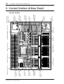 20
20
-
 21
21
-
 22
22
-
 23
23
-
 24
24
-
 25
25
-
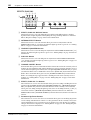 26
26
-
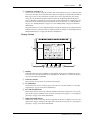 27
27
-
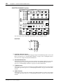 28
28
-
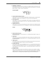 29
29
-
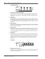 30
30
-
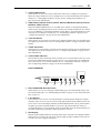 31
31
-
 32
32
-
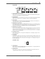 33
33
-
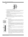 34
34
-
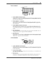 35
35
-
 36
36
-
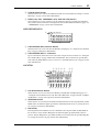 37
37
-
 38
38
-
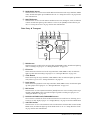 39
39
-
 40
40
-
 41
41
-
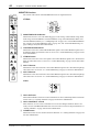 42
42
-
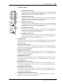 43
43
-
 44
44
-
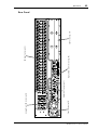 45
45
-
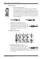 46
46
-
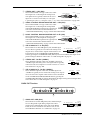 47
47
-
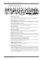 48
48
-
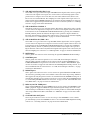 49
49
-
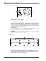 50
50
-
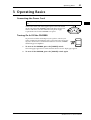 51
51
-
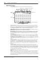 52
52
-
 53
53
-
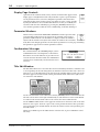 54
54
-
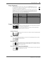 55
55
-
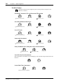 56
56
-
 57
57
-
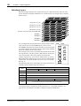 58
58
-
 59
59
-
 60
60
-
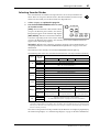 61
61
-
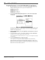 62
62
-
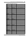 63
63
-
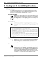 64
64
-
 65
65
-
 66
66
-
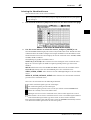 67
67
-
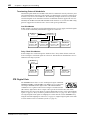 68
68
-
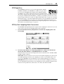 69
69
-
 70
70
-
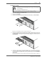 71
71
-
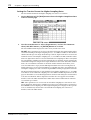 72
72
-
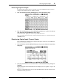 73
73
-
 74
74
-
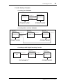 75
75
-
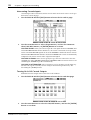 76
76
-
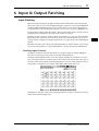 77
77
-
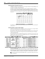 78
78
-
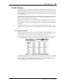 79
79
-
 80
80
-
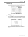 81
81
-
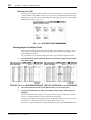 82
82
-
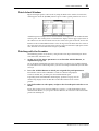 83
83
-
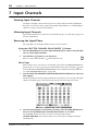 84
84
-
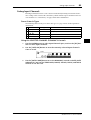 85
85
-
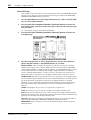 86
86
-
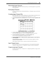 87
87
-
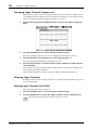 88
88
-
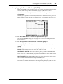 89
89
-
 90
90
-
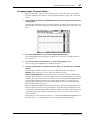 91
91
-
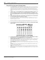 92
92
-
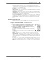 93
93
-
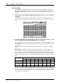 94
94
-
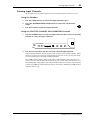 95
95
-
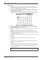 96
96
-
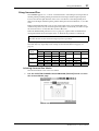 97
97
-
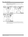 98
98
-
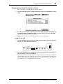 99
99
-
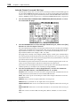 100
100
-
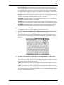 101
101
-
 102
102
-
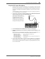 103
103
-
 104
104
-
 105
105
-
 106
106
-
 107
107
-
 108
108
-
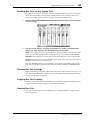 109
109
-
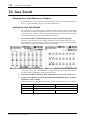 110
110
-
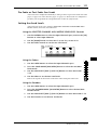 111
111
-
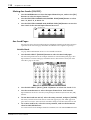 112
112
-
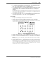 113
113
-
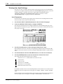 114
114
-
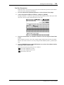 115
115
-
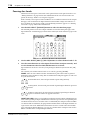 116
116
-
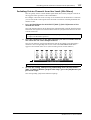 117
117
-
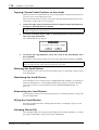 118
118
-
 119
119
-
 120
120
-
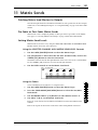 121
121
-
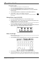 122
122
-
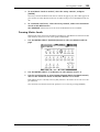 123
123
-
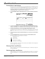 124
124
-
 125
125
-
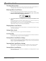 126
126
-
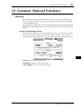 127
127
-
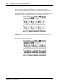 128
128
-
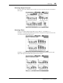 129
129
-
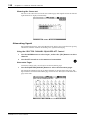 130
130
-
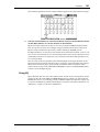 131
131
-
 132
132
-
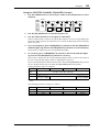 133
133
-
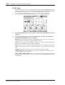 134
134
-
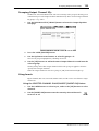 135
135
-
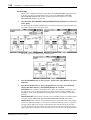 136
136
-
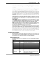 137
137
-
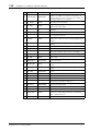 138
138
-
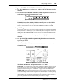 139
139
-
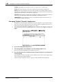 140
140
-
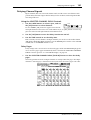 141
141
-
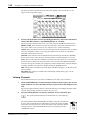 142
142
-
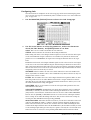 143
143
-
 144
144
-
 145
145
-
 146
146
-
 147
147
-
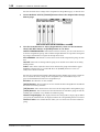 148
148
-
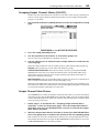 149
149
-
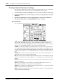 150
150
-
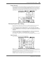 151
151
-
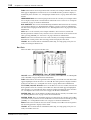 152
152
-
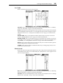 153
153
-
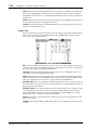 154
154
-
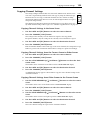 155
155
-
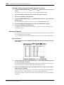 156
156
-
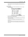 157
157
-
 158
158
-
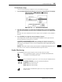 159
159
-
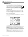 160
160
-
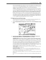 161
161
-
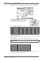 162
162
-
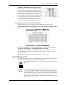 163
163
-
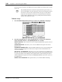 164
164
-
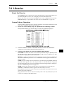 165
165
-
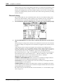 166
166
-
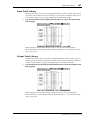 167
167
-
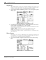 168
168
-
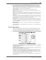 169
169
-
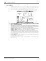 170
170
-
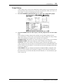 171
171
-
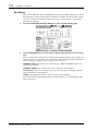 172
172
-
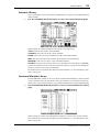 173
173
-
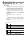 174
174
-
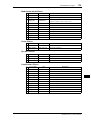 175
175
-
 176
176
-
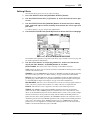 177
177
-
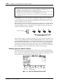 178
178
-
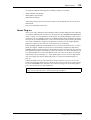 179
179
-
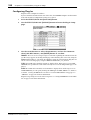 180
180
-
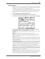 181
181
-
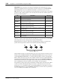 182
182
-
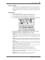 183
183
-
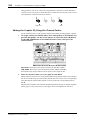 184
184
-
 185
185
-
 186
186
-
 187
187
-
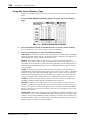 188
188
-
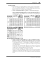 189
189
-
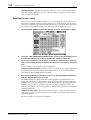 190
190
-
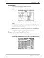 191
191
-
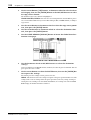 192
192
-
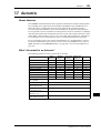 193
193
-
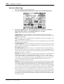 194
194
-
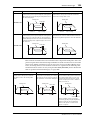 195
195
-
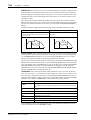 196
196
-
 197
197
-
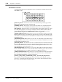 198
198
-
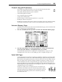 199
199
-
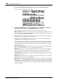 200
200
-
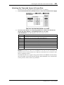 201
201
-
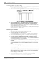 202
202
-
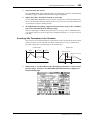 203
203
-
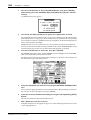 204
204
-
 205
205
-
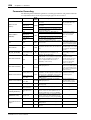 206
206
-
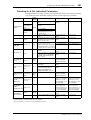 207
207
-
 208
208
-
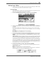 209
209
-
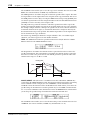 210
210
-
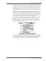 211
211
-
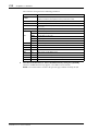 212
212
-
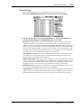 213
213
-
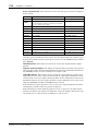 214
214
-
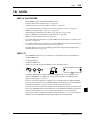 215
215
-
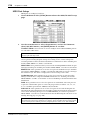 216
216
-
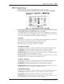 217
217
-
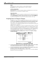 218
218
-
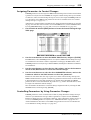 219
219
-
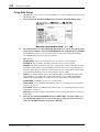 220
220
-
 221
221
-
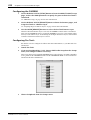 222
222
-
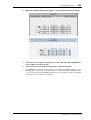 223
223
-
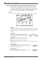 224
224
-
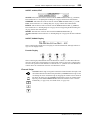 225
225
-
 226
226
-
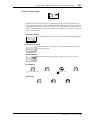 227
227
-
 228
228
-
 229
229
-
 230
230
-
 231
231
-
 232
232
-
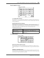 233
233
-
 234
234
-
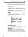 235
235
-
 236
236
-
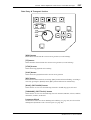 237
237
-
 238
238
-
 239
239
-
 240
240
-
 241
241
-
 242
242
-
 243
243
-
 244
244
-
 245
245
-
 246
246
-
 247
247
-
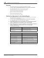 248
248
-
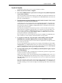 249
249
-
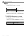 250
250
-
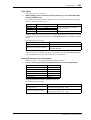 251
251
-
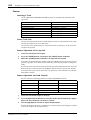 252
252
-
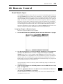 253
253
-
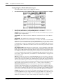 254
254
-
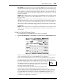 255
255
-
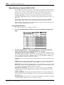 256
256
-
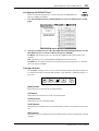 257
257
-
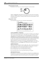 258
258
-
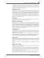 259
259
-
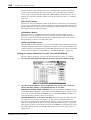 260
260
-
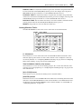 261
261
-
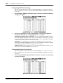 262
262
-
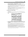 263
263
-
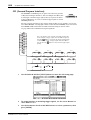 264
264
-
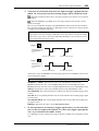 265
265
-
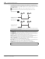 266
266
-
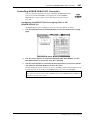 267
267
-
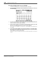 268
268
-
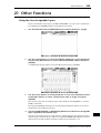 269
269
-
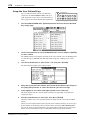 270
270
-
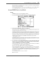 271
271
-
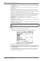 272
272
-
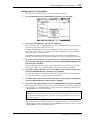 273
273
-
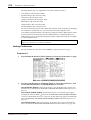 274
274
-
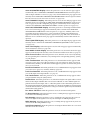 275
275
-
 276
276
-
 277
277
-
 278
278
-
 279
279
-
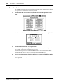 280
280
-
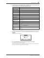 281
281
-
 282
282
-
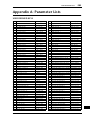 283
283
-
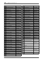 284
284
-
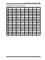 285
285
-
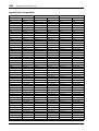 286
286
-
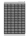 287
287
-
 288
288
-
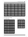 289
289
-
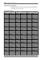 290
290
-
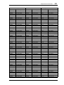 291
291
-
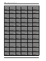 292
292
-
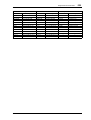 293
293
-
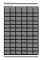 294
294
-
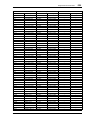 295
295
-
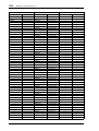 296
296
-
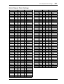 297
297
-
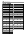 298
298
-
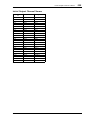 299
299
-
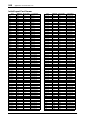 300
300
-
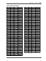 301
301
-
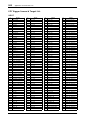 302
302
-
 303
303
-
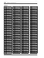 304
304
-
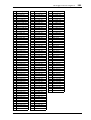 305
305
-
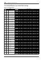 306
306
-
 307
307
-
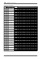 308
308
-
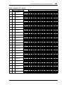 309
309
-
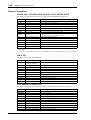 310
310
-
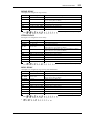 311
311
-
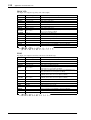 312
312
-
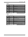 313
313
-
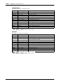 314
314
-
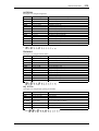 315
315
-
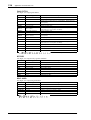 316
316
-
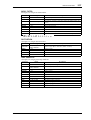 317
317
-
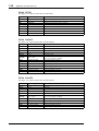 318
318
-
 319
319
-
 320
320
-
 321
321
-
 322
322
-
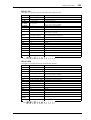 323
323
-
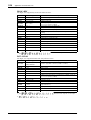 324
324
-
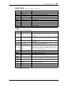 325
325
-
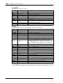 326
326
-
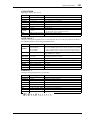 327
327
-
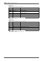 328
328
-
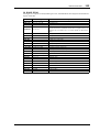 329
329
-
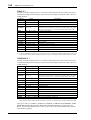 330
330
-
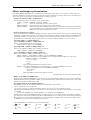 331
331
-
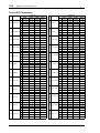 332
332
-
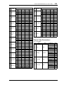 333
333
-
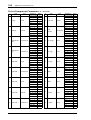 334
334
-
 335
335
-
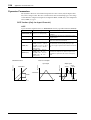 336
336
-
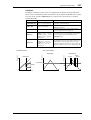 337
337
-
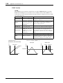 338
338
-
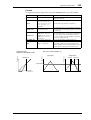 339
339
-
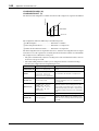 340
340
-
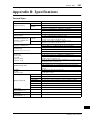 341
341
-
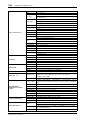 342
342
-
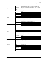 343
343
-
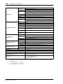 344
344
-
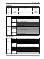 345
345
-
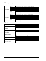 346
346
-
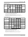 347
347
-
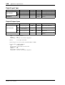 348
348
-
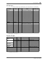 349
349
-
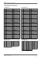 350
350
-
 351
351
-
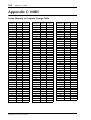 352
352
-
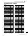 353
353
-
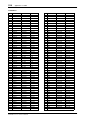 354
354
-
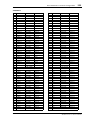 355
355
-
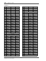 356
356
-
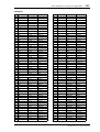 357
357
-
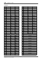 358
358
-
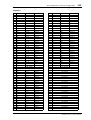 359
359
-
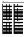 360
360
-
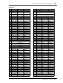 361
361
-
 362
362
-
 363
363
-
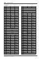 364
364
-
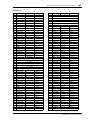 365
365
-
 366
366
-
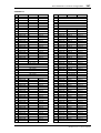 367
367
-
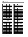 368
368
-
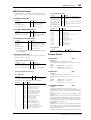 369
369
-
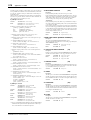 370
370
-
 371
371
-
 372
372
-
 373
373
-
 374
374
-
 375
375
-
 376
376
-
 377
377
-
 378
378
-
 379
379
-
 380
380
-
 381
381
-
 382
382
-
 383
383
-
 384
384
-
 385
385
-
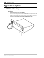 386
386
-
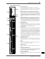 387
387
-
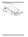 388
388
-
 389
389
-
 390
390
-
 391
391
-
 392
392
-
 393
393
-
 394
394
-
 395
395
-
 396
396
-
 397
397
-
 398
398
-
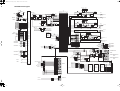 399
399
-
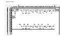 400
400
-
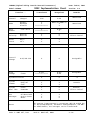 401
401
-
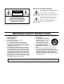 402
402
-
 403
403


Yamaha DM2000 Manual de usuario
- Categoría
- Controladores de DJ
- Tipo
- Manual de usuario
- Este manual también es adecuado para
en otros idiomas
- français: Yamaha DM2000 Manuel utilisateur
- italiano: Yamaha DM2000 Manuale utente
- English: Yamaha DM2000 User manual
- Deutsch: Yamaha DM2000 Benutzerhandbuch
- русский: Yamaha DM2000 Руководство пользователя
- Nederlands: Yamaha DM2000 Handleiding
- português: Yamaha DM2000 Manual do usuário
- dansk: Yamaha DM2000 Brugermanual
- polski: Yamaha DM2000 Instrukcja obsługi
- čeština: Yamaha DM2000 Uživatelský manuál
- svenska: Yamaha DM2000 Användarmanual
- Türkçe: Yamaha DM2000 Kullanım kılavuzu
- suomi: Yamaha DM2000 Ohjekirja
- română: Yamaha DM2000 Manual de utilizare
Artículos relacionados
-
Yamaha DM2000 El manual del propietario
-
-
-
Yamaha AD8HR El manual del propietario
-
-
-
Yamaha V96i Manual de usuario
-
-
-
Otros documentos
-
Phonic IS16v1 Manual de usuario
-
LD Systems AM8 Manual de usuario
-
Ecler DAM514 Manual de usuario
-
Marantz PMD-706 Guía del usuario
-
Peavey PC 1600x Cover El manual del propietario
-
-
Sharp 8M-B120C guía de instalación rápida
-
-
Sharp CP-LS100 High Performance Portable Speaker Manual de usuario
-
Whites TM 808 Manual de usuario