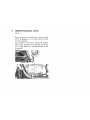
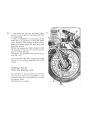
MOTO GUZZI 850-T El manual del propietario
- Tipo
- El manual del propietario

850 - T
OWNER'S
MANUAL
Pt # 1790 0000

Dear rider,
First of
all
we
wish to thank you for choosing this motorcycle of our
preduction.
By
following the instructions outlined
in
this manual you will ensure
your bike
s long
and
troublefree life.
Before riding, please read thoroughly this
manual in order
to
know your
motorcycle's feafures and
how
to
operate it safely.
All
major checking
and
overhaul jobs are best carried out by our dea-
lers who have the necessary
fa
cilities
to
quic
/e
ly
and competently repair
your Mota Guzzi.
Repairs
or
adjustments
by
other than a G
uz
zi dealer during the warranty
period
could
invalidate
th
e
wa
rranty right.


INDEX
4 Main features
10 Controls and accessor
ie
s
12
Identification deta
13
Instruments and controls
19
Riding instructions
22
Maintenance
28
Removal or wheels
31
Lubrication and maintenance chart
36
Lubrications
39
Carburation
42
Valve
gear
ing
43
Ignition - Checking and
ad
justment of double contact breaker
45
Checking of ignition timing
..
fixed
ad
'/ance
..
47
El
ectr
ic
al
eq
uipment

4
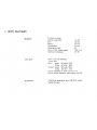
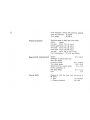
MAIN
FEATURES
Engine
Valve g
ea
r
C
arbu
ra
li
on
2-cylinder 4·stroke
C
ylinder
ci
isposition
Bore
Stroke
Disp
la
cemen
t
Compression
ratio
Revs. at max. engine
speed
Maximum
horsepower
O.H.V. push rod operated.
T
iming
data:
inlet: opens
20"'
before TOe
closes 52' aHer BOC
exhaust:
opens
52*
before
SOC
clos
es
20- after TOe
.v
..
9
0"
mm
83
mm 78
cc 844
9,5
7000 r.p.
m.
H?
65
Recker clearance
for
valve timing mm 1.
:.
Nor
mal
rocker
clearance, ce
ld
engine, mm 0,22.
2
Oell'Orto
carbu
re
tors
type VHB 30 CD (right).
VHB
30 CS (left).

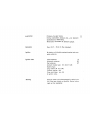
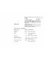
Lubr
icati
on
Ge
nerat
or
Ignillon
Ignition data
Starting
Pressure, by
gear
pump.
Normal lubrication pressure 3,
8";-
4,2
kg
/sqcm
(controlled by
re
li
ef-valve).
El
ectr
ica
lly
controlled o
il
pressure gauge.
Front
(14
V - 13
A)
on the mainshaft.
By
ba
ttery, with double
contact
breaker and auto-
matic advance.
In
iti
el advance
Automatic advance
Fu
ll
advance
Contact
break
S'
r gap mm 0,42 +
0,48
Spark plugs:
long
th
read
(0
14
x 1,25)
Thermal
degree
240
Plug points gap mm 0,6
2 ignition coil
s.
S'
26'
Electric starter with el
ectromagnet
ic
ra
tchet
con
·
trol.
Ring gear bolted on flywheel. Starter button.
ri
ght
on the handlebar.
5

6
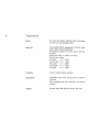
Trasmission
CIU
ICh
Gear
box
Frame
Suspen
sio
n
Wheels
Dry type, twin plates. flywheel driven. Contro
ll
ed
by lever, on the handlebar (left).
Fi
ve
speeds, frontal engagement. constant mesh
gears. Cush dr
iv
e incorporated.
Controlled
by
pedal on the left side of the mo-
torcycle.
Bevel gear ,a/io: 1 : 4,625
(Z
= 8-37
).
Overall
gear
ratios:
low
gear
= 1 :
11
.
424
second
gear
=
1:
7,928
third
gear
=
1:
5,
9EO
fourth
gear
=
1:
4,963
top gear
:::::
1:
4,284
Duplex cradl
e,
tubular structure.
Telescopic front fork
incorpora
t
i
n~
hydrau
li
c
dampers.
Rear swinging
fork with externa
ll
y
ac
j
ustab
le
springs.
Spoked rims,
WM
3/ 2.15 x 18 front and l
sa
r.

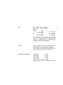
Tires
Brakes
Dimensions
and weights
Front 3,
50
H -
18
S
41
studded.
Rear
4.10 H -
18
S
~1
studded.
Pressure:
front
$010
with
passenger
r
ear
solo
with passenger
1.8
kg
/sqcm
2.2
kg
/sqcm
2
.5
kg
/sqcm
The
abovg data
Bre
for normal
rid
ing (cruising
speed). If us;ng Ihe motorcycle at cons rant h;
gh
speed
or
on
mo/orNays,
It
is recommended
to
increase
pr~ssure
by
0,2
kg/sqcm.
Fro
nl:
hydraulic
di
sc
brake. Disc ~
mm
300.
Controlled
by
lever, right on the handlebar.
Rear: expansion type
(0
220 x
25)
. Controll
ee
by
pedal on
th
e right side of the motorcycle.
Wheelbase
m
1,470
Max. wi
dth
m 0,780
Max. tength m 2
.200
Max. height m
1,OSO
Min. ground clearance m 0,150
Engine
we
ight (dry) with carburetors and elec-
7

8
Performances
Electrical equipment
Passing ability
tr
ical equipme
nt
, without inlet silencers. exhaust
pi
pes
and
s
il
encers
kg
60
,5
00
Cu
rb
wei
gh
t
kg
235
a.
Maximum speed in each gear. 5010 riding:
Gears Spe
ed
1
01'1
gear
km
/ h 76 (
47
m.p.h
.)
second gear
km
/ h 110 ( 63 m.
p.
h.)
thi
rd
gear
km
/ h 146 ( 90 m.p.
h.)
fourth gear
km
/ h
176
(109
m.p.
h.
)
top gear
km
/ h
195
a. (12 m.p.h
.)
Fuel consumption:
I.
7.27 x 100
km
(CUNA
).
Battery
Headlight of
sea
l
ed
beam type
Rear
light (lamp)
parki
ng
and
slop
Turn signal lamps
Spesdo
and
rev
. counter lam
ps
Neutral, generator, o
il
and lights tamps
Horn
12
V -
32Ah
12V-S
/
'<OW
12V
- 21 W
12
'1
- 3 W
12
'1
- 1.2 W
12V
Passi
ng
of a 55 fes! long t
ru
ck travelling at
20
m.p.h.
- Time:
- Distance
trave
ll
ed:
6,5
seconds
334 fe2t

Braking
ability
Passing of a 55 fee! long
truck
travelling
at 9
50 m.p.h.
- Time:
-
Oistanc~
travelled:
8,7 seconds
900
feet
The above includes a safe
ty
distance of
40
and
1
00
feet respectively between the passing and
pace vehicle at the beginning and end of the
manoeuvre.
Slopping distance from
60
m.p.h.
(so
l
o,
using
both brak
es
):
17i
feel.
Stoppi
ng
distance with passenger from
SO
m.p.h.
(us
ing both brakes): 193 1eet.
Fuel and oil capacities
Group
or
part
Fuel tank
Reserve
Sump
Gear box
Rear
dr
ive box
(bevel set lubrication)
Fr
ont
f
ork
(each leg)
Front brake
Quantity Recommendation
I.
25
I.
4
I.
3.5
I.
0,750
I.
0.340
I.
0.02
I.
0.050
Pe
trol
98
/
100
NO
-AM
Ag
ip F
.1
Supermotoroil
SA: 20 W / 50 .
Ag
ip F
.1
Rotta MP SAE S
Ag
ip F
.l
Rotra MP
SA:
90
Molykote type A
Ag
ip
F.
1 ATF Dexron
Agip
F.1
Brake fluid

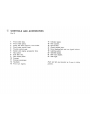
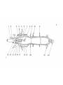
10
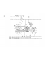
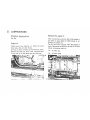
CONTROLS AND ACCESSORIES
(fig. 2)
1 Front brake disc.
2 Front brake pliers.
3
Pump and fluid reservoir,
front
brake.
4 Front
brake
contro
l lever.
S
Throttle
contro
l grip.
6 Starter and engine
emergency
stop.
7 Key
switch
.
8 Fuel filler cap.
9 Rear brake pedal.
10 Footrest
11
Footrest passenger.
12
Head
ligh
t.
13 Fro
nt
turn
si
gna
ls.
14
Indicator panel.
15
Mile counter.
16 Rev·counter.
17
Clutch control lever.
18
Horn. flashi
ng
light and turn sig
r.
als bueons.
19
Lighting switch.
20
Gearshift pedal.
21
Rear turn signals.
22
Rear
light.
Right and lelt ars Imsnded
as
if
se~n
in tiding
position.

11
12
13
14
15
18 19
21
22
2

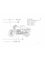
12
IDENTIFICATION DATA
(fig. 3)
E'lery
motorcyc
le is identified by a
se
rial numoei
which Is stamped on the frame down tube and
on the crankcase.
T
he
nu
mber
on
the frame
downtube
appears
also
in the certificate
of
conformity and is
....
a
~
lid
to
legal effects for the identification of the
motorcycle.

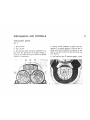
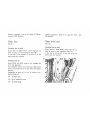
INSTRUMENTS AND CONTROLS
Instrument pan
el
(fig. 4)
M
ile
counter.
2
RS
'I.
-counter.
3 Red
warning
light
i
nd
ica
iing
insufficient
cu
r-
fant
from
the
generator
for battery c
haige.
It
m
ust
go
o
ut
wh
en t
he
eng
in
e reaches e
cer
tain
number
of
revo
lutions.
4 Orange neutral Indicator. It lights when t
he
gearbox
is in neutral position. It may be we
ll
to
ma
ke
sure
that
th
is positi
on
is correc!.
In
an
y
c:~
se
It is a good practice to
pu
ll the clutch
be
-
fore starting.
5
Re
d wa
rn
in
g light.
Oil
press
ure
gaug
e. It g
oes
13

14
out when the pressure is sufficient for normal
engine
lubr
ication. Should it
not
go
out, the
pre~·
sure is not
correc
t; in this case the angine has
to be stopped and
su
itable
chec
kings are to be
carried
o
ut
Ig
nition key and
steering
loc
k
The key has
fQur
positions (fig. 5):
6 High beam warning light (red).
By
da
y riding
all
warning
lighls
ar
e to be out.
·0
·
Standstill. key not
re
movable.
· 1.
(i
ntermediate)
Turned anticlockwise, standstill, key removable. Steering
locked on removal of
key and turning of
th
e handlebar right or
refl
Turned clockwise, be!ween position
-0
..
and position -2
.,
key removable. In
this position the key can
be
remov
ed
without locki
ng
the steering.
Turned c
lock
wi
se
. raaey
to
start, all controls are in.

Lights swi
tch
Left, on the handlebar,
-4
positions (fig. 6
..
a
..
).
..
,
..
OFF Lights oH.
..
2
..
PARK Rear light.
•
3.
L Low
beam.
..
4
..
H High
beam.
• 5. Safety
(to
come back to
posit
ion
OFF
press the button towards
1he
lelt).
~
'I
.
f~
.::
-
....
-:
..
-
.--:-:
-~
.
-
.
...-.
--':"
.
_l~;
Horn, flashing light
and turn signals
left,
on
th
o handlebar (fig. 6 -C
o)
.
• 6
..
HO
RN
Horn button .
..
7
..
F
LASH
Fl
ash
i
ng
light button .
..
8
..
Turn signals button .
..
9
..
When turned to the right operates t
he
right
sig
na
ls .
-
10.
When turned to the l
eft
operates: the le
ft
signalS.
....
'"';.'
".
-:-
-.-
15

16
Starting and engine
emergency stop
Righ
t.
on
the
handle
bar
(fig. 7
.A·
).
With the i
gn
ition key in
pos
ition . 2
..
the motor·
cycle is ready to be started.
To
start the engi
ne
(see
-A.)
press the
button
..
1
..
START.
To s
top
the
~
ng
i
ne
(in case of emergency) turn
the
butten
in pos
itio
n
..
3
..
or
.4.
OFF.
Carburetor starter control
T
he
two levers
for
starting a
cold
engi
na
are
located left on t
he
left ca
rburetor
and right on
the right c
arbu
retor
(fig. 23) .
..
A
..
S
tarting
~os
jti
on
.
• 8
..
R
idi
ng pos
ition
Throttle control
Right on the ha
ndleb
ar;
thr
o
tt
le is opened by
turni
ng
toward the
rider
and closed viceversa.
Clutch control lever
.Left on the
ha
ndlebar, to be used for starti
ng
and gearshifting only.
Front brake control lever
Right on the handlebar. connected with the brake
pump fluid reservoir.
Rear brake pedal
On the right side of the motor
cyc
le.

Gearshift pedal
On
the left sice of
~he
motorcycle (fig. 8).
l
ow
gear: pedal down.
2. 3,
4.
and
top
geer
:
peda
l up.
Neutral position: between low and 2nd gear.
B
elo
re
op~
rat
i
ng
the gears
hift
pedal, the clutch
lever has to be camp/staiy pu
ll
ed in.
,.
•
-,'
10
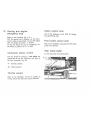
Fuel filler cap
To open it. press the control button
.A.
(fig. 9).
Fuel taps
They
are
loca
ted
fear
, under the fuel tank
(I
ig. 10
).
Pos
itions:
-A.. Open (vertica
l)
.
-R
oo
Reserve (horizontal) see cR_ on the tap
s.
.C.
Closed (horizontal) see •
C·
on
the taps .
17

18
Terminal b
lock
with fuses
It
is
located under the seat (fig.
11
) and
ho
l
ds
n. 6
15
A
fuses
.
11

RIDING INSTRUCTIONS
Chec
:<ing
Befo
re
start
i
ng
the engine ensure t
hat:
• there is sufficient fuel in the tank;
• the o
il
in
th
e
eng
in
e sump is at
correct
le
vel;
• the ig
nit
ion
ke
y is in
po
sition -2- (s
ee
fig. 5
);
• the
wa
rning
li
gh
ts: r
ed
(o
il
pressure
9au9';
and
generator
);
or
ange {
neutra
l i
nd
i
cator
} are
lit;
• the sta
rt
er
levers 0
:1
the car
bure
t
ors
,
for
col
d
eng
in
e
are
in starting position (v
ertical
) see
-A
..
in fig.
23
.
Engine starting.
Aft
er
t
he
f
ir
st checking.
tt!r
Q.
the
tw
ist
gr
ip
1
/
~
towards
the
ri
der
and push the start
butto(l
. ri
gh
t
on the ha
nd
l
eb
ar -1- S
TA
RT in fig. 7.
After the
eng
i
ne
has been starIsd. bef
ore
ret
urn
-
i
ng
the staner con!rol levers into riding position
(horizontal) see
.8
..
in fig.
23.
let
the engine
id
le
a
short
while in the hot season and a few minu-
tes in the
co
ld season.
S:,ould the cont
ro
l starter levers be left In start-
ing
pos
iti
on . An In fig. 2
3)
by
rid
ing, there would
be Irregu
lar
carburction and Increas
ed
luel con-
sumption and ev
en
worse. there could be the pos-
s
ibili
ty
01
seizures because of too much pe
lrol
going in
lo
the cylinders.
Do
nOi
forget
t
h
~
t
if
the engine is in gear. the
neutral i
nd
i
cator
lig
ht
(orange) is
not
lit:
to
start
th
e
~
n
g
i
n s
in
sue
.; co
nd
itions could
be
very dan-
gerous, unless
the
clutch
Is
kept lu
lly
disenga-
ged, as the
motorcycle
itsell
may
stan
off
.
Starting a hot engine
In this C2se it is not necessary to set the
sta
i!
er
control levers on the carburetors in startin
s;
pc-
s
ition
(
..
A
..
in fig.
23
) as this wo
uld
richen t
he
carburati
oio
tco much.
19

20
On
the
way
To ch
a.
nge to
another
gear
close the
thrott
le
control. pu
ll
in
comp
letely
the cl
utch
lever and
sh
ift
into
l
oe
new
ge
ar;
release gen
tly
the clutch
lever
and
open
the
throttle
contro
l at the
sa
me
time. The
gearshift
peda
l has to be firmly actu
=.-
ted
and
foot
accompa
ni
ed
.
When
shifting
do
wn
to
a
lower
gear
,
grad
ually
operate brakes and thr
ot
tle
contro
l
no
t to cau
!:
the
eng
ine
to
go
over
revs
whe
n releasing
th
E
cl
utch
lever.
Stopping
the
mot
orcycle
Close the
thr
ottle
conuol
and
simultan
e
ous
ly
ope
rate
bot
h the
br
ake
contro
l fevers, the cl
UlCh
lever
will
be p
ulled
in· ',
'1hen
the
mo
t
orc
ycle co-
mES
al
most
to
slopp
ing
.
This man
oeuvr
e has
to
be
very co--ordinalely car-
ri
ed
out not
to
let
the
mo
t
orcyc
le
going
beyond
C
ontro
l.
To
no
rmally
reduce
speed, use the engine
b
r
= ~
Ing p
ower
by
c
orrectly
gear
shlft
i
ng
and paying
attention that the engine does not go over
re
vs
On wet
or
slippery
roads, the brakes, expecia
ll
y
the front one, have
to
be
carefully
operated. -
To stop the
~ng
i
ne
turn the igni
tion
key to
p os
i
~
tion
..
0·
see
fig. 5.
~
When the engi
ne
Is stopped remember to clo
se
the taps
by
turning them to
position
n e
ll
In ·
lig. 10.
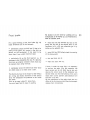
Parking
By
par
king
by
night on
insuff
ici
ently
lighted
roads,
it
is necessary to let the rear
light
on,
by turning the i
gn
i
tio
n key
to
positi
on
. 1
..
see
fig. 5 a
nd
th
e
li
ght sw
it
ch to position . 2-.
To
l
ock
the steering w
ith
the key in position
.1"
sse fi9. 5 turn t
he
handl
ebar
co
mpletely left
Or
right
ihan
take off the key from the s'Nitch.
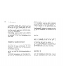
Running in
Du
ring the first 1600 kms (1
000
miles) a new or
overhauled
motorcyc
le has
to
be used very care-

fu
ll
y;
as
efficien
c
y,
performance
and
life
of
the
engine
are l
argeiy
dependan:
on
hoVi the
motor
-
c
ycle
is run in.
The engine sh
ou
ld
never
be a
ll
owed
to reach a
Running
In
speeds
D
istance
low
gear
Up
to 800 km
(500
miles)
~
(26)
From
BOO
up
to
1600
km
55 (3t.,
5)
500
1000
m
il
eS
high
number
or
revol
utions
before having c
2i
chance
to warm up suHici
enlly
.
Never exceed the following speeds and
do
not
force
the engine long time.
Max. permiss
ible
speeds km/ h (miles/ h)
2nd
gear
3rd gear
I
4th gear
5th gear
65
(~O
)
85
(53)
100 (62)
115 (
72
)
80 (00)
105
(
65
)
120
(7
5)
l~O
.(
Bi
,S)
From
1500
up
to 3000
km
Increase
gradua
lly
the speed
up
to the max. permi
ss
ible
li
mits.
1000
1800
miles
After
the fi
rst
500 km (300
miles)
Change
the e
ngin
e oiL
T
ight
en a
ll
nuts and
bo
lts.
Check.
tighten
spokes.
It
necessa
rj
adjust
valve
roc
k
er
clearance.
Check contact breaker points.
Every
500
km
{30D
miles}
Chec
k o
il
le
'l
e
l;
cO
H
~c
f
level is near
ly
at t.'e
maximum mark (see the marks
on
the oil filler
cap
dipstick).

22
MAINTENANCE
Cleaning
: fuel tan
k,
fuel taps,
fi
lter
s and fuel lines
Every 10000 km (6000 m
il
es)
or
so,
or
any lime
fuel
flow
to the
ca
rburetors is
not
re9uI2(, It is
necessary
to clean the fuel tank. the fuel taps
the
filters
and
the fuel
li
nes.
The tap f
ilt
ers and ducts.
th
e filters on the car-
burelOrs
and
th
e fuel
li
nes
are
to
be cleaned in
petrol and
then
to
be
bl
own
with compressed
ai
r.
12
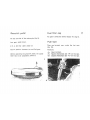
Adjusting the
clutch lever
If the tree play at
th
e handlebar (fig.
12)
is more
or
less than mm
4.
slacken thumb screw
..
a
..
and
screw
in
or
out adjuster
..
A.
to obtain the
ce
f-
rect play.
This adjustment can also be carried out by sla-
ckeni
ng
nuts
.Coo
and acting on
ad
j
uster
..
0
..
that is
lo
cated right on the
geai
box.

Front
br
ake
For a
good
work
ing
of
the
tront
brake
(fig. 13)
these
directi
ons
af!
to be followed:
• periodically check the fluid level (it has
to
be
nearly at t
he
gaiter
..
E
..
located
in the
lIu
id
fe
·
servoir
on
the
handlebar
) ;
it
has never to be
lower than 6
mm
under
maxi
mum
level;
•
period
i
cally
fill up the fluid reservoir
·A
·
(if
necessary)
aftar
loosening the
cap
.;:
. ; lake the
fluid from an
orig
inal
container
which
must only
be
opened
when
using
the lIuid;
•
comp
letely renew the brake fluid every
1SC::O
km (9000 miles)
or
at
least
one::!
a year.
The
fluid
ducts
have
to
be always
fu
ll and
without
air; a l
ong
and elastic movement of the control
lever -8- evidences the presence of air insi
de
the ducts.
Fluid to be used
.Ag
ip F
.1
brake fluid
..
.
Use only fresh fluid in
case oi washing.
No
alcohol
is
to
be used
tor
washing and no
23
compre
ssed air for drying up; use Trichloroethy.
lene
for metallic par
ts.
• check that the play between the
1I0
at on the
pump and
the end
at
the
contro
l lever on
Ute
handlebar
Is
0.1 -:- 0.3 mm; otherwise get
it
by
acting on the adjuster
-G
- ;
•
every
5000
km
(3000 miles)
check
the wearing
of the Drake
pads:
- new pad
th
ick. mm
9'
- wear limit
ih
ick. mm S a.
If
th
ick. is under the
wear
limit
,
it
is necessary
to
rep
l
ace
the pads. After this operation has
ceen
car
ried
out
, do not
dra
in the air but on
ly
ope
rate the
con
trol lever on the handlebar
..
S
..
several times
unt
il
the small pistons of the pliers
reach their normal position; pad distance
item
the disc a. 0.2 mm.
8y the
rep
l
acem~nt
of
the pads cheCk the
con·
dHion
of
the lIuid ducts. should they be
dama;'!d
.
replace them immediatel
y:

24
• the
brake
disc
mus;:
be
accurate
ly clean, 13
without o
il
. fat
or
other
dirt
and must not show
any deep r
ifling.
In case of replacement
or
overhau
li
ng
of the
brake di
sc
, it is
n~ce!sary
to
check
the
flutter-
ing 01 the S2me. This
checking
is
car
ri
ed
out by
means of a
prop
er gauge that must never read
more
than
0,2 mm.
Should the
fluttering
be
higher
, carefully check
the mounting
of
the disc on the
hub
and the
play
of
the
hub
bearings.
Co
nne
c
ti
on
torque
between disc and hub is kg/
cmq
2
.
~
-:- 2,';.
Pa
d repla.cement and disc ch
ecking
are best
ca
rr
i
ed
out
by
officiall
y
appointed
,IAOlO
G
U2zi
dea
lers.
Draining the
air
from the
braki
ng un
it
This
operat
ion is
requ
ired
when
the moveme. t
of
ths
contr
ol
le'!er on the
hand
le
bar
is long
and elastic
because
of the presence
of
air i
r.s
ide
the braki
ng
c
ir
cuit.
Opera
tions are
as
fo
ll
ows:

•
lurn
the
hand
l
ebar
un
til the fluid reS 2
rvoir
..
A
..
reaches t
he
hor
izo
nta
l p
osit
i
on
;
•
if
necessary
. f
ill
up
the lIuid reset"Joir
.A
..
(take
care
tha
during
the air
dra
i
ning
1he
fluid
does
not
go
8
mm
l
ow
er
th
an the
max
i
mum
level);
• by the air
dra
in
in
g
act
on a pliers·ha
lf
..
e
..
at a
time
:
a)
take
out
the
rubber
cova
r,
then fit a transpa·
rent
flexib
le
du
ct
. 1
..
on the drain p
lu
g . H
..
; the
o
ther
e
nd
of
this
duct
will be
plunge
d into a
tra
nsp
are
nt
con
tai
ner
. L
..
partially
filled up w
ith
fluid of the same type;
b)
loosen
the
drain
plug
..
n
..
;
c)
comp
letely
op2
rale several
times
the
bra
ke
control
le
ver
..
5
..
on
the
. handlebar, release
it
slowly and wait for a few
se
conds before ope·
rati
ng
it
aga
in
.
Repeat
this operalion until the
du
ct
plunged
i
nto
the
transpare
nt
con
tainer
em
it
s
airless
flu
i
d;
d)
keep
the
contro
l l
ever
..
5
..
comp
le!ely
drawn
and
lock
t
he
drain plug
..
H
..
then ta
ke
o
f ~
the
due:
..
I
..
and m
ount
the rubber cover.
It
the a
ir
drain
in
g has been
cor
r
e~
t1y
card
-ed
au:
. 25
a
direct
and effici
en
t
work
ing of
~he
fluid w
ill
be
reali
ze
d immedia!ely a
ft
er the initial idle move.
ment of Lie lever -e
..
; otherNise repeat
tn
!:
i!
ir
dra
inin
g.
Adjustment of the rear
brake
control pedal
Th
;!
adjustment is carried out by ac
tir
l
!il
on the
adj
us
ter
-A·
(fi
g.
,~
)
.
Exce
ss
ive play is correc!
ed
by screwing this adjus:er.
The lever is c
orr
ectly adjusted when there is a
20 -:-
25
mm
, play before the
lining
s ca
n'
:'CI
the drum.
Adjustment oi the rear
suspension
The e
Xle
rnal springs of the rear suspension can
be adjusted on five positions by ac:ing on. the
le
ve:s
.;,
...

26
Ste
rting
from p
ositi
on ,
<I
..
tum t e levers
~A
"
(see the
arrow
in fig. 15) i
nto
pos
ition
s
..
II
..
,
.
11
1- ,
.I
V-,
-v_.
In case
of
fau
lt
y
damper
operation,
have t
hem
chec
ked
by
o
ur
daa
lers.
Do
not larger that the two springs have
to
be
ad
jusr
ed
at
t
he
same
positions,
to ensure a
good
stability
01
the
mo
torcycle.
14
Adjusting the steering
For
a safe riding, steering has to be so ad
ju
sted
(fig.
16
) to a
ll
ow
a free movement
01
the hand-
l
ebar
but
without excessive pla
y.
To
correc!
ly adj
ust
steeri
ng
opera
te as fo
ll
ows:
• slacken the steering
head
fixing
bolt
.A.
loos
en the
nut
..
8
..
and screw in or
out
the adiu-
....
-
..
,
...
:::
.
l S
:~~~7~
~_
.

ster
.c
- to :a
ke
up
exc!ss
l'/e piay.
After
this
ad
justment
has
been
made, l
ock
nut
..
8- and the
steering head fixing bolt . A ...
It
is r
ecommended
to ha'ie this operation carried
our
by
our
deafers.
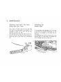
27

28
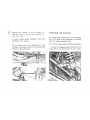
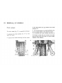
REMOVAL
OF
WHELS
Fr
ont
wheel
The front wheel (fig.
17
) is remov
ed
2S
fo
ll
ow
s:
•
unsere
.....
the wh
ee
! spindle nut
..
A
..
on the
right fork
co
v
er
;
• slacken the screws securing the fork covers
t7
18
to
the wheel spindle . 8. and slide out the
whee4
sp
indle . C
.;
•
lift
the motorcycle
so
to slide the braki
ng
disc
out of its pliers fixed on the
right fork cover.
Tc
re-assemble the wheel operate vi
cever!!,
do
not forget to check the pl
ay
between t
he
brake
pads and the brake disc
(see t
he
chapHH
Main-
tenance -Front brake
..
).

Rear wheel
To remove the
rear
whee
l (fig. 18) from the
rear
dr
iv
e and from the arm of the rear suspension
proce
ed as fo
ll
ows:
•
slacken
the
locknut
"0"
on the
drag
link
of
the brake block lever;
• unscrew
nut
..
c- which
sec
ures
the wheel
sp
indle
to
the
rear
dri
ve
bo
x;
• u
nscrew
nul
..
A
..
w
hi
ch
se
cures
the a
nchor
-
ing
bracket
to the
brake
bloc
k;
• u
nscrew
nut
. 0
..
w
hi
ch
secur
es the
rear
su-
spensi
on
arm to the
whee
l spi
ndle.
then
slide
the sp
indl
e
..
E
.,
out
of
rear
drive box,
whee
i
hub
and rear suspemuon arm:
shift
the
whe
e! to the l
eft
to free the
dr
i
v
j
n~
gear
from the sleeve in the
dr
iv
e
~o
x:
• lean the moto;cyc1e
to
to: left and f e
move
the
whee
l.
To
re·assemb
le the
whee
!
oper
ate vicever
sa
;
remember
to
fix
the
anchoring
bra
kel
10
Ihe
br
ake
block.
Adjusting the spokes
Che
l;
k that a
ll
spokes are
tighten
ed
a
nd
the
wheel is
not
out
of
ce
ntt
!
by
proc
eedi
ng
2:S
f
ollows:
•
get
the wh
ee
l turn and
chec
k its
ce
nteri
;;g
.
it
necessary act on the ri
ght
or left spokes
!Jnl
il
the wheel turns properly. T
hi
s checking
ha!
to
be carried out after
th
e firsl 500 km (
300
m
ii
es
)
and
later
on every 15
00
km (S
OO
miles) or
50
.
Wh
ee
l balance
To improve
st
ab
lll
:y and decrease vibr
at
ions at
hi
gh
s
pseds
the w' eei
s.
ave to be kep!
~.!
I
c.
n
:.!:
.
Operations are
as
follows:
• a
ft
er remo
vin
g the
whee
l and ch
ec
king
tl':
at
all
spokes
are tighten and the wheel
c
~
m
e:
;n
~
.
suspend it on a fork;
•
sp
in the wheel lightly
se
ve,al
times and 52:
if
It stops a
lw
ays in various
pos
itions,
th!.!s
in: i·
cati
nQ
a correct balance;
29

30 •
if
one side of ths wheel always stops at the
bottom.
put
a balance weigh! on a spoke
cppo
-
site that side;
•
re
peat
this
operation until
th
e wheel is c
or·
re ,Iy bal
anced
then fix the balance weights to
the sp
okes
by means
of
pliers.
Balance
weights
are available from our dealers
in
15
,
20.
30 grams.
Normally
. an Imbalance of less than 15 grams
does
not
affect the motorcycle
s
t
a~
ili
t
'l.

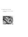
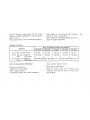
LUBRICATION AND MAINTENANCE CHART
(Iig. 19)
Mo
nthly
every
3000 km
(2000 miles)
1 Check elect
ro
l
yt
e Isvel in catter/ (see chap
te
r
Eleclrical Equipment
..
Ba
tte
ry
).
Periodic
ally
2 Check
ty
re
pressure
(
se~
chapt
er
Main
l
e
a
~
tures pag. 7).
After
the iir
st
5
00
km
(300 m
ile
s)
3
Re
place the crankcase oil
(
s=~
ch
ap
ter
Lu
-
brical
io
ns).
4 T
igh
le
n a
ll
nuls and bo
lt
s.
5 Check a
ll
ti
gh
t
en
spo
k
es
and '
....
hes! centeri
ng
(see chapter Removal of
wh
e
els
_Adjusti
ng
the
spokes
D
) .
6 Check rocker cleara
nc
e (see ch
ap
ter Vaive
gearing
..
Tappet clea
ran
ce
-).
Every 500 km (300 miles)
7 Check o
il
level in thE ciankcasa (see chapter
Lubrications).
Every 1500 km
(900
miles)
8 Check a
ll
li
gh
t
::-
"
spo
k: s a
r.d
c
ent
u ing of
whee!s (see chapler Removal
of
wheels
..
Ad
ju
st
-
ing
th
e spokes
..
).
31

32
PERIODI
CAlL
Y
:'
___
_
-{
EVEnY !
OO
KMS ( 3ro
E
VE?Y
1.3:00
KMS (
EVERY 3.000 KMS
(U!OO
MILES
):
- +-1---!12i-{
E'JE;;'Y S.
1X1
K:
.:S (
3.'::00
MI
t=.S
):
-_-',,
___
t-
__
+
__
_ .;'i:'1i
=
'1
::~
y
10.COO
K!
.:3 ( 6.
C«.I
.-I
I
E.5
l:-
--
-
,!§
-
-iJiQ-
- -{I
4;:---
-
;----
- -.;...--
-------
;:V
:n
Y
lS.er.l.l
Kt
.
'S
( 9
.COO
MIL.:S
I'
_____________
...;'i
!'lZ
E'J
EiW
~
.
~1J
:{1.15
(
,2.C.oo
.MI
'
LE5
1,
---------------
-----
--
~t---
-----
-

------
~4r_
------
~~
~~
__
-------+------
--
-19
I
I
------------~--~~--~
GD
o
MAm
t:
NAU
CE
.6.
AG
IP F
.•
S
UPE~
MOTO
ROIL
S";E ';'JW
.'
s-l
o
AG
IP
F.1
ROiRA
MP S':"E
9G
o
AG
iP F.l
ATr
CE
XRON
o .;GIP F
.1
O
RE
';
SE
30
(~AG
l
?
F.1 9;;',;KE
r:tUIC
"
33

34 Every 3000 km (2000 mil
es
)
9
Replace
o
il
in
the
eng
ine
cran
kc
ase
(see
chapt
er
l ubrications
).
10 C
heck
roc
ker clear
ance
(see chapter Valve
gearing
-Tappe
t
clearance
..
).
11
C
heck
the
o
il
level
In
the
gear
box
(see
chapter
Lubr
ications).
12
Che
ck
oil level in
the
rear
dr
iv
e
box
(see
ch2!pter
Lubrications
).
Every 5000 km (3000 miles)
13
Chec
k the
fluid
le
'l
el in the
bra
ke
fl
uid reser-
voir (S1:9
ch
ap
ter
Maintenance
..
Front brak;
..
).
Every 10000 km (6000 mil
es
)
, t; Clean the fuel
tan
k,
the
fuel taps, Ih; filters
and the fuel lines
(see
chapter
Maintenance
..
Clean
ing
the
lue
l tank.
filter
s.
laps ; nd f el
lin
es
..
).
15
Re
pl
ace
the o
il
in
the
gea
r box (
see
chapt
el
lubrications
).
16 Replace the oil in the rear drive
box
(see
chapl
er
Lub
ricatio
ns
).
17 Clean and smear
aU battery co
nnection
s
(see
chap
t
er
E
lec
trical
equipm!nl
-a
attery-).
Every 15000
km
(9000 miles)
1 B Replace the bra
ke
fluid of the front brake
(see c
hapter
Malnlenanc~
-Front
:'
rake
..
).
After the first
20
000
km
(12000 miles)
All ch
ec
l
dngs
hereunder
c!!c:
i
~ed
mu
st
be
car-
ried out by our dealers:
19
Ch
ee
k that there is s
um
c:e
nt
grease in the
wheel
bea
rin
~s
-Agip F
.1
G.
ra2se 3
0-
or equi-
va
lent.

20
Check
that
there
is sufficient grease in the
sls
ering
bear
ings
..
Agip
F.
1 Grease
30
..
.
21
Repla
ce
the o
il
in the
fork
covers (use
.Ag
ip
F
.1
ATF Dexron
..
)
quantity
I.
0,
020
(h
alf a glass
a.
) per cove
r.
22
Clean
starter
moto
r end generator commu-
tators using
a clean rag slightly moistened with
petro
l.
35

36 LUBRICATIONS
Engine lub
ri
cation
(
fig
. 20)
Engine o
il
Us
in
g the o
il
f
ill
er
dipsti ck
"1"\
"
c
h
!;!c
~<
Ins su
mp
level ev
ery
500
;';:
m (30 miles).
Co
r
rect
o
il
level is
near
ly at
the
max
imum
mar
lc
S
hou
ld the level ba
lower
than
recommend
gd.
fiji
up
with
oil
of
the same type
and
features.
-
--
- -- _.
20
21
Replacing the
en
gine all
Atter
Ihe first 300
~
5
00
km (200 -:- 3
00
m
il
es
) a.
and
later
on every 3000 km (2000 miles)
or
so,
cha
nge
the eng
in
e o
il.
The o
il
has
to
be replaced when the engine is
warm.
Rem
ember
to
a
llo
w all the old oil to drain
before
introducing
fresh oil.
..
A. oil filler cap.
· 8
..
oil drain plug.

Quant
ity
required:
I.
~
,
5
of
o
il
..
Ag
ip
F.1
Super-
rnoloroii
SA:
20
\V / 50
...
Gear box
(f
ig.
21
)
Ch
eck
ing the
oil
level
Every 3000 km
{2COO
:n
il
esj cnsck tha: the o
il
level is
near
ly at the ins;::ecti
on
hole
..
8 ...
lt this level is
not
cor
r
ec~
,
fi
ll
up with o
ii
of the
same type and f
ea
tures.
Changi
ng
the oil
Every 1
eooo
km (
SO
CO
miies)
Qr
so, change the
oil
In the
gear
bo
x.
This
operat
ion should be
car
ried out a
short
time
aller a
ride
When the o
il
is st
ill
waim
and eas
il
y
drained.
Remember to
dr~
in
all the old o
il
be
fore intro-
d
UCin
g fresh oil.
-A-
oil f
ill
er
ca
p .
• 8
..
level inspection plug.
·C
· o
if
drain plug.
22
Oua
ntir
!
re~u
ir
ec
:
I.
0,750
of
oil
-Ag
ip F.1
ROlra
37
M?
SA:
SO
".
Rear drive box
(I
ig. 22)
Checking the o
il
level
Every
3000
km
(
20C>O
m
il
es
)
check
that the o
il
level is
ne2f
[Y .;: the inspe::tion
ho
le
..
A
-.
If the !e'/el is
no
!
e:mect
, fill up with oil
of
H,
!
same type anc featur
es
.

38 C
hanging
the 0
11
Every 10000
km
(6000 miles) change the oil in
the rear
drive
box.
ih
is
operat
i
on
should
be
carr
ied out a
short
time
after a ride when
the
o
il
is st
ill
warm
and
eas
il
9
drained.
Rememcl':lI
.
~
dra
in all the old 0
11
before intro-
duc
ing fresh oil.
..
A..
inspection level plug .
..
3
..
oil filler cap .
..
Coo
oil drain plug.
Quanti
ty
required:
I.
0.3';0
or
oil
-Agip
F.1
Rotr!
M?
SA:
90
..
I.
0.Q20
of
oil
-Molyko!.
A·
.
F
roni
fork, s
teering
bearings,
whe~s
and
rear
suspensio
n
For these
~
t.lbricat
i
cns
it
is
suggested
to apply to
our dealers.

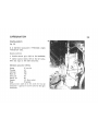
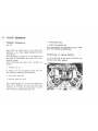
CARBURATION
Carburetors
(fi
g.
23)
N. 2 Oell'Orto Carbure!ors
.VHS:10
CO
..
(right)
.VH
B
30
CS·
(Ielt).
Double controls:
• throttle
co
ntrol gri
p.
right
on
the handlebar;
• starter control levers, left on the left carbu-
retor and right on the right carbure
to
r.
Standard carburetor setllng
Choke
Th
rottle
o
mm
30
40
Atom
izer
255
Main jet 142
Idling jet 50
Slartar
jet
eo
Needle V 9 (2nd
not
ch)
Float 10 grams
Id
ling
screw:
cpen 2 to 2
11
1 turns for the left
carburetor - open 2
1
/ .
to
2
J
/
.1.
turns for the right
carburetor.
39
23

40
Adjusllng
the
carburalion
(fig.
23
)
The
car
b
yration
Is ad
just
ed
on a
hoi
engine after
the
inlet
and
exhaust
tapp
ets have been set at a
correct
di
stance
.
Pr
oceed
as fo
ll
ows
:
1 W
ith
the
ca
rbur
etor
rubber
Inlet manifo
ld
reo.
moved,
che
ck
that
bo
th gas valves
open
at
the
same time. This is done by turning the
thro
ttl
~
grip and at the same time t
ee
li
ng
w
ith
your
tin-
gers on
'he
car
buretor
sli
de
s
if
these
open
simul·
taneously by the same amount.
Sh
ou
ld one valve
open
befo
re the ot
he
r.
corr
ee!
by setting screw . C. in
fig
.
23
in the position
where by
tur
ning
the
thrott
le grip both valv
es
open
simultaneousl
y.
2
Ad
just the id
lin
g speed by
acl
ing
on
the
sc
rew
· 0
...
Scr
ew
ing t
his
in reduces
th
e fuel
flow
and
viceversa i
nc
r
e3ses
It. To adjust,
tight
en
the
scr
ew
then
undo
it 2 to 2
1/
:
turns
for
the left
c
arburetor
and
2
1/
J.
to
2
1
/
~
turns
for
the rig
ht
c
arbu
retor.
With the
eng
in
e revolving at
about
1000 -:-
12
00
r.p.m. di
sco
nne
c:
the plug lead
of
any one
of
the c
ylinders
a
nd
lightly
turn
sc
rew
-0
-
of
the
opposite
carbure
tor
to the
pOS
ition which w
ill
give the best idling spe9d.
i.
e. until the engi
ne
re
vs
i
nc
rease s
li
ghtly.
The
same operation should be repeated on the
car
bu
retor
of
the opposite cylinder. This will
g
iv
e a
correc
t idling speed
an
d prevent engine
popp
ing.
Min. engine speed
Due to the
co
n
str
uc!i'le characteristics
of
this
engine, the id
li
ng sp2ed a
dju
stment should never
be made w
ilh
the engine running al less than
1
OCO
-:- 1200
r.
p.m.
A good
idling
speed is obtain
ed
as
follows;
3 Dis
connect
the rig
ht
cylinder plug lead. start
t
he
engine and
en5:ure
that it slops after
fir
ing
1.·3
strokes; If it di
es
out earlier. or later adjust
idling screw
. E- until
the
eng
i
ne
stops after
firing
~
or
5
ti
mes.
Repeat the
sa
me operatio
r,
on
th
e right cylinder
w
ith
the left cylinder plug l
ee
d disconnected.
If the
ri
g
ht
cy
li
nder
Is nermal.
th,
engine should
stop
att2
r
fir
i
ng
.!
-3 strokes. If not, screw - :
'"

should
be
sim
il
arly
ad
j
usted
to
the
position
where
the engi
ne
does
so.
Then
reconnect
the
lett
cy
li
nder
pl
ug
lead
.
4 R
econ
nec
t
the
carburetor
inl
et
rubber
man
ifold.
For these
ad
justments it is recommended to ap-
ply
to
our
dea/srs.
41

42 VALVE GEARING
T
appet
clearance
(fig. 24)
Every 3000 km (2000 m
il
es)
or
any time valve
ope
ration is
teo
noisy.
tappet
cl
earance
shoul
d
be
checl<~d.
Th
is
adjustmen
t is
made
on
a
co
ld engine
with
the pi
ston
at
TOe
exact
ly
at
the
end
of
its
com-
pression stroke.
After
rem
oving
the head cover,
opera
te as
follows:
slacken nut
.A
..
;
2
sc
rew in
or
out
the adjuster
screw
-0"
un~
!I
the fo
ll
owin!;
clearances
are
ob!a
in
ec:
inl
et
val
v!:
mm
0.
22
:
exhaust
va
l
ve
mm 0.
22.
Use a feel=(
ga u~e
Me"
to ch
ecl
<
this
cl
earanc:.
When
this is excessive,
there
'
,v
iii
~e
no
isy valve
operat
ion; if it is less. the vaives ;;'lay nc·: close
fully
causing
i
nccn
veniences
such
as:
24
- compression loss;
- engine overheating. etc.
On
a new engine, this adj
us
tment must
be
made
aU
et
the first 500 km (300 miles).
Checking
oi
valve timing
A job
ot
this kine is best done by Officially ap-
pointed Moto Guzzi dealers.

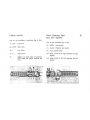
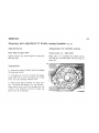
IGNIT
IO
N
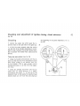
Checking and adjustment of double
contact
breaker (fig. 25)
Maintenance
Evert 3000 km (20
00
m
il
es)
Lighlly
moi
sten
with
some engine o
il
drop
s the
cam felt
pad
.
Inspection
• remove the contac: breaker cover by undoing
the s
ecuring
s
crews;
•
if
contacts
lOA
..
and
·.a
..
are dirty and greasy,
clean them
with
a
petr
ol rncistenec rag. If they
are in any way
asma;!d
repl
ace
them;
• check points
~
ap
of breaker
..
;..
..
(right cylin-
de!
-
ted
cable) and brea.k
er
. 5· (let! cyl
incef
-
gr
een
cab
le)
wh
ich should be
ber
Heen mm 0"';2
~
O
,
~
.
If this distance is high
er
or
lower, the
po
ints haye to be adjusted.
Adjustment of c
on
tact points
Contact polnls . Au • rIght points
Bring cam
.oj.
to maximum lin, loos
en
screws
.e
..
and
.0
" and
mo
ve plate
..
E
..
by
acting en
noent
.F.
,
43

44
After setting the
correc
t distance.
lO
CK
SCiews
.c
· and
.0
..
.
Con
tac1
points "B
..
. lett cylinder
Bring cam
_I
_
10
maxim
um
lift
, loosen screws
-G-
and -H- and move plate
..
L-
by acting on
notch
-M-.
Af1er setting the
correc
t distance,
loc
k
sc
rews
-G-
and -H
-.
When adjusting the contact points ignition timing
should be
checked
as
we
ll
(see chapter
..
Che
-
ck;ng
of
ignition tim;ng
..
).

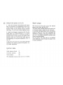
Checking
and adjustment
of
ignition timing
«f
ixed advance»
(fig.
26)
Checking the beginning
of
th
e pOints
sop.
ration
(.A.
in
fig. 25).
• remove the
rubber
cap
which
seals the
in~
'pec
ticn
hole
on
the
right
s
ide
of
the
gear
box
;
25
• to
find
the e
xact
m
om
ent when the
poin
ts
.A.
and . B. in fig.
25
sta
rt separa
ti
ng,
It
is advi.
sable
to
use a suitable timing
light
device
moun·
ted in bet
ween
the
brea
ker
feed clamp and the
g
round
.
Timing
th
e r
ight
cylinder
(see fig.
26
)
• r
otate
the
flywheel anticl
ockw
ise
until
the pi·
ston is at
Ih
e t
he
end
of
its
compression
stro
ke
(bolh
va
lves closed).
In
this
po~
iti
on
,
mark
-0
..
on
the
flywheel
(T
Oe
of
ri
ght
cy
li
nder)
should
coinci
de
with mark .1
..
on the rim of t e inspec·
tion
hole
;
• rotate the
flywheel
cl
ockw
ise
until
the f
ly
-
wh
ee
l mark
..
2- {fixed adv
ance
} is in periect
c
oinc
i
dence
w
it
h
mar
k
..
1
..
on the rim
01
the
inspec
tio
n hole.
In
this pOSition the ignition
:ixed
advance
mark
..
2
..
is 8- from
TOe
(
..
0
-)
t
hat'
s at
45

46 Timing the lell cylinder (
see
lig.
26
)
• rota
le
the flywh
ee
l
ant
icl
cc
kw
ise
un
til the pi-
slon
is at the
end
of
its
compress
i
on
stroke (b
oth
va
lv
es
cl
osed
). In this
position,
mark
· S
..
on the
flywheel (TOe
of
l
elt
cy
li
nder
) should c
oinc
ide
with
mark
.1
..
on
thE:
rim
of
the inspection hole;
• rotate the flywheel
cloc
kwise until
the
fly-
wheel mark
..
3.
(fixed advance)
is
in perieet
co
i
nc
id
ence
with
mark
..
1
..
on the rim
of
;he in-
spect
ion
ho
le. In this positi
on
the
ignition
fixed
advance
mark
..
3
..
is
S-
from TOe
(.5.
) that's
at
the
beginn
ing
of
the
po
ints
separa
ti
on
(
..
a
..
in
IIg
. 25).
II the points (
..
All
and
..
a
..
in
fig. 25) do
not
st
an
opening
in
the above positions, the ignition
tim
-
ing
needs
adjustment.
Ignition data
I
nit
ial adva
nc
e (fixed) 8-
Automat
ic
advance
2~
Total
advance
34
~
This checking is 08St carri
ed
out by o
ur
de
;
'
~rs
.
Spark plugs
This
moto
rcycle
fits spark plugs with thermal
degree
240
(points
gap
0,6 mm).
The spark plugs are best cleaned with petrol and
a
wire
brush usi
ng
a needle for
the
inner part.
In re-fitting the plugs ensure they are properly
st
aned
by hand
'or
a
few
turns completing the
operation
by
means of the pl
ug
wrench
in
the
tool k
it
If not
proper
ly started the
cy
linder head
thread may
get
stripped.
For all
events,
the plugs
ha
ve to
be
replaced
every
10000
km
a.
even
11
they still appear to
be
In good conditions.

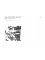
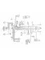
ELECTRICAL EQUIPMENT
(diagram fig. 27)
Battery
The
12
V battery is
centrally
mounted
and has
a
capacity
of
32 Ah. It is ch
arg!.!!d
di
rectly
by
the
generator.
Every month
or
alter
every 3000 km (2000 miles)
chec
k the elecltolyte level and eventually top up
in each cell, the level is correct when the elec-
trolyte
tops the plate
separator
by 6 mm.
Always top up
with
distill
ed
waler, chemica
lly
pure. and never add acid.
Distilled
water
has to be added to a
co
ld battery
efter
it
has
not
been
used
to;
at least 6
hOUiS
.
Make
sure that
no
eiectrolyte
lIows
over
the top
of
the ba
tt
ery
wh
i
ch
must always be in
perle=t
dry conditions.
Ev
ery
10000
km
(6CCO
miles) check that all bat-
tery
connec
ti
ons
are
well tight
and
clean. Smear
them
wi
th
neuter
vaselir.e to
prevent
oxidaUon.
A
charged
baiter)'
has a ydrome
ter
reading
of
1,28
sp
.
g.
and a
discharged
battery
of
about
1.16
sp.g.
To
put
a new battery in serliee apply
to
ollr
dealers.
47

48
WIRING DIAGRAM - LEGEND
Isee fig.
27)
A
B
C
o
•
F
G
H
I
l
"
N
o
P
o
R
5
Gen
era
tor
Rec
til
ie
r
Reg
ulatOr
S
atte
ry
S
larter
motor
Starter motor .elay
H
orn
f i
ash
ing
li; nt :el!.y
H
yd
r05!Op
Rear
stOP
sw
it
ch
Te
fm
inal bloc
l<
.....
ith lu!!!s
Fl
as
he
r u
ni:
Asy
mmetr
ic
lignt
Left tlltn si
gna
l. fe
;:!r
Ri
gh
t turn
sign
al,
rear
l!!ft
turn si
gna
l.
Iront
Ri
ghi
:urn s
ign
a
/.
front
T Eng
in
e
stane:
and
sic:;
switch
U
C~
n!rol
dev
ice.
turn
si
!ij!r:a
!
s.
horn
,
lIashing
li
ght
V
AA
BB
CC
DO
EO
U~h:
$wi!
ch
; dimm:!r,
pat
kir~
li
gn:
Mi
le
counter
Re
v. COur,l!!r
Ga1"le
ral
C(Cl
mmU
:ilf~
r
H.
T.
co
il
Oil
lig
ht
s
.....
itch
FF
GG
HH
II
MM
NN
00
P?
00
R"
55
or
Uu
X
y
Z
Neutral
light
sw
it
ch
Nu
mber
plale ant! 5::;1
Ii
:;
ht
Instrument
pan,
l
a
ll
pr
essure
light (
re:
)
Neuu!1
li
ght (or
an!:!
)
Battery
li
ght
(red)
H
i.h
bea
m light (tlt: l
Connectors
!.
~w
a y
co
nne
ct
or
.;.,:,\?
Spa
rk
plu
gs
1S
·way conn
ec
tor
.',
tel
=-:'<
·
J-way
co
nnector ·MOL=X·
12-
W
il
Y
ccnn
ector .MOL=X-
l ow
beam
H
igh
!:Iu
rn
C
ont
act
bun
ke
r
rUses
FI
F2
FJ
F'
F;
F&
lSA
15:-
lSA
1S
J.
15 A
lSA
Horn
. SlOp.
S
i
~:-
l
:s
r,
J
..
!
Starler (. Ia'l.
ti
!r:!(
:o
mit
Head
li
ght. lifi
l'::
S
:'
L:
Mr.::
NN
?
arl!:
in
g
li
ghl.
li
p:
00
Reserve
Re
serve

11
:3
!
=
-
.1
~
,
1,
'=
I
~
,
,
I
,-
.
='
~
1
r=

SElMM MOTO GUZZI S.p.
A.
Mondello
del
Laria
Regislro Socielo Leeea N.2220
-
 1
1
-
 2
2
-
 3
3
-
 4
4
-
 5
5
-
 6
6
-
 7
7
-
 8
8
-
 9
9
-
 10
10
-
 11
11
-
 12
12
-
 13
13
-
 14
14
-
 15
15
-
 16
16
-
 17
17
-
 18
18
-
 19
19
-
 20
20
-
 21
21
-
 22
22
-
 23
23
-
 24
24
-
 25
25
-
 26
26
-
 27
27
-
 28
28
-
 29
29
-
 30
30
-
 31
31
-
 32
32
-
 33
33
-
 34
34
-
 35
35
-
 36
36
-
 37
37
-
 38
38
-
 39
39
-
 40
40
-
 41
41
-
 42
42
-
 43
43
-
 44
44
-
 45
45
-
 46
46
-
 47
47
-
 48
48
-
 49
49
-
 50
50
-
 51
51


MOTO GUZZI 850-T El manual del propietario
- Tipo
- El manual del propietario
en otros idiomas
- English: MOTO GUZZI 850-T Owner's manual
Artículos relacionados
Otros documentos
-
Daytona DD125E-5C Manual de usuario
-
Maserati QUATTROPORTE El manual del propietario
-
Tanaka TED-270PFHS Manual de usuario
-
Husqvarna WR 125 2010 El manual del propietario
-
-
Husqvarna TXC 510 2009 Manual de usuario
-
-
Honda CB 500 T El manual del propietario
-
 Mhouse GA1 El manual del propietario
-
 Electric Controller & Mfg. (EC&M) DC Magnetic Drum Brake - Class 5010-22, 8 to 23in Type F Guía de instalación

