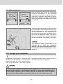
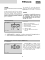
Dometic RML8555 Manual de usuario
- Categoría
- Neveras
- Tipo
- Manual de usuario

Type C40 / 110
822 6102 - 04
INSTRUCCIONES para la INSTALACIÓN
INSTALLATION INSTRUCTIONS
EN
ES
REFRIGERADOR por ABSORBCIÓN
ABSORPTION REFRIGERATOR
Instrucciones para la instalación
Refrigerador por absorbción para vehículos
de ocio
Español
RMS 8400
RMS 8401
RMS 8405
RMS 8460
RMS 8461
RMS 8465
RMS 8500
RMS 8501
RMS 8505
RMS 8550
RMS 8551
RMS 8555
RML 8550
RML 8551
RML 8555
RM 8400
RM 8401
RM 8405
RM 8500
RM 8501
RM 8505
RM 8550
RM 8551
RM 8555
T.B. MBA 10/2007
N 2

2
Guarde cuidadosamente la presente guía de instalación.
En caso de que el aparato cambie de propietario, adjunte siempre esta guía
de instalación.
©
Dometic GmbH - 2007 - Reservado el derecho de realizar modificaciones - Impreso en Alemania

3
ADVERTENCIA indica una situación potencial de peli-
gro que puede provocar la muerte o heridas graves en
caso de no aplicar las medidas indicadas.
ATENCIÓN indica una situación potencial de peligro
que puede provocar heridas leves o medias en caso de
no aplicar las medidas indicadas.
ATENCIÓN sin el símbolo de seguridad indica una
situación potencial de peligro que puede provocar
daños en el aparato en caso de no aplicar las medidas
indicadas.
INFORMACIÓN
REFERENCIA MEDIOAMBIENTAL
ADVERTENCIA
ATENCIÓN
ATENCIÓN
Explicación de los símbolos utilizados
THE SIGN OF COMFORT
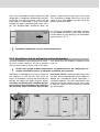
Índice
E1.0 Instrucciones de montaje . . . . . . . . . . . . . . . . . . . . . . . . . . . . . . . . 4
E1.1 Montaje . . . . . . . . . . . . . . . . . . . . . . . . . . . . . . . . . . . . . . . . . . . . . . . . . . . . . . . . . . . . . . . . . . . 4
E1.2 Instalación sin corriente de aire . . . . . . . . . . . . . . . . . . . . . . . . . . . . . . . . . . . . . . . . . . . . . . . . . 6
E1.3 Ventilación . . . . . . . . . . . . . . . . . . . . . . . . . . . . . . . . . . . . . . . . . . . . . . . . . . . . . . . . . . . . . . . . . 8
E1.4 Instalación del sistema de ventilación . . . . . . . . . . . . . . . . . . . . . . . . . . . . . . . . . . . . . . . . . . . . 9
E1.5 Extracción . . . . . . . . . . . . . . . . . . . . . . . . . . . . . . . . . . . . . . . . . . . . . . . . . . . . . . . . . . . . . . . . . 10
E1.6 Hueco para montaje . . . . . . . . . . . . . . . . . . . . . . . . . . . . . . . . . . . . . . . . . . . . . . . . . . . . . . . . . . 10
E1.7 Fijación del frigorífico . . . . . . . . . . . . . . . . . . . . . . . . . . . . . . . . . . . . . . . . . . . . . . . . . . . . . . . . . 12
E1.8 Dekorplatte wechseln . . . . . . . . . . . . . . . . . . . . . . . . . . . . . . . . . . . . . . . . . . . . . . . . . . . . . . . . . 12
E1.9 Instalación de gas . . . . . . . . . . . . . . . . . . . . . . . . . . . . . . . . . . . . . . . . . . . . . . . . . . . . . . . . . . . 13
E1.10 Instalación eléctrica . . . . . . . . . . . . . . . . . . . . . . . . . . . . . . . . . . . . . . . . . . . . . . . . . . . . . . . . . . 14
E2.0 Anexo . . . . . . . . . . . . . . . . . . . . . . . . . . . . . . . . . . . . . . . . . . . . . . . . 22
E2.1 Technische Daten . . . . . . . . . . . . . . . . . . . . . . . . . . . . . . . . . . . . . . . . . . . . . . . . . . . . . . . . . . . . 22
E2.2 Declaración de conformidad . . . . . . . . . . . . . . . . . . . . . . . . . . . . . . . . . . . . . . . . . . . . . . . . . . . 23

4
E1.0 Instrucciones de montaje
Al montar el aparato, deberán cumplirse las
prescripciones técnicas y administrativas del
país en el que se matricula el vehículo por pri-
mera vez. Además también deberán seguirse
las prescripciones de montaje del fabricante.
Por ejemplo, en Europa, los aparatos de gas, la
colocación de líneas, la colocación de bombo-
nas de gas, así como el control y examen de
estanqueidad deben cumplir la norma EN 1949
para instalaciones de gas líquido.
El aparato y el conducto de extracción debe-
rán ser montados de forma que queden
accesibles para realizar trabajos de servicio,
y que puedan montarse y desmontarse del
vehículo sin tener que realizar grandes esfu-
erzos.
A la hora de colocar y conectar el aparato debe-
rán seguirse las disposiciones que correspon-
dan al último estado de la técnica:
La instalación eléctrica debe realizarse
aplicando las normas nacionales y
locales.
La instalación de gas debe realizarse aplican-
do las normas nacionales y locales.
Norma europea EN 1949
Norma europeas EN 60335-1,
EN 60335-2-24, EN 1648-1 , EN 1648-2
Instale el aparato de modo que quede protegi-
do contra una exposición excesiva al calor.
La exposición excesiva al calor perjudicará el rendi-
miento y aumentará el consumo de energía del fri-
gorífico.
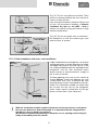
E1.1 Montaje
ATENCIÓN
Ignorar la presente guía de montaje sin la autorización previa de Dometic provo-
cará la anulación de la garantía por parte de nuestra empresa.
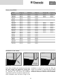
Si el aparato se monta en el lateral de la puerta
de acceso, deberá asegurarse de que la rejilla
de ventilación no quede tapada por la puerta
abierta (Foto E1, Distancia puerta - rejilla de
ventilación mín. 25 mm). En caso contrario, la
ventilación será insuficiente, lo que mermará el
rendimiento de la refrigeración. A menudo, el
lado de la puerta del vehículo está dotado de un
avancé. Éste dificulta el escape de gases de
combustión y de calor por la rejilla de ventilaci-
ón (merma de rendimiento de refrigeración).
E1.1.1 Montaje lateral
La instalación del aparato sólo podrán reali-
zarla especialistas autorizados para ello.
ADVERTENCIA

5
En esta variante de montaje, sólo se podrá realizar el mantenimiento regular de la
unidad del quemador de gas desmontando el aparato. El frigorífico deberá instalar-
se obligatoriamente de forma que quede garantizado un fácil desmontaje.
Por tanto, recomendamos prever una abertura de mantenimiento (tapa de servicio)
en la parte exterior.
E1.1.2 Montaje lateral con ventilación de suelo/techo
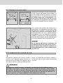
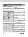
Foto E1
Foto E2
Foto E3
¡Rejilla de ventilación
libre! ¡Correcto!
(Foto E1) Las rejillas de ventilación están
obstruidas. ¡La distancia entre la puerta y la
rejilla de ventilación debe ser al menos de 25
mm!
Para distancias entre puerta/rejilla de entre 25 y
45 mm recomendamos que se instale el kit de
ventilación de Dometic (n° de art. 241 2985 -
00/0) para conseguir un rendimiento óptimo de
refrigeración a altas temperaturas ambientales.
(Foto E2) Las rejillas de ventilación permiten
que el calor del grupo frigorífico y los gases sal-
gan sin problemas incluso teniendo abierta la
puerta del frigorífico.
Otra posibilidad es ventilar el frigorífico dejando
una ranura de ventilación en el suelo e instalan-
do un sistema de ventilación en el techo del
vehículo (véase foto E3). Entre el canto superior
del frigorífico y la ventilación de techo debe
instalarse una chimenea que deje salir el aire
caliente y los gases de escape del grupo frigo-
rífico directamente por el sistema de ventilación
del techo.
La abertura del suelo debe tener una sección
transversal libre de al menos 250 cm². Esta
abertura debe tener una protección, por ejem-
plo, una chapa de desviación y una red, para
evitar que entre suciedad en la zona de combu-
stión de gas. Con este tipo de ventilación puede
entrar más suciedad en la zona posterior del fri-
gorífico (en comparación con la ventilación late-
ral), por lo que deberá realizarse un manteni-
miento regular del quemador de gas, al menos
una vez al año.
Abertura del suelo:
min. 50 mm de ancho
min. 520 mm de largo
Aire caliente
Condensator
Recomendación:
conducto de
aire de techo
R500
THE SIGN OF COMFORT

6
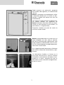
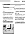
A menudo, el montaje en la parte trasera provo-
ca una situación de montaje poco propicia, ya
que no siempre queda garantizada una ventila-
ción óptima (p. ej., ¡la rejilla de ventilación infe-
rior queda cubierta por el parachoques o las
luces traseras del vehículo!) (
Foto E4
). El máxi-
mo rendimiento de refrigeración del grupo frigo-
rífico no está disponible de forma efectiva.
Una variante poco propicia del montaje en la
parte trasera es la colocación lateral de la rejilla
de ventilación (
Foto E6
). La circulación del aire
caliente es muy limitada, lo que provoca que los
intercambiadores de calor (condensadores,
absorbedores) ya no se refrigeran lo suficiente.
También la variante con una rejilla de ventilación
montada adicionalmente en el suelo presenta
una mala conducción de la corriente de aire.
E1.1.3 Montaje en la parte trasera
Foto E4
Foto E5
¡Rejilla de ventilación
libre! ¡Correcto!
Foto E6
¡No se dispone del máximo rendimiento de
refrigeración! No utilice esta opción de mon-
taje, ya que en esta variante la ventilación no
queda garantizada tal y como se describe en
el punto E1.3.
ATENCIÓN
E1.2 Instalación sin corriente de aire
Los aparatos frigoríficos en caravanas, autoca-
ravanas u otros vehículos deben montarse sin
corriente de aire (EN 1949). Esto significa que el
aire necesario para la combustión del quemador
de gas no se absorbe del espacio habitado, y
que se evita que los gases entren directamente
al mismo.
En ningún caso deberá instalarse el frigorífico sin corriente de aire utilizando pastas
obturadoras resistentes o espumas (por ejemplo, espumas de montaje), u otros produc-
tos similares. NO utilice materiales fácilmente inflamables (sobre todo pastas de sellado
de silicona o similares) para la obturación. Podría provocar un incendio. Al utilizarlos, se
eximen la garantía y la responsabilidad civil de producto del fabricante.
ADVERTENCIA

7
Foto E8
Foto E9
Foto E10
Foto E11
Foto E7
Deberá preverse una obturación apropiada
entre el dorso del frigorífico y el habitáculo del
vehículo.
Dometic recomienda encarecidamente utilizar
un obturador flexible para así facilitar un des-
montaje y montaje del aparato con fines de
mantenimiento.
Para facilitar la colocación de este tipo de rete-
nes labiales flexibles, los frigoríficos de
Dometic Absorber Generation RM 8xxx dispo-
nen de una ranura pasante en los laterales y la
parte inferior (v. la siguiente foto).
Excepción: modelos con paso de rueda sin
ranura en la parte inferior
Dometic recomienda colocar un listón con una
chapa disipadora de calor sobre el aparato,
para que el calor del grupo frigorífico que sube
pueda conducirse directamente hacia el exte-
rior. Esta chapa disipadora también deberá pro-
veerse con un retén labial.
Así, el frigorífico podrá desmontarse fácilmente
para realizar trabajos de mantenimiento y repa-
raciones.
Las obturaciones flexibles se insertan en la
ranura que transcurre por la carcasa. Presione
firmemente la parte provista de botones inser-
tándola en la ranura. Asegúrese de que las
obturaciones están colocadas homogéneamen-
te por la carcasa.
Dometic-Dicht-Kit für RM 8xxx:
Art.-Nummer :
THE SIGN OF COMFORT

8
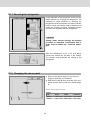
El espacio que se encuentra entre la pared exte-
rior del vehículo y el frigorífico está estanqueiza-
do de la zona habitada. Por tanto, los gases no
pueden entrar en la zona habitada. Los gases
salen por la rejilla superior de la ventilación
hacia el exterior. En la instalación sin corriente
de aire no es necesario utilizar un conducto de
extracción especial. Con esta variante, puede
utilizarse la misma rejilla de ventilación L200 sin
conducto de extracción tanto arriba como
abajo.
Si no obstante se desea tener una chimenea de
extracción, monte el sistema de ventilación
L100 con conducto de extracción (
Montaje de
chimenea de extracción, véase "E1.7"
).
Las modificaciones deberán ser autorizadas por el fabricante.
Foto E12
Foto E13
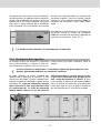
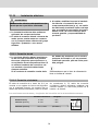
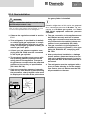
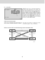
E1.3 Ventilación del frigorífico
El montaje correcto del aparato es importante
para el funcionamiento, ya que en la parte tra-
sera del aparato se genera calor (por las condi-
ciones físicas) que debe conducirse hacia el
exterior.
A altas temperaturas ambientales, un rendimiento pleno del grupo frigorífico sólo
quedará garantizado mediante una ventilación suficiente.
El grupo frigorífico se ventila mediante dos
aberturas de la pared de la caravana. El aire
fresco entra por abajo y circula saliendo calen-
tado por la rejilla de ventilación superior (efecto
chimenea). La rejilla de ventilación superior
debe colocarse lo más arriba posible sobre
el condensador (A). La rejilla de ventilación
inferior deberá colocarse a ras del suelo del
vehículo para que en caso de que se escape
el gas aún no quemado (más pesado que el
aire), salga directamente al exterior. Si esto
no es posible, el fabricante del vehículo deberá
hacer un orificio de ventilación en el fondo del
hueco para que en caso de que se escape el
gas no quemado no se acumule en el fondo.
L100
L100
(L200)
L200
orificio de ventilación
L100
(L200)
L200

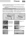
9
Foto E14
Foto E15
Las rejillas de ventilación deben tener una
sección transversal libre de al menos 250
cm². Ésta se consigue con el sistema de venti-
lación con absorbedor L100 / L200 de Dometic,
certificado y autorizado para este propósito.
El sistema de ventilación superior L100 está com-
puesto por un bastidor de montaje (R1640), una
rejilla de ventilación incl. conducto de extracción
(A 1620) y una cubierta de invierno (WA120). El
sistema de ventilación inferior L200 también está
compuesto por un bastidor de montaje (R1650),
rejilla de ventilación (A1630, no obstante sin con-
ducto de extracción) y una cubierta de invierno
(WA130). Para proceder a instalar las rejillas de
ventilación, corte dos rectángulos (451 mm x 156
mm) en la pared exterior del vehículo (para situar
los cortes, véase el punto E1.3).
Foto E20
La colocación correcta de la rejilla de ventilación inferior facilita el acceso a las
conexiones del aparato y a las piezas funcionales a la hora de realizar trabajos de
mantenimiento.
E1.4 Instalación del sistema de ventilación
Foto E16
Foto E17
Foto E18
Foto E19
Foto E21
Obturar el bastidor de
montaje de forma que
quede estanco (
no es
necesario en los basti-
dores de montaje con
obturación integrada
).
1.
Colocar el bastidor y
atornillarlo fijamente.
2.
Colocar la rejilla de ven-
tilación.
3.
Bloquear la rejilla de
ventilación.
4.
Encastrar la pieza para
el conducto de extracci-
ón (
sólo en el sistema de
ventilación superior
L100
).
5.
Colocar la cubierta de
invierno.
6.
THE SIGN OF COMFORT

10
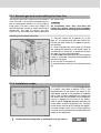
El frigorífico deberá ser montado en un hueco
sin corriente de aire (v. tb. "E1.2"). Las dimen-
siones del hueco deberán tomarse de la tabla
que encontrará a continuación. El nivel A sólo se
necesita en los modelos con paso de rueda. El
aparato deberá insertarse en el hueco hasta que
el canto delantero de la carcasa del frigorífico y
el canto delantero del hueco estén alineados.
Entre la pared del fondo del hueco y el grupo fri-
gorífico deberá existir un espacio libre de 15-20
mm. El suelo del hueco deberá ser plano, de
modo que el aparato pueda desplazarse sin difi-
cultades a su posición correcta. El suelo deberá
ser lo suficientemente firme para poder soportar
el peso del aparato.
E1.6 Hueco para montaje
El frigorífico deberá montarse en posición vertical en el hueco.
Abb. E23
Colocación de la chimenea de extracción estándar:
Abb. E22
1. Insertar la pieza en forma de T (E) en el adap-
tador (F), o bien en el conducto de extracción (K)
y fijarla con el tornillo (G). Deberá tener en cuen-
ta que el distribuidor de calor (H) se encuentra
en su posición prevista.
2. Insertar el conducto de extracción completo
con la placa cobertora (C) por la abertura previ-
sta para ello del marco superior (I) y conectarlo
con la pieza en forma de T (E). En caso perti-
nente, acortar el conducto de extracción (C) a la
longitud apropiada.
3. Colocar la rejilla de ventilación L100 (D) en el
bastidor de montaje (I) y bloquearlo con el cier-
re de muletilla, que se encuentra en el lado
izquierdo de la rejilla.
4. Colocar la tapadera abatible (B) sobre el con-
ducto de extracción (C).
5. Colocar la pieza para el conducto de extracci-
ón (A) en la rejilla de ventilación (D).
El conducto de extracción debe garantizar que
la desviación de los productos de combustión
se produzca fuera del espacio habitado. El con-
ducto de extracción debe colocarse siempre
verticalmente para evitar que se acumulen con-
densados. En el tipo de conducto de extracción
mostrado en la foto E22 la cubierta de invierno
puede colocarse lateralmente.
Una instalación divergente mermará el rendi-
miento de refrigeración, además de eximir la
garantía/responsabilidad de producto.
E1.5 Conducto de extracción y colocación de la chimenea de
extracción
ATENCIÓN
A

11
Inserción en el hueco:
Foto E24
Foto E25 Foto E26
Al montar el aparato deberá asegurarse de que
las bisagras de la puerta estén sostenidas. La
foto E24 muestra la colocación ideal del frigorí-
fico, mientras que la foto E25 presenta los
requisitos mínimos con la distancia máxima de
la superficie de colocación hasta el final de la
bisagra. En un montaje como el que se muestra
en la foto E26, la bisagra no podrá soportar la
posible carga de las puertas. Por tanto, deberá
asegurarse de no superar la distancia máxima
de 40 mm.
Montaje ideal
Requisitos mínimos Distancia no > 40mm
THE SIGN OF COMFORT
Dimensiones del hueco:
Modelo Altura H Ancho B Fondo T Altura HSt Fondo TSt
RMS 8400
RMS 8401
RMS 8405
RM 8400
RM 8401
RM 8405
RMS 8460
RMS 8461
RMS 8465
RMS 8500
RMS 8501)
RMS 8505
RMS 8550
RMS 8551
RMS 8555
RM 8500
RM 8501
RM 8505
RM 8550
RM 8551
RM 8555
RML 8550
RML 8551
RML 8555
825 mm
825 mm
825 mm
825 mm
825 mm
825 mm
825 mm
825 mm
825 mm
825 mm
825 mm
825 mm
825 mm
825 mm
825 mm
825 mm
825 mm
825 mm
825 mm
825 mm
825 mm
1249 mm
1249 mm
1249 mm
490 mm
490 mm
490 mm
490 mm
490 mm
490 mm
490 mm
490 mm
490 mm
527 mm
527 mm
527 mm
527 mm
527 mm
527 mm
527 mm
527 mm
527 mm
527 mm
527 mm
527 mm
529 mm
529 mm
529 mm
542 mm
542 mm
542 mm
542 mm
542 mm
542 mm
607 mm
607 mm
607 mm
542 mm
542 mm
542 mm
597 mm
597 mm
597 mm
542 mm
542 mm
542 mm
597 mm
597 mm
597 mm
599 mm
599 mm
599 mm
220 mm
220 mm
220 mm
220 mm
220 mm
220 mm
220 mm
220 mm
220 mm
220 mm
220 mm
220 mm
235 mm
235 mm
235 mm
235 mm
235 mm
235 mm
235 mm
235 mm
235 mm
235 mm
235 mm
235 mm

12
En los laterales del frigorífico, existen cuatro
manguitos para fijar el frigorífico. Los laterales o
los listones colocados para fijar el frigorífico
deberán colocarse de modo que los tornillos
estén bien apretados incluso en los casos de
mayor esfuerzo (durante la marcha). Los tornil-
los de fijación y las tapaderas abatibles se
adjuntan con el frigorífico.
Girar los tornillos siempre mediante los cas-
quillos previstos para ello, ya que en caso
contrario las piezas cubiertas de plástico,
como por ejemplo los conductos, podrían
resultar dañadas.
Una vez que el frigorífico se haya colocado en
su posición definitiva, los tornillos deberán ator-
nillarse por el frigorífico hasta la pared del
hueco.
E1.7 Fijación del frigorífico
Foto E27
Foto E28
ATENCIÓN
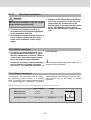
E1.8 Cambio de la placa de decoración
Retire el listón L lateral de la puerta (el listón
está encajado, no atornillado)
Desplace la placa de decoración P sacándo-
la de la puerta, coloque la nueva placa de
decoración y vuelva a colocar el listón L.
Foto E29
L
P
Dimensiones de la placa de decoración:
486 mm 742+/-1 mm 471+/-1 mm max. 2 mm
523 mm 742+/-1 mm 508+/-1 mm max. 2 mm
ancho de
carcasa altura ancho grosor

13
E1.9 Instalación de gas
Siga las indicaciones listadas en el punto
E1.1!
Este frigorífico ha sido concebido para ser
conectado a una instalación de gas líqui-
do según la norma EN1949, y funcionará
únicamente con gas líquido (propano,
butano) (NO con gas natural ni gas
ciudad).
Deberá instalarse un regulador ajustado
de forma fija según la norma EN 12864.
El regulador deberá concordar con la pre-
sión de funcionamiento indicada en la
placa de características. La presión de
funcionamiento se corresponde con la
presión normativa del país pertinente (EN
1949, EN732).
Únicamente se acepta una presión de
conexión por cada vehículo. Allí donde se
instale la bombona de gas, deberá colo-
carse una placa claramente legible que
La toma de gas sólo podrá ser instalada por
un especialista autorizado*.
ADVERTENCIA
Foto E30
SW 14
SW 17
AATTEENNCCIIÓÓNN
20 Nm
max
10 Nm
max
*
Los especialistas autorizados son expertos reconocidos,
que debido a su formación o a sus conocimientos pue-
den garantizar que el examen de estanqueidad ha
sido reali- zado correctamente.
indique esta circunstancia.
Todos los frigoríficos Dometic de esta serie
están equipados para una presión de conexión
de 30 mbar. Al conectarlos a una instalación de
50 mbar utilice el regulador de presión de
admisión Truma VDR 50/30.
La conexión de gas al aparato deberá lle-
var una instalación altamente segura y sin
tensión, y deberá estar bien conectada al
vehículo (no se permiten conexiones de
goma) (EN 1949).
La conexión de gas con el aparato se
efectúa mediante un atornillado de anillo
cortante ("Ermeto") K8, DIN 2353-ST
según EN 1949.
La instalación conforme a las reglas del
arte deberá ser realizada por un especia
lista autorizado*, que deberá realizar una
prueba de fugas y comprobar la llama
según la norma EN 1949. Al realizar dicha
inspección se expedirá un certificado
acreditativo.
El frigorífico deberá estar equipado con
un mecanismo de cierre instalado en el
conducto de abastecimiento. El mecanis-
mo de cierre deberá ser instalado en un
lugar fácilmente accesible para el usuario.
THE SIGN OF COMFORT

14
Las secciones transversales y longitudes de los cables en la caravana/autocaravana:
E1.10 Instalación eléctrica
La instalación eléctrica debe realizarse
aplicando las normas nacionales.
El cable de conexión deberá colocarse de
modo que no puedan entrar en contacto
con los componentes calientes del grupo
frigorífico / quemador o con cantos
afilados.
Al realizar modificaciones en la instalaci-
ón eléctrica o la conexión de otros
componentes eléctricos (p. ej., un ventila
dor adicional) al cableado interno del apa
rato, provocará la exoneración de la apro
bación e1/CE, así como todas los dere
chos de garantía y responsabilidad de
producto!
La instalación eléctrica sólo podrá ser eje-
cutada por un especialista autorizado.
ADVERTENCIA
La corriente eléctrica deberá suministrar-
se de una caja de enchufe con puesta a
tierra que cumpla las prescripciones o a
una conexión de red con puesta a tierra. Si
se utiliza el conducto de conexión a red
con enchufe, el enchufe deberá estar
siempre accesible.
Si el conducto de conexión resulta daña
do, deberá ser sustituido por el servicio
posventa de Dometic o por un personal
cualificado para ello, para así evitar posi-
bles peligros.
Recomendamos que la línea de alimentación
lleve un fusible de a bordo.
E1.10.1 Conexión de red
E1.10.2 Conexión a la batería
El cable de conexión de a bordo de 12 V se
conecta a una regleta de bornes del frigorífico
con la polaridad correcta. La conexión de los
cables del cartucho calentador (véase el cuadro
de conexiones A, B, cable de conexión
rojo/blanco) deberá efectuarse mediante una
conexión directa y lo más corta posible con la
batería o el dínamo.
4 mm
²
< 6 m
6 mm
²
> 6 m
min 2,5 mm
²
(EN1648-1)
Sección transversal Longitud
Autocaravana y
caravana (interior)
caravana (exterior)
2,5mm²
Foto E31

15
Conexión D+:
E1.10.4 Conexión D+ y conexión solar (sólo en modelos AES)
En el modo automático ("Automatic mode") el
sistema electrónico AES selecciona el modo de
energía más adecuado automáticamente. En el
modo automático, el sistema electrónico utiliza
la señal D+ (dínamo +) del dínamo para recono-
cer el modo 12V CC. El funcionamiento con el
modo de energía de 12V CC sólo se seleccio-
nará cuando el motor esté en marcha para así
evitar que la batería se descargue.
A bordo del vehículo, el circuito de 12V
deberá protegerse mediante un fusible de 16
A.
Para que al parar el motor del vehículo no olvi-
de desconectar el modo de 12V (la batería se
descargaría en unas pocas horas), recomenda-
mos que el suministro de corriente para el car-
tucho calentador (conexión A/B de los esque-
mas de conexiones a partir de la pág. 17) se
realice de forma que éste se interrumpa al girar
la llave de encendido. En la conexión C/D (ilu-
minación, sistema electrónico; cable de conexi-
ón negro/violeta) deberá colocar una fuente de
alimentación continua de 12V (CC), que deberá
llevar un fusible de 2A en el lateral!
Al realizar la instalación en la caravana
los conductos negativo y positivo corre-
spondientes de las conexiones de 12V
A/B y C/D no deberán ser conectados
entre sí (EN 1648-1).
ATENCIÓN
ATENCIÓN
D+
S+
por parte del vehículo
por parte del aparato
Foto E33
THE SIGN OF COMFORT
Conexiones:
E1.10.3Regleta de bornes
A = Masa elemento calentador CC
B = Positivo elemento calentador CC
C = Masa electrónica
D = Positivo electrónica
D+ = Señal de dínamo
S+ = Señal de entrada de AES del regulador
de carga solar
AB
D+
S+
CD
-
+
+
-
por parte del vehículo
por parte del aparato
Foto E32
Para el funcionamiento de los tipos de aparatos MES y AES estará prohibido conec-
tar un abastecimiento continuo de 12 V a los bornes C/D (abastecimiento continuo
para la electrónica funcional).

16
Conexión S+:
Como alternativa, el modo de funcionamiento de
12V CC puede ser alimentado mediante un
sistema de energía solar del vehículo. El siste-
ma de energía solar deberá estar equipado con
regulador solar con salida AES (este tipo de
reguladores pueden adquirirse en estableci-
mientos especializados). La conexión S+ (Solar
+) deberá estar conectada al borne correspon-
diente del regulador solar (salida AES). El
sistema electrónico emplea la señal S+ del
regulador solar para reconocer el 12V CC solar.
D+
S+
por parte del vehículo
por parte del aparato
Foto E34
Foto E35
Secciones transversales de cables:
Tiempos de conmutación de los tipos de energía en el modo automático:
Por las conexiones D+ y S+ no fluye una cor-
riente alta, por lo que no hace falta utilizar
cables de secciones transversales especial-
mente grandes (aprox. 1 mm² es suficiente).
230V
Gas 12V Solar
12V CC
~2-5 s
~2-5 s
~2-5 s
~2-5 s
~2-5 s
~2-5 s
~2-5 s
15 min
~2-5 s
~2-5 s

17
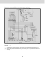
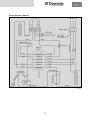
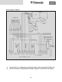
Foto E36
Esquema de conexiones RM8xx0:
THE SIGN OF COMFORT
Légende: p. 21

18
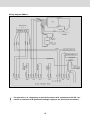
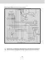
Esquema de conexiones RM8xx1:
Foto E37
A
B
C
D
Leyenda: p. 21
Es obrigatorio operar el aparato con una corriente permanente de 12V DC en los
bornes C/D (alimentación de tensión permanente para el dispositivo electrónico de
función).

19
THE SIGN OF COMFORT
Esquema de conexiones RM8xx5:
Foto E38
A
B
C
D
Leyenda: p. 21
Es obrigatorio operar el aparato con una corriente permanente de 12V DC en los
bornes C/D (alimentación de tensión permanente para el dispositivo electrónico de
función).

20
Esquema de conexiones RM8xx5 con cierre eléctrico (opcional):
Foto E39
Leyenda: p. 21
Es obrigatorio operar el aparato con una corriente permanente de 12V DC en los
bornes C/D (alimentación de tensión permanente para el dispositivo electrónico de
función).

21
THE SIGN OF COMFORT
Leyenda:
Anschlusskabel DC
Anschlusskabel Netz
Klemmleiste
Erdung
Heizelement DC
Heizelement AC
Reed-Schalter
Thermoschalter
Energiewahlschalter
Batteriezündung
Galvanometer
Temperatursensor
Elektronik
Gasfeuerungsautomat GFA
Gasventil GV 100
Gasbrenner
Cable de conexión CC
Cable de conexión red
Regleta de bornes
Puesta a tierra
Elemento calentador CC
Elemento calentador CA
Contacto Reed
Conmutador térmico
Conmutador de selección de energía
Ignición de pila
Galvanómetro
Sensor de temperatura
Electrónica
Sist. autom. de calefacción a gas GFA
Válvula de gas GV 100
Quemador de gas
Conexiones:
A = Masa elemento calentador CC
B = Positivo elemento calentador CC
C = Masa electrónica
D = Positivo electrónica
D+ = Señal de dínamo
S+ = Señal de entrada de AES del regulador de carga solar
Colores:
violett
rot
weiss/rot
braun
schwarz
weiss
gelb/grün
blau
violeta
rojo
blanco/rojo
marrón
negro
blanco
amarillo/verde
azul

RM
S
= Modelo con paso de rueda
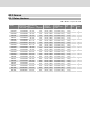
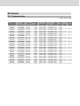
Modelo Dimensiones Capacidad total
Valores de
Consumo Peso Encendido
Al x An x F (mm) con sin conexión electrónico/gas neto piezo autom.
F incl. puerta congelador congelador Red/Batería in 24h
RMS 8400
RMS 8401
RMS 8405
RM 8400
RM 8401
RM 8405
RMS 8460
RMS 8461
RMS 8465
RMS 8500
RMS 8501
RMS 8505
RMS 8550
RMS 8551
RMS 8555
RM 8500
RM 8501
RM 8505
RM 8550
RM 8551
RM 8555
RML 8550
RML 8551
RML 8555
821x486x568
821x486x568
821x486x568
821x486x568
821x486x568
821x486x568
821x486x633
821x486x633
821x486x633
821x523x568
821x523x568
821x523x568
821x523x623
821x523x623
821x523x623
821x523x568
821x523x568
821x523x568
821x523x623
821x523x623
821x523x623
1245x525x625
1245x525x625
1245x525x625
80 / 8 lit.
80 / 8 lit.
80 / 8 lit.
90 / 8 lit.
90 / 8 lit.
90 / 8 lit.
90 / 11 lit.
90 / 11 lit.
90 / 11 lit.
90 / 9 lit.
90 / 9 lit.
90 / 9 lit.
103 /12 lit.
103 /12 lit.
103 /12 lit.
100 / 9 lit.
100 / 9 lit.
100 / 9 lit.
115 /12 lit.
115 /12 lit.
115 /12 lit.
179 /33 lit.
179 /33 lit.
179 /33 lit.
25 kg
25 kg
25 kg
27 kg
27 kg
27 kg
26 kg
26 kg
26 kg
26 kg
26 kg
26 kg
27 kg
27 kg
27 kg
28 kg
28 kg
28 kg
30 kg
30 kg
30 kg
45 kg
45 kg
45 kg
85 lit.
85 lit.
85 lit.
95 lit.
95 lit.
95 lit.
96 lit.
96 lit.
96 lit.
96 lit.
96 lit.
96 lit.
110 lit.
110 lit.
110 lit.
106 lit.
106 lit.
106 lit.
122 lit.
122 lit.
122 lit.
189 lit.
189 lit.
189 lit.
125 W / 120 W
125 W / 120 W
125 W / 120 W
135 W / 130 W
135 W / 130 W
135 W / 130 W
125 W / 120 W
125 W / 120 W
125 W / 120 W
125 W / 120 W
125 W / 120 W
125 W / 120 W
125 W / 120 W
125 W / 120 W
125 W / 120 W
135 W / 130 W
135 W / 130 W
135 W / 130 W
135 W / 130 W
135 W / 130 W
135 W / 130 W
190 W / 170 W
190 W / 170 W
190 W / 170 W
•
•
•
•
•
•
•
•
•
•
•
•
•
•
•
•
•
•
•
•
•
•
ca.2,5 KWh / 270 g
ca.2,5 KWh / 270 g
ca.2,5 KWh / 270 g
ca.2,4 KWh / 270 g
ca.2,4 KWh / 270 g
ca.2,4 KWh / 270 g
ca.2,5 KWh / 270 g
ca.2,5 KWh / 270 g
ca.2,5 KWh / 270 g
ca.2,5 KWh / 270 g
ca.2,5 KWh / 270 g
ca.2,5 KWh / 270 g
ca.2,6 KWh / 270 g
ca.2,6 KWh / 270 g
ca.2,6 KWh / 270 g
ca.2,4 KWh / 270 g
ca.2,4 KWh / 270 g
ca.2,4 KWh / 270 g
ca.2,6 KWh / 270 g
ca.2,6 KWh / 270 g
ca.2,6 KWh / 270 g
ca.3,2 KWh / 380 g
ca.3,2 KWh / 380 g
ca.3,2 KWh / 380 g
E2.1 Datos técnicos
E2.0 Anexo

23
THE SIGN OF COMFORT
E2.2 Declaración de conformidad

INSTALLATION INSTRUCTIONS
EN
ABSORPTION REFRIGERATOR
Installation Instructions
Absorption Refrigerator for Recreation Vehicles
Type C40 / 110
English
T.B. MBA 10/2007
N 2
RMS 8400
RMS 8401
RMS 8405
RMS 8460
RMS 8461
RMS 8465
RMS 8500
RMS 8501
RMS 8505
RMS 8550
RMS 8551
RMS 8555
RML 8550
RML 8551
RML 8555
RM 8400
RM 8401
RM 8405
RM 8500
RM 8501
RM 8505
RM 8550
RM 8551
RM 8555

2
Keep these installation instructions in a safe place.
If this device is passed on, please include these installation instructions with it.
© Dometic GmbH - 2007 - Subject to change - Printed in Germany

3
THE SIGN OF COMFORT
WARNING indicates a potentially hazardous situation
which, if not avoided, could result in death or serious
injury.
CAUTION (used with the safety alert symbol) indicates a
potentially hazardous situation which, if not avoided,
may result in minor or moderate injury.
CAUTION (used without the safety alert symbol) indica-
tes a potentially hazardous situation which, if not avoi-
ded, could result in damage to the appliance.
INFORMATION
ENVIRONMENTAL NOTICE
WARNING
CAUTION
CAUTION
Explanation of symbols used in this manual
Table of contents
E1.0 Installation instructions . . . . . . . . . . . . . . . . . . . . . . . . . . . . . . . . . . 4
E1.1 Installation . . . . . . . . . . . . . . . . . . . . . . . . . . . . . . . . . . . . . . . . . . . . . . . . . . . . . . . . . . . . . . . . . 4
E1.2 Draught-proof installation . . . . . . . . . . . . . . . . . . . . . . . . . . . . . . . . . . . . . . . . . . . . . . . . . . . . . 6
E1.3 Ventilation and air extraction . . . . . . . . . . . . . . . . . . . . . . . . . . . . . . . . . . . . . . . . . . . . . . . . . . . 8
E1.4 Installing the ventilation system . . . . . . . . . . . . . . . . . . . . . . . . . . . . . . . . . . . . . . . . . . . . . . . . . 9
E1.5 Exhaust duct system . . . . . . . . . . . . . . . . . . . . . . . . . . . . . . . . . . . . . . . . . . . . . . . . . . . . . . . . . 10
E1.6 Installation recess . . . . . . . . . . . . . . . . . . . . . . . . . . . . . . . . . . . . . . . . . . . . . . . . . . . . . . . . . . . . 10
E1.7 Securing the refrigerator . . . . . . . . . . . . . . . . . . . . . . . . . . . . . . . . . . . . . . . . . . . . . . . . . . . . . . 12
E1.8 Changing the decor panel . . . . . . . . . . . . . . . . . . . . . . . . . . . . . . . . . . . . . . . . . . . . . . . . . . . . . 12
E1.9 Gas installation . . . . . . . . . . . . . . . . . . . . . . . . . . . . . . . . . . . . . . . . . . . . . . . . . . . . . . . . . . . . . . 13
E1.10 Electrical installation . . . . . . . . . . . . . . . . . . . . . . . . . . . . . . . . . . . . . . . . . . . . . . . . . . . . . . . . . . 14
E2.0 Annex . . . . . . . . . . . . . . . . . . . . . . . . . . . . . . . . . . . . . . . . . . . . . . . . 22
E2.1 Technical data . . . . . . . . . . . . . . . . . . . . . . . . . . . . . . . . . . . . . . . . . . . . . . . . . . . . . . . . . . . . . . 22
E2.2 Declaration of conformity . . . . . . . . . . . . . . . . . . . . . . . . . . . . . . . . . . . . . . . . . . . . . . . . . . . . . . 23

4
E1.0 Installation instructions
On installation of the appliance, the technical
and administrative regulations of the country in
which the vehicle will first be used must be
adhered to. Otherwise the refrigerator must be
installed as described in these instructions. In
Europe, for example, gas appliances, cable rou-
ting, installation of gas cylinders, as well as
approval and checking for leaks must comply
with EN 1949 for liquid gas systems in vehicles
The unit and the exhaust duct system must
be in principle installed so that it is accessi-
ble for maintenance work, can be easily
installed and dismantled and removed from
the vehicle without great effort.
Installation and connection of the appliance
must comply with the latest technical regulati-
ons, as follows:
The electrical installation must comply
with national and local regulations.
The gas installation must comply with
national and local regulations.
European Standards EN 1949
European Standards EN 60335-1, EN
60335-2-24, EN 1648-1, EN 1648-2
The appliance must be installed in such a
way that it is shielded from excessive heat
radiation.
Excessive heat impairs performance and raises
the energy consumption of the refrigerator!
E1.1 Installation
CAUTION
Deviations from these installation instructions without prior notification of Dometic
result in Dometic GmbH's warranty obligations becoming void!
If the appliance is installed on the same side of
the vehicle as the entrance door, it is desirable
that the door does not cover the refrigerator's
vents. (Fig. E1, Clearance door/ventilation grille
at least 25 mm). Otherwise ventilation could be
impaired which causes a loss in cooling perfor-
mance. Awnings are often placed at the door
side of a caravan. This complicates evacuation
of combustion gases and heat through the ven-
tilation grilles (loss in cooling performance)!
E1.1.1 Side installation
The appliance may be installed by authori-
sed personnel only!
WARNING

5
With this installation method, regular maintenance of the gas burner is only possi-
ble once the device has been dismantled. It is imperative that the refrigerator be
installed in a way to allow easy removal.
We therefore recommend providing an adequate access opening (service flap) for
ready serviceability from the outside.
E1.1.2 Side installation with floor-roof ventilation
Fig. E1
Fig. E2
Fig. E3
Air vent grille not
blocked! OK!
(Fig. E1) The air vent grilles are blocked. There
must be a distance between the door and the air
vents of at least 25 mm!
If the door/grille distance is between 25 mm and
45 mm, we recommend installing a Dometic
ventilation kit (item no. 241 2985 - 00/0) to
achieve an optimal cooling performance in high
ambient temperatures.
(Fig. E2) The air vent grilles offer an unobstruc-
ted dissipation of heat and exhaust gas even
when the door is opened.
Proper ventilation of the refrigerator can also be
achieved by lower air intake aperture in the floor
and upper roof exhaust vent (see Fig. E3). A flue
has to be provided between the top edge of the
refrigerator and the roof ventilation which
directs the hot air and the exhausts straight to
the air vent in the roof.
The floor opening must have a cross section of
at least 250 cm². Protect the opening, e.g. with
a baffle plate and a net, to prevent dirt from
entering the gas burner. Compared to side ven-
tilation, this ventilation method can allow more
dirt to enter the rear area of the refrigerator,
which makes regular maintenance of the gas
burner, at least once a year, necessary.
floor opening:
at least 50 mm wide,
at least 520 mm long
hot air
condenser
Recommendation:
Roof vent
R500
THE SIGN OF COMFORT

6
Rear installation often causes an unfavourable
installation arrangement, as ideal ventilation
cannot always be assured (e.g. the lower venti-
lation grille is covered by the bumper or the rear
lights of the vehicle!) (
Fig. E4
). The maximum
cooling performance of the aggregate is actually
not available.
Another unfavourable method of rear installation
is to install the air intake and exhaust grilles (
Fig.
E6
) at the side wall of the recreation vehicle. The
air-heat recirculation is very restricted which
means that heat exchangers (condenser, absor-
ber) cannot be adequately cooled. The optional
method of an additional air vent grille installed in
the floor also exhibits an insufficient air flow duct.
E1.1.3 Rear installation
Fig. E4
Fig. E5
Air vent grille not
blocked! OK!
Fig. E6
The maximum cooling performance is not
available! Do not apply this installation
method, as it does not provide proper venti-
lation! Please refer to the description in sec-
tion E1.3.
CAUTION
E1.2 Draught-proof installation
Refrigerators in motorhomes, caravans or other
vehicles must be installed in a draught-proof
manner (EN 1949). This means that the combu-
stion air for the burner is not taken from the
living space and that exhaust fumes are preven-
ted from entering the living space.
BY NO MEANS use durable sealing compounds, fitting foam or similar material to realise
draught-proof installation of the refrigerator! Do NOT use any easily inflammable materi-
als for sealing (in particular silicon sealing compound or similar). Risk of fire! The device
manufacturer's product liability and warranty shall lapse if such materials are used.
WARNING

7
Fig. E8
Fig. E9
Fig. E10
Fig. E11
Fig. E7
Adequate sealing between the back of the refri-
gerator and the vehicle interior has to be provi-
ded.
Dometic strongly recommend using a flexible
sealing for this purpose, in order to facilitate
future removal or installation of the appliance
during maintenance.
Dometic Refrigerators of RM8xxx Series featu-
re a groove running all around outside and bot-
tom side to facilitate the insertion of such flexi-
ble lipped seals (see Figure E7).
Exception: Stepped cabinets have no groove at
the bottom side
Dometic recommend mounting a strip with a
heat deflector plate into the installation recess
above the appliance. This allows the ascending
hot air to escape directly outside. This deflecti-
on plate must also be provided with a lipped
seal.
That ensures that the refrigerator can easily be
removed for maintenance or repair.
The flexible sealing is pressed into the groove
running around the housing. Press the side pro-
vided with the sealing knob firmly into the groo-
ve. Take care that the sealings uniformly abut
the housing.
Dometic-Sealing-Kit for RM 8xxx:
Item no. :
THE SIGN OF COMFORT

8
The cavity in-between the outer vehicle wall and
refrigerator is completely isolated from the vehi-
cle interior. Intrusion of exhaust fumes into the
living space is prevented. Fumes will escape
through the upper ventilation grille to the outsi-
de. The draught-proof installation does not
require a special exhaust gas duct to be used.
This installation method allows the use of the
same air vent grille L200 at the top and at the
bottom without flue duct.
If a flue duct is nevertheless desirable, incorpo-
rate the L100 ventilation system with flue duct
into the upper air vent opening. (
For installation,
please refer to "E1.7"
)
Deviations require the consent of the manufacturer!
Fig. E12
Fig. E13
E1.3 Ventilation and air extraction of the refrigerator
A correct installation of the refrigerator is essen-
tial for its correct operation, as due to physical
reasons heat builds up at the back of the appli-
ance which must be allowed to escape into the
open air.
In the event of high ambient temperatures, full performance of the cooling unit can
only be achieved by means of adequate ventilation and extraction.
Ventilation is provided for the unit by means of
two apertures in the caravan wall. Fresh air
enters at the bottom, extracts the heat and exits
through the upper vent grille (chimney effect).
The upper ventilation grille should be positio-
ned as high as possible above the condenser
(A). Install the lower ventilation grille at floor
level of the vehicle, allowing unburnt gas (hea-
vier than air) to escape directly into the open air.
Should this arrangement prove impossible, a
ventilation aperture must be introduced by the
manufacturer of the vehicle into the recess floor
in order to avoid the accumulation of unburnt
gas on the floor.
L100
L100
(L200)
L200
ventilation aperture
L100
(L200)
L200

9
Fig. E14
Fig. E15
The ventilation grilles must have an open
cross-section of at least 250cm². This is
achieved by using the Dometic L100 / L 200
absorber ventilation and air extraction system
which has been tested and approved for this
purpose.
Fig. E20
Fig. E16
Fig. E17
Fig. E18
Fig. E19
Fig. E21
Seal the mounting frame
making it waterproof
(does not apply for
mounting frames with
integral seal)
.
1.
Insert frame and screw
into position.
2.
Insert ventilation grille.
3.
Lock ventilation grille.
4.
Clip the insert for flue
gas duct in position
(only
for L100 upper ventilati-
on system kit).
5.
Insert winter cover.
6.
THE SIGN OF COMFORT
The L100 upper vent system kit consists of the
mounting frame (R1640), the air grille including
flue gas duct (A1620) and the winter cover
(WA120). The L200 lower vent system kit con-
sists of the mounting frame (R1650), the air gril-
le (A1630, but without flue gas duct) and the
winter cover (WA130). To install the ventilation
grilles, cut two rectangles (451 mm x 156 mm)
in the outer wall of the vehicle (for position of the
cuts, see point E1.3).
Correct mounting of the lower ventilation grille facilitates access to the connecti-
ons and functional parts during maintenance.
6.4 Installing the ventilation system

10
The refrigerator must be installed draught-proof
in a recess (also refer to Section "E1.2"). The
measurements of the recess are stated in the
table below. Step A is only required for cabinets
with a step. Push the appliance far enough into
the recess until the front edge of the refrigerator
casing is aligned with the front of the recess.
Allow a gap of 15-20 mm between the back wall
of the recess and the refrigeration unit. The floor
of the recess must be level, allowing the applian-
ce to be pushed easily into its correct position.
The floor must be substantial enough to bear the
weight of the appliance.
E1.6 Installation recess
Ensure that the refrigerator is installed level in the recess.
Fig. E23
Installing the standard fume flue:
Fig. E22
1. Connect T-piece (E) to adaptor (F) or flue
pipe (K) as required and affix with screw (G).
Ensure that heat baffle (H) is lodged in the cor-
rect position.
2. Insert flue pipe with cover plate (C) through
the appropriate aperture in the upper frame (I)
and connect to T-piece (E). If necessary, shorten
flue pipe (C) to the required length.
3. Insert L100 ventilation grille (D) into mounting
frame (I) and fasten, using the locking handle on
the left of the grille.
4. Put cap (B) on flue pipe (C).
5. Insert extractor insert (A) into ventilation grille
(D).
The exhaust gas duct system must be made in
such a manner as to achieve a complete extrac-
tion of combustion products to the outside of
living space. The duct system must slope in an
upward direction in order to avoid a build-up of
condensate. The type of exhaust gas duct
shown in Fig. E22 allows the side installation of
the winter cover.
An installation other than described will
reduce the cooling capacity and jeopardise
the manufacturer's warranty/product liability.
E1.5 Exhaust gas duct and installing the fume flue
CAUTION
A

11
Installation in the recess:
Note: When installing the appliance ensure that
the door hinges are supported. Figure E24
shows the optimum installation of the refrigera-
tor, whereas Fig. E25 shows the minimum
requirement with the maximum clearance bet-
ween installation area and end of hinge. If the
installation is carried out as per Fig. E26, the
hinge is not capable of supporting the possible
load in the door. It is therefore essential that the
maximum clearance of 40 mm not be exceeded.
Ideal fitting
Minimum requirement Distance not greater than 40mm
THE SIGN OF COMFORT
Fig. E26Fig. E25Fig. E24
Recess dimensions:
Model Height H Width B Depth T Height HSt Depth TSt
RMS 8400
RMS 8401
RMS 8405
RM 8400
RM 8401
RM 8405
RMS 8460
RMS 8461
RMS 8465
RMS 8500
RMS 8501)
RMS 8505
RMS 8550
RMS 8551
RMS 8555
RM 8500
RM 8501
RM 8505
RM 8550
RM 8551
RM 8555
RML 8550
RML 8551
RML 8555
825 mm
825 mm
825 mm
825 mm
825 mm
825 mm
825 mm
825 mm
825 mm
825 mm
825 mm
825 mm
825 mm
825 mm
825 mm
825 mm
825 mm
825 mm
825 mm
825 mm
825 mm
1249 mm
1249 mm
1249 mm
490 mm
490 mm
490 mm
490 mm
490 mm
490 mm
490 mm
490 mm
490 mm
527 mm
527 mm
527 mm
527 mm
527 mm
527 mm
527 mm
527 mm
527 mm
527 mm
527 mm
527 mm
529 mm
529 mm
529 mm
542 mm
542 mm
542 mm
542 mm
542 mm
542 mm
607 mm
607 mm
607 mm
542 mm
542 mm
542 mm
597 mm
597 mm
597 mm
542 mm
542 mm
542 mm
597 mm
597 mm
597 mm
599 mm
599 mm
599 mm
220 mm
220 mm
220 mm
220 mm
220 mm
220 mm
220 mm
220 mm
220 mm
220 mm
220 mm
220 mm
235 mm
235 mm
235 mm
235 mm
235 mm
235 mm
235 mm
235 mm
235 mm
235 mm
235 mm
235 mm

12
In the sidewalls of the refrigerator, there are four
plastic sleeves for securing the refrigerator. The
sidewalls or strips attached for securing the
refrigerator must be prepared to hold the screws
firmly in place even when under increased load
(while the vehicle is moving). Fastening screws
and caps are supplied with the refrigerator.
Always insert screws through the sleeves
provided as otherwise components laid in
foam, such as cables etc., could be dama-
ged.
After the refrigerator is put in its final place,
secure the screws into the wall of the recess.
The screws must penetrate the casing of the
refrigerator.
E1.7 Securing the refrigerator
Fig. E27
Fig. E28
CAUTION
E1.8 Changing the decor panel
Remove the lateral ledge L from the door
(ledge is attached, not screwed).
Shift decor panel P away from the door and
insert the new decor panel. Re-attach ledge
L.
Fig. E29
L
P
Decor panel dimensions :
486 mm 742+/-1 mm 471+/-1 mm max. 2 mm
523 mm 742+/-1 mm 508+/-1 mm max. 2 mm
Casing
width Height Width Thickness

13
E1.9 Gas installation
Observe the regulations stated in section
E1.1 !
This refrigerator is provided for installati-
on within liquid gas equipment in compli-
ance with EN1949 and must be run exclu-
sively on liquid gas (propane, butane) (no
natural gas, town gas).
A fixed, pre-set pressure regulator com-
plying with EN 12864 must be connected
to the liquid gas cylinder.
The pressure regulator must concur with
the operating pressure specified on the
rating plate of the appliance. The opera-
ting pressure corresponds to the standard
pressure of the country of specification
(EN 1949, EN 732).
Only one connection pressure is permis-
sible for any one vehicle! A plate showing
the permanent, clearly legible notice must
be displayed in full view at the point where
The gas connection shall be carried out by
specialised personnel* only.
WARNING
Fig. E30
SW 14
SW 17
CCAAUUTTIIOONN
20 Nm
max
10 Nm
max
* Specialised personnel are accredited experts who are
able, by virtue of their training and knowledge, to vouch
for the correct implementation of the leakage test.
the gas cylinder is installed.
Dometic refrigerators of this series are prepared
for a connection pressure of 30 mbar. For con-
nection to a 50 mbar gas system, use Truma
VDR 50/30 equipment admission pressure
controller.
The gas connection to the appliance must
be installed securely and free of stress
using pipe connectors and must be secu-
rely connected to the vehicle (a hose con-
nection is not permissible) (EN 1949).
The gas connection to the appliance is
effected by means of (Ermeto-) olive type
fitting L8, DIN 2353-ST, complying with
EN 1949.
After professional installation, a leakage
test as well as a flame test have to be car-
ried out by qualified personnel* in confor-
mity with EN 1949. A test certificate has to
be issued.
The refrigerator must be equipped with a
shut-off valve allowing to cut the supply
line. Such a shut-off device must be rea-
dily accessible to the user.
THE SIGN OF COMFORT

14
Cable cross sections and cable lengths for caravan/motorhome:
E1.10 Electrical installation
The electrical installation must be in
accordance with the national regulations
of the respective countries.
The connection cables must be routed in a
way to prevent contact with hot compo-
nents of the unit/burner or with sharp
edges.
Changes to the internal electrical installa-
tion or the connection of other electrical
components (e.g. external fan) to the
internal wiring of the appliance will render
the e1/ CE admittance as well as any
claims from warranty and product liability
void!
The electrical installation shall be carried
out by qualified personnel only.
WARNING
The power should be supplied by a pro-
perly grounded socket outlet or a groun-
ded non-detachable connection. Where a
socket outlet with mains supply is used,
the outlet must be freely accessible.
Should the connection cable be damaged,
have it replaced by Dometic Customer
Services or by qualified personnel to
avoid hazards.
We recommend leading the power supply via a
board-side fuse protection.
E1.10.1 Mains connection
E1.10.2 Battery connection
The machine's 12V connection cable is connec-
ted (observing correct polarity) to a terminal
strip. The wiring for the heating element (refer to
A, B wiring diagram connections; connection
cable white/red) must be direct and by the shor-
test possible route to the battery or electric
generator.
4 mm
²
< 6 m
6 mm
²
> 6 m
min 2,5 mm
²
(EN1648-1)
Cross section Length
Motorcaravan &
Caravan (inside)
Caravan (outside)
2,5mm²
Fig. E31

15
D+ - connection :
E1.9.4 D+ and solar connection (only for AES models)
In >Automatic Mode< the AES electronic
system automatically selects the most efficient
energy supply. In automatic mode the electronic
system uses the D+ signal (dynamo +) of the
alternator to detect 12V DC. 12V DC operation
is selected only while the engine is running in
order to prevent battery discharge.
Provide a 16 A fuse to protect on-board 12 V
circuit.
In order to ensure that the 12V power supply is
shut off when stopping the engine (otherwise the
battery would discharge within a few hours),
perform the power supply to the heating element
(connection A/B in wiring diagram) in a way to
have the 12V supply only live while the vehicle
ignition is switched on.
The connection C/D (interior light, electronics,
cable black / violet) must be permanently provi-
ded by a 12V DC power supply to be protected
by a 2A fuse.
If the appliance is installed in a caravan
the respective leads for the 12V+ and
12V- connections A/B and C/D must not
be connected to each other on the cara-
van-side (EN 1648-1).
CAUTION
CAUTION
D+
S+
on the vehicle
on the appliance
Fig. E33
THE SIGN OF COMFORT
Connections :
E1.9.3 Terminal strip
A = Ground heating element DC
B = Positive connection, heating element DC
C = Ground electronics
D = Positive connection, electronics
D+ = Alternator signal
S+ = AES input signal from solar charge
regulator
AB
D+
S+
CD
-
+
+
-
on the vehicle
on the appliance
Fig. E32
For MES and AES it is compulsory to provide a permanent 12V DC supply at the ter-
minals C/D (permanent voltage supply for functional electronics).

16
S+ - connection :
12V DC energy can be optionally achieved by
mounting solar equipment to the vehicle. The
solar power equipment must be provided with a
solar charging controller with AES output (ade-
quate charging controllers available in selected
stores). The "S+ connection (Solar +) must be
connected to the respective terminal of the solar
charging controller (AES output). The electronic
system uses the S+ signal of the solar charging
controller to detect solar 12V DC.
D+
S+
on the vehicle
on the appliance
Fig. E34
Fig. E35
Cable cross-sectional areas :
Switch-over time within the individual energy modes in automatic mode:
There are no particularly high current flows via
the D+ and S+ connection; therefore no particu-
larly large cross-section is required for these
connections (approx. 1mm² is sufficient).
230V
Gas 12V Solar
12V DC
~2-5 s
~2-5 s
~2-5 s
~2-5 s
~2-5 s
~2-5 s
~2-5 s
15 min
~2-5 s
~2-5 s

17
Fig. E36
Wiring diagram RM8xx0 :
THE SIGN OF COMFORT

18
Wiring diagram RM8xx1 :
Fig. E37
For operation, it is compulsory to provide the device with a permanent 12V DC con-
nection at terminals C/D (permanent voltage supply for the functional electronics).

19
THE SIGN OF COMFORT
Wiring diagram RM8xx5 :
Fig. E38
For operation, it is compulsory to provide the device with a permanent 12V DC con-
nection at terminals C/D (permanent voltage supply for the functional electronics).

20
Wiring diagram RM8xx5 with electrical lock (optional):
Fig. E39
For operation, it is compulsory to provide the device with a permanent 12V DC con-
nection at terminals C/D (permanent voltage supply for the functional electronics).

21
THE SIGN OF COMFORT

Model Dimensions Gross capacity
Connection
Consumption Net Ignition
(H x W x D) with without
mains / battery
electricity/gas weight manual automat.
Depth incl. door freezer compartment over 24hrs
RMS 8400
RMS 8401
RMS 8405
RM 8400
RM 8401
RM 8405
RMS 8460
RMS 8461
RMS 8465
RMS 8500
RMS 8501
RMS 8505
RMS 8550
RMS 8551
RMS 8555
RM 8500
RM 8501
RM 8505
RM 8550
RM 8551
RM 8555
RML 8550
RML 8551
RML 8555
821x486x568
821x486x568
821x486x568
821x486x568
821x486x568
821x486x568
821x486x633
821x486x633
821x486x633
821x523x568
821x523x568
821x523x568
821x523x623
821x523x623
821x523x623
821x523x568
821x523x568
821x523x568
821x523x623
821x523x623
821x523x623
1245x525x625
1245x525x625
1245x525x625
80 / 8 lit.
80 / 8 lit.
80 / 8 lit.
90 / 8 lit.
90 / 8 lit.
90 / 8 lit.
90 / 11 lit.
90 / 11 lit.
90 / 11 lit.
90 / 9 lit.
90 / 9 lit.
90 / 9 lit.
103 /12 lit.
103 /12 lit.
103 /12 lit.
100 / 9 lit.
100 / 9 lit.
100 / 9 lit.
115 /12 lit.
115 /12 lit.
115 /12 lit.
179 /33 lit.
179 /33 lit.
179 /33 lit.
25 kg
25 kg
25 kg
27 kg
27 kg
27 kg
26 kg
26 kg
26 kg
26 kg
26 kg
26 kg
27 kg
27 kg
27 kg
28 kg
28 kg
28 kg
30 kg
30 kg
30 kg
45 kg
45 kg
45 kg
85 lit.
85 lit.
85 lit.
95 lit.
95 lit.
95 lit.
96 lit.
96 lit.
96 lit.
96 lit.
96 lit.
96 lit.
110 lit.
110 lit.
110 lit.
106 lit.
106 lit.
106 lit.
122 lit.
122 lit.
122 lit.
189 lit.
189 lit.
189 lit.
125 W / 120 W
125 W / 120 W
125 W / 120 W
135 W / 130 W
135 W / 130 W
135 W / 130 W
125 W / 120 W
125 W / 120 W
125 W / 120 W
125 W / 120 W
125 W / 120 W
125 W / 120 W
125 W / 120 W
125 W / 120 W
125 W / 120 W
135 W / 130 W
135 W / 130 W
135 W / 130 W
135 W / 130 W
135 W / 130 W
135 W / 130 W
190 W / 170 W
190 W / 170 W
190 W / 170 W
•
•
•
•
•
•
•
•
•
•
•
•
•
•
•
•
•
•
•
•
•
•
ca.2,5 KWh / 270 g
ca.2,5 KWh / 270 g
ca.2,5 KWh / 270 g
ca.2,4 KWh / 270 g
ca.2,4 KWh / 270 g
ca.2,4 KWh / 270 g
ca.2,5 KWh / 270 g
ca.2,5 KWh / 270 g
ca.2,5 KWh / 270 g
ca.2,5 KWh / 270 g
ca.2,5 KWh / 270 g
ca.2,5 KWh / 270 g
ca.2,6 KWh / 270 g
ca.2,6 KWh / 270 g
ca.2,6 KWh / 270 g
ca.2,4 KWh / 270 g
ca.2,4 KWh / 270 g
ca.2,4 KWh / 270 g
ca.2,6 KWh / 270 g
ca.2,6 KWh / 270 g
ca.2,6 KWh / 270 g
ca.3,2 KWh / 380 g
ca.3,2 KWh / 380 g
ca.3,2 KWh / 380 g
RM
S
= Stufenschrank
E2.1 Technical data
E2.0 Annex

23
THE SIGN OF COMFORT
E2.2 Declaration of Conformity

Dometic GmbH
In der Steinwiese 16
D-57074 Siegen
www.dometic.com
-
 1
1
-
 2
2
-
 3
3
-
 4
4
-
 5
5
-
 6
6
-
 7
7
-
 8
8
-
 9
9
-
 10
10
-
 11
11
-
 12
12
-
 13
13
-
 14
14
-
 15
15
-
 16
16
-
 17
17
-
 18
18
-
 19
19
-
 20
20
-
 21
21
-
 22
22
-
 23
23
-
 24
24
-
 25
25
-
 26
26
-
 27
27
-
 28
28
-
 29
29
-
 30
30
-
 31
31
-
 32
32
-
 33
33
-
 34
34
-
 35
35
-
 36
36
-
 37
37
-
 38
38
-
 39
39
-
 40
40
-
 41
41
-
 42
42
-
 43
43
-
 44
44
-
 45
45
-
 46
46
-
 47
47


Dometic RML8555 Manual de usuario
- Categoría
- Neveras
- Tipo
- Manual de usuario
en otros idiomas
- English: Dometic RML8555 User manual
Artículos relacionados
-
Dometic RM122 El manual del propietario
-
Dometic RM 8501 Instrucciones de operación
-
-
Dometic RMSL8500 Manual de usuario
-
-
-
Dometic RMSL8500 Manual de usuario
-
-
-
Otros documentos
-
GYS SOLAR POWERED CHARGER Ficha de datos
-
Sony L200 Manual de usuario
-
-
ELECTROLUX LOISIRS RM6271 Manual de usuario
-
Binder FP 400 Instrucciones de operación
-
ABB 1SDH002134A1001 Manual de usuario
-
JBL L100 Classic 75 El manual del propietario
-
ABB SACE Emax 2 Manual de usuario
-
-