
REFRIGERATION
8 SERIES
RM8xxx, RMS8xxx, RML8xxx,
RMSL8xxx
Absorber refrigerator
Installation Manual
Nevera con extractor
Instrucciones de montaje
EN
ES
title_16s_A4.fm Seite 1 Donnerstag, 16. Februar 2017 2:21 14


RM 8400 RM 8401 RM 8405 RM 8500 RM 8501 RM 8505 RM 8550 RM 8551 RM 8555
RMS 8400 RMS 8401 RMS 8405 RMS 8460 RMS 8461 RMS 8465 RMS 8500 RMS 8501
RMS 8505 RMS 8550 RMS 8551 RMS 8555 RML 8550 RML 8551 RML 8555 RMSL 8500
RMSL 8501 RMSL 8505
MBA 05/2012
N 1-1
Installation instructions
Absorption refrigerator for recreation vehicles
EN
English
289 0318-00_EN_RMx8xxx-Installation_N1-1.qxp 20.07.2012 10:44 Seite 1

© Dometic GmbH - 2011 - Subject to change without notice
0.0 Unpacking and Transport . . . . . . . . . . . . . . . . . . . . . . . . . . . . . . . . 3
1.0 General . . . . . . . . . . . . . . . . . . . . . . . . . . . . . . . . . . . . . . . . . . . . . . 4
1.1 Introduction . . . . . . . . . . . . . . . . . . . . . . . . . . . . . . . . . . . . . . . . . . . . . . . . . . . . . . . . . . . . . . . . 4
1.2 Guide to these operating instructions . . . . . . . . . . . . . . . . . . . . . . . . . . . . . . . . . . . . . . . . . . . .4
1.3 Copyright protection . . . . . . . . . . . . . . . . . . . . . . . . . . . . . . . . . . . . . . . . . . . . . . . . . . . . . . . . . 4
1.4 Explanation of symbols used in this manual . . . . . . . . . . . . . . . . . . . . . . . . . . . . . . . . . . . . . . . 4
1.5 Warranty . . . . . . . . . . . . . . . . . . . . . . . . . . . . . . . . . . . . . . . . . . . . . . . . . . . . . . . . . . . . . . . . . . . 5
1.6 Limitation of liability . . . . . . . . . . . . . . . . . . . . . . . . . . . . . . . . . . . . . . . . . . . . . . . . . . . . . . . . . . 5
1.7 Declaration of conformity . . . . . . . . . . . . . . . . . . . . . . . . . . . . . . . . . . . . . . . . . . . . . . . . . . . . . . 5
2.0 Safety instructions . . . . . . . . . . . . . . . . . . . . . . . . . . . . . . . . . . . . . . 6
2.1 Application according to regulations . . . . . . . . . . . . . . . . . . . . . . . . . . . . . . . . . . . . . . . . . . . . .6
2.2 User's responsibility . . . . . . . . . . . . . . . . . . . . . . . . . . . . . . . . . . . . . . . . . . . . . . . . . . . . . . . . . . 6
2.3 Working upon and checking the refrigerator . . . . . . . . . . . . . . . . . . . . . . . . . . . . . . . . . . . . . . . 6
2.4 Operating the refrigerator with gas . . . . . . . . . . . . . . . . . . . . . . . . . . . . . . . . . . . . . . . . . . . . . . 6
3.0 Description of model . . . . . . . . . . . . . . . . . . . . . . . . . . . . . . . . . . . . 7
3.1 Model identification . . . . . . . . . . . . . . . . . . . . . . . . . . . . . . . . . . . . . . . . . . . . . . . . . . . . . . . . . . 7
3.2 Refrigerator rating plate . . . . . . . . . . . . . . . . . . . . . . . . . . . . . . . . . . . . . . . . . . . . . . . . . . . . . . . 7
3.3 Technical data . . . . . . . . . . . . . . . . . . . . . . . . . . . . . . . . . . . . . . . . . . . . . . . . . . . . . . . . . . . . . . 7
4.0 Installation instructions . . . . . . . . . . . . . . . . . . . . . . . . . . . . . . . . . . 10
4.1 Installation . . . . . . . . . . . . . . . . . . . . . . . . . . . . . . . . . . . . . . . . . . . . . . . . . . . . . . . . . . . . . . . . . 10
4.1.1 Side installation . . . . . . . . . . . . . . . . . . . . . . . . . . . . . . . . . . . . . . . . . . . . . . . . . . . . . . . . . . . . . . . . . . . . . . 10
4.1.2 Side installation with floor-roof ventilation . . . . . . . . . . . . . . . . . . . . . . . . . . . . . . . . . . . . . . . . . . . . . . . . . 11
4.1.3 Rear installation . . . . . . . . . . . . . . . . . . . . . . . . . . . . . . . . . . . . . . . . . . . . . . . . . . . . . . . . . . . . . . . . . . . . . 11
4.1.4 Draught-proof installation . . . . . . . . . . . . . . . . . . . . . . . . . . . . . . . . . . . . . . . . . . . . . . . . . . . . . . . . . . . . . . 12
4.2 Ventilation and air extraction of the refrigerator . . . . . . . . . . . . . . . . . . . . . . . . . . . . . . . . . . . . 13
4.3 Installing the ventilation system . . . . . . . . . . . . . . . . . . . . . . . . . . . . . . . . . . . . . . . . . . . . . . . . . 14
4.4 Exhaust gas duct and installing the fume flue . . . . . . . . . . . . . . . . . . . . . . . . . . . . . . . . . . . . . . 15
4.5 Installation recess . . . . . . . . . . . . . . . . . . . . . . . . . . . . . . . . . . . . . . . . . . . . . . . . . . . . . . . . . . . . 16
4.5.1 Installation in the recess . . . . . . . . . . . . . . . . . . . . . . . . . . . . . . . . . . . . . . . . . . . . . . . . . . . . . . . . . . . . . . . 16
4.6 Securing the refrigerator . . . . . . . . . . . . . . . . . . . . . . . . . . . . . . . . . . . . . . . . . . . . . . . . . . . . . . 17
4.7 Inserting of the decor panel . . . . . . . . . . . . . . . . . . . . . . . . . . . . . . . . . . . . . . . . . . . . . . . . . . . . 17
4.8 Gas installation . . . . . . . . . . . . . . . . . . . . . . . . . . . . . . . . . . . . . . . . . . . . . . . . . . . . . . . . . . . . . . 19
4.9 Electrical installation . . . . . . . . . . . . . . . . . . . . . . . . . . . . . . . . . . . . . . . . . . . . . . . . . . . . . . . . . . 21
4.9.1 Mains connection . . . . . . . . . . . . . . . . . . . . . . . . . . . . . . . . . . . . . . . . . . . . . . . . . . . . . . . . . . . . . . . . . . . . 21
4.9.2 Battery connection . . . . . . . . . . . . . . . . . . . . . . . . . . . . . . . . . . . . . . . . . . . . . . . . . . . . . . . . . . . . . . . . . . . 21
4.9.3 Cable connections . . . . . . . . . . . . . . . . . . . . . . . . . . . . . . . . . . . . . . . . . . . . . . . . . . . . . . . . . . . . . . . . . . . 22
4.9.4 D+ and solar connection (only for AES models) . . . . . . . . . . . . . . . . . . . . . . . . . . . . . . . . . . . . . . . . . . . . 24
4.9.5 Wiring diagrams . . . . . . . . . . . . . . . . . . . . . . . . . . . . . . . . . . . . . . . . . . . . . . . . . . . . . . . . . . . . . . . . . . . . . 25
2
Table of contents
Dometic GmbH
In der Steinwiese 16
D-57074 Siegen
www.dometic.com
289 0318-00_EN_RMx8xxx-Installation_N1-1.qxp 20.07.2012 10:44 Seite 2

3
Lifting / carrying the refrigerator
0.0 Unpacking and Transport
Never use parts on the refrigerator other than those shown in the illustration (particularly
not the cooling unit, gas lines and control panel) for carrying or lifting the refrigerator !
This prevents damage to the refrigerator.
CAUTION!
NOT
OK
OK
OK
289 0318-00_EN_RMx8xxx-Installation_N1-1.qxp 20.07.2012 10:44 Seite 3

4
General
1.0 General
On installation of the appliance, the technical
and administrative regulations of the country
in which the vehicle will first be used must be
adhered to. Otherwise the refrigerator must be
installed as described in these instructions. In
Europe, for example, gas appliances, cable
routing, installation of gas cylinders, as well as
approval and checking for leaks must comply
with EN 1949 for liquid gas systems in vehi-
cles.
1.1 Introduction
Before you start installing the refrigerator,
please read the installation instructions
carefully.
These instructions provide you with the neces-
sary guidance for the proper installation of
your refrigerator. Observe in particular the
safety instructions. Observation of the
instructions and handling recommendations is
important for dealing with the refrigerator
safely and for protecting you from injury and
the refrigerator from damage. You must under-
stand what you have read before you carry out
a task.
Keep these instructions in a safe place
close to the refrigerator so they may be
referred to at any time.
1.2 Guide to these installation
instructions
The information, texts and illustrations in these
instructions are copyright protected and are
subject to industrial property rights.
No part of these instructions may be reprodu-
ced, copied or utilised in any other way wit-
hout written authorisation by Dometic GmbH,
Siegen.
1.3 Copyright protection
1.4 Explanation of symbols
used in this manual
Warning notices are identified by symbols. A
supplementary text gives you an explanation
of the degree of danger.
Observe these warning notices rigorously.
You will thus protect yourself and other
people from injury, and the appliance from
damage.
Warning notices
DANGER indicates an imminent hazardous
situation which, if not avoided, could result in
death or serious injury.
DANGER!
WARNING indicates a potentially hazardous
situation which, if not avoided, could result in
death or serious injury
WARNING!
WARNING indicates a potentially hazardous
situation which, if not avoided, could result in
death or serious injury
CAUTION!
CAUTION (used without the safety alert sym-
bol) indicates a potentially hazardous situation
which, if not avoided, may result in damage to
the appliance.
CAUTION!
289 0318-00_EN_RMx8xxx-Installation_N1-1.qxp 20.07.2012 10:44 Seite 4

5
General
All information and guidance in these opera-
ting instructions were prepared after taking
into consideration the applicable standards
and regulations as well as the current state of
the art. Dometic reserves the right to make
changes at any time which are deemed to be
in the interest of improving the product and
safety.
Dometic will assume no liability for damage in
the case of :
non-observation of the operating instructi-
ons
application not in accordance with the
regulations or provisions
use of non-original spare parts
modifications and interferences to the
appliance
effect of environmental influences, such as
- temperature fluctuations
- humidity
1.6 Limitation of liability
1.7 Declaration of conformity
Warranty arrangements are in accordance
with EC Directive 44/1999/CE and the normal
conditions applicable for the country concer-
ned. For warranty or other maintenance, plea-
se contact our customer services department.
Any damage due to improper use is not cover-
ed by the warranty. The warranty does not
cover any modifications to the appliance or
the use of non-original Dometic parts. The
warranty does not apply if the installation and
operating instructions are not adhered to and
no liability shall be entertained.
1.5 Warranty
Information
INFORMATION gives you supplementary and
useful guidance when dealing with your refrige-
rator.
Environmental Tips
ENVIRONMENTAL TIPS gives you useful gui-
dance for saving energy and disposal of the
appliance.
289 0318-00_EN_RMx8xxx-Installation_N1-1.qxp 20.07.2012 10:44 Seite 5

6
Safety instructions
2.0 Safety instructions
This refrigerator is designed for installation in
recreation vehicles such as caravans or
motorhomes. The appliance has been type-
approval tested for this application in accor-
dance with the EC Gas Directive.
The refrigerator is to be used solely for storing
foodstuffs.
2.1 Application according to
regulations
2.3 Working upon and checking
the refrigerator
Work on gas equipment, exhaust system
and electrical facilities must be carried
out by authorised personnel only.
Substantial damage to property and/or
injury to persons can arise through unpro-
fessional procedures.
WARNING!
Never use an unshielded flame to check
gas bearing parts and pipes for leakage!
There is a danger of fire or explosion.
DANGER!
Never open the absorber cooling unit! It is
under high pressure.
There is a danger of injury!
WARNING!
Anyone operating the refrigerator must be
familiar with the safe handling and understand
the advice in these operating instructions.
2.2 User's responsibility
It is imperative that the operating pressure
corresponds to the data specified on the
rating plate of the appliance. Compare the
operating pressure of the rating plate with the
data specified on the pressure reducing valve
of the liquid gas cylinder.
2.4 Operating the refrigerator
with gas
The refrigerator must not be exposed to
rain.
CAUTION!
289 0318-00_EN_RMx8xxx-Installation_N1-1.qxp 20.07.2012 10:44 Seite 6

7
Description of model
Dometic refrigerators are equipped for a con-
nection pressure of 30 mbar. For connection
to a 50 mbar gas system, use Truma VDR
50/30 medium pressure controller.
3.0 Description of model
3.1 Model identification
The rating plate is to be found on the inside of
the refrigerator. It contains all important details
of the refrigerator. You can read off from this
the model identification, the product number
and the serial number. You will need these
details whenever you contact the customer
service centre or when ordering spare parts.
3.2 Refrigerator rating plate
Model number
Product number
Serial number
Electrical rating details
Gas pressure
2
1
3
4
5
RM
8 4 0 0
1
5
(S)
(L)
Refrigerator Mobile /
Mobile Absorption Refrigerator
Model range
4 = Width 486mm
5 = Width 523mm
Depth:
0 = Standard
5 = + 55mm
6 = + 65mm
Stepped cabinet
„Large“
Example :
0
manual energy selection + manual ignition
(battery igniter)
1
manual energy selection, automatic ignition
(MES)
5
automatic and manual energy selection,
automatic ignition (AES)
Fig. 1
Example
2
1
3
4
5
289 0318-00_EN_RMx8xxx-Installation_N1-1.qxp 20.07.2012 10:44 Seite 7

8
3.3 Technical data
Description of model
Fig. 3Fig. 2
RMS 8xxx
RM 8xxx
H
W
D
RML 8xxx
Fig. 4
Model Dimensions Gross capacity
Rating details
Consumption * Net Ignition
H x W x D (mm) with without mains/battery electricity/gas weight Piezo Automat
Depth incl. door freezer compartment over 24hrs
RMS 8400
RMS 8401
RMS 8405
RM 8400
RM 8401
RM 8405
RMS 8460
RMS 8461
RMS 8465
RMS 8500
RMS 8501
RMS 8505
RMS 8550
RMS 8551
RMS 8555
RM 8500
RM 8501
RM 8505
RM 8550
RM 8551
RM 8555
RML 8550
RML 8551
RML 8555
RMSL 8500
RMSL 8501
RMSL 8505
821x486x568
821x486x568
821x486x568
821x486x568
821x486x568
821x486x568
821x486x633
821x486x633
821x486x633
821x523x568
821x523x568
821x523x568
821x523x623
821x523x623
821x523x623
821x523x568
821x523x568
821x523x568
821x523x623
821x523x623
821x523x623
1245x523x625
1245x523x625
1245x523x625
1245x523x568
1245x523x568
1245x523x568
80 / 8 lit.
80 / 8 lit.
80 / 8 lit.
90 / 8 lit.
90 / 8 lit.
90 / 8 lit.
90 / 11 lit.
90 / 11 lit.
90 / 11 lit.
90 / 9 lit.
90 / 9 lit.
90 / 9 lit.
103 /12 lit.
103 /12 lit.
103 /12 lit.
100 / 9 lit.
100 / 9 lit.
100 / 9 lit.
115 /12 lit.
115 /12 lit.
115 /12 lit.
179 /33 lit.
179 /33 lit.
179 /33 lit.
145 /28 lit.
145 /28 lit.
145 /28 lit.
25 kg
25 kg
25 kg
27 kg
27 kg
27 kg
26 kg
26 kg
26 kg
26 kg
26 kg
26 kg
27 kg
27 kg
27 kg
28 kg
28 kg
28 kg
30 kg
30 kg
30 kg
45 kg
45 kg
45 kg
40 kg
40 kg
40 kg
85 lit.
85 lit.
85 lit.
95 lit.
95 lit.
95 lit.
96 lit.
96 lit.
96 lit.
96 lit.
96 lit.
96 lit.
110 lit.
110 lit.
110 lit.
106 lit.
106 lit.
106 lit.
122 lit.
122 lit.
122 lit.
189 lit.
189 lit.
189 lit.
155 lit.
155 lit.
155 lit.
125 W / 120 W
125 W / 120 W
125 W / 120 W
135 W / 130 W
135 W / 130 W
135 W / 130 W
125 W / 120 W
125 W / 120 W
125 W / 120 W
125 W / 120 W
125 W / 120 W
125 W / 120 W
125 W / 120 W
125 W / 120 W
125 W / 120 W
135 W / 130 W
135 W / 130 W
135 W / 130 W
135 W / 130 W
135 W / 130 W
135 W / 130 W
190 W / 170 W
190 W / 170 W
190 W / 170 W
190 W / 170 W
190 W / 170 W
190 W / 170 W
•
•
•
•
•
•
•
•
•
•
•
•
•
•
•
•
•
•
•
•
•
•
•
•
•
•
•
ca.2,5 KWh / 270 g
ca.2,5 KWh / 270 g
ca.2,5 KWh / 270 g
ca.2,4 KWh / 270 g
ca.2,4 KWh / 270 g
ca.2,4 KWh / 270 g
ca.2,5 KWh / 270 g
ca.2,5 KWh / 270 g
ca.2,5 KWh / 270 g
ca.2,5 KWh / 270 g
ca.2,5 KWh / 270 g
ca.2,5 KWh / 270 g
ca.2,6 KWh / 270 g
ca.2,6 KWh / 270 g
ca.2,6 KWh / 270 g
ca.2,4 KWh / 270 g
ca.2,4 KWh / 270 g
ca.2,4 KWh / 270 g
ca.2,6 KWh / 270 g
ca.2,6 KWh / 270 g
ca.2,6 KWh / 270 g
ca.3,2 KWh / 380 g
ca.3,2 KWh / 380 g
ca.3,2 KWh / 380 g
ca.3,2 KWh / 380 g
ca.3,2 KWh / 380 g
ca.3,2 KWh / 380 g
Curved door models
289 0318-00_EN_RMx8xxx-Installation_N1-1.qxp 20.07.2012 10:44 Seite 8

9
Description of model
Subject to technical changes.
*Average consumption measured at an average ambient temperature of 25°C in pursuance of ISO Standard.
Model Dimensions Gross capacity
Rating details
Consumption * Net Ignition
H x W x D (mm) with without mains/battery electricity/gas weight Piezo Automat
Depth incl. door freezer compartment over 24hrs
RMS 8500
RMS 8501
RMS 8505
RMS 8550
RMS 8551
RMS 8555
RM 8500
RM 8501
RM 8505
RM 8550
RM 8551
RM 8555
821x523x541
821x523x541
821x523x541
821x523x596
821x523x596
821x523x569
821x523x541
821x523x541
821x523x541
821x523x596
821x523x596
821x523x596
86 / 9 lit.
86 / 9 lit.
86 / 9 lit.
99 /12 lit.
99 /12 lit.
99 /12 lit.
96 / 9 lit.
96 / 9 lit.
96 / 9 lit.
111 /12 lit.
111 /12 lit.
111 /12 lit.
26 kg
26 kg
26 kg
27 kg
27 kg
27 kg
28 kg
28 kg
28 kg
30 kg
30 kg
30 kg
92 lit.
92 lit.
92 lit.
106 lit.
106 lit.
106 lit.
102 lit.
102 lit.
102 lit.
118 lit.
118 lit.
118 lit.
125 W / 120 W
125 W / 120 W
125 W / 120 W
125 W / 120 W
125 W / 120 W
125 W / 120 W
135 W / 130 W
135 W / 130 W
135 W / 130 W
135 W / 130 W
135 W / 130 W
135 W / 130 W
•
•
•
•
•
•
•
•
•
•
•
•
ca.2,5 KWh / 270 g
ca.2,5 KWh / 270 g
ca.2,5 KWh / 270 g
ca.2,6 KWh / 270 g
ca.2,6 KWh / 270 g
ca.2,6 KWh / 270 g
ca.2,4 KWh / 270 g
ca.2,4 KWh / 270 g
ca.2,4 KWh / 270 g
ca.2,6 KWh / 270 g
ca.2,6 KWh / 270 g
ca.2,6 KWh / 270 g
Flat door models
289 0318-00_EN_RMx8xxx-Installation_N1-1.qxp 20.07.2012 10:44 Seite 9

10
Installation
4.0 Installation instructions
The unit and the exhaust duct system must be
in principle installed so that it is accessible for
maintenance work, can be easily installed and
dismantled and removed from the vehicle wit-
hout great effort.
Installation and connection of the appliance
must comply with the latest technical regulati-
ons, as follows:
The electrical installation must comply
with national and local regulations.
The gas installation must comply with
national and local regulations.
European Standard EN 1949
European Standards EN 60335-1,
EN 60335-2-24, EN 1648-1 , EN 1648-2
The appliance must be installed in such
a way that it is shielded from excessive
heat radiation.
Excessive heat impairs performance and rai-
ses the energy consumption of the refrigera-
tor!
4.1 Installation
Deviations from these installation instruc-
tions without prior notification of Dometic
result in Dometic GmbH's warranty obliga-
tions becoming void!
The appliance may be installed by authori-
sed personnel only!
WARNING!
(Fig. 6) The air vent grilles offer an unobstruc-
ted dissipation of heat and exhaust gas even
when the door is opened.
4.1.1 Side installation
If the appliance is installed on the same side of
the vehicle as the entrance door, it is desirable
that the door does not cover the refrigerator's
vents. (Fig. 5, Clearance door/ventilation grille
at least 25 mm). Otherwise ventilation could
be impaired which causes a loss in cooling
performance. Awnings are often placed at the
door side of a caravan. This complicates eva-
cuation of combustion gases and heat through
the ventilation grilles (loss in cooling perfor-
mance)!
(Fig.5) The air vent grilles are blocked. There
must be a distance between the door and the
air vents of at least 25 mm!
If the door/grille distance is between 25 mm
and 45 mm, we recommend installing a
Dometic ventilation kit (
item no. 241 2985 -
00/0
) to achieve an optimal cooling perfor-
mance in high ambient temperatures.
Fig. 5
Fig. 6
Air vent grille not-
blocked! OK!
289 0318-00_EN_RMx8xxx-Installation_N1-1.qxp 20.07.2012 10:44 Seite 10

11
Installation
Fig. 7
floor opening:
at least 50 mm wide,
at least 520 mm long
hot air
condenser
Recommendation:
Roof vent
R500
Proper ventilation of the refrigerator can also
be achieved by lower air intake aperture in the
floor and upper roof exhaust vent (see Fig. 7).
A flue has to be provided between the top
edge of the refrigerator and the roof ventilation
which directs the hot air and the exhausts
straight to the air vent in the roof.
The floor opening must have a cross section of
at least 250 cm² . Protect the opening, e.g.
with a baffle plate and a net, to prevent dirt
from entering the gas burner. Compared to
side ventilation, this ventilation method can
allow more dirt to enter the rear area of the
refrigerator, which makes regular maintenance
of the gas burner, at least once a year, neces-
sary.
With this installation method, regular main-
tenance of the gas burner is only possible
once the device has been dismantled. It is
imperative that the refrigerator be installed
in a way to allow easy removal.
We therefore recommend providing an ade-
quate access opening (service flap) for
ready serviceability from the outside.
4.1.2 Side installation with floor-roof
ventilation
Another unfavourable method of rear installa-
tion is to install the air intake and exhaust gril-
les (Fig. 10) at the side wall of the recreation
vehicle. The air-heat recirculation is very
restricted which means that heat exchangers
(condenser, absorber) cannot be adequately
cooled. The optional method of an additional
air vent grille installed in the floor also exhibits
an insufficient air flow duct.
Fig. 8
Fig. 9
Air vent grille not
blocked ! OK!
Air vent grille
blocked !
4.1.3 Rear installation
Rear installation often causes an unfavourable
installation arrangement, as ideal ventilation
cannot always be assured (e.g. the lower ven-
tilation grille is covered by the bumper or the
rear lights of the vehicle!) (Fig. 8). The maxi-
mum cooling performance of the aggregate is
actually not available.
289 0318-00_EN_RMx8xxx-Installation_N1-1.qxp 20.07.2012 10:44 Seite 11

12
Fig. 10
The maximum cooling performance is not
available! Do not apply this installation
method, as it does not provide proper ven-
tilation! Please refer to the description in
section 4.2 .
CAUTION!
4.1.4 Draught-proof installation
Refrigerators in motorhomes, caravans or
other vehicles must be installed in a draught-
proof manner (EN 1949). This means that the
combustion air for the burner is not taken from
the living space and that exhaust fumes are
prevented from entering the living space.
Adequate sealing between the back of the
refrigerator and the vehicle interior has to be
provided.
Dometic strongly recommends carrying this
out using a flexible seal (in order to simplify
later removal and installation of the unit for
maintenance purposes.
By no means use durable sealing com-
pounds, fitting foam or similar material to
realise draught-proof installation of the
refrigerator! Do NOT use any easily inflam-
mable materials for sealing (in particular
silicon sealing compound or similar). Risk
of fire! The device manufacturer's product
liability and warranty shall lapse if such
materials are used.
WARNING!
The lip seals (1) are installed at the bottom and
on each side in the installation recess (Fig. 11-
13). A heat deflector plate (2) is installed in the
installation recess above the refrigerator. Affix
the this plate to the caravan wall, do NOT
attach to the refrigerator !
Attach the deflector plate so that the heated
air escapes through the top ventilation grill into
the open air and no heat build-up can be pro-
duced.
Fig. 12
Fig. 11
Fig. 13
1
1
2
2
Proposal 1
Installation
289 0318-00_EN_RMx8xxx-Installation_N1-1.qxp 20.07.2012 10:44 Seite 12

13
The cavity in-between the outer vehicle wall
and refrigerator is completely isolated from the
vehicle interior. Intrusion of exhaust fumes into
the living space is prevented. Fumes will esca-
pe through the upper ventilation grille to the
outside.
The draught-proof installation does not requi-
re a special exhaust gas duct to be used. This
installation method allows the use of the same
air vent grille LS200 at the top and at the bot-
tom without flue duct. .-Nummer :
If a flue duct is nevertheless desirable, incor-
porate the LS100 ventilation system with flue
duct into the upper air vent opening. (
For
installation, please refer to "4.4"
)
Deviations require the consent of the manu-
facturer!
In the event of high ambient temperatures,
full performance of the cooling unit can
only be achieved by means of adequate
ventilation and extraction.
A correct installation of the refrigerator is
essential for its correct operation, as due to
physical reasons heat builds up at the back of
the appliance which must be allowed to esca-
pe into the open air.
4.2 Ventilation and air extracti-
on of the refrigerator
The refrigerator is later pushed into the instal-
lation recess from the front. Ensure that the
seals abut the case evenly.
This installation option facilitates the removal
and installation of the appliance for servicing.
Fig. 14
Fasten the sealing lips to a stop bar on the
rear side (1), e.g. by gluing.
1
Proposal 2
Installation
Ventilation is provided for the unit by means of
two apertures in the caravan wall. Fresh air
enters at the bottom, extracts the heat and
exits through the upper vent grille (chimney
effect).
The upper ventilation grille should be posi-
tioned as high as possible above the con-
denser (1, , Fig.16). Install the lower ventila-
tion grille at floor level of the recess (Fig.
16,17), allowing unburnt gas (heavier than air)
to escape directly into the open air.
Fig. 15
289 0318-00_EN_RMx8xxx-Installation_N1-1.qxp 20.07.2012 10:44 Seite 13

14
Correct mounting of the lower ventilation gril-
le facilitates access to the connections and
functional parts during maintenance.
Fig. 18
Fig. 19
The LS 100 upper vent system kit consists of
the mounting frame (RS 1640), the air grille
including flue gas duct (AS 1620) and the win-
ter cover (WA120). The LS 200 lower vent
system kit consists of the mounting frame (RS
1650), the air grille (AS1 630, but without flue
gas duct) and the winter cover (WA130).
4.3 Installing the ventilation system
LS 100
LS 200
1
2
3
4
Installation
Fig. 16
1
2
1
2
Ventilation grille LS 100 or LS 200
Ventilation grille LS 200
2
1
Should this arrangement prove impossible,
a ventilation aperture must be introduced
by the manufacturer of the vehicle into the
recess floor in order to avoid the accumula-
tion of unburnt gas on the floor.
The ventilation grilles must have an open
cross-section of at least 250cm². This is
achieved by using the Dometic LS100/LS 200
absorber ventilation and air extraction system
which has been tested and approved for this
purpose.
Fig. 17
1
The gas burner must be located above the
edge (1, Fig. 17).
An installation other than described will
reduce the cooling capacity and jeopardi-
se the manufacturer's warranty/product
liability.
CAUTION!
289 0318-00_EN_RMx8xxx-Installation_N1-1.qxp 20.07.2012 10:44 Seite 14

15
Fig. 20
Fig. 24
Seal the mounting frame
making it waterproof
(
does not apply for
mounting frames with
integral seal
).
1
Fig. 21
Insert frame and screw
into position
2
To install the ventilation grilles, cut two rectan-
gles (451 mm x 156 mm) in the outer wall of
the vehicle (
for position of the cuts, see point
4.2
).
Fig. 22
Insert and lock ventilati-
on grille.
3
Fig. 23
Clip the insert for flue
gas duct in position (
only
for L100 upper ventilati-
on system kit
).
4
Insert winter cover.
5
Installation
The exhaust gas duct system must be made in
such a manner as to achieve a complete
extraction of combustion products to the out-
side of living space. The duct system must
slope in an upward direction in order to avoid
a build-up of condensate. The type of exhaust
gas duct shown in Fig. 25 allows the installati-
on of the winter cover next to (10) (Fig. 25).
4.4 Exhaust gas duct and instal-
ling the fume flue
Installing the standard fume flue
1. Connect T-piece (1) to adaptor (2) or flue
pipe (3) as required and affix with screw (4).
Ensure that heat baffle (5) is lodged in the cor-
rect position.
2. Insert flue pipe with cover plate (6) through
the appropriate aperture in the upper frame (7)
and connect to T-piece (1). If necessary, shor-
ten flue pipe (6) to the required length.
3. Insert and lock ventilation grill LS 100 (8) in
the mounting frame (7).
4. Put cap (9) on flue pipe (6).
5. Insert extractor insert (10) into ventilation
grille (8) .
Fig. 25
1
2
3
4
5
6 79
10
8
min. 15mm
289 0318-00_EN_RMx8xxx-Installation_N1-1xx_Layout 1 24.04.2013 08:15 Seite 15

16
Installation
Model Height H
ST
Depth T
ST
RMS 8400
RMS 8401
RMS 8405
RMS 8460
RMS 8461
RMS 8465
RMS 8500
RMS 8501
RMS 8505
RMS 8550
RMS 8551
RMS 8555
RMSL 8550
RMSL 8551
RMSL 8555
220 mm
220 mm
220 mm
220 mm
220 mm
220 mm
220 mm
220 mm
220 mm
220 mm
220 mm
220 mm
220 mm
220 mm
220 mm
235 mm
235 mm
235 mm
235 mm
235 mm
235 mm
235 mm
235 mm
235 mm
235 mm
235 mm
235 mm
235 mm
235 mm
235 mm
Push the appliance far enough into the recess
until the front edge of the refrigerator casing is
aligned with the front of the recess. Allow a
gap of 15-20 mm between the back wall of
the recess and the refrigeration unit.
Ensure that the refrigerator is installed
level in the recess.
The refrigerator must be installed draught-
proof in a recess (also refer to Section "4.1.4").
The measurements of the recess are stated in
the table below. Step (1) (Fig. 26) is only requi-
red for cabinets with a step. The floor of the
recess must be level, allowing the appliance to
be pushed easily into its correct position. The
floor must be substantial enough to bear the
weight of the appliance.
4.5 Installation recess
Fig. 26
T
ST
min
15-20mm
H
ST
1
4.5.1 Installation in the recess
289 0318-00_EN_RMx8xxx-Installation_N1-1.qxp 20.07.2012 10:44 Seite 16

17
After the refrigerator is put in its final place,
secure the screws into the wall of the recess.
The screws must penetrate the casing of the
refrigerator.
Fig. 27
Fig. 28
In the sidewalls of the refrigerator, there are
four plastic sleeves for securing the refrigera-
tor. The sidewalls or strips attached for secu-
ring the refrigerator must be prepared to hold
the screws firmly in place even when under
increased load (while the vehicle is moving).
Fastening screws and caps are supplied with
the refrigerator
4.6 Securing the refrigerator
Always insert screws through the sleeves
provided as otherwise components laid in
foam, such as cables etc., could be dama-
ged.
CAUTION!
4.7 Inserting the decor panel
Remove the lateral ledge (1) the door
(ledge is attached, not screwed).
Shift decor panel (2) away from the door
and insert the new decor panel. Re-attach
ledge (1).
Fig. 29
Model RM 8xxx, RMS 8xxx
Decor panel dimensions :
743 +/- 0.5 mm 472 +/- 0.5 mm max. 2.2 mm
Casing width
486 mm
Height Width Thickness
743 +/- 0.5 mm 510.5 +/- 0.5 mm max. 2.2 mm
Casing width
523 mm
Height Width Thickness
2
1
Installation
289 0318-00_EN_RMx8xxx-Installation_N1-1.qxp 20.07.2012 10:44 Seite 17

18
Installation
Fig. 31
Fig. 32
Decor panel dimensions RML 8xxx :
1169,5 +0/-1 mm 507,5 +0/-1 mm max. 1.7 mm
Casing width
523 mm
Height Width Thickness
CAUTION!
Fig. 30
1
2
1.
2.
3.
4.
Model RM 8xxx, RMS 84xx
Fig. 35
Fig. 36
Fig. 34
Model RMx(L) 8xxx, frameless decor
panel
1
2
3
4
1.
2.
Fig. 33
289 0318-00_EN_RMx8xxx-Installation_N1-1.qxp 20.07.2012 10:44 Seite 18

19
Installation
Observe the regulations stated in secti-
on 2.1 .
This refrigerator is provided for installati
on within liquid gas equipment in com-
pliance with EN1949 and must be run
exclusively on liquid gas (propane, buta-
ne) (no natural gas, town gas).
A fixed, pre-set pressure regulator com-
plying with EN 12864 must be connected
to the liquid gas cylinder.
The pressure regulator must concur with
the operating pressure specified on the
rating plate of the appliance. The opera-
ting pressure corresponds to the stan-
dard pressure of the country of specifi-
cation (EN 1949, EN 732).
Only one connection pressure is permis
sible for any one vehicle! A plate sho-
wing the permanent, clearly legible noti-
ce must be displayed in full view at the
point where the gas cylinder is installed.
The gas connection to the appliance
must be installed securely and free of
stress using pipe connectors and must
be securely connected to the vehicle (a
hose connection is not permissible) (EN
1949).
The gas connection to the appliance is
effected by means of (Ermeto-) olive
type fitting L8, DIN 2353-ST, complying
with EN 1949 ( s. figure 37, 38).
After professional installation, a leakage
test as well as a flame test have to be
carried out by qualified personnel* in
* Specialised personnel are accredited experts who are
able, by virtue of their training and knowledge, to vouch
for the correct installation and implementation of the lea-
kage test.
conformity with EN 1949. A test certifica-
te has to be issued.
The refrigerator must be equipped with a
shut-off valve allowing to cut the supply
line. Such a shut-off device must be
readily accessible to the user.
4.8 Gas installation
The gas connection shall be carried out
by specialised personnel* only.
WARNING!
Dometic refrigerators are equipped for a con-
nection pressure of 30 mbar. For connection
to a 50 mbar gas system, use Truma VDR
50/30 medium pressure controller.
When using LPG gas, please consider that the
burner needs cleaning at shorter intervals due
to the gas combustion method (2 - 3 times per
year recommended).
Connection pressure and gas categories
The refrigerators are operated using the gases
and inlet pressures stated below. The pressu-
re reducing valves between the gas cylinder
and refrigerator to be used must comply with
the categories stated in the following table.
Category Pressure in mbar GAS
I3B / P(30) 30 Butane
30 Propane
I3+ (28-30/37) 28-30 Butane
37 Propane
289 0318-00_EN_RMx8xxx-Installation_N1-1.qxp 20.07.2012 10:44 Seite 19

20
Installation
Fig. 38
SW 14
SW 17
CAUTION!
20 Nm
max
10 Nm
max
Gas connection
RM(S) 8xx1, RM(S) 8xx5 models
Fig. 37
Gas connection RM(S) 8xx0 models
SW 14
SW 17
(Ermeto-) Olive type fitting L8,
(EN ISO 8434)
1
1
1
289 0318-00_EN_RMx8xxx-Installation_N1-1.qxp 20.07.2012 10:44 Seite 20

21
Fig. 42
n The electrical installation must be in
accordance with the national regulations
of the respective countries.
n The connection cables must be routed in
a way to prevent contact with hot
components of the unit/burner or with
sharp edges.
n Changes to the internal electrical instal-
lation or the connection of other electri-
cal components (e.g. external fan) to the
internal wiring of the appliance will ren-
der the e1/ CE admittance as well as any
claims from warranty and product liabili-
ty void!
* Specialised personnel are accredited experts who are
able, by virtue of their training and knowledge, to vouch
for the correct installation.
4.9 Electrical installation
The electrical installation shall be carried
out by qualified personnel* only.
WARNING!
4.9.1 Mains connection
n The power should be supplied by a pro-
perly grounded socket outlet or a groun-
ded non-detachable connection. Where
a socket outlet with mains supply is
used, the outlet must be freely accessi-
ble.
n Should the connection cable be dama
ged, have it replaced by Dometic
Customer Services or by qualified per
sonnel to avoid hazards.
We recommend leading the power supply via
a board-side fuse protection.
Cable cross sections and cable lengths :
Motorcaravan & Caravan (inside)
4 mm
²
(RML 8xxx = 6 mm
²
)< 6 m
6 mm
²
(RML 8xxx = 10 mm
²
)> 6 m
Caravan (outside)
min 2,5 mm
²
(EN1648-1)
2,5mm²
Installation
4.9.2 Battery connection
The machine's 12V connection cable is con-
nected (observing correct polarity) to a termi-
nal strip (RMx 8xx0) or plug-in-contacts (RMx
8xx1, 8xx5). The wiring for the 12V heating
element (refer to A, B wiring diagram connec-
tions) must be direct and by the shortest pos-
sible route to the battery or electric generator.
To
protect the on-board 12 V circuit provide
the following fuses:
- RM8xxx, RMS8xxx: 15 A
- RML855x, RMSL855x: 20 A
In order to ensure that the 12V power supply is
shut off when stopping the engine (otherwise
the battery would discharge within a few
hours), perform the power supply to the 12V
heating element (connection A/B in wiring dia-
gram) in a way to have the 12V supply only live
while the vehicle ignition is switched on.
The connection C/D (interior light, electronics)
must be permanently provided by a 12V DC
power supply to be protected by a 2A fuse.
If the appliance is installed in a caravan
the respective leads for the 12V+ and 12V-
connections A/B and C/D must not be
connected to each other on the caravan-
side (EN 1648-1).
CAUTION!
289 0318-00_EN_RMx8xxx-Installation_N1-1xx_Layout 1 24.04.2013 08:08 Seite 21

22
Fig. 41
4.9.3 Cable connections
Position of the control electronics :
The power supplies for electronics and hea-
ting element are connected directly at the
plug-in contacts of the electronics.
For MES and AES it is compulsory to provi-
de a permanent 12V DC supply at the termi-
nals C/D (permanent voltage supply for
functional electronics).
Stepped cabinet models
Fig. 42
Standard models
Connections for models RM(S) 8xx0
Connections for models RM(S) 8xxx (MES),
RM(S) 8xx5 (AES) :
Fig. 39
A = Ground heating element DC (brown)
B = Positive connection, heating element
DC (brown)
C = Ground interior lighting (black)
D = Positive connection lighting (white)
Fig. 40
2
2
L = brown
N = blue
Earth= yellow/green
1
1
A
B
C
D
-
+
-
+
Mains connection
12V connection
on the vehicle
on the appliance
Installation
289 0318-00_EN_RMx8xxx-Installation_N1-1.qxp 20.07.2012 10:44 Seite 22

23
Fig. 43
Contacts at the electronics:
Earth
Mains connection (230 V AC)
INput heating element
(12 V DC)
Electronics connection (12 V)
D+ signal connection
S+ signal connection
Heating element mains
connection (230 V AC)
2
3
4
1
Plug-in contacts (manufacturer: Stocko
®
)
MF 9562-002-80E
MF 9562-002-8 OC
3-pin with D+ contact:
MF 9562-003-8 30 960-000-00
2-pin :
MF 9562-002-8 ON + spade connector 6.3 x 0.8
MKH 5132-1-0-200
2
1
3
4
Installation
2
1
3
-
+
D+/S+
OUTput heating
element (12 V DC)
289 0318-00_EN_RMx8xxx-Installation_N1-1.qxp 20.07.2012 10:44 Seite 23

24
Installation
4.9.4 D+ and solar connection (only
for AES models)
D+ signal connection
In >Automatic Mode< the AES electronic
system automatically selects the most efficient
energy supply. In automatic mode the electro-
nic system uses the D+ signal (dynamo +) of
the alternator to detect 12V DC. 12V DC ope-
ration is selected only while the engine is run-
ning in order to prevent battery discharge.
S+ signal connection:
12V DC energy can be optionally achieved by
mounting solar equipment to the vehicle. The
solar power equipment must be provided with
a solar charging controller with AES output
(adequate charging controllers available in
selected stores). The "S+ connection (Solar +)
must be connected to the respective terminal
of the solar charging controller (AES output).
The electronic system uses the S+ signal of
the solar charging controller to detect solar
12V DC.
Cable cross-sectional areas:
There are no particularly high current flows via
the D+ and S+ connection; therefore no parti-
cularly large cross-section is required for these
connections (approx. 1mm² is sufficient).
289 0318-00_EN_RMx8xxx-Installation_N1-1.qxp 20.07.2012 10:44 Seite 24

25
Installation
Fig. 44
Circuit diagram RM(S) 8xx0 :
4.9.5 Circuit diagrams
A
B
C
D
289 0318-00_EN_RMx8xxx-Installation_N1-1.qxp 20.07.2012 10:44 Seite 25

26
Circuit diagram RM(S) 8xx1, RM(S) 8xx5 :
Installation
Fig. 45
1
C
D B
A
289 0318-00_EN_RMx8xxx-Installation_N1-1.qxp 20.07.2012 10:44 Seite 26

27
Fan (optional) RM(S) 8xx1, RM(S) 8xx5 :
Fig. 46
1
For MES and AES it is compulsory to provide
a permanent 12V DC supply at the terminals
C/D (permanent voltage supply for functional
electronics
= 12V OUT / 12 V power supply for optional connections
= Ground connection heating element 12VDC
= Positive connection, heating element 12VDC
= Ground connection electronics 12VDC
= Positive connection electonics 12VDC
1
A
B
C
D
289 0318-00_EN_RMx8xxx-Installation_N1-1.qxp 20.07.2012 10:44 Seite 27


RM 8400 RM 8401 RM 8405 RM 8500 RM 8501 RM 8505 RM 8550 RM 8551 RM 8555
RMS 8400 RMS 8401 RMS 8405 RMS 8460 RMS 8461 RMS 8465 RMS 8500 RMS 8501
RMS 8505 RMS 8550 RMS 8551 RMS 8555 RML 8550 RML 8551 RML 8555 RMSL 8500
RMSL 8501 RMSL 8505
MBA 05/2012
N 1-1
Instrucciones de instalación
Frigorífico de absorción para vehículos de ocio
ES
Español
289 0318-04_ES_RMx8xxx-Installation_N1-1.qxp 20.07.2012 10:42 Seite 1

© Dometic GmbH - 2011 - Reservado el derecho de realizar modificaciones
0.0 Desembalaje y transporte . . . . . . . . . . . . . . . . . . . . . . . . . . . . . . . . 3
1.0 Aspectos generales . . . . . . . . . . . . . . . . . . . . . . . . . . . . . . . . . . . . . 4
1.1 Introducción . . . . . . . . . . . . . . . . . . . . . . . . . . . . . . . . . . . . . . . . . . . . . . . . . . . . . . . . . . . . . . . . 4
1.2 Indicaciones sobre las presentes instrucciones de instalación . . . . . . . . . . . . . . . . . . . . . . . . . 4
1.3 Derechos de autor . . . . . . . . . . . . . . . . . . . . . . . . . . . . . . . . . . . . . . . . . . . . . . . . . . . . . . . . . . . 4
1.4 Explicación de los símbolos utilizados . . . . . . . . . . . . . . . . . . . . . . . . . . . . . . . . . . . . . . . . . . . 4
1.5 Garantía . . . . . . . . . . . . . . . . . . . . . . . . . . . . . . . . . . . . . . . . . . . . . . . . . . . . . . . . . . . . . . . . . . . 5
1.6 Limitación de responsabilidad . . . . . . . . . . . . . . . . . . . . . . . . . . . . . . . . . . . . . . . . . . . . . . . . . . 5
1.7 Declaración de conformidad . . . . . . . . . . . . . . . . . . . . . . . . . . . . . . . . . . . . . . . . . . . . . . . . . . . 5
2.0 Indicaciones de seguridad . . . . . . . . . . . . . . . . . . . . . . . . . . . . . . . 6
2.1 Uso conforme a lo prescrito . . . . . . . . . . . . . . . . . . . . . . . . . . . . . . . . . . . . . . . . . . . . . . . . . . . 6
2.2 Responsabilidad del usuario . . . . . . . . . . . . . . . . . . . . . . . . . . . . . . . . . . . . . . . . . . . . . . . . . . . 6
2.3 Trabajos y comprobaciones en el frigorífico . . . . . . . . . . . . . . . . . . . . . . . . . . . . . . . . . . . . . . . 6
2.4 Funcionamiento del frigorífico con gas . . . . . . . . . . . . . . . . . . . . . . . . . . . . . . . . . . . . . . . . . . . 6
3.0 Descripción del modelo . . . . . . . . . . . . . . . . . . . . . . . . . . . . . . . . . . 7
3.1 Denominación de modelo . . . . . . . . . . . . . . . . . . . . . . . . . . . . . . . . . . . . . . . . . . . . . . . . . . . . . 7
3.2 Placa de características del frigorífico . . . . . . . . . . . . . . . . . . . . . . . . . . . . . . . . . . . . . . . . . . . . 7
3.3 Datos técnicos . . . . . . . . . . . . . . . . . . . . . . . . . . . . . . . . . . . . . . . . . . . . . . . . . . . . . . . . . . . . . . 8
4.0 Instrucciones de montaje . . . . . . . . . . . . . . . . . . . . . . . . . . . . . . . . 10
4.1 Montaje . . . . . . . . . . . . . . . . . . . . . . . . . . . . . . . . . . . . . . . . . . . . . . . . . . . . . . . . . . . . . . . . . . . 10
4.1.1 Montaje lateral . . . . . . . . . . . . . . . . . . . . . . . . . . . . . . . . . . . . . . . . . . . . . . . . . . . . . . . . . . . . . . . . . . . . . . 10
4.1.2 Montaje lateral con ventilación de suelo/techo . . . . . . . . . . . . . . . . . . . . . . . . . . . . . . . . . . . . . . . . . . . . . 11
4.1.3 Montaje en la parte trasera . . . . . . . . . . . . . . . . . . . . . . . . . . . . . . . . . . . . . . . . . . . . . . . . . . . . . . . . . . . . 11
4.1.4 Instalación sin corriente de aire . . . . . . . . . . . . . . . . . . . . . . . . . . . . . . . . . . . . . . . . . . . . . . . . . . . . . . . . . 12
4.2 Ventilación del frigorífico . . . . . . . . . . . . . . . . . . . . . . . . . . . . . . . . . . . . . . . . . . . . . . . . . . . . . . 13
4.3 Instalación del sistema de ventilación . . . . . . . . . . . . . . . . . . . . . . . . . . . . . . . . . . . . . . . . . . . .14
4.4 Conducto de extracción y colocación de la chimenea de extracción . . . . . . . . . . . . . . . . . . . 15
4.5 Hueco para montaje . . . . . . . . . . . . . . . . . . . . . . . . . . . . . . . . . . . . . . . . . . . . . . . . . . . . . . . . . . 16
4.5.1 Inserción en el hueco . . . . . . . . . . . . . . . . . . . . . . . . . . . . . . . . . . . . . . . . . . . . . . . . . . . . . . . . . . . . . . . . . 16
4.6 Fijación del frigorífico . . . . . . . . . . . . . . . . . . . . . . . . . . . . . . . . . . . . . . . . . . . . . . . . . . . . . . . . . 17
4.7 Colocación de la placa de decoración . . . . . . . . . . . . . . . . . . . . . . . . . . . . . . . . . . . . . . . . . . . 17
4.8 Instalación de gas . . . . . . . . . . . . . . . . . . . . . . . . . . . . . . . . . . . . . . . . . . . . . . . . . . . . . . . . . . . 19
4.9 Instalación eléctrica . . . . . . . . . . . . . . . . . . . . . . . . . . . . . . . . . . . . . . . . . . . . . . . . . . . . . . . . . . 21
4.9.1 Conexión de red . . . . . . . . . . . . . . . . . . . . . . . . . . . . . . . . . . . . . . . . . . . . . . . . . . . . . . . . . . . . . . . . . . . . . 21
4.9.2 Conexión a la batería . . . . . . . . . . . . . . . . . . . . . . . . . . . . . . . . . . . . . . . . . . . . . . . . . . . . . . . . . . . . . . . . . 21
4.9.3 Conexiones de cables . . . . . . . . . . . . . . . . . . . . . . . . . . . . . . . . . . . . . . . . . . . . . . . . . . . . . . . . . . . . . . . . 22
4.9.4 Conexión D+ y conexión solar (sólo en modelos AES) . . . . . . . . . . . . . . . . . . . . . . . . . . . . . . . . . . . . . . . 24
4.9.5 Esquemas de conexiones . . . . . . . . . . . . . . . . . . . . . . . . . . . . . . . . . . . . . . . . . . . . . . . . . . . . . . . . . . . . . 25
2
Índice
Dometic GmbH
In der Steinwiese 16
D-57074 Siegen
www.dometic.com
289 0318-04_ES_RMx8xxx-Installation_N1-1.qxp 20.07.2012 10:42 Seite 2

3
Elevamiento / Transporte del frigorífico
0.0 Desembalaje y transporte
Para llevar o elevar el frigorífico nunca utilice otras piezas del mismo que las indicadas en
la ilustración (en especial, no utilice el grupo frigorífico, los conductos de gas ni el panel
de mandos).
Evitará que el frigorífico resulte dañado.
PRECAUCIÓN!
NO
SI
SI
289 0318-04_ES_RMx8xxx-Installation_N1-1.qxp 20.07.2012 10:42 Seite 3

4
Al montar el aparato, deberán cumplirse las
prescripciones técnicas y administrativas del
país en el que se matricula el vehículo por pri-
mera vez. Además también deberán seguirse
las prescripciones de montaje del fabricante.
Por ejemplo, en Europa, los aparatos de gas,
la colocación de líneas, la colocación de bom-
bonas de gas, así como el control y examen
de estanqueidad deben cumplir la norma EN
1949 para instalaciones de gas líquido.
Los datos, textos e ilustraciones de las
instrucciones están protegidos por derechos
de autor, y están sujetos a los derechos de
protección de propiedad industrial.
Queda prohibido reproducir, fotocopiar o utili-
zar de algún modo cualquier parte de estas
instrucciones sin la autorización escrita de
Dometic GmbH, con sede en Siegen.
1.3 Derechos de autor
Antes de instalar el frigorífico, lea minucio-
samente las presentes instrucciones de
instalación.
Estas instrucciones contienen las indicaciones
necesarias para instalar su frigorífico correcta-
mente. Tenga especialmente en cuenta las
indicaciones de seguridad. Es importante
atenerse a las indicaciones y los modos de
proceder descritos: evitará que usted y el fri-
gorífico sufran daños. Antes de aplicar una
medida deberá haber entendido las instruc-
ciones.
Guarde el presente manual de instalación
en un lugar seguro, para poder volver a
consultarlo en cualquier momento.
1.2 Indicaciones sobre las pre-
sentes instrucciones
1.4 Explicación de los símbolos
utilizados
Las advertencias vienen señaladas mediante
iconos. Un texto complementario le detalla el
grado de peligro existente.
Tenga en cuenta este tipo de advertencias.
Al hacerlo, se protegerá, protegerá a otras
personas y evitará que el aparato sufra
daños.
Advertencias
PELIGRO indica una situación de peligro inme-
diato que puede provocar la muerte o heridas
graves en caso de no aplicar las medidas indi-
cadas.
PELIGRO!
ADVERTENCIA indica una posible situación de
peligro que puede provocar la muerte o heridas
graves en caso de no aplicar las medidas indi-
cadas.
ADVERTENCIA!
PRECAUCIÓN indica una posible situación de
peligro que puede provocar heridas leves o
medias en caso de no aplicar las medidas indi-
cadas.
PRECAUCIÓN!
PRECAUCIÓN sin el símbolo de seguridad indi-
ca una posible situación de peligro que puede
provocar daños en el aparato en caso de no
aplicar las medidas indicadas.
PRECAUCIÓN!
1.0 Aspectos generales
Aspectos generales
1.0 Aspectos generales
1.1 Introducción
Aspectos generales
289 0318-04_ES_RMx8xxx-Installation_N1-1.qxp 20.07.2012 10:42 Seite 4

5
Toda la información y las indicaciones conte-
nidas en las presentes instrucciones de uso
han sido redactadas teniendo en cuenta las
normas y prescripciones vigentes, así como el
estado de la técnica. Dometic se reserva el
derecho de poder realizar en todo momento
modificaciones de producto que mejoren el
producto y su seguridad.Dometic üno asume
ninguna responsabilidad en caso de:
No seguir las instrucciones de uso
Utilizar el aparato de forma no acorde a la
prescrita
Utilizar piezas de repuesto no originales
Realizar modificaciones o intervenciones
en el aparato
Influencias de entorno, como por ejemplo
- cambios de temperatura
- humedad del aire
1.6 Limitación de responsabilidad
1.7 Declaración de conformidad
Información
INFORMACIÓN le proporciona datos comple-
mentarios prácticos para utilizar su frigorífico.
Indicación medioambiental
INDICACIÓN MEDIOAMBIENTAL le propor-
ciona consejos para ahorrar energía y dese-
char el aparato.
Las tramitaciones de garantía siguen la direc-
tiva CE 44/1999/CE y las condiciones prescri-
tas en el país de venta. Para cuestiones rela-
cionadas con la garantía o asistencia técnica,
diríjase a nuestro servicio de atención al clien-
te. Las averías debidas a un uso indebido del
aparato no se incluirán dentro de la garantía.
Toda modificación del aparato o toda utilizaci-
ón de piezas de repuesto que no sean piezas
Dometic originales , así como el no atenerse
a las instrucciones de montaje y uso, provoca-
rá la exoneración de la garantía y la exclusión
de los derechos de hacer efectiva una respon-
sabilidad.
1.5 Garantía
Aspectos generalesAspectos generales
289 0318-04_ES_RMx8xxx-Installation_N1-1.qxp 20.07.2012 10:42 Seite 5

6
Indicaciones de seguridad
2.0 Indicaciones de seguridad
Este frigorífico ha sido concebido para ser
instalado en vehículos de ocio, como por
ejemplo en caravanas o autocaravanas. El
aparato cumple la directiva comunitaria sobre
aparatos de gas de la UE según el modelo de
construcción.
Utilice el frigorífico exclusivamente para refri-
gerar y almacenar alimentos.
2.1 Uso conforme a lo prescrito
2.3 Trabajos y comprobaciones
en el frigorífico
Los trabajos relacionados con las áreas
del gas, de la extracción de humos y los
componentes eléctricos tan sólo podrán
ser realizados por el servicio técnico
autorizado. Si se aplican medidas no
apropiadas pueden provocarse daños
materiales o personales considerables.
ADVERTENCIA!
Nunca compruebe la hermeticidad del
aparato en las piezas y los conductos de
gas teniendo una llama ardiendo.
Existe el peligro de producirse un incen-
dio o una explosión..
PELIGRO!
Nunca abra el grupo frigorífico de absor-
ción. Está sometido a una gran presión.
Existe el peligro de resultar herido.
ADVERTENCIA!
Las personas que manejan el frigorífico debe-
rán saber cómo utilizarlo de forma segura y
conocer las indicaciones de estas instruccio-
nes de uso.
2.2 Responsabilidad del usuario
La presión de funcionamiento deberá corre-
sponderse obligatoriamente con los datos
registrados en la placa de características del
frigorífico. Compare los datos de la presión de
trabajo de la placa del modelo con los del indi-
cador de presión en el cilindro de gas líquido.
2.4 Funcionamiento del
frigorífico a gas
El refrigerador no debe ser expuesto a la
lluvia.
PRECAUCION!
289 0318-04_ES_RMx8xxx-Installation_N1-1.qxp 20.07.2012 10:42 Seite 6

7
Todos los frigoríficos Dometic de esta serie
están equipados para una presión de conexi-
ón de 30 mbar. Al conectarlos a una instalaci-
ón de 50 mbar utilice el regulador de presión
de admisión Truma VDR 50/30.
Ejemplo
N° de modelo
N° de producto
Número de serie
Valores de conexión eléctrica
Presión de gas
2
2
1
1
3
3
4
4
5
5
RM
8 4 0 0
1
5
(S)
(L)
Refrigerator Mobile / Frigorífico de
absorción portátil
0
selección manual de energía + encendido
manual (ignicion de pila)
1
selección manual de energía, encendido
automático (MES)
5
selección automática y manual de energía,
encendido automático (AES)
Serie de modelo
4 = ancho 486mm
5 = ancho 523mm
Fondo :
0 = estándar
5 = + 55mm
6 = + 65mm
Modelo con paso de rueda
„Large“
Ejemplo:
Descripción del modelo
3.0 Descripción del modelo
3.1 Denominación de modelo
En el interior del frigorífico encontrará la placa
de características del frigorífico. En ella se
encuentran todos los datos importantes del
aparato. Podrá leer la denominación de mode-
lo, el número de producto y el número de
serie. Necesitará estos datos a la hora de con-
tactar con el Servicio de atención al cliente o
a la hora de pedir piezas de repuesto.
3.2 Placa de características del
frigorífico
289 0318-04_ES_RMx8xxx-Installation_N1-1.qxp 20.07.2012 10:42 Seite 7

8
3.3 Datos técnicos
Descripción del modelo
Fig. 3Fig. 2
RMS 8xxx
RM 8xxx
H
B
T
RML 8xxx
Fig. 4
Modelo Dimensiones Capacidad total
Valores
Consumo * Peso Encendido
Al x An x F (mm) con sin
de conexión
Eléctrico/Gas neto Piezo autom.
Fdo. incl. puerta congelador congelador Red/Batería en 24h
RMS 8400
RMS 8401
RMS 8405
RM 8400
RM 8401
RM 8405
RMS 8460
RMS 8461
RMS 8465
RMS 8500
RMS 8501
RMS 8505
RMS 8550
RMS 8551
RMS 8555
RM 8500
RM 8501
RM 8505
RM 8550
RM 8551
RM 8555
RML 8550
RML 8551
RML 8555
RMSL 8500
RMSL 8501
RMSL 8505
821x486x568
821x486x568
821x486x568
821x486x568
821x486x568
821x486x568
821x486x633
821x486x633
821x486x633
821x523x568
821x523x568
821x523x568
821x523x623
821x523x623
821x523x623
821x523x568
821x523x568
821x523x568
821x523x623
821x523x623
821x523x623
1245x523x625
1245x523x625
1245x523x625
1245x523x568
1245x523x568
1245x523x568
80 / 8 lit.
80 / 8 lit.
80 / 8 lit.
90 / 8 lit.
90 / 8 lit.
90 / 8 lit.
90 / 11 lit.
90 / 11 lit.
90 / 11 lit.
90 / 9 lit.
90 / 9 lit.
90 / 9 lit.
103 /12 lit.
103 /12 lit.
103 /12 lit.
100 / 9 lit.
100 / 9 lit.
100 / 9 lit.
115 /12 lit.
115 /12 lit.
115 /12 lit.
179 /33 lit.
179 /33 lit.
179 /33 lit.
145 /28 lit.
145 /28 lit.
145 /28 lit.
25 kg
25 kg
25 kg
27 kg
27 kg
27 kg
26 kg
26 kg
26 kg
26 kg
26 kg
26 kg
27 kg
27 kg
27 kg
28 kg
28 kg
28 kg
30 kg
30 kg
30 kg
45 kg
45 kg
45 kg
40 kg
40 kg
40 kg
85 lit.
85 lit.
85 lit.
95 lit.
95 lit.
95 lit.
96 lit.
96 lit.
96 lit.
96 lit.
96 lit.
96 lit.
110 lit.
110 lit.
110 lit.
106 lit.
106 lit.
106 lit.
122 lit.
122 lit.
122 lit.
189 lit.
189 lit.
189 lit.
155 lit.
155 lit.
155 lit.
125 W / 120 W
125 W / 120 W
125 W / 120 W
135 W / 130 W
135 W / 130 W
135 W / 130 W
125 W / 120 W
125 W / 120 W
125 W / 120 W
125 W / 120 W
125 W / 120 W
125 W / 120 W
125 W / 120 W
125 W / 120 W
125 W / 120 W
135 W / 130 W
135 W / 130 W
135 W / 130 W
135 W / 130 W
135 W / 130 W
135 W / 130 W
190 W / 170 W
190 W / 170 W
190 W / 170 W
190 W / 170 W
190 W / 170 W
190 W / 170 W
•
•
•
•
•
•
•
•
•
•
•
•
•
•
•
•
•
•
•
•
•
•
•
•
•
•
•
ca.2,5 KWh / 270 g
ca.2,5 KWh / 270 g
ca.2,5 KWh / 270 g
ca.2,4 KWh / 270 g
ca.2,4 KWh / 270 g
ca.2,4 KWh / 270 g
ca.2,5 KWh / 270 g
ca.2,5 KWh / 270 g
ca.2,5 KWh / 270 g
ca.2,5 KWh / 270 g
ca.2,5 KWh / 270 g
ca.2,5 KWh / 270 g
ca.2,6 KWh / 270 g
ca.2,6 KWh / 270 g
ca.2,6 KWh / 270 g
ca.2,4 KWh / 270 g
ca.2,4 KWh / 270 g
ca.2,4 KWh / 270 g
ca.2,6 KWh / 270 g
ca.2,6 KWh / 270 g
ca.2,6 KWh / 270 g
ca.3,2 KWh / 380 g
ca.3,2 KWh / 380 g
ca.3,2 KWh / 380 g
ca.3,2 KWh / 380 g
ca.3,2 KWh / 380 g
ca.3,2 KWh / 380 g
Modellos con puerta curvada
289 0318-04_ES_RMx8xxx-Installation_N1-1.qxp 20.07.2012 10:42 Seite 8

9
Modellbeschreibung
Reservado el derecho de realizar modificaciones técnicas.
*Consumo medio medido a una temperatura ambiental media de 25°C según en estándar ISO.
Modelo Dimensiones Capacidad total
Valores
Consumo * Peso Encendido
Al x An x F (mm) con sin
de conexión
Eléctrico/Gas neto Piezo autom.
Fdo. incl. puerta congelador congelador Red/Batería en 24h
RMS 8500
RMS 8501
RMS 8505
RMS 8550
RMS 8551
RMS 8555
RM 8500
RM 8501
RM 8505
RM 8550
RM 8551
RM 8555
821x523x541
821x523x541
821x523x541
821x523x596
821x523x596
821x523x569
821x523x541
821x523x541
821x523x541
821x523x596
821x523x596
821x523x596
86 / 9 lit.
86 / 9 lit.
86 / 9 lit.
99 /12 lit.
99 /12 lit.
99 /12 lit.
96 / 9 lit.
96 / 9 lit.
96 / 9 lit.
111 /12 lit.
111 /12 lit.
111 /12 lit.
26 kg
26 kg
26 kg
27 kg
27 kg
27 kg
28 kg
28 kg
28 kg
30 kg
30 kg
30 kg
92 lit.
92 lit.
92 lit.
106 lit.
106 lit.
106 lit.
102 lit.
102 lit.
102 lit.
118 lit.
118 lit.
118 lit.
125 W / 120 W
125 W / 120 W
125 W / 120 W
125 W / 120 W
125 W / 120 W
125 W / 120 W
135 W / 130 W
135 W / 130 W
135 W / 130 W
135 W / 130 W
135 W / 130 W
135 W / 130 W
•
•
•
•
•
•
•
•
•
•
•
•
ca.2,5 KWh / 270 g
ca.2,5 KWh / 270 g
ca.2,5 KWh / 270 g
ca.2,6 KWh / 270 g
ca.2,6 KWh / 270 g
ca.2,6 KWh / 270 g
ca.2,4 KWh / 270 g
ca.2,4 KWh / 270 g
ca.2,4 KWh / 270 g
ca.2,6 KWh / 270 g
ca.2,6 KWh / 270 g
ca.2,6 KWh / 270 g
Modellos con puerta plana
289 0318-04_ES_RMx8xxx-Installation_N1-1.qxp 20.07.2012 10:42 Seite 9

10
4.0 Instrucciones de montaje
El aparato y el conducto de extracción debe-
rán ser montados de forma que queden acce-
sibles para realizar trabajos de servicio, y que
puedan montarse y desmontarse del vehículo
sin tener que realizar grandes esfuerzos.
A la hora de colocar y conectar el aparato
deberán seguirse las disposiciones :
La instalación eléctrica debe realizarse
aplicando las normas nacionales y loca-
les.
La instalación de gas debe realizarse
aplicando las normas nacionales y loca-
les.
Norma europea EN 1949
Normas europeas EN 60335-1,
EN 60335-2-24, EN 1648-1 , EN 1648-2
Instale el aparato de modo que quede
protegido contra una exposición excesi-
va al calor.
La exposición excesiva al calor perjudicará el
rendimiento y aumentará el consumo de
energía del frigoríficos.
4.1 Montaje
Ignorar la presente guía de montaje sin la
autorización previa de Dometic provocará
la anulación de la garantía por parte de
nuestra empresa.
La instalación del aparato sólo podrán
realizarla especialistas autorizados para
ello.
ADVERTENCIA!
Las rejillas de ventilación permiten que el calor
del grupo frigorífico y los gases salgan sin pro-
blemas incluso teniendo abierta la puerta del
frigorífico (Fig. 6).
4.1.1 Montaje lateral
Si el aparato se monta en el lateral de la puer-
ta de acceso, deberá asegurarse de que la
rejilla de ventilación no quede tapada por la
puerta abierta (Fig. 5, Distancia puerta - rejilla
de ventilación mín. 25 mm). En caso contrario,
la ventilación será insuficiente, lo que merma-
rá el rendimiento de la refrigeración. A menu-
do, el lado de la puerta del vehículo está dota-
do de un avancé. Éste dificulta el escape de
gases de combustión y de calor por la rejilla
de ventilación (merma de rendimiento de refri-
geración).
Las rejillas de ventilación están obstruidas. La
distancia entre la puerta y la rejilla de ventila-
ción debe ser al menos de 25 mm (Fig.5) .
Para distancias entre puerta/rejilla de entre 25
y 45 mm recomendamos que se instale el kit
de ventilación de Dometic (
n° de art. 241
2985 - 00/0
) , para conseguir un rendimiento
óptimo de refrigeración a altas temperaturas
ambientales.
Fig. 5
Fig. 6
¡Rejilla de ventilaci-
ón libre! ¡Correcto!
Montaje
289 0318-04_ES_RMx8xxx-Installation_N1-1.qxp 20.07.2012 10:42 Seite 10

11
Fig. 7
Abertura del suelo:
min. 50 mm de
ancho
min. 520 mm de largo
Aire caliente
Condensator
Recomendación:
conducto de
aire de techo
R500
Otra posibilidad es ventilar el frigorífico dejan-
do una ranura de ventilación en el suelo e
instalando un sistema de ventilación en el
techo del vehículo (véase Fig. 7). Entre el
canto superior del frigorífico y la ventilación de
techo debe instalarse una chimenea que deje
salir el aire caliente y los gases de escape del
grupo frigorífico directamente por el sistema
de ventilación del techo.
La abertura del suelo debe tener una sección
transversal libre de al menos 250 cm². Esta
abertura debe tener una protección, por ejem-
plo, una chapa de desviación y una red, para
evitar que entre suciedad en la zona de com-
bustión de gas. Con este tipo de ventilación
puede entrar más suciedad en la zona poste-
rior del frigorífico (en comparación con la ven-
tilación lateral), por lo que deberá realizarse un
mantenimiento regular del quemador de gas,
al menos una vez al año.
En esta variante de montaje, sólo se podrá
realizar el mantenimiento regular de la uni-
dad del quemador de gas desmontando el
aparato. El frigorífico deberá instalarse
obligatoriamente de forma que quede
garantizado un fácil desmontaje.
Por tanto, recomendamos prever una aber-
tura de mantenimiento (tapa de servicio) en
la parte exterior.
4.1.2 Montaje lateral con ventilación
de suelo/techo
Una variante poco propicia del montaje en la
parte trasera es la colocación lateral de la rejil-
la de ventilación (
Fig. 10
). La circulación del
aire caliente es muy limitada, lo que provoca
que los intercambiadores de calor (condensa-
dores, absorbedores) ya no se refrigeran lo
suficiente. También la variante con una rejilla
de ventilación montada adicionalmente en el
suelo presenta una mala conducción de la
corriente de aire.
Fig. 8
Fig. 9
¡Rejilla de ventilación
libre! ¡Correcto!
¡Rejilla de ventilación
no libre!
4.1.3 Montaje en la parte trasera
A menudo, el montaje en la parte trasera pro-
voca una situación de montaje poco propicia,
ya que no siempre queda garantizada una
ventilación óptima (p. ej., ¡la rejilla de ventilaci-
ón inferior queda cubierta por el parachoques
o las luces traseras del vehículo!) (
Fig. 8
). El
máximo rendimiento de refrigeración del
grupo frigorífico no está disponible de forma
efectiva.
Montaje
289 0318-04_ES_RMx8xxx-Installation_N1-1.qxp 20.07.2012 10:42 Seite 11

12
Fig. 10
¡No se dispone del máximo rendimiento
de refrigeración! No utilice esta opción de
montaje, ya que en esta variante la venti-
lación no queda garantizada tal y como se
describe en el punto 4.2.
PRECAUCION!
4.1.4 Instalación sin corriente de aire
Los aparatos frigoríficos en caravanas, auto-
caravanas u otros vehículos deben montarse
sin corriente de aire (EN 1949). Esto significa
que el aire necesario para la combustión del
quemador de gas no se absorbe del espacio
habitado, y que se evita que los gases entren
directamente al mismo.
Deberá preverse una obturación apropiada
entre el dorso del frigorífico y el habitáculo del
vehículo.
Dometic recomienda encarecidamente utilizar
un obturador flexible para así facilitar un des-
montaje y montaje del aparato con fines de
mantenimiento.
En ningún caso deberá instalarse el frigo-
rífico sin corriente de aire utilizando
pastas obturadoras resistentes o espu-
mas (por ejemplo, espumas de montaje), u
otros productos similares. NO utilice
materiales fácilmente inflamables (sobre
todo pastas de sellado de silicona o simi-
lares) para la obturación. Podría provocar
un incendio. Al utilizarlos, se eximen la
garantía y la responsabilidad civil de pro-
ducto del fabricante.
ADVERTENCIA!
Los retenes labiales (1) se colocan en el hueco
para montaje inferior y en los laterales perti-
nentes (Fig. 11-13). Una chapa de disipación
de calor (2) se coloca en el hueco para mon-
taje situado encima del frigorífico (NO fijar al
frigorífico).
Coloque la chapa de disipación de modo que
el aire calentado pueda salir al exterior por la
rejilla de ventilación y no pueda producirse
ninguna acumulación térmica.
Fig. 12
Fig. 11
Fig. 13
1
1
2
2
Propuesta 1
Montaje
289 0318-04_ES_RMx8xxx-Installation_N1-1.qxp 20.07.2012 10:42 Seite 12

13
El espacio que se encuentra entre la pared
exterior del vehículo y el frigorífico está estan-
queizado de la zona habitada. Por tanto, los
gases no pueden entrar en la zona habitada.
Los gases salen por la rejilla superior de la
ventilación hacia el exterior. En la instalación
sin corriente de aire no es necesario utilizar un
conducto de extracción especial.
Con esta variante, puede utilizarse la misma
rejilla de ventilación LS200 sin conducto de
extracción tanto arriba como abajo.tic-Dicht-
Kit Si no obstante se desea tener una chime-
nea de extracción, monte el sistema de venti-
lación LS100 con conducto de extracción
(
Montaje de chimenea de extracción, véase
"4.4"
).
Las modificaciones deberán ser autoriza-
das por el fabricante.
A altas temperaturas ambientales, un ren-
dimiento pleno del grupo frigorífico sólo
quedará garantizado mediante una ventila-
ción suficiente.
El montaje correcto del aparato es importante
para el funcionamiento, ya que en la parte tra-
sera del aparato se genera calor (por las con-
diciones físicas) que debe conducirse hacia el
exterior.
4.2 Ventilación del frigorífico
Más adelante, el frigorífico se insertará desde
arriba en el hueco para montaje. Asegúrese de
que las obturaciones están colocadas homo-
géneamente en la carcasa.
Así, el frigorífico podrá desmontarse fácilmen-
te para realizar trabajos de mantenimiento y
reparaciones.
Fig. 14
Fije las faldas obturadoras en un listón tope
de la parte trasera (1), por ejemplo, pegándo-
las.
1
Propuesta 2
El grupo frigorífico se ventila mediante dos
aberturas de la pared de la caravana. El aire
fresco entra por abajo y circula saliendo calen-
tado por la rejilla de ventilación superior (efec-
to chimenea).
La rejilla de ventilación superior debe colo-
carse lo más arriba posible sobre el con-
densador (1, Fig. 16) . La rejilla de ventila-
ción inferior deberá colocarse a ras del
suelo del vehículo (Fig. 16,17) para que en
caso de que se escape el gas aún no quema-
do (más pesado que el aire), salga directa-
mente al exterior.
Montaje
Fig. 15
289 0318-04_ES_RMx8xxx-Installation_N1-1.qxp 20.07.2012 10:42 Seite 13

Una instalación divergente mermará el
rendimiento de refrigeración, además de
eximir la garantía/responsabilidad de pro-
ducto.
PRECAUCION!
14
La colocación correcta de la rejilla de ventila-
ción inferior facilita el acceso a las conexiones
del aparato y a las piezas funcionales a la hora
de realizar trabajos de mantenimiento.
Fig. 16
1
2
1
2
rejilla de ventilación LS 100 o LS 200
rejilla de ventilación LS 200
2
1
Fig. 18
Fig. 19
El sistema de ventilación superior LS 100 está
compuesto por un bastidor de montaje (RS
1640) (1), una rejilla de ventilación incl. conduc-
to de extracción (AS 1620) (2, 3) y una cubierta
de invierno (WA120) (4). El sistema de ventilaci-
ón inferior LS 200 también está compuesto por
un bastidor de montaje (RS 1650), rejilla de ven-
tilación (AS 1630, no obstante sin conducto de
extracción) y una cubierta de invierno (WA130).
4.3 Instalación del sistema de
ventilación
LS 100
LS 200
1
2
3
4
Montaje
Si esto no es posible, el fabricante del vehí-
culo deberá hacer un orificio de ventilación
en el fondo del hueco para que en caso de
que se escape el gas no quemado no se
acumule en el fondo.
Las rejillas de ventilación deben tener una
sección transversal libre de al menos
250cm². Ésta se consigue con el sistema de
ventilación con absorbedor LS 100 / LS 200
de Dometic, certificado y autorizado para este
propósito.
Fig. 17
1
El quemador de gas debe encontrarse
encima del canto (1, Fig. 17) .
289 0318-04_ES_RMx8xxx-Installation_N1-1.qxp 20.07.2012 10:42 Seite 14

15
Fig. 20
Fig. 24
Obturar el bastidor de
montaje de forma que
quede estanco (n
o es
necesario en los basti-
dores de montaje con
obturación integrada
).
1
Fig. 21
Colocar el bastidor y
atornillarlo fijamente.
2
Para proceder a instalar las rejillas de ventila-
ción, corte un rectángulo (451 mm x 156 mm)
en la pared exterior del vehículo (para situar
los cortes, véase
"4.2"
).
Fig. 22
Colocar y bloquear las
rejillas de ventilación en
el bastidor de montaje.
3
Fig. 23
Encastrar la pieza para
el conducto de extracci-
ón (s
ólo en el sistema de
ventilación superior
LS100
).
4
Colocar la cubierta de invierno.
5
El conducto de extracción debe garantizar
que la desviación de los productos de combu-
stión se produzca fuera del espacio habitado.
El conducto de extracción debe colocarse
siempre verticalmente para evitar que se acu-
mulen condensados. En el tipo de conducto
de extracción mostrado en la fig 25 la cubier-
ta de invierno (10, Fig. 25) puede colocarse
lateralmente.
4.4 Conducto de extracción y
colocación de la chimenea
de extracción
Colocación de la chimenea de extracción
estándar
1. Insertar la pieza en forma de T (1) en el
adaptador (2), o bien en el conducto de
extracción (3) y fijarla con el tornillo (4).
Deberá tener en cuenta que el distribuidor de
calor (5) se encuentra en su posición prevista.
2. Insertar el conducto de extracción com-
pleto con la placa cobertora (6) por la abertu-
ra prevista para ello del marco superior (7) y
conectarlo con la pieza en forma de T (1). En
caso pertinente, acortar el conducto de
extracción (6) a la longitud apropiada.
3. Colocar la rejilla de ventilación LS 100 (8)
en el bastidor de montaje (7) y bloquearlo con
el cierre de muletilla, que se encuentra en el
lado izquierdo de la rejilla.
4. Colocar la tapadera abatible (9) sobre el
conducto de extracción (6).
5. Colocar la pieza para el conducto de
extracción (10) en la rejilla de ventilación (8).
Montaje
Fig. 25
1
2
3
4
5
6 79
10
8
min. 15mm
289 0318-04_ES_RMx8xxx-Installation_N1-1.qxp 20.07.2012 10:42 Seite 15

16
4.5.1 Inserción en el hueco
El aparato deberá insertarse en el hueco
hasta que el canto delantero de la carcasa del
frigorífico y el canto delantero del hueco estén
alineados. Entre la pared del fondo del hueco
y el grupo frigorífico deberá existir un espacio
libre de 15-20 mm.
l frigorífico deberá montarse en posición
vertical en el hueco.
El frigorífico deberá ser montado en un hueco
sin corriente de aire (v. tb. "4.1.4"). El nivel (1)
(Fig. 26) wsólo se necesita en los modelos con
paso de rueda. El suelo del hueco deberá ser
plano, de modo que el aparato pueda despla-
zarse sin dificultades a su posición correcta. El
suelo deberá ser lo suficientemente firme para
poder soportar el peso del aparato.
4.5 Hueco para montaje
Montaje
Fig. 26
T
ST
min
15-20mm
H
ST
1
Modello Altura H
ST
Fondo T
ST
RMS 8400
RMS 8401
RMS 8405
RMS 8460
RMS 8461
RMS 8465
RMS 8500
RMS 8501
RMS 8505
RMS 8550
RMS 8551
RMS 8555
RMSL 8550
RMSL 8551
RMSL 8555
220 mm
220 mm
220 mm
220 mm
220 mm
220 mm
220 mm
220 mm
220 mm
220 mm
220 mm
220 mm
220 mm
220 mm
220 mm
235 mm
235 mm
235 mm
235 mm
235 mm
235 mm
235 mm
235 mm
235 mm
235 mm
235 mm
235 mm
235 mm
235 mm
235 mm
289 0318-04_ES_RMx8xxx-Installation_N1-1.qxp 20.07.2012 10:42 Seite 16

17
Una vez que el frigorífico se haya colocado en
su posición definitiva, los tornillos deberán
atornillarse por el frigorífico hasta la pared del
hueco.
Fig. 27
Fig. 28
En los laterales del frigorífico, existen cuatro
manguitos para fijar el frigorífico. Los laterales
o los listones colocados para fijar el frigorífico
deberán colocarse de modo que los tornillos
estén bien apretados incluso en los casos de
mayor esfuerzo (durante la marcha). Los tornil-
los de fijación y las tapaderas abatibles se
adjuntan con el frigorífico.
4.6 Fijación del frigorífico
Girar los tornillos siempre mediante los
casquillos previstos para ello, ya que en
caso contrario las piezas cubiertas de plá-
stico, como por ejemplo los conductos,
podrían resultar dañadas.
PRECAUCION!
4.7 Colocación de la placa de
decoración
Retire el listón (1) lateral de la puerta (el
listón está encajado, no atornillado).
Desplace la placa de decoración (2) sacán
do la de la puerta, coloque la nueva placa
de decoración y vuelva a colocar el listón
(1) .
Fig. 29
Modello RM 8xxx, RMS 84xx
Dimensiones de la placa de decoración :
743 +/- 0.5 mm 472 +/- 0.5 mm max. 2.2 mm
Ancho de car
casa 486 mm
Altura Ancho Grosor
743 +/- 0.5 mm 510.5 +/- 0.5 mm max. 2.2 mm
Ancho de car
casa
523 mm
Altura Ancho Grosor
2
1
Montaje
289 0318-04_ES_RMx8xxx-Installation_N1-1.qxp 20.07.2012 10:42 Seite 17

18
Montaje
Fig. 31
Fig. 32
Modello RM 8xxx, RMS 84xx
Dimensiones de la placa de decoración :
1169,5 +0/-1 mm 507,5 +0/-1 mm max. 1.7 mm
Ancho de car
casa 523 mm
Altura Ancho Grosor
PRECAUCION!
Fig. 33
Fig. 35
Fig. 36
Fig. 34
Modello RMx(L) 8xxx, placa de decoración
sin marco
1
2
3
4
Fig. 30
1
2
1.
1.
2.
2.
3.
4.
289 0318-04_ES_RMx8xxx-Installation_N1-1.qxp 20.07.2012 10:42 Seite 18

19
Montaje
Siga las indicaciones listadas en el
punto 4.1.
Este frigorífico ha sido concebido para-
ser conectado a una instalación de gas
líquido según la norma EN1949, y funcio-
nará únicamente con gas líquido (propa-
no, butano) (NO con gas natural ni gas
ciudad).
Deberá instalarse un regulador ajustado
de forma fija según la norma EN 12864.
El regulador deberá concordar con la
presión de funcionamiento indicada en
la placa de características. La presión de
funcionamiento se corresponde con la
presión normativa del país pertinente
(EN 1949, EN732).
Únicamente se acepta una presión de
conexión por cada vehículo. Allí donde
se instale la bombona de gas, deberá
colocarse una placa claramente legible
que indique esta circunstancia.
La conexión de gas al aparato deberá
llevar una instalación altamente segura y
sin tensión, y deberá estar bien conecta
da al vehículo (no se permiten conexio-
nes de goma) (EN 1949).
La conexión de gas con el aparato se
efectúa mediante un atornillado de anil-
lo cortante ("Ermeto") K8, DIN 2353-ST
según EN 1949 (fig. 37,38).
La instalación conforme a las reglas del
arte deberá ser realizada por un espe
cialista autorizado*, que deberá realizar
una prueba de fugas y comprobar la
* Los especialistas autorizados son expertos reconoci
dos, que debido a su formación o a sus conocimientos
pueden garantizar que la instalación y el examen de
estan queidad ha sido realizado correctamente.
llama según la norma EN 1949. Al reali-
zar dicha inspección se expedirá un cer-
tificado acreditativo.
El frigorífico deberá estar equipado con
un mecanismo de cierre instalado en el
conducto de abastecimiento. El meca -
nismo de cierre deberá ser instalado en
un lugar fácilmente accesible para el
usuario.
4.8 Instalación de gas
La toma de gas sólo podrá ser instalada
por un especialista autorizado*.
ADVERTENCIA!
Todos los frigoríficos Dometic de esta serie
están equipados para una presión de conexi-
ón de 30 mbar. Al conectarlos a una instalaci-
ón de 50 mbar utilice el regulador de presión
de admisión Truma VDR 50/30.
En caso de utilizar autogás deberá tener en
cuenta de que debido al tipo de combustión
del gas, el quemador deberá limpiarse más a
menudo (se recomienda hacerlo 2 a 3 veces al
año).
Presión de conexión y categorías de gas
Los frigoríficos funcionan con las presiones de
entrada y los gases citados a continuación.
Los reductores de presión que deben instalar-
se entre la bombona de gas y el frigorífico
deberán ser de una de las categorías indica-
das en las siguientes tablas.
Categoría Presión en mbar GAS
I3B / P(30) 30 Butano
30 Propano
I3+ (28-30/37) 28-30 Butano
37 Propano
289 0318-04_ES_RMx8xxx-Installation_N1-1.qxp 20.07.2012 10:42 Seite 19

20
Montaje
Fig. 38
SW 14
SW 17
PRECAUCION!
20 Nm
max
10 Nm
max
Conexión de gas en los modelos
RM(S)(L) 8xx1, RM(S)(L) 8xx5
Fig. 37
Conexión de gas en los modelos
RM(S)(L) 8xx0
SW 14
SW 17
Atornillado de anillo cortante ("Ermeto")
K8, DIN 2353-ST (EN ISO 8434)
1
1
1
289 0318-04_ES_RMx8xxx-Installation_N1-1.qxp 20.07.2012 10:42 Seite 20

21
La instalación eléctrica debe realizarse
aplicando las normas nacionales.
El cable de conexión deberá colocarse
de modo que no puedan entrar en con
tacto con los componentes calientes del
grupo frigorífico / quemador o con can
tos afilados.
Al realizar modificaciones en la instalaci-
ón eléctrica o la conexión de otros com-
ponentes eléctricos (p. ej., un ventilador
adicional) al cableado interno del apara
to, provocará la exoneración de la apro-
bación e1/CE, así como todas los dere-
chos de garantía y responsabilidad de
producto.
* Los especialistas autorizados son expertos reconoci
dos, que debido a su formación o a sus conocimientos
pueden garantizar que la instalación ha sido realizado
correctamente.
4.9 Instalación eléctrica
La instalación eléctrica sólo podrá ser
ejecutada por un especialista autorizado.*
ADVERTENCIA!
4.9.1 Conexión de red
La corriente eléctrica deberá sumini-
strarse de una caja de enchufe con pue-
sta a tierra que cumpla las prescripcio
nes o a una conexión de red con puesta
a tierra. Si se utiliza el conducto de con
exión a red con enchufe, el enchufe
deberá estar siempre accesible.
Si el conducto de conexión resulta daña-
do, deberá ser sustituido por el servicio
posventa de Dometic o por un personal
cualificado para ello, para así evitar
posibles peligros.
Recomendamos que la línea de alimentación
lleve un fusible de a bordo..
Montaje
Fig. 42
4.9.2 Conexión a la batería
El cable de conexión de a bordo de 12 V se
conecta a una regleta de bornes del frigorífico
(RMx 8xx0) o en las tomas de corriente del
sistema electrónico (RMx 8xx1, 8xx5) con la
polaridad correcta. La conexión de los cables
del cartucho calentador (véase el cuadro de
conexiones A, B, cable de conexión rojo/blan-
co) deberá efectuarse mediante una conexión
directa y lo más corta posible con la batería o
el dínamo.
Las secciones transversales y longitudes :
Autocaravana y caravana (interior)
4 mm
²
(RML = 6 mm
²
)< 6 m
6 mm
²
(RML = 10 mm
²
)> 6 m
Caravana (exterior)
min 2,5 mm
²
(EN1648-1)
2,5mm²
Par
a proteger el circuito de a bordo de 12 V
deberán proveerse los siguientes fusibles:
- RM8xxx, RMS8xxx: 15 A
- RML855x, RMSL855x: 20 A
Para que al parar el motor del vehículo no olvi-
de desconectar el modo de 12 V (la batería se
descargaría en unas pocas horas), recomen-
damos que el suministro de corriente para el
cartucho calentador (conexión A/B de los
esquemas de conexiones ) se realice de forma
que éste se interrumpa al girar la llave de
encendido. En la conexión C/D (iluminación,
sistema electrónico; cable de conexión
negro/violeta) deberá colocar una fuente de
alimentación continua de 12V (CC), que debe-
rá llevar un fusible de 2A en el lateral.
Al realizar la instalación en la caravana los
conductos negativo y positivo correspon-
dientes de las conexiones de 12 V A/B y
C/D no deberán ser conectados entre sí
(EN 1648-1).
PRECAUCION!
289 0318-04_ES_RMx8xxx-Installation_N1-1.qxp 20.07.2012 10:42 Seite 21

22
4.9.3 Conexiones de cables
La conexión del abastecimiento de tensión
para el sistema electrónico y los elementos
calefactores se realiza directamente en las
tomas de corriente del sistema electrónico.
Para el funcionamiento de los tipos de apa-
ratos MES y AES estará prohibido conectar
un abastecimiento continuo de 12 V a los
bornes C/D (abastecimiento continuo para
la electrónica funcional).
Conexiones en los modelos RM(S) 8xx0 :
Conexiones en los modelos RM(S) 8xxx
(MES), RM(S) 8xx5 (AES) :
Fig. 39
A = Masa elemento calentador CC
(marrón)
B = Positivo elemento calentador CC
(marrón)
C = Masa iluminación CC (negro)
D = Positivo iluminación 12 V CC (blanco)
Fig. 40
2
2
L = marrón
N = azul
Puesta a tierra =amarillo/verde
1
1
A
B
C
D
-
+
-
+
Conexión de red
Conexión a la batería (12V)
por parte del
vehículo
por parte
del aparato
Montaje
Fig. 41
Posición del control electrónico:
Modelos con paso de rueda
Fig. 42
Modelos estándar
289 0318-04_ES_RMx8xxx-Installation_N1-1.qxp 20.07.2012 10:42 Seite 22

23
Fig. 43
Contactos en el sistema electrónico :
Puesta a tierra
Conexión de red (230V~)
ENTRADA de elemento
calefactor (12V-)
SALIDA de elemento
calefactor (12V-)
Conexión del sistema electrónico (12V)
Conexión de señal D+
Conexión de señal S+
Elemeno calefactor de red
(230V~)
2
3
4
1
Tomas de corriente (Fabricante Stocko
®
)
MF 9562-002-80E
MF 9562-002-8 OC
tripolar con toma D+:
MF 9562-003-8 30 960-000-00
bipolar:
MF 9562-002-8 ON + clavija plana 6.3 x 0.8
MKH 5132-1-0-200
2
1
3
4
Montaje
2
1
3
-
+
D+/S+
289 0318-04_ES_RMx8xxx-Installation_N1-1.qxp 20.07.2012 10:42 Seite 23

24
Montaje
4.9.4 Conexión D+ y conexión solar
(sólo en modelos AES)
Conexión de señal D+:
En el modo automático ("Automatic mode")
el sistema electrónico AES selecciona el
modo de energía más adecuado automática-
mente. En el modo automático, el sistema
electrónico utiliza la señal D+ (dínamo +) del
dínamo para reconocer el modo 12 V CC. El
funcionamiento con el modo de energía de 12
V CC sólo se seleccionará cuando el motor
esté en marcha para así evitar que la batería
se descargue.
Conexión de señal S+:
Como alternativa, el modo de funcionamiento
de 12 V CC puede ser alimentado mediante
un sistema de energía solar del vehículo. El
sistema de energía solar deberá estar equipa-
do con regulador solar con salida AES (este
tipo de reguladores pueden adquirirse en
establecimientos especializados). La conexión
S+ (Solar +) deberá estar conectada al borne
correspondiente del regulador solar (salida
AES). El sistema electrónico emplea la señal
S+ del regulador solar para reconocer el 12 V
CC solar.
Secciones transversales de cables:
Por las conexiones D+ y S+ no fluye una cor-
riente alta, por lo que no hace falta utilizar
cables de secciones transversales especial-
mente grandes (aprox. 1 mm² es suficiente).
289 0318-04_ES_RMx8xxx-Installation_N1-1.qxp 20.07.2012 10:42 Seite 24

25
Montaje
Fig. 44
Esquema de conexiones RM(S) 8xx0 :
4.9.5 Esquemas de conexiones
A = ground heating element 12VDC
B = plus heating element 12VDC
C = ground interior light 12VDC
D = plus interior light 12VDC
A = Negativo elemento calentador 12 V CC
B = Positivo elemento calentador 12 V CC
C = Negativo iluminación 12 V CC
D = Positivo iluminación 12 V CC
Conexiones
A
B
C
D
289 0318-04_ES_RMx8xxx-Installation_N1-1.qxp 20.07.2012 10:42 Seite 25

26
Esquema de conexiones RM(S) 8xx1, RM(S) 8xx5 :
Montaje
Fig. 45
1
C
D B
A
289 0318-04_ES_RMx8xxx-Installation_N1-1.qxp 20.07.2012 10:42 Seite 26

27
Ventilador (opcional) RM(S) 8xx1, RM(S) 8xx5 :
Fig. 46
1
Para el funcionamiento de los tipos de apa-
ratos MES y AES estará prohibido conectar
un abastecimiento continuo de 12 V a los
bornes C/D (abastecimiento continuo para la
electrónica funcional).
= 12V OUT / Abastecimiento 12V para conexiones opcionales
= Negativo elemento calentador 12 V CC
= Positivo elemento calentador 12 V CC
= Negativo electrónica 12 V CC
= Positivo electrónica 12 V CC
1
A
B
C
D
Leyenda
Connecting cable DC
Mains cable AC
Terminal block
GROUND
Heating element DC
Heating element AC
Frame heater
Reed-switch
Thermal switch
Temperature sensor
Electronic
Burner control device GFA
Gas valve GV 100
Gas burner
violet
red
white / red
brown
black
white
yellow/green
blue
Cable de conexión CC
Cable de conexión red
Regleta de bornes
Puesta a tierra
Elemento calentador CC
Elemento calentador CA
Calefacción del marco
Contacto Reed / Conmutador de iluminación
Conmutador térmico
Sensor de temperatura
Electrónica
Sist. autom. de calefacción a gas GFA
Válvula de gas GV 100
Quemador de gas
violeta
rojo
blanco/rojo
marrón
negro
blanco
amarillo/verde
azul
289 0318-04_ES_RMx8xxx-Installation_N1-1.qxp 20.07.2012 10:42 Seite 27


AUSTRALIA
Dometic Australia Pty. Ltd.
1 John Duncan Court
Varsity Lakes QLD 4227
1800 212121
+61 7 55076001
Mail: sales@dometic.com.au
AUSTRIA
Dometic Austria GmbH
Neudorferstraße 108
A-2353 Guntramsdorf
+43 2236 908070
+43 2236 90807060
Mail: info@dometic.at
BENELUX
Dometic Branch Office Belgium
Zincstraat 3
B-1500 Halle
+32 2 3598040
+32 2 3598050
Mail: info@dometic.be
BRAZIL
Dometic DO Brasil LTDA
Avenida Paulista 1754, conj. 111
SP 01310-920 Sao Paulo
+55 11 3251 3352
+55 11 3251 3362
Mail: info@dometic.com.br
DENMARK
Dometic Denmark A/S
Nordensvej 15, Taulov
DK-7000 Fredericia
+45 75585966
+45 75586307
Mail: info@dometic.dk
FINLAND
Dometic Finland OY
Mestarintie 4
FIN-01730 Vantaa
+358 20 7413220
+358 9 7593700
Mail: info@dometic.fi
FRANCE
Dometic SAS
ZA du Pré de la Dame Jeanne
B.P. 5
F-60128 Plailly
+33 3 44633525
+33 3 44633518
Mail : vehiculesdeloisirs@dometic.fr
HONG KONG
Dometic Group Asia Pacific
Suites 2207-11 · 22/F · Tower 1
The Gateway · 25 Canton Road,
Tsim Sha Tsui · Kowloon
+852 2 4611386
+852 2 4665553
Mail: info@waeco.com.hk
HUNGARY
Dometic Zrt. Sales Office
Kerékgyártó u. 5.
H-1147 Budapest
+36 1 468 4400
+36 1 468 4401
Mail: [email protected]
ITALY
Dometic Italy S.r.l.
Via Virgilio, 3
I-47122 Forlì (FC)
+39 0543 754901
+39 0543 754983
Mail: vendite@dometic.it
JAPAN
Dometic KK
Maekawa-Shibaura, Bldg. 2
2-13-9 Shibaura Minato-ku
Tokyo 108-0023
+81 3 5445 3333
+81 3 5445 3339
Mail: [email protected]
MEXICO
Dometic Mx, S. de R. L. de C. V.
Circuito Médicos No. 6 Local 1
Colonia Ciudad Satélite
CP 53100 Naucalpan de Juárez
Estado de México
+52 55 5374 4108
+52 55 5393 4683
Mail: [email protected]
NETHERLANDS
Dometic Benelux B.V.
Ecustraat 3
NL-
4879 NP Etten-Leur
+31 76 5029000
+31 76 5029019
Mail: [email protected]
NEW ZEALAND
Dometic New Zealand Ltd.
PO Box 12011
Penrose
Auckland 1642
+64 9 622 1490
+64 9 622 1573
Mail: customerservices@dometic.co.nz
NORWAY
Dometic Norway AS
Østerøyveien 46
N-3232 Sandefjord
+47 33428450
+47 33428459
Mail: firmapost@dometic.no
POLAND
Dometic Poland Sp. z o.o.
Ul. Puławska 435A
PL-02-801 Warszawa
+48 22 414 3200
+48 22 414 3201
Mail: [email protected]
PORTUGAL
Dometic Spain, S.L.
Branch Office em Portugal
Rot. de São Gonçalo nº 1 – Esc. 12
2775-399 Carcavelos
+351 219 244 173
+351 219 243 206
Mail: [email protected]
RUSSIA
Dometic RUS LLC
Komsomolskaya square 6-1
RU-107140 Moscow
+7 495 780 79 39
+7 495 916 56 53
Mail: [email protected]
SINGAPORE
Dometic Pte Ltd
18 Boon Lay Way 06–140 Trade Hub 21
Singapore 609966
+65 6795 3177
+65 6862 6620
Mail: [email protected]
SLOVAKIA
Dometic Slovakia s.r.o. Sales Office Bratislava
Nádražná 34/A
900 28 Ivánka pri Dunaji
/ +421 2 45 529 680
Mail: [email protected]om
SOUTH AFRICA
Dometic (Pty) Ltd.
Regional Office
South Africa & Sub-Saharan Africa
2 Avalon Road
West Lake View Ext 11
Modderfontein 1645
Johannesburg
+27 11 4504978
+27 11 4504976
Mail: [email protected]
SPAIN
Dometic Spain S.L.
Avda. Sierra del Guadarrama, 16
E-28691 Villanueva de la Cañada
Madrid
+34 902 111 042
+34 900 100 245
Mail: [email protected]
SWEDEN
Dometic Scandinavia AB
Gustaf Melins gata 7
S-42131 Västra Frölunda
+46 31 7341100
+46 31 7341101
Mail: [email protected]
SWITZERLAND
Dometic Switzerland AG
Riedackerstrasse 7a
CH-8153 Rümlang
+41 44 8187171
+41 44 8187191
Mail: [email protected]
UNITED ARAB EMIRATES
Dometic Middle East FZCO
P. O
. Box 17860
S-D 6, Jebel Ali Freezone
Dubai
+971 4 883 3858
+971 4 883 3868
Mail: [email protected]
UNITED KINGDOM
Dometic UK Ltd.
Dometic House, The Brewery
Blandford St. Mary
Dorset DT11 9LS
+44 344 626 0133
+44 344 626 0143
Mail: [email protected]
USA
Dometic RV Division
1120 North Main Street
Elkhart, IN 46515
+1 574-264-2131
GERMANY
Dometic WAECO International GmbH
Hollefeldstraße 63 · D-48282 Emsdetten
+49 (0) 2572 879-195 · +49 (0) 2572 879-322
Mail: info@dometic-waeco.de
dometic.com
289 0755 04 06/2017
address_A4.fm Seite 22 Dienstag, 31. Januar 2017 3:07 15
-
 1
1
-
 2
2
-
 3
3
-
 4
4
-
 5
5
-
 6
6
-
 7
7
-
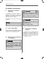 8
8
-
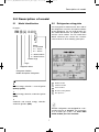 9
9
-
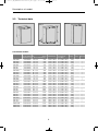 10
10
-
 11
11
-
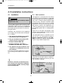 12
12
-
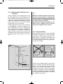 13
13
-
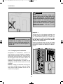 14
14
-
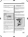 15
15
-
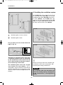 16
16
-
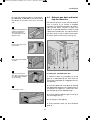 17
17
-
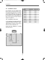 18
18
-
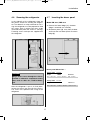 19
19
-
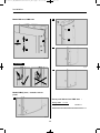 20
20
-
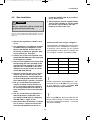 21
21
-
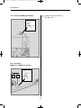 22
22
-
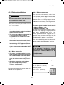 23
23
-
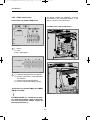 24
24
-
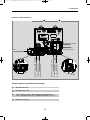 25
25
-
 26
26
-
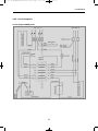 27
27
-
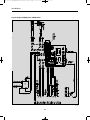 28
28
-
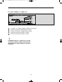 29
29
-
 30
30
-
 31
31
-
 32
32
-
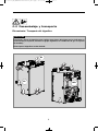 33
33
-
 34
34
-
 35
35
-
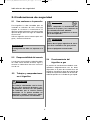 36
36
-
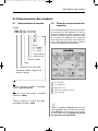 37
37
-
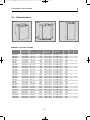 38
38
-
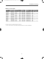 39
39
-
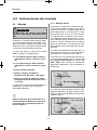 40
40
-
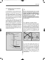 41
41
-
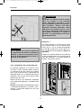 42
42
-
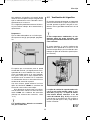 43
43
-
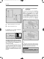 44
44
-
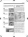 45
45
-
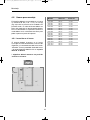 46
46
-
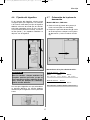 47
47
-
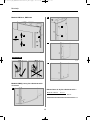 48
48
-
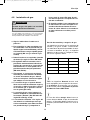 49
49
-
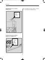 50
50
-
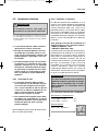 51
51
-
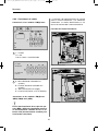 52
52
-
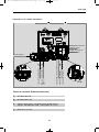 53
53
-
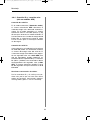 54
54
-
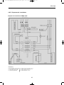 55
55
-
 56
56
-
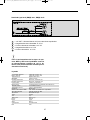 57
57
-
 58
58
-
 59
59
-
 60
60


Dometic RM 8xxx, RMS 8xxx, RML 8xxx, RMSL 8xxx Guía de instalación
- Tipo
- Guía de instalación
- Este manual también es adecuado para
En otros idiomas
Documentos relacionados
-
Dometic RM122 El manual del propietario
-
-
-
Dometic RM 8501 Instrucciones de operación
-
Dometic RMSL8500 Manual de usuario
-
-
-
-
Dometic ACC3100D Guía de instalación
-