
T.B. MB 05/2006
Instrucciones de uso
Español
REFRIGERADOR por ABSORBCIÓN para VEHÍCULOS DE OCIO
Type C40 / 110
821 2690 - 63
EN
INSTRUCCIONES de USO y para la INSTALACIÓN
OPERATING INSTRUCTIONS / INSTALLATION INSTRUCTIONS
REFRIGERADOR por ABSORBCIÓN
ABSORPTION REFRIGERATOR
ES
Número del modelo .............................................
Número del producto .............................................
Número de serie .............................................
Apunte los siguientes datos:
RM 6290 (L)
RM 6291 (L)
RM 6401 (L)
RM 7270 (L)
RM 7290 (L)
RM 7360 (L)
RM 7370 (L)
RM 7400 (L)
RM 7540 (L)
RM 7550 (L)

2
Servicio de
Atención al
Cliente
Cómo almacenar alimentos en un refrigerador:
Ningún aparato refrigerador puede mejorar la calidad de los alimentos: sólo es posible, en el mejor de los casos, mantener la
calidad de los alimentos existente en el momento del almacenamiento durante un breve período de tiempo.
Tenga en cuenta las siguientes condiciones especiales a la hora de guardar alimentos en un refrigerador integrado en un
vehículo:
- Modificaciones de las condiciones climáticas como los cambios de temperature.
- Gran temperatura en el interior del vehículo, si éste se ha aparcado completamente cerrado y está expuesto directamente a
rayos solares (temperatura posible de hasta 50°C).
- Uso del refrigerador durante la marcha del vehículo con la fuente de energía 12V-CC.
- El refrigerador está integrado detrás de una ventana y expuesto a luz solar directa.
- Almacenamiento demasiado rápido poco después de haber puesto en marcha el aparato.
Bajo estas condiciones especiales, el refrigerador no puede garantizar la temperatura necesaria para los alimentos muy
perecederos.
Entre los alimentos muy perecederos se encuentran: todos los productos lácteos con una fecha de caducidad indicada y
una temperatura mínima de almacenamiento de +4°C o inferior, especialmente la carne roja, carne blanca, el pescado, los
embutidos y los platos preparados.
Indicaciones
- Empaquete los productos crudos separados de los cocinados (por ejemplo, en recipientes, papel de aluminio o similares).
- Retire los embalajes de los paquetes individuales sólo cuando también pueda leer todos los datos necesarios, como por
ejemplo la fecha de caducidad, en los paquetes individuales.
- No deje los productos fríos durante demasiado tiempo fuera del refrigerador.
- Coloque en la parte delantera los alimentos que caduquen antes.
- Vuelva a empaquetar los restos y consúmalos lo antes posible.
- Lávese las manos antes de tocar los alimentos.
- Limpie el interior del refrigerador con regularidad.
Información:
Siga las indicaciones y descripciones sobre la fecha de caducidad indicados en los embalajes de los productos.
Tenga en cuenta los apartados de las presentes instrucciones "5.1 Limpieza" y "5.3 Almacenamiento de alimentos".
Instrucciones de seguridad
Guarde cuidadosamente estas instrucciones de uso.
En caso de transmisión del aparato adjunte estas instrucciones de uso.
© Dometic GmbH - 2007 - Salvo modificación - Imprimido en Alemania
Advertencia
Atención
Información
Nota
medioambiental
Dansk
Deutsch
Ελληνικά
English
Español
Français
Italiano
Nederlands
Norsk
Português
Suomi
Svensk
via INTERNET
www
.dometic.com

3
ÍNDICE
1.0 INTRODUCCIÓN . . . . . . . . . . . . . . . . . . . . . . . . . . . . . . . . . . . . . . . 4
2.0 PARA SU SEGURIDAD . . . . . . . . . . . . . . . . . . . . . . . . . . . . . . . . . . 4
2.1 Advertencias de segurida . . . . . . . . . . . . . . . . . . . . . . . . . . . . . . . . . . . . . . . . . . . . . . . . . . . . . . 4
2.2 Líquido refrigerante . . . . . . . . . . . . . . . . . . . . . . . . . . . . . . . . . . . . . . . . . . . . . . . . . . . . . . . . . . 4
3.0 GARANTÍA Y SERVICIO DE ATENCIÓN AL CLIENTE . . . . . . . . . 5
4.0 DESCRIPCIÓN DEL MODELO . . . . . . . . . . . . . . . . . . . . . . . . . . . . 5
5.0 GUÍA DEL REFRIGERADOR . . . . . . . . . . . . . . . . . . . . . . . . . . . . . 5
5.1 Limpieza . . . . . . . . . . . . . . . . . . . . . . . . . . . . . . . . . . . . . . . . . . . . . . . . . . . . . . . . . . . . . . . . . . . 5
5.2 Conectar el refrigerador . . . . . . . . . . . . . . . . . . . . . . . . . . . . . . . . . . . . . . . . . . . . . . . . . . . . . . . 6
5.3 Conservación de los alimentos . . . . . . . . . . . . . . . . . . . . . . . . . . . . . . . . . . . . . . . . . . . . . . . . . 9
5.4 Fabricación de cubitos de hielo . . . . . . . . . . . . . . . . . . . . . . . . . . . . . . . . . . . . . . . . . . . . . . . . . 10
5.5 Colocación de las rejillas de almacenamiento . . . . . . . . . . . . . . . . . . . . . . . . . . . . . . . . . . . . . . 10
5.6 Cierre de la puerta . . . . . . . . . . . . . . . . . . . . . . . . . . . . . . . . . . . . . . . . . . . . . . . . . . . . . . . . . . . 10
5.7 Descongelación . . . . . . . . . . . . . . . . . . . . . . . . . . . . . . . . . . . . . . . . . . . . . . . . . . . . . . . . . . . . . 11
5.8 Funcionamiento en invierno . . . . . . . . . . . . . . . . . . . . . . . . . . . . . . . . . . . . . . . . . . . . . . . . . . . . 11
5.9 Desconectar el refrigerador . . . . . . . . . . . . . . . . . . . . . . . . . . . . . . . . . . . . . . . . . . . . . . . . . . . . 12
5.10 Puesta fuera de servicio . . . . . . . . . . . . . . . . . . . . . . . . . . . . . . . . . . . . . . . . . . . . . . . . . . . . . . . 12
5.11 Iluminación . . . . . . . . . . . . . . . . . . . . . . . . . . . . . . . . . . . . . . . . . . . . . . . . . . . . . . . . . . . . . . . . . 12
5.12 Cambio de la placa de decoración . . . . . . . . . . . . . . . . . . . . . . . . . . . . . . . . . . . . . . . . . . . . . . . 13
5.13 Cambiar el tope de puerta . . . . . . . . . . . . . . . . . . . . . . . . . . . . . . . . . . . . . . . . . . . . . . . . . . . . . 14
5.14 Localización y reparación de averías . . . . . . . . . . . . . . . . . . . . . . . . . . . . . . . . . . . . . . . . . . . . . 15
5.15 Mantenimiento . . . . . . . . . . . . . . . . . . . . . . . . . . . . . . . . . . . . . . . . . . . . . . . . . . . . . . . . . . . . . . 16
5.16 Responsabilidad del producto . . . . . . . . . . . . . . . . . . . . . . . . . . . . . . . . . . . . . . . . . . . . . . . . . . 16
5.17 Referencias medioambientales . . . . . . . . . . . . . . . . . . . . . . . . . . . . . . . . . . . . . . . . . . . . . . . . . 16
5.18 Eliminación de resíduos . . . . . . . . . . . . . . . . . . . . . . . . . . . . . . . . . . . . . . . . . . . . . . . . . . . . . . . 16
5.19 Consejos para el ahorro de energía . . . . . . . . . . . . . . . . . . . . . . . . . . . . . . . . . . . . . . . . . . . . .16
5.20 Datos técnicos . . . . . . . . . . . . . . . . . . . . . . . . . . . . . . . . . . . . . . . . . . . . . . . . . . . . . . . . . . . . . . 17
5.21 Declaración de conformidad . . . . . . . . . . . . . . . . . . . . . . . . . . . . . . . . . . . . . . . . . . . . . . . . . . . 17
6.0 MANUAL DE INSTALACIÓN . . . . . . . . . . . . . . . . . . . . . . . . . . . . . . 18
6.1 Instalación . . . . . . . . . . . . . . . . . . . . . . . . . . . . . . . . . . . . . . . . . . . . . . . . . . . . . . . . . . . . . . . . . 18
6.2 Instalación sin corriente de aire . . . . . . . . . . . . . . . . . . . . . . . . . . . . . . . . . . . . . . . . . . . . . . . . . 20
6.3 Ventilación y extraccón de aire . . . . . . . . . . . . . . . . . . . . . . . . . . . . . . . . . . . . . . . . . . . . . . . . . 21
6.4 Instalación del sistema de ventilación . . . . . . . . . . . . . . . . . . . . . . . . . . . . . . . . . . . . . . . . . . . .22
6.5 Hueco de la instalación . . . . . . . . . . . . . . . . . . . . . . . . . . . . . . . . . . . . . . . . . . . . . . . . . . . . . . . 23
6.6 Fijación del refrigerador . . . . . . . . . . . . . . . . . . . . . . . . . . . . . . . . . . . . . . . . . . . . . . . . . . . . . . . 23
6.7 Extracción de humos . . . . . . . . . . . . . . . . . . . . . . . . . . . . . . . . . . . . . . . . . . . . . . . . . . . . . . . . . 24
6.8 Instalación del gas . . . . . . . . . . . . . . . . . . . . . . . . . . . . . . . . . . . . . . . . . . . . . . . . . . . . . . . . . . . 25
6.9 Instalación eléctrica . . . . . . . . . . . . . . . . . . . . . . . . . . . . . . . . . . . . . . . . . . . . . . . . . . . . . . . . . . 27

4
INTRODUCCIÓN
Sin duda ha realizado una excelente elección al escoger el refrigerador por absorción
de Dometic. En todos los aspectos, estamos convencidos de que estará totalmente
satisfecho con su nuevo aparato electrodoméstico. Este aparato, que funciona de
manera silenciosa, cumple las más altas exigencias de calidad y garantiza el uso
eficaz de los recursos y de la energía a lo largo de todo su ciclo vital, cuando se
fabrica, cuando se utiliza y cuando deba retirarse.
Antes de proceder a poner en marcha el aparato, lea cuidadosamente las instrucciones
de instalación y funcionamiento. El refrigerador se ha diseñado para que pueda
instalarse en vehículos de ocio como puedan ser las caravanas o los remolques de
acampada. El aparato ha obtenido la certificación para esta aplicación, de acuerdo con
la Directiva sobre Gas 90/396/EEC de la UE.
PARA SU SEGURIDAD
Advertencias de seguridad
No debe usarse nunca una llama viva para comprobar las fugas
del aparato.
¡Proteja a los niños!
Cuando decida dejar fuera de servicio el refrigerador, quite todas las puertas
y deje las rejillas de almacenamiento en el interior. Así evitaremos los cierres
accidentales o la asfixia.
Si oliera a gas:
- cierre la espita del suministro de gas y la válvula del regulador de la bombona.
- abra las ventanas y abandone la habitación.
- no conecte ningún aparato eléctrico.
- apague cualquier llama viva.
No abra nunca el conjunto de absorción puesto que mantiene una presión elevada.
Los trabajos relacionados con las áreas del gas, la extracción de humos y los compo-
nentes eléctricos tan solo los podrá llevar a cabo el servicio técnico autorizado
.
Es imprescindible que la presión de uncionamiento se corresponda con los datos
registrados en la placa de características del aparato.
Compárense los datos de la presión de trabajo de la placa del modelo con los del
indicador de presión en el cilindro de gas líquido.
El funcionamiento a gas del aparato no està permitido en transbordadores.
Las cubiertas aseguran la seguridad eléctrica y tan solo se pueden extraer utilizando
una herramienta.
El mecanismo no debe ser expuesto a la lluvia.
El refrigerador no está previsto para almacenar medicamentos.
Líquido refrigerante
Como líquido refrigerante se emplea el amoníaco. Se trata de un compuesto natural,
que se usa también en los productos de limpieza doméstica (1 litro de limpiador de sal
de amoníaco contiene hasta 200g. de amoníaco: aproximadamente será el doble en
caso de que se use en el refrigerador). El cromato sódico se utiliza para la protección
contra la corrosión (1,8 % del disolvente). Si se produjera alguna fuga (fácilmente
identificable debido al olor desagradable):
desconecte el aparato.
airee completamente la habitación.
llame al departamento de atención al cliente autorizado.
11..00
22..00
2.1
2.2

5
GARANTIA Y SERVICIO AL CLIENTE
Las condiciones de garantía están de acuerdo con la directiva CE 44/1999/CE y
las condiciones habituales aplicables en cada país. Para cuestiones relacionadas
con la garantía o el servicio de reparaciones, deberá ponerse en contacto con
nuestro departamento de atención al cliente.
La garantía no cubrirá aquellos daños que puedan ocasionarse por un uso indebido
del aparat. Tampoco cubrirá las modificaciones que se hagan en el aparato, así como
el uso de piezas que no sean originales de Dometic. La garantía tampoco tendrá
validez si no se siguen correctamente las instrucciones de instalación y puesta en
marcha, con lo cual no podrán reclamarse responsabilidades. Las piezas de repuesto
pueden obtenerse en toda Europa a través del departamento de atención al cliente.
Cuando se ponga en contacto con el servicio posventa, por favor indique siempre el
modelo, el número del producto, el número de serie así como el código MLC, si fuera
requerido. Encontrará esta información en la placa de características en el interior del
refrigerador.
DESCRIPCIÓN DEL MODELO
GUÍA DEL REFRIGERADOR
Limpieza
Es aconsejable que antes de poner en marcha el refrigerador se limpie tanto por
la parte exterior como por la interior:
Utilice un paño suave y agua templada con un detergente suave.
A continuación proceda al aclarado con agua limpia y séquelo completamente.
Una vez al año quite el polvo de la unidad del refrigerador con un cepillo o un
paño suave.
AATTEENNCCIIÓÓNN
Para evitar el deterioro de los materiales:
No utilice jabón ni productos de limpieza que sean fuertes, abrasivos o que
contengan sosa cáustica.
No permita que la junta hermética de la puerta entre en contacto con aceite
o grasa.
33..00
44..00
55..00
5.1
RM 7550 L
por ejemplo:
Refrigerador móvil /
Refrigerador por absorción móvil
1 = Encendido automático
0 = Encendido manual
0 = puerta plana
5 = puerta curvada
"L" iluminado
Modelo

6
Conexión del refrigerador
La unidad frigorífica funciona de forma silenciosa.
Al poner el aparato en funcionamiento por primera vez, es posible que éste
desprenda un olor que desaparecerá transcurridas algunas horas.
Ventile bien la casa.
El refrigerador alcanza su temperatura de funcionamiento después de algu-
nas horas; el congelador debería enfriarse después de aprox. una hora.
Controles
5.2
5.2.1
Nota:
El refrigerador está equipado para trabajar con suministro de energía de la red, a
12V o con gas líquido.
La opción de potencia, que se desee, se selecciona con el conmutador de selección
de energía (A).
Éste selector (A) dispone de posiciones:
230V (potencia principal de CA), 12V (CC), gas (gas líquido), OFF (desconectado).
OFF
Potencia principal de CA
12V CC
Gas
A. Encendido manual (p.e. RM6290L o RM7400L+)
B. Encendido automático (p.e. RM6291L)
A B D
A = conmutador de selección de energía
B = termostato gas/eléctrico
C = pulsador de "encendido manual (encendido piezoeléctrico)"
D = galvanómetro
A = conmutador de selección de energía
B = termostato gas/eléctrico
D = indicador de "encendido automático"
A
B
C
A
B
C
D

Funcionamiento eléctrico
1. 12V (CC)
El refrigerador sólo puede usarse a través del suministro principal de la
máquina, mientras el motor esté en marcha.
Ponga el interruptor de selección de energía "A" en 12V .
El refrigerador funciona sin control del termostato
(funcionamiento continuo).
2. Funcionamiento con tensión de red
Seleccione este modo de funcionamiento sólo si el suministro de tensión de la
toma de corriente corresponde al valor indicado en la placa de características.
¡Valores divergentes pueden dañar el aparato!
1. Ponga el interruptor de selección de energía "A" en 230V .
2. Ajustar con el interruptor giratorio "B" la temperatura en el compartimento principal del
refrigerador.
Funcionamiento con gas
7
5.2.2
5.2.3
El refrigerador debe funcionar exclusivamente con gas líquido
(propano, butano) - en ningún caso podrá usarse gas ciudad, gas
natural o Autogas.
Si el refrigerador funciona con gas durante el viaje, hay que tomar
las precauciones necesarias, previstas por el legislador del país
correspondiente (conforme norma europea EN 732).
A una altura de aprox. 1000 m NN pueden producirse fallos al encender
el gas por motivos físicos (¡no se trata de un fallo funcional!).
El funcionamiento con gas está prohibido en las proximidades de las
estaciones de servicio!
Todos los refrigeradores, tanto si usan el encendido manual como el
automático, están equipados con una protección automática de la
llama que interrumpe automáticamente el suministro de gas, aproxima-
damente 30 segundos después de que la llama se haya apagado.
Cuando se pone en marcha por primera vez, y también cuando se
cambia la bombona, las conducciones de gas pueden contener aire. Al
poco de ponerse en marcha el refrigerador u otros aparatos de gas
(por ejemplo cocinas), el aire saldrá de las conducciones de gas. Éste
podrá entonces encenderse sin demora.
A
A
B

8
1. Encendido manual
1. Abra la válvula del regulador en la bombona de gas.
2. Abra la espita de paso del suministro de gas.
7. Mantenga el mando giratorio (B) apretado durante otros 10-15 segundos, después
suéltelo.
8. Observe el indicador del galvanómetro para comprobar que la llama esté encendida.
9. Si la llama estuviese apagada, repita el proceso otra vez.
10. Ajustar con el interruptor giratorio "B" la temperatura en el compartimento principal
del refrigerador.
2. Encendido automático (RM 6291, RM 6401)
4. Mantenga el mando giratorio (B) apretado durante otros 10-15 segundos, después
suéltelo.
5. Observe el cristal de inspección para comprobar que la llama esté encendida.
6. Ajuste la temperatura en el compartimento principal del refrigerador mediante el
interruptor giratorio "B".
Nota: Si la llama no estuviera quemando, el sistema repetiría el proceso de encendido
automáticamente..
3. Ponga el interruptor
de selección de
energía "A" en la
posición "G .
4. Presione y mantenga
apretado el mando
giratorio (B).
5. Active el encendido
piezoeléctrico (C)
varias veces en
intervalos de 1 a 2
segundos.
A
B
C
6. Compruebe el cristal de
inspección para detectar si
se ha encendido la llama
(este cristal se halla situa-
do en el interior del refrige-
rador en la parte inferior
izquierda).
5. Pulse el botón de
confirmación (C)
de la ignición de
pila y manténgalo
pulsado.
C
6. El indicador del galvanómetro pasa
a la zona verde cuando la llama se
ha encendido y se mantiene.
1. Ponga el interruptor
de selección de
energía "A" en la
posición Gas.
2. Presione y
mantenga
apretado el
mando giratorio
(B).
3. El proceso de encendido se activa automáticamente,
acompañado de una señal acústica, mientras que la
lámpara de señalización (D) parpadeará. Si el encendido
se ha completado sin problemas, cesará el sonido y la
lámpara se apagará.
Encendido manual con ignición de piezo:
Encendido manual con ignición de pila:
D
A
B

9
Ajustar la temperatura de la cámara frigorífica
Como indicado, puede ajustar a través del
botón gira torio (B) la temperatura de la cámara
frigorífica, según fuera preciso.
Los refrigeradores de Dometic trabajan siguiendo el principio de la
absorción. Un sistema absorbente reacciona lentamente a las modifi-
caciones del termostato, a la pérdida de frío por apertura de puertas
o almacenamiento de productos, debido a principios físicos.
Los aparatos se incluyen en la clase climática SN según EN/ISO 7371
en la gama de temperatura ambiente de +10°C a 32°C.
5.2.4
Las condiciones ambientales influyen en el rendimiento del agregado.
Elija la posición central si las temperaturas ambientales oscilan entre los
+15°C und +25°C. El agregado funciona en la margen de potencia óptima.
5.3.2 Congelador
No meta bebidas con gas en el congelador.
El congelador permite la fabricación de cubitos de hielo así como el
almacenamiento por un corto período de alimentos congelados.
No se puede utilizar como congeal dor de comida a largo plazo.
En caso de registrarse temperaturas ambientales inferiores a +10 °C no puede
garantizarse una regulación homogénea de la temperatura del congelador,
si el refrigerador queda expuesto a estas temperaturas durante largo tiempo.
Esto podría provocar un posible aumento de temperatura en el congelador y
la descongelación de los productos almacenados en él.
5.3
Conservación de los alimentos
5.3.1
B
Posición central
Indicaciones
Ponga el refrigerador en funcionamiento unas 12 horas antes de llenarlo.
Almacene siempre productos previamente refrigerados. Asegúrese de que
los productos están bien refrigerados a la hora de comprarlos y transportarlos.
Utilice bolsas térmicas.
Al sacar productos del refrigerador, abra la puerta sólo brevemente.
Los productos deben estar empaquetados, a ser posible en recipientes cerrados,
y deben almacenarse por separado.
Deje enfriar los productos calentados antes de meterlos en el refrigerador.
Los productos que pueden emitir gases volátiles o inflamables no deberían guardarse
en el refrigerador.
Deposite los alimentos sensibles cerca de las aletas de refrigeración.
El refrigerador no deberá quedar expuesto a los rayos solares directos. Tenga en
cuenta que la temperatura del interior de un vehículo cerrado aumenta considerable-
mente mediante los rayos solares, lo que puede afectar al rendimiento del refrigerador.
La circulación de aire sin obstáculos del motor del refrigerados deberá quedar garanti-
zada (véase también el capítulo 6.3 "Ventilación y extracción de aire").

10
Fabricación de cubitos de hielo
La mejor hora para fabricarlos es durante la noche. Durante este tiempo, el
refrigerador trabaja menos y la unidad dispone de más reservas.
¡Utilice sólo agua potable!
5.4
5.5
1. Llene la cubitera
con agua potable.
2. Colóquela dentro
del compartimento
del congelador.
Antes de iniciar el viaje, ¡ cierre bien la puerta del refrigerador
y bloquéela!
abrir
cerrar
1. Afloje las abrazaderas
de fijación delantera y
trasera.
2. Desplace la rejilla de almacenamiento
hacia la izquierda y extráigala hacia
arriba.
Desmontaje:
2.
1.
Para montar la rejilla de almacenaje, procédase en orden inverso.
5.6
Colocación de las rejillas de almacenamiento
puerta del frigorífico
cerrar
RM 6xxx
RM 7xx0
abrir
Cierre de la puerta

11
Descongelación
Con el tiempo, se forma escarcha en los bordes.
Cuando la capa de hielo alcance los 3 mm de grosor, el refrigerador debería
descongelarse.
1. Desconecte el refrigerador, tal como se describe en la Sección 5.9: "Desconexión".
2. Quite la cubitera y la comida.
3. Deje la puerta del refrigerador abierta.
4. Una vez descongelado (el congelador y los bordes sin escarcha), pase un paño
por el recipiente seco.
5. Use un paño para absorber el agua del congelador.
6. Vuelva a conectar el refrigerador, según el procedimiento descrito en "5.2".
Bajo ningún concepto se debe extraer la capa de hielo a la fuerza, ni
tampoco acelerar la descongelación usando elementos calefactores.
NNoottaa::
El agua de la descongelación en el compartimento principal del refrigerador se
deposita en un recipiente apropiado en la parte trasera del aparato. Desde allí,
se evapora.
Funcionamiento en invierno
1. Compruebe que las rejillas de ventilación
y el extractor no hayan quedado
bloqueados por la nieve,
hojas u otros elementos.
5.7
5.8
2. Cuando la temperatura ambiente descienda por debajo de los 8º C, debería
montarse la cubierta invernal. Esto protege la unidad del frío extremo.
Rejilla de ventilación inferior (L200)
Rejilla de ventilación superior con el
extractor (L100)
3. Añada la cubierta y fíjela.
Coloque también la cobertura de invierno si no utiliza el vehículo
durante un período prolongado o al limpar la parte exterior.
TTIIPP

12
Iluminación
Cambio de bombillas
5.9
5.11
1. Quite la tapa.
2. Desenrosque la
bombilla fundida.
3. Introduzca una nueva
bombilla.
4. Abdeckung einclipsen.
90°
1.
2.
Nota:
Para 12V de CC: 1 bombilla de 12V, 2W
Para 24V de CC: 2 bombillas de 28V, 1,5W
Póngase en contacto con los centros de servicio
de atención al cliente de Dometic cuando necesite
cambiar las bombillas
Desconectar el refrigerador
1. Sitúe el conmutador de selección de
energies (A) en la posición "OFF".
El aparato quedará completamente
desconectado!
2. Asegúrese de que la puer ta quede abierta
por medio del tope de puerta.
Para evitar que se forme moho en el interior del
aparato, la puerta debería quedar entreabierta.
Desconexión del funcionamiento con gas!
La espita de paso de la conducción de gas, así como la válvula del regulador
de la bombona deberán cerrarse, si se prevé que el refrigerador estará fuera
de servicio un largo periodo de tiempo.
A
puerta del frigorífico
Pulsando y girando el botón de mando (C) en unos 90° hacia la derecha se desbloquea
la pila. Una vez retirada la tapa, puede sacar la pila (1,5 V AAA / R3 / Micro) y
sustituirla por otra (¡tenga en cuenta la polaridad!).
Cambio de pila en la ignición (opcional)
+
_
C
5.10

13
Cambio de la placa de decoración5.12
1. Abra la puerta y
afloje el tornillo de
la bisagra.
2. Saque la puerta
con un movimiento
hacia arriba.
3. Desatornille la
plataforma interior
(3 tornillos).
4. Retire la placa
de decoración
e introduzca la
nueva.
5. Vuelva a atornillar
la plataforma
interior en su
posición.
6. Reinstale la
puerta.
7. Apriete el
tornillo de la
bisagra.
La dimensiones del panel deben ser las siguientes (mm):
Modelo Altura Anchura Espesor
RM 6290 718 +/-1 491,5 +1 3,2
RM 6291 718 +/-1 491,5 +1 3,2
RM 6401 718 +/-1 491,5 +1 3,2
RM 7270 730 +/-1 453,5 + 1 3,2
RM 7270 + 741 +/-1 462,0 1,8
RM 7290 730 +/-1 491,5 + 1 3,2
RM 7290 + 741 +/-1 500,0 1,8
RM 7360 730 +/-1 453,5 + 1 3,2
RM 7360 + 741 +/-1 462,0 1,8
RM 7370 730 +/-1 453,5 + 1 3,2
RM 7370 + 741 +/-1 462,0 1,8
RM 7400 730 +/-1 491,5 + 1 3,2
RM 7400 + 741 +/-1 500,0 1,8
RM 7540 + 730 +/-1 491,5 + 1 2,6
RM 7550 + 741 +/-1 500,0 2,6
„+“ = puerta curvada

14
Cambiar el tope de puerta
Ajustar la bisagra de la puerta
Puede ser necesario ajustar la bisagra de la puerta para permitir que la puerta se blo-
quee correctamente. Para ello, este refrigerador viene equipado con un tornillo de
bisagra ajustable. Para ajustarlo, utilice la herramienta adjuntada.
5.13
No es siempre posible cambiar la puerta una vez que el frigorífico esté instalado.
1. Abrir la puerta, desenroscar
el tornillo de bisagra y
guardarlo.
2. Extraer la puerta
hacia arriba.
5. Colocar puerta.
6. Enroscar el tornillo
de bisagra.
3.
4.
5.12.1
A
B
1. El tornillo de bisagra
está compuesto por una
pieza móvil (A) y
otra fija (B).
2. Ajuste la altura de la
espiga de bisagra (A)
con la herramienta sumi-
nistrada.
3. Compruebe si la puerta se
cierra correctamente.

15
Procedimiento en caso de averías5.14
Avería: El refrigerador no funciona con gas.
Posible causa Acción correctora
a.) La bombona de gas está vacía.
b.) ¿El mecanismo de cierre preconectado
está abierto?
c.) ¿Hay aire en la conducción?
a.) Cambiar la bombona de gas.
b.) Abrir el mecanismo de cierre.
c.) Desconectar el aparato y conectarlo de
nuevo.
Repetir el procedimiento 3 a 4 veces, si fuera
necesario.
Antes de llamar al departamento de servicio autorizado de atención al cliente,
compruebe lo siguiente:
1. que se han seguido las instrucciones de la sección "Conexión del refrigerador".
2. que el refrigerador se encuentra nivelado.
3. que el refrigerador funciona con una de las fuentes de alimentación disponibles.
Avería: El refrigerador no funciona con 12V.
Posible causa Acción correctora
a.) Fusible de a bordo defectuoso.
b.) Bateria descargada.
c.) Encendido no conectado.
a.) Insertar nuevo fusible.
b.) Verificar bateria y cargarla.
c.) Arrancar el motor.
Avería: Der Kühlschrank kühlt nicht ausreichend.
Posible causa Acción correctora
a.) La aireación del agregado de
refrigeración no es suficiente.
b.) El termostato está en una posición
muy baja.
c.) El evaporador está demasiado
congelado.
d.) Demasiados alimientos calientes
depositados en poco tiempo.
e.) El aparato lleva poco tiempo
conectado.
a.) Compruebe que las rejillas de ventilación no
estén obstruidas.
b.) Coloque el termostato en una posición más
alta.
c.) Compruebe si la puerta del refrigerador
cierra herméticamente.
d.) Deje enfriar primero los alimentos.
e.) Compruebe si el refrigerador enfria bien
después de algunas horas de
funcionamiento.
Avería: El refrigerador no funciona con 230V.
Posible causa Acción correctora
a.) Fusible de a bordo defectuoso.
b.) El vehículo no está conectado a la red.
a.) Insertar nuevo fusible.
b.) Conectar a la red.

16
Mantenimiento
Las conducciones de gas y las instalaciones eléctricas únicamente
deberán ser manipuladas por personal autorizado. Se recomienda que
el trabajo se lleve a cabo por un centro autorizado del servicio de atención al
cliente.
De acuerdo con la normativa vigente, la instalación de gas y el equipo
complementario de extracción de humos deben ser inspeccionados antes de la
primera puesta en marcha del aparato y en lo sucesivo, cada dos años;
además, los aparatos electrodomésticos, que funcionan con gas líquido, deben
ser inspeccionados cada año por el servicio técnico autorizado en cumplimiento
de las "regulaciones técnicas EN1949". Una vez realizada la inspección, se
expedirá el certificado correspondiente. Es responsabilidad del cliente
procurar que esta inspección se lleve a cabo.
El quemador del gas debería limpiarse siempre que fuera necesario, pero al
menos una vez al año.
Recomendamos entretener el refrigerador después del vehículo estar fuera
deservicio por un largo período.
Responsabilidad del producto
La responsabilidad del producto por parte de la Dometic GmbH no abarca daños
resultantes de errores de manejo, de manipulaciones y tervenciones indebidas en el
aparato, de la influencia de factores ambientales, tal como alteraciones de
temperatura y humedad atmosférica junto al aparato o en proximidad inmedata del
mismo, así como de personas.
Referencias medioambientales
Los aparatos de refrigeración fabricados por Dometic GmbH no contienen CFC y
HCFC. En el sistema de enfriamiento se emplea el amoníaco (un compuesto
natural de hidrógeno y nitrógeno) como líquido refrigerante. En la fabricación de la
espuma aislante PU se ha usado como combustible el ciclopentano, que no daña la
capa de ozono.
Eliminación de resíduos
Enviaremos al servicio local de recogida de residuos los materiales del embalaje,
que sean reciclables, para asegurarnos que éstos se reutilizan.
En cuanto al aparato electrodoméstico, una vez en desuso, debería llevarse a un
centro especializado de recogida de residuos, en donde se procedería a separar los
componentes, que sean reciclabes, de los que no lo son y que deben almacenarse
en el sitio adecuado.
Sería conveniente disponer de una planta de recogida de residuos especializada
para que se hiciera cargo del líquido refrigerante utilizado en las unidades de
refrigeración por absorción, respetando de ese modo la ecología del entorno.
Consejos para el ahorro de energía
Con una temperatura media ambiental de 25º C, es suficiente mantener la
regulación del termostato en la mitad para hacer funcionar el aparato (tanto para
la alimentación a gas como a través del suministro eléctrico).
Cuando sea posible, enfríe los alimentos antes de guardarlos.
No instale el refrigerador donde pueda darle directamente la luz solar.
5.15
5.16
5.17
5.18
5.19
TTIIPP

17
La unidad de refrigeración necesita de una circulación de aire permanente.
Descongele el aparato con regularidad.
Cuando saque alimentos del refrigerador procure mantener la puerta abierta
el menor tiempo posible.
Instale y conecte el aparato por lo menos 12 horas antes de empezar a
llenarlo.
Datos técnicos
Declaración de conformidad
5.20
5.21
Modelo Dimensiones Capacidad Capacidad Potencia de * Consumo Peso neto Encendido Rejillas
H x A x F (mm) total del conexión eléctrico/gas graduables
F incl. puerta congelador red/batería en 24 horas
La empresa tiene los derechos reservados para realizar cambios técnicos.
* Consumo medio medido con una temperatura ambiental de 25º C en aplicación de la norma ISO.
RM 6290 821x525x541 86 lit. 10,5 lit. 125 W / 120 W ca.2,5 KWh / 270 g 27 kg X X
RM 6291 821x525x541 86 lit. 10,5 lit. 125 W / 120 W ca.2,5 KWh / 270 g 27 kg X
RM 6401 821x525x541 97 lit. 10,5 lit. 135 W / 130 W ca.2,6 KWh / 270 g 29 kg
RM 7270 821x486x538 77 lit. 9,5 lit. 125 W / 120 W ca.2,5 KWh / 270 g 26 kg X X
RM 7270+ 821x486x565 81 lit. 9,5 lit. 125 W / 120 W ca.2,5 KWh / 270 g 26 kg X X
RM 7290 821x525x541 86 lit. 10,5 lit. 125 W / 120 W ca.2,5 KWh / 270 g 27 kg X X
RM 7290+ 821x525x565 93 lit. 10,5 lit. 125 W / 120 W ca.2,5 KWh / 270 g 27 kg X X
RM 7360 821x486x541 88 lit. 9,5 lit. 135 W / 130 W ca.2,6 KWh / 270 g 28 kg X
RM 7360+ 821x486x568 92 lit. 9,5 lit. 135 W / 130 W ca.2,6 KWh / 270 g 28 kg X
RM 7370 821x486x606 89 lit. 11,0 lit. 125 W / 120 W ca.2,5 KWh / 270 g 27 kg X X
RM 7370+ 821x486x630 93 lit. 11,0 lit. 125 W / 120 W ca.2,5 KWh / 270 g 27 kg X X
RM 7400 821x525x541 97 lit. 10,5 lit. 135 W / 130 W ca.2,6 KWh / 270 g 29 kg X
RM 7400+ 821x525x568 104 lit. 10,5 lit. 135 W / 130 W ca.2,6 KWh / 270 g 29 kg X
RM 7540+ 821x525x596 110 lit. 12,0 lit. 135 W / 130 W ca.2,6 KWh / 270 g 30 kg X
RM 7550+ 821x525x623 117 lit. 12,0 lit. 135 W / 130 W ca.2,6 KWh / 270 g 30 kg X
„+“ = puerta curvada

18
GUÍA DE INSTALACIÓN
Cuando se instale un aparato electrodoméstico deberán observarse las disposiciones que
sobre normativa técnica y administrativa rijan en el país, donde por primera vez se vaya a
utilizar el aparato.
En Europa, por ejemplo, los aparatos de gas, los cableados, la instalación de
bombonas, así como las comprobaciones y el visto bueno de las fugas deben
cumplir con la norma EN 1949 para aparatos de gas líquido en vehículos.
Instalación
El aparato y la extracción de humos asociada deberán instalarse de manera que sean
accesibles para el mantenimiento y que sean de fácil instalación y desmontaje.
El aparato electrodoméstico debe ser instalado sólo por personal autorizado.
La instalación y la conexión del aparato deberán cumplir con las últimas
disposiciones técnicas, que aparecen a continuación:
La instalación gas debe realizarse según las disposiciones nacionales.
Disposiciones técnicas EN 1949 , Disposiciones técnicas EN 732
La instalación eléctrica debe realizarse según las disposiciones nacionales.
Disposiciones técnicas EN 60335-1, EN 60335-2-24, EN 1648-1 , EN 1648-2
Normativa sobre locales y edificios
El aparato deberá instalarse de manera que esté protegido contra una radiación
calorífica excesiva.
La exposición a un calentamiento excesivo perjudicará el funcionamiento y
aumentará el consumo de energía del refrigerador.
Instalación lateral
Si el aparato se monta en el lateral de la puerta de acceso, deberá asegurarse de que la
rejilla de ventilación no quede tapada por la puerta abierta.
(Fig.1, distancia mín. puerta - rejilla de ventilación 25 mm).
En caso contrario, la ventilación será insuficiente, lo que mermará el rendimiento de la
refrigeración. A menudo, el lado de la puerta del vehículo está dotado de un avancé.
Éste dificulta el escape de gases de combustión y de calor por la rejilla de ventilación.
(¡Merma del rendimiento de la refrigeración!)
66..00
6.1
6.1.1
Una instalación incompetente pone en peligro la garantía del
productor.
Fig.1
Fig.2
Rejilla de ventilación
no obstruida:
Conforme
(Fig.1) La rejilla de ventilación está tapada. ¡La distancia entre la puerta y la rejilla de ventilación
debe ser al menos de 25 mm! Para distancias entre puerta/rejilla de entre 25 y 45 mm
recomendamos que se instale el kit de ventilación de Dometic (n° de art. 241 2985 - 00/0),
para conseguir un rendimiento óptimo de refrigeración a altas temperaturas ambientales.

19
Montaje lateral con ventilación de suelo/techo6.1.2
6.1.3
En esta variante de montaje, sólo se podrá realizar el mantenimiento regular de
la unidad del quemador de gas desmontando el aparato. El refrigerador deberá
instalarse obligatoriamente de forma que quede garantizado un fácil desmontaje.
¡No se dispone del máximo
rendimiento de refrigeración!
En todas las situaciones de montaje,
¡la ventilación debe quedar
garantizada tal y como se describe
en el apartado 6.3!
Fig.4
Fig.5
Otra posibilidad es ventilar el refrigerador dejando una ranura de ventilación en el
suelo e instalando un sistema de ventilación en el techo del vehículo (Fig. 3). Entre
el canto superior del refrigerador y la
ventilación de techo debe existir una
chimenea que deje salir el aire caliente y
los gases de escape del motor del
refrigerador directamente por el sistema
de ventilación del techo.
La abertura del suelo debe tener una
sección transversal libre de al menos 250
cm². Esta abertura debe tener una
protección, por ejemplo, una chapa de
desviación y una red, para evitar que entre
suciedad en la zona de combustión de
gas. Con este tipo de ventilación puede
entrar más suciedad en la zona posterior
del refrigerador (en comparación con la
ventilación lateral), por lo que deberá
realizarse un mantenimiento regular del
quemador de gas, al menos una vez al
año.
A menudo, el montaje en la parte trasera provoca una
situación de montaje poco propicia, ya que no siempre
queda garantizada una ventilación óptima (p. ej., ¡la rejilla
de ventilación inferior queda cubierta por el parachoques o
las luces traseras del vehículo!). (Fig. 4). El máximo
rendimiento de refrigeración del motor no está disponible
de forma efectiva.
Una variante adicional también usual del
montaje en la parte trasera es la
colocación lateral de la rejilla de
ventilación (Fig. 5). La circulación del aire
caliente es muy limitada, lo que provoca
que los intercambiadores de calor
(condensadores, absorbedores) ya no se
refrigeran lo suficiente. También la
variante con una rejilla de ventilación
montada adicionalmente en el suelo
presenta una mala conducción de la
corriente de aire.
Abertura del suelo:
mín. 50 mm de ancho
mín. 520 mm de largo
Condensador
Fig.3
Aire caliente
Montaje en la parte trasera
Rejilla de
ventilación no
obstruida:
Conforme

20
Instalación sin corriente de aire
Los aparatos de refrigeración en caravanas, motocaravanas u otros vehículos deben
instalarse sin circulación de aire. Esto significa que el aire necesario para la
combustión del quemador no se absorbe del espacio vital y que se impide la
penetración de humos en este espacio (EN 1949).
En ningún caso deberá instalarse el frigorífico sin corriente de aire utilizando
pastas obturadoras o espumas (por ejemplo, espumas de montaje), u otros
productos similares.
Propuesta 1:
Utilización del kit de montaje estanco de
Dometic
(Art.No. 241 2559-00, en venta en la Dometic)
Introduzca las juntas herméticas
de los bordes (A) en los huecos
de la instalación, en la parte infe-
rior y a los lados.
Introduzca la placa de evacuaci-
ón (B), montada con una tira de
bordes (A) de material de alto
rendimiento, no inflamable, en el hueco de la
instalación (véase la Fig.).
Fije la placa de evacuación (B) en la pared de la
caravana, ¡no en el refrigerador!
Nos aseguraremos que el refrigerador quede
nivelado en su emplazamiento.
Propuesta 2:
Otra opción es instalar el refrigerador con una cubierta
(A). Esta cubierta (A) deberá fijarse a la pared de la cara-
vana, no al refrigerador. Coloque las juntas herméticas
en la parte inferior y en los laterales de la cubierta.
Finalmente, introduzca el refrigerador en la cubierta por
delante.
Ambas posibilidades facilitan el desmontaje y la
instalación del aparato para revisiones.
El espacio entre la pared de la caravana y el refrigerador
queda aislada del área habitable. Así, se evita la entrada
de humos en dicha área. Esta instalación no requiere un sistema especial de
extracción de humos. Éstos salen al exterior a través de la rejilla de ventilación
superior. Para este método de instalación se recomienda que se use la misma rejilla
de ventilación tanto en la parte superior como en la inferior (L200) sin ningún sistema
de extracción de humos.
6.2
¡NO utilize materiales fácilmente inflamables (sobre todo pastas de sellado
de silicona o semejantes) para la impermeabilización! La utilización de los
mismos exime al productor del aparato de la responsabilidad civil por el
producto y de la garantia.

21
En este caso, cuando se utilice el gas, ¡no debería usarse la cubierta
invernal!
Si de todos modos se desea una chimenea de humos, se puede incorporar el sistema
de ventilación y extracción L100 en el orifico de la rejilla de ventilación superior.
(Para la instalación de la chimenea véase el punto 6.7)
Ventilación y extracción
Una instalación perfecta es crucial para un funcionamiento correcto puesto que, debi
do a razones físicas, en la parte trasera del aparato se acumula calor, que debe salir
con facilidad al exterior.
En caso de temperaturas ambientales elevadas, el rendimiento máximo de la
unidad de refrigeración únicamente se podrá lograr por medio de sistemas
adecuados de ventilación y extracción.
Las modificaciones requieren el consentimiento
del productor.
6.3
La fijación correcta de la rejilla de ventilación inferior facilita el acceso a
las conexiones de gas y de electricidad en caso de trabajos de manteni-
miento.
El sistema de ventilación consta de dos orificios, que se encuentran en la pared de la
caravana. El aire frío entra por la parte inferior y se calienta, con lo cual asciende hasta
la rejilla de ventilación superior (efecto chimenea).
La rejilla de ventilación superior debería colocarse lo más alejada posible por encima
del condensador (A).
La rejilla de ventilación inferior debería estar a ras del suelo del vehículo, permitiendo
así que cualquier fuga de gas (más pesado que el aire) salga directamente al aire libre.
Si esto no es posible, el fabricante del vehículo deberá hacer un orificio de ventilación
en el fondo del hueco para que en caso de que se escape el gas no quemado no se
acumule en el fondo. (EN 1949).
Las rejillas de ventilación deberán tener una sección transversal de al menos
250cm². Recomendamos el sistema de ventilación y extracción L100 / L 200 de
Dometic, testado y aprobado para este fin.
La parte superior del sistema (L100) consta de un armazón de montaje (R1640), una
rejilla de ventilación completa con el extractor (A1620) y una cubierta para el invierno
(WA120).
La parte inferior del sistema (L200) incorpora también un armazón de montaje (R1650)
y una rejilla de ventilación (A1630, aunque sin extractor), y la cubierta para el invierno
(WA130).
Con paso
15-20mm
13cm²
15-20mm
13cm²
Sin paso

22
Instalación del sistema de ventilación6.4
3. Introducir la rejilla de ventilación.
6. Introducir la cubierta para el invierno.
2. Introducir el armazón ...
4. Fijar la rejilla de ventilación.
5. Colocar el extractor en su posición (sólo en el
sistema de ventilación superior L100).
... y fijarlo en la posición.
1. Sellar el armazón de montaje, para impermeabi lizarlo.
El punto 1 no será válido para el armazón de montaje con junta
integrada.
Para proceder a instalar las rejillas de ventilación, corte dos rectángulos (451
mm x 156 mm) en la pared exterior del vehículo (para situar los cortes, véase el
punto 6.3).
L 100
L 200

23
Hueco de la instalación
El refrigerador deberá instalarse sin corriente de aire en un hueco.
Las medidas de este receptáculo se reflejan en la tabla que se encuentra más
adelante.
El paso (A) se utiliza sólo en receptáculos con un paso. Introduzca el aparato lo más
adentro posible del hueco hasta que la parte frontal del refrigerador esté a ras de la
parte frontal del hueco. Deje un espacio de entre 15 y 20 mm entre la pared posterior
del hueco y la unidad de refrigeración. La parte inferior del hueco deberá estar nivelad
a para que el refrigerador se pueda colocar sin esfuerzo en su posición correcta.
Asimismo, deberá ser lo suficientemente consistente para poder soportar el peso del
aparato.
Asegúrese de que el refrigerador esté correctamente nivela
do dentro del receptáculo.
Medidas del hueco:
Fijación del refrigerador
En las caras laterales del refrigerador encontramos cua-
tro manguitos de plástico con sus respectivos tornillos
para fijar el refrigerador. Las caras laterales o raíles
acoplados para fijar el refrigerador están diseñados de
tal manera que los tornillos permanecen en su sitio,
incluso cuando se produce un incremento de la carga
(mientras el vehículo se mueve).
Introduzca siempre los tornillos a través de los
manguitos suministrados; si no pueden dañarse
algunos elementos que forman parte de la estructura
que soporta la espuma, como es el caso de los
cables, etc.
Una vez en su posición final, habrá que asegurar los
tornillos en el interior del hueco a través de la carcasa
metálica del refrigerador.
6.5
6.6
Modelo Altura H Anchura A Fondo T Altura HSt Fondo TSt
RM 6290 825 mm 529 mm 515 mm 220 mm 235 mm
RM 6291 825 mm 529 mm 515 mm 220 mm 235 mm
RM 6401 825 mm 529 mm 515 mm - -
RM 7270 825 mm 490 mm 515 mm 220 mm 235 mm
RM 7290 825 mm 529 mm 515 mm 220 mm 235 mm
RM 7360 825 mm 490 mm 515 mm - -
RM 7370 825 mm 490 mm 580 mm 220 mm 235 mm
RM 7400 825 mm 529 mm 515 mm - -
RM 7540 825 mm 529 mm 570 mm 220 mm 235 mm
RM 7550 825 mm 529 mm 570 mm - -
Anchura del hueco = A
Anchura del hueco = A

24
Extracción de humos
La extracción de humos deberá montarse de tal forma que proporcione una
extracción total de todos los productos de combustión hacia la parte exterior
del espacio habitable.
Además, el humo deberá ascender siempre para evitar que se produzca
condensación.
Montaje de la chimenea en la rejilla de ventilación superior
6.7
6.7.1
min. 10 mm
max. 20 mm
Una instalación incompetente reduce la eficacia refrigerante y pone
en peligro la garantía.
1. Conecte la pieza en forma de T (E) al adaptador (F) o al tubo de salida (K), según
convenga, y fíjela con el tornillo (G). Asegúrese de que el distribuidor de calor (H)
está colocado en su sitio.
2. Introduzca el tubo desalida en la placa de la cubierta (C) a través del orificio del
armazón (I) y conéctelo a la pieza en forma de T (E). En caso necesario, corte el
tubo de salida (C) a la longitud apropiada.
3. Introduzca la rejilla de ventilación (D) en el armazón de montaje (I) y fíjela usando
la manivela de cierre de la parte izquierda de la rejilla.
4. Ponga la tapa (B) en el tubo de salida (C).
5. Instale el extractor (A) en la rejilla de ventilación (D).
Este sistema de extracción de humos permite el uso de la cubierta invernal.

25
Extracción de humo independiente (Accesorios especiales)
1. Corte un rectángulo de 80 x 40 mm en la
pared exterior de la caravana.
La posición del corte debe ser la apropiada
para el modelo en particular de refrigerador y
para las condiciones de la instalación.
2. Conecte la pieza en forma de T (E) al adaptador (F) o al tubo de salida (K), según
convenga, y fíjela con el tornillo (G). Asegúrese de que el distribuidor de calor (H)
está colocado en su sitio.
3. Introduzca el tubo de salida (C) por e orificio.
4. Conecte el tubo de salida (C) a la pieza en forma de T (E). Si es necesario, corte
el tubo de salida (C) para conseguir la longitud apropiada.
5. Selle el agujero con material no inflamable (por ejemplo, lana de alambre).
6. Atornille la placa de seguridad (D) en su posición.
7. Ponga la tapa (B) en el tubo de salida (C).
8. Atorníllelo a la placa exterior (A).
Instalación de gas
Se tendrá en cuenta la normativa señalada en el punto 6.1.
Cuando trabajan con gas, estos aparatos deben usar exclusivamente gas
líquido (propano/butano) -en ningún caso podrá usarse gas ciudad o gas
natural (EN 27418).
Se deberá conectar un regulador de presión fijo y preajustado a la bombona
de gas líquido, que cumpla las normas EN 12864.
El regulador de presión debe marcar la misma presión de trabajo
especificada en la placa de características del aparato. La presión de trabajo
corresponde a la presión normalizada en el país en cuestión EN 1949, EN
732).
Únicamente se acepta una presión de conexión por cada vehículo.
Allí donde se instale la bombona deberá colocarse una placa claramente
legible que indique esta circunstancia.
La conexión de gas al aparato deberá comportar una instalación altamente
segura y con riesgo cero, usando conducciones de tubo, y deberá estar bien
conectada al vehículo (no se permiten conducciones de manguera de goma)
( EN 1949 ).
6.7.2
Corte:
80mm de alto
40mm de ancho
6.8
min. 10 mm
max. 20 mm

La conexión de gas con el aparato se efectúa mediante tubos, accesorios y
uniones L8 herméticos, DIN 2353-ST y EN 1949.
¡La conexión del gas sólo debe ser llevada a cabo por personal autorizado!
Una vez finalizada la instalación, se deberá
efectuar la prueba de fugas y de comproba
ción de la llama, que llevará a cabo el
personal autorizado* de acuerdo con la
norma EN 1949 respectivamente.
Al finalizar, se expedirá un certificado.
* personal autorizado
Se trata de profesionales acreditados que son
capaces, debido a su formación y a su experiencia, de
certificar que la prueba de fugas cumple con las
especificaciones.
El refrigerador debe estar equipado de un
mecanismo de cierre (C), instalado en la
conducción del suministro, que permita que éste
pueda ser desconectado. El mecanismo de
cierre debería ser fijado en un lugar que sea de
fácil acceso para el usuario.
26
SW 14
SW 17
C
Presión normalizada
Categoría I
3P(30)
I
3P(37)
I3P(50) I3+ I
3B/P(50)
I
3B/P(30)
mbar 30 37 50 28-37 30-37 50 30
Druckpaar Druckpaar
BE
•
DK
•
DE
••
FI
•
FR
•
GR
••
IE
••
IS
•
IT
•
LU
••
NL
••
NO
•
AT
••
PT
••
SE
•
CH
••
ES
•
UK
•• •

27
Instalación eléctrica
La instalación eléctrica sólo la podrá llevar a cabo personal autorizado.
La instalación eléctrica debe realizarse según las disposiciones naciona-
les. (EN 60335-2-24, EN 1648-1, EN 1648-2).
Los cables de conexión deberán instalarse de manera tal que no puedan
entrar en contacto con los componentes calientes de la unidad del
quemador o con cantos afilados.
¡Al llevar a cabo modificaciones en la instalación de electricidad interna
o la conexión de otras componentes eléctricas (p.ej. ventilador adicional)
al cableado interno del aparato caduca la aprobación e1/CE así como
todos los derechos de garantía y de responsabilidad del producto!
Conexión de la línea de potencia
El suministro eléctrico se efectuará a través de tomas de corriente
conectadas a una toma de tierra exterior o por medio de conexiones
permanentes.
Si el cable de conexión a la red se utiliza con un enchufe, éste debe ser
fácilmente accesible.
Se recomienda que la línea de alimentación esté provista de un sistema propio de
desconexión automática. El cable de alimentación deberá instalarse de manera que
no pueda entrar en contacto con las partes calientes de la unidad del quemador ni
con bordes afilados.
Si se daña el cable de conexión, el mismo tiene que ser sustituído por la
asistencia técnica de Dometic o por personal con una calificación
idéntica para evitar peligros.
Conexión de la bateria
El cable de conexión de a bordo será conectado a una regleta de bornes del
refrigerador, con la polaridad correspondiente.
La conexión de los cables del cartucho calentador debería efectuarse a través de
una conexión directa y lo más corta posible con la batería o el dínamo.
Por parte del vehículo se debe proteger el circuito de 12V con un fusible
de 16A.
Para que al parar el motor del vehículo no olvide desconectar el funcionamiento a
12V (la batería se descargaría dentro de pocas horas), recomendamos efectuar el
suministro de corriente para el cartucho calentador (conexión A/B en el esquema de
distribuición) de manera que el mismo sea interrumpido al girar la llave de
encendido.
¡La conexión C/D (iluminación) tiene que estar conectada a un suministro
permanente de 12V (DC)!
En caso de instalación en la caravana los correspondientes conductores
negativos y positivos de las conexiones A/B y C/D no deben ser
conectados (conforme EN 1648-1).
6.9
6.9.1
6.9.2
4 mm
²
< 6 m
6 mm
²
> 6 m
min 2,5 mm
²
(EN1648-1)
Sección del cable Longitud del cable
Motorcaravan
Caravan (interior)
Caravan (exterior)
2,5mm²

28
Esquema de conexiones eléctricas
1. Esquema de conexiones eléctricas para encendido manual
y sin iluminación
2. Esquema de conexiones eléctricas para encendido manual
y con iluminación
A = Massse Heizelement DC- weiss
B = Heizelemt DC- rot
C = Masse Beleuchtung schwarz
D = Beleuchtung violett

3. Esquema de conexiones eléctricas para encendido automático
y sin iluminación
4. Esquema de conexiones eléctricas para encendido automático
y con iluminación
29
A = Masa elemento de calefacción DC blanco
B = elemento de calefacción DC rojo
C = Masa encendido automático negro
D = encendido automático violeta
A = Masa elemento de calefacción DC blanco
B = elemento de calefacción DC rojo
C = Masa encendido automático negro
/ iluminación
D = encendido automático violeta
/ iluminación


T.B. MB 05/2006
English
Typ C40 / 110
OPERATING INSTRUCTIONS / INSTALLATION INSTRUCTIONS
ABSORPTION REFRIGERATOR
EN
Model number .............................................
Product number .............................................
Serial number .............................................
Please state for future reference :
Operating instructions
ABSORPTION-REFRIGERATORS for RECREATIONAL VEHICLES
RM 6290 (L)
RM 6291 (L)
RM 6401 (L)
RM 7270 (L)
RM 7290 (L)
RM 7360 (L)
RM 7370 (L)
RM 7400 (L)
RM 7540 (L)
RM 7550 (L)

2
Customer Service
Instructions for storing food in a refrigerator:
No refrigerator of any kind can improve the quality of the food; refrigerators can only maintain the food's quality for a short
duration as from the time of storing it.
Please observe the following particular conditions for storing food in a refrigerator that is built into a vehicle:
- A change in the climatic conditions such as temperature fluctuations
- High temperatures inside the vehicle when it is closed and parked in direct sunlight (temperatures are possible
up to 50°C)
- Use of the refrigerator whilst travelling with the power supply of 12V--DC
- A refrigerator built in behind a window and exposed to direct sunlight
- Storing the goods too soon, i.e. shortly after switching the device on for use
Under these particular conditions the refrigerator cannot guarantee having the temperature needed for food that perishes quik-
kly.
Foods that perish quickly include: all the products with a stipulated use-by date and a minimum storage temperature of +4°C
or less, especially for meat, poultry, fish, sausage, pre-packed foods.
Instructions
- Pack raw and cooked foods separately (e.g. in containers, aluminium foil, etc.)
- Only remove the outside packaging of single packs if all the necessary data, such as the use-by date, for
example, can also be read on the single packs.
- Do not leave cooled goods outside the refrigerator for too long.
- Place the foods with the next use-by date at the front, accordingly.
- Pack away any left-over food again and eat at the first opportunity.
- Wash your hands before and after touching any food.
- Clean the inside of the refrigerator at regular intervals.
Information :
Please observe the instructions and information regarding the use-by date on the outside packaging of the food.
Please observe the following sections in these instructions: "5.1 Cleaning" and "5.3 Storing food".
Safety instructions
These operating instructions should be kept in a safe place.
If this device is passed on, please include these operating instructions with it.
© Dometic GmbH - 2003 - Subject to change without notice - Printed in Germany
Warning
Attention
Information
Environmental
Advice
Dansk
Deutsch
Ελληνικά
English
Español
Français
Italiano
Nederlands
Norsk
Português
Suomi
Svensk
via INTERNET
www
.dometic.com

3
TABLE OF CONTENTS
1.0 INTRODUCTION . . . . . . . . . . . . . . . . . . . . . . . . . . . . . . . . . . . . . . . 4
2.0 FOR YOUR SAFETY . . . . . . . . . . . . . . . . . . . . . . . . . . . . . . . . . . . . 4
2.1 Warning and safety notices . . . . . . . . . . . . . . . . . . . . . . . . . . . . . . . . . . . . . . . . . . . . . . . . . . . . 4
2.2 Coolant . . . . . . . . . . . . . . . . . . . . . . . . . . . . . . . . . . . . . . . . . . . . . . . . . . . . . . . . . . . . . . . . . . . . 4
3.0 WARRANTY AND CUSTOMER SERVICE . . . . . . . . . . . . . . . . . . . 5
4.0 DESCRIPTION OF MODEL . . . . . . . . . . . . . . . . . . . . . . . . . . . . . . 5
5.0 REFRIGERATOR GUIDE . . . . . . . . . . . . . . . . . . . . . . . . . . . . . . . . 5
5.1 Cleaning . . . . . . . . . . . . . . . . . . . . . . . . . . . . . . . . . . . . . . . . . . . . . . . . . . . . . . . . . . . . . . . . . . . 5
5.2 Using the refrigerator . . . . . . . . . . . . . . . . . . . . . . . . . . . . . . . . . . . . . . . . . . . . . . . . . . . . . . . . . 6
5.3 Storing food . . . . . . . . . . . . . . . . . . . . . . . . . . . . . . . . . . . . . . . . . . . . . . . . . . . . . . . . . . . . . . . . 9
5.4 Making ice cubes . . . . . . . . . . . . . . . . . . . . . . . . . . . . . . . . . . . . . . . . . . . . . . . . . . . . . . . . . . . . 10
5.5 Positioning the storage racks . . . . . . . . . . . . . . . . . . . . . . . . . . . . . . . . . . . . . . . . . . . . . . . . . . . 10
5.6 Door locking . . . . . . . . . . . . . . . . . . . . . . . . . . . . . . . . . . . . . . . . . . . . . . . . . . . . . . . . . . . . . . . . 10
5.7 Defrosting . . . . . . . . . . . . . . . . . . . . . . . . . . . . . . . . . . . . . . . . . . . . . . . . . . . . . . . . . . . . . . . . . . 11
5.8 Winter operation . . . . . . . . . . . . . . . . . . . . . . . . . . . . . . . . . . . . . . . . . . . . . . . . . . . . . . . . . . . . . 11
5.9 Switching off . . . . . . . . . . . . . . . . . . . . . . . . . . . . . . . . . . . . . . . . . . . . . . . . . . . . . . . . . . . . . . . . 12
5.10 Exchange of the igniter’s battery . . . . . . . . . . . . . . . . . . . . . . . . . . . . . . . . . . . . . . . . . . . . . . . . 12
5.11 Interior light . . . . . . . . . . . . . . . . . . . . . . . . . . . . . . . . . . . . . . . . . . . . . . . . . . . . . . . . . . . . . . . . . 12
5.12 Changing the decor panel . . . . . . . . . . . . . . . . . . . . . . . . . . . . . . . . . . . . . . . . . . . . . . . . . . . . . 13
5.13 Changing the door hang . . . . . . . . . . . . . . . . . . . . . . . . . . . . . . . . . . . . . . . . . . . . . . . . . . . . . . . 14
5.14 Troubleshooting . . . . . . . . . . . . . . . . . . . . . . . . . . . . . . . . . . . . . . . . . . . . . . . . . . . . . . . . . . . . . 15
5.15 Maintenance . . . . . . . . . . . . . . . . . . . . . . . . . . . . . . . . . . . . . . . . . . . . . . . . . . . . . . . . . . . . . . . . 16
5.16 Product liability . . . . . . . . . . . . . . . . . . . . . . . . . . . . . . . . . . . . . . . . . . . . . . . . . . . . . . . . . . . . . . 16
5.17 Environmental hints . . . . . . . . . . . . . . . . . . . . . . . . . . . . . . . . . . . . . . . . . . . . . . . . . . . . . . . . . . 16
5.18 Disposal . . . . . . . . . . . . . . . . . . . . . . . . . . . . . . . . . . . . . . . . . . . . . . . . . . . . . . . . . . . . . . . . . . . 16
5.19 Energy-saving tips . . . . . . . . . . . . . . . . . . . . . . . . . . . . . . . . . . . . . . . . . . . . . . . . . . . . . . . . . . . 16
5.20 Technical data . . . . . . . . . . . . . . . . . . . . . . . . . . . . . . . . . . . . . . . . . . . . . . . . . . . . . . . . . . . . . . 17
5.21 Declaration of conformity . . . . . . . . . . . . . . . . . . . . . . . . . . . . . . . . . . . . . . . . . . . . . . . . . . . . . . 17
6.0 INSTALLATION GUIDE . . . . . . . . . . . . . . . . . . . . . . . . . . . . . . . . . . 18
6.1 Installation . . . . . . . . . . . . . . . . . . . . . . . . . . . . . . . . . . . . . . . . . . . . . . . . . . . . . . . . . . . . . . . . . 18
6.2 Draught free installation . . . . . . . . . . . . . . . . . . . . . . . . . . . . . . . . . . . . . . . . . . . . . . . . . . . . . . . 20
6.3 Ventilation and air extraction . . . . . . . . . . . . . . . . . . . . . . . . . . . . . . . . . . . . . . . . . . . . . . . . . . . 21
6.4 Installation of the ventilation system . . . . . . . . . . . . . . . . . . . . . . . . . . . . . . . . . . . . . . . . . . . . . 22
6.5 Installation recess . . . . . . . . . . . . . . . . . . . . . . . . . . . . . . . . . . . . . . . . . . . . . . . . . . . . . . . . . . . . 23
6.6 Securing the refrigerator . . . . . . . . . . . . . . . . . . . . . . . . . . . . . . . . . . . . . . . . . . . . . . . . . . . . . . 23
6.7 Fume extraction . . . . . . . . . . . . . . . . . . . . . . . . . . . . . . . . . . . . . . . . . . . . . . . . . . . . . . . . . . . . . 24
6.8 Gas installation . . . . . . . . . . . . . . . . . . . . . . . . . . . . . . . . . . . . . . . . . . . . . . . . . . . . . . . . . . . . . . 25
6.9 Electrical installation . . . . . . . . . . . . . . . . . . . . . . . . . . . . . . . . . . . . . . . . . . . . . . . . . . . . . . . . . . 27

4
INTRODUCTION
You have made an excellent choice in selecting the Dometic Absorption Refrigerator.
We are sure that you will be fully satisfied with your new appliance in all respects.
The appliance, which works silently, meets high quality standards and guarantees
the efficient utilisation of resources and energy throughout its entire life cycle, during
manufacture, in use and when being disposed of.
Before you start to use the appliance, please read the installation and operating
instructions carefully.
The refrigerator is designed for installation in leisure vehicles such as caravans or
motorcaravans. The appliance has been certified for this application in accordance with
EU Gas Directive 90/396/EEC.
FOR YOUR SAFETY
Warning and safety notices
Never use a naked flame to check the appliance for leaks.
Protect children!
When disposing of the refrigerator, remove all refrigerator doors and leave the
storage rack in the refrigerator. This will prevent accidental locking in or suffocation.
If you smell gas:
- close the locking tap of the gas supply and the valve on the cylinder.
- open the windows and leave the room.
- do not switch on anything electrical.
- extinguish naked flames.
Never open the cooling unit; it is under high pressure.
Work on the gas, flue system and electrical components must only be
carried out by qualified service personnel.
It is imperative that the operating pressure should correspond to the data given on
the model plate of the appliance.
Compare the operating pressure data given on the model plate with the data on the
pressure monitor of the liquid gas cylinder.
Liquid gas cylinders may only be changed by qualified personnel.
Gas operation of the appliance is not permitted while travelling on ferries.
Covers ensure electrical safety and must only be removed using a tool.
The appliance must not be exposed to rain.
The refrigerator is not suitable for the proper storage of medications.
Coolant
Ammonia is used as a coolant.
This is a natural compound also used in household cleaning agents (1 litre of
Salmiak cleaner contains up to 200g of ammonia - about twice as much as is used in
the refrigerator). Sodium chromate is used for corrosion protection (1.8% of the
solvent).
In the event of leakage (easily identifiable from the unpleasant odour):
switch off the appliance.
air the room thoroughly.
inform the authorised Customer Service department.
11..00
22..00
2.1
2.2

5
WARRANTY AND CUSTOMER SERVICE
Warranty arrangements are in accordance with EC Directive 44/1999/CE and the
normal conditions applicable for the country concerned. For warranty or other
servicing, please contact our Dometic Service department. Any damage due to impro-
per use is not covered by the warranty. The warranty does not cover any modifica-
tions to the appliance or the use of non-original Dometic parts;
the warranty does not apply if the installation and operating instructions are not
adhered to and no liability shall be entertained. Parts can be ordered throughout
Europe from our Dometic Service department. Your Service Centre contact numbers
numbers are found in the “European Service Network” booklet
When contacting Dometic Service, please state the model and product numbers,
the serial numbers together with the MLC Code, if applicable. You will find this
information on the data plate inside the refrigerator.
DESCRIPTION OF MODEL
REFRIGERATOR GUIDE
Cleaning
Before using the refrigerator, it is advisable to clean the appliance both inside and
out, and repeat this at regular intervals.
Use a soft cloth and lukewarm water with a mild detergent.
Then rinse the appliance with clean water and dry thoroughly.
Remove dust from the refrigerator unit at yearly intervals using a brush or soft cloth.
AAtttteennttiioonn
To avoid deterioration of materials:
Do not use soap or hard, abrasive or soda-based cleaning agents.
Do not allow the door seal to come into contact with oil or grease.
33..00
44..00
55..00
5.1
RM 7550 L
e.g.
Refrigerator Mobil /
Mobile Absorber Refrigerator
Last digit 1 = automatic ignition
Last digit 0 = manual ignition
“L” with interior light
Model range
5 = curved door

6
Using the refrigerator
The cooling unit is silent in operation.
When the appliance is first put into operation, there may be a mild odour
which will disappear after a few hours. Ensure the living area is well venti
lated.
The refrigerator will take several hours to reach its operating temperature
in the cooling compartment. The freezer compartment should be cold about
one hour after switching on the refrigerator.
Controls
5.2
5.2.1
Off
AC mains power 230V
DC 12V
Gas
Note:
The refrigerator is equipped to operate off mains power, DC or liquid gas.
The desired power option is selected by means of energy selector switch (A).
Energy selector switch (A) has four settings: AC mains power, DC (12V),
liquid gas, off (O).
A. Manual ignition “Piezo” (e.g. RM 6290L or RM 7400L+)
B. Automatic ignition ( e.g. RM 6291L)
A B D
A = energy selector switch
B = gas/electric thermostat
C = manual ignition button (“Piezo ignition, battery igniter as an option)”
D = flame indicator ( galvanometer)
A = energy selector switch
B = gas/electric thermostat
D = “automatic ignition” indicator
A
B
A
B
C
D

7
Electrical operation
1. 12V DC
The refrigerator should only be used while the motor is running.
Set energy selector switch (A) to 12 V .
The refrigerator operates without thermostatic
control (continuous operation).
2. Mains power
This option should only be selected where the supply voltage of the connection
for power supply corresponds to the value specified on the data plate. Any dif-
ference in values may result in damage the appliance.
Gas operation
5.2.2
5.2.3
All refrigerators, whether manual or automatic ignition, are equipped
with automatic flame protection, which automatically cuts off the sup-
ply of gas approximately 30 seconds after the flame goes out.
When using for the first time, and after changing the gas cylinder, the
gas pipes may contain air. By means of brief operation of the refrigera-
tor and any other gas appliances (e.g. cookers), air is removed from
the gas pipes. The gas will ignite without delay
The refrigerator should only be operated using liquid gas
(Propane, Butane). Do not use Autogas, town gas or natural gas.
If the refrigerator is operated during travel using gas, the precautions
stipulated by the legislation in the respective country must be taken (in
conformity with the European standard EN 732).
Due to physical reasons, ignition faults could occur starting from an
altitude above sea level of approx. 1000 m /3280 ft. (No malfunction!)
As a basic rule, operation using gas is prohibited in petrol stations.
A
1. Set energy
selector switch
(A) to
A
B
2. Use rotary switch
(B) to egulate the
temperature in
the main refrige-
rator compartment.

8
1. Manual ignition
1. Open the valve of the gas cylinder.
2. Open the shut-off valve to the gas supply.
7. Release igniter button (C). Keep rotary switch (B) depressed for another 10-15
seconds, then release.
8. Check the flame indicator to see whether a flame is burning.
9. Repeat the entire process if the flame has gone out.
10. Use rotary switch (B) to regulate the temperature in the main refrigerator compartment.
2. Automatic ignition (RM 6291, RM 6401)
4. Keep rotary switch (B) depressed for another 10-15 seconds, then release.
5. Check the inspection glass (if existing) to see whether the flame is burning.
6. Adjust the temperature in the main refrigerator compartment using rotary switch (B).
Note:
If the flame goes out, the ignition system will repeat the ignition process automatically.
3. Set energy
selector switch
(A) to
4. Press and hold
rotary switch (B)
5. Activate Piezo
ignition (C)
several times at
intervals 1-2
seconds.
A
B
C
6. Check the inspection glass to
see whether there is a flame
(the inspection glass is insi-
de the refrigerator at the
bottom left).
5. Activate ignition
by pressing the
button (C) and
keep it depressed.
C
6. Once the flame has been ignited
and is burning, the needle of the
galvanometer passes over into the
green section.
Manual ignition with Piezo igniter :
Manual ignition with battery igniter :
1. Set energy
selector switch (A)
to
2. Press and hold
rotary switch (B).
3. The ignition process is activated automatically,
accompanied by a ticking sound; the indicator
lamp (D) will flash. Upon successful ignition, the
sound and the flashing will stop.
D
A
B

Temperature setting cooling compartment
As shown, you are able to regulate the temperature of
the cooling compartment, if necessary, by turning
rotary knob (B)
9
5.3.2
5.3
Storing food
5.3.1
General advices
Switch the refrigerator on approx. 12 hours before filling it.
Always store pre-cooled foods in the refrigerator. Make sure that the food is well
cooled when it is bought and also when transporting it. Use insulated cooling bags.
When taking food out of the refrigerator only open the refrigerator door very briefly.
Foods must be packed - best of all in closed containers - and stored separately from
each other.
Allow foods that have been warmed up to cool down before storing.
Products that could emit volatile, flammable gases must not be stored in the refrigera-
tor.
Store quickly perishable foods directly next to the cooling fins.
The refrigerator must not be exposed to direct sunlight. Please bear in mind that the
tem- perature inside a closed vehicle increases sharply if exposed to sunlight and that
this can reduce the efficiency of the refrigerator..
The air around the cooling unit MUST be able to circulate freely without any hindrance
(see also section 6.3 "Ventilation and air extraction") .
Freezer compartment
Do not keep carbonated drinks in the freezer.
The freezer compartment is suitable for making ice cubes and for short-term
storage of frozen food. It is not suitable as a means of freezing foods.
When ambient temperatures are lower than +10°C an even regulation of freezer
temperature cannot be guaranteed, if the refrigerator is exposed to these tem-
peratures for a long period of time. This can cause the temperature in the free-
zer to rise and the stored goods to defrost.
Dometic refrigerators work according to the absorption principle.
Due to physical reasons, an absorption system responds slowly to changes
made on the thermostat controller, or a loss in cooling through opening the
door, or storing food. The devices fulfill the cooling performance require-
ments of the Climatic Class SN acc. to EN/ISO 7371 in the temperature
range of +10°C to 32°C ambient temperature.
5.2.4
The cooling unit’s performance is influenced by ambient temperatures.
At ambient temperatures of +15°C up to +25°C, set the knob B to the
middle position. The cooling unit works with optimal performance.
B
middle
position

10
Making ice cubes
Ice cubes are best frozen overnight. At night, the refrigerator has less work to do and
the unit has more reserves.
Only use drinking water!
2. Place the ice cube tray
in the freezer
compartment.
5.4
5.5
1. Fill the ice
cube tray with
drinking water.
1. Loosen the front
and back securing
brackets.
2. Move the storage rack to the left and
remove it.
Dismantling:
2.
1.
To fit the storage rack, the reverse order applies.
Positioning the storage rack
Always shut and lock the refrigerator before you start your journey!
open
close
5.6
park position/
vent position
closed
RM 6xxx
open
Door locking
RM 7xx0

Defrosting
As time goes by, frost builds up on the fins.
When the layer of frost is about 3mm thick, the refrigerator should be defrosted.
1. Switch off the refrigerator, as described in Section 5.9 - "Switching off".
2. Remove the ice cube tray and food.
3. Leave the refrigerator door open.
4. After defrosting (freezer compartment and fins free of frost), wipe the cabinet dry
with a cloth.
5. Use a cloth to mop up the water from the freezer compartment.
6. Switch the refrigerator back on again.
The layer of ice must never be removed forcibly, nor may defrosting be
accelerated using a heat source.
Note:
Water thawing in the main compartment of the refrigerator runs into an appropriate
container at the back of the refrigerator. From there, the water evaporatesr
Winter operation
1. Check that the ventilation grilles and the extractor have not been blocked by
snow, leaves or similar.
11
5.7
5.8
2. When the ambient temperature falls below +8°C, the optional winter covers
should be fitted. This protects the unit from excessively cold air.
Lower ventilation grille ( L200 )
Upper ventilation grille with flue vent ( L100)
3. Affix the cover and fasten it.
You should also attach the winter cover if
the vehicle is taken out of service for a lon-
ger period or while it is being cleaned from
the outside.
TTIIPP

12
Interior light
(when fitted)
Changing the light bulbs
5.9
1. Remove cover.
2. Detach defective light
bulb.
3. Fit new light bulb.
4. Clip the cover back in
place.
90°
1.
2.
Note:
for 12V DC :
1 light bulb 8V, 2W
for 24V DC :
2 light bulbs 28V, 1,5W
Please contact Dometic
Service centres for
replacement light bulbs.
5.11
Switching off
1. Set energy selector switch (A)
to position "0" (OFF). The appliance is
now fully switched off.
2. Secure the door open by means of the door
stop. The door will be slightly ajar. This is
to prevent mould from forming inside
the appliance.
Abschalten Gasbetrieb!
Wird der Kühlschrank für längere Zeit außer Betrieb genommen, bordseitiges
Absperrventil und das Flaschenventil schließen.
A
park position
Unlock the battery by depressing and turning the button (C) approx. 90° clockwise.
Remove cap and exchange battery (1.5V AAA / R3 / Micro). Observe correct polarity.
Exchange of the igniter's battery (option)
+
_
C
5.10

13
Changing the decor panel5.12
1. Open the door
and loosen the
hinge screw.
2. Take off the door
by moving it upwards.
3. Unscrew the door strip
(3 screws).
4. Remove the decor
plate and insert a new
decor plate.
5. Screw the door
strip back in
position.
6. Put the door
back on.
7. Tighten the
hinge screw.
Dimensions of the panels (mm) :
Model Height Width Thickness
RM 6290 718 +/-1 491,5 +1 3,2
RM 6291 718 +/-1 491,5 +1 3,2
RM 6401 718 +/-1 491,5 +1 3,2
RM 7270 730 +/-1 453,5 + 1 3,2
RM 7270 + 741 +/-1 462,0 1,8
RM 7290 730 +/-1 491,5 + 1 3,2
RM 7290 + 741 +/-1 500,0 1,8
RM 7360 730 +/-1 453,5 + 1 3,2
RM 7360 + 741 +/-1 462,0 1,8
RM 7370 730 +/-1 453,5 + 1 3,2
RM 7370 + 741 +/-1 462,0 1,8
RM 7400 730 +/-1 491,5 + 1 3,2
RM 7400 + 741 +/-1 500,0 1,8
RM 7540 + 730 +/-1 491,5 + 1 2,6
RM 7550 + 741 +/-1 500,0 2,6
The + sign describes models with curved door.

14
Changing the doorhang
Adjustment of door hinges
In order to enable the proper locking of the door, it might be necessary to adjust the
door hinges. For this reason, the fridge is equipped with an adjustable door hinge
screw. Please use the enclosed tool.
5.13
It is not always possible to change the door when the refrigerator is installed.
1. Open the door, unscrew the
hinge screw and keep it to
hand.
2. Take off the door by
moving it upwards.
5. Attach the door.
6. Screw the hinge
screw back in.
3.
4.
5.12.1
1.The hinge screw con-
sists of a movable part
(A) and a fixed part (B).
2. Adjust the height of the
hinge pin (A) with the
help of the enclosed tool.
3. Check, if the door closes
properly.
A
B

15
Troubleshooting5.14
Failure : The refrigerator does not work in gas operation mode.
Possible cause Action you can take
a.) Gas bottle empty.
b.) Is the supply cut-out device open?
c.) Air in the gas pipe?
Before calling the authorised Service Department, please check whether:
1. The instructions in the section "Using the refrigerator" have been followed.
2. The refrigerator is not tilted excessiveley.
3. It is possible to operate the refrigerator with an available power source.
Failure : The refrigerator does not work on 12V.
Possible cause Action you can take
a.) On-board fuse defective.
b.) Engine not running.
a.) Fit new fuse.
b.) Start engine.
Failure : The refrigerator does not work on 230V.
Possible cause Action you can take
a.) On-board fuse defective.
b.) No connection to supply voltage.
a.) Fit new fuse.
b.) Establish power connection.
Failure : The refrigerator does not cool sufficiently.
Possible cause Action you can take
a.) Inadequate ventilation to the unit.
b.) The thermostat setting is too low.
c.) There is too much ice on the condenser.
d.) Too much warm food put inside.
e.) Appliance running for a short time.
a.) Check that the ventilation grilles are not
covered.
b.) Turn the thermostat to a higher setting.
c.) Check that the refrigerator door seals
when shut.
d.) Let food cool down first.
e.) Wait several hours, check again.
a.) Change gas bottle.
b.) Open the cut-out device.
c.) Switch device off and on again 3-4 times to
remove air from the gas pipe.

16
Maintenance
Works on gas components and electical installation may only be carried out
by authorised personnel. We recommend to contact your Dometic Service
Centre.
EN 1949 stipulates that the appliance´s gas equipment and it’s associated fume
system must be inspected after installation and a certificate issued.
Afterwards a qualified technician must inspect according to EN 1949 every two
years and a certificate issued.
It is the user’s responsibily to arrange for inspections after purchase.
It is recommended that the gas burner be inspected and cleaned as necessary at
least once a year.
Product liability
The product liability of Dometic GmbH does not cover damage due to improper use or
any modifications or damage caused by the effect of environmental influence on the
device or in direct proximity to the device as a result of this effect, e.g. temperature
fluctuations and humidity.
Environmental hints
Refrigerators manufactured by Dometic contain neither CFC/HCFC nor HFC.
Ammonia (a natural compound of hydrogen and nitrogen) is used in the cooling unit
as a coolant. The non-ozone-hazardous cyclopentan is used as a propellant in the
manufacture of the PU foam insulation.
Disposal
In order to ensure that the recyclable packaging materials are re-used, these should
be sent to the usual local collection system.
The appliance should be transferred to a suitable waste disposal company that will
ensure re-use of the recyclable components and proper disposal of the rest.
For eco-friendly draining of the coolant from all absorber refrigeration units, a suitable
disposal plant should be used
Energy-saving tips
At an average ambient temperature of approx. 25°C, it is sufficient to operate the
refrigerator at the middle thermostat setting (for both gas and mains voltage).
Where possible, always store goods that have previously been cooled.
Do not position the refrigerator in direct sunlight.
Constant circulation of air must be supplied to the refrigerator unit.
Defrost regularly.
Open the door only for a short time when removing goods from the refrigerator.
Run the refrigerator for about 12 hours before filling it.
5.15
5.16
5.17
5.18
5.19

17
Technical data
Declaration of conformity
5.20
Model Dimensions Groos capacity Usable Connection * Consumption Netweight Ignition Stepped
H x W x D (mm) incl. freezer capacity of Mains / Battery electricity / gas Piezo cabinet
depth incl. door compartment freezer in 24 hrs
compart.
5.21
We reserve the right to make technical changes.
*Average consumption measured at an average ambient temperature of 25°C in pursuance of
ISO Standard.
RM 6290 821x525x541 86 lit. 10,5 lit. 125 W / 120 W ca.2,5 KWh / 270 g 27 kg X X
RM 6291 821x525x541 86 lit. 10,5 lit. 125 W / 120 W ca.2,5 KWh / 270 g 27 kg X
RM 6401 821x525x541 97 lit. 10,5 lit. 135 W / 130 W ca.2,6 KWh / 270 g 29 kg
RM 7270 821x486x538 77 lit. 9,5 lit. 125 W / 120 W ca.2,5 KWh / 270 g 26 kg X X
RM 7270+ 821x486x565 81 lit. 9,5 lit. 125 W / 120 W ca.2,5 KWh / 270 g 26 kg X X
RM 7290 821x525x541 86 lit. 10,5 lit. 125 W / 120 W ca.2,5 KWh / 270 g 27 kg X X
RM 7290+ 821x525x565 93 lit. 10,5 lit. 125 W / 120 W ca.2,5 KWh / 270 g 27 kg X X
RM 7360 821x486x541 88 lit. 9,5 lit. 135 W / 130 W ca.2,6 KWh / 270 g 28 kg X
RM 7360+ 821x486x568 92 lit. 9,5 lit. 135 W / 130 W ca.2,6 KWh / 270 g 28 kg X
RM 7370 821x486x606 89 lit. 11,0 lit. 125 W / 120 W ca.2,5 KWh / 270 g 27 kg X X
RM 7370+ 821x486x630 93 lit. 11,0 lit. 125 W / 120 W ca.2,5 KWh / 270 g 27 kg X X
RM 7400 821x525x541 97 lit. 10,5 lit. 135 W / 130 W ca.2,6 KWh / 270 g 29 kg X
RM 7400+ 821x525x568 104 lit. 10,5 lit. 135 W / 130 W ca.2,6 KWh / 270 g 29 kg X
RM 7540+ 821x525x596 110 lit. 12,0 lit. 135 W / 130 W ca.2,6 KWh / 270 g 30 kg X
RM 7550+ 821x525x623 117 lit. 12,0 lit. 135 W / 130 W ca.2,6 KWh / 270 g 30 kg X
The + sign describes models with curved door.

18
INSTALLATION GUIDE
On installation of the appliance, the technical and administrative regulations of the
country in which the vehicle will first be used must be adhered to. Otherwise the
refrigerator must be installed as described in these instructions. In some OEM applica-
tions it may not be possible for these instructions to be followed exactly. In this case an
authorised Dometic representative may issue supplementary instruction
In Europe, for example, gas appliances, cable laying, installation of gas
cylinders, as well as approval and checking for leaks must comply with
EN 1949 for liquid gas units in vehicles.
Installation
The appliance and its fume extraction shall be installed in such a way as to be acces-
sible for servicing at all times and must be capable of easy removal and installation.
The appliance may only be installed by authorised personnel.
Installation and connection of the appliance must comply with the latest
technical regulations, as follows:
European Standard EN 1949
European Standard EN 732
The electrical installation must comply with national regulations
( EN 1648-1 , EN 1648-2 , EN 60335-1, EN 60335-2-24 for Europe).
The gas installation must comply with national regulations.
Local and building control department requirements
The appliance shall be installed in such a way that it is shielded from
excessive heat radiation.
Excessive heat impairs performance and raises the energy consumption of the
refrigerator.
Side installation
If the appliance is installed on the same side of the vehicle as the entrance door, it is
desirable that the door does not cover the refrigerator's vents (fig. 1, gap between door
and vent grille min. 25 mm). Otherwise ventilation could be impaired which causes a
loss in cooling performance. Awnings are often placed at the door side of a caravan.
This complicates discharge of combustion gases and heat through the ventilation grill-
es (loss in cooling performance)!
66..00
6.1
6.1.1
Any installation that is not carried out by qualified persons will
jeopardize the manufacturer's guarantee.
Fig.1
Fig.2
Air vent grille not
blocked ! OK!
(Fig.1) Air vent grille blocked. There must be a distance between the door and the air vents of at
least 25 mm! If the door/grille distance is between 25mm and 45 mm, we recommend installing a
Dometic ventilation kit (
spare part no. 241 2985 - 00/0
) to achieve an optimal cooling perfor-
mance in high ambient temperatures.

19
6.1.2
6.1.3
With this method of installation regular maintenance of the gas burner is only
possible once the device has been dismantled. The refrigerator has to be
installed in a way allowing easy dismantling.
The maximum cooling performance
is not available!
Please assure at all the installation
variations correct ventilation and
extraction, as described in item 6.3!
Fig.4
Fig.5
It is also possible to perform ventilation of
the refrigerator via an aperture in the floor
and a roof ventilation (see fig. 3). A flue
has to be provided between the top edge
of the refrigerator and the roof ventilation
which directs the hot air and the exhausts
straight to the air vent in the roof.
The opening in the floor must have a cross
section of at least 250cm². Protect the
opening, e.g. with a baffle plate and a net,
to prevent dirt from entering the gas bur-
ner. Compared to side ventilation, this ven-
tilation method can allow more dirt to enter
the rear area of the refrigerator, which
makes regular maintenance of the gas
burner, at least once a year, necessary.
Rear installation often causes an unfavou-
rable installation arrangement, as ideal
ventilation cannot always be assured (e.g.
the lower ventilation grille is covered by the
bumper or the rear lights of the vehicle!)
(Fig. 4). The maximum cooling performan-
ce of the aggregate is actually not availa-
ble.
Another variant of the rear installation is
the side installation of the ventilation grilles
(fig. 5). The air-heat recirculation is very
restricted which means the heat exchan-
gers (condenser, absorber) cannot be ade-
quately cooled. The variant with an addi-
tional ventilation grille mounted in the floor
also has a bad airflow duct.
floor opening:
at least 50 mm wide
at least 520 mm long
Fig.3
hot air
condenser
Rear installation
Side installation with floor-roof ventilation
Air vent grille
not blocked !
OK!

20
Draught-free installation
The refrigerator must be sealed in accordance with EN 1949.
Illustrated below are two typical approved methods of sealing.
Proposal 1:
Using the Installation Sealing Kit from Dometic
(SP.No. 241 2559-00, available from Dometic)
Insert lipped seals (A) into the installation
recesses at the bottom and at each side.
Insert deflector plate (B), fitted with a lipped seal
(A) of heavy-duty, nonflammable material, into the
installation recess (see Fig. 1).
Insert deflector plate (B) in such a way that the hot
air escapes through the air vent grating into the
open air.
Affix the discharge plate to the caravan wall, not to
the refrigerator!
In addition, discharge plate (B) with its lipped seal
(A) must seal the refrigerator off from the living
area (see Fig. 1).
Ensure that the refrigerator is installed level in the
recess.
Proposal 2:
Another option is to provide the refrigerator with a cowl (A).
The cowl (A) should ideally be affixed to the caravan wall,
not to the refrigerator. Insert sealing strips at the bottom
and sides of the cover.
Finally, push the refrigerator into the cover from the front.
Both of these installation options facilitate the remo-
val and installation of the appliance for servicing.
Comment:
Other methods of sealing may be approved. However the
chosen method must prevent draughts entering the living space of the caravan or
motorhome. Failure to seal correctly will allow warm air to collect around the refrigera
tor and its performance will be affected. If the cavity between the caravan wall and the
refrigerator is sealed so that fumes cannot penetrate the living area it is possible to
vent the flue gas directly through the upper grille without using the aluminium flue pipe.
For this installation method, it is recommended that the same air vent grille should be
used at the top and at the bottom (L200), and that the T-piece of the flue pipe is turned
45 degrees.
6.2
Fig.1
Do NOT use any easily inflammable materials (in particular silicone sealing
agent or similar) for sealing! The device manufacturer's product liability
and guarantee shall lapse if such materials are used.

21
In this case, for gas operation, do not use the upper winter cover!
If even with draught-free installation a fume chimney is desirable, you must incorporte
the L100 ventilation and extraction system
into the upper air vent opening.
Installation of fume chimney: please refer to point 6.7.
Ventilation and air extraction
A correct installation is important for correct operation of the appliance to ensure, there
is no a build-up of heat at the back of the appliance; this heat must be allowed to escape
into the open air.
In the event of high ambient temperatures, full performance of the cooling unit
can only be achieved by means of adequate ventilation and extraction.
Deviations shall require the consent of the
manufacturer.
6.3
Correct mounting of the lower ventilation grille facilitates the access
to the electrical and gas connections during maintenance work.
Ventilation is provided for the unit by means of two apertures in the caravan wall. Fresh
air enters at the bottom, extracts the heat and exits through the upper vent grille.
The upper ventilation grille should be positioned as high as possible above condenser
(A). The lower ventilation grille should be flush with the floor of the vehicle, allowing
any gas leakages (heavier than air) to escape directly into the open air.
If such an arrangement is not possible a hole must be provided under the refrigerator
(not close to the burner) so that any leaking LP gas can escape. This must have an
effictive area of at least 13cm². It is desirable to fit the hole with wire mesh or similar,
and an angle plate to protect it from stones, mud etc., the wire mesh must not reduce
the effective area of 13cm² ( EN 1949).
The ventilation grilles must have an open cross-section of at least 250 cm². This
is reached using the Dometic Absorber Ventilation and Air Extraction System
L100 / L 200 that has been tested and approved for this purpose.
Comment:
If the distance between the wall and the refrigerator is greater than 20 mm the gap can
be reduced to 20 mm by fitting a suitable baffle piece.
with step
15-20mm
13cm²
15-20mm
13cm²
without step

22
Installing the ventilation system6.4
3. Insert the ventilation grilles.
6. Insert winter cover
2. Insert the frame ...
4. Lock the ventilation grilles.
5. Clip the extractor insert in position
(only for upper ventilation system L100)
... and screw into position.
1. Seal the mounting frame, making it waterproof.
Item 1 does not apply for installation framess with an
integrated seal.
To install the ventilation grilles, cut two rectangles (451mm x 156mm) in the
outer wall of the vehicle (for position of the cuts, see point 6.3).
L 100
L 200

23
Installation recess
The refrigerator must be installed draught-free in a recess.
The measurements of the recess are given in the table below.
Step (A) is only required for cabinets with a step. Push the appliance far enough into
the recess until the front edge of the refrigerator casing is flush with the front of the
recess. Allow a gap of 15-20 mm between the back wall of the recess and the
refrigeration unit. The floor of the recess must be level, allowing the appliance to be
pushed easily into its correct position. The floor must be substantial enough to bear the
weight of the appliance.
Ensure that the refrigerator is installed level in the recess.
Recess measurements :
Securing the refrigerator
In the sidewalls of the refrigerator, there are four plastic
sleeves with screws for securing the refrigerator. The
sidewalls or rails attached for securing the refrigerator
must be designed in such a way that the screws will
remain firmly in place even when under increased load
(while the vehicle is moving).
Always insert screws through the sleeves provided;
otherwise, structural parts embedded in the foam,
such as cables, etc., may be damaged.
Once the refrigerator is in its final position, secure the
screws into the wall of the recess.
The screws must penetrate through the sheet metal
casing of the refrigerator.
6.5
6.6
Model Height H Width B Depth T Height HSt DepthTSt
RM 6290 825 mm 529 mm 515 mm 220 mm 235 mm
RM 6291 825 mm 529 mm 515 mm 220 mm 235 mm
RM 6401 825 mm 529 mm 515 mm - -
RM 7270 825 mm 490 mm 515 mm 220 mm 235 mm
RM 7290 825 mm 529 mm 515 mm 220 mm 235 mm
RM 7360 825 mm 490 mm 515 mm - -
RM 7370 825 mm 490 mm 580 mm 220 mm 235 mm
RM 7400 825 mm 529 mm 515 mm - -
RM 7540 825 mm 529 mm 570 mm 220 mm 235 mm
RM 7550 825 mm 529 mm 570 mm - -
Width of recess = W
Width of recess = W

24
Fume extraction
Fume extraction must be arranged in such a way as to provide complete
extraction of all products of combustion to an area outside the living area.
The flue system must slope in an upward direction in order to avoid a
build-up of condensation.
Fitting the fume flue in the upper ventilation grille
6.7
6.7.1
min. 10 mm
max. 20 mm
An installation that is not carried out by qualified persons causes a
reduction in the cooling capacity and will jeopardize the
manufacturer's guarantee.
1. Connect T-piece (E) to adaptor (F) or flue pipe (K) as required and affix with screw
(G). Ensure that heat baffle (H) is lodged in the correct position.
2. Insert flue pipe with cover plate (C) through the appropriate aperture in frame (I) and
connect to T-piece (E). If necessary, shorten flue pipe (C) to the required length.
3. Insert ventilation grille (D) into mounting frame (I) and fasten, using the locking
handle on the left of the grille.
4. Put cap (B) on flue pipe (C).
5. Insert extractor insert (A) into ventilation grille (D).
This type of fume extraction allows use a winter cover.

25
Separate fume extraction
1. Cut an 80mm x 40mm rectangle in the outer
wall of the caravan. The position of the cut
must be appropriate to the particular model
of refrigerator and installation conditions.
2. Connect T-piece (E) to adaptor (F) or flue
pipe (K) as required and affix with screw
(G). Ensure that heat distributor (H) is
lodged in the correct position.
3. Insert flue pipe (C) through the aperture.
4. Connect flue pipe (C) to T-piece (E). If necessary, shorten flue pipe (C) to the
required length.
5. Pack the cut with non-flammable material (e.g. Rock Wool).
6. Screw securing plate (D) into position.
7. Put cap (B) on flue pipe (C).
8. Screw on outer plate (A).
Gas installation
The rules in point 6.1 must be adhered to.
When running on gas, these appliances are intended exclusively to use
liquid gas (propane/butane) - under no circumstances should town gas or
natural gas be used (EN 27418).
A fixed, pre-set pressure regulator complying with EN 12864 must be
connected to the liquid gas cylinder.
The pressure regulator must concur with the operating pressure specified
on the data plate of the appliance. The operating pressure corresponds to
the standard pressure of the country of specification (EN 1949, EN 732).
Only one connection pressure is permissible for any one vehicle. A plate
showing the permanent, clearly legible notice must be displayed in full view
at the point where the gas cylinder is installed.
The gas connection to the appliance must be installed securely and at
zero potential using tube connectors and must be securely connected to the
vehicle (a hose connection is not permissible) (EN 1949).
Inflamable material should not be in immediate proximity to the burner.
6.7.2
Cut:
80mm high
40mm wide
6.8
min. 10 mm
max. 20 mm

26
The gas connection to the appliance is effected by means of a suitable
coupling tube fitting L8, DIN 2353-ST, complying with European Standard
EN 1949 (e.g. Ermeto).
The gas connection may only be carried out by a qualified personnel.
Following proper installation, a testing for
leakage and a flame test must be carried
out by *qualified personnel in compliance
with EN1949 .
A certificate of testing must be issued.
* qualified personnel
Qualified personnel are accredited experts who
are able, by virtue of their training and knowledge,
to vouch for the correct implementation of the lea-
kage test.
The refrigerator must be equipped with a
gas cock (C) in the supply line to allow the
supply to be disconnected. Such a cutout
device must be readily accessible to the user.
SW 14
SW 17
C
Gas pressure
Category I
3P(30)
I
3P(37)
I3P(50) I3+ I
3B/P(50)
I
3B/P(30)
mbar 30 37 50 28-37 30-37 50 30
BE
•
DK
•
DE
••
FI
•
FR
•
GR
••
IE
••
IS
•
IT
•
LU
••
NL
••
NO
•
AT
••
PT
••
SE
•
CH
••
ES
•
UK
•• •

27
Electrical installation
Electrical installation may only be carried out by qualified personnel.
The connection cables must be laid in such a way that they do not
come in contact with hot components of the unit/burner or with sharp
edges. The electrical installation must comply with national regulations
(EN 60335-2-24 for Europe). It is advisable to run the incoming supply
through an on-board fuse or automatic circuit breaker. The power
cable must be laid in such a way that it does not come in contact with
hot components of the unit/burner or with sharp edges.
Changes at the internal electrical installation or the connection of
other electrical components (e.g. additional fan, no Dometic part) to
the internal wiring of the appliance will expire the e1/ CE admittance as
well as any claims from guarantee and product liability!
Power line connection
The power must be supplied via a properly earthed socket outlet or
hardwired connection.
Where a socket outlet is used for the mains connection lead, the outlet
must be freely accessible.
It is advisable to run the incoming supply through an on-board fuse or automatic
circuit breaker. The power cable must be laid in such a way that it does not come
in contact with hot components of the unit/burner or with sharp edges.
If the connection cable is damaged it must be replaced by the
Customer Service at Dometic, or by respectively qualified personnel, in
order to prevent any hazards.
Battery connection
The machine's mains 12V connection cable is connected (observing correct
polarity) to a terminal strip.The cabling must be direct and by the shortest possible
route to the battery and alternator respectively.
The heating element circuit must be connected to the vehicle battery by a suitable
ignition operated relay in order that the 12V supply is only live while the vehicle
ignition is switched on.It is recommended that the electronic re-igniter and the inte
rior light is connected to the on-board auxiliary battery.
The 12V circuit must be protected with a 16A fuse.
If the appliance is installed in a caravan the respective leads for 12V+
and 12V- the connections A/B and C/D must not be connected to each
other on the caravan-side ( EN 1648-1).
6.9
6.9.1
6.9.2
A = ground heating element DC (white)
B = connection to the heating element DC (only live
while the vehicle ignition is switched on, red).
C = ground for lighting (black),
D = connection for lighting,
permanent DC (12V) available (violet).
4 mm
²
< 6 m
6 mm
²
> 6 m
min 2,5 mm
²
(EN1648-1)
Cross-sectional area of cable Length of cable
Motorcaravan
Caravan (inside)
Caravan (outside)
2,5mm²

28
Wiring diagrams
1. Wiring diagram with manual ignition and no interior light.
2. Wiring diagram with manual ignition and interior light
battery connection
12V/24V --
mains connection ~
heating-
element
DC-
resistor (replaced by a bridge
for 24V battery voltage)
thermo cut-off current
light DC --
reed contacts
(sensor switching)
to casing
to casing
heating-
element
AC
~
Battery connection 12V/24V -
A = Ground heating element DC, white
B = heating element DC-, red
C = Ground interior light, black
D = Interior light, violet
6.9.3
battery connection DC
mains connection AC
heating-
element
DC
thermo cut-off current
heating-
element
AC

3. Wiring diagram with automatic ignition and no interior light
4. Wiring diagram with automatic ignition and interior light
29
spark plug
light DC --
reed contacts
(sensor switching)
* resistor (replaced by a bridge for 24V battery voltage)
ignition control lamp
thermo cut-off current
mains connection ~
to casing
heating-
element
AC~
ground
battery connection
12V/24V --
mains connection ~
to casing
thermo cut-off current
heating-element DC -
reigniter
spark plug
to casing
heating-
element
AC~
from battery
heating-element DC -
Battery connection 12V/24V -
A = Ground heating element DC, white
B = Heating element DC-, red
C = Ground automatic ignition, black
D = Automatic ignition violet
ground
ignition control lamp
to casing
battery connection
12V/24V --
* resistor
to casing
Battery connection 12V/24V -
A = Ground heating element DC, white
B = Heating element DC-, red
C = Ground, automatic ignition black
and interior light,
D = Automatic ignition and violet
interior light
from battery

Dometic GmbH
In der Steinwiese 16
D-57074 Siegen
www.dometic.com
-
 1
1
-
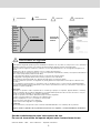 2
2
-
 3
3
-
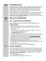 4
4
-
 5
5
-
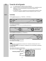 6
6
-
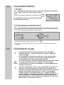 7
7
-
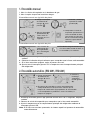 8
8
-
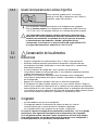 9
9
-
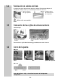 10
10
-
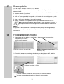 11
11
-
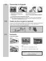 12
12
-
 13
13
-
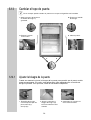 14
14
-
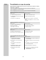 15
15
-
 16
16
-
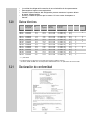 17
17
-
 18
18
-
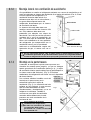 19
19
-
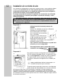 20
20
-
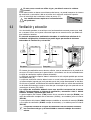 21
21
-
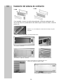 22
22
-
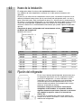 23
23
-
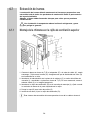 24
24
-
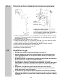 25
25
-
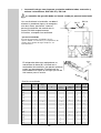 26
26
-
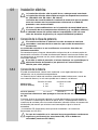 27
27
-
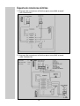 28
28
-
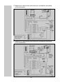 29
29
-
 30
30
-
 31
31
-
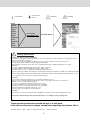 32
32
-
 33
33
-
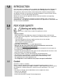 34
34
-
 35
35
-
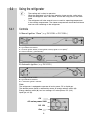 36
36
-
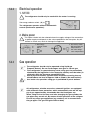 37
37
-
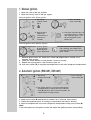 38
38
-
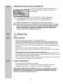 39
39
-
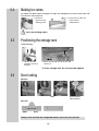 40
40
-
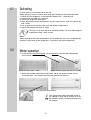 41
41
-
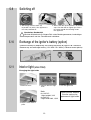 42
42
-
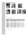 43
43
-
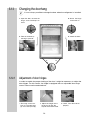 44
44
-
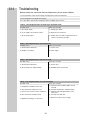 45
45
-
 46
46
-
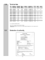 47
47
-
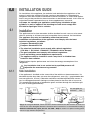 48
48
-
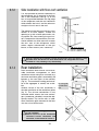 49
49
-
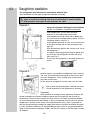 50
50
-
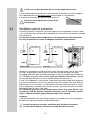 51
51
-
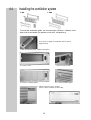 52
52
-
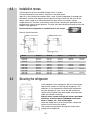 53
53
-
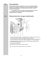 54
54
-
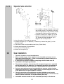 55
55
-
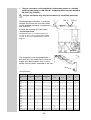 56
56
-
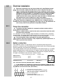 57
57
-
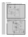 58
58
-
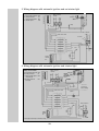 59
59
-
 60
60


en otros idiomas
- English: Dometic RM7290 User manual
Artículos relacionados
-
Dometic RM122 El manual del propietario
-
Dometic RM7390L Manual de usuario
-
-
-
Dometic RF60 Instrucciones de operación
-
-
Dometic RF62 Instrucciones de operación
-
-
-
