Nilfisk-ALTO 56507003 Manual de usuario
- Categoría
- Máquina de piso
- Tipo
- Manual de usuario

Exterra™
11/06 revised 5/08 Form No. 56041656
SR 1900
A-English
B-Español
Instructions For Use / Instrucciones de uso
Advance Models: 56507000 (3 cyl LPG), 56507001 (3 cyl Petrol)
56507003, 56307252 (4 cyl LPG), 56507004 (4 cyl Petrol), 56507005 (4 cyl Diesel)
56508639 (4 cyl LPG / cab), 56508640 (4 cyl Petrol / cab), 56508641 (4 cyl Diesel / cab)
Nilfi sk Models: 56507009 (4 cyl LPG), 56507010 (4 cyl Petrol), 56507011 (4 cyl Diesel)
56508769 (4 cyl LPG / cab), 56508770 (4 cyl Petrol / cab), 56508771 (4 cyl Diesel / cab)

A-2 / ENGLISH
A-2 - FORM NO. 56041656 - Exterra™ / SR 1900
TABLE OF CONTENTS
Page
Introduction ................................................................................A-3
Parts and Service ......................................................................A-3
Nameplate .................................................................................A-3
Uncrating the Machine ...............................................................A-3
Cautions and Warnings .............................................................A-4
Consignes de prudence et de sécurité ......................................A-5
General Information ...................................................................A-6
Know Your Machine..................................................... A-8 – A-11
Preparing the Machine for Use
Pre-Operational Checklist ........................................................A-12
Main Broom .............................................................................A-12
Fuel ..........................................................................................A-12
Operating the Machine
Before Starting the Machine ....................................................A-13
Starting the Diesel Engine .......................................................A-13
Starting the Gasoline Engine ...................................................A-13
Starting the Propane Engine ...................................................A-13
Sweeping .................................................................................A-14
Emptying the Hopper ...............................................................A-14
After Using the Machine
After Use ..................................................................................A-15
Shutting Down the Diesel / Gasoline Engine ...........................A-15
Shutting Down the Propane Engine ........................................A-15
Maintenance
Maintenance Schedule ............................................................A-15
Main Broom Maintenance ........................................................A-16
Side Broom Maintenance ........................................................A-18
Hopper Dust Control Filter .......................................................A-20
Hydraulic Oil ............................................................................A-21
Engine Oil ................................................................................A-21
Engine Coolant ........................................................................A-21
Engine Air Filter .......................................................................A-21
Circuit Breaker Location ..........................................................A-22
Troubleshooting .......................................................................A-23
Technical Specifi cations ..........................................................A-25

ENGLISH / A-3
FORM NO. 56041656 - Exterra™ / SR 1900 - A-3
INTRODUCTION
This manual will help you get the most from your Nilfi sk-Advance Sweeper. Read it thoroughly before operating the machine.
Note: Bold numbers in parentheses indicate an item illustrated on pages 8-11.
PARTS AND SERVICE
Repairs, when required, should be performed by Nilfi sk-Advance service personnel using Nilfi sk-Advance original replacement parts and
accessories.
Call Nilfi sk-Advance for repair parts or service. Please specify the Model and Serial Number when discussing your machine.
NAME PLATE
The Model and Serial Number of your machine are shown on the Nameplate on the right side of the machine. This information is needed when
ordering repair parts for the machine. Use the space below to note the Model and Serial Number of your machine for future reference.
MODEL ________________________________________________
SERIAL NUMBER _______________________________________
UNCRATING THE MACHINE
Upon delivery, carefully inspect the shipping crate and the machine for damage. If damage is evident, save all parts of the shipping crate so that
they can be inspected by the trucking company that delivered the machine. Contact the trucking company immediately to fi le a freight damage
claim.
1 After removing the crate, remove the wooden blocks next to the wheels.
2 Check the engine oil and coolant levels.
3 Check the hydraulic oil level.
4 Read the instructions in the Preparing the Machine For Use section of this manual, then fi ll the fuel tank.
6 Place a ramp next to the front end of the pallet.
7 Read the instructions in the Operating Controls and Operating the Machine sections of this manual and start the engine. Slowly drive the
machine forward down the ramp to the fl oor. Keep your foot lightly on the brake pedal until the machine is off the pallet.
CAUTION!
Use extreme CAUTION when operating this sweeper. Be certain that you are thoroughly familiar with all of the operating instructions
prior to using this sweeper. If you have any questions, contact your supervisor or your local Nilfi sk-Advance Industrial Dealer.
Should your sweeper malfunction, do not attempt to correct the problem unless your supervisor directs you to do so. Have a
qualifi ed company mechanic or an authorized Nilfi sk-Advance Dealer Service person make any necessary corrections to the
equipment.
Use extreme care when working on this machine. Neckties, loose clothing, long hair, rings and bracelets can get caught in moving
parts. Turn the Key Switch (TT) OFF, remove the Key, set the Parking Brake (F) and disconnect the battery before working on the
machine. Use good common sense, practice good safety habits and pay attention to the yellow decals on this machine.
Drive the machine slowly on inclines. Use the Brake Pedal (F) to control machine speed while descending inclines. DO NOT turn
the machine on an incline; drive straight up or down.
The maximum rated incline during transport with a 3 cylinder model is 15%.
The maximum rated incline during transport with a 4 cylinder model is 24%.
* Note: Reference the separately supplied engine manufacturer’s maintenance and operator manual for more detailed engine
specifi cation and service data.
All references to 3 cylinder models apply to Advance branded models only. There are no 3 cylinder Nilfi sk branded models.
revised 8/07

A-4 / ENGLISH
A-4 - FORM NO. 56041656 - Exterra™ / SR 1900
CAUTIONS AND WARNINGS
SYMBOLS
Nilfi sk-Advance uses the symbols below to signal potentially dangerous conditions. Always read this information carefully and take
the necessary steps to protect personnel and property.
DANGER!
Is used to warn of immediate hazards that will cause severe personal injury or death.
WARNING!
Is used to call attention to a situation that could cause severe personal injury.
CAUTION!
Is used to call attention to a situation that could cause minor personal injury or damage to the machine or other property.
Read all instructions before using.
GENERAL SAFETY INSTRUCTIONS
Specifi c Cautions and Warnings are included to warn you of potential danger of machine damage or bodily harm.
DANGER!
* This machine emits exhaust gases (carbon monoxide) that can cause serious injury or death, always provide adequate
ventilation when using machine.
WARNING!
* This machine shall be used only by properly trained and authorized persons.
* While on ramps or inclines, avoid sudden stops when loaded. Avoid abrupt sharp turns. Use low speed down hills. Clean only
while ascending (driving up) the ramp.
* To avoid hydraulic oil injection or injury always wear appropriate clothing and eye protection when working with or near hydraulic
system.
* Turn the key switch off (O) and disconnect the batteries before servicing electrical components.
* Never work under a machine without safety blocks or stands to support the machine.
* Do not dispense fl ammable cleaning agents, operate the machine on or near these agents, or operate in areas where fl ammable
liquids exist.
* Only use the brushes provided with the appliance or those specifi ed in the instruction manual. The use of other brushes may
impair safety.
CAUTION!
* This machine is not approved for use on public paths or roads.
* This machine is only approved for hard surface use.
* This machine is not suitable for picking up hazardous dust.
* When operating this machine, ensure that third parties, particularly children, are not endangered.
* Before performing any service function, carefully read all instructions pertaining to that function.
* Do not leave the machine unattended without fi rst turning the key switch off (O), removing the key and applying the parking
brake.
* Turn the key switch off (O) and remove the key, before changing the brushes, and before opening any access panels.
* Take precautions to prevent hair, jewelry, or loose clothing from becoming caught in moving parts.
* Before use, all doors and hoods should be properly latched.
* Do not use on surfaces having a gradient exceeding that marked on the machine.
* All doors and covers are to be positioned as indicated in the instruction manual before using the machine.
SAVE THESE INSTRUCTIONS
revised 3/07

ENGLISH / A-5
FORM NO. 56041656 - Exterra™ / SR 1900 - A-5
CONSIGNES DE PRUDENCE ET DE SECURITE
SYMBOLES
Nilfi sk-Advance utilise les symboles reproduits ci-dessous pour attirer l’attention de l’opérateur sur des situations potentiellement dangereuses. Il
est donc conseillé de lire attentivement ces indications et de prendre les mesures adéquates en vue de protéger le personnel et le matériel.
DANGER !
Ce symbole est utilisé pour mettre l’opérateur en garde contre les risques immédiats pouvant provoquer des dommages corporels graves, voire
entraîner la mort.
ATTENTION !
Ce symbole est utilisé pour attirer l’attention sur une situation susceptible d’entraîner des dommages corporels graves.
PRUDENCE !
Ce symbole est utilisé pour attirer l’attention de l’opérateur sur une situation qui pourrait entraîner des dommages corporels minimes ou des
dommages à la machine ou à d’autres équipements.
Veuillez lire toutes les instructions avant d’utiliser l’appareil.
CONSIGNES GENERALES DE SECURITE
Les consignes spécifi ques de prudence et de sécurité mentionnées ici ont pour but de vous informer de la survenance de tout risque de
dommages matériels ou corporels.
DANGER !
* Les gaz d’échappement (monoxyde de carbone) évacués par la machine peuvent entraîner de graves dommages corporels, voire la mort.
Veillez donc toujours à bénéfi cier d’une ventilation suffi sante lorsque vous utilisez la machine.
ATTENTION !
* Cette machine ne pourra être utilisée que par du personnel parfaitement entraîné et dûment autorisé.
* Evitez les arrêts subits lorsque la machine est chargée et se trouve sur des rampes ou des plans inclinés. Evitez les virages serrés. Adoptez
une vitesse réduite lorsque la machine est en descente. Ne nettoyez que lorsque la machine monte la pente.
* Lorsque vous utilisez le système hydraulique ou travaillez à proximité de celui-ci, veillez à porter une tenue appropriée et des lunettes de
protection afi n d’éviter tout risque de blessures ou toute projection d’huile.
* Positionnez la clé de contact sur off (O) et déconnectez les batteries avant de procéder à l’entretien des composants électriques.
* Ne travaillez jamais sous une machine sans y avoir placé, au préalable, des blocs de sécurité ou des étais destinés à soutenir la machine
* Ne déversez pas d’agents nettoyants infl ammables, ne faites pas fonctionner la machine à proximité de ces agents ou d’autres liquides
infl ammables.
* Utilisez uniquement les brosses fournies avec l’appareil ou celles spécifi ées dans le manuel d’instructions. L’utilisation d’autres brosses peut
mettre la sécurité en péril.
PRUDENCE !
* Cette machine n’est pas conçue pour une utilisation sur les chemins ou voies publiques.
* Cette machine est seulement approuvée pour l’usage extérieur dur.
* Cette machine n’est pas conçue pour le ramassage des poussières dangereuses.
* Lors de l’utilisation de cette machine, assurez-vous que des tiers, et notamment des enfants, ne courent pas le moindre risque.
* Avant de procéder à toute opération d’entretien, veuillez lire attentivement toutes les instructions qui s’y rapportent.
* Ne laissez pas la machine sans surveillance sans avoir, au préalable, coupé le contact, enlevé la clé de contact (O) et tiré le frein à main.
* Positionnez la clé de contact sur off (O) avant de remplacer les brosses ou d’ouvrir tout panneau d’accès.
* Prenez toutes les mesures nécessaires pour éviter que les cheveux, les bijoux ou les vêtements amples ne soient entraînés dans les parties
mobiles de la machine.
* Avant utilisation, toutes les portes et capots doivent être correctement fermés.
* N’utilisez pas sur des surfaces dont la pente dépasse celle mentionnée sur la machine.
* Toutes les portes et couvercles doivent être dans la position mentionnée dans le manuel d’instruction avant de mettre la machine en service.
CONSERVEZ SOIGNEUSEMENT CES INSTRUCTIONS
revised 3/07

A-6 / ENGLISH
A-6 - FORM NO. 56041656 - Exterra™ / SR 1900
HOPPER SAFETY SUPPORT
WARNING!
Make sure the Hopper Safety Support (5) is in place whenever attempting to do any maintenance work under or near the raised
hopper. The Hopper Safety Support (5) holds the hopper in the raised position to allow work to be performed under the hopper.
NEVER rely on the machine’s hydraulic components to safely support the hopper.
JACKING THE MACHINE
CAUTION!
Never work under a machine without safety stands or blocks to support the machine.
• When jacking the machine, do so at designated locations (Do Not jack on the hopper) - see jacking locations (8).
TRANSPORTING THE MACHINE
CAUTION!
Before transporting the machine on an open truck or trailer, make sure that...
• All access doors are latched securely
• The machine is tied down securely.
• The machine parking brake is set.
TOWING OR PUSHING A DISABLED MACHINE
The machine’s drive propelling pump is manufactured with an adjustable tow valve. This valve prevents damage to the hydraulic system when the
machine is being towed/pushed short distances without use of the engine.
To access the valve open the Engine Compartment Cover (1) and locate the hydrostatic pump at the rear of the engine. The top half the
illustration on the following page shows the location on 3 cylinder models and the bottom half shows the 4 cylinder model location. Turn the valve
90 degrees, this disengages the hydrostatic lock between the motor and pump.
WARNING: The hydraulic propelling pump can be damaged if the machine is towed with the valve in the normal working position (A). Reference
the illustration on the following page for the normal working setting (A) (vertical) and the free wheeling towing setting (B) (horizontal). Note: If the
tow valve is left in free wheeling (B) (horizontal) position the propelling pump can’t drive the machine FWD or REV. No damage will result, just
re-set valve to the normal working setting (A) (vertical). NOTE: Tow or push machine no faster than a normal walking pace (2-3 miles per hour)
and for short distances only. If the machine is to be moved long distances the drive wheel needs to be raised off the fl oor and placed on a suitable
transport dolly.


A-8 / ENGLISH
A-8 - FORM NO. 56041656 - Exterra™ / SR 1900
KNOW YOUR MACHINE
As you read this manual, you will occasionally run across a bold number in parentheses - example: (2). These numbers refer to an item on the
next four pages. Refer back to these pages whenever necessary to pinpoint the location of an item mentioned in the text.
1 Engine Compartment Cover
2 Left Side Main Broom Access Panel
3 Battery
4 Center Cover Assembly
5 Hopper Safety Support
6 Hopper Cover Latch
7 Head Light
8 Jacking Locations (rear location is large weight below radiator)
9 Side Broom
10 Side Broom Height Adjustment Knob
11 Dust Filter Shaker Assembly
12 Hopper Dust Control Filter
European models use a maintenance free bag type fi ltration system not shown here
13 Shaker Assembly Retainer Knobs
14 Hydraulic Oil Filter
15 Coolant Recovery Tank (4 cylinder location)
revised 8/07

ENGLISH / A-9
FORM NO. 56041656 - Exterra™ / SR 1900 - A-9
KNOW YOUR MACHINE (CONTINUED)
16 Hopper Cover
17 Hopper Cover Prop Rod
18 Right Side Main Broom Access Panel
19 Oil Reservoir
20 Oil Reservoir / Fuel Tank Cover
21 Fuel Tank (LPG tank shown / Gasoline tank is in same location)
22 Coolant Recovery Tank (3 cylinder & diesel location)
23 Radiator Cap
24 Engine Air Filter (3 cylinder & diesel location)
25 Fuel Tank Cover Release Latch
26 Tie-Down Locations (5)
27 Air Filter Service Indicator
28 Engine Air Filter (4 cylinder location)
revised 8/07

A-10 / ENGLISH
A-10 - FORM NO. 56041656 - Exterra™ / SR 1900
OPERATOR’S COMPARTMENT
A Operator’s Seat
B Main Broom Lever
C Main Broom Adjust Knob
D Control Panel (See Associated Pages)
E Steering Wheel
F Brake Pedal / Parking Brake
G FWD / REV Drive Pedal
H Circuit Breaker Panel
I Hopper Safety Support Handle
J Operator Seat Adjustment Lever
K Choke Cable (3 Cylinder)

ENGLISH / A-11
FORM NO. 56041656 - Exterra™ / SR 1900 - A-11
CONTROL PANEL
AA Fuel Gauge (Gasoline and Diesel Only)
BB Horn Switch
CC PROPANE Low Indicator Light
DD Headlight Switch
EE Engine Service Indicator (4 cylinder)
FF Glow Plug Indicator Light (Diesel Only)
GG Engine Speed Switch
HH Side Broom ON-Down / OFF-Up Switch
II Dust Control Indicator
JJ Dust Control Switch
KK Plugged Filter Indicator
LL Shaker Switch
MM Hopper UP Indicator
NN Open Dump Door Switch
OO Hopper Overtemp Indicator
PP Close Dump Door Switch
QQ Lower Hopper Switch
RR Raise Hopper Switch
SS Hour Meter
TT Ignition Switch
UU Service Indicator Light
revised 8/07

A-12 / ENGLISH
A-12 - FORM NO. 56041656 - Exterra™ / SR 1900
PRE-OPERATIONAL CHECKLIST
Before Each Use:
* Inspect the machine for damage, oil or coolant leaks.
* Squeeze the rubber dust cup on the Engine Air Filter (24) to release built-up dust.
* Check the engine coolant level (23).
* Check the engine oil level.
* Check the hydraulic oil level (19).
* Check the Fuel Gauge (AA) on the gasoline and diesel models.
* Check the Fuel Gauge located on the PROPANE tank (21) for PROPANE model.
* Check the tire pressure of all three tires, should be 90-95 psi.
* Check the Air Filter Service Indicator.
In the Driver’s Seat:
* Be sure that you understand the operating controls and their functions.
* Adjust the seat to allow easy reach of all controls.
* Insert the Master Key and turn the Ignition Switch (TT) to the ON position. Check for proper operation of the Horn (BB), Hour Meter (SS) and
Headlights (DD). Turn the Ignition Key Switch (TT) OFF.
* Check the Parking Brake (F). The brake must hold its (locked parked) setting fi rmly with out easily being released.
(Report all defects immediately to service personnel).
Plan Your Cleaning in Advance:
* Arrange long runs with a minimum of stopping or starting.
* Allow 6 inches of broom path overlap to ensure complete coverage.
* Avoid making sharp turns, bumping into posts, or scraping the side of the machine.
MAIN BROOM
Several different main brooms are available for this machine. Contact your Nilfi sk-Advance dealer if you need help selecting the best broom for the
surface and litter that you will be sweeping. Note: Reference broom maintenance for installation steps.
FUEL
WARNING !
• ALWAYS STOP THE ENGINE BEFORE FILLING THE FUEL TANK.
• DO NOT SMOKE WHILE FILLING THE FUEL TANK.
• FILL THE FUEL TANK IN A WELL-VENTILATED AREA.
• DO NOT FILL THE FUEL TANK NEAR SPARKS OR OPEN FLAME.
• USE ONLY THE FUEL SPECIFIED ON THE FUEL TANK DECAL.
DIESEL ENGINE
Fill the tank with Number 2 Diesel Fuel if the machine will be used in an area where the temperature is 30° Fahrenheit (0° Celsius) or higher. Use
Number 1 Diesel Fuel if the machine will be used in an area where the temperature is below 30° Fahrenheit (0° Celsius).
NOTE: If the diesel machine runs out of fuel completely, the fuel system must be bled before the engine can be re-started. To avoid this situation,
fi ll the fuel tank when the fuel gauge indicates 1/4 tank. Fuel tank capacity is 12.75 gallons (48.26 liters).
GASOLINE ENGINE
FILL THE TANK WITH UNLEADED 87 OCTANE REGULAR GASOLINE. FUEL TANK CAPACITY IS 12.75 GALLONS (48.26 LITERS).
Note: Reference the separately supplied engine manufacture’s maintenance and operator manual for more detailed engine specifi cation and
service data.
PROPANE ENGINE
Mount a standard 33 lb. liquid withdrawal propane tank on the machine, connect the fuel hose and open the shutoff valve on the tank. Wear
gloves when connecting or disconnecting the fuel hose. Shut the propane tank service valve OFF when the machine is not in use.
NOTE: Make sure to properly orient the horizontal LPG tank for liquid withdrawal. After connecting the fuel hose to the tank check for leaks by
listening and smelling for gas.
WARNING!
Do not operate the machine if a gas leak is present. Disconnect the fuel hose and replace the LPG tank. If a gas leak is still present
disconnect the fuel hose and contact your Nilfi sk-Advance Service Center.

ENGLISH / A-13
FORM NO. 56041656 - Exterra™ / SR 1900 - A-13
OPERATING THE MACHINE
The Exterra™ / SR 1900 is a rider-type automatic fl oor sweeping machine. The controls were designed with one touch operation in mind. For
single pass sweeping the operator can simply lower the main broom and all sweeping functions will be ready to go.
Note: Bold numbers in parentheses indicate an item illustrated on pages 8-11.
BEFORE STARTING THE MACHINE
1 Be sure you understand all machine controls and their functions.
2 Plan your cleaning route. Arrange long, straight passes with as few turns as possible.
3 Check the Brake Pedal (FF). The pedal should be fi rm.
If the pedal is “spongy” or fades under pressure, DO NOT DRIVE THE MACHINE. Report all defects immediately to service personnel.
STARTING THE DIESEL ENGINE
1 Turn the Key Switch (TT) counter-clockwise to the “Pre-Heat” position and hold it there until the Glow Plug Indicator (FF) turns OFF. Once
the indicator turns OFF the engine can be started. Skip this step if the engine has been running and is already warm.
2 Turn the Key Ignition Switch (TT) clockwise to the START position and release it as soon as the engine starts. If the engine does not start
after cranking for 15 seconds, release the key, wait for 1 minute and try steps 1-3 again.
3 Let the engine run at “IDLE” speed for 5 minutes before using the machine.
4 Push the Engine Speed Switch (GG) to switch to “FULL THROTTLE” and move the machine around for 2 or 3 minutes at a slow speed to
warm up the hydraulic system.
STARTING THE PROPANE / GASOLINE ENGINE
1 NOTE: Propane models only: Open the service valve on the LP fuel tank (21).
2 NOTE: 3 Cylinder models: Pull the Choke Knob all the way out. (Skip this step if the engine has been running and is already warm.)
3 Turn the Ignition Key Switch (TT) clockwise to the START position and release it as soon as the engine starts. If the engine does not start
after cranking for 15 seconds, release the key, wait for 1 minute, then try again.
4 NOTE: 3 Cylinder models: Once started, push the Choke Knob in slowly until the engine runs smoothly.
5 Let the engine run at “IDLE” speed for 5 minutes before using the machine.
NOTE: 3 Cylinder models: Push the Choke Knob all the way in.
6 Push the Engine Speed Switch (GG) to switch to “FULL THROTTLE” and move the machine around for 2 or 3 minutes at a slow speed to
warm up the hydraulic system.
NOTE: ALWAYS operate the machine with the Throttle Control at full throttle. Use the Forward/Reverse Pedal (G) - not the Throttle
Control - to control the speed of the machine. The speed of the machine will increase as the pedal is pushed closer to the fl oor. Do not press the
Forward/Reverse Pedal until the engine has started, this will disengage the starter.

A-14 / ENGLISH
A-14 - FORM NO. 56041656 - Exterra™ / SR 1900
SWEEPING
Follow the instructions in the preparing the machine for use section of the manual.
1 While seated on the machine, adjust the seat to a comfortable operating position using the adjustment controls (J).
2 Release the Parking Brake (F). To transport the machine to the work area, apply even pressure with your foot on the front of the Drive Pedal
(G) to go forward or the rear of the pedal for reverse. Vary the pressure on the foot pedal to obtain the desired speed.
3 Push the Lower Hopper Switch (QQ) to make sure the hopper is seated properly.
4 Move the Main Broom Lever (B) to the SWEEP (middle notch) position to lower and enable the main broom. NOTE: The dump door opens
automatically when the main broom (B) is lowered and closes when the broom is raised.
Use the FULL FLOAT (last notch forward) position only when sweeping extremely rough or uneven fl oors. Use at other times will only
increase broom wear.
5 When sweeping fl oors with puddles, push the Dust Control Switch (JJ) to turn OFF the dust control system before the machine enters a
puddle. Turn the dust control system back ON when the machine is back on completely dry fl oor.
When sweeping wet fl oors, keep the Dust Control Switch (JJ) OFF at all times.
6 The Side Broom (9) is automatically enabled when the main broom is lowered and starts spinning when the Drive Pedal (G) is activated. The
Side Broom (9) can be turned off and back on at any time by pushing the Side Broom Switch (HH).
The side broom sweeping pattern is adjusted by turning the Side Broom Height Adjustment Knob (10).
7 Drive the machine straight forward at a quick walking speed. Drive the machine slower when sweeping large amounts of dust or debris or
when safe operation dictates slower speeds. Overlap passes 6 inches (15 cm).
8 If dust comes out of the broom housing while sweeping, the Dust Control Filter (12) may be clogged. Push the Shaker Switch (LL) to clean
the dust control fi lter. The dust control system (JJ) will automatically turn OFF while the shaker is running and turn ON after the shaker turns
OFF (the shaker runs for 15 seconds).
9 Check behind the machine occasionally to make sure that the machine is picking up debris. Dirt left behind in the path of the machine usually
indicates that the machine is moving too fast, the broom needs to be adjusted, or the hopper is full.
EMPTYING THE HOPPER
WARNING!
Make sure the Hopper Safety Support (5) is in place whenever attempting to do any maintenance work under or near the raised
hopper. The Hopper Safety Support (5) holds the hopper in the raised position to allow work to be performed under the hopper.
NEVER rely on the machine’s hydraulic components to safely support the hopper.
NOTE: The MINIMUM ceiling height dumping clearance required for raising the hopper is 102” (259.08 cm)
1 Put the Main Broom Lever (B) in the UP / OFF position. NOTE: The Shaker will automatically run for about 15 seconds after the main broom
is raised.
2 If you do not raise the main broom, push the Shaker Switch (LL) to remove excess dirt from the dust control fi lter. SERVICE NOTE: For
best shaker performance always run the shaker with the hopper fully down.
3 Drive the machine close to a large trash receptacle and hold the Raise Hopper Switch (RR) until the hopper is all the way up. NOTE: The
dump door automatically closes when switch (RR) is pushed. You regain control of the dump door as soon as the hopper begins to raise so
you can dump at any height if necessary.
4 Move the machine forward until the hopper is over the receptacle and set the Parking Brake (F). Press the Open Dump Door Switch (NN) to
open the dump door and empty the hopper. NOTE: If not dumping into a trash receptacle, low dumping is recommended to help eliminate
airborne dust.
5 Put the Hopper Safety Support (5) in place by pulling back on the Hopper Safety Support Pull Rod (I), then lower the hopper slightly to
secure.
6 Check the hopper door and the front edge seal. Use a broom, if necessary, to remove litter from these areas. The hopper door must seal
tightly against the broom housing bulb gasket for proper operation.
7 Return to the operator’s compartment. Release the parking brake. Move the machine back until the hopper will clear the receptacle. Raise
the hopper slightly and push forward on the Hopper Safety Support Handle (I) until the Hopper Safety Support (5) disengages, then lower the
hopper. NOTE: The brooms will not turn on if the hopper is not completely down. The indicator light (MM) on the control panel should turn
OFF indicating that the machine is ready for use.

ENGLISH / A-15
FORM NO. 56041656 - Exterra™ / SR 1900 - A-15
AFTER USE
1 Shake the Hopper Dust Control Filter (LL) and empty the hopper.
2 Check the maintenance schedule and perform all required maintenance before storage.
3 Move the machine to an indoor storage area.
4 Shut down the engine according to the shut down procedures.
5 Make sure the Ignition Switch (TT) is OFF and the Parking Brake (F) is engaged.
NOTE: It is safe to clean this machine with a pressure washer as long as you do not spray directly at or into electrical components. The machine should always
be allowed to dry completely before each use.
TO SHUT DOWN THE DIESEL / GASOLINE ENGINE...
1 Turn all controls to the OFF position.
2 Raise the brooms.
3 Place the Engine Speed Switch (GG) in IDLE and let the engine idle for 25 - 30 seconds.
4 Turn the Ignition Key Switch (TT) OFF and remove the key. NOTE: The 4 cylinder gasoline engine will continue to run for a few seconds after switching the
key to off. This is part of the proper operation of the closed loop electronic control system.
5 Apply the Parking Brake (F).
TO SHUT DOWN THE PROPANE ENGINE...
1 Turn all controls to the OFF position.
2 Raise the brooms.
3 Turn the service valve on PROPANE Tank (21) OFF.
4 Run the engine until all the PROPANE is dispelled from the line (the engine will stall).
5 Turn the Ignition Key Switch (TT) OFF and remove the key. NOTE: The 4 cylinder LPG engine will continue to run for a few seconds after switching the key
to off. This is part of the proper operation of the closed loop electronic control system.
6 Apply the Parking Brake (F).
REPORT ANY DEFECT OR MALFUNCTION NOTED DURING OPERATION TO AUTHORIZED SERVICE OR MAINTENANCE PERSONNEL.
MAINTENANCE
Make sure that the machine is kept in top shape by following the maintenance schedule closely. Repairs, when required, should be performed by your Authorized
Nilfi sk-Advance Service Center, who employs factory trained service personnel and maintains an inventory of Nilfi sk-Advance Original Equipment Replacement
Parts and Accessories.
NOTE: Refer to the Service Manual for more detail on maintenance and service repairs.
MAINTENANCE SCHEDULE
Maintenance intervals given are for average operating conditions. Machines used in severe operational environments may require service more often.
MAINTENANCE ITEM PERFORM DAILY
Perform the “After Use” maintenance steps X
Check parking brake X
Check engine oil X
*Clean main and side broom(s) X
Check fi lter indicator and lights (hyd & air) X
Check engine coolant level X
Check hydraulic oil level X
MAINTENANCE ITEM 15 hrs. 30 hrs. 150 hrs. 300 hrs. 1000 hrs.
*Rotate main broom X
*Inspect/adjust brooms X
* Check / Clean Hopper Dust Control Filter Using Method “A” X
*Inspect broom housing skirts X
*Inspect hopper seals X
Clean radiator and oil cooler X
Perform engine maintenance X
*Inspect and grease steering spindle X
* Check / Clean Hopper Dust Control Filter Using Method “B” X
* Check / Clean Hopper Dust Control Filter Using Method “C” X
Change the hydraulic “charge” oil fi lter X
Change reservoir hydraulic oil X
Flush the radiator X
Engine fuel fi lter(s) X
*See the Mechanical Repair Service Manual for detailed maintenance information of systems listed. (Sweeping, Hopper, Steering, Dust Control). NOTE: Cleaning
the hopper dust control fi lter is not required on models using the maintenance free bag fi lter.

A-16 / ENGLISH
A-16 - FORM NO. 56041656 - Exterra™ / SR 1900
MAIN BROOM MAINTENANCE
Since the Main Broom Motor always turns in the same direction, the bristles on the broom eventually become curved, reducing sweeping
performance. Sweeping performance can be improved by removing the broom and turning it around (end-for-end). This procedure, known as
“rotating” the main broom, should be done once every 15 hours of operation. NOTE: This procedure does not apply to the optional chevron
broom.
The main broom should be replaced for optimal performance when the bristles are worn to a length of 2 inches (5.08 cm). The main broom stop
must be re-adjusted when the broom is replaced. NOTE: The main broom is functional to a bristle length of 1/2 inch (12.7mm)
NOTE: The machine should be stored with the Main Broom in the raised position.
WARNING!
The engine must not be running when performing this procedure.
To Rotate or Replace the Main Broom...
1 Turn the Ignition Switch (TT) OFF.
2 Put the Main Broom Lever (B) in the DOWN position.
3 Open the Right Side Main Broom Access Panel (18).
4 See Figure 1. Pivot the Idler Arm Assembly (A1) out of the main broom core. NOTE: The Idler Arm is held in place by the Right Side Main
Broom Access Panel (18).
5 Pull the Main Broom (A2) out of the broom housing and remove any string or wire wrapped around it. Also inspect the skirts at the front, back
and sides of the broom housing. The skirts should be replaced or adjusted if they are torn or worn to a height of more than 1/4 inch (6.35
mm) off the ground.
6 Turn the broom around (end-for-end) and slide it back into the broom housing. Make sure that the lugs on the broom core (left side) engage
the slots in the broom drive hub and that the broom is fully seated.
7 Swing the idler arm assembly back into the broom core. NOTE: Make sure the lugs on the idler arm engage the slots in the broom core
8 Close and latch the Right Side Main Broom Access Panel (18).
To Adjust the Main Broom Height...
1 Drive the machine to an area with a level fl oor and set the parking brake.
2 Pull the Main Broom Lever (B) back and slide to the right and up to lower the main broom. DO NOT move the machine.
3 Lightly press the Drive Pedal (G) to start the main broom and let it run in place for 1 minute. This allows the broom to polish a “strip” on the
fl oor. After 1 minute, raise the broom, release the parking brake and move the machine so that the polished strip is visible.
4 Inspect the polished strip on the fl oor. If the strip is less than 2 inches (5.08 cm) or more than 3 inches (7.62cm) wide, the broom needs to be
adjusted.
5 To adjust, loosen the Knob (C) and slide forward or backward to lower or raise the Main Broom. The farther the Lever (B) travels forward in
the slot, the lower the Main Broom will be. Tighten Knob (C) after adjusting the position of the stop bracket.
6 Repeat steps 1-5 until the polished strip is 2-3 inches (5.08-7.62cm) wide.
The width of the polished strip should be the same at both ends of the broom. If the strip is tapered, move the machine to a different area
and repeat steps 1-5. If the polished strip is still tapered, contact your Nilfi sk-Advance Dealer for service.


A-18 / ENGLISH
A-18 - FORM NO. 56041656 - Exterra™ / SR 1900
SIDE BROOM MAINTENANCE
To adjust the Side Broom...
1 Drive the machine to an area with a level fl oor and set the parking brake.
2 Pull the Main Broom Lever (B) back and slide to the right and up to lower the main and side brooms.
3 See Figure 2. When in the Down position, the Side Broom (9) should be contacting the fl oor from the 10 O’Clock (A1) to the 3 O’Clock (A2)
area shown.
4 If it requires adjustment, turn the Side Broom Height Adjustment Knob (10) either clockwise to raise or counter-clockwise to lower the side
broom.
NOTE: The machine should be stored with the Side Broom (9) in the raised position. The Side Broom (9) should be replaced when the bristles
are worn to a length of 3 inches (7.62 cm) or it becomes ineffective. The Side Broom height must be re-adjusted when ever the broom has been
replaced.
FIGURE 2

ENGLISH / A-19
FORM NO. 56041656 - Exterra™ / SR 1900 - A-19
FIGURE 3
SIDE BROOM MAINTENANCE
To replace the Side Broom...
1 See Figure 3. Raise the hopper until the side broom is approximately at chest height.
2 Grab hold of the side broom with both hands and rotate until the ring end of the Hitch Pin (A1) is facing toward the rear of the hopper. NOTE:
The side broom(s) will only rotate freely in one direction.
3 Remove the Hitch Pin (A1) and pull the Side Broom (A2) off of the motor shaft.
4 Slide the new broom onto the motor shaft, line up the pin hole and reinstall the Hitch Pin (A1).

A-20 / ENGLISH
A-20 - FORM NO. 56041656 - Exterra™ / SR 1900
HOPPER DUST CONTROL FILTER (PANEL FILTER)
The hopper dust control fi lter must be cleaned regularly to maintain the effi ciency of the vacuum system. Follow the recommended fi lter service
intervals for the longest fi lter life.
CAUTION!
Wear safety glasses when cleaning the fi lter.
Do not puncture the paper fi lter.
Clean the fi lter in a well-ventilated area.
Wear appropriate dust mask to avoid breathing in dust.
To remove the hopper dust control fi lter...
1 Unlatch and open the Hopper Cover (16). Make sure that the Hopper Cover Prop Rod (17) is in place.
2 Inspect the top of the Hopper Dust Control Filter (12) for damage. A large amount of dust on top of the fi lter is usually caused by a hole in the
fi lter or a damaged fi lter gasket.
3 Remove the four Shaker Assembly Retainer Knobs (13). Lift off the Dust Filter Shaker Assembly (11) to access the panel fi lter.
4 Lift the Hopper Dust Control Filter (12) out of the machine.
5 Clean the fi lter using one of the methods below:
Method “A”
Vacuum loose dust from the fi lter. Then gently tap the fi lter against a fl at surface (with the dirty side down) to remove loose dust and dirt.
NOTE: Take care not to damage the metal lip which extends past the gasket.
Method “B”
Vacuum loose dust from the fi lter. Then blow compressed air (maximum pressure 100 psi) into the clean side of the fi lter (in the opposite
direction of the airfl ow).
Method “C”
Vacuum loose dust from the fi lter. Then soak the fi lter in warm water for 15 minutes, then rinse it under a gentle stream of water (maximum
pressure 40 psi). Let the fi lter dry completely before putting it back into the machine.
6 Follow the instructions in reverse order to install the fi lter. If the gasket on the fi lter is torn or missing, it must be replaced. NOTE: Before
replacing fi lter clear debris from dust plate located under fi lter. Verify that the debris fl ap at the rear of the dust plate swings freely
HOPPER DUST CONTROL FILTER (OPTIONAL NILFISK POCKET FILTER SYSTEM)
The optional Nilfi sk pocket fi lter system is basically maintenance free. The only periodic maintenance required by the machine operator is to run
the Shaker (LL) on a daily basis. NOTE: The shaker should only be run with the hopper in the down position.
revised 8/07

ENGLISH / A-21
FORM NO. 56041656 - Exterra™ / SR 1900 - A-21
HYDRAULIC OIL
Unlatch and swing open the Oil Reservoir / Fuel tank Cover (20). Remove the reservoir cap to check the oil level. The hydraulic oil level should
be half way up the screen fi lter inside the fi ller neck of the reservoir. Add SAE 10W30 motor oil if it is below this level. Change the oil if major
contamination from a mechanical failure occurs.
ENGINE OIL – GASOLINE (PETROL) & LPG
Check the engine oil level when the machine is parked on a level surface and the engine is cool. Change the engine oil after the fi rst 35 hours of operation and
every 150 hours after that. Use any SF or SG rated oil meeting API specifi cations and suited to seasonal temperatures. Refer to the Engine System section for oil
capacities and additional engine specifi cations. Replace the oil fi lter with every oil change.
TEMPERATURE RANGE OIL WEIGHT
Above 60° F (15° C) SAE 10W-30
Below 60° F (15° C) SAE 5W-30
ENGINE OIL - DIESEL
Check the engine oil level when the machine is parked on a level surface and the engine is cool. Change the engine oil after the fi rst 35 hours of operation and
every 150 hours after that. Use CF, CF-4 or CG-4 oil meeting API specifi cations and suited temperatures (*important reference the oil/fuel type note below for
further diesel oil recommendations). Refer to the Engine System section for oil capacities and additional engine specifi cations. Replace the oil fi lter with every oil
change.
TEMPERATURE RANGE OIL WEIGHT
Above 77 °F (25 °C) SAE 30 or 10W-30
32 °F to 77 °F (0 °C to 25 °C) SAE 20 or 10W-30
Below 32 °F (0 °C) SAE 10W or 10W-30
* Diesel Lubricating Oil Note:
With the emission control now in effect, the CF-4 and CG-4 lubricating oils have been developed for use of a low-sulfur fuel on-road vehicle engines. When
an off-road vehicle engine runs on a high-sulfur fuel, it is advisable to employ the CF, CD or CE lubricating oil with a high total base number. If the CF-4 or
CG-4 lubricating oil is used with a high-sulfur fuel, change the lubricating oil at shorter intervals.
• Lubricating oil recommended when a low-sulfur or high-sulfur fuel is employed.
Fuel
Lubricating
Oil class
Low sulfur
(0.5 % ≥)High sulfur Remarks
CF OO
TBN ≥ 10
CF-4 OX
CG-4 OX
O : Recommendable X : Not recommendable
ENGINE COOLANT
Open the Engine Compartment Cover (1) and observe the coolant level in the Coolant Recovery Tank (22). If the level is low, add a mixture of half
water and half automotive type anti-freeze.
CAUTION!
Do not remove the Radiator Cap (23) when the engine is hot.
ENGINE AIR FILTER
Check the Engine Air Filter Service Indicator (24) before each use of the machine. Do not service the air fi lter unless the red fl ag is visible in the
service indicator. NOTE: After cleaning or replacing the engine air fi lter, the service indicator can be reset by pressing the end of the indicator.
CAUTION!
When servicing the engine air fi lter elements, use extreme care to prevent loose dust from entering the engine. Dust can severely
damage the engine.
The engine air fi lter contains a Primary (outer) and a Safety (inner) fi lter element. The Primary Element may be cleaned twice before being
replaced. The Safety Element should be replaced every third time that the Primary Filter Element is replaced. Never attempt to clean the Inner
Safety Element.
To clean the Primary Filter Element, unsnap the 2 clips at the end of the air fi lter and remove the end housing. Pull the primary element out. Clean
the element with compressed air (maximum pressure 100 psi) or wash it with water (maximum pressure 40 psi). DO NOT put the element back
into the canister until it is completely dry.
revised 5/08


ENGLISH / A-23
FORM NO. 56041656 - Exterra™ / SR 1900 - A-23
TROUBLESHOOTING
If the possible causes listed below are not the source of trouble, it is a symptom of something more serious. Contact your Nilfi sk-Advance Service
Center immediately for service.
TRIPPING THE CIRCUIT BREAKERS
The circuit breakers are located on the Circuit Breaker Panel (H), they protect electrical circuits and motors from damage due to overload
conditions. If a circuit breaker trips, try to determine the cause.
Main Circuit Breaker (CB1 / 70 Amp) Possible cause may be:
1 Electrical short circuit or overload (have your Nilfi sk-Advance Service Center or qualifi ed electrician check the machine)
Headlight Circuit Breaker (CB2 / 20 Amp) Possible cause may be:
1 Electrical short circuit or overload (have your Nilfi sk-Advance Service Center or qualifi ed electrician check the machine)
Starter Motor Circuit Breaker (CB3 / 15 Amp) Possible causes may be:
1 Electrical short circuit or overload (have your Nilfi sk-Advance Service Center or qualifi ed electrician check the machine)
Accessory Circuit Circuit Breaker (CB4 / 20 Amp) Possible cause may be:
1 Electrical short circuit or overload (have your Nilfi sk-Advance Service Center or qualifi ed electrician check the machine)
Ignition Circuit Circuit Breaker (CB5 / 10 Amp) Possible cause may be:
1 Electrical short circuit or overload (have your Nilfi sk-Advance Service Center or qualifi ed electrician check the machine)
Shaker Circuit Breaker (CB6 / 20 Amp) Possible cause may be:
1 Electrical short circuit or overload (have your Nilfi sk-Advance Service Center or qualifi ed electrician check the machine)
Turn Signal Circuit Breaker (CB7 / 20 Amp) Possible cause may be:
1 Electrical short circuit or overload (have your Nilfi sk-Advance Service Center or qualifi ed electrician check the machine)
Mister Circuit Breaker (CB8 / 10 Amp) Possible cause may be:
1 Electrical short circuit or overload (have your Nilfi sk-Advance Service Center or qualifi ed electrician check the machine)
HVAC Circuit Breaker (CB9 / 30 Amp) Possible cause may be:
1 Electrical short circuit or overload (have your Nilfi sk-Advance Service Center or qualifi ed electrician check the machine)
Once the problem has been corrected, push the button in to reset the circuit breaker. If the button does not stay in, wait 5 minutes and try again.
If the circuit breaker trips repeatedly, call your Nilfi sk-Advance Service Center for service.
revised 8/07

A-24 / ENGLISH
A-24 - FORM NO. 56041656 - Exterra™ / SR 1900
TROUBLESHOOTING
If the possible causes listed below are not the source of trouble, it is a symptom of something more serious. Contact your Nilfi sk-Advance Service
Center immediately for service.
MACHINE WILL NOT START
Possible causes may be:
1 Foot Pedal not in neutral position (ensure pedal is in neutral position)
2 Foot Pedal neutral position is not correctly set (contact your Nilfi sk-Advance service center)
3 Battery is not connected (connect battery)
4 Machine is out of fuel (refuel)
5 Tripped circuit breaker(s) (reset any tripped circuit breakers)
MACHINE WILL NOT MOVE
Possible causes may be:
1 Parking Brake (F) set (release parking brake)
2 Towing Valve in wrong position (set correctly)
3 Tripped circuit breaker(s) (reset any tripped circuit breakers)
MAIN BROOM WILL NOT RUN
Possible causes may be:
1 Debris wrapped around the broom drive (remove debris)
2 Hopper is not completely down (lower hopper completely)
3 Tripped circuit breaker(s) (reset any tripped circuit breakers)
SIDE BROOM WILL NOT RUN
Possible causes may be:
1 Ensure Side Broom OFF switch isn’t selected (push switch to turn ON)
2 Debris wrapped around the broom drive (remove debris)
3 Hopper is not completely down (lower hopper completely)
4 Tripped circuit breaker(s) (reset any tripped circuit breakers)
HOPPER WILL NOT RAISE
Possible causes may be:
1 Tripped circuit breaker(s) (reset any tripped circuit breakers)
HOPPER DUMP DOOR WILL NOT OPEN
Possible causes may be:
1 Dump door jammed by debris (remove debris and clean edges of dirt chamber)
2 Tripped circuit breaker(s) (reset any tripped circuit breakers)
SHAKER MOTOR WILL NOT RUN
Possible causes may be:
1 Tripped circuit breaker(s) (reset any tripped circuit breakers)
DUST CONTROL SYSTEM (IMPELLER) WILL NOT RUN
Possible causes may be:
1 Tripped circuit breaker(s) (reset any tripped circuit breakers)
2 Ensure Dust Control OFF switch isn’t selected (push switch to turn ON)

ENGLISH / A-25
FORM NO. 56041656 - Exterra™ / SR 1900 - A-25
TECHNICAL SPECIFICATIONS (as installed and tested on the unit)
Model Exterra™ Exterra™
3 cyl. Propane 3 cyl. Gasoline
Model No. 56507000 56507001
Sound Pressure Level (ISO 11201) dB(A)/20μPa 80.8 80.8
Sound Power Level (ISO 3744) dB(A)/20μPa Lwa 99.80 Lwa 99.80
Gross Weight lbs/kg 2,700 / 1,224 2,700 / 1,224
Tire Pressure psi 90-100 90-100
Vibrations at the Hand Controls (ISO 5349-1) m/s2 1.13 m/s2 1.13 m/s2
Vibrations at the Seat (EN 1032) m/s2 0.14 m/s2 0.14 m/s2
Gradeability
Transport 15%(8.5º) 15%(8.5º)
Model Exterra™ Exterra™ Exterra™
SR 1900 SR 1900 SR 1900
4 cyl. Propane 4 cyl. Gasoline 4 cyl. Diesel
Model No. 56507003 / 56307252 56507004 56507005
56507009 56507010 56507011
Sound Pressure Level (ISO 11201) dB(A)/20μPa 85.8 85.8 82.7
Sound Power Level (ISO 3744) dB(A)/20μPa Lwa 107.2 Lwa 107.2 Lwa 106.3
Gross Weight lbs/kg 3,300 / 1,496 3,300 / 1,496 3,300 / 1,496
Tire Pressure psi 90-100 90-100 90-100
Vibrations at the Hand Controls (ISO 5349-1) m/s2 1.08 m/s2 1.08 m/s2 1.5 m/s2
Vibrations at the Seat (EN 1032) m/s2 0.15 m/s2 0.15 m/s2 0.16 m/s2
Gradeability
Transport 20%(11.5º) 20%(11.5º) 25%(14º)
Model Exterra™ Exterra™ Exterra™
SR 1900 SR 1900 SR 1900
4 cyl. Propane 4 cyl. Gasoline 4 cyl. Diesel
Model No. 56508639 56508640 56508641
56508769 56508770 56508771
Sound Pressure Level (ISO 11201) dB(A)/20μPa 85.8 85.8 82.7
Sound Power Level (ISO 3744) dB(A)/20μPa Lwa 107.2 Lwa 107.2 Lwa 106.3
Gross Weight lbs/kg 3,300 / 1,496 3,300 / 1,496 3,300 / 1,496
Tire Pressure psi 90-100 90-100 90-100
Vibrations at the Hand Controls (ISO 5349-1) m/s2 1.08 m/s2 1.08 m/s2 1.5 m/s2
Vibrations at the Seat (EN 1032) m/s2 0.15 m/s2 0.15 m/s2 0.16 m/s2
Gradeability
Transport 20%(11.5º) 20%(11.5º) 25%(14º)
revised 8/07

B-2 / ESPAÑOL
B-2 - FORM NO. 56041656 - Exterra™ / SR 1900
ÍNDICE
Página
Introducción ...............................................................................B-3
Componentes y servicio ............................................................B-3
Placa de identifi cación ...............................................................B-3
Desembalaje de la máquina ......................................................B-3
Precauciones y advertencias .....................................................B-4
Información general ...................................................................B-6
Conozca su máquina ................................................... B-8 – B-11
Preparación de la máquina para su utilización
Comprobaciones previas a la utilización .................................B-12
Cepillo principal .......................................................................B-12
Combustible .............................................................................B-12
Manejo de la máquina
Antes de encender la máquina ................................................B-13
Encendido del motor diesel .....................................................B-13
Encendido del motor de gasolina ............................................B-13
Encendido del motor de propano ............................................B-13
Barrido .....................................................................................B-14
Vaciado de la tolva ..................................................................B-14
Después de la utilización de la máquina
Después de la utilización .........................................................B-15
Para apagar el motor de gasolina/diesel .................................B-15
Para apagar el motor de propano ............................................B-15
Mantenimiento
Programa de mantenimiento ...................................................B-15
Mantenimiento del cepillo principal ..........................................B-16
Mantenimiento del cepillo lateral .............................................B-18
Filtro de control de polvo de la tolva ........................................B-20
Aceite hidráulico ......................................................................B-21
Aceite del motor .......................................................................B-21
Líquido de refrigeración del motor ...........................................B-21
Filtro del aire del motor ............................................................B-21
Ubicación de los disyuntores ...................................................B-22
Localización de averías ...........................................................B-23
Especifi caciones técnicas ........................................................B-25

ESPAÑOL / B-3
FORM NO. 56041656 - Exterra™ / SR 1900 - B-3
INTRODUCCIÓN
Este manual le ayudará a obtener el máximo rendimiento de su Barredora Nilfi sk-Advance. Léalo con atención antes de utilizar la máquina.
Nota: Los números que aparecen en negrita entre paréntesis indican elementos ilustrados en las páginas 8-11.
COMPONENTES Y SERVICIO
Las reparaciones, en caso necesario, deben ser realizadas por el personal de servicio de Nilfi sk-Advance con los repuestos y accesorios
originales de Nilfi sk-Advance.
Llame a Nilfi sk-Advance para lo referente a piezas de repuesto y servicio. Por favor, especifi que el Modelo y Número de Serie cuando hable de
su máquina.
PLACA DE IDENTIFICACIÓN
El Modelo y el Número de Serie de la máquina están indicados en la Placa de identifi cación situada en el lado derecho de la máquina. Esta
información es necesaria a la hora de solicitar repuestos para la máquina. Utilice el siguiente espacio para anotar el Modelo y el Número de Serie
de su máquina para futuras consultas.
MODELO ______________________________________________
NÚMERO DE SERIE _____________________________________
DESEMBALAJE DE LA MÁQUINA
Tras la recepción, inspeccione la caja de embalaje y la máquina para ver si existen daños. Si los daños son evidentes, guarde todas las piezas
de la caja de embalaje de modo que puedan ser inspeccionadas por el transportista que entregó la máquina. Póngase en contacto con el
transportista inmediatamente para presentar una reclamación por daño durante el transporte.
1 Después de retirar la caja, retire los bloques de madera situados junto a las ruedas.
2 Compruebe el nivel de aceite y refrigerante del motor.
3 Compruebe el nivel del aceite hidráulico.
4 Lea las instrucciones de la sección “Preparación de la máquina para su utilización” de este manual y llene el depósito de combustible.
6 Coloque una rampa junto al extremo delantero de la tarima de carga.
7 Lea las instrucciones de las secciones “Funcionamiento de los controles” y “Funcionamiento de la máquina” de este manual y encienda el
motor. Conduzca despacio la máquina desde la rampa hasta el suelo. Mantenga el pie pisando ligeramente el pedal del freno hasta que la
máquina haya bajado de la tarima.
¡PRECAUCIÓN!
Extreme las PRECAUCIONES al utilizar esta barredora. Antes de utilizarla, debe conocer bien todas sus instrucciones de
funcionamiento. Si tiene alguna duda, consulte con su supervisor o con su Proveedor Industrial local Nilfi sk-Advance.
En caso de funcionamiento incorrecto de su barredora, no intente solucionar el problema a menos que se lo ordene su supervisor.
Solicite la ayuda de un mecánico cualifi cado de su empresa o de una persona autorizada por el Servicio del Proveedor Nilfi sk-
Advance para que efectúen las correcciones necesarias en el equipo.
Extreme las precauciones al utilizar esta máquina. Existe el peligro de que las corbatas, prendas sueltas, pelo largo, anillos y
pulseras queden atrapados entre los componentes móviles. Apague el interruptor de llave (TT), retire la llave, eche el freno de
estacionamiento (F) y desconecte la batería antes de utilizar la máquina. Utilice el sentido común, respete las normas de seguridad
y preste atención a las pegatinas amarillas colocadas en la máquina.
Conduzca la máquina lentamente en pendientes. Use el pedal de freno (F) para controlar la velocidad de la máquina al descender
las pendientes. NO gire la máquina en una pendiente; conduzca en línea recta hacia arriba o hacia abajo.
La pendiente nominal máxima durante el transporte con un modelo de 3 cilindros es del 20%.
La pendiente nominal máxima durante el transporte con un modelo de 4 cilindros es del 28%.
* Nota: Si desea datos más detallados sobre especifi caciones y servicio del motor, consulte el manual de utilización y mantenimiento
del motor elaborado por el fabricante y entregado por separado.
Todas las referencias a modelos de 3 cilindros se aplican únicamente a los modelos de la marca Advance. No hay ningún modelo de 3
cilindros de la marca Nilfi sk.
revised 8/07

B-4 / ESPAÑOL
B-4 - FORM NO. 56041656 - Exterra™ / SR 1900
PRECAUCIONES Y ADVERTENCIAS
SÍMBOLOS
Nilfi sk-Advance utiliza los símbolos que aparecen a continuación para indicar situaciones potencialmente peligrosas. Lea siempre
con atención esta información y tome las medidas necesarias para la protección del personal y los objetos.
¡PELIGRO!
Se utiliza para advertir de peligros inmediatos que pueden producir graves daños personales o la muerte.
¡ADVERTENCIA!
Se utiliza para llamar la atención sobre una situación que puede causar graves daños personales.
¡PRECAUCIÓN!
Se utiliza para llamar la atención sobre una situación que puede causar daños personales leves o daños a la máquina u otros
objetos.
Lea todas y cada una de las instrucciones antes de utilizar el aparato.
INSTRUCCIONES GENERALES DE SEGURIDAD
Se incluyen Precauciones y Advertencias específi cas que le advierten de los posibles riesgos de daño a la máquina o daño corporal.
¡PELIGRO!
* Esta máquina despide gases de escape (monóxido de carbono) que pueden producir daños graves o la muerte. Disponga
siempre la ventilación adecuada cuando utilice la máquina.
¡ADVERTENCIA!
* Sólo deben utilizar esta máquina las personas autorizadas y con la formación adecuada.
* Si se encuentra sobre una rampa o inclinación, evite las paradas bruscas cuando lleve carga. No tome las curvas bruscamente.
Utilice una velocidad lenta si va cuesta abajo. Limpie sólo yendo cuesta arriba.
* Para evitar la inyección de aceite hidráulico o los daños, lleve siempre la vestimenta adecuada y protección ocular cuando
trabaje con el sistema hidráulico o cerca de él.
* Ponga el conmutador en posición de apagado (O) y desconecte las baterías antes de revisar los componentes eléctricos.
* No trabaje nunca debajo de la máquina sin colocar antes bloques o soportes de seguridad en los que apoyar la máquina.
* No aplique sustancias limpiadoras infl amables ni utilice la máquina sobre estas sustancias, cerca de ellas, ni en zonas en las
que haya líquidos infl amables.
* Use solamente los cepillos suministrados junto con el aparato o aquellos especifi cados en el manual de instrucciones. El uso
de otros cepillos puede afectar a la seguridad.
¡PRECAUCIÓN!
* Esta máquina no ha sido aprobada para su uso en vías públicas.
* Esta máquina está aprobada sólo para uso sobre superfi cie dura.
* Esta máquina no es apta para la recogida de polvo peligroso.
* Cuando utilice la máquina, asegúrese de que no existe peligro para terceras personas, especialmente niños.
* Antes de proceder a cualquier función de servicio, lea con atención todas las instrucciones relativas a dicha función.
* No abandone la máquina sin antes apagar el interruptor de llave (O), retirar la llave y echar el freno de estacionamiento.
* Apague el conmutador de llave (O) y quite la llave antes de cambiar los cepillos y antes de abrir cualquiera de los paneles de
acceso.
* Tome las debidas precauciones para evitar que el pelo, las joyas o las prendas sueltas queden atrapados entre los
componentes móviles.
* Antes de utilizar la máquina, todas las puertas y cubiertas deberían estar bien cerradas.
* No utilice la máquina en superfi cies con pendientes superiores a las indicadas en la máquina.
* Antes de utilizar la máquina, todas las puertas y cubiertas deberían estar colocadas como se indica en el manual de
instrucciones.
GUARDE ESTAS INSTRUCCIONES
revised 3/07


B-6 / ESPAÑOL
B-6 - FORM NO. 56041656 - Exterra™ / SR 1900
SOPORTE DE SEGURIDAD DE LA TOLVA
¡ADVERTENCIA!
Compruebe que el Soporte de Seguridad de la Tolva (5) se encuentra colocado cuando vaya a realizar alguna operación de
mantenimiento debajo de la tolva levantada o cerca de ella. El Soporte de Seguridad de la Tolva (5) mantiene la tolva en posición
elevada para permitir la realización de operaciones debajo de la tolva. No se limite NUNCA a los componentes hidráulicos de la
máquina solamente para soportar la tolva de manera segura.
ELEVACIÓN DE LA MÁQUINA
¡PRECAUCIÓN!
No trabaje nunca debajo de la máquina sin colocar antes los soportes o bloques de seguridad para apoyar la máquina.
• Cuando eleve la máquina, aplique los gatos en los lugares indicados (No en la tolva) – véase puntos de elevación (8).
TRANSPORTE DE LA MÁQUINA
¡PRECAUCIÓN!
Antes de transportar la máquina sobre un camión o remolque abierto, asegúrese de...
• cerrar bien todas las puertas de acceso
• sujetar bien la máquina, de forma que quede segura
• echar el freno de estacionamiento de la máquina.
REMOLQUE O EMPUJE DE LA MÁQUINA EN CASO DE AVERÍA
La bomba de propulsión de transmisión de la máquina lleva una válvula de remolque ajustable que impide que se produzcan daños en el sistema
hidráulico en caso de que deba remolcarse/empujarse la máquina a una distancia corta sin el uso del motor.
Para acceder a la válvula, abra la cubierta del compartimiento del motor (1) y localice la bomba hidrostática en la parte trasera del motor. La
mitad superior de la ilustración en la página siguiente muestra la ubicación en modelos de 3 cilindros y la mitad inferior muestra la ubicación en
modelos de 4 cilindros. Gire la válvula 90 grados. De esta forma desacoplará el bloqueo entre el motor y la bomba.
ADVERTENCIA: La bomba de propulsión hidráulica puede sufrir daños si se remolca la máquina con la válvula en posición normal de
funcionamiento (A). Consulte en las ilustraciones en la página siguiente el ajuste normal de funcionamiento (A) (vertical) y el ajuste de giro libre
para remolque (B) (horizontal). Nota: si la válvula de remolque se deja en posición de giro libre (B) (horizontal), la bomba de propulsión no podrá
desplazar la máquina hacia delante ni hacia atrás. No se producirá ningún daño; sólo tiene que volver a situar la válvula en el ajuste normal de
funcionamiento (A) (vertical). NOTA: No remolque ni empuje la máquina a una velocidad superior a la del paso normal de una persona (3-5
km/h) y hágalo solamente en distancias cortas. Si necesita desplazar la máquina una larga distancia, la rueda motriz debe elevarse del suelo y
colocarse sobre un gato rodante.


B-8 / ESPAÑOL
B-8 - FORM NO. 56041656 - Exterra™ / SR 1900
CONOZCA SU MÁQUINA
A lo largo de este manual encontrará números en negrita entre paréntesis – por ejemplo: (2). Estos números se refi eren a uno de los elementos
que aparecen en las siguientes cuatro páginas. Consulte estas páginas siempre que lo necesite para localizar los elementos citados en el texto.
1 Cubierta del compartimiento del motor
2 Panel de acceso del cepillo principal izquierdo
3 Batería
4 Conjunto de cubierta central
5 Soporte de seguridad de la tolva
6 Pestillo de la cubierta de la tolva
7 Faro delantero
8 Puntos de elevación (la ubicación trasera tiene el mayor peso debajo del radiador)
9 Cepillo lateral
10 Botón de ajuste de altura del cepillo lateral
11 Conjunto del agitador del fi ltro de polvo
12 Filtro de control de polvo de la tolva
Los modelos europeos utilizan un sistema de fi ltración tipo bolsa exenta de mantenimiento que no se muestra aquí
13 Botones de retén del conjunto del vibrador
14 Filtro de aceite hidráulico
15 Depósito de recuperación de líquido de refrigeración (ubicación 4 cilindros)
revised 8/07

ESPAÑOL / B-9
FORM NO. 56041656 - Exterra™ / SR 1900 - B-9
CONOZCA SU MÁQUINA (CONTINUACIÓN)
16 Cubierta de la tolva
17 Varilla de apoyo de la cubierta de la tolva
18 Panel de acceso del cepillo principal derecho
19 Depósito del aceite
20 Cubierta del depósito de combustible/depósito del aceite
21 Depósito de combustible (se muestra el depósito de propano / depósito de gasolina en la misma ubicación)
22 Depósito de recuperación de líquido de refrigeración (ubicación 3 cilindros y diesel)
23 Tapa del radiador
24 Filtro de aire del motor (ubicación de 3 cilindros y diesel)
25 Pestillo de liberación de cubierta del depósito de combustible
26 Ubicaciones de sujeciones (5)
27 Indicador de mantenimiento del fi ltro de aire
28 Filtro de aire del motor (ubicación de 4 cilindros)
revised 8/07

B-10 / ESPAÑOL
B-10 - FORM NO. 56041656 - Exterra™ / SR 1900
COMPARTIMIENTO DEL OPERARIO
A Asiento del operador
B Palanca del cepillo principal
C Botón de ajuste del cepillo principal
D Panel de control (ver la páginas asociadas)
E Volante
F Pedal de freno / freno de estacionamiento
G Pedal de tracción hacia delante/hacia atrás
H Panel de disyuntores
I Asa del soporte de seguridad de la tolva
J Palanca de ajuste del asiento del operador
K Cable del estrangulador (3 cilindros)

ESPAÑOL / B-11
FORM NO. 56041656 - Exterra™ / SR 1900 - B-11
PANEL DE CONTROL
AA Indicador de nivel de combustible (sólo gasolina y diesel)
BB Interruptor de claxon
CC Luz indicadora de nivel bajo de PROPANO
DD Interruptor de los faros
EE Indicador de mantenimiento del motor (4 cilindros)
FF Luz indicadora de bujía de calentamiento (sólo diesel)
GG Interruptor de velocidad del motor
HH Interruptor encendido-descenso / apagado-ascenso del cepillo lateral
II Indicador de control de polvo
JJ Interruptor de control del polvo
KK Indicador de obstrucción del fi ltro
LL Interruptor del agitador
MM Indicador de elevación de la tolva
NN Interruptor de apertura de la puerta de descarga
OO Indicador de sobretemperatura de la tolva
PP Interruptor de cierre de la puerta de descarga
QQ Interruptor de descenso de la tolva
RR Interruptor de elevación de la tolva
SS Cronómetro
TT Interruptor de encendido
UU Luz del indicador de mantenimiento
revised 8/07

B-12 / ESPAÑOL
B-12 - FORM NO. 56041656 - Exterra™ / SR 1900
COMPROBACIONES PREVIAS A LA UTILIZACIÓN
Antes de cada utilización:
* Examine la máquina para comprobar si existen daños o fugas de aceite o líquido de refrigeración.
* Estruje la copa de goma del polvo del fi ltro del aire del motor (24) para retirar el polvo acumulado.
* Compruebe el nivel del líquido de refrigeración del motor (23).
* Compruebe el nivel de aceite del motor.
* Compruebe el nivel del aceite hidráulico (19).
* Compruebe el indicador del nivel de combustible (AA) en los modelos de gasolina y diesel.
* Compruebe el indicador del nivel de combustible situado en el depósito de PROPANO (21) en el modelo de PROPANO.
* Compruebe la presión de los tres neumáticos. Ésta debe ser de 90-95 libras por pulgada cuadrada.
* Compruebe el indicador de servicio del fi ltro del aire.
En el asiento del conductor:
* El conductor debe conocer todos los controles y sus funciones.
* Ajuste el asiento para alcanzar cómodamente todos los controles.
* Introduzca la llave maestra y sitúe el interruptor de encendido (TT) en posición ON. Compruebe el funcionamiento correcto del claxon (BB),
el contador horario (SS) y los faros delanteros (DD). Sitúe el interruptor de llave de encendido (TT) en OFF.
* Compruebe el freno de estacionamiento (F). El freno debe mantenerse en su posición (de estacionamiento) sin que se suelte con facilidad.
(Comunique inmediatamente cualquier defecto al personal de servicio).
Planifi que su limpieza por adelantado:
* Utilice la máquina en tramos largos, manteniendo al mínimo el número de detenciones y puestas en marcha.
* Los tramos de barrido deben solaparse unos 150 mm para conseguir un barrido completo de la superfi cie.
* Evite tomar las curvas bruscamente, chocar contra postes y arañar los laterales de la máquina.
CEPILLO PRINCIPAL
Existen varios cepillos principales diferentes para esta máquina. Consulte con su distribuidor de Nilfi sk-Advance si necesita ayuda a fi n de
seleccionar el mejor cepillo para la superfi cie y residuos que vaya a limpiar. Nota: Consulte el mantenimiento del cepillo si desea obtener las
etapas de instalación.
COMBUSTIBLE
¡ADVERTENCIA!
• APAGUE SIEMPRE EL MOTOR ANTES DE LLENAR EL DEPÓSITO DE COMBUSTIBLE.
• NO FUME CUANDO ESTÉ LLENANDO EL DEPÓSITO DE COMBUSTIBLE.
• LLENE EL DEPÓSITO DE COMBUSTIBLE EN UN LUGAR BIEN VENTILADO.
• NO LLENE EL DEPÓSITO DE COMBUSTIBLE CERCA DE CHISPAS O LLAMAS.
• UTILICE SÓLO EL COMBUSTIBLE ESPECIFICADO EN LA PEGATINA DEL DEPÓSITO DE COMBUSTIBLE.
MOTOR DIESEL
Llene el depósito con combustible diesel número 2 si la máquina se va a utilizar en una zona donde la temperatura es de 0° o superior. Utilice
combustible diesel número 1 si la máquina se va a utilizar en una zona donde la temperatura está por debajo de los 0°.
NOTA: Si la máquina diesel se queda sin combustible, el sistema de combustible debería alimentarse antes de volver a poner en marcha el motor.
Para evitar esta situación, llene el depósito de combustible cuando el indicador del nivel de combustible muestre 1/4 en el depósito. La capacidad
del depósito de combustible es de 12.75 galones (48,26 litros).
MOTOR DE GASOLINA
LLENE EL DEPÓSITO DE GASOLINA NORMAL SIN PLOMO DE 87 OCTANOS. LA CAPACIDAD DEL DEPÓSITO DE COMBUSTIBLE ES DE
12.75 GALONES ( 48,26 LITROS).
Nota: Si desea datos más detallados sobre especifi caciones y servicio del motor, consulte el manual de utilización y mantenimiento del motor
elaborado por el fabricante y entregado por separado.
MOTOR DE PROPANO
Instale un depósito de 14,85 kg de propano líquido de retirada en la máquina, conecte la manguera de combustible y abra la válvula de cierre
despacio en el depósito. Póngase guantes para conectar o desconectar la manguera de combustible. Cuando no esté utilizando la máquina,
cierre la válvula de servicio del depósito de propano.
NOTA: Asegúrese de que el depósito horizontal de propano está correctamente orientado para la retirada del líquido. Después de conectar la
manguera de combustible al depósito, compruebe si hay fugas de gas con el oído y el olfato.
¡ADVERTENCIA!
No utilice la máquina si hay una fuga de gas. Desconecte la manguera de combustible y sustituya el depósito de propano. Si aún
hay una fuga de gas, desconecte la manguera de combustible y póngase en contacto con su Centro de Servicio Nilfi sk-Advance.

ESPAÑOL / B-13
FORM NO. 56041656 - Exterra™ / SR 1900 - B-13
FUNCIONAMIENTO DE LA MÁQUINA
La Exterra™ / SR 1900 es una máquina automática de barrido de suelos sobre ruedas. Los controles han sido diseñados para su utilización
con un solo toque. Para el barrido de una sola pasada, el operario puede simplemente bajar el cepillo principal y todas las funciones de barrido
estarán listas para empezar.
Nota: Los números que aparecen en negrita entre paréntesis indican elementos ilustrados en las páginas 8-11.
ANTES DE ENCENDER LA MÁQUINA
1 Asegúrese de que comprende todos los controles de la máquina y sus funciones.
2 Planifi que su limpieza por adelantado. Utilice la máquina en tramos largos y rectos, manteniendo al mínimo el número de giros.
3 Compruebe el pedal de freno (FF). El pedal debería estar fi rme.
Si el pedal está “esponjoso” o pierde potencia bajo presión, NO CONDUZCA LA MÁQUINA. Comunique inmediatamente cualquier defecto
al personal de servicio.
ENCENDIDO DEL MOTOR DIESEL
1 Gire el interruptor llave (TT) en el sentido contrario de las agujas del reloj hacia la posición “Pre-Heat” (Precalentar) y manténgalo hasta que
se apague el indicador de bujía de calentamiento (FF). Una vez apagado el indicador puede arrancarse el motor. Sáltese este paso si el
motor ha estado funcionando y ya está caliente.
2 Gire el interruptor de llave de encendido (TT) en el sentido de las agujas del reloj hacia la posición START (arrancar) y suéltelo en cuanto
arranque el motor. Si el motor no arranca en 15 segundos, suelte la llave, espere 1 minuto y vuelva a realizar los pasos 1 - 3 de nuevo.
3 Deje el motor en punto muerto “IDLE” durante 5 minutos antes de utilizar la máquina.
4 Sitúe el interruptor de velocidad del motor (GG) en posición de máxima aceleración y dé unas vueltas con la máquina durante 2 ó 3 minutos
a velocidad baja para calentar el sistema hidráulico.
ENCENDIDO DEL MOTOR DE GASOLINA / PROPANO
1 NOTA: Sólo modelos de propano: Abra la válvula de servicio del depósito de propano (21).
2 NOTA: Modelos de 3 cilindros: Tire del botón de estrangulamiento completamente hasta afuera. (Sáltese este paso si el motor ha estado
funcionando y ya está caliente).
3 Gire el interruptor de llave de encendido (TT) en el sentido de las agujas del reloj hacia la posición START (arrancar) y suéltelo en cuanto
arranque el motor. Si el motor no arranca en 15 segundos, suelte la llave, espere 1 minuto y vuelva a intentarlo.
4 NOTA: Modelos de 3 cilindros: Una vez que ha comenzado, empuje hacia adentro el botón de estrangulamiento lentamente hasta que el
motor funcione con soltura.
5 Deje el motor en punto muerto “IDLE” durante 5 minutos antes de utilizar la máquina.
NOTA: Modelos de 3 cilindros: Pulse del botón de estrangulamiento completamente hasta adentro.
6 Sitúe el interruptor de velocidad del motor (GG) en posición de máxima aceleración y dé unas vueltas con la máquina durante 2 ó 3 minutos
a velocidad baja para calentar el sistema hidráulico.
NOTA: Utilice SIEMPRE la máquina con el control de aceleración en posición de máxima aceleración. Utilice el pedal de tracción hacia
delante / hacia atrás (G) (y no el control de aceleración) para controlar la velocidad de la máquina. La velocidad de la máquina aumentará
cuanto más a fondo se pise el pedal. No pise el pedal de tracción hacia delante/hacia atrás antes de encender el motor, ya que desacoplaría el
motor de arranque.

B-14 / ESPAÑOL
B-14 - FORM NO. 56041656 - Exterra™ / SR 1900
BARRIDO
Siga las instrucciones de la sección “Preparación de la máquina para su utilización” del manual.
1 Sentado en la máquina y utilizando los controles de ajuste (J), coloque el asiento en una posición de funcionamiento cómoda.
2 Suelte el freno de estacionamiento (F). Para llevar la máquina a la zona de trabajo, aplique con el pie una presión uniforme en la parte de
delante del pedal de tracción (G) para ir hacia delante o en la parte de atrás para ir hacia atrás. Cambie la presión que hace en el pedal con
el pie para obtener la velocidad deseada.
3 Pulse el interruptor de descenso de la tolva (QQ) para asegurarse de que la tolva está asentada correctamente.
4 Desplace la palanca del cepillo principal (B) a la posición de barrido “SWEEP” (muesca intermedia) para bajar y activar el cepillo principal.
NOTA: La puerta de descarga se abre automáticamente cuando el cepillo principal (B) se baja y se cierra cuando el cepillo se sube.
Utilice la posición de fl otación total (última muesca hacia delante) sólo cuando se barran suelos extremadamente rugosos o irregulares. Si
se utiliza sobre otras superfi cies aumentará el desgaste del cepillo.
5 Al barrer suelos con charcos, pulse el interruptor de control de polvo (JJ) para apagar el sistema de control de polvo antes de que la
máquina se introduzca en un charco. Vuelva a encender el sistema de control de polvo cuando la máquina haya vuelto a una superfi cie
totalmente seca.
Si barre suelos húmedos, mantenga el interruptor de control de polvo (JJ) apagado.
6 El cepillo lateral (9) se habilita automáticamente cuando el cepillo principal se baja y comienza a girar al activar el pedal de tracción (G). El
cepillo lateral (9) se puede apagar y encender nuevamente en cualquier momento pulsando el interruptor del cepillo lateral (HH).
El barrido del cepillo lateral se ajusta girando el botón de ajuste de altura del cepillo lateral (10).
7 Conduzca la máquina hacia delante en línea recta a velocidad de paso rápido. Conduzca la máquina más despacio si barre una gran
cantidad de suciedad o residuos o si así lo exige la seguridad. Cada pasada debe coincidir con la anterior en una banda de 6 pulgadas (15
cm) de ancho.
8 Si el polvo sale del alojamiento del cepillo al barrer, el fi ltro de control de polvo (12) podría obstruirse. Pulse el interruptor del agitador (LL)
para limpiar el fi ltro de control de polvo. El sistema de control de polvo (JJ) se apagará automáticamente mientras que el agitador esté
funcionando y se encenderá una vez apagado el agitador (el agitador funciona durante 15 segundos).
9 Mire de vez en cuando detrás de la máquina para comprobar si está recogiendo los residuos. Si queda suciedad tras el paso de la máquina,
esto indica que la máquina va demasiado rápida, que debe ajustarse el cepillo o que la tolva está llena.
VACIADO DE LA TOLVA
¡ADVERTENCIA!
Compruebe que el Soporte de Seguridad de la Tolva (5) se encuentra colocado cuando vaya a realizar alguna operación de
mantenimiento debajo de la tolva levantada o cerca de ella. El Soporte de Seguridad de la Tolva (5) mantiene la tolva en posición
elevada para permitir la realización de operaciones debajo de la tolva.
No se limite NUNCA a los componentes hidráulicos de la máquina solamente para soportar la tolva de manera segura.
NOTA: El espacio MÍNIMO de descarga hasta el techo para el vaciado de la tolva es de 102 pulgadas (259,08 cm).
1 Coloque la palanca del cepillo principal (B) en la posición de ascenso/apagado. NOTA: El agitador funcionará automáticamente durante 15
segundos después de que se haya levantado el cepillo principal.
2 Si no levanta el cepillo principal, pulse el interruptor del agitador (LL) para limpiar el fi ltro de control de polvo. NOTA DE SERVICIO: Para
maximizar el rendimiento del agitador, utilícelo siempre con la tolva totalmente hacia abajo.
3 Sitúe la máquina junto a un contenedor de basura grande y mantenga el interruptor de elevación de la tolva (RR) hasta que la tolva se eleve
a la altura deseada. NOTA: La puerta de descarga se cierra automáticamente cuando se pulsa este interruptor (RR). Recuperará el control
de la puerta de descarga en cuanto la tolva empiece a elevarse, por tanto, puede descargar a cualquier altura si fuera necesario.
4 Conduzca la máquina hacia delante hasta que la tolva quede sobre el contenedor y ponga el freno de estacionamiento (F). Pulse el
interruptor de apertura de la puerta de descarga (NN) para abrir la puerta de descarga y vaciar al a tolva. NOTA: Si no se descarga en un
contenedor de basura, se recomienda vaciar un poco para evitar propagar el polvo suspendido en el aire.
5 Coloque el soporte de seguridad de la tolva (5) tirando de la varilla de tiro del soporte de seguridad de la tolva (I) y baje ligeramente la tolva
para que quede sujeta.
6 Compruebe la puerta de la tolva y la junta del borde delantero. Si es necesario, utilice una escoba para retirar los residuos de estas zonas.
Para su correcto funcionamiento, la puerta de la tolva debe quedar herméticamente cerrada contra la junta de la bombilla del alojamiento del
cepillo.
7 Vuelva al compartimento del operador. Suelte el freno de estacionamiento. Mueva la máquina hasta que la tolva quede fuera del
contenedor. Levante ligeramente la tolva y empuje hacia delante el asa del soporte de seguridad de la tolva (I) hasta que se desacople el
soporte de seguridad de la tolva (5); a continuación, baje la tolva. NOTA: Los cepillos no se encenderán si la tolva no está completamente
abajo. La luz indicadora (MM) del panel de control se apagará, lo que indica que la máquina está lista para su uso.

ESPAÑOL / B-15
FORM NO. 56041656 - Exterra™ / SR 1900 - B-15
DESPUÉS DE LA UTILIZACIÓN
1 Sacuda el fi ltro de control de polvo de la tolva (LL) y vacíe la tolva.
2 Consulte el programa de mantenimiento y realice todas las operaciones de mantenimiento necesarias antes de guardar la máquina.
3 Lleve la máquina a un lugar interior de almacenamiento.
4 Apague el motor de acuerdo con las instrucciones al efecto.
5 Compruebe que el interruptor de encendido (TT) se encuentra apagado y que el freno de estacionamiento (F) está echado.
NOTA: Es seguro limpiar esta máquina con una limpiadora a presión mientras no pulverice directamente ni dentro de los componentes eléctricos. Debe permitir
que la máquina se seque completamente antes de cada uso.
PARA APAGAR EL MOTOR DE GASOLINA/DIESEL...
1 Sitúe todos los controles en posición OFF.
2 Eleve los cepillos.
3 Sitúe el interruptor de velocidad del motor (GG) en PUNTO MUERTO (IDLE) y mantenga el motor al ralentí durante 25-30 segundos.
4 Sitúe el interruptor de llave de encendido (TT) en la posición OFF y retire la llave. NOTA: El motor de gasolina de 4 cilindros continuará funcionando
durante unos segundos después de poner la llave en posición de apagado. Esto es parte del funcionamiento correcto de sistema de control electrónico en
bucle cerrado.
5 Eche el freno de estacionamiento (F).
PARA APAGAR EL MOTOR DE PROPANO...
1 Sitúe todos los controles en posición OFF.
2 Eleve los cepillos.
3 Sitúe la válvula de servicio del depósito de PROPANO (21) en posición OFF.
4 Deje el motor en marcha hasta que todo el PROPANO haya sido expulsado de la tubería (el motor se ahogará).
5 Sitúe el interruptor de llave de encendido (TT) en posición OFF y retire la llave. NOTA: El motor de propano líquido de 4 cilindros continuará funcionando
durante unos segundos después de colocar la llave en apagado. Esto es parte del funcionamiento correcto de sistema de control electrónico en bucle
cerrado.
6 Eche el freno de estacionamiento (F).
COMUNIQUE CUALQUIER DEFECTO O FUNCIONAMIENTO INCORRECTO QUE OBSERVE DURANTE LA UTILIZACIÓN AL PERSONAL AUTORIZADO DE
SERVICIO O MANTENIMIENTO.
MANTENIMIENTO
Conserve el máximo rendimiento de su máquina siguiendo estrictamente el programa de mantenimiento. Las reparaciones, en caso necesario, deben ser
realizadas por el Centro de Servicio Autorizado Nilfi sk-Advance, donde se encuentra el personal de servicio formado en la fábrica y se mantiene un inventario de
los repuestos y accesorios originales de los equipos Nilfi sk-Advance.
NOTA: Para más información sobre reparaciones de mantenimiento y servicio, consulte el Manual de Servicio.
PROGRAMA DE MANTENIMIENTO
La frecuencia de mantenimiento indicada corresponde a condiciones normales de utilización. Si la máquina se utiliza en condiciones más duras,
puede ser necesario el mantenimiento con mayor frecuencia.
OPERACIÓN DE MANTENIMIENTO DIARIAMENTE
Realice los pasos de mantenimiento descritos en “Después de la utilización” X
Compruebe el freno de estacionamiento X
Compruebe el aceite del motor X
*Limpie el (los) cepillo(s) lateral(es) y principal X
Compruebe las luces y el indicador de fi ltro (hid. y aire) X
Compruebe el nivel del líquido de refrigeración del motor X
Compruebe el nivel del aceite hidráulico X
OPERACIÓN DE MANTENIMIENTO 15 hrs. 30 hrs. 150 hrs. 300 hrs. 1000 hrs.
*Gire el cepillo principal X
*Inspeccione y ajuste los cepillos X
*Compruebe / Limpie el fi ltro de control de polvo de la tolva con el método “A” X
*Inspeccione las faldillas contenedoras de barrido X
*Inspeccione las juntas de la tolva X
Limpie el radiador y el enfriador de aceite X
Realice el mantenimiento del motor X
*Inspeccione y engrase el husillo de dirección X
*Compruebe / Limpie el fi ltro de control de polvo de la tolva con el método “B” X
*Compruebe / Limpie el fi ltro de control de polvo de la tolva con el método “C” X
Cambie el fi ltro de aceite hidráulico X
Cambie el aceite hidráulico del depósito X
Lave el radiador X
Filtro(s) de combustible del motor X
*Consulte el manual de servicio de reparación mecánica para información de mantenimiento más detallada sobre los sistemas incluidos en la lista. (Barrido,
tolva, dirección, control de polvo). NOTA: No se requiere limpiar el fi ltro de control de polvo de la tolva en modelos que utilizan el fi ltro de bolsa exento de
mantenimiento.

B-16 / ESPAÑOL
B-16 - FORM NO. 56041656 - Exterra™ / SR 1900
MANTENIMIENTO DEL CEPILLO PRINCIPAL
Dado que el motor del cepillo principal gira siempre en la misma dirección, las cerdas acaban por curvarse, reduciendo la efi cacia del barrido.
Para corregir esto puede retirar el cepillo principal y darle la vuelta. Este procedimiento debe realizarse cada 15 horas de funcionamiento.
NOTA: Este procedimiento no se aplica al cepillo de tipo “chevron” opcional.
Para obtener un mayor rendimiento, el cepillo principal debe cambiarse cuando las cerdas estén gastadas hasta una longitud de 2 pulgadas (5,08
cm). El tope del cepillo principal debe volver a ajustarse cuando se cambie el cepillo principal. NOTA: El cepillo principal funciona hasta con una
longitud de las cerdas de ½ pulgada (12,7 mm).
NOTA: La máquina debe guardarse con el cepillo principal en posición elevada.
¡ADVERTENCIA!
El motor debe estar apagado cuando se realice este procedimiento.
Para cambiar el cepillo principal o darle la vuelta...
1 Sitúe el interruptor de encendido (TT) en OFF.
2 Coloque la palanca del cepillo principal (B) en la posición de DESCENSO.
3 Abra el panel de acceso del cepillo principal lateral derecho (18).
4 Ver la fi gura 1. Gire el conjunto del brazo (A1) hasta sacarlo del núcleo del cepillo principal. NOTA: El brazo está sujeto por el panel de
acceso del cepillo principal lateral derecho (18).
5 Saque el cepillo principal (A2) de su alojamiento y retire las cuerdas o alambres que puedan haber quedado enrollados en él. Examine
también los zócalos de la parte delantera, trasera y laterales del alojamiento del cepillo. Cambie o ajuste los zócalos si están rotos o
gastados hasta una altura superior a 1/4 pulgadas (6,35 mm) del suelo.
6 Dé la vuelta al cepillo y vuelva a colocarlo en su alojamiento. Asegúrese de que las lengüetas del núcleo del cepillo (lado izquierdo) encajen
en las ranuras del cubo de transmisión del cepillo y de que el cepillo esté completamente asentado.
7 Introduzca de nuevo el conjunto del brazo en el núcleo del cepillo. NOTA: Asegúrese de que las lengüetas del brazo encajen con las
ranuras en el núcleo del cepillo.
8 Cierre bien el panel de acceso del cepillo principal lateral derecho (18).
Para ajustar la altura del cepillo principal...
1 Lleve la máquina a una zona con el suelo nivelado y eche el freno de estacionamiento.
2 Eche hacia atrás la palanca del cepillo principal (B) y deslícela hacia la derecha y hacia arriba para bajar el cepillo principal. NO mueva la
máquina.
3 Pise suavemente el pedal de tracción (G) para poner en marcha el cepillo principal y déjelo en marcha durante 1 minuto. Esto permite barrer
una “banda” del suelo. Al cabo de 1 minuto, levante el cepillo, suelte el freno de estacionamiento y mueva la máquina para que quede visible
la banda barrida.
4 Examine la banda barrida del suelo. Si su anchura es inferior a 2 pulgadas (5,08 cm) o superior a 3 pulgadas (7,62 cm), será necesario
ajustar el cepillo.
5 Para ajustar, afl oje el botón (C) y deslice hacia delante o hacia atrás para subir o bajar el cepillo principal. Cuanto más arriba se desplace la
palanca (B) en la ranura, más bajo quedará el cepillo principal. Apriete el botón (C) una vez ajustada la posición de la abrazadera de tope.
6 Repita los pasos 1-5 hasta que la banda barrida presente una anchura de 2-3 pulgadas (5,08-7,62 cm).
La anchura de la banda barrida debe ser la misma en ambos extremos del cepillo. Si los extremos son más estrechos, lleve la máquina a
una zona distinta y repita los pasos 1-5. Si la banda barrida sigue presentando una forma desigual, póngase en contacto con su proveedor
Nilfi sk-Advance.


B-18 / ESPAÑOL
B-18 - FORM NO. 56041656 - Exterra™ / SR 1900
MANTENIMIENTO DEL CEPILLO LATERAL
Para ajustar el cepillo lateral...
1 Lleve la máquina a una zona con el suelo nivelado y eche el freno de estacionamiento.
2 Eche hacia atrás la palanca del cepillo principal (B) y deslícela hacia la derecha y hacia arriba para bajar el cepillo principal y laterales.
3 Ver la fi gura 2. Cuando se encuentra bajado en posición DOWN, el cepillo lateral (9) debe estar en contacto con el suelo cubriendo la zona
entre las 10 (A1) y las 3 (A2), según se indica.
4 Si necesita ajuste, gire el botón de ajuste de la altura del cepillo lateral (10) ya sea en el sentido de las agujas del reloj para levantar o en
sentido contrario a de las agujas del reloj para bajar el cepillo lateral.
NOTA: La máquina debe guardarse con el cepillo lateral (9) en posición elevada. Para su uso efi caz, el cepillo lateral (9) debe cambiarse
cuando las cerdas estén gastadas hasta una longitud de 3 pulgadas (7,62 cm). La altura del cepillo lateral debe volver a ajustarse cada vez que
se cambie el cepillo.
FIGURA 2

ESPAÑOL / B-19
FORM NO. 56041656 - Exterra™ / SR 1900 - B-19
FIGURA 3
MANTENIMIENTO DEL CEPILLO LATERAL
Para cambiar el cepillo lateral...
1 Ver la fi gura 3. Levante la tolva hasta que el cepillo lateral se encuentre a la altura del pecho aproximadamente.
2 Agarre el cepillo lateral con ambas manos y gire hasta que el extremo del anillo del pasador de enganche (A1) esté mirando hacia la parte
trasera de la tolva. NOTA: El (los) cepillo(s) lateral(es) rotará(n) libremente sólo en una dirección.
3 Retire el pasador de enganche (A1) y tire del cepillo lateral (A2) para sacarlo del eje del motor.
4 Deslice el cepillo nuevo en el eje del motor, alinee el orifi cio del pasador y reinstale el pasador de enganche (A1).

B-20 / ESPAÑOL
B-20 - FORM NO. 56041656 - Exterra™ / SR 1900
FILTRO DE CONTROL DE POLVO DE LA TOLVA (FILTRO DEL PANEL)
El fi ltro de control de polvo de la tolva debe limpiarse con regularidad para mantener la efi cacia del sistema de aspiración. Respete la frecuencia
de servicio recomendada para conseguir la máxima duración del fi ltro.
¡PRECAUCIÓN!
Lleve puestas unas gafas protectoras para limpiar el fi ltro.
No perfore el fi ltro de papel.
Limpie el fi ltro en una zona bien ventilada.
Utilice la mascarilla adecuada para evitar respirar el polvo.
Para retirar el fi ltro de control de polvo de la tolva...
1 Abra la cubierta de la tolva (16). Compruebe que la varilla de apoyo de la cubierta de la tolva (17) se encuentra colocada en su lugar.
2 Examine la parte superior del fi ltro de control de polvo de la tolva (12) para comprobar si existe algún deterioro. La acumulación de gran
cantidad de polvo en la parte superior del fi ltro suele deberse a la presencia de agujeros en el fi ltro o a daños en la junta.
3 Retire los cuatro botones de retén del conjunto del vibrador (13). Eleve el conjunto del vibrador del fi ltro de polvo (11) para sacarlo y acceder
al fi ltro del panel.
4 Saque de la máquina el fi ltro de control de polvo (12).
5 Limpie el fi ltro de acuerdo con uno de los siguientes métodos:
Método “A”
Desprenda el polvo del fi ltro mediante aspiración. A continuación, golpee suavemente el fi ltro contra una superfi cie plana (con el lado sucio
hacia abajo) para eliminar el polvo y la suciedad. NOTA: Procure no dañar el borde metálico que se extiende más allá de la junta.
Método “B”
Desprenda el polvo del fi ltro mediante aspiración. A continuación, aplique aire comprimido (presión máxima: 100 libras por pulgada
cuadrada) al lado limpio del fi ltro (en dirección contraria a la corriente de aire).
Método “C”
Desprenda el polvo del fi ltro mediante aspiración. A continuación, introduzca el fi ltro en agua templada durante 15 minutos, aclárelo con un
chorro suave de agua (presión máxima: 40 libras por pulgada cuadrada). Deje secar completamente el fi ltro antes de volver a colocarlo en
la máquina.
6 Siga las instrucciones en el orden inverso para instalar el fi ltro. Si la junta del fi ltro está rota o falta, debe instalarse una nueva. NOTA:
Antes de sustituir el fi ltro, elimine los residuos de la placa de polvo situada debajo del fi ltro. Compruebe que el fl anco de residuos en la parte
trasera de la placa de polvo se mueve libremente.
FILTRO DE CONTROL DE POLVO DE LA TOLVA (SISTEMA OPCIONAL DE FILTRO DE BOLSAS
NILFISK)
Básicamente, el sistema opcional de fi ltro de bolsas Nilfi sk no necesita mantenimiento. El único mantenimiento periódico necesario por parte del
operador de la máquina es hacer funcionar el vibrador (LL) diariamente. NOTA: El vibrador solo debe hacerse funcionar con la tolva en posición
bajada.
revised 8/07

ESPAÑOL / B-21
FORM NO. 56041656 - Exterra™ / SR 1900 - B-21
ACEITE HIDRÁULICO
Abra la cubierta del depósito de combustible/depósito del aceite (20). Retire la tapa del depósito para verifi car el nivel de aceite. El nivel del aceite hidráulico debe estar en la
mitad superior del fi ltro de criba dentro del cuello de llenado del depósito. Añada aceite de motor SAE 10W30 si está por debajo de este nivel. Cambie el aceite si se produce una
contaminación grave debida a un fallo mecánico.
ACEITE DEL MOTOR: GASOLINA Y PROPANO LÍQUIDO
Compruebe el nivel del aceite del motor cuando la máquina esté estacionada sobre una superfi cie nivelada y el motor esté frío. Cambie el aceite del motor tras las primeras 35 horas de
funcionamiento y, después, cada 150 horas. Utilice cualquier aceite de grado SF o SG que cumpla las especifi caciones del API y sea adecuado para las temperaturas de la estación.
Consulte la sección Sistema del motor para conocer las capacidades del aceite y las especifi caciones adicionales del motor. Sustituya el fi ltro del aceite con cada cambio de aceite.
TEMPERATURA PESO DEL ACEITE
Más de 15°C SAE 10W-30
Menos de 15°C SAE 5W-30
ACEITE DEL MOTOR: DIESEL
Compruebe el nivel del aceite del motor cuando la máquina esté estacionada sobre una superfi cie nivelada y el motor esté frío. Cambie el aceite del motor tras las primeras 35 horas
de funcionamiento y, después, cada 150 horas. Use aceite CF, CF-4 o CG-4 que cumpla las especifi caciones del API y sea adecuado para las temperaturas (*es importante consultar
la nota sobre el tipo de aceite/combustible que aparece más adelante para obtener más recomendaciones sobre el aceite para diesel). Consulte la sección Sistema del motor para
conocer las capacidades del aceite y las especifi caciones adicionales del motor. Sustituya el fi ltro del aceite con cada cambio de aceite.
TEMPERATURA PESO DEL ACEITE
Más de 25°C SAE 30 o 10W-30
De 0°C a 25°C SAE 20 o 10W-30
Menos de 0°C SAE 10W o 10W-30
*Nota sobre el aceite lubricante para diesel:
Con el control de emisiones ya en vigor, los aceites lubricantes CF-4 y CG-4 se han desarrollado para el uso de un combustible con bajo contenido de azufre en motores para
vehículos de carretera. Cuando el motor de un vehículo para fuera de la carretera funciona con un combustible con alto contenido en azufre, se recomienda emplear aceite
lubricante CF, CD o CE con un número base total alto. Si se usa aceite lubricante CF-4 o CG-4 con un combustible con alto contenido en azufre, cambie el aceite lubricante a
intervalos más cortos.
• Aceite lubricante recomendado cuando se utiliza un combustible con bajo contenido o con alto contenido en azufre.
Combustible
Lubricante
Clase de aceite
Bajo contenido
de azufre
(0,5 % ≥)
Alto contenido de
azufre Observaciones
CF OO
Número base
total ≥ 10
CF-4 OX
CG-4 OX
O: Recomendable X: No recomendable
LÍQUIDO DE REFRIGERACIÓN DEL MOTOR
Abra la cubierta del compartimiento del motor (1) y observe el nivel del líquido de refrigeración en el depósito de recuperación del líquido de refrigeración (22). Si
el nivel es demasiado bajo, añada una mezcla de agua y anticongelante de automoción a partes iguales.
¡PRECAUCIÓN!
No retire la tapa del radiador (23) cuando el motor está caliente.
FILTRO DEL AIRE DEL MOTOR
Compruebe el indicador de servicio del fi ltro del aire del motor (24) cada vez antes de la utilización de la máquina. No realice operaciones de servicio en el fi ltro
del aire si no aparece la bandera roja en el indicador de servicio. NOTA: Después de limpiar o cambiar el fi ltro de aire del motor, el indicador de servicio se puede
reiniciar pulsando el extremo del indicador.
¡PRECAUCIÓN!
Cuando realice operaciones de servicio en los elementos del fi ltro de aire, extreme las precauciones para impedir que el polvo suelto
penetre en el motor. El polvo podría dañarlo gravemente.
El fi ltro del aire del motor contiene un elemento de fi ltro principal (externo) y un elemento de fi ltro de seguridad (interno). El elemento principal puede limpiarse dos veces antes ser
sustituido. El elemento de seguridad debe cambiarse una vez por cada tres veces que se cambie el elemento de fi ltro principal. No intente nunca limpiar el elemento interno de
seguridad.
Para limpiar el elemento de fi ltro principal, retire las 2 pinzas del extremo del fi ltro del aire y retire el alojamiento del extremo. Saque el elemento principal y límpielo con aire
comprimido (presión máxima: 100 libras por pulgada cuadrada) o lávelo con agua (presión máxima: 40 libras por pulgada cuadrada). NO vuelva a colocar el elemento en el cartucho
hasta que esté completamente seco.
revised 5/08


ESPAÑOL / B-23
FORM NO. 56041656 - Exterra™ / SR 1900 - B-23
LOCALIZACIÓN DE AVERÍAS
Si las posibles causas indicadas a continuación no son el origen del problema, éste es un síntoma de algo más grave. Póngase en contacto
inmediatamente con su Centro de Servicio Nilfi sk-Advance.
DESCONEXIÓN DE LOS DISYUNTORES
Los disyuntores están situados en el panel de disyuntores (H) y protegen los circuitos eléctricos y los motores de los daños provocados por
condiciones de sobrecarga. Si se produce la desconexión de algún disyuntor, intente averiguar la causa.
Posibles causas de desconexión del disyuntor principal (CB1 / 70 Amp):
1 Cortocircuito eléctrico o sobrecarga (revise la máquina en un Centro de Servicio Nilfi sk-Advance o consulte a un electricista cualifi cado)
Posibles causas de desconexión del disyuntor de los faros delanteros (CB2 / 20 Amp):
1 Cortocircuito eléctrico o sobrecarga (revise la máquina en un Centro de Servicio Nilfi sk-Advance o consulte a un electricista cualifi cado)
Posibles causas de desconexión del disyuntor del motor de arranque (CB3 / 15 Amp):
1 Cortocircuito eléctrico o sobrecarga (revise la máquina en un Centro de Servicio Nilfi sk-Advance o consulte a un electricista cualifi cado)
Posibles causas de desconexión del disyuntor del circuito de accesorios (CB4 / 20 Amp):
1 Cortocircuito eléctrico o sobrecarga (revise la máquina en un Centro de Servicio Nilfi sk-Advance o consulte a un electricista cualifi cado)
Posibles causas de desconexión del disyuntor del circuito de encendido (CB5 / 10 Amp):
1 Cortocircuito eléctrico o sobrecarga (revise la máquina en un Centro de Servicio Nilfi sk-Advance o consulte a un electricista cualifi cado)
Disyuntor del vibrador (CB6 / 20 A), la causa posible puede ser:
1 Cortocircuito eléctrico o sobrecarga (revise la máquina en un Centro de Servicio Nilfi sk-Advance o consulte a un electricista cualifi cado)
Posibles causas de desconexión del disyuntor del circuito de señal de giro (CB7 / 20 Amp):
1 Cortocircuito eléctrico o sobrecarga (revise la máquina en un Centro de Servicio Nilfi sk-Advance o consulte a un electricista cualifi cado)
Posibles causas de desconexión del disyuntor de Nebulizador (CB8 / 10 Amp):
1 Cortocircuito eléctrico o sobrecarga (revise la máquina en un Centro de Servicio Nilfi sk-Advance o consulte a un electricista cualifi cado)
Posibles causas de desconexión del disyuntor del HVAC (CB9 / 30 Amp):
1 Cortocircuito eléctrico o sobrecarga (revise la máquina en un Centro de Servicio Nilfi sk-Advance o consulte a un electricista cualifi cado)
Una vez corregido el problema, pulse el botón para volver a conectar el disyuntor. Si el botón no queda pulsado, espere 5 minutos e inténtelo de
nuevo. Si el disyuntor se desconecta una y otra vez, póngase en contacto con su Centro de Servicio Nilfi sk-Advance.
revised 8/07

B-24 / ESPAÑOL
B-24 - FORM NO. 56041656 - Exterra™ / SR 1900
LOCALIZACIÓN DE AVERÍAS
Si las posibles causas indicadas a continuación no son el origen del problema, éste es un síntoma de algo más grave. Póngase en contacto
inmediatamente con su Centro de Servicio Nilfi sk-Advance.
LA MÁQUINA NO ARRANCA
Posibles causas:
1 El pedal no está en la posición neutra (asegúrese de que le pedal se encuentre en la posición neutra)
2 La posición neutra del pedal no está en posición correcta (contacte con el centro de Servicio Nilfi sk-Advance)
3 La batería no está conectada (conecte la batería)
4 La máquina no tiene combustible (ponga combustible)
5 Desconexión de algún disyuntor (conecte de nuevo los disyuntores desconectados)
LA MÁQUINA NO SE MUEVE
Posibles causas:
1 Freno de estacionamiento (F) echado (suelte el freno de estacionamiento)
2 Válvula de remolque en posición incorrecta (colóquela en posición correcta)
3 Desconexión de algún disyuntor (conecte de nuevo los disyuntores desconectados)
EL CEPILLO PRINCIPAL NO FUNCIONA
Posibles causas:
1 Residuos atascados en la transmisión del cepillo (retire los residuos)
2 La tolva no está bajada del todo (baje del todo la tolva)
3 Desconexión de algún disyuntor (conecte de nuevo los disyuntores desconectados)
EL CEPILLO LATERAL NO FUNCIONA
Posibles causas:
1 Asegúrese de que el interruptor OFF del cepillo lateral no está seleccionado (pulse el interruptor para encenderlo)
2 Residuos atascados en la transmisión del cepillo (retire los residuos)
3 La tolva no está bajada del todo (baje del todo la tolva)
4 Desconexión de algún disyuntor (conecte de nuevo los disyuntores desconectados)
LA TOLVA NO SE ELEVA
Posibles causas:
1 Desconexión de algún disyuntor (conecte de nuevo los disyuntores desconectados)
LA PUERTA DE DESCARGA DE LA TOLVA NO SE ABRE
Posibles causas:
1 Atascamiento de la puerta de descarga por la presencia de residuos (retire los residuos y limpie los bordes de la cámara sucia)
2 Desconexión de algún disyuntor (conecte de nuevo los disyuntores desconectados)
EL MOTOR DEL AGITADOR NO FUNCIONA
Posibles causas:
1 Desconexión de algún disyuntor (conecte de nuevo los disyuntores desconectados)
EL SISTEMA DE CONTROL DE POLVO (PROPULSOR) NO FUNCIONA
Posibles causas:
1 Desconexión de algún disyuntor (conecte de nuevo los disyuntores desconectados)
2 Asegúrese de que el interruptor OFF del control de polvo no está seleccionado (pulse el interruptor para encenderlo)

ESPAÑOL / B-25
FORM NO. 56041656 - Exterra™ / SR 1900 - B-25
ESPECIFICACIONES TÉCNICAS (según la instalación y comprobaciones de la unidad)
Modelo Exterra™ Exterra™
3 cil. Propano 3 cil. Gasolina
Nº Modelo 56507000 56507001
Nivel de presión sonora (ISO 11201) dB(A)/20μPa 80,8 80,8
Nivel de potencia sonora (ISO 3744) dB(A)/20μPa Lwa 99.80 Lwa 99.80
Peso bruto kg 2,700 / 1,224 2,700 / 1,224
Presión de los neumáticos psi (libras por pulgada cuadrada) 90-100 90-100
Vibraciones en los controles manuales (ISO 5349-1) m/s2 1.13 m/s2 1.13 m/s2
Vibraciones en el asiento (EN 1032) m/s2 0.14 m/s2 0.14 m/s2
Capacidad ascendente
Transporte 15% (8,5º) 15% (8,5º)
Modelo Exterra™ Exterra™ Exterra™
SR 1900 SR 1900 SR 1900
4 cil. Propano 4 cil. Gasolina 4 cil. Diesel
Nº Modelo 56507003 / 56307252 56507004 56507005
56507009 56507010 56507011
Nivel de presión sonora (ISO 11201) dB(A)/20μPa 85,8 85,8 82,7
Nivel de potencia sonora (ISO 3744) dB(A)/20μPa Lwa 107.2 Lwa 107.2 Lwa 106.3
Peso bruto kg 3,300 / 1,496 3,300 / 1,496 3,000 / 1,360
Presión de los neumáticos psi (libras por pulgada cuadrada) 90-100 90-100 90-100
Vibraciones en los controles manuales (ISO 5349-1) m/s2 1.08 m/s2 1.08 m/s2 1.5 m/s2
Vibraciones en el asiento (EN 1032) m/s2 0.15 m/s2 0.15 m/s2 0.16 m/s2
Capacidad ascendente
Transporte 20% (11,5º) 20% (11,5º) 25% (14º)
Modelo Exterra™ Exterra™ Exterra™
SR 1900 SR 1900 SR 1900
4 cil. Propano 4 cil. Gasolina 4 cil. Diesel
Nº Modelo 56508639 56508640 56508641
56508769 56508770 56508771
Nivel de presión sonora (ISO 11201) dB(A)/20μPa 85,8 85,8 82,7
Nivel de potencia sonora (ISO 3744) dB(A)/20μPa Lwa 107.2 Lwa 107.2 Lwa 106.3
Peso bruto kg 3,300 / 1,496 3,300 / 1,496 3,000 / 1,360
Presión de los neumáticos psi (libras por pulgada cuadrada) 90-100 90-100 90-100
Vibraciones en los controles manuales (ISO 5349-1) m/s2 1.08 m/s2 1.08 m/s2 1.5 m/s2
Vibraciones en el asiento (EN 1032) m/s2 0.15 m/s2 0.15 m/s2 0.16 m/s2
Capacidad ascendente
Transporte 20% (11,5º) 20% (11,5º) 25% (14º)
revised 8/07


-
 1
1
-
 2
2
-
 3
3
-
 4
4
-
 5
5
-
 6
6
-
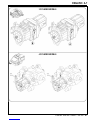 7
7
-
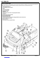 8
8
-
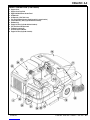 9
9
-
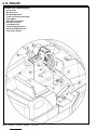 10
10
-
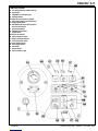 11
11
-
 12
12
-
 13
13
-
 14
14
-
 15
15
-
 16
16
-
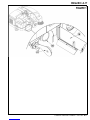 17
17
-
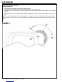 18
18
-
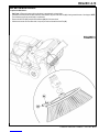 19
19
-
 20
20
-
 21
21
-
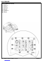 22
22
-
 23
23
-
 24
24
-
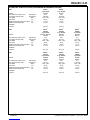 25
25
-
 26
26
-
 27
27
-
 28
28
-
 29
29
-
 30
30
-
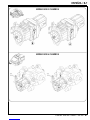 31
31
-
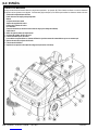 32
32
-
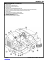 33
33
-
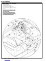 34
34
-
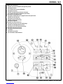 35
35
-
 36
36
-
 37
37
-
 38
38
-
 39
39
-
 40
40
-
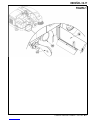 41
41
-
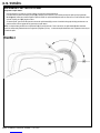 42
42
-
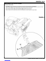 43
43
-
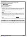 44
44
-
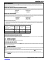 45
45
-
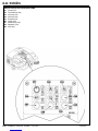 46
46
-
 47
47
-
 48
48
-
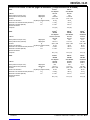 49
49
-
 50
50
-
 51
51
-
 52
52


Nilfisk-ALTO 56507003 Manual de usuario
- Categoría
- Máquina de piso
- Tipo
- Manual de usuario
En otros idiomas
- English: Nilfisk-ALTO 56507003 User manual
Documentos relacionados
Otros documentos
-
Nilfisk SW5500 60 B El manual del propietario
-
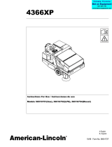 American-Lincoln 4366XP Instrucciones de operación
-
 Nilfisk-Advance America RS 1300 Manual de usuario
-
 Nilfisk-Advance America Terra 5200B Manual de usuario
-
Columbus AKS 88|VDM 180 Manual de usuario
-
Nilfisk-Advance SW 650 Manual de usuario
-
Advance acoustic Terra 26M Instructions For Use Manual
-
 Nilfisk-Advance America 56316025 (R32-C) Manual de usuario
-
Harper Hawk 4400 El manual del propietario
-


