Moog Videolarm FDP75C2N/AX Installation And Operation Instructions Manual
- Categoría
- Accesorios para cámaras de seguridad
- Tipo
- Installation And Operation Instructions Manual
Este manual también es adecuado para

Before a t t e m pti n g t o co n n e c t o r op e r a te t h i s p ro d u c t ,
pl e a s e rea d t h e s e in s t r u c t i o ns c o m p l ete l y.
81-IN5358R1
www.videolarm.com
F D W 7 5
Fusion Dome (Outdoor Wall Mount with Housing)
Installation and Operation Instructions for the following models:
FDW75C2N IP Network Ready 7” Outdoor dome hsg w/wall mount, clear dome, w/24Vac input, heater/
blower, fan an IP Network PTZ camera, 120 to 24Vac transformer.
FDP75C2N IP Network Ready 7” Outdoor dome hsg w/pendant mount, clear dome, w/24Vac input, heater/
blower, fan an IP Network PTZ camera,120 to 24Vac transformer.
IFDW75CN IP Network Ready 7” Indoor dome hsg w/wall mount, clear dome, w/24Vac input, heater/
blower, fan an IP Network PTZ camera, 120 to 24Vac transformer.
IFDP75CN IP Network Ready 7” Indoor dome hsg w/pendant mount, clear dome, w/24Vac input, heater/
blower, fan an IP Network PTZ camera,120 to 24Vac transformer.
FDW75C2NE IP Network Ready 7” Outdoor dome hsg w/wall mount, clear dome, w/24Vac input, heater/
blower, fan an IP Network PTZ camera. (European Model)
FDP75C2NE IP Network Ready 7” Outdoor dome hsg w/pendant mount, clear dome, w/24Vac input, heater/
blower, fan an IP Network PTZ camera. (European Model)
FDW75C2N/AC IP Network Ready 7” Outdoor dome hsg w/wall mount, clear acrylic dome, w/24Vac input, heater/
blower, fan an IP Network PTZ camera, 120 to 24Vac transformer.
FDP75C2N/AC IP Network Ready 7” Outdoor dome hsg w/pendant mount, clear dome, w/24Vac input, heater/
blower, fan an IP Network PTZ camera,120 to 24Vac transformer.

IMPORTANT SAFEGUARDS SAFETY PRECAUTIONS
UNPACKING
SERVICE
1 Read Instructions - All the safety and operating
instructions should be read before the unit is
operated.
2 Retain Instructions - The safety and operating
instructions should be retained for future
reference.
3 Heed Warnings - All warnings on the unit and in the
operating instructions should be adhered to.
4 Follow Instructions - All operating and user
instructions should be followed.
5 Electrical Connections - Only a qualified
electrician should make electrical connections.
6 Attachments - Do not use attachments not
recommended by the product manufacturer as
they may cause hazards.
7 Cable Runs - All cable runs must be within
permissible distance
8 Mounting - This unit must be properly and securely
mounted to a supporting structure capable of
sustaining the weight of the unit.
Accordingly:
a. The installation should be made by a qualified
installer.
b. The installation should be in compliance with
local codes.
c. Care should be exercised to select suitable
hardware to install the unit, taking into
account both the composition of the mounting
surface and the weight of the unit.
Be sure to periodically examine the unit and the
supporting structure to make sure that the integrity
of the installation is intact. Failure to comply with the
foregoing could result in the unit separating from the
support structure and falling, with resultant damages or
injury to anyone or anything struck by the falling unit.
Unpack carefully. Electronic components can be
damaged if improperly handled or dropped. If an item
appears to have been damaged in shipment, replace
it properly in its carton and notify the shipper.
Be sure to save:
1 The shipping carton and packaging material.
They are the safest material in which to make
future shipments of the equipment.
2 These Installation and Operating Instructions.
If technical support or service is needed, contact us
at the following number:
The lightning flash with an arrowhead
symbol, within an equilateral triangle, is
intended to alert the user to the presence
of non-insulated “dangerous voltage”
within the product’s enclosure that may be
of sufficient magnitude to constitute a risk
of electric shock to persons.
Este símbolo se piensa para alertar al usuario a la
presencia del “voltaje peligroso no-aisIado” dentro del
recinto de los productos que puede ser un riesgo de
choque eléctrico.
Ce symbole est prévu pour alerter I’utilisateur à la
presence “de la tension dangereuse” non-isolée dans la
clôture de produits qui peut être un risque de choc
électrique.
Dieses Symbol soll den Benutzer zum Vorhandensein der
nicht-lsolier “Gefährdungsspannung” innerhalb der
Produkteinschließung alarmieren die eine Gefahr des
elektrischen Schlages sein kann.
Este símbolo é pretendido alertar o usuário à presença
“di tensão perigosa non-isolada” dentro do cerco dos
produtos que pode ser um risco de choque elétrico.
Questo simbolo è inteso per avvertire I’utente alla
presenza “di tensione pericolosa” non-isolata all’interno
della recinzione dei prodotti che può essere un rischio di
scossa elettrica
.
The exclamation point within an equilateral
triangle is intended to alert the user to
presence of important operating and
maintenance (servicing) instructions in the
literature accompanying the appliance.
Este símbolo del punto del exclamation se piensa para
alertar al usuario a la presencia de instrucciones
importantes en la literatura que acompaña la
aplicación.
Ce symbole de point d’exclamation est prévu pour
alerter l’utilisateur à la presence des instructions
importantes dans la littérature accompagnant
l’appareil.
Dieses Ausruf Punktsymbol soll den Benutzer zum
Vorhandensein de wichtigen Anweisungen in der
Literatur alarmieren, die das Gerät begleitet.
Este símbolo do ponto do exclamation é pretendido
alertar o usuário à presença de instruções importantes
na literatura que acompanha o dispositivo.
Questo simbolo del punto del exclamaton è inteso per
avvertire l’utente alla presenza delle istruzioni importanti
nella letteratura che accompagna l'apparecchio.
TECHNICAL SUPPORT
AVAILABLE 24 HOURS
1- 800 - 554 -1124
CAUTION: TO REDUCE THE RISK OF ELECTRIC SHOCK,
DO NOT REMOVE COVER (OR BACK).
NO USER SERVICEABLE PARTS INSIDE.
REFER SERVICING TO QUALIFIED SERVICE PERSONNEL
RISK OF ELECTRIC SHOCK
DO NOT OPEN
CAUTION
IMPORTANT SAFEGUARDS SAFETY PRECAUTIONS
UNPACKING
SERVICE
1 Read these instructions.
2 Keep these instructions.
3 Heed all warnings
4 Follow all instructions.
5 Do not use this apparatus near water.
6 Clean only with damp cloth.
7 Do not block any of the ventilation openings. Install in accordance with the
manufacturers instructions.
8 Cable Runs- All cable runs must be within permissible distance.
9 Mounting - This unit must be properly and securely mounted to a supporting
structure capable of sustaining the weight of the unit.
Accordingly:
a. The installation should be made by a qualified installer.
b. The installation should be in compliance with local codes.
c. Care should be exercised to select suitable hardware to install the unit, taking into
account both the composition of the mounting surface and the weight of the
unit.
10 Do not install near any heat sources such as radiators, heat registers, stoves, or other
apparatus ( including amplifiers) that produce heat.
11 Do not defeat the safety purpose of the polarized or grounding-type plug. A
polarized plug has two blades with one wider than the other. A grounding type
plug has two blades and a third grounding prong. The wide blade or the third
prong are provided for your safety. When the provided plug does not fit into your
outlet, consult an electrician for replacement of the obsolete outlet.
12 Protect the power cord from being walked on or pinched particularly at plugs,
convenience receptacles, and the point where they exit from the apparatus.
13 Only use attachment/ accessories specified by the manufacturer.
14 Use only with a cart, stand, tripod, bracket, or table specified by the manufacturer,
or sold with the apparatus. When a cart is used, use caution when moving the cart/
apparatus combination to avoid injury from tip-over.
15 Unplug this apparatus during lighting storms or when unused for long periods of time.
16 Refer all servicing to qualified service personnel. Servicing is required when the
apparatus has been damaged in any way, such as power-supply cord or plug is
damaged, liquid has been spilled of objects have fallen into the apparatus, the
apparatus has been exposed to rain or moisture, does not operate normally, or
has been dropped.
Be sure to periodically examine the unit and the supporting structure to make sure that the
integrity of the installation is intact. Failure to comply with the foregoing could result in the
unit separating from the support structure and falling, with resultant damages or injury to
anyone or anything struck by the falling unit.
Unpack carefully. Electronic components can be
damaged if improperly handled or dropped. If an item
appears to have been damaged in shipment, replace
it properly in its carton and notify the shipper.
Be sure to save:
1 The shipping carton and packaging material.
They are the safest material in which to make
future shipments of the equipment.
2 These Installation and Operating Instructions.
If technical support or service is needed, contact us
at the following number:
The lightning flash with an arrowhead
symbol, within an equilateral triangle, is
intended to alert the user to the presence
of non-insulated “dangerous voltage”
within the product’s enclosure that may be
of sufficient magnitude to constitute a risk
to persons.
Este símbolo se piensa para alertar al usuario a la
presencia del “voltaje peligroso no-aisIado” dentro del
recinto de los productos que puede ser un riesgo de
choque eléctrico.
Ce symbole est prévu pour alerter I’utilisateur à la
presence “de la tension dangereuse” non-isolée dans la
clôture de produits qui peut être un risque de choc
électrique.
Dieses Symbol soll den Benutzer zum Vorhandensein der
nicht-lsolier “Gefährdungsspannung” innerhalb der
Produkteinschließung alarmieren die eine Gefahr des
elektrischen Schlages sein kann.
Este símbolo é pretendido alertar o usuário à presença
“di tensão perigosa non-isolada” dentro do cerco dos
produtos que pode ser um risco de choque elétrico.
Questo simbolo è inteso per avvertire I’utente alla
presenza “di tensione pericolosa” non-isolata all’interno
della recinzione dei prodotti che può essere un rischio di
scossa elettrica
.
The exclamation point within an equilateral
triangle is intended to alert the user to
presence of important operating and
maintenance (servicing) instructions in the
literature accompanying the appliance.
Este símbolo del punto del exclamation se piensa para
alertar al usuario a la presencia de instrucciones
importantes en la literatura que acompaña la
aplicación.
Ce symbole de point d’exclamation est prévu pour
alerter l’utilisateur à la presence des instructions
importantes dans la littérature accompagnant
l’appareil.
Dieses Ausruf Punktsymbol soll den Benutzer zum
Vorhandensein de wichtigen Anweisungen in der
Literatur alarmieren, die das Gerät begleitet.
Este símbolo do ponto do exclamation é pretendido
alertar o usuário à presença de instruções importantes
na literatura que acompanha o dispositivo.
Questo simbolo del punto del exclamaton è inteso per
avvertire l’utente alla presenza delle istruzioni importanti
nella letteratura che accompagna l'apparecchio.
TECHNICAL SUPPORT
AVAILABLE 24 HOURS
1- 800 - 554 -1124
RISK OF ELECTRIC SHOCK
DO NOT OPEN
CAUTION
CAUTION: TO REDUCE THE RISK OF
ELECTRIC SHOCK, DO NOT REMOVE
COVER ( OR BACK). NO USER- SERVICE-
ABLE PARTS INSIDE. REFER SEVICING TO
QUALIFIED SERVICE PERSONNEL.

IMPORTANT SAFEGUARDS SAFETY PRECAUTIONS
UNPACKING
SERVICE
1 Read Instructions - All the safety and operating
instructions should be read before the unit is
operated.
2 Retain Instructions - The safety and operating
instructions should be retained for future
reference.
3 Heed Warnings - All warnings on the unit and in the
operating instructions should be adhered to.
4 Follow Instructions - All operating and user
instructions should be followed.
5 Electrical Connections - Only a qualified
electrician should make electrical connections.
6 Attachments - Do not use attachments not
recommended by the product manufacturer as
they may cause hazards.
7 Cable Runs - All cable runs must be within
permissible distance
8 Mounting - This unit must be properly and securely
mounted to a supporting structure capable of
sustaining the weight of the unit.
Accordingly:
a. The installation should be made by a qualified
installer.
b. The installation should be in compliance with
local codes.
c. Care should be exercised to select suitable
hardware to install the unit, taking into
account both the composition of the mounting
surface and the weight of the unit.
Be sure to periodically examine the unit and the
supporting structure to make sure that the integrity
of the installation is intact. Failure to comply with the
foregoing could result in the unit separating from the
support structure and falling, with resultant damages or
injury to anyone or anything struck by the falling unit.
Unpack carefully. Electronic components can be
damaged if improperly handled or dropped. If an item
appears to have been damaged in shipment, replace
it properly in its carton and notify the shipper.
Be sure to save:
1 The shipping carton and packaging material.
They are the safest material in which to make
future shipments of the equipment.
2 These Installation and Operating Instructions.
If technical support or service is needed, contact us
at the following number:
The lightning flash with an arrowhead
symbol, within an equilateral triangle, is
intended to alert the user to the presence
of non-insulated “dangerous voltage”
within the product’s enclosure that may be
of sufficient magnitude to constitute a risk
of electric shock to persons.
Este símbolo se piensa para alertar al usuario a la
presencia del “voltaje peligroso no-aisIado” dentro del
recinto de los productos que puede ser un riesgo de
choque eléctrico.
Ce symbole est prévu pour alerter I’utilisateur à la
presence “de la tension dangereuse” non-isolée dans la
clôture de produits qui peut être un risque de choc
électrique.
Dieses Symbol soll den Benutzer zum Vorhandensein der
nicht-lsolier “Gefährdungsspannung” innerhalb der
Produkteinschließung alarmieren die eine Gefahr des
elektrischen Schlages sein kann.
Este símbolo é pretendido alertar o usuário à presença
“di tensão perigosa non-isolada” dentro do cerco dos
produtos que pode ser um risco de choque elétrico.
Questo simbolo è inteso per avvertire I’utente alla
presenza “di tensione pericolosa” non-isolata all’interno
della recinzione dei prodotti che può essere un rischio di
scossa elettrica
.
The exclamation point within an equilateral
triangle is intended to alert the user to
presence of important operating and
maintenance (servicing) instructions in the
literature accompanying the appliance.
Este símbolo del punto del exclamation se piensa para
alertar al usuario a la presencia de instrucciones
importantes en la literatura que acompaña la
aplicación.
Ce symbole de point d’exclamation est prévu pour
alerter l’utilisateur à la presence des instructions
importantes dans la littérature accompagnant
l’appareil.
Dieses Ausruf Punktsymbol soll den Benutzer zum
Vorhandensein de wichtigen Anweisungen in der
Literatur alarmieren, die das Gerät begleitet.
Este símbolo do ponto do exclamation é pretendido
alertar o usuário à presença de instruções importantes
na literatura que acompanha o dispositivo.
Questo simbolo del punto del exclamaton è inteso per
avvertire l’utente alla presenza delle istruzioni importanti
nella letteratura che accompagna l'apparecchio.
TECHNICAL SUPPORT
AVAILABLE 24 HOURS
1- 800 - 554 -1124
CAUTION: TO REDUCE THE RISK OF ELECTRIC SHOCK,
DO NOT REMOVE COVER (OR BACK).
NO USER SERVICEABLE PARTS INSIDE.
REFER SERVICING TO QUALIFIED SERVICE PERSONNEL
RISK OF ELECTRIC SHOCK
DO NOT OPEN
CAUTION
LIMITED WARRANTY FOR VIDEOLARM INC. PRODUCTS
VIDEOLARM INC. warrants this Product to be free from defects in material or workmanship, as follows:
PRODUCT CATEGORY PARTS LABOR
All Enclosures and Electronics Three (3) Years Three (3) Years
Pan/Tilts Three (3) Years **6 months if used in autoscan Three (3) Years **6 months if used in autoscan
Poles/PoleEvators Three (3) Years Three (3) Years
Warrior/Q-View/I.R. Illuminators/SView Five (5) Years Five (5) Years
Controllers Three (3) Years Three (3) Years
Power Supplies Three (3) Years Three (3) Years
Accessory Brackets Three (3) Years Three (3) Years
During the labor warranty period, to repair the Product, Purchaser will either return the defective product, freight prepaid, or deliver it to Videolarm Inc.
Decatur GA. The Product to be repaired is to be returned in either its original carton or a similar package an equal degree of protection with a
RMA # (Return Materials Authorization number) displayed on the outer box or packing slip. To obtain a RMA# you must contact our Technical Support
Team at 800.554.1124, extension 101. Videolarm will return the repaired Product freight prepaid to Purchaser. Videolarm is not obligated to provide
Purchaser with a substitute unit during the warranty period or at any time. After the applicable warranty period, Purchaser must pay all labor and/or
parts charges.
The limited warranty stated in these product instructions is subject to all of the following terms and conditions:
1. NOTIFICATION OF CLAIMS: WARRANTY SERVICE: If Purchaser believes that the Product is defective in material or workmanship, then written notice
with an explanation of the claim shall be given promptly by Purchaser to Videolarm but all claims for warranty service must be made within the
warranty period. If after investigation Videolarm determines that the reported problem was not covered by the warranty, Purchaser shall pay Videolarm
for the cost of investigating the problem at its then prevailing per incident billable rate. No repair or replacement of any Product or part thereof shall
extend the warranty period as to the entire Product. The warranty on the repaired part only shall be in for a period of ninety (90) days
following the repair or replacement of that part or the remaining period of the Product parts warranty, whichever is greater.
2. EXCLUSIVE REMEDY: ACCEPTANCE: Purchaser’s exclusive remedy and Videolarm’s sole obligation is to supply (or pay for) all labor necessary to repair
any Product found to be defective within the warranty period and to supply, at no extra charge, new or rebuilt replacements for defective parts.
3. EXCEPTIONS TO LIMITED WARRANTY: Videolarm shall have no liability or obligation to Purchaser with respect to any Product requiring service
during the warranty period which is subjected to any of the following: abuse, improper use: negligence, accident, lightning damage or other acts
of God (i.e., hurricanes, earthquakes), failure of the end-user to follow the directions outlined in the product instructions, failure of the
end-user to follow the maintenance procedures recommended by the International Security Industry Organization, written in product instructions,
or recommended in the service manual for the Product. Furthermore, Videolarm shall have no liability where a schedule is for regular
replacement or maintenance or cleaning of certain parts (based on usage) and the end-user has failed to follow such schedule; attempted repair by
personnel; operation of the Product outside of the published environmental and electrical parameters, or if such Product’s original
(trademark, serial number) markings have been defaced, altered, or removed. Videolarm excludes from warranty coverage Products sold
AS IS and/or WITH ALL FAULTS and excludes used Products which have not been sold by Videolarm to the Purchaser. All software and accompanying
documentation furnished with, or as part of the Product is furnished “AS IS” (i.e., without any warranty of any kind), except where expressly provided
otherwise in any documentation or license agreement furnished with the Product.
4. PROOF OF PURCHASE: The Purchaser’s dated bill of sale must be retained as evidence of the date of purchase and to establish warranty eligibility.
DISCLAIMER OF WARRANTY EXCEPT FOR THE FOREGOING WARRANTIES, VIDEOLARM HEREBY DISCLAIMS AND EXCLUDES ALL OTHER WARRANTIES, EXPRESS OR IMPLIED,
INCLUDING, BUT NOT LIMITED TO ANY AND/OR ALL IMPLIED WARRANTIES OF MERCHANTABILITY, FITNESS FOR A PARTICULAR PURPOSE AND/OR ANY WARRANTY WITH
REGARD TO ANY CLAIM OF INFRINGEMENT THAT MAY BE PROVIDED IN SECTION 2-312(3) OF THE UNIFORM COMMERCIAL CODE AND/OR IN ANY OTHER COMPARABLE
STATE STATUTE. VIDEOLARM HEREBY DISCLAIMS ANY REPRESENTATIONS OR WARRANTY THAT THE PRODUCT IS COMPATIBLE WITH ANY COMBINATION OF NON-VIDEOLARM
PRODUCTS OR NON-VIDEOLARM RECOMMENDED PRODUCTS PURCHASER CHOOSES TO CONNECT TO PRODUCT.
LIMITATION OF LIABILITY THE LIABILITY OF VIDEOLARM, IF ANY, AND PURCHASER’S SOLE AND EXCLUSIVE REMEDY FOR DAMAGES FOR ANY CLAIM OF ANY KIND
WHATSOEVER, REGARDLESS OF THE LEGAL THEORY AND WHETHER ARISING IN TORT OR CONTRACT, SHALL NOT BE GREATER THAN THE ACTUAL PURCHASE PRICE OF

FDW75
24 VAC
26 Watts
Accessories: Heater: 25 Watts, Blower: 1 Watt
Camera Power: 40 Watts Max
Tools Required: .100” Flat Head Screwdriver
Phillips Head Screwdriver
24 VAC
26 vatios
Accesorios: Calentador: 25 Vatios, Soplador: 1 vatio
Energía De la Cámara fotográfica: 40 vatios Max
Las Herramientas Requirieron: Destornillador Principal Plano Del
100". Destornillador Principal Phillips.
24 VCA
26 watts
Accessoires : Réchauffeur : 25 Watts, Ventilateur : 1 watt
Puissance D'Appareil-photo : 40 watts Max
Les Outils Ont exigé : Tournevis Principal Plat De 100".
Tournevis Principal Phillips.
24 VAC
26 Watt
Zusatzgeräte: Heizung: 25 Watt, Gebläse: 1 Watt.
Kamera-Energie: 40 Watt Max
Werkzeuge Erforderten: 100"Flacher Hauptschraubenzieher.
Kreuzkopfhauptschraubenzieher.
24 VAC
26 watts
Acessórios: Calefator: 25 Watts, Ventilador: 1 watt.
Poder Da Câmera: 40 watts Max
Ferramentas Requeridas: Chave de fenda Principal Lisa Do
100". Chave de fenda Principal Phillips.
24 VCA.
26 watt
Accessori: Riscaldatore: 25 Watt, Ventilatore: 1 watt.
Alimentazione Della Macchina fotografica: 40 watt Max
Gli Attrezzi Hanno richiesto: Cacciavite Capo Piano Del 100".
Cacciavite Capo "phillips".
Electrical Specifications
IFDP75CFN
FDW75CFN (INDOOR ONLY)
Power 24VAC
Class 2 Only
24 VAC
No power options provided.
Power required for camera only.
24 VAC
Ningunas opciones de la energía proporcionaron.
Energía requerida para la cámara fotográfica solamente.
24 VCA
Option de puissance n'a pas fourni.
Puissance requise pour l'appareil-photo seulement.
24 VAC
Keine Energie Wahlen stellten zur Verfügung.
Energie erfordert für nur Kamera.
24 VAC
Nenhumas opções do poder fornecidas.
Poder requerido para a câmera somente.
24 VAC
Nessun'opzione di alimentazione ha fornito.
Alimentazione richiesta per la macchina fotografica soltanto.
!!
Indoor Models IFDP75CN/ IFDP75CN Include NO Power
Accessories
International Models FDW75C2NE/ FDP75C2NE Include NO
Power Transformer
!!
Français
Deutsch
Italiano
Portuguese
Español
English
Contents of Box
*** WALL MOUNT FOR (W) MODELS.

Securely mount unit to wall or to appropriate
adapter bracket.
• Monte con seguridad la unidad a la pared o al
soporte apropiado del adaptador.
• Montez solidement l'unité au mur ou à la parenthèse
appropriée d'adapteur.
• Bringen Sie sicher Maßeinheit zur Wand oder zum
passenden Adapterhaltewinkel an.
• Monte firmemente a unidade à parede ou ao suporte
apropriado do adaptador.
• Monti saldamente l'unità alla parete o alla staffa
adatta dell'adattatore.
If using conduit connect, connect to
incoming conduit fitting.
• Si usa el conducto conecte, conecte con la guar-
nición entrante del conducto.
• Si à l'aide du conduit reliez, reliez à l'ajustage de
précision entrant de conduit.
• Wenn Sie Rohr verwenden, schließen Sie an, schließen
Sie an ankommende Rohrbefestigung an.
• Se usando a canalização conecte, conecte ao
encaixe entrante da canalização.
• Se per mezzo del condotto colleghi, colleghi al mon-
taggio ricevuto del condotto.
Open access door to access power and
control connectors.
• Abra la puerta de acceso en los conectadores de la
energía y de control del acceso.
• Ouvrez la porte d'accès aux connecteurs de
puissance et de commande d'accès.
• Öffnen Sie Zugang zur Zugang Energie und zu den
Geräteanschlüssen.
• Abra a porta de acesso aos conectores do poder e
de controle do acesso.
• Apra il portello di accesso ai connettori di alimentazi-
one e di controllo di accesso.
Make wire connection as they are required
for your needs.
• Haga la conexión del alambre como se requieren
para sus necesidades.
• Établissez le rapport de fil comme ils sont exigés pour
vos besoins.
• Stellen Sie Leitung Beziehung her, wie sie für Ihre
Notwendigkeiten angefordert werden.
• Faça a conexão do fio como são requeridos para suas
necessidades.
• Faccia il collegamento del legare come sono richiesti
per i vostri bisogni.
WALL MOUNTING
1 2
3 4

1
Securely mount bracket to wall. Pull wiring
through bracket and position grommet as shown.
• Con seguridad soporte del montaje a emparedar. Tire del cableado
a través del soporte y del ojal de la posición según lo demostrado.
• Solidement parenthèse de bâti à murer. Tirez le câblage par la
parenthèse et le canon isolant de position comme montré.
• Sicher Einfassung Haltewinkel wall. Ziehen Sie Verdrahtung durch
Haltewinkel und Position Gummimuffe, wie gezeigt.
• Firmemente suporte da montagem a wall. Puxe a fiação através do
suporte e do ilhó da posição como mostrado.
• Saldamente staffa del supporto da wall. Tiri i collegamenti tramite la
staffa ed il gommino di protezione di posizione come indicato.
4
Screw the (2) bolts into the coupling.
• Atornille (2) los pernos en el acoplador.
• Vissez (2) les boulons dans l'accouplement.
• Schrauben Sie die (2) Schraubbolzen in die Koppe-
lung.
• Parafuse (2) os parafusos no acoplamento.
• Avviti (2) i bulloni nell'accoppiamento.
2
Wrap Teflon tape around the pipe threads
to ensure a tight seal.
• La cinta del Teflon del abrigo alrededor de la pipa rosca
para asegurar un sello apretado.
• La bande de teflon d'enveloppe autour de la pipe filète
pour assurer un joint serré.
• Verpackung Teflonklebeband um das Rohr verlegt, um
eine feste Dichtung sicherzustellen.
• A fita adesiva do Teflon do envoltório em torno da
tubulação enfía para assegurar um selo apertado.
• Il nastro del Teflon dell'involucro intorno al tubo filetta per
accertare una guarnizione stretta.
TM
3
Screw the coupling onto the pipe threads
until it is hand tight.
• Atornille el acoplador sobre los hilos de rosca de la pipa
hasta que es mano firmemente.
• Vissez le couplage sur les fils de pipe jusqu'à ce que ce
soit main fortement.
• Schrauben Sie die Koppelung auf die Rohrgewinde, bis
es Hand fest ist.
• Parafuse o acoplamento nas linhas da tubulação até
que esteja mão firmemente.
• Avviti l'accoppiamento sui filetti del tubo fino a che non
sia fortemente mano.
FOR PENDENT/
WALL MOUNTING
5
6
7
8

5
Loop the lanyard over the set screw to
temporarily hold housing.
• Coloque el acollador sobre el tornillo de presión para
celebrar temporalmente la cubierta.
• Faites une boucle la lanière au-dessus de la vis de réglage
pour tenir temporairement le logement.
• Schlingen Sie die Abzuglinie über der Klemmschraube, um
Gehäuse vorübergehend zu halten.
• Dê laços no colhedor sobre o parafuso de fixação para
prender temporariamente a carcaça.
• Colleghi la cordicella in circuito sopra la vite di arresto
temporaneamente per tenere l'alloggiamento.
6
Make the appropriate wiring connections
from the dome to the gooseneck.
• Haga las conexiones apropiadas del cableado de la bóveda
al gooseneck.
• Établissez les rapports appropriés de câblage à partir du dôme
au col de cygne.
• Stellen Sie die passenden Verdrahtung Beziehungen von der
Haube zum gooseneck her.
• Faça as conexões apropriadas da fiação da abóbada ao
gooseneck.
• Faccia i collegamenti adatti dei collegamenti dalla cupola al
gooseneck.
7
Undo the lanyard, pull housing up and twist
secure with the locking bolt and washers.
• Deshaga el acollador, tire de contener para arriba y tuerza seguro
con el perno y las arandelas de fijación.
• Défaites la lanière, tirez loger vers le haut et tordez bloqué avec le
boulon et les rondelles de fermeture.
• Annulieren Sie die Abzuglinie, ziehen Sie oben unterbringen und
verdrehen Sie sicheres mit dem verriegelnschraubbolzen und den
Unterlegscheiben.
• Undo o colhedor, puxe abrigar acima e torça seguro com o
parafuso e as arruelas travando.
• Undo la cordicella, tiri l'alloggio in su e torca sicuro con il bullone e
le rondelle di bloccaggio.
8
Slide the grommet down over the coupling to prevent
water from entering and complete the assembly.
• Resbale el ojal abajo sobre el acoplador para evitar que el agua
entre y para terminar a la asamblea.
• Glissez le canon isolant vers le bas au-dessus de l'accouplement
pour empêcher l'eau d'entrer et pour accomplir l'assemblée.
• Schieben Sie die Gummimuffe unten über der Koppelung, um zu
verhindern, daß Wasser und die Versammlung durchzuführen
hereinkommt.
• Deslize o ilhó para baixo sobre o acoplamento para impedir que a
água entre e para terminar o conjunto.
• Faccia scorrere il gommino di protezione giù sopra l'accoppiamento
per impedire l'acqua entrare e per completare il complessivo.
9
10
11
12

Green
Yellow
Orange
Red
Camera
Power
Accessory
Power
Camera = red & orange wires to terminal
Heater/Blower = yellow & green wires to terminal
• Cámara fotográfica = alambres rojos y anaranjados al
terminal Heater/Blower = alambres del amarillo y del verde
al terminal
• Appareil-photo = fils rouges et oranges à la borne
Heater/Blower = fils de jaune et de vert à la borne
• Kamera = rote u. orange Leitungen zum Anschluß
Heater/Blower = Gelb- u. Grünleitungen zum Anschluß
• Câmera = fios vermelhos & alaranjados ao terminal
Heater/Blower = fios do amarelo & do verde ao terminal
• Macchina fotografica = legare rossi & arancioni al terminale
Heater/Blower = legare di verde & di colore giallo al termi-
nale
MM
2
AWG
,5 ,75 1,0 1,5 2,5 4 6
22 20 18 16 14 12 10
The beam angle may be adjusted on the
bottom of the unit.
• Éstos se recomiendan las distancias máximas para
24VAC con una gota del voltage del 10%.
• Ceux-ci sont recommandés des distances maximum
pour 24VAC avec une chute de tension de 10%.
• Diese werden maximale Abstände für 24VAC mit
einem 10% Spannungsabfall empfohlen.
• Estes são recomendados distâncias máximas para
24VAC com uma queda de tensão de 10%.
• Questi sono suggeriti distanze massime per 24VAC
con una differenza de potenziale di 10%.
12
These are recommended maximum distances
for 24VAC with a 10% voltage drop.
15
RJ45
BNC
24VAC
1
2
3
4
Camera
Camera
Heater/Blower
Heater/Blower
Red
Orange
Yellow
Green
POWER
Max 40 Watts
26 Watts
1/0
1
2
3
4
Alarm 1
Alarm 2
Alarm 3
Common
Blue
Violet
Gray
White
Make the appropriate male and female connections. Indoor model does not include pre-run cables.
• Haga las conexiones masculinas y femeninas apropiadas. El modelo de interior no incluye pre-funciona los cables.
• Établissez les rapports masculins et femelles appropriés. Le modèle d'intérieur n'inclut pas pré-courent des câbles.
• Stellen Sie die passenden männlichen und weiblichen Beziehungen her. Innenmodell schließt nicht vor-laufen lassen Kabel
ein.
• Faça as conexões masculinas e fêmeas apropriadas. O modelo indoor não inclui pre-funciona cabos.
• Faccia i collegamenti maschii e femminili adatti. Il modello dell'interno non include pre-fa funzionare i cavi.
14
13

18
3026 Mounting
Plate
Mounting
Hole
Mounting
Hole
Mounting Hole
Axis 214
(52
mm
) 2"
Captive
Screw
(3) #8 x 3/8”
Install the camera to the mounting plate using (3) 3mm x 12mm bolts and lock washers. Place (3) #8x3/8”
screws on the spacers and line up the mounting slots. Slide plate in and secure.
• Instale la cámara fotográfica a la placa de montaje usando (3) los pernos de 3m m x de 12m m y las arandelas de cerradura.
Coloque los tornillos de (3) del # 8x3/8"en los espaciadores y alinee las ranuras de montaje. Resbale la placa adentro y
asegúrela.
• Installez l'appareil-photo sur le plat de support en utilisant (3) des boulons de 3mm x de 12mm et des rondelles de freinage.
Placez les vis de (3) # de 8x3/8"sur les entretoises et alignez les fentes de support. Glissez le plat dedans et le fixez.
• Bringen Sie die Kamera zur Montageplatte mit (3) 3mm x 12mm den Schraubbolzen und den Federringen an. Setzen Sie (3) #
8x3/8"die Schrauben auf die Distanzscheiben und richten Sie die Befestigungsschlitze aus. Schieben Sie Platte innen und sichern
Sie.
• Instale a câmera à placa de montagem usando (3) os parafusos de 3mm x de 12mm e as arruelas de fechamento. Coloque os
parafusos de (3) # de 8x3/8"nos espaçadores e alinhe-os acima dos entalhes de montagem. Deslize a placa dentro e fixe-a.
• Installi la macchina fotografica al giunto di supporto usando (3) i bulloni di 12mm x di 3mm e le ranelle di bloccaggio. Disponga
le viti di 8x3/8"# di (3) sui distanziatori ed allinei le scanalature di montaggio. Faccia scorrere la piastra dentro e fissi.
17
Install the camera to the mounting plate with (2) #10 screws and lock washers provided. Place (3)
#8x3/8” screws on the spacers and align the mounting slots. Slide on plate and camera then secure.
• Instale la cámara fotográfica a la placa de montaje con (2) los tornillos #10 y las arandelas de cerradura proporcionadas. Coloque los
tornillos de (3) del # 8x3/8"en los espaciadores y alinee las ranuras de montaje. Resbale en la placa y la cámara fotográfica entonces
seguras.
• Installez l'appareil-photo sur le plat de support avec (2) les vis #10 et les rondelles de freinage fournies. Placez les vis de (3) # de 8x3/8"
sur les entretoises et alignez les fentes de support. Glissez du plat et de l'appareil-photo puis bloqués.
• Bringen Sie die Kamera zur Montageplatte mit (2) den bereitgestellten Schrauben #10 und Federringen an. Setzen Sie (3) # 8x3/8"die
Schrauben auf die Distanzscheiben und richten Sie die Befestigungsschlitze aus. Schieben Sie auf die sichere Platte und Kamera dann.
• Instale a câmera à placa de montagem com (2) os parafusos #10 e as arruelas de fechamento fornecidas. Coloque os parafusos de
(3) # de 8x3/8"nos espaçadores e alinhe os entalhes de montagem. Deslize na placa e na câmera então seguras.
• Installi la macchina fotografica al giunto di supporto con (2) le viti #10 e le ranelle di bloccaggio fornite. Disponga le viti di 8x3/8"# di (3)
sui distanziatori ed allinei le scanalature di montaggio. Faccia scorrere sulla piastra e sulla macchina fotografica allora sicure.
2539 Mounting Plate
Mounting
Hole
Mounting
Hole
Axis 213
(26
mm
) 1"
(52
mm
) 2"
(13
mm
) ½"
Captive
Screw
(3) #8x3/8”
16
17

17
Install the camera to the mounting plate with (4) #8 screws and lock washers provided. Place (3)
#8x3/8” screws on the spacers and align the mounting slots. Slide on plate and camera then secure.
• Instale la cámara fotográfica a la placa de montaje con (4) los tornillos #8 y las arandelas de cerradura proporcionadas. Coloque los
tornillos de (3) del # 8x3/8"en los espaciadores y alinee las ranuras de montaje. Resbale en la placa y la cámara fotográfica entonces
seguras.
• Installez l'appareil-photo sur le plat de support avec (4) les vis #8 et les rondelles de freinage fournies. Placez les vis de (3) # de 8x3/8"
sur les entretoises et alignez les fentes de support. Glissez du plat et de l'appareil-photo puis bloqués.
• Bringen Sie die Kamera zur Montageplatte mit (4) den bereitgestellten Schrauben #8 und Federringen an. Setzen Sie (3) # 8x3/8"die
Schrauben auf die Distanzscheiben und richten Sie die Befestigungsschlitze aus. Schieben Sie auf die sichere Platte und Kamera dann.
• Instale a câmera à placa de montagem com (4) os parafusos #8 e as arruelas de fechamento fornecidas. Coloque os parafusos de
(3) # de 8x3/8"nos espaçadores e alinhe os entalhes de montagem. Deslize na placa e na câmera então seguras.
• Installi la macchina fotografica al giunto di supporto con (4) le viti #8 e le ranelle di bloccaggio fornite. Disponga le viti di 8x3/8"# di (3)
sui distanziatori ed allinei le scanalature di montaggio. Faccia scorrere sulla piastra e sulla macchina fotografica allora sicure.
Axis 215
(26
mm
) 1"
(52
mm
) 2"
Captive
Screw
(3) #8x3/8”
(26
mm
) 1"
MOUNTING HOLE
AXIS215-VL3026
MOUNTING HOLE
18

17
Axis 231D/232D
Use the (3) keyhole slots indicated above.
• Utilice (3) las ranuras del ojo de la cerradura indicadas
arriba.
• Employez (3) les fentes de trou de la serrure indiquées
ci-dessus.
• Benutzen Sie die (3) Schlüssellochschlitze, die oben
angezeigt werden.
• Use (3) os entalhes do buraco da fechadura indicados
acima.
• Usi (3) le scanalature del buco della serratura indicate
sopra.
Mounting
Hole
Mounting
Hole
Mounting Hole
Tab
Loosen
Screw
AXIS 231-232D
18
Loosen the screw to the right of the tab by
approximately (5) turns.
• Afloje el tornillo a la derecha de la lengüeta aproxi-
madamente (5) vueltas.
• Desserrez la vis à la droite de l'étiquette approxima-
tivement (5) aux tours.
• Lösen Sie die Schraube auf der rechten Seite des
Vorsprunges durch ungefähr (5) Umdrehungen.
• Afrouxe o parafuso à direita da aba aproximada-
mente (5) por voltas.
• Allenti la vite alla destra della linguetta circa (5) dalle
girate.
19
Captive
Screw
(3) #8 x 3/8”
Locking Screw
Locking
Pins
Keyhole
Slot (3)
(13
mm
) ½"
Position locking pins and locking screw over slots and turn clockwise; secure the screw. Place (3)
#8x3/8” screws on the spacers and line up mounting slots. Slide on plate and camera then secure.
• Coloque los pernos de fijación y el tornillo de fijación sobre ranuras y dé vuelta a la derecha; asegure el tornillo. Coloque los tornillos de
(3) del # 8x3/8"en los espaciadores y las ranuras de montaje de la formación. Resbale en la placa y la cámara fotográfica y asegure.
• Placez les chevilles de verrouillage et la vis de blocage au-dessus des fentes et tournez dans le sens des aiguilles d'une montre ; fixez la
vis. Placez les vis de (3) # de 8x3/8"sur les entretoises et les fentes de support de ligne. Glissez du plat et de l'appareil-photo et fixez.
• Bringen Sie Sicherungsstifte und Sicherungsschraube über Schlitzen in Position und drehen Sie nach rechts; sichern Sie die Schraube.
Setzen Sie (3) # 8x3/8"die Schrauben auf die Distanzscheiben und die Anordnungbefestigungsschlitze. Schieben Sie auf Platte und
Kamera und sichern Sie.
• Posicione os pinos travando e o parafuso travando sobre entalhes e gire-os no sentido horário; fixe o parafuso. Coloque os parafusos
de (3) # de 8x3/8"nos espaçadores e alinhe-os acima dos entalhes de montagem. Deslize na placa e na câmera e fixe.
• Posizioni i perni di bloccaggio e la vite di bloccaggio sopra le scanalature e giri in senso orario; fissi la vite. Disponga le viti di 8x3/8"# di
(3) sui distanziatori e sulle scanalature di montaggio dell'allineamento. Faccia scorrere sulla piastra e sulla macchina fotografica e fissi.
19
20
21

3mm
Screw
Power
Board
Connection
Module
20
This is what the typical path of illumination will look like with the setting at 30 degrees.
• Quite a tablero de energía situado dentro de la cubierta. Una el módulo de la conexión según lo demostrado. Una
a esta asamblea a la cubierta usando (1) "arandela del tornillo 6-32x3/8 y de la estrella.
• Enlevez carte d'alimentation situé à l'intérieur du logement. Attachez le module de raccordement comme montré.
Attachez cette assemblée au logement en utilisant (1) la "vis 6-32x3/8 et tenez le premier rôle la rondelle.
• Entfernen Sie das Energie Brett, das innerhalb des Gehäuses befunden wird. Bringen Sie das Anschlußmodul an, wie
gezeigt. Bringen Sie diese Versammlung zum Gehäuse mit (1) "Schraube 6-32x3/8 und Sternunterlegscheibe an.
• Remova a placa de poder situada dentro da carcaça. Una o módulo da conexão como mostrado. Una este
conjunto à carcaça usando (1) do "arruela parafuso 6-32x3/8 e da estrela.
• Rimuova il bordo di alimentazione situato all'interno dell'alloggiamento. Fissi il modulo del collegamento come
indicato. Fissi questo complessivo all'alloggiamento usando (1) "rondella della vite 6-32x3/8 e della stella.
Remove the power board located inside the housing. Attach the connection module as shown.
Attach this assembly to the housing using (1) 6-32x3/8” screw and star washer.
This is what the typical path of illumination will look like with the setting at 30 degrees.
• Termine el cableado a la cámara fotográfica. Una el montaje de la cámara fotográfica a la cubierta resbalando
(3) las ranuras abiertas del tornillo sobre los tornillos en la cubierta; apriete los sujetadores en el soporte.
• Accomplissez le câblage à l'appareil-photo. Attachez l'appareil-photo au logement en glissant (3) les fentes
ouvertes de vis au-dessus des vis dans le logement ; serrez les attaches sur la parenthèse.
• Führen Sie die Verdrahtung zur Kamera durch. Bringen Sie die Kamera zum Gehäuse an, indem Sie die (3) geöffne-
ten Schraube Schlitze über den Schrauben im Gehäuse schieben; ziehen Sie die Befestiger am Haltewinkel fest.
• Termine a fiação à câmera. Una o conjunto da câmera à carcaça deslizando (3) os entalhes abertos do parafuso
sobre os parafusos na carcaça; aperte os prendedores no suporte.
• Completi i collegamenti alla macchina fotografica. Fissi il complessivo della macchina fotografica all'alloggiamento
facendo scorrere (3) le scanalature aperte della vite sopra le viti nell'alloggiamento; stringa i fermi sulla staffa.
CONTROL
RJ45 Ethernet Connector
ALARMS
1 Alarm 1 Blue
2 Alarm 2 Violet
3 Alarm 3 Gray
4 Common White
POWER
1 Camera Power (24VAC) Red
2 Camera Power (24VAC) Orange
Captive
Screw
Open Screw
Slots
Cable
Ties
Complete the wiring to camera. Attach the camera assembly to the housing by sliding the (3)
open screw slots over the screws in the housing; tighten the fasteners on the bracket.
22
23

Axis 233D
Use the holes indicated above to mount
the camera.
• Utilice los agujeros indicados arriba para montar la
cámara fotográfica.
• Employez les trous indiqués ci-dessus pour monter
l'appareil-photo.
• Benutzen Sie die Bohrungen, die oben angezeigt
werden, um die Kamera anzubringen.
• Use os furos indicados acima para montar a
câmera.
• Usi i fori indicati sopra per montare la macchina
fotografica.
Mounting Hole
Mounting Hole
Disconnect the orange, red, and black wires. Remove the
power board in the housing by loosening screws on the
terminal block and the (4) machine screws.
• Desconecte los alambres anaranjados, rojos, y negros. Quite a tablero de
energía en la cubierta aflojando los tornillos en el bloque de terminales y (4)
los tornillos de la máquina.
• Débranchez les fils oranges, rouges, et noirs. Enlevez carte d'alimentation
dans le logement en desserrant des vis sur le TB et (4) les vis de machine.
• Trennen Sie die orange, roten und schwarzen Leitungen. Entfernen Sie das
Energie Brett im Gehäuse, indem Sie Schrauben am Klemmenblock und an
den (4) Maschine Schrauben lösen.
• Desconecte os fios alaranjados, vermelhos, e pretos. Remova a placa de
poder na carcaça afrouxando os parafusos no bloco terminal e (4) nos
parafusos da máquina.
• Stacchi i legare arancioni, rossi e neri. Rimuova il bordo di alimentazione
nell'alloggiamento allentando le viti sul blocchetto terminali e (4) sulle viti
della macchina.
Power
Board
Now remove the mounting bracket and attach (4) 1/2” spacers (located in the packet that came
with the housing) to the base bracket.
• Ahora quite el soporte de montaje y una (4) los espaciadores del 1/2"(situados en el paquete que vino con la cubierta)
al soporte bajo.
• Maintenant enlevez le support et attachez (4) les entretoises de 1/2"(situées dans le paquet qui est venu avec le
logement) à la parenthèse basse.
• Jetzt entfernen Sie die Schienenplatte und bringen Sie (4) die 1/2"Distanzscheiben (gelegen im Paket, das mit dem
Gehäuse kam), zum niedrigen Haltewinkel an.
• Agora remova o suporte de montagem e una (4) os espaçadores de 1/2"(situados no pacote que veio com a
carcaça) ao suporte baixo.
• Ora rimuova il supporto di attacco e fissi (4) i distanziatori di 1/2"(situati nel pacchetto che è venuto con
l'alloggiamento) alla staffa bassa.
Mounting
Bracket
½"
24
25
26

Quick Release
Plate
Base Bracket
Camera
Bracket
Additional
Spacers
Keyhole
Slots
This is what the typical path of illumination will look like with the setting at 30 degrees.
• Monte el soporte de la cámara fotográfica del eje 233D y la placa rápida del lanzamiento usando los espaciadores
adicionales del paquete del hardware.
• Montez la parenthèse d'appareil-photo de l'axe 233D et le plat rapide de dégagement en utilisant les entretoises
additionnelles du paquet de matériel.
• Bringen Sie den Mittellinie 233D Kamerahaltewinkel und schnelle die Freigabeplatte mit den zusätzlichen Distanzs-
cheiben vom Kleinteilpaket an.
• Monte o suporte da câmera da linha central 233D e a placa rápida da liberação usando os espaçadores adicio-
nais do pacote da ferragem.
• Monti la staffa della macchina fotografica di asse 233D e la piastra rapida del rilascio usando i distanziatori supple-
mentari dal pacchetto dei fissaggi.
Mount the Axis 233D camera bracket and quick release plate using the additional spacers from
the hardware packet.
This is what the typical path of illumination will look like with the setting at 30 degrees.
• Coloque la placa rápida del lanzamiento sobre el fondo de la cámara fotográfica. Alinee los tornillos de fijación de la cámara fotográfica y las
ranuras del ojo de la cerradura. Resbale la cámara fotográfica dentro de las ranuras del ojo de la cerradura hasta que los botones de fijación
golpean el extremo, y apriete el tornillo de pulgar.
• Placez le plat rapide de dégagement sur le fond de l'appareil-photo. Alignez les vis de blocage d'appareil-photo et les fentes de trou de la
serrure. Glissez l'appareil-photo dans les fentes de trou de la serrure jusqu'à ce que les boutons de fermeture frappent l'extrémité, et serrez la vis de
pouce.
• Setzen Sie schnelle Freigabeplatte auf der Unterseite der Kamera. Richten Sie die Sicherungsschrauben der Kamera und die Schlüssellochschlitze
aus. Schieben Sie Kamera in die Schlüssellochschlitze, bis die verriegelntasten das Ende schlagen, und ziehen Sie die Rändelschraube fest.
• Coloque a placa rápida da liberação no fundo da câmera. Alinhe os parafusos travando da câmera e os entalhes do buraco da fechadura.
Deslize a câmera nos entalhes do buraco da fechadura até que as teclas travando batam a extremidade, e aperte o parafuso de polegar.
• Disponga la piastra rapida del rilascio sulla parte inferiore della macchina fotografica. Allinei le viti di bloccaggio della macchina fotografica e le
scanalature del buco della serratura. Faccia scorrere la macchina fotografica nelle scanalature del buco della serratura fino a che i tasti di
bloccaggio non colpiscano l'estremità e stringa la vite di pollice.
Place quick release plate onto the bottom of the camera. Align the camera locking screws and the keyhole
slots. Slide camera into the keyhole slots until the locking buttons hit the end, and tighten the Thumb screw.
Keyhole Slots
Thumb Screw
Locking Screw
27
28

22
2539 Mounting Plate
Mounting
Hole
Mounting
Hole
Canon VB-C10R
Captive
Screw
(26
mm
) 1"
(52
mm
) 2"
(13
mm
) ½"
Mount the camera to the 2539 plate using the provided hardware. Place (3) 8 x 32 x 3/8 Phillips
head screws on the top of the spacer as shown above. Slide plate in and secure.
• Monte la cámara fotográfica a la placa 2539 usando el hardware proporcionado. Coloque (3) 8 x 32 x 3/8 de los
tornillos principales Phillips en la tapa del espaciador según lo demostrado arriba. Resbale la placa adentro y
asegúrela.
• Montez l'appareil-photo au plat 2539 à l'aide du matériel fourni. Placez (3) 8 x 32 x 3/8 de vis principales Phillips sur le
dessus de l'entretoise comme montré ci-dessus. Glissez le plat dedans et le fixez.
• Bringen Sie die Kamera zur Platte 2539 mit den zur Verfügung gestellten Kleinteilen an. Setzen Sie (3) 8 x 32 x 3/8 Kreuz-
kopfhauptschrauben auf die Oberseite der Distanzscheibe, wie oben gezeigt. Schieben Sie Platte innen und sichern Sie.
• Monte a câmera à placa 2539 usando a ferragem fornecida. Coloque (3) 8 x 32 x 3/8 dos parafusos principais Phillips
no alto do espaçador como mostrado acima. Deslize a placa dentro e fixe-a.
• Monti la macchina fotografica alla piastra 2539 per mezzo dei fissaggi forniti. Disponga (3) 8 x 32 x 3/8 delle viti cape
"phillips" sulla parte superiore del distanziatore come indicato sopra. Faccia scorrere la piastra dentro e fissi.
23
2539 Mounting Plate
Mounting
Hole
Mounting
Hole
Canon VB-C50IR
Captive
Screw
(26
mm
) 1"
(52
mm
) 2"
(13
mm
) ½"
Mount the camera to the 2539 plate using the provided hardware. Place (3) 8 x 32 x 3/8
Phillips head screws on the top of the spacer as shown above. Slide plate in and secure.
• Monte la cámara fotográfica a la placa 2539 usando el hardware proporcionado. Coloque (3) 8 x 32 x 3/8 de los
tornillos principales Phillips en la tapa del espaciador según lo demostrado arriba. Resbale la placa adentro y
asegúrela.
• Montez l'appareil-photo au plat 2539 à l'aide du matériel fourni. Placez (3) 8 x 32 x 3/8 de vis principales Phillips sur le
dessus de l'entretoise comme montré ci-dessus. Glissez le plat dedans et le fixez.
• Bringen Sie die Kamera zur Platte 2539 mit den zur Verfügung gestellten Kleinteilen an. Setzen Sie (3) 8 x 32 x 3/8 Kreuz-
kopfhauptschrauben auf die Oberseite der Distanzscheibe, wie oben gezeigt. Schieben Sie Platte innen und sichern Sie.
• Monte a câmera à placa 2539 usando a ferragem fornecida. Coloque (3) 8 x 32 x 3/8 dos parafusos principais Phillips
no alto do espaçador como mostrado acima. Deslize a placa dentro e fixe-a.
• Monti la macchina fotografica alla piastra 2539 per mezzo dei fissaggi forniti. Disponga (3) 8 x 32 x 3/8 delle viti cape
"phillips" sulla parte superiore del distanziatore come indicato sopra. Faccia scorrere la piastra dentro e fissi.
29
30

24
2539 Mounting Plate
Mounting Hole
Mounting Hole
Canon VC-C4R/VC-C50IR
(3) 8 x 32 x 3/8
Captive
Screw
(26
mm
) 1"
(52
mm
) 2"
(26
mm
) 1"
Mount the camera to the 2539 plate using the provided hardware. Place (3) 8 x 32 x 3/8 Phillips
head screws on the top of the spacer as shown above. Slide plate in and secure.
• Monte la cámara fotográfica a la placa 2539 usando el hardware proporcionado. Coloque (3) 8 x 32 x 3/8 de los tornillos
principales Phillips en la tapa del espaciador según lo demostrado arriba. Resbale la placa adentro y asegúrela.
• Montez l'appareil-photo au plat 2539 à l'aide du matériel fourni. Placez (3) 8 x 32 x 3/8 de vis principales Phillips sur le
dessus de l'entretoise comme montré ci-dessus. Glissez le plat dedans et le fixez.
• Bringen Sie die Kamera zur Platte 2539 mit den zur Verfügung gestellten Kleinteilen an. Setzen Sie (3) 8 x 32 x 3/8 Kreuzkopf-
hauptschrauben auf die Oberseite der Distanzscheibe, wie oben gezeigt. Schieben Sie Platte innen und sichern Sie.
• Monte a câmera à placa 2539 usando a ferragem fornecida. Coloque (3) 8 x 32 x 3/8 dos parafusos principais Phillips no
alto do espaçador como mostrado acima. Deslize a placa dentro e fixe-a.
• Monti la macchina fotografica alla piastra 2539 per mezzo dei fissaggi forniti. Disponga (3) 8 x 32 x 3/8 delle viti cape
"phillips" sulla parte superiore del distanziatore come indicato sopra. Faccia scorrere la piastra dentro e fissi.
25
2539 Mounting Plate
Mounting Hole
Mounting Hole
Elmo PTC-200C
(26
mm
) 1"
(52
mm
) 2"
Captive
Screw
(13
mm
) ½"
(3) 8 x 32 x 3/8
Place the camera onto the quick release bracket using the (4) metric 3M Phillips head screws
provided. Place the screws on the spacers. Slide on the plate and camera then secure.
• Coloque la cámara fotográfica sobre el soporte rápido del lanzamiento usando (4) los tornillos principales los 3M Phillips
métricos proporcionados. Coloque los tornillos en los espaciadores. Resbale en la placa y la cámara fotográfica entonces
seguras.
• Placez l'appareil-photo sur la parenthèse rapide de dégagement à l'aide (4) des vis principales 3M Phillips métriques fournies.
Placez les vis sur les entretoises. Glissez du plat et de l'appareil-photo puis bloqués.
• Setzen Sie die Kamera auf dem schnellen Freigabehaltewinkel mit den (4) metrischen 3M bereitgestellten Kreuzkopf-
hauptschrauben. Setzen Sie die Schrauben auf die Distanzscheiben. Schieben Sie auf die sichere Platte und die Kamera dann.
• Coloque a câmera no suporte rápido da liberação usando (4) os parafusos principais 3M Phillips métricos fornecidos. Coloque
os parafusos nos espaçadores. Deslize na placa e na câmera então seguras.
• Disponga la macchina fotografica sulla staffa rapida del rilascio per mezzo (4) delle viti cape "phillips" 3M metriche fornite.
Disponga le viti sui distanziatori. Faccia scorrere sulla piastra e sulla macchina fotografica allora sicure.
31
32

2539 Mounting Plate
Mounting Hole
Mounting Hole
Elmo PTC-201
(52
mm
) 2"
(13
mm
) ½"
Place the camera onto the quick release bracket using the (4) metric 3M Phillips head screws
provided. Place the screws on the spacers. Slide on the plate and camera then secure.
Captive
Screw
•
Coloque la cámara fotográfica sobre el soporte rápido del lanzamiento usando (4) los tornillos principales los 3M Phillips
métricos proporcionados. Coloque los tornillos en los espaciadores. Resbale en la placa y la cámara fotográfica entonces
seguras.
•
Placez l'appareil-photo sur la parenthèse rapide de dégagement à l'aide (4) des vis principales 3M Phillips métriques fournies.
Placez les vis sur les entretoises. Glissez du plat et de l'appareil-photo puis bloqués.
•
Setzen Sie die Kamera auf dem schnellen Freigabehaltewinkel mit den (4) metrischen 3M bereitgestellten Kreuzkopf-
hauptschrauben. Setzen Sie die Schrauben auf die Distanzscheiben. Schieben Sie auf die sichere Platte und die Kamera dann.
•
Coloque a câmera no suporte rápido da liberação usando (4) os parafusos principais 3M Phillips métricos fornecidos.
Coloque os parafusos nos espaçadores. Deslize na placa e na câmera então seguras.
•
Disponga la macchina fotografica sulla staffa rapida del rilascio per mezzo (4) delle viti cape "phillips" 3M metriche fornite.
Disponga le viti sui distanziatori. Faccia scorrere sulla piastra e sulla macchina fotografica allora sicure.
27
2539 Mounting Plate
Mounting Hole
Mounting Hole
Elmo PTC-400C
(52
mm
) 2"
(13
mm
) ½"
Attach quick release bracket to mounting plate using (4) #8 screws and star washer. Complete
assembly as shown, then secure camera to the quick release plate.
(26
mm
) 1"
• Una el soporte rápido del lanzamiento a la placa de montaje usando (4) los tornillos #8 y la arandela de la estrella.
Termine a asamblea como cámara fotográfica demostrada, después segura a la placa rápida del lanzamiento.
• Attachez la parenthèse rapide de dégagement au plat de support à l'aide (4) des vis #8 et tenez le premier rôle la
rondelle. Accomplissez l'assemblée en tant qu'appareil-photo montré et puis bloqué au plat rapide de dégagement.
• Bringen Sie schnellen Freigabehaltewinkel zur Montageplatte mit (4) Schrauben #8 und Sternunterlegscheibe an. Führen
Sie Versammlung als gezeigte, dann sichere Kamera zur schnellen Freigabeplatte durch.
• Una o suporte rápido da liberação à placa de montagem usando (4) os parafusos #8 e a arruela da estrela. Termine o
conjunto como a câmera mostrada, a seguir segura à placa rápida da liberação.
• Fissi la staffa rapida del rilascio al giunto di supporto usando (4) le viti #8 e la rondella della stella. Completi il complessivo
come macchina fotografica indicata e quindi sicura alla piastra rapida del rilascio.
Quick release
plate
33
34

28
2539 Mounting Plate
Mounting Hole
Mounting Hole
Elmo PTC-401
(52
mm
) 2"
Attach quick release bracket to mounting plate using (4) #8 screws and star washer. Complete
assembly as shown, then secure camera to the quick release plate.
(26
mm
) 1"
Captive
Screw
• Una el soporte rápido del lanzamiento a la placa de montaje usando (4) los tornillos #8 y la arandela de la estrella.
Termine a asamblea como cámara fotográfica demostrada, después segura a la placa rápida del lanzamiento.
• Attachez la parenthèse rapide de dégagement au plat de support à l'aide (4) des vis #8 et tenez le premier rôle la
rondelle. Accomplissez l'assemblée en tant qu'appareil-photo montré et puis bloqué au plat rapide de dégagement.
• Bringen Sie schnellen Freigabehaltewinkel zur Montageplatte mit (4) Schrauben #8 und Sternunterlegscheibe an. Führen
Sie Versammlung als gezeigte, dann sichere Kamera zur schnellen Freigabeplatte durch.
• Una o suporte rápido da liberação à placa de montagem usando (4) os parafusos #8 e a arruela da estrela. Termine o
conjunto como a câmera mostrada, a seguir segura à placa rápida da liberação.
• Fissi la staffa rapida del rilascio al giunto di supporto usando (4) le viti #8 e la rondella della stella. Completi il comples-
sivo come macchina fotografica indicata e quindi sicura alla piastra rapida del rilascio.
Quick release
plate
29
2539 Mounting Plate
Mounting Hole
JVC VN-C30U
(52
mm
) 2"
Remove the camera plate and mount to the bracket using the (3) metric 3M Phillips head screws.
Reattach plate back to the camera. Place the screws on the spacers. Secure the plate and camera.
(13
mm
) ½"
• Quite la placa y el montaje de la cámara fotográfica al soporte usando (3) los tornillos principales los 3M Phillips métricos. Reate
la placa de nuevo a la cámara fotográfica. Coloque los tornillos en los espaciadores. Asegure la placa y la cámara fotográfica.
• Enlevez le plat et le bâti d'appareil-photo sur la parenthèse à l'aide (3) des vis principales 3M Phillips métriques. Rattachez le plat
de nouveau à l'appareil-photo. Placez les vis sur les entretoises. Fixez le plat et l'appareil-photo.
• Entfernen Sie die Kameraplatte und -einfassung zum Haltewinkel mit den (3) metrischen 3M Kreuzkopfhauptschrauben. Befesti-
gen Sie Platte zurück zu der Kamera wieder. Setzen Sie die Schrauben auf die Distanzscheiben. Sichern Sie die Platte und die
Kamera.
• Remova a placa e a montagem da câmera ao suporte usando (3) os parafusos principais 3M Phillips métricos. Reate a parte
traseira da placa à câmera. Coloque os parafusos nos espaçadores. Fixe a placa e a câmera.
• Rimuova la piastra ed il supporto della macchina fotografica alla staffa per mezzo (3) delle viti cape "phillips" 3M metriche.
Riattacci la piastra di nuovo alla macchina fotografica. Disponga le viti sui distanziatori. Fissi la piastra e la macchina fotografica.
35
36

30
2630 Mounting
Plate
Mounting
Hole
JVC VN-C625U / TK-625U
Remove the cover and detach bracket. Attach (4) 1” spacers to the 2630 mounting plate and (4) to
the main bracket. Place (3) 8x32x3/8” Phillips screws onto the spacers. Secure plate and camera.
(26
mm
) 1"
(26
mm
) 1"
• Quite la cubierta y separe el soporte. Una (4) los espaciadores del 1"a la placa de montaje 2630 y (4) al soporte principal.
Coloque (3) los tornillos Phillips del 8x32x3/8"sobre los espaciadores. Asegure la placa y la cámara fotográfica.
• Enlevez la couverture et détachez la parenthèse. Attachez (4) les entretoises de 1"au plat de support 2630 et (4) à la paren-
thèse principale. Placez (3) les vis Phillips de 8x32x3/8"sur les entretoises. Fixez le plat et l'appareil-photo.
• Entfernen Sie die Abdeckung und trennen Sie Haltewinkel ab. Bringen Sie (4) die 1"Distanzscheiben zur 2630 Montageplatte und
(4) zum Haupthaltewinkel an. Setzen Sie (3) 8x32x3/8"die Kreuzkopfschrauben auf den Distanzscheiben. Sichern Sie Platte und
Kamera..
• Remova a tampa e destaque o suporte. Una (4) espaçadores de 1"à placa de montagem 2630 e (4) ao suporte principal.
Coloque (3) os parafusos Phillips de 8x32x3/8"nos espaçadores. Fixe a placa e a câmera.
• Rimuova la copertura e stacchi la staffa. Fissi (4) i distanziatori di 1"al giunto di supporto 2630 e (4) alla staffa principale.
Disponga (3) le viti "phillips" di 8x32x3/8"sui distanziatori. Fissi la piastra e la macchina fotografica.
31
2630 Mounting
Plate
Mounting
Hole
JVC VN-C655U
Place the camera on the bracket with the (4) phillips head screws. Use (4) 1” spacers and (4) 1/2”
spacers provided. Place the screws on the spacers. Slide on the plate and camera then secure.
(26
mm
) 1"
(13
mm
) ½"
• Coloque la cámara fotográfica en el soporte con (4) los tornillos principales Phillips. Utilice (4) los espaciadores del 1"y (4) 1/2"
spacers proporcionados. Coloque los tornillos en los espaciadores. Resbale en la placa y la cámara fotográfica entonces seguras.
• Placez l'appareil-photo sur la parenthèse avec (4) les vis principales Phillips. Employez (4) les entretoises de 1"et (4) le 1/2" spacers
fournis. Placez les vis sur les entretoises. Glissez du plat et de l'appareil-photo puis bloqués.
• Setzen Sie die Kamera am Haltewinkel mit den (4) Kreuzkopfhauptschrauben. Verwenden Sie (4) die 1"Distanzscheiben und (4) 1/2"
spacers, die bereitgestellt werden. Setzen Sie die Schrauben auf die Distanzscheiben. Schieben Sie auf die sichere Platte und die
Kamera dann.
• Coloque a câmera no suporte com (4) os parafusos principais Phillips. Use (4) os espaçadores de 1"e (4) o 1/2"spacers fornecidos.
Coloque os parafusos nos espaçadores. Deslize na placa e na câmera então seguras.
• Disponga la macchina fotografica sulla staffa con (4) le viti cape "phillips". Usi (4) i distanziatori di 1"e (4) 1/2"spacers forniti. Disponga
le viti sui distanziatori. Faccia scorrere sulla piastra e sulla macchina fotografica allora sicure.
37
38

31
(26
mm
) 1"
(52
mm
) 2"
(13
mm
) ½"
Panasonic BB-HCM381/580/581 & KX-HMC280
Install the camera to the bracket with the 1/4x20” washer and lock washer. Place (3) 8x32x3/8”
screws on the spacers. Slide on the camera and plate then secure.
• Instale la cámara fotográfica al soporte con la arandela del 1/4x20"y la arandela de cerradura. Coloque (3) los tornillos
del 8x32x3/8" en los espaciadores. Resbale en la cámara fotográfica y platee entonces seguro.
• Installez l'appareil-photo sur la parenthèse avec la rondelle de 1/4x20"et la rondelle de freinage. Placez (3) les vis de
8x32x3/8" sur les entretoises. Glissez sur l'appareil-photo et plaquez alors bloqué.
• Bringen Sie die Kamera zum Haltewinkel mit der 1/4x20"Unterlegscheibe und Federring an. Setzen Sie (3) die 8x32x3/8"
Schrauben auf die Distanzscheiben. Schieben Sie auf die Kamera und überziehen Sie dann sicheres.
• Instale a câmera ao suporte com a arruela de 1/4x20"e a arruela de fechamento. Coloque (3) os parafusos de
8x32x3/8" nos espaçadores. Deslize na câmera e chapeie então seguro.
• Installi la macchina fotografica alla staffa con la rondella di 1/4x20"e la ranella di bloccaggio. Disponga (3) le viti di
8x32x3/8"sui distanziatori. Faccia scorrere sulla macchina fotografica e placchi allora sicuro.
Mounting
Hole
2539 Mounting Plate
33
2630 Mounting
Plate
Mounting
Hole
Pixord 261/262
Install camera to the bracket with (3) 8x32x.5” flat head screws, nuts and washers. Place (3)
8x32x3/8”screws on the spacers. Slide on the plate and camera then secure.
(13
mm
) ½"
• Instale la cámara fotográfica al soporte con (3) los tornillos, las tuercas y las arandelas principales el 8x32x.5"planos.
Coloque (3) 8x32x3/8"screws en los espaciadores. Resbale en la placa y la cámara fotográfica entonces seguras.
• Installez l'appareil-photo sur la parenthèse avec (3) les vis, les écrous et les rondelles principaux 8x32x.5"plats. Placez (3)
8x32x3/8"screws sur les entretoises. Glissez du plat et de l'appareil-photo puis bloqués.
• Bringen Sie Kamera zum Haltewinkel mit (3) 8x32x.5"flachen Hauptschrauben, Nüssen und Unterlegscheiben an. Setzen
Sie (3) 8x32x3/8"screws auf die Distanzscheiben. Schieben Sie auf die sichere Platte und die Kamera dann.
• Instale a câmera ao suporte com (3) os parafusos, as porcas e as arruelas principais 8x32x.5"lisos. Coloque (3)
8x32x3/8"screws nos espaçadores. Deslize na placa e na câmera então seguras.
• Installi la macchina fotografica alla staffa con (3) le viti, i dadi e le rondelle capi piani 8x32x.5". Disponga (3)
8x32x3/8"screws sui distanziatori. Faccia scorrere sulla piastra e sulla macchina fotografica allora sicure.
39
40

34
2539 Mounting
Plate
Mounting Hole
Mounting Hole
Sony SNCRZ25
Attach bracket with (1) 1/4x20 bolt, washer and lock washer and (2) 3mm x 8mm Phillip head screws
and lockwashers. Place the screws on the spacers. Slide on the plate and camera then secure.
(26
mm
) 1"
• Instale la cámara fotográfica al soporte con (3) los tornillos, las tuercas y las arandelas principales el 8x32x.5"planos.
Coloque (3) 8x32x3/8"screws en los espaciadores. Resbale en la placa y la cámara fotográfica entonces seguras.
• Installez l'appareil-photo sur la parenthèse avec (3) les vis, les écrous et les rondelles principaux 8x32x.5"plats. Placez (3)
8x32x3/8"screws sur les entretoises. Glissez du plat et de l'appareil-photo puis bloqués.
• Bringen Sie Kamera zum Haltewinkel mit (3) 8x32x.5"flachen Hauptschrauben, Nüssen und Unterlegscheiben an. Setzen
Sie (3) 8x32x3/8"screws auf die Distanzscheiben. Schieben Sie auf die sichere Platte und die Kamera dann.
• Instale a câmera ao suporte com (3) os parafusos, as porcas e as arruelas principais 8x32x.5"lisos. Coloque (3) 8x32x3/8"
screws nos espaçadores. Deslize na placa e na câmera então seguras.
• Installi la macchina fotografica alla staffa con (3) le viti, i dadi e le rondelle capi piani 8x32x.5". Disponga (3) 8x32x3/8"
screws sui distanziatori. Faccia scorrere sulla piastra e sulla macchina fotografica allora sicure.
35
2539 Mounting
Plate
Mounting Hole
Sony SNCRZ30
Attach bracket with (1) 1/4x20 bolt, washer and lock washer. Place (3) 8x32x3/8”screws on the
spacers. Slide on the plate and camera then secure.
(52
mm
) 2"
• Una el soporte con (1) el perno 1/4x20, la arandela y la arandela de cerradura. Coloque (3) 8x32x3/8" screws en los
espaciadores. Resbale en la placa y la cámara fotográfica entonces seguras.
• Attachez la parenthèse avec (1) le boulon 1/4x20, la rondelle et la rondelle de freinage. Placez (3) 8x32x3/8" screws sur
les entretoises. Glissez du plat et de l'appareil-photo puis bloqués.
• Bringen Sie Haltewinkel mit (1) Schraubbolzen 1/4x20, Unterlegscheibe und Federring an. Setzen Sie (3) 8x32x3/8" screws
auf die Distanzscheiben. Schieben Sie auf die sichere Platte und die Kamera dann.
• Una o suporte com (1) parafuso 1/4x20, arruela e arruela de fechamento. Coloque (3) 8x32x3/8" screws nos espaça-
dores. Deslize na placa e na câmera então seguras.
• Fissi la staffa con (1) il bullone 1/4x20, la rondella e la ranella di bloccaggio. Disponga (3) 8x32x3/8" screws sui distanzia-
tori. Faccia scorrere sulla piastra e sulla macchina fotografica allora sicure.
41
42

36
2539 Mounting
Plate
Mounting Hole
Mounting Hole
Sony SNCRZ50
Attach bracket with 3mm x 8mm bolts and lock washers. Place (3) 8x32x3/8”screws on the spacers.
Slide on the plate and camera then secure.
(52
mm
) 2"
(13
mm
) ½"
• Una el soporte con los pernos de 3m m x de 8m m y las arandelas de cerradura. Coloque (3) 8x32x3/8"screws en los
espaciadores. Resbale en la placa y la cámara fotográfica entonces seguras.
• Attachez la parenthèse avec des boulons de 3mm x de 8mm et des rondelles de freinage. Placez (3) 8x32x3/8"screws sur
les entretoises. Glissez du plat et de l'appareil-photo puis bloqués.
• Bringen Sie Haltewinkel mit 3mm x 8mm den Schraubbolzen und den Federringen an. Setzen Sie (3) 8x32x3/8"screws auf
die Distanzscheiben. Schieben Sie auf die sichere Platte und die Kamera dann.
• Una o suporte com parafusos de 3mm x de 8mm e arruelas de fechamento. Coloque (3) 8x32x3/8"screws nos espaça-
dores. Deslize na placa e na câmera então seguras.
• Fissi la staffa con i bulloni di 8mm x di 3mm e le ranelle di bloccaggio. Disponga (3) 8x32x3/8"screws sui distanziatori.
Faccia scorrere sulla piastra e sulla macchina fotografica allora sicure.
37
2539 Mounting
Plate
Mounting Hole
Mounting Hole
Toshiba IK-WB21A
Remove camera bracket and attach to the 2539 plate with (4) 8x32x3/8 bolts and star washers.
Place (3) 8x32x3/8”screws on the spacers. Slide on the plate and camera then secure.
(26
mm
) 1"
(52
mm
) 2"
• Quite el soporte de la cámara fotográfica y únalo a la placa 2539 con (4) los pernos 8x32x3/8 y las arandelas de la estrella.
Place(3) 8x32x3/8"screws en los espaciadores. Resbale en la placa y la cámara fotográfica entonces seguras.
• Enlevez la parenthèse d'appareil-photo et l'attachez au plat 2539 avec (4) les boulons 8x32x3/8 et tenez le premier rôle les
rondelles. Place(3) 8x32x3/8"screws sur les entretoises. Glissez du plat et de l'appareil-photo puis bloqués.
• Entfernen Sie Kamerahaltewinkel und bringen Sie zur Platte 2539 mit (4) Schraubbolzen 8x32x3/8 und Sternunterlegscheiben an.
Place(3) 8x32x3/8"screws auf den Distanzscheiben. Schieben Sie auf die sichere Platte und die Kamera dann.
• Remova o suporte da câmera e una-o à placa 2539 com (4) parafusos 8x32x3/8 e arruelas da estrela. Place(3) 8x32x3/8"screws
nos espaçadores. Deslize na placa e na câmera então seguras.
• Rimuova la staffa della macchina fotografica e fissi alla piastra 2539 con (4) i bulloni 8x32x3/8 e le rondelle della stella. Place(3)
8x32x3/8"screws sui distanziatori. Faccia scorrere sulla piastra e sulla macchina fotografica allora sicure.
43
44

Tab
Loop the lanyard around the tab inside the
housing.
• Coloque el acollador alrededor de la lengüeta
dentro de la cubierta.
• Faites une boucle la lanière autour de l'étiquette à
l'intérieur du logement.
• Schlingen Sie die Abzuglinie um den Vorsprung
innerhalb des Gehäuses.
• Dê laços no colhedor em torno da aba dentro da
carcaça.
• Colleghi la cordicella in circuito intorno alla
linguetta all'interno dell'alloggiamento.
Before
After
Align the arrows on the outside of the dome
and lock.
• Alinee las flechas en el exterior de la bóveda y
trábese.
• Alignez les flèches sur l'extérieur du dôme et
fermez à clef.
• Richten Sie die Pfeile auf der Außenseite der
Haube aus und verriegeln Sie sich.
• Alinhe as setas na parte externa da abóbada e
trave-as.
• Allinei le frecce sulla parte esterna della cupola e
blocchi.
Fasten down the dome with a Phillips
screwdriver.
• Sujete abajo de la bóveda con un destornillador
Phillips.
• Attachez en bas du dôme avec un tournevis
Phillips.
• Befestigen Sie sich hinunter die Haube mit einem
Kreuzkopfschraubenzieher.
• Prenda abaixo a abóbada com uma chave de
fenda Phillips.
• Fissisi giù la cupola con un cacciavite "phillips".
Wipe the dome clean.
• Limpie la bóveda limpia.
• Essuyez le dôme.
• Wischen Sie die Haube sauber ab.
• Limpe a abóbada limpa.
• Asciughi la cupola.
45
46
47
48

Replacement Parts List
FDW75
1
11
6
9
10
11
1
2
3
5
4
7
8
14
16
6
12
13
17
(1)
(1)
(2)
(2)
(8)
(4)
(2)
(1)
(4)
(1)
(1)
(1)
(3)
(2)
(2)
(4)
(1)
(3)
(4)
(3)
(3)
(1)
(1)
(4)
(4)
(1)
(1)
(4)
(4)
Part Number Description
1 RPFD7501 LOWER TRIM RING
2 FD7T TINTED REPLACEMENT CAPSULE
FD7C CLEAR REPLACEMENT CAPSULE
3 RPFD703 DOME CLAMPING BRACKET
4 RPFD072 24 VAC HEATER
5 RPFD080 (12 VDC) BLOWER (USED IN 24V HOUSINGS)
6 RPFD060 CAMERA BRACKET
7 RPFD050 (MODEL FD7HB) CONNECTION PCB (24VAC ONLY)
RPRH707 (MODEL FD7NHB) CONNECTION PCB (NETWORK MODELS) (24VAC ONLY)
8 RPFD040 HOUSING HARDWARE
9 RPFD709 HOUSING TOP
10 RPFD2612 HOUSING TOP - GASKET
11 WM10 WM10 WALL MOUNT
12 RPNET02 NETWORK HOUSINGS POWER BOARD
13 RPNET04 NETWORK CAMERA BRACKETS
14 SD0170 PENDANT HOUSING COUPLING
15 SD0180 QUICK RELEASE PIPE COUPLING
16 SD0160 PENDANT MOUNT BRACKET
17 RPPKE1100 HOUSING HARDWARE PACKET B
18
RPPKH2090 ELECTRICAL PACKET
19
RPPKH2071 HOUSING HARDWARE PACKET A
N/S RPPKE1125 ELECTRICAL PACKET, HB, FIXED NETWORK
N/S RPTRAN02 40VA WALL TRANSFORMER

Product Registration/Warranty
Thank you for choosing Videolarm. We value your patronage and are solely committed to
providing you with only the highest quality products available with unmatched customer service
levels that are second-to-none in the security industry.
Should a problem arise, rest assure that Videolarm stands behind its products
by offering some of the most impressive warranty plans available: 3 Years
on all Housings, Poles, Power Supplies, and Accessories and 5 Years on
all camera systems (SView, QView, Warriors), and InfraRed Illuminators.
Register Your Products
Option 1: Online Option 2: Mail-In
Take a few moments and validate your purchase with our Online Product Registration Form
at www.videolarm.com/productregistration.jsp
or complete and mail-in the bottom portion of this flyer.
Register your recent Videolarm purchases and benefit from the following:
Simple and Trouble-Free RMA process
Added into customer database to receive product updates / news
Eliminate the need to archive original purchase documents:
Receipts, Purchase Orders, etc…
•
•
•
Main Contact Info
First Name: Last Name:
Professional Title: Company:
Address 1: Address 2:
City: State / Province/Country:
Zip / Postal Code: Phone Number: E-mail Address:
Product Information
Please Circle One: Business Personal
Name & Location of Company / Store where Purchased:
(City, State, Country)
Videolarm Product ID Product Description
Serial #
(Available only for Camera Systems, IR Illuminators, Wireless Devices)
PO#
Cut at the dotted Line
Place in envelope, affix stamp and mail to:
Videolarm ATTN: Warranty
2525 Park Central Ave.
Decatur, GA 30035
Transcripción de documentos
www.videolarm.com FDW75 Fusion Dome (Outdoor Wall Mount with Housing) Installation and Operation Instructions for the following models: FDW75C2N IP Network Ready 7” Outdoor dome hsg w/wall mount, clear dome, w/24Vac input, heater/ blower, fan an IP Network PTZ camera, 120 to 24Vac transformer. FDP75C2N IP Network Ready 7” Outdoor dome hsg w/pendant mount, clear dome, w/24Vac input, heater/ blower, fan an IP Network PTZ camera,120 to 24Vac transformer. IFDW75CN IP Network Ready 7” Indoor dome hsg w/wall mount, clear dome, w/24Vac input, heater/ blower, fan an IP Network PTZ camera, 120 to 24Vac transformer. IFDP75CN IP Network Ready 7” Indoor dome hsg w/pendant mount, clear dome, w/24Vac input, heater/ blower, fan an IP Network PTZ camera,120 to 24Vac transformer. FDW75C2NE IP Network Ready 7” Outdoor dome hsg w/wall mount, clear dome, w/24Vac input, heater/ blower, fan an IP Network PTZ camera. (European Model) FDP75C2NE IP Network Ready 7” Outdoor dome hsg w/pendant mount, clear dome, w/24Vac input, heater/ blower, fan an IP Network PTZ camera. (European Model) FDW75C2N/AC IP Network Ready 7” Outdoor dome hsg w/wall mount, clear acrylic dome, w/24Vac input, heater/ blower, fan an IP Network PTZ camera, 120 to 24Vac transformer. FDP75C2N/AC IP Network Ready 7” Outdoor dome hsg w/pendant mount, clear dome, w/24Vac input, heater/ blower, fan an IP Network PTZ camera,120 to 24Vac transformer. B e fo r e a t t e m p t i n g t o c o n n e c t o r o p e r a t e t h i s p r o d u c t , p l e a s e r e a d t h e s e i n s t r u c t i o n s c o m p l e t e l y. 81-IN5358R1 IMPORTANT SAFEGUARDS IMPORTANT SAFEGUARDS 1 2 SAFETY PRECAUTIONS SAFETY PRECAUTIONS Read these instructions. 1 Read Instructions Keep these instructions. instructions - All the safety and operating should be read before the unit is 3 operated. Heed all warnings 4 Instructions Follow 2all Retain instructions. - The safety and operating for future 5 instructions should be retained Do not use this apparatus near water. 6 Clean only with damp cloth. reference. 3 Heed Warnings - All warnings on the unit and in the 7 Do not block any of the ventilation openings. Install in accordance with the operating instructions should be adhered to. manufacturers instructions. 4 Follow Instructions - All operating and user 8 Cable Runs- All cable runs must be within permissible distance. instructions should be followed. 9 Mounting - This unit must be properly and securely mounted to a supporting 5 Electrical Connections - Only a qualified structure capable of sustaining the weight of the unit. electrician should make electrical connections. Accordingly: 6 Attachments - Do not use attachments not a. The installation should be made by a qualified installer. recommended by the product manufacturer as b. The installation should be in compliance with local codes. they may cause hazards. c. Care should be exercised to select suitable hardware to install the unit, taking into 7 Cable Runs - All cable runs must be within account both the composition of the mounting surface and the weight of the permissible distance unit. 8 Mounting - This unit must be properly and securely 10 Do not install near any heat sources such as radiators, heat registers, stoves, or other mounted to a supporting structure capable of apparatus ( including amplifiers) that produce heat. sustaining the weight of the unit. 11 Do not defeat the safety purpose of the polarized or grounding-type plug. A Accordingly: polarized plug has two blades with one wider than the other. A grounding type a. The installation should be made by a qualified plug has two blades and a third grounding prong. The wide blade or the third installer. prong are provided for your safety. When the provided plug does not fit into your b. The be in with outlet, consult an installation electrician for should replacement of compliance the obsolete outlet. local codes. 12 Protect the power cord from being walked on or pinched particularly at plugs, c. Care shouldand bethe exercised tothey select suitable convenience receptacles, point where exit from the apparatus. hardware to install the unit, taking into 13 Only use attachment/ accessories specified by the manufacturer. both thebracket, composition of the mounting 14 Use only withaccount a cart, stand, tripod, or table specified by the manufacturer, surface andWhen the weight of the or sold with the apparatus. a cart is used, useunit. caution when moving the cart/ apparatus combination to avoid injury from tip-over. Be sure to periodically examine the unit and the 15 Unplugsupporting this apparatus during lighting storms or when for long periods of time. structure to make sure thatunused the integrity 16 Refer all to qualified ofservicing the installation is service intact.personnel. Failure toServicing complyis required with thewhen the apparatus has been damaged any way, such as power-supply foregoing could resultin in the unit separating from cord the or plug is damaged, liquidstructure has been spilled of objects have fallen into the apparatus, support and falling, with resultant damages or the apparatus has exposed to rain or moisture, does notfalling operate normally, or injury tobeen anyone or anything struck by the unit. has been dropped. UNPACKING Be sure to periodically examine the unit and the supporting structure to make sure that the integrity of Unpack the installation is intact.Electronic Failure to comply with the foregoing could result in the carefully. components can be unit separating from the support structure handled and falling, or with resultant damages or injury to damaged if improperly dropped. If an item anyone or anything struck by the been falling unit. appears to have damaged in shipment, replace it properly in its carton and notify the shipper. UNPACKING Be sure to save: 1 The shipping cartonElectronic and packaging material. Unpack carefully. components can be They are theifsafest material in which to makeIf an item damaged improperly handled or dropped. future shipments the equipment. appears to haveofbeen damaged in shipment, replace it properly in its carton and notify Instructions. the shipper. 2 These Installation and Operating Be sure to save: 1 The shipping carton and packaging material. If technical support or service is needed, contact us They are the safest material in which to make at the future following number: shipments of the equipment. 2 These Installation and Operating Instructions. TECHNICAL SUPPORT AVAILABLE 24 HOURS SERVICE 1 - 800 - 554 -1124 SERVICE If technical support or service is needed, contact us at the following number: TECHNICAL SUPPORT AVAILABLE 24 HOURS 1 - 800 - 554 -1124 CAUTION CAUTION OF ELECTRIC RISK OFRISK ELECTRIC SHOCKSHOCK DO NOT OPEN DO NOT OPEN CAUTION: TO REDUCE THE RISK OF ELECTRIC SHOCK, DO NOT REMOVE DO NOT REMOVE COVER (OR BACK). COVER ( OR BACK). NO USER- SERVICENO PARTS USER SERVICEABLE PARTS INSIDE. SEVICING TO ABLE INSIDE. REFER QUALIFIED SERVICE REFER SERVICING TO QUALIFIED SERVICEPERSONNEL. PERSONNEL CAUTION: TO REDUCE THE RISK OF ELECTRIC SHOCK, The lightning an arrowhead The lightning flashflash with with an arrowhead symbol, within an equilateral triangle, symbol, within an equilateral triangle, is is intended to alert the user to presence the presence intended to alert the user to the of non-insulated “dangerous voltage” of non-insulated “dangerous voltage” within the product’s enclosure within the product’s enclosure that that maymay be be of sufficient magnitude to constitute of sufficient magnitude to constitute a riska risk to persons. of electric shock to persons. Este símbolo se piensa para alertar al usuario Este símbolo se piensa para alertar al usuario a la a la presencia del “voltaje peligroso no-aisIado” dentro presencia del “voltaje peligroso no-aisIado” dentro del del recinto los productos que puede un riesgo recinto de losde productos que puede ser unser riesgo de de choque eléctrico. choque eléctrico. Ce symbole est prévu pour alerter I’utilisateur Ce symbole est prévu pour alerter I’utilisateur à la à la presence la tension dangereuse” non-isolée dans la presence “de la“de tension dangereuse” non-isolée dans la clôture de produits qui être peutun être un risque de choc clôture de produits qui peut risque de choc électrique. électrique. Symbol sollBenutzer den Benutzer zum Vorhandensein DiesesDieses Symbol soll den zum Vorhandensein der der nicht-lsolier “Gefährdungsspannung” innerhalb nicht-lsolier “Gefährdungsspannung” innerhalb der der Produkteinschließung alarmieren dieGefahr eine Gefahr Produkteinschließung alarmieren die eine des des elektrischen Schlages sein kann. elektrischen Schlages sein kann. Este símbolo é pretendido o usuário à presença Este símbolo é pretendido alertaralertar o usuário à presença “di tensão perigosa non-isolada” dentro do cerco “di tensão perigosa non-isolada” dentro do cerco dos dos produtos que pode um de risco de choque elétrico. produtos que pode ser umser risco choque elétrico. Questo simbolo è inteso per avvertire I’utente Questo simbolo è inteso per avvertire I’utente alla alla presenza “di tensione pericolosa” non-isolata all’interno presenza “di tensione pericolosa” non-isolata all’interno recinzione dei prodotti cheessere può essere un rischio di della della recinzione dei prodotti che può un rischio di elettrica. scossascossa elettrica. The exclamation within an equilateral The exclamation pointpoint within an equilateral triangle is intended to alert the user triangle is intended to alert the user to to presence of important operating presence of important operating and and maintenance (servicing) instructions in the maintenance (servicing) instructions in the literature accompanying the appliance. literature accompanying the appliance. Este símbolo del punto del exclamation se piensa Este símbolo del punto del exclamation se piensa para para al usuario a la presencia de instrucciones alertaralertar al usuario a la presencia de instrucciones importantes la literatura que acompaña la importantes en la en literatura que acompaña la aplicación. aplicación. Ce symbole de point d’exclamation est prévu Ce symbole de point d’exclamation est prévu pour pour l’utilisateur à la presence des instructions alerteralerter l’utilisateur à la presence des instructions importantes dans la littérature accompagnant importantes dans la littérature accompagnant l’appareil. l’appareil. Punktsymbol sollBenutzer den Benutzer DiesesDieses AusrufAusruf Punktsymbol soll den zum zum Vorhandensein de wichtigen Anweisungen Vorhandensein de wichtigen Anweisungen in derin der Literatur alarmieren, dieGerät das Gerät begleitet. Literatur alarmieren, die das begleitet. Este símbolo do ponto do exclamation é pretendido Este símbolo do ponto do exclamation é pretendido o usuário à presença de instruções importantes alertaralertar o usuário à presença de instruções importantes na literatura que acompanha o dispositivo. na literatura que acompanha o dispositivo. Questo simbolo del punto del exclamaton è inteso Questo simbolo del punto del exclamaton è inteso per per avvertire l’utente alla presenza delle istruzioni importanti avvertire l’utente alla presenza delle istruzioni importanti nella letteratura che accompagna l'apparecchio. nella letteratura che accompagna l'apparecchio. LIMITED WARRANTY FOR VIDEOLARM INC. PRODUCTS VIDEOLARM INC. warrants this Product to be free from defects in material or workmanship, as follows: PRODUCT CATEGORY PARTS LABOR All Enclosures and Electronics Three (3) Years Three (3) Years Pan/Tilts Three (3) Years **6 months if used in autoscan Three (3) Years **6 months if used in autoscan Poles/PoleEvators Three (3) Years Three (3) Years Warrior/Q-View/I.R. Illuminators/SView Five (5) Years Five (5) Years Controllers Three (3) Years Three (3) Years Power Supplies Three (3) Years Three (3) Years Accessory Brackets Three (3) Years Three (3) Years During the labor warranty period, to repair the Product, Purchaser will either return the defective product, freight prepaid, or deliver it to Videolarm Inc. Decatur GA. The Product to be repaired is to be returned in either its original carton or a similar package an equal degree of protection with a RMA # (Return Materials Authorization number) displayed on the outer box or packing slip. To obtain a RMA# you must contact our Technical Support Team at 800.554.1124, extension 101. Videolarm will return the repaired Product freight prepaid to Purchaser. Videolarm is not obligated to provide Purchaser with a substitute unit during the warranty period or at any time. After the applicable warranty period, Purchaser must pay all labor and/or parts charges. The limited warranty stated in these product instructions is subject to all of the following terms and conditions: 1. NOTIFICATION OF CLAIMS: WARRANTY SERVICE: If Purchaser believes that the Product is defective in material or workmanship, then written notice with an explanation of the claim shall be given promptly by Purchaser to Videolarm but all claims for warranty service must be made within the warranty period. If after investigation Videolarm determines that the reported problem was not covered by the warranty, Purchaser shall pay Videolarm for the cost of investigating the problem at its then prevailing per incident billable rate. No repair or replacement of any Product or part thereof shall extend the warranty period as to the entire Product. The warranty on the repaired part only shall be in for a period of ninety (90) days following the repair or replacement of that part or the remaining period of the Product parts warranty, whichever is greater. 2. EXCLUSIVE REMEDY: ACCEPTANCE: Purchaser’s exclusive remedy and Videolarm’s sole obligation is to supply (or pay for) all labor necessary to repair any Product found to be defective within the warranty period and to supply, at no extra charge, new or rebuilt replacements for defective parts. 3. EXCEPTIONS TO LIMITED WARRANTY: Videolarm shall have no liability or obligation to Purchaser with respect to any Product requiring service during the warranty period which is subjected to any of the following: abuse, improper use: negligence, accident, lightning damage or other acts of God (i.e., hurricanes, earthquakes), failure of the end-user to follow the directions outlined in the product instructions, failure of the end-user to follow the maintenance procedures recommended by the International Security Industry Organization, written in product instructions, or recommended in the service manual for the Product. Furthermore, Videolarm shall have no liability where a schedule is for regular replacement or maintenance or cleaning of certain parts (based on usage) and the end-user has failed to follow such schedule; attempted repair by personnel; operation of the Product outside of the published environmental and electrical parameters, or if such Product’s original (trademark, serial number) markings have been defaced, altered, or removed. Videolarm excludes from warranty coverage Products sold AS IS and/or WITH ALL FAULTS and excludes used Products which have not been sold by Videolarm to the Purchaser. All software and accompanying documentation furnished with, or as part of the Product is furnished “AS IS” (i.e., without any warranty of any kind), except where expressly provided otherwise in any documentation or license agreement furnished with the Product. 4. PROOF OF PURCHASE: The Purchaser’s dated bill of sale must be retained as evidence of the date of purchase and to establish warranty eligibility. DISCLAIMER OF WARRANTY EXCEPT FOR THE FOREGOING WARRANTIES, VIDEOLARM HEREBY DISCLAIMS AND EXCLUDES ALL OTHER WARRANTIES, EXPRESS OR IMPLIED, INCLUDING, BUT NOT LIMITED TO ANY AND/OR ALL IMPLIED WARRANTIES OF MERCHANTABILITY, FITNESS FOR A PARTICULAR PURPOSE AND/OR ANY WARRANTY WITH REGARD TO ANY CLAIM OF INFRINGEMENT THAT MAY BE PROVIDED IN SECTION 2-312(3) OF THE UNIFORM COMMERCIAL CODE AND/OR IN ANY OTHER COMPARABLE STATE STATUTE. VIDEOLARM HEREBY DISCLAIMS ANY REPRESENTATIONS OR WARRANTY THAT THE PRODUCT IS COMPATIBLE WITH ANY COMBINATION OF NON-VIDEOLARM PRODUCTS OR NON-VIDEOLARM RECOMMENDED PRODUCTS PURCHASER CHOOSES TO CONNECT TO PRODUCT. LIMITATION OF LIABILITY THE LIABILITY OF VIDEOLARM, IF ANY, AND PURCHASER’S SOLE AND EXCLUSIVE REMEDY FOR DAMAGES FOR ANY CLAIM OF ANY KIND WHATSOEVER, REGARDLESS OF THE LEGAL THEORY AND WHETHER ARISING IN TORT OR CONTRACT, SHALL NOT BE GREATER THAN THE ACTUAL PURCHASE PRICE OF ! English Español Français Electrical Specifications Portuguese Italiano Heater: 25 Watts, Blower: 1 Watt 40 Watts Max .100” Flat Head Screwdriver Phillips Head Screwdriver 24 VAC 26 vatios Accesorios: Calentador: 25 Vatios, Soplador: 1 vatio Energía De la Cámara fotográfica: 40 vatios Max Las Herramientas Requirieron: Destornillador Principal Plano Del 100". Destornillador Principal Phillips. 24 VCA 26 watts Accessoires : Réchauffeur : 25 Watts, Ventilateur : 1 watt Puissance D'Appareil-photo : 40 watts Max Les Outils Ont exigé : Tournevis Principal Plat De 100". Tournevis Principal Phillips. 24 VAC 26 Watt Zusatzgeräte: Kamera-Energie: Werkzeuge Erforderten: Deutsch FDW75 Power 24VAC Class 2 Only 24 VAC 26 Watts Accessories: Camera Power: Tools Required: Contents of Box Heizung: 25 Watt, Gebläse: 1 Watt. 40 Watt Max 100"Flacher Hauptschraubenzieher. Kreuzkopfhauptschraubenzieher. 24 VAC 26 watts Acessórios: Calefator: 25 Watts, Ventilador: 1 watt. Poder Da Câmera: 40 watts Max Ferramentas Requeridas: Chave de fenda Principal Lisa Do 100". Chave de fenda Principal Phillips. 24 VCA. 26 watt Accessori: Riscaldatore: 25 Watt, Ventilatore: 1 watt. Alimentazione Della Macchina fotografica: 40 watt Max Gli Attrezzi Hanno richiesto: Cacciavite Capo Piano Del 100". Cacciavite Capo "phillips". IFDP75CFN FDW75CFN (INDOOR ONLY) ! Indoor Models IFDP75CN/ IFDP75CN Include NO Power Accessories International Models FDW75C2NE/ FDP75C2NE Include NO Power Transformer 24 VAC No power options provided. Power required for camera only. 24 VAC Ningunas opciones de la energía proporcionaron. Energía requerida para la cámara fotográfica solamente. 24 VCA Option de puissance n'a pas fourni. Puissance requise pour l'appareil-photo seulement. 24 VAC Keine Energie Wahlen stellten zur Verfügung. Energie erfordert für nur Kamera. 24 VAC Nenhumas opções do poder fornecidas. Poder requerido para a câmera somente. 24 VAC Nessun'opzione di alimentazione ha fornito. Alimentazione richiesta per la macchina fotografica soltanto. *** WALL MOUNT FOR (W) MODELS. 1 WALL MOUNTING Securely mount unit to wall or to appropriate adapter bracket. • Monte con seguridad la unidad a la pared o al soporte apropiado del adaptador. • Montez solidement l'unité au mur ou à la parenthèse appropriée d'adapteur. • Bringen Sie sicher Maßeinheit zur Wand oder zum passenden Adapterhaltewinkel an. • Monte firmemente a unidade à parede ou ao suporte apropriado do adaptador. • Monti saldamente l'unità alla parete o alla staffa adatta dell'adattatore. 2 If using conduit connect, connect to incoming conduit fitting. • Si usa el conducto conecte, conecte con la guarnición entrante del conducto. • Si à l'aide du conduit reliez, reliez à l'ajustage de précision entrant de conduit. • Wenn Sie Rohr verwenden, schließen Sie an, schließen Sie an ankommende Rohrbefestigung an. • Se usando a canalização conecte, conecte ao encaixe entrante da canalização. • Se per mezzo del condotto colleghi, colleghi al montaggio ricevuto del condotto. 3 4 Open access door to access power and control connectors. Make wire connection as they are required for your needs. • Abra la puerta de acceso en los conectadores de la energía y de control del acceso. • Ouvrez la porte d'accès aux connecteurs de puissance et de commande d'accès. • Öffnen Sie Zugang zur Zugang Energie und zu den Geräteanschlüssen. • Abra a porta de acesso aos conectores do poder e de controle do acesso. • Apra il portello di accesso ai connettori di alimentazione e di controllo di accesso. • Haga la conexión del alambre como se requieren para sus necesidades. • Établissez le rapport de fil comme ils sont exigés pour vos besoins. • Stellen Sie Leitung Beziehung her, wie sie für Ihre Notwendigkeiten angefordert werden. • Faça a conexão do fio como são requeridos para suas necessidades. • Faccia il collegamento del legare come sono richiesti per i vostri bisogni. 1 5 FOR PENDENT/ WALL MOUNTING 2 6 Wrap Teflon tape around the pipe threads to ensure a tight seal. Securely mount bracket to wall. Pull wiring through bracket and position grommet as shown. • Con seguridad soporte del montaje a emparedar. Tire del cableado a través del soporte y del ojal de la posición según lo demostrado. • Solidement parenthèse de bâti à murer. Tirez le câblage par la parenthèse et le canon isolant de position comme montré. • Sicher Einfassung Haltewinkel wall. Ziehen Sie Verdrahtung durch Haltewinkel und Position Gummimuffe, wie gezeigt. • Firmemente suporte da montagem a wall. Puxe a fiação através do suporte e do ilhó da posição como mostrado. • Saldamente staffa del supporto da wall. Tiri i collegamenti tramite la staffa ed il gommino di protezione di posizione come indicato. 3 7 TM • La cinta del Teflon del abrigo alrededor de la pipa rosca para asegurar un sello apretado. • La bande de teflon d'enveloppe autour de la pipe filète pour assurer un joint serré. • Verpackung Teflonklebeband um das Rohr verlegt, um eine feste Dichtung sicherzustellen. • A fita adesiva do Teflon do envoltório em torno da tubulação enfía para assegurar um selo apertado. • Il nastro del Teflon dell'involucro intorno al tubo filetta per accertare una guarnizione stretta. 4 8 Screw the coupling onto the pipe threads until it is hand tight. • Atornille el acoplador sobre los hilos de rosca de la pipa hasta que es mano firmemente. • Vissez le couplage sur les fils de pipe jusqu'à ce que ce soit main fortement. • Schrauben Sie die Koppelung auf die Rohrgewinde, bis es Hand fest ist. • Parafuse o acoplamento nas linhas da tubulação até que esteja mão firmemente. • Avviti l'accoppiamento sui filetti del tubo fino a che non sia fortemente mano. Screw the (2) bolts into the coupling. • Atornille (2) los pernos en el acoplador. • Vissez (2) les boulons dans l'accouplement. • Schrauben Sie die (2) Schraubbolzen in die Koppelung. • Parafuse (2) os parafusos no acoplamento. • Avviti (2) i bulloni nell'accoppiamento. 5 9 Loop the lanyard over the set screw to temporarily hold housing. • Coloque el acollador sobre el tornillo de presión para celebrar temporalmente la cubierta. • Faites une boucle la lanière au-dessus de la vis de réglage pour tenir temporairement le logement. • Schlingen Sie die Abzuglinie über der Klemmschraube, um Gehäuse vorübergehend zu halten. • Dê laços no colhedor sobre o parafuso de fixação para prender temporariamente a carcaça. • Colleghi la cordicella in circuito sopra la vite di arresto temporaneamente per tenere l'alloggiamento. 7 11 Undo the lanyard, pull housing up and twist secure with the locking bolt and washers. 6 10 Make the appropriate wiring connections from the dome to the gooseneck. • Haga las conexiones apropiadas del cableado de la bóveda al gooseneck. • Établissez les rapports appropriés de câblage à partir du dôme au col de cygne. • Stellen Sie die passenden Verdrahtung Beziehungen von der Haube zum gooseneck her. • Faça as conexões apropriadas da fiação da abóbada ao gooseneck. • Faccia i collegamenti adatti dei collegamenti dalla cupola al gooseneck. 8 12 Slide the grommet down over the coupling to prevent water from entering and complete the assembly. • Deshaga el acollador, tire de contener para arriba y tuerza seguro con el perno y las arandelas de fijación. • Resbale el ojal abajo sobre el acoplador para evitar que el agua entre y para terminar a la asamblea. • Défaites la lanière, tirez loger vers le haut et tordez bloqué avec le boulon et les rondelles de fermeture. • Glissez le canon isolant vers le bas au-dessus de l'accouplement pour empêcher l'eau d'entrer et pour accomplir l'assemblée. • Annulieren Sie die Abzuglinie, ziehen Sie oben unterbringen und verdrehen Sie sicheres mit dem verriegelnschraubbolzen und den Unterlegscheiben. • Schieben Sie die Gummimuffe unten über der Koppelung, um zu verhindern, daß Wasser und die Versammlung durchzuführen hereinkommt. • Undo o colhedor, puxe abrigar acima e torça seguro com o parafuso e as arruelas travando. • Deslize o ilhó para baixo sobre o acoplamento para impedir que a água entre e para terminar o conjunto. • Undo la cordicella, tiri l'alloggio in su e torca sicuro con il bullone e le rondelle di bloccaggio. • Faccia scorrere il gommino di protezione giù sopra l'accoppiamento per impedire l'acqua entrare e per completare il complessivo. 13 RJ45 24VAC 1 2 3 4 POWER Camera Camera Heater/Blower Heater/Blower Red Orange Yellow Green Max 40 Watts 26 Watts 1/0 1 2 3 4 Alarm 1 Alarm 2 Alarm 3 Common Blue Violet Gray White BNC Make the appropriate male and female connections. Indoor model does not include pre-run cables. • Haga las conexiones masculinas y femeninas apropiadas. El modelo de interior no incluye pre-funciona los cables. • Établissez les rapports masculins et femelles appropriés. Le modèle d'intérieur n'inclut pas pré-courent des câbles. • Stellen Sie die passenden männlichen und weiblichen Beziehungen her. Innenmodell schließt nicht vor-laufen lassen Kabel ein. • Faça as conexões masculinas e fêmeas apropriadas. O modelo indoor não inclui pre-funciona cabos. • Faccia i collegamenti maschii e femminili adatti. Il modello dell'interno non include pre-fa funzionare i cavi. 14 12 15 Green Yellow Orange Accessory Power ,5 22 ,75 20 1,0 18 1,5 16 2,5 14 4 12 6 10 MM2 AWG Camera Power Red Camera = red & orange wires to terminal Heater/Blower = yellow & green wires to terminal • Cámara fotográfica = alambres rojos y anaranjados al terminal Heater/Blower = alambres del amarillo y del verde al terminal • Appareil-photo = fils rouges et oranges à la borne Heater/Blower = fils de jaune et de vert à la borne • Kamera = rote u. orange Leitungen zum Anschluß Heater/Blower = Gelb- u. Grünleitungen zum Anschluß • Câmera = fios vermelhos & alaranjados ao terminal Heater/Blower = fios do amarelo & do verde ao terminal • Macchina fotografica = legare rossi & arancioni al terminale Heater/Blower = legare di verde & di colore giallo al terminale These are recommended distances The beam angle may bemaximum adjusted on the for 24VAC a 10% voltage drop. bottom of with the unit. • Éstos se recomiendan las distancias máximas para 24VAC con una gota del voltage del 10%. • Ceux-ci sont recommandés des distances maximum pour 24VAC avec une chute de tension de 10%. • Diese werden maximale Abstände für 24VAC mit einem 10% Spannungsabfall empfohlen. • Estes são recomendados distâncias máximas para 24VAC com uma queda de tensão de 10%. • Questi sono suggeriti distanze massime per 24VAC con una differenza de potenziale di 10%. 17 16 Axis 213 (3) #8x3/8” (13mm) ½" 2539 Mounting Plate Captive Screw (26mm) 1" (52mm) 2" Mounting Hole Mounting Hole Install the camera to the mounting plate with (2) #10 screws and lock washers provided. Place (3) #8x3/8” screws on the spacers and align the mounting slots. Slide on plate and camera then secure. • Instale la cámara fotográfica a la placa de montaje con (2) los tornillos #10 y las arandelas de cerradura proporcionadas. Coloque los tornillos de (3) del # 8x3/8"en los espaciadores y alinee las ranuras de montaje. Resbale en la placa y la cámara fotográfica entonces seguras. • Installez l'appareil-photo sur le plat de support avec (2) les vis #10 et les rondelles de freinage fournies. Placez les vis de (3) # de 8x3/8" sur les entretoises et alignez les fentes de support. Glissez du plat et de l'appareil-photo puis bloqués. • Bringen Sie die Kamera zur Montageplatte mit (2) den bereitgestellten Schrauben #10 und Federringen an. Setzen Sie (3) # 8x3/8"die Schrauben auf die Distanzscheiben und richten Sie die Befestigungsschlitze aus. Schieben Sie auf die sichere Platte und Kamera dann. • Instale a câmera à placa de montagem com (2) os parafusos #10 e as arruelas de fechamento fornecidas. Coloque os parafusos de (3) # de 8x3/8"nos espaçadores e alinhe os entalhes de montagem. Deslize na placa e na câmera então seguras. • Installi la macchina fotografica al giunto di supporto con (2) le viti #10 e le ranelle di bloccaggio fornite. Disponga le viti di 8x3/8"# di (3) sui distanziatori ed allinei le scanalature di montaggio. Faccia scorrere sulla piastra e sulla macchina fotografica allora sicure. 18 17 Axis 214 Mounting Hole 3026 Mounting Plate (3) #8 x 3/8” (52mm) 2" Mounting Hole Captive Screw Mounting Hole Install the camera to the mounting plate using (3) 3mm x 12mm bolts and lock washers. Place (3) #8x3/8” screws on the spacers and line up the mounting slots. Slide plate in and secure. • Instale la cámara fotográfica a la placa de montaje usando (3) los pernos de 3m m x de 12m m y las arandelas de cerradura. • • • • Coloque los tornillos de (3) del # 8x3/8"en los espaciadores y alinee las ranuras de montaje. Resbale la placa adentro y asegúrela. Installez l'appareil-photo sur le plat de support en utilisant (3) des boulons de 3mm x de 12mm et des rondelles de freinage. Placez les vis de (3) # de 8x3/8"sur les entretoises et alignez les fentes de support. Glissez le plat dedans et le fixez. Bringen Sie die Kamera zur Montageplatte mit (3) 3mm x 12mm den Schraubbolzen und den Federringen an. Setzen Sie (3) # 8x3/8"die Schrauben auf die Distanzscheiben und richten Sie die Befestigungsschlitze aus. Schieben Sie Platte innen und sichern Sie. Instale a câmera à placa de montagem usando (3) os parafusos de 3mm x de 12mm e as arruelas de fechamento. Coloque os parafusos de (3) # de 8x3/8"nos espaçadores e alinhe-os acima dos entalhes de montagem. Deslize a placa dentro e fixe-a. Installi la macchina fotografica al giunto di supporto usando (3) i bulloni di 12mm x di 3mm e le ranelle di bloccaggio. Disponga le viti di 8x3/8"# di (3) sui distanziatori ed allinei le scanalature di montaggio. Faccia scorrere la piastra dentro e fissi. 17 18 Axis 215 (26mm) 1" (3) #8x3/8” Captive Screw (26mm) 1" MOUNTING HOLE MOUNTING HOLE (52mm) 2" AXIS215-VL3026 Install the camera to the mounting plate with (4) #8 screws and lock washers provided. Place (3) #8x3/8” screws on the spacers and align the mounting slots. Slide on plate and camera then secure. • Instale la cámara fotográfica a la placa de montaje con (4) los tornillos #8 y las arandelas de cerradura proporcionadas. Coloque los tornillos de (3) del # 8x3/8"en los espaciadores y alinee las ranuras de montaje. Resbale en la placa y la cámara fotográfica entonces seguras. • Installez l'appareil-photo sur le plat de support avec (4) les vis #8 et les rondelles de freinage fournies. Placez les vis de (3) # de 8x3/8" sur les entretoises et alignez les fentes de support. Glissez du plat et de l'appareil-photo puis bloqués. • Bringen Sie die Kamera zur Montageplatte mit (4) den bereitgestellten Schrauben #8 und Federringen an. Setzen Sie (3) # 8x3/8"die Schrauben auf die Distanzscheiben und richten Sie die Befestigungsschlitze aus. Schieben Sie auf die sichere Platte und Kamera dann. • Instale a câmera à placa de montagem com (4) os parafusos #8 e as arruelas de fechamento fornecidas. Coloque os parafusos de (3) # de 8x3/8"nos espaçadores e alinhe os entalhes de montagem. Deslize na placa e na câmera então seguras. • Installi la macchina fotografica al giunto di supporto con (4) le viti #8 e le ranelle di bloccaggio fornite. Disponga le viti di 8x3/8"# di (3) sui distanziatori ed allinei le scanalature di montaggio. Faccia scorrere sulla piastra e sulla macchina fotografica allora sicure. 17 19 Axis 231D/232D Mounting Hole 18 20 AXIS 231-232D Tab Loosen Screw Mounting Hole Mounting Hole Use the (3) keyhole slots indicated above. Loosen the screw to the right of the tab by approximately (5) turns. • Utilice (3) las ranuras del ojo de la cerradura indicadas arriba. • Employez (3) les fentes de trou de la serrure indiquées ci-dessus. • Benutzen Sie die (3) Schlüssellochschlitze, die oben angezeigt werden. • Use (3) os entalhes do buraco da fechadura indicados acima. • Usi (3) le scanalature del buco della serratura indicate sopra. • Afloje el tornillo a la derecha de la lengüeta aproximadamente (5) vueltas. • Desserrez la vis à la droite de l'étiquette approximativement (5) aux tours. • Lösen Sie die Schraube auf der rechten Seite des Vorsprunges durch ungefähr (5) Umdrehungen. • Afrouxe o parafuso à direita da aba aproximadamente (5) por voltas. • Allenti la vite alla destra della linguetta circa (5) dalle girate. 19 21 Locking Screw Captive Screw Keyhole Slot (3) Locking Pins (3) #8 x 3/8” (13mm) ½" Position locking pins and locking screw over slots and turn clockwise; secure the screw. Place (3) #8x3/8” screws on the spacers and line up mounting slots. Slide on plate and camera then secure. • Coloque los pernos de fijación y el tornillo de fijación sobre ranuras y dé vuelta a la derecha; asegure el tornillo. Coloque los tornillos de (3) del # 8x3/8"en los espaciadores y las ranuras de montaje de la formación. Resbale en la placa y la cámara fotográfica y asegure. • Placez les chevilles de verrouillage et la vis de blocage au-dessus des fentes et tournez dans le sens des aiguilles d'une montre ; fixez la vis. Placez les vis de (3) # de 8x3/8"sur les entretoises et les fentes de support de ligne. Glissez du plat et de l'appareil-photo et fixez. • Bringen Sie Sicherungsstifte und Sicherungsschraube über Schlitzen in Position und drehen Sie nach rechts; sichern Sie die Schraube. Setzen Sie (3) # 8x3/8"die Schrauben auf die Distanzscheiben und die Anordnungbefestigungsschlitze. Schieben Sie auf Platte und Kamera und sichern Sie. • Posicione os pinos travando e o parafuso travando sobre entalhes e gire-os no sentido horário; fixe o parafuso. Coloque os parafusos de (3) # de 8x3/8"nos espaçadores e alinhe-os acima dos entalhes de montagem. Deslize na placa e na câmera e fixe. • Posizioni i perni di bloccaggio e la vite di bloccaggio sopra le scanalature e giri in senso orario; fissi la vite. Disponga le viti di 8x3/8"# di (3) sui distanziatori e sulle scanalature di montaggio dell'allineamento. Faccia scorrere sulla piastra e sulla macchina fotografica e fissi. 20 22 Connection Module 3mm Screw Power Board Remove thethe power board located inside the thesetting connection module as shown. This is what typical path of illumination willhousing. look likeAttach with the at 30 degrees. Attach this assembly to the housing using (1) 6-32x3/8” screw and star washer. • Quite a tablero de energía situado dentro de la cubierta. Una el módulo de la conexión según lo demostrado. Una a esta asamblea a la cubierta usando (1) "arandela del tornillo 6-32x3/8 y de la estrella. • Enlevez carte d'alimentation situé à l'intérieur du logement. Attachez le module de raccordement comme montré. Attachez cette assemblée au logement en utilisant (1) la "vis 6-32x3/8 et tenez le premier rôle la rondelle. • Entfernen Sie das Energie Brett, das innerhalb des Gehäuses befunden wird. Bringen Sie das Anschlußmodul an, wie gezeigt. Bringen Sie diese Versammlung zum Gehäuse mit (1) "Schraube 6-32x3/8 und Sternunterlegscheibe an. • Remova a placa de poder situada dentro da carcaça. Una o módulo da conexão como mostrado. Una este conjunto à carcaça usando (1) do "arruela parafuso 6-32x3/8 e da estrela. • Rimuova il bordo di alimentazione situato all'interno dell'alloggiamento. Fissi il modulo del collegamento come indicato. Fissi questo complessivo all'alloggiamento usando (1) "rondella della vite 6-32x3/8 e della stella. 23 Open Screw Slots POWER 1 Camera Power (24VAC) Red 2 Camera Power (24VAC) Orange Cable Ties CONTROL RJ45 Ethernet Connector ALARMS 1 Alarm 1 Blue 2 Alarm 2 Violet 3 Alarm 3 Gray 4 Common White Captive Screw Complete thetypical wiring to of camera. Attach thelike camera the housing by sliding the (3) This is what the path illumination will look with the assembly setting at 30 to degrees. open screw slots over the screws in the housing; tighten the fasteners on the bracket. • Termine el cableado a la cámara fotográfica. Una el montaje de la cámara fotográfica a la cubierta resbalando (3) las ranuras abiertas del tornillo sobre los tornillos en la cubierta; apriete los sujetadores en el soporte. • Accomplissez le câblage à l'appareil-photo. Attachez l'appareil-photo au logement en glissant (3) les fentes ouvertes de vis au-dessus des vis dans le logement ; serrez les attaches sur la parenthèse. • Führen Sie die Verdrahtung zur Kamera durch. Bringen Sie die Kamera zum Gehäuse an, indem Sie die (3) geöffneten Schraube Schlitze über den Schrauben im Gehäuse schieben; ziehen Sie die Befestiger am Haltewinkel fest. • Termine a fiação à câmera. Una o conjunto da câmera à carcaça deslizando (3) os entalhes abertos do parafuso sobre os parafusos na carcaça; aperte os prendedores no suporte. • Completi i collegamenti alla macchina fotografica. Fissi il complessivo della macchina fotografica all'alloggiamento facendo scorrere (3) le scanalature aperte della vite sopra le viti nell'alloggiamento; stringa i fermi sulla staffa. 24 Axis 233D 25 Mounting Hole Power Board Mounting Hole Disconnect the orange, red, and black wires. Remove the power board in the housing by loosening screws on the terminal block and the (4) machine screws. Use the holes indicated above to mount the camera. • Utilice los agujeros indicados arriba para montar la cámara fotográfica. • Employez les trous indiqués ci-dessus pour monter l'appareil-photo. • Benutzen Sie die Bohrungen, die oben angezeigt werden, um die Kamera anzubringen. • Use os furos indicados acima para montar a câmera. • Usi i fori indicati sopra per montare la macchina fotografica. 26 • • • • • Desconecte los alambres anaranjados, rojos, y negros. Quite a tablero de energía en la cubierta aflojando los tornillos en el bloque de terminales y (4) los tornillos de la máquina. Débranchez les fils oranges, rouges, et noirs. Enlevez carte d'alimentation dans le logement en desserrant des vis sur le TB et (4) les vis de machine. Trennen Sie die orange, roten und schwarzen Leitungen. Entfernen Sie das Energie Brett im Gehäuse, indem Sie Schrauben am Klemmenblock und an den (4) Maschine Schrauben lösen. Desconecte os fios alaranjados, vermelhos, e pretos. Remova a placa de poder na carcaça afrouxando os parafusos no bloco terminal e (4) nos parafusos da máquina. Stacchi i legare arancioni, rossi e neri. Rimuova il bordo di alimentazione nell'alloggiamento allentando le viti sul blocchetto terminali e (4) sulle viti della macchina. Mounting Bracket ½" Now remove the mounting bracket and attach (4) 1/2” spacers (located in the packet that came with the housing) to the base bracket. • Ahora quite el soporte de montaje y una (4) los espaciadores del 1/2"(situados en el paquete que vino con la cubierta) al soporte bajo. • Maintenant enlevez le support et attachez (4) les entretoises de 1/2"(situées dans le paquet qui est venu avec le logement) à la parenthèse basse. • Jetzt entfernen Sie die Schienenplatte und bringen Sie (4) die 1/2"Distanzscheiben (gelegen im Paket, das mit dem Gehäuse kam), zum niedrigen Haltewinkel an. • Agora remova o suporte de montagem e una (4) os espaçadores de 1/2"(situados no pacote que veio com a carcaça) ao suporte baixo. • Ora rimuova il supporto di attacco e fissi (4) i distanziatori di 1/2"(situati nel pacchetto che è venuto con l'alloggiamento) alla staffa bassa. 27 Quick Release Plate Additional Spacers Keyhole Slots Camera Bracket Base Bracket Mount the Axis camera and quick release plate theatadditional spacers from This is what the 233D typical path ofbracket illumination will look like with theusing setting 30 degrees. the hardware packet. • Monte el soporte de la cámara fotográfica del eje 233D y la placa rápida del lanzamiento usando los espaciadores adicionales del paquete del hardware. • Montez la parenthèse d'appareil-photo de l'axe 233D et le plat rapide de dégagement en utilisant les entretoises additionnelles du paquet de matériel. • Bringen Sie den Mittellinie 233D Kamerahaltewinkel und schnelle die Freigabeplatte mit den zusätzlichen Distanzscheiben vom Kleinteilpaket an. • Monte o suporte da câmera da linha central 233D e a placa rápida da liberação usando os espaçadores adicionais do pacote da ferragem. • Monti la staffa della macchina fotografica di asse 233D e la piastra rapida del rilascio usando i distanziatori supplementari dal pacchetto dei fissaggi. 28 Thumb Screw Keyhole Slots Locking Screw Place quick release plate onto the bottom of the camera. Align the camera locking screws and the keyhole This isSlide what the typical path illumination will look likeuntil with the at 30 degrees. slots. camera intoof the keyhole slots thesetting locking buttons hit the end, and tighten the Thumb screw. • Coloque la placa rápida del lanzamiento sobre el fondo de la cámara fotográfica. Alinee los tornillos de fijación de la cámara fotográfica y las ranuras del ojo de la cerradura. Resbale la cámara fotográfica dentro de las ranuras del ojo de la cerradura hasta que los botones de fijación golpean el extremo, y apriete el tornillo de pulgar. • Placez le plat rapide de dégagement sur le fond de l'appareil-photo. Alignez les vis de blocage d'appareil-photo et les fentes de trou de la serrure. Glissez l'appareil-photo dans les fentes de trou de la serrure jusqu'à ce que les boutons de fermeture frappent l'extrémité, et serrez la vis de pouce. • Setzen Sie schnelle Freigabeplatte auf der Unterseite der Kamera. Richten Sie die Sicherungsschrauben der Kamera und die Schlüssellochschlitze aus. Schieben Sie Kamera in die Schlüssellochschlitze, bis die verriegelntasten das Ende schlagen, und ziehen Sie die Rändelschraube fest. • Coloque a placa rápida da liberação no fundo da câmera. Alinhe os parafusos travando da câmera e os entalhes do buraco da fechadura. Deslize a câmera nos entalhes do buraco da fechadura até que as teclas travando batam a extremidade, e aperte o parafuso de polegar. • Disponga la piastra rapida del rilascio sulla parte inferiore della macchina fotografica. Allinei le viti di bloccaggio della macchina fotografica e le scanalature del buco della serratura. Faccia scorrere la macchina fotografica nelle scanalature del buco della serratura fino a che i tasti di bloccaggio non colpiscano l'estremità e stringa la vite di pollice. 22 29 Canon VB-C10R (13mm) ½" 2539 Mounting Plate Captive Screw (26mm) 1" (52mm) 2" Mounting Hole Mounting Hole Mount the camera to the 2539 plate using the provided hardware. Place (3) 8 x 32 x 3/8 Phillips head screws on the top of the spacer as shown above. Slide plate in and secure. • Monte la cámara fotográfica a la placa 2539 usando el hardware proporcionado. Coloque (3) 8 x 32 x 3/8 de los • • • • tornillos principales Phillips en la tapa del espaciador según lo demostrado arriba. Resbale la placa adentro y asegúrela. Montez l'appareil-photo au plat 2539 à l'aide du matériel fourni. Placez (3) 8 x 32 x 3/8 de vis principales Phillips sur le dessus de l'entretoise comme montré ci-dessus. Glissez le plat dedans et le fixez. Bringen Sie die Kamera zur Platte 2539 mit den zur Verfügung gestellten Kleinteilen an. Setzen Sie (3) 8 x 32 x 3/8 Kreuzkopfhauptschrauben auf die Oberseite der Distanzscheibe, wie oben gezeigt. Schieben Sie Platte innen und sichern Sie. Monte a câmera à placa 2539 usando a ferragem fornecida. Coloque (3) 8 x 32 x 3/8 dos parafusos principais Phillips no alto do espaçador como mostrado acima. Deslize a placa dentro e fixe-a. Monti la macchina fotografica alla piastra 2539 per mezzo dei fissaggi forniti. Disponga (3) 8 x 32 x 3/8 delle viti cape "phillips" sulla parte superiore del distanziatore come indicato sopra. Faccia scorrere la piastra dentro e fissi. 23 30 Canon VB-C50IR (13mm) ½" 2539 Mounting Plate Mounting Hole (26mm) 1" Captive Screw (52mm) 2" Mounting Hole Mount the camera to the 2539 plate using the provided hardware. Place (3) 8 x 32 x 3/8 Phillips head screws on the top of the spacer as shown above. Slide plate in and secure. • Monte la cámara fotográfica a la placa 2539 usando el hardware proporcionado. Coloque (3) 8 x 32 x 3/8 de los tornillos principales Phillips en la tapa del espaciador según lo demostrado arriba. Resbale la placa adentro y asegúrela. • Montez l'appareil-photo au plat 2539 à l'aide du matériel fourni. Placez (3) 8 x 32 x 3/8 de vis principales Phillips sur le dessus de l'entretoise comme montré ci-dessus. Glissez le plat dedans et le fixez. • Bringen Sie die Kamera zur Platte 2539 mit den zur Verfügung gestellten Kleinteilen an. Setzen Sie (3) 8 x 32 x 3/8 Kreuzkopfhauptschrauben auf die Oberseite der Distanzscheibe, wie oben gezeigt. Schieben Sie Platte innen und sichern Sie. • Monte a câmera à placa 2539 usando a ferragem fornecida. Coloque (3) 8 x 32 x 3/8 dos parafusos principais Phillips no alto do espaçador como mostrado acima. Deslize a placa dentro e fixe-a. • Monti la macchina fotografica alla piastra 2539 per mezzo dei fissaggi forniti. Disponga (3) 8 x 32 x 3/8 delle viti cape "phillips" sulla parte superiore del distanziatore come indicato sopra. Faccia scorrere la piastra dentro e fissi. 24 31 Canon VC-C4R/VC-C50IR Mounting Hole (26mm) 1" (3) 8 x 32 x 3/8 2539 Mounting Plate Captive Screw (26mm) 1" (52mm) 2" Mounting Hole Mount the camera to the 2539 plate using the provided hardware. Place (3) 8 x 32 x 3/8 Phillips head screws on the top of the spacer as shown above. Slide plate in and secure. • Monte la cámara fotográfica a la placa 2539 usando el hardware proporcionado. Coloque (3) 8 x 32 x 3/8 de los tornillos principales Phillips en la tapa del espaciador según lo demostrado arriba. Resbale la placa adentro y asegúrela. • Montez l'appareil-photo au plat 2539 à l'aide du matériel fourni. Placez (3) 8 x 32 x 3/8 de vis principales Phillips sur le dessus de l'entretoise comme montré ci-dessus. Glissez le plat dedans et le fixez. • Bringen Sie die Kamera zur Platte 2539 mit den zur Verfügung gestellten Kleinteilen an. Setzen Sie (3) 8 x 32 x 3/8 Kreuzkopfhauptschrauben auf die Oberseite der Distanzscheibe, wie oben gezeigt. Schieben Sie Platte innen und sichern Sie. • Monte a câmera à placa 2539 usando a ferragem fornecida. Coloque (3) 8 x 32 x 3/8 dos parafusos principais Phillips no alto do espaçador como mostrado acima. Deslize a placa dentro e fixe-a. • Monti la macchina fotografica alla piastra 2539 per mezzo dei fissaggi forniti. Disponga (3) 8 x 32 x 3/8 delle viti cape "phillips" sulla parte superiore del distanziatore come indicato sopra. Faccia scorrere la piastra dentro e fissi. 25 32 Elmo PTC-200C Mounting Hole 2539 Mounting Plate (13mm) ½" Captive Screw (3) 8 x 32 x 3/8 (26mm) 1" (52mm) 2" Mounting Hole Place the camera onto the quick release bracket using the (4) metric 3M Phillips head screws provided. Place the screws on the spacers. Slide on the plate and camera then secure. • Coloque la cámara fotográfica sobre el soporte rápido del lanzamiento usando (4) los tornillos principales los 3M Phillips métricos proporcionados. Coloque los tornillos en los espaciadores. Resbale en la placa y la cámara fotográfica entonces seguras. • Placez l'appareil-photo sur la parenthèse rapide de dégagement à l'aide (4) des vis principales 3M Phillips métriques fournies. Placez les vis sur les entretoises. Glissez du plat et de l'appareil-photo puis bloqués. • Setzen Sie die Kamera auf dem schnellen Freigabehaltewinkel mit den (4) metrischen 3M bereitgestellten Kreuzkopfhauptschrauben. Setzen Sie die Schrauben auf die Distanzscheiben. Schieben Sie auf die sichere Platte und die Kamera dann. • Coloque a câmera no suporte rápido da liberação usando (4) os parafusos principais 3M Phillips métricos fornecidos. Coloque os parafusos nos espaçadores. Deslize na placa e na câmera então seguras. • Disponga la macchina fotografica sulla staffa rapida del rilascio per mezzo (4) delle viti cape "phillips" 3M metriche fornite. Disponga le viti sui distanziatori. Faccia scorrere sulla piastra e sulla macchina fotografica allora sicure. 33 Elmo PTC-201 Mounting Hole 2539 Mounting Plate Captive Screw (13mm) ½" (52mm) 2" Mounting Hole Place the camera onto the quick release bracket using the (4) metric 3M Phillips head screws provided. Place the screws on the spacers. Slide on the plate and camera then secure. • Coloque la cámara fotográfica sobre el soporte rápido del lanzamiento usando (4) los tornillos principales los 3M Phillips • • • • métricos proporcionados. Coloque los tornillos en los espaciadores. Resbale en la placa y la cámara fotográfica entonces seguras. Placez l'appareil-photo sur la parenthèse rapide de dégagement à l'aide (4) des vis principales 3M Phillips métriques fournies. Placez les vis sur les entretoises. Glissez du plat et de l'appareil-photo puis bloqués. Setzen Sie die Kamera auf dem schnellen Freigabehaltewinkel mit den (4) metrischen 3M bereitgestellten Kreuzkopfhauptschrauben. Setzen Sie die Schrauben auf die Distanzscheiben. Schieben Sie auf die sichere Platte und die Kamera dann. Coloque a câmera no suporte rápido da liberação usando (4) os parafusos principais 3M Phillips métricos fornecidos. Coloque os parafusos nos espaçadores. Deslize na placa e na câmera então seguras. Disponga la macchina fotografica sulla staffa rapida del rilascio per mezzo (4) delle viti cape "phillips" 3M metriche fornite. Disponga le viti sui distanziatori. Faccia scorrere sulla piastra e sulla macchina fotografica allora sicure. 27 34 Elmo PTC-400C Mounting Hole 2539 Mounting Plate (13mm) ½" Quick release plate (26mm) 1" (52mm) 2" Mounting Hole Attach quick release bracket to mounting plate using (4) #8 screws and star washer. Complete assembly as shown, then secure camera to the quick release plate. • Una el soporte rápido del lanzamiento a la placa de montaje usando (4) los tornillos #8 y la arandela de la estrella. Termine a asamblea como cámara fotográfica demostrada, después segura a la placa rápida del lanzamiento. • Attachez la parenthèse rapide de dégagement au plat de support à l'aide (4) des vis #8 et tenez le premier rôle la rondelle. Accomplissez l'assemblée en tant qu'appareil-photo montré et puis bloqué au plat rapide de dégagement. • Bringen Sie schnellen Freigabehaltewinkel zur Montageplatte mit (4) Schrauben #8 und Sternunterlegscheibe an. Führen Sie Versammlung als gezeigte, dann sichere Kamera zur schnellen Freigabeplatte durch. • Una o suporte rápido da liberação à placa de montagem usando (4) os parafusos #8 e a arruela da estrela. Termine o conjunto como a câmera mostrada, a seguir segura à placa rápida da liberação. • Fissi la staffa rapida del rilascio al giunto di supporto usando (4) le viti #8 e la rondella della stella. Completi il complessivo come macchina fotografica indicata e quindi sicura alla piastra rapida del rilascio. 28 35 Elmo PTC-401 Mounting Hole 2539 Mounting Plate (26mm) 1" Quick release plate Captive Screw (52mm) 2" Mounting Hole Attach quick release bracket to mounting plate using (4) #8 screws and star washer. Complete assembly as shown, then secure camera to the quick release plate. • Una el soporte rápido del lanzamiento a la placa de montaje usando (4) los tornillos #8 y la arandela de la estrella. Termine a asamblea como cámara fotográfica demostrada, después segura a la placa rápida del lanzamiento. • Attachez la parenthèse rapide de dégagement au plat de support à l'aide (4) des vis #8 et tenez le premier rôle la rondelle. Accomplissez l'assemblée en tant qu'appareil-photo montré et puis bloqué au plat rapide de dégagement. • Bringen Sie schnellen Freigabehaltewinkel zur Montageplatte mit (4) Schrauben #8 und Sternunterlegscheibe an. Führen Sie Versammlung als gezeigte, dann sichere Kamera zur schnellen Freigabeplatte durch. • Una o suporte rápido da liberação à placa de montagem usando (4) os parafusos #8 e a arruela da estrela. Termine o conjunto como a câmera mostrada, a seguir segura à placa rápida da liberação. • Fissi la staffa rapida del rilascio al giunto di supporto usando (4) le viti #8 e la rondella della stella. Completi il complessivo come macchina fotografica indicata e quindi sicura alla piastra rapida del rilascio. 29 36 JVC VN-C30U 2539 Mounting Plate (13mm) ½" (52mm) 2" Mounting Hole Remove the camera plate and mount to the bracket using the (3) metric 3M Phillips head screws. Reattach plate back to the camera. Place the screws on the spacers. Secure the plate and camera. • Quite la placa y el montaje de la cámara fotográfica al soporte usando (3) los tornillos principales los 3M Phillips métricos. Reate la placa de nuevo a la cámara fotográfica. Coloque los tornillos en los espaciadores. Asegure la placa y la cámara fotográfica. • Enlevez le plat et le bâti d'appareil-photo sur la parenthèse à l'aide (3) des vis principales 3M Phillips métriques. Rattachez le plat de nouveau à l'appareil-photo. Placez les vis sur les entretoises. Fixez le plat et l'appareil-photo. • Entfernen Sie die Kameraplatte und -einfassung zum Haltewinkel mit den (3) metrischen 3M Kreuzkopfhauptschrauben. Befestigen Sie Platte zurück zu der Kamera wieder. Setzen Sie die Schrauben auf die Distanzscheiben. Sichern Sie die Platte und die Kamera. • Remova a placa e a montagem da câmera ao suporte usando (3) os parafusos principais 3M Phillips métricos. Reate a parte traseira da placa à câmera. Coloque os parafusos nos espaçadores. Fixe a placa e a câmera. • Rimuova la piastra ed il supporto della macchina fotografica alla staffa per mezzo (3) delle viti cape "phillips" 3M metriche. Riattacci la piastra di nuovo alla macchina fotografica. Disponga le viti sui distanziatori. Fissi la piastra e la macchina fotografica. 37 30 JVC VN-C625U / TK-625U (26mm) 1" 2630 Mounting Plate Mounting Hole (26mm) 1" Remove the cover and detach bracket. Attach (4) 1” spacers to the 2630 mounting plate and (4) to the main bracket. Place (3) 8x32x3/8” Phillips screws onto the spacers. Secure plate and camera. • Quite la cubierta y separe el soporte. Una (4) los espaciadores del 1"a la placa de montaje 2630 y (4) al soporte principal. Coloque (3) los tornillos Phillips del 8x32x3/8"sobre los espaciadores. Asegure la placa y la cámara fotográfica. • Enlevez la couverture et détachez la parenthèse. Attachez (4) les entretoises de 1"au plat de support 2630 et (4) à la parenthèse principale. Placez (3) les vis Phillips de 8x32x3/8"sur les entretoises. Fixez le plat et l'appareil-photo. • Entfernen Sie die Abdeckung und trennen Sie Haltewinkel ab. Bringen Sie (4) die 1"Distanzscheiben zur 2630 Montageplatte und (4) zum Haupthaltewinkel an. Setzen Sie (3) 8x32x3/8"die Kreuzkopfschrauben auf den Distanzscheiben. Sichern Sie Platte und Kamera.. • Remova a tampa e destaque o suporte. Una (4) espaçadores de 1"à placa de montagem 2630 e (4) ao suporte principal. Coloque (3) os parafusos Phillips de 8x32x3/8"nos espaçadores. Fixe a placa e a câmera. • Rimuova la copertura e stacchi la staffa. Fissi (4) i distanziatori di 1"al giunto di supporto 2630 e (4) alla staffa principale. Disponga (3) le viti "phillips" di 8x32x3/8"sui distanziatori. Fissi la piastra e la macchina fotografica. 31 38 JVC VN-C655U (13mm) ½" 2630 Mounting Plate Mounting Hole (26mm) 1" Place the camera on the bracket with the (4) phillips head screws. Use (4) 1” spacers and (4) 1/2” spacers provided. Place the screws on the spacers. Slide on the plate and camera then secure. • Coloque la cámara fotográfica en el soporte con (4) los tornillos principales Phillips. Utilice (4) los espaciadores del 1"y (4) 1/2" spacers proporcionados. Coloque los tornillos en los espaciadores. Resbale en la placa y la cámara fotográfica entonces seguras. • Placez l'appareil-photo sur la parenthèse avec (4) les vis principales Phillips. Employez (4) les entretoises de 1"et (4) le 1/2" spacers fournis. Placez les vis sur les entretoises. Glissez du plat et de l'appareil-photo puis bloqués. • Setzen Sie die Kamera am Haltewinkel mit den (4) Kreuzkopfhauptschrauben. Verwenden Sie (4) die 1"Distanzscheiben und (4) 1/2" spacers, die bereitgestellt werden. Setzen Sie die Schrauben auf die Distanzscheiben. Schieben Sie auf die sichere Platte und die Kamera dann. • Coloque a câmera no suporte com (4) os parafusos principais Phillips. Use (4) os espaçadores de 1"e (4) o 1/2"spacers fornecidos. Coloque os parafusos nos espaçadores. Deslize na placa e na câmera então seguras. • Disponga la macchina fotografica sulla staffa con (4) le viti cape "phillips". Usi (4) i distanziatori di 1"e (4) 1/2"spacers forniti. Disponga le viti sui distanziatori. Faccia scorrere sulla piastra e sulla macchina fotografica allora sicure. 31 39 Panasonic BB-HCM381/580/581 & KX-HMC280 (13mm) ½" 2539 Mounting Plate (26mm) 1" (52mm) 2" Mounting Hole Install the camera to the bracket with the 1/4x20” washer and lock washer. Place (3) 8x32x3/8” screws on the spacers. Slide on the camera and plate then secure. • Instale la cámara fotográfica al soporte con la arandela del 1/4x20"y la arandela de cerradura. Coloque (3) los tornillos del 8x32x3/8" en los espaciadores. Resbale en la cámara fotográfica y platee entonces seguro. • Installez l'appareil-photo sur la parenthèse avec la rondelle de 1/4x20"et la rondelle de freinage. Placez (3) les vis de 8x32x3/8" sur les entretoises. Glissez sur l'appareil-photo et plaquez alors bloqué. • Bringen Sie die Kamera zum Haltewinkel mit der 1/4x20"Unterlegscheibe und Federring an. Setzen Sie (3) die 8x32x3/8" Schrauben auf die Distanzscheiben. Schieben Sie auf die Kamera und überziehen Sie dann sicheres. • Instale a câmera ao suporte com a arruela de 1/4x20"e a arruela de fechamento. Coloque (3) os parafusos de 8x32x3/8" nos espaçadores. Deslize na câmera e chapeie então seguro. • Installi la macchina fotografica alla staffa con la rondella di 1/4x20"e la ranella di bloccaggio. Disponga (3) le viti di 8x32x3/8"sui distanziatori. Faccia scorrere sulla macchina fotografica e placchi allora sicuro. 33 40 Pixord 261/262 (13mm) ½" 2630 Mounting Plate Mounting Hole Install camera to the bracket with (3) 8x32x.5” flat head screws, nuts and washers. Place (3) 8x32x3/8”screws on the spacers. Slide on the plate and camera then secure. • Instale la cámara fotográfica al soporte con (3) los tornillos, las tuercas y las arandelas principales el 8x32x.5"planos. Coloque (3) 8x32x3/8"screws en los espaciadores. Resbale en la placa y la cámara fotográfica entonces seguras. • Installez l'appareil-photo sur la parenthèse avec (3) les vis, les écrous et les rondelles principaux 8x32x.5"plats. Placez (3) 8x32x3/8"screws sur les entretoises. Glissez du plat et de l'appareil-photo puis bloqués. • Bringen Sie Kamera zum Haltewinkel mit (3) 8x32x.5"flachen Hauptschrauben, Nüssen und Unterlegscheiben an. Setzen Sie (3) 8x32x3/8"screws auf die Distanzscheiben. Schieben Sie auf die sichere Platte und die Kamera dann. • Instale a câmera ao suporte com (3) os parafusos, as porcas e as arruelas principais 8x32x.5"lisos. Coloque (3) 8x32x3/8"screws nos espaçadores. Deslize na placa e na câmera então seguras. • Installi la macchina fotografica alla staffa con (3) le viti, i dadi e le rondelle capi piani 8x32x.5". Disponga (3) 8x32x3/8"screws sui distanziatori. Faccia scorrere sulla piastra e sulla macchina fotografica allora sicure. 34 41 Sony SNCRZ25 Mounting Hole (26mm) 1" 2539 Mounting Plate Mounting Hole Attach bracket with (1) 1/4x20 bolt, washer and lock washer and (2) 3mm x 8mm Phillip head screws and lockwashers. Place the screws on the spacers. Slide on the plate and camera then secure. • Instale la cámara fotográfica al soporte con (3) los tornillos, las tuercas y las arandelas principales el 8x32x.5"planos. Coloque (3) 8x32x3/8"screws en los espaciadores. Resbale en la placa y la cámara fotográfica entonces seguras. • Installez l'appareil-photo sur la parenthèse avec (3) les vis, les écrous et les rondelles principaux 8x32x.5"plats. Placez (3) 8x32x3/8"screws sur les entretoises. Glissez du plat et de l'appareil-photo puis bloqués. • Bringen Sie Kamera zum Haltewinkel mit (3) 8x32x.5"flachen Hauptschrauben, Nüssen und Unterlegscheiben an. Setzen Sie (3) 8x32x3/8"screws auf die Distanzscheiben. Schieben Sie auf die sichere Platte und die Kamera dann. • Instale a câmera ao suporte com (3) os parafusos, as porcas e as arruelas principais 8x32x.5"lisos. Coloque (3) 8x32x3/8" screws nos espaçadores. Deslize na placa e na câmera então seguras. • Installi la macchina fotografica alla staffa con (3) le viti, i dadi e le rondelle capi piani 8x32x.5". Disponga (3) 8x32x3/8" screws sui distanziatori. Faccia scorrere sulla piastra e sulla macchina fotografica allora sicure. 35 42 Sony SNCRZ30 (52mm) 2" 2539 Mounting Plate Mounting Hole Attach bracket with (1) 1/4x20 bolt, washer and lock washer. Place (3) 8x32x3/8”screws on the spacers. Slide on the plate and camera then secure. • Una el soporte con (1) el perno 1/4x20, la arandela y la arandela de cerradura. Coloque (3) 8x32x3/8" screws en los espaciadores. Resbale en la placa y la cámara fotográfica entonces seguras. • Attachez la parenthèse avec (1) le boulon 1/4x20, la rondelle et la rondelle de freinage. Placez (3) 8x32x3/8" screws sur les entretoises. Glissez du plat et de l'appareil-photo puis bloqués. • Bringen Sie Haltewinkel mit (1) Schraubbolzen 1/4x20, Unterlegscheibe und Federring an. Setzen Sie (3) 8x32x3/8" screws auf die Distanzscheiben. Schieben Sie auf die sichere Platte und die Kamera dann. • Una o suporte com (1) parafuso 1/4x20, arruela e arruela de fechamento. Coloque (3) 8x32x3/8" screws nos espaçadores. Deslize na placa e na câmera então seguras. • Fissi la staffa con (1) il bullone 1/4x20, la rondella e la ranella di bloccaggio. Disponga (3) 8x32x3/8" screws sui distanziatori. Faccia scorrere sulla piastra e sulla macchina fotografica allora sicure. 36 43 Sony SNCRZ50 Mounting Hole (13mm) ½" (52mm) 2" 2539 Mounting Plate Mounting Hole Attach bracket with 3mm x 8mm bolts and lock washers. Place (3) 8x32x3/8”screws on the spacers. Slide on the plate and camera then secure. • Una el soporte con los pernos de 3m m x de 8m m y las arandelas de cerradura. Coloque (3) 8x32x3/8"screws en los espaciadores. Resbale en la placa y la cámara fotográfica entonces seguras. • Attachez la parenthèse avec des boulons de 3mm x de 8mm et des rondelles de freinage. Placez (3) 8x32x3/8"screws sur les entretoises. Glissez du plat et de l'appareil-photo puis bloqués. • Bringen Sie Haltewinkel mit 3mm x 8mm den Schraubbolzen und den Federringen an. Setzen Sie (3) 8x32x3/8"screws auf die Distanzscheiben. Schieben Sie auf die sichere Platte und die Kamera dann. • Una o suporte com parafusos de 3mm x de 8mm e arruelas de fechamento. Coloque (3) 8x32x3/8"screws nos espaçadores. Deslize na placa e na câmera então seguras. • Fissi la staffa con i bulloni di 8mm x di 3mm e le ranelle di bloccaggio. Disponga (3) 8x32x3/8"screws sui distanziatori. Faccia scorrere sulla piastra e sulla macchina fotografica allora sicure. 37 44 Toshiba IK-WB21A Mounting Hole (26mm) 1" (52mm) 2" 2539 Mounting Plate Mounting Hole Remove camera bracket and attach to the 2539 plate with (4) 8x32x3/8 bolts and star washers. Place (3) 8x32x3/8”screws on the spacers. Slide on the plate and camera then secure. • Quite el soporte de la cámara fotográfica y únalo a la placa 2539 con (4) los pernos 8x32x3/8 y las arandelas de la estrella. Place(3) 8x32x3/8"screws en los espaciadores. Resbale en la placa y la cámara fotográfica entonces seguras. • Enlevez la parenthèse d'appareil-photo et l'attachez au plat 2539 avec (4) les boulons 8x32x3/8 et tenez le premier rôle les rondelles. Place(3) 8x32x3/8"screws sur les entretoises. Glissez du plat et de l'appareil-photo puis bloqués. • Entfernen Sie Kamerahaltewinkel und bringen Sie zur Platte 2539 mit (4) Schraubbolzen 8x32x3/8 und Sternunterlegscheiben an. Place(3) 8x32x3/8"screws auf den Distanzscheiben. Schieben Sie auf die sichere Platte und die Kamera dann. • Remova o suporte da câmera e una-o à placa 2539 com (4) parafusos 8x32x3/8 e arruelas da estrela. Place(3) 8x32x3/8"screws nos espaçadores. Deslize na placa e na câmera então seguras. • Rimuova la staffa della macchina fotografica e fissi alla piastra 2539 con (4) i bulloni 8x32x3/8 e le rondelle della stella. Place(3) 8x32x3/8"screws sui distanziatori. Faccia scorrere sulla piastra e sulla macchina fotografica allora sicure. 45 46 Before Tab After Loop the lanyard around the tab inside the housing. Align the arrows on the outside of the dome and lock. • Coloque el acollador alrededor de la lengüeta dentro de la cubierta. • Faites une boucle la lanière autour de l'étiquette à l'intérieur du logement. • Schlingen Sie die Abzuglinie um den Vorsprung innerhalb des Gehäuses. • Dê laços no colhedor em torno da aba dentro da carcaça. • Colleghi la cordicella in circuito intorno alla linguetta all'interno dell'alloggiamento. • Alinee las flechas en el exterior de la bóveda y trábese. • Alignez les flèches sur l'extérieur du dôme et fermez à clef. • Richten Sie die Pfeile auf der Außenseite der Haube aus und verriegeln Sie sich. • Alinhe as setas na parte externa da abóbada e trave-as. • Allinei le frecce sulla parte esterna della cupola e blocchi. 47 48 Fasten down the dome with a Phillips screwdriver. Wipe the dome clean. • Sujete abajo de la bóveda con un destornillador Phillips. • Attachez en bas du dôme avec un tournevis Phillips. • Befestigen Sie sich hinunter die Haube mit einem Kreuzkopfschraubenzieher. • Prenda abaixo a abóbada com uma chave de fenda Phillips. • Fissisi giù la cupola con un cacciavite "phillips". • Limpie la bóveda limpia. • Essuyez le dôme. • Wischen Sie die Haube sauber ab. • Limpe a abóbada limpa. • Asciughi la cupola. Replacement Parts List FDW75 16 (1) 17 14 (3) (1) (2) (1) 11 10 (2) (2) (1) (2) (2) (1) (1) (4) (8) (4) 9 8 (3) 7 (1) 6 4 1 (1) (4) (3) (1) (4) (4) (4) (4) (3) (4) 3 (1) 5 (1) 2 Part Number Description 1 RPFD7501 LOWER TRIM RING 2 FD7T TINTED REPLACEMENT CAPSULE FD7C CLEAR REPLACEMENT CAPSULE 3 RPFD703 DOME CLAMPING BRACKET 4 RPFD072 24 VAC HEATER 5 RPFD080 (12 VDC) BLOWER (USED IN 24V HOUSINGS) 6 RPFD060 CAMERA BRACKET 7 RPFD050 (MODEL FD7HB) CONNECTION PCB (24VAC ONLY) RPRH707 (MODEL FD7NHB) CONNECTION PCB (NETWORK MODELS) (24VAC ONLY) 8 RPFD040 HOUSING HARDWARE 9 RPFD709 HOUSING TOP 10 RPFD2612 HOUSING TOP - GASKET 11 WM10 WM10 WALL MOUNT 12 RPNET02 NETWORK HOUSINGS POWER BOARD 13 RPNET04 NETWORK CAMERA BRACKETS 14 SD0170 PENDANT HOUSING COUPLING 15 SD0180 QUICK RELEASE PIPE COUPLING 16 SD0160 PENDANT MOUNT BRACKET 17 RPPKE1100 HOUSING HARDWARE PACKET B 18 RPPKH2090 ELECTRICAL PACKET 19 RPPKH2071 HOUSING HARDWARE PACKET A N/S RPPKE1125 ELECTRICAL PACKET, HB, FIXED NETWORK N/S RPTRAN02 40VA WALL TRANSFORMER 1 12 13 6 Product Registration/Warranty Thank you for choosing Videolarm. We value your patronage and are solely committed to providing you with only the highest quality products available with unmatched customer service levels that are second-to-none in the security industry. Should a problem arise, rest assure that Videolarm stands behind its products by offering some of the most impressive warranty plans available: 3 Years on all Housings, Poles, Power Supplies, and Accessories and 5 Years on all camera systems (SView, QView, Warriors), and InfraRed Illuminators. Register Your Products Option 1: Online Option 2: Mail-In Take a few moments and validate your purchase with our Online Product Registration Form www.videolarm.com/productregistration.jsp at or complete and mail-in the bottom portion of this flyer. Register your recent Videolarm purchases and benefit from the following: • Simple and Trouble-Free RMA process • Added into customer database to receive product updates / news • Eliminate the need to archive original purchase documents: Receipts, Purchase Orders, etc… Main Contact Info Cut at the dotted Line Place in envelope, affix stamp and mail to: Videolarm ATTN: Warranty 2525 Park Central Ave. Decatur, GA 30035 First Name: Last Name: Professional Title: Company: Address 1: Address 2: City: State / Province/Country: Zip / Postal Code: Phone Number: Product Information Please Circle One: Name & Location of Company / Store where Purchased: (City, State, Country) Videolarm Product ID Product Description Serial # (Available only for Camera Systems, IR Illuminators, Wireless Devices) PO# E-mail Address: Business Personal-
 1
1
-
 2
2
-
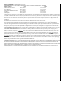 3
3
-
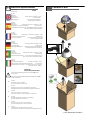 4
4
-
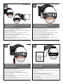 5
5
-
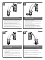 6
6
-
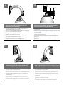 7
7
-
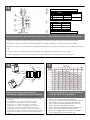 8
8
-
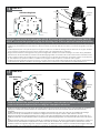 9
9
-
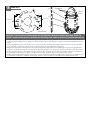 10
10
-
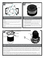 11
11
-
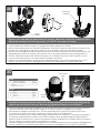 12
12
-
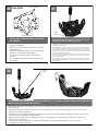 13
13
-
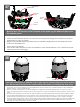 14
14
-
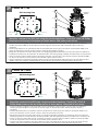 15
15
-
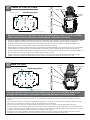 16
16
-
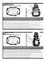 17
17
-
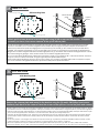 18
18
-
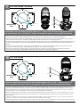 19
19
-
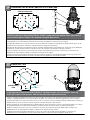 20
20
-
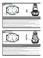 21
21
-
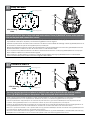 22
22
-
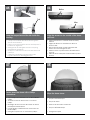 23
23
-
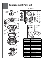 24
24
-
 25
25


Moog Videolarm FDP75C2N/AX Installation And Operation Instructions Manual
- Categoría
- Accesorios para cámaras de seguridad
- Tipo
- Installation And Operation Instructions Manual
- Este manual también es adecuado para
en otros idiomas
- italiano: Moog Videolarm FDP75C2N/AX
- English: Moog Videolarm FDP75C2N/AX
Artículos relacionados
-
Moog Videolarm SM75C12N Installation And Operation Instructions Manual
-
-
-
-
Moog Videolarm FDW75TF2N Installation And Operation Instructions Manual
-
-
-
-
-
Otros documentos
-
Axis 25735 Manual de usuario
-
Moog RHW75 SERIES Instrucciones de operación
-
-
-
Sony UMI-MDB3 Manual de usuario
-
Axis TownSquare 2555.050 Manual de usuario
-
-
Moog FusionDome PFDW75T2N Installation And Operation Instructions Manual
-
-