COMFORT-AIRE RAD-183A El manual del propietario
- Tipo
- El manual del propietario

MODELS: P_D-1i83A
iiiii_;_';;ii;ii;ii;ii;ii;ii;ii;_i;_i;_i;_i;_i;_i;_i;_i;_i;_i;_i;_i;_i;_i;_i;_i;;i_'_ii;_i;_i;_i;_i;_i;_i;_i;_i;_i;_i;_i;_i;_i;_i;_i;_i;_i;_i;_i;_i;_i;_i;_i;_i;_i;_i'¸_ _
9

FOR "fOUR RECORDS
Write the mode_ and serial numbers here:
Model #
Serial #
You can find them on a label on the side of each unit,
Dealer's Name
Date Pu_sed
m Staple your receipt to this page in the event you need
to p_ date of purcha_ or for warranty issues.
READ THiS MANUAL
inside you _11 find maw helpful hlnLs on how to u_ and
main_in your air conditioner prop,edy.Just a liWe prevenU_
_re on your part _n s_ you a groat deal of time and
money Mr _e I_ of your air conditioner.
You'll find many answersi to common problems in _e cha_
of troubleshooting tj_. If you _i_ our _art of
Troubleshooting Tips first, you may not n_ to _ll for
servi_ at all.
• Contact the authorized _r¢|ce technic_Jan_r repair
or maintenan_ of this unit, Call 1-877-755-7932to
locate _e nearest ASC.
• Contact the installer for installation of th_ unit.
• The air conditioner is not intended for u_ by young
children or irrcal_s without supervision,
• Young children should _ su_rvised to ensure that
they do not prelacywith the air conditioner.
• When the power cerd is. to be replaced, replacement
_rk shall be _rfermed by authorized personnel only
using only _nuine repla_ment parts.
• installation work mu_ be performed in acco_ance
with the National Ele_c _de by quailed and
authorized personnel only.
2 Room Air Conditioner

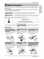
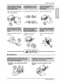
Safety Precautions
To prevent injury to the user or other people and property damage, the following instructions
must be followed.
II incorrect operation due to ignoring instruction will cause harm or damage. The seriousness
is classified by the fol!owing indications,
WAiRNIr-,IG This symbol indicates the possibility' of death or serious i_ury. "]
............... --I
[.& CAUTION Thissym_indicates the possibility of injury or damage to properties only...,J
[] Meanings of symbols used in this manual are as shown below.
[] Installation
WARNINQ
• Othe_isie, it may cause a fire
or electricaJ shock.
• it may cause failure and
electric sh_ck.
* Othent¢ise, it may cause a fire
or electrical shock.
* Itwill cause electric sh_k or fire
due to heat generation.
* Sharp edges may cause
injur_y.
• It may cause explosion or fire,
Owner's Manual 3

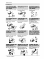
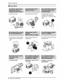
Safety Precautions
[] Operation
• There is danger of fire or electric
sh_k,
* It may cause fire and el_tric
sh_k.
• Jtwill cause electric shock or fire
due to heat generation,
° it will cause failure of machine or
electric sh_k.
• Otherwise, it may _use a fire
or electrical shock,
• The _pearance of the air
° Otherwise it may cause fire and
electric shock accident.
* An oxygen shortage may occur,
° Otherwise, it may"electrical
shock and failure.
conditioner may deteriorate,
change color, or develop surface
flaws.
• Since the fan rotates at high
speed during operation, it may
cause Injury
4 Room Air Conditioner
• Prevent accidental startup and
the possibility of injury:

Safety Precautions
, It will cause electric shock or fire • It will cause electric shock or fire, ,. It will cause electric sh_k
due to heat generation,
) S "-.,v
• It may cause electric shock and
damage.
- Othe_ise, Jtmay cause
explosion, and a fire.
CAUTION
[] Installation
• Otherwi_, it may cau_ dispute _th the
oThey are sharp and may cause
injury.
• _erwise, it may cause vibration or water
Owner's Manual 5

Safety Precautions
[] Operation
° It may cause injury: • it may Ruse product failure ° The appearance d the air
conditioner may deteriorate,
change color, or develop surface
flaws,
° It may cause an injury through
dropping of the unit or falling
down
• It may cause injury.
° Operation without filters will
cause failure,
• Otherwi_, it may do harm
your health,
, It contains containments and will
make you sick,
@
6 Room Air Conditioner
• _e_se, it may cause
personal injury.

Before Operation
1. Contact an installation specialist for installation.
2. Plug in the power plug properly.
3. Use a dedicated circuit.
4. Do not use an extension cord.
5. Do not start/st:op operation by plugging/unplugging the power cord.
6. If the cordlplug is damaged, replace it with only an authorized replacement
part.
i. Being exposed to direct airflow for an extended period of time could be
hazardous to your health. Do not expose occupants, pets, or plants to direct
ai_low for extended periods of time.
2. Due to the possibility of oxygen deficiency, ventilate the room when used
together with stoves or other heating devices.
3. Do not use this air conditioner for non-specified special purposes (e.g.
preseP¢ing precision devices, food, pets, plants, and art o_ects). Such usage
could damage the items.
1. Do not touch the metal parts of the unit when removing the filter. Injuries can
occur when handling sharp metal edges.
2. Do not use water to clean inside the air conditioner. Exposure to water can
destroy the insulation, leading to possible electric shock.
3. When cleaning the unit, first make sure that the power and breaker are turned
off. The fan rotates at a very high speed during operation. There is a
possibility of inju_ if the unit's power is accidentally triggered on while
cleaning inner parts of the unit.
For repair and maintenance, contact your authorized service dealer.
Owner's Manual 7

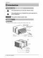
Introduction
This symbol ale,s you to the risk of electric shock,
This symbol ale,s you to hazards that could cause harm to
the air conditioner:
This symbol indicates special notes.
This appaianceshould be installedin a_ordance withthe National Electric Code
Vertical Air Deflector
(HorizontalLouver)
Horizon_ Air Deflector
(Ve_ica_Louver)
Air Discharge
Air Intake(InletGrille
Air Fi_ter RemoteController
Conden_r
Pan
Compressor
PowerCord
ControUBoard
Evaporator
8 Room Air Conditioner

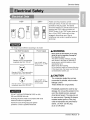
ElectricalSafety
115V_- 230V~
m
Power cord may include a current
interrupter device, A test and reset button is
provided on the plug case. The device
should be tested on a periodic basis by first
pressing the TEST bu_on and then the
RESET button if the TEST button does not
trip or if the RESET button will not stay
engaged, discontinue use of the air
conditioner and contact a qualified service
technician.
The shape may be different according to its model
Use Wall Receptacle Power Supply
S_a_ 12:5V,3_wiregrounding
receptacle rated 15A, 125V AC
Standard 250V_ 3-wire grounding
receptacle rated 15A 250V AC
Standard 250V 3wire grounding
receptacle rated 20A, 250V A©
Use 15 AMP, time
delay fuse or 15 AMP.
circuit breaker,
Use 20 AMP, time
delay fuse or" 20 AMP
c_rcuit breaker,
DO NOT USE AN EXTENSION CORD on 230,
20& and 230/208 Volt units
NI wiring should be made in accordance with local
electrical codes and regulations.
Aluminum house wiring may pose special
problem& Consult a qualified electrician,
Never push the test button on the plug
while the unit is operating .Damage to
the plug may result.
This d_ice contains chemical including
lead, known to the State of California to
_use cancer, and birth defects or other
reproductive harm,
Wash hands after handling.
Do not remove, modify or immerse this plug.
If this device trips, the cause must be found
corrected before further use,
The conductors insidethis cord are
surrounded by shields, whichmonitor
leakage current.
These shields are not grounded.
Periodically examine the cord for any
damage. Do not use this product in the
event _e shields become _posed,
Avoid sh_k hazard. The p,lugcan not
be user serviced, Opening the tamper
resistant sealed portion of _e plug
voids all warranties and performance
claims. DO NOT use the plug
as an on-off switch.
Owner's Manual 9

Electrical Safety
IMPORTANT
(PL_SF_ READ CAREFULLY)
FOR THE USER'S PERSONAL SAFETY, THIS
APPLIANCE MUST BE PROPERLY GROUNDED
The power cord of this appliance is equip_d with a
three-prong (grounding) plug. Use this with a standard
three-s_ot (grounding) wa_l power outlet to minimize the
hazard d electric shock. The customer should have
the wall receptacle and circuit checked by a qualified
electrician to make sure the receptacle is properly
grounded.
DO NOT CUT OR REMOVE THE THIRD (GROUND)
PRONG FROM THE POWER PLUG.
USE OF EXTENSION CORDS
Because of potentiaJ safety hazards, we strongly
discourage the use d an extension cord.
10 Room Air Conditioner

Installation
114Bubble
INSIDE
FOAM ...........
COOLED
AIR_
OUTSIDE FENCE
AWNING
HEAT
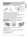
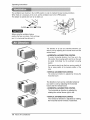
1,To avoid vibration and noise, make sure the unit is installed securely and firmly,
2. Install the unit where the sunlight does not shine directly on the unit.
if the unit receives direct sunlight, build an awning to shade the cabinet.
3, There should be no obstacle, like a fence, within 20'' which might restrict heat radiation from the condenser
4. To prevent reducing performance, install the unit so that louvers of the cabinet are not blocked.
5, Install the unit a little slanted so the back is slightly lower than the front (about 1/2"
or 1/4 bubble ), This will force condensed water to flow to the outside.
6, Install the unit with i_ bottom portion 30~60" above the floor level,
7. Stuff the foam between the top of the unit and the,wall to prevent air and insects from getting into the room,
8. The power cord must be connected to an independent circuit. The green wire must be grounded.
9. Connect the drain tube to the base pan hole in the rear side if you need to drain (consult a dealer.)
Plastic hose or equivalent may be connoted to the drain tube.
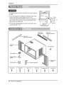
The grille is designed to clean the filter both upward and down_rd.
(a) (b) (c)
A. Before attaching the front grille to the cabinet, ff you want to pull out the filter upward;
1. Open the inlet grille slightly (a).
2_Turn inside out the front grille (a),
3, Disassemble the inlet grille from the front grille with separating the hinged part by inserting a straight type
screw-driver tip (b),
4. Then, rotate the inlet grille 180 degrees and insert the hooks into bottom holes of the front grille.
5. Insert the filter and attach the front grille to the cabinet.
B. ff you want to puff out the filter downward;
The grille is already designed that way.
Owner's Manual 11

Installation
All supporting parts should be secured to firm wood, masonry,
or metal.
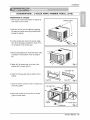
1_This unit is designed for installation in standard double hung
windows with actual opening widths from 29" to 41"
The top and bosom window sashes must open sufficiently to
allow a clear vertical opening of 18" from the bottom of the
upper sash [o the window sill.
2. The sill offset (height between the interior and exterior sills)
must be less than 1 1/4"_
29" to 41'_
18" min
Stooi
_.o_ Offset
Less
"_%,,.i' than1 '/4"
.o-" _Extedor
ilJ'i'
iiiiii iii k
Foam strip Foam-PE
(Plain-Back) (Adhesive-Backed)
Ty_ A (14) Type B (7) Type C(5) Type D (2) Carfia_ Bolt (2) L_k Nut (4)
12 Room Air Conditioner

Installation
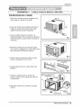
PREPARATIONOFCHASSIS
i. Remove the screws which fasten the cabinet at
both sides and at the back_
2 Slide the unit out:from the cabinet by gripping
the base pan handle and pulling forward while
bracing the cabinet.
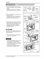
3. Cut the window sash seal to the proper length.
Peel off the backing and attach the Foam-PE to
the underside of the window sash.
Shipping screws
4. Remove the backing from Foam-PE with 3 holes
and attach it to the bo_orn of the Top retainer
bar.
5, Attach the Top retainer bar on the top of the
cabinet with 3 screws (Type A).
Fig. 2
6. Insert the Frame guides into the bottom of the
cabinet,
7 Insert the Frame Curtain into the Top retainer bar
and Frame guides.
8 Fasten the curtains to the unit with 10 screws
(Type A) at both sides,
Foarn-PE
Toprelier bar
Top retainer bar
Screw
(TypeA)
Screw(TypeA)
"Frameguide Fig. 4
Owner's Manual 13

Installation
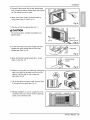
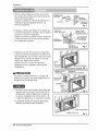
I. Open the window, Mark a line on the center of
the window stool between the side window stop
molding&
Loosely attach the siil bracket to the support
bracket using the carriage bolt and the look nut.
SJ]U
Bracket
Carriag
Bolt
(M-Screw)
nut
Fig, 5
2. Attach the sill bracket to the window sill using
the screws (Type B),
Carefully place the cabinet on the window sill
and aiign the center mark on the bottom front
with the center line marked window sill,
3. Using the M-screw and the lock nut, attach the
support bracket to the cabinet track hole, Use
the first track hole aRer the sill bracket on the
outer edge of the window sill. Tighten the
carriage bolt and the lock nut. Be sure the
cabinet slan_ outward,
,dkCAUTION
Do not drill a hole inthe bosom pan, The unit is
designed to operate with approximately 1/2" of
water in bottom pan.
4. Pull the boEom window sash down beNnd the
Top retainer bar until they meet.
1. Do not pull the window sash down so tightly
that the movement of Frame curtain is
restricted Attach the cabinet to the window
stool by driving the _rews (Type B) through
the cabinet: into window sill.
2.The cabinet should be installed with a very,
slight tiit downward toward the outside,
Outer edge
of window
sill
B)
Sill bracket
Fig, 6
retainer
bar
Windowstool
Frontangle Fig. 7
Window sash retainer bar
Frame curtain
Foam-PE
Fig. 8
FrontA_ie
Screw(TypeB) Fig, 9
14 Room Air Conditioner

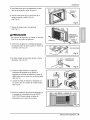
5. Pull each Frame curtain fully to each window sash
track, and pull the bottom window sash down behind
the Top retainer bar until it meets.
6, Attach each Frame curtain the window sash by
using screws (Type C,) (See Fig, 1O)
7, Sfide the unit into the cabinet.(See Fig. 11)
A CAUTION
For security purpose_ reinstall screws(Pype A) at
c_binet's sides.
8 Cut the Foam-strip to the proper length and insert
between the upper window sash and the lower
window sash.(See Fig. 12)
9, Attach the Window locking bracket with a screw
(Type C,) (See Fig, 13)
10 Attach the front grille to the cabinet by inserting the
tabs on the grille into the tabs on the front of the
cabinet Push the grille in until it snaps into
place.(See Fig.14)
11. Lift the inlet grille and secure it with a screw (Type
A) through the front grille.(See Fig. 14)
12 Window installation of room air conditioner is now
completed. See ELECTRICAL DA1Afor attaching
power cord to electrical outlet.
Installation
c_
Fig. 10
few
Power Cord
Fig. 11
Fig. i2
III..- wio wlowing 1
Fig. 13
_14
i5
Owner's Manual 15

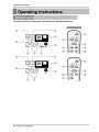
Operating Instructions
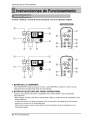
The mm,ote control and control panel will look like one,of the foflowing pictures.
Q ®
®
®
®
®
©
®
®
®
®
®
®
16 Room Air Conditioner

OperatingInstructions
1. POWER BUTTON
Toturn the air conditioner ON_push the button,Toturn the air conditioner OFE push the buttonagain
This button takes priority overany other buttons.
2. OPERATION MODE SELECTION BUTTON
Everytime you push this button_it will toggle COOL FANand DRY.
• Dry Mode: Please change to this mode when you want to use the room air unit as a dehumidifier.No cooling
will be performed during this time, but moisturewill be removedfrom the air similar to the function of a
dehumidifier.This function works best during those high humidity days whenthe temperature is not too hot.
3. ON/OFF TIMER BUTTON
Everytime you push this button, timer is set as follows.(1Hour _ 2Hours _ 3Hours -_ 4Hours ,e 5Hours
6Hours e 7Hours -) 8Hours ,e 9Hou_ e, lOHours ,e 11Hours -) 12Hours e Cancel}
4. FAN SPEED SELECTOR
Everytime you push this button, itis set as follows (Hi[ _3 ] _ Low[ f: I] _ Med[ F2 ] _ Hi[ 1:3]-)
5. ROOM TEMPERATURE SETTING BUTTON
This button can automatically control the temperature of the room, The temperature can be set withina range of
60°Fto 86°Fby l°R
Select the lower numberfor lowertemperature of the room.
6. AUTO SWING
This button can automati_lly control the air flowdirection_
7. ENERGY SAVER
The fan stops when the compressor stops _oling
Approximately every 3 munutes the hn will turn on and ched_the room air to determine if cooling is needed,
8. REMOCON SIGNAL RECEIVER
after an electrical power failure, the unit wilt begin to run at its last setting.
When the air conditioner has b_n _rform_ i_ cooling operation and is turned off or set to the fan
position,wait at least 3 minutes before resetting to the cooling o_ration _ain.
1, Remove the cover from the back of the remote
controller.
2. Insert two batteries.
• Be sure that the (+) and (-) directions are
correct,
° Be sure that both batteries are new.
3 Re-attach the cover,
• Do not use rechargeable batteries,
Such batteries differ from standard
dry cells in shape, dimensions, and
performance.
° Remove the batteries from the
remote controller if the air
_nditioner is not going to be used
for an extended length of time.
Owner's Manual 17

OperatingInstructions
The ventilation lever must be in the CLOSE position in order to maintain the best cooling conditions.
When fresh air is necessary in the room, set the ventilation ]everto the OPEN position.
The damper is opened and room air is drawn out
Before using the ventilation feature
positbn the lever as:shown. First, pull down
part _i_:_to horizontal line with part :'i:_).
Part
The direction of air can be controlled wherever you
want to coo] by adjusting the horizontal louver and the
vertical louver.
HORIZONTAL AIR-DIRECTION CONTROL
To control horizontal direction of air flow, set to the
ON position the air-swing switch and the air flow will
be _ept horizontally by the automatic air-swing
system.
Ifyou want to stop the air flow from moving, Twitch off
the air swing switch at the desired position of the
vane,
• VERTICAL AIR-DIRECTION CON_OL
The vertical air direction is adjusted by moving the
horizontal louver.
The direction of air can be controll_ wherever
you want to cool by adjusting the horizontal
louver and the vertical louver.
• HORIZONTAL AIR-DIRECTION CONTROL
The horizontal air direction is adjust_ by
rotating the vertical louver right or left.
° VERTICAL AIR-DIRECTION CONTROL
The vertical air dir_tion is adjusted by rotating
the horizontal louver forward or backward.
18 Room Air Conditioner

OperatingInstructions
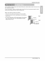
The air conditioner employs a proper drain method whereby the condensed water (moisture removed from the
air) is drained to the outside.
In very humid weather, excessive condensate water removed from the air may cause some water to collect,
A drain hole is provided at the rear of'the air conditioner unit
Select a drain method according to the following.
1_Remove the hole rubber from the base-pan, (for some models)
2. Connect a drain hose of 9t16" inside diameter to the drain pipe as
shown in Fig_1.
3. Or connect a pipe elbow of 9/16" inside diameter to the drain pipe,
then connect a drain hose of 9f16" inside diameter to the pipe
elbow as shown in Fig. 2.
Fig. 1
DRAINPIPE
HOSE
,__ L_, Fig, 2
/_ DRA_ PiPE
.......DRA ELBOW
F DRAIN HOSE
Owner's Manual 19

Maintenance and Service
TURN THE AIR CONDITIONER OFF AND REMOVE THE PLUG FROM THE POWER OUTLET,
The air filter should be checked at least twice a month to see if cleaning is necessary. Trapped particles in the
filter will build up and block the airflow:This reduces the cooling capacity and also causes an accumulation of
frost on the cooling coil&
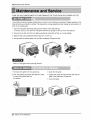
1. Open the inlet grille upward by pulling out:the bottom of the inlet grille.(a)
In another case, you can open the inlet grille downward by pulling out the top of the inlet grille,(b)
2, Remove the air filter from the front grille assembly by pulling the air filter up or down slightly,
3. Wash the filter using lukewarm water below 40°C (104°F).(c)
4 Gently shake the excess water from the filter completety, Replace the flitch
(a) (b) (c)
Mark b,of inlet grille means opening direction,
1. Pull down front grille from the cabinet top.
2. Push front grille's tips toward the cabinet in order
to insert front griile's tabs into
the cabinet
3. Open the inlet grille.
4. Tighten the _rew through the front grille into the
plate of the evaporator or base pan
5. Close inlet grille
20 Room Air Conditioner

MaintenanceandService
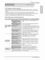
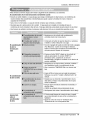
Bebre calling for service, please review the following list of common problems and solutions,
The air conditioner is operating normally when:
• You hear a pinging noise. This is caused by water being picked up by the condenser on rainy days or in
highly humid conditions, This feature is designed to help remove moisture in the air and improve cooling
efficiency_
° You hear the thermostat click, This is caused by'the compressor cycb starting and stopping,
°You see water dripping from the rear of the unit. Water may be collected in the base pan in highly humid
conditions or on rainy days. This water overflows and drips from the rear of the unit.
• "(ou hear the fan running while the compressor is silent This is a normal operational feature,
The air conditioner may be, operating abnormally when:
The air conditioner
does not operate
at all
Air conditioner
does not cool
Ice appears on the
air conditioner.
• Make sure the plug is completely plugged intothe
outlet
• Ch_k the fuse/circuit breaker box and replace the
fuse or reset the breaker
• Inthe event of a power failure, set the power control
to OFF (Mechani_l Type). When the power is restored,
wait 3 minutes to restart the air conditioner to prevent
the compressor from overloading
° Press the RESET button located on the power cord
plug. Ifthe RESET button will not st_ engaged,
discontinue use of the air conditioner and contact a
qualified service technician,
• Make sure there are no curtains, blinds, furniture or
other obstacles in front of the air conditioner
• Set the TEMP control to a lower number,
* Clean the filter at least ever:/2 weeks Refer to the
"Maintenance and Service" s_tion of the manual_
° After the air conditioner is turned on, you need to
give the air conditioner some time to cooi the room.
, Check for open furnace floor resisters and cold air
returns.
oCLOSE the air conditioner vent
• See ice appears on the air conditioner below
° Ice may block the air flow and obstruct the air
conditioner from properly cooling the room.
° Set the mode control at HIGH fan or high cool with
the high temperature.
Owner's Manual 21

,o
PARA SUS ARCHIVOS
Escriba aquf el mode]o y nQmero de serie:
Modelo n °:
Serie n°:
Puede encont:rar estos datos en la etiqueta situada en el
lateral de cada unJdad,
Nombre del distri_idor:
Fecha de _mpra:
= Adjunte su reci_ a esta p_g[na con [a grapadora para
el momento que }o necesite para probar Jafecha de su
adquisic[6n o para la validaci6n de ]a garant[a
LEA ESTE MANUAL
En su interior encont_r_, muchos _nsejos Qti]es sobre ]a
utiiizacJ6n y manten[miento de su acondJcionador de aire,
Unos pocos cuidados _r su parte le pueden ahorrar
mucho tiempo y dinero durante la vJda de su
acondicJonador de aire
En ia tabia de _nsejos para la soluci6n r_,pida de
proMemas encontrar_ muchas respues_s a los problemas
mas habituales, Si revisa prJmero nuestra Tabla de
Consejos _ra ]a soluci6n rapida de problemas, ta[ vez no
necesite I_amar nunca a_servicio t_nico
* Contacte a un Centro de _rvicio Autorizado para reparar
o realizar el mantenimiento de esta unidad, Llame a
i-877-75_7932 para ubicar el CSA mas cercano,
oP6ngase en contacto con un insta|ador para realizar
la instalaci6n de esta unidad.
- Cuando se va a cambiar el cable el6ctrico, el trabajo
de reemplazamiento debe ser realizado _micamente
por personal autoti_do, utilizando las pie_s de
cambio genuinas _nicamente.
oE,Itrsbajo de reemplazamiento de_ _r realizado de
acuerdo con el C6digo EI6ctrico Nacional
_nicamente pot personal autorizado.
22 Aire Acondicionador

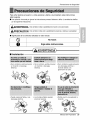
PrecaucionesdeSeguridad
Para evitar lesiones al usuario o a otras personas y daSos a la propiedad, estas instrucciones
esten seguirse.
| Unaoperacionincorrectapor[gnorar]asinstruccionesprovocarales[oneso daSos.Laseriedadseclasifi_
potlass[guJentes[ndicacione&
I_ADVERTENCIA Estesimbolo indicaJaposibiHdaddemuerteo deseria ]esi6n. ]
-._
1!
[.,_ PRECAUCION Estesimbolo indicas01ola posibilidadde lesioneso dares a la propiedad J
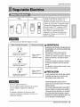
[] Significados de los simbobs utilizados en este manual
®, t °o ace . 1
Siga estas instrucciones.
.............................................................................. j
ml Instalaci6n
• De Io contrado, podfia provocar
un incendio o descarga
el6ctfica.
• De [o contrario, podrla provocar
un incendio o descarga
el6ctr[ca.
o,De lo contrario, puede provocar
una descarga e]_ctrica o
incendio debido a [a
generaci6n de ca]or.
• Puede ocas[onar fallos y una
descarga electrica
• Los bordes afilados pueden
provocar lesiones,
• Podrfa ocurrir una explosi6n o
incendio
®
Manual del Propietario
23

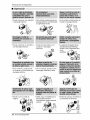
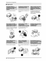
Precauciones de Seguridad
I Operaci6n
• Puede ocasionar una explosi6n
o descarga el6ctdca.
• De locontrario,puedeprc_,ocaruna • De Io contrario, p_rla provocar un
descargael_ctricao incendiodebJdo incendio o des_rga el_ctrica.
a la generaci6nde calor.
° Puede ocasionar un incendio y
una descarga el_ctrica
° De Io contrario, puede ocurrir
• Puede provocar fallos en el
producto o descargas
el_ctdcas.
• La apadenciadel aparatode aire
acondicionadopu_e deteriorar,
cambiarel coloro desarrollarflujos
en las
supedicies.
un incendio y un accidente por
descarga el6ctrica.
• Puede ocurdr un falta de
oxfgeno.
• De Io contrario, pueden ocurrir
descargas elect:ricas y faHos.
• DebJdoa que el ventilador gira a
alta velocidad durante el
funcionamiento, podrfa ocasionar
lesiones.
24 Aire Acondicionador
, Evitar_. el arranque accidental y
la posibNidad de lesiones.

Precauciones de Seguridad
• De Io contrado, puede provocar
una descarga el_ctrica o
incendio debido a la
generaci6n de calor.
• Puede causar descarga
el6ctrica y daSos.
• ProvocarA descargas el_ctricas
o incendios,
• Provocar_. descargas
el_ctricas_
• De [o contrario, podrfa ocurrir
una explosi6n o incendio.
• Son puntiagudas y pueden
provocar Uesiones.
II Instalaci6n
ADVERTENCI/ )
° De Io contrario puede dar lugar a disputas
vecinales.
• De Io contrario se podrfa causar vibraciones o
escapes de agua,
Manual del Propietario 25

PrecaucionesdeSeguridad
[] Operaci6n
- Podr/a ocasionar lesiones • Puede causar una averfa en el
aparato
- La aparienciadel aparatode aire
acondicionadopu_e deteriorar
cambiarel coDr o desarrollarflujos
en lassuperficies
* Puede lesionarse al caerse del
aparato o al caerse los objetos
que haya colocado
• Podrfa ocasionar lesiones
• El funcionamiento sin filtros
puede provocar fallos,
• De Io contrario podr[a da_ar su
saDd,
26 Aire Acondicionador
• De Io contrario, podrlan ocurrir
lesiones personales

Antes de poner el equipo en funcionamiento
z z
1. P6ngase en contacto con un especialista para realizar la instalaci6n.
2. Enchufe correctamente la toma de alimentaci6n.
3. Utilice un circuito dedicado.
4. No utilice un cable alargador.
5. No inicie/cese el funcionamiento enchufando/desenchufando el cable
electrico.
6. Si el cableienchufe esta daffado, sustit0yalo solo por una pieza autorizada.
1. Estando expuesto a la circulaci6n directa de aire durante un extenso perfodo
de tiempo podrfa resultar peligroso para su salud. No exponga alas personas,
animales dom4sticos, o alas plantas a la circulaci6n de aire durante largos
perfodos de tiempo.
2. Debido a la probabilidad de falta de oxfgeno, ventile el cuarto cuando est4
utilizado el aparato junto con estufas u otros aparatos de calefacci6n.
3. No utilice este aire acondicionado con prop6sitos especiales no especificados
(Ej.: consewaci6n de dispositivos de precisi6n, comida, animales dom4sticos,
plantas y objetos de arte). Tal uso podrfa daffar los artfculos.
1. No toque las piezas metAlicas de la unidad al retirar el filtro. Manejar aristas
afiladas de metal puede causar lesiones.
2. No utilice el agua para limpiar el interior del aire acondicionado. La exposici6n
a[ agua puede destruir el aislamiento, conduciendo a posibles descargas
electricas.
3. AI limpiar la unidad, aseg0rese antes de que la electricidad y el interruptor
esta.n apagados. El ventilador rota a muy alta velocidad durante el
funcionamiento del equipo. Existe la posibilidad de iesiones si acciona
accidentalmente la electricidad de la unidad mientras limpia el interior de la
unidad.
Para cuestiones de reparaci6n y mantenimiento, p6ngase en contacto con su
distribuidor de servicio autorizado.
Manual del Propietario 27

IntroducciSn
i i
Este simbolo Io adviede de un _ligro de accidente por
corriente el_ctrica.
Este simbolo 1o adiverte de un peligro que pueda causar un
da_o del ventliador,
Este simbolo significa condicciones es_ciales.
Este aparato deberla instalarse de acuerdo con ias normas del C6digo Ei6ctrico Nacional,
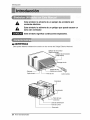
Deflectordeaireve_cal
(RejiHahonzontai)
Deflectordeairehorizon_J
(Rejillaverti_i}
Descarga de aire
Gabinete
RejiHaffontai--
Entrada de aire
_{Re]illa para entrada)
--Filtro de aire Co_rol rernoto
Abrazadera
Condensador
--Compresor
C_le _ _imentacion
Pare1de control
Evaporador
28 Aire Acondicionador

SeguraidaElectrica
115V~ 230V~
= =
El cable de aaimentaci6n puede incUuirun
dispositivo interruptor de corfiente La
carcasa de1enchufe cuenta con un bot6n de
prueba y otto de reinicio, El dispositivo debe
comprobarse peri6dicamente presionando
pfimero el bot6n TEST y despu6s RESET
Si ei bot6n TEST no se descon_ta o si el
bot6n RESET no perman_e activo,
suspenda el uso del aire acondicionado y
p6ngase en contacto con un t6cnico de
servicio cualificado,
La forma puede s.er diferente segQn su modelo.
Utilice el enchufe de la pared Consumo de Energ/a
St_dard 125V, enchufe de 3
Lineas de 15A_125V AC
Stan_rd 250V, er_ch_e de 3
Lfneas de 15A_ 250V AC
Utilice un fusib_ de
15AMP o un
Interrupter de 15AMP,
Utilice un fusib_ de
20AMP. o un
Interruptor de 20AMP,
Standard 250V, enchufe de 3
Linens de 2OA, 250V AC
No use un cable de extension.
Todo el cableado deber_, realizarse de acuerdo
con los c6digos y reglamentos el6ctricos
Iocales.
El cableado dom6stico de aluminio podrla
ocasionar problemas especiale& Consulte aun
electricista calificado.
Nopresionenuncaelbot6n de pruebaduranteel
funcionamiento,deIocontrarioelenchufe_dria
resultar daS_o.
Estedispositivocontie_ productosqu/mi_s,
incluyendopl_o, conocidoeneiestado
California_o productocanceriger#ycau_nte de
defectos@nacimientoy otrosdaScLsal sis_ema
reproductor.
LAve_ bienInsman_ trasmanipulareldisposRivo
No@smonte,m_ifique ni surnedaenaguaeste
end_ufe.
Siei disp_Hivoseactivara,deberacorregirla_usa
antesdev@er a utilizarl&
L_ hil_ conductor_d_trodelcable_tan r_eados
potblindajes,quesu_r¢isanlacordente@fu_.
Estosblindajesnoestanpue_osatJerra.
Examine_rbdicamenteelc_bleenbuscade
c_lquierdaSo.Noutiliceestepro@ctosilos_indajes
resulta_anexpuestos,
Ev_eelriesgodedes_rgasel_as; estaun_adno
puedesetreparadapotelusuariopotsetres_tentey
ap_ue_'Adealteracbnes.M_ipularlaporcion_llada
delaun_adanularatodaslasgaranfiasyquejasde
ren@iento.Estaunidadno_ta diseSadaparasuuso
comouninter[upto_deen_ndido-a_gado.
Manual del Propietario 29

SeguraidaElectrica
IMPORTANTE
(FAVORL_ CON ATENCION)
POR LASEGURIDADPERSONALDEL USUARIO,
ESTEAPARATODEBESERDEBIDAMENTE
NEUTRALIZADO.
El cord6n de energia de 6ste aparato es_
equipado con tres patas(_He a tierra). Utilice
6ste con un enchufe de pared de tres salidas(a
tierra) para minimizar el peligro, de choque
el6ctrico. El cliente debe revisar el receptor de
pared y el circJJito pot un electricista calificado
para asegurarse que la recepci6n esta
debidamente neutralizada.
NO CORTE 0 REMUEVA _ TERCERA
PATA(GROUND) DEL ENCHUFE
USO DE EXTENSIONES
Debido al peligro potencial, no recomendamos
la utilizaci6n de extensiones.
30 Aire Acondicionador

Instalacion
TOLDO
BARDA
FOAM ........
1/4 AmpoHa RADIACION
NR DE CALOR
ENFR_
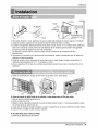
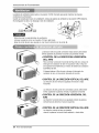
1. Para evitar vibraci6n y ruido, aseflJrese de que la unidad est_ instalada de manera segura y firmemente.
2. Instale la unidad en lugares fuera de luzsoiar directa dir_tamente sobre la unidad.
3. El exterior de1gabinete deber_ extenderse hacia afuera cuando menos 10" y no deben existir obstAculos,
tales como una barda o pared, dentro de una distancia de 20" desde la pparte posterior del gabinet:e
porque esto evitarA Ia radiaci6n de calor del oondensador
La restricci6n del aire exterior reducirA en gran manera la eficiencia de enfriamiento det aire
acondidonado.
4. Para prevenir la reduccidn de la eficiencia del funcionamiento, instale la unidad para que las rejillas del
cabinete no sean bloqueados
5. Instaie la unidad un poco obliouamente hacia afuera para no dejar escapar el agua condensado a la
habitaci6n (aproximadamente 1/2" o 1/4 ampolla con nivel).
6. Llene la espuma entre el tope de Ia unidad y la pared para prevenir que el aire e insectos entren en Ia
habitaci6n.
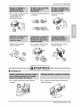
La rejilla es diseRada para limpiar el filtro tanto hacia arriba como hacia abajo.
®
(a) (b) (c)
A. Antes de Instalar la rejilla frontal en el cabinete, si usted deseasacar el filtro por arriba;
1. Abra la rejilla de entrada ligeramente (a).
2_Vuelte la rejilla frontal (a)
3. Separe la parte engoznada insertando la punta del destornillador de tipo "-" para desensamblar la rejilla
de entrada desde la rejilla frontal. (b).
4. Luego, gire la rejilla de entrada 180 grados e inserte los ganchos en los huecos inferiores del rijilla frontal.
5. Inserte el filtro e instale la rejilla frontal al cabinete.
B, Si usted desea sacar el filtro pot abajo;
La rejilla es ya diseSada para tal manera.
Manual del Propietario 31

Instalacion
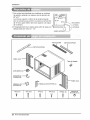
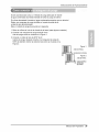
1, Esta unidad estA diseRada para instaJarse en ventanas
de guillothla estAndar con espesor real de abertura de
29" a 41%
Los marcos superior e inferior de la ventana dever_n
abdr Io suficiente para permitir una abertura vertical libre
de 18" de la parte inferior deg marco, superior a Jarepisa
de la ventana.
2, El desplazamiento de la repisa (altura entre la repisa y el
alf_izar) debe ser menor a 1 1/4".
PARED
REP_SA
TIPOA(14) TIPO B (7) TIPO(5) TIPO D(2)
Y
PERNO (2)
TUERCA DE
SEGURIDAD (4)
32 Aire Acondicionador

Instaladon
DESARMADOR (+,), REGLA, CUCHILLO, MARTILO, LAPIZ, NIVEL
PREPARAOION DEL CHASIS
1. Retire Uos4 tornillos que unen el gabinete a la
parte posterior y lateral de la unidad,
2, Deslice la unidad fuera del gabiete tomando la
manija de la charola de la base y jaUehacia
adelante mi_ntras sostiene el gabinete,
3, Corte el seWode chasis de la ventana a la
longitud apropiada, PeJeel resfuerzo y apiique Ia
Cinta de Espuma a la parte inferior del chais de
la ventana.
Fig, 1
,! I,H,HW
4, Remueva el refuerzo de la Cinta de Espuma
con 3 huecos y agr_guelo en la parte inferior det
tope de ia barra de Retencion Superior.
5, Sujete la barra de retenci6n superior al iado
superior del gabinete con los 3 torni.
6. Inserta la guia marco en la parte inferior del
gabinete,
Fig. 2
BARRA DE RETENCION
SUPERIOR
Espuma Fig, 3
7, Inserte los paneles gulas en la barra de
retencion superior yen la guia marco del aire
acondicionado.
8. Sujete las cortinas de la unidad con tornillos
(Tipo A),
BARRA DE RETENCION
SUPERIOR
TORNILLO
(T_POA) rORNILLO
(TIPOA)
Manual del Propietario 33

Instalacion
1, Abra la ventana Marque una I¢neaen el centro
de Jarepisa de la ventana entre las molduras de
tope de la ventana lateral.
Coloque sin apretar la m_nsula del alf_izar en la
m6nsula de soporte utilizando el pemoy la
tuerca de segutidad,
MENSULADEL
ALFEI_R
BULON
!NSULA
DESOPORTE
DE
SEGUR_DA
Fig. 5
2_Coloque la m_nsula del alf_izar en e! alf@zar de
la ventana utilizando los tornillos (Tipo B), Apriete
el perno y la tuerca de seguridad.
Repisa de la ventana y alinee la marca central en
el frente del rondo con la h'nea centrai marcada
en la repisa de la ventana,
ORIFIC/ODE
TORNILLOPARA
METALES(TiPOD)Y
TUERCADESEGURIDA
_--"'_ TORNILLO(TIPOB)
MEN_ULA
DEL ALFEIZAR Fig. 6
3_Utilizando el tornillo M y la tuerca de seguridad,
coloque la m6nsuia de soporte en el odficio de la
gu_a del gabinete, Use ei primer orificio de la gu/a
despu_s de la m_nsula del alf_zar en el borde
exterior del alf_izar de la ventana.
Apdete el perno y la tuerca de seguridad
Aseg8rese de que el gabinete est6 inclinado
hacia afuera,
No pedore la charola del fondo, La unidad estA
diseSada para operar con aproximadamente 1/2"
de agua en la charoia del rondo.
1. No hale el marco de la ventana hacia abajo tan
apretado que se restrinja el movimiento de los
desiizadores, Sujete el gabinete a ia repisa de
la ventana insstalando los tornillos (tipo A o B)
a trav6s del gabinete en la repisa de la ventana,
2. El gabinete deberA ser instalado ligeramente
inclinado hacia abajo hacia el exterior
SUPERIOR
MARCODE
REPBADEVENTN/A
INTERIORFig, 7
BARRADE
RETENCIONSUPEREOR
CINTADE-J
ESPUMA
GABINETE
PANEL
GUIA
CINTA DE
ESPUMA Fig, 8
ParteFrontalInterior
TORNILLO(TIPOB) Fig, 9
34 Aire Acondicionador

5. Hale cada panel gu[a completamente a cada
Jadode la ventana y repita del paso 2.
6. Adjunte cada panel gufa a cada lado de Ia
ventana usando tornillos (Tipo C)_
(Ver Rg,10)
7. Deslice eI chasfs dentro deJgabinete.
(Vet FJg.11)
APRECAUCION
Por razones de seguddad, re instale los tornillos
(Tipo A) en los lados deJ gabinete
8. Corte la tira de goma a la medida apropiada e
introd[3zcala entre la parte superior e inferior de
Javentana. (Ver Fig. 12)
TORNILLO
Instaladon
TORNJLLO
c)
Fig, 10
CORDON DE
AUMENTACION
ELETRICA
9. Se debe Jnstalar el asa antes de fijar el frente
decorativo. (Vet Fig. 13)
10. ln_ale la rqilla frontal en el cabinete
insertando la lengOeta en la rejilla a la
lengOeta en eJfrente deJcabinete. Empuje la
rejilla hasta que se cierre con sonido de golpe.
(Ver Fig. 14)
11, Levante la rejilla de entrada y aseg8rela con
un tornillo (tJpoA) a trav6s de la reiilla frontal,
(Vet Fig.!4)
...,,_/j__ SOPORTE DE
CERRADURA
__% Fig. 13
i4
12. Ahora la insta[aci6n de[ aire acondicionado en
la ventana es completada, Vea los DATOS
ELECTRiCOS para instalar el cable de
alimentaci6n en la toma de corriente,
15
Manual del Propietario 35

Instruccionnes de Funcionamiento
El mando a distancia y et panel de control se parecer_n a los de las siguientes im#gene&
Q ®
®
O
®
®
1. BOTON DE LA CORRIENTE
Para ENCENDER el sistema presione el bot6n_ y para APAGARLO presione el bot6n otra vez
Este bot6n tiene pnoridad sobre todos los otros botones.
2. BOTON DE SELEOOION DEL MODO OPERAC!ONAL
Cada vez que presione este bot6n, las palabras FR[O, VENTILADOR y SECO apareceran
altemadamente.
• Modo secado: Cambie a este modo cuando desee utilizar la unidad de aire de la habitaci6n como
desh umidificador_
Durante este tiempo no habr_ enfriamiento, pero se eliminar_ la humedad del aire de manera
parecida a la funcidn de un deshumidificador.
Esta funcidn funciona mejor en esos d_asde mucha humedad cuando la temperatura no es
demasiado elevada,
36 Aire Acondicionador

InstruccionnesdeFuncionamiento
3. BOTON ON/OFF TIMER
Cada vez que presione este bot6n, el marcador de tiempo se ajustar_ de la siguiente manera:
(1Hora -) 2 Horas -->3 Horas -) 4 Horas _ 5 Horas -e 6 Horas _ 7 Horas -.> 8 Horas _ 9 Horas -_
10 Horas _ I1 Horas _ 12 Horas _ Cancelar).
4. SELECTOR DE LA VELOCIDAD DEL VENTILADOR
Cada vez que presione este bot6n, el ajuste es como sigue.
(Alto[ F3 ] -'> Bajo[ F I ] "> Medio[ F2 ] _ Alto[ F3 ]_.)
5, BOTON DE SELECCION DE LA TEMPERATURA DE LA HABITACION
Este bot6n puede controlar la temperatura del cuarto autom_ticamente. La temperatura se puede
ajustar de grado en grado, desde 60°F hasta 86°F cada I°R
Seleccione el nOmero m_.s bajo para la temperatura m_ts baja en el cuarto_
6, AUTOGIRO
Este bot6n puede controlar autom_.flcament la direcci6n de1fiujo de aire.
7. AHORRADOR DE ENERG|A
El ventilador se detiene cuando el compre_or no sigue enfriando
Aproximadamente cada 3 minutos el ventilador se encenderA, y necesitarA verificar la temperatura
del cuarto para saber si es necesario mAs enfriamiento.
8, RECEPTOR DE SE[_IAL
Cuando se mstabtezca la afimentacidn despu6s de un corte en et suministro, ta unidad empezarb a
funcionar con su _ftimo ajuste.
APRECAUClON
Cuandoel aireacondicionadoha estadooperandobajola fasedeenfriaraientoy se apaga,oseajustala posicionde
ventilacion0espere_r Iomenos3 miautos,antes de reiniciar laoperaci6nde_friami_to.
1. Quite la tapa de Ia parte posterior del
telemando. Para ello haga deslizar la tapa
segt_n la direcci6n della flecha.
2 Introduzca las dos baterfas, asegurAndose de
que las direcciones (+) y (-} est6n colo_das
correctament. Use baterfas nuevas.
3i Volver a cerrar,i resbalando la tapa hasta la
posici6n inicial.
No utilice batefis recargables,
estas son diferentes de forma,
de dimensi6n y uso respecto a
las baterfas secas usuales.
Seque las bater_'as del
telemando cuando el
acondicionador no vaya a ser
usado durante un largo
perlodo.
Manual del Propietario 37

lnstru_,ionnes de Funcionamiento
La palanca de ventilaci6n deberA estar en la posicJ6nCLOSE (Cerrado) para poder mantener las mejores
_ndiciones de enfriamiento.
C:uandose necesite aire fresco en la habJtaci6n,cobque la paJancade ventilacidn en raposJcJdnOPEN (Abierto).
El amortiguador se abre y se descarga el aire de la h_itaci6n ,, , PaR
cEn_:_ARVENTILAC_ONABR_r_ I jjL _
Part@
Antes de usar la caracteffstica de ventilaci6n,
coloque la palanca como se muestra. Primero jale hacia
abajo la parte @ para que quede en una Ifnea horizontal con la parte ®.
La dire_i6n del aire puede controlarse hacia donde usted desee
enfriar ajustando la persiana horizontal y la persiana vertical
° CONTROL DE LA DIRECClON HORIZONTAL
DEL AIRE
Para controlar la dire_i6n horizontal del flujo del aJre,coloque el
interruptor de oscilacidn de aire en la posicidn ON y el fiujo de
aire soplara horizontalmente pot medic del sistema de oscilaci6n
automatica de aire.
Si desea detener el fluio de aire, coloque el interruptor de
oscilaoJ6nde aire en la posici6n deseada de la aleta.
• CONTROL DE LA DiRECCION VERTICAL DEL AIRE
La d[recci6n de aire vertical es ajustada moviendo la rejila
horizontai.
La direcci6n del aJrepuede ser _ntrotada cuando usted desee
enfriar, aiustando la palanca vertical y la palanca horiziontal.
,,CONTROL DE LA DIRECCION HORIZONTAL DEL
La direcci6n horizontal del aire es ajustada rotando la palanca
vertical hacia la derecha o hacia la izquierda.
• CONTROL DE LA DIRECCION VERTICAL DEL AIRE
La direcci6n vertical del aire es ajustada
rotando la palanca horizontal hacJa adelanto o hacia atr_s_
38 Aire Acondicionador

InstruccionnesdeFuncionamiento
El aire a_ndicionado ut[Hza un m6todo de purga adecuado en donde
el agua _ndensada (humedad retirada de] aire) se purga a] exterior:
En dimas demasiado h_medos e] agua condensada excesiva que se retira del.
Existe una manguera de purga incMda en [a parte de atr&s de ]a
unidad de aire acondicionado,
Elija un m6todo de purga de acuerdo a Io siguJente,
1. Retire el orificio de hu]e de la charoMade la base. (para algunos m_de]os).
2. Conecte una manguera de purga de 9/16" de di
tubo de purga como se muestra en ]a Figura 1.
3. Conecte un codo de tu_ de 9/16" de di
tuberla de purga, despu6s conecte una manguera de purga de
9/16" de di_metro interior al c_o de tubo como se muestra en la
Figura 2.
DE PURGA
Manual del Propietario 39

Cuidadoy Mantenimiento
APAGUE EL AIRE ACONDICIONADO Y SAQUE EL ENCHUFE DEL TOMA CORRIEIVTE DE LA PARED.
EEfiltro de aire deverA revisarse cuando menos dos veces aJmes para vertioficar si es necesario
limpiado. Las parficuJas atrapadas en el filtro poddan acumularse y bloquear el fiujo de aire. Esto
reduce la capacidad de enfdamiento y tambi_n ocasiona la acumulaci6n de escarcha en ios
serpentines de enfriamiento
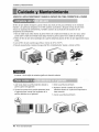
1. Abra la reiilla hacia arriba tirando la parte inferior de la reiilla de entrada (a). En otto caso, usted
puede abrir la rejilla de entrada hacia abajo tirando Ia parte superior de Ia rejilla de entrada.(b)
2 Retire el filtro de aire del ensamblaie de la parrilla delantera jalando el filtro de aire ligeramente hacia
arriba
3. Lave el filtro de aire usando agua tibia a menos de 40°C (104°F).
4. Sacuda suavemente el exceso de agua del filtro completamente. Vuelva a colocar el filtro.
(a) (b) (c)
La marca A de la rejilla de entrada significa la direcci6n abierta.
1. Jale hacia abajo la parrilla delantera desde la
parte superior del gabinete.
2_Optima las puntas de la parrilla delantera hacia
el gabinete para insertar las lengQetas de la
parrilla delantera en el gabinete.
3. Abra la parrNla de admisi6n.
4. Apriete el tornillo a traves de la parrNla
delantera dentro en la placa de evaporador o
base cacerola.
5. Cierre la parrilla de admisi6n.
40 Aire Acondicionador

Cuidado y Mantenimiento
Antes de llamar al servicio,tenga a bien revi_r ]asiguientelis_ de problemasy sus _luciones.
E! acondicionadordeaim es_ funcionandonormalmentecuando:
. Escuchaun _nido met_lico.Lo cau_ el agua querecogeel condensadoren dias Iluviososo en condicionesde
muchahumedad.Es_ _racteflsti_ est_ diseSadapara ayudara quitarla hum_ad en el aire y mejorarla
_paci_d de enfdamiento.
• Oyeun clic einel termostato.Lo cau_ el ciclo de]compresorqueicomienzay sedetiene.
•Ve gotearaguade ]a porteposterior de [aunidad. Elagua pu_e set recogidaen[a bandejade baseen
condicionesde muchahum_ad odfas de lluvia. Estaagua des_rda y goteadesde la parte posteriorde la unidad.
° Oyefuncionarel ventiladormient[asel compre_r est_ silencioso.Estoes una _ractertstica o_rativa normal,
• Aseg5rese que el enchufe est&comp]etamente
enchdado dentro del tomacorr[ente
El acondicionador
de aire no
funciona _ra
rta_
El acondicionador
de aire noenfria
Apar_ hielo
sobreel
acondicionador
de airea
Compruebe el fusible/la caia del disyunbr y reemplace
el fusible o vue]va el disyuntor a su lugar;
Si ocurr el apag6n,d_ vuelta al control del modo a apagado
(Tipo Mecanico). Cuando es la energ[a se restaura,
espera 3 minutos para re_menzar el acond[cionadorde
aire pare prevenir disparar de]compresor.
Presione el bot6n RESET s[tuado en el enchufe del
cable de alimentaci6noSi el bot6n RESET no
permanece activo, suspenda el uso del aire
acondicionado y p6ngase en contacto con un t6cnico de
servicio cualificado,
° Aseg_rese que no haya corflnas, persianas, muebles u
otros obstAculosfrente al acondic_onadorde aire
° Gire el control de TEMPERATURA a un nt_merom_s
ba}o.
• Limpie el fiitro al menos una vez _da dos semanas.
Refierasea ia seccibn "Cui_do y Mantenimiento"del
manual.
• Despu6sque se enciende el acondicionador de aire,
debe _rle un tiempo al acondicionador de aire para
enffiar la habitaci6n
° Busquea[guna hornalla de resistencia encendida y el
aire fr[o vuelve.
° C[ERRE la ventilaci6n del acondic[onader de aire
• Vea Aparece hieio sobre el acondicionador de aire abajo
• El hielo puede bloquear la corriente de ere e impedir
que el acond[donador de aire enfrfe correctamente la
habitaci6n.
° Ajustar el control de modo en _Ventilaci6nalW o
'Effriamiento alto' con la temperatura alta.
Manual del Propietario 41

Nota
42 Aire Acondicionador

Specifications and performance data subject to change without notice.
HEAT CONTROLLER, INC.
1900 WELLWORTH AVENUE • JACKSON, MICHIGAN 49203
THE QUALITY LEADER IN CONDITIONING AIR
P/No: 3828A20800M Printed in China
-
 1
1
-
 2
2
-
 3
3
-
 4
4
-
 5
5
-
 6
6
-
 7
7
-
 8
8
-
 9
9
-
 10
10
-
 11
11
-
 12
12
-
 13
13
-
 14
14
-
 15
15
-
 16
16
-
 17
17
-
 18
18
-
 19
19
-
 20
20
-
 21
21
-
 22
22
-
 23
23
-
 24
24
-
 25
25
-
 26
26
-
 27
27
-
 28
28
-
 29
29
-
 30
30
-
 31
31
-
 32
32
-
 33
33
-
 34
34
-
 35
35
-
 36
36
-
 37
37
-
 38
38
-
 39
39
-
 40
40
-
 41
41
-
 42
42
-
 43
43


COMFORT-AIRE RAD-183A El manual del propietario
- Tipo
- El manual del propietario
en otros idiomas
- English: COMFORT-AIRE RAD-183A Owner's manual
Artículos relacionados
Otros documentos
-
LG LW2512ER El manual del propietario
-
Panasonic HQ-2243TH Manual de usuario
-
Goldstar WG1805R El manual del propietario
-
-
Quasar HQ-2244UH Manual de usuario
-
-
LG BG8000ER El manual del propietario
-
-
LG LW2410HR El manual del propietario
-
LG LW1812HR El manual del propietario