
ww_ .goldsgir applianc cs_com
OWNER'S MANUAL
MANUAL DEL PROPIETARIO
Models/Modelo WG ! 805R,WG2405R
para el future

,o
FOR YOUR RECORDS
Write the model and serial numbers here:
Model #
Serial #
You can find them on a label on the side of each unit,
Dealer's Name
D_e Purchased
Staple your receipt to this page in the event you need it:
to prove date of purchase or for warranty issues.
READ THiS MANUAL
Inside you will find many helpful hints on how to use and
maintain your air conditioner properly. Just a little preventive
care on your part can save you a great dea_ of time and
money over the life of your air conditioner.
You'll find many answers to common problems in the chart
of troubleshooting tips If you review our chart of
Troubleshooting Tips first, you may not need to call for
service at aH_
PRECAUTION
• Contact the authorized service technician for repair
or maintenance of this un_.
• Contact the installer for installation of this unit.
• The air conditioner is not intended for use by young
children or invalids w_ho_ supervision,,
-Young children should _ supervised to ensure that
they do not play"with the air conditioner.
• When the power cord is to _ replaced, replacement
work shah be performed by authorized personnel only
using only genuine replacement pans.
• installation work must _ performed in accordance
w_h the National Electric Code by qualified and
authorized personnel only.
2 Room Air Conditioner

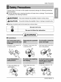
SafetyPrecautions
To prevent injury to the user or other people and proper_ damage, the following instructions
must be followed,
m Incorrect operation due to ignoring instruction will cause harm or damage, The seriousness
is classified by the fol!owing indications,
This symbol indicates the possibility of death or serious injury: J
J
This sym_l indicates the possibility of injury or damage to properties only.
[] Meanings of sym_ls used in this manual are as shown below.
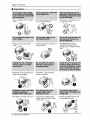
[] Installation
* Othe_ise, it may cause a fire
or electrica( shock.
• it may cause failure and
electric sh_k.
* Otherwise, it may cause a fire
or electrical shock.
* It wilt cause electric sh_k or fire
due to heat generation.
* Sharp edges may cause
injury.
• It may cause explosion or fire.
®
Owner_ Manual 3

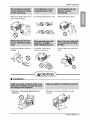
SafetyPrecautions
[] Operation
• There is danger of fire or electric
sh_k,
* It may cause fire and el_tric
sh_k,
• It will cause electric shock or fire
due to hea[ generation.
• It wiElcause failure of machine or
electric shock.
• Othe_ise it may cause fire and
electric shock accident.
* An oxygen shortage may occur,
• Otherwise, it may electrical
shock and failure.
• Otherwise, it may _use a fire
or electrical shock.
• The _pearance of the air
conditioner may deteriorate,
change color, or develop su_ace
flaws.
° Since the fan rotates at high
speed during operation, it may
cause injury:
4 Room Air Conditioner
• Prevent accidental startup and
the possibility of injury,

Safety Precautions
, it will cause electric shock or fire • It will cause eiectdc shock or fire. • Itwill cause electric sh_k
due to heat generation.
• it may cause electric shock and
damage.
- Othe_ise, it may cause
explosion, and a fire.
oThey are sharp and may cause
injury.
[] Installation
• Otherwise, it may cause dispute with the
neighbors.
* Otherwise, it may cause vibration or water
Jeakage.
Owner_ Manual 5

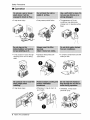
SafetyPrecautions
[] Operation
• It may cause injury • It may Ruse product failure • The appearance d the air
conditioner may deteriorate,
change color, or develop surface
flaws,
• It may cause an injury through
dropping of the unit or falling
down
• It may cause injury:
• Operation without filters will
cause failure+
° Otherwise, it may do harm to
your health+
, It contains containments and will
make you sicL
@
6 ROom Air Conditioner
• Otherwise, it may' cause
personal injury.

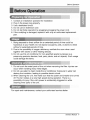
Before Operation
1. Contact an installation specialist for installation.
2. Plug in the power plug properly.
3. Use a dedicated circuit.
4. Do not use an extension cord.
5. Do not start/st:op operation by plugging/unplugging the power cord.
6. If the cordlplug is damaged, replace it with only an authorized replacement
part.
1. Being exposed to. direct airflow for an extended period of time could be
hazardous to your health. Do not expose occupants, pets, or plants to direct
airflow for extended periods of time.
2. Due to the possibility of oxygen deficiency; ventilate the room when used
together with stoves or other heating devices.
3. Do not use this air conditioner for non-specified special purposes (e.g.
preserving precision devices, food, pets, plants, and art objects). Such usage
could damage the items.
i ii i
1. Do not touch the metal parts of the unit when removing the filter. Injuries can
occur when handling sharp metal edges.
2. Do not use water to clean inside the air conditio.ner. Exposure to water can
destroy the insulation, leading to possible electric shock.
3. When cleaning the unit, first make sure that the power and breaker are turned
off. The fan rotates at a very high speed during operation. There is a
possibility of injury if the unit's power is accidentally triggered on while
cleaning inner parts of the unit.
For repair and maintenance, contact your authorized service dealer.
Owner_ Manual 7

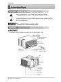
Introduction
This symbol ale,s you to the risk of electric shock,
This symbol ale,s you to hazards that could cause harm to
the air conditioner;
This symbol indicates special notes.
This appaianceshould be installedin a_ordance withthe National Electric Code
Vertical Air Deflector
(Hofizon_l Louver)
Hofizon_ Air Deflector
(Ve_ica_Louver)
1
Air IntakednietGrille
Air Fi_ter RemoteController
Conden_r
Pan
Compressor
PowerCord
ContromBoard
Eva_rator
8 Room Air Conditioner

ElectricalSafety
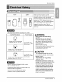
115V~ 230V~
m
Power cord may include a current
interrupter device, A test and reset button is
provided on the plug case. The device
should be tested on a periodic basis by first
pressing the TEST bu_on and then the
RESET button if the TEST button does not
trip or if the RESET button will not stay
engaged, discontinue use of the air
conditioner and contact a qualified service
technician.
The shape may be different according to its model
Use Wall Receptacle Power Supply
Sta_ard 125V, 3_wiregrounding
receptacle rated 15A, 125V AC
Standard 250V_ 3-wire grounding
receptacle rated 15A 250V A©
Standard 250V 3owire grounding
receptacle rated 20A 250V AC
Use 15 AMP, time
delay fuse or 15 AMP.
circuit breaker,
Use 20 AMP, time
delay fuse or" 20 AMP
c4rcuit breaker,
DO NOT USE AN EXTENSION CORD on 230,
208° and 230/208 Volt units
All wiring should be made in accordance with local
electrical codes and regulations.
Aluminum house wiring may pose special
probiem& Consult a qualified electrician,
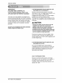
Never push the test b_on during
Otherwise this plug can damaged.
This device contains chemical including
lead, known to the State of California to
_use cancer, and birth defects or other
reproductive harm,
Wash hands after handling.
Do not remove, modify or immerse this plug.
If this device trips, the cause it to be
corrected before further use,
The conductors inside this cord are
surrounded by shields, whichmonitor
leakage current.
These shields are not grounded.
<Made in Tower>
Periodically examine the cord for any'
damage. Do not use this product in the
event the shields become exposed.
Avoid sh_k hazard, this unit can not
be user serviced opening the tamper
resistant. Sealed porti_ of the unit
voids all warranties and performance
claims. This unit not intended for use
as an on-off switch.
Owner_ Manual 9

Electrical Safety
(PLEASE READ' CAREFULLY')
FOR THE USER'S PERSONAL SAFET_ THIS
APPLIANCE MUST BE PROPERLY GROUNDED
The power cord of this appliance is equipped with a
three-prong (grounding) plug. Use this with a standard
three-sbt (grounding) wall power outlet to minimize the
hazard of: electric shock. The customer should have
the wall receptacle and circuit chewed by a qualified
electridan to make sure the receptacle is properly
grounded.
DO NOT CUT OR REMOVE THE THIRD (GROUND)
PRONG FROM THE POWER PLUG,
A. SITUATIONSWHEN THE APPLIANCE WILL BE
DISCONNECTED OCCASIONALLY:
Because of potential safety hazards, we strongly
di_urage the use of an adapter p]ug, However, if you
wish to use an adapter, a TEMPORARY
CONNECTION may be made. Use UL4isted adapter,
available from most Iot'HI hardware stores.
The large slot in the adapter must be aligned with the
large slot in the receptacle to assure a proper polarity
connection.
A CAUTION
: Attaching the adapter ground terminal to the wall
receptacle cover screw _ not ground the
appliance unless the cover scr_ is metal, and not
insulated, and the wali receptacle is grounded
through the hou_ wiring. The customer should have
the circuit _ecked by a qualified ei_rician to make
sure the recep_le is properly grounded.
Disconnect the power cord from the adapter, using
one hand on each. Othe_ise, the adapter ground
terminal might br_k. DO NOT USE the appliance with
a broken adapter plug.
B, SITUATIONS WHEN THE APPLIANCE WILL BE
DISCONNECTED OFTEN.
Do not use an adapter plug in these situations.
Unplugging the power cord frequently can lead to an
eventual breakage d the ground terminal. The wall
power outlet should be replaced by' a three-slot
(grounding) outlet instead.
USE OF EXTENSION CORDS
B_use d potential safety hazards, we strongly
di_urage the use of an extension cord. However, if
you wish to use an extension cord, use a CSA
certifiediUL-listed 3°wire (grounding) extension cord,
rated at 15A, 125V.
10 Room Air Conditioner

Installation
114Bubble
I
Level
INSIDE
FOAM ...............
COOLED
OUTSIDE FENCE
AWNING;
HEAT
RADIATION
About 1/2"
Over 20"
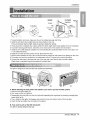
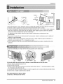
1.To avoid vibration and noise, make sure the unit is installed securely and firmly.
2. Install the unit where the sunlight does not shine directly on the unit.
If the unit receives direct sunlight, build an awning to shade the cabinet
3, There should be no obstacle, like a fence, within 20" which might restrict heat radiation from the condenser
4. To prevent reducing performance, install the unit so that louvers of the cabinet are not blocked.
5. Install the unit a little obliquely outward not to avoid leaking the condensed water into the room (about 1/2"
or 1/4 bubble with level).
6, Install the unit with its bosom portion 30-60" above the floor level,
7. Stuff the foam between the top of the unit and the wall to prevent air and insects from geeing into the room,
8. The power cord must be connected to an independent circuit. The green wire must be grounded.
9. Connect the drain tube to the base pan hole in the rear side if you need to drain (consult a dealer.)
Pl_tic hose or equivalent may be connected to the drain tube,
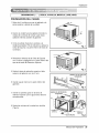
The grille is designed to clean the filter both upward and down_rd.
®
(a) (b) (c)
A. Before attaching the front grille to the cabinet, ff you want to puff out the filter upward;
1. Open the inlet grille slightly (a).
2_Turn inside out the front gr[He(a).
3, Disassemble the inlet griile from the front grille with separating the hinged part by inserting a straight type
screw-driver tip (b),
4. Then, rotate the inlet grille 180 degrees and insert the hooks into bottom holes of the front grille.
5. Insert the filter and attach the front grille to the _binet.
B. ff you want to pull out the filter downward;
The grille is already designed that way.
Owner's Manual 11

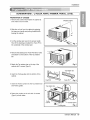
tnstallation
All supporting parts should be secured to firm wood, masonry,
or metal.
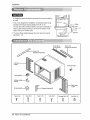
1,This unit is designed for installation in standard double hung
windows with actual opening widths from 29" to 41",
The top and bottom window sashes must open sufficiently to
allow a clear vertical opening of 18" from the bottom of the
upper sash to the window stool,
2. The stool offset (height between the stool and sift) must be
less than 1 1/4"_
29" to 41'_
18" min
Stool
Offset
Less
"_',,,_,!' than1 '/4"
Foam strip Foam-PE
(Plain-Back) (Adhesive-Backed)
Ty_ A (14) Type B (7) Type C(5) TypeD (2) Carria_ Bolt (2) L_k Nut (4)
12 Room Air Conditioner

Installation
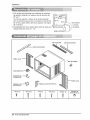
PREPARATION OF CHASSIS
1. Remove the screws which fasten the cabinet at
both sides and at [he back,
2 Slide the unit out:from the cabinet by gripping
the base pan handle and pulling forward wMe
bracing the cabinet.
3. Cut the window sash seal to the proper length.
Peel off the backing and attach the Foam-PE to
the underside of the window sash.
Shipping screws
Fig, 1
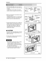
4. Remove the backing from Foam-PE with 3 holes
and attach it:to the bosom of the Top retainer
bar,
5, Attach the Top retainer bar on the top of the
cabinet with 3 screws (Type A).
Fig. 2
6. Insert the Frame guides intothe bottom of the
cabineL
7, Insert the Frame Curtain into the Top retainer bar
and Frame guides,
8 Fasten the curtains to the unit with 10 screws
(Type A) at both sides,
Foam-PE
Topretai_r bar
Top retainer bar
Screw(TypeA)
guide Fig. 4
Owner_ Manual 13

tnstallation
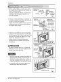
I Open the window. Mark a line on the center of
the window stool between the side window stop
molding&
Loosely attach the sill bracket to the support
bracket using the carriage bolt and the look nut.
Sill
Bracket
Carriag
BoJt
(M-Screw)
nut
Fig, 5
2. Attach the sill bracket to the window sill using
the screws (Type B),
Carefully place the cabinet on the window stool
and align the center mark on the bottom front
with the center line marked window stool.
3, Using the M-screw and the lock nut, attach the
support bracket to the cabinet track hole, Use
the first track hole after the sill bracket on the
outer edge of the window sill. Tighten the
carriage bolt and the lock nut. Be,sure the
cabinet slan_ outward,
A CAUTION
Do not drill a hole in the bottom pan. The unit is
designed to operate with approximately 1/2" of
water in bottom pan,
4. Pull the bottom window sash down behind the
Top retainer bar until they meet.
1. Do not pull the window sash down so tightly
that the movement of Frame curtain is
restricted Attach the cabinet to the window
stool by driving the _rews (Type B) through
the cabinet into window stool.
2.The cabinet should be installed with a very
slight tilt downward toward the outside.
quietedge
Ofw_naow
sill
B)
Sill bracket
Fig, 6
retainer
bar
Wind_ st_l
Frontangle Fig. 7
Window sash retainer bar
Frame curtain
Foam-PE
Fig. 8
FrontA_le
Screw(TypeB) Fig, 9
14 Room Air Conditioner

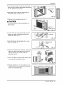
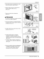
5. Pull each Frame curtain fully to each window sash
track, and pull the bottom window sash down behind
the Top retainer bar until it meet&
6, Attach each Frame curtain the window sash by
using screws (Type C.) (See Fig, 10)
7. Slide the unit into the cabinet.(See Fig. 11)
A CAUTION
For security purpose_ reinstall screws(Type A) at
cabinet's sides.
8 Cut the Foam-strip to the proper length and insert
between the upper window sash and the lower
window sash.(See Fig. 12)
9, Attach the Window I_king bracket with a screw
(Type C.) (See Fig, 13)
10 Attach the front grille to the cabinet by inserting the
tabs on the grille into the tabs on the front of the
cabinet, Push the grille in until it snaps into
place.(See Fig.14)
11. Lift the inlet grille and secure it with a screw (Type
A) through the front grille.(See Fig. 14)
12 Window ins:tailation of room air conditioner is now
completed. See ELECIRICAL DATAfor attaching
power cord to electrical outlet.
Installation
c_
Fig. i0
rew
Power Cord
Fig. 11
Fig. i2
/. II1/---wio wIo iog 1
Fig. 13
_14
i5
Owner_ Manual 15

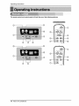
Operating Instructions
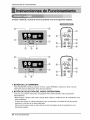
me mmote control and control panel wifl look like one of the foflowing pictures,
© ®
®
@
®
.............................,
© ®
®
®
®
16 Room Air Conditioner

Opera#ngInstructions
1. POWER BUTTON
Toturn the air conditioner ON_push the button.Toturn the air conditioner OFF,push the bu_on again.
This button takes pr[or_y overany other buttons.
2. OPERATION MODE SELECTION BUTTON
Everytime you push this button, itwilltoggle COOL, FANand DRY.
• Dry Mode: Please change to this mode when you want to use the room air unit as a dehumidifier. No cooling
will be performed during this time, but moisturewill be removed from the air similar to the function of a
dehumidifier.This function works best during those high humidity dayswhen the temperature is not too hot.
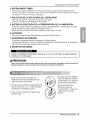
3. ON/OFF TIMER BUTTON
Every'timeyou push this button, timer isset as follows.(1Hour 4, 2Hours 4, 3Hours 4, 4Hours 4, 5Hours 4,
6Hours 4, 7Hou_ 4, 8Hours 4, 9Hours 4, lOHours 4, 11Hours 4, 12Hours 4, Cancel}
4. FAN SPEED SELECTOR
Everytime you push this button, itis set as follows. (Hi[ _3 ] 4, Low[ f: I] 4, Med[ 1:2] 4, Hi[ 1:3]-)
5. ROOM TEMPERATURE SETTING BUTTON
This button can automatically control the temperature of the room_The temperature can be set within a range of
60°Fto 86°F by 1°R
Select the lower numberfor lowertemperature of the room.
6. AUTO SWING
This bu_on can automati_lly controlthe _r flow direction,
7. ENERGY SAVER
The fan stops when the compressor stops _oling
Approximately every 3 munutes the fan will turn on and check the room air to determine if cooling is needed.
8. REMOCON SIGNAL RECEIVER
after an electrical power _itum, the unit wifl begin to run at its last setting.
)
When the air conditioner has been performed i_ cooling operation and is turned off or set to the fan
position, wait at least 3 minutes before resetting to the cooling operation again.
1, Remove the cover from the back of the remote
controller.
2. Insert two batteries.
• Be sure that the (+) and (-) directions are
correcL
° Be sure that both batteries are new.
3 Re-a_ach the cover,
• Do not use rechargeable baEeries,
Such batteries differ from standard
dry cells in shape, dimensions, and
performance.
° Remove the batteries from the
remote controller if the air
_nditioner is not going to be, used
for an extended length of time.
Owner's Manual 17

Operating Instructions
The ventilation lever must be in the CLOSE position in order to maintain the best cooling conditions.
When fresh air is necessary in the room, set the ventilation lever to the OPEN position.
The damper is opened and room air is drawn ouL
BeDre using the ventilation feature,
position the lever, as:shown. First, pull down
part :,i_._to horizontal line with part d;>.
The direction of air can be controlled wherever you
want to cool by adjusting the horizontal louver and the
vertical louver,
HORIZONTAL AIR-DIRECTION CONTROL
To control horizontal direction of air flow, set to the
ON position the air-swing switch and the air flow will
be _ept horizontally by the automatic air-swing
system
Ifyou want to stop the air flow from moving, Twitch off
the air swing switch at the desired position of the
vane
• VERTICAL AIR-DIRECTION CONTROL
The vertical air direction is adjusted by moving the
horizontal louver.
The direction of air can be controlled wherever
you want to cool by adjusting the horizontal
louver and the vertical louver.
° HORIZONTAL AIR-DIRECTION CONTROL
The horizontal air direction is adjusted by
rotating the vertical louver right or left.
• VERTICAL AIR-DIRECTION CONTROL
The vertical air direction is adjusted by rotating
the horizontal louver forward or backward.
18 Room Air Conditioner

OperatingInstructions
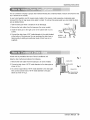
The air conditioner employs a proper drain method whereby the condensed water (moisture removed from the
air) is drained to the outside.
in very humid weather, (and for reverse cycle models in the reverse mode) excessive condensate water
removed from the air may cause some 'waterto collect To remove this excess water you can install the drain
pan as detailed below.
1.Take the drain pan which is located in the air discharge.
2, Remove the hole rubber from the base-pan (for some models),
3. install the drain pan to the right corner of the cabinet with 4 (or 2)
screws,
4, Connect the drain hose of 3/5" inside diameter to the outlet located
at the bottom of the drain pan.You can purchase the drain hose or
tubing locally to satisfy your particular needs. (Drain hose is not
supplied),
DRAI N
PAN
SCREW
DRAIN HOSE ÷ I _ ,_
A drain hole is provided a_the rear of the air conditioner unit.
Select a drain method a_ording to the following.
1. Remove the hole rubber from the base-pan. (for some models)
2. Connect a drain hose of 9/16" inside diameter to the drain pipe as
shown in Fig. 1.
3, Or conn_t a pipe elbow of 9/16" inside diameter to the drain pipe,
then connect a drain hose of 9/16" inside diameter to the pipe
elbow as shown in Fig. 2.
Ownerb Manual 19

Maintenance and Service
TURN THE AIR CONDITIONER OFF AND REMOVE THE PLUG FROM THE POWER OUTLET.
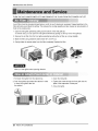
he air filter should be checked at least twice a month to see if cleaning is necessary. Trapped particles in the,
filter will build up and block the airflow:This reduces the cooling capacity and also causes an accumulation of
frost on the cooling coils.
1. Open the inlet grille upward by pulling out the bottom of the inlet grille.(a)
in another case, you can open the inlet grille downward by pulling out the top of the inlet grilb,(b)
2, Remove the air filter from the front grille assembly by pulling the air filter up or down slightly.
3. Wash the filter using luke_rm water below 40°C (104°F),(c)
4 Gently shake the excess water from the filter completely, Replace the filter_
(a) (b) (c)
Mark A of inlet grille means opening direction.
1. Pull down front grille from the cabinet top.
2. Push front grille's tips to_rd the cabinet in order
to insert front grilleb tabs into
the cabinet,
3, Open the inlet gritle.
4. Tighten the _rew through the front grille into the
plate of the evaporator or base pan
5, Close inlet grille
20 Room Air Conditioner

Maintenance and Service
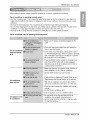
BeDre calling for service, please review the following list of common problems and solutions.
The air conditioner is operating normally when:
• You hear a pinging noise. This is caused by water being picked up by the condenser on rainy days or in
higNy humid conditions, This feature is designed to help remove moisture in the air and improve cooling
efficiency_
° You hear the thermostat click, This is caused by the compressor cycle starting and stopping
°You see water dripping from the rear of the unit. Water may be collated in the base pan in highly humid
conditions or on rainy days. This water overflows and drips from the rear of the unit.
• You hear the fan running while the compressor is silent This is a normal operational feature,
me air conditioner may _ operating abnormally when:
• Make sure the plug is completely plugged intothe
outlet
The air conditioner
does not operate
at all
Air conditioner
does not cool
Ice appears on the
air conditioner.
° Ch_k the fuse/circuit breaker box and replace the
fuse or reset the breaker
• Inthe event of a power failure, set the power control
to OFF (Mechanical Type). When the power is restored,
wait 3 minutesto restart the air conditioner to prevent
the compressor from overloading
• Press the RESET bu_on located on the power cord
plug. If the RESET button will not stay engaged,
discontinue use of:the air conditioner and contact a
qualified service technician
° Make sure there are no curtains, blinds, furniture or
other obstacles in front of the air conditioner
• Set the TEMP control to a lower number,
•Clean the filter at least every 2 weeks Refer to the
"Maintenance and Service" s_tion of the manual.
° After the air conditioner is turned on, you need to
give the air conditioner some time to cooi the room.
• Check for open furnace floor resisters and cold air
returns.
° CLOSE the air conditioner vent
• See Ice appears on the air conditioner below
• Ice may block the air flow and obstruct the air
conditioner from properly cooling the room.
° Set the mode control at HIGH fan or high cool with
the high temperature.
Owner's Manual 21

PARA SUS ARCHIVOS
Escriba aqui el modelo y nQmero de sede:
Modelo n*:
Serie n°:
Puede encontrar estos datos en la etiqueta situada en el
_aterai de cada unidad,
Nombre del distri_idor:
m Adjunte su reci_ a esta pagina con Eagrapadora para
el momento que _onecesite para probar Jafecha de su
adquisici6n o para la validaci6n de la garantla
LEA ESTE MANUAL
En su interior encont_rb, muchos _nsejos Qtiles sobre la
utiiizaci6n y mantenimiento de su acondicionador de aire,
Unos pocos cuidados pot su parte le pueden ahorrar
mucho tiempo y dinero durante la vida de su
acondicionador de aire
En Ea tabia de _nsejos para la soluci6n rapida de
problemas encontrar& muchas respues_s a los problemas
mas habituales, Si revisa primero nuestra Tabla de
Consejos _ra la soluci6n r&pida de problemas, ta_ vez no
necesite llamar nunca a_servicio t_nico
° Pongase en corttacto con un t_cnico del servicio
autori_do para realizar la reparacion y
mantenimiento de esta unidad_
° Pongase en contacto con un insta|ador para realizar
la instalacibn de esta unidad.
° Cuando se va a cambiar el cable electrico, el trabajo
de reemplazamiento debe ser realizado _nicamente
pot _rsonal autori_do, utilizando las pie_s de
cambio genuinas _nicamente.
* El trabajo de reemp_azamiento de_ _r realizado de
acuerdo con el Codigo Electrico Nacional
_nicamente por personal autorizado.
22 Aire Acondicionador

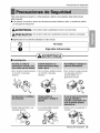
PrecaucionesdeSeguridad
Para evitar lesiones al usuario o a otras personas y dafios a la propiedad, estas instrucciones
esten seguirse.
| Unaoperaci6nincorrectaporignorar1asinstruccionespro.vocaralesioneso da5os.Laseri_ad seclasifi_
potlassiguientesindicacione&
PRECAUCION
Estesimbolo indicala posibilidaddemuerteo de seria lesi6n.
Estesimbolo indi_ s61ola posibilidadde lesioneso da_osa la propiedad
[] Significados de los simbolos utilizados en este manual.
NOhacer. 1
Siga estas instrucciones. J
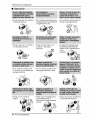
ml Instalacibn
• De Io contrario, podria provocar
un incendio o descarga
el6ctrica.
° Puede ocasionar fallos y una
descarga el_ctrica,
• De Io contrario, podrfa provocar
un incendio o descarga
el6ctrica.
• Los bordes afilados pueden
provocar lesiones,
• De lo contrario, puede provocar
una descarga el_ctrica o
incendio debido a Ja
generaci6n de calor.
• Podria ocurrir una explosi6n o
incendio
®
Manual del Propietario
23

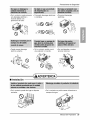
Precauciones de d
m Operaci6n
• Puede ocasionar una expJosi6n
o descarga el6ctdca.
• De 1ocontrario,pu_e provocaruna
descargaelectricao incendiodebJdo
a la generaddn de calor.
• Puede ocasionar un incendio y
una descarga el_ctrica
° De Io contrario, puede ocurrir
• Puede provocar fallos en el
producto o descargas
el_ctricas_
• De Io contrario, p_ria provocar un
incendio o descarga electrica.
• La apadenciade[aparatodeaire
acondicionadopu_e deteriomr
cambiarel coloro desarrollarflujos
en las
superficies.
un incendio y un accidente por
descarga el6ctrica.
• Puede ocurdr un falta de
oxfgeno.
• De Io contrario, pueden ocurrir
descargas elect:dcas y faHos.
• DebJdoa que el ventilador gira a
alta vel_idad durante el
funcionamiento, podria ocasionar
lesiones.
24 Aire Acondicionador
, Evitar_. el arranque accidental y
la posibNidad de lesiones.

Precauciones de Seguridad
• De Io contrario, puede provocar
una descarga el_ctrica o
incendio debJdo a Ia
generaci6n de calor.
• ProvocarA descargas el_ctricas
o incendios,
•,Provocardt descargas
el_ctricas_
..... ,o:¸ • , _.
• Puede causar descarga
el6ctrica y daSos.
• De Io contrario, podrfa ocurrir
una explosi6n o incendio.
•,Son puntiagudas y pueden
provocar Uesiones.
[] Instalacibn
° De Io contrario puede dar lugar a disputas
vecinages,
• De Io contrario se podda causar vJbraciones o
escapes de agua,
Manual del Propietario 25

Precauciones de d
[] Operaci6n
- Podria ocasionar lesiones. ° Puede causar una averfa en el
aparato.
•.La apatienciadel aparatode aire
acondicionadopu_e deteriorar,
cambiarel coloro desarrollarfluj_
en lassuperficies.
,, Puede Jesionarse al caerse del
aparato o al caerse los objetos
que haya colocado.
° Podria ocasionar lesiones,
° El fundonamiento sin f:iltros
puede provocar fallos
° De Io contrario, podr/a da_ar su
saDd.
26 Aire Acondicionador
• De Io contrario, podrlan ocurrir
lesiones personales.

Antes de poner el equipo en funcionamiento
1. P6ngase en contacto con un especialista para realizar la instalaci6n.
2. Enchufe correctamente la toma de alimentaci6n.
3. Utilice un circuito dedicado.
4. No utilice un cable alargador.
5. No inicie/cese el funcionamiento enchufando/desenchufando el cable
electrico.
6. Si el cable/enchufe esta daSado, sustit0yalo solo por una pieza autorizada.
1. Estando expuesto a la circulaci6n directa de aire durante un extenso pedodo
de tiempo podria resultar peligroso para su salud. No exponga alas personas,
animales domesticos, o alas plantas a la circulaci6n de aire durante largos
perfodos de tiempo.
2. Debido a la probabilidad de falta de oxigeno, ventile el cuarto cuando este
utilizado el aparato junto con estufas u otros aparatos de calefacci6n.
3. No utilice este aire acondicionado con prop6sitos especiales no especificados
(Ej.: consewaci6n de dispositivos de precisi6n, comida, animales domesticos,
plantas y objetos de arte). Tal uso podria daSar los arficulos.
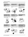
1. No toque las piezas metMicas de la unidad al retirar el filtro. Manejar aristas
afiladas de metal puede causar lesiones.
2. No utilice el agua para limpiar el interior del aire acondicionado. La exposici6n
al agua puede destruir el aislamiento, conduciendo a posibles descargas
electricas.
3. AI limpiar la unidad, aseg0rese antes de que la electricidad y el interruptor
est#.n apagados. El ventilador rota a muy alta velocidad durante el
funcionamiento del equipo. Existe la posibilidad de lesiones si acciona
accidentalmente la electricidad de la unidad mientras limpia el interior de la
unidad.
Para cuestiones de reparacion y mantenimiento, p6ngase en contacto con su
distribuidor de servicio autorizado.
Manual del Propietario 27

IntroducciSn
Este simbolo Io adviede de un _ligro de accidente por
corriente eldctrica.
Este simbolo 1oadiverte de un peligro que pueda causar un
daho del ventliador,
Este sfmbolo signifi_ condicciones es_ciales.
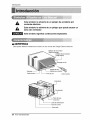
Este aparato deberla instalarse de acuerdo con ias normas del C6digo El6ctrico Nacional,
Deflector de aire ve_cal
(RejiHahonzontaJ)
Deflectordeaire horizor¢_I
(Rejillaverti_i}
1
Descarga de aire
Gabinete
RejiHaffontai--
Entrada de aire
_{Rejilla para entrada)
--Filtro de aire Co_rol remoto
Abrazadera
Condensador
--Compresor
C_le _ _imentacion
Pare1de co_rol
Evaporador
28 Aire Acondicionador

SeguraidaElectrica
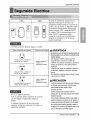
1i5V_
i
230V~
= ,
El cable de aaimentacidn puede incluir un
dispositivo interruptor de corr_ente La
carcasa de1enchufe cuenta con un botdn de
prueba y otto de reinicio, El dispositivo debe
comproba_e peri6dicamente presionando
pdmero el bot6n TEST y despu6s RESET.
Si el botdn TEST no se descon_ta o si el
botdn RESET no perman_e activo,
suspenda el uso del aire aoondicionado y
p6ngase en contacto con un t_onioo de
se_icio cualificado,
La forma puede set diferente segQn su modelo.
Utilice el enchufe de la pared Consumo de Energ/a
Standard 125V, enchufe de 3
Lineas de 15A, 125V AC
Standard 250V, ench_e de 3
Lineas de 15A_ 250V AC
Utilice un fusib_ de
15AMP o un
Interrupter de 15AMP,
___ Utilice un fusib_ de
20AMP. o un
laterruptor de 20AMP,
Standard 250V, enchufe de 3
Lineas de 2OA, 250V AC
No use un cable de extension.
Todo el cableado deber_, realizarse de acuerdo
con los c6digos y reglamentos el6ctricos
locales,
El cableado dom6stico de aluminio podrfa
ocasionar problemas especiale& Consulte a un
electricista calificado.
Nopresionenuncael_t6n de pruebaduranteel
funcionamiento,deIocontraHoelenchufep_ria
resu_tardaS_o.
Estedispositivocontie_ produdosquimi_s,
incluyendoplomo,conocidoenelestado
Calitornia_mo productocanceriger#ycau_nte de
defectosdenacimientoy otrosdaScLsalsislema
reproductor,
L&ve_ bienlasrnan_ trasmanipulareldi_os_ivo
Nodesmonte,m_ifique ni surnerjaenaguaeste
end_ufe.
Siel disp_ivo seactivara,_berA corregirla_usa
antesdevoNera utilizarlo_
L_ hil_ conductoresd_troddcableestanrodeados
porblindaps,quesu_r,,isanlacorriente_ fuga.
Estosblindajesnoest_puestosatJerra.
<FabdcadoenT_,,er>
Examine_rbdicamented ca_eenbuscade
c_lquierdaSo.Noutiliceesteproductosilos_indajes
resulta[anexpuest_.
Ev_eelri_goded_c_gasel_as; e_ un_adno
puedesetreparadapotelusuariopor_r resistentey
ap[uebadeal_eracbnes.Manipularlaporci6nsellada
delaun_adanularat0daslasgarantiasyquejasde
rendmient0,Estauddadnoestadise_adaparasuus0
comouninte_uptordeen_ndido-apagado,
Manual del Pmpietario

Seguraida
(FAVORLEA CON ATENC/ON)
POR LA SEGUR/DAD PERSONAL DEL USUARIO,
ESTE APARATO DEBE SER DEB[DAMENTE
El cord6n de energia de _ste aparato esta
equi_do con tres patas(cable a tierm). Utilice
este con un enchufe de pared de tres salidas(a
tierra) para minimizar el peligro de choque
el_trico. El cliente debe revisar el receptor de
pared y el circuito por un electricis_ calificado
para asegurarse que la recepci6n es_
debidamente neutralizada.
NO CORTE 0 REMUEVA LA TERCERA
PATA(GROUND) DEL ENCHUFE,
A. S|TUAC|ONES EN LAS CUALES EL
APARATO ES DESCONECTADO
OCASIONALMENTE:
Debido at peligro F-_tencial, noso.tros no
recomendamos el uso de adaptadores. Sin
embargo, si usted desea utilizar un adaptador,
una CONEXION TEMPORAL, puede ser
efectuad& Utilice adaptadores UL, disponibles
en la mayoria de los estable cimientos de
herramientas. La pata mas grande del
adaptador debe ser alineada _n la pata mas
gmnde del interruptor para asegurarse una
polarizaci6n adecuad&
APRECAUCION
Adaptar |a terminal del ground del
adaptador a la cubie_a de |a pared con un
torni||o no neutraliza el aparato a menos
que |a cubierta de| tornillo sea de metal, u
no _a insolada, y el r_eptor de pared
este
neutralizado a trav6s del alambrado del la
casa. El cliente debe hacer verificar el
circuito por un electricista calfficado para
asegurarse que el r_eiptor es_
debidamente neutralizado,
Desconecte el cord6n de energfa del adaptador,
utilizado una mano en cada uno, De 1ocontrario,
la terminal del adaptador puede romperse_ NO
UTILICE el aparato con un enchufe roto,
B. SITUACIONES EN LAS CUALES EL
APARATO ES DESCONECTADO CON
FRECUENCIA.
No utilice un adiaptador en es_s
circunstancias. Desconectar el cord6n de
energia con frecuencia Io Ilevara al eventual
rompimiento de la terminal de neutralizaci6n.
La saluda de energia de la pared debe ser
ree,rnplazada pot una salida de tres
patas(neutralizada).
USO DE EXTENSIONES
Debido al peligro _tencial, no recomendamos
la utilizaciSn de extensiones. Sin embargo, si
usted desea utilizar una extensi6n, utilice una
certificada por CSAiUL de tres alambres,
catalogada 15A, 125"_,(
30 Aire Acondicionador

Instalacion
TOLDO
BARDA
FOAM ........
1/4 AmpoHa RADIACION
NR DE CALOR
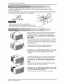
1. Para eqtar vibraci6n y ruido, asef_rese de que la unidad est6 instalada de manera segura y firmemente.
2. Instale la unidad en lugares fuera de luzsolar dir_ta directamente sobre la unidad.
3. El exterior del gabinete deber_ extenderse hacia afuera cuando menos 10" y no deben existir obstAculos,
tales como una barda o pared, dentro de una distancia de 20" desde la pparte posterior del gabinete
porque esto evitarA la radiaci6n de calor del condensador,
La restricci6n del sire exterior reducir_ en gran manera la eficiencia de enfriamiento del aire
acondidonado.
4. Para prevenir la reducci6n de Is eficiencis del funcionamiento, instale la unidad pars que las rejillas del
cabinete no sean bloqueados,
5_Instale la unidad un poco oblicuamente hacia afuera pars no dejar escapar el agua condensado a la
habitaci6n (aproximadamente 1/2" o 1/4 ampolla con nivel).
6. Llene la espuma entre el tope de Ia unidad y la pared para prevenir que el sire e insectos entren en Ia
habitaci6n.
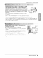
La rejilla es diseSada pars limpiar el filtro tanto hacia arriba como hacia abajo_
®
(a) (b) (c)
A, _,tes de Instalar la rejilla frontal en el cabinete, si usted desea_car el filtro por arriba;
1. Abra la rejilla de entrada ligeramente (a).
2_Vuelte Is rejilla frontal (a),
3 Separe la parte engoznada insertando la punts del destornillador de tipo "-" pars desensamblar la rejilla
de entrada desde la rejiila frontal, (b),
4. Luego, gire la rejilla de entrada 180 grados e inserte los ganchos en los huecos inferiores del rijilla frontal.
5. Inserte el filtro e instale la rejilla frontal al c@inete.
B. Si usted desea sacar el filtro pot abajo;
La rejilla es ya diseSada para tal manera.
Manual del Propietario 31

_s_c_n
1_Esta unidad estA diseffada para instalarse en ventanas
de guillotina estAndar con espesor real de abertura de
29" a 41 ".
Los marcos superior e inferior de la ventana deverAn
abdr 1osuficiente para permitir una abertura vertica[ libre
de 18" de la parte inferior deg marco, superior a la repisa
de [a ventana.
2, El desplazamiento de la repisa (altura entre [a repisa y el
aIf_izar) debe ser menor a 1 1/4",
PARED
ALFEZAR
......EXTERI OR
TIPOA(14) TIPO B (7) TiPO(5) TIPO D(2)
Y
PERNO (2:)
TUERCA DE
SEGURIDAD (4)
32 Aire Acondicionador

Instaladon
DESARMADOR (+,), REGLA, CUCHILLO, MARTILO, LAPIZ, NIVEL
PREPARACION DEL CHASIS
1. Retire Uos4 tornillos que unen el gabinete a la
parte posterior y lateral de la unidad,
2, Deslice la unidad fuera del gabiete tomando la
manija de la charola de la base y jaUehacia
adelante mi_ntras sostiene el gabinete,
3, Corte el seWode chasis de la ventana a la
longitud apropiada, PeJeel resfuerzo y apiique Ia
Cinta de Espuma a la parte inferior del chais de
la ventana.
Fig, 1
4, Remueva el refuerzo de la Cinta de Espuma
con 3 huecos y agr_guelo en la parte inferior det
tope de ta barra de Retencion Superior.
5, Sujete la barra de retenci6n superior al iado
superior del gabinete con los 3 torni.
6. Inserta la guia marco en la parte inferior del
gabinete,
7, Inserte los paneles gutas en la barra de
retencion superior yen la guia marco del aire
aoondicionado.
8, Sujete las cortinas de la unidad con tornillos
(Tipo A),
Fig. 2
BARRA DE RETENCION
SUPERIOR
BARRA DE RETENCION
SUPERIOR
Espuma Fig, 3
TORNILLO
(T_POA) FORNILLO
(TIPO A)
Manual del Propietario 33

Instalacion
1. Abra la ventana. Marque una IInea en el centro
de Jarepisa de la ventana entre las molduras de
tope de la ventana lateral.
Coloque sin apretar la m_nsula del alf_izar en la
m6nsula de soporte utilizando el pemoy la
tuerca de segutidad.
MENSUL&DEL
ALFEI_R
BULON
DESOPORTE
DE
SEGUR_DA
Fig. 5
2_Coloque ia m6nsula del alf_izar en e! alf6izar de
la ventana utilizando los tornillos (Tipo B). Apriete
el perno y la tuerca de seguridad.
Repisa de la ventana y alinee la marca central en
el frente del rondo con la l/nea centrai marcada
en la repisa de la ventana_
ORiFIQODE
TORNILLOPARA
METALES{TiPOO)Y
TUERCADESEGOBIDA
_--"'_ TORNILLO(TIPOB)
MEN_ULA
DEL ALFEIZAR Fig. 6
3_Utilizando el tornillo M y la tuerca de seguridad,
coloque la m6nsuia de soporte en el orificio de la
guIa del gabinete. Use ei primer orificio de la guIa
despu_s de la m_nsula del alf_zar en el borde
exterior del alf_izar de la ventana.
Apriete el perno y la tuerca de seguridad
AsegQrese de que el gabinete est6 inciinado
hacia afuera.
No pedore la charola del fondo. La unidad estA
disefiada para operar con aproximadamente 1/2"
de agua en la charola del rondo.
1. No hale el marco de la ventana hacia abajo tan
apretado que se restrinja el movimiento de los
deslizadores. Sujete el gabinete a ia repisa de
la ventana insstalando los tornilios (tipo A o B)
a trav6s del gabinete en la repisa de la ventana.
2. El gabinete deberA ser instalado ligeramente
inclinado hacia abajo hacia el exterior
BARRA
DE
RETENQON
SUPERIOR
MARCO DE LA
CINTA DEJ
ESPUMA
GABINETE
PANEL
GUIA
CINTA DE
ESPUMA
REPISADEVENTANA
INTERIORFig, 7
BARRADE
RETENCIONSUPERIOR
Fig, 8
ParteFrontalInterior
TORNiLLO(TIPOB) Fig, 9
34 Aire Acondicionador

5. Hale cada panel gu[a completamente a cada
Jadode la ventana y repita del paso 2.
6. Adjunte cada panel guia a cada lado de Ia
ventana usando tornillos (Tipo C)_
(Ver Rg,10)
7. Deslice eI chasfs dentro del,gabinete.
(Ver Fig.11)
APRECAUCION
Por razones de segufidad, re instale los tornillos
(Tipo A) en los lados deJ gabinete
8. Corte la tira de goma a la medida apropiada e
introdL_zcala entre la parte superior e infenor de
Javentana. (Ver Fig. 12)
TORNILLO
Instaladon
TORNJLLO
Fig, 10
CORDON DE
AUMENTACION
ELETRICA
9. Se debe Jnstalar el asa antes de fijar el frente
decorativo. (Vet Fig. 13)
10. ln_ale la rejilla frontal en el cabinete
insertando la lengOeta en la rejilla a la
lengQeta en el frente del cabinete. Empuje la
rejilla hasta que se cierre con sonido de golpe.
(Ver Fig. 14)
11, Levante la rejilla de entrada y aseg8rela con
un tornillo (tJpo A) a trav6s de la reiilla frontal,
(Vet Fig.!4)
...,,_j,,.__ SOPORTE DE
CERRADURA
_% Fig. 13
i4
12. Ahora la insta[aci6n del aJreacondicionado en
la ventana es completada, Vea los DATOS
ELECTRICOS para instalar el cable de
alimentaci6n en la toma de corriente,
15
Manual del Pmpietario 35

Instruccionnes de Funcionamiento
El mando a distancia y el panel de control se parecer_n a los de/as siguientes imagenes,
®
®
0
®
© ®
®
® @
®
1. BOT(3N DE LA CORRIENTE
Para ENCENDER el sJstema presione el bot6n, y para APAGARLO presione el bot6n otra vez
Este bot6n tiene prioridad sobre todos los otros botones.
2. BOTON DE SELECClON DEL MODO OPERAC!ONAL
Cada vez que presJone este bot6n, las palabras FR[O, VENTILADOR y SECO apareceran
altemadamente.
• Modo secado: Cambie a este modo cuando desee utilizar la unidad de aire de la habitaci6n como
desh umidificador,
Durante este tiempo no habrA enfriamiento, pero se eliminarA la humedad del aire de manera
parecida a Ia funci6n de un deshumidificador.
Esta funci6n funciona meior en esos dias de mucha humedad cuando la temperatura no es
demasiado elevada.
36 Aire Acondicionador

Instruccionnes de Funcionamiento
3, BOTON ON/OFF TIMER
Cada vez que presione este bot6n, el marcador de tiempo se ajustar_ de la siguiente manera:
(1Hora -e 2 Horas _ 3 Horas .-->4 Horas .e 5 Horas _ 6 Horas .e 7 Horas .-->8 Horas .e 9 Horas -_
10 Horas _ I1 Horas _ 12 Horas _ Cancelar).
4, SELECTOR DE LA VELOCIDAD DEL VENTILADOR
Cada vez que presione este bot6n, el ajuste es como sigue,
(Alto[ F3 ] "> Bajo[ F _] "-'>Medio[ F2 ] "> AJto[ F3 ],,)
5, BOTON DE SELECCION DE LA TEMPERATURA DE LA HABITACION
Este bot6n puede controlar la temperatura del cuarto autom_ticamente. La temperatura se puede
ajustar de grado en grado, desde 60°F hasta 86°F cada l°R
Seleccione el nOmero m_.s bajo para la temperatura m_.s baja en el cuarto.
6, AUTOGIRO
Este bot6n puede controlar autom,_ticament Sadirecci6n de1fiujo de aire,
7, AHORRADOR DE E.NERGiA
El ventilador se detiene cuando el compre_or no sigue enfriando,
Aproximadamente cada 3 minutos el ventilador se encenderA, y necesitarA verificar la temperatura
del cuarto para saber si es necesario mAs enfriamiento,
8, RECEPTOR DE SEf, tAL
Cuando se restablezca la alimentacidn despu6s de un corte en el suministro, la unidad empezara a
funcionar con su ultimo ajuste
APRECAUCION
Cuandoel aireacondicionadohaestadooperando bajo la fasedeenfriamientoy se apaga,oseajustala positionde
ventilacion0espere_r Iomenos3 minutos,antes de reiniciar la operacibnde enfriamiento,
1, Quite la tapa de Ia parte posterior del
telemando, Para ello haga deslizar la tapa
segOn la direcci6n del la flecha.
2 Introduzca las dos baterlas, asegur_.ndose de
que las direcciones (+) y (-) est6n colo_das
correctament. Use baterfas nuevas.
31Volver a cerrar,, resbalando la tapa hasta la
posici6n inicial,
No utilice bateris recargables,
_stas son diferentes de forma,
de dimensi6n y uso respecto a
las batertas secas usuales,
Seque las baterias del
telemando cuando el
acondicionador no vaya a ser
usado durante un largo
per/odo.
Manual del Propietario 37

lnstruccionnes de Funcionamiento
La palanca de ventilaci6n deberb_estar en la posici6n CLOSE (Cerrado) para poder mantener las m_ores
_ndiciones de enfriamiento.
Cuando se necesite aire fresco en la habJtaci6n,cobque la palanca de ventJlacidnen la posici6n OPEN (Abierto).
El amortiguador se abre y se descarga el aire de la h_itaci6n
CERRAR VENTILACION ABRJR
Antes de usar la caractedstica de ventilaci6n,
coloque Ia palanca como se muestra. Primero jale hacia
Part@
abajo la parte ® para que quede en una Ifnea horizontal con la parte @.
La dire_i6n del aire puede controlarse hacia donde usted desee
enfriar ajustando la persiana horizontal y la persiana vertical
- CONTROL DE LA DIRECClON HORIZONTAL
DEL AIRE
Para controlar la direcci6n horizontal del fiujo del aire, coloque el
interruptor de oscilacion de aire en la posici6n ON y el fiujo de
aire soplara horizontalmente por medic del sistema de oscilaci6n
autornatica de aire.
Si desea detener el fluio de aire, coloque el interruptor de
osciJacJ6nde aire en la posici6n deseada de la aleta.
• CONTROL DE LA DiRECCION VERTICAL DEL AIRE
La direcci6n de aire vertical es ajustada moviendo la rejila
horizontai.
La direcci6n del aJrepuede ser controtada cuando usted desee
enfdar, aiustando la palanca vertical y la palanca horiziontal.
• CONTROL DE LA DIRECCION HORIZONTAL DEL
La direcci6n horizon_l del aire es ajustada rotando la palanca
vertical hacia la derecha o hacia la izquierda.
• CONTROL DE _ DIRECCION VERTICAL DEL AIRE
La direcci6n vertical del aire es ajustada
rotando la palanca horizontal hacJa adelanto o hacia atr_&
38 Aire Acondicionador

InstruccionnesdeFuncionamiento
El aire acondicionado utiliza un m_todo de purga adecuado en donde
el agua condensada (humedad retirada dei aire)se purga al exterior
En climas demasiado hOmedos (y para modelos de cicJo invertido en la
modalidad de inversi6n) eJagua condensada excesiva que se retira det
aire puede ocasionar que se recoJecte algo de agua. Para eHminar este
exceso de agua, puede instaNaruna charola de purga como se detalla
a contJnuaci6n.
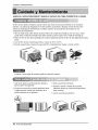
1 Tome la charola de purga que se Iocaliza en la descarga de aire o
en la barrera.
DE PURGA
DE: PURGA
2. Retire el odficio de hule de la charola de la base. (para algunos modelos).
3. lnstale la charola de purga en el extermo izquierdo del gabinete con 4 (o 2) tornillos,
4. Conecte la manguera de purga en la descarga Iocalizada en el rondo de la charola de purga. Puede
adquirir la manguera o tuberia de purgga Iocalmente para satisfacer sus necesidades particulates
(No se incluye la manguera de purga),
Existe una manguera de purga incUda en la parte de at:r&s de la
unidad de aire acondicionado.
Elija un m_todo de purga de,acuerdo a Io siguiente.
1. Retire el orificio de hule de la charola de la base. (para algunos
modelos),
2, Conecte una manguera de purga de 9/16" de diAmetro interior al
tubo de purga como se muestra en la Figura 1.
3 Conecte un codo de tubo de 9/16 ° de di&metro interior a la
tuberia de purga, despues conecte una manguera de purga de
9/16° de di&met:ro interior al _do de tubo como se muestra en la
Figura 2.
DE PURGA
Manual del Propietario 39

Cuidado y Mantenimiento
APAGUE EL A/RE ACONDICIONADO Y SAQUE EL ENCHUFE DEL TOMA CORRilENTE DE LA PARED.
EEfiltro de aire deverA revisarse cuando menos dos veces aJmes para vertioficar si es necesario
limpiado. Las parficulas atrapadas en el filtro poddan acumularse y bloquear el fiujo de aire. Esto
reduce la capacidad de enfdamiento y tambi_n ocasiona la acumulaci6n de escarcha en ios
serpentines de enfriamiento
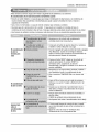
1. Abra la rejilla hacia arriba tirando la parte inferior de la reiilla de entrada (a)oEn otto caso, usted
puede abrir la rejilla de entrada hacia abajo tirando Ia parte superior de la rejilla de entrada.(b)
2 Retire eI filtro de aire del ensamNaie de la parrilia delantera jalando el filtro de aire ligeramente hacia
arriba
3. Lave el filtro de aire usando agua tibia a menos de 40°C (104°F).
4. Sacuda soavemente el exceso de agua del filtro completamente. Vuelva a colocar el filtro.
(a) (b) (c)
La marca A de la rejilla de entrada significa la direcci6n abierta.
1. Jale hacia abajo la parrilla deiantera desde la
parte superior del gabinete.
2_Optima las puntas de la parrilla delantera hacia
el gabinete para insertar las lengQetas de la
parrilla delantera en el gabinete.
3. Abra la parrNla de admisi6n.
4. Apriete el tornillo a trav6s de la parrNla
delantera dentro en la placa de evaporador o
base cacerola,
5. Cierre la parrilla de admisi6n.
40 Aire Acondicionador

Cuidadoy Mantenimiento
Antes de llamar al servicio,tenga a bien revisar]asiguientelista de proib]emasy sus soluciones.
El acondicionadordeaim est_ funcionandonormalmentecuando:
* Escuchaun sonido metalico.Lo cau_ el agua que recogeel condensadoren dfas Iluviososo en condicionesde
muchahumedad.Esta _ractefisti_ est_ diseSadapara ayudara quitarla hum_ad en el aire y mejorarla
_paddad deenfdamiento.
, aye un dic einel termostato.Lo causa el ciclo de]compresorqueicomienzay sedetienei.
, Vegotearagua de ]a parteposterior de [aunidad. El agua pu_e _r recogidaen la bandejade baseen
condicionesde muchahum_ad o dfas de Ilu-v[&Estaagua des_rda y goteadesde la parte p_terior de la un[dad.
° aye funcionarei venti[adormientrasel compresorestersilencioso.Esto es una _ractertstica o_rativa normal.
• Aseg0rese que el enchufe estAcompletamente
enchufado dentro del tomacorriente
El acondicionador
de aire no
funciona _ra
rta_
El acondicionador
de aire noenfria
Apar_ hielo
sabre el
acondiciona(for
de airea
Compruebe el fusibie/la _ja del disyuntor y reemplace
el fusible o vuelva el disyuntor a su lugar.
Si ocurr el apag6n,d_ vueita a]_ntroi del modo a apagado
(Tipo Mecanico). Cuando es la energ[a s.erestaura,
espera 3 minutos para reoamenzar el acond[donador de
aire pare prevenir disparar del compresor.
• Presione el bot6n RESET s[tuado en el enchufe de]
cable de alimentaci6noSi e] bot6n RESET no
permanece activo, suspenda e] usa del aire
acondicionado y p6ngase en contacto con un t6cnico de
servicio cuaiificado,
° AsegOreseque no haya cortinas, persianas, muebles u
arras obstaculos frente al acond[cionadorde aire
° Gire el control de TEMPERATURA a un nt_meromb.s
bajo.
° Limpie el fiitro al menosuna vez cadados semanas.
Refierasea la secci6n "Cuidado y Mantenimiento"del
manual.
• Despuesque se enciende el acondicionador de aire,
debe _rle un tiempo al acondicionador de aire para
enffiar la habitaci6n.
* Busquealguna homa]la de resistencia encendida y el
aire frio vueh;e.
° C[ERRE la ventilad6n de] acond[c[onadorde aire
• '.,teaAparece hielo sabre el acondicionador de aire _ajo
• El hielo puede bioquear la corriente de aire e impedir
que el acondidonador de aire enfrfe correctamente la
habitaci6n.
° Ajustar el control de modo en 'Ventilaci6nalta' o
Effriamiento alto' con la temperatura alta.
Manual del Propietario 4i

Nota
42 AireAcondicionador

LG IE_ec|ron_os _no0 r_a_t or d _fs option replace, wffh, ouf charge, your product if # proves to, be defective in
moterEa! or workmanship under normal use during Me warran_y perlod set f,orth below, effective from the date,of
_g_r_ co_Jmer purch_ of the pr_ucf, Th_s_t¢od wa#enbt _sgo_ only to Me odg_noll purct'_r of the ptod!uef
a_ effective on_ '_n _sed _ _he Un_ed Sfa_, _nd_ng _sko, HOwelL a_ U,& T_fl_.
WARIP_ _mOD;
_Year from _ D_e of _Jrche_
_: | 'Year from t_ D_e of _c_so.
5 Y_ #ore the _te of
_fch_e.
H_ SF¥¢ICE• _N_L_:
Col1 1-_243_ and choo_ ihe opp_d_e pr_p!', Rea.se
_ve _odiuct type (_m AJt Co_ff[onerX m_ num_r, _al
_m_ and _P code rea_,
Tr_ worronie_ _bor ¢_,_ the e_ of in-Home _rv_ce _ all
_s _u_ng _he com_re&_o_,
_iffi _D WA_ _E$ _ _LY
2.
_r¢_e _ to y_r h,om_ to d_r, pick ®_ _/or _'_1| lh_ Ipr_t, i_uet, or rep_ce ho_e _
cor_l w_ng, _ correcllon o_ u_o_ed repaY; _d
Damages or operating pr,ob_ems that resu# from misuse, abuse, operation outside enviro_mental
_e¢_ftcations or con#a_ to _he requl_emen_s or pr,_aufl_s _nMe _er_ng Guiide, accOUnt, vermin,
fire, flood, _m_o_r iP_ailat©n, ac_ of GOd, u_a_l-#r_ed mod_flcat#n o_ _erat_on, _correet _ectdcal
CU_ER |N_IR-A_V_ C_R: NUMB_I_:
To_mce Wer_ Cortege
yo_ _ _ |o p_e _ _ p_.
A co, py of your Soles Receipt m_st be submfted ot
_e ame w_ran_ s_cie _s_ov_e_
_- , _ _ _ _, 7 d_ _r week.
Ch_ _e _pr_rlato _omp| from the me,,end
h@_e your _u_ ty_ (_ A_tCon_e0, m_
num_, sedal _mb_, and ZiP Code;
P/NO.,: 3828A21015K Pdnted in China
-
 1
1
-
 2
2
-
 3
3
-
 4
4
-
 5
5
-
 6
6
-
 7
7
-
 8
8
-
 9
9
-
 10
10
-
 11
11
-
 12
12
-
 13
13
-
 14
14
-
 15
15
-
 16
16
-
 17
17
-
 18
18
-
 19
19
-
 20
20
-
 21
21
-
 22
22
-
 23
23
-
 24
24
-
 25
25
-
 26
26
-
 27
27
-
 28
28
-
 29
29
-
 30
30
-
 31
31
-
 32
32
-
 33
33
-
 34
34
-
 35
35
-
 36
36
-
 37
37
-
 38
38
-
 39
39
-
 40
40
-
 41
41
-
 42
42
-
 43
43


Goldstar WG1805R El manual del propietario
- Tipo
- El manual del propietario
- Este manual también es adecuado para
en otros idiomas
- English: Goldstar WG1805R Owner's manual
Artículos relacionados
Otros documentos
-
LG LW2512ER El manual del propietario
-
-
LG Electronics LW7012HR Manual de usuario
-
LG LW1212HR Guía de instalación
-
-
LG LW1812HR El manual del propietario
-
LG LW2410HR El manual del propietario
-
Panasonic HQ-2243TH Manual de usuario
-
COMFORT-AIRE RAD-183A El manual del propietario
-