
www.goldstarappliances.com
OWNER'S MANUAL
MANUAL DEL PROPIETARIO
/
NN
ROO M AI R CONDITIONER
AIRE ACONDICIONADOR
Models/Modelo WG8005R,WG1005R
@
after
rentilador de
para el futuro

FOR YOUR RECORDS
Write the model and serial numbers here:
Model #
Serial #
You can find them on a label on the side of the product.
Dealer's Name
Date Purchased
• Staple your receipt to this page in the event you need it
to prove date of purchase or for warranty issues.
READ THIS MANUAL
Inside you will find many helpful hints on how to use and
maintain your air conditioner properly. Just a little preventive
care on your part can save you a great deal of time and
money over the life of your air conditioner.
You'll find many answers to common problems in the chart
of troubleshooting tips. If you review our chart of
Troubleshooting Tips first, you may not need to call for
service at all.
PRECAUTION
• Contact an Authorized Service Center for repair or
maintenance of this unit. Call 1-800-243-0000 to
locate the nearest ASC.
• This air conditioner is not intended for use by young
children or invalids without supervision.
• Young children should be supervised to ensure that
they do not play with the air conditioner.
• If the power cord requires replacement, have an
Authorized Servicer install an exact replacement part.
• Installation work must be performed in accordance
with the National Electric Code by qualified and
authorized personnel only.
2 Room Air Conditioner

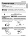
SafetyPrecautions
To prevent injury to the user or other people and property damage, the following instructions
must be followed.
• Incorrect operation due to ignoring instructions will cause harm or damage. The seriousness
is classified by the following indications.
• Because of the weight of the product, it is recommended that you have a helper to assist in
the installation.
WARNING This symbol indicates the possibility of death or serious injury.
CAUTION This symbol indicatesthe possibilityof injury or damage to property only.
• Meanings of symbols used in this manual are as shown below.
Q Be not to do.
sure
Be sure to follow the instruction.
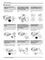
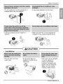
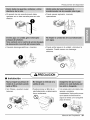
• Installation
WARNING
@@
• Improper assembly or installation may cause
incorrect operation, including injury, fire, and
poor performance electric shock hazards.
• It may cause explosion or fire.
• It may cause fire and electric shock.
C,
• It may cause failure and electric shock.
Owner's Manual 3

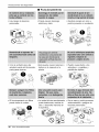
Safety Precautions
• Operation
• Otherwise, it will cause
electric shock or fire.
• It will cause electric shock or
fire.
ON
• It will cause electric shock or
fire.
• Otherwise it may cause fire
and electric shock accident.
• It will cause electric shock or
fire.
• It will cause electric shock or
fire.
• No grounding may cause
electric shock.
• It may cause fire and electric
shock.
• It will cause electric shock.
®
4 Room Air Conditioner

• The air conditioner must be operated in a
enclosed area to be most effective.
• It will cause electric shock or failure of
machine.
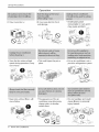
Safety Precautions
• It may cause explosion, fire, and burn.
Installation
• They are sharp and may
cause injury.
•Water may enter the unit and degrade the
insulation. It may cause an electric shock.
®
• It may cause failure of
appliance or performance
deteriorate.
• If the outer case is damaged,
it must be repaired or
replaced immediately.
Leaving it damaged could
result in the air conditioner
falling out of the window,
creating a safety hazard.
Owner's Manual 5

Safety Precautions
. It may cause injur y.
Operation
®
. It may causeelectricshock
anddamage.
• It will waste power
consumption in vain and it
may cause accident.
• Since the fan rotates at high
speed during operation, it may
cause injury.
"Operation without filters will
cause failure.
• This could injure the pet or
plant.
- It is an air conditioner, not a
precision refrigeration system.
• The appearance of the air
conditioner may deteriorate
change color, or develop
surface flaws.
• It is not sanitary and could
cause illness or personal
injury hazard.
6 Room Air Conditioner

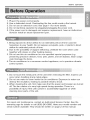
Before Operation
1. Plug in the power cord properly.
2. Use a dedicated circuit. Overloading the line could create a fire hazard.
3. Do not use an extension cord. See page 11 for more details.
4. Do not start/stop operation by plugging/unplugging the power cord.
5. If the power cord is damaged and requires replacement, have an Authorized
Servicer install an exact replacement part.
1. Being exposed to direct airflow for an extended period of time could be
hazardous to your health. Do not expose occupants, pets, or plants to direct
airflow for extended periods of time.
2. Due to the possibility of oxygen deficiency, ventilate the room when used
together with stoves or other heating devices.
3. Do not use this air conditioner for non-specified special purposes (e.g.
preserving precision devices, food, pets, plants, and art objects). Such usage
could damage the items.
4. The air conditioner is a consumer comfort appliance, not a precision climate
control system.
1. Do not touch the metal parts of the unit when removing the filter. Injuries can
occur when handling sharp metal edges.
2. Do not use water to clean inside the air conditioner. Exposure to water can
destroy the insulation, leading to possible electric shock.
3. When cleaning the unit, first make sure that the power and breaker are turned
off. The fan rotates at a very high speed during operation. There is a
possibility of injury if the unit's power is accidentally triggered on while
cleaning inner parts of the unit.
For repair and maintenance, contact an Authorized Service Center. See the
warranty page for details or call (800) 243-0000. Have your model number and
serial number available. They should be written on page 2 of this manual.
Owner's Manual 7

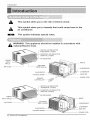
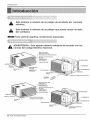
Introduction
This symbol alerts you to the risk of electric shock.
This symbol alerts you to hazards that could cause harm to the
air conditioner.
This symbol indicates special notes.
_lb ARNING: This appliance should be installed in accordance with
national Electric Code.
CABINET
FRONT
GRILLE
AIR FILTER
VERTICAL AIR DEFLECTOR
(HORIZONTAL LOUVER)
HORIZONTAL AIR DEFLECTOR
(VERTICAL LOUVER)
--AIR DISCHARGE
AIR INTAKE
(INLET GRILLE)
EVAPORATOR
CONTROL BOARD
REMOTE
CONTROLLER
BRACE
_-COMPRESSOR
CONDENSER
BASE PAN
POWER CORD
VERTICAL AIR DEFLECTOR
(HORIZONTAL LOUVER)
HORIZONTAL AIR DEFLECTOR
FRONT GRILLE-
AIR FILTER
AIR INTAKE
(INLET GRILLE)
BRACE
COMPRESSOR
8 Room Air Conditioner
EVAPORATOR
CONTROL BOARD
POWER CORD

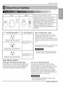
E/ectrical Safety
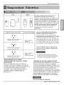
115V~ 230V~
Power cord may include a current
interrupter device. A test and reset button is
provided on the plug case. The device
should be tested on a periodic basis by first
pressing the TEST button and then the
RESET button. If the TEST button does not
trip or if the RESET button will not stay
engaged, discontinue use of the air
conditioner and contact a qualified service
technician.
Use Wall Receptacle Power Supply
@
Standard 125V,3-wiregrounding
receptaclerated 15A, 125VAC
@
Standard 250V, 3-wire grounding
receptacle rated 15A, 250V AC
@
Standard 250V, 3-wire grounding
receptacle rated 20A, 250V AC
Use 15 AMP. time
delay fuse or 15 AMP.
circuit breaker.
Use 20 AMP. time
delay fuse or 20 AMP.
circuit breaker.
Use of extension cords
Because of potential safety hazards, we
strongly discourage the use of an extension
cord. However, if you wish to use an
extension cord, use a CSA certified/UL-listed
3-wire (grounding) extension cord, rated 15A,
125V.
All wiring should be made in accordance with
local electrical codes and regulations.
Aluminum house wiring may pose special
problems. Consult a qualified electrician.
ELECTRICAL SAFETY
IMPORTANT GROUNDING INSTRUCTIONS
Air conditioner has a three-prong grounding plug on
its power supply cord, which must be plugged into
properly grounded three-prong wall receptacle for
your protection against possible shock hazard.
230, 208, and 2301208 VOLT UNITS
These units are equipped with a three-prong
grounding plug on the power supply cord, which
must be plugged into a matching properly grounded
three-prong wall receptacle for your protection
against possible shock hazard. If such an outlet is
not present, one must be installed by a qualified
electrician in accordance with the National Electrical
Code and local codes and ordinances.
DO NOT USE AN EXTENSION CORD on 230,
208, and 230/208 Volt units.
Owner's Manual 9

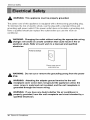
Electrical Safety
WARNING: This appliance must be properly grounded.
The power cord of this appliance is equipped with a three-prong grounding plug.
To minimize the risk of electric shock, use the plug with a standard three-slot
grounding wall power outlet. If the power outlet does not include a grounding slot,
have a qualified electrician replace the outlet before you use the room air
conditioner.
WARNING: Changing the outlet without making the appropriate wiring
changes will create an unsafe condition that could result in fire or
electrical shock. Refer all such work to a licensed and qualified
electrician.
Preferred method
Ensure proper ground
exists before use
WARNING: Do not cut or remove the grounding prong from the power
plug.
WARNING: Attaching the adapter ground terminal to the wall
receptacle cover screw does not ground the appliance unless the
cover screw is metal and not insulated, and the wall receptacle is
grounded through the house wiring.
WARNING: If you have any doubt whether the air conditioner is
properly grounded, have the wall receptacle and circuit checked by a
qualified electrician.
10 Room Air Conditioner

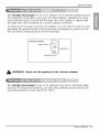
ElectricalSafety
We strongly discourage the use of an adapter due to potential safety hazards.
For temporary connections, use only a UL-listed adapter, available from most
local hardware stores. Ensure that the large slot in the adapter is aligned with
the large slot in the receptacle for a proper polarity connection.
To disconnect the power cord from the adapter, use one hand on each to avoid
damaging the ground terminal. Avoid frequently unplugging the power cord as
this can lead to eventual ground terminal damage.
Temporary method
Adapter Plug_
Metal Screw
Receptacle Cover
WARNING: Never use the appliance with a broken adapter.
We strongly discourage the use of an extension cord due to potential safety
hazards. For temporary situations, use only CSA certified and UL listed 3-wire
grounded extension cords, rated 15 A, 125 V.
Owner's Manual 11

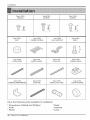
Installation
Type A: 16EA Type B:3EA Type C:5EA
(SCREW) (SCREW) (SCREW)
fL--_
E
F_
E
Type D:2EA Type E:2EA Type F:2EA Type G:2EA
(NUT) (FRAME CURTAIN) (SILL SUPPORT) (BOLT)
©
lO
Type H:I EA Type I:1EA Type J:l EA Type K:2EA
(FOAM-STRIP) (UPPER GUIDE) (FOAM-PE) (FRAME-GUIDE)
Type L:IEA Type M:IEA Type N:IEA Type O:IEA
(WINDOWLOCKINGBRACKET) (FOAM-PE) (DRAIN JOINT PIPE) (DRAIN WASHER)
G
Have the following tools available for installation:
* Screwdriver (Slotted and Phillips) * Ruler
* Knife * Hammer
* Pencil * Level
12 Room Air Conditioner

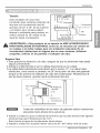
Installation
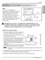
Size
This room air conditioner is
designed for installation in standard
double-hung windows with actual
opening widths from 22" to 36".
The upper and lower window sash
must open sufficiently to allow a
clear vertical opening of 15" from the
bottom of the upper sash to the
window stool.
15"min
(Withframecurtain)Sill
I
).
Interior wall
18 1/2"rain.
'(Withoutframecurtain)
Offset
1/2"to 11/4"
&
WARNING:This product is a WINDOW AIR CONDITIONER. As such,
a standard single=hung or double=hung window is required for proper
installation. Non=window installations, including using sleeves, holes
in walls, and other installations are not recommended.
Select the best location
1. To prevent vibration and noise, make sure
the unit is installed securely and firmly
2. Install the unit where the sunlight does not I _--------_Awning
shine directly on the unit.
Cooled air Heat
3. The outside of the cabinet must extend _ _ radiation
outward for at least 11" and there should_
be no obstacles, such as a fence or wall,/
within 20" from the back of the cabinet "--_ ,
because it will prevent heat radiation of the o
condenser.
co
Restriction of outside air will greatly reduce
the cooling efficiency of the air conditioner.
Fence
•All side louvers of the cabinet must remain exposed to the outside of the
structure.
4. Install the unit a little slanted so the back is slightly lower than the front(about W').
This will force condensed water to flow to the outside.
5. Install the unit with the bottom about 30"~60" above the floor level.
Owner's Manual 13

Installation
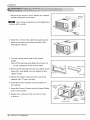
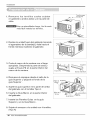
1. Remove the screws which fasten the cabinet
at both sides and at the back.
Use a long screwdriver and installing the
screws will be easier.
2. Slide the unit from the cabinet by gripping the
base pan handle and pulling forward while
bracing the cabinet.
3. Cut the window sash seal to the proper
length.
Peel off the backing and attach the Foam-Pe
to the underside of the window sash.
4. Remove the backing from the top Upper Guide
Foam-PE and attach it to the bottom of the
Upper Guide.
5. Attach the Upper Guide onto the top of the
cabinet with 3 Type A screws.
6. Insert the Frame Guides into the bottom of
the cabinet.
7. Insert the Frame Curtain into the Upper Guide
and Frame Guides.
8. Fasten the curtains to the unit with 4 Type
A screws.
Upper Guide
Foam-Pe
(Type A) Upper Guide
Screw
(Type A)
Frame Guides
Sc_rew
(Type A)
Frame
Guides
14 Room Air Conditioner

Installation
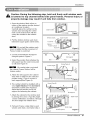
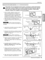
_k aution: During the following step, hold unit firmly until window sash
is lowered to top channel behind side panel frames. Personal injury or
property damage may result if unit falls from window.
1. Open the window. Mark a line on
center of the window stool(or desired
air conditioner location).
Carefully place the cabinet on the
window stool and align the center
mark on the bottom front with the
center line marked in the window
stool.
2. Pull the bottom window sash down
behind the upper guide until it meets.
:Do not pull the window sash
down so tightly that the movement of
Frame Curtain is restricted.
3. Loosely assemble the sill support
using the parts in Figure 3.
4. Select the position that will place the
sill support near the outer most point
on sill (See Figure 4)
• Be careful when you install
the cabinet (Frame Guides will be
broken easily).
5. Attach the sill support to the cabinet
track hole in relation to the selected
position using 2 Type A screws in
each support(See Figure 4).
6. The cabinet should be installed with a
very slight tilt(about V2") downward
toward the outside (See Figure 5).
Adjust the bolt and the nut of sill
support for balancing the cabinet.
7. Attach the cabinet to the window stool
by driving the screws (Type B:Length
sixteen millimeters and below.) through
the front angle into window stool.
8. Pull each Frame curtain fully to each
window sash track, and repeat step 2.
Upper G uid_in dOF_O_ie 1
Window Sash Upper Guide
Foam-Pe
Cabinet/ "_"_ __"_._ Iltl
Frame Curtain 1111_i__
Foam-Pe _ Figure 2
INDOOR _-------, r ,OUTDOOR I
- - I
Sill Support
Bolt ...... Nut F gure 3
Frame Guide
Screw(Type A)
"///7//////4 OUTDOORFigure
Screw(Type B)
Sill Support
Sill Support
;i[;i
.z- SashTrack
_FrontAngle
\
Screw(Type B) Figure 5
Owner's Manual 15

Installation
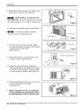
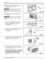
9. Attach each Frame Curtain the window sash
using screws (Type C).(See Figure 6)
: DO NOT DRILL A HOLE IN THE
BOTTOM PAN. The unit is designed to operate
with approximately 1/2" of water in bottom pan.
iiiiiiiiilHii/Hi!!iiii,,'i::ii iJiiiii!L,:i;i ii i iiiiii!!! I
I
[_- Figure S
10. Slide the unit into the cabinet.(See Figure 7)
: For security purpose, reinstall
screws(Type A) at cabinet's sides.
Screw(Type A)
/ PowerCord
/
7
Screw(TypeA) .,_ure
11. Cut the Foam-Strip to the proper length
and insert between the upper window sash
and the lower window sash.
(See Figure 8)
Foam-Strip
Figure 8
12. Attach the Window Locking Bracket with
a Type C screw. (See Figure 9)
13. Attach the front grille to the cabinet by
inserting the tabs on the grille into the tabs
on the front of the cabinet. Push the grille
in until it snaps into place. (See Figure 10)
14. Lift the inlet grille and secure it with a Type
A screw through the front grille.
(See Figure 11)
15. Window installationofroom airconditioner
isnow completed.See ELECTRICALDATA
forattachingpowercord toelectricaloutlet.
J Window Locking Bracket
Figure 9
Figure10
Figure11
16 Room Air Conditioner

OperatingInstructions
CAUTION: If you turn off the air conditioner or switch from cooling to
the fan, wait at least 3 minutes before setting to cooling again.
Operation
o_
Med
]-. cool
i
LowCool
Thermostat
4 s6
Off - Turns air conditioner off.
Med Fan - Med speed fan operation without cooling.
Low Fan - Low speed fan operation without cooling.
High Cool - Cooling with high speed fan operation.
Met Cool - Cooling with reed speed fan operation.
Low Cool - Cooling with low speed fan operation.
This automatically controls thetemperature of the indoor air.
Turn the knob so that arrow points to the larger marks for greater cooling,
Point the arrow to the smallermarks for more moderatecooling,
(i,e.the higher the number, the greater the cooling)
FOR NORMAL COOLING
1. Turn the operation switch to the High Cool or the Low Cool setting.
2. Set the thermostat control to the desired temperature mark (the mid-point is a
good starting position). If the room temperature is not satisfactory after a
reasonable time, adjust the control to a cooler or warmer setting, as
appropriate.
FOR MAXIMUM COOLING
1. Turn the operation switch to the High Cool setting.
2. Set the thermostat control to the largest temperature mark.
FOR QUIETER OPERATION
1. Turn the operation switch to the Low Cool setting.
2. Set the thermostat control as needed.
Owner's Manual 17

OperatingInstructions
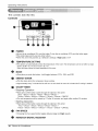
The controls look like this:
Controls
O
00000
0
POWER
oTo turn theair conditionerON, pushthe button.Toturn theair conditionerOFF,pushthebutton again.
oThis buttontakespriority over any otherbuttons.
oWhen the unit isfirst poweredup,it defaultsto settingsof High Cool at72F
O TEMPERATURESETTING
• This button can automaticallycontrol the temperature ofthe room.The temperaturecan beset withina range
of 60F to 86F by 1"E(16C to30% by 1"C)
Selectthelowernumberforlowertemperatureoftheroom.
O MODE
®
O
O
• Everytime you push this button, it will toggle between COOL, FAN, and DRY.
ENERGYSAVER
• The fan stops when the compressor stops cooling.
• Approximatelyevery 3 minutesthefanwill turnon and check theroom airto determineifcooling is needed.
ON/OFFTIMER
- Stopping Operation
• Each press of the button cycles through the options in this order:
1Hour -2Hours -3Hours -4Hours -5Hours -6Hours
7Hours- 8Hours- 9Hours- 10Hours- 11Hours- 12Hours- CANCLE
• The set temperature will be raised by 2'F after 30 minutes and again after another 30 minutes.
- Starting Operation
• Each press of the button cycles through the options in this order:
1Hour_ 2Hours _3Hours-4Hours _5Hours - 6Hours
7Hours- 8Hours* 9Hours * 10Hours_ 11Hours_ 12Hours- CANCEL
FAN SPEED
• PressingtheFanspeedbuttontogglesbetweenLowandHighspeeds.
REMOCONSIGNAL RECEIVER
18 Room Air Conditioner

OperatingInstructions
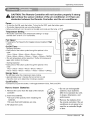
_k AUTION: The Remote Controller will not function properly if strong
light strikes the sensor window of the air conditioner or if there are
obstacles between the Remote Controller and the air conditioner.
Power
• To turn the Set ON, push the button. To turn the Set OFF, push the button again.
• This button takes priority over any other buttons.
• When you first turn it on, the set is on the High cool mode and the temp. at 72°F
Temperature Setting
• This button control the room temperature setting in a range
between 60°F to 86°F in 1°F increments.
Fan Speed
• Pressing the Fan Speed button toggles between Lowand High
speeds.
On/Off Timer
- Stopping Operation
• Each press of the button cycles through the options in this
order:
1Hour_ 2Hours_ 3Hours_ 4Hours_ 5Hours_ 6Hours_ ,.
7Hours_ 8Hours_ 9Hours _10Hours _ 11Hours_ 12Hours_ CANCLE.
• The set temperature will be raised by 2°F after 30 minutes and
again after another 30 minutes.
- Starting Operation
• Each press of the button cycles through the options in this
order:
1Hour_ 2Hours_ 3Hours_ 4Hours_ 5Hours_ 6Hours
7Hours_ 8Hours_9Hours _ 10Hours_ 11Hours_ 12Hours_ CANCLE.
EnergySaver
The fan stops when the compressor stops cooling.
• Approximately every 3 minutes the fan will turn on and
check the room air to determine ifcooling is needed.
Cool/Fan/Dry
• Everytime you push this button, it will toggle between COOL, FAN, and DRY.
Fan Speed
Timer Mode
Energy
Saver
How to Insert Batteries
1. Remove the cover from the back of the remote
controller
2. Insert two batteries.
• Be sure of the polarity when installing the
batteries.
• Be sure that both batteries are new.
3. Re-attach the cover.
®
• Do not use rechargeable
batteries. Such batteries
differ from standard dry cells
in shape, dimensions, and
performance.
• Remove the batteries from
the remote controller if the air
conditioner is not going to be
used foran extended length
of time.
Owner's Manual 19

Operating Instructions
Air Direction
The direction of air can be controlled wherever you
want to cool by adjusting the horizontal louver and
the vertical louver.
• HORIZONTAL AIR-DIRECTION CONTROL
The horizontal air direction is adjusted by
rotating the vertical louver right or left.
• VERTICAL AIR-DIRECTION CONTROL
The vertical air direction is adjusted by
rotating the horizontal louver forward or
backward.
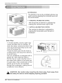
Drain Pipe
In humid weather, excess water may
cause the Base Pan to overflow. To
drain the water, remove the Drain Cap
and secure the Drain Pipe to the rear
hole of the Base Pan.
Press the drain pipe into the hole by
pushing down and away from the fins
to avoid injury.
This air conditioner is equipped with a
slinger fan. (See drawing, below.)
The fan has an outer ring that runs in
the water that collects in the base pan
if it gets deep. That condensate is then
picked up by the fan and expelled
through the condenser, making the air
conditioner more efficient.
(D Hang
Drain Cap
Ring
,_ CAUTION: Be careful when inserting the drain pipe. Push away from
the sharp fin area to avoid slipping injuring yourself.
20 Room Air Conditioner

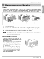
MaintenanceandService
Air Filter
Check the air filter at least twice a month to see if cleaning is necessary. Trapped
particles in the filter can build up and block the airflow, reducing cooling capacity
and causing an accumulation of frost on the evaporator. To clean the air filter:
(a) (b) (c)
1. Lift the inlet grille.
2. Remove the air filter from the front grille by pulling the air filter up slightly.
3. Wash the filter using lukewarm water below 40 °C (104 °F).
4. Gently shake the excess water from the filter and replace.
:DO NOT operate the air conditioner without a filter because dirt and lint will
clog it and reduce performance.
Cleaning the Air Conditioner
The front grille and Inlet grille may be
wiped with a cloth dampened in a mild
detergent solution.
The cabinet may be washed with mild
soap or detergent and lukewarm
water, then polished with Liquid Wax
for Appliances.
To ensure continued peak efficiency,
the condenser coils (outside of unit)
should be checked periodically and
cleaned if clogged with soot or dirt
from the atmosphere.
Owners Manual 21

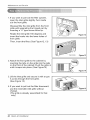
Maintenance and Service
1.If you want to pull out the filter upward,
open the inlet grille slightly. Turn inside
out the front grille.
Disassemble the inlet grille from the front
grille with separating the hinged part by
inserting a '"_"type screw-driver tip.
Rotate the inlet grille 180 degrees and
insert the hooks into the lower holes of
front grille.
Then, insert the filter. (See Figure12, 13)
2.Attach the front grille to the cabinet by
inserting the tabs on the grille into the tabs
on the front of the cabinet. Push the grille in
until it snaps into place. (See Figure14)
Figure12
Figure 13
3. Lift the inlet grille and secure it with a type
A screw through the front grille.
(See Figure 15)
4. If you want to pull out the filter downward,
use the reversible inlet grille without
change.
(The grille is already assembled for that
way.)
igure 15
22 Room Air Conditioner

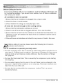
Before Calling for Service
Maintenance and Service
If you have problems with your air conditioner, read the following information and
try to solve the problem. If you cannot find a solution, turn off the air conditioner
and contact your dealer.
Air conditioner does not operate
1. Ensure that the air conditioner is plugged into a proper outlet.
2. Check the fuse or circuit breaker.
3. Check whether the voltage is unusually high or low.
Air does not feel cold enough on the cooling setting
1. Ensure that the temperature settings are correct.
2. Check to see if the air filter is clogged with dust. If so, clean the filter.
3. Ensure that the air flow from the outside is not obstructed and that there is a
clearance of over 20" between the back of the air conditioner and the wall or
fence behind it.
4. Close all doors and windows and check for any source of heat in the room.
Before calling for service, please review the following list of common
problems and solutions.
The air conditioner is operating normally when:
• You hear a pinging noise. This is caused by water being picked up by the fan on
rainy days or in highly humid conditions. This feature is designed to help remove
moisture in the air and improve cooling efficiency. See the section on Slinger
Fan, page 20.
• You hear the thermostat click. This is caused by the compressor cycle starting
and stopping.
• You see water dripping from the rear of the unit. Water may be collected in the
base pan in highly humid conditions or on rainy days. This water overflows and
drips from the rear of the unit.
• You hear the fan running while the compressor is silent. This is a normal
operational feature.
Owners Manual 23

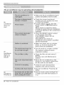
Maintenance and Service
The air conditioner may be operating abnormallywhen:
_,_ _ ..............
Air
conditioner
does not
start
Air
conditioner
does not
cool as it
should
Air
conditioner
freezing up
• Make sure the air conditioner plug is
pushed completely into the outlet.
• Check the house fuse/circuit
breaker box and replace the fuse
or reset the breaker.
• If power failure occurs, turn the
mode control to Off.(Mechanical
Type).
When power is restored, wait 3
minutes to restart the air conditioner
to prevent tripping of the compressor
overload.
• Press the RESET button located
on the power cord plug.
If the RESET button will not
stay engaged,
discontinue use of the air
conditioner and contact a qualified
service technician.
• Make sure there are no curtains,
blinds, or furniture blocking the
front of the air conditioner.
• Turn the knob to a higher number
The highest setting provides.
maximum cooling.
• Clean the filter at least every 2
weeks.
See the care and Maintenance
section.
• When the air conditioner is first
turned on, you need to allow time
for the room to cool down.
• Check for open furnace floor
registers and cold air returns.
• See Air Conditioner Freezing Up
below.
• Set the mode control at High Fan
or High Cool with thermostat at 1
or 2.
24 Room Air Conditioner

ManualdelPropietario25

,p
PARA SUS ARCHIVOS
Escriba aqui el modelo y numero de serie:
Modelo n°:
Serie n°:
Puede encontrar los numeros en la etiqueta de la parte
lateral del producto .
Nombre del distribuidor:
Fecha de compra:
• Adjunte su recibo a esta pagina con la grapadora para
el momento que Io necesite para probar la fecha de su
adquisici6n o para la validaci6n de la garantia.
LEA ESTE MANUAL
En su interior encontrara muchos consejos utiles sobre la
utilizaci6n y mantenimiento de su acondicionador de aire.
Unos pocos cuidados per su parte le pueden ahorrar
mucho tiempo y dinero durante la vida de su
acondicionador de aire.
En la tabla de consejos para la soluci6n rb,pida de
problemas encontrara muchas respuestas a los problemas
mas habituales. Si revisa primero nuestra Tabla de
Consejos para la solucion rapida de problemas, tal vez no
necesite Ilamar nunca al servicio tecnico.
PRECAUClON
oContacte a un Centro de Servicio Autorizadopara reparar o
realizar el mantenirniento de esta unidad. Llame a 1-800-243-0000
para ubicar el CSA mas cercano.
oEl aire acondicionado no es apto para ser usado per nihos
pequehos o discapacitados sin la supervision adecuada.
oLos niSos peque5os deben ser supervisadospara asegurar que
no jueguen con elaire acondicionado.
oSi hay que cambiar el cablede alimentaci6n, solicitea un tecnico
de servicio que instaleun recambioexacto.
• El trabajo de la instalaci6ndebe serrealizado deacuerdo al
C6digo Electrico Nacional, _nicamente por el personal calificado y
autorizado.
26 Aire Acondicionador

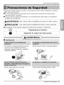
PrecaucionesdeSeguridad
Para prevenir tanto lesiones al usuario u otras personas como daSos materiales, es preciso
seguir estas instrucciones.
• La incorrecta operaci6n del aparato como consecuencia de ignorar las instrucciones
provocara dafios o lesiones.
• A cause del peso pesado del producto, se recomienda que usted tenga a un ayudante a
participa en la instalaci6n.
, ,ADVERTENClA Este simbolo indica la posibilidad de lesiones mortales o graves.
,PRECAUCION Este simbolo indica la posibilidad de lesiones o daSos materi-ales.
• El significado de los s[mbolos utilizados en este manual se indica a continuaci6n.
Q Aseg_rese de no hacerlo.
J
AsegOrese de seguir las instrucciones.
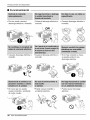
• Instalacion
(, ,ADVERTENCIA)
• Un montaje o instalaci6n defectuoso puede
provocar un funcionamiento incorrecto,
incluyendo riesgos de lesiones, incendios o
descargas electricas. _i l Illl ............
• Puede causar explosi6n o incendio.
• Puede causar incendio y descarga electrica.
• Puede causar descarga electrica y fallos.
Manual del Propietario 27

Precauciones de Seguridad
• Funcionamiento
• De otro modo, causara.
descarga electrica o incendio.
• Causara.descarga electrica o
incendio.
• En caso que no, puede
• Causara descarga electrica o
incendio.
• Causara descarga electrica o
incendio.
ON q
• Causara descarga electrica o
incendio.
• Si no hay conexi6n a rnasa,
se puede producir una
descarga electrica.
causar incendio y accidente
de cqrto circuito.
• Puede causar descarga
electrica.
28 Aire Acondicionador

PrecaucionesdeSeguridad
• El aparato de aire acondicionado debe
operarse en un a.reacerrada para ser ma.s
efectivo.
• Puede causar explosion, incendio,
quemaduras.
• Causara.descarga electrica o incendio. • Puede entrar agua en la unidad y disminuir la
aislacion. Puede causar una descarga
electrica.
• Instalacion
PRECAUCION
• Son filosas y pueden causar
lesiones.
• Puede provocarel fallo de un
electrodomesticoo deterioraci6n
de surendimiento.
• Silacarcasaexteriorestadafiada,debe
repararseorecambiarse
inmediatamente.Dejarlapodriaprovocar
queelaparatodeaoondicionadose
caigadelaventana,conelconsiguiente
peligrodelesiones.
Manual del Propietario 29

Precauciones de Seguridad
• Hay riesgo de lesiones
personales.
• Funcionamiento
®
• Puede causar descarga
electrica y daSo.
• Gastara.energia en vano y
podria provocar un accidente.
• Comoel ventiladorgiraaalta
velocidadcuandoest,.funcionando,
puedecausarlesiones.
Q
• El funcionamiento sin filtros
puede da_ar la unidad.
• Este puede causar lesiones o
da_os en la mascota o la
planta.
• Puede causardaSo a los
anirnales o v egetales y
p@dida de objetos.
\
• Launidaddelaire acondicionado
puededeteriorarse,cambiarde
color,o desarrollarmanchasen
la superficie.
®
• No es sano y podria provocar
enfermedades o peligros de
lesiones personales.
30 Aire Acondicionador

1. Coloque el enchufe correctamente.
Previo al Funcionamiento
2. Use un Qnico circuito para este aparato. Recargar el circuito podria provocar
un riesgo de incendios.
3. No utilice un alargador. Consulte la pSgina 35 para m_s detalles.
4. No arranque/detenga el funcionamiento enchufando/desenchufando el cable
de corriente el6ctrica.
5. Si el alargador est_ da_ado y ha de ser recambiado, solicite a un t6cnico
autorizado que instale un recambio exacto.
1. Estar expuesto al flujo directo de aire por un periodo largo de tiempo puede
constituir un riesgo para su salud. No exponga alas personas, mascotas o
plantas al flujo directo por periodos largos de tiempo.
2. Debido a la posibilidad de falta de oxigeno, ventile la habitaci6n cuando se
use al mismo tiempo que estufas u otros dispositivos de calefacci6n.
3. No use este acondicionador de aire para prop6sitos determinados no
especificados (por ej.: preservar dispositivos de precisi6n, alimentos,
cachorros, plantas y objetos de arte). Tales usos puede da_ar los elementos.
4. El aparato de aire acondicionado es un aparato dise_ado para el confort del
consumidor. No es un sistema aclimatizador.
1. No toque las partes de metal de la unidad cuando quite el filtro. Puede
lastimarse cuando manipule bordes filosos de metal.
2. No use agua para limpiar adentro del acondicionador. La exposici6n al agua
puede destruir la aislaci6n y esto a su vez provocar una descarga el6ctrica.
3. Cuando limpie la unidad, asegQrese que la corriente y el interruptor est6n
desconectados. El ventilador gira a muy alta velocidad cuando est_
funcionando. Existe la posibilidad de lesionarse si la energia se conecta
accidentalmente cuando est6 limpiando las piezas internas de la unidad.
Para reparaciones y mantenimiento, p6ngase en contacto con un centro de
servicio autorizado. Consulte la p&gina de garantia o Ilame al nQmero (800) 243-
0000. Tenga su nQmeor d emodelo y nQmero de serie a mano. Los encontrar8
en la pSgina 25 de este manual.
@
Manual del Propietario 31

In#oduccidn
Este simbolo Io advierte de un peligro de accidente por corriente
el_ctrica.
Este simbolo Io adiverte de un peligro que pueda causar un da_o
del ventliador.
r_mrta Este sirnbolo significa condicciones especiales.
_k DVERTENCIA : Este aparato deberia instalarse de acuerdo con las
normas del C6digo El_ctrico National.
GABINETE
REJILLA
FRONTAL
FILTRO DE
NRE
DE AIRE
ANDEJA DE
TRADA)
DEFLECTOR DE
(VENTANILLAS HORIZONTALES)
DEFLECTOR HORIZONTAL
(VENTANILLAS
VERTICALES)
SALIDA DE AIRE
EVAPORADOR
DECONTROL
PANEL
CONTROL_
REMOTO
DEFLECTOR DE AIRE
HORIZONTAL
SUSPENSORES
CONDENSADOR
CNDEJA
CABLE DE CONEXlON ELECTRICA
GABINETE
REJILLA
FILTRO DE
AIRE
DEFLECTOR HORIZONTAL
VENTANILLAS
VERT CALES
SALIDA DE AIRE
DE AIRE
(BANDEJA DE ENTRADA)
EVAPORADOR
DECONTROL
PANEL
SUSPENSORES
-CONDENSADOR
_-*_CABLEDECONEXION
ELECTRICA
32 Aire Acondicionador

SeguraidaEl#ctrica
115V-
_T
230V-
Utilice el enchufe de la pared Consume de Energia
@
Standard 125V, enchufe de 3
Lineas de 15A, 125V AC
©
Standard 250V, enchufe de 3
LIneas de 15A, 250V AC
@
Standard 250V, enchufe de 3
LIneas de 20A, 250V AC
Utilice un fusible de
15AM P. o un
Interruptor de 15AMP.
Utilice un fusible de
20AMP. o un
Interruptor de 20AMP.
SEGURIDAD ELECTRICA
NSTRUCCIONES DE CONEXION A TIERRA
IMPORTANTES
El aire acondicionado tiene una clavija de
conexi6n a tierra de tres patas en su cable de
suminstro de energia, que dever& enchufarse en
un tomacorriente de pared de tres paras
conectado a tierra adecuadamente para su
protecci6n contra un posible riesgo de
electrocuci6n.
El cable de alimentaci6n puede induir un
dispositivo interruptor de corriente. La
carcasa del enchufe cuenta con un boton de
prueba y otto de reinicio. El dispositivo debe
comprobarse periodicamente presionando
primero el boton TEST y despues RESET. Si
el boton TEST no se desconecta o si el boton
RESET no permanece activo, suspenda el
uso del aire acondicionado y pongase en
contacto con un tecnico de servicio
cualificado.
USO DE CORDONES DE EXTENSION
Debido al potencial de peligro a su
seguridad bajo ciertas circunstancias
recomendamos encaredidamente no utiliar
cordones de extensi6n. Sin embargo, si
usted decide usar un cord6n de extensi6n,
es absolutamente necesario que este sea
un cord6n listado bajo UL de tres espigas
con conexi6n a tierra calificado 15A, 125V.
Todo el cableado deber& realizarse de
acuerdo con los c6digos y reglamentos
el_ctricos locales.
El cableado dom6stico de aluminio
podria ocasionar problemas espedales.
Consulte a un electricista calificado.
UN/DADES DE230, 208y230/208 VOLT/OS
Estas unidades est&n equipadas con una davija de
conexi6n a tierra de tres patas en el cable de
suministro de energia que deberb, enchufarse en un
tomacorriente de pared para tres paras conectado a
tierra adecuadamente (ver las ilustraciones a
continuaci6n) para su protecci6n contra un posible
riesgo de electrocucion. Si no tiene un tomacorriente
con estas caracteristicas, un electricista calificado
deverA instalar uno de acuerdo con el C6digo
EIctrico Nacional y los c6digos y normas locales.
No use un cane de extension.
Manual del Propietario 33

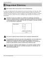
SeguridadElectrica
_k Este equipo debe estar puesto a tierra debidamente.
El cable de al[mentaci6n esta equ[pado de una toma de tierra con tres pins. Para
minimizar el peligro de una lesi6n por corriente electrica, utilice una toma con
enchufe de tierra estandar con tres contactos. Si el enchufe de pared no contiene
un borne de tierra, antes de usar el ventilador haga camb[ar el enchufe por un
electr[c[sta.
&
Cambiar la toma sin realizar los cambios de cableado apropiados
crear_ un estado el_ctrico inseguro que podrfa resultar en un incendio
o descarga el_ctrica. Para todo este tipo de trabajos, consulte siempre
con un electricista cualificado.
Metodo preferido
AsegL_reseque existe debida
neutralizaci6n antes de utilizar el
aparat0.
&
No corte ni quite el borne de tierra de la clavija de alimentaci6n
El acoplamiento del borne de tierra del adaptador con el tornillo de la
cubierta del enchufe de pared no pondr_ el equipo a tierra, si el
tornillo de la cubierta no es de metal y est_ aislado y el enchufe de
pared no est_ puesto a tierra a tray,s de la red de la casa.
En el caso de cualquier duda respecto a la correcta puesta a tierra
del ventilador, haga revisar el enchufe de pared y el circuito pot un
electricista profesional.
34 Aire Acondicionador

SeguridadElectrica
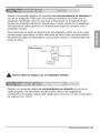
Debido a eventuales peligros de seguridad no recomendamos en absoluto el
uso de un adaptador. $61o para una conexi6n transitoria se puede usar el
adaptador clasificado como UL que est,. a disposici6n en la mayor_a de las
tiendas de productos electricos. Atienda que e orificio grande en el adaptador
corresponda al orificio grande en el enchufe para Iograr la conexi6n con la
polaridad correcta.
Desconectando el cable de alimentaci6n del adaptador utilice una mano para
sendas partes para evitar un daSo del borne de tierra. Evite una desconexi6n
frecuente del cable de alimentaci6n, pues puede causar un eventual daSo del
borne de tierra.
Metodo temporal
Adaptad0r
LlTornillo de Metal
Cubierta del
Interruptor
Nunca utilice el equipo con un adaptador da5ado.
Debido a un eventual peligro no recomendamos en absoluto el uso de un
cable alargador. En situaciones excepcionales utilice s61oalargadores
certificados con puesta a tierra CSA clasificados como UL con tres conductores
de valores 15 A, 125 V.
Manual del Propietario 35

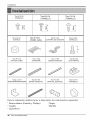
Instalacion
TipoA:16EA Tipo B:3 EA Tipo C:5 EA
(TORNILLO) (TORNILLO) (TORNILLO)
F_
U'
E
E
!
F_
E
E
Tipo D:2 EA Tipo E:2 EA Tipo F:2 EA Tipo G:2 EA
(TUERCA) (PANELGUiA) SOPORTE DEALFEIZAR) (TORNILLO)
©
10
Tipo H:I EA Tipo I:1EA TipoJ:l EA Tip,o K:2 EA
(TIRA DE GOMA) (SUPERIOR) (BANDA ADHESIVA) (GUIA MARCO)
Tipipo L:I EA Tipo M:I EA Tipo N:I EA Tipo O:1 EA
3HAPADES0PORTEPARALAWNrANA(BANDAADHESlVA) (TAPADEL DESAGOE) (ARANDELA)
%
G
Para la instalaci6n deberia tener a dispostci6n los instrumentos siguientes:
* Destornillador (Estrella y Phillips) * Regla
* Cucjillo * Martillo
* Lapiz Nivel
36 Aire Acondicionador

Instalacidn
i
a,
Tamaffo
Este ventilador de casa esta
construido para ventanas estb.ndar de
dos alas con [a extensi6n real de
apertura de 22" a 36". El ala superior
y el inferior de la ventana deben
abrirse Io suficiente para producir un
orificio vertical de 15" desde el ala
superior hasta el antepecho.
15" min Banqueta[[
/\°
i
Pared inten
18 1/2"min.
s ncortnade marco
_Compensaci6n
1/2"to 11/4"
Sill
Exterior
ADVERTENCIA : Este producto es un aparato de AIRE ACONDICIONADO
PARA INSTALACION EN VENTANAS. Como ta[, se necesita una ventana de
un cuelgue o de dobie cueigue para una instaiaci6n adecuada. No se
recomiendan instalaciones en lugares que no sean ventanas, utilizando
casquillos, orificios en las paredes ni cualquier otto tipo.
Espacio libre
1.Para prevenir la vibraci6n y el ruido, asegure de que la unidd este insta alada
segura y fimemente.
2.1nstale la unidad donde el sol no refleje directmente en la unidad.
3.La salida debe extenderse hacia afuera por Io menos 11" y no debe haber
obstaculos, como cercas o paredes, en 20" de la parte de atras del gabinete
porque va ha prevenir la rediaci6n de calor del condensador. Restriciones dl
aire de fuera reducira grande mente la eficiencia del alre
|
Aire enfriado_ _ Radiacion
_ de calor
AIr'ededorde 1/2"
,] Porencimade 20"
\\\\\\\\\\\\\\\\\\\\\\\\\\\\\\ \
Valla
Todas las ventanillas de los lados del gabinete deben mantenerse
expuestas hacia afuera de la estructura.
4.1nstale la unidad un poco inclinada de tal forma que la parte trasera est_ ligeram
entemas baja que fl frente(cerca de 1/2").
Esto forzara el agua del condensador hacia afuera.
5.1nstale la unidad con la parte inferior cerca de 30"~60" arriba nivel de suelo.
Manual del Propietario 37

Instalacion
1. Remueva los tornillos cuales sujetan
el gabinete a ambos lados yen la parte de
atr&s.
Use un atornillador largo. Asi le ser&
mAs fAcil instala los tornilos.
Tornillos para
transporte
2. Deslice la unidad fuera del gabinete tomando
el agarradero de la bandeja y hale hacia el
frente mientras mantiene el gabinete.
3. Corte el marco de la ventana con el largo
apropiado. Desprenda la parte de atr&s y
sujete el Foam-PE en la parte inferior del
marco de la ventana.
Superior
Banda Adh _ive
4. Remueva el empaque desde el sello de la
guia Superior y p_guelo al fondo de la
guia Superior.
5. Sujete la guia superior en la parte de arriba
del gabinete con 3 tornillos Tipo A.
6. Inserta la Guia Marco en la parte inferior
del gabinete.
7. Inserte los Paneles Guias en la guia
Superior yen la Guia Marco.
(Tipo A)
Screv
(Tipo
Screw
Superior
-_,-. Guia Marco
Screw
Guia Marco (Tipo A)
8. Sujete el armazon a la unidad con 4 tornillos.
(Tipo A)
38 Aire Acondicionador

Instalacion
Precauti6n: En lassiguientes instrucciones,sostenga la unidad firmemente
hastaque la parte corrediza de la ventana descanse sobre la parte superior
del canal y pot detr_s del marco de los paneles corredizos. Puede haber
lesiones o da_os si la unidad se cae de la ventana.
1. Abra la ventana. Marque una linea en el
centro del banqueta de la ventana(o la
ubicaci6n deseada del aire acondicionado).
Cuidadosamente ubique el gabinete en la
banqueta de la ventana y alinee la marca
central en el frente inferior con el centro de la
linea marcada en la banqueta de la ventana.
2. Hale hacia abajo la parte inferior de la
ventana hasta que se una detras de la guia
superior.
No hale la ventana hacia abajo tan
apretadamente que el movimiento del panelguia sea
restringido.
Guia Superior
de la Ventana
Angulo de Delante Figura 1
Marco de Venta
Banda adhesi
Gabinet _-"_"__. Illil
Panel Gufa Nil I_ __
BandaadhesivaI_igura 2
3. Ligeramente ensamble el soporte del alfeizar
usando las partes de la Figura 3.
4. Seleccione la posici6n que ubicara el soporte
del alfeizar cerca del punto mas exterior del
alfeizar.(Ver Figura 4)
Tenga cuidado al instalar el
gabinete(las Guias Marco se rompen facilmente).
5. Pegue el soporte antepecho a los rieles de la
caja en relacion a la posicion deseada
usando dos tornillos Tipo A en cada soporte.
(Vet Figura 4)
6. El gabinete debe ser instalado con una
pequefia caida(cerca de W') hacia abajo
hacia afuera (Ver Figura 5).
7. Adjunte el gabinete al banquete de la ventana
atornillando los tornillos (Tipo B: Largo
dieciseis milimetros y menos.) a traves del
angulo frontal en la banqueta de la ventana.
8. Hale cada panel guia completamente a cada
lado de la ventana y repita del paso 2.
Interior _ -- , Exterior
- -
e del Alfeizar
Tornillo .......... _ Tuerca Figura 3
Guia Marco
Interi_
Tornillo(Tipo A)
,,
, • JJ
_Gabinete _-
///////////4 Exterior Figura 4
Tornillo(Tipo B)
Soporte del Alfeizar
o
Soporte del Alfeizar _-
_ Pista de
Marco
•_ -Angulo de Delante
Tornillo(Tipo B)
Figura 5
Manual del Propietario 39

Instalacion
9. Adjunte cada Panel Guia a cada lado de la
ventana usando tornillos (Tipo C).
(Ver Figura 6)
No perfore la charola del fondo.
La unidad est,. diseSada para operar con
aproximadamente 1/2" de agua en la charola del
fondo.
10. Deslice el chasis dentro del gabinete.
(Ver Figura 7)
: Por razones de seguridad, re
instale los tornillos(Tipo A) en los lados del
gabinete.
11. Corte la Tira De Goma a la medida
apropiada e introdQzcala entre la parte
superior e inferior de la ventana.
(Ver Figura 8)
12. Sujete la Chapade Soporte En El Marco De
La Ventana con untornillo Tipo C.
(Ver Figura 9)
13. Pegue el panel frontal a la caja insertando
los fijadores en el panel adentro los del
panel de la caja. (Ver Figura 10)
Figura6
Tornillo(Tipo A)
Conrdon
deAlimentacion
jJ
/
Tornillo(TipoA) Figura 7
Tira de Goma
Figura8
Chapa de soporte para
la ventana
Figura9
Figura10
14. Levante la parrilla de entrada y ajtJstela
con tornillos Tipo A, atraves de la parrilla
frontal. (Ver Figura 11)
15.Ahorala instalaci6ndel aireacondicionado
en laventanaescompletada,Vealos DATOS
ELECTRICOSpara instalarel cablede
alimentaci6nenlatoma decorriente.
Figura11
40 Aire Acondicionador

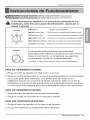
Instruccionesdefuncionamiento
Si Vd. desconecta eJ ventilador o Io conmuta del enfriarniento a la
ventilaci6n, antes del nuevo ajuste del enfriamiento espere pot Io
menos 3 minutos,
Operation
of_
", °
|
Low Cool
Thermostat
41 t 6
O ff(Apagado) :Apagael aireacondicionado.
MedFan(Ventilad0rMedio) :Permitela0peraci6ndelavel0cidadmediadelventihd0rsinenfriar,
LowFan(Ventilad0rBajo) :Perrnitela0peraci6ndelavel0cidadbajadelventiladorsinenfriar,
HighCool(EnfriamientoAlto) :Perrniteenfriarconla0peraci6ndelavelocidadaltadelventilad0r.
MedCool(Enfriamient0Medi0) :Permiteenfriarconla0peraci6ndelavel0cidadmediadelventilad0r,
LowCool(EnfriamientoBajo) :Permiteenfriarconlaoperaci6ndelavelocidadbajadelventilador,
La temperatura del aire interno ser,;ficontrolada
automaticamente. Mientras mas alta sea la marca mas fifo
estara el aire internio. La temperatura se selecciona
3osicionando el control en la marca deseada.
(es decir, a mayor sea el numero, mayor ser_.el enfriamiento)
PARA UN ENFRIAMIENTO NORMAL
1. Ponga el bot6n de operation en High Cool o Low Cool.
2. Ajuste el control del Termostat en la marca deseada(usualmente el punto medio
es un buen punto para comenzar). Si la temperatura del cuarto no es
satifactoria despues de un periodo de fiempo razonable, ajuste el control de
temperatura a una marca mas grande (para una temperatura interna mas fria)
o a una marca mas pequefia (para que la temperatura interna sea menos fria).
PARA UN ENFRIAMIENTO MAXIMO
1. Ponga el bot6n de operation en la marca m&s grande.
2. Ponga el control del Termostat en la marcam&s grande.
PARA UNA OPERACION SILENCIOSA
1. Ponga el bot6n de operation en la marca m&s pequefia.
2. Ponga el termostat en la temperatura interior deseada.
Manual del Propietario 41

Instruccionesdefuncionamiento
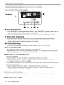
Los controles tienen este aspecto:
Controles
0
00000
O Enecndido/Apagado
• ParaENCENDERelsistemapresioneelboton, yparaAPAGARLOpresioneelbotonotravez.
• Estebotontieneprioridadsobretodoslosotrosbotones.
• Cuando se enciende el aparato pot primera vez,usar_, los ajustes del modo High Cool a 72°F
@ Ajuste de la Temperatura
• Este boton puede controlar la ternperatura del cuarto autornaticamente. La ternperatura
se puede ajustar de grado en grado, desde 60 °F hasta 86°F cada 1°F.Seleccione el
ntJmero m_s bajo para la temperatura m_s baja en el cuarto.
@ Frio/Ventilador/Seco
•Cada vez que usted presione este boton, este seSalara entre COOL, FAN y DRY.
@ Ahorrador de energia
El ventilador se detiene cuando el compressor no sigue enfriando.
•Aproximadamente cada 3 minutos el ventilador se encender& y necesitar_ verificar la temperatura
del cuarto para saber si es necesario mas enfriamiento.
@ Marcador de encendido/Apagado
- Operacion de Parada:
• Con cada pulsaci6n del bot6n se realiza un ciclo por las opciones en este orden:
1 hora---,2 horas---_3 horas---,4 horas---,5 horas---,6 horas---W horas ---,8 horas ---,9 horas
---,10 horas ---'11 horas'_, 12horas---_ CANCEL
• Latemperatura fija se elevara 2 °Ftranscurridos 30 minutos y de nuevo transcurridos otros 30 minutos.
- Operacion de Iniciacion:
• Con cada pulsaciOn del botOnse realiza un ciclo por las opciones en este orden:
1 hora---_2 horas---_3 horas---,4 horas---,5 horas---,6 horas---W horas---,8 horas---,9 horas
---,10 horas---,11 horas---4 2 horas---_CANCEL
@ Velocidad del Ventilador
• Pulsar el bot6n de velocidad del ventilador hace cambiar las velocideades entre Low y High.
@ RECEPTOR DE SENAL
42 Aire Acondicionador

Instruccionesdefuncionamiento
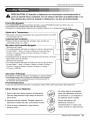
PRECAUTI6N: El mando a distancia no funcionar_ correctamente si
una luz fuerte hace contacto con el sensor del aire acondicionado o si
hay obs_culos entre el mando a distancia y el aire acondicionado.
Enecndido/Apagado
• Para ENCENDER el sistema presione el bot6n, y para APAGARLO presione el bot6n otra vez.
• Este bot6n tiene prioridad sobre todos los otros botones.
• Cuando Ud. Io enciende por primera vez, el sistema est,. en el y la temperatura es de 72°F.
Ajuste de la Temperatura
• Este bot6n controla la temperatura de la sala entre los 60°F y los 86°F
en incrementos de 1°F.
Velocidad del Ventilador
• Pulsar el bot6n de velocidad del ventilador hace cambiar las |
/
velocidades entre Low y High.
Marcadorde Encendido/Apagado
- Operaci6n de Parada:
• Con cade pulsaci6n del bot6n se realiza un ciclo pot las opciones
en este orden: 1 hora.-, 2 horas.-,3 horas.-,4 horas.-,5 horas-,
6 horas--,7 horas--,8 horas_9 horas--,10 horas--,11 horas --,
12 horas--,CANCEL
• La temperatura fija se elevate. 2°F transcurridos 30 minutos y de nuevo
transcurridos otros 30 minutos.
- Operaci6n de Iniciaci6n:
• Con cade pulsaci6n del bot6n se realiza un ciclo por las opciones
en este orden: 1 hora--, 2 horas--,3 horas--,4 horas--,5 horas--,
6 horas--,7 horas--,8 horas--,9 horas--,10 horas--,11 horas --,
12 horas--,CANCEL
Power
• Temp •
I FanSpeed
I Timer Mode
Energy
Saver
Ahorrador de Energia
El ventilador se detiene cuando el compressor no sigue enfriando.
• Aproximadamente cada 3 minutos el ventilador se encendera,
y necesitar_, verificar la temperatura del cuarto para saber si
es necesario ma.senfriamiento.
Frio/Ventilador/Seco
• Cada vez que presione este bot6n, las palabras COOL, FAN y DRY apareceran alternadamente.
Como Poner las Baterias
1.Quite la tapa de la parte posteriordel telemando.
Paraello hagadeslizar la tapasegt]n la direcci6n
della flecha.
2. Introduzcalas dos baterias, Respetesiempre la
polaridadal instalarlas pilas.Use bateriasnuevas.
3.Volvera cerrar,resbalandola tapa hastala
posici6ninicial.
®
@
• No utilice bateris recargables,
estas son diferentes de forma,
de dimensi6n y uso respecto a
las baterias secas usuales,
• Seque las baterias del
telemando cuando el
acondicionador no vaya a ser
usado durante un largo periodo.
Manual del Propietario 43

Instruccionesdefuncionamiento
La direcci6n del aire
La direcci6n del aire puede ser controlada cuando
usteddesee enfriar, ajustando la palanca vertical
y la palanca horiziontal.
• CONTROL DE LA DIRECCION HORIZONTAL DEL AIRE
La direcci6n horizontal del aire es ajustada
rotando lapalanca vertical hacia la derecha o
hacia la izquierda.
• CONTROL DE LA DIRECCION VERTICAL DEL AIRE
La direcci6n vertical del aire es ajustada rotando
la palanca horizontal hacia adelanto o hacia
atrAs.
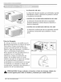
Tubo de Desag_e
En climas h6medos, es posible que la
Bandeja Evaporadora se Ilenne de agua.
Para quitar el agua acumulado, es
preciso conectar el tubo de desagOe.
Quite la Tapa del DesagOe y conecte el
Tubo a la Bandeja Evaporadora.
Este aparato de aire acondicionado va
equipado con un ventilador de
extracci6n. (Vease la ilustraci6n de
abajo). El ventilador tiene un anillo
externo que gira en el agua que recoge
en la plancha base al entrar en
profundidad. La condensaci6n la recoge
el ventilador y la expulsa a traves del
condensador, haciendo mas eficiente al
aparato de aire acondicionado
ue
Tapa_lE_
deldesagQe
Tubo
_ RECALITI6N: Tenga cuidado al insertar el tubo de drenaje. Al_jalo de
la area aguda para evitar el deslice y lesiones por usted mismo.
44 Aire Acondicionador

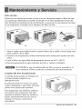
Mantenimientoyservicio
Filtro de Aire
Revise por Io menos dos veces al mes si no es necesario limpiar el filtro de aire.
Las particulas detenidad se pueden acumular en el filtro impidiendo el flujo del
aire, limitando el rendimiento de enfriamiento y causando la acumulaci6n de hielo
en el evaporador. Proceder de la limpieza del filtro de aire:
(a) (b)
i
(c)
1. Abra la rejilla hacia arriba tirando la parte inferior de la rejilla o hacia abajo tiran
parte superior de la rejilla.
2. Usando una lengueta,tire el filtro lieramente hacia arriba para sacarlo por aba
arriba.
3. Lave el filtro con agua tibia de temperatura menor de 40°C (104°F).
4. Escurra ligeramente el agua sobrante del filtro y vuelva a instalarlo.
NO OPERE el aire acondicionado sin filtro ya que la suciedad y el
tamo obstruira el filtro y reducira la eficiencia del funcionamiento.
Limpieza del Aire Acondicionado
La parrilla frontal puede ser limpiada con
un trapo hQmedo mojado en un
detergente suave.
El gabinete puede ser lavado con jab6n
suave o detergente y agua tibia, entonces
pulido Cera Liquida para aparatos.
Para asegurarse una eficiencia continua,
las bobinas del condensador (del lado
expuesto al exterior) debe ser revisado y
lavado peri6dicamente sea por que se
tranque con basura o polvo de la
atmosferico.
Manual del Propietario 45

Mantenimientoyservicio
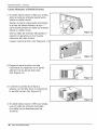
Como Remover la Parilla Frontal
1. Si usted desea sacar el filtro por arriba,
abra la rejilla de entrada ligeramente.
Vuelte la rejilla frontal.
Separe la parte engoznada insertando
la punta del destornillador de tipo "-"
para desensamblar la rejilla de entrada
desde la rejilla frontal.
Gire la rejilla de entrada 180 grados e
inserte los ganchos en los huecos
inferiores del rijilla frontal.
Luego, inserte el filtro. (Ver Figura12, 13
" Inlet Grille
Figura12
Figura13
2. Pegue el panel frontal a la caja
insertando los fijadores en el panel
adentro los del panel dela caja.
(Ver Figura 14)
Figura14
3. Levante la parrilla de entrada y
ajt_stela con tornillos Tipo A, atraves de
la parrilla frontal. (Ver Figura 15)
4. Si usted desea sacar el filtro por abajo,
usar la rejilla de entrada reversible.
(La rejilla es ya dise5ada para tal
manera)
Figura15
46 Aire Acondicionador

Mantenimientoyservicio
Antes de Llamar eRServicio de Asistencia T_cnica
Si tiene problemas con su ventilador, lea las informaciones siguientes y trate de
resolver el problema. Si no puede encontrar la soluci6n, desconecte el ventilador
y dirijase a su suministrador.
El ventilador no funeiona
1. Compruebe que el ventilador est_ conectado en un enchufe correcto.
2. Revise el fusible.
3. Compruebe que la tensi6n no sea demasiado alta o baja.
AI ajustarse el enfriamiento, el aire no parece frfo Io suficiente
1. Revise si los ajustes de la temperatura son correctos
2. Revise si el filtro de aire no esta atascado de polvo. En este caso, limpie el
filtro.
3. Compruebe que afuera no haya un obstaculo del flujo de aire y si entre la
parte trasera del ventilador y la pared o la barrera haya espacio libre de por Io
menos 1 metro (20").
4. Cierre todas las puertas y ventanas y compruebe que no haya una fuente de
calor en la habitaci6n.
Antes de Ilamar al servicio, tenga a bien revisar la siguiente lista de
problemas y sus soluciones.
El acondicionador de aire esta funcionando normalmente cuando:
• Escucha un sonido metalico. Lo causa el agua que recoge el condensador en
dias Iluviosos o en condiciones de mucha humedad. Esta caracter[stica esta
diseSada para ayudar a quitar la humedad en el aire y mejorar la capacidad de
enfriamiento. Consulte la secci6n del Ventilador de wxtracci6r en la pagina 44.
• Oye un clic en el termostato. Lo causa el ciclo del compresor que comienza y se
detiene.
,,Ve gotear agua de la parte posterior de la unidad. El agua puede ser recogida
en la bandeja de base en condiciones de mucha humedad o dias de Iluvia. Esta
agua desborda y gotea desde la parte posterior de la unidad.
• Oye funcionar el ventilador mientras el compresor est& silencioso. Esto es una
caracteristica operativa normal.
Manual del Propietario 47

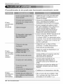
Mantenimientoyservicio
El acondicionador de aire puede estar funcionando anormalmente cuando:
El aire
acondiciona
do no
enciende
• AsegQrese que ei aire acondicionado
esta conectado completamente a la
fuente de energia.
• Cheque los fusibles/interruptor de la
casa y reemplace los fusibles o
reestablezca el interruptor de energia.
, Si ocurr el apag6n,de vuelta al control
del modo a apagado (Tipo Mecanico ).
Cuando es la energia se restaura,
espera 3 minutos para recomenzar el
acondicionador de aire pare prevenir
disparar del overlord del compresor.
, presion el bot6n RESETsituade en el
enchufe del cable de alimentci6n
Si el bot6n RESETno permanece activo,
suspenda el uso del aire acondicionado y
p6ngase en contacto con un t6cnico de
servicio cualificado.
El aire
acondiciona
do no enfria
corno
debiera
i_i:i_iiiiiiiiiiiiiiiii_!i_!i_!i!_!ii:¸!i!_iliiiiiiiiiiiiiiiiiiiiiiiiii!ii!ii!]ii¸iiiilili_iiiiiiiii_!_ii!!_i!:!!ii!!_iiiii!i¸iiiiiiiiiiiii!ii!i!]iill¸ii¸ii¸ii¸ii¸ii¸iii¸iii¸iii¸iii¸iii¸iii¸i!ii!iiiil¸iii¸iii¸iii¸iii¸iiiiiiiii¸iiiiiiiiiiiiiiiiii!ili;i;i;i;i;i;i;i;i;i;i;!!il
• AsegQreseque no haya cortinas,
persianas o muebles bloqueando el
frente del aire acondicionado.
• Ajustar el control de temperatura a un
nemero m&sbajo.
oLimpie el filtro por Iomenos cada dos
semanas.Vea la secci6n de
instrucciones de operaci6n.
• Cuando usted endende el aire
acondicionado debe esperar un
momento para que la habitaci6n se
enfrie.
• AsegQreseque todas las salidas de
aire est6n cerradas para que el aire
regrese.
• Establezca una temperatura m&s alta.
El aire
acondiciona
do enfria
dernasiado
48 Aire Acondicionador
• Elija el modo alto del ventilador High
Fan o enfriado alto High Cool con el
termostato en el nQmero1 o 2.

Manual del Propietario 49

LG Electronics Inc. repair or at its option replace, without charge, your product if it proves to be defective in
material or workmanship under normal use during the warranty period set forth below, effective from the date of
original consumer purchase of the product. This limited warranty is good only to the original purchaser of the product
and effective only when used in the United States, including Alaska, Hawaii, and U.S. Territories.
WARRANTY PERIOD:
Labor: 1 Year from the Date of Purchase.
Parts: I Year from the Date of Purchase.
Compressor: 5 Years from the Date of
Purchase.
HOW SERVICE IS HANDLED:
Call 1-800-243-0000 and choose the appropriate prompt, Please
have product type (Room Air Conditioner), model number, serial
number, and ZIP code ready.
The warranted labor covers the cost of In-Home Service on all
parts including the compressor.
THiS WARRANTY iS iN LiEU OF ANY OTHER WARRANTIES, EXPRESS OR iMPLiED, iNCLUDiNG WITHOUT LiMiTATiON, ANY
WARRANTY OF MERCHANTABiLiTY OR FITNESS FOR A PARTICULAR PURPOSE. TO THE EXTENT ANY IMPLIED WARRANTY iS
REQUIRED BY LAW_ iT iS LiMiTED iN DURATION TO THE EXPRESS WARRANTY PERIOD ABOVE. LG WiLL NOT BE LIABLE FOR
ANY CONSEQUENTIAL, iNDiRECT, OR INCIDENTAL DAMAGES OF ANY KmND, INCLUDING LOST REVENUES OR PROFITS, iN
CONNECTION WiTH THE PRODUCT. SOME STATES DO NOT ALLOW LiMiTATiON ON HOW LONG AN iMPLiED WARRANTY
LASTS OR THE EXCLUSION OF iNCiDENTAL OR CONSEQUENTIAL DAMAGES, SO THE ABOVE LiMiTATiONS OR EXCI.USIONS
MAY NOT APPLY TO YOU.
THIS LIMITED WARRANTY DOES NOT APPLY TO:
I.
2.
Service trips to your home to deliver, pick up, and/or install the product, instruct, or replace house fuses or
correct wiring, or correction of unauthorized repairs; and
Damages or operating problems that result from misuse, abuse, operation outside environmental
specifications or contrary to the requirements or precautions in the Operating Guide, accident, vermin,
fire, flood, improper installation, acts of God, unauthorized modification or alteration, incorrect electrical
current or voltage, or commercial use, or use for other than intended purpose,
3. Therefore, the cost of repair or replacement of such a defective product shall be borne by the consumer.
CUSTOMER INTER-ACTIVE CENTER NUMBERS:
To Prove Warranty Coverage
To Obtain Nearest Authorized Service Center or Sales
Dealer, or to Obtain Product, Customer, or Service
Assistance
Retain your Sales Receipt to prove date of purchase.
A copy of your Sales Receipt must be submitted at
the time warranty service is provided.
Call 1-800-243-0000,24 hrs a day, 7 days per week.
Choose the appropriate prompt from the menu,and
have your product type (Room Air Conditioner), model
number, seriaI number, and ZIP Code;
P/No.: 3828A20528D Printed in Thailand
-
 1
1
-
 2
2
-
 3
3
-
 4
4
-
 5
5
-
 6
6
-
 7
7
-
 8
8
-
 9
9
-
 10
10
-
 11
11
-
 12
12
-
 13
13
-
 14
14
-
 15
15
-
 16
16
-
 17
17
-
 18
18
-
 19
19
-
 20
20
-
 21
21
-
 22
22
-
 23
23
-
 24
24
-
 25
25
-
 26
26
-
 27
27
-
 28
28
-
 29
29
-
 30
30
-
 31
31
-
 32
32
-
 33
33
-
 34
34
-
 35
35
-
 36
36
-
 37
37
-
 38
38
-
 39
39
-
 40
40
-
 41
41
-
 42
42
-
 43
43
-
 44
44
-
 45
45
-
 46
46
-
 47
47
-
 48
48
-
 49
49
-
 50
50


Goldstar WG8005R El manual del propietario
- Tipo
- El manual del propietario
- Este manual también es adecuado para
en otros idiomas
- English: Goldstar WG8005R Owner's manual
Artículos relacionados
Otros documentos
-
LG Comfort-Cire RAD-121B El manual del propietario
-
-
-
-
LG LW1010ER El manual del propietario
-
COMFORT-AIRE COMFORT AIRE REG-123A El manual del propietario
-
-