
Please read these operating instructions thoroughly
before using your air conditioner and keep for future
reference.
For assistance, please call: 1-800-211-PANA(7262) or
Register your product at : http://www.panasonic.com/register
INSTALLATION AND
OPERATING INSTRUCTIONS
Room Air Conditioner
Model: HQ-2244UH
CW382820391G

2
Safety Precautions
About the Controls on the Air Conditioner
Features and Installation
Before you call for service...
FOR YOUR RECORDS
Staple your receipt to this page in case you need it later.
Write down the model and serial numbers here:
Model #
Serial #
You can find them on a label on the side of each unit.
Dealer's Name
Date Purchased
Inside you will find many helpful hints on how to use and
maintain your air conditioner properly. Just a little preventive
care on your part can save you a great deal of time and
money over the life of your air conditioner.
You'll find many answers to common problems in the chart
of troubleshooting tips. If you review our chart of
Troubleshooting Tips first, you may not need to call for
service at all.
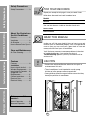
READ THIS MANUAL
CAUTION
• Contact the authorized Service technician for repair or
maintenance of this unit.
• The air conditioner is not intended for use by young
children or infirm persons without supervision.
• Young children should be supervised to ensure that they
do not play with the air conditioner.
Safety Precautions
Safety Precautions .............3
About the Controls on
the Air Conditioner
Controls..............................5
Ventilation ..........................6
Air Direction........................6
How to Secure Drain Pipe..6
Care and Maintenance
Air Filter Cleaning...............7
Features
Features .............................8
Installation
How to Install the Unit ........9
Window Requirements .......9
Installation Kit Contents ...10
Suggested Tool
Requirements...................11
Cabinet Installation...........12
Electrical Data ..................14
Electrical Safety ...............14
Before you call for
service...
Normal Operation.............15
Abnormal Operation .........15

WARNING
3
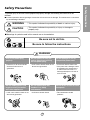
Safety Precautions
Safety Precautions
To prevent injury to the user or other people and property damage, the following instructions must be
followed.
■ Incorrect operation due to ignoring of instruction will cause harm or damage. The seriousness is classified
by the following indications.
WARNING :
This symbol indicates the possibility of death or serious injury.
CAUTION
:
This symbol indicates the possibility of injury or damage to
property only.
■ Meanings of symbols used in this manual are as shown below.
Be sure not to do this.
Be sure to follow the instructions.
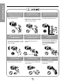
Plug in the power plug
properly.
• Otherwise, it will cause electric
shock or fire due to heat
generation.
Do not operate or stop the
unit by inserting or pulling
out the power plug.
• It will cause electric shock or fire
due to heat generation.
Do not damage or use an
unspecified power cord.
• It will cause electric shock or fire.
•
If the power cord is damaged, it must
be replaced by the manufacturer or
an authorized service center or a
similarly qualified person in order to
avoid a hazard.
Do not modify power cord
length or share the outlet
with other appliances.
• It will cause electric shock or fire
due to heat generation.
Do not operate with wet
hands or in a damp
environment.
• It will cause electric shock.
Do not direct air flow at room
occupants.
• This could lead to health
problems.

4
Safety Precautions
When the air filter is to be
removed, do not touch the
metal parts of the unit.
• It may cause an injury.
Do not clean the air
conditioner with water.
• Water may enter the unit and
degrade the insulation. It may
cause an electric shock.
Ventilate well when used
together with a stove, etc.
• An oxygen shortage may occur.
When the unit is to be
cleaned, switch off, and turn
off the breaker.
• Since the fan rotates at high
speed during operation, it may
cause an injury.
Do not put a pet or house
plant where it will be exposed
to direct air flow.
• This could injure the pets or
plants.
Do not use for special
purposes.
• Do not use this air conditioner to
preserve precision devices, food,
pets, plants, and art objects.
It may cause deterioration of
quality, etc.
Do not operate switches
with wet hands
.
• It may cause an electric shock.
Do not apply an insecticide
or flammable spray.
• It may cause a fire or deformation
of the cabinet.
Do not put a heater, etc.
where it is exposed to direct
air flow.
•
It may cause imperfect
combustion.

5
About the Controls on the Air Conditioner
62
1
8
34 7
OPERATION
TEMP
TIMER
AIR
SWING
MODE
ECONOMY
FAN SPEED
1
6
2 4
5
3
7
About the Controls on the Air Conditioner
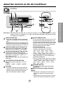
Controls
OPERATION BUTTON
• To turn the air conditioner ON, push the button.
To turn the air conditioner OFF, push the button
again.
• This button takes priority over any other buttons.
• When you first turn it on, the air conditioner is on
the High cool mode and the temp. at 72°F(22°C)
OPERATION MODE SELECTION BUTTON
Every time you push this button. It will toggle
between COOL, ECONOMY, FAN and DRY.
ROOM TEMPERATURE SETTING BUTTON
This button can automatically control the
temperature of the room. The temperature can
be set within a range of 60°F to 86°F by 1°F.
(16°C to 30°C by 1°C)
Select the lower number for lower temperature
of the room.
FAN SPEED SELECTION BUTTONS
Every time you push this button, it is set as
follows.
{High(F3) → Low(F1) → Med(F2) → High(F3)...}.
ECONOMY
• If you push the button, the fan stops when the
compressor stops cooling. Approximately every
3 minutes the fan will turn on and check the
room air to determine if cooling is needed.
ON/OFF TIMER BUTTON
You can set the time when the unit will turn on or turn
off automatically by pressing the timer button. If the
unit is operating, this button controls the time it will be
turned off. If the unit is in off state, this button controls
the time it will start. Every time you push this button,
the remaining time will be set as follows.
- STOPPING OPERATION
•
Every time you push this button, when the air
conditioner is operating, timer is set as follows.
(1Hour → 2Hours → 3Hours → 4Hours → 5Hours →
6Hours → 7Hours → 8Hours → 9Hours → 10Hours →
11Hours → 12Hours → 0Hour → 1Hour → 2Hours → ...)
• The Setting Temperature will be raised by 2°F(1°C)
30min. later and by 2°F(1°C) after another 30 min.
- STARTING OPERATION
•
Every time you push this button, when the air conditioner
is not operating, timer is set as follows. (1Hour → 2Hours
→ 3Hours → 4Hours → 5Hours → 6Hours → 7Hours →
8Hours → 9Hours → 10Hours → 11Hours → 12Hours →
0Hour → 1Hour → 2Hours → ...)
AIR SWING BUTTON
This button can automatically control the air
flow direction.
REMOTE CONTROL SIGNAL RECEIVER
DRY
•
When this unit is in dry mode, the fan rotates in low
speed. The fan stops when the compressor stops
cooling.
Approximately every 3 minutes the fan will turn on and
the unit checks the room air temperature to set itself.
7
7
6
6
8
8
9
9
Precaution: The Remote Controller will not function properly if strong light strikes the sensor
window of the air conditioner or if there are obstacles between the Remote Control
unit and the air conditioner.

Additional controls and important information.
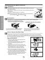
Ventilation
The ventilation lever must be in the CLOSE position in order to maintain the
best cooling conditions.
When fresh air is necessary in the room, set the ventilation lever to the
OPEN position.
The damper is opened and room air is drawn out.
Air Direction
The vertical air direction is adjusted by rotating the
horizontal louver forward or backward manually.
The horizontal air direction is adjusted by
rotating the vertical louver right or left by
Remote Controller.
The direction of air can be controlled wherever you want to cool by adjusting the
horizontal louver and the vertical louver.
• VERTICAL AIR-DIRECTION CONTROL
•
HORIZONTAL AIR-DIRECTION CONTROL
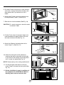
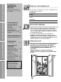
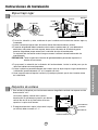
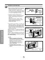
How to Secure the Drain Pipe
In humid weather, excess water may cause the BASE PAN to overflow. To drain the water, remove the DRAIN
CAP and secure the DRAIN PIPE to the rear hole of the BASE PAN. Press the drain pipe into the hole by pushing
down and away from the fins to avoid injury. (See Fig.1)
Optional(CW3H02502C)
1. Remove the rubber plug and slide the chassis out
from the cabinet. (See Fig.2)
2. Install the drain pan over the corner of the cabinet
where you removed the plug with 4 screws.
(See Fig.3)
3. Connect the drain hose to the outlet located at the
bottom of the drain pan. You can purchase the drain
hose or tubing locally to satisfy your particular
needs. (Drain hose is not supplied). (See Fig.3)
4. Select the most appropriate connection from among
the figures to the right (by considering the hole of the
unit) to fit drain pan to your own unit. (See Fig.3)
5. Slide the chassis back into the cabinet. Reinstall the
cabinet screws. Secure the cabinet to chassis by
using screws. (See Fig.4)
6
About the Controls on the Air Conditioner
VENTCLOSE
OPEN
Part
A
Part
B
Drain pipe
Drain cap
Fig. 4
Fig. 3
Fig. 2
DRAIN HOSE
Inside diameter 17mm (5/8")
Fig. 1
O
F
F
/
O
N
O
P
E
R
A
T
I
O
N
T
E
M
P
/
T
I
M
E
R
C
O
O
L
F
A
N
H
I
G
H
M
E
D
L
O
W
M
O
D
E
F
A
N
S
P
E
E
D
S
E
T
T
I
M
E
R
S
E
T
/
C
A
N
C
E
L
A
I
R
S
W
I
N
G
E
C
O
N
O
M
Y
h
r
F
W
i
r
e
l
e
s
s
R
e
m
o
t
e
C
o
n
t
r
o
l
DRAIN
PAN
CABINET
SCREW
Remove the
rubber plug
O
F
F
/
O
N
O
P
E
R
A
T
I
O
N
T
E
P
/
T
I
C
O
O
L
FA
N
H
I
G
H
M
E
D
L
O
W
M
O
E
F
A
N
S
P
E
E
D
S
E
T
T
I
M
E
R
S
E
T
/
C
N
E
A
I
R
E
C
O
N
O
MY
F
W
i
r
e
l
e
s
s
R
e
m
o
t
e
C
o
n
t
r
o
l
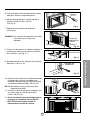
NOTE: Before using the ventilation feature, and prior to installing the front
grille, pull down part until level with part .

7
About the Controls on the Air Conditioner
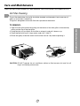
Air Filter Cleaning
The air filter behind the front grille should be checked and cleaned at least once every 2
weeks or more often if necessary.
The grille is designed to clean the filter both upward and downward.
TO REMOVE:
1. Open the inlet grille upward by pulling out the bottom of the inlet grille or downward by
pulling out the top of the inlet grille.
2. Using the tab, pull up slightly on the filter to release it and pull it down or up.
3. Clean the filter with warm, soapy water under 40°C (104°F).
4. Rinse and gently shake the water from the filter and let it dry before replacing it.
CAUTION: DO NOT operate the air conditioner without a filter because dirt and lint will
clog it and reduce performance.
Care and Maintenance
TURN THE AIR CONDITIONER OFF AND REMOVE THE PLUG FROM THE POWER OUTLET.

8
Features and Installation
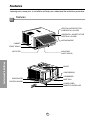
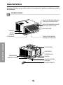
Learning parts name prior to installation will help you understand the installation procedure.
Features
Features
CABINET
FRONT GRILLE
AIR FILTER
AIR INTAKE
(INLET GRILLE)
AIR DISCHARGE
HORIZONTAL AIR DEFLECTOR
(VERTICAL LOUVER)
VERTICAL AIR DEFLECTOR
(HORIZONTAL LOUVER)
EVAPORATOR
CONTROL BOARD
POWER CORD
BASE PAN
CONDENSER
COMPRESSOR
BRACE
REMOTE CONTROLLER

About 1/2"
Over 20"
HEAT
RADIATION
FENCE
AWNING
INSIDE OUTSIDE
FOAM
COOLED
AIR
30-60"
Level
1/4 Bubble
26" to 41"
18" min
Offset
Sill
Exterior
Interior wall
Stool
9
Installation
Features and Installation
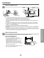
How to Install the Unit
1. To avoid vibration and noise, make sure the unit is installed securely and firmly.
2. Install the unit where the sunlight does not shine directly on the unit.
If the unit receives direct sunlight, build an awning to shade the cabinet.
3. There should be no obstacle, like a fence, within 20” which might restrict heat radiation from the
condenser.
4. To prevent reducing performance, install the unit so that louvers of the cabinet are not blocked.
5. Install the unit a little obliquely outward not to avoid leaking the condensed water into the room
(about 1/2” or 1/4 bubble with level).
6. Install the unit with its bottom portion 30~60” above the floor level.
7. Stuff the foam between the top of the unit and the wall to prevent air and insects from getting into
the room.
8. The power cord must be connected to an independent circuit. The green wire must be grounded.
9. Connect the drain tube to the base pan hole in the rear side if you need to drain (consult a dealer.)
Plastic hose or equivalent may be connected to the drain tube.
NOTE: All supporting parts should be secured to firm wood, masonry, or metal.
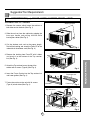
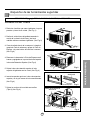
WINDOW REQUIREMENTS
1. This unit is designed for installation in
standard double hung windows with actual
opening widths from 26" to 41".
The top and bottom window sashes must
open sufficiently to allow a clear vertical
opening of 18" from the bottom of the upper
sash to the window stool.
2. The stool offset (height between the stool
and sill) must be less than 1
1
/
4
".
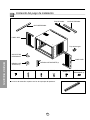
Window Requirements

Foam-PE
(Adhesive-Backed)
Foam-PE
(Adhesive-Backed)
Type C (5) Type D (2)
Type A (14)
Carriage Bolt (2) Lock Nut (4)
Type B (7)
Foam strip
(Plain-Back)
Right frame
curtain
Drain pipe
Window locking
bracket
Left frame
curtain
Sill
bracket
(2)
Support bracket(2)
10
Features and Installation
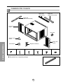
Installation Kits Contents
■ Top retainer bar is in product package.

11
Features and Installation
Foam-PE
Top retainer bar
Top retainer bar
Foam-PE
Screw
(Type A)
Screw(Type A)
Shipping screws
Lower guide
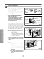
PREPARATION OF CHASSIS
1. Remove the screws which fasten the cabinet at
both sides and at the back.(See Fig. 1)
2. Slide the unit out from the cabinet by gripping the
base pan handle and pulling forward while
bracing the cabinet.(See Fig. 2)
3. Cut the window sash seal to the proper length.
Peel off the backing and attach the Foam-PE to the
underside of the window sash.(See Fig. 3)
4. Remove the backing from Foam-PE with 3 holes
and attach it to the bottom of the Top retainer
bar.(See Fig. 4)
5. Attach the Top retainer bar on the top of the
cabinet with 3 screws (Type A).(See Fig. 4)
6. Insert the Frame Curtain into the Top retainer bar
and Lower guides.(See Fig. 4)
7. Fasten the curtains to the unit with 10 screws
(Type A) at both sides.(See Fig. 4)
Suggested Tool Requirements
SCREWDRIVER(+, -), RULER, KNIFE, HAMMER, PENCIL, LEVEL
Fig. 1
Fig. 2
Fig. 3
Fig. 4

Support
Bracket
Lock nut
Sill
Bracket
Carriage
Bolt
(M-Screw)
Window sash
Top retainer bar
Cabinet
Foam-PE
Frame curtain
Screw(Type B)
Front Angle
Sash track
Foam-PE
Cabinet
Track hole
Support
Bracket
Carriage bolt
and lock nut
Machine screw(Type D)
and lock nut
Outer edge
of window
sill
Screw(Type B)
Sill bracket
Cabinet Installation
1. Open the window. Mark a line on the center
of the window stool between the side
window stop moldings.
Loosely attach the sill bracket to the support
bracket using the carriage bolt and the lock
nut. (See Fig. 5)
2. Attach the sill bracket to the window sill
using the screws (Type B).
Carefully place the cabinet on the window
stool and align the center mark on the
bottom front with the center line marked
window stool.(See Fig. 6)
3. Using the M-screw and the lock nut, attach
the support bracket to the cabinet track hole.
Use the first track hole after the sill bracket
on the outer edge of the window sill. Tighten
the carriage bolt and the lock nut. Be sure
the cabinet slants outward. (See Fig. 6)
CAUTION: DO NOT DRILL A HOLE IN THE
BOTTOM PAN.
The unit is designed to operate
with approximately 12.7mm(1/2")
of water in bottom pan.
4. Pull the bottom window sash down behind
the Top retainer bar until they meet.
(See Fig. 7)
NOTE: 1. Do not pull the window sash down so
tightly that the movement of Frame
curtain is restricted. Attach the
cabinet to the window stool by
driving the screws (Type B) through
the cabinet into window stool.
(See Fig. 8)
2. The cabinet should be installed with
a very slight tilt downward toward the
outside.
Fig. 5
Fig. 6
Fig. 7
Fig. 8
12
Features and Installation

Power Cord
Screw
Screw
Window locking
bracket
Foam-Strip
Screw(Type C)
5. Pull each Frame curtain fully to each window
sash track, and pull the bottom window sash
down behind the Top retainer bar until it
meets.
6. Attach each Frame curtain the window sash
by using screws (Type C.) (See Fig. 9)
7. Slide the unit into the cabinet.(See Fig. 10)
CAUTION: For security purpose, reinstall screws
at cabinet's sides.
8. Cut the Foam-strip to the proper length and
insert between the upper window sash and
the lower window sash.(See Fig. 11)
9. Attach the Window locking bracket with a
screw (Type C.) (See Fig. 12)
10. Attach the front grille to the cabinet by
inserting the tabs on the grille into the tabs
on the front of the cabinet. Push the grille in
until it snaps into place.(See Fig.13)
NOTE: Please refer p.6 for setting ventilation kit.
11. Lift the inlet grille and secure it with two
screw (Type A) through the front grille.(See
Fig. 13)
12. Window installation of room air conditioner is
now completed. See ELECTRICAL DATA for
attaching power cord to electrical outlet.
Fig. 9
Fig. 10
Fig. 11
Fig. 12
Fig. 13
Fig. 14
13
Features and Installation

Do not under any
circumstances cut
or remove the
grounding prong
from the plug.
Line Cord Plug Use Wall Receptacle Power Supply
Line Cord Plug Use Wall Receptacle Power Supply
Power supply cord with
3-prong grounding plug
Do not under any
circumstances cut
or remove the
grounding prong
from the plug.
Power supply cord with
3-prong grounding plug
Standard 125V, 3-wire grounding
receptacle rated 15A, 125V AC
Standard 250V, 3-wire grounding
receptacle rated 15A, 250V AC
Use 15 AMP. time
delay fuse or 15 AMP.
circuit breaker.
Use 15 AMP. time
delay fuse or 15 AMP.
circuit breaker.
Use 20 AMP. time
delay fuse or 20 AMP.
circuit breaker.
Do not under any
circumstances cut
or remove the
grounding prong
from the plug.
Power supply cord with
3-prong grounding plug
Standard 250V, 3-wire grounding
receptacle rated 20A, 250V AC
Electrical Data(For 230/208V model only)
■ ELECTRICAL SAFETY
All wiring should be made in accordance with local electrical codes and regulations.
NOTE :
Aluminum house wiring may pose special problems. Consult a qualified electrician.
IMPORTANT GROUNDING INSTRUCTIONS
Air conditioner has a three-prong grounding plug
on its power supply cord, which must be plugged
into properly grounded three-prong wall
receptacle for your protection against possible
shock hazard.
230, 208, and 230/208 VOLT UNITS
These units are equipped with a three-prong
grounding plug on the power supply cord, which
must be plugged into a matching properly
grounded three-prong wall receptacle for your
protection against possible shock hazard. If such
an outlet is not present, one must be installed by
a qualified electrician in accordance with the
National Electrical Code and local codes and
ordinances.
NOTE: DO NOT USE AN EXTENSION CORD
ON 230, 208, AND 230/208 VOLT UNITS.
14
Before you call for service...

Before you call for service...
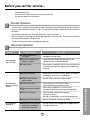
Troubleshooting Tips
Save time and money! Review the chart below first and
you may not need to call for service.
Normal Operation
• You may hear a pinging noise caused by water being picked up and thrown against the condenser
on rainy days or when the humidity is high. This design feature helps remove moisture and improve
efficiency.
• You may hear the relay click when the compressor cycles on and off.
• Water will collect in the base pan during high humidity or on rainy days. The water may overflow
and drip from the outdoor side of the unit.
• The fan may run even when the compressor does not.
Abnormal Operation
15
Before you call for service...
Problem Possible Causes What To Do
■ The air conditioner is
unplugged.
■ The fuse is blown/circuit
breaker is tripped.
■ Power failure.
■ Airflow is restricted.
■ TEMP Control set to a
higher number.
■ The air filter is dirty.
■ The room may have been
hot.
■ Cold air is escaping.
■ Cooling coils have iced up.
■ Ice blocks the air flow and
stops the air conditioner
from cooling the room.
• Make sure the air conditioner plug is pushed
completely into the outlet.
• Check the house fuse/circuit breaker box and
replace the fuse or reset the breaker.
• When power is restored, wait 3 minutes to restart the
air conditioner to prevent tripping of the compressor
overload.
• Make sure there are no curtains, blinds, or furniture
blocking the front of the air conditioner.
• Set the TEMP Control to a lower number.
• Clean the filter at least every 2 weeks.
See the operating instructions section.
• When the air conditioner is first turned on
you need to allow time for the room to cool down.
• Check for open furnace floor registers
and cold air returns.
• Set the air conditioner's vent to the closed position.
• See Air Conditioner Freezing Up below.
• Set the mode control at High Fan or High Cool with
the high temperature.
Air conditioner
does not start
Air conditioner
does not cool as it
should
Air conditioner
freezing up

16
Precauciones Importantes de seguridad
Instrucciones de Funcionamiento
Características e Instalacion
Antes de avisar al Servicio Técnico
PARA SU INFORMACION
Escriba aquí los números de serie y modelo de las
unidades exterior e interior:
Nº de Modelo
Nº Serie
Los números figuran en una etiqueta en el lateral de cada
unidad.
Distribuidor
Fecha de compra
• Aquí encontrará numerosas sugerencias sobre cómo
utilizar y mantener adecuadamente su acondicionador de
aire. Con unos cuantos cuidados preventivos se puede
ahorrar mucho tiempo y dinero a lo largo de la vida útil de
su acondicionador de aire.
• En la tabla de sugerencias para la resolución de
problemas encontrará respuestas a la mayoría de los
problemas más comunes. Si consulta primero la tabla de
Sugerencias para la resolución de problemas, quizá ni
siquiera necesite avisar al servicio técnico.
• Consulte con el servicio técnico autorizado sobre la
reparación o el mantenimiento de esta unidad.
• El acondicionador de aire no debe ser utilizado por
niños pequeños o personas inestables sin
supervisión.
• Es preciso vigilar a los niños pequeños para
asegurarse de que no juegan con el acondicionador
de aire.
LEA ESTE MANUAL
PRECAUCION
Precauciones
Importantes de
Seguridad
Precauciones Importantes
de seguridad ....................17
Instrucciones de
Funcionamiento
Controles...........................19
Ventilación.........................20
Como controlar la
direccion del aire ...............20
Como installar el Tubo de
desagüe.............................20
Cuidado y Mantenimiento
Limpieza de filtro de aire...21
Características
Características ..................22
Instrucciones de
instalación
Elija el major lugar.............23
Requisitos de ventana.......23
Contenido del juego de
instalación
..........................24
Requisitos de las
herramientas sugeridas
.......25
Instalación del Gabinete....26
Datos Electricos ................28
Seguridad Electrica ...........28
Antes de avisar al
Servicio Técnico
Operacíon normal ............29
Operacíon anormal ..........29

Precauciones Importantes de seguridad
ADVERTENCIA
17
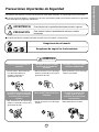
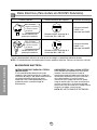
Precauciones Importantes de Seguridad
Para prevenir tanto lesiones al usuario u otras personas como daños materiales, es preciso seguir estas instrucciones.
■ El manejo incorrecto debido a la inobservancia de estas instrucciones puede causar lesiones o daños cuya gravedad
está clasificada en las siguientes indicaciones.
ADVERTENCIA Este símbolo indica la posibilidad de lesiones mortales o graves.
PRECAUCION
Este símbolo indica la posibilidad de lesiones o daños
materiales.
■
El significado de los símbolos utilizados en este manual se indica a continuación.
Asegúrese de no hacerlo.
Asegúrese de seguir las instrucciones.
Conecte correctamente el
enchufle
• De otra forma, ello ocasionaría
una descarga eléctrica o
incendio a causa de la
generación de calor.
No opere o pare la unidad
insertando o tirando del
enchufe
• Ello ocasionaría una descarga
eléctrica o incendio a causa de la
generación de calor.
No dañe o utilize un cable
eléctrico inadecuado
• Ello ocasionaría una descarga
eléctrica o incendio.
No modifique el largo del cable
eléctrico, y tampoco comparta
el tomacorriente con otros
aparatos
• Ello ocasionaría una descarga
eléctrica o incendio a causa de la
generación de calor.
No lo maneje con las manos
humedas
• Puede ocasionar una descarga
eléctrica.
No exponga durante mucho
tiempo la piel al aire frío
procedente directamente del
acondicionador.
• Esto podría dañar su salud.

18
Precauciones Importantes de seguridad
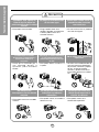
PRECAUCION
Cuando se vaya a quitar el
filtro de aire no toque las
partes metálicas de la unidad
interior.
• Esto podría causar heridas.
No limpie el acondicionador
de aire con agua.
• El agua podría entrar en la
unidad y degradar el aislamiento.
También podría causar una
sacudida eléctrica.
Ventile bien cuando utilice el
acondicionador junto con
una estufa, etc.
• En este caso tal vez se produzca
una falta de oxígeno.
Cuando limpie la unidad,
desconecte la alimentación y
desconecte también el
disyuntor.
• Puesto que el ventilador gira a
alta velocidad durante la
operación, podría ocasionar
heridas.
NO ponga un animal doméstico
ni una planta donde quede
directamente expuesto al flujo
de aire.
• Esto podría dañar al animal o a
la planta.
No lo utilice para propósitos
especiales.
• No utilice este acondicionador de
aire para conservar dispositivos
de precisión, alimentos y objetos
de arte; no ponga tampoco
animales y plantas cerca de él.
Esto podría deteriorar la calidad,
etc.
No manipule los
interruptores con las manos
mojadas.
• Esto podría causar una sacudida
eléctrica.
No aplique aerosoles con
insecticida o productos
inflamables.
• Esto podría causar un incendio o
deformar la caja.
No ponga una estufa, etc.
donde quede expuesta al
flujo de aire directo.
•
Esto podría causar una
combustión imperfecta.

62
1
8
34 7
OPERATION
TEMP
TIMER
AIR
SWING
MODE
ECONOMY
FAN SPEED
1
6
2 4
5
3
7
19
Instrucciones de Funcionamiento
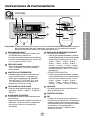
Instruccionnes de Funcionamiento
Controles
ENECNDIDO/APAGADO
• Para ENCENDER el sistema presione el botón, y para
APAGARLO presione el botón otra vez.
• Este botón tiene prioridad sobre todos los otros botones.
• Cuando Ud. Io enciende por primera vez, el sistema está
en el y la temperatura es de 72˚F(22˚C).
FRÍO/VENTILADOR
• Cada vez que presione este botón, las palabras
COOL, ECONOMY, FAN y DRY aparecerán
alternadamente.
AJUSTE DE LA TEMPERATURA
• Este botón puede controlar la temperatura del
cuarto automáticamente. La temperatura se
puede ajustar de grado en grado, desde 60˚F
hasta 86˚F cada 1˚F (16˚C hasta 30˚C cada
1˚C). Seleccione el número más bajo para la
temperatura más baja en el cuarto.
VELOCIDAD DEL VENTILADOR
• Cada vez que presione este botón, el ajuste es
como sigue. {Alto(F3) → Bajo(F1) → Medio(F2) →
Alto(F3)...}
AHORRADOR DE ENERGÍA
El ventilador se detiene cuando el compressor no
sigue enfriando.
• Aproximadamente cada 3 minutos el ventilador se
encenderá, y necesitará verificar la temperatura
del cuarto para saber si es necesario más
enfriamiento.
MARCADOR DE ENCENDIDO/APAGADO
- OPERACIÓN DE PARADA:
• Cada vez que presione este botón, cuando el
sistema esté operando, el marcador de tiempo
se ajustará de la siguiente manera: (1 Hora →
2 Horas → 3 Horas → 4 Horas → 5 Horas →
6 Horas → 7 Horas → 8 Horas → 9 Horas →
10 Horas → 11 Horas → 12 Horas → 0 Hora).
• La temperatura de ajuste se elevará 2˚F(1˚C),
30 minutos después, y otros 2˚F(1˚C) media
hora después.
- OPERACIÓN DE INICIACIÓN:
• Cada vez que presione este botón, cuando el
sistema esté operando, el marcador de tiempo
se ajustará de la siguiente manera: (1 Hora →
2 Horas → 3 Horas → 4 Horas → 5 Horas →
6 Horas → 7 Horas → 8 Horas → 9 Horas →
10 Horas → 11 Horas → 12 Horas → 0 Hora).
AUTOGIRD
• Este botón puede controlar automáticament la
dirección del flujo de aire.
RECEPTOR DE SEÑAL
DRY
•
Cuando esta unidad se torna al modo seco, el
ventilador gira en velocidad lenta. El ventilador se
detiene cuando el compresor se para de enfriar.
Aproximadamente cada 3 minutos se encendera
el ventilador y la unidad comprueba la
temperatura del aire de la habitacion para
ajustarse a si mismo.
6
6
7
7
8
8
9
9
Precaución: El dispositivo de control remoto no funcionará adecuadamente si la ventana sensora
del acondicionador de aire es expuesta a luz fuerte, o si hay obstáculos entre el
dispositivo de control remoto y el acondicionador de aire.

Instrucciones de Funcionamiento
Parte
A
Parte
B
VENTCERRADO
ABIERTO
O
F
F
/
O
N
O
P
E
R
A
T
I
O
N
T
E
M
P/
T
I
M
E
R
C
OO
L
F
A
N
H
I
G
H
M
E
D
L
O
W
M
O
D
E
F
A
N
S
P
E
E
D
S
E
T
T
I
M
E
R
S
E
T
/
C
A
N
C
E
L
A
I
R
S
W
I
N
G
E
C
O
N
O
M
Y
h
r
F
W
i
r
e
l
e
s
s
R
e
m
o
t
e
C
o
n
t
r
o
l
Retire el tapón
de goma
Tapa
del desagüe
Tubo
Fig. 4
Fig. 3
Fig. 2
Fig. 1
BANDEJA
DE DRENAJE
MANGUERA DE DRENAJE
El diámetro interior 17mm (5/8")
TA PA
TORNILLOS
O
F
F
/
O
N
O
P
E
R
A
T
I
O
N
T
E
P
/
T
I
C
O
O
L
F
A
N
H
I
G
H
M
E
D
L
O
W
M
O
E
F
A
N
S
P
E
E
D
S
E
T
T
I
M
E
R
S
E
T
/
C
N
E
A
I
R
E
C
O
N
O
M
Y
F
W
i
r
el
e
s
s
R
e
m
o
t
e
C
o
n
t
r
o
l
20
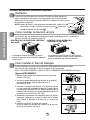
Controles adicionales e informacion importante.
Ventilación
La palanca de ventilación debe estar en posición CERRADA para poder mantener las
mejores condiciones de enfriamiento. Cuando se necesite aire fresco en la habitación,
coloque la palanca de ventilación en posición ABIERTA. La Compuerta es abierta y el aire
de la habitación es expulsado.
NOTA: Antes de utilizar la característica de ventilación, haga un kit de
ventilación. Primero, hale hacia abajo la parte hasta que
quede horizontal con la parte .
Como controlar la direccion del aire
La dirección del aire puede ser controlada cuando usted desee enfriar, ajustando la
palanca vertical y la palanca horiziontal.
• CONTROL DE LA DIRECCIÓN VERTICAL
DEL AIRE
La dirección vertical del aire es ajustada
rotando la palanca horizontal hacia adelanto
o hacia atrás.
La dirección horizontal del aire es ajustada
rotando la palanca vertical hacia la derecha o
hacia la izquierda por Director Remoto.
• CONTROL DE LA DIRECCIÓN
HORIZONTAL DEL AIRE
Como Installar el Tubo de Desagüe
En climas húmedos, es posible que la BANDEJA EVAPORADORA se llene de agua.
Para quitar el agua acumulado, es preciso conectar el tubo de desagüe.
Quite la TAPA DEL DESAGÜE y conecte el TUBO a la BANDEJA EVAPORADORA.(Ver Fig.1)
Opcional(CW3H02502C)
1. Retire el tapón de plástico y deslice el chasis fuera del
armario.
(Ver Fig.2)
2. Instale la bandeja de drenaje por encima de la esquina
de la tapa de donde retiró el tapón con 4 (o 2)
tornillos.
(Ver Fig.3)
3. Conecte la manguera de drenaje a la salida situada en
la parte inferior de la bandeja de drenaje. Puede adquirir
una manguera de drenaje o una tubería apropiada en su
localidad que satisfaga sus necesidades particulares (la
manguera no se suministra).
(Ver Fig.3)
4. Seleccione la conexión más apropiada entre las figuras
siguientes (teniendo en cuenta el orificio de la unidad)
para acoplar la bandeja de drenaje en su unidad.
(Ver
Fig.3)
5. Deslice el chasis en el interior del armario.
Vuelva a apretar los tornillos del armario. Fije el armario
al chasis con tornillos.
(Ver Fig.4)

Instrucciones de Funcionamiento
21
Limpieza de filtro de Aire
El filtro de aire detrás de la rejilla frontal debe ser revisado y limpiado por lo menos una
vez por cada dos semanas o más frecuentemente si es necesario.
La rejilla es diseñado para limpiar el filtro tanto hacia arriba como hacia abajo.
PARA REMOVER:
1. Abra la rejilla hacia arriba tirando la parte inferior de la rejilla o hacia abajo tirando la
parte superior de la rejilla.
2. Usando una lengüeta, tire el filtro ligeramente hacia arriba para sacarlo por abajo o
arriba.
3. Limpie el filtro con agua tibia y jabonosa bajo 40°C (104°F).
4. Enjuague y sacuda el filtro suavemente bajo la corriente de agua y déjelo secar antes
de reponerlo.
PRECAUCION: NO OPERE el aire acondicionado sin filtro ya que la suciedad y el tamo
obstruirá el filtro y reducirá la eficiencia del funcionamiento.
Cuidado y Mantenimiento
Apague el aire acondicionado y saque el enchufe del toma corriente de la pared.

22
Características e Instalacion
Aprender el nombre de las partes antes de la instalación le ayudará a entender el proceso
de instalación.
Características
Características
GABINETE
REJILLA
FRONTAL
FILTRO DE AIRE
RECOLECTOR DE AIRE
(BANDEJA DE ENTRADA)
SALIDA DE AIRE
DEFLECTOR HORIZONTAL DE AIRE
(VENTANILLAS VERTICALES)
DEFLECTOR DE AIRE HORIZONTAL
(VENTANILLAS HORIZONTALES)
CONTROL REMOTO
EVAPORADOR
PANEL DE CONTROL
CABLE DE CONEXIÓN
ELÉCTRICA
BANDEJA
CONDENSADOR
COMPRESOR
SUSPENSORES

APROXIMADAMENTE /
ARRIBA DE 20"
RADIACION
DE CALOR
BARDA
TOLDO
FOAM
AIR
ENFRIADO
30-60"
Nivel
1/4 Ampolla
1
2
26" to 41"
18" min
DESPLAZAMIENTO
ALFEZAR
EXTERIOR
PARED INTERIOR
REPISA
23
Instrucciones de Instalación
Características e Instalacion
Elija el major lugar
1. Para evitar vibración y ruido, asefúrese de que la unidad esté instalada de manera segura y
firmemente.
2. Instale la unidad en lugares fuera de luzsolar directa directamente sobre la unidad.
3. El exterior del gabinete deberá extenderse hacia afuera cuando menos 10" y no deben existir
obstáculos, tales como una barda o pared, dentro de una distancia de 20" desde la pparte
posterior del gabinete porque esto evitará la radiación de calor del condensador.
La restricción del aire exterior reducirá en gran manera la eficiencia de enfriamiento del aire
acondicionado.
PRECAUCION: Todas las persianas laterales del gabinete deberán permanecer expuestas al
exterior de la estructura.
4. Para prevenir la reducción de la eficiencia del funcionamiento, instale la unidad para que las
rejillas del cabinete no sean bloqueados.
5. Instale la unidad un poco oblicuamente hacia afuera para no dejar escapar el agua condensado a
la habitación (aproximadamente 1/2" o 1/4 ampolla con nivel).
6. Llene la espuma entre el tope de la unidad y la pared para prevenir que el aire e insectos entren
en la habitación.
1. Esta unidad está diseñada para instalarse en ventanas de guillotina estándar con espesor real de
abertura de 26" a 41".
Los marcos superior e inferior de la ventana
deverán abrir lo suficiente para permitir una abertura
vertical libre de 18" de la parte inferior del marco
superior a la repisa de la ventana.
2. El desplazamiento de la repisa (altura entre la repisa
y el alféizar) debe ser menor a 1
1
/4".
Requisitos de ventana

Características e Instalacion
CINTA DE ESPUMA
CINTA DE ESPUMA
TIPO (5) TIPO D (2)
TIPO A (14)
PERNO (2)
TUERCA DE
SEGURIDAD (4)
TIPO B (7)
TIRA DE GOMA
PANEL GUÍA
SOPORTE DE
CERRADURA
PANEL GUÍA
MENSULA DEL
ALFEIZAR (2)
MENSULA DE SOPORTE (2)
Tapa del desagüe
24
Contenido del juego de instalación
■
La barra de retención superior está en el empaque del producto.

25
Características e Instalacion
BARRA DE RETENCION
SUPERIOR
BARRA DE RETENCION
SUPERIOR
Cinta de Espuma
TORNILLO
(TIPO A)
TORNILLO
(TIPO A)
Guía mas baja
PREPARACION DEL CHASIS
1. Retire los 4 tornillos que unen el gabinete a la parte
posterior y lateral de la unidad.
(Ver Fig.1)
2. Deslice la unidad fuera del gabiete tomando la
manija de la charola de la base y jale hacia
adelante miéntras sostiene el gabinete.
(Ver Fig.2)
3. Corte el sellode chasis de la ventana a la longitud
apropiada. Pele el resfuerzo y aplique la Cinta de
Espuma a la parte inferior del chais de la ventana.
(Ver Fig.3)
4. Remueva el refuerzo de la Cinta de Espuma con 3
huecos y agréguelo en la parte inferior del tope de
la barra de Retencion Superior.
(Ver Fig.4)
5. Sujete la barra de retención superior al lado
superior del gabinete con los 3 torni.
(Ver Fig.4)
6. Inserte los paneles guías en la barra de retencion
superior y en la guia marco del aire acondicionado.
(Ver Fig.4)
7. Sujete las cortinas de la unidad con tornillos
(Tipo A).
(Ver Fig.4)
Requisitos de las herramientas sugeridas
DESARMADOR ( , ), REGLA, CUCHILLO, MARTILO, LAPIZ, NIVEL
Fig. 1
Fig. 2
Fig. 3
Fig. 4

MENSULA
DE SOPORTE
TUERCA DE
SEGURIDA
MENSULA DEL
ALFEIZAR
BULÓN
MARCO DE LA
VENTANA
BARRA DE
RETENCION SUPERIOR
GABINETE
PANEL
GUIA
CINTA DE
ESPUMA
CINTA DE
ESPUMA
TORNILLO(TIPO B)
Parte Frontal Interior
ORIFICIO DE
CARRIL DE GABINETE
MENSULA
DE SOPORTE
TORNILLO PARA
METALES
(TIPO D)
Y
TUERCA DE SEGURIDA
BORDE EXTERIOR
DEL ANTEPECHO
DE LA VENTANA
TORNILLO(TIPO B)
MENSULA
DEL ALFEIZAR
26
Características e Instalacion
Instalacion del Gabinete
1. Abra la ventana. Marque una línea en el
centro de la repisa de la ventana entre las
molduras de tope de la ventana lateral.
Coloque sin apretar la ménsula del alféizar
en la ménsula de soporte utilizando el pemo
y la tuerca de segutidad.
(Ver Fig.5)
2. Coloque la ménsula del alféizar en el
alféizar de la ventana utilizando los tornillos
(Tipo B). Apriete el perno y la tuerca de
seguridad.
Repisa de la ventana y alinee la marca
central en el frente del fondo con la línea
central marcada en la repisa de la
ventana.
(Ver Fig.6)
3. Utilizando el tornillo M y la tuerca de
seguridad, coloque la ménsula de soporte
en el orificio de la guía del gabinete. Use el
primer orificio de la guía después de la
ménsula del alfézar en el borde exterior del
alféizar de la ventana.
Apriete el perno y la tuerca de seguridad.
Asegúrese de que el gabinete esté inclinado
hacia afuera.
PRECAUCION: No perfore la charola del
fondo. La unidad está diseñada para operar
con aproximadamente 12.7mm(1/2") de agua
en la charola del fondo.
4. NOTA:
1. No hale el marco de la ventana hacia
abajo tan apretado que se restrinja el
movimiento de los deslizadores. Sujete el
gabinete a la repisa de la ventana
insstalando los tornillos (tipo A o B) a
través del gabinete en la repisa de la
ventana.
(Ver Fig.8)
2. El gabinete deberá ser instalado
ligeramente inclinado hacia abajo hacia el
exterior.
Fig. 5
Fig. 6
Fig. 7
Fig. 8

CORDÓN DE
ALIMENTACIÓN
ELÉTRICA
TORNILLO
TORNILLO
SOPORTE DE
CERRADURA
TIRA DE GOMA
TORNILLO
(TIPO C)
27
Características e Instalacion
5. Hale cada panel guía completamente a cada
lado de la ventana y repita del paso 2.
6. Adjunte cada panel guía a cada lado de la
ventana usando tornillos (Tipo C).
(Ver Fig. 9)
7. Deslice el chasís dentro del gabinete.
(Ver Fig.10)
CUIDADO: Por razones de seguridad, re instale
los tornillos en los lados del
gabinete.
8. Corte la tira de goma a la medida apropiada e
introdúzcala entre la parte superior e inferior
de la ventana. (Ver Fig. 11)
9. Se debe instalar el asa antes de fijar el frente
decorativo. (Ver Fig. 12)
10.
Instale la rejilla frontal en el cabinete insertando
la lengüeta en la rejilla a la lengüeta en el
frente del cabinete. Empuje la rejilla hasta que
se cierre con sonido de golpe. (Ver Fig. 13)
NOTA: Se refiere por favor p.20 para poner
juego de ventilación.
11. Levante la rejilla de entrada y asegúrela con
un tornillo (tipo A) a través de la rejilla
frontal. (Ver Fig.13)
12. Ahora la instalación del aire acondicionado en
la ventana es completada. Vea los DATOS
ELECTRICOS para instalar el cable de
alimentación en la toma de corriente.
Fig. 9
Fig. 10
Fig. 11
Fig. 12
Fig. 13
Fig. 14

No lo corte bajo
ninguna circunstancia
o remueva la punta
del enchufe.
No lo corte bajo
ninguna circunstancia
o remueva la punta
del enchufe.
No lo corte bajo
ninguna circunstancia
o remueva la punta
del enchufe.
Cordón eléctrico con
puntas para enchufar
Utilice un fusible de
15AMP. o un
Interruptor de 15AMP.
Utilice un fusible de
15AMP. o un
Interruptor de 15AMP.
Utilice un fusible de
20AMP. o un
Interruptor de 20AMP.
Corcón Eléctrico Utilice el enchufe de la pared Consumo de Energía
Corcón Eléctrico Utilice el enchufe de la pared Consumo de Energía
Standard 125V, enchufe de 3
Líneas de 15A, 125V AC
Cordón eléctrico con
puntas para enchufar
Standard 250V, enchufe de 3
Líneas de 15A, 250V AC
Cordón eléctrico con
puntas para enchufar
Standard 250V, enchufe de 3
Líneas de 20A, 250V AC
28
Características e Instalacion
Datos Electricos (Para modelo de 230/208V Solamente)
■ SEGURIDAD ELECTRICA
Todo el cableado deberá realizarse de acuerdo con los códigos y reglamentos eléctricos locales.
NOTA :
El cableado doméstico de aluminio podría ocasionar problemas especiales. Consulte a un electricista calificado.
NSTRUCCIONES DE CONEXION A TIERRA
IMPORTANTES
El aire acondicionado tiene una clavija de
conexión a tierra de tres patas en su cable de
suminstro de energía, que deverá enchufarse en
un tomacorriente de pared de tres paras
conectado a tierra adecuadamente para su
protección contra un posible riesgo de
electrocución.
UNIDADES DE 230, 208 y 230/208 VOLTIOS
Estas unidades están equipadas con una clavija de
conexión a tierra de tres patas en el cable de
suministro de energía que deberá enchufarse en un
tomacorriente de pared para tres patas conectado a
tierra adecuadamente (ver las ilustraciones a
continuación) para su protección contra un posible
riesgo de electrocución. Si no tiene un tomacorriente
con estas características, un electricista calificado
deverá instalar uno de acuerdo con el Código Eléctrico
Nacional y los códigos y normas locales.
NOTA: NO USE UN CABLE DE EXTENSION.

Before you call for service...
29
Antes de avisar al Servicio Técnico
Antes de avisar al Servicio Técnico
Tips para solucionar problemas
(Ahorre temopo y dinero) Cuando tenga algún problema
primero consulte el cuadro que se encuentra abajo y tal vez no
necesite llamar para solicitar servicio técnico.
Operación normal
• Durar te dias lluviosos o cuando la humedad es alta usted puede escuchar un ruido metállco causa
do por agua recogida y arrojada contra el condensador. Esta caracteristica ayuda a remover la
humedad y mejorar la eficiencia.
• Usted puede escuchar que el relavo hace un click cuando se enciende o apaga el ciclo del comp
esor.
• Durar te dias lluviosos o cuando la humedad es alta el agua será recolectada on la base del
aparato. Esta agua podrá fluir y será eliminada por el lado externo de la unidad.
• El ventilador podrá correr aún cuando el compresor no esté encendido.
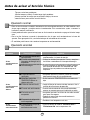
Operación anormal
Probama Causas posibles Que hacer
■ El aire acondicionado está
desconectado.
■ El fusible está quemado/el
interruptor de energía se ha
bloqueado.
■ Falta de energía.
■ El flujo de aire esta
restringido.
■ Coloque el control de
TEMPERATURA en un
número más alto.
■ El filtro de aire está sucio.
■ El cuarto aún está caliente.
■ El aire frio se está
escapando.
■
El serpentin de refrigeración
se ha
congelado.
■ El hielo bloquea el flujo de
aire y detiene el
enfriamiento del cuarto.
• Asegúrese que ei aire acondicionado está conectado
completamente a la fuente de energia.
• Cheque los fusibles/interruptor de la casa y reemplace
los fusibles o reestablezca el interruptor de energía.
• Cuando la energía se reestablezca, espere 3 minutos
para encender de nuevo el aire acondicionado. Con
esto evitará que se produzca una sobrecarga en el
compresor.
• Asegúrese que no haya cortinas, persianas o muebles
bloqueando el frente del aire acondicionado.
• Gire el control de TEMPERATURA a un número más
bajo.
• Limpie el filtro por lo menos cada dos semanas. Vea la
sección de instrucciones de operación.
• Cuando usted enciende el aire acondicionado debe
esperar un momento para que la habitación se enfrie.
• Asegúrese que todas las salidas de aire estén cerradas
para que el aire regrese.
• Coloque la ventana del aire acondicionado en la
posición más cercana.
• Establezca una temperatura más alta.
•
Ajustar el control de mode en 'Ventilación Alta' o
'Erfriamiento Alto' con la temperatura alta.
El aire
acondicionado no
enciende
El aire
acondicionado no
enfría corno
debiera
El aire
acondicionado
enfria dernasiado

30
Model
Modèle
Modelo
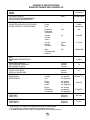
COOLING CAPACITY Btu/h 23,500/23,000
CAPACITÉ DE REFROIDISSEMENT
CAPACIDAD DE ENFRIAMIENTO
ELECTRICAL RATING Phase Single
CARACTÉRISTIQUES ÉLECTRIQUES Phase Simple
CLASIFICION DE LA ELECTRICIDAD Fase Monofasico
Frequency (Hz) 60
Fréquence
Frecuencia
Voltage (V) 230/208
Tension
Voltaja
Current (Amps) 11.2/12.0
Courant (A)
Corriente (Amps)
Input (W) 2,500/2,450
Consommation
Potencia
EER
RENDEMENT ÉNERGÉTIQUE 9.4/9.4
EER
MOISTURE REMOVAL (Pints/h)
SUPPRESSION D'HUMIDITÉ (pinte/h) 7.5
DESHUMIDIFICACION (Tinta/h)
ROOM CIRCULATION (Cf/min)
CIRCULATION D'AIR (pi/min) 477
CIRCULACION DE AIRE (pie/min)
DIMENSIONS Height cm (inches)
DIMENSIONS Hauteur cm (pouces) 42.8 (16
27
/32)
DIMENSIONES Alto cm (pulgadas)
Width cm (inches)
Largeur cm (pouces) 66.0 (26)
Ancho cm (pulgadas)
Depth cm (inches)
Profondeur cm (pouces) 77.0 (30
23
/32)
Profundidad cm (pulgadas)
NET WEIGHT kg (Ib)
POIDS NET kg (livres) 66 (146)
PESO NETO kb (libras)
GROSS WEIGHT kg (Ib)
POIDS BRUT kg (livres) 72 (161)
PESO BRUTO kb (libras)
PRODUCT SPECIFICATION
ESPECIFICIONES DEL PRODUCTO
* Specifications are subject to change without notice for improvement.
* Les spécifications ci-dessus peuvent être changées sans préavis.
* Las especificacionas están sujetas a cambios por majoras sin previo aviso.
HQ-2244UH

31
Nota

Panasonic Room Air Conditioner
Limited Warranty
Panasonic Consumer Electronics Company or Panasonic Sales Company (collectively referred to as "the Warrantor") will repair
this product with new or refurbished parts in case of defects in material or workmanship, free of charge, in the USA or Puerto
Rico in accordance to the following (All time periods start from the date of the original purchase).
SEALED REFRIGERATING SYSTEM (compressor and interconnecting tube): FIVE (5) YEARS - PARTS AND LABOR
ALL OTHER COMPONENTS: ONE (1) YEAR - PARTS AND LABOR
In-home service in the USA can be obtained during the warranty period by contacting a Panasonic Service Company (PASC)
Factory Servicenter listed in the Servicenter Directory. Or call toll free, 1-800-211-PANA(7262), to locate a PASC authorized
Servicenter. In-home service in Puerto Rico can be obtained during the warranty period by calling the Panasonic Sales Company
telephone number listed in the Servicenter Directory.
Note: If the unit is installed at the other than normal window height and/or has been
custom-installed (e.g., through the wall), the customer is responsible for removing
the unit from its installation prior to the performance of in-home service.
This warranty is extended only to the original purchaser. A purchase receipt or other proof of date of the original purchase is
required for service and parts replacement under this warranty.
This warranty only covers failures due to defects in materials and workmanship and does not cover normal wear or cosmetic
damage. The warranty does not cover damages which occur in shipment, or failures which are caused by products not supplied by
the warrantor, or failures which result from accident, misuse, abuse, neglect, mishandling, misapplication, faulty installation,
maladjustment of customer controls, improper maintenance, alteration, modification, power line surge, lightning damage,
improper voltage supply, commercial use such as hotel, office, restaurant, or other business or rental use of the product, or service
by anyone other than a PASC Factory Servicenter or a PASC authorized Servicenter, or damage that is attributable to acts of God.
LIMITS AND EXCLUSIONS
There are no express warranties except as listed above.
THE WARRANTOR SHALL NOT BE LIABLE FOR INCIDENTAL OR CONSEQUENTIAL DAMAGES RESULTING
FROM THE USE OF THIS PRODUCT, OR ARISING OUT OF ANY BREACH OF THIS WARRANTY ALL EXPRESS AND
IMPLIED WARRANTIES, INCLUDING THE WARRANTIES OF MERCHANTABILITY, ARE LIMITED TO THE
APPLICABLE WARRANTY PERIOD SET FORTH ABOVE.
Some states do not allow the exclusion or limitation of incidental or consequential damages or limitations on how long an
implied warranty lasts, so the above exclusions or limitations may not apply to you.
This warranty gives you specific legal rights and you may also have other rights which vary from state to state If a problem with
this product develops during or after the warranty period, you may contact your dealer or Servicenter If the problem is not
handled to your satisfaction, then write to the Consumer Affairs Department at the company address indicated above
SERVICE CALLS WHICH DO NOT INVOLVE DEFECTIVE MATERIALS OR WORKMANSHIP AS DETERMINED BY
THE WARRANTOR, IN ITS SOLE DISCRETION, ARE NOT COVERED COSTS OF SUCH SERVICE CALLS ARE THE
RESPONSIBILITY OF THE PURCHASER.
[For assistance, please call: 1-800-21 1-PANA (7262) or send e-mail to [email protected]]
Printed in Korea
Panasonic Consumer Electronics Company,
Division of Matsushita Electric Corporation
of America
One Panasonic Way
Secaucus, New Jersey 07094
Panasonic Sales Company,
Division of Matsushita Electric of Puerto Rico, Inc.,
Ave. 65 de Infanteria, Km. 9.5
San Gabriel Industrial Park
Carolina, Puerto Rico 00985
-
 1
1
-
 2
2
-
 3
3
-
 4
4
-
 5
5
-
 6
6
-
 7
7
-
 8
8
-
 9
9
-
 10
10
-
 11
11
-
 12
12
-
 13
13
-
 14
14
-
 15
15
-
 16
16
-
 17
17
-
 18
18
-
 19
19
-
 20
20
-
 21
21
-
 22
22
-
 23
23
-
 24
24
-
 25
25
-
 26
26
-
 27
27
-
 28
28
-
 29
29
-
 30
30
-
 31
31
-
 32
32


Quasar HQ-2244UH Manual de usuario
- Tipo
- Manual de usuario
- Este manual también es adecuado para
En otros idiomas
- English: Quasar HQ-2244UH User manual
Documentos relacionados
Otros documentos
-
LG LW7012HR El manual del propietario
-
LG Electronics LW7012HR Manual de usuario
-
LG LW1212HR Guía de instalación
-
-
Goldstar BG8000ER El manual del propietario
-
-
Panasonic CWXC80YU Instrucciones de operación
-
-
LG LW2410HR El manual del propietario
-
LG LW1812HR El manual del propietario