El Watlow SERIES F4 es un controlador de temperatura versátil y potente diseñado para una amplia variedad de aplicaciones. Con su avanzado algoritmo de control adaptativo y su capacidad de manejar cargas complejas, el SERIES F4 puede ayudar a mejorar el rendimiento del proceso y ahorrar energía. Además, el SERIES F4 cuenta con una variedad de características que lo hacen fácil de usar y mantener, incluyendo una interfaz intuitiva, un gran display LCD y diagnósticos integrados.
El Watlow SERIES F4 es un controlador de temperatura versátil y potente diseñado para una amplia variedad de aplicaciones. Con su avanzado algoritmo de control adaptativo y su capacidad de manejar cargas complejas, el SERIES F4 puede ayudar a mejorar el rendimiento del proceso y ahorrar energía. Además, el SERIES F4 cuenta con una variedad de características que lo hacen fácil de usar y mantener, incluyendo una interfaz intuitiva, un gran display LCD y diagnósticos integrados.

Transcripción de documentos
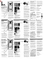
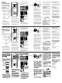
2B Install or Replace the Series F4 Solid-State Relay Output Module (Z100-0745-0001) A Solid-State Relay Output Module is represented in Series F4 controllers with a “K” in the appropriate position: Output 2B (terminal 33, 34, 35) F4D_-_ _ _K-_ _ _ _ Output 2A (terminal 36, 37, 38) F4D_-_ _K_-_ _ _ _ Output 1B (terminal 39, 40, 41) F4P_-_K_ _-_ _ _ _ F4S_-_KA _-_ _ _ _ F4D_-_K_ _-_ _ _ _ Output 1A (terminal 42, 43, 44) F4P_-K_ _ _-_ _ _ _ F4S_-K_ A _-_ _ _ _ F4D_-K_ _ _-_ _ _ _ Installieren oder Ersetzen des HalbleiterrelaisAusgangsmoduls der Serie F4 R2 2A R1 1A 1B I2 I1 1. Update the model number. On a separate sheet of paper, copy the model number of your controller from the label on the back of the case. Decide which output you will install the Solid-State Relay Output Module in. Beneath the original model number, write the new model number. Be careful to note the correct code in the correct position for any output module you have installed or moved. • Use the labels included in this kit to update the output schematic and model number on the back of your Series F4. 2B 2A 1A 1B (Z100-0745-0001) Ein Halbleiterrelais-Ausgangsmodul wird in Reglern der Serie F4 mit einem “K” in der entsprechenden Position dargestellt: Ausgang 2B (Anschluß 33, 34, 35) F4D_-_ _ _K-_ _ _ _ Ausgang 2A (Anschluß 36, 37, 38) F4D_-_ _K_-_ _ _ _ Ausgang 1B (Anschluß 39, 40, 41) F4P_-_K_ _-_ _ _ _ F4S_-_KA _-_ _ _ _ F4D_-_K_ _-_ _ _ _ Ausgang 1A (Anschluß 42, 43, 44) F4P_-K_ _ _-_ _ _ _ F4S_-K_ A _-_ _ _ _ F4D_-K_ _ _-_ _ _ _ 1. Aktualisieren Sie die Typennummer. Schreiben Sie die Typennummer des Reglers vom Etikett auf der Gehäuserückseite auf ein separates Blatt Papier. Entscheiden Sie, in welchen Ausgang Sie das HalbleiterrelaisAusgangsmodul installieren möchten. Schreiben Sie die neue Typennummer unter Instale o reemplace el módulo de salida del relé de estado sólido del controlador Serie F4 R2 R1 I2 I1 Abbildung 1 — Die Steckplätze des Ausgangsmoduls befinden sich auf der oberen Leiterplatten hälfte des Reglers (Ansicht von der Rückseite). die ursprüngliche Typennummer. Achten Sie darauf, daß Sie für jedes installierte bzw. verschobene Ausgangsmodul den korrekten Code in der richtigen Position notieren. • Verwenden Sie die mitgelieferten Etiketten, um das Ausgangsschema und die Typennummer auf der Rückseite des Reglers der Serie F4 zu aktualisieren. • Bringen Sie das Etikett mit den entsprechenden Anschlußnummern am Modulsteckverbinder an. Orientieren Sie das Etikett so, daß die Anschlußnummern lesbar sind, wenn die Schraubenköpfe nach unten zeigen. 2B 2A 1A 1B (Z100-0745-0001) El módulo de salida del relé de estado sólido se indica en los modelos de la Serie F4 con una letra “K” en la posición apropiada: Salida 2B (terminal 33, 34, 35) F4D_-_ _ _K-_ _ _ _ Salida 2A (terminal 36, 37, 38) F4D_-_ _K_-_ _ _ _ Salida 1B (terminal 39, 40, 41) F4P_-_K_ _-_ _ _ _ F4S_-_KA _-_ _ _ _ F4D_-_K_ _-_ _ _ _ Salida 1A (terminal 42, 43, 44) F4P_-K_ _ _-_ _ _ _ F4S_-K_ A _-_ _ _ _ F4D_-K_ _ _-_ _ _ _ 1. Actualice el número del modelo. En una hoja aparte, copie el número del modelo de su controlador (dicho número se encuentra en la etiqueta de la parte posterior de la caja). Elija la salida donde va a instalar el Figure 1 — The output module slots are on the upper half of the controller’s circuit board, viewed from the back. R2 R1 I2 I1 Figura 1 — Las ranuras del módulo de salida del relé de estado sólido se encuentran en la mitad superior de la placa del circuito impreso del controlador (visto desde atrás). módulo de salida del relé de estado sólido. Escriba el número nuevo debajo del original. Cerciórese de anotar el código correcto en la posición correcta para cualquier módulo de salida que haya instalado o transferido. • Utilice las etiquetas proporcionadas para actualizar el número del modelo en la parte posterior de su controlador Serie F4. • Fije la etiqueta con el número de terminal apropiado en el conector del módulo. Colóquela de manera que los números de la terminal queden con el lado derecho hacia arriba cuando las cabezas de los tornillos Figure 2 — Use this label (included with the module) to update the connector, model number and wiring label on the back of the case. Socket for Slot Keys Connector Apply terminal number label here. 33 34 35 DCDC+ 36 37 38 NO COMM 39 40 41 NO COMM NC 42 + 43 44 + Figure 3 — Update the output schematic and model number on the label on the back of the controller case. 93RL PROCESS CONTROL EQUIPMENT • Apply the appropriate terminal number label to the module connector. Orient the label so that the terminal numbers are right-side-up when the screw heads are facing down. 2. Dismount the controller and disconnect the connectors. Before you open the Series F4 controller, all wires must be disconnected Abbildung 2 — Verwenden Sie dieses Etikett (im Lieferumfang des Moduls enthalten), um den Steckverbinder, die Typennummer und das Verdrahtungsetikett auf der Gehäuserückseite zu aktualisieren. from it and the mounting bracket must be removed. The installation chapter of the Series F4 User’s Manual explains how to do this. 3. Open the controller case. To remove the back half of the Series F4, grasp the front half of the controller with one hand, insert a 6mm (0.25-inch) flat screwdriver into the slot on top of the unit between the case halves. Rotate the screwdriver 90° while prying toward the front of the controller. Turn the controller over and repeat the procedure on the bottom slot. 4. Locate the circuit board assembly. The controller circuit board assembly should be in the front half of the case. If it is in the back half, remove it and slide it into the front half of the case, making sure that the boards line up with the slots on the case and that the boards are seated so that the notches on both sides of each board are inside the case. Sockel für Steckplatz Naben Steckverbinder Anschlußnummernetikett hier anbringen 33 34 35 DCDC+ 36 37 38 NO COMM 93RL PROCESS CONTROL EQUIPMENT NO 39 40 41 COMM NC 42 + 43 44 + Abbildung 3 — Aktualisieren Sie das Ausgangsschema und die Typennummer auf dem Etikett auf der Gehäuserückseite des Reglers. 2. Bauen Sie den Regler aus, und trennen Sie alle Steckverbinder. Bevor Sie den Regler der Serie F4 öffnen, müssen Sie alle Drähte vom Regler abtrennen und die Halterung entfernen. Im Series F4 User’s Manual Figura 2 — Utilice esta etiqueta (incluida junto con el módulo) para actualizar el conector, el número del modelo y la etiqueta de cableado de la parte posterior de la caja. DCDC+ 36 37 38 NO COMM 93RL PROCESS CONTROL EQUIPMENT 39 40 41 NO COMM NC 42 + 43 44 + Figura 3 — Actualice el diagrama de salida y el número del modelo de la etiqueta que está en la parte posterior de la caja del controlador. estén orientados hacia abajo. 2. Desarme el controlador Serie F4 y desenchufe los conectores. Antes de abrir el controlador Serie F4, desconecte todos los cables y retire el soporte de montaje. Para hacerlo, consulte el capítulo de instalación Abbildung 4 — Entfernen Sie den Steckverbinder, und aktualisieren Sie das Etikett, bevor Sie das Modul installieren. (Benutzerhandbuch zum Regler der Serie F4) bzw. in der Kurzanleitung werden die hierzu notwendigen Schritte in den jeweiligen Kapiteln zur Installation erläutert. 3. Öffnen Sie das Gehäuse des Reglers. Um die hintere Gehäusehälfte des Reglers der Serie F4 zu entfernen, halten Sie die vordere Gehäusehälfte des Reglers mit einer Hand fest, und stecken Sie einen flachen Schraubendreher (6 mm) in den Schlitz am Gehäuseoberteil zwischen den beiden Gehäusehälften. Drehen Sie den Schraubendreher um 90°, und drücken Sie gleichzeitig gegen die Vorderseite des Reglers. Drehen Sie den Regler um, und wiederholen Sie den Vorgang am unteren Schlitz. 4. Identifizieren Sie die Leiterplatte. Die Leiterplatte des Reglers sollte sich in der vorderen Gehäusehälfte befinden. Wenn sich die Leiterplatte in der hinteren Gehäusehälfte befindet, entfernen Sie die Gruppe, und schieben Sie sie in die vordere Receptáculo para la ranura Llaves Conector Fijar aquí la etiqueta con el número del terminal 33 34 35 Figure 4 — Remove the connector and update the label before installing the module. Figura 4 — Desenchufe el conector y actualice la etiqueta antes de instalar el módulo. del Series F4 User’s Manual (manual de instrucciones del controlador Serie F4) o la Guía de puesta en marcha rápida. 3. Abra la caja del controlador. Para desmontar la mitad posterior del Serie F4, sujete firmemente la mitad delantera del controlador con una mano e introduzca un destornillador plano de 6 mm en la ranura situada en la parte superior del equipo (entre las dos mitades de la caja). Gire el destornillador 90° y trate de levantar la caja haciendo palanca hacia la parte delantera del controlador. Invierta ahora el equipo y repita el procedimiento en la ranura inferior. 4. Busque el montaje de placa del circuito impreso. El montaje de placa del circuito impreso del controlador debe estar en la mitad delantera de la caja. Si estuviera en la mitad posterior, sáquelo e instálelo en la mitad delantera, cerciorándose de que las placas queden alineadas con las ranuras de la caja y colocadas de manera que las 5. Disconnect the connector from the SolidState Relay Output Module. 6. Plug in the module. The Solid-State Relay Output Module plugs into the slots on the top half of the circuit board facing the back of the controller. Each output number is written above the slot. Make sure the pins on the circuit board line up with the socket on the module and the two keys on the module line up with the two holes on the circuit board, then plug the module in firmly. 7. Check knockouts. Before replacing the back half of the case, check that the knockout (on the back of the case) for the module terminals has been removed, if necessary. 8. Reassemble the case. Make sure the back ç CAUTION CAUTION: Use MIL-STD-1686B / EN10015-1 ESD (electrostatic discharge) procedures when handling output modules. Failure to follow these procedures could result in damage to equipment and product. ESD Grounding Strap available; order p/n: 08300494-0000 NOTE: The module procedure must be performed by a qualified technician. Gehäusehälfte. Achten Sie darauf, daß die Leiterplatten auf die Gehäuseschlitze ausgerichtet sind und die Kerben auf beiden Seiten der Leiterplatten innerhalb des Gehäuses liegen. 5. Trennen Sie den Steckverbinder vom Halbleiterrelais-Ausgangsmodul. 6. Stecken Sie das Modul ein. Das Halbleiterrelais-Ausgangsmodul wird in die Steckplätze auf der oberen, gegen die Rückseite des Reglers gerichteten Leiterplattenhälfte eingesteckt. Die jeweilige Ausgangsnummer ist oberhalb des Steckplatzes angegeben. Stellen Sie sicher, daß die Pins der Leiterplatte auf den Sockel des Moduls und die beiden Naben des Moduls auf die beiden Öffnungen der ç VORSICHT VORSICHT: Bei der Handhabung von Ausgangsmodulen gemäß MIL-STD-1686B / EN10015-1 ESD (elektrostatische Entladung) vorgehen. Eine Nichtbeachtung dieser Richtlinien kann Geräte- und Produktschäden zur Folge haben. Erdungslasche für elektrostatische Entladung, Bestell-Nr. 0830-0494-0000. HINWEIS: Die Arbeit am Modul muß von einem qualifizierten Techniker ausgeführt werden. muescas de ambos lados de cada placa queden dentro de la caja. 5. Desenchufe el conector del módulo de salida del relé de estado sólido. 6. Enchufe el módulo. El módulo de salida del relé de estado sólido se enchufa en las ranuras de la mitad superior de la placa del circuito impreso orientado hacia la parte posterior del controlador. Cada número de salida está escrito sobre la ranura. Compruebe que las espigas de la placa del circuito estén alineadas con el enchufe del módulo y que las dos llaves del módulo estén alineadas con los dos agujeros de la placa. Seguidamente enchufe el módulo con firmeza. ç PRECAUCIÓN PRECAUCIÓN: Durante el manejo de los módulos de salida, emplee los procedimientos de protección contra descargas electrostáticas MIL-STD-1686B / EN10015-1. El incumplimiento de dichos procedimientos puede traer como consecuencia daños a los equipos y productos. Se ofrecen bandas de puesta a tierra para proteger contra descargas electrostáticas; para efectuar pedidos, especifique el no. de ref. 0830-0494-0000. NOTA: El reemplazo del módulo debe ser efectuado por técnicos de servicio debidamente capacitados. half of the controller case is right-side-up, then align the circuit boards with the slots on the back half of the case, before sliding the case halves together until all four fasteners snap into place. Check to be certain that the terminals fit into the holes in the back of the case, then reassemble the connectors. 9. Refer to the Series F4 User’s Manual for wiring information. Watlow Controls 1241 Bundy Blvd., P.O. Box 5580 Winona, Minnesota USA 55987-5580 Phone: (507) 454-5300 Fax: (507) 452-4507 http://www.watlow.com Watlow Limited Robey Close, Linby Ind. Estate Linby, Nottingham Great Britain NG15 8AA Phone: (0) 115-9640777 Fax: (0) 115-9640071 TOTAL CUSTOMER SATISFACTION ISO 9001 0600-0032-0005 Rev. A (1333) Copyright © May 1998 Watlow Controls Registered Company Winona, Minnesota USA 98 Leiterplatte ausgerichtet sind. Stecken Sie dann das Modul fest ein. 7. Überprüfen Sie die Vorprägungen. Bevor Sie die hintere Gehäusehälfte wieder einsetzen, stellen Sie sicher, daß die Vorprägungen (auf der Gehäuserückseite) für die Modulanschlüsse entfernt wurden (falls erforderlich). 8. Bauen Sie das Gehäuse wieder zusammen. Stellen Sie sicher, daß die hintere Gehäusehälfte des Reglers korrekt ausgerichtet ist, und richten Sie dann die Leiterplatten auf die Schlitze auf der hinteren Gehäusehälfte aus. Schieben Sie dann die beiden Gehäusehälften zusammen, bis die vier Befestigungselemente einschnappen. Stellen Sie sicher, daß die Anschlüsse in die Öffnungen auf der Gehäuserückseite passen. Schließen Sie dann die Steckverbinder wieder an. 9. Für Informationen zur Verdrahtung siehe Series F4 User's Manual (Benutzerhandbuch zum Regler der Serie F4) bzw. Kurzanleitung. Watlow Electric GmbH Lauchwasenstr. 1 Postfach 1165, 76709 Kronau, Germany Telefon: 07253/9400-50 Fax: 07253/9400-44 7. Revise los agujeros ciegos. Antes de volver a colocar la mitad posterior de la caja, compruebe que se hayan destapado los agujeros ciegos para las terminales del módulo (si es necesario); dichos agujeros están situados en la parte posterior de la caja. 8. Vuelva armar la caja. Verifique que la mitad posterior del controlador tenga el lado derecho hacia arriba. Alinee las placas del circuito impreso con las ranuras de la mitad posterior de la caja, y seguidamente junte las dos mitades de la caja hasta que los cuatro sujetadores encajen apropiadamente. Compruebe que las terminales encajen en los agujeros de la parte posterior de la caja, y a continuación vuelva a instalar los conectores. 9. Las instrucciones de cableado se encuentran en el Series F4 User’s Manual (manual de instrucciones del controlador Serie F4) o la Guía de puesta en marcha rápida. Watlow de México Av. Fundición #5 Col. Parques Industriales Querétaro. Qro México CP-76130 Teléfono: (42) 17-6235 Fax: (42) 17-6403-
 1
1
-
 2
2


El Watlow SERIES F4 es un controlador de temperatura versátil y potente diseñado para una amplia variedad de aplicaciones. Con su avanzado algoritmo de control adaptativo y su capacidad de manejar cargas complejas, el SERIES F4 puede ayudar a mejorar el rendimiento del proceso y ahorrar energía. Además, el SERIES F4 cuenta con una variedad de características que lo hacen fácil de usar y mantener, incluyendo una interfaz intuitiva, un gran display LCD y diagnósticos integrados.
en otros idiomas
- français: Watlow SERIES F4 Manuel utilisateur
- italiano: Watlow SERIES F4 Manuale utente
- English: Watlow SERIES F4 User manual
- Deutsch: Watlow SERIES F4 Benutzerhandbuch
